THE UNIVERSITY OF TEXAS AT AUSTIN J.J. PICKLE ...
446
THE UNIVERSITY OF TEXAS AT AUSTIN J.J. PICKLE RESEARCH CENTER Project Manual FOR TAS Packaged Chilling Plant Relocation and Integration AUSTIN, TX Issued for Construction March 11, 2016 Prepared by: TBPE Firm No. 2966 2705 Bee Cave Rd Suite 300 Austin, TX 78746 JEG FEWE4801
-
Upload
khangminh22 -
Category
Documents
-
view
0 -
download
0
Transcript of THE UNIVERSITY OF TEXAS AT AUSTIN J.J. PICKLE ...

THE UNIVERSITY OF TEXAS
AT AUSTIN
J.J. PICKLE RESEARCH CENTER
Project Manual
FOR
TAS Packaged Chilling Plant Relocation and Integration AUSTIN, TX
Issued for Construction
March 11, 2016
Prepared by:
TBPE Firm No. 2966
2705 Bee Cave Rd
Suite 300
Austin, TX 78746
JEG FEWE4801

PAGE INTENTIONALLY LEFT BLANK


PAGE INTENTIONALLY LEFT BLANK

Jacobs FEWE4801 – Issued for Construction TABLE OF CONTENTS
March 11, 2016 TOC - 1
Division Section Title
SPECIFICATIONS GROUP
General Requirements Subgroup
DIVISION 01 - GENERAL REQUIREMENTS
011000 SUMMARY
012500 SUBSTITUTION PROCEDURES
013100 PROJECT MANAGEMENT AND COORDINATION
013200 CONSTRUCTION PROGRESS DOCUMENTATION
013300 SUBMITTAL PROCEDURES
014000 QUALITY REQUIREMENTS
014200 REFERENCES
015000 TEMPORARY FACILITIES AND CONTROLS
017300 EXECUTION
017700 CLOSEOUT PROCEDURES
017823 OPERATION AND MAINTENANCE DATA
017839 PROJECT RECORD DOCUMENTS
Facility Construction Subgroup
DIVISION 03 - CONCRETE
033000 CAST-IN-PLACE CONCRETE
DIVISION 05 - METALS
051200 STRUCTURAL STEEL FRAMING
053100 STEEL DECKING
Facility Services Subgroup
DIVISION 23 - HEATING VENTILATING AND AIR CONDITIONING
230050 MECHANICAL GENERAL PROVISIONS
230051 SUBMITTALS GENERAL
230052 OPERATION AND MAINTENANCE MANUALS
230517 SLEEVES, FLASHINGS, SUPPORTS AND ANCHORS
230533 HEAT TRACING FOR HVAC PIPING
230553 MECHANICAL IDENTIFICATION
230700 MECHANICAL INSULATION
232213 PLANT PIPING AND VALVES
232213-A UT REQUIREMENTS FOR WATER TREATMENT AND HYDROSTATIC TESTING
OF NEW PIPING SYSTEMS
232213-B PROCEDURES FOR CLEANING, PASSIVATING, & FINAL TREATMENT OF
CHILLED WATER PIPING
232213-C PIPE SPECIFICATION TABLES

Jacobs FEWE4801 – Issued for Construction TABLE OF CONTENTS
March 11, 2016 TOC - 2
Division Section Title
239087 PLANT PIPING SPECIALTIES
DIVISION 25 - INTEGRATED AUTOMATION
250500 COMMON WORK RESULTS FOR INTEGRATED AUTOMATION
253000 INTEGRATED AUTOMATION INSTRUMENTATION & TERMINAL DEVICES
255000 INTEGRATED AUTOMATION FACILITY CONTROLS
DIVISION 26 - ELECTRICAL
260500 COMMON WORK RESULTS FOR ELECTRICAL
260519 LOW-VOLTAGE ELECTRICAL POWER CONDUCTORS AND CABLES
260523 CONTROL-VOLTAGE ELECTRICAL POWER CABLES
260526 GROUNDING AND BONDING FOR ELECTRICAL SYSTEMS
260529 HANGERS AND SUPPORTS FOR ELECTRICAL SYSTEMS
260533 RACEWAYS AND BOXES FOR ELECTRICAL SYSTEMS
260543 UNDERGROUND DUCTS AND RACEWAYS FOR ELECTRICAL SYSTEMS
260544 SLEEVES AND SLEEVE SEALS FOR ELECTRICAL RACEWAYS AND CABLING
260553 IDENTIFICATION FOR ELECTRICAL SYSTEMS
261200 MEDIUM-VOLTAGE TRANSFORMERS
261329 MEDIUM-VOLTAGE, PAD-MOUNTED SWITCHGEAR
262816 ENCLOSED SWITCHES AND CIRCUIT BREAKERS
264113 LIGHTNING PROTECTION FOR STRUCTURES
Site and Infrastructure Subgroup
DIVISION 31 - EARTHWORK
311000 SITE CLEARING
312200 FINE GRADING
312316 EXCAVATION, BACKFILLING AND COMPACTING
316329 DRILLED CONCRETE PIERS AND SHAFTS
DIVISION 32 - EXTERIOR IMPROVEMENTS
321123 FLEXIBLE BASE COURSE
321216 ASPHALT PAVING
321313 CONCRETE PAVING
329200 TURF AND GRASSES
DIVISION 33 - UTILITIES
331116 SITE WATER UTILITY DISTRIBUTION PIPING
331300 DISINFECTION OF WATER UTILITY DISTRIBUTION
333111 SITE SANITARY SEWERAGE UTILITY PIPING
DIVISION 34 - TRANSPORTATION
342100 PAVEMENT MARKING PAINT
343200 PAVEMENT SURFACE PREPARATION FOR MARKINGS

Jacobs FEWE4801 – Issued for Construction TABLE OF CONTENTS
March 11, 2016 TOC - 3
END OF TABLE OF CONTENTS

Jacobs FEWE4801 – Issued for Construction TABLE OF CONTENTS
March 11, 2016 TOC - 4
PAGE INTENTIONALLY LEFT BLANK

Jacobs FEWE4801 - Issued for Construction SUMMARY
March 11, 2016 011000 - 1
SECTION 011000 - SUMMARY
PART 1 - GENERAL
1.1 RELATED DOCUMENTS
A. Drawings and General Provisions of the Contract, including General and Supplementary
Conditions and other Division 01 Specification Sections, apply to this Section.
1.2 PROJECT INFORMATION
A. Project Identification: The University of Texas at Austin JJ Pickle Research Campus TAS
Packaged Chilling Plant Relocation and Integration.
1. Project Location: The University of Texas at Austin JJ Pickle Research Campus, CP-1.
Austin, Texas.
B. Owner: The University of Texas at Austin.
1. Owner's Representative: Michael (Mike) Manoucheri, (512) 471.8818.
C. Architect/Engineer: Jacobs Engineering Group, Austin, Texas. J. Darrell Widner, P.E., Project
Manager, (512) 732.7505, [email protected].
D. This specification manual and the related construction drawings provided under Package 1 were
developed in consideration of the scope of work for the disassembly, transport, and re-assembly
of the Owner provided packaged chiller plant outlined in Package 2 of this overall bid Package.
Any deviations in the Package 2 documentation and the actual field conditions associated with
the existing packaged chiller plant are to be documented by the contractor as “As-Built”
conditions and shall be considered in the efforts required for the Package 2 scope of work.
Should any condition exist and impact the work covered under Package 1, it should be
identified, thoroughly documented and addressed with the Owner and Engineer.
1.3 WORK COVERED BY CONTRACT DOCUMENTS
A. The work includes the furnishing of all the necessary labor, tools, equipment, materials,
supplies and miscellaneous items required for the Demolition and Construction in accordance
with the Contract, Drawings and Specifications including Addenda, as prepared by Jacobs
Engineering dated March 11, 2016 plus any required revisions and/or clarifications issued to the
contractor, in addition to the Owner provided requirements in Package 2 and consists of the
following:
1. Package 1 - The new construction consists of, but is not limited to, the following as
indicated on Drawings and herein:
a. Structural foundations for packaged equipment, new and/or relocated electrical
equipment and cooling tower structure and pipe supports.

Jacobs FEWE4801 - Issued for Construction SUMMARY
March 11, 2016 011000 - 2
b. Civil selective demolition, excavation, grubbing, grading, and sanitary sewer line
extensions.
c. Excavation, tie in and extension of new water line and associated valving to serve
as the make-up water piping.
d. Chilled water supply and return system modifications as shown on drawings
e. Instrumentation and controls associated required to tie the packaged enclosure into
the existing chilled water control system.
f. Complete electrical system modifications and additions as indicated on Drawings
and herein:
1) 12.47 kV medium voltage switch procurement, installation and testing.
2) 12.47 kV medium voltage pad mounted transformer procurement,
installation and testing.
3) Grounding and lightning protection systems.
4) 480V and 120V distribution and branch circuiting and raceway as needed to
replace package loads back into service.
5) Disconnecting means.
6) Underground raceways and cabling for new medium voltage and low
voltage power systems.
7) Raceways and cabling for control systems.
8) Connection to Owner supplied equipment provided under other contracts
including but not limited to:
a) Main switchboard.
b) Chiller
c) MCC
d) Other equipment as indicated on drawings.
g. Complete structural system and assembly as indicated on Drawings and herein,
including, but not limited to selective demolition, concrete and steel structure(s),
waterproofing, pipe supports and miscellaneous steel.
2. Package 2 – Owner provided details for the Disassembly, Packing, Transport, and
Reassembly of the Packaged Chiller Plant on the foundations supplied by the Package 1
documents.
B. Refer to front end specifications and bidder information for project schedule requirements.
C. Work Layout
1. The Contractor shall be responsible for the correct setting out of the work in accordance
with the drawings. If there is any discrepancy between actual site conditions and the
drawings, the Contractor shall notify the Architect/Engineer in writing and shall not
proceed with any work affected by such discrepancy until he has instruction from the
Architect/Engineer
D. Discrepancies and Measurements
1. The Contractor shall in writing, call to the attention of the Architect/Engineer any
discrepancies between Specifications, Plans, Details or Schedules. The
Architect/Engineer will inform the Contractor in writing which documents take

Jacobs FEWE4801 - Issued for Construction SUMMARY
March 11, 2016 011000 - 3
precedence. Before ordering any materials or doing any work, verify all measurements
and be responsible for the correctness of same. No extra charge or compensation will be
allowed on account of difference between actual dimensions and the measurements
indicated on the drawings. Any difference which may be found shall be submitted to the
Architect/Engineer for consideration before proceeding with the work.
E. Jurisdiction of Work
1. The question of jurisdiction of work between the various crafts as herein specified shall
be settled without work stoppage.
2. The placing in the specifications of certain portions of the work under any particular
section of the specifications shall in no manner relieve the Subcontractors from
performing such work as this work is normally performed under his or their jurisdiction.
Each Subcontractor shall furnish the material or perform his work on the basis of the
entire and complete plans and specifications
1.4 PHASED CONSTRUCTION
A. The Work shall be conducted in phases in order to maintain existing utilities to campus. All
new construction shall be conducted prior to major demolition.
1.5 PERMITS AND REGULATIONS
A. The Contractor shall obtain and pay for all permits and licenses; pay all fees, comply with all
local, state laws, ordinances, rules, regulations applicable to work. If plans and specifications
are at variance with any of the above provisions, notify the Architect/Engineer in writing before
work is performed and proper adjustment shall be made.
1.6 ACCESS TO SITE
A. General: Contractor shall have full use of Project site for construction operations during
construction period. Contractor's use of Project site is limited only by Owner's right to perform
work or to retain other contractors on portions of Project.
B. Use of Site: Limit use of Project site to areas within the Contract limits indicated. Do not
disturb portions of Project site beyond areas in which the Work is indicated.
1. Limits: Confine construction operations to area indicated on site Drawings.
2. Driveways, Walkways and Entrances: Keep driveways, loading areas and entrances
serving premises clear and available to Owner, Owner's employees, and emergency
vehicles at all times. Do not use these areas for parking or storage of materials.
a. Schedule deliveries to minimize use of driveways and entrances by construction
operations.
b. Schedule deliveries to minimize space and time requirements for storage of
materials and equipment on-site.

Jacobs FEWE4801 - Issued for Construction SUMMARY
March 11, 2016 011000 - 4
C. Temporary office and tool storage: Contractor shall provide and maintain facilities and
enclosures needed for his work.
D. Contractor Parking: Contractor parking shall be coordinated with University of Texas Parking
and Transportation Services.
1.7 PROTECTION
A. The Contractor and his Subcontractors shall not use adjacent property or the public domain for
any purpose whatsoever, but shall confine apparatus, equipment, storage of materials and
operations of workmen to limits provided by law, ordinances, or permits and in an orderly
manner. He shall make all necessary or required provisions for the protection of the public.
B. The Contractor shall protect all existing streets and curbs and all walks, paving, etc. All
damage caused by him or his Subcontractors shall be made good at the Contractor's expense.
No patching will be allowed; broken or cracked walks shall be fully replaced. Maintain
adequate protection with barricades and other apparatus as required to provide adequate
protection to the public. Barricades shall conform to all state, local codes and regulations, and
insurance requirements governing same.
C. The Contractor shall protect all existing trees, landscaping plant materials and turf areas. All
damage caused by him or his Subcontractors shall be made good at the Contractor's expense.
D. The Contractor shall be responsible for all damage to property, injury to persons, and loss,
expense, inconvenience, and delay that may be caused by or result from the carrying out of the
work to be done under the contract, or from any act, omission, or neglect of the Contractor,
Contractor’s Subcontractors or employees.
E. The Contractor shall provide secure storage for materials and equipment and insure that
materials, construction, or finishes are not damaged thereby
F. The Contractor shall furnish and maintain a minimum of five (5) ABC dry chemical type fire
extinguishers with 3A-30BC rating on the site during the entire construction period.
1.8 ENVIRONMENTAL SAFETY REQUIREMENTS
A. Contractor shall be required to comply with all applicable Federal, State, and Local
environmental, occupational, and safety regulations and guidelines.
B. Contractor shall be responsible for providing a training and education program for its
employees which meets the requirements of the Federal Hazard Communication Standard (29
CFR 1910.1200, 29 CFR 1926.59) where applicable. The Contractor may be required to submit
proof of such training prior to award.
C. The existing cooling towers may contain asbestos. It is the responsibility of the Contractor to
disseminate this information to the subcontractors and all employees involved. Asbestos
containing material may cause health problems. This will only occur if disturbance or damage
results in significant fiber release. The EPA National Emission Standard of Hazardous Air
Pollutants (EPA-NESHAP 40CFR 61 subpart M) regulates the renovation and demolition of

Jacobs FEWE4801 - Issued for Construction SUMMARY
March 11, 2016 011000 - 5
buildings pertaining to the emission of asbestos. The Occupational Safety and Health
Administration (OSHA 29 CFR 1926.1101) regulations require the abatement and proper
notification to all General Contractors, and sub-contractor(s) and their employees of any
asbestos materials that will or may become damaged during renovation or demolition activities.
These requirements apply regardless of the extent of activity. Coordinate abatement activities
with the University prior to commencing work.
D. Contractors whose materials or work may pose a health hazard to University of Texas
employees shall be responsible for providing Material Safety Data Sheets (MSDSs) to the office
of Environmental Health and Safety. They must also inform the affected employees’ supervisor
of the nature and extent of the hazard(s) those materials may pose.
E. The Contractor shall not dispose of hazardous materials on University property or down
sanitary or sewer drains, and shall not dispose of any materials, including water or wastewater,
down storm drains.
F. All hazardous wastes generated by the Contractor are the responsibility and property of the
Contractor who must dispose of them in an environmentally responsible manner and in
compliance with all applicable laws and regulations.
G. Contractors who encounter suspected asbestos containing material (ACM) during the course of
their work and who must disturb, contact, or damage the suspected ACM must immediately stop
work and contact the Construction Manager.
H. The Contractor will be required to ensure that any Subcontractors comply with these
requirements.
1.9 OCCUPANCY COORDINATION
A. Partial Owner Occupancy: Owner will occupy the premises during portions of the construction
period, with the exception of areas under construction. Cooperate with Owner during
construction operations to minimize conflicts and facilitate Owner usage. Perform the Work so
as not to interfere with Owner's operations. Maintain existing exits unless otherwise indicated.
1. Maintain access to existing walkways, corridors, and other adjacent occupied or used
facilities. Do not close or obstruct walkways, corridors, or other occupied or used
facilities without written permission from Owner and authorities having jurisdiction.
2. Provide not less than five (5) days’ notice to Owner of activities that will affect Owner's
operations.
1.10 WORK RESTRICTIONS
A. Work Restrictions, General: Comply with restrictions on construction operations.
1. Comply with limitations on use of public streets and other requirements of authorities
having jurisdiction.
B. On-Site Work Hours: Limit work on site to normal business working hours of 7 a.m. to 5 p.m.,
Monday through Friday, except as otherwise indicated.

Jacobs FEWE4801 - Issued for Construction SUMMARY
March 11, 2016 011000 - 6
1. Hours for Utility Shutdowns: Coordinate with Owner’s Representative.
C. Existing Utility Interruptions: Do not interrupt utilities serving facilities occupied by Owner or
others unless permitted under the following conditions and then only after providing temporary
utility services according to requirements indicated:
1. Utility shut-downs shall not be allowed without two weeks advance notice to The
University of Texas. The Contractor shall notify the Owner.
2. Obtain Owner’s written permission before proceeding with utility interruptions.
D. Noise, Vibration, and Odors: Coordinate operations that may result in high levels of noise and
vibration, odors, or other disruption to Owner occupancy with Owner.
1. Notify Owner not less than two days in advance of proposed disruptive operations.
2. Obtain Owner's written permission before proceeding with disruptive operations.
E. Nonsmoking Building: Smoking is not permitted on University of Texas property.
F. Controlled Substances: Use of tobacco products and other controlled substances on the Project
site is not permitted.
1.11 PRODUCT DELIVERY, STORAGE, AND HANDLING
A. Deliver, store, and handle products using means and methods that will prevent damage,
deterioration, and loss, including theft and vandalism. Comply with manufacturer's written
instructions.
B. Delivery and Handling:
1. Schedule delivery to minimize long-term storage at Project site and to prevent
overcrowding of construction spaces.
2. Coordinate delivery with installation time to ensure minimum holding time for items that
are flammable, hazardous, easily damaged, or sensitive to deterioration, theft, and other
losses.
3. Deliver products to Project site in an undamaged condition in manufacturer's original
sealed container or other packaging system, complete with labels and instructions for
handling, storing, unpacking, protecting, and installing.
4. Inspect products on delivery to determine compliance with the Contract Documents and
to determine that products are undamaged and properly protected.
C. Storage:
1. Store products to allow for inspection and measurement of quantity or counting of units.
2. Store materials in a manner that will not endanger Project structure.
3. Store products that are subject to damage by the elements, under cover in a weather tight
enclosure above ground, with ventilation adequate to prevent condensation.
4. Store foam plastic from exposure to sunlight, except to extent necessary for period of
installation and concealment.
5. Comply with product manufacturer's written instructions for temperature, humidity,
ventilation, and weather-protection requirements for storage.

Jacobs FEWE4801 - Issued for Construction SUMMARY
March 11, 2016 011000 - 7
6. Protect stored products from damage and liquids from freezing.
7. Provide a secure location and enclosure at Project site for storage of materials and
equipment by Owner's construction forces. Coordinate location with Owner.
1.12 SPECIFICATION AND DRAWING CONVENTIONS
A. Specification Content: The Specifications use certain conventions for the style of language and
the intended meaning of certain terms, words, and phrases when used in particular situations.
These conventions are as follows:
1. Imperative mood and streamlined language are generally used in the Specifications. The
words "shall," "shall be," or "shall comply with," depending on the context, are implied
where a colon (:) is used within a sentence or phrase.
2. Specification requirements are to be performed by Contractor unless specifically stated
otherwise.
B. Division 01 General Requirements: Requirements of Sections in Division 01 apply to the Work
of all Sections in the Specifications.
C. Drawing Coordination: Requirements for materials and products identified on the Drawings are
described in detail in the Specifications. One or more of the following are used on the
Drawings to identify materials and products:
1. Terminology: Materials and products are identified by the typical generic terms used in
the individual Specifications Sections.
2. Abbreviations: Materials and products are identified by abbreviations published as part
of the U.S. National CAD Standard and scheduled on Drawings.
3. Keynoting: Materials and products are identified by reference keynotes referencing
Specification Section numbers found in this Project Manual.
PART 2 - PRODUCTS (Not Used)
PART 3 - EXECUTION (Not Used)
END OF SECTION 011000

Jacobs FEWE4801 - Issued for Construction SUMMARY
March 11, 2016 011000 - 8
PAGE INTENTIONALLY LEFT BLANK

Jacobs FEWE4801 - Issued for Construction SUBSTITUTION PROCEDURES
March 11, 2016 012500 - 1
SECTION 012500 - SUBSTITUTION PROCEDURES
PART 1 - GENERAL
1.1 RELATED DOCUMENTS
A. Drawings and general provisions of the Contract, including General and Supplementary
Conditions and other Division 01 Specification Sections, apply to this Section.
1.2 SUMMARY
A. Section includes administrative and procedural requirements for substitutions.
1.3 DEFINITIONS
A. Substitutions: Changes in products, materials, equipment, and methods of construction from
those required by the Contract Documents and proposed by Contractor.
1. Substitutions for Cause: Changes proposed by Contractor that are required due to
changed Project conditions, such as unavailability of product, regulatory changes, or
unavailability of required warranty terms.
2. Substitutions for Convenience: Changes proposed by Contractor or Owner that are not
required in order to meet other Project requirements but may offer advantage to
Contractor or Owner.
1.4 SUBMITTALS
A. It is not the intent of the Drawings and/or Specifications to limit products to any particular
manufacturer or to discriminate against an "APPROVED EQUAL" product as produced by
another manufacturer. Some proprietary products are mentioned to set a definite standard for
acceptance and to serve as a reference in comparison with other products. When a
manufacturer's name appears in these Specifications, it is not to be construed that the
manufacturer is unconditionally acceptable as a provider of equipment for this project. The
successful manufacturer or supplier shall meet all of the provisions of the appropriate
specification(s). Consideration of alternate and/or “or equal” suppliers will require that a list of
end users with multiple years of good experience be provided. Contact names and phone
numbers of the end users must be provided for any consideration to be given. Submittal of end
users with multiple years of good experience does not ensure that any substitution will be
allowed by Owner.
B. Within thirty days after the date of contract award or work order, whichever is later, and before
purchasing or starting installation of materials or equipment, the Contractor shall submit for
review, a complete list of suppliers, contractors and manufacturers for all materials and
equipment which will be submitted for incorporation into the project. The list shall be arranged
in accordance with the organization of the Specifications. This initial list shall include the
manufacturer's name and type or catalog number as required to identify the quality of material

Jacobs FEWE4801 - Issued for Construction SUBSTITUTION PROCEDURES
March 11, 2016 012500 - 2
or equipment proposed. This list will be reviewed by the Engineer and the Owner and will be
returned to the Contractor with comments as to which items are acceptable without further
submittal data and which items will require detailed submittal data for further review and
subsequent approval. The initial list shall be submitted as herein specified. Materials and
equipment requiring detailed submittal data shall be submitted with sufficient data to indicate
that all requirements of these Specifications have been met and samples shall be furnished when
requested. All manufacturers’ data used as part of the submittal shall have all inapplicable
features crossed out or deleted in a manner that will clearly indicate exactly what is to be
furnished
C. Substitution Requests: Submit three copies of each request for consideration. Identify product
or fabrication or installation method to be replaced. Include Specification Section number and
title and Drawing numbers and titles.
1. Substitution Request Form: Use CSI Form 13.1A.
2. Documentation: Show compliance with requirements for substitutions and the following,
as applicable:
a. Statement indicating why specified product or fabrication or installation cannot be
provided, if applicable.
b. Coordination information, including a list of changes or modifications needed to
other parts of the Work and to construction performed by Owner and separate
contractors that will be necessary to accommodate proposed substitution.
c. Detailed comparison of significant qualities of proposed substitution with those of
the Work specified. Include annotated copy of applicable specification section.
Significant qualities may include attributes such as performance, weight, size,
durability, visual effect, sustainable design characteristics, warranties, and specific
features and requirements indicated. Indicate deviations, if any, from the Work
specified.
d. Product Data, including drawings and descriptions of products and fabrication and
installation procedures.
e. Samples, where applicable or requested.
f. Certificates and qualification data, where applicable or requested.
g. List of similar installations for completed projects with project names and
addresses and names and addresses of architects and owners.
h. Material test reports from a qualified testing agency indicating and interpreting test
results for compliance with requirements indicated.
i. Research reports evidencing compliance with building code in effect for Project.
j. Detailed comparison of Contractor's construction schedule using proposed
substitution with products specified for the Work, including effect on the overall
Contract Time. If specified product or method of construction cannot be provided
within the Contract Time, include letter from manufacturer, on manufacturer's
letterhead, stating date of receipt of purchase order, lack of availability, or delays
in delivery.
k. Cost information, including a proposal of change, if any, in the Contract Sum.
l. Contractor's certification that proposed substitution complies with requirements in
the Contract Documents except as indicated in substitution request, is compatible
with related materials, and is appropriate for applications indicated.
m. Contractor's waiver of rights to additional payment or time that may subsequently
become necessary because of failure of proposed substitution to produce indicated
results.

Jacobs FEWE4801 - Issued for Construction SUBSTITUTION PROCEDURES
March 11, 2016 012500 - 3
3. Architect/Engineer’s Action: If necessary, Architect/Engineer will request additional
information or documentation for evaluation within seven days of receipt of a request for
substitution. Architect/Engineer will notify Contractor through Construction Manager of
acceptance or rejection of proposed substitution within 15 days of receipt of request, or
seven days of receipt of additional information or documentation, whichever is later.
a. Forms of Acceptance: Change Order, Construction Change Directive, or
Architect’s Supplemental Instructions for minor changes in the Work.
b. Use product specified if Architect does not issue a decision on use of a proposed
substitution within time allocated.
1.5 QUALITY ASSURANCE
A. Compatibility of Substitutions: Investigate and document compatibility of proposed
substitution with related products and materials. Engage qualified testing agency to perform
compatibility tests recommended by manufacturers.
1.6 PROCEDURES
A. Coordination: Modify or adjust affected work as necessary to integrate work of the approved
substitutions.
PART 2 - PRODUCTS
2.1 SUBSTITUTIONS
A. Substitutions for Cause: Submit requests for substitution immediately upon discovery of need
for change, but not later than 15 days prior to time required for preparation and review of
related submittals.
1. Conditions: Architect will consider Contractor's request for substitution when the
following conditions are satisfied. If the following conditions are not satisfied, Architect
will return requests without action, except to record noncompliance with these
requirements:
a. Requested substitution is consistent with the Contract Documents and will produce
indicated results.
b. Substitution request is fully documented and properly submitted.
c. Requested substitution will not adversely affect Contractor's construction schedule.
d. Requested substitution has received necessary approvals of authorities having
jurisdiction.
e. Requested substitution is compatible with other portions of the Work.
f. Requested substitution has been coordinated with other portions of the Work.
g. Requested substitution provides specified warranty.
h. If requested substitution involves more than one contractor, requested substitution
has been coordinated with other portions of the Work, is uniform and consistent, is
compatible with other products, and is acceptable to all contractors involved.

Jacobs FEWE4801 - Issued for Construction SUBSTITUTION PROCEDURES
March 11, 2016 012500 - 4
B. Substitutions for Convenience: Architect/Engineer will consider requests for substitution if
received within 30 days after Notice to Proceed. Requests received after that time may be
considered or rejected at discretion of Architect/Engineer.
1. Conditions: Architect/Engineer will consider Contractor's request for substitution when
the following conditions are satisfied. If the following conditions are not satisfied,
Architect/Engineer will return requests without action, except to record noncompliance
with these requirements:
a. Requested substitution offers Owner a substantial advantage in cost, time, energy
conservation, or other considerations, after deducting additional responsibilities
Owner must assume. Owner's additional responsibilities may include
compensation to Architect for redesign and evaluation services, increased cost of
other construction by Owner, and similar considerations.
b. Requested substitution does not require extensive revisions to the Contract
Documents.
c. Requested substitution is consistent with the Contract Documents and will produce
indicated results.
d. Substitution request is fully documented and properly submitted.
e. Requested substitution will not adversely affect Contractor's construction schedule.
f. Requested substitution has received necessary approvals of authorities having
jurisdiction.
g. Requested substitution is compatible with other portions of the Work.
h. Requested substitution has been coordinated with other portions of the Work.
i. Requested substitution provides specified warranty.
j. If requested substitution involves more than one contractor, requested substitution
has been coordinated with other portions of the Work, is uniform and consistent, is
compatible with other products, and is acceptable to all contractors involved.
PART 3 - EXECUTION (Not Used)
END OF SECTION 012500

Jacobs FEWE4801 - Issued for Construction PROJECT MANAGEMENT AND COORDINATION
March 11, 2016 013100 - 1
SECTION 013100 - PROJECT MANAGEMENT AND COORDINATION
PART 1 - GENERAL
1.1 RELATED DOCUMENTS
A. Drawings and general provisions of the Contract, including General and Supplementary
Conditions and other Division 01 Specification Sections, apply to this Section.
1.2 SUMMARY
A. Section includes administrative provisions for coordinating construction operations on Project
including, but not limited to, the following:
1. General project coordination procedures.
2. Administrative and supervisory personnel.
3. Coordination drawings.
4. Requests for Information (RFIs).
5. Project meetings.
B. Related Sections:
1. Division 01 Section "Construction Progress Documentation" for preparing and
submitting Contractor's construction schedule.
2. Division 01 Section "Execution" for procedures for coordinating general installation and
field-engineering services, including establishment of benchmarks and control points.
3. Division 01 Section "Closeout Procedures" for coordinating closeout of the Contract.
1.3 DEFINITIONS
A. RFI: Request from Owner, Engineer/Engineer, or Contractor seeking information from each
other during construction.
1.4 COORDINATION
A. Coordination: Coordinate construction operations included in different Sections of the
Specifications to ensure efficient and orderly installation of each part of the Work. Coordinate
construction operations, included in different Sections that depend on each other for proper
installation, connection, and operation.
1. Schedule construction operations in sequence required to obtain the best results where
installation of one part of the Work depends on installation of other components, before
or after its own installation.
2. Coordinate installation of different components to ensure maximum performance and
accessibility for required maintenance, service, and repair.
3. Make adequate provisions to accommodate items scheduled for later installation.

Jacobs FEWE4801 - Issued for Construction PROJECT MANAGEMENT AND COORDINATION
March 11, 2016 013100 - 2
B. Prepare memoranda for distribution to each party involved, outlining special procedures
required for coordination. Include such items as required notices, reports, and list of attendees
at meetings.
1. Prepare similar memoranda for Owner and separate contractors if coordination of their
Work is required.
C. Administrative Procedures: Coordinate scheduling and timing of required administrative
procedures with other construction activities to avoid conflicts and to ensure orderly progress of
the Work. Such administrative activities include, but are not limited to, the following:
1. Preparation of Contractor's construction schedule.
2. Preparation of the schedule of values.
3. Installation and removal of temporary facilities and controls.
4. Delivery and processing of submittals.
5. Progress meetings.
6. Preinstallation conferences.
7. Project closeout activities.
8. Startup and adjustment of systems.
9. Project closeout activities.
D. Conservation: Coordinate construction activities to ensure that operations are carried out with
consideration given to conservation of energy, water, and materials. Coordinate use of
temporary utilities to minimize waste.
1. Salvage materials and equipment involved in performance of, but not actually
incorporated into, the Work. Refer to other Sections for disposition of salvaged materials
that are designated as Owner's property.
1.5 RESPONSIBILITY AND COOPERATION OF SUBCONTRACTORS, TRADES, ETC.
A. All subcontractors shall cooperate with each other. They shall properly install and coordinate
their work with other subcontractors at such times and in such manner as not to delay or
interfere with the work of others. They shall perform their work in conformity with the
construction called for under other phases of this project.
B. All subcontractors shall examine all drawings and read all specifications, whether for their
specific work or for the work of others, so that they will be able to coordinate their work
accordingly. They shall submit all required samples promptly and shall schedule their work
through the General Contractor.
C. Each subcontractor shall report promptly to the General Contractor for any delay or difficulties
encountered in the installation of his work or make it unsuitable to connect or receive his work
or the work of others. This report shall be in writing with a copy of the letter sent to the
Engineer/Engineer. Failure of the subcontractor involved to so report shall constitute an
acceptance of the work of others as being fit for the proper reception of his work.
D. General Contractor is responsible for proper fitting of all work; for coordination of operations of
all trades, for subcontractors and material suppliers engaged in connection with work, as well as
his own employees; he shall exercise every effort to assure a harmonious, cooperative attitude

Jacobs FEWE4801 - Issued for Construction PROJECT MANAGEMENT AND COORDINATION
March 11, 2016 013100 - 3
on the part of all concerned. He shall be prepared to guarantee, to each of his subcontractors
and foremen, all dimensions they require for fitting necessary to make the several parts of the
work come together properly and to fit.
1.6 COORDINATION DRAWINGS
A. Coordination Drawings, General: Prepare coordination drawings in accordance with
requirements in individual Sections, where installation is not completely shown on Shop
Drawings, where limited space availability necessitates coordination, or if coordination is
required to facilitate integration of products and materials fabricated or installed by more than
one entity.
1. Content: Project-specific information, drawn accurately to a scale large enough to
indicate and resolve conflicts. Do not base coordination drawings on standard printed
data. Include the following information, as applicable:
a. Use applicable Drawings as a basis for preparation of coordination drawings.
Prepare sections, elevations, and details as needed to describe relationship of
various systems and components.
b. Indicate functional and spatial relationships of components of Engineerural,
structural, civil, mechanical, and electrical systems.
c. Indicate space requirements for routine maintenance and for anticipated
replacement of components during the life of the installation.
d. Show location and size of access doors required for access to concealed dampers,
valves, and other controls.
e. Indicate required installation sequences.
f. Indicate dimensions shown on the Drawings. Specifically note dimensions that
appear to be in conflict with submitted equipment and minimum clearance
requirements. Provide alternate sketches to Engineer/Engineer indicating proposed
resolution of such conflicts. Minor dimension changes and difficult installations
will not be considered changes to the Contract.
B. Coordination Drawing Organization: Organize coordination drawings as follows:
1. Floor Plans and Reflected Ceiling Plans: Show Engineerural and structural elements, and
mechanical, plumbing, fire protection, fire alarm, and electrical Work. Show locations of
visible ceiling-mounted devices relative to acoustical ceiling grid. Supplement plan
drawings with section drawings where required to adequately represent the Work.
2. Structural Penetrations: Indicate penetrations and openings required for all disciplines.
3. Slab Edge and Embedded Items: Indicate slab edge locations and sizes and locations of
embedded items for metal fabrications, sleeves, anchor bolts, bearing plates, angles, door
floor closers, slab depressions for floor finishes, curbs and housekeeping pads, and
similar items.
4. Mechanical and Plumbing Work: Show the following:
a. Sizes and bottom elevations of ductwork, piping, and conduit runs, including
insulation, bracing, flanges, and support systems.
b. Dimensions of major components, such as dampers, valves, diffusers, access
doors, cleanouts and electrical distribution equipment.

Jacobs FEWE4801 - Issued for Construction PROJECT MANAGEMENT AND COORDINATION
March 11, 2016 013100 - 4
5. Electrical Work: Show the following:
a. Runs of vertical and horizontal conduit 1inch diameter and larger.
b. Panel board, switch board, switchgear, transformer, bus-way, generator, and motor
control center locations.
6. Review: Engineer/Engineer will review coordination drawings to confirm that the Work
is being coordinated, but not for the details of the coordination, which are the
Contractor's responsibility. If the Engineer/Engineer determines that the coordination
drawings are not being prepared in sufficient scope or detail, or are otherwise deficient,
the Engineer/Engineer will so inform the Contractor, who shall make changes as directed
and resubmit.
7. Coordination Drawing Prints: Prepare coordination drawing prints in accordance with
requirements of Division 01 Section "Submittal Procedures."
C. Coordination Digital Data Files: Prepare coordination digital data files in accordance with the
following requirements:
1. File Preparation Format: Same digital data software program, version, and operating
system as the original Drawings.
2. File Preparation Format: DWG, Version 2011, operating in Microsoft Windows
operating system.
3. File Submittal Format: Submit or post coordination drawing files using Portable Data
File (PDF) format.
4. Engineer/Engineer will furnish Contractor one set of digital data files of the Drawings for
use in preparing coordination digital data files.
a. Engineer/Engineer makes no representations as to the accuracy or completeness of
digital data files as they relate to the Drawings.
b. Contractor shall execute a data licensing agreement in the form of an Agreement
form acceptable to the Owner and Engineer/Engineer.
1.7 KEY PERSONNEL
A. Key Personnel Names: Within 15 days of starting construction operations, submit a list of key
personnel assignments, including superintendent and other personnel in attendance at Project
site. Identify individuals and their duties and responsibilities; list addresses and telephone
numbers, including home, office, and cellular telephone numbers and email addresses. Provide
names, addresses, and telephone numbers of individuals assigned as standbys in the absence of
individuals assigned to Project.
1. Keep list current at all times.
1.8 REQUESTS FOR INTERPRETATION (RFIs)
A. General: Immediately on discovery of the need for additional information or interpretation of
the Contract Documents, Contractor shall prepare and submit an RFI in the form specified.

Jacobs FEWE4801 - Issued for Construction PROJECT MANAGEMENT AND COORDINATION
March 11, 2016 013100 - 5
1. Engineer/Engineer will return RFIs submitted to Engineer/Engineer by other entities
controlled by Contractor with no response.
2. Coordinate and submit RFIs in a prompt manner so as to avoid delays in Contractor's
work or work of subcontractors.
B. Content of the RFI: Include a detailed, legible description of item needing information or
interpretation and the following:
1. Project name.
2. Project number.
3. Date.
4. Name of Contractor.
5. Name of Engineer/Engineer.
6. RFI number, numbered sequentially.
7. RFI subject.
8. Specification Section number and title and related paragraphs, as appropriate.
9. Drawing number and detail references, as appropriate.
10. Field dimensions and conditions, as appropriate.
11. Contractor's suggested resolution. If Contractor's solution(s) impacts the Contract Time
or the Contract Sum, Contractor shall state impact in the RFI.
12. Contractor's signature.
13. Attachments: Include sketches, descriptions, measurements, photos, Product Data, Shop
Drawings, coordination drawings, and other information necessary to fully describe items
needing interpretation.
a. Include dimensions, thicknesses, structural grid references, and details of affected
materials, assemblies, and attachments on attached sketches.
C. RFI Forms: Refer to Attachment.
D. Engineer/Engineer's Action: Engineer/Engineer will review each RFI, determine action
required, and respond. Allow five working days for Engineer/Engineer's response for each RFI.
RFIs received by Engineer/Engineer after 2:00 p.m. will be considered as received the
following working day.
1. The following RFIs will be returned without action:
a. Requests for approval of submittals.
b. Requests for approval of substitutions.
c. Requests for coordination information already indicated in the Contract
Documents.
d. Requests for adjustments in the Contract Time or the Contract Sum.
e. Requests for interpretation of Engineer/Engineer's actions on submittals.
f. Incomplete RFIs or inaccurately prepared RFIs.
2. Engineer/Engineer's action may include a request for additional information, in which
case Engineer/Engineer's time for response will date from time of receipt of additional
information.
3. Engineer/Engineer's action on RFIs that may result in a change to the Contract Time or
the Contract Sum may be eligible for Contractor to submit Change Proposal according to
Division 01 Section "Contract Modification Procedures."

Jacobs FEWE4801 - Issued for Construction PROJECT MANAGEMENT AND COORDINATION
March 11, 2016 013100 - 6
a. If Contractor believes the RFI response warrants change in the Contract Time or
the Contract Sum, notify Engineer/Engineer in writing within five days of receipt
of the RFI response.
E. On receipt of Engineer/Engineer's action, update the RFI log and immediately distribute the RFI
response to affected parties. Review response and notify Engineer/Engineer within seven days
if Contractor disagrees with response.
F. RFI Log: Prepare, maintain, and submit a tabular log of RFIs organized by the RFI number.
Submit log bi-weekly:
1. Project name.
2. Name and address of Contractor.
3. Name and address of Engineer/Engineer.
4. RFI number including RFIs that were dropped and not submitted.
5. RFI description.
6. Date the RFI was submitted.
7. Date Engineer/Engineer's response was received.
8. Identification of related Minor Change in the Work, Construction Change Directive, and
Proposal Request, as appropriate.
9. Identification of related Field Order, Work Change Directive, and Proposal Request, as
appropriate.
1.9 PROJECT MEETINGS
A. General: Schedule and conduct meetings and conferences at Project site, unless otherwise
indicated.
1. Attendees: Inform participants and others involved, and individuals whose presence is
required, of date and time of each meeting. Notify Owner and Engineer/Engineer of
scheduled meeting dates and times.
2. Agenda: Prepare the meeting agenda. Distribute the agenda to all invited attendees.
3. Minutes: Entity responsible for conducting meeting will record significant discussions
and agreements achieved. Distribute the meeting minutes to everyone concerned,
including Owner and Engineer/Engineer, within three days of the meeting.
B. Preconstruction Conference: Schedule and conduct a preconstruction conference before starting
construction, at a time convenient to Owner and Engineer/Engineer, but no later than 10 days
after execution of the Agreement.
1. Conduct the conference to review responsibilities and personnel assignments.
2. Attendees: Authorized representatives of Owner, Engineer/Engineer, and their
consultants; Contractor and its superintendent; major subcontractors; suppliers; and other
concerned parties shall attend the conference. Participants at the conference shall be
familiar with Project and authorized to conclude matters relating to the Work.
3. Agenda: Discuss items of significance that could affect progress, including the
following:
a. Tentative construction schedule.
b. Phasing.

Jacobs FEWE4801 - Issued for Construction PROJECT MANAGEMENT AND COORDINATION
March 11, 2016 013100 - 7
c. Critical work sequencing and long-lead items.
d. Designation of key personnel and their duties.
e. Lines of communications.
f. Procedures for processing field decisions and Change Orders.
g. Procedures for RFIs.
h. Procedures for testing and inspecting.
i. Procedures for processing Applications for Payment.
j. Distribution of the Contract Documents.
k. Submittal procedures.
l. Sustainable design requirements.
m. Preparation of record documents.
n. Use of the premises.
o. Work restrictions.
p. Working hours.
q. Owner's occupancy requirements.
r. Responsibility for temporary facilities and controls.
s. Procedures for moisture and mold control.
t. Procedures for disruptions and shutdowns.
u. Construction waste management and recycling.
v. Parking availability.
w. Office, work, and storage areas.
x. Equipment deliveries and priorities.
y. First aid.
z. Security.
aa. Progress cleaning.
4. Minutes: Entity responsible for conducting meeting will record and distribute meeting
minutes.
C. Preinstallation Conferences: Conduct a preinstallation conference at Project site before each
construction activity that requires coordination with other construction.
1. Attendees: Installer and representatives of manufacturers and fabricators involved in or
affected by the installation and its coordination or integration with other materials and
installations that have preceded or will follow, shall attend the meeting. Advise
Engineer/Engineer of scheduled meeting dates.
2. Agenda: Review progress of other construction activities and preparations for the
particular activity under consideration, including requirements for the following:
a. Contract Documents.
b. Options.
c. Related RFIs.
d. Related Change Orders.
e. Purchases.
f. Deliveries.
g. Submittals.
h. Review of mockups.
i. Possible conflicts.
j. Compatibility problems.
k. Time schedules.
l. Weather limitations.

Jacobs FEWE4801 - Issued for Construction PROJECT MANAGEMENT AND COORDINATION
March 11, 2016 013100 - 8
m. Manufacturer's written recommendations.
n. Warranty requirements.
o. Compatibility of materials.
p. Acceptability of substrates.
q. Temporary facilities and controls.
r. Space and access limitations.
s. Regulations of authorities having jurisdiction.
t. Testing and inspecting requirements.
u. Installation procedures.
v. Coordination with other work.
w. Required performance results.
x. Protection of adjacent work.
y. Protection of construction and personnel.
3. Record significant conference discussions, agreements, and disagreements, including
required corrective measures and actions.
4. Reporting: Distribute minutes of the meeting to each party present and to other parties
requiring information.
5. Do not proceed with installation if the conference cannot be successfully concluded.
Initiate whatever actions are necessary to resolve impediments to performance of the
Work and reconvene the conference at earliest feasible date.
D. Project Closeout Conference: Schedule and conduct a Project closeout conference, at a time
convenient to Owner and Engineer/Engineer, but no later than 90 days prior to the scheduled
date of Substantial Completion.
1. Conduct the conference to review requirements and responsibilities related to Project
closeout.
2. Attendees: Authorized representatives of Owner, Engineer/Engineer, and their
consultants; Contractor and its superintendent; major subcontractors; suppliers; and other
concerned parties shall attend the meeting. Participants at the meeting shall be familiar
with Project and authorized to conclude matters relating to the Work.
3. Agenda: Discuss items of significance that could affect or delay Project closeout,
including the following:
a. Preparation of record documents.
b. Procedures required prior to inspection for Substantial Completion and for final
inspection for acceptance.
c. Submittal of written warranties.
d. Requirements for preparing sustainable design documentation.
e. Requirements for preparing operations and maintenance data.
f. Requirements for demonstration and training.
g. Preparation of Contractor's punch list.
h. Procedures for processing Applications for Payment at Substantial Completion and
for final payment.
i. Submittal procedures.
j. Owner's partial occupancy requirements.
k. Installation of Owner's furniture, fixtures, and equipment.
l. Responsibility for removing temporary facilities and controls.
4. Minutes: Entity conducting meeting will record and distribute meeting minutes.

Jacobs FEWE4801 - Issued for Construction PROJECT MANAGEMENT AND COORDINATION
March 11, 2016 013100 - 9
E. Weekly Construction Schedule: To be prepared by Contractor within fifteen (15) days of award
of Contract, indicating a plan of operation covering allotted days set forth in contract for
completion of project. Schedule to show weeks of operation, with heavy lines to indicate
planned installation of various items, and space provided to indicate work as it is accomplished
by drawing parallel lines. Submit in triplicate. This "at-a-glance" record shall be kept up to
date by the contractor's job superintendent and the University's project manager.
F. Progress Meetings: Conduct progress meetings at biweekly intervals.
1. Coordinate dates of meetings with preparation of payment requests.
2. Attendees: In addition to representatives of Owner and Engineer/Engineer, each
contractor, subcontractor, supplier, and other entity concerned with current progress or
involved in planning, coordination, or performance of future activities shall be
represented at these meetings. All participants at the meeting shall be familiar with
Project and authorized to conclude matters relating to the Work.
3. Agenda: Review and correct or approve minutes of previous progress meeting. Review
other items of significance that could affect progress. Include topics for discussion as
appropriate to status of Project.
a. Contractor's Construction Schedule: Review progress since the last meeting.
Determine whether each activity is on time, ahead of schedule, or behind schedule,
in relation to Contractor's construction schedule. Determine how construction
behind schedule will be expedited; secure commitments from parties involved to
do so. Discuss whether schedule revisions are required to ensure that current and
subsequent activities will be completed within the Contract Time.
1) Review schedule for next period.
b. Review present and future needs of each entity present, including the following:
1) Interface requirements.
2) Sequence of operations.
3) Status of submittals.
4) Deliveries.
5) Off-site fabrication.
6) Access.
7) Site utilization.
8) Temporary facilities and controls.
9) Progress cleaning.
10) Quality and work standards.
11) Status of correction of deficient items.
12) Field observations.
13) Status of RFIs.
14) Status of proposal requests.
15) Pending changes.
16) Status of Change Orders.
17) Pending claims and disputes.
18) Documentation of information for payment requests.
4. Minutes: Entity responsible for conducting the meeting will record and distribute the
meeting minutes to each party present and to parties requiring information.

Jacobs FEWE4801 - Issued for Construction PROJECT MANAGEMENT AND COORDINATION
March 11, 2016 013100 - 10
a. Schedule Updating: Revise Contractor's construction schedule after each progress
meeting where revisions to the schedule have been made or recognized. Issue
revised schedule concurrently with the report of each meeting.
PART 2 - PRODUCTS (Not Used)
PART 3 - EXECUTION (Not Used)
END OF SECTION 013100

Jacobs FEWE4801 - Issued for Construction CONSTRUCTION PROGRESS DOCUMENTATION
March 11, 2016 013200 - 1
SECTION 013200 - CONSTRUCTION PROGRESS DOCUMENTATION
PART 1 - GENERAL
1.1 RELATED DOCUMENTS
A. Drawings and general provisions of the Contract, including General and Supplementary
Conditions and other Division 01 Specification Sections, apply to this Section.
1.2 SUMMARY
A. Section includes administrative and procedural requirements for documenting the progress of
construction during performance of the Work, including the following:
1. Start-up construction schedule.
2. Contractor's construction schedule.
3. Daily construction reports.
4. Field condition reports.
5. Special reports.
B. Related Sections:
1. Division 01 Section "Submittal Procedures" for submitting schedules and reports.
2. Division 01 Section "Quality Requirements" for submitting a schedule of tests and
inspections.
1.3 INFORMATIONAL SUBMITTALS
A. Format for Submittals: Submit required submittals in the following format:
1. PDF electronic file.
2. Three (3) paper copies.
B. Start-up construction schedule.
1. Approval of cost-loaded start-up construction schedule will not constitute approval of
schedule of values for cost-loaded activities.
C. Contractor's Construction Schedule: Initial schedule, of size required to display entire schedule
for entire construction period.
1. Submit a working electronic copy of schedule, using software indicated, and labeled to
comply with requirements for submittals. Include type of schedule (initial or updated)
and date on label.
D. CPM Reports: Concurrent with CPM schedule, submit each of the following reports. Format
for each activity in reports shall contain activity number, activity description, cost and resource

Jacobs FEWE4801 - Issued for Construction CONSTRUCTION PROGRESS DOCUMENTATION
March 11, 2016 013200 - 2
loading, original duration, remaining duration, early start date, early finish date, late start date,
late finish date, and total float in calendar days.
1. Activity Report: List of all activities sorted by activity number and then early start date,
or actual start date if known.
2. Logic Report: List of preceding and succeeding activities for all activities, sorted in
ascending order by activity number and then early start date, or actual start date if known.
3. Total Float Report: List of all activities sorted in ascending order of total float.
4. Earnings Report: Compilation of Contractor's total earnings from the Notice to Proceed
until most recent Application for Payment.
E. Daily Construction Reports: Submit at weekly intervals.
F. Field Condition Reports: Submit at time of discovery of differing conditions.
G. Special Reports: Submit at time of unusual event.
1.4 COORDINATION
A. Coordinate preparation and processing of schedules and reports with performance of
construction activities and with scheduling and reporting of separate contractors.
B. Coordinate Contractor's construction schedule with the schedule of values, list of subcontracts,
submittal schedule, progress reports, payment requests, and other required schedules and
reports.
1. Secure time commitments for performing critical elements of the Work from entities
involved.
2. Coordinate each construction activity in the network with other activities and schedule
them in proper sequence.
PART 2 - PRODUCTS
2.1 CONTRACTOR'S CONSTRUCTION SCHEDULE, GENERAL
A. Time Frame: Extend schedule from date established for commencement of the Work to date of
final completion.
1. Contract completion date shall not be changed by submission of a schedule that shows an
early completion date, unless specifically authorized by Change Order.
B. Activities: Treat each project phase and separate plant system as a separate numbered activity
for each principal element of the Work. Comply with the following:
1. Activity Duration: Define activities so no activity is longer than 20 days, unless
specifically allowed by Engineer/Engineer.
2. Procurement Activities: Include procurement process activities for the following long
lead items and major items, requiring a cycle of more than 60 days, as separate activities

Jacobs FEWE4801 - Issued for Construction CONSTRUCTION PROGRESS DOCUMENTATION
March 11, 2016 013200 - 3
in schedule. Procurement cycle activities include, but are not limited to, submittals,
approvals, purchasing, fabrication, and delivery.
a. Pad Mounted Transformer
b. Pad Mounted Switch
c. Reinforcing Steel
d. Structural Steel
e. Piping
f. Valves
g. Electrical Conductors
3. Submittal Review Time: Include review and resubmittal times indicated in Division 01
Section "Submittal Procedures" in schedule. Coordinate submittal review times in
Contractor's construction schedule with submittal schedule.
4. Startup and Testing Time: Include not less than 15 days for startup and testing.
5. Substantial Completion: Indicate completion in advance of date established for
Substantial Completion, and allow time for Engineer/Engineer's administrative
procedures necessary for certification of Substantial Completion.
C. Constraints: Include constraints and work restrictions indicated in the Contract Documents and
as follows in schedule, and show how the sequence of the Work is affected.
1. Phasing: Arrange list of activities on schedule by phase.
2. Work under More Than One Contract: Include a separate activity for each contract.
3. Work Restrictions: Show the effect of the following items on the schedule:
a. Coordination with existing construction.
b. Limitations of continued occupancies.
c. Uninterruptible services.
d. Partial occupancy before Substantial Completion.
e. Use of premises restrictions.
f. Provisions for future construction.
g. Seasonal variations.
h. Environmental control.
4. Work Stages: Indicate important stages of construction for each major portion of the
Work, including, but not limited to, the following:
a. Submittals.
b. Purchases.
c. Installation.
d. Tests and inspections.
e. Adjusting.
f. Startup and placement into final use and operation.
5. Construction Areas: Identify each major area of construction for each major portion of
the Work. Indicate where each construction activity within a major area must be
sequenced or integrated with other construction activities to provide for the following:
a. Structural completion.
b. Completion of mechanical installation.
c. Completion of electrical installation.

Jacobs FEWE4801 - Issued for Construction CONSTRUCTION PROGRESS DOCUMENTATION
March 11, 2016 013200 - 4
d. Substantial Completion.
D. Milestones: Include milestones indicated in the Contract Documents in schedule, including, but
not limited to, the Notice to Proceed, Substantial Completion, final completion and the
following interim milestones:
1. Chilled water system production operation.
E. Cost Correlation: At the head of schedule, provide a cost correlation line, indicating planned
and actual costs. On the line, show dollar volume of the Work performed as of dates used for
preparation of payment requests.
1. Refer to Division 01 Section "Payment Procedures" for cost reporting and payment
procedures.
F. Upcoming Work Summary: Prepare summary report indicating activities scheduled to occur or
commence prior to submittal of next schedule update. Summarize the following issues:
1. Unresolved issues.
2. Unanswered RFIs.
3. Rejected or unreturned submittals.
4. Notations on returned submittals.
G. Recovery Schedule: When periodic update indicates the Work is 14 or more calendar days
behind the current approved schedule, submit a separate recovery schedule indicating means by
which Contractor intends to regain compliance with the schedule. Indicate changes to working
hours, working days, crew sizes, and equipment required to achieve compliance, and date by
which recovery will be accomplished.
H. Computer Scheduling Software: Prepare schedules using current version of a program that has
been developed specifically to manage construction schedules.
2.2 CONTRACTOR'S CONSTRUCTION SCHEDULE (GANTT CHART)
A. Gantt-Chart Schedule: Submit a comprehensive, fully developed, horizontal Gantt-chart-type,
Contractor's construction schedule within 30 days of date established for commencement of the
Work. Base schedule on the start-up construction schedule and additional information received
since the start of Project.
B. Preparation: Indicate each significant construction activity separately. Identify first workday of
each week with a continuous vertical line.
1. For construction activities that require three months or longer to complete, indicate an
estimated completion percentage in 10 percent increments within time bar.
2.3 REPORTS
A. Daily Construction Reports: Prepare a weekly construction report recording the following
information concerning events at Project site:

Jacobs FEWE4801 - Issued for Construction CONSTRUCTION PROGRESS DOCUMENTATION
March 11, 2016 013200 - 5
1. List of subcontractors at Project site.
2. Approximate count of personnel at Project site.
3. Equipment at Project site.
4. Material deliveries.
5. High and low temperatures and general weather conditions, including presence of rain or
snow.
6. Accidents.
7. Meetings and significant decisions.
8. Unusual events (refer to special reports).
9. Stoppages, delays, shortages, and losses.
10. Emergency procedures.
11. Orders and requests of authorities having jurisdiction.
12. Change Orders received and implemented.
13. Construction Change Directives received and implemented.
14. Equipment or system tests and startups.
B. Field Condition Reports: Immediately on discovery of a difference between field conditions
and the Contract Documents, prepare and submit a detailed report. Submit with a Request for
Information. Include a detailed description of the differing conditions, together with
recommendations for changing the Contract Documents.
2.4 SPECIAL REPORTS
A. General: Submit special reports directly to Owner within one day(s) of an occurrence.
Distribute copies of report to parties affected by the occurrence.
B. Reporting Unusual Events: When an event of an unusual and significant nature occurs at
Project site, whether or not related directly to the Work, prepare and submit a special report.
List chain of events, persons participating, response by Contractor's personnel, evaluation of
results or effects, and similar pertinent information. Advise Owner in advance when these
events are known or predictable.
PART 3 - EXECUTION
3.1 CONTRACTOR'S CONSTRUCTION SCHEDULE
A. Contractor's Construction Schedule Updating: At monthly intervals, update schedule to reflect
actual construction progress and activities. Issue schedule at each regularly scheduled progress
meeting.
1. Revise schedule immediately after each meeting or other activity where revisions have
been recognized or made. Issue updated schedule concurrently with the report of each
such meeting.
2. Include a report with updated schedule that indicates every change, including, but not
limited to, changes in logic, durations, actual starts and finishes, and activity durations.
3. As the Work progresses, indicate final completion percentage for each activity.

Jacobs FEWE4801 - Issued for Construction CONSTRUCTION PROGRESS DOCUMENTATION
March 11, 2016 013200 - 6
B. Distribution: Distribute copies of approved schedule to Engineer/Engineer, Owner, separate
contractors, testing and inspecting agencies, and other parties identified by Contractor with a
need-to-know schedule responsibility.
1. Post copies in Project meeting rooms and temporary field offices.
2. When revisions are made, distribute updated schedules to the same parties and post in the
same locations. Delete parties from distribution when they have completed their assigned
portion of the Work and are no longer involved in performance of construction activities.
END OF SECTION 013200

Jacobs FEWE4801 - Issued for Construction SUBMITTAL PROCEDURES
March 11, 2016 013300 - 1
SECTION 013300 - SUBMITTAL PROCEDURES
PART 1 - GENERAL
1.1 RELATED DOCUMENTS
A. Drawings and general provisions of the Contract, including General and Supplementary
Conditions and other Division 01 Specification Sections, apply to this Section.
1.2 SUMMARY
A. Section includes requirements for the submittal schedule and administrative and procedural
requirements for submitting Shop Drawings, Product Data, Samples, and other submittals.
B. Related Sections:
1. Division 01 Section "Construction Progress Documentation" for submitting schedules
and reports, including Contractor's construction schedule.
2. Division 01 Section "Operation and Maintenance Data" for submitting operation and
maintenance manuals.
3. Division 01 Section "Project Record Documents" for submitting record Drawings, record
Specifications, and record Product Data.
4. Division 01 Section "Demonstration and Training" for submitting video recordings of
demonstration of equipment and training of Owner's personnel.
1.3 DEFINITIONS
A. Action Submittals: Written and graphic information and physical samples that require
Engineer/Engineer's responsive action. Action submittals are those submittals indicated in
individual Specification Sections as action submittals.
B. Informational Submittals: Written and graphic information and physical samples that do not
require Engineer/Engineer's responsive action. Submittals may be rejected for not complying
with requirements. Informational submittals are those submittals indicated in individual
Specification Sections as informational submittals.
C. File Transfer Protocol (FTP): Communications protocol that enables transfer of files to and
from another computer over a network and that serves as the basis for standard Internet
protocols. An FTP site is a portion of a network located outside of network firewalls within
which internal and external users are able to access files.
D. Portable Document Format (PDF): An open standard file format licensed by Adobe Systems
used for representing documents in a device-independent and display resolution-independent
fixed-layout document format.

Jacobs FEWE4801 - Issued for Construction SUBMITTAL PROCEDURES
March 11, 2016 013300 - 2
1.4 ACTION SUBMITTALS
A. Submittal Schedule: Submit a schedule of submittals, arranged in chronological order by dates
required by construction schedule. Include time required for review, ordering, manufacturing,
fabrication, and delivery when establishing dates. Include additional time required for making
corrections or modifications to submittals noted by the Engineer/Engineer and additional time
for handling and reviewing submittals required by those corrections.
1. Coordinate submittal schedule with list of subcontracts, the schedule of values, and
Contractor's construction schedule.
2. Initial Submittal: Submit concurrently with start-up construction schedule. Include
submittals required during the first 60 days of construction. List those submittals
required to maintain orderly progress of the Work and those required early because of
long lead time for manufacture or fabrication.
3. Final Submittal: Submit concurrently with the first complete submittal of Contractor's
construction schedule.
a. Submit revised submittal schedule to reflect changes in current status and timing
for submittals.
4. Format: Arrange the following information in a tabular format:
a. Scheduled date for first submittal.
b. Specification Section number and title.
c. Submittal category: Action, informational.
d. Name of subcontractor.
e. Description of the Work covered.
f. Scheduled date for Engineer/Engineer's final release or approval.
g. Scheduled dates for purchasing.
h. Scheduled dates for installation.
i. Activity or event number.
1.5 SUBMITTAL ADMINISTRATIVE REQUIREMENTS
A. All submittals shall include a copy of the specification pertinent to the submittal and shall
include a line by line compliance or deviation statement and explanation. Submittals provided
without compliance statement will be rejected without review and are required to be
resubmitted.
B. Designate in the construction schedule, or in a separate coordinated schedule, the dates for
submission and the dates that reviewed shop drawings, product data and samples will be
needed.
C. Engineer/Engineer's Digital Data Files: Electronic copies of CAD Drawings of the Contract
Drawings will be provided by Engineer/Engineer for Contractor's use in preparing submittals.
1. Engineer/Engineer will furnish Contractor one set of digital data drawing files of the
Contract Drawings for use in preparing Shop Drawings and Project record drawings.

Jacobs FEWE4801 - Issued for Construction SUBMITTAL PROCEDURES
March 11, 2016 013300 - 3
a. Engineer/Engineer makes no representations as to the accuracy or completeness of
digital data drawing files as they relate to the Contract Drawings.
b. Digital Drawing Software Program: The Contract Drawings are available in
AutoCad 2012 format.
c. Contractor shall execute a data licensing agreement in the form of an Agreement
form acceptable to the Owner and Engineer/Engineer.
D. Coordination: Coordinate preparation and processing of submittals with performance of
construction activities.
1. Coordinate each submittal with fabrication, purchasing, testing, delivery, other
submittals, and related activities that require sequential activity.
2. Submit all submittal items required for each Specification Section concurrently unless
partial submittals for portions of the Work are indicated on approved submittal schedule.
3. Submit action submittals and informational submittals required by the same Specification
Section as separate packages under separate transmittals.
4. Coordinate transmittal of different types of submittals for related parts of the Work so
processing will not be delayed because of need to review submittals concurrently for
coordination.
a. Engineer/Engineer reserves the right to withhold action on a submittal requiring
coordination with other submittals until related submittals are received.
E. Processing Time: Allow time for submittal review, including time for resubmittals, as follows.
Time for review shall commence on Engineer/Engineer's receipt of submittal. No extension of
the Contract Time will be authorized because of failure to transmit submittals enough in
advance of the Work to permit processing, including resubmittals.
1. Initial Review: Allow 10 days for initial review of each submittal. Allow additional time
if coordination with subsequent submittals is required. Engineer/Engineer will advise
Contractor when a submittal being processed must be delayed for coordination.
2. Intermediate Review: If intermediate submittal is necessary, process it in same manner
as initial submittal.
3. Resubmittal Review: Allow 10 days for review of each resubmittal.
4. Concurrent Consultant Review: Where the Contract Documents indicate that submittals
may be transmitted simultaneously to Engineer/Engineer and to Engineer/Engineer's
consultants, allow 15 days for review of each submittal. Submittal will be returned to
Engineer/Engineer before being returned to Contractor.
F. Identification and Information: Place a permanent label or title block on each paper copy
submittal item for identification.
1. Indicate name of firm or entity that prepared each submittal on label or title block.
2. Include the following information for processing and recording action taken:
a. Project name.
b. Date.
c. Name of Engineer/Engineer.
d. Name of Contractor.
e. Name of subcontractor.
f. Name of supplier.

Jacobs FEWE4801 - Issued for Construction SUBMITTAL PROCEDURES
March 11, 2016 013300 - 4
g. Name of manufacturer.
h. Submittal number or other unique identifier, including revision identifier.
1) Submittal number shall use Specification Section number followed by a
decimal point and then a sequential number (e.g., 061000.01). Resubmittals
shall include an alphabetic suffix after another decimal point (e.g.,
061000.01.A).
i. Number and title of appropriate Specification Section.
j. Drawing number and detail references, as appropriate.
k. Location(s) where product is to be installed, as appropriate.
l. Other necessary identification.
G. Identification and Information: Identify and incorporate information in each electronic
submittal file as follows:
1. Assemble complete submittal package into a single indexed file with links enabling
navigation to each item.
2. Name file with submittal number and specification section name, including revision
identifier.
a. File name shall use project identifier and Specification Section number followed
by a decimal point and then a sequential number and the name of the submittal
section (e.g., 061000.01-Carpentry). Resubmittals shall include an alphabetic
suffix after another decimal point (e.g., 061000.01.A-Carpentry).
3. Provide means for insertion to permanently record Contractor's review and approval
markings and action taken by Engineer/Engineer.
4. Include the following information on an inserted cover sheet:
a. Project name.
b. Date.
c. Name and address of Engineer/Engineer.
d. Name of Contractor.
e. Name of firm or entity that prepared submittal.
f. Name of subcontractor.
g. Name of supplier.
h. Name of manufacturer.
i. Number and title of appropriate Specification Section.
j. Drawing number and detail references, as appropriate.
k. Location(s) where product is to be installed, as appropriate.
l. Related physical samples submitted directly.
m. Other necessary identification.
5. Include the following information as keywords in the electronic file metadata:
a. Project name.
b. Number and title of appropriate Specification Section.
c. Manufacturer name.
d. Product name.

Jacobs FEWE4801 - Issued for Construction SUBMITTAL PROCEDURES
March 11, 2016 013300 - 5
H. Options: Identify options requiring selection by the Engineer/Engineer.
I. Deviations: Identify deviations from the Contract Documents on submittals.
J. Additional Paper Copies: Unless additional copies are required for final submittal, and unless
Engineer/Engineer observes noncompliance with provisions in the Contract Documents, initial
submittal may serve as final submittal.
1. Submit one copy of submittal to concurrent reviewer in addition to specified number of
copies to Engineer/Engineer.
K. Transmittal: Assemble each submittal individually and appropriately for transmittal and
handling. Transmit each submittal using a transmittal form. Engineer/Engineer will discard
submittals received from sources other than Contractor.
1. Transmittal Form: Provide locations on form for the following information:
a. Project name.
b. Date.
c. Destination (To:).
d. Source (From:).
e. Names of subcontractor, manufacturer, and supplier.
f. Category and type of submittal.
g. Submittal purpose and description.
h. Specification Section number and title.
i. Indication of full or partial submittal.
j. Drawing number and detail references, as appropriate.
k. Transmittal number, numbered consecutively.
l. Submittal and transmittal distribution record.
m. Remarks.
n. Signature of transmitter.
2. On an attached separate sheet, prepared on Contractor's letterhead, record relevant
information, requests for data, revisions other than those requested by
Engineer/Engineer on previous submittals, and deviations from requirements in the
Contract Documents, including minor variations and limitations. Include same
identification information as related submittal.
3. Include An 8 in. x 8 in. blank space for Contractor, Engineer/Engineer, and Owner
stamps. Provide Contractor's stamp, initialed or signed, certifying to review of
submittals, verification of products, field measurements and field construction criteria,
and coordination of the information within the submittal with requirements of the Work
and of Contract Documents. Stamp shall be applied to each sepia and opaque copy of
each drawing, and to the cover or title page of each data booklet.
L. Contractor Certification: Submittals will be submitted only by Contractor. Indicate by signed
stamp that Contract Documents have been checked, that the work shown in the submittals is in
accordance with contract requirements and that dimensions and relationship with work of other
trades have been checked. Submittals submitted for review that have not been checked and
signed by Contractor will be returned for checking before being considered by the
Engineer/Engineer.

Jacobs FEWE4801 - Issued for Construction SUBMITTAL PROCEDURES
March 11, 2016 013300 - 6
1. Preparation:
a. All documents, drawings, and data submitted shall be in the English language, with
all units in English.
b. Include information relevant to particular equipment or materials to be furnished,
where product data published by manufacturer is part of submittal. All
information shall be submitted in English only.
c. Provide documentation of compliance with manufacturer's published literature or
drawings or letter signed by officer of manufacturer in cases where compliance
with UL, FM, ARI, or other similar organization standards are required.
d. Furnish submittal schedule with bid.
e. Include identifying symbols and equipment numbers used in Contract Documents
for all equipment and material submitted.
f. Submit only requested submittals complete by types of equipment labeled with
applicable specification section(s) included. Each submittal will be handled
separately. Should any item not be acceptable, the entire submittal will be returned
to Contractor for correction and resubmittal. Partial submittals will not be
acceptable. The intent of this requirement is that all approved bound sets of data
will be identical and will contain only acceptable information.
g. Submit a compliance sheet for each submittal indicating the submittal is in full
compliance with the drawings and specifications. Indicate by drawing number or
specification section number and paragraph numbers all exceptions taken and
include an explanation.
h. The review of submittals does not relieve or modify Contractor's responsibility for
compliance with Contract Documents or dimensions or errors contained in the
submittal or quantity count. It is clearly understood that, in the review process,
noting of some discrepancies but overlooking others does not grant Contractor
permission to proceed in error. Regardless of any information contained in the
submittals, Contract Documents govern the work, and are neither waived nor
suspended in any way by the review of the submittals.
i. A minimum review period of two weeks, exclusive of transmittal time, will be
required in Engineer office for each submittal. Take this time period into
consideration when scheduling work.
j. Include in submittals sufficient plans, elevations, sections, performance data,
dimensions, bolt locations, ratings, sound data, weights and schematics to clearly
describe the equipment and to show compliance with these specifications. Provide
a cover or title sheet for the submittal (provided in 013300 Attachment A)
containing the following:
1) Name of Contractor or Supplier originating the submittal.
2) Name of project for which the submittal is made.
3) An index of all items submitted including:
a) Mark of equipment on drawings.
b) Manufacturer.
c) Catalog number.
d) Specification section number.
4) Date of submittal and date of each revision.
5) Contractor's certification of review.
6) Contractor's certification of compliance.

Jacobs FEWE4801 - Issued for Construction SUBMITTAL PROCEDURES
March 11, 2016 013300 - 7
k. Drawings and data which do not comply with specified requirements will be
returned for resubmittal.
l. One copy will be returned to Contractor marked FURNISH AS SUBMITTED,
FURNISH AS CORRECTED or REVISE AND RESUBMIT. If it is marked
FURNISH AS SUBMITTED or FURNISH AS CORRECTED, no additional
submittal is required. If it is marked REVISE AND RESUBMIT, repeat the
submittal in accordance with this section. It is intended that Contractor submit
complete and accurate shop drawings and product data at the first submittal. If the
submittals are returned to Contractor marked REVISE AND RESUBMIT, only
one additional submission is permitted. It is intended that Contractor submit
complete and accurate shop drawings and product data at the first submittal.
m. If the drawing or product data marked FURNISH AS SUBMITTED or FURNISH
AS CORRECTED is altered for any reason after it has been stamped, the
REVIEWED stamp shall automatically be voided.
n. Provide all work in accordance with the submittals stamped FURNISH AS
SUBMITTED or FURNISH AS CORRECTED inasmuch as they are in agreement
with Contract Documents. Where differences occur between the submittals and
Contract Documents, Contract Documents shall govern the work.
M. Resubmittals: Make resubmittals in same form and number of copies as initial submittal.
1. Note date and content of previous submittal.
2. Note date and content of revision in label or title block and clearly indicate extent of
revision.
3. Resubmit submittals until they are marked with approval notation from
Engineer/Engineer's action stamp.
N. Distribution: Furnish copies of final submittals to manufacturers, subcontractors, suppliers,
fabricators, installers, authorities having jurisdiction, and others as necessary for performance of
construction activities. Show distribution on transmittal forms.
O. Use for Construction: Use only final submittals that are marked with approval notation from
Engineer/Engineer's action stamp.
PART 2 - PRODUCTS
2.1 SUBMITTAL PROCEDURES
A. Designate in the construction schedule, or in a separate coordinated schedule, the dates for
submission and the dates that reviewed shop drawings, product data and samples will be
needed.
B. General Submittal Procedure Requirements: Prepare and submit submittals required by
individual Specification Sections. Types of submittals are indicated in individual Specification
Sections.
1. Submit electronic submittals via email as PDF electronic files.

Jacobs FEWE4801 - Issued for Construction SUBMITTAL PROCEDURES
March 11, 2016 013300 - 8
a. Engineer/Engineer will return annotated file. Annotate and retain one copy of file
as an electronic Project record document file.
2. Action Submittals: Submit five (5) paper copies of each submittal, unless otherwise
indicated. Engineer/Engineer will return retain one copy and return remaining copies.
3. Informational Submittals: Submit two (2) paper copies of each submittal, unless
otherwise indicated. Engineer/Engineer will not return copies.
4. Closeout Submittals and Maintenance Material Submittals: Comply with requirements
specified in Division 01 Section "Closeout Procedures."
5. Certificates and Certifications Submittals: Provide a statement that includes signature of
entity responsible for preparing certification. Certificates and certifications shall be
signed by an officer or other individual authorized to sign documents on behalf of that
entity.
a. Provide a digital signature with digital certificate on electronically-submitted
certificates and certifications where indicated.
b. Provide a notarized statement on original paper copy certificates and certifications
where indicated.
6. Test and Inspection Reports Submittals: Comply with requirements specified in
Division 01 Section "Quality Requirements."
C. Product Data: Collect information into a single submittal for each element of construction and
type of product or equipment.
1. If information must be specially prepared for submittal because standard published data
are not suitable for use, submit as Shop Drawings, not as Product Data.
2. Mark each copy of each submittal to show which products and options are applicable.
3. Include the following information, as applicable:
a. Manufacturer's catalog cuts.
b. Manufacturer's product specifications.
c. Standard color charts.
d. Statement of compliance with specified referenced standards.
e. Testing by recognized testing agency.
f. Application of testing agency labels and seals.
g. Notation of coordination requirements.
h. Availability and delivery time information.
4. For equipment, include the following in addition to the above, as applicable:
a. Wiring diagrams showing factory-installed wiring.
b. Printed performance curves.
c. Operational range diagrams.
d. Clearances required to other construction, if not indicated on accompanying Shop
Drawings.
5. Submit Product Data before or concurrent with Samples.
6. Submit Product Data in the following format:
a. PDF electronic file.

Jacobs FEWE4801 - Issued for Construction SUBMITTAL PROCEDURES
March 11, 2016 013300 - 9
b. Eight paper copies of Product Data, unless otherwise indicated. Engineer/Engineer
will retain one copy and return remaining copies.
D. Shop Drawings: Prepare Project-specific information, drawn accurately to scale. Do not base
Shop Drawings on reproductions of the Contract Documents or standard printed data.
1. Preparation: Fully illustrate requirements in the Contract Documents. Include the
following information, as applicable:
a. Identification of products.
b. Schedules.
c. Compliance with specified standards.
d. Notation of coordination requirements.
e. Notation of dimensions established by field measurement.
f. Relationship and attachment to adjoining construction clearly indicated.
g. Seal and signature of professional engineer if specified.
2. Sheet Size: Except for templates, patterns, and similar full-size drawings, submit Shop
Drawings on sheets at least 8-1/2 by 11 inches but no larger than 30 by 42 inches.
3. Submit Shop Drawings in the following format:
a. PDF electronic file.
b. Five opaque (bond) copies of each submittal. Engineer/Engineer and Owner will
retain one copy each.
E. Product Schedule: As required in individual Specification Sections, prepare a written summary
indicating types of products required for the Work and their intended location. Include the
following information in tabular form:
1. Type of product. Include unique identifier for each product indicated in the Contract
Documents.
2. Manufacturer and product name, and model number if applicable.
3. Number and name of room or space.
4. Location within room or space.
5. Submit product schedule in the following format:
a. PDF electronic file.
b. Three paper copies of product schedule or list, unless otherwise indicated.
Engineer/Engineer will return two copies.
F. Contractor's Construction Schedule: Comply with requirements specified in Division 01
Section "Construction Progress Documentation."
G. Schedule of Values: Comply with requirements specified in Owner Payment Procedures.
H. Subcontract List: Prepare a written summary identifying individuals or firms proposed for each
portion of the Work, including those who are to furnish products or equipment fabricated to a
special design. Include the following information in tabular form:
1. Name, address, and telephone number of entity performing subcontract or supplying
products.

Jacobs FEWE4801 - Issued for Construction SUBMITTAL PROCEDURES
March 11, 2016 013300 - 10
2. Number and title of related Specification Section(s) covered by subcontract.
3. Drawing number and detail references, as appropriate, covered by subcontract.
4. Submit subcontract list in the following format:
a. PDF electronic file.
b. Number of Copies: Eight paper copies of subcontractor list, unless otherwise
indicated. Engineer/Engineer will retain one copy.
I. Coordination Drawings: Comply with requirements specified in Division 01 Section "Project
Management and Coordination."
J. Qualification Data: Prepare written information that demonstrates capabilities and experience
of firm or person. Include lists of completed projects with project names and addresses, contact
information of Engineers and owners, and other information specified.
K. Product Certificates: Submit written statements on manufacturer's letterhead certifying that
product complies with requirements in the Contract Documents.
L. Material Test Reports: Submit reports written by a qualified testing agency, on testing agency's
standard form, indicating and interpreting test results of material for compliance with
requirements in the Contract Documents.
M. Product Test Reports: Submit written reports indicating current product produced by
manufacturer complies with requirements in the Contract Documents. Base reports on
evaluation of tests performed by manufacturer and witnessed by a qualified testing agency, or
on comprehensive tests performed by a qualified testing agency.
N. Schedule of Tests and Inspections: Comply with requirements specified in Division 01 Section
"Quality Requirements."
O. Preconstruction Test Reports: Submit reports written by a qualified testing agency, on testing
agency's standard form, indicating and interpreting results of tests performed before installation
of product, for compliance with performance requirements in the Contract Documents.
P. Field Test Reports: Submit reports indicating and interpreting results of field tests performed
either during installation of product or after product is installed in its final location, for
compliance with requirements in the Contract Documents.
Q. Maintenance Data: Comply with requirements specified in Division 01 Section "Operation and
Maintenance Data."
PART 3 - EXECUTION
3.1 CONTRACTOR'S REVIEW
A. Action and Informational Submittals: Review each submittal and check for coordination with
other Work of the Contract and for compliance with the Contract Documents. Note corrections
and field dimensions. Mark with approval stamp before submitting to Engineer/Engineer.

Jacobs FEWE4801 - Issued for Construction SUBMITTAL PROCEDURES
March 11, 2016 013300 - 11
B. Project Closeout and Maintenance/Material Submittals: Refer to requirements in Division 01
Section "Closeout Procedures."
C. Approval Stamp: Stamp each submittal with a uniform, approval stamp. Include Project name
and location, submittal number, Specification Section title and number, name of reviewer, date
of Contractor's approval, and statement certifying that submittal has been reviewed, checked,
and approved for compliance with the Contract Documents.
3.2 ENGINEER/ENGINEER'S ACTION
A. General: Engineer/Engineer will not review submittals that do not bear Contractor's approval
stamp and will return them without action.
B. Action Submittals: Engineer/Engineer will review each submittal, make marks to indicate
corrections or modifications required, and return it. Engineer/Engineer will stamp each
submittal with an action stamp and will mark stamp appropriately to indicate action.
C. Informational Submittals: Engineer/Engineer will review each submittal and will not return it,
or will return it if it does not comply with requirements. Engineer/Engineer will forward each
submittal to appropriate party.
D. Partial submittals prepared for a portion of the Work will be reviewed when use of partial
submittals has received prior approval from Engineer/Engineer.
E. Incomplete submittals are not acceptable, will be considered nonresponsive, and will be
returned without review.
F. Submittals not required by the Contract Documents may not be reviewed and may be discarded.
END OF SECTION 013300

Jacobs FEWE4801 - Issued for Construction SUBMITTAL PROCEDURES
March 11, 2016 013300 - 12
PAGE INTENTIONALLY LEFT BLANK

Jacobs FEWE4801 - Issued for Construction QUALITY REQUIREMENTS
March 11, 2016 014000 - 1
SECTION 014000 - QUALITY REQUIREMENTS
PART 1 - GENERAL
1.1 RELATED DOCUMENTS
A. Drawings and general provisions of the Contract, including General and Supplementary
Conditions and other Division 01 Specification Sections, apply to this Section.
1.2 SUMMARY
A. Section includes administrative and procedural requirements for quality assurance and quality
control.
B. Testing and inspecting services are required to verify compliance with requirements specified or
indicated. These services do not relieve Contractor of responsibility for compliance with the
Contract Document requirements.
1. Specific quality-assurance and -control requirements for individual construction activities
are specified in the Sections that specify those activities. Requirements in those Sections
may also cover production of standard products.
2. Specified tests, inspections, and related actions do not limit Contractor's other quality-
assurance and -control procedures that facilitate compliance with the Contract Document
requirements.
3. Requirements for Contractor to provide quality-assurance and -control services required
by Engineer, Owner or authorities having jurisdiction are not limited by provisions of this
Section.
C. Related Sections:
1. Division 01 Section "Construction Progress Documentation" for developing a schedule of
required tests and inspections.
2. Divisions 02 through 49 Sections for specific test and inspection requirements.
3. Inspection and Testing to be provided by Owner or Owner’s third party testing agency
shall include:
a. Structural – Soils Special Inspection – Reference S-003.
b. Structural – Concrete Special Inspection – Reference S-003.
c. Structural – Deep Foundation Elements – Reference S-003.
d. Structural – Structural Steel, Bolting and Welding Inspections – Reference S-003.
e. Welding of Mechanical Piping.
f. Electrical – Cable Testing for Medium voltage cables only.
4. All other tests, inspections and quality requirements as specified within this project
manual and the drawings are the responsibility of the Contractor.
1.3 DEFINITIONS

Jacobs FEWE4801 - Issued for Construction QUALITY REQUIREMENTS
March 11, 2016 014000 - 2
A. Quality-Assurance Services: Activities, actions, and procedures performed before and during
execution of the Work to guard against defects and deficiencies and substantiate that proposed
construction will comply with requirements.
B. Quality-Control Services: Tests, inspections, procedures, and related actions during and after
execution of the Work to evaluate that actual products incorporated into the Work and
completed construction comply with requirements. Services do not include contract
enforcement activities performed by Engineer.
C. Preconstruction Testing: Tests and inspections performed specifically for the Project before
products and materials are incorporated into the Work to verify performance or compliance with
specified criteria.
D. Product Testing: Tests and inspections that are performed by an NRTL, an NVLAP, or a testing
agency qualified to conduct product testing and acceptable to authorities having jurisdiction, to
establish product performance and compliance with specified requirements.
E. Source Quality-Control Testing: Tests and inspections that are performed at the source, i.e.,
plant, mill, factory, or shop.
F. Field Quality-Control Testing: Tests and inspections that are performed on-site for installation
of the Work and for completed Work.
G. Testing Agency: An entity engaged to perform specific tests, inspections, or both. Testing
laboratory shall mean the same as testing agency.
H. Installer/Applicator/Erector: Contractor or another entity engaged by Contractor as an
employee, Subcontractor, or Sub-subcontractor, to perform a particular construction operation,
including installation, erection, application, and similar operations.
1. Use of trade-specific terminology in referring to a trade or entity does not require that
certain construction activities be performed by accredited or unionized individuals, or
that requirements specified apply exclusively to specific trade or trades.
I. Experienced: When used with an entity or individual, "experienced" means having successfully
completed a minimum of five previous projects similar in nature, size, and extent to this Project;
being familiar with special requirements indicated; and having complied with requirements of
authorities having jurisdiction.
1.4 CONFLICTING REQUIREMENTS
A. Referenced Standards: If compliance with two or more standards is specified and the standards
establish different or conflicting requirements for minimum quantities or quality levels, comply
with the most stringent requirement. Refer conflicting requirements that are different, but
apparently equal, to Engineer for a decision before proceeding.
B. Minimum Quantity or Quality Levels: The quantity or quality level shown or specified shall be
the minimum provided or performed. The actual installation may comply exactly with the
minimum quantity or quality specified, or it may exceed the minimum within reasonable limits.
To comply with these requirements, indicated numeric values are minimum or maximum, as

Jacobs FEWE4801 - Issued for Construction QUALITY REQUIREMENTS
March 11, 2016 014000 - 3
appropriate, for the context of requirements. Refer uncertainties to Engineer for a decision
before proceeding.
1.5 INFORMATIONAL SUBMITTALS
A. Testing Agency Qualifications: For testing agencies specified in "Quality Assurance" Article to
demonstrate their capabilities and experience. Include proof of qualifications in the form of a
recent report on the inspection of the testing agency by a recognized authority.
B. Schedule of Tests and Inspections: Prepare in tabular form and include the following:
1. Specification Section number and title.
2. Entity responsible for performing tests and inspections.
3. Description of test and inspection.
4. Identification of applicable standards.
5. Identification of test and inspection methods.
6. Number of tests and inspections required.
7. Time schedule or time span for tests and inspections.
8. Requirements for obtaining samples.
9. Unique characteristics of each quality-control service.
1.6 CONTRACTOR'S QUALITY-CONTROL PLAN
A. Quality-Control Plan, General: Identify personnel, procedures, controls, instructions, tests,
records, and forms to be used to carry out Contractor's quality-assurance and quality-control
responsibilities. Coordinate with Contractor's construction schedule.
B. Quality-Control Personnel Qualifications: Engage qualified full-time personnel trained and
experienced in managing and executing quality-assurance and quality-control procedures
similar in nature and extent to those required for Project.
C. Submittal Procedure: Describe procedures for ensuring compliance with requirements through
review and management of submittal process. Indicate qualifications of personnel responsible
for submittal review.
D. Testing and Inspection: Include in quality-control plan a comprehensive schedule of Work
requiring testing or inspection, including the following:
1. Contractor-performed tests and inspections including subcontractor-performed tests and
inspections. Include required tests and inspections and Contractor-elected tests and
inspections.
2. Special inspections required by authorities having jurisdiction and indicated on the
"Statement of Special Inspections."
3. Owner-performed tests and inspections indicated in the Contract Documents.
E. Continuous Inspection of Workmanship: Describe process for continuous inspection during
construction to identify and correct deficiencies in workmanship in addition to testing and
inspection specified. Indicate types of corrective actions to be required to bring work into

Jacobs FEWE4801 - Issued for Construction QUALITY REQUIREMENTS
March 11, 2016 014000 - 4
compliance with standards of workmanship established by Contract requirements and approved
mockups.
F. Monitoring and Documentation: Maintain testing and inspection reports including log of
approved and rejected results. Include work Engineer has indicated as nonconforming or
defective. Indicate corrective actions taken to bring nonconforming work into compliance with
requirements. Comply with requirements of authorities having jurisdiction.
1.7 REPORTS AND DOCUMENTS
A. Test and Inspection Reports: Prepare and submit certified written reports specified in other
Sections. Include the following:
1. Date of issue.
2. Project title and number.
3. Name, address, and telephone number of testing agency.
4. Dates and locations of samples and tests or inspections.
5. Names of individuals making tests and inspections.
6. Description of the Work and test and inspection method.
7. Identification of product and Specification Section.
8. Complete test or inspection data.
9. Test and inspection results and an interpretation of test results.
10. Record of temperature and weather conditions at time of sample taking and testing and
inspecting.
11. Comments or professional opinion on whether tested or inspected Work complies with
the Contract Document requirements.
12. Name and signature of laboratory inspector.
13. Recommendations on retesting and reinspecting.
B. Manufacturer's Technical Representative's Field Reports: Prepare written information
documenting manufacturer's technical representative's tests and inspections specified in other
Sections. Include the following:
1. Name, address, and telephone number of technical representative making report.
2. Statement on condition of substrates and their acceptability for installation of product.
3. Statement that products at Project site comply with requirements.
4. Summary of installation procedures being followed, whether they comply with
requirements and, if not, what corrective action was taken.
5. Results of operational and other tests and a statement of whether observed performance
complies with requirements.
6. Statement whether conditions, products, and installation will affect warranty.
7. Other required items indicated in individual Specification Sections.
C. Factory-Authorized Service Representative's Reports: Prepare written information documenting
manufacturer's factory-authorized service representative's tests and inspections specified in
other Sections. Include the following:
1. Name, address, and telephone number of factory-authorized service representative
making report.
2. Statement that equipment complies with requirements.

Jacobs FEWE4801 - Issued for Construction QUALITY REQUIREMENTS
March 11, 2016 014000 - 5
3. Results of operational and other tests and a statement of whether observed performance
complies with requirements.
4. Statement whether conditions, products, and installation will affect warranty.
5. Other required items indicated in individual Specification Sections.
D. Permits, Licenses, and Certificates: For Owner's records, submit copies of permits, licenses,
certifications, inspection reports, releases, jurisdictional settlements, notices, receipts for fee
payments, judgments, correspondence, records, and similar documents, established for
compliance with standards and regulations bearing on performance of the Work.
1.8 QUALITY ASSURANCE
A. General: Qualifications paragraphs in this article establish the minimum qualification levels
required; individual Specification Sections specify additional requirements.
B. Manufacturer Qualifications: A firm experienced in manufacturing products or systems similar
to those indicated for this Project and with a record of successful in-service performance, as
well as sufficient production capacity to produce required units.
C. Fabricator Qualifications: A firm experienced in producing products similar to those indicated
for this Project and with a record of successful in-service performance, as well as sufficient
production capacity to produce required units.
D. Installer Qualifications: A firm or individual experienced in installing, erecting, or assembling
work similar in material, design, and extent to that indicated for this Project, whose work has
resulted in construction with a record of successful in-service performance.
E. Professional Engineer Qualifications: A professional engineer who is legally qualified to
practice in jurisdiction where Project is located and who is experienced in providing
engineering services of the kind indicated. Engineering services are defined as those performed
for installations of the system, assembly, or products that are similar to those indicated for this
Project in material, design, and extent.
F. Specialists: Certain Specification Sections require that specific construction activities shall be
performed by entities who are recognized experts in those operations. Specialists shall satisfy
qualification requirements indicated and shall be engaged for the activities indicated.
1. Requirements of authorities having jurisdiction shall supersede requirements for
specialists.
G. Testing Agency Qualifications: An NRTL, an NVLAP, or an independent agency with the
experience and capability to conduct testing and inspecting indicated, as documented according
to ASTM E 329; and with additional qualifications specified in individual Sections; and where
required by authorities having jurisdiction, that is acceptable to authorities.
1. NRTL: A nationally recognized testing laboratory according to 29 CFR 1910.7.
2. NVLAP: A testing agency accredited according to NIST's National Voluntary
Laboratory Accreditation Program.

Jacobs FEWE4801 - Issued for Construction QUALITY REQUIREMENTS
March 11, 2016 014000 - 6
H. Manufacturer's Technical Representative Qualifications: An authorized representative of
manufacturer who is trained and approved by manufacturer to observe and inspect installation
of manufacturer's products that are similar in material, design, and extent to those indicated for
this Project.
I. Factory-Authorized Service Representative Qualifications: An authorized representative of
manufacturer who is trained and approved by manufacturer to inspect installation of
manufacturer's products that are similar in material, design, and extent to those indicated for this
Project.
J. Preconstruction Testing: Where testing agency is indicated to perform preconstruction testing
for compliance with specified requirements for performance and test methods, comply with the
following:
1. Contractor responsibilities include the following:
a. Provide test specimens representative of proposed products and construction.
b. Submit specimens in a timely manner with sufficient time for testing and analyzing
results to prevent delaying the Work.
c. Provide sizes and configurations of test assemblies, mockups, and laboratory
mockups to adequately demonstrate capability of products to comply with
performance requirements.
d. Build site-assembled test assemblies and mockups using installers who will
perform same tasks for Project.
e. Build laboratory mockups at testing facility using personnel, products, and
methods of construction indicated for the completed Work.
f. When testing is complete, remove test specimens, assemblies, mockups, and
laboratory mockups; do not reuse products on Project.
2. Testing Agency Responsibilities: Submit a certified written report of each test,
inspection, and similar quality-assurance service to Engineer, with copy to Contractor.
Interpret tests and inspections and state in each report whether tested and inspected work
complies with or deviates from the Contract Documents.
1.9 QUALITY CONTROL
A. Owner Responsibilities: Where quality-control services are indicated as Owner's responsibility,
Owner will engage a qualified testing agency to perform these services.
1. Owner will furnish Contractor with names, addresses, and telephone numbers of testing
agencies engaged and a description of types of testing and inspecting they are engaged to
perform.
2. Payment for these services will be made from testing and inspecting allowances, as
authorized by Change Orders.
3. Costs for retesting and reinspecting construction that replaces or is necessitated by work
that failed to comply with the Contract Documents will be charged to Contractor, and the
Contract Sum will be adjusted by Change Order.

Jacobs FEWE4801 - Issued for Construction QUALITY REQUIREMENTS
March 11, 2016 014000 - 7
B. Contractor Responsibilities: Tests and inspections not explicitly assigned to Owner are
Contractor's responsibility. Perform additional quality-control activities required to verify that
the Work complies with requirements, whether specified or not.
1. Unless otherwise indicated, provide quality-control services specified and those required
by authorities having jurisdiction. Perform quality-control services required of
Contractor by authorities having jurisdiction, whether specified or not.
2. Where services are indicated as Contractor's responsibility, engage a qualified testing
agency to perform these quality-control services.
a. Contractor shall not employ same entity engaged by Owner, unless agreed to in
writing by Owner.
3. Notify testing agencies at least 24 hours in advance of time when Work that requires
testing or inspecting will be performed.
4. Where quality-control services are indicated as Contractor's responsibility, submit a
certified written report, in duplicate, of each quality-control service.
5. Testing and inspecting requested by Contractor and not required by the Contract
Documents are Contractor's responsibility.
6. Submit additional copies of each written report directly to authorities having jurisdiction,
when they so direct.
C. Manufacturer's Field Services: Where indicated, engage a factory-authorized service
representative to inspect field-assembled components and equipment installation, including
service connections. Report results in writing as specified in Division 01 Section "Submittal
Procedures."
D. Manufacturer's Technical Services: Where indicated, engage a manufacturer's technical
representative to observe and inspect the Work. Manufacturer's technical representative's
services include participation in preinstallation conferences, examination of substrates and
conditions, verification of materials, observation of Installer activities, inspection of completed
portions of the Work, and submittal of written reports.
E. Retesting/Reinspecting: Regardless of whether original tests or inspections were Contractor's
responsibility, provide quality-control services, including retesting and reinspecting, for
construction that replaced Work that failed to comply with the Contract Documents.
F. Testing Agency Responsibilities: Cooperate with Engineer and Contractor in performance of
duties. Provide qualified personnel to perform required tests and inspections.
1. Notify Engineer and Contractor promptly of irregularities or deficiencies observed in the
Work during performance of its services.
2. Determine the location from which test samples will be taken and in which in-situ tests
are conducted.
3. Conduct and interpret tests and inspections and state in each report whether tested and
inspected work complies with or deviates from requirements.
4. Submit a certified written report, in duplicate, of each test, inspection, and similar
quality-control service through Contractor.
5. Do not release, revoke, alter, or increase the Contract Document requirements or approve
or accept any portion of the Work.
6. Do not perform any duties of Contractor.

Jacobs FEWE4801 - Issued for Construction QUALITY REQUIREMENTS
March 11, 2016 014000 - 8
G. Associated Services: Cooperate with agencies performing required tests, inspections, and
similar quality-control services, and provide reasonable auxiliary services as requested. Notify
agency sufficiently in advance of operations to permit assignment of personnel. Provide the
following:
1. Access to the Work.
2. Incidental labor and facilities necessary to facilitate tests and inspections.
3. Adequate quantities of representative samples of materials that require testing and
inspecting. Assist agency in obtaining samples.
4. Facilities for storage and field curing of test samples.
5. Delivery of samples to testing agencies.
6. Preliminary design mix proposed for use for material mixes that require control by testing
agency.
7. Security and protection for samples and for testing and inspecting equipment at Project
site.
H. Coordination: Coordinate sequence of activities to accommodate required quality-assurance
and -control services with a minimum of delay and to avoid necessity of removing and
replacing construction to accommodate testing and inspecting.
1. Schedule times for tests, inspections, obtaining samples, and similar activities.
I. Schedule of Tests and Inspections: Prepare a schedule of tests, inspections, and similar quality-
control services required by the Contract Documents as a component of the Contractor's quality-
control plan. Coordinate and submit concurrently with Contractor's construction schedule.
Update as the Work progresses. .
1. Distribution: Distribute schedule to Owner, Engineer, testing agencies, and each party
involved in performance of portions of the Work where tests and inspections are required.
1.10 SPECIAL TESTS AND INSPECTIONS
A. Special Tests and Inspections: Conducted by a qualified testing agency as required by
authorities having jurisdiction, as indicated in individual Specification Sections, and in
Statement of Special Inspections attached to this Section, and as follows:
1. Verifying that manufacturer maintains detailed fabrication and quality-control procedures
and reviewing the completeness and adequacy of those procedures to perform the Work.
2. Notifying Engineer and Contractor promptly of irregularities and deficiencies observed in
the Work during performance of its services.
3. Submitting a certified written report of each test, inspection, and similar quality-control
service to Engineer with copy to Contractor and to authorities having jurisdiction.
4. Submitting a final report of special tests and inspections at Substantial Completion,
which includes a list of unresolved deficiencies.
5. Interpreting tests and inspections and stating in each report whether tested and inspected
work complies with or deviates from the Contract Documents.
6. Retesting and reinspecting corrected work.
PART 2 - PRODUCTS (Not Used)

Jacobs FEWE4801 - Issued for Construction QUALITY REQUIREMENTS
March 11, 2016 014000 - 9
PART 3 - EXECUTION
3.1 TEST AND INSPECTION LOG
A. Prepare a record of tests and inspections. Include the following:
1. Date test or inspection was conducted.
2. Description of the Work tested or inspected.
3. Date test or inspection results were transmitted to Engineer.
4. Identification of testing agency or special inspector conducting test or inspection.
B. Maintain log at Project site. Post changes and modifications as they occur. Provide access to
test and inspection log for Engineer/Engineer's reference during normal working hours.
3.2 REPAIR AND PROTECTION
A. General: On completion of testing, inspecting, sample taking, and similar services, repair
damaged construction and restore substrates and finishes.
1. Provide materials and comply with installation requirements specified in other
Specification Sections or matching existing substrates and finishes. Restore patched
areas and extend restoration into adjoining areas with durable seams that are as invisible
as possible. Comply with the Contract Document requirements for cutting and patching
in Division 01 Section "Execution."
B. Protect construction exposed by or for quality-control service activities.
C. Repair and protection are Contractor's responsibility, regardless of the assignment of
responsibility for quality-control services.
END OF SECTION 014000

Jacobs FEWE4801 - Issued for Construction QUALITY REQUIREMENTS
March 11, 2016 014000 - 10
PAGE INTENTIONALLY LEFT BLANK

Jacobs FEWE4801 - Issued for Construction REFERENCES
March 11, 2016 014200 - 1
SECTION 014200 - REFERENCES
PART 1 - GENERAL
1.1 RELATED DOCUMENTS
A. Drawings and General Provisions of the Contract, including General and Supplementary
Conditions and other Division 01 Specification Sections, apply to this Section.
1.2 DEFINITIONS
A. General: Basic Contract definitions are included in the Conditions of the Contract.
B. "Approved": When used to convey Engineer's action on Contractor's submittals, applications,
and requests, "approved" is limited to Engineer's duties and responsibilities as stated in the
Conditions of the Contract.
C. "Directed": A command or instruction by Engineer. Other terms including "requested,"
"authorized," "selected," "required," and "permitted" have the same meaning as "directed."
D. "Indicated": Requirements expressed by graphic representations or in written form on
Drawings, in Specifications, and in other Contract Documents. Other terms including "shown,"
"noted," "scheduled," and "specified" have the same meaning as "indicated."
E. "Regulations": Laws, ordinances, statutes, and lawful orders issued by authorities having
jurisdiction, and rules, conventions, and agreements within the construction industry that control
performance of the Work.
F. "Furnish": Supply and deliver to Project site, ready for unloading, unpacking, assembly,
installation, and similar operations.
G. "Install": Operations at Project site including unloading, temporarily storing, unpacking,
assembling, erecting, placing, anchoring, applying, working to dimension, finishing, curing,
protecting, cleaning, and similar operations.
H. "Provide": Furnish and install, complete and ready for the intended use.
I. "Project Site": Space available for performing construction activities. The extent of Project site
is shown on Drawings and may or may not be identical with the description of the land on
which Project is to be built.
J. Responsibility Terminolgy – Where utilized on drawings or in specifications, the following
notations shall apply:
1. OFOI: Owner Furnished, Owner Installed.
2. OFCI: Owner Furnished, Contractor Installed.
3. CFCI: Contractor Furnished, Contractor Installed.

Jacobs FEWE4801 - Issued for Construction REFERENCES
March 11, 2016 014200 - 2
1.3 INDUSTRY STANDARDS
A. Applicability of Standards: Unless the Contract Documents include more stringent
requirements, applicable construction industry standards have the same force and effect as if
bound or copied directly into the Contract Documents to the extent referenced. Such standards
are made a part of the Contract Documents by reference.
B. Publication Dates: Comply with standards in effect as of date of the Contract Documents unless
otherwise indicated.
C. Copies of Standards: Each entity engaged in construction on Project should be familiar with
industry standards applicable to its construction activity. Copies of applicable standards are not
bound with the Contract Documents.
1. Where copies of standards are needed to perform a required construction activity, obtain
copies directly from publication source.
1.4 Quality Assurance
A. Application: When a standard is specified by reference, comply with requirements and
recommendations stated in that standard, except when requirements are modified by the
Contract Documents, or applicable codes establish stricter standards.
B. Edition Date of References Standard
1. Code Listings: Any reference to standards of any society, institute, association, or
governmental agency which is part of the Building Code in effect for this Project shall
comply with the edition date published in the referenced edition of the Building Code.
2. Non-Code Listings: Any reference to standards of any society, institute, association or
governmental agency which is not a part of the Building Code for this Project shall be the
edition in effect at the time of opening of Bids, except as otherwise specifically stated in
this Project Manual.
3. Project Manual Listings: Edition dates listed with reference standard in each Section of
this Project Manual are included for reference only.
1.5 ABBREVIATIONS, NAMES, AND ADDRESSES OF ORGANIZATIONS
AA Aluminum Association
900 19th St., N.W. - Suite 300
Washington, DC 20006
(202) 862-5100
www.aluminum.org
AABC Associated Air Balance Council
1518 K Street, NW, Suite 503
Washington, DC 20005
(202) 737-0202

Jacobs FEWE4801 - Issued for Construction REFERENCES
March 11, 2016 014200 - 3
AAMA American Engineerural Manufacturer’s Association
1827 Walden Office Sq., Ste. 104
Schaumberg, IL 60173-4268
(847) 303-5664
www.aamanet.org
AASHTO American Association of State Highway & Transportation Officials
444 North Capitol Street, N.W., Ste. 249
Washington, DC 20001
(202) 624-5800
www.aashto.org
ACI American Concrete Institute
P.O. Box 9094
Farmington Hills, MI 48333
(248) 848-3800
www.aci-int.org
AEIC Association of Edison Illuminating Cos.
P.O. Box 2641
Birmingham, AL 35291-0992
(205) 257-2530
AGC Associated General Contractors of America
333 John Carlyle St., Ste. 200
Alexandria, VA 22314
(703) 548-3119
www.agc.org
AGMA American Gear Manufacturers Association
AHA American Hardboard Association
1210 W. Northwest Hwy.
Palatine, IL 60067
(847) 934-8394
AI Asphalt Institute
P.O. Box 14052
Lexington, KY 40512-4052
(859) 288-4960
www.asphaltinstitute.org
AIA American Institute of Engineers
1735 New York Avenue, NW
Washington, DC 20006-5292
(202) 626-7300

Jacobs FEWE4801 - Issued for Construction REFERENCES
March 11, 2016 014200 - 4
AISC American Institute of Steel Construction
1 E. Wacker Drive, 3100
Chicago, IL 60601-2001
(312) 670-2400
www.aisc.org
AISI American Iron & Steel Institute
1101 17th Street, N.W., Ste. 1300
Washington, DC 20036-4700
(202) 452-7100
www.steel.org
AITC American Institute of Timber Construction
7012 S. Revere Parkway, Ste. 140
Englewood, CO 80112
(303) 792-9559
www.aitc-glulam.org
AMCA Air Movement & Control Association
30 West University Drive
Arlington Heights, IL
ANSI American Natl. Stds. Institute
11 W. 42nd Street, 13th Floor
New York, NY 10036
(888) 267-4788
www.ansi.org
APA American Plywood Association
P.O. Box 11700
Tacoma, WA 98411-0700
(253) 565-6600
API American Petroleum Institute
1220 L Street, N.W.
Washington, DC 20005
(202) 682-8000
www.api.org
AREMA American Railway Engineering & Maintenance-of-Way Association
8201 Corporate Drive, Ste 1125
Landover, MD 20785
(301) 459-3200
www.arema.org
ARI Air Conditioning & Refrigeration Institute
4301 North Fairfax Dr., Ste 425
Arlington, VA 22203
(703) 524-8800
www.ari.org

Jacobs FEWE4801 - Issued for Construction REFERENCES
March 11, 2016 014200 - 5
ASHRAE American Society of Heating, Refrigeration & Air Conditioning Engineers, Inc.
1791 Tullie Circle, NE
Atlanta, GA 30329-2305
(800) 527-4723
www.ashrae.org
ASME American Society of Mechanical Engineers
3 Park Avenue
New York, NY 10016-5990
(212) 591-7722
www.asme.org
ASTM American Society for Testing & Materials
100 Bar Harbor Drive
W. Conshohocken, PA 19428-2959
(610) 832-9585
www.astm.org
AWI Engineerural Woodwork Institute
1952 Isaac Newton Square
Reston, VA 22090
(800) 449-8811
www.awinet.org
AWPA American Wood Preservers' Association
3246 Fall Creek Hwy, Ste 190
Granbury, TX 76049
(817) 326-6300
AWPI American Wood-Preservers' Institute
1945 Old Gallows Rd., Ste. 150
Vienna, VA 22182
(703) 893-4005
www.awpi.org
AWS American Welding Society
550 N.W. LeJeune Road
Miami, FL 33126
(800) 443-9353
www.aws.org
AWWA American Water Works Assn.
6666 West Quincy Avenue
Denver, CO 80235
(303) 794-7711
www.awwa.org

Jacobs FEWE4801 - Issued for Construction REFERENCES
March 11, 2016 014200 - 6
BHMA Builders' Hardware Manufacturer’s Association
335 Lexington Ave., 17th Floor
New York, NY 10017
(212) 661-4261
www.buildershardware.com
BIA Brick Industry Association
11490 Commerce Park Dr., Ste 300
Reston, VA 22091-1525
(703) 620-0010
www.brickinfo.org
CFR Code of Federal Regulations
c/o Superintendent of Documents
Government Printing Office
Washington, DC 20374
(202) 512-1800
CGA Compressed Gas Association
1725 Jefferson Davis Hwy., Ste. 1004
Arlington, VA 22202-4102
(703) 412-0900
CLFMI Chain Link Fence Manufacturers Institute
9891 Broken Land Pkwy., Ste. 300
Columbia, MD 21046
(301) 596-2583
CRSI Concrete Reinforcing Steel Inst.
933 Plum Grove Road
Schaumburg, IL 60173-4758
(847) 517-1200
www.crsi.org
CTI Cooling Tower Institute
Box 73383
Houston, TX 77273
(713) 583-4087
DHI Door and Hardware Institute
14150 Newbrook Drive
Chantilly, VA 20151
(703) 222-2010
EIA/TIA Environmental Information Association
3805 Presidential Parkway, Ste. 106
Atlanta, GA 30340
(770) 986-2760

Jacobs FEWE4801 - Issued for Construction REFERENCES
March 11, 2016 014200 - 7
EJMA Expansion Joint Manufacturers Assn.
25 N. Broadway
Tarrytown, NY 10591
(914) 332-0040
www.ejma.org
EPA Environmental Protection Agency
401 M St., S.W.
Washington, DC 20460
FAA Federal Aviation Administration
800 Independence Ave., S.W.
Washington, DC 20591
(202) 267-3111
FM Factory Mutual Research Corporation
1151 Boston-Providence Turnpike
Norwood, MA 02062
(781) 762-4300
FS Federal Standardization Documents
General Services Administration
Specifications Unit (WFSIS)
7th and D Streets, S.W.
Washington, DC 20406
(203) 472-2205
GANA Glass Association of North America
2945 S.W. Wanamaker Dr., Ste A
Topeka, KS 66614-5321
(785) 271-0208
www.glasswebsite.com/gana
IAPMO International Association of Plumbing & Mechanical Officials
20001 Walnut Drive South
Walnut, CA 91789-2825
(909) 594-3690
ICEA Insulated Cable Engineers Association
P.O. Box 440
S. Yarmouth, MA 02664
(508) 394-4424
www.icea.net
IEEE Institute of Electrical & Electronics Engineers
445 Hoes Lane
P.O. Box 1331
Piscataway, NJ 08855-1331
(800) 678-4333
www.ieee.org

Jacobs FEWE4801 - Issued for Construction REFERENCES
March 11, 2016 014200 - 8
ISA International Society for Measurement & Control
67 Alexander Drive
Research Triangle Park, NC 27709
(919) 549-8411
ISO International Standards Organization
MIL Military Standardization Documents (U.S. Dept of Defense)
Naval Publications & Forms Center
5801 Tabor Avenue
Philadelphia, PA 19120
MSS Manufacturers Standardization Society of the Valve and Fittings Industry
127 Park Street, NE
Vienna, VA 22180
(703) 281-6613
MUTCD Manual on Uniform Traffic Code Devices
Federal Highway Administration
http://mutcd.fhwa.dot.gov/kno-millennium.htm
NAAMM National Association of Engineerural Metal Manufacturers
8 S. Michigan Ave., Suite 1000
Chicago, IL 60603
(312) 332-0405
www.naamm.org
NACE National Association of Corrosion Engineers
1440 South Creek Drive
Houston, TX 71084
(281) 492-0535
NCMA National Concrete Masonry Association
2302 Horse Pen Road
Herndon, VA 20171-3499
(703) 713-1900
www.ncma.org
NEC National Electric Code (see NFPA)
NEMA National Electrical Manufacturers Association
1300 N. 17th Street, Suite 1846
Rosslyn, VA 22209
(703) 841-3200
www.nema.org
NESC National Electrical Safety Code

Jacobs FEWE4801 - Issued for Construction REFERENCES
March 11, 2016 014200 - 9
NFPA National Fire Protection Association
P.O. Box 9101
1 Batterymarch Park
Quincy, MA 02269-9101
(800) 344-3555
www.nfpa.org
NIST National Institute of Standards & Tech.
(formerly Natl. Bureau of Standards)
U.S. Dept. of Commerce
Gaithersburg, MD 20899
(301) 975-NIST
www.nist.gov
NRCA National Roofing Contractors Association
10255 West Higgins Rd., Ste 600
Rosemont, IL 60018-5607
(847) 299-9070
www.ncra.net
NRMCA National Ready-Mix Concrete Association
900 Spring Street
Silver Spring, MD 20910
(301) 587-1400
NSF National Sanitation Foundation
P.O. Box 1468
3475 Plymouth Road
Ann Arbor, MI 48106
(313) 769-8010
NTMA The National Terrazzo and Mosaic Association, Inc.
3166 Des Plains Ave., IL 60018
(312) 635-7744
NWMA National Woodwork Manufacturers Association (now NWWDA)
NWWDA National Wood Window and Door Association (formerly NWMA)
1400 E. Touhy Avenue #G54
Park Ridge, IL 60018
(312) 299-5200
TXDOT Texas Department of Transportation
TCEQ Texas Commission on Environmental Quality
12100 Park 35 Circle
Austin, TX 78753
(512) 239-1000

Jacobs FEWE4801 - Issued for Construction REFERENCES
March 11, 2016 014200 - 10
OSHA Occupational Safety & Health Administration
200 Constitution Ave., NW, N2625
Washington, DC 20210
(800) 321-6742
www.osha.gov
PCA Portland Cement Association
5420 Old Orchard Road
Skokie, IL 60077-1083
(800) 868-6733
www.portcement.org
PCI Precast/Prestressed Concrete Institute
209 W. Jackson Blvd., Ste. 500
Chicago, IL 60604
(312) 786-0300
www.pci.org
PDI Plumbing and Drainage Institute
45 Bristol Drive, Suite 101
S. Easton, MA 20375-1916
(800) 589-8956
www.pdionline.org
PPI Plastics Pipe Institute
1801 K St., N.W., Suite 600K
Washington, DC 20006-1301
(202) 974-5318
RCSC Research Council on Structural Connections
c/o Sargent & Lundy Engineers
55 East Monroe St.
Chicago, IL 60603
(312) 269-2424
RMA Rubber Manufacturers Association
1400 K St., N.W.
Washington, DC 20005
(800) 220-7622
SEFA Scientific Equipment and Furniture Association
1205 Franklin Avenue, suite 320
Garden City, NY 11503
www.sefalabs.com
SDI Steel Deck Institute
P.O. Box 25
Fox River Grove, IL 60021-0025
(847) 462-1930
www.sdi.org

Jacobs FEWE4801 - Issued for Construction REFERENCES
March 11, 2016 014200 - 11
SDI Steel Door Institute
30200 Detroit Road
Cleveland, OH 44145-1967
(440) 899-0010
www.steeldoor.org
SIGMA Sealed Insulating Glass Manufacturers Association
401 No. Michigan Ave., Ste 2400
Chicago, IL 60611
(312) 644-6610
SJI Steel Joist Institute
3127 10th Ave., North
Myrtle Beach, SC 29577-6760
(843) 626-1995
www.steeljoist.org
SMACNA Sheet Metal & Air Conditioning Contractors National Association, Inc.
4201 Lafayette Center Dr.
Chantilly, VA 22022-1209
(703) 864-2980
SPIB Southern Pine Inspection Bureau
4709 Scenic Highway
Pensacola, FL 32504-9094
(850) 434-2611
SSPC Steel Structures Painting Council
40 24th St., Sixth Floor
Pittsburgh, PA 15222-4623
(412) 281-2331
STI Steel Tank Institute
Lake Zurich, IL 60047
(847) 438-8265
TCA Tile Council of America, Inc.
100 Clemson Research Blvd.
Anderson, SC 29625
(864) 646-TILE
www.tileusa.com
TIMA Thermal Insulation Manufacturers Association
29 Bank St.
Stamford, CT 06901
(203) 324-7533

Jacobs FEWE4801 - Issued for Construction REFERENCES
March 11, 2016 014200 - 12
UL Underwriters’ Laboratories, Inc.
333 Pfingston Road
Northbrook, IL 60062
(847) 272-8800
www.ul.com
UNI-BELL UNI-BELL PVC Pipe Association
2655 Villa Creek Drive, Suite 155
Dallas, TX 75234
(972) 243-3902
www.uni-bell.org
WCLIB West Coast Lumber Inspection Bureau
P.O. Box 23145
Portland, OR 97281
(503) 639-0651
www.wclib.org
PART 2 - PRODUCTS (Not Used)
PART 3 - EXECUTION (Not Used)
END OF SECTION 014200

Jacobs FEWE4801 - Issued for Construction TEMPORARY FACILITIES AND CONTROLS
March 11, 2016 015000 - 1
SECTION 015000 - TEMPORARY FACILITIES AND CONTROLS
PART 1 - GENERAL
1.1 RELATED DOCUMENTS
A. Drawings and General Provisions of the Contract, including General and Supplementary
Conditions and other Division 01 Specification Sections, apply to this Section.
1.2 SUMMARY
A. Section includes requirements for temporary utilities, support facilities, and security and
protection facilities.
B. Related Sections:
1. Division 01 Section "Summary" for work restrictions and limitations on utility
interruptions.
1.3 EXCLUSIVITY AGREEMENTS
A. The Contractor acknowledges that the University of Texas may be obligated under terms and
conditions of certain exclusivity agreements with other suppliers or parties. Whenever this is
the case, the Contractor shall not make any commitments, commit any acts or otherwise conduct
its operations in any manner which, in fact or appearance, would cause or threaten to cause the
University of to be in violation of such exclusivity agreements when the Contractor is placed
on notice by the Owner of these agreements.
1.4 USE CHARGES
A. Sewer Service: Owner will pay sewer service use charges for sewer usage by all entities for
construction operations.
B. Water Service: Water service for construction operations will be paid for by Owner. Provide
meter for all water connections and report monthly consumption total.
C. Electric Power Service from Existing System: Electric power from Owner's existing system is
available for use without payment or usage charges. Provide meter for electricity consumption
and report monthly usage to Owner. Provide connections and extensions of services as required
for construction operations.
D. The Contractor shall arrange for (and bear the cost of) telecommunications services that are
needed at the project site.

Jacobs FEWE4801 - Issued for Construction TEMPORARY FACILITIES AND CONTROLS
March 11, 2016 015000 - 2
1.5 INFORMATIONAL SUBMITTALS
A. Moisture-Protection Plan: Describe procedures and controls for protecting materials and
construction from water absorption and damage; including delivery, handling, and storage
provisions for materials subject to water absorption or water damage, discarding water-damaged
materials, protocols for mitigating water intrusion into completed Work, and replacing water
damaged Work.
1. Indicate sequencing of work that requires water, such as sprayed fire-resistive materials,
plastering, and terrazzo grinding, and describe plans for dealing with water from these
operations. Show procedures for verifying that wet construction has dried sufficiently to
permit installation of finish materials.
B. Dust-Control and HVAC-Control Plan: Submit coordination drawing and narrative that
indicates the dust-control and HVAC-control measures proposed for use, proposed locations,
and proposed time frame for their operation.
1.6 QUALITY ASSURANCE
A. Tests and Inspections: Arrange for authorities having jurisdiction to test and inspect each
temporary utility before use. Obtain required certifications and permits.
1.7 PROJECT CONDITIONS
A. Temporary Use of Permanent Facilities: Engage installer of each permanent service to assume
responsibility for operation, maintenance, and protection of each permanent service during its
use as a construction facility before Owner's acceptance, regardless of previously assigned
responsibilities.
PART 2 - PRODUCTS
2.1 MATERIALS (IF REQUIRED)
A. Chain-Link Fencing: Minimum 2-inch, 0.148-inch- thick, galvanized steel, chain-link fabric
fencing; minimum 6 feet high with galvanized steel pipe posts; minimum 2-3/8-inch- OD line
posts and 2-7/8-inch- OD corner and pull posts, with 1-5/8-inch- OD top rails.
B. Portable Chain-Link Fencing: Minimum 2-inch, 0.148-inch- thick, galvanized steel, chain-link
fabric fencing; minimum 6 feet high with galvanized steel pipe posts; minimum 2-3/8-inch- OD
line posts and 2-7/8-inch- OD corner and pull posts, with 1-5/8-inch- OD top and bottom rails.
Provide concrete bases for supporting posts.
C. Insulation: Unfaced mineral-fiber blanket, manufactured from glass, slag wool, or rock wool;
with maximum flame-spread and smoke-developed indexes of 25 and 50, respectively.

Jacobs FEWE4801 - Issued for Construction TEMPORARY FACILITIES AND CONTROLS
March 11, 2016 015000 - 3
2.2 EQUIPMENT
A. Fire Extinguishers: Portable, UL rated; with class and extinguishing agent as required by
locations and classes of fire exposures.
B. HVAC Equipment: Unless Owner authorizes use of permanent HVAC system, provide vented,
self-contained, liquid-propane-gas or fuel-oil heaters with individual space thermostatic control.
1. Use of gasoline-burning space heaters, open-flame heaters, or salamander-type heating
units is prohibited.
2. Heating Units: Listed and labeled for type of fuel being consumed, by a testing agency
acceptable to authorities having jurisdiction, and marked for intended use.
PART 3 - EXECUTION
3.1 INSTALLATION, GENERAL
A. Locate facilities where they will serve Project adequately and result in minimum interference
with performance of the Work. Relocate and modify facilities as required by progress of the
Work.
1. Locate facilities to limit site disturbance as specified in Division 01 Section "Summary."
B. Provide each facility ready for use when needed to avoid delay. Do not remove until facilities
are no longer needed or are replaced by authorized use of completed permanent facilities.
3.2 TEMPORARY UTILITY INSTALLATION
A. General: Install temporary service or connect to existing service.
1. Arrange with utility company, Owner, and existing users for time when service can be
interrupted, if necessary, to make connections for temporary services.
B. Sewers and Drainage: Provide temporary utilities to remove effluent lawfully.
1. Connect temporary sewers to municipal system as directed by authorities having
jurisdiction.
C. Water Service: Install water service and distribution piping in sizes and pressures adequate for
construction.
D. Sanitary Facilities: Provide temporary toilets, wash facilities, and drinking water for use of
construction personnel. Comply with requirements of authorities having jurisdiction for type,
number, location, operation, and maintenance of fixtures and facilities.
E. Heating and Cooling: Provide temporary heating and cooling required by construction activities
for curing or drying of completed installations or for protecting installed construction from
adverse effects of low temperatures or high humidity. Select equipment that will not have a
harmful effect on completed installations or elements being installed.

Jacobs FEWE4801 - Issued for Construction TEMPORARY FACILITIES AND CONTROLS
March 11, 2016 015000 - 4
F. Isolation of Work Areas in Occupied Facilities: Prevent dust, fumes, and odors from entering
occupied areas.
1. Maintain dust partitions during the Work. Use vacuum collection attachments on dust-
producing equipment. Isolate limited work within occupied areas using portable dust
containment devices.
2. Perform daily construction cleanup and final cleanup using approved, HEPA-filter-
equipped vacuum equipment.
3. Install electric power service underground, unless otherwise indicated.
4. Connect temporary service to Owner's existing power source, as directed by Owner.
3.3 SUPPORT FACILITIES INSTALLATION
A. General: Comply with the following:
1. Maintain support facilities until Architect schedules Substantial Completion inspection.
Remove before Substantial Completion. Personnel remaining after Substantial
Completion will be permitted to use permanent facilities, under conditions acceptable to
Owner.
B. Temporary Use of Permanent Roads and Paved Areas: Maintain roads and paved areas
adequate during construction operations. Contractor is responsible for repairing and/or
replacing damaged roads prior to substantial completion.
C. Traffic Controls: Comply with requirements of authorities having jurisdiction.
1. Protect existing site improvements to remain including curbs, pavement, and utilities.
2. Maintain access for fire-fighting equipment and access to fire hydrants.
D. Temporary Traffic Signs: Contractor shall provide any necessary temporary traffic signage in
compliance with the Manual on Uniform Traffic Control (MUTCD) published by the Federal
Highway Administration.
E. Parking: Use designated areas of Owner's existing parking areas for construction personnel.
F. Project Signs and Advertising:
1. Provide Project signs as indicated. Unauthorized signs are not permitted.
a. Identification Signs: Provide project identification sign as indicated in Attachment
A.
b. Maintain and touchup signs so they are legible at all times.
2. Temporary Signs: Provide other signs as indicated and as required to inform public and
individuals seeking entrance to Project.
a. Provide temporary, directional signs for construction personnel and visitors.
3. The advertising privileges will be retained by the Owner, and the Contractor shall keep
the premises free from all unauthorized posters, decorations, signs, etc.

Jacobs FEWE4801 - Issued for Construction TEMPORARY FACILITIES AND CONTROLS
March 11, 2016 015000 - 5
G. Lifts and Hoists: Provide facilities necessary for hoisting materials and personnel.
1. Truck cranes and similar devices used for hoisting materials are considered "tools and
equipment" and not temporary facilities.
3.4 SECURITY AND PROTECTION FACILITIES INSTALLATION
A. Environmental Protection: Provide protection, operate temporary facilities, and conduct
construction as required to comply with environmental regulations and that minimize possible
air, waterway, and subsoil contamination or pollution or other undesirable effects.
1. Comply with work restrictions specified in Division 01 Section "Summary."
B. Stormwater Control: Comply with requirements of authorities having jurisdiction. Provide
barriers in and around excavations and subgrade construction to prevent flooding by runoff of
stormwater from heavy rains.
C. Security Enclosure and Lockup: Install temporary enclosure around partially completed areas
of construction. Provide lockable entrances to prevent unauthorized entrance, vandalism, theft,
and similar violations of security. Lock entrances at end of each work day.
D. Barricades, Warning Signs, and Lights: Comply with requirements of authorities having
jurisdiction for erecting structurally adequate barricades, including warning signs and lighting.
1. Paint and maintain appearance of walkway for duration of the Work.
E. Temporary Enclosures: Provide temporary enclosures for protection of construction, in
progress and completed, from exposure, foul weather, other construction operations, and similar
activities. Provide temporary weathertight enclosure for building exterior.
1. Where heating or cooling is needed and permanent enclosure is not complete, insulate
temporary enclosures.
F. Temporary Partitions: Provide floor-to-ceiling dustproof partitions to limit dust and dirt
migration and to separate areas occupied by Owner from fumes and noise.
1. Construct dustproof partitions with gypsum wallboard with joints taped on occupied side,
and fire-retardant plywood on construction operations side.
2. Where fire-resistance-rated temporary partitions are indicated or are required by
authorities having jurisdiction, construct partitions according to the rated assemblies.
3. Insulate partitions to control noise transmission to occupied areas.
4. Seal joints and perimeter. Equip partitions with gasketed dustproof doors and security
locks where openings are required.
5. Protect air-handling equipment.
6. Provide walk-off mats at each entrance through temporary partition.
3.5 OPERATION, TERMINATION, AND REMOVAL
A. Supervision: Enforce strict discipline in use of temporary facilities. To minimize waste and
abuse, limit availability of temporary facilities to essential and intended uses.

Jacobs FEWE4801 - Issued for Construction TEMPORARY FACILITIES AND CONTROLS
March 11, 2016 015000 - 6
B. Maintenance: Maintain facilities in good operating condition until removal.
1. Maintain operation of temporary enclosures, heating, cooling, humidity control,
ventilation, and similar facilities on a 24-hour basis where required to achieve indicated
results and to avoid possibility of damage.
C. Temporary Facility Changeover: Do not change over from using temporary security and
protection facilities to permanent facilities until Substantial Completion.
D. Termination and Removal: Remove each temporary facility when need for its service has
ended, when it has been replaced by authorized use of a permanent facility, or no later than
Substantial Completion. Complete or, if necessary, restore permanent construction that may
have been delayed because of interference with temporary facility. Repair damaged Work,
clean exposed surfaces, and replace construction that cannot be satisfactorily repaired.
1. Materials and facilities that constitute temporary facilities are property of Contractor.
Owner reserves right to take possession of Project identification signs.
2. At Substantial Completion, repair, renovate, and clean permanent facilities used during
construction period. Comply with final cleaning requirements specified in Division 01
Section "Closeout Procedures."
END OF SECTION 015000

Jacobs FEWE4801 - Issued for Construction EXECUTION
March 11, 2016 017300 - 1
SECTION 017300 - EXECUTION
PART 1 - GENERAL
1.1 RELATED DOCUMENTS
A. Drawings and General Provisions of the Contract, including General and Supplementary
Conditions and other Division 01 Specification Sections, apply to this Section.
1.2 SUMMARY
A. Section includes general administrative and procedural requirements governing execution of the
Work including, but not limited to, the following:
1. Construction layout.
2. Field engineering and surveying.
3. Installation of the Work.
4. Cutting and patching.
5. Coordination of Owner-installed products.
6. Progress cleaning.
7. Starting and adjusting.
8. Protection of installed construction.
9. Correction of the Work.
B. Related Sections:
1. Division 01 Section "Submittal Procedures" for submitting surveys.
2. Division 01 Section "Closeout Procedures" for submitting final property survey with
Project Record Documents, recording of Owner-accepted deviations from indicated lines
and levels, and final cleaning.
1.3 DEFINITIONS
A. Cutting: Removal of in-place construction necessary to permit installation or performance of
other work.
B. Patching: Fitting and repair work required to restore construction to original conditions after
installation of other work.
1.4 INFORMATIONAL SUBMITTALS
A. Extent: Describe reason for and extent of each occurrence of cutting and patching.
B. Changes to In-Place Construction: Describe anticipated results. Include changes to structural
elements and operating components as well as changes in building appearance and other
significant visual elements.

Jacobs FEWE4801 - Issued for Construction EXECUTION
March 11, 2016 017300 - 2
C. Products: List products to be used for patching and firms or entities that will perform patching
work.
D. Dates: Indicate when cutting and patching will be performed.
E. Utilities and Mechanical and Electrical Systems: List services and systems that cutting and
patching procedures will disturb or affect. List services and systems that will be relocated and
those that will be temporarily out of service. Indicate how long services and systems will be
disrupted.
1.5 QUALITY ASSURANCE
A. Cutting and Patching: Comply with requirements for and limitations on cutting and patching of
construction elements.
1. Structural Elements: When cutting and patching structural elements, notify Engineer of
locations and details of cutting and await directions from the Engineer before proceeding.
Shore, brace, and support structural element during cutting and patching. Do not cut and
patch structural elements in a manner that could change their load-carrying capacity or
increase deflection
2. Operational Elements: Do not cut and patch operating elements and related components
in a manner that results in reducing their capacity to perform as intended or that result in
increased maintenance or decreased operational life or safety. Operational elements
include the following:
a. Primary operational systems and equipment.
b. Fire separation assemblies.
c. Fire-suppression systems.
d. Mechanical systems piping and ducts.
e. Control systems.
f. Communication systems.
g. Conveying systems.
h. Electrical wiring systems.
i. Operating systems of special construction.
3. Other Construction Elements: Do not cut and patch other construction elements or
components in a manner that could change their load-carrying capacity, that results in
reducing their capacity to perform as intended, or that results in increased maintenance or
decreased operational life or safety. Other construction elements include but are not
limited to the following:
a. Water, moisture, or vapor barriers.
b. Membranes and flashings.
c. Exterior curtain-wall construction.
d. Equipment supports.
e. Piping, ductwork, vessels, and equipment.
f. Noise- and vibration-control elements and systems.
4. Visual Elements: Do not cut and patch construction in a manner that results in visual
evidence of cutting and patching. Do not cut and patch exposed construction in a manner

Jacobs FEWE4801 - Issued for Construction EXECUTION
March 11, 2016 017300 - 3
that would, in Engineer's opinion, reduce the building's aesthetic qualities. Remove and
replace construction that has been cut and patched in a visually unsatisfactory manner.
B. Cutting and Patching Conference: Before proceeding, meet at Project site with parties involved
in cutting and patching, including mechanical and electrical trades. Review areas of potential
interference and conflict. Coordinate procedures and resolve potential conflicts before
proceeding.
C. Manufacturer's Installation Instructions: Obtain and maintain on-site manufacturer's written
recommendations and instructions for installation of products and equipment.
1.6 WARRANTY
A. Existing Warranties: Remove, replace, patch, and repair materials and surfaces cut or damaged
during installation or cutting and patching operations, by methods and with materials so as not
to void existing warranties.
PART 2 - PRODUCTS
2.1 MATERIALS
A. General: Comply with requirements specified in other Sections.
B. In-Place Materials: Use materials for patching identical to in-place materials. For exposed
surfaces, use materials that visually match in-place adjacent surfaces to the fullest extent
possible.
1. If identical materials are unavailable or cannot be used, use materials that, when installed,
will provide a match acceptable to the Engineer for the visual and functional performance
of in-place materials.
PART 3 - EXECUTION
3.1 EXAMINATION
A. Existing Conditions: The existence and location of underground and other utilities and
construction indicated as existing are not guaranteed. Before beginning sitework, investigate
and verify the existence and location of underground utilities, mechanical and electrical
systems, and other construction affecting the Work.
1. Before construction, verify the location and invert elevation at points of connection of
sanitary sewer, storm sewer, and water-service piping; underground electrical services,
and other utilities.
2. Furnish location data for work related to Project that must be performed by public
utilities serving Project site.

Jacobs FEWE4801 - Issued for Construction EXECUTION
March 11, 2016 017300 - 4
B. Examination and Acceptance of Conditions: Before proceeding with each component of the
Work, examine substrates, areas, and conditions, with Installer or Applicator present where
indicated, for compliance with requirements for installation tolerances and other conditions
affecting performance. Record observations.
1. Verify compatibility with and suitability of substrates, including compatibility with
existing finishes or primers.
2. Examine roughing-in for mechanical and electrical systems to verify actual locations of
connections before equipment and fixture installation.
3. Examine walls, floors, and roofs for suitable conditions where products and systems are
to be installed.
4. Proceed with installation only after unsatisfactory conditions have been corrected.
Proceeding with the Work indicates acceptance of surfaces and conditions.
3.2 PREPARATION
A. Existing Utility Information: Furnish information to Owner that is necessary to adjust, move, or
relocate existing utility structures, utility poles, lines, services, or other utility appurtenances
located in or affected by construction. Coordinate with authorities having jurisdiction.
B. Field Measurements: Take field measurements as required to fit the Work properly. Recheck
measurements before installing each product. Where portions of the Work are indicated to fit to
other construction, verify dimensions of other construction by field measurements before
fabrication. Coordinate fabrication schedule with construction progress to avoid delaying the
Work.
C. Space Requirements: Verify space requirements and dimensions of items shown
diagrammatically on Drawings.
D. Review of Contract Documents and Field Conditions: Immediately on discovery of the need for
clarification of the Contract Documents caused by differing field conditions outside the control
of the Contractor, submit a request for information to Engineer according to requirements in
Division 01 Section "Project Management and Coordination."
E. Surface and Substrate Preparation: Comply with manufacturer's recommendations for
preparation of substrates to receive subsequent work.
3.3 CONSTRUCTION LAYOUT
A. Verification: Before proceeding to lay out the Work, verify layout information shown on
Drawings, in relation to the property survey and existing benchmarks. If discrepancies are
discovered, notify Engineer promptly.
B. General: Engage a professional engineer to lay out the Work using accepted surveying
practices.
1. Establish benchmarks and control points to set lines and levels at each story of
construction and elsewhere as needed to locate each element of Project.

Jacobs FEWE4801 - Issued for Construction EXECUTION
March 11, 2016 017300 - 5
2. Establish dimensions within tolerances indicated. Do not scale Drawings to obtain
required dimensions.
3. Inform installers of lines and levels to which they must comply.
4. Check the location, level and plumb, of every major element as the Work progresses.
5. Notify Engineer when deviations from required lines and levels exceed allowable
tolerances.
6. Close site surveys with an error of closure equal to or less than the standard established
by authorities having jurisdiction.
C. Site Improvements: Locate and lay out site improvements, including pavements, grading, fill
and topsoil placement, utility slopes, and rim and invert elevations.
D. Building Lines and Levels: Locate and lay out control lines and levels for structures, building
foundations, column grids, and floor levels, including those required for mechanical and
electrical work. Transfer survey markings and elevations for use with control lines and levels.
Level foundations and piers from two or more locations.
E. Record Log: Maintain a log of layout control work. Record deviations from required lines and
levels. Include beginning and ending dates and times of surveys, weather conditions, name and
duty of each survey party member, and types of instruments and tapes used. Make the log
available for reference by Engineer.
3.4 FIELD ENGINEERING
A. Reference Points: Locate existing permanent benchmarks, control points, and similar reference
points before beginning the Work. Preserve and protect permanent benchmarks and control
points during construction operations.
1. Do not change or relocate existing benchmarks or control points without prior written
approval of Engineer. Report lost or destroyed permanent benchmarks or control points
promptly. Report the need to relocate permanent benchmarks or control points to
Engineer before proceeding.
2. Replace lost or destroyed permanent benchmarks and control points promptly. Base
replacements on the original survey control points.
B. Benchmarks: Establish and maintain a minimum of two permanent benchmarks on Project site,
referenced to data established by survey control points. Comply with authorities having
jurisdiction for type and size of benchmark.
1. Record benchmark locations, with horizontal and vertical data, on Project Record
Documents.
2. Where the actual location or elevation of layout points cannot be marked, provide
temporary reference points sufficient to locate the Work.
3. Remove temporary reference points when no longer needed. Restore marked
construction to its original condition.
3.5 INSTALLATION

Jacobs FEWE4801 - Issued for Construction EXECUTION
March 11, 2016 017300 - 6
A. General: Locate the Work and components of the Work accurately, in correct alignment and
elevation, as indicated.
1. Make vertical work plumb and make horizontal work level.
2. Where space is limited, install components to maximize space available for maintenance
and ease of removal for replacement.
3. Conceal pipes, ducts, and wiring in finished areas, unless otherwise indicated.
4. Maintain minimum headroom clearance of 96 inches in occupied spaces and 90 inches in
unoccupied spaces.
B. Comply with manufacturer's written instructions and recommendations for installing products in
applications indicated.
C. Install products at the time and under conditions that will ensure the best possible results.
Maintain conditions required for product performance until Substantial Completion.
D. Conduct construction operations so no part of the Work is subjected to damaging operations or
loading in excess of that expected during normal conditions of occupancy.
E. Tools and Equipment: Do not use tools or equipment that produce harmful noise levels.
F. Templates: Obtain and distribute to the parties involved templates for work specified to be
factory prepared and field installed. Check Shop Drawings of other work to confirm that
adequate provisions are made for locating and installing products to comply with indicated
requirements.
G. Attachment: Provide blocking and attachment plates and anchors and fasteners of adequate size
and number to securely anchor each component in place, accurately located and aligned with
other portions of the Work. Where size and type of attachments are not indicated, verify size
and type required for load conditions.
1. Mounting Heights: Where mounting heights are not indicated, mount components at
heights directed by Engineer.
2. Allow for building movement, including thermal expansion and contraction.
3. Coordinate installation of anchorages. Furnish setting drawings, templates, and
directions for installing anchorages, including sleeves, concrete inserts, anchor bolts, and
items with integral anchors, that are to be embedded in concrete or masonry. Deliver
such items to Project site in time for installation.
H. Joints: Make joints of uniform width. Where joint locations in exposed work are not indicated,
arrange joints for the best visual effect. Fit exposed connections together to form hairline joints.
I. Hazardous Materials: Use products, cleaners, and installation materials that are not considered
hazardous.
3.6 CUTTING AND PATCHING
A. Cutting and Patching, General: Employ skilled workers to perform cutting and patching.
Proceed with cutting and patching at the earliest feasible time, and complete without delay.

Jacobs FEWE4801 - Issued for Construction EXECUTION
March 11, 2016 017300 - 7
Contractor shall be responsible for all cutting, fitting and patching, including attendant
excavation and backfill, required to complete the Work or to:
1. Make its several parts fit together properly.
2. Uncover portions of the Work to provide for installation of ill-timed work.
3. Remove and replace defective work.
4. Remove and replace work not conforming to requirements of Contract Documents.
5. Remove samples of installed work as specified for testing.
6. Provide routine penetrations of nonstructural surfaces for installation of piping and
electrical conduit.
7. Cut in-place construction to provide for installation of other components or performance
of other construction, and subsequently patch as required to restore surfaces to their
original condition.
B. Temporary Support: Provide temporary support of work to be cut.
C. Protection: Protect in-place construction during cutting and patching to prevent damage.
Provide protection from adverse weather conditions for portions of Project that might be
exposed during cutting and patching operations.
D. Adjacent Occupied Areas: Where interference with use of adjoining areas or interruption of
free passage to adjoining areas is unavoidable, coordinate cutting and patching in accordance
with requirements of Division 01 Section "Summary."
E. Existing Utility Services and Mechanical/Electrical Systems: Where existing services/systems
are required to be removed, relocated, or abandoned, bypass such services/systems before
cutting to minimize interruption to occupied areas.
F. Cutting: Cut in-place construction by sawing, drilling, breaking, chipping, grinding, and similar
operations, including excavation, using methods least likely to damage elements retained or
adjoining construction. If possible, review proposed procedures with original Installer; comply
with original Installer's written recommendations.
1. In general, use hand or small power tools designed for sawing and grinding, not
hammering and chopping. Cut holes and slots neatly to minimum size required, and with
minimum disturbance of adjacent surfaces. Temporarily cover openings when not in use.
2. Finished Surfaces: Cut or drill from the exposed or finished side into concealed surfaces.
3. Concrete and Masonry: Cut using a cutting machine, such as an abrasive saw or a
diamond-core drill.
4. Excavating and Backfilling: Comply with requirements in applicable Division 31
Sections where required by cutting and patching operations.
5. Mechanical and Electrical Services: Cut off pipe or conduit in walls or partitions to be
removed. Cap, valve, or plug and seal remaining portion of pipe or conduit to prevent
entrance of moisture or other foreign matter after cutting.
6. Proceed with patching after construction operations requiring cutting are complete.
G. Patching: Patch construction by filling, repairing, refinishing, closing up, and similar operations
following performance of other work. Patch with durable seams that are as invisible as
practicable. Provide materials and comply with installation requirements specified in other
Sections, where applicable.

Jacobs FEWE4801 - Issued for Construction EXECUTION
March 11, 2016 017300 - 8
1. Inspection: Where feasible, test and inspect patched areas after completion to
demonstrate physical integrity of installation.
2. Exposed Finishes: Restore exposed finishes of patched areas and extend finish
restoration into retained adjoining construction in a manner that will minimize evidence
of patching and refinishing.
a. Clean piping, conduit, and similar features before applying paint or other finishing
materials.
b. Restore damaged pipe covering to its original condition.
3. Floors and Walls: Where walls or partitions that are removed extend one finished area
into another, patch and repair floor and wall surfaces in the new space. Provide an even
surface of uniform finish, color, texture, and appearance. Remove in-place floor and wall
coverings and replace with new materials, if necessary, to achieve uniform color and
appearance.
a. Where patching occurs in a painted surface, prepare substrate and apply primer and
intermediate paint coats appropriate for substrate over the patch, and apply final
paint coat over entire unbroken surface containing the patch. Provide additional
coats until patch blends with adjacent surfaces.
4. Ceilings: Patch, repair, or rehang in-place ceilings as necessary to provide an even-plane
surface of uniform appearance.
5. Exterior Building Enclosure: Patch components in a manner that restores enclosure to a
weathertight condition.
H. Cleaning: Clean areas and spaces where cutting and patching are performed. Remove paint,
mortar, oils, putty, and similar materials from adjacent finished surfaces.
3.7 PROGRESS CLEANING
A. General: Clean Project site and work areas daily, including common areas. Enforce
requirements strictly.
1. Disposal Requirements: Conduct cleaning and disposal operations to comply with codes,
ordinances, regulations, and antipollution laws.
2. Materials:
a. Use only those cleaning materials which will not create hazards to health or
property and which will not damage surfaces.
b. Use only those cleaning materials and methods recommended by manufacturer of
the surface material to be cleaned.
3. Comply with requirements in NFPA 241 for removal of combustible waste materials and
debris.
4. Do not hold waste materials more than seven days during normal weather or three days if
the temperature is expected to rise above 80 deg F.
5. Containerize hazardous and unsanitary waste materials separately from other waste.
Mark containers appropriately and dispose of legally, according to regulations.

Jacobs FEWE4801 - Issued for Construction EXECUTION
March 11, 2016 017300 - 9
a. Utilize containers intended for holding waste materials of type to be stored.
6. Coordinate progress cleaning for joint-use areas where more than one installer has
worked.
B. Site: Maintain Project site free of waste materials and debris. Provide on-site containers for the
collection of waste materials, debris and rubbish.
1. Remove waste materials, debris and rubbish from the site at the close of work each
Friday and dispose of at legal disposal area away from the site.
2. Ensure roadways, sidewalks, and other traffic areas are kept clean or are cleaned
regularly to prevent tracking of soils and debris off site.
C. Dust Control:
1. Clean interior spaces prior to the start of finish painting and continue cleaning on an as-
needed basis until painting is finished.
2. Schedule operations so that dust and other contaminants resulting from cleaning process
will not fall on wet or newly coated surfaces.
D. Work Areas: Clean areas where work is in progress to the level of cleanliness necessary for
proper execution of the Work.
1. Remove liquid spills promptly.
2. Where dust would impair proper execution of the Work, broom-clean or vacuum the
entire work area, as appropriate.
E. Installed Work: Keep installed work clean. Clean installed surfaces according to written
instructions of manufacturer or fabricator of product installed, using only cleaning materials
specifically recommended. If specific cleaning materials are not recommended, use cleaning
materials that are not hazardous to health or property and that will not damage exposed surfaces.
F. Concealed Spaces: Remove debris from concealed spaces before enclosing the space.
G. Exposed Surfaces in Finished Areas: Clean exposed surfaces and protect as necessary to ensure
freedom from damage and deterioration at time of Substantial Completion.
H. Waste Disposal: Do not bury or burn waste materials on-site. Do not wash waste materials
down sewers or into waterways. Comply with waste disposal requirements of Owner.
I. During handling and installation, clean and protect construction in progress and adjoining
materials already in place. Apply protective covering where required to ensure protection from
damage or deterioration at Substantial Completion.
J. Clean and provide maintenance on completed construction as frequently as necessary through
the remainder of the construction period. Adjust and lubricate operable components to ensure
operability without damaging effects.
K. Limiting Exposures: Supervise construction operations to assure that no part of the
construction, completed or in progress, is subject to harmful, dangerous, damaging, or otherwise
deleterious exposure during the construction period.

Jacobs FEWE4801 - Issued for Construction EXECUTION
March 11, 2016 017300 - 10
L. Final Cleaning:
1. Employ skilled workmen for final cleaning.
2. Remove grease, mastic, adhesives, dust, dirt, stains, fingerprints, labels, and other foreign
materials from sight-exposed interior and exterior surfaces.
3. Wash and shine glazing and mirrors.
4. Polish glossy surfaces to a clean shine.
5. Ventilating Systems:
a. Clean permanent filters and replace disposable filters if units were operated during
construction.
b. Clean ducts, blowers and coils if units were operated without filters during
construction.
6. Broom clean exterior paved surfaces; rake clean other surfaces of the grounds.
7. Prior to final completion, or Owner occupancy, Contractor shall conduct an inspection of
sight-exposed interior and exterior surfaces, and all work areas, to verify that the entire
work is clean.
3.8 STARTING AND ADJUSTING
A. Coordinate startup and adjusting of equipment and operating components with requirements in
Division 01 Section "General Commissioning Requirements."
B. Start equipment and operating components to confirm proper operation. Remove
malfunctioning units, replace with new units, and retest.
C. Adjust equipment for proper operation. Adjust operating components for proper operation
without binding.
D. Test each piece of equipment to verify proper operation. Test and adjust controls and safeties.
Replace damaged and malfunctioning controls and equipment.
E. Manufacturer's Field Service: Comply with qualification requirements in Division 01 Section
"Quality Requirements."
3.9 PROTECTION OF INSTALLED CONSTRUCTION
A. Provide final protection and maintain conditions that ensure installed Work is without damage
or deterioration at time of Substantial Completion.
B. Comply with manufacturer's written instructions for temperature and relative humidity.
3.10 CORRECTION OF THE WORK
A. Repair or remove and replace defective construction. Restore damaged substrates and finishes.
1. Repairing includes replacing defective parts, refinishing damaged surfaces, touching up
with matching materials, and properly adjusting operating equipment.

Jacobs FEWE4801 - Issued for Construction EXECUTION
March 11, 2016 017300 - 11
B. Restore permanent facilities used during construction to their specified condition.
C. Remove and replace damaged surfaces that are exposed to view if surfaces cannot be repaired
without visible evidence of repair.
D. Repair components that do not operate properly. Remove and replace operating components
that cannot be repaired.
E. Remove and replace chipped, scratched, and broken glass or reflective surfaces.
END OF SECTION 017300

Jacobs FEWE4801 - Issued for Construction EXECUTION
March 11, 2016 017300 - 12
PAGE INTENTIONALLY LEFT BLANK

Jacobs FEWE4801 - Issued for Construction CLOSEOUT PROCEDURES
March 11, 2016 017700 - 1
SECTION 017700 - CLOSEOUT PROCEDURES
PART 1 - GENERAL
1.1 RELATED DOCUMENTS
A. Drawings and general provisions of the Contract, including General and Supplementary
Conditions and other Division 01 Specification Sections, apply to this Section.
1.2 SUMMARY
A. Section includes administrative and procedural requirements for contract closeout, including,
but not limited to, the following:
1. Substantial Completion procedures.
2. Final completion procedures.
3. Warranties.
4. Final cleaning.
B. Related Sections:
1. Division 01 Section "Execution" for progress cleaning of Project site.
2. Division 01 Section "Operation and Maintenance Data" for operation and maintenance
manual requirements.
3. Division 01 Section "Project Record Documents" for submitting Record Drawings,
Record Specifications, and Record Product Data.
4. Division 01 Section "Demonstration and Training" for requirements for instructing
Owner's personnel.
5. Divisions 02 through 49 Sections for specific closeout and special cleaning requirements
for the Work in those Sections.
1.3 SUBSTANTIAL COMPLETION
A. Preliminary Procedures: Before requesting inspection for determining date of Substantial
Completion, complete the following. List items below that are incomplete with request.
1. Prepare a list of items to be completed and corrected (punch list), the value of items on
the list, and reasons why the Work is not complete.
2. Advise Owner of pending insurance changeover requirements.
3. Submit specific warranties, workmanship bonds, maintenance service agreements, final
certifications, and similar documents.
4. Obtain and submit releases permitting Owner unrestricted use of the Work and access to
services and utilities. Include occupancy permits, operating certificates, and similar
releases.
5. Prepare and submit Project Record Documents, operation and maintenance manuals, final
completion construction photographic documentation, damage or settlement surveys,
property surveys, and similar final record information.

Jacobs FEWE4801 - Issued for Construction CLOSEOUT PROCEDURES
March 11, 2016 017700 - 2
6. Deliver tools, spare parts, extra materials, and similar items to location designated by
Owner. Label with manufacturer's name and model number where applicable.
7. Make final changeover of permanent locks and deliver keys to Owner. Advise Owner's
personnel of changeover in security provisions.
8. Complete startup testing of systems.
9. Submit test/adjust/balance records.
10. Terminate and remove temporary facilities from Project site, along with mockups,
construction tools, and similar elements.
11. Advise Owner of changeover in heat and other utilities.
12. Submit changeover information related to Owner's occupancy, use, operation, and
maintenance.
13. Complete final cleaning requirements, including touchup painting.
14. Touch up and otherwise repair and restore marred exposed finishes to eliminate visual
defects.
B. When Contractor considers the work is substantially complete, he shall submit to
Engineer/Engineer a written notice that the work, or designated portion thereof, is substantially
complete.
1. Within a reasonable time after receipt of such notice, Engineer/Engineer and Owner will
determine the status of completion on the basis of his on-site observations.
2. Should Engineer/Engineer and Owner determine that the work is not substantially
complete:
a. Engineer/Engineer will promptly notify the Contractor in writing, giving the
reasons therefor.
b. Contractor shall remedy the deficiencies in the work and send a second written
notice of substantial completion to the Owner's Representative.
c. Engineer/Engineer will reevaluate the work.
C. When Engineer/Engineer concurs that the work is substantially complete, he will:
1. Prepare a Certificate of Substantial Completion on AIA Form G704, accompanied by
Contractor's list of items to be complete or corrected, as verified and amended by the
Engineer/Engineer, all in three originals.
D. Submit the three original Certificates to Owner and Contractor for their written acceptance of
the responsibilities assigned to them in the Certificate.
1.4 FINAL COMPLETION
A. Preliminary Procedures: Before requesting final inspection for determining final completion,
complete the following:
1. Submit a final Application for Payment according to Division 01 Section "Payment
Procedures."
2. Submit certified copy of Engineer's Substantial Completion inspection list of items to be
completed or corrected (punch list), endorsed and dated by Engineer. The certified copy
of the list shall state that each item has been completed or otherwise resolved for
acceptance.

Jacobs FEWE4801 - Issued for Construction CLOSEOUT PROCEDURES
March 11, 2016 017700 - 3
3. Submit evidence of final, continuing insurance coverage complying with insurance
requirements.
4. Submit pest-control final inspection report and warranty.
5. Instruct Owner's personnel in operation, adjustment, and maintenance of products,
equipment, and systems. Submit demonstration and training video recordings.
B. Final Inspection:
1. When Contractor considers the work is complete, he shall submit written certification
that:
a. Contract Documents have been reviewed.
b. Work has been inspected for compliance with Contract Documents.
c. Work has been completed in accordance with Contract Documents.
d. Equipment and systems have been tested in the presence of the Engineer/Engineer
and Owner and are operational.
e. Work is completed and ready for final inspection.
2. Engineer/Engineer will make an on-site visit to verify the status of completion with
reasonable promptness after receipt of such certification.
3. Should Engineer/Engineer consider that the work is incomplete or defective:
a. Engineer/Engineer will promptly notify the Contractor in writing, listing the
incomplete or defective work.
b. Contractor shall take immediate steps to remedy the stated deficiencies, and send a
second written certification to Engineer/Engineer that the work is complete.
c. Engineer/Engineer will reevaluate the work.
4. When the Engineer/Engineer finds that the work is acceptable under the Contract Docu-
ments, he shall request the Contractor to make closeout submittals.
C. Reinspection Fees:
1. Should Engineer/Engineer perform additional on-site visits due to failure of the work to
comply with the claims of status of completion made by the Contractor:
a. Owner will compensate Engineer/Engineer for such additional services.
b. Owner will deduct the amount of such compensation from the final payment to the
Contractor.
1.5 LIST OF INCOMPLETE ITEMS (PUNCH LIST)
A. Organization of List: Include name and identification of each space and area affected by
construction operations for incomplete items and items needing correction including, if
necessary, areas disturbed by Contractor that are outside the limits of construction.
1. Organize list of spaces in sequential order.
2. Organize items applying to each space by major element, including categories for ceiling,
individual walls, floors, equipment, and building systems.
3. Include the following information at the top of each page:

Jacobs FEWE4801 - Issued for Construction CLOSEOUT PROCEDURES
March 11, 2016 017700 - 4
a. Project name.
b. Date.
c. Name of Contractor.
d. Page number.
4. Submit list of incomplete items in the following format:
a. PDF electronic file.
1.6 WARRANTIES
A. Submittal Time: Submit written warranties on request of Engineer for designated portions of
the Work where commencement of warranties other than date of Substantial Completion is
indicated.
B. Partial Occupancy: Submit properly executed warranties within 15 days of completion of
designated portions of the Work that are completed and occupied or used by Owner during
construction period by separate agreement with Contractor.
C. Organize warranty documents into an orderly sequence based on the table of contents of the
Project Manual.
1. Bind warranties and bonds in heavy-duty, three-ring, vinyl-covered, loose-leaf binders,
thickness as necessary to accommodate contents, and sized to receive 8-1/2-by-11-inch
paper.
2. Provide heavy paper dividers with plastic-covered tabs for each separate warranty. Mark
tab to identify the product or installation. Provide a typed description of the product or
installation, including the name of the product and the name, address, and telephone
number of Installer.
3. Identify each binder on the front and spine with the typed or printed title
"WARRANTIES," Project name, and name of Contractor.
4. Scan warranties and bonds and assemble complete warranty and bond submittal package
into a single indexed electronic PDF file with links enabling navigation to each item.
Provide table of contents at beginning of document.
D. Provide additional copies of each warranty to include in operation and maintenance manuals.
1.7 CONTRACT CLOSEOUT
A. Contractor's Closeout Submittals to Engineer/Engineer:
1. Evidence of compliance with requirements of governing authorities.
a. Certificate of Occupancy.
b. Certificate of Inspections:
1) Mechanical
2) Electrical
2. Project Record Documents to requirements of Section 017839.

Jacobs FEWE4801 - Issued for Construction CLOSEOUT PROCEDURES
March 11, 2016 017700 - 5
3. Operating and Maintenance Data, Instructions to Owner's Personnel.
4. Warranties and Bonds: To requirements of Section 016000.
5. Keys and Keying Schedule: To Owner’s requirements.
6. Evidence of Payment and Release of Liens, utilizing forms AIA G706 and AIA G706A.
7. Certificate of Insurance for Products and Completed Operations.
8. Consent of Surety to Final Payment, utilizing form AIA G707.
B. Final Adjustment of Accounts
1. Submit a final statement of accounting to Engineer/Engineer.
2. Statement shall reflect adjustments to the Contract Sum:
a. The original Contract Sum.
b. Additions and deductions resulting from:
1) Previous change orders
2) Allowances
3) Unit prices
4) Deductions for uncorrected work
5) Deductions for reinspection payments
6) Other adjustments
c. Total Contract Sum, as adjusted.
d. Previous payments.
e. Sum remaining due.
3. Engineer/Engineer will prepare a final Change Order, reflecting approved adjustments to
the Contract Sum which were not previously made by Change Orders.
C. Final Application for Payment: Contractor shall submit the final Application for Payment in
accordance with procedures and requirements stated in the Agreement.
D. Correction of Work After Final Payment: Neither the Final Payment nor any provision in the
Contract Documents shall relieve the Contractor of responsibility for faulty materials or
workmanship, and unless otherwise specified, the Contractor shall remedy any defects due
thereto and pay for any damage to other work resulting therefrom which may appear within a
period of one (1) year from the date of acceptance of the completed building or installation.
The Owner shall give notice of observed defects with reasonable promptness.
PART 2 - PRODUCTS
2.1 MATERIALS
A. Cleaning Agents: Use cleaning materials and agents recommended by manufacturer or
fabricator of the surface to be cleaned. Do not use cleaning agents that are potentially
hazardous to health or property or that might damage finished surfaces.

Jacobs FEWE4801 - Issued for Construction CLOSEOUT PROCEDURES
March 11, 2016 017700 - 6
1. Use cleaning products that meet Green Seal GS-37, or if GS-37 is not applicable, use
products that comply with the California Code of Regulations maximum allowable VOC
levels.
PART 3 - EXECUTION
3.1 FINAL CLEANING
A. General: Perform final cleaning. Conduct cleaning and waste-removal operations to comply
with local laws and ordinances and Federal and local environmental and antipollution
regulations.
B. Cleaning: Employ experienced workers or professional cleaners for final cleaning. Clean each
surface or unit to condition expected in an average commercial building cleaning and
maintenance program. Comply with manufacturer's written instructions.
1. Complete the following cleaning operations before requesting inspection for certification
of Substantial Completion for entire Project or for a portion of Project:
a. Clean Project site, yard, and grounds, in areas disturbed by construction activities,
including landscape development areas, of rubbish, waste material, litter, and other
foreign substances.
b. Sweep paved areas broom clean. Remove petrochemical spills, stains, and other
foreign deposits.
c. Remove tools, construction equipment, machinery, and surplus material from
Project site.
d. Clean exposed exterior and interior hard-surfaced finishes to a dirt-free condition,
free of stains, films, and similar foreign substances. Avoid disturbing natural
weathering of exterior surfaces. Restore reflective surfaces to their original
condition.
e. Remove debris and surface dust from limited access spaces, including roofs,
plenums, shafts, trenches, equipment vaults, manholes, attics, and similar spaces.
f. Sweep concrete floors broom clean in unoccupied spaces.
g. Clean transparent materials, including mirrors and glass in doors and windows.
Remove glazing compounds and other noticeable, vision-obscuring materials.
Replace chipped or broken glass and other damaged transparent materials. Polish
mirrors and glass, taking care not to scratch surfaces.
h. Remove labels that are not permanent.
i. Touch up and otherwise repair and restore marred, exposed finishes and surfaces.
Replace finishes and surfaces that cannot be satisfactorily repaired or restored or
that already show evidence of repair or restoration.
1) Do not paint over "UL" and other required labels and identification,
including mechanical and electrical nameplates.
j. Wipe surfaces of mechanical and electrical equipment and similar equipment.
Remove excess lubrication, paint and mortar droppings, and other foreign
substances.

Jacobs FEWE4801 - Issued for Construction CLOSEOUT PROCEDURES
March 11, 2016 017700 - 7
k. Replace parts subject to operating conditions during construction that may impede
operation or reduce longevity.
l. Clean plumbing fixtures to a sanitary condition, free of stains, including stains
resulting from water exposure.
m. Replace disposable air filters and clean permanent air filters. Clean exposed
surfaces of diffusers, registers, and grills.
n. Clean ducts, blowers, and coils if units were operated without filters during
construction or that display contamination with particulate matter upon inspection.
o. Retain first subparagraph below in environments with demanding HVAC system
cleaning standards or for special contamination issues. Below will add
significantly to cleaning cost.
p. Clean light fixtures, lamps, globes, and reflectors to function with full efficiency.
Replace burned-out bulbs, and those noticeably dimmed by hours of use, and
defective and noisy starters in fluorescent and mercury vapor fixtures to comply
with requirements for new fixtures.
q. Leave Project clean and ready for occupancy.
C. Construction Waste Disposal: Comply with waste disposal requirements in accordance with
Owner requirements. Construction waste shall be removed from site daily.
END OF SECTION 017700

Jacobs FEWE4801 - Issued for Construction CLOSEOUT PROCEDURES
March 11, 2016 017700 - 8
PAGE INTENTIONALLY LEFT BLANK

Jacobs FEWE4801 - Issued for Construction OPERATION AND MAINTENANCE DATA
March 11, 2016 017823 - 1
SECTION 017823 - OPERATION AND MAINTENANCE DATA
PART 1 - GENERAL
1.1 RELATED DOCUMENTS
A. Drawings and general provisions of the Contract, including General and Supplementary
Conditions and other Division 01 Specification Sections, apply to this Section.
1.2 SUMMARY
A. Section includes administrative and procedural requirements for preparing operation and
maintenance manuals, including the following:
1. Operation and maintenance documentation directory.
2. Emergency manuals.
3. Operation manuals for systems, subsystems, and equipment.
4. Product maintenance manuals.
5. Systems and equipment maintenance manuals.
B. Related Sections:
1. Division 01 Section "Submittal Procedures" for submitting copies of submittals for
operation and maintenance manuals.
2. Divisions 02 through 49 Sections for specific operation and maintenance manual
requirements for the Work in those Sections.
1.3 DEFINITIONS
A. System: An organized collection of parts, equipment, or subsystems united by regular
interaction.
B. Subsystem: A portion of a system with characteristics similar to a system.
1.4 CLOSEOUT SUBMITTALS
A. Manual Content: Operations and maintenance manual content is specified in individual
specification sections to be reviewed at the time of Section submittals. Submit reviewed
manual content formatted and organized as required by this Section.
1. Where applicable, clarify and update reviewed manual content to correspond to
modifications and field conditions.
B. Format: Submit operations and maintenance manuals in the following format:

Jacobs FEWE4801 - Issued for Construction OPERATION AND MAINTENANCE DATA
March 11, 2016 017823 - 2
1. PDF electronic file. Assemble each manual into a composite electronically-indexed file.
Submit on digital media acceptable to Engineer.
a. Name each indexed document file in composite electronic index with applicable
item name. Include a complete electronically-linked operation and maintenance
directory.
b. Enable inserted reviewer comments on draft submittals.
2. Three paper copies. Include a complete operation and maintenance directory. Enclose
title pages and directories in clear plastic sleeves. Engineer/Engineer will return two
copies.
C. Initial Manual Submittal: Submit draft copy of each manual at least 30 days before
commencing demonstration and training. Engineer/Engineer will comment on whether general
scope and content of manual are acceptable.
D. Final Manual Submittal: Submit each manual in final form prior to requesting inspection for
Substantial Completion and at least 15 days before commencing demonstration and training.
1. Correct or modify each manual to comply with Engineer/Engineer's Comments. Submit
copies of each corrected manual within 15 days of receipt of Engineer/Engineer's
Comments and prior to commencing demonstration and training.
2. Provide five copies of approved Operations and maintenance manuals to Owner.
PART 2 - PRODUCTS
2.1 OPERATION AND MAINTENANCE DOCUMENTATION DIRECTORY
A. Organization: Include a section in the directory for each of the following:
1. List of documents.
2. List of systems.
3. List of equipment.
4. Table of contents.
B. List of Systems and Subsystems: List systems alphabetically. Include references to operation
and maintenance manuals that contain information about each system.
C. List of Equipment: List equipment for each system, organized alphabetically by system. For
pieces of equipment not part of system, list alphabetically in separate list.
D. Tables of Contents: Include a table of contents for each emergency, operation, and maintenance
manual.
E. Identification: In the documentation directory and in each operation and maintenance manual,
identify each system, subsystem, and piece of equipment with same designation used in the
Contract Documents. If no designation exists, assign a designation according to
ASHRAE Guideline 4, "Preparation of Operating and Maintenance Documentation for Building
Systems."

Jacobs FEWE4801 - Issued for Construction OPERATION AND MAINTENANCE DATA
March 11, 2016 017823 - 3
2.2 REQUIREMENTS FOR EMERGENCY, OPERATION, AND MAINTENANCE MANUALS
A. Organization: Unless otherwise indicated, organize each manual into a separate section for each
system and subsystem, and a separate section for each piece of equipment not part of a system.
Each manual shall contain the following materials, in the order listed:
1. Title page.
2. Table of contents.
3. Manual contents.
B. Title Page: Include the following information:
1. Subject matter included in manual.
2. Name and address of Project.
3. Name and address of Owner.
4. Date of submittal.
5. Name and contact information for Contractor.
6. Name and contact information for Construction Manager.
7. Name and contact information for Engineer.
8. Name and contact information for Commissioning Agent.
9. Names and contact information for major consultants to the Engineer that designed the
systems contained in the manuals.
10. Cross-reference to related systems in other operation and maintenance manuals.
C. Table of Contents: List each product included in manual, identified by product name, indexed
to the content of the volume, and cross-referenced to Specification Section number in Project
Manual.
1. If operation or maintenance documentation requires more than one volume to
accommodate data, include comprehensive table of contents for all volumes in each
volume of the set.
D. Manual Contents: Organize into sets of manageable size. Arrange contents alphabetically by
system, subsystem, and equipment. If possible, assemble instructions for subsystems,
equipment, and components of one system into a single binder.
E. Manuals, Electronic Files: Submit manuals in the form of a multiple file composite electronic
PDF file for each manual type required.
1. Electronic Files: Use electronic files prepared by manufacturer where available. Where
scanning of paper documents is required, configure scanned file for minimum readable
file size.
2. File Names and Bookmarks: Enable bookmarking of individual documents based upon
file names. Name document files to correspond to system, subsystem, and equipment
names used in manual directory and table of contents. Group documents for each system
and subsystem into individual composite bookmarked files, then create composite
manual, so that resulting bookmarks reflect the system, subsystem, and equipment names
in a readily navigated file tree. Configure electronic manual to display bookmark panel
upon opening file.
F. Manuals, Paper Copy: Submit manuals in the form of hard copy, bound and labeled volumes.

Jacobs FEWE4801 - Issued for Construction OPERATION AND MAINTENANCE DATA
March 11, 2016 017823 - 4
1. Binders: Heavy-duty, three-ring, vinyl-covered, post-type binders, in thickness necessary
to accommodate contents, sized to hold 8-1/2-by-11-inch paper; with clear plastic sleeve
on spine to hold label describing contents and with pockets inside covers to hold folded
oversize sheets.
a. If two or more binders are necessary to accommodate data of a system, organize
data in each binder into groupings by subsystem and related components. Cross-
reference other binders if necessary to provide essential information for proper
operation or maintenance of equipment or system.
b. Identify each binder on front and spine, printed as shown in Attachment A.
2. Dividers: Heavy-paper dividers with plastic-covered tabs for each section of the manual.
Mark each tab to indicate contents. Include typed list of products and major components
of equipment included in the section on each divider, cross-referenced to Specification
Section number and title of Project Manual.
3. Protective Plastic Sleeves: Transparent plastic sleeves designed to enclose diagnostic
software storage media for computerized electronic equipment.
4. Supplementary Text: Prepared on 8-1/2-by-11-inch white bond paper.
5. Drawings: Attach reinforced, punched binder tabs on drawings and bind with text.
a. If oversize drawings are necessary, fold drawings to same size as text pages and
use as foldouts.
b. If drawings are too large to be used as foldouts, fold and place drawings in labeled
envelopes and bind envelopes in rear of manual. At appropriate locations in
manual, insert typewritten pages indicating drawing titles, descriptions of contents,
and drawing locations.
2.3 EMERGENCY MANUALS
A. Content: Organize manual into a separate section for each of the following:
1. Type of emergency.
2. Emergency instructions.
3. Emergency procedures.
B. Type of Emergency: Where applicable for each type of emergency indicated below, include
instructions and procedures for each system, subsystem, piece of equipment, and component:
1. Fire.
2. Flood.
3. Gas leak.
4. Water leak.
5. Power failure.
6. Water outage.
7. System, subsystem, or equipment failure.
8. Chemical release or spill.
C. Emergency Instructions: Describe and explain warnings, trouble indications, error messages,
and similar codes and signals. Include responsibilities of Owner's operating personnel for
notification of Installer, supplier, and manufacturer to maintain warranties.

Jacobs FEWE4801 - Issued for Construction OPERATION AND MAINTENANCE DATA
March 11, 2016 017823 - 5
D. Emergency Procedures: Include the following, as applicable:
1. Instructions on stopping.
2. Shutdown instructions for each type of emergency.
3. Operating instructions for conditions outside normal operating limits.
4. Required sequences for electric or electronic systems.
5. Special operating instructions and procedures.
2.4 OPERATION MANUALS
A. Content: In addition to requirements in this Section, include operation data required in
individual Specification Sections and the following information:
1. System, subsystem, and equipment descriptions. Use designations for systems and
equipment indicated on Contract Documents.
2. Performance and design criteria if Contractor is delegated design responsibility.
3. Operating standards.
4. Operating procedures.
5. Operating logs.
6. Wiring diagrams.
7. Control diagrams.
8. Piped system diagrams.
9. Precautions against improper use.
10. License requirements including inspection and renewal dates.
B. Descriptions: Include the following:
1. Product name and model number. Use designations for products indicated on Contract
Documents.
2. Manufacturer's name.
3. Equipment identification with serial number of each component.
4. Equipment function.
5. Operating characteristics.
6. Limiting conditions.
7. Performance curves.
8. Engineering data and tests.
9. Complete nomenclature and number of replacement parts.
C. Operating Procedures: Include the following, as applicable:
1. Startup procedures.
2. Equipment or system break-in procedures.
3. Routine and normal operating instructions.
4. Regulation and control procedures.
5. Instructions on stopping.
6. Normal shutdown instructions.
7. Seasonal and weekend operating instructions.
8. Required sequences for electric or electronic systems.
9. Special operating instructions and procedures.

Jacobs FEWE4801 - Issued for Construction OPERATION AND MAINTENANCE DATA
March 11, 2016 017823 - 6
D. Systems and Equipment Controls: Describe the sequence of operation, and diagram controls as
installed.
E. Piped Systems: Diagram piping as installed, and identify color-coding where required for
identification.
2.5 PRODUCT MAINTENANCE MANUALS
A. Content: Organize manual into a separate section for each product, material, and finish.
Include source information, product information, maintenance procedures, repair materials and
sources, and warranties and bonds, as described below.
B. Source Information: List each product included in manual, identified by product name and
arranged to match manual's table of contents. For each product, list name, address, and
telephone number of Installer or supplier and maintenance service agent, and cross-reference
Specification Section number and title in Project Manual and drawing or schedule designation
or identifier where applicable.
C. Product Information: Include the following, as applicable:
1. Product name and model number.
2. Manufacturer's name.
3. Color, pattern, and texture.
4. Material and chemical composition.
5. Reordering information for specially manufactured products.
D. Maintenance Procedures: Include manufacturer's written recommendations and the following:
1. Inspection procedures.
2. Types of cleaning agents to be used and methods of cleaning.
3. List of cleaning agents and methods of cleaning detrimental to product.
4. Schedule for routine cleaning and maintenance.
5. Repair instructions.
E. Repair Materials and Sources: Include lists of materials and local sources of materials and
related services.
F. Warranties and Bonds: Include copies of warranties and bonds and lists of circumstances and
conditions that would affect validity of warranties or bonds.
1. Include procedures to follow and required notifications for warranty claims.
2.6 SYSTEMS AND EQUIPMENT MAINTENANCE MANUALS
A. Content: For each system, subsystem, and piece of equipment not part of a system, include
source information, manufacturers' maintenance documentation, maintenance procedures,
maintenance and service schedules, spare parts list and source information, maintenance service
contracts, and warranty and bond information, as described below.

Jacobs FEWE4801 - Issued for Construction OPERATION AND MAINTENANCE DATA
March 11, 2016 017823 - 7
B. Source Information: List each system, subsystem, and piece of equipment included in manual,
identified by product name and arranged to match manual's table of contents. For each product,
list name, address, and telephone number of Installer or supplier and maintenance service agent,
and cross-reference Specification Section number and title in Project Manual and drawing or
schedule designation or identifier where applicable.
C. Manufacturers' Maintenance Documentation: Manufacturers' maintenance documentation
including the following information for each component part or piece of equipment:
1. Standard maintenance instructions and bulletins.
2. Drawings, diagrams, and instructions required for maintenance, including disassembly
and component removal, replacement, and assembly.
3. Identification and nomenclature of parts and components.
4. List of items recommended to be stocked as spare parts.
D. Maintenance Procedures: Include the following information and items that detail essential
maintenance procedures:
1. Test and inspection instructions.
2. Troubleshooting guide.
3. Precautions against improper maintenance.
4. Disassembly; component removal, repair, and replacement; and reassembly instructions.
5. Aligning, adjusting, and checking instructions.
6. Demonstration and training video recording, if available.
E. Maintenance and Service Schedules: Include service and lubrication requirements, list of
required lubricants for equipment, and separate schedules for preventive and routine
maintenance and service with standard time allotment.
1. Scheduled Maintenance and Service: Tabulate actions for daily, weekly, monthly,
quarterly, semiannual, and annual frequencies.
2. Maintenance and Service Record: Include manufacturers' forms for recording
maintenance.
F. Spare Parts List and Source Information: Include lists of replacement and repair parts, with
parts identified and cross-referenced to manufacturers' maintenance documentation and local
sources of maintenance materials and related services.
G. Maintenance Service Contracts: Include copies of maintenance agreements with name and
telephone number of service agent.
H. Warranties and Bonds: Include copies of warranties and bonds and lists of circumstances and
conditions that would affect validity of warranties or bonds.
1. Include procedures to follow and required notifications for warranty claims.
PART 3 - EXECUTION
3.1 MANUAL PREPARATION

Jacobs FEWE4801 - Issued for Construction OPERATION AND MAINTENANCE DATA
March 11, 2016 017823 - 8
A. Operation and Maintenance Documentation Directory: Prepare a separate manual that provides
an organized reference to emergency, operation, and maintenance manuals.
B. Emergency Manual: Assemble a complete set of emergency information indicating procedures
for use by emergency personnel and by Owner's operating personnel for types of emergencies
indicated.
C. Product Maintenance Manual: Assemble a complete set of maintenance data indicating care
and maintenance of each product, material, and finish incorporated into the Work.
D. Operation and Maintenance Manuals: Assemble a complete set of operation and maintenance
data indicating operation and maintenance of each system, subsystem, and piece of equipment
not part of a system.
1. Engage a factory-authorized service representative to assemble and prepare information
for each system, subsystem, and piece of equipment not part of a system.
2. Prepare a separate manual for each system and subsystem, in the form of an instructional
manual for use by Owner's operating personnel.
E. Manufacturers' Data: Where manuals contain manufacturers' standard printed data, include
only sheets pertinent to product or component installed. Mark each sheet to identify each
product or component incorporated into the Work. If data include more than one item in a
tabular format, identify each item using appropriate references from the Contract Documents.
Identify data applicable to the Work and delete references to information not applicable.
1. Prepare supplementary text if manufacturers' standard printed data are not available and
where the information is necessary for proper operation and maintenance of equipment or
systems.
F. Drawings: Prepare drawings supplementing manufacturers' printed data to illustrate the
relationship of component parts of equipment and systems and to illustrate control sequence and
flow diagrams. Coordinate these drawings with information contained in record Drawings to
ensure correct illustration of completed installation.
1. Do not use original project record documents as part of operation and maintenance
manuals.
2. Comply with requirements of newly prepared record Drawings in Division 01 Section
"Project Record Documents."
G. Comply with Division 01 Section "Closeout Procedures" for schedule for submitting operation
and maintenance documentation.
END OF SECTION 017823

Jacobs FEWE4801 - Issued for Construction PROJECT RECORD DOCUMENTS
March 11, 2016 017839 - 1
SECTION 017839 - PROJECT RECORD DOCUMENTS
PART 1 - GENERAL
1.1 RELATED DOCUMENTS
A. Drawings and general provisions of the Contract, including General and Supplementary
Conditions and other Division 01 Specification Sections, apply to this Section.
1.2 SUMMARY
A. Section includes administrative and procedural requirements for project record documents,
including the following:
1. Record Drawings.
2. Record Specifications.
3. Record Product Data.
4. Miscellaneous record submittals.
B. Related Sections:
1. Division 01 Section "Execution" for final property survey.
2. Division 01 Section "Closeout Procedures" for general closeout procedures.
3. Division 01 Section "Operation and Maintenance Data" for operation and maintenance
manual requirements.
4. Divisions 02 through 49 Sections for specific requirements for project record documents
of the Work in those Sections.
1.3 CLOSEOUT SUBMITTALS
A. Record Drawings: Comply with the following:
1. Number of Copies: Submit one set(s) of marked-up record prints and digital record
drawings as described herein.
2. Number of Copies: Submit copies of record Drawings as follows:
a. Initial Submittal: Submit one paper copy set of marked-up record prints and one
set of plots from corrected record digital data files. Engineer will indicate whether
general scope of changes, additional information recorded, and quality of drafting
are acceptable.
b. Final Submittal: Submit one paper copy set of marked-up record prints, one set of
record digital data files (AutoCAD), and three sets of record digital data file plots
(PDF). Plot each drawing file, whether or not changes and additional information
were recorded.
B. Record Specifications: Submit one paper copy of Project's Specifications, including addenda
and contract modifications.

Jacobs FEWE4801 - Issued for Construction PROJECT RECORD DOCUMENTS
March 11, 2016 017839 - 2
C. Record Product Data: Submit one paper copy of each submittal.
1. Where record Product Data are required as part of operation and maintenance manuals,
submit duplicate marked-up Product Data as a component of manual.
D. Miscellaneous Record Submittals: Refer to other Specification Sections for miscellaneous
record-keeping requirements and submittals in connection with various construction activities.
Submit one paper copy of each submittal.
E. Reports: Submit written report weekly indicating items incorporated in Project record
documents concurrent with progress of the Work, including modifications, concealed
conditions, field changes, product selections, and other notations incorporated.
PART 2 - PRODUCTS
2.1 RECORD DRAWINGS
A. Record Prints: Maintain one set of marked-up paper copies of the Contract Drawings and Shop
Drawings.
1. Preparation: Mark record prints to show the actual installation where installation varies
from that shown originally. Require individual or entity who obtained record data,
whether individual or entity is Installer, subcontractor, or similar entity, to provide
information for preparation of corresponding marked-up record prints.
a. Give particular attention to information on concealed elements that would be
difficult to identify or measure and record later.
b. Accurately record information in an acceptable drawing technique.
c. Record data as soon as possible after obtaining it.
d. Record and check the markup before enclosing concealed installations.
e. Cross-reference record prints to corresponding archive photographic
documentation.
2. Content: Types of items requiring marking include, but are not limited to, the following:
a. Dimensional changes to Drawings.
b. Revisions to details shown on Drawings.
c. Depths of foundations below first floor.
d. Locations and depths of underground utilities.
e. Revisions to routing of piping and conduits.
f. Revisions to electrical circuitry.
g. Actual equipment locations.
h. Duct size and routing.
i. Locations of concealed internal utilities.
j. Changes made by Change Order or Construction Change Directive.
k. Changes made following Engineer's written orders.
l. Details not on the original Contract Drawings.
m. Field records for variable and concealed conditions.
n. Record information on the Work that is shown only schematically.

Jacobs FEWE4801 - Issued for Construction PROJECT RECORD DOCUMENTS
March 11, 2016 017839 - 3
3. Horizontal and vertical geometry data shall be recorded. 4. All new and existing active underground and underslab utilities and appurtenances
exposed during construction shall be recorded. Coordinates with applicable field notes
shall be recorded at:
a. any significant change in direction, material, or size
b. deviations from design greater than 6 inches in any direction
c. all appurtenances (valves, junctions, etc.)
d. every 50 feet otherwise
5. Construction Manager’s field engineers shall verify weekly sub-contractor’s as-builts for
deviated and non-deviated utility locations. This information shall be made available
monthly to UT Location Services in electronic format for review and coordination with
other planned construction.
6. Contractor shall provide up-to-date field data via progress submittals for interim update
and review every month in GIS (preferred) or AutoCAD, and .pdf formats.
7. Mark the Contract Drawings and Shop Drawings completely and accurately. Utilize
personnel proficient at recording graphic information in production of marked-up record
prints.
8. Mark record sets with erasable, red-colored pencil. Use other colors to distinguish
between changes for different categories of the Work at same location.
9. Mark important additional information that was either shown schematically or omitted
from original Drawings.
10. Note Construction Change Directive numbers, alternate numbers, Change Order
numbers, and similar identification, where applicable.
B. Record Digital Data Files: Immediately before inspection for Certificate of Substantial
Completion, review marked-up record prints with Engineer. When authorized, prepare a full set
of corrected digital data files of the Contract Drawings, as follows:
1. GIS and AutoCAD data guidelines:
a. Provide simple (non-solid) features: centerline polylines (e.g. pipe) and
points (e.g. valve) intended to be drawn as a 2D plan view, schematic-style
map/drawing, not modeled.
b. Vector geometry (features) must contain x, y, z values representing
geolocation and elevation as an integral attribute/property (not as a label or
annotation beside feature), so the features are drawn in correct space on the
earth when loaded into ArcGIS or AutoCAD; layers are not to be flattened.
Each polyline vertex and feature point shall have a Z value denoting the
elevation above sea level.
c. Vector geometry (features) must be spatially referenced to Texas Central
State Plane coordinate system, located on the earth (not local project
coordinate system), see Section 6.
d. Features must have descriptive attributes/properties per industry standards,
including, but not limited to the blank feature class or shapefile data model
(GIS schema) provided by Location Information Services, including:
material, diameter, dimensions, name plate data, serial number, model, date,
sub-contractor, GPS coordinates, etc. Attribute fields (data columns) shall
be added where necessary to record industry standard attributes.
e. Provide surveyor’s or field engineer’s GPS points.

Jacobs FEWE4801 - Issued for Construction PROJECT RECORD DOCUMENTS
March 11, 2016 017839 - 4
f. GIS data in a shapefile or geodatabase readable in ArcMap Basic.
g. AutoCAD drawing readable in “vanilla” AutoCAD.
h. Each engineering and construction sub-discipline (i.e. gas, wastewater,
electric service, electric transmission, tunnel, etc.) shall be on their
AutoCAD drawing readable in “vanilla” AutoCAD own respective layers
(AutoCAD). AutoCAD colors shall conform to the layer state (LAS) file
provided by Location Information Services of UT Austin. 2. The final deliverable coordinate system shall be:
a. 2011 State Plane Texas Central FIPS 4203.
b. NAD83 (horizontal).
c. NAVD88 (vertical).
d. US Survey Feet. 3. Elevation is above sea level.
4. Incorporate changes and additional information previously marked on record prints.
Delete, redraw, and add details and notations where applicable.
5. Refer instances of uncertainty to Engineer for resolution.
6. Engineer will furnish Contractor one set of digital data files of the Contract Drawing
Backgrounds for use in recording information.
a. Refer to Division 01 Section "Submittal Procedures" for requirements related to
use of Engineer's digital data files.
C. Format: Identify and date each record Drawing; include the designation "PROJECT RECORD
DRAWING" in a prominent location.
1. Record Prints: Organize record prints and newly prepared record Drawings into
manageable sets. Bind each set with durable paper cover sheets. Include identification
on cover sheets.
2. Format: Annotated PDF electronic file with Comment function enabled and Digital Data
files as described above (item 2.1-B).
3. Record Digital Data Files: Organize digital data information into separate electronic files
that correspond to each sheet of the Contract Drawings. Name each file with the sheet
identification. Include identification in each digital data file.
4. Identification: As follows:
a. Project name.
b. Date.
c. Designation "PROJECT RECORD DRAWINGS."
d. Name of Engineer.
e. Name of Contractor.
2.2 RECORD SPECIFICATIONS
A. Preparation: Mark Specifications to indicate the actual product installation where installation
varies from that indicated in Specifications, addenda, and contract modifications.
1. Give particular attention to information on concealed products and installations that
cannot be readily identified and recorded later.

Jacobs FEWE4801 - Issued for Construction PROJECT RECORD DOCUMENTS
March 11, 2016 017839 - 5
2. Mark copy with the proprietary name and model number of products, materials, and
equipment furnished, including substitutions and product options selected.
3. Record the name of manufacturer, supplier, Installer, and other information necessary to
provide a record of selections made.
4. For each principal product, indicate whether record Product Data has been submitted in
operation and maintenance manuals instead of submitted as record Product Data.
5. Note related Change Orders, record Product Data, and record Drawings where applicable.
B. Format: Submit record Specifications as annotated PDF electronic file.
2.3 RECORD PRODUCT DATA
A. Preparation: Mark Product Data to indicate the actual product installation where installation
varies substantially from that indicated in Product Data submittal.
1. Give particular attention to information on concealed products and installations that
cannot be readily identified and recorded later.
2. Include significant changes in the product delivered to Project site and changes in
manufacturer's written instructions for installation.
3. Note related Change Orders, record Specifications, and record Drawings where
applicable.
B. Format: Submit record Product Data as annotated PDF electronic file.
1. Include record Product Data directory organized by specification section number and
title, electronically linked to each item of record Product Data.
2.4 MISCELLANEOUS RECORD SUBMITTALS
A. Assemble miscellaneous records required by other Specification Sections for miscellaneous
record keeping and submittal in connection with actual performance of the Work. Bind or file
miscellaneous records and identify each, ready for continued use and reference.
B. Format: Submit miscellaneous record submittals as PDF electronic file.
1. Include miscellaneous record submittals directory organized by specification section
number and title, electronically linked to each item of miscellaneous record submittals.
PART 3 - EXECUTION
3.1 RECORDING AND MAINTENANCE
A. Recording: Maintain one copy of each submittal during the construction period for project
record document purposes. Post changes and modifications to project record documents as they
occur; do not wait until the end of Project.
B. Maintenance of Record Documents and Samples: Store record documents and Samples in the
field office apart from the Contract Documents used for construction. Do not use project record

Jacobs FEWE4801 - Issued for Construction PROJECT RECORD DOCUMENTS
March 11, 2016 017839 - 6
documents for construction purposes. Maintain record documents in good order and in a clean,
dry, legible condition, protected from deterioration and loss. Provide access to project record
documents for Engineer/Engineer's reference during normal working hours.
END OF SECTION 017839

Jacobs FEWE4801 - Issued for Construction CAST-IN-PLACE CONCRETE
March 11, 2016 033000 - 1
SECTION 033000 - CAST-IN-PLACE CONCRETE
PART 1 - GENERAL
1.1 RELATED DOCUMENTS
A. Drawings and general provisions of the Contract, including General and Supplementary
Conditions and other Division 01 Specification Sections, apply to this Section.
1.2 SUMMARY
A. Section includes cast-in-place concrete, including formwork, reinforcement, concrete materials,
mixture design, placement procedures, and finishes.
B. Related Requirements:
1. Section 312200 "Fine Grading" for drainage fill under slabs-on-grade.
1.3 ACTION SUBMITTALS
A. Product Data: For each type of product.
B. Design Mixtures: For each concrete mixture.
C. Steel Reinforcement Shop Drawings: Placing Drawings that detail fabrication, bending, and
placement.
1.4 INFORMATIONAL SUBMITTALS
A. Material certificates.
B. Material test reports.
C. Formwork Shop Drawings: Prepared by or under the supervision of a qualified professional
engineer, detailing fabrication, assembly, and support of formwork.
D. Floor surface flatness and levelness measurements indicating compliance with specified
tolerances.

Jacobs FEWE4801 - Issued for Construction CAST-IN-PLACE CONCRETE
March 11, 2016 033000 - 2
1.5 QUALITY ASSURANCE
A. Manufacturer Qualifications: A firm experienced in manufacturing ready-mixed concrete
products and that complies with ASTM C 94/C 94M requirements for production facilities and
equipment.
1. Manufacturer certified according to NRMCA's "Certification of Ready Mixed Concrete
Production Facilities."
B. Testing Agency Qualifications: An independent agency, acceptable to authorities having
jurisdiction, qualified according to ASTM C 1077 and ASTM E 329 for testing indicated.
1.6 PRECONSTRUCTION TESTING
A. Preconstruction Testing Service: Engage a qualified testing agency to perform preconstruction
testing on concrete mixtures.
1.7 FIELD CONDITIONS
A. Cold-Weather Placement: Comply with ACI 306.1.
1. Do not use calcium chloride, salt, or other materials containing antifreeze agents or
chemical accelerators unless otherwise specified and approved in mixture designs.
B. Hot-Weather Placement: Comply with ACI 301.
PART 2 - PRODUCTS
2.1 CONCRETE, GENERAL
A. ACI Publications: Comply with the following unless modified by requirements in the Contract
Documents:
1. ACI 301.
2. ACI 117.
2.2 FORM-FACING MATERIALS
A. Smooth-Formed Finished Concrete: Form-facing panels that provide continuous, true, and
smooth concrete surfaces. Furnish in largest practicable sizes to minimize number of joints.
B. Rough-Formed Finished Concrete: Plywood, lumber, metal, or another approved material.
Provide lumber dressed on at least two edges and one side for tight fit.

Jacobs FEWE4801 - Issued for Construction CAST-IN-PLACE CONCRETE
March 11, 2016 033000 - 3
2.3 STEEL REINFORCEMENT
A. Reinforcing Bars: ASTM A 615/A 615M, Grade 60, deformed.
B. Low-Alloy-Steel Reinforcing Bars: ASTM A 706/A 706M, deformed.
C. Plain-Steel Welded-Wire Reinforcement: ASTM A 1064/A 1064M, plain, fabricated from as-
drawn steel wire into flat sheets.
D. Deformed-Steel Welded-Wire Reinforcement: ASTM A 1064/A 1064M, flat sheet.
E. Bar Supports: Bolsters, chairs, spacers, and other devices for spacing, supporting, and fastening
reinforcing bars and welded-wire reinforcement in place. Manufacture bar supports from steel
wire, plastic, or precast concrete according to CRSI's "Manual of Standard Practice."
2.4 CONCRETE MATERIALS
A. Cementitious Materials:
1. Portland Cement: ASTM C 150/C 150M, Type II or Type V, gray.
2. Fly Ash: ASTM C 618, Class F or C, maximum allowed 20 percent.
3. Slag Cement: ASTM C 989/C 989M, Grade 100 or 120.
B. Normal-Weight Aggregates: ASTM C 33/C 33M, graded.
1. Maximum Coarse-Aggregate Size: As indicated on drawings.
2. Fine Aggregate: Free of materials with deleterious reactivity to alkali in cement.
C. Air-Entraining Admixture: ASTM C 260/C 260M.
D. Chemical Admixtures: Certified by manufacturer to be compatible with other admixtures and
that do not contribute water-soluble chloride ions exceeding those permitted in hardened
concrete. Do not use calcium chloride or admixtures containing calcium chloride.
1. Water-Reducing Admixture: ASTM C 494/C 494M, Type A.
2. Retarding Admixture: ASTM C 494/C 494M, Type B.
3. Water-Reducing and Retarding Admixture: ASTM C 494/C 494M, Type D.
4. High-Range, Water-Reducing Admixture: ASTM C 494/C 494M, Type F.
5. High-Range, Water-Reducing and Retarding Admixture: ASTM C 494/C 494M, Type G.
6. Plasticizing and Retarding Admixture: ASTM C 1017/C 1017M, Type II.
E. Water: ASTM C 94/C 94M and potable.
2.5 WATERSTOPS
A. Flexible Rubber Waterstops: CE CRD-C 513, for embedding in concrete to prevent passage of
fluids through joints. Factory fabricate corners, intersections, and directional changes.

Jacobs FEWE4801 - Issued for Construction CAST-IN-PLACE CONCRETE
March 11, 2016 033000 - 4
1. Manufacturers: Subject to compliance with requirements, available manufacturers
offering products that may be incorporated into the Work include, but are not limited to
the following:
a. Williams Products, Inc.
B. Chemically Resistant Flexible Waterstops: Thermoplastic elastomer rubber waterstops, for
embedding in concrete to prevent passage of fluids through joints; resistant to oils, solvents, and
chemicals. Factory fabricate corners, intersections, and directional changes.
1. Manufacturers: Subject to compliance with requirements, available manufacturers
offering products that may be incorporated into the Work include, but are not limited to
the following:
a. JP Specialties, Inc.
b. Sika Corporation.
C. Flexible PVC Waterstops: CE CRD-C 572, for embedding in concrete to prevent passage of
fluids through joints. Factory fabricate corners, intersections, and directional changes.
1. Manufacturers: Subject to compliance with requirements, available manufacturers
offering products that may be incorporated into the Work include, but are not limited to
the following:
a. BoMetals, Inc.
b. Paul Murphy Plastics Company.
c. Sika Greenstreak.
d. Vinylex Waterstop & Accessories.
D. Self-Expanding Butyl Strip Waterstops: Manufactured rectangular or trapezoidal strip, butyl
rubber with sodium bentonite or other hydrophilic polymers, for adhesive bonding to concrete,
3/4 by 1 inch.
1. Manufacturers: Subject to compliance with requirements, available manufacturers
offering products that may be incorporated into the Work include, but are not limited to
the following:
a. Barrier-Bac; Inteplast Group, Ltd.
b. Carlisle Coatings & Waterproofing Inc.
c. CETCO, a Minerals Technologies company.
d. Concrete Sealants Inc.
e. Henry Company, Sealants Division.
f. JP Specialties, Inc.
g. Sika Greenstreak.
E. Self-Expanding Rubber Strip Waterstops: Manufactured rectangular or trapezoidal strip,
bentonite-free hydrophilic polymer-modified chloroprene rubber, for adhesive bonding to
concrete, 3/8 by 3/4 inch.

Jacobs FEWE4801 - Issued for Construction CAST-IN-PLACE CONCRETE
March 11, 2016 033000 - 5
1. Manufacturers: Subject to compliance with requirements, available manufacturers
offering products that may be incorporated into the Work include, but are not limited to
the following:
a. Adeka Ultra Seal/OCM, Inc.
b. CETCO, a Minerals Technologies company.
c. Grace Construction Products; W.R. Grace & Co. -- Conn.
d. Sika Greenstreak.
2.6 VAPOR RETARDERS
2.7 CURING MATERIALS
A. Evaporation Retarder: Waterborne, monomolecular film forming, manufactured for application
to fresh concrete.
1. Manufacturers: Subject to compliance with requirements, available manufacturers
offering products that may be incorporated into the Work include, but are not limited to
the following:
a. BASF Corporation; Construction Systems.
b. Bon Tool Co.
c. Brickform; a division of Solomon Colors.
d. ChemMasters, Inc.
e. Dayton Superior.
f. Euclid Chemical Company (The); an RPM company.
g. Kaufman Products, Inc.
h. L&M Construction Chemicals, Inc.
i. Lambert Corporation.
j. Metalcrete Industries.
k. Nox-Crete Products Group.
l. Sika Corporation.
m. SpecChem, LLC.
n. TK Products.
o. Vexcon Chemicals Inc.
p. W. R. Meadows, Inc.
B. Absorptive Cover: AASHTO M 182, Class 2, burlap cloth made from jute or kenaf, weighing
approximately 9 oz./sq. yd. when dry.
C. Moisture-Retaining Cover: ASTM C 171, polyethylene film or white burlap-polyethylene sheet.
D. Water: Potable.
E. Clear, Waterborne, Membrane-Forming Curing Compound: ASTM C 309, Type 1, Class B,
dissipating.

Jacobs FEWE4801 - Issued for Construction CAST-IN-PLACE CONCRETE
March 11, 2016 033000 - 6
1. Manufacturers: Subject to compliance with requirements, available manufacturers
offering products that may be incorporated into the Work include, but are not limited to
the following:
a. Anti-Hydro International, Inc.
b. BASF Corporation; Construction Systems.
c. ChemMasters, Inc.
d. Dayton Superior.
e. Euclid Chemical Company (The); an RPM company.
f. Kaufman Products, Inc.
g. L&M Construction Chemicals, Inc.
h. Lambert Corporation.
i. Nox-Crete Products Group.
j. Right Pointe.
k. SpecChem, LLC.
l. TK Products.
m. Vexcon Chemicals Inc.
n. W. R. Meadows, Inc.
2.8 RELATED MATERIALS
A. Expansion- and Isolation-Joint-Filler Strips: ASTM D 1751, asphalt-saturated cellulosic fiber.
2.9 CONCRETE MIXTURES, GENERAL
A. Prepare design mixtures for each type and strength of concrete indicated on the drawings,
proportioned on the basis of laboratory trial mixture or field test data, or both, according to
ACI 301.
B. Cementitious Materials: Use fly ash, pozzolan, slag cement, and silica fume as needed to reduce
the total amount of portland cement, which would otherwise be used, by not less than 40
percent.
C. Admixtures: Use admixtures according to manufacturer's written instructions.
1. Use water-reducing, high-range water-reducing or plasticizing admixture in concrete, as
required, for placement and workability.
2. Use water-reducing and -retarding admixture when required by high temperatures, low
humidity, or other adverse placement conditions.
3. Use water-reducing admixture in concrete with a w/c ratio below 0.50.
2.10 FABRICATING REINFORCEMENT
A. Fabricate steel reinforcement according to CRSI's "Manual of Standard Practice."

Jacobs FEWE4801 - Issued for Construction CAST-IN-PLACE CONCRETE
March 11, 2016 033000 - 7
2.11 CONCRETE MIXING
A. Ready-Mixed Concrete: Measure, batch, mix, and deliver concrete according to
ASTM C 94/C 94M, and furnish batch ticket information.
1. When air temperature is between 85 and 90 deg F, reduce mixing and delivery time from
1-1/2 hours to 75 minutes; when air temperature is above 90 deg F, reduce mixing and
delivery time to 60 minutes.
PART 3 - EXECUTION
3.1 FORMWORK INSTALLATION
A. Design, erect, shore, brace, and maintain formwork, according to ACI 301, to support vertical,
lateral, static, and dynamic loads, and construction loads that might be applied, until structure
can support such loads.
B. Construct formwork so concrete members and structures are of size, shape, alignment,
elevation, and position indicated, within tolerance limits of ACI 117.
C. Chamfer exterior corners and edges of permanently exposed concrete.
3.2 EMBEDDED ITEM INSTALLATION
A. Place and secure anchorage devices and other embedded items required for adjoining work that
is attached to or supported by cast-in-place concrete. Use setting drawings, templates, diagrams,
instructions, and directions furnished with items to be embedded.
3.3 STEEL REINFORCEMENT INSTALLATION
A. General: Comply with CRSI's "Manual of Standard Practice" for fabricating, placing, and
supporting reinforcement.
1. Do not cut or puncture vapor retarder. Repair damage and reseal vapor retarder before
placing concrete.
3.4 JOINTS
A. General: Construct joints true to line with faces perpendicular to surface plane of concrete.
B. Construction Joints: Install so strength and appearance of concrete are not impaired, at locations
indicated or as approved by Architect.

Jacobs FEWE4801 - Issued for Construction CAST-IN-PLACE CONCRETE
March 11, 2016 033000 - 8
3.5 WATERSTOP INSTALLATION
A. Waterstops: Install in construction joints and at other locations indicated, according to
manufacturer's written instructions.
3.6 CONCRETE PLACEMENT
A. Before placing concrete, verify that installation of formwork, reinforcement, and embedded
items is complete and that required inspections are completed.
B. Deposit concrete continuously in one layer or in horizontal layers of such thickness that no new
concrete is placed on concrete that has hardened enough to cause seams or planes of weakness.
If a section cannot be placed continuously, provide construction joints as indicated. Deposit
concrete to avoid segregation.
1. Consolidate placed concrete with mechanical vibrating equipment according to ACI 301.
3.7 FINISHING FORMED SURFACES
A. Rough-Formed Finish: As-cast concrete texture imparted by form-facing material with tie holes
and defects repaired and patched. Remove fins and other projections that exceed specified limits
on formed-surface irregularities.
1. Apply to concrete surfaces not exposed to public view.
B. Smooth-Formed Finish: As-cast concrete texture imparted by form-facing material, arranged in
an orderly and symmetrical manner with a minimum of seams. Repair and patch tie holes and
defects. Remove fins and other projections that exceed specified limits on formed-surface
irregularities.
1. Apply to concrete surfaces exposed to public view, to receive a rubbed finish, or to be
covered with a coating or covering material applied directly to concrete.
C. Rubbed Finish: Apply the following to smooth-formed-finished as-cast concrete where
indicated:
1. Smooth-Rubbed Finish: Not later than one day after form removal, moisten concrete
surfaces and rub with carborundum brick or another abrasive until producing a uniform
color and texture. Do not apply cement grout other than that created by the rubbing
process.
2. Grout-Cleaned Finish: Wet concrete surfaces and apply grout of a consistency of thick
paint to coat surfaces and fill small holes. Mix 1 part portland cement to 1-1/2 parts fine
sand with a 1:1 mixture of bonding admixture and water. Add white portland cement in
amounts determined by trial patches, so color of dry grout matches adjacent surfaces.
Scrub grout into voids and remove excess grout. When grout whitens, rub surface with
clean burlap and keep surface damp by fog spray for at least 36 hours.
3. Cork-Floated Finish: Wet concrete surfaces and apply a stiff grout. Mix 1 part portland
cement and 1 part fine sand with a 1:1 mixture of bonding agent and water. Add white
portland cement in amounts determined by trial patches, so color of dry grout matches

Jacobs FEWE4801 - Issued for Construction CAST-IN-PLACE CONCRETE
March 11, 2016 033000 - 9
adjacent surfaces. Compress grout into voids by grinding surface. In a swirling motion,
finish surface with a cork float.
D. Related Unformed Surfaces: At tops of walls, horizontal offsets, and similar unformed surfaces
adjacent to formed surfaces, strike off smooth and finish with a texture matching adjacent
formed surfaces. Continue final surface treatment of formed surfaces uniformly across adjacent
unformed surfaces unless otherwise indicated.
3.8 FINISHING FLOORS AND SLABS
A. General: Comply with ACI 302.1R recommendations for screeding, restraightening, and
finishing operations for concrete surfaces. Do not wet concrete surfaces.
B. Scratch Finish: While still plastic, texture concrete surface that has been screeded and bull-
floated or darbied. Use stiff brushes, brooms, or rakes to produce a profile amplitude of 1/4 inch
in one direction.
1. Apply scratch finish to surfaces indicated and to receive concrete floor toppings.
C. Float Finish: Consolidate surface with power-driven floats or by hand floating if area is small or
inaccessible to power-driven floats. Restraighten, cut down high spots, and fill low spots.
Repeat float passes and restraightening until surface is left with a uniform, smooth, granular
texture.
1. Apply float finish to surfaces indicated to receive trowel finish and to be covered with
fluid-applied or sheet waterproofing, built-up or membrane roofing, or sand-bed terrazzo.
D. Trowel Finish: After applying float finish, apply first troweling and consolidate concrete by
hand or power-driven trowel. Continue troweling passes and restraighten until surface is free of
trowel marks and uniform in texture and appearance. Grind smooth any surface defects that
would telegraph through applied coatings or floor coverings.
1. Apply a trowel finish to surfaces indicated.
E. Broom Finish: Apply a broom finish to exterior concrete platforms, steps, ramps, and elsewhere
as indicated.
1. Immediately after float finishing, slightly roughen trafficked surface by brooming with
fiber-bristle broom perpendicular to main traffic route. Coordinate required final finish
with Architect before application.
3.9 CONCRETE PROTECTING AND CURING
A. General: Protect freshly placed concrete from premature drying and excessive cold or hot
temperatures. Comply with ACI 306.1 for cold-weather protection and ACI 301 for hot-weather
protection during curing.
B. Evaporation Retarder: Apply evaporation retarder to unformed concrete surfaces if hot, dry, or
windy conditions cause moisture loss approaching 0.2 lb/sq. ft. x h before and during finishing

Jacobs FEWE4801 - Issued for Construction CAST-IN-PLACE CONCRETE
March 11, 2016 033000 - 10
operations. Apply according to manufacturer's written instructions after placing, screeding, and
bull floating or darbying concrete, but before float finishing.
C. Formed Surfaces: Cure formed concrete surfaces, including underside of beams, supported
slabs, and other similar surfaces. If forms remain during curing period, moist cure after
loosening forms. If removing forms before end of curing period, continue curing for remainder
of curing period.
D. Cure concrete according to ACI 308.1, by one or a combination of the following methods:
1. Moisture Curing: Keep surfaces continuously moist for not less than seven days.
2. Moisture-Retaining-Cover Curing: Cover concrete surfaces with moisture-retaining cover
for curing concrete, placed in widest practicable width, with sides and ends lapped at
least 12 inches, and sealed by waterproof tape or adhesive. Cure for not less than seven
days. Immediately repair any holes or tears during curing period, using cover material
and waterproof tape.
3. Curing Compound: Apply uniformly in continuous operation by power spray or roller
according to manufacturer's written instructions. Recoat areas subjected to heavy rainfall
within three hours after initial application. Maintain continuity of coating and repair
damage during curing period.
a. Removal: After curing period has elapsed, remove curing compound without
damaging concrete surfaces by method recommended by curing compound
manufacturer.
4. Curing and Sealing Compound: Apply uniformly to floors and slabs indicated in a
continuous operation by power spray or roller according to manufacturer's written
instructions. Recoat areas subjected to heavy rainfall within three hours after initial
application. Repeat process 24 hours later and apply a second coat. Maintain continuity
of coating and repair damage during curing period.
3.10 CONCRETE SURFACE REPAIRS
A. Defective Concrete: Repair and patch defective areas when approved by Architect. Remove and
replace concrete that cannot be repaired and patched to Architect's approval.
3.11 FIELD QUALITY CONTROL
A. Special Inspections: Engage a special inspector and qualified testing and inspecting agency to
perform field tests and inspections and prepare test reports.
END OF SECTION 033000

Jacobs FEWE4801 - Issued for Construction STRUCTURAL STEEL FRAMING
March 11, 2016 051200 - 1
SECTION 051200 - STRUCTURAL STEEL FRAMING
PART 1 - GENERAL
1.1 RELATED DOCUMENTS
A. Drawings and general provisions of the Contract, including General and Supplementary
Conditions and other Division 01 Specification Sections, apply to this Section.
1.2 SUMMARY
A. Section Includes:
1. Structural steel.
2. Grout.
1.3 DEFINITIONS
A. Structural Steel: Elements of the structural frame indicated on Drawings and as described in
AISC 303, "Code of Standard Practice for Steel Buildings and Bridges."
1.4 PREINSTALLATION MEETINGS
A. Preinstallation Conference: Conduct conference at Project site.
1.5 ACTION SUBMITTALS
A. Product Data: For each type of product.
B. Shop Drawings: Show fabrication of structural-steel components.
1.6 INFORMATIONAL SUBMITTALS
A. Qualification Data: For Installer, fabricator and testing agency.
B. Welding certificates.
C. Mill test reports for structural steel, including chemical and physical properties.
D. Source quality-control reports.
E. Field quality-control and special inspection reports.

Jacobs FEWE4801 - Issued for Construction STRUCTURAL STEEL FRAMING
March 11, 2016 051200 - 2
1.7 QUALITY ASSURANCE
A. Fabricator Qualifications: A qualified fabricator that participates in the AISC Quality
Certification Program and is designated an AISC-Certified Plant, Category STD.
B. Installer Qualifications: A qualified installer who participates in the AISC Quality Certification
Program and is designated an AISC-Certified Erector, Category CSE.
C. Welding Qualifications: Qualify procedures and personnel according to AWS D1.1/D1.1M,
"Structural Welding Code - Steel."
D. Comply with applicable provisions of the following specifications and documents:
1. AISC 303.
2. AISC 360.
3. RCSC's "Specification for Structural Joints Using ASTM A 325 or A 490 Bolts."
PART 2 - PRODUCTS
2.1 PERFORMANCE REQUIREMENTS
A. Connections: Provide details as indicated on drawings.
2.2 STRUCTURAL-STEEL MATERIALS
A. W-Shapes: Refer to Structural drawings.
B. Channels and Angles: Refer to Structural drawings.
C. Plate and Bar: Refer to Structural drawings.
D. Cold-Formed Hollow Structural Sections: Refer to Structural drawings.
E. Steel Pipe: Refer to Structural drawings.
F. Welding Electrodes: Refer to Structural drawings.
2.3 BOLTS, CONNECTORS, AND ANCHORS
A. High-Strength Bolts, Nuts, and Washers: ASTM A 325, Type 1, hot dip galvanized, heavy-hex
steel structural bolts; ASTM A 563, Grade DH, zinc-coated, heavy-hex carbon-steel nuts; and
ASTM F 436, Type 1, hot dip galvanized, hardened carbon-steel washers..
B. Unheaded Anchor Rods: ASTM F 1554, Grade 55, weldable, hot dip galvanized
C.
D.

Jacobs FEWE4801 - Issued for Construction STRUCTURAL STEEL FRAMING
March 11, 2016 051200 - 3
2.4 PRIMER
A. Primer: Comply with Section 099113 "Exterior Painting" and Section 099123 "Interior
Painting."
B. Primer: SSPC-Paint 25, Type I, zinc oxide, alkyd, linseed oil primer.
C. Primer: Fabricator's standard lead- and chromate-free, nonasphaltic, rust-inhibiting primer
complying with MPI#79 and compatible with topcoat.
2.5 GROUT
A. Metallic, Shrinkage-Resistant Grout: ASTM C 1107/C 1107M, factory-packaged, metallic
aggregate grout, mixed with water to consistency suitable for application and a 30-minute
working time.
B. Nonmetallic, Shrinkage-Resistant Grout: ASTM C 1107/C 1107M, factory-packaged,
nonmetallic aggregate grout, noncorrosive and nonstaining, mixed with water to consistency
suitable for application and a 30-minute working time.
2.6 FABRICATION
A. Structural Steel: Fabricate and assemble in shop to greatest extent possible. Fabricate according
to AISC 303, "Code of Standard Practice for Steel Buildings and Bridges," and to AISC 360.
2.7 SHOP CONNECTIONS
A. High-Strength Bolts: Shop install high-strength bolts according to RCSC's "Specification for
Structural Joints Using ASTM A 325 or A 490 Bolts" for type of bolt and type of joint
specified.
B. Weld Connections: Comply with AWS D1.1/D1.1M for tolerances, appearances, welding
procedure specifications, weld quality, and methods used in correcting welding work.
2.8 SHOP PRIMING
A. Shop prime steel surfaces except the following:
1. Surfaces embedded in concrete or mortar. Extend priming of partially embedded
members to a depth of 2 inches.
2. Surfaces to be field welded.
3. Surfaces of high-strength bolted, slip-critical connections.
4. Surfaces to receive sprayed fire-resistive materials (applied fireproofing).
5. Galvanized surfaces.
6. Surfaces enclosed in interior construction.
B. Surface Preparation: Clean surfaces to be painted. Remove loose rust and mill scale and spatter,
slag, or flux deposits. Prepare surfaces according to the following specifications and standards:

Jacobs FEWE4801 - Issued for Construction STRUCTURAL STEEL FRAMING
March 11, 2016 051200 - 4
1. SSPC-SP 2, "Hand Tool Cleaning."
2. SSPC-SP 3, "Power Tool Cleaning."
3. SSPC-SP 7/NACE No. 4, "Brush-off Blast Cleaning."
C. Priming: Immediately after surface preparation, apply primer according to manufacturer's
written instructions and at rate recommended by SSPC to provide a minimum dry film thickness
of 1.5 mils. Use priming methods that result in full coverage of joints, corners, edges, and
exposed surfaces.
2.9 SOURCE QUALITY CONTROL
A. Testing Agency: Engage a qualified testing agency to perform shop tests and inspections.
1. Provide testing agency with access to places where structural-steel work is being
fabricated or produced to perform tests and inspections.
B. Bolted Connections: Inspect and test shop-bolted connections according to RCSC's
"Specification for Structural Joints Using ASTM A 325 or A 490 Bolts."
C. Welded Connections: Visually inspect shop-welded connections according to
AWS D1.1/D1.1M and the following inspection procedures, at testing agency's option:
1. Liquid Penetrant Inspection: ASTM E 165.
2. Magnetic Particle Inspection: ASTM E 709; performed on root pass and on finished
weld. Cracks or zones of incomplete fusion or penetration are not accepted.
3. Ultrasonic Inspection: ASTM E 164.
4. Radiographic Inspection: ASTM E 94.
D. Prepare test and inspection reports.
PART 3 - EXECUTION
3.1 EXAMINATION
A. Verify, with certified steel erector present, elevations of concrete- and masonry-bearing surfaces
and locations of anchor rods, bearing plates, and other embedments for compliance with
requirements.
B. Proceed with installation only after unsatisfactory conditions have been corrected.
3.2 ERECTION
A. Set structural steel accurately in locations and to elevations indicated and according to
AISC 303 and AISC 360.
B. Baseplates: Clean concrete-bearing surfaces of bond-reducing materials, and roughen surfaces
prior to setting plates. Clean bottom surface of plates.

Jacobs FEWE4801 - Issued for Construction STRUCTURAL STEEL FRAMING
March 11, 2016 051200 - 5
1. Set plates for structural members on wedges, shims, or setting nuts as required.
2.
3. Snug-tighten anchor rods after supported members have been positioned and plumbed.
Do not remove wedges or shims but, if protruding, cut off flush with edge of plate before
packing with grout.
4. Promptly pack grout solidly between bearing surfaces and plates so no voids remain.
Neatly finish exposed surfaces; protect grout and allow to cure. Comply with
manufacturer's written installation instructions for shrinkage-resistant grouts.
C. Maintain erection tolerances of structural steel within AISC 303, "Code of Standard Practice for
Steel Buildings and Bridges."
3.3 FIELD CONNECTIONS
A. High-Strength Bolts: Install high-strength bolts according to RCSC's "Specification for
Structural Joints Using ASTM A 325 or A 490 Bolts" for type of bolt and type of joint
specified.
B. Weld Connections: There shall be no field-welded connections.
3.4 FIELD QUALITY CONTROL
A. Special Inspections: Engage a qualified special inspector to perform the following special
inspections:
1. Verify structural-steel materials and inspect steel frame joint details.
2. Verify connection materials and inspect high-strength bolted connections.
B. Testing Agency: Engage a qualified testing agency to perform tests and inspections.
C. Bolted Connections: Inspect and test bolted connections according to RCSC's "Specification for
Structural Joints Using ASTM A 325 or A 490 Bolts."
D. Welded Connections: There shall be no field-welded connections.
END OF SECTION 051200

Jacobs FEWE4801 - Issued for Construction STRUCTURAL STEEL FRAMING
March 11, 2016 051200 - 6
PAGE INTENTIONALLY LEFT BLANK

Jacobs FEWE4801 - Issued for Construction STEEL DECKING
March 11, 2016 053100 - 1
SECTION 053100 - STEEL DECKING
PART 1 - GENERAL
1.1 SUMMARY
A. Section Includes:
1. Roof deck.
1.2 ACTION SUBMITTALS
A. Product Data: For each type of deck, accessory, and product indicated.
B. Shop Drawings:
1. Include layout and types of deck panels, anchorage details, reinforcing channels, pans,
cut deck openings, special jointing, accessories, and attachments to other construction.
1.3 INFORMATIONAL SUBMITTALS
A. Welding certificates.
B. Product Certificates: For each type of steel deck.
C. Evaluation reports.
D. Field quality-control reports.
1.4 QUALITY ASSURANCE
A. Testing Agency Qualifications: Qualified according to ASTM E 329 for testing indicated.
B. Welding Qualifications: Qualify procedures and personnel according to AWS D1.3/D1.3M,
"Structural Welding Code - Sheet Steel."
PART 2 - PRODUCTS
2.1 PERFORMANCE REQUIREMENTS
A. AISI Specifications: Comply with calculated structural characteristics of steel deck according to
AISI's "North American Specification for the Design of Cold-Formed Steel Structural
Members."

Jacobs FEWE4801 - Issued for Construction STEEL DECKING
March 11, 2016 053100 - 2
2.2 ROOF DECK
A. Manufacturers: Subject to compliance with requirements, available manufacturers offering
products that may be incorporated into the Work include, but are not limited to, the following:
1. ASC Profiles, Inc.
2. Canam Steel Corporation; Canam Group, Inc.
3. CMC Joist & Deck.
B. Roof Deck: Fabricate panels, without top-flange stiffening grooves, to comply with "SDI
Specifications and Commentary for Steel Roof Deck," in SDI Publication No. 31, and with the
following:
1. Galvanized and Shop-Primed Steel Sheet: ASTM A 653/A 653M, Structural Steel (SS),
Grade 33, G60 zinc coating; cleaned, pretreated, and primed with manufacturer's standard
baked-on, rust-inhibitive primer.
a. Color: Gray.
2. Deck Profile: As indicated.
3. Profile Depth: As indicated.
4. Design Uncoated-Steel Thickness: As indicated.
2.3 ACCESSORIES
A. General: Provide manufacturer's standard accessory materials for deck that comply with
requirements indicated.
B. Mechanical Fasteners: Corrosion-resistant, low-velocity, power-actuated or pneumatically
driven carbon-steel fasteners; or self-drilling, self-threading screws.
C. Side-Lap Fasteners: Corrosion-resistant, hexagonal washer head; self-drilling, carbon-steel
screws, No. 10 minimum diameter.
D. Flexible Closure Strips: Vulcanized, closed-cell, synthetic rubber.
E. Miscellaneous Sheet Metal Deck Accessories: Steel sheet, minimum yield strength of 33,000
psi, not less than 0.0359-inch design uncoated thickness, of same material and finish as deck; of
profile indicated or required for application.
F. Galvanizing Repair Paint: ASTM A 780/A 780M.
G. Repair Paint: Manufacturer's standard rust-inhibitive primer of same color as primer.

Jacobs FEWE4801 - Issued for Construction STEEL DECKING
March 11, 2016 053100 - 3
PART 3 - EXECUTION
3.1 INSTALLATION, GENERAL
A. Install deck panels and accessories according to applicable specifications and commentary in
SDI Publication No. 31, manufacturer's written instructions, and requirements in this Section.
B. Place deck panels flat and square and fasten to supporting frame without warp or deflection.
C. Cut and neatly fit deck panels and accessories around openings and other work projecting
through or adjacent to deck.
D. Provide additional reinforcement and closure pieces at openings as required for strength,
continuity of deck, and support of other work.
E. Comply with AWS requirements and procedures for manual shielded metal arc welding,
appearance and quality of welds, and methods used for correcting welding work.
F. Mechanical fasteners may be used in lieu of welding to fasten deck. Locate mechanical
fasteners and install according to deck manufacturer's written instructions.
G. Miscellaneous Roof-Deck Accessories: Install ridge and valley plates, finish strips, end
closures, and reinforcing channels according to deck manufacturer's written instructions.
mechanically fasten to substrate to provide a complete deck installation.
1. Weld cover plates at changes in direction of roof-deck panels unless otherwise indicated.
3.2 FIELD QUALITY CONTROL
A. Testing Agency: Owner will engage a qualified testing agency to perform tests and inspections.
B. Field welds will be subject to inspection.
C. Prepare test and inspection reports.
3.3 PROTECTION
A. Galvanizing Repairs: Repair damaged galvanized coatings on both surfaces of deck with ZRC
Cold Galvanizing Compound by ZRC Worldwide. Prepare the surface and apply the repair
compound per manufacturer's written instructions.
B. Repair Painting: Wire brush and clean rust spots, welds, and abraded areas on both surfaces of
prime-painted deck immediately after installation, and apply repair paint.
END OF SECTION 053100

Jacobs FEWE4801 - Issued for Construction STEEL DECKING
March 11, 2016 053100 - 4
PAGE INTENTIONALLY LEFT BLANK

Jacobs FEWE4801 - Issued for Construction MECHANICAL GENERAL PROVISIONS
March 11, 2016 230050 - 1
SECTION 230050 – MECHANICAL GENERAL PROVISIONS
PART 1 - GENERAL
1.1 RELATED DOCUMENTS
A. Drawings and general provisions of the Contract, including General and Supplementary
Conditions and other Division 01 Specification Sections, apply to this Section.
1.2 SUMMARY
A. Section Includes:
1. Basic mechanical requirements specifically applicable to plant mechanical systems.
2. For purposes of this specification, “plant mechanical systems” shall be understood to
include all piping systems and associated equipment which are within the jurisdiction of
ASME B31.1, Power Piping. Building services/HVAC piping systems within the
jurisdiction of ASME B31.9 are covered separately.
1.3 REFERENCE STANDARDS AND CODES
A. The "Authority Having Jurisdiction" over the project described by these documents is the
Owner, University of Texas at Austin, Office of Utilities and Energy Management. As such, it
is required that the installation shall meet the minimum standards prescribed in the latest
editions of the applicable codes and standards of the following organizations, which are made a
part of these specifications. All referenced codes and standards shall be those current at the date
of issue of the design documents.
1. AGA – American Gas Association
2. AISC - American Institute of Steel Construction
3. AISI - American Iron and Steel Institute
4. ANSI - American National Standards Institute
5. ASCE – American Society of Civil Engineers
6. ASME - American Society of Mechanical Engineers
7. ASTM - American Society for Testing and Materials
8. AWWA – American Water Works Association
9. AWS - American Welding Society
10. EPA - Environmental Protection Agency
11. FM - Factory Mutual
12. IEEE - Institute of Electrical and Electronics Engineers
13. ISA – Instrumentation, Systems, and Automation Society
14. NBIC – National Board of Boiler & Pressure Vessel inspectors/National Board
Inspection Code
15. NEC - National Electrical Code
16. NEMA - National Electrical Manufacturers Association
17. NFPA - National Fire Protection Association

Jacobs FEWE4801 - Issued for Construction MECHANICAL GENERAL PROVISIONS
March 11, 2016 230050 - 2
18. OSHA - Occupational Safety and Health Administration
19. SSPC - National Steel Structures Painting Council
20. IBC - International Building Code
21. UL - Underwriters’ Laboratories
B. Additionally, the following specific codes shall govern and are incorporated as a part of these
specifications:
1. ASME B31.1, Power Piping
2. ASME B31.9, Building Services Piping
3. Sheet Metal and Air Conditioning Contractors National Association, Inc. (SMACNA):
All current editions of applicable manuals and standards.
C. Refer to Specification Sections hereinafter bound for additional Codes and Standards.
D. All materials and workmanship shall comply with all applicable state and national codes,
specifications, and industry standards. In all cases where Underwriters' Laboratories, Inc. has
established standards for a particular type material, such material shall comply with these
standards. Evidence of compliance shall be the UL "label" or "listing" under Re-Examination
Service.
E. The Contract Documents are intended to comply with the aforementioned rules and regulations;
however, some discrepancies may occur. Where such discrepancies occur, the Contractor shall
immediately notify the Engineer in writing of said discrepancies and apply for an interpretation.
Should the discovery and notification occur after the execution of a contract, any additional
work required for compliance with said regulations shall be paid for as covered by Division 01
of these Contract Documents, providing no work of fabrication of materials has been
accomplished in a manner of non-compliance. Should the Contractor fabricate and/or install
materials and/or workmanship in such a manner that does not comply with the applicable codes,
rules and regulations, the Contractor who performed such work shall bear all costs arising in
correcting these deficiencies to comply with said rules and regulations.
1.4 DOCUMENTATION
A. The Contractor shall be responsible for obtaining all available documentation, installation
manuals, material lists, shipping data, lifting/rigging drawings, equipment weights, and other
necessary information from the equipment vendors and suppliers to facilitate installation of
equipment. Contractor shall coordinate directly with the on-site Vendor representatives to
schedule installation work and to ensure that all installation, alignment, and startup activities are
in accordance with Vendor/Manufacturer requirements and recommendations.
B. The Contractor shall execute all work hereinafter specified or indicated on accompanying
drawings. Contractor shall provide all equipment necessary and usually furnished in connection
with such work and systems whether or not mentioned specifically herein or on the drawings.
C. The mechanical, electrical, and associated drawings are necessarily diagrammatic by their
nature, and are not intended to show every connection in detail or every pipe or conduit in its
exact location. All dimensions should be considered as approximate and should be field-
verified prior to fabrication. These details are subject to the requirements of standards
referenced elsewhere in these specifications, and structural and architectural conditions. The

Jacobs FEWE4801 - Issued for Construction MECHANICAL GENERAL PROVISIONS
March 11, 2016 230050 - 3
Contractor shall carefully investigate structural and finish conditions and shall coordinate the
separate trades in order to avoid interference between the various phases of work. All exposed
work shall be installed parallel or perpendicular to the lines of the building unless otherwise
noted.
D. When the mechanical and electrical drawings do not give exact details as to the elevation of
pipe, conduit and ducts, the Contractor shall physically arrange the systems to fit in the space
available at the elevations intended with proper grades for the functioning of the system
involved. Piping, exposed conduit and the duct systems are generally intended to be installed
true and square to the building construction, and located as high as possible against the structure
in a neat and workmanlike manner. Systems installed in proximity to existing equipment shall
not interfere with maintenance access areas, or operating range of existing overhead bridge
cranes. The drawings do not show all required offsets, control lines, pilot lines and other
location details.
E. All dimensional information related to new structures shall be taken from the appropriate
drawings. All dimensional information related to existing facilities shall be taken from actual
measurements made by the Contractor on the site.
F. The interrelation of the specifications, the drawings, and the schedules are as follows: The
specifications determine the nature and setting of the several materials, the drawings establish
the quantities, dimensions and details, and the schedules give the performance characteristics.
If the Contractor requires additional clarification, he shall request it in writing, following the
contractually prescribed information flow requirements.
G. Drawings are generally diagrammatic and are intended to encompass a system that will not
interfere with the structural and architectural design of the existing buildings and facilities.
Coordinate work to avoid interferences between piping, equipment, architectural, and structural
work.
H. Horsepower ratings on motors are based on scheduled equipment and design conditions. Actual
field condition or substitutions from scheduled equipment may require different horsepower. If
larger motor sizes are required, coordinate electrical service to ensure proper wire sizes and
devices.
I. Drawings are based on equipment specified. Make adjustments, modifications, or changes
required, due to use of other equipment.
J. The size of mechanical and electrical equipment indicated on the drawings is based on the
dimensions of a particular manufacturer. While other manufacturers may be acceptable, it is the
responsibility of the Contractor to determine if the equipment he proposes to furnish will fit in
the space. Fabrication drawings shall be prepared when required by the Engineer or Owner to
indicate a suitable arrangement.
K. All tests shall have pertinent data logged by the Contractor at the time of testing. Data shall
include date, time, personnel, description, and extent of system tested, test conditions, test
results, specified results, and other pertinent data. Data shall be delivered to the Engineer as
specified under "Requirements for Final Acceptance". All Test Log entries shall be legibly
signed by the Project Contractor or his authorized job superintendent.

Jacobs FEWE4801 - Issued for Construction MECHANICAL GENERAL PROVISIONS
March 11, 2016 230050 - 4
L. The Contractor shall maintain a set of prints in the Field Office for the sole purpose of recording
"installed" conditions. Daily note all changes made in these drawings in connection with the
final installation including exact dimensioned locations of all new underground utilities,
services and systems and all uncovered existing active and inactive piping outside the building.
M. At contract completion the Contractor shall transfer the information from the prints maintained
as described above, and turn over this neatly marked set of reproducible drawings representing
the "as installed" work to the Engineers for verification and subsequent transmittal to the
Owner. The Contractor shall refer to Division 01 of these specifications, and to the Uniform
General Conditions, for additional information. These drawings shall include as a minimum:
1. Addendum written drawing changes.
2. Addendum supplementary drawings.
3. Accurate, dimensioned locations of all underground utilities, services and systems.
4. Identification of equipment work shown on Alternates as to whether alternates were
accepted and work actually installed.
5. RFI-associated drawing changes and supplementary drawings.
6. Change Order written drawing changes.
Change Order supplementary drawings.
N. Hard Copies and Electronic Media
1. Two (2) hard copies of “as installed” drawings shall be provided to the Owner.
2. In addition, disk electronic copies of all “as installed” drawings shall be provided, either
in scanned TIFF or PDF format, or in AUTOCAD (2007 or later) format.
1.5 QUALITY ASSURANCE
A. The Contractor shall comply in every respect with all requirements of National Fire Protection
Association, local Fire Department regulations and utility company requirements. In no case
does this relieve the Contractor of the responsibility of complying with these specifications and
drawings where specified conditions are of higher quality than the requirements of the
above-specified authorities. Where requirements of the specifications and drawings are more
lenient than the requirements of the above authorities having jurisdiction, the Contractor shall
make installations in compliance with the requirements of the above authorities with no extra
compensation.
1.6 APPLICATION
A. The components described in the mechanical specifications will be installed as part of the
relocation of the TAS packaged chilling unit to the Universtiy of Texas Pickle Research
Campus..
B. The following table shows the site ambient conditions and other general design criteria.
Site Elevation / FT 659
Site Class B
0.2 Second Spectral Response Acceleration 0.10g
1 Second Spectral Response Acceleration 0.04g

Jacobs FEWE4801 - Issued for Construction MECHANICAL GENERAL PROVISIONS
March 11, 2016 230050 - 5
Seismic Importance Factor 1.0
Wind Load Criteria 90 MPH (3-second gust)
Wind Importance Factor 1.0
Wind Exposure C
20 Year Max Dry Bulb Temperature (ASHRAE) 109.1°F
20 Year Min Dry Bulb Temperature (ASHRAE) -14.1°F
Summer Cooling Dry Bulb, 0.4% ASHRAE 99.7°F
Summer Evaporation Wet Bulb, 0.4% ASHRAE 78.5°F
Winter Heating Dry Bulb, 99.6% ASHRAE -28.4°F
PART 2 - PRODUCTS
2.1 GENERAL
A. All materials, unless otherwise specified, shall be new, free from all defects, suitable for the
intended use, and of the best quality of their respective kinds. Materials and equipment shall be
installed in accordance with the manufacturer's recommendations and the best standard practice
for the type of work involved. All work shall be executed by mechanics skilled in their
respective trades, and the installations shall provide a neat, precise appearance. Materials
and/or equipment damaged in shipment or otherwise damaged prior to installation shall not be
repaired at the job site but shall be replaced with new materials and/or equipment.
B. The responsibility for the furnishing of the proper equipment and/or material and seeing that it
is installed as intended by the manufacturer rests entirely upon the Contractor who shall request
advice and supervisory assistance from the representative of specific manufacturers during the
installation.
PART 3 - EXECUTION
3.1 GENERAL
A. Visit the site of the proposed construction to become thoroughly familiar with details of work
and working conditions, verify dimensions in the field, and advise Engineer of discrepancies
before performing work.
B. Install work in locations shown on drawings, unless prevented by Project conditions.
C. Consider space limitations imposed by contiguous work in location of equipment and material.
Do not provide equipment or material which is not suitable in this respect.
D. The Contractor shall be responsible for fitting his material and apparatus into the building and
shall carefully lay out his work at the site to conform to the structural conditions, to avoid all
obstructions, to conform to the details of the installation and thereby to provide an integrated
satisfactory operating installation.
E. Install work to accommodate the Owner's occupancy requirements during the construction
period. Coordinate mechanical schedule and operations with the Owner.

Jacobs FEWE4801 - Issued for Construction MECHANICAL GENERAL PROVISIONS
March 11, 2016 230050 - 6
F. The manufacturer's published directions shall be followed in the delivery, storage, protection,
installation, piping, and wiring of all equipment and material. The Contractor shall promptly
notify the Engineer, in writing, of any conflict between the requirements of the Contract
Documents and the manufacturers' directions, and shall obtain the Engineer's instructions before
proceeding with the work. Should the Contractor perform any such work that does not comply
with the manufacturers' directions or such instructions from the Engineer, he shall bear all costs
arising in connection with the deficiencies.
G. All equipment shall be installed in a manner to permit access to all surfaces. All valves, motors,
drives, filters, and other accessory items shall be installed in a position to allow removal for
service without disassembly of another part. Attached drain piping, conduits, ducting, etc., shall
be routed to prevent obstruction of walkways and maintenance access to equipment. Drain
piping across walkways must be routed below the walking elevation to the drain areas to
prevent trip hazards.
H. Site observation by the Engineer is for the express purpose of verifying compliance by the
Contractor with the Contract Documents, and shall not be construed as construction supervision
or indication of approval of the manner or location in which the work is being performed as
being a safe practice or place.
I. The installation precedence of materials shall be as follows. Note that if interference is
encountered, this shall guide the contractor in the determination of which trade shall be given
the "Right-of-Way".
1. Building lines
2. Structural members
3. Soil and drain piping
4. Condensate drains
5. Vent piping
6. HVAC water piping
7. Domestic water (cold and hot)
8. Electrical conduit
3.2 EXISTING FACILITIES
A. The Contractor shall be responsible for loss or damage to the existing facilities caused by him
and his workmen, and shall be responsible for repairing or replacing such loss or damage. The
Contractor shall send proper notices, make necessary arrangements, and perform other services
required for the care, protection and in service maintenance of all plumbing, heating, air
conditioning, and ventilating services for the new and existing facilities. The Contractor shall
erect temporary barricades, with necessary safety devices, as required to protect personnel from
injury, removing all such temporary protection upon completion of the work.
B. The Contractor shall provide temporary or new services to all existing facilities as required to
maintain their proper operation when normal services are disrupted as a result of the work being
accomplished under this project.
C. Where existing construction is removed to provide working and extension access to existing
utilities, Contractor shall remove doors, piping, conduit, outlet boxes, wiring, light fixtures, air

Jacobs FEWE4801 - Issued for Construction MECHANICAL GENERAL PROVISIONS
March 11, 2016 230050 - 7
conditioning ductwork and equipment, etc., to provide this access and shall reinstall same upon
completion of work in the areas affected.
D. Where partitions, walls, floors, or ceilings of existing construction are indicated to be removed,
all Contractors shall remove and reinstall in locations approved by the Engineer all devices
required for the operation of the various systems installed in the existing construction. This is
to include but is not limited to temperature controls system devices, electrical switches, relays,
fixtures, piping, conduit, etc.
E. Outages of services as required by the new installation will be permitted but only at a time
approved by the Owner. The Contractor shall allow the Owner two weeks in order to schedule
required outages. The time allowed for outages will not be during normal working hours unless
otherwise approved by the Owner. All costs of outages, including overtime charges, shall be
included in the contract amount.
3.3 CUTTING AND PATCHING
A. Cut and patch walls, floors, etc., resulting from work in existing construction or by failure to
provide proper openings or recesses in new construction.
B. Openings cut through concrete and masonry shall be made with masonry saws and/or core
drills and at such locations acceptable to the Engineer. Impact-type equipment shall not be used
except where specifically acceptable to the Engineer. Openings in precast concrete slabs for
pipes, conduits, outlet boxes, etc., shall be core drilled to exact size.
C. Coordinate with Owner prior to cutting or core drilling for hazardous material assessment.
D. All openings shall be restored to "as-new" condition under the appropriate Specification Section
for the materials involved, and shall match the remaining surrounding materials and/or finishes.
E. Where openings are cut through masonry walls, provide and install lintels or other structural
supports to protect the remaining masonry. Adequate supports shall be provided during the
cutting operation to prevent any damage to the masonry occasioned by the operation. All
structural members, supports, etc., shall be of the proper size and shape, and shall be installed in
a manner acceptable to the Engineer.
F. All mechanical work in areas containing plaster shall be completed prior to the application of
the finish plaster coat. Cutting of finish plaster coat will not be permitted.
G. No cutting, boring, or excavating which will weaken the structure shall be undertaken.
3.4 EQUIPMENT ERECTION
A. Owner-Furnished Equipment
1. Contractor shall obtain installation manuals, drawings, procedures, and other necessary
documentation from Owner for erection of Owner-furnished equipment. Contractor shall
strictly adhere to Vendor installation and erection requirements.

Jacobs FEWE4801 - Issued for Construction MECHANICAL GENERAL PROVISIONS
March 11, 2016 230050 - 8
2. Contractor shall coordinate with Owner and with equipment Vendors to schedule on-site
Vendor representation during equipment erection, installation, alignment, and testing.
3.5 CLEANING AND PAINTING
A. All equipment, piping, conduit, ductwork, grilles, insulation, etc., furnished and installed in
exposed areas under Division 23 and 26 of these Specifications and as hereinafter specified
shall be cleaned, prepared, and painted according to the following specification. In the event of
a conflict between the specifications referenced, the provisions of this specification shall prevail
only for Division 23 and Division 26 work.
B. All purchased equipment furnished by the mechanical and electrical subcontractors shall be
delivered to the job with a suitable factory protective finish with the colors herein after
specified. The following materials shall not be painted: copper, galvanized metal, stainless
steel, fiberglass, PVC, PVDF, and all aluminum jacketed insulation in the Central Plant.
C. Prior to painting, materials and equipment surfaces shall be prepared in accordance with SSPC-
SP 10. Materials and equipment surfaces shall be thoroughly cleaned of cement, plaster, and
other foreign materials, and all oil and grease spots shall be removed. Such surfaces shall be
carefully wiped and all cracks and corners scraped out. Exposed metal work shall be carefully
brushed down with the steel brushes to remove rust and other spots and left smooth and clean.
D. All materials and equipment surfaces required by this section to be painted shall be performed
in the Contractor’s or Equipment manufacturer’s shop. Field cleaning and painting is to be
limited to surfaces in which preparation was damaged upon delivery or installation, or where
shop painting will hinder or be removed during installation.
E. Jacketing on insulation and equipment couplings shall not be painted.
F. No nameplates on equipment shall be painted, and suitable protection shall be afforded to the
plates to prevent their being rendered illegible due to the painting operation.
G. Scope of painting for Divisions 23 and 26 work in areas other than those defined as "exposed" is
as follows:
1. All uncovered steel pipe, supports, exposed pipe and hanger rod threads, and hangers in
underfloor spaces shall be cleaned and painted with two coats of Tropical Paint Co. No.
77 black asphaltic emulsion. Galvanized steel and copper lines in these spaces shall not
be painted.
2. All canvas finishes including those underfloor and in concealed spaces shall be painted
with one sizing coat if not already sized, containing mildew resistant additive and Arabol
adhesive prior to any other specified finish paint.
3. All fuel piping (natural gas, LPG, etc.) and all fire protection piping shall be painted
whether concealed or exposed, in all areas of the project without exception. Fuel piping
shall be painted safety yellow, and fire protection piping shall be painted safety red.
These "safety" colors shall be as defined by OSHA.
4. If insulated, the piping shall be primed with inorganic zinc-rich epoxy primer, only, prior
to insulation, and the insulation jacketing shall be painted as specified for piping.
5. Piping will be primed and painted at the Contractor’s facility prior to shipment and
installation.

Jacobs FEWE4801 - Issued for Construction MECHANICAL GENERAL PROVISIONS
March 11, 2016 230050 - 9
6. The requirements of this paragraph are "primary" and have priority over any conflicting
specification or instruction, should a conflict in the Construction Documents exist.
H. In addition to painting in mechanical rooms, materials, piping, ductwork, conduit, gear,
supports, foundations, equipment and appurtenances installed by the mechanical and electrical
subcontractors in exposed areas shall be finish painted with two coats of Pratt and Lambert,
Inc.'s "Effector" enamel of color selected by the Architect/Engineer.
I. Additional areas to be defined as "exposed" for purposes of painting, are defined as follows:
(Note that paragraph 1.3.10 of this Section defines exposed areas for the balance of the project.
The areas listed below are to be painted in addition to exposed areas as previously defined.)
J. The surfaces to be finish painted shall first be prepared as follows:
1. On canvas finishes pretreat as specified above. Insulated surfaces having vapor barrier
jacket exposed to view shall first be painted with one (l) coat of sealer.
2. Galvanized and black steel surfaces shall first be painted with one (1) coat of P&L
galvanized metal primer. Primer may be eliminated on concealed fire and gas piping.
3. Aluminum surfaces shall first be painted with one (1) coat of P&L zinc chromate primer.
4. Cast iron pipe shall first be primed with a "non-bleed" primer
5. All ferrous metal surfaces without a protective finish and not galvanized in exposed and
concealed areas including chases, underfloor and above ceilings shall be painted with two
(2) coats of P&L zinc chromate primer as the construction progresses to protect against
deterioration.
6. Insulated piping paint shall be inorganic zinc-rich epoxy.
7. Uninsulated piping paint shall be inorganic zinc-rich epoxy or Pitt-Guard primer, Pitthane
topcoat.
K. Electrical switchgear, disconnect switches, contactors, etc., with suitable factory applied
finishes shall not be repainted; except for aesthetic reasons where located in finished areas as
directed by the Architect/Engineer and in a color selected by the Architect/Engineer. Where
factory applied finishes are damaged in transit, storage or installation, or before final
acceptance, they shall be restored to factory fresh condition by competent refinishers using the
spray process
3.6 TESTING
A. The Contractor shall make, at no additional cost to the Owner, any tests deemed necessary by
the inspection departments having jurisdiction, and in the Standards listed herein. The
Contractor shall provide all equipment, materials, and labor for making such tests. Reasonable
amounts of fuel and electrical energy costs for system tests will be paid by the Owner. Fuel and
electrical energy costs for system adjustment and tests which follow beneficial occupancy by
the Owner will be borne by the Owner.
B. Additional tests specified hereinafter under the various Specification Sections shall be made.
C. The Owner shall be notified in writing at least ten (10) working days prior to each test and other
specification requirements requiring action on the part of the Construction Inspector. All
equipment shall be placed in operation and tested for proper automatic control requirements
before the balancing agency starts their work.

Jacobs FEWE4801 - Issued for Construction MECHANICAL GENERAL PROVISIONS
March 11, 2016 230050 - 10
D. Maintain Log of Tests as hereinafter specified.
E. See specifications hereinafter for additional tests and requirements.
3.7 LOG OF TEST
A. All tests shall have pertinent data logged by the Contractor at the time of testing. Data shall
include date, time, personnel, description, and extent of system tested, test conditions, test
results, specified results, and other pertinent data. Data shall be delivered to the
Architect/Engineer as specified under "Requirements for Final Acceptance". All Test Log
entries shall be legibly signed by the Project Contractor or his authorized job superintendent.
END OF SECTION 230050

Jacobs FEWE4801 - Issued for Construction SUBMITTALS GENERAL
March 11, 2016 230051 - 1
SECTION 230051 – SUBMITTALS GENERAL
PART 1 - GENERAL
1.1 RELATED DOCUMENTS
A. Drawings and general provisions of the Contract, including General and Supplementary
Conditions and other Division 01 Specification Sections, apply to this Section.
1.2 SUMMARY
A. Section Includes:
1. Preparation and submission of shop drawings and catalog data. It is preferred by
the Owner that listed manufacturers be used. Listed manufacturers will be
acceptable as long as specified requirements are met. Manufacturers who are not
listed as acceptable manufacturers bear the burden of proof to the Engineer that
their products comply with specified requirements. Those manufacturers shall
agree in writing to bear the cost of Engineer time to review compliance with
Specifications whether their products are approved or not.
2. Each section included in Division 23 - Mechanical incorporates this section by
reference and is incomplete without the provisions stated herein.
1.2 DOCUMENTATION
A. All documents, drawings, and data submitted shall be in the English language, with all
dimensions in feet and inches.
B. Include information relevant to particular equipment or materials to be furnished, where
product data published by manufacturer is part of submittal.
C. Provide documentation of compliance with manufacturer's published literature or
drawings or letter signed by officer of manufacturer in cases where compliance with UL,
FM, ARI, IRI, or other similar organization standards are required.
D. Furnish submittals within 45 days after receiving a signed contract and prior to the start
of installation. Furnish submittal schedule with bid.
E. Include identifying symbols and equipment numbers used in Contract Documents for all
equipment and material submitted.
F. Cross reference sheet numbers on Drawings for shop drawings. Provide shop drawings
consisting of plans drawn to scale, with elevations and sections, to show clearly the
location of major items of equipment and clearances for maintenance and code
requirements.
G. All required Fabrication Drawings, except as noted otherwise, shall be prepared at a scale
of not less than 1/4" = 1'-0". Fabrication Drawings for ductwork, air handling units, and

Jacobs FEWE4801 - Issued for Construction SUBMITTALS GENERAL
March 11, 2016 230051 - 2
sections in Mechanical Rooms shall be drawn at a minimum scale of 3/8" = 1'-0".
H. Submit only requested submittals complete by types of equipment (i.e., pumps, air
handling equipment, etc.) labeled with applicable specification section(s) included. Each
submittal will be handled separately. Should any item not be acceptable, the entire
submittal will be returned to Contractor for correction and resubmitted. Partial submittals
will not be acceptable. The intent of this requirement is that all approved bound sets of
data will be identical and will contain only acceptable information.
I. Submit a compliance sheet, stamped and signed by the Contractor, for each submittal
indicating the submittal is in full compliance with the drawings and specifications and
that dimensions and relationship with work of other trades have been checked. Indicate
by drawing number or specification section number and paragraph numbers all
exceptions taken and include an explanation. Submittals submitted for review that have
not been checked and signed by the Contractor will be returned for checking before being
considered by the engineer.
J. The review of submittals does not relieve or modify Contractor's responsibility for
compliance with Contract Documents or dimensions or errors contained in the submittal
or quantity count. It is clearly understood that, in the review process, noting of some
discrepancies but overlooking others does not grant Contractor permission to proceed in
error. Regardless of any information contained in the submittals, Contract Documents
govern the work, and are neither waived nor suspended in any way by the review of the
submittals.
K. A minimum review period of two (2) weeks, exclusive of transmittal time, will be
required in Engineer office for each submittal. Take this time period into consideration
when scheduling construction.
L. Include in submittals sufficient plans, elevations, sections, performance data, dimensions,
bolt locations, ratings, sound data, weights and schematics to clearly describe the
equipment and to show compliance with these specifications. Provide a cover or title
sheet for the submittal containing the following:
1. Name of Contractor originating the submittal.
2. Name of project for which the submittal is made:
3. An index of all items submitted including:
a. Mark of equipment on drawings.
b. Manufacturer.
c. Catalog number.
d. Specification section number.
4. Date of submittal and date of each revision.
5. Contractor's certification of review.
6. Contractor's certification of compliance.
M. Shop drawings and product data which do not comply with specified requirements will be
returned for resubmittal.

Jacobs FEWE4801 - Issued for Construction SUBMITTALS GENERAL
March 11, 2016 230051 - 3
N. One copy of each submittal will be returned to Contractor marked FURNISH AS
SUBMITTED, FURNISH AS CORRECTED, REVISE AND RESUBMIT or
REJECTED. If it is marked FURNISH AS SUBMITTED or FURNISH AS
CORRECTED, no additional submittal is required. If it is marked REVISE AND
RESUBMIT or REJECTED, repeat the submittal in accordance with this section. It is
intended that Contractor submit complete and accurate shop drawings and product data at
the first submittal.
O. If the reproducible or product data marked FURNISH AS SUBMITTED or FURNISH
AS CORRECTED is altered for any reason after it has been stamped, the REVIEWED
stamp shall automatically be voided.
P. Provide all work in accordance with the submittals stamped FURNISH AS SUBMITTED
or FURNISH AS CORRECTED inasmuch as they are in agreement with Contract
Documents. Where differences occur between the submittals and Contract Documents,
Contract Documents shall govern the work.
Q. The data, documents, drawings, and manuals shall be submitted in digital form for each
review cycle, except for the final approved/certified drawings which shall be submitted in
hard copy form as part of the O&M documentation.
1. The digital form shall be in software suitable with industry standards (Excel,
Word, Searchable PDF, Autocad, etc.). If proprietary software is utilized,
necessary viewing software shall be furnished.
R. Hard copy data and drawings minimum size in 8-1/2” x 11” and 11” x 17” respectively
and must be clear and fully reproducible. Larger sizes are acceptable but must be folded
to 8-1/2” x 11”.
S. All supplier data and manuals shall be project specific with all non-project related
information removed or annotated.
T. All “Certified Final” reference data/drawings submitted after the order shall be provided
on CD-ROM disk(s).
U. In addition to the number of copies of shop drawings and product data required to review
submittals, maintain separate file of final reviewed copies of such material. Deliver
approved submittals in hardback binder for Owner's use. Incorporate changes and
revisions made throughout construction period. Refer to Section 230052.
PART 2 - PRODUCTS (Not Used)
PART 3 - EXECUTION (Not Used)
END OF SECTION 230051

Jacobs FEWE4801 - Issued for Construction SUBMITTALS GENERAL
March 11, 2016 230051 - 4
PAGE INTENTIONALLY LEFT BLANK

Jacobs FEWE4801 - Issued for Construction OPERATION AND MAINTENANCE MANUALS
March 11, 2016 230052 - 1
SECTION 230052 - OPERATION AND MAINTENANCE MANUALS
PART 1 - GENERAL
1.1 RELATED DOCUMENTS
A. Drawings and general provisions of the Contract, including General and Supplementary
Conditions and other Division 01 Specification Sections, apply to this Section.
1.2 SUMMARY
A. Section Includes:
1. Preparation and submission of operation and maintenance manuals.
2. Each section included in Division 23 – Mechanical incorporates this section by
reference and is incomplete without the provisions stated herein.
1.3 DOCUMENTATION
A. Furnish six (6) copies of complete operation and maintenance instructions, service
manuals and parts list applicable to each manufactured item of equipment furnished.
Bind operation and maintenance information in separate loose leaf binders and deliver to
the Engineer at least four weeks prior to final review of the project.
B. Organize binders to contain like equipment such as pumps, piping, valves or air handlers,
terminal boxes, condensers, etc., in separate divisions. Provide a complete double index
for each binder to include:
1. An alphabetized list of the products by name.
2. An alphabetized list of manufacturers whose products have been incorporated in
the work, together with their addresses and the name, addresses and telephone
numbers of the local sales representative or supplier.
C. For each section of product, equipment or system, organize the data as follows:
1. Furnish a general description of the equipment or system listing the major
components, intended service and other general data.
2. Furnish technical data including nameplate data, design parameters, ratings,
capacity, performance data, operating curves, characteristics and the like.
Clearly distinguish between information which does and does not apply.
3. Provide complete list of recommended alarms and set points, as applicable.
4. List warnings and cautions to be observed during both installation and
operations.
5. Fully detailed installation and operation instructions including special tools
required, alignment instructions, start-up, and shut-down sequences.
6. Furnish maintenance, service and repair instructions including maintenance and
service schedules, materials, and methods for performing routine and annual
service.

Jacobs FEWE4801 - Issued for Construction OPERATION AND MAINTENANCE MANUALS
March 11, 2016 230052 - 2
7. Furnish a troubleshooting guide and check list indicating common failures, test
methods and procedures for determining component fault or failure.
8. Furnish a spare parts list indicating part and order number with name, address,
and telephone number of supplier. Include current prices of replacement parts
and supplies.
9. Furnish diagrams including controls, wiring, installation or operation of the
equipment or system.
10. Furnish copies of all approved submittals. Refer to Section 230051 “Submittals
General.”
11. Furnish copies of all test reports.
12. Print copies of the "AS-BUILT" drawings. Refer to Section 230050 “Mechanical
General Provisions.”
13. Furnish all warranties and guarantees.
D. In addition to the required hard copies, the Contractor shall provide one electronic copy
(searchable PDF or other approved electronic format) of all final O&M Manual
documentation.
PART 2 - PRODUCTS (Not Used)
PART 3 - EXECUTION (Not Used)
END OF SECTION 230052

Jacobs FEWE4801 - Issued for Construction SLEEVES, FLASHINGS, SUPPORTS AND ANCHORS
March 11, 2016 230517 - 1
SECTION 230517 - SLEEVES, FLASHINGS, SUPPORTS AND ANCHORS
PART 1 - GENERAL
1.1 RELATED DOCUMENTS
A. Drawings and general provisions of the contract, including general and supplementary
conditions and other division 01 specification sections, apply to this section.
1.2 SUMMARY
A. Section Includes:
1. Fixed pipe and equipment hangers, supports and anchors.
2. Equipment bases and supports.
3. Sleeves and seals.
B. Products Furnished But Not Installed Under This Section:
1. Provide hanger and support inserts and sleeves and coordinate placement into
formwork.
C. Products Installed But Not Furnished Under This Section:
1. Not Applicable.
1.3 REFERENCES
A. The equipment, materials and services furnished under this Specification shall meet or
exceed the requirements of all applicable federal, state and local codes, as well as the
following specific standards and regulations:
1. ASME B31.1 - Power Piping
2. ASME B31.9 – Building Services Piping
3. ASTM F708 - Design and Installation of Rigid Pipe Hangers.
4. MSS SP58 - Pipe Hangers and Supports
5. NFPA 13 - Installation of Sprinkler Systems.
6. NFPA 14 - Installation of Standpipe and Hose Systems
7. UL 203 - Pipe Hanger Equipment for Fire Protection Service
1.4 SUBMITTALS
A. Product data, support location plan.
1. Hanger and support assembly drawing for each hanger and support in accordance
with MSS-SP-58. Provide model No., size, location (using column lines), etc.

Jacobs FEWE4801 - Issued for Construction SLEEVES, FLASHINGS, SUPPORTS AND ANCHORS
March 11, 2016 230517 - 2
2. Pipe hanger schedule including spring hangers.
3. Product data shall include manufacturers catalog data, materials of construction,
operating and installation instructions and applicable load data.
4. Electronic input/output files for piping stress analysis shall be submitted as part
of final documentation package.
1.5 REGULATORY REQUIREMENTS
A. Conform with applicable code for support of plumbing, hydronic, steam and steam
condensate piping.
1.6 QUALITY ASSURANCE
A. Supports for Standpipes: NFPA 14.
B. MSS-SP-58: Pipe Hangers and Supports.
PART 2 - PRODUCTS
2.1 GENERAL
A. Provide an engineered hanger system for the piping associated with this project. Hanger
system shall include hangers, rods, attachments, rollers, clamps and all components
necessary to support the piping from the structure. Contractor shall refer to standard
pipe support details depicted on the drawings for minimum design and material
requirements for the types of supports anticipated for this project.
B. All auxiliary structural steel required to support for supports shall be provided by the
Mechanical Trade, unless specifically indicated to be provided by others.
C. Where not specifically indicated otherwise on the drawings, pipe hangers shall comply
with MSS-SP-58.
D. The designer will provide in the contract documents, a support system based on the
“basis of design” equipment, which complies with ASME B31.1 Power Piping code.
The contractor shall provide a hanger system in accordance with ASME B31.1 based on
the actual equipment installed.
E. Pipe support system shall be designed for the operating and design parameters indicated
on the Drawings for each system.

Jacobs FEWE4801 - Issued for Construction SLEEVES, FLASHINGS, SUPPORTS AND ANCHORS
March 11, 2016 230517 - 3
2.2 HANGERS AND SUPPORTS
A. Manufacturers:
1. Anvil.
2. Kindorf
3. B-Line
4. Power Strut
5. Grinnell
6. Approved Equal
B. Horizontal and vertical pipe attachments shall be selected in accordance with MSS-SP-
58.
C. Unless specifically identified otherwise on the drawings, support spacing for horizontal
pipe hangers shall be in accordance with table 3 of MSS-SP-58 and table 121.5 of ASME
B31.1.
D. Chilled water, condensate, and other process piping shall be supported using either shoes
or hangers. Supporting these lines directly on steel is not acceptable.
E. Multiple or Trapeze Hangers: Steel channels with welded spacers and hanger rods; cast
iron roll and stand for hot pipe sizes 6 inches and over.
F. Copper Pipe Support and Hangers: Carbon steel ring, adjustable, copper plated.
G. Shield for Insulated Piping 2 Inches and Smaller: 18 gage hot dipped galvanized steel
shield over insulation in 180-degree segments, minimum 12 inches long at pipe support.
If not already specified for the system, use rigid insulation under shield to prevent
insulation damage.
H. Shield for Insulated Piping 2-1/2 Inch and Larger (Except Cold Water Piping): Use pipe
covering protective saddles.
I. Contractor shall review all Drawings, including Structural Drawings, for details
regarding pipe supports, anchors, hangers, and guides.
J. All Supports shall be of type and arrangement to prevent excessive deflection, to avoid
excessive bending stresses between supports, and to eliminate transmission of vibration.
K. All rod sizes indicated in this Specification are minimum sizes only. This trade shall be
responsible for structural integrity of all supports, anchors, guides, etc. All structural
hanging materials shall have a minimum safety factor of 5 built in.
L. Supports, hangers, anchors, and guides shall be fastened to the structure only at such
points where the structure is capable of restraining the forces in the piping system.

Jacobs FEWE4801 - Issued for Construction SLEEVES, FLASHINGS, SUPPORTS AND ANCHORS
March 11, 2016 230517 - 4
M. Other special type of hangers may be employed where so specified or indicated on the
Drawings, or where required by the particular conditions. In any case, all hangers must
be acceptable to the Owner.
N. Each hanger shall be properly sized to fit the supported pipe or fit the outside of the
insulation on lines where specified. Hangers for low temperature insulation pipes shall
bear on the outside of the insulation, which shall be protected by support shields as
specified in Section 230700 - Mechanical Insulation. Protect insulation from crushing by
means of a section of rigid insulation to be installed at hanger points. Hangers for high
temperature insulated pipes and all insulated hot and cold domestic water pipes shall be
encased in the insulation unless supported by trapezes in which case shield and rigid
insulation shall be provided as specified above for low temperature insulated pipes.
O. Supports for vertical piping in concealed areas shall be double bolt riser clamps, Anvil
Fig. 261, or other approved equal, with each end having equal bearing on the building
structure, and located at each floor. Two-hole rigid pipe clamps at 4 ft. o.c. or Kindorf
channels and Anvil Fig. 261 riser clamps may be used to support pipe directly from
vertical surfaces or members where lines are not subject to expansion and contraction.
When piping is subject to expansion and contraction, provide spring supports. Where
brass or copper lines are supported on trapeze hangers or Kindorf channels the pipes
shall be isolated from these supports with plastic tape with insulating qualities, or strut
clamps as manufactured by Specialty Products Company, Stanton, California.
P. Supports for vertical piping in exposed areas (such as fire protection standpipe in
stairwells) shall be attached to the underside of the building structure above the top of
the riser, and the underside of the penetrated structure. The contractor shall use a drilled
anchor as specified above, and use a Anvil No. 595 Socket Clamp with Anvil No. 594
Socket Clamp Washers, as a riser clamp. The top riser hanger shall consist of two (2)
hanger rods (sized as specified) anchored to the underside of the building structure,
supporting the pipe by means of the material specified. Risers penetrating floors shall be
supported from the underside of the penetrated floor as specified for the top of the riser.
Q. All electrical conduits shall be run parallel or perpendicular to adjacent building lines.
Single conduits running horizontally shall be supported by "Caddy" or "Minerallac" type
hangers from adequately sized rods (minimum 1/4") from the building structure. Where
multiple conduits are run horizontally, they shall be supported on trapeze of "Unistrut"
type channel suspended on rods or bolted to vertical building members. Conduit shall be
secured to channel with hot dipped galvanized "Unistrut" type conduit clamps or
stainless steel "Unistrut" type "Uni-Clips". All hangers shall be fastened to the building
structure in the same manner as specified above for pipe hangers. Spacing of hangers
shall be adequate for the weight and rigidity of the conduits involved; in any case, no
greater than 8' centers. Where feasible, conduits may be fastened to the concrete by
one-hole straps thoroughly anchored to the concrete in an approved manner. Flexible
conduit shall also be supported in an acceptable manner so as not to interfere with the
maintenance of above-ceiling equipment, and to support it from touching the ceiling
system. Conduit shall be located so as not to inhibit removal of ceiling tiles.
R. Vertical conduits shall be supported as often as necessary for rigidity by clamps resting
on adjacent beams or floor slabs; minimum of one support per floor.

Jacobs FEWE4801 - Issued for Construction SLEEVES, FLASHINGS, SUPPORTS AND ANCHORS
March 11, 2016 230517 - 5
S. Attachment:
1. The load and spacing on each hanger and/or insert shall not exceed the safe
allowable load for any component of the support system, including the concrete
which holds the inserts. Reinforcement at inserts shall be provided as required
to develop the strength required.
2. Inserts shall be of a type which will not interfere with reinforcing as shown on
the structural Drawings and which will not displace excessive amounts of
structural concrete.
3. All supports shall be designed and installed to avoid interference with other
piping, hangers, ducts, electrical conduit, supports, building structures,
equipment, etc. All piping shall be installed with due regard to expansion and
contraction and the type of hanger method of support, location of support, etc.
shall be governed in part by this Specification.
4. Hangers shall be attached to the structure as follows:
a) Steel Bar Joists: Where pipes and loads are supported under bar joists,
hanger rods may be run through the space between the bottom angles
and secured with a washer and two nuts. Where larger lines are
supported beneath bar joists, hanger rods shall be secured to angle irons
of adequate size; each angle shall span across two or more joists as
required to distribute the weight properly and shall be welded to the
joists or otherwise permanently fixed thereto.
b) Steel Beams: Where pipes and loads are supported under steel beams,
approved type beam clamps shall be used.
c) Pre-Cast Tee Structural Concrete: Hanger supports, anchors, etc.
required for mechanical systems attached to the precast, double tee,
structural concrete system are to be installed in accord with approved
shop Drawings only. Holes required for hanger rods shall be core drilled
in the "flange" of the double tee only; impact type tools are not allowed
under any circumstances. Core drilling in the "stem" portions of the
double tee is not allowed. Holes core drilled through the "flange" for
hanger rods shall be no greater than 1/4" larger than the diameter of the
hanger rod. Hanger rods shall be supported by means of bearing plates
of size and shape acceptable to the Engineer, with welded double nuts on
the hanger rod above the bearing plate. Cinch anchors, lead shields,
expansion bolts, and studs driven by explosion charges are not allowed
under any circumstances in the lower 15" of each stem and in the
"shadow" of the stem on the top side of the "double tees".
d) If it is necessary to install a method of fastening a hanger after the
structure has been installed, then only clamps or drilled anchors shall be
used.
T. Power-actuated fasteners (shooting) will not be acceptable under any circumstances.
U. Note: Under no circumstances will the use of plastic anchors or plastic expansion
shields be permitted for any purpose whatsoever.

Jacobs FEWE4801 - Issued for Construction SLEEVES, FLASHINGS, SUPPORTS AND ANCHORS
March 11, 2016 230517 - 6
V. Trapezes: Where multiple lines are run horizontally at the same elevation and grade,
they may be supported on trapezes of channel-suspended on rods. Trapeze members
including suspension rods shall each be properly sized for the number, size, and loaded
weight of the lines they are to support.
W. Finishes: All hangers on piping including clevis hangers, rods, inserts, clamps,
stanchions, brackets, shall be hot dipped galvanized. Rods shall be re-galvanized after
threading. Cold galvanizing of field cut hangers and supports is not permitted..
X. Miscellaneous: Provide any other special foundations, hangers and supports indicated on
the Drawings, specified elsewhere herein; or required by conditions at the site. Hangers
and supporting structures for suspended equipment shall be provided as required to
support the load from the building structure in a manner acceptable to the Engineer.
2.3 ACCESSORIES
A. Hanger Rods: Hot dipped galvanized mild steel threaded both ends, galvanized threaded
one end, or galvanized continuous threaded. Cold galvanizing of field-cut hangers and
supports is not permitted.
B. Inserts: Malleable iron case of hot dipped galvanized steel shell and expander plug for
threaded connection with lateral adjustment, top slot for reinforcing rods, lugs for
attaching to forms; size inserts to suit threaded hanger rods. Suitable concrete inserts for
pipe and equipment hangers shall be set and properly located for all pipe and equipment
to be suspended from concrete construction. If the inserts are later found not to be in the
proper location for the placement of hangers, then drilled anchors shall be installed.
Drilled anchors in concrete or masonry shall be submitted for the approval by the Owner.
2.4 SLEEVES
A. Refer to Contract Drawings for typical sleeve details at penetrations.
B. General: All openings through all floors, walls, and roofs, etc., regardless of material for
the passage of piping, ductwork, conduit, cable trays, etc., shall be sleeved. All
penetrations must pass through sleeves. Sleeves shall be set in new construction before
concrete is poured, as cutting holes through any part of the concrete will not be permitted
unless acceptable to the Engineer.
1. Sleeve material for floors and exterior walls shall be Schedule 40 hot dipped
galvanized steel with welded water stop rings.
C. The minimum clearance between horizontal penetrations including insulation where
applicable, and sleeve shall be 1/4", except that the minimum clearance shall
accommodate a Thunderline Link-seal closure where piping exits the building, or
penetrates a wall below ground level. Contractor shall be responsible for the accurate
location of penetrations in the slab for his pipe, duct, etc. All penetrations shall be of
ample size to accommodate the pipe, duct, etc. plus any specified insulation. Void

Jacobs FEWE4801 - Issued for Construction SLEEVES, FLASHINGS, SUPPORTS AND ANCHORS
March 11, 2016 230517 - 7
between sleeve and pipe in interior penetrations shall be filled with Nelson Flameseal
Firestop or approved equal caulk or putty.
D. Sleeves for penetrations passing through walls or floors on or below grade shall be
removed, if practical, and after the pipes have been installed, the void space around the
pipe shall be caulked with a suitable material to effect a waterproof penetration. Note
that the practicality of the removal of the sleeve shall be the decision of the Construction
Inspector. The decision of the Inspector shall be final.
E. Vermin proofing: The open space around all ductwork, piping, etc., passing through the
ground floor and/or exterior walls shall be vermin proofed in a manner acceptable to the
Engineer.
F. Waterproofing: The annular space between a pipe and its sleeve in interior floors shall
be filled with polyurethane foam rods 50 percent greater in diameter than the space as
backing and fill material and made watertight with a permanent elastic polysulfide
compound. Seal both surfaces of floor.
G. Air Plenums: The space around piping, ductwork, etc., passing through air plenums shall
be made airtight in a manner acceptable to the Engineer.
H. Fireproofing: Seal all cable trays, pipe, conduit, duct, etc., penetrations through roof,
fire rated walls and floors with a foam or sealant as described below, that will form a
watertight, vermin tight barrier that is capable of containing smoke and fire up to 2000°
F for two hours. Sealing of cable trays, and conduits that extend through rated walls
from ends of cable tray shall be done after conductors have been installed. For wet
locations, the foam material shall be a silicone RTV foam or an approved equal. For dry
locations, a premixed putty equal to Nelson Flameseal Firestop putty may be used.
PART 3 - EXECUTION
3.1 INSTALLATION
A. Install in accordance with manufacturer's instructions.
3.2 INSERTS
A. Provide inserts for placement in concrete formwork.
B. Provide inserts for suspending hangers from reinforced concrete slabs and sides of
reinforced concrete beams.
C. Provide hooked rod to concrete reinforcement section for inserts carrying pipe over 4
inches.
D. Where concrete slabs form finished ceiling, locate inserts flush with slab surface.

Jacobs FEWE4801 - Issued for Construction SLEEVES, FLASHINGS, SUPPORTS AND ANCHORS
March 11, 2016 230517 - 8
E. Where inserts are omitted, drill through concrete slab from below and provide
through-bolt with recessed square steel plate and nut recessed into and grouted flush with
slab.
3.3 PIPE HANGERS AND SUPPORTS
A. Install hangers to provide minimum 1/2 inch space between finished covering and
adjacent work.
B. Place hangers within 12 inches of each horizontal elbow.
C. Use hangers with 1-1/2 inch minimum vertical adjustment.
D. Support horizontal cast iron pipe adjacent to each hub, with 5 feet maximum spacing
between hangers.
E. Support vertical piping at every floor. Support vertical cast iron pipe at each floor at
hub.
F. Where several pipes can be installed in parallel and at same elevation, provide multiple
or trapeze hangers.
G. Support riser piping independently of connected horizontal piping.
H. Provide copper plated hangers and supports for copper piping.
I. Design hangers for pipe movement without disengagement of supported pipe.
J. Unless specifically identified otherwise on the drawings, all pipe support hardware
(including spring hangers) shall be hot dipped galvanized, unless field welding is
required. Field welded supports shall be completely finish coated consistent with the
system in which they are installed. Repair any damaged galvanized plating with a
coating of 'Galvalum'.
K. Hanger Rods: (NOTE: All hanger rods shall be trimmed neatly so that no more than 1
inch of excess hanger rod protrudes beyond the hanger nut. In the event a rod is
intentionally but temporarily left excessively long (for sloped or insulated lines for
example), the contractor shall take appropriate measures to protect the pipe or other
materials from damage.)
3.4 SLEEVES
A. Set sleeves in position in formwork. Provide reinforcing around sleeves.
B. Size sleeves large enough to allow for movement due to expansion and contraction.
Provide for continuous insulation wrapping.

Jacobs FEWE4801 - Issued for Construction SLEEVES, FLASHINGS, SUPPORTS AND ANCHORS
March 11, 2016 230517 - 9
C. Extend sleeves through floors (except in stair wells) two inches above finished floor
level. Sleeves thru floors to have welded waterstop ring. Sleeves shall be sealed
watertight to floors and pipe.
D. Where piping, ductwork or conduit penetrates floor, ceiling, or wall, close space between
pipe or duct and adjacent work with fire stopping insulation and caulk air tight. Provide
close fitting metal collar or escutcheon covers, as appropriate, at both sides of
penetration.
E. Install chrome plated steel or stainless steel escutcheons at finished surfaces.
END OF SECTION 230517

Jacobs FEWE4801 - Issued for Construction SLEEVES, FLASHINGS, SUPPORTS AND ANCHORS
March 11, 2016 230517 - 10
PAGE INTENTIONALLY LEFT BLANK

Jacobs FEWE4801 – Issued for Construction HEAT TRACING FOR HVAC PIPING
March 11, 2016 230533 - 1
SECTION 230533 - HEAT TRACING FOR HVAC PIPING
PART 1 - GENERAL
1.1 SUMMARY
A. Section includes heat tracing for HVAC piping with the following electric heating cables:
1. Self-regulating, parallel resistance.
1.2 NOTICE TO BIDDERS
A. Heat tracing must be provided and installed by manufacturer or manufacturer’s approved
installer.
1.3 REFERENCES
A. Applicable Standards (Latest Edition):
1. The Institute of Electrical and Electronics Engineers, Inc. (IEEE)
a. 515.1 – Recommended Practice for the Testing, Design, Installation, and
Maintenance of Electrical Resistance Heat Tracing for Commercial Applications.
2. National Fire Protection Association (NFPA)
a. 70 – National Electrical Code
1.4 SUBMITTALS
A. Product Data: For each type of product.
1. Include rated capacities, operating characteristics, and furnished specialties and
accessories.
2. Schedule heating capacity, length of cable, spacing, and electrical power requirement for
each electric heating cable required.
B. Shop Drawings: For electric heating cable.
1. Include plans, elevations, sections, and attachment details.
2. Include diagrams for power, signal, and control wiring.
C. Field quality-control reports.
D. Sample Warranty: For special warranty.

Jacobs FEWE4801 – Issued for Construction HEAT TRACING FOR HVAC PIPING
March 11, 2016 230533 - 2
E. Operation and Maintenance Data: For electric heating cables to include in operation and
maintenance manuals.
1.5 QUALITY ASSURANCE
A. Electrical Components, Devices and Accessories: Listed and labeled as defined in NFPA 70,
Article 100, by a testing agency acceptable to authorities having jurisdiction, and marked for
intended use.
1.6 WARRANTY
A. Special Warranty: Manufacturer agrees to repair or replace electric heating cable that fails in
materials or workmanship within specified warranty period.
1. Warranty Period: 10 years from date of Substantial Completion.
PART 2 - PRODUCTS
2.1 SELF-REGULATING, PARALLEL-RESISTANCE HEATING CABLES
A. Manufacturers: Subject to compliance with the requirements, provide products by one of the
following
1. BH Thermal Corporation
2. Chromalox, Inc
3. Delta-Therm Corporation
4. Easy Heat Inc; Emerson Industrial Automation
5. Nelson Heat Trace
6. Pentar Thermal Management; Raychem Corporation
7. Pyrotenx; a division of Tyco Thermal Controls
8. Thermon Manufacturing Company
9. Trasor Corp.
10. Approved Equal
B. Heating Element: Pair of parallel No. 16 AWG, nickel-coated, stranded copper bus wires
embedded in crosslinked conductive polymer core, which varies heat output in response to
temperature along its length. Terminate with waterproof, factory-assembled, nonheating leads
with connectors at one end, and seal the opposite end watertight. Cable shall be capable of
crossing over itself once without overheating.
C. Electrical Insulating Jacket: Flame-retardant polyolefin.
D. Cable Cover: Tinned-copper braid and polyolefin outer jacket.
E. Maximum Operating Temperature (Power On): 150 deg F
F. Maximum Exposure Temperature (Power Off): 185 deg F .

Jacobs FEWE4801 – Issued for Construction HEAT TRACING FOR HVAC PIPING
March 11, 2016 230533 - 3
G. Capacities and Characteristics:
1. Provide heat trace system capable of maintaining internal fluid temperature of at least 40
deg F during an extended period of 0 deg F ambient condition with zero flow. Refer to
230700 – “Mechanical Insulation”
2.2 CONTROLS
A. Remote bulb unit with adjustable temperature range from 30 to 50 deg F
B. Snap action; open-on-rise, single-pole switch with minimum current rating adequate for
connected cable.
C. Remote bulb on capillary, resistance temperature device, or thermistor for directly sensing pipe-
wall temperature.
D. Corrosion-resistant, waterproof control enclosure.
2.3 ACCESSORIES
A. Cable Installation Accessories: Fiberglass tape, heat-conductive putty, cable ties, silicone end
seals and splice kits, and installation clips all furnished by manufacturer, or as recommended in
writing by manufacturer.
B. Warning Tape: Continuously printed "Electrical Tracing"; vinyl, at least 3 mils (0.08 mm) thick,
and with pressure-sensitive, permanent, waterproof, self-adhesive back.
1. Width for Markers on Pipes with OD, Including Insulation, Less Than 6 Inches (150
mm): 3/4 inch (19 mm) minimum.
2. Width for Markers on Pipes with OD, Including Insulation, 6 Inches (150 mm) or Larger:
1-1/2 inches (38 mm) minimum.
PART 3 - EXECUTION
3.1 GENERAL
A. Installation must be provided by manufacturer or manufacturer’s approved installer.
3.2 EXAMINATION
A. Examine surfaces and substrates to receive electric heating cables for compliance with
requirements for installation tolerances and other conditions affecting performance.
1. Ensure surfaces and pipes in contact with electric heating cables are free of burrs and
sharp protrusions.
2. Proceed with installation only after unsatisfactory conditions have been corrected.

Jacobs FEWE4801 – Issued for Construction HEAT TRACING FOR HVAC PIPING
March 11, 2016 230533 - 4
3.3 INSTALLATION
A. Install electric heating cable across expansion joints according to manufacturer's written
instructions; use slack cable to allow movement without damage to cable.
B. Install electric heating cables after piping has been tested and before insulation is installed.
C. Install electric heating cables according to IEEE 515.1.
D. Install insulation over piping with electric cables according to Section 230700 "Mechanical
Insulation."
E. Install warning tape on piping insulation where piping is equipped with electric heating cables.
F. Set field-adjustable switches and circuit-breaker trip ranges.
G. Apply heat tracing so that in-line devices, including but not limited to valves, flanged fittings
pump casings and other appurtenances, can be removed without cutting heating cable.
H. Strap heating cable with fiberglass tape on maximum one (1) foot centers and at heat sinks.
Apply continuous length of 2 inch wide aluminum tape over heating cable at pumps, valves, and
at other heat sinks to improve heat transfer.
I. Provide typewritten, protected record showing circuit number, description of piping or areas,
and measured initial ampere reading for each circuit along with ambient temperature. Mount
record in the control panel.
J. Protect installed heating cables, including nonheating leads from damage.
K. Remove and replace damaged heat-tracing cables.
3.4 CONNECTIONS
A. Ground equipment according to DIVISION 26
B. Connect wiring according to DIVISION 26
3.5 FIELD QUALITY CONTROL
A. Testing: Perform tests after cable installation but before application of coverings such as
insulation, wall or ceiling construction, or concrete:
1. Test cables for electrical continuity and insulation integrity before energizing.
2. Test cables to verify rating and power input. Energize and measure voltage and current
simultaneously.
B. Repeat tests for continuity, insulation resistance, and input power after applying thermal
insulation on pipe-mounting cables.
C. Remove and replace malfunctioning units and retest as specified above.

Jacobs FEWE4801 – Issued for Construction HEAT TRACING FOR HVAC PIPING
March 11, 2016 230533 - 5
D. Record results of field tests on standard test report forms. Submit certified field test report upon
completion of tests
END OF SECTION 230533

Jacobs FEWE4801 – Issued for Construction HEAT TRACING FOR HVAC PIPING
March 11, 2016 230533 - 6
PAGE INTENTIONALLY LEFT BLANK

Jacobs FEWE4801 - Issued for Construction MECHANICAL IDENTIFICATION
March 11, 2016 230553 - 1
SECTION 230553 - MECHANICAL IDENTIFICATION
PART 1 - GENERAL
1.1 RELATED DOCUMENTS
A. Drawings and general provisions of the Contract, including General and Supplementary
Conditions and other Division 01 Specification Sections, apply to this Section.
1.2 SUMMARY
A. Section Includes:
1. Materials for identification of Process Mechanical products installed under
Division 23, including:
a. Nameplates.
b. Tags.
c. Stencils.
d. Pipe Markers.
1.3 REFERENCES
A. The equipment, materials and services furnished under this Specification shall meet or
exceed the requirements of all applicable federal, state and local codes, as well as the
following specific standards and regulations:
1. ASME A13.1 - Scheme for the Identification of Piping Systems.
2. NFPA 90A – Installation of Air Conditioning and Ventilating Systems.
1.4 SUBMITTALS
A. Submit list of wording, symbols, letter size, and color coding for mechanical
identification.
B. Submit valve chart and schedule, including valve tag number, location, function, and
valve manufacturer's name and model number.
C. Product Data: Provide manufacturers catalog literature for each product required.
D. Samples: Submit two of each type of label, tag, etc., of the approximate size specified or
implied in the specification.
E. Manufacturer's Installation Instructions: Indicate special procedures, and installation.
1.5 PROJECT RECORD DOCUMENTS
A. Submit under provisions of Section 230050 “Mechanical General Provisions.”

Jacobs FEWE4801 - Issued for Construction MECHANICAL IDENTIFICATION
March 11, 2016 230553 - 2
B. Record actual locations of tagged valves.
PART 2 - PRODUCTS
2.1 GENERAL
A. The Contractor shall make it possible for the personnel operating and maintaining the
equipment and systems in this project to readily identify the various pieces of equipment,
valves, piping, etc., by marking them. All items of equipment such as fans, pumps, etc.,
shall be clearly marked using engraved nameplates as hereinafter specified. The item of
equipment shall indicate the same number as shown on the Drawings.
2.2 NAMEPLATES
A. Manufacturers:
1. Craftsmark.
2. Markem Corporation.
3. Seton Name Plate Company.
4. W.H. Brady Company.
5. Other acceptable manufacturers offering equivalent products.
B. Description: Laminated three-layer plastic with engraved black letters on light
contrasting background color.
2.3 TAGS
A. Metal Tags: Stainless Steel with stamped letters; tag size minimum 1-1/2 inch (40 mm)
diameter with smooth edges.
B. Chart: Typewritten letter size list in anodized aluminum frame.
2.4 PIPE MARKING
A. Color: Conform to ASME A13.1
SERVICE BAND LETTERS AND
ARROW
LEGEND
Cold Water (Potable) Green White POT
Cold Water (non-
potable)
Green White NPW
Condenser Water
Supply
Green White CWS
Condenser Water
Return
Green White CWR
Chilled Water Supply Green White CHWS
Chilled Water Return Green White CHWR
Chemical Feed Yellow Black CH. FEED

Jacobs FEWE4801 - Issued for Construction MECHANICAL IDENTIFICATION
March 11, 2016 230553 - 3
SERVICE BAND LETTERS AND
ARROW
LEGEND
Instrument Air Blue White IA
2.5 PROCESS MECHANICAL
A. All items of process mechanical equipment shall be identified by the attachment of
engraved nameplates constructed from laminated phenolic plastic, at least 1/16" thick,
3-ply, with black surfaces and white core. Engraving shall be condensed Gothic, at least
1/2" high, appropriately spaced. Nomenclature on the label shall include the name of the
item, its mark number, area, space, or equipment served, and other pertinent information.
Process Mechanical equipment to be labeled shall include but not be limited to the
following:
1. Manual Valves
2. Control Valves
3. Inline Devices
4. Strainers
5. Panels and switches
6. Miscellaneous – Similar
7. And/Or related items
2.6 ELECTRICAL
Refer to Division 26 for electrical equipment labeling requirements.
2.7 VALVE TAGS
A. All valves on Mechanical piping systems shall be numbered. Numbering scheme will be
furnished by Owner.
B. The Contractor shall provide and install identification tags lettered and numbered to
correspond to the information described above. These tags are to be affixed to all valves
except simple service and drain valves located within 10' and within sight of the device or
equipment served. These tags shall be 1/8" thick brass discs, 1 1/2" in diameter. Each
tag shall be attached to its valve with copper clad annealed iron wire or other approved
material.
2.8 PIPE MARKERS
A. In addition, pipe runs throughout the building including those above lift out ceilings,
under floor, and those exposed to view when access doors or access panels are opened
shall be identified by means of Seton Setmark or Brady mechanical pipe markers.
Concealed areas, for purposes of this identification section, are those areas which cannot
be seen except by demolition of the building elements. In addition to the pipe markers,
arrow markers shall be used to indicate direction of flow. The following specific
instructions shall apply to the application of these markers:

Jacobs FEWE4801 - Issued for Construction MECHANICAL IDENTIFICATION
March 11, 2016 230553 - 4
1. Provide a pipe marker at each valve to indicate proper identification of pipe
contents. Where several valves exist on one header, it is necessary to mark only
the header.
2. Provide an arrow marker with each pipe marker pointing away from the pipe
marker to indicate direction of flow.
3. Provide a double ended arrow marker when flow can be in either or both
directions.
4. Provide a pipe marker and an arrow marker at every point of pipe entry or exit
where line goes through a wall or service column.
5. Provide pipe markers and arrow markers at intervals not exceeding 50 feet.
6. Markers shall be located on the two lower quarters of the pipe where view is
unobstructed.
7. Use Seton Setmark Type SNA or Brady snap-on type identification for allpiping
systems, 3/4" thru 6". For piping systems larger than 6", use Seton or Brady strap
on markers.
8. Pipe Markers shall conform to ANSI A 13.1-1981 "Scheme for the Identification
of Piping Systems". Arrow markers must have same ANSI background colors as
their companion pipe markers, or be incorporated into the pipe identification
marker.
9. Locate markers so as to be visible from floor.
PART 3 - EXECUTION
3.1 PREPARATION
A. Degrease and clean surfaces to receive adhesive for identification materials.
B. Prepare surfaces in accordance with painting specifications in 230050 for stencil painting.
3.2 INSTALLATION
A. Install plastic nameplates with corrosive-resistant mechanical fasteners, or adhesive.
Apply with sufficient adhesive to ensure permanent adhesion and seal with clear lacquer.
B. Install tags with corrosion resistant chain.
C. Apply stencil painting in accordance with Section 230050 painting specifications.
D. Install plastic pipe markers in accordance with manufacturer's instructions.
E. Install plastic tape pipe markers complete around pipe in accordance with manufacturer's
instructions.
F. Install underground plastic pipe markers 6 to 8 inches (150 to 200 mm) below finished
grade, directly above buried pipe.
G. Identify pumps, heat transfer equipment, tanks, and water treatment devices with plastic
nameplates or stencil painting. Small devices, such as in-line pumps, may be identified
with tags.

Jacobs FEWE4801 - Issued for Construction MECHANICAL IDENTIFICATION
March 11, 2016 230553 - 5
H. Identify control panels and major control components outside panels with plastic
nameplates.
I. Identify valves in main and branch piping with tags.
J. Tag automatic controls, instruments, and relays. Key to control schematic.
END OF SECTION 230554

Jacobs FEWE4801 - Issued for Construction MECHANICAL IDENTIFICATION
March 11, 2016 230553 - 6
PAGE INTENTIONALLY LEFT BLANK

Jacobs FEWE4801 - Issued for Construction MECHANICAL INSULATION
March 11, 2016 230700 - 1
SECTION 230700 - MECHANICAL INSULATION
PART 1 - GENERAL
1.1 RELATED DOCUMENTS
A. Drawings and general provisions of the Contract, including General and Supplementary
Conditions and other Division 01 Specification Sections, apply to this Section.
1.2 SUMMARY
A. Section Includes:
1. Thermal insulation, jacketing and sealing materials, including, but not limited to: Chilled
water, domestic water, and non-potable water.
2. Mechanical System includes horizontal roof drains and waste lines, which relieve
condensate from AHU's or evaporators as well as thermal system piping.
3. Insulation Materials:
a. Cellular glass.
b. Aluminum Jackets
1.3 QUALITY ASSURANCE
A. Manufacturer's Qualifications: Firms regularly engaged in manufacture of mechanical insulation
products, of types and sizes required, whose products have been in satisfactory use in similar
service for not less than 3 years.
B. Installer Qualifications: Firm with at least 3 years successful installation experience on projects
with mechanical insulations similar to that required for this project. Skilled mechanics who
have successfully completed an apprenticeship program or another craft training program
certified by the Department of Labor, Bureau of Apprenticeship and Training. Installer workers
to be trained and approved by manufacturer for the fabrication and installation of products.
C. Fire-Test-Response Characteristics: Insulation and related materials shall have fire-test-
response characteristics indicated, as determined by testing identical products per ASTM E 84,
by a testing and inspecting agency acceptable to authorities having jurisdiction. Factory label
insulation and jacket materials and adhesive, mastic, tapes, and cement material containers, with
appropriate markings of applicable testing and inspecting agency.
1. Insulation Installed Outdoors: Flame-spread index of 75 or less, and smoke-developed
index of 150 or less.

Jacobs FEWE4801 - Issued for Construction MECHANICAL INSULATION
March 11, 2016 230700 - 2
1.4 REFERENCES
A. The equipment, materials and services furnished under this Specification shall meet or exceed
the requirements of all applicable federal, state and local codes, as well as the following specific
standards and regulations:
1. ASTM B 209 – Aluminum and Aluminum alloy Sheet and Plate.
2. ASTM C 177 – Steady State Heat Flux Measurements and Thermal Transmission
Properties by Means of the Guarded Hot Plate Apparatus.
3. ASTM C 195 – Mineral Fiber Thermal Insulation Cement.
4. ASTM C 533 – Calcium Silicate Block and Pipe Thermal Insulation.
5. ASTM C 547 – Mineral Fiber Preformed Pipe Insulation.
6. ASTM C 552 – Cellular Glass Block and Pipe Thermal Insulation.
7. ASTM C 553 – Mineral Fiber Blanket and Felt Insulation.
8. ASTM C 612 – Mineral Fiber Block and Board Thermal Insulation.
9. ASTM C 1126 – Faced or Unfaced Rigid Cellular Phenolic Thermal Insulation
10. ASTM E 84 – Surface Burning Characteristics of Building Materials.
11. ASTM E 96 – Water Vapor Transmission of Materials.
12. PIP INIC1000 – Cold Insulation Installation Details
13. PIP INSC1000 – Cold Insulation Materials and Installation Specification.
1.5 SUBMITTALS
A. Product Data: For each type of product indicated, submit manufacturer's technical product data
and installation instructions. Submit schedule showing manufacturer's product number, k-value,
thickness, and furnished accessories for each location requiring insulation. All submittals shall
be approved by Owner prior to installation.
B. Qualification Data: Qualified Installer training approved by manufacturer of products.
C. Material Test Reports: From a qualified testing agency acceptable to authorities having
jurisdiction indicating, interpreting, and certifying test results for compliance of insulation
materials, sealers, attachments, cements, and jackets, with requirements indicated.
D. Field quality-control reports
1.6 COORDINATION
A. Coordinate size and location of supports, hangers, and insulation shields specified in Section
230517 “Sleeves, Flashings, Supports and Anchors.”
B. Coordinate clearance requirements with piping Installer for piping insulation application, duct
Installer for duct insulation application, and equipment Installer for equipment insulation
application. Before preparing piping and ductwork Shop Drawings, establish and maintain
clearance requirements for installation of insulation and field-applied jackets and finishes and
for space required for maintenance.
C. Coordinate installation and testing of heat tracing.

Jacobs FEWE4801 - Issued for Construction MECHANICAL INSULATION
March 11, 2016 230700 - 3
1.7 SCHEDULING
A. Schedule insulation application after pressure testing systems and, where required, after
installing and testing heat tracing. Insulation application may begin on segments that have
satisfactory test results.
1.8 DELIVERY, STORAGE, AND HANDLING
A. Deliver insulation, coverings, cements, adhesives, and coatings to site in containers with
manufacturer’s stamp or label, affixed showing fire hazard indexes of products.
B. Protect insulation against dirt, water, and chemical and mechanical damage. Do not install
damaged or wet insulation; remove from project site.
PART 2 - PRODUCTS
2.1 INSULATION MATERIALS
A. Comply with requirements in Part 3 schedule articles and the Drawings for where insulating
materials shall be applied.
B. Products shall not contain asbestos, lead, mercury, or mercury compounds.
C. Products that come in contact with stainless steel shall have a leachable chloride content of less
than 50 ppm when tested according to ASTM C 871.
D. Insulation materials for use on austenitic stainless steel shall be qualified as acceptable
according to ASTM C 795.
E. Foam insulation materials shall not use CFC or HCFC blowing agents in the manufacturing
process.
F. Cellular Glass: Inorganic, incombustible, foamed or cellulated glass with annealed, rigid,
hermetically sealed cells. Factory-applied jacket requirements are specified in "Factory-
Applied Jackets" Article.
1. Products: Subject to compliance with requirements, available products that may be
incorporated into the Work include, but are not limited to, the following:
a. Pittsburgh Corning Corporation; Foamglas Super K.
b. Cell-U-Foam Corporation; Ultra-CUF.
2. Block Insulation: ASTM C 552, Type I.
3. Special-Shaped Insulation: ASTM C 552, Type III.
4. Board Insulation: ASTM C 552, Type IV.
5. Preformed Pipe Insulation without Jacket: Comply with ASTM C 552, Type II, Class 1.
6. Preformed Pipe Insulation with Factory-Applied ASJ-SSL: Comply with ASTM C 552,
Type II, Class 2.
7. Factory fabricate shapes according to ASTM C 450 and ASTM C 585.

Jacobs FEWE4801 - Issued for Construction MECHANICAL INSULATION
March 11, 2016 230700 - 4
2.2 ADHESIVES
A. Materials shall be compatible with insulation materials, jackets, and substrates and for bonding
insulation to itself and to surfaces to be insulated, unless otherwise indicated.
B. Cellular-Glass Adhesive: Solvent-based resin adhesive, with a service temperature range of
minus 75 to plus 300 deg F.
1. Products: Subject to compliance with requirements, available products that may be
incorporated into the Work include, but are not limited to, the following:
a. Childers Products, Division of ITW; CP-96.
b. Foster Products Corporation, H. B. Fuller Company; 81-33.
2. For indoor applications, use adhesive that has a VOC content of 50 g/L or less when
calculated according to 40 CFR 59, Subpart D (EPA Method 24).
C. ASJ Adhesive, and FSK and PVDC Jacket Adhesive: Comply with MIL-A-3316C, Class 2,
Grade A for bonding insulation jacket lap seams and joints.
1. Products: Subject to compliance with requirements, available products that may be
incorporated into the Work include, but are not limited to, the following:
a. Childers Products, Division of ITW; CP-82.
b. Foster Products Corporation, H. B. Fuller Company; 85-20.
c. ITW TACC, Division of Illinois Tool Works; S-90/80.
d. Marathon Industries, Inc.; 225.
e. Mon-Eco Industries, Inc.; 22-25.
2.3 MASTICS
A. Materials shall be compatible with insulation materials, jackets, and substrates; comply with
MIL-C-19565C, Type II.
B. Vapor-Barrier Mastic: Water based; suitable for indoor and outdoor use on below ambient
services.
1. Products: Subject to compliance with requirements, available products that may be
incorporated into the Work include, but are not limited to, the following:
a. Childers Products, Division of ITW; CP-35.
b. Foster Products Corporation, H. B. Fuller Company; 30-90.
c. ITW TACC, Division of Illinois Tool Works; CB-50.
d. Marathon Industries, Inc.; 590.
e. Mon-Eco Industries, Inc.; 55-40.
f. Vimasco Corporation; 749.
g. Pitssburgh Corning; Pittcote 300, fire-resistive
2. Water-Vapor Permeance: ASTM E 96, Procedure B, 0.013 perm at 43-mil dry film
thickness.

Jacobs FEWE4801 - Issued for Construction MECHANICAL INSULATION
March 11, 2016 230700 - 5
3. Service Temperature Range: Minus 20 to plus 180 deg F.
4. Solids Content: ASTM D 1644, 59 percent by volume and 71 percent by weight.
5. Color: White.
6. 63 percent by volume and 73 percent by weight.
7. Color: White.
2.4 SEALANTS
A. Joint Sealants for Cellular-Glass Products:
1. Products: Subject to compliance with requirements, available products that may be
incorporated into the Work include, but are not limited to, the following:
a. Childers Products, Division of ITW; CP-76.
b. Foster Products Corporation, H. B. Fuller Company; 30-45.
c. Marathon Industries, Inc.; 405.
d. Mon-Eco Industries, Inc.; 44-05.
e. Pittsburgh Corning Corporation; Pittseal 444.
f. Vimasco Corporation; 750.
2. Materials shall be compatible with insulation materials, jackets, and substrates.
3. Permanently flexible, elastomeric sealant.
4. Service Temperature Range: Minus 100 to plus 300 deg F.
5. Color: White or gray.
6. For indoor applications, use sealants that have a VOC content of 250 g/L or less when
calculated according to 40 CFR 59, Subpart D (EPA Method 24).
B. FSK and Metal Jacket Flashing Sealants:
1. Products: Subject to compliance with requirements, available products that may be
incorporated into the Work include, but are not limited to, the following:
a. Childers Products, Division of ITW; CP-76-8.
b. Foster Products Corporation, H. B. Fuller Company; 95-44.
c. Marathon Industries, Inc.; 405.
d. Mon-Eco Industries, Inc.; 44-05.
e. Vimasco Corporation; 750.
2. Materials shall be compatible with insulation materials, jackets, and substrates.
3. Fire- and water-resistant, flexible, elastomeric sealant.
4. Service Temperature Range: Minus 40 to plus 250 deg F.
5. Color: Aluminum.
2.5 FACTORY-APPLIED JACKETS
A. Insulation system schedules indicate factory-applied jackets on various applications. When
factory-applied jackets are indicated, comply with the following:

Jacobs FEWE4801 - Issued for Construction MECHANICAL INSULATION
March 11, 2016 230700 - 6
1. ASJ-SSL: ASJ with self-sealing, pressure-sensitive, acrylic-based adhesive covered by a
removable protective strip; complying with ASTM C 1136, Type I.
2.6 FIELD-APPLIED JACKETS
A. Field-applied jackets shall comply with ASTM C 921, Type I, unless otherwise indicated.
B. Metal Jacket:
1. Products: Subject to compliance with requirements, available products that may be
incorporated into the Work include, but are not limited to, the following:
a. Childers Products, Division of ITW; Metal Jacketing Systems.
b. PABCO Metals Corporation; Surefit.
c. RPR Products, Inc.; Insul-Mate.
2. Aluminum Jacket: Comply with ASTM B 209, Alloy 3003, 3005, 3105 or 5005,
Temper H-14.
a. Sheet and roll stock ready for shop or field sizing.
b. Finish and thickness: Smooth, 0.020".
c. Moisture Barrier for Indoor Applications: 3-mil- thick, heat-bonded polyethylene
and kraft paper.
d. Moisture Barrier for Outdoor Applications: 2.5-mil- thick Polysurlyn.
e. Factory-Fabricated Fitting Covers:
1) Same material, finish, and thickness as jacket.
2) Preformed 2-piece or gore, 45- and 90-degree, short- and long-radius
elbows.
3) Tee covers.
4) Flange and union covers.
5) End caps.
6) Beveled collars.
7) Valve covers.
8) Field fabricate fitting covers only if factory-fabricated fitting covers are not
available.
2.7 TAPES
A. ASJ Tape: White vapor-retarder tape matching factory-applied jacket with acrylic adhesive,
complying with ASTM C 1136.
1. Products: Subject to compliance with requirements, available products that may be
incorporated into the Work include, but are not limited to, the following:
a. Avery Dennison Corporation, Specialty Tapes Division; Fasson 0835.
b. Compac Corp.; 104 and 105.
c. Ideal Tape Co., Inc., an American Biltrite Company; 428 AWF ASJ.
d. Venture Tape; 1540 CW Plus, 1542 CW Plus, and 1542 CW Plus/SQ.

Jacobs FEWE4801 - Issued for Construction MECHANICAL INSULATION
March 11, 2016 230700 - 7
2. Width: 3 inches.
3. Thickness: 11.5 mils.
4. Adhesion: 90 ounces force/inch in width.
5. Elongation: 2 percent.
6. Tensile Strength: 40 lbf/inch in width.
7. ASJ Tape Disks and Squares: Precut disks or squares of ASJ tape.
B. Aluminum-Foil Tape: Vapor-retarder tape with acrylic adhesive.
1. Products: Subject to compliance with requirements, available products that may be
incorporated into the Work include, but are not limited to, the following:
a. Avery Dennison Corporation, Specialty Tapes Division; Fasson 0800.
b. Compac Corp.; 120.
c. Ideal Tape Co., Inc., an American Biltrite Company; 488 AWF.
d. Venture Tape; 3520 CW.
2. Width: 2 inches.
3. Thickness: 3.7 mils.
4. Adhesion: 100 ounces force/inch in width.
5. Elongation: 5 percent.
6. Tensile Strength: 34 lbf/inch in width.
2.8 SECUREMENTS
A. Aluminum Bands: ASTM B 209, Alloy 3003, 3005, 3105, or 5005; Temper H-14, 0.020 inch
thick, 3/4 inch wide with wing seal. Maximum spacing 12” on center.
1. Products: Subject to compliance with requirements, available products that may be
incorporated into the Work include, but are not limited to, the following:
a. Childers Products; Bands.
b. PABCO Metals Corporation; Bands.
c. RPR Products, Inc.; Bands.
2.9 CORNER ANGLES
A. Aluminum Corner Angles: 0.040 inch thick, minimum 1 by 1 inch, aluminum according to
ASTM B 209, Alloy 3003, 3005, 3105 or 5005; Temper H-14.
PART 3 - EXECUTION
3.1 SCHEDULE
A. Refer to the following schedule for insulation and jacket types.

Jacobs FEWE4801 - Issued for Construction MECHANICAL INSULATION
March 11, 2016 230700 - 8
Piping & Equipment Type
Pipe Size Insulation
Thickness
Jacket
Chilled water (aboveground) Cellular
Glass
Equipment 3” Min
Metal/Aluminum 4” & Smaller 1-1/2”
6” & Smaller 2”
8” & Larger 3”
Domestic Cold Water Piping Cellular
Glass All 1-1/2” Metal/Aluminum
3.2 PREPARATION
A. Surface Preparation: Clean and dry surfaces to receive insulation. Remove materials that will
adversely affect insulation application. Prime pipe with Pittsburge Corning Corporation Pittcote
300.
B. Coordinate insulation installation with the trade installing heat tracing. Comply with
requirements for heat tracing that apply to insulation.
C. Mix insulating cements with clean potable water; if insulating cements are to be in contact with
stainless-steel surfaces, use demineralized water.
3.3 GENERAL INSTALLATION REQUIREMENTS
A. Refer to Process Industry Practices (PIP) INIC1000 – Cold Insulation Details, latest edition, for
insulation installation requirements.
B. Install insulation materials, accessories, and finishes with smooth, straight, and even surfaces;
free of voids throughout the length of equipment, ducts and fittings, and piping including
fittings, valves, and specialties.
C. Install insulation materials, forms, vapor barriers or retarders, jackets, and thicknesses required
for each item of equipment, duct system, and pipe system as specified in insulation system
schedules.
D. Install accessories compatible with insulation materials and suitable for the service. Install
accessories that do not corrode, soften, or otherwise attack insulation or jacket in either wet or
dry state.
E. Install insulation with longitudinal seams at top and bottom of horizontal runs.
F. Install multiple layers of insulation with longitudinal and end seams staggered.
G. Do not weld brackets, clips, or other attachment devices to piping, fittings, and specialties.
H. Keep insulation materials dry during application and finishing.
I. Install insulation with tight longitudinal seams and end joints. Bond seams and joints with
adhesive recommended by insulation material manufacturer.

Jacobs FEWE4801 - Issued for Construction MECHANICAL INSULATION
March 11, 2016 230700 - 9
J. Install insulation with least number of joints practical.
K. Where vapor barrier is indicated, seal joints, seams, and penetrations in insulation at hangers,
supports, anchors, and other projections with vapor-barrier mastic.
1. Install insulation continuously through hangers and around anchor attachments.
2. For insulation application where vapor barriers are indicated, extend insulation on anchor
legs from point of attachment to supported item to point of attachment to structure. Taper
and seal ends at attachment to structure with vapor-barrier mastic.
3. Install insert materials and install insulation to tightly join the insert. Seal insulation to
insulation inserts with adhesive or sealing compound recommended by insulation
material manufacturer.
4. Cover inserts with jacket material matching adjacent pipe insulation. Install shields over
jacket, arranged to protect jacket from tear or puncture by hanger, support, and shield.
L. Apply adhesives, mastics, and sealants at manufacturer's recommended coverage rate and wet
and dry film thicknesses.
M. Install insulation with factory-applied jackets as follows:
1. Draw jacket tight and smooth.
2. Cover circumferential joints with 3 inch wide strips, of same material as insulation jacket.
Secure strips with adhesive and outward clinching staples along both edges of strip,
spaced 4 inches o.c.
3. Overlap jacket longitudinal seams at least 1-1/2 inches. Install insulation with
longitudinal seams at bottom of pipe. Clean and dry surface to receive self-sealing lap.
Staple laps with outward clinching staples along edge at 2 inches o.c.
a. For below ambient services, apply vapor-barrier mastic over staples.
4. Cover joints and seams with tape as recommended by insulation material manufacturer to
maintain vapor seal.
5. Where vapor barriers are indicated, apply vapor-barrier mastic on seams and joints and at
ends adjacent to duct and pipe flanges and fittings.
N. Cut insulation in a manner to avoid compressing insulation more than 75 percent of its nominal
thickness.
O. Finish installation with systems at operating conditions. Repair joint separations and cracking
due to thermal movement.
P. Repair damaged insulation facings by applying same facing material over damaged areas.
Extend patches at least 4 inches beyond damaged areas. Adhere, staple, and seal patches similar
to butt joints.
Q. For above ambient services, do not install insulation to the following:
1. Vibration-control devices.
2. Testing agency labels and stamps.
3. Nameplates and data plates.
4. Manholes.

Jacobs FEWE4801 - Issued for Construction MECHANICAL INSULATION
March 11, 2016 230700 - 10
5. Handholes.
6. Cleanouts.
R. For heat traced piping, insulate fittings, joints, and valves with insulation of like material,
thickness, and finish as adjoining pipe. Size large enough to enclose pipe and heat tracer. Cover
with aluminum jacket with seams located on bottom side of horizontal piping.
S. Self Sealing Lap and butt joints will not be acceptable as the only seal on piping insulation
joints. Self Sealing Lap and butt joints may be utilized only if the joints are additionally secured
with field applied vapor barrier adhesive.
T. All exposed outdoor piping shall have metal jacket.
U. Fitting insulation shall be applied in same manner as pipe application. Protruding metal parts
(such as valve stems) shall be completely sealed off. Fitting cover jacketing shall be equal to
Gasco, Pabco or RPR Metals prefabricated fitting covers of 0.016” paper coated aluminum,
secured as recommended by the manufacturer.
3.4 INSULATION OMITTED
A. Omit insulation on chrome-plated exposed piping (except for handicapped fixtures), air
chambers, unions, strainers, check valves, balance cocks, flow regulators, drain lines from water
coolers, drainage piping located in crawl spaces or tunnels, buried piping, fire protection piping,
and pre-insulated equipment. Omit insulation on HVAC hot piping within radiation enclosures
or unit cabinets; on cold piping within unit cabinets, provided piping is located over drain pan;
on heating piping beyond control valve, located within heated space; on condensate piping
between steam trap and union; and on unions, flanges, strainers, flexible connections, and
expansion joints.
B. Removable expanded metal guards shall be installed for personnel protection on uninsulated
surfaces with operating temperatures exceeding 140 deg. F.
3.5 PENETRATIONS
A. Insulation Installation at Aboveground Exterior Wall Penetrations: Install insulation
continuously through wall penetrations.
1. Seal penetrations with flashing sealant.
2. For applications requiring only indoor insulation, terminate insulation inside wall surface
and seal with joint sealant. For applications requiring indoor and outdoor insulation,
install insulation for outdoor applications tightly joined to indoor insulation ends. Seal
joint with joint sealant.
3. Extend jacket of outdoor insulation outside wall flashing and overlap wall flashing at
least 2 inches.
4. Seal jacket to wall flashing with flashing sealant.

Jacobs FEWE4801 - Issued for Construction MECHANICAL INSULATION
March 11, 2016 230700 - 11
3.6 GENERAL PIPE INSULATION INSTALLATION
A. Requirements in this article generally apply to all insulation materials except where more
specific requirements are specified in various pipe insulation material installation articles.
B. Insulation Installation on Fittings, Valves, Strainers, Flanges, and Unions:
1. Install insulation over fittings, valves, strainers, flanges, unions, and other specialties with
continuous thermal and vapor-retarder integrity, unless otherwise indicated.
2. Insulate pipe elbows using preformed fitting insulation or mitered fittings made from
same material and density as adjacent pipe insulation. Each piece shall be butted tightly
against adjoining piece and bonded with adhesive. Fill joints, seams, voids, and irregular
surfaces with insulating cement finished to a smooth, hard, and uniform contour that is
uniform with adjoining pipe insulation.
3. Insulate tee fittings with preformed fitting insulation or sectional pipe insulation of same
material and thickness as used for adjacent pipe. Cut sectional pipe insulation to fit. Butt
each section closely to the next and hold in place with tie wire. Bond pieces with
adhesive.
4. Insulate valves using preformed fitting insulation or sectional pipe insulation of same
material, density, and thickness as used for adjacent pipe. Overlap adjoining pipe
insulation by not less than two times the thickness of pipe insulation, or one pipe
diameter, whichever is thicker. For valves, insulate up to and including the bonnets,
valve stuffing-box studs, bolts, and nuts. Fill joints, seams, and irregular surfaces with
insulating cement.
5. Insulate strainers using preformed fitting insulation or sectional pipe insulation of same
material, density, and thickness as used for adjacent pipe. Overlap adjoining pipe
insulation by not less than two times the thickness of pipe insulation, or one pipe
diameter, whichever is thicker. Fill joints, seams, and irregular surfaces with insulating
cement. Insulate strainers so strainer basket flange or plug can be easily removed and
replaced without damaging the insulation and jacket. Provide a removable reusable
insulation cover. For below ambient services, provide a design that maintains vapor
barrier.
6. Insulate flanges and unions using a section of oversized preformed pipe insulation.
Overlap adjoining pipe insulation by not less than two times the thickness of pipe
insulation, or one pipe diameter, whichever is thicker.
7. Cover segmented insulated surfaces with a layer of finishing cement and coat with a
mastic. Install vapor-barrier mastic for below ambient services. Reinforce the mastic
with fabric-reinforcing mesh. Trowel the mastic to a smooth and well-shaped contour.
C. Insulate instrument connections for thermometers, pressure gages, pressure temperature taps,
test connections, flow meters, sensors, switches, and transmitters on insulated pipes, vessels,
and equipment. Shape insulation at these connections by tapering it to and around the
connection with insulating cement and finish with finishing cement, mastic, and flashing
sealant.
D. Install removable insulation covers at locations indicated. Installation shall conform to the
following:
1. Make removable flange and union insulation from sectional pipe insulation of same
thickness as that on adjoining pipe. Install same insulation jacket as adjoining pipe
insulation.

Jacobs FEWE4801 - Issued for Construction MECHANICAL INSULATION
March 11, 2016 230700 - 12
2. When flange and union covers are made from sectional pipe insulation, extend insulation
from flanges or union long at least two times the insulation thickness over adjacent pipe
insulation on each side of flange or union. Secure flange cover in place with stainless-
steel or aluminum bands. Select band material compatible with insulation and jacket.
3. Construct removable valve insulation covers in same manner as for flanges except divide
the two-part section on the vertical center line of valve body.
4. When covers are made from block insulation, make two halves, each consisting of
mitered blocks wired to stainless-steel fabric. Secure this wire frame, with its attached
insulation, to flanges with tie wire. Extend insulation at least 2 inches over adjacent pipe
insulation on each side of valve. Fill space between flange or union cover and pipe
insulation with insulating cement. Finish cover assembly with insulating cement applied
in two coats. After first coat is dry, apply and trowel second coat to a smooth finish.
5. Unless a PVC jacket is indicated in field-applied jacket schedules, finish exposed
surfaces with a metal jacket.
3.7 CELLULAR-GLASS INSULATION INSTALLATION
A. Insulation Installation on Straight Pipes and Tubes:
1. Secure each layer of insulation to pipe with wire or bands and tighten bands without
deforming insulation materials.
2. Where vapor barriers are indicated, seal longitudinal seams, end joints, and protrusions
with vapor-barrier mastic and joint sealant.
3. For insulation with factory-applied jackets on above ambient services, secure laps with
outward clinched staples at 6 inches o.c.
4. For insulation with factory-applied jackets on below ambient services, do not staple
longitudinal tabs but secure tabs with additional adhesive as recommended by insulation
material manufacturer and seal with vapor-barrier mastic and flashing sealant.
B. Insulation Installation on Pipe Flanges:
1. Install preformed pipe insulation to outer diameter of pipe flange.
2. Make width of insulation section same as overall width of flange and bolts, plus twice the
thickness of pipe insulation.
3. Fill voids between inner circumference of flange insulation and outer circumference of
adjacent straight pipe segments with cut sections of cellular-glass block insulation of
same thickness as pipe insulation.
4. Install jacket material with manufacturer's recommended adhesive, overlap seams at least
1 inch, and seal joints with flashing sealant.
C. Insulation Installation on Pipe Fittings and Elbows:
1. Install preformed sections of same material as straight segments of pipe insulation when
available. Secure according to manufacturer's written instructions.
2. When preformed sections of insulation are not available, install mitered sections of
cellular-glass insulation. Secure insulation materials with wire or bands.
D. Insulation Installation on Valves and Pipe Specialties:
1. Install preformed sections of cellular-glass insulation to valve body.

Jacobs FEWE4801 - Issued for Construction MECHANICAL INSULATION
March 11, 2016 230700 - 13
2. Arrange insulation to permit access to packing and to allow valve operation without
disturbing insulation.
3. Install insulation to flanges as specified for flange insulation application.
3.8 FIELD-APPLIED JACKET INSTALLATION
A. Where metal jackets are indicated, install with 2-inch overlap at longitudinal seams and end
joints. Overlap longitudinal seams arranged to shed water. Seal end joints with weatherproof
sealant recommended by insulation manufacturer. Secure jacket with stainless-steel bands 12
inches o.c. and at end joints.
3.9 FINISHES
A. Do not field paint aluminum or stainless-steel jackets.
3.10 INSERTS, SUPPORTS, AND SHIELDS
A. Application: Piping 3/4 inch diameter or larger for all systems except direct buried.
B. Shields: Install between pipe hangers or pipe hanger rolls and inserts. Hangers shall be on the
outside of the insulation and shall not be in contact with the pipe. Curved metal shields shall be
used between the hangers or support points and the bottom of the insulated pipe for insulated
pipes 3/4” and larger. Curved metal shields shall be designed to limit the bearing stress on the
insulation to 35 psi and shall be curved to fit up to mid-perimeter of the insulated pipe. Shields
shall be made of galvanized iron, or black iron painted on both sides with two coats of
aluminum paint. Required metal shield sizes are as follows:
Nominal IPS Shield Thickness Length
≤2” 14 gauge 12”
≤ 6” and ≥ 2-1/2” 12 gauge 16”
≥ 8” 10 gauge 20”
C. Insert Location: Between support shield and piping and under the finish jacket.
D. Insert Configuration: Minimum 2” inches longer than length of shield, of same thickness and
contour as adjoining insulation; may be factory fabricated.
E. Insert Material: Heavy density insulating material suitable for the planned temperature range,
and the weight of the pipe.
F. The shields at support points shall be secured with ½” x 0.016” stainless steel bands and seals.
G. Finish insulation at supports, protrusions, and interruptions.

Jacobs FEWE4801 - Issued for Construction MECHANICAL INSULATION
March 11, 2016 230700 - 14
H. The application of the protective shields at rack and guide points shall be as detailed on the
accompanying Drawings.
3.11 FIELD QUALITY CONTROL
A. Perform tests and inspections.
B. Tests and Inspections:
1. Inspect ductwork, randomly selected by Architect, by removing field-applied jacket and
insulation in layers in reverse order of their installation. Extent of inspection shall be
limited to one location(s) for each duct system defined in the "Duct Insulation Schedule,
General" Article.
2. Inspect field-insulated equipment, randomly selected by Architect, by removing field-
applied jacket and insulation in layers in reverse order of their installation. Extent of
inspection shall be limited to one location(s) for each type of equipment defined in the
"Equipment Insulation Schedule" Article. For large equipment, remove only a portion
adequate to determine compliance.
3. Inspect pipe, fittings, strainers, and valves, randomly selected by Architect, by removing
field-applied jacket and insulation in layers in reverse order of their installation. Extent
of inspection shall be limited to three locations of straight pipe, three locations of
threaded fittings, three locations of welded fittings, two locations of threaded strainers,
two locations of welded strainers, three locations of threaded valves, and three locations
of flanged valves for each pipe service defined in the "Piping Insulation Schedule,
General" Article.
C. All insulation applications will be considered defective Work if sample inspection reveals
noncompliance with requirements.
END OF SECTION 230700

Jacobs FEWE4801 - Issued for Construction PLANT PIPING AND VALVES
March 11, 2016 232213 - 1
SECTION 232213 – PLANT PIPING AND VALVES
PART 1 - GENERAL
1.1 RELATED DOCUMENTS
A. Drawings and general provisions of the Contract, including General and Supplementary
Conditions and Division 01 Specification Sections, apply to this Section.
1.2 SUMMARY
A. This Section includes piping materials and installation methods common to Division 23 as it
applies to plant process piping.
1. Pipe.
2. Fittings.
3. Flanges.
4. Bolting.
5. Valves.
6. Pipes, pipe fittings and valves furnished as part of factory-fabricated equipment as part of
the equipment assembly.
B. System specific requirements pertaining to above list, including the following material types:
1. Carbon Steel
2. Stainless Steel
3. Ductile Iron
4. Type K Copper
1.3 DEFINITIONS
A. “Owner”, “University”: The Board of Regents of the University of Texas at Austin
B. “Engineer”: Jacobs Engineering Group, Austin, TX.
C. "Bidder": Entity responding to this Invitation to Bid.
D. “Vendor”: Recipient of any award of any Purchase Order resulting from this Invitation to Bid.
E. “Supplier”: Entity supplying equipment and/or materials to Vendor.

Jacobs FEWE4801 - Issued for Construction PLANT PIPING AND VALVES
March 11, 2016 232213 - 2
1.4 REFERENCE STANDARDS AND CODES
A. The equipment, materials and services furnished under this Specification shall meet or exceed
the requirements of all applicable federal, state and local codes, as well as the following specific
standards and regulations:
1. API 607 – Fire Test for Soft-Seated Quarter Turn Valves
2. API 6D – Specification for Pipeline Valves
3. ASME B1.1 – Unified Inch Screw Threads.
4. ASME B1.20.1 – Pipe threads, General Purpose (Inch).
5. ASME B16.1 – Cast Iron Pipe Flanges and Flanged Fittings
6. ASME B16.5 – Pipe Flanges and Flanged Fittings.
7. ASME B16.9 – Factory-Made Wrought Steel Buttwelding Fittings.
8. ASME B16.10 – Face-to-Face and End-to-End Dimensions of Valves.
9. ASME B16.11 – Forged Fittings, Socket-Welding and Threaded.
10. ASME B16.20 - Metallic Gaskets for Pipe Flanges: Ring-Joint, Spiral-Wound, and
Jacketed
11. ASME B16.21 – Non-Metallic Flat Gaskets for Pipe Flanges.
12. ASME B16.22 – Wrought Copper and Copper Alloy Solder-Joint Pressure Fittings.
13. ASME B16.25 – Buttwelding Ends.
14. ASME B16.34 – Valves - Flanged, Threaded, and Welding End
15. ASME B16.36 – Orifice Flanges
16. ASME B31.1 – Power Piping.
17. ASME B31.9 – Building Services Piping
18. ASME B36.10M – Wrought Steel and Wrought Iron Pipe.
19. ASME SECTION I – Power Boilers.
20. ASME SECTION VIII – Design and Fabrication of Pressure Vessels.
21. ASME SECTION IX – Welding and Brazing Qualifications.
22. ASTM A53: Standard Specification for Pipe, Steel, Black and Hot Dipped, Zinc Coated,
Welded and Seamless.
23. ASTM A105/A105M: Carbon Steel Forgings for Piping Applications.
24. ASTM A671: Electric Fusion Welded Steel Pipe for Atmospheric and Lower
Temperatures.
25. ASTM B32: Solder Metal.
26. ASTM B88: Seamless Copper Water Tube.
27. AWS QC1: Standard for AWS Certification of Welding Inspectors.
28. AWWA C504: Rubber Seated Butterfly Valves.
29. NSF 61: Drinking Water System Components - Health Effects
30. Pipe Fabrication Institute Standard ES-3
B. While a number of applicable sections of the aforementioned codes and standards have been
identified in portions of this Specification, the Vendor has the ultimate responsibility for the
complete identification and execution of all applicable sections of the aforementioned codes and
standards.
C. Unless otherwise stated, these codes, standards or material specifications shall be the latest
revisions, including all effective publications, supplements, addenda and editions in effect at the
issuance date of this document.

Jacobs FEWE4801 - Issued for Construction PLANT PIPING AND VALVES
March 11, 2016 232213 - 3
D. These codes and standards set forth the minimum requirements. These may be exceeded by the
Vendor if, in its judgment and with Owner’s acceptance, superior or more economical designs
or materials are available.
E. The most severe requirements shall prevail in the event of conflict between requirements,
specifications and applicable and governing codes. All conflicts among the Codes,
specifications and/or purchase order shall be brought to the Owner’s attention for written
resolution prior to release for fabrication.
F. It is the vendor's responsibility that all equipment and materials furnished and installed be in
strict conformity with all current, applicable codes and regulations of the state of Texas.
Violations resulting from stipulations in the existing codes shall be corrected by the vendor at
its own expense.
G. The Vendor shall be responsible for obtaining copies and paying all costs of all applicable codes
and regulations.
1.5 SUBMITTALS
A. Submit shop drawings and product data under provisions of Sections 013300 “Submittal
Procedures” and 230051 “Submittal General”.
B. Product Data: Provide data on pipe materials, pipe fittings, valves, and accessories. Provide
manufacturers catalog information, valve data and ratings, and related operation and
maintenance manual.
C. Manufacturer’s certificate: Certify that products meet or exceed specified requirements.
D. Include welders certification in compliance with ASME Section IX.
E. Provide operation and maintenance manuals.
F. Maintenance Data: Maintenance data and parts lists for each type of mechanical fitting and
valve.
G. Quality Control:
1. Welding Procedures.
2. Welding Procedure Qualification Records (PQR’s).
3. Welder Qualification Records.
4. Independent Testing Agency Qualifications.
5. Welders’ Certificates.
H. Piping Tests:
1. Hydrostatic Testing Records: Log shall be available to the Engineer and Owner at all
times. Final log shall be submitted to the Owner.
2. Visual Examination Examiners’ Qualifications.
3. Visual Inspection Reports.

Jacobs FEWE4801 - Issued for Construction PLANT PIPING AND VALVES
March 11, 2016 232213 - 4
4. Independent Testing Agency Information: The Contractor and independent testing
agency shall provide a signed statement that the testing agency has no affiliation with the
Contractor and can serve as an independent agency to provide testing as specified.
5. Welder Identification List.
I. Qualification Records:
1. After achieving qualification, but before being assigned to work, all qualification records
shall be submitted. Information shall include name of the person, type of welding, date
qualified, and the firm and individual certifying the qualification tests.
J. Weld record
1. For all welding within the scope of ANSI/ASME B31.1 Power Piping, the Contractor
shall submit to the Engineer for approval an administrative procedure for recording,
locating, monitoring and maintaining the quality of all welds to be performed on the
project. This quality control document record shall include but not be limited to:
a. Drawings and schedules identifying location of each weld by individual number,
identification of welder who performed each weld by individual welder's name,
stamp number, date, and Welding Procedures Specification (WPS) used
1.6 QUALITY ASSURANCE
A. Code: The fabrication and erection of all piping and piping supports, and the qualification of all
welders and welding operators shall conform to the latest edition with all current revisions of
the as defined in their scopes.
1. AWS D1/1/D1/1M
2. ASME B31.1 (Unless otherwise noted)
3. ASME Boiler and Pressure Vessel Code
4. All applicable Federal, State, and Local laws.
B. Welding:
1. Welding shall be in accordance with ASME Section IX.
2. Welding Procedures;
a. Prepare welding methods and procedures for all materials under the conditions of
this contract. Submitted procedures shall fully describe and include the following:
1) Number of beads for various pipe thicknesses and materials.
2) Number of volts and amperes for various pipe thicknesses and materials.
3) Welding rods/materials to be used for various pipe thicknesses and
materials.
4) End preparation for butt welds including cleaning, alignment, and root
openings.
b. Welding procedures shall be identified individually and shall be clearly referenced
to the type of welding required for this project.

Jacobs FEWE4801 - Issued for Construction PLANT PIPING AND VALVES
March 11, 2016 232213 - 5
c. Procedures shall be consistent between all pipe welder qualification tests, all shop
welds, and all field welds.
d. Submit all welding procedures and qualification test records to Owner for approval
e. prior to performing any welding..
3. Welder Qualification Testing:
a. The Contractor shall hire an independent testing agency to qualify all welders,
welding operators, and tackers assigned to work in accordance with ASME Section
IX, Article III - Welding Performance Qualifications QW-300. Qualification of all
welders is required regardless if welding is performed in the shop or the field.
Qualification is also required for welders performing prefabrication welding of a
piping system who may not be an employee of the Contractor.
b. All welding for the qualifications testing shall be performed at the Contractor’s
shop or at the project site and witnessed by the independent testing agency.
Notification shall be given to the owner or owner’s representative 48 hours in
advance of any qualifications testing.
c. Persons administering the tests shall be employees of the independent testing
agency and shall be certified according to AWS QC1. The qualifications of the
persons administering the test shall be submitted for review 48 hours in advance of
any qualifications testing.
d. Each person tested shall be tested for the approved welding procedures that each
person will perform. A person may only perform work for which he has been
qualified by the independent testing agency at the job site. Individuals shall not
perform welding unless they have been qualified.
e. The Contractor shall bear all costs associated with testing and the independent
testing agency.
f. Qualification of welders on-site is required (based on metallurgy being welded)
regardless of the previous qualifications, certifications, or experience the person
has.
g. After achieving qualification, but before being assigned to work, all qualification
records shall be submitted. Information shall include name of the person, type of
welding, date qualified, and the firm and individual certifying the qualification
tests.
h. Renewal of qualification shall be required under the following conditions:
1) When a person has not performed any welding process for a period of 3
months.
2) When a person has not performed the specific welding process for a period
of 3 months; the period may be extended to 6 months if they have performed
other welding processes during the 3-month time.
3) At the discretion of the Engineer, if there is a specific reason to question the
ability of a person to perform a process, i.e., the identification of a failed
weld discovered by visual, ultrasonic, or hydrostatic evaluation or testing.
4. Identification of welders:
a. After achieving qualification, but before being assigned work, each qualified
person shall be assigned an identifying number by the Contractor that shall then be
used to identify all of his or her welds. A list of qualified persons with their

Jacobs FEWE4801 - Issued for Construction PLANT PIPING AND VALVES
March 11, 2016 232213 - 6
respective numbers shall be submitted by the Contractor and shall be maintained
accurately with deletions and additions reported promptly.
b. Upon completing a joint, the welder shall mark the pipe not more than 6 inches
from the weld with the identifying number and the last two digits of the year in
which the work was performed. Identification marks shall be made by using a
rubber stamp or felt-tipped marker with permanent, weatherproof ink or other
methods approved by the Engineer that do not deform the metal. For seam welds,
identification marks shall be placed adjacent to the welds at 3-foot intervals.
Identification by die stamps or electric etchers will not be allowed. For schedule
10S and under stainless steel, the stamping shall be on a stainless steel tag of the
same pipe material welded to the pipe not more than 6 inches from the weld.
These markers, bands, and stainless steel tags are to be provided by the Contractor.
Substituting a map of welds with welders’ names shall not be acceptable.
5. Inspections and Stamping:
a. Compliance with the requirements of ASME B31.1 shall be verified by an
authorized code recognized insurance or inspection company.
b. Compliance with the requirements of the ASME Boiler and Pressure Vessel Code
shall be verified by an authorized code inspector.
c. Inspect welds in accordance with the requirements of this section including
radiography of all welds in the lines specified to receive radiographic inspection.
d. Subcontractor shall assume the expense for all inspections required.
6. Weld record
For all welding within the scope of ANSI/ASME B31.1 Power Piping, the Contractor
shall submit to the Engineer for approval an administrative procedure for recording,
locating, monitoring and maintaining the quality of all welds to be performed on the
project. This quality control document record shall include but not be limited to:
a. Drawings and schedules identifying location of each weld by individual number,
identification of welder who performed each weld by individual welder's name,
stamp number, date, and Welding Procedures Specification (WPS) used.
C. Valves: Manufacturer's name and pressure rating shall be marked on valve body.
D. Piping: All plant piping shall bear the continuous marking of the manufacturer, ASTM grade
and schedule number.
E. Brazing: Certify brazing procedures, brazers, and operators in accordance with ASME Boiler
and Pressure Vessel Code, Section IX, for shop and project-site brazing of piping work.
PART 2 - PRODUCTS
2.1 PIPING - GENERAL
A. Refer to the attached Pipe Specification Tables for details as to the design conditions, pipe
material, schedule, fitting type, connection type, gasket and bolting requirements, valve

Jacobs FEWE4801 - Issued for Construction PLANT PIPING AND VALVES
March 11, 2016 232213 - 7
specifications, etc. that are required on a system-specific basis. These tables are attached and
made a part of this specification.
B. Piping Materials: Provide all pipe and tube of material, joint type, grade, size and weight (wall
thickness or Class) indicated for each service. Where type, grade or class is not indicated,
provide proper selection as determined by the intended service use, comply with governing
regulations and industry standards, and obtain approval from the Engineer and/or Owner prior
to any work.
C. Pipe/Tube Fittings: Provide factory-fabricated fittings of type, materials, grade, class and
pressure rating indicated for each service and pipe size. Provide sizes and types matching pipe,
tube valve or equipment connection in each case. Unless otherwise specified, fitting
construction type (i.e. welded vs. seamless) shall match the piping for the specification in which
they are referenced (including nipples). Where not otherwise indicated, comply with governing
regulations and industry standards for selections as determined by the intended service use and
install in accordance with pipe manufacturer’s recommendations. In addition, obtain approval
from the Engineer and/or Owner before performing any work.
2.2 PIPE IDENTIFICATION SYSTEM
A. General: A pipe line numbering system has been established which identifies the specific
piping materials and procedures, insulation, gaskets, and other components for each type of pipe
identified in the Contract Drawings. Detailed pipe specifications are provided for each system
which are referenced by the line numbers which appear on the Drawings. The line numbering
system is described by the following sample:
1½” – CHWS – 01 – MC23 - A
where:
1. 1½” - Nominal pipe size of line.
2. CHWS – System abbreviation code (refer to legend sheet for definition).
3. 01 – Unique line sequence number.
4. MC23 – Piping specification (see above).
5. A - Insulation class (refer to Section 230700 “Mechanical Insulation”).
2.3 SHOP PREFABRICATION
A. Where shop prefabrication is not specified but is done as the Contractor's choice, any
adjustments necessary due to inaccuracies in equipment setting and dimensions or location of
existing obstructions shall be done at no additional cost. No shop fabrication sketches under
this article will be checked by the Engineer, but Contractor shall submit drawings to the
Engineer for information.
B. No shop fabrication sketches under this article will be checked by the Engineer, but Contractor
shall submit drawings to the Engineer for information.
C. All shop fabrication shall be fabricated to dimensional tolerances in accordance with Pipe
Fabrication Institute Standard ES-3.

Jacobs FEWE4801 - Issued for Construction PLANT PIPING AND VALVES
March 11, 2016 232213 - 8
2.4 HYDRONIC SPECIALTIES
A. Refer to SECTION 239087 “Plant Piping Specialties.”
2.5 CONTROL AND INSTRUMENT TUBING
A. Tubing:
1. General:
a. Tubing materials shall meet the requirements of Power Piping Code, Paragraph
122.3.
b. Tubing shall be fully annealed and suitable for bending.
2. Stainless steel tubing shall be seamless ASTM A213 min wall tubing. Hardness not
greater than Rockwell B90. A hardness of B80 or less is preferred. Types shall be as
follows:
3. Tubing shall be 0.035-inch wall thickness, Grade TP316.
B. Tube Fittings:
1. All tubing fittings provided by this Contract shall be by the same manufacturer.
2. Grip-type flareless tubing fittings shall be one of the following:
a. Swagelok
3. Socket weld-type tubing fittings shall be one of the following:
a. Swagelok ELT
4. Tubing fitting material shall be as follows:
a. 316 stainless steel for all stainless tubing installations.
5. Tubing fitting or tube adapters type shall be as follows:
a. Socket weld-type for services where the pressure measurements with an upper
range limit of less than 25 in. w.c. Otherwise, use Grip-type flareless.
b. As indicated on the Instrument Installation Details.
c. Socket weld to grip-type flareless tubing fitting adapters shall be used to interface
piping to tubing systems.
d. Tubing fitting size shall match the tubing size.
2.6 VALVES - GENERAL
A. The attached pipe specification tables include specific valve types and styles, including “or
equal” manufacturer and model designations for some, to be used for each designated service.
Listed below are additional detailed requirements which supplement the information in the
specification tables.

Jacobs FEWE4801 - Issued for Construction PLANT PIPING AND VALVES
March 11, 2016 232213 - 9
B. All valves shall conform to the latest edition of applicable ANSI, ASTM, NEMA, ASME, and
MSS standards.
C. Valves shall have dimensions conforming to face-to-face dimensions of ASME B16.10.
D. Cast iron flanges shall conform to ASME B16.1.
E. Welded end and flanged gate, globe, angle, and other rising stem valves shall be of the outside
screw and yoke type except where space limitations restrict their use.
F. All valves shall be located such that the removal of their bonnets is possible.
G. All flanged valves without chain operators shown in horizontal lines with the valve stem in a
horizontal position shall be positioned so that the valve stem is inclined one bolt hole above the
horizontal position.
H. Screw pattern valves without chain operators placed in horizontal lines shall be installed with
their valve stems inclined at an angle of a minimum of 30 degrees above the horizontal position.
I. All valves must be true and straight at the time the system is tested and inspected for final
acceptance.
J. Valves shall be installed as nearly as possible to the locations indicated in the Construction
Drawings. Any change in valve location must be so indicated on the Record Drawings.
K. Valve types shall be as shown on the Drawings or as appropriate for the designated service.
Additional valve specifications are provided in the Pipe Specification Tables attached herein.
L. Cast Steel body valves shall be of the following construction
1. All cast steel body valves shall have the pressure containing parts constructed of ASTM
designation A216 Gr. WCB or WCC carbon steel.
2. Gate and globe (rising stem) valves shall be bolted bonnet with pressure-temperature
rating conforming to ANSI B16.34.
3. Stems shall meet ASTM designation A186 F6 chromium stainless steel.
4. Wedges (gate valves) shall meet ASTM A182 F6 chromium stainless steel on valves
from 2" to 6". Sizes 8" and larger may be A216 WCB with forged rings or overlay equal
to 182 F6.
5. Seat ring shall be hard faced carbon steel or 13% chromium A182 F6 stainless.
Handwheels shall be A47 Grade 35018 malleable iron or Ductile Iron ASTM A536.
M. Forged Steel body valves shall be of the following construction
1. All forged steel body valves shall have the pressure containing parts constructed of
ASTM A105, Grade 2 forged carbon steel.
2. Seat and wedges shall meet ASTM A182 F6 chromium stainless steel.
3. Seat rings shall be hard faced. Valves shall conform to ANSI B16.34
pressure-temperature rating.

Jacobs FEWE4801 - Issued for Construction PLANT PIPING AND VALVES
March 11, 2016 232213 - 10
N. All gate valves, globe valves, angle valves and shutoff valves of every character shall have
malleable iron hand wheels, except iron body valves 2-1/2" and larger which may have either
malleable iron or ASTM A126 Class B, gray iron hand wheels.
O. Valve packing selection and design shall satisfy the following criteria:
1. All valves shall be repackable, under pressure, with the valve in the full open position.
2. Packing for all valves shall be free of asbestos fibers and selected for the
pressure-temperature service of the valve. It is incumbent upon the manufacturer to
select the best quality, standard packing for the intended valve service.
3. At the end of one year, periodic spot checks will be made, and should the packing show
signs of hardening or causing stem corrosion then all valves supplied by the manufacturer
shall be repacked by the Contractor, at no expense to the Owner, with a packing material
selected by the Owner.
4. Valves Class 300 or higher shall have bolted packing glands.
5. All standard cast iron, brass, or bronze, screwed end gate or globe valves shall have
screwed packing glands.
6. Provide two repacking kits for each size/type of valve.
P. Unless specifically shown otherwise, flanged connections are to be used for valves 2-1/2” and
larger in the following services:
Pipe
Specification Gate Valves Globe Valves Check Valves
MC23 X X X
Q. Valve Bonnet/Cover Joints
1. Joints between bodies and bonnets of flanged or butt-welded gate and globe valves shall
be flanged joints, except where special joints may be specified elsewhere or shown on the
drawings.
2. Socket welding end or screwed end steel gate or globe shall be bolted or welded bonnet
joint type. All such valves shall have back seats. Loose back seats may be used only if
the specific design has the approval of the Engineer.
3. Joints between flanged or butt-welding end check valve bodies and covers shall be
flanged joints.
4. Studs for bonnet or cover joints shall be as specified for flanged joints in the line in
which the valves are installed.
R. Butterfly valves, where used, shall be of the high-performance type for critical applications.
1. Critical applications are defined as those in which a single valve failure or valve leak
could result in a major outage of a piping system or plant.
2. Butterfly valves are to be used for water service only.
3. Butterfly valves with wafer pinned connections are not permitted.
4. Elastomeric-seated butterfly valves will be approved on a case-by-case basis by the
5. Utilities Engineering staff, and only those valves listed in the line class and herein may be
utilized.
S. Supplier shall furnish all special appurtenances for valves such as chain wheels, chain guides,
chains, extension stems, gear drives, floor stands, locks, etc., or any other accessory required for

Jacobs FEWE4801 - Issued for Construction PLANT PIPING AND VALVES
March 11, 2016 232213 - 11
ease of operation as dictated by piping arrangement, valve location, system design conditions,
valve design, etc. Chain wheel operators shall be furnished on all manual valves for which their
handwheels/actuators are seven (7) feet or more from the nearest access point (e.g. floor,
platform, etc.).
T. All valves shall have “full size” ports unless specified otherwise in individual cases. Supplier
shall furnish Cv, K, or other flow capacity factors for all valves he/she furnishes. Acceptance of
valve design by the Owner and Engineers will include consideration of these factors.
U. Manufacturers:
1. Gate/Globe/Check Valves
a. Vogt
b. Edward
c. Crane
d. Powell
e. Flowserve
f. Walworth
g. Or Approved Equal
2. Butterfly Valves (note: must be from one of the following vendors)
a. Fisher Posi-Seal
b. Durco
c. Jamesbury
3. Ball & Plug Valves
a. WKM
b. Cameron
c. Valvtechnologies
d. Mogas
e. Jamesbury
f. Crane
g. Flowserve
h. Or Approved Equal
PART 3 - EXECUTION
3.1 DELIVERY, STORAGE AND HANDLING
A. Pipe Storage: Upon the receipt of each shipment of pipe on the job, the Contractor is
responsible for maintaining the marking and for the storage of all pipe in such a manner that the
ASTM material specifications and method of manufacture (seamless, etc.) of each piece of pipe
will be clearly discernible at the time of its installation in the system. If at the time of its
installation any piece of pipe is not readily identifiable, it will be subject to rejection, or
arbitrary downgrading by the Engineer to the lowest grade that has been received on the job to
that date.

Jacobs FEWE4801 - Issued for Construction PLANT PIPING AND VALVES
March 11, 2016 232213 - 12
B. Provide factory-applied plastic end-caps on each length of pipe and tube, except for concrete,
corrugated metal, hub-and-spigot, and clay pipe. Maintain end-caps through shipping, storage
and handling to prevent pipe-end damage and prevent entrance of dirt, debris, and moisture.
C. Protect stored pipes and tubes. Elevate above grade and enclose with durable, waterproof
wrapping. When stored inside, do not exceed structural capacity of the floor.
D. Protect flanges, fittings, and specialties from moisture and dirt by inside storage and enclosure,
or by packaging with durable, waterproof wrapping.
E. Accept valves on site in shipping containers with labeling in place. Inspect for damage.
1. Provide temporary protective coating on cast iron and steel valves.
F. Protect piping systems from entry of foreign materials by temporary covers, completing
sections of the work, and isolating parts of completed system.
3.2 PREPARATION
A. Ream pipe and tube ends. Remove burrs. Bevel plain end ferrous pipe.
B. Remove scale and dirt on inside and outside before assembly.
C. Prepare piping connections to equipment with flanges or unions.
D. After completion, fill, clean, and treat systems.
3.3 INSTALLATION
A. Install pipes and pipe fittings in accordance with recognized industry practices which will
achieve permanently-leak-proof piping systems, capable of performing each indicated service
without piping failure. Install each run with minimum joints and couplings. Reduce sizes
(where indicated) by use of reducing fittings. Align piping accurately at connections, within
0.05 inches misalignment tolerance without the use of lateral restraints such as come-alongs,
etc.
B. Piping Locations and Arrangements: Drawings (plans, schematics, and diagrams) indicate the
general location arrangement and restrictions of the piping systems. Location and arrangement
of piping layout shall take into consideration pipe sizing and friction loss, expansion, pump
sizing, and other design considerations. So far as practical, install piping as indicated.
C. Minimum connection size for piping is ¾” unless specific approval is granted by the Owner.
D. Install piping free of sags or bends and with ample space between piping to permit proper
insulation applications.
E. Install exposed piping at right angles or parallel to building walls. Diagonal runs are not
permitted, unless expressly indicated on the Contract Drawings.

Jacobs FEWE4801 - Issued for Construction PLANT PIPING AND VALVES
March 11, 2016 232213 - 13
F. Locate groups of pipes parallel to each other, spaced to permit applying full insulation,
servicing of valves, and thermal expansion of piping systems.
G. Provide vents at high points and drains at low points in mains, risers, and branch lines
consisting of a tee, reducing tee, weld-o-let, or soc-o-let fitting, applicable 3/4 inch shut-off
valve, 3/4 inch nipple, and cap for pipe sizes 6 inches and smaller; provide 2 inch shut off valve,
nipple, and cap for pipe sizes 8 inches and larger. Drain and vents shall consist of two valves
for boiler drains, superheater drains, and boiler feedwater discharge systems. All components
shall conform to the piping systems described in this Section. The location of the high point
vents and low point drains shall be approved by the Engineer.
H. Exterior Wall Penetrations: Seal pipe penetrations through exterior walls using sleeves and
mechanical sleeve seals. Wall penetration seals for hot (>120 deg. F operating temperature)
piping shall accommodate thermal movement.
I. Electrical Equipment Spaces: Do not run piping through transformer vaults and other electrical
rooms or electronic equipment spaces and enclosures. In no instance shall piping be routed
above electrical equipment.
J. Connections To Pumps, Tanks, and Equipment:
1. Contractor shall erect and support piping in manner that shall not put undue strain on
pumps, tanks, or equipment.
2. The procedure for connection of piping to equipment shall be as follows:
a. After the equipment has been set and grouted, the Contractor shall run the pipe to
the equipment without making any tight connections to flanges.
b. Flat faced flanges and full face gaskets shall be used on piping connecting to
equipment with flat faced flanges. Raised faces of standard flanges may be
machined off flat to accomplish this. Bolting for these joints shall be per ASME
B31.1.
c. Flanges shall be checked by Contractor to assure that no strain is placed on the
equipment. If pipe is not in correct alignment, the Contractor shall remove piping
and correct. The correction in alignment shall not be made while the pipe is
connected to the equipment.
d. Piping connected to pumps will be installed in compliance with API 686 standards;
Owner will sign off on installation prior to starting equipment.
3. After alignment is verified correct, the Contractor shall bolt up the flanges.
4. When required by the Engineer after the equipment has been in service, tested at
operating temperatures, and with the lines and equipment still hot, the Contractor shall
loosen flange connections to pumps, tanks, and equipment, and check for alignment,
position, expansion, and strain applied to the equipment; make any adjustments
necessary, and obtain approval of the Engineer before reconnecting.
5. Provide temporary strainers for flushing and cleaning as directed per Section 239087
“Plant Piping Specialties.”

Jacobs FEWE4801 - Issued for Construction PLANT PIPING AND VALVES
March 11, 2016 232213 - 14
3.4 INSTALLATION OF SANITARY DRAINAGE PIPING
A. All pipe used for interior, above ground sewer and drainage purposes, unless specifically shown
to the contrary, shall be service weight cast iron soil pipe.
B. All underground sanitary waste piping, of all sizes, shall be cast iron hub and spigot type, with
Tyseal (or approved equal) neoprene gaskets. Hubless piping systems shall not be used in a
directly buried, underground application.
C. Galvanized or black steel pipe shall not be used in any waste connection to a fixture or in any
section of the soil or waste piping system.
D. All piping shall be run in the most direct manner. Horizontal pipes shall have a grade of one-
quarter inch (1/4") per foot, wherever possible, and not less in any case than one-eighth inch
(1/8") per foot, unless otherwise noted on Drawings.
E. Cleanouts shall be provided at the bottom of each riser, at each change of direction and at
intervals not exceeding 95 feet in horizontal runs. Exterior cleanouts shall consist of a concrete
encased wye in the line with sewer pipe extending upward therefrom and terminating in a
concrete slab below grade. A standard cast iron cleanout casting shall be set on this slab in such
manner as to be flush with finished grade and to provide access through its cover to the
cleanout. A removable concrete stopper shall be set in the open top of the cleanout pipe.
3.5 FITTINGS AND SPECIALTIES
A. Use fittings for all changes in direction and all branch connections.
B. Pipe Elbows: Provide pipe elbows where depicted on the Contract Drawings. Use long radius
elbows except where specifically designated on the Contract Drawings.
C. Remake leaking joints using new materials.
D. Install dielectric unions to connect piping materials of dissimilar metals in dry piping systems
(gas, compressed air).
E. Install dielectric fittings to connect piping materials of dissimilar metals in wet piping systems
(water, steam).
3.6 JOINTS
A. General
1. Where more than one piping system material is specified, ensure system components are
compatible and joined to ensure the integrity of the system is not jeopardized. Provide
necessary joining fittings. Ensure flanges, union, and couplings for servicing are
consistently provided.
2. Use unions, flanges, and couplings downstream of valves and at equipment or apparatus
connections. Use non-conducting dielectric connections whenever jointing dissimilar
metals in open systems.

Jacobs FEWE4801 - Issued for Construction PLANT PIPING AND VALVES
March 11, 2016 232213 - 15
B. Threaded Joints:
1. Threaded joints shall only be used as permitted herein and in ASME B31.1. Threaded
joints shall not under any circumstances be used in natural gas service.
2. Thread pipe with tapered pipe threads in accordance with ANSI B1.1. Cut threads full
and clean using sharp dies. Ream threaded ends to remove burrs and restore full inside
diameter. Immediately before erecting the piping, all threads on pipe and all fittings shall
be thoroughly cleaned of cuttings, dirt, oil, or other foreign matter.
3. Apply pipe joint lubricant or sealant suitable for the service for which the pipe is intended
on the male threads at each joint and tighten joint to leave not more than 3 threads
exposed. Use Loctite C5-A copper-based anti-seize thread compound or equal, except
for threaded joints on urea or ammonia process lines, which shall use nickel-based thread
compound.
4. Thread galvanized piping on-site and treat ends with appropriate corrosion protection.
C. Welded Joints:
1. General:
a. All welding on metal piping systems shall be done using qualified welding
procedures and qualified welders and welding operators in accordance with
Section IX of the ASME Boiler and Pressure Vessel Code. All welding shall be
done according to a process that is compatible with the work being welded and the
working conditions. Shielded metal-arc welding (SMAW) shall not be used on
work less than 3/16 inch thick.
b. Welding shall be completed using only the following processes:
1) Shielded Metal Arc Welding (SMAW), also known as "stick" welding.
E6010/E7018 welding electrodes only.
2) Gas Tungsten Arc Welding (GTAW), also known as TIG and Heliarc
welding.
3) Submerged Arc Welding (SAW).
4) Root pass must be applied by only GTAW process with argon gas purge (all
passes) for stainless steel piping.
c. Fabrication, installation, inspection, examination and testing shall be in accordance
with ANSI/ASME B31.1as applicable.
d. Backing rings (chill rings) or consumable inserts are not allowed.
e. All completed welds shall be wire brushed a minimum of 2 inches on either side
and coated with a coat of high temperature (500°F) primer prior to being insulated.
Contractor shall remove and reapply this primer if a weld is chosen by Owner to be
checked using ultrasonic testing methods.
f. The Owner will be ultrasonic testing 100% of piping welds (both field and shop),
during fabrication and have them tested using ultrasonic testing methods.
Acceptance criteria will be per ASME B31.1 code. This testing will be provided by
Owner. If any welds fail testing, subsequent testing and repairs shall be provided
by Piping Installer at no additional cost to Owner. Contractor to remove all paint
for ultrasonic testing and recoat after testing is completed.
g. To the extent practical, weld pipe joints only when ambient temperature is above 0
degree F.

Jacobs FEWE4801 - Issued for Construction PLANT PIPING AND VALVES
March 11, 2016 232213 - 16
h. Bevel pipe ends per approved WPS, smooth rough cuts, and clean to remove slag,
metal particles, and dirt.
i. Use pipe clamps or tack-weld joints with 1 inch long welds; 4 welds for pipe sizes
to 10 inches, 8 welds for pipe sizes 12 inches to 20 inches.
j. Build up welds with stringer-bead pass, followed by hot pass, followed by cover or
filler pass. Eliminate valleys at center and edges of each weld. Weld by
procedures that will ensure elimination of unsound or un-fused metal, cracks,
oxidation, blowholes, and non-metallic inclusions.
k. Do not weld-out piping system imperfections by tack-welding procedures; re-
fabricate to comply with requirements.
l. Wherever branch pipe is indicated, install type of fitting shown on Drawings, i.e.
forged branch connection fitting, regular "T" fitting, or reducing "T" fitting. If the
type of fitting is not shown on the Contract Drawings, the Installer may chose
between the above mentioned fittings, within the limits of the following:
1) Forged branch connection fittings may only be used if the smaller branch
pipe is at least two standard nominal pipe sizes smaller than the larger main
pipe.
2) All fittings and procedures conform to the specific piping group
specification as scheduled in this Section.
3) The Contractor shall provide taps into existing mains that will remain
energized at up to piping system design pressure where a hot tap is
specifically indicated on the Contract Drawings. This procedure is also
known as wet tapping. Experienced personnel with special hot tap
fabrication equipment shall perform all hot or wet tapping. All hot tapping
shall be coordinated with the Owner. Hot tapping is only allowed where
indicated on the Contract Drawings or by written approval from the
Engineer and the Owner. Where utilized, hot tap procedures shall be
submitted to Engineer for approval prior to proceeding.
m. If piping component ends are bored, such boring shall not result in the finished
wall thickness after welding less than the minimum design thickness (nominal
thickness minus 12.5% manufacturer’s tolerance). The inside diameters of piping
components to be butt-welded shall be aligned as accurately as is practicable
within existing commercial tolerances on diameters, wall thickness and out of
roundness. Alignment shall be preserved during welding. The internal
misalignment of the ends to be joined shall not exceed 0.05 inch, without the use
of lateral restraints.
2. Welding Grooves:
a. The ends of steel pipe and fittings to be erected with butt welded joints shall be
beveled to form welding grooves in accordance with ANSI B16.25, except where
otherwise noted in these Specifications, or on the Contract Drawings.
b. Welding grooves for butt-welded joints in pipe of unequal wall thickness shall be
beveled in accordance with ASME Code for Pressure Piping B31.1 - latest edition,
latest revision and section that is applicable.
3. Cleaning of Welding: All slag or flux remaining on the bead of welding shall be
completely removed before laying down the next successive bead and at the completion
of the weld.

Jacobs FEWE4801 - Issued for Construction PLANT PIPING AND VALVES
March 11, 2016 232213 - 17
4. Preheating of Welded Joints: Pipe adjacent to joints before and during welding shall be
preheated by any suitable method in accordance with the qualified welding procedure and
in all cases shall be in accordance with ASME B31.1.
5. Weld Quality:
a. All welds shall have full penetration and complete fusion with a minimum of weld
metal protruding on the inside of the pipe.
b. The finished weld contour shall be uniform, with the toe or edge of the weld
merging smoothly into the base material. Butt welds shall have a slight
reinforcement build-up gradually from the toe or edge toward the center of the
weld. The limitation on butt weld reinforcement shall be in accordance with ANSI
B31.1, Table 127.4.2 and shall apply separately to both inside and outside surfaces
of the joint. Fillet welds may be slightly concave on the furnished surface.
c. Identification of Welders: Refer to Quality Assurance paragraph of Part 1 of this
Section.
6. Post Heat Treatment of Welded Joints In Carbon and Ferritic Alloy Steel Pipe:
a. Post heat treatment of welded joints in carbon and ferritic alloy steel piping shall
be in accordance with ASME B31.1 or as specified in the piping group or on the
Drawings except the cooling rate for stress relieving shall not exceed 200 degrees
F per hour down to 600 degrees F. In each case, the temperature given is a
minimum and where a higher temperature is called for in the welding procedure,
the welding procedure shall govern.
b. Stress relieving is to be by one of the following methods:
1) Electrical resistance or induction coil heating is the preferred method for
field use. The temperature shall be recorded by pyrometer from the start of
the heating operation until 600 degrees F. is reached during cooling.
2) The gas, natural or liquid petroleum, torch stress relieving procedure may be
used only where approved by Engineer. A temperature record shall be
maintained from the start of the heating operation until 600 degrees F. is
reached during cooling. Two measuring thermocouples shall be placed 180
degrees apart at the centerline of the weld and two measuring thermocouples
each placed 90 degrees away from the centerline thermocouples at a
distance from the centerline of the weld equal to three times the wall
thickness.
3) Furnace post heat treatment may be employed when desirable to treat
several welded or formed assemblies simultaneously. Temperature range,
heating conditions, holding time, and cooling conditions shall be as outlined
above but shall satisfy the requirements for the thickest section, etc. of the
load. When this method is used, pipe and pipe assemblies shall be
adequately supported to minimize distortion.
D. Socket Welding Joints: Where socket welding valves or fittings are used, the pipe shall be
spaced with a minimum of 1/16-inch clearance between the end of the pipe and the socket so
that no stresses will be imparted to the weld due to "bottoming" of the pipe in the socket. The
fit between the socket and the pipe shall conform to applicable standards for socket weld fittings
and in no case shall the inside diameter of the socket exceed the outside diameter of the pipe by
more than 0.075 inches.

Jacobs FEWE4801 - Issued for Construction PLANT PIPING AND VALVES
March 11, 2016 232213 - 18
E. Non-ferrous Pipe Joints:
1. Brazed and Soldered Joints: For copper tube and fitting joints, braze joints in accordance
with ASME B31.1.
2. Thoroughly clean tube surface and inside surface of the cup of the fittings, using very
fine emery cloth, prior to making soldered or brazed joints. Wipe tube and fittings clean
and apply flux. Flux shall not be used as the sole means for cleaning tube and fitting
surfaces.
3. Use 15% silver/copper solder for soldered joints.
F. Flanged Joints:
1. Match flanges within piping system and at connections with valves and equipment where
specified. Clean flange faces and install gaskets. Tighten bolts to provide uniform
compression of gaskets.
2. Slip-on flanges shall only be used where specifically shown or otherwise approved by
Engineer. All slip-on flanges are to be welded on front and back. Welding neck flanges
shall be bored to match the attached pipe.
3. Flange and flange fittings located exterior to building shall pre-coated PTFE B7 studs and
H2 nuts. Bolts shall not be cut to length in field.
G. Hubless Cast-Iron Joints: Comply with coupling manufacturer's installation instructions.
H. Plastic Pipe/Tube Joints: Comply with manufacturer's instruction and recommendations, and
with applicable industry standards.
I. Victaulic Joints: Comply with manufacturer’s instructions and recommendations, and with
applicable industry standards.
3.7 CLEANING, FLUSHING, INSPECTING
A. Clean exterior surfaces of installed piping systems of superfluous materials, and prepare for
application of specified coatings (if any).
B. Flush out piping systems with clean water, air, or steam unless otherwise specified in the pipe
group specifications or directed by the Engineer before proceeding with required tests. Inspect
each run of each system for completion of joints, supports, and accessory items. Owner’s
representatives will make the determination that the system is ready for final connection to
existing systems.
C. Refer to Attachment B of this Section for flushing, cleaning, and passivating procedures
specific to chilled water piping.
D. The following system-specific requirements are applicable:
1. New and modified instrument and plant air piping shall be blown clear of all loose debris
using compressed air.

Jacobs FEWE4801 - Issued for Construction PLANT PIPING AND VALVES
March 11, 2016 232213 - 19
3.8 PIPING – PRESSURE TESTING
A. Except as otherwise specified herein, all non-boiler external piping shall be hydrostatically
tested in accordance with Paragraph 137 of the ASME B31.1 Power Piping Code.
B. General: Provide temporary equipment for testing, including pump and gages. Test gage(s)
shall be installed at the highest elevation in the system to be tested. The gage shall be accurate
to within 3 psig and shall be calibrated within six months of the test as recorded on a sticker on
the gage. Test piping system before insulation is installed. Pressure testing shall be performed
following the completion of post weld heat treatment, nondestructive examinations, and all
other fabrication, assembly, and erection activities required to provide the system subjected to
the pressure test with pressure retaining capability. Remove control devices before testing.
Test each natural section of each piping system independently but do not use piping system
valves to isolate sections where test pressure exceeds valve pressure rating. Fill each section
with water and pressurize for indicated pressure and time. The Contractor shall provide air
vents at all high points in the system to purge air pockets while the system is filling.
C. Test Medium:
1. All piping subjected to hydrostatic pressure testing shall utilize approved water supplies
2. Refer to Attachment A for additional system-specific water requirements.
D. Test Pressure:
1. The hydrostatic test pressure shall be as defined in Paragraph 137.4.5 of the ASME B31.1
Power Piping Code, but no less than 225 psig. The design pressure for each pipe line is
identified in the Line List and/or piping drawings, as applicable.
2. The test pressure shall be continuously maintained for a minimum time of 4 hours and
may then be reduced to design pressure and held for 24 hours or additional time as may
be necessary to conduct the examinations for leakage. Examinations for leakage shall be
made of all joints and connections. The piping system shall show no visual evidence of
weeping or leaking.
3. Contractor shall repair any leaks and re-test at his own expense.
4. Where sections of existing piping are being replaced or rerouted, the new section(s) of
pipe shall be hydrostatically tested prior to final connection to the existing system. Final
tie-in connections shall then be subjected to Initial Service Testing in accordance with
section 137.7 of ASME B31.1.
E. Test Blinds:
1. If during the field testing of piping it becomes necessary to insert test blinds in any part
of this piping, the Contractor shall provide test blinds.
2. Test blinds shall be equipped with a long handle.
3. The Contractor shall submit a written description of the location of test blinds before
testing.
4. The Contractor shall remove all test blinds after testing.
F. The following piping systems shall be pneumatically tested in accordance with ASME B31.1:
1. Instrument Air Service

Jacobs FEWE4801 - Issued for Construction PLANT PIPING AND VALVES
March 11, 2016 232213 - 20
G. Repair piping systems sections which fail required piping test, by disassembly and re-
installation, using new materials to extent required to overcome leakage. Do not use chemicals,
stop-leak compounds, mastics, or other temporary repair methods.
H. Records:
1. Owner will witness all pressure/hydrotests.
2. Keep accurate, updated records of all hydrostatic testing. The Contractor shall submit a
final log of all hydrostatic testing for the Owner's records.
3. Maintain a constantly updated listed of the following for all hydrostatic tests:
a. Date and time of test.
b. Hydrostatic test pressure.
c. Piping system tested.
d. Extent of piping system tested so that it can be clearly identified up to what point a
piping system has been tested.
e. Test results. All failures shall be indicated with the cause explicitly stated.
f. Signed witnesses of each test which shall be one employee of the Contractor, by
the Owner, and by the Engineer.
3.9 PIPING TESTS - VISUAL EXAMINATION
A. General: Visually examine pipe welds as required by ASME B31.1. Refer to the Line List for
pressures, temperatures and thicknesses of piping systems. As described below, the Contractor
shall perform visual examination of welds; however, the Owner reserves the right to inspect all
piping/fabrication at any time.
B. Acceptance Standards:
1. The acceptance standards for visual examination shall be as defined in ASME B31.1,
Paragraph 136.4.2.A
2. In addition, acceptance will also be based on the proper layout, materials, and methods,
as specified.
C. Failed Welds:
1. Welds not passing visual examination shall be repaired or replaced at no expense to the
Owner.
2. Do not begin to repair or replace the weld until the weld report has been submitted to the
Owner’s Representative and the Owner’s Representative gives approval for repairing the
weld with the method that the Contractor proposes.
D. Reporting:
1. When the independent testing agency is specified to perform the visual examinations, the
report of each weld examination shall be submitted to the Engineer within three working
days of the examination. Reports performed for visual examinations by the Contractor
are not required to be submitted, but shall be kept available for review at any time by the
Engineer.
2. Weld reports shall include the following:

Jacobs FEWE4801 - Issued for Construction PLANT PIPING AND VALVES
March 11, 2016 232213 - 21
a. Date of weld examination.
b. Type of examination.
c. Examiner's name.
d. Welders' names including all persons who worked on the weld and their work
involved.
e. Piping system.
f. Weld location.
g. Weld procedure and materials.
h. Materials and dimensions of items that were welded.
i. Visual examination results.
E. Examiners' Qualifications:
1. Persons performing visual examinations and evaluating examinations shall be certified
according to AWS QC1 whether an employee of the independent testing agency or the
Contractor.
2. Credentials and certification of all examiners must be submitted and approved prior to an
examiner performing the initial examination.
F. Visual Examination Requirements:
1. Welds designated for visual examination shall be examined as follows:
a. Before welding - for compliance with requirements for joint preparation, alignment
and fit-up, cleanliness, condition of welding equipment, quality and condition of
base and filler materials to be used, and preheat, when required.
b. During welding - for cracks, conformance to the qualified welding procedure,
quality of individual weld passes, interpass temperature, placement and sequencing
of individual weld passes, and back gouged surfaces.
c. After welding - for cracks, contour and finish, bead reinforcement, undercutting,
overlap, size of fillet welds, finished weld appearance, weld size, weld length,
dimensional accuracy of weldment, and monitor post weld heat treatment.
2. Records of visual examinations must be kept as described in this Section.
3. Visually examine a weld examined by ultrasonic or radiographic examination.
4. Shop fabricated welds may be examined in the shop prior to arrival at the project site
provided all other conditions of this Section are satisfied.
3.10 PIPING TESTS – RADIOGRAPHIC EXAMINATION
A. Pipe welds shall be examined per the requirements of ASME B31.1. Refer to the Line List
and/or piping drawings for pressures, temperatures and thicknesses of piping systems.
B. If radiographic examination is required, it shall be coordinated through the Owner’s Project
Manager to ensure that proper campus procedures are followed.
C. All defects determined through testing shall be repaired at Contractor’s expense.

Jacobs FEWE4801 - Issued for Construction PLANT PIPING AND VALVES
March 11, 2016 232213 - 22
3.11 PIPING TESTS - ULTRASONIC EXAMINATION
A. Ultrasonically examine pipe welds as required by ASME B31.1. Ultrasonic testing shall be
performed by an independent testing agency. Refer to the Line List and/or piping drawings for
pressures, temperatures and thicknesses of piping systems.
B. Acceptance Standards: Shall be in accordance with Paragraph 136.4.6 of ASME B31.1. The
Engineer may, at his sole discretion, elect to waive some of the acceptance standards on a case
by case basis.
C. Procedure:
1. Ultrasonic examination shall be performed in accordance with Article 5 of Section V of
the ASME Boiler and Pressure Vessel Code.
2. Submit written procedure as described in Paragraph T-522 of Article 5 of Section V of
the ASME Boiler and Pressure Vessel Code.
D. Reporting:
1. The report of each ultrasonic examination shall be submitted to the Engineer within 5
working days of the examination.
2. In addition to the requirements of Paragraph T-593 of Article 5 of Section V of the
ASME Boiler and Pressure Vessel Code, each weld report shall include the following:
a. Date of weld examination.
b. Type of examination.
c. Examiner's name.
d. Welders' names including all persons who worked on the weld and their work
involved.
e. Pipe system.
f. Weld location.
g. Weld procedure and materials.
h. Materials and dimensions of items that were welded.
i. Visual examination results.
E. Examiner's Qualifications:
1. All persons performing and evaluating ultrasonic examinations shall be certified for NDT
Level II as recognized by the American Society for Nondestructive Testing.
2. Credentials and certification of all examiners must be submitted and approved prior to a
person performing the initial examination.
F. Ultrasonic Examination Requirements:
1. If ultrasonic testing is required due to welds that have failed testing provided by the
Owner, or by Code, the Contractor shall be responsible for obtaining and paying for the
services of the independent testing agency.
G. Failed Welds:

Jacobs FEWE4801 - Issued for Construction PLANT PIPING AND VALVES
March 11, 2016 232213 - 23
1. All welds not passing ultrasonic examination shall be repaired or replaced at no expense
to the Owner.
2. Do not begin to repair or replace the failed weld until the weld report has been submitted
to the Engineer and the Engineer gives approval for repairing the weld with the method
that the Contractor proposes.
3. All failed welds discovered by ultrasonic examination shall be re-examined by ultrasonic
examination after the weld is repaired or replaced at no additional cost to the Owner.
4. For every weld found defective by means of ultrasonic examination, an additional two
welds besides the repaired weld shall be examined by ultrasonic examination at no
additional cost to the Owner. At the discretion of the Engineer, the additional
examinations may be on the same piping system with the same nominal diameter, may be
of the same welder for the failed weld, and shall be selected randomly by the Engineer.
5. Coordinate painting of welded joints to be ultrasonically tested with the Owner and
testing agency - it is typically advantageous to coat after testing is complete. If
Contractor must coat the welds prior to inspection, then they will bear the cost of coating
removal prior to UT testing and coating reapplication after testing is complete (if coating
removal required).
3.12 INSULATION, PAINTING, AND IDENTIFICATION
A. Refer to Section 230700 - MECHANICAL INSULATION and other Division 23 sections for
pipe insulation requirements.
B. Piping identifications shall be in accordance with Section 230553 “Mechanical Identification.”
C. Paint piping as specified in Section 230050 “Mechanical General Provisions.”
END OF SECTION 232213

Jacobs FEWE4801 - Issued for Construction PLANT PIPING AND VALVES
March 11, 2016 232213 - 24
PAGE INTENTIONALLY LEFT BLANK

Jacobs FEWE4801 – Issued for Construction WATER TREATMENT AND HYDROSTATIC
TESTING OF NEW PIPE SYSTEMS
March 11, 2016 232213-A - 1
SECTION 232213-A – UT REQUIREMENTS FOR WATER TREATMENT AND HYDROSTATIC
TESTING OF NEW PIPING SYSTEMS
1.1 SCOPE
A. Water treatment chemicals and discharge requirements for hydrostatic test water for use in new
chilled water systems. These procedures shall apply to: carbon steel piping systems.
1.2 HYDROTEST WATER REQUIREMENTS
A. Ensure that water meeting water quality specifications for hydrotesting the system will be used
to fill the system.
B. Approved city water may be used for testing of chilled water and cooling water lines. For hot
water lines, condensate and/or campus lab water shall be used unless approved well in advance
by UEM. The following steps will need to be taken for these services. Chemicals shall be
provided by Mechanical Contractor, and contractor is responsible for all pumps, piping,
connections, etc. for injecting and circulating the chemicals. All procedures shall be submitted
to UT UEM for approval prior to execution of work.
1. Prior to hydrotesting, add 1/2 gallon of ChemCal 1032 per 1,000 gallons of water and
then fill with water. Ensure that proper backflow protection is in place on water supply.
2. After hydrotesting, if the system will remain filled for longer than 7 days without
cleaning or passivation, add an additional 24 oz ChemCal 1032 and 20 oz ChemCal 1560
per 1,000 gallons of system water.
3. If the system will be full of water longer than 2 weeks without cleaning and passivating,
system shall be drained, dried as much as practical, and left dry until the cleaning process
starts.
4. The UT Project Manager and Environmental Health and Safety (EH&S) must be
contacted before ANY water may be discharged to the sanitary sewer. All water
discharged to the sanitary sewer shall be sampled by UT’s EH&S department, analyzed,
and approved by UT prior to release. Maximum discharge rate shall not exceed 20 gpm.
5. Contact UT UEM for further clarification if a wet layup must be performed due to
scheduling reasons. Additional treatment and/or circulation may be required. Flushing of
the line prior to commissioning may be required if a wet layup is performed.
6. Contractor shall coordinate scheduling of water discharge closely with the Owner;
discharge approvals may take several days.
END OF SECTION 232213-A

Jacobs FEWE4801 – Issued for Construction WATER TREATMENT AND HYDROSTATIC
TESTING OF NEW PIPE SYSTEMS
March 11, 2016 232213-A - 2
PAGE INTENTIONALLY LEFT BLANK

Jacobs FEWE4801 – Issued for Construction PROCEDURES FOR CLEANING, PASSIVATING,
& FINAL TREATMENT OF CHILLED WATER PIPING
March 11, 2016 232213-B - 1
SECTION 232213-B – PROCEDURES FOR CLEANING, PASSIVATING, & FINAL TREATMENT
OF CHILLED WATER PIPING
1.1 SCOPE
A. Procedures for cleaning, passivating, and final treatment of new chilled/hot water piping. This
procedure has been written assuming that the piping will be hydrotested prior to cleaning, and
that there will be some time between hydrotesting and cleaning in which the lines will stay full
and blocked. The cleaning/flushing procedures should be performed as close to commissioning
as possible to minimize corrosion. Any deviations to this scope shall be reviewed by the
Owner and the Owner’s water treatment supplier.
B. Chemicals shall be provided by Contractor. Contractor is responsible for performance of all
flushing/cleaning/passivating and final treatment activities unless noted herein. The flushing
and final treatment procedures shall apply to all piping systems in chilled water service that
contain any carbon steel (piping, or steel body valves). The cleaning/passivation procedures
shall apply to: carbon steel piping systems
C. The Owner’s Project Manager and EH&S must be contacted before any water may be
discharged to the sanitary sewer. Discharge of water to the sanitary sewer will require
sampling/analysis of the solution and approval by EH&S. This can take at least several days.
Typical allowable discharge rate is 20 GPM maximum.
1.2 FLUSHING
A. The Mechanical Contractor shall meet with Owner and Owner’s water treatment supplier prior
to start of cleaning/passivating to review procedures and also circulation routing through the
piping.
B. Ensure that water that meets water quality specifications for hydrotesting will be used to fill
and flush the system. Ensure that backflow prevention is adequate.
C. Do not flush or clean the piping through heat exchangers, cooling coils, or air handlers. These
heat exchangers must be bypassed and left dry until the piping has been cleaned and passivated.
D. Where permanent strainers are not already in-place, temporary strainers shall be installed in the
system to protect chilled water pumps, and to prevent contamination of the existing system
from the new chilled water lines. If the air handlers do not have permanent strainers, temporary
strainers shall be installed to protect those as well.
E. Temporary strainers shall be installed for the flushing sequence that shall collect all debris in
the flushing loop. The maximum mesh size for the start of flushing shall be as recommended
by the pump manufacturer. Progressively smaller sizes shall be installed as the flushing is
performed, with the end point being a 40 mesh screen size. During the flushing procedure,
strainers shall be cleaned as often as necessary to remove debris, and, in any event, all strainers
shall be cleaned by physically removing the strainer screen from the body of the strainer at the
end of the flushing. Replace strainer and gasket after each cleaning of strainer.

Jacobs FEWE4801 – Issued for Construction PROCEDURES FOR CLEANING, PASSIVATING,
& FINAL TREATMENT OF CHILLED WATER PIPING
March 11, 2016 232213-B - 2
F. Flush and drain loops to remove debris. Temporary pumps and piping will need to be furnished
and installed by contractor to circulate through the new system. The new piping shall not be
directly connected to the existing chilled water loop until it has been cleaned and passivated.
System shall ultimately be circulated at 10 ft/s. Repeat until strainers are free of large particles.
Owner’s representatives will make the determination that the system is ready to proceed to the
cleaning phase.
1.3 CLEANING & PASSIVATION
A. Ensure that strainers are cleaned prior to adding cleaning chemicals. Check with Owner to
determine proper mesh size for strainers.
B. Once the system has been readied for the cleaning process, start the circulation pumps and add
1 gallon ChemCal 1960 and ½ gallon of ChemCal 42270 for every 1000 gallons of system
volume.
C. Add 2 ounces of ChemCal AF 2 antifoam per 1000 gallons of system volume.
D. Add chemicals using either a metering pump, temporary by-pass pot feeder, or by a vacuum
into the suction side of the circulation pump.
E. Circulation rate shall be a minimum of 3 ft/s and maximum of 5 ft/s.
F. After adding chemicals, circulate for a minimum of 24 hours and sample. At this time the
Owner’s representatives will determine if additional circulation time is needed. Once
circulation has started for cleaning, system shall circulate continuously (24 hours/day).
G. If necessary, add additional chemicals to meet desired concentration.
H. Circulate solution at a minimum of 3 ft/s and maximum of 5 ft/s for 24-72 hours.
I. Sample cleaning solution. Results will be analyzed and reviewed by Owner’s representatives.
Circulation shall continue throughout this process.
J. When indicated, drain system, refill, sample, and repeat until system is clean. The
methodology to determine the end point of the flushing is testing the conductivity, iron level,
and phosphate level.
1. If intent is to drain to sanitary sewer, samples must be taken and approved by UT EH&S
and the City. It can take several days for this process to occur and circulation must
continue throughout that time. The Contractor shall set up a meeting with the Owner and
EH&S well in advance of cleaning to determine the likelihood of discharge to the
sanitary sewer. If draining to sanitary sewer is not an option, then the Contractor shall
arrange for temporary storage and disposal of the cleaning solution
K. If acceptable to EH&S, an alternate flush method would be to flush continuously with fresh
water until samples indicate that pipe has been cleaned.
L. Clean strainers at the completion of the cleaning cycle.

Jacobs FEWE4801 – Issued for Construction PROCEDURES FOR CLEANING, PASSIVATING,
& FINAL TREATMENT OF CHILLED WATER PIPING
March 11, 2016 232213-B - 3
1.4 FINAL TREATMENT
A. Once pipe is clean, refill and immediately add 32 oz. of ChemCal 1032 inhibitor for every 1000
gallons of system volume.
B. Circulate for 4 hours, sample, then shut down pumps and shut in system after satisfactory
sample results have been obtained.
C. Provisions will need to be made to allow for intermittent circulation and analytical testing if
pipe is projected to stay full and idle longer than 2 weeks.
D. For each step in the process (flushing, cleaning, passivating, & final treatment) the Owner,
Owner’s water treatment supplier, and Owner’s representatives shall review and approve results
prior to proceeding to the next step.
E. Once the system is readied for the tie-in to the main chilled water system, no further action is
required.
END OF SECTION 232213-B

Jacobs FEWE4801 – Issued for Construction PROCEDURES FOR CLEANING, PASSIVATING,
& FINAL TREATMENT OF CHILLED WATER PIPING
March 11, 2016 232213-B - 4
PAGE INTENTIONALLY LEFT BLANK

Jacobs FEWE4801 – Issued for Construction
March 11, 2016
PIPING SPECIFICATION TABLES
232213-C - 1
These Piping Design Standards have been issued and revised as indicated
below. If there is a later revision than now in your possession, please
destroy the previous issue, or clearly mark it "SUPERSEDED".
REV.
NO.
REVISION
DATE BY
A 11/20/2015 JME
0 1/29/2016 JME
PIPING DESIGN STANDARDS
DESCRIPTION
ISSUE FOR 75% REVIEW
ISSUE FOR CONSTRUCTION
Cover

Jacobs FEWE4801 – Issued for Construction
March 11, 2016
PIPING SPECIFICATION TABLES
232213-C - 2
These Piping Design Standards have been issued and revised as indicated
1. There are two types of Design Standards:
a) Standards based on actual service conditions. Piping components in these Design Standards are selected
based on design conditions of the system. Typical standard numbering is a single digit System Code followed
by a single digit Material Code followed by a two digit Pressure Class Code (ex. SA25).
System Code Material Code
A= Instrument & Plant Air, CO2, N2, H2, RO & Demin. Water A= Alloy Steel
C= Condensate, Blowdown, Feedwater B= Hastelloy
F= Fire Protection C= Carbon Steel, Cast Iron
H= Hydrocarbon, Fuel Gas, Natural Gas, Amine, Ammonia Vapor G= Galvanized CS
O= Lube & Seal Oil H= HDPE
S= Steam N= Alloy 20
W= Water, Wastewater P= PVC, CPVC
X= Chemicals & Chemical Feed, Phosphate, etcF S= Stainless Steel
Pressure Class Code
01= 150#
03= 300#
06= 600#
09= 900#
15= 1500#
25= 2500#
b) Standards based on flange rating. Piping components in these Design Standards are selected based on the
full rating of the flange material within the temperature range indicated. Standards of this type are identified
by the letters "MC" followed by a numerical sequence (ex. MC23).
DESIGN STANDARD NUMBERING
General

Jacobs FEWE4801 – Issued for Construction
March 11, 2016
PIPING SPECIFICATION TABLES
232213-C - 3
DESIGN CORR. FLG
STD REV. ALLOW. MATERIAL RATING SERVICE:
MC23 A 0.0625 A106 GR B 150# RF CHILLED WATER
AS01 0 NONE 304/304L SS 150# RF EXTERIOR INSTRUMENT AIR
AC01 0 0.0625 A106 GR B 150# RF INSTRUMENT & SERVICE AIR
TU01 A NONE COPPER 150# RF POTABLE WATER
WG01 A 0.0625 GALVANIZED STEEL 150# RF CITY WATER
PIPING DESIGN STANDARD INDEX
Index

Jacobs FEWE4801 – Issued for Construction
March 11, 2016
PIPING SPECIFICATION TABLES
232213-C - 4
APPROVED BY: JME REVISION: A DATE: 42328
REV LARGE END
SIZE
NOTE
NO.
REFERENCE
**** GENERAL NOTES ****
(SEE NOTES 1, 206)
**** PIPE ****
PIP 1/2 2 PIPE, SCH 80 SMLS ASTM A106 GR B 761
PIP 2 1/2 - 24 PIPE, STD WALL ASTM A106 GR B
**** PIPE NIPPLES ****
NIPTBE 1/2 - 2 NIPPLE SCH 80 SMLS ASTM A106 GR B TBE
NIPTOE 1/2 - 2 NIPPLE SCH 80 SMLS ASTM A106 GR B TOE
NIPPBE 1/2 - 2 NIPPLE SCH 80 SMLS ASTM A106 GR B PBE
**** FITTINGS **** (SEE NOTES 325, 331, NR1)
ELL 1/2 - 2 ELBOW, 90 DEG 3000# SW ASTM A105
45L 1/2 - 2 ELBOW, 45 DEG 3000# SW ASTM A105
TEE 1/2 - 2 TEE, 3000# SW ASTM A105
CPL 1/2 - 2 COUPLING, 3000# SW ASTM A105
CPLR 1/2 - 2 REDUCING COUPLING, 3000# SW ASTM A105 331, NR1
CAP 1/2 - 2 CAP, 3000# SW ASTM A105
PLG 1/2 - 2 PLUG, ROUND HEAD SW ASTM A105
ELL 2 1/2 - 24 ELBOW, LR 90 DEG STD WT ASTM A234 WPB
45L 2 1/2 - 24 ELBOW, 45 DEG STD WT ASTM A234 WPB
TEE 2 1/2 - 24 TEE, STD WT ASTM A234 WPB
TEER 2 1/2 - 24 TEE, RED. STD WT. ASTM A234 WPB 331, NR1
CNCRED 2 1/2 24 REDUCER, CONC STD WT A234 WPB 331, NR1
ECCRED 2 1/2 - 24 REDUCER, ECC STD WT A234 WPB 331, NR1
CAP 2 1/2 - 24 CAP, STD WT. ASTM A234 WPB
**** OLETS **** (SEE NOTES 320, 465)
WOL 2 1/2 - 12 WELDOLET, STD WT ASTM A-105 320
SOL 1/2 - 2 SOCKOLET, 3000# ASTM A-105 320
TOL 1/2 - 2 THREADOLET, 3000# ASTM A182 F304L 465
**** FLANGES, GASKETS & BOLTING **** (SEE NOTES 300, 403)
FLGSW 1/2 - 2 FLANGE, 150# RF SW ASTM A105
FLGSO 2 1/2 - 24 FLANGE, SO 150# RF ASTM A105 403
SHORT DESCR SIZES LONG DESCRIPTION
CHILLED WATER
CLASS 150 - BELOW 750 DEG F
UNIVERSITY OF TEXAS AT AUSTIN
J.J. PICKLE RESEARCH CAMPUS
PACKAGED CHILLER PLANT RELOCATION
PIPING DESIGN STANDARD MC23
MC23

Jacobs FEWE4801 – Issued for Construction
March 11, 2016
PIPING SPECIFICATION TABLES
232213-C - 5
APPROVED BY: JME REVISION: A DATE: 42328
REV LARGE END
SIZE
NOTE
NO.
REFERENCESHORT DESCR SIZES LONG DESCRIPTION
CHILLED WATER
CLASS 150 - BELOW 750 DEG F
UNIVERSITY OF TEXAS AT AUSTIN
J.J. PICKLE RESEARCH CAMPUS
PACKAGED CHILLER PLANT RELOCATION
PIPING DESIGN STANDARD MC23
WNK 2 1/2 - 24 FLANGE, WN, 150# RF STD BORE ASTM A105
BFL 1/2 - 24 BLIND FLANGE, 150# RF ASTM A105
GAS 1 - 24 GASKET, COMPRESSED FIBER FLAT PER ASME B16.20, 1/8" THK 93 GARLOCK OR KLINGER ONLY
GAS 1 - 24 GASKET, 304SS SPIRAL WOUND GRAPHITE PER ASME B16.21, 1/8" THK W/INNER RING 94 GARLOCK OR KLINGER ONLY
BOL 1/2 - 24 BOLTS, ASTM A-193 GR B7 STUDS W/2 HEX NUTS A-194 471
BOL 1/2 - 24 BOLTS, PTFE COATED ASTM A-193 GR B7 STUDS W/2 HEX NUTS A-194
**** ORIFICE FLANGES ****
ORI 3 - 24 WN ORIFICE FLANGE SET 300#RF ASTM A105 PER ASME B16.36
**** MISCELLANEOUS PIPING COMPONENTS ****
NOT USED
**** VALVES ****
BFY 2 - 6
131, 477,
479
FISHER POSI-SEAL A11/DURCO /JAMESBURY
BFY 8 - 24
131, 477,
479
FISHER POSI-SEAL A11/DURCO /JAMESBURY
VBALL 8 - 20
FISHER VEE-BALL V150, APPROVAL REQ'D FOR
ALTERNATE
GAT 1/2 - 2 GATE 800# SW STL F6/STEL SEATS & WEDGE, OS&Y-BB, SOLID WEDGE VOGT #SW-2801
GATSWS 1/2 - 2 GATE 800# SW/SCRD STL F6/STEL SEATS & WEDGE, OS&Y-BB, SOLID WEDGE 122 VOGT #TSW-2801
GAT 2 1/2 - 12 GATE 150# BW STL, F6/STEL SEATS & WEDGE, OS&Y-BB, FLEXIBLE WEDGE POWELL
GATFLG 2 1/2 - 12 GATE 150# RF STL, F6/STEL SEATS & WEDGE, OS&Y-BB, FLEXIBLE WEDGE POWELL
GLB 1/2 - 2 GLOBE 800# SW STL F6/STELLITED SEATS AND PLUG/DISC, OS&Y-BB VOGT #SW-2821FHF
GLB 2 1/2 - 12 GLOBE 150# BW STL F6/STELLITED SEATS AND PLUG/DISC, OS&Y-BB POWELL
GLBFLG 2 1/2 - 12 GLOBE 150# RF STL F6/STELLITED SEATS AND PLUG/DISC, OS&Y-BB POWELL
CHE 1/2 - 2 CHECK 800# SW STL F6/STEL SPRING PISTON EDWARD 838Y
CHE 2 1/2 - 12 CHECK 150# BW STL, F6 STEL SWING TYPE CRANE #147-1/2
CHE 2 1/2 - 24 SPLIT DISC CHECK, 150# STL, LUG OR WAFER, NON-SLAM DESIGN 475 CRANE DUO-CHEK
CHEFLG 2 1/2 - 12 CHECK 150# RF STL, F6 STEL SWING TYPE CRANE #147
MATERIAL: ASTM A106 GR B MAX. PRESS. (PSI) @ MAX. TEMP.: CLASS 150 BELOW 750 DEG F
CORR. ALLOW.: 0.0625 IN FLANGE RATING: 150# RF 2" & SMALLER - SOCKET WELD
CODE(S): ASME B31.1 SERVICE: CHILLED WATER 3" & LARGER - BUTTWELD OR FLANGED
CONSTRUCTION:
DESIGN CONDITIONS
BUTTERFLY 150# CS, LUG STYLE, SS DISK, PTFE/EPDM SEAT, GR OPR, SS RETAINER REQ'D
BUTTERFLY 150# CS, LUG STYLE, SS DISK, PTFE/EPDM SEAT, HDL/GR OPR, SS RETAINER REQ'D
VEE-BALL 150# CS, FLANGED STYLE, CROMIUM PLATED SS, PTFE SEAL, MODULATING FLOW
CONTROL (DENOTED AS BALL VALVES ON P&ID'S
MC23

Jacobs FEWE4801 – Issued for Construction
March 11, 2016
PIPING SPECIFICATION TABLES
232213-C - 6
APPROVED BY: JME REVISION: A DATE: 42328
REV LARGE END
SIZE
NOTE
NO.
REFERENCESHORT DESCR SIZES LONG DESCRIPTION
CHILLED WATER
CLASS 150 - BELOW 750 DEG F
UNIVERSITY OF TEXAS AT AUSTIN
J.J. PICKLE RESEARCH CAMPUS
PACKAGED CHILLER PLANT RELOCATION
PIPING DESIGN STANDARD MC23
MC23

Jacobs FEWE4801 – Issued for Construction
March 11, 2016
PIPING SPECIFICATION TABLES
232213-C - 7
APPROVED BY: JME REVISION: A DATE: 42328
REV LARGE END
SIZE
NOTE
NO.
REFERENCE
**** GENERAL NOTES ****
(SEE NOTE 2)
**** PIPE ****
PIP 1/2 1 PIPE, SMLS STAINLESS STEEL SCH 80S ASTM A312 GR. TP304/304L 761
PIP 1 1/2 - 2 PIPE, SMLS STAINLESS STEEL SCH 40S ASTM A312 GR. TP304/304L
PIP 2 1/2 - 3 PIPE, SMLS STAINLESS STEEL SCH 40S ASTM A312 GR. TP304/304L
PIP 4 - 6 PIPE, SMLS STAINLESS STEEL SCH 10S ASTM A312 GR. TP304/304L
**** FITTINGS **** (SEE NOTE 331, NR1)
ELL 1/2 - 2 ELBOW, 90 DEG 3000# SW ASTM A182 F304L
45L 1/2 - 2 ELBOW, 45 DEG 3000# SW ASTM A182 F304L
TEE 1/2 - 2 TEE, 3000# SW ASTM A182 F304L
TEER 1/2 - 2 TEE, REDUCING, 3000# SW ASTM A182 F304L
CPL 1/2 - 2 COUPLING, 3000# SW ASTM A182 F304L
CPLR 1/2 - 2 REDUCING COUPLING, 3000# SW ASTM A182 F304L 331, NR1
CAP 1/2 - 2 CAP, 3000# SW ASTM A182 F304L
PLG 1/2 - 2 PLUG, ROUND HEAD SW ASTM A182 F304L
UNN 1/2 - 2 UNION, 3000# SW ASTM A182 F304L
ELL 2 1/2 - 3 ELBOW, LR 90 DEG SCH 40S ASTM A403 WP304L
45L 2 1/2 - 3 ELBOW, 45 DEG SCH 40S ASTM A403 WP304L
TEE 2 1/2 - 3 TEE, SCH 40S ASTM A403 WP304L
TEER 2 1/2 - 3 TEE, REDUCING, SCH 40S ASTM A403 WP304L
CNCRED 2 1/2 3 REDUCER, CONC SCH 40S A403 WP304L NR1
ECCRED 2 1/2 - 3 REDUCER, ECC SCH 40S A403 WP304L NR1
ELL 4 - 6 ELBOW, LR 90 DEG SCH 10S ASTM A403 WP304L
45L 4 - 6 ELBOW, 45 DEG SCH 10S ASTM A403 WP304L
TEE 4 - 6 TEE, SCH 10S ASTM A403 WP304L
TEER 4 - 6 TEE, REDUCING, SCH 10S ASTM A403 WP304L
CNCRED 4 6 REDUCER, CONC SCH 10S A403 WP304L NR1
ECCRED 4 - 6 REDUCER, ECC SCH 10S A403 WP304L NR1
**** OLETS **** (SEE NOTES 320, 465)
SHORT DESCR SIZES LONG DESCRIPTION
EXTERIOR INSTRUMENT AIR
UNIVERSITY OF TEXAS AT AUSTIN
J.J. PICKLE RESEARCH CAMPUS
PACKAGED CHILLER PLANT RELOCATION
PIPING DESIGN STANDARD AS01
AS01

Jacobs FEWE4801 – Issued for Construction
March 11, 2016
PIPING SPECIFICATION TABLES
232213-C - 8
APPROVED BY: JME REVISION: A DATE: 42328
REV LARGE END
SIZE
NOTE
NO.
REFERENCESHORT DESCR SIZES LONG DESCRIPTION
EXTERIOR INSTRUMENT AIR
UNIVERSITY OF TEXAS AT AUSTIN
J.J. PICKLE RESEARCH CAMPUS
PACKAGED CHILLER PLANT RELOCATION
PIPING DESIGN STANDARD AS01
WOL 2 1/2 - 3 WELDOLET, SCH 40S ASTM A182 F304L 320
SOL 1/2 - 2 SOCKOLET, 3000# ASTM A182 F304L
TOL 1/2 - 2 THREADOLET, 3000# ASTM A182 F304L 465
**** FLANGES, GASKETS & BOLTING **** (SEE NOTE 403)
FLGSW 1/2 - 2 FLANGE, 150# RF SW ASTM A182 F304L
FLGSO 2 1/2 - 3 FLANGE, 150# RF SO ASTM A182 F304L 403
WNK 2 1/2 - 3 FLANGE, 150# RF WN SCH 40S BORE ASTM A182 F304L
WNK 4 - 6 FLANGE, 150# RF WN SCH 10S BORE ASTM A182 F304L
BFL 1/2 - 6 BLIND FLANGE, 150# RF ASTM A182 F304L
GAS 1 - 6 GASKET, COMPRESSED FIBER FLAT PER ASME B16.20, 1/8" THK 93
GAS 1 - 6 GASKET, 304SS SPIRAL WOUND GRAPHITE PER ASME B16.21, 1/8" THK W/INNER RING 94
BOL 1/2 - 6 BOLTS, ASTM A-193 GR B8 STUDS W/2 HEX NUTS A-194 B8
**** ORIFICE FLANGES ****
ORI 1 1/2 - 2 WN ORIFICE FLANGE SET 300#RF 304/304L SS SCH 80S BORE PER ASME B16.36
ORI 3 - 6 WN ORIFICE FLANGE SET 300#RF 304/304L SS SCH 40S BORE PER ASME B16.36
**** VALVES ****
GLB 1/2 - 2 GLOBE 800# SW 316/316L SS
CHE 1/2 - 2 CHECK 800# SW 316/316L SS SPRING PISTON 100
CHE 1/2 - 2 CHECK 800# SW 316/316L SS SWING TYPE
GLB 2 1/2 - 6 GLOBE 150# RF FLG, 316/316L SS
CHE 2 1/2 - 6 CHECK 150# RF FLG, 316/316L SS
BFY 2 1/2 - 6 BUTTERFLY VALVE 150# LUG, 316/316L SS
130, 131,
133
BALL 1/2 - 2 BALL VALVE 150#, SW 316/316L SS, LEVER OPERATED FULL PORT, PTFE SEATS
BALL 2 1/2 - 4 BALL VALVE 150#, RF 316/316L SS, LEVER OR GEAR OPERATED FULL PORT, PTFE SEATS
MATERIAL: 304/304L SS MAX. PRESS. (PSI) @ MAX. TEMP.: 200 PSIG @ 200 DEG F
CORR. ALLOW.: NONE FLANGE RATING: 150# RF 2" & SMALLER - SOCKET WELD
CODE(S): ASME B31.1 SERVICE: EXTERIOR INSTRUMENT AIR 3" & LARGER - BUTTWELD OR FLANGED
CONSTRUCTION:
MATERIAL:
AS01

Jacobs FEWE4801 – Issued for Construction
March 11, 2016
PIPING SPECIFICATION TABLES
232213-C - 9
APPROVED BY: JME REVISION: A DATE: 42328
REV LARGE END
SIZE
NOTE
NO.
REFERENCE
**** PIPE ****
PIP 1/2 - 2 PIPE, SCH 80 SMLS ASTM A106 GR B 761
PIP 2 1/2 - 4 PIPE, SCH 40 SMLS ASTM A106 GR B
**** FITTINGS **** (SEE NOTE NR1)
ELL 1/2 - 1 ELBOW, 90 DEG 300# SCRD ASTM A105
45L 1/2 - 1 ELBOW, 45 DEG 300# SCRD ASTM A105
TEE 1/2 - 1 TEE, 300# SCRD ASTM A105
CPL 1/2 - 1 COUPLING, 300# SCRD ASTM A105
UNN 1/2 - 1 UNION, 300# SCRD ASTM A105
CAP 1/2 - 1 CAP, 300# SCRD ASTM A105
PLG 1/2 - 1 PLUG, ROUND HEAD SCRD ASTM A105
BUS 1/2 - 1 BUSHING, HEX HEAD SCRD ASTM A105
SWCTB 1/2 - 1 SWAGE, CNC XS ASTM A234 WPB TBE
SWETB 1/2 - 1 SWAGE, ECC XS ASTM A234 WPB TBE
ELL 1 1/2 - 2 ELBOW, 90 DEG 3000# SW ASTM A105
45L 1 1/2 - 2 ELBOW, 45 DEG 3000# SW ASTM A105
TEE 1 1/2 - 2 TEE, 3000# SW ASTM A105
CPL 1 1/2 - 2 COUPLING, 3000# SW ASTM A105
CPLR 1 1/2 - 2 REDUCING COUPLING, 3000# SW ASTM A105 331, NR1
CAP 1 1/2 - 2 CAP, 3000# SW ASTM A105
PLG 1 1/2 - 2 PLUG, ROUND HEAD SW ASTM A105
ELL 2 1/2 - 4 ELBOW, LR 90 DEG STD WT ASTM A234 WPB
45L 2 1/2 - 4 ELBOW, 45 DEG STD WT ASTM A234 WPB
TEE 2 1/2 - 4 TEE, STD WT ASTM A234 WPB
TEER 2 1/2 - 4 TEE, RED. STD WT. ASTM A234 WPB 331, NR1
CNCRED 2 1/2 4 REDUCER, CONC STD WT A234 WPB 331, NR1
ECCRED 2 1/2 - 4 REDUCER, ECC STD WT A234 WPB 331, NR1
CAP 2 1/2 - 4 CAP, STD WT. ASTM A234 WPB
**** FLANGES, GASKETS & BOLTING ****
FLG 1/2 - 1 FLANGE, 150# RF SCRD ASTM A105
FLGSW 1 1/2 - 2 FLANGE, 150# RF SW ASTM A105
UNIVERSITY OF TEXAS AT AUSTIN
J.J. PICKLE RESEARCH CAMPUS
PACKAGED CHILLER PLANT RELOCATION
PIPING DESIGN STANDARD AC01
INTERIOR INSTRUMENT & SERVICE AIR
SHORT DESCR SIZES LONG DESCRIPTION
AC01

Jacobs FEWE4801 – Issued for Construction
March 11, 2016
PIPING SPECIFICATION TABLES
232213-C - 10
APPROVED BY: JME REVISION: A DATE: 42328
REV LARGE END
SIZE
NOTE
NO.
REFERENCE
UNIVERSITY OF TEXAS AT AUSTIN
J.J. PICKLE RESEARCH CAMPUS
PACKAGED CHILLER PLANT RELOCATION
PIPING DESIGN STANDARD AC01
INTERIOR INSTRUMENT & SERVICE AIR
SHORT DESCR SIZES LONG DESCRIPTION
WNK 2 1/2 - 4 FLANGE, WN, 150# RF STD BORE ASTM A105
BFL 1/2 - 4 BLIND FLANGE, 150# RF ASTM A105
GAS 1/2 - 4 GASKET, COMPRESSED FIBER FLAT PER ASME B16.20, 1/8" THK
BOL 1/2 - 4 BOLTS, ASTM A193 GR B7 STUDS W/2 HEX NUTS A194 2H 470, 471
BOL 1/2 - 4 STUD BOLTS A193 B7 W/ HVY HEX NUTS A194 2H 470, 471
**** VALVES ****
BAL 1/2 - 1 BALL 600# SCRD BRONZE FULL PORT HNDL OPR
BALSW 1 1/2 - 2 BALL, 150# CARBON STEEL, SW
BALFLG 1 1/2 - 4 BALL, 150# CARBON STEEL, RF FLANGED
BALW 2 1/2 - 4 BALL, 150# CARBON STEEL, BW
1 CHE 1/2 - 1 CHECK 200# SCRD BRONZE
CHESW 1 1/2 - 2 CHECK, 150# CARBON STEEL, SW
CHEFLG 1 1/2 - 4 CHECK, 150# CARBON STEEL, RF FLANGED
CHEW 2 1/2 - 4 CHECK, 150# CARBON STEEL, BW
MATERIAL: A106 GR B MAX. PRESS. (PSI) @ MAX. TEMP.: 150 PSIG @ 150 DEG F
CORR. ALLOW.: 0.0625 IN FLANGE RATING: 150# RF 1" & SMALLER - THREADED
CODE(S): ASME B31.1 SERVICE: INSTRUMENT & SERVICE AIR 1 1/2" -2" - SW OR FLANGED
2 1/2" - 4" - BUTTWELD OR FLANGED
GENERAL: TUBING 1/2" AND SMALLER SHALL BE STAINLESS STEEL IN ACCORDANCE WITH INSTRUMENT SPECIFICATION. MINIMUM TUBING SIZE SHALL BE 3/8"
CONSTRUCTION:
DESIGN CONDITIONS
AC01

Jacobs FEWE4801 – Issued for Construction
March 11, 2016
PIPING SPECIFICATION TABLES
232213-C - 11
APPROVED BY: JME REVISION: A DATE: 42328
REV LARGE END
SIZE
NOTE
NO.
REFERENCE
**** GENERAL NOTES ****
(SEE NOTES 1, 51, 206)
**** TUBING ****
TUB 1/4 - 1/4 TUBING SMLS COPPER 0.035 WALL, B88 TYPE K
TUB 3/8 - 1 TUBING SMLS COPPER 0.049 WALL, B88 TYPE K
TUB 1 1/2 - 1 1/2 TUBING SMLS COPPER 0.072 WALL, B88 TYPE K
TUB 2 - 2 TUBING SMLS COPPER 0.083 WALL, B88 TYPE K
**** TUBING FITTINGS ****
ELL 1/4 - 2 ELL 45 FEMALE SOLDER COPPER B16.22 GRINNELL
ELL 1/4 - 2 ELL 90 FEMALE SOLDER COPPER B16.22 GRINNELL
FTC 1/4 - 2 ADAPTER SOLDER TUBE X FPT COPPER B75 GRINNELL
MTC 1/4 - 2 ADAPTER SOLDER TUBE X MPT COPPER B75 GRINNELL
TTT 1/4 - 2 TEE FEMALE SOLDER COPPER B16.22 GRINNELL
UNN 1/4 - 2 UNION TUBE X TUBE COPPER B75 GRINNELL
COU 1/4 - 2 COUPLING FEMALE SOLDER COPPER B16.22 GRINNELL
COUBZJ 1/4 - 2 COUPLING RED FEMALE SOLDER COPPER B16.22 GRINNELL
PLG 1/4 - 2 PLUG SQUARE HEAD SCRD BRONZE B62 GRINNELL
CAP 1/4 - 2 CAP FEMALE SOLDER COPPER B16.22 GRINNELL
**** PIPE ****
NOT USED
**** FLANGES, GASKETS & BOLTING ****
NOT USED
**** VALVES ****
GAT 1/2 - 2 GATE CLASS 200# BRONZE SCRD
GLB 1/2 - 2 GLOBE 200# SCRD BRONZE ISRS-UB
CHE 1/2 - 2 CHECK 200# SCRD BRONZE
BAL 1/2 - 2 BALL 600# SCRD BRONZE FULL PORT HDLE OPR
UNIVERSITY OF TEXAS AT AUSTIN
J.J. PICKLE RESEARCH CAMPUS
PACKAGED CHILLER PLANT RELOCATION
PIPING DESIGN STANDARD TU01
POTABLE WATER
SHORT DESCR SIZES LONG DESCRIPTION
TU01

Jacobs FEWE4801 – Issued for Construction
March 11, 2016
PIPING SPECIFICATION TABLES
232213-C - 12
APPROVED BY: JME REVISION: A DATE: 42328
REV LARGE END
SIZE
NOTE
NO.
REFERENCE
UNIVERSITY OF TEXAS AT AUSTIN
J.J. PICKLE RESEARCH CAMPUS
PACKAGED CHILLER PLANT RELOCATION
PIPING DESIGN STANDARD TU01
POTABLE WATER
SHORT DESCR SIZES LONG DESCRIPTION
MATERIAL: COPPER MAX. PRESS. (PSI) @ MAX. TEMP.: 150 PSIG @ 150 DEG F
CORR. ALLOW.: NONE FLANGE RATING: 150# FF 2" AND SMALLER - SOLDER JOINT USING
CODE(S): ASME B31.1 SERVICE: POTABLE WATER SIL-FOS 15 SOLDER ONLY
CONSTRUCTION:
DESIGN CONDITIONS
TU01

Jacobs FEWE4801 – Issued for Construction
March 11, 2016
PIPING SPECIFICATION TABLES
232213-C - 13
APPROVED BY: JME REVISION: A DATE: 42328
REV LARGE END
SIZE
NOTE
NO.
REFERENCE
**** PIPE ****
PIP 1/2 - 1 1/2 PIPE, SCH 80 SMLS ASTM A-53 GR B GALV T&C 476, 761
PIP 2 - 6 PIPE, STD WALL SMLS ASTM A-53 GR B GALV GROOVED END VICTAULIC
**** FITTINGS **** (SEE NOTE NR1)
ELL 1/2 - 1 1/2 ELBOW, 90 DEG 300# SCRD GALV MI ASTM A197
45L 1/2 - 1 1/2 ELBOW, 45 DEG 300# SCRD GALV MI ASTM A197
TEE 1/2 - 1 1/2 TEE, 300# SCRD GALV MI ASTM A197
CPL 1/2 - 1 1/2 COUPLING, 300# SCRD GALV MI ASTM A197
UNN 1/2 - 1 1/2 UNION, 300# SCRD GALV MI ASTM A197
CAP 1/2 - 1 1/2 CAP, 300# SCRD GALV MI ASTM A197
PLG 1/2 - 1 1/2 PLUG, ROUND HEAD SCRD GALV ASTM A105
BUS 1/2 - 1 1/2 BUSHING, HEX HEAD SCRD GALV ASTM A105
SWCTB 1/2 - 1 1/2 SWAGE, CNC XS GALV ASTM A234 WPB TBE
SWETB 1/2 - 1 1/2 SWAGE, ECC XS GALV ASTM A234 WPB TBE
ELL 2 - 6 ELBOW, 90 DEG DI, VICTAULIC NO. 10 OR EQUAL
45L 2 - 6 ELBOW, 45 DEG DI, VICTAULIC NO. 11 OR EQUAL
TEE 2 - 6 TEE, DI, VICTAULIC NO. 20 OR EQUAL
CPL 2 - 6 COUPLING, RIGID, VICTAULIC ZERO-FLEX STYLE 07 OR EQUAL
TEER 2 - 6 TEE, REDUCING, DI, VICTAULIC NO. 25 OR EQUAL
TRT 2 - 6 TEE, REDUCING W/THRD OUTLET, DI, VICTAULIC NO. 29 OR EQUAL
RED 2 - 6 REDUCER, DI, VICTAULIC NO. 50 OR EQUAL
CAP 2 - 6 CAP, DI, VICTAULIC NO. 60 OR EQUAL
PLG 2 - 6 BULL PLUG, DI, VICTAULIC NO. 61 OR EQUAL
**** FLANGES, GASKETS & BOLTING ****
FLG 1/2 - 1 1/2 FLANGE, 150# FF SCRD GALV ASTM A105
BFL 1/2 - 1 1/2 BLIND FLANGE, 150# FF GALV ASTM A105
GAS 1/2 - 1 1/2 GASKET, COMPRESSED FIBER FLAT PER ASME B16.20, 1/8" THK
BOL 1/2 - 1 1/2 BOLTS, ASTM A-193 GR B7 STUDS W/2 HEX NUTS A-194 470, 471
BOL 1/2 - 1 1/2 STUD BOLTS A193 B7 W/ HVY HEX NUTS A194 2H 470, 471
**** VALVES ****
SHORT DESCR SIZES LONG DESCRIPTION
UNIVERSITY OF TEXAS AT AUSTIN
J.J. PICKLE RESEARCH CAMPUS
PACKAGED CHILLER PLANT RELOCATION
PIPING DESIGN STANDARD WG01
CITY WATER
WG01

Jacobs FEWE4801 – Issued for Construction
March 11, 2016
PIPING SPECIFICATION TABLES
232213-C - 14
APPROVED BY: JME REVISION: A DATE: 42328
REV LARGE END
SIZE
NOTE
NO.
REFERENCESHORT DESCR SIZES LONG DESCRIPTION
UNIVERSITY OF TEXAS AT AUSTIN
J.J. PICKLE RESEARCH CAMPUS
PACKAGED CHILLER PLANT RELOCATION
PIPING DESIGN STANDARD WG01
CITY WATER
BAL 1/2 - 1 1/2 BALL 600# SCRD BRONZE FULL PORT HNDL OPR
BAL 2 - 6 BALL 150# DI, FULL PORT HNDL OPR VICTAULIC 722
GLO 1/2 - 1 1/2 GLOBE 200# SCRD BRONZE RS-UB
CHE 1/2 - 1 1/2 CHECK 200# SCRD BRONZE
CHE 2 - 6 CHECK 150# DI VICTAULIC 716
MATERIAL: GALVANIZED STEEL MAX. PRESS. (PSI) @ MAX. TEMP.: 150 PSIG @ 150 DEG F
CORR. ALLOW.: 0.0625 IN FLANGE RATING: 150# FF 1 1/2" & SMALLER - THREADED GALV.
CODE(S): ASME B31.1 SERVICE: CITY WATER 2" & LARGER - VICTAULIC ZERO FLEX
WITH EPDM ELASTOMERS
CONSTRUCTION:
DESIGN CONDITIONS
WG01

Jacobs FEWE4801 – Issued for Construction
March 11, 2016
PIPING SPECIFICATION TABLES
232213-C - 15
Pipe Specification Notes:
The following requirements are applicable where specifically noted on the individual pipe specification tables.
1 THIS LINE CLASS IS BASED ON THE FULL RATING OF THE FLANGE MATERIAL WITHIN THE TEMPERATURE RANGE INDICATED.
2 PIPING COMPONENTS IN THIS LINE CLASS ARE SELECTED BASED ON THE DESIGN CONDITIONS LISTED ABOVE. THESE COMPONENTS SHOULD BE INVESTIGATED FOR THEIR SUITABILITY IN PIPING SYSTEMS WHERE THE DESIGN CONDITIONS EXCEED THE LIMITS OF THIS LINE CLASS.
3 DELETED FOR UT PROJECTS
4 FOR VALVES 8" AND LARGE, ALTERNATE 2 1/4 CHROME VALVE BODY MATERIAL MAY BE USED WITH THE APPROPRIATE PRESS./TEMP. RATING AND TRANSITION PIECES. CONSULT MATERIAL ENGINEER FOR APPROVAL.
5 CARBON STEEL PIPING AND FITTINGS SHALL BE HOT DIP GALVANIZED.
6 WHERE UNIONS ARE USED THEY SHALL BE 300# MALLEABLE IRON EXCEPT FOR LINES UNDER VACUUM 3000# SOCKET WELD OR SCREWED AND BACK WELDED FORGED
STEEL UNIONS SHALL BE USED
7 IN CERTAIN INSTANCES, FOR COLD WATER SERVICE WHERE PIPING ARRANGEMENT MAY PERMIT, 150# MALLEABLE IRON SCREWED FITTINGS PER ANSI B16.3 MAY BE
USED IN LIEU OF SOCKET WELD OR SCREWED FORGED STEEL FITTINGS, SUCH SUBSTITUTION IS SUBJECT TO APPROVAL OF THE ENGINEERS.
8 THREADED JOINTS ARE NOT PERMITTED WITHOUT AUTHORIZATION.
11 ALL FLANGED JOINTS INCLUDING VALVE BONNET IN CAUSTIC OR ACID SERVICES SHALL BE FITTED WITH INDICATING SPRAY SHIELDS.
22 WELDS IN CARBON STEEL PIPING WITH WELD THICKNESS EXCEEDING 0.75" SHALL BE STRESS RELIEVED IN ACCORDANCE WITH PROJECT SPECIFICATIONS.
23 WELDS IN CHROME ALLOY PIPING WITH WELD THICKNESS EXCEEDING 0.500 INCH SHALL BE STRESS RELIEVED IN ACCORDANCE WITH THE REQUIREMENTS OF PROJECT SPECIFICATIONS AND B31.1.
24 CONTRACTOR TO SPECIFY BORE.
26 78" PIPE SHALL BE SUPPLIED WITH BELL AND SPIGOT ENDS SUITABLE FOR PIPE TO PIPE JOINTS. WELDED JOINT SHALL BE PER AWWA M11, FIG.8.1.A FOR OUTSIDE WELDS.
32 IN STEAM SERVICE, ALL GATE VALVES 8" AND LARGER SHALL HAVE A WARM UP GLOBE BY-PASS VALVE ATTACHED TO THE LINE AND SIZED IN ACCORDANCE WITH STANDARD MSS-SP-45.
51 ALL BELOW GROUND PIPING COMPONENTS SHALL BE EXTERNALLY PROTECTED IN ACCORDANCE WITH CONTRACT SPECIFICATION 15162.
90 USE CLASS 300 PIPE FLANGES AND GASKETS AS REQUIRED TO MATCH CLASS 300 EQUIPMENT OR VESSEL NOZZLES OF THE SAME FLANGE FACING FINISH
91 USE WELD NECK FLANGES WITH BUTTERFLY VALVES.
92 USE WELD NECK FLANGES BELOW GROUND.
93 USE COMPRESSED FIBER GASKET WITH FLAT FACE FLANGES AND RAISED FACE SLIP-ON FLANGES
94 USE SPIRAL WOUND GASKET WITH RAISED FACE FLANGES, EXCEPT RAISED FACE SLIP-ON FLANGES
100 DO NOT USE PISTON CHECK VALVE IN VERTICAL LINES.
101 PIPE SHALL CONFORM TO AWWA C900.
102 USE FOR VENTS AND/OR DRAINS AND WHERE SCREWED OUTLET IS REQUIRED FOR INSTRUMENT CONNECTION.
105 BALL VALVES ARE LIMITED TO THE MANUFACTURER'S PUBLISHED PRESS./TEMP. RATING AND SHALL NOT EXCEED 400 DEG. F.
110 USE FLANGE VALVES AGAINST VESSEL OR EQUIPMENT NOZZLE OR WHERE FLANGE VALVE IS REQUIRED.
115 USE FLANGED VALVES AGAINST VESSEL OR EQUIPMENT NOZZLE OR WHERE FLANGED CONNECTION IS MANDATED.
118 USE FLAT FACE FLANGES AND FULL FACE GASKET AGAINST FLAT FACE OR CAST IRON VALVES AND EQUIPMENT NOZZLES.
120 BUSHINGS TO BE USED ONLY AFTER TAKE-OFF VALVES. DO NOT USE FOR ONE SIZE REDUCTIONS.
122 USE FOR VENT, DRAIN, SAMPLE AND PRESSURE CONNECTIONS. NORMALLY TO BE 1".
123 VENT & PRESSURE CONNECTIONS TO BE 1" FOR NORMAL CONDITIONS.
130 RUBBER OR NEOPRENE LINED VALVES WITH LINING EXTENDING OVER THE FLANGE FACING SHALL BE INSTALLED WITHOUT GASKET.
131 INSTALL BUTTERFLY VALVE BETWEEN WELDNECK FLANGES ONLY.
132 DO NOT INSTALL DUO-CHECK VALVES AGAINST BUTTERFLY VALVES.
133 BUTTERFLY VALVES TO BE USED IN WATER SERVICE ONLY
140 USE CAST IRON GATE VALES FOR BLOCK VALVES ON HYDRANTS. VALVE BOX IS REQUIRED.
143 CONSIDER USING TEFLON PASTE IN SERVICES WHERE DEBRIS FROM TEFLON TAPE MAY CAUSE PLUGGAGE DOWNSTREAM. EXAMPLES MIGHT BE INSTRUMENT AIR FITTINGS UPSTREAM OF CRITICAL INSTRUMENTS, OR FITTINGS UPSTREAM OF ANALYZERS.
150 VALVES SHALL BE PROVIDED WITH DRAIN BOSSES IN STEAM SERVICE.
202 SEAMLESS PIPE OF THE SAME MATERIAL AND GRADE MAYBE SUBSTITUTED FOR WELDED PIPE WITH PIPING MATERIAL ENGINEER APPROVAL.
206 UNINSULATED PIPE, FITTINGS AND FLANGES SHALL BE CLEANED AND PRIMED IN ACCORDANCE WITH PROJECT SPECIFICATIONS FOR PAINING.
300 DELETED FOR UT PROJECTS
302 USE FOR PLUGGED UNVALVED VENT AND DRAIN.
303 USE FOR JOINING PIPE AND SWAGES WITH PLAIN ENDS. AT CONSTRUCTION'S OPTION, 2" PIPE SIZE MAYBE SOCKETWELDED IN LIEU OF BUTTWELD.
305 USE SOCKETWELD PLUG WITH SOCKETWELD TEE ONLY WHEN ATTACHING TO A DUMMY SUPPORT @ CHANGE OF DIRECTION.
307 USE ONLY FOR HYDROSTATIC VENTS AND DRAINS CONNECTIONS. SEAL WELD THREADED PLUG AFTER COMPLETION OF HYDROSTATIC TESTING.
308 FOR DRAIN AND VENT LINES TO THE ATMOSPHERE, USE THREADED PIPING COMPONENTS DOWNSTREAM OF THE LAST BLOCK VALVES.
320 SIZE SHOWN IS BRANCH SIZE. WELDOLETS ARE SPECIFIED AS HEADER WEIGHT BY BRANCH WEIGHT.
325 IN SOME LINE REDUCTIONS, WHERE THE SMALL AND LARGE ENDS OF REDUCERS OR WHERE THE RUN & BRANCH OF A TEE REQUIRE DIFFERENT SCHEDULES, ALWAYS SELECT ONE SCHEDULE (THE HEAVIER OF THE TWO SCHEDULES) FOR BETTER AVAILABILITY. TAPER BORE AS REQUIRED.
326 SHORT RADIUS ELBOWS SHALL NOT BE USED WITHOUT AUTHORIZATION FROM ENGINEER.
327 USE BENDS IN LIEU OF ELBOWS WHEREVER SPACE PERMITS.
330 USE SWAGES WHERE SMALL END IS 2" OR SMALLER AND LARGE END IS 6" OR SMALLER, USE REDUCERS FOR SMALL END LARGER THAN 2"
331 USE SWAGES IN LIEU OF WELD END REDUCERS ONLY WHEN REDUCERS ARE NOT AVAILABLE FOR THE SIZE REDUCTION DESIRED.
332 USE LATROLETS FOR 45 DEGREE BRANCH CONNECTIONS WHERE INDICATED ON P&ID.
335 DELETED
336 PIPE RESTRAINT DEVICES ARE REQUIRED FOR ALL RESTRAINT DEVICES EXCEPT FLANGED CONNECTIONS
403 USE SLIP-ON FLANGES ONLY FOR REDUCING AND WHERE WELDING NECK FLANGES ARE IMPRACTICAL. SLIP-ON FLANGES ARE NOT PERMITTED ON VIBRATING SERVICE.
404 USE CARBON STEEL LAP JOINT FLANGES WITH STAINLESS STEEL STUB ENDS.
428 USE FOR BURIED BOLTING.
465 USE ONLY FOR THERMOWELL ASSEMBLY.
468 DELETED
469 USE WITH TAPPED LUG TYPE BUTTERFLY VALVES.
470 USE STUD BOLTS FOR BOLTING BETWEEN CARBON STEEL FLANGES OR AGAINST STEEL EQUIPMENT OR PUMP NOZZLES. USE MACHINE BOLTS FOR BOLTING CAST IRON
FLANGES OR EQUIPMENT NOZZLES.
Notes

Jacobs FEWE4801 – Issued for Construction
March 11, 2016
PIPING SPECIFICATION TABLES
232213-C - 16
471 BURIED BOLTING SHALL BE CADMIUM PLATED IN ACCORDANCE WITH ASTM A165 OR ZINC PLATED IN ACCORDANCE WITH ASTM A153.
472 BLIND FLANGE INSTALLATION REQUIRES LONGER MACHINE BOLT LENGTH.
473 INCLUDE HIGH PRESSURE FITTINGS FOR LUBRICATION TO AID IN SEALING. (NOTE: VALVES SUPPLYING FUEL GAS TO GAS TURBINE SHALL BE NON-LUBRICATED TO PREVENT CONTAMINATION OF FUEL PIPING)
474 BUTTERFLY VALVE SPEC FOR COOLING TOWER WATER AND CHILLED WATER SERVICE ONLY.
475 NON-SLAM CHECK VALVES TO BE USED FOR PUMP DISCHARGES WHERE INDICATED IN COOLING WATER, CHILLED WATER, AND HEATING HOT WATER SERVICE.
476 THREADED PIPING SHALL BE THREADED ON-SITE OR AT CONTRACTOR'S SHOP, AND ENDS PROPERLY COATED FOR CORROSION PREVENTION. PRE-THREADED PIPING IS NOT ACCEPTABLE.
477 WORKING PRESSURE OF BUTTERFLY VALVES AROUND CHW PUMPS AT MAIN CAMPUS MUST BE MIN 225 PSIG DUE TO PUMP DEADHEAD AT 80 PSIG SUCTION PRESSURE. FOR OTHER SERVICES SEE ENGR, BUT 175 PSIG MIN WORKING PRESSURE
478 ENSURE THAT ALL THREAD COMPOUNDS AND VALVE LUBRICANTS ARE COMPATIBLE WITH UREA AND NH3 SERVICE. COPPER COMPOUNDS ARE NOT ALLOWED
479 USE EXTENDED HANDLES WHERE REQUIRED FOR INSULATED PIPING SERVICES TO PREVENT VALVE OPERATOR INTERFERENCE WITH INSULATION
701 USE JACKSCREWS ONLY WHERE PIPING CAN NOT BE OPENED WITH FLANGE SPREADERS.
710 TUBING BENDS SHALL BE 5 DIAMETERS MINIMUM.
760 OPERATING LINE BLANKS SHALL BE IN ACCORDANCE WITH ASME/ANSI B16.5 AND API STD 590.
761 MINIMUM PIPE SIZE SHALL BE 3/4" EXCEPT FOR INSTRUMENTATION LINES. INSTRUMENT CONNECTIONS ON PROCESS PIPE SHALL STILL BE 3/4" MINIMUM, THEN BUSHED DOWN TO ROOT VALVE SIZE.
DP1 USE MANUFACTURER'S DERATING CURVE TO DETERMINE ACTUAL RATING AT TEMPERATURE ABOVE THE BASELINE TEMPERATURE.
DP5 USE DUCTILE IRON EXTENSION PIECE TO CONNECT UNDERGROUND AND ABOVEGROUND PIPING.
GP1 USE GASKET ONLY WHEN MATING TO A METAL FLANGE SURFACE.
NR1 SIZES SHOWN IN SIZE COLUMNS ARE THE SMALL END OF REDUCERS AND THE BRANCH SIZE OF OLETS.
Notes

Jacobs FEWE4801 – Issued for Construction
March 11, 2016
PIPING SPECIFICATION TABLES
232213-C - 17
STDS: ASME B16.20 NONMETALLIC FLAT GASKETS FOR PIPE FLANGES
ASME B16.21 METALLIC GASKETS FOR PIPE FLANGES
SCOPE: Specifiy the following gaskets for the following service conditions.
SERVICE ANSI CLASS BASIS OF DESIGN GASKET
CHW, CW, HW PROCESS WATER ALL GARLOCK BG3000 GASKET, RAISED FACE PER ASME B16.47, 1/8" THK
CW, FRP ALL GARLOCK BG3000 GASKET, FLAT FACE PER ASME B16.20, 1/4" THK, OR PER MANUFACTURER
PLANT / INSTRUMENT AIR ALL GASKET, FLAT PER ASME B16.21, 1/8" THK
RESEARCH OTHER CHEMICALS BEFORE SPECIFYING GASKETS.
Gaskets

Jacobs FEWE4801 – Issued for Construction
March 11, 2016
PIPING SPECIFICATION TABLES
232213-C - 18
STDS:
SCOPE: SPECIFY FLANGE BOLTING PER THE FOLLOWING CONDITIONS.
SERVICE ANSI CLASS BOLT
ABOVEGROUND STEEL PIPING => 150# STUD BOLTS A193 B7 W/ HVY HEX NUTS A194 2H
UNGERGROUND SERVICE ALL STUD BOLTS A193 B7 W/ HVY HEX NUTS A194 2H CAD. PLATED
LOW PRESSURE ABOVE GROUND PIPING <= 150# STUD BOLTS A193 B7 W/ HVY HEX NUTS A194 2H
ABOVEGROUND EXTERIOR PIPING ALL STUD BOLTS A193 B8M W/ HVY HEX NUTS A194 8M
Bolts

Jacobs FEWE4801 - Issued for Construction PLANT PIPING SPECIALTIES
March 11, 2016 239087 - 1
SECTION 239087 – PLANT PIPING SPECIALTIES
PART 1 - GENERAL
1.1 RELATED DOCUMENTS
A. Drawings and General Provisions of the Contract, including General and Supplementary
Conditions and other Division 01 Specification Sections, apply to this Section.
1.2 SUMMARY
A. Section Includes:
1. This Section includes plant piping specialties common to Division 23 as it applies to
plant process piping, including:
a. Strainers
b. Pressure Relief Valves
c. Air Control Devices
d. Pressure Regulating Valves
e. Area Drains
f. Cleanouts
g. Backflow Preventers
1.3 REFERENCE STANDARDS AND CODES
A. The equipment, materials and services furnished under this Specification shall meet or exceed
the requirements of all applicable federal, state and local codes, as well as the following specific
standards and regulations:
1. ANSI/ASSE 1012 - Backflow Preventers with Immediate Atmospheric Vent
2. ANSI/ASSE 1013 - Backflow Preventers, Reduced Pressure Principle
3. API Std. 2000 - Venting Atmospheric and Low-Pressure Storage Tanks: Nonrefrigerated
and Refrigerated
4. ASME B31.1 – Power Piping.
5. ASME Boiler & Pressure Vessel Code Section VIII – Rules for Construction of Pressure
Vessels Division 1.
6. ASME Section Boiler & Pressure Vessel Code Section IX – Welding and Brazing
Qualifications.
7. ASTM A 105 - Forgings, Carbon Steel, for Piping Components.
8. ASTM A 126 - Gray Iron Castings for Valves, Flanges, and Pipe Fittings.
9. ASTM A 216 - Steel Casings, Carbon, Suitable for Fusion Welding, for High
Temperature Service.
10. ASTM A 395 - Ferric Ductile Iron Pressure-Retaining Castings for Use at Elevated
Temperatures.
11. ASME B16.5 - Pipe Flanges and Flanged Fittings: NPS 1/2 through 24

Jacobs FEWE4801 - Issued for Construction PLANT PIPING SPECIALTIES
March 11, 2016 239087 - 2
12. ASME B16.20 - Metallic Gaskets for Pipe Flanges: Ring-Joint, Spiral-Wound, and
Jacketed
13. ASME B16.48 – Line Blanks
14. AWWA C506 - Backflow Prevention Devices - Reduced Pressure Principle and Double
Check Valve Types
B. While a number of applicable sections of the aforementioned codes and standards have been
identified in portions of this Specification, the Vendor has the ultimate responsibility for the
complete identification and execution of all applicable sections of the aforementioned codes and
standards.
C. Unless otherwise stated, these codes, standards or material specifications shall be the latest
revisions, including all effective publications, supplements, addenda and editions in effect at the
issuance date of this document.
D. These codes and standards set forth the minimum requirements. These may be exceeded by the
Vendor if, in its judgment and with Owner’s acceptance, superior or more economical designs
or materials are available.
E. The most severe requirements shall prevail in the event of conflict between requirements,
specifications and applicable and governing codes. All conflicts among the Codes,
specifications and/or purchase order shall be brought to the Owner’s attention for written
resolution prior to release for fabrication.
F. It is the vendor's responsibility that all equipment and materials furnished and installed be in
strict conformity with all current, applicable codes and regulations of the state of Minnesota.
Violations resulting from stipulations in the existing codes shall be corrected by the vendor at
its own expense.
G. The Vendor shall be responsible for obtaining copies and paying all costs of all applicable codes
and regulations.
1.4 SUBMITTALS
A. Submit shop drawings and product data under provisions of Sections 013000 and 230051.
B. Submit shop drawings and product data for manufactured products and assemblies required for
this project.
C. Include product description, model, dimensions, component sizes, rough-in requirements,
service sizes, and finishes.
D. Submit schedule indicating manufacturer, model number, size, location, rated capacity, dynamic
loads for relief valves, and features for each specialty.
E. Submit manufacturer's installation instructions.
F. Submit operation and maintenance data under Specification Section 230052.

Jacobs FEWE4801 - Issued for Construction PLANT PIPING SPECIALTIES
March 11, 2016 239087 - 3
1.5 QUALITY ASSURANCE
A. Provide manufacturer's certification that materials meet or exceed minimum requirements as
specified.
PART 2 - PRODUCTS
2.1 STRAINERS (WATER SERVICE)
A. Y-Pattern Strainers
1. Manufacturers
a. Winston/Royal Guard
b. Fluid Engineering
c. Owner Approved Equal
2. In-line process Y-pattern strainers shall be provided where shown on the Drawings to
remove debris during normal operation.
3. Y-pattern strainers shall be equipped with flanged connections of a type and class
consistent with the piping system in which they are installed. Strainers shall include a
blowoff tap and valve. Blowoff taps shall be constructed of seamless pipe, Sch. XS
minimum. Blowoff valves shall be full-port gate valves for steam service, full-port ball
valves for water service. Refer to appropriate pipe specification tables in section 232213
for further details.
4. Strainers shall include ¼” NPT taps upstream and downstream for installation of
differential pressure gauge.
5. Strainer baskets shall be constructed of 304 or 316 stainless steel. Strainer body shall be
constructed of a material type consistent with the piping system in which it is installed.
B. Start-Up Strainers
1. Manufacturers
a. Winston/Royal Guard
b. Fluid Engineering
c. Owner Approved Equal
2. In-line process piping startup strainers shall be provided where shown on the Drawings to
remove construction debris during startup and commissioning.
3. Startup strainers shall be installed in a flanged, removable spool section of pipe to
facilitate removal and disposal of the strainer after the system is verified to be free of
debris.
4. Startup strainers shall be conical type, designed for installation between raised face ANSI
flanges of type and class consistent with the piping system in which they are installed.
5. Strainers shall be constructed of 304 or 316 stainless steel and shall have minimum 40x40
mesh liner.

Jacobs FEWE4801 - Issued for Construction PLANT PIPING SPECIALTIES
March 11, 2016 239087 - 4
2.2 PRESSURE RELIEF VALVES
A. Manufacturers
1. Consolidated
2. Dresser
3. Crosby
4. Owner Approved Equal
B. Relief valves shall be furnished where shown on the Drawings in accordance with applicable
ASME codes. The valve materials shall be selected to be consistent with the environment and
the process fluid to which they are exposed. Relief valves shall be equipped with raised-face
flanged connections.
C. Generally, safety valves for steam applications shall be the open bonnet type. Safety valves
shall be fitted with gags, lifting levers, drip pan, drain piping connections, discharge vent
piping, and weather protecting hoods. Structural steel to support the safety valve vent piping
shall be designed and supplied by others; however, Vendor shall furnish dynamic relief valve
discharge load calculations in accordance with ASME B31.1 for this purpose.
D. Relief valves shall be furnished pre-set and sealed at the factory.
2.3 AIR CONTROL DEVICES
A. Subject to compliance with requirements, provide products by the following:
1. Armstrong International
B. Manual Air Vents:
1. Use NPS 1/2 ball valve for service selected .
2. Provide copper discharge with a 180-degree bend to turn the discharge down to a location
where the discharge can be collected.
C. Automatic Air Vents
1. Basis of Design: Armstrong No. .21AR
2. Body: Cast iron.
3. Internal Parts: Stainless Steel
4. Operator: Stainless steel float.
5. Inlet Connection: NPS 1/2.
6. Discharge Connection: NPS 1/4.
7. CWP Rating: 250 psig.
8. Provide shut-off valve to facilitate maintenance of air vent
2.4 PRESSURE REGULATING VALVES
A. Chilled Water and Domestic Make-up to Closed Systems:

Jacobs FEWE4801 - Issued for Construction PLANT PIPING SPECIALTIES
March 11, 2016 239087 - 5
1. Basis-of-Design Product: Subject to compliance with requirements, provide a comparable
product by one of the following:
a. Armstrong Pumps, Inc
b. Fisher
c. Conbraco Industries, Inc
d. Watts Regulator Company
e. Approved Equal
2. Outlet Pressure: Adjustable 25 to 75 psig
3. Body: Bronze or brass
4. Disc: Glass and carbon filled PTFE
5. Seat: Brass
6. Stem Seals: EPDM O-Rings
7. Diaphragm: EPT
8. Low Inlet-pressure check valve.
9. Integral Inlet strainer: stainless steel, removable without system shutdown
10. Valve Seat and Stem: Noncorrosive
11. Valve Size, Capacity, and Operating Pressure: Selected to suit system in which installed,
with operating pressure and capacity factory set and field adjustable.
2.5 AREA DRAIN
A. Basis of Design Product: Watts Drainage FD-540 or approved equal
B. Epoxy coated area drain with fabricated steel body, extra heavy duty two section ductile iron
grate and no hub 6” NPS outlet
C. Drain dimensions shall be at minimum 24”x24”x17” (LxWxH).
2.6 CLEANOUTS
A. At each change in direction, at the end of each continuous waste line, at the foot of each riser in
the building and at 50' intervals in long horizontal runs, of lines of four inch (4") size and
smaller, and not more than 95' intervals for larger lines, cleanouts shall be placed in soil and
waste lines. The size of the cleanouts shall be identical with the size of the soil or waste line in
which they are placed for four inch (4") and smaller lines. The size of cleanouts in lines larger
than four inches (4") shall be six inches (6") in all cases. All cleanouts shall be placed to be
easily accessible for servicing. Where they occur in pipe chases, they shall be placed above the
floor in such a location so they will be easily accessible through access doors, or they shall be
brought through the walls and be provided with covers. All horizontal soil and waste lines shall
have a cleanout placed in the end of the line by the use of a wye and a 1/8 bend, or by a
combination tee-wye and made easily accessible by extending the cleanout through the wall and
be covered as described above. The screw plug of all cleanouts shall be of cast brass.
B. Outside Areas, Round Top. Primer coated cast iron, extra heavy traffic duty floor cleanout with
taper thread bronze plug, threaded adjustable housing with flanged ferrule, secured/vandal
proof, round, extra heavy duty, gasketed satin finished nickel bronze scoriated top that adjusts
to finished grade in field after installation. Cast cleanouts flush in a 16" by 16" by 6" thick

Jacobs FEWE4801 - Issued for Construction PLANT PIPING SPECIALTIES
March 11, 2016 239087 - 6
concrete pad. Concrete pad and cleanout shall be installed such that the top of pad and cleanout
top are both set with top flush with finished grade. Jay R. Smith No.4113L~U (service weight
Speedi-Set hub outlet), Josam 56040-1-15-22-Y, Wade W-6O30-Z-XS-1-5-75 or Zurn ZN-1400
(Neo-Loc)-BP-MODIFIED for Extra Heavy Duly Top-VP. Set top of exterior floor cleanouts
such that top is flush with finished grade.
2.7 BACKFLOW PREVENTERS
A. Backflow preventers (BFP) shall be reduced pressure type, Watts 909, or approved equal. A
BFP shall be installed to isolate all non-potable water requirements from the building domestic
water system. (All BFP's shall be installed within the building or weatherproof enclosure.)
PART 3 - EXECUTION
3.1 INSTALLATION
A. Install all mechanical piping specialties in accordance with manufacturer's instructions.
B. Provide manual air vents at system high points and as indicated on Contract Drawings.
C. Provide manual drains at system low points and as indicated on Contract Drawings
D. Provide valved drain and hose connection on strainer blow down connections.
E. Clean all permanent strainers after circulating systems for a minimum of 48 hours at full
capacity.
F. Provide relief valves on pressure tanks, low pressure side of reducing valves, heat exchangers,
and expansion tanks.
G. Install area drains flush with finish floor. Encase exterior cleanouts in concrete flush with
grade.
H. Pipe relief from backflow preventer to nearest drain.
I. It is forbidden that lead in any form be used in any domestic water system. If lead is used in the
fabrication or installation of any water system other than waste, then all of the installed
equipment and material, which may have come in contact with the lead, shall be marked with
bright red or orange spray paint, and shall be removed from the project site. The systems shall
then be restored and re-installed using all new materials
END OF SECTION 239087

Jacobs FEWE4801 - Issued for Construction COMMON WORK RESULTS FOR
INTEGRATED AUTOMATION
March 11, 2016 250500 - 1
SECTION 250500 - COMMON WORK RESULTS FOR INTEGRATED AUTOMATION
PART 1 - GENERAL
1.1 RELATED DOCUMENTS
A. Drawings and General Provisions of the Contract, including General and Supplementary
Conditions and other Division 01 Specification Sections, apply to this Section.
1.2 SUMMARY
A. Furnish, install and test wire and cable, including:
1. 600V Control Cable.
2. Instrument Cable.
3. Wiring connections and terminations.
B. Furnish, install and test instrumentation tubing.
C. Furnish and install raceways, supports and fittings required for the wiring and cables included
for the complete and operational automation system specified herein and indicated on the PID
drawings.
D. Provide materials, equipment, labor and other incidental items necessary to provide a complete
and functional system regardless of any materials or equipment not listed in this specification.
E. Related Sections
1. Section 230050 “Mechanical General Provisions.”
2. Section 232213 “Plant Piping and Valves.”
3. Section 253000 “Integrated Automation Instrumentation & Terminal Devices.”
4. Section 255000 “Integrated Automation Facility Controls.”
5. Section 260000 “Cable Schedule.”
6. Section 260500 “Common Work Results for Electrical.”
7. Section 260519 “Low-Voltage Electrical Power Conductors and Cables.”
8. Section 260523 “Control-Voltage Electrical Power Cables.”
9. Section 260526 “Grounding and Bonding for Electrical Systems.”
10. Section 260529 “Hangars and Supports for Electrical Systems.”
11. Section 260533 “Raceway and Boxes for Electrical Systems.
12. Section 260536 cable trays for electrical systems.
13. Section 260553 “Identification for Electrical Systems.”

Jacobs FEWE4801 - Issued for Construction COMMON WORK RESULTS FOR
INTEGRATED AUTOMATION
March 11, 2016 250500 - 2
1.3 REFERENCES
A. The equipment, materials and services furnished under this Specification shall meet or exceed
the requirements of all applicable federal, state and local codes, as well as the following specific
standards and regulations:
1. ANSI B31.1 - Power Piping.
2. ASTM A 269 - Seamless and Welded Austenitic Stainless Steel Tubing for General
Service.
3. ASTM B 33 - Standard Specification for tinned Soft or Annealed Copper Wire for
Electrical Purposes.
4. ICEA S-95-658 / NEMA WC70 – Nonshielded 0-2kV Cables.
5. IEEE STD-802.3 - Carrier Sense Multiple Access with Collision Detection Access
Method and Physical Layer Specifications.
6. ISA-S77.70 - Fossil Fuel Power Plant Instrument Piping Installation.
7. NFPA 70 – National Electric Code.
8. TIA/EIA-455-25B - Repeated Impact Testing of Fiber Optic Cables and Cable
Assemblies.
9. TIA/EIA-455-41A - Compressive Loading Resistance of Fiber Optic Cables.
10. TIA/EIA-455-104A - Fiber Optic Cable Cyclic Flexing Test.
11. TIA/EIA-568 - Commercial Building Telecommunications Cabling Standard.
12. TIA/EIA-606 - Administrative Standard for the Telecommunications Infrastructure of
Commercial Buildings.
13. TIA/EIA Publication TSB67 - Transmission Performance Specifications for Field Testing
of Unshielded Twisted-Pair Cabling Systems.
14. UL-44 - Thermoset-Insulated Wires and Cables.
15. UL-2024 - Optical Fiber Cable Raceway.
16. ANSI C63.4 - Methods of Measurement of Radio-Noise Emissions from Low-Voltage
Electrical and Electronic Equipment in the range of 9kHz to 40GHz.
17. ANSI C63.12 - Recommended Practice on Electromagnetic Compatibility Limits.
18. ANSI/HFS 100 - Human Factors Engineering of Visual Display Terminal Workstations.
19. IEEE 802 Series - Information and Technology Standards for Local & Metropolitan Area
Networks (LAN/MAN).
20. IEEE Std-1100 - Recommended Practice for Powering and Grounding Sensitive
Electronic Equipment.
21. NEMA ICS 1 - Industrial Controls and Systems: General Requirements.
22. NEMA ICS 3 - Industrial Control Systems: Factory Built Assemblies.
23. TIA/EIA-232 - Interface Between Data Terminal Equipment and Data Circuit-
Terminating Equipment Employing Serial Binary Data Interchange.
24. UL-508A- Industrial Control Panels.
25. ASME Boiler Code.
26. ASME CSD-1- Control and Safety Devices for Automatic Boilers.
27. ANSI/ISA-75.01.01- Flow Equations for Sizing Control Valves.
28. ANSI/ISA-5.1- Instrumentation Symbols and Identification.
29. ANSI/FCI 70-2- Control Valve Seat Leakage
1.4 DOCUMENTATION
A. Submittals, provide the following information after receipt of order:

Jacobs FEWE4801 - Issued for Construction COMMON WORK RESULTS FOR
INTEGRATED AUTOMATION
March 11, 2016 250500 - 3
1. Product Data: Submit manufacturer’s data sheets, clearly marked, for specific products
furnished.
2. Drawings: Submit conduit and cable schedules and routing layouts.
3. Calculations: Perform cable pulling calculations for conduit installations and fill
calculations for cable tray installations, based on actual field routing of cables.
4. Submit as-built documents for final configuration.
5. Test Reports:
1) Submit test results for instrument tubing physical inspection and pressure test/leak
check.
2) Submit test results for copper wire and cable continuity testing.
3) Submit test results for communications cable continuity, attenuation and crosstalk
testing.
4) Submit test results for fiber optic cables on the reel, after installation and after
termination.
5) Document test equipment used (manufacturer, model, and serial number) date
tested, and person(s) performing test.
6) Manufacturer's Certificate: Certify that products meet or exceed specified
requirements.
1.5 QUALITY ASSURANCE
A. Regulatory Requirements: Comply with NFPA 70 – National Electric Code with State
amendments.
B. Manufacturer Qualifications: Company specializing in manufacturing of products specified in
this Section with minimum fifteen years documented experience.
C. Installer Qualifications: Company performing Work of this Section with minimum five years
documented experience, and approved by manufacturer.
D. Testing Qualifications: Test personnel shall have a minimum of five years documented
experience with cable testing.
1.6 INTEPRETATION OF DRAWINGS
A. Unless specifically stated to the contrary, the Drawings do not show exact locations of field
instruments. Coordinate the conduit installation with other trades, the final piping layouts in the
field and the actual supplied equipment.
B. Raceways installed concealed shall be run in the center of concrete floor slabs, above suspended
ceilings, or in partitions as required.
C. All necessary fittings, boxes and supports shall be provided for a complete raceway installation.
Where home-runs indicate conduit is to be installed concealed or exposed the entire circuit shall
be installed in the same manner.
D. Verify the exact locations and mounting heights of all instruments and control devices indicated
on the PIDs prior to the installation of raceways, conductors and cables.

Jacobs FEWE4801 - Issued for Construction COMMON WORK RESULTS FOR
INTEGRATED AUTOMATION
March 11, 2016 250500 - 4
E. Except where dimensions are shown, the locations of equipment, instruments and control
devices shown on the Drawings are approximate only. Exact locations shall be determined by
the Contractor during construction. Obtain information relevant to the placing of electrical
work required herein with other work, proceed as directed by the Engineer and furnish all labor
and materials necessary to complete the work in an approved manner.
F. Furnish all labor and materials to install and place in satisfactory operation the control system as
specified herein and indicated on the Drawings.
G. Redesign of electrical or mechanical work, which is required due to the Contractor's use of an
alternate item, arrangement of equipment and/or layout other than specified herein, shall be
done by the Contractor at his/her own expense. Redesign and detailed plans shall be submitted
to the Engineer for approval. No additional compensation will be provided for changes in the
work, either his/her own or others, caused by such redesign.
H. It is the intent of these Specifications that the raceway, conductor and cabling system shall be
suitable in every way for the service required. All materials and all work that may be implied as
being incidental to the work of this Section shall be furnished at no additional cost to the
Owner.
PART 2 - PRODUCTS
2.1 MANUFACTURERS
A. Copper Wire and Cable (Instrumentation, Control and Telecommunication):
1. Belden.
2. General Cable.
3. Okonite.
4. Rockbestos
5. Pirelli Cable
6. CommScope
B. Connectors for Copper Wire and Cable:
1. AMP.
2. Burndy,
3. Lumberg.
4. Woodhead Connectivity.
C. HDPE Innerduct Conduit
1. Carlon.
2. Endot.
3. Duraline.
D. Instrument Fittings
1. Swagelok.

Jacobs FEWE4801 - Issued for Construction COMMON WORK RESULTS FOR
INTEGRATED AUTOMATION
March 11, 2016 250500 - 5
E. Instrument Tubing: (metal)
1. Swagelok.
F. Instrument Tubing: (plastic)
1. Dekoron.
2. TBD.
2.2 INSTRUMENT CABLE
A. Basis of Design: Belden
1. Series 9318, Twisted Shielded Pair
2. Series 9365, Multi pair / Triads
B. 300 V shielded multi-conductor cables shall be suitable for operation in instrument circuits
carrying low-level digital and analog signals.
C. Sunlight resistant and suitable for installation in wet or dry locations, whether in tray, conduit or
underground duct, both indoors and outdoors.
D. Conductor: No. 18 AWG (No. 16 AWG for cable runs in excess of 400 feet) annealed copper
with Class B stranding; tinned copper or alloy-coated as required to be compatible with material
in contact with them.
E. Insulation: PVC or XLPE is acceptable. Polyvinyl Chloride (PVC) shall be rated for at least
300 V and continuous operation at a 105 degrees C conductor temperature with a minimum
thickness of 20 mils. Cross-linked polyethylene (XLPE) shall be rated for at least 300 V and
continuous operation at 90 degrees C conductor temperature with a minimum thickness of 20
mils. Insulation shall be free stripping from the conductor material.
F. Each analog input or output pair or triad shall consist of individually insulated conductors
twisted together with a drain wire and covered with an overall shield and jacket. Drain wire to
be 20 AWG, Class B stranded tinned copper wire in accordance with ASTM B 33. Maximum
lay of twist to be three inches. Discrete inputs and outputs may use cables without an overall
shield.
G. Multi-paired/triad cables shall consist of bunched pairs or triads, with an overall drain wire,
shield and jacket.
H. Shielding shall consist of a minimum 2 mil thick laminated, non-burning aluminum Mylar tape
applied helically with the aluminum side in continuous contact with the drain wire. A minimum
15 percent overlap is required in the shield tape lay to ensure 100 percent coverage.
I. Jacket material shall be flame retardant Polyvinyl chloride (PVC), moisture, and sunlight
resistant. Alternative flame resistant, self extinguishing heavy duty thermosetting
chlorosulphonated polyethylene (CSPE-Hypalon, trade name) or chlorinated polyethylene
(CPE) which is oil, heat, moisture, weathering, abrasion and chemical resistant may also be
used.

Jacobs FEWE4801 - Issued for Construction COMMON WORK RESULTS FOR
INTEGRATED AUTOMATION
March 11, 2016 250500 - 6
J. Color coding shall be in accordance with ICEA S-95-658 Method 1 K-1 as follows.
1. Pairs: One conductor Black (positive) and one Red (negative).
2. Triads: One conductor Black, one White and one Red.
2.3 TERMINATIONS AND CONNECTORS
A. Provide high conductivity ring or spade lugs as required for copper conductor termination at
terminal blocks.
B. Provide manufacturer recommended connectors for control network cables.
C. Provide RJ-45 connectors for data and RJ-11 for voice UTP cables in accordance with
TIA/EIA-568.
2.4 INSTRUMENT TUBING AND FITTINGS
A. Process instrument tubing for instruments and control valves of Section 253000 shall be
seamless, fully annealed stainless steel conforming to ASTM A 269, Grade TP316.
B. Provide plugs in ends of tubing prior to shipment.
C. Provide 1/2-inch outside diameter (by 0.035 inch wall thickness) tubing for process input to
pressure or flow transmitters, flow indicators, flow or pressure switches, pressure gauges, and
analyzer sample lines.
D. Provide type 316 Stainless Steel fittings for tubing.
E. Provide tubing clamps with vibration cushions on Unistrut sections for tubing supports.
F. Flexible plastic tubing shall be limited to 24 inches in length.
G. Provide minimum 3/8” outside diameter with (0.035” wall thickness) tubing for process input to
pneumatic ports on valves and dampers.
H. Provide minimum 1/2” outside diameter with (0.035” wall thickness) tubing for process input to
control cabinets. Refer to ISA-S77.70
PART 3 - EXECUTION
3.1 DELIVERY, STORAGE, AND HANDLING
A. Materials are to be packed and shipped to ensure undamaged and complete arrival at the
destination.
B. Containers are to have their contents listed on a packing slip secured to the outside of the
container.

Jacobs FEWE4801 - Issued for Construction COMMON WORK RESULTS FOR
INTEGRATED AUTOMATION
March 11, 2016 250500 - 7
C. Protect materials from construction operations, dust and adverse environmental conditions by
storing indoors.
3.2 EXAMINATION
A. Inspect wire and cable for physical damage before and after installation.
B. Inspect cables for proper connectors and termination.
C. Inspect tubing for:
1. Correct diameter.
2. Proper slopes maintained.
3. Supports installed.
4. Connections properly made.
5. Welded connections inspected.
3.3 ELECTRICAL INSTALLATION
A. General:
1. The installation shall be in compliance with the current version of the National Electrical
Code and local amendments.
2. Wire and cable to be installed in conduit, unless indicated otherwise.
3. Do not exceed manufacturer’s maximum pull tension value.
4. Pull cables simultaneously where more than one cable is being installed in the same
raceway.
5. Use pulling means, including fish tape, cable, rope, and basket-weave wire/cable grips
that shall not damage the cable or raceway.
6. Use UL listed pulling compound or lubricant where necessary; compound or lubricant
used shall not degrade the cable.
7. Do not exceed manufacturer’s bend radius, minimize the number of 90-degree bends and
do not exceed a 90-degree bend.
8. Splice connections are not allowed unless shown on the Drawings or approved by Owner.
9. Support cables, wires, and raceway to relieve strain on connections at the equipment and
excess vibration or movement of cables.
10. Neatly train and lace wiring inside boxes, panelboards, switchgear, motor control centers,
wiring gutters, and other equipment using Thomas & Betts or Panduit "Ty-Wraps."
11. Make cable shields continuous and connect circuit shield to equipment ground only at the
control system I/O cabinets.
12. Guard the cabling against weather and conditions that may degrade the electrical and
mechanical characteristics of the wire/cable.
13. Route cabling to avoid interference with other service, system, operation or maintenance
purposes.
14. Leave 36 inches excess cable at each termination at system cabinets.
15. Label terminations using heat shrinkable permanent labels. Install labels in a readable
manner; text shall be not hand written and shall coordinate with the as-built documents.

Jacobs FEWE4801 - Issued for Construction COMMON WORK RESULTS FOR
INTEGRATED AUTOMATION
March 11, 2016 250500 - 8
B. Conduit / Signal Separation
1. Maintain equipment and cable separation between EMI/RFI emitter and EMI/RFI
sensitive equipment as shown in the table:
EMI/RFI EMITTER
OPERATING VOLTAGE
SEPARATION DISTANCE (1)
EQUIPMENT CABLE
Greater than 125V
5 feet with no shielding;
2.5 feet if cable in rigid steel
conduit.
26 inches if cable in cable
tray;
12 inches if cable in rigid
steel conduit.
Less than or equal to 125V None
6 inches if cable in tray (2)
;
6 inches if in rigid steel con-
duit.
Notes:
1. Avoid separation distances that are equal to 1/4 wavelength of EMI.
2. Maintain separation distance at the back of equipment where 120 VAC or 125 VDC supply
and signal lead connections are terminated.
C. Raceways
1. Arrange raceway supports to prevent misalignment during wiring installation.
2. Run exposed and concealed raceways parallel or perpendicular to walls, structural
members, or intersections of vertical planes to provide a neat appearance unless shown
otherwise on the Drawings. Follow surface contours as much as possible.
3. Do not support raceway with wire or perforated pipe straps. Remove wire used for
temporary supports.
4. Do not attach raceway to ceiling support wires or other piping systems.
5. Do not notch structural members for passage of raceways.
6. Maintain clearance between raceway and piping for maintenance purposes.
7. Maintain 12 inch clearance between raceway and surfaces with temperatures exceeding
104° F.
8. Cut conduit square using saw or pipe cutter; de-burr cut ends.
9. Insert conduit to shoulder of fittings; fasten securely.
10. Install no more than equivalent of three 90 degree bends between boxes. Install conduit
bodies to make sharp changes in direction, as around beams. Install factory elbows for
bends in metal conduit larger than 2 inch size.
11. Avoid moisture traps; install conduit with drip legs and drain fitting at low points in
conduit system.
12. Install fittings to accommodate expansion and deflection where raceway crosses seismic,
control and expansion joints.
13. Install suitable pull string or cord in each empty raceway except sleeves and nipples.
14. Install suitable caps to protect installed conduit against entrance of dirt and moisture.
15. Close ends and unused openings in wireway.
16. Install flexible conduit connection to local instrumentation or other equipment where
flexible connection is required to minimize vibration or where required to facilitate
removal or adjustment of equipment. The flexible conduit shall be long enough to allow
the item to which it is connected to be withdrawn or moved off its base. Maximum length
allowed is 48-inches.

Jacobs FEWE4801 - Issued for Construction COMMON WORK RESULTS FOR
INTEGRATED AUTOMATION
March 11, 2016 250500 - 9
17. Seal around all raceways entering structures at the first box or outlet with suitable plastic
expandable compound to prevent the entrance into the structure of gases, liquids, or
rodents.
18. Conduits routed perpendicular through floors, walls, or other concrete structures shall
pass through cast-in-place openings wherever possible or appropriate size holes shall be
bored through the concrete to accommodate the conduit passage. The size and location of
the holes shall not impair the integrity of the structure. Grout around conduit and finish to
match existing surroundings.
19. Conduits entering electrical devices, cabinets, J-boxes, etc. in wet locations or outside
shall use water-tight gasketed sealed fittings; such as, Myers Hub, with an insulated-
bonding-bushing installed.
20. Sleeves shall have bushings installed at open ends. Where sleeves are used for cable
exiting cable trays, grounding bushings shall be used and shall be bonded to the cable
tray system grounding.
21. Sleeves entering electrical enclosures shall be sealed with suitable sealing compound,
such as “Duxseal” to prevent entry of rodents or dirt after installation of cables. Fire
rated walls shall be sealed with appropriate fire rated compound.
22. Conduit, cable tray fill shall not exceed 40 percent of total cross-sectional area.
23. Install cable so that entry to and exit from cable tray is supported and not stressed.
24. Cables shall drop perpendicular (slope shall be less than one foot along tray) for
transition from conduit to cable tray.
25. Cables routed through manholes or handholds shall be provided with a 15-foot service
loop at each manhole or handhold. Cable shall be neatly managed and racked to side
walls of vault.
26. Cable shall be routed as close as possible to the ceiling, floor, or corners to ensure that
adequate wall or backboard space is available for future equipment.
27. Raceways, conductors and cables shall be provided as required for a complete and
operating system. Homeruns, where shown on the Drawings, are to assist the Contractor
in identifying raceways to be run exposed and raceways to be run concealed.
28. Raceways shall be installed concealed in all finished spaces and may be installed exposed
or concealed in all process spaces. Raceways installed exposed shall be near the ceiling
or along walls of the areas through which they pass and shall be routed to avoid conflicts
with HVAC ducts, cranes hoists, monorails, equipment hatches, doors, windows, etc.
3.4 INSTRUMENT TUBING INSTALLATION
A. Tubing shall be neat in appearance and contain necessary provisions for expansion, drainage
and application of cover material.
B. Tubing shall not interfere with access to equipment or obstruct passageways of any kind.
C. Install tubing in accordance with manufacturer’s instruction and industry standard ISA-S77.70.
D. Tubing shall not interfere with access to valves or equipment or obstruct passageways.
E. Tubing bends shall be made with a bending tool. Hand bends or wrinkled tubing bends are not
acceptable. The minimum bending radius shall be 2.25 times the tubing outer diameter for
tubing less than 1/2-inch and 3 times the tubing outer diameter for tubing 1/2-inch and larger.
F. Tubing cuts shall be made with a tube cutter. Cuts made with a hacksaw are not acceptable.

Jacobs FEWE4801 - Issued for Construction COMMON WORK RESULTS FOR
INTEGRATED AUTOMATION
March 11, 2016 250500 - 10
G. Tubing supports shall be determined in the field to support runs relieve strain on connections at
the equipment and instruments. Multiple tubing runs shall be parallel and support intervals
shall not exceed 4 feet. Supports shall be sufficiently strong and adequately braced to carry the
static load plus a safety margin.
H. Tubing shall be supported in channels or trays. Tubing shall not be run in electrical or
instrument wiring tray.
I. Tubing support shall be supported from building structure with suspension rods, structural
shapes or channel strut; sufficiently strong and adequately braced to carry the static load plus a
safety margin, which will allow tubing to be worked in the support.
J. Tubing supports shall not be attached to equipment that may be removed frequently for
maintenance or which may impart vibration and/or expansion from temperature change.
K. Perform tubing fitting makeup in accordance with manufacturer’s recommendations. Tubing
connections shall not be made to a fitting prior to completing the make up of the pipe
connection (this is to prevent tube torque and the possible development of a failure point).
L. Tubing fittings shall be installed at least three tubing diameters away from a bend.
M. Tubing shall be in proper alignment with the fitting installed – springing tubing into position is
not acceptable.
N. Tubing shall be routed from the header to the end device in such a manner as to minimize the
number of bends.
O. Flexible tubing connections made with plastic tubing shall be limited to 24” in length.
P. Tubing shall be routed to ensure that the function of these lines is not affected by the
entrapment of gas (fluid sensing line) or liquid (gas sensing line).
1. For liquid measurement slope tubing downward from the tap to the instrument at 1 inch
or more per foot.
Q. Welding procedures and welding performance qualifications shall be in accordance with ANSI
B31.1.
R. Instruments and instrument tubing located in areas subject to freezing shall be provided with
freeze protection. Heat tracing on instrument tubing shall withstand maximum process
temperature and be insulated.
3.5 FIELD QUALITY CONTROL
A. General:
1. Testing shall be performed in the presence of Owner or Owner's Representative.
Construction Manager must provide 48 hours notice prior to conducting tests.
2. Prepare a test report upon completion of testing activities. Report format shall include the
following information:

Jacobs FEWE4801 - Issued for Construction COMMON WORK RESULTS FOR
INTEGRATED AUTOMATION
March 11, 2016 250500 - 11
a. Summary of test results.
b. Test equipment summary (model number, accuracy, calibration date).
c. Test personnel names and sign-offs.
d. Completed data sheets.
e. Test log and observations.
f. Certificate of Compliance.
B. Cable Testing:
1. Copper Wire and Cable: perform continuity checks on conductors prior to termination.
2. Telecommunications Cable:
a. Perform continuity checks on conductors.
b. Perform attenuation tests and crosstalk measurements in accordance with
TIA/EIA-568 and publication TIA/EIA TSB 67.
C. Instrument Tubing Testing:
1. Perform pressure testing of air supply lines to 150% of process pressure.
2. Perform leak check for process instrument tube fittings during normal start-up testing
operations in accordance with ISA standard S77.70 and ASME B31.1.
END OF SECTION 250500

Jacobs FEWE4801 - Issued for Construction COMMON WORK RESULTS FOR
INTEGRATED AUTOMATION
March 11, 2016 250500 - 12
PAGE INTENTIONALLY LEFT BLANK

Jacobs FEWE4801 - Issued for Construction INTEGRATED AUTOMATION
INSTRUMENTATION & TERMINAL DEVICES
March 11, 2016 253000 - 1
SECTION 253000 - INTEGRATED AUTOMATION INSTRUMENTATION & TERMINAL DEVICES
PART 1 - GENERAL
1.1 RELATED DOCUMENTS
A. Drawings and general provisions of the Contract, including General and Supplementary
Conditions and Division 01 Specification Sections, apply to this Section.
1.2 SUMMARY
A. Section Includes
1. Furnish, install, and test process instruments, transmitters and local gages for monitoring
and indicating flow, level, pressure, and temperature. Devices indicted on the Piping and
Instrument Diagrams (P&ID’s).
2. Furnish, install, and test control valves, actuators and regulators.
3. The Contractor shall provide materials, equipment, labor, and other incidental items
necessary to provide a complete and functional system regardless of any materials or
equipment not listed in this specification.
B. Related Sections
1. Section 232213 “Mechanical Piping.”
2. Section 250500 “Common Work Results For Integrated Automation.”
3. Section 255000 “Integrated Automation Facility Controls.”
1.3 DOCUMENTATION
A. Submittals: Provide the following information after receipt of order:
1. Product Data: Data sheets shall be clearly marked to reflect actual product and options
furnished.
a. Submit fully populated data sheets for instruments and control valves per ISA 20
format (or design professional approved format).
b. Submit the following for each instrument furnished:
1) Manufacturers’ data indicating use, operating range, accuracy, and location
for manufactured components.
2) Product description, model, dimensions, component sizes, rough-in
requirements, service sizes, and finishes.
3) Schedule indicating P&ID instrument tag and P&ID drawing number with
instruments manufacturer, model number, size, location, rated capacity,
loads served, and accessories for each instrument.
4) Electrical characteristics and connection requirements.

Jacobs FEWE4801 - Issued for Construction INTEGRATED AUTOMATION
INSTRUMENTATION & TERMINAL DEVICES
March 11, 2016 253000 - 2
5) Installation data including mechanical, electrical and programming data in
Adobe Acrobat (PDF) format.
2. Submit the following information for each valve and actuator furnished:
a. Valve tag and specific application in plant expressed in terms of service and
contract P&ID drawing number where shown.
b. Description including type of valve, type of operator, and accessories.
c. Outline dimensions, weights, size and type of end connections.
d. Maximum working pressures, inlet, outlet, and shutoff, for which valve is
designed.
e. Materials of construction and coatings for valves and accessories.
f. Valve sizing calculations are based on ISA 75.01.01 sizing formulas.
g. Installation data including mechanical, electrical and programming data in PDF
format.
3. Drawings:
a. Submit installation details for each type of device showing mounting, tubing,
manifolds, isolation valves, bill of materials. Include weights, mounting and lifting
details for valves and actuator assemblies.
b. Submit nameplate and legend engraving lists.
c. Submit communications segment drawings for networked devices.
d. Provide as-built piping drawings to show final-installed location and configuration
of valves and instrumentation.
4. Special Tools: Furnish one set of special tools, calibration devices, or specific test
instruments required for operation, calibration, and maintenance of each type of device
provided under this section.
5. Spare Parts: Provide a recommended spare parts list.
6. Schedule:
a. Maintain an expediting and delivery schedule for all valves and instruments.
b. Track submittals and product delivery, update schedule weekly.
c. Provide schedule for field checkout and calibration of instruments and control
valves.
7. Manufacturer’s certificate: Certify that products meet or exceed specified requirements.
8. Records: Furnish field quality control installation inspection report with the following
records/reports for the instruments and control valves:
a. Factory calibration and test reports.
b. Field checkout/calibration data.
c. Instrument loop checks.
B. Operations and Maintenance Manuals: Submit O&M manuals for equipment provided. Include
a table of contents, manufacturer’s information of equipment and function, listing of supplier
contract information (name, address, and telephone), theory of operation, operation procedures,
instructions for calibrating instruments, installation instructions, assembly views, lubrication,

Jacobs FEWE4801 - Issued for Construction INTEGRATED AUTOMATION
INSTRUMENTATION & TERMINAL DEVICES
March 11, 2016 253000 - 3
troubleshooting and repair procedures, preventative maintenance schedule, warranties,
replacement parts, and recommended spare parts list.
1.4 QUALITY ASSURANCE
A. The design, equipment, material and installation of the Work shall conform to requirements of
the latest edition of the following codes and standards :
1. National Electrical Code (NEPA 70 with State amendments)
2. National Electric Manufacturers Association (NEMA)
3. American National Standard Institute (ANSI)
4. Institute of Electrical and Electronics Engineers (IEEE)
5. International Society of Automation (ISA)
6. UL Rated Components.
B. Installer Qualifications: Company specializing in performing Work of this Section with
minimum five years documented experience, and approved by manufacturer.
C. Field Testing/Calibration Qualifications: Test personnel shall have a minimum of ten years
documented experience with testing of the system equipment.
D. Provide services of qualified technicians to support start-up and commissioning of field
instrumentation and valves.
1.5 WARRANTY
A. Furnish manufacturer's warranty for items supplied under this Section; minimum of one year
warranty for parts and labor.
PART 2 - PRODUCTS
2.1 GENERAL
A. Provide 16 gage stainless steel tags 1 inch x 2 inch or larger for all field instrumentation and
valves engraved with the instrument tag number as indicated on the device data sheet. Tags are
to be affixed to devices with ether stainless steel cable or screws.
B. All instruments and equipment provided and installed by the Contractor shall be new and free
from defects.
C. Field devices shall be rated for use in designated area classification.
2.2 INSTRUMENTATION

Jacobs FEWE4801 - Issued for Construction INTEGRATED AUTOMATION
INSTRUMENTATION & TERMINAL DEVICES
March 11, 2016 253000 - 4
A. Contractor to select instrumentation based on process data contained within the contract
documentation
B. Provide instruments, valves and associated equipment rated as industrial grade to provide a 30
year installed equipment life.
C. Provide same manufacturer's equipment for similar type installations, i.e., pressure transmitters
shall be supplied from one manufacturer.
D. Provide instruments including pipe, tubing, manual valves, supports, pipe and tube fittings,
wire/cable, conduit, tray, terminations, racks, mounting stands, mounting plates, and other
accessories as needed to complete a working and operable instrumentation and control system.
E. Provide local process gages with dial sizes between 3 to 5 inches in diameter unless location is
further away than 3 feet when 6 to 8 inch or larger gages will be required, as read from the
operating floor.
F. Provide analog process gauge scales so that the expected normal operating value is
approximately 1/3 to 2/3 of full-scale range. Working pressure in all cases shall be limited to 75
percent of full-scale range.
G. Provide transmitters so that the maximum expected process value is approximately 80-90
percent of the calibrated range.
H. Provide remote sensing electronics for transmitters with local indication as noted on the
drawings, mount at a location away from heat sources and accessible by plant operators as close
as possible to sensing point.
I. Provide transmitters with integral display units, as marked on drawings.
J. Provide transmitters with required environmental ratings for service duty, for process and
location (indoor or outdoor) temperature and pressure ratings.
K. Provide transmitters with “HART” protocol, where available.
1. Connect HART communication signals as a homerun, not in a multi-drop configuration.
2. HART hand-held interface connections shall be fixed to the terminal block on smart
transmitters and actuators.
3. P&ID’s, as depicted, reflect traditional hardwired convention.
4. HART communications shall include the following device parameters:
a. Digital process variable (primary and secondary).
b. Status and diagnostic information.
c. Device identification.
d. Calibration information.
L. Provide control valves and automated actuators for isolation (open/close) and modulating
(throttling) operation with networked communications for control and monitoring functions.
Communications segments to be aligned with the respective remote I/O panel for the loop
equipment; coordinate segments with the Engineer. Communication protocols:

Jacobs FEWE4801 - Issued for Construction INTEGRATED AUTOMATION
INSTRUMENTATION & TERMINAL DEVICES
March 11, 2016 253000 - 5
1. Pneumatic valve smart positioners: HART.
2.3 PROCESS CONTROL VALVES
A. Manufacturers:
1. Fisher
2. Tyco Vanessa
3. Flowserve
B. Provide valves with the manufacturer’s name, pressure rating and flow direction clearly marked
on the outside of the valve body.
C. Provide valves of the same type from a single manufacturer.
D. Size valves in accordance with ISA 75.01 flow equations with valve sized to pass 110 percent
of maximum flow.
E. Control valve noise limit shall be 85 dBA at 3 feet.
F. Valve failure mode shall be designed to ensure safe operation and shutdown of the appropriate
process equipment.
G. Control valve terminology shall comply with ISA 75.05.
H. Valve leakage shall comply with FCI 70-2, Class IV minimum.
I. Provide valves with equal percentage or modified equal percentage flow characteristics for
modulating applications.
J. Provide manual means of operation independent of the actuator, where 3-valve isolation/bypass
manifolds are not provided.
K. Hydrostatically test valves per ISA 75.19.01 at the factory simulating dead end service at the
design pressure in psig.
L. All control valves shall have flanged connections matching the requirements of the mechanical
piping specification 232213.
M. Hydronic Water Systems (1/2-inch to 3 inch):
1. Type: Ball
2. Material:
a. Body: Carbon steel or stainless steel, 3 piece design
b. Ball: Stainless steel or chrome plated brass
c. Stem: Stainless steel or brass, blow-out proof
d. Seals and Seat: PTFE (Polytetrafluoroethylene) or RTFE (Reinforced
Polytetrafluoroethylene)

Jacobs FEWE4801 - Issued for Construction INTEGRATED AUTOMATION
INSTRUMENTATION & TERMINAL DEVICES
March 11, 2016 253000 - 6
e. Class/End Connection: See Section 232213 “Mechanical Piping.”
3. Provide V-ball valve where flow control at low valve openings is required.
N. Hydronic Water Systems (larger than 3 inch):
1. Type: High performance butterfly
2. Class/End Connection: See Section 232213 “Mechanical Piping.”
3. Material: See Section 232213 “Mechanical Piping.”
4. Shut-Off: ANSI Class VI
O. Solenoid Valves
1. Manufacturers:
a. Automatic Switch Co. (ASCO):
b. J.D. Gould Company, Inc.
c. Magnatrol Valve Corp.
d. Parker Hannifin Corp.
2. Applications: Gas, air, steam, liquids.
3. Equipment:
a. Body:
1) Air: Brass
2) Process Fluid: Stainless steel
b. Disc: Teflon, Buna-N, NBR or cast UR
c. Springs: 302 Stainless Steel
d. Coil: Continuous Duty, encapsulated, with 18-inch leads (minimum).
e. Electrical: 24VDC, 1/2-inch NPT
f. Process Connection: 1/8-inch to 2-1/2 inch NPT
g. Enclosure: NEMA 4
h. Operation:
1) Normally closed (energize to open)
2) Normally open (energize to close)
2.4 ACTUATORS AND REGULATORS
A. Digital Valve Controller:
1. Manufacturer:
a. Fisher
b. Masoneilan
c. Rotork
d. Valtek (Flowserve)

Jacobs FEWE4801 - Issued for Construction INTEGRATED AUTOMATION
INSTRUMENTATION & TERMINAL DEVICES
March 11, 2016 253000 - 7
e. Samson
2. Mounting: Integral to valve.
3. Output: Pneumatic, up to 95% of air supply.
4. Linearity: 0.75% of output span.
5. Action: Double, Single Direct, Single Reverse, per Drawings.
6. Gauges: Supply and output pressure.
7. Connections:
a. Supply Pressure: ¼ inch FNPT
b. Output Pressure: ¼ inch FNPT
c. Tubing: 3/8 inch diameter
d. Vent: 3/8 inch FNPT
e. Electrical: ½ inch FNPT
8. Signal: Networked digital communications loop powered.
9. Communication Protocol: HART FDT (ISA 103) certified DTM; setup and diagnostic
information plus I/O parameters over datalink:
a. Primary: Valve position command (drive signal).
b. Secondary: Valve position (travel) 0-100%.
c. Tertiary: Output pressure.
d. Quaternary: Temperature (internal).
B. Instrument Air Supply Filter Regulator:
1. Manufacturers:
a. Fairchild Industrial Products Company
b. Fisher
c. Flowserve (Automax Valve)
d. Jordan
e. Cashco
2. Body: Aluminum
3. Spring Case: Aluminum
4. Diaphragm, Valve Plug, and O-Ring: Nitrile
5. Stem: Stainless Steel
6. Body Plug: Stainless Steel
7. Plug Spring: Stainless Steel
8. Inlet Pressure Rating: 0-250 psig
9. Outlet Pressure Range: As required
10. Process Connection: 1/4 inch NPT, screwed
11. Adjustment: Hand wheel adjusting screw
12. Inlet Sensitivity: 0.2 psig minimum
13. Repeatability: 0.1 psig
14. Air consumption: 5 SCFH maximum
15. Filter: Free area of 12 times pipe area; 10 microns
16. Drain and Vent: Aligned with inlet
17. Pressure gauge: 2-inch face; range as required

Jacobs FEWE4801 - Issued for Construction INTEGRATED AUTOMATION
INSTRUMENTATION & TERMINAL DEVICES
March 11, 2016 253000 - 8
2.5 INSTRUMENT VALVES
A. Manufacturers:
1. Rosemount (basis of design: Model 306)
2. PGI
B. Provide instrument valves for isolation and calibration as shown on instrumentation detail
Drawings.
C. Provide 316 stainless steel two-valve configuration manifold with connection to match process
connection size.
D. Instrument valve manifolds shall be preferred over individual valves:
1. 2-Way Manifold: Absolute or gauge pressure instruments.
2.6 PROCESS INSTRUMENTS
A. General:
1. Provide same manufacturer's equipment for similar type installations, i.e., pressure
transmitters shall be supplied from one manufacturer.
2. Provide local process gages with dial sizes between 3 to 5 inches in diameter unless
location is further away than 3 feet when 6 to 8 inches or larger gages will be required, as
read from the operating floor. Connections are ½ NPT.
3. Provide analog process gauge scales so that the expected normal operating value is
approximately 1/3 to 2/3 of full-scale range. Working pressure in all cases shall be
limited to 75 percent of full-scale range.
4. Provide transmitters so that the maximum expected process value is approximately 80-90
percent of the calibrated range.
5. Provide remote sensing electronics for transmitters with local indication if needed to
mount at a location accessible by plant operators as close as possible to sensing point.
6. Provide smart transmitters with “HART” protocol, where available.
7. Provide transmitters with required environmental ratings for service duty, for process and
location (indoor or outdoor) temperature and pressure ratings.
8. Provide transmitters with integral display units, as marked on drawings.
9. Provide process instruments with wetted parts that are compatible with the intended
service.
B. Flowmeters:
1. Flowmeter operating principle application is dependent on process fluid and physical
piping configuration requirements, minimum number of upstream and downstream pipe
diameter straight run.
2. Magnetic Flowmeter
a. Manufacturers:

Jacobs FEWE4801 - Issued for Construction INTEGRATED AUTOMATION
INSTRUMENTATION & TERMINAL DEVICES
March 11, 2016 253000 - 9
1) Rosemount
b. Application: Liquid Flow.
c. Flowtube:
1) Bi-directional
2) Flow Range: 0.04 and 40 ft/s
3) Accuracy: 0.25 percent
4) Process Temperature Range: –30 to 185 degrees F
5) Pressure: ASME B16.5 (ANSI) Class 150
6) Materials:
a) Lining: Neoprene
b) Tube: Stainless Steel Type 304
c) Flanges: Stainless Steel Type 304
d) Housing: Welded Steel
e) Electrodes: Stainless Steel Type 316L
f) Coating: Epoxy Resin/Polyurethane
7) Electrical Connections: 1/2 inch NPT
8) Protection: NEMA 4
d. Flow Transmitter:
1) Flow Range: Variable
2) Power Supply: 24VDC with surge protection
3) Ambient Temperature: 0-140F
4) Ambient Humidity: 0-100 percent RH
5) Analog Output: 4-20mA dc, with HART communication protocol
6) Local Display: LCD or LED
7) Damping: 0.5 to 49 seconds.
C. Pressure Transmitters:
1. Manufacturer:
a. Rosemount
2. Application: Liquid fluids, chemical treatment, air, or steam.
3. Instrument shall be microprocessor based. It shall be fully configurable via Highway
Addressable Remote Transmitter communication protocol via a handheld communicator,
on-line via Emerson AMS, or directly from the LOI.
4. Equipment:
a. Range: Variable, minimum -14.7 to 150 psig
b. Type: Electronic, Isolating diaphragm
c. Indicator: Local, 4 digit LCD
d. Electronics Housing: NEMA 4X
e. Diaphragm: 316L Stainless Steel
f. Wetted O-Rings: Viton
g. Cover O-Rings: Buna-N
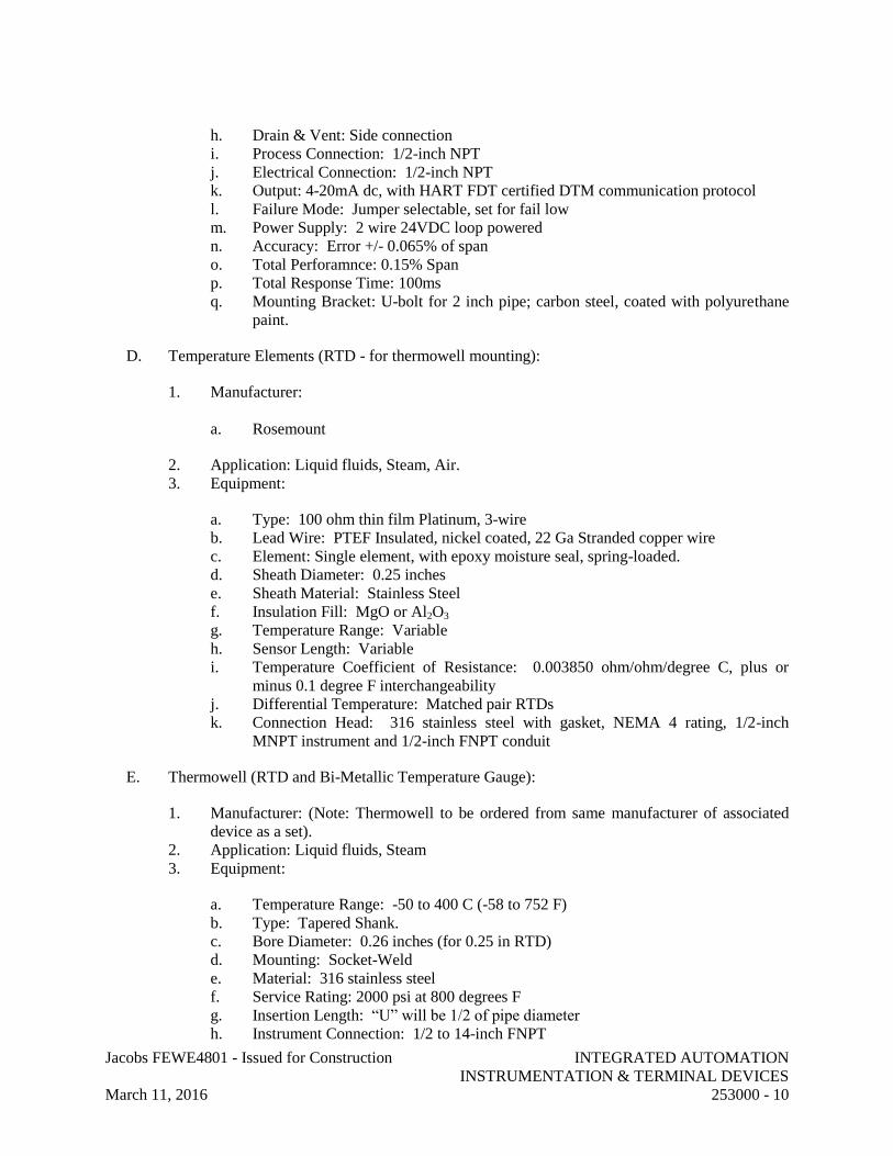
Jacobs FEWE4801 - Issued for Construction INTEGRATED AUTOMATION
INSTRUMENTATION & TERMINAL DEVICES
March 11, 2016 253000 - 10
h. Drain & Vent: Side connection
i. Process Connection: 1/2-inch NPT
j. Electrical Connection: 1/2-inch NPT
k. Output: 4-20mA dc, with HART FDT certified DTM communication protocol
l. Failure Mode: Jumper selectable, set for fail low
m. Power Supply: 2 wire 24VDC loop powered
n. Accuracy: Error +/- 0.065% of span
o. Total Perforamnce: 0.15% Span
p. Total Response Time: 100ms
q. Mounting Bracket: U-bolt for 2 inch pipe; carbon steel, coated with polyurethane
paint.
D. Temperature Elements (RTD - for thermowell mounting):
1. Manufacturer:
a. Rosemount
2. Application: Liquid fluids, Steam, Air.
3. Equipment:
a. Type: 100 ohm thin film Platinum, 3-wire
b. Lead Wire: PTEF Insulated, nickel coated, 22 Ga Stranded copper wire
c. Element: Single element, with epoxy moisture seal, spring-loaded.
d. Sheath Diameter: 0.25 inches
e. Sheath Material: Stainless Steel
f. Insulation Fill: MgO or Al2O3
g. Temperature Range: Variable
h. Sensor Length: Variable
i. Temperature Coefficient of Resistance: 0.003850 ohm/ohm/degree C, plus or
minus 0.1 degree F interchangeability
j. Differential Temperature: Matched pair RTDs
k. Connection Head: 316 stainless steel with gasket, NEMA 4 rating, 1/2-inch
MNPT instrument and 1/2-inch FNPT conduit
E. Thermowell (RTD and Bi-Metallic Temperature Gauge):
1. Manufacturer: (Note: Thermowell to be ordered from same manufacturer of associated
device as a set).
2. Application: Liquid fluids, Steam
3. Equipment:
a. Temperature Range: -50 to 400 C (-58 to 752 F)
b. Type: Tapered Shank.
c. Bore Diameter: 0.26 inches (for 0.25 in RTD)
d. Mounting: Socket-Weld
e. Material: 316 stainless steel
f. Service Rating: 2000 psi at 800 degrees F
g. Insertion Length: “U” will be 1/2 of pipe diameter
h. Instrument Connection: 1/2 to 14-inch FNPT

Jacobs FEWE4801 - Issued for Construction INTEGRATED AUTOMATION
INSTRUMENTATION & TERMINAL DEVICES
March 11, 2016 253000 - 11
i. Provide wake frequency calculation on thermowells per ASME PTC 19.3.
F. Temperature Transmitter:
1. Manufacturer:
a. Rosemount (Model 3144P)
2. Application: Liquid fluids, Saturated Steam
3. Equipment:
a. Type: 3-wire, 100 ohm RTD
b. Electronics Housing: NEMA 4X
c. Housing Material: Dual compartment, Polyurethane covered Aluminum
d. Indicator: LCD display
e. Output: 4-20mA dc, with HART FDT certified DTM communication protocol
f. Failure Mode: Jumper selectable, set for fail low
g. Power Supply: 2 wire loop 24VDC loop powered
h. Digital Accuracy: +/- 0.18 deg F
i. D/A Accuracy: 0.02% of Span
j. Temperature Range: 0 to 185 deg F
k. Connections: Screw terminals.
4. Instrument shall be microprocessor based. It shall be fully configurable via Highway
Addressable Remote Transmitter communication protocol via a handheld communicator,
on-line via Emerson AMS, or directly from the LOI.
PART 3 - EXECUTION
3.1 GENERAL
A. Contractor shall have the overall responsibility for the installation, commissioning, successful
operation and performance of all the instrumentation and performance of all the instrumentation
and control systems referred to herein.
B. Provide and install all instrumentation tubing, fitting and special wire necessary to install the
instrumentation system.
C. Perform testing of field instrumentation and support the testing of the overall instrumentation
and control systems.
3.2 DELIVERY, STORAGE, AND HANDLING
A. Contractor shall provide the services of an expeditor to track submittals, promised delivery, and
final delivery of all valves and instruments. Tracking schedule shall be updated weekly.
B. All instruments shall be tagged with instrument number prior to commissioning.

Jacobs FEWE4801 - Issued for Construction INTEGRATED AUTOMATION
INSTRUMENTATION & TERMINAL DEVICES
March 11, 2016 253000 - 12
3.3 EXAMINATION
A. Verify that areas and conditions where equipment is to be installed are satisfactory to proceed
with work activities.
B. Verify installations against the piping and instrument diagram and installation details.
C. Visually inspect installation for damage. If damage is observed, it shall be recorded and
corrective action taken.
3.4 MAINTENANCE
A. Mount equipment so that maintenance personnel have clear access for calibration, repair,
removal, and replacement services
3.5 INSTALLATION
A. Instruments:
1. Install instruments in accordance with manufacturer’s requirements and applicable
industry standards, including ISA-S 77.70.
2. Locate instruments to minimize effects of vibration, extreme ambient temperatures and
moisture.
3. Locate instruments to allow for ease of access for normal operations and maintenance
activities.
4. Install meters in accordance with AWWA M6, with isolating valves on inlet and outlet.
5. Provide instruments with scale ranges selected according to service with largest
appropriate scale.
6. Install gages and thermometers in locations where they are easily read from normal
operating level. Install vertical to 45 degrees off vertical.
7. Adjust gages and thermometers to final angle, clean windows and lenses, and calibrate to
zero.
8. Install flowmeters in accordance with manufacturer’s upstream and downstream pipe
straight run requirements.
9. Temperature Sensors/Thermowells/Transmitters:
a. Install temperature sensors with thermowells in piping systems with threadolets
and ensure minimum of 2 inch clearance from insulation.
b. Install temperature sensors a minimum of 3 pipe diameters away from major
equipment (e.g., pumps or valves). Install thermowells in elbows for small pipe
sizes.
c. Transmitter shall be mounted in a way such that access to field terminations can be
achieved by rotating transmitter 90 degrees on “L” bracket.
d. Transmitter shall be set-up as follows for dual mode:
1) PV = Differential Temperature
2) URV = 50 F
3) LRV = -5 F
4) Sensor #1 is Return Temp
5) Sensor #2 is Supply Temp

Jacobs FEWE4801 - Issued for Construction INTEGRATED AUTOMATION
INSTRUMENTATION & TERMINAL DEVICES
March 11, 2016 253000 - 13
6) Display shall rotate between DT, Supply Temp, Return Temp, mA.
10. Pressure Transmitters:
a. Install with minimum 3/4 inch process connection.
b. Install manifold and valve with same diameter as process connection
c. Install such that manifold valves can be reached and operated by hand.
d. Install transmitter as close to process as practical, using minimal piping/process
tubing as possible to achieve best accuracy.
11. Use special caution to provide raceway and conductor entries and conductor routing
within each sensor in strict accord with the manufacturer's published instructions.
a. Ensure any unused entry ports on the transmitter are plugged with metal plugs, not
the plastic shipping protective covers.
b. Wire size and type shall be in accordance with manufacturers published
instructions.
c. Wiring between transmitter and controller shall be in a protective ferrous raceway
designated for control wiring properly segregated from AC power sources.
d. Multipair cabl, if needed, only to be used with pre-approval by Owner.
e. Wire will be tagged at both ends using a two line tagging system on heat
shrinkable tags and indicate: 1st Line - Instrument Tag name, 2nd Line –
Destination of the other end of the wire
f. Ground the shield wire at the controller location and float the shield in the field,
unless indicated differently by manufacturers published instructions.
B. Valves:
1. Install valves and valve operators to provide ease of access for operation, service, and
removal without interference from structures, piping or other equipment.
2. Install valves in accordance with manufacturer’s instructions and recommendations.
3. Install with stems upright or horizontal, not inverted.
4. Provide non-conducting dielectric connections when joining dissimilar metals.
C. Instrument Impulse Lines:
1. Instrument impulse lines include pipes, tubing, fittings and components used to connect
the instrument to other piping or equipment starting at but not including the first block
valve.
2. Slope impulse lines at a minimum of 1 inch per foot or greater slope.
3. Support impulse lines securely and firmly by bracketing from building steel, walls,
instrument supports or stands. In no case shall the instrument serve to support the
impulse line. Impulse lines, whether of tubing or pipe, must be fitted carefully and their
configuration must be such that minimum stress of vibration is imposed upon the
instrument.
4. Provide remote differential pressure and remote pressure transmitters with self-
supporting type manifold valves. Installation is to be such that the transmitter can be
removed without removing the manifold valve from the support or disconnecting any
tubing.
5. Use thread compounds as follows unless otherwise specified:
a. Pipe threads: Minus 50 degrees F to 500 degrees F – Use Teflon base paste such as
Liquid “O” ring or equal.

Jacobs FEWE4801 - Issued for Construction INTEGRATED AUTOMATION
INSTRUMENTATION & TERMINAL DEVICES
March 11, 2016 253000 - 14
b. Bolt threads: Minus 50 degrees F to 500 degrees F – Use Graphite and Oil
Compound.
6. The use of tubing for instrument impulse lines is preferred. Pipe may be substituted at
the discretion of the field where tubing cannot be used because of problems of support,
size, pressure ratings, materials of construction, etc. Any pipe or pipe fittings used must
conform in all respects to the code of the process or service piping to which the impulse
line connects.
7. Instrument impulse lines shall meet the requirements of Section 232213 “Mechanical
Piping.”
D. Instrument Location and Support
1. Locate instruments to provide safe monitoring and maintenance access; and to maintain
clearances required for walkways and access ways as well as for the operation and
maintenance of valves and other equipment.
2. Locate primary instrument block valves, primary elements and instruments for access from
grade, platform, stairway, permanent or portable ladder.
a. Access from portable ladders is limited to 15 feet above grade.
b. Above 15 feet, accessibility is to be from a platform having a 7 feet directly
overhead limitation, or from a permanent ladder.
3. Mount individual instruments, except for blind type transmitters, with a centerline 4 feet, 6
inch above grade or on a platform on a vibration –free support.
E. Process instrument piping is not to be used as support.
1. Mount non-indicating or blind transmitters on the line as close to the sensing point as
possible. If accessibility, clearance, vibration or hydraulic shock, which may damage or
affect the operation of the instrument is encountered, the instrument will be remote mounted.
2. Locate receiver type local indicators at each transmitter that is not part of a control loop.
3. If the transmitter is part of a control loop, locate the indicator at the control valve, visible
from the bypass valve.
4. Mount instruments in vapor or gas service normally above the sensing point. Mount
instruments in liquid or steam service (with condensate pots) normally below the sensing
point. If accessibility, visibility or clearance requirements preclude either situation,
provisions will be made in the instrument piping arrangement to insure proper operation of
the instrument.
5. Mount remote mounted instruments at grade or platform using rigid pipe stand type
supports. Where possible, remote mounted instruments should be grouped and utilize
common supports.
6. Mount instruments on the line using rigid pipe supports, either the pipe clamp method or the
saddle type. No welding of supports to process piping is permitted.
7. Locate differential pressure instruments in level services in the same horizontal plane with
the lower connection.
3.6 FIELD QUALITY CONTROL

Jacobs FEWE4801 - Issued for Construction INTEGRATED AUTOMATION
INSTRUMENTATION & TERMINAL DEVICES
March 11, 2016 253000 - 15
A. Inspections:
1. Verify installations against the piping and instrument diagram and installation details.
2. Visually inspect installation for damage. If damage is observed, it shall be recorded and
corrective action taken.
3. Verify removal of temporary protective devices, restraints or stops.
4. Verify instruments and control valves/actuators are accessible from and not located in the
operator aisle ways.
5. Verify that high and low side impulse piping of DP type instruments are connected to
proper instrument ports with valve manifold.
6. Verify piping system for proper alignment, cleanliness and freedom from foreign
materials prior to equipment installation.
7. Inspect threads on both the valve and mating pipe for correct thread form and cleanliness.
8. Inspect internal length of threads in the valve ends and proximity of the valve internal
seat to ensure pipe will not hit the seat when assembled.
9. Inspect mating flange facings for conditions that might cause leakage.
10. Check flange bolting for proper size, length and material.
11. Check gasket materials for defects or damage.
B. Testing of instrument impulse piping shall be with nitrogen or other inert type of gas. Primary
process pressure lines shall be tested to 150% of external differential design pressure of the
primary process line to which it is connected, but no less than 15 psig.
C. Provide schedule at least 2 weeks in advance of testing activity and document test results;
Owner reserves the right to witness testing activity.
D. Instrument Calibrations:
1. Provide factory calibrations of instruments to verify accuracy and linearity in accordance
with standard industry practices or manufacturer's recommendations, whichever is more
stringent.
2. Calibrations to check sensing element directly, electronics checking only is not
acceptable.
3. Factory calibrations shall follow standard procedures. In lieu of factory calibrations the
calibration data points shall be recorded in each direction (ramp up and ramp down): 0,
25, 50, 75, and 100 percent of range relative to a reference instrument. The reference
instrument accuracy shall be ten times the accuracy required for the field instrument.
Record data using NIST traceable instrumentation in applicable engineering units.
4. Provide labor, supervision, services, tools, special equipment and consumable supplies
required to perform instrumentation and controls checkout and calibration.
5. Test equipment shall have a minimum accuracy four times equipment being calibrated,
traceable to NIST.
6. Calibrate instruments individually or as a system where applicable.
7. Factory calibration and installation records shall be prepared and maintained with the
following information:
a. Tag number.
b. Date component received.
c. Purchase order number.
d. Serial number.

Jacobs FEWE4801 - Issued for Construction INTEGRATED AUTOMATION
INSTRUMENTATION & TERMINAL DEVICES
March 11, 2016 253000 - 16
e. Calibration data.
f. Date of calibration.
g. Person performing calibration.
h. Date component installed.
i. Test Equipment: Manufacturer, model number, date calibrated, calibration lab,
and accuracy.
j. Attach calibration sticker to the instrument. Submit sample calibration stickers to
Owner for approval. Coordinate sticker location on each type of instrument with
Owner. Sticker content:
1) Date calibrated.
2) Calibration due date.
3) Initials of person performing calibration.
8. Field verify instrument calibrations at 3 points (0, 50, and 100 percent) prior to start-up
testing. Document verification with same information required for calibration records. If
instrument is out-of-tolerance then recalibrate, recording 3 points in each direction.
E. Loop checks:
1. Field verify instrument loops from instrument terminal connection to the DCS HMI
display at 3 points (0%, 50%, 100%) for analog points and each state (open/close, on/off)
for discrete (digital) points.
2. Document results, including:
a. Dates started & completed.
b. Person(s) performing checks.
c. Verify 0%, 50%, and 100% points.
d. Discrete state changes (record actual value).
e. Problem description.
f. Corrective action description.
END OF SECTION 253000

Jacobs FEWE4801 - Issued for Construction INTEGRATED AUTOMATION
FACILITY CONTROLS
March 11, 2016 255000 - 1
SECTION 255000 - INTEGRATED AUTOMATION FACILITY CONTROLS
PART 1 - GENERAL
1.1 RELATED DOCUMENTS
A. Drawings and general provisions of the Contract, including General and Supplementary
Conditions and Division 01 Specification Sections, apply to this Section.
1.2 SUMMARY
A. Section Includes:
1. Provides the functional description, technical requirements, and design parameters for the
University of Texas Pickle Research Campus TAS skid relocation project.
2. Provides the expected performance requirements by function and system components for
operation and integration.
B. Related Section:
1. Section 250500 “Common Work Results For Integrated Automation.”
2. Section 253000 “Integrated Automation Instrumentation & Terminal Devices.”
1.3 DEFINITIONS
A. Automatic: action is performed by the plant control system or local controller based on software
programming
B. Interlock: either hardwired or via programming software; typically used to protect machine or
system process from damaging itself by stopping the machine or process.
C. Local Manual: action performed by the operator locally at a field control panel or field device.
D. Remote Manual: action performed by the operator at the PCS with the field control panel or
field device remaining in Auto.
E. Redundancy: duplication of selected equipment and components in a system with the intention
of increasing the availability of the system.
F. Remote: action performed by the operator via the plant control system.
G. Separation: the distribution of equipment and field signals to increase the availability of system
operations in case of a single failure.
H. Single failure proof: failure of a single device or piece of equipment does not preclude the
system from providing at least partial services.

Jacobs FEWE4801 - Issued for Construction INTEGRATED AUTOMATION
FACILITY CONTROLS
March 11, 2016 255000 - 2
I. DLR: Device Level Ring: An Ethernet I/P ring topology supported by many Allen Bradley
dual port devices.
1.4 SYSTEM DESCRIPTION
A. Provide control components required to integrate instrumentation, as shown on the construction
drawings and specified herein to the existing campus control system
B. Integrate relocated packaged chilled water skid to the existing control system
C. Update existing campus control system graphics to include, but not limited to new
instrumentation and relocated chilled water skid.
1.5 DOCUMENTATION
A. Submittals
1. For all submittals, provide six hard copies and one CD ROM disk copy.
2. Provide the following information after receipt of order:
a. Drawings:
1) Prepare drawings using applicable industry standards, including ISA-5.1,
5.2, 5.3, and 5.4, and ISA-TR5.1.01.
2) Connection diagrams that show placement, labeling, and point-to-point
wiring for all components within panels, cabinets, and consoles.
3) Interconnection diagrams that show wiring diagrams for product wiring that
includes location, I/O data characteristics (range and units), termination
points, wire color, polarities, jumpers, shielding, and grounding details.
4) Installation drawings that show installation arrangements for equipment,
labels, mounting and anchoring details, conduit entries, control system
electrical power supply distribution conduit and wiring, and EMI/RFI
restrictions.
5) Maintain a working set of redline drawings during the construction process;
keep a copy of every version/revision of each drawing. Mark drawing to
show actual change (if change is extensive, mark area of drawing affected
and list reference that provides details) and reference (e.g., RFI, Addenda,
etc.).
6) Provide as-built drawings showing final configuration.
b. Software Functional Design Specification detailing the implementation and
operation of the software configurations. This shall include all configuration
parameters, alarms and settings, I/O, modular code implementations, sequential
descriptions, interlock requirements, security access levels, and operator
interactions.
c. ‘Screen Captures’ of PCS screens and pop-ups shall be submitted for Owner
approval review of layout, approach and consistency.
d. Product Data: Submit data sheets, clearly marked, for each component, including
sensors, control drives and elements,

Jacobs FEWE4801 - Issued for Construction INTEGRATED AUTOMATION
FACILITY CONTROLS
March 11, 2016 255000 - 3
e. Calculations:
1) Data throughput and response time.
2) Electrical and heat load (tabulate data for components).
3) Fuse sizing for output signals.
4) Power requirements.
f. Software: Quality Assurance Plan.
g. Manufacturer's Installation Instructions: Provide detailed instructions and figures
for the installation of equipment.
h. Manufacturer's Certificate: Certify that products meet or exceed specified
requirements.
i. Manufacturer's Field Reports: Indicate acceptance of component and equipment
installation, interconnecting wiring, and weekly progress on installation and
start-up of system software.
j. Project Record Documents:
1) Record actual locations of every input and output circuit termination, and
identification marking of each circuit.
2) Provide factory acceptance and site acceptance test plan, procedures, and
reports.
3) Provide software error logs.
4) Provide training course outline and manuals.
B. Operation and Maintenance Manuals
1. Submit O&M manuals for equipment and software provided. Include:
a. Table of contents.
b. General information of equipment and function.
c. Listing of supplier contact information (name, address, telephone).
d. Theory of equipment operation.
e. Software code listings, system disks, and manuals, including programming and
operating reference for central processing unit operating system and for each
application and programming language provided.
f. Operation procedures, troubleshooting and repair procedures, preventative
maintenance schedule, drawings, and recommended spare parts list.
g. Warranties.
1.6 PRE-INSTALLATION MEETING
A. Notify Owner and Construction Manager a minimum of three weeks prior to commencing Work
of this Section.
B. Pre-installation meeting shall be held at the Owner's facilities.
C. Construction Manager shall:
1. Schedule the meeting time and place.
2. Notify parties that are directly affecting or affected by Work of this section.

Jacobs FEWE4801 - Issued for Construction INTEGRATED AUTOMATION
FACILITY CONTROLS
March 11, 2016 255000 - 4
3. Prepare meeting agenda and preside at the meeting.
4. Review conditions of installation, preparation and installation procedures.
5. Review coordination with related work.
6. Record meeting minutes and distribute copies to participants, with copies to Owner’s
Representative, Owner, participants and those affected by decisions made.
1.7 QUALITY ASSURANCE
A. Regulatory Requirements:
1. Comply with CFR 47 Parts 15 and 18, Code of Federal Regulations - Federal
Communications Commission (FCC) Rules and Regulations pertaining to EMI.
2. Comply with NFPA-70, “National Electrical Code” with state amendments.
3. Comply with ANSI C63.12 - Recommended Practice on Electromagnetic Compatibility
Limits.
B. Software Quality Assurance (SQA):
1. Establish a SQA plan that addresses software tests normally performed by programmers
and tests performed to verify system operation.
2. Perform software tests to benchmark functional evaluations, including the following:
a. Conformance to specification.
b. Language deviation.
c. Error handling.
d. Operational speed.
3. Maintain a software error log to record date, description of occurrence, proposed
solution, Owner approval, and date(s) error was corrected and re-tested.
C. Manufacturer and System Integrator Qualifications:
D. Company specializing in manufacturing or integrating, CSIA membership or (registered as a
system integrator with Rockwell Automation) products specified in this Section with minimum
ten years documented experience, and with service facilities (capable of providing hardware,
software and equipment repair support) within 300 miles of Project.
E. Installer Qualifications:
F. Company specializing in performing Work of this Section with minimum five years
documented experience, and approved by manufacturer.
G. Testing Qualifications: Test personnel shall have a minimum of ten years documented
experience with testing of the system equipment. Provide services of equipment manufacturer's
qualified technicians to supplement their personnel as needed.
1.8 EMI/RFI ENVIRONMENT

Jacobs FEWE4801 - Issued for Construction INTEGRATED AUTOMATION
FACILITY CONTROLS
March 11, 2016 255000 - 5
A. Equipment shall be installed at the University of Minnesota Combined Heat and Power Plant in
Minneapolis, MN which is subject to various backgrounds, RF signals. Protect system
equipment from interference within this environment and comply with FCC rules of CFR 47,
ANSI C63.12, and ANSI C63.4, including:
1. Mobile Communications equipment operating in the 450 MHz range at 4 watts output
power.
2. Commercial cellular telephones operating in the 1.9 to 5.8 GHz range at 0.7 to 3 watts.
3. Moving machinery.
1.9 WARRANTY
A. Furnish manufacturer's warranty for items supplied under this section; minimum of one year for
parts and labor.
1.10 MAINTENANCE
A. Provide recommended spare parts list for the first five years of operation.
PART 2 - PRODUCTS (Not Used)
PART 3 - EXECUTION
3.1 DELIVERY, STORAGE, AND HANDLING
A. Containers are to have their contents listed on a packing slip secured to the outside of the
container.
B. Protect electronic components from construction operations, dust and adverse environmental
conditions by storing in air-conditioned space.
3.2 INSTALLATION
A. Install equipment in accordance with manufacturer's instructions.
B. Ground and bond equipment in accordance with IEEE Std-1100 and Manufacturers
requirements for controller racks etc.
C. Notify Owner 14 days in advance of installation. Owner or Owner's Representative reserves the
right to witness installation activities.
D. PCS redundant network cables shall be run in separate conduits, which remain 10’ apart to
provide physical segregation. These conduits shall exit the panel on opposite sides and the
cables shall use different routes inside the panel, where possible. The redundant networks
include the SCADA Ethernet, CONTROL DLR, and I/O Device DLR.

Jacobs FEWE4801 - Issued for Construction INTEGRATED AUTOMATION
FACILITY CONTROLS
March 11, 2016 255000 - 6
3.3 INTERFACE WITH OTHER WORK
A. Coordinate installation of PCS system equipment with the activities of the other construction
trades.
B. Coordinate interface to the existing Network Interfaces with the Owner.
3.4 FIELD QUALITY CONTROL
A. Verify that the area is clean and ready for installation of system equipment.
B. Verify system equipment has been installed in accordance with manufacturer’s instructions.
C. Provide technical specialists on site to support plant system installation, checkout, start-up,
plant testing/balancing and commissioning.
D. Provide field inspection report that documents satisfactory completion of system equipment
installation.
3.5 START-UP TESTING/COMMISSIONING
A. Provide 20 days of on-site support, in addition to PCS pre-functional checkout and SAT efforts,
to support overall plant start-up and commissioning work.
3.6 PROTECTION
A. Protect equipment from construction or accidental damage during the installation period prior to
system commissioning and turnover to the Owner.
END OF SECTION 255000

Jacobs FEWE4801 - Issued for Construction COMMON WORK RESULTS FOR ELECTRICAL
March 11, 2016 260500 - 1
SECTION 260500 - COMMON WORK RESULTS FOR ELECTRICAL
PART 1 - GENERAL
1.1 RELATED DOCUMENTS
A. Drawings and general provisions of the Contract, including General and Supplementary
Conditions and Division 01 Specification Sections, apply to all Division 26 specifications.
1.2 SUMMARY
A. Section Includes:
1. Electrical equipment coordination and installation.
2. Common electrical installation requirements specified under Division 26.
1.3 QUALITY ASSURANCE
A. Warrant electrical work against faulty material or Workmanship in accordance with Division 1.
If the project is occupied or systems are placed in operation in phases at the request of the
Owner’s Representative, then the warranty of each system or piece of equipment, shall begin on
the date each system or component was placed in operation as designed and accepted as such, in
writing, by the Owner’s Representative. The use of equipment for temporary service and
testing does not constitute the beginning of the warranty.
B. Equipment and materials provided and installed under this Division shall periodically be
inspected and serviced by competent mechanics or technicians. This function becomes the
responsibility of the Owner’s Representative when the system is accepted, in writing, by the
Owner’s Representative. The material and Workmanship warranty is not intended to supplant
normal inspection or service and shall not be construed to mean the Contractor shall provide
free service for normal maintenance items such as periodic lubrication and adjustment due to
normal use, nor to correct, without charge, breakage, maladjustment, and other trouble caused
by improper maintenance.
C. Upon completion of contract and progressively as work proceeds, clean up dirt, debris and scrap
materials. Maintain premises neat and clean throughout. Protect and preserve access to
energized equipment at all times. Clean items with factory finishes. Touch up minor damage to
surfaces; refinish entire piece of equipment in the event of major damage as determined by
Owner’s Representative. Use only factory supplied paints of matching color and formula.
Schedule an off-hour shutdown of all electrical equipment during the 2 week period preceding
substantial completion. During this shutdown, clean all busses and insulators inside switchgear,
switchboards, bus ducts, collector busses and panel boards located inside or adjacent to the
project limits.

Jacobs FEWE4801 - Issued for Construction COMMON WORK RESULTS FOR ELECTRICAL
March 11, 2016 260500 - 2
1.4 STANDARDS
A. Perform all work specified in Division 26 in strict accordance with the following codes and
standards, latest edition, adopted by the authority having jurisdiction. Where these
specifications are more stringent than the AHJ, these specifications shall take precedence.
1. National Electric Code NFPA 70 (NEC).
2. Life Safety Code.
3. NESC-National Electric Safety Code
4. Association of Edison Illuminating Companies (AEIC).
5. American National Standards Institute (ANSI).
6. American Society for Testing Materials (ASTM).
7. Certified Ballast Manufacturers (CBM).
8. Electrical Testing Laboratories (ETL).
9. Insulated Cable Engineers Association (ICEA).
10. Institute of Electrical and Electronic Engineers (IEEE).
11. National Electrical Contractors Association (NECA)
12. National Electrical Manufacturer's Association (NEMA)
13. Underwriters Laboratories, Inc. (UL)
14. All applicable OSHA Publications.
15. Hospital Licensing Standards, Texas Department of Health, Hospital Facility Licensure
and Certification Division.
16. The Joint Commission.
1.5 SUBMITTALS
A. Comply with provisions in accordance with Division 01.
B. Submit all data specified in Division 26.
1.6 OPERATION AND MAINTENANCE MANUALS
A. Comply with provisions of Division 01
B. In addition to required submittals, manuals shall include copies of all test reports specified in
Division 26.
C. Provide completed warranty certificates for systems and equipment.
1.7 RECORD DRAWINGS
A. Comply with provisions of Division 01.

Jacobs FEWE4801 - Issued for Construction COMMON WORK RESULTS FOR ELECTRICAL
March 11, 2016 260500 - 3
PART 2 - PRODUCTS
2.1 NOT APPLICABLE
PART 3 - EXECUTION
3.1 COMMON REQUIREMENTS FOR ELECTRICAL INSTALLATION
A. Comply with NECA 1.
B. Measure indicated mounting heights to bottom of unit for suspended items and to center of unit
for wall-mounting items.
C. Headroom Maintenance: If mounting heights or other location criteria are not indicated,
arrange and install components and equipment to provide maximum possible headroom
consistent with these requirements.
D. Equipment: Install to facilitate service, maintenance, and repair or replacement of components
of both electrical equipment and other nearby installations. Connect in such a way as to
facilitate future disconnecting with minimum interference with other items in the vicinity.
E. Right of Way: Give to piping systems installed at a required slope.
3.2 COORDINATION
A. Coordinate arrangement, mounting, and support of electrical equipment:
1. To allow maximum possible headroom unless specific mounting heights that reduce
headroom are indicated.
2. To provide for ease of disconnecting the equipment with minimum interference to other
installations.
3. To allow right of way for piping and conduit installed at required slope.
4. So connecting raceways, cables, wireways, cable trays, and busways will be clear of
obstructions and of the working and access space of other equipment.
B. Coordinate all items which will affect the installation of the work of this Division. This
coordination shall include, but not be limited to, voltage, ampacity, capacity, connections, space
requirements, sequence of construction, building requirements and special conditions.
C. Examine specifications and drawings for all equipment and systems that require electrical
connections and coordination.
D. Coordinate installation of required supporting devices and set sleeves in cast-in-place concrete,
masonry walls, and other structural components as they are constructed.
E. Coordinate location of access panels and doors for electrical items that are behind finished
surfaces or otherwise concealed.

Jacobs FEWE4801 - Issued for Construction COMMON WORK RESULTS FOR ELECTRICAL
March 11, 2016 260500 - 4
F. Coordinate sleeve selection and application with selection and application of firestopping.
G. Electrical drawings are diagrammatic only and shall not be scaled for exact sizes.
H. Coordinate all work with other trades prior to beginning work.
I. By submitting shop drawings on the project, it is to be understood that the contractor is
indicating that all necessary coordination has been completed and that the systems, products and
equipment submitted can be installed and will operate as specified and intended, in full
coordination with all other trades.
3.3 INSPECTION FEES AND PERMITS
A. Contractor shall obtain and pay for all necessary permits and inspection fees for all systems
covered under Divisions 26.
END OF SECTION 260500

Jacobs FEWE4801 - Issued for Construction LOW-VOLTAGE ELECTRICAL POWER
CONDUCTORS AND CABLES
March 11, 2016 260519 - 1
SECTION 260519 - LOW-VOLTAGE ELECTRICAL POWER CONDUCTORS AND CABLES
PART 1 - GENERAL
1.1 RELATED DOCUMENTS
A. Drawings and general provisions of the Contract, including General and Supplementary
Conditions and Division 01 Specification Sections, apply to this Section.
1.2 SUMMARY
A. This Section includes the following:
1. Building wires and cables rated 600 V and less.
2. Connectors, splices, and terminations rated 600 V and less.
1.3 DEFINITIONS
A. EPDM: Ethylene-propylene-diene terpolymer rubber.
B. NBR: Acrylonitrile-butadiene rubber.
1.4 SUBMITTALS
A. Product Data: For each type of product indicated.
B. Qualification Data: For testing agency.
C. Field quality-control test reports.
1.5 QUALITY ASSURANCE
A. Testing Agency Qualifications: An independent agency, with the experience and capability to
conduct the testing indicated, that is a member company of the InterNational Electrical Testing
Association or is a nationally recognized testing laboratory (NRTL) as defined by OSHA in
29 CFR 1910.7, and that is acceptable to authorities having jurisdiction.
1. Testing Agency's Field Supervisor: Person currently certified by the InterNational
Electrical Testing Association or the National Institute for Certification in Engineering
Technologies to supervise on-site testing specified in Part 3.
B. Electrical Components, Devices, and Accessories: Listed and labeled as defined in NFPA 70,
Article 100, by a testing agency acceptable to authorities having jurisdiction, and marked for
intended use.

Jacobs FEWE4801 - Issued for Construction LOW-VOLTAGE ELECTRICAL POWER
CONDUCTORS AND CABLES
March 11, 2016 260519 - 2
C. Comply with NFPA 70.
1.6 COORDINATION
A. Set sleeves in cast-in-place concrete, masonry walls, and other structural components as they
are constructed.
PART 2 - PRODUCTS
2.1 CONDUCTORS AND CABLES
A. Available Manufacturers: Subject to compliance with requirements, manufacturers offering
products that may be incorporated into the Work include, but are not limited to, the following:
B. Manufacturers: Subject to compliance with requirements, provide products by one of the
following:
1. American Insulated Wire Corp.; a Leviton Company.
2. Okonite.
3. Southwire Company.
C. Copper Conductors: Comply with ICEA S-95-658/NEMA WC 70.
D. Conductor Insulation: Comply with ICEA S-95-658/NEMA WC 70 for Types THHN-THWN,
XHHW and SO. Outer cable jacket shall be color coded in accordance with the associated
phase it is connected to. Reference Section 260553.
2.2 CONNECTORS AND SPLICES
A. Available Manufacturers: Subject to compliance with requirements, manufacturers offering
products that may be incorporated into the Work include, but are not limited to, the following:
B. Manufacturers: Subject to compliance with requirements, provide products by one of the
following:
1. AFC Cable Systems, Inc.
2. Hubbell Power Systems, Inc.
3. O-Z/Gedney; EGS Electrical Group LLC.
4. 3M; Electrical Products Division.
5. Tyco Electronics Corp.
C. Description: Factory-fabricated connectors and splices of size, ampacity rating, material, type,
and class for application and service indicated.

Jacobs FEWE4801 - Issued for Construction LOW-VOLTAGE ELECTRICAL POWER
CONDUCTORS AND CABLES
March 11, 2016 260519 - 3
PART 3 - EXECUTION
3.1 CONDUCTOR MATERIAL APPLICATIONS
A. Feeders: Copper. Solid for No. 10 AWG and smaller; stranded for No. 8 AWG and larger.
B. Branch Circuits: Copper. Solid for No. 10 AWG and smaller; stranded for No. 8 AWG and
larger.
3.2 CONDUCTOR INSULATION AND WIRING METHODS
A. Service Entrance: Type XHHW-2, single conductors in raceway.
B. Exposed Feeders: Type THHN-THWN, single conductors in raceway.
C. Feeders Concealed in Ceilings, Walls, Partitions, and Crawlspaces: Type THHN-THWN,
single conductors in raceway.
D. Feeders Concealed in Concrete, below Slabs-on-Grade, and Underground: Type XHHW-2 or
THHN-THWN, single conductors in raceway.
E. Feeders Installed below Raised Flooring: Type THHN-THWN, single conductors in raceway.
F. Exposed Branch Circuits, Including in Crawlspaces: Type THHN-THWN, single conductors in
raceway.
G. Branch Circuits Concealed in Ceilings, Walls, and Partitions: Type THHN-THWN, single
conductors in raceway.
H. Branch Circuits Concealed in Concrete, below Slabs-on-Grade, and Underground:
Type THHN-THWN, single conductors in raceway.
I. Branch Circuits Installed below Raised Flooring: Type THHN-THWN, single conductors in
raceway.
J. Cord Drops and Portable Appliance Connections: Type SO, hard service cord with stainless-
steel, wire-mesh, strain relief device at terminations to suit application.
K. Class 1 Control Circuits: Type THHN-THWN, single conductors in raceway.
L. Class 2 Control Circuits: Type THHN-THWN, single conductors in raceway.
3.3 INSTALLATION OF CONDUCTORS AND CABLES
A. Conceal cables in finished walls and ceilings, unless otherwise indicated.
B. Use manufacturer-approved pulling compound or lubricant where necessary; compound used
must not deteriorate conductor or insulation. Do not exceed manufacturer's recommended
maximum pulling tensions and sidewall pressure values.

Jacobs FEWE4801 - Issued for Construction LOW-VOLTAGE ELECTRICAL POWER
CONDUCTORS AND CABLES
March 11, 2016 260519 - 4
C. Use pulling means, including fish tape, cable, rope, and basket-weave wire/cable grips, that will
not damage cables or raceway.
D. Install exposed cables parallel and perpendicular to surfaces of exposed structural members, and
follow surface contours where possible.
E. Support cables according to Division 26 Section "Hangers and Supports for Electrical Systems."
F. Identify and color-code conductors and cables according to Division 26 Section "Identification
for Electrical Systems."
3.4 CONNECTIONS
A. Tighten electrical connectors and terminals according to manufacturer's published torque-
tightening values. If manufacturer's torque values are not indicated, use those specified in
UL 486A and UL 486B.
B. Make splices and taps that are compatible with conductor material and that possess equivalent
or better mechanical strength and insulation ratings than unspliced conductors.
C. Wiring at Outlets: Install conductor at each outlet, with at least 12 inches of slack.
3.5 FIRESTOPPING
A. Apply firestopping to electrical penetrations of fire-rated floor and wall assemblies to restore
original fire-resistance rating of assembly.
3.6 FIELD QUALITY CONTROL
A. Testing Agency: Engage a qualified third party testing agency to perform tests and inspections
and prepare test reports.
B. Tests and Inspections:
1. After installing conductors and cables and before electrical circuitry has been energized,
test for compliance with requirements.
2. Perform each visual and mechanical inspection and electrical test stated in NETA
Acceptance Testing Specification. Certify compliance with test parameters.
C. Test Reports: Prepare a written report to record the following:
1. Test procedures used.
2. Test results that comply with requirements.
3. Test results that do not comply with requirements and corrective action taken to achieve
compliance with requirements.
D. Remove and replace malfunctioning units and retest as specified above.

Jacobs FEWE4801 - Issued for Construction LOW-VOLTAGE ELECTRICAL POWER
CONDUCTORS AND CABLES
March 11, 2016 260519 - 5
END OF SECTION 260519

Jacobs FEWE4801 - Issued for Construction LOW-VOLTAGE ELECTRICAL POWER
CONDUCTORS AND CABLES
March 11, 2016 260519 - 6
PAGE INTENTIONALLY LEF BLANK

Jacobs FEWE4801 - Issued for Construction CONTROL-VOLTAGE
ELECTRICAL POWER CABLES
March 11, 2016 260523 - 1
SECTION 260523 - CONTROL-VOLTAGE ELECTRICAL POWER CABLES
PART 1 - GENERAL
1.1 RELATED DOCUMENTS
A. Drawings and general provisions of the Contract, including General and Supplementary
Conditions and Division 01 Specification Sections, apply to this Section.
1.2 SUMMARY
A. Section Includes:
1. UTP cabling.
2. RS-232 cabling.
3. RS-485 cabling.
4. Low-voltage control cabling.
5. Control-circuit conductors.
6. Identification products.
1.3 DEFINITIONS
A. Basket Cable Tray: A fabricated structure consisting of wire mesh bottom and side rails.
B. Channel Cable Tray: A fabricated structure consisting of a one-piece, ventilated-bottom or
solid-bottom channel section.
C. EMI: Electromagnetic interference.
D. IDC: Insulation displacement connector.
E. Ladder Cable Tray: A fabricated structure consisting of two longitudinal side rails connected
by individual transverse members (rungs).
F. Low Voltage: As defined in NFPA 70 for circuits and equipment operating at less than 50 V or
for remote-control and signaling power-limited circuits.
G. Open Cabling: Passing telecommunications cabling through open space (e.g., between the studs
of a wall cavity).
H. RCDD: Registered Communications Distribution Designer.
I. Solid-Bottom or Nonventilated Cable Tray: A fabricated structure consisting of integral or
separate longitudinal side rails, and a bottom without ventilation openings.

Jacobs FEWE4801 - Issued for Construction CONTROL-VOLTAGE
ELECTRICAL POWER CABLES
March 11, 2016 260523 - 2
J. Trough or Ventilated Cable Tray: A fabricated structure consisting of integral or separate
longitudinal rails and a bottom having openings sufficient for the passage of air and using 75
percent or less of the plan area of the surface to support cables.
K. UTP: Unshielded twisted pair.
1.4 SUBMITTALS
A. Product Data: For each type of product indicated.
B. Shop Drawings: For cable tray layout, showing cable tray route to scale, with relationship
between the tray and adjacent structural, electrical, and mechanical elements. Include the
following:
1. Vertical and horizontal offsets and transitions.
2. Clearances for access above and to side of cable trays.
3. Vertical elevation of cable trays above the floor or bottom of ceiling structure.
4. Load calculations to show dead and live loads as not exceeding manufacturer's rating for
tray and its support elements.
C. Qualification Data: For qualified layout technician, installation supervisor, and field inspector.
D. Source quality-control reports.
E. Field quality-control reports.
F. Maintenance Data: For wire and cable to include in maintenance manuals.
1.5 QUALITY ASSURANCE
A. Testing Agency Qualifications: Member company of an NRTL.
1. Testing Agency's Field Supervisor: Currently certified by BICSI as an RCDD to
supervise on-site testing.
B. Surface-Burning Characteristics: As determined by testing identical products according to
ASTM E 84 by a qualified testing agency. Identify products with appropriate markings of
applicable testing agency.
1. Flame-Spread Index: 25 or less.
2. Smoke-Developed Index: 50 or less.
C. Electrical Components, Devices, and Accessories: Listed and labeled as defined in NFPA 70,
by a qualified testing agency, and marked for intended location and application.

Jacobs FEWE4801 - Issued for Construction CONTROL-VOLTAGE
ELECTRICAL POWER CABLES
March 11, 2016 260523 - 3
PART 2 - PRODUCTS
2.1 PATHWAYS
A. Support of Open Cabling: NRTL labeled for support of Category 5e, Category 6, and Category
6a cabling, designed to prevent degradation of cable performance and pinch points that could
damage cable.
1. Support brackets with cable tie slots for fastening cable ties to brackets.
2. Lacing bars, spools, J-hooks, and D-rings.
3. Straps and other devices.
B. Conduit and Boxes: Comply with requirements in Division 26 Section "Raceway and Boxes for
Electrical Systems." Flexible metal conduit shall not be used.
1. Outlet boxes shall be no smaller than 2 inches wide, 3 inches high, and 2-1/2 inches deep.
2.2 BACKBOARDS
A. Description: Plywood, fire-retardant treated, 3/4 by 48 by 96 inches. Comply with
requirements for plywood backing panels in Division 06 Section "Rough Carpentry."
2.3 RS-232 CABLE
A. Standard Cable: NFPA 70, Type CM.
1. Paired, two pairs, No. 22 AWG, stranded (7x30) tinned-copper conductors.
2. Polypropylene insulation.
3. Individual aluminum foil-polyester tape shielded pairs with 100 percent shield coverage.
4. PVC jacket.
5. Pairs are cabled on common axis with No. 24 AWG, stranded (7x32) tinned-copper drain
wire.
6. Flame Resistance: Comply with UL 1581.
2.4 RS-485 CABLE
A. Standard Cable: NFPA 70, Type CM.
1. Paired, two pairs, twisted, No. 22 AWG, stranded (7x30) tinned-copper conductors.
2. PVC insulation.
3. Unshielded.
4. PVC jacket.
5. Flame Resistance: Comply with UL 1581.
2.5 LOW-VOLTAGE CONTROL CABLE
A. Paired Cable: NFPA 70, Type CMG.

Jacobs FEWE4801 - Issued for Construction CONTROL-VOLTAGE
ELECTRICAL POWER CABLES
March 11, 2016 260523 - 4
1. One pair, twisted, No. 16 AWG, stranded (19x29) tinned-copper conductors.
2. PVC insulation.
3. Unshielded.
4. PVC jacket.
5. Flame Resistance: Comply with UL 1581.
B. Plenum-Rated, Paired Cable: NFPA 70, Type CMP.
1. One pair, twisted, No. 16 AWG, stranded (19x29) tinned-copper conductors.
2. PVC insulation.
3. Unshielded.
4. PVC jacket.
5. Flame Resistance: Comply with NFPA 262.
2.6 CONTROL-CIRCUIT CONDUCTORS
A. Class 1 Control Circuits: Stranded copper, Type THHN-THWN, in raceway, complying with
UL 83.
B. Class 2 Control Circuits: Stranded copper, Type THHN-THWN, in raceway, complying with
UL 83.
C. Class 3 Remote-Control and Signal Circuits: Stranded copper, Type TW or Type TF,
complying with UL 83.
2.7 IDENTIFICATION PRODUCTS
A. Manufacturers: Subject to compliance with requirements, provide products by one of the
following:
1. Brady Corporation.
2. HellermannTyton.
3. Kroy LLC.
4. Panduit Corp.
B. Comply with UL 969 for a system of labeling materials, including label stocks, laminating
adhesives, and inks used by label printers.
C. Comply with requirements in Division 26 Section "Identification for Electrical Systems."
2.8 SOURCE QUALITY CONTROL
A. Testing Agency: Engage a qualified testing agency to evaluate cables.
B. Factory test UTP and optical fiber cables on reels according to TIA/EIA-568-B.1.
C. Cable will be considered defective if it does not pass tests and inspections.
D. Prepare test and inspection reports.

Jacobs FEWE4801 - Issued for Construction CONTROL-VOLTAGE
ELECTRICAL POWER CABLES
March 11, 2016 260523 - 5
PART 3 - EXECUTION
3.1 INSTALLATION OF PATHWAYS
A. Cable Trays: Comply with NEMA VE 2 and TIA/EIA-569-A-7.
B. Comply with TIA/EIA-569-A for pull-box sizing and length of conduit and number of bends
between pull points.
C. Comply with requirements in Division 26 Section "Raceway and Boxes for Electrical Systems"
for installation of conduits and wireways.
D. Install manufactured conduit sweeps and long-radius elbows if possible.
E. Pathway Installation in Equipment Rooms:
1. Position conduit ends adjacent to a corner on backboard if a single piece of plywood is
installed or in the corner of room if multiple sheets of plywood are installed around
perimeter walls of room.
2. Install cable trays to route cables if conduits cannot be located in these positions.
3. Secure conduits to backboard if entering room from overhead.
4. Extend conduits 3 inches above finished floor.
5. Install metal conduits with grounding bushings and connect with grounding conductor to
grounding system.
F. Backboards: Install backboards with 96-inch dimension vertical. Butt adjacent sheets tightly
and form smooth gap-free corners and joints.
3.2 INSTALLATION OF CONDUCTORS AND CABLES
A. Comply with NECA 1.
B. General Requirements for Cabling:
1. Comply with TIA/EIA-568-B.1.
2. Comply with BICSI ITSIM, Ch. 6, "Cable Termination Practices."
3. Terminate all conductors; no cable shall contain unterminated elements. Make
terminations only at indicated outlets, terminals, and cross-connect and patch panels.
4. Cables may not be spliced. Secure and support cables at intervals not exceeding 30
inches and not more than 6 inches from cabinets, boxes, fittings, outlets, racks, frames,
and terminals.
5. Bundle, lace, and train conductors to terminal points without exceeding manufacturer's
limitations on bending radii, but not less than radii specified in BICSI ITSIM, "Cabling
Termination Practices" Chapter. Install lacing bars and distribution spools.
6. Do not install bruised, kinked, scored, deformed, or abraded cable. Do not splice cable
between termination, tap, or junction points. Remove and discard cable if damaged
during installation and replace it with new cable.
7. Cold-Weather Installation: Bring cable to room temperature before dereeling. Heat
lamps shall not be used for heating.

Jacobs FEWE4801 - Issued for Construction CONTROL-VOLTAGE
ELECTRICAL POWER CABLES
March 11, 2016 260523 - 6
8. Pulling Cable: Comply with BICSI ITSIM, Ch. 4, "Pulling Cable." Monitor cable pull
tensions.
C. Installation of Control-Circuit Conductors:
1. Install wiring in raceways. Comply with requirements specified in Division 26 Section
"Raceway and Boxes for Electrical Systems."
D. Open-Cable Installation:
1. Suspend copper cable not in a wire way or pathway a minimum of 8 inches above
ceilings by cable supports not more than 60 inches apart.
2. Cable shall not be run through structural members or in contact with pipes, ducts, or other
potentially damaging items.
E. Installation of Cable Routed Exposed under Raised Floors:
1. Install plenum-rated cable only.
2. Install cabling after the flooring system has been installed in raised floor areas.
3. Coil cable 72 inches long shall be neatly coiled not less than 12 inches in diameter below
each feed point.
F. Separation from EMI Sources:
1. Comply with BICSI TDMM and TIA/EIA-569-A recommendations for separating
unshielded copper voice and data communication cable from potential EMI sources,
including electrical power lines and equipment.
2. Separation between open communications cables or cables in nonmetallic raceways and
unshielded power conductors and electrical equipment shall be as follows:
a. Electrical Equipment Rating Less Than 2 kVA: A minimum of 5 inches.
b. Electrical Equipment Rating between 2 and 5 kVA: A minimum of 12 inches.
c. Electrical Equipment Rating More Than 5 kVA: A minimum of 24 inches.
3. Separation between communications cables in grounded metallic raceways and
unshielded power lines or electrical equipment shall be as follows:
a. Electrical Equipment Rating Less Than 2 kVA: A minimum of 2-1/2 inches.
b. Electrical Equipment Rating between 2 and 5 kVA: A minimum of 6 inches.
c. Electrical Equipment Rating More Than 5 kVA: A minimum of 12 inches.
4. Separation between communications cables in grounded metallic raceways and power
lines and electrical equipment located in grounded metallic conduits or enclosures shall
be as follows:
a. Electrical Equipment Rating Less Than 2 kVA: No requirement.
b. Electrical Equipment Rating between 2 and 5 kVA: A minimum of 3 inches.
c. Electrical Equipment Rating More Than 5 kVA: A minimum of 6 inches.
5. Separation between Cables and Electrical Motors and Transformers, 5 kVA or HP and
Larger: A minimum of 48 inches.

Jacobs FEWE4801 - Issued for Construction CONTROL-VOLTAGE
ELECTRICAL POWER CABLES
March 11, 2016 260523 - 7
6. Separation between Cables and Fluorescent Fixtures: A minimum of 5 inches.
3.3 REMOVAL OF CONDUCTORS AND CABLES
A. Remove abandoned conductors and cables.
3.4 CONTROL-CIRCUIT CONDUCTORS
A. Minimum Conductor Sizes:
1. Class 1 remote-control and signal circuits, No 14 AWG.
2. Class 2 low-energy, remote-control, and signal circuits, No. 14 AWG.
3. Class 3 low-energy, remote-control, alarm, and signal circuits, No 12 AWG.
3.5 GROUNDING
A. For data communication wiring, comply with ANSI-J-STD-607-A and with BICSI TDMM,
"Grounding, Bonding, and Electrical Protection" Chapter.
B. For low-voltage wiring and cabling, comply with requirements in Division 26 Section
"Grounding and Bonding for Electrical Systems."
3.6 IDENTIFICATION
A. Identify system components, wiring, and cabling according to TIA/EIA-606-A. Comply with
requirements for identification specified in Division 26 Section "Identification for Electrical
Systems."
3.7 FIELD QUALITY CONTROL
A. Testing Agency: Engage a qualified testing agency to perform tests and inspections.
B. Tests and Inspections:
1. Visually inspect UTP and optical fiber cable jacket materials for UL or third-party
certification markings. Inspect cabling terminations to confirm color-coding for pin
assignments, and inspect cabling connections to confirm compliance with TIA/EIA-568-
B.1.
2. Visually inspect cable placement, cable termination, grounding and bonding, equipment
and patch cords, and labeling of all components.
3. Test UTP cabling for DC loop resistance, shorts, opens, intermittent faults, and polarity
between conductors. Test operation of shorting bars in connection blocks. Test cables
after termination but not after cross connection.
a. Test instruments shall meet or exceed applicable requirements in TIA/EIA-568-
B.2. Perform tests with a tester that complies with performance requirements in
"Test Instruments (Normative)" Annex, complying with measurement accuracy

Jacobs FEWE4801 - Issued for Construction CONTROL-VOLTAGE
ELECTRICAL POWER CABLES
March 11, 2016 260523 - 8
specified in "Measurement Accuracy (Informative)" Annex. Use only test cords
and adapters that are qualified by test equipment manufacturer for channel or link
test configuration.
4. Optical Fiber Cable Tests:
a. Test instruments shall meet or exceed applicable requirements in TIA/EIA-568-
B.1. Use only test cords and adapters that are qualified by test equipment
manufacturer for channel or link test configuration.
b. Link End-to-End Attenuation Tests:
1) Multimode Link Measurements: Test at 850 or 1300 nm in one direction
according to TIA/EIA-526-14-A, Method B, One Reference Jumper.
2) Attenuation test results for links shall be less than 2.0 dB. Attenuation test
results shall be less than that calculated according to equation in TIA/EIA-
568-B.1.
C. Document data for each measurement. Print data for submittals in a summary report that is
formatted using Table 10.1 in BICSI TDMM as a guide, or transfer the data from the instrument
to the computer, save as text files, print, and submit.
D. End-to-end cabling will be considered defective if it does not pass tests and inspections.
E. Prepare test and inspection reports.
END OF SECTION 260523

Jacobs FEWE4801 - Issued for Construction GROUNDING AND BONDING
FOR ELECTRICAL SYSTEMS
March 11, 2016 260526 - 1
SECTION 260526 - GROUNDING AND BONDING FOR ELECTRICAL SYSTEMS
PART 1 - GENERAL
1.1 RELATED DOCUMENTS
A. Drawings and general provisions of the Contract, including General and Supplementary
Conditions and Division 01 Specification Sections, apply to this Section.
1.2 SUMMARY
A. This Section includes methods and materials for grounding systems and equipment, plus the
following special applications:
1. Underground distribution grounding.
2. Common ground bonding with lightning protection system.
1.3 SUBMITTALS
A. Product Data: For each type of product indicated.
B. Other Informational Submittals: Plans showing dimensioned as-built locations of grounding
features specified in Part 3 "Field Quality Control" Article, including the following:
1. Test wells.
2. Ground rods.
3. Ground rings.
4. Grounding arrangements and connections for separately derived systems.
5. Grounding for sensitive electronic equipment.
C. Qualification Data: For testing agency and testing agency's field supervisor.
D. Field quality-control test reports.
E. Operation and Maintenance Data: For grounding to include the following in emergency,
operation, and maintenance manuals:
1. Instructions for periodic testing and inspection of grounding features at test wells ground
rings grounding connections for separately derived systems based on NETA MTS and
NFPA 70B.
a. Tests shall be to determine if ground resistance or impedance values remain within
specified maximums, and instructions shall recommend corrective action if they do
not.
b. Include recommended testing intervals.

Jacobs FEWE4801 - Issued for Construction GROUNDING AND BONDING
FOR ELECTRICAL SYSTEMS
March 11, 2016 260526 - 2
1.4 QUALITY ASSURANCE
A. Testing Agency Qualifications: An independent agency, with the experience and capability to
conduct the testing indicated, that is a member company of the InterNational Electrical Testing
Association or is a nationally recognized testing laboratory (NRTL) as defined by OSHA in
29 CFR 1910.7, and that is acceptable to authorities having jurisdiction.
1. Testing Agency's Field Supervisor: Person currently certified by the InterNational
Electrical Testing Association to supervise on-site testing specified in Part 3.
B. Electrical Components, Devices, and Accessories: Listed and labeled as defined in NFPA 70,
Article 100, by a testing agency acceptable to authorities having jurisdiction, and marked for
intended use.
C. Comply with UL 467 for grounding and bonding materials and equipment.
PART 2 - PRODUCTS
2.1 CONDUCTORS
A. Insulated Conductors: Copper wire or cable insulated for 600 V unless otherwise required by
applicable Code or authorities having jurisdiction.
B. Bare Copper Conductors:
1. Solid Conductors: ASTM B 3.
2. Stranded Conductors: ASTM B 8.
3. Tinned Conductors: ASTM B 33.
4. Bonding Cable: 14 strands of No. 17 AWG conductor, 1/4 inch in diameter.
5. Bonding Conductor: No. 4 or No. 6 AWG, stranded conductor.
6. Bonding Jumper: Copper tape, braided conductors, terminated with copper ferrules; 1-
5/8 inches wide and 1/16 inch thick.
7. Tinned Bonding Jumper: Tinned-copper tape, braided conductors, terminated with
copper ferrules; 1-5/8 inches wide and 1/16 inch thick.
C. Grounding Bus: Rectangular bars of annealed copper, 1/4 by 4 inches in cross section by 24
inches (600 mm), unless otherwise indicated; with insulators and mounting hardware. Stand-off
insulators for mounting shall comply with UL 891 for use in switchboards, 600 V. Lexan or
PVC, impulse tested at 5000 V.
2.2 CONNECTORS
A. Listed and labeled by a nationally recognized testing laboratory acceptable to authorities having
jurisdiction for applications in which used, and for specific types, sizes, and combinations of
conductors and other items connected.
B. Bolted Connectors for Conductors and Pipes: Copper or copper alloy, bolted pressure-type,
with at least two bolts.

Jacobs FEWE4801 - Issued for Construction GROUNDING AND BONDING
FOR ELECTRICAL SYSTEMS
March 11, 2016 260526 - 3
1. Pipe Connectors: Clamp type, sized for pipe.
C. Welded Connectors: Exothermic-welding kits of types recommended by kit manufacturer for
materials being joined and installation conditions.
D. Bus-bar Connectors: Mechanical type, cast silicon bronze, solderless compression-type wire
terminals, and long-barrel, two-bolt connection to ground bus bar.
2.3 GROUNDING ELECTRODES
A. Ground Rods: Copper-clad steel, sectional type; 3/4 inch by10 feet
PART 3 - EXECUTION
3.1 APPLICATIONS
A. Conductors: Install solid conductor for No. 8 AWG and smaller, and stranded conductors for
No. 6 AWG and larger, unless otherwise indicated.
B. Underground Grounding Conductors: Install bare copper conductor, No. 4/0 AWG minimum.
1. Bury at least 24 inches below grade.
2. Duct-Bank Grounding Conductor: Provide two (2) continuous runs from source to
destination encased in concrete or 12 inches (300 mm) above direct buried conduit. Only
use exothermic welds for splices. Extend each grounding conductor a minimum of 5’
into each manhole for manhole grounding.
C. Conductor Terminations and Connections:
1. Pipe and Equipment Grounding Conductor Terminations: Bolted connectors.
2. Underground Connections: Welded connectors except at test wells and as otherwise
indicated.
3. Connections to Ground Rods at Test Wells: Bolted connectors.
4. Connections to Structural Steel: Welded connectors.
3.2 GROUNDING UNDERGROUND DISTRIBUTION SYSTEM COMPONENTS
A. Comply with IEEE C2 grounding requirements.
B. Grounding Manholes and Handholes: Install two (2) driven ground rods through manhole or
handhole floor, close to wall, and set rod depth so 4 inches will extend above finished floor. If
necessary, install ground rod before manhole is placed and provide No. 1/0 AWG bare, tinned-
copper conductor from ground rod into manhole through a waterproof sleeve in manhole wall.
Protect ground rods passing through concrete floor with a double wrapping of pressure-sensitive
insulating tape or heat-shrunk insulating sleeve from 2 inches above to 6 inches below concrete.
Seal floor opening with waterproof, nonshrink grout.

Jacobs FEWE4801 - Issued for Construction GROUNDING AND BONDING
FOR ELECTRICAL SYSTEMS
March 11, 2016 260526 - 4
C. Grounding Connections to Manhole Components: Bond exposed-metal parts such as inserts,
cable racks, pulling irons, ladders, and cable shields within each manhole or handhole, to
ground rod or grounding conductor. Make connections with No. 4 AWG minimum, stranded,
hard-drawn copper bonding conductor. Train conductors level or plumb around corners and
fasten to manhole walls. Connect to cable armor and cable shields as recommended by
manufacturer of splicing and termination kits.
D. Pad-Mounted Transformers and Switches: Install two ground rods and ground ring around the
pad. Ground pad-mounted equipment and noncurrent-carrying metal items associated with
substations by connecting them to underground cable and grounding electrodes. Install tinned-
copper conductor not less than No. 2 AWG for ground ring and for taps to equipment grounding
terminals. Bury ground ring not less than 6 inches from the foundation.
3.3 EQUIPMENT GROUNDING
A. Install insulated equipment grounding conductors with all feeders and branch circuits.
B. Install insulated equipment grounding conductors with the following items, in addition to those
required by NFPA 70:
1. Feeders and branch circuits.
2. Lighting circuits.
3. Receptacle circuits.
4. Single-phase motor and appliance branch circuits.
5. Three-phase motor and appliance branch circuits.
6. Flexible raceway runs.
7. Armored and metal-clad cable runs.
8. Busway Supply Circuits: Install insulated equipment grounding conductor from
grounding bus in the switchgear, switchboard, or distribution panel to equipment
grounding bar terminal on busway.
9. Computer and Rack-Mounted Electronic Equipment Circuits: Install insulated equipment
grounding conductor in branch-circuit runs from equipment-area power panels and
power-distribution units.
10. X-Ray Equipment Circuits: Install insulated equipment grounding conductor in circuits
supplying x-ray equipment of the same size of phase conductors.
C. Signal and Communication Equipment: For telephone, alarm, voice and data, and other
communication equipment, provide No. 4 AWG minimum insulated grounding conductor in
raceway from grounding electrode system to each service location, terminal cabinet, wiring
closet, and central equipment location.
1. Service and Central Equipment Locations and Wiring Closets: Terminate grounding
conductor on a 1/4-by-4-by-12-inch grounding bus.
2. Terminal Cabinets: Terminate grounding conductor on cabinet grounding terminal.
D. Metal Poles Supporting Outdoor Lighting Fixtures: Install grounding electrode and a separate
insulated equipment grounding conductor in addition to grounding conductor installed with
branch-circuit conductors.

Jacobs FEWE4801 - Issued for Construction GROUNDING AND BONDING
FOR ELECTRICAL SYSTEMS
March 11, 2016 260526 - 5
3.4 INSTALLATION
A. Grounding Conductors: Route along shortest and straightest paths possible, unless otherwise
indicated or required by Code. Avoid obstructing access or placing conductors where they may
be subjected to strain, impact, or damage.
B. Common Ground Bonding with Lightning Protection System: Comply with NFPA 780 and
UL 96 when interconnecting with lightning protection system. Bond electrical power system
ground directly to lightning protection system grounding conductor at closest point to electrical
service grounding electrode. Use bonding conductor sized same as system grounding electrode
conductor, and install in conduit.
C. Ground Rods: Drive rods until tops are 2 inches below finished floor or final grade, unless
otherwise indicated.
1. Interconnect ground rods with grounding electrode conductor below grade and as
otherwise indicated. Make connections without exposing steel or damaging coating, if
any.
D. Test Wells: Ground rod driven through drilled hole in bottom of handhole. Handholes are
specified in Division 26 Section "Underground Ducts and Raceways for Electrical Systems,"
and shall be at least 12 inches deep, with cover.
1. Test Wells: Install at least one test well for each service, unless otherwise indicated.
Install at the ground rod electrically closest to service entrance. Set top of test well flush
with finished grade or floor.
E. Bonding Straps and Jumpers: Install in locations accessible for inspection and maintenance,
except where routed through short lengths of conduit.
1. Bonding to Structure: Bond straps directly to basic structure, taking care not to penetrate
any adjacent parts.
2. Bonding to Equipment Mounted on Vibration Isolation Hangers and Supports: Install so
vibration is not transmitted to rigidly mounted equipment.
3. Use exothermic-welded connectors for outdoor locations, but if a disconnect-type
connection is required, use a bolted clamp.
F. Grounding and Bonding for Piping:
1. Metal Water Service Pipe: Install insulated copper grounding conductors, in conduit,
from building's main service equipment, or grounding bus, to main metal water service
entrances to building. Connect grounding conductors to main metal water service pipes,
using a bolted clamp connector or by bolting a lug-type connector to a pipe flange, using
one of the lug bolts of the flange. Where a dielectric main water fitting is installed,
connect grounding conductor on street side of fitting. Bond metal grounding conductor
conduit or sleeve to conductor at each end.
2. Water Meter Piping: Use braided-type bonding jumpers to electrically bypass water
meters. Connect to pipe with a bolted connector.
3. Bond each aboveground portion of gas piping system downstream from equipment
shutoff valve.

Jacobs FEWE4801 - Issued for Construction GROUNDING AND BONDING
FOR ELECTRICAL SYSTEMS
March 11, 2016 260526 - 6
G. Grounding for Steel Building Structure: Install a driven ground rod at base of each corner
column and at intermediate exterior columns at distances not more than 60 feet apart.
H. Ground Ring: Install a grounding conductor, electrically connected to each building structure
ground rod and to each steel column indicated item, extending around the perimeter of building
area or item indicated.
1. Install tinned-copper conductor not less than No. 4/0 AWG for ground ring and for taps
to building steel.
2. Bury ground ring not less than 24 inches from building foundation.
3.5 FIELD QUALITY CONTROL
A. Testing Agency: Engage a qualified testing and inspecting agency to perform the following
field tests and inspections and prepare test reports:
B. Perform the following tests and inspections and prepare test reports:
1. After installing grounding system but before permanent electrical circuits have been
energized, test for compliance with requirements.
2. Test completed grounding system at each location where a maximum ground-resistance
level is specified, at service disconnect enclosure grounding terminal and, at ground test
wells. Make tests at ground rods before any conductors are connected.
a. Measure ground resistance not less than two full days after last trace of
precipitation and without soil being moistened by any means other than natural
drainage or seepage and without chemical treatment or other artificial means of
reducing natural ground resistance.
b. Perform tests by fall-of-potential method according to IEEE 81.
3. Prepare dimensioned drawings locating each test well, ground rod and ground rod
assembly, and other grounding electrodes. Identify each by letter in alphabetical order,
and key to the record of tests and observations. Include the number of rods driven and
their depth at each location, and include observations of weather and other phenomena
that may affect test results. Describe measures taken to improve test results.
C. Report measured ground resistances that exceed the following values:
1. Power and Lighting Equipment or System with Capacity More Than 1000 kVA: 3 ohms.
2. Power Distribution Units or Panelboards Serving Electronic Equipment: 1 ohm.
3. Substations and Pad-Mounted Equipment: 5 ohms.
4. Manhole Grounds: 5 ohms.
D. Excessive Ground Resistance: If resistance to ground exceeds specified values, notify Engineer
promptly and include recommendations to reduce ground resistance.
END OF SECTION 260526

Jacobs FEWE4801 - Issued for Construction HANGERS AND SUPPORTS
FOR ELECTRICAL SYSTEMS
March 11, 2016 260529 - 1
SECTION 260529 - HANGERS AND SUPPORTS FOR ELECTRICAL SYSTEMS
PART 1 - GENERAL
1.1 RELATED DOCUMENTS
A. Drawings and general provisions of the Contract, including General and Supplementary
Conditions and Division 01 Specification Sections, apply to this Section.
1.2 SUMMARY
A. This Section includes the following:
1. Hangers and supports for electrical equipment and systems.
1.3 DEFINITIONS
A. EMT: Electrical metallic tubing.
B. IMC: Intermediate metal conduit.
C. RMC: Rigid metal conduit.
1.4 PERFORMANCE REQUIREMENTS
A. Delegated Design: Design supports for multiple raceways, including comprehensive
engineering analysis by a qualified professional engineer, using performance requirements and
design criteria indicated.
B. Design supports for multiple raceways capable of supporting combined weight of supported
systems and its contents.
C. Design equipment supports capable of supporting combined operating weight of supported
equipment and connected systems and components.
D. Rated Strength: Adequate in tension, shear, and pullout force to resist maximum loads
calculated or imposed for this Project, with a minimum structural safety factor of five times the
applied force.
1.5 SUBMITTALS
A. Product Data: For the following:
1. Steel slotted support systems.
2. Nonmetallic slotted support systems.

Jacobs FEWE4801 - Issued for Construction HANGERS AND SUPPORTS
FOR ELECTRICAL SYSTEMS
March 11, 2016 260529 - 2
B. Shop Drawings: Show fabrication and installation details and include calculations for the
following:
1. Trapeze hangers. Include Product Data for components.
2. Steel slotted channel systems. Include Product Data for components.
3. Nonmetallic slotted channel systems. Include Product Data for components.
4. Equipment supports.
C. Welding certificates.
1.6 QUALITY ASSURANCE
A. Welding: Qualify procedures and personnel according to AWS D1.1/D1.1M, "Structural
Welding Code - Steel."
B. Comply with NFPA 70.
1.7 COORDINATION
A. Coordinate size and location of concrete bases. Cast anchor-bolt inserts into bases. Concrete,
reinforcement, and formwork requirements are specified in Division 03.
B. Coordinate installation of roof curbs, equipment supports, and roof penetrations. These items
are specified in Division 07 Section "Roof Accessories."
PART 2 - PRODUCTS
2.1 SUPPORT, ANCHORAGE, AND ATTACHMENT COMPONENTS
A. Steel Slotted Support Systems: Comply with MFMA-4, factory-fabricated components for field
assembly.
1. Manufacturers: Subject to compliance with requirements, provide products by one of the
following:
a. Allied Tube & Conduit.
b. Cooper B-Line, Inc.; a division of Cooper Industries.
c. ERICO International Corporation.
d. GS Metals Corp.
e. Thomas & Betts Corporation.
f. Unistrut; Tyco International, Ltd.
g. Wesanco, Inc.
2. Metallic Coatings: Hot-dip galvanized after fabrication and applied according to
MFMA-4.
3. Nonmetallic Coatings: Manufacturer's standard PVC, polyurethane, or polyester coating
applied according to MFMA-4.

Jacobs FEWE4801 - Issued for Construction HANGERS AND SUPPORTS
FOR ELECTRICAL SYSTEMS
March 11, 2016 260529 - 3
4. Painted Coatings: Manufacturer's standard painted coating applied according to MFMA-
4.
5. Channel Dimensions: Selected for applicable load criteria.
B. Nonmetallic Slotted Support Systems: Structural-grade, factory-formed, glass-fiber-resin
channels and angles with 9/16-inch-diameter holes at a maximum of 8 inches o.c., in at least 1
surface.
1. Manufacturers: Subject to compliance with requirements, provide products by one of the
following:
a. Allied Tube & Conduit.
b. Cooper B-Line, Inc.; a division of Cooper Industries.
c. Fabco Plastics Wholesale Limited.
d. Seasafe, Inc.
2. Fittings and Accessories: Products of channel and angle manufacturer and designed for
use with those items.
3. Fitting and Accessory Materials: Same as channels and angles, except metal items may
be stainless steel.
4. Rated Strength: Selected to suit applicable load criteria.
C. Raceway and Cable Supports: As described in NECA 1 and NECA 101.
D. Conduit and Cable Support Devices: Steel hangers, clamps, and associated fittings, designed
for types and sizes of raceway or cable to be supported.
E. Support for Conductors in Vertical Conduit: Factory-fabricated assembly consisting of
threaded body and insulating wedging plug or plugs for non-armored electrical conductors or
cables in riser conduits. Plugs shall have number, size, and shape of conductor gripping pieces
as required to suit individual conductors or cables supported. Body shall be malleable iron.
F. Structural Steel for Fabricated Supports and Restraints: ASTM A 36/A 36M, steel plates,
shapes, and bars; black and galvanized.
G. Mounting, Anchoring, and Attachment Components: Items for fastening electrical items or
their supports to building surfaces include the following:
1. Mechanical-Expansion Anchors: Insert-wedge-type, zinc-coated stainless steel, for use
in hardened portland cement concrete with tension, shear, and pullout capacities
appropriate for supported loads and building materials in which used.
a. Available Manufacturers: Subject to compliance with requirements, manufacturers
offering products that may be incorporated into the Work include, but are not
limited to, the following:
b. Manufacturers: Subject to compliance with requirements, provide products by one
of the following:
1) Cooper B-Line, Inc.; a division of Cooper Industries.
2) Empire Tool and Manufacturing Co., Inc.
3) Hilti Inc.

Jacobs FEWE4801 - Issued for Construction HANGERS AND SUPPORTS
FOR ELECTRICAL SYSTEMS
March 11, 2016 260529 - 4
4) ITW Ramset/Red Head; a division of Illinois Tool Works, Inc.
5) MKT Fastening, LLC.
2. Concrete Inserts: Steel or malleable-iron, slotted support system units similar to MSS
Type 18; complying with MFMA-4 or MSS SP-58.
3. Clamps for Attachment to Steel Structural Elements: MSS SP-58, type suitable for
attached structural element.
4. Through Bolts: Structural type, hex head, and high strength. Comply with
ASTM A 325.
5. Toggle Bolts: All-steel springhead type.
6. Hanger Rods: Threaded steel.
PART 3 - EXECUTION
3.1 APPLICATION
A. Comply with NECA 1 and NECA 101 for application of hangers and supports for electrical
equipment and systems except if requirements in this Section are stricter.
B. Maximum Support Spacing and Minimum Hanger Rod Size for Raceway: Space supports for
EMT, IMC, and RMC as required by NFPA 70. Minimum rod size shall be 1/4 inch in
diameter.
C. Multiple Raceways or Cables: Install trapeze-type supports fabricated with steel slotted support
system, sized so capacity can be increased by at least 25 percent in future without exceeding
specified design load limits.
1. Secure raceways and cables to these supports with single-bolt conduit clamps using
spring friction action for retention in support channel.
D. Spring-steel clamps designed for supporting single conduits without bolts may be used for 1-
1/2-inch and smaller raceways serving branch circuits and communication systems above
suspended ceilings and for fastening raceways to trapeze supports.
3.2 SUPPORT INSTALLATION
A. Comply with NECA 1 and NECA 101 for installation requirements except as specified in this
Article.
B. Raceway Support Methods: In addition to methods described in NECA 1, EMT, IMC, and
RMC may be supported by openings through structure members, as permitted in NFPA 70.
C. Strength of Support Assemblies: Where not indicated, select sizes of components so strength
will be adequate to carry present and future static loads within specified loading limits.
Minimum static design load used for strength determination shall be weight of supported
components plus 200 lb.

Jacobs FEWE4801 - Issued for Construction HANGERS AND SUPPORTS
FOR ELECTRICAL SYSTEMS
March 11, 2016 260529 - 5
D. Mounting and Anchorage of Surface-Mounted Equipment and Components: Anchor and fasten
electrical items and their supports to building structural elements by the following methods
unless otherwise indicated by code:
1. To Wood: Fasten with lag screws or through bolts.
2. To New Concrete: Bolt to concrete inserts.
3. To Masonry: Approved toggle-type bolts on hollow masonry units and expansion anchor
fasteners on solid masonry units.
4. To Existing Concrete: Expansion anchor fasteners.
5. Powder-actuated fasteners shall not be utilized in any circumstance.
6. To Steel: Beam clamps (MSS Type 19, 21, 23, 25, or 27) complying with MSS SP-69.
7. To Light Steel: Sheet metal screws.
8. Items Mounted on Hollow Walls and Nonstructural Building Surfaces: Mount cabinets,
panelboards, disconnect switches, control enclosures, pull and junction boxes,
transformers, and other devices on slotted-channel racks independent of structures unless
approved by Engineer.
E. Drill holes for expansion anchors in concrete at locations and to depths that avoid reinforcing
bars.
3.3 PAINTING
A. Touchup: Clean field welds and abraded areas of shop paint. Paint exposed areas immediately
after erecting hangers and supports. Use same materials as used for shop painting. Comply
with SSPC-PA 1 requirements for touching up field-painted surfaces.
1. Apply paint by brush or spray to provide minimum dry film thickness of 2.0 mils.
B. Touchup: Comply with requirements in Division 09 for cleaning and touchup painting of field
welds, bolted connections, and abraded areas of shop paint on miscellaneous metal.
C. Galvanized Surfaces: Clean welds, bolted connections, and abraded areas and apply
galvanizing-repair paint to comply with ASTM A 780.
END OF SECTION 260529

Jacobs FEWE4801 - Issued for Construction HANGERS AND SUPPORTS
FOR ELECTRICAL SYSTEMS
March 11, 2016 260529 - 6
PAGE INTENTIONALLY LEFT BLANK

Jacobs FEWE4801 - Issued for Construction RACEWAY AND BOXES
FOR ELECTRICAL SYSTEMS
March 11, 2016 260533 - 1
SECTION 260533 - RACEWAYS AND BOXES FOR ELECTRICAL SYSTEMS
PART 1 - GENERAL
1.1 RELATED DOCUMENTS
A. Drawings and general provisions of the Contract, including General and Supplementary
Conditions and Division 01 Specification Sections, apply to this Section.
1.2 SUMMARY
A. This Section includes raceways, fittings, boxes, enclosures, and cabinets for electrical wiring.
B. Related Sections include the following:
1. Section 260543 “Underground Ducts and Raceways for Electrical Systems.”
2. Section 260553 “Identification for Electrical Systems.”
1.3 DEFINITIONS
A. EMT: Electrical metallic tubing.
B. ENT: Electrical nonmetallic tubing.
C. EPDM: Ethylene-propylene-diene terpolymer rubber.
D. FMC: Flexible metal conduit.
E. IMC: Intermediate metal conduit.
F. LFMC: Liquidtight flexible metal conduit.
G. LFNC: Liquidtight flexible nonmetallic conduit.
H. NBR: Acrylonitrile-butadiene rubber.
I. RNC: Rigid nonmetallic conduit.
J. Raceway: An enclosed channel of metal or nonmetallic materials designed expressly for holding
wires, cables, or busbars, with additional functions as permitted in this Code. Raceways include,
but are not limited to, rigid metal conduit, rigid nonmetallic conduit, intermediate metal conduit,
liquidtight flexible conduit, flexible metallic tubing, flexible metal conduit, electrical
nonmetallic tubing, electrical metallic tubing, underfloor raceways, cellular concrete floor
raceways, cellular metal floor raceways, surface raceways, wireways, and busways; (as defined
by NFPA 70- National Electric Code).

Jacobs FEWE4801 - Issued for Construction RACEWAY AND BOXES
FOR ELECTRICAL SYSTEMS
March 11, 2016 260533 - 2
1.4 SUBMITTALS
A. Product Data: For surface raceways, wireways and fittings, floor boxes, hinged-cover
enclosures, and cabinets.
B. Shop Drawings: For the following raceway components. Include plans, elevations, sections,
details, and attachments to other work.
1. Custom enclosures and cabinets.
2. For handholes and boxes for underground wiring, including the following:
a. Duct entry provisions, including locations and duct sizes.
b. Frame and cover design.
c. Grounding details.
d. Dimensioned locations of cable rack inserts, and pulling-in and lifting irons.
e. Joint details.
C. Coordination Drawings: Conduit routing plans, drawn to scale, on which the following items
are shown and coordinated with each other, based on input from installers of the items involved:
1. Structural members in the paths of conduit groups with common supports.
2. HVAC and plumbing items and architectural features in the paths of conduit groups with
common supports.
D. Source quality-control test reports.
1.5 QUALITY ASSURANCE
A. Electrical Components, Devices, and Accessories: Listed and labeled as defined in NFPA 70,
Article 100, by a testing agency acceptable to authorities having jurisdiction, and marked for
intended use.
B. Comply with NFPA 70.
PART 2 - PRODUCTS
2.1 METAL CONDUIT AND TUBING
A. Available Manufacturers: Subject to compliance with requirements, manufacturers offering
products that may be incorporated into the Work include, but are not limited to, the following:
B. Manufacturers: Subject to compliance with requirements, provide products by one of the
following:
1. AFC Cable Systems, Inc.
2. Alflex Inc.
3. Allied Tube & Conduit; a Tyco International Ltd. Co.

Jacobs FEWE4801 - Issued for Construction RACEWAY AND BOXES
FOR ELECTRICAL SYSTEMS
March 11, 2016 260533 - 3
4. Anamet Electrical, Inc.; Anaconda Metal Hose.
5. Electri-Flex Co.
6. Manhattan/CDT/Cole-Flex.
7. Maverick Tube Corporation.
8. O-Z Gedney; a unit of General Signal.
9. Wheatland Tube Company.
10. Rob Roy (PVC-RGS)
C. Galvanized Rigid Steel Conduit (RMC):
1. Comply with ANSI C80.1.
2. Material: Mild steel tube with continuous welded seam in accordance with ANSI C80.1,
and UL 6.
3. Exterior and Interior protective coating: Metallic zinc applied by hot-dip galvanizing.
Apply final coat of transparent zinc chromate to exterior. Exterior and interior coatings
applied to conduit shall afford sufficient flexibility to permit field bending without
cracking or flaking.
4. Thread pitch shall conform to ANSI/ASME B1.20.1. Taper shall be 3/4”/ft (62.5 mm/m).
5. Each length of conduit shall have UL listing label.
6. Couplings, unions, and fittings: Threaded-type, galvanized steel.
7. Conduit bodies: Threaded or threadless type, cast metal or malleable iron type with zinc
or cadmium coating. Covers shall have solid gaskets and captive screw fasteners.
8. Running thread not acceptable.
D. IMC:
1. Comply with ANSI C80.6.
2. Material: High-grade sheet steel with continuous welded seam.
3. External protective coating: Metallic zinc applied by hot-dip galvanizing or electro-
galvanizing. Coating shall not flake or crack when conduit is bent. Internal coating of
enamel or similar material resulting in smooth surface.
4. Fittings: Threaded or threadless type, galvanized steel or malleable iron.
5. Conduit bodies: Threaded-type, cast metal, or malleable-iron type, with zinc or cadmium
coating. Covers shall have solid gaskets and captive screw fasteners.
6. Running thread not acceptable.
E. EMT:
1. Comply with ANSI C80.3.
2. Material: Hot-dipped galvanized, high-grade steel with continuously welded seam.
3. External protective coating: Metallic zinc applied by hot-dip galvanizing or electro-
galvanizing. Coating shall not flake or crack when conduit is bent.
4. Internal coating: Baked enamel or similar compound resulting in smooth surface.
5. Fittings: Rust-resistant steel compression type. Connectors shall have insulated insert in
throat. Die-cast aluminum material, and indent or set screw type, are not acceptable.
6. Conduit bodies: Malleable iron for use with compression type fittings. Set screw type
not acceptable.
F. FMC:

Jacobs FEWE4801 - Issued for Construction RACEWAY AND BOXES
FOR ELECTRICAL SYSTEMS
March 11, 2016 260533 - 4
1. Material: Galvanized mild steel.
2. Construction: One continuous length of steel strip of uniform weight and thickness and
shaped in interlocking convolutions; fabrication shall result in smooth interior and
exterior surfaces, reduced or full wall.
3. Fittings: Cadmium-plated steel, malleable iron, or zinc alloy. Screw in type, 3/4” (19
mm) shall have high-density polypropylene liners.
G. LFMC: Material:
1. Mild steel, galvanized.
2. Construction: One continuous length steel strip of uniform weight and thickness and
shaped in interlocking convolutions; fabrication shall result in smooth interior surface.
3. External coating: Provide outer jacket of tough extruded polyvinyl. Jacket shall be
positively locked to steel core and be sunlight resistant and listed as oil resistant.
4. Continuous integral grounding strip: Required in sizes 1-1/4” (31 mm) and smaller.
Ground wire shall be required for larger sizes.
5. Fittings: Cadmium or zinc-plated steel or malleable iron. Compression type with tapered
hub and synthetic rubber gasket and ground ferrule for making positive ground contact
with steel core, designed to prevent outer jacket from pulling away from steel core.
Connectors shall have insulated insert in throat. Suitable for grounding through 1-1/4”
(31 mm) trade size, provide ground wire lug for sizes 1-1/2” (38 mm) and larger.
2.2 NONMETALLIC CONDUIT AND TUBING
A. Available Manufacturers: Subject to compliance with requirements, manufacturers offering
products that may be incorporated into the Work include, but are not limited to, the following:
B. Manufacturers: Subject to compliance with requirements, provide products by one of the
following:
1. CANTEX Inc.
2. CertainTeed Corp.; Pipe & Plastics Group.
3. Condux International, Inc.
4. Electri-Flex Co.
5. Lamson & Sessions; Carlon Electrical Products.
6. Thomas & Betts Corporation.
C. ENT: NEMA TC 13.
D. RNC: NEMA TC 2, Type EPC-40 and EPC-80 PVC.
E. LFNC: UL 1660.
F. Fittings for ENT and RNC: NEMA TC 3; match to conduit or tubing type and material.
G. Fittings for LFNC: UL 514B.

Jacobs FEWE4801 - Issued for Construction RACEWAY AND BOXES
FOR ELECTRICAL SYSTEMS
March 11, 2016 260533 - 5
2.3 METAL WIREWAYS
A. Manufacturers: Subject to compliance with requirements, provide products by one of the
following:
1. Cooper B-Line, Inc.
2. Hoffman.
3. Square D; Schneider Electric.
B. Description: Sheet metal sized and shaped per NEC, NEMA 250, Type 3R, unless otherwise
indicated.
C. Fittings and Accessories: Include couplings, offsets, elbows, expansion joints, adapters, hold-
down straps, end caps, and other fittings to match and mate with wireways as required for
complete system.
D. Wireway Covers: Hinged type.
E. Finish: Manufacturer's standard enamel finish.
2.4 NONMETALLIC WIREWAYS
A. Manufacturers: Subject to compliance with requirements, provide products by one of the
following:
1. Hoffman.
2. Lamson & Sessions; Carlon Electrical Products.
3. Krayloy
B. Description: Fiberglass polyester, extruded and fabricated to size and shape indicated, with no
holes or knockouts. Cover is gasketed with oil-resistant gasket material and fastened with
captive screws treated for corrosion resistance. Connections are flanged, with stainless-steel
screws and oil-resistant gaskets.
C. Fittings and Accessories: Include couplings, offsets, elbows, expansion joints, adapters, hold-
down straps, end caps, and other fittings to match and mate with wireways as required for
complete system.
2.5 BOXES, ENCLOSURES, AND CABINETS
A. Manufacturers: Subject to compliance with requirements, provide products by one of the
following:
1. Cooper Crouse-Hinds; Div. of Cooper Industries, Inc.
2. EGS/Appleton Electric.
3. Erickson Electrical Equipment Company.
4. Hoffman.
5. Hubbell Incorporated; Killark Electric Manufacturing Co. Division.

Jacobs FEWE4801 - Issued for Construction RACEWAY AND BOXES
FOR ELECTRICAL SYSTEMS
March 11, 2016 260533 - 6
6. O-Z/Gedney; a unit of General Signal.
7. RACO; a Hubbell Company.
8. Robroy Industries, Inc.; Enclosure Division.
9. Scott Fetzer Co.; Adalet Division.
10. Spring City Electrical Manufacturing Company.
11. Thomas & Betts Corporation.
12. Walker Systems, Inc.; Wiremold Company (The).
13. Woodhead, Daniel Company; Woodhead Industries, Inc. Subsidiary.
B. Sheet Metal Outlet and Device Boxes: NEMA OS 1.
C. Cast-Metal Outlet and Device Boxes: NEMA FB 1, ferrous alloy or aluminum, Type FD, with
gasketed cover.
D. Small Sheet Metal Pull and Junction Boxes: NEMA OS 1.
E. Cast-Metal Access, Pull, and Junction Boxes: NEMA FB 1, galvanized, cast iron with gasketed
cover.
F. Hinged-Cover Enclosures: Continuous-hinge cover with flush latch, unless otherwise indicated.
1. Metal Enclosures: Steel, finished inside and out with manufacturer's standard enamel.
2. Nonmetallic Enclosures: Plastic finished inside with radio-frequency-resistant paint.
3. Coordinate NEMA ratings with application specifications in Part 3 of this section.
G. Cabinets:
1. Steel box with removable interior panel and removable front, finished inside and out with
manufacturer's standard enamel.
2. Hinged door in front cover with flush latch and concealed hinge.
3. Key latch to match panelboards.
4. Metal barriers to separate wiring of different systems and voltage.
5. Accessory feet where required for freestanding equipment.
6. Coordinate NEMA ratings with application specifications in Part 3 of this section.
2.6 HANDHOLES AND BOXES FOR EXTERIOR UNDERGROUND WIRING
A. Description: Comply with SCTE 77.
1. Color of Frame and Cover: Gray.
2. Configuration: Units shall be designed for flush burial and have integral closed bottom,
unless otherwise indicated.
3. Cover: Weatherproof, secured by tamper-resistant locking devices and having structural
load rating consistent with enclosure.
4. Cover Finish: Nonskid finish shall have a minimum coefficient of friction of 0.50.
5. Cover Legend: Molded lettering, as indicated for each service.
6. Conduit Entrance Provisions: Conduit-terminating fittings shall mate with entering ducts
for secure, fixed installation in enclosure wall.

Jacobs FEWE4801 - Issued for Construction RACEWAY AND BOXES
FOR ELECTRICAL SYSTEMS
March 11, 2016 260533 - 7
7. Handholes 12 inches wide by 24 inches long and larger shall have inserts for cable racks
and pulling-in irons installed before concrete is poured.
B. Polymer-Concrete Handholes and Boxes with Polymer-Concrete Cover: Molded of sand and
aggregate, bound together with polymer resin, and reinforced with steel or fiberglass or a
combination of the two.
1. Manufacturers: Subject to compliance with requirements, provide products by one of the
following:
a. Armorcast Products Company.
b. Carson Industries LLC.
c. CDR Systems Corporation.
d. NewBasis.
2.7 SOURCE QUALITY CONTROL FOR UNDERGROUND ENCLOSURES
A. Handhole and Pull-Box Prototype Test: Test prototypes of handholes and boxes for compliance
with SCTE 77. Strength tests shall be for specified tier ratings of products supplied.
1. Strength tests of complete boxes and covers shall be by either an independent testing
agency or manufacturer. A qualified registered professional engineer shall certify tests
by manufacturer.
2. Testing machine pressure gages shall have current calibration certification complying
with ISO 9000 and ISO 10012, and traceable to NIST standards.
PART 3 - EXECUTION
3.1 RACEWAY APPLICATION
A. Outdoor Applications: Apply raceway products as specified below, unless otherwise indicated:
1. Exposed Conduit: (RMC) Galvanized rigid steel conduit.
2. Exposed Conduit, Corrosive Areas (Cooling Towers, etc.): Sch. 80 PVC.
a. Above ground: Conduit to transition from metallic conduit to Sch. 80 PVC within
25’ of tower.
b. Below ground: Conduit to transition immediately to Sch. 80 upon leaving ground
cover and concrete encasement.
3. Concealed Conduit, Aboveground: IMC.
4. Underground Conduit: RNC, Type EPC-40-PVC, concrete encased.
5. Direct Buried Underground Conduit: RNC, Type EPC-80-PVC.
6. Connection to Vibrating Equipment (Including Transformers and Hydraulic, Pneumatic,
Electric Solenoid, or Motor-Driven Equipment): LFMC.
7. Boxes and Enclosures, Aboveground: NEMA 250, Type 3R. Utilize NEMA 250 Type 4
or 4X stainless steel in corrosive or salty environments.

Jacobs FEWE4801 - Issued for Construction RACEWAY AND BOXES
FOR ELECTRICAL SYSTEMS
March 11, 2016 260533 - 8
8. Application of Handholes and Boxes for Underground Wiring:
a. Handholes and Pull Boxes in Driveway, Parking Lot, and Off-Roadway Locations,
Subject to Occasional, Nondeliberate Loading by Heavy Vehicles: Polymer
concrete Fiberglass-reinforced polyester resin, SCTE 77, Tier 15 structural load
rating.
b. Handholes and Pull Boxes in Sidewalk and Similar Applications with a Safety
Factor for Nondeliberate Loading by Vehicles: Polymer-concrete units, SCTE 77,
Tier 8 structural load rating.
c. Handholes and Pull Boxes Subject to Light-Duty Pedestrian Traffic Only:
Fiberglass-reinforced polyester resin, structurally tested according to SCTE 77
with 3000-lbf vertical loading.
B. Indoor Applications: Apply raceway products as specified below, unless otherwise indicated:
1. Exposed, Not Subject to Physical Damage: EMT.
2. Exposed, Not Subject to Severe Physical Damage: IMC, identified for such use.
3. Exposed and Subject to Severe Physical Damage: (RMC) Galvanized rigid steel conduit.
Includes raceways in the following locations:
a. Loading dock.
b. Corridors used for traffic of mechanized carts, forklifts, and pallet-handling units.
c. Mechanical and Electrical rooms.
d. Plant environment.
4. Corrosive Areas: PVC Coated Galvanized Rigid Steel Conduit.
5. Concealed in Ceilings and Interior Walls and Partitions: EMT.
6. Connection to Vibrating Equipment (Including Transformers and Hydraulic, Pneumatic,
Electric Solenoid, or Motor-Driven Equipment): FMC, except use LFMC in damp or wet
locations.
7. Damp or Wet Locations: (RMC) Galvanized rigid steel conduit.
8. Raceways for Optical Fiber or Communications Cable in Spaces Used for Environmental
Air: EMT.
9. Boxes and Enclosures: NEMA 250, Type 1, except use NEMA 250, Type 4 or 4X,
stainless steel in damp or wet locations, kitchen areas, or corrosive environments.
C. Minimum Raceway Size: 3/4-inch trade size.
D. Raceway Fittings: Compatible with raceways and suitable for use and location.
1. Rigid and Intermediate Steel Conduit: Use threaded rigid steel conduit fittings, unless
otherwise indicated.
2. PVC Externally Coated, Rigid Steel Conduits: Use only fittings listed for use with that
material. Patch and seal all joints, nicks, and scrapes in PVC coating after installing
conduits and fittings. Use sealant recommended by fitting manufacturer.
E. Install nonferrous conduit or tubing for circuits operating above 60 Hz. Where aluminum
raceways are installed for such circuits and pass through concrete, install in nonmetallic sleeve.
F. Do not install aluminum conduits in contact with concrete.

Jacobs FEWE4801 - Issued for Construction RACEWAY AND BOXES
FOR ELECTRICAL SYSTEMS
March 11, 2016 260533 - 9
3.2 INSTALLATION
A. Comply with NECA 1 for installation requirements applicable to products specified in Part 2
except where requirements on Drawings or in this Article are stricter.
B. Keep raceways at least 6 inches away from parallel runs of flues and steam or hot-water pipes.
Install horizontal raceway runs above water and steam piping.
C. Horizontal raceway and/or cable runs within walls are not acceptable. Any installation of
horizontal raceway and/or cable runs within walls will be completely removed and replaced at
contractor’s expense.
D. Complete raceway installation before starting conductor installation.
E. Support raceways as specified in Division 26 Section "Hangers and Supports for Electrical
Systems."
F. Arrange stub-ups so curved portions of bends are not visible above the finished slab.
G. Install no more than the equivalent of three (3) 90-degree bends between pull points in any
conduit run except for communications conduits, for which fewer bends are allowed.
H. Conceal conduit and EMT within finished walls, ceilings, and floors, unless otherwise
indicated.
I. Raceways shall not be embedded within slabs.
J. Raceways Embedded under slabs (lowest floor only):
1. Run conduit parallel or at right angles to main reinforcement. Where at right angles to
reinforcement, place conduit close to slab support.
2. Arrange raceways to cross building expansion joints at right angles with expansion
fittings.
3. Transition from ENT to Rigid Steel Conduit before rising above the floor.
4. All metallic conduit in contact with soil and/or concrete shall be primed and then
wrapped with a corrosion resistant tape (3M Scotchrap 50, or approved equal) to an
elevation of 4” (120 mm) above finished slab. Conduits shall not be poured integral with
structural foundations/slabs. Contractor shall utilize sleeves or independently form
conduit entrance boxes with isolation joints between the structural foundation and the
conduit concrete encasement.
K. Threaded Conduit Joints, Exposed to Wet, Damp, Corrosive, or Outdoor Conditions: Apply
listed compound to threads of raceway and fittings before making up joints. Follow compound
manufacturer's written instructions.
L. Raceway Terminations at Locations Subject to Moisture or Vibration: Use insulating bushings
to protect conductors, including conductors smaller than No. 4 AWG.
M. Install pull wires in empty raceways. Use polypropylene or monofilament plastic line with not
less than 200-lb tensile strength. Leave at least 12 inches of slack at each end of pull wire.

Jacobs FEWE4801 - Issued for Construction RACEWAY AND BOXES
FOR ELECTRICAL SYSTEMS
March 11, 2016 260533 - 10
N. Raceways for Optical Fiber and Communications Cable: Install raceways, metallic and
nonmetallic, rigid and flexible, as follows:
1. 3/4-InchTrade Size and Smaller: Install raceways in maximum lengths of 50 feet.
2. 1-Inch Trade Size and Larger: Install raceways in maximum lengths of 75 feet.
3. Install with a maximum of two 90-degree bends or equivalent for each length of raceway
unless Drawings show stricter requirements. Separate lengths with pull or junction boxes
or terminations at distribution frames or cabinets where necessary to comply with these
requirements.
O. Install raceway sealing fittings at suitable, approved, and accessible locations and fill them with
listed sealing compound. For concealed raceways, install each fitting in a flush steel box with a
blank cover plate having a finish similar to that of adjacent plates or surfaces. Install raceway
sealing fittings at the following points:
1. Where conduits pass from warm to cold locations, such as boundaries of refrigerated
spaces.
2. Where otherwise required by NFPA 70.
P. Expansion-Joint Fittings: Install in each run of aboveground conduit that is located where
environmental temperature change may exceed 30 deg F, and that has straight-run length that
exceeds 25 feet.
1. Install expansion-joint fittings for each of the following locations, and provide type and
quantity of fittings that accommodate temperature change listed for location:
a. Outdoor Locations Not Exposed to Direct Sunlight: 125 deg F temperature
change.
b. Outdoor Locations Exposed to Direct Sunlight: 155 deg F temperature change.
c. Indoor Spaces: Connected with the Outdoors without Physical Separation: 125
deg F temperature change.
d. Indoor Spaces: Connected across all structural expansion joints for all conduits 1”
and larger.
e. Attics: 135 deg F temperature change.
2. Install fitting(s) that provide expansion and contraction for at least 0.00041 inch per foot
of length of straight run per deg F of temperature change.
3. Install each expansion-joint fitting with position, mounting, and piston setting selected
according to manufacturer's written instructions for conditions at specific location at the
time of installation.
Q. Flexible Conduit Connections: Use maximum of 72 inches of flexible conduit for recessed and
semirecessed lighting fixtures, equipment subject to vibration, noise transmission, or
movement; and for transformers and motors.
1. Use LFMC in damp or wet locations subject to severe physical damage.
2. Use LFMC or LFNC in damp or wet locations not subject to severe physical damage.
R. Recessed Boxes in Masonry Walls: Saw-cut opening for box in center of cell of masonry block,
and install box flush with surface of wall.

Jacobs FEWE4801 - Issued for Construction RACEWAY AND BOXES
FOR ELECTRICAL SYSTEMS
March 11, 2016 260533 - 11
S. Set metal floor boxes level and flush with finished floor surface.
T. Set nonmetallic floor boxes level. Trim after installation to fit flush with finished floor surface.
U. All boxes and enclosures, including but not limited to junction, splice, pull, and device
mounting boxes, comprising a raceway system shall be supported independently from the
conduits. The utilization of conduit, cable tray or any other raceway system component as a
supporting means is not permitted and will be removed and replaced with proper materials and
methods at Contractor’s expense.
V. All boxes and enclosures, including but not limited to junction, splice, pull, and device
mounting boxes, comprising a raceway system shall be installed in an accessible location in
accordance with the NEC, OSHA, and Owner Safety Guidelines. Any box or enclosure
installation not conforming to this guideline shall be relocated at Contractor’s expense.
W. All indoor raceway systems shall be color coded according to the branch it is associated with.
Conduits shall either have factory applied color finish or shall be identified within 6” of all
junction or outlet boxes with colored tape. All boxes shall be spot painted in accordance with
the color code of its specific branch.
3.3 INSTALLATION OF UNDERGROUND CONDUIT
A. Direct-Buried Conduit:
1. Excavate trench bottom to provide firm and uniform support for conduit. Prepare trench
bottom as specified for pipe less than 6 inches in nominal diameter.
2. Install backfill as specified.
3. After installing conduit, backfill and compact. Start at tie-in point, and work toward end
of conduit run, leaving conduit at end of run free to move with expansion and contraction
as temperature changes during this process. Firmly hand tamp backfill around conduit to
provide maximum supporting strength. After placing controlled backfill to within 12
inches of finished grade, make final conduit connection at end of run and complete
backfilling with normal compaction as specified in Division 31 Section "Earth Moving."
4. Install manufactured duct elbows for stub-ups at poles and equipment and at building
entrances through the floor, unless otherwise indicated. Encase elbows for stub-up ducts
throughout the length of the elbow.
5. Install manufactured rigid steel conduit elbows for stub-ups at poles and equipment and
at building entrances through the floor.
a. Couple steel conduits to ducts with adapters designed for this purpose, and encase
coupling with 3 inches of concrete.
b. For stub-ups at equipment mounted on outdoor concrete bases, extend steel conduit
horizontally a minimum of 60 inches from edge of equipment pad or foundation.
Install insulated grounding bushings on terminations at equipment.
6. Warning Planks: Bury warning planks approximately 12 inches above direct-buried
conduits, placing them 24 inches o.c. Align planks along the width and along the
centerline of conduit.

Jacobs FEWE4801 - Issued for Construction RACEWAY AND BOXES
FOR ELECTRICAL SYSTEMS
March 11, 2016 260533 - 12
3.4 INSTALLATION OF UNDERGROUND HANDHOLES AND BOXES
A. Install handholes and boxes level and plumb and with orientation and depth coordinated with
connecting conduits to minimize bends and deflections required for proper entrances.
B. Unless otherwise indicated, support units on a level bed of crushed stone or gravel, graded from
1/2-inch sieve to No. 4 sieve and compacted to same density as adjacent undisturbed earth.
C. Elevation: In paved areas, set so cover surface will be flush with finished grade. Set covers of
other enclosures 1 inch above finished grade.
D. Install handholes and boxes with cover flush with grade.
E. Install removable hardware, including pulling eyes, cable stanchions, cable arms, and insulators,
as required for installation and support of cables and conductors and as indicated. Select arm
lengths to be long enough to provide spare space for future cables, but short enough to preserve
adequate working clearances in the enclosure.
F. Field-cut openings for conduits according to enclosure manufacturer's written instructions. Cut
wall of enclosure with a tool designed for material to be cut. Size holes for terminating fittings
to be used, and seal around penetrations after fittings are installed.
3.5 FIRESTOPPING
A. Apply firestopping to electrical penetrations of fire-rated floor and wall assemblies to restore
original fire-resistance rating of assembly. Firestopping materials and installation requirements
are specified in Division 07 Section "Penetration Firestopping."
3.6 PROTECTION
A. Provide final protection and maintain conditions that ensure coatings, finishes, and cabinets are
without damage or deterioration at time of Substantial Completion.
1. Repair damage to galvanized finishes with zinc-rich paint recommended by
manufacturer.
2. Repair damage to PVC or paint finishes with matching touchup coating recommended by
manufacturer.
END OF SECTION 260533

Jacobs FEWE4801 - Issued for Construction UNDERGROUND DUCTS AND RACEWAYS
FOR ELECTRICAL SYSTEMS
March 11, 2016 260543 - 1
SECTION 260543 - UNDERGROUND DUCTS AND RACEWAYS FOR ELECTRICAL SYSTEMS
PART 1 - GENERAL
1.1 RELATED DOCUMENTS
A. Drawings and general provisions of the Contract, including General and Supplementary
Conditions and Division 01 Specification Sections, apply to this Section.
1.2 SUMMARY
A. This Section includes the following:
1. Conduit, ducts, and duct accessories for direct-buried and concrete-encased duct
banks, and in single duct runs.
2. Handholes and boxes.
3. Manholes.
1.3 DEFINITION
A. RNC: Rigid nonmetallic conduit.
1.4 SUBMITTALS
A. Product Data: For the following:
1. Duct-bank materials, including separators and miscellaneous components.
2. Ducts and conduits and their accessories, including elbows, end bells, bends, fittings, and
solvent cement.
3. Accessories for manholes, handholes, boxes, and other utility structures.
4. Warning tape.
B. Shop Drawings for Precast or Factory-Fabricated Underground Utility Structures: Include
plans, elevations, sections, details, attachments to other work, and accessories, including the
following:
1. Duct entry provisions, including locations and duct sizes.
2. Reinforcement details.
3. Frame and cover design and manhole frame support rings.
4. Grounding details.
5. Dimensioned locations of cable rack inserts, pulling-in and lifting irons, and sumps.
6. Joint details.
C. Qualification Data: For professional engineer and testing agency.
D. Source quality-control test reports.

Jacobs FEWE4801 - Issued for Construction UNDERGROUND DUCTS AND RACEWAYS
FOR ELECTRICAL SYSTEMS
March 11, 2016 260543 - 2
E. Field quality-control test reports.
F. Recycled Content Certification: Manufacturer’s or fabricator’s certificate indicating percentage
of post-consumer recycled content by weight and post-industrial recycled content by weight for
each Product specified under this Section.
G. Local/Regional Source Certification: Manufacturer or fabricator’s certificate indicating
location, and distance in miles from the Project Site, of each Product’s final assembly,
extraction, harvesting, or recovery prior to shipment to the Project Site.
H. Submit a Trench Safety Plan signed and sealed by a registered Engineer of the State of Texas.
1.5 QUALITY ASSURANCE
A. Testing Agency Qualifications: Qualified according to ASTM E 329 for testing indicated.
B. Comply with ANSI C2.
C. Comply with NFPA 70.
D. Should damage result to any structure through the Contractors negligence, he shall be liable for
such damage and expense incurred in the expeditious repair of such damaged facilities. Repair
of such facility shall be to a condition equal to or better than the undamaged status. Should any
construction means require that an existing structure or item be destroyed (such as gas lines,
water lines, storm sewer lines, sewer lines, irrigation systems, sidewalks, curbs, drives, shrubs,
grass, etc.) then the Contractor shall repair the item to the undamaged condition at his expense.
E. Any excavation shall meet the current requirements of O.S.H.A. and any other governing
federal, state, or local authority with regards to trench safety. A Trench Safety Plan covering all
excavation aspects of this Project shall be submitted for approval. The Plan shall be signed and
sealed by a registered Engineer of the State of Texas.
1.6 DELIVERY, STORAGE, AND HANDLING
A. Deliver ducts to Project site with ends capped. Store nonmetallic ducts with supports to prevent
bending, warping, and deforming.
B. Store precast concrete and other factory-fabricated underground utility structures at Project site
as recommended by manufacturer to prevent physical damage. Arrange so identification
markings are visible. Under no circumstances shall any of the duct materials be exposed to
sunlight for a significant length of time.
C. Lift and support precast concrete units only at designated lifting or supporting points.

Jacobs FEWE4801 - Issued for Construction UNDERGROUND DUCTS AND RACEWAYS
FOR ELECTRICAL SYSTEMS
March 11, 2016 260543 - 3
1.7 PROJECT CONDITIONS
A. Interruption of Existing Electrical Service: Do not interrupt electrical service to facilities
occupied by Owner or others unless permitted under the following conditions and then only
after arranging to provide temporary electrical service according to requirements indicated:
1. Notify Construction Manager and no fewer than two days in advance of proposed
interruption of electrical service.
2. Do not proceed with interruption of electrical service without Construction Manager’s
written permission.
B. All streets and drive entrances shall be kept open at all times. Suitable type metal plates shall
covers open ditches and holes as necessary.
C. Suitable means shall be provided for the abatement of water run-off contaminated by
construction materials and the prevention of discharges into sewers and waterways. These
containment procedures shall meet all local, state, and federal regulations and requirements.
1.8 COORDINATION
A. Coordinate layout and installation of ducts, manholes, handholes, and boxes with final
arrangement of other utilities, site grading, and surface features as determined in the field.
B. Coordinate elevations of ducts and duct-bank entrances into manholes, handholes, and boxes
with final locations and profiles of ducts and duct banks as determined by coordination with
other utilities, underground obstructions, and surface features. Revise locations and elevations
from those indicated as required to suit field conditions and to ensure that duct runs drain to
manholes and handholes, and as approved by Engineer.
1.9 EXTRA MATERIALS
A. Furnish extra materials described below that match products installed and that are packaged
with protective covering for storage and identified with labels describing contents.
B. Furnish cable-support stanchions, arms, insulators, and associated fasteners in quantities equal
to 5 percent of quantity of each item installed.
PART 2 - PRODUCTS
2.1 NONMETALLIC DUCTS AND DUCT ACCESSORIES
A. Manufacturers: Subject to compliance with requirements, provide products by one of the
following:
1. Cantex, Inc.
2. Lamson & Sessions; Carlon Electrical Products.
3. O-Z/Gedney Type CSB Series.

Jacobs FEWE4801 - Issued for Construction UNDERGROUND DUCTS AND RACEWAYS
FOR ELECTRICAL SYSTEMS
March 11, 2016 260543 - 4
B. Duct Fittings and Accessories:
1. Factory Fabricated Bends: Minimum radius for medium voltage ductbank applications
shall be Forty Eight (48”) inches.
2. Duct Separators: Factory-fabricated rigid PVC interlocking spacers, sized for type and
sizes of ducts with which used, and selected to provide minimum duct spacings indicated
while supporting ducts during concreting or backfilling.
3. Warning Tape: Underground-line warning tape specified in Division 26 Section
"Identification for Electrical Systems."
2.2 PRECAST CONCRETE HANDHOLES AND BOXES
A. Manufacturers: Subject to compliance with requirements, provide products by one of the
following:
1. Oldcastle Precast Group.
2. Riverton Concrete Products; a division of Cretex Companies, Inc.
3. Utility Concrete Products, LLC.
4. Utility Vault Co.
5. Wausau Tile, Inc.
B. Comply with ASTM C 858 for design and manufacturing processes.
C. Description: Factory-fabricated, reinforced-concrete, monolithically poured walls and bottom
unless open-bottom enclosures are indicated. Frame and cover shall form top of enclosure and
shall have load rating equal to HS-20 standards.
1. Frame and Cover: Weatherproof cast-iron frame, with cast-iron cover with recessed
cover hook eyes and tamper-resistant, captive, cover-securing bolts.
2. Cover Finish: Nonskid finish shall have a minimum coefficient of friction of 0.50.
3. Cover Legend: Molded lettering. As indicated for each service. Configuration: Units
shall be designed for flush burial and have integral closed bottom, unless otherwise
indicated.
4. Extensions and Slabs: Designed to mate with bottom of enclosure. Same material as
enclosure.
a. Extension shall provide increased depth of 12 inches.
b. Slab: Same dimensions as bottom of enclosure, and arranged to provide closure.
5. Windows: Precast openings in walls, arranged to match dimensions and elevations of
approaching ducts and duct banks plus an additional 12 inches vertically and horizontally
to accommodate alignment variations.
a. Windows shall be located no less than 6 inches from interior surfaces of walls,
floors, or frames and covers of handholes, but close enough to corners to facilitate
racking of cables on walls.
b. Window opening shall have cast-in-place, welded wire fabric reinforcement for
field cutting and bending to tie in to concrete envelopes of duct banks.
c. Window openings shall be framed with at least two additional No. 4 steel
reinforcing bars in concrete around each opening.

Jacobs FEWE4801 - Issued for Construction UNDERGROUND DUCTS AND RACEWAYS
FOR ELECTRICAL SYSTEMS
March 11, 2016 260543 - 5
6. Duct Entrances in Handhole Walls: Cast end-bell or duct-terminating fitting in wall for
each entering duct.
a. Type and size shall match fittings to duct or conduit to be terminated.
b. Fittings shall align with elevations of approaching ducts and be located near
interior corners of handholes to facilitate racking of cable.
7. Handholes 12 inches wide by 24 inches long and larger shall have inserts for cable racks
and pulling-in irons installed before concrete is poured.
2.3 PRECAST MANHOLES
A. Available Manufacturers: Subject to compliance with requirements, manufacturers offering
products that may be incorporated into the Work include, but are not limited to, the following:
1. Oldcastle Precast Group.
2. Riverton Concrete Products; a division of Cretex Companies, Inc.
3. Utility Concrete Products, LLC.
4. Utility Vault Co.
5. Wausau Tile, Inc.
B. Comply with ASTM C 858, and with interlocking mating sections, complete with accessories,
hardware, and features.
1. Windows: Precast openings in walls, arranged to match dimensions and elevations of
approaching ducts and duct banks plus an additional 12 inches vertically and horizontally
to accommodate alignment variations.
a. Windows shall be located no less than 6 inches from interior surfaces of walls,
floors, or roofs of manholes, but close enough to corners to facilitate racking of
cables on walls.
b. Window opening shall have cast-in-place, welded wire fabric reinforcement for
field cutting and bending to tie in to concrete envelopes of duct banks.
c. Window openings shall be framed with at least two additional No. 4 steel
reinforcing bars in concrete around each opening.
2. Duct Entrances in Manhole Walls: Cast end-bell or duct-terminating fitting in wall for
each entering duct.
a. Type and size shall match fittings to duct or conduit to be terminated.
b. Fittings shall align with elevations of approaching ducts and be located near
interior corners of manholes to facilitate racking of cable.
C. Concrete Knockout Panels: 1-1/2 to 2 inches thick, for future conduit entrance and sleeve for
ground rod.
D. Joint Sealant: Asphaltic-butyl material with adhesion, cohesion, flexibility, and durability
properties necessary to withstand maximum hydrostatic pressures at the installation location
with the ground-water level at grade.

Jacobs FEWE4801 - Issued for Construction UNDERGROUND DUCTS AND RACEWAYS
FOR ELECTRICAL SYSTEMS
March 11, 2016 260543 - 6
E. Grounding Provisions: Provide two (2) sleeves in floor base for 3/4” # 10’ ground rods.
2.4 UTILITY STRUCTURE ACCESSORIES
A. Manufacturers: Subject to compliance with requirements, provide products by one of the
following:
1. Bilco Company (The).
2. Campbell Foundry Company.
3. Carder Concrete Products.
4. Christy Concrete Products.
5. East Jordan Iron Works, Inc.
6. Elmhurst-Chicago Stone Co.
7. McKinley Iron Works, Inc.
8. Neenah Foundry Company.
9. NewBasis.
10. Oldcastle Precast Group.
11. Osburn Associates, Inc.
12. Pennsylvania Insert Corporation.
13. Riverton Concrete Products; a division of Cretex Companies, Inc..
14. Strongwell Corporation; Lenoir City Division.
15. Underground Devices, Inc.
16. Utility Concrete Products, LLC.
17. Utility Vault Co.
18. Wausau Tile, Inc.
B. Manhole Frames, Covers, and Chimney Components: Comply with structural design loading
specified for manhole.
1. Frame and Cover: Weatherproof, gray cast iron complying with ASTM A 48/A 48M,
Class 30B with milled cover-to-frame bearing surfaces; diameter, 42inches.
a. Cover Finish: Nonskid finish shall have a minimum coefficient of friction of 0.50.
b. Special Covers: Recess in face of cover designed to accept finish material in
paved areas.
2. Cover Legend: Cast in. Selected to suit system.
a. Legend: "ELECTRIC-LV" for duct systems with power wires and cables for
systems operating at 600 V and less.
b. Legend: "ELECTRIC-HV" for duct systems with medium-voltage cables.
c. Legend: "TELECOMMUNICATIONS" for communications, data, and telephone
duct systems.
3. Manhole Chimney Components: Precast concrete rings with dimensions matched to
those of roof opening.
a. Mortar for Chimney Ring and Frame and Cover Joints: Comply with
ASTM C 270, Type M, except for quantities less than 2.0 cu. ft. where packaged
mix complying with ASTM C 387, Type M, may be used.

Jacobs FEWE4801 - Issued for Construction UNDERGROUND DUCTS AND RACEWAYS
FOR ELECTRICAL SYSTEMS
March 11, 2016 260543 - 7
C. Manhole Sump Frame and Grate: ASTM A 48/A 48M, Class 30B, gray cast iron.
D. Pulling Eyes in Concrete Walls: Eyebolt with reinforcing-bar fastening insert, 2-inch-diameter
eye, and 1-by-4-inch bolt.
1. Working Load Embedded in 6-Inch, 4000-psi Concrete: 13,000-lbf minimum tension.
E. Pulling Eyes in Nonconcrete Walls: Eyebolt with reinforced fastening, 1-1/4-inch-diameter
eye, rated 2500-lbf minimum tension.
F. Pulling-In and Lifting Irons in Concrete Floors: 7/8-inch-diameter, hot-dip galvanized, bent
steel rod; stress relieved after forming; and fastened to reinforcing rod. Exposed triangular
opening.
1. Ultimate Yield Strength: 40,000-lbf shear and 60,000-lbf tension.
G. Bolting Inserts for Concrete Utility Structure Cable Racks and Other Attachments: Flared,
threaded inserts of noncorrosive, chemical-resistant, nonconductive thermoplastic material; 1/2-
inch ID by 2-3/4 inches deep, flared to 1-1/4 inches minimum at base.
1. Tested Ultimate Pullout Strength: 12,000 lbf minimum.
H. Expansion Anchors for Installation after Concrete Is Cast: Zinc-plated, carbon-steel-wedge
type with stainless-steel expander clip with 1/2-inch bolt, 5300-lbf rated pullout strength, and
minimum 6800-lbf rated shear strength.
I. Cable Rack Assembly: Nonmetallic. Components fabricated from nonconductive, fiberglass-
reinforced polymer.
1. Stanchions: Nominal 36 inches high by 4 inches wide, with minimum of 9 holes for arm
attachment.
2. Arms: Arranged for secure, drop-in attachment in horizontal position at any location on
cable stanchions, and capable of being locked in position. Arms shall be available in
lengths ranging from 3 inches with 450-lb minimum capacity to 20 inches with 250-lb
minimum capacity. Top of arm shall be nominally 4 inches wide, and arm shall have
slots along full length for cable ties.
J. Duct-Sealing Compound: Nonhardening, safe for contact with human skin, not deleterious to
cable insulation, and workable at temperatures as low as 35 deg F. Capable of withstanding
temperature of 300 deg F without slump and adhering to clean surfaces of plastic ducts, metallic
conduits, conduit coatings, concrete, masonry, lead, cable sheaths, cable jackets, insulation
materials, and common metals.
K. Fixed Manhole Ladders: Arranged for attachment to wall and floor of manhole. Ladder and
mounting brackets and braces shall be fabricated from nonconductive, structural-grade,
fiberglass-reinforced resin.
L. Cover Hooks: Heavy duty, designed for lifts 60 lbf and greater. Two required.

Jacobs FEWE4801 - Issued for Construction UNDERGROUND DUCTS AND RACEWAYS
FOR ELECTRICAL SYSTEMS
March 11, 2016 260543 - 8
2.5 SOURCE QUALITY CONTROL
A. Test and inspect precast concrete utility structures according to ASTM C 1037.
B. Nonconcrete Handhole and Pull-Box Prototype Test: Test prototypes of manholes and boxes
for compliance with SCTE 77. Strength tests shall be for specified tier ratings of products
supplied.
1. Strength tests of complete boxes and covers shall be by either an independent testing
agency or the manufacturer. A qualified registered professional engineer shall certify
tests by manufacturer.
2. Testing machine pressure gages shall have current calibration certification complying
with ISO 9000 and ISO 10012, and traceable to NIST standards.
PART 3 - EXECUTION
3.1 UNDERGROUND DUCT APPLICATION
A. Ducts shall be as specified below unless noted otherwise on drawings. The contractor shall
inform the engineer of any discrepancy in writing.
B. Ducts for Electrical Feeders greater than 600 V: 5” RNC, NEMA Type EPC-40-PVC, in red
reinforced concrete-encased duct bank.
C. Ducts for Electrical Feeders 600 V and Less: RNC, NEMA Type EPC-40-PVC, in red
reinforced concrete-encased duct bank.
D. Ducts for Electrical Feeders 600 V and Less: RNC, NEMA Type EPC-80 PVC, in direct-buried
duct bank with warning tape.
E. Ducts for Electrical Branch Circuits: RNC, NEMA Type EPC-80-PVC, in direct-buried duct
bank.
F. Underground Ducts for Telephone, Communications, or Data Utility Service Cables: RNC,
NEMA Type EPC-40-PVC, in reinforced concrete-encased duct bank.
3.2 EARTHWORK
A. Excavation and Backfill: Comply with Division 31, but do not use heavy-duty, hydraulic-
operated, compaction equipment.
B. Restore surface features at areas disturbed by excavation and reestablish original grades, unless
otherwise indicated. Replace removed sod immediately after backfilling is completed.
C. Restore areas disturbed by trenching, storing of dirt, cable laying, and other work. Restore
vegetation and include necessary topsoiling, fertilizing, liming, seeding, sodding, sprigging, and
mulching. Comply with Division 32.

Jacobs FEWE4801 - Issued for Construction UNDERGROUND DUCTS AND RACEWAYS
FOR ELECTRICAL SYSTEMS
March 11, 2016 260543 - 9
D. Cut and patch existing pavement in the path of underground ducts and utility structures
according to Division 01.
3.3 DUCT INSTALLATION
A. Open cut type ditch construction shall be used to the openings necessary for the placement of
the ductbank and the manholes. Blasting shall not be permitted.
B. The trench for the ductbank shall be excavated to the extent required and shall extend to firm
material that shall compact to at least 95% of the maximum dry density determined using State
Department of Highways and Public Transportation Test Method TEX-113-E and a laboratory
compactive effort of 6.63 ft.-lbs./cu. in. Water content during construction shall be held to +/-
2% of optimum. The trench bed shall be smooth and properly graded for the placement of the
bottom row of spacers.
C. Bank of ducts shall be installed by the built-up method of construction and all ducts shall be
securely anchored together with ties which are non-metallic before the encasement is provided.
Provide Snap-Loc Spacers for nonmetallic conduit. Include 4” base spacers and 4” intermediate
spacers. On each section of built-up spacers provide a rebar holder on each side.
D. Where a ductbank is installed over an extensive area of disturbed earth, a separate 3000 psi
concrete base, satisfactory to the Engineer, shall be provided to insure stability of the conduits
during installation. The base shall be allowed to set before the conduit bank is installed.
E. Where it is necessary to trench into areas that have a finished asphalt covered surface, the
outside boundaries of the area to be excavated shall first be saw-cut so that the re-paved surface
will mate to a straight cut edge.
F. Slope: Pitch ducts a minimum slope of 1:300 down toward manholes and handholes and away
from buildings and equipment. Slope ducts from a high point in runs between two manholes to
drain in both directions.
G. Curves and Bends: Use 5-degree angle couplings for small changes in direction. Use
manufactured long sweep bends with a minimum radius of 60inches, both horizontally and
vertically, at other locations, unless otherwise indicated.
H. Joints: Use solvent-cemented joints in ducts and fittings and make watertight according to
manufacturer's written instructions. Stagger couplings so those of adjacent ducts do not lie in
same plane.
I. Duct Entrances to Manholes and Concrete and Polymer Concrete Handholes: Use end bells,
with 3 inch spacing for all ducts.
1. Begin change from regular spacing to end-bell spacing 10 feet from the end bell without
reducing duct line slope and without forming a trap in the line.
2. Direct-Buried Duct Banks: Install an expansion and deflection fitting in each conduit in
the area of disturbed earth adjacent to manhole or handhole.
3. Grout end bells into structure walls from both sides to provide watertight entrances.

Jacobs FEWE4801 - Issued for Construction UNDERGROUND DUCTS AND RACEWAYS
FOR ELECTRICAL SYSTEMS
March 11, 2016 260543 - 10
J. Building Wall Penetrations: Make a transition from underground duct to rigid steel conduit at
least 10 feet outside the building wall without reducing duct line slope away from the building,
and without forming a trap in the line. Use fittings manufactured for duct-to-conduit transition.
Install conduit penetrations of building walls as specified in Division 26.
K. Sealing: Provide temporary closure at terminations of ducts that have cables pulled. Seal spare
ducts at terminations. Use sealing compound and plugs to withstand at least 15-psig hydrostatic
pressure.
L. Pulling Cord: Install 100-lbf-test nylon cord in ducts, including spares.
M. Concrete-Encased Ducts: Support ducts on duct separators.
1. Separator Installation: Space separators close enough to prevent sagging and deforming
of ducts, with not less than 5 spacers per 20 feet of duct. Secure separators to earth and
to ducts to prevent floating during concreting. Stagger separators approximately 6 inches
between tiers. Tie entire assembly together using fabric straps; do not use tie wires or
reinforcing steel that may form conductive or magnetic loops around ducts or duct
groups.
2. Concreting Sequence: Pour each run of envelope between manholes or other
terminations in one continuous operation.
a. Start at one end and finish at the other, allowing for expansion and contraction of
ducts as their temperature changes during and after the pour. Use expansion
fittings installed according to manufacturer's written recommendations, or use
other specific measures to prevent expansion-contraction damage.
b. If more than one pour is necessary, terminate each pour in a vertical plane and
install 3/4-inch reinforcing rod dowels extending 18 inches into concrete on both
sides of joint near corners of envelope.
3. Concrete:
a. All ductbanks are required to have a red concrete envelope:
1) Aggregate: 3/8” maximum.
2) Strength: 3000 PSI.
3) 5 Sack mix design.
4) Slump: 4 ½” – 5”.
5) Dye: Mixed with red dye at a rate of 8 pounds per cubic yard (lb./yd3) at the
origination of the concrete supply. Dusting or mixing on site is not
permitted and will be removed and replaced at contractor’s expense.
4. Pouring Concrete: Spade concrete carefully during pours to prevent voids under and
between conduits and at exterior surface of envelope. Do not allow a heavy mass of
concrete to fall directly onto ducts. Use a plank to direct concrete down sides of bank
assembly to trench bottom. Allow concrete to flow to center of bank and rise up in
middle, uniformly filling all open spaces. Carefully utilize small hand held, power-
driven agitating equipment specifically designed for duct-bank application.
5. Reinforcement: #4 rebar shall extend continuously at each corner of the ductbank with
#4 stirrups at 4 ft. intervals.
6. Forms: Use walls of trench to form side walls of duct bank where soil is self-supporting
and concrete envelope can be poured without soil inclusions; otherwise, use forms.

Jacobs FEWE4801 - Issued for Construction UNDERGROUND DUCTS AND RACEWAYS
FOR ELECTRICAL SYSTEMS
March 11, 2016 260543 - 11
7. Minimum Space between Ducts: 3 inches between ducts and exterior envelope wall, 2
inches between ducts for like services, and 4 inches between power and signal ducts.
8. Depth: Install top of duct bank at least 24 inches below finished grade. Exceptions to
this must be approved by the Owner.
9. Stub-Ups: Use manufactured rigid steel conduit elbows for all vertical stub-ups at poles
and equipment and at building entrances through the floor. Extend concrete encasement
throughout the length of the elbow.
a. Couple steel conduits to ducts with adapters designed for this purpose, and encase
coupling with 3 inches of concrete.
b. Stub-Ups to Equipment: For equipment mounted on outdoor concrete bases,
extend steel conduit horizontally a minimum of 60 inches from edge of base.
Install insulated grounding bushings on terminations at equipment.
10. Warning Tape: Bury warning tape approximately 12 inches above all concrete-encased
ducts and duct banks. Align tape parallel to and within 3 inches of the centerline of duct
bank. Provide an additional warning tape for each 12-inch increment of duct-bank width
over a nominal 18 inches. Space additional tapes 12 inches apart, horizontally.
11. Grounding: Provide one (1) #4/0 AWG bare copper conductors along entire ductbank
path. Extend conductors into manholes a minimum of 5’ for connection to manhole
grounding system.
12. Backfill:
a. The fill under the ductbank shall be firm material that shall compact to at least
95% of the maximum dry density determined using The Texas State Department of
Highways and Public Transportation Test Method TEX-113-E and a laboratory
compactive effort of 6.63 ft.-lbs./cu. in. Water content during construction shall be
held to +/- 2% of optimum.
b. The fill above the ductbank in areas where the finished grade will be soil, shall be
stabilizing sand for at least the first 12 inches topped with the finished grade type
soil. The compacting requirement shall be as listed above.
c. The fill above the ductbank for roadway areas and under sidewalks shall be
crushed stone, Type A, Grade 1, per the latest revision of the Standard
Specification of the Texas Highway Department. The compacting requirements
shall be as listed above
3.4 INSTALLATION OF CONCRETE MANHOLES, HANDHOLES, AND BOXES
A. Precast Concrete Handhole and Manhole Installation:
1. Comply with ASTM C 891, unless otherwise indicated.
2. Install units level and plumb and with orientation and depth coordinated with connecting
ducts to minimize bends and deflections required for proper entrances.
3. Unless otherwise indicated, support units on a level bed of crushed stone or gravel,
graded from 1-inch sieve to No. 4 sieve and compacted to same density as adjacent
undisturbed earth.
B. Elevations:
1. Manhole Roof: Install with rooftop at least 15 inches below finished grade.

Jacobs FEWE4801 - Issued for Construction UNDERGROUND DUCTS AND RACEWAYS
FOR ELECTRICAL SYSTEMS
March 11, 2016 260543 - 12
2. Manhole Frame: In paved areas and trafficways, set frames flush with finished grade.
Set other manhole frames 1 inch above finished grade.
3. Handhole Covers: In paved areas and trafficways, set surface flush with finished grade.
Set covers of other handholes 1 inch above finished grade.
4. Where indicated, cast handhole cover frame integrally with handhole structure.
C. Manhole Access: Circular opening in manhole roof; sized to match cover size.
1. Manholes with Fixed Ladders: Offset access opening from manhole centerlines to align
with ladder.
2. Install chimney, constructed of precast concrete collars and rings to support frame and
cover and to connect cover with manhole roof opening. Provide moisture-tight masonry
joints and waterproof grouting for cast-iron frame to chimney.
D. Waterproofing: Apply waterproofing to exterior surfaces of manholes after concrete has cured
at least three days. Waterproofing materials and installation are specified in Division 07. After
ducts have been connected and grouted, and before backfilling, waterproof joints and
connections and touch up abrasions and scars. Waterproof exterior of manhole chimneys after
mortar has cured at least three days.
E. Dampproofing: Apply dampproofing to exterior surfaces of manholes after concrete has cured
at least three days. Dampproofing materials and installation are specified in Division 07. After
ducts have been connected and grouted, and before backfilling, dampproof joints and
connections and touch up abrasions and scars. Dampproof exterior of manhole chimneys after
mortar has cured at least three days.
F. Hardware: Install removable hardware, including pulling eyes, cable stanchions, and cable
arms, and insulators, as required for installation and support of cables and conductors and as
indicated.
G. Grounding: Provide a #4/0 AWG bare copper grounding ring around entire manhole. Provide
stanchions for mounting grounding conductor 24” above floor of manhole. Drive two (2) 3/4” x
10’ copper clad grounds and bond to ground ring and incoming ductbank grounding conductors.
H. Fixed Manhole Ladders: Arrange to provide for safe entry with maximum clearance from
cables and other items in manholes.
I. Field-Installed Bolting Anchors in Manholes and Concrete Handholes: Do not drill deeper than
3-7/8 inches for manholes and 2 inches for handholes, for anchor bolts installed in the field.
Use a minimum of two anchors for each cable stanchion.
J. Warning Sign: Install "Confined Space Hazard" warning sign on the inside surface of each
manhole cover.
3.5 INSTALLATION OF HANDHOLES AND BOXES OTHER THAN PRECAST CONCRETE
A. Install handholes and boxes level and plumb and with orientation and depth coordinated with
connecting ducts to minimize bends and deflections required for proper entrances. Use box
extension if required to match depths of ducts, and seal joint between box and extension as
recommended by the manufacturer.

Jacobs FEWE4801 - Issued for Construction UNDERGROUND DUCTS AND RACEWAYS
FOR ELECTRICAL SYSTEMS
March 11, 2016 260543 - 13
B. Unless otherwise indicated, support units on a level bed of crushed stone or gravel, graded from
1/2-inch sieve to No. 4 sieve and compacted to same density as adjacent undisturbed earth.
C. Elevation: In paved areas and trafficways, set so cover surface will be flush with finished
grade. Set covers of other handholes 1 inch above finished grade.
D. Install removable hardware, including pulling eyes, cable stanchions, cable arms, and insulators,
as required for installation and support of cables and conductors and as indicated. Select arm
lengths to be long enough to provide spare space for future cables, but short enough to preserve
adequate working clearances in the enclosure.
E. Field-cut openings for ducts and conduits according to enclosure manufacturer's written
instructions. Cut wall of enclosure with a tool designed for material to be cut. Size holes for
terminating fittings to be used, and seal around penetrations after fittings are installed.
F. For enclosures installed in asphalt paving and subject to occasional, nondeliberate, heavy-
vehicle loading, form and pour a concrete ring encircling, and in contact with, enclosure and
with top surface screeded to top of box cover frame. Bottom of ring shall rest on 95%
compacted earth.
1. Concrete: 3000 psi, 28-day strength, complying with Division 03 with a troweled finish.
2. Dimensions: 10 inches wide by 12 inches deep.
3.6 GROUNDING
A. Ground underground ducts and utility structures according to Division 26 Section "Grounding
and Bonding for Electrical Systems."
3.7 FIELD QUALITY CONTROL
A. Perform the following tests and inspections and prepare test reports:
1. Demonstrate capability and compliance with requirements on completion of installation
of underground ducts and utility structures.
2. Ductbank backfill compaction testing.
3. Pull aluminum or wood test mandrel through duct to prove joint integrity and test for out-
of-round duct. Provide mandrel equal to 80 percent fill of duct. If obstructions are
indicated, remove obstructions and retest.
4. Test manhole and handhole grounding to ensure electrical continuity of grounding and
bonding connections. Measure and report ground resistance as specified in Division 26
Section "Grounding and Bonding for Electrical Systems."
B. Correct deficiencies and retest as specified above to demonstrate compliance.
3.8 CLEANING
A. After the ductbank installation has been completed, a standard flexible mandrel not less than 12
inches long, having a diameter approximately 1/4 inch less than the inside diameter of the

Jacobs FEWE4801 - Issued for Construction UNDERGROUND DUCTS AND RACEWAYS
FOR ELECTRICAL SYSTEMS
March 11, 2016 260543 - 14
conduit, shall be pulled through each conduit, after which a brush with stiff bristles shall be
pulled through each conduit to make certain that no particles of earth, sand, or gravel have been
left in the line. Pneumatic rodding may be used to draw in the lead wire.
B. Clean internal surfaces of manholes, including sump. Remove foreign material and standing
water.
C. All spare conduits shall be plugged at both ends and contain a mylar pull wire.
D. The cover over the final grade (such as grass, concrete, asphalt, etc.) shall be as indicated on the
drawings and shall meet the applicable requirements as noted in other areas of these
Specifications
END OF SECTION 260543

Jacobs FEWE4801 - Issued for Construction SLEEVES AND SLEEVE SEALS
FOR ELECTRICAL RACEWAYS AND CABLING
March 11, 2016 260544 - 1
SECTION 260544 - SLEEVES AND SLEEVE SEALS FOR ELECTRICAL RACEWAYS AND
CABLING
PART 1 - GENERAL
1.1 RELATED DOCUMENTS
A. Drawings and general provisions of the Contract, including General and Supplementary
Conditions and Division 01 Specification Sections, apply to this Section.
1.2 SUMMARY
A. Section Includes:
1. Sleeves for raceway and cable penetration of non-fire-rated construction walls and floors.
2. Sleeve-seal systems.
3. Sleeve-seal fittings.
4. Grout.
5. Silicone sealants.
1.3 ACTION SUBMITTALS
A. Product Data: For each type of product.
PART 2 - PRODUCTS
2.1 SLEEVES
A. Wall and Floor Sleeves:
1. Steel Pipe Sleeves: ASTM A 53/A 53M, Type E, Grade B, Schedule 40, zinc coated,
plain ends.
2. Cast-Iron Pipe Sleeves: Cast or fabricated "wall pipe," equivalent to ductile-iron pressure
pipe, with plain ends and integral waterstop unless otherwise indicated.
B. Sleeves for Conduits Penetrating Non-Fire-Rated Gypsum Board Assemblies: Galvanized-steel
sheet; 0.0239-inch minimum thickness; round tube closed with welded longitudinal joint, with
tabs for screw-fastening the sleeve to the board.
C. Sleeves for Rectangular Openings:
1. Material: Galvanized sheet steel.
2. Minimum Metal Thickness:

Jacobs FEWE4801 - Issued for Construction SLEEVES AND SLEEVE SEALS
FOR ELECTRICAL RACEWAYS AND CABLING
March 11, 2016 260544 - 2
a. For sleeve cross-section rectangle perimeter less than 50 inches and with no side
larger than 16 inches, thickness shall be 0.052 inch.
b. For sleeve cross-section rectangle perimeter 50 inches or more and one or more
sides larger than 16 inches, thickness shall be 0.138 inch.
2.2 SLEEVE-SEAL SYSTEMS
A. Description: Modular sealing device, designed for field assembly, to fill annular space between
sleeve and raceway or cable.
1. Manufacturers: Subject to compliance with requirements, provide products by one of the
following:
a. Advance Products & Systems, Inc.
b. CALPICO, Inc.
c. Metraflex Company (The).
d. Pipeline Seal and Insulator, Inc.
e. Proco Products, Inc.
2. Sealing Elements: EPDM rubber interlocking links shaped to fit surface of pipe. Include
type and number required for pipe material and size of pipe.
3. Pressure Plates: Stainless steel, include two (2) for each sealing element.
4. Connecting Bolts and Nuts: Stainless steel of length required to secure pressure plates to
sealing elements.
2.3 SLEEVE-SEAL FITTINGS
A. Description: Manufactured plastic, sleeve-type, waterstop assembly made for embedding in
concrete slab or wall. Unit shall have plastic or rubber waterstop collar with center opening to
match piping OD.
1. Manufacturers: Subject to compliance with requirements, provide products by one of the
following:
a. Presealed Systems.
b. Garvin Industries.
2.4 GROUT
A. Description: Nonshrink; recommended for interior and exterior sealing openings in non-fire-
rated walls or floors.
B. Standard: ASTM C 1107/C 1107M, Grade B, post-hardening and volume-adjusting, dry,
hydraulic-cement grout.
C. Design Mix: 5000-psi, 28-day compressive strength.
D. Packaging: Premixed and factory packaged.

Jacobs FEWE4801 - Issued for Construction SLEEVES AND SLEEVE SEALS
FOR ELECTRICAL RACEWAYS AND CABLING
March 11, 2016 260544 - 3
2.5 SILICONE SEALANTS
A. Silicone Sealants: Single-component, silicone-based, neutral-curing elastomeric sealants of
grade indicated below.
1. Grade: Pourable (self-leveling) formulation for openings in floors and other horizontal
surfaces that are not fire rated.
B. Silicone Foams: Multicomponent, silicone-based liquid elastomers that, when mixed, expand
and cure in place to produce a flexible, nonshrinking foam.
PART 3 - EXECUTION
3.1 SLEEVE INSTALLATION FOR ELECTRICAL PENETRATIONS
A. Comply with NECA 1.
B. Comply with NEMA VE 2 for cable tray and cable penetrations.
C. Coordinate sleeve selection and application with selection and application of firestopping
specified in Division 07 Section "Penetration Firestopping."
D. Use pipe sleeves unless penetration arrangement requires rectangular sleeved opening.
1. Rectangular Sleeve Minimum Metal Thickness:
a. For sleeve cross-section rectangle perimeter less than 50 inches and no side greater
than 16 inches, thickness shall be 0.052 inch.
b. For sleeve cross-section rectangle perimeter equal to, or greater than, 50 inches and
1 or more sides equal to, or greater than, 16 inches, thickness shall be 0.138 inch.
E. Sleeves for Conduits or Cables Penetrating Fire-Rated Assemblies: Install sleeves for
penetrations of fire-rated floor and wall assemblies unless openings compatible with firestop
system used are fabricated during construction of floor or wall.
1. Size pipe sleeves to provide 1/4-inch annular clear space between sleeve and raceway
2. Fire-Rated-Assembly Penetrations: Maintain indicated fire rating of walls, partitions,
ceilings, and floors at raceway penetrations. Install sleeves and seal with firestop
materials. Comply with Division 07 Section "Penetration Firestopping."
3. Install sleeves during erection of walls. Cut sleeves to length for mounting flush with
both surfaces of walls. Deburr after cutting.
4. Install sleeves for floor penetrations. Extend sleeves installed in floors 4 inches above
finished floor level. Install sleeves during erection of floors.
F. Sleeves for Conduits or Cables Penetrating Above-Grade Non-Fire-Rated Concrete and
Masonry-Unit Floors and Walls:
1. Interior Penetrations of Non-Fire-Rated Walls and Floors:

Jacobs FEWE4801 - Issued for Construction SLEEVES AND SLEEVE SEALS
FOR ELECTRICAL RACEWAYS AND CABLING
March 11, 2016 260544 - 4
a. Seal annular space between sleeve and raceway or cable, using joint sealant
appropriate for size, depth, and location of joint. Comply with requirements in
Division 07 Section "Joint Sealants."
b. Seal space outside of sleeves with mortar or grout. Pack sealing material solidly
between sleeve and wall so no voids remain. Tool exposed surfaces smooth;
protect material while curing.
2. Use pipe sleeves unless penetration arrangement requires rectangular sleeved opening.
3. Size pipe sleeves to provide 1/4-inch annular clear space between sleeve and raceway or
cable unless sleeve seal is to be installed.
4. Install sleeves for wall penetrations unless core-drilled holes or formed openings are
used. Install sleeves during erection of walls. Cut sleeves to length for mounting flush
with both surfaces of walls. Deburr after cutting.
5. Install sleeves for floor penetrations. Extend sleeves installed in floors 4 inches above
finished floor level. Install sleeves during erection of floors.
G. Sleeves for Conduits or Cables Penetrating Non-Fire-Rated Gypsum Board Assemblies:
1. Use circular metal sleeves unless penetration arrangement requires rectangular sleeved
opening.
2. Seal space outside of sleeves with approved joint compound for gypsum board
assemblies.
H. Roof-Penetration Sleeves: Seal penetration of individual raceways and cables with flexible
boot-type flashing units applied in coordination with roofing work.
I. Aboveground, Exterior-Wall Penetrations: Seal penetrations using steel pipe sleeves and
mechanical sleeve seals. Select sleeve size to allow for 1-inch annular clear space between pipe
and sleeve for installing mechanical sleeve seals.
J. Underground, Exterior-Wall and Floor Penetrations: Install cast-iron pipe sleeves. Size sleeves
to allow for 1-inch annular clear space between raceway or cable and sleeve for installing
sleeve-seal system.
3.2 SLEEVE-SEAL-SYSTEM INSTALLATION
A. Install sleeve-seal systems in sleeves in exterior concrete walls and slabs-on-grade at raceway
entries into building.
B. Install type and number of sealing elements recommended by manufacturer for raceway or
cable material and size. Position raceway or cable in center of sleeve. Assemble mechanical
sleeve seals and install in annular space between raceway or cable and sleeve. Tighten bolts
against pressure plates that cause sealing elements to expand and make watertight seal.
3.3 SLEEVE-SEAL-FITTING INSTALLATION
A. Install sleeve-seal fittings in new walls and slabs as they are constructed.

Jacobs FEWE4801 - Issued for Construction SLEEVES AND SLEEVE SEALS
FOR ELECTRICAL RACEWAYS AND CABLING
March 11, 2016 260544 - 5
B. Assemble fitting components of length to be flush with both surfaces of concrete slabs and
walls. Position waterstop flange to be centered in concrete slab or wall.
C. Secure nailing flanges to concrete forms.
D. Using grout, seal the space around outside of sleeve-seal fittings.
END OF SECTION 260544

Jacobs FEWE4801 - Issued for Construction SLEEVES AND SLEEVE SEALS
FOR ELECTRICAL RACEWAYS AND CABLING
March 11, 2016 260544 - 6
PAGE INTENTIONALLY LEF BLANK

Jacobs FEWE4801 - Issued for Construction IDENTIFICATION FOR ELECTRICAL SYSTEMS
March 11, 2016 260553 - 1
SECTION 260553 - IDENTIFICATION FOR ELECTRICAL SYSTEMS
PART 1 - GENERAL
1.1 RELATED DOCUMENTS
A. Drawings and general provisions of the Contract, including General and Supplementary
Conditions and Division 01 Specification Sections, apply to this Section.
1.2 SUMMARY
A. Section Includes:
1. Identification for raceways.
2. Identification of power and control cables.
3. Identification for conductors.
4. Underground-line warning tape.
5. Warning labels and signs.
6. Instruction signs.
7. Equipment identification labels.
8. Miscellaneous identification products.
1.3 SUBMITTALS
A. Product Data: For each electrical identification product indicated.
B. Samples: For each type of label and sign to illustrate size, colors, lettering style, mounting
provisions, and graphic features of identification products.
C. Identification Schedule: An index of nomenclature of electrical equipment and system
components used in identification signs and labels.
1.4 QUALITY ASSURANCE
A. Comply with ANSI A13.1 and IEEE C2.
B. Comply with NFPA 70.
C. Comply with 29 CFR 1910.144 and 29 CFR 1910.145.
D. Comply with ANSI Z535.4 for safety signs and labels.
E. Adhesive-attached labeling materials, including label stocks, laminating adhesives, and inks
used by label printers, shall comply with UL 969.

Jacobs FEWE4801 - Issued for Construction IDENTIFICATION FOR ELECTRICAL SYSTEMS
March 11, 2016 260553 - 2
1.5 COORDINATION
A. Coordinate identification names, abbreviations, colors, and other features with requirements in
other Sections requiring identification applications, Drawings, Shop Drawings, manufacturer's
wiring diagrams, and the Operation and Maintenance Manual; and with those required by codes,
standards, and 29 CFR 1910.145. Use consistent designations throughout Project.
B. Coordinate installation of identifying devices with completion of covering and painting of
surfaces where devices are to be applied.
C. Coordinate installation of identifying devices with location of access panels and doors.
D. Install identifying devices before installing acoustical ceilings and similar concealment.
PART 2 - PRODUCTS
2.1 POWER RACEWAY IDENTIFICATION MATERIALS
A. Comply with ANSI A13.1 for minimum size of letters for legend and for minimum length of
color field for each raceway size.
B. All junction boxes shall be color coded and labeled in accordance with the system it is integral
to and the circuits it contains.
C. Colors for Raceways Carrying Circuits at 600 V or Less:
1. Black letters on a white field.
2. Legend: Indicate voltage and system or service type.
D. Colors for Raceways Carrying Circuits at More Than 600 V:
1. Black letters on an orange field.
2. Legend: "DANGER CONCEALED HIGH VOLTAGE WIRING" with 3-inch-high
letters on 20-inch centers.
E. Snap-Around Labels for Raceways Carrying Circuits at 600 V or Less: Slit, pretensioned,
flexible, preprinted, color-coded acrylic sleeve, with diameter sized to suit diameter of raceway
or cable it identifies and to stay in place by gripping action. Circuit identification shall be pre
printed and integral to label.
F. Tape and Stencil for Raceways Carrying Circuits More Than 600 V: 4-inch-wide black stripes
on 10-inch centers diagonally over orange background that extends full length of raceway or
duct and is 12 inches wide. Stop stripes at legends.
G. Metal Tags: Brass or aluminum, 2 by 2 by 0.05 inch, with stamped legend, punched for use
with self-locking cable tie fastener.

Jacobs FEWE4801 - Issued for Construction IDENTIFICATION FOR ELECTRICAL SYSTEMS
March 11, 2016 260553 - 3
2.2 ARMORED AND METAL-CLAD CABLE IDENTIFICATION MATERIALS
A. Comply with ANSI A13.1 for minimum size of letters for legend and for minimum length of
color field for each raceway and cable size.
B. Colors for Raceways Carrying Circuits at 600 V and Less:
1. As described in “EQUIPMENT IDENTIFICATION LABELS”, this section.
2. Legend: Indicate voltage and system or service type.
C. Self-Adhesive Vinyl Tape: : Preprinted, flexible, colored, heavy duty, waterproof, fade
resistant; 2 inches wide; compounded for outdoor use.
2.3 POWER AND CONTROL CABLE IDENTIFICATION MATERIALS
A. Comply with ANSI A13.1 for minimum size of letters for legend and for minimum length of
color field for each raceway and cable size.
B. Self-Adhesive Vinyl Labels: Preprinted, flexible label laminated with a clear, weather- and
chemical-resistant coating and matching wraparound adhesive tape for securing ends of legend
label.
C. Marker Tapes: Vinyl or vinyl-cloth, self-adhesive wraparound type or heat shrink style, with
circuit identification legend machine printed by thermal transfer or equivalent process.
2.4 CONDUCTOR IDENTIFICATION MATERIALS
A. Color-Coding Conductor Tape: Colored, self-adhesive vinyl tape not less than 3 mils thick by 1
to 2 inches wide.
B. Self-Adhesive Vinyl Labels: Preprinted, flexible label laminated with a clear, weather- and
chemical-resistant coating and matching wraparound adhesive tape for securing ends of legend
label.
C. Marker Tapes: Vinyl or vinyl-cloth, self-adhesive wraparound type or heat shrink style, with
circuit identification legend machine printed by thermal transfer or equivalent process.
2.5 UNDERGROUND-LINE WARNING TAPE
A. Tape:
1. Recommended by manufacturer for the method of installation and suitable to identify and
locate underground electrical [and communications ]utility lines.
2. Printing on tape shall be permanent and shall not be damaged by burial operations.
3. Tape material and ink shall be chemically inert, and not subject to degrading when
exposed to acids, alkalis, and other destructive substances commonly found in soils.
B. Color and Printing:

Jacobs FEWE4801 - Issued for Construction IDENTIFICATION FOR ELECTRICAL SYSTEMS
March 11, 2016 260553 - 4
1. Comply with ANSI Z535.1 through ANSI Z535.5.
2. Inscriptions for Red-Colored Tapes: ELECTRIC LINE, HIGH VOLTAGE.
3. Inscriptions for Orange-Colored Tapes: TELEPHONE CABLE, CATV CABLE,
COMMUNICATIONS CABLE, OPTICAL FIBER CABLE,.
2.6 WARNING LABELS AND SIGNS
A. Comply with NFPA 70 and 29 CFR 1910.145.
B. Self-Adhesive Warning Labels: Factory-printed, multicolor, pressure-sensitive adhesive labels,
configured for display on front cover, door, or other access to equipment unless otherwise
indicated.
C. Baked-Enamel Warning Signs:
1. Preprinted aluminum signs, punched or drilled for fasteners, with colors, legend, and size
required for application.
2. 1/4-inch grommets in corners for mounting.
3. Nominal size, 7 by 10 inches.
D. Metal-Backed, Butyrate Warning Signs:
1. Weather-resistant, nonfading, preprinted, cellulose-acetate butyrate signs with 0.0396-
inch galvanized-steel backing; and with colors, legend, and size required for application.
2. 1/4-inch grommets in corners for mounting.
3. Nominal size, 10 by 14 inches.
E. Warning label and sign shall include, but are not limited to, the following legends:
1. Multiple Power Source Warning: "DANGER - ELECTRICAL SHOCK HAZARD -
EQUIPMENT HAS MULTIPLE POWER SOURCES."
2. Workspace Clearance Warning: "WARNING - OSHA REGULATION - AREA IN
FRONT OF ELECTRICAL EQUIPMENT MUST BE KEPT CLEAR FOR 36 INCHES."
2.7 INSTRUCTION SIGNS
A. Engraved, laminated acrylic or melamine plastic, minimum 1/16 inch thick for signs up to 20
sq. inches and 1/8 inch thick for larger sizes.
1. Engraved legend with black letters on white face.
2. Punched or drilled for mechanical fasteners.
3. Framed with mitered acrylic molding and arranged for attachment at applicable
equipment.
B. Adhesive Film Label: Machine printed, in black, by thermal transfer or equivalent process.
Minimum letter height shall be 3/8 inch.
C. Adhesive Film Label with Clear Protective Overlay: Machine printed, in black, by thermal
transfer or equivalent process. Minimum letter height shall be 3/8 inch. Overlay shall provide a
weatherproof and UV-resistant seal for label.

Jacobs FEWE4801 - Issued for Construction IDENTIFICATION FOR ELECTRICAL SYSTEMS
March 11, 2016 260553 - 5
2.8 EQUIPMENT IDENTIFICATION LABELS
A. Engraved, Phenolic Label: Punched or drilled for screw mounting. Minimum letter height shall
be 3/8 inch.
1. Normal Power Distribution System – White letters on a black background.
2. Essential/Emergency Systems:
a. Life Safety Distribution System – Black letters on a Yellow background.
b. Critical Branch Distribution System – Black letters on an Orange background.
c. Equipment Branch Distribution System – White letters on a Green background.
d. Essential Kitchen Branch – White letters on a Purple background.
3. Isolated Ground Power Distribution System – white letters on an orange background.
4. Fire Alarm System – White letters on a Red background.
B. Stenciled Legend: In nonfading, waterproof, black ink or paint. Minimum letter height shall
be 1 inch.
2.9 CABLE TIES
A. General-Purpose Cable Ties: Fungus inert, self extinguishing, one piece, self locking, Type 6/6
nylon.
1. Minimum Width: 3/16 inch.
2. Tensile Strength at 73 deg F, According to ASTM D 638: 12,000 psi.
3. Temperature Range: Minus 40 to plus 185 deg F.
4. Color: Black except where used for color-coding.
B. UV-Stabilized Cable Ties: Fungus inert, designed for continuous exposure to exterior sunlight,
self extinguishing, one piece, self locking, Type 6/6 nylon.
1. Minimum Width: 3/16 inch.
2. Tensile Strength at 73 deg F, According to ASTM D 638: 12,000 psi.
3. Temperature Range: Minus 40 to plus 185 deg F.
4. Color: Black.
2.10 MISCELLANEOUS IDENTIFICATION PRODUCTS
A. Paint: Comply with requirements in Division 09 painting Sections for paint materials and
application requirements. Select paint system applicable for surface material and location
(exterior or interior).
B. Fasteners for Labels and Signs: Self-tapping, stainless-steel screws or stainless-steel machine
screws with nuts and flat and lock washers.

Jacobs FEWE4801 - Issued for Construction IDENTIFICATION FOR ELECTRICAL SYSTEMS
March 11, 2016 260553 - 6
PART 3 - EXECUTION
3.1 INSTALLATION
A. Verify identity of each item before installing identification products.
B. All wiring device faceplates shall be labeled in accordance with Division 26 section “Wiring
Devices” and shall comply with “Equipment Identification Labels” requirements of this section.
C. Location: Install identification materials and devices at locations for most convenient viewing
without interference with operation and maintenance of equipment.
D. Apply identification devices to surfaces that require finish after completing finish work.
E. Self-Adhesive Identification Products: Clean surfaces before application, using materials and
methods recommended by manufacturer of identification device.
F. Attach signs and plastic labels that are not self-adhesive type with mechanical fasteners
appropriate to the location and substrate.
G. System Identification Color-Coding Bands for Raceways and Cables: Each color-coding band
shall completely encircle cable or conduit. Place adjacent bands of two-color markings in
contact, side by side. Locate bands at changes in direction, at penetrations of walls and floors,
at 50-foot maximum intervals in straight runs, and at 25-foot maximum intervals in congested
areas.
H. Aluminum Wraparound Marker Labels and Metal Tags: Secure tight to surface of conductor or
cable at a location with high visibility and accessibility.
I. Cable Ties: For attaching tags. Use general-purpose type, except as listed below:
1. Outdoors: UV-stabilized nylon.
2. In Spaces Handling Environmental Air: Plenum rated.
J. Underground-Line Warning Tape: During backfilling of trenches install continuous
underground-line warning tape directly above line at 6 to 8 inches below finished grade. Use
multiple tapes where width of multiple lines installed in a common trench or concrete
envelope exceeds 16 inches overall.
K. Painted Identification: Comply with requirements in Division 09 painting Sections for surface
preparation and paint application.
3.2 IDENTIFICATION SCHEDULE
A. Accessible Raceways and Metal-Clad Cables, 600 V or Less, for Service, Feeder, and Branch
Circuits equal to and greater than 15 A, and 120 V to ground: Identify with self-adhesive vinyl
label. Install labels at 30-foot maximum intervals.
B. Accessible Raceways and Cables within Buildings: Identify the covers of each junction and
pull box of the following systems with color coded self-adhesive vinyl labels with the circuits

Jacobs FEWE4801 - Issued for Construction IDENTIFICATION FOR ELECTRICAL SYSTEMS
March 11, 2016 260553 - 7
contained within. Color coding of the cover of each junction and pull box shall as described in
“EQUIPMENT IDENTIFICATION LABELS”, this section.
C. Power-Circuit Conductor Identification, 600 V or Less: For conductors in vaults, pull and
junction boxes, manholes, and handholes, use color-coding conductor tape to identify the phase.
1. Color-Coding for Phase and Voltage Level Identification, 600 V or Less: Use colors
listed below for ungrounded service feeder and branch-circuit conductors.
a. Color shall be factory applied or field applied for sizes larger than No. 8 AWG, if
authorities having jurisdiction permit.
b. Colors for 208/120-V Circuits:
1) Phase A: Black.
2) Phase B: Red.
3) Phase C: Blue.
4) Neutral: White with phase color coordinated tracer.
c. Colors for 480/277-V Circuits:
1) Phase A: Brown.
2) Phase B: Orange.
3) Phase C: Yellow.
4) Neutral: Gray with phase color coordinated tracer.
d. Field-Applied, Color-Coding Conductor Tape: Apply in half-lapped turns for a
minimum distance of 6 inches from terminal points and in boxes where splices or
taps are made. Apply last two turns of tape with no tension to prevent possible
unwinding. Locate bands to avoid obscuring factory cable markings.
D. Install instructional sign including the color-code for grounded and ungrounded conductors
using adhesive-film-type labels.
E. Conductors to Be Extended in the Future: Attach write-on tags to conductors and list source.
F. Auxiliary Electrical Systems Conductor Identification: Identify field-installed alarm, control,
and signal connections.
1. Identify conductors, cables, and terminals in enclosures and at junctions, terminals, and
pull points. Identify by system and circuit designation.
2. Use system of marker tape designations that is uniform and consistent with system used
by manufacturer for factory-installed connections.
3. Coordinate identification with Project Drawings, manufacturer's wiring diagrams, and the
Operation and Maintenance Manual.
G. Locations of Underground Lines: Identify with underground-line warning tape for power,
lighting, communication, and control wiring and optical fiber cable.
1. Limit use of underground-line warning tape to direct-buried cables.
2. Install underground-line warning tape for both direct-buried cables and cables in
raceway.

Jacobs FEWE4801 - Issued for Construction IDENTIFICATION FOR ELECTRICAL SYSTEMS
March 11, 2016 260553 - 8
H. Workspace Indication: Install floor marking tape to show working clearances in the direction of
access to live parts. Workspace shall be as required by NFPA 70 and 29 CFR 1926.403 unless
otherwise indicated. Do not install at flush-mounted panelboards and similar equipment in
finished spaces.
I. Warning Labels for Indoor Cabinets, Boxes, and Enclosures for Power and Lighting: Self-
adhesive warning labels or Baked-enamel warning signs.
1. Comply with 29 CFR 1910.145.
2. Identify system voltage with black letters on an orange background.
3. Apply to exterior of door, cover, or other access.
4. For equipment with multiple power or control sources, apply to door or cover of
equipment including, but not limited to, the following:
a. Power transfer switches.
b. Controls with external control power connections.
J. Operating Instruction Signs: Install instruction signs to facilitate proper operation and
maintenance of electrical systems and items to which they connect. Install instruction signs
with approved legend where instructions are needed for system or equipment operation.
K. Equipment Identification Labels: On each unit of equipment, install unique designation label
that is consistent with wiring diagrams, schedules, and the Operation and Maintenance Manual.
Apply labels to disconnect switches and protection equipment, central or master units, control
panels, control stations, terminal cabinets, and racks of each system. Systems include power,
lighting, control, communication, signal, monitoring, and alarm systems unless equipment is
provided with its own identification.
1. Labeling Instructions:
a. Indoor Equipment: Engraved, phenolic label. Unless otherwise indicated, provide
a single line of text with 1/2-inch-high letters on 1-1/2-inch-high label; where two
lines of text are required, use labels 2 inches high.
b. Outdoor Equipment: Engraved, phenolic label.
c. Elevated Components: Increase sizes of labels and letters to those appropriate for
viewing from the floor.
d. Fasten labels with appropriate mechanical fasteners that do not change the NEMA
or NRTL rating of the enclosure.
2. Equipment to Be Labeled:
a. Panelboards: Typewritten directory of circuits in the location provided by
panelboard manufacturer.
b. Enclosures and electrical cabinets.
c. Access doors and panels for concealed electrical items.
d. Switchgear
e. Switchboards.
f. Transformers: Label that includes tag designation shown on Drawings for the
transformer, feeder, and panelboards or equipment supplied by the secondary.
g. Transfer switches.
h. Enclosed switches.

Jacobs FEWE4801 - Issued for Construction IDENTIFICATION FOR ELECTRICAL SYSTEMS
March 11, 2016 260553 - 9
i. Enclosed circuit breakers.
j. Enclosed controllers.
k. Variable-speed controllers.
l. Lighting controllers.
m. UPS System components.
n. Push-button stations.
o. Monitoring and control equipment.
END OF SECTION 260553

Jacobs FEWE4801 - Issued for Construction IDENTIFICATION FOR ELECTRICAL SYSTEMS
March 11, 2016 260553 - 10
PAGE INTENTIONALLY LEFT BLANK

Jacobs FEWE4801 - Issued for Construction MEDIUM-VOLTAGE TRANSFORMERS
March 11, 2016 261200 - 1
SECTION 261200 - MEDIUM-VOLTAGE TRANSFORMERS
PART 1 - GENERAL
1.1 RELATED DOCUMENTS
A. Drawings and general provisions of the Contract, including General and Supplementary
Conditions and Division 01 Specification Sections, apply to this Section.
1.2 SUMMARY
A. This Section includes the following types of transformers with medium-voltage primaries:
1. Pad-mounted, liquid-filled transformers.
1.3 DEFINITIONS
A. NETA ATS: Acceptance Testing Specification.
1.4 SUBMITTALS
A. Product Data: Include rated nameplate data, capacities, weights, dimensions, minimum
clearances, installed devices and features, location of each field connection, and performance
for each type and size of transformer indicated.
B. Shop Drawings: Diagram power, signal, and control wiring.
C. Coordination Drawings: Floor plans, drawn to scale, on which the following items are shown
and coordinated with each other, based on input from installers of the items involved:
1. Underground primary and secondary conduit stub-up location.
2. Dimensioned concrete base, outline of transformer, and required clearances.
3. Ground rod and grounding cable locations.
D. Qualification Data: For testing agency.
E. Source quality-control test reports.
F. Field quality-control test reports.
G. Follow-up service reports.
H. Operation and Maintenance Data: For transformer and accessories to include in emergency,
operation, and maintenance manuals.
Jacobs FEWE4801 - Issued for Construction MEDIUM-VOLTAGE TRANSFORMERS
March 11, 2016 261200 - 2
1.5 QUALITY ASSURANCE
A. Testing Agency Qualifications: An independent testing agency, with the experience and
capability to conduct the testing indicated, that is a member company of the InterNational
Electrical Testing Association or is a nationally recognized testing laboratory (NRTL) as
defined by OSHA in 29 CFR 1910.7, and that is acceptable to authorities having jurisdiction.
1. Testing Agency's Field Supervisor: Person currently certified by the InterNational
Electrical Testing Association or the National Institute for Certification in Engineering
Technologies to supervise on-site testing specified in Part 3.
B. Product Options: Drawings indicate size, profiles, and dimensional requirements of
transformers and are based on the specific system indicated. Refer to Division 01 Section
"Product Requirements."
C. Electrical Components, Devices, and Accessories: Listed and labeled as defined in NFPA 70,
Article 100, by a testing agency acceptable to authorities having jurisdiction, and marked for
intended use.
D. Comply with IEEE C2.
E. Comply with ANSI C57.12.10, ANSI C57.12.28, IEEE C57.12.70, and IEEE C57.12.80.
F. Comply with NFPA 70.
1.6 PROJECT CONDITIONS
A. Service Conditions: IEEE C37.121, usual service conditions except for the following:
1. Exposure to significant solar radiation.
2. Exposure to fumes, vapors, or dust.
3. Exposure to hot and humid climate or to excessive moisture, including steam, salt spray,
and dripping water.
4. Exposure to excessively high or low temperatures.
PART 2 - PRODUCTS
2.1 MANUFACTURERS
A. Manufacturers: Subject to compliance with requirements, provide products by one of the
following:
1. Cooper Industries; Cooper Power Systems Division.
2. Cutler-Hammer.
3. GE Electrical Distribution & Control.
4. Siemens Energy & Automation, Inc.
5. Square D; Schneider Electric.

Jacobs FEWE4801 - Issued for Construction MEDIUM-VOLTAGE TRANSFORMERS
March 11, 2016 261200 - 3
2.2 PAD-MOUNTED, LIQUID-FILLED TRANSFORMERS
A. Description: ANSI C57.12.13, IEEE C57.12.00, IEEE C57.12.22, pad-mounted, 2-winding
transformers. Stainless-steel tank base. New unit, not re-built.
B. Insulating Liquid: Less flammable, dielectric, and UL listed as complying with NFPA 70
requirements for fire point of not less than 300 deg C when tested according to ASTM D 92.
Liquid shall be biodegradable and nontoxic.
C. Insulation Temperature Rise: 55 deg C when operated at rated kVA output in a 40 deg C
ambient temperature. Transformer shall be rated to operate at rated kilovolt ampere in an
average ambient temperature of 30 deg C over 24 hours with a maximum ambient temperature
of 40 deg C without loss of service life expectancy.
D. Ratings:
1. kVA: 2000 kVA AA, Live Front
2. %Z: 5.75%
3. H.V. Winding: 12.47 kV Delta
4. H.V. BIL: 95 kV.
5. L.V. Winding: 480Y/277 V, solidly grounded wye.
6. L.V. BIL: 30 kV
7. Winding Material: Copper
E. Full-Capacity Voltage Taps: Four 2.5 percent taps, 2 above and 2 below rated high voltage;
with externally operable tap changer for de-energized use and with position indicator and
padlock hasp.
F. Primary Fuses: 150-kV fuse assembly with fuses complying with IEEE C37.47. Rating of
current-limiting fuses shall be 50-kA RMS at specified system voltage.
1. Bay-O-Net liquid-immersed current-limiting fuses that are externally replaceable without
opening transformer tank.
G. Surge Arresters: Distribution class, one for each primary phase; complying with IEEE C62.11
and NEMA LA 1; support from tank wall within high-voltage compartment. Transformers shall
have three arresters for radial-feed circuits.
H. High-Voltage Terminations and Equipment: Live front with externally clamped porcelain
bushings and cable connectors suitable for terminating primary cable.
I. Accessories:
1. Drain Valve: 1 inch, with sampling device.
2. Dial-type thermometer.
3. Liquid-level gage.
4. Pressure-vacuum gage.
5. Pressure Relief Device: Self-sealing with an indicator.
6. Mounting provisions for low-voltage current transformers.
7. Mounting provisions for low-voltage potential transformers.
8. Alarm contacts for gages and thermometer listed above.

Jacobs FEWE4801 - Issued for Construction MEDIUM-VOLTAGE TRANSFORMERS
March 11, 2016 261200 - 4
2.3 IDENTIFICATION DEVICES
A. Nameplates: Engraved, laminated-plastic or metal nameplate for each transformer, mounted
with corrosion-resistant screws. Nameplates and label products are specified in Division 26
Section "Identification for Electrical Systems."
2.4 SOURCE QUALITY CONTROL
A. Factory Tests: Perform design and routine tests according to standards specified for
components. Conduct transformer tests according to IEEE C57.12.90.
B. Factory Tests: Perform the following factory-certified tests on each transformer:
1. Resistance measurements of all windings on rated-voltage connection and on tap extreme
connections.
2. Ratios on rated-voltage connection and on tap extreme connections.
3. Polarity and phase relation on rated-voltage connection.
4. No-load loss at rated voltage on rated-voltage connection.
5. Excitation current at rated voltage on rated-voltage connection.
6. Impedance and load loss at rated current on rated-voltage connection and on tap extreme
connections.
7. Applied potential.
8. Induced potential.
PART 3 - EXECUTION
3.1 EXAMINATION
A. Examine areas and conditions for compliance with requirements for medium-voltage
transformers.
B. Examine roughing-in of conduits and grounding systems to verify the following:
1. Wiring entries comply with layout requirements.
2. Entries are within conduit-entry tolerances specified by manufacturer and no feeders will
have to cross section barriers to reach load or line lugs.
C. Examine walls, floors, roofs, and concrete bases for suitable mounting conditions where
transformers will be installed.
D. Verify that ground connections are in place and that requirements in Division 26 Section
"Grounding and Bonding for Electrical Systems" have been met. Maximum ground resistance
shall be 5 ohms at location of transformer.
E. Proceed with installation only after unsatisfactory conditions have been corrected.

Jacobs FEWE4801 - Issued for Construction MEDIUM-VOLTAGE TRANSFORMERS
March 11, 2016 261200 - 5
3.2 INSTALLATION
A. Install transformers on concrete foundations per structural drawings.
B. Maintain minimum clearances and workspace at equipment according to manufacturer's written
instructions and NFPA 70.
3.3 IDENTIFICATION
A. Identify field-installed wiring and components and provide warning signs as specified in
Division 26 Section "Identification for Electrical Systems."
3.4 CONNECTIONS
A. Ground equipment according to Division 26 Section "Grounding and Bonding for Electrical
Systems."
B. Connect wiring according to Division 26 Section "Low-Voltage Electrical Power Conductors
and Cables."
3.5 FIELD QUALITY CONTROL
A. Testing Agency: Engage a qualified third party testing and inspecting agency to perform the
following field tests and inspections and prepare test reports:
B. Perform the following field tests and inspections and prepare test reports:
1. After installing transformers but before primary is energized, verify that grounding
system at substation is tested at specified value or less.
2. After installing transformers and after electrical circuitry has been energized, test for
compliance with requirements.
3. Perform visual and mechanical inspection and electrical test stated in NETA ATS.
Certify compliance with test parameters.
4. Test and adjust controls and safeties. Replace damaged and malfunctioning controls and
equipment.
C. Remove and replace malfunctioning units and retest as specified above.
D. Test Reports: Prepare written reports to record the following:
1. Test procedures used.
2. Test results that comply with requirements.
3. Test results that do not comply with requirements and corrective actions taken to achieve
compliance with requirements.
END OF SECTION 261200

Jacobs FEWE4801 - Issued for Construction MEDIUM-VOLTAGE TRANSFORMERS
March 11, 2016 261200 - 6
PAGE INTENTIONALLY LEFT BLANK

Jacobs FEWE4801 - Issued for Construction MEDIUM-VOLTAGE,
PAD-MOUNTED SWITCHGEAR
March 11, 2016 261329 - 1
SECTION 261329 - MEDIUM-VOLTAGE, PAD-MOUNTED SWITCHGEAR
PART 1 - GENERAL
1.1 RELATED DOCUMENTS
A. Drawings and general provisions of the Contract, including General and Supplementary
Conditions and Division 01 Specification Sections, apply to this Section.
1.2 SUMMARY
A. Section includes dead-front, remotely controlled insulated vacuum load and fault interrupting
switchgear.
1.3 DEFINITIONS
A. BIL: Basic Impulse Insulation Level.
B. Bushing: An insulating structure including a central conductor, or providing a central passage
for a conductor, with provision for mounting on a barrier, conducting or otherwise, for
insulating the conductor from the barrier and conducting current from one side of the barrier to
the other.
C. Bushing Elbow: An insulated device used to connect insulated conductors to separable insulated
connectors on dead-front, pad-mounted switchgear and to provide a fully insulated connection.
Also called an "elbow connector."
D. Bushing Insert: That component of a separable insulated connector that is inserted into a
bushing well to complete a dead-front, load break or non-load break, separable insulated
connector (bushing).
E. Bushing Well: A component of a separable insulated connector, either permanently welded or
clamped to an enclosure wall or barrier, having a cavity that receives a replaceable component
(bushing insert) to complete the separable insulated connector (bushing).
F. Fault Interrupter: A self-controlled mechanical switching device capable of making, carrying,
and automatically interrupting an alternating current. It includes an assembly of control
elements to detect overcurrents and control the fault interrupter. A fault interrupter always
consists of a switching device, a control unit, and sensors for current and/or voltage sensing.
G. Hotstick: An insulated stick, usually made of fiberglass, that is used to work energized overhead
conductors and operate electrical equipment that is overhead, underground, and
compartmentalized.
H. NETA ATS: Acceptance Testing Specification.
I. SCADA: Supervisory control and data acquisition.

Jacobs FEWE4801 - Issued for Construction MEDIUM-VOLTAGE,
PAD-MOUNTED SWITCHGEAR
March 11, 2016 261329 - 2
J. Way: A three-phase or single-phase circuit connection to the bus that may contain combinations
of switches and protective devices or may be a solid bus.
1.4 ACTION SUBMITTALS
A. Product Data: For each type of product.
1. Include rated capacities, operating characteristics, and furnished specialties and
accessories.
2. Time-current characteristic curves for overcurrent protective devices.
B. Shop Drawings: For pad-mounted switchgear.
1. Include plans and elevations showing major components and features.
a. Include a plan view and cross section of equipment base showing clearances,
required work space, and locations of penetrations for grounding and conduits.
2. Include details of equipment in each way and indicate dimensions, weights, loads,
required clearances, and location and size of each field connection.
3. Include single-line diagram.
4. Include list of materials.
5. Include nameplate data.
6. Include control power wiring diagrams.
7. Include battery, charger, and transfer switch ratings.
8. Include copy of nameplate.
9. Switchgear Ratings:
a. Voltage.
b. Continuous current.
c. Short-circuit rating.
d. BIL.
10. Wiring Diagrams: For each switchgear assembly, include the following:
a. Power, signal, and control wiring.
b. Schematic diagrams showing connections to remote devices.
1.5 INFORMATIONAL SUBMITTALS
A. Coordination Drawings:
1. Utilities site plan, drawn to scale, showing heavy equipment or truck access paths for
maintenance and replacement.
B. Qualification Data: For testing agency.
C. Product Certificates: For pad-mounted switchgear.

Jacobs FEWE4801 - Issued for Construction MEDIUM-VOLTAGE,
PAD-MOUNTED SWITCHGEAR
March 11, 2016 261329 - 3
1. Switch ratings as listed in IEEE C37.74.
2. Interrupter ratings as listed in IEEE C37.60.
3. Coating system compliance with the IEEE standard listed in "Enclosure" Article.
4. Article 490.21(e) in the National Electrical Code, which specifies that the interrupter
switches in combination with power fuses shall safely withstand the effects of closing,
carrying, and interrupting all possible currents up to the assigned maximum shortcircuit
rating.
5. The manufacturer shall furnish, upon request, certification of ratings of the basic switch
and fuse components and/or the integrated pad-mounted gear assembly consisting of the
switch and fuse components in combination with the enclosure.
D. Source quality-control reports.
E. Field quality-control reports.
1.6 CLOSEOUT SUBMITTALS
A. Operation and Maintenance Data: For switchgear and switchgear components to include in
emergency, operation, and maintenance manuals.
1. In addition to items specified in Section 017823 "Operation and Maintenance Data,"
include the following:
a. Manufacturer's written instructions for testing and adjusting overcurrent protective
devices.
b. Time-current curves, including selectable ranges for each type of overcurrent
protective device.
c. Record as-left set points of adjustable devices.
1.7 QUALITY ASSURANCE
A. Testing Agency Qualifications: Member company of NETA.
1. Testing Agency's Field Supervisor: Certified by NETA to supervise on-site testing.
PART 2 - PRODUCTS
2.1 MANUFACTURERS
A. S&C Electric
B. G&W Electric
2.2 SYSTEM DESCRIPTION
A. Manufactured Unit: Pad-mounted switchgear, designed for application in solidly grounded
neutral underground distribution systems.

Jacobs FEWE4801 - Issued for Construction MEDIUM-VOLTAGE,
PAD-MOUNTED SWITCHGEAR
March 11, 2016 261329 - 4
B. Electrical Components, Devices, and Accessories: Listed and labeled as defined in NFPA 70, by
a qualified testing agency, and marked for intended location and application.
C. Comply with IEEE C2.
D. Comply with IEEE C37.74.
2.3 PERFORMANCE REQUIREMENTS
A. Service Conditions:
1. Switchgear shall be suitable for operation under service conditions specified as usual
service conditions in IEEE C37.20.3.
2.4 RATINGS
A. The short-circuit and three-time duty-cycle fault-closing ratings of switches, short-circuit rating
of bus, interrupting ratings of fuses, and duty-cycle fault-closing capabilities of fuses with
integral load interrupters shall equal or exceed the short-circuit ratings of the padmounted gear.
B. Switchgear is applied to a nominal 12.47 kV (L-L) medium-voltage electrical power system.
Minimum ratings of the switchgear shall be as follows:
Nominal Voltage, kV: 14.4
Maximum Voltage, kV 17
BIL Voltage, kV 95
Short-Circuit
Peak Withstand Current, Amperes, Peak 36,400
One-Second Short-Time Withstand Current, Amperes, 14,000
RMS, Symmetrical
MVA, Three-Phase Symmetrical, at Rated Nominal Voltage 350
Main Bus
Continuous Current, Amperes 600
Peak Withstand Current, Amperes, Peak 36,400
One-Second Short-Time Withstand Current, Amperes, 14,000
RMS, Symmetrical
Three-Pole Load-Interrupter Switches
Continuous Current, Amperes 600
Load Dropping Current, Amperes 600
Peak Withstand Current, Amperes, Peak 36,400
One-Second Short-Time Withstand Current, 14,000
Amperes, RMS, Symmetrical
Three Time Duty-Cycle Fault-Closing Current, 14,000
Amperes, RMS, Symmetrical

Jacobs FEWE4801 - Issued for Construction MEDIUM-VOLTAGE,
PAD-MOUNTED SWITCHGEAR
March 11, 2016 261329 - 5
Fuses with Integral Load Interrupters
Maximum Current, Amperes 200 E or K
Load Dropping Current, Amperes 200
Duty-Cycle Fault-Closing Current 14,000
Capability, Amperes, RMS, Symmetrical
2.5 ENCLOSURE
A. Weatherproof enclosure with an integral skid mounting frame, designed for mounting on a
concrete pad, suitable to allow skidding or rolling of the switchgear in any direction, and with
provision for anchoring the frame to the pad.
B. Enclosure Integrity: Comply with IEEE C57.12.28 for compartmentalized enclosures that
contain energized electrical equipment in excess of 600 V that may be exposed to the public.
C. Corrosion Protection: Enclosure coating system shall be factory applied, meeting the
requirements of IEEE C57.12.28, in manufacturer's standard color green.
D. The pad-mounted gear enclosure shall be of unitized (not structural frame-and bolted- sheet)
construction to maximize strength, minimize weight, and inhibit corrosion.
E. The basic material shall be 11-gauge hot-rolled, pickled and oiled steel sheet.
F. All structural joints and butt joints shall be welded, and the external seams shall be ground flush
and smooth. The gas-metal-arc welding process shall be employed to eliminate alkaline residues
and to minimize distortion and spatter.
G. To guard against unauthorized or inadvertent entry, enclosure construction shall not utilize any
externally accessible hardware.
H. The base shall consist of continuous 90-degree flanges, turned inward and welded at the
corners, for bolting to the concrete pad.
I. The door openings shall have 90-degree flanges, facing outward, that shall provide strength and
rigidity as well as deep overlapping between doors and door openings to guard against water
entry.
J. Polyurethane self-adhesive bumpers shall be placed on the left-hand door channel to prevent the
right-hand door from abrading the paint, and on the center door divider to prevent the left-hand
door from rubbing against the center door divider.
K. Enclosure top side edges shall overlap with roof side edges to create a mechanical maze which
shall allow ventilation of high-voltage compartments to help keep the enclosure interior dry
while discouraging tampering or insertion of foreign objects.
L. A heavy coat of insulating “no-drip” compound shall be applied to the inside surface of the roof
to minimize condensation of moisture thereon.

Jacobs FEWE4801 - Issued for Construction MEDIUM-VOLTAGE,
PAD-MOUNTED SWITCHGEAR
March 11, 2016 261329 - 6
M. Insulating interphase and end barriers of NEMA GPO3-grade fiberglass-reinforced polyester
shall be provided for each interrupter switch and each set of fuses where required to achieve
BIL ratings. Additional insulating barriers of the same material shall separate the front
compartments from the rear compartments and isolate the tie bus (where furnished).
N. Full-length steel barriers shall separate side-by-side compartments.
O. Interrupter switches shall be provided with dual-purpose front barriers. These barriers, in their
normal hanging positions, shall guard against inadvertent contact with live parts. It shall also be
possible to lift these barriers out and insert them into the open gap when the switch is open.
These barriers shall meet the requirements of Section 381G of the National Electrical Safety
Code (ANSI Standard C2).
P. Interrupter switches shall be provided with window panels to allow viewing of the switch
position without removing the dual-purpose front barriers. Window panels shall be removable
to facilitate phasing and shall be secured to the enclosure with stainless-steel or zinc-nickel
plated hardware.
Q. Each fuse shall be provided with a dual-purpose front barrier. These barriers, in their normal
hanging positions, shall guard against inadvertent contact with live parts. It shall also be
possible to lift these barriers out and insert them into the open gaps when the fuses are in the
disconnect position. These barriers shall meet the requirements of Section 381G of the National
Electrical Safety Code (ANSI Standard C2).
R. The enclosure shall be provided with an instruction manual holder.
S. Lifting tabs shall be removable. Sockets for the lifting-tab bolts shall be blind-tapped. A
resilient material shall be placed between the lifting tabs and the enclosure to help prevent
corrosion by protecting the finish against scratching by the tabs. To further preclude corrosion,
this material shall be closed-cell to prevent moisture from being absorbed and held between the
tabs and the enclosure in the event that lifting tabs are not removed.
T. Doors shall be constructed of 11-gauge hot-rolled, pickled and oiled steel sheet.
U. Door-edge flanges shall overlap with door-opening flanges, and shall be formed to create a
mechanical maze that shall guard against water entry and discourage tampering or insertion of
foreign objects, but shall allow ventilation to help keep the enclosure interior dry.
V. Doors shall have a minimum of two extruded-aluminum hinges with stainless-steel hinge pins,
and interlocking extruded-aluminum hinge supports for the full length of the door to provide
strength, security, and corrosion resistance. Mounting hardware shall be stainless steel or zinc
nickel-plated steel, and shall not be externally accessible to guard against tampering.
W. In consideration of controlled access and tamper resistance, each set of double doors shall be
equipped with an automatic three-point latching mechanism.
1. The latching mechanism shall be spring-loaded, and shall latch automatically when the
door is closed. All latch points shall latch at the same time to preclude partial latching.
2. A pentahead socket wrench or tool shall be required to actuate the mechanism to unlatch
the door and, in the same motion, recharge the spring for the next closing operation.

Jacobs FEWE4801 - Issued for Construction MEDIUM-VOLTAGE,
PAD-MOUNTED SWITCHGEAR
March 11, 2016 261329 - 7
3. The latching mechanism shall have provisions for padlocking that incorporate a means to
protect the padlock shackle from tampering and that shall be coordinated with the latches
such that:
a. It shall not be possible to unlatch the mechanism until the padlock is removed, and
b. It shall not be possible to insert the padlock until the mechanism is completely
latched closed.
X. Doors providing access to solid-material power fuses shall have provisions to store spare fuse
units or refill units.
Y. Each door shall be provided with a zinc-nickel-plated steel door holder located above the door
opening. The holder shall be hidden from view when the door is closed, and it shall not be
possible for the holder to swing inside the enclosure.
2.6 CONSTRUCTION
A. Live-front, front and rear access switchgear.
B. Insulators – The interrupter-switch and fuse-mounting insulators shall be of a cycloaliphatic
epoxy resin system with characteristics and restrictions as follows:
1. Operating experience of at least 25 years under similar conditions.
2. Adequate leakage distance established by test per IEC Publication 507, “Artificial
Pollution Test on High Voltage Insulators to be Used on AC Systems.”
3. Adequate strength for short-circuit stress established by test.
4. Conformance with applicable ANSI standards.
5. Homogeneity of the cycloaliphatic epoxy resin throughout each insulator to provide
maximum resistance to power arcs. Ablation due to high temperatures from power arcs
shall continuously expose more material of the same composition and properties so that
no change in mechanical or electrical characteristics takes place because of arc-induced
ablation. Furthermore, any surface damage to insulators during installation or
maintenance of the pad-mounted gear shall expose material of the same composition and
properties so that insulators with minor surface damage need not be replaced.
C. High-Voltage Bus
1. Bus and interconnections shall consist of aluminum bar of 56% IACS conductivity.
2. Bus and interconnections shall withstand the stresses associated with short-circuit
currents up through the maximum rating of the pad-mounted gear.
3. Bolted aluminum-to-aluminum connections shall be made with a suitable number of
1/2—13 galvanized steel bolts, with two Belleville spring washers per bolt, one under the
bolt head and one under the nut. Bolts shall be tightened to 50 foot-pounds torque.
4. Before installation of the bus, all electrical contact surfaces shall first be prepared by
machine-abrading to remove any aluminum-oxide film. Immediately after this operation,
the electrical contact surfaces shall be coated with a uniform coating of an oxide inhibitor
and sealant.
D. Ground-Connection Pads

Jacobs FEWE4801 - Issued for Construction MEDIUM-VOLTAGE,
PAD-MOUNTED SWITCHGEAR
March 11, 2016 261329 - 8
1. A ground-connection pad shall be provided in each compartment of the pad-mounted
gear.
2. The ground-connection pad shall be constructed of 3/16 in. thick steel. It shall be nickel
plated and welded to the enclosure, and shall have a short-circuit rating equal to that of
the pad-mounted gear.
3. Ground-connection pads shall be coated with a uniform coating of an oxide inhibitor and
sealant prior to shipment.
E. Interrupter Switches
1. Interrupter switches shall have a three-time duty-cycle fault-closing rating equal to or
exceeding the short-circuit rating of the pad-mounted gear. These ratings define the
ability to close the interrupter switch three times against a three-phase fault with
asymmetrical current in at least one phase equal to the rated value, with the switch
remaining operable and able to carry and interrupt rated current. Tests substantiating
these ratings shall be performed at maximum voltage with current applied for at least 10
cycles. Certified test abstracts establishing such ratings shall be furnished upon request.
2. Interrupter switches shall be operated by means of an externally accessible 3/4 in. hex
switch-operating hub. The switch-operating hub shall be located within a recessed
stainless-steel pocket mounted on the side of the pad-mounted gear enclosure and shall
accommodate a 3/4 in. deep-socket wrench or a 3/4 in. shallow-socket wrench with
extension. The switch-operating-hub pocket shall include a padlockable stainless-steel
access cover that shall incorporate a hood to protect the padlock shackle from tampering.
Stops shall be provided on the switch-operating hub to prevent overtravel and thereby
guard against damage to the interrupter switch quick-make quick-break mechanism.
Labels to indicate switch position shall be provided in the switch-operating-hub pocket.
3. Each interrupter switch shall be provided with a folding switch-operating handle. The
switch-operating handle shall be secured to the inside of the switch-operating-hub pocket
by a brass chain. The folded handle shall be stored behind the closed switchoperating-hub
access cover.
4. Interrupter switches shall utilize a quick-make quick-break mechanism installed by the
switch manufacturer. The quick-make quick-break mechanism shall be integrally
mounted on the switch frame, and shall swiftly and positively open and close the
interrupter switch independent of the switch-operating-hub speed.
5. Each interrupter switch shall be completely assembled and adjusted by the switch
manufacturer on a single rigid mounting frame. The frame shall be of welded steel
construction such that the frame intercepts the leakage path which parallels the open gap
of the interrupter switch to positively isolate the load circuit when the interrupter switch
is in the open position.
6. Interrupter switch contacts shall be backed up by stainless-steel springs to provide
constant high contact pressure.
7. Interrupter switches shall be provided with a single blade per phase for circuit closing,
including fault closing, continuous current carrying, and circuit interrupting. Spring-
loaded auxiliary blades shall not be permitted. Interrupter switch blade supports shall be
permanently molded in place in a unified insulated shaft constructed of the same
cycloaliphatic epoxy resin as the insulators.
8. Circuit interruption shall be accomplished by use of an interrupter which is positively and
inherently sequenced with the blade position. It shall not be possible for the blade and
interrupter to get out of sequence. Circuit interruption shall take place completely within
the interrupter, with no external arc or flame. Any exhaust shall be vented in a controlled
manner through a deionizing vent.

Jacobs FEWE4801 - Issued for Construction MEDIUM-VOLTAGE,
PAD-MOUNTED SWITCHGEAR
March 11, 2016 261329 - 9
9. Interrupter switches shall have a readily visible open gap when in the open position to
allow positive verification of switch position.
10. Ground studs shall be provided at all switch terminals. Ground studs shall also be
provided on the ground pad in each interrupter switch compartment and on the terminals
and ground pad in any bus compartment. The momentary rating of the ground studs shall
equal or exceed the short-circuit rating of the pad-mounted gear.
11. Base-mounted distribution-class surge arresters, metal-oxide type rated (15 kV), shall be
provided at all source switch terminals.
12. Mounting provisions for porcelain cable terminators shall be provided at all switch
terminals and all bus-compartment terminals.
13. Switch and bus-compartment terminals shall be provided with adapters to accommodate
two cables per phase.
14. Cable guides shall be provided to help orient cables at switch terminals and bus-
compartment terminals.
15. Mounting provisions shall be provided accommodating one three-phase fault indicator
with three single-phase sensors in each switch compartment (except series tap switch,
where furnished).
16. Construct switchgear assembly with switched ways that have front-accessible
terminations for cables entering from below and with manual operating provisions with a
lineman's hotstick.
17. Viewing Windows: For each switch, located adjacent to manual operating devices, and
positioned to show switch contact position.
F. Fuses
1. Solid-Material Power Fuses
a. Solid-material power fuses shall utilize refill-unit-and-holder or fuse-unit-andend-
fitting construction. The refill unit or fuse unit shall be readily replaceable and low
in cost. Fuse mountings shall be disconnect style.
b. Fusible elements shall be nonaging and nondamageable, so it is unnecessary to
replace unblown companion fuses following a fuse operation.
c. Fusible elements for refill units or fuse units, rated 10 amperes or larger, shall be
helically coiled to avoid mechanical damage due to stresses from current surges.
d. Fusible elements that carry continuous current shall be supported in air to help
prevent damage from current surges.
e. Refill units and fuse units shall have a single fusible element to eliminate the
possibility of unequal current sharing in parallel current paths.
f. Solid-material power fuses shall have melting time-current characteristics that are
permanently accurate to within a maximum total tolerance of 10% in terms of
current. Time current characteristics shall be available which permit coordination
with source-side and load-side protective relays, automatic circuit reclosers, and
other fuses.
g. Solid-material power fuses shall be capable of detecting and interrupting all faults,
whether large, medium, or small (down to minimum melting current); under all
realistic conditions of circuitry; and with line-to-line or line-toground voltage
across the fuse. They shall be capable of handling the full range of transient
recovery voltage severity associated with these faults.
h. All arcing accompanying solid-material power fuse operation shall be contained
within the fuse, and all arc products and gases evolved shall be effectively
contained within the exhaust control device during fuse operation.

Jacobs FEWE4801 - Issued for Construction MEDIUM-VOLTAGE,
PAD-MOUNTED SWITCHGEAR
March 11, 2016 261329 - 10
i. Solid-material power fuses shall be equipped with a blown-fuse indicator that shall
provide visible evidence of fuse operation while installed in the fuse mounting.
2. Fuse-mounting jaw contacts shall incorporate an integral load interrupter that shall permit
live switching of fuses with a hookstick.
a. The integral load interrupter housing shall be of a thermoplastic material.
b. The integral load interrupter shall be in the current path continuously. Auxiliary
blades or linkages shall not be used.
c. Live switching shall be accomplished by a firm, steady opening pull on the fuse
pull-ring with a hookstick. No separate load-interrupting tool shall be required.
d. The integral load interrupter shall require a hard pull to unlatch the fuse, reducing
the possibility of an incomplete opening operation.
e. Internal moving contacts of the integral load interrupter shall be self-resetting after
each opening operation, permitting a closing operation to be performed
immediately.
f. Circuit interruption shall take place completely within the integral load interrupter
with no external arc or flame.
g. The integral load interrupter and the fuse shall be provided with separate fault-
closing contacts and current-carrying contacts. The fuse hinge shall be self-guiding
and, together with the fault-closing contacts, shall guide the fuse into the current-
carrying contacts during closing operations. Circuit-closing inrush currents and
fault currents shall be picked up by the fault-closing contacts, not by the current-
carrying contacts or interrupting contacts.
h. Integral load interrupters for fuses for 14.4 kV rated pad-mounted gear shall have a
three-time duty-cycle fault-closing capability equal to the interrupting rating of the
fuse. Integral load interrupters for fuses for 25 kV rated padmounted gear shall
have a two-time duty-cycle fault-closing capability equal to the interrupting rating
of the fuse. The duty-cycle fault-closing capability defines the level of available
fault current into which the fuse can be closed the specified number of times (twice
or three times), without a quick-make mechanism and when operated vigorously
through its full travel without hesitation at any point, with the integral load
interrupter remaining operable and able to carry and interrupt currents up to the
emergency peak-load capabilities of the fuse.
3. Fuse terminal pads shall be provided with a two-position adapter, making it possible to
accommodate a variety of cable-terminating devices.
4. Ground studs shall be provided at all fuse terminals. One ground stud shall also be
provided on the ground pad in each fuse compartment. The momentary rating of the
ground studs shall equal or exceed the short-circuit rating of the pad-mounted gear.
5. Cable guides shall be provided to help orient cables at fuse terminals.
6. A fuse-storage feature shall be provided in (one, two) source interrupter-switch
compartment(s). Each fuse-storage feature shall provide space for storing three spare fuse
holders or fuse units with end fittings for solid-material power fuses, or one spare
electronic power fuse holder.
7. Copper bus and switch terminals, fuse connector adapters, and bus terminals shall be
provided.
8. A copper ground stud shall be provided for each terminal and ground pad in the (fuse
compartments, switch and bus compartments).
9. Reinforced bus shall be provided.

Jacobs FEWE4801 - Issued for Construction MEDIUM-VOLTAGE,
PAD-MOUNTED SWITCHGEAR
March 11, 2016 261329 - 11
2.7 FINISH
A. Full coverage at joints and blind areas shall be achieved by processing enclosures independently
of components such as doors and roofs before assembly into the unitized structures.
B. All exterior seams shall be filled and sanded smooth for neat appearance.
C. To remove oils and dirt, to form a chemically and anodically neutral conversion coating to
improve the finish-to-metal bond, and to retard underfilm propagation of corrosion, all surfaces
shall undergo a thorough pretreatment process comprised of a fully automated system of
cleaning, rinsing, phosphatizing, sealing, drying, and cooling before any protective coatings are
applied. By utilizing an automated pretreatment process, the enclosure shall receive a highly
consistent thorough treatment, eliminating fluctuations in reaction time, reaction temperature,
and chemical concentrations.
D. After pretreatment, protective coatings shall be applied that shall help resist corrosion and
protect the steel enclosure. To establish the capability to resist corrosion and protect the
enclosure, representative test specimens coated by the enclosure manufacturer’s finishing
system shall satisfactorily pass the following tests:
1. 4000 hours of exposure to salt-spray testing per ASTM B 117 with:
a. Underfilm corrosion not to extend more than 1/32 in. from the scribe, as evaluated
per ASTM D 1645, Procedure A, Method 2 (scraping); and
b. Loss of adhesion from bare metal not to extend more than 1/8 from the scribe.
2. 1000 hours of humidity testing per ASTM D 4585 using the Cleveland Condensing Type
Humidity Cabinet, with no blistering as evaluated per ASTM D 714.
3. 500 hours of accelerated weathering testing per ASTM G 53 using lamp UVB-313, with
no chalking as evaluated per ASTM D 659, and no more than 10% reduction of gloss as
evaluated per ASTM D 523.
4. Crosshatch-adhesion testing per ASTM D 3359 Method B, with no loss of finish.
5. 160-inch-pound impact, followed by adhesion testing per ASTM D 2794, with no
chipping or cracking.
6. 3000 cycles of abrasion testing per ASTM 4060, with no penetration to the substrate.
Certified test abstracts substantiating the above capabilities shall be furnished upon
request.
E. After the finishing system has been properly applied and cured, welds along the enclosure
bottom flange shall be coated with a wax-based anticorrosion moisture barrier to give these
areas added corrosion resistance.
F. A resilient closed-cell material, such as PVC gasket, shall be applied to the entire underside of
the enclosure bottom flange to protect the finish on this surface from scratching during handling
and installation. This material shall isolate the bottom flange from the alkalinity of a concrete
foundation to help protect against corrosive attack.
G. After the enclosure is completely assembled and the components (switches, fuses, bus, etc.) are
installed, the finish shall be inspected for scuffs and scratches. Blemishes shall be touched up by
hand to restore the protective integrity of the finish.

Jacobs FEWE4801 - Issued for Construction MEDIUM-VOLTAGE,
PAD-MOUNTED SWITCHGEAR
March 11, 2016 261329 - 12
H. The finish shall be olive green, Munsell 7GY3.29/1.5.
2.8 SURGE ARRESTERS
A. Distribution class; metal-oxide-varistor type, fully shielded, separable elbow type, suitable for
plugging into the inserts. Comply with IEEE C62.11 and IEEE 386.
1. Nominal System Line-to-Line Voltage: 12.47 kV rms.
2. Maximum Continuous Operating Voltage: 7.65 kV rms.
3. Duty-Cycle Voltage: 9.0 kV rms.
2.9 WARNING LABELS AND SIGNS
A. Comply with requirements in Section 260553 "Identification for Electrical Systems" for labels
and signs.
1. High-Voltage Warning Label: Self-adhesive warning signs on the outside of the high-
voltage compartment door(s). Sign legend shall be "DANGER HIGH VOLTAGE"
printed in two lines of nominal 2-inch (50 mm) high letters. The word "DANGER" shall
be in white letters on a red background and the words "HIGH VOLTAGE" shall be in
black letters on a white background.
2. Arc-Flash Warning Label: Self-adhesive warning signs on the outside of the high-voltage
compartment door(s), warning of potential electrical arc-flash hazards and appropriate
personal protective equipment required.
3. Interrupter switch compartments shall be provided with “Danger” signs indicating that
“Switches May Be Energized by Backfeed.”
4. Fuse compartments shall be provided with “Danger” signs indicating that “Fuses May Be
Energized by Backfeed.”
5. Barriers used to prevent access to energized live parts shall be provided with “Danger—
Keep Away—Hazardous Voltage—Will Shock, Burn, or Cause Death” signs.
B. The outside of each set of double doors providing access to high voltage shall be provided with
a nameplate indicating the manufacturer’s name, catalog number, model number, date of
manufacture, and serial number
C. The inside of each set of double doors shall be provided with a ratings label indicating the
following:
1. Overall pad-mounted gear ratings: nominal voltage, kV; maximum voltage, kV; BIL
voltage, kV; power frequency, Hz; short-circuit peak withstand current, amperes, peak;
short-circuit one-second short-time withstand current, amperes, RMS, symmetrical; and
short-circuit MVA, three-phase symmetrical, at rated nominal voltage.
2. Main bus ratings: continuous current, amperes; peak withstand current, amperes, peak;
and one-second short-time withstand current, amperes, RMS symmetrical.
3. Switch ratings: continuous current, amperes; load splitting current, amperes; load
dropping current, amperes; peak withstand current, amperes, peak; one-second short-time
withstand current, amperes, RMS, symmetrical; and three-time duty-cycle fault-closing
current, amperes, RMS symmetrical.

Jacobs FEWE4801 - Issued for Construction MEDIUM-VOLTAGE,
PAD-MOUNTED SWITCHGEAR
March 11, 2016 261329 - 13
4. Fuse type and integral load interrupter ratings and capabilities: maximum current,
amperes; load splitting current, amperes; load dropping current, amperes; and duty-cycle
fault-closing current, amperes, RMS symmetrical or asymmetrical.
D. A three-line connection diagram showing interrupter switches, fuses with integral load
interrupters, and bus, along with the manufacturer’s model number, shall be provided on the
inside of each door (or set of double doors), and on the inside of each switch-operating-hub
access cover.
2.10 SOURCE QUALITY CONTROL
A. Factory Tests: Comply with requirements in IEEE C37.60 and IEEE C37.74 for testing
procedures.
1. Circuit Resistance Test: Verify that switchgear contacts have been properly aligned and
current transfer points have been properly assembled.
2. Power-frequency dry withstand voltage test.
3. Dielectric withstand test; one-minute dry power-frequency.
4. Calibrate overcurrent devices for conformance to published time-current characteristic
curves.
5. Sealed Tank Leak Test:
a. Comply with IEC 62271-1 for test procedure for switchgear using SF6.
b. The test procedure for vacuum switchgear shall be as follows:
1) Each vacuum tube shall be identified by its serial number. Its vacuum
pressure level shall be tested by the manufacturer of the vacuum interrupter.
Document the test results.
2) After assembly of the switchgear way, test the vacuum pressure level of the
vacuum tubes by the routine dielectric test across the open contacts. The test
voltage shall be stated by the manufacturer. The dielectric test shall be
carried out after the mechanical routine test.
6. Operating tests shall verify the following:
a. Switch position indicators and contacts are in the correct position for both the open
and closed positions.
b. Insulating medium quantity indicator (if provided) is functioning properly.
c. Circuit configuration is shown correctly.
d. Mechanical interlocks are in place and operative.
e. Position and polarity of current transformers meets requirements.
f. Control, secondary wiring, and accessory devices are connected correctly.
g. Devices and relays actually operate as intended. Circuits for which operation is not
feasible shall be checked for continuity.

Jacobs FEWE4801 - Issued for Construction MEDIUM-VOLTAGE,
PAD-MOUNTED SWITCHGEAR
March 11, 2016 261329 - 14
2.11 ACCESSORIES
A. End fittings and fuse unit, holder and refill unit, or interrupting module and control module shall
be furnished for each fuse mounting. In addition, one spare fuse unit, refill unit, or interrupting
module shall be furnished.
B. A fuse handling tool as recommended by the fuse manufacturer shall be furnished.
C. A total of two (2) set(s) of three grounding jumpers, 3 feet in length, shall be provided,
complete with a storage bag for each set.
D. A shotgun clamp stick (8 ft.–5 1/2 in.) length shall be provided, complete with canvas storage
bag.
PART 3 - EXECUTION
3.1 EXAMINATION
A. Upon delivery of switchgear and prior to unloading, inspect equipment for damage.
1. Examine tie rods and chains to verify they are undamaged and tight and that blocking and
bracing are tight.
2. Verify that there is no evidence of load shifting in transit and that readings from
transportation shock recorders, if equipped, are within manufacturer's recommendations.
3. Examine switchgear for external damage, including dents or scratches in doors and sill,
and termination provisions.
4. Compare switchgear and accessories received with the bill of materials to verify that the
shipment is complete. Verify that switchgear and accessories conform to the
manufacturer's quotation and Shop Drawings. If the shipment is not complete or does not
comply with project requirements, notify the manufacturer in writing immediately.
5. Unload switchgear, observing packing label warnings and handling instructions.
6. Open compartment doors and inspect components for damage or displaced parts, loose or
broken connections, cracked or chipped insulators, bent mounting flanges, dirt or foreign
material, and water or moisture.
B. Handling:
1. Handle switchgear, according to manufacturer's recommendations; avoid damage to the
enclosure, termination compartments, base, frame, and internal components. Do not
subject switchgear to impact, jolting, jarring, or rough handling.
2. Transport switchgear upright to avoid internal stresses on equipment mounting
assemblies. Do not tilt or tip switchgear.
3. Use spreaders or a lifting beam to obtain a vertical lift and to protect switchgear from
straps bearing against the enclosure. Lifting cable pull angles may not be greater than 15
degrees from vertical.
4. Do not damage structure when handling switchgear.
C. Storage:

Jacobs FEWE4801 - Issued for Construction MEDIUM-VOLTAGE,
PAD-MOUNTED SWITCHGEAR
March 11, 2016 261329 - 15
1. Switchgear may be stored outdoors. If possible, store switchgear at final installation
locations on concrete pads. If dry concrete surfaces are not available, use pallets of
adequate strength to protect switchgear from direct contact with the ground. Ensure
switchgear is level.
2. Protect switchgear from physical damage. Do not store switchgear in the presence of
corrosive or explosive gases.
3. Store switchgear with compartment doors closed.
D. Examine roughing-in of conduits and grounding systems to verify the following:
1. Wiring entries comply with layout requirements.
2. Entries are within conduit-entry tolerances specified by manufacturer and no feeders have
to cross section barriers to reach load or line lugs.
E. Pre-Installation Checks:
1. Verify removal of any shipping bracing after placement.
F. Verify that ground connections are in place and that requirements in Section 260526
"Grounding and Bonding for Electrical Systems" have been met. Maximum ground resistance
shall be 5 ohms at switchgear location.
G. Proceed with installation only after unsatisfactory conditions have been corrected.
3.2 SWITCHGEAR INSTALLATION
A. Comply with NECA 1.
B. Equipment Mounting:
1. Install switchgear on cast-in-place concrete equipment base(s). Comply with
requirements for equipment bases and foundations specified in Section 033000 "Cast-in-
Place Concrete."
2. Comply with requirements for vibration isolation and seismic control devices specified in
Section 260548.16 "Seismic Controls for Electrical Systems."
C. Install level and plumb, tilting less than 1.5 degrees when energized.
D. Maintain minimum clearances and workspace at equipment according to manufacturer's written
instructions and NFPA 70.
E. Maintain minimum clearances and workspace at equipment according to manufacturer's written
instructions and IEEE C2.
3.3 CONNECTIONS
A. Ground equipment according to Section 260526 "Grounding and Bonding for Electrical
Systems."

Jacobs FEWE4801 - Issued for Construction MEDIUM-VOLTAGE,
PAD-MOUNTED SWITCHGEAR
March 11, 2016 261329 - 16
1. Make joints in grounding conductors and loops by exothermic weld or compression
connector.
2. Terminate all grounding and bonding conductors on a common equipment grounding
terminal on the switchgear enclosure.
3. Complete the switchgear grounding and surge protector connections prior to making any
other electrical connections.
B. Connect wiring according to Section 260519 "Low-Voltage Electrical Power Conductors and
Cables."
1. Maintain air clearances between energized live parts and between live parts and ground
for exposed connections in accordance with manufacturer recommendations.
2. Bundle associated phase, neutral, and equipment grounding conductors together within
the switchgear enclosure. Arrange conductors such that there is not excessive strain on
the connections that could cause loose connections. Allow adequate slack for expansion
and contraction of conductors.
C. Terminate medium-voltage cables in incoming section of switchgear according to
Section 260513 "Medium-Voltage Cables."
3.4 SIGNS AND LABELS
A. Comply with the installation requirements for labels and signs specified in Section 260553
"Identification for Electrical Systems."
B. Install warning signs as required to comply with OSHA 29 CFR 1910.269.
3.5 FIELD QUALITY CONTROL
A. Testing Agency: Engage a qualified testing agency to perform tests and inspections.
B. Perform the following tests and inspections:
C. General Field Testing Requirements:
1. Comply with the provisions of NFPA 70B, "Testing and Test Methods" chapter.
2. Perform each visual and mechanical inspection and electrical test. Certify compliance
with test parameters.
3. After installing switchgear but before primary is energized, verify that grounding system
at the switchgear is tested at the specified value or less.
4. After installing switchgear and after electrical circuitry has been energized, test for
compliance with requirements.
D. Medium-Voltage Switchgear Field Tests:
1. Visual and Mechanical Inspection:
a. Verify that current and voltage transformer ratios correspond to Drawings.

Jacobs FEWE4801 - Issued for Construction MEDIUM-VOLTAGE,
PAD-MOUNTED SWITCHGEAR
March 11, 2016 261329 - 17
b. Inspect bolted electrical connections for high resistance using one of the following
two methods:
1) Use a low-resistance ohmmeter to compare bolted connection resistance
values to values of similar connections. Investigate values that deviate from
those of similar bolted connections by more than 50 percent of the lowest
value.
2) Verify tightness of accessible bolted electrical connections by calibrated
torque-wrench method according to manufacturer's published data or
NETA ATS, Table 100.12. Bolt-torque levels shall be according to
manufacturer's published data. In the absence of manufacturer's published
data, use NETA ATS, Table 100.12.
c. Confirm correct operation and sequencing of electrical and mechanical interlock
systems.
1) Attempt closure on locked-open devices. Attempt to open locked-closed
devices.
2) Make key exchange with devices operated in off-normal positions.
d. Inspect control power transformers.
1) Inspect for physical damage, cracked insulation, broken leads, tightness of
connections, defective wiring, and overall general condition.
2) Verify that primary and secondary fuse or circuit breaker ratings match
Drawings.
2. Electrical Tests:
a. Perform dc voltage insulation-resistance tests on each bus section, phase-to-phase
and phase-to-ground, for one minute. If the temperature of the bus is other than
plus or minus 20 deg C, adjust the resulting resistance as provided in NETA ATS,
Table 100.11.
1) Insulation-resistance values of bus insulation shall be according to
manufacturer's published data. In the absence of manufacturer's published
data, comply with NETA ATS, Table 100.1. Investigate and correct values
of insulation resistance less than manufacturer's recommendations or
NETA ATS, Table 100.1.
2) Do not proceed to the dielectric withstand voltage tests until insulation-
resistance levels are raised above minimum values.
b. Perform a dielectric withstand voltage test on each bus section, each phase-to-
ground with phases not under test grounded, according to manufacturer's published
data. If manufacturer has no recommendation for this test, it shall be conducted
according to NETA ATS, Table 100.2. Apply the test voltage for one minute.
1) If no evidence of distress or insulation failure is observed by the end of the
total time of voltage application during the dielectric withstand test, the test
specimen is considered to have passed the test.

Jacobs FEWE4801 - Issued for Construction MEDIUM-VOLTAGE,
PAD-MOUNTED SWITCHGEAR
March 11, 2016 261329 - 18
c. Perform insulation-resistance tests on control wiring with respect to ground.
Applied potential shall be 500 V dc for 300 V-rated cable and 1000 V dc for
600 V-rated cable. Test duration shall be one minute. For units with solid-state
components or control devices that cannot tolerate the applied voltage, follow the
manufacturer's recommendation.
1) Minimum insulation-resistance values of control wiring shall not be less
than two megohms.
E. Ground Resistance Test:
1. Visual and Mechanical Inspection:
a. Verify ground system complies with the Contract Documents and NFPA 70
"Grounding and Bonding" Article.
b. Inspect physical and mechanical condition. Grounding system electrical and
mechanical connections shall be free of corrosion.
c. Inspect bolted electrical connections for high resistance using one of the following
two methods:
1) Use a low-resistance ohmmeter to compare bolted connection resistance
values to values of similar connections. Investigate values that deviate from
those of similar bolted connections by more than 50 percent of the lowest
value.
2) Verify tightness of accessible bolted electrical connections by calibrated
torque-wrench method according to manufacturer's published data or
NETA ATS, Table 100.12. Bolt-torque levels shall be according to
manufacturer's published data. In the absence of manufacturer's published
data, use NETA ATS, Table 100.12.
d. Inspect anchorage.
2. Electrical Tests:
a. Perform fall-of-potential or alternative test according to IEEE 81 on the main
grounding electrode or system. The resistance between the main grounding
electrode and ground shall be no more than 5 ohms.
b. Perform point-to-point tests to determine the resistance between the main
grounding system and all major electrical equipment frames, system neutral, and
derived neutral points. Investigate point-to-point resistance values that exceed
0.5 ohms. Compare equipment nameplate data with Contract Documents.
c. Inspect physical and mechanical condition.
d. Inspect anchorage.
F. Switchgear will be considered defective if it does not pass tests and inspections.
G. Prepare test and inspection reports.

Jacobs FEWE4801 - Issued for Construction MEDIUM-VOLTAGE,
PAD-MOUNTED SWITCHGEAR
March 11, 2016 261329 - 19
3.6 SYSTEM FUNCTION TESTS
A. System function tests shall prove the correct interaction of sensing, processing, and action
devices. Perform system function tests after "Field Quality Control" tests have been completed
and all components have passed specified tests.
1. Develop test parameters and perform tests for evaluating performance of integral
components and their functioning as a complete unit within design requirements and
manufacturer's published data.
2. Verify the correct operation of interlock safety devices for fail-safe functions in addition
to design function.
3. Verify the correct operation of sensing devices, alarms, and indicating devices.
3.7 DEMONSTRATION
A. Engage a factory-authorized service representative to train Owner's maintenance personnel to
adjust, operate, and maintain systems.
END OF SECTION 261329

Jacobs FEWE4801 - Issued for Construction MEDIUM-VOLTAGE,
PAD-MOUNTED SWITCHGEAR
March 11, 2016 261329 - 20
PAGE INTENTIONALLY LEFT BLANK

Jacobs FEWE4801 - Issued for Construction ENCLOSED SWITCHES
AND CIRCUIT BREAKERS
March 11, 2016 262816 - 1
SECTION 262816 - ENCLOSED SWITCHES AND CIRCUIT BREAKERS
PART 1 - GENERAL
1.1 RELATED DOCUMENTS
A. Drawings and general provisions of the Contract, including General and Supplementary
Conditions and other Division 01 Specification Sections, apply to this Section.
1.2 SUMMARY
A. Section Includes:
1. Fusible switches.
2. Nonfusible switches.
3. Receptacle switches.
4. Shunt trip switches.
5. Molded-case circuit breakers (MCCBs).
6. Molded-case switches.
7. Enclosures.
1.3 DEFINITIONS
A. NC: Normally closed.
B. NO: Normally open.
C. SPDT: Single pole, double throw.
1.4 SUBMITTALS
A. Product Data: For each type of enclosed switch, circuit breaker, accessory, and component
indicated. Include dimensioned elevations, sections, weights, and manufacturers' technical data
on features, performance, electrical characteristics, ratings, accessories, and finishes.
1. Enclosure types and details for types other than NEMA 250, Type 1.
2. Current and voltage ratings.
3. Short-circuit current ratings (interrupting and withstand, as appropriate).
4. Include evidence of NRTL listing for series rating of installed devices.
5. Detail features, characteristics, ratings, and factory settings of individual overcurrent
protective devices, accessories, and auxiliary components.
6. Include time-current coordination curves (average melt) for each type and rating of
overcurrent protective device; include selectable ranges for each type of overcurrent
protective device.

Jacobs FEWE4801 - Issued for Construction ENCLOSED SWITCHES
AND CIRCUIT BREAKERS
March 11, 2016 262816 - 2
B. Shop Drawings: For enclosed switches and circuit breakers. Include plans, elevations, sections,
details, and attachments to other work.
1. Wiring Diagrams: For power, signal, and control wiring.
C. Qualification Data: For qualified testing agency.
D. Field quality-control reports.
1. Test procedures used.
2. Test results that comply with requirements.
3. Results of failed tests and corrective action taken to achieve test results that comply with
requirements.
E. Manufacturer's field service report.
F. Operation and Maintenance Data: For enclosed switches and circuit breakers to include in
emergency, operation, and maintenance manuals. In addition to items specified in Division 01
Section "Operation and Maintenance Data," include the following:
1. Manufacturer's written instructions for testing and adjusting enclosed switches and circuit
breakers.
2. Time-current coordination curves (average melt) for each type and rating of overcurrent
protective device; include selectable ranges for each type of overcurrent protective
device.
1.5 QUALITY ASSURANCE
A. Testing Agency Qualifications: Member company of NETA or an NRTL.
1. Testing Agency's Field Supervisor: Currently certified by NETA to supervise on-site
testing.
B. Source Limitations: Obtain enclosed switches and circuit breakers, overcurrent protective
devices, components, and accessories, within same product category, from single source from
single manufacturer.
C. Product Selection for Restricted Space: Drawings indicate maximum dimensions for enclosed
switches and circuit breakers, including clearances between enclosures, and adjacent surfaces
and other items. Comply with indicated maximum dimensions.
D. Electrical Components, Devices, and Accessories: Listed and labeled as defined in NFPA 70,
by a qualified testing agency, and marked for intended location and application.
E. Comply with NFPA 70.

Jacobs FEWE4801 - Issued for Construction ENCLOSED SWITCHES
AND CIRCUIT BREAKERS
March 11, 2016 262816 - 3
1.6 PROJECT CONDITIONS
A. Environmental Limitations: Rate equipment for continuous operation under the following
conditions unless otherwise indicated:
1. Ambient Temperature: Not less than minus 22 deg F and not exceeding 104 deg F.
2. Altitude: Not exceeding 6600 feet.
1.7 COORDINATION
A. Coordinate layout and installation of switches, circuit breakers, and components with equipment
served and adjacent surfaces. Maintain required workspace clearances and required clearances
for equipment access doors and panels.
PART 2 - PRODUCTS
2.1 FUSIBLE SWITCHES
A. Manufacturers: Subject to compliance with requirements, provide products by one of the
following:
1. Eaton Electrical Inc.; Cutler-Hammer Business Unit.
2. General Electric Company; GE Consumer & Industrial - Electrical Distribution.
3. Siemens Energy & Automation, Inc.
4. Square D; a brand of Schneider Electric.
B. Type HD, Heavy Duty, Six Pole, Single Throw, 600-V ac, 200 A and Smaller: UL 98 and
NEMA KS 1, horsepower rated, with clips or bolt pads to accommodate indicated fuses,
lockable handle with capability to accept three padlocks, and interlocked with cover in closed
position.
C. Type HD, Heavy Duty, Double Throw, 600-V ac, 1200 A and Smaller: UL 98 and
NEMA KS 1, horsepower rated, with clips or bolt pads to accommodate indicated fuses,
lockable handle with capability to accept three padlocks, and interlocked with cover in closed
position.
D. Accessories:
1. Equipment Ground Kit: Internally mounted and labeled for copper and aluminum ground
conductors.
2. Neutral Kit: Internally mounted; insulated, capable of being grounded and bonded;
labeled for copper and aluminum neutral conductors.
3. Isolated Ground Kit: Internally mounted; insulated, capable of being grounded and
bonded; labeled for copper and aluminum neutral conductors.
4. Class R Fuse Kit: Provides rejection of other fuse types when Class R fuses are
specified.
5. Auxiliary Contact Kit: One NO/NC (Form "C") auxiliary contact(s), arranged to activate
before switch blades open.

Jacobs FEWE4801 - Issued for Construction ENCLOSED SWITCHES
AND CIRCUIT BREAKERS
March 11, 2016 262816 - 4
6. Hookstick Handle: Allows use of a hookstick to operate the handle.
7. Lugs: Mechanical type, suitable for number, size, and conductor material.
8. Service-Rated Switches: Labeled for use as service equipment.
9. Accessory Control Power Voltage: Remote mounted and powered; 120-V ac.
2.2 NONFUSIBLE SWITCHES
A. Manufacturers: Subject to compliance with requirements, provide products by one of the
following:
1. Eaton Electrical Inc.; Cutler-Hammer Business Unit.
2. General Electric Company; GE Consumer & Industrial - Electrical Distribution.
3. Siemens Energy & Automation, Inc.
4. Square D; a brand of Schneider Electric.
B. Type HD, Heavy Duty, Six Pole, Single Throw, 600-V ac, 200 A and Smaller: UL 98 and
NEMA KS 1, horsepower rated, lockable handle with capability to accept three padlocks, and
interlocked with cover in closed position.
C. Type HD, Heavy Duty, Double Throw, 600-V ac, 1200 A and Smaller: UL 98 and
NEMA KS 1, horsepower rated, lockable handle with capability to accept three padlocks, and
interlocked with cover in closed position.
D. Accessories:
1. Equipment Ground Kit: Internally mounted and labeled for copper and aluminum ground
conductors.
2. Neutral Kit: Internally mounted; insulated, capable of being grounded and bonded;
labeled for copper and aluminum neutral conductors.
3. Isolated Ground Kit: Internally mounted; insulated, capable of being grounded and
bonded; labeled for copper and aluminum neutral conductors.
4. Auxiliary Contact Kit: One NO/NC (Form "C") auxiliary contact(s), arranged to activate
before switch blades open.
5. Hookstick Handle: Allows use of a hookstick to operate the handle.
6. Lugs: Mechanical type, suitable for number, size, and conductor material.
7. Accessory Control Power Voltage: Remote mounted and powered; 24-V ac 120-V ac
208-V ac 240-V ac 6-V dc 12-V dc 24-V dc.
2.3 MOLDED-CASE CIRCUIT BREAKERS
A. Manufacturers: Subject to compliance with requirements, provide products by one of the
following:
1. Eaton Electrical Inc.; Cutler-Hammer Business Unit.
2. General Electric Company; GE Consumer & Industrial - Electrical Distribution.
3. Siemens Energy & Automation, Inc.
4. Square D; a brand of Schneider Electric.

Jacobs FEWE4801 - Issued for Construction ENCLOSED SWITCHES
AND CIRCUIT BREAKERS
March 11, 2016 262816 - 5
B. General Requirements: Comply with UL 489, NEMA AB 1, and NEMA AB 3, with
interrupting capacity to comply with available fault currents.
C. Thermal-Magnetic Circuit Breakers: Inverse time-current element for low-level overloads and
instantaneous magnetic trip element for short circuits. Adjustable magnetic trip setting for
circuit-breaker frame sizes 250 A and larger.
D. Adjustable, Instantaneous-Trip Circuit Breakers: Magnetic trip element with front-mounted,
field-adjustable trip setting.
E. Electronic Trip Circuit Breakers: Field-replaceable rating plug, rms sensing, with the following
field-adjustable settings:
1. Instantaneous trip.
2. Long- and short-time pickup levels.
3. Long- and short-time time adjustments.
4. Ground-fault pickup level, time delay, and I2t response.
F. Current-Limiting Circuit Breakers: Frame sizes 400 A and smaller, and let-through ratings less
than NEMA FU 1, RK-5.
G. Integrally Fused Circuit Breakers: Thermal-magnetic trip element with integral limiter-style
fuse listed for use with circuit breaker and trip activation on fuse opening or on opening of fuse
compartment door.
H. Ground-Fault, Circuit-Interrupter (GFCI) Circuit Breakers: Single- and two-pole configurations
with Class A ground-fault protection (6-mA trip).
I. Ground-Fault, Equipment-Protection (GFEP) Circuit Breakers: With Class B ground-fault
protection (30-mA trip).
J. Features and Accessories:
1. Standard frame sizes, trip ratings, and number of poles.
2. Lugs: Mechanical type, suitable for number, size, trip ratings, and conductor material.
3. Application Listing: Appropriate for application; Type SWD for switching fluorescent
lighting loads; Type HID for feeding fluorescent and high-intensity discharge lighting
circuits.
4. Ground-Fault Protection: Comply with UL 1053; integrally mounted, self-powered type
with mechanical ground-fault indicator; relay with adjustable pickup and time-delay
settings, push-to-test feature, internal memory, and shunt trip unit; and three-phase, zero-
sequence current transformer/sensor.
5. Shunt Trip: Trip coil energized from separate circuit, with coil-clearing contact.
6. Undervoltage Trip: Set to operate at 35 to 75 percent of rated voltage without intentional
time delay.
7. Auxiliary Contacts: One SPDT switch with "a" and "b" contacts; "a" contacts mimic
circuit-breaker contacts, "b" contacts operate in reverse of circuit-breaker contacts.
8. Alarm Switch: One NC contact that operates only when circuit breaker has tripped.
9. Key Interlock Kit: Externally mounted to prohibit circuit-breaker operation; key shall be
removable only when circuit breaker is in off position.
10. Electrical Operator: Provide remote control for on, off, and reset operations.

Jacobs FEWE4801 - Issued for Construction ENCLOSED SWITCHES
AND CIRCUIT BREAKERS
March 11, 2016 262816 - 6
11. Accessory Control Power Voltage: Integrally mounted, self-powered.
2.4 ENCLOSURES
A. Enclosed Switches and Circuit Breakers: NEMA AB 1, NEMA KS 1, NEMA 250, and UL 50,
to comply with environmental conditions at installed location.
1. Indoor, Dry and Clean Locations: NEMA 250.
2. Outdoor Locations: NEMA 250, Type 3R.
3. Wash-Down Areas: NEMA 250, Type 4X, stainless steel.
4. Other Wet or Damp, Indoor Locations: NEMA 250, Type 4.
5. Indoor Locations Subject to Dust, Falling Dirt, and Dripping Noncorrosive Liquids:
NEMA 250, Type 12.
PART 3 - EXECUTION
3.1 EXAMINATION
A. Examine elements and surfaces to receive enclosed switches and circuit breakers for compliance
with installation tolerances and other conditions affecting performance of the Work.
B. Proceed with installation only after unsatisfactory conditions have been corrected.
3.2 INSTALLATION
A. Install individual wall-mounted switches and circuit breakers with tops at uniform height unless
otherwise indicated.
B. Comply with mounting and anchoring requirements specified in Division 26 Section "Vibration
and Seismic Controls for Electrical Systems."
C. Temporary Lifting Provisions: Remove temporary lifting eyes, channels, and brackets and
temporary blocking of moving parts from enclosures and components.
D. Install fuses in fusible devices.
E. Comply with NECA 1.
3.3 IDENTIFICATION
A. Comply with requirements in Division 26 Section "Identification for Electrical Systems."
1. Identify field-installed conductors, interconnecting wiring, and components; provide
warning signs.
2. Label each enclosure with engraved metal or laminated-plastic nameplate.

Jacobs FEWE4801 - Issued for Construction ENCLOSED SWITCHES
AND CIRCUIT BREAKERS
March 11, 2016 262816 - 7
3.4 FIELD QUALITY CONTROL
A. Testing Agency: Engage a qualified testing agency to perform tests and inspections.
B. Perform tests and inspections.
1. Manufacturer's Field Service: Engage a factory-authorized service representative to
inspect components, assemblies, and equipment installations, including connections, and
to assist in testing.
C. Acceptance Testing Preparation:
1. Test insulation resistance for each enclosed switch and circuit breaker, component,
connecting supply, feeder, and control circuit.
2. Test continuity of each circuit.
D. Tests and Inspections:
1. Perform each visual and mechanical inspection and electrical test stated in NETA
Acceptance Testing Specification. Certify compliance with test parameters.
2. Correct malfunctioning units on-site, where possible, and retest to demonstrate
compliance; otherwise, replace with new units and retest.
3. Test and adjust controls, remote monitoring, and safeties. Replace damaged and
malfunctioning controls and equipment.
E. Enclosed switches and circuit breakers will be considered defective if they do not pass tests and
inspections.
F. Prepare test and inspection reports, including a certified report that identifies enclosed switches
and circuit breakers and that describes scanning results. Include notation of deficiencies
detected, remedial action taken, and observations after remedial action.
3.5 ADJUSTING
A. Adjust moving parts and operable components to function smoothly, and lubricate as
recommended by manufacturer.
B. Set field-adjustable circuit-breaker trip ranges.
END OF SECTION 262816

Jacobs FEWE4801 - Issued for Construction ENCLOSED SWITCHES
AND CIRCUIT BREAKERS
March 11, 2016 262816 - 8
PAGE INTENTIONALLY LEF BLANK

Jacobs FEWE4801 - Issued for Construction LIGHTNING PROTECTION FOR STRUCTURES
March 11, 2016 264113 - 1
SECTION 264113 - LIGHTNING PROTECTION FOR STRUCTURES
PART 1 - GENERAL
1.1 RELATED DOCUMENTS
A. Drawings and general provisions of the Contract, including General and Supplementary
Conditions and Division 01 Specification Sections, apply to this Section.
1.2 SUMMARY
A. Section includes lightning protection for structures.
1.3 SUBMITTALS
A. Product Data: For each type of product.
B. Shop Drawings: For air terminals and mounting accessories.
1. Layout of the lightning protection system, along with details of the components to be
used in the installation.
2. Include indications for use of raceway, data on how concealment requirements will be
met, and calculations required by NFPA 780 for bonding of grounded and isolated metal
bodies.
C. Qualification Data: For qualified Installer and manufacturer. Include data on listing or
certification by UL.
D. Certification, signed by Contractor, that roof adhesive is approved by manufacturer of roofing
material.
E. Field quality-control reports.
F. Comply with recommendations in NFPA 780, Annex D, "Inspection and Maintenance of
Lightning Protection Systems," for maintenance of the lightning protection system.
G. Other Informational Submittals: Plans showing dimensioned as-built locations of grounding
features, including the following:
1. Ground rods.
2. Ground loop conductor.
3. Air terminals.
4. All other lightning protection equipment required under this contract

Jacobs FEWE4801 - Issued for Construction LIGHTNING PROTECTION FOR STRUCTURES
March 11, 2016 264113 - 2
1.4 QUALITY ASSURANCE
A. Installer Qualifications: Certified by UL, trained and approved for installation of units required
for this Project.
B. System Certificate:
1. UL Master Label.
C. Electrical Components, Devices, and Accessories: Listed and labeled as defined in NFPA 780,
"Definitions" Article.
1.5 COORDINATION
A. Coordinate installation of lightning protection with installation of other building systems and
components, including electrical wiring, supporting structures and building materials, metal
bodies requiring bonding to lightning protection components, and building finishes.
B. Coordinate installation of air terminals attached to roof systems with roofing manufacturer and
Installer.
C. Flashings of through-roof assemblies shall comply with roofing manufacturers' specifications.
PART 2 - - PRODUCTS
2.1 LIGHTNING PROTECTION SYSTEM COMPONENTS
A. Comply with UL 96 and NFPA 780.
B. Equipment Mounted Air Terminals: NFPA 780, Class I, copper unless otherwise indicated.
1. Manufacturers: Subject to compliance with requirements, provide products by one of the
following:
a. East Coast Lightning Equipment Inc.
b. ERICO International Corporation.
c. Harger.
d. Heary Bros. Lightning Protection Co. Inc.
e. Independent Protection Co.
f. Preferred Lightning Protection.
g. Robbins Lightning, Inc.
h. Thompson Lightning Protection, Inc.
2. Air Terminals More than 24 Inches (600 mm) Long: With brace attached to the terminal
at not less than half the height of the terminal.
C. Main and Bonding Conductors: Copper.
D. Ground Loop Conductor: The same size and type as the main conductor except tinned.

Jacobs FEWE4801 - Issued for Construction LIGHTNING PROTECTION FOR STRUCTURES
March 11, 2016 264113 - 3
E. Ground Rods: Copper-clad steel, sectional type; 3/4 inch (19 mm) in diameter by 10 feet (3 m)
long.
F. Heavy-Duty, Stack-Mounted, Lightning Protection Components: Solid copper.
PART 3 - - EXECUTION
3.1 INSTALLATION
A. Install lightning protection components and systems according to UL 96A and NFPA 780.
B. Install conductors with direct paths from air terminals to ground connections. Avoid sharp
bends.
C. Conceal the following conductors:
1. System conductors.
2. Down conductors.
D. Cable Connections: Use crimped or bolted connections for all conductor splices and
connections between conductors and other components. Use exothermic-welded connections in
underground portions of the system.
E. Cable Connections: Use exothermic-welded connections for all conductor splices and
connections between conductors and other components.
1. Exception: In single-ply membrane roofing, exothermic-welded connections may be
used only below the roof level.
F. Bond extremities of vertical metal bodies exceeding 60 feet (18 m) in length to lightning
protection components.
G. Ground Loop: Install ground-level, potential equalization conductor and extend around the
perimeter of structure.
1. Bury ground ring not less than 24 inches (600 mm) from building foundation.
2. Bond ground terminals to the ground loop.
3. Bond grounded building systems to the ground loop conductor within 12 feet (3.6 m) of
grade level.
H. Bond lightning protection components with intermediate-level interconnection loop conductors
to grounded metal bodies of building at 60-foot (18-m) intervals.
3.2 CORROSION PROTECTION
A. Do not combine materials that can form an electrolytic couple that will accelerate corrosion in
the presence of moisture unless moisture is permanently excluded from junction of such
materials.

Jacobs FEWE4801 - Issued for Construction LIGHTNING PROTECTION FOR STRUCTURES
March 11, 2016 264113 - 4
B. Use conductors with protective coatings where conditions cause deterioration or corrosion of
conductors.
3.3 FIELD QUALITY CONTROL
A. Notify Architect at least 48 hours in advance of inspection before concealing lightning
protection components.
B. LPI System Inspection: Meet requirements to obtain an LPI System Certificate.
END OF SECTION 264113

Jacobs FEWE4801 - Issued for Construction SITE CLEARING
March 11, 2016 311000 - 1
SECTION 311000 – SITE CLEARING
PART 1 - GENERAL
1.1 RELATED DOCUMENTS
A. Drawings and general provisions of the Contract, including General and Supplementary
Conditions and other Division 1 Specification Sections, apply to this Section.
1.2 SUMMARY
A. This Section includes the following:
1. Protecting existing trees and shrubs to remain.
2. Clearing and grubbing.
3. Stripping and stockpiling topsoil.
4. Removing above – and below – grade site improvements.
5. Temporary erosion and sediment control measures.
B. Related Sections include the following:
1. Division 01 Section “Temporary Facilities and Controls” for temporary utilities,
temporary construction and support facilities, temporary security and protection facilities,
and temporary erosion and sedimentation control procedures.
2. Division 01 Section “Temporary Tree and Plant Protection” for protecting trees
remaining on-site that are affected by site operation.
3. Division 01 Section “Execution” for verifying utility locations and for recording field
measurements.
4. Division 02 Section “Demolition” for partial and full demolition of buildings, structures,
and site improvements.
5. Division 31 Section “Earth Moving” for soil materials, excavation, backfilling, and site
grading.
1.3 DEFINITIONS
A. Subsoil: All soil beneath the topsoil layer of the soil profile, and typified by the lack of organic
matter and soil organisms.
B. Surface soil: Soil that is present at the top layer of the existing soil profile at the Project Site.
C. Topsoil: Top layer of the soil profile consisting of existing native surface topsoil or existing
inplace surface soil and is the zone where plant roots grow. Its appearance is generally friable,
pervious, and black or a darker shade of brown, gray, or red than underlying subsoil; reasonably
free of subsoil, clay lumps, gravel, and other objects more than 2 inches in diameter; and free of
subsoil and weeds, roots, toxic materials, or other nonsoil materials.

Jacobs FEWE4801 - Issued for Construction SITE CLEARING
March 11, 2016 311000 - 2
D. Tree Protection Zone: Area surrounding individual trees or groups of trees to be protected
during construction, and defined by the drip line of individual trees or the perimeter drip line of
groups of trees, unless otherwise indicated.
1.4 MATERIAL OWNERSHIP
A. Except for stripped topsoil or other materials indicated to remain Owner’s property, cleared
materials shall become Contractor’s property and shall be removed from Project site.
1.5 SUBMITTALS
A. Photographs or videotape, sufficiently detailed, of existing conditions of trees and plantings,
adjoining construction, and site improvements that might be misconstrued as damage caused by
site clearing.
B. Record drawings, according to Division 01 Section “Project Record Documents,” identifying
and accurately locating capped utilities and other subsurface structural, electrical, and
mechanical conditions.
1.6 PROJECT CONDITIONS
A. Traffic: Minimize interference with adjoining roads, streets, walks, and other adjacent occupied
or used facilities during site-clearing operations.
1. Do not close or obstruct streets, walks, or other adjacent occupied or used facilities
without permission from Owner and authorities having jurisdiction.
2. Provide alternative routes around closed or obstructed traffic ways if required by
authorities having jurisdiction.
3. Follow City of Austin protocol for operating within or adjacent to City of Austin right-of-
way.
B. Improvements on Adjoining Property: Authority for performing site clearing indicated on
property adjoining Owner’s property will be obtained by Owner before award of contract.
1. Do not proceed with work on adjoining property until directed by Engineer.
C. Salvable Improvements: Carefully remove items indicated to be salvaged and store on Owner’s
premises where indicated.
D. Utility Locator Service: Notify utility locator service for area where Project is located before
site clearing.
E. Do not commence site clearing operations until temporary erosion and sedimentation control
measures are in place.
PART 2 - PRODUCTS

Jacobs FEWE4801 - Issued for Construction SITE CLEARING
March 11, 2016 311000 - 3
2.1 SOIL MATERIALS
A. Satisfactory Soil Materials: Requirements for satisfactory soil materials are specified in
Division 31 Section “Earth Moving.”
1. Obtain approved borrow soil materials off-site when satisfactory soil materials are not
available on-site.
PART 3 - EXECUTION
3.1 PREPARATION
A. Protect and maintain benchmarks and survey control points from disturbance during
construction.
B. Locate and clearly flag trees and vegetation to remain or be relocated.
C. Protect existing site improvements to remain from damage during construction
1. Restore damaged improvements to their original condition, as acceptable to Owner.
3.2 TEMPORARY EROSION AND SEDIMENTATION CONTROL
A. Provide temporary erosion and sedimentation control measures to prevent soil erosion and
discharge of soil-bearing water runoff or airborne dust to adjacent properties and walkways,
according to a sediment erosion control plan, specific to the site that complies with applicable
requirements of the Texas Commission on Environmental Equality or requirements of
authorities having jurisdiction, whichever is more stringent.
B. Inspect, repair, and maintain erosion and sedimentation control measures during construction
until permanent vegetation has been established.
C. Remove erosion and sedimentation controls and restore and stabilize areas disturbed during
removal.
3.3 TREE PROTECTION
A. Erect and maintain temporary fencing around tree protection zones before starting site clearing.
Remove fence when construction is complete.
1. Do not store construction materials, debris, or excavated material within fenced area.
2. Do not permit vehicles, equipment, or foot traffic within fenced area.
3. Maintain fenced area free of weeds and trash.
B. Do not excavate within tree protection zones, unless otherwise indicated.

Jacobs FEWE4801 - Issued for Construction SITE CLEARING
March 11, 2016 311000 - 4
C. Where excavation for new construction is required within tree protection zones, hand clear and
excavate to minimize damage to root systems. Use narrow-tine spading forks, comb soil to
expose roots, and cleanly cut roots as close to excavation as possible.
1. Cover exposed roots with burlap and water regularly.
2. Temporarily support and protect roots from damage until they are permanently redirected
and covered with soil.
3. Coat cut faces of roots more than 1-1/2 inches (38 mm) in diameter with emulsified
asphalt or other approved coating formulated for use on damaged plant tissues.
4. Backfill with soil as soon as possible.
D. Repair or replace trees and vegetation indicated to remain that are damaged by construction
operations, in a manner approved by Engineer.
1. Employ an arborist, licensed in jurisdiction where Project is located, to submit details of
proposed repairs and to repair damage to trees and shrubs.
2. Replace trees that cannot be repaired and restored to full-growth status, as determined by
Engineer.
3.4 UTILITIES
A. Owner will arrange for disconnecting and sealing indicated utilities that service existing
structures before site clearing, when requested by Contractor.
1. Verify that utilities have been disconnected and capped before proceeding with site
clearing.
B. Locate, identify, disconnect, and seal or cap off utilities indicated to be removed.
1. Arrange with utility companies to shut off indicated utilities.
2. Owner will arrange to shut off indicated utilities when requested by Contractor.
C. Locate, identify, and disconnect utilities indicated to be abandoned in place.
D. Existing Utilities: Do not interrupt utilities serving facilities occupied by Owner or others unless
permitted under the following conditions and then only after arranging to provide temporary
utility services according to requirements indicated:
1. Notify Engineer not less than two days in advance of proposed utility interruptions.
2. Do not proceed with utility interruptions without Engineer’s written permission.
E. Excavate for and remove underground utilities indicated to be removed.
3.5 CLEARING AND GRUBBING
A. Remove obstructions, trees, shrubs, grass, and other vegetation to permit installation of new
construction.
1. Do not remove trees, shrubs, and other vegetation indicated to remain or to be relocated.

Jacobs FEWE4801 - Issued for Construction SITE CLEARING
March 11, 2016 311000 - 5
2. Cut minor roots and branches of trees indicated to remain in a clean and careful manner
where such roots and branches obstruct installation of new construction.
3. Grind stumps and remove roots, obstructions, and debris extending to a depth of 18
inches (450 mm) below exposed subgrade.
4. Use only hand methods for grubbing within tree protection zone.
5. Chip removed tree branches and dispose of as approved by Engineer.
B. Fill depressions caused by clearing and grubbing operations with satisfactory soil material
unless further excavation or earthwork is indicated.
1. Place fill material in horizontal layers not exceeding a loose depth of 8 inches (200 mm),
and compact each layer to a density equal to adjacent original ground.
3.6 TOPSOIL STRIPPING
A. Remove sod and grass before stripping topsoil.
B. Strip topsoil to whatever depths are encountered in a manner to prevent intermingling with
underlying subsoil or other waste materials.
1. Remove subsoil and nonsoil materials from topsoil, including trash, debris, weeds, roots,
and other waste materials.
C. Stockpile topsoil materials away from edge of excavations without intermixing with subsoil.
Grade and shape stockpiles to drain surface water. Cover to prevent windblown dust.
1. Limit height of topsoil stockpiles to 72 inches (1800 mm).
2. Do not stockpile topsoil within tree protection zones.
3. Dispose of surplus topsoil. Surplus topsoil is that which exceeds the quantity indicated to
be stockpiled or reused.
4. Stockpile surplus topsoil to allow for respreading deeper topsoil.
3.7 SITE IMPROVEMENTS
A. Remove existing above- and below-grade improvements as indicated and as necessary to
facilitate new construction.
B. Remove slabs, paving, curbs, gutters, and aggregate base as indicated.
1. Unless existing full-depth joints coincide with line of demolition, neatly saw-cut length
of existing pavement to remain before removing existing pavement. Saw-cut faces
vertically.
2. Paint cut ends of steel reinforcement in concrete to remain to prevent corrosion.
3.8 DISPOSAL
A. Disposal: Remove surplus soil material, unsuitable topsoil, obstructions, demolished materials,
and waste materials including trash and debris, and legally dispose of them off Owner’s
property.

Jacobs FEWE4801 - Issued for Construction SITE CLEARING
March 11, 2016 311000 - 6
1. Separate recyclable materials produced during site clearing from other nonrecyclable
materials. Store or stockpile without intermixing with other materials and transport them
to recycling facilities.
END OF SECTION 311000

Jacobs FEWE4801 - Issued for Construction FINE GRADING
March 11, 2016 312200 - 1
SECTION 312200 – FINE GRADING
PART 1 - GENERAL
1.1 SCOPE
A. Work in this section includes furnishing all labor, materials, equipment, and services required to
construct, shape, and finish earthwork to the required lines fine grades, and cross sections as
specified herein and on the plans.
1.2 RELATED WORK SPECIFIED ELSEWHERE
A. Section 312316 – Excavation, Backfilling, and Compacting
B. Section 329200 – Turf and Grasses
C. Grading Plan: Refer to plan sheets.
1.3 TEST REPORTS
A. The Contractor will bear the cost of all testing requirements and will submit test reports from a
commercial testing laboratory as specified herein and in the Conditions of the Contract.
1.4 METHOD OF PAYMENT
A. Fine grading of the earthwork is a necessary and incidental part of the work. The total cost will
be included in the Bid Proposal. Payment will not be made on a unit price basis or by any other
separate measured payment method.
1.5 GENERAL IMPORTANCE
A. Properly placed and finished earthwork accomplished by fine grading is essential to the success
of this project. Much of the areas to be planted in turfgrass have minimal surface gradients
which must be properly finished to ensure positive surface drainage. The Contractor will be
required to prove the competence and experience of his workers and subcontractors with respect
to their abilities to execute the fine grading required on this project.
PART 2 - PRODUCTS
2.1 TOPSOIL AND UNCLASSIFIED FILL
A. Topsoil on the site shall be placed and used in the construction of fine graded areas to be
planted with turfgrass or other plant materials. Unclassified fill may be appropriate in the

Jacobs FEWE4801 - Issued for Construction FINE GRADING
March 11, 2016 312200 - 2
construction of subgrade for pavements. Both materials exist in place within the project limits.
If necessary, and with prior approval of the Landscape Engineer/Engineer, provide imported
materials obtained from sources outside the project limits.
PART 3 - EXECUTION
3.1 GENERAL
A. All fine grading and corresponding construction shall be performed as specific herein, and the
completed work shall conform to the required lines, grades, and cross sections of the plans.
Where topsoil has been lost to erosion or construction operations, it shall be replaced.
3.2 ALLOWABLE DEVIATION
A. The maximum allowable deviation from the required finished grades of a line or plane shall be a
slope (gradient) of plus or minus 0.5% in a horizontal dimension of eight (8’) feet maximum.
This shall be field tested by using an eight (8’) foot long straight edge. If the surface has a
deviation of more than one-half inch (1/2”) above or below the midpoint of the straight edge
when its ends rest on high or low points, the finished grade will be unsatisfactory and shall be
immediately corrected.
B. Surface gradients and flowlines may be similarly checked by the use of string lines and survey
instruments. The Owner’s Representative will be the judge of whether deviations from the
designed gradients are acceptable or not.
3.3 LIMITS OF WORK
A. The limits of areas to be fine graded shall generally correspond to the areas to be planted in
turfgrass and to the areas to be paved. On this project, the entire area within the limits of the
work shall be fine graded.
3.4 SEQUENCE OF WORK
A. Fine grading will not begin until all underground installations are complete, in place, tested to
be working properly, and properly backfilled. Fine grading will not be attempted until
construction which involved heavy vehicles is complete. Such vehicles cause rutting and over
compaction.
B. If topsoil has been lost to erosion or construction operations it shall be replaced. If not
recoverable on the site, topsoil shall be provided from an off-site source as “imported topsoil.”
C. After fine grading is accomplished, it shall be the Contractor’s responsibility to protect all fine
graded areas from vehicular traffic or other disruptive activities. Damages to the fine graded
surfaces will be restores to a satisfactory condition as prescribed herein until the job is finished
and accepted.

Jacobs FEWE4801 - Issued for Construction FINE GRADING
March 11, 2016 312200 - 3
D. Lawn Areas and Other Areas to be Planted in Turfgrass: Fine grading shall be performed as a
final step after replacing topsoil and installing the irrigation system and preparing the soil for
planting. See Section 32 92 00 – TURF AND GRASSES.
3.5 FINE GRADING OPERATIONS
A. As a minimum, the following measures will be executed in the accomplishment of fine grading
on athletic field areas and other areas to be planted in turfgrass. The Contractor may elect to use
additional or supplemental measures to accomplish fine grading.
B. In place topsoil shall be used, or replacement topsoil shall first be placed and compacted to
normal density at a depth of six (6”) inches and shall be rough graded to within 0.05 foot of
finished grade.
C. Fine grading will be executed with any or all of the following or other appropriate machinery:
lightweighted road grader, tractor box blade, discing machinery, weighted spike harrow, and
weighted drags. Bull dozer blades or front end loader buckets are not acceptable devices for fine
grading operations.
D. It is anticipated that some areas of topsoil may become overcompacted and resistant to proper
grading. Such areas will be loosened and pulverized with discing machinery and will then be
recompacted to normal density before fine grading.
3.6 ACCEPTABILITY
A. Satisfactorily fine graded areas shall be true in plane, even in gradient (slope), uniform in
surface texture, and of normal compaction. Areas of loose granular soil pockets interspersed
with overcompacted soils are not acceptable. Fine graded areas for turfgrass will promote
complete surface drainage, will be ready for turfgrass planting.
B. The Owner’s Representative will perform instrumented checks of final grade stakes and surface
gradients as he deems proper and necessary. Unsatisfactory areas will be regarded and corrected
until they are acceptable. The Owner’s Representative will be the judge of whether fine graded
areas are acceptable or not.
3.7 EROSION CONTROL THROUGH COMPLETION OF PROJECT
A. The Contractor is responsible for the maintenance of all finished surface gradients in the project
until the project is declared complete. However, the project will not be complete until other
work is complete and all areas within the project limits are satisfactorily fine graded and all
turfgrass planting areas have been established with a uniform stand as specified. The Contractor
will maintain erosion control measures over the entire area of the project up until final
acceptance of the project by the Owner.

Jacobs FEWE4801 - Issued for Construction FINE GRADING
March 11, 2016 312200 - 4
3.8 DENSITIES
A. Topsoil: Densities of fine graded topsoil areas shall be at a minimum ninety-five percent (95%)
of Standard Density ASTM D 698 with minus on to plus four percentage points above that of
optimum moisture content (-1 to +4).
B. Other Subgrades in General: Earth embankment shall be compacted in lifts at a minimum
ninety-five (95%) percent of Standard AASHTO Density with the moisture content between
minus one to plus four percentage points above that of optimum (-1 to +4).
3.9 TESTING
A. Spot field tests of soil densities shall be required of the Contractor by the Owner’s
Representative at the Contractor’s expense at the place and time of the Owner’s choosing. Any
area not meeting density control requirements shall be immediately excavated, reconstructed,
and retested, at the expense of the Contractor, until satisfactory results are obtained. Up to a
total of ten (10) initial tests may be required.
END OF SECTION 312200

Jacobs FEWE4801 - Issued for Construction EXCAVATION, BACKFILLING AND COMPACTING
March 11, 2016 312316 - 1
SECTION 312316 – EXCAVATION, BACKFILLING AND COMPACTING
PART 1 - GENERAL
1.1 SCOPE
A. The work to be performed under this section of the specifications shall consist of furnishing all
labor, equipment and materials, and performing all operations in connection with the
excavation, trenching, and backfilling for the installation of utility lines as shown on the plans
and as specified herein.
1.2 RELATED WORK SPECIFIED ELSEWHERE
A. Section 333111 – Site Sanitary Sewerage Utility Piping
B. Section 312200– Fine Grading
1.3 SUBMITTALS
A. Submit to the Engineer in conformance with the requirements of the Conditions of the Contract.
PART 2 - PRODUCTS
2.1 MATERIALS
A. Granular embedment for water pipe shall be a free flowing sand or mixed sand and pea gravel.
Gradation shall be such that no more than 10% shall be retained on a one (1”) inch sieve and no
more than 40% retained on a No. 40 sieve. Material shall be free of large stones, clay, and
organic material.
B. Crushed rock embedment for sanitary sewer lines shall consist of sound durable limestone
particles, gradation size No. 4 as defined in ASTM C 33, with no more than 5% retained on a
one (1”) inch sieve, 40-75% retained on a 1/2” sieve, and 90-100% retained on a No. 4 sieve.
C. Encasement for perforated pipe underdrains shall be clean washed concrete sand conforming to
ASTM C 33 unless otherwise specified.
PART 3 - EXECUTION
3.1 EXCAVATION
A. General: Prior to commencing this work, site preparation should be completed conforming to
Sections 31 10 00, “Site Clearing”. In all cases, the conditions of the Storm Water Pollution

Jacobs FEWE4801 - Issued for Construction EXCAVATION, BACKFILLING AND COMPACTING
March 11, 2016 312316 - 2
Prevention Plan (SWPPP) shall be followed, if applicable. Excavation shall include the removal
of any trees, stumps, brush, debris or other obstacles that may obstruct the line of work, and the
excavation and removal of all earth, rock, or other materials to the extent necessary to install the
pipe, appurtenances, and structures in conformance with the line and grades shown in the plans
or as specified.
Excavation in a street or paved area that is to be protected shall be preceded by saw cutting
completely through any asphaltic or Portland cement concrete surface, base, or subbase to the
underlying subgrade. This requirement shall not apply to excavations made with trenching
machines that use a rotating continuous belt or chain for cutting and removing of material.
B. Maximum and Minimum Width of Trenches: Trenching shall conform to the requirements of
Federal Regulations and State Statutes, and the width constraints prescribed below. The sides
of all trenches shall be cut as nearly vertical as possible from the bottom of the trench to a point
twelve (12”) inches above the top of the pipe when it is laid to grade. The minimum and
maximum widths of trench in which the pipe may be installed shall be as provided below,
measured at an elevation in the trench which is twelve (12”) inches above the top of the pipe
when it is laid to grade:
1. Trenches for water and wastewater lines shall have a clear width on each side beyond the
outside surfaces of the pipe bell or coupling of not less than 6 inches nor more than 12
inches.
2. Trenches for storm sewers (up to 42 inches) shall have a width of 1 foot on each side
beyond the outside surfaces of the pipe.
3. Whenever the prescribed maximum trench width within the pipe zone is exceeded, the
entire pipe zone shall be refilled with approved backfill material, thoroughly compacted
to a minimum of 95 percent of maximum density as determined by TxDOT Test Method
Tex-114-E and then re-excavated to the proper grade and dimensions. Excavation along
curves and bends shall be so oriented that the trench and pipe are approximately centered
on the centerline of the curve, using short lengths of pipe and/or bend fittings if
necessary.
4. Nothing herein shall be construed as prohibiting the Contractor from moving the upper
portion of earth to a depth twelve (12”) inches above the top of the pipe, in sections of the
line where the cut is deep, by means of scrapers, bulldozers, or other dirt moving
equipment, as a preliminary to trenching for the pipe if he elects to do so and has
permission therefore from the property owner whose land will be affected. Such
permission must be obtained from the property owner prior to the start of any such earth
moving operations.
C. Trench Safety: Comply with OSHA Standards
D. Dewater Excavation: The Contractor shall, commencing sufficiently in advance of excavation,
during the excavation period, and as long thereafter as the condition of the work may require,
provide and maintain in good operation condition such equipment as may be required to prevent
all water from entering any trench excavation. This shall include, but is not limited to: surface
water which would drain into the excavation; seepage water which would enter the trench as a
result of the excavation and a high ground water level; and the water which could penetrate the
trench bottom due to the anticipated piezometric head coupled with the removal of overburden
should the Contractor not lower the water table in advance of the excavation. Backfilling
operations shall be completed before dewatering operations are suspended. Water removed from
the excavation shall be disposed of in such a manner as to prevent damage to adjacent property

Jacobs FEWE4801 - Issued for Construction EXCAVATION, BACKFILLING AND COMPACTING
March 11, 2016 312316 - 3
or to other work under construction. Damage of whatever nature caused by dewatering the work
or failure to dewater the work satisfactorily shall be promptly repaired and/or remedied by the
Contractor at his own expense.
1. Provision shall be made for the satisfactory disposal of water pumped from excavations
so as to prevent damage to public or private property. In all cases, accumulated water in
the trench shall be removed before placing embedment, laying pipe, placing any concrete
or backfilling.
E. Bedding material for all piping shall be clean washed sand, with at least 12 inches of sand
below pipe, at least 6 inches of sand on either side, and at least 12 inches of sand above pipe.
F. Soft Subgrade: If soft or spongy material is encountered in the excavation at subgrade level,
after proper dewatering has been performed, it shall be removed, to such a depth that, by
replacing the unsuitable material with tamped crushed stone or gravel, a firm and stable
foundation can be secured.
G. Disposal of Excavated Materials: Excavated material shall be stored adjacent to the work to be
used for backfilling. Where required, desirable topsoil shall be piled separately in a careful
manner and replaced in its original position.
1. Excavated material which is unsuitable for backfilling, and excess material, shall be
disposed of in a manner approved by the Owner or the Architect/Engineer.
H. Subgrade in Rock: If the bottom of the excavation for the pipeline is found to be in rock or other
hard material that cannot be excavated to a true subgrade and shaped to provide uniform bearing
for the pipe barrel, the rock or other material shall be removed to a depth not less than three (3”)
inches below subgrade and the bottom of the trench brought to true subgrade elevation by filling
with gravel or suitable rock cuttings and shavings from the excavation and compacting by
means of tamping until a firm and uniformly unyielding foundation is obtained.
I. Protection of Existing Utilities:
1. Prior to the start of construction, the Contractor shall contact all local utility companies
and any other public or private utilities to obtain the assistance of the utility companies in
the location of and in the avoidance of conflicts with utility lines. The Contractor shall
uncover and determine the location and elevation of conflicts well ahead of trench
excavation.
2. Should utilities be damaged by construction, they shall be replaced with materials equal
to or better than existing, to the full satisfaction of the utility owner. Such work shall be
at the sole expense of the Contractor.
3.2 BACKFILLING
A. Backfilling shall closely follow pipe laying so that no pipe is left exposed and unattended after
initial assembly. Backfilling shall include the refilling and consolidating of the fill in trenches
and excavations up to the surrounding ground surface or road grade at crossings. Backfilling
shall be done with good earth, sand, or gravel and shall be free from large rocks or hard lumpy
material over three (3”) inches in size. No material of a perishable, spongy or otherwise
unsuitable nature shall be used in backfilling.

Jacobs FEWE4801 - Issued for Construction EXCAVATION, BACKFILLING AND COMPACTING
March 11, 2016 312316 - 4
B. After the pipe and embedment have been placed, the method of backfilling pipe trenches shall
be as follows: Embedment material shall first be carefully placed on both sides of the pipe
simultaneously in layers of not more than four (4”) inches in loose thickness, and these layers
shall be firmly compacted by hand or mechanical tamping. The layers of backfill shall be
sprinkled lightly with water if additional moisture is required for proper compaction. This
process of filing and tamping in layers shall be continued until the backfill is brought up to the
top of the pipe. A sufficient amount of selected material shall then be carefully placed over the
top of the pipe so that, when consolidated, the level of the select material will not be less than
twelve (12”) inches above the top of the pipe. Before backfilling the remainder of the trench, the
select material shall be consolidated by jetting and flooding or mechanical tamping, at the
option of the Contractor, to such an extent as to secure uniform consolidation.
C. The remainder of the trench shall then be filled with suitable material obtained from the spoil
bank. Compact by mechanical tamping in eight (8”) inch maximum lifts to 50% Proctor Density
in non-paved areas and 95% Proctor Density in paved areas. In no case shall equipment be used
that may cause damage to the pipe.
END OF SECTION 312316

Jacobs FEWE4801 - Issued for Construction DRILLED CONCRETE PIERS AND SHAFTS
March 11, 2016 316329 - 1
SECTION 316329 - DRILLED CONCRETE PIERS AND SHAFTS
PART 1 - GENERAL
1.1 RELATED DOCUMENTS
A. Drawings and general provisions of the Contract, including General and Supplementary
Conditions and other Division 01 Specification Sections, apply to this Section.
1.2 SUMMARY
A. Section Includes:
1. Dry-installed drilled piers.
1.3 UNIT PRICES
A. Drilled Piers: Actual net volume of drilled piers in place and approved. Actual length, shaft and
diameter,, may vary, to coincide with elevations where satisfactory bearing strata are
encountered. These dimensions may also vary with actual bearing value of bearing strata
determined by an independent testing and inspecting agency. Adjustments are made on net
variation of total quantities, based on design dimensions for shafts and bells.
1. Base bids on indicated number of drilled piers and, for each pier, the design length from
top elevation to bottom of shaft, extended through the bell, if applicable, and the diameter
of shaft and bell.
2. Unit prices include labor, materials, tools, equipment, and incidentals required for
excavation, trimming, shoring, casings, dewatering, reinforcement, concrete fill, testing
and inspecting, and other items for complete drilled-pier installation.
B. Rock Measurement: Volume of rock actually removed, measured in original position, but not to
exceed outside dimensions of drilled piers cast against rock. Unit prices for rock excavation
include replacement with approved materials.
1.4 PREINSTALLATION MEETINGS
A. Preinstallation Conference: Conduct conference at Project site.
1.5 ACTION SUBMITTALS
A. Product Data: For each type of product.
B. Design Mixtures: For each concrete mixture.

Jacobs FEWE4801 - Issued for Construction DRILLED CONCRETE PIERS AND SHAFTS
March 11, 2016 316329 - 2
C. Shop Drawings: For concrete reinforcement.
1.6 INFORMATIONAL SUBMITTALS
A. Welding certificates.
B. Material certificates.
C. Material test reports.
D. Field quality-control reports.
1.7 CLOSEOUT SUBMITTALS
A. Record drawings.
1.8 QUALITY ASSURANCE
A. Welding Qualifications: Qualify procedures and personnel according to the following:
1. AWS D1.1/D1.1M, "Structural Welding Code - Steel."
2. AWS D1.4/D1.4M, "Structural Welding Code - Reinforcing Steel."
1.9 FIELD CONDITIONS
A. Project-Site Information: A geotechnical report has been prepared for this Project and is
available for information only. The opinions expressed in this report are those of geotechnical
engineer and represent interpretations of subsoil conditions, tests, and results of analyses
conducted by geotechnical engineer. Owner is not responsible for interpretations or conclusions
drawn from this data.
1. Make additional test borings and conduct other exploratory operations necessary for
drilled piers.
2. The geotechnical report is referenced elsewhere in the Project Manual.
B. Survey Work: Engage a qualified land surveyor or professional engineer to perform surveys,
layouts, and measurements for drilled piers. Before excavating, lay out each drilled pier to lines
and levels required. Record actual measurements of each drilled pier's location, shaft diameter,
bottom and top elevations, deviations from specified tolerances, and other specified data.
1. Record and maintain information pertinent to each drilled pier and indicate on record
Drawings.

Jacobs FEWE4801 - Issued for Construction DRILLED CONCRETE PIERS AND SHAFTS
March 11, 2016 316329 - 3
PART 2 - PRODUCTS
2.1 PERFORMANCE REQUIREMENTS
A. Drilled-Pier Standard: ACI 336.1 except as modified in this Section.
2.2 STEEL REINFORCEMENT
A. Reinforcing Bars: ASTM A 615/A 615M, Grade 60, deformed.
B. Low-Alloy-Steel Reinforcing Bars: ASTM A 706/A 706M, deformed.
C. Plain-Steel Wire: ASTM A 82/A 82M.
2.3 CONCRETE MATERIALS
A. Cementitious Material: Refer to Section 033000 “Cast-in-Place Concrete.”
B. Normal-Weight Aggregate: ASTM C 33/C 33M, graded, 3/4-inch- nominal maximum coarse-
aggregate size.
1. Fine Aggregate: Free of materials with deleterious reactivity to alkali in cement.
C. Water: ASTM C 94/C 94M and potable.
D. Chemical Admixtures: Provide admixtures certified by manufacturer to be compatible with
other admixtures and that do not contribute water-soluble chloride ions exceeding those
permitted in hardened concrete. Do not use calcium chloride or admixtures containing calcium
chloride.
1. Water-Reducing Admixture: ASTM C 494/C 494M, Type A.
2. Water-Reducing and Retarding Admixture: ASTM C 494/C 494M, Type D.
3. High-Range, Water-Reducing and Retarding Admixture: ASTM C 494/C 494M, Type G.
4. Plasticizing and Retarding Admixture: ASTM C 1017/C 1017M, Type II.
2.4 STEEL CASINGS
A. Steel Pipe Casings: ASTM A 283/A 283M, Grade C, or ASTM A 36/A 36M, carbon-steel plate,
with joints full-penetration welded according to AWS D1.1/D1.1M.
2.5 CONCRETE MIXTURES AND MIXING
A. Prepare design mixtures for each type and strength of concrete, proportioned on the basis of
laboratory trial mixture or field test data, or both, according to ACI 301.
B. Cementitious Materials: Limit percentage, by weight, of cementitious materials other than
portland cement according to ACI 301 limits as if concrete were exposed to deicing chemicals.

Jacobs FEWE4801 - Issued for Construction DRILLED CONCRETE PIERS AND SHAFTS
March 11, 2016 316329 - 4
C. Limit water-soluble, chloride-ion content in hardened concrete to [0.15] [0.30] percent by
weight of cement.
D. Proportion normal-weight concrete mixture as follows:
1. Compressive Strength (28 Days): Refer to Structural drawings.
E. Ready-Mixed Concrete: Measure, batch, mix, and deliver concrete according to
ASTM C 94/C 94M, and furnish batch ticket information.
PART 3 - EXECUTION
3.1 EXCAVATION
A. Unclassified Excavation: Excavate to bearing elevations regardless of character of surface and
subsurface conditions encountered.
B. Classified Excavation: Excavation is classified as standard excavation, special excavation, and
obstruction removal and includes excavation to bearing elevations as follows:
1. Standard excavation includes excavation accomplished with conventional augers fitted
with soil or rock teeth, drilling buckets, or underreaming tools attached to drilling
equipment of size, power, torque, and downthrust necessary for the Work.
2. Special excavation includes excavation that requires special equipment or procedures
where drilled-pier excavation equipment used in standard excavation, operating at
maximum power, torque, and downthrust, cannot advance the shaft.
3. Obstructions: Payment for removing unanticipated boulders, concrete, masonry, or other
subsurface obstructions that cannot be removed by conventional augers fitted with soil or
rock teeth, drilling buckets, or underreaming tools attached to drilling equipment of size,
power, torque, and downthrust necessary for the Work is according to Contract
provisions for changes in the Work.
C. Excavate shafts for drilled piers to indicated elevations. Remove loose material from bottom of
excavation.
D. Notify and allow testing and inspecting agency to test and inspect bottom of excavation. If
unsuitable bearing stratum is encountered, make adjustments to drilled piers as determined by
Architect.
1. Do not excavate shafts deeper than elevations indicated unless approved by Architect.
2. Payment for additional authorized excavation is according to Contract provisions for
changes in the Work.
E. End-Bearing Drilled Piers: Probe with auger to a depth below bearing elevation, equal to
diameter of the bearing area of drilled pier. Determine whether voids, clay seams, or solution
channels exist.

Jacobs FEWE4801 - Issued for Construction DRILLED CONCRETE PIERS AND SHAFTS
March 11, 2016 316329 - 5
F. Temporary Casings: Install watertight steel casings of sufficient length and thickness to prevent
water seepage into shaft; to withstand compressive, displacement, and withdrawal stresses; and
to maintain stability of shaft walls.
1. Remove temporary casings, maintained in plumb position, during concrete placement and
before initial set of concrete.
G. Tolerances: Construct drilled piers to remain within ACI 336.1 tolerances.
3.2 INSTALLATION
A. Install steel casings of minimum wall thickness indicated and of diameter not less than diameter
of drilled pier.
B. Comply with recommendations in CRSI's "Manual of Standard Practice" for fabricating,
placing, and supporting reinforcement.
C. Place concrete in continuous operation and without segregation immediately after inspection
and approval of shaft by a qualified Special Inspector.
D. Place concrete to fall vertically down the center of drilled pier without striking sides of shaft or
steel reinforcement.
E. Coordinate withdrawal of temporary casings with concrete placement to maintain at least a 60-
inch head of concrete above bottom of casing. Vibrate top 60 inches of concrete after
withdrawal of temporary casing.
3.3 FIELD QUALITY CONTROL
A. Special Inspections: Engage a qualified special inspector to perform the following special
inspections:
1. Drilled piers.
2. Excavation.
3. Concrete.
4. Steel reinforcement welding.
5. Concrete special inspection per IBC 2012, Chapter 17.
B. Testing Agency: Engage a qualified testing agency to perform tests and inspections.
C. Drilled-Pier Tests and Inspections: For each drilled pier, before concrete placement.
1. Soil Testing: Bottom elevations, bearing capacities, and lengths of drilled piers indicated
have been estimated from available soil data. Actual elevations and drilled-pier lengths
and bearing capacities are determined by testing and inspecting agency. Final evaluations
and approval of data are determined by Architect.
D. Concrete Tests and Inspections: ACI 301.

Jacobs FEWE4801 - Issued for Construction DRILLED CONCRETE PIERS AND SHAFTS
March 11, 2016 316329 - 6
3.4 DISPOSAL OF SURPLUS AND WASTE MATERIALS
A. Disposal: Remove surplus satisfactory soil and waste material, including unsatisfactory soil,
trash, and debris, and legally dispose of it off Owner's property.
END OF SECTION 316329

Jacobs FEWE4801 - Issued for Construction FLEXIBLE BASE COURSE
March 11, 2016 321123 - 1
SECTION 321123 – FLEXIBLE BASE COURSE
PART 1 - GENERAL
1.1 SCOPE
A. This item governs furnishing and placing a crushed stone base course for surfacing, pavement,
or other base courses.
1.2 RELATED WORK
A. Section 321216 “Asphalt Paving.”
B. Section 321313 “Concrete Paving.”
1.3 Geotechnical Report 06-21215, Subsurface Investigation and Foundation Recommendations for
U.T. Packaged Chiller Relocation, July 2, 2015
1.4 CODES AND STANDARDS
A. Comply with the following codes and standards and those included by reference:
1. City of Austin Standard Specification No. 210S – Flexible Base.
END OF SECTION 321123

Jacobs FEWE4801 - Issued for Construction FLEXIBLE BASE COURSE
March 11, 2016 321123 - 2
PAGE INTENTIONALLY LEFT BLANK

Jacobs FEWE4801 - Issued for Construction ASPHALT PAVING
March 11, 2016 321216 - 1
SECTION 321216 – ASPHALT PAVING
PART 1 - GENERAL
1.1 SCOPE
A. This item shall govern base, level up, and pavement surface courses composed of a compacted
mixture of aggregate and asphaltic cement mixed hot in a mixing plant. The hot mix asphaltic
(HMA) concrete pavement shall be constructed on a previously completed and approved
subgrade, subbase material, base material, concrete slab or existing pavement.
1.2 RELATED WORK
A. Section 321123 “Flexible Base Course.”
B. Geotechnical Report No 06-21215, Subsurface Investigation and Foundation Recommendations
for U.T. Packaged Chiller Relocation, July 2, 2015
C. Comply with the following codes and standards and those included by reference:
1. City of Austin Standard Specification No. 340S – Hot Mix Asphaltic Concrete Pavement.
END OF SECTION 321216

Jacobs FEWE4801 - Issued for Construction ASPHALT PAVING
March 11, 2016 321216 - 2
PAGE INTENTIONALLY LEFT BLANK

Jacobs FEWE4801 - Issued for Construction CONCRETE PAVING
March 11, 2016 321313 - 1
SECTION 321313 – CONCRETE PAVING
PART 1 - GENERAL
1.1 SCOPE
A. This item shall consist of a pavement and/or base of Portland Cement concrete, with or without
reinforcement as indicated on the Drawings, with or without monolithic curbs, constructed as
herein specified, on prepared subgrade or base course in conformity with the thickness and
typical cross sections indicated on the Geotechnical Report. Concrete to be considered of
satisfactory quality provided it is made (a) of materials accepted for job, (b) in the proportions
established by the Contractor and (c) mixed, placed, finished and cured in accordance with the
requirements of this specification.
1.2 RELATED WORK SPECIFIED ELSEWHERE
A. Section 321123 “Flexible Base Course.”
1.3 Geotechnical Report No. 06-21215, Subsurface Investigation and Foundation
Recommendations for U.T. Packaged Chiller Relocation, July 2, 2015
1.4 CODES AND STANDARDS
A. Comply with the following codes and standards and those included by reference:
1. City of Austin Standard Specification No. 360S – Concrete Pavement.
END OF SECTION 321313

Jacobs FEWE4801 - Issued for Construction CONCRETE PAVING
March 11, 2016 321313 - 2
PAGE INTENTIONALLY LEFT BLANK

Jacobs FEWE4801 - Issued for Construction TURF AND GRASSES
March 11, 2016 329200 - 1
SECTION 329200 - TURF AND GRASSES
PART 1 - GENERAL
1.1 RELATED DOCUMENTS
A. Drawings and general provisions of the Contract, including General and Supplementary
Conditions and Division 01 Specification Sections, apply to this Section.
1.2 SUMMARY
A. Section Includes:
1. Sodding.
B. Related Requirements:
1. Section 312200 "Fine Grading”
1.3 DEFINITIONS
A. Finish Grade: Elevation of finished surface of planting soil.
B. Pests: Living organisms that occur where they are not desired or that cause damage to plants,
animals, or people. Pests include insects, mites, grubs, mollusks (snails and slugs), rodents
(gophers, moles, and mice), unwanted plants (weeds), fungi, bacteria, and viruses.
C. Planting Soil: Existing, on-site soil; imported soil; or manufactured soil that has been modified
with soil amendments and perhaps fertilizers to produce a soil mixture best for plant growth.
D. Subgrade: The surface or elevation of subsoil remaining after excavation is complete, or the top
surface of a fill or backfill before planting soil is placed.
1.4 ACTION SUBMITTALS
A. Product Data: For each type of product.
1. Include manufacturer's installation instructions.
1.5 INFORMATIONAL SUBMITTALS
A. Qualification Data: For landscape Installer.
B. Product Data: Manufacturer's product data and installation instructions.

Jacobs FEWE4801 - Issued for Construction TURF AND GRASSES
March 11, 2016 329200 - 2
C. Material Certificates: For base course and sand fill materials.
D. Certification of Grass Seed: From seed vendor for each grass-seed monostand or mixture,
stating the botanical and common name, percentage by weight of each species and variety, and
percentage of purity, germination, and weed seed. Include the year of production and date of
packaging.
1. Certification of each seed mixture for turfgrass sod, Include identification of source and
name and telephone number of supplier.
1.6 CLOSEOUT SUBMITTALS
A. Maintenance Data: Recommended procedures to be established by Owner for maintenance of
turf during a calendar year. Submit before expiration of required maintenance periods.
1.7 QUALITY ASSURANCE
A. Installer Qualifications: A qualified landscape installer whose work has resulted in successful
turf establishment and paving projects of comparable size.
1. Professional Membership: Installer shall be a member in good standing of either the
Professional Landcare Network or the American Nursery and Landscape Association.
2. Experience: Three years' experience in turf installation in addition to requirements in
Section 014000 "Quality Requirements."
3. Installer's Field Supervision: Require Installer to maintain an experienced full-time
supervisor on Project site when work is in progress.
1.8 DELIVERY, STORAGE, AND HANDLING
A. Sod: Harvest, deliver, store, and handle sod according to requirements in "Specifications for
Turfgrass Sod Materials" and "Specifications for Turfgrass Sod Transplanting and Installation"
sections in TPI's "Guideline Specifications to Turfgrass Sodding." Deliver sod within 24 hours
of harvesting and in time for planting promptly. Protect sod from breakage and drying.
B. Bulk Materials:
1. Do not dump or store bulk materials near structures, utilities, walkways and pavements,
or on existing turf areas or plants.
2. Provide erosion-control measures to prevent erosion or displacement of bulk materials;
discharge of soil-bearing water runoff; and airborne dust reaching adjacent properties,
water conveyance systems, or walkways.
3. Accompany each delivery of bulk materials with appropriate certificates.
1.9 FIELD CONDITIONS
A. Grade: 0%- 5% percent.

Jacobs FEWE4801 - Issued for Construction TURF AND GRASSES
March 11, 2016 329200 - 3
B. Weather Limitations: Proceed with planting only when existing and forecasted weather
conditions permit planting to be performed when beneficial and optimum results may be
obtained. Apply products during favorable weather conditions according to manufacturer's
written instructions.
PART 2 - PRODUCTS
2.1 TURFGRASS SOD
A. Turfgrass Sod: Furnish viable sod of uniform density, color, and texture that is strongly rooted
and capable of vigorous growth and development when planted.
1. Use a 1/4 inch (6 mm) shallow cut rolled sod from a reputable local grower.
2. Species should be wear-resistant, free from disease, and in excellent condition.
3. Sod shall be grown in sand or sandy loam soils only. Sod grown in soils of clay, silt, or
high organic materials such as peat, will not be accepted.
B. Traffic Applications:
1. Southern Climates: Zoysia, Fescue, or Bermuda types.
C. Turfgrass Species: Bermudagrass (Cynodon dactylon), St. Augustinegrass (Stenotaphrum
secundatum)
2.2 FERTILIZERS
A. Commercial "Starter" Fertilizer: Commercial-grade complete fertilizer of neutral character,
consisting of fast- and slow-release nitrogen, 50 percent derived from natural organic sources of
urea formaldehyde, phosphorous, and potassium in the following composition:
1. Composition: 17 percent nitrogen, 23 percent phosphorous, and 6 percent potassium, by
weight.
2. Composition: Nitrogen, phosphorous, and potassium in amounts recommended by local
grass supplier.
PART 3 - EXECUTION
3.1 EXAMINATION
A. Examine areas to be planted for compliance with requirements and other conditions affecting
installation and performance of the Work.
1. Verify that no foreign or deleterious material or liquid such as paint, paint washout,
concrete slurry, concrete layers or chunks, cement, plaster, oils, gasoline, diesel fuel,
paint thinner, turpentine, tar, roofing compound, or acid has been deposited in soil within
a planting area.

Jacobs FEWE4801 - Issued for Construction TURF AND GRASSES
March 11, 2016 329200 - 4
2. Suspend planting operations during periods of excessive soil moisture until the moisture
content reaches acceptable levels to attain the required results.
3. Uniformly moisten excessively dry soil that is not workable or which is dusty.
B. Examine subgrade and base course installed conditions for areas to receive grass paving units.
Check for improperly compacted trenches, debris, and improper gradients.
C. Proceed with installation only after unsatisfactory conditions have been corrected.
D. If contamination by foreign or deleterious material or liquid is present in soil within a planting
area, remove the soil and contamination as directed by Architect and replace with new planting
soil.
E. All hard surface paving adjacent to grass paving unit areas, including concrete walks and
asphalt paving, must be completed prior to installation of grass paving units.
3.2 PREPARATION
A. Protect structures; utilities; sidewalks; pavements; and other facilities, trees, shrubs, and
plantings from damage caused by planting operations and grass paving unit installation.
B. Install erosion-control measures to prevent erosion or displacement of soils and discharge of
soil-bearing water runoff or airborne dust to adjacent properties and walkways.
3.3 TURF AREA PREPARATION
A. General: Prepare planting area for soil placement and mix planting soil according to 312200
Fine Grading.
1. Reduce elevation of planting soil to allow for soil thickness of sod.
B. Moisten prepared area before planting if soil is dry. Water thoroughly and allow surface to dry
before planting. Do not create muddy soil.
C. Before planting, obtain Engineer's acceptance of finish grading; restore planting areas if eroded
or otherwise disturbed after finish grading.
3.4 TURF MAINTENANCE
A. General: Maintain and establish turf by watering, fertilizing, weeding, mowing, trimming,
replanting, and performing other operations as required to establish healthy, viable turf. Roll,
regrade, and replant bare or eroded areas to produce a uniformly smooth turf. Provide materials
and installation the same as those used in the original installation.
1. Fill in as necessary soil subsidence that may occur because of settling or other processes.
Replace materials and turf damaged or lost in areas of subsidence.
2. Apply treatments as required to keep turf and soil free of pests and pathogens or disease.
Use integrated pest management practices whenever possible to minimize the use of
pesticides and reduce hazards.

Jacobs FEWE4801 - Issued for Construction TURF AND GRASSES
March 11, 2016 329200 - 5
B. Watering: Install and maintain temporary piping, hoses, and turf-watering equipment to convey
water from sources and to keep turf uniformly moist to a depth of 4 inches
1. Schedule watering to prevent wilting, puddling, erosion, and displacement of seed or
mulch. Lay out temporary watering system to avoid walking over muddy or newly
planted areas.
2. Water turf with fine spray at a minimum rate of 1 inch per week unless rainfall
precipitation is adequate.
C. Mow turf as soon as top growth is tall enough to cut. Repeat mowing to maintain specified
height without cutting more than one-third of grass height. Remove no more than one-third of
grass-leaf growth in initial or subsequent mowings. Do not delay mowing until grass blades
bend over and become matted. Do not mow when grass is wet. Schedule initial and subsequent
mowings to maintain the following grass height:
1. Mow bermudagrass to a height of 1/2 to 1 inch.
3.5 SATISFACTORY TURF
A. Turf installations shall meet the following criteria as determined by Engineer:
1. Satisfactory Sodded Turf: At end of maintenance period, a healthy, well-rooted, even-
colored, viable turf has been established, free of weeds, open joints, bare areas, and
surface irregularities.
B. Use specified materials to reestablish turf that does not comply with requirements, and continue
maintenance until turf is satisfactory.
3.6 CLEANUP AND PROTECTION
A. Promptly remove soil and debris created by turf work from paved areas. Clean wheels of
vehicles before leaving site to avoid tracking soil onto roads, walks, or other paved areas.
B. Remove surplus soil and waste material, including excess subsoil, unsuitable soil, trash, and
debris, and legally dispose of them off Owner's property.
C. Erect temporary fencing or barricades and warning signs as required to protect newly planted
areas from traffic. Maintain fencing and barricades throughout initial maintenance period and
remove after plantings are established. Any barricades constructed must still be accessible by
emergency and fire equipment during and after construction.
1. Sodded areas must be protected from any traffic, other than emergency vehicles, for a
period of 3 to 4 weeks, or until root system has penetrated below the AirDrain units.
D. Remove nondegradable erosion-control measures after grass establishment period.
E. Repair any damage to adjacent materials and surfaces resulting from installation of this work.

Jacobs FEWE4801 - Issued for Construction TURF AND GRASSES
March 11, 2016 329200 - 6
END OF SECTION 329200

Jacobs FEWE4801 - Issued for Construction SITE WATER UTILITY DISTRIBUTION PIPING
March 11, 2016 331116 - 1
SECTION 331116 - SITE WATER UTILITY DISTRIBUTION PIPING
PART 1 GENERAL
1.1 RELATED DOCUMENTS
A. The Uniform General Conditions, Supplementary General Conditions, and Division 01 of
the Specifications apply to the work specified in this section.
1.2 WORK INCLUDED
A. Underground potable water distribution pipe 4 through 12 inch diameter, outside of building
B. Underground valves and valve boxes
C. Hydrants
1.3 RELATED SECTIONS
A. Section 31 23 16 – Excavation, Backfilling, and Compacting
B. Section 33 13 00 - Disinfection of Water Utility Distribution
C. Section 23 22 13– Plant Piping and Valves
1.4 APPLICABLE CODES AND STANDARDS
A. American Water Works Association (AWWA):
1. AWWA C105 Polyethylene Encasement for Ductile-Iron Pipe Systems
2. AWWA C104 Cement-Mortar Lining for Ductile-Iron pipe and Fittings for Water
3. AWWA C110 Ductile-Iron and Gray-Iron Fittings, 3 Inches through 48 Inches, for
water and other liquids
4. AWWA C111 Rubber Gasket Joints for Ductile Iron and Gray-Iron Pressure Pipe and
Fittings
5. AWWA C150 Thickness Design of Ductile-Iron Pipe
6. AWWA C151 Ductile-Iron Pipe, Centrifugally Cast in Metal Molds or Sand-Lined
Molds, for Water or Other Liquids
7. AWWA C153 Compact Fittings for Water Service
8. AWWA C509 Resilient Seated Gate Valves, 3 Inches through 12 Inches NFS, for water
systems
9. AWWA C502 Dry-Barrel Fire Hydrants
10. AWWA C550 Protective Interior Coatings for Valves and Hydrants
11. AWWA C651 Disinfecting Water Mains

Jacobs FEWE4801 - Issued for Construction SITE WATER UTILITY DISTRIBUTION PIPING
March 11, 2016 331116 - 2
B. Regulatory Requirements: Texas Commission on Environmental Quality (TCEQ), Title 31
Texas Administrative Code (TAC), Chapter 317, “Design Criteria for Sewage Systems.”
1. Rule §317.13 Appendix E - Separation Distances
C. National Fire Protection Association (NFPA)
1. NFPA 24 Installation of Private Fire Service Mains and Their Appurtenances
1.5 SUBMITTALS
A. Procedures for Submittals: Division 01.
B. Product Data: Manufacturer's product data sheets.
C. Certificates: Manufacturer's certificates attesting compliance with applicable specifications
for grades, types, classes, and other properties of pipe, fitting, valves, valve boxes, and fire
hydrants.
D. Shop drawings showing any deviations to the location and arrangement of water service and
fire service piping systems.
E. Test Reports: Provide two (2) copies of each field quality control tests including, but not
limited to hydrostatic tests, bacteriological tests, flow test, etc.
F. Contractor is to accurately record installation of piping systems with appurtenances and
present the information to Owner at the completion of the project as “Project Record
Drawings.”
1.6 QUALITY ASSURANCE
A. Contractor is to choose and install materials as defined herein or by reference, and as shown
on the Plans.
B. Required submittals are to be made in a timely manner so as that review will not delay
construction.
1.7 QUALIFICATIONS
A. Manufacturer: Company specializing in manufacturing the Products specified in this section
with minimum three years documented experience.
B. Installer: Company specializing in performing the work of this section with minimum of six
years documented experience.
1.8 REGULATORY REQUIREMENTS

Jacobs FEWE4801 - Issued for Construction SITE WATER UTILITY DISTRIBUTION PIPING
March 11, 2016 331116 - 3
A. Unless otherwise noted on the plans, perform Work in accordance with International Plumbing
Code.
B. City of Austin Standard Specifications and Details for Public Improvements (if work
includes Austin Water Utility-owned infrastructure).
C. City of Austin Utility Criteria Manual (if work includes Austin Water Utility-owned
infrastructure).
1.9 DELIVERY, STORAGE, AND HANDLING
A. The interior of all pipe, fittings, and other accessories shall be kept free from dirt and foreign
matter at all times, and stored in a manner that will protect them from damage. Stockpiled
materials shall be stacked so as to minimize entrance of foreign matter.
B. The interior of all pipeline components shall be clean, dry and unobstructed when installed.
C. Piping materials shall not be skidded or rolled against other pipe, etc. and under no
circumstances shall pipe, fittings or other accessories be dropped or jolted.
D. During handling and placement, materials shall be carefully observed and inspected and any
damaged, defective or unsound materials shall be marked, rejected and removed from the job
site.
1.10 ENVIRONMENTAL REQUIREMENTS
A. Do not install underground piping when bedding is wet or frozen.
B. When rainfall or runoff is occurring or is forecast by the U.S. Weather Service, the
Contractor shall not perform or attempt any excavation or other earth moving Work in or
near the flood plain of any stream or watercourse or on slopes subject to erosion or runoff,
unless given specific approval by the E/A.
PART 2 PRODUCTS
2.0 DUCTILE IRON (DI) PIPE AND FITTINGS
A. General:
All water distribution pipe and fittings shall be listed in the Fire Protection Equipment
Directory published by the Underwriter’s Laboratories, Inc., or shall be Factory Mutual
approved for fire service. All water pipe and related products shall be registered by the
National Sanitation Foundation as having been certified to meet NSF/ANSI Standard 61.

Jacobs FEWE4801 - Issued for Construction SITE WATER UTILITY DISTRIBUTION PIPING
March 11, 2016 331116 - 4
All water pipe and fittings 4 through 12 inch diameter shall be Special Class 50 ductile iron
push on or mechanical joint pipe, Pressure Class 350, meeting all requirements of standard
AWWA C-151. Interior surfaces of pipe shall be cement-mortar lined and seal coated as
required by AWWA C-104. Pipe shall be fully restrained at all joints and fittings.
Pipe shall be provided in laying lengths of 18 feet. Each length of pipe shall be plainly
marked in such a fashion as to indicate the type and brand of interior lining material.
Exterior surfaces shall be coated as required by AWWA C-151.
Pipe shall meet the following minimum physical characteristics:
Minimum tensile strength: 60,000 psi
Minimum yield strength: 42,000 psi
Minimum elongation: 10 percent
It is forbidden that lead in any form be used in any potable water system. If lead is used in
the fabrication or installation of any water system, then ALL of the installed equipment and
material, which may have come in contact with the lead, shall be marked with bright red or
orange spray paint, and shall be removed from the project site. The system(s) shall then be
restored and reinstalled using ALL NEW MATERIALS.
B. Fittings:
Fittings shall be push on or mechanical joint and shall meet all requirements as follows:
AWWA C-110 Ductile iron fittings
AWWA C-153 Compact ductile iron fittings
AWWA C-104 Interior surfaces and coating of ductile iron fittings
C. Joint Materials:
Gaskets for mechanical joints shall conform to ANSI/AWWA A21.11/C-111.
Joining of slip joint iron pipe shall be accomplished with the natural or synthetic rubber
gaskets of the manufacturer of that particular pipe being used. A joint lubricant shall be
used and applicable recommendations of the manufacturer shall be followed.
Tee-head bolts, nuts and washers for mechanical joints shall be high strength, low alloy,
corrosion resistant steel stock equal to “COR-TEN A” having UNC Class 2 rolled threads or
alloyed ductile iron conforming to ASTM A536; either shall be fabricated in accordance
with ANSI/AWWA A21.11/C-111.
Hex head bolts and nuts shall satisfy the chemical and mechanical requirements of ASTM
A449 SAE Grade 5 plain, and shall be fabricated in accordance with ASTM B 18.2 with
UNC Class 2 rolled threads.
Either Tee-Head or Hex-head bolts, nuts and washers as required, shall be protected with
bonded fluoro-polymer corrosion resistant coating where specifically required by the E/A.

Jacobs FEWE4801 - Issued for Construction SITE WATER UTILITY DISTRIBUTION PIPING
March 11, 2016 331116 - 5
All threaded fasteners shall be marked with a readily visible symbol cast, forged or stamped
on each nut and bolt, which will identify the fastener material and grade. The producer and
the supplier shall provide adequate literature to facilitate such identification; painted
markings are not acceptable.
D. Polyethylene Film Wrap:
All pipe, fittings and accessories shall be wrapped with standard 8 mil (minimum) low
density polyethylene film or 4-mil (minimum) cross laminated high-density polyethylene
conforming to AWWA C-105, with all edges overlapped and taped securely with duct tape
to provide a continuous wrap to prevent contact between the piping and the surrounding
backfill. Repair all punctures of the polyethylene, including those caused in the placement
of bedding aggregates, with duct tape to restore the continuous protective wrap before
backfilling. Polyethylene film wrap shall be black.
E. Markings:
Each pipe joint and fitting shall be marked as required by the applicable AWWA
specification. This includes in all cases: Manufacturer’s identification, country where cast,
year of casting, and “DUCTILE” or “DI”. Barrels of pipe shall show pressure class.
Fittings shall show pressure rating, the nominal diameter of openings and the number of
degrees for bends. Painted markings are not acceptable.
F. Warning Tape:
Warning tape for identifying restrained joint pipe and fittings shall be yellow and shall have
black lettering at least 2 inches high that reads “Restrained Joint / Junta de Restriccion” at
intervals not exceeding 24 inches. The warning tape shall be polypropylene having a
minimum thickness of 2 mils, a minimum width of 3 inches, and adhesive backing on the
side opposite the lettering.
2.1 IRON-BODY GATE VALVES AND VALVE BOXES
A. Valves:
All gate valves for potable water distribution lines shall be resilient wedge gate valves and
shall conform to AWWA C-509. Acceptable valves would be Mueller Model A-2360 and
East Jordan Flowmaster series.
1. Valves shall have approved O-ring type stem seals. At least two O-rings shall be in
contact with the valve stem where it penetrates the valve body.
2. Valves shall have non-rising stems with a 2-inch square operating nut, or with a spoke
type handwheel when so ordered, turning clockwise to close.
3. Valve stem extensions shall consist of a single piece of the required length with a socket
on one end and a nut on the other.
4. All joints shall be restrained including pipe, fittings and valves.
B. Valve Boxes:

Jacobs FEWE4801 - Issued for Construction SITE WATER UTILITY DISTRIBUTION PIPING
March 11, 2016 331116 - 6
1. For each underground valve installed by the Contractor, the Contractor shall provide and
install a two-piece, screw adjustable type valve box. These valve boxes shall be
designed for heavy roadway service and they shall have a deep socket type of cover
which prevents their being accidentally knocked out of position.
2. The word “WATER” shall appear on each cover. The installation of these members
shall be such that by the use of adjustable screw type bodies the tops are just flush with
the finished grade. These valve boxes shall be Tyler Pipe Industries #6850 or East
Jordan Valve Box Model 8560.
3. Valve extensions are required on all valves over 3 ft. deep with 2” extension nut to be 18
to 24 inches from finish grade and shall consist of a single piece of the required length
with a socket on one end and a nut on the other.
4. VALVE BOX DEBRIS COVER - Lockable Debris Caps shall be installed in all
underground valve boxes. They should have a blue handle for domestic water and shall
be installed as per manufacturer’s installation instructions. Approved manufacturer is
the SW Services LLC. (Model DC457 for Tyler and East Jordan valve boxes).
PART 3 INSTALLATION OF WATER PIPING SYSTEM
3.0 EXAMINATION
A. General:
Prior to commencing this work, site preparation should be completed conforming to Sections
31 10 00, “Site Clearing”. In all cases, the conditions of the Storm Water Pollution Prevention
Plan (SWPPP) shall be followed. Trench excavation should conform with the requirements of
Section 31 23 16, “Excavation, Backfilling, and Compacting”.
Depth of cover shall be measured from the established finish grade, natural ground surface,
subgrade for staged construction, street or other permanent surface to the top or uppermost
projection of the pipe. Unless otherwise noted on the Plans, water piping shall have a
minimum cover of 4 ft.
Wherever existing utility branch connections, sewers, drains, conduits, ducts, pipes or
structures present obstructions to the grade and alignment of the pipe, they shall be
permanently supported, removed, relocated or reconstructed by the Contractor through
cooperation with the owner of the utility, structure or obstruction involved. In those instances
where their relocation or reconstruction is impractical, a deviation from the line and grade will
be ordered by the Engineer and the change shall be made in the manner directed.
Adequate temporary support, protection and maintenance of all underground and surface
utility structures, drains, sewers and other obstructions encountered in the progress of the
Work shall be furnished by the Contractor, at his expense and as approved by the
Engineer/Architect.
Where traffic must cross open trenches, the Contractor shall provide suitable bridges.

Jacobs FEWE4801 - Issued for Construction SITE WATER UTILITY DISTRIBUTION PIPING
March 11, 2016 331116 - 7
B. Water Line/New Wastewater Line Separation:
Separation between water and wastewater lines shall be provided as shown in the Drawings,
and crossings of water and wastewater lines shall conform to the details in the Drawings, but
in all cases must conform to the minimum spacing requirements of the Texas Commission on
Environmental Quality (TCEQ), Title 31 Texas Administrative Code (TAC), Chapter 317,
“Design Criteria for Sewage Systems.” New wastewater manholes within 9 feet of water
lines shall be made to be watertight according to details in the Drawings.
C. Trench Excavation:
Trench excavation shall be executed in conformance with Section 31 23 16, “Excavation,
Backfilling, and Compacting”.
D. Laying Pipe:
No pipe shall be installed in the trench until excavation has been completed, the bottom of the
trench graded and the trench completed as indicated.
All recommendations of the manufacturer shall be carefully observed during handling and
installation of each material. Unless otherwise indicated, all materials shall be delivered to the
project by the manufacturer or agent and unloaded as directed by the Contractor. Storage and
handling of materials shall be as set forth in this Section 1.8.
E. Assembling of Pipe:
Angular spacing of all joints shall meet the manufacturer’s recommendations for the pipe and
accessories being used. Side outlets shall be rotated so that the operating stems of valves shall
be vertical when the valves are installed. Pipe shall be laid with bell ends facing the direction
of pipe installation.
Before joining any pipe, all foreign matter, lumps, blisters, excess coal tar coating, oil or
grease shall be removed from the ends of each pipe and the pipe ends shall then be wire
brushed and wiped clean and dry. Pipe ends shall be kept clean until joints are made.
Valve boxes and valve stem casings shall be firmly supported and maintained, centered and
aligned plumb over the valve or operating stem. Valve stems shall be adjusted to situate the
operating nut not more than 24 inches below the proposed ground or paving surface of the
finished project.
Every precaution shall be taken to prevent foreign material from entering the pipe during
installation. No debris, tools, clothing or other materials shall be placed in the pipe.
F. Joints:
Just before making a joint the ends of the pipe shall be clean, dry, free of any foreign matter,
lump blisters, grease or oil and shall be wire brushed. The gasket and the inside surface of the
bell shall be lubricated with a light film of soft vegetable soap compound (Flax soap) to
facilitate telescoping the joints. The rubber gasket if not factory installed shall be stretched

Jacobs FEWE4801 - Issued for Construction SITE WATER UTILITY DISTRIBUTION PIPING
March 11, 2016 331116 - 8
uniformly as it is placed in the spigot groove to insure a uniform volume of rubber around the
circumference of the groove. The spigot shall be centered in the bell, the pipe pushed home
uniformly and brought into true alignment. Bedding material shall be placed and tamped
against pipe to secure the joint. Care should be taken to prevent dirt or foreign matter from
entering the joint space.
Mechanical or other bolted joints shall be joined with nuts and bolts and shall have a black
coating.
G. Temporary Pipe Plugs, Caps, Bulkheads and Trench Caps:
Temporary plugs, caps or plywood bulkheads shall be installed to close all openings of the
pipe and fittings when pipeline construction is not in progress.
H. Corrosion Control:
Unless otherwise indicated, all flanges, nuts, bolts, pipe, valves, threaded outlets and all other
iron or steel components buried and in contact with earth or backfill shall be wrapped with
black, 8-mil (minimum) polyethylene film meeting ANSI/AWWA C-105 to provide a
continuous wrap.
I. Pipe Anchorage, Support and Protection:
All restrained joint systems shall be standard manufactured products fabricated from cast
ductile iron, hot-dip galvanized steel, brass or other corrosion resistant materials and the entire
assembly shall be protected with a continuous wrap in 8-mil (minimum) polyethylene film
meeting ANSI/AWWA C-105. All pipe and fitting systems with restrained joints shall be
identified by applying an adhesive-backed warning tape per Section 2.0 (F) to the top of the
polyethylene film wrap.
J. Concrete Encasement, Cradles, Caps and Seals:
When trench foundation is excessively wet or unstable or installation of water pipe will result
in less than 30 inches of cover, Contractor shall notify Engineer. Engineer may require
Contractor to install a concrete seal, cradle, cap, encasement or other appropriate action.
K. Acceptance Testing and Documentation:
After the pipe has been installed and backfilled and all service laterals, fire hydrants and other
appurtenances installed and connected, a pressure test, followed by a leakage test, will be
conducted by the Contractor. The Contractor will furnish the pump and gauges for the tests;
gauges shall have a range no greater than 50% over test pressure. The Owner and Engineer
will be present and shall furnish all necessary assistance for conducting the tests. The
specified test pressures will be based on the elevation of the lowest point of the line or section
under test. Before applying the specified test pressure, all air shall be expelled from the pipe.
If permanent air vents are not located at all high points, the Contractor shall install corporation
cocks at such points.
1. Pressure Test

Jacobs FEWE4801 - Issued for Construction SITE WATER UTILITY DISTRIBUTION PIPING
March 11, 2016 331116 - 9
The entire project or each valved section shall be tested, at a constant pressure of 200 psi
for a sufficient period (approximately 10 minutes) to discover defective materials or
workmanship. The Contractor assumes all risks associated with testing against valves.
Repairs shall be made by the Contractor to correct any defective materials and
workmanship. Contractor to provide pressure testing plans/schematics for Owner
approval prior to testing. Owner or an Owner representative shall witness and sign off on
all pressure tests.
2. Leakage Test
A leakage test will follow the pressure test and will be conducted on the entire project or
each valved section. The Contractor assumes the risk associated with testing against
valves. The leakage test shall be conducted at 150 psi for at least 2 hours. All joints
should be left exposed and accessible for inspection during the leakage test. If the joints
cannot be left exposed and accessible, then the system pressure test shall be conducted at
150 psi for at least 8 hours without any pressure loss. The test pressure shall not vary by
more than ±5 psi for the duration of the test.
a. Allowable leakage. Leakage shall be defined as the quantity of water that must be
supplied into any test section of pipe to maintain the specified leakage test pressure
after the air in the pipeline has been expelled and the pipe has been filled with water.
No pipe installation will be accepted if leakage exceeds the amount given by the
following formula:
Allowable leakage (gal/hr) = [LxD]÷10,875
where L = length of pipe tested, in feet
D = nominal pipe diameter, in inches, as marked on pipe
b. Location and correction of leakage. If such testing discloses leakage in excess of this
specified allowable, the Contractor, at his expense, shall locate and correct all defects
in the pipeline until the leakage is within the indicated allowance.
All visible leakage in pipe shall also be corrected by Contractor at his own expense.
L. Disinfection of Potable Water Lines:
Prior to the Owner’s acceptance for operation and maintenance of the water system piping, the
Contractor must disinfect the piping pursuant to Section 33 13 00.
END OF SECTION

Jacobs FEWE4801 - Issued for Construction SITE WATER UTILITY DISTRIBUTION PIPING
March 11, 2016 331116 - 1
PAGE INTENTIONALLY LEFT BLANK

Jacobs FEWE4801 - Issued for Construction DISINFECTION OF WATER
UTILITY DISTRIBUTION
March 11, 2016 331300 - 1
SECTION 331300 - DISINFECTION OF WATER UTILITY DISTRIBUTION
PART 1 - GENERAL
1.1 RELATED DOCUMENTS
A. The Uniform General Conditions, Supplementary General Conditions, and Division 01 of the
Specifications apply to the work specified in this section.
B. Procedure shall conform with City of Austin Standard Specification Item No. 510, PIPE, section
510.3 (29), and all other section by reference.
1.2 SUMMARY
A. Work includes disinfection of underground potable water distribution pipe 6 through 12 inch
diameter, outside of building, and all associated appurtenances
B. Related Requirements:
1. Section 33 11 16 – Site Water Distribution Utility Piping.
2. Section 22 13 16 – Plumbing Piping.
3. Section 23 20 00.A – Piping, Valves and Fittings.
1.3 APPLICABLE CODES AND STANDARDS
A. American Water Works Association (AWWA):
1. AWWA C105 Polyethylene Encasement for Ductile-Iron Pipe Systems
2. AWWA C104 Cement-Mortar Lining for Ductile-Iron pipe and Fittings for Water
3. AWWA C110 Ductile-Iron and Gray-Iron Fittings, 3 Inches through 48 Inches, for
water and other liquids
4. AWWA C111 Rubber Gasket Joints for Ductile Iron and Gray-Iron Pressure Pipe and
Fittings
5. AWWA C150 Thickness Design of Ductile-Iron Pipe
6. AWWA C151 Ductile-Iron Pipe, Centrifugally Cast in Metal Molds or Sand-Lined
Molds, for Water or Other Liquids
7. AWWA C153 Compact Fittings for Water Service
8. AWWA C509 Resilient Seated Gate Valves, 3 Inches through 12 Inches NFS, for water
systems
9. AWWA C502 Dry-Barrel Fire Hydrants
10. AWWA C550 Protective Interior Coatings for Valves and Hydrants
11. AWWA C651 Disinfecting Water Mains
12. ANSI/AWWA B300 Standard for Hypochlorites
B. Regulatory Requirements: Texas Commission on Environmental Quality (TCEQ), Title 31
Texas Administrative Code (TAC), Chapter 317, “Design Criteria for Sewage Systems.”

Jacobs FEWE4801 - Issued for Construction DISINFECTION OF WATER
UTILITY DISTRIBUTION
March 11, 2016 331300 - 2
1. Rule §317.13 Appendix E - Separation Distances
C. National Fire Protection Association (NFPA)
1. NFPA 24 Installation of Private Fire Service Mains and Their Appurtenances
1.4 SUBMITTALS
A. Procedures for Submittals: Division 01.
B. Product Data: Manufacturer's product data sheets.
C. Potable Water Line Disinfection Plan.
D. Certificates: Manufacturer's certificates attesting compliance with applicable specifications for
grades, types, classes, and other properties of pipe, fitting, valves, valve boxes, and fire
hydrants.
E. Shop drawings showing any deviations to the location and arrangement of water service and fire
service piping systems.
F. Test Reports: Provide two (2) copies of each field quality control tests including, but not limited
to hydrostatic tests, bacteriological tests, flow test, etc.
G. Contractor is to accurately record installation of piping systems with appurtenances and present
the information to Owner at the completion of the project as “Project Record Drawings.”
1.5 QUALITY ASSURANCE
A. Contractor is to choose and install materials as defined herein or by reference, and as shown on
the Plans.
B. Required submittals are to be made in a timely manner so as that review will not delay
construction.
1.6 QUALIFICATIONS
A. Manufacturer: Company specializing in manufacturing the Products specified in this section
with minimum three years documented experience.
B. Installer: Company specializing in performing the work of this section with minimum of six
years documented experience.
1.7 REGULATORY REQUIREMENTS
A. Unless otherwise noted on the plans, perform Work in accordance with International Plumbing
Code.

Jacobs FEWE4801 - Issued for Construction DISINFECTION OF WATER
UTILITY DISTRIBUTION
March 11, 2016 331300 - 3
B. City of Austin Standard Specifications and Details for Public Improvements (if work includes
Austin Water Utility-owned infrastructure).
C. City of Austin Utility Criteria Manual (if work includes Austin Water Utility-owned
infrastructure).
D. Sodium Hypochlorite or Calcium Hypochlorite can be used for disinfecting potable water mains
and appurtenances, meeting AWWA B300 and being NSF 60 certified. These certified
chemicals may be in the form of tablets, granules, or liquids and shall not contain sequestering
agents. Containers shall have markings indicating that the contents meet AWWA B300 and are
NSF 60 certified. All disinfecting chemicals shall be administered as per manufacturer’s
specifications and follow guidelines required by ANSI/AWWA C651-14.
1.8 DELIVERY, STORAGE, AND HANDLING
A. The interior of all pipe, fittings, and other accessories shall be kept free from dirt and foreign
matter at all times, and stored in a manner that will protect them from damage. Stockpiled
materials shall be stacked so as to minimize entrance of foreign matter.
B. The interior of all pipeline components shall be clean, dry and unobstructed when installed.
C. Piping materials shall not be skidded or rolled against other pipe, etc. and under no
circumstances shall pipe, fittings or other accessories be dropped or jolted.
D. During handling and placement, materials shall be carefully observed and inspected and any
damaged, defective or unsound materials shall be marked, rejected and removed from the job
site.
1.9 ENVIRONMENTAL REQUIREMENTS
A. When rainfall or runoff is occurring or is forecast by the U.S. Weather Service, the Contractor
shall not perform or attempt any excavation or other earth moving Work in or near the flood
plain of any stream or watercourse or on slopes subject to erosion or runoff, unless given
specific approval by the E/A.
B. Contractor must submit disposal plan for chlorinated water with Disinfection Plan submittal.
PART 2 - PRODUCTS (Not Applicable)
PART 3 - EXECUTION (Not Applicable)
END OF SECTION 331300

Jacobs FEWE4801 - Issued for Construction DISINFECTION OF WATER
UTILITY DISTRIBUTION
March 11, 2016 331300 - 4
PAGE INTENTIONALLY LEFT BLANK

Jacobs FEWE4801 – Issued for 100% Review SITE SANITARY
SEWERAGE UTILITY PIPING
March 11, 2016 333111 - 1
SECTION 333111 - SITE SANITARY SEWERAGE UTILITY PIPING
PART 1 - GENERAL
1.1 RELATED DOCUMENTS
A. Drawings and general provisions of the Contract, including General and Supplementary
Conditions and Division 01 Specification Sections, apply to this Section.
1.2 SUMMARY
A. Underground gravity sanitary sewer pipe and pipe fittings 6 through 15 inch diameter, outside
of building
B. Related Sections
1. Section 3110 00 “Site Clearing.”
2. Section 312316 “Excavation, Backfilling, and Compacting.”
1.3 SUBMITTALS
A. Product Data: Manufacturer's product data sheets.
B. Certificates: Manufacturer's certificates attesting compliance with applicable specifications for
grades, types, classes, and other properties of pipe and fittings and appurtenances.
C. Shop drawings showing any deviations to the location and arrangement of storm sewer piping
systems.
D. Test Reports: Provide two (2) copies of each field quality control tests including, but not limited
to low pressure air test, deflection test, etc.
E. Contractor is to accurately record installation of piping systems with appurtenances and present
the information to Owner at the completion of the project as “Project Record Drawings.”
1.4 QUALITY ASSURANCE
A. Contractor is to choose and install materials as defined herein or by reference, and as shown on
the Plans.
B. Required submittals are to be made in a timely manner so as that review will not delay
construction.

Jacobs FEWE4801 – Issued for 100% Review SITE SANITARY
SEWERAGE UTILITY PIPING
March 11, 2016 333111 - 2
1.5 QUALIFICATIONS
A. Manufacturer: Company specializing in manufacturing the Products specified in this section
with minimum three years documented experience.
B. Installer: Company specializing in performing the work of this section with minimum of six
years documented experience.
1.6 REGULATORY REQUIREMENTS
A. Unless otherwise noted on the plans, perform Work in accordance with Uniform Plumbing
Code.
B. Texas Commission on Environmental Quality (TCEQ), Title 30 Part 1 Texas Administrative
Code (TAC), Chapter 317, “Design Criteria for Sewage Systems.”
C. City of Austin Standard Specifications and Details for Public Improvements (if work includes
Austin Water Utility-owned infrastructure).
D. City of Austin Utility Criteria Manual (if work includes Austin Water Utility-owned
infrastructure).
1.7 STORAGE AND HANDLING
A. The interior of all pipe, fittings, and other accessories shall be kept free from dirt and foreign
matter at all times, and stored in a manner that will protect them from damage. Stockpiled
materials shall be stacked so as to minimize entrance of foreign matter.
B. The interior of all pipeline components shall be clean, dry and unobstructed when installed.
C. Piping materials shall not be skidded or rolled against other pipe, etc. and under no
circumstances shall pipe, fittings or other accessories be dropped or jolted.
D. During handling and placement, materials shall be carefully observed and inspected and any
damaged, defective or unsound materials shall be marked, rejected and removed from the job
site.
1.8 ENVIRONMENTAL REQUIREMENTS
A. Do not install underground piping when bedding is wet or frozen.
B. When rainfall or runoff is occurring or is forecast by the U.S. Weather Service, the Contractor
shall not perform or attempt any excavation or other earth moving Work in or near the flood
plain of any stream or watercourse or on slopes subject to erosion or runoff, unless given
specific approval by the E/A.

Jacobs FEWE4801 – Issued for 100% Review SITE SANITARY
SEWERAGE UTILITY PIPING
March 11, 2016 333111 - 3
PART 2 - PRODUCTS
2.1 POLYVINYL CHLORIDE (PVC) PIPE (NONPRESSURE) AND FITTINGS
A. General:
1. Gravity sanitary sewer pipe and fittings 6 through 15 inch diameter shall be SDR-26 PVC
sewer pipe, conforming to ASTM D 3034, when placed downstream of a manhole, grease
interceptor, or other structure. Pipe shall have a minimum cell classification of 12364 or
12454. Fittings shall have a cell classification of 12454 or 13343. Pipe stiffness shall be
at least 115 psi as determined by ASTM D 2412.
2. Gravity sanitary sewer pipe 6 through 12 inch diameter shall be Schedule 40 PVC and
fittings 6 through 12 inch diameter shall be Schedule 40 PVC DWV fittings, conforming
to ASTM D 2665, with glued or elastomer-gasketed joints, when placed between the
building and the first manhole, grease interceptor, or other structure.
B. Joints:
1. PVC pipe and fittings using elastomeric gasket joints shall conform to ASTM D 3212.
Gaskets shall conform to ASTM F 477.
2. Glued PVC pipe and fittings shall be glued per manufacturer recommendations.
C. Pipe Markings:
a. Pipe shall have permanent marking on the pipe that includes the following at
intervals of not more than 5 feet:
1) Manufacturer’s name and/or trademark and code
2) Nominal pipe size
3) PVC cell classification per ASTM D 1784
4) The legend “Schedule 40 PVC Sewer Pipe”
5) The designation “ASTM D 3034”
D. Fitting Markings:
1. Fittings shall have permanent marking that includes the following:
a. Manufacturer’s name or trademark
b. Nominal size
c. The material designation “PVC”
d. The designation “ASTM D 3034”
E. Tracer Tape:
1. Inductive Tracer Detection tape shall be placed directly above the centerline of all
Schedule 40 sanitary sewer pipe a minimum of 12 inches below subgrade if under
pavement, or if outside the limits of pavement, a minimum of 18 inches below finished
grade. The tracer tape shall be encased in a protective, inert, plastic jacket and color
coded according to American Public Works Association Uniform Color Code: green for

Jacobs FEWE4801 – Issued for 100% Review SITE SANITARY
SEWERAGE UTILITY PIPING
March 11, 2016 333111 - 4
sanitary sewer. Except for minimum depth of cover, the tracer tape shall be placed
according to manufacturer’s recommendations.
PART 3 - EXECUTION
3.1 INSTALLATION OF PIPING
A. General:
1. Prior to commencing this work, site preparation should be completed conforming to
Sections 311000 “Site Clearing”. In all cases, the conditions of the Storm Water
Pollution Prevention Plan (SWPPP) shall be followed. Trench excavation should
conform to the requirements of Section 312316 “Excavation, Backfilling, and
Compacting”.
2. Depth of cover shall be measured from the established finish grade, natural ground
surface, subgrade for staged construction, street or other permanent surface to the top or
uppermost projection of the pipe. Unless otherwise noted on the Plans, wastewater
piping shall have the following minimum depths:
a. At least 24 inches of cover when installed under natural ground where no streets,
parking lots, or other traffic areas exist or are proposed.
b. At least 24 inches of cover when installed under existing streets, parking lots, or
other traffic areas.
c. At least 24 inches of cover below actual proposed subgrade when installed in areas
of proposed streets, parking lots, or other traffic areas.
3. Double cleanouts shall be installed just outside the building on every sanitary sewer line.
Cleanouts on lines 6-inch and larger shall be 6-inch size. Cleanout plugs shall be brass.
4. Wherever existing utility branch connections, sewers, drains, conduits, ducts, pipes or
structures present obstructions to the grade and alignment of the pipe, they shall be
permanently supported, removed, relocated or reconstructed by the Contractor through
cooperation with the owner of the utility, structure or obstruction involved. In those
instances where their relocation or reconstruction is impractical, a deviation from the line
and grade will be ordered by the Engineer and the change shall be made in the manner
directed.
5. Adequate temporary support, protection and maintenance of all underground and surface
utility structures, drains, sewers and other obstructions encountered in the progress of the
Work shall be furnished by the Contractor, at his expense and as approved by the
Engineer/Architect.
6. Where traffic must cross open trenches, the Contractor shall provide suitable bridges.
B. Water Line/New Wastewater Line Separation:
1. Separation between water and wastewater lines shall be provided as shown in the
Drawings, and crossings of water and wastewater lines shall conform to the details in the
Drawings, but in all cases must conform to the minimum spacing requirements of the
Texas Commission on Environmental Quality (TCEQ), Title 30 Texas Administrative
Code (TAC), Chapter 317, “Design Criteria for Sewage Systems.” New wastewater

Jacobs FEWE4801 – Issued for 100% Review SITE SANITARY
SEWERAGE UTILITY PIPING
March 11, 2016 333111 - 5
manholes within 9 feet of water lines shall be made to be watertight according to details
in the Drawings.
C. Trench Excavation:
1. Trench excavation shall be executed in conformance with Section 31 23 16, “Excavation,
Backfilling, and Compacting”.
D. Laying Pipe:
1. No pipe shall be installed in the trench until excavation has been completed, the bottom
of the trench graded and the trench completed as indicated.
2. All recommendations of the manufacturer shall be carefully observed during handling
and installation of each material. Unless otherwise indicated, all materials shall be
delivered to the project by the manufacturer or agent and unloaded as directed by the
Contractor. Storage and handling of materials shall be as set forth in this Section 1.8.
E. Assembling of Pipe:
1. Angular spacing of all joints shall meet the manufacturer’s recommendations for the pipe
and accessories being used. Pipe end bells shall be placed upgrade for all wastewater
lines.
2. Before joining any pipe, all foreign matter, lumps, blisters, oil or grease shall be removed
from the ends of each pipe and the pipe ends shall then be wire brushed and wiped clean
and dry. Pipe ends shall be kept clean until joints are made.
3. Every precaution shall be taken to prevent foreign material from entering the pipe during
installation. No debris, tools, clothing or other materials shall be placed in the pipe.
F. Joints:
1. Just before making a joint the ends of the pipe shall be clean, dry, free of any foreign
matter, lump blisters, grease or oil and shall be wire brushed. The gasket and the inside
surface of the bell shall be lubricated with a light film of soft vegetable soap compound
(Flax soap) to facilitate telescoping the joints. The rubber gasket if not factory installed
shall be stretched uniformly as it is placed in the spigot groove to insure a uniform
volume of rubber around the circumference of the groove. The spigot shall be centered in
the bell, the pipe pushed home uniformly and brought into true alignment. Bedding
material shall be placed and tamped against pipe to secure the joint. Care should be taken
to prevent dirt or foreign matter from entering the joint space.
G. Temporary Pipe Plugs, Caps, Bulkheads and Trench Caps:
1. Temporary plugs, caps or plywood bulkheads shall be installed to close all openings of
the pipe and fittings when pipeline construction is not in progress.
H. Concrete Encasement, Cradles, Caps and Seals:
1. When trench foundation is excessively wet or unstable or installation of sanitary sewer
pipe will result in less than 30 inches of cover, Contractor shall notify Engineer.
Engineer may require Contractor to install a concrete seal, cradle, cap, encasement or
other appropriate action.

Jacobs FEWE4801 – Issued for 100% Review SITE SANITARY
SEWERAGE UTILITY PIPING
March 11, 2016 333111 - 6
I. Connections to the Existing System:
1. Branch connections made to the existing sanitary sewer system shall be made at
manholes. A temporary plug must be installed downstream of the connection to prevent
water and debris from entering the existing system before final completion. These plugs
shall be removed after the castings are adjusted to finish grade and prior to final
completion.
J. Pipe to Manhole Connections:
1. Flexible connectors and seals at connections of wastewater pipes to pre-cast and cast-in-
place manholes shall be watertight, flexible, resilient and non-corrosive, conforming to
ASTM C 923. Metallic mechanical devices for securing the connectors and seals in place
shall be Type 304 stainless steel.
2. When two or more sewer lines meet in a manhole, match the elevations of their crowns
(or install with the inlet crown(s) higher). Design of flow line across a manhole shall
include a 0.1-foot drop.
K. Testing and Documentation:
1. Low Pressure Air Test- After the pipe has been backfilled, the Contractor shall perform
low pressure air tests as set forth under TCEQ Title 30 TAC Chapter 217. Manholes are
to be tested independently from the sanitary sewer pipe. Results are to be provided to the
Engineer and Owner. Pipe failing to meet the minimum requirements of the test shall be
rejected and the deficiency corrected prior to the test being redone. Contractor to provide
pressure testing plan / schematics for Owner approval prior to testing. Owner or an
owner approved representative shall witness and sign off on all pressure tests.
2. Deflection Test – After the backfill has been in place for a minimum of 30 days, testing
for in-place deflection shall be performed as set forth in TCEQ Title 30 TAC Chapter
217. Any deficiencies shall be corrected by the Contractor and the tests redone.
END OF SECTION 333111

Jacobs FEWE4801 - Issued for Construction PAVEMENT MARKING PAINT
March 11, 2016 342100 - 1
SECTION 342100 - PAVEMENT MARKING PAINT
PART 1 - GENERAL
1.1 RELATED DOCUMENTS
A. Drawings and general provisions of the Contract, including General and Supplementary
Conditions and Division 01 Specification Sections, apply to this Section.
1.2 SUMMARY
A. This item shall govern the installation of reflectorized paint pavement marking. The width of
the line shall be 4 inches and the color as indicated on the Drawings.
B. This specification is applicable for projects or work involving either inch-pound or SI units.
Within the text and accompanying tables, the inch-pound units are given preference followed by
SI units shown within parentheses.
1.3 REFERENCE STANDARDS AND CODES
A. The equipment, materials and services furnished under this Specification shall meet or exceed
the requirements of all applicable federal, state and local codes, as well as the following specific
standards and regulations:
1. University of Texas Standard Specifications
a. Item No. 342300 Work Zone Pavement Markings
b. Item No. 342400 Reflectorized Pavement Markings
c. Item No. 343100 Eliminating Existing Pavement Markings and Markers
d. Item No. 343200 Pavement Surface Preparation For Markings
2. City of Austin Standard Specifications
a. Item No. 863S Reflectorized Pavement Markers
b. Item No. 864S Abbreviated Pavement Markings
c. Item No. 865S Non-Reflectorized Traffic Buttons
d. Item No. 866S Jiggle Bar Tile
e. Item No. 867S Epoxy Adhesive
f. Item No. 872S Prefabricated Pavement Markings
g. Item No. 873S Raised Pavement Markers
3. Texas Department of Transportation: Standard Specifications for Construction and
Maintenance of Highways, Streets, and Bridges
a. Item No. 662 Work Zone Pavement Markings
b. Item No. 666 Reflectorized Pavement Markings
c. Item No. 668 Prefabricated Pavement Markings

Jacobs FEWE4801 - Issued for Construction PAVEMENT MARKING PAINT
March 11, 2016 342100 - 2
d. Item No. 672 Raised Pavement Markers
e. Item No. 677 Eliminating Existing Pavement Markings and Markers
f. Item No. 678 Pavement Surface Preparation For Markings
4. Texas Department of Transportation: Manual of Testing Procedures
a. Tex 801-B Testing Coatings and Related Materials
b. Tex 806-B Method for Determining Grind and Oversize Pigment Particles
c. Tex-810-B Test Method for Color and Color Stability of Opaque Colored
Pigments
d. Tex-811-B Skinning Characteristics of Coatings
e. Tex-822-B Method for Determining Refractive Index of Glass Beads
f. Tex-826-B Water Absorption Test of Beads
g. Tex-828-B Determining Functional Characteristics of Pavement Markings
h. Tex-829-B Method For Measuring Pavement Temperature
i. Tex-830-B Method for Sampling Traffic Stripe Beads
j. Tex-831-B Method for Determining The Gradation of Glass Traffic-Stripe
Beads
k. Tex-832-B Methods for Determining the Roundness of Glass Spheres
5. Texas Department of Transportation : Departmental Materials Specifications
a. DMS-8200 Traffic Paint
b. DMS-8290 Glass Traffic Beads
6. American Society for Testing and Materials (ASTM)
a. D-235 Specification for Mineral Spirits
b. D-362 Specification for Industrial Grade Toluene
c. D-476 Specification for Titanium Dioxide Pigments
d. D-600 Specification for Liquid Paint Driers
e. D-605 Specification for Magnesium Silicate Pigment (Talc)
f. D-740 Specification for Methyl Ethyl Ketone
g. D-1152 Specification fro Methanol (Methyl Alcohol) with Refractive Index
h. S-1199 Specification for Calcium Carbonate Pigments
i. D-1210 Test Method For Fineness Of Dispersion Of Pigment-Vehicle Systems
j. G-23 Recommended Practice for Operating Light-and- Water-Exposure Apparatus
(Carbon-Arc Type) for Exposure of Nonmetallic Materials
1.4 SUBMITTALS
A. Submit the following for submittal requirement.
1. Proposed paint color(s), brand names, raw materials and products for traffic paint.
2. Sampling and testing procedures and specific test results for pigment, calcium carbonate,
acrylic resins and other materials used in the traffic paints.
3. Proposed shipping requirements including container type(s) (drums and/or buckets), and
labeling.
4. Manufacturer's recommendations for mixing, storage and application of the traffic glass
beads and traffic paint.

Jacobs FEWE4801 - Issued for Construction PAVEMENT MARKING PAINT
March 11, 2016 342100 - 3
5. All applicable Materials Safety Data Sheets for the traffic paint.
PART 2 - PRODUCTS
2.1 MATERIALS
A. Traffic Stripe Reflective Glass Traffic Beads:
1. The glass spheres shall not contain more than 30 percent (by weight {mass}) irregular
shaped particles when tested in accordance with TxDOT Test Method-832-B. The no. 20
(850 μm) sieve shall have a maximum of 35% by weight (mass) allowed irregular
particles, based on a visual inspection.
a. Unless noted otherwise on the Drawings or designated in writing by the Engineer
or designated representative, the application rate of the glass traffic beads shall not
be less than 6 pounds per gallon. Glass traffic beads shall be essentially free of
sharp angular particles and particles showing milkiness or surface scarring or
scratching. Glass traffic beads shall be water white in color.
2. The glass traffic beads shall meet the following graduation requirements when tested in
accordance with TxDOT Test Method Tex-831-B:
US Sieve SI Sieve % weight (mass) retained
# 20 (850 m) 3 to 10
# 30 (600 m) 20 to 40
# 40 (425 m) 30 to 50
# 50 (300 m) 15 to 35
# 80 (180 m) 0 to 10
3. Index of Refraction: The glass traffic beads, when tested by the liquid immersion method
at 77°F, shall show an index of refraction within the range of 1.50 to 1.53.
4. Wetting: The glass traffic beads shall be capable of being readily wet with water, when
tested according to TxDOT Test Method Tex-826-B.
5. Stability: The glass traffic beads shall show no tendency toward decomposition, surface
etching, change in retroreflective characteristics or change in color after
a. One-hour exposure to concentrated hydrochloric acid at 77°F,
b. 24 hours exposure to weak acids, weak alkali, and
c. 100 hours of weather-o-meter (Atlas, Sunshine Type) exposure, ASTM G-23,
Method 1, Type EH.
6. Contaminants: Glass traffic beads shall:
a. contain less than 1/4 of 1 percent moisture by weight (mass).
b. free of trash, dirt, etc.
c. show no evidence of objectionable static electricity when flowing through a
regular traffic bead dispenser.

Jacobs FEWE4801 - Issued for Construction PAVEMENT MARKING PAINT
March 11, 2016 342100 - 4
7. Sampling and Testing (TxDOT Test Method Tex-801-B) shall be in accordance with the
latest applicable procedures included in the TxDOT Manual on Testing. Applicable test
methods include but are not limited to the following:
a. Tex 806-B, "Method for Determining Grind and Oversize Pigment Particles"
b. Tex-810-B, "Test Method for Color and Color Stability of Opaque Colored
Pigments"
c. Tex-811-B, "Skinning Characteristics of Coatings"
d. Tex-822-B, "Method for Determining Refractive Index of Glass Beads"
e. Tex-826-B, "Water Absorption Test of Beads"
f. Tex-828-B, "Determining Functional Characteristics of Pavement Markings"
g. Tex-830-B, "Method for Sampling Traffic Stripe Beads"
h. Tex-831-B, "Method for Determining The Gradation of Glass Traffic-Stripe
Beads"
i. Tex-832-B, "Methods for Determining the Roundness of Glass Spheres"
B. Pavement Marking Paint
1. Functional Requirements
a. All paint-type materials that are applied at ambient or slightly elevated
temperatures shall conform to TxDOT Departmental Materials Specifications
DMS-8200, YPT 10 and/or WPT-10 and DMS-8290.
b. The paint shall be homogenous, well ground to a uniform and smooth consistency
and shall not skin nor settle badly nor cake, liver, thicken, curdle or gel in the
container.
c. The paint, when applied to a bituminous pavement surface under normal field
conditions at the required rate of 0.015 inch wet film thickness, shall have a
maximum "no pickup" drying time of 15 minutes to prevent displacement or
discoloration under traffic.
d. In preparation of the paint, the pigments shall be dispersed in the vehicle by
appropriate methods so that a fineness reading of not less than 4 is obtained with a
Hegman grind gauge.
e. Consistency viscosity, measured with a Krebs-Modified-Stormer Viscometer at
77°F, shall be from 80-90 K.U (with water deleted).
f. A thin film of paint spread on a glass plate and allowed to dry thoroughly shall not
darken or show any discoloration when subjected to ultraviolet rays for a period of
5 minutes.
2. Material Requirements
a. Raw Materials
1) The exact brands and types of raw materials used in the wet standards are
listed for the purpose of facilitating the selection of parallel materials that
are equal, not only in quality and composition but also in physical and
chemical behavior after aging in the finished product.
2) After proposed brand names and types of raw materials by the City of
Austin, no substitution will be allowed during the manufacture without prior
agreement with the City.

Jacobs FEWE4801 - Issued for Construction PAVEMENT MARKING PAINT
March 11, 2016 342100 - 5
3) It shall be the responsibility of the Contractor to utilize materials that not
only meet the individual raw material specification, but that also produce a
coating that meets the specific formula requirements.
4) All materials required to meet TxDOT, Federal and ASTM specifications
must meet the latest specification as indicated on the Drawings in effect on
the date of the proposal or invitation to bid.
b. Pigments
1) Titanium Dioxide shall meet ASTM D-476, Type II requirements.
2) Yellow Pigment:
Yellow Pigment CI 65 (Reddish Yellow)
Characteristic Values
Specific Gravity 1.74 to 1.76
Oil Absorption 20 to 30 %
Moisture 0.5 % maximum
Pigment retained on #325 (45 m) sieve 0.1 % maximum
C.I. Number 11740
Heat Stability 266oF (130
oC)
In addition to the requirements identified above, evidence shall be
provided that the infrared spectrum matches the standard spectrum
on file with TxDOT's Construction Division, Materials Section
(CSTM)
3) Calcium Carbonate: Calcium Carbonate shall conform to ASTM D-1199,
Type GC, Grade I, with a minimum of 95% CaCO3 and Type PC, with a
minimum of 98% CaCO3.
c. Acrylic Traffic Resins: The acrylic traffic resin shall be similar and equal to the
standard sample submitted by the manufacturer. The resin shall be approved prior
to the contract award for the proposed use of the pavement paint.
Acrylic Traffic Emulsion
Characteristic Values
Solids Content 49.5 to 50.5
Viscosity, #2 Spindle, 60 rpm, 77oF, cps 250 maximum
pH 10.0 to 10.6
Film appearance, 3 mil (75 m) dry Smooth, clear, continuous
In addition to the requirements identified above, evidence shall be provided that the
infrared spectrum matches the standard spectrum on file with TxDOT's Construc-
tion Division, Materials Section (CSTM)
d. Miscellaneous Materials: These materials shall be similar and equal to the
standard sample submitted by the vendor. The specific materials shall be approved
prior to the contract award for the proposed use of the pavement paint.
1) Dispersant
a) Byk 156

Jacobs FEWE4801 - Issued for Construction PAVEMENT MARKING PAINT
March 11, 2016 342100 - 6
b) Tamol 850
c) Colloids 226/35
2) Surfactant
a) Triton X-405
b) Colloids CA-407
3) Defoamer
a) Foamaster 111
b) Drew 493
c) Colloids 654
4) Hydroxy Ethyl Cellulose
a) Natrosol 250 HBR
b) Bermocoll E431FQ
c) Cellosize QP - 30,000
5) Coalescent
a) Texanol
b) Exxate 1200
6) Preservative
a) Troysan
b) Dowicil 75
c) Nuosept 101
7) Methyl Alcohol
a) ASTM D-1152, 1.3320 maximum
3. Standard Formulae: The following tables represent the Standard Formulae to be followed
by the manufacturer when manufacturing paint to be used by the Contractor on City of
Austin paint striping contracts.
Formula: White Traffic Paint WPT-11 - LEAD FREE WHITE TRAFFIC PAINT Component Pounds Kilograms
Acrylic Emulsion, 50% Solids, Fastrack 2706 540. 245. Coalescent, Texanol 20. 9.1
Titanium Dioxide, Rutile, Type II, Tiona RCL-9 100. 45.4 Calcium Carbonate, Type PC, Mississippi M-60 150. 68. Calcium Carbonate, Type GC, Hubercarb M-4 440. 199.6 Hydroxy Ethyl Cellulose, Natrosol 250 HBR (*) 0.5 0.2 Defoamer, Foamaster 111 5. 2.3 Disapersant, Colloids 226/35 9. 4.1
Surfactant, Triton X-405 2. 0.9 Methyl Alcohol 30. 13.6

Jacobs FEWE4801 - Issued for Construction PAVEMENT MARKING PAINT
March 11, 2016 342100 - 7
Preservative, Troysan 192 2. 0.9 Water, Potable (**) 18.** 8.1**
TOTALS 1316.5 597.2 (*) The Hydroxy Ethyl Cellulose amount may be varied up to two (2) pounds. (**) Only 10 pounds shall be used in the actual manufacture of the pavement paint. The remaining 8 pounds shall be used as a drum float.
Formula: Yellow Traffic Paint
YPT-11 - LEAD FREE YELLOW TRAFFIC PAINT Component Pounds Kilograms
Acrylic Emulsion, 50% Solids, Fastrack 2706 540 245. Coalescent, Texanol 20 9.1 C.I. Pigment Yellow 65, Sunglow Yellow 1244 30. 13.6 Titanium Dioxide, Rutile, Type II, Tiona RCL-9(***) 20. 9.1
Calcium Carbonate, Type PC, Mississippi M-60 150 68. Calcium Carbonate, Type GC, Hubercarb M-4 450 204.1 Hydroxy Ethyl Cellulose, Natrosol 250 HBR (*) 0.5 0.2 Defoamer, Foamaster 111 5. 2.3 Dispersant, Colloids 226/35 9. 4.1 Surfactant, Triton X-405 2. 0.9
Methyl Alcohol 30. 13.6 Preservative, Troysan 192 2. 0.9 Water, Potable (**) 18.** 8.1**
TOTALS 1276.5 579.0 Additional Criteria for Pavement Paint
Item Requirements
Grind Particles: 4 minimum, 8 maximum (TxDoT Test Method Tex-806-B) Gallon Weight: ± 0.10 lbs. of theoretical gallon weight
(Liter mass:) (± 0.012 kilograms of theoretical liter mass) Consistency: 80 to 90 K.U.
PH: a minimum of 9.6 Skinning: No skinning within 48 hours (TxDoT Test Method Tex-811-B)
(*) The Hydroxy Ethyl Cellulose amount may be varied up to two (2) pounds. (**) Only 10 pounds shall be used in the actual manufacture of the pavement paint. The remaining 8 pounds shall be used as a drum float.
(***) Titanium Dioxide, Rutile, Special, Hilox will be allowed as a substitute in the YPT-11 formula only.
4. Container and Marking
a. Shipment: Shipment shall be made in suitable, strong, well-sealed containers that
meet this specification, State of Texas, and federal requirements and are
sufficiently sturdy to withstand normal shipping and handling.
b. Drum Package Requirements. The paint shall be provided in a new, serviceable,
non-leaking, 55 gallon lined, steel drum meeting all applicable federal regulations.
Drums are to be non-returnable with full removable heads, three (3) rolling hoops
and 12 gauge locking rings with 5/8 inch locking nut bolt. The nominal metal
thickness is to be 0.044 inch. Each drum is to be equipped with a natural sponge-
rubber cord, high-density gasket. The rubber shall be approximately 0.4375 inch
thick. The gasket, when compressed, shall produce an airtight closure when the
drum is sealed.

Jacobs FEWE4801 - Issued for Construction PAVEMENT MARKING PAINT
March 11, 2016 342100 - 8
1) When a locking nut is used on drum rings, the locking nut shall be in a non-
locking position while tightening the ring. After the ring is tight, the locking
nut shall be secured in the locking position.
2) A seal shall be affixed to each drum in a manner that the contents of the
drum cannot be adulterated without destroying the seal.
c. Bucket Packaging Requirements: Paint is to be furnished in new 5 gallon lined, 24
gauge steel, non-leaking buckets.
d. Filling Instructions: The paint drums will be filled at 54.5 gallons by weight (mass)
with a water float of 0.53 gallon.
e. The paint buckets will be filled at 4.95 gallons by weight (mass) with a water float
of 0.05 gallons.
f. Labeling: Finished paint product containers and cases shall be plainly and securely
labeled with:
1) City of Austin
2) Name and designation of the product,
3) Requisition number,
4) Batch number,
5) Manufacturing date,
6) Gross weight, and
7) Manufacturer's name.
8) Labeling shall be prominently displayed on the sides of containers and cases
and must be moisture resistant to withstand outdoor storage for a minimum
of one year. When the finished product is palletized for shipment, the labels
shall be displayed on the outside fore easy identification. Once the finished
product has been labeled properly, the label shall not be modified or
changed in any manner without specific approval from the City of Austin.
(Note: The material manufacturer shall supply a Materials Safety Data
Sheet to comply with OSHA's "Hazard Communication Standard 29 CFR
1910.1200").
PART 3 - EXECUTION
3.1 CONSTRUCTION
A. The Contractor shall use a crew, that is experienced in the work of installing pavement
markings and in the necessary traffic control for such operations on the roadway surface, and
shall supply all the equipment, personnel, traffic control and materials necessary for the
placement of the pavement markings as indicated on the Drawings or directed by the Engineer
or designated representative. All work shall conform to the current edition of the Texas Manual
of Uniform Traffic Control Devices (TMUTCD), The City of Austin Transportation Criteria
Manual, Standard Details 804S-3C and 804S-3D, and this standard specification item.
B. The pavement surface to receive the pavement markings shall be thoroughly cleaned of all dirt,
organic growth or other material that will prevent adhesion of the paint to the roadway surface.
C. The pavement markings shall be placed in the proper alignment with guides established on the
roadway. Deviation from the alignment established shall not exceed 2 inches and in addition,

Jacobs FEWE4801 - Issued for Construction PAVEMENT MARKING PAINT
March 11, 2016 342100 - 9
the deviation in alignment of the markings being placed shall not exceed 1 inch per 200 feet of
roadway nor shall any deviation be abrupt.
D. When deemed necessary by the Engineer or designated representative, the Contractor, at his
expense, shall place any additional pilot markings required to facilitate the placement of the
permanent markings in the alignment specified. Any and all additional markings placed on the
roadway for alignment purposes shall be temporary in nature and shall not establish a
permanent marking on the roadway.
E. Materials used for pilot markings and equipment used to place such markings shall be approved
by the Engineer or designated representative.
F. Paint markings on the roadway that are not in alignment or sequence as indicated shall be totally
and completely removed by any effective method approved by the Engineer or designated
representative, except that grinding will not be permitted.
G. Paint shall be applied at a rate of not less than 15 gallons nor more than 20 gallons per mile of
solid 4 inch stripe (not less than 35 liters nor more than 45 liters per kilometer of solid 100-mm
stripe). Application rate for solid 8-inch stripe shall be between 30 and 40 gallons per mile.
(These rates yield wet film thickness from 15 to 20 mils.)
H. Beads shall be applied to the paint markings at a uniform rate sufficient to achieve the
retroreflective characteristics specified when observed conforming to TxDOT Test Method Tex-
828-B. All markings placed shall have uniform and distinctive retroreflective characteristics.
I. Applied markings shall be protected from traffic until they have dried sufficiently so as not to
be damaged or tracked by normal traffic movements.
3.2 EQUIPMENT
A. Paint striping equipment used to place 4 inch solid or broken lines shall have the capability of
placing a minimum of 60,000 linear feet of marking per working day. Equipment used for
placing markings in widths other than 4 inches shall have capabilities similar to 4 inch marking
equipment and shall be capable of placing linear markings up to 8 inches in width in 1 pass.
B. The equipment shall be maintained in satisfactory operating condition. The equipment shall be
equipped so that one 4-inch broken line and either 1 or 2 solid lines can be placed at the same
time in alignment and spacing as indicated on the drawings. Four inch marking equipment will
be considered as unsatisfactorily maintained if it fails to attain an average hourly placement rate
of 7000 linear feet in any 5 consecutive working days of 7 hours or more.
C. The equipment shall be equipped with an automatic cutoff device (with manual operating
capabilities) to provide clean, square marking ends and to provide a method of applying broken
line in a stripe to gap ratio of 15 to 25. The length of the stripe shall not be less than 15 feet nor
longer than 15.5 feet. The total length of the stripe-gap cycle shall not be less than 39.5 feet nor
longer than 40.5 feet in variance from one cycle to the next nor shall the average total length of
a cycle for a road mile of broken line exceed 40.5 feet or be less than 39.5 feet.

Jacobs FEWE4801 - Issued for Construction PAVEMENT MARKING PAINT
March 11, 2016 342100 - 10
D. The equipment shall be capable of placing lines of all widths with clean edges and of uniform
cross section. Four-inch lines shall be 4 inches plus or minus 1/8 inch. Eight inch lines shall be
8 inches minimum and 8 1/4 inches maximum in width.
E. The equipment shall be equipped with an outrigger or outriggers as required to place edge-lines
as called for in the plans.
F. The equipment shall be equipped with traffic glass bead dispensers, 1 for each paint spray gun,
placed on the equipment so that beads are applied to the paint almost instantly as the marking is
being placed on the roadway surface. The traffic glass bead dispensers shall be designed and
aligned so that the beads are applied uniformly to the entire surface of the marking. The traffic
glass bead dispensers shall be equipped with automatic cutoff controls, synchronized with the
cutoff of the marking equipment. Paint pots or tanks shall be equipped with an agitator that will
keep the paint thoroughly mixed and may be either a pressurized or non-pressurized type.
END OF SECTION 342100

Jacobs FEWE4801 - Issued for Construction PAVEMENT SURFACE
PREPARATION FOR MARKINGS
March 11, 2016 343200 - 1
SECTION 343200 - PAVEMENT SURFACE PREPARATION FOR MARKINGS
PART 1 - GENERAL
1.1 RELATED DOCUMENTS
A. Drawings and general provisions of the Contract, including General and Supplementary
Conditions and Division 01 Specification Sections, apply to this Section.
1.2 SUMMARY
A. This item shall govern the surface preparation of pavement surface areas prior to placement of
pavement markings or raised pavement markers.
B. This specification is applicable for projects or work involving either inch-pound or SI units.
Within the text the inch-pound units are given preference followed by SI units shown within
parentheses.
1.3 REFERENCE STANDARDS AND CODES
A. The equipment, materials and services furnished under this Specification shall meet or exceed
the requirements of all applicable federal, state and local codes, as well as the following specific
standards and regulations:
1. University of Texas Standard Specifications
a. Item No. 341100 Barricades, Signs, and Traffic Handling
b. Item No. 342300 Work Zone Pavement Markings
c. Item No. 342100 Pavement Marking Paint
d. Item No. 342400 Reflectorized Pavement Markings
e. Item No. 343100 Eliminating Existing Pavement Markings and Markers
f. Item No. 343200 Pavement Surface Preparation For Markings
2. City of Austin Standard Specifications
a. Item No. 301S Asphalts, Oils and Emulsions
b. Item No. 302S Aggregates for Surface Treatments
c. Item No. 310S Emulsified Asphalt Treatment
d. Item No. 311S Emulsified Asphalt Repaving
e. Item No. 312S Seal Coat
f. Item No. 313S Rubber Asphalt Joint and Crack Sealant
g. Item No. 315S Asphaltic Concrete Paving
h. Item No. 320S Two Course Surface Treatment
i. Item No. 340S Hot Mix Asphaltic Concrete Pavement
j. Item No. 341S Paving Fabric
k. Item No. 350S Heating, Scarifying and Repaving

Jacobs FEWE4801 - Issued for Construction PAVEMENT SURFACE
PREPARATION FOR MARKINGS
March 11, 2016 343200 - 2
l. Item No. 360 Concrete Pavement
m. Item No. 801S Construction Detours
n. Item No. 864S Abbreviated Pavement Markings
o. Item No. 865S Non-Reflectorized Traffic Buttons
p. Item No. 866S Jiggle Bar Tile
q. Item No. 867S Epoxy Adhesive
r. Item No. 872S Prefabricated Pavement Markings
s. Item No. 873S Raised Pavement Markings
3. City of Austin Standard Details
a. 863S-1 Pavement Buttons (Reflectorized-Type I & Type II)
b. 865S-1 Traffic Buttons (Non-Reflectorized)
4. Texas Department of Transportation: Standard Specifications for Construction and
Maintenance of Highways, Streets, and Bridges
a. Item No. 302 Aggregates for Surface Treatments
b. Item No. 314 Emulsified Asphalt Treatment
c. Item No. 315 Emulsified Asphalt Seal
d. Item No. 316 Surface Treatments
e. Item No. 334 Hot Mix-Cold Laid Asphaltic Concrete Pavement
f. Item No. 340 Hot Mix Asphaltic Concrete Pavement
g. Item No. 342 Plant Mix Seal
h. Item No. 351 Repairing Existing Flexible Pavement Structure
i. Item No. 354 Planing and/or Texturing Pavement
j. Item No. 358 Asphaltic Concrete Surface Rehabilitation
k. Item No. 360 Concrete Pavement
l. Item No. 421 Hydraulic Cement Concrete
m. Item No. 427 Surface Finishes for Concrete
n. Item No. 428 Concrete Surface Treatment
o. Item No. 662 Work Zone Pavement Markings
p. Item No. 666 Reflectorized Pavement Markings
q. Item No. 668 Prefabricated Pavement Markings
r. Item No. 672 Raised Pavement Markers
s. Item No. 677 Eliminating Existing Pavement Markings and Markers
t. Item No. 678 Pavement Surface Preparation For Markings
5. Texas Department of Transportation: Manual of Testing Procedures
a. Tex 729-1 Sampling of Traffic Markers
b. Tex-828-B Determining Functional Characteristics of Pavement Markings
c. Tex-829-B Method For Measuring Pavement Temperature
d. Tex-854-B Evaluation of Thermoplastic Striping for Uniformity and
Thickness
6. Texas Department of Transportation : Departmental Materials Specifications
a. DMS-4100 Jiggle Bar Tile
b. DMS-4200 Pavement Markers (Reflectorized)
c. DMS-4210 Snowplowable Pavement Markers

Jacobs FEWE4801 - Issued for Construction PAVEMENT SURFACE
PREPARATION FOR MARKINGS
March 11, 2016 343200 - 3
d. DMS-4300 Traffic Buttons
e. DMS-6130 Bituminous Adhesive for Pavement Markers
f. DMS-8200 Traffic Paint
g. DMS-8220 Hot Applied Thermoplastic
h. DMS-8240 Permanent Prefabricated Pavement Marking
i. DMS-8241 Temporary Removable Prefabricated Pavement Marking
j. DMS-8290 Glass Traffic Beads
1.4 MATERIALS
A. Submit Abrasive blasting medium, when used, shall be a quality commercial product capable of
producing the specified surface cleanliness without the deposition of deleterious materials on
the cleaned surface. Water used in blasting operations shall be potable.
1.5 EQUIPMENT
A. Equipment shall be maintained in good condition. Air compression equipment shall utilize
moisture and oil traps, in working order, of sufficient capacity to remove contaminants from
blasting air and prevent the deposition of moisture, oil or other contaminants on the street
surface.
PART 2 - PRODUCTS (Not Used)
PART 3 - EXECUTION
3.1 CONSTRUCTION
A. Widths, lengths and shapes of the prepared surfaces shall be of sufficient size to include the full
area of pavement markings or raised pavement markers shown on the Drawings.
B. Surface preparation of Portland cement concrete surfaces shall be sufficient to remove
contaminants. Damage to the street due to over-blasting shall be held to a minimum. Asphaltic
surfaces shall be cleaned by brushing, washing, compressed air, high pressure water or any
combination thereof to remove all forms of contamination and loose materials. All other
surfaces to be cleaned by blast cleaning shall be cleaned sufficiently to remove loose and
flaking materials from the street surface.
C. When existing markings are encountered, they shall be cleaned sufficiently to remove all loose
and flaking materials. Small spots of old markings or contaminants of up to 0.5 square inch in
area may remain if the contaminant is not removed by the following test:
D. Firmly press a 10 inch long, two-inch wide strip of monofilament tape onto the surface to be
tested, leaving approximately 2 inches free. Grasp the free end and remove the tape with a
sharp pull.

Jacobs FEWE4801 - Issued for Construction PAVEMENT SURFACE
PREPARATION FOR MARKINGS
March 11, 2016 343200 - 4
E. Blasting pressure and technique shall be controlled to prevent damage to the pavement surface.
Portland cement concrete surfaces shall not be cleaned by grinding.
END OF SECTION 343200