
The System of Automatic Control of Fuel Supply to the Boiler ...
10
The System of Automatic Control of Fuel Supply to the Boiler at the Thermal Power Plant Valeria Dmitrieva 1 , Pavel Sizin 2, * , and Dmitry Dzyuin 1 1 Gubkin University, 119991, Moscow, Leninsky prospect, 65 2 NUST MISiS, 119049, Moscow, Leninsky prospect, 6 Abstract. The article is devoted to the analysis of the technological process of heat load control and cost-effective fuel combustion in furnaces of drum steam generators at a thermal power plant. The object of automation – boiler unit type “Е-75-3,9-440G” – is analyzed. The mathematical model of fuel and air supply system to the steam generator is developed according to installed equipment characteristics. The model’s parameters are calculated. The actuating element of the system is an electric single-turn mechanism designed to actuate shut-off and control valves in the fuel and air supply channels. Two-channel control system is synthetized for providing an optimal ratio of fuel and air consumption with oxygen content correction in the flue gases. The automatic control system model is realized in Matlab application package, Simulink programming environment. The achieved results show the right settings for cascade control system. In conclusion, an example of the necessary technical equipment complex is listed for technical implementation of the developed control system. 1 Introduction Currently, in a rapidly growing economy, resource consumption is increasing every year. The increased demand for resources leads to an increase in their extraction from the subsoil [1], which leads to an increase in energy production and the accumulation of man-made waste [2]. A vicious circle forms in the production chain. It is necessary to gradually resolve the emerging issues of increasing the efficiency and environmental friendliness of production, which is inextricably linked with the use (disposal) of man-made waste [3, 4]. In these conditions, it is necessary to find a balance between extracted resources, product quality, the amount of energy consumed, the amount of resources required for its production, etc. The introduction of a regulation system for individual production processes [5] and the entire chain will ensure safety in production, create materials of the required quality and given properties [6], to achieve maximum environmental and economic efficiency [7]. The use of electrical energy is a necessity in all production processes, from the extraction of minerals to their consumption. Large thermal power plants form the basis of modern energy. Technological processes at TPPs take place in difficult conditions and * Corresponding author: [email protected] MATEC Web of Conferences 346, 03092 (2021) ICMTMTE 2021 https://doi.org/10.1051/matecconf /202134603092 © The Authors, published by EDP Sciences. This is an open access article distributed under the terms of the Creative Commons Attribution License 4.0 (http://creativecommons.org/licenses/by/4.0/).
-
Upload
khangminh22 -
Category
Documents
-
view
5 -
download
0
Transcript of The System of Automatic Control of Fuel Supply to the Boiler ...
The System of Automatic Control of Fuel Supply to the Boiler at the Thermal Power Plant
Valeria Dmitrieva1, Pavel Sizin2, *, and Dmitry Dzyuin1
1Gubkin University, 119991, Moscow, Leninsky prospect, 65 2NUST MISiS, 119049, Moscow, Leninsky prospect, 6
Abstract. The article is devoted to the analysis of the technological process of heat load control and cost-effective fuel combustion in furnaces of drum steam generators at a thermal power plant. The object of automation – boiler unit type “Е-75-3,9-440G” – is analyzed. The mathematical model of fuel and air supply system to the steam generator is developed according to installed equipment characteristics. The model’s parameters are calculated. The actuating element of the system is an electric single-turn mechanism designed to actuate shut-off and control valves in the fuel and air supply channels. Two-channel control system is synthetized for providing an optimal ratio of fuel and air consumption with oxygen content correction in the flue gases. The automatic control system model is realized in Matlab application package, Simulink programming environment. The achieved results show the right settings for cascade control system. In conclusion, an example of the necessary technical equipment complex is listed for technical implementation of the developed control system.
1 Introduction Currently, in a rapidly growing economy, resource consumption is increasing every year. The increased demand for resources leads to an increase in their extraction from the subsoil [1], which leads to an increase in energy production and the accumulation of man-made waste [2]. A vicious circle forms in the production chain. It is necessary to gradually resolve the emerging issues of increasing the efficiency and environmental friendliness of production, which is inextricably linked with the use (disposal) of man-made waste [3, 4]. In these conditions, it is necessary to find a balance between extracted resources, product quality, the amount of energy consumed, the amount of resources required for its production, etc. The introduction of a regulation system for individual production processes [5] and the entire chain will ensure safety in production, create materials of the required quality and given properties [6], to achieve maximum environmental and economic efficiency [7].
The use of electrical energy is a necessity in all production processes, from the extraction of minerals to their consumption. Large thermal power plants form the basis of modern energy. Technological processes at TPPs take place in difficult conditions and
* Corresponding author: [email protected]
MATEC Web of Conferences 346, 03092 (2021)
ICMTMTE 2021https://doi.org/10.1051/matecconf /202134603092
© The Authors, published by EDP Sciences. This is an open access article distributed under the terms of the CreativeCommons Attribution License 4.0 (http://creativecommons.org/licenses/by/4.0/).
require maintaining a continuous correspondence between the amounts of generated and consumed energy.
The task of optimizing a single process (electric power generation) can be solved by introducing local automatic control systems (ACS) of a steam boiler, turbine and electric generator as part of a single APCS. The introduction of a unified process control system at TPPs ensures the achievement of the main goal of power unit control while simultaneously performing their functions by control subsystems [8].
Technological processes associated with the production and distribution of heat and electricity at modern CHP plants are mainly mechanized and automated. When automating heat and power equipment with the help of control systems, the tasks of monitoring and regulating the parameters of the technological process are solved. During operation, it is required to regulate the characteristics of the steam boiler, turbine and electric generator [9].
Process automation systems place increased demands on electromechanical actuators. Accordingly, the development of a multichannel control system for electric drives in the fuel supply circuit to the boiler at the CHPP as part of technical re-equipment to ensure economical fuel consumption and minimize energy losses is relevant.
2 Control object The boiler unit acts as the main object of regulation at a thermal power plant. During their operation, steam generators must generate as much steam as the turbines consume. The indication of the balance between steam generation by steam generators and steam consumption by turbines is the constancy of steam pressure in the steam line. Steam generator performance depends on the amount of heat released in the furnace, obtained because of fuel combustion.
The fuel in the furnace of the steam generator must be burned as economically as possible. Efficiency of fuel combustion is ensured by supplying the optimal amount of air (Vв) to the furnace in accordance with the fuel consumption. The amount of air supplied to the furnace is the product of the excess air ratio and the amount of air theoretically required for complete combustion of the fuel. In practice, the excess air ratio is determined by measuring the percentage of free oxygen O2 in the flue gas. When burning natural gas, the optimal oxygen content in the flue gases from the furnace is approximately equal to 2% (1,1=αaT
опт=1,1) [10, 11]. Maintaining the fuel combustion and steam generation processes in the drum steam
generator at a given level consists of ensuring the supply of the required amount of fuel and air, as well as removing flue gases. In order to ensure the efficiency of fuel combustion, control system for automatic regulation of fuel and air supply to the boiler is considered in the article [12].
For boilers operating on natural gas, the change in the flow rate of gaseous fuel entering the furnace of the steam generator is carried out using control valves or butterfly valves.
Since the measurement of the flow rate of liquid or gaseous fuel does not cause technical difficulties, a fuel consumption pulse is used in the heat load control circuit (Figure 1). Practically low inertia of the fuel consumption impulse provides high speed and dynamic accuracy of fuel consumption stabilization [13 – 15].
MATEC Web of Conferences 346, 03092 (2021)
ICMTMTE 2021https://doi.org/10.1051/matecconf /202134603092
2
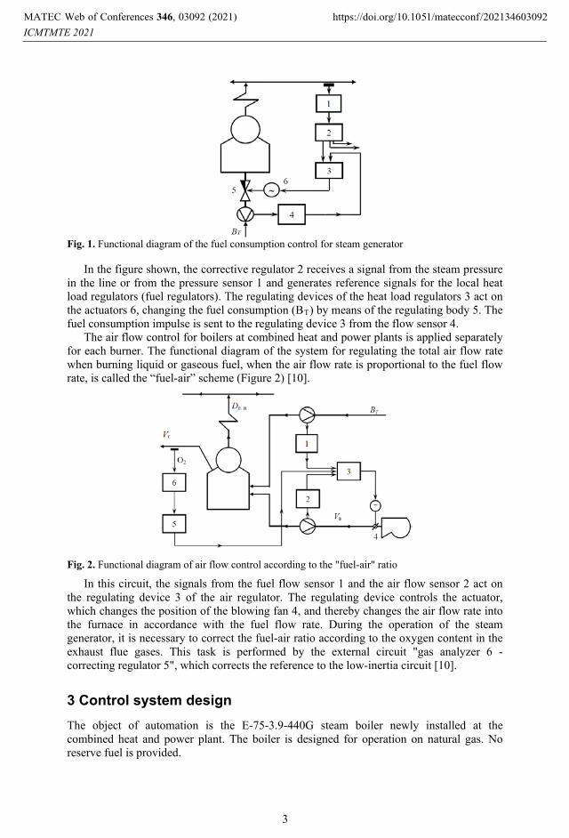
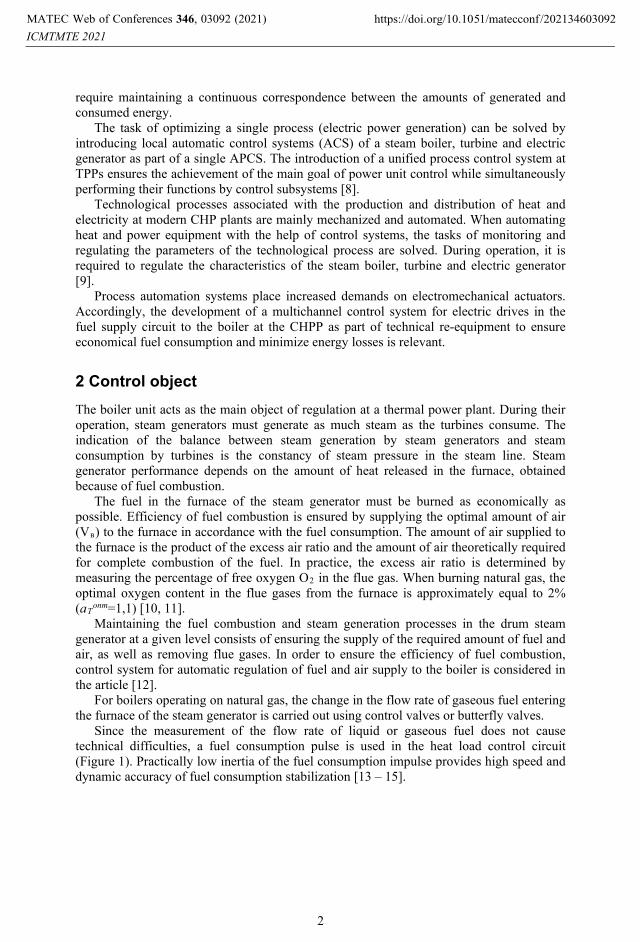
Fig. 1. Functional diagram of the fuel consumption control for steam generator
In the figure shown, the corrective regulator 2 receives a signal from the steam pressure in the line or from the pressure sensor 1 and generates reference signals for the local heat load regulators (fuel regulators). The regulating devices of the heat load regulators 3 act on the actuators 6, changing the fuel consumption (BT) by means of the regulating body 5. The fuel consumption impulse is sent to the regulating device 3 from the flow sensor 4.
The air flow control for boilers at combined heat and power plants is applied separately for each burner. The functional diagram of the system for regulating the total air flow rate when burning liquid or gaseous fuel, when the air flow rate is proportional to the fuel flow rate, is called the “fuel-air” scheme (Figure 2) [10].
Fig. 2. Functional diagram of air flow control according to the "fuel-air" ratio
In this circuit, the signals from the fuel flow sensor 1 and the air flow sensor 2 act on the regulating device 3 of the air regulator. The regulating device controls the actuator, which changes the position of the blowing fan 4, and thereby changes the air flow rate into the furnace in accordance with the fuel flow rate. During the operation of the steam generator, it is necessary to correct the fuel-air ratio according to the oxygen content in the exhaust flue gases. This task is performed by the external circuit "gas analyzer 6 - correcting regulator 5", which corrects the reference to the low-inertia circuit [10].
3 Control system design The object of automation is the E-75-3.9-440G steam boiler newly installed at the combined heat and power plant. The boiler is designed for operation on natural gas. No reserve fuel is provided.
MATEC Web of Conferences 346, 03092 (2021)
ICMTMTE 2021https://doi.org/10.1051/matecconf /202134603092
3
To calculate the dynamic settings of the combustion process regulators, it is necessary to take the acceleration curves. To analyze the dynamic properties along the listed channels, the accelerating curves of the contours are approximated by inertial links with a delay [16]. For this boiler, as a result of the approximation, the transfer functions W(p), shown in the table 1 [17, 18] were obtained.
Table 1. Transfer functions of boiler control channels
№ Regulation channel Transmission function 1 Air consumption – content of O2 ( )
1+16p560,224+2,74p
2 +p=pW
2 Air consumption – content of O2 ( )
1+16p560,224
2 +p=pW
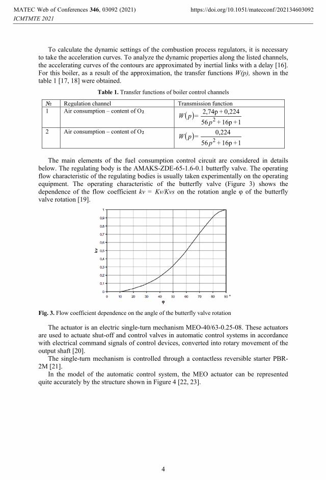
The main elements of the fuel consumption control circuit are considered in details below. The regulating body is the AMAKS-ZDE-65-1.6-0.1 butterfly valve. The operating flow characteristic of the regulating bodies is usually taken experimentally on the operating equipment. The operating characteristic of the butterfly valve (Figure 3) shows the dependence of the flow coefficient kv = Kv/Kvs on the rotation angle φ of the butterfly valve rotation [19].
Fig. 3. Flow coefficient dependence on the angle of the butterfly valve rotation
The actuator is an electric single-turn mechanism MEO-40/63-0.25-08. These actuators are used to actuate shut-off and control valves in automatic control systems in accordance with electrical command signals of control devices, converted into rotary movement of the output shaft [20].
The single-turn mechanism is controlled through a contactless reversible starter PBR-2M [21].
In the model of the automatic control system, the MEO actuator can be represented quite accurately by the structure shown in Figure 4 [22, 23].
MATEC Web of Conferences 346, 03092 (2021)
ICMTMTE 2021https://doi.org/10.1051/matecconf /202134603092
4
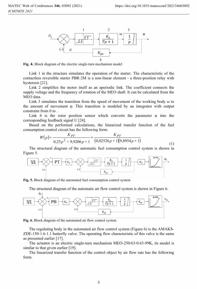
Fig. 4. Block diagram of the electric single-turn mechanism model
Link 1 in the structure simulates the operation of the starter. The characteristic of the contactless reversible starter PBR-2M is a non-linear element - a three-position relay with hysteresis [21].
Link 2 simplifies the motor itself as an aperiodic link. The coefficient connects the supply voltage and the frequency of rotation of the MEO shaft. It can be calculated from the MEO data.
Link 3 simulates the transition from the speed of movement of the working body ω to the amount of movement φ. This transition is modeled by an integrator with output constraint from 0 to π2.
Link 4 is the rotor position sensor which converts the parameter φ into the corresponding feedback signal U [24].
Based on the performed calculations, the linearized transfer function of the fuel consumption control circuit has the following form:
( ) ( )( )19,895410,0252619,92060,25 2 +p+p
K=
+p+p
K=pW РТРТ
(1) The structural diagram of the automatic fuel consumption control system is shown in
Figure 5.
Fig. 5. Block diagram of the automated fuel consumption control system
The structural diagram of the automatic air flow control system is shown in Figure 6.
Fig. 6. Block diagram of the automated air flow control system
The regulating body in the automated air flow control system (Figure 6) is the AMAKS-ZDE-150-1.6-1.1 butterfly valve. The operating flow characteristic of this valve is the same as presented earlier [17].
The actuator is an electric single-turn mechanism MEO-250/63-0.63-99K, its model is similar to that given earlier [19].
The linearized transfer function of the control object by air flow rate has the following form:
MATEC Web of Conferences 346, 03092 (2021)
ICMTMTE 2021https://doi.org/10.1051/matecconf /202134603092
5
( ) ( ) ( )( )12510,01
1≈. +p+pKKpWK=pW заслφзМЭОUΣ ∗∗∗
(2)
The stability of the obtained automatic control system has been estimated by the Nyquist method. The synthesis of automated fuel and air consumption control system with a proportional controller according to the criterion of modular optimum is performed.
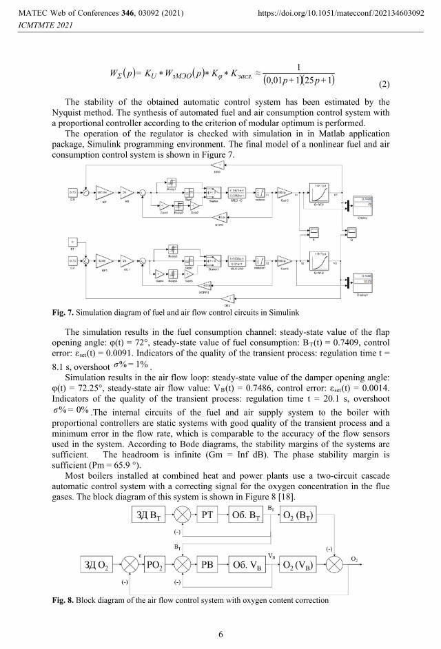
The operation of the regulator is checked with simulation in in Matlab application package, Simulink programming environment. The final model of a nonlinear fuel and air consumption control system is shown in Figure 7.
Fig. 7. Simulation diagram of fuel and air flow control circuits in Simulink
The simulation results in the fuel consumption channel: steady-state value of the flap opening angle: φ(t) = 72°, steady-state value of fuel consumption: BT(t) = 0.7409, control error: εset(t) = 0.0091. Indicators of the quality of the transient process: regulation time t = 8.1 s, overshoot 1%% =σ .
Simulation results in the air flow loop: steady-state value of the damper opening angle: φ(t) = 72.25°, steady-state air flow value: VB(t) = 0.7486, control error: εset(t) = 0.0014. Indicators of the quality of the transient process: regulation time t = 20.1 s, overshoot
0%% =σ .The internal circuits of the fuel and air supply system to the boiler with proportional controllers are static systems with good quality of the transient process and a minimum error in the flow rate, which is comparable to the accuracy of the flow sensors used in the system. According to Bode diagrams, the stability margins of the systems are sufficient. The headroom is infinite (Gm = Inf dB). The phase stability margin is sufficient (Pm = 65.9 °).
Most boilers installed at combined heat and power plants use a two-circuit cascade automatic control system with a correcting signal for the oxygen concentration in the flue gases. The block diagram of this system is shown in Figure 8 [18].
Fig. 8. Block diagram of the air flow control system with oxygen content correction
MATEC Web of Conferences 346, 03092 (2021)
ICMTMTE 2021https://doi.org/10.1051/matecconf /202134603092
6
The internal fuel and air flow control contours have been tuned earlier. The output value of the internal loop of the fuel flow control system (BT) is a disturbance for the air flow control contour. The external contour is formed by a PO2 correcting regulator for oxygen content and by objects of regulation O2(BT) and O2(VB) through the channels "fuel consumption - oxygen content" and "air consumption - oxygen content".
To create an astatic system and compensate the significant inertia of the control object, a proportional-integral controller is selected. For the convenience of adjusting the regulators, the linearized model of the total air flow rate is obtained in Simulink programming environment. Such a model makes it possible to calculate the corrective regulator by computer methods. The optimal ratio of control time and overshoot is set using the "Tune" function in Simulink environment. According to Bode diagrams, the stability margins of the system are sufficient. Запасы устойчивости по амплитуде и по фазе Gm = 52,9 dB,
082=Pm . The resulting controller is installed in the original system with nonlinear characteristics
and the operation is checked by simulating in Simulink (Figure 9).
Fig. 9. Model of the automatic regulation system of total air flow rate with oxygen content correction in Simulink
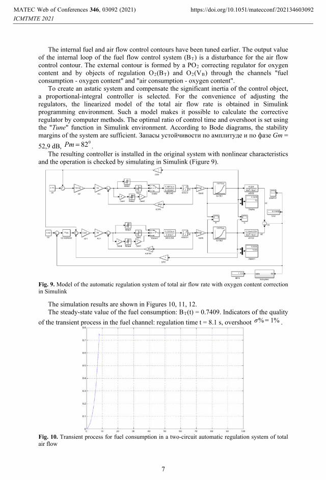
The simulation results are shown in Figures 10, 11, 12. The steady-state value of the fuel consumption: BT(t) = 0.7409. Indicators of the quality
of the transient process in the fuel channel: regulation time t = 8.1 s, overshoot 1%% =σ .
Fig. 10. Transient process for fuel consumption in a two-circuit automatic regulation system of total air flow
MATEC Web of Conferences 346, 03092 (2021)
ICMTMTE 2021https://doi.org/10.1051/matecconf /202134603092
7
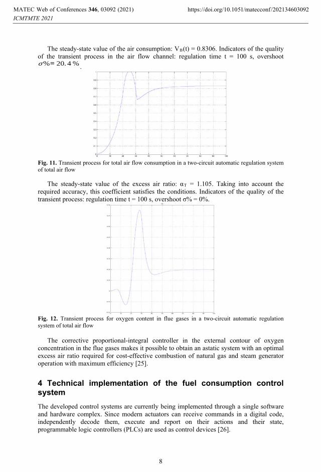
The steady-state value of the air consumption: VB(t) = 0.8306. Indicators of the quality of the transient process in the air flow channel: regulation time t = 100 s, overshoot σ%= 20. 4 % .
Fig. 11. Transient process for total air flow consumption in a two-circuit automatic regulation system of total air flow
The steady-state value of the excess air ratio: αT = 1.105. Taking into account the required accuracy, this coefficient satisfies the conditions. Indicators of the quality of the transient process: regulation time t = 100 s, overshoot σ% = 0%.
Fig. 12. Transient process for oxygen content in flue gases in a two-circuit automatic regulation system of total air flow
The corrective proportional-integral controller in the external contour of oxygen concentration in the flue gases makes it possible to obtain an astatic system with an optimal excess air ratio required for cost-effective combustion of natural gas and steam generator operation with maximum efficiency [25].
4 Technical implementation of the fuel consumption control system The developed control systems are currently being implemented through a single software and hardware complex. Since modern actuators can receive commands in a digital code, independently decode them, execute and report on their actions and their state, programmable logic controllers (PLCs) are used as control devices [26].
MATEC Web of Conferences 346, 03092 (2021)
ICMTMTE 2021https://doi.org/10.1051/matecconf /202134603092
8
The cost-effective fuel combustion control system has stringent requirements for reliability and redundancy. Moreover, the implemented PLC must be integrated into the existing automation structure, and in addition, to facilitate the work of technicians and engineers of the thermal power plant to provide simplicity, reliability and redundancy [27].
To control the electric drives in the fuel and air supply system to the boiler, the REGUL 500 controller (ProsoftSystems) was chosen. The REGUL 500 controller is designed for building fault-tolerant control systems. This controller can include several frames of USO modules, spaced at distances of up to 10 km when using fiber-optic communication cables. In addition to speed, reliability, ability to work in distributed systems in real time and popularity, the REGUL500 controllers have high accuracy of measuring channels, the ability to hot-swap modules of all types, resistance to external influences (temperature, interference, etc.) [26].
5 Conclusions The hardware and software tools (several families of modern controllers from Russian manufacturers; a set of compatible SoftLogic and SCADA systems) make it possible to cope successfully with the solution of the main task of combined heat and power plants automation: maintaining a continuous correspondence between the amounts of generated and consumed energy and minimizing energy losses.
References 1. J. Rybak, Ch. Kongar-Syuryun, Y. Tyulyaeva, A. Khayrutdinov, I. Akinshin // Mining
Science. 28.(2021). doi: 10.37190/msc212802 2. J. Rybak, S.M. Gorbatyuk, K.Ch. Bujanovna-Syuryun, A.M. Khairutdinov, Yu.S.
Tyulyaeva, P.S. Makarov, Metallurgist 64 (2021). doi: 10.1007/s11015-021-01065-5; 3. M.M. Khayrutdinov, Ch.B. Kongar-Syuryun, Yu.S. Tyulyaeva, A.M. Khayrutdinov,
Bulletin of the Tomsk Polytechnic University. Geo Аssets Engineering 331, 11 (2020). doi: 10.18799/24131830/2020/11/2883.
4. V.I. Golik, Ch.B. Kongar-Syuryun, Y.S. Tyulyaeva, A. Khayrutdinov , Bulletin of the Tula State University. Earth Science, 4. (2020).
5. Alexander Ivannikov, Andrey Chumakov, Vladimir Prischepov, Kristina Melekhina, Express determination of the grain size of nickel-containing minerals in ore material. Materials Today: Proceedings, 38 (2021).. https://doi.org/10.1016/j.matpr.2020.10.141
6. Ch. Kongar-Syuryun, A. Aleksakhin, A. Khayrutdinov, Y. Tyulyaeva, Materials Today: Proceedings. International Conference on Modern Trends in Manufacturing Technologies and Equipment (ICMTMTE). 6-10 September. Sevastopol, Russia, 38. (2021) doi: 10.1016/j.matpr.2020.10.139.
7. Ch. Kongar-Syuryun, A. Ivannikov, Y. Tyulyaeva, A. Khayrutdinov, Materials Today: Proceedings. International Conference on Modern Trends in Manufacturing Technologies and Equipment (ICMTMTE). 6-10 September. Sevastopol, Russia, 38. (2021. doi: 10.1016/j.matpr.2020.10.145.
8. Pletnev, G. P. Automation of technological processes and production in heat and power engineering: [textbook for universities on the specialty " Automation of technological processes and production (power engineering)"] (Publishing house MPEI, 2007).
9. Pletnev, G. P. Automatic control and protection of thermal power plants power plants: a Textbook for technical schools (Energoatomizdat, 1986)
MATEC Web of Conferences 346, 03092 (2021)
ICMTMTE 2021https://doi.org/10.1051/matecconf /202134603092
9
10. Andyk V. S., Automated control systems for technological processes at TPP: textbook: (Publishing house of Tomsk Polytechnic University, 2016)
11. Volkova P. I., Dmitrieva V. V., Development of a complex system for regulating a boiler unit. - Access mode: URL: https://cyberleninka.ru/article/n/razrabotka-kompleksnoy-sistemy-regulirovaniya-kotelnogo-agregata-2 (accessed 12.01.2021).
12. Belov A. A., Principles of automation of heat and power processes: textbook for practical classes and independent work of students of the specialty "heat Power engineering" / (Novocherkassk: YURSPU (NPI), 2015)
13. Goldobin, Yu. M., Automation of heat and power installations: textbook. manual (Yekaterinburg: UrFU, 2017)
14. Demchenko, V. A., Automation and modeling of technological processes of NPP and TPP] (O.: Astroprint, 2001)
15. Klyuev, A. S., Adjustment of automatic control systems of boilers (M.: Energiya, 1970) 16. Kulakov G. T., Engineering express methods for calculating industrial control
systems: Spr. Manual (Mn.: Vysh. shk., 1984) 17. Methodological guidelines for setting up the system for regulating the gorenje process
of gas-and-oil boilers: RD 153-34. 1-35.418-2002. Introduction. 2003-03-01. (Moscow: SPO ORGRES, 2003)
18. Stepanets A.V., Koropova L. A., Technology audit and production reserves, 2(23) (2015) Access mode: URL: https://cyberleninka.ru/article/n/audit-kachestva-raboty-algoritmov-upravleniya-barabannyh-parovyh-kotlov-na-stadii-proektirovaniya-sistemy-avtomatizatsii (accessed 12.01.2021).
19. Throttle valves of the AMAKS-ZD type according to TU 3742-006-20652433-98. - CJSC AMAKS Valve Plant .
20. Single-turn electric actuating mechanisms MEO-99K, MEO-99: Operation manual YALBI. 421321. 111 RE. - JSC "ABS ZEiM Automation".
21. Contactless reversible starter PBR-2M: Operating manual YALBI. 421235. 002 RE. - JSC "ABS ZEiM Automation".
22. Lukas V. A., Theory of automatic control: Textbook for universities. 2nd ed., reprint. and additional, (M.: Nedra, 1990)
23. Pevzner L. D., Theory of control systems.( M.: Moscow State Mining University Press, 2002).
24. Novikov, S. I., Optimization of automatic control systems of heat and power equipment: textbook. Stipend, Part 1. (Novosibirsk: NSTU Publishing House, 2006).
25. Nazarov V. I., Burov A. L., Power engineering. Proceedings of higher educational institutions and energy associations of the CIS, 2 (2013). Access mode: URL: https://cyberleninka.ru/article/n/obosnovanie-shemy-korrektiruyuschego-kontura-avtomaticheskoy-sistemy-regulirovaniya-rashoda-obschego-vozduha-kotla (accessed: 13.01.2021).
26. REGUL R500. Controllers of domestic production for the construction of distributed control systems // Branch scientific and technical journal "ISUP", 2. (2017) URL: https://isup.ru/upload/pdf-zhurnala/2018%20i%20dalee/2017/Magazine_ISUP_2 (68)_2017.pdf (accessed: 01.02.2021).
27. Mendelevich V. A. (JSC “NVT Systems"), Automation and IT in the energy sector, 2 (2020) Access mode: URL: https://nvtsys.ru/statiya/200201avite.pdf (accessed 01.02.2020).
MATEC Web of Conferences 346, 03092 (2021)
ICMTMTE 2021https://doi.org/10.1051/matecconf /202134603092
10