The Roman Aqueductbridge of Los Bañales (Uncastillo, Spain): structural analysis
14
BABESCH Annual Papers on Mediterranean Archaeology Supplement 24 — 2013 Ö STErrEICHISCHES A rCHäOlOGISCHES I nSTITuT Sonderschriften — Band 49 BABESCH FOunDATIOn Stichting Bulletin Antieke Beschaving
Transcript of The Roman Aqueductbridge of Los Bañales (Uncastillo, Spain): structural analysis

B A B E S C HAnnual Papers on Mediterranean Archaeology
Supplement 24 — 2013
ÖSTErrEICHISCHESArCHäOlOGISCHES InSTITuT
Sonderschriften — Band 49
BABESCH FOunDATIOnStichting Bulletin Antieke Beschaving

InHAlTSVErZEICHnIS
Abbreviations
HAnS MEHlHOrnVorwort des Präsidenten der Frontinus-Gesellschaft
GIlBErT WIPlInGErVorwort und Einleitung
Awarding of the Frontinus-Medal
WOlFGAnG MErkEllaudatio to the Awarding of the Frontinus Medal to Signora Professore Fanny Del ChiccaAuditorium Vienna Water Company, October 21, 2011
FAnny DEl CHICCAAnswer to the laudatio
Eröffnungsvortrag
WOlFGAnG MErkElSextus Iulius Frontinus, ein moderner CEO der Wasserversorgung roms um 100 n.Chr.
Wien
WOlFGAnG BÖrnErHistorische Wasserleitungen in WienDas Webportal “Wien Kulturgut“ - Ein Fenster in die Vergangenheit Wiens
HAnS SAIlErThe Vienna Mountain Spring lines
Vorderer Orient und Kleinasien
CHrISTInE ErTElDas römische Wasserleitungsnetz von kanatha (Qanawat, Syrien)
kArl STrOBElDas Wassermanagement hethitischer und hellenistisch-römischer Zeit in Zentralanatolien
DEnnIS MurPHyThe Aqueduct of Elaiussa Sebaste in rough CiliciaWater Channels for today and yesterday
JulIAn rICHArD, MArC WAElkEnSA newly Discovered nymphaeum near the Stadium of Sagalassos (SW Turkey)
HAVVA İşkAn, n. OrHAn BAykAnneue Ergebnisse zur Wasserleitung von Patara/Türkei
IX
XI
XIII
3
7
11
23
35
47
55
71
85
93

GIlBErT WIPlInGErDer Değirmendere Aquädukt von Ephesos und seine Zukunft
rAlF krEInErDie Mühlen des Değirmendere Aquäduktes von Ephesos und des Aquäduktes von Anaia/kadikalesı (Türkei)Ein Zwischenbericht
InGE uyTTErHOEVEnrunning Water Aqueducts as Suppliers of Private Water Facilities in (Late) Roman Asia Minor
Westliche Provinzen – von der Römerzeit zur Neuzeit
luIS M. VIArTOlA, JAVIEr AnDrEu, MAríA J. PEréXThe roman Aqueductbridge of los Bañales (uncastillo, Spain)Structural Analysis
FErnAnDO ArAnDA GuTIérrEZ, MAríA EuGEnIA POlO GArCíA, JOSé luíS SánCHEZ CArCABOSO,ESPErAnZA AnDréS DíAZ, TrInIDAD nOGAlES BASArrATE, JOSé MAríA álVArEZ MArTínEZThe roman Water Supply Systems to Augusta Emerita
DIETrICH lOHrMAnnDrei große Aquädukte des Mittelalters (12.-13. Jahrhundert)Sevilla, Perugia, Waltham Abbey
JOSé MAnuEl DE MASCArEnHAS, PAul BEnOIT, kArInE BErTHIEr, JOSéPHInE rOuIllArD, VIrGOlInA JOrGEThe Aqueduct of Setúbal (Portugal)Characterization and Development as Heritage
DIETEr BISCHOPDie Wasserversorgung von Bremen vom Spätmittelalter bis in die Frühe neuzeit
ulrICH MOHrDie rannaleitung - seit 99 Jahren ein unverzichtbarer Bestandteil der Wasserversorgung vonnürnberg
Wassertürme
H. PAul M. kESSEnErA Pompeiian-type Water System in Modern Times
AnDrIJ kuTnyIHistorische Wasserversorgung in Buchara (usbekistan)
JEnS u. SCHMIDTWassertürme als Touristenattraktion
105
131
139
163
173
183
195
205
217
229
241
249

Südamerika
FrAnCISCO SAnTAnA, JOSé MAnuEl DE MASCArEnHAS, MárIO MEnDOnçA DE OlIVEIrA, VIrGOlInOFErrEIrA JOrGEThe Hydraulic Systems of the Convent of St. Anthony of Paraguaçu (Bahia, Brazil)
Anhang
Gül SürMElIHInDI, CEES PASSCHIErSinter AnalysisA Tool for the Study of Ancient Aqueducts
list of Participants and Authors
VII
259
269
287

At the archaeological site of Los Bañales (Spanishname related to baths), a roman city that is cur-rently being excavated (in Northern Spain, Uncas -tillo, only one hundred kilometres from Saragossa),there is a very singular and unique Roman aque-duct bridge that was part of the water supply sys-tem related with the roman city. The city grew upbeside an important Roman way linking CaesarAugusta (current Saragossa) with the Pyreneesand its floruit corresponded to the period from the1st century BC to the 3rd century AD when it wasabandoned. This paper presents some reflectionson the structural principles of the aqueduct bridge,on some problems connected with its conserva-tion, its final aspect in Roman times and the wayit worked out.1
DESCRIPTION
Despite its rough appearance and the scarcity ofremains that have survived until today, the aque-duct bridge is a construction that displays a num-ber of peculiarities that make it a standard refer-ence in Spanish roman aqueducts (fig. 1).2 Theso-called ‘El Pueyo de Los Bañales’, the area inwhich the Roman city grew up, is located to theWest of the aqueduct and includes the remains ofthe baths, right near the ancient forum where cur-rently from 2009, the excavations have beenfocused on.3
The aqueduct bridge runs along a curvilinearrocky crest that appears in the middle of the val-ley and has to be crossed by the hydraulic system
163
The Roman Aqueductbridge of Los Bañales(Uncastillo, Spain)Structural Analysis
Luis M. Viartola, Javier Andreu, María J. Peréx
Fig. 1. Aqueduct Overview taken from the ‘Puy Foradado’ hill (in English: drilled hill) (photo L.M. Viartola).

before providing water to the city. Only thirty-two pillars (P1 to P32) stand nowadays and thereare no remains of the aqueduct channel that wassupported by them. The pillars are variable inheight, reaching 7 m in the highest zone. The dis-tance between pillar axis is around 4.90 m andthis span distance remains consistent.
A variable number of sandstone blocks consti-tute the different pillars. The blocks have variabledimensions, and are coarse worked except for thetop and bottoms that were precisely cut to fittogether. The block’s width - transverse dimen-sion - is bigger than its length - longitudinaldimension, the one parallel to the alignment - andthe thickness is the minor dimension. Generallyspeaking, the dimension of the blocks decreasegradually as their position rises in height with theexception of the top block that is normally slight -ly overlapping. As an example, a 6 m tall pillarhas a base of 140 cm width and a 90 cm length.
The blocks have been dry jointed without anymortar paste. The bottom block constitutes thefoundation and it in turn rests on the previouslymentioned sandstone layer. Numerous rock cutrecess marks can be found in the bedrock that pro-vide a horizontal plan of the foundations (fig. 2).
The top block has a 40 cm wide and 7 cm deepgroove that served as a support for the deck inwhich the channel rested. These top blocks alsohave vertical drill holes of around 5 cm in diam-eter, to enable joining between deck and pillar.
A singularity in the pillars of the aqueduct ofLos Bañales is the existence of a horizontal drillingcross located 90 cm bellow the top. These holes
were made using a prismatic groove in the centreof the lower or the upper side of the block thatwas completed with the previous or next block soas to obtain the mentioned drilling cross (fig. 3).
ALIGNMENT
The horizontal alignment of the aqueduct wasconditioned by the sandstone crest it rests on.This crest ensures the foundation bearing capac-ity of the aqueduct, and the lower height of thepillars. To fit the curved geometry of the crestwith a rational horizontal alignment for the aque-duct, the alignment was structured as a succes-sion of straight lines that were placed within thelimits of the sandstone crest as is usual in otherRoman aqueducts. Four straight lines were usedin this case to link the 250 m in length betweenexisting P1 and P32 pillars.
While the series of pillars included in align-ments 2, 3 and 4 maintain the same orientation,respectively, this is not the case for alignment 1.Here two singularities occur. First of all: the seriesof four pillars P1 to P4 have the same orientation,which varies slightly from that showed by theseries of pillars P5 to P10. And secondly: the ori-entation of these pillars is different from that ofpillar P11. The rotation existing at pillar P11 be -tween the bottom block and the other blocks ofthe pillar is a remarkable fact to take into account.Although footprints of the foundations are locatedalong the alignment 2 beyond P11 pillar, this rota-tion requires the existence of two additional align-ments that reconcile the alignment of the channel
164
Fig. 2. Aqueduct pillars with foundation cutting (photo L.M. Viartola).

with the orientation of the top block of this pillar(alignments 1C and 1D, in red in fig. 4).
Therefore, the main alignment 1 would be
formed by the succession of four shorter align-ments, called alignments 1A, 1B, 1C and 1D.Taking into account the horizontal alignment as
165
Fig. 3. Detail of pillar top blocks and horizontal drilling holes (photo L.M. Viartola).
Fig. 4. Plan view of pillar alignment and numbering (Foto Google Earth, drawing L.M. Viartola).

well as the typical span of 4.9 m, it is possible tocalculate the number and position of the inter-mediate piers currently missing, giving a total of20 units. Figure 4 shows a plan view, includingalignments, and the identification of existing andintermediate missing pillars (fig. 4).
Using the previous data, and the fact that thetop level of the pillars stand about 524 m distancein the central part of the aqueduct,4 it is possibleto calculate precisely the number of missing pil-lars from the one at the extremes (P1 and P32) tothe origin and to the end of this part of the aque-duct bridge. Antonio Beltrán, who first studiedthe ruins, proved the existence of twelve pillarsat a 58 m elongation, from the last remaining pil-lar (P32) to the place where the aqueduct contin-ued through the ground right to the urban area.This end would be located at the ground level dis-tance of 522 m. It leads to a substructio of about 2m high, a perfectly reasonable value here: the con-struction using isolated support is not too compli-cated and, besides, it requires less consumption ofmaterial than if a wall solution had been used.Following the same criteria, the origin of the aque-duct can be determined as the intersection betweenthe first alignment and the level of 522 m. Thus,extending alignment 1A from P1 position to thislevel it results in a line of about 40 m in length, inwhich eight spans can be placed. Therefore sevenadditional pillars besides the one corresponding tothe substructio, might be considered.5
In summary the aqueduct would have twentyadditional pillars from the existing ends (P1 andP32) to the original beginning and end, and thenthere would probably be a total of seventy twowith a total length of about 350 m.
STRUCTURAL PROPOSAL
From a structural point of view, the aqueduct-bridge of Los Bañales belongs to the type of deck(or lintel) supported on isolated supports. Re -garding the nature of the deck, it was made ofwood (trabes clauatae in the latin sources), and itsupported the specus, the channel for the water torun. A composite structure, like this, with a wood -en deck resting on masonry pillars was quite ausual solution in Roman engineering.6
Although a simply supported span solutioncould achieve lengths between pillars even higherthan those of the aqueduct of Los Bañales, if onlyresistance aspects are considered, it is very impor-tant to relate the slope7 of the conduit to the deflec -tion of the deck so as not to affect the performanceand the capacity of the channel. If a comparative
analysis is made between a simply supportedspan and the one with an additional intermediatesupport, it is possible to notice the great improve-ment that the additional support offers. Maximumdeflection is forty time lower, and the rotation atthe end is reduced by sixteen. The better dynamicresponse under the wind load is also highlighted,since the frequency of the deck is increased four-fold.8 This is an important subject because theinfluence of wind had to be decisive taking intoaccount the continuous winds in the area and thelightness of the wooden deck.
There are also other factors that lead us to con-sider the possibility that there was an intermedi-ate support.
As mentioned above, the top blocks of pillarshave only one centered vertical drilling to anchorthe deck as shown in figure 3. If simple supportedspans had been placed, they should have beenjoined to the same pillar as the tail end of the pre-vious span and the leading end of the next one,so there should be two holes. What this layoutsuggests is that the deck had continuity over thepillars, and did not begin or end on them, andtherefore the union between two sections of thewooden deck should occur at another point. Be -cause of the changes of alignment in the aqueduct,there might have been elements that allowedthose rotations in the deck alignment. The exist-ing pillars placed at the points (P11, P16 and P17)do not have the required change in theirs topblock grooves, to keep them straight. An inter-mediate support would permit the link betweenthe different sections of the wooden deck in addi-tion to its change of alignment. All of this seemsto indicate that the aqueduct had an intermediate
166
Fig. 5. Schematic model of proposed roman aqueductstructure (reconstruction and drawing
J. Tutor Pellicer-Palacín and L.M. Viartola).

support obtained by means of struts, and the lackof holes in the frontal faces of the pillars in whichto allocate the struts is what could give sense tothe drilling cross at the top part of every pillar,rather than being mere supports for temporary
and maintenance platforms (fig. 5). The conduitwould have rested on a wooden deck that wassupported by the pillars and by an intermediatesupport, and in turn, resting on a set of struts.These struts joined the pillars in their lateral faces
167
Fig. 6. Virtual image of proposed channel construction (reconstruction and drawing L.M. Viartola and J. Tutor Pellicer-Palacín).
Fig. 7. Photomontage comparing original rests of the aqueduct with its proposed aspect in Roman times (photomontage L.M. Viartola and J. Tutor Pellicer-Palacín).

using the drilling cross.9 This structural schemeallows a dual strut plane, one on each lateral sideof the pillars which has important advantages overa single plane solution, not so much in regard tovertical loads but as compared to horizontal ones,for example the wind load. The deck would bemade entirely of wood, like the struts and thecrossbar, although the latter could be reinforcedwith metal facings together with nails, in the sameway that the connecting piece between this beamand struts. In turn, the union of the struts with thispiece and with the intermediate support of thedeck may have been reinforced by metal pins.
Taking all those factors into account, the aque-duct bridge would have looked, more or less, likethe one presented in figure 6, a picture whichincludes the texture of their constituent materials,and includes a specus obtained through twowooden side walls attached to the deck (see alsofig. 7, where a photomontage is also shown, inorder to present the aspect that the structural pro-posal described could have had).10
STRUCTURAL CALCULATIONS
Stability calculations of the pillars have been carriedout in order to value its structural response duringoperation.11 The results prove the proper structuralresponse, as well as the wind pressure acting on thetransverse direction, is the main load to be resistedduring the aqueduct in service. Pillars present noproblem of sliding between blocks or between theblocks and the foundation, and taper in the faces ofthe pillars, which increase the base dimensions astheir height increase, en sures an adequate level ofsafety against overturning.
These calculations show that the geometry ofthe pillars of the aqueduct bridge is sufficientlyadequate to endure the loads, and they are anexcellent example of the structural understandingof those in charge of its design and construction.
DETERIORATION PROCESSES
It has been shown that the aqueduct bridge hadmore than seventy pillars when it functioned, andonly thirty two pillars stand nowadays.12 Whatprocesses could have caused the ruin of more than50% of the pillars that originally formed the aque-duct bridge? Probably, the answer lies in the degra-dation processes of the rock used to build themand to support the pillars. The rock is a calcareoussandstone with a soft skeleton,13 which has beenaltered by physical and chemical pro cesses: ero-sion, freeze-thaw cycles and localized stresses, and,
mainly, the dissolution of its components.The rock that forms the foundation of the pil-
lars is the same as that used in its construction.Therefore, it is equally sensitive to the deteriora-tion processes mentioned. In this case, there aretwo significant deterioration phenomena: the ero-sion of water runoff and the dissolution processescaused by surface water stagnation in the flat areasthat served as a foundation. These erosion pro -cesses in the plane of the foundation can gener-ate, in turn, two types of conditions affecting thepillars, a vertical deviation of the pillar or a lackof support of the foundation block.14 However,analyses show that both phenomena do not sig-nificantly affect the overall stability of the pillarsonce the deck has disappeared (fig. 8).15 Thisdegradation seems to have followed a very par-ticular evolution. Pictures on the top of figure 8present situations of emerging lack of support.The images below represent very clearly the con-sequences of the lack of support on the founda-tion block of the pillars, which have to withstandthe loads transmitted from the upper blocks as acantilever. Additionally, other processes of lack ofsupport have been observed, affecting not onlythe foundation blocks but the whole foundationsandstone stratum. The area between P15 and P16pillars, presents what might have been a collapseof the sandstone strata due to the loads of selfweight and pillars acting on a rock slab whosesupport has been removed as the underlying marlwas melted and washed away (fig. 9).
CONSTRUCTION
The following paragraphs include some aspectsrelated to the construction procedure of the pil-
168
Fig. 8. Various stages of foundation erosion (photo L.M. Viartola).

lars. Some marks can be highlighted in the poorlydressed faces of intermediate blocks (fig. 10). Theymight be related to the quarry extraction proce-dure, due to the similarity present with the foot-prints of the slots for the wedges used to split offa block of stone in the quarries as attested in thesurrounded area and with the same evidence ofhaving been used in Roman times. The blockswere not worked in full detail and, sometimes,used in the construction directly from the quar -ry.16 This fact has preserved those marks.
Regarding the system of lifting the blocks, theevidence found (fig. 11) suggests that a lewis sys-
tem was used.17 On the left and the upper rightsides of figure 11 an isolated block can be seen be -tween P31 and P32 pillars. Paying attention to thecenter hole, it can be noticed a clear analogy withthe slots that exist in the voussoirs of the vault18
located at the apodyterium entrance of the Romanbaths which are located on the same archeologicalsite, on the bottom left side of this picture. Com -ing back to the places where the quarry extractionmarks appear (fig. 10), the mark located in themiddle of the joint between the two upper blockscan also be highlighted. This is a mark repeated inmany other blocks of the pillars, and they areprobably traces corresponding to the insertion ofthe positioning lever. These levers were used inRoman construction for adjusting the position ofblocks to their final resting place. These marks arevery common in Roman bridges and aqueductsof Hispania.19
TYPE OF CHANNEL
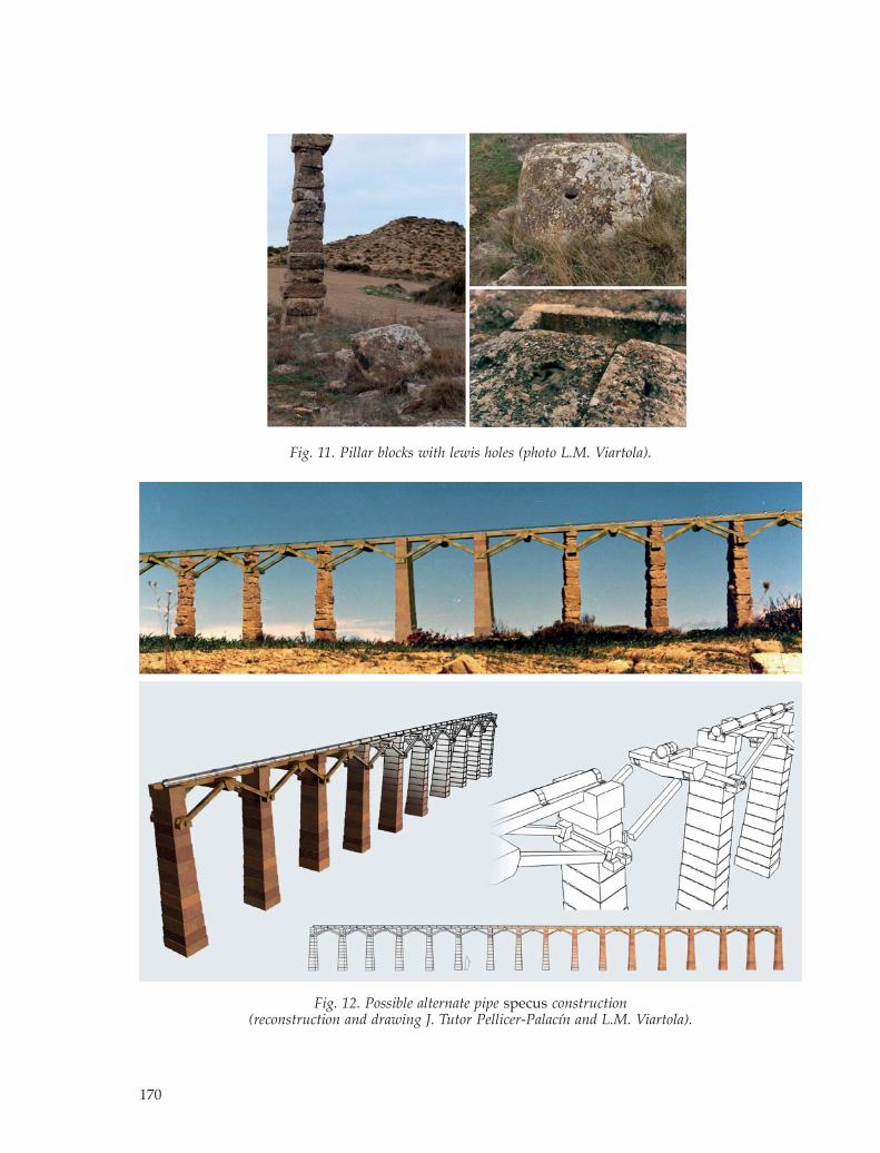
Only subjects related to the morphology and thestructural type of the aqueduct bridge have beenexposed in this paper, but it can be interesting toreflect on future studies about the specus sup-ported by the structure that has been analysed.Was it a conventional channel or a pipe? Theanswer, probably, is that both were possible; agravity channel or pipe could provide a similarflow of water (fig. 12).20 A lead pipe was found inthe baths in 1975,21 and also ceramic pipes have
169
Fig. 10. Quarry marks on pillar blocks(photo L.M. Viartola).
Fig. 9. Foundation bedrock fracturing (photo L.M. Viartola).
170
Fig. 12. Possible alternate pipe specus construction (reconstruction and drawing J. Tutor Pellicer-Palacín and L.M. Viartola).
Fig. 11. Pillar blocks with lewis holes (photo L.M. Viartola).

appeared in different parts of the ruins,22 but notin the aqueduct area where no excavations havebeen done. These remains would suggest that, atleast, this possibility could be taken into accountbut anyway, this is a worthy subject for furtherand future investigations.
NOTES
1 The most complete and up-to-date study of the aque-duct will be found in Viartola 2011 (in fact, the presentpaper is only a brief abstract of some of the aspects thatwere discussed there even when we here deal withsome unattended and unpublished problems of thisaqueduct, its past working and layout and its futureconservation). For the archaeological site of Los Bañalessee Andreu 2011a, with all the bibliography and theprevious investigations that took place in the area inthe 1940’s and the 1970’s of 20th century, and the recentabstract by Andreu 2011b, with a particular new ap -proach to the place.
2 Several studies focused on the roman aqueduct of LosBañales have been published. The largest until today,apart from Viartola 2011, is Beltrán Martínez 1977a, 95-101, which includes all data obtained by the author forthe archaeological study he led in 1973 (focused, any-way, on the roman baths of the city), and the previousones supported in the 1940s by J. Galiay, that were pub-lished in Galiay 1944 and Galiay 1949. A more recentstudy is the one by Leather 2002, 36-39. All those studiesare available from the Publication sections of the ar -chaeological site homepage (http://www.losbanales.es/).
3 See Andreu 2011a and 2011b and, for the chronology ofthe city, Andreu, Peréx and Bienes 2011.
4 This value, compared with the levels of the groundunder the foundations, results in a maximum height ofabout 7 m, while the average height does not exceed 6 m.
5 There is evidence of at least three foundations in thisinitial elongation, the rest of them disappear into thelabour fields.
6 Galliazzo 1995, 288 and 326-327. Different structuralschemes of bridges with wooden deck and masonrypier are described. Many other references of romancomposite bridges are known. For instance, the bridgeover the Danube, by Apollodorus of Damascus, a com-posite bridge represented in the Trajan column is oneof the most famous bridges in Roman Empire. But,appart from this bridge, another three different woodenbridges appear in this well-known monument: bridgeson boats, bridges on piles driven into the bed of theriver, and finally one located in the Roman camp, whichpresents a more elaborate structural sequence consist-ing of a series of successive spans with an intermediatesupport made by struts, which seems to be the modelused in the Los Bañales’ aqueduct. This ‘military inspi-ration’ of the aqueduct could be also historically inter-esting if some marks inscribed in the stones of the pillarsof the aqueduct of Los Bañales probably showing theformula L, four brakes, and, sometimes, M, are finallyconnected with the L(egio) IV Macedonica, one of thelegions that also worked in the opening of the romanroad in the area as we know form the milestones dis-covered in the sourroundings (AE 1984, 584) and that,maybe, had something to do with the building of thisaqueduct at the same time: around years 9 and 5 BC, so
in Augustan times (for this possibility see Jordán 2011)a very remarkable time to the history of the city as theultimate investigations seem to underline (Andreu 2001b).
7 The slope of the specus was around 80 cm per kilome-ter, value obtained by dividing the approximately 20cm difference in elevation of P1 and P32 pillars betweenthe distance of nearly 250 m that separates them. Thisleads to a difference of just a few millimeters betweentwo consecutive pillars.
8 For further information on this analyses see Viartola2011.
9 In a simple way, both the crossbar connection and thestruts can be compared to those in the wheels of a romanchariot, the crossbar would be the axle and the strutswould be the spokes. It is possible to check that the loadin the crossbar in the aqueduct would be lower that theone supported by a similar piece in a chariot wheel.
10 The photomontage shows the area at alignments 3 and4, more precisely pillars P20-P22 and P23-P25.
11 Calculations have been made for a typical pillar of 6.0m in height. Sliding and overturning safety factors, aswell as maxima and average stresses in the blocks andfoundation, were obtained (see Viartola 2011, 182, Fig12 and 188, fig. 16).
12 In 1610 it only had thirty six pillars, a half of the total,as related by Portuguese cosmographer J.B. Labaña inhis visit to the ruins when he was making a Map ofAragón, commissioned by the Diputación del Reino. Adescription of this visit can be found in Labaña 1610,18-19. After four hundred more years there are onlythirty two pillars.
13 Subjects related to geological nature of the archaeologi -cal site of Los Bañales, as well as the type of stone usedin the aqueduct, can be found in Cisneros 1986 and,with new data, in Lapuente et al. 2011.
14 If the surface of the rock foundation has been degra-dated in a gradual process and it affects the entire areaof contact with the foundation block, then a rotation inthe base of the pillar occurs, resulting in a tilted pillar.The lack of support of the foundation block is anotherpathology that can be caused by the alteration of therock foundation, whether this deterioration is locatedunder the external areas of the contact between pillarand foundation.
15 The influence of wind load both on a tilted pillar andon a pillar with lack of support of its foundation hasbeen analyzed. Results show that only a very highspeed of wind could possibly have influence in globalstability of an isolated pillar (see Viartola 2011).
16 Previous analyses demonstrated that the quarries usedfor the construction of the aqueductbridge were locatedin a very close surrounded area (Lapuente et al. 2001).
17 A description of this lifting method can be found inAdam 1984, 23-36.
18 This is the only vault that stands nowadays in thearqueological site. There are also remains of other vault,the one of the apodyterium of the baths, in the center ofthe ancient city.
19 Durán 2004, 142. Examples of these marks are the onesin the blocks of the famous Segovia aqueductbridge.
20 Considering a gravity conduction with a slope between80 cm and 100 cm per kilometre, the flow would reacharound 1,000 and 1,300 cubic metres per day, both fora wooden channel 20 cm wide and 20 cm deep, as in apipe 20 cm in inner diameter.
21 Beltrán Martínez 1977b.22 Beltrán Martínez/Andreu 2011, 152, fig. 24.
171
BIBLIOGRAPHY
Adam, J.-P. 1984, La construction romaine. Materiaux et tech-niques, Paris.
Andreu, J. (ed.). 2011a, La ciudad romana de Los Bañales(Uncastillo, Zaragoza): entre la historia, la arqueología y lahistoriografía (Caesaraugusta 82), Zaragoza.
Andreu, J. 2011b, Una ciudad romana al pie de la víaCaesaraugusta-Pompelo: Los Bañales de Uncastillo, ElNuevo Miliario 12, 3-15.
Andreu, J./Mª Peréx/J.J. Bienes 2011, New findings onLate Antiquity in a town of the Vascones area (LosBañales de Uncastillo, Zaragoza, Spain), in D. Hernán -dez Lafuente (ed.), New Perspectives on Late Antiquity,Cambridge, 119-123.
Beltrán Martínez, A. 1977a, Las obras hidráulicas de LosBañales (Uncastillo, Zaragoza), in Universidad deBarcelona (ed.), Segovia. Symposium de Arqueologíaromana, Barcelona, 91-129.
Beltrán Martínez, A. 1977b, El tubo de plomo del frigi-darium de las termas de Los Bañales (Uncastillo, Zara -goza), in Secretaría de los Congresos ArqueológicosNacionales (ed.), XIV Congreso Nacional de Arqueología(Vitoria, 1975), Zaragoza, 1049-1054.
Beltrán Martínez, A./J. Andreu 2001, Las excavacionesarqueológicas de Los Bañales, in J. Andreu (ed.), La ciu-dad romana de Los Bañales (Uncastillo, Zaragoza): entre lahistoria, la arqueología y la historiografía, Zaragoza, 99-158.
Cisneros, M. 1986, Canteras y materiales de construcciónen Los Bañales (Uncastillo, Zaragoza), in Facultad deFilosofía y Letras de la Universidad de Zaragoza (ed.),Estudios en homenaje al Dr. Antonio Beltrán Martínez,Zaragoza, 613-619.
Durán, M. 2004, Técnica y construcción de puentes roma -nos, in R. Alba/I. Moreno Gallo/R. Gabriel (eds), Ele -mentos de Ingeniería Romana. II Congreso de las ObrasPúblicas Romanas, Madrid, 135-155.
Galiay, J. 1946, Las excavaciones del Plan Nacional de LosBañales de Sádaba (Zaragoza), Madrid.
Galiay, J. 1949, Segunda campaña del Plan Nacional en LosBañales (Zaragoza), Madrid.
Galliazzo, V., 1995. I ponti romani I, Treviso.Jordán, Á.A. 2001, Inscripciones, monumentos anepí-
grafos, dudosos, sellos y grafitos procedentes del muni -cipium ignotum de Los Bañales de Uncastillo, in J. An -dreu (ed.), La ciudad romana de Los Bañales (Uncastillo,Zaragoza): entre la historia, la arqueología y la historiografía,Zaragoza, 285-332.
Labaña, J.B. 1610, Itinerario del Reino de Aragón, Zaragoza. Lapuente, Mª P/H. Royo/A. Gutiérrez. 2011, Un aspecto
de la monumentalización de Los Bañales: caracteriza -ción de materiales pétreos y fuentes de aprovisiona -miento, in J. Andreu (ed.): La ciudad romana de LosBañales (Uncastillo, Zaragoza): entre la historia, la arque-ología y la historiografía, Zaragoza, 257-282.
Leather, G. M. 2002, Roman Aqueducts in Iberia, Garstam. Viartola, L. M. 2011, El acueducto romano de Los Bañales:
propuesta de recreación estructural, in J. Andreu (ed.),La ciudad romana de Los Bañales (Uncastillo, Zaragoza):entre la historia, la arqueología y la historiografía, Zaragoza,167-196.
172