Rebounding Trauma: Representations, Polemic and Critique of Abraham’s Trial of Sacrificial Violence
Upload
independentCategory
view
4download
0
A
TuiTg4(©
K
1
gaacaiiisttsW
h0
Available online at www.sciencedirect.com
ScienceDirect
Journal of the European Ceramic Society 35 (2015) 1527–1537
The role of sacrificial fugitives in thermoplastic extrusion feedstocks onproperties of MgO supports for oxygen transport membranes
D.K. Ramachandran a,∗, K. Kwok a, M. Søgaard a, F. Clemens b, A.J. Glasscock a, A. Kaiser a
a Department of Energy Conversion and Storage, Technical University of Denmark, Frederiksborgvej 399, Building 779, DK-4000 Roskilde, Denmarkb EMPA, Swiss Federal Laboratories for Materials Science and Technology, Laboratory for High Performance Ceramics, Ueberlandstrasse 129, CH-8600
Dübendorf, Switzerland
Received 16 August 2014; received in revised form 11 November 2014; accepted 16 November 2014Available online 9 December 2014
bstract
hree different compositions of MgO compounds were investigated for use in oxygen transport membranes. Porous MgO supports were extrudedsing different kind (size, morphology and chemistry) of pore formers: A flaky graphite, a spherical graphite and ideal spheres of PMMA. Thenfluence of the pore former on microstructure, gas permeation and the mechanical properties for various sintering temperatures were investigated.he gas permeation behavior of the MgO supports was highly dependent on pore neck size and total open porosity. MgO substrate, with 20% sphericalraphite as a pore former, sintered at 1300 ◦C for 2 h, showed a total porosity of 42.5% and gas permeability of 4.7 × 10⁻¹⁶ m2. Subsequently, the-point bending strengths of this substrate, scaled to an effective volume of 10 mm3, were 77 and 60 MPa for room and operation temperature
850 ◦C). Both, permeation rate and mechanical strength is sufficient for using the support for further investigations in OTM.2014 Elsevier Ltd. All rights reserved.
eywords: Porous MgO; Oxygen membrane; Microstructure; Mechanical strength; Gas permeability
esfshmhg
ccOa
. Introduction
Carbon dioxide (CO2) is one of the important greenhouseases which is largely emitted from chemical, power generationnd cement industries. Carbon capture and storage (CCS) is onepproach for reducing CO2 emissions in an attempt to overcomeurrent global warming issues. Using carbon capture and storage
high CO2 content in the exhaust gas is favoured. One possibilitys using oxyfuel power plants in combination with pure oxygennstead of air for combustion process. Practically, pure oxygens conventionally produced by cryogenic distillation in largecale or by pressure swing adsorption in small scale.1 Oxygenransport membranes are a promising alternative for integra-
ion in high temperature combustion processes due to their highelectivity for oxygen and significantly lower efficiency losses.2ith pure oxygen, the NOx emissions in exhaust gas can be
∗ Corresponding author. Tel.: +45 4677 4800; fax: +45 4677 5858.E-mail addresses: [email protected], [email protected] (D.K. Ramachandran).
omttifd
ttp://dx.doi.org/10.1016/j.jeurceramsoc.2014.11.014955-2219/© 2014 Elsevier Ltd. All rights reserved.
liminated, since atmospheric nitrogen is separated from the airtream by the membrane before combustion process.3–7 There-ore leaving only CO2 and H2O can be easily and cost effectivelyeparated for CCS. In the last decade, intensive researchas been dedicated to the preparation and characterization ofonolithic oxygen transport membranes (OTM) to achieve
igh oxygen fluxes through thin planar or tubular membraneeometries.8–13
In comparison to monolithic membrane asymmetric OTMonsists of different functional layers namely; porous support,atalytic and dense membrane layer. In order to fabricate anTM all these layers should be tailored in a way that theyre chemically, structurally and thermally compatible with eachther. The support layer provides mechanical stability to the thinembranes and should ideally allow unrestricted gas access to
he activation layers present on the membrane surface. Hence,he support layer of the membrane should have a high level of
nterconnected open porosity and minimal resistance to gas flowor better membrane performance. There have been many studiesevoted to developing a porous support layer (both ceramic and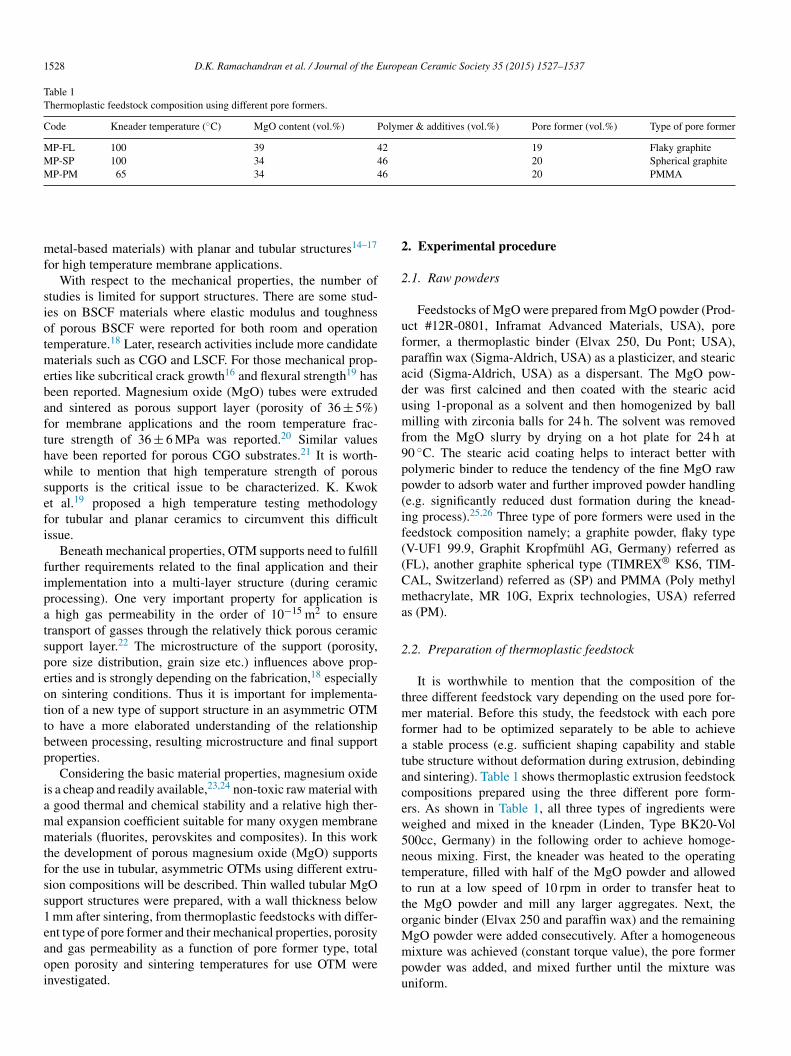
1528 D.K. Ramachandran et al. / Journal of the European Ceramic Society 35 (2015) 1527–1537
Table 1Thermoplastic feedstock composition using different pore formers.
Code Kneader temperature (◦C) MgO content (vol.%) Polymer & additives (vol.%) Pore former (vol.%) Type of pore former
MP-FL 100 39 42 19 Flaky graphiteMP-SP 100 34 46 20 Spherical graphiteMP-PM 65 34 46 20 PMMA
mf
siotmebafthwsefi
fipatspeottbp
iammtfss1eaoi
2
2
ufpadumf9pp(if((Cma
2
tmfatacew5nttto
etal-based materials) with planar and tubular structures14–17
or high temperature membrane applications.With respect to the mechanical properties, the number of
tudies is limited for support structures. There are some stud-es on BSCF materials where elastic modulus and toughnessf porous BSCF were reported for both room and operationemperature.18 Later, research activities include more candidate
aterials such as CGO and LSCF. For those mechanical prop-rties like subcritical crack growth16 and flexural strength19 haseen reported. Magnesium oxide (MgO) tubes were extrudednd sintered as porous support layer (porosity of 36 ± 5%)or membrane applications and the room temperature frac-ure strength of 36 ± 6 MPa was reported.20 Similar valuesave been reported for porous CGO substrates.21 It is worth-hile to mention that high temperature strength of porous
upports is the critical issue to be characterized. K. Kwokt al.19 proposed a high temperature testing methodologyor tubular and planar ceramics to circumvent this difficultssue.
Beneath mechanical properties, OTM supports need to fulfillurther requirements related to the final application and theirmplementation into a multi-layer structure (during ceramicrocessing). One very important property for application is
high gas permeability in the order of 10−15 m2 to ensureransport of gasses through the relatively thick porous ceramicupport layer.22 The microstructure of the support (porosity,ore size distribution, grain size etc.) influences above prop-rties and is strongly depending on the fabrication,18 especiallyn sintering conditions. Thus it is important for implementa-ion of a new type of support structure in an asymmetric OTMo have a more elaborated understanding of the relationshipetween processing, resulting microstructure and final supportroperties.
Considering the basic material properties, magnesium oxides a cheap and readily available,23,24 non-toxic raw material with
good thermal and chemical stability and a relative high ther-al expansion coefficient suitable for many oxygen membraneaterials (fluorites, perovskites and composites). In this work
he development of porous magnesium oxide (MgO) supportsor the use in tubular, asymmetric OTMs using different extru-ion compositions will be described. Thin walled tubular MgOupport structures were prepared, with a wall thickness below
mm after sintering, from thermoplastic feedstocks with differ-nt type of pore former and their mechanical properties, porosity
nd gas permeability as a function of pore former type, totalpen porosity and sintering temperatures for use OTM werenvestigated.Mmpu
. Experimental procedure
.1. Raw powders
Feedstocks of MgO were prepared from MgO powder (Prod-ct #12R-0801, Inframat Advanced Materials, USA), poreormer, a thermoplastic binder (Elvax 250, Du Pont; USA),araffin wax (Sigma-Aldrich, USA) as a plasticizer, and steariccid (Sigma-Aldrich, USA) as a dispersant. The MgO pow-er was first calcined and then coated with the stearic acidsing 1-proponal as a solvent and then homogenized by ballilling with zirconia balls for 24 h. The solvent was removed
rom the MgO slurry by drying on a hot plate for 24 h at0 ◦C. The stearic acid coating helps to interact better witholymeric binder to reduce the tendency of the fine MgO rawowder to adsorb water and further improved powder handlinge.g. significantly reduced dust formation during the knead-ng process).25,26 Three type of pore formers were used in theeedstock composition namely; a graphite powder, flaky typeV-UF1 99.9, Graphit Kropfmühl AG, Germany) referred asFL), another graphite spherical type (TIMREX® KS6, TIM-AL, Switzerland) referred as (SP) and PMMA (Poly methylethacrylate, MR 10G, Exprix technologies, USA) referred
s (PM).
.2. Preparation of thermoplastic feedstock
It is worthwhile to mention that the composition of thehree different feedstock vary depending on the used pore for-er material. Before this study, the feedstock with each pore
ormer had to be optimized separately to be able to achieve stable process (e.g. sufficient shaping capability and stableube structure without deformation during extrusion, debindingnd sintering). Table 1 shows thermoplastic extrusion feedstockompositions prepared using the three different pore form-rs. As shown in Table 1, all three types of ingredients wereeighed and mixed in the kneader (Linden, Type BK20-Vol00cc, Germany) in the following order to achieve homoge-eous mixing. First, the kneader was heated to the operatingemperature, filled with half of the MgO powder and allowedo run at a low speed of 10 rpm in order to transfer heat tohe MgO powder and mill any larger aggregates. Next, therganic binder (Elvax 250 and paraffin wax) and the remaining
gO powder were added consecutively. After a homogeneousixture was achieved (constant torque value), the pore formerowder was added, and mixed further until the mixture wasniform.

D.K. Ramachandran et al. / Journal of the European Ceramic Society 35 (2015) 1527–1537 1529
bular
2
tspictpAoatalgese
2
Sdpa1tma
2
wpd
Gttdr
uZtcopt0v0o4between 240 �m and 0.003 �m.
Gas permeation measurements were carried out using an in-house built system device. The setup consists of a gas supply
Fig. 1. The experimental extrusion of tu
.3. Thermoplastic extrusion of thin walled support tubes
Thermoplastic extrusion was used to shape support tubes ashe process is capable of producing thin walled, form-stable sub-trates suitable for further membrane processing by dip-coatingrocess. The extruder (Model 19/20DN Brabender, Germany)n combination of oil baths were used to heat up the extruderhamber to 100 ◦C and the die head to 90 ◦C. The die heademperature was always kept 10 ◦C lower than the chamber tem-erature to ensure form stability of the tube at the exit of the die.n extruder speed of 10 rpm and a die assembly with inner anduter diameters of 12 mm and 14 mm, respectively, was used forll experiments. Feedstock (MP-PM) was extruded using loweremperatures (extruder chamber: 75 ◦C, die head: 70 ◦C) as theddition of a polymeric pore former produced a feedstock withower viscosity at higher temperature. PMMA typically has alass transition temperature at around 105 ◦C and it was nec-ssary to optimize the extruder temperature to ensure a stabletructure. Fig. 1 shows the image taken during thermoplasticxtrusion process.
.4. Debinding and sintering
Based on the thermo gravimetric experiments (discussed inection 3.3), all three extruded feedstock compositions wereebindered at different temperatures and heating rates which isresented in Fig. 2. After debinding, the samples were sinteredt different sintering temperatures such as 1250 ◦C, 1300 ◦C,350 and 1400 ◦C with a heating rate of 30 ◦C h−1 in ordero investigate the influence of the sintering temperature on the
icrostructure properties. For thermo gravimetric experimentsre described in Section 2.5.
.5. Material characterization
The properties of the different MgO feedstock compositionsere characterized by thermal analysis, electron microscopy, Hgorosimetry, gas permeation and mechanical testing, as will beescribed in detail in this section.
FtP
device using thermoplastic feedstock.
A thermo-gravimetric balance (STA 409 CD, Netzsch GmbH,ermany) was used to study the decomposition behavior of the
hermoplastic binder system (EVA, paraffin, stearic acid) andhe three different pore formers in the MgO feedstock duringebinding in air. All experiments were conducted with a heatingate of 1 ◦C min−1 and an air flow of 100 ml min−1.
The microstructure of the samples was studied after sinteringsing scanning electron microscopy (SEM) (SUPRA35, Carleiss, Germany). The samples for the microstructural charac-
erization were prepared using lap polishing with decreasingoarseness of sandpaper/polishing solution, where the last stagef polishing was with a 0.25 �m diamond paste. Additionally,orosimetry measurements were conducted using a Pore Mas-er (PR-60 GT, Micromeritics, USA). Samples with weights of.9 to 1.1 g were measured in a penetrometer with a 5 cm3 bulbolume and a usable Hg volume in the penetrometer stem of.392 cm3, allowing for a maximum measureable pore volumef 0.366 cm3. All measurements were run between 5 Pa and20 MPa translating into a measurement range of pore diameters
ig. 2. Debinding cycle derived from thermo gravimetric experiments for allhree supports; MP-FL (Flaky graphite), MP-SP (Spherical graphite) and MP-M (PMMA).

1530 D.K. Ramachandran et al. / Journal of the Europ
F
ugitMdmoUoasTq
j
wi(
bmptbecswl
ribdlsm
eci
ao
tm
d
E
wts
cbAao
P
wlpm
ptsv
V
wifa
otbfiWM
3
3t
uF1and mixing and to avoid inhomogeneity in the final feedstock.
ig. 3. Specimen geometry and loading configuration for strength testing.
nit, a testing chamber and a unit for measuring the flow of theas that permeates the sample to be measured. The typical spec-men size is a tubular supports with an area of approximately 10o 20 cm2. After sintering, the thickness of the different porous
gO support samples varies from 0.85 to 0.90 mm. A pressureifference across the samples was created using an electropneu-atic pressure controller (Tescom, ER3000, USA). The flow
f permeated gas was measured using a flow meter (Agilent,SA). The measurements were made with a pressure differencef 200 kPa at room temperature and with nitrogen as the perme-te gas. MgO tubes sintered at 1300 ◦C were glued at one end toteel fixtures and to a polymer composite enclosure at the other.hen gas permeation measurements were carried out in order touantify the gas permeability using the Darcy equation:
= κ
μ∇P (1)
here k is the permeability (m2), j is the flux (m3 (m2 s)−1), μ
s the viscosity of the gas (Pa s), and �P is the pressure gradientpressure (Pa)/sample thickness (m)).
The elastic modulus and strength were measured by 4-pointending test of sectored specimens, which is a variant of theethod developed.19 Typically a large number (∼30) of sam-
les is used to investigate mechanical properties. Often this isime-consuming and therefore many reported strength values areased on a small sample number and are subjected to consid-rable uncertainties.20,27 Sectored specimens were prepared byutting the extruded tubes on the long axis into 4 quarters, eachubtending an angle of 90◦. The cut surfaces of the specimensere ground flat and then tested under four-point bending. The
ength of specimens is 60 mm.A schematic of the specimen geometry and loading configu-
ation is shown in Fig. 3. The distance between the loading pinss 25.0 mm. The support pin and the loading pin are separatedy 12.5 mm. A large tensile stress zone is created in the mid-le bottom region of the specimen. The highest tensile stress isocated away from the cut surfaces and therefore the measuredtrength data were not influenced by defects introduced by theachining.All experiments were conducted using specially designed test
quipment for continuous testing of multiple specimens underontrolled environments. The test facility is described in detailn.19
Four-point bending tests were performed at room temperaturend 850 ◦C in atmospheric air. The rate of downward movementf the actuator was 0.1 mm s−1. The vertical displacement of
Tpo
ean Ceramic Society 35 (2015) 1527–1537
he loading pins and the forces acting on the support pins wereeasured continuously.The elastic modulus E was obtained from the load-
isplacement curve based on the Euler–Bernoulli beam theory,
= P
d
3La2 + 2a3
6I(2)
here d is the vertical displacement of the loading pins, P ishe applied force, and I is the second moment of area of thepecimen cross section.
To obtain the strength of each specimen, the maximum stressorresponding to the applied force at fracture was computedy the finite element method using the commercial softwarebaqus.28 The calculated strength distribution was evaluated
ccording to the conventional Weibull theory.29 The probabilityf fracture Pf is given by
f = 1 − exp
(−
(σmax
σ0
)m)(3)
here σmax is the maximum tensile stress in the specimen. Theinear regression method was used to compute the two Weibullarameters, namely the characteristic strength σ0 and Weibullodulus m.Since the stress distribution in the specimen is multi-axial, the
rinciple of independent action30 was employed in calculatinghe effective volume. This principle assumes that the principaltresses act independently on fracture, which leads to an effectiveolume expression given by
eff =∫
V
(σ1
σmax
)m
+(
σ2
σmax
)m
+(
σ3
σmax
)m
dV (4)
here σ1, σ2, σ3 are the three principal stresses, and V is the spec-men volume. The effective volume was determined numericallyrom the computed stress distributions based on finite elementnalysis.
Weibull parameters were determined from a finite numberf specimens invariably deviate from that of the parent popula-ion. The uncertainty in the measured Weibull parameters cane assessed by means of Monte Carlo simulations.31 The con-dence intervals for the measured characteristic strength andeibull modulus were determined after carrying out 10,000onte Carlo runs for each set of tests.
. Result and discussion
.1. Characterization of raw materials and feedstocks forhermoplastic extrusion of MgO tubes
Fig. 4 shows SEM pictures of the raw materials that weresed for preparation of thermoplastic feedstocks for extrusion.ig. 4(a) shows the MgO powder that was pre-calcined at000 ◦C in order to improve de-agglomeration during milling
32
hree different types of pore formers, with quite differentarticle size and shape are shown in Fig. 4(b) to (d): Two typesf graphite (named by the supplier as flaky graphite (b) and

D.K. Ramachandran et al. / Journal of the European Ceramic Society 35 (2015) 1527–1537 1531
F ks forg
sdmm
mwccwhtdAassihascpp
ooAcc
pciaie
(aFEa
taidatfrbTtrt
ig. 4. SEM images of raw powders for preparation of thermoplastic feedstocraphite powder, spherical (SP), and (d) PMMA (PM).
pherical graphite (c)) and PMMA. The influence of theseifferent pore formers on processing, microstructure develop-ent (pore size, shape and distribution), gas permeability andechanical strength are reported in the following sections.From the particle size distribution (PSD) measurements, the
ean particle size of the MgO powder and the pore formersere estimated using particle size analyzer (LS 13320, Beckman
olter, Inc., USA). The uncalcined (as-received) MgO powderonsisted of extremely fine (nanometric) primary particles thatere aggregated into larger, irregular agglomerates (not shownere). Calcination of the MgO at 1000 ◦C resulted in reduction ofhe surface area and the measured PSD; the d50 value of the pow-er decreased from 2.99 �m to 1.53 �m after the processing.32
flaky graphite powder (FL) with an average particle size ofbout 11 �m was selected; this particle size is at least a factor ofeven larger than the calcined MgO powder. The introduction ofuch large pore former particles was done with the intention ofntroducing sufficiently large pores in the sintered support, andence achieving high gas permeation. With the same intention,nother graphite powder (spherical, SP) with a mean particleize of 5.5 �m, and a PMMA pore former with 10.5 �m parti-le size were used to study the influence of the type and size ofore former on different MgO support properties (porosity, gasermeation and mechanical strength) after shaping and sintering.
In thermoplastic ceramic processing the debinding cycle isften critical and time consuming step. Relative large amountsf organics need to be removed before sintering step (Fig. 2).
n incomplete or to quick debinding cycle will result in blister,racks and voids which will negatively influence the mechani-al strength. Thus, in this study thermogravimetric analysis was
pfa
extrusion: (a) MgO calcined at 1000 ◦C, (b) graphite powder, flaky (FL), (c)
erformed to identify decomposition temperatures of the organicomponents. Subsequently, the temperature profiles for debind-ng were optimized to ensure a very slow and smooth debindingnd avoid the formation of any cracks/defects. Flaw-free ceram-cs are especially important for the study of the mechanical prop-rties of the tubular membrane supports (reported in Section 3.3).
Fig. 5 shows the weight loss as a function of temperature fora) the single components of the thermoplastic binder systemnd pore formers, as well as (b) the three MgO feedstocks (MP-L, MP-SP and MP-PM). All feedstocks contain MgO powder,lvax 250 as the main binder, paraffin wax as lubricant/bindernd stearic acid as a dispersant.
The evaporation of the pure stearic acid and the decomposi-ion of paraffin wax start rapidly at relatively low temperatures ofround 160 ◦C, and 90% of the wax and stearic acid are removedn the narrow temperature range up to 300 ◦C. The Elvax250ecomposition starts slowly at a slightly higher temperature ofbout 250 ◦C, with the highest rate of weight loss occurring atemperatures between 400 ◦C and 500 ◦C. The polymeric poreormer (PMMA) decomposes completely in the temperatureange of 250 ◦C to 350 ◦C. This pore former is therefore removedefore the debinding of the thermoplastic binder is completed.he mass loss curve for the pure graphite shows decomposi-
ion between 500 ◦C and 750 ◦C. In this case the pore former isemoved at higher temperatures than the thermal decompositionemperature of the thermoplastic binder.
When the pore formers are mixed with MgO and thermo-
lastic additives (Fig. 5(b)), the decomposition peak for alleedstocks are broadened and slightly shifted to higher temper-tures, first reaching complete decomposition at temperatures
1532 D.K. Ramachandran et al. / Journal of the European Ceramic Society 35 (2015) 1527–1537
F lvax 2t erical
amoifd
cftatfcft
Fsdoa
ftAtM(aistMt2
ig. 5. (a) Thermogravimetric analysis (TGA) of the individual components; Ehree different MgO feedstocks: MP-FL (graphite, flaky), MP-SP (graphite, sph
round 450 ◦C and 800 ◦C for PMMA and graphite pore for-ers, respectively. This shift can be explained by a slightly
xygen deficient atmosphere due to the binder decompositionn a densely packed MgO matrix that restricts the heat trans-er and the removal of decomposition products (gases evolvinguring organic removal).33
The difference in decomposition temperature of organicompounds in the different feedstock can be better comparedrom the rate of the weight loss plotted in Fig. 6. The thermoplas-ic feedstocks that contain graphite (MP-FL and MP-SP) show
broader decomposition peak than the PMMA feedstock. Thehree distinct peaks are shifted slightly to higher temperaturesor the graphite feedstock MP-FL which has slightly higher
eramic content (39 vol.% ceramic) compared to the MP-SPeedstock (34 vol.% ceramic). As discussed above, the shift inhe decomposition peaks to higher temperatures for the MP-FLig. 6. Thermogravimetric analysis (TGA) of three thermoplastic MgO feed-tocks: MP-FL, MP-SP and MP-PM. The major decomposition ranges for theifferent additives and pore formers are indicated; 100–300 ◦C (decompositionf stearic acid, paraffin and PMMA), 300–500 ◦C (decomposition of Elvax 250)nd 500–800 ◦C (decomposition of graphite).
ofpSbl
FF1
50, paraffin wax, stearic acid, graphite and PMMA, (b) the binder removal of) and MP-PM (PMMA).
eedstock might be related to the a limited heat and air/oxygenransport inside the green body during organic removal.33
ccording to the TG experiments, three different criticalemperatures (320 ◦C, 420 ◦C, and 720 ◦C) where identified for
P-FL whereas the feedstock MP-SP has peak temperatures300 ◦C, 400 ◦C, and 670 ◦C). Hence, a heating rate 15 ◦C h−1
nd a dwell time of 1 h with at each of these temperatures wasmplemented in the debinding cycle to allow slow and completetepwise decomposition of the polymer components, avoidinghe formation of defects from degassing. In the case of the
P-PM feedstock, the debinding was more challenging due tohe high polymer content (46 vol.% thermoplastic polymer and0 vol.% PMMA) which decomposes in the temperature rangef 200 to 420 ◦C. Fig. 6 shows distinct peaks for the MP-PMeedstock at 270 ◦C (assigned to a merging of the peaks fromaraffin, stearic acid and PMMA) and at 375 ◦C (Elvax 250).
ince the pore former of feedstock MP-PM leaves the greenody in a very early stage of the debinding, the shape stability isower in comparison to feedstocks with graphite as a pore formerig. 7. Total porosity and pore size of the different MgO supports: (a) MP-L, (b) MP-SP and (c) MP-PM sintering temperatures ranging from 1250 ◦C to400 ◦C.

D.K. Ramachandran et al. / Journal of the Europ
FM
(sd3o
3M
M(tdTopecwppstMii
watetpsspws1tshpcnf
tbsapapdaaht
eemtspci
ig. 8. Pore size distribution determined by Hg porosimetry for the differentgO supports (MP-FL, MP-SP and MP-PM) sintered at 1300 ◦C.
MP-FL and MP-SP), and a slower heating rate needed to avoidhape deformation. Hence, a heating rate of 10 ◦C h−1 and awell of 2 h at each of the indicated temperatures (270 and80 ◦C) were applied to achieve a successful debinding cyclef MP-PM.
.2. Effect of sintering temperature on the evolution of thegO support microstructures
After the optimized debinding cycle (see Section 2.4), thegO supports were sintered for 2 h at several temperatures
1250 ◦C, 1300 ◦C, 1350 ◦C and 1400 ◦C) in order to evaluatehe microstructural development. The porosity and the pore sizeistribution, measured by Hg intrusion, are presented in Fig. 7.his graph present porosity and four classes of poro size inrder to visualize changes in the pore structure for the differentore formers depending on the sintering temperature. The high-st porosity (52.5%) was achieved for MP-SP at 1250 ◦C thatonstitutes a large volume of small pores. Pores below 0.1 �mere eliminated by increase of sintering temperatures. As shownreviously,32 this class of pores sizes is related from the MgOarticle network (e.g. MgO skeleton). A decrease of this poreize class can be explained by a sintering of the MgO skele-
on through the collapse of these small pores. A sintering of thegO skeleton does not only result in a decrease of the poros-ty. It also result in an increase of the lager pores as indicatedn Fig. 7. For the MP-FL supports, the total porosity decreased
Ice
Fig. 9. SEM micrographs of polished cross sections of MgO suppor
ean Ceramic Society 35 (2015) 1527–1537 1533
ith increasing sintering temperature, except between 1350 ◦Cnd 1400 ◦C, where the total porosity remained constant whilehe pore size increased. Furthermore these phenomena can bexplained by further sintering and densification of MgO skele-on. Due to the larger pore size distribution and the constantorosity, it is thought that the MP-FL support sintered at 1400 ◦Chould have better gas permeation properties than the supportintered 1350 ◦C. In the case of MP-SP, consistently decreasingorosity with increasing sintering temperature is observed, asell as a gradual increase in pore size. Meanwhile, the MP-PM
howed very drastic changes in the pore size between 1250 and300 ◦C from elimination of pores below 0.1 �m, reducing theotal porosity from 38 to 29%. The MP-PM support also showsimilar trend MP-SP, but the total porosity is reduced to almostalf of that of MP-SP at 1400 ◦C and there is no significantore size enlargement observed after 1300 ◦C. This eventuallyonfirms that the MP-PM has the least pore volume and poor con-ectivity, which may resist resulting in insufficient gas supplyor the final application.
Previous investigations have been shown that 1300 ◦C seemo be a good compromise to achieve a dense CGO oxygen mem-rane on a tubular porous MgO support. In Fig. 8, the poreize distributions of the three different MgO supports sinteredt 1300 ◦C are reported. For later applications the sintering tem-erature is most relevant, as it allows the densification of thective CGO membranes on the porous MgO support at low tem-eratures and high porosity. Fig. 8 shows a bimodal pore sizeistribution for MP-FL and monomodal distribution for MP-SPnd MP-PM. It can easily be deduced that MP-SP should have
higher gas permeation value than other two supports, since itas similar mean pore size ∼0.33 �m, but a total pore volume 5o 13% higher than other two supports.
The microstructure (polished cross sections) as observed bylectron microscopy are shown in Fig. 9 for all three differ-nt MgO supports sintered at 1300 ◦C. They all show differenticrostructures due the different debinding properties and par-
icle sizes of the pore formers. Micrographs indicate that theupport (MP-SP) has a better pore connectivity than all two sup-orts which ideally enhances gas permeation value. This can beonfirmed by the gas permeability measurements which is max-mum for MP-SP and which will be discussed in Section 3.3.
n the case of MP-PM, there are some big isolated pores whichan be easily visualized Fig. 9(c) and the weak pore networkventually deteriorates the gas permeation properties.ts sintered at 1300 ◦C (a) MP-FL, (b) MP-SP and (c) MP-PM.

1534 D.K. Ramachandran et al. / Journal of the European Ceramic Society 35 (2015) 1527–1537
Table 2The pore size characteristics of three MgO support sintered at 1300 ◦C.
Code Pore former(�m)
Pore size (imageanalysis) (�m)
Pore neck size (Hgporosimetry) (�m)
Size ratio (neck topore) (%)
MP-FL 11.3 10.3 0.36 3.5MM
Sugatrtpa
rwrtlg
3s
tettm
alaut
e
dt
E
waatMtwtp
segFps
pWTpa
sdma
TMf
P-SP 5.5 2.8P-PM 10.5 7.9
In order to calculate the mean pore size of MgO support fromEM 2D image, the image analysis MAT LAB program wassed by simply selecting right threshold point in order to distin-uish two different phases; ceramic and pore boundaries. It islso well known that the pore size determined by Hg porosime-ry indicates pore neck size and it always underestimates theeal pore size which is shown in SEM images. Table 2 showshe mean size of pore former, pore size, pore neck size (Hgorosimetry) and neck to pore ratio for all three supports sinteredt 1300 ◦C.
Referring Table 2, it is important to calculate the neck to poreatio as this value indicates how well the pores are connectedith each other. It can be concluded that a higher neck to pore
atio was achieved for MP-SP (12%) whereas the ratio for thewo other supports isunder 4%. Ultimately, the smaller pore andarger neck size of MP-SP improves mechanical strength andas permeability respectively.
.3. Mechanical and gas permeation properties of MgOupports
The mechanical properties of the three different MgO supportubes (MP-FL, MP-SP, and MP-PM,all sintered at 1300 ◦C) werevaluated by 4-point bending strength measurements at roomemperature (25 ◦C) and at 850 ◦C which is a relevant operationemperature for an asymmetric ceria or ceria composite oxygenembrane.The elastic modulus for the three different supports char-
cterized at 25 ◦C and 850 ◦C are shown in Table 3. Alload-displacement curves obtained from four-point bending testsre linear and reproducible over the all tests. The elastic mod-
li reported were determined by averaging results over allests.The difference in elastic moduli between the three differ-nt types of supports is due to the porosity difference. The
oinm
able 3echanical properties measured at 25 ◦C and 850 ◦C for MgO supports, sintered at 13
rom finite sampling.
Parameters MP-FL*
25 ◦C 850 ◦C 25
Number of specimens 25 30 30
Elastic modulus [GPa] 49.89 42.39 42.Weibull modulus 7.75 (5.45–10.61) 5.12 (3.70–6.83) 8.Effective volume [mm3] 6.91 10.82 5.Characteristic strength [MPa] 79.79 (76.14–83.47) 59.56 (55.90–63.42) 82.Porosity (%) 37 42
* Sintering temperature for all samples was 1300◦C with 2 h holding.
0.34 12.00.30 3.8
ependence of the elastic modulus on porosity for ceramics canypically be described by an empirical relation34:
= E0 exp (−bp)
here E0 is the elastic modulus at zero porosity, p is the porosity,nd b is an empirical constant. Using the reported values for E0nd b of dense MgO at room temperature 34, the empirical rela-ion gives elastic moduli of 55.0 GPa, 41.0 GPa, and 80.0 GPa for
P-FL, MP-SP, and MP-PM, respectively. As shown in Table 3,he measured elastic moduli for MP-FL and MP-SP agree quiteell with the empirical model, except for MP-PM for which
he measured elastic modulus is lower than the empirical modelrediction.
The elastic moduli for the three types of supports decreaselightly with temperature, of the order of 7–9 GPa. The measuredlastic moduli are slightly lower than the range of 50–66 GPaiven in the literature for MgO with a porosity of 36%.20
or application as support materials, a low elastic modulus isreferred because a more compliant support induces smallertresses in the membrane.35,36
The fracture strength distribution at 25 ◦C and 850 ◦C arelotted in Fig. 10(a) and (b), respectively. The correspondingeibull moduli and characteristic strengths are summarized in
able 3, together with the effective volume of each test series andorosity of the supports. Limits of the 90% confidence intervalre shown for the Weibull parameters in brackets.
Similar values for Weibull moduli were obtained for the threeupports. This indicates that the spread of the critical flaw sizeistributions for the three supports are comparable. The Weibulloduli at 850 ◦C were found to be lower than those at 25 ◦C for
ll three supports. The differences are however within the limits
f uncertainty due to finite sampling. Since the Weibull moduluss a measure of the spread of the critical flaw size, it is thereforeot expected to correlate with temperature. Overall, the Weibulloduli for the three supports are typical for ceramics.00 ◦C. Numbers in brackets refer to limits of 90% confidence interval resulting
MP-SP* MP-PM*
◦C 850 ◦C 25 ◦C 850 ◦C
24 30 3051 34.56 51.60 43.0197 (6.51–11.95) 6.35 (4.44–8.77) 8.74 (6.36–11.3) 5.45 (3.99–7.26)53 7.67 5.68 9.0631 (79.39–85.33) 62.27 (58.76–65.84) 73.17 (70.56–75.88) 61.72 (58.16–65.47)
29

D.K. Ramachandran et al. / Journal of the European Ceramic Society 35 (2015) 1527–1537 1535
Fig. 10. Fracture probability of MgO supports at (a) room temperature (25 ◦C) and (b) membrane operation temperature (850 ◦C) for the three supports MP-FL (flakygraphite), MP-SP (spherical graphite) and MP-PM (PMMA) sintered at 1300 ◦C.
F r sama
tabm
suu
(
wv
fA
ft
cutissf
s(om
TC
T
28
ig. 11. Fracture surface and inhomogeneity in the microstructure of the tubulat 1300 ◦C.
For each support, the effective volume at 850 ◦C is larger thanhat at 25 ◦C because of the lower Weibull modulus measuredt the higher temperature. The differences in effective volumesetween the supports are due to the difference in both the Weibullodulus and specimen dimensions.To correctly compare the characteristic strengths of different
upports, the measured strength values at different effective vol-mes in Table 3 need to be scaled to the same effective volumesing the relation:
σ′0
σ′′0
)m
= V ′′eff
V ′eff
here σ′0 and σ′′
0 are the characteristic strengths at the effective′ ′′
olumes Veff and Veff.Table 4 shows the comparison of characteristic strength of dif-erent supports scaled to the same effective volume of 10 mm3.ll supports show a decrease in characteristic strength going
Tori
able 4haracteristic strength of porous supports scaled to an effective volume of 10 mm3.
emperature (◦C) MP-FL (MPa) MP-SP (M
5 76.07 77.05
50 60.48 59.72
ples at the surface of (a) MP-FL, (b) MP-SP, and (c) MP-PM supports sintered
rom 25 ◦C to 850 ◦C. The drop in strength is primarily due tohe reduction in elastic modulus with temperature.
At room temperature, MP-FL and MP-SP have similarharacteristic strengths with a difference within the statisticalncertainty. The total open porosity difference of 6% betweenhe two supports has little influence on the strength. Despite hav-ng the lower porosity (higher solid volume) the characteristictrength of MP-PM is lower than the other two supports. Thisuggests that the critical pore/flaw size is the strength-controllingactor in the supports.
Analysis of the fractured surfaces of the MP-FL and MP-SPupports in Fig. 11(a) and (b) reveal that locally dense spotse.g. inhomogeneity in the MgO skeleton) are situated near theuter surface of the tubular supports. Cracks of a few hundredicrometers long surrounding the dense spots were observed.
hese cracks are likely to be resulted from the local mismatchf elastic moduli between the dense spots and the porous sur-ounding. Since the outer surface was subjected to tensile stressn the four-point bending tests, such dense spots were identifiedPa) MP-PM (MPa) BSCFZ19 (MPa)
68.58 21.1560.61 16.94

1536 D.K. Ramachandran et al. / Journal of the Europ
Table 5The measured gas permeability of the MgO tubular supports at �P of 200 kPa.
MP-FL MP-SP MP-PM
D 2 −16 −16 −17
tccsFiiaa
spsihmwMiotmp
4
nu(wgecaprpdwsIwtcfpwww
dgttT7psnpavstwM
A
pwateiiMos
R
arcian gas permeability (m ) 1.25 × 10 4.70 × 10 1.0 × 10
o be the fracture initiators. As shown in Fig. 11(c), even longerracks were found in MP-PM than in MP-FL and MP-SP. Theracks are straight and oriented in the radial direction of theupports, and can extend as long as half of the support thickness.or all supports, cracks significantly larger than the pores can be
dentified. Fracture of specimens is therefore controlled by suchnhomogeneity in the microstructure, and the pore geometrynd distribution of the pore formers are expected to have only
minor effect in the characteristic strengths measured.The gas permeability measurements were performed on MgO
upports sintered at 1300 ◦C. The results of the MgO tubular sup-orts at 200 kPa are presented in Table 5. This study indicates atrong correlation between the permeability and the open poros-ty, as expected. From Table 5, it is seen that the permeability isighest for the MgO support used spherical graphite as pore for-er (MP-SP). The achieved permeability value of 4.70 × 10⁻¹⁶
as almost 0.4–1.5 orders of magnitude higher than other twogO supports. The reason for the higher permeability of MP-SP
s due to the microstructures which contains high interconnectedpen porosity (ref Fig. 9). The decrease in permeability of otherwo supports originates from the decrease in porosity and the for-
ation of randomly oriented larger elongated pores and isolatedores that may restrict the gas transport pathway.
. Conclusion
Porous tubular MgO supports (14 mm diameter and a thick-ess of 1 mm) were developed through thermoplastic processingsing three different types of pore former. The microstructurepore size distributions, open porosity etc.) was investigatedith respect to its influence on mechanical properties and theas permeation. Thermoplastic processing was shown to be anasy route to produce porous structures and the level of porosityould be optimized to obtain a suitable support for OTMpplications. Debinding studies were carried out in order torepare stable and defect-free components. Three temperatureegimes were identified as crucial areas where the polymers andore former in the feedstock predominantly decompose. Hencewell times of 1 h at each peak of these temperature regimesere implemented in the debinding cycle to allow slow and
tep-wise decomposition of the polymers and graphite powder.n the case of MP-PM, the temperatures 270 ◦C and 380 ◦Cere observed to be critical temperatures and hence dwell
ime periods of 2 h were used at these temperatures to ensureomplete organic removal. In the microstructural studies it wasound that the supports prepared with spherical graphite as aore former (MP-SP) showed open interconnected structures
hich resulted in higher open porosities about 42.5% at 1300 ◦Cith a moderate gas permeation value. The mechanical strengthas characterized using 4-point bending of tubes cut in the axialean Ceramic Society 35 (2015) 1527–1537
irection. The Weibull moduli for MgO with spherical typeraphite (MP-SP) were the highest among the supports inves-igated. This suggests that the spread of flaw size distribution ishe narrowest which is desirable for a ceramic under application.he characteristic strengths of MgO support (MP-SP) were7 MPa and 60 MPa for room and membrane operating tem-erature which are likely sufficient for a mechanically robustupport. Moreover, MgO support it preferred because it haso problems with high temperature redox reactions or carbonoising and cation diffusion which is typically observed in CGOnd perovskite materials.37,38 Comparing the gas permeationalues at the same sintering temperature (1300 ◦C, considereduitable temperature of co-sintering with membrane layer inhe future), the highest gas permeation value of 4.7 × 10⁻¹⁶ m2
as achieved for MP-SP which is almost 40% higher thanP-FL supports with similar mechanical strength.
cknowledgements
The authors would like to thank the Danish Council for Inde-endent Research Technology and Production Sciences (FTP)hich is part of The Danish Agency for Science. Technology
nd Innovation (FI) (Project no. 09-072888) for sponsoringhe OPTIMAC research work. We would also like to acknowl-dge DTU-Division of Energy Conversion and Storage for thenternally-funded project (BIO-OTM) under which the mechan-cal testing was performed. Pernille Hedemark Nielsen and
arianne Nielsen are thankfully acknowledged for preparationf feedstocks, dilatometry analzses and Hg-porosimetry mea-urements.
eferences
1. Belaissaoui B, Le Moullec Y, Hagi H, Favre E. Energy efficiency of oxygenenriched air production technologies: cryogeny vs. membranes. Sep PurifTechnol 2014;125:142–50.
2. Puig-Arnavat M, Soprani S, Søgaard M, Engelbrecht K, Ahrenfeldt J, Hen-riksen UB. Integration of mixed conducting membranes in an oxygen–steambiomass gasification process. RSC Adv 2013;3:20843–54.
3. Lemes-rachadel P, Sachinelli G, Antonio R, Machado F, Hotza D, Car-los J. Current developments of mixed conducting membranes on poroussubstrates. Mater Res 2014:17.
4. Sammells AF, Schwartz M, Mackay RA, Barton TF, Peterson DR. Catalyticmembrane reactors for spontaneous synthesis gas production. Catal Today2000;56:325–8.
5. Dyer PN, Richards RE, Russek SL, Taylor DM. Ion transport membranetechnology for oxygen separation and syngas production. Solid State Ionics2000;134:21–33.
6. Leo A, Liu S, Diniz da Costa JC. The enhancement of oxygen flux onBa0.5Sr0.5Co0.8Fe0.2O3−δ (BSCF) hollow fibers using silver surface modi-fication. J Membr Sci 2009;340:148–53.
7. Sunarso J, Baumann S, Serra JM, Meulenberg WA, Liu S, Lin YS. Mixedionic–electronic conducting (MIEC) ceramic-based membranes for oxygenseparation. J Membr Sci 2008;320:13–41.
8. Fan CG, Wu RM, Pei LZ, Zhang QF. Effect of sintering temperature onthe behavior of oxygen permeation for La0.6Sr0.4Co0.2Fe0.8O3−δ tubularmembranes. Adv Mater Res 2010;105–106:643–6.
9. Watenabe K, Yuasa M, Kida T, Teraoka Y, Yamazoe N, ShimanoeK. High-performance oxygen-permeable membranes with an asymmet-ric structure using Ba(0.95)La(0.05)FeO(3-delta) perovskite-type oxide. AdvMater 2010;22:2367–70.

urop
1
1
1
1
1
1
1
1
1
1
2
2
2
2
2
2
2
2
2
2
3
3
3
3
3
3
3
3
D.K. Ramachandran et al. / Journal of the E
0. Julian A, Juste E, Geffroy PM, Coudert V, Degot S, Del Gallo P.Elaboration of La0.8Sr0.2Fe0.7Ga0.3O3−δ/La0.8M0.2FeO3−δ (M Ca, Sr andBa) asymmetric membranes by tape-casting and co-firing. J Membr Sci2009;333:132–40.
1. Zhu DC, Xu XY, Feng SJ, Liu W, Chen CS. La2NiO4 tubular membranereactor for conversion of methane to syngas. Catal Today 2003;82:151–6.
2. Meng X, Ding W, Jin R, Wang H, Gai Y, Ji F. Two-step fabrication ofBaCo0.7Fe0.2Nb0.1O3−δ asymmetric oxygen permeable membrane by dipcoating. J Membr Sci 2014;450:291–8.
3. Baumann S, Meulenberg WA, Buchkremer HP. Feature article manufactur-ing strategies for asymmetric ceramic membranes for efficient separation ofoxygen from air. J Eur Ceram Soc 2013;33:1251–61.
4. Sarasketa-Zabala E, Otaegi L, Rodriguez-Martinez LM, Alvarez MA, Bur-gos N, Castro F. High temperature stability of porous metal substrates underhighly humidified hydrogen conditions for metal supported solid oxide fuelcells. Solid State Ionics 2012;222–223:16–22.
5. Chen Z, Shao Z, Ran R, Zhou W, Zeng P, Liu S. A dense oxygen sep-aration membrane with a layered morphologic structure. J Membr Sci2007;300:182–90.
6. Zhou Y, Fukushima M, Miyazaki H, Yoshizawa Y, Hirao K, Iwamoto Y.Preparation and characterization of tubular porous silicon carbide membranesupports. J Membr Sci 2011;369:112–8.
7. Li S, Jin W, Huang P, Xu N, Shi J, Lin Y. Tubular lanthanumcobaltite perovskite type membrane for oxygen permeation. J Membr Sci2000;166:51–61.
8. Lipinska-chwalek M, Malzbender J, Chanda A, Baumann S. Mechani-cal characterization of porous Ba0.5Sr0.5Co0.8Fe0.2O3-d. J Eur Ceram Soc2011;31:2997–3002.
9. Kwok K, Kiesel L, Frandsen HL, Søgaard M, Hendriksen PV. Strengthcharacterization of tubular ceramic materials by flexure of semi-cylindricalspecimens. J Eur Ceram Soc 2014;34:1423–32.
0. Lipinska-Chwałek M, Kiesel L, Malzbender J. Mechanical properties ofporous MgO substrates for membrane applications. J Eur Ceram Soc2014;34:2519–24.
1. Pecanac G, Foghmoes S, Lipinska-Chwałek M, Baumann S, Beck T,Malzbender J. Strength degradation and failure limits of dense and porousceramic membrane materials. J Eur Ceram Soc 2013;33:2689–98.
2. Kaiser A, et al. Evaluation of thin film ceria membranes for syngas mem-
brane reactors—preparation, characterization and testing. J Membr Sci2011;378:51–60.3. Hong L, Chen X, Cao Z. Preparation of a peroskite La0.2Sr0.8CoO3−x mem-brane on a porous MgO substrate. J Eur Ceram Soc 2011;21:2207–15.
3
ean Ceramic Society 35 (2015) 1527–1537 1537
4. Middleton H, Diethelm S, Larrain D, Sfeir J. Co-casting and co-sinteringof porous MgO support plates with thin dense perovskite layers ofLaSrFeCoO3. J Eur Ceram Soc 2004;24:1083–6.
5. Ismael MR, Clemens F, Graule T, Hoffmann MJ. Effects of different thermo-plastic binders on the processability of feedstocks for ceramic co-extrusionprocess. Ceram Int 2011;37:3173–82.
6. Heiber J, Clemens F, Graule T, Hülsenberg D. Thermoplastic extrusion tohighly-loaded thin green fibres containing Pb(Zr, Ti)O3. Adv Eng Mater2005;7:404–8.
7. Pecanac G, Baumann S, Malzbender J. Mechanical properties and lifetimepredictions for Ba0.5Sr0.5Co0.8Fe0.2O3−δ membrane material. J Membr Sci2011;385–6:263–8.
8. Abaqus 6.12 Documentation. Dassault Systemes Simulia Corporation;2012.
9. Waloddi weibull. A statistical distribution function of wide applicability. JAppl Mech 1951;18:293–7.
0. De A, Jayatilaka S, Trustrum K. Statistical approach to brittle fracture. JMater Sci 1977;12:1426–30.
1. Khalili A, Kromp K. Statistical properties of Weibull estimators. J MaterSci 1991;26:6741–52.
2. Ramachandran DK, Clemens F, Glasscock AJ, Søgaard M, Kaiser A. Tai-loring the microstructure of porous MgO supports for asymmetric oxygenseparation membranes: optimization of thermoplastic feedstock systems.Ceram Int 2014;40:10465–73.
3. Salehi M, Clemens F, Graule T, Grobéty B. Kinetic analysis of thepolymer burnout in ceramic thermoplastic processing of the YSZ thinelectrolyte structures using model free method. Appl Energy 2012;95:147–55.
4. Spriggs RM, Brissette LA, Vasilos T. Effect of porosity on elastic and shearmoduli of polycrystalline magnesium oxide. J Am Ceram Soc 1962;45:400.
5. Kwok K, Frandsen HL, Søgaard M, Hendriksen PV. Stress analysis and fail-safe design of bilayered tubular supported ceramic membranes. J Membr Sci2014;453:253–62.
6. Kwok K, Frandsen HL, Søgaard M, Hendriksen PV. Mechanical reliabilityof geometrically imperfect tubular oxygen transport membranes. J MembrSci 2014;470:80–9.
7. Yaremchenko AA, Kharton VV, Avdeev M, Shaula AL, Marques FMB.Oxygen permeability, thermal expansion and stability of SrCo0.8Fe0.2O3−δ–
SrAl2O4 composites. Solid State Ionics 2007;178:1205–17.8. Mogensen M, Sammes NM, Tompsett GA. Physical, chemical andelectrochemical properties of pure and doped ceria. Solid State Ionics2000;129:63–94.
Copyright © 2022 FDOKUMEN