
THE PROJECT FOR CAPACITY ENHANCEMENT IN ROAD ...
240
JAPAN INTERNATIONAL COOPERATION AGENCY DIRECTORATE FOR ROADS OF VIETNAM MINISTRY OF TRANSPORT (MOT) THE SOCIALIST REPUBLIC OF VIETNAM THE PROJECT FOR CAPACITY ENHANCEMENT IN ROAD MAINTENANCE PHASE II Final Report VOULME 3.2: ROAD ROUTINE MAINTENANCE MANUAL March 2018 JAPAN INTERNATIONAL COOPERATION AGENCY (JICA) KATAHIRA & ENGINEERS INTERNATIONAL CENTRAL NIPPON EXPRESSWAY CO. LTD. ORIENTAL CONSULTANTS PASCO CORPORATION 18-027 JR EI
-
Upload
khangminh22 -
Category
Documents
-
view
3 -
download
0
Transcript of THE PROJECT FOR CAPACITY ENHANCEMENT IN ROAD ...

JAPAN INTERNATIONAL COOPERATION AGENCY
DIRECTORATE FOR ROADS OF VIETNAM
MINISTRY OF TRANSPORT (MOT)
THE SOCIALIST REPUBLIC OF VIETNAM
THE PROJECT FOR CAPACITY ENHANCEMENT IN ROAD
MAINTENANCE PHASE II
Final Report VOULME 3.2: ROAD ROUTINE
MAINTENANCE MANUAL
March 2018
JAPAN INTERNATIONAL COOPERATION AGENCY (JICA)
KATAHIRA & ENGINEERS INTERNATIONAL CENTRAL NIPPON EXPRESSWAY CO. LTD.
ORIENTAL CONSULTANTS PASCO CORPORATION
18-027
JR
EI

Preface
Against the background of the increase of road stock and strong demand of good road traffic service by road users, the role of road maintenance activities with a focus on repairiment are recently becoming necessary and important increasingly in Vietnam.
Since the roads are affected by external factors such as traffic load and weather conditions, they gradually lose serviceability and safety due to aging of pavement and brige structure itself without proper maintenance activities and finally interfere with the smooth and safe transportation. As a result, the road administrators must be responsible for defect management for proper maintenance.
Furthermore, in order to successfully conserve valuable social assets like roads and bridges and perform economical management of them, keeping roads always in good condition with appropriate mainrenance activities and avoiding aging and damage of road assets are required. And it is also necessary to decide suitable methods of maintenance works, taking into account affection on the living environment.
From the above viewpoint, special attention should be given to the following maintenance activities:
i) To remove the factors causing the road defect and damage and to prevent their occurrence in advance;
ii) To make effort in finding road defects and damages quickly in order to conduct urgent repair if necessary;
iii) To pay much attention on the affection of road repair works for traffic and living space in the vicinity;
This manualserves routine maintenance technology of roads for all responsible staffs including the administrators and the performers who deal with road repair and maintenance when maintenance and repair activities are implemented. This is an established guideline that should be encouraged to refer for road maintenance implementation in Vietnam.

Capacity Enhancement in Road Maintenance in Vietnam Phase II
Road Maintenance Technology i Road Routine Maintenance Manual
TABLE OF CONTENT
1 SCOPE OF APPLICATION ............................................................................................................ 1
2 QUOTED DOCUMENT ................................................................................................................... 1
3 TERMS AND DEFINITIONS .......................................................................................................... 1
4 GENERAL REGULATION ............................................................................................................. 2
5 ROAD MAINTENANCE TECHNOLOGY ................................................................................. 11
5.1 GENERAL PROVISIONS ..................................................................................................... 11
5.1.1 Objectives of Road Maintenance ........................................................................................ 11
5.1.2 Definition of maintenance and repair ................................................................................. 11
5.1.3 Road Elements and Structures on the Road ....................................................................... 12
5.1.4 Road Maintenance .............................................................................................................. 13
5.2 ROADSIDE AREA ROUTINE MAINTENANCE ............................................................... 14
5.2.1 Introduction ........................................................................................................................ 14
5.2.2 Defects and routine maintenance for roadside area ............................................................ 15
5.2.3 Routine Maintenance of Roadside Area ............................................................................. 18
5.2.4 Road slope maintenance ..................................................................................................... 25
5.3 DRAINAGE SYSTEM ROUTINE MAINTENANCE .......................................................... 38
5.3.1 Introduction of Road Drain System .................................................................................... 38
5.3.2 Drainage System Distresses ............................................................................................... 40
5.3.3 Road Drain System Maintenance and Repair ..................................................................... 43
5.4 ROUTINE MAINTENANCE OF TRANSVERSE DRAINAGE OR CULVERTS SYSTEM ........................................................................................................................................... 45
5.4.1 Introduction of Transverse Drainage System and Distresses of Culverts .......................... 45
5.4.2 Maintenance and repair of transverse drainage system ...................................................... 46
5.4.3 Cleaning drainage facilities ................................................................................................ 46
5.5 BITUMINOUS PAVEMENT MAINTENANCE .................................................................. 50
5.5.1 Introduction ........................................................................................................................ 50
5.5.2 Defects of Bituminous Pavement and Causes .................................................................... 51
5.5.3 Treatment Selection Recommendation ............................................................................... 62
5.5.4 Defects Treatment for Bituminous Pavement .................................................................... 62
5.5.5 Preservation Maintenance for Asphalt Pavement ............................................................... 68
5.6 CONCRETE PAVEMENT ROUTINE MAINTENANCE ................................................... 83
5.6.1 Defects of Concrete Pavement and Treatment Selection Recommendation ...................... 83
5.6.2 Cement Concrete Pavement Treatment Selection Recommendation ................................. 94
5.6.3 Defects Treatment of Concrete Pavement .......................................................................... 96
5.7 UNPAVED PAVEMENT MAINTENANCE ...................................................................... 109
5.7.1 Introduction of Unpaved Pavement .................................................................................. 109
5.7.2 Defects of Unpaved Pavement and Treatment Selection Recommendation .................... 110

Capacity Enhancement in Road Maintenance in Vietnam Phase II
Road Maintenance Technology ii Road Routine Maintenance Manual
5.7.3 Defects Treatment Technology for Unpaved Pavement ................................................... 111
5.7.4 Bitumen Treatment on Unbound Aggregate Existing Pavement ..................................... 123
5.8 ROAD CLEANING ............................................................................................................. 128
5.8.1 Introduction ...................................................................................................................... 128
5.8.2 Road Surface Cleaning ..................................................................................................... 128
5.8.3 Oil Contamination Clearing ............................................................................................. 135
5.9 MAINTENANCE OF PAVEMENT ON BRIDGE ............................................................. 135
5.9.1 Introduction ...................................................................................................................... 135
5.9.2 Bridge pavement surface failure and causes ..................................................................... 136
5.9.3 Evaluation of Bridge Pavement Surface ........................................................................... 137
5.9.4 Selection of treatment method .......................................................................................... 138
5.9.5 Maintenance method ........................................................................................................ 138
5.10 MAINTENANCE OF PAVEMENT IN TUNNEL .............................................................. 140
5.11 ROAD PROTECTION STRUCTURE MAINTENANCE .................................................. 141
5.11.1 Introduction ...................................................................................................................... 141
5.11.2 Defects and Causes ........................................................................................................... 141
5.11.3 Maintenance and Repair ................................................................................................... 141
5.11.4 Revetment maintenance and repair .................................................................................. 144
5.12 DRIFT AND CAUSEWAY ROUTINE MAINTENANCE ................................................ 145
5.12.1 Introduction ...................................................................................................................... 145
5.12.2 Routine maintenance activities ......................................................................................... 145
5.13 TUNNEL ROUTINE MAINTENANCE ............................................................................. 146
5.13.1 Introduction ...................................................................................................................... 146
5.13.2 Defects and treatments selection ...................................................................................... 146
5.13.3 Treatment methods ........................................................................................................... 150
5.14 MAINTENANCE TECHNOLOGY FOR FERRY ACCESS ROAD ................................. 168
5.14.1 Introduction ...................................................................................................................... 168
5.14.2 Ferry access road maintenance ......................................................................................... 168
5.15 EMERGENCY ESCAPE RAMP MAINTENANCE TECHNOLOGY .............................. 169
5.15.1 Introduction ...................................................................................................................... 169
5.15.2 Emergency Escape Ramp Maintenance ........................................................................... 169
5.16 BRIDGE ROUTINE MAINTENANCE .............................................................................. 170
5.16.1 Overview .......................................................................................................................... 170
5.16.2 Classification of intervention levels ................................................................................. 170
5.16.3 Policy of repairing ............................................................................................................ 173
5.16.4 Repairing methods of steel structures ............................................................................... 175
5.16.5 Repair methods for concrete structure .............................................................................. 183
5.16.6 Bridge bearing repair ........................................................................................................ 198
5.16.7 Repair expansion joints .................................................................................................... 202
5.16.8 Bridge cleaning ................................................................................................................. 208

Capacity Enhancement in Road Maintenance in Vietnam Phase II
Road Maintenance Technology iii Road Routine Maintenance Manual
5.16.9 Record of repairing ........................................................................................................... 209
5.17 MAINTENANCE OF ROAD ASSOCIATED FACILITIES .............................................. 210
5.17.1 Introduction ...................................................................................................................... 210
5.17.2 Road Lighting ................................................................................................................... 211
5.17.3 Signs 213
5.17.4 Safety Fence ..................................................................................................................... 214
5.17.5 Delineator/ road reflector ................................................................................................. 216
5.18 PLANTING .......................................................................................................................... 217
5.18.1 Overview .......................................................................................................................... 217
5.18. 2 Maintenance plan .............................................................................................................. 217
5.18.2 Trimming and molding ..................................................................................................... 217
5.18.3 Preventing and eliminating pests ...................................................................................... 218
5.18.4 Soil Conservation ............................................................................................................. 219
5.18.5 Tree Protection ................................................................................................................. 220
6 ACCEPTANCE OF ROAD ROUTINE MAINTENANCE ....................................................... 221
6.1 INTRODUCTION ................................................................................................................ 221
6.2 INSPECTION METHOD ..................................................................................................... 221
6.3 INSPECTION PROCEDURE .............................................................................................. 223
6.4 WORK PERFORMANCE EVALUATION ........................................................................ 225
6.5 ACCEPTANCE CRITERIA ................................................................................................ 228

Capacity Enhancement in Road Maintenance in Vietnam Phase II
Road Maintenance Technology iv Road Routine Maintenance Manual
List of Table
Table 5.2.1 Defects and routine maintenance for roadside area .................................................... 16
Table 5.2.2 Walkway pavement structure ..................................................................................... 22
Table 5.2.3 Reasons and countermeasure for the walkway surface .............................................. 22
Table 5.2.4 Damages of road slope ............................................................................................... 27
Table 5.2.5 The planting technologys and purpose ....................................................................... 33
Table 5.2.6 Protection technology of slope by structural materials and purposes ........................ 34
.Table 5.2.7 Treatment for damages of concrete crib works ......................................................... 37
Table 5.2.8 Treatment for damages of mortar or concrete mortar spraying protection slope ....... 38
Table 5.2.9 Damages and treatments for grid-frame or slope protection net ................................ 38
Table 5.3.1 Treatment solutions of side drain system defects ....................................................... 44
Table 5.3.2 Treatment solutions of slope drain system defects ..................................................... 45
Table 5.3.3 Recommended treatment for manhole and drain pipes system defects ...................... 45
Table 5.4.1 Defects and treatment solutions of transverse drainage system ................................. 46
Table 5.4.2 Example of frequency of periodic cleaning sanitary sewage system ......................... 47
Table 5.4.3 Classification of wastewater systems and basic implementations .............................. 47
Table 5.5.1 Treatment Selection Recommendation for Asphalt Mix Pavement Failures ............. 62
Table 5.5.2 Aggregate grading used for slurry mixtures ............................................................... 71
Table 5.5.3 Required quantities of asphalt and aggregate per square meter for cape seal ............ 73
Table 5.5.4 Classification of roads according to big vehicles circulation amount ........................ 76
Table 5.5.5 Equivalent coefficient used to calculate (TA0) ............................................................ 76
Table 5.5.6 TA targeted for CBR design of the subgrade .............................................................. 77
Table 5.5.7 Necessary overlay thickness based on deflection values............................................ 78
Table 5.5.8 Characteristics of road surface cutting machines (3 types) ........................................ 82
Table 5.6.1 Classification of failure types of the concrete pavement ........................................... 84
Table 5.6.2 Standard values for determination of maintenance and repair of concrete road ........ 95
Table 5.6.3 Relation between classification of failures and maintenance /repair works of concrete pavement ................................................................................................................... 95
Table 5.6.4 Crack width and sealing viscosity (Unit: Centipoise – C.P) ...................................... 98
Table 5.6.5 Main materials used for patching ............................................................................. 100
Table 5.6.6 Relation between scale of joint edge damage and repair method ............................. 102
Table 5.7.1 Wearing course materials for crushed stone pavement ............................................ 110
Table 5.7.2 Defects and repairing solutions of the unpaved pavements ..................................... 111
Table 5.7.3 The amount of additional materials for the wearing course and working frequency of the grader................................................................................................................. 112
Table 5.7.4 Recommended chloride content ............................................................................... 122
Table 5.7.5 The amount of spreading material for a treatment ................................................... 123
Table 5.7.6 Evaluation basing on investigated criteria ................................................................ 124
Table 5.7.7 Characteristics of subgrade soil ............................................................................... 125

Capacity Enhancement in Road Maintenance in Vietnam Phase II
Road Maintenance Technology v Road Routine Maintenance Manual
Table 5.7.8 General assessment and thickness treatment ............................................................ 125
Table 5.8.1 Features comparison of different sanitary module trucks ........................................ 133
Table 5.8.2 Example of combination between types of machine for road cleaning works ......... 134
Table 5.9.1 Classification of the bridge pavement surface failures and the causes ..................... 136
Table 5.9.2 Indexes related to necessity to repair and improve the bridge ................................. 137
Table 5.9.3 Construction and repair method for each type of the bridge pavement surface failures ............................................................................................................................................. 138
Table 5.13.1 Descriptions of tunnel leakage ............................................................................... 147
Table 5.13.2 Causes of change and criteria to select measurements ........................................... 149
Table 5.13.3 Example of coordinate air mortar ........................................................................... 151
Table 5.13.4 An example of the combination of air milk............................................................ 151
Table 5.13.5 Example of coordinating grout stopper .................................................................. 152
Table 5.13.6 Table distinguish and compare the types of materials used in construction .......... 154
Table 5.13.7 The comparison between the method of dry and wet construction. ....................... 157
Table 5.13.8 Characteristics to select comprehensive adhesive- type locking bolt ..................... 159
Table 5.13.9 Water leakage protection methods ......................................................................... 160
Table 5.13.10 Suitability between environmental conditions and the wedging spray method ... 164
Table 5.16.1 Intervention level of steel and concrete structures of bridge .................................. 170
Table 5.16.2 Criteria of repair necessity for steel structure according to the results of detailed investigations (Steel girder bridge, steel pier) ...................................................... 171
Table 5.16.3 The judgment of need to repair as a result of detailed investigation for concrete structure ................................................................................................................ 172
Table 5.16.4 Judgement of Alkali-Aggregate Reaction ............................................................. 173
Table 5.16.5 Level of harm of damage to the durability of the concrete .................................... 173
Table 5.16.6 The cause of damages and repair methods of steel structure ................................. 176
Table 5.16.7 Examples of aging mechanisms and repair plan .................................................... 185
Table 5.16.8 Causes of damage of concrete structure and repair methods .................................. 185
Table 5.16.9 Main characteristics of the cover materials ............................................................ 192
Table 5.16.10 The criteria of cause of damage and repair method.............................................. 199
Table 5.16.11 Causes of damage and repair methods of expansion joint.................................... 204
Table 5.16.12 Typical contents which should be recorded during repair implementation .......... 210
Table 5.18.1 Main kind of diseases ............................................................................................. 219
Table 6.4.1 Outline of evaluators ................................................................................................ 226
Table 6.4.2 Indexes for evaluation .............................................................................................. 227
Table 6.4.3 Index weight point .................................................................................................... 228
Table 6.5.1Pavement Condition and MCI value ......................................................................... 229

Capacity Enhancement in Road Maintenance in Vietnam Phase II
Road Maintenance Technology vi Road Routine Maintenance Manual
List of Figure
Figure 5.2.1 Examples of investigation method of slope movements ........................................... 26
Figure 5.2.2 Landslide at the upper part of slopes......................................................................... 28
Figure 5.2.3 Simple countermeasure to protect natural slope ....................................................... 28
Figure 5.2.4 Drainage with horizontal boring and stacked soil sacks in emergency ..................... 29
Figure 5.2.5 Cross section of collapse of mortar stabilized slope ................................................. 30
Figure 5.2.6 Example of the recovery method using cast in-situ concrete frame ......................... 30
Figure 5.2.7 Examples of damaged steep slope due to standing water restriction method ........... 31
Figure 5.2.8 Drainage with horizontal boring ............................................................................... 31
Figure 5.3.1 Structure drainage system ......................................................................................... 39
Figure 5.3.2 Waste water pipe, connecting pipe, and manholes ................................................... 40
Figure 5.3.3 The slope drain system .............................................................................................. 42
Figure 5.3.4 The underground drainage system ............................................................................ 42
Figure 5.4.1 Structure of toilet tank truck (Vacuum type-blower) ................................................ 48
Figure 5.4.2 Structure of sludge vacuum truck (pump type (vacuum tank)) ................................. 49
Figure 5.4.3 Structure of the sanitary sewage pipe truck .............................................................. 49
Figure 5.4.4 Waste pipe sanitary conditions of waste pipe cleaning vehicles ............................... 50
Figure 5.5.1 Asphalt Pavement Failures Classification ................................................................. 52
Figure 5.5.2 Cutting and patching of asphalt pavement ................................................................ 66
Figure 5.5.3 Temperature Adjustment Curve ................................................................................ 78
Figure 5.5.4 (a) – Slope adjustment between old and new pavement surface after overlaying ... 81
Figure 5.5.5 Road surface cutter’s structure .................................................................................. 82
Figure 5.6.1 Setting shrinkage crack ............................................................................................. 85
Figure 5.6.2 Crack in resin-like concrete ...................................................................................... 85
Figure 5.6.3 Crack due to temperature .......................................................................................... 85
Figure 5.6.4 Roughness due to structure buried under the ground ................................................ 87
Figure 5.6.5 Edge chip at the joint edge ........................................................................................ 89
Figure 5.6.6 An example of the largest stress comparison the position of loads (weight of 8 tons, concrete slab thickness of 25cm, loading slab diameter of 30cm) ............................ 92
Figure 5.6.7 Temperature effect in day and night ......................................................................... 93
Figure 5.6.8 Curling ...................................................................................................................... 93
Figure 5.6.9 Erosion ..................................................................................................................... 94
Figure 5.6.10 Joint Sealing Materials ............................................................................................ 97
Figure 5.6.11 Trench type for progressive cracks ......................................................................... 99
Figure 5.6.12 Treatment at adjusting portion .............................................................................. 101
Figure 5.6.13 Example of reconstruction at corner of intersection ............................................. 104
Figure 5.6.14 Partial reconstruction near center of concrete slab (example) .............................. 105
Figure 5.6.15 Deflection change between injection before and after .......................................... 106
Figure 5.6.16 Shape of grooving (unit: mm) ............................................................................... 107

Capacity Enhancement in Road Maintenance in Vietnam Phase II
Road Maintenance Technology vii Road Routine Maintenance Manual
Figure 5.6.17 Relation between vehicle speed and friction ......................................................... 108
Figure 5.6.18 Example of reinforcing vertical sectional cracks .................................................. 109
Figure 5.7.1 Structure of the unpaved pavement ......................................................................... 110
Figure 5.7.2 Treatment of asphalt surface ................................................................................... 123
Figure 5.7.3 Two group of standard design of bitumen treatment on existing macadam pavement ............................................................................................................................................. 127
Figure 5.8.1 Structure of sanitary module truck .......................................................................... 133
Figure 5.9.1 Scope of examine .................................................................................................... 137
Figure 5.9.2 Contact by cutting end at head of expansion joint .................................................. 139
Figure 5.9.3 Lifting expansion joint ............................................................................................ 139
Figure 5.11.1 Example of water absorbent prevention methods on the ground .......................... 142
Figure 5.11.2 Example of anchor work ....................................................................................... 143
Figure 5.11.3 Stone wall reinforcement by concrete ................................................................... 144
Figure 5.13.1 Illustration of blowing pipes arrangement ............................................................ 153
Figure 5.13.2 Illustration of blowing pipe installation ................................................................ 153
Figure 5.13.3 Diagram of equipment .......................................................................................... 155
Figure 5.13.4 Protecting grid ....................................................................................................... 156
Figure 5.13.5 Illustration of gunite concrete maintenance by SFRC (unit: mm) ........................ 157
Figure 5.13.6 Illustrates construction of locking bolt .................................................................. 158
Figure 5.13.7 Construction sequence of bolt to drill hole ........................................................... 158
Figure 5.13.8 Typical water leakage protection technology ....................................................... 160
Figure 5.13.9 Irrigation Method .................................................................................................. 161
Figure 5.13.10 Water anti-seepage method according to U cross section ................................... 162
Figure 5.13.11 Water anti-seepage method by spraying crack .................................................... 162
Figure 5.13.12 Drainage hole ...................................................................................................... 165
Figure 5.13.13 (a) - Construction method of internal arc concrete; (b) - Illustrate PCL construction method (unit:mm) .............................................................................................. 166
Figure 5.16.1 Concept of life cycle cost ...................................................................................... 174
Figure 5.16.2 Welding repair method.......................................................................................... 178
Figure 5.16.3 Stop-hole Method .................................................................................................. 178
Figure 5.16.4 Example of Cover-sheet Repair Method ............................................................... 179
Figure 5.16.5 Example of repairing small cracks by shape improving method .......................... 180
Figure 5.16.6 Example of partial replacing method .................................................................... 181
Figure 5.16.7 Example of the heat straightening method ............................................................ 181
Figure 5.16.8 Example of the Painting Repair Method ............................................................... 182
Figure 5.16.9 Example of waterproofing method........................................................................ 183
Figure 5.16.10 Example of the surface treatment method ........................................................... 188
Figure 5.16.11 Example of the crack injecting, (a) and (c), and filling method (b) .................... 189
Figure 5.16.12 Example of the cross section repairing ............................................................... 190
Figure 5.16.13 Example of prepacked method ............................................................................ 190

Capacity Enhancement in Road Maintenance in Vietnam Phase II
Road Maintenance Technology viii Road Routine Maintenance Manual
Figure 5.16.14 Example of coating surface by painting .............................................................. 191
Figure 5.16.15 Example of sticking steel sheet ........................................................................... 193
Figure 5.16.16 FRP sticking method ........................................................................................... 193
Figure 5.16.17 The impressed current system to prevent the electric corrosion ......................... 194
Figure 5.16.18 Conception of electrochemic desalination method ............................................. 196
Figure 5.16.19 Conception of re-alkali method ........................................................................... 197
Figure 5.16.20 Repairing parts of sole plate ................................................................................ 201
Figure 5.16.21 Non-drainage method .......................................................................................... 208
Figure 5.18.1 Typical shapes of the trees in the streets (tall trees) .............................................. 218
Figure 6.2.1 Inspection mechanism for Method-Based maitenance contract .............................. 222
Figure 6.2.2 Inspection mechanism for Peformance-Based maitenance contract ....................... 223
Figure 6.3.1 Inspection procedure ............................................................................................... 225

Capacity Enhancement in Road Maintenance in Vietnam Phase II
Road Maintenance Technology ix Road Routine Maintenance Manual
List of Image
Image 5.5.1 Bleeding and fatting-up of asphalt pavement ............................................................ 53
Image 5.5.2 Fretting and stripping of asphalt pavement ............................................................... 54
Image 5.5.3 Raveling of asphalt pavement ................................................................................... 54
Image 5.5.4 Aggregate Polishing .................................................................................................. 54
Image 5.5.5 Pot hole ...................................................................................................................... 55
Image 5.5.6 Corrugation ................................................................................................................ 55
Image 5.5.7 Hair crack .................................................................................................................. 56
Image 5.5.8 Longitudinal single crack .......................................................................................... 56
Image 5.5.9 Transverse Single Crack ............................................................................................ 57
Image 5.5.10 Slippage crack ......................................................................................................... 57
Image 5.5.11 Reflection cracks from old concrete pavement ....................................................... 58
Image 5.5.12 Alligator cracks ....................................................................................................... 59
Image 5.5.13 Grade Depression at Structures ............................................................................... 59
Image 5.5.14 Rutting caused by asphalt deformation ................................................................... 60
Image 5.5.15 Rutting caused by abrasion of asphalt compound ................................................... 60
Image 5.5.16 Shoving of asphalt pavement ................................................................................... 61
Image 5.5.17 Depression on asphalt pavement ............................................................................. 61
Image 5.6.1 Cracks near manhole ................................................................................................. 86
Image 5.6.2 Bumping .................................................................................................................... 86
Image 5.6.3 Roughness between concrete slab and asphalt road surface ...................................... 87
Image 5.6.4 Abrasion due to polishing (left slab) ......................................................................... 88
Image 5.6.5 Lapping of filler ......................................................................................................... 88
Image 5.6.6 Leaking of filler ......................................................................................................... 89
Image 5.6.7 Lost edges at the joint edge (repaired by resin mortar) ............................................. 90
Image 5.6.8 Hole (Hole of about 10cm) ........................................................................................ 90
Image 5.6.9 Transverse crack ........................................................................................................ 91
Image 5.6.10 Longitudinal crack .................................................................................................. 91
Image 5.6.11 Tortoise shell crack.................................................................................................. 91
Image 5.6.12 Clearing joints (left: whole image of joint clearing, right: clearing slot) ................ 96
Image 5.6.13 Injection by pressure of rubber tube ........................................................................ 98
Image 5.6.14 Injection by spring pressure ..................................................................................... 99
Image 5.6.15 Trench digger machine ............................................................................................ 99
Image 5.6.16 Examples of joint repair ........................................................................................ 101
Image 5.6.17 Grooving works ..................................................................................................... 108

Capacity Enhancement in Road Maintenance in Vietnam Phase II
Road Maintenance Technology 1 Road Routine Maintenance Manual
1 SCOPE OF APPLICATION
1) This manual regulates technical requirements and provides some guidelines on management and implementation of routine maintenance of roads managed by Central and Local agencies.
2) This manual does not target all types of roads nationwide. Its main content represents technology of road routine maintenance for ordinaly road networks (except for expressways) which is under the management of central and local authorities.
2 QUOTED DOCUMENT
1) The quoted documents are available materials used to develop the manual. 2) Followings are main quoted documents:
• Maintenance and Repair of Pavement, Kensetsu Tosho, ISBN4-87459-103-5 (Japanese)
• Road Maintenance and Repair Manual, July 1978, Japan Road Association, BN03565157
(Japanese)
• 22 TCN 306-03 – Specification of Road Routine Maintennance issued by MOT on 28th May
2003.
• TCCS 07: 2013/TCĐBVN – Specification of Road Routine Maintennance issued by DRVN
on 7th October 2013.
3 TERMS AND DEFINITIONS
In this manual, those terms and definitions are used 1) Road routine maintenance is technical actions carried out regularly to prevent small damages
and to restrictly minimize development from small damage to big damages on roads. These works are carried out daily and regularly in the whole year on the entire roads in order to assure safety, continuity and smoothness of road transport.
2) Road management agency is ministerial agency, agency under government, DRVN, central provincial, and city people’s committee taking responsibility for state management on road.
3) Units carrying out routine maintenance work are the units directly assigned for road management including RRMBs, PDOTs and distric, town and city people’s committee under the province, which is entruasted road management by Ministry, central agency, provincial people’s committee.
4) Units carrying out Road routine maintenance are capable organizations possessing business license in construction and maintenance of transport works; Assigned and ordered or participated and bid accepted to implement road maintenance and management.

Capacity Enhancement in Road Maintenance in Vietnam Phase II
Road Maintenance Technology 2 Road Routine Maintenance Manual
5) Road routine maintenance management according to executed method and quantity (MBC - Method Based Contract) is the management type of traditional routine maintenance implementation based on required methods and quantity and certified by Road Management Agency. The management type may follow routine maintenance plan assigned by year or fixed rate of routine maintenance quantity for unit carrying out road routine maintenance.
6) Road routine maintenance management as per executed quality (PBC - Performance Based Contract) is the management type of progressive routine maintenance implementation based on road quality and works on the roads which are evaluated periodically according to united norms. This type of management is carried out on the basis of road routine maintenance contracts through bidding, order placing or assignment.
7) Abbreviations:
AC: Asphalt concrete
CC: Cement concrete
DRVN: Directorate for Roads of Vietnam
MBC: Method Based Contract
MOT: Ministry of Transport
PCI: Pavement Condition Index
PBC: Performance Based Contract
PDOT: Provincial Department of Transport
PSRC: Pre-stressed reinforced concrete
RC: Reinforced Concrete
ROW: Right of Way
RRMB: Regional Road Management Bureau
4 GENERAL REGULATION
1) The following activities are regulated as routine repair maintenance activity carried out by road routine maintenance unit. a) Backfill single cracks on asphalt pavement and cement concrete pavement. Backfill joints
of cement concrete pavement. b) Patch asphalt pavement, patching potholes on asphalt pavement. c) Patch potholes on pavement with non-consolidated material. d) Control plant, grass, garbage, etc on road side, median strip, protection slope in the area
of road safety corridor.

Capacity Enhancement in Road Maintenance in Vietnam Phase II
Road Maintenance Technology 3 Road Routine Maintenance Manual
e) Repair to ensure shape, crossfall of ground edge, gradient of protection slope. f) Fill settled road side, grade camber road side, fill scoured protection slope. g) Replant grass on protection slopes reinforced by grass planting. Repair small damage, loss
of protection slope structure for the slope reinforced by paving stone, masonry stone or cement concrete.
h) To dredge longitudinal and horizontal ditchs to ensure drainage when it rains; To dredge water drainage at local water stagnant to ensure drainage when it rains; To control plant, grass, garbage, settled mud, etc in culvert, side ditch, line ditch, etc.
i) Repair to ensure shape, dimension, and longitudinal gradient of side ditch. j) Repair damages of masonry longitudinal ditch, cement concrete longitudinal ditch. k) Repair small damages in head wall, wing wall or culvert body, repair, reinforce, restore
scouring of culvert platform, small damages of bridge quarter cones, channel scouring under bridge.
l) Repair damages of concrete structure, RC, steel structure, etc of small bridge work. To grease bridge bearing; To paint bridge handrail, to repair and replace expansion joint.
m) Repair damages of concrete structure, RC, steel structure, etc of tunnel work on the road. n) Maintain drainage system of retaining back of wall, assuring good operation. o) Repair such small damages as peeling off, breaking on surface of wall body, wall top of
masonry retaining wall structure, cement concrete retaining wall, reinforced cement concrete, etc.
p) Maintain steel mesh of gabion retaining wall or steel mesh type/geo-technical mesh to reinforce slope protection.
q) Small repair or adjustment of position/elevation, repainting guardrail system, protection wall
r) Readjust position/elevation, repaint guidepost system, H post, Km post, s, ROW. s) Clean, repaint, repair, supplement, replace traffic signboards. t) Small repair, replace other devices such as elastic bearing, reflective diaphragm, shading
plate, traffic lights, convex mirror. u) Repaint, additionally paint, remove road markings. v) To control plant, lawn on median strip, slope and road corridor.
2) The following activities are regulated as management activity carried out by road routine maintenance unit. a) Receives and manages documents of road works during implementation time of road
routine maintenance duty. Documents of road works include: as-built documents, registration and appraisal documents of roads and works on the roads, acceptance and inspection minutes, photos, CD disks, etc relating to registration and appraisal of roads and works on the roads. To implement archives and timely supplement changes of works into documents of road work management.
+ Document management must be systematically, scientifically implemented to make it convenient for exploitation and use process; it must be arranged in accordance with

Capacity Enhancement in Road Maintenance in Vietnam Phase II
Road Maintenance Technology 4 Road Routine Maintenance Manual
standard of archives work. In case of having software for road data management, the system must be regularly updated with data, back-up file is needed to avoid problems of computer system.
+ The updates of additional data into the documents must be in accordance with regulation of updating time and data.
b) Maintain road safety corridor in management area of the unit, including duties: + To organize patrol, inspection of road safety corridor protection. + To summarize monthly and report road corridor violation + To coordinate with road management agency, local government in preventing, fighting
against encroachment, violation of road safety corridor; To coordinate with local authority in enforcement of violation
+ To check site and compare with layout, to coordinate with local authority in management and protection of site clearance post and ROW. In case of missing post, to inform local authority and road management agency to hadle
+ Management documents of road safety corridor include: - Alignment plan, fully showing encroached, violated works in the area of road safety
corridor. - Handover minutes with local authorities about right of way. - Written commitments of not encroaching, violating road safety corridor of households
living on both sides of the roads. c) To stay on duty to ensure traffic as regulation to deal with unexpected occurrences in
storms, floods or traffic accidents. To arrange and manage forces to solve problems, ensuring traffic smoothness.
d) Bridge and road registration: routes putting into operation shall be registered anf after 10-15 years use, these works shall be re-registered to identify technical status comparing with initial condition and changes comparing with technical factor during operation.
Registration document shall include:
• Road
Horizontal alignment, in which to describe
+ Geometric factors of road (radius of horizontal curve; radius of vertical curve; horizontal gradient; superelevation; vertical gradient; width of roadbed, pavement, road length), pavement structure type (top layer), depth of top pavement, pavement strength etc.,
+ Revetment, soil retaining wall, spillway etc.,: Location, length, structure etc., + Draingage system (ditch etc.,): Location, length, structure etc., + Road signal system (sign post etc.,) and lighting, traffic signal (If any);
- Layout of ROW, site clearance post, level; - Chart expressing data on trepassing and road corridor violation

Capacity Enhancement in Road Maintenance in Vietnam Phase II
Road Maintenance Technology 5 Road Routine Maintenance Manual
• Bridge
To register following “Bridge CV” form regulated by Road management agency.
+ Road and bridge registration is stored in computer at road routine maintenance implementing units and send to road direct management agency (RRMB/PDOT).
+ Roaf routine maintenance implementing agencies shall supplement and update changes of technical status of bridge, road into registration record.
e) Traffic inspection: Depending on concretely assigned duty or following contract conditions, the unit can carry out traffic inspection, including vehicle counting to define its flow and composition and check vehicle load. Data of traffic inspection are made with report, updated and kept in management system of the unit.
+ Traffic inspection needs to be implemented in such a manner to collect right data that represents traffic flow on the roads. Main and subordinate vehicle counting stations can be used. - Main station: is a fixed one, not changing location, used to study features about flow,
types and load of vehicles in a section or an area. - Subordinate station: defines local vehicle flow in a short section, narrow area or in roads
with low vehicle flow to serve road design, repair or improvement. - The stations must be arranged in appropriate locations to create reasonable network - Locations of station shall express regular traffic volume of route between 2 T-junctions
or continuous crossroads. Traffic count station should be arranged at suitable locations to ensure that collected data will reflect properly traffic volume.
- On main routes, station should be arranged 30÷50Km/ station. On subordinate station, branch road should be arrange with distance of 50÷100Km/ station.
- Main stations should be arranged at ferry, pontoon bridge and toll fee.
• Depending on assigned duty or contract conditions, the traffic inspection can be done as per
plan given by the unit and approved by direct road management agency in the implementation area of the unit.
Traffic counting time at stations can refer these guide: once per month, 3 continous days per time at main station, implemented on 5th 6th and 7th in the month. Two first days count 16/24h (from 5:00 to 21:00), the third day count 24/24 (From 0:00 to 00 of the next day) to indentify average volume of the month, to summarize 12 months to take average day and night volume/ year. Subordinate station shall organize to count in 2 continous days (5th and 6th), 16/24h (from 5:00 to 21:00) in the first day and 24/24 in the second day as similar to the third day in main station.
• Vehicle counting can be manual or automatic.

Capacity Enhancement in Road Maintenance in Vietnam Phase II
Road Maintenance Technology 6 Road Routine Maintenance Manual
+ Manual counting is carried out by human, counting in two directions of vehicle flow in one road cross section.
+ Automatic counting uses counting equipments that are carried out depending on instructions of each kind of equipment. Counting data are saved in computers. When using vehicle counting equipment, operation of the counting station with specialized equipment must be regularly maintained, data are recorded in computers to transfer data to higher management agency.
• Report and data summary regulation
+ Traffic counting stations shall send traffic counting results to road routine maintenance implementing Unit s on 10th of every month
+ Road routine maintenance implementing Unit shall summarize all data and report traffic counting data to road direct management agency (RRMB/ PDOT) on 15th of every month;
+ In one year, road direct management Unit (RRMB/ PDOT) shall analyze and summarize data on average traffic counting in 6 first months and annual average traffic counting to report to DRVN. Time for sending report to DRVN shall be from 20 to 30 of July and January of next year;
+ Form of vehicle counting report and vehicle classification as per manual counting method is referred to Annex B. When using the counting equipment, the report shall be directly made from program compatible with the equipment.
• Vehicle axial load inspection is implemented by static balance or automatic balance system.
Method of the axial load inspection and data treatment is included in plan of traffic inspection. f) To monitor, make statistics of road traffic accidents, participate in solving, proposing
measures on road traffic accidents in the implementation area of the unit. + The unit must send person in charge in coordination with road traffic police force and local
government to make minutes of monitoring, summary, analysis of reasons for the accidents, participating in saving the victims, clearing roads and repairing works damages for all traffic accidents occurred in the management area of the unit.
+ To take part in and support the traffic police to make minutes for all traffic accidents on the assigned area for routine maintenance. To collect information on road traffic accident such as statistic data on human and asset damages of victims, damage of transport works, statements of witnesses, preliminary evaluation of reason for the accident.
+ To implement traffic accident report as regulations and upon request. Refer to Annex C for form of traffic accident report.
Report regulation:
+ Road routine maintenance implementing unit shall make statistic and summarize road traffic accidents on 5th of every month to road direct management agency (RRMB/ PDOT);

Capacity Enhancement in Road Maintenance in Vietnam Phase II
Road Maintenance Technology 7 Road Routine Maintenance Manual
+ In case of fatality or asset damage up to 1 billion VND (called serious accident) in traffic accident, it shall be reported to road direct management unit (RRMB/PDOT) and DRVN;
+ Every 6 months, road direct management agency (RRMB/ PDOT) shall summarize and report road accident to DRVN
g) Depending on statistical data about monitoring and analysis of reason for traffic accidents, define black spots of road traffic accidents and implement the repair, improvement or timely supplementation of road signal device to ensure traffic safety.
h) To arrange patrol staff in road routine maintenance Units. + Duties of patroller
- To discover extraordinary situation of road works and other works which impact on traffic safety and accident as well as traffic jam (taking pictures of site to report in time).
- To make statistic and grasp number, position and specific situation of road works in assigned routes; To check frequently to discover damages, work trespass to report to road routine maintenance implementing units, to chief patroller to have solution.
- In case of small damages, treatment without material and equipment (inclined post, signal, losen bolt, fallen trees, scattered material or similar damages), patroller shall take action or request routine maintenance worker to implement immediately.
- In case of big damages, repair with material and equipment, there must be signal for road users to avoid and at the same time to report to routine maintenance implementing unit and chief patroller to have countermeasures in time.
- As traffic congestion or accidents happen, patroller shall go to the site to collect information and foind out reason and propose countermeasure; to implement or coordinate with functional force to guide and control traffic;
- To monitor ongoing construction works on road and to remind the Contractor to ensure traffic; In case of violation, to report immediately to chief patroller to handle.
- Management and protection of road corridor: To discover in time and make Minutes for confirmation of violation and report to routine maintenance implementing Units and chief patroller to handle regarding violation in accordance with law.
- To make statistic and grasp site clearance posts, ROW, situation of road safety corridor violation of assigned routes
- To discover in time the violation on management and protection of road safety corridor; To make Minutes for confirmation of violation and report to road routine maintenance implementing Unit and chief patroller
+ Responsibilities of the patrol staff include: - To actively remind and explain, guide violated peopleto comply with law to stop all
violation. - To report timely all violation, traffic safety disorder and punishment result for road
routine maintenance implementing units chief patroller to have countermeasure. - All situation about weather, bridge, road, work and road corridor violation situation
(including Minutes and comments) in working shift are written in road patrol book.

Capacity Enhancement in Road Maintenance in Vietnam Phase II
Road Maintenance Technology 8 Road Routine Maintenance Manual
Result shall be reported and road patrol diary shall be submitted at end of working shift to leader of road routine maintenance unit
- In one working day, each position on the route shall be checked at least once. Regarding weak bridges, traffic disordered position or position which violations on road infrastructure protection regulation happen quite frequent, inspection shall be conducted at least twice a day
- Patroller shall take responsibility before leader of road routine maintenance units about implementation result and shall be check and supervised by chief patroller
- Patroller shall wear uniform and necessary equipments in accordance with regulation. + Road patrol staff must be equipped as united regulation (refer to Annex A) + This staff must have educational capability from road professional intermediate school or
worker grade 5 and above; Understand about law, be capable to disseminate, propagandize, guide and explain ablout road traffic law.
i) To implement periodical inspection of road routine maintenance implementation and management every month, which also applies the same to road items and works on the road as well as to implement and manage road routine maintenance.
+ Monthly inspection of road routine maintenance implementation and management includes: - Checking the update of road management documents and works on the roads. - Checking the implementation and update of monitoring and management data of traffic
accident, traffic flow and load, road patrol diary. - Checking the site to evaluate damage, downgrade of embankment, pavement and other
transport works on the roads. - Checking the implementation of road routine maintenance as per investigation and
acceptance criteria of routine maintenance. + Periodically check embankment and its routine maintenance implementation work
- Check positions possible to be settled, slid, dangerous hilly sections, high slope, positions easy to be flooded in rainy season, etc, ensuring that damages must be repaired or the repair not in time, sufficient signboard, barrier for the dangerous area must be arranged or staked with gauge pole, and reason for not repairing must be reported.
- Check the clearing, embankment backfill, road shoulders, etc as regulation. - To evaluate quantity as per investigation and acceptance criteria of routine maintenance
result regarding embankment. + Periodical checking pavement and the routine maintenance implementation is to define
damage type of pavement such as pothole, jagging, small crack, settlement, spongy, etc, and damage level of each type. The monitoring and evaluation of damage of pavement can refer to table form in Annex D
+ Periodically check drainage system and periodical maintenance implementation of drainage system on the roads.

Capacity Enhancement in Road Maintenance in Vietnam Phase II
Road Maintenance Technology 9 Road Routine Maintenance Manual
- Check drainage situation in culverts, settled level of soil, mud in upstream manhole, downstream gate and inside culvert body; damages of culvert pipe, slab, joints, head wall, wing wall, culvert platform, anti-scouring cutoff.
- Check drainage possibility of ditch system, special attention is paid to sections with high longitudinal gradient, usually being deep scouring, causing danger and instability for embankment; check damage of masonry ditch.
+ Check road signal system, about amount and technical situation (guidepost, signboard, convex mirror, corrugated iron sheet median strip, etc.). To evaluate quality of road signal equipment system as per investigation and acceptance criteria of routine maintenance results.
+ Check stability and damages of revetment works, earth retaining wall, underground, spillway, etc, safety equipments of works such as gauge pole, guidepost, signboard, etc.
+ Check stability and damages of bridge works - Check situation of covering layer of bridge surface; drainage situation of bridge surface;
if expansion joints are broken down or not; bead, handrail; other equipments like signboard, lighting pole, protective walls at both sides of the bridge.
- Check situation of bridge girder structure: curving, deflection, spiral or breaking of girders and steel girders; painting and rusting situation of steel girder, especially bridge connections and joint slabs of girders; check joint bolts, screws and rust of structural parts. For reinforced concrete, pre-stressed RC structure or combined steel girder, check cracking, breaking, peeling off of concrete; rust and damage of steel reinforcement; water penetration, water dropping under girder web and bridge slab. For arch structure, check breaking, mortar peel-off and water penetration in arch bottom.
- Check bridge bearing shoes including: de-shaping, wearing, come-off of rollers, pivots of bearing, horizontal shifting of rollers, deflection of bridge centerline of rollers in steel bearing shoes; check the aging and de-shaping of bearing rubber shoes; check flatness, cleanness and space of bridge bearing; check lubricant of steel bearing.
- Check bridge abutment, pier, including: breaking, masonry, stone peel-off; concrete weathering and wearing of abutment, pier body; check scouring of footing of abutment, pier; deflection, shifting, settlement of abutment, pier. In all cases, horizontal crack of abutment, pier needs to be checked, special attention is paid to piers with height in curve, check realizable exposed part of piles due to scouring; check cutoff and quarter cones; check embankment, pavement after abutment.
- Check protective works and channel circulation such as channel flow revetment, roof revetment of approach road embankment, river bank embankment, etc., attention is paid to stability of these works (without breaking, sliding, deflection, settlement) and evaluate efficiency of that circulation works.
+ In case of checking routine maintenance, repair implementation as per BPC contract, the check, evaluation shall be carried out in sections selected in an accidental possibility, complying with procedures and evaluation mark in accordance with contract documents.

Capacity Enhancement in Road Maintenance in Vietnam Phase II
Road Maintenance Technology 10 Road Routine Maintenance Manual
j) Before storm season and after heavy rains or storm, the Unit needs to check road and works on the roads, especially drainage works on the roads.
+ Checking, before storm season, road and drainage works, protective works on the roads includes: checking entire drainage works, including spillway, underground sections to ensure maximum drainage possibility of the work and timely repair damages to minimize problems due to flooding; check essential sections easy to be slid – supervise sliding monitoring data (if any), find out sections possible to be slid in flooding season.
+ Checking, before storm season, bridge work, focusing on abutment, pier; cutoff, quarter cones, embankment after abutment; channel circulation works and other protective works. It is important to timely realize and immediately repair damages to prevent, minimize problems due to flooding.
+ Checking, after storm, road and drainage works, protective works on the roads is to check development, problems and solving result of road sliding; check development of breaking, problems and solving result of road drainage and protective works in sections occurring problems due to flooding according to report by the road patrol.
+ Checking, after storm, bridge work is to check developments like sliding, foundation scouring of abutment, pier, possible to cause deflection of abutment, pier leading to deflection of girders and settlement, crack of abutments, piers, directly affecting safety of the work and transport safety.; check the change of flow compared to that before the storm season, making collapse, deposit, sliding around abutment, pier.
k) Road routine maintenance implementing Unit takes part in coordinating in inspection activities like unexpected, periodical, special inspection made by Road Management Agencies.
3) Management activities of Road direct management Agency + To directly manage activities of Road routine maintenance implementing unit, to organize
and implement inspection, to evaluate activies of Road routine maintenance implementing units. To coordinate with Road management agencies in unscheduled inspection, periodical inspection and special inspection of Road management agency.
+ To coordinate with functional agencies in releasing road traffic safety corridor + To coordinate with functional agencies in organizing to ensure road transport + To coordinate with functional agencies in preventing and dolve with damages caused by
flood, natural disaster and traffic incidents on the road. 4) Inspection works
a) Including routine inspection of Road Routine Maintenance implementation units, periodic inspection, unscheduled inspection and special inspection of Road direct management Agencies and Road management agencies. Inspection result, apart from purpose of serving evaluation of routine maintenance implementation, is used to classify, evaluate road and works on the roads, taking the base to make routine maintenance plan and support to make periodical maintenance plan for subsequent years.

Capacity Enhancement in Road Maintenance in Vietnam Phase II
Road Maintenance Technology 11 Road Routine Maintenance Manual
b) Classification, evaluation of road quality are based on damage of embankment, pavement, pavement strength, roughness, flatness. Evaluation standard is regulated in Annex E.
c) Works on the road are evaluated with damage and there is detailed report for each work.
5 ROAD MAINTENANCE TECHNOLOGY
5.1 General Provisions
5.1.1 Objectives of Road Maintenance
The maintenance of roads shall be carried out at an appropriate time so as not to lead a degradation of the structural function and durability of the roads.
Road maintenance is basically as follows:
+ Constant repair and maintenance to maintain in order to retain the functionality of when the road has been constructed;
+ Simple maintenance works including road facilities to hold the safety and benefits of persons using the road
+ Disaster recovery work, whose object is to recover the original shape from damaged facilities by disaster, is considered a form of maintenance and repair.
The objectives of maintenance indicate to ensure 3 following goals:
i) Ensuring the bearing capacity and structural functions of the pavement; ii) Ensuring the traveling performance of the road surface, the traffic safety and smooth
traffic; iii) Preventing environmental degradation in the vicinity – caused by the road surface;
5.1.2 Definition of maintenance and repair
Maintenance works for roads are strictly divided into two major items, maintenance work and repair work respectively. However, this division is not quite clear because both words have some overlapping as terminology.
Therefore, in this standard, they shall be defined as follows:
+ Maintenance is preservation work of roads implemented to maintain functions of the road and normally indicates daily repeated care works or small repairs planned.
+ Daily repeated care works planned here include road surface cleaning, watering, weeding, filling joint materials, and small repairs include patching of pavement, surface treatment, supplementary planting and so forth.
+ Repair implies large-scale repair works that cannot be treated by daily maintenance work, and newly replacement of equipment damaged extensively. Repair means large-scale correction including repair works to recover function of facilities to initial function, or

Capacity Enhancement in Road Maintenance in Vietnam Phase II
Road Maintenance Technology 12 Road Routine Maintenance Manual
repair to improve some functions of the facilities. Moreover, it includes new replacement of old or aged equipment.
5.1.3 Road Elements and Structures on the Road
5.1.3.1 Roadbed and road slope
• Roadbed
Roadbed is a soil structure built based on natural ground with designed road dimension. The top part of roadbed is named subgrade.
• Subgrade
Subgrade is upper layer of the natural or imported soil, free of unsuitable material, which supports the pavement.
• Road slope
Road slope is a natural or artificially soil surface at an angle to the horizontal. Road slope can be cutting slope (back-slope), filling slope (side-slope or fore-slope).
5.1.3.2 Road Pavement
• Pavement
Pavement includes constructed layers on which the vehicles travel. Pavement structure from bottom includes subgrade, sub-base, base and surfacing layers.
• Paved pavement
Paved pavement is the pavement with surfacing layer using binder materials of organic or non-organic
• Unpaved pavement
Unpaved pavement is the pavement with surfacing layer of soil or natural gravel, or aggregate
5.1.3.3 Side-drain system
Side drain system includes side ditches, cut-off or catch water drain, mitre drains or turn out drain. Side ditch is a long excavation designed or intended to collect and drain off surface water. Cut-off or catch water drain is ditch constructed uphill from a cutting face to intercept surface water flowing towards the road. Mitre drain or turn out drain is a ditch leads water

Capacity Enhancement in Road Maintenance in Vietnam Phase II
Road Maintenance Technology 13 Road Routine Maintenance Manual
away from the side drains to adjoining land.
Side drains can be from natural materials as soil or rock, or either from artificial materials as masonry, concrete, etc. The shape of side drains can be different from triangle (V-ditch) of rock, trapezoidal of natural soil and/or masonry and/or concrete, and rectangular of concrete or reinforcing concrete.
5.1.3.4 Culverts
Culvert is a structure allowing water to flow under the road and having an open span or normally between 0.5 and about 5 meters. The opening may be round, rectangular or arched. The invert, walls and soffit often form an integral unit.
5.1.3.5 Bridges
Bridge is a structure usually with a span of 6 meters or more, providing a means of crossing above water course. A bridge consists of abutment, desk and sometimes wing walls and piers.
5.1.3.6 Retaining walls
Retaining wall is a structure to keep roadbed in stability. Retaining walls can be gravity wall whose stability based on its mass or cantilever whose stability based on flexural strength of reinforcing steel. Semi-gravity is the structure whose stability is combined of structure mass and structure reinforcing.
5.1.3.7 Road Safety system
Road safety system is a system of traffic control devices which have functions of giving orders, giving warning and reducing hazards of traffic accidents. The traffic control devices include traffic signs, reflectors, guide posts, kilometer-stones, guardrails and pavement marking.
5.1.4 Road Maintenance
• Road Maintenance
Road Maintenance includes suitable routine, periodic and urgent activities to keep pavement, shoulders, slopes, drainage facilities and all other structures and property within the road margins as near as possible to their as-constructed or renewed condition. Maintenance includes minor repairs and improvements to eliminate the cause of defects and avoid excessive repetition of maintenance efforts.
• Road Routine Maintenance
Road Routine Maintenance is operations required to be carried out once or more per year on a

Capacity Enhancement in Road Maintenance in Vietnam Phase II
Road Maintenance Technology 14 Road Routine Maintenance Manual
section of road. These operations are typically small scale or simple, but widely dispersed, and require skilled or un-skilled manpower. The need for some of these can be estimated and planned on a regular basis e.g. vegetation control.
5.2 Roadside Area Routine Maintenance
5.2.1 Introduction
• Roadside Areas
Roadside Areas include the shoulders and side slopes, and all surface areas within road margins maintained by the Road Authority, except the carriageway. Although these areas are normally not used by traffic, their maintenance contributes to the safety of road users and stability of the road.
• Shoulder
The functions of shoulder are:
+ Protect road structure (maintain general status) + Ensure two sided lanes for traffic, to be parking area in case of breakdown (maintain road
efficiency)
The improvement and repair of shoulder is intended to prevent penetration of rain water into the road, to reshape cross slope to maintain water drainage status and to repair wheel impression, vehicle collision and to ensure the functions of shoulder.
• Paved shoulder
Paved shoulder or treated shoulder is usually required in the case of high class road to prevent pavement edge damage. The treated shoulder can be asphalt mix, asphalt treatment or cement concrete depending on pavement structure and the pavement design.
The improvement and repair of asphalt is similar with to the contents in corresponding pavement maintenance. However, it is required to pay attention to followings:
+ The surface of shoulder is simpler structure than the other for carriageway, so that it is easy to generate irregularities, deposited water and weaken surface and base layers. When the failures are occurred, it is required to cut out damaged section then patch up or repair by means of surface treatment. Joints between carriageway and shoulder and/or cracks on shoulder should be sealed by suitable materials to avoid water penetrate into the road from the joints or the cracks.

Capacity Enhancement in Road Maintenance in Vietnam Phase II
Road Maintenance Technology 15 Road Routine Maintenance Manual
+ Since the width of the shoulder is very narrow and the shoulder is into the middle of the pavement and side drain structures, compaction of treated shoulder should be carried in appropriate method to avoid damages of drain covers. Repairing or replacing drain covers should be taken when necessary. Moreover, it can be required for clear the drain covers from dust, debris… due to shoulder treatment.
• Unpaved shoulder/ Earth shoulder
Normally, the earth shoulder is not used in traffic, but to ensure the above functions, the earth shoulder must be built with selected materials which can withstand the car load. It is often constructed with gravel or crushed stone layer with thickness of about 10 15 cm.
In case of no regular maintenance and repair, grass grows quickly, it will result in the width of the shoulder is not clear and water drainage at shoulder is ineffective. Moreover, roughness on the shoulder due to cars leads to absorption phenomena. In such case, rain water will enter the floor and destroy road surface. Also, at land walkway, it is required to repair and maintain to avoid eater penetration which can destroy slope surface and weaken the shoulder.
General Requirements of Roadside Area
The roadside area should be kept in the same dimensions and slopes as designed and out of any obstructions as debris, soil, … The vegetation on the roadside should be controlled not to reduce visibility of road users during travel.
The object of maintenance of slopes and others in roadside areas is to ensure that:
+ The slopes are protected against the potential erosion forces of water, and to retain their shape and stability,
+ The accident risk to road users due to poor visibility, grazing animals or fire hazard is minimized
5.2.2 Defects and routine maintenance for roadside area
The defects of road shoulder, road slope and others within roadside area and corresponding routine maintenance for are presented in Table 5.2.1.
.

Capacity Enhancement in Road Maintenance in Vietnam Phase II
Road Maintenance Technology 16 Road Routine Maintenance Manual T
able
5.2
.1 D
efec
ts a
nd r
outin
e m
aint
enan
ce fo
r ro
adsi
de a
rea
Or.
D
efec
ts
Mai
n ca
uses
D
evel
opm
ent i
f neg
lect
ed
Tre
atm
ent S
olut
ions
1
Obs
truct
ions
(de
bris
, tre
e,
soil,
..) o
n sh
ould
er
Mat
eria
l fal
len
from
slop
es o
r tre
es, m
ater
ial b
low
n or
was
hed
onto
the
shou
lder
s,
debr
is le
ft by
road
us
ers.
- H
azar
d to
road
use
rs,
- O
bstru
ctio
n of
wat
er fl
ow fr
om c
arria
gew
ay.
Rem
ovin
g an
d di
spos
ing
obst
ruct
ions
2 Sh
ould
er
high
er
than
ca
rria
gew
ay,
shou
lder
m
issh
aped
- C
arria
gew
ay s
urfa
ce m
ater
ial
has
colle
cted
on
the
shou
lder
by
the
actio
n of
traf
fic/w
ater
, -
Soil
from
th
e cu
tting
ha
s sl
ippe
d on
to
the
shou
lder
, -
Veg
etat
ion
has t
rapp
ed m
ater
ial o
n th
e sh
ould
er,
- Sh
ould
er m
ater
ial
has
been
dis
plac
ed b
y th
e ac
tion
of tr
affic
.
- Su
rfac
e w
ater
can
pon
d at
the
edg
e of
the
ca
rria
gew
ay a
nd w
eake
n th
e pa
vem
ent
and
shou
lder
, -
Dan
ger o
f acc
iden
ts,
- Th
e ro
adsi
de d
itch
may
bec
ome
bloc
ked
by
the
exce
ss m
ater
ial.
- R
esha
pe
or
re-g
rade
sh
ould
er
surf
ace
to th
e co
rrec
t lev
el,
- Veg
etat
ion
cont
rol
3 Sh
ould
er
low
er
than
ca
rria
gew
ay,
ruts
of
de
pres
sion
s
- Tr
affic
has
bee
n tra
velli
ng o
n th
e sh
ould
er a
nd
mat
eria
l has
bee
n w
orn
away
, -
Wat
er e
rosi
on o
f the
shou
lder
, -
Settl
emen
t of t
he sh
ould
er,
- Th
e ca
rria
gew
ay h
as b
een
over
laid
lea
ving
the
sh
ould
er su
rfac
e lo
wer
than
the
pave
men
t.
- In
adeq
uate
supp
ort f
or th
e ro
ad p
avem
ent,
- W
ater
col
lect
s an
d so
ftens
the
sho
ulde
r an
d pa
vem
ent f
ound
atio
n,
- Th
e ed
ge o
f th
e pa
vem
ent
will
bre
ak w
hen
vehi
cle
whe
els r
un o
ver i
t, -
Incr
ease
d ris
k of
acc
iden
ts.
Add
shou
lder
mat
eria
l.
4 H
igh
vege
tatio
n on
th
e sh
ould
er
- G
rass
, wee
ds, b
ushe
s or t
rees
hav
e be
en a
llow
ed
to g
row
unc
heck
ed.
- Su
rfac
e w
ater
can
pon
d at
the
edg
e of
the
ca
rria
gew
ay a
nd w
eake
n th
e pa
vem
ent,
- Si
lt ac
cum
ulat
es
at
the
edge
of
th
e ca
rria
gew
ay,
- Th
e vi
sibi
lity
for
road
use
rs i
s re
duce
d, w
ith
incr
ease
d ris
k of
acc
iden
ts w
ith p
erso
ns o
r an
imal
s, - I
ncre
ased
fire
haz
ard
in th
e dr
y se
ason
.
Veg
etat
ion
cont
rol

Capacity Enhancem
ent in Road Maintenance in Vietnam
Phase II
Road Maintenance Technology
17 Road Routine M
aintenance Manual
5 Vegetation overgrown on the slope
- Insufficient grass cutting, bush clearing and tree trimming.
- Overgrown trees or branches can fall and block the carriageway*
- Visibility for road users is reduced, with increased risk of accidents with persons or animals,
- The vegetation can block the drainage system or prevent it being inspected or maintained,
- Increase fire hazard in the dry season.
Vegetation control.
6 Surface water erosion - Rainwater concentrated into channels at the top of the slope,
- Lack of vegetation cover.
- deep erosion of the slope, - earth slips, - Obstruction of roadside ditch or shoulder.
Erosion prevention or repair by means of: - berm, - cut-off ditch for cuttings, - curbs or channel drain and
chute* for embankments, - turf, - seeding, - waffling, - Stone pitching.
7 Earth slip - the slope was too steep for its height, and the soil, - Water penetrating the slope from above, - Ground water pressure or flow.
- the soil in the slope may continue to move downwards, blocking/cutting the roadway,
- Water in roadside ditches cannot flow and ponding will occur.
Slip repair by means of: - reducing slope angle, - clearing slip material, - surcharging the slope, - gabions, - cribwork, - masonry retaining wall, - Concrete retaining wall.

Capacity Enhancement in Road Maintenance in Vietnam Phase II
Road Maintenance Technology 18 Road Routine Maintenance Manual
5.2.3 Routine Maintenance of Roadside Area
5.2.3.1 Removing and disposing obstructions
Obstructions such as rocks, fallen trees or branches, soil heaps, windblown sand, abandoned vehicles/debris, are a hazard to road users and may prevent the flow of water from the carriageway to the drainage system.
These obstructions should be loaded onto a truck or trailer, or otherwise removed from the shoulder, and disposed of at a safe location. Materials can often be spread safely on adjacent slopes.
This activity is often carried out in conjunction with other tasks.
5.2.3.2 Reshape or re-grade shoulder surface to the correct level
• Mechanized Method
+ The existing surface of the shoulder should be scarified with the tines of a motor or towed grader. This will loosen the raised areas and allow the loosened material to key into any existing low areas.
+ The shoulders should be reshaped to slightly above the final level and the correct cross-fall using the motor or towed grader blade.
+ Care must be taken not to damage the edge of the road pavement with the blade. + The cross fall of the un-compacted material should be checked with a camber template + Excess material and vegetation should be graded to the embankment side slope. In cuttings,
excess material and vegetation should be graded into a windrow for removal by wheelbarrow, tractor and trailer or truck.
+ Material should not be deposited on the carriageway or into the drainage ditch. + If the material is dry it should be sprinkled with water. + The shoulder is then compacted using self-propelled, towed or pedestrian roller. + The compacted surface should butt smoothly onto the road pavement. + Check the finished cross-fall with the camber template and repeat the reshaping if necessary. + Brush all loose material and debris from the carriageway.
• Labour Method
+ The low surfaces and all high material should be loosened with a pick axe or mattock.
+ The shoulder should be reshaped to slightly above the final level and the correct cross-fall using a shovel and rake.
+ The cross-fall of the un-compacted material should be checked with a camber template.

Capacity Enhancement in Road Maintenance in Vietnam Phase II
Road Maintenance Technology 19 Road Routine Maintenance Manual
+ Excess material should be spread over the embankment slope or transported by wheelbarrow to a convenient and safe dumping site. Material should not be deposited on the carriageway or in the drainage ditch.
+ If the material is dry it should be sprinkled with water. The shoulder is then compacted with hand rammers or a hand roller.
+ The compacted surface should butt smoothly onto the road pavement.
+ Check the finished cross-fall with the camber template and repeat the reshaping if necessary.
+ Brush all loose material and debris from the carriageway.
5.2.3.3 Vegetation control on shoulder and on the slopes
With the exception of arid areas, grass and weed cutting and bush clearing on shoulders is a basic maintenance activity. It is carried out at least once a year after the rainy season, or more often where the climate causes vegetation to grow rapidly. Most of the activities required for this task may be carried out by an agricultural tractor equipped with a sicklebar mower, flail mower or rotary brush cutters. Alternatively, all of the activities may be achieved using labour and hand-tools. Grass, weeds and bush should be cut at least once a year after vegetation reaches full growth or according to local experience.
• Mechanized Method
+ Mow only on level ground, free from obstructions and debris, + Do not mow when grass is wet, if experience shows this to be unsatisfactory, + Mow all shoulder areas between pavement and edge of road side ditch.
As an alternative to the tractor-drawn sickle-bar mower, a hand-guided sickle-bar power mower or power flail mower can be used. The hand-guided mower will have a lower output than the tractor-drawn equipment, but it has the advantage of being able to operate on slopes of about 1 to 1.5.
Where only small areas need to be mowed, a small rotary grass mower may be appropriate.
+ Part of the workforce should work well ahead of the mower, removing obstructions, debris and bush stems in the path of the mower which could damage sickle-bar cutters.
+ Ditches should be cleared of all unnecessary vegetation including the areas around fixed traffic control devices, which cannot be cut by mower,
+ The supervisor should mark out any areas on the inside of curves which extend behind the shoulder and ditch, and where bush cutting is required to improve the line of sight for road users,
+ Bush and grass cuttings left behind machines should be removed from the shoulder. Rake these into stacks at short intervals and remove them well away from the roadside so that

Capacity Enhancement in Road Maintenance in Vietnam Phase II
Road Maintenance Technology 20 Road Routine Maintenance Manual
they cannot block the drainage ditches. Debris should not be burned causing a hazard to traffic or surrounding vegetation.
• Labour Method
As an alternative to mowing and in areas inaccessible to power equipment, (especially ditch side-slopes or on other steep slopes), the vegetation should be trimmed by hand. Sickles, scythes, slashers, bush knives, axes, saws or similar hand tools will be required.
+ Trees
Dead or leaning trees within the right-of-way which may fall on the carriageway or block the drainage system, or block sight lines should be removed. The felling of trees or the removal of large branches at heights of more than 2 meters above ground level can be hazardous. This work should only be carried out under expert supervision or by experienced workers.
Trees should be felled using two-man saws or axes. Ladders should be used for climbing trees, and ropes should be used to restrain trees and control felling. Traffic should be halted when the tree is finally toppled. All debris should be removed and disposed of safely.
+ Herbicides
Herbicides (weed-killer) are chemical agents intended to destroy or reduce vegetation growth. It is not recommended that herbicides or any chemical methods be used to control roadside vegetation. Some reasons are:
- Herbicides can cause pollution of crops, rivers and streams and drinking water supplies, - Herbicides are often dangerous to health, - Herbicides are expensive, and must often be imported, - Herbicides do not always produce satisfactory results.
+ Burning
Do not burn roadside vegetation to control its growth or the debris from Vegetation Control activities. The results may be more harmful than desired:
- The fire could spread and destroy valuable vegetation (trees, grass), and traffic control devices,
- Vegetation may grow faster after burning, - Smoke and flames blowing across the highway are dangerous for traffic
5.2.3.4 Adding Shoulder Material
• Mechanized Method
+ The existing surface of the shoulder should be scarified with the tines of a motor or towed grader. This will loosen the surface and allow a key for the added material.

Capacity Enhancement in Road Maintenance in Vietnam Phase II
Road Maintenance Technology 21 Road Routine Maintenance Manual
+ New shoulder material is oft-loaded or tipped onto the shoulder, allowing a small surplus to requirements.
+ The added material should be shaped to slightly above the final level and the correct cross-fall using the motor or towed grader blade.
+ Care must be taken not to damage the edge of the road pavement with the blade. + The cross-fall of the un-compacted material should be checked with a camber template. + Excess material should be graded to the embankment side slope. In cuttings, excess
material should be graded into a windrow for removal by wheelbarrow, tractor and trailer, or truck. Material should not be deposited on the carriageway or into the drainage ditch.
+ If the material is dry it should be sprinkled with water. + The shoulder is then compacted using a self-propelled, towed or pedestrian roller. + The compacted surface should butt smoothly onto the road pavement. + Check the finished cross-fall with the camber-template and repeat the reshaping if
necessary. + Brush all loose material and debris from the carriageway.
• Labour Method
+ The existing surface of the shoulder should be loosened with a pickaxe or mattock to allow a key for the added material.
+ New shoulder material is off-loaded or tipped onto the shoulder, allowing a small surplus to requirements.
+ The added material should be shaped to slightly above the final level and the correct cross-fall using a shovel/hoe and rake.
+ The cross-fall of the un-compacted material should be checked with a camber template. + Excess material should be collected and transported by wheelbarrow for use further along
the shoulder or discarded safely by spreading over the embankment slope or at a convenient location.
+ If the material is dry it should be sprinkled with water, using containers or a small water bowser.
+ The shoulder should be compacted using a hand rammer or a hand roller. + Check the work and clear debris as for the Mechanized Method.
5.2.3.5 Walkway maintenance
1) Introduction of walkway
Walkway surface includes asphalt walkway, block assembled walkway, cement concrete walkway. Moreover, in areas of event organization, commercial center, restaurant, beauty is specially paid attention, and the walkway is also painted.
The road surface must be maintained in good condition to avoid problems as absorption into the surface.

Capacity Enhancement in Road Maintenance in Vietnam Phase II
Road Maintenance Technology 22 Road Routine Maintenance Manual
Normally, the walkway is used for pedestrian and vehicle traffic, also is a place to install the equipment such as road signs, lighting systems, and trees along the roads ... and telephone wire, electricity wire, gas or water conduct, and drainage system so it should be used simple structure. Road surface is easy to meet status of uneven condition, the stagnant pools of water after rain affect pedestrian and traffic. It is required to periodically check or check after rain by walking or riding. As discovering traces of water, it is necessary to remove them.
Because the walkway surface can only bear very small load, so digging should be implemented regularly and normally it is common to use simple surface type. The surface types are shown in Table 5.2.2.
Table 5.2.2 Walkway pavement structure Types Application
Asphalt pavement Hot mixing method Cold mixing method Penetrating method
Walkway and bicycle track
Cement concrete pavement Walkway and bicycle track Cobble rock pavement Concrete brick Asphalt plate China plate
Walkway and bicycle track combined with landscaping purpose
Other type pavement Color pavement Brick pavement Drain pavement
Landscaping roads and/or special purposed roads Roads for bicycle Walkway within area of growing tree
2) Walkway defects and causes
The reasons of walkway surface failure are mostly resulted from incorrect use of walkway pavement by pedestrians and vehicles and a little is surface aging. Most of the walkway pavement is broken by illegal vehicles travel and poor construction of underground works.
Main failures of walkway pavement are potholes, ruts, local settlements and cracks.
For walkway block pavement, failures are commonly corner break, drop-off or heave of blocks due to base settlement, and block subsidence.
Causes and countermeasure for the failures are reflected in Table 5.2.3
Table 5.2.3 Reasons and countermeasure for the walkway surface Type of failures
Classification
Pothole Ruts Pock-out
Crack
Corner break
Types of surface
Asphalt pavement ○ ○ ○ ○ Cement concrete pavement ○ ○ Block pavement ○ ○
Reasons External reasons
Heavy load ○ ○ ○ ○ Illegal vehicles traveling and parking
○ ○
○

Capacity Enhancement in Road Maintenance in Vietnam Phase II
Road Maintenance Technology 23 Road Routine Maintenance Manual
Vehicle stand loading ○ ○ ○ Effect of roadside structures
○
Oil contamination ○ ○ Reasons by floor and base
Inconsistent capacity of subgrade
○ ○
Poor compaction of backfill on underground structures
○ ○ ○
Damaged underground structures
○ ○
Method of preservation maintenance Patching by asphalt mix
Patching or leveling asphalt mix
Patching by asphalt mix
Crack sealing
Patching by asphalt mix or milling and replacing by new pavement
Method of repair Milling and replacing 3) Methods of maintenance and repair walkway pavement
a) Asphalt walkway pavement
Normally, taking advantage of road edge of the walkway is limited so to failure like entire surface cracks or uneven, it is not used overlaying method but replacing newly. In this case, it is required to carry out simultaneously repair of poor positions of bearing load or unequal load bearing capacity.
Before replacing, it is necessary to cut surface layer by concrete cutters. When replacing a small area, should destroy the surface layer with a hammer but for large area it should use machine. After removing the surface layer, well-graded crushed stone is paved and compacted by roller. Depending on the rolling area, it is possible to implement with small vibration compactor.
b) Cement concrete walkway pavement
Because of some reason, an uneven appears on the walkway surface; it is required to adjust the uneven by asphalt mix. When carrying out emergency repair, then use cold mix, in case of non-emergency, use hot mix.
On the good road surface, in case of partial replacement; it is required to cut concrete by concrete cutting machine.
If concrete slab is damaged seriously, the flat has been lost due to repeated conduction in burying separate holes; it is required to replace the entire surface.
The road surface can be destroyed by the machines (such as crusher, excavators) but note not to affect the structure as manhole, culvert head, and road edges. Pouring the destroyed concrete slab will use a small excavator, but pay attention to avoid heavy vehicles on the walkway spontaneously.

Capacity Enhancement in Road Maintenance in Vietnam Phase II
Road Maintenance Technology 24 Road Routine Maintenance Manual
During construction, avoid causing problems for pedestrians, as well as home access and pay attention to remove machinery and raw materials out of the road.
To add material on the road then use small vibration compactor or small roller
For crushed stone surface, if finished layer is uneven, it is required to spreads sand or chippings.
When pouring concrete by labor, it is necessary to check labor skill before implementation
Concrete during curing period must be protected by covering plates of iron, wood in the manner of not preventing movement of pedestrians as well as people to/from surrounding houses.
c) Walkway block pavement
In case of ruts, subsidence, corner break, it is necessary to remove the plates and patch by asphalt mix or replace with other block.
In case of cracks, uneven surfaces, it should replace surface. The replacement will be done by following these steps:
+ Remove the broken plates, choose reusable plates + In case of subsidence, too marked uneven; remove the layer of sand under the plate, add
background material and roll or compress carefully. Compressing can be implemented by small vibration compressor subject to area
+ The standard size is about 5 m in longitudinal direction, pull the drainage system in the cross direction. Place temporarily plate on the outside of the drainage system, making this plate to be standard ruler; measure the height, width of the connector correctly. Level the sand spread by hand; pile plates; use the wooden box into the cushion part; nail with a hammer, fix sand and adhere plate with water systems in height.
+ Then fill connection. Usually, junction is used with sand, but in places easy to grow weeds or spray more water; use cement mortar.
When replacing plates or blocked made of ceramic; it is necessary to carefully remove mortar and junctions, clean the foundations of alternative position, to spray water, so that the basic concrete and mortar could tie together.
In case of irregular or indented deflection after replacing broken concrete; replace the ceramic blocks. In case uneven and indented subsidence is the cause of damage to underground equipment, it should carry out repairing the road surface after repairing such equipment.
d) Walkway divided by curb stone and fences
For walkway divided by curb stone and fences; it is necessary to maintain the curb stone, and protecting fences. In addition, the openings, manholes are required to be clean regularly.
Fence built to dived the road for cars so in case of accident; it is necessary to check to avoid

Capacity Enhancement in Road Maintenance in Vietnam Phase II
Road Maintenance Technology 25 Road Routine Maintenance Manual
affection to pedestrians
The curb stone built to divide the lanes for cars is usually used concrete block or poured concrete border lines in the site. If possible, it should build continuous curb stone, but should design the opening, drainage holes with the proper distance after considering the drainage system on the road for car, considering the longitudinal slope. Further, curb stones have also been broken down by exposure to car; it is required to detect and quickly repair.
At the walkway with flat modes are separated by the curb stones and protecting fences, the mounted part above the ditches also become part of the road. However, they are unsteady causing insecurity for pedestrians; it is required to fix by using cement mortar.
5.2.4 Road slope maintenance
5.2.4.1 Overview
1) Introduction
There are two kinds of slopes including artificial slope and natural slope. The tilt of the artificial surface is covered by planting vegetation or the use of structural materials to resist slope collapsed, erosion, and weathering and for skew stability by drainage or other structures for soil keeping. Attention should be paid to prevent accidents in the area such as landslide or rock-fall.
Retaining walls are structural support to prevent landslides and are built in places where the tilt does not hold due to the limited stability of the land or terrain when land covered or cut. Retaining walls could be bulged, cracked or fell due to the change of load of the back or top of retaining walls, or may be tilted, fractured due to subsidence of the foundation.
Revetment dykes are built with the purpose of protecting and reinforcing the foundations of the line segment in contact with rivers, lakes and sea. In addition to the effects as in retaining walls, revetment dykes are at risk of erosion and erosion due to water, swell.
To renovate and upgrade the retaining walls, embankments system, the topography of the area, geological features, biological condition of the carpet slope, materials, land use status, meteorological characteristics.... should be fully aware of and understood properly.
Beside inspecting and patrolling in general, patrol should be performed periodically to each type of slopes, retaining walls. In addition, after any occurrence of unusual natural phenomena such as strong winds, large waves, heavy rain, earthquakes, slope and retaining wall condition should be inspected to provide appropriate responses to problems.
Also, for the slope of the line segment passing through the area which had been landslides or areas at risk of landslide, it should be restricted and inspected fully. In case of any extraordinary case, the possibility of the extraordinary case should be predicted and measures should be taken such as regulations apply (if necessary).

Capacity Enhancement in Road Maintenance in Vietnam Phase II
Road Maintenance Technology 26 Road Routine Maintenance Manual
2) Checking for failures of road slope
To recognize phenomenon of slope failures, the following points should be noticed:
+ Irregular status of current underground water and surface water, whether or not the erosion due to the current water flow state.
+ The direction of the center stone, the status of stone cracked + The direction of geologic stratum and cracking of stone stratum + The phenomenon of changes and rising up from the ground of laterite and cobble stones + Whether or not having unusual phenomena such as cracking bulge out of the mountainside. + The status lopsided vegetation.
For irregular slope, the causes should be studied and responses should be taken quickly.
For extraordinary case which is not clear, after applying reaction such as stacked soil sacks, net hurdling, drainage, a thorough investigation will be conducted thorough. It needs continuously checking, set up the simple measuring devices such as codes linked to the material structure, piling for the instructions at the fixed point, investigating the change of relative position of slope and structural materials ... to understand the situation (Figure 5.2.1).
Figure 5.2.1 Examples of investigation method of slope movements
3) Counter measures for natural slope protection
There are some counter-measures for natural slope protections:
+ To isolate and remove the water flows into and upside down overflow by berm, cut-off ditch for cuttings, curbs or channel drain and chute for embankments
+ To establish the drainage system for the slopes bottom and downstream processing + To clean the top of the hill, cut down the bushes which cause hindrance to the slope area. + To set up counter weight fill and reinforce the slopes + To execute stacked soil sack, net hurdling, gabion work, rock falling prevention work.

Capacity Enhancement in Road Maintenance in Vietnam Phase II
Road Maintenance Technology 27 Road Routine Maintenance Manual
This policy system must be carried out appropriately after investigating and understanding the current situation. However, in the progress of construction we need to consider whether there is a hazard to daily traffic or not. In case of necessity, instruction boards, traffic regulations and directives to detour must be given.
5.2.4.2 Damages of road slope
The damages of slope can be different with different types of slope. They can relate to status of plant weeds and shrubs, the absence of water flow on the surface and groundwater to make corrosion phenomenon, the workability of drainage system, the phenomenon of cracking, blistering slopes, steep peaks and status of buildup rocks, gravel, etc. Table 5.2.4 shows damages of road slope corresponding to the type of slope.
Table 5.2.4 Damages of road slope Type of road slope Failures
Natural Slope (un-stabilized slope)
- Landslide at the upper part of slopes - Slope collapse
Bio-engineering protection slope
- Withered plants and grass - Land sliding - Slope collapse
Stoned rip-rap, concrete block pitching slope - Back filling soil flowing - Holes or cave-in in protected slope - Pebbles, crushed stone, stone ... Are dropped or fallen
out - Protected slope has been sliding, subsidence, bulging,
or cracking - Groundwater and rainwater penetrates down of slope - Corrosion of protected slope foundation
Concrete crib works - Corrosion of protected slope foundation - Landslides in the back of the frame - The frame is cracked or swelled out - The foundation of concrete crib is corroded
Mortar and concrete spraying slope - Swelling, deviation, cracking slope - Water seepage from protected slope - Damages of drainage system at slope
Grid-frame/Net protected slope - Sloping falling/ multiple landslides due to accumulation of gravel and soil for long time
- Sloping falling due to the corrosion of grid frame Gabion Retaining Walls - Rocks falling due to tearing-up of steel wire
- Corrosion of steel wire, slip of rock out contained steel bag
Rock fall prevention work
- Weathering and damage of foundation - Accumulation soil and rocks falling - Disconnection, grid corrosion and straps - Anchor loosen or missing

Capacity Enhancement in Road Maintenance in Vietnam Phase II
Road Maintenance Technology 28 Road Routine Maintenance Manual
5.2.4.3 Emergent measures of slope maintenance
Depending on the situation, there are many different emergent measures. Bellowing are few typical examples.
1) Landslide at the upper part of slopes
Figure 5.2.2 Landslide at the upper part of slopes
Figure 5.2.3 Simple countermeasure to protect natural slope
In the cases there are cracks or damage on the surface of soil layer section as shown in Figure 5.2.2, it is necessary to consider the level of danger to everyday transportation first then introduce the traffic regulations if needed. If the level of damage is only partial damage and

Capacity Enhancement in Road Maintenance in Vietnam Phase II
Road Maintenance Technology 29 Road Routine Maintenance Manual
there is no risk of immediate harm, the simple countermeasures as shown in Figure 5.2.3. In the cases of large-scale landslides and local countermeasure such is not enough, it is necessary to develop the long-term safety plan by re-cutting the slopes, reducing the slope steepness.
2) Cracks, damage and reflux water on the surface of slopes
Figure 5.2.4 Drainage with horizontal boring and stacked soil sacks in emergency
Apart from the method described in (1), source water treatment must be implemented using measures such as: use drainage holes as illustrated in Figure 5.2.4. Insert perforated pipes into drilling holes in the ground so that the holes will not be collapsed. In addition, earth filling into cracks on the upper slopes is also necessary to prevent the water from passing through.
3) Cracks or damages in the lower part of the slopes with underground water seepage
Where the landslide is big, it should be studied carefully how the damages in the lower part of the slopes may influence the stability of the upper slopes. If being left without attention, this area may be intruded by rain water, leading to large-scale landslides. Therefore, slope works with stacked soil sacks at the foot of the slope is necessary, etc…or immediately carry the recovery and repair work. Also, depending on the actual situation, long-term countermeasure should be applied such as gabion, wood piles, etc…. In the cases that the stability for the entire slope cannot be guaranteed, re-cutting the slope is necessary.
4) Spalls or boulders on the slope
In the cases there are spalls or boulder on the slopes and there is the possibility of rock slides, immediately remove floating rock or perform rock erosion control measure is a must. People often use the grid to prevent rock slides.
5) Mortar stabilized slope due to weathering and/or poor drainage
It is necessary to partially reinforce by concrete or precast concrete frame, or other measures such as using grid to prevent the rolling stone in the case that the drainage system of the mortar spraying slopes becomes poorer, after a long period of time, due to mud, garbage, grass clog the drainage holes. Water then shall remain in the system, or in case of weathered slopes leading to landslides. In the case of major damage and big steep slopes, in-situ concrete work should be conducted (Figure 5.2.5).

Capacity Enhancement in Road Maintenance in Vietnam Phase II
Road Maintenance Technology 30 Road Routine Maintenance Manual
Figure 5.2.5 Cross section of collapse of mortar stabilized slope
Figure 5.2.6 Example of the recovery method using cast in-situ concrete frame
6) Water concentration on the surface of the slopes causing landslides
In the cases that heavy rain concentrated in a few places, eventually leading to small landslides at steep slope. If this condition spreads out, it can cause damage to the roadbed shoulder. In the cases, we must make use of barrier methods first, and strengthen the foot of the slopes with soil sacks. Then remove the drifting soil and sand, cutting for stratification, and use good quality soil to restore the original status of the slopes Figure 5.2.7. In addition, blind drainage conduit measure can be applied to remove all standing water.

Capacity Enhancement in Road Maintenance in Vietnam Phase II
Road Maintenance Technology 31 Road Routine Maintenance Manual
Figure 5.2.7 Examples of damaged steep slope due to standing water restriction method 7) Surface water drainage
In the cases that there are ponds, swamp on the slopes, effort must be taken to have standing water escaped. Use a nylon cover to protect cracks from water penetration, temporary drainage by nylon or wooden pipes to avoid water penetration from ground water and surface water…. etc.
8) Groundwater drainage
In the case of landslides, measure for the drainage should be horizontal boring. Horizontal boring is often cited as major cracking groove among other cracks on the side of slopes (standard for selection of groove is upon the drainage capacity), perpendicular the direction of landslides with the distance of 510m and the length of about 10 20m from the sliding surface (Figure 5.2.8)
The outlet of water drainage holes is located outside the boring landslide area or using concrete or gabion to protect the slopes against soil erosion. In addition, collecting well also can be used for groundwater drainage in large-scale. In addition, large-scale cases, can also escape by combining groundwater wells using water storage.
Figure 5.2.8 Drainage with horizontal boring

Capacity Enhancement in Road Maintenance in Vietnam Phase II
Road Maintenance Technology 32 Road Routine Maintenance Manual
9) Soil holding method
When the last frontier of landslides area is at risk of subsidence or there is the risk of spreading the landslides, it must take use of gabion, frame, bearing bar, bulkhead…etc for soil retaining.
10) Method of emergent restoration
When the road subsidence occurs and the subsidence is small, not deep, landfilling is not recommended but leveling the cracked areas allowing low-speed traffic. In the cases where the subsidence is deep and of large scale, new temporary road should be built. Whether in any cases, it must arrange the elasticity meter, landslides warning device to give landslide alert at the same time stop the traffic temporary and execute the restoration process. The construction of temporary roads must minimize the amount of construction soil and must be executed with the fastest speed.
Despite the prevention measures, landslide phenomena cannot be stopped immediately, so we should closely monitor changes of this phenomenon and avoid happening of secondary accidents
5.2.4.4 Maintenance and repair of natural slope
When having maintenance and repairing, the following points should be noted:
• Landslides have very intimate relationship with water permeability and often occurs in the
accumulation areas such as when having rain ... Especially, in case accrual soil are not safe in mountain areas will become avalanche phenomenon and cause huge damages. Therefore, attention should be paid to these skews. In particular, when weather changes during the rainy season, flooding season, boulders will become unsafe, it is necessary to study on countermeasure such as constructing disaster prevention system.
• For each area where landslides have occurred:
+ Emergency maintenance team with suitable plants and equipment such as excavator, motor grader and/or bulldozer should be at landslide site as soon as possible for landslide clearing.
+ Suitable traffic control solutions must be applied for traffic opened and also for work safety + Reinforcement and protection of the slopes by vegetation or suitable composition material
should be taken soon after finished landslide clearing. The typical countermeasures of natural slope protection are introduced above in section 5.2.4.1.
5.2.4.5 Maintenance and repair damages of bio-engineering stabilized slope
1) Introduction
Method of vegetation planting is effective only when the vegetation develops normally and has long term effects if they are taken care of appropriately.

Capacity Enhancement in Road Maintenance in Vietnam Phase II
Road Maintenance Technology 33 Road Routine Maintenance Manual
The method of vegetation falls into two categories: seed planting and grass planting.
Table 5.2.5 below outlines the basic technology.
Table 5.2.5 The planting technologys and purpose Technologys Purposes
Seeds spraying; Sodding mat; Sodding To prevent rain water causing soil erosion, greening, vegetation around the area
Seed matting; Strip sodding To prevent rain water causing soil erosion, greening, vegetation around the area, vegetation rows on the mound for embankment
Seed board; Seed packet; Pick-hole seeding
To prevent rain water causing soil erosion, greening, vegetation around the area and partial vegetation on borrow soil in the cut slope.
2) Maintenance and repair damages of bio-engineering stabilized slope
There are some points should be considered when maintaining and repairing slopes covered with vegetation:
+ After the completion of covering with vegetation, it needs about 2 to 3 years that leaves, old twigs are decayed into nutrients for plants growing in that period, and the plants should be fertilized at least once a year.
+ Fertilizers with quick effects should be added, and should be conducted on growth period of vegetation from late April to mid June. In addition, liquid fertilizers with high levels of chemicals also hinder the growth of trees. Therefore, it should be used low level of fertilizer and divided doses.
+ For the short grasses, living in the shade as wild sod, kourai sodding, Bermuda grass, tall grass should be removed away. Besides, in order to ensure the beautiful looking, grass need to be cut in line and to prevent fires caused by cigarette butts, or to exclude pest’s environment.... But the grass should be not cut too short that is not good for grass growth.
+ When planting tree to overcome the erosion area, or landslide, the time of implementation and the plant environment are limited that it should be noted about selection of planting technology and crop plants accordingly.
+ When planting in hot and dry season, the sun light can dry and cause adverse effects to the seeds, so sprouts need to be fully watered until seeds are fully developed.
+ It’s difficult for plants to develop at the top area that they require more fertilizers and more care.
+ Vegetation development on sand ground is easier than on clay. However, due to sandy soils retain water poorly, so it is not sufficient water for the development of germs. Also, if the cover progress is slow, there will be high erosion potential in the rainy season. Therefore, the entire cover should be carried out such as using highly effective vegetative drug or covered with cover materials and watering in hot and dry season. Fertilizer should be added when the vegetation develops slowly.

Capacity Enhancement in Road Maintenance in Vietnam Phase II
Road Maintenance Technology 34 Road Routine Maintenance Manual
At the place where plant and/or grass have been withered, the damaged areas should be excavated and replaced by the new plant and/or grass at suitable season of growing. The solutions such as providing rich soil, fertilizer, etc. should be applied.
When there are phenomena of slope sliding or erosion, other countermeasures of natural slope protection introduced in section 5.2.4.1 should be combined with bio-engineering solution.
3) Maintenance and repair reinforce sloped using structural materials combined with bio-engineering method.
When having maintenance and repairing on works to reinforce slopes used structural materials, the following points should be noted:
a) In case protection works damaged or deformed partially ... the cause should be identified and carry out repairs, include surrounding parts.
For example: In case of lack of material stuffed inside the concrete frame works, it is needed to supplement such lack materials. In addition, in case the material was stuffed into and swelled out partially, measures need to be taken to repair such as replacing stuffing (including the surrounding parts).
b) Slope itself at risk of being damaged, so in the case of slope reinforcement work under aging or deformity, checking should be regular and appropriate responses should be delivered.
For example: There are cases where the back of the reinforced slope works, due to stagnant water, earth mounds full, bulging out to the entire system will fail simultaneously. The main reason is due to error handling groundwater and pit water. Therefore, special attention needed to maintain the function of the drainage system in slope areas in high dyke or the areas with wide section or areas with high section.
5.2.4.6 Slopes are covered with structural materials
1) Introduction
For areas which are not suitable for planting, the areas where planted by tree still not making sure of the stability of slopes, or areas at risk of fracture, erosion, collapse; they should be applied to the method reinforced with structural materials. Table 5.2.6 shows basic method of reinforcement
Table 5.2.6 Protection technology of slope by structural materials and purposes Technologys Purposes
Mortar spraying Concrete spraying Stone pitching Concrete block pitching
Against weathering, erosion

Capacity Enhancement in Road Maintenance in Vietnam Phase II
Road Maintenance Technology 35 Road Routine Maintenance Manual
Technologys Purposes Concrete block crib
Concrete pitching Cast-in-place concrete crib Slope anchor
Against weathering, erosion Preventing sloping surface cracks, anti-fracture, the rock avalanche,
Net hurdling Slope gabion
Preventing landslides in tilt surface layer
Rock fall prevention net Rock fall prevention fence Rock fall shed
Preventing rock slides
2) Repair damages of stoned rip-rap, concrete block pitching slope a) Back filling soil flowing
Back fill soil has been flowed when being wet by water sources (surface water stagnant or underground water). Drainage solutions which are introduced in section 5.2.4.3 are necessary. Soil replacement should be applied after drainage providing. General procedure for back filling soil flowing is:
+ Remove wet or flowed back filling soil + Provide appropriate drainage + Replace new back fill soil by appropriate materials (well-graded soil, sand,..) and compact
to required density. b) Holes or cave-in in protected slope
Holes or cave-in in protected slope can be failures of slope constructions. It also can results from back filling soil flowing. The treatment solution for the first case is holes filling by suitable materials of cement mortar and stones and crushed stone and for the later one is similar with back filling soil flowing treatments as stated above. The general procedure for the first case is:
+ Remove loose materials of stabilized slope + Fill holes and cave-in by appropriate size stone and pitching by mortar. + Cleaning and maintaining finished surface of treated slope c) Pebbles, crushed stone, stone … are dropped or fallen out
Drop or fall of pebbles, crushed stone or stone… of stoned rip-rap, concrete block pitching slope can be occurred by weathering, and/or animal or even human activities make stabilized slope surface loose.
Treatment solution is clearing dropped or fallen materials and replace by new materials of stone rip-rap or pitch concrete block.
d) Protected slope has been sliding, subsidence, bulging, or cracking
The protected slope can have problems of sliding, subsidence, bulging or cracking by various

Capacity Enhancement in Road Maintenance in Vietnam Phase II
Road Maintenance Technology 36 Road Routine Maintenance Manual
causes of incorrect design or failure during construction stage. Steeper slope than requirement might result to sliding, subsidence then causes to bulging at adjacent areas or cracking of concrete block can result from unsuitable or poor compaction of back fill soil,…
The single crack of concrete block can be independent with subsidence, thus it can be sealed by cement mortar or by bitumen. Replacement of new concrete block should be applied when concrete block has been cracked or broken.
The treatment of protected slope sliding consist steps:
+ Remove sliding materials of stones, concrete block and soil,… + Excavate slope to designed shape (design stable slope or grades) + Compact slope to required density + Re-stabilize slope as original design
Bulging or cracking areas due to subsidence can be repaired using procedure of:
+ Excavate subsidence, bulging or cracking areas, and remove excavating materials + Compact slope to designed slope and density + Re-stabilize slope as original design e) Groundwater seepage out and/or rainwater penetration into protected slope or slope
foundation
The water seepage from surface of stabilized slope can be from groundwater or penetrated rainwater. Drainage should be provided for treatment solution. The general procedure is:
+ Check for source of water seepage from the slope and provide appropriate drainage system + Replace stabilized slope of rip-rap stones or concrete blocks when necessary at provided
drainage system area. 3) Repair damages of masonry stabilized slope
If masonry structure has settled or is in danger of collapse, only complete reconstruction can be recommended. The following activities should only be carried out on masonry structures for small damages.
+ Clean and rake out defective joints of weak mortar, soil and vegetation using compressed air or a water spray, hammer and chisel,
+ At locations where the joint has to be completely renewed, the stone or brick should be eased out of place temporarily until a new mortar bed is placed,
+ Dampen the joint surfaces where fresh mortar has to be applied, + Mix a mortar of cement and sand as required (1 cement: 3 sand) and add only enough water
to permit mortar to be applied, + Apply fresh mortar to joint, filling all space available, compacting with a suitable wooden
hammer. Do not use mortar which has fallen on the ground,

Capacity Enhancement in Road Maintenance in Vietnam Phase II
Road Maintenance Technology 37 Road Routine Maintenance Manual
+ Smooth joints with a suitable tool (a piece of rubber or plastic water hose, or bent reinforcing steel),
+ The final mortar surface should be inset slightly from the stone/brick surface to achieve a tidy finish,
+ in dry weather conditions, mortar can dry out quickly. Prevent this by sprinkling water on joints after the mortar has set and until mortar has completely hardened. Alternatively cover the work area with wet jute sacks or similar,
+ Clean visible stone or brick surfaces which have been stained by mortar or cement-water in the process of the work so that the finished work will present a neat appearance,
+ Remove surplus materials and leave the site in a clean and tidy condition. 4) Repair damages of concrete crib works
No supports to concrete crib works due to subsidence of back fill material or erosion/sliding of back fill soil can result to dissemble or brokenness of concrete crib. Swelling of back fill materials due to construction failures or wet materials causes swells or cracks of concrete cribs. Poor concrete pouring lets water penetration into concrete crib then results to corrosion of reinforcing steel. The proposed treatment solutions are provided in Table 5.2.7.
Table 5.2.7 Treatment for damages of concrete crib works Damages Corresponding treatment
Disassemble concrete crib or broken concrete crib due to subsidence
Partly disassemble or broken concrete crib should be removed and replaced by new one. The general procedure is: Remove dissemble and broken part of concrete crib by hammer. Repair or replace reinforcing steel, connect new reinforcing steel with origin system by appropriate method Prepare framework of concrete crib Pouring concrete as designed concrete mix and maintain in required time
Erosion or sliding of fill back soil When erosion or sliding occurred at back of concrete crib, the eroded or sliding materials need to be removed then refilled back by appropriate materials
Cracked and/or swelled out of concrete cribs
Remove wet or swelled back fill soil Break and remove cracked and/or swelled concrete cribs Prepare framework of concrete crib Pouring concrete as designed concrete mix and maintain in required time Refill soil into back of concrete crib works
Reinforcing steel corrosion Corroded reinforcing steel should be replaced by following procedure: Break and remove cracked and/or swelled concrete cribs Prepare framework of concrete crib Pouring concrete as designed concrete mix and maintain in required time Refill soil into back of concrete crib works
5) Repair damages of mortar or concrete spraying stabilized slope
Depression, bulging and cracking of mortar or concrete surface can be caused from poor compaction or wet and/or swelled back soil. Water seepage sources can be underground or rainwater penetration and can cause bulging and cracking of mortar or concrete protection slope. Drain system damages such as block, brokenness, etc. are also causes of bulging, cracks.
Treatment solutions for damages of mortar or concrete protection slope are recommended in

Capacity Enhancement in Road Maintenance in Vietnam Phase II
Road Maintenance Technology 38 Road Routine Maintenance Manual
the table below.
Table 5.2.8 Treatment for damages of mortar or concrete mortar spraying protection slope Damages Corresponding treatment
Depression, bulging and cracking Break and remove damaged mortar area Remove wet or swelled back fill soil Re-fill back soil and compact to required density Re-mortar slope surface
Water seepage Break and remove damaged area near seepage position (if any) Remove wet or swelled back fill soil Check existing drainage system and provide appropriate drainage system if necessary Re-fill back soil and compact to required density Re-mortar slope surface
Drainage system damages Repair drainage system (as in 5.3 Section) 6) Repair damages of grid-frame or slope protection net
Treatment for grid-frame or slope protection net depends on type of damages as in Table 5.2.9.
Table 5.2.9 Damages and treatments for grid-frame or slope protection net Damages Corresponding treatment
Damages of foundation due to weathering
Check for distresses of foundation of slope protection net. Depend on foundation materials, the distresses are repaired as stated in section 5.5 of retaining wall maintenance
Erosion and agglomeration of sliding soil, gravel, stone debris,… at foundation of slope
Clear foundation from agglomerated soil and debris. Clear drains near foundation of slope protection net
Brokenness or corrosion of stakes, piles or pillars
Clean corroded piles or pillars of net foundation and repainting the piles or pillars Cut/ remove broken plies, strengthen the piles or pillars by welding or an appropriate method or replace the ne pillars
Brokenness, corrosion of net or wires Clean and paint corroded net Cut broken net area, replace and strengthen the net by appropriate material
Disassemble of bolt or dowel Remove damaged bolt or dowels and replace by new one
5.3 Drainage System Routine Maintenance
5.3.1 Introduction of Road Drain System
Water caused directly or indirectly to damage the road system. It can erode soils, weaken pavements, destroy shoulder and slopes, wash-out culverts, embankment or even bridges. The satisfactory operation with appropriate maintenance and repair is therefore a vital condition for a satisfactory road.
The object of maintenance is to ensure that drain system elements remain free of obstructions, retain their intended cross sections and grades to drain freely and quickly surface water and groundwater away from the road or under the road.
Road drainage system is the system by which rainwater is cleared on road surface. There are following systems:

Capacity Enhancement in Road Maintenance in Vietnam Phase II
Road Maintenance Technology 39 Road Routine Maintenance Manual
a) Depending on location condition of the road, there can have different type of sewers. For function of drain, it normally consists of side drains, mitre (turnout) drains, cut-off or slope drains, drainage pipes, manholes, chutes, cascades, culverts, drifts and subsoil (underground) drains.
+ The surface water drainage system is a system to prevent weakness, pressure capacity reduction of roads spoiled by rain.
+ The underground drainage system is a system to prevent water absorption from groundwater and waste water of nearby roads.
+ The slope drainage system is a filtration system of raining or reflux water - which causes damage slopes – to ensure safety for slopes.
+ The horizontal drainage system is a system across the street to handle its own waste water and regular water treatment such as mud sediment
+ The wastewater pit is an underground sewage system of some routes and a system to be used for rivers, streams, water paths ... The wastewater pits are usually designed to locate outside roads.
Figure 5.3.1 Structure drainage system b) In aspects of drain features, the drain (sewer) can be digging sewer, the digging sewers
with grass cover or stone cover (treated by grass or cobble stone for erosion protection), concrete culvert L-shaped sewers, U-shaped concrete sewers, concrete semicircular sewers, special L-shaped form sewers (a combination of L and U-shaped), finished concrete sewers.
c) For rainwater, depending on each sewer type, there are types of trench, pit for water collection.

Capacity Enhancement in Road Maintenance in Vietnam Phase II
Road Maintenance Technology 40 Road Routine Maintenance Manual
Figure 5.3.2 Waste water pipe, connecting pipe, and manholes
Along with regular clearing, to achieve maximum effectiveness, the drainage system must be inspected periodically. In addition, inspection should be conducted after the occurrence of unusual natural phenomena to capture situation of the system. Defects were determined through inspection, and then appropriate remedial measures are proposed to maintain function of the drainage system.
5.3.2 Drainage System Distresses
5.3.2.1 Distresses of rainwater side drainage system
The road drainage system can have distresses as followed:
+ Drains have been blocked or obstructed due to vegetation growth, bushes, fallen trees, debris, loose silt or rocks.
+ Drains have silting due to inlet slope is too flat then water cannot flow at sufficient speed for clearing
+ There is ponding in the drain due to the drain cross-section is too small and/or drain gradient is too flat.
+ The drain cross-section is destroyed (unlined drain) due to vehicular or animal actions, cave-in

Capacity Enhancement in Road Maintenance in Vietnam Phase II
Road Maintenance Technology 41 Road Routine Maintenance Manual
+ Drain lining is damaged due to - poor construction workmanship, soil settlement, erosion of soil under ditch lining, or poor alignment or sudden change in flow direction.
+ Erosion at invert and sides of drain due to steep gradient + Erosion at drain outfall due to flow is too fast or too concentrated
For concrete drains, in addition with the damages described above, some other features of defects can be:
+ Cracks or brokenness of concrete drain due to drain lining (foundation) is damaged or eroded
+ Wash-out concrete drain due to high speed flow
For covered concrete drains, there are still damages of drain covers. The reinforcing concrete covers can be cracked or broken due to traffic actions.
5.3.2.2 Distresses of slope drains system
Slope drainage is a system to prevent surface water flow downward the slopes, lead surface and groundwater out of slope (Figure 5.3.3). These types are as follows:
+ Cut-off drains are provided at top of slope to collect surface water flow down on the natural slope.
+ Ladder-type drains built at the stages of the slopes to collect surface water flow down on each slope grade. This type of slope drain can be combined with type (a) to cut-off drain system
+ Drains along slope which cut underground water and leads to outside of road. It is one type of underground drains.
+ Sewers, lines (holes) horizontal to drainage dams, drainage from the slopes

Capacity Enhancement in Road Maintenance in Vietnam Phase II
Road Maintenance Technology 42 Road Routine Maintenance Manual
Figure 5.3.3 The slope drain system
The defects of slope drainage system include:
+ Block of slope drainage due to accumulated waste, debris in the drains, at collectors + Flow-over during heavy rain due to low drain capacity or silting of soil, waste and debris + Broken or collapsed drains due to erosion lining
5.3.2.3 Distresses of underground drainage system
There are three common types of underground drain, such as:
+ Underground drainage systems collect water penetrates from open or semi-open pavement or joints or cracks of paved pavement (Figure 5.3.4 (c)). It also can be designed when underground water rises and absorbs too much to subgrade or sub-base/base layer
+ Crossing road sewer collects underground water from cutting, called cross discharge sewer as presented in Figure 5.3.4 (b)
+ The drainage catches underground water and reduce water level (Figure 5.3.4 (b))
Figure 5.3.4 The underground drainage system
(c)
(b)
(a)

Capacity Enhancement in Road Maintenance in Vietnam Phase II
Road Maintenance Technology 43 Road Routine Maintenance Manual
For underground drain system, over time, it is more and more difficult to determine location and structure of the underground drainage system. Therefore, when inspecting the system, previous document of this system should be collected and referred and examine under the following categories:
+ Check for the road being cracked, cracked or uneven in underground drain area. It may result from block of underground drain causing wet and weakening of subgrade, sub-base and base
+ Check for the status of outlet flow change: position, cross section and flow discharge. Broken of blocked outlet flow can results from brokenness and block of underground drain system.
5.3.2.4 Distress of manholes and drainage pipes
The defects of manholes and drainage pipes include:
+ Water is flowing up at manhole because of being blocked and water cannot flow as intended + Manhole cover or grating is missing or damaged due to accident or vandalism + The manhole is covered with soil and vegetation causing by silting or ground area at
manhole or manhole cover level possibly set too low + The catch pit sump is completely silted up due to silt and debris collecting in the sump has
not been removed sufficiently and regularly
5.3.3 Road Drain System Maintenance and Repair
When conducting maintenance and repair for road drain system, some following points need to be noted:
a) In case there is no drain covers, drain functions will easily be reduced by accumulation of garbage and sludge in the drainage basin, accumulation of leaves, landslides in mountainous areas. Especially digging sewers often suffer from many weeds, accumulation of long-term soil clogging the water flow. Therefore, need to conduct clearing weeds, dredging mud.
In case there is a concrete drain cover, however the cover is broken because of the traffic. Therefore, inside of the sewer should be reinforced. In addition, if pre-casted sewers have not been jointed together or joining parts are damaged, the flow will be affected. In this case, it should be repaired by measures such as re-digging.
b) Drain cover damage is usually caused from traffic accidents. Replacement or repair should be done quickly. In addition, soil and stone following raining water and flowing down in to the sewer, cause to reduction of drain’s functions should be cleaned.

Capacity Enhancement in Road Maintenance in Vietnam Phase II
Road Maintenance Technology 44 Road Routine Maintenance Manual
c) Connecting pipes and waste water pipelines are damaged by heavy load or land subsidence; subsidence areas will form potholes on the road and cause accidents. In addition, garbage and mud as stored in a long-term, will reduce the flowing area, and also cause water overflowing. For all cases, it should be considered on measures to enhance water drainage.
Details of treatment solutions for each defects of side drain system are expressed in Table 5.3.1 for each type of defects.
Table 5.3.1 Treatment solutions of side drain system defects Type of drains and the defects Treatment Selections
1. Side drain Obstruction or block - Clearing and cleaning drains Silting - Deepen ditch (de-silting), and/or provide new mitre drains (turnouts),
- Where deepening or turnouts are not possible because of topography, the construction of a new culvert* with a drop-inlet may be possible, in order to discharge water onto the other side of the road.
Ponding - Deepen ditch - Provide a new mitre drain.
Unlined drain - Reshape/regrade ditch, line drain. Erosion at invert and sides of drain - Provide erosion control of:
- Regrade/realign drains, - Provide repair scour protection, - Line drain slopes and invert, - Construct cascade.
Erosion at drain outfall - Provide erosion control of: - Repair lining, - Realign drain.
Cracked or broken concrete drain - Removed damaged concrete block. - Removed lining materials and wet soil - Refill and replace new material of drain foundation to correct density - Install new concrete block of drain and fill joints
Wash-out concrete drain block - Removed lining materials and wet soil - Refill and replace new material of drain foundation to correct density - Install new concrete block of drain and fill joints
Treatments for slope drain defects are similar with side drain. Some remarkable considerations are followed and common treatments are described in Table 5.3.2. The cause of collapse and break of slopes is the lack of soil slope. This is caused by the flow of surface water, water permeability and water gushing from the ground. Therefore, we need to build sewer systems to drain water outside of slopes quickly to prevent the collapse. Rocks, soil, grasses or fallen leaves built up after a long time can impede drainage capabilities of the system so they need to be taken away. Especially, the uneven subsidence may cause water leaks, erosion and collapse in the joints, damaging the building. Therefore, the maintenance and repair of this area take priority.

Capacity Enhancement in Road Maintenance in Vietnam Phase II
Road Maintenance Technology 45 Road Routine Maintenance Manual
Table 5.3.2 Treatment solutions of slope drain system defects
Type of drains and the defects Treatment Selections
Accumulated waste, debris in the drains, at collectors
- Regularly clearing and cleaning drains and collector
Water flow-over during heavy rain - Clearing and cleaning silted soil, waste and debris or - Provide new drain line to reduce flow charge or increase capacity of
whole slope drain system Broken or collapsed drain - Removed damaged concrete drain
- Removed lining materials and wet soil - Refill and replace new material of drain foundation to correct density - Install new concrete block of drain and fill joints
For block of underground drain, the treatment is only reconstruction, means providing new underground drain system. Treatments for manholes are suggested in Table 5.3.3.
Table 5.3.3 Recommended treatment for manhole and drain pipes system defects Type of drains and the defects Treatment Selections
Blocked manhole - Clear manhole and underground pipes. Manhole cover or grating is missing or damaged - Replace manhole cover or grating The manhole is covered with soil and vegetation - Clear manhole area. The catch pit sump is completely silted up - Clean catch pit sump. Broken or collapsed manhole or pipes - Removed broken or collapsed manhole and pipes
- Removed lining materials and wet soil - Refill and replace new material of drain foundation to correct
density - Reconstruct manholes and pipes
5.4 Routine Maintenance of Transverse Drainage or Culverts System
5.4.1 Introduction of Transverse Drainage System and Distresses of Culverts
The horizontal water drainage is applied in two cases: at draining water condensation or concentration or at the locations of flows such as stream, canals,… crossing the road.
The horizontal water drainage systems include:
+ Box drain (culverts) + Pipe culvert + Arc culvert (including corrugated sewers)
In aspects of construction materials, the box culverts can be steel reinforcing concrete or masonry with steel reinforcing concrete covers. The pipe culvert includes pipes of steel reinforcing concrete. The arc culvert can be corrugated steel or masonry or brick.
Inspection activities should be done regularly and especially before storm season and after heavy rain and/or flooding. The following items have to be inspected:
a) Check for breaks, cracks or water leakages. b) Check for the accumulation of soil, rocks and trash c) Check the status of the water flow due to cracks and subsidence

Capacity Enhancement in Road Maintenance in Vietnam Phase II
Road Maintenance Technology 46 Road Routine Maintenance Manual
d) Check the abnormal and torn-out condition of the building e) Check the conditions of the exit
5.4.2 Maintenance and repair of transverse drainage system
Cracks in sewers or damage in the joints can lead to subsidence due to water leakage. Therefore, joints should be fastened tightly.
The accumulation of trash, soil and rocks will impede the flow; and the subsidence can also narrow water flow. Especially, in mountainous areas, wood, soil and rocks drifting from the mountains can also block the flow. These factors cause major impact on the structure of the road. Therefore, before constructing, we should find out in advance the characteristics of the upstream in order to have appropriate policy.
Details of repairing solution corresponds the defects are in Table 5.4.1.
Table 5.4.1 Defects and treatment solutions of transverse drainage system Defects and Potential Causes Treatment Selections
Silting, sanding, blocked by debris due to: - Inlet gradient is too flat, - The culvert is constructed too low - Vegetation and floating debris carried by water and
lodged in the culvert.
- Clearing and cleaning, - Provide debris rack - Re-construct the culvert at correct level and fall.
Manhole cover or grating is missing or damaged - Replace manhole cover or grating The manhole is covered with soil and vegetation - Clear manhole area. The catch pit sump is completely silted up - Clean catch pit sump. Broken or collapsed manhole or pipes - Removed broken or collapsed manhole and pipes
- Removed lining materials and wet soil - Refill and replace new material of drain foundation
to correct density - Reconstruct manholes and pipes
5.4.3 Cleaning drainage facilities
5.4.3.1 Cleaning plan
Cleaning the drainage facilities is to prevent impairment of the wastewater system, and in terms of safety for area residents on the way, this is also important.
Depending on condition of vehicles and both sides of the road, if sand and all kinds of garbage accumulate over time in the drainage facilities, it will greatly affect waste water discarding function, thus system sanitation should be focused. If sanitation is not conducted adequately, standing water on the road will affect traffic, or the road will be weaken and then cracked or broken. It is necessary to investigate accumulation status of soil, sand and garbage, and then plan how many times for cleaning as well as implementation methods.
In addition, when deciding time and frequency of cleaning the sanitary sewage system, it should be evaluated holistically, including cleaning the road.

Capacity Enhancement in Road Maintenance in Vietnam Phase II
Road Maintenance Technology 47 Road Routine Maintenance Manual
Factors to consider when deciding time and frequency of cleaning drainage facilities as below:
i) Weather such as rain season, storm, ii) Road status, regional conditions, traffic density iii) Category, shape of the wastewater system.
When heavy rain, storm, water flows into the sewage system increase suddenly that even there is little sand left in the drain, it is likely to cause flood. Therefore, cleaning should be carried out before and after each rainy period intendedly.
In areas where traffic volume has increased seasonally, swamp, or coastal areas with strong winds and moving sand, if necessary inspection of abnormal liabilities should be carried out
An example of frequency for cleaning drainage facilities is shown in Table 5.4.2 below.
Table 5.4.2 Example of frequency of periodic cleaning sanitary sewage system
Type Frequency
Gutter ≥ 1 times / year Tank ≥ 1 times / year ewer ≥ 1 times /1-2 years
5.4.3.2 Cleaning methods
Cleaning is divided into two types: performing by humans and using machine. But in the way of high traffic density, after considering job dangers and implementation productivity, it should be performed by machine.
Time for cleaning shall be considered base on traffic but in urban areas, it should be done at night and in other areas done in the daytime. In addition, working methods based on past experiences is also needed to consider. Table 5.4.3 shows equipment in the sewage cleaning system and implementation forms as standard
Table 5.4.3 Classification of wastewater systems and basic implementations Type of drain facility Tasks Tank Gutter Drain
Vacuum (fan-blower) ○ ○ Pump (vacuum tank) ○ △ Water sprayer △* ○ Container (winch attached) △ ○ Driller ○ Manpower (shovel, dredge)
• Note: ○: effective, △: depending on each circumstance that may be used
* If the gutter having a cap, it may be useful, if having not, it cannot be used

Capacity Enhancement in Road Maintenance in Vietnam Phase II
Road Maintenance Technology 48 Road Routine Maintenance Manual
5.4.3.3 Cleaning the waste water tank
The method of cleaning by machine is mainly using vehicles for cleaning gutters, vacuum type (vacuum intake) (fan - blower) (blower). In this case, put the truck on the top of waste water tank, firstly, flip the cap of the waste water tank, put suction hose in to and suck. Depending on each type, if the truck does not suck up both water and soil, it will not be effective. After cleaning a waste water tank, move on to the next tank, just pay attention to perform fast, not to affect traffic, just pay attention to put the tank cap in place.
Structure of the vacuum gutter suction truck as shown in Figure 5.4.1.
Figure 5.4.1 Structure of toilet tank truck (Vacuum type-blower)
5.4.3.4 Cleaning the gutters
Methods for cleaning gutters can vary depending on what gutters have cap or not, and if it have a cap, the cap could be removed or not. In case of removing the gutter cap and the gutter, cleaning workers can shovel sand in the gutter and fill up the truck, or use cleaning vacuum type trucks to handle.
If soil and sand in the gutter is in muddy condition, or cleaning vacuum type trucks cannot suck all collected solid and sand, pump type trucks (vacuum tank type) (Figure 5.4.2) should be used.
In case of being not able to remove the cap of the gutter, use method of scratching sand and soil from the gutter: thread copper wire (wire rope), attach the bucket (bucket) and drag the winch (winch), clean sanitary sewers.

Capacity Enhancement in Road Maintenance in Vietnam Phase II
Road Maintenance Technology 49 Road Routine Maintenance Manual
Figure 5.4.2 Structure of sludge vacuum truck (pump type (vacuum tank))
5.4.3.5 Cleaning sewers
When cleaning a sanitary sewer, have to investigate the diameter of the sewer, accumulated sand and soil amount and hardness of soil (solidification), to find the most suitable implementation methods.
If the diameter of the sewer of 400 mm or less, it is usually to use sanitary sewer trucks. Sanitation methods are as follows: from the sewer top, use a high pressure pipe and from nozzles (nozzle) spray water up into the sewer to let soil and sand run out of concentrate in manholes or containing tanks, and professional cleaning sewer truck will suck all sand and sand up. When using sanitary sewer trucks, it should have to pay attention on old sewer condition (superannuated) and not fully investigating the sewage system.
Structure of a sanitary sewer truck and sanitary sewer condition is shown in Figure 5.4.3 and Figure 5.4.4.
When the sewer is small and bent, because sand in the sewer often harden, cleaning tool (cleaner) drill type (screw auger) should be used to drill and any foreign material has to be removed before cleaning.
In case of lager sewer but nozzle trunk (water jet type) is not suitable or sand in the sewer is harden, cleaning bucket tool (bucket type cleaner) or soil digging type cleaning tool (grub type cleaner) should be used and combined with winch (winch) to dig up.
Figure 5.4.3 Structure of the sanitary sewage pipe truck

Capacity Enhancement in Road Maintenance in Vietnam Phase II
Road Maintenance Technology 50 Road Routine Maintenance Manual
Figure 5.4.4 Waste pipe sanitary conditions of waste pipe cleaning vehicles
In addition, the drain pipe is large enough so that people can go in for the cleaning so the cleaners can go in to dig that stuff of soil and sand, however, this case must pay utmost attention to the generation of gas toxic gas.
Soil and sand after cleaning it legally can be considered industrial waste, it should pay attention to the shipping method as well as where you can drop.
5.5 Bituminous Pavement Maintenance
5.5.1 Introduction
1. Based on water pressure from the nozzle of the high-pressure rubber hose to help churn and repel soil and sand from sewers
2. The Jet Propulsion nozzle will washed all mud and clean the sewers. Speed depends on condition of mud accumulation, residue type
3. In case of sewer blocked by sand and soil, it should be used a jet nebulizer to break land and pushed out.
4. For cleaning waste pipes with a diameter of at least 500 mm, using with the special nozzle with a weight of about 10kg to clean the tube almost completely.

Capacity Enhancement in Road Maintenance in Vietnam Phase II
Road Maintenance Technology 51 Road Routine Maintenance Manual
For maintenance and management purpose, pavement can be classified:
+ Bituminous pavement + Cement concrete pavement + Unpaved pavement (Aggregate, Natural Gravel, Soil)
Bituminous Pavement included asphalt mix and bitumen treated pavement. Asphalt mix is mix of aggregate (coarse and fine), mineral filler and binder which can be in hot, warm or cold mixing, paving and compacting process. Bitumen treated pavement can include different type of treatment, such as bitumen sealing and bitumen penetration as traditional methods and advanced methods as fog seal, chip seal, slurry seal and cape seal.
+ Asphalt road surface treatment is a method used much for small traffic, and it is included in regular improvement and repair. So, it is required to check the road regularly to detect incidents and to treat timely.
+ On the other hand, it is required to provide technicians as conducting the inspection around the roads. Because of lack of technical staff, the inspections are implemented by the local people in some cases.
+ For asphalt road surface treatment, normally after 3 6 months of construction, failures, cracks and potholes will be generated. Such failures will increase over time. Therefore, not only the initially repair, but also it is required to repair and maintain periodically with refer to the past experience of failures.
+ The regular maintenance and repair is to extend the life of the asphalt road surface treatment.
• Note: The frequency of periodic repair and improvement in asphalt road surface treatment is
twice a year for 2 years after completion and once a year after that in the case of bitumen sealing.
5.5.2 Defects of Bituminous Pavement and Causes
Failures of the asphalt road are generally classified into a lot of types and they are classified into two main failures like following;
The first type is the failures related to the road surface status. It is directly connected with reduction of traveling performance which pavement essentially must keep as its one of the functions.
The second type is the failures related to pavement structure. It is directly connected with reduction of bearing capacity and durability necessary for traffic loads as a road function and is eventually connected with the whole pavement structure.
Asphalt failures are classified as shown in Figure 5.5.1 based on viewpoint of their phenomena and treatment methods for failures.
The failures related to the asphalt road surface and structure are caused by mains factors such

Capacity Enhancement in Road Maintenance in Vietnam Phase II
Road Maintenance Technology 52 Road Routine Maintenance Manual
as traffic conditions, climatic conditions, environmental conditions, water drainage conditions, material conditions and construction conditions.
To recognize range (both plain and cross direction) of asphalt road surface failures and their causes are very important in designing activity of repair works and planning of repair work implementation.
Failures
of the
asphalt
pavement
Surfacing
Failures
Structural
failures
Cracks
Hair crack
Grade depression at structures
Rutting
Corrugation
Shoving
Depression
Bleeding or flushing asphalt
Stripping
Longitudinal (single) crack
Reflection cracking
Slippage cracking
Transverse (single) cracks
Upheaval
Fretting
Loss of Aggregate/ Raveling
Aggregate Polishing
Potholes
Deformation
Alligator Crack
Figure 5.5.1 Asphalt Pavement Failures Classification

Capacity Enhancement in Road Maintenance in Vietnam Phase II
Road Maintenance Technology 53 Road Routine Maintenance Manual
5.5.2.1 Failures of surface
1) Bleeding or flashing asphalt and fatting-up (Image 5.5.1)
Bleeding or flashing asphalt is phenomenon of continuous film of binder covering the aggregate. Flash implied irruption of asphalt out of the asphalt road surface. The reason is too much volume of asphalt in the mixture, bad grain size, and usage of soft asphalt.
Fatting-up is smooth and shiny appearance but aggregate still is visible on pavement surface. It can result from exceed of binder, over application of tack coat, variation within mixing process or poor control during binder spraying
Image 5.5.1 Bleeding and fatting-up of asphalt pavement 2) Fretting and stripping (Image 5.5.2)
Fretting is the progressive loss of fine aggregate from the road surface under the action of traffic, exceeds the breaking strain of the bitumen.
Stripping in asphalt surfacing is the results of the displacement of binder from the surface of the aggregate caused by the combined action of water and traffic.
Main causes of fretting are bitumen aging combination with high traffic stress while stripping normally results from poor bonding between aggregate and bitumen. In addition, high air void of asphalt mix causes action of free water within asphalt mix layer and vibration traffic is also major contribution of stripping.

Capacity Enhancement in Road Maintenance in Vietnam Phase II
Road Maintenance Technology 54 Road Routine Maintenance Manual
Image 5.5.2 Fretting and stripping of asphalt pavement 3) Raveling (Image 5.5.3)
Raveling means peeled asphalt road surface due to wheel. The main causes are insufficient asphalt volume in the mixture, too high temperature of asphalt, oil drop from vehicles, bad compound, insufficient rolling.
Image 5.5.3 Raveling of asphalt pavement 4) Aggregate Polishing (Image 5.5.4)
Aggregate polishing results to low skidding resistance at high speeds and/or during wet weather. It is caused by vehicle tires abrasion and due to bad quality coarse aggregate in the mixture.
Image 5.5.4 Aggregate Polishing

Capacity Enhancement in Road Maintenance in Vietnam Phase II
Road Maintenance Technology 55 Road Routine Maintenance Manual
5) Potholes
Pothole mean small hole on the pavement surface (Image 5.5.5). The main causes are insufficient asphalt volume in mixture, too high temperature of asphalt, bad mixing, water absorption, and insufficient rolling.
Image 5.5.5 Pot hole 6) Corrugation
Corrugation means wave-shaped roughness in short cycle generated regularly in the longitudinal direction of road. (Image 5.5.6)
Such roughness is generated easily at the position where vehicles must brakes much. If roughness is generated once, it shall sequentially develop ahead.
Image 5.5.6 Corrugation
The causes of this failure are considered to be unsteady asphalt mixture, excessive asphalt, bad grain size, or compression by the wheel load at high temperatures causing decreased percentage of void. Moreover, corrugation is caused by the instability of road body or subgrade, too thick tack coat and prime coat, or slip between the layers in the case of unequal spraying.
5.5.2.2 Structural failures

Capacity Enhancement in Road Maintenance in Vietnam Phase II
Road Maintenance Technology 56 Road Routine Maintenance Manual
1) Cracks i) Hair crack
The hair crack (Image 5.5.7) are very small cracks (less than 3mm wide) occur continuously and non-directionally on pavement surface. The main causes of the hair crack generated in the initial period are insufficient asphalt volume in the mixture, too much granular materials, too big weight of roller, and too high temperature at rolling work, and so on.
Image 5.5.7 Hair crack ii) Longitudinal single crack (Image 5.5.8)
The main causes of longitudinal single crack are irregular bearing capacity of road body and subgrade, differential settlement at transition zone of cut and embankment, defectiveness of construction joint, bad work of tack coat, and movement to the surface of joint made of stabilization materials with cement or white base and cracks.
Image 5.5.8 Longitudinal single crack iii) Transverse single crack (Image 5.5.9)

Capacity Enhancement in Road Maintenance in Vietnam Phase II
Road Maintenance Technology 57 Road Routine Maintenance Manual
The main cause of transverse single crack is thermal stresses due to high diurnal temperature changes shrinkage tresses combined with poor materials quality. It also can be differential vertical movement caused by consolidation or secondary compaction.
Image 5.5.9 Transverse Single Crack iv) Slippage crack (Image 5.5.10)
• Slippage cracks (Parabolic cracks)
Slippage cracks (Parabolic cracks) are normally found at road tolls, bus stops or at intersections and zebra crossing where transverse wheel loading is very high. The main cause of slippage crack can be low strength of hot mix asphalt, poor bond between the surface course and the layer below, high lateral and shear stresses cause by traffic load or combination between these factors.
Image 5.5.10 Slippage crack v) Reflection crack (Image 5.5.11)
Reflection crack is the cracks developed from underlying layer of cement treated aggregate, lean cement concrete or existing concrete pavement to upper layer of asphalt mix. The main cause of reflection crack is thermal stress due to differences of thermal extension properties of materials. It also can result from differences of deformation due to widening pavement or any

Capacity Enhancement in Road Maintenance in Vietnam Phase II
Road Maintenance Technology 58 Road Routine Maintenance Manual
similar situation.
Image 5.5.11 Reflection cracks from old concrete pavement vi) Alligator crack (Image 5.5.12)
This is an overall meshed-shape crack and its causes are lack of enough thickness of asphalt pavement, poor mixing materials (poor aggregate grading and/or low bitumen content) and traffic volume more than planned. Aging and hardening of asphalt or week subgrade also can be causes of this failure.

Capacity Enhancement in Road Maintenance in Vietnam Phase II
Road Maintenance Technology 59 Road Routine Maintenance Manual
Image 5.5.12 Alligator cracks 2) Deformation
i) Grade Depression at Structures
Grade depression at structure means unevenness generated on the asphalt road surface at the points connecting structural objects, by underground equipment, and along the edge of approach cushions (Image 5.5.13). Normally, there are cracks generated near such uneven areas.
The cause of this failure is that it is generated by the difference of displacement in subgrades and road body after a long time burden of repeated traffic loads.
Image 5.5.13 Grade Depression at Structures

Capacity Enhancement in Road Maintenance in Vietnam Phase II
Road Maintenance Technology 60 Road Routine Maintenance Manual
ii) Rutting
Rutting is unevenness in the cross section of the road and generated on position with highest frequency of passing wheel (Image 5.5.15).
Wheel track means partial tracks generated by vehicle wheels or heavy object on soft asphalt surface.
These failures are related to high-temperature stability of asphalt mixture which is connected with tolerance for deformation. Then quality and quantity of raw material used in asphalt mixture (asphalt, aggregate, and filler) and degree of compaction of asphalt mixture (percent void) are causes of this failure type.
The rutting can be classified by cause, which includes three types:
+ Due to deformation or flow of asphalt mixture (Image 5.5.14) + Due to consolidation settlement of the portion under subgrade + Due to abrasion of asphalt mixture by vehicle tires (Image 5.5.15)
Image 5.5.14 Rutting caused by asphalt deformation
Image 5.5.15 Rutting caused by abrasion of asphalt compound iii) Vertical roughness

Capacity Enhancement in Road Maintenance in Vietnam Phase II
Road Maintenance Technology 61 Road Routine Maintenance Manual
Vertical roughness implies unevenness with long wave length in the longitudinal direction of road.
The main causes of this failure are the difference of deformation generated by traffic loads due to inequality of structural strength (bearing capacity of subgrade, sectional structure etc.) in the same route and lack of stability of asphalt mixture.
iv) Shoving
Shoving means partial lifting of the surface (Image 5.5.16). The main reason for this failure is too rich asphalt content due to thick coating or excessive bitumen spraying.
Image 5.5.16 Shoving of asphalt pavement v) Depression
Depression (Image 5.5.17) is partial holes on the asphalt road surface. The main causes of this failure are uneven road body, less compaction, and bad coating work. Locally week subgrade is also a popular cause of this phenomenon.
Image 5.5.17 Depression on asphalt pavement vi) Upheaval

Capacity Enhancement in Road Maintenance in Vietnam Phase II
Road Maintenance Technology 62 Road Routine Maintenance Manual
Upheaval means partial upheaved tracks on the surface. Upheaval might generate from the mixture of the surface layer, and from between the surface layer and the base layer. The main cause of the first case is that the water is still contained in the mixture and steam grows by repeated change of the temperature from high to low. The cause of the second case is that water contained in the asphalt mixture of binder layer and concrete slab and it acts as same as above.
Usually, the upheaval generates in guss-asphalt layer which includes a lot of asphalt and fine asphalt concrete which has small void.
5.5.3 Treatment Selection Recommendation
Treatment selection for asphalt mix pavement is recommended in Table 5.5.1.
Table 5.5.1 Treatment Selection Recommendation for Asphalt Mix Pavement Failures Distress Description Repair Technology
Alligator cracking Full-depth patch Bleeding or flushing asphalt Cold mill and thin overlay Corrugation Deep or full-depth patch Single cracks Crack seal or fill Raveling - Light - Medium - Severe
Fog seal Fog seal, slurry seal or micro-surfacing Slurry seal, micro-surfacing, or thin overlay
Grade depressions Cold mill and overlay Longitudinal cracking Crack seal or fill Low skid resistance Seal coat or slurry seal Polished aggregate Seal coat or slurry seal Potholes Injection or full-depth patch Reflection cracking Crack seal or fill Rutting Cold mill and overlay Slippage cracking Deep patch or full-depth sliding patch Transverse cracks Crack seal or fill Upheaval Full-depth patch
5.5.4 Defects Treatment for Bituminous Pavement
Maintenance works are not aimed at fundamental repairing damage of road surface, but at the keep of serviceability of pavement by emergency repair.
If maintenance works for asphalt surface are classified, there are following categories:
+ Sanding + Crack Sealing + Patching + Cutting and Patching + Skid Resistance Improvement

Capacity Enhancement in Road Maintenance in Vietnam Phase II
Road Maintenance Technology 63 Road Routine Maintenance Manual
+ Surface treatment + Partial reconstruction + Others
5.5.4.1 Sanding
Sanding is the treatment to be used where the road surface is bleeding, coarse sand up to 5 mm should be used where possible. Two activities, which may need to be repeated, are involved in the treatment:
+ The sand is scattered by shovel over the affected surfaces from a truck or trailer. + The sand is then spread out with a broom so that the bleeding surface is evenly covered.
Light roller can be used when necessary to fix chippings or sand aggregate into pavement surface.
Sanding should be carried in hot weather when bleeding bitumen is smelt.
5.5.4.2 Crack sealing
This is the repair method in which single (longitudinal or transverse) cracks or reflection cracks are sealed by bitumen, slurry seal or even asphalt sand mix depended on crack width.
1) Hair and small cracks can be treated by bitumen sealing or slurry seal on cracked area.
• Bitumen sealing:
Bitumen sealing can be applied on hair or small crack in local areas. The treatment is applied in three main stages:
+ Sweep the cracked area by hand. The road surface must be clean and dry following this operation.
+ Distribution of the binder on the sealing area at the following rates of around 1.5 kg/m2 for bitumen emulsion, and 1 kg/m2 for cut back bitumen. The binder should be at temperature specified by type of binder. Check the temperature during heating binder by thermometer for not overheating the cut back bitumen or cationic emulsion as this will affect its durability. Anionic emulsion does not normally require heating. Smoking should not be allowed when handling cut back bitumen for safety.
+ Distribution of the aggregate: The aggregate is scattered by shovel from the truck or trailer. When dealing with cracks, coarse sand up to 5 mm is used and chipping (such as 6-10 mm size) is used for local surfacing repairs.
+ Sweep redundant material and clean road surface
• Slurry Sealing:
Slurry Sealing is an alternative treatment used to repair cracks. The cracks are filled in with

Capacity Enhancement in Road Maintenance in Vietnam Phase II
Road Maintenance Technology 64 Road Routine Maintenance Manual
bituminous slurry in three steps:
+ Sweep the area: This is carried out by hand in small area of crack. The road surface must be clean and dry following this operation.
+ Production of the slurry: The slurry is produced by mixing bitumen emulsion with coarse sand, up to 5 mm, in a wheel barrow in the proportions of 20 liters sand and 6 liters emulsion. The emulsion does not normally require heating. However the emulsion drums will require rolling to thoroughly mix the contents before use.
+ Spreading the slurry: The material must be spread out in a thin layer, approximately 5 mm thick, over the whole of the cracked area. The slurry must be allowed to dry completely before allowing traffic to pass over the repair.
2) Medium and large single cracks can be sealed directly in the cracks. Work procedures are as follows. i) Remove dust and mud in the cracks by blowing with compressed air. ii) Remove broken pavement parts. iii) Dry wet parts of cracks with burner iv) Fill them with asphalt mortar, slurry mixture, blown asphalt, joint sealing compound, or
mastic asphalt.
5.5.4.3 Patching
Patching is the repair method by pouring or filling pavement materials quickly in the damaged positions such as pot hole, bump, partial cracks, and slight rutting and slight depression. This method includes a simple and temporary method in which pavement materials are directly filled in the damaged spots and a fundamental method in which damaged spots are cut and then replaced by new pavement materials. The former measure is often used when emergent repair is needed. The repaired zone is sometimes damaged again, and then secondary repair work should be immediately executed so that there is no obstacle to vehicle traffic.
The best used materials for repairing should be the same with existing pavement materials. However, in the case of an emergency, there are time constraints; thereby it is also inevitable to use a material available at hand at the time.
Popular maintenance method includes 3 types: hot mixing method, cold mixing method and penetration macadam. The former two methods; hot mixing and cold mixing methods, are usual methods.
1) Hot mixing method
Mixtures used in the hot mixing method have very good adhesion to the existing pavement, good endurance and stability, so it's appropriate in use on the pavement with much traffic of large-size vehicles. The work depends much on the compound’s temperature; therefore, transporting compounds needs to use equipment or sheet to maintain the temperature so that fall of compound’s temperature is prevented.

Capacity Enhancement in Road Maintenance in Vietnam Phase II
Road Maintenance Technology 65 Road Routine Maintenance Manual
a) Materials
Considering work condition and compaction method, choose dense-graded or fine-graded mixtures with maximum size less than 13mm. Asphalt emulsion is used as tack coat.
b) Execution
Execution will be essentially done by following steps:
i) Cut damaged parts and areas containing bad parts with concrete cutter in rectangular shape or vertically from the bottom and then trim.
ii) Remove dust and mud inside and around carefully. iii) Heat and dry wet parts with burner. iv) Execute tack coat at the bottom and all sides. If bituminous materials are left many in
the bottom, wipe it with a cloth to adjust appropriate volume. v) Fill the mixtures in the hole and spread them. Fill them in excess a bit and spread so that
the surface become even with existing pavement; however, it is difficult to compress them completely and then there is a possibility of settlement. Therefore, finish spreading slightly higher than existing surface in a range causing no traffic hazard. Height which does not interfere with traffic is less than 1cm. Excessive height of new pavement is supposed to be about 1 cm to 3 cm in total depth in the case of appropriate temperature of mixtures.
vi) Compress with roller or tamper. If possible, roller is much better than tamper for compression work. However, in the case of small area where roller cannot be effectively used, use heated tamper for compression work.
vii) When using rollers, compressing effect is not enough at corners and edges of pavement; therefore, compress there with heated tamper carefully before using rollers. Moreover, if the depth of the pot hole is over 7 cm, compression works should be repeated two times with two layers divided. Try to remove trace of roller or tamper with a smoothing iron.
viii) When surface temperature become in touchable status, open to traffic. 2) Cold mixing method
The characteristic of cold mixing method is that it can be manipulated at normal temperature, so it is convenient executing as well as shipping. Moreover, depending on type of asphalt, the storage is possible. Compared to hot mixing method, its endurance and stability are inferior and it needs time to dry mixtures. But, even on the road with much traffic, it can be temporarily used in emergent case.
a) Materials
Bituminous materials include asphalt emulsion and cut-back asphalt and gradation includes course graded, dense graded and fine graded.

Capacity Enhancement in Road Maintenance in Vietnam Phase II
Road Maintenance Technology 66 Road Routine Maintenance Manual
Furthermore, though the retention period of the cold mixture bagged is different by the manufacturer, storage of 1-3 months is possible in general.
b) Execution
Execution procedures are basically same as hot mixing method. However, pay attention particularly to the following point.
To keep the cold mixture stable, water content must be vaporized and solvent also must be evaporated. In order to push these effects further, it is better to expose mixtures to air after spreading and to take enough time for compression work.
3) Penetration macadam
This method is suitable for the area where there is no mixing facility. In this method, there are two types of works such as the work using hot binder (heated bitumen) and the work using cold binder (emulsion or cut-back). In detail,
5.5.4.4 Cutting and patching
Cutting and patching (or base patching) can be used to repair:
+ Mesh cracking + Deep ruts and depression + Edge subsidence and rutting + Edge surface failure + Potholes + Shoving
Cutting and patching for asphalt pavement damages can be carried in following procedure
Figure 5.5.2 Cutting and patching of asphalt pavement

Capacity Enhancement in Road Maintenance in Vietnam Phase II
Road Maintenance Technology 67 Road Routine Maintenance Manual
+ Break asphalt layer with rock drill and excavate subgrade and roadbed with tractor shovel if necessary.
+ In the case of renovating roadbed, make roadbed with sand and then compress with iron wheel roller or compacter. In the case of replacing subgrade, roadbed is disturbed by excavation work, so roadbed is also adjusted and compressed with roller or compacter.
+ Spread subgrade materials and compress them with roller or compacter. The corners and edges may not have adequate compression, so use compacter and compress them carefully.
+ Construct sub-base and base layers as designed + Clean mud, garbage in the existing asphalt layer’s cut sides and execute prime coat. + Spread hot mixture for binder layer and then compress with roller or compacter. + Sprinkle asphalt emulsion evenly with sprayer as tack coat and at the same time apply tack
coat materials sufficiently on cut sides of existing asphalt layer with brush. + When spreading surface layer, spread mixing materials with extra mixtures by asphalt
finisher or manual labor so that finished surface is about 0.5 1.0 cm higher than the existing road surface because of expected settlement after opening to traffic. Excessive height of new pavement is supposed to be about 1 cm to 3 cm in total depth in the case of appropriate temperature of mixtures.
+ Compress surface sufficiently with iron wheel roller, tire roller, or compact roller. + Open to traffic when the surface temperature can be touched by hand. + In the case of open to traffic at the time of completion of binder or subgrade, execute
adjustment work with asphalt mixture at the difference level between existing surface and manholes etc. in order to prevent traffic obstructions. Also set signs at appropriate locations.
5.5.4.5 Skid-resistance improvement
1) Skid-resistance improvement by scraping heated pavement
This method can recover evenness and skid resistance of pavement surface by cutting swelling portions with machine when continuous or intermittent roughness arise on the asphalt surface and then flatness extremely become worse. This method is used for ripping of rutting, bumps generated from deflection, deformed parts by flow at the intersection area, and the parts with decreased skid resistance.
Construction method includes hot mixture way and cold mixture way. The former method uses a machine with cutting blades or a machine with rotating cutting blades for ripping after heating the road surface up to 60 1800C with heating equipment installed in the machine (there are indirect heating method using infrared heater and direct heating methods using burners). The waste materials left after cutting are gathered with waste material handling machines and then contained on trucks.
The latter method uses a machine with rotating cutting blades when the temperature is above

Capacity Enhancement in Road Maintenance in Vietnam Phase II
Road Maintenance Technology 68 Road Routine Maintenance Manual
150C and the handling way of waste materials are same as the former method. Moreover, the machines with rotating cutting blades include two types: crawler type and tire type.
Although cutting ability is same, it is significantly different depending on the type of pavement and hardness of road surface. The depth of cutting with a machine of rotating blades is about 10cm and it can cut more deeply than the machine with cutting blades. The machine with cutting blades is suitable for cutting intermittent roughness; on the other hand, the machine with rotating blades is for cutting continuous roughness.
Road surface after cutting hopefully need surface treatment or overlay; however, no treatment is also acceptable for serviceability.
2) Kid-resistance improvement by making safety trench
This is the method of cutting shallow grooves at equal distance in longitudinal or cross direction on the road surface with grooving machine; one of the dedicated machines. These grooves are expected to increase friction coefficient of road surface in wet condition and generally their width and depth are about 3 mm and the distance between the grooves is 25 mm. However, in the case of asphalt surface, it is unable to prevent movement of the compounds, so its durability is poor.
3) Countermeasures against flash
This is the method in which dried crushed stones (chippings) are spread on the flashed road surface, then compressed and injected with iron wheel roller so that slippery resistance of road surface can recover. Aggregate rock is more effective if being covered with asphalt emulsion or diluted asphalt. In very urgent case, there is a method that asphalt flashed is absorbed stably by spreading coarse sand.
5.5.5 Preservation Maintenance for Asphalt Pavement
5.5.5.1 Seal Coat
Seal coat is the method in which sand or crashed stone is covered and adhered on dispersed bituminous material on pavement surface. This method, if done repeatedly more than twice and make thicker layer of sand and stone, is called Armor coat method.
Attentions to be focused on execution are as follows:
i) This method is suitable for the climate like sunny days at temperatures above 10 degrees, then summer is the most appropriate time for this method. This work must not be done in case of temperature below 10 degrees, or under the rainy climate.
ii) Roll paper or spray mineral powder on curb stone, manhole, bridge structural members and guard fence beforehand in order not to adhere bituminous material on them.
5.5.5.2 Fog Seal

Capacity Enhancement in Road Maintenance in Vietnam Phase II
Road Maintenance Technology 69 Road Routine Maintenance Manual
In this method, asphalt emulsion diluted with water is spread in thin layer on road surface, filled into small cracks or air-void in surface and, then can refresh old pavement.
A fog seal is a light application to an existing surface of a slow setting asphalt emulsion diluted with water. It can be diluted in varying proportion - up to one part emulsion to five parts water, but in most cases, a one-to-one dilution is used. Grades of asphalt emulsion normally used for this purpose are SS-1, SS-1h, CSS-1, or CSS-1h.
A fog seal can be maintenance aid when used for its intended purpose. It is not a substitute for an asphalt-aggregate surface treatment or a slurry seal. It is used to renew old HMA pavement surface that have become dry and brittle with age, to seal small cracks and surface voids, and to inhibit raveling.
For fog seal treatment, the fairly low-viscosity diluted emulsion flows easily into the cracks and surface voids. It also coats aggregate particles on the surface.
This corrective action prolongs pavement life and may delay the need for major maintenance of rehabilitation.
The total quantity of fog seal used is approximately 0.45 - 0.7 liter/sqm of diluted material. Exact quantities are determined by the surface texture, dryness, and degree of cracking or raveling of pavement on which the fog seal is to be sprayed. Over application must be avoided because it will result in asphalt pickup by vehicles and possibly creating a slippery surface. If excessive emulsion is applied, a light dusting of the affected area with fine sand may remedy the problem.
Fog seal should be carried out on dry, clean pavement surface and in dry weather with minimum ambient temperature of 160C. Traffic must be kept off the fog seal until the emulsion breaks and is substantially absorbed into the existing surface. This curing period may range from one hour in hot, dry conditions to as much as three hours or longer in cool, humid conditions.
Rolling with a pneumatic-tire roller may reduce the curing period
Other materials for fog seal treatment can be special materials which can work as rejuvenator. The rejuvenators are also used are recycling agents to restore the aged binder in recycle mixes.
Like fog seals, rejuvenators are used for preventive maintenance. The application rate of a rejuvenator is crucial. Trial tests must be done to determine the amount of rejuvenator the pavement will sufficiently absorb. Once the application rate is determined, care must be taken to assure that the correct rate is applied to the pavement.

Capacity Enhancement in Road Maintenance in Vietnam Phase II
Road Maintenance Technology 70 Road Routine Maintenance Manual
5.5.5.3 Slurry Seal
This is the method in which asphalt emulsion makes cold mixture slurry (fluid state) and then mixture is spread in thin layer at damaged area without compression work. Slurry seal has been introduced for the repair of hair crack and surface worn by traffic. It is also a solution of preventive maintenance.
Slurry seal is a mixture of well-graded fine aggregate, mineral filler (if needed) emulsified asphalt, and water applied to a pavement as a surface treatment. It is used in both preventive and corrective maintenance of asphalt pavement surfaces. It does not increase the structure strength of a pavement section. Any pavement that is structurally weak in localized areas should be repaired before applying the slurry seal. All ruts, humps, low pavement edges, crown deficiencies, waves, or other surface irregularities that diminish the riding quality should be corrected before placing the slurry seal.
Slurry seal, when properly applied to the surface of a pavement, can be very effective. Its timely application can help reduce surface distress caused by oxidation of the asphalt and embrittle of the paving mixture. It is seal the surface cracks, stop raveling and loss of matrix, make open surfaces impermeable to air and water, and improve skid resistance and pavement appearance.
Slurry seal has a number of advantages, including
+ Rapid application; + No loose cover aggregate; + Excellent surface texture for paint striping; + The ability to correct minor surface irregularities; + Minimum loss of curb height; + No need for manhole or other structure adjustment; and + Improving the aesthetics of the existing pavement.
1) Materials
The aggregate used in slurry seal must be clean, angular, durable, well-graded, and uniform. An individual aggregate or a blend of aggregates to be used in a slurry mix should meet these limits:
+ Sand equivalent value 45 + Los Angeles abrasion loss < 35 + The three generally accepted grading used for slurry mixtures are shown in Table 5.5.2
Table 5.5.2 Aggregate grading used for slurry mixtures

Capacity Enhancement in Road Maintenance in Vietnam Phase II
Road Maintenance Technology 71 Road Routine Maintenance Manual
Type of Slurry I II III
General usage Crack filling and fine seal
General seal, medium-textured surface
1st and/or 2nd application, two-course slurry, highly textured
surfaces
Sieve Size (mm) Percent Passing (%)
9.5 4.75 2.36 1.18 600 m 300 m 150 m 75 m
100 100
90-100 65-90 40-65 25-42 15-30 10-20
100 90-100 65-90 45-70 30-50 18-30 10-21 5-15
100 70-90 45-70 28-50 19-34 12-25 7-18 5-15
Residual Asphalt Content, % weight of dry aggregate
10-16 7.5-13.5 6.5 - 12
Application Rate (kg/m2), based on mass (weight) of dry aggregate
6-10 (3 - 5.5)
10-15 (5.5 - 8)
15(8) or more
Type I is used for maximum crack penetration. Also, it makes an excellent pretreatment for an HMA overlay or chip seal. It is usually used in low-density traffic areas such as light-aircraft airfields, parking areas, or shoulders where the primary objective is sealing.
Type II is the most widely used gradation. It is used to seal; to correct severe raveling, oxidation, and loss of matrix, and to improve skid resistance. It is used for moderate traffic, depending on the quality of aggregate available and the design.
Type III is used to correct surface conditions, as the first course in multicourse applications for heavier traffic, and to provide skid resistance
Emulsified asphalt used in the slurry mix may be SS-1, SS-1h, CS-1 or CSS-1h. Quick setting asphalt emulsion is being used when an early opening to traffic is necessary. Sometimes, a small amount of liquid or powders additive is added to the asphalt emulsion to control the setting time of slurry seal mixture.
It is almost always necessary to add a small amount of mineral filler such as hydrated lime, limestone dust, Portland cement, or fly ash to aid in stabilizing and setting the slurry. Water used in the slurry should be potable and compatible with the mix.
For slurry seal mix design, the following sources are recommended: ASTM D 3910 - Standard Practices for Design, Testing and Construction of Slurry Seal.
2) Construction Process a) Slurry Seal Paving Machine

Capacity Enhancement in Road Maintenance in Vietnam Phase II
Road Maintenance Technology 72 Road Routine Maintenance Manual
The machine used for production of the slurry seal is a self-contained, continuous-flow mixing unit. It is capable of accurately delivering predetermining amounts of aggregate, mineral filler (if required), water, and asphalt emulsion to the mixing chamber. It also discharges the thoroughly mixed materials onto the prepared surface. Certain basic features are common to all batch-type slurry machines. They are truck-mounted units with separate storage tanks, bins, and metering systems for emulsified asphalt, water, aggregate, and mineral filler. The slurry machine has a continuous-flow mixing unit, either a single or double pug-mill, from which the slurry is discharged into a spreader box. The box is equipped with flexible squeegees and a device for adjustable placement width. Spreader boxes may equipped with hydraulically powered augers to keep the slurry in motion and help keep the mixture uniformly spread across the spreader box width. These are helpful when quick-setting emulsion is used.
Slurry is usually applied in a thickness of 3 to 6 mm. It comes directly from a traveling mixing plant into an attached spreader box that spreads the slurry by a squeegee-type action.
b) Preparing the Mixture
Blending the slurry seal materials in varying proportions in the laboratory is a great aid in selecting the proper mixture.
After mix proportions have been determined in the laboratory, it is advisable to place one or more trial mixes. This should be done either at the job site or in a location where small spreads of the slurry seal would not be objectionable. This trial sections serve a two-fold purpose:
+ To calibrate the feeding and metering devices on the slurry machine. Aggregate flow should be determined for different gate openings and the amount of emulsion pumped per revolution of the aggregate feed belt/
+ To ensure that the slurry mix proportions are right. c) Paving the Mixture
Just before applying the slurry, the pavement surface should be cleaned of all dirt, dust, mud spots, vegetation, and other foreign matter. A tack coat of diluted emulsified asphalt of the same type and grade specified for the slurry may be required directly ahead of the slurry application. With relatively new asphalt pavements, the tack coat may omit.
It is especially important to get a homogenous mix, one that will produce a slurry with a creamy texture that will flow smoothly in a rollaway wave inside the spreader box. A non-homogenous mixture will cause an asphalt-rich surface and many ensuing problems.
Special care must be taken with longitudinal and transverse joint to prevent excessive buildup of slurry (ridging) and streaking. It is best to make the joint after the first placed lane is either completely cured or is still in a semifluid condition. For good appearance and durability, a joint should not be made when the lane to be jointed is only partially set because tearing and scarring might result. Other requirements during mixture paving are the same with normal

Capacity Enhancement in Road Maintenance in Vietnam Phase II
Road Maintenance Technology 73 Road Routine Maintenance Manual
asphalt mix.
d) Compaction
Rolling slurry seal is only needed in those areas where pneumatic-tire rolling will improve durability. Such areas include taxiways, runways, truck terminal yards, and intersections of heavily traveled roads. All of these are subject to power-steering turns, braking, or acceleration forces. For rolling, a 5-ton pneumatic roller with 345 kPa tire pressure will be most effective. Rolling can start as soon as clear water can be pressed out of the slurry mixture with a piece of paper without discoloring the paper. Rolling usually is not needed unless the thickness is more than 6mm.
e) Curing/ Traffic Control
Slurry should be placed only when the temperature is at least 100C and when no rain is expected. Roads with newly placed slurry should not be opened to traffic until the slurry has completely set. As with rolling, traffic generally can be allowed on the slurry as soon as clear water can be pressed out of the mixture with a piece paper without discoloring the paper. The traffic, of course, must be controlled for slow and uniform velocity without braking, accelerating and turning.
5.5.5.4 Cape Seal
A cape seal can be defined as a single layer surface treatment (chip seal) followed by an emulsion-mix slurry seal. The most critical element to avoid in a cape seal is an excess of slurry, which can destroy the surface texture.
The requirements of slurry seal are as presented in above section and the requirements of aggregate are similar with use in chip seal. Quantities of asphalt and aggregate for cape seal are as in Table 5.5.3.
Table 5.5.3 Required quantities of asphalt and aggregate per square meter for cape seal 12.5 mm thick Asphalt (l/m2) Aggregate (kg/m2) Slurry Mixture (kg/m2)
Emulsion (RS-2; CRS-2) 1.4-2.0
Cover Aggregate
Size 12.5 - 4.75 mm 14-16
Slurry Seal - Type I 3-5.5
5.5.5.5 Micro-surfacing
Micro-surfacing is similar to slurry seal but with several exceptions. First, polymer-modified binder is used. Second, because a polymer-modified binder makes a much stiffer mix and the placing thickness is limited to about ¾ in. ( 2 cm). Again, because of mix stiffness, a more substantial mixer is required, and twin-shafted paddles or spiral augers are required to proper

Capacity Enhancement in Road Maintenance in Vietnam Phase II
Road Maintenance Technology 74 Road Routine Maintenance Manual
uniform flow of the mix in the spreader box.
Micro-surfacing mixture consists of polymer-modified emulsion, a high-quality aggregate, mineral filler, additives and water. It is generally required that mixture includes 82-90% aggregate and the following materials by weight of the dry aggregate:
+ 1.5 - 3 percent Portland cement as a mineral filler + 5.5 - 9.5 percent residual asphalt binder
1) Materials
Binder as emulsified asphalt is a quick-setting, polymer-modified asphalt emulsion. The aggregates used for micro-surfacing should meet the requirements of Type II and Type III aggregate as set forth in above section of slurry seal. The mineral filler is a non-air entrained Portland cement or hydrated lime. The type and amount of mineral filler is determined by laboratory mix design. An increase or decrease of less than 1 percent may be required when the micro-sufacing is being placed to provide better consistency or set times. Materials evaluation and mix design should be accordance relevant specifications.
2) Equipments a) Mixing equipment
The micro-surfacing is mixed in a continuous-flow mixing unit that can accurately deliver and proportion the aggregate, modified asphalt, mineral filler, control-setting additive, and water to a moving multi-blade, double-shafted mixer, and to discharge the mixed micro-surfacing on a continuous flow basis.
b) Spreading Equipment
The mixture is spread uniformly in the surfacing box by means of twin-shafted paddles or spiral augers fixed in box.
One feature of micro-surfacing is that it can be used to fill ruts or channels in the traffic wheel paths, provided the pavement is no longer in plastic flow condition. It can be used to fill ruts, usually cuts, depressions in the existing surface. Ruts of ½ in (12.7 mm) or greater in depth can be filled independently with a rut-filling spreader box either 1.5 or 1.8 m in width. For irregular or shallow rutting of less than 37.5 mm may require multiple placements with the rut-filling spreader box to restore the cross-section. All rutting material should cure under traffic for at least 24 hours before additional material in placed.
3) Weather Limitations
Micro-surfacing should not be applied if either the pavement or air temperature is below 100C and falling, but may be applied when both pavement and air temperature are above 70C and rising.

Capacity Enhancement in Road Maintenance in Vietnam Phase II
Road Maintenance Technology 75 Road Routine Maintenance Manual
4) Surface Preparation
Before micro-surfacing is placed, the surface of the existing pavement should be cleaned and prepared. Tight cracks should be cleaned and sealed, wide cracks should be filled, and the pavement should be thoroughly boomed and cleaned to remove any loose dirt and contaminants.
A tack coat is not usually applied for HMA pavements but can be required in specific applications. An asphalt emulsion - usually a diluted CSS or SS emulsion - is applied at a rate of 0.19 - 0.38 liter/m2.
5) Application
Micro-surfacing mix is paved by special pavers after surface preparation. Paving and joints processing are the same with normal asphalt mix construction.
5.5.5.6 Surfacing Treatment using Epoxy binder
In this method, epoxy resin is spread or painted on the surface and then hard aggregate is spread and firmly fixed on it. This method is especially aimed at anti-slippery measure. By using dye or pigmented aggregates, it can be also used as colored road surface.
Epoxy resin used as bond is composed of 2 types of liquid; base and hardener, and if those two liquid are mixed, they cause a chemical reaction and then harden. Choose the epoxy resin which hardens within 6 hours and generates enough extension strength and growth rate as the state after hardening at the actual execution.
Use hard aggregate such as emery, molten aluminum, and calcite bauxite as aggregate to be used. Moreover, in the case of colored road surface, use pottery, colored emery, and colored silica. Their grain size should be in range from 1.2 3.2mm.
Attentions to be focused on execution are as follows:
i) Not execute on the road surface which is not dry enough. ii) Not execute when the temperature is below 5 degrees. iii) If there is rain during construction, immediately cease work. iv) Existing cracks on road surface must be repaired first.
5.5.5.7 Asphalt Mix Overlay
Repair works are methods intended to repair in order to extend pavement’s life. They include overlay, reconstruction after scarification, and reconstruction.
Overlay is the method to be implemented in the case that emergent measures are considered to lead to whole damage in the near future with developing cracks and partial damage generated on the pavement surface and the surface thickness is not enough due to increase of

Capacity Enhancement in Road Maintenance in Vietnam Phase II
Road Maintenance Technology 76 Road Routine Maintenance Manual
traffic volume.
The method of reconstruction after scarification is to implement overlay after cutting or scarification of part of existing road surface. This method is used after careful considering degree of road surface damage and surroundings along the roads.
Reconstruction method is implemented in the case that the failure of pavement is so remarkable and it is judged that any other methods cannot keep good road conditions. Every repair work costs much; therefore, decision maker must consider very carefully whether these works are applied or not and which method is chosen as a best method if applied.
1) Overlay method a) Method of designing overlay thickness with CBR
There are two methods to design overlay thickness, one based on the value of CBR and the other based on deflection. The method based on CBR follows new road surface thickness design.
Depending on condition of road surface damage, evaluate the current road surface based on the converted thickness equivalent to asphalt concrete value (TA0). Then, decide the converted thickness equivalent to asphalt concrete value (TA) as stated in Table 5.5.5 and Table 6.5.6, from road foundation strength (design CBR) and traffic volume involved big vehicles in the future. Next, find the thickness value of overlay (asphalt concrete thickness) from calculation using the following formula. However, the value of t should be 15 cm at maximum, if the value is more than this, research other ways of repair work.
In case of reconstruction after scarification, design procedure also follows this way.
Over lay thickness (cm) = TA - TA0
Moreover, equivalent coefficient when calculating TA0 shown in Table 5.5.4.
Table 5.5.4 Classification of roads according to big vehicles circulation amount Classification of traffic volume Large vehicles traffic volume(Volume/day-direction)
Traffic L Under 100 Traffic A From 100 to under 250 Traffic B From 250 to under 1000 Traffic C From 1000 to under 3000 Traffic D From 3000 up to
Table 5.5.5 Equivalent coefficient used to calculate (TA0) Existing road surface Layer status Coefficient Application
Surface/ Binder course
Hot Asphalt Mix Failure condition is at level 1 and be possible to level 2
0.9 Broken down condition near level 1and level 3 choose the smallest coefficient, if middle
Failure condition is at level 2 and be possible to level 3
0.850.6

Capacity Enhancement in Road Maintenance in Vietnam Phase II
Road Maintenance Technology 77 Road Routine Maintenance Manual
Existing road surface Layer status Coefficient Application Failure condition is at level 3 0.5 depending on each case to
choose appropriate coefficient
Base course
Hot-mixed asphalt mixture stabilized
0.80.4 For parts need keeping speed as renewing, choose the highest coefficient, rest parts depend on road condition to choose the smallest coefficient
Cement stability treatment
0.550.3
Lime soil stability treatment
0.450.25
Adjust sized hydraulic property slag
0.550.3
Adjust sized macadam
0.350.2
Sub-base course
Gravel and macadam 0.250.15
Cement and lime soil stability treatment
0.250.15
Concrete slab
Cement concrete State of corruption is in level 1 or 2
0.9
State of corruption is in level 3 0.850.5
• Note - Standard for road surface damage status
+ Level 1: To have fairly complete serviceability, the repair and maintenance is not currently needed, just only maintained daily (crack rate under 15%)
+ Level 2: To have fairly completed serviceability, but needs repair, maintenance and to maintain partially (crack rate about 15% ~ 35%)
+ Level 3: Overlay or more large-scale repair work is necessary. (crack rate over 35%)
Table 5.5.6 TA targeted for CBR design of the subgrade (Unit: cm)
Subgrade’s design CBR Classification traffic volume
Traffic L Traffic A Traffic B Traffic C Traffic D
Over 2 17 21 29 39 51
Over 3 15 19 26 35 45
Over 4 14 18 24 32 41
Over 6 12 16 21 28 37
Over 8 11 14 19 26 34
Over 12 13 17 23 30
Over 20 20 26
b) Design method of overlay thickness with deflection value

Capacity Enhancement in Road Maintenance in Vietnam Phase II
Road Maintenance Technology 78 Road Routine Maintenance Manual
In this method, get deflection value D of existing pavement surface from the results of deflection measurement with Benkelman beam tool in the sections to be repaired and then also get thickness of overlay from Table 5.5.7.
• Measure deflection value at every 25 m at the position of vehicle wheels in the sections to be
repaired. Then, calculate deflection value at the existing road surface (D). 𝐷 = (�̅� + 2√𝑉) ∗ 𝑓
Where:
+ D: Deflection value of the existing road surface (mm) + �̅�: The average of measured value (5t wheel load) + √𝑉: Square root number of unbiased variance of measured value + f : Temperature adjustment coefficient with average temperature of asphalt concrete layer
of the entire road surface (based on Figure 5.5.3)
When it is difficult to measure average temperature of the road surface, measure deflection at 8 to 10 am, and get f value (temperature adjustment coefficient) on the supposition that average temperature of asphalt concrete pavement is same as the surface temperature which is measured at that time.
Figure 5.5.3 Temperature Adjustment Curve
Table 5.5.7 Necessary overlay thickness based on deflection values (Unit: cm)
Deflection value D (mm) Classification of traffic volume
Traffic L Traffic A Traffic B Traffic C Traffic D
Less 0.6 - - - 4 4
Over 0.6 - - 4 6 8
Over 1.0 - 4 6 10 12

Capacity Enhancement in Road Maintenance in Vietnam Phase II
Road Maintenance Technology 79 Road Routine Maintenance Manual
Deflection value D (mm) Classification of traffic volume
Traffic L Traffic A Traffic B Traffic C Traffic D
Over 1.5 4 6 10 12 15
Over 2.0 6 10 12 15 -
c) Overlay construction
Before making overlay, damaged positions of the existing road surface are repaired by patching depending on each case’s situation. But if the damages are so serious and their causes are seemed to be due to partial defect of subgrade or roadbed, execute replacement work partially. Moreover, when there are arising cracks on road surface, execute seal coat if necessary. When constructing overlay, need very careful cleaning on road surface, remove junk and mud, and then execute tack coat.
Use asphalt emulsion as tack coat generally. Its amount varies with roughness of existing road surface and aging degree, but typically uses 0.4 ~ 1.0l/m2. To use equitably, it is sometimes diluted with water. If use too much amount, breeding (small water trace floating on surface) or unevenness in the longitudinal direction occurs sometimes after overlay.
In case of small area of execution, use engine sprayer (motor jet) and in case wide area, use asphalt distributor. Then execution can be well effective.
Notes:
i) In winter, if sprayed after heating asphalt emulsions, resolution will be faster. ii) At the time of start and finish of spraying asphalt, emulsified asphalt is very easy to leak
from the vent and lead to too much pouring amount, so, cover that part with thin wood panels.
iii) If emulsified asphalt sticks to the adjacent structural objects, it would be very difficult to wash it, thereby protect these parts by rolling paper on the structure, or by covering liquid of mineral powder dissolved with water.
To improve the road surface flatness after overlay, existing pavement surface must be even before overlay. This work is called leveling.
Leveling is to fill asphalt mixture into depressions of the existing road surface or to spread thin and uneven mixture to make the whole surface flat, which is not converted to TA. At leveling work, in case of less than 2 cm thickness, use the same materials used in the binder.
During constructing overlay, if necessary, raising side ditches, sewers, manholes, guard rails etc. must be carried out. Moreover, when road height is lifted due to overlay, implement adjustments between new road and link roads or existing pavement surface so that traffic can be smooth. In winter, when overlay is done over existing concrete pavement, asphalt mixtures

Capacity Enhancement in Road Maintenance in Vietnam Phase II
Road Maintenance Technology 80 Road Routine Maintenance Manual
becomes quickly cold and easily leads to inadequate compression case, so complete overlay at thickness over 5cm.
The slope (adjustments between old and new surface after overlay) should be referred to Figure 5.5.4.

Capacity Enhancement in Road Maintenance in Vietnam Phase II
Road Maintenance Technology 81 Road Routine Maintenance Manual
Figure 5.5.4 (a) – Slope adjustment between old and new pavement surface after overlaying in case of having pedestrian track
(b) – Slope adjustment between old and new pavement surface after overlaying in case of no pedestrian track
d) Reconstruction after scarification
There are two cases of reconstruction after scarification: replacement original pavement by the new material with the same thickness; replacement of a thicker layer than original depth to fulfill lack of road surface thickness.
For cutting, the survey at every 100m should be carried to study existing pavement thickness. The overlay thickness to cover after cutting then is decided based on the overlay thickness design method.
There are two methods of cutting road surface: cutting by machine at normal temperature, and pulling out soften surface layer after heating with blowlamp burner.
Specialized machinery should be used when cutting pavement surface at normal temperature, which can be either running with roller chains and running with wheels. Characteristics of each type of road surface cutting machine are specified in Table 5.5.8, and structure of road surface cutting machine is outlined in Figure 5.5.5. Some notes for pavement surface cutting are followed:

Capacity Enhancement in Road Maintenance in Vietnam Phase II
Road Maintenance Technology 82 Road Routine Maintenance Manual
i) During cutting, note to keep machine direction not raised and lowered, and cut exactly to match the height as planned.
ii) Cut scrap must be removed clean, and note to not remain special cutting fragment in cutting grooves.
iii) Before implementation of surface cut, adjust manhole height.
Table 5.5.8 Characteristics of road surface cutting machines (3 types) Machine type Crawler type Wheel type (1) Wheel type (2)
Cutter type Drum cutter Drum cutter Cutting blade
Cutting way Cut at normal temperature Cut at normal temperature Cut after heating and softening with burner
Dust during cutting Prevent by sprinkling water
None
Climate effect Small effect at low temperature
Small effect at low temperature
At low temperature decrease capacity
Workability Less mobility but applied to all types of works
Suitable for places of movability
Suitable for places of movability
Noise (1m from origin) Moving sound + cutting sound 7585 phone
Moving sound + cutting sound 7585 phone
Moving sound + burner sound 7080 phone
Vibration A bit A bit Nearly none
Attached machines Loading equipment Loading equipment Pulling + Loading equipment
Others Attached automatically controlled equipment for depth of cut
Figure 5.5.5 Road surface cutter’s structure

Capacity Enhancement in Road Maintenance in Vietnam Phase II
Road Maintenance Technology 83 Road Routine Maintenance Manual
5.5.5.8 Partial Reconstruction
When there is no other suitable method due to remarkable defects of existing pavement, this method of work is feasible, in which the damaged parts are partially replaced from surface, binder, or subgrade. This method is almost one of the repair works and most expensive one; therefore, pay much attention on the survey of the status of damages and their causes before deciding to choose this method.
1) Shape of reconstruction and thickness design
The basic shape of reconstruction is rectangular in which the line parallel to road‘s center line is one of four lines. Because of workability of construction machinery, the width of work area is at least 2.5m or more. Considering settlement of the site after execution, the thickness must be designed to be 0.5 1.0cm higher than the existing road surface.
2) Execution
Execute according to the process as in section 5.5.4.4.
5.5.5.9 Reconstruction
In the case that the damage of asphalt pavement is remarkable and the situation is identified as unable to maintain good road surface by normal repair methods, and emergent maintenance, reconstruction method shall implemented. Moreover, in the case of road surface damaged by rutting or whole alligator cracks, when in despite of overlay method implemented these failures are considered to be risk of turning again, the measure can be changed to reconstruction method.
i) As reconstruction method is the most expensive repair method, consider the adoption and construction method very carefully before using it.
ii) Moreover, in work of cities and big traffic volume roads, plan and execute it so that nuisance to people living on the same areas and obstruction to traffic can be minimized.
5.6 Concrete Pavement Routine Maintenance
5.6.1 Defects of Concrete Pavement and Treatment Selection Recommendation
Failure types of the cement concrete pavement (hereinafter called concrete pavement) are similar with those of the asphalt road surface. They are divided into 2 main types which are “failures related to the road surface status” and “failures related to structure”.
“The failures related to the road surface status" is the failure damaging the driving performance, safety, and amenity, and deteriorating environment in the vicinities along the road due to vibration and noise, then finally they leads to reduction of durability and structural function of concrete pavement. On the other hand, “failures related to the structure" is the failure which directly damages durability and structural function of pavement.

Capacity Enhancement in Road Maintenance in Vietnam Phase II
Road Maintenance Technology 84 Road Routine Maintenance Manual
In the failures of concrete pavement, usually after the failures related to the road surface status occur, failures related to structures follow. Classification of failure types of concrete pavement is shown in Table 5.6.1.
Table 5.6.1 Classification of failure types of the concrete pavement Classification Explanation
Failures related to the road surface status
Partial crack Crack not extended to bottom
Initial crack Vertical crack and crack at corner of intersection Crack near structural members
Bumping
Bumping of concrete slab Mutual bump of concrete slab at the joint and crack Bumping near structural members
Bump between concrete slab and structure Bump between asphalt pavement and concrete slab.
Deformation Vertical roughness Vertical folding on concrete slabs at joint and crack. Abrasion Polishing Polishing by wheels
Peeling Peeling Joint failures Joint filler failures Stick of joint and joint sealing compound, crack,
aging, and missing Failure at joint edge Corner break and crack at joint edge
Other Hole Hole on concrete slab Failures related to structure
Allover crack
Crack extended to the bottom
All directions crack and crack at corner of intersection Alligator crack
Buckling Blow-up Slab’s lifting up due to compressive stress Crush Concrete failure due to compressive stress
Other Erosion Erosion of roadbed due to pumping (water effect)
Failures of concrete slab are usually generated due to reciprocal reactions with some factors; therefore, it may be difficult to detect real causes from failure inspection. Some possible causes are as follows.
5.6.1.1 The failure related to the road surface status
1) Partial crack
This is the crack that does not reach to the bottom of slab and has two types of cracks such as cracks generated during the construction, and cracks generated after construction. The depth of the former type is at most about one third of thickness of concrete slab from the surface; however, the latter type of crack sometimes reaches to the bottom.
a) Initial crack
Setting shrinkage crack and plastic shrinkage crack in initial crack often arise much within the limited area at the size from a few centimeters to several tens of centimeters in length. Initial crack is composed of three types of cracks such as setting shrinkage, plastic shrinkage and temperature crack in occurrence order.
• Setting shrinkage crack:
Setting shrinkage crack arises immediately just after placing concrete due to influence of prevention activity of concrete setting by steel mesh and reinforcing bar (Figure 5.6.1).

Capacity Enhancement in Road Maintenance in Vietnam Phase II
Road Maintenance Technology 85 Road Routine Maintenance Manual
Figure 5.6.1 Setting shrinkage crack
• Plastic shrinkage crack:
Plastic shrinkage crack arises in the case that the concrete surface is dried suddenly under the condition of high temperature or strong wind after placing concrete. (Figure 5.6.2).
Figure 5.6.2 Crack in resin-like concrete
• Temperature crack:
Temperature crack arises due to temperature stress (stretching stress) in the concrete slab at the time from about 20 hours to several days after placing concrete when the difference between low and high temperature is above 100C. The wet formed joint is executed to prevent temperature cracks (Figure 5.6.3).
Figure 5.6.3 Crack due to temperature
(Concrete slab)
(Shrinkage due to drying)
Concrete surface
Heavy wind Plastic shrinkage crack Steam
(Concrete slab)
(High) temperature)
(Low) temperature)
Actual slab shape
Concrete slab without restraint
Tension
Ground
Temperature crack
Restraint by own
weight
Reinforcing bar
(Concrete slab)
Stretching
force
Concrete surface after subsidence
Concrete surface just after casting
Setting shrinkage crack Subsidence due to bleeding etc.

Capacity Enhancement in Road Maintenance in Vietnam Phase II
Road Maintenance Technology 86 Road Routine Maintenance Manual
b) Cracks of vertical or cross-sectional direction and corner of intersection
This part shall be stated later in Section (2) – Breakage related to structure (Whole cracks)
• Cracks adjacent structure
In the case that the buried structural materials like manhole are included inside the concrete slab, cracks arise due to the movement of concrete slabs bound by this structure. (Image 5.6.1)
Image 5.6.1 Cracks near manhole 2) Bumping
Bumps include roughness among concrete slabs at joints or in crack zone, that between the adjacent structures (bridge connection parts) and concrete slabs, that of slabs in the case of crossing under drainage system buried deeply under road surface (Image 5.6.2), and that of joint zone between concrete and asphalt pavement (Image 5.6.3).
Image 5.6.2 Bumping
(Buried structures)

Capacity Enhancement in Road Maintenance in Vietnam Phase II
Road Maintenance Technology 87 Road Routine Maintenance Manual
Figure 5.6.4 Roughness due to structure buried under the ground
Image 5.6.3 Roughness between concrete slab and asphalt road surface
The causes of these failures reconsidered to be imperfection of load transfer function (dowel bar, tie-bar, steel net etc.) between the concrete slabs (or the adjacent structures), compaction deficiency or bearing capacity deficiency due to submergence of subgrade and road body, and differential settlement of ground etc..
3) Deformation
Deformation is defined as unevenness with comparatively long wavelength in the longitudinal direction of road and joint’s and crack’s folding in vertical direction. The main causes are the reduced bearing capacity of subgrade and road body and differential settlement of ground etc.
4) Abrasion a) Abrasion and/or Polishing
Polishing means that road surface becomes smooth and slippery due to reduction of surface texture by repeated driving of vehicles with rubber wheel (Image 5.6.4).
b) Peeling
Mortar is peeled from the road surface due to low quality of concrete.

Capacity Enhancement in Road Maintenance in Vietnam Phase II
Road Maintenance Technology 88 Road Routine Maintenance Manual
Image 5.6.4 Abrasion due to polishing (left slab)
5) Failure at joint intersection a) Failure of joint filling material
Failure of joint filling materials includes filler’s peeling, lapping, leaking, aging, cracking and missing due to stretch of joint, press by vehicles, and pumping action(Image 5.6.5, Image 5.6.6). Especially, in the case of loss of filler, joint edge is early damaged by invasion of water and soil.
Image 5.6.5 Lapping of filler

Capacity Enhancement in Road Maintenance in Vietnam Phase II
Road Maintenance Technology 89 Road Routine Maintenance Manual
Image 5.6.6 Leaking of filler
b) Failure at joint edge
This failure implies edge chip and crack at the joint edge of the concrete slab.
The main cause is too big force put on the joint edge of the concrete slab due to breakage of joint filling materials and erosion of road body by pumping action.
Figure 5.6.5 Edge chip at the joint edge
As other causes, there are inadequate compression of concrete, segregation of material, impact load by roughness, and wrong assembling of reinforcing bars or steel mesh etc. (Image 5.6.7).
Wheel load
Missing parts Soil, stone etc.
(Concrete slab)
Ground Cavity

Capacity Enhancement in Road Maintenance in Vietnam Phase II
Road Maintenance Technology 90 Road Routine Maintenance Manual
Image 5.6.7 Lost edges at the joint edge (repaired by resin mortar) 6) Others damages - Holes
When concrete slab includes foreign objects such as piece of wood, and stones, after beginning service, the objects come out from the surface and then it makes the holes on the surface of concrete slabs (Image 5.6.8).
Image 5.6.8 Hole (Hole of about 10cm)
5.6.1.2 Breakage related to structure
• Whole cracks
These are deep cracks reaching to the bottom of concrete slabs. This type of crack includes that in vertical or horizontal direction, that in the corners of intersection, and that in shape of tortoise shell (Image 5.6.9, Image 5.6.10 and Image 5.6.11). These cracks are mostly local cracks developed due to long time service and normally generate edge loss at crack position.

Capacity Enhancement in Road Maintenance in Vietnam Phase II
Road Maintenance Technology 91 Road Routine Maintenance Manual
Image 5.6.9 Transverse crack
Image 5.6.10 Longitudinal crack
Image 5.6.11 Tortoise shell crack
It is caused by inadequate bearing capacity of subgrade and road body, imperfection of joint structure and function (corrosion of the slip bar and tie-bar, and bars installed badly), inadequate thickness of concrete slabs, differential settlement of the ground, and low quality concrete.

Capacity Enhancement in Road Maintenance in Vietnam Phase II
Road Maintenance Technology 92 Road Routine Maintenance Manual
Cracks are supposed to arise when the stress and strain in concrete slabs become larger than strength and stretching ability of concrete due to traffic loads, climate change, drying shrinkage. To understand the causes of crack, it is required to analyze stress distribution inside the concrete slab, and then following sections explain about wheel load stress and temperature stress of concrete slabs.
• Wheel load stress
In the case of loading 8 tons on the central portion, corners of intersection, free edges and joint edges of the concrete slab with thickness of 25cm, the maximum values of stress were measured at each point and the results are shown in Figure 5.6.6.
From the figure, it can be seen that compared to the stress value at the center, those at free edge and free joint edge is 1.7 times that at the center of the slab. On the other hand, the stress values at the transverse dummy joint edge (slip bar reinforcement) and butt joint edge (tie-bar reinforcement) are small, which are 0.8 1.3. This is due to the transmission efficiency of the reinforcing bars.
However, in the case that reinforcing bars become rusty after long time service and repair by simple concrete pavement is implemented, joint with reinforcing bars is gradually becoming like free edge or free corner in accordance with the open of the joint. As a result, it leads to making cracks with affection of decrease of ground bearing capacity.
Figure 5.6.6 An example of the largest stress comparison the position of loads (weight of 8 tons, concrete slab thickness of 25cm, loading slab diameter of 30cm)
Tie-bar
Butt joint edge
Slip bar
Joint
Horizontal joint
Center
Free edge
Transverse
dummy joint
corner
Free corner Free edge
Transverse
dummy joint edge
Max
imum
Ben
ding
Tens
ion
stre
ss (k
gf/c
m2)
Load position

Capacity Enhancement in Road Maintenance in Vietnam Phase II
Road Maintenance Technology 93 Road Routine Maintenance Manual
5.6.1.3 Effect of temperature
The effect of temperature stress includes the stress effect by warping restraint effect and inner-slab stress effect. These effects shall arise in the concrete slab due to temperature difference (Figure 5.6.7).
Figure 5.6.7 Temperature effect in day and night
Failures directly caused by the effect of temperature stress are temperature cracks due to temperature difference. It can be concluded that the effect of temperature is also one of the causes of crack.
• Curling
In blow-up among curling activities, expansion of the concrete slabs occurs accompanying with temperature rise in the hot summer days and then slabs are suddenly lifted up by the phenomena that longitudinal stress produces compressive power and extra width of joint is finally lost. (Figure 5.6.8).
On the other hand, failure due to concrete compression in near the joint or cracks is called crashing.
Figure 5.6.8 Curling
5.6.1.4 Others
• Erosion
Actual slab shape
(Ground) Tension (Ground) Compression
Concrete slab Concrete slab
Day (compression) Night (tension)
Shape of concrete as deformed freely
Expansion by temperature Concrete
Concrete slab
Concrete slab Expansion by temperature
Compressive break Crashing
Blow-up

Capacity Enhancement in Road Maintenance in Vietnam Phase II
Road Maintenance Technology 94 Road Routine Maintenance Manual
When water is absorbed inside the ground through cracks and joints, and then ground is saturated, concrete slabs are bent and silt and soil gush from the gap due to traffic loading. This phenomenon is known as Pumping. The result of this phenomenon is that cavity is made under the position of the crack. This is called erosion (corrosion) and it leads to worse resistance of the ground and crack. (Figure 5.6.9).
Figure 5.6.9 Erosion
5.6.2 Cement Concrete Pavement Treatment Selection Recommendation
5.6.2.1 Determination of necessity to repair or maintain the road
The standard value for determination of maintenance and repair for road are shown in Table 5.6.2.
(Concrete slab)
3. Cavity occurring
Cavity
Silt Silt (Ground)
(Concrete slab)
Silt Silt
Load 2. Pumping action
1. Water inflow
(Concrete slab)
(Ground)
Water Water
Water Water
(Ground)

Capacity Enhancement in Road Maintenance in Vietnam Phase II
Road Maintenance Technology 95 Road Routine Maintenance Manual
Table 5.6.2 Standard values for determination of maintenance and repair of concrete road Defects
Pavement Type
Rutting (mm)
Grade Depression
(mm)
Skid resistance coefficient
IRI (m/km)
Crack length
(cm/m2)
Joint failures
Cement concrete road for motorized vehicle only (expressway)
25 10 0.25 4 20 In the case of detecting abnormal-ities
Normal road with high traffic volume
30 40 15 0.25 6 30
Normal road with low traffic volume
40 50 - - - 50
• Notes:
1) The skid resistance coefficient for road vehicle only is measured at speed of 80km/h, and normal
road is at 60km/h in damp condition.
2) Better of lower standard value can be proposed depending on budget limitation
5.6.2.2 Selection of maintenance and repair works
Selection of maintenance and repair works is comprehensively decided based on the “Standard values for determination of maintenance and repair of roads” shown in Table 5.6.2 and “Relation between classification of failures and maintenance /repair works of concrete pavement” shown in Table 5.6.3.
Table 5.6.3 Relation between classification of failures and maintenance /repair works of concrete pavement
Work classification
Kinds of failures
Maintenance work method Repair work method
Sealing
Patching
Surface treatment
Partial reconstruction
Injection method
Other Method Grooving m
ethod
Rough treatm
ent
Acid treatm
ent
Bar stitch
Overlay
Reconstruction
Non-progressive cracks not reaching bottom
○ _ _ _ _ _ _ _ _ _ _
Bump _ ○ _ _ ○ _ _ _ _ ○ ○ Roughness (longitudinal)
_ ○ _ _ ○ _ _ _ _ ○ ○
Abrasion Raveling _ ○ ○ _ _ _ _ _ _ ○ _ Polishing _ _ ○ _ _ ○ ○ ○ _ ○ _ Peeling _ ○ ○ _ _ _ _ _ _ ○ _
Joint failure
Filler failure ○ _ _ _ _ _ _ _ _ _ _ Edge failure ○ ○ _ _ _ _ _ _ _ _ _
Hole _ ○ _ _ _ _ _ _ _ _ _ Cracks reaching bottom ○ ○ ○ ○ ○ _ _ _ ○ ○ ○ Buckling Blowup _ _ _ ○ _ _ _ _ _ _ ○
Crushing _ ○ _ ○ _ _ _ _ _ _ ○ Erosion _ _ _ _ ○ _ _ _ _ _ _

Capacity Enhancement in Road Maintenance in Vietnam Phase II
Road Maintenance Technology 96 Road Routine Maintenance Manual
5.6.3 Defects Treatment of Concrete Pavement
5.6.3.1 Joints Sealing
Sealing method is a work method using sealing material (such as joint sealing compound) for the purpose of preventing the water from penetrating through joint or cracks in the case of drop, aging, cracks, and peeling of joint sealing compound, or in the case of appearance of cracks on the concrete slab surface. If this method is implemented periodically, it will gain high effectiveness in preventing concrete road surface from breaking down.
Image 5.6.12 Clearing joints (left: whole image of joint clearing, right: clearing slot) 1) Joint clearing
Before sealing joints, it is necessary to remove old joint compound, dust, mud, and other objects. Old joint compound might be removed by manpower work using tools like chisel and pickax or machine work using joint clearing machine (Image 5.6.12) or concrete cutting machine (cutting with two blades wider than the width of current joint).
After removing old joint compound, washing is implemented by using air compressor, and then new compound is injected. In case of missing sharp part on the edge of joint, if width and depth of missing part is less than 30mm and independent, remove loosen concrete and inject compound after washing.
2) Joint sealing materials
It is necessary to choose suitable compound in accordance with kinds of joints, motion of joints and position (whether they need oil-resistance and heat-resistance or not). Joint sealing compound’s types are as stated in Figure 5.6.10.

Capacity Enhancement in Road Maintenance in Vietnam Phase II
Road Maintenance Technology 97 Road Routine Maintenance Manual
Joint Filling Materials
Sealing Joint Compound
Pre-made joint
Joint Fillers
Hot Method
Cold Method
Bitumen (Mostly mixture type of rubber and plastic)
Asphalt Concrete
Tar
Bitumen
Hardening type with two components
Hardening type with one components
Emulsion
Mastic
Polysulphide
Polyurethane
Polybutadiene
Silicon rubber
Silicon rubber
Void rubber type
Band shape, slope type
Wood Manterial
Sponge rubber, resin sparkling
Bituminous fiber asphalt
Asphalt admixture
Figure 5.6.10 Joint Sealing Materials
5.6.3.2 Crack Sealing
There are two types of cracks on the road such as narrow-width and non-progressive type crack and progressive type crack. The methods to seal these cracks are as follow:
1) Sealing non-progressive cracks
Normally, resin materials are used for sealing of non-progressive cracks. The most popular type of resin materials is Epoxy and the others are Polyester, polyurethane, and Rubberized Asphalt.
As for the method of injection, recent way is the method of low speed and pressure injection. However, in the case of crack wider than 1mm, materials are injected by gravity flow with use of low-adhesion materials.
Notes for use resin materials are as follows.
+ Cracks should be completely dried. (not inject just after rain) + Use resin with adhesion in accordance with width of crack. (injection is possible and until
hardening, resin does not run down from cracks) + Survey relation between the temperature of work and time necessary for hardening. (Epoxy
has tendency of slow hardening under temperature lower than 50C)
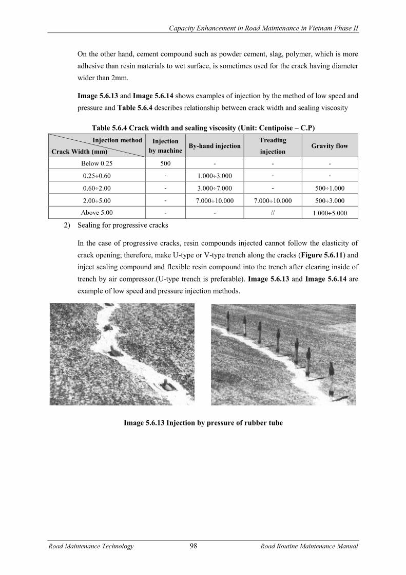
Capacity Enhancement in Road Maintenance in Vietnam Phase II
Road Maintenance Technology 98 Road Routine Maintenance Manual
On the other hand, cement compound such as powder cement, slag, polymer, which is more adhesive than resin materials to wet surface, is sometimes used for the crack having diameter wider than 2mm.
Image 5.6.13 and Image 5.6.14 shows examples of injection by the method of low speed and pressure and Table 5.6.4 describes relationship between crack width and sealing viscosity
Table 5.6.4 Crack width and sealing viscosity (Unit: Centipoise – C.P) Injection method
Crack Width (mm) Injection
by machine By-hand injection
Treading
injection Gravity flow
Below 0.25 500 - - -
0.250.60 - 1.0003.000 - -
0.602.00 - 3.0007.000 - 5001.000
2.005.00 - 7.00010.000 7.00010.000 5003.000
Above 5.00 - - // 1.0005.000
2) Sealing for progressive cracks
In the case of progressive cracks, resin compounds injected cannot follow the elasticity of crack opening; therefore, make U-type or V-type trench along the cracks (Figure 5.6.11) and inject sealing compound and flexible resin compound into the trench after clearing inside of trench by air compressor.(U-type trench is preferable). Image 5.6.13 and Image 5.6.14 are example of low speed and pressure injection methods.
Image 5.6.13 Injection by pressure of rubber tube

Capacity Enhancement in Road Maintenance in Vietnam Phase II
Road Maintenance Technology 99 Road Routine Maintenance Manual
Image 5.6.14 Injection by spring pressure
Figure 5.6.11 Trench type for progressive cracks
Image 5.6.15 Trench digger machine (Left: Underside of machine, Right: digging work)
If the crack is in shape of straight line, cut and widen the crack by cutter. If the crack is not in shape of straight line, use trench digger machine shown in Image 5.6.15.
5.6.3.3 Patching
Patching method shall be used to make road surface flat by filling materials or making a thin layer at the defect parts such as bump, roughness in longitudinal direction, revering, peeling, broken edge of joint or crack, pothole, crashing etc..
Materials for patching method consist of 3 types, which are cement, asphalt and resin.
Compound
Crack
U-type trench
Compound
Crack V-type trench

Capacity Enhancement in Road Maintenance in Vietnam Phase II
Road Maintenance Technology 100 Road Routine Maintenance Manual
Depending on the patching thickness, mortar or concrete could be used. Materials used to patch shall be determined based on failure scale, traffic condition, urgency, and economy. Main materials used for patching are listed on Table 5.6.5.
Table 5.6.5 Main materials used for patching Classification Main materials used for patching
Cement On-site or plant mixture Normal Portland cement
High early strength Portland cement
Super high early strength Portland cement
Super-fast hardening cement
Alumina cement
Packed cement on sale Normal Portland cement
Super-fast hardening cement
Maggie phosphate cement
Asphalt Plant mixture Hot mixed asphalt
Cold mixed asphalt
(Cut back asphalt)
Packed asphalt on sale Mixture type
Cold mixed asphalt
(Cut back asphalt, normal type, high strength type)
On-site mixture type
Cold mixed asphalt
(Cut back asphalt, normal type, asphalt emulsion type)
Resin On-site mixture Epoxy
MMA (methyl methacrylate)
Polyester
Polyurethane
Packed resin on sale Epoxy
Acrylic
Some attention points for execution are as follows.
i) It is required to keep good adherence between patching materials and ground concrete surface in order to increase durability of patching. Therefore, it is necessary to precede preparatory treatment such as clearing, removing failed part, sand and soil and then cleaning on the concrete ground.
ii) As for the condition on road surface, if cement is used to patch, it is required to ensure that the road surface is in saturated and dried on surface. If asphalt or resin is used, it is required to keep the road surface in dried condition.
iii) Treatment methods of concrete ground surface are as follow: - In the case of using cement or resin materials

Capacity Enhancement in Road Maintenance in Vietnam Phase II
Road Maintenance Technology 101 Road Routine Maintenance Manual
First, expose healthy surface of concrete body by treatment with compressed air, pressure water, chipping, and blasting (shot blast, sand blast).
Cement materials: When the surface is in saturated and surface-dry condition, scrape cement paste or mortar in thin layer on the surface and within wet condition of cement or mortar, inject mortar and cement which are made separately.
Resin materials: After confirmation of surface dry, coat primer which is suitable for resin materials to be used. The primer is used at 0.30.5kg/m2. However, its volume is changed depends on roughness situation on the ground, then check that primer is not concentrated only on counter portion.
- In the case of using asphalt material.
After clearing by compressed air, spread asphalt as tack coat.
i) At adjustment portion of patching, it is difficult to execute and then it is easily strippable after patching, Especially at using cement or resin case, in order to prevent zero adjustment, it is desirable to treat joint parts in the surroundings of existing slab and patching (Figure 5.6.12).
Figure 5.6.12 Treatment at adjusting portion iv) In the case that missing parts of joint edge is wider and deeper than 30mm, detailed
patching work should be selected in accordance with criterion shown in Table 5.6.6. In the Table, the relation between scale of joint edge damage and repair method is shown as a criterion. Examples of joint repair using cement concrete are displayed in Image 5.6.16.
Image 5.6.16 Examples of joint repair
Patching (cement, resin)
Joint
Concrete slab
Cut line
Parts to be removed

Capacity Enhancement in Road Maintenance in Vietnam Phase II
Road Maintenance Technology 102 Road Routine Maintenance Manual
(Left: After removing bad part, coat cements mortar and set the new joint, Right: cast concrete)
5.6.3.4 Surface Treatment
In the case of revering, polishing, peeling, or occurrence of hair cracks on the road surface, this treatment executes thin layer pavement on the slabs so that vehicle traveling, skid resistance, and water proof can be recovered. This method is generally implemented according to patching method.
The term “Thin layer pavement” is defined as follow:
“Thin layer pavement is one of the methods of surface treatment. Normally, it is the pavement with the thickness less than 2.5 cm using hot mixture and is used for the repair of cracks and recovery of skid resistance. Moreover, it includes bridge pavement with thickness of 0.3 – 2.0cm using rubber latex bituminous emulsion and epoxy resin and so forth”.
The point to be careful is that there are materials for concrete pavement and those for asphalt pavement in utilizing resin surface treatment work method.
Table 5.6.6 Relation between scale of joint edge damage and repair method Width of missing edge angel (mm)
Treatment Width (w) Height (h) Length (l)
Below 10 Below 15(10) Not related to length
No need if no defect of joint materials
If some defects, filling or replacing
Above 15(10) Supplement joint compound
Above 10
Below 30 (15)
Below 15(10)
Above 15(10)
Above 30(15) Both related to h Repairing missing angle
Values are for constriction joints. If expansion joint, use values in parenthesis.
Example for missing angle
• Notice: Though the missing angle is less than 30 (15) mm and joint width is added, it shall be
less than 40mm. Therefore, filling method is still effective for smooth traffic. Moreover, if the
Joint compound
Missing angle
Missing angle Joint

Capacity Enhancement in Road Maintenance in Vietnam Phase II
Road Maintenance Technology 103 Road Routine Maintenance Manual
width is more than 40mm, filling method is not effective, so it is required to use another material.
5.6.3.5 Partial Replacement
This is the method replacing parts including concrete slabs or road surface in the case that cracks which reach slab bottom generate in both vertical and horizontal directions or in the corner of intersection and then load transfer cannot be expected or blow-up and crashing of slabs are happen.
With respect to area to be replaced as a position, generally, area of less than 15m2 is considered to be acceptable.
Partial reconstruction by using hot asphalt mixture causes weak strength. After executing it, the road cannot bear great pressure from traffic. Therefore, it is easy to form roughness between concrete slab and reconstructed portion and then it is required to maintain periodically with the methods like patching.
As a result, partial reconstruction method by placing concrete is more effective method than asphalt.
1) Reconstruction near joint
Reconstruction work for the cracks in all directions generating in corner of intersection or at the positions within 3m from the joint shall be implemented as follows in order to integrate those all cracks:
i) Cut the surface of slab from outside of the cracks with a depth of about 2 3 cm by concrete cutters and remove crashed concrete while breaking it in small pieces with breaker, and then scrape sides so that the seam of old concrete is upright. In this action, it is necessary to pay attention not to scratch reinforcement like wire mesh, reinforcing steel, iron bars.
ii) Wire mesh and reinforcing steel are bent as in the Figure 5.6.14, but in case of difficulties in remaining all reinforcing materials, it is able to cut them leaving 20 to 30 cm. (In this case, it is necessary to install wire mesh at cast in concrete.)

Capacity Enhancement in Road Maintenance in Vietnam Phase II
Road Maintenance Technology 104 Road Routine Maintenance Manual
Figure 5.6.13 Example of reconstruction at corner of intersection
iii) In the case of deficiency (rust) of bars in existing slab’s joint; remove them, make holes with perforator, and install a new bar and fix by epoxy resin mortar etc. after clearing by compressed air inside holes. In the case of slip bar, paint asphalt to prevent adhesion of bars and concrete.
iv) Regarding the contact surfaces between newly casted concrete and existing concrete: - In case of shrinkage joint: apply bituminous materials and prevent adhesion of old and
new concrete. - In case of expansion joint: install joint filler. - In case of warping joint: clean construction joint of existing slab and cast new concrete
after the condition of saturated surface-dry. v) After concrete being harden, inject filling materials into joint trenches cut by cutting
machine. 2) Partial reconstruction near the center of concrete slab
Partial reconstruction for the cracks in the direction of both cross and vertical generated apart more than 3m from joints around center of slab is implemented as in the Figure 5.6.14 which is in the way that the defect part due to cracks is replaced with new constriction joint.
Moreover, for the concrete slab without wire meshing, it is easy to generate damage around repaired area even after partially replaced, so in this case it is common to replace an entire concrete slab. In the case of necessarily partial replacement, it is required to make a constriction joint like above to transmit loads.
Wire mesh, Reinforcing bar
Wire mesh

Capacity Enhancement in Road Maintenance in Vietnam Phase II
Road Maintenance Technology 105 Road Routine Maintenance Manual
i) At the width where slip bar can be set, cut about 2 3 cm from the surface on one side of crack and cut at full depth of slab on the other side.
ii) Remove concrete between both sides very carefully so that any reinforcement is not damaged.
iii) Make a hole by perforator on the full cut cross section after cutting entire sections by cutting machine, and fix slip bars by using Epoxy resin mortar. Then, paint asphalt on the slip bars and, after that cast new concrete.
iv) After the concrete being harden, inject filling materials into joint trench cut by cutting machine.
Figure 5.6.14 Partial reconstruction near center of concrete slab (example)
5.6.3.6 Injection method for holes filling between concrete slab and subgrade
Injection method is the method filling spaces generated between concrete slabs and ground surface, and pushing up concrete slabs by injection pressure to be back to its original position. This method is called under-sealing or sub-sealing.
(normally is about 1m)
Crack
Cut
Full cut Depth of
cut
More
than 3m Slip Bar
Steel mesh
Steel mesh
Apply asphalt
Fix by Epoxy resin mortar after
making a hole
Concrete casting
Inject joint compound
Adhesion prevention sheet or bituminous
materials
Joint Joint
More than length of slip bar

Capacity Enhancement in Road Maintenance in Vietnam Phase II
Road Maintenance Technology 106 Road Routine Maintenance Manual
Injection materials have two major categories such as asphalt type and cement type.
This method does not comparatively cost much and is highly effective in prolonging the service life of concrete.
1) Asphalt injection method
In this method, blown asphalt is injected into the space between the concrete slabs and subgrade. (Penetration 10 40) The survey results of injection of blown asphalt are described in Figure 5.6.15.
Figure 5.6.15 Deflection change between injection before and after
Process of asphalt injection method is as follows:
Relative density
Deflection
(After 2nd injection)
Relative density
Freq
uenc
y
Before injection
Freq
uenc
y
Deflection
(After 1st injection)
Relative
density
Deflection
Freq
uenc
y

Capacity Enhancement in Road Maintenance in Vietnam Phase II
Road Maintenance Technology 107 Road Routine Maintenance Manual
+ Make a hole with a diameter of about 50mm reaching to the bottom of concrete slab by perforator. The hole shall be normally made with ratio of 1 per about 2 8m2. However, it is required to consider factors such as the width of the concrete slab, settlement condition, cracked condition, machine capacity and nature of bituminous materials for deciding the rate.
+ After finishing to make a hole, clean the inside of the hole with compressed air to ensure no water in the hole, and then inject heated blown asphalt at more than 2100C under the concrete slab with presser of 2 4kgf/cm2.
+ The amount of asphalt usually injected is 2 6kg/m2 (if asphalt volume injected is more than this amount, running out in space below the concrete slab is considered. So stop to inject once and after cooling the asphalt, continue to do it.) 30 seconds after injection, plug a tube into the hole and just after pulling out the tubes, seal the hole by driving a pillar of wood, or cement grout column.
+ Normally about 30 minutes to 1 hour after injection, open to traffic can be possible. Moreover, while injecting blown asphalt, as high-temperature asphalt is used, it needs to pay attention to safety management for the injured by fire not only for those who execute, but also the surrounding environment.
2) Cement injection method
In cement injection method, cement grout is injected into the space between concrete slab and subgrade and as a result slab can be lifted up against settlement. This method is carried out with normal temperature.
When lifting up concrete slab, it is necessary to seal around scope of concrete slabs so that the mortar does not leak.
Process of cement injection method is relatively similar to the method of asphalt injection method, but mortar pump or spray machine shall be used with injection pressure of 3 5 kgf/cm2.
5.6.3.7 Skid Resistance Improvement Method - Grooving method
Grooving method is the method used to repair slip of the road, improve friction between road surface and wheel, minimize hydroplaning by grooving slot in shape as Figure 5.6.16 using split machine having diamond blade, and tungsten carbide.
Figure 5.6.16 Shape of grooving (unit: mm)

Capacity Enhancement in Road Maintenance in Vietnam Phase II
Road Maintenance Technology 108 Road Routine Maintenance Manual
Direction of safe slot: longitudinal slot (direction of traffic) and transverse slot (perpendicular with traffic direction)
Image 5.6.17 Grooving works Left: split machine; Right: road surface after grooving (cross line is junction)
Longitudinal slot would be effective for cross slip and transverse wind. But it is not possible to drain water cross the road and it is very difficult for two-wheel vehicles to drive safely. Transverse slot will be effective in shortening braking distance, improving traction of wheels and fitting slope, road section near traffic lights.
Image of grooving machine and status of the road after grooving is shown in Image 5.6.17.
As the method of improving road surface slip, there are other methods such as completing mechanically rough surface (such as machine shot blaster, grinder ...), or treating acid. When choosing those methods, it is required to consider generally factors such as construction capacity, economy, maintenance efficiency, noise during construction, and vehicle noise after construction, vehicle traffic ability, and so on.
The relation between vehicle speed and friction in every method is shown in Figure 5.6.17.
Figure 5.6.17 Relation between vehicle speed and friction
I. Shot blast
II. Medicine treatment
III. Cut soil
IV. Hi-pressure sandblast
V. Resin pavement
VI. Grooving

Capacity Enhancement in Road Maintenance in Vietnam Phase II
Road Maintenance Technology 109 Road Routine Maintenance Manual
5.6.3.8 Dowel Bars Replacement
In this method, concrete slabs with cracks are combined and stitched with reinforcing bars and then damaged slabs are reinforced. After injection method, implement sealing method and reduce spreading of cracks and then lead to extend life of concrete slabs.
Reinforcing method using deformed bars is described in Figure 5.6.18.
Figure 5.6.18 Example of reinforcing vertical sectional cracks
5.7 Unpaved Pavement Maintenance
5.7.1 Introduction of Unpaved Pavement
The unpaved pavement is usually composed of wearing course and base course. The thickness of wearing course is normally 10 cm. The thickness of base course will be determined after considering factors such as traffic amount, subgrade soil, the level of underground water, and base course materials. However in the case of using crusher-run and unscreened gravel, the thickness is about 30 50cm. In the case of using sand on the subgrade soil, the upper layer is crusher-run whose thickness is about 10 20cm and then the total thickness of the road bed will be about 40 60cm included subgrade.
In the wearing course, mixed materials of crushed stone, sand, and fine-grained soil are usually used. The required grading range for wearing course is shown in Table 5.7.1.
Materials used in the base course include crusher-run, unscreened gravel, slag and sand. If local materials can be obtained easily, it should be divided into two layers, upper layer and lower layer. In the upper layer, clean crusher-run and unscreened gravel which consist 50% of particle retaining on 2.5mm sieve and the content passing 0.074 mm sieve is less than 10% is used. The biggest particle size should not exceed 50mm and less than 1/3 of whole layer thickness. The lower layer normally consists of only local materials, such as sand and crusher-run which includes less than 10% particle in size of 0.074mm. The biggest size of grain shall not exceed 80mm, and the thickness is less than 1/3 poured layer.
In the anti-dust treatment, a thin layer of sand or breakstone shall be usually spread after the
Mortar
Concrete
thickness

Capacity Enhancement in Road Maintenance in Vietnam Phase II
Road Maintenance Technology 110 Road Routine Maintenance Manual
asphalt is spread on the gravel surface repaired. Asphalt materials used in anti-dust method including cut-back asphalt, slurry asphalt.
The surface treatment method is used asphalt layer less than 2.5cm thick, to prevent dust and prevent surface wear due to wheel load, prevent water from entering to the pavement structure. Asphalt material being used as surface treatment is slurry asphalt, cut-back asphalt, refined bitumen (penetration of 100/200). Example of the macadam pavement road is shown in Figure 5.7.1.
Table 5.7.1 Wearing course materials for crushed stone pavement Sieve size (mm) 20 10 5 2.5 1.2 0.4 0.15 0.074
Passing percentage (%) 80 100 5980 4263 3050 2038 1025 618 515
• Notes:
The content passing 0.4 mm sieve has PI from 4 to 9
The content passing 0.074 mm sieve has LL is around 2/3 of the one passing 0.4 mm
Figure 5.7.1 Structure of the unpaved pavement
5.7.2 Defects of Unpaved Pavement and Treatment Selection Recommendation
Unpaved pavement is the pavement with surfacing layer of unbound aggregate, such as graded crushed stone, macadam, natural gravel and soil. The defects of unpaved pavement, major causes of the defects, defects’ propagation and corresponding treatment solutions are presented in Table 5.7.2.
Old gravel
surface
Surfacing
layer
Anti-dust treatment
Macadam pavement
(b) Anti-dust treatment (c) Surface treatment
Old gravel pavement
surface
Old gravel pavement surface
Surface treatment
Base course
Surfacing
layer
Base course

Capacity Enhancement in Road Maintenance in Vietnam Phase II
Road Maintenance Technology 111 Road Routine Maintenance Manual
Table 5.7.2 Defects and repairing solutions of the unpaved pavements Or. Defects Main causes Treatment Solutions
1 Loss of shape - Failure in construction: inefficient compaction.
- Second compaction by traffic. - Erosion
- Grading / reshaping - Scarifying + Adding selected
material + grading + compacting.
2 Ruts, settlement, shoving
- Loading repetition + weak pavement (base/ sub-base)/ bad drainage.
- Grading / reshaping - Scarifying + Adding selected
material + grading + compacting 3 Soft spot / muddy
- Wrong pavement material + loading
repetition + rainy and poor drainage - Remove poor material + laying
new layer of selected material + grading + compacting
4 Potholes - Fine (poor) material of surface layer + traffic impulse action + rainy
- Pothole filling/ grading,...
5 Corrugations - Wrong pavement material + loading repetition + rainy & poor drainage
- Remove poor material/ laying new layer of selected material + grading + compacting
6 Erosion Gullies - Fine (poor) material of surface layer + high gradient + rainy
- Grading / reshaping
5.7.3 Defects Treatment Technology for Unpaved Pavement
When potholes, corrugations, and depressions,… appear on the unpaved pavement surface, they will develop fast due to wheel loading impacts such as heavy repeated loads, impulse and vibration, so it is required to supplement materials and repair them quickly. Moreover, because the road is not thick and consists of unbound materials, in case of heavy load combined with the incomplete drainage system, and rain storms, the failures are more serious and impact to road bed.
5.7.3.1 Grading unpaved pavement
1) Introduction
Grading is needed to restore a good camber of the road to enable water to drain off quickly. On unpaved roads, grading is needed to restore gravel from the shoulders which has been lost from the road surface, to fill pot-holes and corrugations.
A road with a flat surface will collect water. Traffic and water together will quickly cause potholes and rough spots. So, the object of grading is to restore the camber by returning material from the sides and shoulders towards the center of the road. This will enable water to drain off easily.
Rollers should be used to compact the road after grading whenever possible as this will improve the initial quality of the reshaped surface.
Work is best scheduled to follow a period of rain, as the moisture in the material will greatly help compaction by rollers or traffic. For some materials the addition of water can be justified.
Grading can also be used to restore the shape of shoulders, ditches and turnouts.

Capacity Enhancement in Road Maintenance in Vietnam Phase II
Road Maintenance Technology 112 Road Routine Maintenance Manual
In summary, grading is used to correct loss of shape, ruts, potholes, corrugations, erosion gullies, silted or blocked ditches. It is a fast moving activity often carried out at long distances from the equipment base. Although it may be carried out by individual graders or towed graders, it is best organized using mobile units of 2-3 grading machines with arrangements for temporary overnight accommodation.
The number and types of grading machines, rollers, watering equipment, and mobile accommodation depend on the road condition (which needs light or heavy grading), moisture conditions, compaction requirements, organizational requirements, accommodation arrangements, and resources available.
2) Grading the running surface a) Preparation + Patching of large potholes or depressions should be carried out in advance of the grading. + Areas of standing water should be drained. b) Scarifying
It may be necessary to scarify the existing surface to cut to the bottom of any surface defects and loosen the material for reshaping.
Where the gradation of the wearing course material becomes poor, it is required to supplement raw materials to ensure the thickness of the surface, compaction level and to create uniform structures.
The raw materials to supplement are dependent on condition of existing pavement with the particle size missing or well-graded materials. Single-size aggregate and large size particle materials should not be used because they prevent surface stability and serviceability of the road.
The amount of additional materials can be usually determined based on relationships with the traffic, working frequency of grader, but it must be sufficient to prevent road surface subsidence. The amount of additional materials and the relationship with the traffic will be stated in the Table 5.7.3.
Additional materials are spread during scarifying process for uniform gradation.
Table 5.7.3 The amount of additional materials for the wearing course and working frequency of the grader
Traffic (vehicle/day) Additional material (m3/km/year) Working frequency of the grader (time/month)
100 300 20 60 1
300 500 60 100 2

Capacity Enhancement in Road Maintenance in Vietnam Phase II
Road Maintenance Technology 113 Road Routine Maintenance Manual
c) Grading + The grader works on one side of the road at a time and works in passes about 200 metres
long to convenient and safe turning points. + Light grading will normally require 4 passes to reshape the road. Heavy grading will
require additional passes to achieve the required camber. Work should be completed on one side of the road at a time. An even number of passes should be used to avoid a flat finished crown
+ Normally initial cutting passes are required to bring material in from the edges of the road. Spreading passes redistribute the material away from the crown. The cutting and leveling procedure is implemented from the shoulder, then moving to the center of the road. The appropriate operation speed during cutting is 3 6 km / h, during leveling is 4 10 km / h.
+ It is required to re-grade as the water content wearing course materials is about optimum moisture contents depend surface materials, sometimes reach to 15 to 20%. In case of small water rate, it is required to use water sprayer to increase moisture content to required rate.
+ In the case of additional material spreading, it is required to implement based on the width of blade and angle of the blade and also material amount. The flat spreading is implemented to avoid the materials coming out and the material is distributed regularly.
+ Machine attendants are needed to help direct traffic and grader turning, and remove large stones and other unwanted material from the path of the grader.
+ The road should be cambered to fall away from the crown at a rate of about 6 to 7 cm for each metre from the centre of the road before compaction. This should achieve a crossfall of about 4 to 6 cm per metre (4 to 6%) after compaction.
+ If there is insufficient camber, water will not drain easily from the surface of the road, potholes will form and the road will deteriorate quickly. This is particularly important on gradients, where the rain water tends to run along the road forming erosion channels.
+ Do not make a final pass down the centre of the road with the grader blade horizontal. This flattens the centre of the road and causes water to pond leading to rapid deterioration of the surface.
d) Compaction + When compaction plant is being used, it must follow close up behind the grader, but only
on sections where grading has been completed. About eight passes of a roller will be needed to achieve full compaction, working towards the centre of the road.
+ Shoulders are treated as part of the running surface. + When grading pavement at junctions and bends, graders must not stop near junctions or
bends where they will be a danger to traffic. 3) Check the camber
+ Camber should be checked about 100 metre intervals along the road using camber board. Place the camber board on its edge across the road with the shorter end pointing towards the centre line.

Capacity Enhancement in Road Maintenance in Vietnam Phase II
Road Maintenance Technology 114 Road Routine Maintenance Manual
+ Check the level bubble. If it is central, the camber is correct. If it is not central, the camber is either too steep or too flat and further grading and compaction are required.
+ On bends, the surface must be straight (at 4-6%) from shoulder to shoulder with the outer shoulder higher. This is called superelevation. Any crown on a bend can be very dangerous to traffic. The superelevation must be retained for the complete length of the bend.
+ On the transition curves at each end of the bend into the straight sections, the superelevation should be gradually reduced until the normal cross section shape with 5% camber is obtained again.
• Notes:
+ The shape of the road must be maintained over culverts to avoid a hump. Material should be brought in if necessary from either side of the culvert to maintain a cover to the top of the culvert of at least ¾ diameter of culvert.
+ Bridge decks should be kept free from gravel. Loose material should be swept away by the attendants.
+ It is important to have smooth approaches to the bridge. They should be smoothed out using the back of the blade with the grader working in reverse, or by hand.
+ For most grading work, the cutting blade is set to be vertical. + For cutting hard surfaces, the cutting blade should be set back at the top to give the most
effective cutting angle, means the angle of grader blade is about 30 45 degrees for forward direction.
+ For soft surface the standard angle is about 40 55 degrees + To move or mix material: Travel forwards slowly in low gear. Pick up material from one
side of the machine and pass it to the other. + It should try to match the gear and speed to the work to be done.
5.7.3.2 Labor based reshaping
1) Introduction
The road camber can also be restored by labor. This is a viable option when grading equipment is too expensive or not available.
The object of reshaping pavement is the same with regarding to restore the camber by returning material from the road sides and shoulders towards the centre of the road and to drain water off easily.
As well as regarding, reshaping unpaved pavement by labor also is used to correct loss of shape, ruts, potholes, corrugations, erosion gullies, silted or blocked side ditches, but normally with small quantity.

Capacity Enhancement in Road Maintenance in Vietnam Phase II
Road Maintenance Technology 115 Road Routine Maintenance Manual
2) Execution of the work
The attendant or length-man trims the surfacing material with the pickaxe, hoe or mattock and rakes it to form the required camber and crossfall. The shape is checked with the camber board and spirit level.
If gravel stockpiles are provided, any local depressions are filled with material transported in the wheelbarrow. Then, the loose material is compacted with the hand rammer.
Major reshaping may be carried out on low traffic volume roads which are still open to vehicles. However it is preferable to close the road and divert traffic, at least during working hours.
For major reshaping of high traffic volume roads, the road should be closed and diversions provided during working hours.
The implementation procedure comprises four steps: setting out; excavation of ditch; excavation of backslope; camber formation and final compaction.
a) Setting out
The profile method of setting out enables a smooth vertical alignment to be re-established on a severely deteriorated road surface. The alignment will consist of straight gradients and vertical curves.
+ The centre line of the road is pegged every 10 metres. A ranging rod is fixed at each 10 metre peg. Each ranging rod is fitted with a profile board. The profile board can slide up and down the ranging rod and be clamped at any height.
+ Setting out is arranged in sections of 60 to 100 metres, which approximate to either straight gradients or vertical curves.
+ Check that the amount of earthworks at each centre line (finished level) peg is acceptable, or repeat the procedure using different assumptions.
+ When the centre line level pegs are fixed, set out the pegs at the edge of the roadway using the tape measure, camber board and spirit level for the required road cross section.
+ Pegs should be driven in to the required finished cross section level, or a fixed height above. b) Excavate ditch and slope + Material is excavated from the ditch and slope area and used to form the camber until the
required shape of ditch and slope is achieved. + Check shape with the ditch and slope template, and spirit level. + If too much material is excavated discard the surplus material well beyond the side drain. + If the filling placed is greater than 15 cm deep, then it is preferable to spread and compact
the fill material with rakes and hand rammers or a hand/animal drawn roller in 15-20 cm layers.
c) Excavate backslope

Capacity Enhancement in Road Maintenance in Vietnam Phase II
Road Maintenance Technology 116 Road Routine Maintenance Manual
If insufficient material is excavated to form the camber, dig additional material from the backslope or from beyond the side drain.
d) Camber formation and final compaction
Continue adding material to the camber to achieve the required profile after compaction.
String lines stretched directly and diagonally across the running surface between the setting out pegs can be used to check the shape.
Compact the fill material to the final profile, preferably using a hand or animal drawn roller.
5.7.3.3 Patching
1) Introduction + Holes in the road may need to be patched. Patching is sometimes required between grading
or reshaping operations, or before grading when the potholes or depressions are large. Patching may either be used to repair worn or eroded areas or can be used to restore areas which become soft when wet. This maintenance activity consists of replacing or adding new gravel surfacing material over relatively small areas.
+ Patching is used to correct potholes, ruts, soft spots, erosion gullies. It is not a satisfactory method of repairing corrugations. Where there are large numbers of potholes, the section will need scarifying with a self propelled grader and possibly regarvelling. Patching may be used instead of grading on selfcementing gravels or gravels with large lumps.
+ Patching can be carried out by a mobile gang or by labor based road attendants. 2) Mechanized method
a) Materials + Gravel for patching should be stockpiled at the quarry or maintenance camp, or dumped at
the side of the road near where it will be used (so that it does not block the road or drainage system).
+ The gravel must be at least as good a quality as the material already surfacing the road, and meet relevant materials specifications.
+ Water must be carried from the depot if it is not obtainable near the site. In either case, a container will be needed.
b) Execution of the work + The material is off-loaded manually or tipped onto the shoulder adjacent to where the
patching is required. Material must never be dumped onto the road. + Loose material and standing water is brushed from the pothole or rut to be patched. Large
or deep potholes should have their sides cut back to be vertical and to reach sound material. + The moisture content of the material can be checked quickly by squeezing it in the hand. If
the material is wet enough to stick together, it is suitable for use. If water runs out of the material, it is too wet and should not be used. If the material is dry, the area to be patched should be sprinkled with water and water should also be added to the patching material.

Capacity Enhancement in Road Maintenance in Vietnam Phase II
Road Maintenance Technology 117 Road Routine Maintenance Manual
+ The area is filled with gravel to a depth of about 10cm + The layer is then compacted using the roller or hand rammer. In this way the thickness of
the patch is built up in layers. Finally, the patched area is filled evenly with the gravel to approximately 3cm above the level of the surface and is spread and raked to the correct shape.
+ The patch is then compacted using the roller or hand yammer to give a surface which is slightly above the level of the surrounding road.
+ Both large or small areas to be patched are repaired in the same way, the yammer is used for the smaller potholes. The roller is used for larger areas although the hand yammers will still be required for the corners and short edges.
+ Patching work started must not be left unfinished overnight. At night the site should be made safe for traffic and all signs and obstacles removed from the road.
+ Ensure that the site is left clean and tidy with no stockpiles of material left on the road. 3) Labor based method
On low traffic volume roads (less than about 50 vpd) it is often appropriate for patching to be carried out by these labour based methods.
a) Materials
Gravel for patching should be obtained from the quarry by truck or tractor and trailer. This is most efficiently done when major regravelling works are being carried out in the area of the road.
The gravel should be stockpiled at convenient locations for the attendant to use on his section of road. The stockpiles must not obstruct the road, the shoulder or the drainage system.
Where there is no space in the road reserve the stockpile should be placed downhill of a turnout drain to avoid blocking the drainage system.
If possible a one truck or trailer load stockpile should be left every 100 to 200 metres along the road.
b) Execution of work
The attendant should use the wheelbarrow to transport the gravel material from the stockpiles to the patching site.
The patching should be carried out as shown for the mobile gang.
5.7.3.4 Regravelling
1) Introduction
The surfacing material of unpaved roads is worn away by traffic, eroded by rain and blown away as dust. As the surface of a gravel road wears away, new gravel must be added before

Capacity Enhancement in Road Maintenance in Vietnam Phase II
Road Maintenance Technology 118 Road Routine Maintenance Manual
rapid deterioration of the surface starts. Before all the gravel surfacing has worn away the road requires re-gravelling. Re-gravelling may also be needed to correct other defects when these become severe, and may also be used to improve an engineered earth road to a gravel road.
Re-gravelling is normally a periodic maintenance task. It is important that the re-gravelling work has been done well in advance so that work is carried out before serious defects appear.
Before re-gravelling is carried out, it is important to make any necessary repairs or improvements to the camber and drainage system of the road. If this is not done, the new gravel surface will deteriorate very quickly.
Re-gravelling is normally carried out with one layer 15 cm thickness. Usually a continuous layer of gravel is laid on the existing running surface, however on some occasions only short stretches showing severe defects are covered under a spot re-gravelling operation.
Re-gravelling is used to correct loss of surfacing material. It is needed before the subgrade is exposed on the road surface. This will be seen particularly in ruts and depressions. Re-gravelling is also used to correct loss of shape, ruts, potholes, erosion gullies when they are severe.
2) Mechanized re-gravelling a) Materials + Gravel obtained from a quarry or gravel pit must be of a quality that meets the relevant
specifications and also be approved by the Engineer. + A source of water will be needed as near as possible to the site. b) Site preparation
Wherever possible, before the re-gravelling work starts, the grader should open a diversion adjacent to the road. If traffic is diverted from the work site, it will enable the job to be carried out more efficiently and safely.
Before the re-gravelling work starts, gravel should be stockpiled at the quarry or borrow pit. It may also be helpful to start hauling the material to site. Plan the quarry excavations and stockpiles so that:
+ The quarry can be fully exploited with removal of the maximum amount of gravel, + The overburden is stockpiled so that it will not hinder future extension, and that it can be
used to reinstate the quarry, + The best material is taken, where gravel quality is variable within the quarry, + Material is stockpiled to minimize segregation, environmental damage by poor drainage
and erosion during and after exploitation of the quarry.
The quarry layout should:
+ Permit efficient excavation and stockpiling of gravel,

Capacity Enhancement in Road Maintenance in Vietnam Phase II
Road Maintenance Technology 119 Road Routine Maintenance Manual
+ Allow the trucks to enter and leave without obstructions.
The quarry access road should be repaired, if necessary, to ensure safe passage of trucks.
c) Execution of the work + The road surface must be graded-off to provide a firm regular surface on which to work
and the edges should be "boxed" to provide support for the new gravel. + The camber should be checked with a camber board and the road level should fall 4 to 6
cm for each one metre width of road (4-6 %). + The drainage system should be checked and repaired if necessary otherwise the
performance of the gravel surface will be affected. + Material should be dumped on one side of the road only. Loads should be placed at the
correct spacing to give the required thickness of gravel over the complete road width. If the road is not closed, material should be dumped on the shoulder.
+ The tankers should have filled up with water using the pump and then have driven to the site.
+ Spreading of the gravel can start when there is a working length of at least 200 metres of dumped material. The material is spread right across the road using the grader.
+ The material is watered with the tanker until its moisture content is correct for compaction. The amount of water to be added must be determined by moisture content tests on site.
+ The new material is graded to produce a camber" of 4 to 6 cm for each one metre width of road (4 to 6 %). The camber should be checked with the camber board at approximately 100 metre intervals along the road. For checking camber, the camber board is placed on its edge across the road with the shorter end pointing towards the centre line. Check the level bubble, if it is central, the camber is correct. If it is not central, the camber is either too steep or flat and further grading and compaction are required. If the camber does not fall 4 to 6 cm for each one metre width of straight road, the grading must be repeated.
+ When the correct camber has been achieved, rolling can start. Water should not be added during rolling as the material may stick to the wheels or drums. Rolling should start at the edge of the road and work towards the middle. The roller should aim to progress from section to section at the same rate as the grader. About eight passes of the roller will be needed to achieve full compaction.
d) Completion of work
The work proceeds along the road in sections. As each section is completed, the traffic signs, cones and barriers are moved along the road. This opens the road at the completed end for traffic, and closes it at the other end to allow new gravel to be dumped.
Ensure that the site is left clean and tidy with no stockpiles of material left on the road.
3) Labor re-gravelling
This option avoids the need for heavy equipment. Tractor haulage of gravel can be economical

Capacity Enhancement in Road Maintenance in Vietnam Phase II
Road Maintenance Technology 120 Road Routine Maintenance Manual
for distances up to about 10 km with labor used to excavate, load, unload and spread the gravel.
a) Site preparation
The site for re-gravelling to be done by labor is prepared the same as in mechanized method. (Part 1)
b) Execution of the work
Gravel stockpiling
+ Gravel should be excavated and stockpiled at least one day before it is required to be hauled. + Gravel should be excavated and stockpiled alongside to allow easy loading and avoid
multiple handling. + Where possible excavate bays, using gang tasks, so that trailers can be backed in for loading. + Ramps into loading bays must not be too steep for tractors hauling loaded trailers. + In hillside quarries, excavate material to ease loading and ensure safety of workmen.
• Hauling
Gravelling should commence from where the quarry access joins the road to be regravelled.
Initially the road should be gravelled away from the quarry access in both directions simultaneously. With short hauls this will reduce congestion at the unloading sites.
When hauls exceed about 1 km, gravelling should continue only in one direction at a time.
The advantages are:
+ The tractors and trailers compact the material as they haul over the already laid gravel, damage to existing road camber is minimised,
+ Gravelling traffic does not interfere with reshaping activities, gravelling can recommence sooner after rainfall.
• Offloading and spreading
It is important to off load the trailers as quickly as possible.
The material from one trailer is unloaded and spread within a "box" marked out by pegs and string/sisal twine.
Any gravel lumps or stones larger than 5 cm should be removed.
• Compacting
If necessary, the gravel layer should be watered using the towed water bowser before compaction.

Capacity Enhancement in Road Maintenance in Vietnam Phase II
Road Maintenance Technology 121 Road Routine Maintenance Manual
Compaction is carried out with a hand operated vibrating roller.
5.7.3.5 Anti-dust treatment
Anti-dust treatment is the requisite minimum method. It is often constructed as temporary method. This method mainly uses bituminous materials, however, depend on case, it may also use chloride material.
1) Anti-dust treatment by bitumen
Asphalt materials used are some kinds of slurry asphalt, cutback asphalt.
Construction method includes mixing method and spreading method. Mixing method is implemented by in-place mixing method. However, this method needs skilled operator, so in general spreading method is usually used.
Anti-dust treatment by distributed manner is to use slurry asphalt implemented as follows:
+ In the case of warping on the road, it is required to level by the motorized grader. If there are weak points, it is required to cut and replace with better subbase course materials.
+ After completion of repair the road surface, it is required to transmit pressure by the roller, making the road surface harder. If necessary, conduct water sprincling.
Spread slurry asphalt for the first time by machine with the rate of about 1.2 1.6 l/m2. Then spread crusher-run S-5 (No. 7) (should have aggregate size) with rate of 0.5m3/100m2, and then compacting several times by the roller. In the case of opening road after the first spread, it is necessary to spread sand with rate around 0.4m3/100m2. After waiting resolution of slurry asphalt and then open to the traffic.
The second time shall be at 1.1 1.5l/m2, then spreading sand around 0.4m3/100m2, then compacting several times by the roller. After required setting time of slurry asphalt, the traffic can be opened.
In the case of using cutback asphalt, anti-dust treatment shall also be performed as a special case of slurry asphalt. After anti-dust treatment, if detect pot holes, or other defects, they are required to treat properly such as pothole filling and sealing.
2) Anti-dust treatment by chloride
Chloride includes calcium chloride, magnesium chloride. Construction process includes mixing and spreading. The example of using chloride content is given in Table 5.7.4.
Solid or liquid chloride is sprayed gradually on pavement. If solid chlorite is used, pavement surface should be wetted by watering for about 10%, then spread chlorite. The chlorite is mixed with surfacing materials by stabilizer, then leveling by grader and compacting by roller. If the dust still appears, it is required to spread additional cover. The chlorite when being used, especially during rain, may damage to agricultural products as its demerit.

Capacity Enhancement in Road Maintenance in Vietnam Phase II
Road Maintenance Technology 122 Road Routine Maintenance Manual
Table 5.7.4 Recommended chloride content Chloride content
Construction method Types of chloride Used content Additional content
Mixing method Solid Chloride 0.50.8kg/m2 Liquid chloride 3.6 liter/m2
(1kg/liter of water)
Spreading method Solid Chloride 0.4kg/m2 Supplementary spreading 0.25kg/m2
Liquid chloride 2.5 liter/m2 (1kg/liter of water)
Supplementary spreading 1.2l/m2
3) Anti-dust treatment by waste pulp
Construction methods include mixing and spreading. With respect to the spreading method, after spraying for the first time, the second time will be continued after the solution is completely absorbed. If the road must be opened as soon as spreading is completed, sand or crusher-run (size of 5 2.5mm) should be spread. Moreover, waste water smells badly, it can cause damage to agricultural products. This disadvantage is easy to lose the method effectiveness.
5.7.3.6 Surface Treatment
Unpaved pavement can be treated using asphalt products, becoming asphalt treated bitumen. Normally, surface treatment includes 3 methods as follows:
+ Bitumen sealing which is the treatment to create thin asphalt layer by bitumen spraying then covered by chippings after the asphalt material absorbed into the existing pavement.
+ Surface leveling, subject to the case refill asphalt after adding crushed stone, then mix on the road to create a asphalt layer.
+ Surface treatment method by penetration macadam. It consists of spread crushed stone on the road surface, then spraying bitumen to penetrate deeply into the crushed stone.
In these methods, the second is the same bituminous stabilization method and the last is same as the armor coat method.
Surface treatment according to the first method depends on surface condition, and can be different in the construction method. There are following types:
+ Fine soil road surface with more mud and clay + The walkway (pedestrian path) made of crushed gravel, crusher-run
• Fine soil road surface treatment
The treatment procedure for fine soil road surface is as follows:
+ Using grader to cut and create uniform soil composition. If the soil composition is poor, it should be replaced by good quality materials.
+ The asphalt layer to be applied consists bitumen spraying and chipping covering. The number of spreading times shall be referred to the bitumen sealing (single, double or triple)

Capacity Enhancement in Road Maintenance in Vietnam Phase II
Road Maintenance Technology 123 Road Routine Maintenance Manual
• Rough surface treatment
Rough surface treatment can be performed like surface treatment. But it is required to pay attention to preparation and cutting-leveling by the grader with the 3 cm depth to have uniform particle gradation.
The road treated by the above methods can have 1 year life. I is required to be treated again at appropriate intervals. The amount of spreading material for one time of treatment is stated in the Table 5.7.5.
Table 5.7.5 The amount of spreading material for a treatment
Type of asphalt Specification
Slurry asphalt Cut back asphalt Refined asphalt (100200 Pen.)
Asphalt material 1.11.8 l/m2 1.11.6 l/m2 1.11.8 l/m2 Gravel and crushed tone 11kg/m2
(520mm) 1320kg/m2 (520mm)
1627kg/m2 (2030mm)
5.7.4 Bitumen Treatment on Unbound Aggregate Existing Pavement
Treatment of asphalt road surface is implemented for low traffic roads, and is the most economically efficient method. To use this method, it is required to inspect the heavy vehicles, thickness of the current macadam surface, soil quality at the roadbed, and then decide the structure basing on standard thickness stated in the Table 5.7.8. The basic structure makes use of the existing macadam surface, but in case that resistance of the surface stone is not good, it is required to use 3cm thick surface layer. The regular structure is shown in Figure 5.7.2.
Figure 5.7.2 Treatment of asphalt surface
5.7.4.1 Road conditions for this method application
After considering the characteristics of the construction method, the road condition shall be treated by this method as follows:
i) The amount of traffic is small, particularly heavy vehicles ii) A type of road with the width for the car less than 4m (total width is 5m) iii) This road can be constructed in the form of overlay iv) After putting into service, it can be maintained and managed properly
Surface layer
Foundation New strengthen surface layer
(Current macadam surface) (Current macadam layer)

Capacity Enhancement in Road Maintenance in Vietnam Phase II
Road Maintenance Technology 124 Road Routine Maintenance Manual
• Note 1 - Traffic is less than 300 vehicles per day, in which large vehicles are less than 60
vehicles per day
• Note 2 - When use of this method, it should avoid the following issues:
i) In case of development plan in the near future, there is a possiblity to expand volume of traffic
v) In the case of the place near residential area and then it is difficult to excavate in the future.
vi) As visual observation, there are places where the deflection is very large, and the subgrade soil is very poor.
5.7.4.2 Investigation
It is required to investigate traffic volume of heavy vehicles, thickness of the current macadam, soil of the subgrade, value for each parameter, collect and implement synthesis evaluation.
a) Investigation contents
The investigation contents are stated in the Table 5.7.6, including the value of each parameter.
b) General evaluation and treatment thickness
Road evaluation is implemented by assembling statistical evaluation scores for each content of Table 5.7.6, making the overall evaluation and based on that score to classify according to Table 5.7.6, treatment thickness then is determined.
5.7.4.3 Determine the layer structure and thickness
The layer structure is determined based on technical and economic consideration. The layer thickness should be feasible feature and have and efficient capacity to stand traffic loading in design life. The thickness of the layers includes macadam material and surface layer with following criteria:
+ Surface layer can be full penetration macadam, cold mix or hot mix in 3cm thick. + Strengthen (can be called roadbase) thickness of asphalt treatment in 5 10cm thickness
Table 5.7.6 Evaluation basing on investigated criteria Items Classification Contents
Heavy vehicle volume in two-way/day
Classification Under 10 vehicles
From 10 - 40 vehicles
More than 40 vehicles
Evaluation score +3 0 -3 Thickness of current macadam
Classification > 25 cm 10-25cm Under 10cm Evaluation score +2 0 -2
Subgrade soil character Classification Sand Clay small Silt water
content
Clay large Silt water
content Evaluation score +1 0 -1

Capacity Enhancement in Road Maintenance in Vietnam Phase II
Road Maintenance Technology 125 Road Routine Maintenance Manual
• Note 1 - Investigation of large vehicles on the road is calculated on all day, but in some
required cases, a few hours in normal day will be taken. Large vehicles include heavy trucks, large bus, special large vehicles. The traffic includes in both directions.
• Note 2 - Macadam thickness is the smallest thick aggregate layer defined by actual
measurement on test pit digging by axe or shovel in interval 100 meters distance. But the bad layers contain much sticky mud; the coarse material less than 50% shall not be considered thick layer of macadam.
Good or bad aggregate should be judged by dividing by the actual screening, screening rates of 2.5mm reaching 50% is not considered a layer of macadam.
• Note 3 - Subgrade is divided into two types of the sandy soil and clay soil or silt as Table 5.7.7.
In addition, depending on absorption, the clay soil and silt are divided into two small types.
Absorption status of subgrade is closely related to climate, so survey should not implement just after raining.
Table 5.7.7 Characteristics of subgrade soil Evaluation Classification Absorption status
Good Sandy soil Main compound of soil is small grains not be seen by emmetropic eyes in good water drainage and easy to fall including granite sand, volcano sand, mountain sand, etc.
Normal Silt soil and clay soil
Little sand, much clay percentage, held by hand tightly might change shape.
Little water content In case that it is easy to drain because it is low underground water
Bad Much water content In case that the underground water level is high
Table 5.7.8 General assessment and thickness treatment
General assessment point Group 1 Group 2 Group 3 +6 +3 +2 -2 -3 -6
Surface thickness treated on existing macadam road
Adjustment of surface and roughness only
(under 5)
6 15 (under 10)
16 25 (under 20)
• Note:
+ The indexes in the pretenses are the thickness of the current macadam road in case of additional material added to existing macadam road by stable machine, and treat stability partially or completely.
+ Crusher-run (crushed stone): 5 25 ’’ + Adjusted-grain crusher-run: 5 12’’

Capacity Enhancement in Road Maintenance in Vietnam Phase II
Road Maintenance Technology 126 Road Routine Maintenance Manual
+ Cement or lime soil stabilization: 10 12’’ + In case of using mixing method or penetrating method to create subgrade, it is possible to
be compatible with the surface layer. Moreover, it is possible to use sealing method or armor coating method on bituminous stabilization treatment surface.
5.7.4.4 Example of standard design
Standard design is classified into groups as Figure 5.7.3.
a) Road bed (Subgrade)
The principle of this method is to take advantage of existing macadam efficiently as road base and replace position of the surface layer over this base layer. In fact, in the cases after general assessment of existing macadam layer that will become road base, then it is implemented to finish by adjusting the uneven ground with crusher-run with the thickness of about 3 cm.
b) Surface layer
Surface layer shall be generally constructed by penetrating method, cold mixing and hot mixing method. When selecting a method of implementation, it is required to consider the size of the project, construction site, scope, meteorological conditions, the period of construction and materials used to make the surface layer have economy.

Capacity Enhancement in Road Maintenance in Vietnam Phase II
Road Maintenance Technology 127 Road Routine Maintenance Manual
Figure 5.7.3 Two group of standard design of bitumen treatment on existing macadam pavement
3. Group 2 (-3~-6)
Bitumen Sealing
7cm field-mixing
asphalt
10cm thick crusher-
run or adjusted-
grading crusher-run
Existing
macadam road
Double bitumen sealing
8cm field-mixing
asphalt
Existing macadam
road
10 cm cement or
lime treated Existing
macadam road
7cm additional materials
12 cm cement or lime
treated
2.5 – 3 cm thick
penetration macadam/ hot
mix or cold mix
Existing macadam
road
Additional materials 10 cm
Existing
macadam road
Leveling
3 cm thick crasher-run
Penetration macadam or
asphalt mix 2.5cm
Double Bitumen Sealing
Existing macadam
road
5cm field-mixing asphalt
Note: This example is not used
for general assessment +5, +6
1. Group 1 (+6~+3)
Triple bitumen sealing
Existing
Leveling
3cm thick crusher-run
Note: This example is not used for
general assessment +3.
2. Group 3(+2~--2)
Existing macadam
road
10 cm thick crusher-
run or adjusted-grading
crusher-run
2.5~3cm penetration
macadam/ hot mix or
cold mix

Capacity Enhancement in Road Maintenance in Vietnam Phase II
Road Maintenance Technology 128 Road Routine Maintenance Manual
5.8 Road Cleaning
5.8.1 Introduction
Road cleaning work aims at maintaining the function of the road, ensuring the aesthetics of the road and protecting the roadside environment.
The pavement cleaning work can include:
i) Cleaning the surface of highways, pedestrian ways, pedestrian bridge, median strip area on the road
ii) Cleaning the waste water system iii) Cleaning the tunnels iv) Cleaning auxiliary equipment of the street such as other bridge expansion devices,
lighting system, barriers, road signs, direction signs...
The frequency of road cleaning like this depends on the condition of the road, traffic and environmental conditions. In addition, with each cleaning methods, the productivity is also different. For example, in the cases that the traffic is limited, it is the best to carry out all cleaning works at the same time. If there is a concern that road sanitation may affect or contaminate the road surface, it is necessary to develop a master sanitation plan, for example, we can choose to clean the roadside just before cleaning the road surface.
It is also necessary to pay attention to safety measures when performing road cleaning to ensure the safety for the cleaner at the same time handle the traffic. The time for cleaning must be determined basing on the actual condition in each area. For example, in the downtown or in the street of big traffic volume or in the area having difficulties for cleaning in daytime, it is necessary to conduct quick cleaning or clean at night.
Furthermore, when carrying out the cleaning, it is not recommended to leave the soil and sand at roadsides in a long time but quickly clean up.
5.8.2 Road Surface Cleaning
5.8.2.1 Implementation and execution plan
Pavement surface should be clear from trees, debris,… by labor or by sweeping machine. Depending on actual cleanness of pavement and the requirement of specific urban region, this type of work can be carried daily or normally around 12 times per week.
Cleaning of the road surface varies depending on the situation of the street and of both roadsides. Therefore, it is necessary to investigate and analyze the structure of the road, the auxiliary equipment of the road, special used buildings, the actual condition of cleaning area which can be based on to develop the plan for cleaning.
The points need to be considered when develop the plan for cleaning

Capacity Enhancement in Road Maintenance in Vietnam Phase II
Road Maintenance Technology 129 Road Routine Maintenance Manual
1) Determine the operating environment and the space for road cleaning. + When developing the plan for cleaning, it is necessary to pay attention to traffic safety so
that a plan for cleaning in good condition can be developed. + The cleaning work must not affect traffic and houses on roadsides. + When reviewing the implementation method and traffic conditions, road conditions, safety
of the cleaner and the necessity of the cleaning, it may require to place the sign posts, barricade,…
+ When establishing the cleaning area, it is necessary to investigate the cleaning distance, cleaning time, the time required to complete the cleaning, the number of clean, the place to be clean, place of disposing to develop and determine the cleaning schedule both effectively and economically.
2) Set up cleaning teams
The road cleaning is conducted primarily by machines, people only do auxiliary operations. However, the two key teams of road cleaning including machine-based cleaning team and human-supported cleaning team.
Machine-based cleaning team is established including:
+ The foreman, supervisor + The driver of cleaning machine (including those with combination between machine and
driver) + Worker who clean up material refuse and/or soil.
The human team is to support the cleaning works which a machine can not do, such as the collection of huge rubbish
3) Operation capacity
Cleaning distance in a day may vary depending on the quality of machine, road conditions, amount of rubbish, cleaning clearance, time of cleaning. However, normal cleaning distance is from 20 to 40 km. In big cities where the traffic condition is not good, this standard may be less or more than 20km.
Cleaning capacity is determined by the features of the cleaning machine. The relationship between the standard operating speed and the operating capacity depends on the cleaning condition. However, the time required for the cleaning work t (in hour) could be calculated using the following formula:
𝑇 =𝐿
𝑉. 𝐸+ 𝑛 ∗ 𝑡1 +𝑄 ∗ 𝑡2 +
𝑙
𝑣
Where :
V: standard cleaning speed (km/h) L: Actual cleaning distance (km)

Capacity Enhancement in Road Maintenance in Vietnam Phase II
Road Maintenance Technology 130 Road Routine Maintenance Manual
E: Operating efficiency n: Number of waste disposal (time)
t1 : Waste disposal (h/time) t2: Water intake time (h/l)
Q: Water intake quantity (l) l: cleaning clearance (km)
v: Speed of recovery (km/h)
4) Determine the operation speed
Operation speed is determined basing on the standard operation speed of the machine which are already defined in terms of features and the efficiency of the operation in terms of actual conditions. The operation efficiency normally falls in the range of 0.750.95
In addition, the factors affecting the speed of operation are also the amount and type of waste, the wetness of the road, the condition of the road, the traffic situation, the weather conditions, there is or not the obstacles or damaged things on the road….
5) Garbage disposal
Collected garbage is mostly handled as below. However, it is necessary to determine the garbage disposal site which can accommodate the collected garbage volume
+ Carrying garbage to public garbage disposal site or waste disposal areas. + Carrying garbage to garbage disposal site which is specified by the Road management
Board. + Assign a cleaning contractor to handle the garbage disposal
6) Cleaning work by machine
The road structure has great influence on the productivity of the cleaning work using machines. The car parking on the roadsides is also a big obstacle. Therefore, the road surface condition, the pavement condition, gutters, sewage works, and the removable manholes are expected to be good. At the same time, widely notice before cleaning is also necessary. For example, it must have prior notice at the parking lot on the day and time of cleaning.
7) Water spraying and supplying a) Water spraying
To avoid dust and increase the productivity of cleaning machine during cleaning works, we can spray the water and the method is as follows:
+ Spraying water by cleaning truck: The water amount is small and there is water supplying line along the road which can be easy for water feeding.
+ Spraying water using sprinkler vehicles: This method is used in the cases that the cleaning distance in a day is long or the cleaning place is in urban areas or at place having sandy dust. In addition, this washing method will require a large amount of water and should only be used if we cannot make sure about the water supplying point along the road.

Capacity Enhancement in Road Maintenance in Vietnam Phase II
Road Maintenance Technology 131 Road Routine Maintenance Manual
b) Water supply
Water supply can be done by specialized water feeding tap, vehicles sprinkler, water in rivers or lakes or water for industrial use. However, we should use the specialized nozzles for road surface cleaning in order to ensure the good efficiency of water supplying. Arrange water tank along the road is also another option. In this case, there must be parking lots for sprinkler vehicles to intake water.
8) Road cleaning with manpower
If there is the plan for cleaning using machine in combination with manpower, the efficiency and effectiveness of cleaning work can be improved much. The major tasks in cleaning work having manpower support can be named as below:
+ Before cleaning by machine, collect and dispose large rubbish + Carry out cleaning in narrow road section or in section with obstacles which cannot be done
by machine + Cleaning works at intersections or the loop of extended road section + Cleaning the dust on the pavement + Cleaning the auxiliary equipment of the road.
9) Points need to be noted for the safety
When applying the cleaning work on road surfaces, it is necessary to pay attention to following points:
+ Use of the spinning yellow light of the sanitary truck, use of road traffic signs + Assign the monitoring car to go ahead for confirmation of the status of auxiliary equipment
then carry out necessary handling measure. + At the separation line on the middle of the road, if possible, the sanitary vehicle can perform
the cleaning work at the same direction with other vehicles in circulation. Where it is impossible, the vehicle can use the opposite direction and such case requires road signs as well as guider arrangement to give instructions for means of transports passing through.
+ When the sanitary module truck moves or stop, it is necessary to pay attention to vehicles and pedestrians. Instructions for transport vehicles should be given if needed.
+ The loading of rubbish into another vehicle for transporting to dumping site must be conducted at a safe place.
• Notices for operation and management of sanitary module truck
When operating, managing the sanitary module truck, the following points should be noted in order to perform the inspections and to direct the cleaning works.
+ The driver must be proficient in operating the vehicle and must understand the road condition.

Capacity Enhancement in Road Maintenance in Vietnam Phase II
Road Maintenance Technology 132 Road Routine Maintenance Manual
+ Strictly observe the inspection works. + Check the sanitary vehicle associated devices + Follow the manipulation instruction + After finish cleaning work, it is necessary to check the completion of the work and follow
the repairing preparation procedure. + Record accurately of work performed
5.8.2.2 Mode of cleaning by machine and mode of combination
1) Selection of sanitary vehicle
Table 5.8.1 shows the applications based on the types of cleaning machine and the sanitary condition. The selection can base on this Table. In addition, Figure 5.8.1 shows the structure of the sanitary truck on the standard roads.
2) Combination machine
In order to carry out effectively the road surface cleaning by using the cleaning machine, it is also necessary to combine with other additional works when using the machine for cleaning. Combination means that before and after the cleaning machine performs the cleaning works, other auxiliary machine may be used. For example, before using cleaning machine, we can use the large rubbish collection truck, sprinkler, dump truck….. However, the common modes of combination are shown in Figure 5.8.1.
(1) Three-wheels brush truck (front lift dump)
Fuel feeding
Chain
Differential Drive shaft
Engine
Rear wheel Brake
Front wheel Slot brush Main brush
Conveyor

Capacity Enhancement in Road Maintenance in Vietnam Phase II
Road Maintenance Technology 133 Road Routine Maintenance Manual
(2) Four-wheels brush truck (front lift dump)
(3) Four-wheels vacuum truck (rear dump)
Figure 5.8.1 Structure of sanitary module truck
Table 5.8.1 Features comparison of different sanitary module trucks
Types of sanitary truck
Performance conditions
Three-wheels brush truck (front lift dump)
Four-wheels brush truck (bottom dump)
Four-wheels vacuum truck (rear dump)
Soil and sand accumulation
Large rubbish and huge accumulation
Small size rubbish and small accumulation
Prolong the daytime performance
The cleaning is not done regularly in this area
Narrow and winding road
Auxiliary engine Water tank
Steeped conveyor
Brake Main brush Slot brush (rear
brush)
Front rag rubber
piece
Push plate
Front rag brush

Capacity Enhancement in Road Maintenance in Vietnam Phase II
Road Maintenance Technology 134 Road Routine Maintenance Manual
Types of sanitary truck
Performance conditions
Three-wheels brush truck (front lift dump)
Four-wheels brush truck (bottom dump)
Four-wheels vacuum truck (rear dump)
There are many obstacles on the road
Especially avoid dust
Reduce the influence of rain, slippery roads
The moving distance to another place is very far △
Only sanitary module truck performs the road cleaning
Avoid making noise when working △
Expect to clean up the water tank and slot apart from cleaning the road
--- ---
Expect to transfer the rubbish into another truck on the road
△ △
Can observe the side brush
Comfortable driving position
Driving license Special huge truck
Normal huge truck
Normal huge truck
Note: good, : fair, △: Not suitable
Table 5.8.2 Example of combination between types of machine for road cleaning works
Type of machine Three-wheels brush truck (front lift dump)
Four-wheels brush truck (bottom dump)
Four-wheels vacuum truck (rear dump)
Combination machine and quantity
01 large rubbish collection truck
01 large rubbish collection truck
01 large rubbish collection truck
01 sprinkler 01 sprinkler 01 sprinkler 01 sanitary module truck 01 sanitary module truck 01 sanitary module truck 01 Dump struck 01 Dump struck
Note: *: to be used if needed 3) Cleaning frequency
As reviewing the road cleaning frequency, it is necessary to consider following factors:
+ Road types and road functions + Traffic amount of passing vehicles + Generated waste amount + Situation of the area and the road side but it is important, that we have to make a decision
basing on the level of aesthetics which is considered to appropriate in each area.
Therefore, it is difficult to define a specific uniform frequency, but according to survey results, the following is example data for reference. The ratio of cleaning the whole roads once per year is 93% in cities of over 500 thousand people, 82% in medium and small cities, 70% in other cities and the cleaning frequency in turn in above cities is 50 150 times / year, 15 50 times / year, 5 15 times / year

Capacity Enhancement in Road Maintenance in Vietnam Phase II
Road Maintenance Technology 135 Road Routine Maintenance Manual
5.8.3 Oil Contamination Clearing
The handling of oil, dirt and sand on the road, in principle, has to be done by people who cause this. But in most of cases, we do not know who did it before. When road management authorities realize of its bad influence on traffic safety, the road should be rapidly cleaned.
1) In case of oil spilling
If oil is spilled due to accidents, and be spread on a wide level, sand should be spread to avoid vehicle accidents due to slippery. Then, select the time when the traffic volume is low, use road-cleaning truck installed with water sprayer, or uses a specialized car to spray water to clean the oil and sand.
2) In case of dirt, sand was poured into the street
In case the road is heavily contaminated by big amount of unidentified cars day by day with a small amount of dirt, or sand, or garbage arising in nature, a road-cleaning truck installed with water sprayer, or a specialized car to spray water to clean can be used.
3) The other cases
If chemical drugs spread over the road and have to use neutralized chemicals to handle, contact the fire department to ask for treatment. Then, use a road-cleaning truck which is installed with water sprayer, or a specialized car to spray water to clean pavement.
In the square, in front of the station or sidewalks paved colorful tile, appropriate cleaners should be used.
4) Notes on washing the street + Select the low traffic time to carry out cleaning the road, and always pay attention on
vehicles or structures. However, spilled oil due to accidents has to be handled immediately regardless of the time.
+ The collection of garbage in the region near gutter can be done easily. The gutters can be cleaned just after washing road surface.
+ Consider carefully in terms of execution speed, spray pressure and water spray.
5.9 Maintenance of pavement on bridge
5.9.1 Introduction
Surface of elevated road or viaduct (hereinafter called bridge pavement surface) is the surface of bridge road and viaduct which have floor slab (concrete floor slab, steel floor). Construction of bridge surface is implemented with the purpose of heavy load resistance, floor protection and high riding quality.
If the surface condition becomes bad, it shall affect traffic and upper structure of the bridge with the increase of vibration and impact on the bridge floor slab, water penetration and so on.

Capacity Enhancement in Road Maintenance in Vietnam Phase II
Road Maintenance Technology 136 Road Routine Maintenance Manual
In fact, there are a lot of factors influencing on the bridge pavement surface, such as small bridge width resulting to more critical wheel rutting; sharp horizontal curves due to limited space way near the bridge resulting high shear stress from wheel loading; limited overlay due to bridge structure. Therefore, it is required to inspect and maintain to detect incident, find out causes, and settle appropriately.
5.9.2 Bridge pavement surface failure and causes
In order to repair and improve the bridge surface, it is required to understand failure of the bridge surface clearly. Reasons for bridge surface failure shall be very different with road surface because structures under the surface are made of rigid and impermeable materials. Main failures and the causes are presented in Table 5.9.1.
Table 5.9.1 Classification of the bridge pavement surface failures and the causes Classification Main causes
Main failure related to surface status
Partial crack Hair cracks Quality of compound is not good. Construction temperature is not suitable.
Roughness Asperity near expansion joints
Deformation and abrasion is due to difference in strength of pavement surface materials and expansion joints, and unsteady compound.
Deformation Rutting
Heavy traffic, low speed traffic or stopping traffic, unsteady surface materials, fixed wheel loading, low quality pavement surface
Roughness in longitudinal direction, Corrugation, Depression,
Vibration due to dynamic loading from vehicle on the bridge surface, heavy traffic, unsteady mixtures, floor roughness, too much and irregular quantity of tack coat.
Flushing Too much asphalt in mix compound; unsuitable asphalt (soft asphalt); too much and/or irregular quantity of tack coat.
Abrasion Raveling, Polishing, Peeling
Insufficient compression, lack of asphalt, too hot mixtures resulting to aged asphalt, soft aggregates.
Broken and surface materials losing
Pot hole Stripping Aging
Low quality mixtures, insufficient compression, water absorption, bolts of steel slab.
Other Scratch Uplift
Objects fallen from the vehicles, traffic accidents. Thick mixtures, swollen air under the surface, volatile of tack coat and stream evaporation of concrete slabs.
Main failures related to structure
Crack in scale of the whole bridge surface
Line crack Bridge with large deflection amount, concentration of partial stress due to vibrating feature of the bridge, warping feature of floor, peeling
Alligator crack Vibrating of the bridge, warping, low quality of mixtures aging, and strip of asphalt.
• Notes of bridge pavement surface failures:

Capacity Enhancement in Road Maintenance in Vietnam Phase II
Road Maintenance Technology 137 Road Routine Maintenance Manual
1) Crack + In addition to normal cracks, there are cracks at the middle of expansion joint and curb
pavement. 2) Roughness
+ Roughness occurs at location at the approaching part from road embankment to bridge structure or at the bordering part of expansion joints. The main reason is lack of compaction due to difficulty of compact work around joints and rutting on earthwork at embankment.
3) Scratch + Scratches on the bridge surface are normally caused by accidents and objects fallen from
the cars. It is required to examine impact of scratches to bridge structure (floor, expansion joints) and scope of impact. In case of large scratch (depth of the scratch is bigger than ½ thickness of the bridge pavement surface), it shall influence on floor. So it is required to examine in area of more than 0.5m from scratch (Figure 5.9.1). Moreover, in case the surface is destroyed because of fire, it is also required to examine as above.
Figure 5.9.1 Scope of examine
5.9.3 Evaluation of Bridge Pavement Surface
With respect to repair of the bridge pavement surface, each failure on the surface shall influence largely on the whole bridge, so it is required to indivisually repair each type of failure. Indexes related to necessity to improve the bridge shall be stated in Table 5.9.2. In addition, it is necessary to construct bridge pavement surface carefully to avoid impact to the bridge structure. It should consult this table to determine repair method for each type of failure.
Table 5.9.2 Indexes related to necessity to repair and improve the bridge Items
Type of road
Rutting (mm)
Roughness (mm)
Skid resistance coefficient
Crack, space between cracks Diameter of pot hole (cm) Rate (%) Width (mm)
Road for cars 15 10 0.25 20 3 10
Normal road with high traffic
2030 1520 0.25 20 3 1020
Normal road low traffic
3035 2030 - 20 3 20
Note 1: In item of roughness, positions near expansion joint are also included.
Some types of failure (such as crack, pot hole) are caused by bridge structure, so it is required
Scratch

Capacity Enhancement in Road Maintenance in Vietnam Phase II
Road Maintenance Technology 138 Road Routine Maintenance Manual
to pay attention to evaluation work.
5.9.4 Selection of treatment method
Determination of construction, repair and improvement method should be implemented after analyzing, studying generally methods of repair and maintenance for each type of failure as stated in Table 5.9.3 and based on experience.
In case of repair pavement surface on the bridge, some failures are caused by structure, so the repairs might influence on the whole bridge structure if they are neglected. It is required to examine each type of failure and repair basing on examination result regardness of failure dimension.
5.9.5 Maintenance method
Repair method of the bridge surface is mostly like pavement. In addition, there are some notes during repairing for bridge pavement:
5.9.5.1 First-aid repair
1) Patching
When removing damage part, it is necessary to pay attention not to scratch floor. In addition, it is required to examine the floor status and find out reasons for failures if any.
2) Spreading crusher-run and sand
In case the bridge near residential areas, flaking stones that might not be adhered may fly. So it needs to be care as repairing.
Table 5.9.3 Construction and repair method for each type of the bridge pavement surface failures
Classification Maintenance/repair work Main failure related to surface status
Partial crack Hair crack, space
Sealing Filling
Roughness Roughness near expansion joint Patching, reconstruction Deformation Rutting Scarification, replacing, overlay
Roughness in longitudinal direction
Scarification, replacing, overlay
Corrugation Scarification, replacing, overlay Deflection and depression Scarification and carpet-coat method Flush Spreading crusher-run or sand
Abrasion Raveling Carpet coating, patching
Polishing
Carpet coating, surface treatment by resin Carpet coating, patching
Peeling Coating protecting cover, patching Surface materials losing
Pot hole, stripping, aging Patching , reconstruction

Capacity Enhancement in Road Maintenance in Vietnam Phase II
Road Maintenance Technology 139 Road Routine Maintenance Manual
Classification Maintenance/repair work Others Scratch Patching
Uplift Patching Main failures related to structure
Allover crack Line-shape crack, Alligator crack
Filling, overlay, reconstruction Carpet coating, overlay, reconstruction
3) Filling
Because rain might intrude into position between the floor and bridge surface through the crack, it is required to check carefully and pour joint sealing compound into the crack. At the space between the bridge surface and bridge structure, after using cutter to fix width of the space, pouring joint sealing compound into such positions shall be implemented.
4) Surface treatment
The purpose of the bridge pavement surface repair is not to increase dead load, so it should not use overlaying method but can use carpet coating to make thin protecting cover. As implementing carpet coat, it is required to remove roughness near the joints by following procedure.
a) Contact by cutting end
After cutting head of old bridge surface contacting with the expansion joint as in the Figure 5.9.2, carpet coat shall be executed to contact with the expansion joint.
Figure 5.9.2 Contact by cutting end at head of expansion joint
Figure 5.9.3 Lifting expansion joint b) Nâng khe giãn
List of materials: Long bolt Screw Packing washer Anchor bar Anchor bolt
Lock screw Long bolt Long screw Washer
Before overlay After overlay
Carpet coating
Current bridge pavement surface Expansion joint
Floor
Cut width of 35cm

Capacity Enhancement in Road Maintenance in Vietnam Phase II
Road Maintenance Technology 140 Road Routine Maintenance Manual
Lifting of the expansion joint shall be implemented as Figure 5.9.3 after putting steel, rubber or resin sheet in suitable thickness with coating cover under the expansion joint. In case of lifting the expansion joint, it needs to replace short bolt by long bolt, then put washer (steel, rubber or plastic washer). If it is lowered, reverse process is done.
5.9.5.2 Repair Method
Normally, the repair method is to implement overlay after cutting the bridge surface with appropriate thickness. It is possible to implement like method of asphalt pavement. However, it is required to pay attention to followings:
1) As cutting i) On the concrete deck, thickness of the surface is not consistent because of irregular floor,
so it is required not to cut floor as cutting the old surface. ii) On the steel floor, it might have screw head, bolt head; therefore, it is required to check
carefully and draw this position on the old surface before cutting and this work requires man power.
iii) Cut carefully and pay attention to cut so that concrete floor, steel floor, expansion joint and bridge connecting part, are not destroyed and it needs to construct by machine first, then use man power. On the other hand, it is required to pay attention not to destroy rubber joint by heat.
2) Paving
In case of the bridge surface, positions surrounding the bridge connecting part and expansion joint easy to contract and to be lack; therefore, it is required to pay attention to contraction after putting into service. As finishing the expansion joint, it is better to finish at position a little higher than that of the expansion joint (around 23mm).
5.10 Maintenance of pavement in tunnel
With respect to road surface inside the tunnel, because road floor is solid rock in many cases, road surface shall be designed thinner than that of other roads. In addition, because of irregular level of road floor due to excavating and irregular thickness of the road base due to laying drainage culverts, bearing capacity is not identical.
Moreover, after finishing, it is impossible to avoid water leak due to spring water, so it is very difficult to maintain initial status of the road base. Hence, before repairing or upgrading the road surface inside the tunnel, it is required to examine method to prevent water leak.
Abnormal state of the road surface which is paved inside the tunnel might cause traffic accidents, so it is required to pay attention when checking visually by walking. As detecting special incidents, it is necessary to resolve them immediately and appropriately. When repairing the road surface inside the tunnel, it is required to use reconstruction method and reconstruction after scarifying

Capacity Enhancement in Road Maintenance in Vietnam Phase II
Road Maintenance Technology 141 Road Routine Maintenance Manual
to ensure clearance. In respect to light efficiency and leak resistance, cement concrete pavement is required; however, asphalt pavement is usually used.
5.11 Road Protection Structure Maintenance
5.11.1 Introduction
Retaining walls can be classified by the used materials and shape of the walls, but mainly gravity (masonry, concrete, rock gabion) and cantilever (reinforcing concrete) retaining wall.
5.11.2 Defects and Causes
For retaining wall, it is regularly for patrols taking inspection and maintenance periodically 1 2 times per year. In unusual weather phenomena, heavy rain, storm, flooding or in case of earthquakes the inspection should be carried during or immediately after these unusual weather. If not, it would be very difficult to predict abnormal risk and hard to clarify the causes of these phenomena.
Inspection and maintenance are carried out with the following contents.
+ Whether walls have any cracks, cracked vessel, swelling, corroded surfaces or not + Whether walls are tilted, slipped, subsided or not + Function of the drainage holes and sweating condition, check for water leak or not + Whether any dorsal gaps, spaces between the soil surface and walls + Status of the foundation area around the front and back of walls.
The unusual phenomenon of walls normally occurred due to critical weather. Causes of these phenomena are due to weather conditions beyond the conditions assumed in design, or due to surface water and underground water trapped too much within backfill, or not enough time to escape.
When investigating causes, requires further investigation and details of land nature affecting the morphological structure, depth of foundation, base support and soil pressure.
5.11.3 Maintenance and Repair
Maintaining and repairing damages of retaining walls are carried the same as other structures of masonry, concrete or reinforcing concrete. Some particular issues should be considered when maintaining and repairing the walls are as follows:
a) In case of discovering any abnormal phenomenon, the damaged part should be repaired, reinforced or rebuilt. The records should be kept as assessment records.

Capacity Enhancement in Road Maintenance in Vietnam Phase II
Road Maintenance Technology 142 Road Routine Maintenance Manual
b) Drainage is a particularly important part in maintenance and repair of retaining walls. If the drainage system is not perfect, will increase the amount of water in the backfill soil, change the land nature, increase soil pressure, cause significant effect to the entire wall. Therefore, all possible means must be used to prevent water infiltration down the wall back, and also to quickly lead absorbent water outside. Water sources impact to backfill soil can be raining water absorbed on the ground and infiltrate through cracks or water pits after the retaining wall, or underground water.
Figure 5.11.1 Example of water absorbent prevention methods on the ground
There are some measures to handle these water sources as follows:
• Prevention of surface water absorbent
+ Separate the wall back and slope from water areas with means: stucco, concrete, rock riprap, concrete blocks, etc. (See Figure 5.11.1(left))
+ Dig U-shaped drain in the wall back to hold water. (See Figure 5.11.1 (right))
• Water drainage hole
A drainage hole is provided for release water out from 2-3m2 wide water pit of wall back. Drainage holes typically is made of PVC plastic pipe with a diameter between 5-10cm. The drainage pipe will not be able to promote its effects due to concrete spills into the hole during concreting or after finishing, or rocks bury. In this case some treatment measures are applied such as cleaning drainage holes, or renew a drainage hole depending on actual condition.
c) If there is any gap, space between slope and wall back, it should be quickly filled up with appropriate materials as soil, sand... and covered by concrete, asphalt… to prevent water absorbent.
d) For gabion retaining wall, if bulge phenomenon has been found from investigation, the bulge parts should be restructured locally.
e) For masonry retaining wall, to overcome circuit cracks, cement mortar is usually used.

Capacity Enhancement in Road Maintenance in Vietnam Phase II
Road Maintenance Technology 143 Road Routine Maintenance Manual
f) For concrete or reinforced concrete walls, some materials have to be used such as epoxy resin to overcome cracking process. In addition, the cracks, leaning on the reinforcing concrete or cantilever wall are dangerous, they should be studied very carefully based on the method of dealing situation.
Some reciprocal methods are as follows:
• Anchor works
This method helps ease tension load for steep slopes by anchors. Materials often used as anchors, are steel materials with high hardness such as PC steel wire, steel core PC.... Plug steel cores in to drilled hole and then pour grout into anchor fixation.In this method, depending on each type, shape and material, soil characteristics in each shaped area, its design and performance have to be changed accordingly. There are many types of anchor, so we should also need to consider carefully before using.
Figure 5.11.2 Example of anchor work
• Wall expansion by concrete
When the gabion or masonry wall is bulging, sprouted, cracked, or the structure is lost stability, the structure can be reinforced by adding a concrete wall layer on top of the wall. However, in this case it should be studied on the stability of the entire construction.

Capacity Enhancement in Road Maintenance in Vietnam Phase II
Road Maintenance Technology 144 Road Routine Maintenance Manual
Figure 5.11.3 Stone wall reinforcement by concrete
• Reinforcing foundation
Foundation reinforcement can be made by means of reinforcing areas around the foundation, or can be strengthen resistance enhancement using sheet pile, steel piles, concrete piles or fences surrounding the underground. Or foundation reinforcement can be made by using liquid chemicals.
g) In case construction maintenance and repair spend much money, people will choose to rebuild a new one
5.11.4 Revetment maintenance and repair
5.11.4.1 Introduction
Revetment can be erosion and scour by water and wave, so it is necessary to observe especially foundation at the parts contacting with water. If finding any abnormal phenomenon, quickly find the cause and understand situation of progress.
Inspection of revetment follows checkout process of reinforced retaining walls. However the inspection can be difficult if it is carried soon after a storm, heavy rain, so it needs to check revetment status and landslides situation once again after water withdrawal. The defects include corrosion and damage foundation status and river bank erosion and coastal erosion or landslides.
5.11.4.2 Maintenance and repair
Maintenance and repair of revetment is similar with road slope maintenance (section 6.2.4). For particular case of revetment maintenance and repair, some issues should take notes follows:

Capacity Enhancement in Road Maintenance in Vietnam Phase II
Road Maintenance Technology 145 Road Routine Maintenance Manual
a) Immediately after water withdrawal, should examine revetment foot. In case of erosion and landslides, it is necessary to refill additional materials such as stone, frame ... to resist the revetment foot.
b) Revetment slopes have risk of landslides caused by water flow and wave. The problem is normally generated from the sinking part of road slope, and cause unpredictable effects. Therefore, when detecting any abnormalities of erosion or sliding, it should immediately make measures to prevent erosion such as concrete pouring, reinforced concrete strengthening or replace locally by appropriate materials.
c) For the gabion, check wire erosion, net drop-out to fall rocks out and then repair and reinforce by replacing a new one or using concrete lock before wire corrosion. In addition, in the case of wood floor corrosion, it should provide appropriate corrective measures such as replacing with concrete materials, reinforcing by pouring concrete on wood floor.
d) In case of risk of erosion of revetment stand dykes, exposing stand dykes must offer appropriate strategies for each erosion and river terrain such as concreting but keeping the old foundation, driving pile, using a wire mesh, concrete stones...
5.12 Drift and Causeway Routine Maintenance
5.12.1 Introduction
Drift and causeway is the structures at which stream or river crossing at bed level. These structures normally are built from concrete slab. In the cases of rural local roads, they can be masonry or brick or even rip-rap.
On drift and causeway, it should be guide post system to mark road areas for traffic safety in storm season.
5.12.2 Routine maintenance activities
5.12.2.1 Small repairs
In the case of paved fords (masonry, brick or concrete slab), cracks should be filled with a bituminous mortar.
Before filling, remove all soil and sand and clean thoroughly with water.
Potholes on the drift and causeway should be broken out down to slab depth, cleaned and then filled with concrete (1 cement: 2 sand 4 gravel), mortared stone work or bricks as appropriate.
Erosion cavities immediately upstream or downstream of the drift or causeway should be filled with large stones or rip rap. In the case of serious or recurring erosion, gabion mattresses should be laid on the bed of the watercourse with their top surface at the same level as, or slightly below the level of the drift or causeway inverts.
5.12.2.2 Grading and clearing

Capacity Enhancement in Road Maintenance in Vietnam Phase II
Road Maintenance Technology 146 Road Routine Maintenance Manual
Water will deposit silt, sand and debris on the drift or causeway from time to time, and in or against the causeway openings. This must be regularly removed to avoid danger to traffic and the risk of erosion at the drift or causeway.
Material and debris should be removed by hand and disposed of well clear of, and downstream from, the crossing. A motor or towed grader may be used for clearing the paved surface, however the windrow must be spread clear and downstream of the crossing to allow the free passage of water.
5.12.2.3 Replace guide posts
Missing or damaged marker or guide-posts on drifts or causeways should be replaced as required before the flood season. Repainting guide posts (in red and white) should be made after flooding.
5.13 Tunnel Routine Maintenance
5.13.1 Introduction
• It is necessary to evaluate the abnormal states of tunnels by the investigation and estimation
of the causes. Depending on the state of change, it is needed to discuss the most appropriate method to be able to restore the functionality and endurance of the tunnel’s structures that were weakened. According to actual tunnel condition based on the inspection and investigation results, considering to maintenance policy, the economic decisions of the scope and scale of the project that must meet the requirements of the policy.
There can have two types of project scale for tunnel maintenance. The first is repairing that can promote the normal function and parts of the tunnel after arising abnormal status. The second is extreme large scale which can affect to components of the tunnel and be applied in the case of abnormal state of the tunnel has been going on.
5.13.2 Defects and treatments selection
5.13.2.1 Tunnel damage types
The most significant problem in constructed tunnels is groundwater intrusion. The presence of water in a tunnel, especially if uncontrolled and excessive, accelerates corrosion and deterioration of the tunnel liner. Other popular defects of tunnel are cracks, damages of segmental liners, corrosion of steels or cast iron components, concrete or masonry elements movements or degradation which create gaps at backfill. All these defects relates directly to problem of groundwater intrusion.
Groundwater intrusion is phenomenon of water appearance on roof or ceiling of the tunnel through cracks. Each site of groundwater intrusion has its own particular environmental and physical properties which impact to treatment selection. They are pH, hardness, chemical

Capacity Enhancement in Road Maintenance in Vietnam Phase II
Road Maintenance Technology 147 Road Routine Maintenance Manual
composition, turbidity of the groundwater entering the tunnel, which contribute to the ability of the chemical or particle grouts to effectively seal the leaking defect, and physical conditions that created the defect, movement of the crack or joint, the potential for freezing and the amount of water inflow all are site specific constraints for the selection of the repair material.
The selection of the proper grout to seal a tunnel liner is dependent on the degree of leakage into the tunnel from the defect. Typically the tunnel defects that cause leakage are construction joints liner gaskets, and cracks that are the full depth of the liner. Standardized terms have been developed to describe the inflow of water. The degree of water inflow is in Table 5.13.1.
Table 5.13.1 Descriptions of tunnel leakage Item Symbol Description
Moist M Discoloration of the surface of the lining, moist to touch Past Moisture PM Area showing indications of previous wetness, calcification etc Glistening Surface GS Visible movement of a film of water across a surface Flowing F Continuous flow of water from a defect; requires volume measurement Dry D Structural defect illustrates no signs of moisture
5.13.2.2 Monitoring and causes of damage
• Monitoring means observing carefully main points discovered through the investigation
process of standards, the process of thorough investigation and policy construction positions for unusual points. For the contents of observation, in case of following the causes of abnormal changes we have to make daily checks. Confirming effectiveness of changes and policy, construction method must have the same content and level of investigation.
Treatment for tunnel damages should be made after knowing exactly the cause of the abnormality and based on assessment of the effectiveness, feasibility, safety, and economic as well as construction time considering maintenance policy.
These measures are not merely adding materials, reinforcing and improving the degradation positions of the tunnel, but it also includes items and measures to strengthen the control and supervision of tunnel’s degradation as well as controlling and supervising traffic under tunnel’s condition.
One of the focal points of these policies is that if it removes the management of emergency when there is unusual state, it must understand the causes of these abnormal states. If in terms of research, depending on each cause of those unusual states that we can see phenomenon of the different change of state. Therefore, for guessing reasons of degradation, together with reading the special causes, we also need to conduct generally based on materials related to the design and construction of the tunnel, cadastral status to verify latitude longitude location of the situation that arises abnormal changes. The causes for state change of the tunnel will be classified as following:

Capacity Enhancement in Road Maintenance in Vietnam Phase II
Road Maintenance Technology 148 Road Routine Maintenance Manual
+ Soft soil foundation (including collapse due to cracks) + Pressure of rocks and earth deviating on one side + Land-slip + Soil pressure with expansion + Lack of capacity to support + Water pressure + Pressure of frozen soil + Degraded arterial and material + Water leak + Back type face to be empty + Not enough thickness + No invert arch
5.13.2.3 Treatment selection
Above is the list of the causes, however, the causes occur only by a reason is very few, almost it usually happens by a few overlap reasons and cases such as the nature of the construction materials at each time, the design is error and empty at back type face or improper construction also is the cause. So to choose a method of the policy, we need to calculate carefully the items as specified in the Table 5.13.1, and even independent and combination construction method, we also need to study carefully. In addition, when constructing, we also need to focus on the calculation to the regulations on traffic, safety measures as well as the time when carrying out the project.

Capacity Enhancem
ent in Road Maintenance in Vietnam
Road Maintenance Technology
149 Road Routine M
aintenance Manual
Table 5.13.2 Causes of change and criteria to select measurements
Cause of change Method
Cause of change Change by action of external force
By degraded materials
By water leak
Other causes
Loose, soft earth
pressure by conflict
Earth pressure
deflecting at one side
Land-slip
Earth pressure
with expansion
Lack of support
Water pressure
Pressure of frozen
soil
Gaps at backfill
Lack of thickness
Not having dilatation
joint
Methods
Focus on treating back side ◎ ◎ ◎ ◎ ◎ ◎ ◎ △ ◎ Protecting net made by parachute cord ◎
Gunite △ ○ ○ ○ △ △ ○ ○ Bolt ○ ◎ ○ ◎ ○ △ ○ △ ○ ◎ Antiseepage construction △ △ ○ △ ○ ◎ ◎ ◎ Pour arc concrete inside △ ○ ○ ○ △ △ ○ ◎ Heat insulation ◎ Stable construction of bevel (policy from outside the tunnel)
○ ◎
Blowing construction in mountain earth △ △ ○ △ △ ○ ○ ○
Construct grout anchor type ○ ◎ ◎ ◎ △ △
Construct invert type ◎ ○ ◎ ◎ △ ○ Construct again each part ○ ○ ○ ○ ○ △ △ ◎ ○ ○ ◎
◎: Policies that are considered the most effective to causes of change ○ : Policies that are considered the most effective to causes of change
△ : Policies that are considered the provisional effectiveness to causes of change

Capacity Enhancement in Road Maintenance in Vietnam Phase II
Road Maintenance Technology 150 Road Routine Maintenance Manual
5.13.3 Treatment methods
5.13.3.1 Cement atomization
1) Concepts
Cement is atomized on back space of repaired area and inside tunnel, after that this material will be frozen and considerably improve coherence between repaired area and earth. Aim of this method is to fulfill back space of construction because of followings reasons.
+ The material is fulfilled in back space of work to reduce reaction for external force decrease of the tunnel.
+ Pressure decentralization on earth is based for making its weight to be the same form. (Prevent contact point and differential pressure).
+ Making back space stable. + Preventing downgrade of construction due to water penetration. + Controlling water leakage, assume responsibility for safe of transport vehicle.
And it is basic method to improve safe and assume responsibility for safe of construction as well. Furthermore, it also helps stabilize old parts, gain initiative in prevention of external force such as earthquake and effect of neighboring construction.
2) Key issues of design and construction a) Atomized materials and material distribution
Due to different atomized material, equipment and machines used in construction process and atomization pressure, it should choose suitable method depending on actual conditions such as back space, status of earth, leakage, construction condition.
Basically, material used for back atomizing is cement milk, cement mortar, air-cement milk or air-cement sand grout. However, the method does not need so hard material such as concrete. So cement mill or cement mortar can be replace with fly ash or bentonite, which helps reduce volume of cement usage, its connection with AE active ingredient brings higher mobility.
For choosing atomization material, pay attention to following points.
+ Should use insulating material, freeze composite which have less shrinkage volume after atomized.
+ In case of water inside atomizing space, the material has heavy density will be chosen as material with light density will be washed away easily.
+ Need balance between used material and earth pressure. Normally, material has pressure intensity from 10 to 15kg/cm3 will be used.
For method preventing displacement of atomized material, followings steps are implemented.

Capacity Enhancement in Road Maintenance in Vietnam Phase II
Road Maintenance Technology 151 Road Routine Maintenance Manual
+ The leakages on weak points of concrete will be stop with mortar or wiper. If this method is not successful, atomization will not be continued provisionally until dry of the leakage.
+ Prevent the deflecting flow without expecting
Firstly it is blown around the area to be treated a material with its quick frozen to form the rags to over flood. Position of the rags is approximately 200 m, for places that has much penetration, only should create rags about 100m. The width of these rags according to a way that previously were often made is 5m. However, setting this rag along with its width must depend on the reality of improvement blowing construction on the back side.
3) Coordinate the design
Material used should have a high mobility ensures it has to fill in the gaps that need to blow. In case of using the mortar and milk grout, its mobility is closely related to separated materials, and if its mobility increases too high, it will become the cause affecting the separated material, it should be note. Normally people will manage the use of mortar grout by the process.
The process of air mortar (P lot): 25 5 sec
Process of air milk (Cylinder method): 200 20 sec
Table 5.13.3 Example of coordinate air mortar
No
Design standards intension
δ28 (kgf/cm3 )
Scope of
process (s)
Scope of air
volume (%)
Rate of
grout W/C (%)
Unit weight (kg/m3)
C:S ratio Cemen
t Sand Water Foaming materials
1 10 25±5 35±5 110 195 975 215 Appropriate quantity 1:5 2 10 25±5 40±5 100 210 840 210 Appropriate quantity 1:4 3 10 25±5 45±5 80 240 720 192 Appropriate quantity 1:3
• Notes:
i) Scope of the air volume in the table must ensure coordination is δ28 = 10kgf/cm3 ii) Rate of FM combination of sand is 2.2 iii) The table of above process is by Ploot method iv) Foaming materials must be calculated according to a rate to match the air flow.
Table 5.13.4 An example of the combination of air milk Design
standards intension δ28
(kgf/cm3)
Scope of process (mm)
Scope of air
volume
Rate of grout W/C
(%)
Genetic density
Unit weight (kg/m3)
Cement water Foaming materials
10 200±20 65±5 66 0.58±0.05 350 231 17
• Notes:
i) Scope of the air volume in the table must ensure coordination is δ28 = 10kgf/cm3 v) Schedule process is by cylinder method

Capacity Enhancement in Road Maintenance in Vietnam Phase II
Road Maintenance Technology 152 Road Routine Maintenance Manual
Table 5.13.5 Example of coordinating grout stopper Liquid A (5001) kg Liquid B (5001)kg
Quick frozen substance
Substance makes slow
Water Normal cement Water
100 0.3 465 300 403
Characteristics of blowing material are quick frozen substance according to a kind of cement are:
+ The soft soils locate between the clay and sand, clay, and can be blown in as the circuit format.
+ There is feature of galate gel in a short time + When combined with grout will have the high-strength.
Especially when blowing combination into renovation construction at the backside, where has the high water permeability, after confirming result of test generally expect the following items.
+ Dissociated materials (separated) in low construction process. + After blowing, the stability in the treated region is enhanced. + Volume changes a little.
4) The construction procedure
The blowing procedure on backside will be sequential as following steps
Hole drill
Hole drill in concrete part of construction (of tunnel) on mark of
central hole drill Install blowing equipment
After drilling, install blowing pipe into drilling hole
Grout
Blowing grout into hole by pump using pressure blowing forms
Change to another blowing point Confirm blew volume through access hole, after blowing necessary material volume, change to another point
a) Hole drill and install the blowing equipment
Because of the blowing volume and level of effectiveness are different by blowing pipes are arranged at positions separated according to line, so when constructing must grasp the state of spaces that need to the construct of work. Normally the spaces of the building are near the arched roof of the tunnel, so when want to blow in an amount such that the left and right side are the same, it will design blowing hole in the middle of the arches concrete. It is the most optimal method. However, when calculating to traffic vehicle in the tunnel, if a tunnel is used for many lanes, it often encounters problems such as the difficulty of the hole drill, connecting, the dismantling of the tube used in the blowing process, the distribution of materials during construction, access to the main routes so it is also divided into two above and below lines to make construction. The blowing holes, after calculating and considering the amount of space and materials to blow, they will set up the tunnel into two above and below lines about from

Capacity Enhancement in Road Maintenance in Vietnam Phase II
Road Maintenance Technology 153 Road Routine Maintenance Manual
0.5 to 1 m as shown in Figure 5.13.1 and Figure 5.13.2. The designed holes are according to the actual damage conditions and should be stated before construction. They have the same distance as the blowing hole drilled on the arched roof of the tunnel.
Figure 5.13.1 Illustration of blowing pipes arrangement
Figure 5.13.2 Illustration of blowing pipe installation

Capacity Enhancem
ent in Road Maintenance in Vietnam
Road Maintenance Technology
154 Road Routine M
aintenance Manual
Table 5.13.6 Table distinguish and compare the types of materials used in construction
Items Method of construction
GROUT STOPPER Method of construction
AIR MILK Method of construction
AIR MORTAR Method of construction BENTONITE cement
Drawing
Typical features
This prevents the spreading of the material injected into the construction work to other places. It shall be poured into specified locations only. Freezing time (gel time), the type of material based on cement groups, the LW group are adjustable.
The dorsal side of the tunnel is atomized a mixture of a foaming agent and airmilk at a low pressure (1 to 2kgf/cm3). This method offers higher mobility, wide-scale spraying yet a great leakage. Distance of total pressure pump is over 500m.
Sand is poured in. Mobility is lower than that offered by airmilk. Bearing strength, whereas, is far better. Its compressive strength is about 10kgf/cm3. Effective distance of total pressure pump is under 300m.
Cement without a foaming agent is mixed with bentonite. Its mobility is far lower than that of airmilk and airmortar. Bearing strength is expected to reach over 10kgf/cm3 and effective distance of total pressure pump is under 300m.
Registered items
The materials included in the cement group are cheaper than others, but it is more costly using them to make a stopper in comparison with the construction methods of airmilk, airmortar, or bentonite cement; so, they are used limitedly at some points. Grout stopper + airmilk Grout stopper + airmortar Grout stopper + bentonite cement
Easy to freeze and unseen points become visible under strength. When the foaming agent works, its volume is doubled, but its proportion is smaller than that of water y = 0.6. Machines can be installed outside the tunnel. Able to withstand pressure when the foaming agent takes effect.
The ability to freeze is slower than that of airmilk, bearing strength is secure at 10kgf/cm3 level. The distance of total pressure pump is not advantageous, so machines must be installed inside the tunnel. However, mobile machines are expected to be manufactured. Able to withstand pressure when the foaming agent takes effect.
Combinations are different but able to withstand a pressure of up to 20kgf/cm3. The distance of total pressure pump is not advantageous, so machines must be installed inside the tunnel. However, mobile machines are expected to be manufactured. Able to withstand pressure when the foaming agent takes effect.

Capacity Enhancement in Road Maintenance in Vietnam
Road Maintenance Technology 155 Road Routine Maintenance Manual
b) Grout
Press operation must be carried out based on the quality control of materials, recording the regime of construction, coherent construction management (eg certifying state of the pour)
Compressor, as shown in Figure 5.13.3, the majority is formed by gout mixer and grout pump.
Press pressure for the new tunnel that is constructed, usually 3kgf/cm2, but in the case of cracking, due to the risk of distortion, so besides confirmation before seeing lining can withstand the pressure or not, need to manage the press pressure from 1.5 2.0 kgf/cm2. In addition, have to prevent leak of beam materials by caulking.
Therefore, it must set up pressure gauges having accuracy from 0.1kgf/cm2 or more to measure the press force. In particular, in part of the grout pump, the speed and pressure of the material in the pipe when concreting can affect the productivity and efficiency of press that should pay attention in determining the amount of mixing, pumping capacity and diameter of pipe, it must try not to lose the balance between those factors.
Figure 5.13.3 Diagram of equipment
5.13.3.2 Breaking base, projecting net
1) Overview
For danger of falling lining material due to aging factionary material such as crack, breaks in the surface of lining backing in the relatively narrow scope, this method of construction is a solution to fix protecting net in surface of covered backing by bolt anchor, against falling. Illustrations presentation is in Figure 5.13.4.
• For example, there are many cases of construction which simultaneously use two measures:
rescue and policy 2) Key issues of design and construction
+ Like a treatment method before constructing, the aging parts seem to fall off need to be considered as falling parts.
+ Installing hinge bolt over 2 pieces / m2 that make protecting grid not be fallen out by wind force of passing cars.
+ For protecting grid, select the type with small mesh, small weight, not cause load for lining backing. In addition, it needs to select material of protecting grid having fire resistance.

Capacity Enhancement in Road Maintenance in Vietnam
Road Maintenance Technology 156 Road Routine Maintenance Manual
Figure 5.13.4 Protecting grid
5.13.3.3 Concrete blowing
1) Overview
This is a construction method by blowing grout and reinforced concrete at 100 150mm of thickness in surface of lining at a relatively wide range, is complete repair-assisted solution or repair a part of the lining’s surface for trouble of peeling the lining’s surface of the tunnel. If there is not a reliable guarantee of adhesion between gunite concrete and lining concrete, it may cause peeling of the blowing material. So, in the blowing construction method, treat lining surface is conducted, as splinter proof, to have integration of materials by metal grid attached consistent anchor with the lining works were done before.
However, this method of construction has many different types of materials, depending on the degree of deformation and condition of construction; therefore, it must choose the appropriate type responding to the situation.
+ Grout + metal grid + Concrete + metal grid + SFRC (Servo-assisted concrete with steel wire) + GFRC (Servo-assisted concrete with glass wire)
1) Key issues of design and construction
It should stipulate structure of concrete and blowing grout to gain grout type with good strength, adhesion and construction. In particular, in the case of mixing glass and steel wire, it needs to calculate carefully effectiveness and construction.
In order to support in bending and anti-peeling by integration, adding metal grid that is coherent with disfigurement. However, if metal grid is escaped after blowing will cause corrosion, cracking, peeling, need to set up the covering appropriately.
Gunite concrete often arises rebounding, so in the case of constructing by passing a side, must pay attention to the exchange of gas and dust, precaution not to affect the rebounding for vehicles passing through.
When constructing base floor, drying occurs too quickly will generate cracks, is the cause of subsidence, therefore, it needs to pay attention to concrete maintenance in the first time and avoid constructing with low temperature
To have integration with lining backing that was constructed before, need to establish breech button 1 piece/m2.

Capacity Enhancement in Road Maintenance in Vietnam
Road Maintenance Technology 157 Road Routine Maintenance Manual
After constructing gunite concrete, there is a case appearing the phenomenon of moving rock on outside wall. Main cause is due to limitation with low background and lack of quickly stable admixture. It should be noted during the construction process.
Construction method of gunite concrete having dry type and wet type, each one has its own advantages and disadvantages. Note to the condition of the construction site to choose the method of construction.
Table 5.13.7 The comparison between the method of dry and wet construction. Dry construction Wet construction
Quality of concrete
Because of mixing water with dry substance by nozzle, quality depends on heat miscibility and capacity of operator.
Because it calculated types of materials before (including water) exactly, it is easy to manage quality.
Limitation of action
Dry material was availably mixed at certain level, so there is no limitation in action of material delivery.
Having crossed limitation in action of material delivery
Distance of displacement
Can displace at a relatively long distance Not be suitable to displace at a long distance
Generated dust Relatively much Relatively little
Rebounding Relatively much Relatively little
Space of action Small-size action machine Large-size action machine
Figure 5.13.5 Illustration of gunite concrete maintenance by SFRC (unit: mm)
5.13.3.4 Locking bolt
1) Overview
For the deformation caused by external forces such as the elastic pressure, unsymmetrical pressure, this method of construction will close the locking bolt into the base, forming the assumed structure in a part of the base around the available structure, in order to achieve effectiveness of internal pressure, raising moving pressure of base.
Locking bolt is classified according to adhesive form is the comprehensive and dead end cohesive types, in addition, classified according to the hole drilling method, there are grout

Capacity Enhancement in Road Maintenance in Vietnam
Road Maintenance Technology 158 Road Routine Maintenance Manual
and the type of hole drilling (Figure 5.13.6). However, it should use locking bolt having dead end exposure will be limited by hard rock or average hard rock, hereinafter present a comprehensive cohesive is major (Figure 5.13.7).
Figure 5.13.6 Illustrates construction of locking bolt
Figure 5.13.7 Construction sequence of bolt to drill hole 2) Key issues of design, construction
When designing, grasp accurately condition of soil substance, pitch, the length of the bolt should be based on standard form of formwork, at the same time, needing to confirm resistant capacity to stretching force by experiment.
The important thing is along with the design of bolt’s length, must try on constructing in the original position, measure the force of locking bolt axis, measure displacement in the soil.

Capacity Enhancement in Road Maintenance in Vietnam
Road Maintenance Technology 159 Road Routine Maintenance Manual
Land foundation through the annual change, capability of aging is high, so it will arise rough holes and large holes in drilling, causing difficulty to construct. In this case, use the locking bolt to drill hole, for the type of cement and in the urgent case, it needs to consider renovating the ground by using concrete materials such as urethane, silicon glue. However, in the cracked tunnels, pressure may increase the risk of breakage, so it needs to construct at pressure does not affect the lining.
Depending on the condition specifying the route should select construction machine and length of bolts.
Depending on the state of deformation, there is a case to create pressure.
Table 5.13.8 Characteristics to select comprehensive adhesive- type locking bolt
Types of bolt Cement Field of application (level of spring water) Function Drill jig
Backfill type by grout
Grout Much ↕
Little
Hole, grout backfill, bolt with type of comprehensive adhesive when plugging bolt
Drill jumbo
Type of compression
Cement passage having quick
toughness, dry grout
Much ↕
Little
Pour adhesion at level 1.3 shot
Drill jumbo Leg drill
Self-drill hole type
Grout, urethane Much
↕ Little
Pour adhesion material from the central hole Using screw should be optional on selecting the length of bolt Can select auger according to ground base Good adhesion by deformed steel bar
Drill jumbo Leg drill
Casing type Grout, urethane Much ↕
Little
Be easy to construct in ground having subsidence Can pour at high pressure Can use equipment, construction machines that have ever had
Drill jumbo
5.13.3.5 Anti-seepage construction
1) Overview
This is the most common method of construction, regarded as a policy for the watermark by cracking of lining and long-term used concrete.
However, this method is suitable for the case of water leak is not agglomerated, for case of anti-setting water in cold places.
To select the effective water leakage protection technology, we need to rely on status of water leakage and environmental conditions. The methods can be combined in proper way. Typical water leakage protection technology and selection table of water leakage protection methods are shown in Figure 5.13.8 and Table 5.13.9.

Capacity Enhancement in Road Maintenance in Vietnam
Road Maintenance Technology 160 Road Routine Maintenance Manual
Figure 5.13.8 Typical water leakage protection technology
Table 5.13.9 Water leakage protection methods
Reason Solution
Input Water Amount (Small) Input Water Amount (Large) Excessive section in tunnel (With)
Excessive section in
tunnel (Without)
Excessive section in
tunnel (With)
Excessive section in tunnel (Without)
Partial water leakage protection technology
Water gutter Technology
Straggling Technology
Comprehensive water leakage protection technology
Injection Technology
Cover Technology
Waterproof case and panel
Backside Injection Technology Water level reduction
2) Irrigation method a) Overview
Irrigation Method is a way that we make water along the leaking location so that the water line is not blocked, mainly for maintaining the spatial landscape in the tunnel. It also helps us adjust
Partial water leakage protection technology
Injection Method
Waterproof case and waterproof panel usage
Straggling Technology
Cut groove Technology
Comprehensive water leakage protection technology
Backside Injection Technology
Water level reduction Technology
Injection Method
Waterproof case and waterproof panel usage Method
Drain hole Lower drain
Drain hole drill
Well of hole pipe

Capacity Enhancement in Road Maintenance in Vietnam
Road Maintenance Technology 161 Road Routine Maintenance Manual
the cross section of water output depending on the more or less amount of drainage water.
As shown in Figure 5.13.9, this is vertical water gutter technology that is designed as a water pipe outside the tunnel, and the tunnel surface makes up U or V-shaped. The vertical water gutter method is one of irrigation methods through the installation of plastic or synthetic rubber pipe.
In vertical water gutter technology, the material on the surface of the concrete tray is fixed by rivets. Although it is not beautiful, it is easy to clean up in case of congestion by cement.
Straggling Technology is the one that grooves are made in the concrete surface for irrigation, in which U-cutting method, which is cut from rectangular, can ensure cross section is larger than the V-cut ones and build broken lines, curves, ... In addition, because the surface is protected by synthetic rubber which is elasticity, highly insulated, it is useful for the solid surface.
The two methods as mentioned above are selected depending on the location and amount of water leakage.
b) Key issues of design and construction + Select materials for long-term use (durability) + Understand the status of water input, and ensure cross-sectional area of the drain pipe in
accordance with the amount of water flowing into it. + Based on the relationship between the location of machine and the quality of slice surface
in the mine, it is necessary to look at the water-spout installation’s location carefully.
Straggling Technology Vertival water gutter technology
Figure 5.13.9 Irrigation Method 3) Technical measures to block water
a) Introduction
The technical measures to block water is the measures which reduces the amount water released by blocking water flow in small gaps because water flows along the joints or cracks-connectors where water leakage generates.
As described in Figure 5.13.10 and Figure 5.13.11, these measures include blocking the streams and cover crack without groove.

Capacity Enhancement in Road Maintenance in Vietnam
Road Maintenance Technology 162 Road Routine Maintenance Manual
b) Key issues of design and execution
It is necessary to choose reasonable materials and methods, where is setting time is the most important.
In the case of water leakage condition, it is necessary to choose hydrophobic material.
Figure 5.13.10 Water anti-seepage method according to U cross section
Figure 5.13.11 Water anti-seepage method by spraying crack 4) Method waterproof, waterproof coated panels
a) Concept
This is the method of surface water, used in the case of water leakage on the surface a little or simultaneously with measures of other reliable water leak.
FPR, polymer (vinyl-cloride, …) is essentially used waterproof coated panels, waterproof coated plate uses polyethene on its surface to drain water.
b) Key issues of design and execution
• Material selection
Waterproof-coated panels: strong, fireproof (for example: Figure 5.13 .12)
Waterproof coated plates: including 3 types such as vinyl- chloride (PVC), polyethylene (PE), Ethylene Vinyl Acetate (EVA) fireproof and, thick over 0.8mm.

Capacity Enhancement in Road Maintenance in Vietnam
Road Maintenance Technology 163 Road Routine Maintenance Manual
Figure 5.13.11 Illustrate using anti-seepage + Considering the suitable position of cross-sectional shape, make sure the cross-sectional
area of the tunnel arch. + Before proceeding, it is required to perform cables protection and sanity, cleaning the dirt,
preparing for construction can proceed smoothly. + Both waterproof covers and panels must be carried out treatments at the edges and margins
correctly, take caution not to let water leak for a long time. + With crack rails, it is necessary to create specialized window design for supervision and
inspection. 5) Method of backside covers spraying
a) Overview
This is the method in which a liquid like cement or molten glass is plastered from the inner surface of the tunnel or from the ground surface, to the back of the tunnel or to the land in the middle of the mountains in order to prevent water leakage.
In addition, generally, counter-tactics for soil pressure would normally be carried out, so this method is also used in the case of binding tunnel to the mountain land through filling the gap in the dorsal surface of the tunnel, to balance the pressure that the land impacts on the tunnel.
b) Key issues of design and construction + In the selection of wedging agents and methods of wedging, it is necessary to fully explain
the principles of effective filling-up and osmotic properties of the wedging agents, then consider soil conditions and the other conditions. In addition, the molten glass is not considered as the only effective waterproof material, but the method of wedging spray with ash powder burnt at high temperature… also needs to be developed.
+ The conditions required in the wedging spray are stated in the following categories: - To be able to penetrate deeply into the interstices of the soil and cracks of the rocks, it
is necessary to reduce the viscosity in the first period (viscosity before solidification and gelatinization) as much as possible.
- After solidification and gelatinization, the spray material should be observed as highly durable, not to be divided, shrink... but show stable waterproof property.

Capacity Enhancement in Road Maintenance in Vietnam
Road Maintenance Technology 164 Road Routine Maintenance Manual
- Stabilize all the environmental factors in the long term. - The mixing and using of wedging agent are quite simple, moreover, it is also easy to
adjust its solidification and gelatinization time. - Solidification and gelatinization reactions are hardly affected by the diversity of
chemical and physical properties of the mountain ground. - Does not include matters polluting the mountain area and the groundwater.
+ Because the crack can expand as a result of spraying pressure, so before implementation, along with analyzing whether the tunnel can withstand wedging pressure, it is also necessary to maintain the spraying pressure at about 1.5 2kgf /cm2.
+ After spraying, to prevent the rise of the groundwater, it should be designed to create drainage holes on the wall.
c) Common measures to assess injection efficiency + Test drill holes and collecting documents, along with the condition assessment through
observation and phenolphthalein reaction, the soil strength also needs to be good for the air compression test.
+ Check the efficiency in blocking water for the test of water soaking into the field test. + Suitability between environmental conditions and the wedging spray method is presented
in Table 5.13.10.
Table 5.13.10 Suitability between environmental conditions and the wedging spray method
Spraying Method/ Ground condition
PP Double Tube
Packer
Single Tube – PP Road
Double Tube -PP
neighboring coalescence
Double Tube – PP
Road
resultant
Grouting-
PP
Blow grout
Rock sheet
Normal crack ○
Multiple crack ○ ○
Break each particle ○ ○
Sand surplus ○
Clay ○
Binding formation
Array lava stone ○
Semi-frozen sandstone
○ ○
Flexible stone with mud state
○
Normal soil
horizon
Even and steady sand
○ ○ ○
Medium sand ~ crude
○ ○ ○ ○
Grained sand ○ ○ ○ ○
General sand ○ ○
Clay ○ ○ ○ ○

Capacity Enhancement in Road Maintenance in Vietnam
Road Maintenance Technology 165 Road Routine Maintenance Manual
○: accommodated : unsure accommodation 6) Lowering the water table
a) Overview
This construction method is lowering the water table in the back of the tunnel liner or groundwater levels near the construction of the tunnel, to prevent water leakage with interstitial sand drift into crevices.
The common method is the construction of lowering the water table of the behind tunnel’s lining, to arrange installation of the drainage holes, deep down drains response; but in special situations is lowering the water table near the construction of the tunnel, it must consider the construction to the case of horizontal drains in the direction of the tunnel axis.
b) Key issues of design and construction + To prevent incidents such as drainage holes rules, it is necessary to use materials with
filtering. + In the case of lower drainage system, should be noted carefully, grasp the disfigurement
occurs. + When applied to the drain, in addition to the usual investigation, need to understand the
status of groundwater and geological conditions of the peripheral area of the tunnel. + Need to handle the end of the flow from the end of the drainage holes to drain
Figure 5.13.12 Drainage hole
5.13.3.6 Internal rolled concrete
1) Overview
This implementation method is applied to the phenomenon of deformation caused by damage to the material as well as the impact of external forces such as pressure, in the case, it can be easily seen that the coil thickness which is still spacious enough inside in the cross section of the tunnel, can reinforce more concretes into available lining coat (180kgf/cm2 design strength),

Capacity Enhancement in Road Maintenance in Vietnam
Road Maintenance Technology 166 Road Routine Maintenance Manual
increasing surface area in order to strengthen the overall endurance capacity of works.
This method is not very suitable in case of continuous traffic, so it is recommended to apply construction methods called PCL (the method of using armored concrete arch bars with highly mechanical strength in light red color which have been shed availably at the assembly construction site inside the tunnel), thereby reducing the traffic problem.
2) Key issues of design and construction + Decision on coil thickness must be considered carefully based on the inner damaged state,
external forces such as pressure, excessive space inside the cross-sectional area … as well as considering similar cases in the past. Besides, it is feasible for rolled thickness of 12.5 cm or more. In the case of about 12.5 to 15 cm, it is necessary to discuss to maintenance contractor for the feasibility and the economy.
+ On the disposal prior to the construction, to ensure adhesion of the concrete tunnel, the cross-sectional tunnel must have a depth of 1 cm to 2 cm, as shown in drawing 5.13.14
(a)
(b)
Figure 5.13.13 (a) - Construction method of internal arc concrete; (b) - Illustrate PCL construction method (unit:mm)
+ In case of being designed in the unified purposes the previous construction, depending on the construction, after applying adhesive glue to joints, installed on 2 sheets/m2.The thickness of the inner layer is made thicker while not using the same previous methods, it

Capacity Enhancement in Road Maintenance in Vietnam
Road Maintenance Technology 167 Road Routine Maintenance Manual
requires to use the tempered glass construction and waterproofing, as shown in Figure 5.13.14 (b).
+ In case of inner section not having the extra space, reinforce the tempered glass capacity, and use anti-fall caused by cracks, using efficient construction method as sticking fiberglass or carbon fiber.
5.13.3.7 Cleaning the road at tunnel
1) Introduction
Road tunnel is often dirty because of rain and there are no places to flow, so the best way is to regularly clean the road, however in fact the cleaning of the road tunnel is usually carried out at the same time as the normal road surface.
When cleaning the road tunnel, it is necessary to consider the status of dirt and traffic planning. Tunnel cleaning can be considered as periodic maintenance.
2) Cleaning the tunnel’s walls and furniture
Wall and the interior materials in the basement can obstruct the view when soiled; reduce lighting efficiency so it needs to be maintained in a good condition.
The wall of road tunnel is blackened by automobile’s smoky emission, which can not be washed by water. In order to increase effective of cleanness, it should be cleaned by water with detergents. When using detergent, do not select the type of corrosive equipment in the road tunnel but select the neutral type, because it can be dangerous for the vehicles and for the cleaners.
In addition, it will be more effective by using sprayed detergent together with machine brush. Waste wash water should be considered as it can affect the environment.
In addition, when cleaning, it should be careful not to break down the equipment used in an emergency and should not let them watered, so as not to degrade the functionality of these devices.
3) Cleaning lighting devices
The lighting devices in the road tunnel can be contaminated by smoke and dust to impair lighting function. It should be considered for maintaining and cleaning periodically.
It is noted that should use soft cloth or cotton tip to clean lighting devices in order not to affect the glass of the lamps and reflector plates. At the same time while cleaning, it should be careful not to splash the lights or the wiring.
4) Cleaning sewage system.
Wastewater system at the mouth of the road tunnel often impaired in terms of function as sand, dust settle and harden. In addition, in case the drainage in road tunnel is not good it will lead to damage the tunnel pavement, to dust and to ruin the coating walls and furniture in the road

Capacity Enhancement in Road Maintenance in Vietnam
Road Maintenance Technology 168 Road Routine Maintenance Manual
tunnel. So it is necessary to carry out cleaning sewage system periodically.
Water mostly used when cleaning the road tunnels, so before cleaning, it is necessary to check the status of drainage and culverts, and to keep them in a good condition.
5) Cleaning other devices
When the warning device is abnormal, other display devices located in the road tunnels contaminated, it will make visual observation decreased so together with checking the functions of those devices, it also needs to clean the surface of them.
6) Frequency of cleaning
Frequency of cleaning should be based on actual conditions, such as type of road, traffic volume, the character of the surrounding area, and in general, in case of being more and more traffic, the frequency of cleaning should be increased.
5.14 Maintenance technology for ferry access road
5.14.1 Introduction
A big ferry terminal or station has complicated structure which includes:
+ Buildings for passenger service (vehicle ticketing, border controlling, public service, passenger pavilion, administration,…)
+ Ferry access ramps, bridges,… + Drainage, water and sewerage system + Lighting system, and + Road system approaching to ferry station
The bid ferry terminal is normally has separated team for maintenance. This section covers maintenance work only for approach road to ferry terminal which normally includes pavement, drainage system and lighting system.
Pavement of approach road to ferry terminal can be asphalt, cement concrete or even unpaved. But slip road is built from concrete or reinforcing concrete.
5.14.2 Ferry access road maintenance
+ Pavement maintenance of ferry access road is similar with corresponding pavement as asphalt, concrete or unpaved as stated in section 5.5, 5.6 and 5.7.
+ Drainage, road signs and plants system of ferry access road is maintained similarly with the same items of drainage in section 5.4; 5.17 and 5.18.
+ Road slip structures of concrete or reinforcing concrete can have damages as cracks or brokenness due to water flow impaction, dynamic loading from vehicles. These damages should be repaired as soon as possible to prevent more serious deterioration. The treatment methods should have particular design to be suitable to road slip structure.

Capacity Enhancement in Road Maintenance in Vietnam
Road Maintenance Technology 169 Road Routine Maintenance Manual
5.15 Emergency Escape Ramp maintenance technology
5.15.1 Introduction
An emergency escape ramp (runaway truck ramp, runaway truck lane, escape lane, or truck arrester bed) is a traffic device that enables vehicles that are having braking problems to safely stop. It is typically a long, sand or gravel-filled lane adjacent to a road with a steep grade, and is designed to accommodate large trucks. The deep gravel allows the truck's momentum to be dissipated in a controlled and relatively harmless way, allowing the operator to stop it safely.
Other structures on the emergency escape ramp are drainage system (side drain, underground drain and culverts) and traffic signs system.
Emergency Escape Ramp maintenance covers activities to ensure the ram is clear to recognized, and the pavement is dry and high friction.
5.15.2 Emergency Escape Ramp Maintenance
Maintenance activities for emergency escape ramp include:
1) Road safety system of traffic signs, lighting + Traffic signs and other road safety facilities should be maintained in good condition by re-
painting or replacing reflection stubs + Lighting system should be maintenance to provide good sight distance during night, then
driver can rely emergency escape ramp and drive vehicle into the escape ramp safely. It means damaged light bulb must be replaced immediately and electric system is under control for continuous operation.
+ Wrecker anchor should be checked regularly for working condition. Routine maintenance such as lubricating or repainting for anti-corrosion should be carried.
+ See more detail for traffic signs maintenance at section 5.17 and for lighting at 5.18 2) Drainage system
+ Drainage system of escape ramp should be always in good condition to avoid water pond on escape ramp pavement. It should be cleared regularly and damages must be repaired immediately.
+ See more detail for drainage system maintenance at section 5.4 3) Pavement
+ Clear obtacles such as falling rock, soils or mud,… on escape pavement, especially at the bed approach section
+ Pavement materials at arrestor bed section (loose gravel, sand or crushed stone) should be ploughed and re-graded regulary to provide efficient friction. The materials must be supplemented when being washed.
+ Pavement materials at service lane depends on the type of pavement of asphalt or concrete,… The details of these maintenance works can be reffered in corresponding sections of 5.5, 5.6 or 5.7.

Capacity Enhancement in Road Maintenance in Vietnam
Road Maintenance Technology 170 Road Routine Maintenance Manual
5.16 Bridge Routine Maintenance
5.16.1 Overview
Bridge repairing is the process of repairing the damage that is judged to be necessary to repair as a result of the detailed inspection and investigation.
+ Bridge repairing is repairing the damaged parts to improve the durability of the bridge. It is different from reinforcing to improve the load bearing capacity of the bridge.
+ Repairing is carried out in order to improve the durability and to increase the life of the structure of the bridge, along with avoiding damage propagation.
+ If the judge is required to repair, or is likely to cause impaction to the third one, or affect the road traffic, it is necessary to repair in the shortest time.
However, the load bearing capacity and durability of the bridge is often not reduced dramatically so if we want to fix in order to improve the load bearing capacity and durability of the bridge, basing on the actual situation of the bridge, we will select time to carry out the appropriate repairing.
5.16.2 Classification of intervention levels
5.16.2.1 Introduction
Decision whether needed for repair or not is made along with consideration of priority order of maintenance activities based on the effects of damage to the road traffic safety, to the load bearing capacity and the durability of the bridge, the third one and costs needed for the repair.
The decision whether to repair steel and concrete structures is based on the results of inspection and investigation, and divided into three categories is shown in Table 5.16.1. Category A is judgment which needs to repair soon, and B is no need to repair.
Table 5.16.1 Intervention level of steel and concrete structures of bridge Classification Items Judgement content
A (Need to repair) Serious or large damage, so need to be repaired urgently
To maintain the function of the road
Impact to the safety of road
Improve bearing capacity and durability of the structure
If ignored, it will be extend to require reinforcement
Repair to prevent damage to human
There is danger to human
B (No need to repair)
Conduct follow-up investigation
Depending on the develop of damage that consider the need to repair or not
To maintain the function of the road
May interfere with the safety of road
For the load bearing capacity and durability of the struction
The load bearing capacity and durability of the bridge is reduced, likely to have to carry out repairs
For prevention damage to human
May give danger to human
Be damaged but unpropagated trend
To maintain the function of the road
Can ensure road safety

Capacity Enhancement in Road Maintenance in Vietnam
Road Maintenance Technology 171 Road Routine Maintenance Manual
Classification Items Judgement content No need to conduct follow-up investigation
For the load bearing capacity and durability of the structure
No need to repair
For prevention damage to human
There is no danger to human
+ When damages as invested is class A which needs to repair, it is expected to consider priority order of repairing and managing works and decide the conducting time of works based on the priority order and available budget.
+ If the damage is too large to be repair, or if the cause of the damage is harmful effects of salt, alkali, neutral reaction, repeating over loading and it requires specialized knowledge, it should be consulted for advice and guidance of knowledgeable and experienced specialists.
5.16.2.2 Criteria of intervention level of steel structures
From the results of detailed investigation, consider whether need to repair or not the main parts, spare parts, adjunct of the bridge corresponding to their functions. It should have judgement criteria supporting to damage evaluation to decide the necessity of treatment.
Table 5.16.2 Criteria of repair necessity for steel structure according to the results of detailed investigations (Steel girder bridge, steel pier)
Evaluation Type of damage A (It is necessary to repair) B (No need to repair, following
investigation) Corrosion Cross section damage is more than
10% of material thickness Rust at large range and dotted corrosion
Cracked Cracked
Loose The main material More than 10% or more than 10 bars At 5 ~ 10%, or from 5 ~ 10 bars
Subsection More than 35% or more than 10 bars At 10 ~ 35%, or from 5 ~ 10 bars
Broken Broken
Painting aging Painting is peelingoff the entire surface Painting is peeling off some places
Abnormal sound Abnormal sound of metal Squeal of metal
Abnormal shake Abnormal shake
Abnormal Flexure, transformation
The main material
Bent ≥125 the length of the material Bent under 125
Subsection Bent ≥ 50mm Bent under 50mm
Cracked the welding Cracked the welding Painting film cracking near the welding
For the steel components except those shown in Table 5.16.2 such as shoes, expansion joint, bridg-fall preventing facility, it is necessary to inspect the condition of damage part, the cause of damage, the growth of the damage, and to judge whether repair is necessary or not.
5.16.2.3 Criteria of intervention level of concrete structures
There are many causes of damage of the concrete structure and the phenomeno of damage is also complicated, so it is necessary to capture the results of detailed investigation and aging

Capacity Enhancement in Road Maintenance in Vietnam
Road Maintenance Technology 172 Road Routine Maintenance Manual
prediction to decide whether need to repair or not.
For level A - need to repair, if there is a hazard to road traffic safety or human, based on survey results, it is necessary to repair quickly.
For those parts which are likely to cause harmful commander for the main part of the concrete structure and the third side, need to repair or not is represented by the values obtained afterdetailed investigation as shown in Table 5.16.3.
Table 5.16.3 The judgment of need to repair as a result of detailed investigation for concrete structure
Judgment Investigation
Items A (Need to repair) B (Need to repair) (Note1)
(Note 2) Compressive strength
Compressive strength is less than 85% of standard design strength.
Compressive strength is greater than 85% of standard design strength.
Chloride ion content ≥ 2.5 kg/m3 ≤ 1.2 kg/m3 Depth of carbonation The carbonation spread is within 10 mm from
reinforcing bar The neutral spread is under 10 mm from reinforcing bar
Alkali-Aggregate Reaction (Note 3)
Has alkali-Aggregate Reaction Has not alkali-Aggregate Reaction
Corrosion of reinforcing bar
Cross-sectional surface corrosion is remarkable
Corrosion is not visible
Crack up (unit mm)
Big, Medium, Small level show level of harm to endurability of concrete
• Note
i) If the value reached after detailed survey results exceeds the value and condition showed in section B-No need to repair in Table 5.16.3 and do not repair, we must investigate more at least 1 time to confirm the spread of the damage.
If the damage is confirmed to be spreading strongly after further investigation, decide whether to repair or not accoding to the results of further investigation.
ii) In the case except taking the core for other evamination, it is possible to measure the compressive strength with a Schmith hammer. However, if the decline of the compressive strength of concrete structure with high strength is not allowed or higher accuracy is needed, it is desirable to check the compression by taking the core.
(Note 4) Corrosive environment Serious Normal Light
Big ≥0.4 ≥0.4 ≥0.6 Medium ≥0.4 ≥0.6 ≥0.8 Small ≥0.6 ≥0.6 ≥1.0
(Note 4) Corrosive environment Serious Normal Light
Big ≤0.1 ≤0.2 ≤0.2 Medium ≤0.1 ≤0.2 ≤0.3 Small ≤0.2 ≤0.3 ≤0.3

Capacity Enhancement in Road Maintenance in Vietnam
Road Maintenance Technology 173 Road Routine Maintenance Manual
iii) To determine whether or not Alkali-Aggregate Reaction, it is necessary to consider synthetically items such as (1) Type of stone, minerals (2) Rate of the reaction components (3) Alkali in concrete (4) Width of crack (5) Gel is leaked or not.
iv) Environment Corrosion is defined as below
Serious: In heavy rain and frequently wet; In serious dew and freezed; Be weared away by seawater or the water of rough field.
Normal: Normal climatic conditions and normal structure; No heavy rain, no immersion in water, no freezing, for example, concrete in the ground and concrete in water continuously
v) Light: In normal climatic conditions, only a short time in the beginning nutrients and
Level of harm of damage to the durability of the concrete is shown in Table 5.16.5.
Table 5.16.4 Judgement of Alkali-Aggregate Reaction
Alkali-Aggregate Reaction No Alkali-Aggregate Reaction
Alkali-Aggregate Reaction is identified. Spread ≥ 1000μ, and crack width≥ 0.2mm of PC structure, density per unit of ≥ 0.3mm crack width of RC structure ≥1m/ m2
Beyond the value in the left column
Table 5.16.5 Level of harm of damage to the durability of the concrete
Items Level of harm
Large Medium Small
Depth of cracks Passing-through crack Medium crack Surface crack
Covering depth ≤40mm 40~70mm ≥70mm
Notes Causes affecting the level of damage, in addition to the reasons stated above, are whether of not concrete surface covering, materials, concrete mix proportion, concrete joints.
vi) The allowance values of the crack by design are listed below:
Especially serious corrosion: 0.0035 C
Corrosion environment: 0.004 C
General environment: 0.005 C
C: Reinforcing bar covering depth (mm)
5.16.3 Policy of repairing
1) The level of improved durability after repair varies depending on the method of repair so it should be based on life-cycle costs to choose the method and time to repair.

Capacity Enhancement in Road Maintenance in Vietnam
Road Maintenance Technology 174 Road Routine Maintenance Manual
2) After understanding the cause of damage, and considering factors such as the combination of construction methods corresponding to the level and extent of damage, the effectiveness of the repair, construction, economics, and the appropriate repair method should be selected.
3) When choosing a repair method and execution time, it is necessary to consider service life of repair method, and draw a comparison between methods to reduce to minimum all costs necessary to repairing during the use of the bridge.
The concept of life cycle cost of the bridge is shown in Figure 5.16.1.
Figure 5.16.1 Concept of life cycle cost 1) Establishing a durable time of repair methods should be consistent with the time that the road
manager requires, and it is necessary to discuss, review priorities and the level of difficulties of the repairs.
4) Select the scope of repairing should be in accordance with the extent of damage which not have to repair again immediately.
- If it is a local damage and the circumference of that damage is healthy, repairing only that damage is enough.
- In case of continuous damage affecting adjacent and if it is ignored, the damage will spread and it is necessary to repair whole the damaged area.
1) When choosing the method of repair, it is necessary to understand the cause of damage in order to select the repair method which is appropriate with that damage.
2) When making surface covering, it is necessary to pay attention to color and scope of repair in order not make bad influence on the surrounding landscape.
3) Whether damage is still developed repaired places, it is necessary to check the repaired place regularly, and record the problems and the durability of the repair methods. The recording data is very important to streamline the maintenance management of bridge hereafter.
4) Particularly, whether to use the new repair technology according to the development of new technologies in recent years, but it is necessary to review carefully to verify the durability of the repair methods.
5) If the damage is caused by the lack of structural details and the structural durability, even if repaired, it would still be damaged easily. So it is necessary to strengthen the structures before repairing.

Capacity Enhancement in Road Maintenance in Vietnam
Road Maintenance Technology 175 Road Routine Maintenance Manual
5.16.4 Repairing methods of steel structures
5.16.4.1 Repairing methods selection
When carrying out repair of steel structures, it must consider conditions such as traffic restrictions in the welding position, measures to prevent wind, measures to reduce moist, and must consider the safety of the bridge which was designed such as load capacity while exchanging steel materials, and consideration of construction, capacity of the bridge after repair.
In the typical repair methods of steel structure, there are the following methods:
1) Crack repair methods include: welding repair, stop-hole, cover-sheet and shape improvement method
2) Element replacement methods include: high strength bolt replacement, whole element replacement, and partial element replacement method
3) The heat straightening method 4) The paint refinishing method 5) The waterproofing method
The cause of damage and repair methods of steel structure shown in Table 5.16.6.

Capacity Enhancem
ent in Road Maintenance in Vietnam
Road Maintenance Technology
176 Road Routine M
aintenance ManualZ
Table 5.16.6 The cause of damages and repair methods of steel structure
Damage Repair method
Cause of damage
Welding repair
Stop-hole Method
Cover Sheet
method
Shape improve
ment
Element replacemen
t d
Heat straighte
ning d
paint refinishing
water proofing method
Corrosion Due to environment Salt damage ○ ◎ Chemical corrosion ○ ◎
Due to aging of materials Quality Defect ○ ◎ Due to production and construction
Bad production and construction
○ ◎
Bad waterproofing and water draining
○ ◎ ◎
Crack Due to external forces Repeated load ◎ ○ ◎ ◎ ○ Collision, earthquake ◎ ◎ ○
Due to aging of materials Quality Defect ○ ○ ○ Due to production and construction
Bad production and construction
◎ ○ ○ ○
Due to the structure Form and shape of the structure is not good
○
Loose Due to external forces Repeated load ◎ Collision, earthquake ◎
Due to production and construction
Bad production and construction
◎
Due to the structure Form and shape of the structure is not good
◎
Broken Due to external forces Repeated load ○ ○ ○
Collision, earthquake ○ ○ ◎
Due to aging of materials Quality Defect ○ ◎
Due to production and construction
Bad production and construction
○ ○ ○
Paint aging Due to external forces Fire ◎
Due to environment Salt damage ◎
Chemical corrosion ◎
Due to aging of materials Quality Defect ◎
Due to production and construction
Bad production and construction
◎

Capacity Enhancem
ent in Road Maintenance in Vietnam
Road Maintenance Technology
177 Road Routine M
aintenance ManualZ
Damage Repair method
Cause of damage
Welding repair
Stop-hole Method
Cover Sheet
method
Shape improve
ment
Element replacemen
t d
Heat straighte
ning d
paint refinishing
water proofing method
Bad waterproofing and water draining
◎ ◎
De-formation
Due to external forces Repeated load ○
Collision, earthquake, fire ◎ ○
Due to production and construction
Bad production and construction
○
Ab-normal shock
Due to external forces Repeated load ○ Earthquake ○
Due to production and construction
Bad production and construction
○
◎: Extremely effective
○: Effective

Capacity Enhancement in Road Maintenance in Vietnam Phase II
Road Maintenance Technology 178 Road Routine Maintenance Manual
5.16.4.2 Crack treatment
1) The welding repair method
Use arc air gouging to smooth cracks at the welding position, weld it then finish fully the top end of the welding.
When repair cracks by welding, it is necessary to note the following points:
a) The cause of cracks: Because fatigue cracks occurred by stress concentration and occurrence of secondary stress, the welding repair should be conducted after fixing the causes of cracks.
b) If the cause of cracks is bad welding work, it means after welding repair, cracks will certainly be improved than before, so just repairing by welding is enough.
c) Because welding repair is on-site work, when it is carried in special locations which are difficult of impossible to weld, it can be easy to make weld defects and/or incompleted repair.
d) To increase fatigue strength, the top end of welding should be finised by TIG or grinding.
Figure 5.16.2 Welding repair method 2) The Stop-hole Method
Create a round hole at the tip of the crack to remove the stress concentration of the tip of the crack and prevent the spread of the crack.
This method is used much as a first aid measure, but is also used to prevent the spread of cracks.
Initiation stress at the tip of the crack when stop-hole is effective will reach to 50N/mm2 compared with the nominal in-plane stress.
Figure 5.16.3 Stop-hole Method
Use a drill to drill stop hole, and use a grinder to smooth the area around the hole with the main purpose is to reduce stress concentration. Standard diameter of the hole is 24mm ᶲ.

Capacity Enhancement in Road Maintenance in Vietnam Phase II
Road Maintenance Technology 179 Road Routine Maintenance Manual
After creating stop hole, if waiting time to repair that takes a long time, we will insert high strength bolts to tighten in order to limit the spread of the crack.
3) Cover- sheet repair method
If it is difficult to conduct crack welding repair and for reducing the stress at position arising the crack, it should insert a splice sheet surrounding the position arising the crack and use a high strength bolt to friction joint, called cover-sheet repair method. The expected efficiency of the use of the cover sheet are is follows:
i) Reduce the stress arising at cracks position ii) Increase the rigidity at the arising crack position i) The stress will be transferred to the cover sheet even when the crack spreads
Figure 5.16.4 Example of Cover-sheet Repair Method
There are some cases that the cover-sheet repair method can be used in combination with welding repair methods.
When jointing by welding, it is necessary to note that there is a new stress concentration place and if welding defects occur, fatigue strength may be even lower than before repairing.
This method is used much when repairing cracks of sole sheet welding position.
4) Shape improving method
If cracks occur at the top end of the welding after removing cracks, we grind the shape of the top end of the welding, smoothen by TIG welding and reduce stress concentration.

Capacity Enhancement in Road Maintenance in Vietnam Phase II
Road Maintenance Technology 180 Road Routine Maintenance Manual
Figure 5.16.5 Example of repairing small cracks by shape improving method
Alpha
This method will be effective if the cause of cracks is fatigue caused by stress concentration arising fromthe shape of the welding.
If the crack is small and the stress concentration of the crack is low, it is unnecessary to weld again the position removed the crack.
5.16.4.3 Replacing Methods
1) The high strength bolt replacing method
High strength bolt replacement method is removing broken bolts and rivets of coupling joints and exchange them by new high strength bolts. The method also is used in case of bolts are dropped out or missing.
Joint mechanism of rivet and bolt are diffirent, the rivet is bearing pressure joint, and the bolt is friction joint. Replacing a part of rivets with high strength bolts can form admixture of different joints, so it is necessary to check the joints for safety.
In case of replace all the bolts and rivets of the joints, it should leave the bolts needed for joints and exchange one by one.
For other cases when there is a gap part between base materials of the back side of the cover sheet, it is necessary to check and replace the cover sheet also if the cover sheet is corroded and the cross section is damaged.
2) The method of replacing the entire materials
If the secondary materials are damaged by corrosion and the damage of the cross section is severe, it should remove all damaged materials and replace them by new materials.
In case of secondary material is damaged, in order to ensure the safety of the entire bridge, replacing the entire materials is much more optimal than repairing parts.
When replacing the entire materials, it is necessary to check and consider method statement to ensure safety when materials are removed.
If safety can not be guaranteed, we must use temporary alternative materials.

Capacity Enhancement in Road Maintenance in Vietnam Phase II
Road Maintenance Technology 181 Road Routine Maintenance Manual
3) Partial replacing method
If a portion of the materials was badly damaged by corrosion and collision,etc those materials should be removed and replaced by new materials and joint by high strength bolts or welding.
In the case of secondary materials, it is necessary to compare the partial replacing method and replacing the entire materials.
Figure 5.16.6 Example of partial replacing method
When removing damaged materials, the cross section may be damaged so it is necessary to ensure the safety of the entire bridge. The safety also needs to be considered when the stress and tension is reallocated around repaired places to be larger than before.
When removing damaged cross section, the influence of removing to other healthy parts should be considered. It is necessary to carry out appropriate measures such as installing temporary materials before removing.
Both high-strength-bolts using method and on-site welding method can be used for installing new materials. When the joints have made by welding, new defects can be uccured, such as welding defects, so it is necessary to use high strength bolts
5.16.4.4 The heat straightening method
If materials are collided and have slight deformation, they should not be replaced but be heated by gas burner and mechanically back to the original shape.
This method is suitable for materials with low strength (SS400, SM400). When heating, the specific characteristic of high strength materials would be changed and this method is not suitable.
Figure 5.16.7 Example of the heat straightening method

Capacity Enhancement in Road Maintenance in Vietnam Phase II
Road Maintenance Technology 182 Road Routine Maintenance Manual
The temperature of heat straightening method is 850950°C for alloying steel.
When heating, stress redistribution is occurred and the stress around the damaged location will be increased. It should not be neglected and the appropriate measures such as using temporary materials should be taken.
The heat straightening method should not be used when as well deformation, the material is also cracked and torn. In this case, the method of replacing materials is recommended or combination of the heat straightening method and the on-site welding repair method.
5.16.4.5 Painting repair method
Painting repair method is to clean the rusted place and repair by painting in order to prevent corrosion of steel materials.
Figure 5.16.8 Example of the Painting Repair Method
This method can be applied for the rusted position, but in case of there is not enough space to paint, the method of replacing materials should be considered. Furthermore, other appropriate measures also should be taken if the cause of rust can not be removed makes repainting not be eliminated. For example, the cause of rust is leakage of water, the measure to stop water should be conducted before painting.
When it does not reach repainting period and the rusted part affects the entire bridge, there are two reasons as follow:
1) First painting is unreasonable 2) Type of the first paiting is not suitable to the local environment
In the latter case, we must paint with painting which is suitable to the local environment.
In areas of extremely severe conditions such as salt damage at coastal areas, sulfurous acid gas from heavy industrial areas, etc, anti-corrosion painting must be conducted in accordance with environmental conditions.
5.16.4.6 Waterproofing method
Incomplete waterproofing lets water leakage and cause rust, corrosion of steel materials in areas where water leaks. So the waterproofing method must be conducted completely.
Leakage of water from the end of the expansion equipment is the most popular, and expansion equipment becomes undrainage. When water leakage is observed, it must be quickly repaired.

Capacity Enhancement in Road Maintenance in Vietnam Phase II
Road Maintenance Technology 183 Road Routine Maintenance Manual
Water leaks from floor also corrode steel materials. So the leaked floor should be provided by waterproofing equipment.
Figure 5.16.9 Example of waterproofing method
The damages of drainage equipment will cause corrosion of steel materials. They should be quickly repaired.
5.16.5 Repair methods for concrete structure
5.16.5.1 Repair method selection
There are many cases in which the damage of concrete and the cause of damage are complicated, so it is necessary to select a method that is appropriate for any damage. Furthermore, if different damage is contiguous, we must choose a repair method which can counter any damage.
For the cases such as the damage is on a large scale, the method of replacing entire materials with the new one would be used after considering the issues of economy and construction.
There are typical methods for repairing concrete structure as follows:
+ Crack repair methods: surface treatment method and crack infusion method + Cross section repair method: cross section mortar method, prepacked concrete method + Method of replacement parts + Surface cover method: the method of covering surface with paint, the method of covering
surface aims to prevent peeling paint + Reinforcing bar anti-rust method: anti-rust treatment method, the method of changing
titanium to anode to prevent electric corrosion, the method of changing zinc to anode to prevent electric corrosion.
+ Desalting method: (Electro chemical desalting method) + Re-alkali method (Electrochemical re-alkali method) + Waterproofing method, water stopping method + The entire replastering method
Repairing of peeled concrete and exposed reinforcing bar is usually combination of anti-rust treatment, cross section repair and surface cover method. But if the construction is not properly,

Capacity Enhancement in Road Maintenance in Vietnam Phase II
Road Maintenance Technology 184 Road Routine Maintenance Manual
by the time reinforcing bar inside will expand by corrosion and the efficiency of the repair will be reduced. So conducting anti-rust treatment of reinforcing bar is very important.
After a detailed survey, besides selecting the appropriate repair method with aging mechanism, it is necessary to define intervention level and repairing policy, type of repair materials, cross-section measurement after repairing, and construction methods.
For example, the aging mechanism of the concrete structure and repair plan are shown in Table 5.16.7.

Capacity Enhancem
ent in Road Maintenance in Vietnam
Road Maintenance Technology
185 Road Routine M
aintenance Manual
Table 5.16.7 Examples of aging mechanisms and repair plan Aging mechanisms Repair policies Possibly appropriate repair methods Factors need to consider in order to reach repair standard
Neutralization - Remove the neutral concrete - Restraint the infiltration of CO2 and water after repairing
Cross section repair method Surface cover method Re-alkali method
- Degree of removal of neutral concrete - Anti-rust treatment of reinforcing bar - Quality and thickness of surface cover materials
Salt damage - Remove infiltrated Cl- - Remove aging concrete - Restraint the infiltration of CO2 and water after repairing
Cross section repair method Surface cover method Desalting method
- Degree of removal of the infiltrated Cl- - Anti-rust treatment of reinforcing bar - Quality and thickness of surface cover materials -
- Control electrical potential of reinforcing bar
Prevent electric corrosion Quality and polarization quantity of anode materials
Frost damage - Remove aging concrete - Restraint the infiltration of water after repairing - Improve freeze-thaw resistance of concrete
Cross section repair method Crack infusion method Surface cover method
- Freeze-thaw resistance of cross section repair materials - Quality of crack infusion materialsand construction method - Quality and thickness of surface cover materials
Chemical corrosion - Remove aging concrete - Restraint the infiltration of harmful chemical materials
Cross section repair method Surface cover method
- Quality and thickness of surface cover materials - Degree of removal of aging concrete
Alkali-aggregate reaction
- Restraint the supply of water - Increase the dissipation of water inside - Restraint the supply of alkali
Crack infusion method Surface cover method
- Quality of crack infusion materials and construction method - Quality and thickness of surface cover materials
Overload - Control the spread of cracks
Cl: Ion Chrloride; CO2: Carbon DioxideCauses of damage of concrete structure and repair methods are shown in Table 5.16.8.
Table 5.16.8 Causes of damage of concrete structure and repair methods
Damage Cause of damage Repair method Crack
repair
Cross sectionre
pair
Replacement parts
Surface cover
Anti-rust treatment
Electric anti-
corrosion Desalting Re-alkali Waterpro
ofing
Crack External forces
Repeated load ○ ○ ○ ○ Sustained load ◎ ○ ○ ○ Collision, earthquake, fire ◎ ○ ○ ○ Unsymmetrical pressure, consolidation settlement, scouring
◎ ○ ○ ○
Environment factors
Drying shrinkage, temperature change
◎ ○ ○ ◎
Salt damage ◎ ○ ◎

Capacity Enhancem
ent in Road Maintenance in Vietnam
Road Maintenance Technology
186 Road Routine M
aintenance Manual
Damage Cause of damage Repair method Crack
repair
Cross sectionre
pair
Replacement parts
Surface cover
Anti-rust treatment
Electric anti-
corrosion Desalting Re-alkali Waterpro
ofing
Frost damage ○ ◎ ○ ◎ Chemical Corrosion ○ ◎
Aging of materials
Alkali-aggregate reaction ○ ◎ ○ ◎ Neutralization ◎ ○ ◎ Quality defect ○ ◎ ○ ◎
Poor production and construction
Bad production and construction ◎ ○ ○ ○ Bad waterproof or drainage
◎ ◎ ○ ◎
Stripping, reinforcement exposure
External forces
Repeated load ◎ ○ ○ ◎ Collision, earthquake, fire ◎ ○ ○ ◎ Unsymmetrical pressure, consolidation settlement, scouring
◎ ○ ○ ◎
Environment factors
Drying shrinkage, temperature change
◎ ○ ○ ◎
Salt damage ◎ ○ ◎ ◎ ○ ○ Frost damage ◎ ○ ○ ◎ Chemical Corrosion ◎ ○ ◎ ◎
Aging of materials
Alkali-aggregate reaction ◎ ○ ○ ◎ Neutralization ◎ ○ ◎ ◎ ○ ○ Quality defect ◎ ○ ○ ◎
Poor production and construction
Bad production and construction ◎ ○ ○ ◎ Bad waterproofing and water draining
◎ ○ ◎ ◎
Calcification, water leak
Environment Factors
Drying shrinkage, temperature change
○ ◎ ○ ○ ◎ ◎
Salt damage ○ ◎ ○ ◎ ◎ ○ ○ ◎ Frost damage ○ ◎ ○ ○ ◎ ◎
Aging of materials
Alkali-aggregate reaction ○ ◎ ○ ○ ◎ ◎ Neutralization ○ ◎ ○ ◎ ◎ ○ ○ ◎ Quality defect ○ ◎ ○ ○ ◎ ◎
Poor production and construction
Bad production and construction ○ ◎ ○ ○ ◎ ◎ Bad waterproofing and water draining
○ ◎ ○ ◎ ◎

Capacity Enhancem
ent in Road Maintenance in Vietnam
Road Maintenance Technology
187 Road Routine M
aintenance Manual
Damage Cause of damage Repair method Crack
repair
Cross sectionre
pair
Replacement parts
Surface cover
Anti-rust treatment
Electric anti-
corrosion Desalting Re-alkali Waterpro
ofing
Fall out External forces
Repeated load ◎ ○ ◎ Collision, earthquake ◎ ○ ◎
Environment factors
Salt damage ◎ ◎ ◎ ○ ○ Frost damage ◎ ○ ◎ Alkali-aggregate reaction ◎ ○ ◎ Neutralization ◎ ◎ ◎ ○ ○ Quality defect ◎ ○ ◎
Poor production and construction
Bad production and construction ◎ ○ ◎ Bad waterproofing and water draining
◎ ◎ ◎
A perforated hollowed
Aging of materials
Quality defect ◎ ○ ◎
Poor production and construction
Bad production and construction ◎ ○ ◎ Bad waterproofing and water draining
◎ ○ ◎ ◎
Discoloration, aging
External forces
Fire ◎ ○
Environment factors
Drying shrinkage, temperature change
○
Salt damage ◎ ○ ○ Chemical corrosion ◎
Aging of materials
Alkali-aggregate reaction ○ Neutralization ◎ ○ ○ Quality defect ○
Poor production and construction
Bad production and construction ○ Bad waterproofing and water draining
◎
◎: Extremely effective
○: Effective

Capacity Enhancement in Road Maintenance in Vietnam
Road Maintenance Technology 188 Road Routine Maintenance Manual
5.16.5.2 Cracks treatment methods
1) The surface treatment method
If small cracks less than 0.2mm are concentrated in the concrete surface, because it is not suitable to use crack infusion method, a waterproofing film along with the crack to prevent water from leaking into is set up.
This method is not suitable in cases where it is necessary to remove part of aging around the crack because the damage is caused by salt, neutralization, material defect.
In the surface treatment method, polymer cement paste, cement filler, coating elasticity waterproofing materials such as acrylic resin, uretheme resin can be used.
Figure 5.16.10 Example of the surface treatment method 2) Crack infusion (filling) method
Crack infusion method is infusing or filling repair materials such as epokin resin, polymercement, ...deeply inside the crack in order to prevent the infiltration of water and chloride into the crack.
This method is suitable for the cracks which are stable. If it is necessary to remove the aging concrete around the crack which is caused by salt damage, neutralization, the combination of this method and the cross section repair method is recommended.
Epokin resin has low viscosity so it is suitable to the crack of about 0.25.0 mm, and is usually infused at low pressure. Polymer cement slurry with low viscosity also can be used.
At temperature below 5℃, epokin resin can not harden. This property needs to pay attention to during construction at low temperature.
For the crack more than 5.0mm, dig a hole of U shape along the crack and fill polymer mortar into the hole is the suitable treatment.
Epokin resin can infiltrate into small cracks and its adhesive property is higher than polymer cement so filling epokin resin is highly appreciated.
For spreading cracks, it is difficult for materials adhere to the expansion of the cracks, so the

Capacity Enhancement in Road Maintenance in Vietnam
Road Maintenance Technology 189 Road Routine Maintenance Manual
crack infusion method is not recommended. If the infusion method is forced to use for spreading crack repair, it must ensure enough materials to absorb the width of the cracks and fill elastic seat into the cracks.
When inpusing resin, it is unsuitable to construct in areas with serious water leakage. For repairing the crack at these areas, inorganic cement crystal should be used to increase material to stop water. In this case, repairing materials will react with water in the concrete and produce a cement crystal. This crystallization makes the impermeability ofthe entire cement.
Figure 5.16.11 Example of the crack injecting, (a) and (c), and filling method (b)
5.16.5.3 Cross section repair methods
1) Cross section repair mortar method
Cross section repair mortar method is the method of using trowel, spatula to paint the damaged part of cross section by repair materials many times. This method is also called mortar patching method.
This method is used when the cross-section damage is relatively small and the repair depth is below 5cm. When construction condition is convenient which provide sufficient working space, this method can be used at all positions.
The materials are used for cross section repair mortar method as polymer cement mortar, concrete, epokin resin mortar, unconstricted mortar.
+ Polymer cement mortar or concrete is cheap, efficient to neutralization and can be worked in wet conditions.
+ Polymer SBR has good long-term adhesive property, and PAE polymer has good initial
adhesive property. + Epokin resin mortar is expensive in comparison with polymer but because of the good
adhesion, it is suitable to repair the cross section of relatively thin layer of about 612mm. However, it should not be used at low temperatures of less than 50 C because can not harden.

Capacity Enhancement in Road Maintenance in Vietnam
Road Maintenance Technology 190 Road Routine Maintenance Manual
+ Unconstricted mortar has thick coating so it is suitable to repair the relatively large cross section. But in comparison with other materials, it has weak adhesion and needs the hydraulic environment.
If reinforcing bar is corroded severely, it should be removed and replaced by the new one.
Water jet should be used to remove ingaging concrete on a large scale due to salt, neutralization to prevent damage spreading to reinforcing bar and other healthy steel.
Figure 5.16.12 Example of the cross section repairing 2) Pre-packing Concrete Method
Pre-packing Concrete Method consists of firstly filling coarse aggregate into a mold and then pouring mortar into that gap to make concrete and repair cross section.
This method is suitable to large cross section damage and the inverted construction of filling concrete from bottom to top.
Pouring mortar should have:
+ Good fluidity but less bleeding + High adhesion + Less shrinkage when hardening + High solidity when harden + Has the same coefficient of linear expansion and elastic modulus as concrete + High durability
Pouring mortar which is often used is polymer cement mortar.
Figure 5.16.13 Example of prepacked method
5.16.5.4 The partial filling method

Capacity Enhancement in Road Maintenance in Vietnam
Road Maintenance Technology 191 Road Routine Maintenance Manual
If the cross section of concrete is damaged by peeling and flaking out, it can be repaired by leaving the wrap of reinforcing bar, removing the damaged part, setting new reinforcing bar, and pouring new concrete mortar.
This method is suitable to the damages of components that even if remove the structure built as floor system, wall handrail, it will not affect the entire bridge.
Old reinforcing bar and new reinforcing bar need to be connected closely with wrap joint or flare welding. In case of unable to ensure wrap space, this method can not be used. Furthermore, this method is not suitable to narrow places where can not assemble reinforcing bar and mold.
5.16.5.5 Surface re-covering methods
1) The method of covering the surface with painting materials
The method of covering the surface with painting materials is using paint materials to cover the concrete surface in order to prevent the infiltration of water, salt, carbonic acid gas and oxygen.
After cleaning and preparing the concrete surface, we adjust the irregularity of the surface and paint middle coating materials, final coating materials on the surface.
Figure 5.16.14 Example of coating surface by painting
Key points of cover material selection are as follows:
a) It is necessary to select appropriate materials for the construction environment as wet environment, tracking of the cracks.
b) It is necessary to select appropriate materials for purposes such as measures against aging, salt damage, neutralization, frost damage, ...
c) In the surface cover method, because the moist air inside the concrete usually could not be gone out by itself, so it is necessary to implement methods to prevent infiltration of water from elsewhere.
d) Main characteristics of the cover materials are shown in Table 5.16.9
Table 5.16.9 Main characteristics of the cover materials

Capacity Enhancement in Road Maintenance in Vietnam
Road Maintenance Technology 192 Road Routine Maintenance Manual
Types of cover materials
Characteristics
Silane Is moisture permeability material which emit moisture inside the concrete outside
Epokin This material has high water resistance, but low weather resistance so it is used as middle coating materials.
It can not be hardened at low temperature, and should not be used at low temperatures.
If flexibility is required, the flexible type should be used, but the thick film type to prevent severe corrosion.
Polymer Cement Used as middle coating materials.
Cheap, can keep alkalinity inside the concrete.
Can be constructed even in wet environment.
Polyurethanes
Fluorine
This material has good weather resistance and can be dry quickly so it is mainly used as final coating materials.
Gum This material is good at flexibility and can prevent cracks well but not convenient at construction.
2) The surface cover method aimed at preventing peeling off
In the paint cover method, if after repairing, cracking and peeling occur and it is unable to completely prevent peeling off, the treatments of pasting steel sheet, carbon fiber, aramid fiber, glass fiber on the repaired concrete surface can be applied to prevent peeling.
This method is suitable to the places where must be causion to make damages or dangers to the 3rd part from peeling such as the floor undersurface, concrete barrier.
The steel sheet pasting is use of anchor bolts to paste on the concrete surface, and pour Epokin resin to make the steel sheet stick closely to the concrete surface.
Parameters of steel sheet sticking method are as follows:
+ Thickness of the steel sheet: 4.5mm + The space to fill Epokin resin : 5mm + The space of anchor bolts: M10, under 50cm
FRP covering method is making Epokin resin binding materials and fiber reinforcing materials impregnated to the concrete surface, to creat laminating adhesion, to unify with the concrete fiber reinforcing materials are such as carbon fiber, aramid fiber, glass fiber.
In comparison with the steel sheet pasting method, lighter weight material is used makes this method is more preeminent. Furthermore, it is unnecessary to worry about the corrosion as the steel sheet.
The material which is most commonly used is carbon fiber, usually one layer sticking at the longitudinal direction, one layer at the cross direction, making a total of 2-storey construction.
Aramid fiber compared with carbon fiber has low elastic modulus so it is easy to use and does not need to take the corner.

Capacity Enhancement in Road Maintenance in Vietnam
Road Maintenance Technology 193 Road Routine Maintenance Manual
Recently, the method widely used is cyber sheet (super strength poryechiren fiber) which has lighter weight than carbon fiber and aramid fiber, also high alkali resistance
The materials used in these surface cover methods have high ultimate tensile strength and give reinforcement efficiency.
Figure 5.16.15 Example of sticking steel sheet
Figure 5.16.16 FRP sticking method
5.16.5.6 Anti-rust treatment method
If the cross section damage of reinforcing bar is small, the concrete surface is chipped to make the reinforcing bar exposed, then clean the rust of the reinforcing bar, and paint anti-rust materials on the reinforcing bar. This treatment procedure is called anti-rust treatment method.
This method is also used as a temporary treatment in order to limit the spread of corrosion of the exposed reinforcing bar.
Painting materials are used such as Epokin resin, polymer cement. It should be noted that if coating is not carried completely, means a part of the coating of the reinforcing bar is damaged, the electrical corrosion can be occurred focusing to the position which is not covered and increase the corrosion of the reinforcing bar.
The method in which anti-rust materials of high permeability (lithium nitrite) are used to make the dissipation of the anti-rust materials inside concrete can overcome the above shortcomings.
The anti-rust treatment of the reinforcing bar due to salt damage is painting the anti-rust paste mixed with salt adsorption materials on the exposed reinforcing bar in order to make adsorptive immobilization of chloride ion inside the concrete, and make lithium ion released and prevent the corrosion of the reinforcing bar.
If the cross section damage of reinforcing bar is large, it is necessary to add new reinforcing

Capacity Enhancement in Road Maintenance in Vietnam
Road Maintenance Technology 194 Road Routine Maintenance Manual
bar. Repairing the cross section of the concrete is conducted by the cross section repair method.
5.16.5.7 The method of making titanium metal anode to prevent the electric corrosion (the impressed current system )
Making titanium metal anode to prevent the electric corrosion is a method to keep the reinforcing bar inside the concrete structure as cathode and keep the titanium metal on the surface of the concrete as anode, then let a electric current run through directly and make the reinforcing bar become the inactive state and prevent the spread of the corrosion.
This method is used when the reinforcing bar of the concrete is corroded by salt damage, neutralization, ..
This method is also used as a measure preventing corrosion of the reinforcing bar of the concrete structure in harsh environments which are expected in the area of corrosion in the future.
Figure 5.16.17 The impressed current system to prevent the electric corrosion
Due to the high cost and large scale construction, this method is only used in the special case of corrosion.
In anti-corrosion methods by changing the titanium metal anode, depending on the maker, there are different methods as titanium mesh method, conductive coating material method, titanium grid method, Internal closet anode method, ... so it is necessary to choose the method suitable for the spot situation
In the electric anti-corrosion method, it is necessary to conduct regular maintenance checks to confirm the system is operating in an effective manner or not.
Normal check: every two months (confirm amperage, electrometry)
Periodical check: one per year, with four times for the first year to confirm the integrity of the entire anti-corrosion network.

Capacity Enhancement in Road Maintenance in Vietnam
Road Maintenance Technology 195 Road Routine Maintenance Manual
Exact check: one in five years
5.16.5.8 The electric anti-corrosion methods by changing the zinc anode (the anode current system)
These are methods to keep the reinforcing bar inside the concrete structure as cathode and keep the zinc on the surface of the concrete as anode, then let electric current run through directly and make the reinforcing bar become the inactive state and prevent the spread of the corrosion.
The methods are used when the reinforcing bar of the concrete is corroded by salt damage, neutralization,
The methods are also used as a measure preventing corrosion of the reinforcing bar of the concrete structure in harsh environments which are expected in the area of corrosion in the future.
Conception of the anode current system
Due to the high cost and large scale construction, these methods are only used in the special case of corrosion.
The methods consist of:
1) Zinc sheet method
Use anchor bolts to fix the zinc anti-corrosion sheet made from zinc sheet, special back fill and protective cover on the concrete surface and install monitoring equipment.
2) Zinc injection method
Spray tiny zinc particles in molten state which is heated, accelerated by spraying gun on the concrete surface, form a zinc-spray film on the concrete surface and joint electrically with the reinforcing bar inside the concrete.

Capacity Enhancement in Road Maintenance in Vietnam
Road Maintenance Technology 196 Road Routine Maintenance Manual
The electric anti-corrosion method by changing the zincanode does not need a power source but because zinc will corrode by a potential difference, so if using zinc of thichness of 1mm, the effect period is about 15 years.
5.16.5.9 Electrochemic desalination method
This is the method of housing external electrode temporarily and let a electric current run directly through the reinforcing bars inside the concrete and extract salt out the concrete.
The desalination method is used when the salt concentration in the reinforcing bar reachs over the rusting limit (1.22.0 kg/m3) or if does not interfere with, the salt concentration will predicted to increase.
This method is effective in the case when the method of removing the concrete aging due to salt damage and covering the cross section does not match.
Figure 5.16.18 Conception of electrochemic desalination method
This method can not be applied in the following environment:
+ The places where can not set up scaffolding + In the case of on-going implementation of measures to protect the insulation surface on the
concrete surface. + In the case where the concrete surface is wet + In the case where conductors such as bolts are being exposed.
In the desalting method, it is necessary to let an electric current with power density of 1A per 1m2 of the concrete surface area run continuously about 8 weeks.
5.16.5.10 Electrochemic re-alkali method
This is the method of housing external electrode temporarily and let electric current run directly through the reinforcing bars inside the concrete and make alkaline solution in temporary materials penetrate compulsorily into the concrete and re-alkali.

Capacity Enhancement in Road Maintenance in Vietnam
Road Maintenance Technology 197 Road Routine Maintenance Manual
This method is used in cases which neutralization is spreading to the reinforcing bars position steel core, or if does not interfere with, the neutralization is predicted to spread and make corrosion of the reinforcing bars.
Figure 5.16.19 Conception of re-alkali method
This method is effective in the case which the method of removing the concrete aging due to neutralization and covering the cross section does not match.
This method can not be applied in the following environment:
+ The places where can not set up scaffolding + In the case of on-going implementation of measures to protect the insulation surface on the
concrete surface. + In the case where the concrete surface is wet + In the case where conductors such as bolts are being exposed.
In the desalting method, it is necessary to let electric current with power density of 1A per 1m2 of the concrete surface area run continuously about 8 weeks.
In the re-alkali method, if the depth of neutralization is less than 30mm, it is necessary to let an electric current with power density of 1A per 1m2 of the concrete surface area run continuously about 1 week.
5.16.5.11 Water proofing method, water stopping method
Water proofing method is the method of painting water proof materials on the concrete surface, aims to prevent water and not let water to penetrate into the concrete.
Water stopping method is the method of filling water stop cement into the cracks which are in water drainage in order to stop water leakage.
1) The waterproofing method on the concrete floor
Waterproofing sheet, waterproofing coating film are used. Bitumen materials are also used effectively.

Capacity Enhancement in Road Maintenance in Vietnam
Road Maintenance Technology 198 Road Routine Maintenance Manual
When repairing under side of the concrete floor, if necessary, water proofing method must be conducted on the floor. Water proofing coating film method is used in the partial repair method.
2) The stopping water method at water leaking places
In water stopping materials, there are cement system water stopping materials, cement system osmosis water proofing materials, urethane resin system water stopping materials.
5.16.5.12 The method to replacing the entire materials
This method is applied in cases such as damage on a large scale and the case in which concrete quality is poor so construction is particularly bad, and it is difficult to conduct repairing and reinforcing, and the case in which the result of repairing and reinforcing can not be expected. Meanwhile, we will replace with the entire new concrete of the same shape with the present condition.
In the construction process, it is necessary to stop all the traffic or proceed with traffic lane regulation, only permit a part of vehicles go through. Until the casted concrete become harden, it is necessary to pay attention not to give excessive vibration and collision, transformation, and to consider the speed control of the traffic vehicle.
5.16.6 Bridge bearing repair
5.16.6.1 Introduction
Damage of the bridge bearing is caused by a lateral move and the subsidence of the substructure, and the influence of other parts (materials) including the slant. In these cases, incombination with repairing the bridge bearing, it is necessary to repair and reinforce the other parts (materials).
1) Typical methods of bridge bearing repair + The partial repair method + The method of replacing the entire materials:
- Replacing with the same shape, - Replacing with diffirent shape
+ The method of filling more materials - Anti-rust method: the painting repair method, - Method of injecting zinc
2) When exchanging the bridge bearing, it is necessary to conduct the jack up. So it is necessary to consider the reinforcement of the main girder, the cross girder and the reinforcement of widening the abutment and the bridge pier.
3) The criteria of cause of damage and repair method are shown in Table 5.16.10.

Capacity Enhancem
ent in Road Maintenance in Vietnam
Road Maintenance Technology
199 Road Routine M
aintenance Manual
Table 5.16.10 The criteria of cause of damage and repair method
Damage Cause of damage
Repair methods
Partial repair
Replacing with the
same shape
Replacing with the
other shape
Filling mortar Anti-rust
Corrosion Due to environmental Salt damage ○ ◎ ◎ Chemical corrosion ◎ ◎ ◎
Due to aging of materials Quality defect ◎ ○ ○ ○ Produced by construction Construction, production is not good ◎ ◎ ○ ○
Prevent water, good sewage ◎ ◎ Due to the structure Construction, production is not good ○ ◎ ○
Crack Due to external forces Continuous heavy capacity ◎ ○ ◎ Due to earthquakes ◎ ○ ◎
Due to aging of materials Quality damage ◎ ○ ○ Produced by construction Construction, production is not good ◎ ◎ ○ Due to the structure Construction, production is not good ◎
Loose Due to external forces Continuous heavy capacity ○ ○ ◎ Due to earthquakes ◎ ○ ○
Due to aging of materials Quality damage ◎ ○ ○ Produced by construction Construction, production is not good ◎ ○ ○ Due to the structure Construction, production is not good ◎
Breaks Due to external forces Continuous heavy capacity ◎ ○ ◎ Due to earthquakes ◎ ○ ◎
Due to aging of materials Quality damage ◎ ○ ○ Produced by construction Construction, production is not good ◎ ○ ○ Due to the structure Construction, production is not good ◎
Paint aging Due to external forces Fires ◎ Due to environmental Corrosion salt ◎ Due to aging of materials Quality damage ◎
Produced by construction Construction, production is not good ◎ Prevent water, good sewage ◎
Due to the structure Construction, production is not good ○ ○ ○

Capacity Enhancem
ent in Road Maintenance in Vietnam
Road Maintenance Technology
200 Road Routine M
aintenance Manual
Damage Cause of damage
Repair methods
Partial repair
Replacing with the
same shape
Replacing with the
other shape
Filling mortar Anti-rust
Cracked grout
Due to external forces Continuous heavy capacity ○ ◎ ◎ Due to earthquakes ◎
Due to environmental Dry and shrink, the temperature change ◎ Been damaged in salt ◎
Corrosion salt ◎ Due to aging of materials Be neutral ◎
Quality damage ◎ Produced by construction Construction, production is not good ◎
Prevent water, good sewage ◎ Due to the structure Construction, production is not good ◎ ○
There is a strange noise
Due to external forces Continuous heavy capacity ◎ ○ ◎ Due to earthquakes ◎ ○ ◎
Due to land pressure, the subsidence ◎ ◎ ◎ Washing by digging, corrosion ◎ ◎ ◎
Due to environmental Dry and shrink, the temperature change ◎ ○ Due to aging of materials Quality damage ◎ ○ Produced by construction Construction, production is not good ◎ ○ Due to the structure Construction, production is not good ◎
Moving Due to external forces Continuous heavy capacity ◎ ○ ◎ Due to earthquakes ◎ ○ ◎
Due to land pressure, the subsidence ◎ ◎ ◎ Washing by digging, corrosion ◎ ◎ ◎
Due to environmental Dry and shrink, the temperature change ◎ ○ Produced by construction Construction, production is not good ◎ ○ Due to the structure Construction, production is not good ◎
◎: Extremely effective
○: Effective

Capacity Enhancement in Road Maintenance in Vietnam Phase II
Road Maintenance Technology 201 Road Routine Maintenance Manual
5.16.6.2 The partial repair method
The partial repair method is local damages repair by replacing the damaged parts of a bridge bearing.
Typical examples of the partial repair method as follows:
1) Replace roller for roller bearing 2) Widen the upper shoe and the under shoe 3) Replace the bearing and the upper shoe of the bearing 4) Tighten the anchor bolts which are loosened 5) Fix the cracks and the broken parts of the moving regulation equipment 6) Replace the upper shoe which are deformed or broken, or repair sole plate
Figure 5.16.20 Repairing parts of sole plate
5.16.6.3 Bridge bearings replace
1) The method of replacing with the same type
Due to the damage of bridge bearings, they do not achieve supporting and moving function, while there is not any structural defect of the shape, the bearing will replaced by the new one of the same shape.
The precondition is that the cause of damage does not originate from the shape of the bearings.
This method is mostly used in case when moving function is not achieved by compression, crane of the bearings of the steel bridge and in case when some important parts are erroded at large scale and damage the cross section.
The bearings of steel bridge joint with the girders and the upper foot by bolts and nuts so changing the upper foot is easy. But if anchor bolts of the upper foot are buried in the concrete of the girders, removing the bridge bearings is not easy.
When replacing all bearings of a bridge, it is necessary to set main girder. If the girder is set in front of the bearings, it may need to widen of the abutment at the edge at the setting position.
Also the case of replacing all bearings of a bridge, established system of anchor bolts and snag

Capacity Enhancement in Road Maintenance in Vietnam Phase II
Road Maintenance Technology 202 Road Routine Maintenance Manual
can be used in order not to harm the reinforcing bars of substructure and joint old bearings with new bearing together during replacing process.
2) The method of replacing with other type
Due to the damage of bridge bearings, they do not achieve supporting function and movingfunction, replacing new bearings with specific type can be proposed. A typical example is that the roller of a roller bearing is damaged, the roller bearing can be replaced by new bearing.
When replacing all bearings of bridge, it is necessary to set a main girder. If the girde is set in front of the bearing, it may need to widen the edge of the abutment at the setting position.
5.16.6.4 Methods of filling more materials
1) The method of filling mortar
This method includes setting a girder and conducts a jack-up, snag the damaged mortar, and fill no shrinkage mortar upon.
Mortar damage can be caused from corrosion of steel material which is used to control height and shape of bearing. The corrosed steel must be removed and replaced by new on then new mortar is filled back in.
2) The painting repair method
After cleaning the rusted part, bearing surface is painted to prevent corrosion. The condition is that it must ensure the space to be able to carry out cleaning and painting. If the movable function is lost by corrosion, it is necessary to inject lubricant into.
3) The method of injecting zinc
The bearings are cleaned completely by brush, and a spraying film of the alloy of zinc and zinc aruminium is applied on the surface of the bearings. If the spraying film of the alloy of zinc and zinc aruminium then can be coated by epokin resin of permeability, the anti-rust effect will be higher than normal but cost is high.
This method is effective for corrosion caused by water leakage from flexible equipments and the accumulation of dust after years.
If the movable function of bearings is lost by corrosion, it is necessary to inject lubricant into.
5.16.7 Repair expansion joints
5.16.7.1 Overview
Damage of expansion joints is caused by a lateral move and the subsidence of the substructure, and the influence of other parts (materials) including the sealant. In these cases, in combination with repairing the flexible equipments, it is necessary to repair and reinforce the other parts (materials).

Capacity Enhancement in Road Maintenance in Vietnam Phase II
Road Maintenance Technology 203 Road Routine Maintenance Manual
The typical methods of expansion joints repair are as follow:
+ The partial repair method + The method of replacing the entire materials:
- Replacing with the same shape, - Replacing with the other shape
+ The method of filling more materials + The non drainage method
Expansion joint must work in harsh conditions, so if life expectancy is failed by damage, it must be replaced by material of the same shape.
If the equipment is damaged, an investigation should be carried carefully to define the cause, then consideration for repairing method in order damage not to be arised after repairing should be made.
Causes of damage and repair methods of expansion joint are shown in Table 5.16.11.

Capacity Enhancem
ent in Road Maintenance in Vietnam
Phase II
Road Maintenance Technology
204 Road Routine M
aintenance Manual
Table 5.16.11 Causes of damage and repair methods of expansion joint
Damage
Repair methods Causes of damage
The partial repair
method
The method of replacing the
entire materials with
the same shape
The method of replacing the
entire materials with
the other shape
The method of filling
more materials
The non-drainage method
Corrosion Due to environmental Salt damage ◎ ○ ○ ○ Chemical corrosion ◎ ○ ○ ○
Due to aging of materials Quality defect ◎ ○ ○ ○ Due to production and construction
Bad production and construction ◎ ○ ○ ○ Bad waterproofing and water draining ○ ◎
Due to the structure Bad form and shape of the structure ○ ◎ ◎ Crack Due to external forces Repeated load ◎ ○ ○ ○
Earthquake ◎ ◎ ◎ ◎ Due to aging of materials Quality Defect ◎ ○ ○ ○ Due to production and construction
Bad production and construction ◎ ○ ○ ○
Due to the structure Bad form and shape of the structure ○ ◎ ◎ Loose Due to external forces Repeated load ○ ○ ◎ ◎
Earthquake ○ ○ ◎ ◎ Due to aging of materials Quality Defect ◎ ○ ○ ○ Due to production and construction
Bad production and construction ◎ ○ ○ ○
Due to the structure Bad form and shape of the structure ◎ ◎ Broken Due to external forces Repeated load ○ ○ ◎ ◎
Earthquake ○ ○ ◎ ◎ Due to aging of materials Quality defect ◎ ○ ○ ○ Due to production and construction
Bad production and construction ◎ ○ ○ ○
Due to the structure Form and shape of the structure is not good ◎ ◎ Abnormal expansion
Due to external forces Repeated load ○ ◎ ◎ Earthquake ◎ ◎ ◎ Due to land pressure, the subsidence ◎ ◎ ◎

Capacity Enhancem
ent in Road Maintenance in Vietnam
Phase II
Road Maintenance Technology
205 Road Routine M
aintenance Manual
Damage
Repair methods Causes of damage
The partial repair
method
The method of replacing the
entire materials with
the same shape
The method of replacing the
entire materials with
the other shape
The method of filling
more materials
The non-drainage method
Due to land pressure, the subsidence ◎ ◎ ◎ Due to environmental Dry and shrink, the temperature change ○ ◎ ◎ Due to production and construction
Bad production and construction ◎ ◎ ◎
Due to the structure Bad form and shape of the structure ◎ ◎ Different if level
Due to external forces Repeated load ○ ○ ◎ Earthquake ◎ ◎ ◎ Due to land pressure, the subsidence ◎ ◎ ◎ Washing by digging, corrosion ◎ ◎ ◎
Due to environmental Dry and shrink, the temperature change ◎ ◎ ◎ Due to aging of materials Quality damage ○ ○ ◎ Due to production and construction
Bad production and construction ○ ○ ◎
Due to the structure Bad form and shape of the structure ◎ ◎ Abnormal
noise Due to external forces Repeated load ○ ○ ○ Due to environmental Earthquake ○ ○ ○
Due to land pressure, the subsidence ○ ○ ○ Washing by digging, corrosion ○ ○ ○ Dry and shrink, the temperature change ○ ○
Due to aging of materials Quality damage ○ ○ ○ Due to production and construction
Bad production and construction ○ ○ ○
Due to the structure Bad form and shape of the structure ◎ ◎ Water
leakage Due to environmental Dry and shrink, the temperature change ○ ◎
Salt being harmful ○ ◎ Corrosion chemicals ○ ◎
Due to aging of materials Quality damage ◎ ◎ Due to production and construction
Bad production and construction ◎ ◎ Bad waterproofing and water draining ◎

Capacity Enhancem
ent in Road Maintenance in Vietnam
Phase II
Road Maintenance Technology
206 Road Routine M
aintenance Manual
Damage
Repair methods Causes of damage
The partial repair
method
The method of replacing the
entire materials with
the same shape
The method of replacing the
entire materials with
the other shape
The method of filling
more materials
The non-drainage method
Due to the structure Bad form and shape of the structure ◎ ○ ○ ◎
◎: Extremely effective
○: Effective

Capacity Enhancement in Road Maintenance in Vietnam Phase II
Road Maintenance Technology 207 Road Routine Maintenance Manual
5.16.7.2 The partial repair method
If the expansion joint is damaged partially, the damaged part should be repaired and replaced.
Typical examples of this method are as follows:
1) Replace the damaged bolts 2) Pour materials into the detached bolt hole 3) Replace gum of the steel joint which are detached 4) Repair cracks of the steel finger joint
5.16.7.3 Replacing the entire materials
1) The method of replacing the entire materials with the same type
The damaged expansion joint when being unable to repair by the partial repair method, can be replaced by new one. If there is not any problem with the form of joint before repairing, the replacement of new joint is for the life of the joint, the damaged joint can be replaced by new joint with same form.
Before replacing the entire joint, it is necessary to check expansion gap and expansion quantity. If the expansion gap is in the appropriate range which required expansion joint, the damaged joint can be replaced by new one without any problems.
The expansion quantity should be calculated before repair considering to construction statement, drying and shrinking properties of sealant material.
It is necessary to combine the method of replacing the entire materials with the method of filling more materials.
2) The method of replacing new materials with a new shape
If it is unable to repair by the partial repair method and keeping the shape as before repairing is not suitable, method of replace the entire expansion joint with a new shape is recommended.
When replacing the entire equipments, it is necessary to check expansion gap and expansion quantity before, and replace with new equipments of different shape which is suitable to the range of expansion gap.
The expansion quantity should be calculated before repair considering to construction statement, drying and shrinking properties of sealant material.
When replacing with other shape, the matching gum joints will drop out easily so it is necessary to replace with the gum joints of the underground laying system or the load bearing system.
If the expension gap is too large in comparison with expansion quantity, we should consider for repairing the edge of the floor. In addition, if expansion quantity is small, it is necessary to

Capacity Enhancement in Road Maintenance in Vietnam Phase II
Road Maintenance Technology 208 Road Routine Maintenance Manual
consider changing to the underground laying system.
It is necessary to combine the method of replacing the entire materials with the method of filling more materials.
5.16.7.4 The method of filling more materials
For the method of filling more materials, it is necessary to fix expansion joint before pouring more materials into them on two sides of expansion gap. In case of cracks and peeling of the filled materialsare are visible, loose materials should be removed for clean joint then replaced by new materials.
The damage of expansion joint needs to be repaired soon in any case. The damage of filled parted if being ignored will result to damage of fixing position of the expansion joint and widespread of damage to the entire expansion joint.
The later filling materials are used can be resin concrete, resin mortar, concrete, mortar, etc. However, super quick hardening concrete should be used for traffic opened early.
5.16.7.5 The non-drainage method
The steel finger joint of the old type have the form as a drainage gutter established under the joint but due to the accumulation of earth and sand, water drainage is not completely and causes damage of the substructure and the surrounding of the bearing.
The non-drainage method includes filling back up materials and elastic seal materials into the expansion gap. The structure of this method has stainless gutter type and web type.
Figure 5.16.21 Non-drainage method
The back up materials is used as polyurethane and polyechiren, but recently urethane material of high elasticity is mostly used. In addition, foaming gum can be set on top of elastic seal materials to prevent the materials flying out. In the method of injecting elastic seal materials, it is necessary to control traffic until the sealing material is compressed to 85% of completion.
5.16.8 Bridge cleaning
Except for special cases, the bridge itself virtually rarely cleaned but at the points where are

Capacity Enhancement in Road Maintenance in Vietnam Phase II
Road Maintenance Technology 209 Road Routine Maintenance Manual
next to the truss bridge, in terms of structure, in the places of waste accumulation, they are easy to make the bridge rusty so periodical inspection and cleaning is necessary. Also, in expanded or narrow places, near the supporting places, soil and sand can easily accumulate to affect the function of the bridge and it is considered as the cause of bridge damage so it is necessary to have bridge cleaned while periodic inspection.
Besides, if the sewage system blocked, in case of high suspension bridges then at the places where are under a girder bridge, it will easily arise problems. If the road is flooded, it would obstruct the traffic. To avoid this situation, it is necessary to check the sewage system (if any) and to carry out cleaning.
• Cleaning the pedestrian bridge
The user is very easy to recognize stains on the surface of pedestrian bridge or on the surface of steps, in addition, they are often in direct contact with balustrades and handrails, so it is necessary to be noticed, regularly kept clean.
When patrolling, it is necessary to check the bridge’s surface was dirty or not, the consideration is based on the quantity of people on the bridge and the situation of the road, given the time needed for cleaning.
When carrying out cleaning, it should avoid the time when there are more people using the bridge, or where the road is downtown, especially there are restaurants, it is necessary to pay attention to time. When cleaning, it should avoid garbage and waste into the sewer pipe.
Tto keep the pedestrian bridge nice and clean, it also needs be beautiful on the terms of urban landscape, so it is not only the road but also the pillars need to be cleaned periodically, about 1 time per year. In addition, it is necessary to remove frequently the ads, pictures pasted on columns, piers of the bridges.
5.16.9 Record of repairing
Record of repairing in principle is keeping the checking time, the detailed investigation, and the operation time of the structure.
The record should present how repairing works have been conducted according result of checking, surveying, etc for the bridge. It also includes details of repairing work, such as repairing parts, repairing metho and the person in charge of repairing, etc.
The standard contents should be recorded during repair implementation are shown in Table 5.16.12.

Capacity Enhancement in Road Maintenance in Vietnam Phase II
Road Maintenance Technology 210 Road Routine Maintenance Manual
Table 5.16.12 Typical contents which should be recorded during repair implementation
Person in charge of repairing Name of the repairing company, name of the person in charge of the repair (repair work manager)
Date of repairing Repairing time, starting and completing date
Repair purposes Type of damage, the detailed investigation
Repairing location Repairing locations, name of the used materials, the scope of repair work
Repair methods Repair methods, the used main material
Repairing results Report of the repairing results
Evaluation results after repairing Number of years that the repairing is effective (the warranty period of repairing that the manager required)*
Evaluation results on the necessity of repairing
• Note: If the repair technology is new technology used in recent years, however, it should be
clear in record whether it is able to verify the durability of the repair methods or not.
Record of repairing works in addition should include information of repaired parts condition by time. It is becaused of the repaired parts will be aging and need to be repaired again, so it is necessary to check the repaired parts regularly and record durability and the problem of the repair methods in order to store information and data.
5.17 Maintenance of Road Associated Facilities
5.17.1 Introduction
Auxiliary equipments in the road are mostly the products of the second industry and the forms and types of these products are very diverse. Therefore, when carrying out maintenance, it should understand not only functions but also types and forms of these facilities.
Most of these auxiliary equipments have specified technical standards when installed. These technical standards should be referred when checking their functions.
Where these auxiliary equipments are broken, they need to be immediately restored to ensure their functionality. Thus, from the beginning, there must be reserved auxiliary equipments or a complete purchasing system. In general, inspection for the equipments’ failure sistuation based on the practices from previous years should be carried to calculate the necessary amount and make ready for urgent sistuations.
In addition, when periodically patrolling, based on the status of the installed auxiliary equipments and the changes of traffic, we need to clearly understand the demand for installing of new auxiliary equipments.

Capacity Enhancement in Road Maintenance in Vietnam Phase II
Road Maintenance Technology 211 Road Routine Maintenance Manual
5.17.2 Road Lighting
1) Overview
Street lighting purpose is to ensure traffic safety during the night. However, the cost of installation and maintenance of the lights is certainly high. Therefore, places where installation of the lightning equipments has general great investment efficiency will take priority.
2) Inspection, guaranty and repair
Inspection and guaranty of the street lighting equipments are different from that of tunnel lighting equipments because the locations to set up these equipments are scattered largely. Thus, based on electrical wiring system and technical standards of these equipments, the exact number of installing locations on each route should be known cleary by road management and maitnenance organization. Plan for lighting system maintenance should be prepared for checking appropriate security and ensure that lightning equipments are always in good condition.
Main items for normal inspection are as followed:
+ Lightning status
+ Checking whether the protection caps are damaged or not + Status of attached lights + Checking whether the lights are shifted and curved
The common tests can be done with the naked eye, and can also be conducted in conjunction with the daily afternoon patrols, but also depending on the situation of the relevant managed area, in some cases, the object of patrols is only lighting equipment.
The certification of the status of lamp is done much based on patrols at night or when there are announcements from management organizations. Broken lights will be handled depending on whether they are continuously or locally lit lamp. However, inspections must be taken quickly.
If the lights are damaged by traffic accidents, they must be immidiately treated depending on the situation.
The bulb replacement is carried for unusable bulbs or replaced periodically. However, it is the best to check, clean and paint at the same time.
• In cases of natural disasters such as heavy rain, storms, earthquakes, the inspection should be
taken combined with periodic inspection for the items below: + Status of wastewater in a septic tank or sewer
+ Status of panel (Switchboard), the status of the wire (wire hanging on the air) + Painting status

Capacity Enhancement in Road Maintenance in Vietnam Phase II
Road Maintenance Technology 212 Road Routine Maintenance Manual
The periodic inspection in general normally is carried once per year checking lightning tool condition, with or without bulbs, whether there is damage due to corrosion or not.
The inspection also needs to examine causes such as road shocks, emissions and rain water leading to lose assembly or screw places and corrosion. During inspection, special attention should be paid to the bolt in the base plate.
i) Status of manholes or hand holes
For lighting of common highways, there are few examples of common use. However, in some cases, they can be installed in large bridges or in high suspension bridges.
It should be noted that if all of the things in the hand holes or manholes are not waste water, the electric wire will damaged quickly.
Besides, depending on installation position, after the rains, we should immediately check and make wastewater treatment...
ii) The type of central switchboards
For central switchboards, we should check the status those with waterproof covers, opening and closing equipments, electric field exposure equipments and automatically disconnected systems.
iii) Painting status
In case bulb paint is peeled or scratched, for safety, it should be repainted immediately
iv) Brightness measurement
In continuously lighting areas, some represented places should be chosen for brightness measurement.
3) Cleaning the lighting devices in road
Degree of making dirt of the lighting equipment in the normal road is different from the degree in the
tunnel, however dust, gas emission from the automobile reduce lighting effect of devices so depending
on the level of contamination, the situation where devices placed that need cleaning to keep the lighting
efficiency.
It should be carried out cleaning one time per year.
While cleaning, in some cases, it is also necessary to limit the traffic, so, the plan should be considered
in advance, full time as well as implementation methodology.

Capacity Enhancement in Road Maintenance in Vietnam Phase II
Road Maintenance Technology 213 Road Routine Maintenance Manual
5.17.3 Signs
1) Overview
Street signs are important to ensure traffic safety and vehicles circulating smoothly, each has mutual link with others, leading to consistent traffic. Therefore, even after signs were installed, maintenance is necessary to not affect that function; and we have to always keep them in good condition.
2) Inspection
For road signs, in regular patrolling, patrolling staffs should observe from patrol cars whether trees and billboards along side the streets obscure them or not, whether the signs and columns are damaged or not. In addition, the items below should also be periodically tested. In case unusual weather conditions such as strong winds and storms can be predicted, and as soon as they occur, the items below should be temporary inspected
i) Whether signs and columns are broken, stained or corroded. ii) Whether paint and reflective substances are peeled. iii) Whether signs are deviated or left out iv) Status of lighting equipments v) Basic status vi) Reflecting features (only in periodical inspection)
Beside the items structurally tested as above, survey on changes in road conditions or traffic conditions should be made periodically at place where signs are installed to define the content displayed or interactive relationship between signs are appropriate or not. Suplimenting signs can be required by changing road or traffic conditions. Annually, state road management organizations will conduct general inspections to all signs.
3) Maintenance
All of unusual road signs discovered by inspection should be immediately restored to the normal conditions. The scope of work for restoring are as followed:
i) Repair
The peeled paint stains caused by scratches on the signs and support columns or rust should be repainted before these stains spread. In special cases when these stuffs are too old, it should be replaced rather than repainted.
If the signs or support columns are bent, which worsen the landscape, they should be quickly fixed. For the support columns, they should be tightened depending on where they are placed.
Attention should be paid to installing the signs. If they are loose, they should be tightened immediately, avoiding accidents due to their falling. Especially, when being checked before

Capacity Enhancement in Road Maintenance in Vietnam Phase II
Road Maintenance Technology 214 Road Routine Maintenance Manual
or after bad weather, they have to be tighten immediately if found to be abnormal.
i) Replacing signs
The rusted and damaged signs that are difficult to recognize should be replaced.
Furthermore, it needs to often check the ability to recognize the signs at night. The signs that lose reflective functions also need to be replaced quickly.
ii) Changing the placing positions
In case there are similar signs nearby or traffic obstruction, placing positions or display content is not appropriate in terms of communication and observation, it needs to review completely and make necessary adjustments.
iii) Cleaning the road signs
At the places where the road sign are dirty, making it difficult to observe so it is necessary to clean those road signs periodically.
The detergent commonly used is liquid, but if you use the kind of over strong detergents, it will lead to rust, so at places where are often dirty, you should increase the frequency of cleaning and by using water.
5.17.4 Safety Fence
5.17.4.1 Overview
Barriers are intended primarily to prevent cars from running out of control and crashing out of the lanes or to the opposite direction, hitting pedestrians. Besides, they also have the following sub functions:
+ Keeping the car crash right in the current lanes + Ensuring the safety of people in the cars. + Ensuring the safety of pedestrians. + Reducing damage significantly. + Navigating the driver's view.
In addition, it can also restrict the pedestrians from going outside the permitted areas and prevent pedestrians or bicycles from going / riding out of the lanes
5.17.4.2 Inspection
In addition to regular patrol to see if there is any abnormality, it needs to conduct a periodic inspection in the appropriate distance.
+ Fixed status of the pillars and the horizontal bar. + Whether the pillar is down low, tilted or curved. + The level of contamination and paint condition.

Capacity Enhancement in Road Maintenance in Vietnam Phase II
Road Maintenance Technology 215 Road Routine Maintenance Manual
+ Whether the horizontal bar of the protection ray and tubes is deformed or broken. + The damaged condition of the coupling beam and box beam wing. + The down extent of the cable. + Concrete-cracked status of the sill's edge of automatic protection.
5.17.4.3 Maintenance
1) Restoration
In case barriers are broken due to accidents or natural disasters, malfunction barriers are detected, it needs to record the broken distance, parts, road’s condition and damage cause... and then process immediately to promote full protection function of barriers
For auxiliary tools for roads damaged by traffic accidents, barriers account for an especially
large proportionand need to be done immediately at the site. When immediate recovery is not possible, for normal traffic accidents, especially at the areas that are considered dangerous, there should be a temporary recovery using available materials in emergency.
The principle of barrier recovery is conducting in accordance with forms, types that have
already been installed. In addition, depending on the damage, barriers must be replaced in accordance with installation standard for a certain distance while reused barriers should be reserved for emergency.
In addition, due to the new surface coating (overlay), the distance between barriers and the road surface is greatly reduced. Therefore, it is necessary to adjust height and replace barriers which are too rusty.
2) Painting
If the barriers’ paint is peeled due to scratches or rust, it is necessary to conduct quick repaint. Paint not only provides protection, but also has vision-navigating function. It also enhances the landscape. Paint is vulnerable in traffic areas or in seaside areas where it is susceptible to salt. Therefore, the number times for painting should be more than usual. Before painting,
the rusty layer should be scraped off and phosphate lining treatment should be conducted.
3) Cleaning the fence
With regard to dirty fence and the emissions of the cars involved in not only affect the function of observability and the external beauty but also causes rust, wear and tear, so depending on the dirty level, road situation, the amount of traffic that needs washing, cleaning accordingly.
Cleaning methods can vary depending on the degree of dirt but as per the case of contamination by dust, mud, etc., you can use a cloth or soft brush and wash with water. Also, as per the cases contaminated by car exhaust, black smoke, it is should be used by brushes, steel tufts to clean with neutral detergent. And after using detergents, it should be used clean water to rinse several times to avoid rust.

Capacity Enhancement in Road Maintenance in Vietnam Phase II
Road Maintenance Technology 216 Road Routine Maintenance Manual
The cleaning of the long barriers cannot be done by human power, so it should be carried out by machinery. When making use of the machine, it is necessary to use the vehicle equipped with attachment.
5.17.5 Delineator/ road reflector
1) Overview
It is very important to maintain the common reflectiveness of delineators and road reflectors
Driving in the night to use reflected light rays emitted from the headlamp for the column-view, and because of this delineators function driver should need to keep these columns reflect the brightness with light evenly, not to the phenomenon of a distance, glistening, almost suddenly bright.
2) Inspection
Abnormalities of delineators and road reflectors can be detected by regular patrols but periodic inspection should be made with the contents below. In addition, if there are abnormalities caused by natural disasters such as strong winds and storms, we should also conduct inspection with the same contents.
a) Whether the pillars have fallen or been damaged
It needs to check the columns are tilted or not because delineators and reflectors are placed in the road. Thus, there are cases pillars are tilted due to collisions with cars. If columns are left tilted, it is not only dangerous to traffic but also causes traffic accidents; so it should be especially noticed.
b) Because of the major columns’ materials are metal, plastic, or concrete, it should inspect if the paint and plating layer are damaged, and the structural lid falls off or is missing.
c) The direction of the reflecting surface
"Life" of delineators and road reflectors is the reflective surface. Because delineators as well as road reflectors are in fixed positions, it needs to check if they are fully in function. In this case, patrolling at night is very effective.
3) Maintenance
Because they are placed in the road, in regular patrols, we need to pay attention to the state of roadside grass, or grow-out trees. If they affect the functions of delineators and road reflectors, they need cutting and pruning.
Delineators and road reflectors work well in normal conditions. Thus, if they are tilted or damaged, they will look very ugly and this affects landscape badly. In this case, they need be fixed quickly right after inspection.

Capacity Enhancement in Road Maintenance in Vietnam Phase II
Road Maintenance Technology 217 Road Routine Maintenance Manual
5.18 Planting
5.18.1 Overview
The trees planted along the roads not only make people feel more relaxing, but also bring a fresh and relaxing space to the roads. Therefore, to preserve the more and more pleasant roads, keeping green areas plays a very important role, and the workload has increased a lot.This section addresses the issue of preserving and maintaining plants and trees on the road as well as designing.
5.18. 2 Maintenance plan
Trees grown in street environment are different from trees grown in natural environment in that they have to grow in very limited conditions. For instant, the physiological conditions is limited, the air environment around them is polluted by dust, exhaust fumes, smoke, ... or the amount of water absorbed and the area of roots are also narrowed by sidewalks, buildings, equipment buried in the ground, or the effects of reflected heat from pavements, or limited space and architecture. In addition, the physical threat such as the effects of wind storms and collision with cars are easily occurred. Therefore, in order for trees to be normally developed, promoting the full range of functions, we need to be aware of the kind of life (life pattern) of trees such as physiology structure, germination, height, level of body fat, fruit. Through this, yearly planning for pruning, preventing pest, soil, plant maintenance... can be set up, and this must be carried out effectively in the relevant period.
5.18.2 Trimming and molding
Trimming trees along the road is based on the breeding grounds and space conditions, along with promoting the beauty of the tree through nurturing the beautiful shape of healthy trees, combined with the shape of the path, consistent with the trees in the city, and also as a countermeasure to strong winds (especially hurricanes). The time of pruning can be scheduled, in the winter when the trees are sleeping or in the summer when they are operating strongly. Pruning in the winter is taken for the purpose of adjusting the trees’ height and branches into a certain shape, as well as greening the streets when the branches grow long in the summer. The trees’ branches can grow into frames, just in proportion to the growth of the branches in winter, making them look very beautiful. The principle in this case is to try to keep the shape closest to the natural shape of each individual tree. (Figure 6.18.1)
Regarding pruning in the winter, duration from November to Janury before the trees grow leaves in spring are the most appropriate. Pruning in the summer is to cut down the sustaining branches that grow too long in spring. It is to prevent the stems from drying due to carrying too many leaves, as well as to limit the trees at a certain shapes in order to ensure the beauty of trees, and not to affect other plants. In addition, pruning can prevent foliage from being too dense so as to minimize the damage caused by storms.

Capacity Enhancement in Road Maintenance in Vietnam Phase II
Road Maintenance Technology 218 Road Routine Maintenance Manual
However, we should be careful when pruning in the summer so as not to cause adverse impacts on the landscape. In addition, we should also avoid trimming too much which affects the plant growth, the necessary greening of the trees in summer days, and the freshness of nature and green trees.
Figure 5.18.1 Typical shapes of the trees in the streets (tall trees)
In tropical plants, as per low and medium trees, despite not all in general, it depends on the type of tree, but to hold the shape of the tree is formed, it is necessary to trim the growing fast branches. In particular, with flowering plants, it should pay attention to take care of trees in the right blooming and also should pay attention to the rising of the tip, to keep the correct shape of the tree. In addition, at the crossroad, turning point should be noted and it is necessary to pay attention to the trees in order that they will not affect the vision.
In lawns, if only lightly trimming is taken, grass and branches will grow long, not only affecting the beautiful sight-seeing, but also preventing sunlight and reducing ventilation. This will cause the grass to be dead, giving rise to disease.
Grass cutting time depends on the type of grass and nurturing environment. If we let grass grow to more than 10cm and then cut them away, only the branches are left. This will not only decrease the grass cutting performance, but also affect the landscape badly. So, when the grass grows around 7 ~ 8 cm, the grass should be cut. Especially, with regard to low grass types or the types grow along the ledge, if they grow long, it may affect the aestheticism. It is important to be cautious to avoid affecting other tree in the same campus when trimming wild grass.
5.18.3 Preventing and eliminating pests
The growing environment of the trees in the road is generally not good (bad). Therefore the resistance of plants against pests and diseases is reduced. To ensure healthy plant growth and

Capacity Enhancement in Road Maintenance in Vietnam Phase II
Road Maintenance Technology 219 Road Routine Maintenance Manual
maintaine landscape without causing discomfort to pedestrians, we need to regularly and actively prevent and eliminate pests. The harmful pests are shown in Table 5.18.1.
Table 5.18.1 Main kind of diseases Tree Insect Disease
Firmiana simplex Homona magnanima Leaf spot disease, Erysiphales, brown spots
Ginkgo biloba Caligula japonica, Coccoidea Dying tree membrane disease, tree rotten disease, leaf spot disease, dead tree branches
Japananese pagoda tree Aphidoidea, Coccoidea Tree anthracnose, tottari disease Zelkova Vexillum plicarium, Aphidoidea White spots, brown spots Cerasus yedoensis Hyphantria cunea drury, lace bug Hexenbesen disease, Erysiphales Rhododendron indicum, ericaceae Rhododendron indicum
lace bug, Coccoidea, red spider Mochi disease, leaf spot, white rotten root
Platanus orientalis Hyphantria cunea drury, Ceroplastes ceriferus Fabricius, Cerambycidae
Tree anthracnose, brown spots, fiber spots
Mapple Coccoidea Withered shoot disease Horse chestnut Caligula japonica Erythema (redness) Locust - tree Aphidoidea, Apriona japonica, Coccoidea Tree anthracnose, rhizopus Poplar Lymantria dispar, lobster moth Rotten tree foot , rust Ternstroemia gymnanthera Homona magnanima, Aphidoidea,
Coccoidea
Weeping willow Chrysomelidae, Aphidoidea, Hyphantria cunea drury
Erysiphales, plast spots, rust
Liriodendron tulipifera Coccoidea Tree anthracnose, Rotten tree foot
To prevent and eliminate pests well, we need to understand the nature and characteristics of the pests. In addition, to get an effective high performance, we need to investigate, trying to discover the pests in the early stage, and then cutting away the decay leaves to avoid spreading. Besides, depending on the necessity, pesticides can be sprayed. The pesticides used may not affect humans but a part the sprays may fly out and stick to pedestrians houses near the road. Therefore, we have to pay high attention to the date, time and type of pesticides used.
5.18.4 Soil Conservation
In natural forests, fallen leaves will add organic matter to soil, helping to ensure good soil condition in a natural way, such as increasing water permeability, aeration, or water retention of the soil. However, soil in the roads is not guaranteed the ecosystems such as natural soil. Therefore, depending on the necessity, we should use mixed organic substances to ensure that water permeability, ventilation or water retention of soil are always good. In this case, we need to dig the soil and put into it enough enhancing substances. When digging the soil, it needs to pay attention not to cause damage to the roots. The best time to do this is during the winter when the trees are resting. In addition, the soils are often stepped on are tight, having low permeability. Thus, in places where many people walk through, if needed, control must be taken into consideration. Depending on the soil quality, we may increase the aeration of the soil and water permeability by placing pipes, improving the growing of soil.

Capacity Enhancement in Road Maintenance in Vietnam Phase II
Road Maintenance Technology 220 Road Routine Maintenance Manual
For such soil, fertilization is an important condition, a way to add nutrients depending on soil conditions. Depending on the growing conditions of the trees, we have to fertilize accordingly.
Fertilizers often used are synthetic fertilizers-mixture of organic and chemical fertilizers. Organic fertilizers are like compost of leaves, straw, or other types of sludge, rice husk of rice, chicken feathers. Meanwhile, the chemical composition includes nitrogen, phosphorus and potassium. Organic fertilizers usually have slow effect, combined with three chemical components, where each component has the effect of increasing the effect of fertilizer,so based on the necessary degree, it should be divided to use. The depth of the layer of fertilizer depending on the state of soil and roots, but normally it is 10-20cm below ground, as per poor land area it had better be dug more deeply than normal area. When digging the distance of the line around the tree, with the flat positions, if taken right under the tip of the leaves as a standard, as per high, medium mature plants, center of the trunk will be taken, and it usually have the hole dug around the circle. As per low trees, it just needs sprinkle fertilize on the surface, and then mix it lightly with soil.
Also, water is drawn from the roots, through pipes to go up to the leaves, and the majority becomes gas, vapors in the air. This is called the transpiration action of trees. Plants constantly absorb water and create steam to evaporate. The land components dissolved in water and plants, many of which have good effects for growth. Thus, taking water is a very important issue for trees. Not doing this task well will result in dryness of the trees. Therefore, if the soil lacks water or has not been cultivated for long, water is necessary. In addition, for maintenance and improvement, it is very good if there are irrigation equipments.
5.18.5 Tree Protection
After planting, trees should be appropriately protected, whether the protection is good or not also affects the sight-seeing. Therefore, for tree protection, we need to understand the current situation to appropriately conduct.
The piles are placed against trees to avoid tilting and pouring, and are attached to trees until the roots stick to the ground firmly. Time required for placing piles varies depending on number of years it takes for growing, the environment, and the types of plants. However, if round and fat trees are used, then the piles need to be replaced at least once. Depending on the sizes of trees, we also need to change the type of piles. We also need to keep the beautiful sight-seeing of the cities, so we have to pay attention to keeping the piles in consistent types and replacing ruin piles. Moreover, to prevent trees from falling due to strong winds, especially in storming seasons, we have to think of solutions for checking and protecting on a daily basis. In the case damage occurs, it must be handled quickly so as not to affect traffic.
Recovering fallen trees depends on the extent of damage. However, the number of branches that need pruning are like in the winter. In addition, the area need digging must be wide enough to avoid harming the roots and allow enough irrigation. The pile putting against the trees must

Capacity Enhancement in Road Maintenance in Vietnam Phase II
Road Maintenance Technology 221 Road Routine Maintenance Manual
be appropriate.
The trees plainting on the streets are susceptible to damage due to geographical conditions. In cases of damage, they need to be quickly protected and taken care of.
For the trees growing in bad conditions because of urban air pollution, dust, toxic gas, depending on the conditions we must have plan to recover the plants’ vitality with the care and protection such as washing and cleaning foliages, spraying oganic substances on the leaf surface, spraying drugs, wrapping the trunks, treating soil, pruning...
6 ACCEPTANCE OF ROAD ROUTINE MAINTENANCE
6.1 Introduction
Inspection for acceptance shall be carried out to judge whether the assets repaired can be accepted from contractors or not in terms of workmanship of repaired objects, repair work progress performance, used materials, quality control management tasks, supervisors’ performance and so forth compared to all contract dossiers.
The acceptance inspection is conducted with fulfillment of contract work to compare, check executed maintenance works with contract documents. As maintenance works, especially routine maintenance is in long-term progress and in very wide scale of road network, inspection which required presence of the supervisors or inspectors during maintenance implementation will take time and high management cost. Furthermore, there are some cases that at time of completion of maintenance works, inspection cannot be done due to invisibility from outside. In such a case, construction process record shall become effective evidence for appropriate performance at execution.
The acceptance inspection is conducted depending conditions of maintenance contract which can be deffirent with contract features, as Method-Based or Performance-Based contract and with management levels, such as at maintenance execution agencies or maintenance management agencies.
6.2 Inspection Method
• Method-Based Maintenance Contract
In the Method-Based maintenance contract, contractor is required to implement maitenance work in the methods which have been stated in the contract. Inspection mechanism for Method-Based contract in general is shown in the Figure 6.1. Supervising staff have to inspect all items as a stated in maintenance contract wit general rule both site and documentary inspection. However, inspectors can carry out inspection with the following criteria.

Capacity Enhancement in Road Maintenance in Vietnam Phase II
Road Maintenance Technology 222 Road Routine Maintenance Manual
i) When inspector has some parts which is not able to be confirmed regarding final completion at site inspection, he can check them by the construction record documents including pictures and supervisor’s or contractor’s explanation.
ii) In the case that there are so many objects to be inspected, if those standard, kinds and contents are similar, inspection can be done on some random samples.
iii) In the case of the fact that some objects do not fit drawing by measurements, the objects shall be destroyed in order to inspect them in detail if necessary.
iv) In documentary inspection, whether all construction related documents to be submitted, which is determined by the contract document, has been submitted or not is checked. Their contents’ validity is also inspected.
v) At final measurement inspection, shape and dimensions of repaired objects have to be measured to check whether they match drawings or not; however, at workmanship inspection, there is no need to measure necessarily and visual inspection is approved.
vi) As a general rule whole objects have to be inspected; however, even in the case of not same objects (not in the case described in (ii)), random inspection can be regarded as identical to the inspection of the overall objects with judgment of inspectors.
Figure 6.2.1 Inspection mechanism for Method-Based maitenance contract
• Performance-Based Maintenance Contract
In the Performance -Based maintenance contract, contractor is required to implement maitenance work in given road section, road or road network. Maintenance methods included routine maintenance activities, small and medium repair, or even big repair or improvement works shall be decided by contractor, and as well as time of maintenance. The items in the contract are criteria and time for checking performance of pavement and other road components or structures. It is noted that the criteria, scoring system and inspection time
Inspection on completion
Site Inspection Documentary Inspection
Final measurement
Inspection
Workmanship
Inspection
Whole Sampling Whole Sampling

Capacity Enhancement in Road Maintenance in Vietnam Phase II
Road Maintenance Technology 223 Road Routine Maintenance Manual
should be clear in the contract and suitable for road category, road condition and consistent with maintenance policy and maitenance budget.
Figure 6.2.2 Inspection mechanism for Peformance-Based maitenance contract
6.3 Inspection Procedure
• Request of inspection
Officer in charge of maintenance contract has to request person to carry out inspection by inspection request form which was submitted from contractor. After receiving inspection request, person in charge of inspection has to carry out inspection immediately.
• Appointment
Person in charge of inspection has to appoint inspectors immediately for inspection of completed work. Inspectors should be selected based on following rules.
+ Inspectors have not to be selected among those who were involved in the management and maitenance work concerned, but from the third party.
+ One of the inspectors shall become a chief inspector of all by designation of person in charge and general inspector more than one person shall be appointed by the chief.
• Inspection on completion
Inspection on completion is implemented by inspectors and finally propriety shall be determined in contrast the contract and design dossiers. In addition to what is prescribed in the preceding paragraph, the inspector shall perform an examination also on the matters set forth in each of the following.
+ Documents generated from supervision + Maintenance implemetation process control + Storage of materials and machines, and maintenance by products + Maintenance safety activities
Inspection on completion
Site Inspection Documentary Inspection
Checking road performance following defined criteria
and scoring at defined time

Capacity Enhancement in Road Maintenance in Vietnam Phase II
Road Maintenance Technology 224 Road Routine Maintenance Manual
+ Environmental measures
Maintenance contractors have to prepare the following documents for documentary inspection in advance.
+ Instruction to bidders + Condition of contract + Technical specification + Bill of quantity + Drawings + Partial payment related documents + Construction execution plan + Various consent request documents + Negotiation record + Construction material used, test results + Quality control tests’ results + Various measurement record + Daily, monthly report + Labor force plan and record + Construction safety plan (if any) + Construction pictures and videos + Other construction related documents
Contractors also have to prepare the following tools for site inspection in order to implement inspection smoothly by inspectors, such as:
+ Measuring tape + Handy scale + Right angle ruler + Level + Staff (lod) + Plumb-bob + Flat lod for surface roughness + Camera (Video camera) + String line + Ladder + Crack gauge + Schmitt hammer (if necessary) + Transit (if necessary) + Sight pole (if necessary) + Binoculars (if necessary) + Paint thickness measure (if necessary)

Capacity Enhancement in Road Maintenance in Vietnam Phase II
Road Maintenance Technology 225 Road Routine Maintenance Manual
• Report of completion
The chief inspector shall report to the person in charge of inspection with the paper on which evaluation is written if the inspection on completion is successfully executed. Accepting report on inspection, the person in charge of inspection shall inform it to the officer in charge of contract. With this report, all acceptance procedures terminate. All procedures for acceptance are described in the following Figure 6.3.
Figure 6.3.1 Inspection procedure
6.4 Work Performance Evaluation
• Evaluation procedure
Officer in charge of
Contract (PO)
Person in charge of
inspection (PE)
Inspector Contractor
Completion report Request of inspection
Inspector
appointment
Report
Request Acceptance inspection
Appointment
Cooperation for
inspection
Implementation
Necessity of
correction
Necessity of
correction
Report
Request of correction
Report
Correction work Request
Completion Completion report Completion report Confirmation of
completion
Report Report Report
Evaluator decision Evaluation meeting Evaluation meeting Evaluation meeting
Convene Convene Convene

Capacity Enhancement in Road Maintenance in Vietnam Phase II
Road Maintenance Technology 226 Road Routine Maintenance Manual
Work performance evaluation procedures shall be conducted in line with the following procedures. 1) Project owners designate three evaluators immediately after acceptance by project owners and
inspection by supervising authorities. 2) Project owners hold the evaluation meeting. The designated evaluators and the contractor
compulsorily participate in the evaluation meeting. 3) Contractor’s work performance is scored by evaluators. 4) Project owners officially decided scored evaluation on the contractor concerned based on the
results by evaluators..
Evaluation is authorized in the meeting after all attendants’ recognition of scored value of evaluation.
• Evaluator
Basically three evaluators per maintenance work project will be designated by project owner. One evaluator, who will be chief inspector, shall be selected among those who were not involved in the maintenance project concerned to ensure fairness and transparency of evaluation. Other two evaluators, chief supervisor and assistant supervisor who directly get involved in the project works shall be selected from the unit concerned. Also evaluators don’t need to get specific qualifications and are selected in terms of knowledge and experiences. Outline of evaluators are shown in the following Table 6.4.1.
Table 6.4.1 Outline of evaluators
No. Evaluator Organization Role Qualification
1 Chief supervisor Unit concerned project Evaluate the work from daily supervision
In-house engineer
2 Assistant supervisor
3 Chief inspector Not involved project Evaluate the work from the third party’s standpoint
No qualification
• Evaluation indexes
The work performance is mainly evaluated in terms of the three main categories with detailed criteria as evaluation indexes. The main categories to be evaluated consist of resources with manpower, management with schedule and safety, and quality with parameter, material, and appearance. Thanks to detailed criteria, the checking points have become clear and this fact has facilitated any evaluator to evaluate the maintenance works appropriately and uniformly.
Table 6.4.2 shows category and detailed criteria for evaluation and Table 6.4.3 shows each index’s weight point as a plan.

Capacity Enhancement in Road Maintenance in Vietnam Phase II
Road Maintenance Technology 227 Road Routine Maintenance Manual
Table 6.4.2 Indexes for evaluation
Category Subcategory Standard items
Resources Site manager Understanding, Management, Communication
Technical staff Understanding, Management
Skilled Worker Quantity, Quality
Machinery Performance Comparison with Request for Proposal, Method Statement, Actual Site
Management General Procedure Task Allocation Dossiers Approval on Method Statement Environment Cleaning on the Site Contribution to Local Community
Schedule Procedure Method Statement Control Delay, Period Complaint Staff Holiday Challenging Situation
Safety Procedure Method Statement Temporary Structure Control Dangerous Behavior Patrol Safety Patrol Improvement on Dangerous Spot Inspection Training Accident Injured worker, dead worker
Quality Parameter Inspection Size, Position Record Hidden Part Direction Repair in writing
Quality Inspection Quality (Setup for each type of structure) Direction

Capacity Enhancement in Road Maintenance in Vietnam Phase II
Road Maintenance Technology 228 Road Routine Maintenance Manual
Category Subcategory Standard items Repair in writing
Workmanship Appearance (Setup for each type of structure)
Table 6.4.3 Index weight point
Country Resources Management Quality Others
Japan 5 40 35 20
Vietnam 15 35 50 0
6.5 Acceptance Criteria
• General
In the fact that there are no actual precise criteria for acceptance in road routine maintenance works in Japan. In most cases, as in standard of Vietnam, inspection is done visually besides special cases. In some cases of rather large-scaled maintenance works such as reconstruction and replacement, measurements of completion are carried out as normal construction works. In case of pavement, which shares most parts in routine maintenance works, there is an evaluation index of surface state
• Acceptance criteria of pavement
1) Evaluation of pavement surface
MCI (Maintenance Control Index) is used as evaluation index so that surface state of pavement can be grasped quantitatively and objectively.
MCI = 10 - 1.48 C0.3 - 0.29D0.7 - 0.47 0.2 ------------------ (1)
MCI = 10 - 1.51 C0.3 - 0.3D0.7 -------------------------------- (2)
MCI = 10 - 2.23 C0.3 --------------------------------------------- (3)
MCI = 10 - 0.54 C0.7 --------------------------------------------- (4)
C: Crack rate (%)
D: Rutting value (mm)
: Flatness (mm: Total length of convex and concave)
If flatness is not measured, use equation of (2), (3) or (4). Then adopt the smallest MCI value of all equations results.

Capacity Enhancement in Road Maintenance in Vietnam Phase II
Road Maintenance Technology 229 Road Routine Maintenance Manual
2) Relation between MCI value and soundness of pavement
In the following table, relation between soundness of pavement surface and MCI value in each lank of grade is shown.
Table 6.5.1Pavement Condition and MCI value Grade Pavement Condition MCI value
A Very good MCI > 6 B Good 5 < MCI ≦ 6 C Acceptable 4 < MCI ≦ 5 D Bad 3 < MCI ≦ 4 E Very bad MCI ≦ 3