
The Interethnic Conflict in Perak: Ideology, Communalism and Resolution
Upload
khangminh22Category
view
0download
0
NLR-TP-2000-004
The PHARE Concept ofThe PHARE Concept ofThe PHARE Concept ofThe PHARE Concept ofConflict Detection and ResolutionConflict Detection and ResolutionConflict Detection and ResolutionConflict Detection and Resolutionand the NLR experienceand the NLR experienceand the NLR experienceand the NLR experiencein PHARE Demonstration 3in PHARE Demonstration 3in PHARE Demonstration 3in PHARE Demonstration 3
W. Post (NLR)
I. Wilson (EUROCONTROL)

Nationaal Lucht- en RuimtevaartlaboratoriumNationaal Lucht- en RuimtevaartlaboratoriumNationaal Lucht- en RuimtevaartlaboratoriumNationaal Lucht- en RuimtevaartlaboratoriumNational Aerospace Laboratory NLR
NLR-TP-2000-004
The PHARE Concept ofThe PHARE Concept ofThe PHARE Concept ofThe PHARE Concept ofConflict Detection and ResolutionConflict Detection and ResolutionConflict Detection and ResolutionConflict Detection and Resolutionand the NLR experienceand the NLR experienceand the NLR experienceand the NLR experiencein PHARE Demonstration 3in PHARE Demonstration 3in PHARE Demonstration 3in PHARE Demonstration 3
W. Post (NLR)
I. Wilson (EUROCONTROL)
This report is based on a presentation held at the FAA/EUROCONTROL TechnicalInterchange Meeting on Ground Based Decision Support for Conflict Detection andResolution, Memphis, Tennessee on 19-21 October 1999.
The contents of this report may be cited on condition that full credit is given to NLR andthe authors.
Division: Air TransportIssued: November 1999Classification of title: Unclassified
-3-NLR-TP-2000-004
Summary
This report contains a paper that has been presented at the fourth Technical Interchange Meeting
(TIM) on Ground-Based Decision Support for Conflict Detection and Resolution that was
organised from 19-21 October in Memphis, Tennessee, by the Federal Aviation Administration
(FAA) and the European Organisation for the Safety of Air Navigation (EUROCONTROL).
The paper represents the conceptual developments in the field of ground based conflict
detection and resolution that have taken place in the Programme for Harmonised Air Traffic
Management Research in EUROCONTROL (PHARE) and in particular the practical experience
that was gained at NLR when preparing and running the PHARE Demonstration (PD) 3 trials.
The conclusion of the paper can be summarised by saying that the provision of appropriate
automated conflict detection and resolution support to air traffic controllers can result in a
reduction of the involved controller workload per flight, which can lead to an increase in system
capacity. The application of an appropriate operational concept is an essential requirement to
achieve this.
The slides that were presented at the conference are included in the appendix.
-4-NLR-TP-2000-004
Contents
Abstract 5
1 Introduction 5
2 PHARE Concept development 6
2.1 PHARE Concepts 7
2.2 Closed planning loop 8
2.3 PHARE Sub-projects and Concepts 9
3 Tools development 10
4 Tools Integration 12
5 System Operation 16
6 Conclusions and recommendations 20
References 20
Acronyms and Definitions 21
Biography 22
Appendix A Slides presented at the conference 23
(48 pages in total)
-5-NLR-TP-2000-004
ir. Wim Post,
National Aerospace Laboratory NLR
Air Traffic Management Department
E-mail: [email protected]
The Netherlands
Ian Wilson
EUROCONTROL
Air Traffic Control and
Data Processing Unit
E-mail: [email protected]
Belgium
$EVWUDFW
This paper highlights the purpose of Air Traffic Management (ATM) in simple terms
and then describes the concepts as applied in the Programme for Harmonised ATM
Research in EUROCONTROL (PHARE). It details the use of 4-dimensional trajectories
and the ‘closed-loop system’ approach to guidance and its importance for deconfliction.
The PHARE methodologies and concepts for conflict detection and conflict resolution,
and the problems associated with their combined use are then discussed. The PHARE
Advanced Tools involved with conflict detection and resolution are briefly described
and the issues raised by their integration into a real-time simulation are detailed. Finally,
the NLR experience of running a large real-time PHARE simulation utilising the
PHARE Advanced Tools is covered in detail with particular attention to the lessons
learnt from using advanced ATM decision support tools for conflict detection and
resolution.
1 Introduction
Air Traffic Management (ATM) is based
around one major issue: keeping aircraft
apart. To this ‘anti-collision’ function an
ideal ATM system will add, in the learnt by
rote phrase, the "safe, economic, orderly
and expeditious" operation of the aircraft1.
The aircraft should be safe, although there
is no real definition of what ‘safe’ means,
there are only standard separation
definitions. The economic operation of the
aircraft should mean giving the aircraft
operator or pilot the flight-path that has
1 Note the addition of “economic” for which we must
thank the Eurocontrol " Strategy for ATM2000+
The PHARE Concept ofConflict Detection and
Resolutionand the NLR experience
in PHAREDemonstration 3
-6-NLR-TP-2000-004
been requested as far as is possible.
However, to be ‘orderly’ the separation
should not be achieved with a flight-path
made up of repeated short term
deconfliction manoeuvres and as far as is
possible there should be no delays to the
aircraft's flight to its destination2.
Of course, to keep aircraft apart it is
necessary to know where they are going in
sufficient detail to be able to forecast future
positions. This means that the aircraft have
to indicate where they are going to whoever
or whatever it is that has the task of
separating them and, if they change where
they are going, they should ensure that the
change is also indicated. Then it is possible
by comparison of the aircraft flight-paths to
see if they will miss each other by a
sufficient margin to be safe from collision.
This flight-path has to extend far enough
into the future to meet the requirement for
orderliness and avoid panic measures. The
accepted names for this flight-path are
either the ‘trajectory’ or its synonym the
'intent' of the aircraft. Both of these are
often qualified with the term "4D" meaning
a trajectory or an intent that is defined in
terms of lateral, 2D; plus altitude, 3D; and
longitudinal - or time – 4D. The aircraft are
then expected to follow their 4D intents,
otherwise the exercise of deconflicting
them would be futile.
It is the expectation or trust that the aircraft
will follow the agreed 4D intent, and the
actions that are taken if it deviates, that
2 All concepts and methods of ATM should be exposed
to scrutiny under these headings
differ between the various methods of
ATM.
This paper discusses those aspects of the
PHARE concept that influenced the
approach to conflict detection and
resolution.
2 PHARE Concept development
In current (1999) ATC Systems, the
limiting factor in airspace capacity is
usually quoted in terms of controller
workload. In the context of a sector team of
two controllers, aircraft separation is
usually assured by the radar controller, with
the planner controller co-ordinating sector
entry and exit conditions with adjacent
sectors. The controller with the highest
workload in this workload share is the
tactical or radar controller. In the
development of the PHARE Operational
Concept, the central issue was to reduce the
tactical controller workload per aircraft by
moving separation tasks to the planner
controller thereby increasing the capacity of
the sector. When the workload of a
controller is analysed, a number of
contributing factors quickly become visible.
A significant amount of work is spent on
the detection of possible conflicting
situations and on subsequently resolving
them. With the current operations, accurate
planning over more than a few minutes is
not possible since flight execution is an
open-loop process without feedback from
trajectory planning and with little feedback
from flight path monitoring. Radio and
telephone communications are significant

-7-NLR-TP-2000-004
contributors to controller workload. These
two aspects in particular influenced the
direction in which the PHARE operational
concept developed.
2.1 PHARE Concepts
The intention of PHARE was to provide the
controllers as far as possible with a ‘known
trajectory environment’. All aircraft,
regardless of avionics equipage and phase
of flight, have an active 4D trajectory. The
best place for the generation of the
trajectory is the aircraft Flight Management
System. The generation of the trajectory
only in three dimensions is of little use for
deconfliction. A 4D trajectory provides
accurate time information for all points.
Datalink allows the reliable transmission of
complex trajectory data that could not be
transmitted by the pilot on radio. It was the
integration of the aircraft and ground
systems using datalink that was the basic
objective of PHARE.
The trajectory generation is based on a set
of ‘constraints’ on the trajectory. These
constraints are 4-dimensional windows
through which the generated trajectory must
pass. On receipt of the initial trajectory
from the aircraft, the ground system and
controller assess the trajectory for conflicts
and pass deconfliction constraints to the
aircraft to be added to the constraint list
used to generate the original trajectory. The
aircraft Flight Management System then
regenerates a trajectory to meet the
deconfliction constraints and, after approval
from the pilot, datalinks it to the ground
system. The datalink negotiation process
for the exchange of constraints and the
resulting trajectories is managed by the
Negotiation Manager tool [1]. Once
negotiated, the trajectory is ‘active’ both in
the ground system and in the 4D Flight
Management System that will accurately
guide the aircraft along the planned
trajectory.
If any change of trajectory is required, the
new ‘active’ trajectory will replace the old.
This ensures that the ground systems3 are
always working on valid data generated by,
and active in, the aircraft Flight
Management System. Aircraft not equipped
with a Flight Management System or
datalink will have trajectories generated on
their behalf in the ground system based on a
generic aircraft-performance model using
specific aircraft type data. The effect is that
the 4D trajectories are known for all aircraft
being managed.
The aircraft must implement the trajectory
that has been transmitted and on which
deconfliction will be based. This requires
accurate guidance by the Flight
Management System. To ensure that the
aircraft does actually follow the trajectory it
is monitored by the ground systems and if
necessary corrected back to the trajectory or
the trajectory is amended to take into
account the deviation. This known
trajectory environment allows the ground
system to identify conflicts between the
trajectories reliably and well in advance.
3 The ATC Ground System will be referred to as the
‘ground system’.
-8-NLR-TP-2000-004
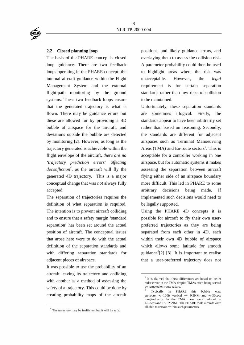
2.2 Closed planning loop
The basis of the PHARE concept is closed
loop guidance. There are two feedback
loops operating in the PHARE concept: the
internal aircraft guidance within the Flight
Management System and the external
flight-path monitoring by the ground
systems. These two feedback loops ensure
that the generated trajectory is what is
flown. There may be guidance errors but
these are allowed for by providing a 4D
bubble of airspace for the aircraft, and
deviations outside the bubble are detected
by monitoring [2]. However, as long as the
trajectory generated is achievable within the
flight envelope of the aircraft, there are no
‘trajectory prediction errors’ affecting
deconfliction4, as the aircraft will fly the
generated 4D trajectory. This is a major
conceptual change that was not always fully
accepted.
The separation of trajectories requires the
definition of what separation is required.
The intention is to prevent aircraft colliding
and to ensure that a safety margin ‘standard
separation’ has been set around the actual
position of aircraft. The conceptual issues
that arose here were to do with the actual
definition of the separation standards and
with differing separation standards for
adjacent pieces of airspace.
It was possible to use the probability of an
aircraft leaving its trajectory and colliding
with another as a method of assessing the
safety of a trajectory. This could be done by
creating probability maps of the aircraft
4 The trajectory may be inefficient but it will be safe.
positions, and likely guidance errors, and
overlaying them to assess the collision risk.
A parameter probability could then be used
to highlight areas where the risk was
unacceptable. However, the legal
requirement is for certain separation
standards rather than low risks of collision
to be maintained.
Unfortunately, these separation standards
are sometimes illogical. Firstly, the
standards appear to have been arbitrarily set
rather than based on reasoning. Secondly,
the standards are different for adjacent
airspaces such as Terminal Manoeuvring
Areas (TMA) and En-route sectors5. This is
acceptable for a controller working in one
airspace, but for automatic systems it makes
assessing the separation between aircraft
flying either side of an airspace boundary
more difficult. This led in PHARE to some
arbitrary decisions being made. If
implemented such decisions would need to
be legally supported.
Using the PHARE 4D concepts it is
possible for aircraft to fly their own user-
preferred trajectories as they are being
separated from each other in 4D, each
within their own 4D bubble of airspace
which allows some latitude for smooth
guidance6[2] [3]. It is important to realise
that a user-preferred trajectory does not
5 It is claimed that these differences are based on better
radar cover in the TMA despite TMAs often being servedby remoted en-route radars.6 Typically in PHARE this bubble was:
en-route: +/ -100ft vertical +/- 0.5NM and +/-30secslongitudinally. In the TMA these were reduced to+/-5secs and +/-0.25NM. The PHARE trials aircraft wereall able to remain within such parameters.
-9-NLR-TP-2000-004
have to be a ‘free’ or direct route, but could
be a trajectory from beacon to beacon along
a fixed route. The 4D separation methods
would be applied in the same way.
2.3 PHARE Sub-projects and Concepts
The PHARE Medium Term Scenario
description was completed in 1990. It
described the proposed PHARE concepts at
a very high level. It was intended that
advanced software tools would be
developed over time and that at points in
the development their capabilities would be
demonstrated in ‘PHARE Demonstrations’.
The tools that were identified were to be
based on tools being developed or planned
to be developed by the PHARE Partners.
Some of these tools were based on slightly
differing concepts although superficially
appearing to be part of a functionally
integrated set of services.
The split of concept setting between the
Medium Term Scenario, the PHARE
Advanced Tools Project and the
Demonstrations caused some difficulties in
the integration of the various approaches.
Within the structure of PHARE
programme, the internal consistency of the
tools and the integration of the tool
concepts into the demonstration operational
concepts remained a problem until the end
of the programme. Not only were the
PHARE Demonstration projects more or
less independently responsible to run a
valid demonstration of parts of the
operational concept which they had refined
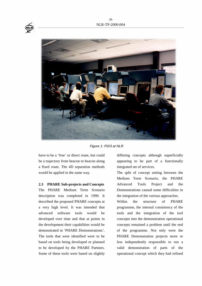
Figure 1: PD/3 at NLR
-10-NLR-TP-2000-004
themselves, but also, initially, the
development of the PHARE tools was not
very much co-ordinated. The latter resulted
in tools that were not very well
implemented to co-operate with each other.
By the time this became visible during the
integration of the first and second PHARE
Demonstration platforms in 1994, it was
probably already too late to fully recover.
The fact that there was not a single, stable,
integration platform available continued to
aggravate the situation up to the last
integration of the PHARE tools in the
PHARE Demonstration 3 (PD/3) platforms.
A detailed description of the operational
scenario that was implemented in the NLR
PD/3 exercises can be found in [5], which
will be published shortly. This Operational
Scenario took the PHARE concept at a
‘2015’ level and removed some of the
limitations that had been envisaged for
PD/3 trials aimed more at controller
transition.7
3 Tools development
Nine advanced ATC support tools were
developed within the PHARE Advanced
Tools (PATs, [8]) project. These tools
were:
Trajectory Predictor (TP)Conflict Probe (CP)Flight Path Monitor (FPM)Problem Solver (PS)
7 Despite this ‘advanced’ approach a traffic sample was
run which initially had all aircraft flying fixed routewithout datalink then over the course of the 90 minutestransitioned to 70% datalink and all off route. Thisshowed that an advanced system is suitable for transition.
Negotiation Manager (NM)Arrival Manager (AM)Departure Manager (DM)Co-operative Tools (CT)Tactical Load Smoother (TLS).
To some extent, all the tools are involved in
conflict detection and deconfliction. The
Arrival Manager and Departure Manager
are sequencing tools that deconflict runway
usage in time. The Tactical Load Smoother
identifies areas in which conflicts occur and
allows the Multi-Sector Planner to move
trajectories to reduce conflicts. The
Negotiation Manager provides protocol
links between air and ground, and controller
to controller, to allow the implementation
of deconfliction actions. However, the tools
that have a direct relationship with conflict
detection and resolution are Conflict Probe,
Problem Solver and Co-operative Tools.
The Conflict Probe probes all active
trajectories and client nominated ‘what-if’
trajectories to detect separation
infringements between trajectories and
between a trajectory and volumes of
airspace (e.g. a Temporary Reserved
Airspace, or even SIGMETs). Separation
infringement can either be detected on a
geometric basis or by using a probabilistic
approach. Some filtering of the output
needs to be carried out by the client tools.
For example, where aircraft are on final
approach to parallel runways they can be
within the separation criteria for the
Conflict Probe but legally separated. The
National Aerospace Laboratory NLR of the
Netherlands developed both types for the
PHARE Conflict Probe.
-11-NLR-TP-2000-004
The initial intent was that the Problem
Solver would provide deconfliction
solutions to the problems detected by the
Conflict Probe. However, after preliminary
prototyping with controllers, it was instead
developed as a tool that provides an
interactive capability to modify an aircraft’s
planned trajectory by dragging it on screen
until the Problem Solver shows that
conflicts have been resolved. The graphical
interface allows the controller to manipulate
constraints points that are applied to the
trajectory.
These constraints can be just lateral, or in
combination with altitude and/or time
constraints. One of the issues raised by this
graphical approach was the mismatch with
the basic concept of applying constraints to
the trajectory. Controllers initially tried to
‘edit the trajectory’ and expected the
system to ‘join up the dots’. However the
Trajectory Predictor generates trajectories
that meet the constraints but these do not
necessarily match the trajectories designed
on the Problem Solver display. To allow for
this the trajectory generation has two steps,
the first being to ‘validate’ the Problem
Solver solution with the Trajectory
Predictor and only then a second step of
Registration instigating negotiation with the
aircraft.
The use of the Problem Solver's interactive
graphical interface for deconfliction was a
huge step forward in decision support for
controllers who immediately grasped its
capabilities8. The subsequent graphical
display of the Flight Management System
generated trajectory to the pilot, based on
the constraints generated by the Problem
Solver, allowed the controller and pilot to
communicate using pictures. Thus, the
Problem Solver not only increased
controller capabilities, but also led to a far
more efficient use of datalink and better,
less error prone information exchange
between ground and air.
The EUROCONTROL Experimental
Centre (EEC) developed the Problem
Solver tool.
The ‘Co-operative Tools’ comprise a set of
tools developed to support the cognitive
processes of air traffic controllers. First,
they include a filtering function that selects
groups of aircraft that are involved in or
related to a possible separation
infringement. These groups, which are
called PROblem SITuations (PROSIT), are
selected using functions that aim to reflect
the conflict detection reasoning of the
human operator.
In simple terms this involves using
geometric parameters larger than those used
for conflict detection to identify aircraft
sufficiently close to a conflict to ‘interfere’
with any resolution action. The aircraft in
conflict and the set of those interfering in
its solution are then added to a PROSIT
which is then graded in severity.
The various PROSITs are presented to the
controller using another function called the
8 Indeed the HIPS has almost become the standard
‘display tool’ of PHARE
-12-NLR-TP-2000-004
Agenda. This function generates a graphical
presentation of the types of the PROSITs
and the moment in time at which they
should be addressed at the latest. It also
allows the planning controller to add
conflict resolution information that can be
picked up by the tactical controller to
actually resolve the problem.
A final function that is included in the Co-
operative Tools is the look-ahead tool. It
allows a controller to drag an aircraft
involved in a PROSIT along its trajectory
and shifts the Radar Plan View Display
forward in time at the same rate, allowing
the controller to assess a predicted future
situation.
The Co-operative Tools were based largely
around more current controller methods and
unlike the other tools expected a degree of
trajectory error widening the scope of the
search for interfering aircraft with time.
Within the PATs project the Co-operative
Tools have been developed by the Centre
d’Etudes de la Navigation Aérienne
(CENA) of France.
4 Tools Integration
In this section, the integration of the tools
will be discussed from the NLR PD/3 point
of view. The other PD/3 partners will have
had partly similar, but sometimes also very
different experiences.
Integration of the PHARE advanced tools
in the NLR ATC Research Simulator
(NARSIM) began as early as 1995 in
preparation for the Internal Operational
Clarification Project (IOCP), to run in
1997. This first integration was planned to
develop into the final system configuration
by integrating updates or first versions of
tools as they became available.
The focus of the NLR PD/3 experiments
was the integration between arrival
management and en-route traffic handling;
it was not planned to integrate all the
PHARE tools. There was no need to
integrate the Tactical Load Smoother and
Departure Manager tools without a multi-
sector planning position or specific
departure planning controller.
Trajectory Predictor integration
The tool that was first integrated was the
Trajectory Predictor, the heart of the
system. It was derived from the trajectory
prediction function of the PHARE
Experimental Flight Management System
(EFMS). With the EFMS designed for
actual operation in research aircraft, it was
implemented in ADA and it used some very
complex data structures. The performance
was designed for use onboard the aircraft,
where trajectory predictions are made
infrequently and a delay of a few seconds is
acceptable. The predicted trajectories
contained a lot of detail required for the
accurate guidance of the real aircraft.
The ground Trajectory Predictor inherited
many of these characteristics as it used the
same trajectory prediction kernel. This was
based on the reasoning that there should be
no large mismatch between the ground
‘what-if’ modelling and the aircraft
generated trajectories. However, instead of
detail for aircraft guidance the ground
-13-NLR-TP-2000-004
system required fast performance capable
of generating trajectories for many flights
in a short time (e.g. to support arrival
rescheduling). Although there were some
problems in PD/2, the impact of these
requirements mismatches only became fully
apparent with the integration of the large-
scale PD/3 platforms. Therefore, NLR and
NATS, who had developed the Trajectory
Predictor, expended significant effort
integrating the PATS Trajectory Predictor
and optimising its performance. This led to
reductions in the trajectory prediction time
and in the system resources required
(mainly memory and CPU-time) by up to a
factor of five. Additionally, due to the way
the Trajectory Predictor was implemented
in the NARSIM platform, it became
possible to run up to ten instances of the
Trajectory Predictor across the network to
provide the various controllers with
predicted ‘what-if’ trajectories.
Conflict Probe integration
Although the Conflict Probe was developed
by NLR, the simulation platform was
developed by a different team. However,
close co-operation was achieved easily and
the integration of the Conflict Probe caused
few problems. Nevertheless, as with the
Trajectory Predictor, performance became a
problem in the full scale PD/3 platform.
With a large number of concurrently active
flight plans in the system, 14 air traffic
controllers and some other PATS tools
requiring conflict information, the Conflict
Probe could become a bottleneck in the
system. Again, this was solved by using
several instances of the Conflict Probe to
serve particular clients.
Problem Solver integration
Due to its interactive nature, the Problem
Solver needed to be closely integrated with
the Ground Human Machine Interface
(GHMI). To achieve this in PHARE
Demonstration 1 (PD/1), every instance of
the GHMI had its own integrated Highly
Interactive Problem Solver (the
combination of Problem Solver and its
GHMI elements).
For PHARE Demonstration 3 (PD/3), a
design problem arose with the integration
of all PHARE tools and a suitable advanced
GHMI. In particular the display and
management of conflict information
coming from several tools (Conflict Probe,
Problem Solver and Co-operative Tools)
resulted in complex discussions between
the teams involved. This highlighted that
the design and development process from
concept to implementation was far from
optimal (see also [5]). The team that
designed the PD/3 GHMI eventually
produced a specification for the "Trajectory
Editor and Problem Solver" (TEPS), a
GHMI function that would use data from all
conflict detection tools. [6]
During the tools integration it was assessed
that the integration of the Co-operative
Tools within the NARSIM platform would
be too difficult and time consuming (see
next section). Although this made it
difficult to maintain the TEPS as specified,
it was decided to implement it mimicking
the Co-operative Tools functions. However,
-14-NLR-TP-2000-004
the first PD/3 GHMI software development
failed in 1998. This left NLR with no
option other than to fall back on the PD/1
GHMI software that had already been
integrated with the PD/3 platform and to
extend it for PD/3 functionality. Thus,
eventually the GHMI still had an integrated
HIPS, but, unlike PD/1 the GHMI elements
were further integrated in the synthetic
radar display.
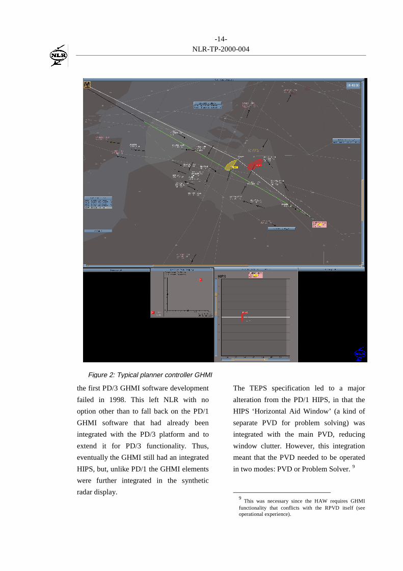
The TEPS specification led to a major
alteration from the PD/1 HIPS, in that the
HIPS ‘Horizontal Aid Window’ (a kind of
separate PVD for problem solving) was
integrated with the main PVD, reducing
window clutter. However, this integration
meant that the PVD needed to be operated
in two modes: PVD or Problem Solver. 9
9 This was necessary since the HAW requires GHMI
functionality that conflicts with the RPVD itself (seeoperational experience).
Figure 2: Typical planner controller GHMI
-15-NLR-TP-2000-004
The main problem that arose with the
integration and use of the Problem Solver
was the consistency of conflict detection
with the Conflict Probe. Initial lack of
consistency was due not only to the
different method of conflict detection in the
Problem Solver, but also to the different
behaviour of the Problem Solver trajectory
prediction function compared to the
Trajectory Predictor tool. Given a certain
set of constraints, the Trajectory Predictor
and the Problem Solver could generate
significantly different trajectories,
especially in the vertical plane.
With support from the EUROCONTROL
Experimental Centre, where the Problem
Solver had been developed, the Problem
Solver internal prediction was amended to
follow the Trajectory Predictor rule base,
making the trajectories predicted by each
tool almost identical. The differing conflict
detection algorithms that could also cause
mismatches were more easily fixed
(although not completely cured) by
parameter changes. These changes resulted
in greater consistency of conflict prediction
between the Conflict Probe and the
Problem Solver.
Co-operative Tools integration
It was decided not to integrate the Co-
operative Tools into NARSIM. The GHMI
design problems had already led to the
identification of some subtle differences in
philosophy between the Co-operative Tools
and the rest of the PHARE tools. These
were the Co-operative Tools’ routine
expectation of errors in guidance for
aircraft following their trajectories, and the
implicit sharing of workload across the
temporal split between Planner Controller
and Tactical Controller. This operational
difference, together with the very tight
integration of the Co-operative Tools with
the Common Modular Simulator (CMS)
platform made integration in the NARSIM
environment a significant risk. This was a
pity, since the conflict management
functionality represented by the Agenda
would probably have been very useful.
Overall integration issues
From the integration experience of PD/3 it
can be concluded that in a multiple-partner
project a stable integration platform, which
acts as a reference, is essential.
Nevertheless, it can also be concluded that
any integration of a tools set in an ATC
simulation platform requires separate and
iterative tuning and adjustment.
The fact that many of the elements of the
final NLR PD/3 platform had been
programmed in different languages meant
that the middle-ware had to be able to cope
with all of these. In addition, wider
expertise was required from the system
integration team in the field of
programming languages. This ranged from
Fortran, through C and C++ up to Ada.
Probably the most important experience
from the system integration is that it must
result in a simulation platform that actually
works. During the concept and system
specification phase, it is quite common that
not everything is specified. It is almost
impossible to see all the consequences
-16-NLR-TP-2000-004
related to the introduction of a new
operational concept. The people involved in
this are usually very capable of continuing
their work while certain details are missing.
When it comes to building a working
system this changes. The system forces one
to think of every detail. Unfortunately, by
the time the system is ready for a ‘full
system test’, the functionality has become
so complex that it is nearly impossible to
design all the test cases that could be used
to verify the system. This is especially true
for novel and experimental systems such as
those in PHARE. The best option is then to
try using the system according to the
operational concept. This not only allows
the identification of missing or incorrect
functionality, but it may also lead to new
insights in the operational concept.
5 System Operation
In the final NLR PD/3 Demonstration in
November 1998, fourteen air traffic
controllers operated the system
simultaneously, simulating five lower
airspace sectors and three upper sectors.
The whole simulation area was centred on
the Amsterdam Schiphol TMA and its
surrounding sectors.
The controllers, of whom only a few had
previous experience with the PHARE
concept, were trained for seven days. The
training used a combination of classroom
instruction, Computer Based Training
(CBT) and hands-on training.
Of course, the amount of training was not
enough to give the controllers a thorough
understanding of the concept and the
operation of the system. Nevertheless, it
allowed them to understand the ideas
behind the system and to control a
significant amount of simulated traffic. It
also gave them time to learn to trust the
conflict detection capability of the system.
They only started to appreciate this
capability when the system detected all the
conflicts that they had found themselves.
During the learning phase, the benefit of the
system is low as the controllers do not yet
trust it and continue to work in parallel with
it.
Conflict detection
If the ATC system is to reduce the
controller workload with respect to conflict
detection, the system must detect all
conflicts. If the controller is aware that not
all conflicts will be detected by the system,
he will not trust or use the system and
instead will perform his own conflict
detection. Conversely, once the controller
can trust the system to detect the conflicts,
he will use it as a trigger to take appropriate
action. In the NLR PD/3 demonstration, the
planning controllers (D-Side) were
therefore instructed only to re-plan traffic
when the system indicated a trajectory
conflict. This reduced the planner controller
task and allowed more workload to be
transferred from conflict detection towards
conflict resolution.In NLR's final PD/3 system, thegeometric Conflict Probe tool was usedto detect all conflicts. With every updateof an active trajectory, it would check for
-17-NLR-TP-2000-004
conflicts against all the other activetrajectories. When a conflict was found,an event would be generated thatresulted in the presentation of a conflictindication on the appropriatecontrollers’ GHMI. There was a generalimpression that probably all conflictswere detected.
However, since the conflict detection and
deconfliction has been carried out on the
active trajectory in the ground system it is
essential that the controller is alerted to any
deviations by the aircraft from that
trajectory. The role of the Flight Path
Monitor tool to signal deviations from the
active trajectory, is therefore very
important. Any deviation should lead either
to a re-planning action that takes into
account amending the trajectory to the
actual flight position or to a tactical
controller action to recover the aircraft to
the agreed conflict free trajectory. It
depends on the situation and the co-
operation between the planning and tactical
controller which action is applied.
One special function of the Conflict Probe
in the NLR PD/3 system is to support the
Negotiation manager tool in identifying
whether co-ordination between sectors is
required. It had been decided that in the
PD/3 user preferred routing environment
the only reason to co-ordinate changes in a
trajectory would be if a controller’s action
created a conflict in the next or previous
sector. Therefore, every re-planned
trajectory is assessed by the Conflict Probe
for conflicts in adjacent sectors. If there is a
conflict the Negotiation Manager indicates
the need to co-ordinate the new plan with
the relevant sector. The Negotiation
Manager follows the same procedure with
trajectories down-linked from the aircraft.
If they do not result in any conflict then
there is no strict need for the controller to
modify them and they are accepted. Thus
predicted trajectories can only be activated
if they do not create any conflicts in the
near future.
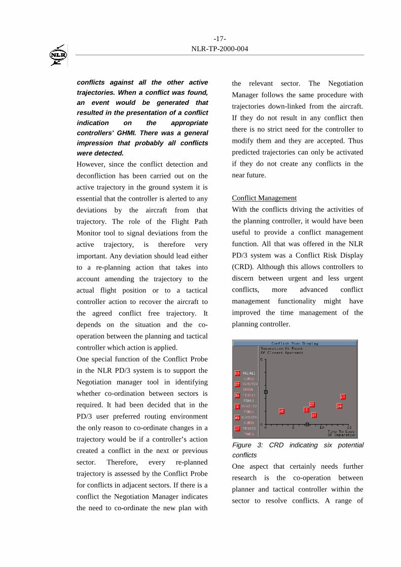
Conflict Management
With the conflicts driving the activities of
the planning controller, it would have been
useful to provide a conflict management
function. All that was offered in the NLR
PD/3 system was a Conflict Risk Display
(CRD). Although this allows controllers to
discern between urgent and less urgent
conflicts, more advanced conflict
management functionality might have
improved the time management of the
planning controller.
Figure 3: CRD indicating six potential
conflicts
One aspect that certainly needs further
research is the co-operation between
planner and tactical controller within the
sector to resolve conflicts. A range of
-18-NLR-TP-2000-004
options is possible. In the current
operational situation, it is normally the
tactical controller that solves nearly all the
conflicts ‘just-in-time’ using radar;
whereas, with the PD/3 system the planner
controller could resolve all conflicts
strategically. It has been postulated that in
order to transition between these extremes,
some of the conflicts would be resolved
strategically, while others would be left for
resolution or implementation of the
resolution by the tactical controller. The
experience gained by CENA in their PD/3
trials has shown that such a transitional case
is by no means straightforward.
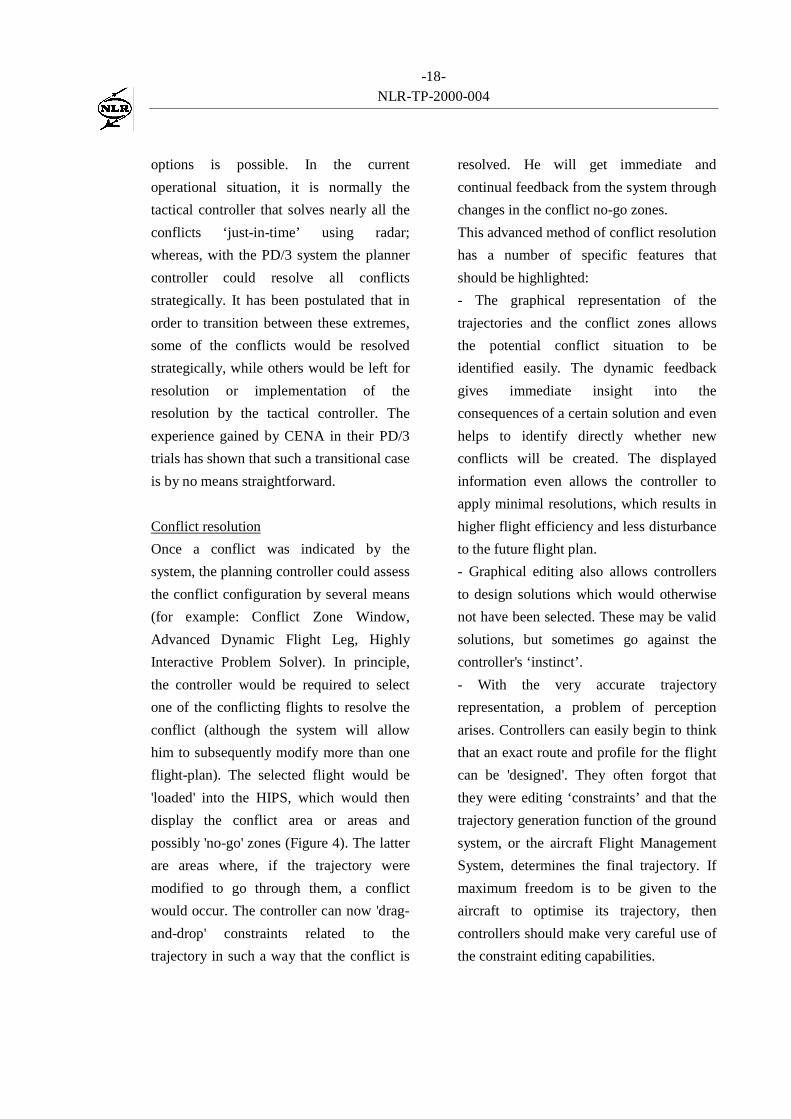
Conflict resolution
Once a conflict was indicated by the
system, the planning controller could assess
the conflict configuration by several means
(for example: Conflict Zone Window,
Advanced Dynamic Flight Leg, Highly
Interactive Problem Solver). In principle,
the controller would be required to select
one of the conflicting flights to resolve the
conflict (although the system will allow
him to subsequently modify more than one
flight-plan). The selected flight would be
'loaded' into the HIPS, which would then
display the conflict area or areas and
possibly 'no-go' zones (Figure 4). The latter
are areas where, if the trajectory were
modified to go through them, a conflict
would occur. The controller can now 'drag-
and-drop' constraints related to the
trajectory in such a way that the conflict is
resolved. He will get immediate and
continual feedback from the system through
changes in the conflict no-go zones.
This advanced method of conflict resolution
has a number of specific features that
should be highlighted:
- The graphical representation of the
trajectories and the conflict zones allows
the potential conflict situation to be
identified easily. The dynamic feedback
gives immediate insight into the
consequences of a certain solution and even
helps to identify directly whether new
conflicts will be created. The displayed
information even allows the controller to
apply minimal resolutions, which results in
higher flight efficiency and less disturbance
to the future flight plan.
- Graphical editing also allows controllers
to design solutions which would otherwise
not have been selected. These may be valid
solutions, but sometimes go against the
controller's ‘instinct’.
- With the very accurate trajectory
representation, a problem of perception
arises. Controllers can easily begin to think
that an exact route and profile for the flight
can be 'designed'. They often forgot that
they were editing ‘constraints’ and that the
trajectory generation function of the ground
system, or the aircraft Flight Management
System, determines the final trajectory. If
maximum freedom is to be given to the
aircraft to optimise its trajectory, then
controllers should make very careful use of
the constraint editing capabilities.
-19-NLR-TP-2000-004
- The interactive conflict resolution
function critically depends on the capability
to accurately predict the effect on changing
constraints on the trajectory prediction.
This has to be done in real time. In addition,
the conflict information has to be updated
with the same refresh rate. This places high
demands on both functions. The current
PATS Trajectory Predictor and Conflict
Probe are not designed to do this. On the
other hand, the Problem Solver cannot do it
with the same accuracy as the Trajectory
Predictor and Conflict Probe. The result is a
'quick and dirty' conflict resolution that
needs to be verified by the Trajectory
Predictor and Conflict Probe. For the
controller this leads to an unnatural
situation of first using the system to design
a solution, and then instructing the system
to verify itself.
Short Term Conflict Alert consistency
It is a safety requirement that there is no
direct link between the conflict detection
function, which works on medium-term
trajectory predictions, and the Short Term
Conflict Alert (STCA), which uses tracking
data to identify more immediate conflicts.
Nevertheless, consistency between both
functions must be achieved as display of an
STCA when the Conflict Probe does not
indicate a conflict can destroy the
controllers’ trust. The experience from
PD/3 at NLR showed that considerable
effort is required to achieve uniformity
between the STCA and Conflict Probe.
Figure 4: The HIPS showing conflict and no-go zones (Note the change in separation criteriashown by the no-go zone as the trajectory enters the TMA)
-20-NLR-TP-2000-004
6 Conclusions andrecommendations
PHARE and PD/3 have provided many
insights into conflict detection and
resolution and much has been learnt.
Although many issues remain to be
resolved, the following conclusions can be
drawn:
- System supported conflict detection
requires equivalent trajectory generation for
all flights. The least accurate trajectory
generation determines the effectiveness of
medium-term conflict detection. A
mismatch between trajectory generation
and flight execution (i.e. a guidance failure)
renders medium-term conflict detection
useless.
- Conflict detection is only a part of the
puzzle. Trajectory generation is probably
even more important. If the generated
trajectory is not used for the guidance and
control of the flight, then it becomes merely
a predicted trajectory and the system is
‘open loop’. The resulting inaccuracy will
make medium-term conflict detection
support less useful.
- Controller trust must be obtained if the
introduction of conflict detection tools is
meant to reduce workload. Otherwise tools
are ignored or double-checked
continuously.
- Performance (response times) of trajectory
prediction and of conflict detection are
important issues for the usability of
interactive conflict detection and resolution
tools.
The following recommendations are made:
- When a novel system is developed, a
‘rapid application development’ approach
should be taken with a fully functional
prototype being used as soon as possible.
This allows the functionality to be better
assessed and can lead to an improved
understanding of the operational concept or
concepts.
- Research should be continued on the
benefits of medium-term conflict detection
and resolution. In particular the interactive
conflict resolution capability requires
further study.
5HIHUHQFHV
[1] "Trajectory Negotiation in a Multi-sector Environment", I. Wilson,EUROCONTROL DOC 97-70-14,January 1998.
[2] “PHARE: Definition and Use ofTubes", I. Wilson, EUROCONTROLDOC 96-70-18, July 1996
[3] “PHARE Experimental FlightManagement System Phase 2 URD”DOC 96-70-19, June 1996
[4] “PHARE Medium Term Scenario2000 to 2015”, Issue 1 (Draft),EUROCONTROL, July 1990
[5] "NLR PHARE Demonstration 3 FinalReport", W. Post , DOC 99-70-01(Volume 4 of 4), December 1999.
[6] “PD/3 Ground Human MachineInterface Specification” Version 2.2,CENA/EEC/NLR, DOC 98-70-07,January 1998
[7] "PHARE Final Report", M. van Gool,H. Schröter, DOC 99-70-09,November 1999.
[8] "PHARE Advanced Tools ProjectFinal Report", DOC 99-70-18 (volume1 to 10), December 1999.
-21-NLR-TP-2000-004
$FURQ\PV DQG 'HILQLWLRQV
4D 4 Dimensional
ADFL Augmented Dynamic Flight Leg
AM Arrival Manager
ATM Air Traffic Management
ATN Aeronautical Telecommunications
Network
CBT Computer Based Training
CENA Centre d’Etudes de la Navigation
Aérienne
CMS Common Modular Simulator
CP Conflict Probe
CRD Conflict Risk Display
CZW Conflict Zoom Window
CT Co-operative Tools
DM Departure Manager
EEC EUROCONTROL Experimental
Centre
EFMS Experimental Flight Management
System
FAA Federal Aviation Administration
FMS Flight Management System
FPM Flight Path Monitor
GHMI Ground Human Machine Interface
HAW Horizontal Assistance Window
HIPS Highly Interactive Problem Solver
IOCP Internal Operational Clarification
Project
MSP Multi Sector Planner
NARSIM NLR Air Traffic Control Research
Simulator
NLR Nationaal Lucht- en
Ruimtevaartlaboratorium
NM Negotiation Manager
PATS PHARE Advanced Tools
PD PHARE Demonstration
PD/1 PHARE Demonstration 1
PD/3 PHARE Demonstration 3
PHARE Programme for Harmonised ATM
Research in EUROCONTROL
PROSIT PROblem SITuation
PS Problem Solver
R/T Radio Telephony
RPVD Radar Plan View Display
STCA Short Term Conflict Alert
TLS Tactical Load Smoother
TMA Terminal Manoeuvring Area
TP Trajectory Predictor
Planner Controller (D-Side):
The controller that is responsible to
plan flights safely and expeditiously
through a sector. He normally
performs planing before the aircraft
actually enters the sector.
Tactical Controller (R-Side):
The controller that is responsible for
the safe and expeditious flights
through a sector. He controls the
aircraft that are in the sector and
maintains R/T contact.
-22-NLR-TP-2000-004
%LRJUDSK\
Ir. Wim Post graduated as an Aerospace
Engineer from Delft University of
Technology in 1989. After that he served
his conscript period as an officer in the
Royal Netherlands Air Force, concerned
with the introduction of new radar training
equipment for military air traffic
controllers. In 1991 Wim Post joined the
National Aerospace Laboratory NLR and
soon became involved in Air Traffic
Management research. After an initial
involvement in the development of a
prototype Aeronautical Telecommuni-
cations Network (ATN), he started to work
in 1994 on the PHARE Demonstration 3
project for which he was the local project
leader until its finish in 1999. He was
actively involved in the definition of the
PD/3 Operational Concept and in the set-up
and execution of the various experiments.
In parallel with the PD/3 work Wim Post
participated in EUROCONTROL's EATMS
Concept Task Force (ECTF) that wrote the
target operational concept for the European
ATM Programme. At this moment he is
still actively involved in the co-operation
between the FAA and EUROCONTROL
on future operational concepts and in the
building of a prototype Validation Data
Repository.
Mr Ian Wilson joined the UK Royal Air
Force in 1968 graduating as a pilot from
RAF College Cranwell in 1970.
Subsequently he worked as an Air Traffic
Controller at military airfields in UK and
Germany and then as an area controller
with UK NATS at Scottish and Oceanic Air
Traffic Control Centre. In 1981 he became
an analyst/programmer team leader in the
Flight Data Processing support group for
NAS Host at London Centre; then in 1984
the Project Leader on the Tandem based
Flight Data and Support Information
Systems. In 1986, he moved to UK CAA
HQ as Project Officer and System
Acceptance Manager on the Electronic
Strip systems for London Centre ENE
Operations Room. From 1989 until 1994
Ian Wilson was the Network Systems and
Installation Manager for a distributed low
flying notification and flight-information
workstation system. In 1994 he joined
EUROCONTROL as a member of the
PHARE Cell and became Project Leader
for the PHARE Advanced Tools project.
Currently, he is working on ATM Research
on 4D decision support tools within
EUROCONTROL Air Traffic and Data
Processing domain and as Project Leader of
the INTEGRA project within the Co-
operative Actions for R&D in
EUROCONTROL (CARE).
-23-NLR-TP-2000-004
$SSHQGL[ $ 6OLGHV SUHVHQWHG DW WKH FRQIHUHQFH
Part I: Presented by I. Wilson.
Slide 1
PHARE Concept andConflict Detection and Resolution
PHARE Concept andConflict Detection and Resolution
byby
Ian WilsonIan Wilson
Slide 2
PHARE Concept and Conflict Detection and Resolutionby Ian Wilson
IntroductionIntroduction
➤➤ ATM system first principlesATM system first principles
➤➤ PHARE ObjectivesPHARE Objectives
➤➤ Trajectories errors and uncertaintiesTrajectories errors and uncertainties
➤➤ Closed loop system feedbackClosed loop system feedback
➤➤ Conflict Detection and ResolutionConflict Detection and Resolution
➤➤ Concept RecommendationsConcept Recommendations

-24-NLR-TP-2000-004
Slide 3
PHARE Concept and Conflict Detection and Resolutionby Ian Wilson
ATM FunctionsATM Functions
➤➤ Safe, Safe, economiceconomic, orderly and expeditious, orderly and expeditiousflow of air trafficflow of air traffic
➤➤ ‘Safe’ not fully defined apart from‘Safe’ not fully defined apart from‘tombstone count’‘tombstone count’
➤➤ Orderly means a flight should not be aOrderly means a flight should not be aseries of short term series of short term deconflictionsdeconflictions
Slide 4
PHARE Concept and Conflict Detection and Resolutionby Ian Wilson
PHARE Objective:PHARE Objective:
“….to organise, co-ordinate and conduct on a“….to organise, co-ordinate and conduct on acollaborative basis, experiments and trialscollaborative basis, experiments and trialsaiming at proving and demonstrating theaiming at proving and demonstrating thefeasibility and meritsfeasibility and merits of a future of a future air groundair groundintegrated air traffic management system integrated air traffic management system ininall phases of flight.”all phases of flight.”

-25-NLR-TP-2000-004
Slide 5
PHARE Concept and Conflict Detection and Resolutionby Ian Wilson
Advantages of DatalinkAdvantages of Datalink
➤➤ Replaces error prone R/TReplaces error prone R/T
➤➤ AllowsAllows➤➤ transmission of complex datatransmission of complex data
➤➤ transmission of trajectoriestransmission of trajectories
➤➤ transmission of transmission of deconfliction deconfliction constraintsconstraints
➤➤ Enables control by picturesEnables control by pictures
Slide 6
PHARE Concept and Conflict Detection and Resolutionby Ian Wilson
ATM Problem lack of CapacityATM Problem lack of Capacity
➤➤ Capacity traditionally equated to Controller workloadCapacity traditionally equated to Controller workload
➤➤ Tactical Controller workload limiting factorTactical Controller workload limiting factor
➤➤ Therefore, move tasks to Planner Controller and increaseTherefore, move tasks to Planner Controller and increasecapacity, or…....capacity, or…....
➤➤ “Re-empower the planner controller”“Re-empower the planner controller”
➤➤ Use Use datalinkdatalink to ‘negotiate’ conflict free trajectories prior to ‘negotiate’ conflict free trajectories priorto sector entryto sector entry
➤➤ Planning and Planning and deconfliction deconfliction with a long look-aheadwith a long look-ahead
-26-NLR-TP-2000-004
Slide 7
PHARE Concept and Conflict Detection and Resolutionby Ian Wilson
What is a Trajectory ?What is a Trajectory ?
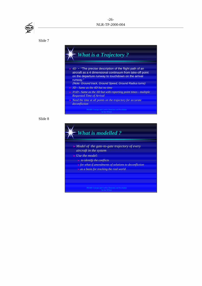
➤➤ 4D 4D - - ““ The precise description of the flight path of anaircraft as a 4 dimensional continuum from take-off pointon the departure runway to touchdown on the arrivalrunway.”(Note: Ground track, Ground Speed, Ground Radius turns)
➤➤ 3D - Same as the 4D but no time3D - Same as the 4D but no time
➤➤ 3½D - Same as the 3D but with reporting point times - multiple3½D - Same as the 3D but with reporting point times - multipleRequested Time of ArrivalRequested Time of Arrival
➤➤ Need the time at all points on the trajectory for accurateNeed the time at all points on the trajectory for accuratedeconflictiondeconfliction
Slide 8
PHARE Concept and Conflict Detection and Resolutionby Ian Wilson
What is modelled ?What is modelled ?
➤➤ Model of the gate-to-gate trajectory of everyModel of the gate-to-gate trajectory of everyaircraft in the systemaircraft in the system
➤➤ Use the model:Use the model:➤➤ to identify the conflicts to identify the conflicts
➤➤ for what-if amendments of solutions tofor what-if amendments of solutions to deconfliction deconfliction
➤➤ as a basis for tracking the real worldas a basis for tracking the real world

-27-NLR-TP-2000-004
Slide 9
PHARE Concept and Conflict Detection and Resolutionby Ian Wilson
Trajectory ‘Prediction’Trajectory ‘Prediction’
➤➤ Trajectory ‘prediction’ is or should be a misnomerTrajectory ‘prediction’ is or should be a misnomer
➤➤ If an aircraft is cleared to fly a certain trajectory even inIf an aircraft is cleared to fly a certain trajectory even intoday’s system they will fly it within the bounds of thetoday’s system they will fly it within the bounds of theaccuracy of the clearance.accuracy of the clearance.
➤➤ Cannot be called a ‘prediction’ unless there is noCannot be called a ‘prediction’ unless there is notracking and no feedback looptracking and no feedback loop
➤➤ Trajectory predictors that have ‘error tubes’ or ‘areasTrajectory predictors that have ‘error tubes’ or ‘areasof uncertainty’ inevitably lead to similar error tubes andof uncertainty’ inevitably lead to similar error tubes anduncertainties in conflict detection / resolutionuncertainties in conflict detection / resolution
Slide 10
PHARE Concept and Conflict Detection and Resolutionby Ian Wilson
Open vs Closed Loop SystemsOpen vs Closed Loop Systems
➤➤ Open LoopOpen Loop - no attempt to correct deviations in flight - no attempt to correct deviations in flighttrack but periodically correct the ground ATM modeltrack but periodically correct the ground ATM model
➤➤ Closed LoopClosed Loop - aircraft are corrected to the agreed ‘4D - aircraft are corrected to the agreed ‘4Dintent’ or ‘contracted trajectory’ - either using internalintent’ or ‘contracted trajectory’ - either using internalguidance guidance andand/or by flight path monitoring and ground/or by flight path monitoring and groundcommand or the aircraft intent is renegotiatedcommand or the aircraft intent is renegotiated
➤➤ If If deconflictiondeconfliction action has been taken which of these action has been taken which of theseapproaches is the safest ?approaches is the safest ?
➤➤ If the trajectory is If the trajectory is notnot for for deconflictiondeconfliction what is it for ? what is it for ?
-28-NLR-TP-2000-004
Slide 11
PHARE Concept and Conflict Detection and Resolutionby Ian Wilson
Trajectories ‘How Accurate’Trajectories ‘How Accurate’
➤➤ More important on ground to have speed of generation forMore important on ground to have speed of generation forwhat-if modelling (spurious trajectory accuracy led towhat-if modelling (spurious trajectory accuracy led toperformance problems in PHARE)performance problems in PHARE)
➤➤ In the air accurate as needed for FMS and pass trajectoryIn the air accurate as needed for FMS and pass trajectoryto ground where it replaces ground generated trajectoryto ground where it replaces ground generated trajectorythat was used for that was used for deconflictiondeconfliction
➤➤ Guidance is far more important for safety than accuracy ofGuidance is far more important for safety than accuracy oftrajectory generationtrajectory generation
Slide 12
PHARE Concept and Conflict Detection and Resolutionby Ian Wilson
Trajectory ‘Prediction’ErrorsTrajectory ‘Prediction’Errors
➤➤ Prediction errors ?Prediction errors ? - if trajectory is flyable there is no such thing in a - if trajectory is flyable there is no such thing in a closed loopclosed loop system system
➤➤ Generation errors -Generation errors -Loss of efficiency but are safe if generated in the air then it is anLoss of efficiency but are safe if generated in the air then it is anairline business case to be efficientairline business case to be efficient
➤➤ Guidance errors -Guidance errors -Mean Mean Loss of implementation accuracy and reduce safetyLoss of implementation accuracy and reduce safety
➤➤ Close the system feedback loop to ensure safetyClose the system feedback loop to ensure safety
➤➤ PHARE had guidance feedback in Flight ManagementPHARE had guidance feedback in Flight ManagementSystem and monitoring by ground Flight Path MonitorSystem and monitoring by ground Flight Path Monitor
-29-NLR-TP-2000-004
Slide 13
PHARE Concept and Conflict Detection and Resolutionby Ian Wilson
Safety means Model Must Match RealitySafety means Model Must Match Reality
➤➤ What to do if it doesn’t ?What to do if it doesn’t ?
➤➤ Change modelChange model
➤➤ Change real worldChange real world
➤➤ Must end up matchingMust end up matching
Slide 14
PHARE Concept and Conflict Detection and Resolutionby Ian Wilson
Safety - Do what has been agreedSafety - Do what has been agreed
➤➤ Contracted trajectory = Agreed 4D intentContracted trajectory = Agreed 4D intent
➤➤ Responsibilities:Responsibilities:➤➤ GroundGround - keep trajectory conflict free - keep trajectory conflict free
➤➤ AirAir - fly the trajectory until agreement is modified - fly the trajectory until agreement is modified
➤➤ Ground and AirGround and Air - Monitor the flight to ensure - Monitor the flight to ensuretrajectory is maintained - if not, correct model ortrajectory is maintained - if not, correct model ortrajectorytrajectory

-30-NLR-TP-2000-004
Slide 15
PHARE Concept and Conflict Detection and Resolutionby Ian Wilson
Safety -Look where you are goingSafety -Look where you are going
➤➤ Trajectories mean no open ended instructionsTrajectories mean no open ended instructions(e.g. headings)(e.g. headings)
➤➤ Entails always considering the longer term effectEntails always considering the longer term effectof trajectory changesof trajectory changes
➤➤ Gate-to-gate continuum must not pass through theGate-to-gate continuum must not pass through theground - likely to reduce CFITground - likely to reduce CFIT
Slide 17
PHARE Concept and Conflict Detection and Resolutionby Ian Wilson
Procedures to use TrajectoriesProcedures to use Trajectories
➤➤ Current procedures are based on ‘oldCurrent procedures are based on ‘oldinnovations’ - trajectories modelled by use ofinnovations’ - trajectories modelled by use ofground navigation aids and estimates - Radarground navigation aids and estimates - Radarcontrol with Procedural fall backcontrol with Procedural fall back
➤➤ PHARE trajectories accurate in 4D long look-PHARE trajectories accurate in 4D long look-ahead ahead - trajectories management withahead ahead - trajectories management withradar fall backradar fall back
➤➤ User preferred trajectories are stable and simple -User preferred trajectories are stable and simple -easy to plan aheadeasy to plan ahead

-31-NLR-TP-2000-004
Slide 18
PHARE Concept and Conflict Detection and Resolutionby Ian Wilson
What is a conflict ?What is a conflict ?
➤➤ Separation less than laid down criteriaSeparation less than laid down criteria➤➤ These have no logical supportThese have no logical support
➤➤ If a safety zone to allow avoidance then byIf a safety zone to allow avoidance then bymaking it a ‘hard’ standard another safety zone ismaking it a ‘hard’ standard another safety zone isgenerated around it wasting capacitygenerated around it wasting capacity
➤➤ Alternative is ‘unacceptable risk of collision’Alternative is ‘unacceptable risk of collision’➤➤ Probability that aircraft will collideProbability that aircraft will collide
➤➤ Either on trajectory on likely guidance failuresEither on trajectory on likely guidance failures
Slide 19
PHARE Concept and Conflict Detection and Resolutionby Ian Wilson
Conflict Probe Conflict Detection 1Conflict Probe Conflict Detection 1
➤➤ Geometric Conflict detection based on standardGeometric Conflict detection based on standardseparation criteria.separation criteria.
➤➤ Rule base allowing different separations at differentRule base allowing different separations at differentaltitudes/levelsaltitudes/levels
➤➤ Required client tool to filter spurious conflictsRequired client tool to filter spurious conflicts(e.g. aircraft approaching parallel runways)(e.g. aircraft approaching parallel runways)
➤➤ Also reported conflicts with ‘airspace’ volumesAlso reported conflicts with ‘airspace’ volumes(e.g. SIGMET, Holds, potentially CFIT detection)(e.g. SIGMET, Holds, potentially CFIT detection)
➤➤ Stop searching after <time> parameter from clientStop searching after <time> parameter from clientto reduce reportsto reduce reports
-32-NLR-TP-2000-004
Slide 20
PHARE Concept and Conflict Detection and Resolutionby Ian Wilson
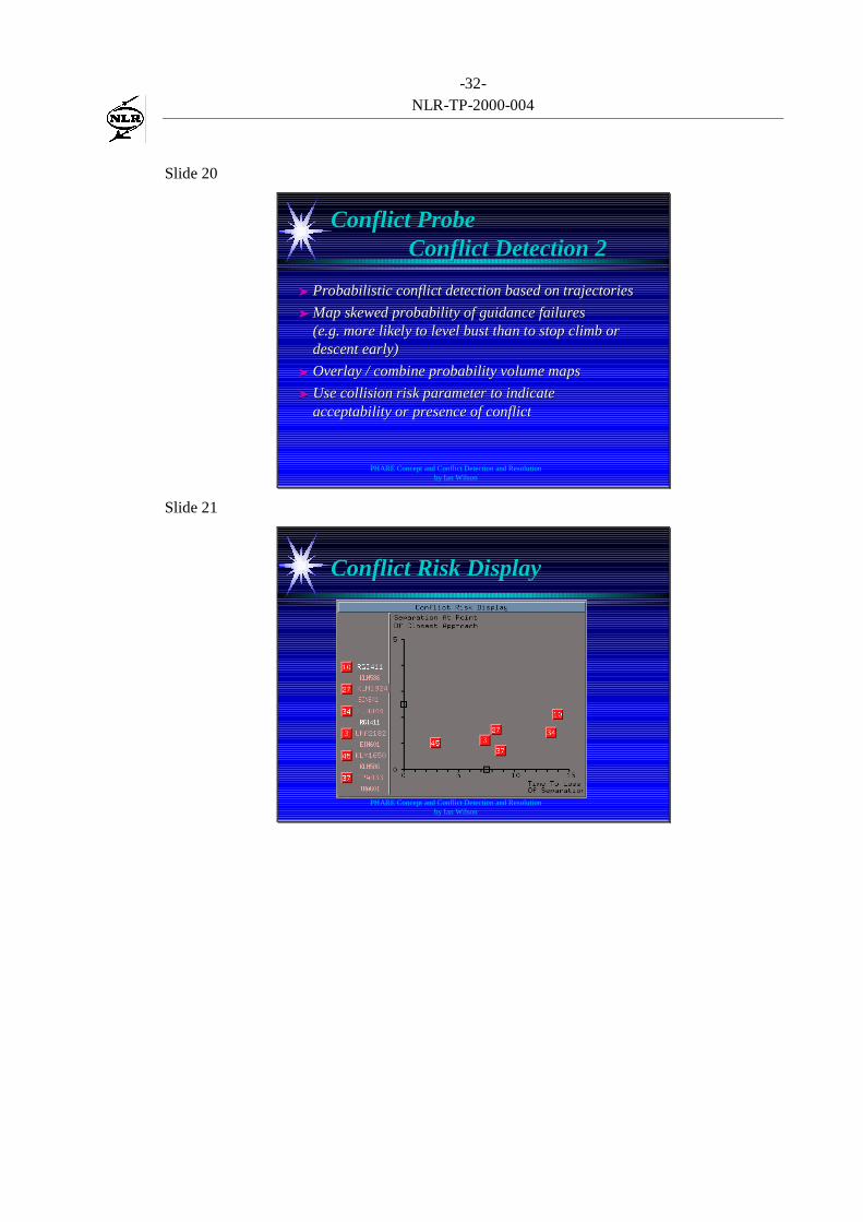
Conflict Probe Conflict Detection 2Conflict Probe Conflict Detection 2
➤➤ Probabilistic conflict detection based on trajectoriesProbabilistic conflict detection based on trajectories
➤➤ Map skewed probability of guidance failuresMap skewed probability of guidance failures(e.g. more likely to level bust than to stop climb or(e.g. more likely to level bust than to stop climb ordescent early)descent early)
➤➤ Overlay / combine probability volume mapsOverlay / combine probability volume maps
➤➤ Use collision risk parameter to indicateUse collision risk parameter to indicateacceptability or presence of conflictacceptability or presence of conflict
Slide 21
PHARE Concept and Conflict Detection and Resolutionby Ian Wilson
Conflict Risk DisplayConflict Risk Display
-33-NLR-TP-2000-004
Slide 22
PHARE Concept and Conflict Detection and Resolutionby Ian Wilson
Co-operative Tools Conflict DetectionCo-operative Tools Conflict Detection
➤➤ Geometric conflict probe but including rule base of ‘controllerGeometric conflict probe but including rule base of ‘controllerlogic’ and ‘continually widening cone of uncertainty’logic’ and ‘continually widening cone of uncertainty’
➤➤ Search area adjusted where known errors occurSearch area adjusted where known errors occur(e.g. in the climb)(e.g. in the climb)
➤➤ Detects aircraft close enough to be a ‘problem to watch’Detects aircraft close enough to be a ‘problem to watch’
➤➤ Larger search area including ‘interfering aircraft set’Larger search area including ‘interfering aircraft set’
➤➤ Allowed interactive drag forward of aircraft to examineAllowed interactive drag forward of aircraft to examineconflictconflict
➤➤ Expected sharing of conflict resolution across the temporalExpected sharing of conflict resolution across the temporalboundaryboundary
Slide 24
PHARE Concept and Conflict Detection and Resolutionby Ian Wilson
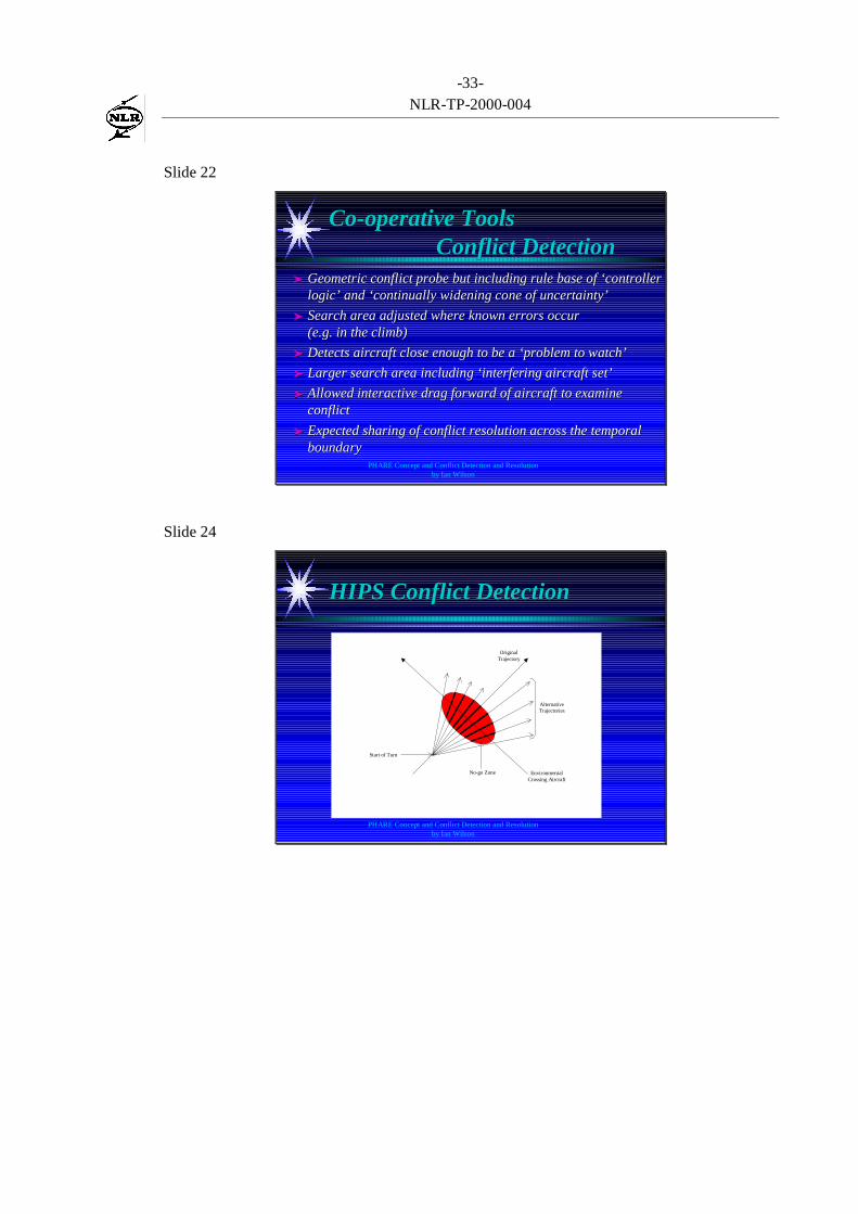
HIPS Conflict DetectionHIPS Conflict Detection
Start of Turn
No-go Zone EnvironmentalCrossing Aircraft
AlternativeTrajectories
OriginalTrajectory

-34-NLR-TP-2000-004
Slide 25
PHARE Concept and Conflict Detection and Resolutionby Ian Wilson
Live HIPSLive HIPS
Slide 26
PHARE Concept and Conflict Detection and Resolutionby Ian Wilson
DeconflictionDeconfliction
➤➤ Used the HIPS as a what if modellingUsed the HIPS as a what if modellingdevicedevice
➤➤ Drag constraints on the trajectory eitherDrag constraints on the trajectory eitherexisting or new constraintsexisting or new constraints
➤➤ Led to discussions on allowing out of sectorLed to discussions on allowing out of sectorchanges by planner controllerschanges by planner controllers

-35-NLR-TP-2000-004
Slide 27
PHARE Concept and Conflict Detection and Resolutionby Ian Wilson
Amending TrajectoriesAmending Trajectories
➤➤ Conflicting Objectives - freedomConflicting Objectives - freedom vs vs control control➤➤ retain the Aircraft freedom to produce a UPTretain the Aircraft freedom to produce a UPT
➤➤ allow realistic what if modelling of the likely aircraft performanceallow realistic what if modelling of the likely aircraft performance
➤➤ This was a problem in HIPSThis was a problem in HIPS vs vs Trajectory Predictor Trajectory Predictor
➤➤ Solution was a 2 stage processSolution was a 2 stage process
➤➤ fast less accurate HIPS model for what-iffast less accurate HIPS model for what-if
➤➤ Validated by ground Trajectory Predictor emulating theValidated by ground Trajectory Predictor emulating theaircraft Flight Management Systemaircraft Flight Management System
➤➤ Lack of ‘control’ seen as a problem by some ‘controllers’Lack of ‘control’ seen as a problem by some ‘controllers’
Slide 28
PHARE Concept and Conflict Detection and Resolutionby Ian Wilson
Concept mismatchesConcept mismatches
➤➤ Trajectory ‘prediction error’ used by Co-operativeTrajectory ‘prediction error’ used by Co-operativeTools although twin feedback loops assured there wasTools although twin feedback loops assured there wasno errorno error
➤➤ Problem Solver seen as ‘trajectory editing’ but was inProblem Solver seen as ‘trajectory editing’ but was infact ‘constraint editing’ initial mismatch withfact ‘constraint editing’ initial mismatch withTrajectory Predictor rule base.Trajectory Predictor rule base.
➤➤ Underlying confusion of ‘trajectory prediction error’Underlying confusion of ‘trajectory prediction error’with uncertainty of trajectory implementationwith uncertainty of trajectory implementation
➤➤ Temporal confusion - planner is working in the futureTemporal confusion - planner is working in the futureand cannot ‘share’ workload simply with the tacticaland cannot ‘share’ workload simply with the tactical

-36-NLR-TP-2000-004
Slide 29
PHARE Concept and Conflict Detection and Resolutionby Ian Wilson
Merits of PHARE ConceptMerits of PHARE Concept
➤➤ Each aircraft flies inside a bubble of allocatedEach aircraft flies inside a bubble of allocatedairspace that is following a conflict free trajectoryairspace that is following a conflict free trajectory
➤➤ This provides the capability to control aircraft in 4DThis provides the capability to control aircraft in 4Dinside or outside the normal 3D route structuresinside or outside the normal 3D route structures
➤➤ The aircraft generates a trajectory that best meetsThe aircraft generates a trajectory that best meetsthe ground constraints that ideally are only providedthe ground constraints that ideally are only providedfor for deconflictiondeconfliction
➤➤ This allows ‘user preferred trajectories’ to be flownThis allows ‘user preferred trajectories’ to be flownbut with Ground Separation Assurancebut with Ground Separation Assurance
Slide 30
PHARE Concept and Conflict Detection and Resolutionby Ian Wilson
Concept recommendationsConcept recommendations
➤➤ Define and Agree on the conceptDefine and Agree on the concept
➤➤ Ensure that everyone understands what is meant -Ensure that everyone understands what is meant -avoid the homonym / synonym trapavoid the homonym / synonym trap
➤➤ Ensure that the concept is operationally acceptableEnsure that the concept is operationally acceptable
➤➤ Define tools that meet the concept withoutDefine tools that meet the concept withoutunnecessary overlapunnecessary overlap
➤➤ Ensure that performance requirements are Ensure that performance requirements are feasiblefeasible
-37-NLR-TP-2000-004
Part II: presentation presented by W. Post
Slide 1
The NLR PD/3 Experience The NLR PD/3 Experience
Wim Post NLR
Slide 2
Nationaal Lucht- en Ruimtevaartlaboratorium
National Aerospace Laboratory NLR
CXXX-2A
NLR PD/3 ExperienceNLR PD/3 Experience
● Tools development
● Tools integration
● System Operation
● Conclusions and recommendations
-38-NLR-TP-2000-004
Slide 3
Nationaal Lucht- en Ruimtevaartlaboratorium
National Aerospace Laboratory NLR
CXXX-3A
NLR PD/3 ExperienceNLR PD/3 Experience
● Tools development
● Tools integration
● System Operation
● Conclusions and recommendations
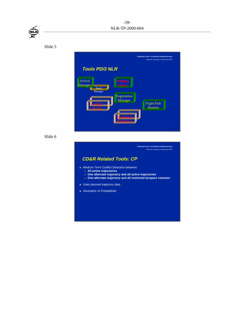
Slide 4
Nationaal Lucht- en Ruimtevaartlaboratorium
National Aerospace Laboratory NLR
CXXX-4A
Tools Hierarchy
ArrivalManager
DepartureManager
ProblemSolver
NegotiationManager
Cooperative Tools
Tactical LoadSmoother
ConflictProbe
Flight PathMonitor
TrajectoryPredictor
-39-NLR-TP-2000-004
Slide 5
Nationaal Lucht- en Ruimtevaartlaboratorium
National Aerospace Laboratory NLR
CXXX-5A
StackManager
Tools PD/3 NLR
ArrivalManager
ProblemSolver
NegotiationManager
ConflictProbe
Flight PathMonitor
Tra jectoryPredictor
Slide 6
Nationaal Lucht- en Ruimtevaartlaboratorium
National Aerospace Laboratory NLR
CXXX-6A
CD&R Related Tools: CP
Ó Medium Term Conflict Detection between:Ó All active trajectoriesÓ One alternate trajectory and all active trajectoriesÓ One alternate trajectory and all restricted airspace volumes
Ó Uses planned trajectory data
Ó Geometric or Probabilistic

-40-NLR-TP-2000-004
Slide 7
Nationaal Lucht- en Ruimtevaartlaboratorium
National Aerospace Laboratory NLR
CXXX-7A
CD&R Related Tools: CT
Ó Filtering of sets of aircraft involved in a PROblem SITuation (PROSIT)
Ó Cognitive Rules
Ó Agenda for PROSIT management
Ó Sharing of sector information between sector controllers
Ó Dragged ‘look ahead’ or conflict preview
Slide 8
Nationaal Lucht- en Ruimtevaartlaboratorium
National Aerospace Laboratory NLR
CXXX-8A
CD&R Related Tools: PS
Ó Drag and Drop constraints on an alternate trajectory
Ó Immediate visual feedback on conflict resolution
Ó Works vertically, horizontally and longitudinally
Ó Simple fast trajectory prediction

-41-NLR-TP-2000-004
Slide 9
Nationaal Lucht- en Ruimtevaartlaboratorium
National Aerospace Laboratory NLR
CXXX-9A
Development Issues
Ó Agree on standard interfaces between tools
Ó Make sure all tools follow the same operational concept
Ó This is also true for the rest of the platform
Ó Ensure all demonstrations/simulations follow the operational concept of thetools and the platform
Slide 10
Nationaal Lucht- en Ruimtevaartlaboratorium
National Aerospace Laboratory NLR
CXXX-10A
NLR PD/3 ExperienceNLR PD/3 Experience
● Tools development
● Tools integration
● System Operation
● Conclusions and recommendations
-42-NLR-TP-2000-004
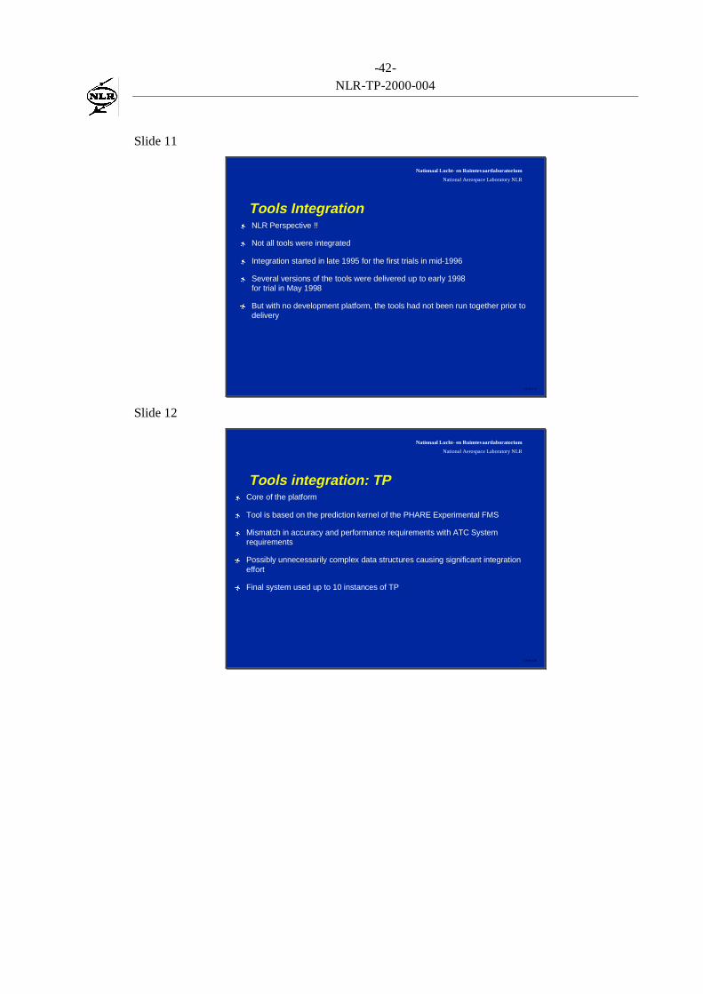
Slide 11
Nationaal Lucht- en Ruimtevaartlaboratorium
National Aerospace Laboratory NLR
CXXX-11A
Tools IntegrationÓ NLR Perspective !!
Ó Not all tools were integrated
Ó Integration started in late 1995 for the first trials in mid-1996
Ó Several versions of the tools were delivered up to early 1998for trial in May 1998
Ó But with no development platform, the tools had not been run together prior todelivery
Slide 12
Nationaal Lucht- en Ruimtevaartlaboratorium
National Aerospace Laboratory NLR
CXXX-12A
Tools integration: TPÓ Core of the platform
Ó Tool is based on the prediction kernel of the PHARE Experimental FMS
Ó Mismatch in accuracy and performance requirements with ATC Systemrequirements
Ó Possibly unnecessarily complex data structures causing significant integrationeffort
Ó Final system used up to 10 instances of TP
-43-NLR-TP-2000-004
Slide 13
Nationaal Lucht- en Ruimtevaartlaboratorium
National Aerospace Laboratory NLR
CXXX-13A
Tools integration: CP
Ó Was developed on the NARSIM NLR platform so little integration effort
Ó With 300 - 400 active trajectories and many system plan updates and what-ifmodelling, performance became a problem
Ó Final system used up to 7 instances of CP
Slide 14
Nationaal Lucht- en Ruimtevaartlaboratorium
National Aerospace Laboratory NLR
CXXX-14A
Tools integration: PS and CT
Ó Interactive nature requires close integration with GHMI
Ó Intention to integrate PS,CP and CT through GHMI ‘Trajectory Editor andProblem Solver’ (TEPS)
Ó For NLR the integration of CT was seen as too much of a risk and so was notintegrated
Ó GHMI problems forced fall back to HIPS developed for PD/1
Ó HIPS was further integrated into the radar PVD
-44-NLR-TP-2000-004
Slide 15
Nationaal Lucht- en Ruimtevaartlaboratorium
National Aerospace Laboratory NLR
CXXX-15A
Tools integration: GeneralÓ Every platform requires full integration cycle, yet pre-integration of tools on
reference platform is very useful
Ó Use of several computer languages is possible but requires more dataconversions reducing performance
Ó The full extent of the operational concept can only be understood once toolsand GHMI have been integrated in the platform
Ó Testing is best performed by using the system in accordance with itsoperational concept
Slide 16
Nationaal Lucht- en Ruimtevaartlaboratorium
National Aerospace Laboratory NLR
CXXX-16A
NLR PD/3 ExperienceNLR PD/3 Experience
● Tools development
● Tools integration
● System Operation
● Conclusions and recommendations

-45-NLR-TP-2000-004
Slide 17
Nationaal Lucht- en Ruimtevaartlaboratorium
National Aerospace Laboratory NLR
CXXX-17A
System Operation Experience
Ó 2 weeks demonstration with 14 ATCOs using full system for the first time
Ó 7 days of training - CBT, Class Room, Hands-on
Ó It takes time to build up trust in the system capabilities and to understand how itwill help manage the traffic
Slide 18
Nationaal Lucht- en Ruimtevaartlaboratorium
National Aerospace Laboratory NLR
CXXX-18A
System operation Experience: Conflict Detection
Ó To gain ATCO trust and to reduce ATCO workload all trajectory conflicts needto be detected.
Ó The conflicts drive the deconfliction action
Ó Resolving trajectory conflicts only makes sense if the trajectory is actually flown- Flight Path Monitor tool
Ó Conflict detection also used by the system to identify need for co-ordinationwith adjacent sectors
Ó Consistency Issues !

-46-NLR-TP-2000-004
Slide 19
Nationaal Lucht- en Ruimtevaartlaboratorium
National Aerospace Laboratory NLR
CXXX-19A
Conflict Management
Ó Only simple support was offered through the conflict riskdisplay
Ó The more advanced support from the agenda like functionof the Co-operative Tools would have been useful
Ó Sharing of conflict resolution activities in the sector teamneeds further research
Slide 20
Nationaal Lucht- en Ruimtevaartlaboratorium
National Aerospace Laboratory NLR
CXXX-20A
Conflict Resolution
Ó Several GHMI functions available to assess conflict configurations
Ó HIPS allows easy re-planning to resolve conflicts
Ó Graphical editing can cause perceptual problems
Ó New solutions possible
Ó Strong performance requirements
Ó STCA consistency - should planning data be used ?

-47-NLR-TP-2000-004
Slide 21
Nationaal Lucht- en Ruimtevaartlaboratorium
National Aerospace Laboratory NLR
CXXX-21A
NLR PD/3 ExperienceNLR PD/3 Experience
● Tools development
● Tools integration
● System Operation
● Conclusions and recommendations
Slide 22
Nationaal Lucht- en Ruimtevaartlaboratorium
National Aerospace Laboratory NLR
CXXX-22A
Conclusions
Ó The basis is an accurate match between flight planning andflight execution
Ó Trajectory prediction is essential
Ó Trust in the system
Ó Good performance is essential for interactive work
-48-NLR-TP-2000-004
Slide 23
Nationaal Lucht- en Ruimtevaartlaboratorium
National Aerospace Laboratory NLR
CXXX-23A
Recommendations
Ó Close the planning loop
Ó Research intoÓFast but accurate trajectory predictionÓFurther development of conflict resolution supportÓConflict management functionalityÓVisualisation of conflict risk
Copyright © 2022 FDOKUMEN