
The Montego Bay Swingset From Backyard Discovery
56
The Montego Bay Swingset From Backyard Discovery Backyard Discovery 3001 N Rouse Ave Pittsburg, KS 66762 www.swingsetsonline.com Sales: 855-308-6871 Support: 800-856-4445 YOU MUST START HERE! Use these assembly instructions to begin assembly of your Montego Bay swingset. 1. The Montego Bay is made from individually packaged components. Each component has its own assembly instructions in the associated box. 2. Build each component according to the instructions in the respective component box(es). 3. Once all components are complete, attach them to the tower to make the Montego Bay configuration as shown. 4. The tower has wall opening panels that are interchangeable so you can choose which one you want to leave off for the slide exit. That way you can have the slide come down either side of the fort you wish without any risk of conflict with another component.
-
Upload
khangminh22 -
Category
Documents
-
view
0 -
download
0
Transcript of The Montego Bay Swingset From Backyard Discovery

The Montego Bay Swingset From Backyard Discovery
Backyard Discovery
3001 N Rouse Ave
Pittsburg, KS 66762
www.swingsetsonline.com
Sales: 855-308-6871
Support: 800-856-4445
YOU MUST START HERE!
Use these assembly instructions to begin assembly of your Montego Bay swingset.
1. The Montego Bay is made from individually packaged components. Each component has its own assembly instructions in the associated box.
2. Build each component according to the instructions in the
respective component box(es).
3. Once all components are complete, attach them to the tower to
make the Montego Bay configuration as shown.
4. The tower has wall opening panels that are interchangeable so you
can choose which one you want to leave off for the slide exit. That
way you can have the slide come down either side of the fort you
wish without any risk of conflict with another component.
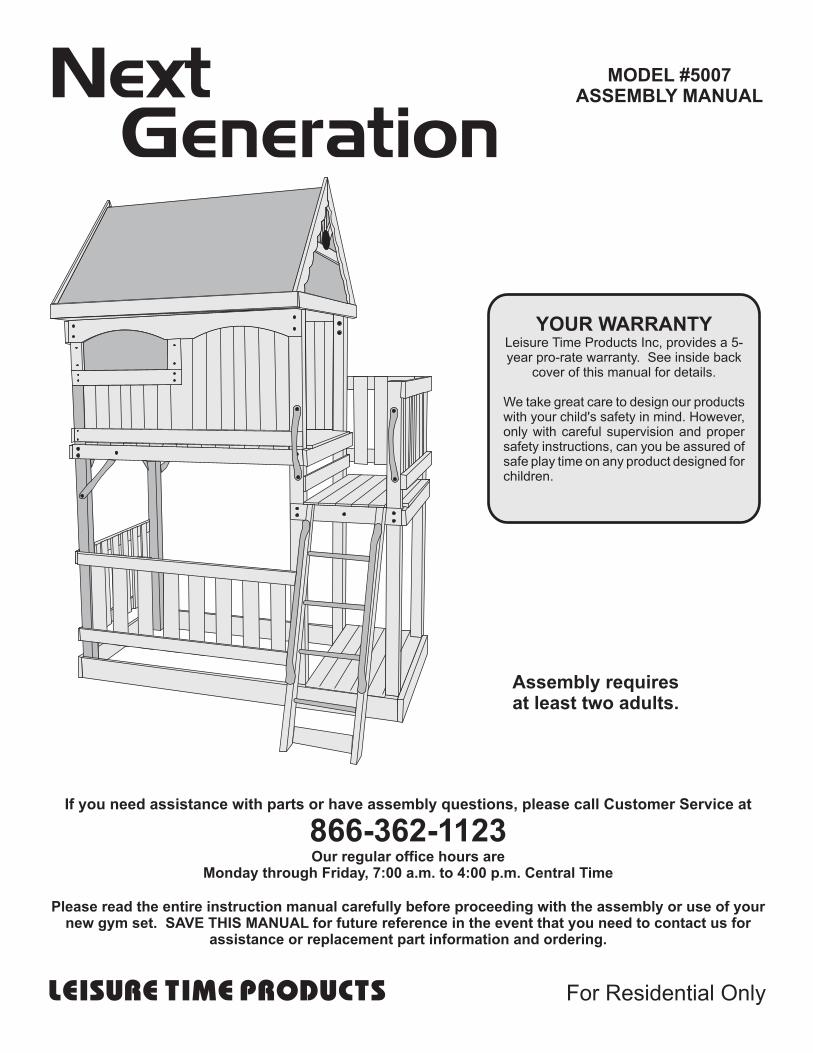
MODEL #5007ASSEMBLY MANUALNext
Generation
If you need assistance with parts or have assembly questions, please call Customer Service at
866-362-1123Our regular office hours are
Monday through Friday, 7:00 a.m. to 4:00 p.m. Central Time
Please read the entire instruction manual carefully before proceeding with the assembly or use of your new gym set. SAVE THIS MANUAL for future reference in the event that you need to contact us for
assistance or replacement part information and ordering.
Assembly requiresat least two adults.
YOUR WARRANTYLeisure Time Products Inc, provides a 5-year pro-rate warranty. See inside back
cover of this manual for details.
We take great care to design our products with your child's safety in mind. However, only with careful supervision and proper safety instructions, can you be assured of safe play time on any product designed for children.
LEISURE TIME PRODUCTS For Residential Only


Prior to assembling your play product, take a installation and at least once per year. thorough inventory of all components using There are many excellent products, such the parts list. as Thompson's Waterseal, Behr Wood
Conditioner, Olympic Water Guard or Sort and lay out all wood pieces, matching Olympic Wood Protector. Please check identical pieces into piles. Mark all pieces of with your local home improvement wood using masking tape, write board letter center to see what they recommend for on tape and adhere to each piece of wood your area conditions. Proper care and for quick reference and identification. maintenance will help maintain the
beauty of the set as well as gain the Sort all hardware according to size. Refer to maximum life of the unit.parts identification section. Selecting the wrong hardware during early assembly will Metal plates: The structural integrity of thelead to shortages. Finding extra hardware is play product is dependent upon the propernot cause for alarm. We often include extra installation of the metal plates. As noted andhardware in case parts are lost during diagramed in these assembly instructions,assembly. the installation of these metal plates must
also be followed precisely. If your play set Selecting the correct location for your has end ladders or swing beam supports,playset product is very important for your make sure they are angled away from thechildren's safety and for the play product's top ladder or swing beam. If a play productlongevity. Your playset must be installed on has one or two climbing towers, the metallevel ground. Installation on sloping ground plates must be installed so that eachwill cause your set to "lean" and, in time, this climbing tower is perpendicular to the topleaning will put stress on all the joints. This ladder.stress will cause the set to become loose and unstable. Once this occurs, it becomes Ground stakes: Metal stakes aredifficult to correct, and Playground, Inc. provided and are to be installed ascannot assume responsibility for any failure outlined in the assembly manual.from incorrect installation. Uneven ground Cementing is recommended andmust be properly leveled before installation. required if you have loose or sandy soil
or if you live in an area that is prone toWarping: Occasionally, some wooden high winds or severe storms.components may twist or warp in the carton
after packaging. This is not necessarily a On site adult supervision is required at allcause for alarm. In most instances, these times for children of all ages.parts straighten out when assembled.
Seasonal checking or cracking of the grain Ensure that suspended climbing ropes,on wooden parts is also quite natural. Water chains or cables are kept tight enough soand heat are the two most frequent causes they cannot be looped back onof expansion and contraction of wood fibers. themselves and are kept secure at bothWe recommend that you apply a wood ends.sealant or protectant at the time of
IMPORTANT TIPS FOR ASSEMBLY
SEE PAGES 34 THRU 36 FOR MAINTENANCE TIPS
Page 1 - SAFETY & ASSEMBLY INFO © Leisure Time Products Inc.Next Generation 5007 10-0409 Version 4
SAFETY AND ASSEMBLY INFORMATIONFOR SAFETY'S SAKE,
PLEASE TAKE TIME TO READ ALL INSTRUCTIONS COMPLETELYAND CAUTION YOUR CHILDREN ACCORDINGLY
Caution for Your Children. Observing the following statements and warnings reduces the likelihood of serious or fatal injury.
• Instruct children not to attach items to the swing set that are not specifically designed for or made to useon the equipment (such as jump ropes, clotheslines, pet leashes, cables, or chains) as this could pose astrangulation hazard.
• Children should use equipment only in its intended manner.• Children should sit in the center of the swings with their full weight on the seats. Only one child per
swing.• Children should NOT wear loose or stringed clothing or jewelry which can cause a potential danger of
strangulation while using playground equipment.• Children should NOT play on equipment in wet weather conditions due to potentially slippery surfaces.• Children should NOT walk too closely in front of, behind, or between moving elements such as swings,
trapezes and gliders.• Children should NOT swing empty swing elements.• Children should NOT jump off swings and/or trapeze while they are in motion. Nor should they jump from
the upper decks – always use the ladders or slides.• Children should NOT climb UP the slide because the slick surface could cause a fall and they should
never slide down head first.• Children should NOT twist swing chains or loop them over the top support beam because this will
weaken and reduce the strength of the chain and possibly break them.• Children should NOT climb on the top ladder when swing elements are in use.• If your set has a Climbing Rope, the Climbing Rope must be attached securely at both ends in such a
manor that it can not be looped back upon itself.
WARNINGSmall components of your play center represent a choking hazard to children. Do not allow access to nuts, bolts, washers or other small parts. Tighten and inspect your play center frequently to avoid this danger.Children must not use equipment until properly installed. Before using your play center, carefully read to any and all children who may use the play center the "safety rules" included in this booklet.Play center modification is forbidden. Any modifications to your play center will affect its structural integrity and render the warranty null and void.
Caution! This play product will not be ready for a child's play until assembly procedures are complete, all hardware is tightened, all ground stakes are installed, and you, the responsible adult, are satisfied that the unit is secure and safe. At this time and always, review the "safety and general information - cautions for use" sections with each child using the play product.
Page 2 - SAFETY & ASSEMBLY INFO © Leisure Time Products Inc.Next Generation 5007 10-0409 Version 4
SAFETY AND ASSEMBLY INFORMATION
Assembly Safety:• Keep the work area clean and clear of obstructions.
• Children should stay out of the work area until the safe play area is cleared of obstacles, the gym set has been completelyassembled, all hardware has been tightened and checked and all tools have been picked up.
• Keep children off the gym set until it has been completely assembled.
• Some parts of the assembly process may require help from another competent adult.
• Do not stand on the platform until the gym set has been completely assembled. Use a step ladder if you can not reach highenough.
• Follow the manufacturers' safety recommendations for the tools and equipment you use.
• Avoid assembling your gym set in poor weather conditions.
• Wear proper clothing and safety equipment (safety glasses, boots and gloves) while assembling your gym set.
Tools and Materials Required:
Claw Type Hammer 10 ft. Tape MeasureFraming Square or Level 10 ft. Step LadderBox Wrench or Sockets (9/16” & ½") Screwdriver (Medium Phillips)Electric Drill or Cordless Beeswax or SoapDrill Bits: 3/16", 3/8" 5/16" & 7/16"(High Speed) (Used to lubricate screw threads)
HAVING THE PROPER TOOLS ON HAND WILL EASE ANDREDUCE THE ASSEMBLY TIME OF YOUR NEW PLAYSET.
YOUR PLAYGROUND, INC READY-TO-ASSEMBLE PLAYSET IS STAINED ATOUR FACTORY. STAINING IS NOT NEEDED AT THE TIME OF INITIAL ASSEMBLY.
Page 3 - SAFETY & ASSEMBLY INFO
POLYETHYLENE ENCASED POSTS:Some lumber inside the polyethylene encased posts MAYBE subject to the following treatment
Supplier: Pacific Wood Preserving22125 Rock Creek Rd.Sheridan, OR 97378
Preservative: Pacbor Treated (Disodium Octaborate Tetrahydrate)
Retention level: .118 pcfWood species: Pine, White Fir, Hem Fir,
and/or Doug Fir
THE WOODEN PARTS FOR YOUR PLAYSET ARE MADE FROMCYPRESS AND OTHER UNTREATED NATURALLY DECAY RESISTANT LUMBER,
WITH THE FOLLOWING, POSSIBLE EXCEPTIONS:
© Leisure Time Products Inc.Next Generation 5007 10-0409 Version 4
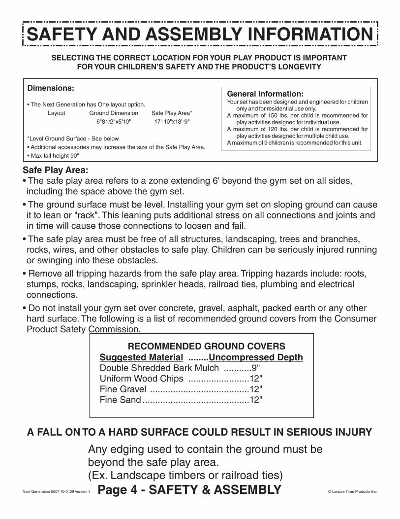
RECOMMENDED GROUND COVERSSuggested Material ........Uncompressed DepthDouble Shredded Bark Mulch ...........9"Uniform Wood Chips ........................12"Fine Gravel .......................................12"Fine Sand ..........................................12"
SELECTING THE CORRECT LOCATION FOR YOUR PLAY PRODUCT IS IMPORTANTFOR YOUR CHILDREN’S SAFETY AND THE PRODUCT’S LONGEVITY
Safe Play Area:• The safe play area refers to a zone extending 6' beyond the gym set on all sides,including the space above the gym set.
• The ground surface must be level. Installing your gym set on sloping ground can causeit to lean or "rack". This leaning puts additional stress on all connections and joints andin time will cause those connections to loosen and fail.
• The safe play area must be free of all structures, landscaping, trees and branches,rocks, wires, and other obstacles to safe play. Children can be seriously injured runningor swinging into these obstacles.
• Remove all tripping hazards from the safe play area. Tripping hazards include: roots,stumps, rocks, landscaping, sprinkler heads, railroad ties, plumbing and electricalconnections.
• Do not install your gym set over concrete, gravel, asphalt, packed earth or any otherhard surface. The following is a list of recommended ground covers from the ConsumerProduct Safety Commission.
A FALL ON TO A HARD SURFACE COULD RESULT IN SERIOUS INJURY
Any edging used to contain the ground must bebeyond the safe play area.(Ex. Landscape timbers or railroad ties)
Dimensions:
• The Next Generation has One layout option.
Layout Ground Dimension Safe Play Area*
6"81/2"x5'10" 17'-10"x18'-9"
*Level Ground Surface - See below
• Additional accessories may increase the size of the Safe Play Area.
• Max fall height 90"
General Information:Your set has been designed and engineered for children
only and for residential use only.A maximum of 150 lbs. per child is recommended for
play activities designed for individual use.A maximum of 120 lbs. per child is recommended for
play activities designed for multiple child use.A maximum of 9 children is recommended for this unit.
SAFETY AND ASSEMBLY INFORMATION
Page 4 - SAFETY & ASSEMBLY © Leisure Time Products Inc.Next Generation 5007 10-0409 Version 4

© Leisure Time Products Inc.Next Generation 5007 10-0409 Version 4 Page 5 - SAFETY & ASSEMBLY
Basic Setup Diagram

PLAYGROUND, INC. GYM SETS USE A FEW STANDARD CONNECTIONS.BECOMING FAMILIAR WITH THESE CONNECTIONS WILL SIMPLIFY ASSEMBLY
AND INSURE A SAFER PLAY PRODUCT FOR YOUR CHILDREN.
USING THE HARDWARE
Failure to replacethis bolt with ashorter one couldresult in personal injury.
Check the positioning of parts in each Step's illustration, noting which of the parts should receive the Spike T-Nut. Place the Spike T-Nut in the hole and then seat it with one or two taps of a hammer. Align the holes in the parts to be fastened. Start preliminary tightening of bolt into seated nut by hand.
To securely tighten, turn the bolt with a wrench until the lock washer is fully compressed between the head of the bolt and the flat washer.
Note that in some steps the instructions say to tighten "just snug." This means to tighten the bolt just enough to keep the parts together, but loose enough to allow the parts to move. This is necessary to allow squaring and leveling. The bolt will be tightened securely in a following step. All bolts and screws must be tightened securely before the playset is ready for use.
Bolt has been screwed securely into Spike T-Nut and the connection is tight.
Check connec-tions periodically for tightness during the life of the Gym set.
Lock Washer
Hex HeadBolt Flat
Washer
Spike T-NutHow to use Hex Head Bolts and Spike T-Nuts Correct
Assembly
Do notover tighten.
Typical Installation -Lag Screw:Typical Installation -Wood Screw:• Use an electric drill or screw gun to drive screws.
• These screws are self-tapping, so no pilotholes are required.• Lubricate the threads of the screwswith beeswax or soap to ease installation and minimize breaking screws.
• It is very important to make certainthat the tops of all screws are flush with the surface of the wood and there are no protruding sharp edges.
• Always drill pilot holeswhen using LagScrews. The size ofthe pilot hole will bespecified in the Step.
• Tap the head of the LagScrew with a hammer tostart the threads into thewood and then use a ½"socket to tighten.
Lag Screw
FlatWasher
LockWasher
• DO NOT over tighten• DO NOT over tighten
• DO NOT DRIVETOO DEEPAND CAUSE
SPLINTERING
• DO NOT DRIVETOO DEEPAND CAUSE
SPLINTERING
Page 6 - USING THE HARDWARE
TIP: Tap the Spike T-Nut into the part before you position the part on the structure. If you put it in the wrong hole, remove it by inserting a bolt from the opposite side of the board and tapping the bolt lightly with a hammer.
Incorrect AssemblyDuring assembly or maintenance, do not over tighten the bolts. Over tightening can cause the bolt to protrude past the spiked tee nut, which could cause personal injury. Over tightening can also cause the wood to be compressed or to “sink in” the bolt, washer or spiked tee nut. If this has happened, you may need to add additional washers or replace the bolt with a shorter one, so that the bolt does not protrude.
© Leisure Time Products Inc.Next Generation 5007 10-0409 Version 4
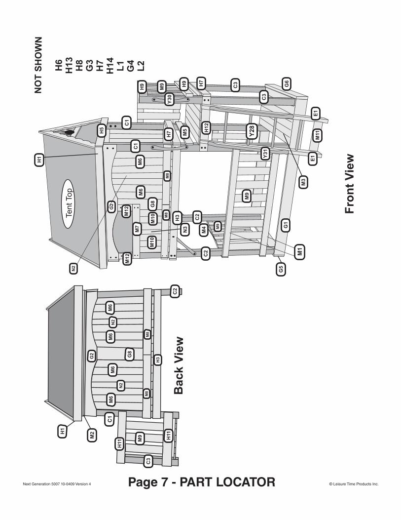
© Leisure Time Products Inc.Next Generation 5007 10-0409 Version 4 Page 7 - PART LOCATOR
Fro
nt
Vie
w
NO
T S
HO
WN
H6
H13
H8
G3
H7
H14
L1
G4
L2
M6
M6
N2
Back V
iew
N2
M8
C1
M2
H11 H
11
C2
C3
H1
M9
G8
M6
M6
M8
H3G
2
Tent To
p
G2
N2
M8
M8
C1
G1
G6
G5
C2
C2
C1
C3
H5
H1
H3
M6
H9 H9
H7
H7 M5
M9
M9
M4
E1
E1
M11H
12
Y28
M3
Y3
1
Y3
0
M6
C3
M7
M12
M12 G
8
N3
M10
M10
M1
M9
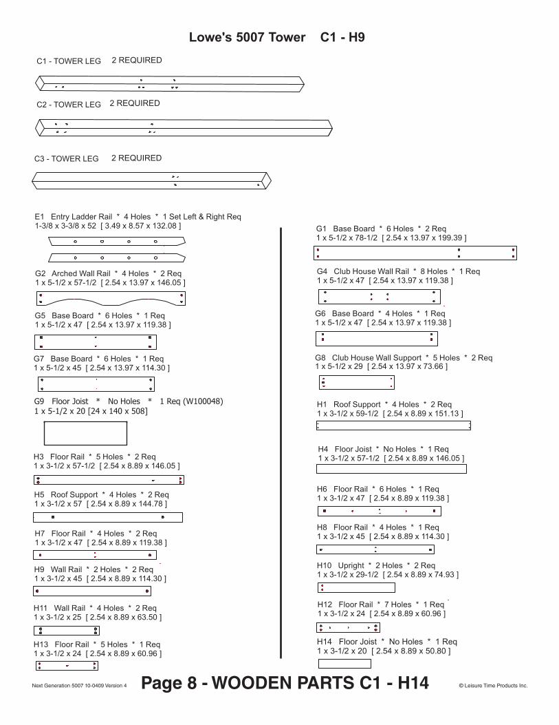
E1 Entry Ladder Rail * 4 Holes * 1 Set Left & Right Req1-3/8 x 3-3/8 x 52 [ 3.49 x 8.57 x 132.08 ]
1 x 5-1/2 x 78-1/2 [ 2.54 x 13.97 x 199.39 ]G1 Base Board * 6 Holes * 2 Req
1 x 5-1/2 x 57-1/2 [ 2.54 x 13.97 x 146.05 ]G2 Arched Wall Rail * 4 Holes * 2 Req
1 x 5-1/2 x 47 [ 2.54 x 13.97 x 119.38 ]G4 Club House Wall Rail * 8 Holes * 1 Req
1 x 5-1/2 x 47 [ 2.54 x 13.97 x 119.38 ]G5 Base Board * 6 Holes * 1 Req
1 x 5-1/2 x 47 [ 2.54 x 13.97 x 119.38 ]G6 Base Board * 4 Holes * 1 Req
1 x 5-1/2 x 45 [ 2.54 x 13.97 x 114.30 ]G7 Base Board * 6 Holes * 1 Req
1 x 5-1/2 x 29 [ 2.54 x 13.97 x 73.66 ]G8 Club House Wall Support * 5 Holes * 2 Req
1 x 3-1/2 x 59-1/2 [ 2.54 x 8.89 x 151.13 ]H1 Roof Support * 4 Holes * 2 Req
1 x 3-1/2 x 57-1/2 [ 2.54 x 8.89 x 146.05 ]H3 Floor Rail * 5 Holes * 2 Req 1 x 3-1/2 x 57-1/2 [ 2.54 x 8.89 x 146.05 ]
H4 Floor Joist * No Holes * 1 Req
1 x 3-1/2 x 57 [ 2.54 x 8.89 x 144.78 ]H5 Roof Support * 4 Holes * 2 Req 1 x 3-1/2 x 47 [ 2.54 x 8.89 x 119.38 ]
H6 Floor Rail * 6 Holes * 1 Req
1 x 3-1/2 x 47 [ 2.54 x 8.89 x 119.38 ]H7 Floor Rail * 4 Holes * 2 Req 1 x 3-1/2 x 45 [ 2.54 x 8.89 x 114.30 ]
H8 Floor Rail * 4 Holes * 1 Req
1 x 3-1/2 x 45 [ 2.54 x 8.89 x 114.30 ]H9 Wall Rail * 2 Holes * 2 Req
Lowe's 5007 Tower C1 - H9
© Leisure Time Products Inc.Next Generation 5007 10-0409 Version 4 Page 8 - WOODEN PARTS C1 - H14
C1 - TOWER LEG 2 REQUIRED
C2 - TOWER LEG 2 REQUIRED
C3 - TOWER LEG 2 REQUIRED
1 x 3-1/2 x 29-1/2 [ 2.54 x 8.89 x 74.93 ]H10 Upright * 2 Holes * 2 Req
1 x 3-1/2 x 25 [ 2.54 x 8.89 x 63.50 ]H11 Wall Rail * 4 Holes * 2 Req
1 x 3-1/2 x 24 [ 2.54 x 8.89 x 60.96 ]H12 Floor Rail * 7 Holes * 1 Req
1 x 3-1/2 x 24 [ 2.54 x 8.89 x 60.96 ]H13 Floor Rail * 5 Holes * 1 Req H14 Floor Joist * No Holes * 1 Req
1 x 3-1/2 x 20 [ 2.54 x 8.89 x 50.80 ]
G9 Floor Joist * No Holes * 1 Req (W100048)1 x 5-1/2 x 20 [24 x 140 x 508]

11/16 x 3-3/8 x 23 [ 1.74 x 8.57 x 58.42 ]M9 Wall Board * 4 Holes * 23 Req11/16 x 3-3/8 x 28-3/4 [ 1.74 x 8.57 x 73.03 ]
M8 Club House Rail * 3 Holes * 4 Req
11/16 x 3-3/8 x 28-3/4 [ 1.74 x 8.57 x 73.03 ]M7 Window Trim * 4 Holes * 1 Req
Lowe's 5007 Tower H10 - N3
L1 Floor Board * 4 Holes * 4 Req11/16 x 4-1/2 x 39 [ 1.74 x 11.43 x 99.06 ]
L2 Club House Wall Board * 4 Holes * 1 Req11/16 x 4-1/2 x 29 [ 1.74 x 11.43 x 73.66 ]
M1 Wall Rail * 4 Holes * 2 Req11/16 x 3-3/8 x 57-1/2 [ 1.74 x 8.57 x 146.05 ]
11/16 x 3-3/8 x 57-1/2 [ 1.74 x 8.57 x 146.05 ]M2 Roof Spacer * 3 Holes * 2 Req
11/16 x 3-3/8 x 47 [ 1.74 x 8.57 x 119.38 ]M3 Floor Board * 5 Holes * 24 Req
11/16 x 3-3/8 x 45-3/4 [ 1.74 x 8.57 x 116.21 ]M4 Wall Rail * 4 Holes * 2 Req
11/16 x 3-3/8 x 45 [ 1.74 x 8.57 x 114.30 ]M5 Club House Rail * 4 Holes * 2 Req
11/16 x 3-3/8 x 29 [ 1.74 x 8.57 x 73.66 ]M6 Club House Wall Board * 4 Holes * 28 Req
M10 Club House Wall Board * 4 Holes * 6 Req11/16 x 3-3/8 x 16 [ 1.74 x 8.57 x 40.64 ] M11 Entry Ladder Support * 4 Holes * 1 Req
11/16 x 3-3/8 x 16 [ 1.74 x 8.57 x 40.64 ]
M12 Window Trim * 2 Holes * 2 Req11/16 x 3-3/8 x 6-3/4 [ 1.74 x 8.57 x 17.15 ] N1 Floor Board * 5 Holes * 1 Req
11/16 x 2-1/2 x 47 [ 1.74 x 6.35 x 119.38 ]
11/16 x 2-1/2 x 29 [ 1.74 x 6.35 x 73.66 ]N2 Club House Wall Board * 2 Holes * 3 Req
11/16 x 2-1/2 x 16 [ 1.74 x 6.35 x 40.64 ]N3 Club House Wall Board * 2 Holes * 1 Req
© Leisure Time Products Inc.Next Generation 5007 10-0409 Version 4 Page 9 - WOODEN PARTS J1 - 02
N4 Cross Brace * 4 Holes * 2 Req (W100043)11/16 x 2-3/8 x 30-7/8 [16 x 60 x 784] N5 Starburst * 2 Holes * 2 Req (W100044)
11/16 x 2-3/8 x 13 [16 x 60 x 332]
N6 Starburst * 2 Holes * 4 Req (W100045)11/16 x 2-3/8 x 7-1/4 [16 x 60 x 184]
L3L Left Roof Rail * 6 Hole * 2 Req (W100042)11/16 x 4-3/8 x 41-5/8 [16 x 110 x 1058]
L3R Right Roof Rail * 6 Hole * 2 Req (W100457)11/16 x 4-3/8 x 41-5/8 [16 x 110 x 1058]
J1 Tent Support * 4 Holes * 1 Req (W100041)1 x 2-3/8 x 57-5/8 [24 x 60 x 1464]
SC1 Tent Cleat * 5 Holes * 2 Req (W100046)11/16 x 2 x 57-3/8 [16 x 50 x 1456]
O1 Tent Cleat * 4 Holes * 4 Req (W100047)11/16 x 1-1/2 x 36-5/8 [16 x 38 x 930]
O2 Roof Cleat * 3 Holes * 4 Req (W100371)11/16 x 1-1/2 x 4-1/4 [16 x 38 x 108]
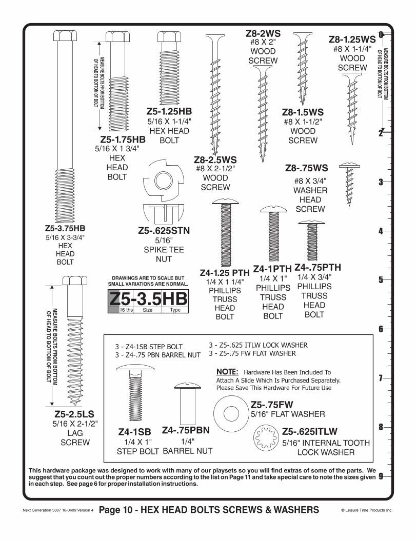
Page 10 - HEX HEAD BOLTS SCREWS & WASHERS
5/16 X 1-1/4"HEX HEAD
BOLT
Z5-1.25HB
DRAWINGS ARE TO SCALE BUTSMALL VARIATIONS ARE NORMAL.
Z5-3.5HB16 ths Size Type
0
1
2
3
4
5
6
7
8
9
MEASURE BOLTS FROM BOTTOMOF HEAD TO BOTTOM OF BOLT
MEASURE BOLTS FROM BOTTOMOF HEAD TO BOTTOM OF BOLT
5/16 X 1 3/4"HEX
HEADBOLT
Z5-1.75HB
5/16 X 3-3/4"HEX
HEADBOLT
Z5-3.75HB
5/16 X 2-1/2"LAG
SCREW
Z5-2.5LS
MEA
SUR
E BO
LTS FRO
M B
OTTO
MO
F HEA
D TO
BO
TTOM
OF B
OLT
1/4"BARREL NUT
Z4-.75PBN1/4 X 1"
STEP BOLT
Z4-1SB
1/4 X 1 1/4"PHILLIPSTRUSSHEADBOLT
Z4-1.25 PTH1/4 X 1"
PHILLIPSTRUSSHEADBOLT
Z4-1PTH1/4 X 3/4"PHILLIPSTRUSSHEADBOLT
Z4-.75PTH
5/16"SPIKE TEE
NUT
Z5-.625STN
5/16" FLAT WASHERZ5-.75FW
#8 X 3/4WASHER
HEADSCREW
"
Z8-.75WS#8 X 2-1/2"WOODSCREW
Z8-2.5WS
#8 X 2"WOODSCREW
Z8-2WS
#8 X 1-1/2"WOODSCREW
Z8-1.5WS
#8 X 1-1/4"WOODSCREW
Z8-1.25WS
This hardware package was designed to work with many of our playsets so you will find extras of some of the parts. We suggest that you count out the proper numbers according to the list on Page 11 and take special care to note the sizes given in each step. See page 6 for proper installation instructions.
© Leisure Time Products Inc.Next Generation 5007 10-0409 Version 4
3 - Z4-1SB STEP BOLT3 - Z4-.75 PBN BARREL NUT
3 - Z5-.625 ITLW LOCK WASHER3 - Z5-.75 FW FLAT WASHER
NOTE: Hardware Has Been Included To
Attach A Slide Which Is Purchased Separately. Please Save This Hardware For Future Use
5/16"LOCK WASHER INTERNAL TOOTH
Z5-.625ITLW

GREEN MESHWINDOW1 13x23
5007
ADDITIONAL ITEMS1 - METAL ID PLAQUE 4 - GROUND STAKES1 - ASSEMBLY MANUAL 1 - POUNDING BLOCK4 - Y28 15 1/4" METAL DOWELS
Y9
5007 TENT TOP87" X 57 ½"
Page 11 - FASTENER DETAIL LIST & MISC. PARTS
NO
TE
: QU
AN
TIT
IES
INC
LU
DE
EX
TR
A H
AR
DW
AR
E
PART # . . . . . . . . . . . . . . . . . . . DESCRIPTION . . . . . . . . . . . . . . TOTAL . BAG #
Z5-3.75HB. . . . . . . . . . . . 5/16-18 x 3 3/4" Hex Head Bolt. . . . . . . . . . . . 40. . . . . . 1
Z5-1.75HB. . . . . . . . . . . . 5/16-18 x 1 3/4" Hex Head Bolt. . . . . . . . . . . . . 4. . . . . . 1
Z5-1.25HB. . . . . . . . . . . . 5/16-18 x 1 1/4" Hex Head Bolt. . . . . . . . . . . . . 6. . . . . . 1
Z4-1.25PTH . . . . . . . . 1/4-20 x 1 1/4" Phillips Truss Head Bolt . . . . . . . . . . 4. . . . . . 2
Z4-1PTH . . . . . . . . . . . . 1/4-20 x 1" Phillips Truss Head Bolt. . . . . . . . . . . . 4. . . . . . 2
Z4-.75PTH . . . . . . . . . . 1/4-20 x 3/4" Phillips Truss Head Bolt . . . . . . . . . . . 4. . . . . . 2
Z4-1SB . . . . . . . . . . 7/8" Head Diameter - 1/4-20 x 1" Step Bolt . . . . . . . . 3. . . . . . 2
Z8-.75WHS. . . . . . #8 x 3/4" Modified Truss Washer Head Screw . . . . . . 15. . . . . . 2
Z4-.75PBN . . . . . . . . . 1/4-20 x 3/4" LONG - Phillips Barrel Nut . . . . . . . . . 17. . . . . . 2
Z5-2.5LS. . . . . . . . . . . . . . . . 5/16 x 2 1/2" Lag Screw . . . . . . . . . . . . . . 60. . . . . . 3
Z8-2.5WS . . . . . . #8 x 2 1/2" Phillips Type 17 w/nibs Wood Screw . . . . . 28. . . . . . 4
Z8-2WS . . . . . . . . . #8 x 2" Phillips Type 17 w/nibs Wood Screw . . . . . . 237. . . . . . 5
Z8-1.5WS . . . . . . #8 x 1 1/2" Phillips Type 17 w/nibs Wood Screw . . . . 116. . . . . . 6
Z8-1.25WS . . . . . #8 x 1 1/4" Phillips Type 17 w/nibs Wood Screw . . . . 160. . . . . . 7
Z5-.625STN . . . . . . . . 5/16-18 x 5/8" LONG - Spiked Tee Nut . . . . . . . . . 58. . . . . . 8
Z5-.75FW . . . . . . . 5/16 SAE Flat Washer - 11/16"OD x 11/32" ID . . . . . 132. . . . . . 9
Z5-.625ITLW . . . . . 5/16 Internal Tooth Lock Washer - 19/32" OD . . . . . 130. . . . . 10
2" x 1" METAL BRACKET
2 REQUIRED
METAL DECK BRACE6 REQUIRED
Y2 Y18
Plastic Cap6 Required
Y30
16 1/2"METAL GRIP2 REQUIRED
Y3135"
METAL GRIP2 REQUIRED
© Leisure Time Products Inc.Next Generation 5007 10-0409 Version 4

STEP 1Start by laying C2, C1 and C3 Posts flat on ground. Install 5/16” Spike T-Nuts in the double holes that are towards the bottom of posts. Then flip posts over so that the T-Nuts are towards the ground. Then place H3 Floor Rail, five-hole board, on C2 and C1 Post. Note: The single hole in the H3 Rail is towards C2, and then attach using 5/16x3-3/4"HEX BOLTS, Internal Tooth Lock Washers and Flat Washers.
STEP 2Install H12 Floor Rail, seven-hole, to C1 and C3 Posts using 5/16 x 3-3/4” Hex Bolts, Internal Tooth Lock Washers and Flat Washers. Note: center hole at 5" towards C1 Post *
STEP 3Lay opposite Posts C2, C1 and C3 as before in Step 1 and Step 2, and place 5/16” Spike T-Nuts in posts and attach H3, again noting single hole toward C2 Post, using 5/16 x 3-3/4” Hex Bolt, Internal Tooth Lock Washers and Flat Washers
STEP 4Attach H13 Floor Rail, five-hole, to C1 and C3 Posts using 5/16 x 3-3/4” Hex Bolts, Internal Tooth Lock Washers , Flat Washers and Spike T Nut.
H13
C3C1 C2
H3
C3 - TOWER LEG
C2 - TOWER LEG
C1 - TOWER LEG
1 x 3-1/2 x 57-1/2 [ 2.54 x 8.89 x 146.05 ]H3 Floor Rail * 5 Holes * 2 Req
1 x 3-1/2 x 24 [ 2.54 x 8.89 x 60.96 ]H13 Floor Rail * 5 Holes * 1 Req
1 x 3-1/2 x 24 [ 2.54 x 8.89 x 60.96 ]H12 Floor Rail * 7 Holes * 1 Req
5/16 X 3-3/4"HEX
HEADBOLT
5/16"SPIKE TEE
NUT5/16"
INTERNALTOOTHLOCK
WASHER
5/16" FLATWASHER
© Leisure Time Products Inc.Next Generation 5007 10-0409 Version 4 Page 12
C1C2
C3
H12
H3
Note Flush Bottom of Posts
Note Flush Bottom of Posts*5"
Single Hole
Single Hole

STEP 5This step will take two people. Stand up front and back assemblies. Attach Left Floor Rail H6 to C2 Post using 5/16"x3-3/4" Hex Bolts, Internal Tooth Lock Washers, Flat Washers and Spike T Nut.
STEP 6 Attach Right Floor Rail H7 to C3 Post using 5/16 x 3-3/4” Hex Bolts, Internal Tooth Lock Washers, Flat Washers and Spike T Nut.
C2
C2 C1C1
C3
C3
H6
H13
H12
H3
C1C1
C2
C3
C3
H12
H13H7
H3
1 x 3-1/2 x 47 [ 2.54 x 8.89 x 119.38 ]H6 Floor Rail * 6 Holes * 1 Req
1 x 3-1/2 x 47 [ 2.54 x 8.89 x 119.38 ]H7 Floor Rail * 4 Holes * 2 Req
5/16 X 3-3/4"HEX
HEADBOLT
5/16"SPIKE TEE
NUT5/16"
INTERNALTOOTHLOCK
WASHER
5/16" FLATWASHER
© Leisure Time Products Inc.Next Generation 5007 10-0409 Version 4 Page 13

STEP 7 Attach another H7 Floor Rail to C1 Post using 5/16 x 3-3/4” Hex Bolts, Internal Tooth Lock Washers, Flat Washers and Spike T Nut.
STEP 8Attach H8 Floor Rail, four-hole, to C1 Post using 5/16 x 3-3/4” Hex Bolts, Internal Tooth Lock Washers, Flat Washers and Spike T Nut.
C1 C1
C1C1
C3C3
C3
C3
C2 C2
C2C2
H7
H7
H7
H7
H8
1 x 3-1/2 x 45 [ 2.54 x 8.89 x 114.30 ]H8 Floor Rail * 4 Holes * 1 Req
1 x 3-1/2 x 47 [ 2.54 x 8.89 x 119.38 ]H7 Floor Rail * 4 Holes * 2 Req
5/16 X 3-3/4"HEX
HEADBOLT
5/16"SPIKE TEE
NUT5/16"
INTERNALTOOTHLOCK
WASHER
5/16" FLATWASHER
© Leisure Time Products Inc.Next Generation 5007 10-0409 Version 4 Page 14

STEP 9Attach G1 Front and Back Baseboards, placing flush with outside of C2 and C3 Posts,pilot drill with 3/16" bit using holes in G1 as guide and attach using 5/16x2-1/2” Lag Screws, Internal Tooth Lock Washers and Flat Washers.Center C1 post straight up and down and finish attaching G1 using 2 1/2" lag screws,lock washers and flat washers.
STEP 10Attach G5 Left Baseboard to C2 Post, flushing with outside of G1 Baseboards, pilot drill with 3/16"bit using holes in G5 as guide and attach using 5/16x2-1/2” Lag Screws, Internal Tooth Lock Washers and Flat Washers. C1
C1
C1C1
C2C2
C2C2
C3
C3
G1
G1
G1G1
G5
H3H6
H8
1 x 5-1/2 x 78-1/2 [ 2.54 x 13.97 x 199.39 ]G1 Base Board * 6 Holes * 2 Req
1 x 5-1/2 x 47 [ 2.54 x 13.97 x 119.38 ]G5 Base Board * 6 Holes * 1 Req
5/16 X 2-1/2"LAG
SCREW
5/16"INTERNAL
TOOTHLOCK
WASHER
5/16" FLATWASHER
© Leisure Time Products Inc.Next Generation 5007 10-0409 Version 4 Page 15

STEP 11Attach G6 Right Baseboard on C3 Post, flushing with G1 Baseboard, pilot drill with 3/16" bit using holes in G6 as a guide. Attach using 2-1/2” Lag Screws, Internal Tooth Lock Washers and Flat Washers.
STEP 12Attach G7 Center Baseboard, 6-hole, on Left side of C1 Post, pilot drill with 3/16" bit using holes in G7 as a guide. Attach using 2-1/2” Lag Screws, Internal Tooth Lock Washers and Flat Washers.
C2
C2
C2
C2
C1
C1
C1C1
C3
C3
C3 C3
G6
G5
G5
G6
G1
G1 G1
1 x 5-1/2 x 47 [ 2.54 x 13.97 x 119.38 ]G6 Base Board * 4 Holes * 1 Req
1 x 5-1/2 x 45 [ 2.54 x 13.97 x 114.30 ]G7 Base Board * 6 Holes * 1 Req
5/16 X 2-1/2"LAG
SCREW
5/16"INTERNAL
TOOTHLOCK
WASHER
5/16" FLATWASHER
© Leisure Time Products Inc.Next Generation 5007 10-0409 Version 4 Page 16
G1
G7

STEP 13Attach G9 Bottom Floor Joist between G7 Baseboard and Left G6 Baseboard and attach with four 2-1/2” Wood Screws.
Note: You must pilot drill G6 and Center screws into G9.
STEP 14Attach H4 Top Floor Joist between H6 Left Floor Rail and H7 Right Floor Rail using four 2-1/2” Wood Screws. Note: Center screws into H7.
C2
C2
C2
C1C1
C1
C1
C3
C3
C3
C3
G1
G1G5
H7
H7
H3
H3
H8
H4H6
1 x 3-1/2 x 57-1/2 [ 2.54 x 8.89 x 146.05 ]H4 Floor Joist * No Holes * 1 Req
#8 X 2-1/2"WOODSCREW
© Leisure Time Products Inc.Next Generation 5007 10-0409 Version 4 Page 17
G7
G9 Floor Joist * No Holes * 1 Req (W100048)1 x 5-1/2 x 20 [24 x 140 x 508]
G6G9

STEP 15Attach H14 Lower Top Floor Joist to H7 Right Floor Rail and H8 Center Floor Rail using four 2-1/2” Wood Screws. Note: Center screws into H14.
STEP 16Attach 5/16” Spike T-Nuts on outside of Floor Rails on left front and back of Upper Floor Rails and front and back of Lower-Upper Floor Rails. Now attach Y2 Deck Braces using 5/16 x 1-1/4” Hex Bolts, Internal Tooth Lock Washers and Flat Washers. At this point, level Set at each corner and attach Y2 Deck Braces, to the Tower Posts, pilot drill using 3/16" bit and attach using 2-1/2” Lag Screws, Internal Tooth Lock Washers and Flat Washers.
STEP 17At this point, place the Y18 Plastic Post Caps on all six of the Tower Posts.
H14
C1C1
C1C1
C3C3
C3
C3
C2
C2
C2
C2
H3
H3
H3H6
H6
H8
H7
H7
H12
H13
H14 Floor Joist * No Holes * 1 Req1 x 3-1/2 x 20 [ 2.54 x 8.89 x 50.80 ]
Y18
Plastic Cap6 RequiredMETAL DECK BRACE
6 REQUIRED
Y2
5/16 X 1-1/4"HEX HEAD
BOLT
5/16 X 2-1/2"LAG
SCREW
5/16"SPIKE TEE
NUT
5/16"INTERNAL
TOOTHLOCK
WASHER
5/16" FLATWASHER
#8 X 2-1/2"WOODSCREW
© Leisure Time Products Inc.Next Generation 5007 10-0409 Version 4 Page 18

STEP 19Attach L1, four-hole Floor Boards, between Tower Posts flushing to outside of Left and Right Floor Rail on Top Floor and between C3 Posts on Lower Floor flush with the Right Floor Rail. Attach using 2” Wood Screws.
28 3/4"
STEP 18Now at Front Floor Rail and Back Floor Rail measure to center of Rail approximately 28-3/4” and mark Rail. Now attach N1, five-hole Floor Board, in center of floor using marks to locate, and Attach using 2” Wood Screws.
STEP 20On Upper Floor place M3, five-hole Floor Boards, seven on each side of N1 Center Floor Board, and space evenly. Then attach using 2” Wood Screws.
C1
C1
C1
C1
C1C1
C2
C2C2
C2
C2
C3
C3
C3
H3
N1
H4
L1
L1
H7
H8
M3M3
N1
L1L1
L1 Floor Board * 4 Holes * 4 Req11/16 x 4-1/2 x 39 [ 1.74 x 11.43 x 99.06 ]
11/16 x 3-3/8 x 47 [ 1.74 x 8.57 x 119.38 ]M3 Floor Board * 5 Holes * 34 Req
N1 Floor Board * 5 Holes * 1 Req11/16 x 2-1/2 x 47 [ 1.74 x 6.35 x 119.38 ]
#8 X 2"WOODSCREW
© Leisure Time Products Inc.Next Generation 5007 10-0409 Version 4 Page 19

STEP 22Drive 5/16” Spike T-Nuts into inside of C2 and C1 Posts. Then attach G2 Sculptured Rails to front and back of C2 and C1 Posts using 5/16 x 3-3/4” Hex Bolts, Internal Tooth Lock Washers and Flat Washers.
G2
G2
C1
C1C2
C2
H3
1 x 5-1/2 x 57-1/2 [ 2.54 x 13.97 x 146.05 ]G2 Arched Wall Rail * 4 Holes * 2 Req L1 Floor Board * 4 Holes * 4 Req
11/16 x 4-1/2 x 39 [ 1.74 x 11.43 x 99.06 ]
© Leisure Time Products Inc.Next Generation 5007 10-0409 Version 4 Page 20
5/16 X 3-3/4"HEX
HEADBOLT
5/16"SPIKE TEE
NUT
5/16"INTERNAL
TOOTHLOCK
WASHER
5/16" FLATWASHER
#8 X 2"WOODSCREW
C2
C1
C1C3
C3
G1
G1
G9
G5
G7
STEP 21
Now is the time to position unit in permanent spot. Secure the playset to the ground by using the stakes in the locations shown by the black circles. Metal stake installation: Measure in 8” from inside post and mark ground for stake location. Now remove G5 and G6 base board to allow room to twist stake into ground. You will need a long screwdriver for leverage. In some cases you may need to dig a hole to install stake and cement. Now reattach the G5 and G6 baseboards to the unit
Use hole in stake as guide to drill 3/8" pilot hole thru base board use 1" phillips truss head bolt, 5/16" flat washer thru stake into baseboard 5/16" flat washer, 5/16" lock washer on barrel nut attach to base board.
Metal Stake
FLATWASHER
BOLT
LOCKWASHER
BO
AR
D
FLATWASHER
BARRELNUT
5/16"
METAL STAKESY41
G6

STEP 24Now install five M3 Floor Boards on Top-Lower Floor spacing evenly using 2” Wood Screws.
STEP 25Attach L1, four-hole Floor Board, between Tower Posts flushing to outside of Left and Right Floor Rail on Bottom Floor and between C3 Posts.
At this point, install Lower Deck Floor Boards, M3, using 2” Wood Screws spacing fifteen M3 Floor Boards evenly.
C1
C1 C3
C3
H7
M3
11/16 x 3-3/8 x 47 [ 1.74 x 8.57 x 119.38 ]M3 Floor Board * 5 Holes * 24 Req
© Leisure Time Products Inc.Next Generation 5007 10-0409 Version 4 Page 21
STEP 23Attach G4, eight-hole, Clubhouse Wall Rail to C2 Post using 5/16 x 3-3/4” Hex Bolts, Internal Tooth Lock Washers, Flat Washers and Spike T Nuts.
G2
G2
C1C1
C2C2
H3H6
G4
1 x 5-1/2 x 47 [ 2.54 x 13.97 x 119.38 ]G4 Club House Wall Rail * 8 Holes * 1 Req
5/16 X 3-3/4"HEX
HEADBOLT
5/16"SPIKE TEE
NUT
5/16"INTERNAL
TOOTHLOCK
WASHER
5/16" FLATWASHER
#8 X 2"WOODSCREW
M3
L1
C3
C3

2 1
/4"
STEP 26Attach M5, four-hole, Clubhouse Rail at left side of Tower C2 Post. Place on top of L1 Deck Board and flush with outside of C2 Post. Attach using 2” Wood Screws.
STEP 27Attach M5, four-hole, Clubhouse Rail at C1 Post above Lower and Top Deck; measuring 2-1/4” up from top of M3 Floor Board mark C1 Post. Attach using 2” Wood Screws.
G2G2
M5
C1 C1
C1
C1 C2C2
C2C2
C3
H6
H7
H7
11/16 x 3-3/8 x 45 [ 1.74 x 8.57 x 114.30 ]M5 Club House Rail * 4 Holes * 2 Req
#8 X 2"WOODSCREW
© Leisure Time Products Inc.Next Generation 5007 10-0409 Version 4 Page 22
M5
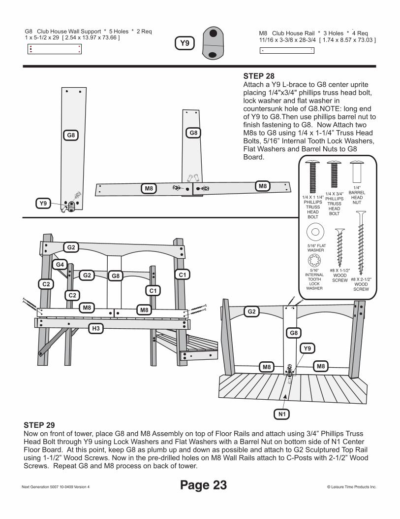
STEP 28Attach a Y9 L-brace to G8 center uprite placing 1/4"x3/4" phillips truss head bolt, lock washer and flat washer in countersunk hole of G8.NOTE: long end of Y9 to G8.Then use phillips barrel nut to finish fastening to G8. Now Attach two M8s to G8 using 1/4 x 1-1/4” Truss Head Bolts, 5/16” Internal Tooth Lock Washers, Flat Washers and Barrel Nuts to G8 Board.
STEP 29Now on front of tower, place G8 and M8 Assembly on top of Floor Rails and attach using 3/4” Phillips Truss Head Bolt through Y9 using Lock Washers and Flat Washers with a Barrel Nut on bottom side of N1 Center Floor Board. At this point, keep G8 as plumb up and down as possible and attach to G2 Sculptured Top Rail using 1-1/2” Wood Screws. Now in the pre-drilled holes on M8 Wall Rails attach to C-Posts with 2-1/2” Wood Screws. Repeat G8 and M8 process on back of tower.
Y9
G8 G8
M8
M8 G2
G2
G2
G4
C2
C2C1
C1G8
M8
M8
M8M8
G8
N1
Y9
H3
11/16 x 3-3/8 x 28-3/4 [ 1.74 x 8.57 x 73.03 ]M8 Club House Rail * 3 Holes * 4 Req
1 x 5-1/2 x 29 [ 2.54 x 13.97 x 73.66 ]G8 Club House Wall Support * 5 Holes * 2 Req
Y9
1/4 X 1 1/4"PHILLIPSTRUSSHEADBOLT
1/4 X 3/4"PHILLIPSTRUSSHEADBOLT
1/4"BARREL
HEADNUT
5/16"INTERNAL
TOOTHLOCK
WASHER
5/16" FLATWASHER
#8 X 2-1/2"WOODSCREW
#8 X 1-1/2"WOODSCREW
© Leisure Time Products Inc.Next Generation 5007 10-0409 Version 4 Page 23
© Leisure Time Products Inc.Next Generation 5007 10-0409 Version 4 Page 24
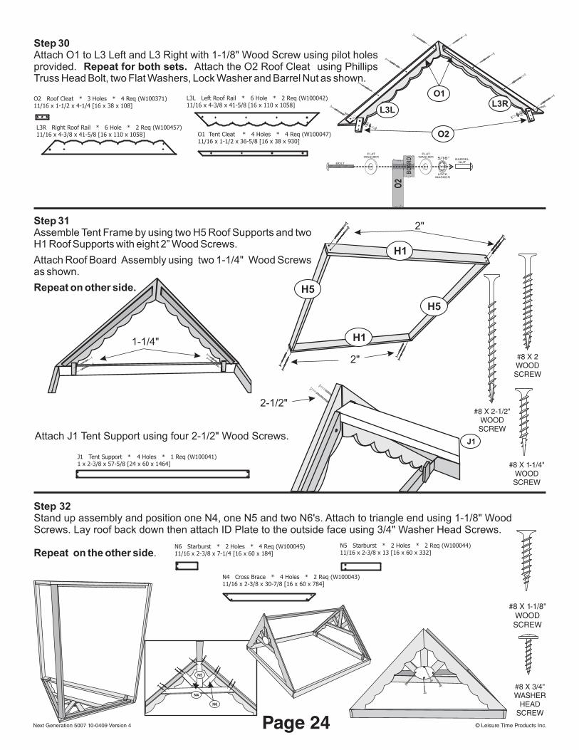
Step 30Attach O1 to L3 Left and L3 Right with 1-1/8" Wood Screw using pilot holes provided. Repeat for both sets. Attach the O2 Roof Cleat using Phillips Truss Head Bolt, two Flat Washers, Lock Washer and Barrel Nut as shown.
O1 Tent Cleat * 4 Holes * 4 Req (W100047)11/16 x 1-1/2 x 36-5/8 [16 x 38 x 930]
L3L Left Roof Rail * 6 Hole * 2 Req (W100042)11/16 x 4-3/8 x 41-5/8 [16 x 110 x 1058]
L3R Right Roof Rail * 6 Hole * 2 Req (W100457)11/16 x 4-3/8 x 41-5/8 [16 x 110 x 1058]
Step 31Assemble Tent Frame by using two H5 Roof Supports and two H1 Roof Supports with eight 2” Wood Screws.
Attach Roof Board Assembly using two 1-1/4" Wood Screws as shown.
Repeat on other side.
O2 Roof Cleat * 3 Holes * 4 Req (W100371)11/16 x 1-1/2 x 4-1/4 [16 x 38 x 108]
J1 Tent Support * 4 Holes * 1 Req (W100041)1 x 2-3/8 x 57-5/8 [24 x 60 x 1464]
Attach J1 Tent Support using four 2-1/2" Wood Screws.
#8 X 2-1/2"WOODSCREW
Step 32Stand up assembly and position one N4, one N5 and two N6's. Attach to triangle end using 1-1/8" Wood Screws. Lay roof back down then attach ID Plate to the outside face using 3/4" Washer Head Screws.
Repeat on the other side.N6 Starburst * 2 Holes * 4 Req (W100045)11/16 x 2-3/8 x 7-1/4 [16 x 60 x 184]
N5 Starburst * 2 Holes * 2 Req (W100044)11/16 x 2-3/8 x 13 [16 x 60 x 332]
N4 Cross Brace * 4 Holes * 2 Req (W100043)11/16 x 2-3/8 x 30-7/8 [16 x 60 x 784]
#8 X 1-1/8"WOODSCREW
#8 X 3/4WASHER
HEADSCREW
"N4
N5
N6
O2
FLATWASHER
BOLT
LOCKWASHER
FLATWASHER
BARRELNUT
5/16"
BOAR
D
L3RL3L
O1
O2
J1
2-1/2"
#8 X 1-1/4"WOODSCREW
#8 X 2WOODSCREW
2"
H5
H1
H1
H5
2"
1-1/4"
© Leisure Time Products Inc.Next Generation 5007 10-0409 Version 4 Page 25
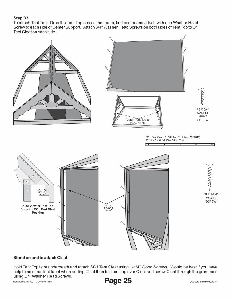
Step 33To attach Tent Top - Drop the Tent Top across the frame, find center and attach with one Washer Head Screw to each side of Center Support. Attach 3/4" Washer Head Screws on both sides of Tent Top to O1 Tent Cleat on each side.
SC1
Stand on end to attach Cleat.
Hold Tent Top tight underneath and attach SC1 Tent Cleat using 1-1/4" Wood Screws. Would be best if you have help to hold the Tent taunt when adding Cleat then fold tent top over Cleat and screw Cleat through the grommets using 3/4” Washer Head Screws.
#8 X 3/4WASHER
HEADSCREW
"
#8 X 1-1/4"WOODSCREW
SC1 Tent Cleat * 5 Holes * 2 Req (W100046)11/16 x 2 x 57-3/8 [16 x 50 x 1456]
Attach Tent Top to these cleats
Side View of Tent TopShowing SC1 Tent Cleat
Position
SC1
© Leisure Time Products Inc.Next Generation 5007 10-0409 Version 4 Page 26
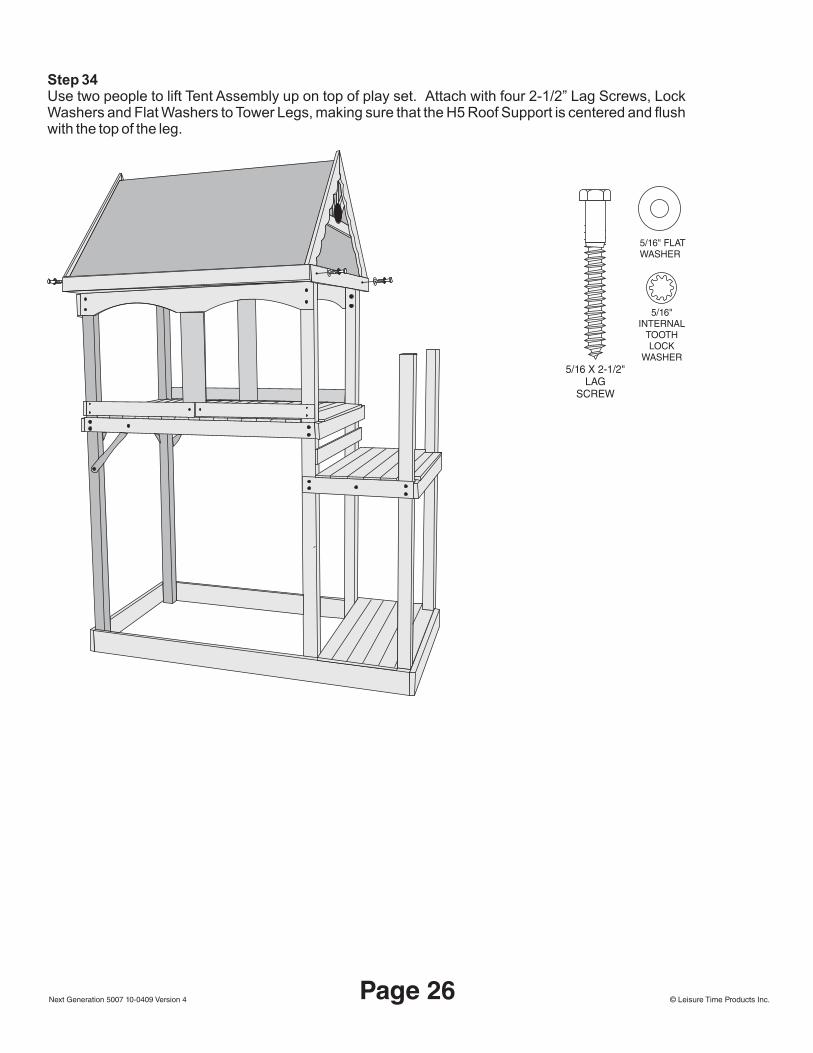
Step 34Use two people to lift Tent Assembly up on top of play set. Attach with four 2-1/2” Lag Screws, Lock Washers and Flat Washers to Tower Legs, making sure that the H5 Roof Support is centered and flush with the top of the leg.
5/16 X 2-1/2"LAG
SCREW
5/16" FLATWASHER
5/16"INTERNAL
TOOTHLOCK
WASHER
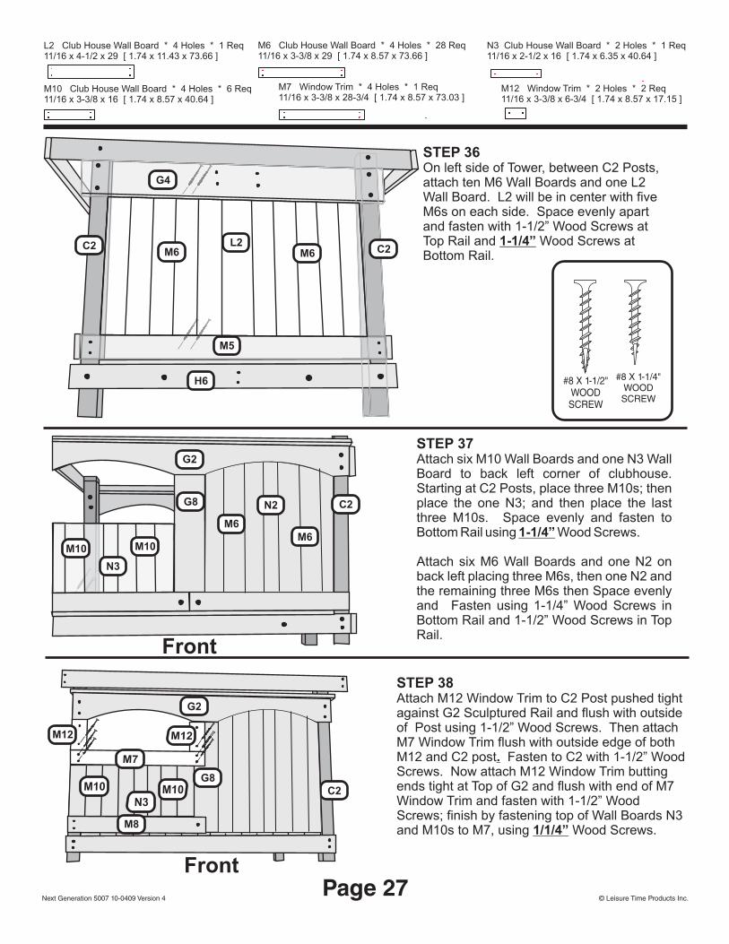
STEP 36On left side of Tower, between C2 Posts, attach ten M6 Wall Boards and one L2 Wall Board. L2 will be in center with five M6s on each side. Space evenly apart and fasten with 1-1/2” Wood Screws at Top Rail and 1-1/4” Wood Screws at Bottom Rail.
STEP 37Attach six M10 Wall Boards and one N3 Wall Board to back left corner of clubhouse. Starting at C2 Posts, place three M10s; then place the one N3; and then place the last three M10s. Space evenly and fasten to Bottom Rail using 1-1/4” Wood Screws.
Attach six M6 Wall Boards and one N2 on back left placing three M6s, then one N2 and the remaining three M6s then Space evenly and Fasten using 1-1/4” Wood Screws in Bottom Rail and 1-1/2” Wood Screws in Top Rail.
STEP 38Attach M12 Window Trim to C2 Post pushed tight against G2 Sculptured Rail and flush with outside of Post using 1-1/2” Wood Screws. Then attach M7 Window Trim flush with outside edge of both M12 and C2 post. Fasten to C2 with 1-1/2” Wood Screws. Now attach M12 Window Trim butting ends tight at Top of G2 and flush with end of M7 Window Trim and fasten with 1-1/2” Wood Screws; finish by fastening top of Wall Boards N3 and M10s to M7, using 1/1/4” Wood Screws.
L2M6 M6
G4
M5
H6
C2 C2
G2
G8
N3
M10M10
G2
C2
L2 Club House Wall Board * 4 Holes * 1 Req11/16 x 4-1/2 x 29 [ 1.74 x 11.43 x 73.66 ]
M10 Club House Wall Board * 4 Holes * 6 Req11/16 x 3-3/8 x 16 [ 1.74 x 8.57 x 40.64 ]
11/16 x 3-3/8 x 29 [ 1.74 x 8.57 x 73.66 ]M6 Club House Wall Board * 4 Holes * 28 Req
M12 Window Trim * 2 Holes * 2 Req11/16 x 3-3/8 x 6-3/4 [ 1.74 x 8.57 x 17.15 ]
11/16 x 2-1/2 x 16 [ 1.74 x 6.35 x 40.64 ]N3 Club House Wall Board * 2 Holes * 1 Req
11/16 x 3-3/8 x 28-3/4 [ 1.74 x 8.57 x 73.03 ]M7 Window Trim * 4 Holes * 1 Req
#8 X 1-1/2"WOODSCREW
#8 X 1-1/4"WOODSCREW
© Leisure Time Products Inc.Next Generation 5007 10-0409 Version 4Page 27
Front
Front
M10 M10N3
M7
M12M12
M8
G8
M6
N2
M6
C2

STEP 39Attach six M6 Wall Boards and one N2 on back left placing three M6s, then one N2 and the remaining three M6s then Space evenly and Fasten using 1-1/4” Wood Screws in Bottom Rail and 1-1/2” Wood Screws in Top Rail.
STEP 40Install 5/16” Spike T-Nuts inside C3 Posts and attach H9 using 5/16 x 3-3/4” Hex Bolts, Internal Tooth Lock Washers and Flat Washers. Measure up 3-1/2” from top of H7 Floor Rail and mark C3 Post. Now attach H9 with bottom of H9 Wall Rail at marks on Post, pilot drill using 3/16" bit and attach using 2-1/2” Lag Screws, Internal Tooth Lock Washers and Flat Washers. Make sure that H9 is flush with outside of C3. Now attach six M9 Wall Boards to H9 Wall Rails on right side of Tower spacing approximately 2-3/4” apart using 1-1/2” Wood Screws.
M6M6
N2
G2
C3
C3M9 M9M9 M9 M9M9
1 x 3-1/2 x 45 [ 2.54 x 8.89 x 114.30 ]H9 Wall Rail * 2 Holes * 2 Req
11/16 x 3-3/8 x 29 [ 1.74 x 8.57 x 73.66 ]M6 Club House Wall Board * 4 Holes * 28 Req
11/16 x 3-3/8 x 23 [ 1.74 x 8.57 x 58.42 ]M9 Wall Board * 4 Holes * 23 Req
11/16 x 2-1/2 x 29 [ 1.74 x 6.35 x 73.66 ]N2 Club House Wall Board * 2 Holes * 3 Req
5/16 X 3-3/4"HEX
HEADBOLT
5/16"SPIKE TEE
NUT5/16"
INTERNALTOOTHLOCK
WASHER
5/16" FLATWASHER
#8 X 1-1/2"WOODSCREW
#8 X 1-1/4"WOODSCREW
5/16 X 2-1/2"LAG
SCREW
© Leisure Time Products Inc.Next Generation 5007 10-0409 Version 4
3 ½"
H9
H7
H9
Page 28
Back
M6M6 M6M6
N2N2

Step 41Attach H11 Wall Rails, noting countersunk holes drilled at 2-1/2” from edge go towards C3 Posts. Flush H11 to outside of H9 Front Wall Rail at top and bottom pilot drill with 3/16" bit using holes in H11 as guides and fasten using 2-1/2” Lag Screws, Internal Tooth Lock Washers and Flat Washers. Now level H11’s and fasten to C1 Posts using 2-1/2” Lag Screws, Internal Tooth Lock Washers and Flat Washers.
STEP 42Attach three M9 Wall Boards to inside of H11 Wall Rails on backside of Lower Deck using 1-1/2” Wood Screws spacing approximately 2” apart.
STEP 43Attach M1 Bottom Wall Rail to C2 and C1 Posts flushing M1 to outside of C2 Posts. Measure up 3-1/2” from G1 Baseboard at front of Set and mark C2 and C1 Posts. Attach M1 with mark to bottom of Rail using 2” Wood Screws. Now measure up 24” from G1 Baseboard and mark Post again. Place bottom of M1 Rail with mark and attach to C2 and C1 Posts using 2” Wood Screws.
C1
C1
C3
C3
H11
H11
H11
H11
M9M9 M9
1 x 3-1/2 x 25 [ 2.54 x 8.89 x 63.50 ]H11 Wall Rail * 4 Holes * 2 Req
11/16 x 3-3/8 x 23 [ 1.74 x 8.57 x 58.42 ]M9 Wall Board * 4 Holes * 23 ReqM1 Wall Rail * 4 Holes * 2 Req
11/16 x 3-3/8 x 57-1/2 [ 1.74 x 8.57 x 146.05 ]
5/16 X 2-1/2"LAG
SCREW
5/16"INTERNAL
TOOTHLOCK
WASHER
5/16" FLATWASHER
#8 X 2"WOODSCREW
#8 X 1-1/2"WOODSCREW
© Leisure Time Products Inc.Next Generation 5007 10-0409 Version 4Page 29
C1
C2
M13 ½"
24"
M1
Back
Back
Front

STEP 44Attach M4 Wall Rails, noting pre-drilled holes in M4 Rail at 1-1/2” from edge towards C2 Post at backside of Set. Flush M4 to outside of M1 Wall Rails and fasten to C2 Post using 2” Wood Screws. Now level across to the other C2 Post and attach there with 2” Wood Screws.
STEP 45Attach six M9 Wall Boards to inside of M4 Wall Rails approximately 2-3/4” apart using 1-1/4” Wood Screws.
M4
M4
H6
H6
G5
G5
C2C2
C2
C2
M9 M9 M9 M9 M9M9
11/16 x 3-3/8 x 45-3/4 [ 1.74 x 8.57 x 116.21 ]M4 Wall Rail * 4 Holes * 2 Req
11/16 x 3-3/8 x 23 [ 1.74 x 8.57 x 58.42 ]M9 Wall Board * 4 Holes * 23 Req
#8 X 1-1/4"WOODSCREW
#8 X 2"WOODSCREW
© Leisure Time Products Inc.Next Generation 5007 10-0409 Version 4
M4
M4
Flush withM1 Wall RailFlush with
C2 Post
Page 30
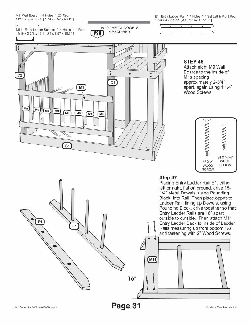
STEP 46Attach eight M9 Wall Boards to the inside of M1s spacing approximately 2-3/4” apart, again using 1 1/4” Wood Screws.
Step 47Placing Entry Ladder Rail E1, either left or right, flat on ground, drive 15-1/4” Metal Dowels, using Pounding Block, into Rail. Then place opposite Ladder Rail, lining up Dowels, using Pounding Block, drive together so that Entry Ladder Rails are 16” apart outside to outside. Then attach M11 Entry Ladder Back to inside of Ladder Rails measuring up from bottom 1/8” and fastening with 2” Wood Screws.
E1E1
M11
16"
M11 Entry Ladder Support * 4 Holes * 1 Req11/16 x 3-3/8 x 16 [ 1.74 x 8.57 x 40.64 ]
11/16 x 3-3/8 x 23 [ 1.74 x 8.57 x 58.42 ]M9 Wall Board * 4 Holes * 23 Req E1 Entry Ladder Rail * 4 Holes * 1 Set Left & Right Req
1-3/8 x 3-3/8 x 52 [ 3.49 x 8.57 x 132.08 ]
15 1/4” METAL DOWELS4 REQUIRED
#8 X 1-1/4"WOODSCREW
#8 X 2"WOODSCREW
© Leisure Time Products Inc.Next Generation 5007 10-0409 Version 4
Y28
Page 31
C1
C2
G1
M1
M9M9M9 M9
M9 M9 M9 M9

STEP 48Stand Entry Ladder up and line up Ladder Rails with pre-drilled holes and H12 Floor Rail and using 3/16” drill bit pilot hole Entry Ladder Rails. Then fasten ladder assembly using 2-1/2” Lag Screws, Internal Tooth Lock Washers and Flat Washers through H12 Floor Rail into Entry Ladder Rails. At this point, attach Y31 metal grip to ladder rails. Measure down 4” from top edge and drill a pilot hole in center of the board with 3/16” drill bit. Attach handles at these points using 2 ½” lag screw, lock washer and flat washer. Now use hole in bottom of handle as guide to pilot drill and finish attaching with 2 ½” lag screw, lock washer and flat washer.
STEP 49Measure up 5-1/4” from H12 Floor Rails and mark center of C1 and C3 Posts. Pilot drill using 3/16” drill bit. Now Attach Y30 Metal Hand Grips to each Post with 5/16 x 2-1/2” Lag Screws, Internal Tooth Lock Washers and Flat Washers. Using hole in Y30 Hand Grip in top as guide, pilot drill and finish attaching with 2-1/2” Lag Screws, Internal Tooth Lock Washers and Flat Washers.
C1
Y30Y30
C3
SHORT METAL HAND GRIP2 REQUIRED
Y30
5/16 X 2-1/2"LAG
SCREW
5/16"INTERNAL
TOOTHLOCK
WASHER
5/16" FLATWASHER
Y31 35"METAL GRIP2 REQUIRED
© Leisure Time Products Inc.Next Generation 5007 10-0409 Version 4
5 1/4"
Page 32
Y31Y31
E1E1
H124"
GREEN MESHWINDOW1 13x23
5007
© Leisure Time Products Inc.Next Generation 5007 10-0409 Version 4
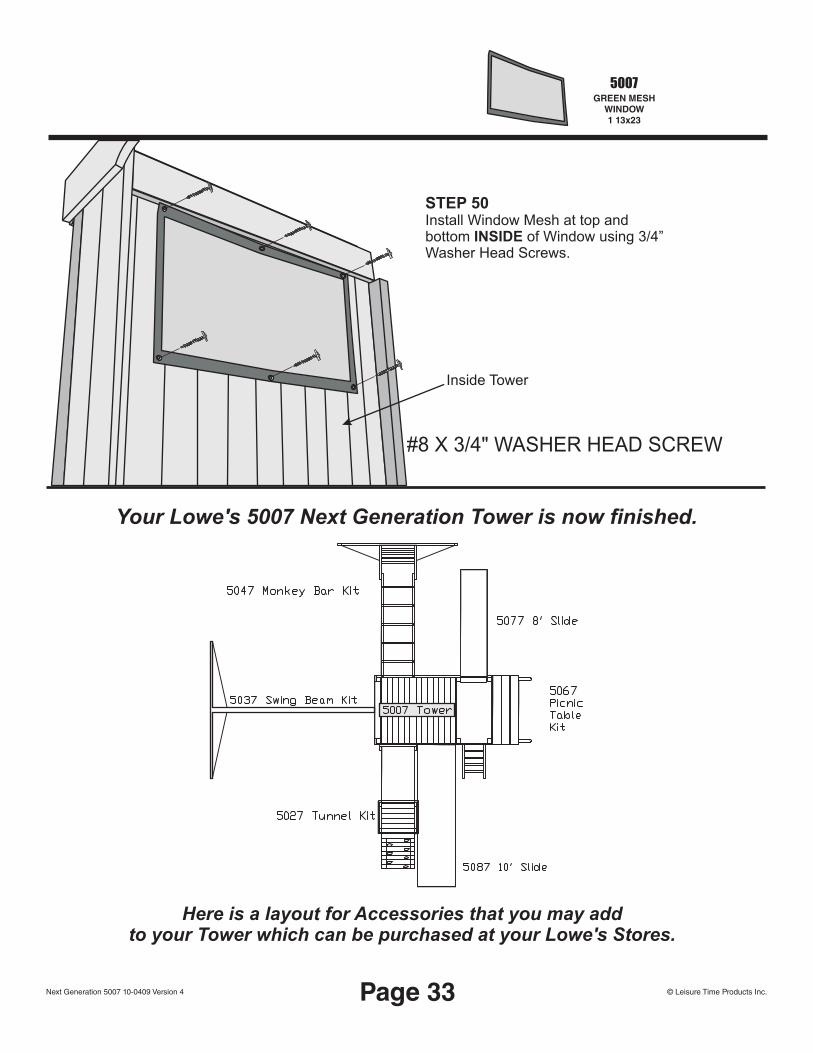
STEP 50Install Window Mesh at top and bottom INSIDE of Window using 3/4” Washer Head Screws.
STEP 94#8 X 3/4" WASHER HEAD SCREW
Inside Tower
Your Lowe's 5007 Next Generation Tower is now finished.
Here is a layout for Accessories that you may addto your Tower which can be purchased at your Lowe's Stores.
Page 33
MAINTENANCE
All outdoor wooden products, including Playground, Inc products, require routine inspection and regular maintenance. After installation, a follow-up inspection should take place after one week and twice a month thereafter for the remaining life of your play products. Maintenance should be performed at any time it is deemed necessary. As a general rule, major maintenance (wood refinishing) should be performed at twelve month intervals from the date of installation. Inspect and perform maintenance based on the following checklist.
Major wood parts: inspect for splintering and structural defects. If necessary, lightly sand and refinish with an exterior water repellent stain.
Hardware: inspect for tightness. Be certain that hardware is firmly against, but not crushing the wood. Over-tightening hardware crushes wood fibers and splits wooden components and could result in the bolt threads extending beyond the wood and presenting a severe safety hazard. If splintering has occurred from over tightening, larger washers can be purchased at your local hardware store and installed under the bolt head. Be sure to reuse or replace your lock washers.
If over-tightening has caused the bolt threads to protrude beyond the wood surface, replace the bolt with a shorter one that will not protrude. These bolts are standard items and can be purchased at your local hardware store.
Swing hangers: check to insure correct installation. Make sure that the bend of the swing hanger is positioned tightly against the stop washer and the ladder or swing beam. The axis of the swing hanger bushing must be perpendicular to the swing motion. If squeaking occurs, the nylon bushings can be sprayed with WD-40 or other household lubricant. Oil all metallic moving parts monthly during the usage period.
Check swings seats, ropes, cables, and chains monthly during usage season for evidence of deterioration. Replacement should be made in accordance with manufacturer's instructions.
Metal components: sand rusted areas on painted components and repaint using a non-lead based paint meeting the requirements of Title 16 CFR Part 1303.
Winterizing Your Play Set: remove plastic swing seats, trapeze bar, slide, and other plastic components and take indoors or do not use when the temperature drops below 20° F.
In the event that your set needs to be dismantled and disposed of due to storm damage, age, or other cause, make sure that you check your local city and state regulations or with your sanitation department for the proper method and means of disposal. Please dispose of the unit in such a way that no unreasonable hazards will exist (sharp edges, broken parts, and exposed screws) at the time it is discarded.
REQUIRED PERIODIC MAINTENANCE
Page 34 - MAINTENANCE © Leisure Time Products Inc.Next Generation 5007 10-0409 Version 4

COMMONLY ASKED QUESTIONS AND ANSWERS
Question: Now that my playset product is assembled and installed, will I have to do anything to it?Answer: Yes. You must provide routine inspections and regular maintenance. These procedures are covered in the "required periodic maintenance" section.
Question: How often should my assembled playset product be inspected?Answer: An initial inspection should take place one week after installation and twice a month thereafter for the remaining life of your playset product.
Question: When should the necessary maintenance be performed?Answer: Generally speaking, at the beginning of each season or as often as may be deemed necessary from an inspection. Major maintenance (primarily a thorough inspection and re-staining) should be performed at twelve-month intervals from the date of installation.
Question: How do I know when my playset product needs refinishing?Answer: If water is absorbed into the wood, it's time to refinish your product. If, however, water beads and rolls off the wood, surfaces are protected.
Question: Why does it seem that my playset product is developing cracks?Answer: The correct terminology for what appears to be cracks is "wood checks". A check is the radial separation of wood fibers running with the grain of wood caused by varying temperatures and moisture conditions. These checks will develop on the surface and end grains of the wood as an unavoidable aspect of the natural weathering process of all wood exposed to the elements. Checks occur after the wood has been wet, and outside surfaces dry faster than inside surfaces. Checks mainly affect the aesthetics of your play products and not its strength or durability. An exterior water repellent stain slows down the checking process because it reduces the amount of water that penetrates the wood.
Question: Why is there so much movement in my play product, especially the top supports? It looks as if the wood will break?Answer: Because the structure is wooden rather then concrete or steel, movement is not only natural, but required. We have a saying... "if the branch doesn't bend, it will break." your play product has been designed to accommodate as many children as there are play positions. We recommend a maximum of 150 lbs. per child for play activities designed for individual use, and 120 lbs for multiple use activities. Please remember that your play product has been engineered for children 2 to 10 years old.
Question: Why is my play product rocking?Answer: Rocking is caused by uneven ground under the base pieces. After a short period of time, your play product should settle into place and the ground stakes will provide proper stability. However, if rocks or roots surface under the base support pieces, these protrusions must be removed or the play product relocated to another area in order to eliminate rocking.
This section addresses some specific issues sometimes encountered during and after the assembly.Most are re-emphasis of items covered in detail elsewhere in this manual.
Page 35 - MAINTENANCE © Leisure Time Products Inc.Next Generation 5007 10-0409 Version 4
Page 36 - MAINTENANCE
Question: Why is my play product leaning (racking)?Answer: Leaning occurs in play products installed on uneven ground. Realignment will be necessary and is covered in the "required periodic maintenance" section of this manual
Question: What can I do about squeaking swing connector hangers?Answer: To eliminate the squeak, spray the nylon bushings with WD-40 or other household lubricant. Some families like the squeaking as it allows them to hear where the children are playing.
Question: Why is the wood splintering under the bolts when I tighten the hardware?Answer: Wood will splinter when compressed. The compression caused by over-tightening fractures wood fibers and is an indication that you are cranking down too hard on the hardware. If splintering has occurred, we recommend that you purchase larger diameter flat washers to install under the head of the bolts.
Question: Why does my play product have mold growing on it? What can I do to remove it and keep it clean of mold and mildew?Answer: Because the structure is wooden rather than concrete or steel, in areas of high humidity mold and/or mildew may occur. A solution of 1 part bleach, 2 parts water applied with a sponge should clean the problem areas. Once the solution is dry, a water sealant should be applied to the entire swingset.
Question: What if my ground stakes won't go in the ground?Answer: If your ground is too hard, you can purchase metal anchors from your local hardware store.
Question: What if my ground stakes won't stay in the ground?Answer: This is probably caused by your ground being too soft. The ground stakes can be concreted or cemented into the ground. Do not concrete or cement the playset itself, only the ground stakes.
Question: Who can I hire to assemble my playset?Answer: We do not suggest assemblers. Please refer to your yellow pages or ask for a recommendation from where you purchased your playset.
© Leisure Time Products Inc.Next Generation 5007 10-0409 Version 4

FOR YOUR RECORDS
WHERE PURCHASED: _____________________________________________________________________
PURCHASE DATE: ____________________________ INSTALLATION DATE: _______________________
MODEL NAME & NUMBER ____________________________________________________________________
PLEASE READ THIS BOOKLET COMPLETELY BEFORE BEGINNING THE ASSEMBLY PROCESS.
THIS MANUAL HAS BEEN PREPARED TO HELP YOU AND YOUR FAMILY ACHIEVE FULL BENEFIT FROM YOUR BACKYARD PLAYSET. IT CONTAINS HELPFUL INFORMATION CONCERNING ASSEMBLY PREPARATION, INSTALLATION
PROCEDURE, REQUIRED MAINTENANCE, REPLACEMENT PARTS, AND SHOULD THE SITUATION OCCUR, THE PROCEDURE FOR FILING A WARRANTY CLAIM.
PLEASE VALIDATE YOUR WARRANTY BY COMPLETING THE WARRANTY INFORMATION CARD AND RETURN IT TO US WITHIN 30 DAYS OF INSTALLATION. THIS INFORMATION IS USED EXCLUSIVELY FOR INTERNAL PURPOSES AND AS A VERIFICATION IF NECESSARY.
THE WARRANTY ON PLAY PRODUCTS IS VALID TO THE ORIGINAL PURCHASER AND IS NOT TRANSFERABLE. IT SHOULD BE NOTED THAT CANNOT ASSUME ANY RESPONSIBILITY FOR MODIFICATION, OR ACCESSORIES ADDED TO THIS PRODUCT OTHER THAN THOSE MANUFACTURED AND SOLD BY
THIS PRODUCT HAS BEEN DESIGNED FOR RESIDENTIAL USE ONLY. THE WARRANTY BECOMES VOID WHEN USED IN A DAYCARE, PRESCHOOL, NURSERY SCHOOL, RECREATIONAL PARK OR ANY OTHER SIMILAR COMMERCIAL APPLICATION.
FOR WARRANTY CLAIM PURPOSES, YOU MUST RETAIN YOUR SALES RECEIPT OR OTHER MEANS OF PROOF-OF-PURCHASE. YOU SHOULD ALSO KEEP THIS BOOKLET FOR FUTURE REFERENCE. PLEASE ATTACH THE SALES RECEIPT TO THE INSIDE COVER OF THIS BOOKLET FOR FUTURE REFERENCE.
LEISURE TIME PRODUCTS, INC.
LEISURE TIME PRODUCTS, INC.LEISURE TIME PRODUCTS, INC.
LEISURE TIME PRODUCTS, INC.
© Copyright Leisure Time Products, Inc.Next Generation 5007 10-0409 Version 4WARRANTY
DETACH HERE AND MAIL
MODEL #5007 • Next Generation
LEISURE TIME PRODUCTS, INC. WARRANTY CARD
NAME________________________________________
ADDRESS ____________________________________
CITY ___________________ST_______ZIP_________
PHONE (_____) _______________________________
MODEL NO./NAME ____________________________
WHERE PURCHASED __________________________
DATE PURCHASED ____________________________
RETAIL PRICE PAID ____________________________
INSTALLATION DATE ___________________________PRODUCT SATISFACTION: EXCELLENT GOOD FAIR POOR
(CIRCLE ONE ABOVE)
I HAVE READ THE ASSEMBLY BOOKLET AND UNDERSTAND MY RESPONSIBILITY TO MAINTAIN MY PLAY PRODUCT AND TO INSTRUCT MY CHILDREN ON PROPER PLAY AND SAFETY PROCEDURES. I ALSO UNDERSTAND THAT ALL CHILDREN THAT UTILIZE MY PLAY PRODUCT ARE TO BE SUPERVISED AT ALL TIMES.
PARENT/OWNER __________________________________________________________
DATE ____________________________________________________________________
COMMENTS: ______________________________________________________________
_________________________________________________________________________
5 YEAR PRO-RATE WARRANTYSubject to normal use, , INC.
warrants, to the original purchaser, all products to be free from workmanship defects for a period of one year from the date of original purchase.
The lumber in all , INC. Ready-to Assemble sets is covered by a 5 year pro-rated warranty against wood rot and termite damage.
Non-wooden parts such as hardware, roped or chained accessories, slides, metal or plastic components, and canopies carry a one year warranty.
It is the customer’s responsibility to perform regular inspections and maintenance to insure that the product is not prematurely aging. These inspections would include an evaluation of the stained finish, all ropes, chains, hardware, plastic and wooden components. A complete listing of replacement parts is available through your , INC. Customer Service Department.
This Limited Warranty does not cover the labor or cost of labor for replacement of the defective item; the cost of freight after the initial 30 day period; any incidental or consequential damages, cosmetic defects which do not affect the structural integrity of the unit; items damaged due to vandalism, acts of God, improper usage, improper installation or other abnormal conditions. Seasonal checks and surface cracks are natural characteristics of all outdoor wooden play equipment, and are not considered defects nor covered under this warranty. , INC. cannot assume any responsibility for modification to, or accessories added to this product, other than those sold by
, INC.This warranty covers residential installations only as the
product has not been designed for, nor will perform safely, in any commercial application. This warranty gives you specific legal rights and you may also have other rights which vary from state to state. This warranty excludes all consequential damages. Some states do not allow the limitation or exclusion of consequential damages so the above limitation may not apply to you.
Special Note: We reserve the right to make changes in material and design without notice.
LEISURE TIME PRODUCTS
LEISURE TIME PRODUCTS
LEISURE TIME PRODUCTS
LEISURE TIME PRODUCTS
LEISURE TIME PRODUCTS
MODEL #5007ASSEMBLY MANUAL
DETACH HERE AND MAIL
Next Generation
LEISURE TIME PRODUCTS
PLA
CE
PO
STA
GE
HE
RE
Leisure Tim
e Products, Inc.
P.O. B
ox 459S
iloam S
prings, AR
72761
WARRANTY REGISTRATION CARD
LEISURE TIME PRODUCTS, INC.P.O. Box 459
Siloam Springs, AR 727611-866-362-1123 Toll Free
Office hours: 7am - 4pm, Mon-Fri, Central Time

© Copyright Playground Inc
SWING HANGER
( ) Swing Beam * 15 Holes * 3-1/4 x 5-1/4 x 94A1
STEP 1
3/8"SPIKE TEE
NUT
3/8"INTERNAL
TOOTHLOCK
WASHER
SAE 3/8"FLAT
WASHER
3/8 X 5-1/2"HEX
HEADBOLT
Part # 5037Next Generation
SWING BEAMASSEMBLY INSTRUCTIONS
A1Attach the Swing Hangers to the Swing Beam using two 3/8 x 5-1/2" Hex Head Bolts, 3/8" Lock Washers, 3/8" Washers and 3/8" Spike Tee Nuts
A1
.
© Copyright Playground Inc
If you need assistance with parts or have assembly questions, please call Customer Service at 866-362-1123. Our regular office hours areMonday through Friday, 7:00 a.m. to 4:00 p.m. Central TimeLEISURE TIME PRODUCTS

© Copyright Playground Inc
Thread a 3/8" Spike Tee Nut as shown in the illustration so that you can pound it into the countersunk hole on one Long Angle Brace E1. Once the Spike Tee Nut is firmly embedded in the wood at the bottom of the hole, un-screw and remove the bolt. This is the easiest way to install the Spike Tee Nuts in a countersunk hole. You only need to do this on one of the Long Angle Braces.
Attach the E1 Long Angle Braces to the B1 Beam End Post using a 3/8"x6-1/2" Hex Head Bolt, 3/8" Lock Washer, and 3/8" Flat Washer,
threading the bolt through the wooden parts into the Spike Tee Nut installed in Step 3.
Tighten securely, but don't over tighten.
Use any convenient long 3/8" bolt.
( E1 ) Long Angle Brace * 1 Hole * 30° - 60° * 1-1/2 x 3-1/2 x 85 ( B1 ) Beam End Post * 3 Holes * 3-1/4 x 3-1/4 x 47
3/8 X 6-1/2" HEX HEAD BOLT
3/8"SPIKE TEE
NUT
3/8"INTERNAL
TOOTHLOCK
WASHER
SAE 3/8"FLAT
WASHER
STEP 3
STEP 4
E1 E1
B1
Attach the two Metal Triangles Y1 to the Swing Beam as shown using two 4" Hex Head Bolts, Lock Washers, Washers and 5/16 Nylock Lock Nuts. Tighten securely, but do not over tighten.
METAL TRIANGLEY1
5/16 X 4"HEX
HEADBOLT
5/16 X 2018NYLOCK
LOCK NUT
5/16" LOCK WASHER
5/16"FLAT
WASHER
Y1
STEP 2
© Copyright Playground Inc
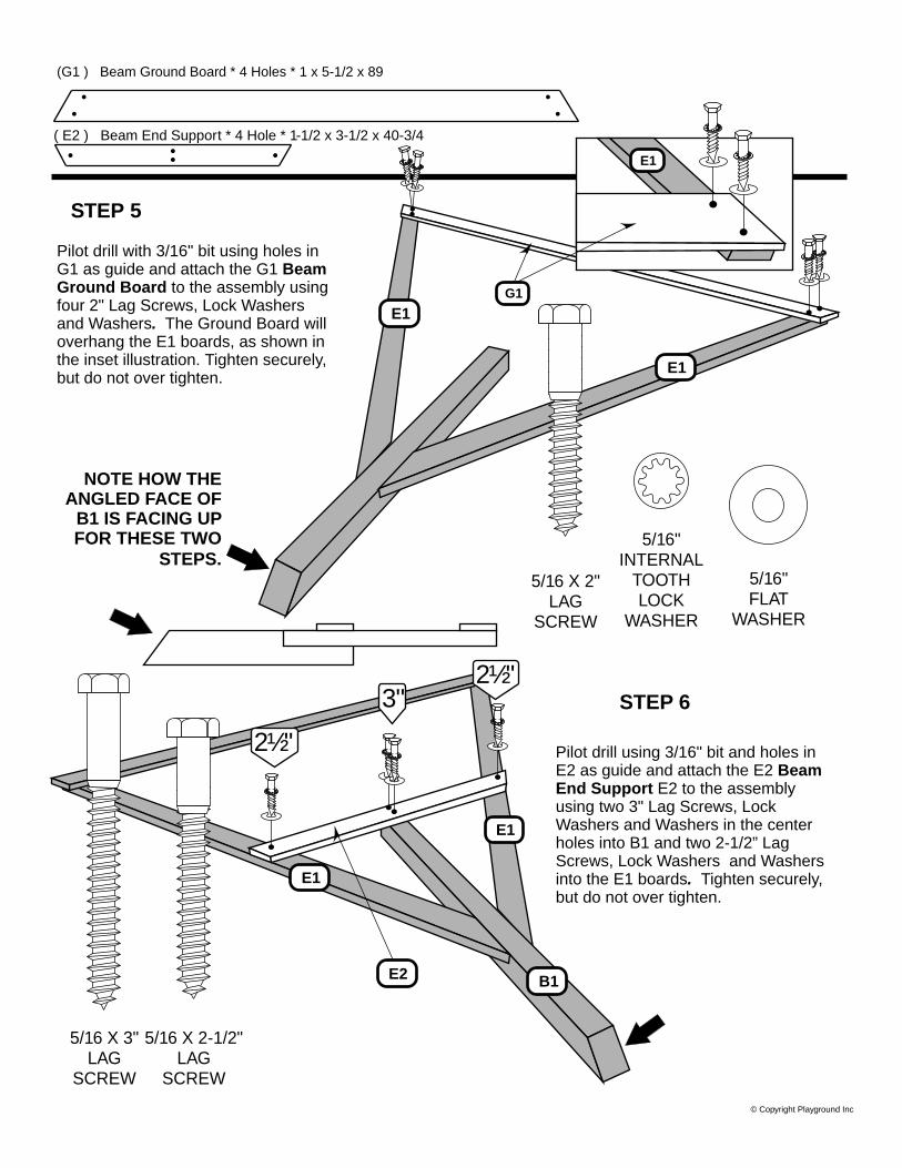
Pilot drill with 3/16" bit using holes in G1 as guide and attach the G1 Beam Ground Board to the assembly using four 2" Lag Screws, Lock Washers and Washers. The Ground Board will overhang the E1 boards, as shown in the inset illustration. Tighten securely, but do not over tighten.
Pilot drill using 3/16" bit and holes in E2 as guide and attach the E2 Beam End Support E2 to the assembly using two 3" Lag Screws, Lock Washers and Washers in the center holes into B1 and two 2-1/2” Lag Screws, Lock Washers and Washers into the E1 boards. Tighten securely, but do not over tighten.
(G1 ) Beam Ground Board * 4 Holes * 1 x 5-1/2 x 89
5/16 X 2"LAG
SCREW
5/16"INTERNAL
TOOTHLOCK
WASHER
5/16"FLAT
WASHER
( E2 ) Beam End Support * 4 Hole * 1-1/2 x 3-1/2 x 40-3/4
3"
2½"
2½"
5/16 X 2-1/2"LAG
SCREW
5/16 X 3"LAG
SCREW
NOTE HOW THE ANGLED FACE OF
B1 IS FACING UP FOR THESE TWO
STEPS.
STEP 6
STEP 5
E1
G1
E1
E1
E2 B1
E1
E1

© Copyright Playground Inc
Attach the support assembly to the Swing Beam with the Metal Triangles Y1 using two 4” Hex Head Bolts, Lock Washers, Flat Washers and Lock Nut.
5/16" X 2018NYLOCK
LOCK NUT
5/16 X 4" HEX HEAD BOLT
5/16" LOCK WASHER 5/16" FLAT WASHER
Y1
Attach the Y16 Swing Assembly Mounts to the end of Swing Beam using two 4” Hex Bolts, Lock Washers, 4 Flat washers and secure with two 5/16 Nylock Nuts.
5/16 X 2"HEX
HEADBOLT
Y16
STEP 7
STEP 8
5/16"FLAT
WASHER
5/16"INTERNAL
TOOTHLOCK
WASHER
G4
M5
H6
C2 C2

G4
M5
H6
C2 C2
STEP 9Using the pre-drilled holes in the G4 Club House Wall Rail as a guide, drill thru the Wall Boards using a 3/8” drill bit. Install four 5/16” Spiked T Nuts, from the inside of the Tower, into these holes.
Turn over the Swing Beam Assembly, stand it up, and line up the holes in the Y16 Swing Beam Mount to the holes in the G4 Club House Wall Rail. Attach the Swing Beam Assembly to the Tower using four 2” Hex Bolts, Lock Washers and Flat Washers through the Y16 Swing Beam Mount and G4 Rail. Tighten securely, but do not over tighten.
5/16” x 2” HEX HEAD BOLT
FLATWASHER
BOLT
LOCKWASHER
BO
AR
D
FLATWASHER
BARRELNUT
5/16"
Metal stake installation: measure in 8” from outside edge of G1 ground board for ground for stake location. Now attach the stakes to G1 Ground Board using 1” Phillips Truss Head Bolt, two Flat Washers, Lock Washer and Barrel Nut Per Diagram at right. You will need a long screwdriver for leverage. In some cases you may need to dig a hole to install stake and cement.
STEP 10
STEP 11
Hang the Swings and Trapeze with this simple procedure:
• Put all the chains on the Carabiners Y5.• Hang the Swings and Trapeze as shown below• Slip the Plastic Safety Tubes Y6 on the Carabiner.
Y6
Y5

© Copyright Playground Inc
COLGADOR DEL COLUMPIO ( A1 ) Barra para columpio * 15 agujeros * 3-1/4 x 5-1/4 x 94
PASO 1
TUERCA EN T DE 3/8 in. (9,5 mm) CON
ESPIGAS
ARANDELA DE SEGURIDAD DE 3/8
in. (9,5 mm) CON DIENTES
INTERNOS
ARANDELA PLANA SAE DE 3/8 in. (9,5 mm)
PERNO CABEZA HEXAGONAL DE 3/8 x 5-1/2 in. (9,5 mm x 14 cm)
Parte # 5037Última Generación
BARRA PARA COLUMPIOINSTRUCCIONES DE ENSAMBLAJE
A1
Fije los colgadores de los columpios a la barra para columpio A1 utilizando dos pernos cabeza hexagonal de 3/8 x 5-1/2 in. (9,5 mm x 14 cm), arandelas de seguridad de 3/8 in. (9,5 mm), arandelas de 3/8 in. (9,5 mm) y tuercas en T con espigas.
© Copyright Playground Inc
Si necesita ayuda con las partes o tiene preguntas sobre el ensamblaje, por favor llame al Dpto. de Servicio al Cliente al 866-362-1123. Nuestras horas regulares
de oficina son de lunes a viernes, de 7:00 a.m. a 4:00 p.m. Hora Central.PRODUCTOS LEISURE TIME

© Copyright Playground Inc
Introduzca una tuerca en T de 3/8 in. (9,5 mm) con espigas como se ilustra de modo que la pueda martillar para avellanar el agujero en un refuerzo largo en ángulo E1. Una vez que la tuerca en T con espigas esté firmemente introducida en la madera en el fondo del agujero, desatorníllela y retire el perno. Esta es la forma más fácil de instalar las tuercas en T con espigas en un agujero avellanado. Sólo necesita hacer esto en uno de los refuerzos largos en ángulo.
Fije los refuerzos largos en ángulo al poste de extremo de la barra B1 utilizando un perno cabeza hexagonal de 3/8 x 6-1/2 in. (9,5 mm x
16,5 cm), una arandela de seguridad de 3/8 in. (9,5 mm) y una arandela plana de 3/8 in. (9,5 mm), insertando el perno a
través de las partes de madera en la tuerca en T con espigas del paso 3.
Apriete de forma segura pero no demasiado.
Utilice cualquier perno largo de 3/8 in. (9,5 mm).
( E1 ) Refuerzo largo en ángulo * 1 agujero * 30° - 60° * 1-1/2 x 3-1/2 x 85 ( B1 ) Poste para extremo de barra * 3 agujeros * 3-1/4 x 3-1/4 x 47
PERNO CABEZA HEXAGONAL DE 3/8 x 6-1/2 in. (9,5 mm x 16,5 cm)
TUERCA EN T DE 3/8 in. (9,5 mm) CON ESPIGAS
ARANDELA DE SEGURIDAD DE 3/8 in. (9,5 mm) CON DIENTES
INTERNOS
ARANDELA PLANA SAE DE 3/8 in. (9,5 mm)
PASO 3
PASO 4
E1 E1
B1
Fije los dos triángulos de metal Y1 a la barra para columpio como se ilustra utilizando 2 pernos cabeza hexagonal de 4 in. (10 cm), arandelas de seguridad, arandelas y tuercas mecánicas de seguridad. Apriete de forma segura pero no demasiado.
TRIÁNGULO DE METALY1
PERNO CABEZA HEXAGONAL DE 5/16 X 4 in. (8 mm
x 10,1 cm)
TUERCA MECÁNICA DE SEGURIDAD DE 5/16 in. (8 mm)
ARANDELA DE SEGURIDAD DE 5/16 in. (8 mm)
ARANDELA PLANA DE 5/16 in. (8 mm)
Y1
PASO 2

© Copyright Playground Inc
Haga un agujero piloto con la broca de 3/16 in. (4,8 mm) utilizando los agujeros de G1 como guía y fije la tabla de tierra G1 al ensamble utilizando dos tornillos tirafondo de 2 in. (5 cm), arandelas de seguridad y arandelas. La tabla de tierra sobresaldrá de las tablas E1 como se ilustra. Apriete de forma segura pero no demasiado.
Haga agujeros piloto utilizando la broca de 3/16 in. (4,8 mm) y agujeros en E2 como guía y fije el soporte de extremo para la barra E2 al ensamble utilizando dos tornillos tirafondo de 3 in. (7,6 cm), arandelas de seguridad y arandelas en los agujeros del centro en B1 y dos tornillos tirafondo de 2-1/2 in. (6,3 cm), arandelas de seguridad y arandelas en las tablas E1. Apriete de forma segura pero no demasiado.
(G1 ) Tabla de apoyo A tierra * 4 agujeros * 1 x 5-1/2 x 89
ARANDELA DE SEGURIDAD DE 5/16 in. (8 mm)CON DIENTES INTERNOS
ARANDELA PLANA DE 5/16 in. (8 mm)
( E2 ) Soporte de extremo para la barra * 4 agujeros * 1-1/2 x 3-1/2 x 40-3/4
3"
2½"
2½"
OBSERVE COMO LA CARA ANGULADA DE B1 ESTÁ ORIENTADA
HACIA ARRIBA EN ESTOS DOS PASOS.
PASO 6
PASO 5
E1
G1
E1
E1
E2 B1
E1
E1
TORNILLO TIRAFONDO DE
5/16 X 3 in. (8 mm x 7,6 cm)
TORNILLO TIRAFONDO DE 5/16 X 2-1/2 in. (8
mm x 6,3 cm)
TORNILLO TIRAFONDO
DE 5/16 X 2 in. (8 mm x (5 cm)

© Copyright Playground Inc
Fije el ensamble del soporte a la barra para columpio con los triángulos de metal Y1 utilizando dos pernos cabeza hexagonal de 4 in. (10 cm), arandelas de seguridad, arandelas planas y tuerca de seguridad.
TUERCA MECÁNICA DE
SEGURIDAD DE 5/16 in. (8 mm)
P E R N O CA B E Z A H E X AG O N A L D E 5 / 16 x 4 in. (8 mm x 10 cm)
ARANDELA DE SEGURIDAD DE 5/16 in.
(8 mm)
ARANDELA PLANA DE 5/16 in. (8 mm)
Y1
Fije los soportes para el ensamble de columpio Y16 al extremo de la barra para columpio utilizando dos pernos hexagonales de 4 in. (10 cm), arandelas de seguridad, 4 arandelas planas y asegure con dos tuercas mecánicas de 5/16 in. (8 mm).
PERNO CABEZA HEXAGONAL DE
2 in. (5 cm),
Y16
PASO 7
PASO 8
ARANDELA PLANA DE
5/16 in. (8 mm)
ARANDELA DE
SEGURIDAD DE 5/16 in. (8 mm)
G4
M5
H6
C2 C2

G4
M5
H6
C2 C2
PASO 9 Utilizando los agujeros pre-taladrados en el larguero para pared de la casa club G4 como guía, taladre a través de las tablas de pared utilizando una broca de 3/8 in. (9,5 mm). Instale cuatro tuercas en T de 5/16 in. (8 mm) con espigas desde la parte interior de la torre en estos agujeros.
Déle vuelta al ensamble de la barra de columpio, colóquelo erguido y alinee los agujeros en el soporte Y16 de la barra para columpio en el larguero para pared G4 de la casa club. Fije el ensamble de la barra para columpio a la torre utilizando cuatro pernos hexagonales de 2 in. (5 cm), arandelas de seguridad y arandelas planas as través del soporte Y16 para viga de columpio y el larguero G4. Apriete de forma segura pero no demasiado.
Instalación de las estacas de metal: Mida 8 in. (20,3 cm) hacia adentro desde el extremo exterior de la tabla a tierra G1 para la ubicación de la estaca. Ahora fije las estacas a la tabla a tierra G1 utilizando el perno Phillips cabeza segmentada de 1 in. (2,5 cm), dos arandelas planas, arandela de seguridad y arandela cilíndrica de acuerdo al diagrama de la derecha. Necesitará un destornillador largo para apalancar. En algunos casos es necesario cavar un agujero para colocar la estaca y cemento.
PASO 10
PASO 11 Coloque los columpios y el trapecio con este procedimiento simple:• Coloque todas las cadenas en el gancho Carabinero Y5.• Cuelgue los columpios y el trapecio como se ilustra más
abajo.• Deslice los tubos plásticos de seguridad Y6 en el
gancho carabinero.Y6
Y5
ARANDELA DE SEGURIDAD DE 5/16 in. (8 mm)
ARANDELA PLANA DE 5/16 in. (8 mm)
PERNO CABEZA HEXAGONAL DE 2 in. (5 cm),
ARANDELAPLANA
PERNO
ARANDELA DESEGURIDAD
ARANDELAPLANA 5/16"
Estaca de metalTA
BLE
RO
TUERCA CILÍNDRICA
TUERCA EN T DE 5/16 in. (8 mm) CON
ESPIGA

Assembly Instructions
10’ Flat Pack S lide


bsparks
Rectangle
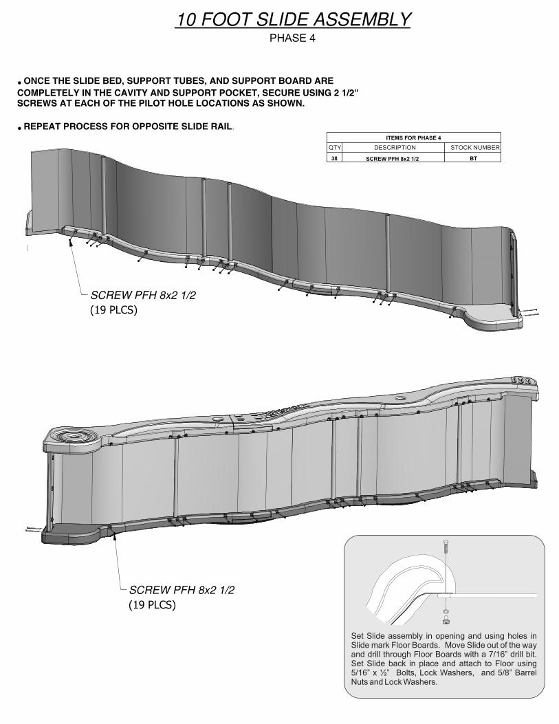
SCREW PFH 8x2 1/2 (19 PLCS)
SCREW PFH 8x2 1/2 (19 PLCS)
● ONCE THE SLIDE BED, SUPPORT TUBES, AND SUPPORT BOARD ARECOMPLETELY IN THE CAVITY AND SUPPORT POCKET, SECURE USING 2 1/2" SCREWS AT EACH OF THE PILOT HOLE LOCATIONS AS SHOWN.
● REPEAT PROCESS FOR OPPOSITE SLIDE RAIL.
10 FOOT SLIDE ASSEMBLYPHASE 4
Set Slide assembly in opening and using holes in Slide mark Floor Boards. Move Slide out of the way and drill through Floor Boards with a 7/16” drill bit. Set Slide back in place and attach to Floor using 5/16” x ½” Bolts, Lock Washers, and 5/8” Barrel Nuts and Lock Washers.
ITEMS FOR PHASE 4
38 SCREW PFH 8x2 1/2 BT