The modern builder's guide: - Internet Archive
308
!!!::s:i!!i!!i!!!:|ii!:i!!:!:!:iii!ii!i *X'i:;i:i:!i iisiii;! :llll!lli;i!!i!l!!|l:!i!ll! ':'"''' i<:-i;i;:i!;"<iM.:.i;!;i!<'i; V V ' '1' ' ' 1 iiiiiii iiii;iii;;i: ii ii ri'i'i /!' ' ' ^l^''I^^l'^l'l' ' ' 'X^'i'X'io 'Xi ' ' lv^^l'I' ' ' ' ' w 'X'liXiiiiXX'i'X'i'i'xiiXiiii'iiiX'l-li;:!!^^ liiiiiii liiii i ii iiiiiiiii iijijii Iji i iiiif i iii!i liii i ;; iiii^i i i lis ii i iiiil i i i;i;ii ;i^^ iiiii i ii iii!!i i il i i ili^^^^^^^^ ii i i i ill; i^^ii S^^ I 11 ill liiiiii ii wmm !i! '" I ' I I I X'XiiUlilXllX'Xilililili iX!! liX-xXiXiii: 1' 111 ! :ll!:l!l! l i! :!!!;':!; iiiiiii !i :!:ii;j;i ; !^^^ ii»^^^^^^^^^^^^^^^ vX'!'l'X'.;!X""!iXX: '"X'l'i"""" i"'i'X 'X""X" ;i""" i" • V ••>i i t I'lV'" I I ' I I ll'XiXi '""X.il:liXil!X' ' iilli:! ! ! ' > " « Mili'ili! I'll ! !X'I'lv;v;'l';!:ll^^^l'^^^^l 1 l^l•^^l•X'^! XiX' '!''^ m^ iXlllllXlXlllXlXilXiXl!!!!!'!!!!!;!! l!ill!!l!lll!l!ll!Xl!lXll ;!i! !;!;!! 11 ' 'I'K'X'X X ^I'^^l'X'X X 1 ii'i'X'X'X : 1 ' V V '1'^ iii ! ! X: iiiiiii : ;:iii 1 liii'li iX'X'Xiii:!; It: ' I" » >iiii!ir!! ! ' iXHiXiX! '"X-li'XlXi 1 lllillilil: 11 li'X! ! !X<!'|.li!;S!i '"•ifi;.; 'liiliWilililili :i;i:ii; I mill 1 V,. i! : : I'l'i^i'i! I ilii^x! 11 i^ii'iii^X^^ /X< ly.i oi I X' 'X' > i . 1 1 X'X' ','Xi < I !1 iX' « I < > 1( 1 ! ) ; '^'^^ l;X:t:Xlx;iI iiitiiliiiii''" vXX< Xv ' 'XX ! 'X' 'X' > I'X'X' ' 'X' I » X' V ss^ ' 'Xi < 1^ t' ' 'X' 'XO Vi'X'X'X'XXiX; ! ' ' 'Xi ' ' I ' ' V ' ^XiXi iSSSV ' 'Xi 1 1 1' 'Xv I ' 1 1 S: X' ' I ' ' t > I X<X' 'X<i 1 1 'I'X' ' '1' ' '^^^'^^^ 111!!! 1 S 1 1 i ! 1*^ ! 1 ijiiii: 1 I 1 ! !i 1 • ::; i : ii§^^ lIlliliX' ^^ IlllXi'iX' ' ' 'X'lllXiliXiX' ' 'iXlXiliXil! ' 1 IwilXXlliX: 'li';v,',';i' 1 ! i li i ii iiS i; i i i jijiii ii ii|i i ilii i i ii^ X!^ ^X' ' XlXiX' ' ' ' I ' XXlliwX'Xf I llllXiXi sX' ' ' 'S Xll'l^X'^'^
-
Upload
khangminh22 -
Category
Documents
-
view
1 -
download
0
Transcript of The modern builder's guide: - Internet Archive

!!!::s:i!!i!!i!!!:|ii!:i!!:!:!:iii!ii!i*X'i:;i:i:!i iisiii;!
:llll!lli;i!!i!l!!|l:!i!ll!':'"''' i<:-i;i;:i!;"<iM.:.i;!;i!<'i;
V V ' '1' ' ' 1
iiiiiii iiii;iii;;i: ii iiri'i'i /!' '
' ^l^''I^^l'^l'l' '' 'X^'i'X'io 'Xi '
' lv^^l'I' ' ' '
' w
'X'liXiiiiXX'i'X'i'i'xiiXiiii'iiiX'l-li;:!!^^
liiiiiii liiii iii iiiiiiiii
iijijii Iji i iiiif i iii!i liii
i ;; iiii^ii
i lis ii i iiiil i i i;i;ii;i^^
iiiiii ii iii!!i i
il i
i
ili^^^^^^^^
ii i i i ill; i^^ii S^^
I 11 ill liiiiii ii wmm
!i! '" I ' I I I
X'XiiUlilXllX'Xilililili
iX!! liX-xXiXiii: 1'
111 ! :ll!:l!l!
l i! :!!!;':!; iiiiiii !i :!:ii;j;i ; !^^^
ii»^^^^^^^^^^^^^^^
vX'!'l'X'.;!X""!iXX:
'"X'l'i"""" i"'i'X
'X""X" ;i""" i"• V • • > i i t I'lV'" I I ' I I
ll'XiXi '""X.il:liXil!X'
' iilli:! !
!'
> " « Mili'ili!
I'll ! !X'I'lv;v;'l';!:ll^^^l'^^^^l 1 l^l•^^l•X'^!XiX' '!''^
m^ iXlllllXlXlllXlXilXiXl!!!!!'!!!!!;!!
l!ill!!l!lll!l!ll!Xl!lXll;!i! !;!;!! 11'
'I'K'X'X X^I'^^l'X'X X 1 ii'i'X'X'X :
1' V V '1'^
iii ! ! X: iiiiiii : ;:iii 1 liii'li
iX'X'Xiii:!;
It: 'I" » >iiii!ir!! !
'
iXHiXiX! '"X-li'XlXi
1 lllillilil:11li'X! ! !X<!'|.li!;S!i '"•ifi;.;
'liiliWilililili
:i;i:ii; Imill 1 V,.i! : : I'l'i^i'i! I ilii^x! 11 i^ii'iii^X^^
/X< ly.i oi I X' 'X' >i
. 1 1 X'X' ','Xi < I ! 1 iX' «I
< > 1 ( 1 ! ); '^'^^
l;X:t:Xlx;iI
iiitiiliiiii''"vXX< Xv ' 'XX ! 'X' 'X' > I'X'X' ' 'X' I» X' V ss^
' 'Xi < 1^ t'' 'X' 'XO Vi'X'X'X'XXiX; ! ' ' 'Xi '
'I '
' V ' ^XiXi iSSSV' 'Xi 1 1
1' 'Xv I'
11 S: X' '
I ''
t > I X<X' 'X<i 11 'I'X' ' '1'
' '^^^'^^^
' 111!!!1 S 1 1
i! 1*^
! 1 ijiiii: 1I
1 !!i
1 •
::; i: ii§^^
lIlliliX'^^ IlllXi'iX' ' ' 'X'lllXiliXiX' ' 'iXlXiliXil! '1 IwilXXlliX:
'li';v,',';i'
1 !i
lii
ii iiSi; i i
i jijiii ii ii|i i ilii i i ii^
X!^ ^X' ' XlXiX' ' ''
I
'XXlliwX'Xf I llllXiXi sX' ' ' 'S Xll'l^X'^'^

Digitized by the Internet Archive
in 2009 with funding from
NCSU Libraries
http://www.archive.org/details/modernbuildersgOOIafe


/
'^
^

li I M. 1. \i i.\ I i;
I
)
/i-.-/ir"
D M
''^'~^l'~^~'' T :i^=c:£:
rj;!>i£jj:^i~^r s-^m. a G&mTrT:! -^vtj.'LA.

THE
MODEEN BUILDER'S GUIDE
BY
MINARD LAFEVRH
ARCHITECT.
ILLUSTRATED BY
NINETY COPPER-PLATE ENGRAVINGS.
NEW-YORK
:
PAINE & BURGESS, No. 60, JOHN STREET.
PRINTED BY C. C. & E. CHILDS, JR.
1846.

#
Entered according to the Act of Congress, May 4, 1846,B3t W1JLI<1AI?I B. SMITH,
In the Clerk's Office of the District Court of the Southern District of New York.
PREFACE.
%Se^-eral years have elapsed since I offered to the public a compilation entitled, " The Builder's General
Instructor." Those who are aware how flattering a reception, and how ready a sale that work met with,
will be somewhat surprised, perhaps, to learn, that, instead of issuing a second edition of it, I have, at a
considerable pecuniary sacrifice, entirely withdrawn the work from print. The truth is, though others seemed
perfectly satisfied with the book, I myself was not. Subsequent investigation, and increased experience as
an architect, enabled me to discover many defects and inaccuracies, which had at first escaped my notice ;
and though I might have issued a corrected edition, yet, as I had much additional matter that I wished to
present, and as this new matter, together with the numerous alterations to be made in the old, would have
materially changed the character, and well nigh destroyed the identity of the original, I, on the whole, pre-
fered to suppress that work, and prepare a substitute.
From the tenor of some of the above remarks respecting my former work, it may perhaps be inferred, that
I deem the present one faultless, and capable of safely bidding defiance to criticism. Such is not the fact.
Faultlessness is scarcely to be looked for in any human production ; and if it were, I should not presume to
claim it as an attribute to the " Modern Builder's Guide." It is hoped, however, that no material error
or glaring defect will be found m this work, and that excellences will be discovered, great and numerous
enough to more than balance its imperfections.
Though there is considerable original matter in the following pages, and though a large portion of that
which is not new, as to substance, is entirely so, as it regards manner and language, yet, taken as a whole,
it claims to be no more than a compilation. Before concluding, therefore, it will be proper to specify the
authors whom I have either consulted or made extracts from, as well as the other sources of aid that I have
enjoyed, in compiling this book. .
From the works of the jnstly celebrated Mr. Nicholson of London, I have derived a greater amount of aid
than from any other source. His " Carpenter's New Guide," and his " New Practical Builder," (especially
the latter,) are works which need no eulogium of mine; nor need I apologise for having, to an extent some-
what large, availed myself of his labours, to enhance the value of this compilation. On the following
subjects, namely. Geometry as connected with practical Carpentry, Veneering, Arches and Groins, Niches,
Coverings of polygonal and hemispherical roofs, Pendentives, Domes, Circular Sashes, and Hand-railing, I
have freely consulted the " Carpenter's New Guide," and in many instances taken it as a model ; while, on
several topics connected with Joinery, Masonry, and Plastering, I have made copious extracts from the " NewPractical Builder." The glossary of Technical Terms is from the same work.
The only other authors to whom I owe acknowledgments, are Messrs. Stuart and Revett, of London, from
whose highly valuable and popular work entitled, " The Antiquities ox Athens," I have borrowed the article
relating to the ancient Orders of Architecture.
To Mr. Joshua Coulter, an eminently skilful and experienced stair-builder residing in Philadelphia, I am
indebted for several valuable suggestions and improvements in the department of Hand-railing., These have,
in their appropriate place, been severally pointed out and duly accredited. I have also consulted several able

4 PREFACE.
and experienced architects in this vicinity ; especially Mr. J. C. Brady (now deceased,) and Mr. Martin E.
Thompson, of this city. The plan of this work was some time since submitted to the inspection of these
two gentlemen, and they were pleased to say that it met with their entire and cordial approbation.
Tlie publication of this work has, of necessity, been delayed much beyond the period originally announced
;
but this delay is the le.ss to be regretted, inasmuch as it has been the means of considerably enhancing the
• value of the work.
^^In the preparation of it, I have all the while acted under a strong conviction that something of the kind
was imperiously demanded by the wants of carpenters and builders in general, but especially by the wants of
such as .^e commencing tbe study and practice of the building art. For these tyros in the art, rather than
for the experienced architect, this work is chieny designed ; and, in preparing it, I have made the benefit of
these my principal aim. At the same time, it is believed that the work will prove a valuable auxiliary to
(liose builders, who, though well versed, perhaps, in the practical part of their profession, have little or no
acquaintance with its theory, or with the scientific principles which lie at its fomidation. In submitting the
1 esult of my labours to these two classes, and to the public at large, I indulge the hope, that, so far as those
labours are calculated to subserve the purpose for which they were bestowed, they may be appreciaited and
rewarded ; and that if, in the following pages, anything of an opposite tendency shall be discovered, it will
be generously overlooked, or at least regarded with an indulgent eye.
MINARD LAFEVER..J\tew York, 1846.

G E O M E T E YADAPTED TO
PRACTICAL CARPENTRYt
As Geometry is the foundation on whicli practical carpentry is based, it is considered
important, in compiling this worlv, to introduce such geometrical problems as will be most
useful to operators. The problems will be accompanied by diagrams, or figures, such as
are common in Carpentry, and will be explained in such a manner that a workman,
even if not thorouglily acquainted with Geometry as a science, will be able to understand
them, and when necessary, make a practical application of them.
The problems introduced in this work, arc much the same as in Mr. Nicholson's new" Carpenters' Guide." The most of these are correct, and well adapted to the purposes
for which they were introduced. The explanations, however, are not, as it seems to me,
sufficiently clear, or suited to the comprehension of Carpenters of limited scientific at-
tainments. To such, the explanations contained in this work, will, it is believed, prove
exceedingly useful..
DEFINITIONS. .
I.
A point has position, but not magnitude. (Plate I. Fig. 1.)
II.
A line is length, without breadth or thickness. (Fig. 2.)
Note.—Lines and points are constantly made use of in Carpentry, and without them,
no figure can be described..
IV.
A superfices has length and breadth only. See abed, (Fig. 4.) Thus, the face of a
board is a superficies.
V.
A solid has three dimensions—length, breadth and thickness.
A solid may be formed in the following manner. Let abed, (Fig. 4.) be the under
side; e f g h, one of the vertical sides ; i ; k I, the other vertical side; and m, the upper
side, or surface. Now suppose i /, moved to b c, and e h, to a d ; then raisej k perpen-
dicMilar to b c, and/ g- perpendicular to a d, and turn m directly over abed; a solid
will be formed.
2

6 GEOMETRY ADAPTED TO PRACTICAL CARPENTRY.
VI.
A curve line is continually changing its direction. (Fig. 5.)
A curve is produced in various ways; as with a compass, trammel, intersecting lines,
«S;c. ; and, except when made by means of a trammel, will be a true curve.
VII.
Parallel lines, whether straight or curved, are always equally distant from each other.
(Fig. 6.)
Note.—Two elliptical lines cannot be drawn parallel to each other by means of atrammel, or intersecting lines.
VIII.
Oblique lines change their distance, so as on one end to approach, and on the other to
recede from each other. On the side where they approach they would meet, if contin-
ued. (Fig. 7.)
IX.
A tangent is a straight line, touching a curve, without cutting it when produced.
(Fig. 9.)
X.
An angle is the inclination towards one another of two straight lines, having differ-
ent directions, but meeting in a point, and being in the same plane. (Fig. 10.)
XI.
A right angle is that, which is made by a straight line perpendicular to another straight
line. (Fig. 8.)
XII.
An oblique angle is one, that is either greater or less than a right angle. If greater,
it is an obtuse angle. (Fig. 12.) If less, it is an acute angle. (Fig. 11.)
XIII. ,
Rectilineal figures are those, which are contained by straight lines.
XIV.
Trilateral figures, or triangles, are bounded by three straight lines. (Fig's. 13, 14, «Stc.)
XV.
(Quadrilateral figures are bounded by four straight lines. (Fig's. 17, 18, «SiC.)
XVI.
Multilateral figures, or polygons, are bounded by more than four straight lines.
XVII.
Of three sided figures, an equilateral triangle is that which has three equal sides.
(Fig. 13.)
XVIII.
An isosceles triangle has only two sides equal. (Fig. 14.)
XIX.
A scalene triangle has all its sides unequal. (Fig. 15.)
XX.
A right-angled triangle has one of its angles a right angle. (Fig. 16.)
XXI.
An obtuse-angled triangle has one of its angles an obtuse angle. Fig. 15.)
XXII.
An acute-angled triangle has all its angles acute angles. (Fig. 13.)

GEOMETRY ADAPTED TO PRACTICAL CARPENTRY. 7
XXIII.
A rectangle is a four sided figure, having all its angles right angles. (Fig's. 17, 18.)
XXIV.
An equilateral rectangle is one that has all its sides equal. Fig. 17.)
XXV.An oblong rectangle, or an oblong, has all its angles right angles, but has not all its
sides equal. (Fig. 18.)
Note.—An oblong has its opposite sides equal.
XXVI.
A rhombus has its four sides equal, but its angles are not right angles. (Fig. 21.)
XXVII.
A rhomboid has four sides, of which the opposite ones are equal to each other, but its
angles are not right angles. (Fig. 22.)
XXVIII.
A trapezium is a quadrilateral figure, having none of its sides parallel. (Fig. 20.)
XXIX.
A trapezoid is a quadrilateral figure, having only two of its sides parallel. (Fig. 19.)
Note.—Figures having three angles, as triangles, are called trigons; four, tetragons
;
five pentagons ; six, hexagons;seven, heptagons ; eight, octagons ; nine, nonagons ; ten,
decagons; eleven, undecagons; twelve duodecagons; and so on.
XXX.A circle is a figure bounded by a curved line, called the circumference, which is every
where equi-distant from a certain point witliin the circle, called the centre. (Fig. 23.)
XXXI.A diameter of a circle is a straight line drawn through the centre, and terminated both
ways by the circumference. (Fig. 23.)
XXXII.
A radius of a circle is half of a diameter, or a straight line drawn from the centre to
the circumference Thus, from 1 to 4, (Fig. 23.) 1 to 2, or 1 to 3, is a radius.
XXXIII.
An arch of a circle is any portion of the circumference ; as at 1, 3, 2, (Fig. 24.)
XXXIV.The chord of an arch is a straight line joining the extremities of the arch ; as 1, 2.
(Fig 24.)
XXXV.A segment of a circle is any portion of the circle, bounded by an arch and its chord.
(Fig. 24.)
XXXVI.A semicircle is half a circle, or the segment cut off by a diameter. (Fig. 25.)
XXXVIIA sector of a circle is any part of the circle, bounded by an ardh and two radii drawn
to the extremities of that arch. Thus, 1, 2, 3, (Fig. 26.) is a sector.
XXXVIII.
A quadrant is a quarter of a circle. Thus, 1, 2, 3, (Fig. 27.) is a quadrant.

GEOMETRY ADAPTED TO PRACTICAL CARPENTRY.
XXXIX.
The altitude of any figure is a perpendicular, let fall from its vortex upon the oppositeside, or base. Thus, a b, (Fig. 28.) is the altitude of the triangle.
Note.—When several angles are at one point, as at 1, (Fig. 29.) any one of them is
expressed by three letters;of which, the letter that is at the angular point, is put be-
tween the other two letters, and one of these two is placed somewhere upon one of thestraight lines that contain the angle, and the other upon the other line. Thus, the an-gle which is contained by the straight lines 3, 1, and 4, I, (Fig. 29.) is named the angle
3, 1, 4. or 4, 1, 3. But if there be only one angle at a point, it may be expressed by asingle letter placed at that point ; as the angle at A, (Fig. 30.)
N.B. To measure an angle, a circle is so described that its centre shall be the angularpoint, and its circumference shall cut the two lines which contain the angle. 'J'he archbetween these two lines is called a measure of the angle. Thus, the arch b c, (Fig. 30.)
is a measure of the angle.
PROBLEM—PL. 2.
TO ERECT A PERPENDICULAR TO A GIYE.X LINE 13 2, (pLATE II. FIG. 1.) FROM AGIVEN POINT IN THE SAME.
On each side of the point 3, take any two equal distances, as 3 1, 3 2; from the points
1 2 as centres, with the distance 1 2 as radius, and on the same side of the given line,
describe two arcs of circles intersecting each other at 4;join 3 4 : the line 3 4 will be the
perpendicular required.
UPON A BASE SIX FEET IN LENGTH, TO ERECT A PERPENDICULAR THAT SHALL BE EIGHTFEET LONG.
Let the line 12 (Fig. 2.) be the given base; from one end, as 1, of this line, with the
distance ten feet lor radius, describe an arc of a circle ; from the other end 2, of the base,
draw a perpendicular 2 3, (see preceding problem,) so as to cut the arc: the perpendicular2 3 will be eight feet long.
FROM A GIVEN POINT, TO LET FALL A PERPENDICULAR UPON A GIVEN STRAIGHT LINE.
Let ], (Fig. 3.) be the given point, and 2, 3, the given straight line; from 1 as a centre,
describe an arc so as to cut the given line in two points, as 2, 3 ;from the points 2, 3, as
centres, with the distance 2, 6, or 3, 5, for r;idiu!i, describe two arcs cutting each other at4
;
join 1, 4 ; 1, 4 will be the perpendicular required
FROM ONE EXTREMITY OF A GIVEN STRAIGHT LINE, TO ERECT A PERPENDICULAR TO THATLINE.
Let 3, 1, (Fig. 4.) be the given straight line, and 1 that extremity from which it is
required to erect a perpendicular ; take any distance, as 1 , 4, and from 4 as a centre, with 4,
1
for radius, describe an arc 3, 1, 2, meeting the given straight line at 1 and 3;join 3, 4 and
produce the line 3, 4 to 2;join 1, 2, and 1, 2 will be the required perpendicular.
TO BISECT, OR DIVIDE A GIVEN LINE INTO TWO EQUAL PARTS,
Let 1, 2, (Fig. 5.) be the given line ; from the points 1, 2, as centres, with any distance
greater than half 1, 2 for radius, as 1, 1 and 2, 3, describe arcs of circle cutting each other
at 5 and G;join 5, 6 : the line 1, 2 is bisected at 9,

GEOMETRY ADAPTED TO PRACTICAL CARPENTRY. »
TO BISECT AN ANGLE.
Let 3, 1, 2, (Fig. 6. ) be the given angle : it is required to bisect it. From the point 1
as centre, with any distance, as 1, 2, for radius, describe an arc so as to cut the sides con-
taining the angle; from the points of intersection, 3,2, with any radius, describe arcs cutting
each other, as at 4;join 4, 1 : the angle 3, 1,2, is bisected by the line 1, 4.
AT A GIVEN POINT IN A GIVEN STRAIGHT LINE, TO MAKE AN ANGLE EQ.UAL TO A GIVEN
ANGLE.
Let 4 6, (Fig, 8.) be the given straight line, and 4 the given point, and 2 13, (Fig. 7)
the given angle; from the point 1, as a centre, with any distance, as 1 3, for radius, describe
an arc 3 2, meeting the lines 1 3, 1 2, at 3, 2 ; on the given straight line 4 6, take the samedistance, and from 4 as centre, describe an arc 6 5, equal to the arc 3 2
;join 5 4 : the angle
5 4 6 is equal to the angle 2 13.
PL. 3.
UPON A G4VEN STRAIGHT LINE, TO DESCRIBE AN EQUILATERAL TRIANGLfe.
Let 1 2, (Plate 111. Fig. 1 .) be the given straight line ;from the points 1, 2, as centres,
with the distance 1 2 for radius, describe arcs of circles cutting each other at 3;join 3 1,
and 3 2; the triangle 1 3 2 is equilateral.
TO DESCRIBE A SQUARE UPON A GIVEN STRAIGHT LINE.
Let 1 2, (Fig. 2.) be the given straight line ; from the points 1,2, as centres, with the
distance 1 2 as radius describe arcs of circles, 1 3 and 2 4;from the point 5 where they
intersect, with half the distance 5 2, that is, with 5 6 for radius, describe the arcs 6 3,74;through the points 3, 4, draw the straight lines 3 2, 3 4, 4 1 : the quadrilateral figure,
described upon the straight line 1 2, is a square.
A SIDE OF A POLVGON OF ANY NUMBER OP SIDES WHATEVER BEING GIVEN, TO DESCRIBE THE
POLYGON OF WHICH IT IS A SIDE.
Let 1 6, (Fig. 5.) be a side of a polygon of six equal sides; from 6, as centre, with the
given side for radius, describe semicircle; divide the semicircle into as many equal parts as
the polygon is to have sides, viz. in this case, six, and through the points ofdivision 2, 3, 4,
draw the straight lines 6 9, 6 8, 6 7 ; draw also the radius 6 5; from the point 1, with the
side 1 6 for radius, describe an arc, and from the point 9, in which it cuts the line 6 9, with
the same radius, describe an arc cutting 6 8 in 8 ; do the same from points 8 and 7 ;join
1 9, 9 8, 8 7 and 7 5 : 1 9 8 7 5 6 is the polygon required.
THROtJCH A GIVEN POINT IN THE CIRCUMFERENCE OF A CIRCLE, TO DRAW A TANGENT TO
THAT CIRCLE.
Let 2 (Fig. 7.) be the given point in the circumference: draw the radius 1 2, aBd through
2, draw 3 4 at right-angles to 1 2 : 3 4 is the tangent required.
A TANGENT TO A CIRCLE BEING GIVEN, TO FIND THE POINT WHERE IT TOUCHES THE CIRCLE.
Let 12 (Fig. 8.) be the given tangent ; take any point, as 2, in 1 2, and from 2 draw a
straight line 2 3 to the centre of the circle ;bisect 2 3 in 4, and from 4, with 4 3 or 4 2 for
radius, describe an arch cutting 1 2 in 5 : 5 is the touching point require.
3

10 GEOMETRY ADAPTED TO PRACTICAL CARPENTRY.
TO FIND A MEAN PROPORTIONAL BETWEEN TWO GIVEN STRAIGHT LINES.
Let 1, 2, (Fig. 9.) be the two given straight lines;place 1, 2 in one straight line 3 4 5,
3 4 being equal to 1, and 4 5 to 2 ; bisect 3 5 in 6 and describe the semicircle 3 7 5, from
the point 4 draw 4 7 at right angles to 3 5 : then 3 4 is to 4 7 as 4 7 is to 4 5 ; that is, 4 7 is
the mean proportional required.
THROUGH ANY THREE POINTS TO DESCRIBE THE CIRCUMFERENCE OP A CIRCLE.
Let 2, 3 4 (Fig. 10.) be the three given points; join 2 3 and 3 4, and from 3, with any
radius, as 3 7, describe a« arc 7 6 5 8 ;from the points 2 and 4, as centres, with the same
radius, describe arcs, cutting the first-described arc in the points 6, 7, and 5, 8 ; through the
points of intersection draw the straight lines 8 5, 7 6, and produce them till they meet:a
circle described from the point 1, in which they meet, will have the points 23and4init3
circumference.
TO FIND THE LENGTH OF ANY GIVEN ARC.
Let 12 3 (Fig. 11.) be a given arc ; draw the chord 1 3 ; bisect the given arc in 2, and
from I, as a centre, with the distance 1 2 as radius, describe the arc 2 6;
produce the chord
1 3 so that 6 4 shall be equal to 1 6 ; divide 3 4 into three equal parts, and produce the
straight line 1 4 so that 4 5 shall be equal to one-third of 3 4 ; the straight line 1 5 is the
length of the arc 12 3.
PL. 4.
TO CONSTRUCT A TRIANGLE OP WHICH THE SIDES SHALL BE EaUAL TO THREE GIVEN
STRAIGHT LINES.
Let 12, 34, 56, (Plate IV. Fig. 1.) be the three given straight lines ;from one extremity,
as 2, of the line 1 2 for a centre, with the distance 3 4 for radius, describe an arc, and from
the other end 1 of the same line, with 5 6 for radius, describe another arc so as to cut the
first-described one ; from the point of intersection 7, draw the straight lines 7 1, 7 2: 1 2 7
is the triangle required.
NoTK.—Of the three given straight lines, the length of any two taken together must be
greater than that of the remaining one.
TO MAKE A TRAPEZIUM EQUAL TO A GIVEN TRAPEZIUM.
Let 12 3 4 (Fig. 2.) be the given trapezium ; divide it into two triangles by joining two
opposite angles, as 2, 4; draw a straight line 5 6 (Fig. 3.) equal to 2 3 in Fig. 2., and at
the points 5, 6, in the straigiit line 5 6, make (See Prob. VII.)the angle 6 5 7 equal lo the
angle 3 2 4, and the angle 5 6 7 equal to the angle 2 3 4 ; at the points 5, 7, in the straight
line 5 7, make the angle 7 5 8 equal to 4 2 I, and the angle 5 7 8 equal to 2 4 1 : the
trapezium 8 5 6 7 is equal to the trapezium 12 3 4,
ANY IRREGULAR POLYGON BEING GIVEN, TO MAKE A POLYGON EftUAL AND SIMILAR TO THE
ONE GIVEN.
Let 1 234 5( Fig. 4.) be the given irregular polygon ; divide it into three triangles by
the straight lines 1 3, 1 4 ; draw a straight" line 1 2 "(Fig. 5.) equal to 1 2 in Fig. 4. and as
in the preceding problem, upon 1 2 (Fig. 5.) make the triangle 12 3 equal to the triangle
1 2 3 in Fig. 4 ; upon 1 3, the triangle I 3 4 equal to 1 3 4 ; and upon 1 4, tlie triangle
1 4 5 equal to the triangle 14 5 in Fig. 4 : then will the two polygons be equal and
similar.

GEOMETRY ADAPTED TO PRACTICAL CARPENTRY. 11
A TRIANGLE BEING GIVEN, TO MAKE A RECTANGLE EdUAL TO THE TRIANGLE.
Let 12 3 (Fig.6.) be the given triangle, and from tlie angle at 1, let fall the perpendi-
cular 1 4 upon the opposite side ; bisect 1 4 in 5, and through 5 draw the straight line 6 7parallel to 2 3 ; draw 3 7 and 2 6 at right angles to 2 3 : the rectangle 2 3 7 6 is equal to
the triangle 12 3.
TO MAKE A SaUARE EftUAt TO A GIVEN RECTANGLE.
Let 12 3 4 (Fig. 7.) be the given rectangle;produce one of its sides, as 1 4, so that the
part produced 4 8 shall be equal to the side 4 3 of the rectangle ; bisect 1 8 in 9, and from9, with 9 8 or 9 1 for radius, describe the semicircle 17 8; produce the side 4 3 till it meetsthesemicircle at 7, and upon the straightline 4 7 describe thesq^uare(See Prob. IX.) 7 6 5 4:the 7 6 5 4, is equal to the rectangle 12 3 4.
TO MAKE A SaOARE EQ.UAL TQ TWO GIVEN SftUARES.
Let 1, 2 (Fig. 8.) be the two given squares;place them so as to touch, and so that one
side of one square shall be at right angles to one side of the other, as 3 5, 5 4 in the Figures;join 3 4, and upon the hypothenuse 3 4 of the right-angled triangle 34 5 describe the square3 6 7 4.; the square 3 6 7 4 is equal to the two squares 1, 2.
PL. 5.
TO MAKE AN ELLIPSIS WITH A THREAD OR STRING.
Let 1 2 (Plate V. Fig. 1) be the longest diameter of the required ellipsis, and let 4 3, at
right angles to 1 2, be half of the shortest diameter ; from the point 3, as centre, with half1 2 for radius, describe arcs cutting 1 2 at the points 5 and 6 ; at these two points place pins,
and, holding a pencil at the point 3, put a thread or cord round the two pins and the pencil,
so that when round them, it shall be stretched or taut; move the pencil round, keeping the
string stretched, and an ellipsis will be described.
TO MAKE AN ELLIPSIS BY TRAMMEL.
Let 1 3, 2 4 (Fig. 2.) be the axis or diameters of the i-equired ellipsis;
let 6 7 8 be a^ trammel, 6 being the place for a pencil, and 7, 8 places for pins to move in grooves ; make6 7 equal to half the shortest diameter, that is, to 4 5, and 6 8 equal to half the longest, Uiatis, to 1 5 ; move the pencil round, and an ellipsis will be described.
AN ELLIPSIS BEING GIVEN, TO FIND ITS CENTRE AND ITS TWO AXIS.
Let 14 7 2 5 8 (Fig. 3.) be the given ellipsis; draw any two parallel lines, as 1 2, 1 2;bisect those lines in 3, 3, and through 3, 3, draw the straight line 4 5 ; bisect 4 5 in 6, andfrom 6, as centre, with any radius, describe an arc so as to cut the circumference of theellipsis, as 7 8; join 7, 8, and through 6 draw 9 10 parallel to 7 8, and tlirough the samepoint draAv 1112 at rig'it angles to 9 10 : 6 is the centre, 9 10 the conjugate axis, and 1 1 12ihe transverse axis, of the given ellipsis.
ONE DIAMETER OP AN ELLIPSIS BEING GIVEN TO DESCRIBE AN ELLIPSIS, SUCH THAT ITS TWO DI-
AMETERS SHALL BE PROPORTIONAL TO THE DIAMETERS OF ANY GIVEN ELLIPSIS.
Let 8 6 (Fig. 4.) be one diameter, as for instance the conjugate of the required ellipsis,and let I 2 3 4 be a given ellipsis, 1 3 being its conjugate and 2 4 its transverse diameter;about the ellipsis 123 4 describe the rectangle 9 10 1 1 12 by drawingslraight lines through

12 GEOMETRY ADAPTED TO PRACTICAL CARPENTRY.
the points 1, 3 parallel to 2 4 and through the points 2, 4, parallel to 1 3; draw the di-
agonals 12 10, 11 9; through the point 8 or 6, and parallel to the transverse axis 2, 4,
draw the straiglit line 13 J 6 or 14 15 so as to meet the diagonals ; through the points in
which they meet the diagonals, and parallel to the conjugate axis 1 3, dra"\v the straight
lines IG 15, 13 14; the part 7 5 of the straight line 2 4, cutofl'by the lines IG 15, 13 14,
is the traverse axis of the required ellipsis; describe (See Prob's. XXII and XXHI.) the
ellipsis 5 8 7 6: the diameters of this ellipsis are proportional to those of the ellipsis 1
2 3 4; that is, 8 G is to 7 5 as 1 3 is to 2 4.
TO DESCRIBE AN ELLIPSIS ABOUT A GIVEN PARALLELOGRAM, SO THAT ITS LENGTH SHALLHAVE THE SAME RATIO TO ITS WIDTH, THAT THE LENGTH OF THE PARALLELOGRAMHAS TO ITS WIDTH.
Let 12 3 4 (Fig. 5.) be the given parallelogram ; draw the diagonals 1 3, 2 4, andthrough the point 1 7 in which they intersect, draw 15 14 parallel to 1 2 or 4 3, andalso G 1 6 parallel to I 4 or 2 3; from the point 1 7 where the diagonals intersect, withhalf the width of the parallelogram for rail i us, describe the quadrant 6 7; bisect the arc
6 7 in 5, and through 5, draw the straight line 8 9 })arallel to the line 15 14; draw the
lines 6 9, 9 1 4, and through the point 2 draw 2 1 2 parallel to 9 G, and 2 11 parallel
to 9 1 4;produce the line 15 14 till it meets 2 1 1 in 1 1, and produce the line 1 G 6
till it meets 2 1 2 in 1 2 ; 17 12 will be half the width, and 17 11 half the length of
the required ellipsis; make 17 10 equal to 1 7 1 1, and 17 13 equal to 1 7 1 2, anddescribe the ellipsis 1 1 2 1 1 1 3: its length is to its width as the lengtli of the par-
allelogram J 2 3 4 is to its width.
TO DIVIDE A GIVEN STRAIGHT LINE INTO PARTS THAT SHALL BE PROPORTIONAL TO THEPARTS OF A GIVEN DIVIDED STRAIGHT LIJfE.
Let 1 4 (Fig. 6.) be a straight line divided in the points 2, 3, and let 1 5 be the line
given to be divided;place the lines 1 4, I 5 so as to make any angle whatever, as 4 1 5;
join the other extremities by the line 4 5, and through the points 3, 2, draw 3 6, 2 7parallel to 4 5 ; the straight line I 5 is divided in the points 6, 7; so that 5 6 is to 6 7 as4 3 is to 3 2, and G 7 is to 7 1 as 3 2 is to 2 1.
ANOTHER METHOD OF DOING THE SAME THING.
Let 1 4 (Fig. 7.) be a straight line divided in the points 2, 3; upon I 4 describe theequilateral triangle 1 G 4, and if, as in this case, the line to be divided be shorter tiianthe divided line, place it within th.e triangle and parallel to the divided line as 7 5
;join
6 2,G 3: the line 7 5 is divided by the lines G 2, G 3, so that its parts are proportional
to the parts of the given divided line 1 4.
Note.—If the line to be divided be longer than the divided one, produce two sidesof'the equilateral triangle beyond the base and until the said line can be placed betweentliem parallel to the base, in both cases, the length of the line to be divided, measuredfrom th.e vortex on the two sides, will give the points in which the said line will cutthose sides.
TO INSCRIBE AN EQUILATERAL AX© EQUIANGULAR OCTAGON IN A GIVEN SQUARE.Let 1 2 3 4 (Fig. 8.) be the given square; draw the diagonals 1 3, 2 4, and from the
points I, 2, 3, 4 as centres, with half of either diagonal for radius, desci-ibe arcs of cir-
cles meeting the sides of the square in the points 5, 8, 7, 10 9, 12, II, 6;join 12 5, 6 7, 8 9,
10 11: an equilateral and equiangular octagon 1256789 10 11 has been inscribed intlie given square 12 3 4.

GEOMETRY ADAPTED TO PRACTICAL CARPENTRY. 13
PL. 6.
THE LENGTH AND HEIGHT OF A SEGMENT OF A CIRCLE BEING GIVEN TO DESCRIBE THE SEGMENT.
Let I 2 (Plate VF. Fig. \.) be the length, and 5 1 3 the height of the segment to be
de.>^ci-ibecl; bi.sectthe line 1 2 in 1 3, and from the point of bisection draw the straight line
1 3 8 at right angles to ihe line 1 2; draw the chord I 5.; bisect that chord, and through the
bisecting point draw the straight line I 8 perpendicular to 1 5; the point8 where the two
perpendiculars meet is the centre ofthe circle of which the required segment is a part; from
8, with 8 5 as radius, describe the arc I 5 2, and you have the segment required.
THE LENGTH AND HEIGHT OF A SEGMENT OF A CIRCLE BEING GIVEN, TO DESCRIBE THE SEGMENT
BY MEANS OF RODS.
Let the line I 2 (Fig. 2.) be the length, and 3 4 the height, of the required segment;
take two rods 5 3, 6 3, each equal in length to the line 1 2, and make such an angle with
them that when the angular point is at 3, the rr)ds will meet the extremities of the line
1 2; secure them at that angle by the cross-piece 7 8; at the points 1, 2 fix pins, and
through a hole in the rods at the point 3 put a pencil ; move the pencil round keeping the
rod.-i pressed against the pins, and the segment 13 2 will be described.
TO DO THE SAME THING BY MEATVS OF A FLAT TRIANGLE.
Let. 4 3 (Fig. 3.) be the length, and I 2 the height, of the required segment; join 3 2,
and through 2 draw 2 u parallel to 4 3 and equal t« 2 3, and join 5 3; place pins at the
points 2, 4", and with a pencil at the vertex of the triangle, move the vertex round from
2 to 4, as in Figure 4; take up tlie pin at 4, and place it at 3; then move the vertex
from 2 to 3^ and the required segment will be described
THE TWO AXIS OF AN ELLIPSIS BEING GIVEN, TO DESCRIBE THE ELLIPSIS.
Let 4 6 (Fig. 5.) be the transverse and I 3 the conjugate axis of the required ellipsis;
through G draw 6 7 parallel and equal to 2 1 ;bisect 6 7 in 8, and draw 8 1,73 cutting
each other at 9; bisect I 9, and from the bisecting point draw a straight line perpendic-
ular to I 9; produce that straight line and the axis 1 3 till they meet at I 2; draw I 2
7 cutting the axis 4 6 in 15; make 2 I 7 equal to 2 I 5, and produce 3 1 so that 2 I 3
shall be^'equal to 2 12; draw 1.2 I 4, I 3 1 8, 1 3 1 6, and from the points 1 2, 1 3, as
centres, with the distance 12 1 or 13 3 for radius, describe the arcs 14 9 18 16, and
from the p;iints 1 7, 1 5, with 4 I 7 or 6 I 5 for radius, describe the arcs 1 4 1 8, 9 16:
1 6 o 4 is the ellipsis required.
TO DO THE SAME THING BY MEANS OF ORDINATES.
Let tlie line 1 2 (Fig. 6.) be the length, and the line 4 9 half the width of the ellipsis
to be descriljcd; on the length 1 2 describe the semicircle 18 2; divide the semicircle
into any number of equal parts, as for instance sixteen, and through the points of divis-
ion I, 2, 3, «S:c. and at right angles to the transverse axis 1 2, draw the ordinates I I, 22,
3 3. &c.; draw I 3 perpendicular to the tnuisverse axis, and equal to 4 9, and join 4 3;
take in the compass tiiat part of the straight line 7 7 which is cut off by the lines 1 4, 3
4, that is, take 7 !, and on both sides of tlie transverse axis, and at each end of the same,
cut off the leufrth 7 1 o?i the straight line I I; take (i 2 ami cut off the same length on
? 2, on eacli side of the transverse axis; on 3 3, cutoff the length 5 3; on 4 4, the lemjlh
4 4, intercepted between the lines I' 4, 3'4; on 5 5, the intercepted length 3 3; on 6 6,
4

14 GEOMETRY ADAPTED TO PRACTICAL CARPENTRY.
the intercepted length 2 2; and so on; the circumference of the required ellipsis will passthrough the points in which the straight lines, orordinates, 1 1, 2 2, 3 3, &c. were cutoff.
PL. 7.
TO FIND THE SECTION OF A SEMI-CYLINDEI?, WHEN IT IS CUT BY A PLANE THAT IS PER-PENDICULAR TO THE PLANE COLNCIDING WITH ITS FLAT SIDE, BUT IS NOT PAKALLKL TOITS ENDS OR BASES.
Let the semicircle 7 6 8 (Plate VII. Fig. 1.) represent one end of a semi-cylinder, thefour-.sided figure 7 8 10 9, a portion of its length, and the line 9 10, the edge of a planeculling the semi-cylinder perpendicularly, but not parallel to the plane 7 6 8; divide the
arc 7 6 8 into any number of equal parts, as for instance twelve; and from the points ofdivision 1, 2, 3, &.c. draw perpendiculars to ihe line 7 8, and produce them lill they meetthe line 9 10; from the points I, 2, 3, &c. where they meet 9 10, and at right angles to
the same, draw the lines I 1, 2 2, 3 3, &c. each equal to the line of the same name in thesemicircle 7 6 8; describe the curve 9 6 10 passing through the extremities of those lines;
the figure B is the section required.
AN ACUTE ANGLE BEING GIVEN, TO CUT A SEMI-CYLINDER IN A DIRECTION OBLIQUE TO THEDIAMETER OK THE BASE, AS BEFORE, AND BY A PLANE MAKING AN ACUTE ANGLE EQUALTO THE GIVEN ONE WITH THE PLANE WHICH COINCIDES WITH THE FLAT SIDE OF THE SEMI-
CYLINDER.
Let the semi-circle 7 « 8, the four sided figure 7 8 10 9, and the straight line 9 10,
represent the same things as in the preceding problem, and let the angle b a /'at C, bethe given acute angle; at C, draw d e at right angles to d a and equal to the radius a 6
or 8 Ij of the base; through e draw c c parallel to d a; produce u f till it meets e c in c,
and from c let fall perpendicular c b ; in 9 10 take any point, as c, and from c draw c /'at
right angles to 9 10, and equal to a c at C;])roduce/ e so that e g shall be equal to a b
at C ; through g draw g d parallel to 7 8, and join df; produce the radius a b io d, andthrough g draw g ji parallel to d a, and join h b; divide the arch 7 rt 8 into any numberof parts, and through the points of division draw straight lines, as I 2,34,56 parallel to
h 1) ; from the points in which those lines meet the line 7 8, draw lines at right angles to
7 8 to meet the line 9 10, and through the points in which they meet 9 10, draw straight
lines parallel to d f\ and efjiial to their corresponding lilies in A; describe a curve passing
through the extremities of the j)arallel lines in B, and you have the required section.
AN ORTUSE ANGLE BEING GIVEN, TO CUT A SEGMENT OF A CYLINDER IN A DIRECTION OB-
LIQUE TO THE DIAMETER OF THE BASE, AND SO THAT THE Pr.ANE CUTTING IT SHALLMAKE AN OBTUSE ANGLE EQUAL TO THIi GIVEN ONE WITH THE PLANE THAT COINCIDES
WITH THE FLAT SIDE OF THE SEGMENT.
Let the angle b a fat C (Fig. 3.) be the given ohtiise angle; from the point a draw adat right angles to a b aiul equal to the radius a b of the base 7 « 8 ; through d draw d c
parallel to a h, and ])rodtice af to meet d c in c ; in 9 10 take any point, as c, and from c
draw 6' /perpend icidar to 9 10 and equal to nd at C; from cf cut off e g equal to df c at C,
and through i,'', and parallel to 7 8, draw i,-- d to meet 9 10 in d and join df; from (/ let
fall upon 7 8 the pcrpendicidar d h. and through g draw g It parallel to d b and join /( b ; in
A drawany nundjcrof lines parallel to A b, and from the ])oints in which tliev meet 7 8, andat right angles lo tliesan:e, draw straight lines to 9 10; through the points where they meet9 10, draw straight Hues parallel to df, making each equal to the line of the same name at

GEOMETRY ADAPTED TO PRACTICAL CARPENTRY. 15
A; through the extremities of these parallels trace a curve, and the required section
will be described.
Note.—In looking at these figures, we must imagine A to be a plane standing at right
angles to the plane 7 8 10 9, and B another plane making with 7 8 10 9 whatever angle
is sj)ecitied in tlie problem. Tiiat the learner may better perceive the /cA// and xchcrc-
furc of what is done, and tlie correctness of the result obtained, it will be well (or himto draw the.se figures on some stiff kind of paper, and tiien cut them out, and bend the
parts A and B so as to make them form, with 7 8 10 9, tjje angles required. A must, in
all these figures, stand at right aUi^les to 7 8 10 9, but in the first of tliem, B must form
a right angle with that plane; in the second, the acute angle b a f\ and in the third, the
obtuse angle 6 a f. By making the planes A and B form the required angles, the learn-
er will see that if planes were made to pass through the j)arallels in A, they would, if
produced, pass through the parallels in B, the plane belonging to each ptu-allel in A,
passing through the corresponding parallel in B,
PL. 8.
TO FIND THE SECTION OF A SEMI-GLOBE, WHEN IT IS CUT BY A PLANE AT RIGHT ANGLESTO ITS BASF:, OR FLAT SIDE.
Let the circle a (//(Plate VIll Fig. 1.) represent a semi-globe with its flat side up-
permost, and let the straight line c d represent the edge of a plane cutting the semi-gUibe
at right angles to its flat side; bisect c d in 1, and from 1, as centre, with 1 c or 1 d lor
radius, describe the semicircle c g d; c g d is the section required.
ANOTHER METHOD OF DOING THE SAME THING.
Let the circle rt f// (Fig. 1.) and the line cd represent the same thing asWfore;
draw the diameter a h. and from the centre e, with the distance from e to the centre of
the line c d, that is with c 1 for radius, describe an arc 1 I, so as to meet I (/ and c b
;
from the same centre with different radii, describe concentric arcs, as 2 2, 3 3, «S;c. to
meet the same lini-s 1 d, c o, and from the points 1, 2, 3, &c. in which the arcs meets the
semi-diameter c b, draw ,)erpendiculars, as I 1,2 2, &c. to the circumference; from the
points in which those arcs meet the line 1 d, draw the j>erpendiculars 1 1,2 2, &c., equal
in length to tliose of the same name on e b : through the extreniities of the perpendic-
ulars on 1 d, and those that may by a similar process be erected on 1 c, describe the
curve c g d : c a d is the section required.
]VoTE.—The learner will see tliat the semicircle c g d represents that face of the piece
a c df, or of the ])iece c It d, which is made by cutting through the .semi-ilobe at c d \n
a direction perpendicular to the flat side of the semi-globe. A moment's reflection, with-
out anv demonstration, will convince him that whenever a send-globe is cut at right an-
gles to its flat side, the face produced by the cutting will be a semicircle, of which the
straight line that designates the place of cutting, will be the base or diameter. When,therefore, this straight line is given, (as it always is,) the learner has only to describe a
semicircle upon it, to find the sliape and size of the face required. That he may clearly
perceive the accuracy of the second method, let him imagine the semi-globe to be cut
through, perpendicularly to its flat side, at a b as well as at c d, and the quarter-globe a
fb lo be turned up atrii^ht angles to the face a It b: he will then see that the lines 1 1,
2 2, &.C. on the face ajf b are the perpendicular distance of the j)oints 1, 2, &c. in the
spherical surface from the flat side of the .semi-globe; and that since the points 1, 2 &.c,
in cd, are at the same distance from the centre c as the points 1, 2 &c. in a b, the per-
pendiculars from 1, 2, &c. in c (/ to the spherical surface must be of the same length with

16 GEOMETRY ADAPTED TO PRACTICAL CARPENTRY.
the perpendiculars from 1, 2, &c. in a b to the spherical surface; in other words, that (helines 1 1,2 2, &c. on the face of c g d, must be equal in length to I ] , 2 2, &c. on o fb.
The required sections in Figures 2. 3. and 4. are found by the second method of the
preceding Problem. In l*'igure 3. tlie solid to be cut is snpposed to have a circular base',
but an elliptical elevation; and A at Figure 4. represents an ogee standing on a circular
base, and from ii B is found by the method just mentioned.
A SEMI-GLOBE BEING CUT BY A CYLINDRICAL SURFACK AT RIGHT ANGLES TO ITS FLATSIDE, TO FIND THE FORM AND SIZE OF A VENEER, OR COVERING, TO BE BENT HOUNDTHE SECTION.
Let the circle a b d c (Fig. 5.) represent a semi-globe, and the arc a b, a cylindrical
surface cutting the semi globe at rigbt angles to its tlat side; draw the diameter c d, andbi.sect the arc a 6 in I ; from c tlic (;entre of the globe, with c 1 for radius, describe the
arc 1 1, and enlarging the radius, describe al.so the arcs 2 2, 3 3, &c. ; from the ])oints 1,
2, &c in which the arcs meet ed, draw to the circumference of the circle the perpendic-ulnrs 1 1,2 2, &c. ; obtain the length of (he arc o b, and place it in a straight line o b at
B, and divide the straiglit line a b, so that if bent round the arc a b, its divisions wouldcorrespondwith those made in that arc by (he arcs 1 1,2 2, &c. ; (rom I in the straight
line a b, corresponding with I in the arc a 6, draw the perpendicular 1 1, equal to 1 1 at
A ;from 2 the perpendicular 2 2, equal to 2 2 at A ; and so on ; (race a curve through
the extremities of these perpendiculars, and you will have the required covering or veneer.
TO FIND THE RIRS OF A GOTHIC NICHE, WHEN THE PLAN AND THE FKO.NT ELEVATIONARE GIVEN.
Let 2 6 8 (Fig. 6 ) be the plan and a b c the front elevation of a Gothic niche ; at H, I, J,
and K, draw the bases I 3, I 4, I 5, I 6, respectively equal lo the bases I 3, I 4, 1 5, 1
6 in the plan;divide the base 1 a (Fig. 6.) into any number of equal parts, as 6, and from
the points of division I, 2, &c. erect the perpendiculars I 1, 2 2, &.C., divide (he bases at
H, I, .}, and K into as many equal parts as I a was divided into, and from (he points of
division erect the perpendiculars I 1, 2 2, &c., each equal to the perpeiuliculars ol' (he
same name on I a; through the ends of these perpendiculars, trace curves, and the ribs
for half the niche will be completed.,
PL. 9.
TO DRAAV THE LINING OF A CYLINDRICAL SOFFIT CUTTING PERPENDICULARLY INTO A FLATWALL WHICH DOES NOT STAND PERPENDICULAR TO A HORIZONTAL BASE.
I.,et (he line 4 1 (Phi(e IX. B.) be a horizontal base, or the level of (he ground; at the
point 1, make the angle 4 1 2 equal to the iiiclinatioii of the wall, and make the line I 2equal to the radius of the cylindrical soffit, and from 2 let fall the perpendicular 2 3;with 1 2 at B for radius, describe the semicircle fA c, (l''ig. 1 ) and on llie diameter / c,
with the distance 3 I at B liir (he width, dcscriiie (either by means of ordinates, as in
the Figure, or by any of the methods pointed out in this book (the .semi-ellipsis/^'- c;
divide the arc/4 fl inio any number of equal p;u(s, as eighl, and from the points ol di-
Yision 1, 2, «S;c. let fall upon/'t' the perpendiculars I d, 2 c, &c. and jirodlice them to the
curve Vmo.fge; take that part of the perpendiculars which is in(ercep(edbetween (he
strniLjIit Wncfc and (he curve/if c, and in the straight line 4 1 at B, make 4 5 equal to
llie intercepled p.-uM d d at Fig. I.; 5 (3 equal to c c; 6 7 equal {abb; and 7 8 equal to a
g] from 2 draw 2 4 at right angles to 2 1; and- from the points 5, 6, 7, 8 in the line 4 I,

GEOMETRY ADAPTED TO PRACTICAL CARPENTRY. 17
draw the jjerpendiculars 5 12, 6 11, &c. to meet the line 4 2; take the stretchout or
ieiiij^th of the arc/ 4 e at Fig. 1., and place it in a straight line ti b at C, and make divi-
sions in a b corresponding with the divisions in fie; from the points of division d, c, b,
&c. erect the perpendicidars d d, c c, b b, &c. and make d. d equal to 4 12 at B; c c equalto 12 11
;b b equal to II 10, and so on; do tiie same with tlie other half of a b, and
through the ends of those perpendiculars describe the curve a ah.
THE BASE OR PLAN AND ONE OF THE COMMON RIBS OF TllE ROOF OF A HEXAGON BEINGGIVEN TO FIND THE ANGLE OR HIP RIBS, AND THE COVERING OF THE ROOF.
Let the licxagon 5 6 7 8 9 10 (Fig. 2 ) be the given plan, and let the part B of Fig. 2.
be the given conunon rib, of which the line o 5 is the base; divide tlie rib B into anynumber of equal parts, as four, and through the points of division 1, 2, &c. and parallel to
the side 6 7 of the hexagon, draw the lines 1 2, 2 3, &c. to meet the base 5 7 of the anglerib to be found
;from the points 2, .3, &c. in which the par.illels meet 5 7, erect the per-
pendiculars 2 1,3 2, &c. making 2 1 equal to 2 I in B, 3 2 to 3 2 in B, and so on ; trace
the curve 7 12 3 4 tlirough the ends of the perpendiculars, and the required angle rib is
found. To find the form of the roof-boards, produce the base 5 o of the rib B to 1, andmake 4 equal lo the stretchout or length of the rib B, and divide it into as many equalparts as you did B, viz four; through the points of division 1, 2, «Stc. and parallel to theside 6 7, draw the lines 1 1, 2 2, 4'(:- making I I on each side of o 4 at D equal to 2 2"between the bases o fi, 7 5; 2 2 on each side of o 4, equal to 3 3 between tho.se bases;and soon; through theendsof the parallels 1 1, 2 2, Vic. trace the curve lines 7 4, 6 4, andthe figure 6 4 7 at lOis the covering for one side of the hexagon roof
AN ARCH OP ANY FORM BEING GIVEN TO DRAW^ ARCHES FOR GROINS WHETHER RIGHT ORRA.MPANT, THAT SHALL BE SIMILAR TO THE GIVEN ARCH.
Let 4 8 (Fig. 3.) be a given arch of a Gothic form; bisect it in 4, and draw the chordo 4; divide o 4 into any number of equal parts, as four, and through the points of divi-
sion 1, 2, «&c., and from the centre p of the base o 8, draw the lines p 7,2) 6, &c. to meetthe arc o 4 ; from o, and at right angles to o 8, draw a straight line o 3 of any length, andthrough the points 7 6, &c. in which the lines ^j 7, p 6, &c. meet the arc o 4, draw fromthe vertex 4 the lines 4 1, 4 2, &c. meeting tlie perpendicular o 3 in 1, 2, &c. ; take anybase 8 at A, and bisect it in />, and from p draw the perpendicular j) 4 equal to^j 4 in
Fig 3. ; from the extremities of the base o 8 erect the perpendiculars o 3, 8 3, and dividethem so that the parts o 1, 8 1, shall each be equal to o 1 in the perpendicular at Fig. 3.;
the parts 1 2, 1 2, equal to 1 2 in the perpendicular at Fig. 3. ; and so on;from the points
of division in the perpendiculars o 3, 8 3, draw the lines 1 4, 2 4, &c. to the point 4, andjoin 4, 8 4; divide the straight lines o 4, 8 1 into as many equal parts as the chord o4in Fig. 3. was divided into, viz. four, and through tlie points of division 1, 2, &c. in theselines, draw from p the lines p 7, p 6, &c. to meet the lines 1 4, 2 4, &c. ; through tln^
points 7, 6, &c. in which they intersect these lines, trace the curves o 4, 8 4, and the archo 4 8 at A is similar to the given arch o 4 8 at Fig. 3.
In the same manner may the rampant arch at B be drawn, with this difference only,that the lines o 3, ;j4, 8 3 are drawn perpendicular, not to the base o 8, but to a horizontal base.The heptagon at Fig. 4 represents tiie plan of a heptagon roof; A is a common rib having
the line o5 for its base; B is an angle rib drawn from A in the same manner as the angle ribin Fig. 2.; and C is the covering for one side of the roof, and is found as in Fig. 2.
D is also a covering of the same dimensions with C, and may be formed in the samemanner.
5

18 GEOMETRY ADAPTED TO PRACTICAL CARPENTRY.
TO FIND THE COVERING OF A HEMISPHERICAL DOME.
Let the circle 16 5 (Fig- 5.) represent tlie base of tlie dome; at F draw the line 5 4equal to the width of any board which you would make a part of the covering; bisect 5
4 in and from o erect tJie perpendicular o 4 equal to the length or stretchout of a quar-
ter of the circiunference 1 G 5 ; on 5 4 describe tlie semi-circle 5 4 4, and divide the quar-
ter circumference 5 4 into any number of equal parts, as four, and from the points of di-
vision 1, 2, &(•,. let fall upon o 4 the perpendiculars 11,2 2,«S;c. ; divide the line n 4 into
as many equal parts as you did the arc 5 4, viz. four, and from the points of division 1,
2, &c. erect the perpendiculars 1 1, 2 2, ^c. making each equal to the perpendicular of
the same name in the semi-circle on 5 4, viz. 1 1 to I 1, 2 2 to 2 2, &c. from the samepoints erect perpendiculars of the same length on the other side of r^ 4, and through the
ends of the perpendiculars on both sides, trace the curve lines 4 4, 5 4 : the board F hasthe requisite length and shape for a part of the covering of the hemispherical dome of
which the circle 1 6 5 is the base.
Note.— If, as in this Figure, the width of each board be made equal to a fourth part of
the stretchout of the arc 1 5 or 6 5, then sixteen boards wdl just cover the dome.
TO FIND THE COVERING OF A DOME HAVING A CIRCULAR BASE, BUT AN ELLIPTICAL ELEVATION-
S' Let 7 (Fig .5. C) be the height of the dome, and let the arc 6 7 represent half of (he
elliptical surface; draw the chord 6 7,and ou the diameter 6 I make 6 o equal to half the
width of a given board, and from 3 draw 3 4 ai right angles to 6 1, and so as to meet the
chord 6 7; take the straight line 1 3 at D equal to twice 6 3 at C, that is, equal to the
width of the given board, and, bisecting 1 3 in 2, erect the perpendicular 2 4 equal to the
stretchout of the arc 6 7 at C ; from the line 2 4 at D, cut off the part 2 a equal to the
perpendicular 3 4 at C, and with 2 a for the height and 1 3 for the length, describe (See
Plate VI. Fig's. 1 2 3.) the segment 1 a 3; divide the arc 1 a into any number of equal
pails, as four, and from the points of division let fall upon 2 4 the perpendicular 1 1 , 22, &c.divide the line 2 4 into the same number of equal parts, viz. four, and from the division
1, 2, &c. and at right angles to 2 4, draw the lines 1 I, 2 2, &c. equal to the corresponding
lines in the segment 1 a 3, that is, 1 1 equal lo 1 1 , 2 2 to 2 2, &c. ; do the same on the
other side of 2 4, and trace curves, and you will have in D the length and form of oneboard, for the covering.
In the same manner may be found the covering of a dome having a circular base andan ogee elevation. See B and E, Fig. 5.
PL. 10.
WHEN, IN A CHURCH OR OTHER BUILDING, THE TOP OF A WINDOW HAVING A SEMICIRCU-
LAR HEAD, RISES ABOVE THE LEVEL OF THE CEILING, SO THAT TO ADMIT LIGHT THROUGHTHIS TOP, AN OPENING MUST BE MADE IN THE CEILING, TO FIND THE FORM AND DIMENSIONS
OP AN OPENING FOR THIS PURPOSE.
Let the semicircle adc (Plate X. Fig. 1 .) represent the head of a window; bisect the arc
adfiinc/, and from cZlet fall upon the base ae the perpendicular df] from df cut off d gequal to the distance that the top of the window rises above the ceiling, and through i,' drawthe chord h c parallel to a e; produce the straight lined f to 7, and make g7 equal to b 7at G ; divide gd into any number of equal parts, as six, and through the points of division
1, 2, &.C. draw the chords I 1,2 2, &c. parallel to f> c; divide ,.^7into as many equal parts
viz. six, and through the divisions I, 2, &c draw the straight lines 11,2 2,«Sic. parallel to
6 c, and make I 1 on each side of ^ 7 equal to I 1 on cither side of ^"-(Z; 2 2 on each side

GEOMETUY ADAITKD TO PRACTICAL CARPENTRY. 19
of g 7, equal to 2 2 an either side of g d, and so on; through the ends of these parallels
trace the curve lines b 7, c 7, and you have in the figure 7 6c the form of the apertureto be made.—To find tiie ribs of this aperture, on the base 1 1 of the rib A with tiiepart I dof gd for tlie height, describe (See Plate VI. Fig's 1. 2. &c.) the segment 1 o 1 •
on 2^2 at B (or the length, with tlie part 2do{\g d for the height, describe the segment 2o2; and so on, omitting, at every step downward, one division more of the lineg- d, tillfor the height of the lowest segment 5 o '>, you have left only the highest division of grf, viz^ 5 d: the arcs 1 rj 1, 2r>2, 3 o 3, &c. constitute the inner or concave edges of theribs A,B, C, &c. the outer edge of vviiich may be bounded by a curve, or bv straiirht linesas in the figure. ' j
& .
Another and perhaps a shorter way of finding the ribs is to take/ a ovfc (or radiusand (rom the ends 1, 1 of tiie base I 1 at A, describe arcs cutting eachother and the line
^ / at 8; the point 8 will be the centre, and/« or fe the radius, for describing the arc1 1, that IS, the rib A. From the ends of the otfier bases, 2 2, 3 3, &c. and witii thesame radius, make intersections of arcs on g 7, org 7 produced, and you will find thecentres for describing all the other arcs, 2 o 2, 3 o 3, &c.
TO DRAW AN ELLIPTICAL RIB BY ME.'i.NS OF A dUADRANT.Let 6 6 (Fig 2 be half the length, and 6 7, at right angles to 6 G, half the width of
the ellipsis of which the required rib will be a part ; with half the length 6 6 as radiusmake at A the quadrant 6 6 7; divide the base 6 7 into any number of equal parts assi.K, and draw the perpendiculars 1 1,2 2, &c. ; divide the base 6 7 in Fig. 2 into asmany equal parts, viz. six, and from the points of division 1, 2 &c. erect the perpendicu-lars 1 2, 2 2, &c. making 1 1 equal to 1 1 at A, 2 2 equal to 2 2 at A, &c. and throuo-hthe ends of the perpendiculars. trace the curve 6 7: the curve 6 7 is the concave ed-re "ofthe required rib.—If the rib is to be backed, that i.s, have a portion of one edge hewn offso as (o make it range with some other edge, and if 7 8 (Fig. 2) be the width that is tobe taken o», from the points in which tlie perpendiculars already dra^vn meet the arc 6 7draw the perpendiculars 11,22 &c. each equal to 7 8, and through the ends 8 1 2 &c'trace the curve 8 6, which will give the rib as required.
TO DO THE SAME THING BY MEANS OF THE COMPASS.Let the line a 3 (Fig. 3.) be half the length, and a h half the width, as in the prece-
ding Problem;with a b for radius, describe from a the arc b c, and divide the diflerence
between a b and a 3, viz. c 3, into 3 equal parts, and make c I equal to one of those parts-produce o a to d, and make a d, a e each equal to the other four parts 3 /; from d ande as centres, with d e for radius, describe arcs cutting each other at/ and through /"and edraw a straight hnefg, unlimited tow^ards o-; /"is the centre and fb the radius for de-scribing the arc - b, and e (he centre and e 3 the radius for describing the arc 3 -—Ifthe width 3 4 IS to be taken off to make the rib range with A, make e i equal to 3 4 andthrough/ draw/A parallel to 3 a and equal to 3 4 ; through h and i drawhk, unlimitedtovvards k: li and i are the centres and h in, i 4 the radii for describing the arcs kb A- 4
h igure 4. is drawn in the same manner with Fig. 3 and therefore needs no explanation.
PL. 11.
ONE RIB OF AN ELLIPTICAL DOME, THE PLAN OF AN OBLONG OPENING OF A STAIRCASE, ANDTHE PLAN OF AN ELLIPTICAL OPENING AT THE TOP FOR A SKY-LIGHT, BEING GIVEN, TO FINDTHE OTHER RIBS, AND ALSO THE SPRINGING CURVE ON EACH SIDE OF THE OPENING OF THESTAIRCASE FOR THE RIBS TO STAND UPON.
Let the arch at F, (Plate XL) having its base and height eachequal to half the width

^ > GEOMliTRy ADAPTliD TO PUACTICAL CARPENTRY.
of the ellipsis efgh, be the given rib, of which the part over 5 j' is all that is wanted; let
the obloiii:; a h c <l represent (lie ()[)eniiig of the staircase, and the small ellipsis at A, the
opeiiiii^^ at the top lor a sky-liglil, and let the lines that converge towards A represent ribs.
'Jo lind any one rib, as I, take the height of F, that is the distance/?, A or/ A lor half thd
conjugate axis, and the distance between the point where the required rib is to meet the
ellipsis <;/':,'• /t and lliei)oiiil A, that is, (/A, lor half the transverse axis and describe (See
Plate V. Fig's. I '^. &.c.) the quarter of an ellipsis; from the point rti in which the base
d A meets the small ellipsis, erect a periiendicular and ])roduce it so as to n;eet (he arch
of the quarter-ellipsis: the part over (/ in is all th;it is wanted of this rib. In like mannerfor any other rib, describe a quarter-ellipsis wilh k A for its width, and the distance Irom
the point A (o Avhere tlie rib meets the ellipsis cfg h lor i(s lengdi, and (he puit (hat is
pi'ipeudicularlv over that pordon of (he base in(ercep(ed between one side ol (he obhmgand the circumference of the small elli|)sisat A, will be the part that is vvan'ed of the rib.
"Tl'Ikis G is a quarter-ellipsis having (he distance /i A ibr its widdi, and thedistanceg- A or e
A !or its length, and the part over 4 k is all that is wanted of it. H is the same with G.
D corresponds with 1, and J with V. B and C repres-ent the ribs of one side and end
of the oblong opening, with the springing curves on which lliey stand, and (he jdate at
the base of the sky-light into which they enter. To find the spriiigirg curves, take half
.the width of the oblong opening, viz b 4 or c 4, and with it for radius -describe the semi-
circle at C for the springing curve on that or the opposite side; and for the springing
curve on the side a 6 or rf c of the opening, describe the quarter-ellipsis at B, having the
same height wiih the semi-circle at C, and a length equal to that of the opening.
iXoTE.— If any learner should fail to obtain a thorough knowledge of the problem from
the foregoing explanations, and from an examiamtion of the figure, let him imagine anelliptical dome to rest upon the ellipsis cfs: h, such that its base or flat side exactly fills
up or corresponds with that ellipsis, and that its altitude is just equal to half (he wid(h
of its base, so that a curve line drawn from h to /' on tiie dome and through the top of
it shall, with a s(raiglit line joining those points on the base, make asemi-cirele; let him
also imagine curve lines, corresponding with the straight ones in the Figure, to be drawnon the elliptical elevation, cutting each other at the top or vert-ex; and he will see, that
while the curve drawn from h to/ is a semi-circle, the curve drawn from any other point
whatever to its opposite point, is a semi-ellipsis. Hence the propriety of making the
rib F or J a quadrant, and every other one a quarter-ellipsis having the same height
with F. Next let the learner imagine a piece cut olT from the top of the elliptical domearid tiie face made by the cutting may be considered the base of the sky light. Thenlei him suppose curves similar to those at B and C drawn on the sides, and ends of
what is left of the dome, and he will see the reason why parts only of the different ribs
found are taken, and why such parts are taken as are, rather than others. If the stu-
dent finds all this loo great a task for his imagination, let him with his knife make a small
elliptical dome, such as I have described, and let him draw the curve lines on it for ribs,
and cut ofl the piece, and describe the springing curves, and he will at once obtain a
satisfactory and an accurate knowledge of the Problem.
PL. 12.
THE BODY AND SIDE ARCHES OF AN UNDER PITCH GROIN KEING GIVEN, TO FIND A MOULDFOR THE INTERSECTING RIBS.
Let E (Plate XII. Fig. 1) represent the body arch, and F the side arch, of an under
pitch groin, and A, B, C, and D, the piers on which the arches rest; bisect the arch Fin 4, and divide the half towards B into any number of equal \'- its, as four; from the
divisions 1, 2, 3, 4, let fall perpendiculars upon the base 8 9 of the arch F, and produce

GEOMETRY ADAPTED TO PRACTICAL CARPENTRY. 21
tliein at pleasure ; from the same puir.ts 1 , 2, «Stc. draw the lines 4 4, 3 3, &c. parallel to the
base 8 9, and meeting a b produced, in the points 4, 3, &c. ; from o as centre, with o 1, o
2, &c: for radii, describe arcs so as to cut 8 9 produced, and from the points where they
cut it, and parallel to the base a />, draw straight lines to meet the arch E; from the
points 4, 3, &c. in which they meet that arch, let fail perpendiculars upon a h, and pro-
duce them till they meet tiie perpendiculars from tlie divisions in F, through the points
of intersection I, 2, 3, &c. trace the curve 1 4 for the place of the intersecting ribs uponthe plan; through the intersections of corresponding orilinates from K and F, continue
the curve 1 4 to the pier D, and on each side of this curve describe another parallel to
it, for the thickness of the rib upon the plan; bisect the inner curve in 4, and from 4draw chords to the extremities of the curve, and parallel to these chords draw twostraight lines so as to touch the outer curve, and the distance between these parallels
will he the width of plank, or other stuff, necessary for the required ribs ; from the points
1, 2, lie. in the curve I 4, let fall perpendiculars upon the chord I 4, and produce themto the points 1 2, &c. nudiing the part produced 1 I equal to 1 I at F; 2 2 equal to 2 2at F, &c. ; througii the ends oi these perpendiculars trace a curve line : G is a mould for
the intersecting ribs. H is the same as G. and found in the same manner.
TO FIND THE ANCLE MOULD, OR A MOULD WHICH, WHEN BENT UNDER THE INTEKSECTINGRIBS, WILL GIVE THE TRUE PLACE OF THE ANGLE UPON THE PLAN.
Obtain the stretchout or length of the under or concave edge of G, and place it in astraight line o 4; (Fig. 2.) divide o 4 into as many equal parts as half the arch F is divi-
ded into, viz. four, and from the points of division draw straight lines perpendicular to
4; and respectively equal to tiie straight lines at I intercepted between the curve 1 4,
and the chord 1 4 ;that is, make I 1 in Fig 2 equal to I 1 at I; 2 2 equal to 2 2 at I
;
and so on;trace a curve through the ends of the perpendiculars on o I, and the required
moid<t is found.
TO P.ANGE THE RIBS, SO THAT THEY WILL STAND PERPENDICULARLY OVER THE PLAN.
From the points 1, 2, &c. in which the straight lines from the arch E meet the base
1 4 of H, and perpendicular to that base, draw the dotted lines I 1,2 2, &c. and makethem respectively equal to those of the sanje name at F
,through the ends of these
dotted perpendiculars, describe the curve o 4, and it will show how much is to be bevel-
ed off IVoni the rib H. The ranging of G is f<nmd in the same manner.
J and K are angle ribs, and are like (i and H, except that they are drawn as already
bevelled off. Fig. 3. shows the clitfert;nt parts of Fig. 1. in a more connected form, as
well as some otiier parts belonging to an under pitch groin. The body arch E will stand
perpendicularly over n, and the side arch F will stand over m. L is a part t)f the arch
E, and will stand over o, and be connected with the angle ribs. The parallel rows of
double lines in R represent the lath beams of the arch, a, b, and c are jack ribs, and
their places are 1, 2 and 3 in Fig. 3. The jack ribs c,f, g and h belong over the letters
of the same name between the angle ribs.
PL. 13.
TO FIND THE RIBS OF THE HEAD OF A NICHE, WHEN THAT HEAD IS TO FORM SOME POR-
TION OF A HOLLOW SPHERE, AND WHEN TUE GROUND-PLAN AND THE FRONT RIB AREGIVEN.
Let the segment of a circle at Fig. I. (Plate XIIL) represent the ground-plan or base
of the head of a niche, and let llie semi-circle at l''ig. 2. be the elevation or Iront rib;
draw the straight line n 3 (Fig. 3.) ecpial to the radius to x or w y at Fig. L and on o 3
set off 2 3 equal to ^ x at Fig. I. ; at the point z in the line o 3, erect a perpendicular of
6

22 GEOMETRY ADAPTED TO PRACTICAL CARPENTRY.
unlimited length, and with o 3 for radius and o as centre, describe an arc so as to cutthe perpendicular and the base o 3: the part 3 .r, intercepted between tlie base and theperpendicular, is the inner edge of the rib that will stand over z x in Fig. 1.—to find therib that will stand over A (Fig. 1.) take the same length v- x for base, and from it cutoff1 3 (Fig. 4.) equal to I 3 at A ; erect a perpendicular, as before, and with the same radiusw X or o 3, describe an arc to cut the perpendicular and also the base ; the arc 3 1 is theconcave edge of the rib belonging over A. In the same manner find any rib whateverfor the head of the niche.— For the bevel of tlie rib that is to stand over A, take 1 7 atA and place ii at 1 7 in the base of Fig. 4., and a perpendicular erected at 7 will cut off
the part required. Proceed in the same way in the bevelling of the other ribs:—Themiddle curve in the semi-circle at Fig. 2. is drawn to show the ranging of the front rib,
and the figures I 2, 1 2. show where the ribs (Fig's. 4. and 5.) will be joined to thefront rib.
PL 14.
THE PLAN OF A NICHE IN A CIRCULAR WALL BEING GIVEN, TO FIND THE FRONT RIB.
Let the arc 5 o 5 (Plate XIV. Fig. 1.) represent a part of the circular wall, and let thecrescent-like figure bounded by the arcs 5 o 5 and .5 ,r 5 be the base or plan of the niche;divide half the arc 5 x 5 into any number of ecjual parts, as five, and from the points ofdivision 1, 2, &c. let fall upon the base 5 s 5 the perpendiculars 1 1,2 2, &:c. ; from thepoints as a centre, with the distance s o for radius, describe the quarter-circumference o
5, and divide it into as many equal parts as you did the arc 5 x, viz. five; from the di-
visions 1, 2, «fcc, and parallel to 5 s 5; draw the straight lines 1 1, 2 2, ifcc. to intersectthe perpendiculars from 5 .r, and through the points in which corresponding perpendicu-lars meet, trace the elliptical curve 5 o; take the stretchout of the arc ."J x 5 and place it
in the straight line 5 o 5 at Fig. 3 and make divisions iu each half of 5 o 5, correspond-ing with those in the arc 5 .?;
;(Fig. I.) at the divisions 1, 2, &c. in 5 o 5, erect perpen-
diculars respectively equal to the straight lines a \, h2 &c. intercepted between the faceof the wall, 5 o, and the elliptical curve 5 2 o; that is, make a \ in Fig. 3. equal to o 1
in Fig L, 6 2 to i 2, &c., and through the ends of the perpendiculars trace the curve 5d c h a 0, and so on the other side of the point o; parallel lo 5 o 5 draw the straight line
5 6 for the thickness of the ribs at the end ands middle, and you will have a mould (Fig.
3.) for finding the front rib and its place over the plan.—When this mould is bentunder the front rib, its curved side will coincide with the front edge of the rib, thai is,
with the curvature of the wall. Fig's. 4 5. and 6, are the back ribs, belonging over D,C, and D, in Fig. 1, and are found in the same manner as in the preceding problem.
—
Fig. 2. represents the front rib, with the back ribs attached to it. Its curvature, as alsothat of the back ribs, is the same with that of the springing curve H, in Fig. 1. To ob-tain a just and clear conception of the position of the front rib, when elevated, let thelearner imagine it laid upon the springing curve H, so as to coincide w ith that curve inevery part, and then, while H remains in a horizontal position, let him suppose the frontrib, its ends turning on the ends of H, to be raised up till the front edge eonies intoexact range with the bend of (he wall, that is, with (he arc 5 o ?>. In (his ])osi(ion, (heopening between this rib and the plane on which ii stands, will be an elliptical opening,though the rib itself has tlie curve of a semi-circle; and this explains why, in the pro-cess of finding a mould for the front rib, some of the curves described are elliptical ones.If the front rib where to be raised so as to sUuid perpendicularly over the chord 5 s 5, it is ev-ident that the back ribs, standing as they will on (he s[)ringing curve H, would not shooffar enough over to come in contact witJi the front rib; and it would therefore be neces-sary to let this rib fall back towards a horizontal position till it came in contact with theback ribs. This falling back is represented by the dotted lines s u and jo o in Fig. 4.
—

GEOMKTRY ADAPTED TO PRACTICAL CARPENTRY. 23
The short line z t represents the front of the rib, when it is cut so as to range with the
bend of the wall ; and z u represents it when so cut as not to range with the wall. Thejunction of the front with the back rib is at v xc. To know at what angle to bevel the
ends of the mould. (Fig. 3.) from o, and perpendicular to the line 5 o 5, draw the line o s
equal to o s in Fig. i.; join s 5, and at right angles to s 5 draw a straight line, 5 6, of
any length: the line 5 6 gives the bevel of the end of the mould If you would have the
front rib of an equal thickness all round, erect perpendiculars at the points 1, 2, &c. in the
straight line 5 5, (Fig. 3.; or at the same points in the line 5 6, and on that side of 5 5 or
of 5 G, which is opposite the curved side of the mould; make these perpendiculars equal,
each to each, to the straight lines intercepted between tiie front elliptical line 5 2 o
(Fig. 1.) and the dotted line above it; that is, at o, (Fig. 3.) or at the point directly over
0, erect a perpendicular equal to o c in Fig. 1. ; at I in Fig. 3., a perpendicular equal to I
1 in Fig. 1.; and so on; a curve traced through the ends of these perpendiculars will be
parallel to the curved side, 5 d c i> ao, of the mould.
PL. 15.
TO FIND THE RIBS OF THE HEAD OF A NICHE, THE PLAN AND ELEVATION OF WHICH ARE GIVENSEGMENTS OF CIRCLES.
Let the segment a c b (Plate XV. Fig. 1.) be the plan, having the point e the centre
of the circle of which it is a segment; and let the segment ac b (Fig. 2.) be tlie elevation,
having^ for the centre of the circle to which it belongs ; through the centre c, and parallel
to the chord a b, draw the diameter b cl, and complete the semicircle b c d; from the
centre e draw the straight line ej\ at right angles to the diameter h d, and equal to df in
Fig. 2, and from/(Fig. 1.) as a centre, with the distance/6 or f d for radius, describe
the arc b id : the arc b i, rf has the same bend or curvature that the back ribs will have. Toknow what part of this arc is wanted for the different ribs belonging over A, B, C, and D,
(Fig. 1.) either proceed the same way as in the two preceding problems; or from e as a
centre, with the distance e I, e 2, e 3 and e 4 for radii, decribe arcs so as to meet the diam-eter b d; from the points in which these concentric arcs meet b d, and' at right angles to
b d, draw straight lines to cut the arc b id: of the arc b id, 6 8 is the part required Ibr the
rib Uiat belongs over A in the plan; 6 6, the part wanted for the rib belonging over B,
and soon. The bevel of the riijs is found in the same way as in plate XIII. The line
9 10 (Fig. 3.) shows the bevel of the rib that is to stand over A in the plan. The bevel-
ling of the front rib (Fig. 2.) is shown by the short lines b i, c g. A and B (Fig. 2 ) re-
present the front studs or joists.
PL. 16.
THE PLAN AND ELEVATION OF THE HEAD OF A CIRCULAR-HEADED SASH, STANDING IN A CIRCU-
LAR WALL BEING GIVEN, TO FIND A MOULD FOR THE RADICAL BARS.
Let the parallel curves I 3, 2 4. (Plate XVI. Fig. 1 .) represent the curvature and thick-
ness of the circular wall ; the curve E s E, the inner or concave edge of the base or plan
of the sash head ; the arc E .r E, (Fig. 2) the elevation of the sash head; the converginglines 1, 2, 3, &c., the places of the radical bars; andF, the arch bar to which the radical
bars are joined; parallel to E E, draw the tangent line ic ?(' ; divide the radical line 1 s
(B. Fig. 2.) into any number of equal parts, as six, (they may be eoual or unequal, at
discretion,) and from the divisions I, 2, «Sic let fall upon E E perpendiculars, and producethem till they meet (he arcs E s E; at the points of divisions 1, 2, &c. in tlie radical line
1 s, erect perpendiculars, and make them respectively equal to the straight lines inter-
cepted between the tangent line w w and the arc E s E ; that is, make I 1 equal to 1 1,
2 2 equal to 2 2, &c. : a curve traced through the ends of these perpendiculars will give
one edge of a mould for the radical bar belonging at B, Proceed in the same way for the

24 GEOMETRY ADAPTED TO PRACTICAL CARPENTRY.
mould D of tlie radical bar belonging at C. As the bar belonging at 3 (Fig. 2.) will bestraight, no mould is needed forlliat; and as A, the niould for 13, will serve for the barbe-
lonuing at 1, and I) for the one belonging at 4, the two moulds A and D are all that are
wanted in this case. If more radical lines are given, iind the moulds for the bars by the
same method.
.\IETHOO OF FINDING THE FACE MOULD FOR THE HEAD OF THE SASH.
Let the arc id n z (Fig. 3.) represent the plan or i)ase of the sash head ; the arc 1 x 2,
the elevation of the same; and the arc o swat D, the arch-bar; divide half ilie arc 1 .r 2,
that is, divide I .t into any number of parts, as six, and Irom the points of division let
fall upon the chord ?/; z the perpendiculars x 7, v 6, &c. ; draw the chord w s of hall' the
an; ip s z, and parallel to ir s draw the tangent line w x; at the intersections of the per-
pendiculars X 7, ?' G, &c. with the tangent to x, erect the perpeiidiiulars x x, v v, &c ,and
make x x equal to x x, interce[)ted between the arc 1 a^' 2 and the chord \ x 2, vv equal
to/; w; and so on; trace the curve o 1 2 o x., and you will have the concave edge of
the lace-mould re(|uired.
i\oTE.—The distance between the parallels lo s and to x (C. Fig. 3.) shows what thick-
ness of stuff will be necessary for making the sash-head.
METHOD OP FINDI.\G THE VENEER OF THE ARCH BAR.
Divide half the arc o s o. viz. s o, into any nimiber of parts, as siy, and from the divi-
sions, let fall perpendiculars upon the plan h h of the arch-bar; at E uraw the straight
line s o, equal to the length or stretchout of the arc o s o, and in the straight line o s o
make divisions, each way from s, corresponding with those in the arc o s o\ at these di-
visions erect perpendi(;ulars equal, each loeacli, to those intercepted between the convexside of the arc ic s z and the line li h: a curve traced thnuigh the ends of these perpen-
diculars will give the required veneer. When this veneer, or covering, is bent roundthe arch-bar, its edges will coincide with those of the bar, and the letters and figures
belonging to it, will stand perpendicularly over those of the same name in the plan hx h.
METHOD OF FINDING THE MOULDS FOR GIVING THE FORM OF THE SASH-IIEAD, SO THAT THE
FRONT EDGE SHALL BE PERPENDICULARLY OVER THE PLAN.
Obtain the stretchout of the upper or convex edge of half the sash-head, and place it
in the straight line ?;; 7; (Fig. 4.) produce in 7 to 1, and make the part produced. 7 1,
equal to the stretchout of the concave edge of half the sash-head; in the line 7o I makedivisions corresponding with those in each half of the sash-head, and at the divisions erect
the perpendiculars 1 s, 6 f, &c. making them equal, eacli to each, to the perpendiculars
of the same name in the plan; (Fig. 3.) trace the curve w u t s and its continuation onthe other side of 7 s, and also the parallel curve 3 10 3, and you will have the required
moulds. If the moul on the left of the line 7 10 be bent round the convex edge o( half
the sash-head, and the one on the right, under the concave edge of the same, the sash-
hi ad, being cut by these moulds, will have the requisite form; so that when executed,
every pan of it will coincide with the bend of the wall, or, in other words, will stand
perpendicularly over its plan.
PL. 17,
TO DRAW AN OPEN GROIN .ARCH.
Let the oblong ABC ' (Plate XVII.) be the plan of the arch, of which the corners
A, 1> C, and D, a e the b tme .(.s; and let Figs. 1 and 2 represent the elevations, and

GEOMETRY ADAPTED TO PRACTICAL CARPENTRY. 25
the (liao-onals A C, B D, the bases over which the angle nbs are to stand;within the
Obion- A BCD, and parallel, respectively, to the sides A B and B C, draw the double
lines L M N O P (nialdng the number of double lines equal to the number of jack-nbs
required,) 'and produce them so as to intersect the diagonals A C, B D;
^-om the pomts
of intersection, 1 2, 1 2, &c. let fall perpendiculars upon the sides A B, B L, ol the ob-
long, and produce these perpendiculars so as to cross <he elevations^ at Fig s^l and^.;
through the points where they meet the elevations, draw the chords L, M, i\, U, f tie
respective arcs subtended by these chords, show the length and curvature of the jack-ribs
required for the arch, and when the jack-ribs and angle-ribs are placed per,iend.cularly
over their bases in the plan, they will intersect each other in- the points 1 ^, 1 ^ ^^'—
Fio- 3. represents an angle-rib. A scale of inches is likewise attached to the plate.—
The student will observe, that that part of the perpendiculars which crosses the eleva-
tions, shews the cuts for the jack-ribs, the dotted line being the cut for the longest side
of the ribs.
PL. 18.
CIRCULAR DOMES.
As the common method of finding the centres for describing the boards to cover a hori-
zontal dome will be found in practice very inconvenient, for those boards which come
near to the bottom; I shall in this place show how to remedy that inconvenience.
TO FIND THE SWEEP OV THE BOARDS ON THE TOP. FIG. A.
Divide the round circumference of the dome into equal parts at 1,2, 3, 4, 5, 6, &c.
each division to the width of a board, making proper allowance for the camber of each
board; draw a line through the points 1, 2, to meet the axis of the dome at .t; on x, as a
centre, with the radii x 1 and .v 9 describe the two concentric circles it will form the
board G; in the same manner continue a line through the points 2 and 3 at C, to meet
the axis in w; then ic is the centre for the board C; proceed in the same manner lor the
boards D, E, and F. , r . , c 4.
Now suppose F to be the last board that you can conveniently find a centre, lor want
of room; on t its centre, and the radius t 5, make from t on the axis of the dome t a,
equal to t 5; through the points 5 and a draw the dotted line 5 a 6, to cut the other side
of the circumference of the dome at 6; from the points 6, 7, 8, 9, 10, 11, draw radical
lines to b, to cut the axis of the dome at i, k, /, m, n, o; also through the points 5, 7, 8,
9 10 11 draw the parallels 6 c, 7 d, 8 e, &c. then will each of these parallel lines be
half the length of a chord line for each board ; then take c 6 from Fig. A, which trans-
fer to No. l] from c to G and 6 ; make the height c i, at No. 1, equal to c i, at Fig A; and
draw the chords i 6 and i 6 ; then upon either point 6, as a centre with any radius, de-
scribe an arch of a circle 12; divide it into two equal parts at 1, and through the
points 6 and 1 draw 6 q; bisect i 6, in p] draw jj q perpendicular; then i 6 is the length,
and p r/the height of the board G, which may be described as in Fig. 4, Plate V, oi the
Geometry. The reader must observe, that the length of the board is of no consequence
so as the true sweep is got, which is all that is required. Proceed in the same mannet
with No 2 by taking d 7 from Fig. A, and place it at No. 2, on each side of d at 7 and 7
and take (/ k, from Fig. A, and make d k at No. 2, equal to it; draw the chords kl and
k 7 and bisect A' 7 at n; draw n a perpendicular; upon the other extremity at 7, as a
centre describe an arch 12, and bisect it at 1, and through the points 7 and 1 draw
the line 7 a to cut the perpendicular n a at a ; but if the distance k 7 is too long for the
lentrth of a board, bisect the arch 1 at 6; through 7 and b draw 7 t, and draw the little
cho'rd a 7, and bisect it at t ;draw t u perpendicular to intersect 7 4 at u
;and with the
chord 7 a and the height t u describe the segment H.
7

26 GEOMETRY ADAPTED TO PRACTICAL CARPENTRY.
In tlie same niaiiner may the next board /be found, and by this means you may bring
the sweep of your board into the smallest compass, wilhoui having any recourse to the
centre.
SUPPOSE IT WERE REdUIRED TO DRAW A TANGENT FROM 8 AT NO. 3, WITHOUT HAVING RE-
COURSE TO THE CENTRE.
Bisect ihe arch 8 / 8 at /; on 8 as a centre, with the radius 8 I, describe an arch e lt\
make / i equal to / e; draw the tangent t 8.
GIVEN THREE POINTS IN THE CIRCUMFERENCE OF A CIRCLE, TO FIND ANY NUMBER OF EQUI-
DISTANT POINTS BEYOND THOSE THAT WILL BE IN THE SAME CIRCUMFERENCE.
Fig K. Suppose the three points a, 6, c, to be given : to one of the extreme point? a
join the other two points b and c by the lines a h and a c; with the radius a b, and the
centre a, describe the arch of a circle 6 12 3; then take b 1, and set it from I to 2, andfrom 2 to 3; through the points 2 and 3, draw a d and a c; then take b c, put the foot
of your compass in c, and with the other foot cross the line a d at d; with the same ex-
tent put the foot of your compass in d, and with the other foot cross the line a e at e ; in
the same manner you may proceed for any number of points whatever.
PL. 19.
Fig's. 1 and 2, Elevation and plan of a niche, standing in a wall, with its ribs, for prac-
tice, which are obtained thus; draw the given rib A, a quadrant of a true circle,
which is equal to the height of the niche in the curve at 6, 8, in Fig. 1, and equal to the
depth G, 7, on the plan Fig. 2. B and C, jack ribs, which are both the quadrant of an
ellipsis, and have for their plans B C in Fig. 2; the two latter are described with a
tranunel, as represented in U. The bevel 1, 2, and 4, 5, in B and C, is the same as 1,2,
and 4, 5, in B C, Fig 2.
Note.—The two last ribs will serve as patterns for the two on the opposite side, andsave the expense of making expressly for that purpose. For taking distances, and mov-
ing the trammel, refer to Fig. 5, Plate XXI. This, however, is guided by pins moving
in grooves, which is represented by the large lines in the cross at the rib C.
HIP-ROOFING, FIG. 3.
To obtain the height, length, and backing of the hip-rafter H, abfe being a plan of
the right angled ends, let e c/be the seat of the common principal rafters, c d the height
of the roof, and e d and df will be the length of the common rafters ; raise g c equal to
C d, the given height, perpendicular from a c, the seat of the hip-rafter, draw o if, and
the line a H g will be the length of the hip-rafter. To obtain the backing, draw .r z yat right angles to a c, the seat of the hip, place one point of the compass on ~ and des-
cribe a circle to touch the rafter, draw ?r x y to intersect the circle and seat a c at re, andx w y will be the plans or backing of the rafter, D will be the shape, and one end of the
rafter required.
TO GET THE CUTS OF THE PURLIN TO THE HIP-RAFTER, AND LIKEWISE THE JACK-RAFTERS TO
THE HIP-RAFTERS.
Place the purlin I, at any place in the principal rafter, and at right-angles to it, take
any distance in the points of the compass, and from the point h describe the circle p ,s rq,
drop h s square from the rafter at the upper side of the plate, drop j) n, s in, h i, rk, and 7 /,
parallel to the wall-plate/ 6, draw A: b at right angles* to r k, and (j I, draw i I, and F will
* It will onlv answer at right angles when the olan is square, which is proved at the upper end of the plan, which
are made parallel to the wall-plates.

GEOMETRY ADAPTED TO PRACTICAL CARPENTRY. 27
be the side bevel cut that part /; 3 and I 2 of tlie purlin to fit to the rafter; draw m n to
intersect the s<uit at in, draw /( <, and the angle round (J will be the down bevel to cut
the sides h i and 2 3 of the purlin ; and when thus applied to the end of the purlin, and
cut accordinij;ly, it will make a perfect joini to the hip-ralter; turn a at the end of F downto the dotted line z, and z i I will be the side bevel lor the jack-ralter to the hip. Thebevel A will be the down bevel for the same or jack-rafters.
All that is necessary to say in relation to tlie opposite end of this plan is, that it is of a
parallelogram form, and terminated at its extixjmities by two obtuse, and two acute angles,
which consequently require the lines g I, r k, h i, s m, p n, I k, and n m, parallel to the
side walls hj] and b j a, in place of at right angles as in the square end. The irregular
end has the same letters, and is performed by the same process, but will require it on
both rafters, and on both sides of them.
TO DESCRIBE A SEGMENT OF A CIRCLE, FIG. 4. AT TWICE UPON TROE. PRINCIPLES BY A FLAT
TRIANGLE.
l<et the extent of the segment be a 6, and its height c d; let a d of the triangle be a
hypothenuse line to one half the segment, n e a parallel line to c b ; place a pin at ad for
the triangle to slide against, place a lead pencil at d, then move the triangle from d downto a, and one half the segment-will be described; and the same process on the other half
will complete the segment.
TO DESCRIBE A SEGMENT WITH THREE STRIPS TO ANY LENGTH ATMD HEIGHT.
Make two rods e d, and d f, to form an angle e df, so that each may be equal to ad and
d b; let c d be the height^place pins at a 6, the extremities— place a pencil at d, then
move d round each way from a to 5, and the segment will be complete. A segment of this
description may be drawn to a great extent with rods, by describing itattwice, as in Fig. 4
TO DESCRIBE AN OCTAGON, AND RAISE AN ELEVATION FROM IT, AS FIg's. 7 AND 8.
Draw a geometrical square, as a.ta b c d ; place one point of the compass on a, extend
the other point to the centre c—let a, stand, and describe a quadrant of a circle;proceed
thus at each corner, and the plan of the octagon will be atffff, &c. This method of
raising the elevation will be understood by only noticing that the dotted lines are raised
from the windows g g g, and angles ff/f, to the same in Fig. 6.
FIG. 8, TO FIND THE CENTRE OF A CIRCLE, WHOSE CENTRE HAS BEEN LOST.
Let a 6 be the curve; take any distance, c d, and at any place on the curve a b, in the
compass, and describe the circles cd e, cd e, and their intersections// will be direct to
to the centre, and at the intersection of the two radiating lines at g, will be the centre re-
quired; and may be proved by setting one point of the compass in ^5 and sweeping it
round from a to b.
FIG. 9, TO FIND THE MITRE" OF A MOULDING IN AN OBTUSE AND ACUTE ANGLE.
Let the plan or shape of the pannel hea b c d, draw the inner line of the moulding,
which is of the same width all round; draw df to cross at the out and inside angles of
the moulding, and df will be the obtuse mitre; and the same process at a e will makethe acute mitre. The two bevels will be the cut for the templets or mouldings.
PL. 20.
Note.-—As the term envelope is not generally used by practical mechanics, it will be

28 GEOMETRY ADAPTED TO PRACTICAL CARPENTRY.
omitted in the explanation of these problems, and use the term stretchout of the soffit, as
is now more generally in use.
PROBLEM 1, FIG. 1.
Xet A B C D be tTie plan of a wall in which a window or door is to be executed, andF the given circle of the window or door head, and L the circle of the head, (which is a semi-
ellipsis, reversed to that of Fig's. 2 and 3,) on the convex side of the plane of the wall;
then, in order to obtain the stretchout of the soffit J, to bend under F and L, draw the line
A B and D C, parallel to the splay of ihe jams, (which is A B and D C,) until they in-
tersect at G; then divide the given circle F, from A to D, into eight equal j)arts, or anyother even numbers, and drop them perpendicular to the chord line A D, of the plan E,
and from thence extend them until they all intersect at G ; then to produce the circle L,
to correspond with the given circle F, draw the cord line L,a, tangent to the convex line
B C, of the plan E, then take the heights 1 1, 2 2, 33, 4 4, &c. in F, the given circle
of the window or door, and transfer them to the circle L, which will produce it whentraced at those points. To produce the soffit to bend under the two circles P and L,
precisely to cover the plan E, from A B to C D, (which is the base of the arch,) place
one point of the compass on the letter G, and extend the other out to A; let G stand,
and turn the point A round to D, across K ; then take the distance 12 3 4, &c. to 8, on
the curve of F, and transfer them to the curve line A D, across K, which will be the
stretchout of the given circle; then take the distances 1 1 1— 2 2 2—3 3 3—4 4 4, «S:c.
across H and E, and transfer them to the same letters across I J; and then by turning
round in 1 2 3 4 5 6 7 and 8, and from A to D, and from B to C, in J; the soffit J will be
described as required, to make a perfect one to bend under F and L, and form under
them two lines that will correspond with the two lines A D and B C, in the plan E.
Note.—This mould as it lays on the plate between the two lines that run from A to
D and B to C, will answer for a pattern to cut the arch stone by, or for a veneering to
the same surface ; and may be obtained by another process, which i.e as follows
:
Draw lines from 12 3 4, on the curve line A D, of the plan E, parallel to the chord
line A D, of the plan, to intersect the splay of the jamb, which is the line A B G; tiicn
place one point of the compass on G, and extend the other point to 1, on the line A BG; let G stand and turn 1 round to 1, on tlie line A D, in which it will be observed to
intersect the line A B, on 1 1 1 G. This one transfer explained is sufficient; lor 2 3 4
is precisely the same in effect.
This last method is not as simple as the former; therefore it is not as expedient for
practical use.
PROBLEM 2, FIG. 2.
Is also a circular head and a circular ba,se, with its given curv^e on the convex side of the
plan, and requiring a soffit, as in the above problem, which is described as follows:
—
First determine the splay of the jambs A B G and D C G; then draw the chord line
gh of the given circle M, a tangent to the convex lineB C, of the plan E, and transfer
the distances I 1, 2 2, 3 3, 4 4,&c. in M, to the same figures in E, the curve of the con-
cave side of the arch ; then trace round by 1 2 3 4, &.c. to 8, and F will be semi-ellipsis;
then to describe the width, length, and curve of the soffit J, take the distances 12 3 4,
which is one half of the span of the given circle M, and place it between G and H, per-
pendicular to G B A, with their parts divided the same as they are on the chord line of
M; then to determine the one half of the soffit J, which is the centre line 4 4, H 1, through
K, take a compass and place one point on G, extend the other point 1, on the concave
line A D, of the plan E ; then take up the compass with G 1 between its points, and place

GEOMETRY ADAPTKD TO PRACTICAL CARPENTRY. 29
the point G on 3, in the line G H ;then take the distanrc A I , on the circumference of the
ellipsis F, and lei the point in A stand and turn I round until it will meet the point 1 of
the compass tliat is extended from 3 in the line G II, as above described; then the distance
A I, on the line A D, of the sotfit J, will be that part of tiie stretchout F, which is the
head of the arch, and likewise determine theline 1,1,1, 3, from the line A D, of the sof-
fit, to the line 6 4. Then to obtain the point 2, on the line A D, of the sollit, take the
distance G 2, on the line A D, of the plan E, and transfer it to the line 2, that extends
from the line G 11, to the line A D, of the solKt; minding particularly to have the dis-
tance 1 2, of the soffit, the same distance of 1 2, in the curve line of F, which will be
the stretchout of that much of F, as above noticed at A 1 ;and by proceedino; thus to
the centre line 4 4, H I, one half of the line A D, the stretchout of the soffit w ill be ob-
tained; and for the other half, take the lines and distances of the half already obtained,
and ti'ansfer them to the lines 5 5 5 1, &c. But before the transfer can be made, the
line H 12 3 4, out to N must be determined, which is done thus: Take a compass andplace one point on H between 1 1 , and extend the other point to G ;
let H stand, and turn
G round to N, which will form the circle GIN; then take the compass and place the
two points on G and I, and let I stand, and move round until it meets the circle G I N, at
N, and N will be the point required for the line H N, which is the same distance of HG. The distances 1 1, 2 2, and 3 3, are transfered by turning 3 over to 3, &c. As the
explanations thus far only show the stretchout AD, of the soffit, the width is yet required,
which is obtained thus;
Take the distances 111, across the plan E, and transfer them to the same figures in
the soffit J, and so on with 2 2 2, 3 3 3, &c. from E to J, and the soffit required to bend
under the arch directly over and parallel lo the plan E, will be produced at J. It will be
observed, that if a window should be executed in a wall that hasone of i he sides straight
and the other circular, as at A D, and g h, in E, the same lines A D, and g /i, in J, wdlcover or envelope the same. But if the walls are both curved, as in A D, and B C, in E,
the plan, the same letters in J will serve them.
PROBLEM 3, FIG. 3,
Is a circular head with splayed jambs standing in a straig'ht wall, and has the same fig-
ures, letiers, and explanations as that of Fig. 2 ; therefore the student will refer to Fig.
2 for its explanations.
AN ELLIPTICAL DOME, WITH ITS TIMBERS AND COVERIXG.
Fig. 1, Is the plan of an elliptical dome, which has for its given height at the transverse
line B F, a semicircle, and for its larger span D F, at right angles to F B, a semi-ellipsis,
the heigiit of which is obtained thus: draw Fig. 7, the given circle rafter or rib of the
dome at F, in Fig. 7, directly over the wall-plate F, in the plan l''ig.4 to join on the plate
T of the sky li^ht, which causi-s the dome to I'all a trifle under s, (T is an elevation of
the plate C on the plan Fig. 4,) draw the line from t in the curb Plate T out to r parallel
to the base ui' Fig. 7, then piace the points of the compass on g aud r. let ^ stand, turn
J- round to ti, and ii g will be the height of the elliptical ribs in Fig. 5, next determine
the location of the purlin at C in F, Fig. 7, and transfer it to Fig. 5 in the same manneras at g r u, and tiie l!>catioii will be determined at G in Fi":. 5. To deter. nine the solid
an<l shape of the purlin plate A, in Fig. 4, as at C C in Fig's. 5 and 7, draw o o through
the centre of the plate A in Fig. 7, through C, then draw a line from o on the outer side
of the rib and in the midille of the plate, to intersect it at the under side of the rib andplate; fur the upper side, draw from n, the middle of tiie plate, at the under side of the
rib to intersect its uppermost side at ':i, and the solid sliape will bt; conlained bel weenthe letters o 2 and o 2
;and to produce the shape at the elliptical rib in Fis;. 5, transfer
8

30 GEOMETRY ADAPTED TO PRACTICAL CARPENTRY.
the letters 2 o 2, round the same letters at C, in Fig. 5, and where they intersect the up-per and lower sides of the rib, will be the corners, form and solid of C, at tliat place.Here it will be seen it is not in square angles, as at C, in Fig. 7, which is caused by theribs being of diiferent circles. Mext as to work the plate into its proper shape as at CC, in Figs 5 and 7; drop lines from ii c in Fig. 7, down to h c at X in A, the j)hite at Fi"-.
4, wiiich determines the plate A at X, then take the distance ^ 2 at C, Fi"-. 4 and trans-fer it to 6 1 at X in A, at Fig. 4, wliich will determine the upper outside angle at Xwhen worked—and for the under angle, take the distance a 2 at C and apply it to h 2 atX, for tlie two middle angles o o, set a guage to the middle of the plate, when in form ofabed; To obtain the angles at D in the Plate A, Fig. 4, noticing that the plate is
wider at D than at X, (which is produced by the plan being of an elliptical figure, droplines from b c at C, Fig. 5, to D, which will determine the width of the plate at D ; andfor the upper angle on the plate, take the distance b 2 at C, and transfer it down to 6 2at D, which will produce the upper angle ; and for the lower angle, take the distance a 2at C, and transfer it to 2 o at D, in Fig. 4, the upper and lower angles will be at 2, anda at D, Fig. 4. As the angles of an elliptical plate cannot be described by a guao-e,
as one could of a true circle, it will be understood that they must be struck A\itli atrammel.
Note.—The plate A, in Fig. 4, in the first operation, is worked out square, as a b c dat C C in Fig's. 5 and 7, and then if worked off as above described, will form the solidand angles precisely as o 2, o 2. EG in Fig. 4, is a seat of an intiermediate rib.
It may be useful to observe, that this method will work the bar of a sash, if required,in a sky-light.
TO OBTAIN THE COVERING FOR ONE FOURTH PART, WHICH WILL SERVE THE OTHER THREE PARTS.
First : Draw the given rib at Fig. 8, which is described at the letters A B 6 ; divide thecurve of the rib from B to 6 into any number of equal parts, say six ; and drop ordinatelines from thence perpendicular to the base line A B ; take tlie base line A B, and trans-
fer it to the seat line B 1 2 3 4 5 6 A, in Fig 4; then draw the line B C, the base ofFig. 9, perpendicular to the seat A B, and transfer 1 2 3 4 5, to the seats C A, E A, andF A, parallel to B B, CD E, and E F, which will determine the seats of all the samefigures in Fig's 9, 10, and 11, when bent over the domes in their practical forms, and areobtained thus
:
Take the distances 1 2 3 4 5 6, on the curve line B 6, of Fig. 8; and transfer them to thesame letters in the perpendicular line of Fig. 9; then draw the lines 1 2 3 4 5, in Fig. 9,
parallel to the base line B C; then raise lines from 12 3 4 5, on the seat line C A, in
Fig. 4, to intersect 12 3 4 5, on the curve line C 6, in Fig. 9; then Fig. 9 will be tlie
covering for that part on the plan Fig. 4, between the letters ABC, and also the stretch-
out of the same. No further explanation will be required for Fig's. 10 and 11, as theyhave the same figures, and are produced by the same process as that of Fig. 9, except to
describe the ribs which are at Fig. 8, and are as follows
:
The curve C 6, next to B 6, in Fig. 8, is the seat of an intermediate rib, over C A,the plan in Fig. 4 ; and the line C 6, of Fig. 10, is the stretchout of the same ; D 6, in
Fig. 8, is the intermediate rib E, in Fig. 5; of which D A and C E, in Fig. 4, is the seat.
E 6, in Fig. 8, is the rib that passes over E A, in the plan Fig. 4, of which the lines E6, in Fig's. 10 and 11 are the stretchout, and will bend and joint over the same in prac-
tice. F 6, in Fig. 8, is the rib D, in Fig's. 5 and 7 : and F A, or A D DD is the seat of it.
PL. 21.
DRAWINGS FOR RAKING MOULDS RULES FOR CUTTING THEIR JOINTS, AND COVERINGS FOR DOMES.
This plate exhibits a drawing for a raking moulding, to mitre with a horizontal mould-

GEOMETRYADAPTED TO PRACTICAL CARPENTRY. '^1
ing, (for instance, the cyinriathiuni or crown moulding of an eave cornice ;and likewise
one of the same nature to mitre round a modillion, mutule, or anything of the like na-
ture suspended to the inclined cornice of a pediment, or any square body like a pedestal,
where it may be necessary to mitre a moulding round it in an oblique direction; a rule
for making a templet, or mitrc-box, for cutting tlie diflfcrent joints to inclined mouldings,
and likewise a method of obtaining the ribs and coverings to oblong, square, and oblong
polygonal domes.Tlie above method of cutting the mitres of a moulding round a modillion or mutule,
(although I believe it has not heretofore been explained,) is a subject of importance to
every executor; for in all pediments, even where the modillion is omitted, the same rule
is required lo cut the mitre of the inclined moulding at the lower end, which joins to the
horizontal one, that is required on the lower side of a modillion. I have considered it
a problem of the utmost use, and consequently have made it a part of this plate, as will
be seen in the following references and explanations.
REFERENCES TO THE FIGURES.
Fig. 1, a raking or inclined moulding, mitring to a bevel one.
Fig. 2, a moulding mitred round a modillion, mutule, or any square body, in an oblique
direction.
Fig. 3, a templet or mitre-box, to show and cut tlie mitres of Fig. 2.
Fig. 4, a section of Fig. 3, with the moulding applied in order to cut the mitre.
Fig. 5, a section or end of Fig. 6, with the mouldings A C, in Fig. 2, applied for sawing.
Fig. 6, a templet or mitre-box, stretched out at A C, in Fig's. 5 and 2.
Fig. 7, an oblong polygonal dome, with its covering attached to it.
Fig. 8, the ribs for Fig. 7, as will be explained hereafter.
Fig. 9, an oblong square dome, with its ribs and coverings.
To draw a raking moulding to mitre with a level one, as in Fig. 1, draw the horizon-
tal mould 1 5 6 3 2, as at A; then draw the horizontal ordinate lines 1, 10 10, 9 9, 8 8, 7 7,
5, 4, 6, and 2, 3, which will represent all the extreme points necessary for transferring
and drawing B C ; then draw the lines 1 10 9 8 7 4 6 3, according to the rake or inclina-
tion of the pediment, up through the moulds B C; then take a divider and apply the twopoints to 10 10, in A, and transfer it to the figures in B and C, and so on until 2 3, in Ais transferred up to B C, which will give all the same points according to their respective
situations that there are in A, the horizontal and given mould ; hence it will readily beseen that B is the size and shape of the raking mould required to mitre on to A, tlie given
mould; G shows the shape of B at the joint of the two inclined mouldings, which is not
important in practical drawings'.
In the ovale which is crowned by a projecting square, there will be a quirk producedby the relief of the ovalo under the square, which will be seen at 4 6, in A, and is also
horizontal ; but in B, the raking mould, it will be seen at 4 6 to be beveled, and is evi-
dently necessary to be so, .to mitre with 4 6 in A, tlie given mould.Note.—The same mitre that is explained in Fig. 3 to cut C in Fig. 2, will also crut A
in Fig. 1.
TO DRAW FIG. 2.
Let B be the given moulding that passes up the pediment, and C A, those that returnfrom the front to the rear of tlie modillion, and mitres- with the one that passes in thefront and tlie rear piece that extends from one modillion to the other, which are both thesame. B being the given moulding, it will be only necessary to say that the distancese e, e e, e e, &c. in B, are transfered to the same letters in C A, in the same manner thedistances- 10, 10, &c. are to B C, in Fig- 1
; and that the line 6 «, in B, is drawn perpen-

32 GEOMETRY ADAPTED TO PRACTICAL CARPE\TRY.
dicular or square to the raUe line//, wliicli is according to the pediment; and that the
line ba, in A, and c d, in C, are drawn perpendicular to a horizontal line.
TO WORK THE MOULD C, TO FIT THE ANGLE PRODUCED WITH THE MODTLLION AND UNDER SIDE
OF THE COUONA OR FACIA BETWEEN THE MODILLION AND CYMATIUM OF CROWN MOULDINGOF THE PEDIMENT,
First: It will be observed that tlie angle is an acute one, as at fi; consequently the
piece out of which the moulding C is to be worked, will be conlained between the letters
d cja; and after the piece is thus worked, the executor will work his moulding precisely
according to the curve of 6 c t c e e a, and C will be precisely the moulding required to
mitre with the given moulding B.
TO WORK THE UPPER MOULDING A, TO MITRE WITH B, THE GIVEN MOULDING.
In this it will be observed that the angle a, is an obtuse angle, directly reverse to that
of (/ in C, but is obtained by the same process ;and the next thing that necessarily follows
in practice, is the cutting of the joints, which is as it follows after the references to the
letters A B C, in Fig. 3.
REFERENCES TO A B C, IN FIG. 3, A TEMPLET OR MITRE-BOX.
A, Is the bottom of the templet, the same as A in the section at Fig. 4.
B, Is the side of the templet turned down.
C, Is the upper edge of the side B, when turned up in the form of Fig .4, the sameasC.
TO OBTAIN THE CUT OF THE MITRK OF THE LOWER AND UPPER END OF THE GIVEN MOULDING B.
First : Lay down the projeclion of B, the given mould in Fig. 2, on the bottom of the
templet at A, in Fig. 3, whicii i^g k, and /i k, then take the distances, cf, and b f, at
the upper and lower end of B,in Fig. 2, and apply fheiii to g I and h I, on the line
between A B, in Fig. 3, which is their projections in their inclined positions then e.xtcnd
the dotted lines I i and y /, out to the dotted lines i k and k v,whic]) is the projection
of the given mould B, Fig. 2, as will readily be seen already applied at B, in the templet
Fig. 4 ; then draw the lines g i and li i, which will be the mitre of their respective incli-
nations, agreeable to the pediment.
As this is not a square mitre or angle of forty-five degrees as it lays on this plate
horizonlally, it is evident that the plum-cut will nol be so (o iheboKom A, of llic temp-
let, as willbe seen at the cuts k and r k, on the side B of the tem|)lct, whicli may be
obtained as follows:
First: It nuist be understood thai (he cuts h g and r //, in B, Fig. 3, are the same as
bg and c h, in I-'ig. 2; and also that they are the same distances, Avhich will consequent-
ly show, that wlien the tenqilet Fig. 3" is in a pandlel line will)// in Fig. 2, that the
cuts b g and c Ji., in Fig. 3, will idso be parall(>l to 'he same letters and sides afthe mod-
illions in Fig. 2.; hence it will be inHler>tiK)d that ilB, in I-'ig. 3, is turned up edgeways,
(speaking after the manner o.( mechanics.) it will Ibrni a tenq)lel, of which I-'ig. 4 will
be a section or eml; showing at 4he sime time the given moulding B, in I'ig. 2, ap|)lied
to the templet in its proper form for sawing its joints. When tlie side B, is turned up
as above described, it will (()rm on its top the letter C, Avhich is the same as C, in the
section l-'ig. 4; then the line./'/- ''i t], will be parallel \o g i, in A, the bottom; a a, will
also be parallel to //, i, in y\, the bottom; tlierelfue it will be understood that if the given
mouliling B, in Fig. 2, is applied in the templet, as at B. in Fig. 4. and cut or sawed ac-
rordinii' to the lines if i an. I >> i, in Fig, 3, it will b^^ 'm a proper shape for jointing to the

GEOMETRY ADAPTED TO PRACTICAL CARPENTRY. 33
moulds C and A, in Fig. 2, which are cut as described in the templet Fig. 6. It will
likewise be understood that the same templet or mitre-box will cut the moulding be-
tween the modillions ; for it is precisely the same in its cuts.
TO DRAW AND CUT THE MITRED IN FIG. 6.
First : Draw the section or end of the templet Fig. 5, -which is drawn precisely the
shape of the modillion Fig. 2 in its elevation, and also right under it, in order to make it
easily understood, together Vvnth the mouldings C and A, in Fig. 2, mechanically applied
for cutting or sawing, which is transferred to the bottom A, in Fig. 6, by placing one point
of the compass in 6, and extending the other point to a, on the dotted line, which is the
bottom of the templet or box, the same as a «, in Fig. 5, in its proper position ; and then
the point a, is moved round to c, in Fig. 6, which will produce tlie bottom A in Fig. 6
on a horizontal plane ; and consequently it will be observed that 6 c in A, Fig. 6, is the
same as a a in B, Fig. 5, which is the bottom, and h e in B, Fig. 6, when turned up in
due form, will form the side a d in D, Fig, 5, and then as a matter of course, it will be
observed, that C, in Fig. 6, will be the top of B in Fig. 6, and D, in Fig. 5, and j jjj in
C, FJig. 6, will be the cuts across the side, and bottom A at h h h h ; therefore the lines
h i, Ji i, will be the side cuts, and at the same time it will be seen that ef in C, Fig. 6,
will be the same as rf e in D, Fig. 5. Now according to the horizontal plane. Fig. 6, it
will appear to cut mitres to form an angle of 45 degrees when put together on a hori-
zontal plane, but when Fig. 6 is put together in the form of Fig. 5, it will be observed
to cut the mouldings A A in Fig. 5, which is the same as A C in Fig. 2, to mitre me-chanically to B the given mould in Fig. 2. as above explained.
TO DIIAW fig's. 5 AND SIX TEMPLETS OR JIITRE-feOX, TO CUT THE MOULDINGS A AND C IN FIG. 2.
First draw Fig. .5, a section or end of the mitre-box, Fig. 6, in the same bevel with the
modillion, Fig. 2, in order to produce the proper shape and bevels of the sides and bottomof the box, Fig. 6, to correspond with the rake and plumb lines in the modillion Fig. 2.
B in Fig. 5, is the bottom of Fig. 6 at A, and is the same distance from a to a that it is
from b to a, on the doited lines starling at h from B in Fig. 6, which is transferred to the
bottom A in Fig. 6, by setting one point of the compass on 6, Fig. 6, and extending the
other point down in «, then let the point on b stand, and move the point a round to c in
Fig. 6, which shows the inclined bottom B of Fig. 5 transferred to Fig. 6, which lays
here in a horizontal position, but will have the same surface, and be the same shape or
bevel of B, in Fig. 5. B B in Fig. 6, are the sides of the box, and are of the same shapeand size of D D in Fig. 5. C C in Fig. 6 is the upper edge of B B, when turned up in
the form of D D in Fig. 5, and the distances d g and e/, in c c, Fig. 6, is the same as g c,
and d c in D D, Fig. 5 ; h h—h h across A, in Fig. 6, represents the mitres the same as
in a common box; hj, &c. in B represents the side cuts; j j^ &c. in c c represents the
cross cuts, which when turned up in the form of D D in Fig. 5, will correspond with h h,
&c. in A, Fig. 6, which will complete the templet required to cut the mouldings A C in
Fig. 2, and likewise applied at A C in the section of the box at Fig. 5.
Note.—The same rule that will cut the joint of the moulding C in Fig. 2, will cut the
joint of A in Fig. 1. This rule I have not seen explained in the publications that havetell in my way, although it may be understood by many.
FIG. 7, to obtain the covering for a polygonal DOME.
The plan of the polygon is repre.sented at the letters 71 p r q s, and the covering atABC, and obtained as follows :
Take the base line 4 in F, at Fig. 7, and transfer it to 4 in Fig. 8, then describe
9

34 GROIN ARCHES AND PRACTICAL CARPENTRY.
the circle 4 0, which will be a true circle, and one half of the given rib, then divide the
back, or circumference of Fig. S, from to 4 into any number of equal parts, say four,
then drop ordinate lines from 1,2, 3, 4, perpendicular to 1,2, 3, 4, on the base line—thentransfer the distance 1— I 2—2 3—3 4 to tlie same and corresponding figures on the
• base line at Fig. 7, then describe the dotted lines 1, 1, 1,—2, 2, 2,-3, 3, 3, at'right angles
across the base in F, Fig. 7, to intersect 1, 2, 3, in the same line, which is directly underthe same figures on the back of the given rib at Fig. 8.
To describe the covering A of the part contained in the letter F, Fig. 7, take the dis-
tances 0, 1,2, 3, 4, on the back of the given rib at Fig. 8, which is the stretchout of it,
and transfer tliem to 0, 1, 2, 3, 4, in A, the covering, then draw the lines 1, 1, 1,—2, 2, 2,
—
3, 3^, in A, across the stretchout lines of the back, and at right angles to it, then raise
the lines 1 1—2 2—3 3 from the angular lines, or seat of the angular ribs, each side of Fto intersect 1 1—2 2—3 3 at each extremity of A, the covering, then describe the lines
u 4 and p 4 at the two extremities of A to intersect at the letters 1, 2. 3, 4, and the cover-
ings for that part of the dome will be complete. Therefore the executor will understand,
that in covering this dome, the boards, copper, or any other material, may be cut by the
mould or pattern A, any Avidth, the same as on any straight surface. The same pij)cess
will produce B and C. The angle rib for E and B in Fig. 7, is represented at ^j 4 in
Fig. 8, and for D C, Fig. 7, at cj 4 and r 4, Fig. 8 ; r 4 is the angle rib, and q 4, the body
on the same figures in D. From the above explanations, it will be understood that the
coverings ABC will bend over their respective planes FED, and also will answer for.
the opposite sides of the polygon.
Fig. 9 is a right-angled oblong dome, and the covering is obtained precisely by the
same process, and is figured by the same figures : consequently it will not require anyfurther explanation than to explain the different parts: A is lialf of the given rib, and is
described by a true circle ; B is a body rib, and got by transferring the distances 1 1
—
2 2 &c., from A to the same figures in B, or otherwise with a trammel, by taking the
distances 4 4, and 4 0, in the trammel as described in Plate XXI, at P'ig. 5 ; C is an an-
irle or hip rib, got by the same process. It will be seen that the perpendicular or vertical
lines 4 4, of A B C, are all of an equal height, and the base lines 4 4— 1 —4 0, of A B C,
are all of difTerent spans, they will, notwithstanding, range when mechanically reared
over their respective seats or bases. For the jack-ribs, the student will refer to the let-
ters E and H, in Plate XXV, where the cutting and fitting of the jack-ribs are clearly
explained. Z is the covering over one quarter of tiie dome at B, and the line 04 in Z,is
equal to the stretchout of 4, the curve or back of the rib B; X is the covering over the
side C, and the line 4 in X is the stretchout of the curve or back of the given rib A,
consequently the line 4 in X will bind over the back of the given rib A in execution.
The boarding for this dome may be cut as directed in Fig. 7.
PL. 22.
Explains the construction and method of executing a series of groin arches, restiiig upon
an inclined plane, the widest opening, or body range having its descent in the direction
of the inclination of the plane; the transvei-se ranges are therefore level. The ribs in
both directions are set in vertical planes. The ribs in the body-range are semi-ellipsis;
those of the sides will also be semi-ellipsis, but will not have their axis in a vertical and
horizontal position.
REFERENCES TO THE FIGURES.
Fig. 1, Is the plan.
Fig. 2, Elevation of the transverse openings with their centres, and likewise a section
of each body-rib at 1 2 3 4, «&.c.

GROIN ARCHES AND PRACTICAL CARPENTRY. .^^
Fig. 3, Section of the body-range at right angles, to the plane of its inclination.
Fig. 4, IMoulds for describing the angles, at the intersection of the body-range and
transverse ribs.
Fig. 5, is an elevation of the centre in the body-range, and likewise a section of the
transverse ribs, (see the Fig's. 12 3 4, &c.) which are the sections.
TO DRAW AND CONNECT THE ANGLE AND JACK-RIBS.
First draw the body-rib. Fig. 5, by the same method as that of Fig's. 5 and 9, in Plate
XXV, then draw the dotted ordinate lines /o, &c. from Fig. 3 through Fig. 5, to inter-
sect the lines A L and M B in the plan Fig. 1, which are the seats of the angle ribs
;
from thence draw the dotted lines out of the curve of the rib in Fig. 2, making the dis-
tance at each ordinate the same distance of the ordinates in Fig's 3 and 5.
TO DRAW THE MOULD, FIG. 4.
Draw the ordinates from the surface of the transverse rib in Fig. 2, perpendicular to
the inclination of the plane, then draw the line 1 2, then take the stretchout of d tf in
Fig. 3, or 5, and transfer it to v w in Fig. 5. hence it will be understood that the line v lo
wraps over one half of the body-range : now it is necessary to produce the angle on the
boarding of the body-range ; first, it will be understood that the body-range is covered
entire with boards, as may be seen in Fig. 5, marked with Fig. 12 : now, to produce the
angles, take the moulds 4 and 5, in Fig. 5, and apply the letters z q r 7j to the letters z i
k y, at the pieces in Fig. 2, and bend them over the boarding of the body-range, and
they will produce the angle required for the boarding of the transverse-range to join on
the boarding of the body-range.
Note.—If any part of this "inclined plane should not be clearly explained, I will refer
the student to the horizontal plane in Plate XXIV, which is in every respect more prac-
tically explained, and is also precisely the same as this in every process, and no difference
prevails only in their planes.
The above is a design of groin arches for brick or stone. The two following are lath-
ed and plastered groin arches.
REFERENCES TO THE FIGURES.
Fig. 6, Plan of the apertiures and piers, (see the letters A B C D E F G H, the plan
of the piers.
Fig. 7, Elevation of the body-rib.
Fig. 8, Elevation of the transverse-rib, drawn to correspond with the body-range.
Fig. 9, Elevation of the transverse-rib, drawn to show the practical application to
the angle ribs in Fig. 11.
Fig. 10, an angle-rib, drawn agreeable to the inclination of the plane, to correspond
with Fig's, 7 and 8.
Fig. 11, Geometrical plan of the hip or angle ribs, with the body and transverse ribs
mitred to them.
REFERENCES TO FIG. 12, AN UNDER PITCHED GROIN,
Fig. 12, Plan and elevation of an under pitched groin.
Fig. 13, Section of the body-range.
Fig. 14, Section of lunetts or under pitched vaults, mitring into a large vault, raising
to a greater height.
Fig. 15, Section of the angle-rib.

36 GROIN ARCHES AND PRACTICAL CARPENTRY.
EXPLANATION TO THE PLANS AND ELEVATIONS OF THE INCLINED PLANE.
'First, locate the piers ABCDEFGHat their proper distances for the apertures,
tlien the inclination of A B, then determine ihe body-rib, Fig. 7, which is a semi-ellipsis,
divide the concave of Fig. 7, into any number of equal parts 1234/c567 8, then dropordinate lines from thence perpendicular to the base line x .r, then extend the same in
dotted lines until they intersect the seat of the groin o p, raise the dotted linesp23 4:V
5 6 7 8 from the seat of the groin perpendicular to the line x x, until they meet their cor-
responding figures on the inclined line A B, and the concave of Fig. 8 ; hence it will beunderstood by the student that Fig. 8 is got by taking the distances 2 2, 3 3 &c. in Fig. 7,
and transferring them to the corresponding figures in Fig. 8, which will produce a cor-
responding curve in Fig. 8 to Fig. 7. The curve will be traced bending a slip of wood to
the figures 12 3 4, &c.
TO DRAW THE ANGLE-RIE, PIG. 10.
Draw the ordinates^j 2 34«5678 perpendicular to the seat of the groin op, across
to the corresponding figures in the concave of the rib, Fig. 10, then take the height q r,
in tlie inclining line A B, which is the height it raises passing over one opening and ap-
ply it to o s from the seat of the groin, then the curve is produced in the same manner as
Fig. 8.
TO SHOW THE APPLICATION OF THE JACK-RIBS TO THE GROIN OR ANGLE-RIBS.
Fig. 14, Is a plan of the angle and jack-ribs. In Fig. 9, it will be seen that I 2 is
equal to 1 2 in Fig. 14, and so on ; 3 4, 5 6, 7 8, in Fig. 9, are equal to the same figures
in Fig. 14—and consequently they will correspond with each other, and form a complete
groin.
EXPLANATION TO FIG. 12, AN UNDER-PITCHED GROIN CEILING.
First it must be understood that f o g is the seat of the groin-ribs ; A D and A D the
seat of the body-ribs C B ; and 12 3 4 5, &c. the seat of the beams of 1 2345, &c. in
tlie body-rib C B. The beams are straight, and lathed the same as straight or horizontal
ceilings.
TO DRAW THE ANGLE RIB, FIG. 15.
Extend tlie opening of the body-range out to A D, then draw a semi-circle at Fig. 13>
equal to the dotted arch line C B under the beams; also draw the dotted lines oo, n vi,
and ]i h, y ~, equal to the lunettes or projection of the undcr-pitch opening, which is the
distance of o i at Fig. 14 ;then describe the angle or seat of the groin or hip at ^ o /,
then raise the line o 2 equal to n in in Fig 13, and i h in Fig. 1 4, the height of the under-
pitch, perpendicular to the angle o g, then transfer the ordinates^j q, &.c. as in the pre-
ceding examples, and the curve of Fig. 15 will be ])roduced.
Note.—The lathing in this example is bent under the beams, which is not tlie case
where the jack-ribs mitre or join on to the hip or groin rib, when at right angles to the
sides or butments of the groin.
• PL. 23.
Represents two windows or doors; the first standing in an oblique wall, and the latter in
a circular wall.
Fig. 1, Phui and elevation of an obli(|ue window or door; the elevation is conqjosed
of the circle G II li—the plan of the oblic[uc parallel lines A B C D.

GROIN ARCHES AND PRACTICAL CARPENTRY. 37
Fig. 2, Soffit, obtained by taking the distances from the lines G B, to the lines A B,
and D C, in Fig. 1.
To obtain Fig. 2, draw the line B G F, at right angles to the sides or jamb lines B C,
and A D. To produce the stretchout of tlie line or head G H B, in Fig. 1 ;place one
foot of the compass on B, and extend the other out to G ; let B stand and move G roundto I; then draw I J, touching the circle at B, and H J will be one half of the stretchout
of the circle G H B ; take H J in the compass, and step it twice from G out to F, whichwill be the stretchout of the soffit. Place the compass to 1 2, in Fig. 1, and transfer it to
1 2, Fig. 2, and 2 3 to 2 3, 3 4 to 3 4, &c. ; then take 2 2, across the plan Fig. 1, andtransfer it to 2 2, in Fig. 2, and thus through from A D to B C, and F E ; then trace
round by the figures 2 2, 3 3, 4 4, &c. out to F E, and the surface contained between the
lines D A, E F, will be the soffit required. This soffit is equal in length to the circular
head G H B, and will bend under it and be in range witli the plan A B C D.Fig. 3, is a circuLirhead and circular base, with a soffit dra\vn at Fig. 4. The pro-
cess of drawing is precisely the same as Fig's. 1 and 2. A B C D is the plan and shapeof the wall; A D E F, is the construction and size of the soffit when stretched out. Thissoffit, when practically applied and bent under the line A H B, will correspond precisely
with the plan A B C D.Note.—The figures 1 2 3 4 5 6 7, «&c. on the lines A H B, in Fig's. 1 and 3, are the
corresponding figures with the figures on G F, in Fig's. 2 and 4, and likewise in plansand soffits.
PL. 24.
Exhibits a plan of groin arches, designed for brick or stone materials, resting on twelvepiers, which are represented by the letters A B C D, &c.
It is often the case, that in architectural studies, the student labours under disadvan-tages at the first examination, for want of references to the different parts engaged in theproblems which he wishes to learn; therefore I shall continue to give them in all intricate
drawings.
REFERENCES TO THE DIFFERENT PARTS.
A B C D E, &c. plans of the piers.
Fig. 1, Elevation of the centring of the elliptical range, and likewise a sectional viewof the serni-circled centt-es.
Fig. 2, Sect'ons of the covering, or boarding to the elliptical range;(see o o o o o, the
ends of the boards.)
Fig. 3, Sections of the semi-circle range, and likewise the given height of the groin.
Fig. 4, Is a sectional view of the elliptical centring, and an elevation of the givencentre.
Fig. 5, Is a mould or pattern for determining the groin, or angle of the two ranges.Fig. 6, Is an elevation of the given rib, or centre, and likewise three jack-ribs.1^ ig. 7, Mould or pattei-n for forming the angle or groin in connection with Fig. 5.
To erect a number of groin arches, the first thing necessary, is to determine the open-ing and height thereof. For the height, in this example, I have taken a semi-circle for
the summit, or given height : now as the given height is of a semi-circle, and much lessspan than that of Fig. 2, it follows that 2 must necessarily be of an ellipsis ; to obtainthis ellipsis, the student will refer to Plate XXV, and he will obtain the necessary parti-culars therein at Fig. 5.
In the execution of a brick or stone groin arch, it is necessary to erect an entire rangeof centres, either one way or the other. (In this, I have taken those of the greatest span,
10

38 GROIN ARCUES AND PRACTICAL CARPENTRY.
which is considered most praclicul.) It will be seen that one of these openings is coveredwith boards, and tlie other has only the plan of the centres, (see m n oji rj, &c. the plansof the centres,) on which the elevation / under Fig. 1 stands. The opening between thepiers A B E D G H I and K, which is boarded over, is also timbered the same as theopening between the opposite piers and letters, it being understood that the body rangesor openings are covered with boards or plank entire, from one end to the other It is
next necessary to cover the lesser openings, consequently it will be necessary to obtainthe seat of the angle on the covering, to correspond with tlie angles on the plan at the
letters a b c d, for which proceed thus : Divide Fig s. 2 and 3 into as many distances as
there are boards or plank to cover the same, then drop dotted lines from each joint or
board perpendicular to the lines a b and c, and from thence continue the same lines to the
diagonal line ab c and ab d, which has the same figures as those on the circular line at
Fig's. 2 and 3, and are likewise the seat of the groin or angle.
To obtain the seat of the angle on the covering of the elliptical range, get the stretch-
out of Fig. 2, from a to 6, aand place it at any convenient place, say Fig. 5, (see the line
a b in Fig. 5, which is the stretchout,) then take the distances; d from the line a b from onepier to the other of the capital letters A and B, and set to e d in Fig. 5, 5 5, 9 9, &c. andtransfer them to the corresponding letters in Fig. 5, and then strike a line through all
of those points, and it wall produce the necessary line for the seat of ihe angle on the
covering. It wall be proper to observe, that those parts in the line a b, Fig. 5, are just
equal to the width of the boards in the circle at Fig, 2, for a 6 in 5 is the stretchout or2.
To apply Fig. 5 to the covering, first it is understood that Fig. 2 is the covering : ac-
cordingly it will be proper to suppose Fig. 2 standing on the level a b, and also under-
boarding ; hence it is evident that if the pattern at the letters a c b d are bent over the
boarding at a c b d, and marked round accordingly, it will produce the seat of the angle
required; to obtain the opposite, just I'everse the pattern. I have also given Fig. 7 to
bend over Fig. 3, wdrich is obtained by the same process, and likewise applied in the samemanner. This, however, is more essential to cut the ends of the boards to joint on to
the body-range, than for any other purpose. To cut the boards, it will be observed, that
the distances marked in Fig. 7, ai-e equal to the boarding in Fig. 3; therefore, if they are-
cut according to thi- circles c d and a d, they will make a perfect joint to the boarding
of the body-range.
Fig. 6 is an elevation of one of the semi-circled centres and their jack-ribs, (see the
sections at Fig. 1,) /at Fig. 6, is an elevation off in Fig. 1, g and h in Fig. 6 are also
elevations of g 6 in Fig. 1. It will be understood that fg h in the plan, are the seats
of the jack-ribs fg hiw Fig. 6 ; and likewise, that fg h will set on the circled sides
of the body-range, consequently they will require beveling. The bevel may be obtained
•by applying to the sections fg h in Fig. 1, where the bevel may be seen at the seat
of each section.
REFERENCES TO THE SMALL LETTERS.
I, in Fig. 1, represents an elevation on the elliptical centre.
0, in /, represents the boarding.
in n op, &c. represents the plans of the centres, (see /, elevation of centre.)
0, long side of the piers C F I, represents the boarding.
ab c efg h ij k, plans. The same letters in Fig. 1, and also in 6.
12 3 4.^, &c. by the side of the piers B E H, represents tlie plates.
Note.—It may be understood that a bed at Fig. 5, will answer the same purpose as
a 8 d in Fig. 5, for they precisely fit each other.
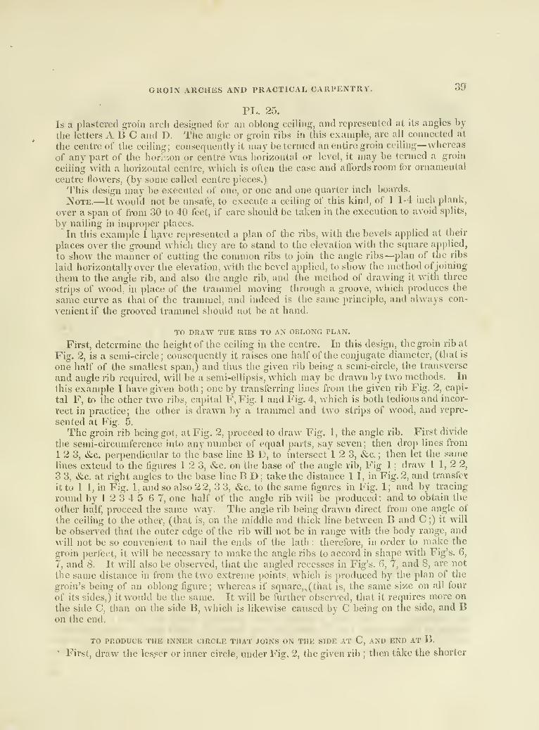
GROIN ARCHES AND PRACTICAL CARPENTRY. 39
PL. 25.
Is a plastered groin arcli designed for an oblong ceiling, and represented at its angles by
the letters ABC and D. The angle or groin ribs in this example, are all connected at
the centre of the ceiling; consequently it may be termed an entire groin ceiling—whereas
of any part of the hori.ion or centre was horizontal or level, it may be termed a groin
ceiling with a horizontal centre, which is often the case and affords room for ornamental
centre ilowers, (by some called centre pieces.)
This design may be executed of one, or one and one quarter inch boards.
]\oTE.—It would not be unsafe, to execute a ceiling of this kind, of 1 1-4 inch plank,
over a span of from 30 to 40 feet, if care should be taken in the execution to avoid splits,
by nailing in improper places.
In this example I have represented a plan of the ribs, with the bevels applied at their
places over the ground whicii they are to stand to the elevation with the square applied,
to show the manner of cutting the common ribs to join the angle ribs—plan of the ribs
laid horizontally over the elevation, with the bevel applied, to show the method ofjoining
them to the angle rib, and also the angle rib, and the method of drawing it witii three
strips of wood, in place of the ti-ammel moving through a groove, which produces the
same curve as that of the trammel, and indeed is the same principle, and always con-
A^enient if the grooved trammel should not be at hand.
TO DRAW THE RIBS TO AN OBLONG PLAN.
First, determine the height of the ceiling in the centre. In this design, the groin rib at
Fig. 2, is a semi-circle; consequently it raises one half of the conjugate diameter, (that is
one half of the smallest span,) and thus the given rib being a semi-circle, the transverse
and angle rib required, will be a semi-ellipsis, which may be drawn by two methods. In
this example I have given both ;one by transferring lines from the given rib Fig, 2, capi-
tal F, to the other two ribs, capital F, Fig. 1 and Fig. 4, which is both tedious and incor-
rect in practice; the other is drawn by a trammel and two strips of wood, and repre-
sented at Fig. 5.
The groin rib being got; at Fig. 2, proceed to draAv Fig. I , the angle rib. First divide
the semi-circumference into any number of equal parts, say seven ; then drop lines from
12 3, &c. perpendicular to tiie base line B L, to intersect 12 3, &c. ; then let the samelines extend to the figures 1 2 3, &c. on the base of the angle rib. Fig 1 ; draw I 1,2 2,
3 3, &c. at right angles to the base line B D ; take the distance 1 1, in Fig. 2, and transfer
it to 1 1, in Fig. 1, and so also 22, 3 3, &c. to the same figxires in Fig. 1; and by tracing
round by 1 2 3 4 5 6 7, one half of the angle rib will be produced: and to obtain the
other half, proceed the same way. The angle rib being drawn direct from one angle of
the ceiling to the other, (that is, on the middle and thick line between B and C ;) it will
be observed that the outer edge of the rib will not be in range with the body range, andwill not be so convenient to nail the ends of the lath : therefore, in order to make the
groin perfect, it will be necessary to make the angle ribs to accord in shape with Fig's. 6,
7, and 8. It will also be observed, that ihe angled recesses in Fig's. 6, 7, and 8, are not
the same distance in from the two extreme points, which is produced by the plan of the
groin's being of an oblong figure ; whereas if square,^(that is, the same size on all four
of its sides,) it would be the same. It will be further observed, that it requires more on
the side C, tiian on the side B, which is likewise caused by C being on the side, and Bon the end.
TO PRODUCE THE INNER CIRCLE THAT JOINS ON THE SIDE AT C, AND END AT B.
' First, draw the lesser or inner circle, under Fig. 2, the given rib ; then take the shorter

40 GROIN ARCHES AND PRACTICAL CARPENTRY.
distances 2 2, 3 3, &c. in Fig. 2, and transfer them to the same figures in Fig. 1 ; traceround as abo\ e described for the outer circle, and the circle required to correspond withthe angle and body, aa-III be produced.
TO SHOW THE METHOD OF CUTTING THE BODY RIBS, TO JOINT WITH THE ANGLE RIBS.
First, determine the location of the ribs, say at E F G and H ; then raise two perpen-diculars from the letters j i, in G, to cross the rib Fig. 4, which, when raised up, will
range directly over G; then draw the lines y p, parallel to the base line C D; now takethe square and apply it to the Fig's. 8 9 10;tlien scribe across from 8 to 9, and theplumb-cut i-equired will be produced. To get the cut atlhe joint, just slide tlie squareout to X y, Aviiich will give the cut required. Proceed the same way down at thesquare II 12 13, for the rib H.
TO COT THE JOINT, JOINING ON THE SIDE OF THE ANGLE RIB.
Take the bevel 14 15 16, and apply it to H, the plan of the rib, and join the blade14 16, to the plan of the angle rib A D; then take the bevel and apply it to H, directly
over the rib Fig. 4, which is the same length of the shortest rib, (see the letters a, h, c,
d, c,f, in II A, which shows that if the shortest rib in Fig. 4 is raised perpendicular andset over the plan H, would be in its practical position, and also joint to the angle rib.)
It must be observed that the stock of the bevel must lay on the line II (j, which is parallel
to the base, and by applying the stock thus, the blade will not lay flat on the under side,
but will only touch at the lower and opposite corner, but at the same time, when thusapplied and cut accordingly, the joints will be perfect.
REFERENCES TO THE FIGURES.
A, B, C, D, plan of the groin.
Fig. 1, Elevation of the angle rib.
Fig. 2, Elevation of the given rib across the smallest span.
Fig. 3, One half of the angle rib in the shape when cut out of the board.Fig. 4, One half of the transverse rib, or rib over the greatest span.
Fig. 5, An ElcA^ation of the angle rib drawn by a trammel.Fig's. 6, 7, 8, plan of the angle rib at its butments.
t, u, V, 10, X, y, represent an elevation of the rib, Fig. 2, when cut out of the board, andlikewise are the same at Fig. 4, in the transverse rib.
E F G H, ground plan of the ribs. It will be noticed that E F G H are placed overthe elevation of the ribs, which is done for the purpose of conveying a proper understand-ing of them.
a, b, c, d, c,f, m G H, over the elevation, will correspond with the same G, H, in the
plan.
14, 15, 16, bevel applied.
8, 9, 10, Square applied to fhe horizontal y, p.
11, 12, 13, Square applied to cut the joint of the short rib, to the angle rib.
TO DRAW FIG. 5 WITH A TRAMMEL.
First, draw the line C B, the base line of the angle rib Fig, 1, in the plan ; then get
the centre of C B, and raise a perpendicular therefrom equal to 7 7, the height of the
ceiling at the given rib. Fig. 2 ; then take the height 7 7, and apply it to the trammelat 1, on the circle of the ellipsis, and 2, on the base line; then the distance 1 2, on the
trammel, will be just equal to 1 2, in the perpendicular lines at the centre ; then take the

PKACTICAL CARPENTRY. 41
semi-transverse diameter of the line C B, which is from C to 2, and apply it to the
trammel form 1 to 4, which is also placed oiv the perpendicular line 1 4 ;now suppose
the trammel first located perpendicular, and 1 4 of tlie trammel would be equal to, and
on 1 4 on the perpendicular line. The trammel or slip being thus placed, fix brad-awls
in 2 and 4 in the trammel ; the black dots represent the awl, and the outer circle the
handle to the awl, to secure the strips z z ; if for a large span, tliey may be screwed on,
and if for a smaller span, brads or small naUs will answer. To describe the cu'cle from
1 at the centre in the horizon, round to C, at the base of the rib, supj)ose the trammel x,
to be placed perpendicular on 1 4—apply a lead jTtncil to the hole at 1 ;then move the
trammel x round from I to 2, minding at the same time to keep, the brad-awls at 2 4,
snug to the strips z.z, and one half of the rib will be complete. For the other half,
if made in two pieces, take the half already obtained, and use it for a pattern thereto
;
but if required in one entire rib or piece, the two strips z z, should be reversed ; then
move the perpendicular piece on the opposite side of the centre line, and the horizontal
piece directly under Fig. 5 ; for to describe the ellipsis, proceed as in the above already
drawn, and the circle C 1 B, will be produced.
DESCRIPTION OF THE INNER CIRCLE.
First, it will be observed that the circle 6 1 d, is a trifle to the right of the centre, which
is caused by the plan of groins being of an oblong square;(see the plan of the rib from
C to B ; and the greater difference will be understood to proceed at C, from its sitting on
the longest side; and at the opposite angle atB, from its sitting on the shortest side of the
plan.) "To make the thing easily understood, I have given a plan of the butments at
Fig's. 6, 7, and 8, represented by the letters a b c—which will show that this difference
will be right—the reverse on the opposite side. This inner circle is drawn the same wayas that of the outer, with no other alterations than to take half the distance b d, which
is at 3, on the opposite side from the line from 2, and set it on 5 on the trammel, just
above 4. Now proceed the same way to describe the ellipsis as above directed; for the
outer line thus far, produces one side of the angle rib.* For the opposite side, the one
obtained may answer for a pattern.
Note.—The transverse is drawn the same as that of the angle rib, and is generally
represented first, which is, however, a matter of no difference, for they are of the sameheight in the centre of the ceiling. Further— if the ribs are drawn and cut as herein
described, and executed accordingly, it will produce a perfect plastered groin ceiling in
every respect.
PL. 26.
As a roof constitutes one of the principle parts of an edifice, I have given three exam-ples in this plate, on which I shall make a few observations.
First, in order to make a roof uniformly strong and light, it is necessary for the architect
or builder, in making preparations for the execvition, to lay aside all suppositions, andapply mechanical principles; which is the only true system by which any tiling of tlie
like nature can be made any where near perfect, or even to answer the purpose for whichit was designed. For it is often the case, that a roof built on a continued tie beam, has a
greater number of pieces than is actually necessary, and therefore contains too muchmaterial; for, generally, a roof executed on a continued tie beam, there is no very con-
siderable strength required of any piece, except the tie beam itself; and the strength
* This angle rib is made of two plank or boards, as occasion may require, and when cut and put together as here
represented, will form a complete angle rib. (See the Fig's. 6, 7, 8".) At the ceulie it will be square.
11•

42 PRACTICAL CARPENTRY.
required of that is length-ways, in order to counteract the pressure of the rafters whichare annexed to it; that is, when are there no ceiling joists. And further, the strengthof a principal rafter required is quite inconsiderable, when on the construction of thedesign represented by the letter A, in this plate
; for it has two prominent resting placesat the junction of c and d, and that together with the exertion of the rafters again'st theirbutments renders them very strong, although they may be quite small. And it may, byexamination, be ascertained, that tiie braces c c and d d d d, have but little to do, but tocounteract tiie falling or sagging of the two sides of the roof; for it is evident that thefalling of one will tend to raise the other : therefore all the strength required of the bracesor trusses, is sufficient to resist the weight that will proceed therefrom, and retain theirstraight line. Consequently, by a mechanical examination, and with a judicious arrange-ment ol' the timbers in a roof, the contractor may save the expense which might be veryimprudently applied; and that, many times the walls of buildings are made quite thin,
and consequently not Yexy strong, and are not well calculated to bear up unnecessaryweight.
In making preparations for the erection of a roof to receive a pointed or Gothic archabove the base of its rafters, requires the utmost skill in the architect or builder, in orderto avoid settling in its inclined sides, and extension of the rafters at their bases.
I have therefore thought proper to give three designs on roofs in this plate, hoping theymay be more or less useful to workmen, in their practical pursuits. I do not claim theexamples here described as my own designs, although I have not seen any, either drawnor executed, like the one representetl by the letter B. I do not claim any thing in A,unless the application of the truss running directly parallel, and under the principalrafter, should be mine, I feel satisfied however, that either of the two upper designs aresufficient to span ninety, or even one hundred feet withimt segment, or extension at thebase of the rafter, that would be perceptible to the eye.
A is a design of a roof with a continued tie beam, showing two designs at the eve, oneto show the projection required, if finished with a projecting eve-cornice, and on theopposite to show the method of executing a copper, lead, or stone water gutter behindthe parapet wall, (see n the gutter.) This design is also calculated for a cove ceiling,
consequently the tie beam is not required as large as otherwise.
REFERENCES TO A.
b king post, 7 by IS inches below the trusses, and the head or joggle, 6 by 22; c c
trusses, 7 by 6 : d d d d trusses, 7 l>y 6; e tie beam, 7 by 16; yy iron rods, \ hy \
] g gwalls, 22 by 6; h wall to show the method of framing for a parapet wall; i i wall plates,
8 by 12; j strengthening piece, 7 by 12, to the tie beam, when executed for a parapetwall, which will be seen necessary directly under the feet of the rafters ; k k k k purlineplates, 6 by 10, which should extend across three spaces, and will consequently join onthe fourth rafter, whereby they will or can break joints, and give the strength necessarily
required to bind the principal rafters sufficiently strong. In order to retain the strength
of the purline plates and rafters, I shall advise the executor not to cut his gain entire
across the rafter, but only about 1 inch in each side, and leave the middle uncut, whichwill tend not to weaken the rafters; and at the same time, the purline being thus cut to
fit the gain, it has the whole plate for the support of the jack or common rafters. Anintroduction of braces in the inclined sides of a roof, in my opinion, will answer their
desired purposes, if made of considerable length, and aj)])lied at or near the wall-plate,
better than if applied in any other situation. The method hcrereccommended is, to con-
nect the lower end of the liraces to the wall plate, directly at and against the tie beamat the foot of the rafter, and the upper end to the rafters in the usual method of applying

PRACTICAL CARPENTRY. 43
braces. It will be understood that the braces lie under the jack-rafters. The braces,
according to my views, should be locked together. If a dome, or any thing of a similar
kind, sliould be applied, the roof will require tlie more strength.
II Principal rafters, 6 by 18.
m jack or common rafters, 3 by 7, and placed two feet from centre to centre.
n Eave gutter behind the parapet wall, of lead, copper, or stone.
O Scale for each design.
This design raises one-fourth of its whole span. The iron rods//might be dispensed
with, and remain sufficiently stiff and strong.
REFERENCES TO B.
B is a design of a roof to accommodate a gothic ceiling, and consequently requires a
peculiar sort of construction and distribution of its timbers. This example is drawn to
a 70 feet span, but would, I have no doubt, retain itself with the utmost perfection on 90feet span ; and if executing it myself, I would not hesitate on 100 with a small addition to
the size of the timber.
• cc Principal rafters, 7 by 20 inches.
& King-post, below the joggle, 10 by 22 inches.
King-post, at the joggle, 10 by 31.
d d Hammer, or lock beams, 4 by 18.
The hammer or lock beams are coupled, (that is, one on both sides of the rafters andking-post.) These beams are halved together at the king-post, and likewise let into the
king-post 1 1-2 on each side, or whatever the post is thicker than the rafter, (in this
the rafter is 7 inches, and the post 10.)
e Collar beam, 8 by 15.
This beam is made equal to the thickness of the rafter and two hammer or lock beams,
in order to make the iron work in the centre all in one mass or body. The beam maybe made in two ]>iece.s, which would not render it so difficult to put together : it also
receives a strap directly over it at the principal rafter.
// King-po.st to d c and k, 4 by 8.
g g Trusses, or rather a collar beam broken, and let down to meet the trusses h h,
which, at their intersections, form a resting point for the principal rafters, 7 by 8.
i i i Purline plates, which are disposed of as in the above plate, 6 by 10.
j Sort of wooden butment for the rafters and truss h. This butment is one inch thicker
than the rafter. The iron strap is let in a half inch on each side, 8 by 20.
k k Trusses running alongside the principal rafter, 4 by 8.
/ / Wall plates, 9 by 12.
711 m Walls.
n n at the dotted lines, are iron straps over the angle of the butment.
Water-gutters behind the parapet walls.
p p Common, or jack-rafters, 3 by 7.
This roof is elevated at its ridge or .summit, the sixth and one-half of its whole span;
it gives room in its interior for a vaulted ceiling, sixteen feet nine inches above its
butments.
Note.—The dotted lines are designed to represent the covering.
REFERENCES TO CC exhibits the design of a roof that will answer for from 40 to 55 feet span, without
any king-post; but has an iron rod of 1 inch by 1 1-2, which would not cost any more,
and at the same time be attended with much less trouble in putting together and raising.

44 PRACTICAL CARPENTRY.
This design may be executed with the purlines framed into the principal rafters, and the
common rafters framed into the purlines ; or otherwise, may be framed like the two pre-
ceding examples, which is much the best method.
REFERENCKS TO THE NAMES AND SIZE OF TIMBERS.
a Iron rod, 1 by 1 1-2.
h b Trusses, 7 by 7.
c Tie beam, 7 by 11.
d d Principal rafters, 7 by 11.
The elevation and inclination of tlus design is equal to, and drawn by a pediment pitch,
as follows.
TO DRAW A PEDIMENT PITCH.
First, set one point of the compass in the centre o, and extend the other point out Xap,either way ; then let the point in o stand, and move the point p round down to q ; thenlet the point q stand, and extend the other point diagonally up to p; then move^j roundto r, perpendicular to the point q, and the summit of the pediment is produced as re-
quired ; then draw the rafter lines r j) 2^i ^^^^ the inclination of the pediment will becomplete.
PL. 27.
This Plate exhibits an elevation of a trussed partition—a plan and elevation of a trussedbeam, and likewise a plan and section of the common beams bridged, acting in concertwith the trussed beam.
REFERENCES TO THE FIGURES AND LETTERS.
Fig. 1, Plan of the floor beams.Fig. 2, A section of Fig. 1.
Fig. 3, An elevation of the trussed beam and partition.
LETTERS IN FIG. 1.
a a a Straining bolts (see a a a in C, Fig. 3.)
h b Bolts to gripe the trussed beam.C Plan of the trussed beam.d d d Plan of the common beams.e e e Plan of bridging cap to connect the strength of the common beams with the
trussed beam C.
//, &.C. Trusses, sometimes called bridging, (see /"/, &c. in Fig. 2.)
g g, &c. Wedges to key up the bridging cap e e e.
Note—This bridging cap is a piece of" 1 ]-4 inch oak or yellow pine plank about 5inches wide. The wedges, when sufliciently drove, secure tliem by driving a nail in thethin end. The bridging cap and wedges should be well seasoned, clear of knots, andstraight grained
LETTERS IN FIG. 2.
C Section of the trussed beam, (see the plan C in Fig. 1.)d d d Section of the common beams,e e e Bridging cap, (see e e e in Fig. 1.)

PRACTICAL STAIR RAILING. 45
LETTERS IN FIG. 3.
a a a Straining bolts, (see a a a in C at Fig. 1.)
b b Griping bolts, (see 6 6 in C in Fig. 1.)
C An elevation ot the trussed beam, showing the straining bolts, trusses d d, and
straining beam g ; and likewise the griping bolts b b.
d d Iron or wooden trusses—most proper of iron.
E Floor beam.
ff Trusses to support E.
g Straining beam of iron.
Ji h Trusses to counteract the falling in of the beam E.i i Brace to counteract the extension of the trusses h h.
Trussed beams are frequently necessary in great spans to accommodate the bearing
of two lengths of beams or joists, but more frequently to support partitions that may benecessary to erect over the ceiling of a large room in the story below it, and to supportgallery fronts, «Sic. without columns, or any thing of the kind, between the outer hutments,in order to secure the ceiling from falling in and destroying the elegance of the room—andfurther, this sort of partition and flooring will retain for ages their horizontal and vertical
lines—if their hutments are made secure—and will thereby experience no change in theinternal part of the edifice, which is a highly important consideration, particularly in goodbuildings.
REMARKS ON THE GENERAL BEARING OF FIG. 3.
First, It will be seen that the partition is connected by two horizontal beams, and twoperpendicular posts.
2d, That the two trusses// have their bearing on the hutments.3d, That the beam E has two prominent resting places on the trusses/ /J hence it is
evident that if E tends to fall, h h will counteract every possible exertion of that kind
—
and it is likewise evident, that h h cannot extend their span ; for, in the attempt, theywill meet i ^, Avhich is prepared to counteract it. Thus it is evident, that the partition
will support itself, and leave but little for the beam to do but support its own weight, &c.The general bearing of Fig. 2, will be seen to be very nearly the same as a straight or .
common piece of beam—for, as they are connected by the bridging cap e e e, they cannotseparate; therefore, it is reasonable, if the bridging pieces/// &c. are pi'operly placedand secured, that one beam cannot go down without the whole act in concert. Thebridgings are generally thrown in of about 1 1-2 by 3 or 4 inches, and secured at the topand bottom with one or two nails, as may be found necessary by the executor.
The bridgings or trusses ///, &c., may be placed adjoining each other, or a smalldistance apart as in Fig. 1, at the letters///, &c.Note—This partition is calculateti to accommodate three doors—whereas, if other
locations of doors should be necessary, it might require a different set of trusses, andthese very differently arranged.
PL. 28.
This Plate is a practical drawing for the carriages of a geometrical stair, raisuig oversix winding steps, explained in two different ways : the first, by framing bearers of plankinto plank risers
; the latter, by cutting bearers out of plank to support three steps, rising
from the centre and middle riser to the last riser of the winders, in an oblique direction,(that is, the front and middle bearers)—the one adjoining the wall, passes under onlywo steps. 12

46 PRACTICAL STAIR RAILING.
REFERENCES TO THE FIGURES.
Fig. 1, Plan of the stairs, and framing to support the steps and risers over the circularor winders.
Fig. 2, Elevation of a part of the front string, in the straight part joining unto thewinders : likewise the risers, brackets thrown in the angles of the bearers and risers, andthe screw (a bedtsead screw) to connect the straight string to the winders.
Fig. 3, An elevation of the middle carriage or horse, for three steps.
Fig. 4, Plan of the carriage or horse, for two steps.
Fig. 5, Plan of the middle horse.
e;xplanation to the letters.
a a a a Carriages.
b b Front string.
e e e e e e Bearers, framed into c c, &c. (see the dotted tenons on c c, &c. in Fig. 2.)c c c Plank risers for the carriage way, (place c c c above e e e.)
d d d d d d Common risers.
ffffff Staves for the front string, front worked to the circle, and finished with arabbit or face of about 1 1-2 inch, with 1-2 inch worked in front, and returned on theunder side. On the back side they are designed to fit against the brackets 2^ q r s, andths risers c c c, and bearers e. e, in Fig. 2.
g Bracket line.
h h Bearers.
i i i i Studs ur joists.
A B C D At tlif angles of the dotted lines round Fig. 5, represent the width andlength of the plank required to cut a horse for three steps.
EFGHIJKL represent the steps and risers of Fig. 5, which the student will
observe are drawn direct from the intersection of the risers and Fig. 5.
E F G H I J represent the steps and risers to Fig. 4.
abc din. Fig. 4, represent the plan of the bearer.
Note.—The method of cutting the bearers after this method, is of at least one-half less
expense than to frame after the manner of Fig. 2, and in short steps, would answerequally as well.
letters in fig. 2.
g h ij k / «t Is a part of the front string, joining unto the winders.
c c c Plank risers.
d d d Common risers.
e e e Bearers tenoned into the plank risers, (see the dotted lines.)
fff Ends of the steps,,
m n p An elevation of the bracket, fitted in the angle of c and e, directly behind thestave or front string fff, &c. in Fig. 1 . These staves are fitted all the way up, andscrewed fast on the back side—and after thus fitted, they are taken down, and well glued,
refitted and secured to their former placeSj which will render the front of the stairs verystrong. The brackets under the middle and back bearers are of the same height at the
joints as those of the front. Those brackets answer also for lathing joists under thestairway.
w A bedstead screw let through the riser into the string.

PRACTICAL STAIR RAILING. 47
PL. 27.
lu this Plate are two scrolls described by the same rules and centres, but have differ-
ent proportions.
I have given these two examples with the same rule, in order to show that a scroll or
spiral fret may be contracted by making the centres smaller, and extended by makingthem larger.
REFERENCES TO THE FIg's. 12 3 4 5 AND 6.
Fig. 1, A scroll of one revolution and three quarters, drawn by six centres got bydividing a geometrical square into 36 equal parts.
Fig. 2, An elevation of the wedges to strain the veneer round the block under the
curtail step.
Fig. 3, A part of the riser and veneer, (see riser and veneer in Fig. 1.)
Fig. 4. Plan of a revolution, and a half scroll.
Fig. 5, Pitch board.
Fig. 6, Face mould.
NoT&.
—
Iq Fig. 1, I have likewise described the block and curtail step, which will beexplained.
TO DRAW THE SCROLL IN FIG. 1.
First, draw a circle, (generally called the eye,) 3 1-4 or 3 1-2 inches, (in this it is
3 1-4;) then draw a geometrical square equal to one half of the eye—divide the geome-trical square into 36 equal parts or si.uares, and at the same time extend one of those
parts out to 6; now draw the spiral liues—set one point of the compass on 1, one square
from the centre o, and extend the other p liat down to o on the edge of the eye—let 1
stand, move o round to I ; let the outer 1 stand, extend the inner 1 out two squares to
2 ; let 2 stand, move 1 round to 2 : let the outer 2 stand, move the inner 2 down to 3,
move 2 round to 3 ; let the outer 3 stand, move the inner 3 out to 4 ; let 4 stand, move 3
round to 4; let the outer 4 stand, move 4 out to 5; let 5 stand, move 4 round to 5; let
the outer 5 stand, move inner 5 out to 6 ; let 6 stand, and move 5 round to 6, and the
convex side of the scroll will be complete. To describe the inner or concave side, follow
the same figures back—that is, alter setting the width of the rail in at 6 6.
TO DRAW THE BLOCK AND VENEER FOR THE CURTAIL STEP.
First, set back from the front of the rail at b, Fig. 1, to I, one half of the projection
of the nosing, which will be the front line of the bracket or front string ; then draw the
line I J M N P, by following the same centres of the rail, and the concave side of the
block will be produced. For the veneer and convex side of the block, set one point of
the compass in 5, and extend the other point out to K ; let 5 stand, move K round to L,
and so round until the line or veneer meets the letter A—which is the end of the vene er
let into the block from P to A, by running in the cut of a pannel saw.
TO-FORM THE BLOCK, AND WORK IT OUT.
In order to secure the block from shrinking and breaking apart, it is necessary to glue
it up into about five thicknesses, (see Fig. 2, the riser.*) These thicknesses must be
equal in width to the line L 20, (that is, the ones that lay across the step,) and those
that run lengthways the step, equal in width to the line C 21. To prepare the block for
* And wedges to strain the yeneer.

48 PRACTICAL STAIR RAILING.
the reception of the front string and bracket, cut the gain I H D, noticing that the junc-
tion of the string and block is at I ; the letter 6 is the bracket, and c rf e H a part of the
front string; from the bracket, it will be understood that the block is made sufficiently
smooth round to P, not to require any veneer. To get the length of the veneer, take a
small chord or twine, and apply one end at the end of the veneer at the letter A—then
encircle the block from A rouiid by L K to G, which will be the length of the veneer
required; then calculate whatever thickness for the wedge may be thought proper; (in
this it is one half of an inch)—from that to one inch is proper. It will be understood
at the same time from Fig. 3, that the lower riser must be in the same piece with the
veneer.
TO PREPARE THE RISER AND VENEER.
First, get the length as above described, tlien guage the veneer at B about l-8th of aninch thick; then take a rip saw and cut the veneer from A to B, plane it up without the
least variation that can be seen, crossways, giving it a gradual diminish from B to A, so
that A may enter the cut of a pannel saw;then prepai'e a quantity of hot water and put
the veneer into it, and there let it remain until it becomes as soft as a piece of leather.
Prior to this, take a sizing of glue "and size the block, and let it get dry before the appli-
cation of the veneer—and at the application give it another good coat of well-prepared
glue. Then take it and place the end perfectly square into the saw cut at A, and gradu-
ally bend it round the block, until it will admit of the riser's fitting in the block at E,minding to have it well glued at the same time ; then ta^e the wedges at Fig. 2, anddrive one from the upper side and one from the under side, and the wedges being
properly drove, will strain the riser smooth and snug to the block. Care must be taken
to have the veneer lay snug to the block from K to B, which may be effected by placing
the block in some proper place and applying a flat piece across it, and secure it by aweight or some other means, in which place it should remain until it becomes perfectly
dry.
TO DRAW THE CURTAIL STEP.
In Fig. 1 the dotted lines represented by the letters k I h n, &c. is the outer line of thenosing of the curtail step, and is drawn by the same centres of the rail.
The dotted line g g at the right hand, is the width of the tread of the step from thefirst rise to the second ; 5 12 is likewise the width of the step ; h h, nosing of the secondstep
; g i, second rise; j Ik is the return of the nosing round the bracket. In this plan,
I have extended the nosing over the bracket, equal to the size of the banister, which is
not practised by all stair builders, though to me it appears most mechanical.
TO DRAW THE SCROLL FIG. 4.
Draw the eye or circle 3 1-4 or 3 1-2 inclies, then draw a geometrical square in the
centre, equal to one-third the diameter of the eye, and for the other parts, proceed pre-
cisely as in Fig. 1.
TO DRAW THE FACE MOULD FIG. 6.
Take the pitch board Fig. 5, and apply the baseline 5 12 to the convex side of tlie
rail or scroll ; then draw the ordinate lines 6, 5, 6, 6—7, 7, 8, 7—5, 9, 10, 5, &c. perpen-dicular to the base or under edge of the pitch board 5 12, and extend them up to thehypothenuse or rake line 5 13, to intersect the figures 6, 7, 5, &c. then take the distance
6, 6, G, from the line 5, 12 across the eye of the scroll in the point of the compass, and

PRACTICAL STAIR RAILING. 49
transfer them to 6, 6, 6, in Fig. 6, (noticing that the ordinates in 6 are drawn at rightangles to the rake of the pitch-board.) Proceed the same way with 7, 5, 20, 21, &c. andthen trace round from 6,6, to 5,5, and the size and shape of the face mould will be pro-duced. Now to understand the practical position of the face mould, Fig. 6, suppose thepitch-board, Fig. 5, to stand on the line 5 12 across the eye—then it will be understoodthat the line 5 13 of the pitch-board is the rake of the stairs. Now, if the student ob-serves with attention the pitch-board standing as above placed on the line 5 12 acrossthe scroll, he uill see that the face mould. Fig. 6, will range precisely over the corres-
ponding one in the plan of the scroll. Fig. 4.
Note.—The letters fff, &c. Fig. 1, represent the banisters.
PL. 30.
Explains a practical method for obtaining the thickness of stuff* required to pass overthe plan D, or one half of A, in Plate VI, and also the shank of the scroll, Fig. 4, in
Plate XXIX.
METHOD FOR OBTAINING THE THICKNESS OF STUFF FOR HAND-RAILING.
REFERENCES TO THE FIGURES.
Fig. 1, Falling-mould, over the stretchout of Fig. 3, (see the letters ft6cl234567on the line A B,) under Fig. 1, which are the same as those on the convex of Fig. 3, andalso of the same length.
Fig. 2. The thickness of stuff required for the rail:
Fig. 3, Plan of the rail D or A in Plate VI.Fig. 4, Shank of the scroll, Fig. 4, Plate XXIX.Fig. 5, Plan of the shank of Fig. 4, Plate XXIX, from 5 5, to 6 6.
Fig. 6, Stretchout of the falling-mould, Fig. 4, in Plate XXX.
TO DRAW OR OBTAIN THE THICKNESS OF STUFF.
Place the stretchout of Fig. 3, on the line A B, from a to 7, then place the falling-
mould Fig. 1, in its practical position, meaning on the rake of the stairs; divide a 7 into
the same number and distances of the convex line of Fig. 3 from a b c round to 7, thenraise perpendiculars from a6cl234567to cross the falling mould. Fig. 1, draw lines
parallel to A B from 112 2 3 3, &c. to cross Fig. 2, then raise lines from the samefigures on both sides of the plan Fig. 3, to cross Fig. 2, and where they cross,the corres-
ponding lines at 1 2 3 4, &c. will be the extremity and shape of the rail when in its
square shape, ready for moulding or rounding.
TO DRAW FIG. 4, THE SHANK OP THE SCROLL IN PLATE XXIX.
Lay the plan of Fig. 4, from tlie joint at 5 5 round to 6 6 in Plate XXIX, on Fig. 5,
in this Plate, then divide the convex side of the rail into 5 12 3 4, &c. equal parts, andtlien draw lines across the rail to the centre 6, which will also divide the concave side
into the same number of equal parts ; then take the falling-mould, Fig. 6, the same asthat of Fig. 4, in Plate XXX, and take the stretchout of Fig. 5, from 5 round by 1 2 3 45 6 7 6, (6 being the termination of the scroll,) 8 9 10 11, (11 is 5-8 below the second
* In this plate, I have given the twist, although it is not necessary ; for when the extremities and backs are ob-tained, the thickness of the stufi will be produced: for instance, see o c 1 5 7 6 are the extremities, and the twoparallel lines contain the wood necessary, which is 2 and 3-4 thick. The rail is 1 3-4 by 2 1-4.
13

50 PRACTICAL STAIR RAILING.
riser,) at which I have made the joint. This however, may always be discretionate with
the executor. The falling-mould thus placed, and divided into the same number of equal
parts and distances from the two heavy lines 5 and 6, it will be understood the same will
apply and bind round the shank Fig. 4 when applied over Fig. 5 in its practical position,
(meaning tlie rake or inclination of the stairs.) To draw the twist, and obtain the thick-
ness of stuff for Fig. 4, raise perpendicular lines through the line A B, from the figures
51234567 6, &c. in the convex and concave sides of Fig. 5 up through the shank
Fig. 4, to intersect the same and corresponding figures ; then take the distances 5 5 5
from Fig. 6, and transfer them to 5 5 5 on the outside of the plan Fig. 5, and the shanks
Fig. 4, and so on* 1 1, 2 2, 3 3, 4 4, 5 5, 6 6, 7 7, 6 6, 8 8, 9 9, 10 10, and 0, and the
upper edge of the convex side of the shank will be at the upper line of figures. Todetermine the upper and under edge of the concave side of the rail, take the figures Fl^l
,
2 2 2, 3 3 3, 4 4 4, 5 5 5, 6 6 6, 7 7 7, 6 6 6, &c. and they will produce a perspective
view of the twist of the part of the rail contained in the shank of the scroll. C represents
a section of tlie rail at the joint, with a screw nut and washer practically : D at the upper
end and at the joint, represents the bolt which connects the shank and straight part of the
rail. The two parallel lines in Fig. 4, represent the thickness of stuff requisite, with the
most perfect workmanship ; for it will be perceived tliat those dotted lines will produce
a lack of wood on the upper edge of the convex side, and under of the concave ; but as
above observed, with precise workmanship it will make a perfect rail, and require only
2 1-2 inches thick of stuff; whereas, if made to work square all round, it would require
3 inches, which is not only an additional expense, but sometimes difficult to obtain a
piece of that thickness, especially well seasoned.
Note.—All the above drawing is not necessary to obtain the thickness of stuff; for
the lower angle at 5 in Fig. 4, and at 4 the highest extremity on the back will produce
the thickness, and the four angles in Fig. 2, it may plainly be seen, will produce the same.
PL. 31.
As stairs of six to eight inch openings, are the most in use of any other kind, there
are frequently instances of many being obliged to execute them, who are but little expe-
rienced in stair-building ; consequently, I have thought proper to give the most difficult
parts engaged therein, in the following practical manner.
REFERENCES TO THE FIGURES.
Fig A, Plan of the rail, front string and nosing : the outer dotted line represents the
front line of the foot string; (that is, the one farthest from the centre o, commencing at
1, and terminating at 2:) the inner dotted line represents the front line of the nosing onthe platform.
Fig. B, Plan of the cylinder put up in staves, glued and screwed together.
Fig. C, The elevation and stretchout of the circular part of the front string passing
over the dotted line 1 2, in Fig. A with a part of the last step of the first flight, and part
of the first of the short flight going off the platform and landing on the floor.
Fig. D, Falling-movdd for the concave side of the rail, passing over the line 5 7, in
Fig. A.
Fig. E, Convex falling mould, passing over the outer line 6 11, in the plan Fig. A.
* The above distances are taken from the line A B, at Pig. 6, to the upper side of the same, which is the falling-
mould, and those that determine the other two lines will be taken from the line A B, and the under and upper sideof the falling-mould.
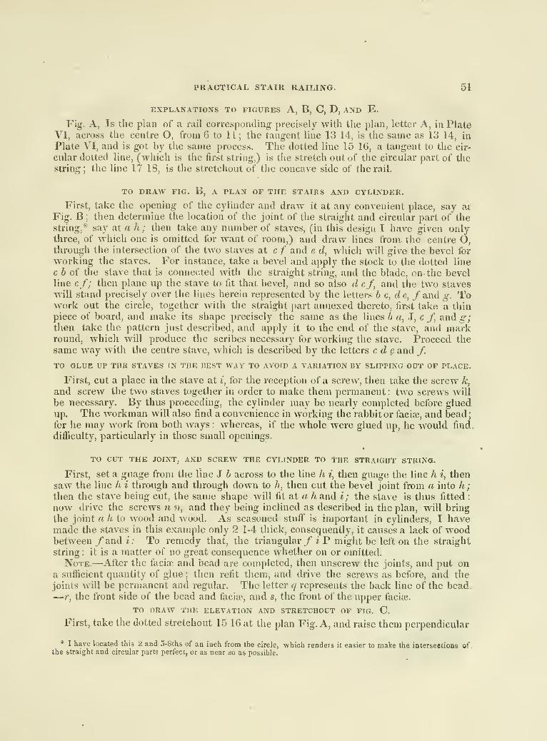
PRACTICAL STAIR RAILING. 51
EXPLANATIONS TO FIGURES A, B, C, D, AND E.
Fig. A, Is the plan of a rail corresponding precisely with the plan, letter A, in PlateVI, across the centre O, from 6 to 11 ; the tangent line 13 14, is the same as 13 14, in
Plate VI, and is got by the same process. The dotted line 15 16, a tangent to the cir-
cular doited line, (which is the first string,) is the stretch out of the circular part of the
siring; tlie line 17 18, is the stretchout of the concave side of the rail.
TO DRAW FIG. B, A PLAN OF THE STAIRS AND CYLINDER.
First, take the opening of the cylinder and draw it at any convenient place, say ai
Fig. B ; then determine the location of the joint of the straight and circular part of thestring,* say at a h ; then take any number of staves, (in this design I have given onlythree, of which one is omitted for want of room,) and draw lines from., the centre O,through the intersection of the two staves at c f and e d, which will give the bevel for
working the staves. For instance, take a bevel and apply the stock to the dotted line
c 6 of the stave that is connected with the straight string, and the blade, on the bevelline cf; then plane up the stave to fit that bevel, and so also d cf, and the two staveswill stand precisely over the lines herein represented by the letters b c, de, f and g. Towork out the circle, together Avith the straight part annexed thereto, first take a thinpiece of board, and make its shape precisely the same as the lines b a, 3, c f, and^;then take the pattern just described, and apply it to the end of the stave, and markround, which will produce the scribes necessary for working the stave. Proceed the
same way with the centre stave, which is described by the letters c d § and /.
TO GLUE UP THE STAVES IN THE BEST WAY TO AVOID A VARIATION BY SLIPPING OUT OF PLACE.
First, cut a place in the stave at i, for the reception of a screw, then take the screw k,
and screw the two staves together in order to make them permanent : two screws will
be necessary. By thus proceeding, the cylinder may be nearly completed before gluedup. The workman will also find a convenience in working the rabbit or faciaj, and bead;for he may work from both ways : whereas, if the whole were glued up, he would find,
difficulty, particularly in those small openings.
TO CUT THE JOINT, AND SCREW THE CYLINDER TO THE STRAIGHT STRING.
First, set a guage from the line J b across to the line h i, then guage the line h i, then
saw the line h i through and through down to h, then cut the bevel joint from a into h ;
then the stave being cut, the same shape will fit at a h and i; the stave is thus fitted :
now drive the screws n n, and they being inclined as described in the plan, will bring
the joint a h to wood and wood. As seasoned stuff is important in cylinders, I havemade the staves in this example only 2 1-4 thick, consequently, it causes a lack of woodbetween /and i: To remedy that, the triangular/ i P might be left on the straight
string : it is a matter of no great consequence whether on or omitted.
Note.—After the facise and bead are completed, then unscrew the joints, and put ona sufficient quantity of glue ; then refit them, and drive the screws as before, and the
joints will be permanent and regular. The letter q represents the back line of the bead
.
— r, the front side of the bead and facise, and s, the front of the upper facise.
TO DRAW THE ELEVATION AND STRETCHOUT OF FIG. C.
First, take the dotted stretchout 15 16 at the plan Fig. A, and raise them perpendicular
* I have located this 2 and o-8ths of an iach from the circle, which renders it easier to make the inlerseetions of.the straight and circular parts perfect,, or as near so as possible.

52 PRACTICAL STAIR RAILING.
up to 15 16 on the under edge of the nosing of the platform ;then set up from 16 to 19
the height of a riser ; then set down from 15 to I the height of a riser. This produces
thejstretchout of the cylinder, and at the same time represents a part of two commonsteps. The figures 3 and 4, at the extremities of the nosing, are just equal to the stretch-
out of the dotted line 3 4 in tlie plan Fig. A, representing the nosing line.
TO GET THE LENGTH OP THE STAVES.
First, find the stretchout of the staves round from b a3 c and d, and apply them to the
dotted lines on the under side of the falling-mould or under side of the elevation of the
front string at 1 2 3 4 5 6 ; then commence at 1, and raise a perpendicular line from 1 up
to I, which will be the length ;the width will be from 1 to 2 on the horizontal dotted
line': for the middle stave, take the perpendicular line 3 2 for the length, and the hori-
zontal dotted line 3 4 for the width : a a are the joints of the cylinder to the straight
string,—6 b are the joints in the rabbit or faci*, caused by cutting a bevel (see the joint
in the plan of cylinder) at a h, and it will be seen at the bevel joint, by its passing from
the letter h out to a, it makes the difference of the two dotted lines in crossing the pro-
jection of the rabbit of the facia-, which is represented by the break in the two lines or
joints of the cylinder marked a b, to the string in the elevation at the intersections of the
straight and circular parts. The dotted lines 1 1 and 6 6, at the upper and lower ends,
represent the line b g in Fig. B.
jVoTE.—Before I proceed any farther, it will be proper to mention the peculiarity of a
winding or circular rail passing over any number of elevated steps.
First, It is known by practical demonstration, that a hand-rail raising and winding
over any number of steps, terminating in a circular cylinder, that neither two of the front
and back edges will be parallel to each other ;consequently it is evident that the cuts in
the convex and concave falling-mould will not be parallel to each other;
if both are cut
square to the rake of the falling-moulds, (see Fig's. D and E placed on their stretchouts)
that they do not run parallel over the stretchout part, but at the same time run parallel
down at s s and up at ?• r, and is also the same distance apart at s s that it is at r r, and
so also is the underside of the falling-mould to the front string. Fig. C. It will likewise
be observed that the four lines across the two falling-moulds at each end of Fig's. D and
E, are square to the hypothenuse, or rake-line of the pitch-boards, and parallel to each
other; but at the same time, the cuts at the centre of the stretchouts are not parallel
when cut square to the rake or hypothenuse line. Therefore, it is a duty that devolves
on me, tlu-ough the nature of my proposals for this work, to explain satisfactorily the
mysterious parts connected with the various problems or examples that I include in this
work. The above references and notices are inserted for the purpose of placing in view
the proper object that will be most likely to lead the student to a more direct understand-
ing of them; and at the same time it will be proper to direct the student to PlateXXXIV,for the application of the moulds and pitch-boards or bevels,* more particularly than any
succeeding Plate ; for if I should explain the application of the moulds and pitch bevels
to all the examples that will be included in this work, I should be obliged to omit exam-
ples of equal importance ; and as Plates VI and VII treat on the applications in the best
practical manner, it would be taxing the patrons of the work with money and studies,
which would be perfectly useless to them.
* Noticing that the pitch-board of tlie front «;tring in a stair with winding steps, will not answer for the rake and
plumb cuts or lines, to neither side of the rail which may be seen by the variation of the two falling moulds and front
string in this Plate, but a pitch-board equal to the inside or outside of the rail will answer for the same.
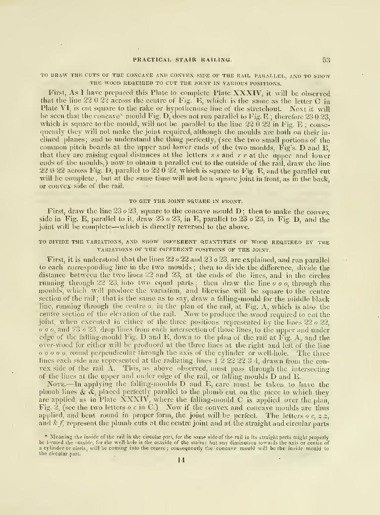
PRACTICAL STAIR RAILING. 53
TO DRAW THE CUTS OF THE CONCAVE AND CONVEX SIDE OF THE RAIL PARALLEL, AND TO SHOWTHE WOOD REaUIRED TO CUT THE JOINT IN VARIOUS POSITIONS.
First, As I Iiave prepared this Plate to complete Plate XXXIV, it will be observedthat the line 22 22 across the centre of Fig. E, whicli is the same as the letter C in
Plate VI, is cut square to the rake or hypothcnuse line of the stretchout. Next it willbe seen that the concave* mould Fig. D, does not run parallel to Fig. E ; therefore 23 23,which is square to the mould, will not be parallel to the line 22 22 in Fig. E ; conse-quently they will not make the joint required, although the moulds are both on their in-
clined planes; and to understand ihe thing perfectly, (see the two small portions of thecommon pitch boards at the upper and lower ends of the two moulds, Fig's. D and E,that they are raising equal distances at the letters s s and r r at the upper and lowerends of the moulds,) now to obtain a parallel cut to tl>e outside of the rail, draw the line
22 U 22 across Fig. D, parallel to 22 22, which is square to Fig. E, and the parallel cutwill be complete
,but at the same time will not be a square joint in front, as in the back,
or convex, side of the rail.
TO GET THE JOINT SQUARE IN FRONT.
First, draw the line 23 o 23, square to the concave mould D ; then to make the convexside in Fig. E, parallel to it, draw 23 o 23, in E, parallel to 23 o 23, in Fig. D, and thejoint will be complete—which is directly reversed to the above.
TO DIVIDE THE VARIATIONS, AND SHOW DIFFERENT aUANTITTES OF WOOD REQUIRED BY THEVARIATIONS OF THE DIFFERENT POSITIONS OF THE JOINT.
First, it is understood that the lines 22 o 22 and 23 o 23, are explained, and run parallel
to each corresponding line in the two moulds; then to divide the difference, divide the
distance between the two lines 22 and 23, at the ends of the lines, and in the circles
running through 22 23, into two equal parts; then draw the line o o o, through themoulds, which will produce the variation, and likewise will be square to the centresection of the rail ; that is the same as to say, draw a falling-mould for the middle blackline, running through the centre o, in the plan of the rail, at Fig, A, which is also thecentre section of the elevation of the rail. Now to produce the wood required to cut thejoint, when executed in either of the three positions represented by the lines 22 o 22,o 0., and ?3 o 23, drop line-s from each intersection of those lines, to the upper and underedge of the falling-mould Fig. D and E, down to the plan of the rail at Fig. A, and theover-wood for either will be produced at the three lines at the right and left of the line
0, round perpendicular through the axis of the cylinder or well-hole. The threelines each side are represented at the radiating lines 1 2 22 22 3 4, drawn from the con-vex side of the rail A. This, as above observed, must pass through the intersecting
of the lines at the upper and under edge of the rail, or falling moulds D and E.Note.—In applying the falling-moulds D and E, care must be taken to have the
plumb lines & &, placed perfectly parallel to the plumb cut on the piece to which theyare applied, as in Plate XXXIV, where the falling-mould C is applied over the plan,
Fig. 2, (see the two letters o c in C.) Now if the convex and concave moulds are thusapplied, and bent round in proper form, the joint will be perfect. The letters o c, z z,
and kf, represent the plumb cuts at the centre joint and at the straight and circular parts
* Meaning the inside of the rail in the circular pnrr, for the srirae side of the rail in its straight parts might properlybe termed the nulside, for the well-hnje is the outside of the stairs : but any diminution towai ds the axis or centre ofa cylinder or circle, will be conning into the centre; consequently the concave mould will be the inside mould to
the circular part.
14

54 , HAND-RAILING
PL. 32.
This Plate is designed to explain a falling-mould for starting off of tlie second floor,
when in connection with the first story rail; and also to bore for the ballusters without
applying it to the stairs until it is finished.
REFERENCES TO FIGURES 1,2, AND 3.
Fig. 1, Falling-mould or rail stretched out over the floor and stairs of the 2d story.
Fig. 2, Ground of the rail and well-hole.*
Fig. 3, Shows a practical position of the rail and twist passing over the platform,
landing on the floor, and from thence ascending the second flight.
Note.—Generally the student in his practical pursuits of stair building, labors under
some difficulties from not being aware of the method of drawing and applying the different
falling-moulds to their respective places—(for instance the falling-mould that connects
the level rail on the floor with the rail that ascends the second flight,)—notwithstanding
the similarity existing in this and all other falling-moulds. This is a matter of the first
consideration that the student should inquire into, for by such means he may execute the
most intricate stairs with as much ease as he could the plainest branch connected withthe building business.
EXPLANATION TO FIG. I.
Draw the floor line p O, (which is the same as the floor line h O in Fig. 3,) then raise
the first riser q u r of the second flight at the intersection of the straight rail ascending
the circular part that passes round the well-hole, and connected with ihe straight part
that lies horizontal until it intersects the casing over the last riser, and descends to the
platform (as in Fig. 3)—then apply the falling-mould to the steps and risers 1, 2, 3, 4,
—
then raise a on the rise line q u w just half a rise (which will also be the same in the
line A ?t A in Fig. 3,)—and from thus proc(?eding, the rail raises one half a riser on thefloor, which is necessary—and then it raises only half a riser in passing round abouttwo-ihirds of the circular opening—which will not require as thick stuff as it would if
the rail did not raise the half rise on the floor. Hence it will be understood that the line
7( s is raised half a rise from the floor, and is also the .stretchout of Fig. 2, q r s, which is
the same as in Plate XVI, only on a smaller scale. It will also be understood that the
line^j q r s t is the stretchout of Fig. 2, from P ir r s t. To produce the rake of the fall-
ing-mould in the circular part of the rail, extend the under line of the rail from G downto 5 to intersect the lower line m 5 s ^ of the rail passing round the circle, then dra« the
intersecting lines as in all other examples, and then the ramp will be produced, as ne-
cessarily required.
To draw the joint in the centre at y, lake any distance y .c in the dividers, place onepoint in y, and mark by turning it from z to z on the upper edge of the mould—then takethe dividers and place one loot on ; and extend the other to r—then let one point stand,
and turn the other point out to ^^—then move the point «5* down to z, and turn the otherpoint up to c*^-—then draw a line from the intersection at ^ across the mould throughthe centre vy, and the joint will be square lo the rail.
In order to communicate the application of the falling-mould to the student more clear
than it has been heretofore, I have given the elevation Fig. 3—to which the falling-mould
Fig. 1 is applied as follows: First, take f t in the mould Fig. 1, which is the joint, andapply it lo the same line or jointpp in Fig. 3, and bend- it round Fig. 3, so that the let-
* This is a supposed well-hjle in length, bul the width is precisely the same as Pftte XXXI, and is dcsigiiidfor the same stairs.
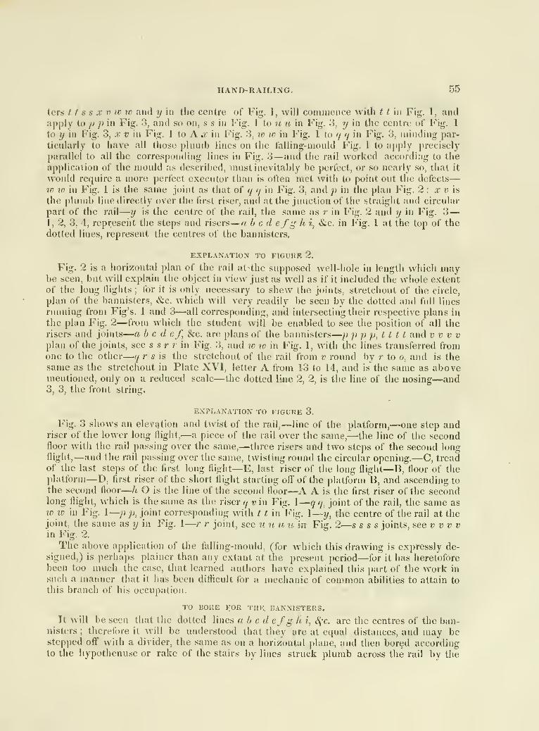
HAND-RATLING. 55
ters 1 1 s s X V ic to and y in the centre of Fig. 1, will commence with 1 1 in Fig. 1, andapply to p p in Fig. 3, and so on, s s in Fig. I to u u in Fig. 3, y in the centre oi' Fig. 1
to y in Fig. 3, .r v in Fig. 1 to A .r in Fig. 3, v) w in Fig. 1 to q q in Fig. 3, minding par-
ticularly to have all those plumb lines on the falling-mould Fig. 1 to apply precisely
parallel to all the corresponding lines in Fig. 3—and the rail worked according to the
application of the mould as described, must inevitably be perfect, or so nearly so, that it
would require a more perfect executor than is often met witli to point out tiie defects
—
w w in Fig. 1 is the same joint as that of q q in Fig. 3, and jj in the plan Fig. 2 : x v is
the plumb line directly over the first riser, and at the junction of the straight and circular
part of the rail—?/ is the centre of the rail, the same as ;• in Fig. 2 and y in Fig. 3
—
I, 2, 3, 4, represent the steps and risers
—
a bed efg h i, &c. in Fig. 1 at the top of the
dotted lines, represent the centres of the bannisters.
EXPLANATION TO FIGURE 2.
Fig. 2 is a horizontal plan of the rail at the supposed well-hole in length which maybe seen, but will explain the object in view just as well as if it included the whole extentof the long flights
;for it is only necessary to shew the joints, stretchout of the circle,
plan of the bannisters, &c. which will very readily be seen by the dotted and full lines
running from Fig's. 1 and 3—all corresponding, and intersecting their respective plans in
the plan Fig. 2—from which the student will be enabled to see the position of all therisers and joints
—
a bed ef, &c. are plans of the bannisters
—
p p p jj, t t 1 1 and v v v v
plan of the joints, see s s r r in Fig. 3, and w %v in Fig. 1, with the lines transferred fromone to the other
—
q r s is the stretchout of the rail from v round by r to o, and is thesame as the stretchout in Plate XVI, letter A from 13 to 14, and is the same as abovementioned, only on a reduced scale—the dotted line 2, 2, is the line of the nosing—and3, 3, the front string.
EXPLANATION TO FIGURE 3.
Fig. 3 shovv.s an elevcition and twist of the rail,
—
line of the platform,—one step andriser of the lower long flight,—a piece of the rail oA^er the same,—the line of the secondfloor with the rail passing over the same,—three risers and two steps of the second longflight,—and the rail passing over the same, twisting round the circular opening.—C, treadof the last steps of the first long flight—E, last riser of the long flight—B, floor of theplatform—D, first riser of the short flight starting oft' of the platform B, and ascending to
the second floor
—
h O is the line of the second floor—A A is the first riser of the secondlong flight, Avhich is the same as the riser q v in Fig. I
—
q q, joint of the rail, the same asWW in Fig. 1—p p, joint corresponding with 1 1 in Vig. 1
—
y, the centre of the rail at thejoint, the same as y in Fig. 1
—
r r joint, see u u u li'in Fig. 2—s s s s joints, see vv vvin Fig. 2.
The above application of the falling-mould, (for Avhich this drawing is expressly de-signed,) is perhaps plainer than any extant at the present period—for it has heretoforebeen too much the case, that learned authors have explained this part of the work in
such a manner that it has been diflicult for a mechanic of common abilities to attain to
this branch of his occupation.
TO BORE FOR THE. BANNISTERS.
It will be seen that the dotted lines abed efg h i, S^-e. are the centres of the ban-nisters
;therefore it will be understood that they are at equal distances, and may be
stepped off" with a divider, the same as on a iiorizontal plane, and then bored accordingto the hypothenu.se or rake of the stairs by lines struck plumb across the rail by the

56 SCROLLS AND HAND-RAILING.
pitch-board. This process is before the rail is rounded or moulded. To set the bannis-
ters in order on the platform or floor, just place the rail up in order to receive the ban-
nisters, all in proper height then take a rod that will easily enter the bannister hole, and
drive a point in the lower end; then put the upper end in the rail, and make it precisely
plumb; then make an impression in the floor with the point, which will give the centre
of the hole ; then let the bannister round the circles be the first set in the rail, as they
cannot he entered at the bottom as in the step.
RECIPROCAL SPIRALS, OR SCROLLS FOR STAIR-RAILING.
To join a scroll to an elliptical or even a circular stair-rail, in such a manner as to have
them perfectly harmonize, is somewhat of a difficult task, and requires a workmanof much taste and judgment. The reciprocal scroll is better adapted to a circular rail,
than any other kind. It is easily drawn, may be expanded to a greater or less distance,
and made to have more or less revolutions, as suits the pleasure of the operator. Thefour designs w^hich follow, have, in the order of the numerical succession, one and a
quarter, one and a half, one and three-quarters, and two, revolutions.
PL. 33.
TO DRAW A RECIPROCAL SPIRAL, WHICH SHALL MAKE ONE REVOLUTION AND A aUARTER.
For the eye of the spiral, describe a circle (Plate XXXIIl.Fig. 1,) having any diame-
ter, say three and a half inches; (see scale of inches at Fig. 5; divide its circumference
into eight equal parts, and from its centre draw radii to the points of division, and produce
or continue those radii indefinately; in the line 5 1, thus produced, take any point, as for
instance 1, as the extent or limit of the expansion of the scroll, and at 1, in the line 5 1,
erect a perpendicular, 1 10, of any length, and divide it into ten equal parts; on the line
5 1, set ofl' the part o s, equal to the width of the rail, and from 1, in the perpendicular
1 10, count oflfas many divisions as are equal to the number of eighths of a circle that
the scroll is to expand; (as, in this instance, two divisions;) from the point of division 2,
in the perpendicular 1 10, draw the line 2 s, and from the point 10, the line 10 0, meeting
the eye of the scroll at 0, and produce the lines 10 0, 2 s, till they meet ; the point where
they meet will be the point wiiere the lines from all the other points of division in 110,
w^ili likewise meet; which draw, accordingly.
TO DETERMINE THE LOCATION OF THE POINTS 2 3, &C. ON THE OUTSIDE OP THE SCROLL.
Take, in the compass, the distance from the centre of the eye to the point where the
line 5 1 is intersected by the line from the first point of division 1, in the perpendicular
1 10, and with that distance as radius, keeping one point of the compass on the centre
of the eye, describe an arc so as to cut the produced line 6 2; the point of intersection,
2, will be one point on the outside of the scroll. And to find other points, as 3, 4, &c.
take, successively, tlie distance from the centre of the eye to the several points where
the line 5 1 is intersected by the second, third, &c. lines from the perpendicular 1 10,
and from the centre of the eye as a centre, with those distances successively as radii,
describe arcs cutting the produced lines 7 3, 2 4, &c.] and the location of the points 3, 4,
&c. on the outside of scroll, will be ascertained.
TO FIND THE CENTRES FROM WHICH TO DESCRIBE THE CURVES 1 2, 2 3, &C. ON THE OUTSIDE
OF THE SCROLL.
From the point 1, in the line 5 1, as a centre, with the distance from that point to
the centre of the eye as radius, describe any arc, as at 1 ; from the point 2, on the outside

SCROLLS AND HAND-RAILING. 57
of the sci'oll, as a centre, and with the same radius, describe another arc, cutting the
former in the point 1, and that point will be the centre for describing the curve 1 2; whichdescribe, accordingly. In like manner, to find the centre for describing the curve 2 3,
take the distance from the centre of the eye to the intersection of the first line from theperpendicular 1 10, with the line 5 1, and with that distance as radius, and from the
points 2, 3, as centres, describe arcs so as to cut each other, and from the point of inter-
section, describe the curve 2 3. Proceed in the same way for the rest.
In the construction of Fig's. 2, 3, and 4, proceed as in drawing Fig. 1 ; bearing it in
mind, that the number of parts into which the perpendicular is to be divided, must equalthe number of eighths of a circle that the spiral is to revolve ; that the number of divisions
to be counted off' on the perpendicular, (reckoning always from that extremity of it whichmeets the line 5 1.) in order to know from what point in it to draw a straight line to s,
must equal the number of eighths that the spiral is to expand; that the outermost line
from the perpendicular must pass through o, on the eye of the spiral ; and tliat the pointwhere, when produced, this outermost line and the one drawn to s, will meet is the pointto which all the other lines from the perpendicular must be drawn. The student will
perceive, that one revolution and a quarter in the spiral, requires ten equal divisions in
the perpendicular ; one revolution and a half, twelve divisions; one and three quarters,
fourteen ; and so on.
Fig. 5. is a scale of inches for figures 1 and 2. and Fig. 6. a scale for figures 3 and 4.
PL. 34.
STAIR RAILING OVER A SMALL OPENING.
To furnish such drawings and explanations of the several parts of stairs as can becomprehended by workmen, not versed in science, nor much experienced in (he stair
department, and as will enable them to execute with a considerable degree of accuracy,,it is necessary to study simplicity, both in the drawings themselves, and in the termsused for their explanation. In what follows, I shall aim to do this, even if it be at theoccasional sacrifice of that verbal polish, and that scientific arrangement and explanation,which a learned reader might desire.
THE PLAN OF THE SEMICIRCULAR PAR,T OP A STAIR-RAIL BEING GIVEN, TO OBTAIN THECONVEX FALLING-MODLD.
Let A C E, F H J (Fig. 1.) be the plan of a .semicircular part of a stair-rail, havinga portion of straight rail attached to it; with the diameter, G I, of the convex side of theplan for radius, and from the points G, I, as centres, describe arcs cutting each other at
P, and join P I, P G; bi.sect the arc I H G in H, and through H draw- a tangent, K H L,of any length, and produce the lines P I, P G, till they meet the tangent: the part K L,cut oir by P I and P G produced, is the extension or stretchout of the convex side, I H G,of the plan. Draw the line c e (Fig. 2,) equal to the tangent K L, and at e, in the basec e, erect a perpendicular, ef, equal to the height of a step, and join c,f; at each endof the hypotlienuse cf, apply the pitch-board of a common step in the manner exhibitedin Fig's. A and B, and make r b ov q y in the pitch-board a b c, and fu in the pitch-board/^ A, each equal in length, I J or D E, of the straight part of the rail; makingallowance for the casings at c and/ the line a cfh, formed by the hypothenuse cf andthe upper edges of the two pitch-boards, is the lower edge of the required convex falling-
mould, of which the part q cfi is all that is required in this instance. On each side
,of the angles c, f, in the lower edge of said mould, set off any number of equal parts, saysix or eight, and from that point of division which is nearest the angle on one side, drawa straight line to that point which is fiirthest from the angle on the other side: do the
15

58 HAND-RAILING
same from all the other points of division, and by the intersections of these lines, obtain the
easings at c and f; parallel to tlie lower edge thus completed, and at wlialever distance
may be fixed upon for the widtli of ihe mould, draw a line for the upper edge, and the
required convex falling-mould (Fig. C) will be completed.
The line / m n (Fig. C) represents a butt-joint, and C r, or II v, (Fig. 1) sliews the
overwood necessary for cutting said joint, and are obtained thus : at the point H, (Fig. 1)
in the tangent K L, erect a perpendicular, and produce it so as to cross the convex mould
C ; bisect the part, z ~, which crosses the mould, and through the point of bisection, m,
draw / in n; at right angles to the hypothenuse c/, and from n, let fall a perpendicular,
n V, upon the tangent K L: as already stated, the line / m n represents a butt-joint in
the centre of the semicircular part of the rail, and C v, or H v, (Fig. 1) is the width of
overwood required to cut it; for which overwood, allowance is made in Fig's. 4, 6, &c.
Fio-ures3 and D represent the stretchout and falling-mould of the concave part of the
plan at Fig. 1, and are obtained in tlie same manner as Fig's. 2 and C: the base c e
(Fig. 3) being equal to the tangent M N at Fig. 1 ; c/, equal to the height of a riser; q y
and/», equal to the same portions of straight rail as in Fig's. 2 and C; and so forth. It
will be perceived, tiiat the two falling-moulds (Fig's. C and D) have different angles of
inclination ;that the line / m n, in order to be parallel to / m n in Fig. C, (which it must
be.) cannot be at riglit angles to the hypothenuse c f, as in Fig. C; and lastly, that
straio-ht lines drawn across the mould C and D, at right angles to the base c e, will have
vmequal lengths, those crossing D being necessarily the longest. This fact must be par-
ticularly attended to by stair-builders if they would construct hand-rails in the best pos-
sible manner. Even where attention is paid to it, some difficulty is experienced in the
application of the moulds, and in the construction of the rail. Mr. Coulter, of Phila-
delphia, recommends the method of dividing the difference in the width of the two fiilling-
moulds into two equal parts, and lowering the concave side of the rail a distance equal
to one of these parts, at the same time that the convex side is elevated a distance equal
to the other. This method, though liable to some trifling objections, is doubtless the
best that has been devised. It will not, however, make an inelegant rail, if the convex
side be elevated a distance equal to the whole difference in the width of the falling-moulds,
without lowering the concave side at all. I will just add that, further on, will be found
drawings and explanations adapted expressly to this case; and to these the student is
referred for what further aid and information he may require.
THE PLAN BEING GIVEN, TO OBTAIN THE FACE MOULD OF A STAIR-RAIL, WHICH, WHEN PLACED
OVER THE PLAN AT A PROPER ANGLE OF INCLINATION, WILL COINCIDE WITH THE SAID PLAN,
PART WITH PART.
Let Fig. 1 be the given plan, as before, and draw A B ?; r I J, (Fig. 4) equal to that
part of Fig. 1 which is represented by the same letters; join the ends of the dotted curve
passing longitudinally through the centre of the semi-plan at Fig. 4, by the straight line
w to ; through the point A, and parallel to id ic, draw a straight line, x A x, of any length,
and parallel to it, draw another line, y p, of indefinite length, so as to touch the convex
side of the semi-plan ; through the point J, draw a straight line at right angles to the
tangent y y, and produce the said line through J and said tangent, till they meet in the
point y; through the middle point, w, of the end of the circular part of the semi-plan,
and at right angles to the straight line w w, draw the line n s n, of any length, and makethe part s n (Fig. 5) equal to s n in Fig. 2 ; through n, (Fig. 5) draw tlie line z n y,
(Avhich line is the hypothenuse of the triangle z y y, and shows the rake or inclination
the face mould is to have,) and through the points A, I, B, &c. in the semi-plan, and at
right angles to the tangent y y, draw the lines A A, 9 9, ^c. meeting the hypothenuse

HAND-RAILING. 59
z y in the points A, 9, ^x ; at the points where they meet said hypothenuse, erect the
perpendiculars 9 I, 6 5, &c. (Fig. 6) making them equal to 9 I, 6 5, «S;c. in Fig. 4, and
the parts 6 B, 7 4, &c. in Fig. 6, equal to the similarly named parts in Fig. 4; through
the points thus obtained, trace the curved J I r, A B u, and you will have the face moiild
required. ,
TO APPLY THE FACE MOULD TO A PLANK FOR GETTING OUT A RAIL PIECE,
Let the oblong 1,2, 3, 4, (Fig. 7) represent the upper side of the plank; 2, 5, 6, .3, the
thickness of the same ; and 5, 8, 7, 6, the under side. Take the face mould (Fig. 6) and
apply it, as at Fig. 7, keeping the end u u as far from the edge of the plank as is indicated
by Figs. 4 and 6, and tracing out its shape A J f v ; take the pitch bevel A at Fig. 5,
(which shows the angle of inclination that the rail is to have.) and apply it as at A and
A;(Fig. 8) make the plumb-cuts C C, A A, across the edge, and also the perpendicular
c V on the under side of the plank, equal to c t> on the upper side, and then applying the
face-mould again, as at Fig. 9, complete the outline for cutting the rail-piece.
TO APPLY THE CONVEX AND CONCAVE FALLING MOULDS TO A RAIL-PIECE.
When the rail-piece has been cut out, as just described, take the convex mould Fig. C,
(which is supposed to be made of pasteboard) and apply it to the convex edge of the
rail-piece at Fig. 7, bending it round so that the points p, o, 3, in the upper edge of the
mould, may coincide, each"with each, with the points J, I, v, in the upper side of the
convex edge of the rail-piece, and so that the lines p q, o c,3 n, drawn across the mould
C at right angles to its base, c e, may tally, each to each, with the plumb cuts A A, B B,
C C, made on the concave edge of the rail-piece, and continue across the under side to
meet the above mentioned lines. Having applied and bent round the mould in this
manner, trace lines along its upper and lower edges, and you will have the outline for
finishing the convex side of the rail.
In the same way, apply the concave mould D to the concave edge of the rail-piece,
making the straight part, j) o, in the upper edge of the mould, coincide with the straight
part, A B, in the upper concave edge of the rail-piece ; and thus far, the two falling-
moulds will have the same angle of inclination. To find what inclination to give to the
circular part of the concave mould D, from the point n, in the lower edge of the convex
mould C, (which is supposed to be bent round the convex edge of the rail-piece,) square
across the under side of the rail-piece, and from the point 2, (Fig. D) where the line thus
squared across, is supposed to meet the lower concave edge of the rail-piece, draw the
horizontal line 2 4 ; from 2, in the line 2 4, set off 2 ~, equal to the overwood for a butt-
joint, and-z will be that point in the concave edge of the rail-piece, on which the middle
point in the lower edge of the circular part of mould D, will rest. Now trace the outline
for completing the concave side of the rail. Observe that the difference in the length
of n 2 in Fig. C, and n 2 in Fig. D, represents the difference the two falling-moulds will
have in their angle of inclination.
PL. 3.5.
For the method of finding the face and falling moulds, exhibited in this and the follow-
ing Plate, and for the drawings connected with the same, I am indebted to Mr. JoshuaCoulter, of Philadelphia, of whom mention has already been made, in the preface to this
work. The method exhibited in this plate, is well adapted to small openings of fromseven to twelve inches in diameter. When the opening is enlarged, it becomes necessary
to throw the steps into a circle, in order to preserve, as nearly as possible, the sameinclination in the circular, that belongs to the straight part of the rail. By pursuing this

60 HAND-RAILIN(5,
method, the usual droop in the middle of the circular part, will be almost wholly pre-
vented and as any length of straight rail may be attached to the circular part, (he
disadvantage of having the grain of the wood run cross-wise, may be avoided.
TO OBTAIN THE FALLING-MOULD AT FIG. 4, FROM THE SEMI-PLAN AT FIG 1. '
Obtain the stretchout, e i, of the curve e d, (Fig. 1) in the same way as in the last
Plate, and Draw the base C F, (Fig. 3)making each of its parts, C D, D F, equal to the
stretchout e i; at right angles C F, Draw F H, equal to the height of a common step,
and draw the hypothenuse H C;place the pitch-boards A B C, H J K, in the position
exhibited in the figure, and produce the side, B C, of the pitch-board A B C, any distance,
C M, say about one-third the length of B C ; through the point E, where a perpendicular
from the middle of the base cuts the hypothenuse C H, draw M N, making E N equal
to M E, and join N H ; from M towards N, in the line M N, set off a part equal to M C,
and from N towards N, a part equal to N H, and divide the part thus set off, together
with M C, N H, into any number of equal parts ; draw the intersecting lines for the
casings at M and N, and complete the falling-mould, in the manner described in
Plate XXXIV.
TO OBTAIN THE FACE MOULT) AT FIG. 5, BY MEANS OF ORDINATES.
Perpendicularly over h g in the semi-plan, form a section of the rail, (Fig. 7) so that
its top shall be on a level with a line drawn from .r (Fig. 4) parallel to the base F C,' andso that the said line from .r, and the line 2 3, in the upper edge of the falling-mould, may,
when produced, meet in the middle point, 4, of the top of the section; through any point,
as a, in the straight part of the semi-plan, and at right angles to the sides of said straight
part, draw a straight line, a b, across it, and produce a h till it cuts the line z h in (/, andtill it meets the upper edge of the falling-mould at the point 2; divide the width of the
rail, a b, into three equal parts, and at that point of division, r, nearest the point a, erect
a perpendicular, ? s, equal to s z in Fig. 7; join (j, s, (Fig. 1) and produce the line qs, till
it meets the side of the rail at t;produce the diameter d C, (Fig. 1) till it meets the
upper edge of the falling-mould, and at the points 3, 2, where the produced lines do, « 2,
meet the upper edge of said mould, erect the perpendiculars 3 a, 2 c, making the parts
3 IP, 2 a, each equal to t a in Fig. 1, and the parts to a, a c, cacli equal to q t in Fig. 1;
through the points a w, in the perpendiculars 2 c, 3 a, draw a straight line, a h a, of anylength, and produce the line b 3, (Fig. 1) till it meets the line a h a in the point 2; from
said point, draw a straight line, 2 a, to the extremity, a, of the perpendicular 3 a. and the
line 2 a will be the directing ordinate for the face-mould at Fig. 5. With this ordinate
for radius, and from d (Fig. 1) as a centre, describe an arc cutting the line z h at 2, andjoin d, 2: the line d 2 will be the directing ordinate of the semi-plan. Parallel lo tZ 2draw other ordinates across the semi-plan, and from tlic points 5, 8, &c. where tliey
meet the convex side of the semi-plan, draw straight lines at right angles to z h, andjiroduce them till they meet the line a h a in Fig. 5
;from the points Avhere they meet
a h a, draw the ordinates 3 5, 6 8, &.c. parallel to the governing ordinate 2 «, and equal
to 3 5, 6 8, iStc. in the semi-plan, and complete the face-mould in the manner heretofore
described.
Fig. 6 shews the bevel or spring of the plank, and is obtained by making a /"and c c
in Fig. 6 equal to if a in Fig. 1, and drawing the lines e b, b c, &c. as in the figure. Therhomboid ab c d, exhibits the shape and spring of the plaiik.
In the application of the face-mould, use the pitch-board in room of the pilch-bevel,
and have the straiglit part of the mould parallel to the edge of the plank. Apply the

HAND-RAILING. 61
falling-mould, and with the exception just mentioned, the face-mould also, precisely as
directed in the preceding plate.
PL. 36.
This Plate exhibits a somewhat different and doubtless better method of drawing theface and foiling moulds of a stair rail, than that exhibited in the preceding Plate. Asalready stated, botli were furnished me by Mr. Joshua Coulter. The face-mould, Avhendrawn as exhibited in this Plate, gives an equal fproportion of width to the upper andlower ends ; and the falling-mould is, by this method, drawn in the best manner, probably,of which it is susceptible. This mode of drawing it, has the effect to lower the concaveside of the rail towards the nosings, and to elevate the convex side; as exhibited in theposition of the two falling-moulds at Fig. A.
TO DR.4.W THE CONVEX AND CONCAVE PALLING MOULDS AT FIG. A.
Let Fig. 1. be the plan of the semi-circular part of the rail, with a portion of straight
rail attached, and let j k be the stretchout of the convex side of the plan, and 5 7, thatof the concave side
; at the end, k, of the convex stretchout j k, place the pitch-boar^3 /.- z, so that its base, k z, shall form a continuation of the stretchout line, and at theend, 7, of the concave stretchout 5 7, place the pitch-board 5 7 &, in the same manner
;
at the other ends, j, 5, of the two stretchouts, erect the perpendiculars j 3, 5 5, each equalin length to the height of the pitch-boards just mentioned and the stretchout of thewinders put together, and at the upper ends of these perpendiculars, place the pitch-boards 3 6 &, 5 y/ ^, in the position exhibited in the figure
;connect the upper pitch-board
3 6 «&, with the lower one 3 k z, by the line 3 3, and allowing for the casings, ^ 3 3 &is the lower edge of the convex falling-mould ; which mould is to be completed in themanner heretofore described. To obtain the butt-joint at i j, joint the tops of the tw(^lower pitch-boards by the line 3 5
;bisect the distances, j 5, 7 k, intercepted between
the ends of the two stretchouts, and at the points of bisection, 2, 6, erect perpendiculars,and produce them till they meet the lines 3 5, 3 5
;join the points where they meet
those lines, by the line 2 2, bisecting the lower edge of the convex falling-mould;bisect
that part of the central perpendicular, ef, which crosses the falling-mould, and throughthe point of bisection, g, and at the right angles to the line 2 2, draw the line ij for a butt-jpint.
To obtain the concave falling-mould, produce the side, k 3, of the pitch-board 3 k z,
till it meets the upper edge of the convex-mould in the point 4, and bisect the producedpart, 3 4, in 1 ;
at the point of bisection, erect a perpendicular, 1 1, producing said per-pendicular and the side 7 5, of the pitch-board 5 7 &, till they meet in the point 1
;pro-
duce the perpendicular j 3, so that the part produced, 3 4, shall be equal to 3 4 at tlie
lower end of tlie mould, and, bisecting 3 4 in 1, obtain the location of the point 1, in theline 5 5 1, in the same manner as at the lower end; join the points 1, 1, thus obtained,by the line 1 1, (which line will pass longitudinally through the centre of the requiredconcave mould,) and through the points, i,j, at the butt-joint, draw lines parallel to thecentre line 1 1, and the concave falling-mould will be completed
TO DRAW THE FACE MOULD AT FIG. 6.
Let Fig. 3 represent the semi-plan, or half of Fig. 1, of which A is the centre, and A ga radius, cutting the semi-plan at the junction of the straight and circular parts of therail
;join the ends of the curve passing lengthwise through the centre of the semi-plan,
by the straight line s t, and through the inside corner (or corner nearest the centre A)of that end of the semi-plan which is straight, draw a straight line, y h v, of any length
16

62 UAND-RAILING.
and parallel to the line s t; througli the pointy, in the butt joiintij, (Fig. A) and parallel
to the perpendicular e f, draw a straight line, meeting the base in the point 8, and the
upper edge of the convex lalling-niould in s ; set the length ol' the straight part of the rail
in Fig. 1 from /.' to m on the base and at m, erect a perpendicular of sufficient length to
meet the upper edge of the mould, as at d; through the ends s, of the line s t, (Fig. 3) andat right angles to s I, draw a straight line meeting the line ij li u in m, and produce it in
the opposite direction till the whole length, reckoning from u, is equal to the line 8 s,
(making allowance for ov^erwood,) intercepted between the base and the upper edge of theconvex mould at Fig. A; through the other end, t, of ihe line s t, (Fig. 3) and at right
angles s t, draw the line h t d, meeting the line y h u in /;, and produced in the other
direction till the whole length h d, is equal to the perpendicular m d in Fig. A ; throughthe upper ends of the two lines thus formed, draw a straight line y u lo, (Fig. 6) of anylength, and from the centre A, draw the line A 5 I 1, at right angles to s t, and meetingthe rake-line y u to in the point 1 1 ; take, in (he compass, the arc §• 5, intercepted onthe convex side of the semi-plan between the radii A ,!^, A 5, and place it fromg- to 7ionthe convex side of Fig. 1 ; from the point;) in Fig. 1, (found when obtaining the convexstretchout,) draw a straight line through n to the base, and at the pointy, where it meetsthe base, erect the perpendicular ^ 10, meeting the upper edge of the falling-mould at
10; on the line A 5 11, (Fig. 3,) cut off the part g 10 equal to g 10 in Fig. A, and fromthe point 10, in the line A 5 11, let fall a perpendicular, 10 lo, upon the rake line y u in
;
with this perpendicular for radius, and from the point 10 as a centre, describe a circle,
and parallel to A 5 11, draw the tangent 1 2, ?<;, touching the circle (Fig. 6) at 12, andmeeting the line y h u (Fig. 3) at zc; join the points ic, 5, by the line lo 5, and producethe perpendicular 10 to (Fig. 6) to n, making the part ro n equal to the line ic 5 in thesemi-plan, and join n, 11 : the line 7i 1 1 will be the governing ordinate for the face-mould.
With this ordinate as radius, and from the poir.t 5 (Fig. 3) as a centre, describe an arc,
Cutting the line y hum the point v, and join v, 5 : the line v 5 will be the directing ordi-
nate for the semi-plan. Parallel to v 5, draw other ordinates so as to meet the line yh u,
and also the convex side of the semi-plan, and through the points where they meet theconvex side, draw straight lines at right angles to y h u, producing them till they meetthe rake-line y u w; from the points where they meet said rake-line, draw the other
ordinates of the face-mould, parallel to the governing one, n 11, and equal, each to each,
to the corresponding ordinates in the semi-plan ; and you will have the points throughwhich to trace the outline of the face-mould, as required.
Fig. 5 is the face-mould for the upper rail-piece, and is found in the same manner as
the other, only that the base from which the heights are taken, is 2 f (Fig. 2) instead
of / z. s s and t i are the perpendiculars from the base 2 /, by which to obtain the properrake or inclination of the upper face-mould, and 9 10, (Fig. 2) is the one for finding the
point fur the centre of the circle in Fig. 5.
It will be observed, that the face-mould for the lower rail-piece (Fig. 6) is considerably
longer than the other, though the semi-plans for obtaining them are precisely alike.
This dilVerence is owing to the fact, that, at the junction of the straight with the circular
part of the rail, the lower rail-piece inclines upward with a steeper slope than before,
while the upper one, at its junction with the straiglit part, has a gentler inclination than
it had.
Fig. 7 represents the spring of the plank, and is obtained by making 9 iv (Fig. 7) equal
to 9 10 in Fig. 3, drawing the perpendicular 9 n (Fig. 7) equal to 5 9 in Fig. 3, and join-
ing n, 10 : the angle 9 lo n (Fig. 7) is called the spring of' the plank. Now when the rail
pieces are cut out by the face-moulds at Fig's. 5 and (3, and bevelled according to Fig"s. 8
and 9, if they are placed over the semi-plans at their proper angle of inclination, and so
that the points o, o, in the centre of their extremities, shall be perpendicularly over the

HAND-RAILING. 63
lines St, s t, in the semi-plans, the several points and lines in the rail-pieces will be ver-
^tically over their corresponding points and lines in the semi-plans.
In the application of the falling-moulds, place that part of the convex one which ex-
tends from s (Fig. A) downward, upon the convex edge of Fig. 6, (supposing the rail
piece cut out, and plumb cuts made on it according to the pitch-bevels,) so that the
points j, c, z, in the convex falling-mould may, each to each, coincide with the points
y, g, y, on the convex edge of Fig. 6. and the lines j, s, c, x, z, d, on the falling-mould, withthe piund) cuts supposed to be made across the convex edge of Fig. 6 from the points
y, gi y, trace lines around the edges of the jnould thus applied, and the outline for the
convex side of the I'ail will be obtained. In applying the concave falling-mould, proceed
in the same way ; observing in both cases, tlie directions given in plate XXXIV.
PL. 37.
This Plate is precisely like the last, except that the face moulds are omitted, and the
falling-moulds, beside being located as in that Plate, are laid down separately, that their
shape and their diilerent inclinations may be more distinctly perceiv'ed. An explanation,
therefore, of the method of drawing the falling-mould, would be a needless repetition.
38.
THE PLAN OF THE SEMI-CIRCULER PART OP A RAIL THAT SHALL HAVE EIGHT WINDERS AROUNDTHAT PART, BEING GIVEN, TO FIND THE FALLING-MOULD POP THE CONVEX SIDE OF THE RAIL.
Let Fig. 1 represent the given plan, having portions of straight rail attached, and divide
the arc c c g, and also the stretchout of that arc, when obtained, into eight equal parts;
obtain the stretchout ; /v, of the convex side of the plan, by the method heretofore de-
scribed, and set it from ; to k, on the base in Fig. 2;at the point k, in the said basej^^
place the pitch-board of a common flyer in the manner described in Plate XXXVI, an^^at the point J in the same base, erect a perpendicular, j o, equal to the whole height
of the risers in the eight winding steps and that of the pitch-board at the base, put to-
gether ; at the end o, of the perpendicidar y o, place a pitch-board in the position exhibited
in the figure, and join the two pitch-boards by the line o o ; obtain the easings at the
angles o, o, and the lower edge of the falling-mould at A, will be completed. Parallel to
it, at any distance determined upon, draw the upper edge, and you will have the required
convex falling-mould.
TO OBTAIN THE BUTT-JOINTS IN THE RAMPS OR EASINGS.
Let the length, a c, or b d, of the straight part of the rail in Fig. 1, from k to m, on the
base, and at m, erect the perpendicular m d, meeting the upper edge of the falling-mould
at d; on the upper edge of said mould, set ofl", on each side of (/, any equal distances, as
d a, d t, and from the points t, a, as centres, with the chord length of ? a as radius, describe
arcs cutting each other at c; join the points c, d, by the line c d, and produce said line
across the falling-mould: the part which crosses the mould, will give the position of the
butt-joints in the lower ramp. Find the upper butt-joint by the same process ; and to
obtain the central one, l j, bisect h fin g, and through g, draw i j, at right angles to the
edges of the mould.
To show the bverwood necessary to cut the central butt-joint, ij, draw straight lines
through the points l, j, parallel to the central line f A, and cutting the plan (Fig. 1) in
the points 8, 8 : the width intercepted on the plan between the central line/ A and either
of the linesj 8, i 8, is the width of overwood necessary for cutting the butt-joint ij.

64 HAND-RAILING
TO FIND THE FACE-MOULD AT FIG. 7.
With the exception of making the height lines start from the line s t, (Fig. 3) insteafi
of the outer one, 2 h n, proceed exactly as in drawing Fig. 6, Plate XXXVI, till you
have found the point, «*, in the line A m 2; instead of describing a circle with m for the
centre, as in Plate XXXVI, draw^ in o, at riglit angles to A 2, and meeting the rake line
2 s in the point o ;through o, and parallel to A 2, draw o w, meeting tlie line s t (Fig. 3.)
in the point w, and from lo, draw a straight line to the point v, where the line A 2 cuts
the dotted curve that passes longitudinally through the centre of the semi-plan;produce
the said straight line both ways, so as to meet the line 2 h n, (Fig. 3) and also ihe con-
vex side of the semi-plan, and parallel to it as the directing ordinate for the semi-plan,
draw other ordinates, and erect perpendiculars to meet the rake line, as directed in
Plate XXXVI. From the point m, in the line A 2, let fall a perpendicular, m, f, upon
the rake line 2 s, and produce it indefinitely on the other side of said rake line; take the
distance %o v, intercepted on the directing ordinate (Fig. 3) between the line s t and the
dotted curve, and from the point o, (Fig. 7) as a centre, with said intercepted distance
as a radius, describe an arc cutting the produced perpendicular, ic, t-, in v;join o, v, and
the line 17 will be the directing ordinate for the face-mould, and its extremity v, one
of the points through which to trace the concave edge of said mould. Complete Fig. 7
by transferring to it the ordinates in Fig. 3, as directed in the last Plate but one.
By the same process, the face-mould for the upper rail-piece (Fig. 8) is obtained; the
line 4 x (Fig. 2) being taken as a base, and the line t i, s s, being the heights by which
to find the proper inclination of the rake line.
Fig. 6, shews the spring or bevel of the plank, at an acute angle, adapted to the lower
fail-piece, and is obtained thus: draw any straight line, n ni, (Fig. 6) and from it cut
olTa part, m ?-, equal to m r in Fig. 7; at r, (Fig. 6) erect a perpendicular r v, equal to
^the part, u v, of the line A 2, (Fig. 3) intercepted between the line s t and the dotted
'^^•urve; join v m, (Fig. 6) and the acute angle v m r, shows the proper spring of ,the plank
for the lower rail-piece. In a similar manner, obtain, from Fig's. 4 and 8, the bevel of the
plank at an obtuse angle, as shown by the angle v r]f,
in Fig. 5.
In the application of the falling-mould A, proceed as directed in Plate XXXIV ; makingd X, in the upper edge of the mould, coincide with 2 2, at the lower end of the convex
side of Fig. 7, and s, in the mould, witii 8, on the convex side of Fig. 7 and bending
the mould round the convex edge of the rail-piece, as heretofore described.
In applying the pitch-bevels to the plank, when getting out rail-pieces, let the stocks
of the bevels coincide with that edge of the plank represented by the rake line 2 s, in
Fig's. 7 and 8, and let their blades fall across the thickness of the plank, so as to havethe plumb cuts parallel to the perpendiculars raised from the semi-plan.
PL. 39.
In this Plate, the falling-moulds are adapted to a stair having ten winders around the
semi-circular part of the rail, and instead of running parallel to the nosing line, as they
ordinarily do, they are drawn so as to have, at the perpendicular height of one riser above
the centre g, (see Fig. 2) a horizontal distance from the nosing line equal to the width
of one tread or step, as at h; while, at the second nosing below the centre, they cut the
nosing line, as at id. It is thought by some, that the hand can glide more easily up or
down a rail of this shape, than over those which are parallel to the nosing line. Themode of drawing the convex mould at Fig. 2, is as follows. Having in the same manneras in preceding plates, obtained the convex stretchout^' /., erected the perpendicular j o,
(equal to the combined height of the lower pitch-board and ten risers,) placed the upperand lower pitch-boards, and joined them by the hypothenuse o o, erect the central

HAND-RAILING. 65
perpendicular ef^ and set the height of a riser from g to A, on the isaid perpendicular;
through the point A, thus found, and the point tc, at the second nosing below ^, draw astraight line, and produce said line, as also the sides to, to, of the upper and lower pitch-
boards, till they meet the points r, r; obtain the easings at the angles ?•, r, and parallel
to the lower edge, t lo h t, thus completed, draw the upper one, d s s, and you will havethe required convex lalling- mould.
Proceed in the same way, in drawing the falling-mould for the concave side of the rail.
Fig's. 5 and 6 represent tlie face-moulds for the upper and lower rail-pieces, and Fig's.
4 and 3; the semi-plans from which they are obtained. The several steps of the process
by which they are obtained, correspond exactly with those detailed in plate XXXVI,and render a formal explanation quite unnecessary. As in Plate XXXVI, the lines
m (I, 8 s, t i, 5 s, (Plate XXXIX, Fig. 2,) are those by which the respective inclinations
of the rake-lines are determined ; and the lines 9 10, 9 10, at the upper and lower parts
of the elevation, are those by which the centres of the circles in Fig's. 5 and 6 are ascer-
tained. To obtain the last named lines, make the arcs ^ n, ^ j?, on the convex side
of Fig. 1, each equal to the arc g n on the convex side of Fig. .3, and from the pointy,(Fig. 1) draw straight lines through the points n, n to the stretchout j k ; at the points
7n, m, where the said straight lines meet ;'A', erect perpendiculai's, and produce them till
they meet the upper edge of the convex falling-mould : the parts 9 10, 9 10, intercepted
between the upper edge of said mould and the respective bases jt, 5 t, are the lines
required.
The lines 5 n, 5 w, (Fig's. 3 and' 6) are respectively, the governing ordinates for thesemi-plan and face-mould, and are obtained precisely as in Plate XXXVI.The .spring of the plank is represented by the angle 9 to n, in the semi-plan at Fig. o.
PL. 40.
This plate exhibits the plan, and the face and falling moulds of an elliptical stair. Theplan (Fig. 1) is by means of chords, divided into as many parts as there are to be pieces
in the rail, and upon these chords, height lines (taken from the elevation) and perpendi-culars are erected, the rake lines and ordinates are drawn, and the face-moulds Fig's. 3,
4, and 5) completed, just as in the foregoing plates, except that the ordinates are at right
angles to the rake lines. (Fig. 6 is a face-mould, with its ordinates drawn so as to forman oblique angle with the rake line, and be adapted to -the spring of the plank ; andFig. 7 represents the said spring or bes^el.)
The triangle b a c, (Fig. 12) represents a square step or flyer, and the line c d f, repre-sents a portion of floor at the top of the first flight of steps. The line d e, interceptedbetween said floor line and the under edge of the convex falling-mould, is equal the half
of a c, that is, half the height of a riser; and the rail, after reaching that elevation abovethe floor, will pass on horizontally till it reaches the foot of the second flight.
PL. 4LIn this plate, Fig, 1 is the plan of an elliptical stair, and Fig. 4, a section or semi-ele-
vation of the same. Fig. 3 represents a bearer for supporting the winders; of which
bearers Fig. 2 is the plan. Fig. 3 is obtained in the folloAving maner :—At the point c,
where the lower side of the plan (Fig. 2) meets the elliptical wall, erect a perpendicular,c 9, equal to the height or stretchout of the risers in as many winding steps as tlie beareris intended to support ; divide said perpendicular into as many equal parts as there arerisers in said step.s, and at the points of division, 1, 2, &c., erect perpendiculars of anylength
;at the point c, c, &c., where the lines representing the division of the steps cut
the lower side of Fig. 2, erect perpendiculars, and produce them till they meet, each17

66 HAND-RAILING.
with each, their corresponding perpendiculars erected on ca: from the points o, a &c.,where they meet, set off, on tlie perpendiculars from Fig. 2, the parts a, a, a, a, &,c. eachequal to a a in the semi-elevation at Fig. 4, and through the lower points a, a, &c. thusobtained, trace the curve for the under edge of the bearer. The parallel straight lines
on either side of this curve, shew the width of stuff requisite for getting out the bearer.
It will be be perceived, that, in its ultimate position, that is, when raised up at rightangles to its plan, the several parts of Fig. 3 will be in a vertical range with the severalparts of Fig. 2. The method of placing bearers exhibited in this Plate, possessesdecided advantages over the old and common mode, as it regards both time and expense,and it is recommended to the notice of such stair-builders as have not already put it in
practice.
PL. 42.
This Plate exhibits the plans and elevations of the front and back strings of a circular
stair. The arc A (Fig. I) represents the plan of the front string, or string adjacent to
the opening, and C, the plan of the string contiguous to the wall, B and ]) are thestretchouts of said arcs, and the several divisions in them correspond, in location, withthe several divisions made in A and C by the dotted radii, which, from the centre O,pass through the front of each step to the plan of the back string. In the plans A and C,a, h, c, Sic. represent the wedges supposed to be inserted on the convex side of the twostair-strings, and made to penetrate to a greater or less depth, and to be a greater or less
distance apart, according to the greater or less extent of the circles in which the strings
are spirally to wind. In tiiis example, the wedges in the front string are made to reachto within about an eighth of an inch (see the scale at bottom) of the concave side, and
be about seven-eighths of an inch apart ; while those in the back string, only comeithin about a quarter of an inch of the concave side, and about an inch and a quarter
apart. The wedges may be shorter and further apart in the back string than in the
other for the reason that the back string Avinds in a larger circle than the front one, andof course has a less prominent curvature. The depth to which the wedges penetrate
and their distance apart, must be left to the discretion of the workman. Care must betaken that they be not too far apart, for ifIhey are, the concave sides of the stair-strings
will present a succession of plane surfaces and angles, instead of that regular curvature
which they are intended to exhibit.
•Fig's 2 and 3 represent the elevation of the front and back strings and are obtained
by a process so very similar to that by which tlie falling-moulds in the preceding plates
are found, that no explanation will be necessary.
In Fig. 2, c represents a separate piece, intended for insertion, at its upper edge, into a
groove to be made in the under edge of the front string, after it has bent to its true shape
and has become entirely dry. In the same way a separate piece may be inserted into a
groove in -the upper edge of the back string at Fig. 3. The line a (Fig. 3) shews the
width of the skirting when got out separately, and the line h is the width of the back
string and skirting, when tliey are got out in one piece. When got out in one piece,
channels or mortices are made in it, for admitting the ends of the treads and risers.
Whether the string be mortised for inserting the ends of the steps, or whether it be
notched, a pitch-board must be applied to it, and. lines traced for the treads and risers
;
but the places for the ends of the steps must not be cut out until the string is bent,
wedged, and dried.
To give the strings of a circular stair their proper curvature and spiral twist, make, for
each string, a cylindrical block, that is, make two frames with battens or narrow strips
of boards nailed on longitudinally and Touuded off at the outer edges, so that each frame

GRECIAN ARCHITECTURji. 67
shall, following the outline of the battens, be cylindrical, and have the respective curva-
tures of the circular wall and well-hole. Around these cylindrical frames bend your stair
strings, gluing in the wedges as you proceed, and, if you please, gluing a piece of coarse
canvass over the wedges.
Note.—In making the apertures for the w'eJges on the convex side of the strings at #Fig's. 2 and 3, care must be taken to cut ihem at right angles to the stretchout D, (or
any other horizontal line,) instead of cutting them at right angles to thP edges of the
elevations.
PL. 43.
OF THE CHORAGIC MONUMENT' OP THRASSYLLtfS.
(From Stewart's Antiquities.)
Just above the place on which I have supposed the Odeum of Pericles to have beenbuilt, there is, in the rock of the Acropolis, a cavern or grotto, the entrance into which is
fronted, and completely closed up by the building here treated of The cavern is now achristian church, called the Panagia Speliottissa, or the Blessed Lady of the Grotto. Onthe front of the building are three inscriptions, recording victories obtained either in the
^Odeum or in the theatre, which prove it to have been a Choragic monument ; not indeedso highly ornamented as the monument of Lysiocrates, but wrought nevertheless withgreat accuracy, and deserving our notice both for the singuiarity of its composition andthe form of its mouldings. Besides which I must observe, that the mutilated statue yetremaining on it is the work of an excellent sculptor. There were inscriptions cut on tho^^^middle of the architrave. ^^^
This is the most ancient of the three inscriptions above-mentioned, as Wheler and^^^Spon have already observed, and w^as doubtless made when the monument was tirst
erected. By it we learn, that " Thrasyllus, the son of Thrasyllus of Deceleia, (a demosor township of the tribe of Hippothoon,) dedicates this building, having been at the ex-
pense of exhibiting.the games, in wdiich, with the men of his own tribe, he obtained thevictory ; that Evius of Chalcis was the musician ; and Karchidamus the son of Sotis
composed the piece, Neaechmus being Archon." This was in the first year of the 115tli
Olympiad, or about 318 years before the Christian era ; so that this building was erect^above two thousand j^ears ago. ^The other two inscriptions record victories of the same kind with the former, obtained
about fifty years afterwards, when Pytharatus was Archon. The following is on the left
hand, or towards the west:
The people gave the games, Pytharatas was Archon,
Thrasycles the son of Thrassyllus, a Decelian, was Agonothetes,
The boys of the tribe of Hippotoon got the victory,
Theon the Theban performed on the flute,
Pronomus the ^Tlieban composed the piece.
&
Pronomus was a celebrated musicia^tf Thebes, refnarkable for having a great beard.
He was contemporary with Aristophanes, who took occasion to scoff at Agyrrhius, anAthenian magistrate, ludicrously siipposiug he had borrowed his beard from Pronomus.As the piece wiiich gained the prize in these games was composed by a musician, it
seems to prove that the inscription relates rather to a musical than a dramatic perform-
ance; and that the victory it records was obtained in the Odeum, not in the theatre. It
is also to be remarked that these games were given more than a hundred years after the

68 GRECIAN ARCHITECTURE.
time when Aristophanes made free with our musician's beard : may we not thereforeconclude, that on this occasion, long after his decease, some favorite composition of his
was performed with great applause? Nor shall we find this to have been without aprecedent
; for by what Pausanius relates to have happened at the rebuilding of thewalls of Messene, in the third year of the 102d Olympiad, ii appears there were at thetime two pty^ies among the frequenters of musical entertainments, some deciding in
favour of PrOTiomus, while others continued to prefer the more ancient compositionsof Sacadas, a musician of Argos, then doubtless many years dead, for he had gained aprize at the Pythian games in the 48th Olympiad : and although the works of his anta-
gonist had long enjoyed a great reputation, Pronomus appears to have had the suflrages
of a majority in his favour.
PL. 44,
OF THE TEMPLE OF THESEUS.
(From Stewart's Antiquities.)
The travellers who have visited the city of Athens, and the authors who have de-scribed its antiquities, all agree, that this Doric Temple, one of the noblest rernains of its
ancient magnificencie, and at present the most entire, was built in honour of Theseus..This 6pinion is abundantly justified by the sculptures in some of the metopes, for,
mutilated as they are, it is evident that' several of the exploits of the hero are thererepresented.
Nor can it be doubted, that this is the temple which both Plutach and Pausanius placeear the Gymnasium of Ptolemy
;great remains of that Gymnasium are yet standing,
and their situation in regard to this temple agrees exactly with the information thoseauthors have left us.
On what occasion Theseus was thus honored, we are taught by the above-mentionedauthors. Plutarch particularly, after recounting his heroic deeds, and the ingratitudeof the factious Athenians towards him, with his banishment and death, says, "In after-
times, several motives concurring, the Athenians honored him as a hero. Many of thosewho fought against the Medes at Marathon, imagined they saw his apparition in com-^te armour, rushing before them on the enemy. After the conclusion of the Medianwar, Pha'don being archon, the Athenians consulting the oracle, the Pythian priestess
answered, that they should bring back the bones of Theseus, deposite them honourablyin their city, and with a religious observance keep them >there."
This was accomplished when Cimon,' the son of Miltiades, had conquered Scyros
;
there, after a diligent search, he discovered the venerable remains of the hero, of superiorstature, with the brazen point of a spear, and a sword lying by him
;(these weapons in
the heroic age were of brass;) and having embarked them on board his ship, he carriedthem to Athens, where they wece received by the citizens with splendid processions andsacrifices, as if the hero himself had returned to visit tliem. His remains were depositedin the middle of the city, near the'present Gymnasium.Nor was this all ; festivals were instituted, and games celebrated, in honour of the
event ; and on this occasion, has it has been generally supposed, liappencd that famouscontest between vEschylus and Sophocles, two competitors for dramatic glory, who, sincethat time, if we except Euripides, have hardly either of them, had a rival : the victorywas adjudged to Sophocles, and his high-spirited antagonist, unable to support the dis-
grace, or submit to the decision of his judges, left his country, and passed into Sicily avoluntary exile. This was transacted, we are told by Plutarch, in the year that

GRECIAN ARCHITECTURE. ^9
Apliepsion was arclion, which the best autliorities place in the fourth year of the seventy-seventh Olympiad, 4G7 before Christ; that is, exactly forty years before the deathof Pericles, or precisely at the time when he began to acquire popularity and power inAthens : so that this temple may well be accounted a work of the age of Pericles.
It is built of Pentelic marble, and in the language of Vitruvius, is a Peripteros. Thepruicipal front faces the east; and the pedini^ent of that front appears to have beenadorned, like those of the Parthenon, with figures of entire relief, fixed in their places bycramps ol" metal
;for on the fcice of this pediment remain several holes, in which the ends
of those cramps have been inserted, though the figures they supported are all of themdestroyed.
On the metopes in this eastern front, are represented ten of the labours of Hercules
;
and on the four metopes next that front, both on the northern and southern sides, areeight of the achievements of Theseus. It will appear the less extraordinary, that thelabours of Hercules should make so considerable a part of the ornaments of this temple,when we recollect the respect and gratitude which Theseus professed to that hero, whowas his kinsman, had delivered him from a tedious captivitv, and had restored him tohis country
;on his return to which, he consecrated to Hercules all the places that the
gratitude of his citizens had formerly dedicated to himself, four only excepted; andchanged their names from Thesea to Heracleia, Nor could it be esteemed a slight com-pliment to Theseus, Avhen on building this temple to his honour, their labours were thusplaced together. The remainder of the metopes, and the pediment of the Posticum, orwestern front, have never been adorned with sculptures.
It is now a church dedicated to St. George, for Avhom the present Athenians have ashigh a veneration as their ancestors had for Theseus ; aud to this we probably owe thatit is not in a more ruinous condition. It seems scarcely worth mentioning, that M]^»Vernon, who visited Athens in the year 1675, and Dr. Spon, with Sir George Whele^^who came there early in the following year, have written theirnames on the wall withinthe temple; their example has been followed by several other travellers of distinction.
PLATES 45, 52, and 53.
THE DORIC ORDER OP THE TEMPLE OP MINERVA, OIALLED THE PARTHENON AND HECATOMPEDON.
(From Slewait's Antiquities of Athens.
)
^
This temple was built during the administration of Pericles, who employed Callicratesand Ictinus as architects, under Phidias, to whom he committed the direction of all worksof elegance and magnificence.
It has been celebrated by some of the most eminent writers of antiquity, whose ac-counts are confirmed and illustrated in the description's given us by those travellers, whosaw it almost entire in the last century. Even in its present state, the spectator on ap-proaching it, will find himself not a little affected by so solelnn an appearance of ruinedgrandeur. Accustomed as we were to the ancient and modern magnificence of Rome,and by what we had heard and read, impressed witli. a.n advantageous opinion of Avhatwe were come to see, we, found the image, our fancy had pre-conceived, greatly inferiorto the real object. ,
When Sir George Wheler and Dr. Spon visited Athens in the year 1676, tliis templewas entire
;and the former has given the following description of it :
" It is situated about the middle of the citadel, and consists altogether of admirablewhite marble. The plane of it is above twice as long as it is broad; being 217 feet 9inches long, and 98 feet 6 inches broad.. It hath an ascent every way of five^'degrees or

70 GRECIAN ARCHITECTURE.
Steps; which seem to be so contrived, to serve as a basis to the portico, which is suprported by channelled pillars of the Doric order, erected round upon them, without anyother basis. These pillars are 46 in number, being eight to the front, and as manybehind, and 17 on each side, counting the four corner ones twice over to be deducted.They are 42 feet high and 17^ feet about. The distance from pillar to pillar is 7 feet 4inches. This portico beareth up a front, and frieze romid about the temple, charged Avithhistorical figures of admirable beauty and work. The figures of the front, Avhich theancients called the eagle, appear, though from that height, of the natural bigness
; beingin entire relievo, and wonderfully well carved. Pausanius saith no more of them, than,
that they concern the birth of the goddess Minerva. What I observed and remembered,of them, is this
:
" There is a figure that stands in the middle of it, having its right arm broken, whichprobably held the thunder. Its legs straddle at some distance from each other, wherewithout doubt was placed the eagle; for its beard and the majesty which the sculptorhath expressed in his countenance, although those other usual characters be wantinghere, do sulEciently shew it to have been made for Jupiter. He stands naked, for so hewas usually represented, especially by the Greeks. At his right hand is another figure,
with its hands and arms broken ofl[', covered down half way the legs, in a posture ascoming towards Jupiter ; which, perhaps was a Victory, leading the horses of the tri-
umphant chariot of Minerva which follows it. The horses are made with such greatart, that the sculptor seems to have out-done himself, by giving them a more than seeminglife, such a vigour is expressed in each posture of their prancing and stamping, naturalto generous horses. Minerva is next repr esented in the chariot, rather as the goddessof learning than of wiir, Avithout helmet, buckler, or a Medusa's Head on her breast.
"Jext behind her is another figure of a woman sitting with her head broken off; Avho it
ras is not certain. But my companion made me observe the next two figures, sitting in
the cornel", to be of the Emperor Adrian and his Empress Sabina, whom I easily knewto be so, by the many medals and statues I have seen of them. At the left hand of Jupiterare five or six other figures ; my companion taketh them to be an assembly of the gods,
where Jupiter introduceth Minerva, and owneth her for his daughter. The postick, or
hind-front, was adorned with figures, expressing Minerva's contest with Neptune aboutnaming the city of Athens ; but now all of them are fallen down, only part of a sea-horse
excepted. The architrave is also charged Avith a basso-relieAO af, several distances,
divided into squares of about tAA^o or tlu'ee feet broad, and three or four feet high. Withintlie portico on high, and on the outside of the cella of the temple itself, is another borderof basso-relievo round about it, or at least on the north and south sides, which, withoutdoubt, is as ancient as the temple, and of admirable work ; but not so liigh a relievo as
the other. Thereon are represented sacrifices, processions, and other ceremonies of the
heathens' worship. Most of them Avere designed by the Marquis De Nointel ; Avho em-ployed a painter to do it tVA^o months together, and sheAved them to us, Avhen we Avaited
on him at Constantinople. The cella of the temple without is 158 feet long, and broad
67 feet. Before you enter into the body of the Temple from the front, is the Pronaos,
whose roof is sustained by six channelled pillars of the same order and bigness Avith
those of tiie portico, and contains near the third part of the cella ; to Avit, 44 feet of the
length. We observed in place of one of the pillars, a great pile of stone and lime, ol' most
rude Avork ; which tli'ey told us the Kisler-Haga had ordered to be so done to help to
support the roof ; because he could ncAcr find a stone big enough to supply the place
of the old pillar broken down, although he had spent tAVO thousand croAvns to do it.
—
From the Pronaos we entered into the temple by a long door in the middle of the front.
But my companion and I Avcre not so much surprised Avitli the obscurity of it, as
Monsieur Guiliter ; becase th^ observations Ave had made on other heathen temples did

GRECIAN ARCHITECTURE. 71
make it no new thing to us. When the Christians consecrated it to serve God in, theylet in the light at the east end, which is all that it yet hath ;
and not only that, but madea semi-circle for the Holy-place, according to their rites; which the Turks have not yet
much altered. This was separated from the rest by jasper pillars, two of which on eachside yet remain. Within tliis chancel is a canopy sustained by four porphyry pillars,
with beautifuUwhite marble chapters of the Corinthian order: but the holy table underit is removed. Beyond the canopy are two or three degrees one above another in a semi-
circle, where the bishop and presbyters used to sit in time of communion, upon certain
solemn days. The bishop sat in a marble chair above the rest ; which yet remaineth> above the degrees, against the window. On both sides and towards the door, is a kind
of gallery, made with two ranks of pillars, twenty-two below, and twenty-three above
;
the odd pillar is over the arcii of the entrance, which was left for the passage. Theyshewed us the place where two orange-trees of marble had stood,- which being takenthence to be caiTied to Constantinople, the vessel miscarried with them. The roof over
the altar and choir, added to the temple by the Greeks, hath tl>e picture of the HolyVirgin on it, of Mosaic work, left yet by the Turks. This temple was covered outwardlywith great planks of stone, of which some are fallen down, and are to be seen in the
Mosque."Thus far Sir George Wheler, who has copied this account from Dr. Spon, and added
to it some mistakes of his own, which I have omitted. Dr. Spon tells us the measureswere taken in French feet ; therefore reckoning the diameters of the columns 5jW suchfeet, the extent of the front between the outer surfaces of the angular columns, reducedto English measure^ will be found nearly 102 feet two inches, that of the side 225 feet
10^ inches. But measures obtained by girting the circumferences of columns are little
to be depended on.
In the year 1687 Athens was besieged by the Venetians, under the command of the
Proveditore Morosini and Count Koningsmark; when an unlucky bomb, falling on this
admirable structure, reduced it to the state in which we saw it.
In our Avay to it from the city, we passed by the theatre of Bacchus, and came to thepropyla^a, which are miserably ruined, and thence through a street of scattered housesto the western front of the temple, the majestic appearance of which cannot easily bedescribed.
On this front the wall with their antae, and all the columns of the portico, with their
entablature and pediment, are standing; and the architecture has suffered little; but the
sculptures in the metopes, and the figures in the pediment, are defaced and ruined.
The columns of the portico stand on a pavement, raised three steps above the ground;
and there are two more from the portico to the pronaos (or rather posticum, for thepronaos was in reality at the opposite front;) from this there is another step, little morethan an inch in height, into the temple ; so inconsiderable a rise has occasioned this stepto remain hitherto unnoticed.
The inside of the temple was divided by a cross wail; and the lesser division, thepavement of which is level with the top of the little step last mentioned, is the part intowhich you first enter ;
Wheler and Spon have called it improperly the pronaos.This was undoubtedly the opisthodomus, where the public treasure was kept. Here
the columns, mentioned by those travellers, are no longer remaining ; but part of therude mass, said to have been erected by a Kisler-Aga, is still to be seen. Hence youpass into the greater division
; at the western end of which, and on both the sides, "thepavement of the opisthodomus is continued on the same level, to about 15 feet from thewalls, enclosing an area sunk a little more than an inch below it. Near the edge of thelittle step down into this area are still to be seen, distinctly traced, certain' circles ; onthese doubtless the columns of the pe.ristyle were placed,- which -supported the galkries

72 GRECIAN ARCHITECTURE.
mentioned by Wheler ; at present not only those galleries are entirely destroyed, but the
walls of this .part, with fourteen of the columns of the peripteros, are no longer standing;
and the pavement is strewed with pieces of sculpture, some of which are very large, and
all of them of excellent workmanship.In this division stood the famous statue of JNIinerva, of ivory and gold, the work
of Phidias. Pausanias says, it was standing erect, her garment reaching tp her feet ; she
had a helmet on, and a 3Iedusa's Head on her breast ; in one hand she held a spear, and
on the other stood a victory of about four cubits high. Pliny tells us the statue wastwenty-six cubits high, in which he perhaps excluded the pedestal ; whereon they both
say, the birth of pandora was represented. We are not told whether the ivory waspainted ; but by what Strabo says, that Pana?nus, the brother or nephew of Phidias,
assisted him in colouring the statue of Jupiter at Elias, which was likewise of ivory and
gold, it probably was. The reason why ivory v-^as used in statues of this kind, rather
than wood, seems not to have been on account of its colour, but because wood is apt to
crack, and be destroyed by Avorms : for ivory is not of a uniform colour, being yellow
near the outside of the tooth, and white in the middle ; it therefore would require painting
on that account, and likewise to hide the joinings of the pieces.
Thucydides says, the gold about it weighed 40 talents, which according to the value
of gold at that time, was worth above 120,000/. sterling. Lachares stript it ofl' about 130
years after the death of Pericles, and we do not read that it was ever replaced.
The eastern front of this temple hath suffered more than the western;
all the walls
and five of the columns of the pronaos are down ;but the eight columns in front Avith
their entablature, remain pretty entire in their original situation, tliough much the greater
part of the pediment is wanting.
^The metopes on the south side were adorned with sculptures, in alto-relievo of Centaurs
and Lapitlise, several of which are not yet entirely defaced.
The outside of the cell was surrounded at the top with a continued frieze of about
three feet four inches deep, representing the Panathenaic pomp or procession, in basso-
relievo;part of which was copied by a young French painter, employed by the Marquis
de Nointel in the year 1674; two or three of whose drawings are represented in Mont-
faucon's Antiquities.
Pausanias gives but a transient account of this temple ; nor does he say whetherAdrian repaired it ; though his statue, and that of his empress Sabina in the western
pediment, have occasioned a doubt Avhether the sculptures in both Avere not put up byhim. Wheler and Spon were of this opinion, and say they were whiter than the rest
of the building ; the statue of Antoninus, now remaining at Rome, may be thought a
proof, that there were artists in his time capable of executing them; but this whiteness
is no proof that they were more modern than the temple, lor they might be made of awhiter marble ; and the heads of Hadrian and Sabina might be put on two of the ancient
figures, which Avas no uncommon practice among the Romans. And if Ave may give
credit to Plutarch, the buildings of Pericles were not in the least impaired by age in his
time, therefore this temple could not want any material repairs in the reign of Hadrian;
unless the damage the Opisthodonuis once suffered by fire, for Avhich, Demosthenes tells
us, not only the treasures of the goddess, but likeAvise those of the other gods, wereimprisoned, had remained so long unrepaired, AAhich is not probable.
I have said that the lesser division of tlie temple Avas called the Opisthodomus, wherethe public treasure Avas kept. Thucydides tells us it was kept in the Acropolis
; and
having reckoned up what it amounted to, he says, " the riches out of the other temples
may likewise be used f Avliich implies, that the treasure he had been speaking of waskept in the temple. Aristophanes places Plutus, the god of riches, in the opisthodomus
of the Temple of Minerva. His scholiast, indeed, says, that this Avas the Temple

GRECIAN ARCHITECTURE. 7S
of Minerva Polias; which is a mistake, for that temple had only a single cell, as will
appear hereafter; nor could it be the temple meant by Thucydides, since it was not
finished till after the death of Pericles, as appears by the inscription brought froin Athens
at the expense of the Society of Diietantti. Demosthenes calls the treasury opisthodo-
inus, whicli probably signifies the back of a temple ;and Hesycliius, Harpocralion, Suidas,
and the Etymologicum, agree that the Athenian treasury was in the opisthodomus of tlie
Temple of Minerva, wiiich could be no other than this.
The, third, fourth, and fifth marble, in the second part of Dr. Chandler's Inscriptions,
are registers of tiie delivery of donations in this temple, by the treasurers to their suc-
cessors in office. The third and fourth were found among its ruins. It is called heca-
tompedon in both, and its opisthodomus is expressly mentioned in the latter. The fifth
calls it Parthenon.
There is a passage in Vitruvius, which if it relates to this temple, as I am persuaded
it does, would prove it to liave been an hypajthros ; that author says, " The hypa*thros
has ten columns in the pronaos and posticum, in all other respects it is like the Dipteros :
within, it has two rows of columns, one above the other, at a distance from the wall, so
that you may pass round it, as in the portico of peristyles ; but in the middle it is open
to the sky, without a roof; the entrance is at each end, by doors in the pronaos and the
posticum. There is no example of this at Rome, but at Athens an octastyle, and in the
Olympian Temple."I shall now remark the particulars in which the Parthenon agrees with what Vitruvius
hath here delivered.
The description I have quoted from Wheler, shews that this temple, when he saw it,
had within the cell on each side, two rows of columns one above the other, standing at
a distance from the wall. The decorations on the eastern front, prove the principal
entrance to have been originally placed there ; though it was most probably closed bythe Greek Christians, because otherwise they could not have placed their CommunionTable at the east end of the temple, a custom they always religiously observe. It is
likewise evident, that the door we now see in the western front was originally there, fo
the threshold or step into it still remains; and thus far the construction of this temple
agrees with what Vitruvius has delivered and favours my opinion. It is true the roof
with which it v/as completely covered when Wheler and Spon, and other travellers
examined it, may seem to furnish a plausible objection to what I have here advanced;
but as great additions and alterations have certainly been made, to adapt it to the per-
formance of the numerous ceremonies of the Greek ritual, and the pompous functions
of the archbishop and his attendant clergy, it is extremely probable that the roof wascompleted at the same time ; and this supposition will acquire additional support, whenwe consider that the space between the columns did not much exceed thirty feet, and
must have been covered in, before it was fit for the reception of a Christian congrega-
tion ; and that this work would not have been of a more expensive kind, nor have required
greater skill in the execution, than the alterations which Wheler and Spon inform us
were made in the eastern end.
Another objection may be deduced from what Vitruvius himself has said (Book IV.
Chap. VII.) where, enumerating several deviations from the usual form of temples, he
tells us, " Temples are also built of other kinds, ordered with the same proportions, but
differently disposed, as that of Castor, in the Circus Flaminus, and that of Vejovis, be-
tween the two groves ; also, but more ingeniou.sly, that of Diana Nemorensis, withcolumns added to the right and left on the shoulders of the pronaos ; but this kind
of temple, like that of Castor, in the Circus, was first erected in the Fortress of Athensto Minerva," &c.
Vitruvius having already told us, that there was no Hvpa>thros at Rome, seems, by19

74 GRECIAN ARCHITECTURE.
remarking the similarity between tliose Temples he has here enumerated, and that
of Minerva in the Acropolis, to furnish a proof that tlie latter was not an Hypa;thros
;
but it must be observed, that in this place he is treating of the disposition of the exleriial
columns only-
It appears extraordinary, that in the account Vitruvius has given of the Hypajthros,the examples he produces are exceptions to his doctrine; but we may be the less sur-
prised at it, as the same unusual proceeding occurs in his account of the Peripteros; and
it is obvious, that an hypajthros, having eight columns in front, differs from one havingten, only in this particular, that the exterior columns form a peripteros instead of adipteros, round the cell of the temple ; as the Marquis Galiani hath well observed in his
comment on this place.
Hiiherto my remarks on what Vitruvius has said concerning this form or a.spect
of temple, regard only that part of it which, I suppose, relates to the Parthenon;but I
find myself obliged to add .some farther remarks on that passiige, on account of an error
I have committed in the fifth chapter of our first volume, which treats of a ruin supposedby me to have been the Poikile. Whelcr and Spon have called it the Temple of JupiterOlympius; and Monsieur Le Roy has followed them in this, as well as in many othermistakes. I have there shewn, that neither the situation nor the dimensions of this ruinanswer to what the ancients have delivered concerning the Templeof Jupiter at Athens,which I have inadvertently said was an octastyle, when it certainly was a decaslyle. I
was led into this error by. Philander, and those Editors of Vitruvius, who since his timehave, as before observed, followed his conjectural emendation
; and who, instead of,
" But an octastyle at Athens, and in the Olympian Temple," read " But an octastyle at
Athens in the Temple of Jupiter Olympius."The plan of the Athenian Temple of Jupiter Olympius, which I shall give at tlie end
of this chapter, will shew that it was a decastyle, and therefore could not possibly betliat meant by Vitruvius, but some other ; how then are we to understand him ? I shall
venture to suppose, that it is the Olympian Temple, in the territory of Elis, he has herementioned; it was of great magnificence, the Olympic games were celebrated there, anda prodigious concourse of people from every part of Greece attended their solemnization.
It seenies to have been erected immediately after the Parthenon, at a time when the studyof architecture was highly cultivated, and therefore might well deserve to be cited as anexample by Vitruvius.
Pausanius has given a more particular description of this temple, thanof any other hehad seen ; he says, it w-as a Doric structure, that it was 68 feet from the pavement to
the top of the pediment, and that the breadth was 95 feet; whence it is evident, therecould not have been more than eight columns in its front; for if we suppose the entabla-ture and pediment occupied two-tlflhs of its height, as in the Parthenon they nearly do,
the columns being of Doric proportion; must have been more than six feet in diameter,
and eight such columns would not have left more than seven feet for each intercolum-niation.
The same author continuing his account, describes the two doors, one in the pronaos,
and the other in the posticum ; and tells us there were, within the cell, columnswhich supported lofty porticos through which you pas.sed on to the image of the god;this like that of Minerva in the Parthenon, was of a colossal size, and made of ivory
and gold by the same great artist. These circumstances answer (o the description
Vitruvius hath given of the hypa'thros; there is however one particular mentioned byStrabo, which may appear to contradict this opinion
; he says this statute of Jujiitcr wasof so great a magnitude, that though he was represented sitting, he almost touched the
roof, and it seemed, if he were to rise, he would uncover the temple, which he adds, wasOi the amplest dimensions.

GRECIAN ARCHITECTURE. 75
Hence, indeed, it is plain, that the statue was under cover; nor can it be supposedthat so magnilicent and costly a work, composed of ivory and gold, and delicately painted,was exposed in the open air to all the variations of weather. Yet those who wouldcontend, that the Temple of Jupiter Olympius at Athens, and not that at Elis, is thehypaUhros which Vitruvius meant to exemplify, will be under the same difficulty; forPausanius informs us, a colossal statue of the god, formed likewise of ivory and gold,was placed in it. We must therefore allow, ihat in temples of this kind, some effectualcovering was contrived to shelter such statues from dust, sun and rain
;though we
are nowhere told, nor is it easy to ascertain, the precise manner in which this, waseffected.
It must be observed, however, that the peristyle or internal colonnade, supported aroof which sheltered great part of the area of the cells, and seems to have projected overthe statue
;this perhaps was the roof, which Strabo thought would have been in danger,
if Jupiter had risen from his seat. And may we not conjecture, that the Peplus ofMinerva, in the Parthenon, and the Parapetasma of Jupiter Olympius in Elis, mentionedby Pausanias in his description of that temple, were each of them suspended in their
respective situations, so as to aflford the requisite shade or shelter to those most celebratedstatues'?
Thus I have said what has occurred to me on the subject of temples without continuedroofs, and with only eight columns in front; of which kind both the Parthenon atAthens, aiid the Olympieum at Elis, two of the most celebrated temples in Greece, seemto have been. And if I am right in my conjectures concerning them, might not Vitru-
vius tliink himself obliged to acquaint his reader with these exceptions to his generaldoctrine?'
The name of this Temple (Hecatompedon) implying that if extended 100 feet, led meto inquire into the measure of the attic foot. For which purpose I compared the length
of the lower step in front, and its length on the side, and found them incommensurable;neither were the front and side lengths of the step above it commen.surable with eachother. But the third step, on which the columns of the portico stand, measured 101 feet
1 7-10 inch English in front, and 227 feet 7 1-20 inch on each side, which are so nearly
in the projTOrtion of 100 to 225, that, had the greater measure been ^ of an inch less, it
would have been deficient of it.
These measures were taken from a brass scale of three feet, divided by that eminentartist Mr. John Bird, whose works are known all ov€r Europe.The front measure gives an attic foot of 12,137 London inches and decimals ; the side
measure one of 12,138.
Hence the Roman foot, which according to Pliny, was to the attic in the proportion
of 600 to 625, or of 2-1 to 25, will be found to be 11,651 London inches and decimals or
971 such parts, as the London foot contains 1000, which does not sensibly differ from
what has been determined by other methods.
I cannot conclude this chapter v.fithout mentioning, that while I measured the steps
of this poi'tico, I observed the blocks of marble, of which they are composed, appeared
to be united and grown together, on their contiguous edges, the whole height of the step;
and tliis apparent junction continued to some distance within the portico. To satisfy
myself in this particular, I traced the joint till no doubt remained of the separation; then
returning to the edge of the step, I broke of a piece across the joint with a liammer,
which verified my conjecture ; for in the piece thus broken off, one half of which waspart of one block, and the other part of the block next to it, the two parts adhered
together as firmly as if they had never been separate.
Other instances of this coalition we met with, which were always as here in the
.Perpendicular joint, never in the horizontal.

76 GRECIAN ARCHITECTURE.
PLATES 46 AND 47.
Plate XLVII. is the volute on a large scale.
OF THE IONIC TEMPLE ON THE ILISSUS.
(From Stewart's Antiquities of Athens.)
On the Southern bank of the Ilissus, not far from the Fountain Enneacrunos, which
at present has recovered its more ancient name, and is called Callirrhoe, stands a little
Ionic Temple, the mouldings of which difler much from all the examples of that order,
hitherto published ; their forms are extremely simple, but withall so elegant, and the
whole is so well executed, that it may doubtless be reckoned among those works of anti-
quity which best deserve our attention.
It should be observed, that most of the ancient structures in Athens, of which there
are any remains, were entirely built of an excellent white marble, on which the weatherhas very little effect ; whatever part therefore of these antiquities, has not been impaired
by violence, is by no means in that mouldering state of decay, to which the dissolvent
quality of the air reduces the ordinary buildings of common stone: from which cause it
is, that, notwithstanding great part of this temple has long since been thrown down, anddestroyed, whatever remains of it is still in good presei'vation. The Athenians, probablyseveral centuries ago, repaired this building; and with some barbarous additions, trans-
formed it into a church, dedicated to the mother of Christ ; and called from its situation,
St. Mary's on the Rock : which name it still retains, although the repairs which werethen bestowed on it, are now also gone to decay, and the church is at present totally
deserted. Spon supposes, that it was anciently dedicated to Ceres, and appropriated to
the celebration of the Lesser Mysteries. It were to be wished that he had producedthe authorities on which his opinion is founded ; it had then perhaps never been con-troverted, or at least he would have enabled his readers to determine with more easeand greater accuracy, how far they could concur with him in his sentiments on this
subject.
The spot on which it is built, commands a very beautiful and extensive prospect ; andin the neighbourhood are still visible the ruins and foundations of many edifices whichformerly improved this pleasing situation, and adorned the banks of the Ilissus. Amongthese were the Lyceum, the Stadium, the Altar of the Muses Ilissiades, the Monumentof Nisus, and the Temple of Diana Agrotera ; all which Pausanius has enumerated ; andof this number likewise was the temple of Boreas, mentioned by Herodotus. But it is
evident from many circumstances, that none of them can be the temple here described
:
these circumstances however do not effect the conjecture of Monsieur Spon. which sofar deserves credit, as it is certain, that the temple dedicated to Ceres Agrotera, was nearthe city, and on the South side of the Ilissus.
It should not however be omitted, that there was a temple, a statue, and a fountain,which were dedicated to an Athenian hero, named Panops, and they were all of them,probably, near this place
; since by the passage in Plato, the foimtain appears to have beenjust without the gate of Athens which was nearest the Lyceum and the Ilissus. Sosmall a temple as this we have treated of, seems not to correspond with the high. vene-ration in which the Goddess Ceres was held at Athens
;and it could by no means be
sufficient for the reception of that train and pomp, which doubtlessly accompanied thecelebration even of the lesser mysteries. It may tlierefore rather be imagined, that thehero Panops was honored in this temple.

GRECIAN ARCHITECTURE. 77
PLATES 48, 49, and 50.
OF THE TEMPLES OP ERECHTHEUS, MINERVA POLIAS. AND fANDROSOS.
(From Stewart's Antiquities of Athens.)
*ro the north of the Parthenon, at the distance of about one hundred and fifty feet, arc
the remains of three contiguous temples. That towards the east was called the Erech-
theum; to the westward of this, but under the same roof, was the Temple of Minerva,
with the title Polias, as protcctoress of the city ;adjoining to which, on the south side is,
the Pandrosium, so named because it was dedicated to the nymph Pandrosus, one of the
daughters of Cecrops.
Pausanias has not given a more particular description of this building than he has
of the Parthenon. He tells us it was a double temple, and that in the Erechtheum wasthe spring of sea-water produced by the stroke of Neptune's trident, when he contended
with Minerva for the patronage of the city. Before the entrance was an altar of Jupiter
the Supreme, and within the temple an altar of Neptune, on which, by command of anoracle, they sacrificed likewise to Erechtheus ; whence we may conclude, it was not
originally dedicated to him, but to Neptune. Here Avas likeAvise an altar of the h toButes, tlie brother of Erechiheus; and another on W'hich they sacrificed to Vulcan. Onthe walls were paintings (inscriptions) relating to the family of Butes, in which the
priesthood of these temples was hereditary.
In the Temple of Minerva Polias was the ancient statue of the goddess ; it wasof wood, and said to have fallen from heaven ; this I suppose to have been one of those
ancient statues, w^hich Pausanias tells us were entire but black, and so scorched with
the flames when Xerxes burnt the temple, that they would not bear a blow. Here waslikewise a Hermes, or statue of Mercury, dedicated by Cecrops
;it was almost hid fronn
the sight by branches of myrtle, on account, it should seem of the indecency and absurdity
of such an image in the temple of a virgin ;superstition alone could have prevented the
Athenians from removing it, for a hermes appears to have been as obscene a figure as a
Priapus. Here also was the golden lamp made by Callimachus, who invented the
Corinthian capital : it was said to burn all the year without fresh supplies of oil : this
damp was placed under a brazen palm-tree, the branches of which extended up the roof,
•and conveyed away the smoke.The Padrosium is the only ancient example we know of, in which the entablature and
roof is supported by Caryatides. Pausanias has not mentioned them, though they are
certainly more ancient than the time in which he wrote. Vitruvius probably alludes to
this building, when he tells us, thai after the defeat of the Persians, and the destruction
of the city of Carya, the architects of those times placed "female figures of this kind in
public buildings, to perpetuate the ignominy of those who deserted the cause of liberty
and their country.
Within the Pandrosium w^as the olive-tree, said to have been produced by Minerva in
lier contest with Neptune above-mentioned, it was called Pankyphos (incurvated) from
its branches being bent downwards after it had grown up to the roof. Under this tree
stood the altar of Jupiter Herceus, Some have imagined that an olive-tree grew in the
temple of Minerva Polias ; but it is quite improbable thtit any tree should groAV iii a place
so unfavourable to vegetation ; for it appears to have been a close room, illuminated only
by a lamp ; whereas, in this of Parndrosus a free admission was given to light and air,
the spaces between the caryatides being left entirely open.
The olive and the spring of .sea-watet- prove this to be the fabulous scene of contention
between the two divinities ; they also prove that these Temples were rebuilt on the
20

78 GRECIAN ARCHITECTURE.
same spot where those stood that were burnt by Xerxes, which doubtless were of great
antiquity, probably the raost ancient in Athens. Homer mentions that of Minerva, underwhich name he seems to include them all, as Herodotus afterwards does under that
of Erechtheus.An inscription brought from Athens at the expense of the Society of Dilettanti, and
published by Dr. Chandler, contains a survey of such parts of these temples as were at
that time unfinished, with what seems to be an estimate in Attic minas of the expenseof completing them, amounting to between three and four hundred pounds sterling.
This survey was taken by order of the people of Athens when Diocles^was archon,
which was in the twenty-third year of the Peloponnesian war;hence it is not improba-
ble, tiiat this building was begun during the administration of Pericles, and a stop putto it either by his death or the calamities and expenses of that war.By the grammatical inaccuracy in this inscription, it seems to have been drawn up
by the mason employed in the survey. And the terms of architecture not to be foundin any writer now remaining, together with our ignorance in what manner the survey"was taken, whether by going regularly round the building, or by -classing similar defi-
ciencies together, render it very obscure, and in a great measure unintelligible.
The situation of some of the most unfinished parts, is described as being near theCecropium
;of others near the Pandrosium, some on the south wall, others on the east.
By the Cecrojpium I understand the Temple of Minerva Polias, which might be so called,
from the opinion that Cecrops was buried there, as the contiguous Temple of Neptune,probably for a like reason was called the Erechtheum.We read of no other building called Cecropium
;the Acropolis, which was the ancient
city, and said to have been built by Cecrops, was called Cecropia.in this survey no part of the Cecropium, or of the Pandrosium, is said to be unfinished.
In the forty-fourth line it mentions columns on the wall next the Pandrosium;and in
the sixty-second, pilasters next to the Cecropium; some other particulars occur in it,
which seem to belong to the present building, but the measures assigned to them provethe contrary. This circumstance is a confirmation of a passage in Xenophon, wherethis temple is said to have been burnt about three years after this survey wastaken, though the names of the archon and ephorus are generally believed to be inter-polated.
These temples are now in a very ruinous condition. Those of Erechtheus and Minervahave at present no roof or covering of any kind. The wall which separated them, andthat by which the Pronaos, or passage to "the Pandrosiiun, Avas parted ofl' from the Tem-ple of Minerva, are so demolished, that hardly any traces of them remain, except wherethey joined the side walls. The pavements are so encumbered Avith large blocksof marble and variety of rubbish, as to render the inside almost impassable, and a moreparticular disquisition there, fruitless. The Pandrosium, though it has suffered least, is
filled up to a great height in the same manner, and one of the Caryatides is wanting.We found the portico of Minerva Polias walled up, and being a magazine of militarystores, all entrance into it was denied us.
In the time of Wheler and Spon this building was more entire, for it was then in-
habited, a Turkish officer having made it his seraglio; but that circumsta?^ was an
insurmountable obstacle to the curiosity of those gentlemen, who, had they viewed theinside, might possibly have given us some information which we now want.
Although these three temples compose one body, they are not on the same level ; for
the pavement of the Temple of Erechtheus, is about eight feet higher than that of therest of the building. Neither has the architect attempted to form them into one regularwhole, but seems purposely to have kept them, as we now see them, in three distinct
forms.

GRECIAN ARCHITECTURE. 79
PL. 51.
OF THE CHORAGIC MONUMENT OF LYSICRATES COMMONLY CALLED THE LANTHORN OF
DEMOSTHENES.
(From Stewart's Antiquities of Athens.)
The modern Athenians call this edifice to Phanaria tou Deraostheneos, or the lanthorn
of Demosthenes, and the vulgar story which says, it was built by that great orator, for a
place of retirement and study, is still as current at Athens as it was in the time of Whelerand Spon ; but like many other popular traditions, it is too absurd to deserve a serious
refutation.
Wheler and Spon have described this building. They are the first authors who havetaken notice of the'l inscriptions upon it, from the tenour of which they conclude, that
this building was erected in honour of the several persons mentioned in the inscription;
and that it was the monument of a victory tliey had obtained in one of the public showsor games.
Their opinion will be confirmed in the course of the present chapter, and the purpose
which this monument was designed to answer, will be farther explained ; for it appears
upon a diligent examination, that besides recording the names of the victors, it likewise
supported a tripod which tliey had contended i'or, and had won in these games. It ap-
pears also that neither the building itself, nor the sculpture which adorns the frieze, have
any relation to Hercules ;though all the writers who have hitherto described them,
imagine they had : neither do they relate to athletic combats of any species. This
sculpture represents one of the adventures of Bacchus ;and the victory which this
monument celebrates, was not obtained in the stadium, but in the theatre.
This monument of^ anti(]^uity, which is exquisitely wrought, stands near the eastern
end of the Acropolis and is partly enclosed in the hospitum of the Capuchins. It is
composed of three distinct parts. First, a quadrangular basement: secondly, a circular
colonnade, the intercolumniations of which were entirely closed up ;and thirdly, a Tholus
or cupola with the ornament which is placed on it.
There is no kind of entrance of aperture in the quadrangular basement ; it is entirely
closed on every side. On breaking through one of the sides, it was found however not
to be quite solid. But the void space is so small and so irregular, that a man can hardly
stand upright in it. •This basement supports the circular colonnade, which was constructed in the follow-
ing manner, six equal pannels of white marble placed contiguous to each other, on a
circular plan, formed a continued cylindrical wall ; which of course was divided from top
to bottom, into six equal parts, by the junctures of the pannels. On the whole length
of each juncture was cut a semi-circular gi'oove, in which a Corinthian column was fitted
with great exactness, and effectually concealed the junctures of the pannels. Tliese
columns projected somewliat more than half their diameters from the surface of the cylin-
drical walL and the wall entirely closed up the intercolumniation. Over this was placed
the entaMpjre, and the cupola, in neither of which any aperture was made, so that there
was no acmission to the inside of this monument, and it was quite dark. It is besides,
only 5 feet 11 inches and a half in the clear, and therefore was never intended for a
habitation, or even a repository of any kind.
An entrance however has been since forced into it, by breaking through one of the
pannels;probably in expectation of finding treasures here ;
for in these countries, suchbarbarism reigns at present, every ancient building which is beautiful or great, beyondthe conception of the present inhabitants, is always supposed by them to be the work

80 GRECIAN ARCHITECTURE.
of magic, and the repository of hidden treasures. At present three of the marble pannelsare destroyed
;their places are supplied by a door, and two brick walls, and it is cCn-
verted into a closet.
It should be observed that two tripods with handles to them, are wrought in basso-
relievo on each of the three pannels which still remain. They are perhaps of the species
which Homer and Hesiod describe by the name of eared tripods.
The architrave and frieze of this circular colonnade are both formed of only one block
of marble. On the architrave there were inscriptions, from which we may conclude that
on some solemn festival which was celebrated with games and plays, Lysicrates ofKikyna,a demos or borough town of the tribe of Akamantis, did on behalf of his tribe, but at his
own expense, exhibit a musical or theatrical entertainment ; in which the boys of the
tribe of Akamantis obtained the victory;that in memory of their victory, this monument
was erected ; and the name of tiie person at whose expense the entertainment was ex-
hibited, of the tribe that gained tiie prize, of the musician who accompanied the per-
formers, and of the composer of the piece, are all recorded on it ; to these the name of theannual Archon is likewise added, in whose year of magistracy all this was transacted.
From which last circumstance it appears that this building was erected above three
hundred and sixty years before the Christian era ;in the time of Demosthenes, Apelles,
Lysippus, and Alexander'the Great.
Round the frieze is represented the story of Bacchus and the Tyrrhenian pirates.
The figure of Bacchus himself, the fauns and satyrs who attend him on the manifestationof his divinity, the chastisement of the pirates, their terror and their transformation into
dolphins, are expressed in tills basso-relievo, with the greatest spirit and elegance.
Tlie cornice which is otherwise very simple, is crowned with a sort of Vitruvianscroll, instead of a syma. It is remarkable that no cornice ofan ancient building actuallyexisting, and decorated in this manner, has hitherto been published
;yet temples crowned
with this ornament, are frequently represented on medals; and there is an examplemuch resembling it among those ancient paintings which adorn a celebrated manuscriptof Virgil, preserved in the Vatican library. This cornice is composed of several piecesof marble; they are bound together by (he cupola, which is of one entire piece.
The outside of the cupola is wrought with mucli delicacy ; it imitates a thatch, ofcovering of laurel leaves; this is likewise edged with a Vitruvian scroll, and enrichedwith otiier ornaments. The flower on the top of the cupola, is a very graceful composi-tion of foliage. This ornament appears to have been a tripod.
It Avas the form of tlie upper surface of the flower, and principally'indeed, the disposi-tion of four remarkable cavities in it, which first led to this discovery. Three of themare cut on the three principal projections of the upper surface, their disposition is thatof the angles of an equilateral triangle
; in these the tripod were probably fixed. In thefourtli cavity, which is much the largest, and is in the centre of this upper surface, aballister w'as in all likelihood inserted ; its use was to support the tripod, and to give it
thai stability which its situation required.
Every body know.s that the games and plays w-hich the ancient Grecians exhibited atthe celebration of their greater festivals were chiefly athletic exercises and theatric ormusical performances
;and that these made a very considerable, essential, ^0 splendid
part of the solemnity. In order, therefore, to engage a greater number of competitors,and to excite their emulation more eflfectually, prizes were allotted to the victors
; andthese prizes were generally exhibited to public view during the time in wliich thesegames were celebrated,
" In view amid the spacious circle lay
The splendid gifts, the prizes of the day,

CHORAGIC MONUMENT OF LYSICRATES. 81
Arms on the ground, and sacred tripods glow.
With wreaths and palms to bind the victor's brow."
Pitt's translation or viugil. ^neid v. verse 140,
None of these prizes seem to have been in higher estimation than tripods, or morefrequently the reward of superior force, address, and genius.
Homer, when he describes the games which were celebrated at the funeral of Patro-
clus, introduces Achilles proclaiming tripods as the principal prizes to be contended for,
both by the charioteers and by those who engaged in wrestling. Pindar celebrates
Castor and lolaus for their excellence in the chariot race, the naked and the armed course,
throwing the javelin, and tossing the discus ; and he represents them adorning their
houses with tripods, and other prizes, which they had w^on in these games. But Hesiodcelebrates his own victory : he obtained it in the games which were solemnized at
Chalcis. On this occasion, he describes himself bearing off the prize tripod from his
competitors in poetry, and consecrating it to the Muses.It was the usual custom, and a very ancient one, for the victors to dedicate these
tripods to some divinity, and to place them, either in temples already built, or upon the
top of some consecrated edifice erected for that purpose; thus they participated of thesanctity of the place, and were secure from injury and violence
; to have destroyed or
defaced them, had doubtless been esteemed an act of sacrilege. A tripod thus dedicated,
was always accompanied with an inscription; so that it became a permanent, authentic,
and public monument of the victory, and of the person v»'ho hadoblained it.
The tripod seems to have been the peculiar reward bastowed by the people of Athenson that Chorague who had exhibited the best musical or theatrical entertainment: for
we find these kinds of tripods had obtained a particular name from this custom, and werecalled Choragic tripods. The gaining of this prize was attended with considerable ex-pense : each Choragus disbursed the money for the entertainment he exhibited, but the
victor was moreover at the charge of consecrating the tripod he had w^on;and .sometimes,
also, of building the temple on which it w^as placed.
There were formerly many edifices or temples of this sort in Athens : one of them, asPlutarch informs us, was built by Nicias within the place consecrated to Bacchus : andPausanias says, that there was a street leading from the Prytaneum, which took its
name from the number of tripods in it. He tells us, they were placed on temples, thatthey were of brass indeed, but, on account of the workmanship, they merited ourattention.
That the building usually called the lanthorn of Demosthei>es was of this sort, theparticulars already recited seem to evince. The three principal projections, which givea triangular form to the upper surface of the flower, and the number and disposition of thecavities in it, which seem so aptly suited to receive the feet of the tripod, must immedi-ately suggest this opinion to any one who recollects that tripods were sometimes placedon temples. The tripods represented on all thepannels which are not destroyed
; andthe inscription, so exactly like those which were inscribed on Clioragic tripods, do greatlyconfirm this opinion: besides all which, we may add, that as this building Avas entirely
closed ayjteround, it seems that no other use can with any show of probability be assignedto it. •We may therefore conclude, that this building supported the choragic tripod of Lysi-
crates;and we may suppose that the sculpture on it, represents the subject of the
theatric or musical entertainment, which was exhibited at his expense by the chorusof boys. Ifwe further suppo.se, that these games were celebrated during the Dionysia,or festivals in honour of Bacchus, both the subject of the sculpture, and the customof giving tripods particularly to the victors in those games, will concur to support theconjecture. %* 21

82 WINDOW SHUTTERS.
PL. 56.
Exhibits a plan of a box frame sitting in a brick wall, with the stone sill, wooden sill,
sash, shutters closed over the window, shutters folded in the box, and inside pilaster
annexed thereto, and likewise a section of the stone sill, wooden sill, inside back andbrick Ayall, with an elevation of one side of the frame at Fig. 2.
As this sort of work falls into almost every carpenter's hand, it may sometimes befound a dilficult job by some ; consequently I shall be more particular in my explanations
than otherwise.
REFERENCES TO FIGURES 1, 2, 3, AND 4.
Fig. 1, is a plan of the box frame, shutter box, inside shutters in the box, inside shut-
ters closed over the window, inside pilaster, stud or joist, stone sill, wooden sill sash,
and the path of the shutters when closing or unclosing.
a. Stone sill, made with a drip or wash from y y, which is the same as y y, m Fig. 2.
b. Wood sill.
c. Sashd d d d, Inside shutter.
e. Upright sash bar.
/, Inside bead or stop..
g, Parting bead.
h, Outside lining.
i, Outside casing, or hanging style to blinds or shutters.
j, Pulley style.
k, Inside lining.
/, Back lining.
7nin, Weights.
n. Brick wall, one foot thick.
0, Back lining to the shutter box.
p, Inside grounds.
q, Inside pilaster.
r, The line of the plinth of the pilaster.
s, Stud or joist.
t, The circle or path of the middle shutter when, folding or unfolding.
u, The path of the shutter hung to the box when folding or unfolding.
V w x, To show the method of calculating the proportion of the shutter and box.
3, The thickness of the lath.
4, Thickness of brown wall.
5, Thickness of hard finish.
TO GET THE PROPORTION OF THE SHUTTERS AND SHUTTER BOXES.
First, obtain the centre of the window at :r, then allow about l-8th or l-4th of an inch
at w] tlien take the remaining distance from %o to x, noticing that a: includes die wholerabbit, and divide it into two equal parts : make x the centre of the hinge, wen makethe rabbit all clear of the hinge, and the proportion or width of the shutters will be com-})lete, as may be seen by the two circles t and w. In order to make it perfectly plain, I
lave given the shutters folded and unfolded.
Fig. 2 is a section of the stone sill. Wood sill, inside back, and brick wall ; and like-
wise an elevation of a part of the brick wall and sash frame.
a, Stone sill.
b, Wood sill. '

WINDOW SHUTTERS. 83
c, Section of sash sill.
d, Inside bead or stop.
e, Bead on the back, and passes over the elbows.
/, Inside back.
g, Pannel to back.
h, Section of brick wall under stone sill.
i, Elevation of tlie brick wall up the side of the window.
j, Parting bead.
k, Groove or channel for the upper sash.
/, Outside bead.
m, Outside casing or hanging style—(see i, in Fig. 1.)
n, Wash stone sill— (see 3 4 5, at the dotted line in Fig. 1.)
y ij, Represents the part of the stone sill in front of the wood sill— (see yy, in Fig. 1
z z, The part in front of the hanging style j, in Fig. 1.
2 2, The part projecting past the brick wall.
THE METHOD OF TAKING OUT AND RE-FITTING THE POCKET PIECE.
Fig. 3, is a side of the pulley style, and Fig. 4, an edge.
d I, In Fig. 3, is a face of the pocket piece ; when in the style a, in Fig. 4, it is a
sectional view of the pocket piece.
PL. 84.
TO DESCRIBE THE ANGLE BARS FOR SHOP FRONTS.
In Fig. 1, B is a common bar, and A is the angle bar of the same thickness ; take the
raking projection 1, 1, in A, and set the foot of your compass in 1 at B, and cross the
middle of the base at the other 1 ; then draw the lines 2 2, 3 3, «Stc. parallel to 1 1 ;then
prick your bar at A from the ordinates so drawn at B, which being traced will give the
angle bar.
HOW TO FIND THE RAKING MOULDINGS OF A PEDIMENT.
In Fig. 2, let the simarecta on the under side be the given mouldings at A, and let
lines be drawn upon the rake at discretion;but if you please, let them be equally divided
upon the simarecta, and drawn parallel to the rake;then the mould at the middle being
pricked off from these level lines at the bottom, will give the form of the face. Thereturn moulding at the top must be pricked upon the rake, according to the letters.
N. B. If the middle moulding. Fig. 2, be given, perpendiculars must be drawn to the
top of it ; then horizontal lines must be drawn over the mouldings at each end, with the
same divisions as are over the mouldings; and lines being drawn perpendicularly down,
as above, will show how to trace the end mouldings.

S4 TERMS USED IN CARPENTRY AND JOINERY.
AN EXPLANATION OF TERMS USED IN CARPENTRY AND JOINERY.
(From Nicholson's New Practical Builder.
Abutment.—The junction or meeting of two pieces of timber, of which the fibres
of the one extend perpendicular to the joint, and those of the other parallel to it.
Arris.—The line of concourse or meeting of two surfaces.
Back of a Hand-rail.—The upper side of it.
Back op a Hip.—The upper edge of a rafter, between the two sides of a hipped roof,
formed to an angle, so as to range with the rafters on each side of it.
Back-Shutters or Back-Flaps.—Additional breadths hinged to the front shutters for
covering the aperture completely, when required to be shut.
Back of a window.—The board or wainscoting between the sash frame and the floor,
uniting with the two elbows, and forming part of the finish of a room. When framed, it
has commonly a single pannel, with mouldings on the framing, corresponding with the
doors, shutters &c., in the apartment in which it is fixed.
Basil.—The sloping edge of a chisel, or of the iron of a plane.
Batten.—A scantling of stnflT from two inches to seven inches in breadth, and fromhalf an inch to one inch and a half in thickness.
Baulk.—A piece of fir or deal, from four to ten inches square, being the trunk of a tree
of that species of wood, generally brought to a square, for the use of building.
Bead.—A round moulding commonly made upon the edge of a piece of stuff. Of beads
there are two kinds; one flush with the surface, called a quirk-bead, and the other raised,
called a cock-bead.
Beam.—A horizontal timber, used to resist a force or weight ; as a tic-beam, where it
acts as a string or chain, by its tension ; as a collar-beam, where it acts by compression;
as a bressummer, where it resists a transverse insisting Aveight.
Bearer.—Any thing used by way of support to another.
Bearing.—The distance in which a "beam or rafter is suspended in the clear : thus,
if a piece of timber rests upon two oppo.site walls, the span of the void is called the bearing,
and not the whole length of the timber.
Bench.—A platform supported on four legs, and used for planing upon, «S;c.
Bevel.—One side is said to be bevelled with respect to another, when the angle formedby these two sides is greater or less than a right angle.
Bird's Mouth —An interior angle, formed on the end of a piece of timber, so that it
may re.st firmly upon the exterior angle of another piece.
Blade.—An part of a tool that is broad and thin ; as the blade of an axe, of an adze,
of a chisel, «&c. : but the blade of a saw is generally called the plate.
Blockings.—Small pieces of wood, fitted in, or glued, or fixed, to the interior angle
of two boards or other pieces, in order to give strength to the joint.
Board.—A substance of wood contained between two parallel planes: as when the
baulk is divided into several pieces by the pit-saw, (he pieces are called boards. Thesection of boards is sometimes, however, of a triangular, or rather trapezoidal form
;that
is, with one edge very thin;
tiiese are caWed feather-edged boards.
Bond-Timbers.—Horizontal pieces, built in stone or brick walls, for strengtheningthem, and securing the battening, lath, and plaster, &c.Bottom Rail.—The lowest rail of a door.

TERMS USED IN CARPENTRY AND JOINERY. 85
Boxings op a Window.—The two cases, one on each side of a window, into whichthe shutters are folded.
Brace.—A piece of slanting timber, used in truss-partitions, or in framed roofs, in
order to form a triangle, and thereby rendering the frame immoveable;when a brace is
used by way of support to a rafter, it is called a strut. Braces, in partitions and span-
roofs, are always, or should be, di.sposed in pairs, and placed in opposite directions.
Brace and Bits.—The same as stork and bits, as explained hereafter.
Brad.—A small nail, having no head except on one edge. The intention is to drive
it within the surface of the wood, by means of a hammer and punch, and to fill the cavity
flush to the surface with putty.
Breaking Down, in sawing, is dividing the baulk into boards or planks ;but, if planks
are sawed longitudinally, through their thickness, the saw-way is called a ripping-cut,
and the former a breaking-cut.
To Break-in.—To cut or break a hole in brick-work, with the ripping-chisel, for in-
serting timber, &c.Breaking-Joint is the joint formed by the meeting of several heading joints in one
continued line, which is sometimes the case in folding doors.
Bressummer or Breastsummer.—A beam supporting a superincumbent part of anexterior wall, and running longitudinally below that part.—See Summer.Bridged Gutters.—Gutters made with boards, supported below with bearers, and
covered with lead.
Bridging-Floors.—Floors in which bridging-joints are used.
Bridging Joists.—The smallest beams in naked flooring, for supporting the boardingfor walking upon.
Butting-Joint.—The junction formed by the surfaces of two pieces of wood, of whichone surface is perpendicular to the fibres, and the other in their direction, or making witii
them an oblique angle.
Camber.—The convexity of a beam upon the upper edge, in order to prevent its be-
coming straight or concave by its own weight, or by the burden it may have to sustain,
in course of lime.
Camber Beams.—Those beams used in the flats of truncated roofs, and raised in the
middle with an obtuse angle, for discharging the rain-water towards both sides of the roof.
Cantalivers.—Horizontal rows of timber, projecting at right angles from the nakedpart of a wall, for sustaining the eaves or other mouldings. Sometimes they are planedon the horizontal or vertical- sides, and sometimes the carpentry is rough and cased
with joinery.
Carriage of a Stair.—The timber work which supports the steps.
Carcase of a Building.—The naked walls, and the rough timber-work of the flooring
and quarter partitions, before the building is plastered or the floors laid.
Carry-up.—A term used among builders or workmen, denoting that the walls, or otherparts, are intended to be built to a certain given height ; thus the carpenter will say to
the bricklayer. Carry up that icall ; carry iqj that stack of chimneys ; which means, build
up that wall or stack of chimneys.Casting or Warping.—The bending of the surfaces of a piece of Wood from their
original position, either by the weight of the wood, or by an unequal exposure to theweather, or "by unequal texture of the wood.
Chamfering.—Cutting the edge of any thing, originally right angled, a^slope or bevel.
Clamp.—A piece of wood fixed to the -end of a thin board, by mortise and tenon, or bygroove and tongue; so that the fibres of the one piece, thus fixed, traverse those of theboard, and by this means prevent it from casting : the piece at the end is called a clampand the board is said to be clamped.
22

86 TERMS USED IN CARPENTRY AND JOINERY.
Clear StoRy Windows, are those that have no transom.Cross-grained Stuff, is that which has its fibres running in contrary positions to
the surfaces;and consequently, cannot be made perfectly smooth, when planed in one -
direction, without turning it or turning the plane.
Crown-Post.—The middle post of a truss roof.—See King-Post.Curling Stuff.—That which is occasioned by the winding or coiling of the fibres
round the boughs of a tree, when they begin to shoot from the trunk.
Deal Timber.—The timber of the fir tree, as cut into boards, planks, &c. for the useof building.
Discharge.—A post trimmed up under a beam, or part of a building which is weakor overcharged by weight.
Door Frame.—The surrounding case of a door, into which, and out of which, the doorshuts and opens.
Dormer or Dormer-Window.—A projecting window, in the roof of a house; theglass frame, or casements, being set vertically, and not in the inclined sides of the roofs
:
thus dormers are distinguished from skyliglits, which have their sides inclined to thehorizon.
Drag.—A door is said to drag when it rubs on the floor. This arises from the loosen-ing of the hinges, or the settling of the building.
Dragon-Beam.—The piece of timber which supports the hip-rafter, and bisects theangle formed by the wall-plates.
Dragon-Piece.—A beam bisecting the wall-plate, for receiving the heel or foot of thehip-rafters.
Edging.—Reducing the edges of ribs or rafters, externally or internally, so as to rangein a plane, or in any curved surface required. I
Enter.—When the end of a tenon is put into a mortise, it is said to enter the mortise.
Face-Mould.—A mould for drawing the proper figure of a hand-rail on both sides
of the plank;so that, when cut by a saw, held at a required inclination, the two surfaces
of the rail-piece, when laid in the right position, will be every where perpendicular tothe plan.
Fang.—The narrow part of the iron of any instrument which passes into the stock.
Frather-edged Boards.—Boards, thicker at one edge than the other, and commonlyused in the facing of wooden walls, and for the covering of inclined roofs, &c.Fence of a Pbane.—A guard, which obliges it to work to a certain horizontal breadth
from the arris.
FiLLiNG-iN Pieces.—Short timbers, less than the full length, as the jack-rafters of aroof, the puncheons, or short quarters, in partitions, betweeia braces and sills, or head-pieces.
Fine-set.—A plane is said to be fine set, when the sole of the plane so projects as to-
take a very thin .broad shaving.
Fir Poles.—Small trunks of fir trees, from ten to sixteen feet in length, u.sed in rustic
buildings and out-houses.
Free Stuff.— That timber or stufif which is quite clean, or without knots, and workseasily, without tearing.
Frowy Stuff.—The same as free stuCFurkings.—Slips of timber nailed to joists or rafters, in order to bring them to a lerel,
and to range them into a straight surface, when the timbers are sagged, either by casting,
or by a set which they have obtained by their weight, in length of time.
Girder.—The principal beam in a floor for supporting the binding-joints.
Glue.—A tenacious viscid matter, which is used as a cement, by carpenters, join-
ers, &c.

TERMS USED IN CARPENTRY AND JOINERY 87
Glues are found to differ very much from each other, in their consistence, colour, taste
smell, and solubility. Some will dissolv e in cold water, by agitation ;while others are
soluble only at the point of ebullition. The best glue is generally admitted to be trans*
parent, and of a brown yellow colour, without either taste or smell. It is perfectly
soluble in water, forming a viscous fluid, which when dry, preserves its tenacity andtransparency in every part; and has solidity, colour, and viscidity, in proportion to the
age and strength of the animal from which it is produced. To distinguish good glue
from bad, it is necessary to hold it between the eye and the light ; and if it appears of a
strong dark brown colour, and free from cloudy or black spots, it may be pronounced to
be good. The best glue may likewise be known by immersing it in cold water for three
or four days, and if it swells considerably without melting, and afterwards regains its
former dimensions and properties by being dried, the article is of the best quality.
In preparing glue for use, it should be softened and swelled by steeping it in cold waterfor a number of hours. It should then be dissolved, by gently boiling it till it is of aproper consistence to be easily brushed over any surface, A portion of water is addedto glue, to make it of a proper consistency, which proportion may be taken at about aquart of water to half a pound of glue. In order to hinder the glue from being burned,during the process of boiling, the vessel containing the glue is generally suspended ia
another vessel, which is made of copper, and resembles in form a tea-kettle without aspout. This latter vessel contains only water, and alone receives the direct influence
of the fire.
A little attention to the following circumstances will tend, in no small degree, to give
glue its full effect in uniting perfectly two pieces of wood : first, that the glue be tho-
roughly melted, and used while boiling hot; secondly, that the wood be perfectly dryand warm ; and, lastly, that the surfaces to be united should be covered only with a thin
coat of glue, and after having been strongly pressed together, left in a moderately warmsituation, till the glue is completely dry. When it so happens that the face of surfaces
to be glued cannot be conveniently compressed together in any great degree, they should,
as soon as besmeared with the glue, be rubbed lengthwise, one on the other, several
times, in order thereby (o settle them close. When all the above circumstances cannotbe combined in the same operation, the hotness of the glue and the dryness of the woodshould, at all events, be attended to.
The qualities of the glue are often impaired by frequent meltings. This may be knownto be the case when it becomes of a dark and almost black colour ; its proper colour
being a light ruddy brown : yet, even then, it may be restored, by boiling it over again,
refining it, and adding a sufficient quantity of fresh : but the fresh is seldom put into the
kettle till what is in it has been purged by a second boiling.
If common glue be melted with the smallest possible quantity of water, and well mixedby degrees with linseed oil, rendered dry by boiling it with litharge, f^luc i^^ay be ob-
tained that will not dissolve in water. By boiling common glue in sl^imed milk the
game effect may be produced.
A small portion of finely levigated chalk is sometimes added to the common solution
of glue in water, to strengthen it and fit it for standing the weather.A glue that will resist both fire and water may be prepared by mixing a handful
of quick lime with four ounces of linseed oil, thoroughly levigated, and then boiled to agood thickness, and kept in the shade, on tin-plates, to dry. It may be rendered fit for
use by boiling it over a fire like common glue.
Grind Stone.—A cylindrical stone, by which, on its being turned round its axis, edge-tools are sharpened, by applying the basil to the convex surface.
Ground-Plate or Sill.—The lowest plate of a wooden building for supporting theprincipal and other posts.

88 TERMS USED IN CARPENTRY AND JOINERY.
Grounds.—Pieces of wood concealed in a wall, to which the facings or finishings are
attached^ and having their surfaces flush with the plaster.
Handspike.—A lever for carrynig a beam, or other body, the weight being placed in
the middle, and supported at each end by a man.Hanging Stile.—The stile of a door or shutter to which the hinge is fastened: also,
a narrow style fixed to the jamb on which a door or shutter is frequently hung.
Hip-Roof.—A roof the ends of which rise immediately from the wall-plate, with the
same inclination to the horizon, and its other two sides. The Backing of a H'qi is the
angle made on its upper edge to range with the two sides or planes of the roof between
which it is placed.
Hoarding.—An enclosure of wood about a building, while erecting or repairing.
Jack Kafters.—All tho.se sort of rafters which meet the hips.
Jack Ribs.—Those short ribs which meet the angle ribs, as in groined domes, &c.
Jack Ti.mber.—A timber shorter than the whole length of other pieces in the same..range.
Intertie.—A horizontal piece of timber, framed between two posts, in order to tie
:them together.
Joggle-Piece.—A tru«s-post, with shoulders and sockets for 'abutting and fixing the
lower ends of the struts.
Joists.—Those beams in a floor which support, or are necessary in the supporting,
of the boarding or ceiling ; as the binding, bridging, and ceiling joists ; girders are, how-
ever, to be excepted, as not being joists.
JuFFERs.—StuflT of about four or five inches square, and of several lengths. This term
is out of use though frequently found in old books.
Kerf.—The way which a saw makes in dividing a piece of wood into two parts.
King-Post.—The middle post of a trussed roof, for supporting the tie-beam at the
middle and lower ends of the struts.
Knee.—A piece of timber cut Kt an angle, or having grooves at an angle. In hand-
railing a knee is part of the back, with a convex curvature, and therefore the reverse of a
ramp, which is hollow on the back.
Knot.—That part of a piece of timber where a branch had issued out of the trunk.
Lining of a Wall.—A timber boarding, of which the edges are either rebated or
grooved and tongued.
Lintels.—Short beams over the heads of doors and windows, for supporting the inside
of an exterior wall ; and the super-incumbent part over doors, in brick or stone partitiona.
Lower Rail.—The rail at the foot of a door next to the floor.
Lying Panel.—A panel with the fibres of the wood disposed horizontally.
Margins or Margents.—The flat part of the stiles and rails of framed work.
Middle RAi^^The rail of a door which is upon a level with the hand when hungfreely and benmig the joint of the wrist. The back of the door is generally fixed in
this rail.
Mitre;—If two pieces of wood be formed to equal angles, or if the two sides of each
piece form equal inclinations, and two sides, one of each piece, be joined togerther at their
common vortex, so as to make an angle, or an inclination, double to that of either piece,
they are said to be mitred together, and the joint is called the mitre.
Mortise and Tenon.—The tenon, in general, may be taken at about one third of the
thickness of the stuff".
When the mortise and tenon are to lie horizontaHy, as the juncture will thus be un-
supported, the tenon should not be more than one-fifth of the thickness of the stuff; in
order that the strain on the upper s-urface of the tcRoned piece may not split oflf the under
cheek of the mortise.

TERMS USED IN CARPENTRY AND JOINERY. 89
When the piece that is tenoned is not to pass the end of the mortised piece, the;tenon
should be reduced one-third or one-fourth of its breadth, to prevent the necessity of open-
ing one side of the tenon. As there is always some danger of splitting the end of the
piece in which the mortise is made, the end beyond the mortise should, as often as possi-
ble, be made considerably longer than it is intended to remain;so that the tenon may be
driven tightly in, and the superfluous wood cut oft' afterwards.
But the above regulations may be varied, according as the tenoned or mortised piece
is weaker or stronger.
The labour of making deep mortises, in hard wood, may be lessened, by first boring anumber of holes with the auger, in the part to be mortised, as the compartments betAveen
may then more easily be cut away by the chisel.
Before employing the saw to cut the shoulder of a tenon, in neat work, if the line of its
entrance be correctly determined by nicking the place with a paring chisel, there will beno danger of the wood being torn at the edges by the saw.As the neatness and durability of a juncture depend entirely on the sides of the mortise
coming exactly in contact with the sides of the tenon;and, as this is not easily performed
when a mortise is to pass entirely through a piece of stufT, the space allotted for it shouldbe first of all correctly guaged on both sides. One-half is then to be cut from one side,
and the other half from the opposite side;and as any irregularities which may arise from
an error in the direction of the chisel, Avill thus be confined to the middle of the mortise,
they will be of very little hindrance to the exact fitting of the sides of the mortise andtenon. Moreover, as the tenon is expanded by wedges after it is driven in, the sides
of the mortise may, in a small degree, be inclined towards each other, near the shoulders
of the tenon.
MuLLioN OR MuNNioN.—A large vertical bar of a window-frame, separating two case-
ments, or glass-frames, from each other.
Vertical mullions are called munnions ; and those which extend horizontally are
transoms.
MuNTiNS OR MoNTANTS.—The Vertical pieces of the frame of a door between the stiles.
Naked Flooring.—The timber-work of a floor for supporting the boarding, or ceiling,
or both.
Newel.—The post in dog-legged stairs, where the winders terminate, and to whichthe adjacent string-boards are fixed.
Ogee.—A moulding, the transverse section of which consists of two curves of contrary
flexure.
Panel.—A thin board, having all its edges inserted in the groove of a surroundingframe.
Pitch of a Roof.—The Inclination which the sloping sides make with the plane, or
level of the wall-plate;or it is the proportion which arises by dividing the span by the
height. Thus, if it be asked. What is the pitch of such a roof.' tfee answer is, one-
quarter, one-third, or half. When the pitch is half, the roof is a square, which is thehighest that is now in use, or that i.s necessary in practice.
Plank.—All boards above one inch thick are caW ed ^ilanks.
Plate.—A horizontal piece of timber in a wall, generally flush with the inside, for
resting the ends of beams, joists, or rafters, upon ; and, therefore, denominated floor or
roof plates.
Post.—All upright or vertical pieces of timber whatever ; truss-posts, door-posts,
quarters in partitions, «&;c.
Prick Posts.—Intermediate posts in a wooden building, framed between principalposts.
Principal Posts.—The corner posts of a wooden building.
23

90 TERMS USED IN CARPENTRY AND JOINERY.
PuDLAiES.—Pieces of timber to serve the purpose of handspikes.
Pdnchions.—Any short post of timber. The small quarterings in a stud partition
above the head of a door, are also called jvuichions.
Purlins.—The horizontal timbers in the sides of a roof, for supporting the spars or
small rafters.
Quartering.—The stud work of a partition.
Quarters.—The timbers to be used in stud partitions, bond in walls, &c.
Rafters.—All the inclined timbers in the sides of a roof; as principal rafters, hip
rafters, and common rafters ; the latter are called in most countries, spars.
Rails.—The horizontal pieces which contain the tenons in a piece of framing, in Avhich
the upper and lower edges of the panels are inserted.
Raising Plates TopPlates.—The plates on which the roof is raised.
Rank-set.—The edge of the iron of a plane is said to be rank-set when it projects
considerably belovs^ the sole.
Return.—In any body with two surfaces, joining each other at an angle, one of the
surfaces is said to return in respect of the other ; or, if standing before one surface, so
that the eye may be in a straight line with the other, or nearly so : this last is said to
return.
Ridge.—The meeting of the rafters on the vertical angle, or highest part of a roof.
Risers.—The vertical sides of the steps of stairs.
Roof.—The covering of a house ; but the word is used in carpentry for the wood-workwhich supports the slating, or other covering.
Scantling.—The transverse dimensions of a piece of timber ; sometimes, also the
small timbers in roofing and flooring are called scantlings.
Scarfing.—A mode of joining two pieces of timber, by bolting or nailing them trans-
versely together, so that the two appear but as one. The joint is called a scarf, and
timbers are said to be scarfed.
Shaken Stuff.—Such timber as is rent or split by the heat of the sun, or by the fall
of the tree, is said to be shaken.
Shingles.—Thin pieces of wood used for covering, instead of tiles, «S;c.
Shreadings.—A term not much used at pi'esent.
Skirtings or Skirting Boards.—The narrow boards round the margin of a floor,
forming a plinth for the base of the (ZfwZo, or simply a plinth for the room itself, whenthere is no dado.
Skirts of a Roof.—The projecture of the eaves.
Sleepers.—Pieces of timber for resting the ground-joists of a floor upon, or for fixing
the planking to, in a bad foundation. The term was formerly applied to the vaUcy-rafters
of a roof
Spars.—A teu^ bv which the common rafters of a roof are best known in almost every
provincial town m (^ireat Britain ; though, generally, called in London common rafters, in
order to distinguish them from the principal rafters.
Staff.—A piece of wood fixed to the external angle of the two upright sides of a wall,
for floating the plaster to, and for defending the angle against accidents.
Stiles of a Door, are the vertical parts of the framing at the edges of the door.
Struts.—Pieces of timber which support the rafters, and which are supported by the
truss-posts.
Summer.—A large beam in a building, either disposed in an outside Avail, or in the
middle of an apartment, parallel to such wall. When a summer is placed under a super-
incumbent part of an outside wall, it is called a bressummer, as it comes in abreast with
the front of the building.
Surbase.—The upper base of a room, or rather the cornice of the pedestal of the room,

ORNAMENTAL MASONRY. 91
which serves to finish the dado, and to secure the plaster against accidents from thebacks of chairs, and other, furniture on tlie same level.
Taper.—The form of a piece of wood which arises from one end of a piece being nar-rower than the other.
Texon.—See Mortise.Tie.—A piece of timber, placed in any position, and acting as a string or tie, to keep
two things together which have a tendency to a more remote distance from each other.
Tr.vnso.m Windows.—Those windows which have horizontal mullions.Trimmers—Joists into which other joists are framed.Trim.ming Joists.—The two joists into which a trimmer is framed.Truncated Roof.—A roof with a flat on the top.
Truss.—A frame constructed of several pieces of timber, and divided into two or moretriangles by oblique pieces, in order to prevent the possibility of its revolving round anyof ihe angles of the frame.
Trussed Roop.—A roof so constructed within the exterior triangular frame, as to sup-port the principal rafters and the tie-beam at certain given points.
Truss-Post.—Any of the posts of a trussed roof, as a king-post, queen-post, or side-post,
or posts into which the braces are formed in a trussed partition.
Trussels.—Four-legged stools for ripping and cross-cutting timber upon.Tusk.—The bevelled upper shoulder of a tenon, made in order to give strength to the
tenon.
Uphers.—Fir-poles from twenty to forty feet long, and from four to seven inches in
diameter, commonly hewn on the sides, so as not to reduce the wane entirely. Whenslit they are frequently employed in slight roofs : but mostly used whole for scaitolding
and ladders.
Valley Rafter.—That rafter which is disposed in the internal angle of a roof.
Wall Plates.—The joist plates and raising plates.
Web of an Iron.—The broad part of it which comes to the sole of the plane.
ORNAMENTAL BIASONRY.
COLUMNS.—These comprise, generally, a conoidal shaft, with a small diminutiontowards their upper diameter, amounting, generally, to about one-sixth less than the
lower diameter. The proportion of columns, from the Egyptians, varied but little ; the
columns of this people, in their larger temples, amounting to only about four and a half
diameters in height. Those of Greece, as in the Parflienon, at Athens, are little morethan five. In the best Roman examples, the proportion was increased to uj)^ward of seven
diameters. The columns oi all the Grecian remains are fluted through in different man-mers. The Doric shafts have their flutes in very flat segments, finished to an arris
:
sometimes flutings of the semi-ellipse shape, with fillets, were adopted.
The genius of an architect is generally displayed in the application of columns. TheGreeks surrounded their public walks with them
; their porticos carried this kind
of spendour to its highest pitch ; as in them may be found the whole syntax of archi-
tecture and masonry. To construct a temple, in the Greek manner, required the greatest
taste and judgment, combined with a perfect knowledge of architecture. The Parthenon,
at Athens, exhibits, or rather did exhibit, the most elaborate display of masonry in the
world.
The comparatively perfect state in which the monuments of Greece remain, is a proof
ofthe great judgment with which they were constructed. The famous Templeof Minervawould have been entire to this day, if it had not been destroyed by a bomb. The

92 ORNAMENTAL MASONRY.
Propylca, which was used as a magazine for powder, was struck by lightning and blownup. The Temple of Theseus, having escaped accidental destruction, is almost as entire
as when first erected. The little choragic monument of Thrasybulus, as well as that
of Lysicrates, are also entire. These instances should impress on modern architects the
utility of employing large blocks, and of uniting them with the greatest accuracy;Avith-
out which, masonry is not superior to brick laying. The core of the rubble-work of the
Grecian walls is impenetrable to a tool ; Avhich is an additional proof of the care whichwas taken in cementing their masonry.The joining of columns in free-stone, has been found more difficult than in marble ; and
the practise used by the French masons, to avoid the failure of the two arrisses of the
joint, might be borrowed with success for constructing columns of some of our softer
kinds of free-stone. It consists in taking away the edge of the joints, by which means a
groove is formed at every one throughout the whole column. This method is employedonly in plain shafts. It appears to have been occasionally used by the ancients, thoughfor a different purpose : viz. to admit the shaft to be adorned with flowers, and other
insignia, on the occasion of tlieir shows and games. In the French capitol, they affix
rows of lamps on their columns, making use of these grooves to adjust them regularly,
which produces a very good efl'ect.
The shafts of columns, in large works, intended to be adorned by flutes, are erected
plain, and the flutings chisseled out afterwards. The ancients commonly formed the
two extreme ends of the fluting previously, as may be seen in the remaining columnsof the Temple of Apollo, in the Island of Delos ; a pi-actice admitting great accuracyand neatness. The finishing the detail of both sculpture and masonry on the building
itself, was an universal practice among the ancients : they raised their columns first in
rough blocks, on them they placed the architraves and friezes, and surmounted the
wdiole by the cornice ; finishing down only such parts as could not be got at in thebuilding; hence, pei'haps, in some measure, arose that striking proportion of parts,
together with the beautiful curvature and finish given to all the profiles in Grecianbuildings.
PILASTERS, in modern design, are frequently very capriciously applied. They are
vertical shafts of square-edged stone, having but a small projection, with capitals andbases like columns ; they are often jjlaced by us on the face of the wall, and with a cor-
nice over them. In Greek architecture, they are to be met with commonly on the endsof the walls, behind the columns, in which application their face was made double thewidth of their sides
;their capitals differing materially from those of the accompanying
'
columns, and somewhat larger at bottom than ai top, but without any entasis or swell.
PARAPETS.—Parapets are very ornamental to the upper parts of an edifice. Theywere used byihe Greeks and Romans, and are composed of three parts ; viz the plijith,
which is theTOlofeking course to the cornice; the shaft, or die, which is the part immedi-ately above the plinth
; and a cornice, which is on its top, and projects in its moulding,sufficiently to carry off the rain water from the shaft and plinth. In buildings of theCorinthian style, the .shaft of the parapet is perforated in the parts immediately over the
apertures in the elevation, and balustrade-enclosures are inserted in the perforations.
—
The architects have devised the parapet with reference to the roof of the building whichit is intended to obscure.
ASHLARING is a term used by masons to designate the plain stone work of the front
of a building, in which all that is regarded is getting the stone to a smooth face, called
its j)lain work. The courses should not be too high, and the joints should be crossedregularly, which will improve its appearance, and add to its solidity.
GILLS.—These belong to the apertures of the doors and windows, at the bottom ofwhich they are fixed ; their thickness varies, but is commonly about one inch and a

ORNAMENTAL MASONRY. 93
half; they are also fluted on their under edges, and sunk on their upper sides, projecting
about two inches, in general, beyond tiie ashlaring.
CORNICE.—This forms the crown to the ashlaring, at the summit of a building; it
is frequently the part which is marlced particularly by the architect, to designate the
particular order of his -work : hence Doric, Ionic, and Coiintluan cornices are employed,vvlien, perhaps, no column of either is used in the work; so that the cornice alone desig-
nates the j)articular style of the building. In working the cornice, the top or upper side
should be splayed away towards its front edge, that it may more readily carry oflf the
water. At the joint of each of the stones of the cornice throughout the whole length
of the building, that part of each stone which comes nearest at the joints, should be left
projecting upwards a small way; a process by workmen called saddling the joints; this
is done to keep the rain water from entering them, and washing out the cement. Thesejoints should be chased or indented, and such chases filled with lead, and even whendowels of iron are employed, they should be fixed by melted lead also.
RUSTICATING, in architecture and masonry, consists in forming horizontal sinkings,
or grooves, in the stone ashlaring of an elevation, intersected by vertical or cross ones
;
perhaps invented to break the plainness of the wall, and denote more obviously the bondof the stones. It is often formed by splaying away the edge of the stone only ; in this
style, the groove forms the elbow of a geometrical square. Many architects omit the
vertical grooves in rustics, so that their walls present an uniform series of horizontal
sinkings. There are many examples, both ancient and modern, of each kind.
ARCHITRAVES adorn the apertures of a building, projecting somewhat from the
face of the ashlaring; they have their faces sunk with mouldings, and also their outside
edges. When they traverse the curve of an arch, they are called archivolts. They give
beauty to the exterior of a building, and the best examples are among the Greek andRoman buildings.
BLOCKING COURSE.—This is a course of stone, traversing the top of the cornice
to which it is fixed;
it is commonly in its height, equal to the projection of the cornice.
It is of great utility in giving support to the latter by its weight, and to which it adds
grace. At the same time it admits of gutters behind it to convey the superfluous waterfrom the covering of the building. The joints should always cross those of the cornice,
and should be plugged with lead, or cramped on their upper edges with iron. TheRomans often dove-tailed such courses of stone.
FASCIA is a plain course of stone, generally about one foot in height, projecting about
an inch before the face of the ashlaring, or in a line with the plinth of the building : it
is fluted or throated on its upper edge, to prevent the water from running over the ash-
laring; its upper edge is sloped downwards for the same purpose. It is commonly in-
serted above the windows of the ground-stories ; viz. between them and those of the
principal story.
A PLINTH, in masonry, is the fii'st stone inserted above the ground : it is in one or
more pieces, according to its situation, projecting beyond the walls above it about an
inch, with its projecting edge sloped downwards, or moulded, to carry off the water that
may fall on it.
IMPOSTS.—These are insertions of stone, with their front faces generally moulded
:
when left plain they are prepared in a similar manner to the facias. They form the
spring-stones to the arches in the apertures of a building, and are of the greatest utility.
24

94 TERMS USED IN MASONRY.
AN EXPLANATION OF TERMS, AND DESCRIPTION OF TOOLS, USEDIN MASONRY: including the composition of Cements, or Mortar, &c.
Abutment.—A term used in both carpentry and masonry. In masonry, the abutmentsof a bridge mean the walls adjoining to the land, which support the ends of the extremearches or roadway.
Aperture.—An opening through a wall, &c. which has, generally, three straight sides;
of these two are perpendicular to the horizon, and the other parallel to it, connecting the
lower ends of the vertical stones or jambs. The lower side is called the cill, and the
upper side the head. The last is either an arch or a single stone. If it be an arch, the
aperture is called an arcade. Apertures may be circular or cylindrical ; but these are notvery frequent.
Arch.—Part of a building su.spended over a hollow, and concave towards the area of
the same.Archivolt of the Arch of a Bridge.—The curved line formed by the upper sides of the
arch-stones in the face of tlie work ; by the archivolt is also understood the Avhole set of
arch-stones that appear in the face of the work.Ashlar.—A term applied to common or free-stones, as they come out of the quarry.
By ashlar is also meant the facing of squarred stones on the front of a building. If the
work be so smoothed as to take out the maiks of the tools by which the stones Avere
first cut, it is called plain-ashlar : if figured, it may be tooled asldar, or random-tooled, or
chiselled., or boasted, or pointed. If the stones project from the joints, it is said to berusticated.
Banker.—The stone bench on which work is cut and squared.Banquet.—The raised footway adjoining to the parapet on the sides of a bridge.
Batter.—The leaning part of the upper part of the face of a wall, which so inclines
as to make the plumb-line fall within (he base.
Beds of a Stone.—The parallel surfaces which intersect the face of the work in lines
parallel to the horizon.
In arching, the beds are, by some, called sumincrings ; by others, Avilh more propriety,
radiations or radiated joints.
Bond.—That regular connection, in lapping the stones upon one another, when carry-
ing up the work, which forms an inseparable mass of building.
Caisson.—A chest of strong timber in which the piers of a bridge are built, by sinkingit, as the work advances, till it comes in contact with the bed of the river, and then thesides are disengaged, being constructed for that purpo.se.
Cement and Moi!tar Composition of.—It is almost superfluous to say, that cement or .
mortar, is a preparation of lime and sand, mixed with water, which serves ta unite thestones, in the building of Avails, &c.On the proper or improper manner in Avhich the cement or mortar is prepared and
used, depends tiie durability and security of every building; we shall, therefore, here
introduce many particulars on this head, discovered by Dr.Higgins, but which, not beinggenerally known, have never been reduced into general practice.
For the preparation of every kind of mortar or cement, the subsequent remarks shouldalways be known. Of sand, the following kinds are to be preferred : first, drift-.'-and, or
quarry-sand, which consists chiefly of hard quartose flat-faced grains, with sharp angles;
secondly, that which is the freest, or may be most easily freed by Avashing, from clay,
salts, and calcareous, gypseous, or other grains less hard and durable than quartz
;

TERMS USED IN MASONRY. 95
thirdly, that which contains the smallest quantity of pyrites or heavy metallic matter,
inseparable by washing; and fourlhly, that which'suffers the smallest diminution of its
bulk in washing. Where a coarse and fine sand of this kind, and corresponding in the
size of their grains with the coarse and fine sands hereafter described, cannot be easily
procured, let such sand of the foregoing quality be chosen as may be sorted and cleansed
in the following manner ;
Let the sand be sifted in streaming clear Avaler, through a sieve which shall give pas-
sage to all such grains as do not exceed one-sixteenth of an inch in diameter;and let
the stream of water, and the sifting, be regulated so that all the sand which is mucli
finer than the Lynn-sand, commonly used in the London glass-houses, together wilh
clav,and every other matter specifically lighter than sand, maybe washed away with the
stream; whilst the purer and coarser sand, which passes through the sieve, subsides in
a convenient receptacle, and the coarse rubbish and rubble remain on the sieve to be
rejected.
Let the sand, which thus subsides in the receptacle, he washed in clean streaming
water, through a finer sieve, so as to be further cleansed, and sorted into two parcels;u
coarser, which will remain in the sieve, which is to give passage to such grains of sand
only as are less than one-thirtieth of an inch in diameter, and which is to be saved apart
under the name of coarse sand; and a finer, which will pass through the sieve and sub-
side in the water, and which is to be saved apart under the name of fine sand. Let the
coarse and the fine sand be dried separately, either in the sun, or on a clean iron plate,
set on a convenient surface, in the manner of a sand-heat.
Let stone-lime be chosen, which heats the most in slaking, and slakes the quickest
when duly watered ; that which is the freshest made and closest kept; that which dis-
solves in distilled vinegar with the least effervescence, and leaves the smallest residue
insoluble, and in the residue the smallest quantity of clay, gypsum, or martial matter.
Let the lime, chosen according to these rules, be put in a brass-wired sieve to the quan-
tity of fourteen pounds. Let the sieve be finer than either of the foregoing ;the finer
the better it will be : let the lime be slaked, by plunging it into a butt filled with soft
water, and raising it out quickly, and suffering it to heat and fume;and by repeating this
plunging and raising alternately, and agitating the lime until it be made to pass through
the sieve into the water; and let the part of the lime which does not etisily pass through
the sieve be rejected : and let fresh portions of the Ume be thus used, until as many
ounces of lime have passed through the sieve as there are quarts of water in the butt.
Let the water, thus impregnated, stand in the butt closely covered until it becomes
clear, and through wooden cocks, placed at different heights in the butt, let (he clear
liquor be drawn off, as fast and as low as the lime subsides, for use. This clear liquor
is called lime-water. The freer the water is from saline matter, the better will be the
cementing liquor made with it.
Let fifty-six pounds of the aforesaid chosen lime be sicked, by gradually sprinkling
the lime-water on it, and especially on the unslaked pieces, in a close clean place. Let
tlie slaked part be immediately sifted throughout the last-mentioned fine bra^s-wired
sieve ; let the lime whic'.i passes be used instantly, or kept in air-tight vessels;and let the
part of the lime which does not pass through the sieve be rejected. This finer and richer
part of the lime, which passes through the sieve, may be called purified lime.
Let bone-ash be prepared in the usual manner, by grinding the whitest biu'nt bones;
but let it be sifted, so as to be much finer than the bone-ash commonly sold for making
cupels.
The best materials for making the cement being thus prepared, take fifty-six poimds
of the coarse sand, and forty-two pounds of the fine sand ; mix them on a large plank
of hard wood placed horizontally ; then spread the sand so that it may stand to the

96 TERMS USED IN MASONRY.
height of six inches, with a flat surface on the plank, wet it with the lime-water, and let
any superfluous quantity of the liquor, which tiie sand in the condition described cannot
retain, flow away ofl' the plank. To the wettest sand add fourteen pounds of the puri-
fied lime, in several successive portions; mixing and beating them up together in the
mean time, with the instruments generally used in making line mortar : then add four-
teen ])ounds of the bone-ash, in successive portions, mixing and beating all together.
The quicker and the more perfectly these materials are mixed and beaten together, andthe sooner the cement thus formed is used, the better it will be. This may be called
coarse-grained icaler cement, which is to be applied in building, pointing, plastering, stuc-
coing, or other work, as mortar and stucco generally are ;with this diiierence chiefly;
that as this cement is shorter than mortar, or common stucco, and dries sooner, it ought
to be worked cxpedi(iou,sly in all cases; and, in stuccoing, it ought to be laid on by slid-
ing the trowel upwards on it. The materials used along with this cement in building,
or the ground on which it is to be laid in stuccoing, ought to be well wetted with the
lime-water in the instant of lying on the cement. The lime-water is also to be used
when it is necessary to moisten the cement, or when a liquid is required to lacilitate the
floating of the cement.
When such cement is required to be of a still finer texture, take ninety-eight poundsof the fine sand, wet it with the lime-water, and mix it with the purified lime and the
bone-ash, in the quantities and in the manner above described; with this diflerence only,
that fifteen pounds of lime, or thereabouts, are to be used instead of fourteen pounds,
if the greater part of the sand be as fine as Lynn sand. This may be called finc-graincd
icater-cement. It is used in giving the last coating, or the finish, to any work intended
to imitate the finer-grained stones or stucco. But it may be applied to all the uses of the
coarse-grained irater-cement, and in tlie same manner.When, for any of the foregoing purposes of pointing, building, &c., a cement is required
much cheaper and coarser-grained than either of the foregoing, then much coarser clean
sand than the foregoing coarse sand, or well-washed fine rubble, is to be provided.
Of this coarse sand, or rubble, take fifty-six pounds, of the i'oregoing coarse sand twenty-
eight potmds, and of the fine sand fourteen pounds;and after mixing these, and wetting
them with the cementing-liquor in the foregoing manner, add fourteen pounds, or some-what less, of the purified lime, and then fourteen pounds, or somewhat less, of the bone-
ash, mixing them together in the manner already described. When the cement is requir-
ed to be white, white sand, white lime, and the whitest bone-ash, are to be chosen.
—
Grey sand, and grey bone-ash formed of half-burnt bones, are to be chosen to makecement grey; and any other color of the cement is obtained, either by choosing coloured
sand, or by the admixture of the necessary quantity of colovucd talc in powder, or of
coloured, vitreous, or metallic powders, or other durable colouring ingredients, commonlyused in paint.
This water-cement, whether the coarse or fine-grained, is applicable in forming artificial
stone, by making alternate layers of the cement and of flint, hard stone, or bricks, in
moulds of the figure of the intended stone, and by exposing the masses so formed to the
open air, to harden.
When such cement is required for water fences, two-thirds of the prescribed quantity
of bone-ashes are to be omitted ;and, in the place thereof, an equal measure of powdei'-
ed terras is to be used ; and, if the sand employed be not of the coarsest sort, more terras
must be added, so that the terras shall be one-sixth part of the weight of the sand.
When such a cement is required of the finest grain, or in a fluid form, so that it maybe applied with a brush, flint powder, or the powder of any quartose or hard earthy sub-
stance, maybe used in the place of sand ;but in a quantity smaller, in proportion as the
flint or other powder is finer ; so that the flint-powder or other such powder, shall not be

TERMS USED IN MASONRY., 97
more than six times the weight of the lime, nor less than four times its weight. Thegreater the quantity of lime within these limits, the more will the cement be liable tocrack by quick drying, and, licc vasa.Where the above-described sand cannot be cotiveniently procured, or where the sand
cannot be conveiiieiuly washed and sorted, tliat sand which most resembles the mixtureof coarse and line sand above described, may be used as directed, provided due attentionbe paid to the quantity of the lime, which is to be greater, as the quality is finer, and,vice versa.
Wliere sand cannot be easily procured, any durable stony body, or baked earth, grosslypowdered, and sorted nearly to the sizes above prescribed for sand, may be used in theplace of sand, measure for measure, but not weight for weight, unless such gross powderbe specifically as heavy as sand.
Sand may be cleansed from every softer, lighter, and less durable matter, and from thatpart of (he sand which is too fine, by various methods preferable in certain circumstan-ces, to that which has been already described.
Water may be found naturally free from fixable gas, selenite, or clay; such water may,
without any great inconvenience, be used in the place of the lime-water; and water ap-
proaching this state will not require so much lime as above prescribed to make the lime-water; and a lime-water sufficiently useful may be made by various methods of mixinglime and water in the described proportions, or nearly so.
When stone-lime cannot be procured, chalk-lime, or shell lime, which best resemblesstone-lime, in the foregoing characters of lime, may be used in the manner described,excepting that fourteen pounds and a half of chalk-lime will be required in the place offourteen pounds of stone-lime. The proportion of lime, as prescribed above, may be in-
creased without inconvenience, when the cement of stucco is to be applied where it is
not liable to dry quickly;and, in the contrary case, this proportion may be diminished.
The defect of lime, in quantity or quality, may be very advantageously supplied, bycausing a considerable quantity of lime-water to soak into the work, in successive por-tions, and at distant intervals of time
;so that the calcareous matter of the lime-water,
and the matter attracted from the open air, may fill and strengthen the work.The powder of almost every well-dried or burnt animal substance may be used instead
of bone-ash;and several earthy powders, especially the micaceous and the metallic
; andtheelixated ashes of diverse vegetables, whose earth will not burn to lime, will answerthe ends of bone-ash in some degree.
The quantity of bone-ash described may be lessened without injuring the cement ; inthose circumstances e.specially which admit the quantity of lime to be lessened, and in
those wherein the cement is not liable to dry quickly. The art of remedying the defects
of lime may be advantageously practised to supply the deficiency of bone-ash, especially
in building, and in making artificial stone with this cement.As the preceding method of making mortar difiers, in many particulars, from the com-
mon process, it may be useful to inquire into the causes on which this difference is
founded.
When the sand contains much clay, the workmen find that the best mortar they canmake must contain about one-half lime; and hence they lay it down as certain, that thebest mortar is made by the composition of half sand and half lime.
But with sand requiring so great a proportion of lime as this, it will be impossible to
make good cement ; for it is universally allowed that the hardness of mortar depends onthe crystallization of the lime round the other materials which are mixed witli it; andthus uniting the whole mass into one solid substance. But, if a portion of the materialsused be clay or any other friable substance, it must be evident that, as these friable
25

j98 TERMS USED IN MASONRY.
substances are not changed in one single particular, by the process of being inlxeit upwith lime and water, the mortar, of which they form a proportion, will consequently be,
more or less, of a friable nature, in proportion to the quantity of friable substances used
in the composition of the mortar. On the other hand, if mortar be composed of lime
and good sand only, as the sand is a stony substance, and not in the least friable, and as
the lime, by perfect crystallization, becomes likewise of a stony nature, it must follow^
that a mass of mortar, composed of these two .stony substances, willl itself be a hard,
solid, unfriable substance. This may account for one of the essential variations in the
preceding method from that in common use, and point out the necessity of never using,
in the place of sand, which is a durable stony body, the scrapings of roads, old mortar,
and other rubbish, from ancient buildings, which are frequently made use of, as all
of them consist, more or less, of muddy, soft, and minutely divided particles.
Another es.sential point is the nature and quality of the lime. Now, experience prove*that, when lime has been long kept in heaps, or untight casks, it is reduced to the state
of chalk, and becomes every day less capable of being made into good raortar ; because,
as the goodness or durability of the mortar depends on the crystallization of the lime,
and, as experiments have proved, that lime, when reduced to this chalk-like state, is
always incapable of perfect crystallization, it must follow that, as lime in this state neverbecomes crystallized, the mortar of which it forms the most indispensable part, will ne-
cessarily be very imperfect ; that is to say, it will never become a solid stony substance;a circumstance absolutely required in the formation of good durable mortar. These are
the two principal ingredients in the formation of mortar ; but, as water is also necessary,
it may be useful to point out that which is the fittest for the purpose ; the best is rain
water, river water the second, land water next, and spring water last.
The ruins of the ancient Roman buildings are found to cohere so strongly, as to havecaused an opinion that their constructors were acquainted with some kijid of a mortarwhich, in comparison with ours, might justly be called cement; and that, to our want of
knowledge of ihe materials they used, is owing the great inferiority of modern buildingsin their clurability. But a proper attention to the above particulars would soon show thatthe durability of the ancient edifices depended on the manner of preparing their mortarmore than on the nature of the material used. The following observations w ill, we think,
prove this beyond the possibility of doubt
:
Lime, which has been slaked and mixed with sand, becomes hard and consistent whendry, by a process similar to that which produces natural slalactkcs in caverns. Theseare always formed by water dropping from the roof. By some unknown and inexplica-ble process of nature, this water has had dissolved in it a small portion of calcareousmatter in a caustic state. So long as the water continues covered from the air, it keepsthe earth dissolved in it; it being the natural property of calcareous earths, when de-prived of their fixed air, to dissolve in water. But, when the small drop of watercomes to be exposed to the air, the calcareous matter contained in it begins to attract thefixable part of the atmosphere. In proportion as it does so^ it also begins to separatefrom the water, and to re-assume its native form of lime-stone or marble. When thecalcareous matter is perAictly crystallized in this manner, it is to all intents and purposeslime-stone or marble of the same consistence as before. If lime, in a caustic state, is
mixed in water, part of the lime WiW be dissolved, and will also begin to crystallize.
The water which parted with the crystallized lime will then begin to act upon the re-
niainder, which it could not dissolve before; and thus the process will continue, eithertill the lime be all reduced to an c//lfc, or crystalline slate, or something hinders theaction of the water upon it. It is this crystallization which is observed by the workmenwhen a heap of lime is mixed with water, and left for some time to n)acerate. A hardcrust is formed on the surface, which is ignorantly called frostUng, though it takes

TERMS USED IN MASONRY. 99
place in summer as well as in winter. If, therefore, the hardness of the lime, or its
becoming a cement, depends entirely on the formation of its crystals, it is evident that
the perfection of the cement nmst depend on the perfection of the crystals, and the hard-ness of the matters which are eri(aMs;ied amoiii^ them. The additional substances usedin making- of mortar, such as sand, brick-dust, or the like, serve only for a purpose similar
to what is answered by slicks put into a vessel full of any saline solution ; namely, toafibrd the crystals an opportunity of fastening themselves upon it. If. therefore, thematter interposed between the crystals of the lime is of a friable brittle nature, such asbrick-dust or chalk, tiie mortar will be of a weak and imperfect kind ; but, when theparticles are hard, angular, and very difficult to be broken, such as those of river or pit-
sand, the mortar turns out exceedingly good and strong. That the crystallization maybe tlie more perfect, a large quantity of water should be used, the ingredients be perfect-
ly mixed together, and the drying be as slow as possible. An attention to these particu-
lars would make the buildings of the moderns equally durable with those of the ancients.
In the old Roman works, the great thickness of the walls neeessarily required a vastlength of time to dry. The middle of them was composed of pebbles thrown in at ran-
dom, and which, evidently, had thin mortar poured in among them. Thus a great
quantity of the lime would be dissolved, and the crystallization performed in the mostperfect manner. The indefatigable pains and perseverence, for which the Romans wereso remarkable in all their undertakings, leave no room to doubt that they would takecare to have the ingredients mixed together as well as possible. The consec[uence of
all this is, that the buildings formed in this manner are all as firm as if cut out of a solid
rock; the mortar being equally hard, if not more so, than the stones themselves.
Centres.—the frame of timber-work for supporting arches during their erection.
Coffer-Dam, or Battardeiau.—A case of piling, without a bottom, constructed for en-
closing and building the piers of a bridge. A cofter-dam may be either single or double,
the space between being filled with clay or chalk, closely rammed.Drag.—A thin plate of steel indented on the edge, like the teeth of a saw, and used
in working soft stone, which has no grit for finishing the surface.
Drift.—The horizontal force of an arch, by which it tends to overset the piers.
ExTRADos OP AN Arch.—The exterior or convex curve, or the top of the arch-stones.
This teiun is opposed to the Intrados, or concave side.
ExTRADos OF A Bridge.—The curve of the road-way.Fence-Wall.—A wall used to prevent the encrochment of men or animals.
Footings.—Projecting courses of stone, without the naked superincumbent part, andwhich are laid in order to rest the wall firmly on its base.
Headers.— Stones disposed with their length horizontally, in the thickness of the
wall.
I.mpost on Springing.—The upper part or parts of a wall employed for springing an
arch.
Jettee.—The border made around the stilts under a pier.
Joggled Joints.—The method of indenting the stones, so as to prevent the one from
being pushed away from the other by lateral force.
Kev-Stones.—A term frequently used for bond-stones.
Key-Stone.—The middle voussoir of an arch over the centre.
Kev-Stone of an Arch.—The stone at the summit of the arch, put in last for wedg-ing and closing the arch.
Level,—Horizontal, or parallel to the horizon.
Naked op a Wall.—The vertical or battering surface, whence all projcctures arise.
Off-Set.—The upper surface of a lower part of a wall, left by reducing the thickness
of the superincumbent part upon one side or the other, or both.
100 TERMS U^ED IN MASONRY.
Parapets.—The breast-walls erected on the sides of the extrados of the bridge, for
preventing passengers from falling over.
Paving.—A floor, or surface of stone, for walking upon.
Piers in Houses.—The walls between apertures, or between an aperture and the
corner.
Piers of a Bridge.—The insulated parts between the apertures or arches, for suppor-
ting the arches and road-way.
Piles.—Timbers driven into the bed of a river, or the foundation of a building for
supporting a structure.
Pitch of an Arch.—The height from the springing to the summit of the arch.
Q^UARRY.—The place whence stones are raised.
Random Courses, in Paving.—Unequal courses, without any regard to equi-distant
joints.
Span.—The span of an arch is its greatest horizontal width.
Sterlings.—A case made about a pier of stilts in order to secure it. See the follow-
ing arlicle.
Stilts.—A set of piles driven into the bed of a rivei', at small distances, with a sur-
rounding case of piling driven closely together, and the interstices filled with stones, in
order to form a foundation for building the pier upon.
Stretchers.—Those stones, wliich have their length disposed horizontally in the
length of tiie wall.
Through-Stones.—A term employed in some countries for bond-stones.
Tools used by Masons.—The masons' Level, Plumb-Rule, Square, Bevel, Troicel, Hod,
and Compasses, are similar in every respect to those tools which bear the same nameamong bricklayers; and which are described hereafter. These tools, which differ from
such as are used by the bricklayer, are as follow:
—
The Saw used by the masons is without teeth, and stretched in a frame nearly resemb-
ling the joiner's saw-frame. It is made from four to six feet or more, in length, according
to the size of the slabs, which are intended to be cut by it. To facilitate the process
of cutting slabs into slips and scantlings, a portion of sharp silicious sand is placed uponan inclined plane, with a small barrel of water at the top, furnished with a spiggot, whichis left sufficiently loose to allow the water to exude drop by drop ; and thus, by runningover the sand, carries with it a portion of sand into the kerf of the stone. The workmensits at one side of the stone, and draws the saw to and fro, horizontally, taking a range
of about twelve inches each time before he returns. By this means, calcareous stones
of the hardest kinds may be cut into slabs of any thickness with scarcely any loss of
substance. But, as this method of sawing stone is slow and expensive, mills have beenerected in various parts of Great Britain, by which the same process is performed at amuch cheaper rate, and in some of these mills every species of moulding on stone is pro-
duced.
Masons make use of many chisels, of different sizes, but all resembling, or nearly re-
sembling, each other in form. They are usually made of iron and steel welded togeth-
er: but, when made entirely of steel, which is more elastic than iron, they will natural-
ly produce a greater effect with any given impulse. The form of masons' chisels is that
of a wedge, the cutting edge being the verticle angle. '1 hey are made about eight or
nine inches long. When the cutting-edge is broader than the portion held in the hand,
the'lowcr part is expanded in the form of a dove-tail. When the cutting-edge i.s smaller
than the handle, the lower end is sloped down in the form of a pyramid. In finishing
off stone, smooth and neat, great care should be taken that the arris is not splintered,
which would certainly occur, if the edge of the chisel were directed outwards in makingtlie blow; but if it be directed inwards, so as to overhang a little, and form

PLASTERING. 101
an angle of about forty-five degrees, there is little danger of splintering the arris in
chipping.
Of the two kinds of chisels, which are the most frequently made use of, the toolis the
largest; that is. to say, in the breadth of its cutting edge; it is used for working the
surface of stone into narrow furroAvs, or channels, at regular distances ; this operation is
called tooling, and the surface is said to be tooled.
The Point is the smallest kind of chisel used by masons, being never more than a
quarter of an inch broad on its cutting-edge. It is used for reducing the irregularity of
the surface of any rough stone.
The Stmight-Edge is similar to the instrument among carpenters, of the same name
;
it being a, thin, broad, planed true, to point out cross-windings and other inequalities of
surface, and thus direct the workmen in the use of the chisel.
The Mallet used by the mason diffei-s from that of any other artizan. It is similar to
a bell in contour, excepting a portion of tlie broadest part, which is rather cylindrical.
The handle is rather short, being only just long enough to be firmly grasped in the hand.
It is employed for giving percussive force to chisels, by striking them with any part of
the cylindrical surface of the mallet.
The Hammer used by masons is generally furnished with a point or an edge like a
chisel. Both kinds are used for dividing stones, and likewise for producing those narrowmarks or furrows left upon hewn stone work which is not ground on the face.
Under Bed op a Stone.—The lower surface, generally placed horizontally.
Upper Bed op a Stone.—The upper surface, generally placed horizontally.
Vault.—A mass of stones so combined as to support each other over a hollow.
VoDssoiRS.—The arch-stones in the face or faces of an arch;the middle one is called
the key-stone.
Wall.—-An erection of stone, generally perpendicular to the horizon ; but sometimes
battering, in order to give stability.
Walls, Emplection.—Those which are built in regular courses, with the stones
smoothed in the face of the work. They are of two kinds, Roman and Grecian, as
already noticed. The difference is, that the core of the Roman emplection is rubble
;
whereas, in the Grecian emplection, it is built in the same manner as the face, and every
alternate stone goes through the entire thickness of the wall.
Walls, Isodomum.—Those wherein the courses are of equal thickness, compact, andregularly built : but the stones are not smoothed on the face.
Walls, Pseodo-Isodomum -Those which have unequal courses.
PLASTERING.
(From Nicholson's New Practical Builder.
In modern practice. Plastering, by its recent improvements, occurs in every depart-
ment of architecture, both internally and externally. It is more particularly applied to
the sides of the walls and the ceilings of the interior parts of buildings, and, also, for
stuccoing the external parts of many edifices.
In treating on this subject, we shall divide Plastering under its several heads : as
plastering on laths, in its several ways ; r-endering on brick and stone ; and, finally, thefinishing to all the several kinds of work of this description; as well as modelling, andcasting the several mouldings, both ornamental and plain ; stuccoing, and other outside
compositions, which are applied upon the exterior of buildings; and, the • making and
polishing the scagUola, now so much used for columns, and their antse, or pilasters, &c.26

102 PLASTERING.
Lime forms an essential ingredient in all the operations of this trade. This usefularticle is vended at the wharves about London in bags, and varies in its price fromthirteen shillings to fifteen shillings per hundred pecks. Most of the lime made use of in
London is prepared from chalk, and the greater portion comes from Purlleet in Kent;
but, for stuccoing, and other work, in which strength and durability is required, the limemade at Dorking, in Surry, is preferred.
The composition, known as Plaster of Paris, is one on which the Plastefer verymuch depends for giving the precise form and finish to all the better parts of his \\ ork
;
with it he makes all his ornaments and cornices, besides mixing it in his lime lo fill upthe finishing coat to the walls and ceilings of rooms.The stone from which the plaster is obtained, is known to professional men by several
names, as sulphate of lime, selenite, gi/psum, &c.; but its common name seems to havebeen derivetl from the immense quantities which have been taken from the hill namedMont-AIartrc, in tlie environs of Paris. The stone from this place is, in its appearance,similar to common free-stone, excepting its being replete with small specular crystals.
The French break it into fragments of about the size of an egg, and then burn it in kilns,
with billets of wood, till the crystals lose their brilliancy ; it is then ground with stones,
to different degrees of fineness, according to its intended uses. This kind of speculargypsum is said to be employed in Russia, where it abounds, as a substitute for glass inwindows.
According to the chemists, the specific gravity of gypsum, or Plaster of Paris, is from1.872 to 2.311, requiring 500 parts of cold and 450 of heat to dissolve^it ; when calcined,it decrepitates, becomes very friable and white, and heals a little with water. In theprocess of burning, or calcination, it loses its water of crystalization, which, accordingto Fourcroy, is 22 per cent.
The Plaster commonly made use of in London is prepared from a sulphate of lime,produced in Derbyshire, and called alabaster. Eight hundred tons are said to be annu-ally raised there. It is brought to London in a crude state, and afterwards calcined, andground in a mill for use, and vended in brown paper bags, each containing about half apeck; the coarser sort is about fourteen-pence per bag, and the finest from eighteen to
twenty-pence. The figure-makers use it for their casts of anatomical and other figures;and it is of the greatest importance not only to the plasterer, but to the sculptor,ma.son, &c.The working tools of the plasterer consist of a spade, of the common sort, with a tiro
or three pronged rake, which he uses for the purpose of mixing his mortar and hairtogether. His trowels are of two sorts, one kind being of three or four sizes. The first
sort is called the laying and smoothing tool; its figure consists in a flat piece of hardenediron, very thin, of about ten inches in length, and two inches and a half in width, groundto a semi-circular shape at one end, while the other is left square; on the back of theplate, and nearest to the square end, is rivetted a piece of small rod-iron, with two legs,
one of which is fixed to the plate, and the other, adapted for being fastened in a roundwooden handle. With this tool all the first coats of plastering are put on ; and it is alsoused in setting the finishing coat.
The trowels of the plasterer are made more neatly than the tools of the same nameused by other artificers. The largest size is about seven inches long on the plate and is,
of polished steel, two inches and three-quarters at the heel, diverging to an apex or point.To the wide end is adapted a handle, commonly of mahogany, with a deep brass ferrule.
With this trowel the plasterer works all his fine stuff, and forms cornices, mouldings, &c.The other trowels are made and fitted-up in a similar manner, varying gradually in theirsizes from two or three inches in length.The plasterer likewise employs several small tools, called slopping and picking-out

PLASTERING. 103
tools ; these are made of steel, well polished, and are of different sizes, commonly about
seven or eight inches long, and half an inch wide, flattened at both ends, and groundaway till they are somewhat rounding. With these he models and finishes all the mitres
and returns to the cornices, and fdls up and perfects the ornaments at their joinings.
The workman in this art should keep all his tools very clean ; they should be daily
polished, and never put away without being wiped and freed from plaster.
In the practice of plastering many rules and models of wood are required. The rules
or straight-edges, as they are called, enable the plasterer to get his work to an upright
line; and tlie models guide him in running plain mouldings, cornices, &c.
The Cements made use of, for the interior work, are of two or three sorts. The first
is called lime and hair, or coarse stuff; this is prepared in a similar way to commonmortar, with the addition of hair, from the tan-yards, mixed in it. The mortar used for
lime and hair is previously mixed with the sand, and the hair added afterward. Thelatter is incorporated by the labourers with a three-pronged rake.
Fine stuff is pure lime, slaked with a small portion of water, and afterwards well
saturated, and put into tubs in a semi-fluid stale, where it is allowed to settle, and the
water to evaporate. A small portion of hair is sometimes added to the fine stuff.
Stucco, for inside walls, called trmcelkd or bastard stucco, is composed of the fine stuff
above described, and very fine washed sand, in the proportion of one of the latter to three
of the former. All walls intended to be painted, are finished with this stucco.
Mortar, called giiage stuff, consists of about three-fifths of fine stuff and one of Plaster
of Paris, mixed together with water, in small quantiiies at a lime : this renders it moresusceptible of fixing or setting. This cement is used for forming all the cornices andmouldings, which are made with wooden moulds. When great expedition is required,
the Plasterers guase all their mortar with Plaster of Paris. This enables them to hasten
the work, as the mortar will then set as soon as laid on.
Plasterers have technical words and phrases, by which they designate the quality
of their work, and estimate its value.
By JiATHiNG is meant the nailing up of laths, or slips of wood, on the ceiling and parti-
tions. The laths are made of fir or oak, and called three-foots and four-foots, being of
these several lengths; they are purchased by the bundle or load.
There are three sorts of laths; viz. single laths, lath and half, and double laths. Single
laths are tlie cheapest and thinest ; lath and half denotes one-third thicker than the single
lath ; and double laths twice their thickness. The laths generally used in London are
made of fir, imported from Norway, the Baltic, and America, in pieces called staves.
Most of the London timber-merchants are dealers in laths :.and there are luany persons
who confine themselves exclusively to this branch of trade.
The fir-laths are generally fastened by cast-iron nails, whereas, the oaken ones require
wrought-iron nails, as no nail of the former kind would be found equal to the perforation
of the oak, which would shiver it in pieces by the act of driving.
In lathing ceilings, it is advisable that the plasterer should make use of laths of both
the usual lengths, and so manage the nailing of them, tliat the joints should be as muchbroken as possible. This will tend to strengthen the plastering laid thereon, by giving it
a stronger key or tie. The strongest laths are adapted for ceilings, and the slightest or
single laths for the partitions of buildings.
Laying consists in spreading a single coat of lime and hair all over a ceiling or parti-
tion; taking care that it is very even in every part, and quite smooth throughout: this
is the cheapest manner of plastering.
Pricking-up is similar to laying, but is used as a preliminary to a more perfect kind
of work. After the plastering has been put up in this manner, it is scratched all over with
the end of a lath, in order to give a key or tie to i\\efinishing coats, which are to follow.
104 PLASTERING.
Lathing, Laying, and Set, are applied to work that is to be lathed as already de-
scribed, and covered with one coat of lime and hair ; and, when sufficiently dry, finished
by being covered over with a thin and smooth coat of lime only, called by the plasterer
inittij or set. This coat is spread with the smoothing trowel, and the surface finished
with a large flat hog's hair brush. The trowel is held in the right hand, and the brushin the left. As the plasterer lays on tlie set, he draws the brush backwards and forwardsover it, till the surface is smooth.
Lathing, Floating, and Set, consists of lathing and covering with a coat of plaster,
which is pricked up for the floated work, and is thus performed : The plasterer provideshimself, with a strong rule, or straight-edge, often from ten to twelve feet in length; twoworkmen are necessarily employed therein. It is began by plumbing with a plumb-rule,and trying if the parts to be floated are upright and straight, to ascertain where filling upis wanting. This they perform by putting on a trowel or two of lime and hair only
;
when they have ascertained these preliminaries, the screeds are prepared.A Screed, in plastering, is a stile foi'med of lime and hair, about seven or eight inches
wide, guaged exactly true. In floated work these screed are made at every three or four
feet distance, vertically round a room, and are prepared perfectly straight by applyingthe straight-edge to them to make them so ; and, when all the screeds are formed, theparts between them are filled up flush with lime and hair, or stuff, and made even withthe face of the screeds. The straight-edge is then worked horizontally upon the screeds,
to take ofl" all superfluous stuff. The floating is thus finished by adding stuff' continually,
aad^applying the rule upon the screens till it becomes, in every part quite even withthem.
Ceilings are floated in the same manner, by having screeds formed across them, andfilling up the intermediate spaces with stuff, and applying the rule as for the wall.
Plastering is good or bad, in proportion to the care taken in this part of the work;
hence the most careful workmen are generally employed therein.
The Set to the floated work is performed in a similar Avay to that already describedfor the laid plastering ; but floated plastering, for the best rooms, is performed with morecare than is required in an inferior style of work. The setting for the floated work, is
frequently prepared by adding to it about one-sixth of Plaster of Paris, that it may fix
more quickly, and have a closer and more compact appearance. This, also, renders it
more firm, and better adapted for being whitened, or coloured when dry. The drier thepricking-up coat of plastering is, the better for the floated stucco-work
; but if the floating
is too dry before the last coat is put on, there is a probability of its peeling off, or crack-ing, and thus giving tlie ceiling an unsightly appearance. These cracks, and otherdisagreeable appearances in ceilings, may likewise arise from the weakness of the laths,
or from too much plastering, or from strong laths and too little plastering. Good floated
work, executed by a judicious hand, is very unlikely to crack, and particularly if thelathing be properly attended to.
Rendering and Set, or Rendering, Floated, and Set, includes a portion of the pro-
cess employed in both tiic previous modes, with the exception that no lathing is requiredin this branch of the work. By rendering is meant that one coat oi' lime and hair is to
be plastered on a wall of brick or stone; and the set implies that it is again to be coveredand finished with fine stuff, or putty. The method of performing thi.s"is similar to thatalready described for the setting of ceilings and partitions. The floated and set is per-
formed on the rendering in the same manner as it is on the partitions and ceilings of thebest kind of plastering, which has been described.
Trowelled-Stdcco is a very neat kind of work, much used in dining-rooms, vestibules,stair cases, «S;c., especially when the walls are to be finished by painting. This kindof stucco requires to be worked upon a floated ground, and the floating should be as dry

PLASTERING. 105
as possible before the stviccding is began. When the stucco is made, as before described,
it is beaten and tempered with clean Avater, and is then fit for use. In order to use it,
the plaster is provided with a surall float, which is merely a piece of half-inch deal, aboutnine inches long and tliree inches wide, planed smooth, and a little rounded away on its
lower edge ; a handle is fitted to the upper side, to enable the workman to move it withease. The stucco is spread upon the ground, which has been prepared to receive it, withthe largest trowel, and made as even as possible. When a piece, four or five feet square,
has been so spread, the plasterer, with a brush, which beholds in his left hand, sprinkles
a small part of the stucco with water, and then applies the float, alternately sprinkling
and rubbing the face of the stucco, till he reduces the whole to a perfect smooth andeven surface. The water has the eflfect of hardening the face of the stucco; so that,
when well floated, it feels to the touch as smooth as glass.
Cornices are plain or ornamented, and sometimes include a portion of both; in the
ornamented, superior taste has latterly prevailed, on principles derived from the studyof the antique. The preliminaries in the formation of cornices in plastering, consist in
the examination of the drawings or designs, and measuring the projections of the mem-bers : should the latter be found to exceed seven or eight inches, bracketing will be ne-
cessary.
Bracketing consists of pieces of wood fixed up at about eleven or twelve inches fromeach other, all round the place intended to have a cornice
;on these brackets laths are
fastened, and the whole is coAered with one coat of plastering, making allowance in the
brackets for the stuff necessary to form the cornice;for this about one inch and a quarter
is generally found sufficient. When the cornice has been so far forwarded, a mouldmust be made of the profile or section of the cornice, exactly representing all its mem-bers
;this is generally prepared, by the carpenters, of beach-wood, about a quarter of an
inch in thickness ; all the quirks, or small sinkings, being formed in brass. When the
mould is ready, the process of running the cornice begins : tAVO workmen are required to
perform this operation;and they are provided with a tub of set, or putty, and a quantity
of Plaster of Paris ; but before they begin with the mould, they guage a straight line, orscreed, on the wall and ceiling, made of putty and plaster, extending so far on each as
to answer to the bottom and top of the cornice, for it to fit into. This is the guide for
moving the mould upon. The putty is then mixed with about one-third of Plaster of
Paris, and incorporated in a semi-fluid state, by being diluted with clean water. One oftlie workmen then takes two or three trowels full of the prepared putty upon his hawk,which he holds in his left hand, having in his right hand a trowel, with which he plas-
ters the putty over the parts where the cornice is to be formed; the other workman ap-
plying the mould to ascertain where more or less of it is required; and, when a suffi-
cient quantity has been put on to fill up all the parts of the mould, the other workmanmoves the mould backwards and forwards, holding it up firmly to the ceiling and wall;
thus removing the superfluous stuff, and leaving in plaster the exact contour of the cor-
nice required. This is not effected at once, but the other workman keeps supplying fresh
putty to the parts which want it. If the stuff dries too fast, one of the workmen sprinkles
it with water from a brush.
When the cornices are of very large proportions, three or four moulds are requisite,
and they are applied in the same manner until the whole of their parts are formed. Themitres, internal and external, and also small returns or breaks, are afterwards modelledand filled up by hand.Ornamental Cornices are formed previously, and in a similar way (o those described,
excepting that the plasterer leaves indents or sinkings in the mould for the casts to befixed in. The plasterers of the present day cast all of their ornaments in Plaster ofParis
;whereas, they were formerly the work of manual labour, performed by ingenious
men then known in the trade as ornamentalplasterers. The castingof ornaments in moulds27

106 PLASTERING.
has almost superseded this branch of the art; and the few individuals now living, bywhom it was formerly professed, are chiefly employed in modelling and framingof moulds.
All the ornaments which are cast in Plaster of Paris, are previously modelled in clay.
The clay-model exhibits the power and taste of the designer, as well as that of thesculptor. When it is finished, and becomes rather firm, it is oiled all over, and put into
a wooden frame. All its parts are then retouched and perfected, for receiving a coveringof melted wax, which is poured warm into the frame and over the clay-mould. Whencool, it is turned upside down, and the wax comes easily away from the clay, and is anexact reversed copy. In such moulds are cast all the enriched mouldings, now preparedby common plasterers. The waxen models are made so as to cast about one foot in
length of the ornaments at a time; this quantity being easily removed out of the moulds,
without the danger of breaking.
The casts are all made of the finest and purest Plaster of Paris, saturated with water.The casts, when first taken out of the moulds, are not very firm, and are suffered to dry alittle, either in the air, or in anoven adapted for the purpose ; and when hard enough to bearhandling, they are scraped and cleaned up for the workmen to fix in the places intended.
The Friezes, and Basso-Relievos are performed in a manner exactly similar, exceptthat the waxen moulds are so made as to allow of grounds of plaster being left behindthe ornaments, half an inch, or more, in thickness ; and these are cast to the ornamentsor figures, which strengthen and secure the proportions.
Capitals to columns are prepared in a similar way, but require several moulds to
complete them. The Corinthian capital will require a shaft or bell to be first made ex-actly shaped, so as to produce graceful effects in the foliage and contour of the volutes;all of which, as well as the other details, require separate and distinct reversed mouldswhen intended for capitals made to order.
The plasterers, as before mentioned, in forming cornices, in which ornaments are to beused, take care to have projections in the running moulds ; which liave the effect ofgrooves or indents in the cornices
; and into those grooves are put the ornaments after
they are cast, which are fixed in their places by having small quantities of liquid Plas-ter of Paris spread at their backs. Friezes are prepared for cornices, &c., in a similarway, by leaving projections in the running moulds, at tho,se parts of the cornices wherethey are intended to be inserted, and they are also fi.Kcd in their places with liquid plas-
ter. Detached ornaments, when designed for ceilings, or any other parts, to which run-ning moulds have not been employed, are cast in pieces exactlv corresponding with thedesigns, and are fixed upon the ceilings, or other places, with white lead.
Plasterers require numerous models in wood, and very few or any of their best workscan be completed without them. But, with moulds, good plasterers are capable of ma-king the most exqui.5ite mouldings, pos.se.ssing sharpness and breadths unequalled by anyother modes now in practice. This, however, is in some measure, dependent on the truthof the moulds. Good plastering is known by its exquisite appearance, as to its regular-
ity, correctness, solid effect, and without any cracks or indications of them.ROMAN CEMENT, or Outside Stucco.—The qualities of this valuable cement is
now generally known in every part of the United Kingdom. It was first introduced to
public notice by the late James Wyatt, Esq., eminent for having planned and executedsome of the most magnificent and useful structures in these countries. It was originally
known as Parker's Patent Cement, and was sold by Mes.srs. Charles Wyatt & Co.,
Bankside, London, at five shMUngfi and sixpence per bushel : it is now vended by different
manufacturers in the Metropolis at tlirec sldllings per bushel, and even less, when thecasks are returned. Equal quantities of this cement and sharp clean grit-sand, mixedtogether, will form very hard and durable coverings for the outside of public and privateedifices. If the sand is wet or damp, the composition should be used immediately.

PLASTERING. 107
When the works are finished, they should be frescoed, or colored, with wash efs, composedin proportions of five ounces of copperas to every gallon of water, and as much fresh lime
and cement as will produce the colors required. Where these sorts of works are exe-
cuted with judgment, and finished with taste, so as to produce picturesque effects, they
are drawn and joined to imitate well-bonded masonry, and the divisions promiscuously
touched with rich tints of umber, and occasionally with vitrol ; and, upon these colours
mellowing, they will produce the most pleasing and harmonious eilects ; especially if
dashed with judgment, and with the skill of a painter who has profited by watching the
playful tints of nature produced by the effects of time in the mouldering remains of our
ancient buildings.
One bushel of cement, vised with discretion, care, and judgment, will perform fromthree to four yards superficial; that is, mixed with an equal portion of clean, sharp grit-
sand;and, in procuring the latter article, great pains should be taken to select such
qualities as are of a lively and binding description, and free from all slime or mud. Assoon as the sand and cement is mixed with clean water, the composition should be usedas quick as possible, and not a moment lost in floating the walls, which will require in-
cessant labour, until the cement is set, which is almost instantaneous.
ROUGH-CASTING is an outside finishing cheaper than stucco. It consists in giving
the wall to be rough-casted a pricking-up coat of lime and hair;and when this is tolera-
bly dry, a second coat of the same material, which is laid on the first, as smooth andeven as can be. As fast as this coat is finished, a second workman follows the other
with a pail of rough-cast, which he throws on the new plastering. The materials for
rough-casting are compo.sed of fine gravel, with the earth washed cleanly out of it, andafterwards mixed with pure lime and water, till the entire together is of the consistence
of a semi-fluid;it is then spread, or rather splashed, upon the wall by a float made of wood.
This float is five or six inches long, and as many wide, made of half-inch deal, to which is
fitted a rounded deal handle. The plasterer holds this in his right hand, and in his left a
common white-wash brush ; with the former he lays on the rough-cast, and with the latter
which he dips in the rough-cast, he brushes and colours the mortar and rough-cast thathe
has spread, to make them, when finished and dry, appear of the same colour throughout.
SCAGLIOLA.—The practice of forming columns with Scagliola is a distinct branchof plastering. It originated in Italy, and was thence introduced into France, then into
England. For its first introduction here, our country is indebted to the late Henry Hol-land, Esq., who was for many years the favourite architect of his present Majesty, whocaused artists to be invited from Paris to perform such works in Carlton Palace ; .some
of whom, from finding a considerable demand for their works, remained with us, andtaught the art to our British workmen.
In order to execute columns and their anta?, or pilasters, in Scagliola, the following
remarks and directions are to be observed : when the architect has finished the draw-ing, exhibiting the diameter of the shafts, a wooden cradle is made about two and a half
inches less in diameter than that of the projected column. This cradle is lathed all
round, as for common plastering, and afterwards covered by a pricking-up coat of lime
and hair: when this is quite dry, the workers in Scagliola commence iheir peculiar labour.
The Scagliola is capable of imitating the most scarce and precious marbles; the imi-
tation taking as high a polish, and feeling to the touch as cold and solid as the niost compactand dense marble. For the composition of it the purest gypsum must be broken in small
pieces, and then calcined till the largest fragments have lost their brilliancy. The calcined
powder is then passed through a very fine seive, and mixed up with a solution of Flan-ders glue, isinglass, &c., with the colours required in the marble they are about to imitate.
When the work is to be of various colours, each colour is prepared separately, andthey are afterwards mingled and combined nearly in the same manner as a painter mixes,

108 MEASURING AND VALUATION.
on his pallet, the primitive colours which are to compose his different shades. Whenthe powdered gypsum, or plaster, is prepared, and mingled for work, it is laid on the
shaft of the column, &c., covering over the pricked-up coat, which has been previously
laid on it, and is floated, with moulds of wood to the sizes required. During the floating,
the artist uses the colours necessary for the marble intended to be imitated, which thus
become mingled and incorporated in it. In order to give his work the polish or glossy
lustre, he rubs it with a pumice-stone, and cleanses it with a wet sponge. He nextproceeds to polish it with tripoli and charcoal, and fine soft linen
;and, after going over
it with a piece of felt, dipped in a mixture of oil and tripoli, finishes the operation by the
application of pure oil.
This is considered as one of the finest imitations in the world ; the Scagliola being as
strong and durable as real marble for all works not exposed to the effects of the atmo-
sphere, retaiiiing its lustre as long and equal to real marble, without being one-eighth
of the expense of the cheapest marble imported.
COMPOSITION.—Besides the composition, before adverted to, for covering the out-
sides of buildings, plasterers use a finer species of composition for inside ornamentalworks. The material alluded to is of a brownish colour, exceedingly compact, and,
when completely dry, very strong. It is composed of powdered whitening, glue in solu-
tion, and linseed-oil ; the proportions of which are to two pounds of whitening, onepound of glue, and half a pound of oil. These are placed in a copper and heated, being
stirred with a spatula till the whole becomes incorporated. It is then suffered to cool
and settle ;after which it is taken and laid upon a stone, covered with powdered whiten-
ing, and beaten till it becomes of a tough and firm consistence. It is then put by for use,
and covered with wetted cloths to keep it fresh.
The ornaments to be cast in this composition are modelled in clay, for common plas-
tering, and afterwards carved in a block of box-wood. The carving must be done withgreat neatness and truth, as on it depends the exquisiteness of the ornament. The com-position is cut with a knife into pieces, and then closely pressed by hand into every part
of the mould ; it is then placed in a press, worked by an iron screw, by which the com-position is forced into every part of the sculpture. After being taken out of the press,
by giving it a tap upside down, it comes easily out of mould. One foot in length is as
much as is usually cast at a time;and when this is first taken out of the mould, all the
superfluous composition is removed by cutting it off with a knife; the waste pieces being
thrown into the copper to assist in making a fresh supply of composition.
This composition, when formed into ornaments, is fixed upon wooden or other ground,by a solution of heated glue, white-lead, &.c. It is afterwards painted or gilded, to suit
the taste and style of the work for which it is intended.
PLASTERER'S MEASURING AND VALUATION.
The measuring and valuation of plasterer s work is conducted by surveyors. All
common plastering is measured by the yard square, of nine feet; this includes the parti-
tions and ceilings of rooms, stuccoing, internally and externally, &c. &c. Cornices are
measured by the foot superficial, girting their members to ascertain their widths, whichmultiplied by their lengths, will produce the superficial contents. Running measuresconsists of beads, quirks, arrises, and small mouldings. Ornamental cornices are frequent-
ly valued in this way ; that is, by the running foot.
The labour in plasterer's work is frequently of more consideration than the materials ;
hence it becomes requisite to note doAvn the exact time which is consumed in effecting
particular portions, so that an adequate and proper value may be put upon the work.

GLOSSARY OF TECHNICAL TERMS.FROM Nicholson's new practical builder.
Aaron's Rod; an ornamental figure, representing
a rod with a serpent twined about it, and, called bysome, though improperly, the Caduceiis of Mercury.Abacus ; the upper member of a capital of a column,
serving as a kind of crown-piece in the Grecian Doric,
and a collection of members or mouldings in the other
Orders.
Abreuvoir or Abrevior, in Masonry ; the joint or
junction of two stones j or the space or interstice to
be filled up with mortar or cement. Abreuvoir also
signifies a Bathing House or Place.
Abutment or Butment; See Groin Arches.
Acanthus ; a plant, the English Bear's Breech, the
leaves of which are represented in the capital of the
Corinthian Order, &c. Acanthine means ornamentedwith leaves of the acanthus.
Accessories ; in architectural composition, those
parts or ornaments, either designed or accidental,
which are not apparently essential to the use and char-
acter of a building.
Accompaniments; subordinate buildings or orna-
ments.
Accoupleraent, in carpentry ; a tie or brace, or the
entire work when framed.
Acropolis ; from the Greek : the highest part of a
city, the citadel or fortress.
Acroterium ; (plural, Acroteria) the extremity or
vertex of any thing; a pedestal or base placed on the
angle, or on the apex of a pediment, which may be for
the support of a vase or statue.
^des ; among the ancients, an inferior kind of
temple.
^gis ; in decoration, a shield or breast-plate, par-
ticularly that of Minerva.iEgricanes ; sculptures representing the heads and
sculls of rams ; commonly used as a decoration of an-
cient altars, friezes, &c. ^
jEneatores ; sculptures representing military musi-
cians.
Aerial Perspective ; the representation of objects,
weakened and diminished in proportion to the distance
from the eye.
^toma ; a pediment, or the tijmpanwn of a pediment.
Aile or Aisle ; a walk in a church, on the sides of
the nave ; the wings of a choir.
Air-trap; an opening for the escape and admisssion
of air.
Alcove ; a recess or part of a chamber, separated
by an estrade, or partition of columns, and other corre-
sponding ornaments^28
Aroestyle ; the greatest interval or distance that canbe made between columns.
Alto-relievo or High relief; that kind or portion of
sculpture which projects so much from the surface to
which it is attached, as to appear nearly insulated. It
is therefore used in comparison with JVIezzo-relievo, or
Mean-relief and in opposition to Basso-relitvo, or Lowrelief.
Amphitheatre ; a spacious edifice, of a circular or
oval form, in which the combats and shows of antiquity
were exhibited.
Amphora ;(plural, Amphorce) a vase or earthen jar,
with two handles ; among the ancients, the usual re-
ceptacles of olives, grapes, oil, and wine. Hence, in
decoration, Ampkoral means shaped like an amphoraor vase.
Amulet ; in decoration, a figure or character to
which miraculous powers are supposed to be attached,
and which particularly distinguished the buildings of
Egypt.
Ancon ; in decoration, a curved drinking cup or
horn. The arm of a chair.
Ancones ; ornaments depending from the corona of
Ionic door-ways, &c. The trusses, or consoles, or
brackets, sometimes employed in the dressings of ap-
ertures, as an apparent support to the cornice, upon
the flanks of the architrave.
Angels ; brackets or corbels, with the figures or
heads of angels.
Angle-Bar ; the upright bar of a window, construct-
ed on a polygonal plan, standing at the meeting ol any
two planes of the sides.
Angle-Chimney ; a chimney in the angle, or in a
side formed at an angle of the apartment.
Angle- Rafter, in carpentry, otherwise Hip-rafter.
Angular Capital ; the modern Ionic or scammazioncapital, which is formed alike on all the four faces, so
as to return at the angles of the building.
Annular-Vault ; a vault rising from two circular
walls ; the vault of a circular corridor.
Annulet or Fillet ; a small square member in the
Doric capital, under the quarter-round. It is also used
to imply a narrow fiat moulding, common to the vari-
ous parts of the column, particularly their bases, capi-
tes, &c.AnttB ; a species of pilasters common in the Gre-
cian temples, but difliering from pilasters, in general,
"both in their capitals and situation.
Apron, in plumbing, the same as Flashing.
Arabesque, or Moresque ; something done after the

110 GLOSSARY OF TECHNICAL TERMS.
manners of the Arabians or Moors, and destitute of
human and animal figuies.
Arcade ; an aperture in a wall, with an arched head :
it also signifies a range of apertures with arched heads.
Arcades arc frequently constructed as porticos, instead
of Coionados, being stronger, and less, expensive. In
the construction, care must be taken that the piers besufficiently strong to resist the pressure of the arches,
particularly those at the extremities. The arcades of
the Romans were seen in triumphal arches, in theatres,
amphitheatres and aqueducts, and frequently in tem-ples. They arc couniion in the piazzas and squaresof modern cities, and may be employed, with great
propriety, in the courts of palaces, &c.Arc-boutants, or Boutants ; arch-formed props, in
Gothic churches, Sic, for sustaining the vaults of the
nave ; their lower ends resting on the pilastered but-
tresses of the aisles, aud their upper ends resisting the
pressure of the middle vault, against the several spring-
ing points of the groins. They are, at times, called
jlijing-buttresses, arched huHrcsses, and arch-hntments.
Arch ; a part of a building supported at its extremi-
ties only, and concave towards the earth or horrizon :
but arches are either circular, elliptical, or slraighf
;
the last being so termed, but improperly by workmen.The terms arch and vault properly differ only in this,
that the arch expresses a narrower, and the vault a
broader piece of the same kind.
Arches, straight ; heads of apertures which have astraight intrados "in several pieces, with radiating joints,
or bricks taporing downwards,Architectonic ; something endowed with the power
and skill of building, or calculated to assist the archi-
tect
Architrave ; a beam ; that part of an entablature
which lies immediately upon the the capital or head ofthe column
B.
Back; generally that side of an object which is op-
posite to the face, or breast : but th« back of a hand-rail, is the u])per side of it ; that of a rafter, is the up-
per side of it in the sloping plane of one side of a roof.
Back-shutters, or back-flaps ; additional breadths
hinged to the iVont shutters, for completely closing the
apertures when the window is to be shut.
Bagnio ; the Italian name for a bath, or bathing-
house ; answering to the Greek Balaneia, and the
Latin Balneum.
Balcony; (from the French Balcon) an open gallery,
projecting from the front of a building, and commonlyconstructed of iron or wood. AYhen a portico or porch
is surmounted with a balconj', it is commonly of stone,
with iron or wood.Ballustcr ; a small kind of column or pillar, belong-
ing to a Balustrade.
Balustrade ; a range of Balusters, supporting a cor-
nice, and used as a parapet or screen, for concealing a
roof or other object.
Bande or Band ; a narrow flat surface, having its
face in a vertical plane : hence Bandelet, a little band,
any flat moulding or fillet.
Bandel Column ; a column encircled with Land^s, or,
annular rustics.
Barge Course;that part of the filing which projects
over the gable of a building, and is made up belowwith mortar.
Base ; the lowest part of a figure or body, and finish
of rooms, &c.Ray-Window ; a window projecting from the front,
In two or more planes, and not forming the segment of
a circle.
Breaking Joint, in Carpentry ; a provincial term, de-
noting that the heading joints of the boards of a floor
fall in the same straight line.
Beam-filling ; filling up the space, with stones or
bricks, from the level of the under edges of the beamsto that of their upper edges, &c.
Bearing-Wall or partition ; in a building, is a wall
resting upon the solid, and supporting some other part,
as another wall, &c.Belfry, anciently the campanile ; the part of a steeple,
in which the bells are hung.
Belvedere ; a turret, look-out, or observatory, com-manding a fine prospect, and generally very orna-
mental.
Bindmg-Joists ; those beams in a floor which support
transversely the bridgings above, and the ceiling- joists
below.
Bittding-Rafters. The saine as Purlins. See Pur-
lins.
Boasting ; in stone-cutting, paring the stone irregu-
larly with a broad chisel and mallet ; in carving, tho
rough cutting of the outline, before the incisions are
made for the minuter parts,
Boning ; in carpentry and masonry, the art of ma-king a plane surface by the guidance of the eye. Join-
ers try up their work by boning viith two straight-edges,
which determine whether it be in or out of Winding;
that is to say, whether the surface be twisted or a plane.
Bosse or Boss, in sculpture ; relief or prominence :
hence Bnssage, the projection of stones laid rough, to
be afterwards carved into mouldings, capitals, or other
ornaments. Bossage is also that which is othei wise
called Rustic work ; consisting of- stones which seemto advance beyond the naked of a building, from in-
dentures or channels left in the joinings ; these are
used chiefly in the corners of edifices, and thence call-
ed Rustic (jiioins.
Boulder-Walls ; those constructed of flints or peb-
ples, laid in strong mortar.
Bow-Window ; a window forming- the segment of a
circle.
Broad-stone ; the same as Free-stone. .
Buflct ; an ornamented cupboard, or cabinet for plate,
glasses, china, &c.
Burrs ; clinker bricks.
Hutment, see .flhntmcnt.
Bu(t-end of timber ; the largest end next to the root.
Buttery ; a store-room for provisions.
Buttress or Plaster Bricks ; those made with a notch
at one end, half the length of the brick, and used for
binding work built with great brick.
Buttresses, flying, &c., see Jlrc-houtanis.

GLOSSARY OF TECHNICAL TEHMS. in
Cauducecs, an emblem or attribute of Mercury ; a
rod entwined by two-winged serpents.
Camber ; an arch on the top of an aperture, or onthe top of a beam : whence Camher-windows, &c.
Campana ; the body of the Corinthian capital.
Canipanir, or Campanula, or Guttx ; the drops of
the Doric architrave.
Campanile ; ancient name for a belfry.
Cant-moukiing ; a bevelled surface, neither perpen-
dicular to the horizon, nor to the vertical surface to
which it may be attached.
Cap, in joinery ; the uppermost of an assemblage
of parts ; as the capital of a column, the cornice of a
door, &c.Carcase roofing ; that which supports the covering
by a grated frame of timber-work.
Caryatida" or Caryatides ; so called from the Carya-
tides, a people of Caria ; an order of columns or pilas-
ters, under the figure of women dressed in long
robes, at'ter the manner of the Carian people, and serv-
ing to support an entablature. This order is styled the
Caryatic.
Case of a Door ; the frame in which the door is hung.
Casements ; sashes or glass frames, opening onhinges, andrevolving upon one of the vertical edges.
Castellated ; built in imitation of an ancient castle.
Catacomb; a subterraneous place for the interment
of the dead.
Cement ; a composition.
Chain-timber, in brick building ; a timber of large
dimensions placed in the middle of the height of a sto-
ry, for imparting strength.
Chancel ; the communion place, or that part of a
Christian church between the altar and balustrade
which encloses it.
Chantry ; a small chapel, on the side of a church, &c.Chapiter ; the same as Capital.
Chaplet ; a small carved or ornamented fillet.
Clamping, in joinery; securing boards with clamps.
CloacfB ; The Roman name for sewers, drains, and
sinks, conveying filth from the city into the river.
Coffer-dam ; a hollow space, formed by a double
range of piles, with clay rammed in between, for the
purpose of constructing an entrance-lock to a canal,
dock, or basin. See also Batterdeittt,
Cogging. See Cocliuo:
Coin, or Quoin ; a corner or an^e made by the twosurfaces of a stone or brick building, whether external
or internal.'
Collar; a ring or cincturei
Collonade ; a range of columns, whether attached
or insulated, and supporting the entablature.
Comparted ; divided into smaller parts ; or partition-
ed into smaller spaces.
Conservatory ; a superior kind of Greenhouse; for
valuable plants, &c., arranged in beds of earth, with
ornamental boarders.
Console ; a bracket or projecting body, shaped like
a curve of contrary flexure, scrolled at the ends, and
serving to support a cornice, bust, vase, or other orna-
ment. Consoles are also called, according to their
form, dncoiics or trusscsj mulidcs, and modillions.
Continued ; uninterrupted ; unbroken ; as a continued
attic, pedestal, &c., not broken by pilasters or columns.
Contour ; a French word for Oullitie.
Coping ; the stones laid on the top of a wall, to
strengthen and defend it from injury.
Corbeils ; carved work, representing baskets filled
with fruit or flowers, and used as a finish to some ele-
gant part of a building. This word is sometimes usedto express the bell or vase of the Corinthian capital.
Corbels ; a horizontal row of stones or timber, fixed
in a wall or on the side of a vault, for sustaining the
timbers of a floor or of a roof; the ends projecting out
six or eight inches, as occasion may require, in the
manner of a shoulder-piece, and cut at the end accord-
ing to fancy, in form of an ogee, &c., the upper side
being flat. In the castellated style of architecture, the
Corbels are a range of stones projecting from a wall,
for the purpose of supporting a parapet or superior part
of the wall, which projects beyond the inferior part.
Cornice ; a crowning ; any moulded projection whichcrowns or finishes the part to which it is attached.
The Cornice of an order is a secondary member of the
order itself, or a primary member of the entablature.
The latter is divided into three principal parts, and the
upper one is the cornice.
Cornucopia ; the horn of plenty ; represented ia
sculpture under the figure of a large horn out of which
issue fruits, flowers, grain, &c.
Corridor ; a long gallery or passage around a build-
ing, and leading to the several apartments.
Counter-forts;projections of masonry from a wall,
at certain regular distances, for strengthening it or re-
sisting a pressure.
Counter-guage, in carpentry ; a method of mea-suring joints by transferring the breadth of a mortise to
the place of the other timber where the tenon is to be
made.Counter-lath, in tiling ; a lath placed, by eye, be-
tween every two guaged ones, so as to divide every
interval into two equal parts.
Country-house- See Villa.
Coupled Columns ; those disposed in pairs; so as to
form a narrow and wide interval alternately.
Couples ; rafters framed together in pairs, with atie, which is- generally fixed above the feet of the raf-
te'rs.
Course ; a continued level range of stones or bricks,
in a wall, &c.Coursing Joint ; the joint between two courses.
Cove ; any kind of concave moulding ; also the con-cavity of a vault. Hence, a cored and flat ceiling is aceiling of which the section is a portion of a circle,
springing from the walls, and rising to a flat surface.
Cover, in slating ; the part of the slate that is hid-
den : the exposed part being called the margin.
Cover-way, in roofing ; the recess or internal angle
left to receive the covering.
Covered-way ; a passage arched over.
Coving ; an exterior projecture, in an arched form,
now disused. The covings of a fire-place are the
112 GLOSSART OF TECHNICAL TERMS.
inclined vertical parts on the sides, so formed for con-tracting the space, &c.
Crociicts ; in the pointed style of architecture, the
small ornaments placed equi-distantly along the anglesof pediments, pinacles, &c.
Crosetts, in decoration ; the trusses or consoles onthe flanks of the architrave, under the cornice.
Cross-springers ; in groins of the pointed style, the
ribs that spring from one diagonal pier to the other.
Crown ; the uppermost member of a cornice, inclu-
ding the corona, &c. Of an arch, its most elevatedline or point.
Crypt ; an ancient name for the lowest part or apart-
ment of a building.
Cupola ; a dome, arched roof, or turret.
Cusps; the pendents of a pointed arch, &c., two of
which form a trefoil, three a quadrefoil, four a cinque-foil, &c.
Cylindro-spheric groin. See Groin,
D,
Dead-shoar ; an upright piece of wood, built up in
a wall which has been broken through, in order to makesome alteration in the building.
Demi, or Semi, or Hemi, signifies one halt HenceSemi-circle, Hemi-sphere, &c.
Demi-relievo, in carving or sculpture, denotes that
the figure rises one half from the plane. See Alto-
relievo.
Die of a pedestal ; the part comprehended betweenthe base and cornice.
Diglyph ; a tablet with two engravings or channels.
Diminished Bar, in joinery ; the bar of a sash that
is thinest on the inner edge.
Dish-out ; to form coves by means of ribs, or wood-en vaults for plastering upon.
Di-stemper ; in painting, the working up of colours
with something besides mere water or oil, as size, or
other glutinous or unctuous substances.
Ditriglyph; having two triglyphs over an inter col-
umn.Double-hung sashes ; in joinery, those of which the
window contains two, and each moveable by means of
weights and lines.
Dove-tailing ; in joinery, a method of festening onepiece of wood to another, by projecting bits, cut in the
form of dove-tails in one piece, and let into correspond-
ing hollows in another.
Dressings ; all mouldings projecting beyond the
naked of walls or ceilings.
Drops ; in ornamental architecture, small pendent
cylinders, or frustrums of cones attached to a surface
vertically, with the upper ends touching a horizontal
surface, as in the cornice of the Doric order.
Drum or Vase, of the Corinthian and Compositecapitals ; the solid part to which the foliage and stalks,
or ornaments are attached.
Dwarf-wainscoting ; that wainscoting which does not
reatih to the usual height.
Dwarf-walls ; those of less height than the story of
buil ading.
Dye ; the plain part of a pedestal, between the baseand cornice.
E.
Eaves ; the margin or edge of a roof, overhangingthe walls.
Elbows of a Window ; the two flanks of panneledwork, one under each shutter, and generally tonguedor rebatted into the back.
Embattled , a building with a parapet, having em-brasures, and therefore resembling a battery or castle.
Embossing ; forming work in relievo, whether cast,
moulded, or cut with a chisel. See Jillo and Demi-relievo.
Epistylium, or architrave of the entablature.
Estrade ; a French word for a public walk. In aroom, a small elevation of the floor, frequently encom-passed with a rail or alcove.
F.
Faqade ; the face or front of a building.
Facings ; in joinery, those fi.xed parts of wood-workwhich cover the rough woric of the interior sides ofwalls, &c.
Falling-moulds ; in joinery, the two moulds whichare to be applied to the vertical sides of the rail-piece,
in order to form the back and under surface of the rail,
and finish the squaring.
Flyers ; steps, of which the treads are all parallel.
Flying buttresses. See Arc-Bouiant.
Framing of a house ; all the timber-work, compre-hending the carcase flooring, partitioning, roofing, ceil-
ing, beams, <kc.
Franking ; in sash-making, is the operation of cut-
ting a small excavation on the side of a bar for the re-
ception of the transverse bar, so that no more of the
wood be cut away than may suffice to show a mitre
when the two bars are joined together.
Fret ; a species of ornament, commonly composedof straight grooves or channelures at right angles to
each other. The labyrinth fret has many turnings or
angles, but in all cases the parts are parallel and per-
pendicular with each other.
Frosted ; a species of rustic work, representing ice
formed by irregular drops of water.
Frowey timber ; such as works freely to the plane,
without tearing.
G.
Gable ; the triangular part of the wall of a house or
buildliig immediately under the roof.
Galilee ; a porch constructed at or near the west end
of the great abbey churches, where the monks and
clergy assembled on proceeding to, and returning from
processions, dec.
Gangway ; in building, the temporary rough stair,
-set up for ascending or descending, before the regular
stair is built.
Gathering of the wings, in a chimney ; the sloping part
above the fire-place, where the funnel contracts or tapers.
Guage or Gage ; in carpentry and joinery, a tool for

GLOSSARY OF TECHNICAL TEUMS. 113
drawing a line or lines on any side of a piece of stuff,
parallel to one of the arrises of that side.
Girt. The same as Fillet.
Gorge ; a concave inoLdding, much less recessedthan a scotia. This word is sometimes used for the
cyna-i ccla.
Uolhic, more properly British, architecture.
Greek Orders of arcliitcctun; ; the Doric, Ionic, andCorinthian. Sec these names respectively.
tfrilfiii, or Grilibn ; a tahulous animal, sacred to
Apollo, and mostly represented witii the head and wingsof an eagle, and the body, legs, and tail of a lion. It
was a common ornament of ancient temples.
Groin , the hollow fonned by the intersection of twoor more simple vaults, crossing each other at the sameheight. Groins of dilTerent forms arc distinguished byparticular designations, as follow :
Conic Groin is a groin formed by the intersection
of one |)Drtion of a cone with another.
CoHO-conic Groin is one which is formed by the in-
tersection of one conic vault piercing another of great-
er allitude.
Cijlindrical Groin ; that which is foniicd by the in-
tersection of one portion of a cylinder with another.
Cijlindroidic Groin ; that which is formed by the
intersection of one portion of a cylinder with another.
Cijlindro-cijlindric Groin is that which is formed bythe intersection of two unequal cylindric vaults.
Equi-angidar Groin is that in which the several axes
of the simple vaults form equal angles around the samepoint, in the same horizontal plane.
JMultan^idar Groin is that which is formed by three
or more simple vaults piercing eacli other.
Rectangular Groin is that which has the axis of the
simple vault in two vertical planes, at right angles to
each other.
Spheric Groin is that which is formed by the inter-
section of one portion of a sphere with another.
Cylindro-spheric Groin; that which is formed by the
intersection ofa cylindric vault with a spheric vault ; the
spheric portion being of less height than the cylindrical.
Spliero-cylindric Groin is that which is formed by
the intersection of a cylindric vault with a spheric vault,
the spheric portion being greater in height than the
cylindric.
Groined ceiling ; a cradling constructed of ribs,
lathed and plastered.
Groins and Arches, in carpentry.
Groins of Bricks, construction in masonry ; a small
recess made with a plane.
Grotesque ; the light, gay, and beautiful style of or-
nament, practised by the ancient Romans in the deco-
ration of their palaces, baths, villas, &c. It is supposed
to have originated from the hieroglyphics of Egypt,
where the human body may be seen fantastically at-
tached to foliage, vases, and other figures.
H.
Half-Space or resting place, in stairs, &c.Hall ; a word commonly denoting a mansion or large
public building, as well as the large room at the entrance.
1, 29
Hammer-Beam ; a transverse beam at the foot of
the rafter, in the usual place of a tie.
Hanging of doors and shutters. Sec Hanging.Heart-bond ; in masonry, the lapping of one stone
over two others, together making the breadth ofa wall.
Helix;
little scrolls in the Corinthian capital, also
called UrillK.
Hem; the projecting and spiral parts of the Ionic
capital.
Hollow-wall ; a wall built in two thicknesses, leav-
ing a cavity between, which may be either for saving
materials, or for preserving a uniform temperature in
apartments.
Housing i the space excavated out of one body for
the insertion of some part of the extremity of another,
in order to unite or fasten the same together.
Hovelini^; carrying up the sides of a chimney, so
that when the w ind rushes over the mouth, the smoke mayescape below the current or against any one side of it.
I.
Impost; the footing of an arch, &c.Intaglios ; the carved work of an order or any part
of an edifice, on which heads or other ornaments maybe sculptured.
Intercolumn ; the open area or space between two
columns.
Inter-dentils ; the space between dentils.
Inter-fenestration ; the space between windows.
Inter-joist ; the space between joists.
Inter-pilaster ;the space between pilasters.
Inter-quarter ; the space between two quarters.
Intersole or Mezzanine.Intrados, of a vault, the concavity or inner surface.
See Extrados.
Involution or Raising of Powers.
Isodomum. See Walt.
Jambs : the vertical side of an aperture, as of doors,
windows, &c.Jamb-lining ;
the lining of a jamb.
Jamb-post; a post fixed on the side of a door, &c.,
and to which the jamb-lining is attached.
Jamb-stones ; in walls, those used in building the
sides of an aperture, and of which every alternate stone
should have the whole thickness of the wall.
Jettee or Jetty, in masonry.
Joggle ; the joint of two substances, as of wood, &c,
so formed as to prevent their sliding past each other.
Joggle-piece, in carpentry.
K.
Keep ;in a castle, the middle or principal tower.
Kerf, in carpentry.
Keyed-dado ; dado, secured from warping by bars
grooved into the back.
Keyes : in naked flooring, are pieces of timber framed
in, between every two joints, by mortise and tenon. If
driven fast between each pair, with the ends butting

114 GLOSSARY OF TECHNICAL TEHMS.
against the grain of the joists, they are denominated' strutting pieces.
Keyes ; in joinery, pieces of wood let transversely into
the back of a board, especially when made of several
breadths of timber, either by dove-tailing or grooving.
Knotting ; in painting, the process for preventing
knots appearing in the finish.
Label ; an ornament placed over a window or other
aperture, generally in a castellated building, and con-
sisting of a horizontal portion over the head, with a part
at each end reluming downwards at a right angle : the
latter may be terminated by a bead, but it more fre-
quently returns again at a right angle outwards or hori-
zontally.
Labyrinth ; an intricate building, so contrived by its
meandering form, as to render it difficult for those whohave entered, to find the way out again. Hence a
Labyrinth-fret, a fret with many turnings, which was a
favorite ornament of the ancients. See Fret.
Lacunaria;, or Lacunars;panels or coffers formed
on the ceilings of apartments, and sometimes on the
soffits of corronsD in the Ionic, Corinthian, and Compo-site orders.
Lancet-arch ; the same as pointed-arch.
Landing of Stairs. See Slaii-s.
Lantern; a turret raised above the roof, with win-
dows round the sides, constructed for lighting an apart-
ment beneath.
Larmier, or Larmer. See Corona.
Lath-bricks; a sort of bricks, much longer than the
ordinary sort, and used for drying malt upon.
Ledgers in scaffolding for brick buildings, the hori-
zontal pieces of timber parallel to the wall, and fastened
to the standards by cords, for supporting the put-logs.
On the last are laid the boards for working upon.
Lever-boards ; a set of boards, parallel to each other,
so connected together that they may be turned to anyangle, for the admission of more or less air or light
;
or so as to lap upon each other and exclude both.
Lining ; the covering of the interior surface of a
hollow body, and used in opposition to casing the ex-
terior surface.
Lining out ; drawing lines on a piece of timber, &c.so as to cut it into boards, planks, or other figures.
Lintels, in carpentry and in masonry; pieces of woodor stone over apertures in walls.
Listing; in carpentry or joinery, the act of cutting
away the sap-ivood from one or both edges of a board.
Lobby ; a small hall or waiting room, or the entrance
mto a principal apartment.
Luffer-boarding ; a series of boards placed in an
aperture, very frequently in lanterns, so as to admit air
into the interior, and exclude rain.
Lunette ; an aperture in a cylindric, cylindroidic, or
spherical ceiling ; the head of the aperture being also
cylindric or cylindroidic.
Luthern ; a kind of window, over the cornice, in the
roof of a building, formed perpendicularly over the
naked of the wall, for the purpose of illuminating the
upper story. They are denominated according to their
forms, as square, semi-circular, bull's eyes, &c.
M.
Mansion;a large dwelling house or habitation : the
chief house of a manor, &c.Mantels of fire-places; the embellishments or furni-
ture of a fire-place.
Mantle-tree ; the lower part of the breast of a chim-
ney, now by law, in disuse; an iron bar, or brick, or
stone, being submitted.
Marble; a species of lime-sionc, too well kno«n to
require description. It is found in almost every part
of the world, more especially Italy, but there are many)
fine varieties in Great Britain and Ireland.
j
Mechanical Posvers ; such implements or machinesas are used for raising great weights, or overcominggreater resistances, than could be effected by the na-
I
tural strength without them. The simple machines,
called Alechanical powers, are six in number ; viz. th&
lever, the wheel and axle, the pulley, the inclined plane,
the wedge, and the screw ; and of these all the mostcompound engines consist.
The general principle is, that the power or advantage
gained by any of these machines, be it ever so simple
or ever so compound, is as great as the space movedthrough by the working power is greater than the space
through which the weight or resistance moves during
the time of working. Thus, if that part of the machine
j
to which the working power is applied moves through
10, 20, or 1000 times as much space as the weight
moves through in the same time, a person who has just
strength enough to work the machine will raise 10, 20,
or lOOO times as much by it as he could do by his
natural strength without it : but then llie time lost uill
I
he altcays as great a.i the poiccr gained : for it \\ ill re-
quire 10, 20, or 1000 times as much time for the powerto move through that number of feet or inches as it
would do to move through one foot, or one inch, &c.
I
Medallion ; a circular tablet, ornamented with em-bossed or carved figures, bustos, &c.
' Member; any part of an edifice or of a moulding.
JMeros ; the middle part of a trigliph. See Triglijih.
Metope ; in the Doric frieze, the square piece or in-
!terval between the trigliphs, or between one trigliph
i
and another. The metopes are sometimes left naked
|,
but are more commonly adorned with sculpture. WhenI
there is less space than the common metope, which is
; square, as at the corner of the frieze, it is called a semi
or demi-metope.
Mezzo-relievo or Demi-relievo ; sculpture in half
relief. See Allo-rcHcro.
Middle Post ; in a roof, the same as King Post.
Minnaret; a Turkish steeple with a balcony.
Mitreing angles,joining an angle by way of a n)itre box
Monopteron, or Monoptral Temple ; an edifice con-
sisting of a circular colonnade, supporting a dome,
without any inclosing wall.
Monofrigliph ; having only one trigliph between two
adjoining columns : the general practice in the Grecian
Doric.
GLOSSARY OP TECHNICAL TEllM*. 116
Moresque, or Moresk. See Arabesque.
Mosaic, or Mosaic Work ; an assemblage or com-bination of small pieces of marble, glass, stones, &c.,of various colours and forms, cemented, on a groundso as to imitate paintings. Mosaic work of marble,
which is, from its nature, very expensive, may be fre-
quently found in the pavements of temples, palaces, &c.Museum ; originally, a palace at Alexandria, which
occupied a considerable part of the city ; it was thus
named from its being dedicated to the Muses, and ap-
propriated to the cultivation of the sciences and of
general knowledge.
Naked of a wall or column ; the plain surface, in
distinction from the ornaments. Thus the JYaked ofawall is the flat plain surface that receives the mould-
ings ; and the naked of a column or pilaster is its base
surface.
Nave ; the body of a church, reaching from the choir
or chancel to the principal door.
Nebule , a zigzag ornament, but without angles, fre-
quently found in the retnains of Saxon architecture.
Neck of a capital ; the space between the channe-
lures and the annulets of the Grecian Doric capital.' In
the Roman Doric, the space between the astragal and
annulet.
Nerves; the mouldings of the groined libs ofGothic
vaults.
Newel ; a post at the starting or landing of a stair.
Niche;trom an Italian word, signifying a skell , a
hollow formed in a wall, for receiving a statue, &c.An Angular IS^iche is one formed in the corner of a
building : a Ground JYiche, one having its rise from the
ground, without a base or dado.
Niches: in carpentry and masonry.Nogs ; a provincial term, signifying what are other-
wise called Wood-hricks.
O.
Obelisk ; a quadrangular pyramid, high and slender,
raised as a monument or ornament, and commonlycharged with inscriptions and ornaments.
Odeum ; among the ancients, a place for the rehear-
sal of music and other particular purposes.
Ogee;a moulding of two members, one concave,
the other convex. It is otherwise called a cymatium.
Opened-newellcd stairs : a stair with newels at the
starting and angles of the well-hole.
Oriel-window ; a projecting angular window, com-monly of a triagonal or pentagonal form, and divided
by mullions and transoms into different bays, and com-partments.
Orthogonal ; the same as Rectangular..
Orthography : an elevation, showing all the parts of
a building in true proportion.
Ova; an ornament in form of an egg. Ociculum is
its diminutive.
Out of winding;
perfectly smooth and even, or form-
ing a true plane.
IOut to out; to the extremities or utmost bounds
;
in taking dimensions.
P.
Pagoda, or Paged; an Indian temple, common in
Hindooslan and the countries to the east. Thesestructures, dedicated to idolatry, are mostly of stone,
square, not very lofty, without windows, and crownedw ith a cupola.
Palace;a name generally given to the dwellings of
kings, princes, bishops, &c.Pale
;a pointed slake, and piece of board, used in
making enclosures. Hence a Puling Fence is that sort
of fence which is constructed with pales. See Postand Paling.
Paling for trees;a sort of fencing for separate trees,
formed by three small posts, connected with cross-bars.
Palisade;
pales or stakes set up for an esclosure.
Pallier or Paillier; a French term signifying a land-ing-place in a stair case, which, being broader than therest of the stairs, serves as a resting-place.
Pallification, or Piling; the act of piling ground
work, or strengthening it with piles.
Pantheon ; a temple of a circular form, originally
pagan.
Parapet ; a dwarf wall, generally raised to preventaccidents.
Parget; the several kinds of gypsum or plaster stone
of which Plaster of Paris is comjiosed.
Paternosters ; a sort of ornament in form of beads,
round or oval, on astragals, &c.Pavilion; a kind of turret or building, usually insu-
lated and contained under a single roof; sometimessquare, and sometims in the form of a dome : thus
called from the resemblance of its roof to a tent.
Pedestal ; a square body of stone or other material,
raised to sustain a column statue, &c. It is, therefore,
the base or lowest part of an order of columns. ASquare Pedestal is that of which the height and widthare equal : a Double Pedestal that which supports twocolumns, and therefore is greater in width than height
;
a Continued Pedestal is that which supports a row ofcolumns, without any break.
Pediment ; au ornament, properly of a low triangular
figure, crowning the front of a building, and serving
often also as a decoration over doors, windows, andniches. Though the original and natural form of the
pediment be triangular, it is sometimes formed as asegment of a circle, and sometimes broke to let in
busts or figures. The pediment consists of its tympa-
num and cornice ; the tympanum is the panel, whichmay be either plain or ornamented. The cornice
crowns this tympanum.Pendent Bridge ; a wooden bridge supported by
posts and pillars, and suspended only by hutments at
the ends.
Pendentive ; the whole body of a vault, suspended
out of the perpendicular of the walls, and bearing
against the arc-boutants.
Pendentive Cradling ; the timber-work, in arched or
vaulted ceilings, for sustaining the lath and plaster.

116 GI.OSSART OF TECHNICAL TERMS.
The term Visking-otd is sometimes used instead of
Cradling.
Pendentive Bracketing. See Per.ihnlice Arch.
Penlastyle ; a work cuntainiiig five rows ofcolumiis.
Periptere ; a building encompassed with columns,which form a kind of aisle all around it. 1 i.s thus
distinguished from a building which has columns only
bejore it, by the Greeks called a I'roshjk, and fromone that has none at the sides, called an Jlmphi-proslyh.
The S])ace, or aisle, in a periptere, between the columnsand the wall, was called the Pcridrome.
Peristyle; among the ancients, the converge of Pe-
riptere, a contiiuied row of columns within the build-
ings ; among the moderns, a range of columns, either
wilhm or without the same.Persians ; statues of men, serving instead of columns
to support entablatures. They differ from the Carya-
tides, inasmuch as the latter represents women only.
Piazza; a portico orcovered walk, supported by arches
Pier ; a square [lillar, without any regular base or
capital.
Pilasters ; a pilaster, in Roman architecture, has the
same proportion in diameter and mouldings as the
column. The Grecian pilaster is generally called Anloi,
and dili'ers in diameter, bases, and capital. A Uemi-pilasUrs is one that supports an arch.
Pile planks;planks of which the ends are sharpened,
so as to enter into the bottom of a canal, &c.Pillar ; a column of an irregular make ; not formed
according to rules, but of arbitrary proportions ; free
or insulated in every part, and always deviating fromthe measures of regular columns. This is the distinc-
tion of the pillar from the column. A square pillar is
commonly called apier. A butting pillar is a bulmentor body of masonry, erected to prop, or to sustain the
thrust of a vault, arch, &c.Pinnacle ; the top or roof of a building, terminating
in a point.
Planting ; laying the first courses ofstone in a found-ation, with all possible accuracy.
Platband ; any flat square mouldmg, of which the
heght much exceeds its projecture. .See Farcice. ThePlatband of a door or windoio, is used for the lintel,
where that is made square or not much archedi Plat-
bands of fittings are the lists or fillets between the
flutings of columns.
Platform ; a row of beams, supporting the timber-
work of a roof, and laying at the top of the wall wherethe entablature ought to be raised : also a flat terrace
on the top of a building.
Plinth ; the squaie piece under the mouldings in the
bases of columns. The plinth terminates the columnwith its base at the bottom, as the abacus does with its
capital at the top : but the abacus, in the Tuscan order,
being plain, square, and massy, has been called the
plinth of that capital. The plinth of a statue, &c. is abase serving to su|)port it and its pedestal.
Plugs; pieces of timber, driven perpendicularly into
a wall, and having the projecting part sawed away, soas to be flush with the face.
Poiiitcd-arch ; an arch so pointed at the top as to
resemble the point of a lance.
Pomted architecture ; that style vulgarly called Go-thic, more pro|)erly English.
Porch ; the kind of vestibule at the entrance of tem-ples, halls, churches, &c.
Portail ; the face of a church, on the tide in whichthe great door is formed ; also the gate of a castle,
palace, &c.Portal ; a little gate, where there are two ofa difler-
ent size : also a kind of arch, of joiner's work, before
a door.
Portico ; a covered walk, porch, or i>iazza, supported
j
by columns.
i
Post and Paling ; a close wooden fence, constructedot posts set into the ground and pales nailed to rails
between them. The part of the post intended to beinseited in the ground should be charred, or superfi-
cially burnt, in order to prevent decay.
Post and Hailing , an open wooden fence, consisting
of posts and rails only.
iPosticum ; a postern gate or buck-door.
Postcenium ; in an ancient theatre, a back room or
place for dressing in, &c.
Powderings ; a species of device for filling up vacant
spaces in carved work, &c.Priming; in painting, the laying on of the first colour.
Principal Brace ; a brace immediately under iho
chief rafters or parallel to them. See Brace.
Principal Rafters. See Rafters.
Priory ; a religious house or institution, at the hesid '
of which is a prior or prioress.
Profile ; the figure or draught of a building, &c
;
also the general contour or outline.
Projecture ; the outjctting, or prominence, which the
mouldings and other ornaments have beyond the nakedof the walls, &c.
Pronaos ; an ancient name for a porch to a temple
or other spacious building.
Proscenium ; in a theatre, the stage or the front of it.
Prostyle ; a range of columns in front of a temple.
Prolhyrum ; a porch or portal at the outer door.
Pudlaies , pieces of timber, for stages, &c.Pug-piling; dove-tailed or pile-planking.
Purified , ornamented in a manner resembling dra-
pery, embroidery, or lace-work.
Putlogs or Putlocks, in scaffolding, the transversa
pieces, at right angles to the wall. See Ledgers.
Puzzolana ; substance composed of volcanic ashes,
named from Puzztwlo in Italy, where it abounds, andcelebrated as a principal ingredient in cements. Whenmixed with a small proportion of lime it quickly hardens,
and this induration takes place even under water. SeoCements.
Pycnostyle ; colums thick set.
Pyramid ; a solid massive structure, which, from a
square, triangular, or other base, rises diminishing to a
vertex or point.
a.
Quadra ; any square boarder or frame encompassing
a basso-relievo, pane), &c.Quadrangle , a figure having four sides and four
GLOSSART OF TECHNICAL TERMS. 117
angles : a square is, therefore, a regular quadrangle,and a trapezium an irregular one.
Quarry ; a pane of glass, in a lozenge or diamondform.
Quink ; a piece of ground taken out of any regularground-plot or floor. Thus, if the ground-plot wereoblong or square, a corner-piece separated from it, to
make a court, yard, &c., is called a qiiinl:
Quirk ; a recess member in mouldings.Quirk-mouldings are the convex parts of Grecian
mouldings, where they recede at (he top, and forma re-entient angle with the soffit which covers the
moulding.
Quoin, external or internal. The name is particu-larly applied to the stones at the corners of brick build-
ings. When these stand out beyond the brick-work,with edges chamfered, they are called Rustic Quoi7is.
R.
Rabetting, or Rebating; a recess made in door-jambs, &c.
Raiser; a board set on edge under the foreside of astep or stair.
Raising-pieces ; pieces that lie under the beams andover the posts or punchions.
Raising-plates or Top-plates ; plates in brick walls
to lay the beams on, or plates to fix the beams, princi-
pal rafters, &c. to.
Raking moulding ; a moulding whose arrises are in-
clined to the horizon in any given angle.
Ramp ; in hand-railing, a concavity on the upperside, formed over risers, or over a half or quarter space,
by a sudden rise of the steps above.
Rampant arch ; an arch, of which the abutmentsspring from an inclined plane.
Reglet, or Riglet ; a flat narrow moulding, usedchiefly in compartments and panels to separate the
parts or members, and to form knots, frets, &c.Regrating; in masonry, taking off the outer surface
of an old hewn stone, so as to make it look new again.
Rejointing in masonry, the filling up of the joints of
stones in old buildings, when worn hollow by time and•weather.
Relievo, Relief.or Embossment. See Mo-relievo, &cResault ; a French word signifying projecting or
receding from a line or general range.
Return-bead ; a bead which appears on the edge and
face of a piece of stuff iu the same manner, forming a
double-quirk.
Revels, pronounced Reveals ; the vertical retreating
surface of an apeiture, as the two vertical sides between
the front of the wall and the windows or door-frame.
Rib ; a curved or arch-formed timber.
Ribbing ; the whole of the timber-work for sustaining
a vaulted or covered ceiling.
Ridge-piece ; a piece running from one king post to
the other, to receive the ends of the jack-rafters.
Rood-loft ; in ancient cathedral and abbey churches,
the gallery over the entrance into the choir.
Rose ; an ornament in the form of a rose, found
chiefly in cornices, friezes, &c.30
Rotondo or Rotunda ,• a common name for any cir-cular building.
Rubble- wall ; a wall built of unhewn stone, whetherwith or without mortar.
Rudenture ; the fig-ure of a rope, or of a stall', whetherplain or carved, with which a third part of the flutingof columns is frequently filled up. It is sometimescalled cabling: hence the columns are said to be cabledor rudenlcd.
Ruderated; in paving, &c. laid with pebbles orUttle
stones.
Rustic building; one constructed in the simplest man-
ner, and apparently more agreeably to the face of naturethan the rules of arl. Rustic work and rustic quoins arecommonly used in the basement part of a building.
Rusticating;incisions made in the stone work, either
by a recess at right angles, or an angle of forty-fivo
degrees to the surface ; the former making a grooveof three sides, the latter two.
Rustic-work ; that exhibited on the face of stones,which, instead of being smooth, are hatched or picked(frosted or vermiculated,) with a point of a tool, &c.
S.
Sagging ; bending downwards in the middle, froma horizontal direction ; as a long plank laid horizontallyand supported at each end only.
Saggitta ; a name by some used for the key-pieceof an arch.
Sally ; a projection or sort of bird's-mouth to arafter, &c.
Saloon; a spacious, lofty, and elegant hall or apart-
ment, vaulted at top, and generally having two rangesof windows. A state-room common in the palaces ofItaly.
Sarcophagus ; a tomb of stone, in general highly
decorated, and used by the ancients to contain the
dead bodies of distinguished personages.
Sash ; a frame for holding the panes or squares ofglass in windows: too well known to require description.
Scaffolding. See Lcdo'ers.
Scribing ; adjusting the edge of a board, so that it
shall fit and correspond with a given surface. In join-
ery, the act of fitting one piece of wood upon another,
so that the fibres of one may be perpendicular to those
of the other. See Mitring.Scroll. See Volute or Slavis.
Sealing ; fixing a piece of wood or iron in a wall, with
mortar, lead, or other binding, for staples, hinges, &c.Section of a building ; a representation of it, as ver-
tically divided into two parts, so as to exhibit the con-
struction of the interior.
Sesspool, or Cesspool ; a deep hole or w'ell under
the mouihof a drain, for the reception of sediment, &c.by which the drain might be choked.
Sewer: a common drain or conduct for conveying
foul water, &c.Shaft of a column ;
the part between the base and
capital.
Sham-door; in joinery, a panel of frame-work that
appears like a door, but does not open.

118 GLOSSAUY OF TECHNICAL TERMS.
Shanks ; the interstical spaces between the channels
of the trigliph, in the Doric frieze , sometimes called
Legs.
Shear; an oblique prop, acting as a brace upon the
the side of a building.
Shoar, dead. See Dead-shoar.Shoe , the part at the bottom of a water trunk or
pipe, for turning the course of the water.
Side-posts ; in rooling, a sort of truss-post, placed
in pairs, each post being fixed at the same distance as
the rest from the middle of the truss.
Single-hung ; in window-sashes, when one only is
moveable.Sinu-le measure
;in doors, means square on both
sides, in opposition to double-measure, which signifies
moulded on both sides. If moulded on one side, andsquare on the other, it is expressed by measure and half.
Slit-deal; an inch deal cut into two leaves or boards.
Socle, or Zoc\e ; a square piece, broader than it is
high, placed under the bases of pedestals, &c., to sup-
port vases and other ornaments. As there is a Con-tinued pedestal, so is there also a Continued Socle.
See Pedestal.
Sodita, or SofHt; any timber ceiling, formed of cross-beams of flying cornices, the square compartments or
panels of which are enriched with sculpture or painting.
SoJJllalAO means the under side of an architrave, and that
of the corona, or drip, &c. ; also, the horizontal under-sides of the heads of apertures, as of doors and windows.
Soflit, of stairs.
Sommering; the continuation of the joints of archestowards a centre or meeting point.
Span of an arch, or building ; the extremities of the
inner or outer sides, as the case may be.
Span-roof; a simple roof, consisting of two inclined
sides.
Spherical and Spheroidal Bracketing ; brackets form-
ed to support lath and plaster, so that the outer surface
shall be spherical, or spheroidal.
Sphin.v ; a favorite ornament in Egyptian architec-
ture, representing the monster, half woman and half
beast, said to have been born of Typhon and Echidna.Splayed
; one side making an oblique angle with the
other, as .Splays or Splaying Jambs.Sprmging-course; the horizontal course from which
an arch begins to spring, or the rows of stones uponwhich the first arch-stones arc laid.
Square in geometry, but, among workmen, it com-monly means that one side or surface is perpendicularto another. In joinery, the work is said to be framedsquare, when the framing has all the angles of its
styles, rails, and mountings, square, without mouldings.Square of building, is 100 superficial feet measured
on the surface of the jiround.
Squaring hand rails ; the method of cutting a plankto the form of a rail for a stuir- case, so that all thevertical sections may be rectangles.
Standards ; the upright poles used in scaflTolding.
In joinery, the upright pieces of a plate-rack.
Staves;
in joinery, the boards that are united late-rally, in order to form a hollow cylinder, cone &c. Instables, the cylinders or rounds forming the hay-rack.
Story-pos'.s ; U|)right timbers, chiefly in sheds andworkshops, and so disposed with a beam over them, asto support the superincumbent part of the exterior wall.
Strite ; the fillets or rays separating the furrows or
grooves of fluted columns.
Striges ; the channels of a fluted columnString-board ; in slairing, a board placed next to the
well-hole, and terminating the ends of the steps.
Summer-tree , a beam full of mortises to receive the
ends of joists, and to which the girders are framed.
Sunk-shelves; in pantries, &r., shelves having a grooveto prevent the plates, set up on edge, from sliding off.
Surbaces;a horizontal finish, around rooms, imme-
diately under the windows.Swallow-tail ; a mode of uniting two pieces of tinibrr
so strongly that they cannot fall asunder. See Dovetail.
Systyle ; an intercolumniation of two diameters.
Table, projecting or raised ; a flat surface, some-times ornamented, which projects from the surface of awall.
Table, raking ; one not perpendicular to the horizon.
Table, rusticated. See Rusticated.
Table of Glass ; the circular plate, before it is cut
or divided. Twenty-four such make a case.
Tabled;cut into, or formed like, tables.
Taenia, or Tenia; a small square fillet, at the top of
the architrave, in the Doric capital.
Tail in ; to fasten any thing into a wall at one end,
as steps, &c. In joinery, commonly called housing.
Tail-trJmmer; a trimmer next to the \vall,i!ito whichthe ends of joists are fastened.
Tailing; the part of a projecting brick, &c. inserted
in a wall.
Talus; the slope or inclination of a wall, amongworkmen called Battering. If the wall inclines beyondthe perpendicular of its base, it is called hanging.Tambour
;from a word signifying a drum, and mean-
ing the naked of a Corinthian or Composite capital :
also the wall of a circular temple, surrounded with
columns. The same word signifies a place enclosedwith folding doors, to break the current of aiv fromwithout, at the entrances of churches. Sic.
Tarras, or Terras;a strong mortar or plaster, used
in aquatic works.
Tassels ; the pieces of timber tliat lie under the
mantletree;common in the country. See Torscl.
Teaze-tenon; a tenon upon the top of a post for
supporting two level pieces of timber at right angles to
each other.
Telamones ; a Roman term for the figm-es of mensupporting a cornice, &c. The same as the Atlantidte
and Persians of the Greeks. See Persians.
Terminus; (plural Terminii) a trunk or pedestal,
sculptured at the top into the figure of the head of a man,woman, or satyr, whose body seems to be enclosed in the
trunk, as in a sheath. The latter is called the Vagina.Terrace
;an elevated area for walking upon, and
sometimes meaning a balcony.
Terrace-roofs;roofs flat on the lop.

GLOS3ART OP TECHNICAL TERMS. 119
Tesselated pavement ; a curious pavement of Mosaicwork, composed of small square stones, bricks, &c.,
called lesselce.
Tessera; a cube or dye; also a modern composition
for covering flat roofs.
Testudinal Ceilings;those formed like the back of a
tortoise.
Tetrastyche ; a gallery with four rows of pillars.
Tie-beam ; a beam running from one wall to the
other, on which a pair of principal rafters maf be placed.
Tiles ; the artificial stones used in covering buildings.
Plane-tiles and Croicn-tiles are of a rectang-ular form,
with a flat surface, of which the dimensions are about
10^ inches long, 6 broad, and five-eighths thick : weight
from 21bs. to 2^Ibs.
Ridge-tiles, or Roof-tiles, are those of a cylindric formand used for covering the ridges of houses. Of these
the dimetisions are twelve inches long 10 broad and five-
eighths thick : weight, about 4ilbs. Those covering the
angle formed by two sloping sides are called hip-tiles.
Gutter-tiles, formed according to the purpose for
, which they are intended, are of the same weight as the
ridge-tiles.
Pan-tiles are those having each surface both concaveand convex; they are hung on the lath, by means of a
ledge formed on the upper end. The usual size is 14^inches long, and 10 broad. Weight, from 5 to S.^lbs,
Tile-creasing ; two rows of tiles fi.Ked horizontally
under the coping of a wall, for discharging lain-water.
Tondino ; a round moulding resembling a ring. SeeTorus.
Tongue; a projecting part, on the edge of a board, to
be inserted in a groove ploughed in the edge of another.
Top-beams; the collar beam of a truss ; the same
as formerly called wind-beam or strut-beam, and nowcollar-beam.
Top-rail ; the upper rail of a piece of framing or
wainscoting.
Torsel ; a piece of wood laid into a wall for the endof a timber or beam to rest on.
Torus; a semi-bead.
Trabs ; an ancient name for wall-plates or rising-
plates, for supporting the rafters.
Transept ; the cross-aisles of a church of a cruciform
structure.
Transom ; a cross-beam : the horizontal piece framed
across a double-lighted window.
Transom windows ; a. window or light, over a door,
&c. Improperly called fan-lights.
Tread of a step ; the horizontal part of it.
Trellis- work: reticulated or net-like framing, madeof thin bars of wood.
Trigliph or Triglyph; an ornament in the frieze of a
Doric entablature.
Trimmed ; cut into shape, or fitted in between parts
previou.sly n.xecutcd, as in partition, walls, &c.
Tripod ; a three-legged seat, from which the priests
of antiquity delivered their oracles, and frequently rep-
resentpd in architectural ornaments.
Trophy ; an ornament representing the trunk of a
tree, supporting military weapons, colours, &c.
Truncated ; cut short or divided parallel to the base.
The frustrum of a cone, pyramid, &.C., is therefore
truncated.
Truss-partition ; one with a truss, generally consist-
ing of a quadrangular frame, two braces, and two queen-
posts, with a straining piece between the queen-posts,
opposite the top of the braces.
Trussels ; small stands upon which carpenters saw.
Trussing-pieces ; such timbers in a roof as are in a
state of compression.
Turning-piece ; a board with a circular edge, for
turning a thin brick arch upon.
Tuscan Order ; an order in architecture, invented in
Tuscany.Tympanum, or Tympan. See Pediment. Tympan
also signifies the panel of a door and the dye of a
pedestal.
Y.
Yallev ; the internal angle of two inclined sides of
a roof
Valley-rafter;a rafter at the internal angle of a roof.
The valley-board is a board fixed fipon this rafter, for
the leaden gutter to lie on.
Vault ; an interior concavity e.xtending over two
parallel opposite walls. The axis of a vault is the
same as the axis of a geometrical solid. See .Arch
and Groin. The Reins of a vault are the sides or
walls which sustain the arch.
Yeller cupola; a cupola or dome, terminated by four
or more walls.
Venetian Door; a door lighted on each side.
Venetian Window; a window having three separate
apertures.
Ventiduct ; a passage or place for wind or fresh air.
Vermiculated Rustics ; stones worked or tooled so
as to appear as if eaten by worms.
Volute ; the scroll or principal ornament of the Ionic
capital.
• W.
Wainscoting ; in joinery, the lining of walls; mostly
panelled.
Wall-plates. See Raising and Top-plates.'
Water-table; the uppermost stone and shield to a wall.
Weather-boarding ;feather-edged boards, lapped and
nailed upon each other, so as to prevent rain or drift
from passing through.
Weather-tiling; the covering of a wall or upright
with tiles.
Well-hole of stairs; the entire space occupied by a
stair, as also the opening between front strings, either
straight or circular.
W^od-bricks ; blocks of wood, shaped like bricks,
and inserted in walls as holds for the joinery.
Wreathed columns ; such as are twisted in the form
of a screw. JVoic obsolete.
Z./?ocLE. See Socle.
Zj'stos : among the ancients, a portico or aisle of
unusual length, commonly appropriated to gymnastia
exercises.


PL 1.
/•>y //••/-/ /.
- —!t. };.,.
ru,.i.
lO Jl
11 If,
u
Ul
A.L'A
BB

VI. 2
F7./.1 />. J
I
4
/f-
J^fj/.-S Fi,/. 4.
Fitf.
/ti/./j
Ff/ '^.
Fi^.S.


I'l. .5.
/-Lv\\
I,.; I Jf.,. Fi<,.ii.
yy„j.
J''
6"--
/ ' 7vyV-
1 y
Fio. ''
6
6V- />
1
F,,,.}/.


F,,7.l.
J-'u/.J. ,fl,/.
JFiq 7.
Tig.H.
-'T/
ri. 1
Fi,).2. / , Fl'i/ i
J^'n/.i/
. Fn/.6'.' \
^[ \^ 5
^%>^


PL b.
J-t,y. J.
-^.^-^>S^
3
tVi/.'J Fi^.4.
^~7\
-^
8 S 1*
K9 4 M
^'^
:'>^^ x\
'^^^ /
.
.12; u
\
J^!,/.6.
X'
., B

^-0

PL ti.
Ft/fJ.Fuj.2.
Fiij. '>


PI.
Fio'^Jr
'5^\ V'\^^'^\\
...^


Fu/.l
J^L 8
Fill. _'.
Fi;,. :i.
[l A .J'^^J il ^-^Uf ,.LLi [ J1 if
.
fS' 7-
1-10 I.
T^


/>;//. I'l.'.p
T-E
.^ I—
-a c


/>.//ri. lit.
A
i 3 2 1
\\//
'%r'


ri. II
/''ff^->--.
^^-
/•
/


//
V\. I.
A
4
-^7B
^^^.^.j.....r
%r
/>'//
^/^=^^
'T
J)
Fig.2.
3—
3
F
/J-
Fi.i.X
£53
M-
'fr-^
te^E [^
<v-.
-^^ _^


PX..1J.


IM. i I.
Is 4

PLir..
Fii/.A."
lJ-
tfI
'
!
r h
a i
/',/ >
'
/''//..''.


ri.Ki.


« I
Fig.l.\
i M:
i.
rL.i7.
AI r^riiT
m- Al
-.4/
t X SI lI \I X (tJ-;,,. J
Fiy 3
^-^"
-< '


X:' / /;,/ A. V\. l!i.
/>>.a:
.I'."--'. Jiif.A.
yV.i.fi<f.A.
r
/»/ /


Fi./J.
V\. "I
iliLL Jl. il t^^ .^^uf
(•.//
--/^
"i. ^'V
/>7^
V
Jri<,.i.
Ftt/.o.
/y,;. I
-^^
" '
/'/// 7
-^ f-
/>
' //F,.,.
y-fj-


II
;' !-%
/>;/._>. /'',. i
•' /'.,v^'^\"\>>
•1
:^^.T^>i4^
2V.y:.
E ; \Di >>y '-.


/.,;./.
"'i', n,/
.
/y,/i.
I'l. .1
"e:/ K
rirf. :i.
"-^
( r,
7't,,.o.
A 7^
A TJ
r "/. I.


I' I. _v
//'/ •>'
i»j/..o. JT^.
f- M xL ii/
ir////
1
XyO^^^
J'ryJJ.
SS-
Mf/M ^\
/y>/''.
\'


I'l. _'.i
1 '' 1
lr.r


I' I.. J
I
':e-feWrij /^./ ,* \\e ]]a —.^- , ij- '[;f- TT
^'i/.j.'
/"/jf
TT


TLi')
J^„/S.


n,..:'">
/•ift:22&/'

^»

//.. J/,
• • ':
.
.LJi^^MMJMMI


V\.2!\.
m./>y.J.
i'


l. ....h
PI. .i'J.
/I,I /.
/'
<> i
'"' 1—
H
1|.
10-4—'
/


TL.iO.
/^ -Y.
6 ,; M't V -B
/

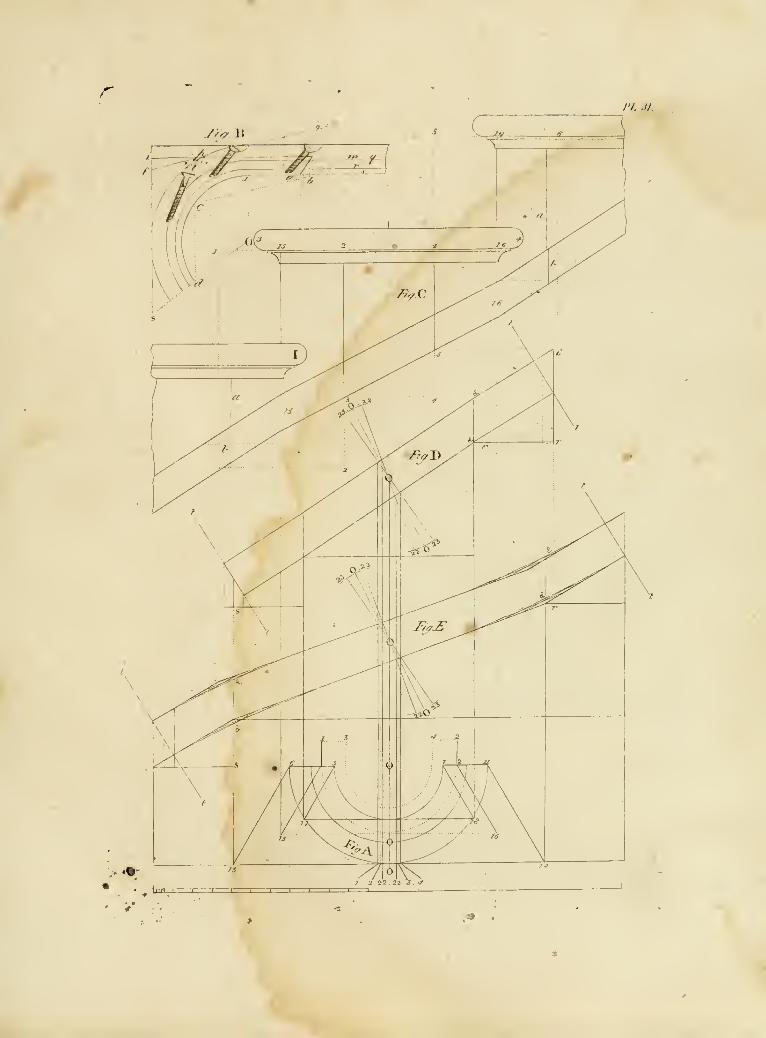
rPL ij.
jy</ \\
.»

J'I,.:J:
a
-S^i-:1 _... Cf ..._: ...cf_.., lb ._,._ jt) %r7- ._. fo 4 ., :b,:^,|:^^)g>j^


/>-/_'.
^ I «~^
//>/ /
J'L (.1.
4.^4 t. .1 isJ
/*
/„/J
/I,/ ,/.
_ .1 13 le n ^ ^.
r I I I !-T-T-i-i I r—T I ] —
L

¥ -
^

I'l. .11
/ /
fii/.i'.
T^/V^.^ \ ,
-... \k_.
y. v.
'
I v^'
Fttjk.
/ ,.;.-\
:\ .
/>.//


t
n.

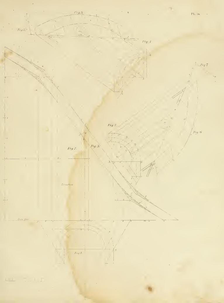


PL.;i7.


ri...;(!
J'li/.i'i.
»k -^v
/•'/</. //
."'- V
V
^

.*

iv:
j^t./ J
A
%


I-i,/JZ
/.•,,,/
I'l.m.
i/V/f
:^9M
r>,/ If".
I


!'l, 11
\-1—t-
/>// J v^j^.
\
VFT
I ' ' I I I ' I ' I ! I


rL.42.
/ -"
,c
^,4..
I '1 I I I T~r-r

"^

Fill :
11


J,Vi.Al.
D D Jl J D D Ji D :e: Ji .
J-r</ jf
r,,,
In,/!|r"
'^IrlKIF-lRi-m W"W
rii/.d.
y Ti i'lii s:
1 J 1


G K E C ] A M DO'E]C DJiDlR
rj-.i.').
rw.
BWSflS
'W '|S!ai'''iiil»«'i|P''i|il I
Wt7 '»i!t''''i;?'"fK^"''Cr-''5i;^^
jTvvip-^'^"
i-'
•Vj.'.i-
K'


J D J"^J J C D ii U £ jL PT.Kl.
I riiiinf^r^i-ji!_
IV..i;ill> I. Mil..- Ill;


n. 17
Jiipaffx


J jM J G D si D £ si.\'\.. V
nnr
^-
ir,v V ;4zi
*9'i
_^jmMMMxm
j^^~^iu =« z'fii m
s


/'/ii!,- /:'.
<c
TO
rr
o
\y^


I'l, .".().
I'luuknlilif lli-Mi> I'ainlMl ViMuliipl llir KnTih.Mis r,-i|.iinl.
::- Yf
h'tnuultlic Flank .
PhuL oV liif fl.uiK

- ^J

COilJ?]T>J JAjN DhDI.ji.i'l. :.i
ih
J
\ I- H [H i: ^j
.7. J
. J If
J If/ I
Fi,/ J
^I J4 {».
J 11 >A
. lliVs., 1 M 'It
smE^m^
IWT^Tfff^^r^
mUi U^
I s.
^
JJ)
n J V.
T?/
\ '"--C
/< \ z
Frniii 111.' .Mauiiment on.vsinales.nl AiIh


/ii)/,-i(' <>/{iu-:/; /,.,„ /y/A tiimi'I.i; i .i//\ /:/, i.i ,// ////a.i.v
V ''t?;
^rr
i»

. s 7'. : /// ' : I/'//: //. '>/<
' //// ' m^/,'a <v//m -/,'1*1. ."..{
/'./ill ,/'
\_
^t y/..I.V .rfi'f./'J/X „/ //,. .IViVA'

m

PLAN AND ELeVATICN OF A CHURCH.
CRECi AN IONIC ORDER.
~' r I
j>-^I
!>-3I
* i^^
I
"'-'
1


€
ri.:ir..

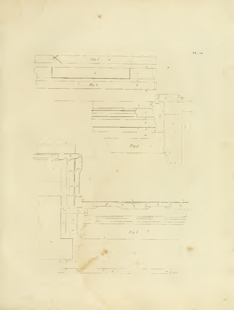
^ rt,/.j. ,i D
I'h r.(;.
ly,/. .?.
^ !
n
kJ
x^
^^
jF„f.2.
A 7
-^ X^^^JT^
7^
-FioJ. f
; V


Wtz^II T m
0>'%& <W <ii? o © I
fy
Pi..:.7
v.;'.^..i.v.f.v.n^.t.i-.^;.i).i.v.v.nj . :.,..'.y.,A...t.i.v.; ^iv.ii^.::A.u;viLt.ia.i'.a./,.;.y.v.A,'KiAf.iu,v,;jii-cv.te'
=^
i£/MM£&l£i^
w'&i'SiiiAf.y
usufulMMM
V^-n
-H

/'hi- / /-.'rf: t'''t;xiri-: t'\t: i J^ .i'y''/.-> n<f.\-i: /ii..:i /.'r,: (.•/..virji i-f/t .1 .' Sr,/.-) //./.,/:. /-"/,. J.y,
mif/
LKa{c.CO!e<S:SL'
l\^I^I\]/W:ktktktlA-m-tK1lL:
Oa(cic m:fic«a(c<
TTTwjinciricicioiaclc
»;,//
^Itf .' .VjTWV- Cl'K.T/CB >TV^ 75 7-C i-i^yT S-J\: j^«,4- Stttcoc Ci'mrjcs Tilt 12 ro /4f F'^ S'rt'jtT.
ii:,//
it:,//
m «C» IK.!K klU k IK Ji^anirwc^Mtds
m(. ;!i -M CK CR. ci.


it.y^i' \trn tii\t:s, 1 1 1 1 si/i 111; i-\i:ifni\
-v
j'y..;.'>.
J
M:rnniL\\i. f'lt runin mat . n .6. .i>.,.i.
_^//(// rj.A : rr si.idim; iuths ri.t.i
J #^^%,
_1 L-
*i'


/••///. I.
I. '.(I
/•"A
1
iS>
iI
!)K\ti;xs f/i/t i-\Hi.i>! i; itiiiins
liil'
1! li .


ri.-iii .
/>«,./ Fi^.Z.
Fi0. 6 Fiff.r.
m
ji-.r\
n-xh-TT-

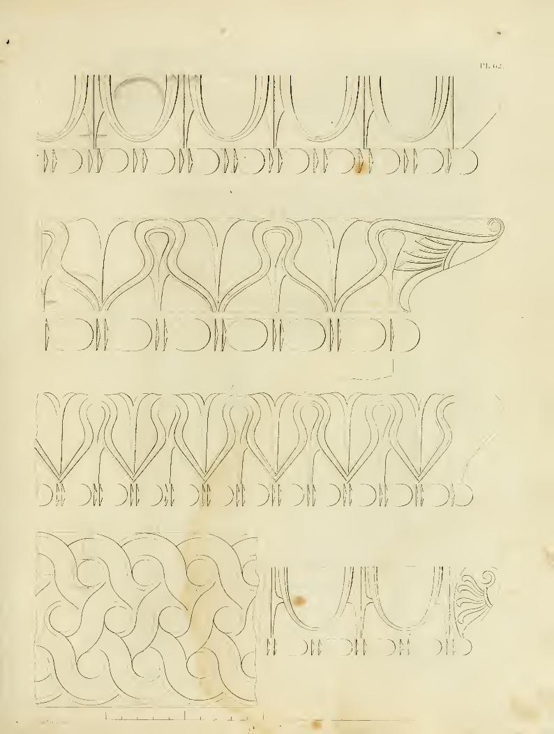
n.i.j
/>,/, /.
vmi

^:.

I'L ().',
(i;|iI||I[|Y;'^"""""^'"''""^
ii%1 fm.ii''/;iiiii;i:':i;ir';i:ii|||
iiw^^^^^
j-WW-''" 'llllllllll
/„««*„
LI ^ J J D ?J P' L* ;J >\ y si D n -r DDD 'A .

i'l.r, I.
MikiM^i^ywMiiyMiiiL^iiiyMa^iiA
iyi:^2.s:i«R^,
III
iiii
'iilj"iyi'i'!fpf!''' ')ii)ittiiiiiiiiimr>;!:witmi'i.i(Hy!ii(;i(iK(t'ii(w:iiii()tiHiitiiiiiiii
Nl'ii
iiiiii'iii".-ii;i' iMi'nii
i'HiiR'if iliiiiiliiiiiii lld^
...v
iij"ii!i'«!i III I
i
a©iJ^j§>MIII
lil!ii«"-l!IK IlilH III"- iiiiii, -^(ililiiii *,
'
I ,
mw
ii::a"'
iiii;;J»' ^.« iiO
llr.
|l|||llMlii;!!i
IliiUlMfliiiliiiiiiMiniiLKiiiiiii iiniiiniiiiii
,llil'i:iiiiiili|ilir'illlilll:iir;iir<,:''li'ii:imillllllllllillllill
V


I'l. (1
1.1 "i I'A;*
f
^^iSfT-i.-iLJUUULJLJUULJUUU U 'U U U^CT^
I II ^1I
. \
'l


I'!. C.t;
I:
- M I -"'i. I
^l-^ ,4,' -^1:^ si^ ^^' ^>!^.r- ^^,''r^C: -i/, ^>o 'i<c 'f-' -'\
u>
/<3?
V'
'!>,v',.-rj. fN.
§^
'J
-J
J


i>"r I'M! ini; !; i,i';v,\'i' i().^ i > !' A 'A i; i,ur k .\>'n i^'Udat ii a I.I, di joi; /'J..07.
r
'^mt;,;.f /-///« «//,/ /?,/»///..*-
'/' f/n tflff.* tif fiiffi /',//'/!/ i
'ttf/ t- fi/A'ft fiiw f/i. /*///*' m /..,/:.„


ii
3; I
I'l. li)!
Vr
i_

^fel*

a--- "t?*r^
n-^--^,Sgr-
kM^^
jj,--
@ @ -S
^^^_


II'
u
il^
-J
ri. -().
^/.77.-
TUTU
It.:Sff/to/i of Shiiz/i^ Iioo7'S
r
-^
PAKl-OT'K Sl.IDIXr. IMiOK.S
V'
..%

»
^
I'l.TI,
ci-

;
\\
J
\

•L.7t.

I
)

ri..T:5.
V.

;

P1.71.
I
/A
/I
I
-HiJam
r
tJ:i i---^
^
i
^i.

/'/, 7.;
f
ul
OzuJ
Q
liJ
cc
>-
cc
hz
ou
q:
Ou.
Zo
I-
<>uJ
I-
zoa:
\r

f
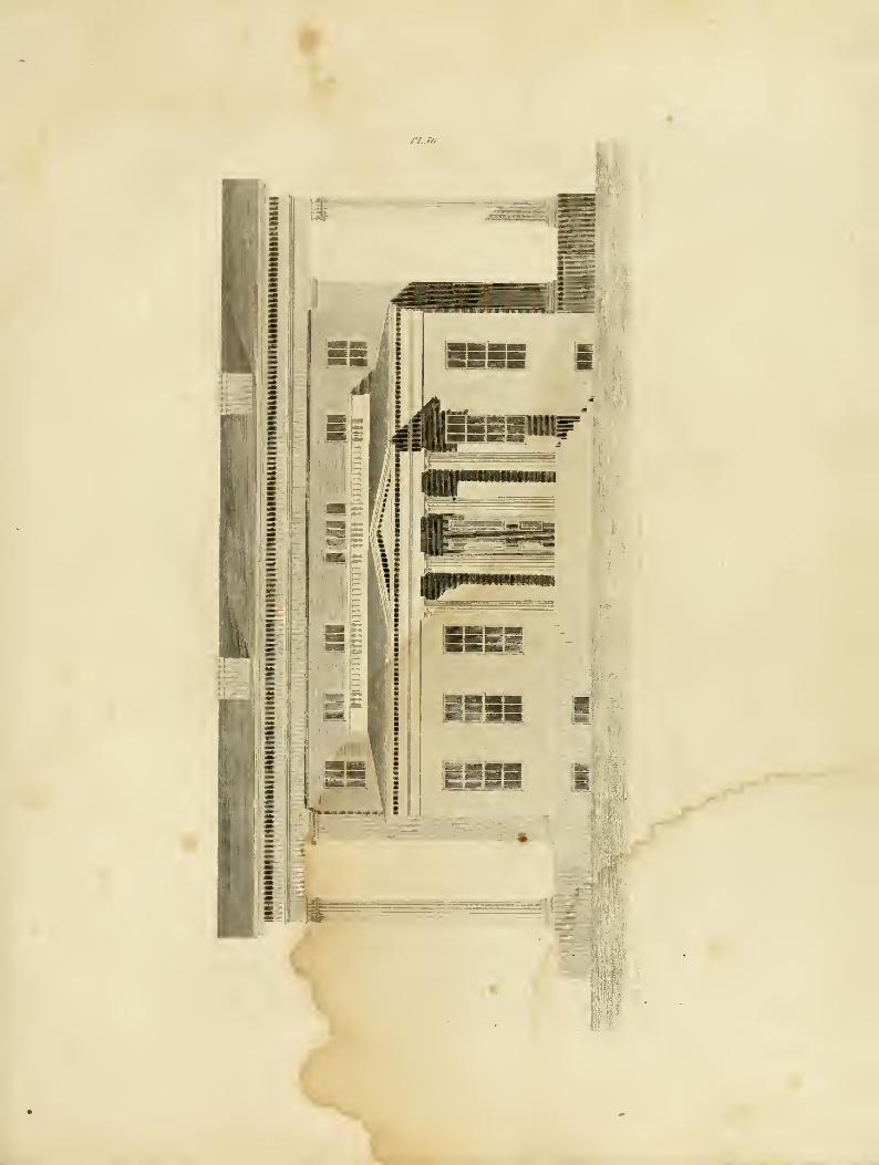
J'L.Tii
X

J

l'L.77.
Ol^
Vl^
=.^^<^xv
"^1 m^
or
I'll'
if
i:^Z2 :
)
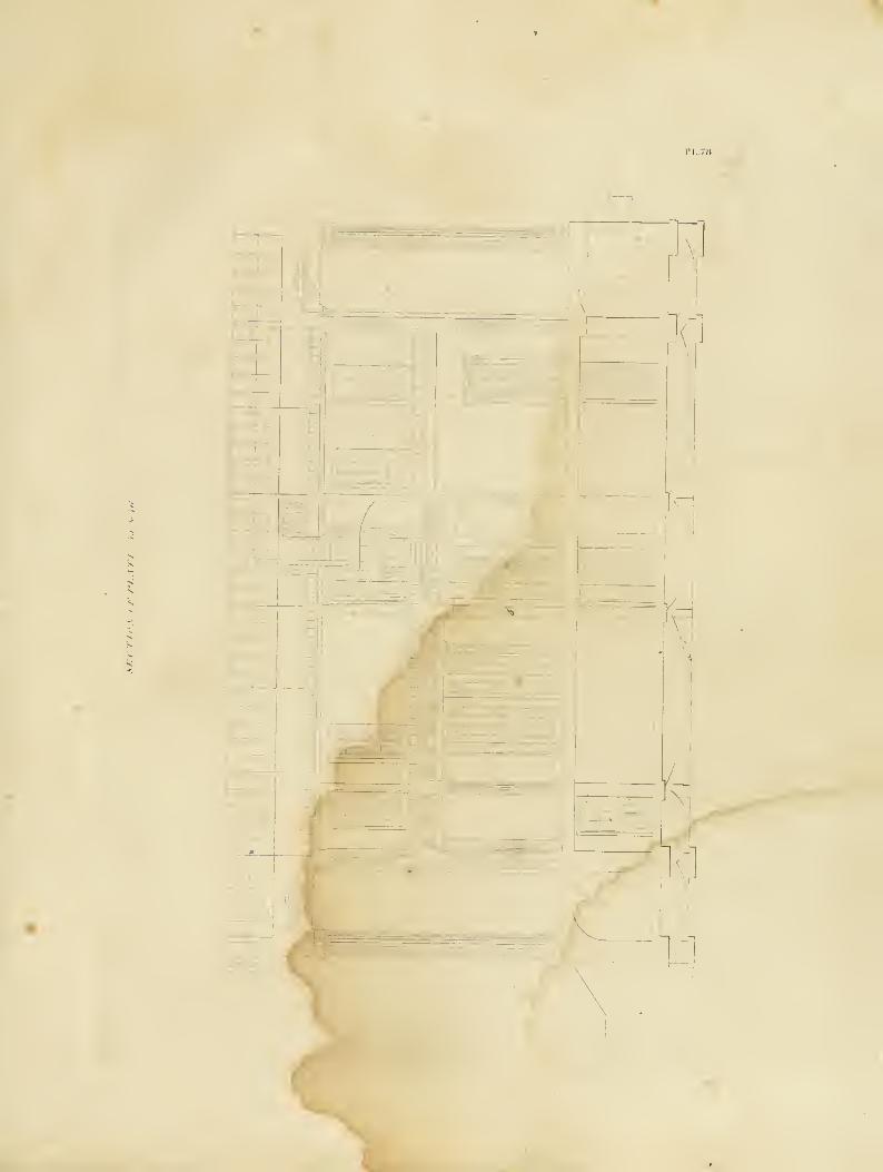
t A
Gl
-t- rr^HT^rH
.J VI
y\}.

y

ri.-n.
(-It
•I-^^-^
"IM

^
^

rr
L
LJ
I'l, .".D
H
u

)
)
\

'4.
'S
® ®I 1=1
3% Igi @ ® ^^ @=
t
-ffl <> ,o:>
i'
® @ sf^^
_^s: <Si a^
I'l.lll
"L''1

1
)
')
s

I'l. .'12.
'i
{
f
•' --——1-
K I, i; VAT! (> V OK I'AUl.iU I! 1 M ) 0>t .

h
1
1
/
/1^

/«/,», /,./.. «/,./>?,/.„ fiiU-z- ffi^HT^ ir.th,F f,l,i.,s .„/mff/if,,f >mt.iflfiriy^htns/fh,^. Jmh,.. ar, t,m.iri^,iflv nrat'iN.f .if,f.h..a/, h .,/,,!. r .,hJ ,nt>rt.^ ^• rK.tr.i.
tNiiititfrr mrtv It Ihin .> r< H //irhu
nr
/
/


/>// /
I'L 114
*Wr-=^? />./ ;
£11t
_^
-• * i \d
r'ti/.i.

)
;
)

I'l. :i:..
i;),'' ;,' ;, v ;',i ^ ')."}. V ;,' >: '),' )/ J, 'J,
'),' j: I' ') ). I ), jv ;, ;, / ); j, ;
j

;

IM. ii(>.
r T-
I !
'C^J
Z^
i"^
/
s
1 f

^
/
)
^

iM. .'i;
-I
V

J^
J
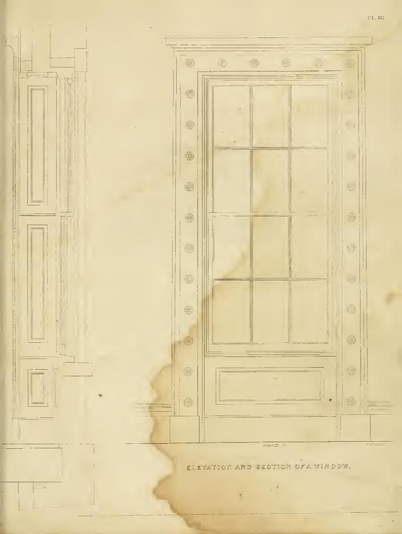
'I. Hi:
111
I
II! MHi
j_
' ' ''
1 '' ' ^-^^—1-<
£L£Y/.tjdj^: Aj^ix) -3£;dt].©>j dfa vyrjNUDvy.

1
7
\

rj.ii!).
COUNTRY RESIDENCE.
r

"N


:'ll V 'I I I I 1 11 1 ' ' I t I 1 I 1 1 1 1 I't'l'l' ' I
' '
•I'j'i'l'i'l'i'" ' ' li> 1,1 J
i'lViitii;,,,, 'i'l•^I'^l';ll'^!l; ! I !1 ' 'I'i'i'l'i
;i;!!l^i:i!!iiiiii:i:::! iiixiX'
ii'i'.ii*ii.' 'iijii * 1.11 li' 1.1 '
'
'''.''.'.'I'l'iS' V I V '1
1 'M',' ' ',' ' '
'1
' 1 i;i 1 1 1 1 1 1 1 1
1
^'^t'l'l'l'l'il'lil'ilwillllllillll'l'i'i'l'l'l'!'!'
il "'V'V ''''!'' 'I 111 Y ''•''>' V '''•''> >« I'll '111 V' v'l
V ' V ' 'Iv 1 > 11
11
1
1'l'i'i'iVi' V ' ''
1
1
'111 Ml 1 1 11'iii'i'i'i' iii;i;i 1
iili 1 1 1 1 1*11
1
'I'l'i' 'I'.t.i 1
!i;i::i!!;!i:ii!ii:i;
,i;ii;) :!'•'•"'- 1-11.
•i'M'I'i'i'l'MiI'i'M'W111111111111111'i:i i!i'i;i 1 1 1 1 1 1 1 ill
s' 1 ''
1 1 1 11 1 1 1
1 ' '
' 'i' 'I' 1'
1 1 11 > 1 1^^^^^v oy,' > M.I 1 1 ) i'
I III III I'lii 111 ii''"' I ''•'•' V 'I'll I'll III II 1
1 111 II iViViN' II 'I 'II I II 1^1 1 II 'III 'I'll1 II 11
1
1 1'
11 • 1 1
1 iv '
'
1 1
1 V 1 1 1
' |^ 11 iX I iS i' ' V 1 1 1 1 '
'1 1 1 1
1
'
1 1 II 11 11 '''II I II '1 1 1 1 1 II II I'l'*'' I' '1 11' II 11
'I I I I I I I 1 V '*'''''»''' I '''•'' I '1
1 ''•'' 'I I I I I
1 1 1 1 1 11 II
1
1'l'' ''I'll I'llI '111 1 11 1^^^| V v> I '1 1 1 1 II
1 1 1 11 l'l'l^''l^^| 1
1 1
'1 1 1 1 1 1 1 1'l I'i'i-n'i'
' '
''1" ' '
'1 1 1 1 1 1
1
'
i i! i i !Illiiii: ill
: i !i; i iiiiiiiili!^^^
N 1 11 I'll! N! V '
' v '' ' ' '
'
I
'1 1
1 |>|i;'X I
;
'V ' ' '
' V '
'
I 'X'X' 'I'li'.ilX!' '
'
X' ' 'X'X' ' ' W i I ixiliVlilll'lX'^-Xililiii 1 1 sbir' i'l'.'i'iYi'i'.'i'.'.'.'isi.'i'.'ii ' ''I'l'i'i'i'i'i'i'i" '
'
1
1"II 1 1 1 1 1 II
1
' '
' '
''i I
' 'X' 'X' ' il'lil'lilijiiili' '1 1 1
'1 1 1 1 1'llili'tli"*'
mRi ''X':'!'i':'ii;X":!:'X'"": x'i!|l!l!i:i::i:!';""""i!'i': ;':'!lii:l:':ii''''XO'iiii!|iXiii:'''''iii;irfl' ,'" ."X'X'X':"X";>:i!i 1
1!; X'X'l'l':' iXi";' iXiXlliiil'MiiiXi'' X' > 'X' • • '!l|i!!|!l'lXlX|X'Xi ' 'X>! i 'lllllllX' 'I'
,.'^:•™!';:xl!;xi;;!^i:;:;x:;XX xl!l:llXxXiXXXl!!t!l|li!l^l!l!^!li'^^^;'^l'l'|!!i!il:!;:';ill:i^xXx^^
i;:;xx:xxii ;!-1 :i
!i!
!i
! J^^^
i.vxiiiiiiiiiiiKiiiiiiiiSiSiiiiii'iii^^^
iiiiii.i;iiX.iiii.iii|''xll!:'!:i!:X'X!X':'^^.
,
1 1 1 1 1 1 1 1 . 1 , 1 , , , , , , , , , , ,,
A Xi,i,i,i,ij,i,mX/X' 'X'Xs'^I
'
I 'X> I 'X' ' ''
i 11iX'Xi 1 1 1
'1 1 1
1 I
' ' '
'X' 'X'X' ' ' ' '' 'X' 'I'X' 1^1^^^
" ' ' ' ' '
'iji ' '?|} I
'1 ' 1 1 1 ' ' 1 1 1 1 1 1 1 XiX'X' "
'1 1 1 1 1
1 1 1 1 1 11 0^
'!'^Xl I ' '
' >Xi 'X' ' > 1 1 1 1 1 1 1 1 1 1 1 lXl^ I'i'i' 'X' 'X' ' 'Xi 1 1 1'
I • 1 1 1'^oiXi 1
1iX'
'•
I • 'X' 'iX) I iX' 1
1iX 1 1
1 I r 'X'' ' ' ' 'X' I 'X' I
'
'11
' V IS' I'
I »I >Xi t > 1 1 1 1 1
1iXi 1
1'
' ' '
'I 'X' '
1
1i I
'1 1
1iXi 1 1^1
I 1 I ' I 11
t I 1^ I'l I iS'lS I'l I'l i*i'l ri) j'|l|i|i|lil,i|l'III
' iX' I I I' '^
I'XiiiXix; X
'IvX'l'X'Xil'X 1 1 1 ! ! i iXi I iXi ' ! :iX' I ' ' ' '
'
1 1 1
1il'iiXX
iijii ii : iiliil
';;!;;! iiSiigiii ill iiiggiiiiiiiiiiiaiiiiSliiiiiiliii ii; i ;i; iiilg
i^^
iiiiiiiSii iiiliiliiiiljii: iiiiiiiiiiii
i'l'i'i'ili'i'i'I I
"X"""" 'X''''i'lil'!il'X'!'!'X|i!llllX'''''''l''li!lil>;'lX'lX"X""i'"ii'>iiiiil.!,!X!!!X!X)iii
iiiii' '" 'I" I
'1
'
1
1
I'lVi' 'X' 11iiiii 1
1
!! ll"J""" iX"i"i'i' ' 'Xi 1 1 1 1 1'l 1
1
Vii,i,i i.i, ,1,1 1 I I
1 II1 111 1 11 1
1
I 1 ] I I'l 1 I'l'i^i^i'ii!i;i;i;iii;i!i;isiiiiiii:i iiiii i:
iiiiiiiii iiii!i!ii;iiS!i!i!;!i i
1 1 1' 'III' 'I'liXii'is'i'ii X ' I
' "
'X' 'X'Xi 'I V 1
1
V 1 11 ^|l^lllll•ll'
' ' ' '' '^v
ii
ii ii ;:; iiiP ii ii^
i I ii; iiiiiiiiiiiii^ I
|||,1||,1 1 1,1,1 1 1 1
1
I'll 'X" '1 11
::X:X!!:X:1';':'!':
Mil I 1 "11 I I 11
il'XiM'lililiJXiXiilX'X
¥ili:iiiii!i$i!iii!iiiiiii:;iiiiS';ift¥;!;ii$iii*i:i:i;i:!:i!i:i;i:;ii:i;;:i;i!i!:^
i iii iiiii iiiSiiiiiiiiii iiiiiiiiiiiiiiiiil^1 1 1 1 ; I'l 1 1 1'l'i'i l^^'l',| 1,1 1 1 1 1 1
'1 1 1 1 1 1 1 1 1 1 , 1
1
1'l i'1 1 1 1 1 1 1 '
'1
' 1 1 1 1 1 1 i'l
Xiliiil'liliI'l'XiXX'XXXiX'l'I'I'i't'X'I'X'l'X'i'X'X'''.''''•'' 'I 'I'll l^l''''^''^lXll'|^ I iiiiiiii
I'l''
'iXi '
'1 1 1 1
'I ilX 1 1'l i'i\'ii '
'
1 11'Xi
'1 1 1
1 > 1 1 1
1'
1 1 ''
I'
1 1 1 1 1 1 1 1 1'l'l'l'l'l'" I" I III 1 1 1 1 1 1 1 1 1 ' I'i'i'l'
ill'!'!: 'XiIX 1 1 1 1 X X XiX'Xi 1 1 1 1 1 1 1 . 1 1 1 1 1 iiXiXiXi
I'l'i'i'i'i'ii ' I
I 1 1 1 1 1 1 1 1 II;'X'l'^^X'^^^l'XX'^^l•xil'x; X '
: ' ' ' '
'^X'|||'|li'll^ll^;lX'^xs^,V 1
1Ml 1
1I I 1
11
11 1 1 1 1), , , I , I
,i,i,iiV,'1
1
1' 1 1
1 iX' I i!i X^
vX'iXv 1 11'I I' 1' 1 1 1 1 11 I i' '
''' '
'I'Xi V 1 1
'I
'1 1 1
1
111'''
j! ;;;;;; I ;¥;;¥: :;:;¥;:i!;!; iWiSiiiiSiiSSiiiiftii':? ViW;!;;::: Si :ii;i:i:!;¥i!i:i:i::!K:i :::!:;;!::!;!;;;;;!* iftiSiiiiiiiiii!i iiiii iiiiiiiiiiiiiiiiiiiiiiiiiiiiiiiii,
I'Xi iX''iX'
I ^:l!•l'l'l'Xl^l'i'^x 1 xxiX'X'X' 'X'X' ' '^ ' ' '^X'l'l'X'XXl'!•!Xl I i
' '
'
iiiiliilM^
'
'1 1 1 1
'1 1 1 1
1 iXi I iWi 1 1 1 1 iV ')' ' ' ' ' 'X' I iX' 1 iXi^^
,v. ' V o'l 1 1 1 1
' ''
' 'Xi ' iX' I iX' 'X^Xi X 1i 1 1:!: : :!'l!XjX'X> !W! • 1
liii iiiii iiiiiiiiiii:iiiiiiiii!i!i!iiiii:i!i!i XIXIXlX
i!!:!!i:;;i! 1: i!i;iii!i!:;; ;i;i^^
1 !!! I
i
lil'I'iJl !
1'
1 11 1 > I 1 1 i!i iti
llllllllllllI
1 1 1 1 1 1 1 ll'l 1 1 1 1'l'l)
'ili'ililX: ; iX'X"Xi" .!«li|i!X!.!i!i
> ! ! ! • 1 1" i > i 1 1 ill
1,1 1 1 It II I'l 1
1
' 'i'll > 111 1 I l.l.l I