The Millennium IGU: Regenerative Concept for a 1000-Year Insulated Glass Unit
17
The Millennium IGU: Regenerative Concept for a 1000-Year Insulated Glass Unit Mic Patterson University of Southern California School of Architecture Advanced Technology Studio-Enclos USA Ben Silverman Island International Exterior Fabricators, USA Karen Kensek University of Southern California School of Architecture USA Douglass Noble University of Southern California School of Architecture USA Abstract Glass is a ubiquitous material in the built environment. But over the past few decades the use of unprocessed float glass as a façade material has virtually disappeared. Raw float glass is a remarkable material not only for its transparency and optical properties, but also for its durability and recyclability. It will last indefinitely in the building façade, until removed or broken, at which time it can be recycled into virgin material with relative ease, improving the energy efficiency of the float line in the process. Unfortunately, post-consumer architectural glass is not recycled, at least partially because the secondary processes—coating, laminating, insulation—render the practice impractical. In addition, the insulated glass unit (IGU) has an average lifespan of only around 30- 40 years, effectively collapsing the durability of architectural glass by at least an order of magnitude—from centuries to a few decades or less. Such realities are seldom questioned or discussed; yet they grow unacceptable as civilization steps towards a sustainable built environment. These issues are explored herein, and a concept is presented for an insulating glass assembly that poses no compromise to the recyclability or durability of float glass and optimizes the lifespan of the IGU. The concept is intended to illustrate an alternative way of thinking about the challenges presented by the pursuit of green building practices. Keywords: insulated glass, IGU, double-glazing, durability, curtainwall, embodied energy 1 Introduction Net lifecycle performance gains are conceptually possible through the adoption of maintenance and renovation planning that increases the durability of buildings and building systems. Such a premise mandates the design of buildings and building systems that facilitate the maintenance and renovation process. Current practices do not support this. There is considerable urgency in moving toward a more sustainable and resilient building sector, yet the required technology and know-how to accomplish this are largely unavailable. Pervasive innovation is
Transcript of The Millennium IGU: Regenerative Concept for a 1000-Year Insulated Glass Unit

The Millennium IGU: Regenerative Concept for a 1000-Year Insulated Glass Unit Mic Patterson University of Southern California School of Architecture Advanced Technology Studio-Enclos USA
Ben Silverman Island International Exterior Fabricators, USA
Karen Kensek University of Southern California School of Architecture USA
Douglass Noble University of Southern California School of Architecture USA
Abstract Glass is a ubiquitous material in the built environment. But over the past few decades the use of unprocessed float glass as a façade material has virtually disappeared. Raw float glass is a remarkable material not only for its transparency and optical properties, but also for its durability and recyclability. It will last indefinitely in the building façade, until removed or broken, at which time it can be recycled into virgin material with relative ease, improving the energy efficiency of the float line in the process. Unfortunately, post-consumer architectural glass is not recycled, at least partially because the secondary processes—coating, laminating, insulation—render the practice impractical. In addition, the insulated glass unit (IGU) has an average lifespan of only around 30-40 years, effectively collapsing the durability of architectural glass by at least an order of magnitude—from centuries to a few decades or less. Such realities are seldom questioned or discussed; yet they grow unacceptable as civilization steps towards a sustainable built environment. These issues are explored herein, and a concept is presented for an insulating glass assembly that poses no compromise to the recyclability or durability of float glass and optimizes the lifespan of the IGU. The concept is intended to illustrate an alternative way of thinking about the challenges presented by the pursuit of green building practices. Keywords: insulated glass, IGU, double-glazing, durability, curtainwall, embodied energy
1 Introduction
Net lifecycle performance gains are conceptually possible through the adoption of maintenance and renovation planning that increases the durability of buildings and building systems. Such a premise mandates the design of buildings and building systems that facilitate the maintenance and renovation process. Current practices do not support this. There is considerable urgency in moving toward a more sustainable and resilient building sector, yet the required technology and know-how to accomplish this are largely unavailable. Pervasive innovation is

required throughout the building process, from design practices to materials, products, and construction methods. Innovation requires different ways of thinking, questioning the conventional manner of doing things, consideration of ideas that may seem unrealistic or impracticable. One specific area that bears consideration is the insulated glass unit (IGU), a ubiquitous component of commercial building facades since the 1980s. Alternative means of providing the functionality of the conventional IGU while mitigating the undesirable lifecycle impacts associated with its production, use, and disposal are possible. Design methods developed within this context may be applicable to a broader range of challenges presented by the built environment. Specific metrics for durability and recyclability of IGU’s were chosen as development goals as these attributes are problematic in conventional insulated glass products. A first objective is for 100% recyclability of all materials used in the unit design. A second is the adoption of a 1000-year service life. Kesik comments that building structural systems are engineered to perform for the long term, with precedents pointing to a typical service life of “several hundred years.” He further remarks that, “the skins of buildings are ideally intended to last the life of the whole building, in particular its structure, or skeletal system.” [1] Given the massive investment of resources characteristic of large residential and commercial buildings, this typical structure lifespan has been deliberately stretched to a goal of 1000 years. The IGU concept developed here has therefore been designated the millennium IGU, or M-IGU. These goals are embraced as design constraints that demand a different way of thinking about the problem of providing a highly insulative glass assembly that is sustainable in terms of lifespan and recyclability.
2 The Problem With the IGU
The highly glazed façade is largely a product of the advent and widespread adoption of curtainwall technology in the mid twentieth century. Early curtainwall buildings were single glazed. Energy was cheap, and the building types were generally office buildings occupied only during the workday. Consequently, energy efficiency was only a minor consideration. It was not until after the first oil crisis in the early 1970s that a widespread adoption of IGUs commenced. The IGU is a strategy to improve the insulative value of the glazing unit by capturing a hermetically sealed cavity between two pieces of glass. The production process involves separating two panes of glass with a continuous perimeter spacer and seal (Figure 1). In addition to the insulating cavity, the IGU construct provides protected interior surfaces for the application of the many performance coatings produced by the glass industry over the intervening decades.
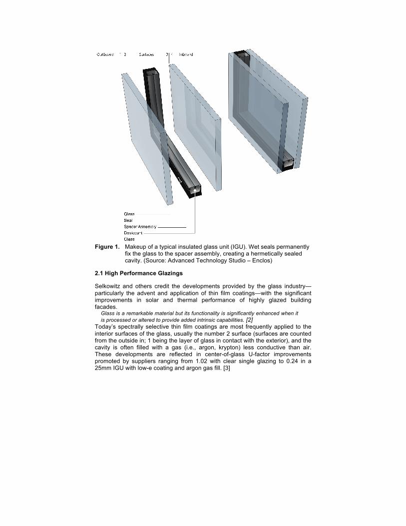
Figure 1. Makeup of a typical insulated glass unit (IGU). Wet seals permanently
fix the glass to the spacer assembly, creating a hermetically sealed cavity. (Source: Advanced Technology Studio – Enclos)
2.1 High Performance Glazings
Selkowitz and others credit the developments provided by the glass industry—particularly the advent and application of thin film coatings—with the significant improvements in solar and thermal performance of highly glazed building facades.
Glass is a remarkable material but its functionality is significantly enhanced when it is processed or altered to provide added intrinsic capabilities. [2]
Today’s spectrally selective thin film coatings are most frequently applied to the interior surfaces of the glass, usually the number 2 surface (surfaces are counted from the outside in; 1 being the layer of glass in contact with the exterior), and the cavity is often filled with a gas (i.e., argon, krypton) less conductive than air. These developments are reflected in center-of-glass U-factor improvements promoted by suppliers ranging from 1.02 with clear single glazing to 0.24 in a 25mm IGU with low-e coating and argon gas fill. [3]

3 Unintended Consequences
The unintended consequences upon glass of the processes and alterations referenced by Selkowitz are twofold: first, the collapse of service life and wasted durability, and second, the float material is rendered unrecyclable. These combine to effect embodied energy. The primary focus of green building has long been reducing energy consumption during the operational phase of building lifecycle. The widespread application of low-e and spectrally selective coatings on the surface of IGUs has become a common solution for high-performance building facades. There are energy efficiency gains resulting from the solar and thermal control provided by these high-performance glazings when considering a building’s operational phase. [4] The emerging practice of lifecycle assessment (LCA) is bringing growing recognition that there is more to it than just operational energy considerations. [5]
3.1 Embodied Energy
A building begins its occupancy phase with an accrued energy debt—referred to as embodied energy—comprised of the energy consumed in material extraction, processing, manufacturing, transport, and erection activities involved in constructing the building. Added to this accrued energy debt is the embodied energy resulting from maintenance, renovation, and disposal, over the lifespan of the building. LCA is a strategy to account for this energy debt and the environmental impacts associated with embodied as well as operational energy. While embodied energy is of a lesser magnitude that operational energy in a typical building lifespan, the ratio of embodied energy to operation energy increases as operational energy consumption is reduced through high-performance design strategies and the use of increasingly energy efficient technology. In short, embodied energy and the associated impacts are becoming an increasingly important consideration of the green building dialogue.
3.2 Durability and Service Life
Durability is a primary factor of the embodied energy equation; associated impacts are reduced as they are spread over a longer timeframe. Service life is the measure of durability in buildings and the systems that comprise them. The concept of differential durability recognizes that buildings and building systems are assemblies typically comprised of subassemblies and components, and that the service life of any system may be limited to its least durable component. [6] The least durable component of an IGU is generally the perimeter sealant that provides the hermetic seal of the cavity. The failure of an IGU is most commonly caused by air leaking into the cavity bringing moisture that results in condensation, fogging, and oxidation of aluminum and metal oxide coatings, and airborne particulates that result in deposits on the interior glass surfaces. Occasionally even mold can develop within the cavity. While this may not constitute catastrophic failure of the product from a performance standpoint, it reduces service quality to the extent that replacement is often implemented for aesthetic reasons, thereby limiting the service life of the product. [7] [8]
3.3 Service Life Collapse and Wasted Durability
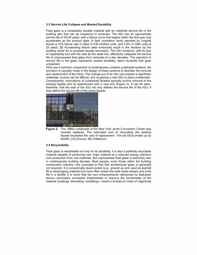
Float glass is a remarkably durable material with an indefinite service life in the building skin that can be measured in centuries. The IGU has an approximate service life of 30-40 years, with a failure curve that begins within the first year and accelerates as the product ages. A field correlation study reported by Lingnell shows a 14% failure rate in class C+CB certified units, and 3.6% in CBA units at 25 years. [9] Accelerating failure rates eventually result in the decision by the building owner for a complete façade renovation. The IGU construct, with its lack of repairability and with the seal as the weak link, effectively collapses the service life of unprocessed float glass from centuries to a few decades. The reduction in service life in the glass represents wasted durability: latent durability that goes unrealized. IGUs are a common component of contemporary unitized curtainwall systems. No provision is typically made in the design of these systems to facilitate the removal and replacement of the IGUs. The change-out of an IGU can present a significant challenge; access can be difficult, and re-glazing a new IGU in place problematic. Consequently, renovations of curtainwall facades typically involve removal of the existing façade and its replacement with a new one (Figure 2). It can be seen, therefore, that the seal of the IGU not only defines the service life of the IGU; it may define the service life of the entire façade.
Figure 2. The 1980s curtainwall of the New York Javits Convention Center was
recently replaced. The estimated cost of renovating the existing façade exceeded the cost of replacement. The old IGUs ended up as landfill. [10] (Source: Mic Patterson)
3.4 Recyclability
Float glass is remarkable not only for its durability: it is also a perfectly recyclable material capable of producing new virgin material at a reduced energy premium over production from raw materials. But unprocessed float glass is extremely rare in contemporary building facades. Most people—even those within the building construction industry—are surprised to find that architectural glass is generally not recycled. It is occasionally down-cycled (e.g., ground up and used as asphalt fill or landscaping material) but most often enters the solid waste stream and ends life in a landfill. It is ironic that the very enhancements referenced by Selkowitz above—secondary processes implemented to improve the functionality of the material (coatings, laminating, insulating)—result in at least an order of magnitude
collapse in durability and render the material unrecyclable. These considerations tend to necessarily broaden the definition of performance.
4 Design Assumptions for the M-IGU
The use of high performance glazing products have contributed positively to energy savings and thermal comfort in buildings, but durability and recyclability are fundamental sustainability attributes that should not be ignored. Yet the current design of the IGU puts thermal and solar performance into opposition with durability and recyclability. What alternative design strategy could equal or better the performance benefits of coated glass while using unprocessed float glass, resulting in no compromise to durability or recyclability of this primary material?
4.1 Service Life
The glass industry has been working toward establishing a service life of 40 years for IGUs. Recently, there has been talk of doubling that goal, certainly an ambitious undertaking with the current IGU design configuration. The question remains, however, as to whether even that is adequately ambitious in the context of achieving a sustainable built environment, especially without a clear solution to the recycling limitations. Conventional assumptions about durability are commonly inadequate, and doubling the current IGU service life, while certainly helpful, may undershoot the need as well as the potential. It reduces but does not dispense with the wasted durability of the current IGU, and does nothing inherently to establish recyclability of the product. An entirely new approach may be required if current high performance systems are to be transformed to the sustainable systems of tomorrow. Adopting constraints, even seemingly insurmountable constraints, may sometimes provide the motivation needed to alter mindset.
4.2 Constraints are Good
The following design constraints are adopted for this exercise: • the use of unprocessed float glass. • the use of fully recyclable materials. • service life – 1000 years (effectively indefinite).
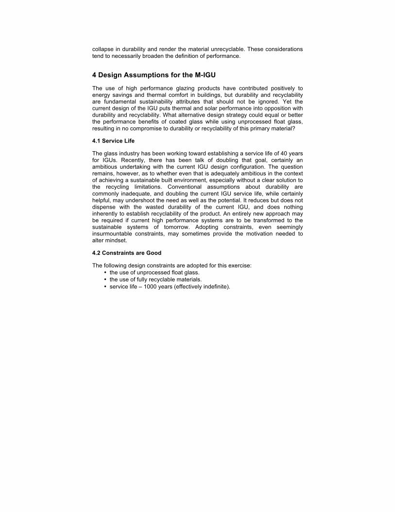
5 Makeup of the M-IGU (Figure 3)
Figure 3. Concept sketches for the M-IGU. (Source: Mic Patterson)
5.1 Material
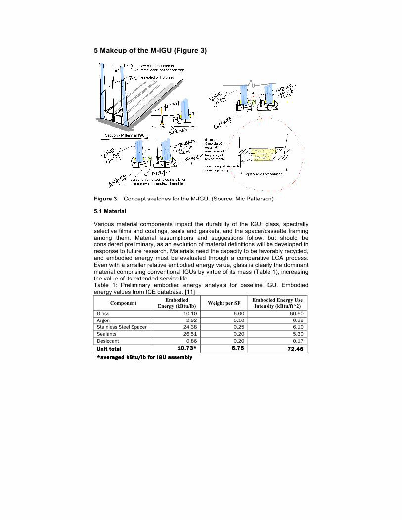
Various material components impact the durability of the IGU: glass, spectrally selective films and coatings, seals and gaskets, and the spacer/cassette framing among them. Material assumptions and suggestions follow, but should be considered preliminary, as an evolution of material definitions will be developed in response to future research. Materials need the capacity to be favorably recycled, and embodied energy must be evaluated through a comparative LCA process. Even with a smaller relative embodied energy value, glass is clearly the dominant material comprising conventional IGUs by virtue of its mass (Table 1), increasing the value of its extended service life. Table 1: Preliminary embodied energy analysis for baseline IGU. Embodied energy values from ICE database. [11]
Component Embodied Energy (kBtu/lb) Weight per SF Embodied Energy Use
Intensity (kBtu/ft^2) Glass 10.10 6.00 60.60 Argon 2.92 0.10 0.29 Stainless Steel Spacer 24.38 0.25 6.10 Sealants 26.51 0.20 5.30 Desiccant 0.86 0.20 0.17 Unit total 10.73* 6.75 72.46 *averaged kBtu/lb for IGU assembly
5.2 Glass
Annealed or heat strengthened glass is used with the M-IGU, without coatings or lamination to assure optimal ease of recycling. The use of annealed glass would provide for greater ease of reuse, as the material could be recut to smaller size to fit a new application. Thermal stresses may require the use of heat-strengthened glass, which cannot be cut after heat treatment. In any case, the use of unprocessed float glass, or minimally processed heat strengthened glass, without the application to the glass surfaces of coatings, laminates, or sealants, eliminates all technological barriers to reintroducing the material to the float process for the production of new material, thereby rendering the glass in the M-IGU fully recyclable.
5.3 Films and Coatings
The strategy here is to keep the coatings from being applied directly to the surfaces of the glass lites. Instead, the coatings are applied to a film suspended within the cavity of the IGU. A precedent for this is the Heat Mirror product, which claims a U-factor as low as 0.05 for a multiple film application. [12] The solar and thermal improvements result in part from the spectrally selective coatings, and part from the cavity partitioning provided by the suspended films, similar in effect to a triple or quadruple glazed IGU, but without the added weight (triple glazed IGUs are 50% heavier that conventional products) and dimensional thickness resulting from additional glass layers. Suspended film IGUs were used in the recent renovation of the Empire State Building. [13]
5.3.1 Durability Harmonization In any case, the durability of the film would not limit the durability of the M-IGU assembly. The film is envisioned as being loaded in a cartridge within the assembly cavity that can be removed, new film installed, and the cartridge replaced. Thus, neither the service life nor the recyclability is compromised by the application of a coating to the glass surface. It is conceivable that coated glass is someday widely accepted by float producers for reintroduction into the float process. Some claim that thin film oxides readily burn off from the glass melt, and there are reports that some producers do recycle coated cullet. Such developments could render the use of coated glass as a viable consideration supporting the goals of this conceptual exercise. There is, however, still the problem of the durability of the film limiting the service life of the glass.
5.3.2 New Tech Ready The suspended film strategy as suggested in the M-IGU has the additional benefit of readily adopting the advances in material science so frequently produced by industry over the past three decades. The use of new high-performance low-e coatings could be accommodated simply by changing out the suspended film cartridge, as opposed to changing out the entire IGU, or in the case of unitized curtainwall systems, replacing the entire façade system, a formidable barrier to the adaption of new glazing technology.
5.3.3 Recycling the Chemical Soup The polymer film with various metal oxide coatings will likely present a recycling challenge to the chemical industry, but one that should be more manageable owing to the separation of the coatings from the glass and the material handling benefits thus provided. However, the viability of this approach as a recycling strategy requires further research.
5.4 Compression gaskets
Wet-applied sealants do not promote ease of maintenance, and are at least part of the reason that the glass in IGUs ends up as landfill. Therefore, compression gaskets are used as an alternative means to provide the seal for the M-IGU. The dry gaskets accommodate the partial disassembly and reassembly of the M-IGU for maintenance purposes.
5.5 Cassette frame
The cassette frame is key to the M-IGU. It combines the primary functions of spacer between the glass lites, replacing the conventional IGU spacer, while also providing a minimal frame designed to facilitate the installation and removal of the IGU from a curtainwall unit.
5.5.1 The cassette frame provides the following functions in sum: • separates the glass lites to create the air cavity using an integral
suspended film cartridge. • holds the compression gaskets that provide the seal to the glass lites,
thereby sealing the cavity between the lites. • holds the pressure equalization filter that links the cavity to the ambient
atmosphere. • holds the suspended film(s) cartridge with spectrally selective coatings. • accommodates partial disassembly for maintenance of the interior cavity
and components. • facilitates the installation and removal of the entire assembly within a
curtainwall module.
5.5.2 Materiality The cassette frame is conceived as an assembly built up from extruded, coextruded, or pultruded plastic rails. Various adhesives are available to join the framing members at their corners. Plastics provide the advantage of low thermal transfer, the reason for their application as thermal breaks in the aluminum extrusions that comprise conventional curtainwall units. The use of thermoforming plastics would present advantages in material recyclability. Multiple material types can be configured within the same section using a co-extrusion process as a means to optimize performance attributes. Alternately, wood could be considered as an appropriate framing material, perhaps as part of a composite assembly that incorporated more moisture resistant materials in surfaces directly exposed to the exterior environment or at likely areas of condensation.
5.5.3 Mechanisms The cassette frame incorporates two important mechanisms not developed as part of this conceptual exercise. The first compresses the seals between the glass and the spacer component (suspended film cartridge) of the frame, and is indicated in the sketch (Figure 3) as a perimeter capture that screws into the frame. It is also easily conceived as discontinuous clamp plates screwed to the frame with a snap cover plate. More elaborate mechanisms may be considered, like a hinged frame subassembly for the inboard lite that would allow for easy opening of the IGU assembly and could facilitate ease of interim maintenance. The benefits of a more elaborate approach to facilitate ease of maintenance would have to be carefully balanced against added cost and complexity. The second mechanism provided by the cassette frame facilitates the primary cassette function: the easy installation and removal of the IGU assembly within a modular unit of the curtainwall system. One of the significant shortcomings of contemporary curtainwall systems is the challenge presented by post-production removal and installation of an IGU, thereby limiting the design quality and even the service life of the curtainwall system to that of the IGU. Cassette strategies afford the opportunity to adopt new glazing product developments without the need to replace the entire façade system. This is a highly desirable attribute as the development of higher performing products accelerates and the uptake of these emergent products becomes vital to increasing the performance of the building sector. While other design strategies are possible, one precedent is found in the use of toggle glazing systems, in which a toggle mechanism is used to fix the IGU within the curtainwall framing systems. [14] In this concept, the cassette frame could facilitate a toggle connection between the IGU and the curtainwall module into which it is fitted. A gasket seal would also be required between the cassette frame and the curtainwall unit as indicated in Figure 3.
5.5.4 Resilience Attribute The ability to change out an entire M-IGU assembly with relative ease and rapidity is an important resilience attribute. Storm damage to the glass caused by high wind or impact from airborne debris, or manmade damage resulting from forced entry or vandalism, can be quickly replaced with relative economy. In comparison, IGU replacement in conventional curtainwall systems will typically require the complexity of façade access from outside the building, and present a removal and replacement challenge depending upon the curtainwall unit design, which typically fails to anticipate this eventuality. [15]
5.6 Vented Cavities in Façade Systems
Vented vs. unvented: Earlier researchers explored the potential advantages of a vented IGU cavity. [16] As a precedent, vented shadowbox constructs are used in contemporary curtainwall systems in spandrel areas. The practice is controversial, with some designers preferring the use of unvented variations. [17] The biggest problem with vented shadowboxes is the lack of easy access for cleaning if moisture and particulates in the cavity negatively effect the appearance of the façade. The debate takes place with the assumption of zero-maintenance. Maintenance access to the spandrel area is complicated by the floor slab, mechanical systems, and interior finishes that typically occupy this
zone. Setting the aesthetics of the all-glass façade aside, the spandrel area is an excellent opportunity for a highly insulated, low maintenance, rain screen panel system. This would lower the window-to-wall ration, affording the benefit of an improved façade system U-factor and providing enhanced building resilience and energy efficiency.
5.6.1 Consideration of a Vented IGU The advantages of a vented IGU include:
• the elimination of pressure differentials significantly reduces stresses on the cavity seals, virtually eliminating the likelihood of the seal discontinuities that compromise service quality and service life.
• elimination of visual distortion in the IGU caused by the bowing—or “pillowing”—of the IGU resulting from the pressure differential inside and outside the cavity.
• pressure equalization cycles allow any moisture that enters the cavity to dry out.
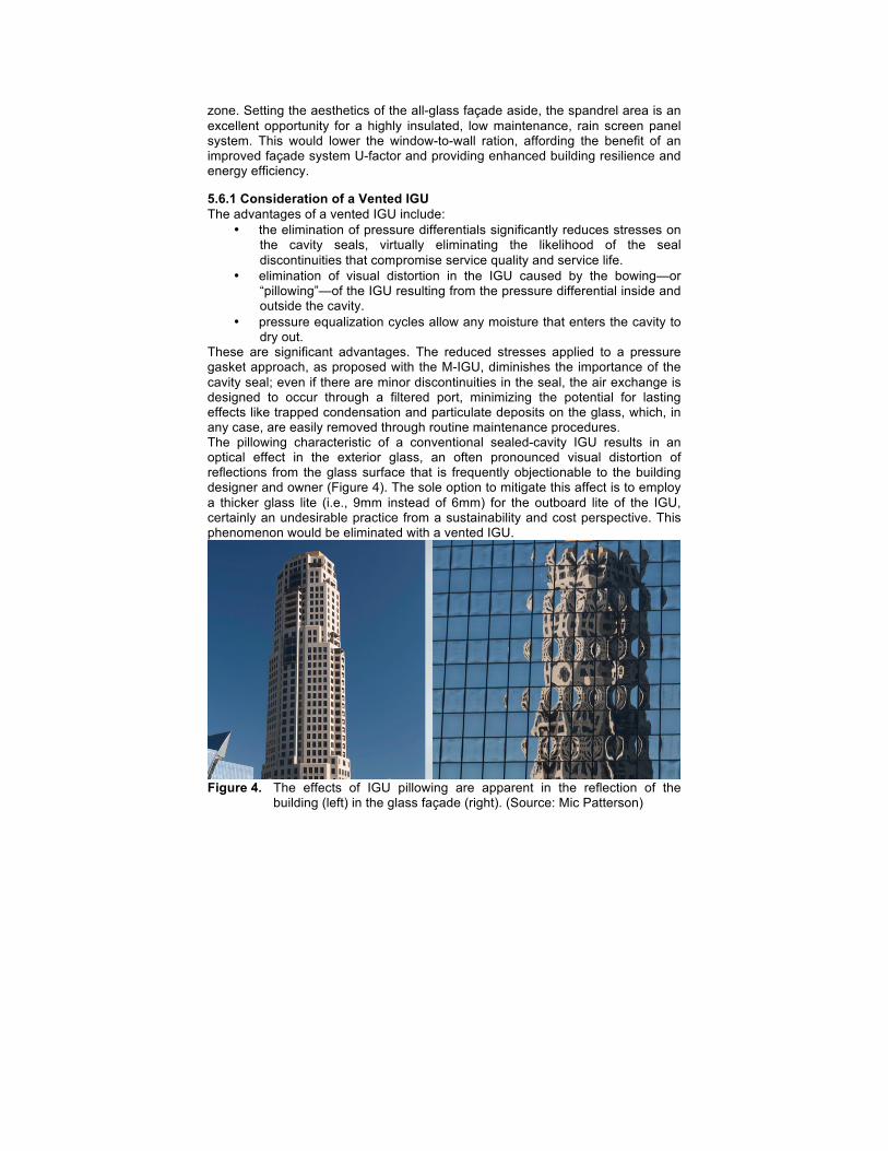
These are significant advantages. The reduced stresses applied to a pressure gasket approach, as proposed with the M-IGU, diminishes the importance of the cavity seal; even if there are minor discontinuities in the seal, the air exchange is designed to occur through a filtered port, minimizing the potential for lasting effects like trapped condensation and particulate deposits on the glass, which, in any case, are easily removed through routine maintenance procedures. The pillowing characteristic of a conventional sealed-cavity IGU results in an optical effect in the exterior glass, an often pronounced visual distortion of reflections from the glass surface that is frequently objectionable to the building designer and owner (Figure 4). The sole option to mitigate this affect is to employ a thicker glass lite (i.e., 9mm instead of 6mm) for the outboard lite of the IGU, certainly an undesirable practice from a sustainability and cost perspective. This phenomenon would be eliminated with a vented IGU.
Figure 4. The effects of IGU pillowing are apparent in the reflection of the
building (left) in the glass façade (right). (Source: Mic Patterson)
5.6.2 Gas Fills A vented cavity prevents the use of low conductivity gas fills like argon and krypton commonly used in high-performance glazing products, but the M-IGU also eliminates the need for such gases, as effective U-factors are achievable without them. Service quality is enhanced in the process, as the performance of the gas fill is easily compromised by minor discontinuities in the hermetic seal of an IGU.
5.6.3 Cavity Ventilation Filter Cavity ventilation is actualized through a filtered port to outside air (Figure 3). The filter material and the size of the port are important design considerations to be determined in future development. The port size should be just large enough to facilitate pressure equalization. The filter should accommodate air passage while trapping particulates and blocking moisture. There are a number of material options for this application with varying behavioral characteristics. Accelerated environmental testing of a mockup or prototype will be required to determine the optimally suited material. The filter would be designed for easy removal and replacement from within the building. The used filters should have the capacity to be cleaned and reused, or recycled, depending upon the filter material employed.
6 Maintenance as a Strategy for Renewal
Order of magnitude service life increases demand a reevaluation of maintenance as a strategy for renewal and regeneration, but maintenance has its own impacts that must be considered.
6.1 Minimizing the Impact of Maintenance
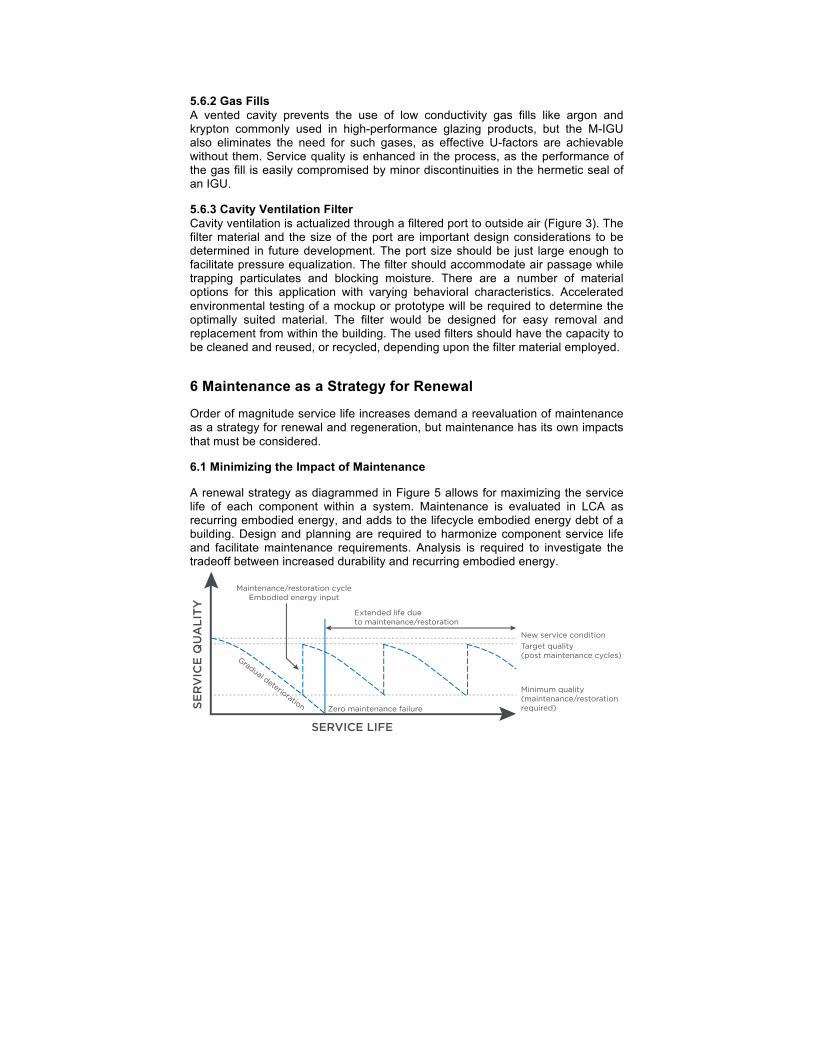
A renewal strategy as diagrammed in Figure 5 allows for maximizing the service life of each component within a system. Maintenance is evaluated in LCA as recurring embodied energy, and adds to the lifecycle embodied energy debt of a building. Design and planning are required to harmonize component service life and facilitate maintenance requirements. Analysis is required to investigate the tradeoff between increased durability and recurring embodied energy.
SER
VIC
E Q
UA
LITY
SERVICE LIFE
Maintenance/restoration cycleEmbodied energy input
Target quality(post maintenance cycles)
Minimum quality(maintenance/restorationrequired)
Gradual deterioration
Extended life due to maintenance/restoration
New service condition
Zero maintenance failure
Figure 5. A renewal strategy using maintenance and restoration (only as needed) as a strategy to extend service life and minimize differential durability. (adapted from Kesik. [18])
Maintenance can also enhance system performance, however, resulting in improved operational energy efficiencies. The aging of air and water seals in unitized curtainwall systems certainly has the potential to compromise performance. Identifying and remedying such a problem presents a considerable challenge, as the seals are concealed from inspection, and impossible to repair in any case. If such systems are to be designed for durability, seals must be easily inspected and replaced as required. The same must be true of the components that comprise the façade system, thus the IGU must incorporate seals that are accessible and replaceable. The maintenance strategy with the M-IGU is threefold:
• balance maintenance requirements to maximize service life while minimizing recurring embodied energy.
• facilitate ease of maintenance through product design. • focus on minimal maintenance provided on an as-needed basis. • maximize the lifespan of each component within the assembly to
minimize the effect of differential durability.
6.2 Maintenance Planning: Procedure and Cycle
The actual maintenance requirements for the M-IGU are the most critical unknown, so a conservative approach has been taken in their accommodation. While mechanisms are not detailed, strategies for both incremental maintenance and complete unit replacement have been incorporated, although the incremental maintenance holds the potential to render the complete unit removal an unnecessary redundancy. Unlike conventional IGUs and curtainwall systems, all component parts are intended for easy inspection and replacement, most especially those critical to performance and/or subject to wear, or simply of lesser durability, as with the various seals and suspended films.
6.3 Ease of Maintenance
The assembly is to be designed so that all maintenance procedures can be actuated from inside the building, avoiding the necessity of accessing the façade from the exterior, a generally favorable attribute with high-rise buildings. Maintenance access is provided through the temporary removal or displacement of the inboard lite. Only the replacement of the outboard lite and the inspection and replacement of the seals between the cassette frame and the curtainwall unit may require the removal of the entire assembly.
6.4 Frequency of Maintenance
Minimal maintenance is the goal, but frequency of the maintenance cycles is a critical unknown. Most particularly, how often would the units have to be opened up for cleaning? The pressure equalization filters can be designed for easy servicing, but the removal or displacement of the inboard light, cleaning, inspection, and reassembly would be more involved. Procedures and equipment
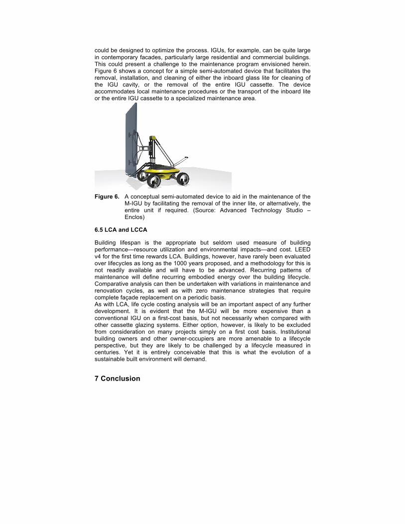
could be designed to optimize the process. IGUs, for example, can be quite large in contemporary facades, particularly large residential and commercial buildings. This could present a challenge to the maintenance program envisioned herein. Figure 6 shows a concept for a simple semi-automated device that facilitates the removal, installation, and cleaning of either the inboard glass lite for cleaning of the IGU cavity, or the removal of the entire IGU cassette. The device accommodates local maintenance procedures or the transport of the inboard lite or the entire IGU cassette to a specialized maintenance area.
Figure 6. A conceptual semi-automated device to aid in the maintenance of the
M-IGU by facilitating the removal of the inner lite, or alternatively, the entire unit if required. (Source: Advanced Technology Studio – Enclos)
6.5 LCA and LCCA
Building lifespan is the appropriate but seldom used measure of building performance—resource utilization and environmental impacts—and cost. LEED v4 for the first time rewards LCA. Buildings, however, have rarely been evaluated over lifecycles as long as the 1000 years proposed, and a methodology for this is not readily available and will have to be advanced. Recurring patterns of maintenance will define recurring embodied energy over the building lifecycle. Comparative analysis can then be undertaken with variations in maintenance and renovation cycles, as well as with zero maintenance strategies that require complete façade replacement on a periodic basis. As with LCA, life cycle costing analysis will be an important aspect of any further development. It is evident that the M-IGU will be more expensive than a conventional IGU on a first-cost basis, but not necessarily when compared with other cassette glazing systems. Either option, however, is likely to be excluded from consideration on many projects simply on a first cost basis. Institutional building owners and other owner-occupiers are more amenable to a lifecycle perspective, but they are likely to be challenged by a lifecycle measured in centuries. Yet it is entirely conceivable that this is what the evolution of a sustainable built environment will demand.
7 Conclusion
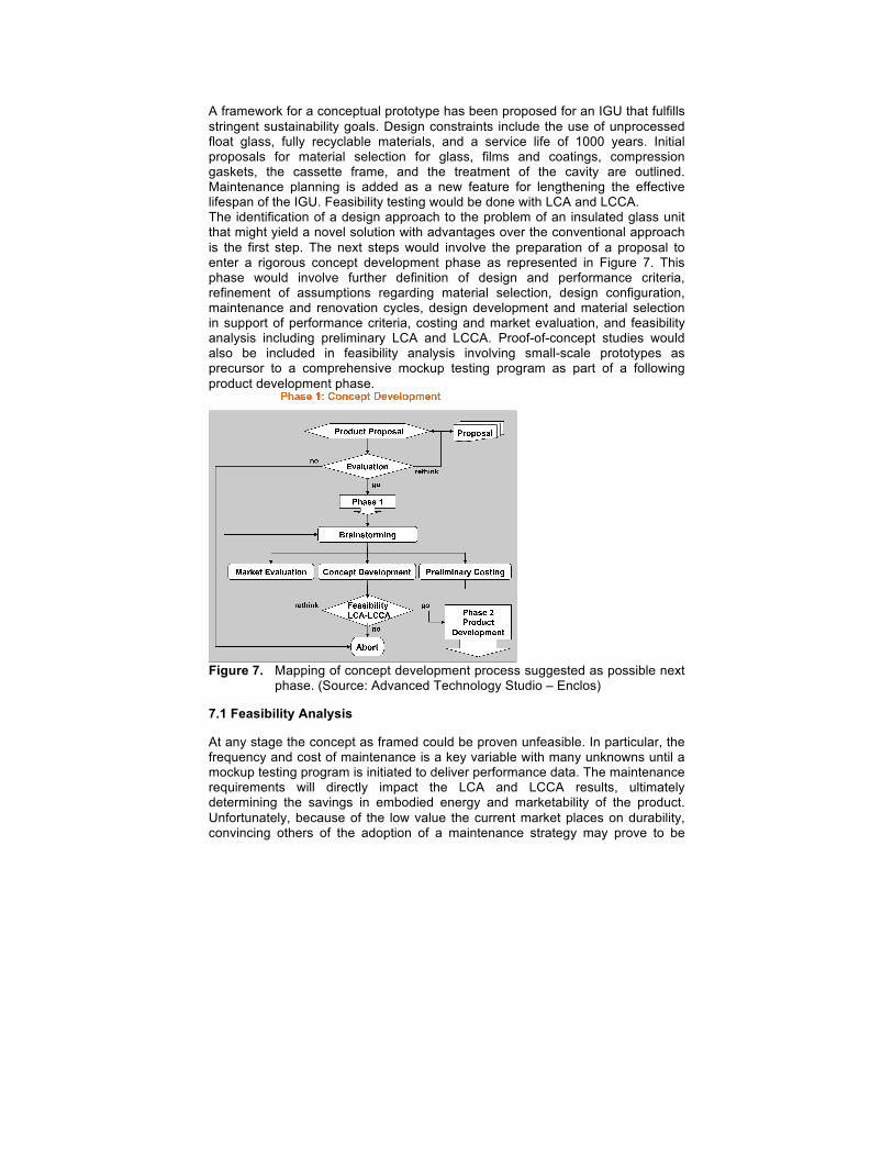
A framework for a conceptual prototype has been proposed for an IGU that fulfills stringent sustainability goals. Design constraints include the use of unprocessed float glass, fully recyclable materials, and a service life of 1000 years. Initial proposals for material selection for glass, films and coatings, compression gaskets, the cassette frame, and the treatment of the cavity are outlined. Maintenance planning is added as a new feature for lengthening the effective lifespan of the IGU. Feasibility testing would be done with LCA and LCCA. The identification of a design approach to the problem of an insulated glass unit that might yield a novel solution with advantages over the conventional approach is the first step. The next steps would involve the preparation of a proposal to enter a rigorous concept development phase as represented in Figure 7. This phase would involve further definition of design and performance criteria, refinement of assumptions regarding material selection, design configuration, maintenance and renovation cycles, design development and material selection in support of performance criteria, costing and market evaluation, and feasibility analysis including preliminary LCA and LCCA. Proof-of-concept studies would also be included in feasibility analysis involving small-scale prototypes as precursor to a comprehensive mockup testing program as part of a following product development phase.
Figure 7. Mapping of concept development process suggested as possible next
phase. (Source: Advanced Technology Studio – Enclos)
7.1 Feasibility Analysis
At any stage the concept as framed could be proven unfeasible. In particular, the frequency and cost of maintenance is a key variable with many unknowns until a mockup testing program is initiated to deliver performance data. The maintenance requirements will directly impact the LCA and LCCA results, ultimately determining the savings in embodied energy and marketability of the product. Unfortunately, because of the low value the current market places on durability, convincing others of the adoption of a maintenance strategy may prove to be
overwhelmingly difficult, even as landfills overflow. At some point societies must proclaim recyclability as a required prerequisite for production. This conceptual exercise assumes that day has come. Similarly, as recycling processes carry their own energy debt and environmental impacts, materials extracted and used in production must be designed for optimal durability so as to reduce the recurring embodied energy associated with maintenance and end-of-life recycling.
7.2 Constraints Drive Innovation
The embrace of constraints involving durability and recyclability can drive innovation. A service life of 1000-years started out as deliberate hyperbole, but as the consideration of this concept progressed, it has come to seem increasingly reasonable and perhaps even viable. The commitment of resources represented by the building sector demands a level of responsibility in the application of these resources that is only beginning to be confronted in current practice. Considerations of cultural resilience and sustainability will eventually comprise a context where such sensibilities become not only compelling but also mandatory. One thousand years may be an appropriate service life for many building types. It can certainly be argued that changing conditions of use over such a time period must necessarily render any discrete building obsolete. Perhaps, but if buildings are designed to adapt to the evolution of occupancy and use as suggested by Stewart Brand in How Buildings Learn [19], then this impact could be minimized, yielding buildings not only designed for longer service life but to facilitate adaptability.
7.3 Renewal and Regeneration vs. Service Life
In a sense, the approach taken here renders the concept of a service life at the scale of building and major building assemblies obsolete, replaced instead by a renewal process that results in perpetual regeneration. An M-IGU may still be operational 1000 years out, yet not contain one component from the original assembly. Yet the assembly was never out of service. Does the concept of service life even apply? The regeneration process required to push the limits of durability may in fact transcend service life, reducing the term’s applicability to the smaller materials and components that comprise these assemblies, parts that can be designed for ease of maintenance and replacement as required, and consequently do not limit the service life of the up-stream systems. Here this regenerative strategy is applied to a singular but ubiquitous glass product. How might this notion translate to other building systems or to the building itself? The millennial curtainwall system may well be the next investigation!
References
[1] Kesik, T.: Enclosure Durability. Architectural Science Forum. 2002. http://www.canadianarchitect.com/asf/enclosure_durability/index.htm. 03.12.2014.
[2] Selkowitz, S.E.: Integrating Advanced Facades Into High Performance Buildings. In 7th International Glass Processing Days June 18-21, 2001 in Tampere, Finland. Glass Performance Days. p.1 2001. http://escholarship.org/uc/item/30g0h715. 03.15.2014
[3] Viracon: Other manufacturers display varying but similar results with proprietary coatings. http://www.viracon.com/search-by-performance. 03.07.14
[4] Selkowitz op.cit., p.4 [5] Mora, R. Bitsuamlak, G. Horvat M.: Integrated life-cycle design of building enclosures.
Building and Environment 46. 2011. 1469–1479. [6] Kesik op. cit.: Differential durability. [7] Garvin, S.: The durability of double-glazing units. Glazing Today, 1994.
http://www.bath.ac.uk/cwct/cladding_org/wlp2001/paper13.pdf. 03.08.2014. [8] Lichtenberger, W.: Calculating the theoretical life expectancy of an insulating glass unit.
Glass Performance Days. Tempere Finland. 2005. http://www.glassfiles.com/articles/calculating-theoretical-life-expectancy-insulating-glass-unit. 03.03.2014
[9] Lingnell, B. Spetz, J.: Performance of insulating glass units – field correlation study over 25 years, 1980-2005. Glass Performance Days. Tampere Finland. 2007. http://web.ornl.gov/sci/buildings/2012/2007%20B10%20papers/066_Lingnell.pdf. 03.08.2015.
[10] Golda, R.: Personal communication. Heintges. 19 April 2014. 14 New York City, USA. [11] Hammond, Geoff and Craig Jones 2011. Inventory of carbon and energy (ICE), version
2.0. Sustainable Energy Research Team (SERT) Department of Mechanical Engineering. University of Bath, UK. Accessed 22 February 2014: http://www.circularecology.com/ice-database.html#.U3lg5q1_vQ4
[12] Eastman. The Science of Heat Mirror. http://www.eastman.com/Brands/HeatMirror/Pages/How_It_Works.aspx, 03.17.2014.
[13] Schneider, D. Rode, P.: Energy Renaissance. High Performing Buildings. Spring, 2010. American Society of Heating, Refrigerating, and Air Conditioning Engineers. http://www.hpbmagazine.org/case-studies/office-institutional/empire-state-building-new-york-ny. 03.17.2014
[14] Kawneer: Clearwall Curtain Wall. http://www.kawneer.com/kawneer/north_america/en/products/clearwall.asp. 03.17.2014
[15] Lee, B. Wills, J.: Vulnerability of fully glazed high-Rrse buildings in tropical cyclones. Journal of Architectural Engineering. Vol. 8(2), 42–48, 2002.
[16] Ambrose, D, Karagiozis, A.. Pressure Equalized Insulated Glass Units in Exterior Building Envelopes. (2007). http://aprs.ornl.gov/sci/roofs+walls/staff/papers/118.pdf. 04.01.2014.
[17] Boswell, K. Walker, J.: Shadow boxes: An architect and cladding designer’s search for solutions. Glass Performance Days 2005, Tampere Finland. http://www.glassfiles.com/articles/shadow-boxes-architect-and-cladding-designers%E2%80%99-search-solutions. 03.03.2014.
[18] Kesik op. cit.: Differential durability. [19] Brand, S.: How Buildings Learn: What Happens After They’re Built. New York: Penguin
Books. 1995