The major causes of machinery failure
25
HI r \ JIIIIIJ lllJ I^K^ 111 liiii:: '^ :| Cavitation llation (Cavitation) large Recirculation (Ca ^--v^ Best Etflcl The major causes of machinery failure • Rotating equipment does not fail randomly • The major causes of machinery failure - failure classifications • Summary Rotating equipment does not fail randomly Regardless of the location, rotating equipment usually fails when we don't want it to ... on the weekend! In the Middle East it fails late on Wednesday afternoon. In other places, failure occurs late Friday afternoon! Are these events random failures.^ Can we predict them.^ There is always a root cause of failure and there are indications in the failed component condition. However, general purpose equipment, because it is not usually continuously monitored (directly in the control room), certainly can appear to fail randomly. Please refer to Figure 2.1. Equipment does not fail randomly! There are root causes The condition of the failed component will change. Figure 2.1 Equipment does not fail randomly! Consider your plant's Bad Actor List. Has progress been made in reducing this list.^ Yes, it has! However, we frequently observe that once 13
-
Upload
khangminh22 -
Category
Documents
-
view
1 -
download
0
Transcript of The major causes of machinery failure

HI
r \
JIIIIIJ
lllJ I^K^
111 l i i i i : :
' ^
:| Cavitation
llation (Cavitation)
large Recirculation (Ca
^--v^ Best Etflcl
The major causes of machinery failure
• Rotating equipment does not fail randomly
• The major causes of machinery failure - failure classifications
• Summary
Rotating equipment does not fail randomly
Regardless of the location, rotating equipment usually fails when we don't want it to ... on the weekend! In the Middle East it fails late on Wednesday afternoon. In other places, failure occurs late Friday afternoon! Are these events random failures.̂ Can we predict them.^
There is always a root cause of failure and there are indications in the failed component condition. However, general purpose equipment, because it is not usually continuously monitored (directly in the control room), certainly can appear to fail randomly.
Please refer to Figure 2.1.
Equipment does not fail randomly!
There are root causes
The condition of the failed component will change.
Figure 2.1 Equipment does not fail randomly!
Consider your plant's Bad Actor List. Has progress been made in reducing this list.̂ Yes, it has! However, we frequently observe that once
13

Reliability Optimization
the root cause of the failure has been determined for a "̂ Bad Actor', it will eventually fail again. Why? It is because the process variables (parameters) affecting the failed component condition are not being monitored. How can we minimize random failures and our *̂ Bad Actor List'? By being aware of the major reasons for failure and by observing the condition of the machinery components.
Please refer to Figure 2.2.
• •
•
How to stop
Know why failures occur
... firefighting
(5 Why's)
Condition monitor the major components
Make it a 'team effort'
(random failure)
Figure 2.2 How to stop ... firefighting (random failure)
Will this involve more data collection, more work.̂ Many times, workload and meetings are reduced.
It all comes down to ... Awareness, knowing what to look for.
In the following sections of this chapter, the root causes of machinery failures will be discussed in detail. In the next chapter, the ways to prevent machinery failures will be discussed.
The major causes of machinery failure - failure classifications
The causes of machinery failure can be grouped into the failure classifications noted in Figure 2.3. Note that usually, failures are the result of more than one cause.
Failure classifications
Process condition changes
Assembly/installation
Operating procedures
Design deficiencies
Component wearout
Figure 2.3 Failure classifications

The Major Causes of Machinery Failure
Figure 2.4 Positive displacement plunger pump
1. Process condition changes This classification is the most overlooked in terms of troubleshooting. For this discussion, the most common type of driven equipment -pumps will be used.
There are two (2) major classifications of pumps, positive displacement and kinetic, centrifugal types being the most common. A positive displacement pump is shown in Figure 2.4. A centrifugal pump is shown in Figure 2.5.
FRONTCASEWEARRINQ
BACK CASE WEAR RMQ
BACK IMPELLER WEAR RING
FROr^ IMPELLER WEAR RING
Figure 2.5 Centrifugal pump
15
Reliability Optimization
In a typical refinery, greater than 95% of the installed pumps are the centrifiigal type.
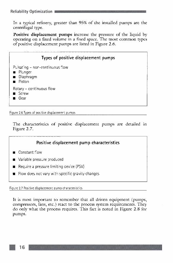
Positive displacement pumps increase the pressure of the liquid by operating on a fixed volume in a fixed space. The most common types of positive displacement pumps are listed in Figure 2.6.
Types of positive displacement pumps
Pulsating - non-continuous flow • Plunger • Diaphragm • Piston
Rotary - continuous flow • Screw • Gear
Figure 2.6 Types of positive displacement pumps
The characteristics of positive displacement pumps are detailed in Figure 2.7.
Positive displacement pump characteristics
Constant flow
Variable pressure produced
Require a pressure limiting device (PSV)
Flow does not vary with specific gravity changes
Figure 2.7 Positive displacement pump characteristics
It is most important to remember that all driven equipment (pumps, compressors, fans, etc.) react to the process system requirements. They do only what the process requires. This fact is noted in Figure 2.8 for pumps.

The Major Causes of Machinery Failure
Pump performance
Pumps produce the pressure required by the process
The flow rate for the required pressure is dependent on the pump's characteristics
Figure 2.8 Pump performance
Based on the characteristics of positive displacement pumps noted in Figure 2.7, positive displacement pump flow rate is not significantly affected by the process system. This fact is shown in Figure 2.9.
HEAD SYSTEM RESISTANCE
FLOW
Figure 2.9 A positive displacement pump in a process system
Therefore, since the flow rate of a positive displacement pump is not affected by the system, it is easy to determine if a positive displacement pump has worn internals. This fact is shown in Figure 2.10.
Positive displacement pump internal wear
Is identified by reduced flow rate
• Control valve closing
• Reduced amps
Figure 2.10 Positive displacement pump internal wear
17

Reliability Optimization
Centrifugal (Kinetic) pumps Centrifugal pumps increase the pressure of the liquid by using rotating blades to increase the velocity of a liquid and then reduce the velocity of the liquid in the volute. Refer again to Figure 2.5.
A good analogy to this procedure is a football (soccer) game. When the ball (liquid molecule) is kicked, the leg (vane) increases its velocity. When the goal tender (volute), hopefully, catches the ball, its velocity is significantly reduced and the pressure in the ball (molecule) is increased. If an instant replay 'freeze shot' picture is taken of the ball at this instant, the volume of the ball is reduced and the pressure is increased.
The characteristics of any centrifugal pump then are significantly different from positive displacement pumps and are noted in Figure 2.11.
Centrifugal pump characteristics
Variable flow
Fixed pressure produced for a specific flow
Does not require a pressure limiting device
Flow varies with differential pressure (P2-P1) and/or specific gravity
Figure 2.11 Centrifugal pump characteristics
Refer again to Figure 2.8 and note that all pumps react to the process requirements.
Based on the characteristics of centrifugal pumps noted in Figure 2.11, the flow rate of all types of centrifijgal pumps is affected by the process system. This fact is shown in Figure 2.12.
Therefore, the flow rate of any centrifugal pump is affected by the system.
Refer to Figure 2.13 and it can be observed that all types of mechanical failures can occur based on where the pump is operating based on the process requirements.
Since greater than 95% of the pumps used in any plant are centrifugal, their operating flow will be affected by the process.
Important facts concerning this failure classification are noted in Figure 2.14.

The Major Causes of Machinery Failure
INCREASED HEAD HEAn Do^ / -^ INCREASEE -^^^£22£yCS0 / REQUIRED
t I
O
X
FLOW-GPM
Figure 2.12 A centrifugal pump in a process system
SYSTEM CURVE (HEAD REQUIRED)
Possible Causes
/ ^ ~ \
Q
X
Low Velocity (Temperature Rise) Cavitation
Suction Recirculation (Cavitation)
Discharge Recirculation (Cavitation)
Best Efficiency Point
Impeller (Suction Side), Wear Rings, Bearings, Seals, Possible Shaft Breakage
High Velocity Cavitation
Z Impeller (Pressure Side), Wear Rings, Bearings, Seals, Possible Shaft Breakage
Component Damage Impeller (Suction Side), Wear Rings, Shaft
FLOW
Figure 2.13 Centrifugal pump component damage and causes as a function of operating point
19
Reliability Optimization
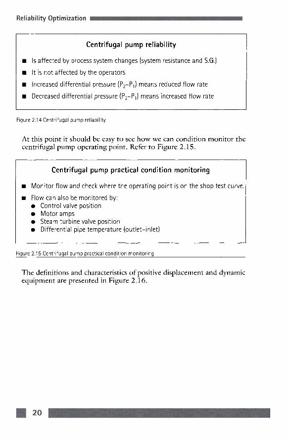
Centrifugal pump reliability
Is affected by process system changes (system resistance and S.G.)
It is not affected by the operators
Increased differential pressure (P2-P1) means reduced flow rate
Decreased differential pressure (P2-P1) means increased flow rate
Figure 2.14 Centrifugal pump reliability
At this point it should be easy to see how we can condition monitor the centrifugal pump operating point. Refer to Figure 2.15.
Centrifugal pump practical condition monitoring
Monitor flow and check where the operating point is on the shop test curve.
Flow can also be monitored by: • Control valve position • Motor amps • Steam turbine valve position • Differential pipe temperature (outlet-inlet)
Figure 2.15 Centrifugal pump practical condition monitoring
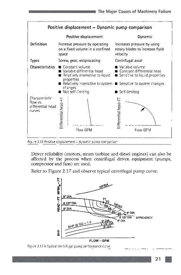
The definitions and characteristics of positive displacement and dynamic equipment are presented in Figure 2.16.
The Major Causes of Machinery Failure
Positive displacement - Dynamic pump comparison
Definition
Types
Characteristics
Characteristic flow vs. differential head curves
Positive displacement
Increase pressure by operating on a fixed volume in a confined space
Screw, gear, reciprocating
• Constant volume • Variable differential head • Relatively insensitive to liquid
properties • Relatively insensitive to system
changes • Not self-limiting
tz 1
-a 03 <u
sz
c <u QJ
M— \
^ Flow GPM
Dynamic
Increases pressure by using rotary blades to increase fluid velocity
Centrifugal axial
• Variable volume • Constant differential head • Sensitive to liquid properties
• Sensitive to system changes
• Self-limiting
1 — ^ ^ ~^ ^^^ OS ^ - - ^
•"̂ \ -•—' \ ^ \ QJ \
QJ \
^ Flow GPM
Figure 2.16 Positive displacement - dynamic pump comparison
Driver reliability (motors, steam turbine and diesel engines) can also be affected by the process when centrifugal driven equipment (pumps, compressor and fans) are used.
Refer to Figure 2.17 and observe typical centrifugal pump curve.
9"DIA
1/2-^iA~^ EFFICIENCY ]h^ ^8" DIA
FLOW-GPM
Figure 2.17 A typical centrifugal pump performance curve
21

Reliability Optimization
Since the flow rate will be determined by the process requirements, the power (BHP) required by the driver will also be affected. What would occur if an 81 /^" diameter impeller were used and the head (differential pressure) required by the process was low? Answer: Since the pressure differential required is low, the flow rate will increase and for the 81/2" diameter impeller, the power required by the driver (BHP) will increase.
Therefore, a motor can trip out on overload, a steam turbine's speed can reduce or a diesel engine can trip on high engine temperature. These facts are shown in Figure 2.18.
Effect of the process on drivers
Motors can trip on overload
Steam turbines can reduce speed
Diesel engines can trip on high engine temperature
Figure 2.18 Effect of the process on drivers
Auxiliary system reliability is also affected by process changes. Auxiliary systems support the equipment and their components by providing ... clean, cool fluid to the components at the correct differential pressure, temperature and flow rate.
Typical auxiliary systems are:
• Lube oil system
• Seal flush system
• Seal steam quench by system
• Cooling water system
The reliability of machinery components (bearings, seals, etc.) is direcdy related to the reliability of the auxiliary system. In many cases, the root cause of the component failure is found in the supporting auxiliary system.
As an example, changes in auxiliary system supply temperature, resulting from cooling water temperature or ambient air temperature changes, can be the root cause of component failure. Figure 2.19 presents these facts.

The Major Causes of Machinery Failure
Component (bearing and seal) reliability
Is directly related to auxiliary system reliability
Auxiliary system reliability is affected by process condition changes.
'Root causes' of component failure are often found in the auxiliary system.
Figure 2.19 Component (bearing and seal) reliability
As a result, the condition of all the auxiliary systems supporting a piece of equipment must be monitored. Please refer to Figure 2.20.
Always Think system'
Monitor auxiliary system condition
Inspect auxiliary systems during component replacement
Figure 2.20 Always Think system'
2. Improper assembly maintenance/installation In proper assembly, maintenance (lubrication) of components and/or improper installation practices will shorten the life of components and cause eventual failure because the anticipated design factors were not met.
Tolerances, maintenance requirements and installation procedures are provided to assure maximum component and equipment life. As an example, refer to Figure 2.21, which shows anti-friction bearings commonly used in pumps.
The relationship that determines how long an anti-friction bearing will last is shown in Figure 2.22.

Reliability Optimization
Ol/TERRINQ OUTER RING
ROLLER BEARING
Figure 2.21 Anti-fr ict ion bearing
BALLBEARING
L-10 LIFE
'B' or 1' - 10 Life is defined as the life in hours that 9 out of 10 randomly selected bearings would exceed in a specific application.
'B'or 'L'- 10 Life = 16700 A/ [F
Where: N= RPM C = Load in LBS that will result in a bearing element life of
1,000,000 revolutions. F= Actual load in LBS
Figure 2.22 L-10 LIFE
Note that the life of the bearing is directly dependent on the forces acting on the bearing to the 3rd power. As an example, if the forces were twice the design value, the life of the bearing would be reduced eight times! The minimum specified life for a bearing is three years or 36 months. In this example, the life would be reduced to approximately five months!
What can cause excessive bearing forces in this case? Refer to Figure 2.23.
24

The Major Causes of Machinery Failure
Sources of forces
Increased process pipe forces and moments
Foundation forces ('soft' foot, differential settlement)
Fouling of plugging of impeller
Misalignment
Unbalance
Rubs
Improper assembly clearances
Thermal expansion of components (loss of cooling medium, excessive operating temperature)
Radial forces (single volute - off design operation)
Poor piping layouts (causing unequal flow distribution to the pump)
Figure 2.23 Sources of forces
When any bearing is designed, it has a maximum acceptable total force which will allow it to operate trouble-free for a period equal to, or in excess of, its specified life. If the total forces acting on the bearing exceed this value, there will be a bearing failure.
Therefore, the bearing must be installed in accordance with the vendor's instructions as detailed in the instruction book. The use of general procedures or *̂ rules of thumb' (using typical values) should be avoided.
In addition to the component assembly procedure, the pump installation procedure must be followed. The pump installation procedure assures that the following items are checked as noted in Figure 2.24.
Pump installation procedure requirements
Proper pump/driver alignment
Minimum external pipe forces
Minimum external foundation forces ('soft foot')
Figure 2.24 Pump installation procedure requirements

Reliability Optimization
Now refer back to Figure 2.23 and observe what additional forces, not anticipated by the vendor, that can be added to the total bearing force!
Therefore, improper installation procedure values will cause bearing failure.
In summary, the proper steps to prevent assembly and/or installation errors are presented in Figure 2.25.
Avoid assembly/installation errors by ...
Having the instruction book available
Completely following specified procedures
Using only specified parts
Using refinery procedures for: • Alignment • Pipe stress check • Soft foot check
Figure 2.25 Avoid assembly/installation errors by .•.
A final word of advice regarding procedures is given in Figure 2.26.
Remember!!
Exceed the specified limits ... and you will reduced equipment reliability
Figure 2.26 Procedures - advice
The final step in any assembly and/or installation procedure is to confirm that the procedure was performed properly. This is accomplished by condition monitoring of the replaced components afiier the machine is operating at normal conditions ... 4ined out'. This method is outlined in Figure 2.27.
The Major Causes of Machinery Failure
Post component replacement check guidelines
Obtain component condition data
Compare data to: • Data before component replacement • Site guidelines • Confirm all component condition data is satisfactory (sign-off)
Figure 2.27 Post component replacement check guidelines
A good question at this point would be ... How long after 'line out' should this check be performed.^ The norm is during the first 4-8 hours after normal operation 'line out' is attained.
All rotating equipment, when manufactured, is only tested for approximately 4 hours. In the case of a pump operating at 3600 RPM, this pump will have rotated 1,000,000 times during this period! If the assembly/installation procedure requirements were not met, we will know from the guidelines at this time.
3. Improper operating procedures Failure of machinery and/or components can occur because equipment will be subjected to conditions that exceed the design values. Refer to Figure 2.28.
Improper operating procedures
Subject the equipment to conditions that exceed design value limits.
Figure 2.28 Improper operating procedures
Operating procedures can be the root cause of failure. Please refer to Figure 2.29.

Reliability Optimization
Operating procedures can cause failure if
They are not complete
They are not followed
The actual operating conditions are different than specified
Figure 2.29 Operating procedures can cause failure if.
Most machinery and/or component damage and wear occur during start-up or shutdown (transient) conditions. During this time, the equipment is subjected to rapid temperature, pressure and speed changes.
Shown in Figure 2.30 are some examples of operating procedure requirements, the reason for the requirement, the consequences, the checks and corrective action.
Operating procedure requirements
Requirement
1. Pump & seal vented and full of liquid
2. Pump suction valve wide open, no suction line restrictions
Reasons
Assure only liquid is present to remove frictional heat from close running parts,
Affected components
Casing, impeller(s), shaft. wear rings. seal(s) and couplings
assure continuous pumping and prevent immediate seal failure
Same as item 1, prevent cavitation and assure discharge pressure is reached
Same as item 1
Check(s) to prevent problem
That discharge pressure is reached immediately and does not fluctuate
Suction valve wide open, discharge pressure reached and does not fluctuate, no cavitation noise
Corrective action
Check process system to determine cause. If discharge pressure does not build up. shut down pump and investigate
Confirm suction valve is wide open. Shutdown pump if problem remains check suction strainer (suction basket if sump pump). Look for suction line obstructions
28

Requirement
3. Discharge
pump valve
pinched for
start-upi
4. Steam turbine & inlet steam line warmed.
5. Standby hot service pump warmed.
6. Cold service pump chilldown.
Reasons
Prevent pump
from running dry,
• • • • • ihe
Affected components
Same as item 1
Prevent high flow
cavitation.
Prevent driver
overload and
high inrush motor
current (which
will reduce
insulation life)
Prevent slugging the turbine with condensate.
Reduces thermal shock, assures proper liquid viscosity and correct shaft alignment.
Eliminates vapor in pump case and seal.
y.Steam turbine Reduces thermal slow roll & start-up sequence.
shock & assures correct alignment.
Bearings, steam seals and possibly turbine blades
Pump casing. seals, bearings and coupling.
Wear rings and seals.
Casing, rotor, internal seals. shaft end seals, coupling and bearings.
Major Lauses ot
Check(s) to prevent problem
Discharge valve is
not full open.
Discharge pressure
is reached quickly.
with a steady rise in
pressure. No
cavitation noise
Check drains for presence of condensate and check that steam is above saturation temperature
Check temperature of casing, seal area and suction line
That discharge pressure is reached immediately. Vent casing high point and seal chamber.
Check drains for presence of condensate and check that steam is above saturation temperature
Machinery hailure
Corrective action
Confirm discharge
valve is not full open.
Shutdown pump if
problem remains. Re
start with discharge
valve partially closed.
Fully open discharge
after pump has
reached full speed
Open drain lines until condensate flow stops. Start turbine slowly, using small bypass valve supplied and confirm absence of condensate.
Confirm bypass valve around the discharge check valve and suction valve are open.
Shut down pump if discharge pressure is not reached. Open vent lines of casing and seal chamber and confirm fluid in unit is lOQo/o liquid.
Prior to slowroll, drain casing, throttle valve and inlet line. Do not commission steam seal system (if supplied) until turbine is turning. Completely follow vendor's startup instructions.
1 For process unit start-up when no other pumps are in operation
Figure 2.30 Operating procedure requirements
29

Reliability Optimization
How can failures associated with operating procedures and their implementation be avoided?
Figure 2.31 presents some guidelines.
Operating procedure reliability guidelines
Confirm the operating conditions are as specified
Confirm the refinery instruction manual 'RIM' is in agreement with vendor's instructions
Understand the reason for the requirement
Do not hesitate to ask ...
Figure 2.31 Operating procedure reliability guidelines
The importance of having operating procedures that are accurate, properly written and completely followed cannot be overemphasized. As previously stated, the transient (rapid change) conditions that equipment is exposed to during start-up and shutdown can cause rapid component wear or failure. These facts are presented in Figure 2.32.
Follow procedures completely because ...
During start-up and shutdown, equipment components are subject to rapid (transient) • Temperature changes • Pressure changes • Speed changes.
Remember, most component wear occurs during transient conditions.
Figure 2.32 Follow procedures completely because .
4. Design problems Possible design problems manifest themselves like all other causes of failure ... component condition values are exceeded. Before a design problem is confirmed, three previously discussed causes of failure should be checked as shown in Figure 2.33.

The Major Causes of Machinery Failure
Possible design problem?
First confirm the following classifications are not the root cause: • Process condition change • Assembly/installation procedures • Operating procedures
Figure 2.33 Possible design problem?
Design problems can fall into three categories as shown in Figure 2.34.
Design problem categories
Engineering errors
Material problems
Manufacturing problems
Figure 2.34 Design problem categories
Design problems usually show up shortly after the process unit is at normal conditions - 4ine out'. However, there are cases when design problems manifest themselves after extended operation and even the warranty period.
The cause of design problems is that the machine and/or its components were not designed for the specified field operating conditions. See Figure 2.35.
A design problem exists if:
The machine and/or components are not designed for spec/f/ed field operating conditions.
Figure 2.35 A design problem exists if:
Often, the vendor is accused of a design error when, in fact, the specified conditions and/or operating procedures have changed.
After '̂ line out' of the process, if problems exist (component condition

Reliability Optimization
LIQUID
THROAT BUSHING
FLUSH CONNECTION
GLAND PLATE
STATIONARY •O" RING
SHAFT PACKING (SECONDARY SEAL)
STATIONARY SEAL MEMBER
SPRING SHAFT
Figure 2.36 Pump mechanical seal
values exceeded), the equipment data sheet should be compared to the actual data to confirm the equipment was designed to the actual field operating conditions. If not, field conditions should be corrected if possible. If field conditions remain different than specified on the data sheet, it is not a design problem, it is an 'application problem'. In this situation, the vendor is justified in asking for redesign costs if necessary.
An example of a possible design problem is a leaking mechanical seal. Refer to Figure 2.36.
All mechanical pump seals are designed to convert the liquid to a vapor across the seal face. If the actual operating liquid conditions (vapor pressure, temperature and pump pressures) are not specified, a mechanical seal failure can occur because either the liquid is not changed to a vapor or the liquid vaporizes in the seal chamber (stuffing box).
Figure 2.37 shows the change of pressure and temperature across a seal face in three (3) cases:
• ONSET OF VAPORIZATION
^¥C^ ONSET OF ^TM "̂̂ FL 'Pyp VAPORIZATION
's'^S h^Ps-»H
NO VAPORIZATION
Figure 2.37 Seal face vaporization
32
The Major Causes of Machinery Failure
• Early vaporization
• Proper design
• No vaporization
In this example, a pump *̂ bad actor', with more than one (1) seal failure per year, should first be checked for proper liquid conditions at the seal face before it is classified as a mechanical seal design problem. The cause of failure may be a process related issue (improper liquid conditions or plugged flush line orifice). If all conditions are as specified, then it is truly a mechanical design problem.
Another example of a possible design problem is oil contamination in the bearing brackets of a single stage steam turbine shown in Figure 2.38. Assume continuous problems are experienced with water in the oil causing bearing failures. It is also confirmed that the source of water is from the carbon ring seal leakage of steam into the bearing bracket.
As was previously stated, first check the other failure causes:
• Process condition changes
• Assembly/installation procedures
• Operating procedures
A check confirms that the failure causes noted above did not occur.
Therefore, the carbon ring seal system (carbon ring seals and bearing bracket isolator) are not designed to prevent oil contamination in the bearing bracket. This case is an example of a true design problem. For this example, there are two (2) possible modifications:
• Install an eductor system to positively prevent steam leakage from the seal assembly (presently a requirement of a major oil company general purpose steam turbine spec).
• Install a bearing isolator to positively prevent steam condensate from entering the bearing bracket (Tmpro' type of equal).
In summary, the factors concerning possible design problems are noted in Figure 2.39.

Reliability O
ptimization
E
34

The Major Causes of Machinery Failure
• •
•
Design problem determination and action plan
Confirm all other failure causes do not exist
Confirm specified operating conditions exist in the field (check data sheet)
Conduct a design audit meeting with the vendor (if necessary)
Figure 2.39 Design problem determination and action plan
5. Component wearout Like design problems, component wearout is often determined to be a root cause of failure.
However, as shown in Figure 2.40, apparent component wearout usually is caused by other failure classifications.
Apparent component wearout
Usually is caused by one or more of the following failure classifications: • Process condition changes affecting the equipment and/or its auxiliary
systems • Assembly/maintenance/installation errors • Improper operating procedures • Design deficiencies
Figure 2.40 Apparent component wearout
Always investigate the other failure classifications first. In many cases, component wearout is the effect, not the cause of the problem. Figure 2.41 presents this information.
Component wearout is often the effect, not the root cause of the problem
Figure 2.41
Refer back to failure classification 1, process condition changes Figure 2.13. What components could 'wearout' if the process required high differential pressure.^

Reliability Optimization
Also refer to failure classification 2, assembly, installation problems, Figures 2.21, 2.22 and 2.23. Why could a bearing 'wearout' if the foundation cracked.^ Why would the bearing 'wearout' if a shim fell out of pipe support?
Finally, refer to failure classification 3, improper operating procedures. Figure 2.30. Why could a seal with a flush from its discharge line wearout if a loading pump were started with the discharge valve wide open.̂
These examples are presented in Figure 2.42.
Component
Bearing, seal,
Bearing
Apparent component wearout examples
impeller wear ring
Mechanical seal
Root Cause
Process condition change
Installation problems
Operating procedure (pump run dry)
Figure 2.42 Apparent component wearout examples
Therefore, when will equipment components wear out.̂ If all the considerations to eliminate failure classifications are met, components will last a long time.
Think of some site pumps and name the shortest and longest periods between:
• Bearing replacement
• Seal replacement
Figure 2.43 presents some components and their life if failure classifications 1-4 are not present.
36

The Major Causes of Machinery Failure
(failure
Component
Anti-friction bearing
Sleeve bearings
Mechanical seal
Wear rings
Impellers
Component Life
classifications 1-4 not present)
Life
8-10 years
15-20 years
7-10 years
10-12 years
15-20 years
Figure 2.43 Component life
In many cases, component wearout is a result of the wearout of the 'secondary' parts in the component. An example is 'o ' rings in mechanical seals.
As in the case of the previous failure classifications, component wearout does not randomly occur. The condition parameters associated with these components will change. Figure 2.44 presents the guidelines to determine component wearout.
Component wearout guidelines
Monitor component condition parameters
Plan scheduled shutdown using predictive maintenance (PDM) principles
Confirm failure classifications 1-4 are not present.
Figure 2.44 Component wearout guidelines
Summary
At this point the five (5) failure classifications have been discussed in detail. How can these failures be minimized.^
The next chapter, 'How to prevent machinery failures', will discuss this subject. The answers should be clear at this point.