the kinematic study of the bok bak fault - UM Students ...
177
THE KINEMATIC STUDY OF THE BOK BAK FAULT ALONG KEDAH-PERAK TRANSECT AHMAD FAIZ BIN SALMANFARSI FACULTY OF SCIENCE UNIVERSITY OF MALAYA KUALA LUMPUR 2017 University of Malaya
-
Upload
khangminh22 -
Category
Documents
-
view
0 -
download
0
Transcript of the kinematic study of the bok bak fault - UM Students ...

THE KINEMATIC STUDY OF THE BOK BAK FAULT ALONG KEDAH-PERAK TRANSECT
AHMAD FAIZ BIN SALMANFARSI
FACULTY OF SCIENCE
UNIVERSITY OF MALAYA KUALA LUMPUR
2017
Univers
ity of
Mala
ya

THE KINEMATIC STUDY OF THE BOK BAK FAULT ALONG KEDAH-PERAK TRANSECT
AHMAD FAIZ BIN SALMANFARSI
DISSERTATION SUBMITTED IN FULFILMENT OF
THE REQUIREMENTS FOR THE DEGREE OF MASTER OF SCIENCE
DEPARTMENT OF GEOLOGY FACULTY OF SCIENCE
UNIVERSITY OF MALAYA KUALA LUMPUR
2017
Univers
ity of
Mala
ya

ii
UNIVERSITY OF MALAYA
ORIGINAL LITERARY WORK DECLARATION
Name of Candidate: AHMAD FAIZ BIN SALMANFARSI
Matric No: SGR110107
Name of Degree: MASTER OF SCIENCE
Title of Project Paper/Research Report/Dissertation/Thesis (“this Work”): THE KINEMATIC STUDY OF THE BOK BAK FAULT ALONG KEDAH-PERAK TRANSECT
Field of Study: GEOLOGY
I do solemnly and sincerely declare that:
(1) I am the sole author/writer of this Work; (2) This Work is original; (3) Any use of any work in which copyright exists was done by way of fair
dealing and for permitted purposes and any excerpt or extract from, or reference to or reproduction of any copyright work has been disclosed expressly and sufficiently and the title of the Work and its authorship have been acknowledged in this Work;
(4) I do not have any actual knowledge nor do I ought reasonably to know that the making of this work constitutes an infringement of any copyright work;
(5) I hereby assign all and every rights in the copyright to this Work to the University of Malaya (“UM”), who henceforth shall be owner of the copyright in this Work and that any reproduction or use in any form or by any means whatsoever is prohibited without the written consent of UM having been first had and obtained;
(6) I am fully aware that if in the course of making this Work I have infringed any copyright whether intentionally or otherwise, I may be subject to legal action or any other action as may be determined by UM.
Candidate’s Signature Date:
Subscribed and solemnly declared before,
Witness’s Signature Date:
Name: MUSTAFFA KAMAL BIN SHUIB
Designation:ASSOCIATE PROF.
Univers
ity of
Mala
ya

iii
ABSTRACT
A section of Bok Bak Fault along southern Kedah and northern Perak is mapped for a
detailed kinematic study of the fault. Remote sensing study shows a main NW-SE
lineament crosscut by other lineament sets, and the lineament sets fit with a sinistral
Riedel Shear model. The fault zone contain a main NW sinistral Bok Bak Fault set, with
WNW sinistral set, NNW to NW sinistral set, NE dextral set, and E fractures. Mapping
of mylonite along the fault zone reveals the presence of an early predominantly dextral
strike slip movement along the shear zone. The shear zone is characterized by steep NW
to W foliation with gentle to sub-horizontal NE stretching lineation deformed in the
brittle-ductile domain. The shear zone is reactivated through sinistral to oblique slip
movement, as shown by the overprinting of brittle faults and brittle-ductile shear zones
on the mylonites. The Bok Bak Fault is reactivated as an oblique slip fault zone,
resulting in crosscutting fault trend, which produce three main brittle episodes that are
represented by NW and NNW faults, NE faults, and E faults. Brittle faulting is observed
in both sedimentary rock unit and granite body. The faults are subsequently subjected to
further reactivation, most likely during later extensional period along the fault zone,
resulting in conflicting sense of movement along the fault trends. 40Ar/39Ar radiometric
dating of biotite in mylonite produced a plateau age of 136.1 ± 1.4 Ma. This age is the
first report of radiometric dating of the Bok Bak Fault, and here it is considered as the
timing of the fault’s initiation. The Early Cretaceous age achieved is later than the
timing of initiation of regional fault discussed in other studies, where the faults of was
previously thought to be formed concurrently with Late Triassic Main Range granite
intrusion. Based on compilation of geochronological data, the Bok Bak Fault is
interpreted to be initiated in Early Cretaceous, representing a major tectonic event in
Sundaland prior to the collision of India and Asia, where the continental core became
cratonized and major faults were being developed. This is a long lived event that
Univers
ity of
Mala
ya

iv
continued until Tertiary time, as evident from brittle reactivation along the fault zone.
Recent reactivation of the fault is indicated by Quaternary sediment deformation and
earthquake report along the fault zone.
Univers
ity of
Mala
ya
v
ABSTRAK
Sebahagian daripada Sesar Bok Bak di sepanjang selatan Kedah dan utara Perak
dipetakan untuk kajian terperinci kinematik sesar. Kajian penderiaan jarak jauh
menunjukkan lineamen BL-TG dipotong oleh set lineamen lain, dan set lineament ini
adalah serasi dengan dengan model Riedel Shear sinistral. Zon sesar mengandungi set
utama BL-TG Sesar Bok Bak, dengan set mengiri BUB, set mengiri UUB ke BL set
sinistral, set menganan TL, dan set rekahan T. Pemetaan milonit sepanjang zon
kesalahan menunjukkan wujudnya akan pergerakan menganan awal sepanjang zon ricih.
Zon ricih mempunyai foliasi BL ke B yang curam, dengan lineasi yang menjunam
secara landai ke separa-mengufuk di dalam domain rapuh-mulur. Zon ricih diaktifkan
semula melalui pergerakan mengiri ke pergerakan serong, seperti yang ditunjukkan oleh
sesar rapuh dan zon ricih rapuh-mulur yang memotong milonit. Sesar Bok Bak
diaktifkan semula sebagai zon sesar serong, seperti yang ditunjukkan oleh set-set sesar
yang memotong set utama, denga tiga episod ricih yang menghasilkan sesar set BL dan
UBL, TL, dan T. Sesar dapat diperhatikan dalam kedua-dua unit batu sedimen dan
granit. Set-set sesar ini kemudiannya diaktifkan semula, pada tempoh pemanjangan
(extensional) zon sesar, yang menghasilkan pergerakan yang bercanggah di sepanjang
trend sesar. Penentuan umur radiometrik secara kaedah 40Ar/39Ar daripada biotit
milonit memberi hasil umur 136.1 ± 1.4 Ma. Umur ini adalah laporan pertama
penentuan umur radiometrik daripada Sesar Bok Bak, dan ia ditafsirkan sebagai umur
permulaan pergerakan sesar tersebut. Usia Batu Kapur Awal yang didapati di dalam
kajian ini adalah lewat dari masa pemulaan sesar rantau dibincangkan dalam kajian lain,
di mana sesar-sesar sebelum ini ditafsirkan terbentuk serentak dengan penerobosan
lewat granit Trias Banjaran Titiwangsa. Berdasarkan penyusunan data geokronologikal
kajian terdahulu, Sesar Bok Bak ditafsirkan terbentuk ketika Batu Kapur Awal, yang
Univers
ity of
Mala
ya

vi
mewakili peristiwa tektonik utama di Sundaland sebelum perlanggaran India dan Asia,
di mana teras benua mengalami kratonasi dan sesar-sesar utama dibentuk. Ini
merupakan satu peristiwa tektonik yang berterusan sehingga Tertiari, seperti yang
terbukti dari pengkaktifan rapuh sepanjang zon sesar. Pengaktifan semula sesar baru-
baru ini ditunjukkan oleh canggaan sedimen Kuaterner dan laporan gempa bumi di
sepanjang zon sesar.
Univers
ity of
Mala
ya
vii
ACKNOWLEDGEMENTS
First and foremost I would like to thank both of my supervisor, Assoc. Prof Mustaffa
Kamal Shuib and Dr. Ng Tham Fatt, for their countless guidance and support
throughout the period of writing of this thesis. I have learned a great deal on the Bok
Bak Fault, and of the art of researching – something which I will continue to keep
learning in the future.
A shoutout for fellow postgraduate researchers – those who provided support
throughout the period of my research, whether it was advising on my subject matter, or
providing advices on researching and writing, or also burning the midnight oil on the
sleepless nights where we’re rushing for deadline.
Many thanks to Tuan Haji Zainol Haji Husin and the staff at JMG
Kedah/Perlis/Pulau Pinang for providing access to materials during early stage of
literature review for this work. Special mention goes to those who are of great help
during my fieldworks: Encik Ismail Zainal Abiddin from Kuari Bina; Encik Jaafar from
Kuari Pati; Encik Akok from Oscar Quarry; Encik Nizan from TAHB Quarry; Encik
Shaari from Sankojaya Quarry; the rest of personnel in aforementioned quarries; and
Aizad (who provided a place to stay during my fieldwork in Kuala Ketil and Baling).
This work was funded by the University of Malaya’s Postgraduate Research Fund
(PPP) grant, project account number PG092-2012B, which is gratefully acknowledged.
Lastly, and most importantly, I would like to dedicate this dissertation to my parents,
Salmanfarsi Elias and Norliza Abu Bakar, who have been patient and supportive
throughout my research.
Univers
ity of
Mala
ya

viii
TABLE OF CONTENTS
Original literary work declaration .................................................................................... iii
Abstract ............................................................................................................................ iii
Abstrak .............................................................................................................................. v
Acknowledgements ......................................................................................................... vii
Table of Contents ............................................................................................................ vii
List of Figures ................................................................................................................ xiii
List of Tables................................................................................................................. xvii
List of Symbols and Abbreviations .............................................................................. xviii
List of Appendices ......................................................................................................... xix
CHAPTER 1: INTRODUCTION .................................................................................. 1
1.1 Previous works......................................................................................................... 2
1.2 Objectives of study .................................................................................................. 3
1.3 Methodology ............................................................................................................ 5
1.3.1 Desk study .................................................................................................. 5
1.3.2 Remote sensing ........................................................................................... 6
1.3.2.1 Aerial photographs ...................................................................... 7
1.3.2.2 Satellite imageries ....................................................................... 7
1.3.2.3 DEM-SRTM ................................................................................ 7
1.3.3 Field work ................................................................................................... 8
1.3.4 Laboratory work ......................................................................................... 8
1.4 Study area ................................................................................................................ 9
1.5 Physiography ......................................................................................................... 11
1.5.1 Topography .............................................................................................. 13
1.5.2 Drainage pattern ....................................................................................... 14
Univers
ity of
Mala
ya

ix
CHAPTER 2: REGIONAL SETTING AND GEOLOGY OF BOK BAK FAULT
ZONE…………….. ....................................................................................................... 17
2.1 Regional tectonic setting........................................................................................ 17
2.2 Geological setting of Peninsular Malaysia ............................................................ 19
2.3 Fault system of Peninsular Malaysia ..................................................................... 21
2.4 Rock units of the Bok Bak Fault Zone .................................................................. 25
2.4.1 Sedimentary formation ............................................................................. 25
2.4.1.1 Baling Formation ....................................................................... 25
2.4.1.2 Mahang Formation .................................................................... 30
2.4.1.3 Semanggol Formation ............................................................... 32
2.4.2 Intrusive bodies ........................................................................................ 33
2.4.2.1 Bukit Perak Granite ................................................................... 34
2.4.2.2 Bukit Enggang Granite .............................................................. 36
2.4.2.3 Bintang Hills Granite ................................................................ 36
2.4.2.4 Other igneous bodies ................................................................. 38
2.4.3 Summary for geology of Bok Bak Fault Zone ......................................... 39
CHAPTER 3: REMOTE SENSING STUDY ............................................................. 40
3.1 Introduction............................................................................................................ 40
3.2 Lineament extraction ............................................................................................. 40
3.3 Geological domains ............................................................................................... 42
3.3.1 Lithological domain ................................................................................. 42
3.3.2 Geomorphology ........................................................................................ 44
3.3.3 Lineament-fracture correlation domains .................................................. 45
3.4 Lineament analysis ................................................................................................ 46
3.4.1 Lineament distribution ............................................................................. 46
3.4.1.1 Aerial photographs .................................................................... 46
Univers
ity of
Mala
ya
x
3.4.1.2 Satellite image ........................................................................... 46
3.4.1.3 DEM-SRTM .............................................................................. 50
3.4.2 Unfiltered lineament analysis ................................................................... 50
3.4.3 Lineament pattern of grid cells ................................................................. 52
3.4.4 Lineament pattern of lithological domain ................................................ 54
3.4.5 Lineament and field data correlation ............................................................ 54
3.4.6 Discussion ................................................................................................ 58
3.5 Structural interpretation of lineament .................................................................... 60
3.5.1 Strike ridges interpretation ....................................................................... 60
3.5.2 Cross-cutting relationship of lineaments .................................................. 62
3.5.3 Riedel Shear interpretation of lineaments ................................................ 62
3.6 Summary of remote sensing studies ...................................................................... 63
CHAPTER 4: DUCTILE DEFORMATION .............................................................. 66
4.1 Introduction............................................................................................................ 66
4.2 Shear zone domain in granite ................................................................................ 68
4.2.1 Bukit Perak shear zone domain ................................................................ 69
4.2.2 Baling-Gerik shear zone domain .............................................................. 74
4.3 Mesoscopic structures ............................................................................................ 75
4.3.1 Foliation .................................................................................................... 77
4.3.2 Mineral elongation lineation .................................................................... 78
4.3.3 S-C structure ............................................................................................. 78
4.3.4 Rigid clasts ............................................................................................... 81
4.3.5 Deformed veins ........................................................................................ 81
4.4 Microstructures ...................................................................................................... 81
4.4.1 Oblique grain-shape fabrics ...................................................................... 82
4.4.2 S-C structure ............................................................................................. 82
Univers
ity of
Mala
ya

xi
4.4.3 Mineral fish .............................................................................................. 85
4.4.4 Mantled porphyroclast .............................................................................. 85
4.4.5 Fractured porphyroclast ............................................................................ 86
4.5 Condition of ductile deformation........................................................................... 86
4.5.1 Deformation mechanism .......................................................................... 87
4.5.1.1 Quartz ........................................................................................ 88
4.5.1.2 Feldspar……………….. ........................................................... 89
4.5.1.3 Mica..... ...................................................................................... 91
4.5.2 Temperature .............................................................................................. 92
4.5.3 Metamorphic condition ............................................................................ 93
4.6 Summary of shear zone kinematics ....................................................................... 94
CHAPTER 5: BRITTLE DEFORMATION .............................................................. 96
5.1 Introduction............................................................................................................ 96
5.2 Brittle deformation structures ................................................................................ 96
5.3 Structural analysis .................................................................................................. 99
5.3.1 Transition from ductile to brittle shearing .............................................. 104
5.3.2 D1: Sinistral oblique faulting ................................................................. 107
5.3.3 D2: Dextral oblique reverse faulting ...................................................... 109
5.3.4 D3: Normal faulting ............................................................................... 111
5.3.5 Discussion .............................................................................................. 116
5.4 Condition of brittle deformation .......................................................................... 116
5.5 Displacement of brittle fault ................................................................................ 117
5.6 Structural model................................................................................................... 120
5.7 Summary of brittle faulting ................................................................................. 123
CHAPTER 6: TIMING FOR EVENTS OF BOK BAK FAULT ........................... 125
Univers
ity of
Mala
ya

xii
6.1 Introduction.......................................................................................................... 125
6.2 Magmatism age .................................................................................................... 126
6.3 40Ar/39Ar thermochronology ................................................................................ 128
6.3.1 Age of mica ............................................................................................ 130
6.3.2 Discussion and interpretation of mica age.............................................. 130
6.4 Timing of brittle deformation .............................................................................. 134
6.5 Neotectonic structures ......................................................................................... 138
CHAPTER 7: DISCUSSION AND CONCLUSION ........................................ ……141
7.1 Correlation with Peninsular Malaysia tectonic history ........................................ 141
7.2 Correlation with regional tectonic history ........................................................... 144
7.3 Conclusion ........................................................................................................... 145
7.3 Recommendation for further studies ................................................................... 146
References ..................................................................................................................... 148
List of Publications and Papers Presented .................................................................... 157
Appendix ....................................................................................................................... 158
Univers
ity of
Mala
ya

xiii
LIST OF FIGURES
Figure 1.1: Flow chart of research progress ...................................................................... 6
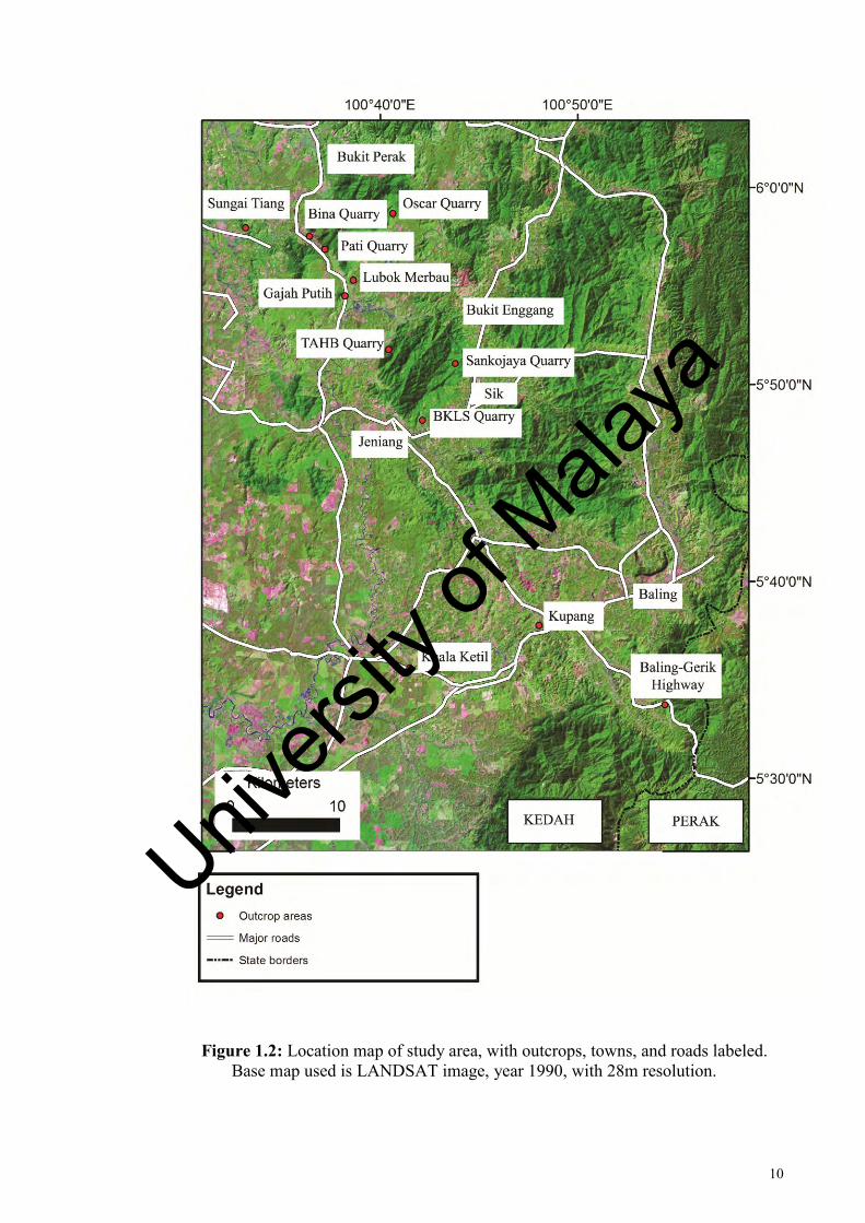
Figure 1.2: Location map of study area, with outcrops, towns, and roads labeled ........ 10
Figure 1.3: Topography of study area, with main rivers plotted ..................................... 12
Figure 1.4: Drainage map of study area .......................................................................... 15
Figure 2.1: The continental core of Sundaland ............................................................... 18
Figure 2.2: Tectonic and structural features of SE Asia ................................................. 18
Figure 2.3: Simplified geology of Peninsular Malaysia, with the geological belts and Bentong-Raub Suture Zone illustrated ............................................................................ 20
Figure 2.4: The three geological belts of Peninsular Malaysia separated by the Bentong Raub Suture and Lebir Fault Zone .................................................................................. 22
Figure 2.5: Major faults of Peninsular Malaysia ............................................................. 23
Figure 2.6: Rock unit of the study area ........................................................................... 26
Figure 2.7: Location for mapped field photos in the study ............................................. 28
Figure 2.8: Sedimentary rock of the study area .............................................................. 29
Figure 2.9: Igneous rock of the study area ...................................................................... 34
Figure 3.1: Lithological domain of the study area .......................................................... 43
Figure 3.2: Aerial photograph lineament interpretation, plotted on series of 1:50000 scaled topographic map ................................................................................................... 47
Figure 3.3: LANDSAT lineament interpretation, plotted on LANDSAT image, year 1990, with 28m resolution .............................................................................................. 48
Figure 3.4: DEM-SRTM lineament interpretation, plotted on hillshade map generated from SRTM digital elevation model ............................................................................... 49
Figure 3.5: Rose diagram for negative lineament and fracture orientation; and positive lineament and bedding orientation .................................................................................. 51
Figure 3.6: Negative and positive lineament extracted from DEM-SRTM .................... 51
Figure 3.7: Map showing spatial distribution of negative lineament in grid cells ........ 53
Univers
ity of
Mala
ya

xiv
Figure 3.8: Rose diagram showing negative lineament orientation in lithological domains ........................................................................................................................... 55
Figure 3.9: Rose diagram showing negative lineament orientation and fracture orientation in mapped rock unit ...................................................................................... 56
Figure 3.10: Rose diagram showing positive lineament orientation and bedding orientation in mapped rock unit ...................................................................................... 57
Figure 3.11: Drag of strike ridges near the Bukit Perak granite body ............................ 59
Figure 3.12: Z-shape of strike ridges adjacent to lineament along main trace of Bok Bak Fault ................................................................................................................................ 61
Figure 3.13: Lineament map and Riedel Shear interpretation of lineaments .................. 64
Figure 4.1: Geometry of a mylonite zone with common type of shear sense indicators shown .............................................................................................................................. 67
Figure 4.2: Classification of fault rocks .......................................................................... 69
Figure 4.3: Distribution of sheared rocks along Bok Bak Fault in southern Kedah-Perak ......................................................................................................................................... 70
Figure 4.4: Mapped shear zone in Bina Quarry .............................................................. 72
Figure 4.5: En echelon quartz filled fracture of Bukit Perak granite .............................. 73
Figure 4.6: Mapped shear zone in Baling-Gerik granite ................................................. 76
Figure 4.7: Mylonitic structure in granite along Bok Bak Fault ..................................... 77
Figure 4.8: Equal area stereogram of mylonitic foliation and stretching lineations measurements along ductile shear zone of Bok Bak Fault ............................................. 79
Figure 4.9: Oriented hand specimens of mylonite showing kinematic indicators .......... 80
Figure 4.10: Microstructures from Bukit Perak granite indicating dextral shearing ...... 83
Figure 4.11: Microstructures from Baling-Gerik granite indicating dextral shearing .... 84
Figure 4.12: Microstructure showing deformation of quartz .......................................... 89
Figure 4.13: Microstructure showing deformation of feldspar ....................................... 91
Univers
ity of
Mala
ya

xv
Figure 5.1: Kinematic indicator of brittle structures in Bok Bak Fault .......................... 97
Figure 5.2: Brittle fault rocks in Bok Bak Fault ............................................................. 98
Figure 5.3: Geometry of fault-slip kinematics in lower hemisphere, equal area stereographic projection ................................................................................................ 100
Figure 5.4: Bok Bak Fault distribution in study area .................................................... 101
Figure 5.5: Brittle-ductile shear zone of Bukit Perak granite ....................................... 105
Figure 5.6: Photomicrograph of brittle-ductile shear zone rock ................................... 105
Figure 5.7: Fault plane solution of faults representing different brittle deformation episodes ......................................................................................................................... 106
Figure 5.8: Distribution of fault plane solutions for measured D1 faults in different localities ........................................................................................................................ 108
Figure 5.9: Distribution of fault plane solutions for measured D2 faults in different localities ........................................................................................................................ 110
Figure 5.10: Distribution of fault plane solutions for measured D3 faults in different localities ........................................................................................................................ 112
Figure 5.11: Sketch of D1 and D3 faults set, showing both reverse and normal movement ...................................................................................................................... 114
Figure 5.12: Sheared rock generated along D1 faults in Semanggol Formation, which occur in close association with D3 faults .................................................................... 1141
Figure 5.13: Photomicrograph of cataclasite formed in granite .................................... 115
Figure 5.14: Conceptual model of a fault zone ............................................................. 118
Figure 5.15: Interpretation of rock unit prior to movement along Bok Bak Fault ........ 119
Figure 5.16: Riedel Shear interpretation of lineaments and faults ................................ 122
Figure 6.1: Ages of various dated granite in NW Peninsular Malaysia ........................ 127
Figure 6.2: Mapped area of Baling-Gerik, showing mapped shear zone, sampling sites for microstructural study, and 40Ar/39Ar dating sampling site ...................................... 129
Figure 6.3: 40Ar/39Ar age spectrum and corresponding isochrone and Ca/K ratio for
biotite from Baling-Gerik shear zone ............................................................................ 131
Univers
ity of
Mala
ya

xvi
Figure 6.4: Histogram of K/Ar apparent ages of granite from Western Belt of Peninsular Malaysia ........................................................................................................................ 132
Figure 6.5: Jurassic-Cretaceous sediments of Peninsular Malaysia. Note the relationship between lineaments and sediment distribution ............................................................. 135
Figure 6.6: Tertiary basins of Peninsular Malaysia ...................................................... 136
Figure 6.7: SRTM shaded relief map showing lineaments and the 2013 earthquake epicenter ........................................................................................................................ 140
Univers
ity of
Mala
ya

xvii
LIST OF TABLES
Table 3.1: Major lineaments in the lithological domain ................................................. 55
Table 3.2: Comparison of major lineaments and structure trends in the mapped lithological unit ............................................................................................................... 56
Table 3.3: Interpretation of simple shear model for Bok Bak Fault Zone, with corresponding shears and faults ...................................................................................... 65
Table 4.1: Summary of deformation of mineral in ductile sheared granite .................... 88
Table 5.1: Linked Bingham axes analysis of fault planes representing different brittle deformation episodes .................................................................................................... 106
Table 5.2: Interpretation of simple shear model for Bok Bak Fault Zone, based on lineament plot in Chapter 3 ........................................................................................... 121
Table 6.1: Tabulated data for 40Ar/39Ar dating of biotite .............................................. 132
Table 6.2: Summary of dating methods commonly used in neotectonic studies .......... 139
Table 7.1: Summary of tectonic events in Peninsular Malaysia which affected the Bok Bak Fault ....................................................................................................................... 142
Univers
ity of
Mala
ya
xviii
LIST OF SYMBOLS AND ABBREVIATIONS
Bt : Biotite
K-spar : K-feldspar
Ms : Muscovite
Plag : Plagioclase
Qtz : Quartz
BLG : Bulging
DEM : Digital elevation model
SGR : Subgrain
SRTM : Shuttle Radar Topography Mission
Univers
ity of
Mala
ya
xix
LIST OF APPENDICES
Appendix A: Spreadsheet for lineament plotting in ArcMap ……………………... 158
Appendix B: Orientation of ductile deformation hand specimens ………………... 163
Appendix C: Linked Bingham axes analysis of fault planes from different
localities ……………...……………………………………………………..……. 164
Appendix D: Actlabs Report ……………………………………………………... 166
Appendix E: Geological map of Kedah-Perak Transect …………………………... 177
Univers
ity of
Mala
ya

1
CHAPTER 1: INTRODUCTION
The Bok Bak Fault is one of the main fault zones of Peninsular Malaysia, stretching
through the northwestern part of the Peninsula. It is rather extensive, with its trace
starting from Perlis and extending southeastward through Kedah, Perak, and Kelantan.
The Bok Bak Fault cuts through the Main Range Granite, as well as sedimentary rocks
and their associated metasedimentary equivalent. The result of the faulting is expressed
through topographic features and mesostructures in the field. The fault trace is well
expressed in remote sensing imageries.
Although the Bok Bak Fault is a major fault zone, not many detailed study has been
done on the fault zone as a whole: studies focus on small parts of the exposure of the
faults, without much detailed study of the fault in a regional sense. Another notable
observation is despite a large amount of igneous plutons being cut by the fault, most of
the fault studies were focused on sedimentary rock formation. Compared to other well
studied major faults of Peninsular Malaysia such as Bukit Tinggi and Kuala Lumpur
Fault, the studies on the kinematic and mechanism of faulting is not well established.
The work on deformed granite along the fault zone is lacking, which is to say that the
deformation condition of the fault – in relation with the igneous intrusion of the region –
is not known.
Of interest to this study are also recent evidences which challenge the claim of the
Peninsula being a tectonically stable region: recent reports of earthquakes in Peninsular
have led some researchers to consider faults which might have undergone reactivation
in recent times, as a response to regional tectonic events. The Bok Bak Fault is among
the structures that are prone to be affected by neighbouring tectonic events, and there
have been several reports of recent seismicity near the fault zone which might be a
result of the fault zone being reactivated.
Univers
ity of
Mala
ya

2
This research will tackle the inadequacy of the studies related to the Bok Bak Fault
by using new methods in an attempt to further understand the evolution of the fault
zone.
1.1 Previous works
The Bok Bak Fault was first described by Burton (1965), where he mapped a 51
miles extension of the fault in the Baling-Jeneri area based from the study of aerial
photographs and field check. The LANDSAT lineament study of the Bok Bak Fault
(Raj, 1982) further extend the fault southward to central Perak and southwest Kelantan,
based on the apparent displacement of Paleozoic sedimentary formation in Perak and
the offsetting of the Main Range granite in Perak. The northwestern extension of the
fault from Pokok Sena to Wang Kelian was proposed based on the drag of strike ridges,
displacement of Paleozoic formations, and features such as deflected rivers and hot
springs along the fault zone (Syed, 1996).
Field occurrences of shear zones in sedimentary formation (Jones, 1970) and granite
(Jones, 1970; Abdul Majid, 1987) in the proposed extension of the fault were seen as
being clear indicator of the existence of the Bok Bak fault further southeast from
Baling. Subsequent field study in central and northern Kedah have reported on the
occurrence of the fault in sedimentary formation (Mustaffa, 1994; Zaiton and Basir,
1999) and granite body (Abdullah, 1993). A gravity survey of Perlis, Kedah and Penang
have detected trace of the fault underneath the sediment cover, and the displacement
along the fault was also identified (Burley and Jamaluddin, 1990).
Several studies have been done on the deformation in sedimentary formations
affected by the Bok Bak fault, especially those that are of the Mahang Formation and
Semanggol Formation in northern and central Kedah (Ibrahim et al., 1989; Zaiton and
Univers
ity of
Mala
ya

3
Basir, 1999; Zaiton et al., 2009). The fault was believed to result in transpressive
regime, resulting in folding and reverse faulting adjacent to the fault (Zaiton and Basir,
1999, 2000).
Zaiton (2002) have studied the timing of deformation for the ductile deformation of
Bukit Tinggi and Bukit Berapit Fault, but have not noted a similar occurrence in the
Bok Bak Fault. The report of ductile mylonite with sinistral shearing in Bukit Perak
(Abdullah, 1993), and the discovery of linear drainage system, quartz reef, outcrops of
mylonites, cataclasite and shear zones in Sungai Siput area, north Perak (Abdul Majid,
1987), points to early ductile deformation of the Bok Bak Fault.
Majority of the previous works on the Bok Bak Fault are focused on the effect of
faulting on sedimentary rock unit, with little detailed studies on the effect of faulting on
granitic bodies. As such, the kinematic and deformation history of the fault is still not
fully understood.
1.2 Objectives of study
The lack of detailed works on the early ductile deformation of the Bok Bak Fault
would point out that the condition of deformation and kinematic history of the fault
were not fully studied. A more detailed kinematic history of the fault and its relationship
with other fault system of the Peninsula is important in delineating the role of the fault
in the tectonic history of the region. The research focus on these main objectives:
Univers
ity of
Mala
ya

4
To characterize the distribution and trend of the Bok Bak fault zone
The extent and trend of the structures along and outside of the research area was
studied to delineate the whole Bok Bak Fault system. This also include other secondary
faults along the main fault zone. Since the fault zones are composed of various
intersecting faults sets, various faults of differing trends found in the field was described
and characterized.
To determine the kinematics and condition of deformation of the fault zone
The sense of movement during the faulting is interpreted from kinematic studies
from the field and examination of fault rocks. Information on the temperature, pressure,
and depth of the fault was studied based on microstructure of the fault rocks.
To discuss the implications of the deformation of Bok Bak fault system on the
different phases of the tectonic evolution of Peninsular Malaysia
The history of deformations along the fault zone was studied in relation to the
different stages of the tectonic evolution of the Peninsula, which results in various
structural trends found in the region.
Univers
ity of
Mala
ya

5
To determine the deformation history of the fault zone and to interpret the
implications of the deformation history along the regional tectonics
Different phases of deformation along the fault zone will result in differences in the
generation of faults and other geological structures. These structures were studied, as
well as the timing of the deformation phases which result in the structures. The timing
of deformation phases was sought from relative and radiometric dating, to interpret the
regional tectonics.
1.3 Methodology
The study combines lineament analysis, detailed field mapping, and petrographic and
microstructural study of oriented sample. A simplified progress of the research is
summarized in a flow chart form (Figure 1.1).
1.3.1 Desk study
The early work of the research focuses on examining available maps and satellite
image to identify accessible outcrops. Published map and geologic report along the
research area was studied to get the general geology of the area. Other relevant
literatures related to the topic are also examined.
Univers
ity of
Mala
ya

6
Figure 1.1: Flow chart of research progress
1.3.2 Remote sensing
The study of Digital Elevation Model-Shuttle Radar Topographic Mission (DEM-
SRTM), LANDSAT satellite images and 1:25000 aerial photographs was carried out to
delineate the distribution, trend, and extension of the Bok Bak fault and its subsidiary
faults. Over these methods, the DEM-SRTM provides the best method in extracting and
analyzing lineament pattern. All these methods are combined to get the most accurate
lineament extraction of the study area. The result of the lineament study is presented in
Univers
ity of
Mala
ya
7
subsequent chapter on the Bok Bak Fault (Chapter 3). The steps for lineament extraction
are as follow:
1.3.2.1 Aerial photographs
Several sets of aerial photographs at the scale of 1:25000 of area in Bukit Perak,
Bukit Enggang, and Baling were studied. By using stereoscope, lineaments were
sketched on tracing paper, which were then transferred to topographic maps scale of
1:50000. Lineaments are identified from long and straight topographic features shown
in the three-dimensional view.
1.3.2.2 Satellite imageries
LANDSAT image sets were used, with two sets studied: a year 1990 image with 28m
resolution, and a year 2000 image with 14.5m resolution. Both satellite images are in
UTM Zone 47 projection. Lineaments are identified in the images as long and straight
feature, although attention is given to distinguish natural and man-made linear structure.
Two set of images are used due to the effect of cloud coverage in the year 2000 image.
The plotting of the lineament is done entirely manually over the images.
1.3.2.3 DEM-SRTM
Digital Elevation Model-Shuttle Radar Topographic Mission (DEM-SRTM) is
primarily used for lineament extraction, where the lineaments were extracted manually.
Although there are several methods for automated extraction of lineaments from DEM,
the lineaments here were plotted manually through ArcMap software. Shaded relief
Univers
ity of
Mala
ya
8
images were created from DEM to accurately pinpoint the lineaments. The DEM were
processed so that shaded relief images were produced from various illumination
conditions: lighting azimuth of 0°, 45°, and 90° were applied to prevent bias of
lineament picking.
1.3.3 Field work
Geological mapping was carried out to differentiate the different lithology unit,
particularly the granite and sedimentary rock. Faults and shear zones in the field were
studied, with their planar and linear features recorded. Other related structures to the
fault such as joints, veins, dikes, and folds were also studied. The mapping was facilated
by the use of Global Positioning System (GPS) in locating outcrops and facilitating
navigation, and the ArcGis software was used to analyze field data and compile the final
geologic map.
Where possible, fault rocks samples were collected for microstructural and
radiometric study. The kinematic of the faults were studied based on mesoscopic
observation as well as microstructural study.
1.3.4 Laboratory work
Samples brought from the field was processed at the laboratory for the petrographic
and geochronological study on the fault rocks:
Univers
ity of
Mala
ya

9
Petrographic study of fault rocks
Petrography of undeformed granite and deformed granite was studied from prepared
thin sections. For deformed rocks, oriented thin sections were prepared, and the analysis
of the microstuctures of the deformed rocks would discern the sense of fault movement.
Geochronology
Samples were sent to the Activation Laboratories Ltd. (Actlabs) in Canada for the
dating of deformation during faulting event through 40Ar/39Ar dating method. The argon
in the secondary biotite of the faulted rocks was dated by using the method
1.4 Study area
For the purpose of the study, the areas covered are portion of central and
southeastern Kedah, with a small part of northern Perak (Figure 1.2). The area was
chosen based on the availability of exposed granite at quarries of Bukit Perak and Bukit
Enggang, the large area of exposed sedimentary formation in Kuala Ketil, and exposed
sheared granite along Baling-Gerik road – all which are along the trace of the fault.
Previous works were studied beforehand to facilitate a plan to collect data from
unobserved area around the fault trace, or to conduct more detailed data collection
where necessary.
The north part of the study area starts near Sungai Tiang, where several active granite
quarries of Bukit Perak (Bina Quarry, Pati Quarry, Oscar Quarry) are to be found. The
granite quarries were found on the west side of the granite massif along Sungai Tiang
Univers
ity of
Mala
ya
10
Figure 1.2: Location map of study area, with outcrops, towns, and roads labeled. Base map used is LANDSAT image, year 1990, with 28m resolution.
Univers
ity of
Mala
ya
11
area, and further northeast near Lubok Merbau. Further southeastward along the study
area are the quarries of Bukit Enggang (TAHB Quarry, BKLS Quarry, Sankojaya
Quarry). In both areas the granites are found in rural areas, with moderate to good
accessibility through the main road and smaller roads.
Further south in Kuala Ketil, the sedimentary rocks were well exposed along
roadcuts and hillcuts. The area lie in between township of Kuala Ketil to west and
Kupang in the east, with the east-west road connecting Sungai Petani-Baling providing
some rather well exposed outcrops. At the furthest southeastern part of the study area
are granite exposure along Baling-Gerik highway. The mapped area along the highway
extends slightly further from the Sungai Rui area, at the Kedah-Perak boundary.
1.5 Physiography
The landscape of the area is characterized by hills and valleys, with several granite
bodies forming highland areas (Figure 1.3). The two main granite pluton of Bukit Perak
and Bukit Enggang show up distinctly in topographic map and satellite imageries, while
the portion of the Bintang Range granite crops up as highland at the southern part of the
area amidst the hilly topography around Baling.
Besides the highland and flat plain, one the most striking geomorphological feature
that can be found is the occurrence of strike ridges: linear positive relief features which
could readily be viewed from satellite imageries. These structures are found in the
Kubang Pasu and Semanggol Formation rocks, and correspond with the general strike
trend of the sedimentary beds in the area. These structures are especially well observed
in Kuala Ketil.
Univers
ity of
Mala
ya

12
Figure 1.3: Topography of study area, with main rivers plotted. Triangle symbol refers to highest point of granite bodies. Topographic contour interval is 100 m.
Univers
ity of
Mala
ya

13
In general the topography and drainage pattern in the area appear to be controlled by
the lithology and structure, with different geology producing some decidedly distinct
topographic feature.
1.5.1 Topography
In Bukit Perak area, the northwest of the granite pluton is relatively flat and low
lying. Closer to the granite pluton, several north-south trending strike ridges break the
monotony of the flat area. The Bukit Perak granite pluton appear as a large rectangular
block which trend NE-SW, with remarkably straight and steep slope in contact with the
low lying sediment. The highest point on the granite pluton is Bukit Perak (865 m).
The Sungai Muda Valley forms as a low lying area between the Bukit Perak and
Bukit Enggang granite pluton. The valley was believed to be underlain by the conjugate
fault set that cut the Bok Bak fault, which was named the Muda Valley Fault (Burton,
1965) and the Lubok Merbau Fault (Abdullah, 1993). Further south, the topography of
the area is more hilly. The Bukit Enggang granite pluton crops up as an oval-shaped
structure, trending roughly at NE-SW. Bukit Enggang (772 m) is the highest point of
the granite pluton.
In Kuala Ketil, the most notable topographic feature are the occurrence of long
parallel sets of ridges (Figure 1.3). These features are well observed in topographic map
and remote sensing. At the west, near the town of Kuala Ketil these ridges trend at a
northeast-southwest trend. Further eastward towards Kupang and Baling, the ridges
swerve to a NNE-SSW trend as they approach the trace of the Bok Bak fault. Further
east of the Bok Bak fault trace, the limestone hill of Baling forms a highland with a
curved shape that follows the valley around it.
Univers
ity of
Mala
ya

14
Southward near the end of the study area lies the granite of the Bintang Range. The
most notable high point of the granite here is Bukit Inas, situated at the north end of the
Bintang Range. The slope of the hill descend sharply into the valley of Sungai Ketil.
Burton (1970) had pointed out that the Bintang Range granite could be found to extend
further northeast of Kedah into Thailand.
1.5.2 Drainage pattern
In both the Bukit Perak and Bukit Enggang pluton, the rivers show a predominantly
dendritic pattern in the pluton (Figure 1.4). As the plutons have steep gradient, the rivers
are fast flowing, and waterfalls could be found. Around the pluton, the rivers show a
predominantly northeasterly-southwesterly direction through the flat and valley area.
Several of the main rivers include Sungai Jeneri (flowing from east to west) and Sungai
Muda northeast to southwest). Sungai Muda and other branching river flows
southwestward through the Muda Valley.
Further south, the main river is Sungai Kuala Ketil, where it flows in a southwesterly
manner through Kupang and Kuala Ketil area. The river corresponds to the general
strike of the underlying sedimentary beds, and as such could be described as a strike
stream. At Baling, the river direction swerves to form a southern-southeasterly flow
direction. South of Kupang, the river branch off southeastward, which forms the two
main set of river: Sungai Kupang and Sungai Tiak. Both rivers flank Kampung Bok
Bak, flowing in the valley adjacent to the Bintang Range granite pluton.
The drainage pattern appears to be affected by the underlying geology and structure.
In sedimentary formation, the river could be found to correspond to the strike trend of
the sedimentary formation. The dendritic river pattern on the granite plutons are
Univers
ity of
Mala
ya

15
Figure 1.4: Drainage map of study area
Univers
ity of
Mala
ya

16
possibly controlled by cooling joints formed after the granite emplacement. Several of
the river flow seems to be fault controlled: this is suggested by their linear pattern and
their trend which coincide with the major trend of the faults. These rivers are more
pronounced in granite pluton, where the fault cutting the granitic bodies result in more
pronounced lineaments. In sedimentary formation, presence of bedding makes it
difficult to differentiate between the structural control of faults or bedding
discontinuities. This is especially obvious in Baling where both the river and structural
trend swerve in a direction similar to the Bok Bak fault.
Univers
ity of
Mala
ya

17
CHAPTER 2: REGIONAL SETTING AND GEOLOGY OF BOK BAK FAULT
ZONE
2.1 Regional tectonic setting
The Peninsular Malaysia forms part of the regional block of Sundaland, a South East
Asian part of the Eurasian Plate (Hutchison, 2007, Metcalfe, 2011). The term strictly
defines the landmass of South-East Asia which include Sumatra, Java, and Borneo
which stood above sea level during the low sea level of Pleistocene epoch (Voris, 2000),
but it is acceptably used in referring a South-East Asian continental part of the Eurasian
plate (Hutchison, 2007).
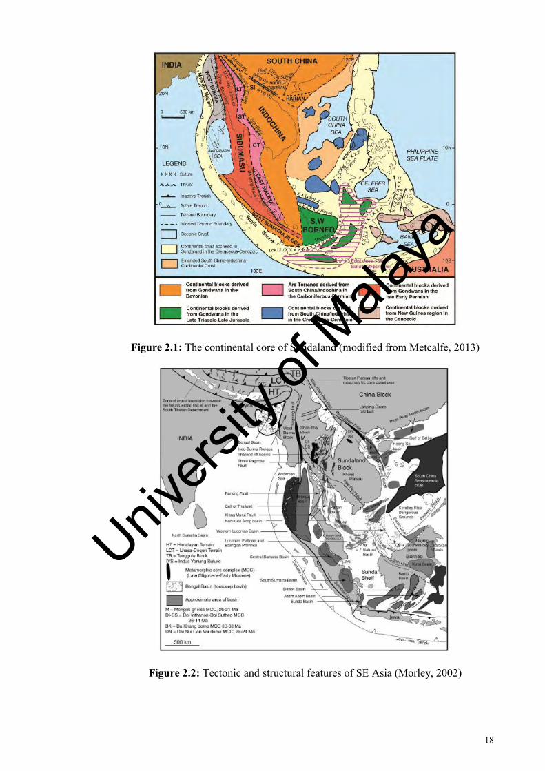
The continental core of Sundaland consist of the South China block, the Indochina
block, the Sibumasu terrane, West Burma block, West Sumatra block, and SW Borneo
block (Figure 2.1). The margin of Sundaland is defined by Sagaing-Namyin Fault in the
west, extending southward into the Andaman Sea and west of Sumatra. The margin of
Sundaland in the east is more fragmented and complicated due to the opening of
Tertiary basins and occurrence suture zones. Most of the continental blocks of SE Asia
were derived from the southern hemisphere of the supercontinent Gondwana (Metcalfe,
1988), and were progressively assembled during Late Palaeozoic to Cenozoic
convergent tectonics, leading to the present continuous collision of India and Asia, and
Australia with SE Asia (Morley, 2012).
The convergence between the Indian and Asian plate is an important event in the
tectonic evolution of SE Asia. The models by Tapponnier et al. (1982, 1986) have
shown that the faults feature of SE Asia could be produced by the collision of India and
Univers
ity of
Mala
ya
18
Figure 2.1: The continental core of Sundaland (modified from Metcalfe, 2013)
Figure 2.2: Tectonic and structural features of SE Asia (Morley, 2002)
Univers
ity of
Mala
ya

19
Eurasia through extrusion tectonic. Subsequent studies have discussed on the model of
escape tectonic and its relationship with the major faults and Cenozoic basins of SE
Asia (e.g. Morley, 2002). Most of these faults are right-lateral wrench faults, resulting
from clockwise rotations (Hutchison, 2007) (Figure 2.2).
2.2 Geological setting of Peninsular Malaysia
The Peninsula hosts an array of geology, subjected to regional tectonic forces which
produce the multitude of structural styles observed in the present. Various works by
geologists incorporating these diverse rock assembly observed with various proposed
tectonic models have resulted in the general subdivision of the Peninsula into three
belts: the Western Belt, Central Belt, and Eastern Belt (Figure 2.3). This subdivision
resulted from the development of the study which distinguishes different stratigraphy,
structure, magmatism, geophysical signatures, and geological evolution between these
belts (Metcalfe, 2013).
Two main tectonic blocks forms the Peninsular Malaysia: the Sibumasu Terrane and
East Malaya Block (Figure 2.1). The Western Belt is part of the Sibumasu Terrane,
whereas the East Malaya Block consists of the Central and Eastern Belts. Recent works
have identified a volcanic arc terrane, the Sukhothai Arc, in the western margin of
Indochina-East Malaya block (Sone and Metcalfe, 2008).
The study area falls under the northwestern domain of the western belt of the
Peninsular, an arbitrary subdivision of the Western Belt of the Peninsula. This
subdivision is based on the most complete Paleozoic rocks exposure, from the age of
Upper Cambrian to Upper Permian (Lee, 2009). The geology of the area is dominated
Univers
ity of
Mala
ya

20
Figure 2.3: Simplified geology of Peninsular Malaysia, with the geological belts and Bentong-Raub Suture Zone illustrated (Metcalfe, 2013)
Univers
ity of
Mala
ya

21
by Paleozoic and Mesozoic aged sedimentary rocks with occurrence of granite plutons.
The Bok Bak Fault is a major fault that cut across the lithology.
The geological belts are also separated by structural elements: the Bentong –Raub
Suture Zone separates the Western and Central Belt, while the Central and Eastern Belt
is marked by the Lebir Fault Zone (Figure 2.4). The boundaries between the
Northwestern Domain with the Western Belt is however unclear, as no major structure
separate within the western belt.
2.3 Fault system of Peninsular Malaysia
The Peninsular is transected by several sets of major strike slip faults. These faults
came to be recognized from earlier studies of remote sensing and field mappings, with
new faults subsequently discovered through study of satellite imageries and shuttle
radar imageries.
The faults can be seperated into three categories based on their orientation and
position to the terranes of Peninsula: terrane-bounding faults, terrane-parallel faults and
terrane-cutting faults (Mustaffa, 2009a). The Bok Bak Fault belong in a group of NNW-
SSE and NW-SE terrane-cutting faults, which includes other faults such as the Bukit
Tinggi, Ruok, Galas, Lebir, Lepar, and Mersing fault zones. Figure 2.5 show the
distribution of these faults in relation with the fault system of Peninsular Malaysia.
The NNW-SSE to N-S faults were believed to be initiated as dextral strike-slip faults
after the amalgamation of the two tectonic blocks of the Peninsula during Permian to
Triassic time, after or during the late stage of the emplacement of the Main Range
Granite during late Triassic to Jurassic (Mustaffa, 2009a). An isotope dating by Zaiton
Univers
ity of
Mala
ya

22
Figure 2.4: The three geological belts of Peninsular Malaysia separated by the Bentong Raub Suture and Lebir Fault Zone (Metcalfe, 2000)
Univers
ity of
Mala
ya

23
Figure 2.5: Major faults of Peninsular Malaysia (Mustaffa, 2009a)
Univers
ity of
Mala
ya

24
(2002) on mylonite from NNW-SSE Bukit Tinggi fault result in late Cretaceous age: it
was believed that movement of the NNW-SSE, NW-SE and WNW-ESE strike slip fault
was sinistral during this time period, and movement of the Bok Bak Fault during this
period result in transpressive deformation of sedimentary formation adjacent to the fault
(Zaiton, 1993; Zaiton and Basir, 1999, 2000). These sinistral movements could thus be
taken to represent reactivation along the previously dextral strike slip faults, as there are
reports of both dextral and sinistral microstructure in the fault zone (e.g Ng, 1994;
Zaiton, 2002). The report of the occurrence of both dextral and sinistral movement
along these faults suggested that the faults are subjected reactivation from a ductile
deformation to a brittle deformation (Ng, 1994). Mustaffa (2009a) had suggested the
earlier dextral ductile deformation of Bukit Tinggi Fault might have taken place during
Late Triassic – Jurassic, after or at least at the late stage of Main Range Granite
emplacement.
The Tertiary basins along trace of NW-SE faults were reported to be formed during
reactivation of the faults in Tertiary (Raj et al., 1998, Zaiton, 2002). The India-Eurasia
collision has resulted in reactivation of pre-existing structures in the region, where it
was suggested that the escape tectonics utilized pre-existing zone of weaknesses such as
suture zones and previously formed shear zones (Hutchison, 2007). Metcalfe (2013)
have however pointed out the finding of counter-clockwise rotation of Peninsular
Malaysia during Cenozoic time (Richter et al., 1999), which would be incompatible
with the ‘extrusion model’ of the India-Eurasia collision.
Univers
ity of
Mala
ya

25
2.4 Rock units of the Bok Bak Fault Zone
2.4.1 Sedimentary formation
The central and southern Kedah is covered extensively by sedimentary formation,
neighboured by bodies of granitic intrusions. The sedimentary formation forms the
majority of low lying area, as well as several of the hills and set of parallel strike ridges.
The Bok Bak Fault is seen acting as forming a separation between these two lithology.
In the north of the study area, the Mahang Formation occurs adjacent to the granite
plutons of Bukit Perak and Bukit Enggang. The Semanggol Formation are found further
northward from these granite plutons. Further south, the Semanggol Formation covers
majority of the area, stretching from Kuala Ketil until Baling. The granite of the Bintang
Range crops up further south, separated from the nearby sedimentary formation by the
Bok Bak Fault. The Baling Formation rocks are found in close proximity to the granite,
producing a host of metasedimentary product from the original sedimentary rocks.
2.4.1.1 Baling Formation
The Baling Formation (earlier classified as the Baling Group) is employed by Burton
(1970) to describe the large occurrence of metamorphosed sedimentary sequence within
the area of Baling. He identified four main facies of arenaceous, argillaceous, calc-
silicate and limestone. The facies of the formation are of lenticular nature, each having
interfingering contact with one another: as such the actual contact between the different
facies are difficult to be pointed out exactly. The limestone forms several of the
prominent hills in the area, with the notable horseshoe shaped hill in west Baling. Trace
of the Baling Formation could be found further south in Grik, where it occurs
Univers
ity of
Mala
ya

26
Figure 2.6: Geological map of study area (geology from field mapping, and modified from Burton, 1970; and Teoh, 1992).
Univers
ity of
Mala
ya

27
Figure 2.6, continued
Univers
ity of
Mala
ya

28
Figure 2.7: Locations for mapped field photos in the study (squares). Refer to Figure 2.6 for details on legend of map.
Univers
ity of
Mala
ya
29
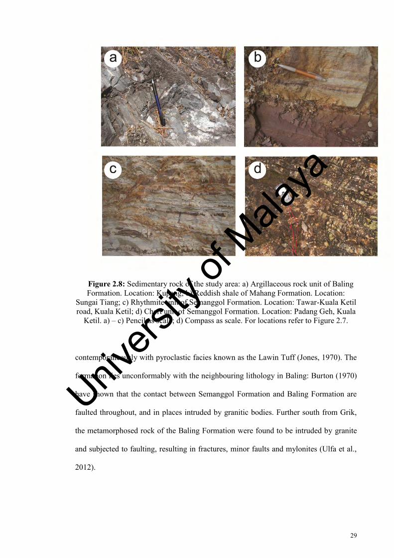
Figure 2.8: Sedimentary rock of the study area: a) Argillaceous rock unit of Baling Formation. Location: Kupang; b) Reddish shale of Mahang Formation. Location:
Sungai Tiang; c) Rhythmite unit of Semanggol Formation. Location: Tawar-Kuala Ketil road, Kuala Ketil; d) Chert unit of Semanggol Formation. Location: Padang Geh, Kuala
Ketil. a) – c) Pencil as scale; d) Compass as scale. For locations refer to Figure 2.7.
contemporaneously with pyroclastic facies known as the Lawin Tuff (Jones, 1970). The
formation lies unconformably with the neighbouring lithology in Baling: Burton (1970)
have shown that the contact between Semanggol Formation and Baling Formation are
faulted throughout, and in places intruded by granitic bodies. Further south from Grik,
the metamorphosed rock of the Baling Formation were found to be intruded by granite
and subjected to faulting, resulting in fractures, minor faults and mylonites (Ulfa et al.,
2012).
Univers
ity of
Mala
ya

30
Majority of Baling Formation rocks are metamorphosed, and as such not many
fossils are preserved that could be used for purpose of dating. However, correlation of
the fosilleferous argillaceous facies with other rock formation in the region yield a
tentative Ordovician to Early Silurian age (Jones, 1970). Graptolites found in the Baling
area reveal an age of Early Silurian (Jones, 1973b).
A small portion of the Baling Formation is exposed in Kupang, where it neighbours
with the Semanggol Formation in Kuala Ketil. The rocks are finely foliated
metamorphosed argillite, which are distinctly different from the intebedded
argillaceous-arenaceous of neighbouring Semanggol Formation.
2.4.1.2 Mahang Formation
The Mahang Formation is an extensive Paleozoic aged siliclastic sedimentary rock
found in southern Kedah, extending into Kulim (Courtier, 1974) and neighbouring
Bedung area (Burton, 1967). The sedimentary formation is also found in central Kedah,
where it is in contact with the Kubang Pasu Formation (Zaiton and Basir, 1999).
Graptolites recovered from the formation give an Early Silurian age (Burton, 1967;
Jones, 1973a). Lower Devonian graptolites, as well as numerous tentaculitids, were
recovered as well (Jones, 1967, 1973a, 1973b).
In satellite imageries, the contact between the Bukit Perak granite and the Mahang
Formation is found to be a remarkably straight linear contact. Burton (1967) identified
the sharp boundary of the Mahang Formation with neighbouring granite as that of
wrench fault. Exposure of the sedimentary formation could be found in the western
margin of Bukit Perak, with several exposed outcrops in Gajah Putih. These outcrops
reveal interbedded sandstone and shale which were subjected to minor folding and
Univers
ity of
Mala
ya

31
faulting. The sandstone show coarse grained yellowish to whitish colour, with fine
lamination to moderately thick bedding. Some of the sandstone beds were found to
show cross bedding texture. The shale and mudstone are dark greyish, and are usually
interbedded along with the lighter coloured sandstone. In several localities further
northwest of Sungai Tiang, the reddish slate of the Mahang Formation could be found,
which shows well-developed slaty cleavage.
A small exposure of the interbedded sandstone-shale sequence of the Mahang
Formation were exposed in the western part of Bina Quarry, neighbouring the granite.
Here the sediment show mostly open folds, with WNW and NW trending bedding. The
rocks here were found to be truncated by small sets of fractures and faults, with some
developing closely spaced cleavages. Closer to the margin of the granite, the folding of
the sediment intensify, forming kink folds with cleavage formation; similarly, fractures
and faults occurrence in the rock increases.
In Gajah Putih, a small outcrop of the Mahang Formation rocks reveal several flank
of fold hinge with different plunge direction, and this was taken to represent more than
one set of deformation phases in the formation. The beddings trend predominantly
north-south, mostly dipping westward. The folds plunge westward and northward, and
appear almost adjacent to faults. The observed faults, based from the displaced beddings
and visible fracture planes, were shown to share similar NW trend of the Bok Bak Fault.
Univers
ity of
Mala
ya

32
2.4.1.3 Semanggol Formation
The Semanggol Formation is the most extensive sedimentary formation in the study
area, covering the northern of Kedah and extending southward to northwest Perak. The
Mid Triassic argillaceous-arenaceous rock group is generally divided to consist of three
main series or members: chert, interbedded sandstone-shale (rhythmite), and
conglomerate. The three group were originally introduced as members by Burton
(1973), although most geologist have used the designation of units by Teoh (1992). Of
the three members, the Chert Member represents the oldest unit, while the
Conglomerate Member is the youngest unit (Burton, 1973). The Semanggol Formation
was proposed to be in a fault contact with the Kubang Pasu Formation (Burton, 1965),
with the contact was later identified to be reverse or thrust fault (Ibrahim et al., 1989).
The formation develop a zone of contact metamorphism with the granite pluton of Bukit
Perak (Teoh, 1992), Baling (Burton, 1970) and Kulim (Courtier, 1974), although the
trace of the contact aureole is not very extensive. Where the Bok Bak Fault separates the
Semanggol Formation and the granitic bodies, contact aureole were obscured by
faulting.
In Sungai Tiang, the Semanggol Formation crops up northward of the granite pluton
of Bukit Perak. The formation is expressed as strike ridges, which start as northeast-
southwest trending parallel ridges near the Bok Bak Fault’s trace. The ridges swerve to
north-south set further north, near Naka (Teoh, 1992). Large exposure of the Semanggol
Formation crops up in the Kuala Ketil. The rocks form sets of parallel trending ridges,
similar to that observed in Sungai Tiang.
Univers
ity of
Mala
ya

33
In the field, the Semanggol Formation consists mainly of interbedded sandstone,
mudstone and shale, with some occurrence of chert and conglomerates. The different
composition of lithology correspond to the classification by Burton (1973), although the
conglomerate found is only a small occurrence. The rhythmite and chert unit is well
exposed in Kuala Ketil. From field observation, the Semanggol Formation rocks were
subjected to folding and cut by several sets of faulting. In areas where the rocks could
be picked up as ridges in remote sensing, the general trend of the bedding appear to
correspond with trend of the ridges.
2.4.2 Intrusive bodies
Several granite bodies crop out as large plutons along the trace of the fault, and these
have been subjected to different naming by authors working on the different areas of
granite occurrence (e.g. Jones, 1970; Burton, 1970; Teoh, 1992). Most of these granites
are somewhat texturally similar, with mostly subtle difference in their mineralogical
content. For this research, the granites are divided into three type based on their
geographical occurrence, using the original term employed by Teoh (1992) and Jones
(1970).
The granites are found as large plutons that form the highland of Bukit Perak and
Bukit Enggang, and along the extent of the Baling-Gerik highway. The granites of the
two hills are well exposed along the faces of quarries, and as outcropping resistant
boulders amidst weathered granitic soils. Along Baling-Gerik, construction of highway
provides good exposure of the granite. Elsewhere, the granite forms the lowland around
the plutons, and these have been suggested to be the downthrown part of the large
plutons (Teoh, 1992).
Univers
ity of
Mala
ya
34
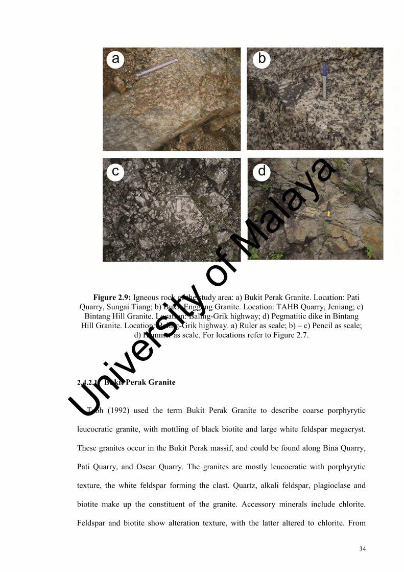
Figure 2.9: Igneous rock of the study area: a) Bukit Perak Granite. Location: Pati Quarry, Sungai Tiang; b) Bukit Enggang Granite. Location: TAHB Quarry, Jeniang; c)
Bintang Hill Granite. Location: Baling-Grik highway; d) Pegmatitic dike in Bintang Hill Granite. Location: Baling-Grik highway. a) Ruler as scale; b) – c) Pencil as scale;
d) Hammer as scale. For locations refer to Figure 2.7.
2.4.2.1 Bukit Perak Granite
Teoh (1992) used the term Bukit Perak Granite to describe coarse porphyrytic
leucocratic granite, with mottling of black biotite and large white feldspar megacryst.
These granites occur in the Bukit Perak massif, and could be found along Bina Quarry,
Pati Quarry, and Oscar Quarry. The granites are mostly leucocratic with porphyrytic
texture, the white feldspar forming the clast. Quartz, alkali feldspar, plagioclase and
biotite make up the constituent of the granite. Accessory minerals include chlorite.
Feldspar and biotite show alteration texture, with the latter altered to chlorite. From
Univers
ity of
Mala
ya

35
mineral composition, majority of the granite could be allocated as alkali granite, with
some granodiorite (Teoh, 1992).
Magmatic flow in granite, shown by arrangement of feldspar clast, is observed in
some localities. The relation of magmatic flow with faulting is rather ambiguous:
although the trend of the feldspar foliation show parallelism with the trend of certain
faults, in other place, the foliation doesn’t follow the trend of nearby faults. Given these
ambiguous indicator, it is most likely that these clasts were affected by magmatic flow
as opposed to shearing along the fault zone. Sheared granite produce cataclastic and
mylonitic granite. The mylonitized granite is well observed along the western part of
Bina Quarry in Sungai Tiang. Elsewhere, shearing in the granite produce brecciated and
fractured granite.
On the southeast of Bukit Perak near the Lubok Merbau area, large bodies of quartz
vein could be found outcropping amongst the weathered granitic soil. The quartz body
form whitish boulders and cobbles in the field, with exposure of several hundred meters.
They are rather heavily fractured and on several occurrence shows brecciated texture.
Despite heavy fracturing, the quartz are solid and consolidated. Teoh (1992) and
Abdullah (1993) have reported instance of large quartz vein formed along NE trending
fault, which borders with the NW fault of main Bok Bak Fault. Both authors believed
the quartz were formed post-faulting.
Univers
ity of
Mala
ya

36
2.4.2.2 Bukit Enggang Granite
The Bukit Enggang Granite forms the Bukit Enggang massif, with the granites well
exposed along the quarries of TAHB Granite Quarry and BKLS Quarry. The granites
were reported to be texturally similar to the Bukit Perak Granite (Teoh, 1992), being
leucocratic and of porpyhrytic texture. The granite could be taken as an extension of
Damar Granite in Baling area by Burton (1970).
As with Bukit Perak Granite, majority of the granite have porphyrytic texture,
feldspar forming the clast. The granite is composed of quartz, alkali feldspar,
plagioclase and biotite, with accessory minerals such as chlorite and epidote. Most of
the biotite in the granite was altered to chlorite: in sheared granite, this result in a
greenish colour. Compared to the Bukit Perak granite, myrmekitic intergrowth texture
between feldspar and quartz could be observed under microscope. Tourmaline crystals
are found as intergrowth in some of the veins, and this is well observed in TAHB
Quarry where the tourmalines could be seen forming veins with epidote as acicular
crystals. Small traces of xenolith were also observed in the granite. The granites are
mostly classified as adamellite and alkali granite (Teoh, 1992). Pegmatitic granite is
well observed in BKLS Quarry, in the form of irregular bodies and large veins: the
granite here is less porphyrytic and coarser grained compared to other granite.
2.4.2.3 Bintang Hills Granite
Jones (1970) have designated the porphyrytic and sheared granite west of Gerik as
the Bintang Hills Granite. Much like the granite of Bukit Perak and Bukit Enggang, the
granite exhibit porphyrytic texture, with feldspar forming the clasts. The author
however doesn’t allocate a detailed subdivision of the granite: Burton (1970), who
Univers
ity of
Mala
ya

37
subsequently mapped the granite in the area, has subdivided the granite bodies of
Kupang, Inas and Damar Granite. It was however maintained that the naming of Inas
Granite is applied to one of the varieties of granite forming the Bintang Range (Burton,
1970): thus, the term Bintang Hill Granite used by Jones (1970) could be said to be a
general term to cover the granite exposed in the area. For this work, the term Bintang
Hills Granite is used as a general term for all granite which outcrops along the Baling-
Gerik highway.
The granites are leucocratic, coarse grained with porphyritic texture. Feldspar makes
up the clast, with other minerals consisting of quartz, alkali feldspar, plagioclase, mica
and other accessory minerals forming the groundmass. Flow banding of the porphyrytic
granite is well observed in most exposure. Biotite form most of the mica in the granite,
and these show exceptional mica fish microstructure when they are deformed. The
biotite from the granite seems much abundant and intact compared to the other two
granitic bodies, and secondary biotite which forms the foliation of mylonitic granite are
quite common where the granite is sheared. The granites show a much more distinct
shearing feature, producing both brittle cataclasite and mylonite.
There is also a small occurrence of microgranite alongside the porphyritic granite.
Through several extent of the area, quartz veins with tourmaline content intrude into the
granite. While most of these occur as isolated veins, in several localities the veins form
a zone with sets of veinlets. Pegmatitic dikes could also be found intruding into the
porphyrytic granite. Compared with pegmatitic granite of Bukit Enggang, these seem to
be more abundant in mica content. The dikes seem to postdate shearing, as some has
exhibited evidence of being folded.
Univers
ity of
Mala
ya
38
2.4.2.4 Other igneous bodies
Burton (1970) designated the granite bodies in Baling to Inas Granite, Damar Granite
and Kupang Granite, allocating them to the localities and different intrusion period. The
southeastern granite extension off Bukit Enggang was given the term Rimba Telui
Granite (Teoh, 1992), where the contact with adjacent Bukit Enggang Granite is defined
by NE-SW trending fault. The majority of the Rimba Telui Granite is reported to be
adamellite (Teoh, 1992). From their mapped extent, the Rimba Telui Granite appears to
be the northwestern extension of Burton’s Damar Granite. Similarly, the Bukit Enggang
Granite could be correlated with Inas Granite in Baling. The Bukit Perak Granite
doesn’t appear to have immediate extension with the granite classification by Burton,
although it was noted to be texturally similar with Inas Granite, Bintang Range Granite
and Main Range Granite (Teoh, 1992).
Several of the mapped intrusive bodies were separated by faults: NW set faults
separate Kupang-Inas Granite, while NE set faults separate Bukit Perak-Bukit Enggang
and Bukit Enggang-Rimba Telui Granite. The Damar Granite doesn’t show a clear
boundary with the faults in geologic map: report of intrusion of granitic bodies similar
with Damar Granite along the main NW trend fault have gave rise to the idea that not
only the Damar Granite is the youngest among the granite intrusion, but is also of the
same time with movement along the Bok Bak Fault (Burton, 1970). There is however
no strong field evidence for the granite being syn-kinematic in respect with the Bok Bak
Fault.
Univers
ity of
Mala
ya

39
2.4.3 Summary for geology of Bok Bak Fault Zone
The geology along the Bok Bak Fault Zone is characterized by sedimentary rock unit
and granitic igneous bodies. Field checks have confirmed the occurrence of these rock
units which have been discussed in greater detail by previous workers.
The Baling Formation rock unit is exposed in Kupang, where it neighbours with the
Semanggol Formation in Kuala Ketil. The rocks are finely foliated metamorphosed
argillite, which is distinct from the rest of the sedimentary rock unit. Rock from Mahang
Formation neighbor granitic bodies in Sungai Tiang, and show evidence of multiple
deformation from the occurrence of several different plunging folds. The Semanggol
Formation is exposed in Sungai Tiang and Kuala Ketil area, with the occurrence of
folding beds and faulting. Both Mahang Formation and Semanggol Formation rock
appear to form sets of parallel trending ridges, and these will be discussed in Chapter 3.
Granites form the large plution of Bukit Perak and Bukit Enggang, and a portion of
the Baling-Gerik highway. As a result of deformation, various products of sheared
granites were produced in the granite plutons. The resulted fault rocks are found to be
generally distinct in texture from that of undeformed granites, and could be
differentiated both in the field and microscopy. The property of these faulted granites
and the deformation mechanism which result in their formation will be discussed in
Chapter 4 and 5.
Univers
ity of
Mala
ya

40
CHAPTER 3: REMOTE SENSING STUDY
3.1 Introduction
Studies on aerial photographs and satellite imageries have proved important in the
study of the fault systems of the Peninsula. With time, more advanced and higher
resolution images in satellite imageries helped to further mapped out fault zones in
greater detail. The work by Raj (1982) is a comprehensive lineament studies on the Bok
Bak Fault, where the fault trace was extended into Central Perak and Kelantan based on
lineaments plot and distribution of lithology. Subsequent use of lineament study,
supplemented with field check, was used in southward extension into Perak (Abdul
Majid, 1987) and northwestward extension into Perlis (Syed, 1995).
In this study, a combination of DEM-SRTM data, satellite imageries and aerial
photograph along the main trend of the fault zone were used in studying pattern of the
lineaments. The trend of these lineaments was compiled, analyzed, and interpreted.
3.2 Lineament extraction
Distinctions are made between negative and positive lineament: the former refers to
linear structures with low relief, and the latter refers to high relief linear structures. The
two types of linear structures are distinguished for the purpose of correlating with
structural data.
Univers
ity of
Mala
ya
41
From the various method of lineament extraction discussed in Chapter 1, regional
lineament study was conducted mostly by using lineament extracted from Digital
Elevation Model-Shuttle Radar Topographic Mission (DEM SRTM) imagery. This
method has several advantages over relying on simply one set of aerial photographs
and/or satellite images, having more flexibility for lineament plotting and analysis as
well as having significant accuracy in lineament detection. The most significant
advantage is the creation of hill shading: DEM was extracted from SRTM, where it is
applied with different azimuth direction and sun angle. This technique is useful in
enhancing geological and geomorphological feature, which might not be visible had
only aerial photograph of LANDSAT images are used. The hill shading image was
created from an input angle of 45°, 90°, and 135°. These angles were chosen to prevent
bias of lineament picking from only using one input angle, and were chosen due to their
relation with trend of major faults reported by other works (NW-SE, N-S, and NE-SW
respectively)
Lineament data (azimuth and length) are plotted graphically as radar graph in
spreadsheet program (MS Excel). The lineament data are separated into an interval of
10°, with the cumulative length of each interval calculated. This produce a more
accurate representation of the lineament distribution, rather than plotting the data solely
based on the azimuth of each lineament without consideration of the length of each
lineament’s group: plotting of lineaments sets without taking into consideration the
length could potentially mean that minor short length lineaments which occur in
scattered group might have a bigger representation graphically when they are plotted
alongside major lineament set.
Univers
ity of
Mala
ya

42
3.3 Geological domains
3.3.1 Lithological domains
As the Bok Bak Fault consist of several rock unit, for the purpose of lineament
analysis, the area is divided into several domains, based on lithology and geographical
location (Figure 3.1). The domains are divided based on rock unit from field mapping,
as well as previous mapping of Burton (1972), Raj (1982), and Teoh (1992). The
division of domains based on rock unit is to study if there is significant change of
lineament density and trend in different geology. For the purpose of this chapter,
additional rock units that are cut by Bok Bak Fault yet not covered by field visit in this
study will also be included:
1) Western Paleozoic Sediment Domain (WPAL)
2) Eastern Paleozoic Sediment domain (EPAL)
3) Mesozoic Sediment Domain (MES)
4) Granite Domain (GR)
5) Tertiary Sediment Domain (TER)
6) Quaternary Sediment Domain (QTY)
Univers
ity of
Mala
ya

43
Figure 3.1: Lithological domain of the study area. Geology from field mapping and Burton (1972), Raj (1982), and Teoh (1992).Refer to Figure 2.6 for geological map of
study area.
Univers
ity of
Mala
ya

44
3.3.2 Geomorphology
The study area is characterized by hills and valleys (Figure 1.3). The Western
Paleozoic Sediment Domain (WPAL) forms N-S trending hills, covering an area of
2047.45 km2. Majority of the lineaments are positive lineaments, which correspond to
the trend of the hills. The negative lineaments are mostly concentrated in sections
adjacent to granite bodies. Most of the observations here have not been noted in other
work relating to the Bok Bak Fault:
The Eastern Paleozoic Sediment Domain (EPAL) shows similar feature with WPAL,
having N-S trending hills. The domain covers an area of 1446.22 km2. Compared to
WPAL, some of the hills show E-W trend, and this is corresponded with the positive
lineaments. The domain also shows high concentration of negative lineament in part
which borders granite.
The Mesozoic Sediment Domain (MES) is made up primarily by the Semanggol
Formation sediments, which forms long narrow hills trending N-S and E-W. The hills
are much more prominent than the Paleozoic Sediment Domain. The domain covers an
area of 1363.69 km2. A number of negative lineament cuts the domain, and the positive
lineament is very distinct, the latter showing clear change of trend across the
subdomains.
The Granite Domain (GR) consist of granitic body which covers a large area, in
irregular bodies trending roughly N-S. The domain covers an area of 6794.54 km2. The
domain forms the highest points in the area, visible as large hills and mountains.
The Tertiary Sediment Domain (TER) refers to a very small spot of sediment in
northern Perak. The sediment is of semi-consolidated, interstratified sand, grit, and
pebble beds (Jones, 1970). It is the smallest of the domains, at only 7.78 km2. The
Univers
ity of
Mala
ya

45
domain is only mentioned here as a subdivision of geologic bodies in the area, since the
small distribution of the sediment does not provide much room for detailed lineament
analysis.
The Quaternary Sediment Domain (QTY) is formed at the coastline in the west, as
well as a few notable large occurrences north of the area. It consists of unconsolidated
sediments, covering an area of 1449.45 km2. Several small lineaments appear to cut the
domain, but these appear to be further extension of lineaments in neighbouring domains
and are thus not counted for lineament analysis. The domain has distinctively low
topography, consisting of flat plains which contrast with the elevated area of other
domains.
3.3.3 Lineament-fracture correlation domains
For detailed study on correlation between lineament and geological structures, the
area have been subdivided into grids (Figure 3.7), based on the categorization by Moore
et al. (2002) on lineaments and fracture correlation. The methods aim to find correlation
between lineaments extracted from remote sensing with fractures from field checks.
Three analysis techniques are mentioned:
1) Unfiltered lineament analysis technique, involving comparison of all lineament
data with fracture data of entire area;
2) Filtered, domain-based correlated lineaments analysis, determined by defining
fracture family for each grid;
Univers
ity of
Mala
ya

46
3) Filtered, discrete-analysis-based fracture correlated lineaments, where structural
data is defined for each grid; lineaments in a particular grid are compared with strike of
planar structural feature in the same grid.
In subsequent writing of this chapter, the term fracture is used to encompass both
joints and fault when correlating with lineaments. Kinematic study of faults in the field
is covered in Chapter 5.
3.4 Lineament analysis
3.4.1 Lineament distribution
3.4.1.1 Aerial photographs
Aerial photographs are studied under stereoscope, which illustrated a three-
dimensional view of the area. Black and white vertical stereo-paired aerial photographs
of the scale 1:25000 are used for this study. Lineaments plotted were transferred to a
map scale of 1:50000 (Figure 3.2).
The result of lineament interpretation show major trend at 60° (ENE-WSW), 90° (E-
W) and 140° (NW-SE).
3.4.1.2 Satellite image
The study use LANDSAT image sets from the year 1990 with 28m resolution, and a
year 2000 image with 14.5m resolution. Both satellite images are in UTM Zone 47
projection. The plotting of the lineament is done entirely manually over the images. For
Univers
ity of
Mala
ya
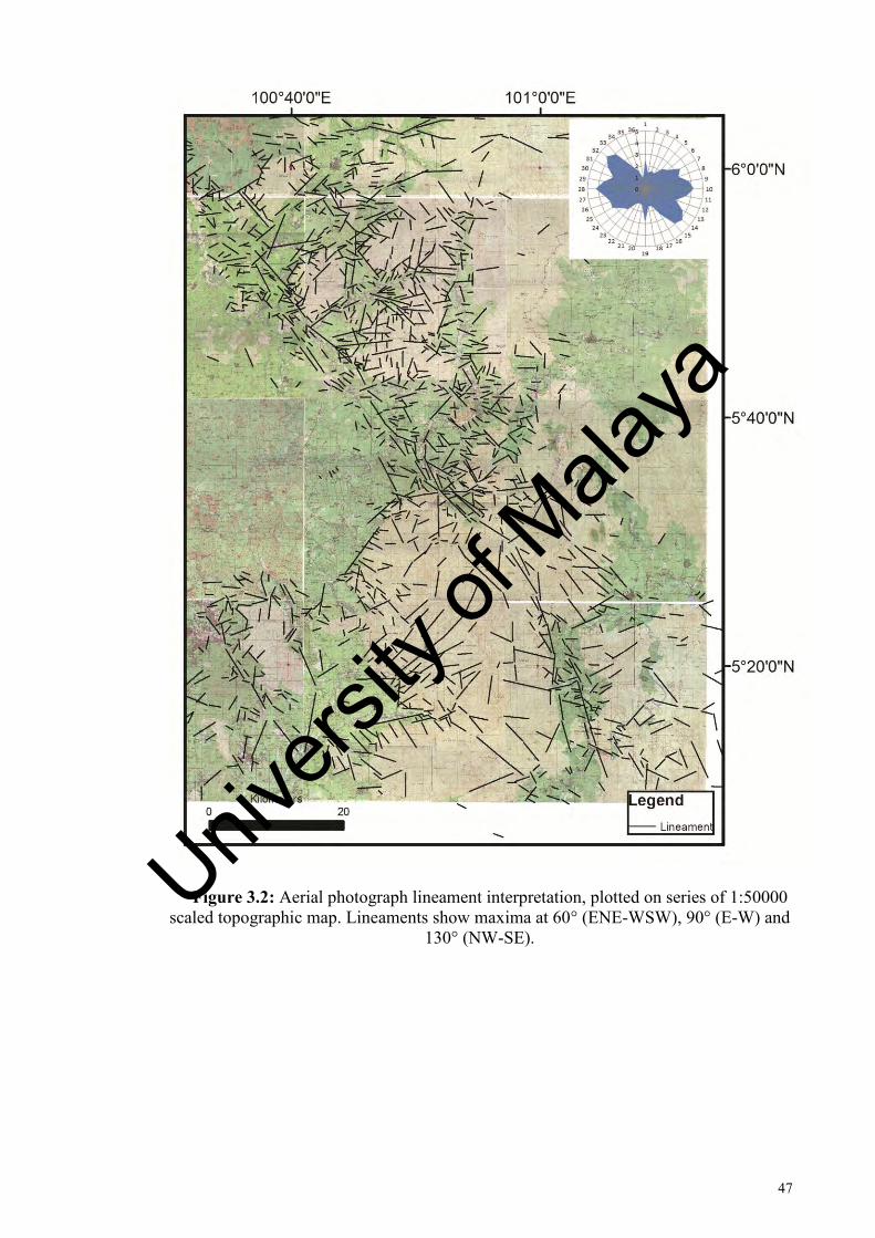
47
Figure 3.2: Aerial photograph lineament interpretation, plotted on series of 1:50000 scaled topographic map. Lineaments show maxima at 60° (ENE-WSW), 90° (E-W) and
130° (NW-SE).
Univers
ity of
Mala
ya

48
Figure 3.3: LANDSAT lineament interpretation, plotted on LANDSAT image, year 1990, with 28m resolution. Lineaments show maxima at 90° (E-W) and 140° (NW-SE).
Univers
ity of
Mala
ya

49
Figure 3.4: DEM-SRTM lineament interpretation, plotted on hillshade map generated from SRTM digital elevation model (sunlight attitude: 045°). Lineaments
show maxima at 90° (E-W) and 140° (NW-SE).
Univers
ity of
Mala
ya

50
the study, the year 1990 image is primarily used in the plot of the lineaments due to its
clearer image. Lineaments are plotted manually through ArcMap software (Figure 3.3).
The result of lineament interpretation show major trend at 90° (E-W) and 140° (NW-
SE).
3.4.1.3 DEM-SRTM
DEM-SRTM is used primarily for lineament analysis. SRTM digital elevation
model is processed by ArcGIS software to produce hillshade maps. Shaded relief
images were produced from lighting azimuth of 0°, 45°, and 90°, and these were chosen
to prevent bias of lineament picking by only using one lighting azimuth. Lineaments
are plotted manually through ArcMap software (Figure 3.4).
Lineament interpretation of the data show major trend at 90° (E-W) and 140° (NW-
SE).
3.4.2 Unfiltered lineament analysis
An initial unfiltered lineament analysis was carried out to compare trend of
lineament and structural trend in whole area. An unfiltered lineament analysis refers to
a quick correlation analysis between all lineament of study area with their respective
geological elements. Negative and positive lineaments plotted were distinguished,
where they are compared with their geological elements (fractures and bedding trend
respectively) (Figure 3.5). The data used are from the DEM-SRTM extraction (Figure
3.6), as the imageries provide the most variables for extraction and interpretation of the
lineaments.
Univers
ity of
Mala
ya

51
Figure 3.5: Rose diagram for (a) negative lineament and fracture orientation; and (b) positive lineament and bedding orientation
Figure 3.6: Negative and positive lineament extracted from DEM-SRTM
Univers
ity of
Mala
ya

52
The unfiltered lineament analysis for negative lineament and fracture shows the
lineament with maxima trend at 100° and 140° (E-W and NW-SE), and fracture with
maxima trend at 090° and 130° (E-W and NW-SE). For unfiltered positive lineament
analysis, the lineaments and bedding show a significant discordance between one
another, where the positive lineament show maximum trend towards 010° (N-S), while
bedding maximum trend towards 070° (ENE-WSW).
3.4.3 Lineament pattern of grid cells
For the purpose of filtered, discrete-analysis-based fracture analysis, the total study
area has been divided into 12 grid-cells, each with dimension of 30 km x 30 km, or an
area of 900 km2, for the domain-based fracture-correlated lineament analysis (Figure
3.7). The size of the grid was chosen arbitrarily based on the overall size of available
data from remote sensing and rock unit: each grid would effectively cover certain rock
units, and a quick analysis of the lineament pattern in each lithological domain is
possible.
Although the lineament varies in each grid, two significant trends are observed
among the grids: maxima at 90° (E-W) and 130° to 140° (NW-SE). This is comparable
with the trend shown by the unfiltered lineament analysis, as well as that observed in
some of the individual lineament distribution analysis (Figure 3.3 and Figure 3.4).
Univers
ity of
Mala
ya
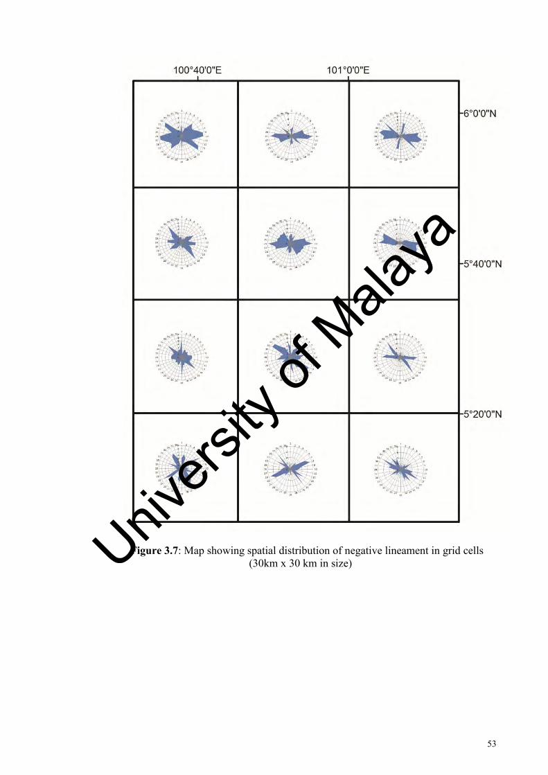
53
Figure 3.7: Map showing spatial distribution of negative lineament in grid cells (30km x 30 km in size)
Univers
ity of
Mala
ya

54
3.4.4 Lineament pattern of lithological domain
A summary of the trend of negative and positive lineament for the lithological
domains is shown in Table 3.1 and Figure 3.8. Both WPAL and GR domains show
trend maxima at 130° (NW-SE) for the negative lineament. EPAL domain show a
maximum trend of negative lineament at 090° (E-W). MES domain show maximum
trend of negative lineament at 080° (E-W). For the positive lineament, the maximum
trend is 050° (NE-SW) for WPAL and MES, and 0° (N-S) for EPAL.Both TER and
QTY domains have negligible number of lineament traversing them, and are not
represented here.
3.4.5 Lineament and field data correlation
A more detailed study for the lineament is correlating between lineament
distribution, and geological structure lithological domain and field data. From the grid
cells of the whole area, only a portion was traversed through field mapping. Four main
lithology type are mapped in the whole area: the Baling Formation (East Paleozoic
Sediment Domain), the Mahang Formation (West Paleozoic Sediment Domain), the
Semanggol Formation (Mesozoic Sediment Domain), and the Bukit Perak Granite,
Bukit Enggang Granite, and Bintang Hills Granite (Granite Domain). The lineament and
fracture trend data recorded from these lithologies are shown in Table 3.2, and the rose
Univers
ity of
Mala
ya
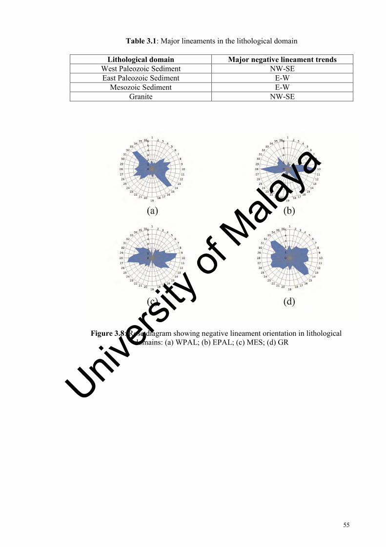
55
Table 3.1: Major lineaments in the lithological domain
Lithological domain Major negative lineament trends West Paleozoic Sediment NW-SE East Paleozoic Sediment E-W
Mesozoic Sediment E-W Granite NW-SE
Figure 3.8: Rose diagram showing negative lineament orientation in lithological domains: (a) WPAL; (b) EPAL; (c) MES; (d) GR
Univers
ity of
Mala
ya

56
Table 3.2: Comparison of major lineaments and structure trends in the mapped lithological unit
Mapped rock unit
Major negative lineament trend
Major fracture
trend
Major positive lineament
trend
Major bedding trend
Mahang Formation
NW-SE NNW-SSE N-S NE-SW
Baling Formation
E-W NE-SW NE-SW
Semanggol Formation
WNW-ESE NW-SE NE-SW NE-SW
Bukit Perak-Bukit Enggang
Granite
NW-SE NW-SE
Bintang Hills Granite
NW-SE ENE-WSW
Figure 3.9: Rose diagram showing negative lineament orientation and fracture orientation in mapped rock unit. (a) Mahang Formation; (b) Semanggol Formation; (c)
Bukit Perak and Bukit Enggang Granite; (d) Bintang Hills Granite
Univers
ity of
Mala
ya

57
Figure 3.10: Rose diagram showing positive lineament orientation and bedding orientation in mapped rock unit. (a) Baling Formation; (b) Mahang Formation; (c)
Semanggol Formation
diagram in Figure 3.9 and Figure 3.10 show the relationship the effects of lithology to
them.
Sedimentary rock of Mahang Formation is cut by 130° (NW-SE) negative lineament,
and show fracture at 150° (NNW-SSE). Semanggol Formation sediment is cut by 120°
(WNW-ESE) negative lineament, and fractures at 130° (NW-SE). Both the Bukit Perak
and Bukit Enggang Granite, and Bintang Hills Granite is cut by negative lineament
trending at 130° (NW-SE); the Bukit Perak and Bukit Enggang Granite fractures trend
of 130° (NW-SE), while the Bintang Bills Granite fractures trend 060° (ENE-WSW).
The Baling Formation forms 010° (N-S) positive lineament, and in the field has 050°
trending (NE-SW) bedding and foliation. Both Mahang Formation and Semanggol
Formation show similar trend, where they forms 050° (NE-SW) positive lineament, and
in the field has bedding trend of 050° (NE-SW).
Univers
ity of
Mala
ya

58
With the exception of the Bintang Hills Granite, comparison of lithology and the
negative lineaments show comparable trend. Similar observation is observed for
comparison between lithology and positive lineament (with the exception of Baling
Formation). This would indicate that the lineaments produced are the result of fractures
and bedding in the lithology.
3.4.6 Discussion
From analysis of the lineaments, a striking difference could be seen in the trend of
lineaments in granitic body and sedimentary formation: negative lineaments’ density is
very high in granite bodies. The density of the lineaments is considerably higher near
the vicinity of the main trend of the fault zone, regardless of the rock unit. The negative
lineaments are therefore an expression of fractures and faults present in the rock unit.
In contrast to this, positive lineaments are prevalent in sedimentary rocks, forming
continuous sets of strike ridges over considerable distance. They are a direct expression
of the sedimentary rock bedding. The strike ridges are strongly deflected near trace of
the main Bok Bak fault, although some also show dragging in vicinity to granite
plutons. The strike ridges north of the Bukit Perak pluton, for example, show sign of
drags as they approach the granite body, without the presence of major fault zone
(Figure 3.11).These strike ridges in the area were bent and dissected by traces of minor
conjugate faults, suggesting that faulting is also responsible in addition to granite
intrusion in forming the trend of strike ridges observed (Figure 3.6).
Univers
ity of
Mala
ya

59
Figure 3.11: Drag of strike ridges near the Bukit Perak granite body. Arrow indicate the effect of drag observed near the granite body.
Univers
ity of
Mala
ya

60
3.5 Structural interpretation of lineament
A problem with using lineaments directly from remote sensing is in differentiating
the origin of these lineaments – whether they are the result of tectonic activity, or are of
non-tectonic origin. A few studies attempted to construct a kinematic model for the Bok
Bak fault, by using a combination of remote sensing and field data:
Raj (1982) interpreted the NW-NNW and NE-ENE trending lineaments in Kedah-
Perak to represent strike of first and second order strike slip faults that are associated
with major left-lateral fault zone. Interpretation of these lineaments have resulted in the
recognition of extensive left-lateral displacement of rock unit in Perak.
Ibrahim et al. (1989) by studying the lithofacies boundary in Semanggol Formation
rocks of Kedah and Perak, pointed out that trend of strike ridges in the rock unit are the
result of clockwise rotation from granite intrusion and left-lateral movement of Bok Bak
Fault.
3.5.1 Strike ridges interpretation
The strike ridges, represented as positive lineaments (Figure 3.11) are visible
structures which are important in interpreting the movement along the Bok Bak Fault.
Indeed, previous studies have used these as the basis for establishing the kinematic of
fault zone (e.g. Ibrahim et al., 1989; Mustaffa, 1994; Syed, 1995). From lineament
plotting, the strike ridges show Z shaped trend close to the main trend of the Bok Bak
Fault (Figure 3.12). This is indicative of drag folds formed by sinistral strike slip
faulting.
Univers
ity of
Mala
ya

61
Figure 3.12: Z-shape of strike ridges adjacent to lineament along main trace of Bok Bak Fault. Sense of shear interpreted as left lateral. Lineaments extracted from DEM-
SRTM.
Univers
ity of
Mala
ya

62
The sinistral movement along the Bok Bak Fault was believed to be responsible for
the formation of folding and reverse faulting adjacent to the fault zone, and the these
structures were said to characterize transpressive tectonic environment along the fault
zone (Zaiton, 2002). While granite intrusion might have played some role in causing the
drag observed in some of the strike ridges (Ibrahim et al., 1989), the overall movement
along the main fault zone is the most significant in producing the drag observed in the
strike ridges.
3.5.2 Cross-cutting relationship of lineaments
The NW-SE negative lineament is the earliest to develop among the negative
lineaments, where it is in turn cut by later lineament sets. These NW-SE lineaments
form the main left lateral strike slip Bok Bak Fault, in which its movement cause the
drags observed in the strike ridges. NE-SW negative lineaments cut the earlier
lineament sets, and right lateral strike slip along these result in an en echelon trend for
the main fault zone (Figure 3.6). The NE-SW sets do not appear to cause significant
drag along strike ridges. E-W lineaments cuts the other lineaments set, but does not
seem to produce any observable sense of movement.
3.5.3 Riedel Shear interpretation of lineaments
One method in interpreting the lineament and how they relate with each other is by
using the Riedel Shear model. This is done by interpreting the lineament in a strike-slip
tectonic framework.
Univers
ity of
Mala
ya

63
By comparing the lineament trend with an idealized sinistral simple shear model
(Figure 3.13, Table 3.3), the major NW-SE lineament set is interpreted as the main
shear (Y shear), representing the major strand of the Bok Bak Fault Zone. WNW-ESE
and NNW-SSE represents synthetic R-shear and P-shear respectively, and NE-SW
lineaments represents associated antithetic R’-shear. E-W lineaments would represent
fracture sets, which are widespread among all rock units, as well as normal fault sets.
These structures in the field will be discussed in detail in Chapter 4 and Chapter 5.
The strike ridges formed adjacent to the main fault zone appear compatible in a
Riedel Shear model, where they could be described as right-handed in relation to the
main fault zone (Figure 3.12). This, along with the distribution of reverse faults and
thrust faults, appear to be one possible basis for the interpretation of the Bok Bak Fault
as undergoing transpressive deformation by Zaiton (2002).
3.6 Summary of remote sensing studies
Remote sensing studies of area transected by the Bok Bak Fault Zone have shown
the presence of lineaments in the different rock units, and lineament analysis was
carried out based on the subdivision of lithological domain to study the relationship
between lineament and rock units. Six lithological domain was identified, each
corresponding with rock units mapped in the field. Comparison between lineaments,
and lithology and structures generally show comparable trend, thus indicating that
lineaments were controlled by fractures and bedding in the lithology. Granites generally
show higher density of negative lineaments, whereas positive lineaments are observed
in most sedimentary rock units. By studying the trend of these lineaments and how they
relate to the rock unit, it is possible to characterize the trend of structures associated
with the Bok Bak Fault, as well as interpret the movement along the fault zone from the
Univers
ity of
Mala
ya

64
Figure 3.13: Lineament map and Riedel Shear interpretation of lineaments. (a) Rose diagram of lineament; and (b) Riedel Shear component
Univers
ity of
Mala
ya

65
Table 3.3: Interpretation of simple shear model for Bok Bak Fault Zone, with corresponding shears and faults
Riedel Shear Orientation Fault or related structures Principal shear / Y shear 320° NW sinistral Bok Bak Fault,
NW shear zone R-shear 305° WNW sinistral faults P-shear 335° NNW to NW sinistral faults R’-shear 065° NE-SW dextral faults
Shortening axis 095° E-W normal faults
resulting structures produced by shearing. The Bok Bak Fault one could be interpreted
as undergoing a sinistral simple shearing, with NW-SE lineaments prevalent in most
rock units representing major trace of the fault zone.
.
Univers
ity of
Mala
ya

66
CHAPTER 4: DUCTILE DEFORMATION
.
4.1 Introduction
Granitic rocks along the Bok Bak fault have been subjected to ductile shearing,
resulting in sheared granite and mylonite observed in the field. Very few studies have
noted on the occurrence of these rocks (e.g. Abdul Majid, 1987; Teoh, 1992, Abdullah,
1993). Ductile shear zones have not been found in sedimentary rocks, although they
have been report of shearing of pyroclastic rock unit along the fault zone in Perak
(Jones, 1970), as well as mylonite in metasedimentary rocks (Ulfa et al., 2012). Detailed
field and microstructural studies of these faults rocks were lacking, leaving the
kinematic and condition of the ductile deformation of the Bok Bak Fault unclear.
In this study, several shear zones in the field were identified and mapped, with
petrography and microstructural study of oriented samples carried out in determining
the nature of the ductile deformation phase. Interpretation of the kinematic and
deformation condition of the ductile phase is based on deformation fabrics and
structures found within the sheared rocks and minerals, and comparison with
deformation experimental results from other studies.
Univers
ity of
Mala
ya

67
Figure 4.1: Geometry of a mylonite zone with common type of shear sense indicators shown. Thin sections are parallel to aggregate lineation. Sense of shear is
dextral. (Passchier and Trouw, 1996)
Univers
ity of
Mala
ya

68
4.2 Shear zone domain in granite
Shear zone is a zone of highly strained rocks bounded by undeformed adjacent rocks.
Shear zone can be formed under different deformation condition: brittle deformation
forms brittle shear zone characterized by fractures; ductile flow form ductile shear zone
which contain foliation and lineation (Figure 4.1); and brittle-ductile shear zones are
formed by both brittle and ductile mechanism and show evidence for both brittle and
ductile deformation which indicate condition during shearing were either intermediate
between ductile and brittle or changed from ductile to brittle or vice versa (Davis and
Reynolds, 1996).
Rocks deformed in shear zones are usually referred as fault rocks (Sibson, 1977),
where they are subjected to different classifications by various authors, most commonly
classified by texture of the fault rocks (e.g. Sibson, 1977; Wise et al., 1984). Mylonite
are fault rocks formed under ductile shearing, and are commonly classified based on the
percentage of matrix compared to the porphyroclast (Figure 4.2).
Through traverse of the study area, evidences of ductile deformation were found in
the granite of Bukit Perak and Baling-Gerik (Figure 4.3). The Baling-Gerik granite
particularly shows clear kinematic indicators of ductile deformation, with the formation
of protomylonite and orthomylonite. The Bukit Perak granite shows mostly brittle-
ductile deformation features, with mylonite overprinted by brittle features.
Univers
ity of
Mala
ya

69
Figure 4.2: Classification of fault rocks (after Sibson, 1977, Wise et al., 1984, and Woodcock and Mort, 2008). Fault gouge is classified as non-foliated and foliated by
Woodcock and Mort (2008)
4.2.1 Bukit Perak shear zone domain
The granite pluton of Bukit Perak is homogenous, truncated by small amount of
microgranite intrusions. Granite show typical porphyrytic megacrystic texture, with
only slight difference in mineral content. The undeformed granite characterized by
arrangement of large feldspar clast set in groundmass of quartz, feldspar, mica, and
other accessory minerals.
Univers
ity of
Mala
ya

70
Figure 4.3: Distribution of sheared rocks along Bok Bak Fault in southern Kedah-Perak. Fault and sheared rocks mapped and based on Burton, 1972 and Teoh, 1992.
Univers
ity of
Mala
ya
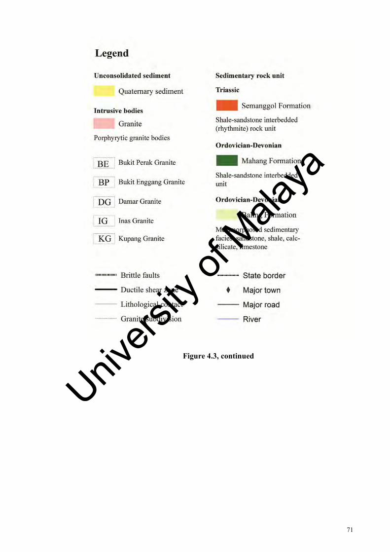
71
Figure 4.3, continued
Univers
ity of
Mala
ya

72
Figure 4.4: Mapped shear zone in Bina Quarry. Location of figures for samples is indicated by squares.
Univers
ity of
Mala
ya
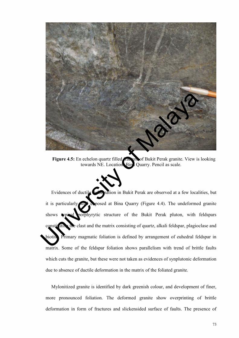
73
Figure 4.5: En echelon quartz filled fracture of Bukit Perak granite. View is looking towards NE. Location: Bina Quarry. Pencil as scale.
Evidences of ductile deformation in Bukit Perak are observed at a few localities, but
it is particularly well exposed at Bina Quarry (Figure 4.4). The undeformed granite
shows typical porphyrytic structure of the Bukit Perak pluton, with feldspars
constituting the clast and the matrix consisting of quartz, alkali feldspar, plagioclase and
biotite. Primary magmatic foliation is defined by arrangement of euhedral feldspar in
matrix. Some of the feldspar foliation shows parallelism with trend of brittle faults
which cuts the granite, but these were not taken as evidences of synplutonic deformation
due to absence of ductile deformation in the matrix of the foliated granite.
Mylonitized granite is identified by dark greenish colour, and development of finer,
more pronounced foliation. The deformed granite show overprinting of brittle
deformation in form of fractures and slickensided surface of faults. The presence of
Univers
ity of
Mala
ya
74
zones of en echelon quartz filled fracture in Bina Quarry points to the occurrence of
brittle-ductile deformation phase (Figure 4.5). Majority of the mylonite could be
classified as protomylonite (Figure 4.2). The mylonite form zones of a few metre in
thickness, which are cut by brittle faults and fractures.
Evidence of ductile deformation is also found in several small localities at the
southern part of Bukit Perak pluton. Sheared granite with rotated clast and dark foliation
were observed in Lubok Merbau. Clear kinematic indicators are however not present in
these sheared granites, and the rock occur only in isolated outcrops.
Feldspar shows evidence of brittle deformation in thin section of the mylonite, but
appear to be undeformed in hand specimens. Quartz are recrystallized in thin sections,
and individual grains show evidence of deformation such as presence of undulatory
extinction. Majority of the minerals were fractured, indicating that the mylonite was
overprinted by brittle deformation.
4.2.2 Baling-Gerik shear zone domain
The Baling-Gerik granite shows significantly high mica content in the matrix,
producing dark colour granite. In addition, the biotite forms mineral lineation across the
granite, which are not to be confused with aggregate lineations that are otherwise a
result of ductile shearing.
The undeformed granite of Baling-Gerik show similar porphyrytic texture to the
Bukit Perak granite, with the clast consisting of feldspar and the matrix made up of
quartz, alkali feldspar, plagioclase and biotite. Flow banding is observed in the granite,
and compared to Bukit Perak granite there is higher occurrence of mafic xenolith and
Univers
ity of
Mala
ya

75
pegmatitic veining. Some of the veins appear to be subjected to shearing, where they
show folding and effect of shearing.
The deformed granite form mylonites with well-developed foliation and shear bands in
the field. The sigmoidal shape of the foliation, rotated clast, and S-C structure gives the
sense of shear of the shear zones. Majority of the mylonite are classified as
protomylonite, with some occurrence of orthomylonite. The mylonite zones are
individually small – about a few metres thick – which span a broad zone of over 4 km
long (Figure 4.6). The shear zones mapped does not seem to be correlated with negative
lineaments plotted in Chapter 3 as they do not coincide, and it is assumed that they do
not form significant zone of weakness which would otherwise be expressed as
lineaments.
In the field, feldspar grains form the observable clasts of the mylonite. They were
found to be undeformed in hand specimens, but in thin sections they show clear brittle
deformation. Quartz grains forms the matrix, and in thin sections show clear plastic
deformation and recrystallization. Biotite and muscovite forms fish structure and shear
bands, clearly indicating ductile shearing process in the mylonite.
4.3 Mesoscopic structures
Lineation and foliation are major structures found in sheared granite, and along with
other structures and fabrics found, provide important kinematic indicator of the Bok
Bak Fault (Figure 4.7). These are used in interpreting the early stage of ductile shearing.
Structures found in the field are as follow:
Univers
ity of
Mala
ya

76
Figure 4.6: Mapped shear zone in Baling-Gerik granite. Location of figures for samples isindicated by squares. Division of granitic bodies based on Burton (1972).
Univers
ity of
Mala
ya

77
Figure 4.7: Mylonitic structure in granite along Bok Bak Fault: a) shear band in mylonite granite. View parallel to stretching lineations; b) Mylonitic foliation. View
shows stretching lineations and exposed surface parallel to stretching lineation; c) S-C structure and rotated clast in mylonite. View parallel to stretching lineations; d) Narrow
mylonite zone in granite with strong stretching lineations formation and large porphyroclast set in foliation. View parallel to stretching lineations. Locations: a) Bina
Quarry, Bukit Perak; b) – d): K173, Baling-Gerik Highway. Pencil as scale. For locations refer to Figure 2.7.
4.3.1 Foliation
Foliated granite produced as a result of ductile shearing are readily distinguished
from primary magmatic foliation in granite. The foliation is strongly penetrative in
mylonite, characterized by strong preferred grain size arrangement of quartz and
feldspar. The magmatic foliation, in contrast, are broadly spaced and with random
arrangement of minerals.
Univers
ity of
Mala
ya

78
In Bukit Perak granite, the sheared granite foliation defined by the arrangement of
feldspar in matrix, shows mostly NW-SE trend in the range of 120° to 140°, dipping S
and N. The Baling-Gerik fault-generated foliation strikes WNW-ESE to NW-SE, in the
range of 100°-120°, generally dipping towards S. The trend of the foliation strike shows
a slight swing from NW-SE to WNW-ESE southward along trace of the shear zone. The
sigmoidal pattern of foliations indicate predominantly dextral strike-slip movement.
4.3.2 Mineral elongation lineation
Mineral elongation lineations are well developed on foliation planes of the
mylonites, and they are defined by elongated minerals in the deformed granite (Figure
4.7d).
Figure 4.8 show the range of attitude of the stretching lineation: In Bukit Perak, the
trend of the lineation is rather cluttered, but in general show sub-horizontal to gentle
plunge (20°) towards northwest and southeast. In Baling-Gerik the lineation is more
uniformly sub-horizontal to gently plunging (20° - 30°) to the southeast. Trend of
mineral elongation lineation shows that the Bok Bak Fault undergoes predominantly
strike-slip motion during ductile deformation.
4.3.3 S-C structure
S-C structures refer to the two set of penetrative foliation in mylonite: S-surface and
C-surface. S-surfaces are defined by elongate mineral grains, defined by arrangement of
feldspar and elongated quartz ribbons, and these form the mylonite foliation. C-surfaces
Univers
ity of
Mala
ya
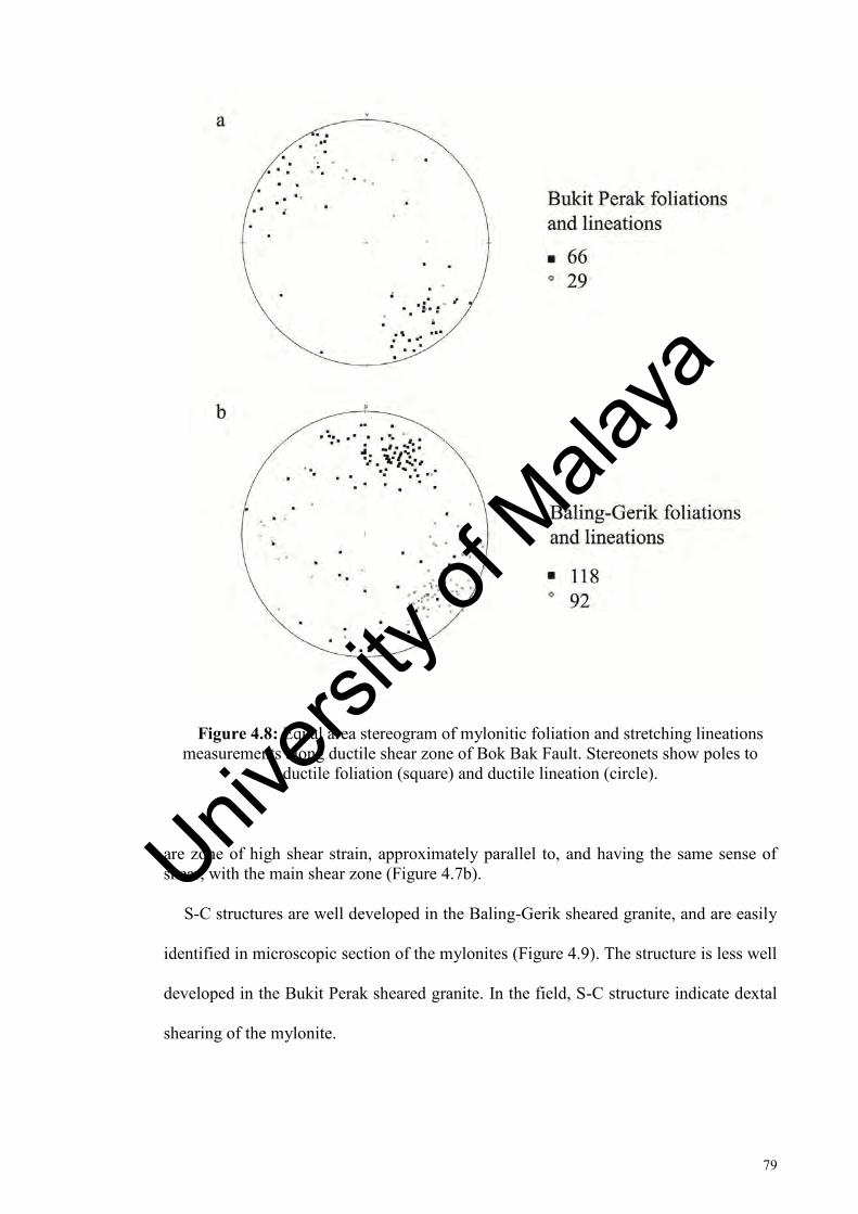
79
Figure 4.8: Equal area stereogram of mylonitic foliation and stretching lineations measurements along ductile shear zone of Bok Bak Fault. Stereonets show poles to
ductile foliation (square) and ductile lineation (circle).
are zone of high shear strain, approximately parallel to, and having the same sense of shear, with the main shear zone (Figure 4.7b).
S-C structures are well developed in the Baling-Gerik sheared granite, and are easily
identified in microscopic section of the mylonites (Figure 4.9). The structure is less well
developed in the Bukit Perak sheared granite. In the field, S-C structure indicate dextal
shearing of the mylonite.
Univers
ity of
Mala
ya

80
Figure 4.9: Oriented hand specimens of mylonite showing kinematic indicators: a) S-C structures; b) Mantled feldspar porphyroclast, and antithetic (sinistral) shearing in feldspar clast. Samples are cut parallel to stretching lineations. Samples location: K173, Baling-Gerik Highway. Coin as scale for a). Refer to Figure 4.6 for location of samples.
Univers
ity of
Mala
ya
81
4.3.4 Rigid clasts
Rotated clast and asymmetric grain in sheared granite provide kinematic indicator
alongside foliation and S-C structure. The grains are mostly feldspar set in fine grained
foliation and matrix (Figure 4.7c). In some mylonite the clasts are rotated without sign
of being deformed, but more commonly they are fractured, hinting at their brittle
property compared to the surrounding material. Antithetic fractures were found in some
of the clast, showing sense of shear opposite from overall sense of shear in the mylonite
(Figure 4.9b). Along with other structures, they indicate dextral strike-slip sense of
shear.
4.3.5 Deformed veins
Pegmatitic dike and quartz veins in Baling-Gerik sheared granite have been observed
to show folding (Figure 2.8d). They do not provide clear kinematic indicator as other
structures and fabric found in the shear zones, but their presence suggest they were
formed pre-kinematic or syn-kinematic with respect to the ductile deformation.
4.4 Microstructures
Microstructural analysis was carried out on oriented thin sections of the mylonites,
with thin sections cut parallel to the mylonitic lineation and normal to the main
foliation, otherwise known as the vorticity profile plane, for best result of kinematic
indicator (Passchier and Trouw, 1996). Microstructures found in deformed granite of
the shear zone include oblique grain shape fabric, S-C fabrics, mica fish, and winged
feldspar porphyroclasts, which provide important information on kinematic of
deformation.
Univers
ity of
Mala
ya

82
4.4.1 Oblique grain-shape fabrics
Oblique grain-shaped fabric is defined by aligned dynamically recrystallized grains
oblique to the long axis of C-foliation defined by larger individual grains. Aggregates of
dynamically recrystallized monomineralic aggregates such as quartz have been
observed o show preferred orientation oblique to mylonitic foliation (e.g. Lister and
Snoke, 1984) and this criteria is used as kinematic indicator.
In the Bok Bak Fault zone, dynamically recrystallized quartz grains are found to be
aligned oblique to the C-foliation defined by band of mica and larger quartz grains
(Figure 4.10a, Figure 4.11b). The microstructure is observed in most mylonite samples
in both Bukit Perak and Baling-Gerik granite. Oblique grain shapes indicate dextral
sense of shear in the mylonite.
4.4.2 S-C structure
Elongate quartz ribbon and mica-rich shear bands, the defining feature of S-C
structures, is well observed in thin section of mylonite samples. The structure is formed
parallel to stretching mineral lineation, along the vorticity profile plane. As such, they
are reliable sense of shear indicator.
Mylonite from both Bukit Perak and Baling-Gerik show well developed S-C fabric,
with S-fabric defined by oblique quartz arrangement, while thin band of recrystallized
mica and quartz ribbons form the shear band of C-fabric (Figure 4.11a). S-C structure
show consistent dextral sense of shear.
Univers
ity of
Mala
ya
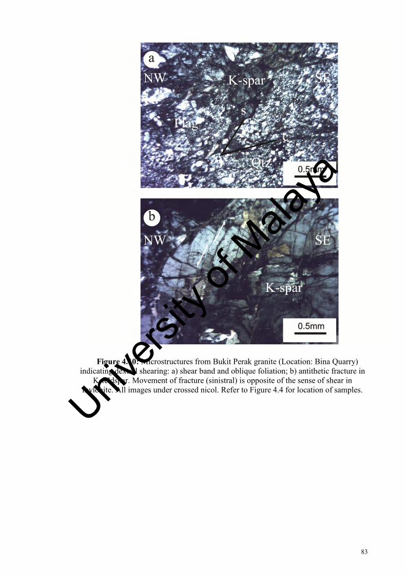
83
Figure 4.10: Microstructures from Bukit Perak granite (Location: Bina Quarry) indicating dextral shearing: a) shear band and oblique foliation; b) antithetic fracture in
K-feldspar. Movement of fracture (sinistral) is opposite of the sense of shear in mylonite. All images under crossed nicol. Refer to Figure 4.4 for location of samples.
Univers
ity of
Mala
ya
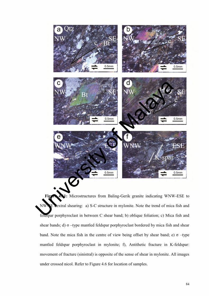
84
Figure 4.11: Microstructures from Baling-Gerik granite indicating WNW-ESE to
NW-SE dextral shearing: a) S-C structure in mylonite. Note the trend of mica fish and
feldspar porphyroclast in between C shear band; b) oblique foliation; c) Mica fish and
shear bands; d) σ –type mantled feldspar porphyroclast bordered by mica fish and shear
band. Note the mica fish in the centre of view being offset by shear band; e) σ –type
mantled feldspar porphyroclast in mylonite; f), Antithetic fracture in K-feldspar:
movement of fracture (sinistral) is opposite of the sense of shear in mylonite. All images
under crossed nicol. Refer to Figure 4.6 for location of samples.
Univers
ity of
Mala
ya
85
4.4.3 Mineral fish
Mica in mylonite commonly exhibit lens shaped with strong preferred arrangement
to the foliation, and this structure is referred as mica fish. Commonly trails of the mica
fragment extend into the matrix from the tips of isolated mica fish (Lister and Snoke,
1984), with well defined stair stepping, and are reliable sense of shear indicator. Both
biotite and muscovite form the fish structure.
Mica fish are observed in the Baling-Gerik sheared granite, and are commonly
arranged between C-foliation shear bands (Figure 4.11c). They indicate dextral sense of
shear for the ductile shear zone.
4.4.4 Mantled porphyroclast
Mantled porphyroclast are structures that consist of central single crystal and fine-
grained mantle of the same mineral. Fine grained mantle can be deformed into wings
that extend on both sides of the porphyroclast parallel to the shape preferred orientation
of mylonite, and are important for sense of shear determination in high strain zones
(Lister and Snoke, 1984; Passchier and Simpson, 1986). Several type of mantled
porphyroclast are recognized in literatures: Θ-type mantled clasts doesn’t have wings
found in other mantled porphyroclast, but have a mantle with orthorhombic symmetry;
σ -type-, δ -type and complex mantled clasts have monoclinic shape symmetry
(Passchier and Trouw, 1996). The wing of these porphyroclasts may lie at different
elevation on both sides, referred to as stair-stepping (Lister and Snoke, 1984).
Univers
ity of
Mala
ya
86
In the Bok Bak Fault shear zone, mantled porphyroclasts is well observed in outcrops
along the Baling-Gerik granite (Figure 4.11d-e). Here, σ –type mantled K-feldspar
porphyroclasts was observed alongside structures such as S-C structure and mica fish.
They demonstrate dextral sense of shear.
4.4.5 Fractured porphyroclast
Microfaulting occur in certain feldspar grains of mylonite. Compared to other
microstructure, the fragmented porphyroclasts are relatively unreliable in determining
overall sense of shear (Simpson and Schmid, 1983; Passchier and Trouw, 1996).
Microfracturing of feldspar is well observed in mylonite from Bukit Perak granite
(Figure 4.10b). Faulting that are antithetic to the overall sense of shear in mylonite are
observed in feldspar grains. The faults are limited to individual grains and does not
extend into the foliation and shear band in the mylonite.
4.5 Condition of ductile deformation
Several factors control the behavior of rocks during deformation, where the
deformation process affecting individual grains. Deformation process involved depends
on lithological control such as mineralogy, composition, abundance of intergranular
fluid, grain size, lattice-preferred orientation, porosity and permeability, and on external
control such as temperature, lithostatic pressure, differential stress, fluid pressure and
externally imposed strain rate (Passchier and Trouw, 1996).
Univers
ity of
Mala
ya
87
There have been almost no detailed studies on deformation condition of fault zones
in the Peninsular, with a few exception (e.g. Ng, 1994), and as such the ductile
deformation condition of these faults are not properly understood. By studying the
microstructure of the sheared rocks, this study provides a look at the deformation
condition of the ductile shearing of the Bok Bak Fault.
4.5.1 Deformation mechanism
Deformation related microstructures of deformed granites vary with changing
pressure-temperature and other ambient conditions (Tullis et al., 1982). In the ductile
shear zone of the Bok Bak Fault, both brittle and plastic microstructures occurs in the
mylonite. Rocks along the Bok Bak Fault show deformation structures that reflect
ductile and brittle deformation.
Thin sections of sample from the sheared granite are studied for petrography and
microstructures study. Quartz and feldspar are the major rock forming mineral in the
shear zone. There is no major difference in the deformation condition between the Bukit
Perak granite and Baling-Gerik granite, and thus the observations are not separated by
the two domains. A summary of the deformation of the minerals is shown in Table 4.1.
Univers
ity of
Mala
ya

88
Table 4.1: Summary of deformation of mineral in ductile sheared granite
Quartz Feldspar Mica Elongate to ribbon shaped recrystallized grains; no fracturing observed
Exhibit bulging recrystallization (BLG) and subgrain rotation recrystallization (SGR)
Deform by fracturing and cataclastic flow
Minor occurrence of σ –type mantled K-feldspar porphyroclasts and recrystallization
Show kinking and folding
Formation of mica fish (commonly in muscovite)
Form shear band (C-surface)
4.5.1.1 Quartz
Recrystallized quartz is predominant in all mylonite samples (Figure 4.12). Crystal
plastic deformation evidences in quartz are abundant, with formation of sub-grain,
deformation bands, and core-mantle structures. Quartz in mylonite are commonly
stretched into lenses and quartz ribbons. Commonly the quartz exhibit deformation
lamellae and undulatory extinction. Microfracturing is uncommon in quartz grains.
Recrystallization of quartz occur through bulging (BLG) recrystallization and
subgrain rotation (SGR) recrystallization. In Baling-Gerik, certain pegmatite dikes
exhibit extensive recrystallization of quartz, with quartz exhibiting SGR
recrystallization and formation of quartz ribbons (Figure 4.12d).
Univers
ity of
Mala
ya

89
Figure 4.12: Microstructure showing deformation of quartz: a) Quartz with undulatory extinction (centre) transected by new grains formed by bulging (BLG)
recrystallization; b) Dynamically recrystallized quartz formed through subgrain rotation (SGR) recrystallization; c) Quartz with BLG recrystallization occurring adjacent to
grains undergoing SGR recrystallization; d) Polycrystalline quartz in pegmatitic dike developed primarily through SGR recrystallization. Samples locations: a) Bina Quarry; b) – d): K173, Baling-Gerik Highway. All images under crossed nicol. Refer to Figure
4.4 & 4.6 for location of samples.
4.5.1.2 Feldspar
Both K-feldspar and plagioclase form the porphyroclast, which are commonly
fractured into smaller grains between quartz ribbons (Figure 4.13). Although both
feldspar show similar microstructures, there are significant differences. While both
exhibit brittle features through fracturing, K-feldspar have been found to form mantled
porphyroclast structure, with formation of wings and stair-stepping structure. Deformed
K-feldspar have been rotated and are aligned to the S-surface. Plagioclase exhibit
mostly microfracturing and cracking with no indication of plastic deformation.
Compared to quartz, recrystallization in feldspar is almost absent.
Univers
ity of
Mala
ya

90
K-feldspar in mylonite generally show irregular, roughly oblong shape, with some
grains forming elliptical shape in response to shearing. The largest face of the rotated
grains are usually aligned with the S-surfaces. Undulatory extinction are observed in the
grains, but are usually weak. K-feldspar are often microfractured, with displacement
along the fracturing resulting in ‘book-shaped’ fragments (Passchier, 1982).
Displacement along the fracturing are mostly antithetic to the overall shear sense of the
mylonite. Cataclastic flow are also observed in the feldspar. In Bukit Perak granite,
fracturing is very dominant in the feldspar grains and other minerals, suggesting
overprinting of brittle deformation on earlier ductile features. Recrystallized K-feldspar
that form mantle and core porphyroclast is well observed in one outcrop in Baling-Gerik
with wings structure consisting of thin band of recrystallized grains (Figure 4.13a). In
other mylonite, evidence of recrystallization is not well observed.
Plagioclase shows microfracturing similar to K-feldspar, although the degree of
fracturing is less intense. The grains commonly exhibit long euhedral shape, with
noticeable large size (0.5 mm to 2 mm in length). Common microstructures in
plagioclase are undulatory extinction, deformation twins, and kink bands. Compared to
K-feldspar, plagioclase show no evident of recrystallization, with the grains retaining
their shape in mylonite (Figure 4.13b).
Univers
ity of
Mala
ya

91
Figure 4.13: Microstructure showing deformation of feldspar: a) K-feldspar with both ductile (recrystallization of fine grains at feldspar rim) and brittle (fracturing)
deformation); b) – c) Feldspar porphyroclast cut by fractures. Note twinning c); d) K-feldspar showing ‘bookshelf’ fracturing. Samples locations: a) – b): K173, Baling-Gerik
Highway; c) – d) Bina Quarry. All images under crossed nicol. Refer to Figure 4.4 & 4.6 for location of samples.
4.5.1.3 Mica
Biotite and muscovite are the mica that makes up the constituent of the mylonite. In
Baling-Gerik mylonite the mica are recrystallized to form lens shaped grains, otherwise
known as mica fish (Figure 4.11c). Trails of the mica grain commonly extend from the
tips of isolated grains into the matrix, forming the stair-stepping feature which is a
reliable sense of shear indicator. Biotite are commonly kinked and folded.
Recrystallization occurs at margin of the mica and extend into the matrix, defining
the C-surface in mylonite. In Bukit Perak mylonite, individual mica grains have
appeared to be altered to form sericite and chlorite, but trace of C-surface is prevalent.
Univers
ity of
Mala
ya

92
4.5.2 Temperature
The different deformational mechanism for the minerals in mylonite provides a key
to the temperature of the ductile deformation of the Bok Bak Fault. Studies on
experimental and naturally deformed rocks have led to the understanding of the
relationship between intracrystalline microstructure for quartz and feldspar and their
deformation temperatures (e.g. Tullis et al., 1985; Simpson, 1985; Passchier and Trouw,
1996). Quartz as well as mica in general show crystal-plasticity behaviour, and studies
generally suggest a temperature range of 250 °C to 300 °C for the onset of crystal-
plasticity. Deformation of feldspar through brittle processes happen at low temperature,
below 400 °C, with the onset of recrystallization at low to medium grade condition
(450 °C – 500 °C) (Pryer, 1993; Passchier and Trouw, 1996).
Quartz had undergone extensive dynamic recrystallization in all the mylonite
observed, forming fine recrystallized grains. The grains are formed through BLG
recrystallization and SGR recrystallization. Recrystallization of quartz are initiated at
temperature of 300 °C with BLG recrystallization, with SGR recrystallization of quartz
initiated at medium temperature of 400 °C (Stipp et al., 2002).
In contrast, feldspar exhibit dominant brittle behaviour through microfracturing,
which include antithetically imbricate fractured feldspars in most mylonite. Evidence of
plastic deformation was only observed in one outcrop in Baling-Gerik, with the
formation of σ –type mantled K-feldspar porphyroclasts. Feldspar deforms through
internal microfracturing with minor dislocation glide in low medium grade condition of
400 °C to 500 °C, where tapering deformation twins, bent twins, undulose extinction,
deformation bands and kink bands with sharp boundaries might be present (Pryer,
1993). Mica may show kinking or layer parallel slip in the form of mica fish in brittle
Univers
ity of
Mala
ya

93
domain (Kanaori et al., 1991), with biotite behaving ductile at temperature above
250 °C (Stesky et al., 1974).
By comparing the contrasting behaviour of quartz, feldspar, and mica described
above, the constrain for deformation temperature for ductile deformation is in the order
of 300 °C to 400 °C. In this temperature range, quartz show extensive range through
BLG and SGR recrystallization, with feldspar showing mainly brittle structure. The lack
of recrystallization in feldspar places a lower limit for the temperature deformation
below 450 °C, at which recrystallization of feldspar become significant. Presence of
antithetically imbricate fracturing of ‘bookshelf’ microfracturing in feldspar (Passchier
and Trouw, 1996) in granitic mylonite suggest deformation in low-medium grade
temperature range (Pryer, 1993).
4.5.3 Metamorphic condition
While there have not been detailed thermochronologic studies on the granitic pluton
cut by the Bok Bak Fault, several studies were done on metamorphic mineral
assemblage of the metamorphosed sedimentary rock and igneous pluton in southern
Kedah. Regional metamorphism affected the sedimentary rocks, where they are
subjected to low grade regional metamorphism (Jones, 1970; Courtier, 1974; Teoh,
1992). Metamorphic rocks in Gerik exhibit greenschist facies, with a less commonly
observed epidote-amphibolite facies (Jones, 1970). These rocks are subjected to a range
of pressure of 0.18 Gpa to 1.2 Gpa, with temperature ranging from 400° to 700° C (Ulfa
et al., 2012).
Univers
ity of
Mala
ya
94
The low intensity regional metamorphism indicates a relatively low lithostatic
pressure. This trend is also observed in the regional metamorphism of Malay Peninsula,
where Palaeozoic rocks were metamorphosed to schists and gneisses of higher
greenschist and locally low amphibolite facies (Hutchison, 2009). Although the timing
of metamorphic event in the western belt is not well constrained, the widespread
metamorphism event is interpreted to occur during Early to Middle Devonian
(Hutchison, 1973a; Khoo and Tan, 1983).
Taking into consideration the metamorphic grades of the rocks, as well as
temperature inferred for deformation from deformation microstructure in mylonite, the
Bok Bak Fault must have been onset at a shallow crustal depth after the rocks were
uplifted. The presence of recrystallized quartz, and other minerals such as K-feldspar,
plagioclase, biotite, muscovite, and chlorite in the mylonite suggest greenschist facies
condition for ductile deformation.
4.6 Summary of shear zone kinematics
The shear zones mapped in the study area were found to be formed away from
lineaments plotted in remote sensing. This is taken to indicate that the mylonite zone
does not form significant zone of weakness, which otherwise would be expressed as
negative lineaments.
Kinematic indicators in mylonite such as foliation, S-C structures, rigid clasts,
mineral fish, and mantled porphyroclasts indicate that the Bok Bak Fault had undergone
WNW-ESE to NW-SE trending ductile dextral movement in its early stages. This sense
of movement was not observed in remote sensing study in Chapter 3, suggesting
Univers
ity of
Mala
ya

95
overprinting by later brittle deformation. The quartz in mylonite show dynamic
recrystallization with the formation of undulatory extinction, BLG recrystallization, and
SGR recrystallization. Feldspar exhibit brittle deformation through microfracturing and
cataclastic flow, and other structures such as deformation twins, kink bands, and rotated
porphyroclast. Microstructure and mineral assemblage suggest that rocks along the Bok
Bak Fault have undergone greenschist facies metamorphism in shallow crustal depth
after the rocks were uplifted.
Kinematic indicators from mylonite consistently demonstrate top to the SE shear
sense. The sub-horizontal to gently plunging stretching lineation in mylonite indicate
predominantly dextral strike slip motion during ductile deformation of the Bok Bak
Fault, with minor thrust movement.
Univers
ity of
Mala
ya

96
CHAPTER 5: BRITTLE DEFORMATION
5.1 Introduction
The late stage brittle faulting activities in Bok Bak Fault resulted in the formation of
joints, faults, and cataclasite in the field. Brittle deformation of the Bok Bak Fault
occurs in both sedimentary (Ibrahim et al., 1989; Syed, 1996; Zaiton & Basir, 1999) and
granitic rocks (Jones, 1970; Abdul Majid, 1987), although majority of studies have
focused on faulting in sedimentary rocks. These structures have been studied by various
workers, forming the basis for the interpretation of the fault zone kinematic history.
Fault movements were found to be oblique slip to reverse, and overall movement along
the fault zone was interpreted to be transpressional (Zaiton, 2002).
Cross-cutting relationship among the faults in the field indicate that the Bok Bak
Fault have undergone several reactivation phases. Three main episodes of brittle
deformation of the fault were identified from the field, and evidences for these faulting
episodes and their kinematic are discussed, followed by analysis of the stress field
accompanying each episodes.
5.2 Brittle deformation structures
Brittle deformation in study area is represented by joints, faults, fault rocks, and
stratigraphic offset along fault planes. Angelier (1994) defined faults as discontinuities
for which visible displacements have occurred, primarily parallel to the fault plane.
Brittle fault rocks are formed through the fault propagation of rock, commonly along
Univers
ity of
Mala
ya

97
Figure 5.1: Kinematic indicator of brittle structures in Bok Bak Fault. All except b) looking into sub-vertical surface: a) Displaced of sedimentary rock unit strata of
Semanggol Formation (Location: Kuala Ketil); b) displacement of quartz vein of Bukit Perak granite (Location: Pati Quarry); c) slickenside and steps on fault plane of Bukit Perak Granite, showing strike slip movement. Movement is to the right relative to the photo (Location: Pati Quarry); d) slickenside on fault plane of Bintang Hills Granite,
showing normal movement (Location: Baling-Gerik Highway). b) Compass as scale; c) – d): pencil as scale. For locations refer to Figure 2.7.
older plane of weakness, and formation of a volume of brittle fault rock in a fault zone
along the active fault (Passchier and Trouw, 1996). As shown in Chapter 4, brittle fault
rocks could be subdivided into incohesive and cohesive type (Figure 4.1): incohesive
fault rocks were grouped based on classification by Sibson (1977), and Woodcock and
Mort (2008); while cohesive fault rocks were grouped based on the terminology by
Wise et al. (1984), incorporating the terms from the classification by Sibson (1977).
Univers
ity of
Mala
ya

98
Figure 5.2: Brittle fault rocks in Bok Bak Fault: a) Fault breccia in Bukit Perak Granite (Location: Pati Quarry); b) – c) Cataclasite in granite (Location: b) Lubok Merbau; c) TAHB Quarry; d) Brittle shear band in Bintang Hills Granite (Location: Baling-Gerik
Highway). a) – c) Pencil as scale; d) Hammer as scale. For locations refer to Figure 2.7.
Both fault gouge and fault breccia were observed in granitic and sedimentary rocks
(Figure 5.2). Fault gouge are weathered rock along fault planes, with few large fragment
isolated in matrix. Fault breccia consists of sharp angular granitic clasts set in
weathered matrix. Contact with host granitic rock is usually sharp, defined by fault
plane. Cataclasite are well developed in granitic rocks, where they consist of coarse
poorly sorted angular clast set in finer matrix. Most of the cataclasite are categorized as
protocataclasite and orthocataclasite, with the matrix percentage less than 50% and 50%
- 90% respectively. Cataclasite found in the field are differentiated from fault breccia
and fault gouge by their cohesive nature, and may occur in host rock without any
obvious discontinuity. Compared to fault breccia, cataclasite might appear similar to
Univers
ity of
Mala
ya

99
undeformed host rock, although features such as fracturing and difference of colour
with host rock, are indication of their brittle properties.
Striations on faults, otherwise known as slickensides, are used in defining the net slip
of faults (Figure 5.1). Care is taken when determining the sense of movement from
slickensides, as they commonly only show the last movement stage on the fault
(Tanaka, 1992). Plunge value of slickensides are used in classification of faults, where
the fault movements are described as either strike-slip, dip-slip, or combination of both
(oblique slip).
Abundant joint set cut both sedimentary and granitic rock. However, they do not
produce striations that are useful for kinematic analysis, and so their role in the
kinematic history of the fault zone is therefore not discussed in this work.
5.3 Structural analysis
Data from the fault plane is calculated for principal directions of finite strains, and
graphically determined using the program FaultKin7 (available at
http://www.geo.cornell.edu/geology/faculty/RWA/programs/faultkin.html, 2016). The
algorithm of the program was discussed by Marrett and Allmendinger (1990), and
Allmendinger et. al (2012), and is too extensive to be discussed in the scope of this
work. Several basic premises for the analysis used in this work are mentioned below:
Kinematic analysis of faults begins with graphical construction of the principal
incremental shortening and extension axes for given population of faults. The pair of
axes are in the ‘movement plate’ containing slip vector and the normal vector to the
fault plane, making a 45° angle with each of the vectors (Figure 5.3). Extension (T-axis)
and shortening (P-axis) axes can be found and graphically contoured (Kamb, 1959) to
Univers
ity of
Mala
ya
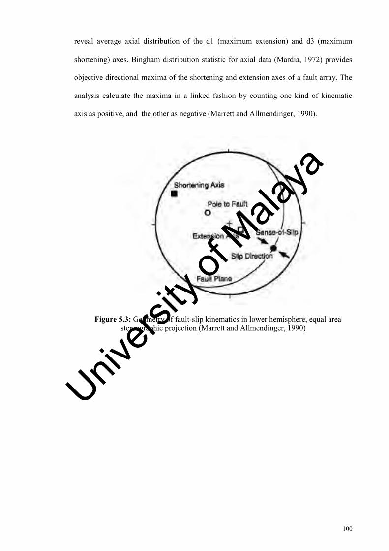
100
reveal average axial distribution of the d1 (maximum extension) and d3 (maximum
shortening) axes. Bingham distribution statistic for axial data (Mardia, 1972) provides
objective directional maxima of the shortening and extension axes of a fault array. The
analysis calculate the maxima in a linked fashion by counting one kind of kinematic
axis as positive, and the other as negative (Marrett and Allmendinger, 1990).
Figure 5.3: Geometry of fault-slip kinematics in lower hemisphere, equal area stereographic projection (Marrett and Allmendinger, 1990)
Univers
ity of
Mala
ya

101
Figure 5.4: Bok Bak Fault distribution in study area. Mylonite equal area southern hemisphere stereonets show poles to ductile foliation (square) and ductile lineations (circle). D1, D2, D3 equal area southern hemisphere stereonets show poles to fault
planes (square) and slickenside lineations (circle).
Univers
ity of
Mala
ya

102
Figure 5.4, continued
Univers
ity of
Mala
ya

103
Figure 5.4, continued
Univers
ity of
Mala
ya

104
5.3.1 Transition from ductile to brittle shearing
Shear zone with combination of both ductile and brittle features were observed in
Bina Quarry (Figure 5.5). These structures overprint mylonitized granite, and are in turn
cut by brittle structures. The shear zone strikes around 120°, with kinematic indicator
showing sinistral movement. Ductile feature dominate the shear zone: the quartz and
feldspar form bands that are similar to mylonitic texture, with quartz undergoing plastic
deformation. Under thin section, quartz shows extensive plastic deformation, while
feldspar were subjected to heavy fracturing (Figure 5.6). The shear zones do exhibit
several brittle features, with formation of en-echelon quartz veins, and sharp fault planes
at the margin of the shear zone. These structures are better known as brittle-ductile
shear zones, and most likely begin as ductile shear zone, but begin to develop brittle
fault-like features when physical conditions changed during deformation (Davis and
Reynolds, 1996).
The orientation and sense of shear of the shear zone is similar with the D1 faults
discussed next. This suggests that the brittle-ductile shear zones were generated under
similar deformation condition that predates D1 faults. The sinistral sense of shear
reported in the mylonite of Bukit Perak reported by Abdullah (1993) is most likely this
brittle-ductile shear zone.
Univers
ity of
Mala
ya

105
Figure 5.5: Brittle-ductile shear zone of Bukit Perak granite. View is looking towards NW. Location: Bina Quarry. Pencil as scale.
Figure 5.6: Photomicrograph of brittle-ductile shear zone rock. Location: Bina Quarry. Image under crossed nicol.
Univers
ity of
Mala
ya

106
Figure 5.7 Fault plane solution of faults representing different brittle deformation episodes: (A) D1; (B) D2; (C) D3. d1: extension axis; d3: shortening axis
Table 5.1: Linked Bingham axes analysis of fault planes representing different brittle deformation episodes. d1 axis represents maximum extension, d3 axis represents
maximum shortening.
Fault episode d1axis D2axis d3axis Deformation D1 6°, 005° 79°, 127° 10°, 274° Strike slip
D2 59°, 082° 29°, 242° 9°, 337° Oblique slip D3 23°, 070° 46°, 186° 35°, 323° Oblique slip
Univers
ity of
Mala
ya

107
5.3.2 D1: Sinistral oblique faulting
The period of sinistral strike-slip faulting of D1 is the most intense of the brittle
deformation, forming the main trend of the Bok Bak Fault Zone which is visible in
remote sensing and in the field. This period of deformation forms steeply dipping fault
with orientation that range between 120° to 160° (NW-SE to NNW-SSE). Trace of the
main Bok Bak Fault Zone extend up to 70 km southeastward of Baling, within a zone of
almost 15 km (Raj, 1982), although there have been field reports of extension of the
fault zone further northwestward. Combined with field signature of the faults reported,
the total brittle length of the main Bok Bak Fault is about 215 km (Syed, 1995).
The D1 faults cut both granitic bodies and sedimentary rock unit, and follow trace of
pre-existing ductile shear zone in granite (Figure 4.3). Displacement along these faults
have affected the contact of neighbouring rocks on the side of the faults. Majority of the
contact between sedimentary rock units and granitic bodies are defined by faults and
zone of fractures, with displaced bedding and formation of tight folding in sedimentary
rock unit that are adjacent to the fault zone. In remote sensing imageries, strike ridges
show swerving of their strike close to trace of NW-SE lineaments (Chapter 3). This is
visible in the field by similar trend of sedimentary rock unit bedding, and is taken to
represent the drag effect caused by shearing along the fault
Outcrop of major faults of this episode are characterized by zones of cataclasite, fault
breccia, and fault planes with slickensides. Contact between the fault rocks with
undeformed host rock are typically gradual, with intensity of fracturing and fault planes
decreasing away from cataclasite zones. Fault breccia are found in some of the granite
outcrops, and are more recognizable from their high degree of weathering. Contact
between host rock and fault breccia are usually defined by fault planes. Fault breccia is
observed in Pati Quarry (Bukit Perak Granite), and TAHB Quarry (Bukit Enggang
Univers
ity of
Mala
ya

108
Figure 5.8: Distribution of fault plane solutions for measured D1 faults in different localities. d1: extension axis; d3: shortening axis. Refer to Figure 5.4 for details on
legend of map.
Univers
ity of
Mala
ya

109
Granite). Matrix of cataclasite and fault breccia are dark green to dark grey in colour.
Sedimentary rock cut by D1 faults are usually weathered to form fault gouge, where
well developed cataclasite were not observed. The lack of cataclastic fault rock in the
sedimentary rock have been attributed to the incompetence of sedimentary strata (Teoh,
1992).
Fault planes formed during this episode of brittle deformation are marked by
slickensides which indicate strike slip and oblique slip movement. The faults are steeply
dipping, with dip value up to 70° and 80°, dipping towards NW and SE. Fault plane
steps generally show sinistral motion, or reverse sinistral for oblique slip movement.
For oblique slip movement, slickenside plunge up to 60° to NE or SW. Normal
movement have however been recorded in NW faults from Semanggol Formation, as
well as Bintang Hills Granite. These were taken to represent later reactivation of the
faults, where condition of deformation changed from compressional to extensional.
From the sense of slip of the D1 faults, the extensional axis (d1) is inferred to be
oriented N-S (005°), while shortening axis (d3) is oriented E-W (274°). The
deformation experienced by the fault overall is strike slip, although individual outcrops
show oblique-slip and compressional stress.
5.3.3 D2: Dextral oblique reverse faulting
The next episode of brittle faulting, D2, is a period of brittle dextral strike slip
faulting. The faults formed during this episode are expressed in remote sensing and field
mapping, which cuts across all rock unit and earlier faults and shear zones. The NE set
faults are known as the second order strike slip faults of the Bok Bak Fault (Raj, 1982),
and have been referred by several names according to their locality (e.g. the Lubok
Univers
ity of
Mala
ya

110
Figure 5.9: Distribution of fault plane solutions for measured D2 faults in different localities. d1: extension axis; d3: shortening axis. Refer to Figure 5.4 for details on
legend of map.
Univers
ity of
Mala
ya

111
Merbau Fault by Abdullah (1993)). Large quartz dyke have been found in the
intersection of the NE faults with the NW faults at the southern part of Bukit Perak
granite, forming outcrop of large quartz bodies (Figure 5.2b). These quartz bodies show
evidence of brittle deformation, with the formation of fault and cataclasite. These quartz
dikes must have therefore predates, or were formed during the D3 brittle episode.
Fault planes formed during this episode of brittle deformation are marked by
slickensides which indicate both strike-slip and oblique slip movement. The faults are
steeply dipping, up to 70° and 80° to the SW and NE. For oblique slip movement,
slickenside plunge up to 60° to the NW or SE. Fault plane steps generally show dextral
motion, or reverse dextral for oblique slip movement.
From the sense of slip of the D3 faults, the extensional axis (d1) is inferred to be
oriented E-W (082°), while shortening axis (d3) is oriented NNW-SSE (337°).
5.3.4 D3: Normal faulting
The least intense of the brittle deformation, D3, is a period of normal faulting. It is
expressed by outcrop scale faults which cut across older faults and shear zones.
Compared to other faulting episodes, faults generated during this episode of brittle
deformation do not form major topographic feature in remote sensing. E-W trending
lineaments, however, do make up a majority of the plotted lineament (Chapter 3),
although it is difficult to interpret whether these are related to normal faults, as no clear
displacement can be observed from the lineament sets. The faults are especially
prominent in Baling-Gerik, where they cut older ductile shear zones. E-W normal faults
have been interpreted as late forming compared to other structures (Mustaffa, 2009b).
Univers
ity of
Mala
ya

112
Figure 5.10: Distribution of fault plane solutions for measured D3 faults in different localities. d1: extension axis; d3: shortening axis. Refer to Figure 5.4 for details on
legend of map.
Univers
ity of
Mala
ya
113
The faults typically strike between 80°to 100° (E-W), with vertical to steep dips.
Steeply plunging slickensides indicate normal movement in the Baling-Gerik granite
and sedimentary rock unit. In the granite body of Bukit Perak Granite and Bukit
Enggang Granite, E-W faults show oblique-slip component, with component of both
strike slip and normal movement.
In Kuala Ketil, NW-SE and NNW-SSE faults have been found to show normal
movement, alongside E-W faults which show normal movement (Figure 5.11). While a
number of these faults appear to be syn-sedimentary in origin due to their limited
occurrence in the sedimentary bedding, there is evidence of these faults being formed by
brittle deformation: sheared rock have been found along the NW-SE faults (Figure
5.12), indicating that the normal movement along these faults are formed during brittle
deformation episode. These normal movements along the NW and NNW faults could be
taken as indication of the change of stress condition along the main Bok Bak Fault, from
strike slip to extensional.
Cataclasite were found in association with the E-W faults in Bintang Hills granite,
further supporting of these faults being formed during later episode of brittle
deformation. Some of the sheared granite show greenish texture, usually forming thin
bands a few centimeters in the host rock, but otherwise these cataclasite does not show
obvious difference with host rock. Under microscope, the original granitic texture could
still be observed, but most of the minerals are fragmented, with the quartz and feldspar
clast enclosed in fine matrix (Figure 5.13).
From the sense of slip of the D3 faults, the extensional axis (d1) is inferred to be
oriented ENE-WSW (070°), while shortening axis (d3) is oriented NW-SE (323°).
Univers
ity of
Mala
ya

114
Figure 5.11: Sketch of D1 and D3 faults set, showing both reverse and normal movement. Location: Kuala Ketil. Geologist (lower left) is 1.6 m in height.
Figure 5.12: Sheared rock generated along D1 faults in Semanggol Formation, which occur in close association with D3 faults. Location: Kuala Ketil. Compass in the
center of figure as scale.
Univers
ity of
Mala
ya

115
Figure 5.13: Photomicrograph of cataclasite formed in granite: a) Bukit Enggang Granite (Location: Sankojaya Quarry); b) Bintang Hills Granite (Location: Baling-Gerik
highway). Images under crossed nicol. For locations refer to Figure 2.7.
Univers
ity of
Mala
ya

116
5.3.5 Discussion
From crosscutting relationship, three main brittle deformation episodes were
identified, following a brittle-ductile transition episode. D1 and D2 episodes are
dominated by compressional stress, while D3 episode is characterized by extensional
stress. From Bingham statistics, D1 episode experience compressional stress from E-W,
D2 episode experience compressional stress from NNW, and D3 episode experience
extensional stress from ENE.
From the kinematic analysis, between D1 and D2 episode there is a significant
change of stress system, where E-W compressional stress was followed with NNW-SSE
compressional stress. D2 and D3 episode appear to occur during almost similar stress
system, with both episodes experiencing NNW-SSE and NW-SE compressional stress
respectively. The difference however being that D3 experience major extensional stress,
forming normal faults, overprinting on older strike slip and reverse movement on earlier
episodes faults.
5.4 Condition of brittle deformation
Fault breccia and cataclasite show clear brittle behaviour in the minerals, with almost
all minerals exhibiting fracturing (Figure 5.13). Recrystallization of quartz are found in
thin section of cataclasite, but these appear to be related to hydrothermal activities rather
than ductile deformation due to a lack of preferred orientation of the grains. Feldspar
deform exclusively through brittle mechanism, where recrystallization of feldspar is
entirely absent in cataclasite.
Univers
ity of
Mala
ya

117
Brittle deformation of quartz indicate temperature of deformation less than 300 °C
(Stipp et al., 2002). Sibson (1977) had estimated that the depth for formation of
cataclasite at a depth of 10 to 15 km, and fault breccias at shallower level (Figure 5.14).
The brittle-ductile deformation of D1 faults show characteristic of both plastic and
brittle deformation, with the formation of foliation, but brittle structures are dominant
with fractures, en echelon quartz veins, and fault planes cutting the shear zone.
.
5.5 Displacement of brittle fault
As all of the fault episodes show evidence of multiple reactivations, it is difficult to
accurately calculate the amount of displacement associated with each individual
episodes of faulting. Of the fault episodes, the NW and NE faults are ones which show
clear displacement of rock units, and are visible in remote sensing imageries.
Extensional period of the fault, represented by D3 faults, does not produce significant
displacement of rock unit that is observable in remote sensing.
Several estimates for the amount of displacement along the Bok Bak Fault have been
covered by various workers. Burton (1965), by using the lithologic boundary of the
sedimentary formation in Baling, arrived at a figure of 55 km left lateral displacement
for the Bok Bak Fault. Raj (1982), by restoring the continuation of Main Range Granite
in southwest Kelantan and Lower Paleozoic strata in Central Perak, gave a figure of a
20 km left lateral displacement. Ibrahim et al. (1989) proposed a total of 25 left lateral
movement, based on the lithofacies boundary of the Semanggol Formation, as well as
considering rotational affect due to granite intrusion. Burley and Jamaluddin (1990)
conducted gravity survey of Perlis, Kedah and Penang, and from steepness of granite
boundaries on both side of Bok Bak Fault, interpreted a total of 30 km sinistral
Univers
ity of
Mala
ya

118
Figure 5.14: Conceptual model of a fault zone (Sibson, 1977)
displacement. Syed (1996), by using the separation between correlatable rock unit of
Kubang Pasu Formation and Chuping Limestone across the fault, came to a figure of 10
km left lateral displacement.
The NE faults show clear displacement of the NW faults of the Bok Bak Fault,
resulting in the en-echelon feature of the main fault strand (Figure 4.2). Teoh (1992)
noted a 3 km displacement of the NW fault in Jeneri. Syed (1995) suggests a 6 km right
lateral displacement along NE trending fault, based on trace of the NW Bok Bak Fault
set northwest of Bukit Perak. Displacement along these faults are not as extensive as the
main fault strand of the fault zone.
Univers
ity of
Mala
ya

119
Figure 5.15: Interpretation of rock unit prior to movement along Bok Bak Fault: (A) Rock unit in Central Perak prior to 20 km sinistral displacement along Bok Bak Fault
(Raj, 1982); (B) The two possible mechanism involving Bok Bak Fault in the modification of structural trend in Semanggol Formation in Kedah and Perak (Ibrahim
et al., 1989).
Univers
ity of
Mala
ya
120
Ibrahim et al. (1989) suggested the possibility of an earlier right lateral movement along
the Bok Bak Fault (Figure 5.15), but this mechanism was not favoured due to absence
of field evidences. With the finding of dextral shearing of mylonite along the Bok Bak
Fault from this study, it is possible that dextral ductile shearing have indeed affected the
surrounding rock as was suggested by the model. However, overprinting of brittle faults
along ductile shear zone have made it difficult to estimate an accurate amount of
displacement during ductile shearing, as there are no clear marker to indicate
displacement during the period of deformation. As such, the various displacement
values are representative of movement during the brittle deformation episodes. From the
various figures on the displacement of the fault, a 20 to 30 km sinistral displacement
occur along the NW fault set, and were later displaced dextrally NE fault set at a slip of
less than 10 of kilometers.
5.6 Structural model
Burton (1965) used the fault model by Anderson (1951) to designate Bok Bak Fault
as a wrench fault. A north-south confining force followed by an east-west compression,
which result in opposing sense to original movement along the fault, was proposed for
the kinematic of the Bok Bak Fault (Burton, 1965; 1988). It was however found that the
model was insufficient in describing the observed sense of movement of the faults. Raj
(1982) would later use the tectonic model of wrench fault of Moody and Hill (1956) to
explain the trend of faults in east Kedah and Central Perak, where the NW and NE sets
represent first order, left lateral strike slip faults, and second order, right lateral strike
slip faults, respectively. This model is comparable with the Riedel Shear model used to
interpret the lineaments in Chapter 3. A correlation between the model and the
Univers
ity of
Mala
ya

121
lineaments was illustrated in Figure 3.13; here, the model is compared with mapped
brittle faults (Table 5.2 and Figure 5.16).
Table 5.2: Interpretation of simple shear model for Bok Bak Fault Zone, based on lineament plot in Chapter 3. Corresponding shears zone and faults from field mapping
are noted in brackets.
Riedel Shear Orientation Brittle faults Principal shear / Y shear 320° NW sinistral Bok Bak Fault (D1
faults), NW shear zone (ductile deformation)
R-shear 305° WNW sinistral faults (D1 faults) P-shear 335° NNW to NW sinistral faults (D1
faults) R’-shear 065° NE-SW dextral faults (D2 faults)
Shortening axis 095° E-W fractures (D3 faults)
Field mapping and structural analysis of the faults shows that the Bok Bak Fault has
undergone several brittle episodes, with the earliest one being the reactivation of the
ductile shear zone to form brittle fault zone. The main NW set faults were reactivated
from earlier ductile shear zone, with evidence of a ductile to brittle transition shear
zone. Ductile deformation formed dextral movement in mylonite, which then undergone
a change to sinistral strike slip movement, represented by brittle-ductile shear zone.
Subsequent brittle deformations overprint these earlier ductile deformation structures.
The presence of ductile mylonite granite adjacent to sedimentary rock unit suggests
the ductile part of the Bok Bak Fault zone has been exhumed to its present level.
Reverse movement associated with strike-slip movement of D1 and D2 faults is most
likely responsible to bring the deformed granite to a shallower depth. Strike slip D2
faults later cuts the earlier fault sets, and the effect is seen in remote sensing where the
main NW faults were displaced by NE faults. Slickensides from D3 faults suggest a
Univers
ity of
Mala
ya

122
Figure 5.16: Riedel Shear interpretation of lineaments and faults. (a) Rose diagram of lineament; Rose diagram of mapped faults; and (c) Riedel Shear component
Univers
ity of
Mala
ya

123
later extensional period of the Bok Bak Fault zone, which would form the E-W normal
faults, as well as the overprinting of normal movement slickenside on earlier faults. The
slip direction for all of the faults in the study area have highly variable slip direction,
represented by more than one set of striae on the fault planes, and these were interpreted
as representing of subsequent reactivations of the Bok Bak Fault.
5.7 Summary of brittle faulting
Three phases of brittle deformation (D1, D2, D3) were identified in the Bok Bak
Fault Zone based on the trend and crosscutting relationship of faults found in the field.
Brittle-ductile shear zone was found in Bukit Perak area, where it shares similar trend
and sense of shear to D1 faults. The earliest of the brittle deformation, D1, is
represented by sinistral oblique NW-SE to NNW-SSE faults, where the faults are
steeply dipping with slickenside plunge of up to 60° to NE or SW. The second
deformation phase, D2, forms dextral oblique reverse NE faults with steep dipping and
slickenside plunge of up to 60° to NE or SW. The third deformation phase, D3, forms
E-W normal faults with steep dip and high angle of plunge for the slickenside.
Kinematic analysis of the slickensides point towards a change of stress system between
the deformation phases, where E-W compressional stress of D1 faults was followed
with NNW-SSE compressional stress of D2 and D3 faults. Movement of D1 and D2
faults are observable in remote sensing images, and these have been reported by several
other workers. Trend of the faults from the different brittle deformation phase is
comparable to the trend of structures formed using the Riedel Shear model, where the
faults were compared with lineament plotting from remote sensing images. The
occurrence of these different brittle deformation phases indicate that the Bok Bak Fault
Univers
ity of
Mala
ya

124
had undergone reactivation, where earlier brittle-ductile shearing was overprinted by
subsequent brittle faults.
Univers
ity of
Mala
ya

125
CHAPTER 6: TIMING FOR EVENTS OF BOK BAK FAULT
6.1 Introduction
Chapter 4 through 5 describes the different phase of deformation experience by the
Bok Bak Fault, where earlier ductile deformation episode was overprinted by later
brittle deformation phases. It is shown that the brittle deformations have produced the
various fault sets that are observed as major lineaments in remote sensing, and
structures in the field. This chapter discusses the studies that attempt to date several of
the events along the fault zone, and attempt to correlate the ductile and brittle
deformation phases of the Bok Bak Fault with these events.
Previous studies of Peninsular Malaysia relies on the studies of the age of the
region’s granite, using isotopic methods and thermochronological dating. Several
studies have attempted to date the age of fault using isotopic dating, but there has yet
been a comprehensive study on the dating of faulting events. Geochronologic and
stratigraphic age dating is commonly relied on to constraint the age of faulting and other
tectonic events. In this study, new result on radiometric dating along the fault zone was
achieved, and the result compared with previous works on the timing of tectonic events,
making it possible to narrow down the timing of faulting events of the Bok Bak Fault.
Univers
ity of
Mala
ya

126
6.2 Magmatism age
Previous studies on the radiometric dating of granitic rocks in Malay Peninsula
typically relies on traditional isotopic method such as Rb-Sr and K-Ar dating (e.g.
Snelling, 1965; Bignell and Snelling, 1977; Krähenbuhl, 1991). Alongside these dating
methods, several recent studies have utilized U-Pb zircon age dating to the granitic
bodies in Peninsular Malaysia (e.g. Liew and Page, 1985; Searle et al., 2012), where
Late Triassic igneous age was reported for the Main Range granite (Figure 6.1).
Ages from the Rb-Sr and U-Pb dating of the Main Range Granite of Peninsula
generally show older ages than those achieved through K-Ar dating of the same rock
unit. Ages achieved from K-Ar dating range from Late Jurassic to Eocene: these
younger ages were attributed to argon loss in the granite as result of Late Triassic
intrusions and young fault related disturbance, with area cut by WNW to ESE wrench
faults showing clear argon loss in the granite (Bignell & Snelling, 1977). These younger
K-Ar ages therefore does not necessarily represent the igneous age of the granitic rocks.
The timing of the initiation of the Bok Bak Fault, and its relationship to the granite
emplacement has not been fully resolved, as there have been no previous radiometric
dating on the fault rock along the fault zones. Several works discussed on the role of the
Bok Bak fault in the formation of strike ridges and Tertiary basins (e.g. Raj et al., 1998;
Zaiton, 2002), but the relation of the fault evolution with the granitic body is not well
discussed. Burton (1972) noted that the main NW Bok Bak fault form the boundary of
Kupang-Inas Granite, where a part of the Bok Bak fault is intruded by small body of
Damar Granite on the northeastern part of the Kupang Granite,. From this, he suggested
that fault initiation must have taken place prior to the intrusion of Damar Granite.
Univers
ity of
Mala
ya

127
Figure 6.1: Ages of various dated granite in NW Peninsular Malaysia. Granite distribution modified from Mineral and Geoscience Department, 2014.
Univers
ity of
Mala
ya

128
Mustaffa (2009a) suggested that the Bok Bak Fault was initiated in Upper Triassic
from cross-cutting relationship between the fault and granite.
6.3 40Ar/39Ar thermochronology
There have been little radiometric studies of fault rocks in Peninsular Malaysia, with
the work by Zaiton (2002) providing radiometric ages as reference in reconstructing the
tectonic evolution of the main faults of the Peninsula. Combined with a lack of studies
on fault rocks, the age of ductile shearing of major faults of Peninsula is still poorly
constrained. From new radiometric dating of the fault rock in this study, it is possible to
place a constraint on the event of ductile deformation of these faults, by combining the
isotopic dating of granitic rocks, along with several radiometric dating ages of other
fault rocks.
For this study, a mylonite sample was sent for a 40Ar/39Ar thermochronology at the
Activation Laboratories Ltd., Canada. The sample was collected from mapped shear
zone in Baling-Gerik area (Figure 6.2), in which the geology have been discussed in
Chapter 4. The biotite of the sample, specifically the recystallized biotite neocryst
produced as a result of deformation, was separated from the rock for purpose of the
analysis.
The result of the analysis of biotite is as follow:
Univers
ity of
Mala
ya

129
Figure 6.2: Mapped area of Baling-Gerik, showing mapped shear zone, sampling sites for microstructural study (circle), and 40Ar/39Ar dating sampling site (star)
Univers
ity of
Mala
ya

130
6.3.1 Age of mica
The biotite is from mylonite exposed along the shear zone. In thin section, biotite
appears to be mostly formed as secondary mineral in the mylonite, although some might
be fragments of magmatic origins.
The result of the method is shown in Figure 6.3 and Table 6.1. The sample shows
stair-stepped age spectrum, with increasing ages from 59.0 ± 1.1 Ma to 138.5 ± 2.0 Ma.
The weighted mean plateau age (WMPA) is 136.1 ± 1.4 Ma. The Total Fusion Age
(TFA) show significant difference in age with the plateau age (around 12 million years),
and the Inverse Isochrone Age (IIA) plot points does not form significant linear trend.
The description of the dated sample and the factual presentation of the results and
age spectra are given in Appendix A.
6.3.2 Discussion and interpretation of mica age
The 40Ar/39Ar date achieved in this study is the first radiometric dating for fault rock
along the Bok Bak Fault. The age is close to a date achieved through K-Ar dating of
biotite in granitic rock near the Bok Bak Fault trace (135 Ma) by Bignell and Snelling
(1977). Several other similar age ranges are observed in K-Ar dating age of muscovite
(134 Ma and 137 Ma) (Figure 6.1), although these are from locations are further from
the main Bok Bak Fault. It was reported that in the K-Ar dating of granites of
Peninsular Malaysia, the histogram of the data show maxima around 135 Ma and 85 Ma
(Figure 6.4). The maxima of dates around Upper Jurassic – Lower Cretaceous was
attributed by Bignell and Snelling (1977) to period of uplift, following the interpretation
by Hutchison (1973a).
Univers
ity of
Mala
ya

131
Age Spectrum
Ca/K Spectrum
Isochrone diagram
Figure 6.3: 40Ar/39Ar age spectrum and corresponding isochrone and Ca/K ratio for
biotite from Baling-Gerik shear zone
0
50
100
150
200
250
0 20 40 60 80 100
Cumulative 39Ar, %
Age
(Ma)
WMPA = 136.1 +- 1.4 Ma
TFA = 124.8 +- 0.8 Ma
0
2.5
5
0 20 40 60 80 100
Cumulative 39Ar, %
Ca/
K
0
0.001
0.002
0.003
0.004
0 0.02 0.04 0.0639Ar/40Ar
36A
r/40
Ar
(40Ar/36Ar)0 = 746 +- 298
MSWD = 1.5
IIA = 227.4 +- 21.0 Ma
Univers
ity of
Mala
ya

132
Table 6.1: Tabulated data for 40Ar/39Ar dating of biotite
Figure 6.4: Histogram of K/Ar apparent ages of granite from Western Belt of Peninsular Malaysia (Bignell and Snelling, 1977)
Univers
ity of
Mala
ya

133
An important consideration when using the 40Ar/39Ar method to date mylonitic
rocks is whether the result should be interpreted as cooling ages, or the age of
crystallization during deformation. Cooling ages require the dated mineral to form at a
temperature greater than an assumed closure temperature (Tc). The Tc concept
considers volume diffusion, for which temperature is the main control, to control
isotope mobility (Dodson, 1973). Recrystallization due to the deformation lower than
Tc would record timing of mineral growth, rather than cooling through Tc – and dated
mineral would indicate the end of a deformation event (Dunlap, 1997). The deformation
temperature of the dated mylonite (300 °C to 400 °C, section 4.5.2) is close to the Tc of
biotite (300±50°C: Harrison et al., 1985): it is likely that the Ar system in the biotite
could have been reset, and the obtained age would represent cooling age associated with
deformation event. The variable age spectra of the mylonite sample (Figure 6.3) are
indicative of partial resetting.
Snelling (1965) reported an age of 150 Ma for K-Ar dating of biotite of a rock unit
referred as Kupang Gneiss. The rock was described as consisting of well-foliated
micaschist with parallel bands of augen gneiss, and the mineralogy of this rock is
entirely metamorphic with no relict igneous textures (Hutchison, 1973a). Due to the
presence of clinopyroxene and microcline, and the absence of muscovite, the rock unit
of Kupang Gneiss was interpreted to be formed under amphibolite facies, where it was
subsequently upfaulted to its present condition. The age was interpreted to be related to
faulting event, rather than the age of metamorphism, as the rock unit is bounded by fault
(Hutchison, 1973a).
The Kupang Gneiss rock unit has been mapped in subsequent works as a part of the
Bintang Hill Granite, and no further mentioning of the rock unit had appeared in recent
publications. Field mapping in this study over areas previously mapped as Kupang
Univers
ity of
Mala
ya

134
Gneiss show granite which are transected by shear zones. It is very likely that the rock
dated by Snelling (1965) was a mylonite, where the foliation observed was in fact
mylonitic texture. If so, the K-Ar age of the biotite would refer to the age of faulting, as
suggested by Hutchison (1973a).
By compiling the radiometric dating ages of granitic rocks, the Early Cretaceous age
is considered as representing the lower age constraint of the ductile shear of the Bok
Bak Fault, while the Late Jurassic age represent an upper age constraint of the ductile
shear. The constraint would bound the timing of ductile shear between 150 ± 8 Ma and
136.1 ± 1.4 Ma. In the absence of other thermochronology method of mineral along the
fault zone, this is the best estimate on the timing for ductile deformation of the Bok Bak
Fault.
6.4 Timing of brittle deformation
The timing of the brittle faulting deformation episodes for fault is more problematic,
as there is no reliable mineral indicator to date directly, with no new mineral phase
crystallized during the brittle deformations. Further complicating an accurate timing of
the episodes is how there is little geological units that that were formed during the
brittle deformation episodes of Bok Bak Fault, which could otherwise be used to
constraint the brittle event timing.
The Jurassic-Cretaceous basins of Peninsular Malaysia were often related to the
initiation of major fault zones. Some of these basins were dated from palynomorph
studies, but in general they do not contain reliable index fossils to accurately date their
timing of deposition. They were thought to be formed in strike-slip pull apart basins due
Univers
ity of
Mala
ya

135
Figure 6.5: Jurassic-Cretaceous sediments of Peninsular Malaysia. Note the relationship between lineaments and sediment distribution (Nuraiteng, 2009)
Univers
ity of
Mala
ya

136
Figure 6.6: Tertiary basins of Peninsular Malaysia. Major faults plotted from Mustaffa (2009a). Geology from Raj et al. (2009).
to dextral movement along the Bentong-Raub Suture and Lebir Fault Zone during
Upper Triassic (Tjia, 1996; Mustaffa, 2000), although Mustaffa (2009a) noted that these
basins formed as pull-apart basin along dextral NNW-SSE to N-S faults, during or after
the late stage of Main Range Granite emplacement (Late Triassic to Jurassic).
In the study area, rock units that are part of the Jurassic-Cretaceous basins are not
found. There is however the report of the occurrence of continental redbed in NE
Kedah, referred to as the Saiong Beds (Figure 6.5). Although this rock unit have not
yield any fossils which can be dated, it was correlated with the Jurassic-Cretaceous
Tembeling Group (Ong, 1969). It is unclear whether the rock unit is related to
deformation along the Bok Bak Fault zone, but it seems likely that faulting plays a role
in the formation of the rock unit, given the occurrence of the rock unit along intersection
Univers
ity of
Mala
ya
137
of major faults. Structures of the Jurassic-Cretaceous strata suggest they were deposited
in a basin undergoing extension (Mustaffa, 2009b).
Further south from the study area, a small body of sedimentary rock referred to as the
Lawin Basin occurs along the Bok Bak Fault trace. This sediment, along with other
similar sediment bodies throughout the Peninsular, belongs to sets of Tertiary aged
basins that were found to be developed along major strike slip faults (Figure 6.6). The
basins were reviewed by Raj et al. (1998), where they were interpreted to develop in
pull-apart basins that form as a result of sinistral displacement in Late Eocene to Early
Oligocene along pre-existing NW-SE faults. The timing was based on correlation with
regional tectonics of Sumatra, where the development of Tertiary grabens and half
grabens were pinpointed to these time period.
Studies on offshore basins of Peninsular Malaysia have further developed the
tectonic evolution of the fault system. The offshore basins of Malay Basin and Penyu
Basin were thought to be developed by sinistral transtensional along pre-existing NW-
trending shear zones during Late Eocene to Early Oligocene (Khalid et al., 1996;
Mazlan, 1997). Reversal of shear during middle Miocene caused transpressive
deformation, and inversion of these basins (Mazlan, 1997). A similar structural
evolution is envisioned for the inland faults of the Peninsula (Zaiton, 2002; Zaiton et al.,
2009). The period of subsidence of offshore basins coincide with a rapid exhumation
observed from thermochronological study of granite (Cottam et al., 2013).
Univers
ity of
Mala
ya

138
6.5 Neotectonic structures
Neotectonic refers to field of study that is a branch of tectonics, concerned with earth
movement that both occurred in the past and are continuing at present day (Stewart and
Hancock, 1994). The study is usually concerned with faults, recognizing if they are still
active in present time. The dating methods used in neotectonic studies (Table 6.2) is out
of the scope of discussion of this study, but two of these methods have been used by
other workers in identifying recent activities along the Bok Bak Fault:
Mustaffa (2011), mapping deformed Quaternary sediments along Bok Bak Fault,
have carried out radiocarbon dating of organic matters in the sediments, which gives the
age between 2000 to 400 years ago. The age is interpreted as the age of seismic
activities, and placed a constraint on the age of neotectonic activity along the fault zone.
Apparent displacement and liquefaction structures in the sediment are seen to indicate
seismicity as a result of reactivation of the fault in recent time.
There have been several reports of recent seismicity in the vicinity of the Bok Bak
Fault in recent time. Burton (1965) in his study of the Bok Bak Fault had noted the
report of tremor in Baling area about 40 years earlier, which he categorized at
approximately Scale V on the Modified Mercalli scale. In 20 August 2013, an
earthquake of 4.1 magnitude on the Richter scale hit Kupang, with the epicenter located
at Tasik Temenggor, Perak, latitude 5.4° N and longitude 101.4° E (Jabatan
Meteorologi Malaysia, 2013). There was no subsequent tremor, nor any report of
structural damage or ground rupture. When plotted, the epicenter of the 2013 tremor is
located on the intersection of NW-SE and NE-SW trending lineaments (Figure 6.7).
While the epicenter is located further from the main Bok Bak Fault trace, it does show
that area close to the fault is susceptible to seismic activities.
Univers
ity of
Mala
ya

139
Table 6.2: Summary of dating methods commonly used in neotectonic studies (Stewart & Hancock, 1994)
It is unclear whether the fault is currently active, but given the evidence of
Quaternary sediment deformation and reports of seismicity in the vicinity of the fault
zone, the Bok Bak Fault is a potential zone of weakness that is susceptible to
reactivation by present day stress system, and perhaps similar to the Bukit Tinggi Fault,
represent recent reactivation of older faults due to the deformation of Sundaland core
(Mustaffa, 2009c).
Univers
ity of
Mala
ya

140
Figure 6.7: SRTM shaded relief map showing lineaments and the 2013 earthquake epicenter
Univers
ity of
Mala
ya
141
CHAPTER 7: DISCUSSION AND CONCLUSION
The study aimed to provide a better understanding of the kinematic history of the
Bok Bak Fault, and its correlation with regional tectonic history of the region. Findings
from this study is discussed in the context of the tectonic history of Peninsular Malaysia
and the region:
7.1 Correlation with Peninsular Malaysia tectonic history
Based on the timing deduced for the ductile and brittle deformation of the study area
in previous chapter, a correlation between the Bok Bak Fault deformation events in the
study area with major tectonic events of the Peninsular Malaysia is thus presented:
1) Initiation of N-S and NNW-SSE faults
NNW-SSE faults such as the Bok Bak Fault was believed to be initiated as dextral
strike-slip faults after the amalgation of two tectonic blocks of Peninsula (Chapter 2)
(Mustaffa, 2000), where movement along these faults took place during or at the late
stage of the emplacement of Main Range Granite, during Late Triassic to Jurassic
(Mustaffa, 2009a). Radiometric dating from previous studies (Chapter 6) placed the
constraint of ductile deformation (Chapter 4) of the Bok Bak Fault as Late Jurassic to
Early Cretaceous. This age is interpreted as representation of the early stage of the fault,
where the fault was initiated as a ductile shear zone.
.
Univers
ity of
Mala
ya

142
Table 7.1: Summary of tectonic events in Peninsular Malaysia which affected the Bok Bak Fault
Age Events Early Cretaceous Dextral reverse NNW-SSE faults during or after late
stage of Main Range Granite emplacement (Late Triassic – Jurassic) followed with dextral transtention on
overlapping of N-S faults and NNW-SSE faults (Tjia, 1996; Mustaffa, 2000)
Dextral to thrust movement of Bok Bak Fault during ductile deformation in Early Cretaeceous (this study)
Late Cretaceous Regional exhumation (Krähenbuhl, 1991; Cottam et al.,
2013)
Sinistral movement of NNW-SSE, NW-SE, and WNW-ESE faults (Zaiton, 2002)
Late Eocene to Early
Oligocene Offshore and inland basins developed by sinistral
transtensional along NW-trending shear zones (Khalid et al., 1996; Mazlan, 1997; Raj et al., 1998)
Miocene Reversal of shear of offshore basins; transpressive
deformation and inversion (Mazlan, 1997)
Quaternary Holocene seismicity (Mustaffa, 2011); Earthquake report
in Baling during 1920s (Burton, 1965); Perak 2013 earthquake (Jabatan Meteorologi Malaysia)
2) Late Cretaceous reactivation
An exhumation event in the Peninsula during Late Cretaceous to early Cenozoic
were found from 40Ar/39Ar and ZHe analysis of granite (Krähenbuhl, 1991; Cottam et
al., 2013). The period represents sinistral reactivation of NNW-SSE, NW-SE, and
WNW-ESE faults of the Peninsula (Zaiton, 2002). NNE-SSW strike-slip faults were
formed during the same time (Mustaffa, 2000), at the same time as intrusion of
Kemahang Granite, Stong Complex, and deformation of continental deposits (Mustaffa,
Univers
ity of
Mala
ya

143
2009a). Brittle faults (Chapter 5) is most likely developed during this period, two main
brittle episodes which result in the D1 faults and D2 faults.
3) Tertiary brittle reactivation
Thermochronological analysis of granitic rocks of the Malay Peninsula show several
periods of exhumation, during Late Cretaceous to early Paleogene, and Eocene
(Krähenbuhl, 1991; Cottam et al., 2013). The Late Eocene to Oligocene rapid
exhumation coincide with significant subsidence in offshore areas (Cottam et al., 2013),
during time where sinistral movement along pre-existing NW-SE fault zones formed the
Tertiary offshore and onshore basins (Raj et al., 1998; Khalid et al., 1996; Mazlan,
1997). Reversal of the sense of shear of these fault zones took place during Middle
Miocene (Mazlan, 1997). N-S, NNW-SSE, and WNW-ESE faults were reactivated as
dextral strike slip during this period (Mustaffa, 2009b).
The Tertiary reactivation of earlier faults were associated with the Indian Plate
collision with Eurasia in early Cenozoic time (Zaiton, 2002; Mustaffa, 2009a). The
normal faults of D3 faults (Chapter 5) is most likely formed during this extensional
period, which would overprint earlier movement along D1 and D2 faults.
4) Quaternary deformation
Quaternary deformations have been reported along the Bok Bak Fault, from
radiocarbon dating of deformed unconsolidated sediments along the fault zone
(Mustaffa, 2011), and report of seismicity in the vicinity of the Bok Bak Fault (Burton,
1965; Jabatan Meteorologi Malaysia, 2013). These evidences point out that deformation
along the Bok Bak Fault have carried on until recent time, and as with other major faults
such as the Bukit Tinggi Fault, represent reactivation of older faults in recent time due
to the Sundaland core being deformed (Mustaffa, 2009c).
Univers
ity of
Mala
ya
144
7.2 Correlation with regional tectonic history
The Late Cretaceous to Paleogene period represent a crucial time for faulting and
deformation in Sundaland, one which is observed Thailand, Burma, and Malaysia
(Morley, 2004, 2012). The event is however not well understood in the context of
Peninsular Malaysia due to lack of detailed studies.
Studies of other faults of the Malay Peninsula have reported an age of Late
Cretaceous and Eocene for the mylonite (Zaiton, 2002). Thermochronological analysis
of granitic rock of the Malay Peninsula have found record of exhumation during Late
Cretaceous to early Paleogene, and Eocene (Krähenbuhl, 1991; Cottam et al., 2013).
The older age from thermochronology analysis of mylonite in this study therefore
appear to be related to a much earlier tectonic events than the Late Cretaceous to Early
Paleogene tectonic events observed in Sundaland (Morley, 2012).
In Sumatra and Myanmar, subduction takes place during Jurassic to Early
Cretaceous (Hutchison, 1973b, 1983, 2007; Hall et al., 2009; Hall, 2012; Morley, 2012),
followed by island arc collision in Middle Cretaceous, which forms the Woyla Terrane
and possibly the Mawgyi Nappe (Barber & Crow, 2009). The Jurassic to Early
Cretaceous is a time which Sundaland became cratonized and major strike-slip and
block fault developed (Gobbett & Tjia, 1973). The NW-SE and NE-SW faults of
Peninsular Malaysia was assumed to be activated during the period of collision of the
Burma Arc to the East Asian Continent during Cretaceous time (Krähenbuhl, 1991).
From this study it is shown that the Bok Bak Fault undergone an early ductile dextral
strike-slip to thrust deformation that was initiated as early as Late Juarassic to Early
Cretaceous. The ductile deformation of the Bok Bak Fault post-date the Indosinian
Orogeny event which have been well dated by various literatures (refer to Metcalfe,
Univers
ity of
Mala
ya

145
2013 for review) and the intrusion of Main Range Granite. Subsequent tectonic events
such as exhumations during Late Cretaceous to Early Paleogene, and Eocene
(Krähenbuhl, 1991; Cottam et al., 2013), and subsidence of offshore basins (Khalid et
al., 1996), which have been observed in other area of Sundaland, appears to be
responsible for reactivation along the Bok Bak Fault.
7.3 Conclusion
The aim of this study was to answer questions on the kinematic history of the Bok
Bak Fault. Remote sensing study and field mapping have helped in delineating the
extension of the fault zone, and effect of the fault to other rock units could be observed.
The lineament trend could be fit under the Riedel Shear model, indicating their origin as
occurring along a strike-slip fault zone.
Ductile episode of the fault zone resulted in mylonite along NW-SE shear zone,
which indicate dextral to thrust movement. A temperature range of 300 °C to 400 °C
was interpreted from the microstructure studies of the minerals. Radiometric dating of
mica gave a constraint of Late Jurassic to Early Cretaceous as the age of ductile
deformation. The ductile deformation show transition to brittle deformation, forming
zone of brittle-ductile shear zone.
The earliest brittle episode, D1, forms NW-SE and NNW-SSE faults with sinistral
and thrust movements. D2 episode forms NE-SW faults with dextral and thrust
movement, which cuts D1 faults. The last brittle episode observed, D3, forms E-W
normal faults, which result in the overprinting of normal movement along older strike
slip and thrust movement of older faults. Kinematic study from fault planes indicate a
Univers
ity of
Mala
ya

146
strike slip deformation during D1 episode, and oblique slip deformation during D2 and
D3 episodes.
The different phases of the kinematic history of the Bok Bak Fault is representative
of several periods of reactivations of other major fault zones in Peninsula. The initiation
of the Bok Bak Fault would precede the event of convergence between Indian and Asian
plate, with the formation post-dating the Indosinian Orogeny event. Other major
tectonic events such as exhumations and subsidence of offsore basins have all seem to
play a role in reactivating the Bok Bak Fault, represented by the different brittle
episodes observed.
7.4 Recommendation for further studies
There are a number of gaps in the knowledge and involvement in this research, and
would benefit from further research:
1) The precise timing of the early ductile deformation still remain inconclusive, as
the dated biotite from the mylonite could represent the cooling age of the fault, rather
than the actual deformation age. Further thermochronology method (e.g. 40Ar/39Ar, (U–
Th–Sm)/He, and fission track data) and geochemistry studies along the fault are needed
to further constraint the timing of deformation of the fault.
2) Most of the brittle age for the fault is derived from cross cutting relationship and
correlation with regional events. Methods to date brittle deformation events could
greatly give a more accurate timing of the brittle deformation of the Bok Bak Fault.
3) This study is mostly focused on the effect of ductile shearing and brittle
deformation in granite. A more detailed study of the effect of the deformation on
Univers
ity of
Mala
ya

147
sedimentary (or meta-sedimentary and metamorphic rock assemblage) is important to
more accurately study the tectonic event of Peninsula during Late Mesozoic to Early
Cenozoic – especially concerning the continental basins, of which is still not properly
understood with regards to the major fault zones of Peninsula.
4) There has not been much intensive field studies for the extension of the Bok Bak
Fault in Perak, and the brittle faults and sheared granite there could be studied in detail.
The result could be compared with this study, to see if there is significant change in
trend of structural elements and mineral texture (for mylonite) along the main trace of
the Bok Bak Fault.
5) A comprehensive study on the similarity and difference between the timing and
kinematic history of the Bok Bak Fault and other major faults of the Malay Peninsula
such as the Bukit Tinggi Fault and Kuala Lumpur Fault would be beneficial to further
refine the tectonic evolution of the Malay Peninsula.
Univers
ity of
Mala
ya

148
REFERENCES
Abdul Majid Sahat. (1987). Bukti lapangan sesar Bok-Bak di luar kawasan Baling. Warta Geologi, 13, 161-164.
Abdullah Zamawi Muhamad. (1993). Geologi kawasan Sungai Tiang – Kalai, Kedah Darul Aman. (Unpublished BSc thesis). University of Malaya, Kuala Lumpur.
Allmendinger, R. W., Cardozo, N. C., & Fisher, D. (2012). Structural Geology
Algorithms: Vectors & Tensors. Cambridge: Cambridge University Press. Anderson, E. M. (1951). The dynamics of faulting. Edinburgh: Oliver & Boyd. Angelier, J. (1994). Fault slip analysis and paleostress reconstruction. In Hancock, P. L.
(Ed). Continental Deformation (pp. 53 – 100). Oxford: Pergamon
Azmiah Jamil & Azman Abdul Ghani. (2014). Petrology, geochemistry & geochronology of Jerai Granite, Kedah. In Nur Iskandar Taib (Ed). Proceedings National Geoscience Conference 2014 (pp. 76-83) Kuala Lumpur: Geological Society of Malaysia.
Barber, A.J., & Crow, M.J. (2009). Structure of Sumatra and its implications for the
tectonic assembly of Southeast Asia and the destruction of Paleotethys. Island Arc, 18, 3–20.
Bignell, J. D., & Snelling, N. J. (1977). Geochronology of Malayan Granites. London:
H.M. Stationery Office. Burley, A. J. & Jamaluddin Othman. (1990). A gravity survey of Perlis, Kedah and
Penang. Geological Society of Malaysia Bulletin, 26, 13-20. Burton, C. K. (1965). Wrench faulting in Malaya. Journal of Geology, 73, 781-
798.Burton, C. K. (1988). The Geology and Mineral Resources of the Bedung Area, Kedah, West Malaysia. Kuala Lumpur: Geological Survey Headquarters.
Burton, C. K. (1967). T he Mahang formation : a mid-palaeozoic euxinic facies from
Malaya, with notes on its conditions of deposition and palaeogeography. Geologie en mijnbouw, 46, 167-187.
Univers
ity of
Mala
ya

149
Burton, C. K. (1970). The geology and mineral resources of the Baling Area, Kedah and Perak. Ipoh: Geological Survey Headquarters.
Burton, C. K. (1972) The geology and mineral resources of the Baling area, Kedah and
Perak. Ipoh : Geological Survey Headquarters. Burton, C. K. (1973). Mesozoic. In Gobbett, D. J., & Hutchison, C. S. Geology of the
Malay Peninsula (pp. 97-141). New York: Wiley-Interscience. Courtier, D. B. (1974). Geology and Mineral Resources of the Neighbourhood of Kulim,
Kedah. Malaysia: Ministry of Primary Industries. Cottam, M, Hall, R., & Azman Abdul Ghani. (2013). Late Cretaceous and Cenozoic
tectonics of the Malay Peninsula constrained by thermochronology. Journal of Asian Earth Sciences, 76, 241–257.
Davis, G. H., & Reynolds, S. J. (1996). Structural Geology of Rocks and Regions. New
York: Wiley. Dodson, M. (1973). Closure temperature in cooling geochronological and petrological
systems. Contrib. Mineral. Petrol., 40, 259–274. Dunlap, W. J. (1997). Neocrystallization or cooling? 40Ar/39Ar ages of white micas
from low‐grade mylonites. Chem. Geol., 143, 181–203. Gobbett, D.J., & Tjia, H.D. (1973). Tectonic History. In Gobbett, D. J and C.S.
Hutchison (Eds), Geology of the Malay Peninsula: West Malaysia and Singapore (pp. 305 – 334). New York: John Wiley-Interscience.
Hall, R. (2012). Late Jurassic–Cenozoic reconstructions of the Indonesian region and
the Indian Ocean. Tectonophysics, 570–571, 1–41.
Hall, R., Clements, B., & Smyth, H.R. (2009). Sundaland, basement character, structure and plate tectonic development. Proceedings of the Indonesian Petroleum Association, 33rd Annual Convention and Exhibition, IPA09-G-134.
Hutchison, C. S. (1973a) Tectonic History. In Gobbett, D. J and C.S. Hutchison (Eds).
Geology of the Malay Peninsula: West Malaysia and Singapore (pp. 253–303). New York: John Wiley-Interscience.
Univers
ity of
Mala
ya

150
Hutchison, C.S. (1973b). Tectonic evolution of Sundaland: a Phanerozoic synthesis. Geological Society of Malaysia Bulletin, 6, 61–86.
Hutchison, C.S. (1983). Multiple Mesozoic Sn–W–Sb granitoids of Southeast Asia.
Geological Society of America Memoir, 159, 35–60. Hutchison, C. S. (1999). Metamorphism. In Hutchison, C. S., & Tan, D. N. K. (Eds).
Geology of Peninsular Malaysia (pp. 233-247). Malaysia: University of Malaya and Geological Society of Malaysia.
Hutchison, C.S. (2007). Geological Evolution of South-East Asia. Kuala Lumpur:
Geological Society of Malaysia. Ibrahim Abdullah, Ahmad Jantan, Basir Jasin, Abdul Rahim Hj. Samsudin, & Uyop
Said (1989). Amount of displacement along the Bok Bak Fault: Estimation by using the lithofacies equivalence. Warta Geologi, 15, 255-262.
Jabatan Meteorologi Malaysia (2013). Senarai Gempa Bumi. In Gempa Bumi.
Retrieved from http://www.met.gov.my/web/metmalaysia/listofrecentearthquake/ earthquaketsunami/2013/08
Jones, C. R. (1967). Graptolites of the Monograptus hercynicus Type recorded from
Malaya. Nature, 215, 497. Jones, C. R. (1970). The Geology and Mineral Resources of the Grik Area, Upper
Perak, Ipoh: Geological Survey Headquarters. Jones, C. R. (1973a). Lower Paleozoic. In Gobbett, D. J and C.S. Hutchison (Eds).
Geology of the Malay Peninsula: West Malaysia and Singapore (pp. 25–60). New York: John Wiley-Interscience.
Jones, C. R. (1973b). The Siluro-Devonian graptolite faunas of the Malay Peninsula.
Overseas Geology and Mineral Resources, 44, 1-28. Kamb, W.B. (1959). Ice petrofabric observations from Blue Glacier, Washington, in
relation to theory and experiment. Journal of Geophysical Research, 64, 1891-1909.
Univers
ity of
Mala
ya

151
Kanaori, Y., Kawakami, S., & Yairi, K. (1991). Microstructure of deformed biotite defining foliation in cataclasite zones in granite, central Japan. Journal of Structural Geology, 13, 777–786.
Khalid Ngah, Mazlan Madon, & Tjia, H. D. (1996). Role of pre-Tertiary fractures in formation and development of the Malay and Penyu basins. In Hall, R., & Blundell, D. (Eds). Tectonic Evolution of Southeast Asia. Geological Society Special Publications 106 (pp. 281-289). London: Geological Society.
Khoo, T. T. & Tan, B. K. (1983). Geological evolution of Peninsular Malaysia.
Proceedings of workshop on stratigraphic correlation of Thailand and Malaysia, 1: Techical papers, Geological Society of Thailand & Geological Society of Malaysia, 253 – 290.
Krähenbuhl, A. (1991). Magmatism, tin mineralization and tectonics of the Main Range.
Geological Society of Malaysia Bulletin, 29, 1-100. Lee, C. P. (2009). Palaeozoic Stratigraphy. In Hutchison, C. S., & Tan, D. N. K. (Eds).
Geology of Peninsular Malaysia (pp. 55-86). Malaysia: University of Malaya and Geological Society of Malaysia.
Liew, T. C., & Page, R. W. (1985). U-Pb zircon dating of granitoid plutons from the
West Coast Province of Peninsular Malaysia. Journal of the Geological Society, 142(3), 515-526.
Lister, G. S., & Snoke, A. W. (1984). S-C Mylonites. Journal of Structural Geology, 6,
617–638. Mardia, K.V. (1972). Statistics of directional data. London, New York: Academic
Press. Marrett, R. A., & Allmendinger, R. W., 1990, Kinematic analysis of fault-slip data:
Journal of Structural Geology, 12, 973-986. Mazlan Madon. (1997). Analysis of tectonic subsidence and heat flow in the Malay
Basin (offshore Peninsular Malaysia). Geological Society of Malaysia Bulletin, 41, 95-108
Metcalfe, I. (1988). Origin and assembly of Southeast Asian continental terranes. In
Audley-Charles, M.G., & Hallam, A. (Eds.). Geological Society of London Special Publication: Gondwana and Tethys, 37, (pp. 101–118). New York: Oxford University Press.
Univers
ity of
Mala
ya

152
Metcalfe, I. (2011). Tectonic framework and Phanerozoic evolution of Sundaland. Gondwana Research, 19, 3-21
Metcalfe, I. (2013). Tectonic evolution of the Malay Peninsula. Journal of Asian Earth
Sciences, 76, 195–213. Moody, J. D., & Hill, M. J. (1956). Wrench-fault tectonics. Geological Society of
America Bulletin, 67, 1206-1247. Moore, R. B., Schwarz, G. E., Clark, S. F. Jr., Walsh, G. J., & Degnan, J. R. (2002)
Factors related to well yield in thefractured-bedrock aquifer of New Hampshire. U.S. Geological Survey Professional Paper 1660.
Morley, C. K. (2004). Nested strike–slip duplexes, and other evidence for Late
Cretaceous–Paleogene transpressional tectonics before and during India–Eurasia collision, in Thailand, Myanmar and Malaysia. Journal of the Geological Society of London, 161(5), 799–812.
Morley, C. K. (2002). A tectonic model for the Tertiary evolution of strike slip faults
and rift basins in SE Asia. Tectonophysics, 347(4), 189-215. Morley, C. K. (2012). Late Cretaceous–Early Palaeogene tectonic development of SE
Asia. Earth-Science Reviews, 115, 37–75.
Mustaffa Kamal Shuib. (1994). Interference of compressional and strike-slip related structures in the Semanggol Formation strata of N. Kedah. Warta Geologi, 20, 95-96.
Mustaffa Kamal Shuib. (2000). The Mesozoic Tectonics of Peninsular Malaysia – an
overview. Warta Geologi, 26, 5. Mustaffa Kamal Shuib. (2009a). Major Faults. In Hutchison, C. S., & Tan, D. N. K.
(Eds). Geology of Peninsular Malaysia (pp. 249-269). Malaysia: University of Malaya and Geological Society of Malaysia.
Mustaffa Kamal Shuib. (2009b). Structures and Deformation. In Hutchison, C. S., &
Tan, D. N. K. (Eds). Geology of Peninsular Malaysia (pp. 271-308). Malaysia: University of Malaya and Geological Society of Malaysia.
Univers
ity of
Mala
ya
153
Mustaffa Kamal Shuib. (2009c). The Recent Bukit Tinggi Earthquakes And Their Relationship To Major Geological Structures. Geological Society of Malaysia Bulletin, 55, 67-72.
Mustaffa Kamal Shuib. (2011). Evidences for recent seismicities and dating of active
faulting in NW Peninsular Malaysia. In Ng, T. F. (Ed). Proceedings National Geoscience Conference 2011 (pp. 64) Kuala Lumpur: Geological Society of Malaysia.
Ng, T. F. (1994). Microstructures of the deformed granites of eastern Kuala Lumpur -
Implications for mechanisms and temperatures of deformation. Geological Society of Malaysia Bulletin, 35, 47-59.
Ong, S.S. (1969). Geology of the Muda Dam Area, Kedah, West Malaysia.
(Unpublished BSc thesis). University of Malaya, Kuala Lumpur. Passchier, C. W. (1982). Mylonitic deformation in the Saint-Barthélemy Massif, French
Pyrenees, with emphasis on the genetic relationship between ultramylonite and pseudotachylyte. GUA Papers of Geology, Series 1, 16, 1–173.
Passchier, C. W., & Simpson, C. (1986). Porphyroclast systems as kinematic indicators.
Journal of Structural Geology, 8, 831–844. Passchier, C. W., & Trouw, R. A. J. (1996). Microtectonics. Berlin : Springer-Verlag,. Pryer, L. L. (1993). Microstructures in feldspars from a major crustal thrust zone: the
Grenville Front, Ontario, Canada. Journal of Structural Geology, 15, 21–36. Raj, J. K. (1982). A reappraisal of the Bok Bak Fault. Warta Geologi, 8, 35-41. Raj, J. K., Abdul Hadi Abd. Rahman, & Mustaffa Kamal Shuib. (1998). Tertiary Basins
of inland Peninsular Malaysia: Review and tectonic evolution. Geological Society of Malaysia Bulletin, 42, 211-226.
Richter, B., Schmidtke, E., Fuller, M., Harbury, N, & Abdul Rahim Samsudin. (1999).
Paleomagnetism of Peninsular Malaysia. Journal of Asian Earth Sciences, 17(4), 477-519
Searle, M. P., Whitehouse, M. J., Robb, L. J., Azman Abdul Ghani, Hutchison, C. S.,
Sone, M., Ng, S. W. P., Muhammad Hatta Roselee, Chung, S. L., & Oliver, G. J. H. (2012). Tectonic evolution of the Sibumasu–Indochina terrane collision zone
Univers
ity of
Mala
ya

154
in Thailand and Malaysia: constraints from new U–Pb zircon chronology of SE Asian tin granitoids. Journal of the Geological Society, London, 169, 489–500.
Sibson, R. H. (1977). Fault rocks and fault mechanism. Journal Geology Society
London, 133, 191-213.
Simpson, C. (1985) Deformation of granitic rocks across the brittle ductile transition. Journal of Structural Geology, 7, 503–511
Simpson, C., & Schmid, S. M. (1983). An evaluation of criteria to determine the sense
of movement in sheared rocks. Geological Society of America Bulletin, 94, 1281–1288.
Sone, M., & Metcalfe, I., 2008. Parallel Tethyan Sutures in mainland SE Asia: new
insights for Palaeo-Tethys closure. Compte Rendus Geoscience, 340, 166–179. Stesky, R. M., Brace, W. F., Riley, D. K., & Robin, P. Y. F. (1974). Friction in faulted
rock at high temperature and pressure. Tectonophysics, 23, 177–203. Stewart, I. S., & Hancock, P. L. (1994). Neotectonics. In Hancock, P. L. (Ed).
Continental Deformation (pp. 370 – 410). Oxford: Pergamon Stipp, M., Stünitz, H., Heilbronner, R., & Schmid, S. M. (2002) The eastern Tonale
fault zone: a “natural laboratory” for crystal plastic deformation of quartz over a temperature range from 250 to 700 °C. Journal of Structural Geology, 24, 1861–1884.
Syed Sheikh Almashoor. (1995). Located: The extension of Bok Bak fault in north
Kedah and Perlis, Peninsular Malaysia. Warta Geologi, 21, 301-304. Syed Sheikh Almashoor. (1996). New Value Of Displacement Of Bok Bak Fault And
Its Implication On The Chuping Limestone Formation Of Kedah And Perlis, Malaysia. Geological Society of Malaysia Bulletin, 39, 101-104.
Tanaka, H. (1992) Cataclastic lineations. Journal of Structural Geology, 14, 1239–1252. Tapponnier, P., Peltzer, G., & Armijo, R. (1986). On the mechanics of the collision
between India and Asia. In: Coward, M.P. & Ries, A.C. (eds) Collision Tectonics. Geological Society, London, Special Publications, 19 (pp.115–157). London: Geological Society.
Univers
ity of
Mala
ya

155
Tapponnier, P., Peltzer, G., Armijo, R., Le Dain, A.-Y., & Cobbold, P. (1982).
Propagating extrusion tectonics in Asia: New insights from simple experiments with plasticine. Geology, 10, 611– 616.
Teoh, L. H. (1992). Geology and mineral resources of the Sungai Tiang area, Kedah
Darulaman. Kuala Lumpur : Geological Survey Headquarters. Tjia, H. D. (1996). Tectonics of deformed and undeformed Jurassic-Cretaceous strata of
Peninsular Malaysia. Geological Society of Malaysia Bulletin, 39, 131-156. Tullis, J. T., Snoke, A. W., & Todd, V. R. (1982) Significance of petrogenesis of
mylonitic rocks. Geology, 10. 227–230 Tullis, J., & Yund, R. A. (1985). Dynamic recrystallisation of feldspar: a mechanism
for ductile shear zone formation. Geology, 13, 238–241. Ulfa, Y, Tan, H. K., & Ham, W. Y. (2012). The transformation of amphibolite facies
gneiss to greenschist facies: an Interesting phenomenon in East-West Highway Route A173, Baling-Gerik, Malaysia. In Ng, T. F., Richard Mani Banda, Mohd Yusop Ramli, Roslan Rajali, Ling, N. L., & Wong, Y. L. (Eds). (pp. 29-30) Proceedings National Geoscience Conference 2012. Kuala Lumpur: Geological Society of Malaysia.
Voris, H. K. (2000). Maps of Pleistocene sea levels in Southeast Asia: shorelines, river
systems and time durations. Journal of Biogeography, 27(5), 1153-1167. Wise, D. U., Dunn, D. E., Engelder, J. T., Geiser, P. A., Hatcher, R. D., Kish, S. A.,
Odom, A. L., & Schamel, S. (1984). Fault related rocks: Suggestions for terminology. Geology, 12, 391-394.
Woodcock, N. H., & Mort, K. (2008). Classification of fault breccias and related fault
rocks. Geological Magazine, 145(03), 435-440. Zaiton Harun. (1993). Tectonic significance of several strike slip faults in the west coast
of Peninsular Malaysia. In Pereira, J. J., Ng, T. F., & Khoo. T. T. (Eds). Gondwana Dispersion and Asian Accretion, Abstracts of Papers, IGCP 321, 3rd International Symposium and Field Excursion, 23-28 August, 1993, (pp. 73). Kuala Lumpur: Geological Society of Malaysia.
Zaiton Harun. (2002). Late Mesozoic-Early Tertiary faults of Peninsular Malaysia.
Geological Society of Malaysia Bulletin, 45, 117-120.
Univers
ity of
Mala
ya

156
Zaiton Harun, & Basir Jasin. (1999). Implications of Bok Bak fault movements on the
structure and lithostratigraphy of the Pokok Sena area. Geological Society of Malaysia Bulletin, 43, 145-153.
Zaiton Harun, & Basir Jasin. (2000). The occurrence of thrusts in north Kedah and
Perlis. Warta Geologi, 26, 163. Zaiton Harun, Basir Jasin, Norshida Mohsin, & Azrelawati Azami (2009). Thrust In The
Semanggol Formation, Kuala Ketil, Kedah. Bulletin of the Geological Society of Malaysia, 55, 61-66.
Univers
ity of
Mala
ya

157
LIST OF PUBLICATIONS AND PAPERS PRESENTED
Ahmad Faiz Salmanfarsi & Mustaffa Kamal Shuib. (2013). Kinematic study of the Bok Bak Fault at Bina Quarry, Bukit Perak, Kedah. In Nur Iskandar Taib (Ed). Proceedings National Geoscience Conference 2013 (pp. 40-41) Kuala Lumpur: Geological Society of Malaysia.
Ahmad Faiz Salmanfarsi & Mustaffa Kamal Shuib. (2014). Sheared granite along K173,
Baling-Gerik Highway, Kedah. In Nur Iskandar Taib (Ed). Proceedings National Geoscience Conference 2014 (pp. 176-177) Kuala Lumpur: Geological Society of Malaysia.
Univers
ity of
Mala
ya