The Keystone Model - IPEM
56
MARCH 2020 SPECIAL FOCUS MEDICAL PHYSICS Institute of Physics and Engineering in Medicine | www.ipem.ac.uk | #IPEMScope | Volume 29 Issue 1 MEDICAL PHYSICS MRI physics workforce: are we meeting the rising demand? CLINICAL ENGINEERING The role of adverse incident investigations in reducing risk BOOK REVIEW Diagnostic Ultrasound: Physics and Equipment, 3rd edn JOIN IPEM SCOPE COMMUNITY OF INTEREST MY.COMMUNITY.IPEM.AC.UK/LOGIN The Keystone Model A guide to improving the value of technology-enabled care ALSO IN THIS ISSUE >> Charles ES Phillips and the WWI X-ray Committee >> Radiotherapy engineering workforce planning: an age-old problem S O C I A L E C O N O M I C P O L I T I C A L T E C H N O L O GI C A L ON L Austerity L Drones L M Brexit M Open Data M Brexit Impact M Social mobility M Wage squeeze – rising prices H GDPR H Audience fragmentation H Digital competency framework (Schools Curricula) H Machine Learning and bots H Big Data H Voice-led search H Image-led search H Data analysis H Stronger approach to privacy from consumers H New networks resulting from social media H Trust in news sources H Trust in leaders (Decline) L Weak or narrowly focused Govt L L Blockchain – bubble bursts? L Increase in digital fraud L Cloud technology L IOT L Larger focus on L Interest Rates L Trade War M Rise of extremism within politics M Augmented Reality M Lack of Government investment in R&D M Lack of Private Sector investment in R&D Government inertia L H Job losses to Automation H Web 3.0 H Un-invented careers H Intelligence M Death of PC M Virtual Reality M Increased broadband provision and speed M 3D printing and improvements in coding H Bite-sized intellectual capability H Increasingly cynical society H Ageing population – retention of skills and talent within PR? H Shift from West to East H New Comms Tech H Skills shortages H Smart cities (mega cities) Aging population H Machine Learning and bots H More diverse workforce H Society’s lack of analytical skills L Infrastructure ownership L End of cash – faster payment M Demographic shift M Further Changes in the market for printed content M Trust economy M Stronger focus on reusable/ recycled products M More peer to peer selling (services and products) M Cities expand – divisions between regions and new mega-cities widens M Flight from quality and strategic value M New international markets M AI and Jobs M Birmingham and Manchester leaving London M Challenge from portfolio careers and Pseudo- Professionalism M Trade Policy – future deals M Public sector M Changes to the structure of the UK M EU Change/ Break up M Gigabit society M Increased leisure time v always on M Further Changes in the market for printed content M Virtual Reality M Rise in robotics in manufacturing and service sectors H Data Protection H Media regulation L Employees on Boards M Brexit M General Election 2022 M Campaign Tech M Possible new, centrist political party H Trust (Decline) H Cultural under- standing (in and beyond UK) M Privacy trend away from social media M Disillusioned under 40s M News consumption M Increased self-learning / M Declining demand for some forms of printed content M Stronger focus on environmental issues and technology HORIZON FOUR (BEYOND 2030) HORIZON THREE (2023- 2029) HORIZON TWO (2020-2022) HORIZON ONE (TO END OF 2019)
-
Upload
khangminh22 -
Category
Documents
-
view
1 -
download
0
Transcript of The Keystone Model - IPEM

MARCH 2020
SPECIAL FOCUS
MEDICAL PHYSICS
Institute of Physics and Engineering in Medicine | www.ipem.ac.uk | #IPEMScope | Volume 29 Issue 1
MEDICAL PHYSICS MRI physics workforce: are we meeting the rising demand?
CLINICAL ENGINEERING The role of adverse incident investigations in reducing risk
BOOK REVIEW Diagnostic Ultrasound: Physics and Equipment, 3rd edn
JOIN IPEM SCOPE COMMUNITY OF INTERESTMY.COMMUNITY.IPEM.AC.UK/LOGIN
The Keystone ModelA guide to improving the value of technology-enabled care
ALSO IN THIS ISSUE
>> Charles ES Phillips and the WWI X-ray Committee
>> Radiotherapy engineering workforce planning: an age-old problem
SOCIAL
ECONOMIC
POLIT
ICAL
TECHNOLOGICAL
CIPRHORIZON SCAN2018H
M
L
Key:High ImpactMedium ImpactLow Impact
L Austerity
L Drones
L
M Brexit
M Open Data
M Brexit Impact
M Social mobility
M Wage squeeze – rising
prices H GDPR
H Audience fragmentation
H Digital competency framework (Schools Curricula)
H Machine Learning and bots
H Big Data
H Voice-led search
H Image-led search
H Data analysis
H Stronger approach to privacy from consumers
H New networks resulting from social media
H Trust in news sources
H Trust in leaders (Decline)
L Weak or narrowly focused Govt
L
L Blockchain – bubble bursts?
L Increase in digital fraud
L Cloud technology
L IOT
L Larger focus on
L Interest Rates
L Trade War M Rise of extremism within politics
M Augmented Reality
M Lack of Government investment in R&D
M Lack of Private Sector investment in R&D
Government inertia
L
H Job losses to Automation
H Web 3.0
H Un-invented careers
H Intelligence
M Death of PC
M VirtualReality
M Increasedbroadbandprovisionand speed
M 3D printing and improvements in coding
H Bite-sized intellectual capability
H Increasingly cynical society
H Ageing population – retention of skills and talent within PR?
H Shift from West to East
H New Comms Tech
H Skills shortages
H Smart cities (mega cities)Aging population
H Machine Learning and bots
H More diverse workforce
H Society’s lack of analytical skills
L Infrastructure ownership
L End ofcash – faster payment
M Demographic shift
M Further Changes in the market for printed content
M Trust economy
M Stronger focus on reusable/ recycled products
M More peer to peer selling (services and products)
M Cities expand – divisions between regions and new mega-cities widens
M Flight from quality and strategic value
M New international markets
M AI and Jobs
M Birmingham and Manchester
leaving London
M Challenge from portfolio careers and Pseudo- Professionalism
M Trade Policy – future deals
M Public sector
M Changes to the structure of the UK
M EU Change/ Break up
M Gigabit society
M Increased leisure time v always on
M Further Changes in the market for printed content
M Virtual Reality
M Rise in robotics in manufacturing and service sectors
H Data Protection
H Media regulation
L Employees on Boards
M BrexitM General Election
2022M Campaign
Tech
M Possible new, centrist political party
H Trust (Decline)
H Cultural under-standing (in and beyond UK)
M Privacy trend away from social media
M Disillusioned under 40s
M Newsconsumption
M Increased self-learning /
M Declining demand for some forms of printed content
M Stronger focus on environmental issues and technology
HORIZON FOUR (BEYOND 2030)
HORIZON THREE (2023- 2029)
HORIZON TWO (2020-2022)
HORIZON ONE (TO END OF 2019)

H(α1,α2)
B
α2
R(α1)R0
o1
o
x3
x1
Institute of Physics and Engineering in Medicine
IPEM–IOP Series in Physics and Engineering in Medicine and Biology
Soft Biological Shells in BioengineeringRoustem N Miftahof Nariman R Akhmadeev
Institute of Physics and Engineering in Medicine
Series in Physics and Engineering in Medicine and Biology
Practical Radiobiology for Proton Therapy PlanningBleddyn Jones
Institute of Physics and Engineering in Medicine
Series in Physics and Engineering in Medicine and Biology
Lasers in Medical Diagnosis and TherapyBasics, applications and future prospects
Stephan Wieneke Christoph Gerhard
Institute of Physics and Engineering in Medicine
IPEM–IOP Series in Physics and Engineering in Medicine and Biology
Anthropomorphic Phantoms in Image Quality and Patient Dose OptimizationA EUTEMPE Network book
Kristina Bliznakova, Ivan Buliev and Zhivko Bliznakov
Series in Physics and Engineering in Medicine and Biology
Design and Shielding of Radiotherapy Treatment FacilitiesIPEM Report 75
Edited by Patrick HortonDavid Eaton
Institute of Physics and Engineering in Medicine
SECOND EDITION
IPEM–IOP Series in Physics and Engineering in Medicine and Biology
Principles of BiophotonicsLinear systems and the Fourier transform in optics
Gabriel Popescu
Institute of Physics and Engineering in Medicine
VOLUME ONE
Institute of Physics and Engineering in Medicine
IPEM–IOP Series in Physics and Engineering in Medicine and Biology
Biomechanical Modeling of the Cardiovascular SystemRicardo L ArmentanoEdmundo I Cabrera FischerLeandro J Cymberknop
Series in Physics and Engineering in Medicine and Biology
Magnetic Nanoparticlesfor Medical DiagnosticsEdited byAdarsh SandhuHiroshi Handa
Institute of Physics and Engineering in Medicine
Institute of Physics and Engineering in Medicine
IPEM–IOP Series in Physics and Engineering in Medicine and Biology
Computational AnatomicalAnimal ModelsMethodological developments and research applications
Edited by Habib Zaidi

ipem.ac.uk IPEM SCOPE | MARCH 2020 | 03
WELCOME
EDITOR'S COMMENT
Times they Are a-ChangingAs my current role as editor of Scope comes to an end, a special thanks goes to staff at National IPEM office and our board editors (current and previous) - we have achieved so much to date
Welcome all to the first issue of IPEM Scope 2020! There have been some significant developments with Scope magazine. By the next issue, we should have a brand new design to Scope, changes to editorial roles, a new
publishing company and a new strategy. This will therefore be my final editorial as Editor-in-Chief of IPEM Scope magazine. I’ve served Scope magazine in my current role for 6 years and during this period we have seen a number of changes to Scope, some of which include: n The first Scope-specific survey and review: We had a fantastic
response to this survey and also had an independent trustee review of Scope magazine
n Strategy (short and long term) for Scope: This allowed us to focus on the most important findings based on the readership survey and independent review
n Design changes: Improvements to ensure the magazine was up-to-date
n Engagement: Piloted the use of the Twitter platform as well as the IPEM Communities of Interest
n Author guidelines: Developed a 1-page template / checklist for authors with defined word limits and related criteria
n Content changes (based on survey and independent review): n Alignment of major IPEM areas and themes: Medical
Physics; Clinical Engineering; Clinical Computing & Applied Academics; and International. This allowed us to balance content
n National Office and Trustee Editorials: Rotating editorials n Policy Updates: A summary of activities IPEM are engaged with n Features: Adding more varieties n Meeting reports: This was changed to Special Reports – with
meeting reports appearing only on the IPEM websiten Member profilesn You Ask the Experts Panel: Something that has been really well
received by the readershipOur contract with CenturyOne Publishing comes to an end with this issue of Scope. Redactive, the new publishing company, based in London, will take over the quarterly publishing of Scope magazine, starting with the June 2020 issue. With that in mind, we now have a new Editor too – Rob Dabrowski (Redactive). Rob has a wealth of experience in professional editing and has previously been the Editor of ‘The Biomedical Scientist’ (on behalf of the Institute of Biomedical Scientists), and ‘Inpharmacy’ (on behalf of the National Pharmacy Association) and Deputy Editor of the Midwives (on behalf of the Royal College of Midwives) magazines. For a number of years he has also worked as a freelance journalist.
As of March 2020, I too have taken on a new voluntary position as Chair of the IPEM Scope Editorial Advisory Board (EAB) and our existing Scope Board Editors have new roles as Commissioning Editors of the EAB. This replaces the former Scope Editorial Board and will allow us to primarily focus and work with the Editor on a number of key items including:
n Commissioning features, strategy, themes and forward planningn Promoting the magazine and stimulating interestn Meeting the needs and seeking views and feedback from readershipn Chairing annual meetings n Selecting best feature(s) for the Keith Boddy prizeThe changes in our role will relieve us of editorial workloads freeing up time to focus on important strategic items. This will also mean I will be able to engage more with the readership – travelling and meeting potential authors and seeking out new features that would interest you the most.
Early last month we had our first EAB meeting with Rob and his colleagues discussing the historical developments of Scope, the proposed and planned changes to the design and content of the magazine as well as items around readership engagement. This all forms part of the wider strategy for Scope. These are exciting changes and I am really looking forward to working closely with Rob, and our Commissioning and Vice Editors.
In this Medical Physics themed issue, we have several exciting features ranging from 10 years of clinical experience of using MRI in radiotherapy treatment planning to a question-answer feature on effective dose! Anyone undertaking projects will find useful the main feature, which is on the ‘Keystone’ Model – it captures the essential technical and clinical elements of the projects we undertake, providing a person-centred focus. It presents a systematic method of planning the acquisition of healthcare technology to support patient care. This I thought would benefit readers from all areas under IPEM.
As you may well already know, we have a new CEO of IPEM, Philip Morgan (a Chartered Manager and a Public Relations Practitioner) – replacing Rosemary Cook. Phil previously held a post as Deputy Chief Executive of the Chartered Institute of Public Relations. Whilst working there, he co-produced a strategy based on a 30-year horizon scan of their operating environment (see front page). To find out more and Phil’s approach to shaping IPEM’s future strategy, please turn to page 6.
Last but not least, I would like to thank you all for continuing to contribute to Scope magazine. A special thanks to the people at CenturyOne publishing, National IPEM office and our board editors (current and previous) – we have achieved so much to date. I have really enjoyed this editorial role whilst also hugely satisfying. It has helped me develop wide-ranging and transferrable skillsets that have been immensely useful with managing Scope magazine but also, in my professional role as a Healthcare Scientist and elsewhere. I would personally very highly recommend volunteering your services and skills, even if that be microvolunteering to start with! Apart from networking opportunities and giving back to society, there are numerous other benefits – a list that would run into pages.
All the very best
USMAN I. LULAEDITOR-IN-CHIEF
Usman I. Lula
H(α1,α2)
B
α2
R(α1)R0
o1
o
x3
x1
Institute of Physics and Engineering in Medicine
IPEM–IOP Series in Physics and Engineering in Medicine and Biology
Soft Biological Shells in BioengineeringRoustem N Miftahof Nariman R Akhmadeev
Institute of Physics and Engineering in Medicine
Series in Physics and Engineering in Medicine and Biology
Practical Radiobiology for Proton Therapy PlanningBleddyn Jones
Institute of Physics and Engineering in Medicine
Series in Physics and Engineering in Medicine and Biology
Lasers in Medical Diagnosis and TherapyBasics, applications and future prospects
Stephan Wieneke Christoph Gerhard
Institute of Physics and Engineering in Medicine
IPEM–IOP Series in Physics and Engineering in Medicine and Biology
Anthropomorphic Phantoms in Image Quality and Patient Dose OptimizationA EUTEMPE Network book
Kristina Bliznakova, Ivan Buliev and Zhivko Bliznakov
Series in Physics and Engineering in Medicine and Biology
Design and Shielding of Radiotherapy Treatment FacilitiesIPEM Report 75
Edited by Patrick HortonDavid Eaton
Institute of Physics and Engineering in Medicine
SECOND EDITION
IPEM–IOP Series in Physics and Engineering in Medicine and Biology
Principles of BiophotonicsLinear systems and the Fourier transform in optics
Gabriel Popescu
Institute of Physics and Engineering in Medicine
VOLUME ONE
Institute of Physics and Engineering in Medicine
IPEM–IOP Series in Physics and Engineering in Medicine and Biology
Biomechanical Modeling of the Cardiovascular SystemRicardo L ArmentanoEdmundo I Cabrera FischerLeandro J Cymberknop
Series in Physics and Engineering in Medicine and Biology
Magnetic Nanoparticlesfor Medical DiagnosticsEdited byAdarsh SandhuHiroshi Handa
Institute of Physics and Engineering in Medicine
Institute of Physics and Engineering in Medicine
IPEM–IOP Series in Physics and Engineering in Medicine and Biology
Computational AnatomicalAnimal ModelsMethodological developments and research applications
Edited by Habib Zaidi

04 | MARCH 2020 | IPEM SCOPE Scope welcomes your feedback! Join IPEM Scope Community of Interest
FEATURES10 Aguidetoimprovingthevalueoftechnology-enabledcare,
theKeystoneModelThe Keystone Model captures the essential technical and clinical elements of medical physics projects, underpinned by a person-centred focus (patient, carer, staff)
14 Publicandpatientinvolvementandengagement(PPIE)inresearchHas PPIE got a useful purpose in a phantom-based research project?
16 It’salldownhill,isn’tit?After 35 years’ working in the NHS, Paul Blackett decided to go ‘walkabout’ and take a gap year to do some exploring in Italy
18 Translationalresearch:accessibilityofradiotherapyservicesinsouth-westWalesQuantifying the benefit of a radiotherapy satellite centre to a region, using modern mapping techniques and its impact on patient travel
20 CharlesESPhillipsandtheWWIX-rayCommitteeFrom his own laboratory in Shooters Hill, to a 10,000 square feet x-ray laboratory at Imperial College, professor Francis Duck looks at the remarkable work done by Charles ES Phillips
23 Radiotherapyengineeringworkforceplanning:anage-oldproblemWith the average age of radiotherapy engineers in the UK being 53, current projections for recruitment on a national scale are concerning to say the least
REGULARS03 Editor’scommentTimestheyArea-Changing06 NationalofficeupdateWhatisthehorizonforphysicsand
engineeringinmedicine?08 PolicyupdateOutstandingpolicyachievementsmadebyIPEM12 TrusteeupdateFerry'crosstheMersey53 LettertotheEditor54 BookreviewDiagnosticUltrasound:PhysicsandEquipment
50 08
20
12 Insid
e thi
s is
sue.
..
ipem.ac.uk IPEM SCOPE | MARCH 2020 | 05
MEDICAL PHYSICS26 Radiationprotection:thingsyouneedtoknow
Building materials effectiveness as barriers for radiation shielding29 UKradiotherapyplanningstudy2019:areweallaboveaverage?
Radiotherapy departments and the dangers posed by illusory superiority32 Electronendframefactors:surveyofUKpractice
Charlie Martin looks at the what makes radiotherapy so safe34 AimingSmall:StereotacticRadiosurgery
Overview of Stereotactic Radiosurgery planning and delivery36 10yearsofclinicalexperienceofMRIinradiotherapy treatmentplanning40 Derivedsurfacecontaminationlimits:areview
The measurement and monitoring of contamination limits42 Effectivedose:hasithaditsday?
Elizabeth Davies in discussion with head of radiology physics Giles Morrison44 MRIphysicsworkforce:arewemeetingtherisingdemand?
Are training schemes providing a sufficient MRI physics workforce?48 Paediatricnuclearmedicine
An insight into the specialist world of Nuclear Medicine for children
CLINICAL & BIOMEDICAL ENGINEERING50 Theroleofadverseincidentinvestigationsinreducingrisk52 TheMedicalDevicesRegulation(MDR)
36
16
FEEDBACKScope welcomes your feedback! Join IPEM Scope Community of Interest my.community.ipem.ac.uk/login
WEBSITEFor more information visit the IPEM website at: ipem.ac.uk
ARCHIVESPast issues of Scope available to download at: bit.ly/2rPAwbR
ScopeisthequarterlymagazineoftheInstituteofPhysicsandEngineeringinMedicineIPEM Fairmount House, 230 Tadcaster Road, York, YO24 1EST 01904 610821F 01904 612279E [email protected] www.ipem.ac.ukW www.scopeonline.co.uk
EDITOR-IN-CHIEFUsmanI.LulaPrincipal Clinical Scientist, 1st Floor, Radiotherapy, Building, Medical Physics – University, Hospitals Birmingham NHS Foundation Trust, Queen Elizabeth Hospital, Queen Elizabeth Medical Centre, Birmingham, UK B15 2THT 0121 371 5056E [email protected]
ASSISTANT EDITORDrMattAldridgeClinical Scientist Radiotherapy Physics/Nuclear Medicine, UCLHE [email protected]
MEETINGS AND SPECIAL REPORTS EDITORKirstenHughesRadiotherapy Physicist, Royal Shrewsbury Hospital, Mytton Oak Road, Shropshire, SY3 8XQE [email protected]
REVIEWS EDITORUsmanI.LulaPrincipal Clinical Scientist, 1st Floor, Radiotherapy, Building, Medical Physics - University, Hospitals Birmingham NHS Foundation Trust, Queen Elizabeth Hospital, Queen Elizabeth Medical Centre, Birmingham, UK B15 2THT 0121 371 5056E [email protected]
APPLIED ACADEMICSVacantpositon
INTERNATIONAL EDITOR (DEVELOPING COUNTRIES)DrMandyPricePrincipal Physicist, Radiation Safety, Barts Health NHS TrustT 0203 594 1142E [email protected]
MEDICAL PHYSICS EDITORSUsmanI.LulaPrincipal Clinical Scientist,1st Floor, Radiotherapy Building,Medical Physics, Queen Elizabeth Hospital, Queen Elizabeth Medical Centre, University Hospitals Birmingham NHS Foundation Trust, Birmingham, UK B15 2THT 0121 371 5056E [email protected]
and
DrPaulDoolanMedical PhysicistGerman Oncology Center, 1 Nikis Avenue,4108 Agios Athanasios Limassol, Cyprus T 00357 2520 8025E [email protected]
CLINICAL & BIOMEDICAL ENGINEERING EDITORVacantpositon
CLINICAL TECHNOLOGY EDITORVacantpositon
PublishedandprintedonbehalfoftheInstituteofPhysicsandEngineeringinMedicinebyCENTURY ONE PUBLISHING LTD. Alban Row, 27–31 Verulam Road, St Albans, Herts, AL3 4DGT 01727 893 894F 01727 893 895E [email protected] www.centuryonepublishing.uk
ADVERTISING SALESDominicArnoldT 01727 739 184E [email protected]
DESIGN & ART DIRECTIONPeterDaviesE [email protected]
LAYOUT & PRODUCTIONStevedeMassimi
PROOFREADERKarenMclaren
Scope is published quarterly by the Institute of Physics and Engineering in Medicine but the views expressed are not necessarily the official views of the Institute.
Authors instructions and copyright agreement can be found on the IPEM website.
Articles should be sent to the appropriate member of the editorial team. By submitting to Scope, you agree to transfer copyright to IPEM. We reserve the right to edit your article.
Proofs are not sent to contributors. The integrity of advertising material cannot be guaranteed.
CopyrightReproduction in whole or part by any means without written permission of IPEM is strictly forbidden.
© IPEM 2020
ISSN 0964-9565

06 | MARCH 2020 | IPEM SCOPE
IPEM NATIONAL OFFICE UPDATE
One of the roles of a professional institution, in any context, is to define the nature of the opportunities that their members will face in the years ahead. Those opportunities will arise in the context of the future operating environment for your profession,
which will be influenced by the political, social, economic and technological factors that are driving change in society. For instance, the future of the National Health Service is typically a political question, influenced by social and economic conditions, but it can also be analysed through the lens of technology and the vast changes that will follow in the development of artificial intelligence, automation and the growth and distribution of processing power (the ‘gigabit society’ may be upon us soon).
I am extremely fortunate to have been appointed to the post of Chief Executive of IPEM as it enters a new strategic phase. My first impressions are of a highly qualified, highly skilled membership who care deeply about their professional contribution to improving human health. In my most recent role, as Deputy Chief Executive of the Chartered Institute of Public Relations, I worked with members for 18 months to co-produce a strategy based on a 30-year horizon scan of their future operating environment (see figure opposite). This was the start of a dialogue which developed a new strategic direction for the CIPR. It emerged around four key areas: lifelong learning, practice development, building strong professional communities and advocacy for PR with clients and employers.
Changes aheadAs you can see from the diagram, the horizons charting technological change are more populated than the others, perhaps because the specific factors of change are easier to anticipate. Ideas like the Internet of Things and driverless cars have been talked about for a long time, and there is a general feeling that, despite the possible end of Moore’s law and the continual downsizing and powering-up of processors, the decade ahead will bring with it an increase in the pace of technological change. Our lives and jobs are already driven by smarter software and applications and are dominated by the Internet. Machine learning may become proper artificial intelligence in the next 10 years. We can also expect a substantial change in the way we work – some jobs will disappear thanks to automation and new jobs will emerge, but it’s quite likely that all jobs will change over the next two decades.
The previous working assumption, that routine jobs are at risk from automation, is only part of the story. There is a debate about the impact of technological change on law, medicine and accountancy and it is very likely that the way in which human experts make their services available is going to change profoundly. We can see the start of this in healthcare science,
with Google Health producing software which marginally outperforms the UK system of examining mammograms. I was very lucky to be able to attend an IPEM lecture on artificial intelligence in medical physics before starting this role and it seemed to me that members of this profession – as you might expect from one which works at the cutting edge of healthcare science – are more comfortable with the pace and nature of change. Indeed, the vast benefits to healthcare services in terms of speed and capacity from artificial intelligence are well understood and appreciated.
But, as observed above, whilst technology is driving vast changes in work, communication and lifestyle, there are other drivers of change – the climate crisis, public policy on diversity and inclusion, our aging population and other health crises, the
approach of a cashless society, the rise of resource nationalism and the possible break-up of the United Kingdom will all have some degree of impact on our professional lives.
The shape of things to comeHorizon scanning produces a list of ideas for future change. The strategic conversation that follows should consider the likelihood and level of impact of those changes and map the ‘critical uncertainties’ (Donald Rumsfeld’s famous ‘known unknowns’) so that the professional community can develop scenarios and plan for a range of outcomes. This can be a high-value exercise. It can deepen understanding of the driving forces affecting the future of the profession and practice, identify gaps in what we know and create ideas for future research, it can build consensus about the issues, identify some of the difficult choices and help create a new, adaptable and resilient strategy.
As well as the here and now of high-value memberships and learning resources, IPEM’s job is to understand the shape of things to come and create a dialogue that addresses the challenges. This should profoundly shape IPEM’s future strategy. I would welcome your ideas for future change to start the process of horizon scanning for IPEM – please get in touch via [email protected].
What is the horizon for physics and engineering in medicine?
CHIEF EXECUTIVE
Discuss this article in the IPEM Scope Community of Interest
Phillip Morgan looks at how technological changes in work, communication and lifestyle, as well as other drivers of change are impacting our professional lives
Scope welcomes your feedback! Join IPEM Scope Community of Interest
Ideas like the Internet of Things and driverless cars have been talked about for a long time, and there is a general feeling that the decade ahead will bring with it an increase in the pace of technological change

SOCIAL
ECONOMIC
POLIT
ICAL
TECHNOLOGICAL
CIPRHORIZON SCAN2018H
M
L
Key:High ImpactMedium ImpactLow Impact
L Austerity
L Drones
L Smart office
M Brexit
M Open Data
M Brexit Impact
M Social mobility
M Wage squeeze – rising Inflation and commodity prices
H GDPR
H Audience fragmentation
H Digital competency framework (Schools Curricula)
H Machine Learning and bots
H Big Data
H Voice-led search
H Image-led search
H Data analysis
H Stronger approach to privacy from consumers
H New networks resulting from social media
H Trust in news sources
H Trust in leaders (Decline)
L Weak or narrowly focused Govt
L Smart office
L Blockchain – bubble bursts?
L Increase in digital fraud
L Cloud technology
L IOT
L Larger focus on gamification
L Interest Rates
L Trade War M Rise of extremism within politics
M Augmented Reality
M Lack of Government investment in R&D
M Lack of Private Sector investment in R&D
Government inertia
L
H Job losses to Automation
H Web 3.0
H Un-invented careers
H Artificial Intelligence
M Death of PC
M VirtualReality
M Increasedbroadbandprovisionand speed
M 3D printing and improvements in coding education – self-sufficiency
H Bite-sized intellectual capability
H Increasingly cynical society
H Ageing population – retention of skills and talent within PR?
H Shift from West to East
H New Comms Tech
H Skills shortages
H Smart cities (mega cities)Aging population
H Machine Learning and bots
H More diverse workforce
H Society’s lack of analytical skills
L Infrastructure ownership
L End ofcash – faster payment
M Demographic shift
M Further Changes in the market for printed content
M Trust economy
M Stronger focus on reusable/ recycled products
M More peer to peer selling (services and products)
M Cities expand – divisions between regions and new mega-cities widens
M Flight from quality and strategic value
M New international markets
M AI and Jobs
M Birmingham and Manchester benefit from talent leaving London
M Challenge from portfolio careers and Pseudo- Professionalism
M Trade Policy – future deals
M Public sector finance
M Changes to the structure of the UK
M EU Change/ Break up
M Gigabit society
M Increased leisure time v always on
M Further Changes in the market for printed content
M Virtual Reality
M Rise in robotics in manufacturing and service sectors
H Data Protection
H Media regulation
L Employees on Boards
M BrexitM General Election
2022M Campaign
Tech
M Possible new, centrist political party
H Trust (Decline)
H Cultural under-standing (in and beyond UK)
M Privacy trend away from social media
M Disillusioned under 40s
M Newsconsumption
M Increased self-learning / flexible education
M Declining demand for some forms of printed content
M Stronger focus on environmental issues and technology
HORIZON FOUR (BEYOND 2030)
HORIZON THREE (2023- 2029)
HORIZON TWO (2020-2022)
HORIZON ONE (TO END OF 2019)
ipem.ac.uk IPEM SCOPE | MARCH 2020 | 07

Scope welcomes your feedback! Join IPEM Scope Community of Interest 08 | MARCH 2020 | IPEM SCOPE
Dr Jemimah Eve, the Institute’s Workforce Intelligence Unit Manager, summarises some outstanding policy achievements made by IPEM on behalf of members
LOBBYING by IPEM led to two significant victories being achieved with far-reaching consequences in each area.
Last year, the Institute was extremely concerned to hear about an apparent funding shortfall from Health Education England (HEE), which threatened the intake to the Scientist Training Programme (STP).
Professor Mark Tooley, IPEM’s Immediate Past President, held talks with Professor Dame Sue Hill, the Chief Scientific Officer for NHS England, about this. Professor Stephen O’Connor, IPEM’s President, wrote to HEE to reiterate the Institute’s concerns about the reduction in funding offered to NHS Trusts employing STP trainees and the potential impact on the workforce.
HEE replied to confirm that for the 2020–21 financial year, all STP trainees would be funded at contemporary Agenda for Change (AfC) rates. This included all trainees due to commence the programme this coming September, and for all existing trainees in years one, two and three, this will be effective from next month. The National School has confirmed funding will increase incrementally each year following AfC rates and this will be for the duration of their training programme.
Towards the end of last year, the Office for National Statistics (ONS) launched the Standard Occupation Classification (SOC) extension project.
The SOC is the UK’s universal system for classifying occupations and it is reviewed and updated every 10 years. The SOC code for medical physicists has been a cause for concern in recent years, as the National Shortage Occupation List (NSOL) had radiotherapy physicist scientists and practitioners and nuclear medicine physics practitioners under the SOC code 2217 (Medical Radiographers). This has created difficulties with some employers sponsoring Tier 2 visas as UK Visas and Immigration (UKVI) has not recognised that medical physics roles fall under this category. There was further confusion raised when the specific listing of these roles was removed in the October 2019 update to the NSOL, which removed reference to specific roles related to radiotherapy physics and nuclear medicine physics. This created a situation in which UKVI could argue these roles were not, in fact, listed on the NSOL, when IPEM had responded to various inquiries with sufficient data and vacancy rates and had been assured that these roles were listed.
With the launch of the SOC extension project, IPEM took
the opportunity to seek clarity about the classification of medical physics. At the time of writing, the ONS confirmed that in the 2020 edition of the SOC, the classification for medical physicists will be 2259 Other health professionals n.e.c. (not elsewhere classified). This is a much more suitable classification, as it confirms the status of medical physicists as healthcare professionals, essential to the provision of a cutting-edge healthcare service.
The clinical engineers code has also been changed to SOC2020 group 2129 Engineering Professionals n.e.c. Whilst IPEM believes this is an acceptable coding, a better coding would also be under health professionals n.e.c., to reflect the essential status of clinical engineers as a profession in the provision of a cutting-edge healthcare service.
IPEM also responded to the Migration Advisory Committee’s (MAC) latest call for evidence, stressing the importance of bespoke salary thresholds for shortage occupations in which the national pay scale does not meet the minimum salary threshold for a Tier 2 visa (at the time of writing this was £30,000 p.a.). The Institute was also able to express concerns to the MAC over
the use of an Australian-style points-based system, which is effectively an individually-driven system instead of an employer-driven system, and stated that in order to retain the option to recruit from overseas into a small, shortage profession, some recognition of employer need was required through retaining a shortage occupation list.
IPEM, through the Professional and Standards Council (PSC), has been linking with the National School on the review of the STP curriculum. This kicked off last summer with a cross-curricular meeting, chaired by the Director of PSC, and was attended by representatives from all different specialisms with an involvement in delivering STP, the result of which was to ask the National School to revisit the specialisms. This led to support emerging for a realigned curriculum with specialisms in radiotherapy, nuclear medicine and radiation protection/diagnostic radiology. Following a survey by the National School, which IPEM assisted in disseminating, these have been taken forward to review by the editing panel, upon which IPEM has offered a representative. The future of the imaging with ionising radiation specialism is, at the time of writing, to undergo further debate as to whether this should be split into its components of magnetic resonance physics and ultrasound physics.
Discuss this article in the IPEM Scope Community of Interest
POLICY UPDATE
THOUGHT LEADERSHIPMEMBERS' ENGAGEMENT IN
IPEM WORKFORCE INTELLIGENCE UNIT MANAGER DR JEMIMAH EVE
A review of the STP curriculum has taken place

ipem.ac.uk IPEM SCOPE | MARCH 2020 | 09
Physics in Medicine & Biology
ISSN 0031-9155
iopscience.org/pmb
The international journal of biomedical physics published by IOP Publishing on behalf of the Institute of Physics and Engineering in Medicine
Get in touchTo see your advertisement in the leading magazine for ‘physics and engineering’ contact us today:
01727 739 184
See your advertisement here
Dominic Arnold
SCOPE is the membership magazine forthe Institute of Physics and Engineeringin Medicine. The magazine is publishedon a quarterly basis and is read by over4,700 physicists and engineers in themedical sector.
It is an invaluable resource for articles on cutting edge technology and procedure as well as information about the progression of the industry as a whole.

10 | MARCH 2020 | IPEM SCOPE Scope welcomes your feedback! Join IPEM Scope Community of Interest
FEATURE THE KEYSTONE MODEL PROJECT
MEDICAL PHYSICISTS AND CLINICAL ENGINEERS are encouraged to consider the needs of patients and carers when practicing their profession. How to systematically achieve this in practice is, however, challenging. It is easy to become engrossed in the
details of the technology, assuming that improved technology automatically translates to improved care. We present a flow chart illustrating the practical application of the Keystone Model1,2 to capture and balance the technical and clinical elements whilst maintaining a person-centred focus.
The Keystone Model is based on the architectural arch supported by pillars (figure 1). At the arch’s apex, holding the structure together, is the keystone, the experience and outcomes for patient and carer. The model focuses on patient and carer needs, whilst examining the technical and clinical elements that support safe and effective care delivery (the structure of the supporting pillars). It facilitates concentrating systematically on these elements through a person-centred lens.
The flow chartSystems engineering teaches us to start projects by clarifying the objectives.3,4 Consistent with this, the Keystone Model starts by identifying how a project benefits patients and carers. Figure 2 summarises the model’s application to procuring healthcare technology, kept generic, applicable to any technology. The flow chart starts by defining the objective in terms of person-care (figure 2, point 1). Figure 2 shows each stage; its description here references each point in the flow chart.
The objective is to supply and apply healthcare technology to support care. Clarifying this core objective is central to
the systems approach aimed at safe, effective and person-centred care. It is fleshed out with three questions (figure 2, points 2, 3 and 4).
Who will this healthcare technology support? What are their needs? Where will the technology be used, at home
or within hospitals? Plan and develop in partnership with those providing and those receiving care.
How will healthcare technology advance and support healthcare delivery, optimising it, making healthcare more
effective? The focus is kept on the needs of the people.
Scope the planning details. Applying technology into care processes requires multiprofessional expertise, calling
for a multidisciplinary team (MDT). This may include physicists, clinicians, education, management and patient and public involvement teams. Methods of evaluating the impact on patients and carers should be identified/developed. Does the technology add value (ratio of benefits to costs)4 for the people involved and for the healthcare organisation? A risk register captures details, highlighting potential problems.
Having clarified the objective we must now detail the clinical and the technical, the building blocks of the
keystone pillars, the elements of the systems approach. Focusing on each individually should identify and address problems. Concentrating on the details whilst remembering the objective is helped by considering two interdependent fundamentals (figure 2, points 5a and 5b):
How will people benefit from the technology?Which technology will benefit the people’s healthcare?
Detail the clinical and technical. Consider each separately, but recognising interdependencies, using the systems
engineering approach.3
Integrate the technology into the care pathway. Do we need to reconsider which technology best adds value?
Produce technical specifications supporting the care pathway. Links between points 6a and 6b emphasise
interdependencies, the technical specification depends on the care to be provided, and the deployment of the technology depends on how it best supports care.
Does introducing this technology impact on other care pathways? Identify and manage balancing measures to add
value to the care package.
The importance of ergonomics warrants its explicit consideration as a technical element. Remember human-
usability and mistake-proofing.
The technology’s introduction may require developing or modifying clinical documentation. Does the documentation
prompt effective setup, operation and monitoring? Consider legislative and patient safety requirements. Develop and test in partnership with users. Obtain necessary approvals.
The Keystone Model captures the essential technical and clinical elements of medical physics projects, underpinned by a person-centred focus (patient, carer, staff)
A guide to improving the value of technology-enabled care, the Keystone Model
2
3
4
5
5a/5b
6
6a
6b
6c
6d
6e
FIGURE 1. The Keystone Model. The keystone focus holds the structure together, representing the patient and carer needs, with the technical and clinical elements of the supporting pillars
1

ipem.ac.uk IPEM SCOPE | MARCH 2020 | 11
Select, acquire and commission the technology, performing compliance checks and configuring for the
care setting. Selection is a multidisciplinary team process,5 with criteria informed by the specification which reflects the clinical requirements and whole cost of ownership to enhance value.
Who requires training? What training is required? Safe effective technology application depends on trained
competent users. Assess the training needs of different staff groups. Will patients and carers require training? Consider the learning needs of each group and the most effective media/education format.
An equipment support plan4 should cover maintenance (breakdown and planned) and support arrangements,
including responding to users’ requests. Its development involves technical and clinical teamwork. Technical staff training includes understanding the technology and its application.
Clinical and technical governance and risk management are related and therefore require a joint approach. They
should link to the organisation’s corporate governance.
Processes for regularly reviewing the technology’s impact and effectiveness should be developed, alert to possible
changing clinical care pathways. Quality control tools may support reviews which may best be multidisciplinary. Does the technology continue to add value? Should its deployment methodology be modified to improve value? Consider ongoing reviews with technology manufacturers and suppliers.
Plan how to routinely assess risk management issues after introducing the technology. How will these be managed and lessons learned? How will lessons be shared within and external to the organisation?
DiscussionA systematic method of planning the acquisition of healthcare technology to support patient care is presented. The method originally arose from the acquisition by the authors of new technology for delivering palliative care and the learning from this. The model was subsequently tested through formal evaluation.1 This demonstrated that planning must focus on patient and carer needs from the outset. This helps to ensure that the technology effectively supports care and avoids hidden impacts, costs and risks arising later following introduction. The tool also considers ‘closing the loop’ with reviews and feedback mechanisms to inform future technology procurement and development, including with manufacturers.
The Keystone Tool flowchart is presented generically, applicable to acquiring any technology. It is shown as an arch supported by two pillars, but some projects may require more pillars to consider all the elements. For example, the development of a new CT room within an imaging department might require interdependent planning of the new CT itself (technical pillar), its application by the radiology staff (clinical pillar) and redesigning the layout of the imaging department, including transition arrangements (estates and management pillar). n
RETIRED CONSULTANT CLINICAL ENGINEERDR JOHN AMOORE
NURSE CONSULTANT PALLIATIVE & END OF LIFE CARE/HONORARY LECTURER PATRICIA BROOKS YOUNG
Discuss this article in the IPEM Scope Community of Interest
> AFFILIATIONPatricia Brooks Young NHS Tayside/University of Dundee Dr John Amoore Retired
6i /6j
6f
6g
6h
7
REFERENCES1 Brooks Young P, Amoore J. Subcutaneous infusions in palliative care: introducing the Keystone Model. 19th International Congress on Palliative Care, Montreal: 2012.
2 Amoore J, Brooks Young P. Person-centred health technology management. Scope 2015; 24(1): 21–24.
3 INCOSE. A better world through a systems approach. https://www.incose.org (accessed 29th November 2019).
4 Hegarty F, Amoore J, Blackett P et al. Healthcare Technology Management: A Systematic Approach. Abingdon: CRC Press, 2017.
5 Amoore JN, Hinrichs S, Brooks-Young P. Medical equipment specification, evaluation and selection. In Clarkson D (ed.). Quality in Clinical Engineering. IPEM Report 110. York: IPEM, 2015, 58–85.
FIGURE 2. Flow chart applying the Keystone Model to acquiring healthcare technology. Each stage is numbered and is described in the text

TRUSTEE UPDATE
Dr Justin Richards (Independent Trustee)
Ferry 'cross the Mersey
WHEN GERRY AND THE PACEMAKERS released their song in 1964, they must have been thinking of the young Stephen O’Connor, who had started his epic daily trip to school the previous year. Little did I know when I attended St Francis Xavier’s
College in 1972 that the future President of IPEM had left 2 years earlier as Head Boy. I am sure that Stephen experienced the same level of dread as we all lined up for the weekly Friday afternoon assembly, which I think might have been more about the length of our hair above our collars than it was about the religious service which followed. I differ from Stephen in that, although offered the opportunity to move up to the B stream at the age of 13, I choose to stay in the C stream, primarily because the teachers were better.
I was also fortunate in that I did not have to endure a full 7 years of Jesuit education, as they handed the school over to another significantly more benign religious order after my second year. However, in those first 2 years I did manage to achieve the lowest ever mark in Latin but it is encouraging that I showed more promise in science. Even in science, my first 2 years were not a great success in that my parents rewarded my brother with £1 for every first place he achieved, whereas I was given £1 simply for getting above 50 per cent. However, in the winter exams of my third year, I came top of the class in chemistry and second in biology and physics. I walked off with £9 just before Christmas (quite a lot of money in those days). My parents saw the light, unfortunately, and changed the rules for the next set of exams.
Liverpudlian resilienceMy history teacher had an interesting technique where he would copy his notes onto the blackboard and expect pupils to write them down verbatim. Unfortunately, he doubled as the careers advisor. After having achieved good science results, but not much else, his advice based on my A-level choice was that I could become a doctor or a biology teacher. He told me clearly that I would not
get into medicine. In spite of this quality advice, I persevered with my choice of physics, chemistry and biology. Not knowing which degree I wished to do, my parents acquired prospectuses for the biochemistry department and medical school at Liverpool, which was probably based on my mother’s chemistry degree (1952) and having about five or six generations of doctors within the wider family. I enjoyed reading about the activities of the Medical Students’ Society and decided that medicine was the way forward.
I received an offer of the usual science A-levels, but I also had to pass either my English Language O-level (three previous unsuccessful attempts) or General Studies A-level. Fortunately, I achieved the grades in my science A-levels but also passed both General Studies and, on my fifth attempt, English Language. I think this was probably my first experience of how ‘not to give up’, or Liverpudlian resilience.
Whilst at school, I was never very good at sport, having the proverbial two left feet, and being in Liverpool, not being able to reliably kick a football was not a good sign. Music was no better; having given up playing the violin, I decided that percussion would be the way forwards. I attended a practice session of the school orchestra and was allowed to play the triangle. I only had one note to play at the end of the piece; unfortunately, my sense of timing let me down and had to endure the comment from the teacher, who said ‘Richards, I didn’t know this piece had an oriental theme’. This was clear a sign to ‘give up’.
Draught beer and uncomfortable chairs I was accepted to study medicine in Liverpool and started in the October of 1979. My exam technique, or the lack of it, featured with a degree of regularity during my 5 years of study, resulting in being invited to spend a further 6 months at the medical school at the end of the course. Towards the end of the course, I decided to try my hand at windsurfing and somewhat foolishly had a 3-hour lesson the day before my surgery final. After falling into the
12 | MARCH 2020 | IPEM SCOPE Scope welcomes your feedback! Join IPEM Scope Community of Interest

water about 50 times, I did manage to sail reasonably successfully; however, the skin on my hands then became so dry that I had difficulty straightening my fingers. The rest of the afternoon was occupied by rubbing in hand cream so that I would be able to use my hands the following day to examine patients.
When I left medical school, I had a rather romanticised view of the life of a country GP, as my uncle worked as a GP just outside Carlisle. I commenced with GP training. My first job was in Whiston and St Helens Hospitals where the activities of the Doctors’ Mess would not be allowed these days, with draught beer and uncomfortable chairs. However, the hospital was very much your home as a junior doctor and although the hours were long, there was always a way of getting a hot meal. I remember going to the canteen at 3am and having freshly cooked fried eggs on toast.
A South Wales soaking My training continued in various hospitals around the North West, with the addition of a 6-month obstetric post in a South Wales ex-mining town. Fortunately, that job was not busy, as it was from Monday to Friday. There was on-call, however, which I shared with one other doctor. At the end, I had a good relationship with the other staff in the hospital and on my last day, I was returning a TV I had borrowed from one of the wards when one of the hospital porters appeared and offered to carry it back up for me, clearly a very kind gesture. When I reached the hospital entrance, I was met by about 20 people standing in front of the hospital entrance. After expressing their appreciation of my endeavours, somebody produced a fire hose and twisted the nozzle to turn it on but, fortunately, no water came out. I then overheard, ‘Turn it on at the wall!’ With fleet of foot, I rushed forwards and in the confusion grabbed the hose and turned it back on the assembled crowd, just as the water gushed out of the hose. I beat a hasty retreat, never to be seen in South Wales again.
I completed my GP training in Crewe, a previous railway hub in the North West, but quickly realised that my romanticised view of being a country GP would not become a reality. I spent 6 months as a resident medical officer in the local private hospital. During this time, I reassessed my career and decided that pharmacology and physiology were the two subjects that had interested me most at medical school, and additionally the local anaesthetists seemed quite a nice bunch of people. I secured a training position and stayed there for 18 months. I took Parts 1 and 2 of the Fellowship exams for the Royal College of Anaesthetists and then secured a registrar position on the Manchester rotation. I had another ‘never give in’ moment when I passed the final FRCA exam (after five attempts) and was appointed as a Senior Registrar. During this time, I wrote a couple of research papers on a new method of inducing anaesthesia, measuring haemodynamic response, quality of laryngoscopy and intraocular pressure during the induction of anaesthesia.
I had about 6 months left of my anaesthetic training, and my thoughts were slowly turning towards gaining a consultant position when I had a chance encounter with the BMJ classified ads. I saw an advert for the position of Deputy Medical Director of Drug Development Scotland, a research company owned by the University of Dundee. I applied, was appointed, and I spent the first year learning about commercial pharmaceutical research, but also that the company had a less than ideal cash flow. I was appointed as Medical Director and then took over as the CEO. Although most of the work was routine clinical pharmacokinetic studies, there were a number of interesting pharmacodynamic studies, such as testing an angiotensin vaccine with a challenge
test, and metabolic rate monitoring with a beta 3 agonist. My efforts were rewarded by correcting the cash flow and returning the company to profit.
Health issues During my time in Dundee, I met and married my wife, Sally, and we had our first daughter, who proudly claims to be Scottish, in spite of the dubious English ancestry of her parents. Our second daughter was born 2 years later in Leicester.
I moved to Leicester to another early phase research unit owned by a larger American company, but management from across the Atlantic and an additional site in Cambridge added a degree of complexity. This was not a particularly happy unit to work in; the fact that there had been six executive directors in the 5 years before I arrived spoke volumes. The stress load was high and a reorganisation of the management team and the additional duties that ensued eventually took their toll. I took time off with mental health issues and was then asked ‘not to return’, which led to dispute, the threat of litigation and finally the company settling with me.
I was told that I would not get another role in the pharmaceutical industry, so using the principle of ‘do not give up’, I secured a 6-month retaining role in anaesthesia in Leicester and then worked in Coventry as a Consultant Cardiothoracic Anaesthetist for 2½ years. During this time, I also did some work for NHS Connecting for Health, the somewhat ill-fated overarching NHS IT system.
The necessity to pay a mortgage is a very good way of concentrating the mind to earn some money. I started working as a contract Cardiothoracic Anaesthetic Consultant. Over the last 12 years, I have worked in units from Edinburgh/Glasgow to Plymouth and about 50 per cent of the cardiothoracic centres in between, and some have even invited me back.
I live in East Leicester in a rebuilt farmhouse, where we have installed renewable heating, with solar thermal and solar photovoltaic panels and now home batteries. In my spare time, I have set up a property development company to build good quality 2/3 bedroom houses at hopefully affordable prices, walk the dogs and do the gardening.
A tale of two Scousers I was appointed as an independent Trustee to IPEM after the re-organisation of the Board. I have a keen interest in roles outside direct clinical medicine, as a way of remaining involved with healthcare but also to redevelop my interest in strategic management. IPEM was a good fit for me as I have a reasonably wide range of interaction with physicists and engineers within my anaesthetic practice. However, I have to admit that I do find some of the science quite technical. The interaction of two Scousers on IPEM’s Trustee Board makes for interesting exchanges but hopefully not a dangerous combination.
I was very interested to read the entries for The Great IPEM Short Story Competition that were published in the December issue of Scope. Having recently taken on the role of Chair of the Public Engagement Committee, I was taken by the ‘Physicists can’t be heroes’ entry, and wondered if there were other stories that members could recount where people are using their skills outside of their normal working environment to help others. With more accounts like this, I would like to look at how the message that ‘physicists and engineers can be heroes’ can be communicated to the public. n
Discuss this article in the IPEM Scope Community of Interest
ipem.ac.uk IPEM SCOPE | MARCH 2020 | 13

14 | MARCH 2020 | IPEM SCOPE Scope welcomes your feedback! Join IPEM Scope Community of Interest
THE PROSPECT OF INVOLVING PATIENTS and the public in research can sound complex and time consuming. Traditionally, research using imaging phantoms (objects with known properties used to mimic the body in medical imaging) has rarely involved patients
and the public, especially young people, as this can be challenging; these projects may not have a direct impact on patient care, may be a forerunner to inform further research and can be technically complex for people with limited background knowledge. So is there value to be added by using public and patient involvement and engagement (PPIE) in phantom-based research?
The benefit of PPIE in research projects that have a direct clinical benefit is well established. It enables us to see projects through the eyes of service users and is increasingly becoming a requirement for gaining funding.1 The benefit of PPIE is less obvious for research that does not have a direct clinical link, such as phantom studies, and can therefore often be overlooked. It is important, however, that patients and the public understand all aspects of development in healthcare and have the opportunity to contribute to the process at an early stage, as this type of research will eventually affect clinical practice.
Meaningful PPIE relies on researchers and public contributors working collaboratively to develop and inform research. NHS England states that PPIE in research is ‘important because it helps us to improve all aspects of healthcare, including patient safety, patient experience and health outcomes’.2 Within medical physics, the first stage in new developments often involves using phantoms as substitutes for patients to allow theories to be developed and tested safely before clinical introduction.
As part of the Higher Specialist Scientist Training (HSST) Scheme, participants without a relevant PhD are required to undertake an original research project to receive a Doctoral award (Doctor of Clinical Science, DClinSci).3 A key element promoted by the university is to engage with lay representatives and ensure that the project has relevant public engagement.
The project that I am undertaking as part of HSST looks at using a specialist CT technique on paediatric patients with a view to showing its benefit for possible future clinical adoption. As the project is at an early stage, the investigation makes use of phantoms rather than clinical patient data. At first, the requirement for PPIE did not seem relevant as there was no direct clinical effect and there may be limited understanding of how CT scanning phantoms relates to the introduction of a new clinical technique, so why would it be of interest to patients and the public? However, as it was a requirement for the DClinSci research project, it had to be undertaken and so I began researching PPIE to see how it could be incorporated and hopefully provide insightful and useful viewpoints that would enrich and advance my project.
As my research focuses on paediatric patients and has the potential to lead to new innovations specifically for paediatrics, gaining insight from young people themselves seemed the logical way of carrying out the PPIE required. Evidence suggests that by engaging with and involving young people early and throughout the research process, we can gain important insights about the relevancy and feasibility of our research before it gets to the clinical stage; it could also lead to better recruitment and retention rates for clinical studies.4 Additionally, the young people themselves can find out about the processes behind it and the importance of evidence-based developments.
There is a growing network of Young People’s Advisory Groups across the UK, many of whom are part of the NIHR-funded GenerationR (https://generationr.org.uk). Voice Up in Manchester is one of these groups, run by the Public Programmes Team at Manchester University NHS Foundation Trust for 11- to 24-year-olds who want to make a difference in health research.4 Voice Up runs quarterly meetings in Manchester and online activities for researchers to bring their ideas and projects for consultation with a diverse range of young people.
In October 2019, I attended a Voice Up meeting with nine young people aged between 12 and 20 years old from across Greater Manchester. The session lasted just over an hour and was facilitated by the Voice Up group organiser (a member of the Public
Programmes Team), myself and another research student. Prior to the meeting, we worked with the Voice Up group organiser to prepare the session, ensuring it was engaging and appropriate for the audience.
After introducing ourselves and giving a brief overview of our backgrounds, we introduced the basic concepts of our projects, providing enough detail for participants to be able to give feedback effectively whilst trying to minimise the technical knowledge needed to do this. It was important to keep the session interactive, varied and informative to ensure the participants’ interest and attention was maintained; they were, after all, giving up their Saturday morning to help us with our research and it was just as important for them to get something out of the experience as us. The techniques we used to conduct the session included videos to show a patient’s experience of CT, the phantoms being used in the project so that they had something they could see and interact with to demonstrate the unfamiliar concept of phantoms, an interactive exercise to demonstrate risk, facilitation of group discussions and answering the group’s questions (of which there were many). It was important to ensure we handled the subjects discussed sensitively, as we were not necessarily aware of the backgrounds of the participants.
Conducting the session was challenging, but fun. The group quickly picked up the concepts, enabling us to have a more
FEATURE PUBLIC AND PATIENT INVOLVEMENT
Public and patient involvement and engagement (PPIE) in research: more than a tick box exercise?Has PPIE got a useful purpose in a phantom-based research project?

ipem.ac.uk IPEM SCOPE | MARCH 2020 | 15
detailed discussion on our research questions than I was expecting. The questions asked by the group were insightful and demonstrated their interest and understanding of a technical project. Showing the group the project’s phantoms, progressing from a basic Perspex cylinder through to an anthropomorphic phantom, was one of the most useful parts of the session. The group’s reaction to the different phantoms and how they viewed them as a tool for conducing preclinical research demonstrated to me the benefit of the session. Their opinions on the fact that the phantoms are not always lifelike and generally one size, along with the limitations and risks associated with this, provided surprising insights and a great alternative viewpoint going beyond what I had anticipated. From the answers given to our specific research questions, the discussion around the subject and questions the group posed during the morning, it was clear that they understood the concepts of phantoms and how it is necessary to conduct this type of research before trying to change things clinically, but were also aware of the limitations of such work. The session helped reaffirm the rationale behind my project and provided validation of the need for this project.
It was important to emphasise why we wanted the participants’ input and the importance of conducting such studies, and how they could influence future clinical developments as the link between phantoms being CT scanned, and introducing a new paediatric CT scanning technique would not necessarily have been obvious to the group. It was important to show these steps are needed to ensure safe and optimised scans, especially as most advances are made for adults and steps need to be taken to child-size the research so that they can benefit from advancing techniques as well.
Carrying out PPIE requires careful planning to make the most of the time with the volunteers. NHS England and Involve have many resources to help plan and carry out PPIE.2, 5 The important lessons I learned from the PPIE carried out are:n Introduce yourself and what you do. n Keep it simple; only give enough information to answer the
questions needed.n Explain why it is important that these questions are answered
and why their opinions matter.n Have a few specific questions.
n Keep it as interactive and as varied as possible. n Be prepared to facilitate discussions.n Give examples and explain concepts in different ways. n Be prepared for a variety of questions.
PPIE is important in all types of healthcare research, not just research that has a direct impact on patients; it can provide insight and alternative views into a project from an outside perspective. This can add depth to any project and can also help educate the patients and public involved in the process about the medical physics profession and the background research that goes into clinical developments. It is an experience I would now repeat when carrying out future projects. n
> AFFILIATIONKirsten Hodgson University Hospitals Birmingham NHS Foundation Trust
Discuss this article in the IPEM Scope Community of Interest
CLINICAL SCIENTIST, RADIATION PROTECTION ADVISER AND MEDICAL PHYSICS EXPERT MRS KIRSTEN HODGSON
u ACKNOWLEDGEMENTS:With thanks to the Voice Up members who participated in the session and to the NIHR Manchester Clinical Research Facility who fund Voice Up, and to Marianne Aznar, Katherine Creswell, Josh Lindsay and Eliana Vasquez Osorio for their support with carrying out this PPIE session.
REFERENCES1 National Institute for Health Research. https://www.nihr.ac.uk/health-and-care-professionals/engagement-and-participation-in-research/involve-patients.htm
2 NHS England. https://www.england.nhs.uk/participation
3 National School of Healthcare Science. https://nshcs.hee.nhs.uk/programmes/hsst/trainees/the-doctoral-award
4 GenerationR. https://generationr.org.uk/about
5 Involve. https://www.involve.org.uk/resources
Attendees at the Voice Up meeting, where the research project was discussed

Scope welcomes your feedback! Join IPEM Scope Community of Interest 16 | MARCH 2020 | IPEM SCOPE
ONCE I HAD POSTED MY HOUSE KEYS back through the letterbox, there was no going back. I had a train ticket to Canterbury in my pocket, an 11 kg rucksack on my back and the essential map and phone. I was finally off!
Back in 2015 on a family holiday in Italy, I came across signposts for a long-distance walk called the Via Francigena. Years went by and it was always something that I thought I’d get around to doing one day. Last year, my wife helpfully suggested that I do the walk whilst I still had the fitness to do it! So, after some significant negotiations at work, I left on my ‘gap year’. The old pilgrimage route first recorded back in the year 990 awaited me, having enjoyed a bit of a renewed interest lately. Shortly before I left, the BBC had shown a series on the route with some well-known celebrities walking (a bit) of it. I was in good company.
I decided that walking from Canterbury to Rome was a great idea in principle, but (a) I don’t speak French and (b) being a northerner of Scandinavian descent, I don’t do heat very well! So I settled on walking from Canterbury to Dover, and then taking the train/bus across France to the Swiss/Italian border. I would then walk to Rome, around 500 miles in all, and hopefully before the summer heat arrived in Italy.
12–15 miles a dayTaking my first steps from Canterbury Cathedral shortly after Easter was a strange experience. I had my ‘Pilgrim Passport’ stamped at the office and I headed south, following the signs that would eventually lead me to Rome. My travels through the Kent Downs to Dover allowed me, my rucksack and boots to get to know each other better. Despite weeks of training, there’s still no substitute for the real thing of walking the walk. It remains ironic to me that the only blister I ever got was on the day I walked into Rome.
I crossed the Channel, sharing the ferry with school parties and day trippers and soon found myself at Calais station. The journey on the French high-speed train was impressive, my changing stations in Paris less so. But, despite the odds stacked against me, I made the connection and before I knew it, I was in Switzerland.
It’s all downhill, isn’t it?After 35 years’ working in the NHS, Paul Blackett decided to go ‘walkabout’ and take a gap year to do some exploring in Italy
Resting my legs
INTERNATIONAL FEATURE
ipem.ac.uk IPEM SCOPE | MARCH 2020 | 17
puffing and panting involved, there was a good share of fango (mud) to plodge through. I was grateful for boots that came up to my ankles as I almost had to wade through it at times. The view from the Cisa Pass into Tuscany was memorable for the low cloud and lack of a view. However, a day or so later I was enjoying fantastic vistas into the Tuscan countryside and staying at B&Bs that grew and cooked their own food each day. Some places were so incredibly isolated that at times I had no mobile phone signal – shock, horror!
Heading always roughly southwards towards Rome, the weeks went by and the weather warmed up. I walked through some fantastic forests which gave some cool relief from the sun’s heat and the silence inside some of them was eerie. The heat increased relentlessly and my water intake began to increase each day. In the last weeks of the walk, I was drinking around 3 litres a day. And, of course, water weighs a lot! Carrying an extra 3 kg is no laughing matter in the heat. Some villages had drinking water fountains that allowed me to top up my bottles, but there were many days when I only drank what I carried as it was so remote.
A highlight of the walk was walking along a Roman road, the Via Cassia near Lake Bolsena. The basalt road had been laid in the third or fourth century BC and was still in such good condition that it still took traffic in parts, quite a difference to more modern roads! It was quite amazing to think of the soldiers, priests and just ordinary people who must have walked along it over the years.
As I neared Rome, the heat increased, along with traffic, people and prices in restaurants! I walked into St Peters Square at the Vatican as the clock struck midday and felt a mixture of emotions. Elation, disappointment (it’s over), relief (I really did do it!) and bewilderment at the amount of people around me. I had, in a small way, experienced being a stranger in another land, not always knowing where I would be sleeping or where my next meal would come from. Back home, I gladly put my boots away with a renewed appreciation of the security and support of a home and family.
During my travels I kept a blog going at http://www.polarsteps.com/paulblackett. The encouragement on this, and phone calls from friends and family, made such a difference at times and left me thinking just how much easier our walk through life is when others encourage us through it (especially the uphill bits!). n
The Great St Bernard Pass in Switzerland that I was to start walking from was still closed due to the depth of snow, so I started walking from the town of Aosta way up in the northern part of Italy. I was immediately taken with the fresh air, beautiful scenery and lovely paths that wound their way along the valley. I wasn’t so impressed with the cold nights where I was wearing every available item to keep warm in bed!
Along the route I stayed overnight in a wide variety of places, from hostels, B&Bs and small hotels to the odd AirBnB. The people I met were all so friendly and interested in the walk. Most places were run by families as extra income, but even the 2* hotels had a family atmosphere. Highlights were staying in the tower of a twelfth-century castle in Palestro and up in the Appenines at Case Storti, where outside the wind whistled and moaned through the trees, the lights flickered and it was pitch black outside.
The Italians have taken to managing the walk well. Signs are plentiful and always pointing the way to Rome, and there are painted way markers on rocks and trees along with more formal signage in towns. I did meet one lady in Villanove who was walking from Rome to her home in Germany. I thought that was difficult enough as the signs were all arranged for walking to Rome and not from it, but she had also broken her phone so was relying on bits of torn out maps from other walkers, and a compass!
From time to time I met other people walking the Via Francigena. I met Canadians, Americans, Bulgarians, Dutch, Germans and, of course, Italians. Many Italians walked at the weekends, working during the week and starting off where they had ended up previously. Over time, I realised that there wasn’t any right or wrong way to walk this pilgrimage route; it was up to the individual how they wanted to do it, and everyone was interested in each other’s journeys. Most of the time I walked alone. There were probably only a couple of days where I walked with someone else, which was fine as I was happy to amble along doing my 12–15 miles a day, walking at my own pace and stopping where I liked to take photos or just sit and take in the countryside. I watched fishing competitions and rice farmers, and walked through villages strewn with flowers during their flower festival. There were surprises around every corner!
A Roman roadWalking every day gave me a good appetite for my evening meal! Thankfully, restaurants in Italy are plentiful, although Monday is a struggle as most close that day. My meals were mostly pizza or pasta, no surprise there, but sometimes wild boar ragu appeared on the menu – delicious! And because I was using so many calories I felt no guilt at all in researching the best tiramisu’s in Italy! Interestingly, the cost of a pizza in a restaurant was around €7, much cheaper than in the UK.
Three months or so in Italy, walking through places that seldom see a tourist and where very few people speak English, certainly improved my Italian language skills. As time went by I grew more capable and was able to have conversations with farmers about their beans and answer questions from little old ladies outside the cemetery gates on where I was going. The day I stayed at a hostel in Orio Litta, I needed to ‘phone the ferry man Danilo, in order to make arrangements for him to take me across the River Po the next day. As he spoke little English, I gave a sigh of relief when I saw his little boat coming upriver in the mist early the next morning. For the bargain price of €10, I shaved a few kilometres off the walk that day and had an extra special memory too.
My journey through Italy had me walking up and over the Appennines and through the Cisa Pass. Apart from the obvious Discuss this article in the IPEM Scope Community of Interest
MEDICAL ENGINEERING MANAGERPAUL BLACKETTLancashire Teaching Hospitals NHS Foundation Trust
My arrival in Rome

18 | MARCH 2020 | IPEM SCOPE Scope welcomes your feedback! Join IPEM Scope Community of Interest
FEATURE REGIONAL DEVELOPMENT
DUE TO THE UNIQUE GEOGRAPHY and population distribution of Wales, access to some health services is often more difficult than it would be in other areas of the United Kingdom. One of these services is radiotherapy: there are only three radiotherapy (RT) centres in Wales,
straddling the north and south coasts, and there is concern that access could affect favourable outcomes. This study aimed to quantify any benefit to patients, in terms of accessibility, if a satellite centre was set up, to support services at the South West Wales Cancer Centre based in Singleton Hospital, Swansea.
Several studies1,2 have documented that travel burden (measured by travel time/distance) can result in delays in diagnosis and can influence the choice of treatment of a variety of common cancers. In the UK, the National Radiotherapy Advisory Group recommends that travel times to RT should be less than 45 minutes for the majority of patients, because a commute longer than this is known to impact on access and uptake.3 Due to Wales’ fragmented population distribution, and limited number of RT centres, Cameron4 suggested that a 60-minute travel time seems more representative for Wales.
This study was performed by quantitatively analysing commuting factors like travel time, distance covered (CO2 as a by-product) and mode of transport taken (car vs bus) to see whether a satellite centre would benefit patients. Work looking at commuting for breast cancer treatment found that patients who lived further away from treatment facilities were less likely to receive RT, and distance to specialist health services has been shown to decrease survival rates from some cancers.5 In this case, benefit was defined as a reduction in travel
time or distance. Conversely, the University of Chicago Medical Center found that cancer patients who travelled over 15 miles for RT had one-third the risk of dying during the trial and follow-up period as those living closer.6 For every 10 miles a patient travelled for care, the risk of death decreased by 3.2 per cent. This, however, did not mean that time on the road is curative. It does suggest that distance is a good marker for unmeasured resources, like healthcare accessibility, personality traits (i.e. compliance/motivation) or a supportive social network. Patients who explore therapeutic options and expend the resources to receive those therapies seem to ‘fare better than those who end up at the closest place’, even if their diseases and treatments are the same.6 Anecdotally, take-up from further afield for the Fast Forward Breast trial was increased in patients that were randomised into the five-fraction arm.
Reducing patient travel timesTo conduct this study, postcodes of anonymised patient data from 15 months of treatments were analysed. 1,515 patients were considered and point data mapping was used to visualise the location of the patients, as well as point density mapping to distinguish areas of varying patient density (figure 1).
Travel time data was collected using Google Maps and Doogal, analysed in Microsoft Excel, and mapped in ArcMap (ArcGIS). From this analysis it was found that 422 patients travelling from their postcode to Singleton Hospital (via car) travelled for over 60 minutes, exceeding the recommendation from the Cameron report4 and the National Radiotherapy Advisory Group. Due to the patient density
Translational research: accessibility of radiotherapy services in south-west Wales Quantifying the benefit of a radiotherapy satellite centre to a region, using modern mapping techniques and its impact on patient travel
FIGURE 1. Point density map, showing clusters of patients dispersed throughout south-west Wales FIGURE 2. Maps showing travel times and distances for different RT centres in Wales

ipem.ac.uk IPEM SCOPE | MARCH 2020 | 19
in specific areas of south-west Wales, an exercise was performed to estimate the most beneficial site for a satellite centre. It was found that placing a satellite centre in Aberystwyth, the effect of which can be seen in figure 2, would significantly reduce the radiotherapy ‘desert’ in mid Wales, leading to far better coverage and reduced travel times for those living in and around Ceredigion.
A satellite site would be an effective alternative. Patients treated at the satellite unit only have to travel to the main unit once, improving the quality of a patient’s life, and avoiding 37,500 trips to the main unit, representing an estimated saving of around 75,000 hours. A good example of this comes from a case study based on a satellite site in Spain, which saved some patients from having to travel more than 200 km ( and 2 hours) every treatment day. The financial saving has been estimated at ~€2 million (over 5 years). Importantly, the service offered is comparable to the service offered at a main RT site.7 A number of additional and satellite RT sites have been established in the UK since 2008, with the aim of reducing travel times for patients in areas that were less well served, similar to Wales and its diverse population distribution. Satellite centres have been established in Oldham (2010), Peterborough (2011), Aintree (2011), Salford (2011) and Bracknell (2011), meaning shorter travel times for patients in areas which had previously been highlighted as having long travel times.
When considering a satellite site in Aberystwyth and recalculating travel time for each patient to their closest centre, we found that a satellite centre would directly improve the commute of 12 per cent of patients in the cohort (figure 3). It is assumed that this number is an underestimate of the potential benefit, due to some
patients not receiving radiotherapy, perhaps due to a commute or other geographical factor being too challenging. Conversely, NHS England found that 57 per cent of people would travel ‘as far as possible’ to access the best available radiotherapy treatment,8 and that 72 per cent would travel further distances to receive better quality treatment.
Overall, a satellite site in Aberystwyth would service a large proportion of mid-west Wales. It has been shown that patient commutes would reduce in length and distance for those living in and around Ceredigion and would almost halve the number of patients currently treated in Singleton Hospital that breach the national recommendation for travel time to access radiotherapy services. n
> AFFILIATIONJoseph Purden College of Human and Health Sciences, Swansea University Tristan Jackson College of Human and Health Sciences, Swansea University Ryan Lewis Department of Medical Physics and Clinical Engineering, South West Wales Cancer Centre, Singleton Hospital, Swansea Bay University Health Board
Discuss this article in the IPEM Scope Community of Interest
HEAD OF RADIOTHERAPY PHYSICS, CONSULTANT CLINICAL SCIENTIST RYAN LEWIS
MSC STUDENT - GEOGRAPHIC INFORMATION AND CLIMATE CHANGETRISTAN JACKSON
SENIOR LECTURER IN MEDICAL PHYSICS TECHNOLOGYJOSEPH PURDEN
REFERENCES 1 Thomas A, Gallagher P, O’Ceilleachair A et al. Distance from treating hospital and colorectal cancer survivors’ quality of life: a gendered analysis. Support Care Cancer 2015; 23(3): 741–51.
2 Lee B, Goktepe O, Hay K et al. Effect of place of residence and treatment on survival outcomes in patients with diffuse large B-cell lymphoma in British Columbia. Oncologist 2014; 19(3): 283–90.
3 NHS Commissioning Board. https://www.england.nhs.uk/wp-content/uploads/2013/06/b01-radiotherapy.pdf (accessed 27th November 2019).
4 Group CSE. Wales NHS. http://www.wales.nhs.uk/sites3/documents/322/Cameron_Volume_1.pdf (accessed 27th November 2019).
5 Cheng A, Levy M. Determining burden of commuting for treatment using online mapping services: a study of breast cancer patients. AMIA Annu Symp Proc 2018; April: 555–64.
6 Wang L, Arnold K. Longer commute for cancer treatment associated with better survival. JNCI–J Natl Cancer I 2003; 95(18): 1349.
7 Arenas M, Gomez D, Sabater S et al. Decentralisation of radiation therapy. Is it possible and beneficial to patients? Experience of the first 5 years of a satellite radiotherapy unit in the province of Tarragona, Spain. Rep Pract Oncol Radiother 2015; 20(2): 141–4.
8 Gray R. https://scienceblog.cancerresearchuk.org/2018/01/31/nhs-radiotherapy-changes-could-see-more-patients-having-modern-treatment/ (accessed 27th November 2019).FIGURE 3. Map showing patients who would benefit from a satellite
centre in Aberystwyth (green points)

20 | MARCH 2020 | IPEM SCOPE Scope welcomes your feedback! Join IPEM Scope Community of Interest
FEATURE PROFILE
CHARLES EDMUND STANLEY PHILLIPS (1871–1945) had the good fortune to have had an inheritance that made it unnecessary for him to find employment. He was thus able to ‘devote his natural talents to some freely chosen field’. In science, this was in the applications of physics
to medicine; in music, it was to master several musical instruments; in art, his paintings were hung at the Royal Academy. He inherited both his wealth and his interest in science from his father, Samuel Edmund Phillips, co-founder of Johnson and Phillips Co, telegraph engineers and electricians.1,2
Surprisingly for one who was to contribute so much, he had no academic qualifications. He was privately educated and, although he attended electrical engineering lectures at the Central Institution, South Kensington (later part of Imperial College London), he never graduated. Nevertheless, his published work eventually led to Fellowships of the Institute of Physics and the Royal Society of Edinburgh.
Experimentalist and inventorInspired by his father and from college, Charles Phillips developed his own laboratory at Castle House, Shooters Hill, in North Kent. From 1892 until 1907, he kept detailed laboratory notebooks of what he did there, adding shorthand notes when he attended lectures.3 Phillips was 26 years old and already experimenting with electrical discharges in evacuated tubes when Röntgen’s discovery of x-rays was announced. Like many others, he immediately created his own x-ray photographs. His earliest was dated 15th February 1896, ‘taken with a Lenard tube and 5” induction coil. Exposure 1 hr 45 min’. He was driven to discover all that he could about this new phenomenon, and how best to master the techniques for himself. His Bibliography of X-ray Literature and Research, published the following year by The Electrician, includes ‘practical hints’ and a review of best practice, based on his own experience. Here, he explains how best to build and use a vacuum pump, to make airtight joints and to select stopcocks. He constructed his own experimental focus tube, with a removable concave cathode and angled anode (figure 1), using it to make many ‘rontographs’, including one of his mother’s hand (figure 2).
The publication of his Bibliography established Phillips as a central figure in the new community of x-ray scientists and medical men. He was one of those who set up the Röntgen Society in 1897, under its first President, Silvanus Thompson. The initial membership was drawn from rather diverse backgrounds, with no more than one-third being doctors, and there was as much interest in understanding the nature of the rays as there was in exploring their medical use. Indeed, when, in November 1897, Phillips advertised his plan to offer radiology to the doctors of Woolwich, he was met initially with little interest.
Charles ES Phillips and the WWI X-ray CommitteeFrom his own laboratory in Shooters Hill, to a 10,000 square feet x-ray laboratory at Imperial College, Francis Duck looks at the remarkable work done by Charles ES Phillips
FIGURE 1. Charles Phillips’ experimental x-ray tube, with removable electrodes
FIGURE 2. Charles Phillips’ x-ray image of his mother’s hand, with an exposure time of 2.5 minutes
ipem.ac.uk IPEM SCOPE | MARCH 2020 | 21
Nevertheless, Phillips was primarily an experimentalist and innovator. He became fascinated with how the gas discharge tube worked. He added extra electrodes to stabilise the discharge and to explore the charge distribution. He used lycopodium powder to visualise the cathode rays. He explored improvements in vacuum pumps, demonstrating his new pump at the British Association meeting in Cambridge in 1904. Challenged with the problem of stray charge, he developed a conductive glass, publishing his achievement in Nature and Scientific American. Most notably, he built a tube of original design with magnetisable soft iron electrodes. With this tube he created a new phenomenon, a stable rotating luminous ring around the electrodes, and went on to examine its properties. It was this work that caught the attention of some of the senior scientists of his time, including Silvanus Thompson, William Crookes and Lord Kelvin, all of whom visited him at his Shooters Hill laboratory or during his stay at the Davy Faraday laboratory at the Royal Institution. Charles Phillips had established himself as a serious contributor to physical science. In November 1906, Lord Kelvin was one of the four eminent scientists who supported his election as Fellow of the Royal Society of Edinburgh.
In July 1903, he purchased 5 mg of radium bromide: ‘Its radiating power is strikingly evident’. Marriage to Winifred Baines that summer interrupted his experiments, but not for long. Now furnished with his own radium source, he was in a position to contribute when, in 1906, the Röntgen Society started to consider a standard means to measure activity. His notebooks include sketches of simple ionisation chambers to test the effect of volume on the quantity of ionisation (figure 3) and means to draw ionised gas from the chamber for external measurement, his own preferred approach.
Experimenting with his radioactive sources, he designed a glowing night compass.
British medical training had largely ignored physics during the nineteenth century and so the medical profession in Britain was ill-prepared to deal knowledgeably with the impact of x-rays and radium. In France, on the other hand, there were numerous doctors who were well grounded in physics, taught by professors of medical physics who were also doctors themselves. So it was not surprising when, in 1911, Robert Knox, then newly appointed as a radiologist at the Cancer Hospital in Fulham, went outside his circle of medical
friends and recruited the help of Charles Phillips to be an honorary physicist. Phillips had just completed his year as President of the Röntgen Society (figure 4). Knox realised that if he was to use radium with any understanding he needed physics skills that could not be readily found amongst his medical colleagues. Phillips continued to contribute to the work of the Cancer Hospital until war broke out in 1914. Just before he left, he wrote a chapter on the physics of radium for Knox’s book Radiography and Radiotherapeutics.
The WWI X-ray CommitteePhillips had been a Captain in the Volunteer Regiment of the Royal West Kent for over a decade when the war broke out, so he had many contacts in military circles. He was soon recruited to be the officer in charge of the x-ray department at the Royal Herbert Military Hospital, just across Eltham Common from his home. He soon realised how badly informed the army was in both the procurement and the use of x-ray equipment. Phillips gained acceptance by the War Office for his ‘proposal for the formation of a committee to control and supervise the x-ray work’. A 10,000 square feet x-ray laboratory was established within Hugh Callender’s physics department at Imperial College, under the lead of physicist James Brinkworth. Phillips’ proposal included an attractive offer to the War Office that they could fix or replace the troublesome Stewart-Turner motorcycle engines that had been bought to power the x-ray sets at the beginning of the war.
The Imperial College laboratory became the first ever co-ordinated testing and evaluation facility for medical x-ray equipment. The
FIGURE 3. Plan to investigate the dependence of ionisation on chamber volume, from Charles Phillips’ laboratory notebook, 3rd October 1906
FIGURE 4. Charles ES Phillips, President of the Röntgen Society, 1909–10
He was driven to discover all that he could about this new phenomenon, and how best to master the techniques for himself

22 | MARCH 2020 | IPEM SCOPE Scope welcomes your feedback! Join IPEM Scope Community of Interest
FEATURE PROFILE
some concern to both of them. Eventually, Phillips was upgraded, but not before Reid had established his seniority in the committee, a position that was endorsed in the official medical history of the war. Phillips was awarded an OBE for his services to the military; Reid was given a knighthood. Phillips returned to the Cancer Hospital for a while at the end of the war, stepping down in 1926 on the appointment of Val Mayneord. He became a founder member of the Institute of Physics in 1921, serving as Treasurer from 1925. He became Secretary of the Royal Institution and was President of the BIR in 1930. A self-sufficient man, his wealth allowed him to leave over £1.25 million to the Institute of Physics on his death in 1945. n
committee initially included only one doctor, Archibald Reid, a radiologist at the No. 2 London Military Hospital. Otherwise, those involved were all physicists or technicians. Other radiologists joined later to teach new military radiographers, with Phillips giving the physics lectures.
Inspection visits of military x-ray installations were a central part of the work. With limited staff, Charles Phillips himself carried out several of them, travelling as far away as Cardiff and, quite probably, France. Suppliers were encouraged to submit all new pieces of equipment for evaluation, knowing that the committee’s endorsement would be vital to gain any future contract with the army. Radiation protection was an early concern. In April 1916, the Council of the Röntgen Society noted ‘with some concern the present conditions of the x-ray examination of patients in His Majesty’s naval and military hospitals, in view of the fact that a number of the installations, some of which we believe are defective in their means of protection, are in the hands of inexperienced x-ray workers’. The recommended inspection of every installation, at home and abroad, was a challenge. There were 528 of them, including 60 portables, 14 mounted in ambulances and 187 field service units complete with generators. Charles Phillips helped to design a test box to evaluate the protection afforded by lead screens, aprons and gloves, and wrote ‘War Office X-ray specification No. 1 for lead rubber’, giving the minimum density for x-ray protection materials. Specifications for other aspects of x-ray equipment followed.3,4
Nevertheless, Captain Phillips remained second-in-command to Major Reid, even though the military pecking order was a matter of
OSL is the exclusive distributor for IBA within the UK and Ireland.
Fast, single set-upOne simple set-up for output, energy,flatness & symmetry, centre, field size (≤ 20 x 20cm).Automatic beam triggered energy measurements.
Highest accuracy125 ionisation chambers providing the largest amount of measured data of any daily QA device.Pass/fail and trend analysis.
Contact OSL to arrange a demo
myQA® DailyMorning QA in 5 minutes
Oncology Systems Ltd+44 (0)1743 [email protected]
osl.uk.com
OSL is the exclusive distributor for IBA Dosimetry within the UK & Ireland
Discuss this article in the IPEM Scope Community of Interest
RETIRED MEDICAL PHYSICISTFRANCIS DUCK
REFERENCES 1 Mould RF. Major Charles Edmund Stanley Phillips (1871–1945). Nowotwory J Oncology 2011; 61(5): 66e–80e.
2 Webb S. The Mayneord-Phillips Summer Schools, 1993.
3 CES Phillips papers. Institute of Cancer Research library.
4 MacPherson WG. Official history of the war, Medical Services general history I. HMSO 1921; 169–172, 402.

ipem.ac.uk IPEM SCOPE | MARCH 2020 | 23
WORKFORCE FEATURE
Radiotherapy engineering workforce planning: an age-old problemWith the average age of radiotherapy engineers in the UK being 53, current projections for recruitment on a national scale are concerning to say the least
FIGURE 1. IPEM workforce data from 2017 and 2019. Please note that 2019 data is interim only. Source: Jemimah Eve BSc DPhil, IPEM
A RECENT LINAC-ENG MAILBASE SURVEY found that the average age of radiotherapy engineers in the UK was 53. In addition, most sites reported difficulties with recruiting suitable engineers, with some having vacancies open for a year following repeated adverts
and interview rounds. This is clearly worrying data from a workforce planning perspective, but how does this tally against the official census data from IPEM and the RCT? Furthermore, what solutions are on offer to tackle this impending skills shortage?
Show me the dataThe 2016 IPEM position on radiotherapy engineering said: ‘We are extremely concerned that there is effectively no supply of trained staff to provide engineering support to radiotherapy’.1 It also highlighted that over 24 per cent of radiation engineering technologists were aged over 55.1 Equivalent 2019 data for radiotherapy engineering is not currently available for comparison, but the recent workforce planning census results have been released early for the purposes of this article. Please note that the data is interim, as departmental responses are still being collated at the time of writing.
Early indications show that there hasn’t been a significant change in the age profile of engineering technologists, with one-third potentially retiring in the next 5 years (figure 1). In addition, there is a high vacancy rate of 10 per cent. Note that these figures show results for general engineering technologists, which includes other disciplines as well as radiotherapy engineering; however, the general age trend matches what is being reported from the world of linac engineers.
Another data set which can be used for comparison is that of the Register of Clinical Technologists (RCT). Figure 2 shows the age profile of engineers currently registered under the radiation engineering scope of practice. A majority of 52 per cent are over the age of 50, with just 3 per cent being in their 20s.
Possible solutions The simplest current solution is to employ experienced engineers from industry and then send them on relevant manufacturers’ training courses. IPEM also provides a route to RCT registration via the Clinical Technologist Training Scheme which is successfully used by some sites. However, what is to be done when suitably qualified engineers cannot be found via this traditional recruitment route? The answer could be to mould your own engineers from scratch by employing an apprentice.
The 2016 IPEM Position Statement on the Radiotherapy Physics Workforce recommended that apprenticeship programmes should be implemented rapidly to provide staff. There does not appear to be any solid data to support whether this was acted upon, although The Christie and at least one other site certainly created, or were already running, apprenticeship posts.
At The Christie, a radiotherapy engineer apprenticeship was run from 2015 to 2019. Qualifications completed included BTEC Level 3, NVQ Level 3 in Engineering Maintenance specialising in the Servicing of Medical Equipment and a HNC in Electrical & Electronic Engineering. On completion of the apprenticeship, the engineer obtained a full-time Band 5 position and has recently been promoted to Band 6, pending completion of the IPEM Training Scheme. The latest apprentice at The Christie, Danielle Watson, is enrolled onto a BEng (Hons) Electrical & Electronics Engineering degree which is all funded by the Apprenticeship Levy and therefore free of charge to the department.2 Other sites have used the levy to fund apprentices through the University of the West of England BSc (Hons) in Healthcare Science which provides automatic registration onto the RCT.
Another valuable source of engineering talent which departments can tap into is local universities. The Christie has taken advantage of this by working with the University of Manchester Electrical & Electronic Engineering faculty at their careers fair. The Christie has employed three Manchester graduates
20–29
2017 2019
30–39
40–54
55+

24 | MARCH 2020 | IPEM SCOPE Scope welcomes your feedback! Join IPEM Scope Community of Interest
FEATURE WORKFORCE
FIGURE 2. Register of Clinical Technologist 2019 data for registrants on radiation engineering scope of pratice. Source: Anna Glavocih, IPEM
REFERENCES1 IPEM. Position Statement on the Radiotherapy Physics Workforce, 2016.
2 https://www.instituteforapprenticeships.org/apprenticeship-standards/electrical-electronic-technical-support-engineer-degree/
Discuss this article in the IPEM Scope Community of Interest
APPRENTICE RADIOTHERAPY ENGINEERDANIELLE WATSONThe Christie NHS Foundation Trust, Manchester
RADIOTHERAPY ENGINEERING MANAGERRYAN YOUNGThe Christie NHS Foundation Trust, Manchester
over the last 4 years and enrolled them onto the IPEM Training Scheme. One of these engineers is now working in a specialised role on the proton beam therapy system.
The LINAC-ENG mailbase survey concluded that apprenticeship schemes were not quick or easy solutions, plus there are better paid jobs in engineering. The unfortunate truth is that there is no easy solution to this recruitment conundrum. Radiotherapy engineers cannot be hired off-the-shelf as it takes years of hard graft to train new recruits up to the necessary competence required – there is no quick fix. With regards to payment, some NHS Trusts are offering Band 5 Annex 21, which is equivalent to the salary advertised for the elite Dyson Engineering Degree Apprenticeship, so this argument doesn’t add up.
In summary, the current projections for radiotherapy engineering recruitment on a national scale are concerning to say the least. The traditional routes do not appear to be working effectively, which calls for more innovative ways of hiring suitable engineers. The Apprenticeship Levy is a rich source of much-needed funding for engineering, which should be used to our advantage. If anyone requires advice or would like to discuss these matters offline then please do not hesitate to get in touch.
Apprenticeship profile: Danielle Watson My name is Danielle Watson and I am the Apprentice Radiotherapy Engineer at The Christie NHS Foundation Trust. I am currently in my first year of a 4½-year apprenticeship, during which I am also studying for an electrical and electronic engineering degree.
I finished my A-levels hoping to complete a physics degree; however, whilst at university my mental health suffered and I made the decision to leave. I returned home and found this apprenticeship on the government apprenticeships website. Engineering was a new field for me, but the opportunity to use my scientific background and problem-solving skills really appealed to me. My mum has been a nurse in the NHS for most of her career so I’ve seen how rewarding a job in healthcare can be. Being able to help others by working in the NHS seemed an amazing opportunity and a great privilege. I jumped at the chance to apply and was delighted when I was offered the job.
Since starting in September, I’ve been shadowing other engineers on faults and services of our Elekta linear accelerators. I’m able to learn on the job which helps me to gain the specialist knowledge that can’t be taught anywhere else. I’ve been signed off to complete morning run-ups, I’m able to complete them independently, with the other engineers around if I ever need any support. This helps me to take pride in my job and play an active part in the team. As my
apprenticeship progresses I’ll fix faults under supervision and gain the experience so that I can be a full member of the team once my apprenticeship is finished. During the summer, I’ll attend the Elekta LSE1 manufacturer’s course as part of my training, where I’ll gain industry training giving me the knowledge to fix the first-line faults.
In between faults, I’ve been assigned a project working with the University of Liverpool, helping them to simulate a control area to be used with their VERT setup. I’ve adapted a function keypad and designed a dose meter using an Arduino microcontroller to be used as a training aid by the radiotherapy students. Projects such as this help me to apply the knowledge that I gain at university to radiotherapy, as well as teaching me good project management skills. Projects help to form a portfolio of work that I submit to show that I have met the apprenticeship competencies.
I attend university on a day release basis. It ensures that I meet the required 20 per cent off-the-job training apprenticeship requirement and I find it a great way to manage my time between studying and work. The two parts are not separate but help each other; when I learn new concepts at university I’m able to relate them to my job which in turn helps my understanding. At university, I’m in a class with other apprentices, where we’re all from a wide range of engineering backgrounds. We’re able to share our own experiences and see how diverse engineering can be.
After completing my first year at university, I plan to apply for EngTech status with IPEM, which I hope to progress to IEng once I’ve finished my degree. Working in a healthcare setting, I feel that it is especially important for me to have professional accreditation to show that I have the relevant knowledge and experience for my role. In the future, I would like to work towards registration on the RCT, by completing the IPEM training scheme. As well as continuing my professional development, it will also help to put my role into perspective.
Coming into engineering has been a completely new experience, but it is one that I am thoroughly enjoying. It is exciting and challenging; no day is ever the same. My role is so diverse that there is always something new to learn. The apprenticeship has given me a career that I can aspire towards in a department that I’m proud to be a part of.
I would encourage anyone to apply for an apprenticeship – it is a great way to gain specialist knowledge and work experience whilst also working towards qualifications that the industry expects. I’ve been introduced to a new field, but one where I hope to stay for the whole of my career. n
60+
2019
50–59
40–49
30–39
20–29

Physiological Measurement
ISSN 0967-3334
iopscience.org/pmea
Published by IOP Publishing on behalf of
the Institute of Physics and Engineering in Medicine
ipem.ac.uk IPEM SCOPE | MARCH 2020 | 25
An IPEM Working Party is developing guidelines for the implementation of online monitoring of VMAT Treatments in radiotherapy. If your centre has an active programme of in vivo dosimetry, help us by filling out our questionnaire at:
https://www.smartsurvey.co.uk/s/TreatmentMonitoring/
For further information contact [email protected] or [email protected].

26 | MARCH 2020 | IPEM SCOPE Scope welcomes your feedback! Join IPEM Scope Community of Interest
MEDICAL PHYSICS
Radiation protection: things you need to knowA wide selection of building materials is available to provide barriers for radiation shielding, however, their effectiveness to provide a safe environment will depend on several factors
Part 1. Building materials for radiation shieldingX-rays are a highly intensive form of radiation used as an effective diagnostic tool in various forms. However, it is essential that exposure is limited to the absolute minimum necessary to obtain a correct diagnosis.
This has to be put into perspective but there is no fixed rule that can accurately calculate if any particular dose is safe or dangerous.
The principal of providing shielding to x-ray departments is to consider the safety of:n the patient;n radiographers;n radiologists;n nursing staff present during
examinations;n other staff within the area of the x-ray
facilities, andn staff working in areas adjacent to the
x-ray department.
What stops radiation? DensityA wide selection of building materials is available to provide barriers for radiation shielding, but their effectiveness will depend on several factors: radiation levels, site conditions, overall cost and the requirement to provide a safe environment and a convenient, functional x-ray facility.
Basic materials and fabricated products
Sand Steel Bricks
Concrete Barium plaster
Barium-based
compounds
Lead Lead glass Lead acrylic
Lead/PVC
Comparison of the shielding characteristicsFollowing the necessary assessment of each individual site by a nominated Radiation Protection Advisor (RPA), their report will identify the potential dangers, confirm the level of shielding required, advise on work practices and recommend any other related precautions. The contents of such reports may have a significant effect on the
selection of the most appropriate materials.The level of shielding is often expressed
as a ‘lead equivalent’. Lead is generally considered to be the most suitable and convenient material to be used, particularly in new buildings.
For convenience, based on the general level of shielding for diagnostic x-ray rooms, a nominal lead thickness based on a British Standard Code 5 equivalent to 2.24 mm has been used to provide a broad comparison with other products. This can only be regarded as a very approximate guide as the density of many of the materials will depend on their specific manufacturing process. n Sand: difficult to assess and dependent
on the accurate compacting of the material on site. It is of limited use and only within cavity walls.
n Steel: approximately 15 mm. It offers strength to a structure but is difficult to cut and work.
n Bricks: two courses or thicknesses totalling approximately 230 mm but this will depend on their overall composition. Inexpensive, but as their installation is considered a ‘wet trade’, they are not generally considered to be an option for new buildings. A cost-effective solution if brick walls already exist, although the condition of the bricks and the mortar needs to be very carefully assessed.
n Concrete: approximately 150 mm but this assumes a density in the order of 2,350 kg per cubic metre. Floor and ceiling slabs as part of the overall structure can often provide all the required protection. However, a waffle-type construction is sometimes used, in which case the thinner sections may need to be confirmed as being of a sufficient thickness.
Concrete walls, although unusual, offer similar advantages to brick construction.
n Barium plaster: approximately 20 mm. It is difficult to apply being a ‘wet trade’ requiring specialist plastering skills and can only be used for walls.
n Barium-based building boards: recently introduced as a ‘lead-free’
product, four layers are required to achieve the comparative lead thickness.
A barium-based paste has to be applied to all panel joints as each layer is fitted. This system may not be a cost-effective alternative, in terms of the material and installation costs and can only be used for walls.
n Lead: 2.24 mm (BS Code 5). A versatile product which can be adapted for use in the shielding of walls, ceilings, floors, partitions, screens and doorsets.
Whilst acknowledged as an efficient shielding material, its very density does present handling issues and care must be taken during the production of the various products, delivery and final installation. The sample thickness quoted weighs approximately 26 kg per square metre.
It is also important to be aware of the potential dangers of traces of lead being absorbed into the body. Protective clothing should be worn. Eating, drinking and smoking should not be allowed whilst it is being handled.
In addition, as it is a malleable material, to maintain a consistent thickness and for ease of installation, it is normally bonded to a building board such as plasterboard or plywood. It may also be integrated within pre-finished laminated panels for free-standing x-ray screens.
Examples of the approximate weights of typically used products
Code 5 lead bonded to plasterboard 3,000 mm × 600 mm 62 kg
Code 5 lead bonded to 12 mm plywood 3,000 mm × 600 mm 55 kg
Code 5 lead-lined door 2,050 mm × 900 mm approx.87 kg
Code 5 lead-lined door frame for the above door 60 kg
n Lead glass: 9 mm. Expensive but a necessary component in x-ray screens and windows. It is similar in appearance to plate glass but is specially formulated with a high lead and barium content to provide its
STOPPING RADIATION

ipem.ac.uk IPEM SCOPE | MARCH 2020 | 27
shielding properties. It is distinctly softer than normal glass, being easily scratched, chipped or broken. In addition, it should be cleaned with non-abrasive materials and carefully dried with a soft cloth.
It is commonly used in x-ray screens, viewing windows, doorsets, etc. in sheets generally no larger than 2,000 mm × 1,000 mm, although larger plates are available to special order.
The manual handling issues already mentioned for lead also apply to lead glass, as the following table illustrates.
Physical thickness
(mm)
Lead equivalent (mm Pb)
Weight (kg sq m)
5–6.5 1.50 29
7–8.5 2.00 38
8.5–10 2.60 45
11–13 3.20 58
Used within windows and screens, the RPA needs to confirm the glass thickness to be used with that specified for the lead.
n Lead acrylic: 4 6mm. It is very expensive and not considered a practical option where a lead equivalent in the order of 2 mm is required.
It is a lead-bonded acrylic copolymer resin and, although often compared with lead glass, has its own distinctive application. It is more durable than lead glass, being much easier to machine, but softer and easily scratched.
In low kV environments, such as mammography, it is a more cost-effective solution, but for conventional x-ray rooms, lead glass is a less expensive option.
Due to its durability, it is the preferred material for vision panels in ceiling suspension units.
The maximum sheet size is 1,830 mm × 2,440 mm, reducing to 1,220 mm × 2,440 mm for the thicker materials, as again manual handling issues need to be taken into consideration.
Physical thickness
(mm)
Lead equivalent (mm Pb)
Weight (kg sq m)
8 0.30 12
12 0.50 19
18 0.80 29
22 1.10 35
35 1.50 56
46 2.20 74
n Lead/PVC: 10 mm. An expensive option and generally used where a lesser degree of shielding is acceptable, e.g. protective curtains or aprons. It is manufactured as an unsupported material typically in thicknesses of 0.125 mm Pb and 0.175 mm Pb, for use in multiple layers within x-ray aprons and curtains.
A supported material up to 0.50 mm Pb is also produced and used; for example, as security flaps for baggage inspection units at airports.
Part 2. Radiation-shielding products within the structure of a buildingThis section explains the use of the materials detailed in Part 1 that are commonly used within the construction of finished radiation-shielding products.
This generally relates to work undertaken in new hospitals or clinics. Similar procedures will be needed for existing buildings, although the walls may already provide sufficient protection. Advice needs to be taken from the local RPA.
Walls For new buildings, internal walls tend to be of a dry line construction, and historically lead has been the preferred material. It is usually bonded to plasterboard, providing one layer of the standard dry lined wall. Panels can be produced in any reasonable sizes but 3,000 mm × 600 mm is typical. It is installed in a vertical position, its width being compatible with the standard 600 mm stud centres used in the UK. Additional panels above 3,000 mm can be provided if specified by the RPA.
Applying panels to walls is, however, not providing sufficient overall protection. There is potential leakage through panel joints and fixing screws. In addition, provision has to be made for installation of services (power sockets, waste pipes and wall fixings such as cupboards, apron hanger racks, x-ray viewers, etc.).
Panel joints are shielded by applying either lead tape or leaded battens to the face or
within the studwork before fitting the panels.Protection to services is provided by
securely fitting sections of lead bonded to plywood, usually 25 mm thick, behind the panels in specified positions.
For existing walls, where additional shielding is required, a similar system may be used by applying the lead plasterboard panels to leaded wall battens. They provide not only structural support but also protection to the panel joints.
CeilingsAlthough most ceilings provide sufficient shielding within their necessary structural thickness, in some instances additional protection will be required.
A similar system to that used for walls is adopted, although for strength and stability, lead is bonded to plywood and the panel sizes are reduced in size, for easier installation.
Floors As for ceilings, there is generally little need for any additional shielding.
When required, lead plywood is used to provide strength and a resilient top surface. The edges of each panel are rebated and lead tape fitted to protect the panel joints. This provides a flush finish to receive the final floor covering.
Doors All entrances to x-ray rooms have to be protected and to date, no alternative to lead has been considered practical. Protection must cover the total structural opening with lead in the doors overlapping the lead necessary in the door stops, frames or linings and architraves, ensuring sealed joints with the wall protection.
Doors should be of a solid core construction, lipped on at least the long edges and supported on heavy-duty hinges or suitable sliding door gear.
Shielded doorsets are generally custom-made to suit specific site requirements, such as opening size, wall thickness, frame profile and door finish.
Doorsets may be constructed to provide 30 minutes or 60 minutes fire rating to BS 476 Part 22:1987, and may include lead glass windows, blinds or similar privacy units.
Viewing windows These are normally provided for areas handling special procedures, where the radiographer is operating the equipment in a separate room. As for doorsets, a lead-lined frame, complete with leaded
It is also important to be aware of the potential dangers of traces of lead being absorbed into the body.

28 | MARCH 2020 | IPEM SCOPE Scope welcomes your feedback! Join IPEM Scope Community of Interest
MEDICAL PHYSICS
architraves, stops, etc., is required using lead glass of a similar lead equivalent to provide safe and clear vision.
Part 3. Radiation shielding products to protect personnelThis section identifies a range of products in varying designs that are available to provide safety for staff regularly working within x-ray and similar areas.
X-ray screens In standard x-ray rooms, a free standing x-ray screen is usually supplied. It is designed specifically to suit the layout of the room, in conjunction with the equipment manufacturer, RPA and the end user. They are constructed from a series of pre-finished lead laminated panels, securely fixed with anodised aluminium sections at each panel joint which need to be fully lead protected. They are fitted with lead glass windows to give maximum possible vision. These provide protection to staff within the room but allow easy access to the patient.
Where space is restricted, hinged panels can also be provided, with or without windows, although it is recommended that
the width does not exceed 600 mm.Mobile screens are also available and
useful for some procedures, in place of ceiling-mounted shields where the radiologist or radiographer needs to be near to the patient. These types of screens can also be integrated with cupboards, filing facilities and worktops to provide mobile work stations.
Adding pictures to the front of screens helps to create a more relaxed atmosphere, particularly for children.
X-ray protective curtains These are typically used in accident and emergency departments to segregate areas from scatter radiation when patients require x-ray examinations. They are usually constructed in sections 600 mm wide with layers of lead/PVC to give 0.50 mm Pb equivalent. Units are available for curtains to move along straight ceiling-suspended tracks or on rotating post systems which can be fully extended but also stored flat against a wall.
Ceiling suspension shieldsIn rooms where interventional procedures
are conducted, the radiologist or cardiologist may be exposed to radiation for extended periods. These shields usually have windows using lead acrylic and may include a flexible lead/PVC skirt fitted to the bottom edge. They are supported on counter-balanced arms to provide flexibility of movement and compact storage.
X-ray protective clothing and eyewear A wide range of products are available in different sizes and styles with lead equivalents ranging from 0.25 mm Pb to 0.50 mm Pb.
As aprons are often worn for long periods, it is essential that they not only give the necessary protection but that they are comfortable to wear and provide sufficient support to minimise any potential back strain.
Get to clinical use sooner.
Take confidence from the automatic flagging of irregular data.
Contact OSL to arrange a demo
SMARTSCAN™Automated and Guided BeamCommissioning
Oncology Systems Ltd+44 (0)1743 [email protected]
osl.uk.com
Get smart. From initial in-room setup and new automated workflow, to final results.
OSL is the exclusive distributor for IBA Dosimetry within the UK & Ireland
Discuss this article in the IPEM Scope Community of Interest
CHAIRMANBOB WARDLEYWardray Premise Ltd, UK
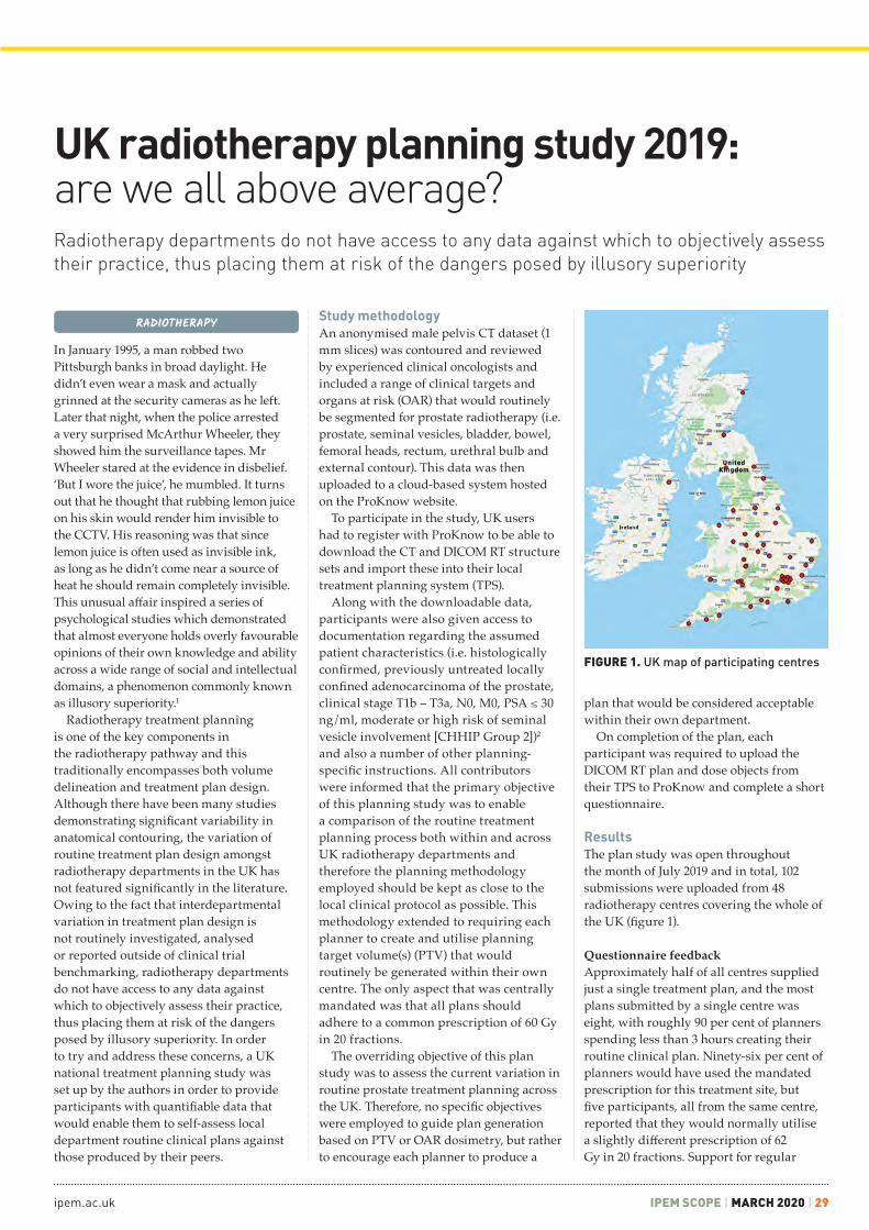
ipem.ac.uk IPEM SCOPE | MARCH 2020 | 29
Radiotherapy departments do not have access to any data against which to objectively assess their practice, thus placing them at risk of the dangers posed by illusory superiority
In January 1995, a man robbed two Pittsburgh banks in broad daylight. He didn’t even wear a mask and actually grinned at the security cameras as he left. Later that night, when the police arrested a very surprised McArthur Wheeler, they showed him the surveillance tapes. Mr Wheeler stared at the evidence in disbelief. ‘But I wore the juice’, he mumbled. It turns out that he thought that rubbing lemon juice on his skin would render him invisible to the CCTV. His reasoning was that since lemon juice is often used as invisible ink, as long as he didn’t come near a source of heat he should remain completely invisible. This unusual affair inspired a series of psychological studies which demonstrated that almost everyone holds overly favourable opinions of their own knowledge and ability across a wide range of social and intellectual domains, a phenomenon commonly known as illusory superiority.1
Radiotherapy treatment planning is one of the key components in the radiotherapy pathway and this traditionally encompasses both volume delineation and treatment plan design. Although there have been many studies demonstrating significant variability in anatomical contouring, the variation of routine treatment plan design amongst radiotherapy departments in the UK has not featured significantly in the literature. Owing to the fact that interdepartmental variation in treatment plan design is not routinely investigated, analysed or reported outside of clinical trial benchmarking, radiotherapy departments do not have access to any data against which to objectively assess their practice, thus placing them at risk of the dangers posed by illusory superiority. In order to try and address these concerns, a UK national treatment planning study was set up by the authors in order to provide participants with quantifiable data that would enable them to self-assess local department routine clinical plans against those produced by their peers.
Study methodologyAn anonymised male pelvis CT dataset (1 mm slices) was contoured and reviewed by experienced clinical oncologists and included a range of clinical targets and organs at risk (OAR) that would routinely be segmented for prostate radiotherapy (i.e. prostate, seminal vesicles, bladder, bowel, femoral heads, rectum, urethral bulb and external contour). This data was then uploaded to a cloud-based system hosted on the ProKnow website.
To participate in the study, UK users had to register with ProKnow to be able to download the CT and DICOM RT structure sets and import these into their local treatment planning system (TPS).
Along with the downloadable data, participants were also given access to documentation regarding the assumed patient characteristics (i.e. histologically confirmed, previously untreated locally confined adenocarcinoma of the prostate, clinical stage T1b – T3a, N0, M0, PSA ≤ 30 ng/ml, moderate or high risk of seminal vesicle involvement [CHHIP Group 2])2 and also a number of other planning-specific instructions. All contributors were informed that the primary objective of this planning study was to enable a comparison of the routine treatment planning process both within and across UK radiotherapy departments and therefore the planning methodology employed should be kept as close to the local clinical protocol as possible. This methodology extended to requiring each planner to create and utilise planning target volume(s) (PTV) that would routinely be generated within their own centre. The only aspect that was centrally mandated was that all plans should adhere to a common prescription of 60 Gy in 20 fractions.
The overriding objective of this plan study was to assess the current variation in routine prostate treatment planning across the UK. Therefore, no specific objectives were employed to guide plan generation based on PTV or OAR dosimetry, but rather to encourage each planner to produce a
plan that would be considered acceptable within their own department.
On completion of the plan, each participant was required to upload the DICOM RT plan and dose objects from their TPS to ProKnow and complete a short questionnaire.
ResultsThe plan study was open throughout the month of July 2019 and in total, 102 submissions were uploaded from 48 radiotherapy centres covering the whole of the UK (figure 1).
Questionnaire feedbackApproximately half of all centres supplied just a single treatment plan, and the most plans submitted by a single centre was eight, with roughly 90 per cent of planners spending less than 3 hours creating their routine clinical plan. Ninety-six per cent of planners would have used the mandated prescription for this treatment site, but five participants, all from the same centre, reported that they would normally utilise a slightly different prescription of 62 Gy in 20 fractions. Support for regular
RADIOTHERAPY
UK radiotherapy planning study 2019: are we all above average?
FIGURE 1. UK map of participating centres

30 | MARCH 2020 | IPEM SCOPE Scope welcomes your feedback! Join IPEM Scope Community of Interest
MEDICAL PHYSICS
planning studies was given by 84 per cent of participants, with 16 per cent not answering.
Variation in OAR dosimetryWhen the data collection phase of the plan study was completed, data from each
submission was extracted automatically for the 17 OAR metrics identified from the CHHIP trial.2 These data were extracted and published in an interactive ‘population results’ module within ProKnow, which presented as a histogram displaying the user-submitted metric against the
values from all submissions. Additional functionality inherent in the ProKnow software was also available, allowing the user to study population statistics, perform TPS-by-TPS and modality-by-modality breakdowns, analyse efficiency (e.g. estimated delivery time) and, most importantly, benchmark themselves nationally against a range of relevant clinical metrics. Femoral head and bowel structures demonstrated minimal variation between submissions, but significant variation was observed for all bladder, rectum and urethral bulb metrics. An example histogram of one of the OAR metrics is provided in figure 2.
Variation in PTV generationCommonly international plan studies have provided pre-contoured PTV(s) as part of the downloadable dataset. Although this methodology makes collating PTV data much easier, it also obscures one of the main differentiating factors in the planning approach taken by different departments, i.e. how PTV(s) are derived from the target structures contoured by the clinician. Therefore, as previously described, in this study all centres were asked to generate
FIGURE 2. Example of ProKnow histogram for OAR dose metric
FIGURE 3. Variation of prescription PTV from all plans: anterior(A), posterior (P), left (L), right (R), superior (S), inferior (I)

ipem.ac.uk IPEM SCOPE | MARCH 2020 | 31
CLINICAL SCIENTISTNEIL RICHMOND
Northern Centre for Cancer Care, Newcastle upon Tyne NHS Hospitals Foundation Trust
CLINICAL SCIENTISTTIM TAYLOR
Royal United Hospitals Bath NHS Foundation Trust, Bath
Discuss this article in the IPEM Scope Community of Interest
REFERENCES1 Kruger J, Dunning D. Unskilled and unaware of it: how difficulties in recognizing one’s own incompetence lead to inflated self-assessments. J Pers Soc Psychol 1999; 77(6): 1121.
2 Dearnaley D, Syndikus I, Sumo G et al. Conventional versus hypofractionated high-dose intensity-modulated radiotherapy for prostate cancer: preliminary safety results from the CHHiP randomised controlled trial. Lancet Oncol 2012; 13(1): 43–54.
u ACKNOWLEDGEMENTSThanks to ProKnow Systems and Ben Nelms for providing free use of ProKnow Plan Studies
A PDF report detailing the major findings of the UK national planning study, along with a spreadsheet containing all the anonymised raw data, was sent to all participants. For anyone who did not participate but who would like to review this data, you can still get hold of it.
1 Copy the link provided into a browser: https://proknowsystems.com/organizations/join/5d13953e688042f03a88d90dd8a3fee7
2 Follow the instructions to register for a ProKnow account and provide email verification.
3 Follow the instructions to request to join UK Planning Studies Organisation (i.e. click Submit Request at the bottom of the page).
4 In the top right of the Plan Studies screen, click Select Organization and choose UK Planning Studies.
5 Click on the 2019 Prostate Plan Study and navigate to the Learn tab to download data.
their own PTV structures from the pre-contoured target structures and then supply information regarding the PTV generation methodology using a questionnaire.
Despite the identical nature of the underlying dataset and patient characteristics provided to each participant, significant variation was observed in the generation of PTV(s) across all submitted plans. Approximately half of submitted plans (47 per cent) generated three PTV structures using the margin methodology described by the CHHIP trial with negligible variation*. A further 16 per cent generated CHHIP-style structures with moderate variation (2–3 mm) in some aspect of the CTV to PTV margin. However, 37 per cent of submissions generated PTV(s) that could not really be considered in accordance with CHHIP definitions.
From the 102 submissions, 17 distinct methodologies were utilised to generate a prescription PTV from the pre-contoured target structures (the prescription PTV is the structure to which the prescription dose of 60 Gy is given). The range of the prescription PTV volumes varied drastically from 32.5 cm3 to 179.9 cm3. A histogram of the volumes and margin methodologies of the different prescription PTV structures is shown in figure 3.
DiscussionThe data presented here demonstrates that, despite supplying centres with a standardised pre-contoured dataset, patient characteristics and prescription information, significant variation in treatment planning methodology exists between radiotherapy departments across the UK. Of particular note are the observed variations in PTV generation and also dose received by selected OAR, with the latter noticeably influenced by the variation in the former. It is accepted that the data collated here cannot, in isolation, reflect the efficacy of an individual centre’s treatment pathway. It may incorporate variation in locally available treatment equipment and techniques, it does not take any account of the robustness of plans to changes in patient shape or position, and it does not take into consideration the relative complexity or deliverability of the generated plans. Despite these shortcomings, the data provided by this study enables radiotherapy departments in the UK to compare their practice against their peers, facilitates reflection on local protocols and provides a potential source of development for those centres who may want to implement change.
At the time of writing, discussions are currently ongoing to try and organise a planning study along similar lines for 2020 – watch this space!
*NB. A comparison of PTV volumes to those defined by CHHIP is not an indication of the authors’ assertion that CHHIP volumes should be considered a gold standard; rather, that CHHIP provided a useful anchor for discussing the observed variation.
VISUALISATION OF SKIN CANCERResearchers have demonstrated the use of millimetre wave imaging (30–300 GHz), which penetrates 1.3 mm into tissue, to diagnose skin cancer. Across 21 samples, the average reflectivity was 74% for tumour regions (basal cell carcinoma or squamous cell carcinoma) and 30% for normal regions, making reflectivity a reliable marker for cancerous tissue. This non-invasive method has the potential to reduce the number of unnecessary biopsies by half.(doi:10.1109/TMI.2019.2902600)
CONTRIBUTION OF COLLAGENMR elastography has been shown to visualise and measure the stiffness and density of tumours. It is more difficult to deliver drugs inside tumours that are more stiff and dense, and specific drugs such as collagenase are required to weaken the structure to allow other drugs to reach cells in their centres. Researchers found that breast tumours were twice as stiff as brain tumours and around three times as dense.(doi:10.1158/0008-5472.CAN-19-1595)
FERROMAGNETIC ROBOTSA magnetically steerable guidewire has been developed, which can slide through blood vessels and reach blood clots in the brain. The nickel titanium alloy wire is coated in a paste of magnetic particles (that make it steerable) and in a hydrogel (to reduce friction). The manipulation of the guidewire, which is able to deliver clot-reducing drugs or can be modified to break up blockages using a laser, was demonstrated by passing it through a life-sized silicone replica of blood vessels in the brain.(doi:10.1126/scirobotics.aax7329)
AUTOMATED TREATMENT PLANSIt has been shown that the average radiotherapy treatment planning time for prostate cancer patients can be reduced from 2 hours down to 20 minutes using a commercial automated planning model. Plans created were shown to be dosimetrically similar to conventionally created plans with regards to target coverage and also had improved rectal sparing. When comparing paired test cases, an expert team of dosimetrists, physicists and radiation oncologists preferred the auto-generated plans 18 out of 20 times.(doi:10.1002/acm2.12674)
INBRIEF

32 | MARCH 2020 | IPEM SCOPE Scope welcomes your feedback! Join IPEM Scope Community of Interest
MEDICAL PHYSICS
Whilst photon radiotherapy treatment techniques have advanced hugely in the last two decades, electrons have languished somewhat, with probably the majority of radiotherapy departments (mine included) calculating patient treatments with tabulated data (even if the front end is a nice piece of software), and assuming patients are homogeneous water phantoms. Measured endframe factors are often required to independently check the primary monitor unit (MU) calculation. During a recent meeting of the IPEM South West (SW) Radiotherapy Audit Group a discussion on the regional electron audits diverged into how small endframe factors were being measured.
I was keen to gather a bit more detail so polled the SW group by email, and received a number of responses. The results were interesting and varied enough that I polled the UK JISCMAIL Medical Physics list using SurveyMonkey; thank you to everyone who responded to either of these surveys. I received a total of 29 responses (a response rate of just over 50 per cent from UK centres, although a couple of responses were received from Australia/New Zealand).
I chose questions first to establish how departments measure and correct applicator factors, as this might influence practice for
endframe factors. The full list of questions can be found in figure 1. Most questions had open text fields for comments and additional explanations – it’s not possible to provide the full analysis in this short article but I am happy to share the anonymised results with anyone who’s interested.
I was limited to nine questions by SurveyMonkey, which kept the survey to a user-friendly 5 minutes, but meant that I couldn’t ask all the questions I would have liked. Further questions could have included: what factors people use for non-water phantoms, perturbation factors for chambers other than the NACP/ROOS, how centres deal with stand-off – the list goes on. Instead of examining each question in turn, here I wanted to present some of the more interesting points, comments and reflections I’ve had during this small investigation.
The Electron Code of PracticeA large proportion of centres (12 out of 29) responded to say that they do not correct applicator factors for the ratio of stopping power ratios. The correction is small (for example, the corrections for a recently commissioned TrueBeam at my centre did not exceed 1 per cent); however, the Electron Code of Practice1 is quite explicit, so the almost equal split in those who do and don’t correct (15 out of 29 do apply a correction) was higher than expected.
The endframe depth of maximum dose (dmax) can change from the applicator nominal with small endframes, and deciding if or when to check this varies quite widely across respondents; lots of useful comments in the free text boxes were provided for question 5 (I do urge anyone responding to surveys to utilise them as the comments are often invaluable!). Fifteen out of 29 centres said they find endframe dmax, five stated that they had a field size limit below which they found endframe dmax and six said they use applicator dmax. Some interesting rules of thumb for when to find endframe depth of maximum dose (dmax) cropped up (for example, Enom (nominal energy)/2.5, or an endframe that blocks more than half the field), and it became clear that many centres do not manufacture ‘custom’ endframes for individual patients, sticking to a standard library characterised fully during linac commissioning.
I attempted to derive a simple rule of thumb for when to find endframe dmax, utilising data from a recently commissioned TrueBeam. Our primary MU calculator RadCalc requires various-sized circle endframe percent depth dose curves (PDDs) and output/endframe factors to be measured for commissioning. Using this data I found the endframe size where dmax changed significantly from its nominal value, and using the incorrect dmax resulted
Electron endframe factors: survey of UK practiceCharlie Martin looks at the attention to detail exhibited by physicists as one of the things that makes radiotherapy so safe
RADIOTHERAPY

ipem.ac.uk IPEM SCOPE | MARCH 2020 | 33
software/spreadsheets), and commission a new algorithm in the department. One can spend inordinate amounts of time investigating, measuring, correcting and ensuring everything is perfect. However, as much as physicists like everything to be truly correct, it is difficult to justify spending a large amount of time improving processes when, at my centre:1 The number of electron patients treated is
relatively low, and the number with small endframes of concern even lower.
2 Measured endframe factors are only used as the independent check of the primary MU calculation (currently RadCalc).
3 Electron treatments are calculated on a homogeneous water phantom. As soon as that calculation is used on a real patient, with irregular surfaces and inhomogeneities, larger differences than the variations in this survey arise.
Should I be dedicating my time to improvements that would benefit the most patients? Should I stop fussing about small differences, and worrying about whether an endframe has had a valid measurement? Perhaps, but attention to detail exhibited by physicists is one of the things that makes radiotherapy so safe: 0.4 per cent of all reported patient safety incidents between April and July 2019 were due to radiotherapy, with only 0.8 per cent of radiotherapy errors being reportable under the Ionising Radiation (Medical Exposure) Regulations.2 Perhaps we just don’t know when to stop worrying, and prefer a good old measurement we can trust to confirm that safety.
I welcome any thoughts or comments. Please get in touch, or start a discussion on the Scope Community of Interest, where I can share more of the survey results if others are interested.
CLINICAL SCIENTIST IN RADIOTHERAPY PHYSICSCHARLIE MARTIN
Poole Hospital NHS Foundation Trust
Discuss this article in the IPEM Scope Community of Interest
REFERENCES 1 Thwaites DI, DuSatouy AR, Jordan T et al. The IPEM Code of Practice for electron dosimetry for radiotherapy beams of initial energy from 4 to 25 MeV based on an absorbed dose to water calibration. Phys Med Biol 2003; 48(18): 2929–70.
2 Public Health England. Safer Radiotherapy. Supplementary data analysis. Issue 29: Full radiotherapy data analysis April to July 2019. https://www.gov.uk/government/publications/safer-radiotherapy-error-data-analysis-report (accessed 6th December 2019).
FIGURE 1. SurveyMonkey questions1 Whatcentreareyoureplyingfor?(This
willbeanonymisedinanycollation/analysisofresults)
2 Whenmeasuringapplicatorfactorsdoyoumeasureatdmaxforeachapplicator,oruseaconsistentdepth(e.g.referenceapplicator)andcorrectusingPDD?
3 Doyoucorrectapplicatorfactorsforstoppingpowerratioorhaveyousatisfiedyourselvesthecorrectionissmallenoughtoignorelocally?
4 Doyoumeasureapplicatorfactors(orasubset)aspartofyourroutineQA?Ifyes,doyouusethemethodusedatcommissioningor(assuggestedinIPEMReport81)useconsistent'QA'depthstospeedupmeasurements?
5 Whenmeasuringendframefactorsdoyou:findendframedmax/haveafieldsizelimitbelowwhichyousearchfordmax/notsearchfordmax–useapplicatordmax?
6 Howdoyoumeasureendframefactors?(detector/filmetc.)
7 DoyouhaveasizelimitontheuseofanNACP/ROOSchamberbelowwhichyouuseadifferentdetector?
8 Ifyoumeasureendframefactorsatadifferentdmaxtotheapplicator,doyoucorrectusingstoppingpowerratios?
9 Ifyoumeasureendframefactorsregularly,doyouusesolidwaterorawatertank?DoyoumeasurefullPDDsfornew/customendframes?
in an endframe factor significantly different (generally more than 1 per cent). However, after this, a new endframe was measured that shouldn’t have required a dmax search, and a 4.5 per cent difference to RadCalc was observed (after finding dmax and correcting for stopping power ratio this decreased to 0.3 per cent!). It is therefore apparent that it is difficult to set generic rules for when to search for dmax.
Nearly three-quarters of respondents use a parallel plate chamber (NACP or ROOS) to measure endframe factors, although a few use the Advanced Markus for these relative measurements (it has a smaller radius/sensitive volume than ROOS/NACP). Some used small-volume thimble ion chambers
(e.g. a Semiflex or Pinpoint chamber), and I would be interested to know if anyone is applying any correction factors for use in small electron fields! Most respondents that specified a field size limit for the NACP or ROOS were much in line with the limits I had optimistically determined for finding endframe dmax: around 6 cm, with a few using lower limits of 3 or 4 cm.
Of those that said they do determine endframe dmax, 14 responded that they corrected for stopping power ratio and nine responded that they did not correct for stopping power ratio (the other six either skipped or stated that endframe dmax was not found or used).
Attention to detailThe Electron Code of Practice1 is an in-depth document and can be, at times, tricky to grasp. It is, however, fairly prescriptive over the requirements for measurements in electron beams. The variations in practice around the country were therefore quite surprising. Deviations from the code of practice may be acceptable but, in my opinion, should be clearly justified in local documentation. I suspect that some centres had, as mine had in the past, generally accepted rules of thumb or simply adhered to the old adage of ‘we’ve always done it this way’. Linac commissioning or review of local QA procedures and frequencies (as I’m sure many have done recently with the 2nd edition of IPEM Report 81) are excellent times to examine practice and ensure that what you’re doing has been investigated in the past and is still acceptable. If you are happy not correcting for stopping power ratio because it is a small correction (this is probably swamped by other sources of uncertainty, such as the calculation assuming a semi-infinite, flat, rigid, immobile, uniform, water-equivalent patient), ensure you can demonstrate this in clinically relevant conditions.
This has mostly been an academic exercise motivated out of personal interest after reviewing local practice; I’ve enjoyed it and learned a lot. Radiotherapy centres are in all likelihood meeting recommendations and guidelines on QA, but often in quite different ways. Exercises like this are a useful tool to compare practice; perhaps IPEM can continue to audit variation across the country in the future, or perhaps this is a function for the new Radiotherapy Networks?
I could continue and investigate the variation in planning practice (i.e. are simple treatments calculated with commercial monitor unit calculation systems, electron Monte-Carlo algorithms or in-house

34 | MARCH 2020 | IPEM SCOPE Scope welcomes your feedback! Join IPEM Scope Community of Interest
MEDICAL PHYSICS
Interest in stereotactic radiosurgery (SRS) and radiotherapy (SRT) techniques has increased rapidly over the last few years. There is an increasing trend to reduce fractionation regimes, with several trials reporting equivalent outcomes for reduced fractionation schedules compared with standard, long fraction courses.1 This interest in SRS/SRT is also present for the treatment of brain metastases. The number of patients presenting with brain metastases is increasing due to more patients surviving their primary tumour and better imaging techniques. A large proportion of these patients would have traditionally been treated using whole-brain radiotherapy (WBRT); however, recent studies have shown no overall survival advantage using WBRT and significant toxicity in terms of loss of cognitive function.2 All of these factors mean that the demand for SRS treatment of brain metastases is increasing.
Basics of SRS planning methodsThe principle of SRS planning is to use several small radiation beams which converge at the centre of the target, delivering an ablative radiation dose (high dose per fraction) and sparing the adjacent healthy tissue. There are several key differences that make SRS planning
a specialist area: small target size (< 3 cm diameter), large number of treatment beams and high spatial accuracy requirements of the treatment (0.5–1.5 mm).
SRS planning was developed almost in isolation from standard radiotherapy as it was traditionally delivered using a gamma knife unit (figure 1A). The gamma knife unit is a dedicated cranial SRS treatment unit consisting of 192 cobalt-60 sources, arranged so the emitted gamma rays are focussed to a single point. These gamma knife units employ a dedicated planning system to produce the required treatment plan that can treat 1–30 brain metastases over several hours of treatment in a single session. More recently, SRS treatments have been delivered using standard radiotherapy linacs (figure 1B) and therefore planned
using commercial radiotherapy treatment planning systems (TPS).
SRS planning approachesTo evaluate the quality of the plan produced, several metrics have been developed for SRS. These evaluate the coverage and selectivity of covering the target with the prescribed dose. There is also a measure of the fall-off of the dose outside of the target. The most widespread metrics used for SRS plan evaluation are the Paddick Conformity Index (PCI)3 and Paddick Gradient Index (GI).4
The PCI is defined by the equation:
where the first term is the selectivity, the second term is the coverage and PI is the required prescription isodose.
The GI is defined by the equation:
Another useful measure of the plan quality is the volume of normal brain that receives 12 Gy. This dose value is chosen as it has been shown in studies to relate to the risk of brain toxicity.5
SRS planning workflowA high-resolution contrast-enhanced MR scan, rigidly registered to the planning CT, is used to aid the clinician’s contouring of the target and organs at risk (OAR), including optic chiasm, optic nerve, globe of eye and lens volumes. There is also growing interest in reducing the dose to the hippocampus as there has been some evidence linked to increased toxicity with higher hippocampus doses.6
SRS PLANNING
Aiming small: stereotactic radiosurgerySRS treatments can now be planned and delivered accurately on routine radiotherapy treatment equipment
FIGURE 1. Comparison of two SRS delivery platforms: (A) gamma knife unit, (B) linear accelerator Source: Elekta.com
FIGURE 2. Measured beam profiles for several small fields, measured using Gafchromic film
Volume of targetcovered by PIVolume of PI
Volume of targetcovered by PI
Volume of targetX
Volume of isodose that is half PIVolume of PI
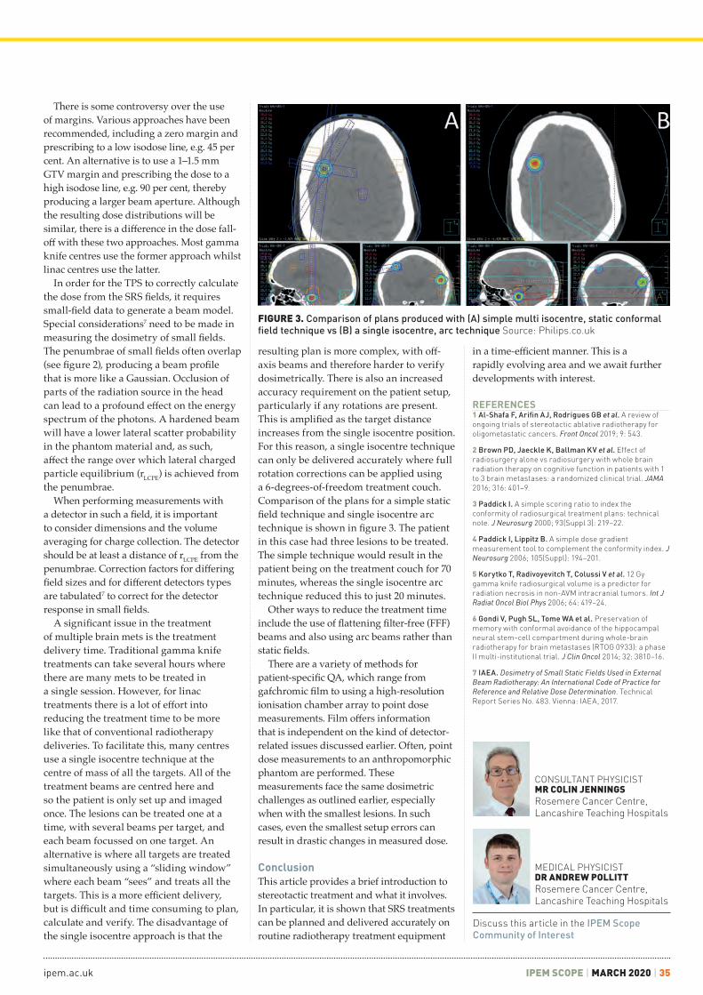
ipem.ac.uk IPEM SCOPE | MARCH 2020 | 35
There is some controversy over the use of margins. Various approaches have been recommended, including a zero margin and prescribing to a low isodose line, e.g. 45 per cent. An alternative is to use a 1–1.5 mm GTV margin and prescribing the dose to a high isodose line, e.g. 90 per cent, thereby producing a larger beam aperture. Although the resulting dose distributions will be similar, there is a difference in the dose fall-off with these two approaches. Most gamma knife centres use the former approach whilst linac centres use the latter.
In order for the TPS to correctly calculate the dose from the SRS fields, it requires small-field data to generate a beam model. Special considerations7 need to be made in measuring the dosimetry of small fields. The penumbrae of small fields often overlap (see figure 2), producing a beam profile that is more like a Gaussian. Occlusion of parts of the radiation source in the head can lead to a profound effect on the energy spectrum of the photons. A hardened beam will have a lower lateral scatter probability in the phantom material and, as such, affect the range over which lateral charged particle equilibrium (rLCPE) is achieved from the penumbrae.
When performing measurements with a detector in such a field, it is important to consider dimensions and the volume averaging for charge collection. The detector should be at least a distance of rLCPE from the penumbrae. Correction factors for differing field sizes and for different detectors types are tabulated7 to correct for the detector response in small fields.
A significant issue in the treatment of multiple brain mets is the treatment delivery time. Traditional gamma knife treatments can take several hours where there are many mets to be treated in a single session. However, for linac treatments there is a lot of effort into reducing the treatment time to be more like that of conventional radiotherapy deliveries. To facilitate this, many centres use a single isocentre technique at the centre of mass of all the targets. All of the treatment beams are centred here and so the patient is only set up and imaged once. The lesions can be treated one at a time, with several beams per target, and each beam focussed on one target. An alternative is where all targets are treated simultaneously using a “sliding window” where each beam “sees” and treats all the targets. This is a more efficient delivery, but is difficult and time consuming to plan, calculate and verify. The disadvantage of the single isocentre approach is that the
resulting plan is more complex, with off-axis beams and therefore harder to verify dosimetrically. There is also an increased accuracy requirement on the patient setup, particularly if any rotations are present. This is amplified as the target distance increases from the single isocentre position. For this reason, a single isocentre technique can only be delivered accurately where full rotation corrections can be applied using a 6-degrees-of-freedom treatment couch. Comparison of the plans for a simple static field technique and single isocentre arc technique is shown in figure 3. The patient in this case had three lesions to be treated. The simple technique would result in the patient being on the treatment couch for 70 minutes, whereas the single isocentre arc technique reduced this to just 20 minutes.
Other ways to reduce the treatment time include the use of flattening filter-free (FFF) beams and also using arc beams rather than static fields.
There are a variety of methods for patient-specific QA, which range from gafchromic film to using a high-resolution ionisation chamber array to point dose measurements. Film offers information that is independent on the kind of detector-related issues discussed earlier. Often, point dose measurements to an anthropomorphic phantom are performed. These measurements face the same dosimetric challenges as outlined earlier, especially when with the smallest lesions. In such cases, even the smallest setup errors can result in drastic changes in measured dose.
ConclusionThis article provides a brief introduction to stereotactic treatment and what it involves. In particular, it is shown that SRS treatments can be planned and delivered accurately on routine radiotherapy treatment equipment
in a time-efficient manner. This is a rapidly evolving area and we await further developments with interest.
FIGURE 3. Comparison of plans produced with (A) simple multi isocentre, static conformal field technique vs (B) a single isocentre, arc technique Source: Philips.co.uk
REFERENCES1 Al-Shafa F, Arifin AJ, Rodrigues GB et al. A review of ongoing trials of stereotactic ablative radiotherapy for oligometastatic cancers. Front Oncol 2019; 9: 543.
2 Brown PD, Jaeckle K, Ballman KV et al. Effect of radiosurgery alone vs radiosurgery with whole brain radiation therapy on cognitive function in patients with 1 to 3 brain metastases: a randomized clinical trial. JAMA 2016; 316: 401–9.
3 Paddick I. A simple scoring ratio to index the conformity of radiosurgical treatment plans: technical note. J Neurosurg 2000; 93(Suppl 3): 219–22.
4 Paddick I, Lippitz B. A simple dose gradient measurement tool to complement the conformity index. J Neurosurg 2006; 105(Suppl): 194–201.
5 Korytko T, Radivoyevitch T, Colussi V et al. 12 Gy gamma knife radiosurgical volume is a predictor for radiation necrosis in non-AVM intracranial tumors. Int J Radiat Oncol Biol Phys 2006; 64: 419–24.
6 Gondi V, Pugh SL, Tome WA et al. Preservation of memory with conformal avoidance of the hippocampal neural stem-cell compartment during whole-brain radiotherapy for brain metastases (RTOG 0933): a phase II multi-institutional trial. J Clin Oncol 2014; 32: 3810–16.
7 IAEA. Dosimetry of Small Static Fields Used in External Beam Radiotherapy: An International Code of Practice for Reference and Relative Dose Determination. Technical Report Series No. 483. Vienna: IAEA, 2017.
MEDICAL PHYSICISTDR ANDREW POLLITTRosemere Cancer Centre, Lancashire Teaching Hospitals
CONSULTANT PHYSICISTMR COLIN JENNINGSRosemere Cancer Centre, Lancashire Teaching Hospitals
Discuss this article in the IPEM Scope Community of Interest

36 | MARCH 2020 | IPEM SCOPE Scope welcomes your feedback! Join IPEM Scope Community of Interest
FIGURE 2. (left) In-house manufactured coils support for pelvis imaging; (right) the couch securing mechanism with adjustable size
FIGURE 1. (left) Medibord RT flat couch top; (top right) access to head coil fixtures; (bottom right) retaining access to coil-securing fixtures and utilising these fixtures for securing the couch top in position
MEDICAL PHYSICS
The Northern Centre for Cancer Care (NCCC) installed its first MRI scanner dedicated to radiotherapy and oncology purposes in 2009, one of the first in the UK. In 2009, the MRI service was introduced as an important addition to the conventional CT planning process; however, it now forms an indispensable part of the radiotherapy service for CT–MR fusion and MR-only planning, and paves the way for MR-guided radiotherapy treatments with the introduction of MR linacs.
Technical preparation: RT planning MRI-specific equipmentAt the inception of our clinical service, there was no commercially available compatible flat couch top. NCCC entered into a research collaboration with Medibord, Nottingham, UK, to develop a bespoke flat couch top to fit with our scanner model and our preferred patient setup. The couch top material is glass fibre, so is extremely light, at less than 4 kg, and easy to manoeuvre. This is particularly important when the radiotherapy couch top needs to be replaced by the diagnostic couch top for clinical trial patient scanning or diagnostic scans for radiotherapy patients. The table-top securing mechanism was designed to fit into the coil’s strap-securing mechanisms on the Siemens couch, which were also used to secure the in-house-manufactured coil supports. The flat couch top was designed by NCCC staff and manufactured by Medibord. Figure 1 shows details of the couch top.
When acquiring diagnostic MRI images, typically the surface coils are directly wrapped around the patient. This can
compress the patient’s skin, which is not appropriate for radiotherapy planning where an accurate image of the patient’s external contour is essential.
To avoid any distortion of the patient skin contour, coil supports for pelvis and head and neck were designed and manufactured in-house by the Mechanical Workshop, Northern Medical Physics and Clinical Engineering. The pelvis coil support secures in position in the coil strap fittings, is manufactured from polyethylene terephthalate glycol (PTEG) and polyvinyl chloride (PVC) and is adjustable to suit a range of patient sizes. Hook and loop fastening is fixed to the PTEG surface to assist with securing the coils onto the support. The
coil support for pelvic imaging is shown in figure 2.
The head and neck coil support is manufactured from PTEG and secured onto an MRI-compatible head board (figure 3).
Clinical preparationDevelopment of radiotherapy-specific MRI protocols was based heavily on those developed by staff at Umea University, who, following a Newcastle evaluation visit, provided extensive mentoring support in the setup of our service.
ProstateThe first patient cohort to receive MRI RT planning acquisitions was prostate patients. Two acquisition sequences were used: a 3D
NCCC was one of the first UK cancer centres to install a dedicated MRI scanner for radiotherapy planning. Now over 35 per cent of radical patients utilise an MRI to improve their planning pathway.
MRI IMAGING
10 years of clinical experience of MRI in radiotherapy treatment planning
FIGURE 3. In-house manufactured coil support for brain and head and neck imaging

ipem.ac.uk IPEM SCOPE | MARCH 2020 | 37
and uterus visualisation. The acquisition sequences have now further developed and include two 2D sequences to assist with delineation, as shown in table 1.
BrainMRI imaging for selected brain tumours was introduced in January 2011. Patients are scanned without the immobilisation device so that the head coil can be used.
A T1 axial 3D sequence is used for delineation of the GTV. Typical patient images and the MRI sequence parameters are shown in figure 6.
Head and neckThe introduction of MRI imaging for oro and hypo-pharyngeal tumours began in April 2011. Two sequences were developed to assist with GTV delineation and nodal and organ-at-risk delineation. A T1 VIBE post-contrast acquisition was used to delineate GTV and
T2 sampling perfection with application-optimised contrasts using different flip angle evolution (SPACE) sequence which was optimised to image the entire patient outline with a small voxel size (1.2 × 1.2 × 1.7 mm3) and a high bandwidth to minimise geometric distortion, and a small FOV T2-weighted turbo spin echo (TSE) sequence. The SPACE sequences have since been further optimised and the TSE sequence replaced with a multi-echo data image contribution (Medic) sequence, which is acquired with a smaller field of view to assist with the definition of the in-slice boundary of the prostate capsule.
A typical patient setup is shown in figure 4, with details of the current acquisition protocols. Prostate delineation protocols were developed with the help of radiologist input. This interdisciplinary team identified a difference in imaging task between diagnosis and delineation.
The experience of a radiologist identified the regions of disease within the prostate, but did not need to identify the boundary of the prostate gland, whereas a clinical oncologist needs to accurately delineate the boundary of the prostate gland. Crossdisciplinary learning produced guidelines on prostate delineation based on MRI when fused with a planning CT. Methods of managing differences in patient anatomy between the MRI and CT scanning sessions were developed. There are inevitable patient setup differences, both in posture and internal anatomy position. Rigid registration can take account of postural differences, but
cannot completely compensate for differences in internal anatomy caused by differing bowel and bladder preparation. As the CT scan is used as the basis of the treatment plan and the reference image set for image-guided radiotherapy, any differences in anatomy between CT and MRI tend to be compensated for by reverting to the CT anatomy as the gold standard. This inevitably compromises the added benefit of the MRI acquisition and results in an ‘MRI-guided CT delineation’ for prostate GTV with OARs delineated on
the CT scan. This means that the excellent MRI soft tissue image quality is not always able to be used to its full potential, providing experiential evidence of the benefit of an MR-only patient pathway. A typical CT–MRI image registration for a prostate patient, and the resultant dose distribution, is shown in figure 5.
The clinical service was quickly extended to gynaecological EBRT sites in January 2010. It was found that the same T2 3D SPACE acquisition protocol was suitable for cervix
FIGURE 4. A typical prostate patient setup and MRI acquisition parameters
FIGURE 5. CT–MRI image fusion with delineation and VMAT dose distribution
FIGURE 6. Soft tissue detail on MRI (top left) and CT (top right) with MRI parameters (bottom)
Sequence name SPACE tse_vfl TSE TSE
Echo time 165 ms 102 ms 101 ms
Repetition time 2,000 ms 9,840 ms 6,300 ms
Flip angle 150° 150° 150°
Bandwidth 651 Hz/Px 140 Hz/Px 150 Hz/Px
Orientation Axial Sagittal Axial
Dimension 3D 2D 2D
Field of view 320 × 320 mm2 290 × 280 mm2 260 × 260 mm2
Number of slices 144 28 45
Voxel size 1.3 × 1.3 × 1.5 mm3 1.1 × 1.1 × 4.0 mm3 1.0 × 1.0 × 4.0 mm3
Sequence name fl3d_vibe
Echo time 2.39 ms
Repetition time 9.00 ms
Flip angle 12°
Bandwidth 210 Hz/Px
Orientation Axial
Dimension 3D
Field of view 250 × 250 mm2
Number of slices 192
Voxel size 1.1 × 1.0 × 1.0 mm3
Sequence name SPACE tse_vfl Medic
Echo time 211 ms 22 ms
Repetition time 1,500 ms 674 ms
Flip angle 150° 28°
Bandwidth 601 Hz/Px 190 Hz/Px
Orientation Axial Axial
Dimension 3D 2D
Field of view 450 × 447.3 mm2 260 × 260 mm2
Number of slices 120 34
Voxel size 1.4 × 1.4 × 1.5 mm3 1.3 × 1.0 × 3.0 mm3
TABLE 1. MRI acquisitions for treatment planning of gynaecological tumours

38 | MARCH 2020 | IPEM SCOPE Scope welcomes your feedback! Join IPEM Scope Community of Interest
MEDICAL PHYSICS
a T2 sequence to delineate lymph nodes and organs at risk. Figure 7 shows a typical patient setup and coil arrangement utilising the in-house manufactured coil support. A second flex coil may be position over the patient’s shoulders if required. The MRI acquisition parameters are also shown in figure 7 and typical patient images and dose distribution shown in figure 8.
RectumRoutine MRI imaging for rectal cancer patients was introduced in April 2018, with MRI planning scans for anus patients following in September 2018. Patient setup is similar to that for prostate patients. The MRI acquisition parameters are shown for rectum patients in table 2 and for anus patients in table 3. A typical example of CT–MRI image registration for planning of a rectal cancer is shown in figure 9.
SRS brainNewcastle is one of 17 cancer centres in England commissioned by NHS England to deliver stereotactic radiosurgery (SRS) and has been treating SRS patients since June 2015. Rapid access to planning MRI
scans is essential to the delivery of this service, particularly for patients travelling large distances. A range of MRI sequences are acquired, often tailored to the specific clinical presentation and vitally supported by neuroradiologists. Figure 10 shows a range of SRS brain tumours with the MRI acquisition image and the treatment dose distribution.
BrachytherapyMRI acquisitions for brachytherapy post
planning for prostate I-125 implants began in February 2010, with MRI-only planning for cervix brachytherapy being implemented in September 2011. MRI-only planning for vaginal vault brachytherapy treatments was introduced in July 2012 when MRI was also introduced as a position check for vaginal vault applicator insertions for patients with intermediate- and high-risk endometrial cancer. Figure 11 shows a brachytherapy treatment for cervical cancer.
Sequence name fl3d_vibe TSE
Echo time 2.39 ms 89 ms
Repetition time 9.00 ms 6,000 ms
Flip angle 12° 150°
Bandwidth 210 Hz/Px 159 Hz/Px
Orientation Axial Axial
Dimension 3D 2D
Field of view 250 × 250 mm2 310 × 271.25 mm2
Number of slices 224 70
Voxel size 1.1 × 1.0 × 1.0 mm3 1.1 × 0.8 × 3.0 mm3
FIGURE 7. A typical head and neck coil arrangement and MRI acquisition parameters
FIGURE 8. Typical image set: (top left) CT; (top right) T1 VIBE; (bottom left) dose distribution; (bottom right) T2 TSE
Sequence name SPACE tse_vfl TSE TSE
Echo time 211 ms 102 ms 101 ms
Repetition time 1,500 ms 9,840 ms 6,300 ms
Flip angle 150° 150° 150°
Bandwidth 601 Hz/Px 140 Hz/Px 150 Hz/Px
Orientation Axial Sagittal Axial
Dimension 3D 2D 2D
Field of view 450 × 447.3 mm2 280 × 280 mm2 260 × 260 mm2
Number of slices 144 28 45
Voxel size 1.4 × 1.4 × 1.5 mm3 1.1 × 1.1 × 4.0 mm3 1.0 × 1.0 × 4.0 mm3
TABLE 2. MRI acquisitions for treatment planning of rectal tumours
Sequence name SPACE tse_vfl TSE TSE
Echo time 165 ms 102 ms 101 ms
Repetition time 2,000 ms 9,840 ms 6,300 ms
Flip angle 150° 150° 150°
Bandwidth 651 Hz/Px 140 Hz/Px 150 Hz/Px
Orientation Axial Sagittal Axial
Dimension 3D 2D 2D
Field of view 320 × 320 mm2 280 × 280 mm2 260 × 260 mm2
Number of slices 144 28 45
Voxel size 1.3 × 1.3 × 1.5 mm3 1.1 × 1.1 × 4.0 mm3 1.0 × 1.0 × 4.0 mm3
TABLE 3. MRI acquisitions for treatment planning of anal tumours
FIGURE 9. MRI–CT fusion for rectum and anus

ipem.ac.uk IPEM SCOPE | MARCH 2020 | 39
35 per cent of radical patients in Newcastle now receive an MRI to improve their planning pathway.
There was overwhelming clinical support to replace our radiotherapy MRI scanner and we now anticipate the installation of our new Siemens Sola 1.5 T MRI (Siemens, Erlangen, Germany) in April 2020. We look forward to extending our MR-only pathway for prostate patients to other treatment sites and cementing MRI as an indispensable part of the radiotherapy pathway.
Discuss this article in the IPEM Scope Community of Interest
MRI-only planningOur growing experience in CT–MR fusion for radiotherapy delineations emphasised the compromises that were necessary to account for differences in patient position and preparation between the CT and MRI imaging sessions. This was resulting in a limitation of the benefit of MRI, as the CT image set was used as the standard where there were anatomical discrepancies between the CT and MRI. Feedback from clinical oncologists described increasing frustration at the compromises that were being imposed by limitations in the technique. NCCC has
been investigating the technical development of an MR-only patient pathway since 2016 with research partners in Australia, the UK and Sweden. Conventional CT–MR-based radiotherapy planning utilises the superior soft tissue provided by the MRI for target and OAR delineation, and the CT image to account for different types of tissue in the dose calculation. An MR-only pathway requires an appropriate dataset for dose calculation, a synthetic CT, and the NCCC research group have investigated the accuracy of available algorithms.1
MR-only pathways are available in some European radiotherapy centres using x-ray IGRT treatment machines, but there is
an important difference in the treatment pathway between these centres and NCCC. Prior to radiotherapy treatment being delivered at each visit, an imaging session is performed on the treatment machine to ensure that the patient is set up and aligned as accurately as possible. In the existing clinical centres in Europe, this is achieved using fiducial markers, whereas image matching using soft tissue anatomy is used in Newcastle, sparing the patient the procedure required to insert fiducial markers. This means that the MRI image used to develop the treatment plan can be used as a reference image for the on-treatment image verification.2
In Newcastle the MriPlanner (Spectronic Medical AB, Helsingborg, Sweden) synthetic CT solution is used, and the MRI acquisition is DICOM relabelled as a CT to allow transfer to ARIA (Varian, Palo Alto, USA) and the Varian TrueBeam treatment machine (Varian). Figure 12 shows the relabelled MRI reference image and the kV CBCT daily verification image.
In addition to standard MU checks, the clinical MR-only plan was also recalculated on the back-up CT as further QA of the process.
Figure 13 shows the clinical dose distribution on the synthetic CT and the dose difference between the clinical plan and the QA plan calculated on the back-up CT.
SummaryNCCC was one of the first UK cancer centres to install a dedicated MRI scanner for radiotherapy planning, in 2009. The clinical workload and clinical scope has significantly increased over the first 10 years so that over
REFERENCES1 Wyatt J, Dowling JA, Kelly CG et al. Investigating the generalisation of an atlas-based synthetic-CT algorithm to another centre and MR scanner for prostate MR-only radiotherapy. Phys Med Biol 2017; 62(24): N548–60.
2 Wyatt J, Brooks R, Ainslie D et al. The accuracy of magnetic resonance – cone beam computed tomography soft-tissue matching for prostate radiotherapy. Phys Imag Radiat Oncol 2019; 12: 49–55.
u ACKNOWLEDGMENTSThe authors would like to acknowledge the contribution of Jill McKenna to the development and introduction of the NCCC MRI service.
Metastases Meningioma Acoustic neuroma Pituitary adenoma
FIGURE 10. SRS brain treatments showing a range of treatment sites with the dose distribution
FIGURE 11. MRI planning image showing a cervical ring brachytherapy treatment. The dashed lines show the clinical delineations and the solid lines the brachytherapy dose distribution
FIGURE 12. Relabelled MRI reference image with kV CBCT acquired on a TrueBeam in the central region of the images
FIGURE 13. First MR-only prostate patient – dose distribution (top) and dose difference to CT (bottom)
CLINICAL SCIENTISTMR JONATHAN WYATTNorthern Centre for Cancer Care, Newcastle upon Tyne Hospitals NHS Foundation Trust
CONSULTANT CLINICAL SCIENTISTDR HAZEL MCCALLUMNorthern Centre for Cancer Care, Newcastle upon Tyne Hospitals NHS Foundation Trust

40 | MARCH 2020 | IPEM SCOPE Scope welcomes your feedback! Join IPEM Scope Community of Interest
MEDICAL PHYSICS
The National Radiological Protection Board (NRPB) was created by the Radiological Protection Act in 1970, before being superseded by the Health Protection Agency in 2005, itself being superseded by Public Health England in 2012. These bodies were public authorities whose statutory functions were to conduct research on radiological protection and provide advice and information on the subject to government departments and others. One should not underestimate the excellent research on ionising radiation matters undertaken by the NRPB during its lifetime.
The initial NRPB report DR11 on derived limits primarily explained the principles which would be adopted in subsequently obtaining the derived limits for surface contamination in later reports. Whereas acceptable levels of contamination are not specified, the second NRPB document DR22 attempts to put the concept of detected/measured surface contamination on a sound scientific footing. Most of the initial work applied to the nuclear industry, although the document does refer to other establishments such as hospitals ‘where only a few low-toxicity radionuclides are used’. The derived limits for surface contamination are based on the dose-equivalent limits for workers recommended by the International Commission on Radiological Protection (ICRP); specifically, the annual dose equivalent limit for skin of 500 mSv recommended by the ICRP. For the average working year of 2,000 hours, this is equivalent to a dose rate of 0.25 mSv/h. The derived limit is then the surface activity that delivers this dose-equivalent rate to the radiation-sensitive layer of the skin. There may be a little confusion in that the previous report DR1 referred to ‘effective dose equivalent’, which was the old term for effective dose, but the derived limit above, based on dose-equivalent rate to the skin, seems more consistent and scientific. The DR2 report considers three possible exposure pathways: external irradiation of the skin, inhalation and ingestion of radioactivity for some 74 radionuclides, and
the point to note here is just how thorough and scientific the research in this report is. Until now, however, radionuclides were divided into radiotoxicity classes, as given by the International Atomic Energy Agency (IAEA), but one of the observations of this NRPB DR2 report is to point out how inappropriate this is, and it proposed a revised classification of radionuclides for controlling surface contamination in workplaces in the United Kingdom based on the dose-equivalent limits for workers, and not based on radiotoxicity. A later supplement3 to the NRPB report DL2 was issued in 1982, but these were principally improved calculations based on the newly available annual limits of intake and derived air concentrations published by the ICRP Publication 30 (1979 to 1982).
The Ionising Radiations Regulations 1985 (IRR85) had a Schedule 2, column 4 which listed surface contamination levels in Bq/cm2 as a basis for designating contaminated work areas as controlled or supervised areas, according to Schedule 6. However, this does not accord with practice; upon finding a contaminated work area, a laboratory manager would immediately set about trying to decontaminate the area, according to guidelines discussed below, rather than taking steps to designate the area as controlled or supervised. It is notable that no such schedules correlating to Schedules 2 and 6 of IRR85 are to be found
in Ionising Radiations Regulations 1999 (IRR99), nor, indeed, in Ionising Radiations Regulations 2017 (IRR17).
Derived levels for surface contaminationAcceptable levels of contamination are not specified. To comply with regulations 19(9) and 20 under IRR17, levels of surface contamination should be kept as low as reasonably practicable. For the purpose of controlling surface contamination, radionuclides are divided into five classes, as shown in table 1; these classes are quite distinct from the radiotoxicity groups. Radionuclides used in medical practice will nearly always be in classes III, IV or V.
Contamination of the surfaces of the body, clothing and bedding should be assessed by direct measurement. For other surfaces, direct monitoring should be employed wherever practicable; if wipe testing is employed, it should be assumed that 10 per cent of the contamination has been transferred to the swab unless other information is available. For 3H, direct monitoring is not possible and wipe testing must be employed.
The NRPB2,3 has calculated derived limits for surface contamination, from which it has proposed levels of contamination that should not be exceeded. Employers should clean up contamination as it occurs so that levels given in table 2 are not exceeded. As noted earlier, the models used to derive these levels are such that continued exposure to them could lead to the annual dose-equivalent limits for adult employees being reached. The levels do not apply to volatile compounds and to radionuclides in forms that can readily penetrate the skin.
Derived surface contamination limits: a reviewDr Christopher H. Green looks at the variation in practice when it comes to the measurement and monitoring of contamination limits
CONTAMINATION
Class I227Ac, 228Th, 230Th, 232Th, Th-natural, 231Pa, 232U, 233U, 234U, 236U, alpha emitters with Z > 92
Class II 147Sm, 210Pb, 227Th, 235U, 238U, U-depleted, U-natural, U-enriched, 241Pu
Class III22Na, 32P, 33P, 36Cl, 42K, 45Ca, 58Co, 59Fe, 86Rb, 111In, 131I, 137Cs, 223Ra, 68Ga, 82Sr, 89Zr, 188W, 18F, 82Rb, 62Cu, 64Cu, 13N
Class IV14C, 35S, 54Mn, 57Co, 65Zn, 67Ga, 75Se, 77Br, 85Sr, 99Tcm, 109Cd, 123I, 125I, 129Cs, 197Hg, 201Tl, 15O, 99Tc, 11C,
Class V 3H, 51Cr, 55Fe, 63Ni, 131Cs
TABLE 1. Surface contamination classes of radionuclides
One should not underestimate the excellent research on ionising radiation matters undertaken by the NRPB

ipem.ac.uk IPEM SCOPE | MARCH 2020 | 41
● Structural X-ray & GammaShielding
● RF & Magnetic Shielding forMRI
● MRI Patient Monitoring
● Bespoke Engineering
● ExportsAgents in over 40 countries
Radiation & RF Shielding,MR & X-ray Imaging Accessories
Quality without Compromise from the UK’s leading radiation shielding company
T •F •E •W •
+44(0) 20 8398 9911+44(0) 20 8398 [email protected]
RADIATION SAFETY PHYSICISTDR CHRISTOPHER H. GREEN
Discuss this article in the IPEM Scope Community of Interest
REFERENCES1 National Radiological Protection Board. The estimation of derived limits DL1; 1979.
2 National Radiological Protection Board. Derived limits for surface contamination DL2; 1979.
3 National Radiological Protection Board. Derived limits for surface contamination: supplement to report DL2; 1982.
4 National Radiological Protection Board. Guidance notes for the protection of persons against ionising radiations arising from medical and dental use; 1988.
Category SurfaceDerived limits in Bq/cm2
Class I Class II Class III Class IV Class V
AInterior of fume cupboards, glove boxes, laminar flow cabinets
The minimum reasonably achievable
B
Surfaces in controlled areas including any equipment (other than those in Category A)
0·3 3 30 300 3,000
C Surfaces of the body 0.03 0.3 3* 30 300
D
Supervised and public areas, personal clothing, hospital bedding, all other surfaces, e.g. walls, ceilings
0.03 0.3 3 30 300
TABLE 2. Surface contamination derived limits
* For alpha emitters, use 1/10 of this value
Decontamination of specific radionuclides:
Do not use oxidising agents (e.g. bleach) on radioiodine contamination; use carrier or reducing agent (e.g. 10 per cent sodium thiosulphate solution) to maintain radioiodine in a reduced state
Note that P-32 will stick strongly to stainless steel and may be more difficult to remove
Iodine will stick to almost anything
Tables 1 and 2 were previously published in the NRPB Guidance Notes,4 but where the Class III radionuclides were not stated explicitly
> AFFILIATIONDr. Christopher H. Green Department of Medical Physics (Radiation Safety Section), Guy’s & St. Thomas’s NHS Foundation Trust

42 | MARCH 2020 | IPEM SCOPE Scope welcomes your feedback! Join IPEM Scope Community of Interest
MEDICAL PHYSICS
Effective dose has been the primary unit for quantifying dose and related risk associated with ionising radiation since 1975.1 Has effective dose had its day? Two scientists with contrasting views have a conversation.
Elizabeth Davies What are your main objections to using effective dose?
Giles Morrison It feels like people generally don’t understand the basis of the unit and its limitations. When new STPs arrive, I ask them about dose and what we can measure. It usually takes a while to get to the point that what we measure is current. Nothing that we can actually measure relates directly to ‘dose’. Dose is a shared figment of the imagination based on accepted standard mathematical models that are effectively unrelated to any individual. Everything that we say about effective dose, and the ICRP have reiterated this, is that it should only be applied to populations.
ED Perhaps there have been issues in the way that effective dose has been used in the past, but should we reject the concept as a whole?
GM The problem is how we talk about accuracy in this context. For example, in research ethics applications, if somebody quotes a dose I’ll accept anything within a factor of two variation from what I might think (i.e. less than the variation across a population). I don’t think we need to worry about the third significant figure.
ED Then we need to think about how we use the concept and talk more about the inaccuracies rather than abandoning it until we have a better method. There will always be inaccuracies; even if we could measure the effective dose exactly for an individual by some mysterious means, there is still not a direct link to the risk to that individual patient. The risk varies on a patient-by-patient basis. I believe, at this point in time, if we accept the linear no threshold model, we need some method of quantifying the risk, otherwise there is no way to compare different tests alongside their efficacy to determine which is optimal.
Is this something that we could rectify by having something in the standard risk
statement for the patient, which should indicate the inaccuracies? Something along the lines of: ‘there are no directly proven effects of very low doses but given evidence at higher doses the anticipated risk is approximately…’ Do you think that the reason why the general population have lost trust in ‘experts’ is because we don’t explain the errors in what we are predicting?
GM Frankly no, because if you imply that there is an unquantified risk, what you are most likely to do is worry them about ‘what if in my case the risk is actually higher?’ You are telling them that a ‘tiny’ risk might be a ‘tiny bit bigger’ or a ‘tiny bit smaller’. If we consider public scientific literacy, it is not that people aren’t educated or are ignorant, but, when it comes to dealing with the uncertainties of scientific methodology when people are ill, or think that they are ill, they are in an emotively heightened frame of mind. Professional communications describe the inaccuracies, peer reviewed papers, etc., but the nature of media is to highlight the sensational.
I don’t agree with ‘doctor knows best’ and I do believe that the way forward is going to require better informing of patients. But the way in which we do that requires a public health education programme with a simple PHE, public participation group-led, communication to GPs, referrers, dentists, etc. giving them a simple communication task. The PHE ‘X-rays: how safe are they?’2 does this very well.
ED Agreed, we use that a lot and an update would be much appreciated, perhaps using updated DRL doses. By banding the risks, the effect of the inaccuracies would be mitigated slightly and would provide an easier way to communicate risk to lay people. If we consider nuclear medicine, the vast majority of departments don’t attempt to calculate individual doses. The ARSAC Notes for Guidance offer standard effective doses for different exams, which are then used for populations. Granted, nuclear medicine is different to diagnostic radiology in that you administer a prescribed activity of radionuclide which is ‘easily’ controlled. However, if we have a definitive list alongside quantified inaccuracies, these could be used, recognising that the variation due to equipment is probably less than the
variation due to the individual patient. Without effective dose, how would we
make comparisons between different countries or techniques? Perhaps the reason that the general population has lost trust in ‘experts’ is actually because they now have access to a World Wide Web of information, often contradictory, and have lost certainty. We may say, ‘you don’t need a thyroid shield for mammography’. We may have perfectly good reasons for this, but they go on the Internet afterwards and find one article saying that ‘you absolutely do’ and think that we have given them the incorrect information. So, we need a consistent message to go out on radiation risk through the dentist, the doctor, the radiographer, the NHS websites, etc. This requires a professional lead, based on evidence about the way that patients want risk to be communicated; for example, we have implemented a tiered approach based on the level of risk associated with the exam.
GM This is what we do locally. Low-risk areas use a poster on the wall because the risk is largely irrelevant to individual health; you are never going to be able to identify a harm. If you are sending a patient a letter, e.g. for consent for contrast or because there is some prep required, you can include information about the radiation risk. If they attend it is reasonable to presume that they have accepted the risk. If a clinician consents the patient face-to-face for vascular, interventional or cardiac treatment or risk of deterministic injury, the radiation risks should be discussed at that point.
ED That is similar to what we do. So is there a level of risk at which you would say the patient should not be informed of the risk?
GM That is a philosophical question. Is healthcare use of radiation causing ‘real’, by which I mean measurable, harm? What do we mean by ‘harm’ and can we confirm that the benefit significantly outweighs that harm? If we can, should we be worrying about it? Or should we just ignore stochastic risk altogether in terms of communicating the risk? For example, should we worry cancer patients having radiotherapy about the risk of secondaries? Because it is not uncommon,
Effective dose: has it had its day?Elizabeth Davies discusses 'Effective dose' with head of radiology physics Giles Morrison
RADIATION ENVIRONMENT

ipem.ac.uk IPEM SCOPE | MARCH 2020 | 43
RADIATION PROTECTION CLINICAL SCIENTISTELIZABETH DAVIES
University of Leicester
Discuss this article in the IPEM Scope Community of Interest
but they are already in a treatment pathway and being closely monitored. Would people turn down treatment for primary cancer in the face of the risk of secondary cancer? But we have to allow patients to make an ‘informed’ choice. The issue comes down to how much information constitutes ‘informed’.
I recently found an interesting quote by Laurie Taylor presented at IRPA 1980:
Man has always lived in a radiation environment, which except for a very small increment due to weapons testing, has been exponentially decreasing. His exposure today is less than half the level experienced during the biblical period
So, on average the amount of medical exposure we get is minimal and beneficial. You could make an argument that informed consent is all very well, but is it necessary below a certain risk value? Say 1 in 100, because if you look at an ethics application and the other clinical risks described, they indicate 1 in 10, 1 in 20, 1 in 50, 1 in 100, risk of death, but these are deterministic risks which are rarely encountered in radiology (but more commonly in radiotherapy). But mostly we are trying to communicate stochastic risk.
ED Within medicine as a whole, there has been a shift from a paternalistic view of patients towards shared decision making.3 Radiation safety has, perhaps, been a little slow to follow.4 However, if you subscribe to the ICRP foundation of ethics in Radiation Safety in Report 138 and believe in the principle of dignity, patients have a right to have access to the information that they require to make an informed decision. This means that we need to have transparency and accountability, and involve patients in how they want the risk to be communicated to them. Patients should be informed of the risk, the alternatives and whether they are possible, and be allowed to participate in the decision-making process. By giving the patient control over the decision, they will hopefully feel that the risk is reduced.
GM The reason we don’t is capacity. If you start having to explain all the alternatives in detail you will run out of
time. The referrer has the responsibility for discussing this with the patient. The NHS is designed around a ‘bottleneck’ where you have the input side – the diagnostic tests. The consultant/clinician represents the bottleneck. Treatment options arise as outputs from the diagnosis. Clinicians are a limited resource. Having nurses etc. trained to perform some of these processes is great, but the bottleneck remains and because the output is not always ‘right first time’, the result is patients being seen multiple times, although that may also be a consequence of an aging population with multiple co-morbidities. But remember, if you go back to the 1950s prior to CT, the alternative was exploratory surgery, where a surgeon unzipped the patient and had a rummage! With the risk of hospital-acquired infection ~1 in 7, what is the practical risk of CT in that context?
ED But do you think that you would need to go into it in a lot of detail? If it was ‘you can have this CT or you can have exploratory surgery, which has higher risks and would not be supported within the NHS’, that shouldn’t take that much extra time. However, it requires clinicians to have a level of knowledge of radiation risk that perhaps they do not possess already.
GM The biggest struggle I have is communicating an abstruse science to clinicians who want simple answers to give their patients. Usually it is very simple. Yes, the patient was pregnant but the dose to the uterus was trivial and all the evidence says that there is no risk. You can make fairly certain statements about the vast majority of healthcare. Where we can’t make certain statements is when it only affects a very small minority of patients. So, it is a balancing act. If you want everybody to have a much higher level of understanding, there is an implicit cost. If you want to provide better information to those few people who need it, then it is worth encouraging working parties of the royal colleges, SOR, IPEM, etc. to develop something definitive. Because, at the end of the day, all we can do as experts is refer to the best guidance available.
SummaryThere may be polarised views, with one challenging the received wisdom that effective dose is useful and the other view that it’s the best that we have. However, there was broad agreement of its value. We are never going to get a perfect answer to this, as science doesn’t provide a perfect
solution. There will always be somebody for whom whatever communication method is used isn’t effective.
Professional bodies need to continue to work together to ensure that patients are broadly consulted on, providing information useful to the majority. It is likely that the method of communication will need to be stratified in terms of risk. But it is important that, as a profession, we reach a consensus so that we all use the same language to discuss risk with patients to balance out the wide variety of information on radiation risks now available to the public through the Internet. One way to do this would be to base information formally on DRLs with effective doses provided by PHE alongside the DRLs, and an update to the ‘X-rays: how safe are they?’ document to include standard risk statements for broad categories of risk.
As it is a new requirement to communicate risk to patients, there will be many debates around how best to do this, including who is best placed to carry out the task, what education they need and what form the information should take. However, this is a positive step forward for radiation safety and will hopefully lead to greater awareness not just for patients but throughout the professions.
REFERENCES1 Jacobi W. The concept of the effective dose: a proposal for the combination of organ doses. Radiat Environ Bioph 1975; 12(2); 101–9.
2 Public Health England. X-rays: how safe are they? www.phe-protectionservices.org.uk/cms/assets/gfx/content/resource_3317cs2c758933af.pdf (accessed 28th November 2019).
3 Charles C, Gafni A, Whelan T. Decision-making in the physician-patient encounter: revisiting the shared treatment decision-making model. Soc Sci Med 1999; 49: 651–61.
4 Sarai M, Ray CE, Duszak R. An ideal opportunity for interventional radiologists to advance shared decision making. J Vasc Interv Radiol 2017; 28(7): 1022–4. http://dx.doi.org/10.1016/j.jvir.2017.02.002
HEAD OF RADIOLOGY PHYSICSGILES MORRISON
Sheffield Teaching Hospitals NHS Foundation Trust

44 | MARCH 2020 | IPEM SCOPE Scope welcomes your feedback! Join IPEM Scope Community of Interest
MEDICAL PHYSICS
Magnetic resonance imaging (MRI) is a complex imaging modality requiring a specialist multidisciplinary team to ensure patient safety, diagnostic accuracy and efficacy. There has been a significant increase in the annual number of MRI scans performed in the UK in the past decade.1 To support this, there has been a corresponding increase in the number of MRI scanners installed.2
The 2019 NHS Long Term Plan3 states that:
Over 1.5 billion diagnostic tests are undertaken every year and feature in four in every five patient pathways. Capacity in diagnostic services has not kept pace with the growth in demand. We have fewer MRI and CT scanners per capita than most OECD countries, for example, while vacancy rates are 12.5% for radiologists and 15% for radiographers. Yet, the number of patients referred for diagnostic tests has risen by over 25% over the last five years. So delivering an effective, high-quality service requires investment in new equipment and staff, underpinned by a new model of diagnostic provision.
As well as radiologists and radiographers, physics support is essential in the provision of high-quality clinical services. In England, Wales and Northern Ireland, aspiring MRI physicists can train through the Scientist Training Scheme (STP). In Scotland, they can achieve STP equivalence through the Scottish Medical Physics Training Scheme with the Academy of Healthcare Science (AHCS). Route 2 training is also possible with the Academy of Clinical Scientists (ACS).
Once qualified, MRI physicists are responsible for patient and staff safety, site planning, commissioning and acceptance testing, quality assurance, image optimisation, quantitative clinical reporting, teaching/training and support for computing/network infrastructures. They often contribute to NHS clinical service development alongside NHS and academic research activity.
With the significant increase in the number and complexity of clinical MRI scans and its use in emerging hybrid modalities such as PET/MRI, as well as the importance of the MRI safety role,4, 5 MRI physics is recognised to be an essential and expanding specialism, vital to ensuring the realisation of the NHS Long Term Plan.
In 2017, there was anecdotal evidence of problems recruiting clinical MRI physicists in the UK, with posts in several organisations re-advertised multiple times. Questions were raised about whether sufficient numbers are being trained to cope with the current and future demand. An IPEM working party was convened to investigate and collate workforce data to inform future policies on training and investment. The full report can be found on the IPEM Workforce Intelligence website.6
Data were collected from organisations such as the NSHCS, AHCS and the ACS and via a series of workforce surveys in the summer of 2019.
Numbers training via different routesPrior to the introduction of STP, clinical scientists completed their training via ACS route 1 or route 2 (figure 1), typically over a 4-year duration. The first STP cohort completed the scheme in 2014 (following 3 years of training), and this resulted in a ‘one-off’ larger qualifying cohort for this year due to the overlapping nature of the two schemes. Going forward, route 1 will no longer be available and all MRI physicists will be
MRI physics workforce: are we meeting the rising demand?Demand for clinical MRI is rocketing. We examine whether training schemes are providing the MRI physics workforce needed to provide scientific support to clinical services
STAFF TRAINING
0
2
4
6
8
10
12
14
2007 2008 2009 2010 2011 2012 2013 2014 2015 2016 2017 2018 2019 2020 2021 2022
Number of Clinical Scientists passing ACS/NSHCS Assessment in Non-Ionising Radiation 2007-2019 and projected numbers for 2019-2022
Projected Scotland STP Equiv Route
Projected Route 2
Projected STP
Return to practice (RTP)
Scotland STP Equivalence Route
STP
Route 2
Route 1
FIGURE 1. Numbers completing training in imaging with non-ionising radiation physics in the UK between 2007 and 2019. Data for 2019–22 are predictions based on the numbers currently registered on each of the training programmes

ipem.ac.uk IPEM SCOPE | MARCH 2020 | 45
trained via route 2, STP or STP equivalence. Although not differentiated in the figure,
n = 13 (of 73 total) route 1 and route 2 trainees in non-ionising radiation techniques were dual registered with another MPCE sub-modality (e.g. radiotherapy, nuclear medicine or scientific computing). This was possible within the route 1 and 2 schemes but not within the STP.
The number of newly qualified STP trainees specialising in imaging with non-ionising radiation (INIR) across the UK varies from three to seven annually, with an average of around five. This accounted for 9 per cent of medical physics STP trainees over the time period 2014–18, whilst 57 per cent specialised in radiotherapy, 25 per cent in imaging with ionising radiation and 9 per cent in radiation safety.
The total number of newly qualified trainees has increased slightly in the 2014–19 period, compared to the 2007–12 period. The predicted STP numbers for 2022 are boosted slightly by a number of STP-commissioned places being restricted to the INIR modality, perhaps in response to concerns over workforce supply in MRI physics. Going forward, the route 2 option remains an essential contribution to the workforce.
Destination data on former trainees Figure 2 provides a snapshot of the roles that former trainees (who completed training in 2007–19) were in at the time of the survey (June 2019). The data is shown as accumulated whole-time equivalent (WTE) information. We see that, of this potential workforce, approximately:
n a third currently delivers clinical MRI physics support;
n a quarter delivers grant-funded research and university-contracted work;
n a fifth is dedicated clinical ultrasound physics support and clinical physics support in other MPCE modalities (this is often delivered in hybrid roles), and
n a smaller fraction work outside of these fields, e.g. working overseas, in education or in industry.
Despite a good response rate (73 per cent for route 2, 83 per cent for route 1, 84 per cent for STP and 100 per cent for the Scottish STP equivalence programme), there were several former trainees who did not respond. Those who are in different industries or careers are less likely to fill in the surveys and are probably over-represented in the non-responder category.
When compared with equivalent data obtained from the radiotherapy physics workforce (figure 2), we see that WTE retention in purely clinical MRI physics roles is much lower. MRI is a vibrant area of research in the UK, more so than other areas of MPCE, and there is an increasing demand for research support within the NHS. Whilst the interplay with research and other clinical physics modalities is positive, it is important to consider this when commissioning sufficient training posts in INIR to ensure adequate workforce for clinical MRI physics support.
Number of vacancies advertised Approximately 73 per cent of those who had advertised roles responded to the survey. Of
those, the main reasons for advertising an MRI physics job were due to:n an increased service demand for clinical
MRI physics support (58 per cent);n staff retirement (16 per cent);n staff moving to work abroad (8 per cent);n staff moving into different industries or
careers (8 per cent), andn staff taking up roles in senior
management (4 per cent).Figure 3 shows that, after those due to internal promotions and fixed-term cover were removed, the number of clinical MRI physics vacancies has increased since 2014, both at entry level and more senior levels. It is important to stress that the data for 2019 is only for the first 6 months of the year, and while preliminary data shows that this increase continues for the second half of the year. it is not possible to say at this point if this is a temporary spike or the start of a step change. According to our survey, Clinical scientist roles in ultrasound physics were found to be far fewer, with less than one WTE role advertised each year.
Barriers to training Training leads were asked about the perceived barriers to training more MR physicists through the STP. They reported on:n the extra workload on existing staff
(eight centres) or insufficient staff to spare any time for training (one centre);
n trainees being reluctant to take up INIR (six centres) or trainees were put off because of the heavy ultrasound component (three centres);
n equipment access (five centres);
FIGURE 2. Destination Data for non-ionising physics (top) and radiotherapy physics (bottom) trainees who completed training in 2007-2019. Posts are shown weighted by their WTE

46 | MARCH 2020 | IPEM SCOPE Scope welcomes your feedback! Join IPEM Scope Community of Interest
MEDICAL PHYSICS
n perception that there were few jobs (two centres);
n in recent years that there had been no ‘undefined’ medical physics STP places; they had all been pre-determined to other specialisms (one centre);
n they were unable to offer INIR at all, as they have no ultrasound physics expertise (four centres), and
n only one of the 17 training centres said that there were no barriers to training.
Many responses cited the link with ultrasound to form the INIR specialism, with a lack of ultrasound physics in their organisation, discouraging them to even consider taking an INIR trainee. However, when asked how many trainees each respondent’s department/consortium could take if necessary, a total of 21 potential spaces were identified across 17 accredited training centres. This is considerably more than have ever specialised in INIR in any year, and so it could be said that there is not so much a shortage of training capacity as insufficient STP trainees in ‘undefined’ medical physics places specialising in INIR. It should be noted that we only assessed the capacity for INIR specialism places. If these were new training places in addition to the current numbers commissioned for medical physics as a whole, additional capacity for rotations would have to be found.
Grouping together MRI with ultrasound in the STP has its difficulties, such as the limited time available for MR training within the specialism period, meaning trainees receive far less experience in their specialism
compared to radiotherapy trainees. There are suggestions in the surveys that some trainees are put off choosing INIR because of the inclusion of ultrasound. It seems likely, however, that a shortage of clinical scientists can be partly redressed through actively encouraging trainees within undefined posts to opt for INIR and centres bidding for restricted INIR training posts. Bidding for additional commissioned places specifically defined for INIR should be considered to avoid worsening workforce shortages in other disciplines, as well as identifying ways to reduce the training burden on existing staff and equipment by collaborating across centres to deliver the specialism.
The responses received regarding barriers to supporting route 2 are varied, but many responses cite funding for such a post, which would have to be provided by the employing organisation, and staff time/availability. There was also some unfamiliarity with the route 2 training scheme, and this is an area in which IPEM could provide help by offering support to share experiences and best practice. Route 2 can be promoted as an option, along with appropriate funding. The development of a level 7 apprenticeship standard for clinical scientists is welcomed, but with many route 2 trainees already having a relevant PhD, it is unclear how well this meets the needs of the MRI physics workforce.
ConclusionWe know that the number of MRI scans and scanners is increasing in the UK and it
is widely reported that investment should be made in the radiography and radiology workforce to support this. We have shown that there is also an increased demand to train the MRI physics workforce to fill a similar gap, which is required to support this increasing clinical demand as well as the increasing complexity of the MRI work being carried out.
From figure 3, we can see there were 7.4 WTE permanent clinical MRI physics roles advertised in the first 6 months of 2019 (excluding those due to internal promotions and fixed-term cover). If the pattern in the first 6 months of 2019 was repeated in the second half of the year, we can estimate that there were nearly 15 MRI physics vacancies in 2019. The current projection of demand for INIR trainees is approximately eight a year for 2019 and future years. We can see that, even if all the INIR trainees were employed in full-time clinical MRI physics roles, there is inadequate training for the workforce requirements. We know from data in figure 2 that only one-third of the total potential trained MRI physics workforce capacity currently provides clinical MRI physics support, so we might project that if this trend continues then we should train three times the number of INIR trainees we need to ensure clinical MRI workforce provision. This does not allow for the small but important number of ultrasound physicists (1 WTE a year) required to support clinical services or any further increase in the MRI physics workforce demand in the future. Other measures might be to improve retention of the workforce in clinical roles, which is significantly less than other areas of medical physics like radiotherapy. The low retention rate may be improved by a higher availability of clinical MRI jobs in the future, or by focusing on attracting staff who originally trained in INIR back into clinical roles.
Areas for considerationn The national MRI physics workforce
needs should be highlighted as individual departments may not be aware of the workforce shortages until they try to recruit.7
n Publication and dissemination of workforce growth and vacancy data, to reduce perception of a lack of jobs, including better communication both within organisations/regions locally and nationally of the need for clinical MRI physics support.
n Consider publishing minimum staffing requirements for MRI physics support.
n Encourage training centres to advertise restricted INIR STP trainee places.
FIGURE 3. WTE-weighted MRI physics vacancies. Posts that were grant funded research, advertised due to an internal promotion within the physics group or for fixed-term cover for parental leave or secondments were excluded

ipem.ac.uk IPEM SCOPE | MARCH 2020 | 47
n As there are proven workforce shortages in other areas of medical physics, consider the case for additional commissioned places specifically for INIR. There would need to be support identified for the additional rotations as well as the specialism placements.
n Increase visibility of the route 2 option and IPEM to provide support to share best practice and experience.
n Look at ways to understand and improve issues with retention; for example, offering part-time research alongside clinical jobs.
n Promote the return to practice scheme to enable staff who have left to return into clinical MR physics roles.8
n Consortia working for departments who do not have an ultrasound physics section.
n Consideration of the current ultrasound/MRI split within the INIR discipline in light of the much greater workforce needs in MRI compared to ultrasound.
n Whilst there were less than 1 WTE ultrasound physicist post advertised each year at clinical scientist level, there were several roles advertised at lower bands,
which may indicate the potential for a practitioner training scheme to meet this workforce need. This could also be explored for MR physics.
REFERENCES1 NHS England. Diagnostic imaging dataset 2019–20 data. https://www.england.nhs.uk/statistics/statistical-work-areas/diagnostic-imaging-dataset/diagnostic-imaging-dataset-2019-20-data/
2 The Royal College of Radiologists. Clinical Imaging Board, MRI equipment report, April 2017. https://www.rcr.ac.uk/sites/default/files/cib_mri_equipment_report.pdf
3 NHS England. The NHS Long Term Plan. https://www.longtermplan.nhs.uk
4 MHRA. Safety guidelines for magnetic resonance imaging equipment in clinical use, March 2015. https://assets.publishing.service.gov.uk/government/uploads/system/uploads/attachment_data/file/476931/MRI_guidance_2015_-_4-02d1.pdf
5 IPEM. IPEM Policy Statement: scientific safety advice to magnetic resonance imaging units that undertake human imaging. https://www.ipem.ac.uk/Portals/0/Documents/Publications/Policy%20Statements/IPEM_MRSafetyExpert_PolicyStatement_04102013_SK.pdf
6 IPEM. https://www.ipem.ac.uk/TrainingWorkforce/WorkforceIntelligence.aspx
7 MRI Physics Mailbase. [email protected]
8 NHS England. https://www.hee.nhs.uk/our-work/return-practice-allied-health-professionals-healthcare-scientists
> CONTRIBUTIONSDr Sarah Peel Health Education England, London; Department of Medical Physics, Guy’s and St Thomas’ NHS Foundation TrustMrs Sarah Bacon Department of Medical Physics and Clinical Engineering, The Leeds Teaching Hospitals NHS TrustDr Angela Darekar Department of Medical Physics, University Hospital Southampton NHS Foundation TrustMs Rebecca Quest Radiological Sciences Unit, Imperial College Healthcare NHS TrustDr Jonathan Phillips Medical School, Institute of Life Science, Swansea University and Swansea Bay University Health BoardDr Shelley Henderson Department of Medical Physics, Ninewells Hospital, NHS Tayside, DundeeDr Stephen Gandy Department of Medical Physics, Ninewells Hospital, NHS Tayside, DundeeDr Jemimah Eve Workforce Intelligence Unit, Institute of Physics and Engineering in Medicine
Discuss this article in the IPEM Scope Community of Interest
Monte Carlo Algorithms &Collapsed Cone Convolution Superposition
Contact OSL to arrange a demo
RadCalc®
3D Dose Volume QA Software
Oncology Systems Ltd+44 (0)1743 [email protected]
osl.uk.com
OSL is the exclusive distributor for LifeLine Software Inc. within the UK & Ireland
Now released:
Delivers fast, easy and accurate 3D Dose Volume verification.
Increase patient safety - dose throughout the treatment volume is verified with RadCalc.
Fully automated process with 3D analysis tools including DVH analysis, distance to agreement, percentage difference and gamma analysis.

48 | MARCH 2020 | IPEM SCOPE Scope welcomes your feedback! Join IPEM Scope Community of Interest
MEDICAL PHYSICS
Paediatric nuclear medicineNuclear medicine is increasingly used in the investigation of gastrointestinal motility. One problem, however, is finding a standard calorific meal that children are willing to eat!
Paediatric nuclear medicine is an interesting and well-established discipline.1–3 Within the UK, a full range of procedures are carried out regionally in specialist childrens’ hospitals, and a subset of the procedures are carried out by specially trained staff in general nuclear medicine departments. The discipline continues to evolve with the development of new hybrid technologies (e.g. SPECT-CT, PET-CT, PET-MR) and new tracers.
One of the biggest problems is, of course, getting children to stay still. Children are notorious for wriggling! It is important to first gain the trust of the child and their family members. Useful preparation materials are available online.4, 5 Children can be distracted
with toys and DVDs to help them keep still during their scan, but the biggest comfort to a child is having their parent or guardian beside them for reassurance. They are often rewarded with a sticker for good behaviour. It is very hard for small children to stay still for the duration of a scan, so for prolonged examinations (e.g. hybrid imaging) they may need to undergo a general anaesthetic under the care of a specialist paediatric team.
Adult diagnostic reference levels would give far too high a radiation dose. The activity administered to children is scaled using a weight-based chart.6 Childrens’ veins are very small and can collapse easily, so specialist care and training are needed for the injection. Topical anaesthetic cream or spray may be required and sometimes a cannula is used.
A large number of scans performed on paediatric patients are renal scans. The vast majority of paediatric scans are of the kidney, using the radiopharmaceutical Tc-99m-dimercaptosuccininc acid (DMSA). This scan is the gold standard examination for the assessment of the renal parenchyma. It is used principally to assess whether there is any residual scarring of the kidneys from urinary tract infections (UTIs). UTIs are extremely common in children and large numbers of DMSA scans are carried out to assist with their management. A small degree of scarring is likely to cause little problem for a child, but a high level of scarring could increase the risk of chronic kidney disease and cause hypertension. A calculation of split function, i.e. the percentage that each kidney contributes to total excretion
WORKING WITH CHILDREN
The submission process is simple and articles are normally published in the next issue. It will also count towards your CPD
Please contact the Editor, Usman LulaE. [email protected]
Written by H
azel Starritt
Can you write an article for Scope?
Scope is YOUR magazine and we rely
on your submissions! If you have an
idea for a feature article or a review
article then please get in touch.
Articles from members on topical
themes ensure that Scope is current
and relevant, whilst review articles
provide valuable background material
to developments and innovations.I am sure you agree that Scope is a high-quality publication for IPEM members to read. We seek to make it relevant and important reading material for people working in the
field, as well as anyone with an interest in medical physics and clinical & bioengineering. To ensure that Scope is filled with interesting,
informative and valuable material, we rely entirely on you to submit articles.
Scope is published four times a year and includes a varied number of feature articles. This is only possible if you continue to provide us with great material.
The readership survey revealed that a number of people were willing to write articles. If you were one of the people who expressed interest in doing so (or
even if you weren’t!), please give it serious consideration. Perhaps you have an idea that could be turned into a feature article but do not feel you are the right person to write it? Ask a friend! Alternatively, simply let us know
about your idea and we will try to take it forward.

ipem.ac.uk IPEM SCOPE | MARCH 2020 | 49
from the kidneys, is used for quantitative assessment. DMSA scans can also be used to investigate acute pyelonephritis. Following strict guidelines, all children with a proven UTI will have a repeat DMSA scan after 6 months to determine whether focal renal scarring has occurred.
The radiopharmaceutical Tc-99mmercapto-acetyl-triglycine (MAG3) is used to investigate: vesico-ureteric reflux in patients with urinary tract infections; known hydronephrosis, usually diagnosed on ultrasound, sometimes antenatally; and to assess the outcome of surgery. This looks at drainage from the kidneys to the bladder and any obstruction to that drainage. The examination is performed dynamically and it assesses renal perfusion, renal parenchymal function, the drainage from the renal collecting system and ureters, and reflux from the bladder into the kidney. A split renal function can also be calculated from a MAG3 scan but is more accurate on DMSA. At RHSC Edinburgh, if vesico-ureteric reflux is suspected, a direct cystogram can be performed, which involves injecting radionuclide percutaneously into the bladder, then having the child empty their bladder whilst sitting in front of the gamma camera. The child must be toilet trained in order for this examination to be successful. Ultrasound scans are frequently performed in conjunction with
nuclear medicine scans to examine the anatomy of the kidneys. Nuclear medicine has the advantage of a higher detection rate for parenchymal defects and for visualising vesico-ureteric reflux.
Paediatric tumours (e.g. neuroblastoma) are treated intensely. Accurate measurement of glomerular filtration rate (GFR) using 99m-Tc-DTPA is important for assessing baseline renal function and for monitoring nephrotoxicity during courses of chemotherapy.
Approximately a third of children with epilepsy have seizures which are resistant to medical treatment. These children may be candidates for surgical intervention as part of a specialist epilepsy surgical programme. This programme is delivered through a regional network within the UK. Nuclear medicine can be helpful in
confirming the focus of the seizure. Patients are investigated by a multidisciplinary team and are monitored with EEG and video. At the start of a seizure, the patient is injected with a radiotracer, Tc-99m-HMPAO or Tc-99m-ECD, which fixes showing the blood flow to the brain at that instant (‘ictal scan’). The patients are imaged shortly thereafter, typically within an hour or so, using SPECT-CT brain imaging. They are also imaged when they are seizure free for an ‘interictal scan’. The two scans are compared to find the seizure focus. Interictal PET-CT is also used for seizure localisation.
Nuclear medicine is increasingly used in the investigation of gastrointestinal motility. The food is mixed with a small amount of radioactivity. One problem is finding a standard calorific meal that children are willing to eat! Procedures have included cheese on toast, mashed potato, mashed banana, scrambled eggs, Weetabix or porridge. Using a standardised meal is important for consistency of reporting. There has also been research with a Technecrispy chocolate cake, following a survey of childrens’ favourite foods.7
Scanning of the liver with Tc-99m-iminodiacetic acid can be used to diagnose congenital biliary atresia if it can be demonstrated that there is no excretion of the radiopharmaceutical within the bowel.
Tc-99m-pertechnetate is used to investigate the presence of ectopic gastric mucosa in Meckel’s diverticulum; a congenital abnormality of the gastrointestinal tract causing bleeding. Tc-99m-pertechnetate is also used to investigate congenital hypothyroidism, which is usually identified through neonatal screening. The test is the most accurate method for locating an ectopic thyroid gland and is used to differentiate between thyroid dysgenesis and dyshormonogenesis.
Bone scans can be carried out to investigate osteomyelitis, a serious infection of the bone, fractures, trauma, joint pain and some tumours. However, MRI is increasingly the investigation of choice where bone scans were once used.
The main application of nuclear medicine therapy in children is the treatment of neuroblastoma using iodine-131-meta iodobenzylguanidine (I-131 mIBG). This specialist service is available at University College Hospital and the Royal Marsden Hospital in London and will shortly be available at the Royal Hospital for Children in Glasgow. mIBG is an analogue of norepinephrine and preferentially taken up by certain neuroendocrine cells. I-123
mIBG is used for initial diagnosis and for monitoring of treatment, often in conjunction with low-dose CT for disease localisation. However, approximately 10 per cent of neuroblastoma tumours are MIBG negative.
PET-CT scans are used in regional paediatric centres for oncological applications. Fluoro-18-fluorodeoxyglucose (FDG) is the most commonly used radiopharmaceutical. FDG identifies areas of unusually high glucose metabolism and is typically used to image lymphoma, neuroblastoma tumours which are MIBG negative, and sarcomas. The range of PET tests is increasing. The somatostatin analogue (Ga-68-DOTA peptides) will become widely available shortly and will be of use for imaging neuroblastoma and other tumours of the neuroendocrine system.
One of the biggest problems is, of course, getting children to stay still. Children are notorious for wriggling!
HEAD OF IMAGINGDR MICHAEL BRADNAM
Department of Clinical Physics and Bioengineering, NHS Greater Glasgow and Clyde
CLINICAL SCIENTIST CERI BAREFORD
NHS Lothian
Discuss this article in the IPEM Scope Community of Interest
REFERENCES1 Treves ST. Pediatric Nuclear Medicine and Molecular Imaging, 4th edn. New York: Springer, 2014.
2 Biassoni L, Easty M. Paediatric nuclear medicine imaging. Brit Med Bull 2017; 123: 127–48.
3 European Association of Nuclear Medicine. https://www.eanm.org/publications/guidelines/paediatrics
4 My child is going for a Renal Scan (Nuclear Medicine test) in hospital, What? Why? Children in Hospital, https://www.whatwhychildreninhospital.org.uk/dmsa.html
5 What? Why? Children in Hospital. My child is going for a MAG3 renal scan (nuclear medicine test) in hospital. https://www.whatwhychildreninhospital.org.uk/mag3.html
6 Public Health England. Notes for guidance on the clinical sdministration of radiopharmaceuticals and use of sealed radioactive sources. Administration of Radioactive Substances Advisory Committee, 2020.
7 Singh SJ, Gibbons NJ, Blackshaw PE et al. Gastric emptying of solids in normal children: a preliminary report. J Ped Surg 2006; 41: 413–17.
SPECIALIST RADIOGRAPHER CAROLINE MCGLYN
NHS Lothian

50 | MARCH 2020 | IPEM SCOPE
CLINICAL & BIOMEDICAL ENGINEERING
Scope welcomes your feedback! Join IPEM Scope Community of Interest
Additionally, there was a failure to observe that the pump had not registered the correct syringe size. Therefore, as Amoore and Ingram identify, a good investigation will not just determine the factors that led to the equipment damage but also identify other causal factors, such as those relating to consumable stock, equipment ergonomics and staff training.
Learning from adverse incidentsIn order to be of benefit, adverse incident investigations should result in some sort of learning. The scale and direction of this learning will depend upon the individual circumstances of the incident itself. It may be limited to staff training in a particular department, if user error was identified as a cause. Alternatively, it could be far more wide ranging; for example,
of a syringe pump. Examination of the pump showed the prime cause of the over-infusion to be a damaged syringe size detector, causing the pump to recognise the syringe as being smaller in diameter than it was. Consequently, a greater volume of the drug was delivered than had been programmed. Examination of the event log could confirm the syringe size that was being detected, whilst the maintenance history could reveal that similar faults were detected in these pumps previously.
The investigation, having determined the primary cause of the incident, may well have concluded at this point. However, most incidents arise due to a number of concurrent factors, so, in this instance, it was not simply enough for the pump to have been faulty. The larger syringe size had to have been available to the staff.
ADVERSE INCIDENTS in hospitals are generally defined as events that caused (or nearly caused) harm to a patient or other person. Examples
of adverse incidents involving medical devices include:n an electronic thermometer giving an
artificially low temperature reading;n an incorrect drug dose being infused by a
syringe driver, andn a blood pressure monitor giving a
member of staff an electric shock.
Reporting of adverse incidentsStaff members within hospitals are encouraged to report adverse incidents shortly after they occur. Today, most hospitals utilise a voluntary electronic adverse incident reporting system for this purpose. When accessed by the reporter of the incident (usually a member of staff having some involvement with the incident itself), various information can be recorded, such as details of the patient, their condition, information about what happened, actions taken immediately following the incident and details of any medical devices involved. Such reporting systems are considered a crucial tool in the management and prevention of clinical incidents.1
There is always a degree of judgement involved when deciding what does or does not constitute an adverse incident. Whilst staff are encouraged to report an incident not just when someone is harmed, but when potential for harm existed, there still exists a degree of subjectivity in such a decision. For example, with respect to when medical devices are involved, any issue that may warrant a device requiring repair could potentially, if not foreseeably, lead to harm.
Investigating adverse incidentsFollowing the completion of an incident report, an investigation may take place. Often, the level of investigation conducted will be determined by the perceived seriousness of the incident itself. In the case of incidents involving medical devices, the investigation may be led by a clinical engineering department. This investigation may include examination of the medical device to check whether it is functioning correctly, examination of event logs to establish the veracity of the investigation report and a review of its maintenance history to check whether any similar issues had occurred previously.
Amoore and Ingram2 discuss an example investigation of a reported over-infusion
The role of adverse incident investigations in reducing riskThere is always a degree of judgement involved when deciding what does or does not constitute an adverse incident. Whilst staff are encouraged to report an incident, there still exists a degree of subjectivity

ipem.ac.uk IPEM SCOPE | MARCH 2020 | 51
recommending a change in equipment design by the manufacturer. Extending from the principle that the cause of the incident may be due to a number of factors, the learning should extend beyond just the obvious or most easily resolvable. So, as Amoore and Ingram state, whilst the main cause could be user error, prompting staff training, the fact that the equipment design may have contributed to the user error may warrant notifying the manufacturer of what could be done to decrease the chance of user error.
A better way of reducing riskWhat has been described thus far is a typical approach to adverse incident investigation. Indeed, such an approach can be a very attractive way to demonstrate that action is being taken to reduce the risk
associated with medical devices using, potentially, relatively few resources. Critics, however, argue that there are better ways of achieving what should arguably be the ultimate goal of clinical engineers – a safer hospital environment.3 The adverse incident investigation, as it is often carried out, is fundamentally a retrospective look for root causes. Whilst they can function as a window into current and also future problems, Simsekler et al.4 suggest that they should be supplemented with more proactive approaches to risk reduction.
There are a number of different proactive approaches to identifying and dealing with risks used in various other safety-critical industries. One example is failure mode effect analysis (FMEA). FMEA is a structured approach to identifying possible failure modes and the potential
effect that these failures can have. This allows these failure modes to be prioritised and mitigated for. Proactive methods such as FMEA, in theory, offer a more extensive and open-ended approach of risk identification than retrospective approaches. They are, however, limited by the experience of those who are employing them. Simsekler et al.4 therefore suggest that both approaches can be combined, with adverse incidents generating the ideas upon which a FMEA expands upon to identify potential risks. To continue such a risk management process, Simsekler et al.4 suggest that these risks then be categorised according to their potential impact. By doing this, a plan for the mitigation and control of these risks can be implemented (figure 1).
FIGURE 1. Using reactive and proactive methods of hazard identification as part of a risk management process4
REFERENCES1 Jang HJ, Choi YD, Kim NH. Effects and satisfaction of medical device safety information reporting system using electronic medical record. Healthc Inform Res 2017; 23(2): 94–100.
2 Amoore J, Ingram P. Learning from adverse incidents involving medical devices. Brit Med J 2002; 325: 272–5.
3 Vincent C. Analysis of clinical incidents: a window on the system not a search for root causes. Qual Saf Health Care 2004; 13: 243–5.
4 Simsekler M, Gurses A, Smith BE et al. Integration of multiple methods in identifying patient safety risks. Safety Sci 2019; 118: 530–37.
CLINICAL ENGINEERMICHAEL AYERS
Discuss this article in the IPEM Scope Community of Interest

52 | MARCH 2020 | IPEM SCOPE
CLINICAL & BIOMEDICAL ENGINEERING
Scope welcomes your feedback! Join IPEM Scope Community of Interest
3. Column three is an area to list relevant standards or guidance documents that apply to the requirement, e.g. MEDDEV documents (see https://ec.europa.eu/growth/sectors/medical-devices/current-directives/guidance_en).
4. Column four is to detail the compliance route taken to meet the requirement, or to provide a justification where the requirement is not applicable to the medical device being considered.
Once ‘stress tested’ and refined as necessary, the checklist will be made available for use within other departments, NHS Trusts and Health Boards.
requirements, broken down into many subcategories. Loh and Boumans estimate that there are 220 individual items to be considered.5 These requirements involve extensive detail and description, with not all of the requirements necessarily being applicable to all manufactured medical devices.
Development of the GSPR checklistIn order to establish a more efficient process for ensuring compliance to the GSPR, it was suggested that a tool would be useful to condense the 14 pages of information into a practical checklist. Given that meeting the GSPR is a requirement for all manufacturers of medical devices, it was likely that potential duplication of effort in developing such a tool would occur. The aim of this article is to describe and make available an open-source copy of the checklist for other organisations to use.
The checklist has been developed using Microsoft Excel, by a team within the Rehabilitation Engineering Unit (REU) at Swansea Bay University Health Board (SBUHB), to provide a platform to evidence the appropriate compliance route to conformity or to provide a justification where a particular requirement is not applicable.
How to use the GSPR checklistThe checklist comprises four columns:1. The first column lists a summarised
version of each general safety and performance requirement, displayed in collapsible grouped rows to access the subsections, where required. Note that the summarised requirement titles are hyperlinked to a separate sheet within the workbook in order to be able to refer to the full and accurate wording of the MDR. Careful reading of the full wording is essential for full clarity and to reduce the risk of misinterpretation.
2. The second column is to simply state whether or not the requirement is applicable to the medical device under consideration. If, for example, a requirement is not applicable to a particular medical device, the requirement does not need to be expanded to reveal the associated subsections.
Implications of new regulationsNew legislation, the Medical Device Regulations (MDR, EU 2017/745),1 came into force in May 2017 and becomes fully applicable in May 2020. This legislation includes requirements in Article 5.5 which may be applied to devices that are used in the same health institution as they are made or modified; the so-called health institution exemption (HIE).2,3
The previous Medical Devices Directive (MDD, 93/42/EEC)4 was silent on the issue of medical devices that are used in the same health institution as they are made. The UK interpretation was that such devices were exempt from all of the requirements of the MDD.
The introduction of the new MDR, which comes into full effect for medical devices on 26th May 2020, however, results in the need for services within health institutions who manufacture and/or modify medical devices (and were previously unregulated by the MDD) to assure themselves that they are compliant with the new legislation. They will either need to undertake a full conformity assessment on all of these devices or apply the provisions of Article 5.5 in the MDR, the HIE.
Introduction to the GSPRAnnex I of the MDR is a set of general safety and performance requirements (GSPR) to which medical device manufacturers must demonstrate compliance in order to meet the Medical Device Regulations. These were previously known as the essential requirements within the MDD; however, the detail within the GSPR has expanded, along with the introduction of additional requirements. Meeting all relevant aspects of the GSPR is a key requirement for both full conformity assessment and of the application of the HIE under Article 5.5.
The GSPR are listed across 14 pages of the MDR (pages 94–107) and can be broken down into three chapters: n Chapter I – ‘General requirements’; n Chapter II – ‘Requirements regarding
design and manufacture’ and n Chapter III – ‘Requirements regarding the
information supplied with the device’. Within these three chapters are 23
The Medical Devices Regulation (MDR): a general safety and performance checklist for manufacturers
Discuss this article in the IPEM Scope Community of Interest
It is mandatory that medical devices meet all relevant General Safety and Performance Requirements of the Medical Device Regulations (MDR, EU 2017/745). An open-source checklist tool is described.
REFERENCES1 European Parliament and Council. Regulation (EU) 2017/745 on medical devices. http://eur-lex.europa.eu/legal-content/EN/TXT/PDF/?uri=CELEX:32017R0745&qid=1498855375001&from=EN (accessed 4th December 2019).
2 Ganney PS. MDR: a brief introduction for software. Scope 2018; 27(2): 20–23.
3 McCarthy JP. MDR: the Health Institution Exemption and MHRA draft guidance. Scope 2018; 27(3): 24–7.
4 European Commission. Council Directive 93/42/EEC (as amended) concerning medical devices. http://eur-lex.europa.eu/LexUriServ/LexUriServ.do?uri=CONSLEG:1993L0042:20071011:en:PDF (accessed 4th December 2019).
5 Loh E, Boumans R. Understanding Europe’s New Medical Devices Regulation – MDR 2017/745. Sheffield: Emergo. https://www.emergogroup.com/resources/articles/whitepaper-understanding-europes-medical-devices-regulation (accessed 4th December 2019).
> AFFILIATIONPearl Read Trainee Clinical Scientist, Rehabilitation Engineering, Swansea Specialist Rehabilitation CentreDr Rebecca Rowlands Quality Implementation Manager Medical DevicesDr Lorna Tasker Consultant Clinical Scientist, Head of Swansea REUJustin McCarthy Clinical Scientist, Consultant Clinical Engineer
TRAINEE CLINICAL SCIENTISTPEARL READ
Rehabilitation Engineering, Swansea Specialist Rehabilitation Centre

ipem.ac.uk IPEM SCOPE | MARCH 2020 | 53
ipem.ac.uk
IPEM SCOPE | DECEMBER 2019 | 43
VMAT, 3D/4D IGRT (KV/MV), adaptive and real-time motion management, etc. Alongside the use of the latest technology, private radiotherapy provides astonishingly reduced waiting times and enhanced services. For instance, at GCUK the average waiting time from referral to CT is three days, and four days from CT to treatment commencement. The patients spend less than four minutes per day, on average, whilst on the treatment unit. Real-time data is displayed on the clinical intelligence dashboard, collected by automated data capture within the oncology information system. Patients further benefit from tattoo-free treatment, surface guidance and motion monitoring. All the patients are discussed in MDTs and SBRT/SRS cases are presented in a specialised virtual MDT hosted on bespoke MDT software. Oncologists share the workload alongside their NHS practice and follow the national guidelines in achieving the best outcome for every patient. Patients are facilitated with enhanced services such as a prescribed exercise medicine programme delivered as a prehabilitation, not a rehabilitation construct, and a personalised wellness programme. Private centres are also instrumental in providing radionuclide therapies around the country. 177Lu PSMA therapy to treat metastatic castration-resistant prostate cancer has been commissioned across various private sites. The therapy delivers a radioactive payload to prostate cancer cells by targeting PSMA protein. GCUK is the first UK provider to create immediate access to 68Ga PSMA and 177Lu PSMA therapy. Similarly, for neuroendocrine tumours, NETs 177Lu DOTATAE therapy treatment is available across various private sites for patients that do not qualify for the treatment criteria set by the NHS. The private sector is also focused on contributing to research and development, performing evidence-based practice. At GCUK, genetic profiling is performed to ensure the appropriateness of any prescribed treatment to the disease profile. GCUK is also looking at the implementation of five-fraction SABR for prostate, partial breast radiotherapy and sequence reversal adjuvant breast radiotherapy, reducing the need for tissue expanders following mastectomy and prior to breast reconstruction. In association with Oxford University, GCUK will soon be providing MR linac-based treatments for pancreas, liver and lung tumours. The partnership will further explore the role and application of theranostics in combination
with external beam radiotherapy. Two clinical trials are in development, assessing the impact of 177Lu PSMA therapy in the early post-prostatectomy recurrence phase. Novel agents such as 64Cu and 67Cu are being explored in the imaging and therapy programmes. GCUK has also formed an R&D partnership with a major equipment vendor looking at creating dose modelling and dose tracking of theranostic treatment within a treatment planning platform. Private institutes have contributed to introducing various state-of-the-art equipment and associated techniques for the first time in the UK. The number of fractions performed outside the NHS domain is on the rise. The convenience of such facilities has further seen an increase in foreign patients receiving radiotherapy treatment in the UK, boosting the health tourism profile of the country. The private sector is dedicated to delivering the radiotherapy programmes in accordance with the national best practice guideline and working in collaboration with the NHS.
REFERENCES1 Ward D, Chijoko L. Spending on and availability of health care resources: how does the UK compare to other countries? https://www.kingsfund.org.uk/publications/spending-and-availability-health-care-resources (accessed September 2019).
2 Office for National Statistics. Healthcare expenditure, UK Health Accounts: 2017. https://www.ons.gov.uk/peoplepopulationandcommunity/healthandsocialcare/healthcaresystem/bulletins/ukhealthaccounts/2017 (accessed September 2019). 3 Arnold M, Rutherford M, Bardot A et al. Progress in cancer survival, mortality, and incidence in seven high-income countries 1995–2014 (ICBP SURVMARK-2): a population-based study. https://doi.org/10.1016/S1470-2045(19)30456-5
4 Gregory A. Half of NHS trusts use obsolete radiotherapy machines far less effective at treating cancer. The Sunday Times, 15th September 2019.5 Plimmer, G. Cancer care becomes biggest earner for London’s private hospitals. Financial Times, 8th February 2019.
6 Building Better Healthcare. Have London trusts planned for 40% growth in private hospital capacity? https://www.buildingbetterhealthcare.co.uk/news/article_page/Have_London_trusts_planned_for_40_growth_in_private_hospital_capacity/155039 (accessed 9th July 2019).
7 Morris J. Cancer waiting times: how has NHS performance changed over time? https://www.nuffieldtrust.org.uk/news-item/cancer-waiting-times-how-has-nhs-performance-changed-over-time (accessed September 2019).
PRINCIPAL PHYSICISTVIVEK MAHALWARVivek works for GenesisCare
Discuss this article in the IPEM Scope Community of Interest
RAMAN SPECTROSCOPYRaman spectroscopy could identify tumours that will be responsive to radiotherapy. After injecting human-derived radiosensitive and radioresistant tumour cells into immunosupressed mice, Raman spectra were collected. Increases in lipid, collagen and glycogen signals were found after radiation, with larger signals in radiosensitive tumours. Such analyses could be used during the long treatment regime of head-and-neck cancer patients, allowing treatment adaptation and de-escalation of dose.(doi:10.1158/0008-5472.CAN-18-2732)
CORTICAL HIERARCHYResearchers have used machine-learning techniques to investigate the cellular architecture of the brain. Each brain region was divided into distinct cellular properties and machine learning was utilised to estimate the model parameters. Parts of the brain controlling sensory perception were found to have cellular properties opposite to those involved in internal thought and memories.
(doi:10.1126/sciadv.aat7854)
EXPERIMENTAL COMPARISONThe first comparison of proton CT (pCT) and dual-energy x-ray CT (DECT) to estimate relative stopping power (RSP) maps for proton treatment planning has been conducted. In the imaging of a heterogeneous geometric phantom with known RSPs, the mean absolute percentage error over all inserts was 0.55% for experimental pCT, 0.67% for a realistic full-detector simulated pCT and 0.67% for DECT. In ideal pCT simulations, the error dropped to 0.17%.(doi:10.1088/1361-6560/ab2b72)
RISK STRATIFICATIONCT images could provide a non-invasive alternative to tissue biopsies to classify the risk of prostate cancer. A team used 522 radiomic features from CT images, such as voxel intensity and textural heterogeneity and were used, togther with the Gleason score (GS) determined by tissue biopsies, to train a machine-learning algorithm. The system proved able to discriminate between low- and high-risk groups, between low and high GS, and between samples with the same GS but with morphological differences.(doi:10.1016/j.ijrobp.2019.06.2504)
INBRIEF
42 | DECEMBER 2019 | IPEM SCOPEScope welcomes your feedback! Join IPEM Scope Community of Interest
sector contributed £11.8 billion. Private health insurance funds 75 per cent of private services, with self-pay and foreign patients contributing to the rest of the income. The private healthcare phenomenon is not recent; in 1977, there were 1,249 registered private hospitals. The Health and Social Care Act 2012 permitted Foundation Trusts to raise private income to 49 per cent of their total and paved the way for a bigger role for private companies. Eighteen NHS Trusts in London now have a private patient unit. The availability of the latest medical devices, advanced techniques and efficient service has seen a rise in the demand for private services, with two-fifths of this being in the London region alone.5,6 The radiotherapy private sector incorporates individual private hospitals, NHS joint ventures with private companies and corporations specialised in providing oncology services. Private enterprises benefit from their purchasing capacity and they can make autonomous decisions. Historically, private providers have introduced innovative and specialised equipment in the UK. Bupa Cromwell Hospital, London, introduced
the first tomotherapy linac in the UK. Tomotherapy is characterised by providing uninterrupted treatment for long PTVs, on-board low-dose MVCT for IGRT and delivering IMRT treatments. It further facilitated FFF modality to perform a SABR technique. In 1998, Bupa Cromwell Hospital also opened the first GammaKnife centre in London, and has successfully treated around 3,000 patients for deep-seated brain, head and neck tumours. GammaKnife provides an alternative to traditional surgery and whole-brain radiation therapy for small brain tumours, trigeminal neuralgia, arteriovenous malformation and cavernoma. In 2008, Harley Street Clinic, London, treated the first patient using CyberKnife. CyberKnife uses a robotic arm to deliver high-dose beams with multiple degrees of freedom. At Rutherford Cancer Centre in Newport, South Wales, the first cancer patient received proton treatment in the UK. The centre has further expanded two units in the north and is planning to open a fourth centre in 2020. Proton therapy offers an opportunity to tackle certain cancers where the location of the tumour makes conventional treatment
unviable as the side effects take over the benefits that conventional radiotherapy offers. Proton treatment is particularly suitable for children, spine tumours and complex brain, head and neck cancers.
Growing sectorGenesisCare UK (GCUK) is the largest private radiotherapy provider in the UK, providing service across 12 linacs, one GammaKnife and one tomotherapy system. Annually, 2,500 patients seek treatment, i.e. five per cent of all UK patients requiring radiotherapy. GCUK is bringing the first MRI linac in London to be used outside the scope of research. Combining two technologies, the linac and MRI offer continuous tumour monitoring during treatment, assisting in pinpointing a tumour with greater precision and allowing delivery of a higher radiation dose per fraction. The technique aims to spare treatment duration and side effects simultaneously. This will be further considered in the reduction of total dose delivery and volume irradiated. Linear accelerators available in private hospitals are mostly under 10 years of age, and hence are capable of delivering IMRT,
FIGURE 2. Age-standardised five-year net survival by site, country and period of diagnosis, 1995–20143
MEDICAL PHYSICS
Letter to The Editor
The Editor,
The article in the December 2019 issue of Scope concerning private radiotherapy in the UK contained a number of concerning and misleading statements that require redress. For brevity, I have limited it to three points.
On the issue of healthcare system funding models, the standard fallacy that UK spending is similar to other countries but somehow delivers an inferior service cannot go unchallenged. Had the author quoted the conclusion to the King’s Fund report cited in the article with regards to OECD healthcare spending, it would have read: ‘the question should perhaps not be why doesn’t the NHS perform better compared to other health systems, but how does it manage to perform so well compared to other countries on delivering accessible and equitable care when it is so clearly under-resourced’.
In addition to the misleading argument against the NHS funding model, the assertion that the 2-month waiting time measure is a good one for assessing radiotherapy services must also be challenged. In the same way that the 4-hour A&E waiting target is important but unhelpful for assessing a particular final treatment option, such as having a cast fitted for a fracture, so too is using the 2-month-wait figures for assessing a radiotherapy service. Whilst important, this measure conflates many other factors and the figures quoted include cancer treatments other than radiotherapy. It is a similar story for the age-standardised 5-year cancer survival rates given in figure 2.
Finally, the first cancer patient to receive proton therapy treatment in the UK was in the NHS, at Clatterbridge Cancer Centre in 1989, 30 years before the example given at the Rutherford Cancer Centre.
Undoubtedly there are lessons we in the NHS can learn from our colleagues in the private sector; however, we must work from a place of mutual respect. This means we must be under no false illusions that the NHS itself is systemically at fault, avoid the misleading use of statistics to justify a point, and ensure our facts are straight.
Many other issues raised in the article are worthy of debate in their own right. For example, the role of so-called state-of-the-art equipment in radiotherapy, and of linacs older than 10 years. The funding radiotherapy receives as a proportion of the overall cancer budget is another and, to add my own, the role of private radiotherapy providers in training the workforce. Perhaps if there is an appetite for it, Scope could trial a point-counterpoint style article, similar to that found in the journal Medical Physics?
Paul BookerPrincipal Radiotherapy Physicist Lancashire Teaching Hospitals NHS Foundation Trust
ipem.ac.uk
IPEM SCOPE | DECEMBER 2019 | 41
The contribution of the private healthcare sector is marginally recognised and understood in the UK. Predominantly, healthcare in the UK is publicly-funded through general taxation and the National Insurance scheme. The Government, through its spending review process, sets the ceiling which is currently at around 10 per cent of the GDP. According to the Organisation for Economic Co-operation and Development (OECD),1 GDP spending is in concordance with an average of 21 developed counties. OECD records further highlight that there are fewer doctors, clinical staff, hospitals beds and medical devices in the UK when compared with the developed nations. However, few studies have been carried out to explore the role of a small private healthcare sector. Since the inception of the use of high-energy x-rays and radionuclides for therapeutic intent, radiotherapy has been integral in treating and curing cancer. However, current clinical demand outstrips available capacity and facilities. A good measure of radiotherapy service is assessed against the ‘waiting time’ and patient ‘access rate’. It is estimated that around half of cancer patients should receive radiotherapy as a part of their cure. The access rate varies across the country and the present-day average is below the recommendation. One in every four individuals misses the 31-day treatment target from the day of the decision to treat, and 62-day target from an urgent GP referral. Despite improvements in the cancer survival rate, it is still the fourth leading cause of death in the UK (figure 1). New opportunities In 2016, the government announced the largest radiotherapy upgrade programme in 15 years with a total investment of £130 million.2 A recently published study announced that the UK has the lowest cancer survival rate when compared with seven economically advanced countries (figure 2).3 A few days later, a leading national newspaper broke the news that half of NHS Trusts use obsolete radiotherapy machines, which are considered less effective at treating cancer.4 As a result of strained healthcare services across all functionalities, the private healthcare sector has set its foot and penetration is growing. It involves private acute healthcare set-up and extension of NHS services to accommodate private patients. In 2017, the UK government spent £155.6 billion, whereas the UK private
Private radiotherapy in the United KingdomGovernment currently sets a ceiling for private medicine at around 10 per cent of the GDP – however, few studies have been carried out to explore the role of a small private healthcare sector, argues Vivek Mahalwar
PRIVATE HEALTHCARE
FIGURE 1. Two months’ wait from GP urgent referral to a first treatment for cancer7
n and training re

54 | MARCH 2020 | IPEM SCOPE Scope welcomes your feedback! Join IPEM Scope Community of Interest
WHEN THE FIRST EDITION of “Hoskins”, as it’s since become known, was published back in 2003, it soon became established
in the UK medical physics community as the go-to introductory textbook for medical ultrasound imaging. Written by a team of a dozen well-known clinical scientists from around the country, led by Peter Hoskins, Kevin Martin and Abigail Thrush, it covered the basics of ultrasound physics and technology in a comprehensive but very readable style, making it attractive to sonographers and trainee radiologists, as well as medical physicists.
Over the years since then, especially since the publication of the second edition in 2010, it’s been widely adopted as a teaching tool by universities and hospitals in the UK and elsewhere. It appears at or near the top of many reading lists for master’s-level “medical ultrasound” courses for trainee sonographers, and is used extensively on UK master’s-level medical physics courses, both within the NHS Scientist Training Programme (for England) and outside it. It’s also often used by clinical scientists involved in the teaching of trainee radiologists, leading up to their first FRCR exam, which covers the basic physics, technology and the safety of medical imaging. This all attests to the high regard that the book is now held in by a wide range of readers, both here and abroad.
Third editionAs a consequence, when I heard over the summer that a new, third edition had recently been published, I got out our requisition book and ordered two copies straight away, one for us and another for the trainees that spend time with us as part of their work-based training. My first impressions were that (a) it’s much more nicely printed than the previous edition and (b) it’s much thicker too – the page count has increased by about 50 per cent, from 260 to 390. In addition, it was a very pleasant surprise to see that the author list was almost unchanged, and that several retired “heavyweight” medical physicists – Francis Duck, Tony Evans, Kevin Martin and Tony Whittingham – had all contributed to the revamped book.
Looking at the content, several chapters have been extended to bring them right up to date, one chapter has been completely rewritten, and many figures have been redrawn to make them clearer and easier to understand. Most noticeably, Nick Dudley has heavily edited the chapter on quality assurance to include his and others’ recent research work, and to bring the text into alignment with the current BMUS guidelines. In addition, the beamforming chapter has been augmented with well-written sections on CMUT transducers and plane wave imaging; the instrumentation chapter has been enlarged, with a more detailed section on harmonic imaging, and an “advanced Doppler” chapter has been split off and updated with sections on vector Doppler and microvascular imaging.
Finally, a collection of up to 30 well-designed multiple-choice and short-answer questions has been added at the end of each chapter, and model answers for them provided at the end of the book.
Recommended readingAny quibbles? Just one: the “proper training” section of the safety chapter hasn’t been updated with the most recent American safety guidelines,1 which are stricter than those from the older Thomas Nelson paper that is referenced in the text. This is really quite important, given that the book, according to the preface, is “primarily aimed at sonographers and clinical users”. Despite that, whether you’re a medical physicist, a sonographer or a radiologist, I would wholeheartedly recommend getting this new edition of “Hoskins” for your departmental library, even if you already own an older edition, and putting it right at the top of your reading list if you’re a teacher.
Diagnostic Ultrasound: Physics and Equipment, 3rd edn
CLINICAL SCIENTIST (ULTRASOUND PHYSICS) BARRY WARD, PHD
Northern Medical Physics and Clinical Engineering, Freeman Hospital, Newcastle upon Tyne
Discuss this article in the IPEM Scope Community of Interest
Peter Hoskins, Kevin Martin and Abigail Thrush (eds). Diagnostic Ultrasound: Physics and Equipment. 3rd edn. Boca Raton, FL: CRC Press/Taylor & Francis Group, 2019. 387 pp. ISBN 9781138892934, £51.99 (pbk)
Reviewed by
I would wholeheartedly recommend getting this new edition of “Hoskins”
BOOKS REVIEW
REFERENCE1 AIUM. http://www.aium.org/officialStatements/65

Medical Engineering and Physics provides a forum for the publication of the latest developments in biomedical engineering, and reflects the essential multidisciplinary nature of the subject. The journal publishes in-depth critical reviews, scientific papers and technical notes. Our focus encompasses the application of the basic principles of physics and engineering to the development of medical devices and technology, with the ultimate aim of producing improvements in the quality of health care. Topics covered include biomechanics, biomaterials, mechanobiology, rehabilitation engineering, biomedical signal processing and medical device development.
Medical Engineering and Physics aims to keep bothengineers and clinicians abreast of the latest applications of technology to health care.
VISIT THE JOURNAL HOMEPAGEwww.medengphys.com
Editor-in-Chief: Richard A. BlackUniversity of StrathclydeGlasgow, UK
1.785

One Phantom. All Tasks.
}Comprehensive testing of the entire treatment chain with one single phantom
}Complete end-to-end tests with one single insert
}Verification of CT/MRI image registration
}System alignment checks, including 6D couch QA
}Automated Winston Lutz testing with IsoCheck epid
}Patient plan verification, including non-coplanar treatments, with film and detector
SYSTEM QA LINAC QA PATIENT QA
SRS/SBRT SGRT
Varian Halcyon™ Elekta Unity
ptwruby.com
Webinar Watch
RUBYThe New Modular QA Phantom