A Preliminary Survey of Lightning Protection Practices ... - HKIE
Upload
khangminh22Category
view
2download
0
The HKIE Structural Examination – Written Examination 2020
Section 2: Design Questions (80% of the Written Examination)
Date: 30 November 2020 (Monday) Time: 12:15 pm – 6:15 pm
(Duration: 6 hours)
Answer ONE question only
Question Paper
Seat number:

Question 1 Airport Concourse
Client’s Requirements
The following client’s requirements must be met:
1. A large span structure for a new airport concourse is proposed near the seaside.
The ground level is +5mPD. Due to airport height restriction, the airport concourse structure has an overall temporary height restriction of 48m during construction. See Figure Q1.
2. The on plan dimensions of the new airport concourse are 60m by 200m for G/F and
1/F. The on plan dimensions of 2/F and roof for the new airport concourse is allowed to be wider each side along the X-direction than the floors underneath.
3. The total building height of the new airport concourse is 40m. The required
headroom of G/F, 1/F and 2/F after allowing for M&E services are 7m, 8m and 14m respectively and the height of each floor is shown in Section A-A and B-B in Figure Q1.
4. To permit 80% transparency for natural lighting through peripheral vertical facade,
the new airport concourse should be cladded with glass wall system and no structural core wall for lift or staircases etc. is allowed.
5. For G/F and 1/F, the center to center spacing of vertical elements shall be at least
15m and 25m respectively along X-direction. For Y-direction, the center to center spacing of vertical elements shall be at least 10m.
6. For 2/F, no internal column is allowed. The peripheral columns are allowed to be
outside the footprint of the proposed 1/F and 2/F floor plates but cannot protrude into the existing buildings.
7. The top of the foundations/pile caps should be at least 2m below the ground
surface to give enough room for utility services to pass into the site. Apart from the excavation for the pile caps and ground beams, no further bulk excavation is allowed due to the tight construction program is concerned.
8. A minimum 2-hour fire resistance rating is required for all elements of
construction for the airport concourse, except the roof.
Imposed Loads
9. Roof 3kN/m2 (including lifting of display items) 2/F 5kN/m2
1/F 5kN/m2 Ground floor 5kN/m2
Page 1

Wind Loads
10. The site is located by the sea. The structure shall be checked against wind loads in accordance with the Code of Practice on Wind Effects in Hong Kong 2004 or 2019.
Site Conditions
11. Ground conditions as revealed by the ground investigation boreholes are:
From Ground level to 3m Very loose and compressible fill, SPT N-values range from 2 to 4.
From 3m to 15m Medium dense sand with SPT N-values range from 11 to 30.
From 15m and below Category 1(C) moderately decomposed (Grade III) granite with total core recovery greater than 85%.
The highest groundwater table is at 1m below the existing ground level.
Omit from Consideration
12. Design of glass walls and roof panels.
13. Design of lift shafts and stair wells for the airport concourse.
14. Design of significant resonant dynamic effect.
Page 2

Section A
a. Prepare a design appraisal with appropriate sketches and calculations indicating two distinct and viable solutions for the proposed airport concourse structure. Candidate is allowed to prepare only one viable scheme for the foundations. Indicate clearly the functional framing, load transfer and stability aspects of each scheme to meet all client’s requirements. Identify the solution you recommend and give reasons for your choice.
(40 marks)
Section B
For the solution recommended in Section A:
b. Prepare sufficient design calculations to establish the form and size of all the principal structural elements including the foundation.
(20 marks)
c. Prepare framing plans, sections and elevations to show the dimensions, layout and disposition of the structural elements and critical details including foundation for estimating purposes.
(20 marks)
d. Prepare clearly annotated sketches of the following connection details: (i) vertical element/roof element; (ii) roof cladding/roof main element; (iii) vertical element/pile cap/foundation.
(9 marks)
e. Provide clear recommendation regarding needed provisions or design calculation to the client to ensure that there will not be progressive collapse given that airplanes/heavy vehicles are moving around the airport concourse.
(3 marks)
f. Prepare a detailed method statement for the construction/erection of the roof during
construction, taking the airport height restriction into consideration.
(8 marks)
Page 3

Page 4

Page 5

Question 2 Showroom
Client’s Requirement The following client’s requirements must be met: 1. A private showroom building is to be constructed within the New Territories area of
Hong Kong (see Figure Q2). 2. The proposed use of the showroom building with the minimum headroom
requirements and fire resistance rating is listed as follows:
Floor Mark Usage Minimum Clear Headroom* (m)
Fire Resistance Rating
Finishes & E/M Services Zone (m)
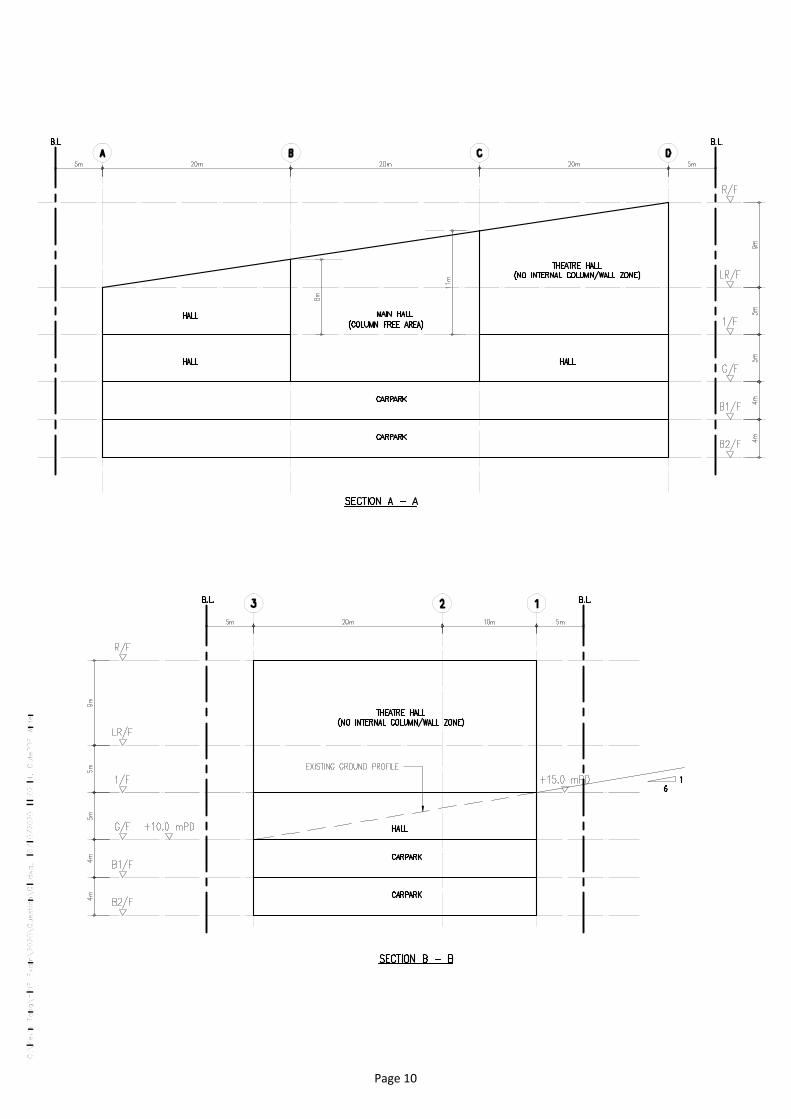
1/F Theatre Hall 8.0 2 hours 1.0
G/F – 1/F Hall 3.5 2 hours 0.5
G/F Main Hall 10.0 2 hours 1.0
G/F Ramp to Basement
3.0 2 hours 0.5
B1/F – B2/F Car park 2.5 4 hours 0.5
* The minimum clear headroom is the floor height clear of all structures,
finishes and building services. 3. The restrictions on the location of vertical structural elements are as follows:
Floor Mark Area Restrictions
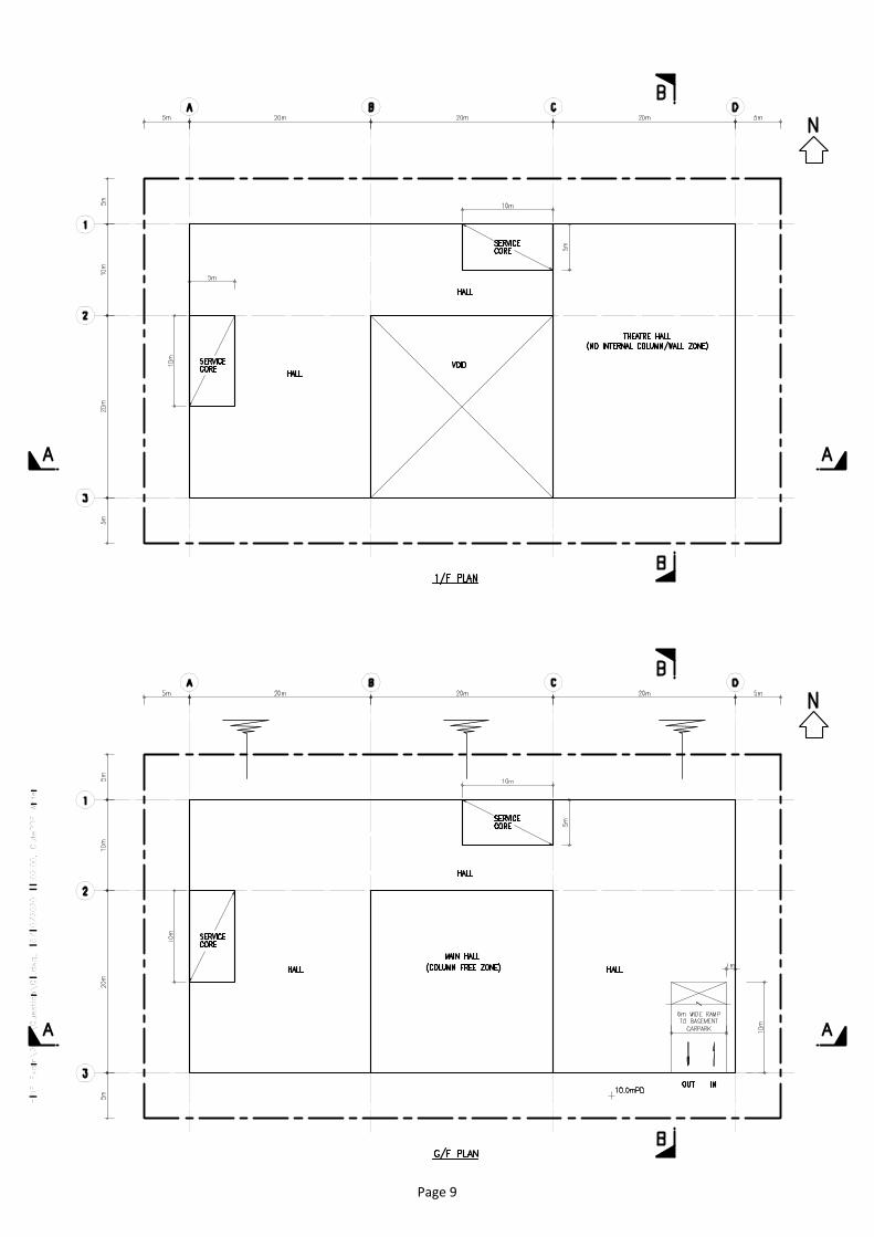
G/F Main Hall - Column free zone. No vertical structural element or part of the element permitted.
G/F – 1/F Hall - Minimum columns centre to centre spacing is 9.0m.
- Minimum clear width of 4.0m to be maintained at all locations.
1/F Theatre Hall - No internal column/ wall allowed within the Theatre Zone.
G/F Driveway - Column free zone. No vertical structural element or part of the element permitted.
B1/F – B2/F Car Parking - Minimum columns centre to centre spacing is 9.0m
- Minimum clear width of 4.0m to be maintained at all locations.
Page 6
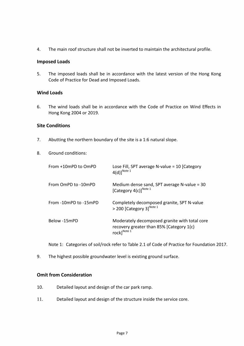
4. The main roof structure shall not be inverted to maintain the architectural profile.
Imposed Loads 5. The imposed loads shall be in accordance with the latest version of the Hong Kong
Code of Practice for Dead and Imposed Loads.
Wind Loads
6. The wind loads shall be in accordance with the Code of Practice on Wind Effects in Hong Kong 2004 or 2019.
Site Conditions
7. Abutting the northern boundary of the site is a 1:6 natural slope.
8. Ground conditions:
From +10mPD to OmPD Lose Fill, SPT average N-value = 10 [Category 4(d)]Note 1
From OmPD to -10mPD Medium dense sand, SPT average N-value = 30 [Category 4(c)]Note 1
From -10mPD to -15mPD Completely decomposed granite, SPT N-value > 200 [Category 3]Note 1
Below -15mPD Moderately decomposed granite with total core recovery greater than 85% [Category 1(c) rock]Note 1
Note 1: Categories of soil/rock refer to Table 2.1 of Code of Practice for Foundation 2017.
9. The highest possible groundwater level is existing ground surface.
Omit from Consideration 10. Detailed layout and design of the car park ramp. 11. Detailed layout and design of the structure inside the service core.
Page 7

Section A a. Prepare a design appraisal with appropriate sketches including two distinct and viable
solutions for the proposed showroom building including two viable foundation schemes. Indicate clearly the functional framing, load transfer and stability aspects of each scheme to meet all client’s requirements. Identify the solution you recommend and give reasons for your choice.
(25 marks) b. Explain how the structure will resist wind, soil and uplift loads including detailed
description of the structural loads and design assumptions. Prepare detailed load calculations and stability checking for the proposed building.
(15 marks)
Section B For the solution recommended in Section A: c. Prepare design calculations to establish the form and size of all principal structural
elements for superstructure from G/F to R/F including all critical structures (if any). (14 marks)
d. Prepare dimensional framing plans for G/F to R/F.
(20 marks)
e. Prepare structural details for the principal structural elements form G/F to R/F for cost estimation purpose.
(12 marks)
f. Prepare the design calculation for the building foundation.
(5 marks)
g. Prepare a preliminary foundation layout plan.
(5 marks)
h. Prepare an outline construction program covering essential activities from commencement of foundation to the completion of structural works.
(4 marks)
Page 8
Page 9
Page 10
Question 3 Composite Shopping Arcade
Client’s Requirements The following client’s requirements must be met: 1. A private composite shopping arcade is to be constructed within the urban
area in Hong Kong. See Figure Q3.
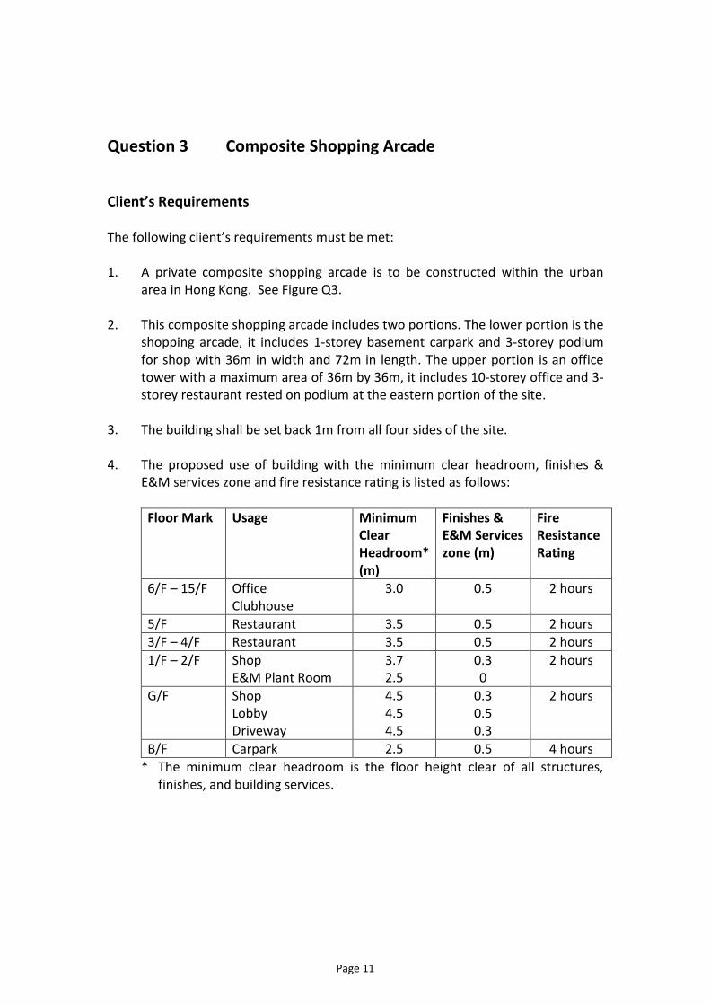
2. This composite shopping arcade includes two portions. The lower portion is the shopping arcade, it includes 1-storey basement carpark and 3-storey podium for shop with 36m in width and 72m in length. The upper portion is an office tower with a maximum area of 36m by 36m, it includes 10-storey office and 3-storey restaurant rested on podium at the eastern portion of the site.
3. The building shall be set back 1m from all four sides of the site. 4. The proposed use of building with the minimum clear headroom, finishes &
E&M services zone and fire resistance rating is listed as follows:
Floor Mark Usage Minimum Clear Headroom* (m)
Finishes & E&M Services zone (m)
Fire Resistance Rating
6/F – 15/F Office Clubhouse
3.0 0.5 2 hours
5/F Restaurant 3.5 0.5 2 hours
3/F – 4/F Restaurant 3.5 0.5 2 hours
1/F – 2/F Shop E&M Plant Room
3.7 2.5
0.3 0
2 hours
G/F Shop Lobby Driveway
4.5 4.5 4.5
0.3 0.5 0.3
2 hours
B/F Carpark 2.5 0.5 4 hours
* The minimum clear headroom is the floor height clear of all structures, finishes, and building services.
Page 11

5. The restrictions on the location of vertical structural elements are as follows:
Floor Mark Area Restrictions
6/F – 15/F Office / Clubhouse No internal column inside the office/clubhouse.
3/F – 5/F Restaurant No restriction of internal columns inside the restaurant area.
1/F – 2/F Shop E&M Plant Room Atrium
Minimum spacing of internal columns/walls is 9m centers.
No restriction on spacing between the internal columns to peripheral wall and/or column, if any.
No internal column inside the atrium void.
G/F Driveway No column/wall inside the driveway.
No restriction of column spacing.
B/F Carpark No column/wall inside the driveway.
Minimum spacing of internal columns is 7.5m centers.
No restriction on spacing between the internal columns to peripheral wall and/or column and service core, if any.
6. The main roof structure above office tower and flat roof at 3/F & 6/F shall not
be inverted.
7. For cantilever structure (if any), the maximum cantilever span shall not be greater than 4m from center of support.
Imposed Loads 8. The imposed loads shall be in accordance with the latest version of the Code of
Practice for Dead and Imposed Loads in Hong Kong.
9. Superimposed dead load of 10kPa should be allowed for the Sky Plaza at 3/F. 10. Superimposed dead load of 5kPa should be allowed for the Sky Garden at 6/F. 11. Superimposed dead load of 6kPa should be allowed for the Club House at 6/F.
Wind Loads
12. The wind loads shall be in accordance with the Code of Practice on Wind
Effects in Hong Kong 2004 or 2019.
Page 12
Site Conditions
13. The site is located at Sheung Wan with flat ground level at +6.5mPD within Scheduled Area Number 3 as defined in the Buildings Ordinance.
14. Abutting the eastern boundary of the site is an adjoining three storey R. C.
building on shallow foundation. 15. Ground conditions are:
From +6.5mPD – +0mPD Loose Fill, SPT average N-value < 10 [Category
4(d)]Note 1
From +0mPD – -8mPD Medium dense sand, SPT average N-value = 30 [Category 4(c)]Note 1
From -8mPD – -20mPD Completely decomposed granite, SPT N-value > 200
[Category 3]Note 1
Below -20mPD Moderately decomposed granite with total core recovery greater than 85% [Category 1(c) rock]Note 1
Note 1: Categories of soil/rock refer to Table 2.1 Code of Practice for Foundation 2017
16. The highest possible groundwater level is at +6.5mPD.
17. No structure above ground, foundation and substructure (including any
structures, pile caps, ground beams, suspended ground slabs, and basement walls) should fall within the MTR protection zone.
Omit from Consideration
18. Design for staircases, cladding, window systems, façade, and protective barrier. 19. Detailed layout and design of the non-structural elements inside the service
core. 20. Detailed layout and design of the carpark ramp.
Page 13
Section A a. Prepare a design appraisal with appropriate sketches indicating Two distinct
and viable solutions for the proposed composite shopping arcade including Two viable foundation schemes. Indicate clearly the functional framing, load transfer and stability aspects of each scheme to meet all client’s requirements. Identify the solution you recommend and give reasons for your choice.
(30 marks) b. Explain how the structure will resist wind load including detailed description of
the structural wind loads and design assumption. Prepare a detailed wind load calculation for the proposed composite shopping arcade.
(10 marks)
Section B For the solution recommended in Section A: c. Prepare sufficient design calculations to establish the form and size of all the
principal structural elements for superstructure for G/F, 3/F, 6/F & Typical floor (7/F – 15/F), including transfer (if any) and critical structures.
(14 marks) d. Prepare dimensional framing plans for G/F, 2/F, 3/F, 6/F & Typical floor (7/F –
15/F), to show the layout and disposition of the structural elements including transfer (if any) and critical structures.
(20 marks) e. Prepare the structural details for the principal structural elements at B/F and
6/F including transfer (if any) and critical structures for estimating purposes. (10 marks)
f. Prepare a preliminary foundation layout plan.
(8 marks) g. Prepare a detailed method statement covering essential activities for the safe
construction of the basement works closed to MTR protection zone. (4 marks)
h. Prepare a detailed construction program covering essential activities from
commencement of foundation to completion of structural works. (4 marks)
Page 14

Page 15

Page 16

Page 17

Page 18

Question 4 Railway Viaduct
Client’s Requirements The following client’s requirements must be met: 1. A railway viaduct is proposed in rural area. The new viaduct crosses a cutting,
with two existing rail tracks and an existing road at a high skew. See Figure Q4. 2. Due to the planning requirements, a height restriction has been imposed and
the new structure must not rise more than 2.5m above the new rail level as shown on Section A-A in Figure Q4.
3. The new deck is to carry two un-ballasted tracks with concrete kerbs and
maintenance walkways. The alignment is to remain horizontal over the length of the viaduct with abutments designed and built under a separate contract and skewed at 35 degrees. The top of bearing seat will be at +5m and no longitudinal forces will be carried onto the abutment.
4. The existing railway is to remain in service as much as possible during the
construction of the new viaduct. The existing track may be closed between 22:00 hours on Saturday evening to 06:00 on the following Sunday morning for a maximum of 12 times in a year. The existing road can be temporarily diverted during the work but the most acceptable designs are those that will involve minimum traffic diversion.
5. The minimum requirements on clear headroom and horizontal clearance for
railway and highway zone are to edge of structures as follows:
Location Min. Clear
Headroom (m) Min Horizontal Clearance (m)
Railway Line 6.50m 4.5m Existing Highway 5.3m 2.0m
6. The construction is planned to complete in three and a half years.
Page 19

Design Requirements
7. The structural design shall be in accordance with the latest version of the
Structures Design Manual for Highways and Railways published by the Highways Department of the HKSAR Government.
Imposed Loads 8. The imposed loads and railway loadings shall be as follows:-
Vertical load for each track = 60kN/m together with a single vertical load of 240 kN(including dynamic factor. Horizontal braking and traction load of 20kN/m per track. Braking and traction may occur at the same time. Non- ballast load to be 15kN/m2 Nominal vertical live load of 1.5kN/m2 is to be considered on maintenance walkways with a lateral load of 0.56kN/m for the edge barrier. Nosing load to be 100kN at track level perpendicular to the track and lurching load to be applied to the track with 0.56 track load applied at one rail and 0.44 track load applied to the other.
Wind Loads 9. The wind loads shall be in accordance with the requirements in the latest
version of the Structures Design Manual for Highways and Railways.
Site Conditions 10. The site is located at rural open area with Degree 3 of exposure to wind.
Page 20

11. Ground conditions are:
0m – 2m Loose Fill, SPT N-value = 0 – 10 {Category 4(d)} Note 1
2m – 8m Medium dense soil, SPT N-value = 10 – 40 {Category 4(c)} Note 1
7m – 20m Very dense soil, SPT N-value >50{Category 4(d)} Note 1
20m and below Moderately decomposed granite with total core recovery >85% {Category 1(c)} Note 1
Groundwater is encountered at 5.0m below ground level.
Note 1: Categories of soil/rock refer to Table 2.1 of Code of Practice for Foundation 2017
Omit from Consideration 12. Design calculations for tracks, barriers and detailed consideration of rail
structure interaction under vertical and horizontal loading.
Page 21

Section A a. Prepare a design appraisal with appropriate sketches indicating two distinct
and viable solutions for the spans of the proposed viaduct between Abutments including two viable foundation schemes. Indicate clearly the functional framing, load transfer and stability aspects of each scheme to meet all client’s requirements. Identify the solution you recommend and give reasons for your choice.
(30 marks) b. Explain how the structure will resist wind load including detailed description of
the wind loads and design assumptions. Prepare detailed wind load calculations for the proposed viaduct.
(10 marks)
Section B For the solution recommended in Section A: c. Prepare sufficient design calculations to establish the form and size of all the
principal structural elements including the foundation. (20 marks)
d. Prepare framing plans, sections and elevations to show the dimensions, layout
and disposition of the structural elements and critical details for cost estimating purposes.
(20 marks) e. Prepare a detailed method statement covering essential activities for the safe
construction of the viaduct including foundation works. (10 marks)
f. Prepare a detailed construction program covering essential activities from
commencement of foundation to completion of structural works. (10 marks)
Page 22
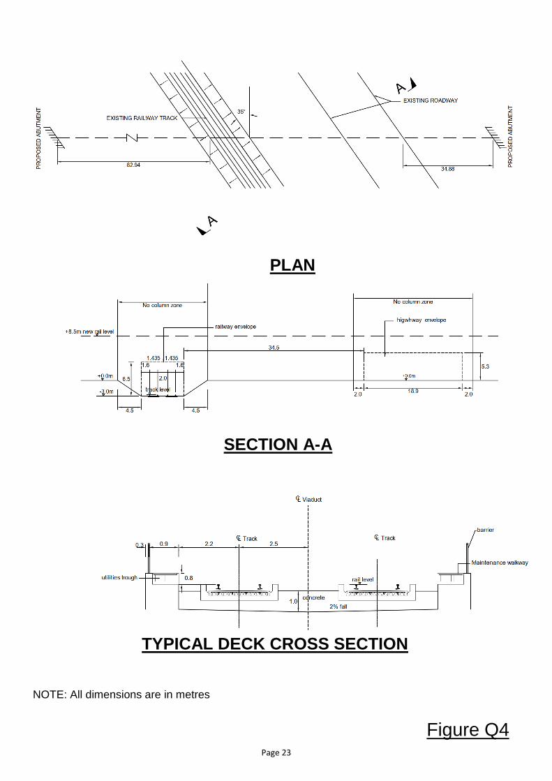
NOTE: All dimensions are in metres
PLAN
SECTION A-A
TYPICAL DECK CROSS SECTION
Figure Q4 Page 23
Copyright © 2022 FDOKUMEN