The frequency crossover for the Goos–Hänchen shift
15
arXiv:1402.2566v1 [physics.optics] 11 Feb 2014 THE FREQUENCY CROSSOVER FOR THE FREQUENCY CROSSOVER FOR THE GOOS-H ¨ ANCHEN SHIFT THE GOOS-H ¨ ANCHEN SHIFT • • Journal of Modern Optics 60, 1772-1780 (2014) Journal of Modern Optics 60, 1772-1780 (2014) • • Abstract. For total reflection, the Goos-H¨ anchen (GH) shift is proportional to the wavelength of the laser beam. At critical angles, such a shift is in- stead proportional to the square root of the prod- uct of the beam waist and wavelength. By us- ing the stationary phase method (SPM) and, when necessary, numerical calculations, we present a de- tailed analysis of the frequency crossover for the GH shift. The study, done in different incidence regions, sheds new light on the validity of the ana- lytic formulas found in literature. Manoel P. Araujo Gleb Wataghin Physics Institute State University of Campinas (Brazil) mparaujo@ifi.unicamp.br Silvˆ ania A. Carvalho Department of Applied Mathematics State University of Campinas (Brazil) [email protected] Stefano De Leo Department of Applied Mathematics State University of Campinas (Brazil) [email protected] I. INTRODUCTION II. THE INCOMING GAUSSIAN BEAM III. THE SPATIAL PHASE OF THE OUTGOING BEAM IV. TRANSMISSION COEFFICIENT AND GEOMETRICAL PATH V. THE GOOS-H ¨ ANCHEN SHIFT BY THE SPM VI. NUMERICAL ANALYSIS VII. CONCLUSIONS [ 14 pages, 4 figures ] I. INTRODUCTION II. THE INCOMING GAUSSIAN BEAM III. THE SPATIAL PHASE OF THE OUTGOING BEAM IV. TRANSMISSION COEFFICIENT AND GEOMETRICAL PATH V. THE GOOS-H ¨ ANCHEN SHIFT BY THE SPM VI. NUMERICAL ANALYSIS VII. CONCLUSIONS [ 14 pages, 4 figures ] • • Σ δ Λ Σ δ Λ • •
-
Upload
independent -
Category
Documents
-
view
1 -
download
0
Transcript of The frequency crossover for the Goos–Hänchen shift
arX
iv:1
402.
2566
v1 [
phys
ics.
optic
s] 1
1 Fe
b 20
14
THE FREQUENCY CROSSOVER FORTHE FREQUENCY CROSSOVER FOR
THE GOOS-HANCHEN SHIFTTHE GOOS-HANCHEN SHIFT
•• Journal of Modern Optics 60, 1772-1780 (2014)Journal of Modern Optics 60, 1772-1780 (2014) ••
Abstract. For total reflection, the Goos-Hanchen(GH) shift is proportional to the wavelength of thelaser beam. At critical angles, such a shift is in-stead proportional to the square root of the prod-uct of the beam waist and wavelength. By us-ing the stationary phase method (SPM) and, whennecessary, numerical calculations, we present a de-tailed analysis of the frequency crossover for theGH shift. The study, done in different incidenceregions, sheds new light on the validity of the ana-lytic formulas found in literature.
Manoel P. AraujoGleb Wataghin Physics InstituteState University of Campinas (Brazil)[email protected]
Silvania A. CarvalhoDepartment of Applied MathematicsState University of Campinas (Brazil)[email protected]
Stefano De LeoDepartment of Applied MathematicsState University of Campinas (Brazil)[email protected]
I. INTRODUCTIONII. THE INCOMING GAUSSIAN BEAMIII. THE SPATIAL PHASE OF THE OUTGOING BEAMIV. TRANSMISSION COEFFICIENT AND GEOMETRICAL PATH
V. THE GOOS-HANCHEN SHIFT BY THE SPMVI. NUMERICAL ANALYSISVII. CONCLUSIONS
[ 14 pages, 4 figures ]
I. INTRODUCTIONII. THE INCOMING GAUSSIAN BEAMIII. THE SPATIAL PHASE OF THE OUTGOING BEAMIV. TRANSMISSION COEFFICIENT AND GEOMETRICAL PATH
V. THE GOOS-HANCHEN SHIFT BY THE SPMVI. NUMERICAL ANALYSISVII. CONCLUSIONS
[ 14 pages, 4 figures ]
•• ΣδΛΣδΛ ••
I. INTRODUCTION
The GH shift, widely investigated in the last decades, continues to attract attention due to availabletechnologies [1–12]. This phenomenon refers to the lateral shift of a totally reflected beam withrespect to the optical path expected from geometrical optics. For an interesting overview of theeffect and its generalizations, we suggest the references [11, 12]. The fact that total reflection doesnot take place at the spatial point predicted by the geometrical optics, see Fig 1a, was discoveredby Newton [13] which proposed that the path during total reflection is a parabola, the vertex beingwithin the rarer medium. The problem was then experimentally and theoretically analyzed by otherauthors in 1920s and 1930s [14, 15]. The first experimental observation of this effect was done byGoos and Hanchen [16]. Their experiment stimulated the study of this shift for different polarizedelectromagnetic waves [17, 18]. In the literature, the longitudinal and transverse shifts of an opticalbeam have been investigated by using the far-field measurement for the reflected field and the scanningtunneling optical microscope for the (evanescent) transmitted beam [1].
The fact that the GH shift has been investigated in different physical problems, see frustratedtotal internal reflection (FTIR) [19–21], partial reflection [22], acoustic [23], nonlinear optics [24],frequency dispersive media [25,26], and surface physics [27], shows the great and increasing attentionof the scientific community to this topic. Some interesting applications, which include sensors andoptical waveguide switching, can be found in recent research works [9,28–30]. On the other hand, themeasurement of this very small shift (of the order of the beam wavelength) represented a continuouschallenge. The proposed solutions to increase its magnitude were discussed in many works [8,31,32].Over the years, this technical problem was solved and it is now possible to measure this shift [33].
In 1948, Artmann obtained an expression for the GH shift at critical angle [17]. After few decades,other authors studied the same problem in detail obtaining an expression for the lateral shift forincidence angles very close to the critical angle [34–36].
In this paper, we describe the beam propagation into the dielectric block by using the analogybetween optcis and quantum mechanics [37,38]. In particular, we derive the transmission and reflectioncoefficients at each interface and then calculate both analytically and numerically the position of theoutgoing beam. The wave packet formalism is introduced by considering a gaussian wave numberdistribution. The SPM, applied to our gaussian beams, leads to an analytical formula for the exitpoint of the optical beam propagating throughout a right angle prism with refractive index n [39–41].The difference between the geometrical result obtained by the Snell law and the real optical path andits frequency crossover will be the subject of our investigation.
The study done in this paper allows to investigate the validity of the analytical formulas for differentincidence angles as well the transition from partial to total internal reflection. A new formula, basedon the SPM, is presented for the shift at critical incidence. The numerical analysis confirms ouranalytical predictions.
This paper is organized as follows. In the following Section, we discuss the Gaussian beam prop-agation in free space. The geometry of the physical system is presented in Section III. In Section IV,we calculate, by using the analogy between optics and quantum mechanics, the reflection and trans-mission coefficients for s and p polarized waves [42]. In section V, by using the SPM, we analyze thequantum additional phase and give our analytical expressions for the GH shift for different incidenceregions. The numerical results are then presented in section VI. Our conclusions and proposals forfuture investigations are drawn in the final section.
II. THE INCOMING GAUSSIAN BEAM
The beam propagation in free space is determined by the wave number laser distribution [43]. Let usconsider the following distribution,
G(k) = exp
[−(k
2
x + k2
y)w20
4
]δ(kz −
√k2 − k2
x − k2
y
), (1)
1
where w0 is the beam waist size and k = 2π/λ. The electric field amplitude is then given by
Ein(r) = E0
w20
4π
∫dk G(k) exp [ ik · r ] ,
= E0
w20
4π
∫dkx dky exp
[−(k
2
x + k2
y)w20
4
]exp
[i(kx x+ ky y +
√k2 − k2
x − k2
y z)], (2)
with E0 = E(0). By considering the paraxial approximation (valid for kw0 ≥ 5), the integrations canbe done analytically leading to
Ein(r) ≈ E0
w20
4πeik z
∫dkx dky exp
[−(k
2
x + k2
y)w20
4
]exp
[i
(kx x+ ky y −
k2
x + k2
y
2 kz
)]
≈ E0
w20
w20 + 2 i
z
k
eik z exp
− x2 + y2
w20 + 2 i
z
k
. (3)
The intensity, I(r) = |E(r)|2
, for the incoming beam is then given by
Iin(r) ≈ I0
[w0
w(z)
]2
exp
[− 2
x2 + y2
w2(z)
], (4)
where w(z) = w0
√
1 +
(λ z
πw2
0
)2
.
III. THE SPATIAL PHASE OF THE OUTGOING BEAM
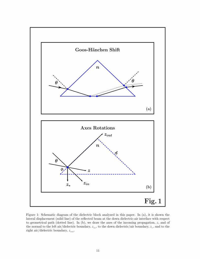
In this section, we determine the direction of propagation of the outgoing beam by calculating itsspatial phase. In doing this, it is convenient to introduce new axes of coordinates, see Fig. 1b. Theplane of incidence is the y-z plane, where z is the propagation direction of the incoming beam, and thenew axes represent rotation of the y-z system with z
in, z
∗, and z
outnormal to the left (air/dielectric),
down (dielectric/ar) and right (dielectric/air) interface. Denoting the incidence angle by θ and usingR(θ) to identify a counterclockwise,
R(θ) =
(cos θ − sin θsin θ cos θ
),
we find (yout
zout
)= R
(3 π
4
)(y∗
z∗
)= R
(π2
)( yin
zin
)= R
(π2− θ)( y
z
). (5)
The spatial phase of the incoming beam is
ϕin
= k · r = kin
· rin, (6)
where rin
= (x , yin, z
in) is obtained from Eq. (5) and k
inis given by
kxin
= kx and
(ky
in
kzin
)= R(−θ)
(kykz
). (7)
Taking into account that the discontinuity is along the zin
axis, the xin(= x) and y
incomponents of
the wave number do not change when the beam crosses the first air/dielectric boundary,
(qx , qyin) = (kx , ky
in) ⇒ qz
in=√n2k2 − k2
x − k2
yin. (8)
2
The spatial phase of the beam moving in the dielectric from the left (air/dielectric) to the down(dielectric/air) interface is
ϕleft/down
= qin
· rin
= q∗
· r∗, (9)
where r∗= (x , y
∗, z
∗) is obtained from Eq. (5) and q
∗
is given by
qx∗= kx and
(qy
∗
qz∗
)= R
(−π4
)( qyin
qzin
). (10)
The spatial phase of the reflected beam at the down interface is obtained from Eq. (9) by changing z∗
in − z∗,
ϕdown/right
= qx∗
x∗+ qy
∗
y∗− qz
∗
z∗= q
out· rout , (11)
where rout
= (x , yout, z
out) is obtained from Eq. (5) and q
outis given by
qxout= kx and
(qyout
qzout
)= R
(3 π
4
)(qy
∗
− qz∗
)=
( − qyin
qzin
). (12)
The beam reaches the right (dielectric/air) boundary and due to the fact that the discontinuity isalong the z
∗axis, the x
∗(= x) and y
∗components of the wave number do not change when the beam
crosses the last dielectric/air interface,
(kx , kyout) = (kx , qyout
) = (kx ,− qyin) = (kx ,− ky
in) ⇒ kzout
= kzin. (13)
Finally, the spatial phase of the outgoing beam is
ϕout
= kout
· rout
= kx x − kyinyout
+ kzzinzout
= kx x+ ( kz cos 2θ − ky sin 2θ ) y + ( kz sin 2θ + ky cos 2θ ) z . (14)
Consequently, the outgoing wave number vector in the (x, y, z) coordinates system is given by
[∇ϕout
](kx=0,ky=0)
= ( 0 , k cos 2θ , k sin 2θ )
( 0 , 0 , k ) for θ = π/4 ,( 0 , k , 0 ) for θ = 0 ,( 0 , 0 , − k ) for θ = − π/4 .
(15)
The outgoing beam propagates parallel to the incoming beam for θ = ± π/4 and perpendicular to theincoming beam for θ = 0.
IV. TRANSMISSION COEFFICIENT AND GEOMETRICAL PATH
The Fresnel formulas for the reflection and transmission coefficients of s-polarized beam can be givenby using the analogy between optics and quantum mechanics [41]. From the non-relativistic quantumanalysis of the step potential [42],
r[α, β] =α− β
α+ βand t[α, β] =
2α
α+ β, (16)
we find
r(s)
in= r[kz
in, qz
in] exp[ 2 i kz
ina
in] , t(s)
in= t[kzin , qzin ] exp[ i (kzin − qz
in) a
in]
r(s)
∗
= r[qz∗
, kz∗
] exp[ 2 i qz∗
a∗] , t(s)
∗
= t[qz∗ , kz∗ ] exp[ i (qz∗ − kz∗
) a∗]
r(s)
out= r[qzout
, kzout] exp[ 2 i qzout
aout
] , t(s)∗
= t[qzout , kzout ] exp[ i (qzout− kzout
) aout
] .
(17)
By choosing the axes origin in ain = 0 (this implies a∗= a/
√2 and aout = b− a) and observing that
qzout= qz
inand kzout
= kzin, we obtain the following expression for the transmission coefficient
t(s)
= t(s)
inr(s)
∗
t(s)
out=
4 kzinqz
in
(kzin
+ qzin)2qz
∗
− kz∗
qz∗
+ kz∗
exp[ i ψout ] , (18)
3

whereψout = qz∗a
√2 + (qz
in− kz
in) (b− a) . (19)
The transmission coefficient for p-polarized is found by the substitution rule
( kzin,∗ , qzin,∗ ) →(n kzin,∗ ,
qzin,∗
n
),
in4 kz
inqz
in
(kzin
+ qzin)2qz
∗
− kz∗
qz∗
+ kz∗
.
This leads to
t(p)
=4n2kz
inqz
in
(n2kzin
+ qzin)2qz
∗
− n2kz∗
qz∗
+ n2kz∗
exp[ i ψout
] . (20)
Once obtained the transmission coefficient, we can write, by using a gaussian convolution, the ampli-tude of the outgoing electric field [41],
E(s,p)
out(r) = E0
w20
4π
∫dkx dky t
(s,p)
exp
[−(k
2
x + k2
y)w20
4
]exp [ ik
out· r
out] . (21)
The geometrical path can be now calculated by using the SPM [39–41]. To illustrate the method, letus consider the incoming beam. By imposing that the derivative of the phase is zero at the center ofour symmetric gaussian distribution, we immediately find
[∂ϕin
∂kx,∂ϕin
∂ky
]
(kx=0,ky=0)
= (0, 0) ⇒ (xmax , ymax )in = ( 0 , 0 ) . (22)
For the outgoing beam, the phase is given by the spatial phase ϕout
and by the phase ψout
comingfrom the transmission coefficient. By using the SPM, we find
[∂(ϕ
out+ ψ
out)
∂kx
]
(0,0)
= 0 ⇒ xmax,out
= 0 , (23)
and [∂(ϕ
out+ ψ
out)
∂ky
]
(0,0)
= 0 ⇒ zmax cos 2θ − ymax sin 2θ = d , (24)
where
d = a (cos θ + sin θ) + b sin θ
(cos θ√
n2 − sin2 θ− 1
). (25)
For refractive index n =√2, we can observe the output beam maximum moving along
y =b√2
(1− 1√
2n2 − 1
)− a
√2 for θ = π/4 ,
z = a for θ = 0 ,
y =b√2
(1− 1√
2n2 − 1
)for θ = − π/4 .
(26)
For θ = π/4, the choice of
a =
√2n2 − 1− 1
2√2n2 − 1
b ,
implies y = 0. Consequently the incoming and outgoing beams move in the same direction.
4
V. THE GOOS-HANCHEN SHIFT BY THE SPM
The optical path obtained in the previous section by using the SPM can be also determined byapplying the Snell law. In this section, we present the calculation of the additional quantum phasewhich cannot be predicted by geometrical optics. At the down interface, the reflection coefficients fors and p polarized wave are
{r(s)
∗
, r(p)
∗
}=
{qz
∗
− kz∗
qz∗
+ kz∗
,qz
∗
− n2kz∗
qz∗
+ n2kz∗
}exp[ 2 i qz
∗
a∗] .
Let us expand kz∗
around the center of the gaussian wave number distribution, i.e. kx = ky = 0,
k2
z∗
(kx, ky) = k2
z∗
(0, 0) +
[∂k
2
z∗
∂ky
]
(0,0)
ky + O[k2
x, k2
y]
= k2
z∗
(0, 0) + 2 qz∗
(0, 0)
[∂qz
∗
∂ky
]
(0,0)
ky + O[k2
x, k2
y] . (27)
By using
k2
z∗
(0, 0) = − k2
2
(n2 − 2 + 2 sin θ
√n2 − sin2 θ
), qz
∗
(0, 0) =k√2
√− sin θ +
√n2 − sin2 θ ,
and [∂qz
∗
∂ky
]
(0,0)
= − cos θ√2
(1 +
sin θ√n2 − sin2 θ
),
we obtain
k2
z∗
(kx, ky)
k2 =
(1− n2
2− sin θ
√n2 − sin2 θ
)− cos θ (n2 − 2 sin2 θ )√
n2 − sin2 θ
kyk. (28)
For ky > σ(n, θ) k,
σ(n, θ) =
(1− n2
2− sin θ
√n2 − sin2 θ
)√n2 − sin2 θ
cos θ (n2 − 2 sin2 θ), (29)
we have k2
z∗
< 0 and consequently an additional quantum phase has to be considered in calculatingthe optical path,
{ψ
(s)
out, ψ
(p)
out
}=
{Arg
[qz
∗
− i |kz∗
|qz
∗
+ i |kz∗
|
], Arg
[qz
∗
− i n2|kz∗
|qz
∗
+ i n2|kz∗
|
]}
= − 2
{arctan
[ |kz∗
|qz
∗
], arctan
[n2|kz
∗
|qz
∗
]}. (30)
The derivatives of these phases,
{∂ψ
(s)
out
∂ky,∂ψ
(p)
out
∂ky
}=
2
|kz∗
|∂qz
∗
∂ky
{1 ,
n2 k2
k2 + (n2 + 1) |kz∗
|2
}, (31)
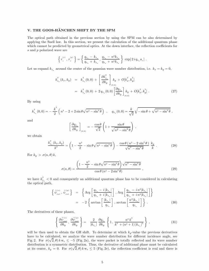
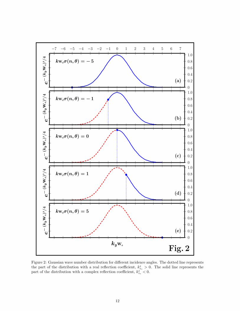
will be then used to obtain the GH shift. To determine at which ky-value the previous derivativeshave to be calculated, we analyze the wave number distribution for different incidence angle, seeFig. 2. For σ(
√2, θ) kw0 ≤ −5 (Fig. 2a), the wave packet is totally reflected and its wave number
distribution is a symmetric distribution. Thus, the derivative of additional phase must be calculatedat its center, ky = 0. For σ(
√2, θ) kw0 ≤ 5 (Fig. 2e), the reflection coefficient is real and there is
5
not an additional phase. The intermediate case, σ(√2, θ) kw0 = 0 (Fig. 2c), represents incidence at
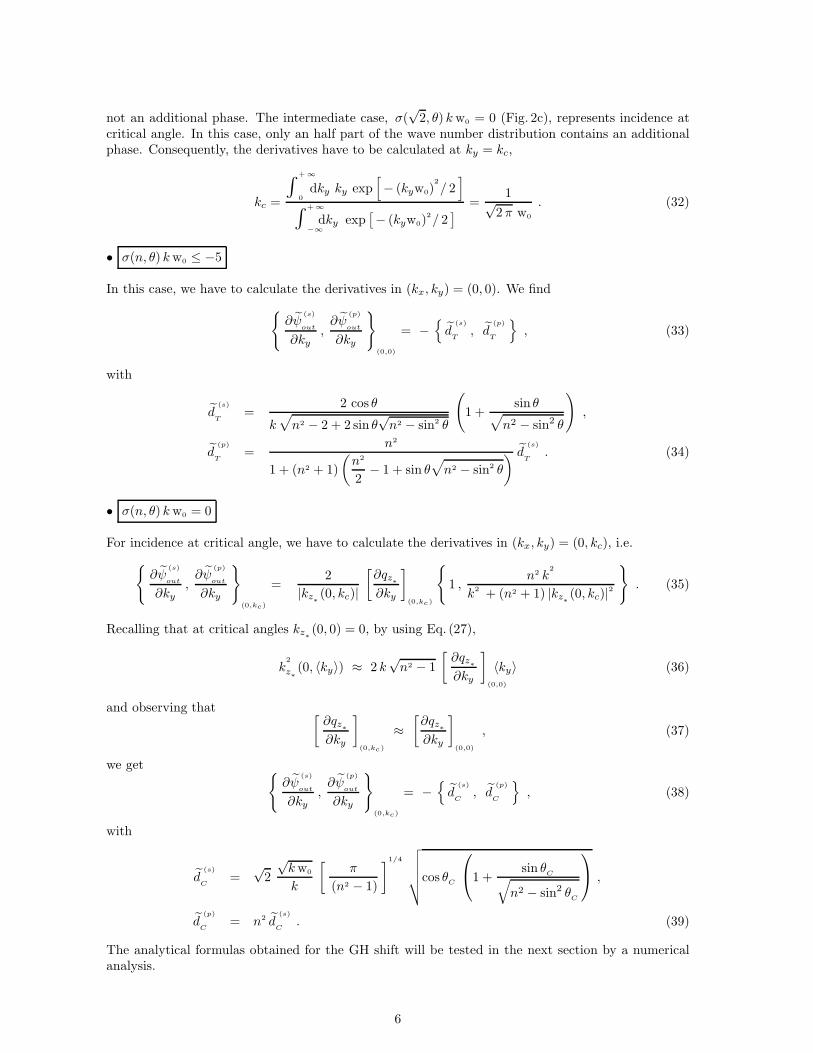
critical angle. In this case, only an half part of the wave number distribution contains an additionalphase. Consequently, the derivatives have to be calculated at ky = kc,
kc =
∫ +∞
0dky ky exp
[− (kyw0)
2
/ 2]
∫ +∞
−∞
dky exp[− (kyw0)
2/ 2] =
1√2 π w0
. (32)
• σ(n, θ) kw0 ≤ −5
In this case, we have to calculate the derivatives in (kx, ky) = (0, 0). We find
{∂ψ
(s)
out
∂ky,∂ψ
(p)
out
∂ky
}
(0,0)
= −{d
(s)
T, d
(p)
T
}, (33)
with
d(s)
T=
2 cos θ
k√n2 − 2 + 2 sin θ
√n2 − sin2 θ
(1 +
sin θ√n2 − sin2 θ
),
d(p)
T=
n2
1 + (n2 + 1)
(n2
2− 1 + sin θ
√n2 − sin2 θ
) d(s)
T. (34)
• σ(n, θ) kw0 = 0
For incidence at critical angle, we have to calculate the derivatives in (kx, ky) = (0, kc), i.e.
{∂ψ
(s)
out
∂ky,∂ψ
(p)
out
∂ky
}
(0,kc)
=2
|kz∗
(0, kc)|
[∂qz
∗
∂ky
]
(0,kc)
{1 ,
n2 k2
k2 + (n2 + 1) |kz∗
(0, kc)|2
}. (35)
Recalling that at critical angles kz∗
(0, 0) = 0, by using Eq. (27),
k2
z∗
(0, 〈ky〉) ≈ 2 k√n2 − 1
[∂qz
∗
∂ky
]
(0,0)
〈ky〉 (36)
and observing that [∂qz
∗
∂ky
]
(0,kc)
≈[∂qz
∗
∂ky
]
(0,0)
, (37)
we get {∂ψ
(s)
out
∂ky,∂ψ
(p)
out
∂ky
}
(0,kc)
= −{d
(s)
C, d
(p)
C
}, (38)
with
d(s)
C=
√2
√kw0
k
[π
(n2 − 1)
]1/4
√√√√√cos θC
1 +
sin θC√
n2 − sin2 θC
,
d(p)
C= n2 d
(s)
C. (39)
The analytical formulas obtained for the GH shift will be tested in the next section by a numericalanalysis.
6
VI. NUMERICAL ANALYSIS
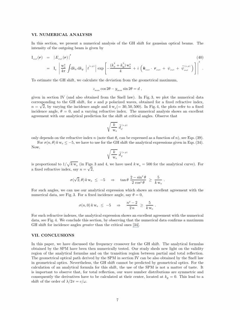
In this section, we present a numerical analysis of the GH shift for gaussian optical beams. Theintensity of the outgoing beam is given by
Iout(r) = |Eout(r) |2
(40)
= I0
∣∣∣∣∣w2
0
4π
∫dkx dky
∣∣∣ t(s,p)∣∣∣ exp
[−(k
2
x + k2
y)w20
4+ i
(k
out· r
out+ ψ
out+ ψ
(s,p)
out
)] ∣∣∣∣∣
2
.
To estimate the GH shift, we calculate the deviation from the geometrical maximum,
zmax
cos 2θ − ymax
sin 2θ = d ,
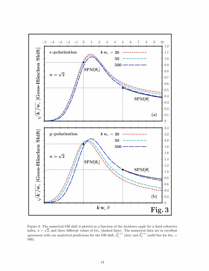
given in section IV (and also obtained from the Snell law). In Fig. 3, we plot the numerical datacorresponding to the GH shift, for s and p polarized waves, obtained for a fixed refractive index,n =
√2, by varying the incidence angle and kw
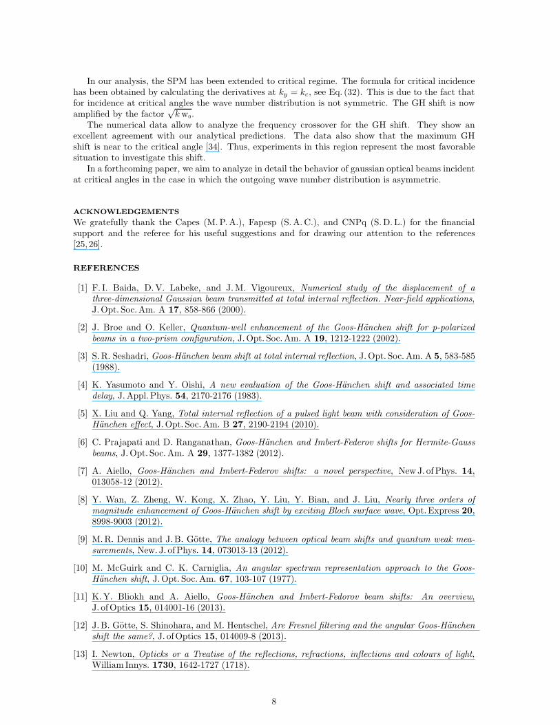
0(= 30, 50, 500). In Fig. 4, the plots refer to a fixed
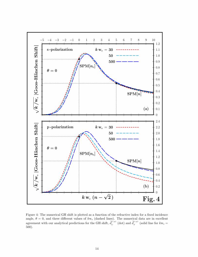
incidence angle, θ = 0, and a varying refractive index. The numerical analysis shows an excellentagreement with our analytical prediction for the shift at critical angles. Observe that
√k
w0
d(s,p)
C
only depends on the refractive index n (note that θc can be expressed as a function of n), see Eqs. (39).For σ(n, θ) kw0 ≤ −5, we have to use for the GH shift the analytical expressions given in Eqs. (34).
Now, √k
w0
d(s,p)
T
is proportional to 1/√kw
0(in Figs. 3 and 4, we have used kw
0= 500 for the analytical curve). For
a fixed refractive index, say n =√2,
σ(√2, θ) kw0 ≤ −5 ⇒ tan θ
2− sin2 θ
2 cos2 θ≥ 5
kw0
.
For such angles, we can use our analytical expression which shows an excellent agreement with thenumerical data, see Fig. 3. For a fixed incidence angle, say θ = 0,
σ(n, 0) kw0 ≤ −5 ⇒ n2 − 2
2n≥ 5
kw0
.
For such refractive indexes, the analytical expression shows an excellent agreement with the numericaldata, see Fig. 4. We conclude this section, by observing that the numerical data confirms a maximumGH shift for incidence angles greater than the critical ones [34].
VII. CONCLUSIONS
In this paper, we have discussed the frequency crossover for the GH shift. The analytical formulasobtained by the SPM have been then numerically tested. Our study sheds new light on the validityregion of the analytical formulas and on the transition region between partial and total reflection.The geometrical optical path derived by the SPM in section IV can be also obtained by the Snell lawin geometrical optics. Nevertheless, the GH shift cannot be predicted by geometrical optics. For thecalculation of an analytical formula for this shift, the use of the SPM is not a matter of taste. Itis important to observe that, for total reflection, our wave number distributions are symmetric andconsequently the derivatives have to be calculated at their center, located at ky = 0. This lead to ashift of the order of λ/2π = c/ω.
7
In our analysis, the SPM has been extended to critical regime. The formula for critical incidencehas been obtained by calculating the derivatives at ky = kc, see Eq. (32). This is due to the fact thatfor incidence at critical angles the wave number distribution is not symmetric. The GH shift is nowamplified by the factor
√kw0.
The numerical data allow to analyze the frequency crossover for the GH shift. They show anexcellent agreement with our analytical predictions. The data also show that the maximum GHshift is near to the critical angle [34]. Thus, experiments in this region represent the most favorablesituation to investigate this shift.
In a forthcoming paper, we aim to analyze in detail the behavior of gaussian optical beams incidentat critical angles in the case in which the outgoing wave number distribution is asymmetric.
ACKNOWLEDGEMENTS
We gratefully thank the Capes (M.P.A.), Fapesp (S.A. C.), and CNPq (S.D. L.) for the financialsupport and the referee for his useful suggestions and for drawing our attention to the references[25, 26].
REFERENCES
[1] F. I. Baida, D.V. Labeke, and J.M. Vigoureux, Numerical study of the displacement of athree-dimensional Gaussian beam transmitted at total internal reflection. Near-field applications,J. Opt. Soc.Am. A 17, 858-866 (2000).
[2] J. Broe and O. Keller, Quantum-well enhancement of the Goos-Hanchen shift for p-polarizedbeams in a two-prism configuration, J.Opt. Soc. Am. A 19, 1212-1222 (2002).
[3] S. R. Seshadri, Goos-Hanchen beam shift at total internal reflection, J. Opt. Soc. Am. A 5, 583-585(1988).
[4] K. Yasumoto and Y. Oishi, A new evaluation of the Goos-Hanchen shift and associated timedelay, J. Appl. Phys. 54, 2170-2176 (1983).
[5] X. Liu and Q. Yang, Total internal reflection of a pulsed light beam with consideration of Goos-Hanchen effect, J.Opt. Soc. Am. B 27, 2190-2194 (2010).
[6] C. Prajapati and D. Ranganathan, Goos-Hanchen and Imbert-Federov shifts for Hermite-Gaussbeams, J. Opt. Soc. Am. A 29, 1377-1382 (2012).
[7] A. Aiello, Goos-Hanchen and Imbert-Federov shifts: a novel perspective, New J. of Phys. 14,013058-12 (2012).
[8] Y. Wan, Z. Zheng, W. Kong, X. Zhao, Y. Liu, Y. Bian, and J. Liu, Nearly three orders ofmagnitude enhancement of Goos-Hanchen shift by exciting Bloch surface wave, Opt.Express 20,8998-9003 (2012).
[9] M.R. Dennis and J. B. Gotte, The analogy between optical beam shifts and quantum weak mea-surements, New. J. of Phys. 14, 073013-13 (2012).
[10] M. McGuirk and C. K. Carniglia, An angular spectrum representation approach to the Goos-Hanchen shift, J.Opt. Soc. Am. 67, 103-107 (1977).
[11] K.Y. Bliokh and A. Aiello, Goos-Hanchen and Imbert-Fedorov beam shifts: An overview,J. ofOptics 15, 014001-16 (2013).
[12] J. B. Gotte, S. Shinohara, and M. Hentschel, Are Fresnel filtering and the angular Goos-Hanchenshift the same?, J. ofOptics 15, 014009-8 (2013).
[13] I. Newton, Opticks or a Treatise of the reflections, refractions, inflections and colours of light,William Innys. 1730, 1642-1727 (1718).
8
[14] J. Picht, uber den Schwingungsvorgang, der einem beliebigen (astigmatischen) Strahlenbundelentspricht, Annalen der Physik 382, 785-882 (1925).
[15] C. Schaefer and R. Pich, Ein Beitrag zur Theorie der Totalreflexion, Annalen der Physik 422,245-266 (1937).
[16] F. Goos and H. Hanchen, Ein neuer und fundamentaler Versuch zur Totalreflexion., An-nalen derPhysik 436, 333-346 (1947).
[17] K. Artmann, Berechnung der Seitenversetzung des totalreflektierten Strahles, Annalen der Physik(Leipizig) 437, 87-102 (1948).
[18] C. v. Fragstein, Zur Seitenversetzung des totalreflektierten Lichtstrahles, Annalen derPhysik 439,271-278 (1949).
[19] J. J. Cowan and B. Anicin, Longitudinal and transverse displacements of a bounded microwavebeam at total internal reflection, J. Opt. Soc. Am. 67, 1307-1314 (1977).
[20] A.K. Ghatak, M.R. Shenoy, I. C. Goyal and K. Thyagarajan, Beam propagation under frustratedtotal reflection, Opt. Commun. 56, 313-317 (1986).
[21] A. Haibel, G. Nimtz and A.A. Stahlhofen, Frustrated total reflection: The double-prism revisited,Phys.Rev. E 63, 047601-3 (2001).
[22] C. F. Li, Negative Lateral Shift of a Light Beam Transmitted through a Dielectric Slab and Inter-action of Boundary Effects, Phys.Rev. Lett. 91, 133903-3 (2003).
[23] R. Briers, O. Leroy and G. Shkerdin, Bounded beam interaction with thin inclusions. Charac-terization by phase differences at Rayleigh angle incidence, J. Acoust. Soc.Am. 108, 1622-1630(2000).
[24] O. Emile, T. Galstyan, A. Le Floch and F. Bretenaker, Measurement of the Nonlinear Goos-Hanchen Effect for Gaussian Optical Beams., Phys.Rev. Lett. 75, 1511-1513 (1995).
[25] J. L. Birman, D.N. Pattanayak, and A. Puri, Prediction of a Resonance-Enhanced Laser-BeamDisplacement at Total Internal Reflection in Semiconductors, Phys.Rev. Lett. 50, 1664-1667(1983).
[26] A. Puri, D.N. Pattanayak, and J. L. Birman, Resonance effects on total internal reflection andlateral (Goos-Hanchen) beam displacement at the interface between nonlocal and local dielectric,Phys.Rev. B 28, 5877-5886 (1983).
[27] N. J. Harrick, Study of physics and chemistry of surfaces from frustrated total internal reflections,Phys.Rev. Lett. 4, 224-226 (1960).
[28] X. Yin and L. Hesselink, Goos - Hanchen shift surface plasmon resonance sensor,Appl. Phys.Lett. 89, 261108-5 (2006).
[29] T. Yu, H. Li, Z. Cao, Y. Wang, Q. Shen, and Y. He, Oscillating wave displacement sensor usingthe enhanced Goos-Hanchen effect in a symmetrical metal-cladding optical waveguide, Opt. Lett.33, 1001-1003 (2008).
[30] T. Sakata, H. Togo and F. Shimokawa, Reflection-type 2 × 2 optical waveguide switch using theGoos-Hanchen shift effect, Appl. Phys. Lett. 76, 2841-2841 (2000).
[31] L. Chen, Z. Q. Cao, F. Ou, H.G. Li, Q. S. Shen and H.C. Qiao, Observation of large positive andnegative lateral shifts of a reflected beam from symmetrical metal-cladding waveguides, Opt. Lett.32, 1432-1434 (2007).
[32] E. Pflegaar, A. Marseille and A. Weis, Quantitative investigation of the effect of resonant ab-sorbers on the Goos-Hanchen shift, Phys.Rev. Lett. 70, 2281-2284 (1993).
9

[33] Y. Qin, Y. Li, X. Feng, Y. F. Xiao, H. Yang and Q. Gong, Observation of the in-plane spinseparation of light, Opt. Express 19, 9636-9645 (2011).
[34] H.M. Lai, F. C. Cheng, and W.K. Tang, Goos-Hanchen effect around and off the critical angle,J. Opt. Soc.Am. A 3, 550-557 (1986).
[35] W. Nasalski, T. Tamir and L. Lin, Displacement of the intensity peak in narrow beams reflectedat the dielectric interface, J.Opt. Soc. Am. A 5, 132-140 (1988).
[36] B.R. Horowitz and T. Tamir, Lateral Displacement of a Light Beam at a Dielectric InterfaceJ.Opt. Soc.Am. 61, 586-594 (1971).
[37] S. De Leo and P. Rotelli, Laser interacting with a dielectric block, Eur.Phys. J. D 61, 481-488(2011).
[38] S. De Leo and P. Rotelli, Resonant laser tunneling, Eur.Phys. J. D 65, 563-570 (2011).
[39] E. Wigner, Lower Limit for the Energy Derivative of the Scattering Phase Shift Phys.Rev. 98,145-147 (1955).
[40] N. Bleistein and R. Handelsman, Asymptotic Expansions of Integrals (Dover, New York, 1975).
[41] S. De Leo and P. Rotelli, Localized beams and dielectric barriers, J. Opt. A: PureAppl.Opt. 10,115001-5 (2008).
[42] M. Born and E. Wolf, Principles of optics, (Cambridge UP, Cambridge, 1999).
[43] B. E.A. Saleh and M.C. Teich, Fundamentals of Photonics (Wiley & Sons, New Jersey, 2007).
10
bb
b
b b
θ θ
n
(a)
Goos-Hanchen Shift
b
θ
n
a
b
zinz∗
zout
z
(b)
Axes Rotations
Fig. 1
Figure 1: Schematic diagram of the dielectric block analyzed in this paper. In (a), it is shown thelateral displacement (solid line) of the reflected beam at the down dielectric-air interface with respectto geometrical path (dotted line). In (b), we draw the axes of the incoming propagation, z, and ofthe normal to the left air/dielectric boundary, z
in, to the down dielectric/air boundary, z
∗, and to the
right air/dielectric boundary, zout
.
11
b 0
0.2
0.4
0.6
0.8
1.0
−7 −6 −5 −4 −3 −2 −1 0 1 2 3 4 5 6 7
kw0σ(n, θ) = − 5
(a)e−
(kyw
0)2
/4
b
0
0.2
0.4
0.6
0.8
1.0
kw0σ(n, θ) = − 1
(b)e−
(kyw
0)2
/4
b
0
0.2
0.4
0.6
0.8
1.0
kw0σ(n, θ) = 0
(c)e−
(kyw
0)2
/4
b
0
0.2
0.4
0.6
0.8
1.0
kw0σ(n, θ) = 1
(d)e−
(kyw
0)2
/4
b 0
0.2
0.4
0.6
0.8
1.0
kw0σ(n, θ) = 5
(e)e−
(kyw
0)2
/4
kyw0
Fig. 2
Figure 2: Gaussian wave number distribution for different incidence angles. The dotted line representsthe part of the distribution with a real reflection coefficient, k2
z∗> 0. The solid line represents the
part of the distribution with a complex reflection coefficient, k2z∗< 0.
12
b
b
s -polarization
n =√
2
k w0
= 30
50
500
SPM[θ]
SPM[θc]
(a)
√
k/w
0|G
oos-
Hanchen
Shift|
0
0.1
0.2
0.3
0.4
0.5
0.6
0.7
0.8
0.9
1.0
1.1
1.2
−5 −4 −3 −2 −1 0 1 2 3 4 5 6 7 8 9 10
b
b
p -polarization
n =√
2
k w0
= 30
50
500
SPM[θ]
SPM[θc]
(b)
√
k/w
0|G
oos-
Hanchen
Shift|
k w0θ
0
0.2
0.4
0.6
0.8
1.0
1.2
1.4
1.6
1.8
2.0
2.2
2.4
Fig. 3
Figure 3: The numerical GH shift is plotted as a function of the incidence angle for a fixed refractiveindex, n =
√2, and three different values of kw0 (dashed lines). The numerical data are in excellent
agreement with our analytical predictions for the GH shift, d(s,p)
C(dot) and d
(s,p)
T(solid line for kw0 =
500).
13
b
b
s -polarization
θ = 0
k w0
= 30
50
500
SPM[n]
SPM[nc]
(a)
√
k/w
0|G
oos-
Hanchen
Shift|
0
0.1
0.2
0.3
0.4
0.5
0.6
0.7
0.8
0.9
1.0
1.1
1.2
−5 −4 −3 −2 −1 0 1 2 3 4 5 6 7 8 9 10
b
b
p -polarization
θ = 0
k w0
= 30
50
500
SPM[n]
SPM[nc]
(b)
√
k/w
0|G
oos-
Hanchen
Shift|
k w0(n −
√2 )
0
0.2
0.4
0.6
0.8
1.0
1.2
1.4
1.6
1.8
2.0
2.2
2.4
Fig. 4
Figure 4: The numerical GH shift is plotted as a function of the refractive index for a fixed incidenceangle, θ = 0, and three different values of kw0 (dashed lines). The numerical data are in excellent
agreement with our analytical predictions for the GH shift, d(s,p)
C(dot) and d
(s,p)
T(solid line for kw0 =
500).
14