Bioluminescence in vivo imaging of autoimmune encephalomyelitis predicts disease
Upload
periyarmaniammaiCategory
view
1download
0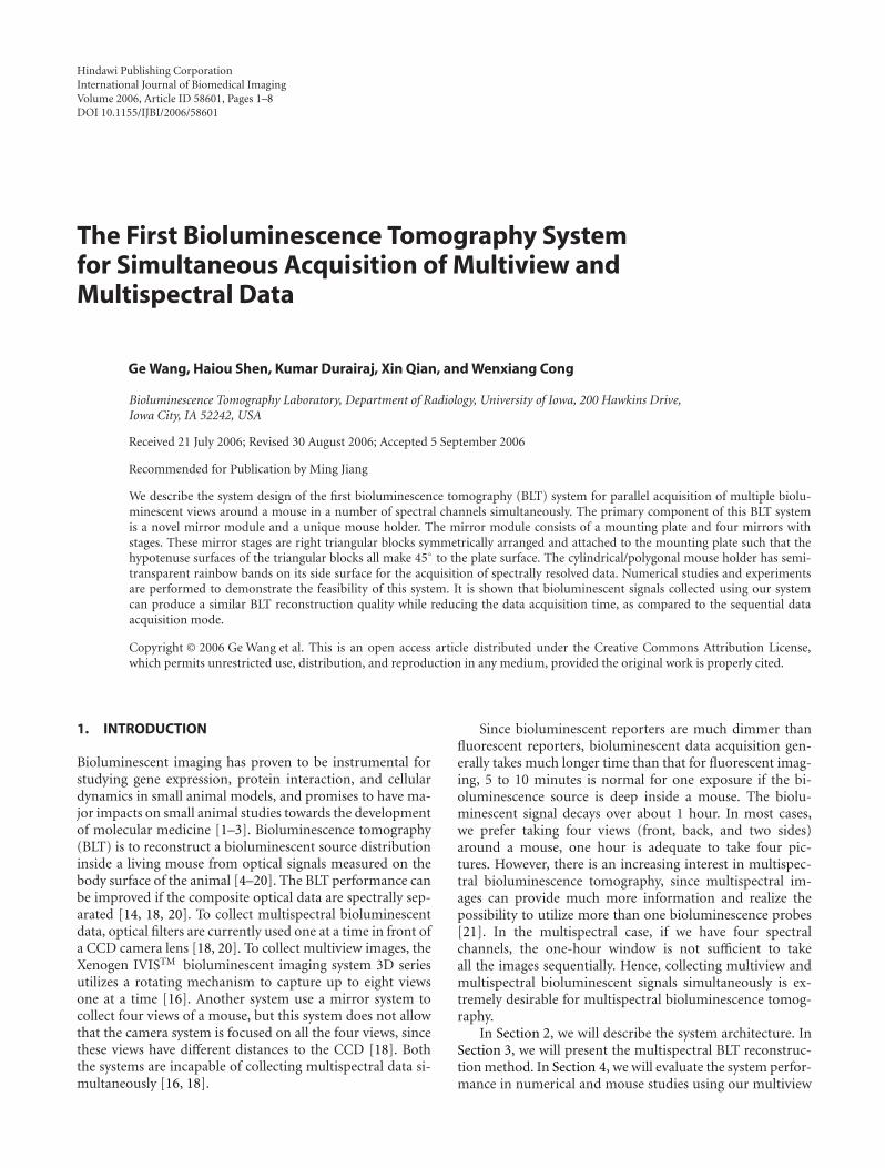
Hindawi Publishing CorporationInternational Journal of Biomedical ImagingVolume 2006, Article ID 58601, Pages 1–8DOI 10.1155/IJBI/2006/58601
The First Bioluminescence Tomography Systemfor Simultaneous Acquisition of Multiview andMultispectral Data
Ge Wang, Haiou Shen, Kumar Durairaj, Xin Qian, and Wenxiang Cong
Bioluminescence Tomography Laboratory, Department of Radiology, University of Iowa, 200 Hawkins Drive,Iowa City, IA 52242, USA
Received 21 July 2006; Revised 30 August 2006; Accepted 5 September 2006
Recommended for Publication by Ming Jiang
We describe the system design of the first bioluminescence tomography (BLT) system for parallel acquisition of multiple biolu-minescent views around a mouse in a number of spectral channels simultaneously. The primary component of this BLT systemis a novel mirror module and a unique mouse holder. The mirror module consists of a mounting plate and four mirrors withstages. These mirror stages are right triangular blocks symmetrically arranged and attached to the mounting plate such that thehypotenuse surfaces of the triangular blocks all make 45◦ to the plate surface. The cylindrical/polygonal mouse holder has semi-transparent rainbow bands on its side surface for the acquisition of spectrally resolved data. Numerical studies and experimentsare performed to demonstrate the feasibility of this system. It is shown that bioluminescent signals collected using our systemcan produce a similar BLT reconstruction quality while reducing the data acquisition time, as compared to the sequential dataacquisition mode.
Copyright © 2006 Ge Wang et al. This is an open access article distributed under the Creative Commons Attribution License,which permits unrestricted use, distribution, and reproduction in any medium, provided the original work is properly cited.
1. INTRODUCTION
Bioluminescent imaging has proven to be instrumental forstudying gene expression, protein interaction, and cellulardynamics in small animal models, and promises to have ma-jor impacts on small animal studies towards the developmentof molecular medicine [1–3]. Bioluminescence tomography(BLT) is to reconstruct a bioluminescent source distributioninside a living mouse from optical signals measured on thebody surface of the animal [4–20]. The BLT performance canbe improved if the composite optical data are spectrally sep-arated [14, 18, 20]. To collect multispectral bioluminescentdata, optical filters are currently used one at a time in front ofa CCD camera lens [18, 20]. To collect multiview images, theXenogen IVISTM bioluminescent imaging system 3D seriesutilizes a rotating mechanism to capture up to eight viewsone at a time [16]. Another system use a mirror system tocollect four views of a mouse, but this system does not allowthat the camera system is focused on all the four views, sincethese views have different distances to the CCD [18]. Boththe systems are incapable of collecting multispectral data si-multaneously [16, 18].
Since bioluminescent reporters are much dimmer thanfluorescent reporters, bioluminescent data acquisition gen-erally takes much longer time than that for fluorescent imag-ing, 5 to 10 minutes is normal for one exposure if the bi-oluminescence source is deep inside a mouse. The biolu-minescent signal decays over about 1 hour. In most cases,we prefer taking four views (front, back, and two sides)around a mouse, one hour is adequate to take four pic-tures. However, there is an increasing interest in multispec-tral bioluminescence tomography, since multispectral im-ages can provide much more information and realize thepossibility to utilize more than one bioluminescence probes[21]. In the multispectral case, if we have four spectralchannels, the one-hour window is not sufficient to takeall the images sequentially. Hence, collecting multiview andmultispectral bioluminescent signals simultaneously is ex-tremely desirable for multispectral bioluminescence tomog-raphy.
In Section 2, we will describe the system architecture. InSection 3, we will present the multispectral BLT reconstruc-tion method. In Section 4, we will evaluate the system perfor-mance in numerical and mouse studies using our multiview
2 International Journal of Biomedical Imaging
Mounting plate
Mirr
or
Mirror
Mirror
Mirror
Rainbow mouse holder
LensCCD
Images
Figure 1: Bioluminescence tomography (BLT) system design for simultaneous acquisition of multiview and multispectral data. This systemconsists of a multimirror module, a cylindrical/polygonal mouse holder on which rainbow bands are attached for resolving data spectrally,a lens, and a CCD camera.
system. In Section 5, we will discuss relevant issues and con-clude the paper.
2. SYSTEM DESIGN
There are currently four bioluminescence probes: hRLuc,CBGr68, Fluc+, and CBRed. The last two have spectral peaksin the orange/red wavelengths (∼ 590 to 650 nm) [22]. Inthis range, the light is less absorbed with a greater pene-tration power through tissues. We can partition the spec-tral [500, 750] nm into three spectral ranges: [500, 590] nm,[590, 625] nm, and [625, 750] nm. The reason for this parti-tion is that these intervals contain similar amounts of energyat the mouse body temperature 37◦C for Fluc+ and CBRed[21, 22]. For Fluc+, the percentages are 28%, 33%, and 39%for [500, 590] nm, [590, 625] nm, and [625, 750] nm, respec-tively. For CBRed, the percentages are 14%, 35%, and 51%,respectively.
Our proposed BLT system design is mainly for parallelacquisition of multiview and multispectral bioluminescentdata. Figure 1 shows the architecture of the system. It con-sists of a multiview mirror module, a mouse holder with pat-terned filter, and a CCD camera with a lens. In Figure 1, themultiview mirror module includes a mounting plate, fourmirror stages, and four mirrors. The aluminum mountingplate is a square of 40 cm side length and 6 mm thickness. Thealuminum mirror stage is right triangular blocks of 125 mmside length and 30 mm thickness. The triangular blocks aremounted on the mounting plate symmetrically around amouse inside a transparent cylindrical (Syntec Technilogies,Inc.) mouse holder of length 120 mm. A rectangular frontmirror of size 160 mm×30 mm is attached to each of the fourhypotenuse surfaces of the mirror stages. Without use of themultispectral components, the mirror-based system can be astandalone multiview system. The four views of the mouse in
the mirrors are parallel to the mounting plate surface. If themouse is placed in the center of the four mirrors, the fourviews will be in the same object plane so that the cameracan focus on all the four views simultaneously. To keep themouse holder in position, it was attached to the mountingplate with a X-Y flexure stage, which can move the mouseholder as needed.
To enhance the multiview system into a multiview mul-tispectral system, we employ a novel mouse holder, as shownin Figure 1. The mouse holder is a custom-designed trans-parent cylindrical (or polygonal) tube (Syntec Technologies,Inc.) of length 120 mm with interleaving filter bands thatseparate bioluminescent light into different spectral chan-nels of interest. Several mouse holders with different radius(10 mm to 15 mm) will be employed in our system to matchthe size of the mouse. In our system, three different filters areplaced on the side surface of the cylinder with 1 mm widthfor each filter band. One filter is a low-pass filter covering thespectral range [400, 590] nm, one filter is a band-pass filterfor the range [590, 625] nm, and another filter is a high-passfilter for the range [625, 750] nm. The transmission at peakfor each filter is greater than 80%.
This system uses a highly sensitive CCD camera (Prince-ton Instruments VersArray 1300 B, Roper Scientific, Trenton,NJ) which offers 1340 × 1300 pixels, 20 × 20 μm pixel size,and 16 bits dynamic range. From 500 nm to 750 nm, quan-tum efficiency (QE) is greater than 80%. With liquid nitrogenthe camera can be cooled down to −110◦C to make the darkcurrent negligible. At this temperature, the typical CCD readnoise is 2 e rms, and the dark current is less than 1 e/p/hr for20 μm pixel. The camera is coupled with a Nikon 85 mm f/1.4lens with about 27× 27.8 cm field of view at 90 cm distance.To cover the 4 reflected bioluminescent views, the camera isplaced 0.9 m away from the mounting plate to provide an ad-equate field of view. An absolute intensity calibration of the
Ge Wang et al. 3
Virtual image
0.1
m
Rainbow filter
0.2 mm
Mirror
1 mm
0.9 m
0.04m
0.25 mm
Spectrallymixed zone
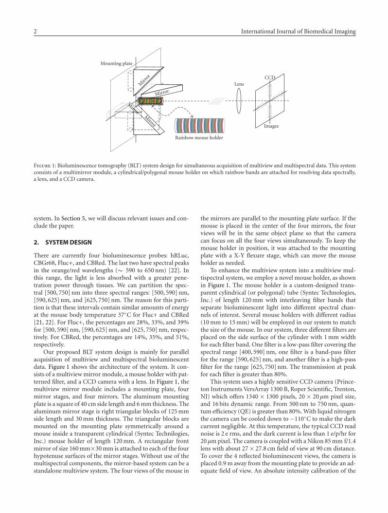
Figure 2: Zoomed view of light transmitting through the rainbowmouse holder.
CCD camera and the overall imaging system is necessary torecover the signal brightness in physical unit (W/cm2/sr). Forthat purpose, the absolutely calibrated 8-inche-integratingsphere system from SphereOptics is used. A 4-inche spherecontains a tungsten lamp light source. A 6-position auto-mated filter wheel with 5 filters (500 nm, 550 nm, 600 nm,650 nm, 700 nm) and a variable attenuator with a dynamicrange up to 11000 are placed between the two spheres to se-lect a particular wavelength and control the light level enter-ing the 8 inches sphere. The 2-inche output aperture of the8-inche sphere allows as low as 2.07× 10⁻¹³ W/cm2/sr in thespectral region of interest. By imaging this output aperture,the gray level of the CCD can be converted into physical unit.The camera is calibrated on f/1.4 and at the distance of 0.9 m.It turns out that each pixel gray level at the CCD is equivalentto 5× 10⁵ photons/sr/cm2.
Note that not all pixels in the image can be used in the re-construction. As shown in Figure 2, since the mouse and themouse holder could not match perfectly. There is some dis-tance between the mouse surface and the filters. As a result,some of the pixels contain light from two filters. We can se-lect those pixels that only contain light from one filter aroundthe central line of each filter band. As shown in Figure 2, withthe size of the pixel 20 × 20 μm, the corresponding area onthe mouse is about 200 × 200 μm. The distance between themouse surface and the front lens is about 90 cm, while thesize of the front lens is about 4 cm. Assume that the distancebetween the mouse surface and the filter is 1 mm, the size ofeach projected pixel on the filter is about 0.25 mm. Since eachfilter band is about 1 mm width, it can cover at least 3 pixelsin width. From the above calculation, we can see that if themouse holder is sufficiently tight, we can always find a goodnumber of pixels recording only one spectral band informa-tion. The disadvantage of this approach is that some of theimage pixels are wasted but they may be utilized using moresophisticated process and analysis, which is beyond the scopeof this feasibility paper. A better way is to place a customizedfilter pattern just in front of the CCD chip or use an opticalsystem to split light into different spectral bands and recordthe resultant signals. Since the mouse holder scheme is theeasiest and cheapest, in this paper we focus on this idea toestablish the feasibility of this multispectral bioluminescencetomography system design.
3. SIGNAL-TO-NOISE RATIO ESTIMATION
The signal-to-noise ratio (SNR) of a camera system can becomputed as in [1]:
SNR = S√S + D × t + N2
, (1)
where S is the signal per pixel in electrons, t the integrationtime, D the dark current value (electrons/pixel/second), andN the CCD read noise (electrons rms/pixel). A typical way toincrease SNR is by binning pixels prior readout. A binningvalue k means that a group of k × k pixels is summed to-gether to form one superpixel. By combining the pixels intoone superpixel we make the signal and dark current k2 timesstronger than before. The readout noise remains the samefor on-chip binning. The VersArray 1300 B CCD permits on-chip binning. Hence, we have the following result:
SNRk×k = S× k2√S× k2 + D × t × k2 + N2
. (2)
The trade-off of binning is spatial resolution. In our fi-nite element algorithm for bioluminescence tomography, thesize of each finite element is about 1 mm. In our system, eachpixel is corresponding to 0.2 mm × 0.2 mm on the mousebody surface. If we apply a single spectral algorithm, we canuse 5 × 5 binning. If we apply a multispectral algorithm, wecan use 3× 5 binning, because along the width of each filterband two spectrally mixed pixels are discarded. For sequen-tial systems, the field of view can be smaller to cover just onemouse view, which means they can use larger binning size toget better SNR given other conditions being identical.
There are two additional common ways to increase SNR:increasing signal strength, and increasing integration time.For bioluminescence imaging/tomography, we could not in-crease the strength of bioluminescent source but we can usea lens with bigger aperture (a customized f/1.0 lens can help)and employ a CCD with higher QE. As far as integration timeis concerned, because we can capture multiview and multi-spectral images simultaneously, the integration time can beincreased to improve the SNR.
In multispectral cases, only part of the energy can beutilized, the signal strength will be weaker than mix-spec-tral cases. Let S be the signal corresponding to spectral[500, 750] nm, let S1, S2, and S3 be the signal correspondingto spectral [500, 590], [590, 625], and [625, 750] nm, respec-tively. We have S = S1 + S2 + S3. The percentage of the signalin each spectral band depends on the probe, the optical coef-ficients of the tissues in different spectral bands, and the dis-tance between a bioluminescent source to the mouse bodysurface. Generally speaking, in a short wavelength spectralband the signal is subject to more absorption and less scatter-ing. Hence, if a light source is deep inside the tissue, spectral[500, 590] nm can be very weak so that the CCD could notrecord a strong signal but it can still receive enough photonsin the other two bands. In this case, we can still use multi-spectral data to do the reconstruction. Actually, the lack ofphotons in the spectral range [500, 590] nm is informativefor reconstruction, which tells us that the source must be rel-atively deep inside the animal.
4 International Journal of Biomedical Imaging
4. NUMERICAL AND EXPERIMENTAL RESULTS
4.1. Multispectral bioluminescencetomography method
In bioluminescent imaging, photons from light-emitting lu-ciferase probes inside a mouse may escape the mouse bodysubject to attenuation. In this process, photon scatteringpredominates over absorption. Hence, the photon propa-gation can be modeled as the well-known diffusion equa-tion. Because the internal bioluminescent light is continu-ously on during the measurement, BLT operates only in theCW mode. Hence, we have the following steady-state diffu-sion equation and the Robin boundary condition [8–13, 21–24]:
−∇ · (D(r, λ)∇Φ(r, λ))
+ μa(r, λ)Φ(r, λ)=S(r, λ) (r ∈ Ω),
Φ(r, λ) + 2A(r, λ)D(r, λ)(ν(r) · ∇Φ(r, λ)
)=0 (r ∈ ∂Ω),(3)
where Φ(r, λ) represents the photon fluence rate (W/mm2)for spectral component λ at location r, S(r, λ) the densityof the bioluminescent source distribution (W/mm3), μa(r, λ)the absorption coefficient (mm−1), μ′s(r, λ) the reduced scat-tering coefficient (mm−1), D(r, λ) = (3(μa(r, λ) +μ′s(r, λ)))−1
the diffusion coefficient, Ω the support for the mouse body,∂Ω the body surface, and A(r, λ) the mismatch coefficientdue to different refractive indices across ∂Ω. With an ade-quate exposure time, a significant amount of bioluminescentphotons can come out of the mouse and can be detected withthe CCD camera. The measured quantity is the photon cur-rent on the body surface [21–24]:
Φ(r, λ) = −D(r, λ)(ν · ∇Φ(r, λ)
)(r ∈ ∂Ω), (4)
where ν denotes the unit outer normal to ∂Ω. Based on (3)-(4), a linear system linking a bioluminescent source distribu-tion and the boundary measurement can be briefly expressedas
B(λ)S(λ)=Φ(λ), (5)
where S(λ) = {S1, S2, . . . , SM}T represents the discretized bi-oluminescent source distribution, B(λ) = {b1, b2, . . . , bM} aweighting matrix consisting of N-dimensional column vec-tors bk (k = 1, 2, . . . ,M), and Φ(λ) an N-dimensional vectorfor the data measured on the body surface. Clearly, Skbk isthe contribution of the kth source component Sk to Φ(λ).Then, the BLT problem is to reconstruct Si (i = 1, 2, . . . ,M)from the data Φ(λ). This is a typical underdetermined prob-lem. As a result, a strong prior knowledge must be incorpo-rated into the reconstruction to overcome the ill-posednesseffectively. Here we propose a multiscale BLT reconstruc-tion procedure to refine permissible source regions gradu-ally and improve image resolution accordingly. Initially, lowresolution BLT can reliably identify clusters of biolumines-cent sources. As image resolution of reconstructed biolumi-nescence sources becomes higher using an iterative proce-dure, permissible source regions can be better delimited with
each iteration. Mathematically, the BLT reconstruction canbe converted into the following optimization subject to reg-ularization [22]:
min0≤S≤US∈ΩS
(∑
λ
∥∥B(λ)S(λ)− Φ(λ)
∥∥2W + εη(S)
)
, (6)
where U denotes the upper bound for the source to be phys-ically meaningful, ΩS a permissible source domain, η a stabi-lizing function, ε a regularization parameter, W a weightingmatrix, and ‖V‖2
W = VTWV .
4.2. Simulation results
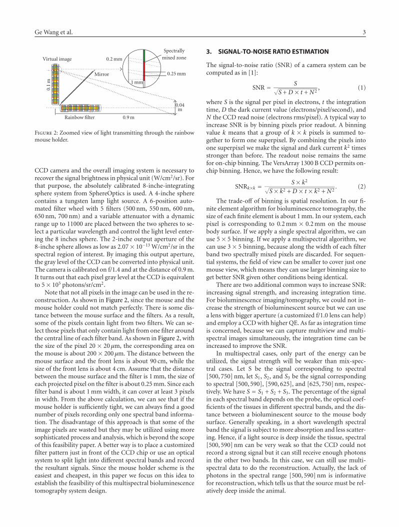
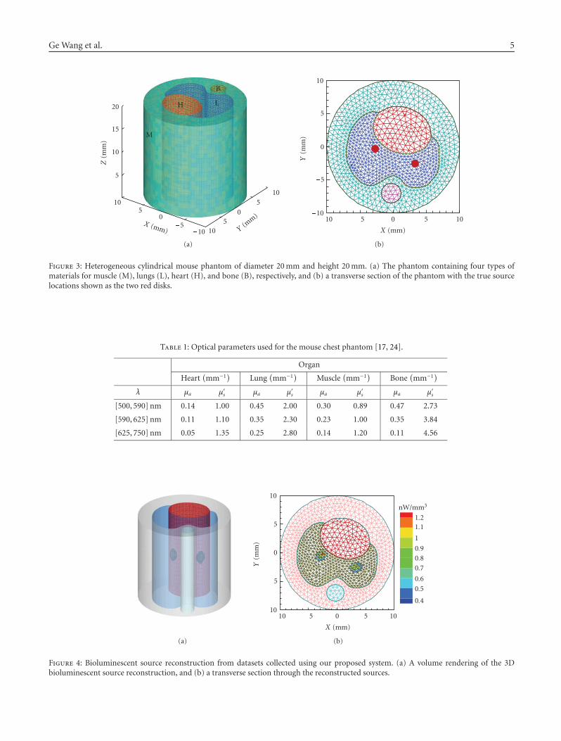
We evaluated the system performance in numerical simula-tion using a heterogeneous cylindrical mouse phantom. Thisnumerical phantom of diameter 20 mm and height 20 mmwas designed to mimic the thoracic cavity of a mouse. Thephantom contains four types of materials representing mus-cle (M), lungs (L), heart (H), and bone (B), respectively, asshown in Figure 3. The appropriate optical parameters wereassigned to each of the four components as summarized inTable 1, which were extracted from the literature [17, 25–27]. The phantom was discretized into 36 000 wedge ele-ments and 19761 nodes. On the side surface of the phan-tom, 1680 sampling locations were assumed along a numberof virtual rings at different elevations. Each ring consisted of80 sampling locations with sampling distance 0.78 mm. Thedistance between the adjacent rings was set to 1 mm for con-sistence with the interband distance on the rainbow holder.These rings were in correspondence to the spectral compo-nents.
Two bioluminescent sources were embedded in the lungsof the phantom at (−2.7,−0.28, 10) and (3.26,−2.52, 10),respectively, as shown in Figure 3. Based on the biolumi-nescent emission spectrum, three spectral bands were de-fined as [500, 590] nm, [590, 630] nm, and [630, 750] nm.Each source had 6.0 nW with the spectral distribution 28%for [500, 590] nm, 33% for [590, 625] nm, and 39% for[625, 750] nm. For each sequential image, we assume 3.5minutes integrating time (total is 56 minutes for 16 images);and for our multiview and multispectral system, we assume20 minutes integrating time. A finite element based forwardsolver in Matlab was employed to solve the forward problemon an Intel dual Xeon 2.8 GHz 2 GB memory Dell Dimension670 machine. Then, we converted the phantom side surfacephoton fluence from floating point W/cm2 into photon/cm2
and add the Poisson noise. Finally, we transformed the pho-ton fluence into CCD readings and added the dark currentand the readout noise to form our multispectral datasets.
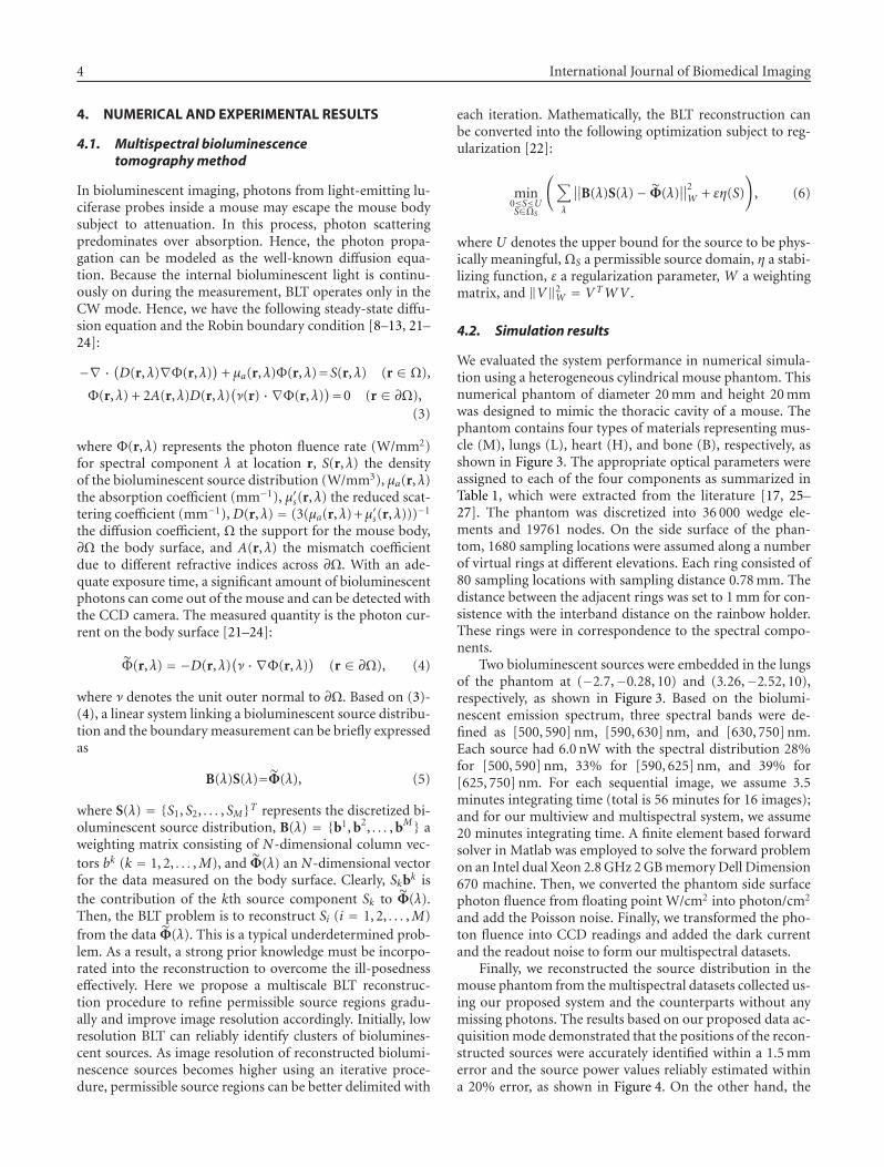
Finally, we reconstructed the source distribution in themouse phantom from the multispectral datasets collected us-ing our proposed system and the counterparts without anymissing photons. The results based on our proposed data ac-quisition mode demonstrated that the positions of the recon-structed sources were accurately identified within a 1.5 mmerror and the source power values reliably estimated withina 20% error, as shown in Figure 4. On the other hand, the
Ge Wang et al. 5
105
0�5
�10X (mm) 10
50
�5�10
Y(m
m)
5
10
15
20Z
(mm
)
M
H L
B
(a)
�10 �5 0 5 10
X (mm)
�10
�5
0
5
10
Y(m
m)
(b)
Figure 3: Heterogeneous cylindrical mouse phantom of diameter 20 mm and height 20 mm. (a) The phantom containing four types ofmaterials for muscle (M), lungs (L), heart (H), and bone (B), respectively, and (b) a transverse section of the phantom with the true sourcelocations shown as the two red disks.
Table 1: Optical parameters used for the mouse chest phantom [17, 24].
Organ
Heart(mm−1
)Lung
(mm−1
)Muscle
(mm−1
)Bone
(mm−1
)
λ μa μ′s μa μ′s μa μ′s μa μ′s
[500, 590] nm 0.14 1.00 0.45 2.00 0.30 0.89 0.47 2.73
[590, 625] nm 0.11 1.10 0.35 2.30 0.23 1.00 0.35 3.84
[625, 750] nm 0.05 1.35 0.25 2.80 0.14 1.20 0.11 4.56
(a)
�10 �5 0 5 10
X (mm)
�10
�5
0
5
10
Y(m
m)
0.4
0.5
0.6
0.70.80.9
1
1.11.2
nW/mm3
(b)
Figure 4: Bioluminescent source reconstruction from datasets collected using our proposed system. (a) A volume rendering of the 3Dbioluminescent source reconstruction, and (b) a transverse section through the reconstructed sources.
6 International Journal of Biomedical Imaging
Mirrors
Mouse holder
CDD camera
Figure 5: Prototype of a multiview system consisting of a multiviewmirror system, a mouse holder, and a CCD camera. For illustrationpurpose, the four mirrors are colored in white.
counterparts based on the traditional sequential data acqui-sition mode indicated that the positions of the reconstructedsources were identified up to a 1.5 mm error and the sourcepower values estimated up to a 16% error.
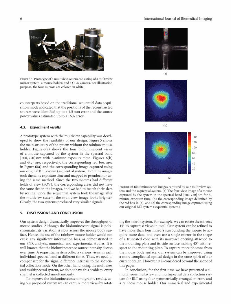
4.3. Experiment results
A prototype system with the multiview capability was devel-oped to show the feasibility of our design. Figure 5 showsthe main structure of the system without the rainbow mouseholder. Figure 6(a) shows the four bioluminescent viewsof a mouse captured by the system in the spectral band[500, 750] nm with 5-minute exposure time. Figures 6(b)and 6(c) are, respectively, the corresponding red box areain Figure 6(a) and the corresponding image captured usingour original BLT system (sequential system). Both the imagestook the same exposure time and mapped to pseudocolor us-ing the same method. Since the two systems had differentfields of view (FOV), the corresponding areas did not havethe same size in the images, and we had to match their sizesby scaling. Since the sequential system took the image afterthe multiview system, the multiview image looks brighter.Clearly, the two systems produced very similar signals.
5. DISCUSSIONS AND CONCLUSION
Our system design dramatically improves the throughput ofmouse studies. Although the bioluminescent signal is poly-chromatic, its variation is slow across the mouse body sur-face. Hence, the use of the rainbow mouse holder would notcause any significant information loss, as demonstrated inour SNR analysis, numerical and experimental studies. It iswell known that the bioluminescence source intensity decaysover time. A sequential system collects various views in eachindividual spectral band at different times. Thus, we need tocompensate for the signal difference intrinsic to the sequen-tial collection mode. On the other hand, using the multiviewand multispectral system, we do not have this problem, everychannel is collected simultaneously.
To improve the bioluminescence tomography results, us-ing our proposed system we can capture more views by rotat-
(a)
(b)
20
40
60
80
100
120
140
(c)
Figure 6: Bioluminescence images captured by our multiview sys-tem and the sequential system. (a) The four-view image of a mousecaptured by the system in the spectral band [500, 750] nm for 5-minute exposure time, (b) the corresponding image delimited bythe red box in (a), and (c) the corresponding image captured usingour original BLT system (sequential system).
ing the mirror system. For example, we can rotate the mirrors45◦ to capture 8 views in total. Our system can be refined tohave more than four mirrors surrounding the mouse to ac-quire more data, and even use a single mirror in the shapeof a truncated cone with its narrower opening attached tothe mounting plate and its side surface making 45◦ with re-spect to the mounting plate. To capture more photons fromthe mouse body surface, our system can be improved usinga more complicated optical design in the same spirit of ourcurrent design. However, it is considered beyond the scope ofthis paper.
In conclusion, for the first time we have presented a si-multaneous multiview and multispectral data collection sys-tem for BLT using four symmetrically arranged mirrors anda rainbow mouse holder. Our numerical and experimental
Ge Wang et al. 7
results have demonstrated that bioluminescent signals col-lected using our new system can produce a similar BLTreconstruction quality while reducing the data acquisitiontime, as compared to that using the sequential data acqui-sition mode. We believe that our system design representsa major step forward in the development of BLT and itsbiomedical applications. Relevant in-vivo mouse results willbe reported in the future.
ACKNOWLEDGMENT
This work was supported by NIH/NIBIB EB001685.
REFERENCES
[1] B. W. Rice, M. D. Cable, and M. B. Nelson, “In vivo imagingof light-emitting probes,” Journal of Biomedical Optics, vol. 6,no. 4, pp. 432–440, 2001.
[2] C. H. Contag and M. H. Bachmann, “Advances in in vivo bi-oluminescence imaging of gene expression,” Annual Review ofBiomedical Engineering, vol. 4, pp. 235–260, 2002.
[3] V. Ntziachristos, J. Ripoll, L. V. Wang, and R. Weissleder,“Looking and listening to light: the evolution of whole-bodyphotonic imaging,” Nature Biotechnology, vol. 23, no. 3, pp.313–320, 2005.
[4] G. Wang, E. A. Hoffman, and G. McLennan, “Systems andmethods for bioluminescent CT reconstruction,” Patent dis-closure filled, July 2002; US provisional patent applicationfilled, March 2003; US patent application filed, March 2004.
[5] G. Wang, et al., “Multi-spectral bioluminescence tomographymethods and systems,” Patent disclosure filed with Universityof Iowa Research Foundation, April 2004; provisional patentfiled.
[6] G. Wang, D. Kumar, H. Shen, X. Qian, and W. Cong, “The Op-tical molecular tomography systems and methods for simul-taneous acquisition of multi-view and multi-spectral data,”Patent disclosure filed with University of Iowa Research Foun-dation, May 2006.
[7] G. Wang, E. A. Hoffman, G. McLennan, et al., “Developmentof the first bioluminescent CT scanner,” Radiology, vol. 229(P),p. 566, 2003.
[8] G. Wang, Y. Li, and M. Jiang, “Uniqueness theorems in bio-luminescence tomography,” Medical Physics, vol. 31, no. 8, pp.2289–2299, 2004.
[9] M. Jiang and G. Wang, “Image reconstruction for biolumines-cence tomography,” in Developments in X-Ray Tomography IV,vol. 5535 of Proceedings of SPIE, pp. 335–351, Denver, Colo,USA, August 2004.
[10] W. Cong, D. Kumar, Y. Liu, A. Cong, and G. Wang, “A practicalmethod to determine the light source distribution in biolumi-nescent imaging,” in Developments in X-Ray Tomography IV,vol. 5535 of Proceedings of SPIE, pp. 679–686, Denver, Colo,USA, August 2004.
[11] W. Cong, G. Wang, D. Kumar, et al., “Practical reconstruc-tion method for bioluminescence tomography,” Optics Ex-press, vol. 13, no. 18, pp. 6756–6771, 2005.
[12] W. Cong and G. Wang, “Boundary integral method for biolu-minescence tomography,” Journal of Biomedical Optics, vol. 11,no. 2, Article ID 020503, 3 pages, 2006.
[13] W. Cong, D. Kumar, L. V. Wang, and G. Wang, “A Born-type approximation method for bioluminescence tomogra-phy,” Medical Physics, vol. 33, no. 3, pp. 679–686, 2006.
[14] A. Cong and G. Wang, “Multispectral bioluminescence to-mography: methodology and simulation,” International Jour-nal of Biomedical Imaging, vol. 2006, Article ID 57614, 7 pages,2006.
[15] X. Gu, Q. Zhang, L. Larcom, and H. Jiang, “Three-di-mensional bioluminescence tomography with model-basedreconstruction,” Optics Express, vol. 12, no. 17, pp. 3996–4000,2004.
[16] C. Kuo, O. Coquoz, T. Troy, D. Zwarg, and B. Rice, “Biolumi-nescent tomography for in vivo localization and quantificationof luminescent sources from a multiple-view imaging system,”Molecular Imaging, vol. 4, p. 370, 2005.
[17] G. Alexandrakis, F. R. Rannou, and A. F. Chatziioannou, “To-mographic bioluminescence imaging by use of a combinedoptical-PET (OPET) system: a computer simulation feasibil-ity study,” Physics in Medicine and Biology, vol. 50, no. 17, pp.4225–4241, 2005.
[18] A. J. Chaudhari, F. Darvas, J. R. Bading, et al., “Hyperspec-tral and multispectral bioluminescence optical tomographyfor small animal imaging,” Physics in Medicine and Biology,vol. 50, no. 23, pp. 5421–5441, 2005.
[19] N. V. Slavine, M. A. Lewis, E. Richer, and P. P. Antich, “Iterativereconstruction method for light emitting sources based on thediffusion equation,” Medical Physics, vol. 33, no. 1, pp. 61–68,2006.
[20] H. Dehghani, S. C. Davis, S. Jiang, B. W. Pogue, K. D. Paulsen,and M. S. Patterson, “Spectrally resolved bioluminescence op-tical tomography,” Optics Letters, vol. 31, no. 3, pp. 365–367,2006.
[21] G. Wang, H. Shen, W. Cong, S. Zhao, and G. W. Wei,“Temperature-modulated bioluminescence tomography,” Op-tics Express, vol. 14, no. 17, pp. 7852–7871, 2006.
[22] H. Zhao, T. C. Doyle, O. Coquoz, F. Kalish, B. W. Rice, and C.H. Contag, “Emission spectra of bioluminescent reporters andinteraction with mammalian tissue determine the sensitivityof detection in vivo,” Journal of Biomedical Optics, vol. 10,no. 4, Article ID 041210, 9 pages, 2005.
[23] A. Ishimaru, Wave Propagation and Scattering in Random Me-dia, Oxford University Press, Oxford, UK, 1997.
[24] F. Natterer and F. Wung, Mathematical Methods in Image Re-construction, Society for Industrial and Applied Mathematics,Philadelphia, Pa, USA, 2001.
[25] http://omlc.ogi.edu/spectra/hemoglobin/index.html.[26] V. Tuchin, Tissue Optics: Light Scattering Methods and Instru-
ments for Medical Diagnosis, SPIE-International Society forOptical Engine, Bellingham, Wash, USA, 2000.
[27] W. F. Cheong, S. A. Prahl, and A. J. Welch, “A review of the op-tical properties of biological tissues,” IEEE Journal of QuantumElectronics, vol. 26, no. 12, pp. 2166–2185, 1990.
Ge Wang received the B.E. degree in elec-trical engineering from Xidian University,Xian, China, in 1982, the M.S. degree in re-mote sensing from the Graduate School ofAcademia Sinica, Beijing, China, in 1985,and the M.S. and Ph.D. degrees in electricaland computer engineering from the StateUniversity of New York, Buffalo, in 1991and 1992. He was an Instructor and Assis-tant Professor with the Department of Elec-trical Engineering, Graduate School of Academia Sinica, in 1984–1988, and Instructor and Assistant Professor with Mallinckrodt
8 International Journal of Biomedical Imaging
Institute of Radiology, Washington University, St. Louis, Mo, in1992–1996. He was an Associate Professor with the University ofIowa in 1997–2002. Currently, he is a Professor with the Depart-ments of Radiology, Biomedical Engineering, Mathematics, CivilEngineering, and Electrical and Computer Engineering, and Di-rector of the Center for X-Ray and Optical Tomography, Univer-sity of Iowa. His interests include computed tomography, biolumi-nescence tomography, and systems biomedicine. He has publishedover 300 journal articles and conference papers, including the firstpaper on spiral/helical cone-beam CT and the first paper on bio-luminescence tomography. He is the Editor-in-Chief for the Inter-national Journal of Biomedical Imaging, and an Associate Editorfor the IEEE Transactions on Medical Imaging and the Journal ofMedical Physics. He is an IEEE Fellow and an AIMBE Fellow. He isalso recognized by a number of awards for academic achievements.
Haiou Shen received the B.E. and M.E. de-grees in electrical engineering from WuhanUniversity, Wuhan, China, in 1995 and1998. He is currently a Ph.D. student inthe Department of Computer Science at theUniversity of Iowa. He is currently work-ing as a research assistant in the BLT Re-search Group, Department of Radiology atthe University of Iowa. His research inter-ests include satisfiability problem and bio-luminescence tomography.
Kumar Durairaj received his Ph.D. de-gree in biomedical engineering from IIT-Madras, in 2003. His interest includes laserinstrumentation, biomedical optics, andimage processing. At present, he is workingas a Professor in the Department of Elec-tronics and Communication Engineering,Periyar Maniammai College of Technologyfor Women, Vallam Thanjavur, India.
Xin Qian received his B.E. degree fromTianjin University, Tianjin, China, in 2001,and Ph.D. degree in fiber optics fromBournemouth University, Southampton,UK, in 2005. He is presently working as aPost Doctor with the BLT Research Groupat the University of Iowa, USA. His researchinterests include biomedical imaging andfiber-based optical devices.
Wenxiang Cong received his B.S. degree inmathematic from Heilongjiang University,Harbin, China, in 1982, M.S. degree in ap-plied mathematic from Harbin Institute ofTechnology, Harbin, China, in 1988, andPh.D. degree in optical imaging from Bei-jing University of Science and Technology,Beijing, China, in 1998. Currently, he isa Research Scientist with the Biolumines-cence Tomography Laboratory, Departmentof Radiology, University of Iowa, Iowa City, Iowa, USA. His re-search interests include biomedical imaging, optical tomographyand bioluminescence tomography. He authored or coauthored 30journal papers and 10 conference proceedings. He is a Member ofthe Optical Society of America.
Copyright © 2022 FDOKUMEN