Anodic stripping voltammetry at a glassy carbon electrode for the ...
Upload
independentCategory
view
1download
0
Research paper294 © Copyright by International OCSCO World Press. All rights reserved. 2013
VOLUME 61
ISSUE 2
December
2013of Achievements in Materialsand Manufacturing Engineeringof Achievements in Materialsand Manufacturing Engineering
The effects of the coating stripping process on regenerated tool cutting edges
D. Toboła*, K. Czechowski, I. Wrońska, A. Łętocha, T. Miller Institute of Advanced Manufacturing Technology, ul. Wrocławska 37a, 30-011 Kraków, Poland* Corresponding e-mail address: [email protected]
Received 08.10.2013; published in revised form 01.12.2013
Properties
AbstrActPurpose: The cutting tools of high speed steel or cemented carbide need to be regenerated in many cases. This involves stripping the remnants of the initial coatings. The effects of chemical removal of the PVD TiN, TiAlN, TiN/(TiAlSi)N/TiN and TiZrN/10x(TiN/ZrN)/TiN coatings on some elements of geometry of cutting edges and the adhesion of subsequent coatings deposited on the cutting inserts are considered.Design/methodology/approach: Scanning electron microscopy is used to examine the structures after the various stages of inserts regeneration: with the initial coating, after it is chemically stripped and subsequently deposited. Geometry of cutting edges, i.e. roughness, edge roundness radius and 2D and 3D geometric structure of rake and flank faces, as well as the adhesion of subsequent coatings deposited on the inserts in the regeneration process are determined.Findings: The chemical coating stripping process did not cause unfavourable changes in the roughness parameter Ra of the rake and flank faces of cutting inserts, or in the roughness of their cutting edges. Subsequent coatings deposited on the decoated inserts had a marginally lower adhesion, but in the case of TiN coated cemented carbide, the latter coating had better adhesion than the original. Surface analyses showed that the PVD coating stripping methods were effective for TiN and TiAlN coated high speed steel HS6-5-2 inserts, as well as for TiN coated and commercially TiN/(TiAlSi)N/TiN coated cemented carbide inserts.Research limitations/implications: The paper is concerned with geometry of cutting edge and adhesive properties of subsequent coatings. To verify fully the effectiveness of the methods described further research on different coating removal from tools made of various tool materials should be carried out.Practical implications: The methods and chemicals used for removal of the initial PVD TiN, TiAlN and TiN/(TiAlSiN)/TiN coatings from high speed steel and cemented carbide inserts proved effective and may be used in the regeneration process of cutting tools.Originality/value: The effects of chemical removal of mono and multilayer PVD coatings from cemented carbide and high speed steel inserts on the regenerated cutting edges quality have been determined.Keywords: PVD; Coatings; Stripping; Roughness; Cutting edge; Coating adhesion
Reference to this paper should be given in the following way: D. Toboła, K. Czechowski, I. Wrońska, A. Łętocha, T. Miller, The effects of the coating stripping process on regenerated tool cutting edges, Journal of Achievements in Materials and Manufacturing Engineering 61/2 (2013) 294-301.
1. Introduction The majority of currently used cutting tools have their cutting
edges modified with anti-wear coatings [1,2], mainly physical vapour deposited, PVD. The more expensive coated tools, e.g. cemented carbide and high speed steel hobs, are reused several times- after a regeneration process [3].The basic regeneration process is grinding of the tool rake face; not necessarily always performed on the other tool surfaces [4]. Regarding the subsequent cutting efficiency, it is considered that, without removal of the original coatings, two is the maximum number of such operations [5]. Hobs, during use, especially by the automotive industry, are frequently refurbished to ensure their high machining efficiency. It is essential then to perform the full regeneration process, i.e. remove the coating from all the surfaces, including the flank face. This takes place up to 15 times [5].
Coating removal process is made more difficult by the variety of both substrate and coating materials. The current estimate of number of coating types is several hundred, of which, on the market in 2009 [5], there were about 70 PVD coatings with various chemical compositions. By 2011 there were new types, raising the number of commercial PVD coatings to about 100 [3]. Structure and properties of different types and PVD coatings deposited on various tool materials were presented in many publications [1,3,5-11]. The coatings efficient removal requires the retention of a proper substrate surface - using an environmentally safe method. This was a problem tackled in recent investigations of numerous substrate materials; in the case of cutting tools: high speed steels, cemented carbides, oxide and mixed ceramics - reported on e.g. in references [12-18].
PVD coated HB 10F cemented carbide hobs were investigated by Institute of Advanced of Manufacturing Technology (IAMT). These were regenerated by grinding the rake face and it was demonstrated that 4-5 coating removals were possible without resorting to chemical means [12]. Successfully studied also were TiN and (TiAl)N successively coated high speed steel hobs [19]. The most commonly-used methods of complete coating removal, however, involve “wet” chemical methods, discussed in references [12,18].
An efficient means of stripping requires complete coating removal without any concurrent geometric or chemical changes in the substrate material [18]. This is not easy, since the wear-resistant nitride coatings are simultaneously corrosion-resistant, more so than the substrate material. Thus the coating removal baths, in addition to the active ingredients (e.g. hydrogen peroxide, H2O2) which separate the coating from the substrate, must contain corrosion inhibitors (e.g. benzotriazole, imidazole, pyrazole), essential to safeguard the substrate. Commercial nitride coating stripping agents include those of Baku Chemie, Borer Chemie, „absolut Decoating Technology” and DETEC Nederland [20], which sells their chemicals only with their own stripping equipment. There is also Deconex de-coat 110 of Borer Chemie AG, for removal of AlTiN, TiAlN and ZrN coatings from surfaces of group P and K cemented carbides and high-alloy steels."absolut Decoating Technology” has introduced for removing PVD coatings from high speed steels new assisting preparations Ferrodec® 56 and Excarbonite® 12 and for various types of coatings and substrates removing agent Uniceral® 108 [20].
This paper presents results of research on the effects of chemical removal (stripping) of the PVD TiN, TiAlN, TiN/(TiAlSi)N/TiN and TiZrN/10x(TiN/ZrN)/TiN coatings from high speed steel and cemented carbide cutting indexable inserts on some elements of geometry of cutting edges such as their roughness and edge roundness radius as well as on the adhesion of subsequent coatings deposited on the inserts in the regeneration process.
2. Experimental procedures
The specimens were PVD coated cemented carbide (HM) and high speed steel cutting tool inserts listed in Table 1. The HM inserts were produced by Baildonit (Sandvik Polska) and HSS inserts were manufactured by Ifanger. a)
b)
Fig. 1. Sites of coating thickness measurement on rake and flank faces (Calotest) and of adhesion (scratch test) for inserts a) high speed steel CNEG 120404 L01 b) cemented carbide SPUN 120308.
For PVD coatings removal from the Table 1 specimens the hydrogen peroxide (H2O2 35% water solution) was used with stabilizing and activating agents: the BAKUTRIT 50 and BAKUTRIT PL, manufactured by Baku Chemie GmbH [20]. The coating chemical stripping process parameters were determined experimentally. Effective process parameters of coatings chemical removal from high speed steel and cemented cerbide inserts are given in Table 2.

295READING DIRECT: www.journalamme.org
Properties
1. Introduction The majority of currently used cutting tools have their cutting
edges modified with anti-wear coatings [1,2], mainly physical vapour deposited, PVD. The more expensive coated tools, e.g. cemented carbide and high speed steel hobs, are reused several times- after a regeneration process [3].The basic regeneration process is grinding of the tool rake face; not necessarily always performed on the other tool surfaces [4]. Regarding the subsequent cutting efficiency, it is considered that, without removal of the original coatings, two is the maximum number of such operations [5]. Hobs, during use, especially by the automotive industry, are frequently refurbished to ensure their high machining efficiency. It is essential then to perform the full regeneration process, i.e. remove the coating from all the surfaces, including the flank face. This takes place up to 15 times [5].
Coating removal process is made more difficult by the variety of both substrate and coating materials. The current estimate of number of coating types is several hundred, of which, on the market in 2009 [5], there were about 70 PVD coatings with various chemical compositions. By 2011 there were new types, raising the number of commercial PVD coatings to about 100 [3]. Structure and properties of different types and PVD coatings deposited on various tool materials were presented in many publications [1,3,5-11]. The coatings efficient removal requires the retention of a proper substrate surface - using an environmentally safe method. This was a problem tackled in recent investigations of numerous substrate materials; in the case of cutting tools: high speed steels, cemented carbides, oxide and mixed ceramics - reported on e.g. in references [12-18].
PVD coated HB 10F cemented carbide hobs were investigated by Institute of Advanced of Manufacturing Technology (IAMT). These were regenerated by grinding the rake face and it was demonstrated that 4-5 coating removals were possible without resorting to chemical means [12]. Successfully studied also were TiN and (TiAl)N successively coated high speed steel hobs [19]. The most commonly-used methods of complete coating removal, however, involve “wet” chemical methods, discussed in references [12,18].
An efficient means of stripping requires complete coating removal without any concurrent geometric or chemical changes in the substrate material [18]. This is not easy, since the wear-resistant nitride coatings are simultaneously corrosion-resistant, more so than the substrate material. Thus the coating removal baths, in addition to the active ingredients (e.g. hydrogen peroxide, H2O2) which separate the coating from the substrate, must contain corrosion inhibitors (e.g. benzotriazole, imidazole, pyrazole), essential to safeguard the substrate. Commercial nitride coating stripping agents include those of Baku Chemie, Borer Chemie, „absolut Decoating Technology” and DETEC Nederland [20], which sells their chemicals only with their own stripping equipment. There is also Deconex de-coat 110 of Borer Chemie AG, for removal of AlTiN, TiAlN and ZrN coatings from surfaces of group P and K cemented carbides and high-alloy steels."absolut Decoating Technology” has introduced for removing PVD coatings from high speed steels new assisting preparations Ferrodec® 56 and Excarbonite® 12 and for various types of coatings and substrates removing agent Uniceral® 108 [20].
This paper presents results of research on the effects of chemical removal (stripping) of the PVD TiN, TiAlN, TiN/(TiAlSi)N/TiN and TiZrN/10x(TiN/ZrN)/TiN coatings from high speed steel and cemented carbide cutting indexable inserts on some elements of geometry of cutting edges such as their roughness and edge roundness radius as well as on the adhesion of subsequent coatings deposited on the inserts in the regeneration process.
2. Experimental procedures
The specimens were PVD coated cemented carbide (HM) and high speed steel cutting tool inserts listed in Table 1. The HM inserts were produced by Baildonit (Sandvik Polska) and HSS inserts were manufactured by Ifanger. a)
b)
Fig. 1. Sites of coating thickness measurement on rake and flank faces (Calotest) and of adhesion (scratch test) for inserts a) high speed steel CNEG 120404 L01 b) cemented carbide SPUN 120308.
For PVD coatings removal from the Table 1 specimens the hydrogen peroxide (H2O2 35% water solution) was used with stabilizing and activating agents: the BAKUTRIT 50 and BAKUTRIT PL, manufactured by Baku Chemie GmbH [20]. The coating chemical stripping process parameters were determined experimentally. Effective process parameters of coatings chemical removal from high speed steel and cemented cerbide inserts are given in Table 2.
1. Introduction
2. Experimental procedures
Research paper296
Journal of Achievements in Materials and Manufacturing Engineering
D. Toboła, K. Czechowski, I. Wrońska, A. Łętocha, T. Miller
Volume 61 Issue 2 December 2013
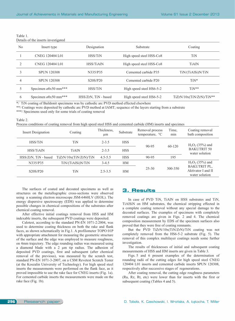
Table 1. Details of the inserts investigated
No Insert type Designation Substrate Coating
1 CNEG 120404 L01 HSS/TiN High speed steel HSS-Co8 TiN
2 CNEG 120404 L01 HSS/TiAlN High speed steel HSS-Co8 TiAlN
3 SPUN 120308 N335/P35 Cemented carbide P35 TiN/(TiAlSi)N/TiN
4 SPUN 120308 S20S/P20 Cemented carbide P20 TiN*
5 Specimen ø8x50 mm*** HSS/TiN High speed steel HS6-5-2 TiN**
6 Specimen ø8x50 mm*** HSS/ZrN, TiN - based High speed steel HS6-5-2 TiZrN/10x(TiN/ZrN)/TiN**
*/ TiN coating of Baildonit specimens was by cathodic arc PVD method effected elsewhere **/ Coatings were deposited by cathodic arc PVD method at IAMT; sequence of the layers starting from a substrate ***/ Specimens used only for some trials of coating removal Table 2. Process conditions of coating removal from high speed steel HSS and cemented carbide (HM) inserts and specimes
Insert Designation Coating Thickness, µm Substrate Removal process
temperature, °C Time, min
Coating removal bath composition
HSS/TiN TiN 2-3.5 HSS 90-95 60-120 H2O2 (35%) and
BAKUTRIT 50 water solution
HSS/TiAlN TiAlN 2-3.5 HSS
HSS/ZrN, TiN - based TiZrN/10x(TiN/ZrN)/TiN 4.5-5.5 HSS 90-95 195 N335/P35 TiN/(TiAlSi)N/TiN 3-4.5 HM
25-30 300-350
H2O2 (35%) and BAKUTRIT PL, Aktivator I and II
water solution S20S/P20 TiN 2.5-3.5 HM
The surfaces of coated and decoated specimens as well as structures on the metallographic cross-sections were observed using a scanning electron microscope JSM-6460LV (JEOL). The energy dispersive spectroscopy (EDS) was applied to determine possible changes in chemical compositions of the substrates after chemical coating removal.
After effective initial coatings removal from HSS and HM indexable inserts, the subsequent PVD coatings were deposited.
Calotest, according to the standard PN-EN 1071-2:2004, was used to determine coating thickness on both the rake and flank faces, as shown schematically in Fig.1. A profilometer TOPO 01P with appropriate attachment for measuring the geometric structure of the surface and the edge was employed to measure roughness, on 4mm trajectory. The edge rounding radius was measured using a diamond blade with a 2 µm tip radius. The adhesion of deposited PVD coatings, first and subsequent (after chemical removal of the previous), was measured by the scratch test, standard PN-EN 1071-3-2007, on a CSM Revetest Scratch Tester (at the Koszalin University of Technology). For high speed steel inserts the measurements were performed on the flank face, as it proved impossible to use the rake face for CNEG inserts (Fig. 1a). For cemented carbide inserts the measurements were made on the rake face (Fig. 1b).
3. Results
In case of PVD TiN, TiAlN on HSS substrates and TiN, TiAlSiN on HM substrates, the chemical stripping effected in a complete coating removal without any special damage to the decoated surfaces. The examples of specimens with completely removed coatings are given in Figs. 2 and 4. The chemical composition measurement by EDS of the specimen surfaces also proved that they were free of coating remnants.
But the PVD TiZrN/10x(TiN/ZrN)/TiN coating was not completely removed from the HS6-5-2 substrate (Fig. 5). The removal of this complex multilayer coatings needs some further investigation.
The results of thicknesses of initial and subsequent coating measurements of HSS and HM inserts are given in Table 3.
Figs. 5 and 6 present examples of the determination of rounding radii of the cutting edges for high speed steel CNEG 120404 L01 inserts and cemented carbide inserts SPUN 120308, respectively after successive stages of regenerations.
After coating removal, the cutting edge roughness parameters (Ra, Rz, Rt, etc) were lower than for inserts with the first or subsequent coating (Tables 4 and 5).
3. results
a)
a)
Fig
a)
Fig.
Fig. 2. S
g. 3. SEM image
4. SEM images
SEM images of H
es of HS6-5-2 str
of cemented car
HS6-5-2 structu
ructure on the cr
rbide structure o
ure on the cross s
ross section a) PV
on the cross secti
b)
section a) PVD T
b)
VD TiZrN/10x( b)
ion a) PVD TiN
TiN coated, b) af
TiN/ZrN)/TiN c
/(TiAlSi)N/TiN
fter removal of t
coated, b) after re
coated, b) after
the coating
emoval of the co
removal of the c
oating
coating

297
Properties
The effects of the coating stripping process on regenerated tool cutting edges
Table 1. Details of the inserts investigated
No Insert type Designation Substrate Coating
1 CNEG 120404 L01 HSS/TiN High speed steel HSS-Co8 TiN
2 CNEG 120404 L01 HSS/TiAlN High speed steel HSS-Co8 TiAlN
3 SPUN 120308 N335/P35 Cemented carbide P35 TiN/(TiAlSi)N/TiN
4 SPUN 120308 S20S/P20 Cemented carbide P20 TiN*
5 Specimen ø8x50 mm*** HSS/TiN High speed steel HS6-5-2 TiN**
6 Specimen ø8x50 mm*** HSS/ZrN, TiN - based High speed steel HS6-5-2 TiZrN/10x(TiN/ZrN)/TiN**
*/ TiN coating of Baildonit specimens was by cathodic arc PVD method effected elsewhere **/ Coatings were deposited by cathodic arc PVD method at IAMT; sequence of the layers starting from a substrate ***/ Specimens used only for some trials of coating removal Table 2. Process conditions of coating removal from high speed steel HSS and cemented carbide (HM) inserts and specimes
Insert Designation Coating Thickness, µm Substrate Removal process
temperature, °C Time, min
Coating removal bath composition
HSS/TiN TiN 2-3.5 HSS 90-95 60-120 H2O2 (35%) and
BAKUTRIT 50 water solution
HSS/TiAlN TiAlN 2-3.5 HSS
HSS/ZrN, TiN - based TiZrN/10x(TiN/ZrN)/TiN 4.5-5.5 HSS 90-95 195 N335/P35 TiN/(TiAlSi)N/TiN 3-4.5 HM
25-30 300-350
H2O2 (35%) and BAKUTRIT PL, Aktivator I and II
water solution S20S/P20 TiN 2.5-3.5 HM
The surfaces of coated and decoated specimens as well as structures on the metallographic cross-sections were observed using a scanning electron microscope JSM-6460LV (JEOL). The energy dispersive spectroscopy (EDS) was applied to determine possible changes in chemical compositions of the substrates after chemical coating removal.
After effective initial coatings removal from HSS and HM indexable inserts, the subsequent PVD coatings were deposited.
Calotest, according to the standard PN-EN 1071-2:2004, was used to determine coating thickness on both the rake and flank faces, as shown schematically in Fig.1. A profilometer TOPO 01P with appropriate attachment for measuring the geometric structure of the surface and the edge was employed to measure roughness, on 4mm trajectory. The edge rounding radius was measured using a diamond blade with a 2 µm tip radius. The adhesion of deposited PVD coatings, first and subsequent (after chemical removal of the previous), was measured by the scratch test, standard PN-EN 1071-3-2007, on a CSM Revetest Scratch Tester (at the Koszalin University of Technology). For high speed steel inserts the measurements were performed on the flank face, as it proved impossible to use the rake face for CNEG inserts (Fig. 1a). For cemented carbide inserts the measurements were made on the rake face (Fig. 1b).
3. Results
In case of PVD TiN, TiAlN on HSS substrates and TiN, TiAlSiN on HM substrates, the chemical stripping effected in a complete coating removal without any special damage to the decoated surfaces. The examples of specimens with completely removed coatings are given in Figs. 2 and 4. The chemical composition measurement by EDS of the specimen surfaces also proved that they were free of coating remnants.
But the PVD TiZrN/10x(TiN/ZrN)/TiN coating was not completely removed from the HS6-5-2 substrate (Fig. 5). The removal of this complex multilayer coatings needs some further investigation.
The results of thicknesses of initial and subsequent coating measurements of HSS and HM inserts are given in Table 3.
Figs. 5 and 6 present examples of the determination of rounding radii of the cutting edges for high speed steel CNEG 120404 L01 inserts and cemented carbide inserts SPUN 120308, respectively after successive stages of regenerations.
After coating removal, the cutting edge roughness parameters (Ra, Rz, Rt, etc) were lower than for inserts with the first or subsequent coating (Tables 4 and 5).
a)
a)
Fig
a)
Fig.
Fig. 2. S
g. 3. SEM image
4. SEM images
SEM images of H
es of HS6-5-2 str
of cemented car
HS6-5-2 structu
ructure on the cr
rbide structure o
ure on the cross s
ross section a) PV
on the cross secti
b)
section a) PVD T
b)
VD TiZrN/10x( b)
ion a) PVD TiN
TiN coated, b) af
TiN/ZrN)/TiN c
/(TiAlSi)N/TiN
fter removal of t
coated, b) after re
coated, b) after
the coating
emoval of the co
removal of the c
oating
coating

Research paper298
Journal of Achievements in Materials and Manufacturing Engineering
D. Toboła, K. Czechowski, I. Wrońska, A. Łętocha, T. Miller
Volume 61 Issue 2 December 2013
TableCoat
face
rakflan
1/ num a)
b)
c)
Fig. of CNstagethe T
e 3. ing thicknesses
Insert type
e
ke Mean1 nk Mean2
mber of measure
5. Examples of NEG 120404 L0es: a) with initiaTiN coating c) w
on the rake and
HSS/TiN
Initial coating
TiN
Subsco
T
1.7 3.2
ements n=2, 2/ nu
f measurement o01 HSS/TiN inseal TiN coating, with subsequent T
flank faces of hi
N
sequent oating TiN
IniticoatinTiAl
1.8 1.82.5 3.5
umber of measur
of cutting edge rerts after varioub) after chemic
TiN coating.
igh speed steel (C
HSS/TiAlN
al ng lN
Subsequecoating
TiN
8 2.5 5 3.1
rements n=4
rounding radii s regeneration
cal removal of
HSS) and cemenCoating thicknes
ent g Initial c
TiN/(TiAl
4.3.
a)
b)
c)
d)
Fig. 6. ExamSPUN 1203a) without removal of t
nted carbide (HMss, μm
HM - N335
coating lSi)N/TiN
SuC
.6
.0
mples of measur308 HM/TiN incoating b) withthe TiN coating
M) inserts
ubsequent Coating
TiN
Inco
T
3.6 22.0 2
rement of cuttingnserts after varioh initial TiN coa
d) with subsequ
HM - S20S
nitial oating TiN
Subseqcoat
TiN
2.6 2.2.0 2.
g edge rounding ous regeneration ating, c) after ch
uent TiN coating
quent ting N
5 2
radii of stages:
hemical
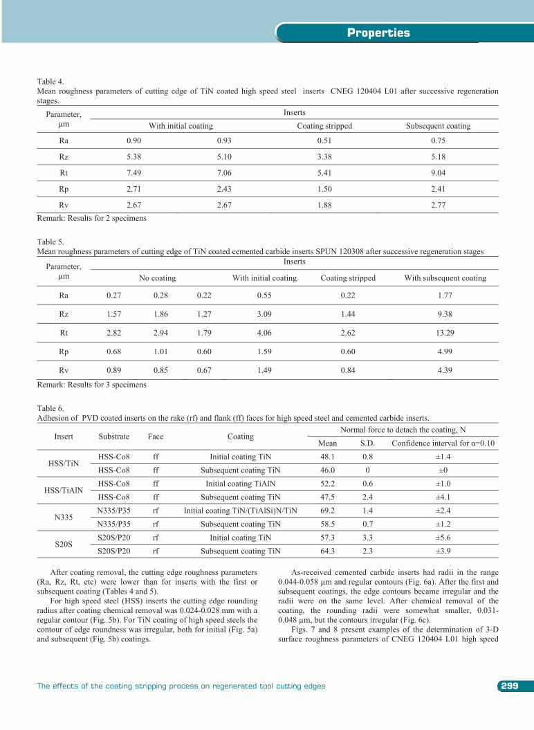
Table 4. Mean roughness parameters of cutting edge of TiN coated high speed steel inserts CNEG 120404 L01 after successive regeneration stages.
Parameter, µm
Inserts With initial coating Coating stripped Subsequent coating
Ra 0.90 0.93 0.51 0.75
Rz 5.38 5.10 3.38 5.18
Rt 7.49 7.06 5.41 9.04
Rp 2.71 2.43 1.50 2.41
Rv 2.67 2.67 1.88 2.77 Remark: Results for 2 specimens Table 5. Mean roughness parameters of cutting edge of TiN coated cemented carbide inserts SPUN 120308 after successive regeneration stages
Parameter, µm
Inserts
No coating With initial coating Coating stripped With subsequent coating
Ra 0.27 0.28 0.22 0.55 0.22 1.77
Rz 1.57 1.86 1.27 3.09 1.44 9.38
Rt 2.82 2.94 1.79 4.06 2.62 13.29
Rp 0.68 1.01 0.60 1.59 0.60 4.99
Rv 0.89 0.85 0.67 1.49 0.84 4.39
Remark: Results for 3 specimens Table 6. Adhesion of PVD coated inserts on the rake (rf) and flank (ff) faces for high speed steel and cemented carbide inserts.
Insert Substrate Face Coating Normal force to detach the coating, N
Mean S.D. Confidence interval for α=0.10
HSS/TiN HSS-Co8 ff Initial coating TiN 48.1 0.8 ±1.4 HSS-Co8 ff Subsequent coating TiN 46.0 0 ±0
HSS/TiAlN HSS-Co8 ff Initial coating TiAlN 52.2 0.6 ±1.0 HSS-Co8 ff Subsequent coating TiN 47.5 2.4 ±4.1
N335 N335/P35 rf Initial coating TiN/(TiAlSi)N/TiN 69.2 1.4 ±2.4 N335/P35 rf Subsequent coating TiN 58.5 0.7 ±1.2
S20S S20S/P20 rf Initial coating TiN 57.3 3.3 ±5.6 S20S/P20 rf Subsequent coating TiN 64.3 2.3 ±3.9
After coating removal, the cutting edge roughness parameters
(Ra, Rz, Rt, etc) were lower than for inserts with the first or subsequent coating (Tables 4 and 5).
For high speed steel (HSS) inserts the cutting edge rounding radius after coating chemical removal was 0.024-0.028 mm with a regular contour (Fig. 5b). For TiN coating of high speed steels the contour of edge roundness was irregular, both for initial (Fig. 5a) and subsequent (Fig. 5b) coatings.
As-received cemented carbide inserts had radii in the range 0.044-0.058 µm and regular contours (Fig. 6a). After the first and subsequent coatings, the edge contours became irregular and the radii were on the same level. After chemical removal of the coating, the rounding radii were somewhat smaller, 0.031-0.048 µm, but the contours irregular (Fig. 6c).
Figs. 7 and 8 present examples of the determination of 3-D surface roughness parameters of CNEG 120404 L01 high speed
299
Properties
The effects of the coating stripping process on regenerated tool cutting edges
TableCoat
face
rakflan
1/ num a)
b)
c)
Fig. of CNstagethe T
e 3. ing thicknesses
Insert type
e
ke Mean1 nk Mean2
mber of measure
5. Examples of NEG 120404 L0es: a) with initiaTiN coating c) w
on the rake and
HSS/TiN
Initial coating
TiN
Subsco
T
1.7 3.2
ements n=2, 2/ nu
f measurement o01 HSS/TiN inseal TiN coating, with subsequent T
flank faces of hi
N
sequent oating TiN
IniticoatinTiAl
1.8 1.82.5 3.5
umber of measur
of cutting edge rerts after varioub) after chemic
TiN coating.
igh speed steel (C
HSS/TiAlN
al ng lN
Subsequecoating
TiN
8 2.5 5 3.1
rements n=4
rounding radii s regeneration
cal removal of
HSS) and cemenCoating thicknes
ent g Initial c
TiN/(TiAl
4.3.
a)
b)
c)
d)
Fig. 6. ExamSPUN 1203a) without removal of t
nted carbide (HMss, μm
HM - N335
coating lSi)N/TiN
SuC
.6
.0
mples of measur308 HM/TiN incoating b) withthe TiN coating
M) inserts
ubsequent Coating
TiN
Inco
T
3.6 22.0 2
rement of cuttingnserts after varioh initial TiN coa
d) with subsequ
HM - S20S
nitial oating TiN
Subseqcoat
TiN
2.6 2.2.0 2.
g edge rounding ous regeneration ating, c) after ch
uent TiN coating
quent ting N
5 2
radii of stages:
hemical
Table 4. Mean roughness parameters of cutting edge of TiN coated high speed steel inserts CNEG 120404 L01 after successive regeneration stages.
Parameter, µm
Inserts With initial coating Coating stripped Subsequent coating
Ra 0.90 0.93 0.51 0.75
Rz 5.38 5.10 3.38 5.18
Rt 7.49 7.06 5.41 9.04
Rp 2.71 2.43 1.50 2.41
Rv 2.67 2.67 1.88 2.77 Remark: Results for 2 specimens Table 5. Mean roughness parameters of cutting edge of TiN coated cemented carbide inserts SPUN 120308 after successive regeneration stages
Parameter, µm
Inserts
No coating With initial coating Coating stripped With subsequent coating
Ra 0.27 0.28 0.22 0.55 0.22 1.77
Rz 1.57 1.86 1.27 3.09 1.44 9.38
Rt 2.82 2.94 1.79 4.06 2.62 13.29
Rp 0.68 1.01 0.60 1.59 0.60 4.99
Rv 0.89 0.85 0.67 1.49 0.84 4.39
Remark: Results for 3 specimens Table 6. Adhesion of PVD coated inserts on the rake (rf) and flank (ff) faces for high speed steel and cemented carbide inserts.
Insert Substrate Face Coating Normal force to detach the coating, N
Mean S.D. Confidence interval for α=0.10
HSS/TiN HSS-Co8 ff Initial coating TiN 48.1 0.8 ±1.4 HSS-Co8 ff Subsequent coating TiN 46.0 0 ±0
HSS/TiAlN HSS-Co8 ff Initial coating TiAlN 52.2 0.6 ±1.0 HSS-Co8 ff Subsequent coating TiN 47.5 2.4 ±4.1
N335 N335/P35 rf Initial coating TiN/(TiAlSi)N/TiN 69.2 1.4 ±2.4 N335/P35 rf Subsequent coating TiN 58.5 0.7 ±1.2
S20S S20S/P20 rf Initial coating TiN 57.3 3.3 ±5.6 S20S/P20 rf Subsequent coating TiN 64.3 2.3 ±3.9
After coating removal, the cutting edge roughness parameters
(Ra, Rz, Rt, etc) were lower than for inserts with the first or subsequent coating (Tables 4 and 5).
For high speed steel (HSS) inserts the cutting edge rounding radius after coating chemical removal was 0.024-0.028 mm with a regular contour (Fig. 5b). For TiN coating of high speed steels the contour of edge roundness was irregular, both for initial (Fig. 5a) and subsequent (Fig. 5b) coatings.
As-received cemented carbide inserts had radii in the range 0.044-0.058 µm and regular contours (Fig. 6a). After the first and subsequent coatings, the edge contours became irregular and the radii were on the same level. After chemical removal of the coating, the rounding radii were somewhat smaller, 0.031-0.048 µm, but the contours irregular (Fig. 6c).
Figs. 7 and 8 present examples of the determination of 3-D surface roughness parameters of CNEG 120404 L01 high speed

Research paper300
Journal of Achievements in Materials and Manufacturing Engineering
D. Toboła, K. Czechowski, I. Wrońska, A. Łętocha, T. Miller
Volume 61 Issue 2 December 2013
steel inserts and SPUN 120308 cemented carbide inserts, respectively after successive stages of regenerations. The coating removal process did not cause unfavourable changes in the roughness parameter Ra, or increase the roughness of the rake faces.
a)
b)
c)
Fig. 7. 3-D surface roughness parameters of the rake faces of CNEG 120404 L01 HSS/TiN inserts after various regeneration stages: a) with initial TiN coating, b) after chemical removal of the TiN coating c) with subsequent TiN coating
a)
b)
c)
d)
Fig. 8. 3-D surface roughness parameters of the rake faces of SPUN 120308 HM/TiN inserts after various regeneration stages: a) insert prior initial coating deposition, b) with initial TiN coating, b) after chemical removal of the TiN coating, c) with subsequent TiN coating
Table 5 lists the adhesion results for both substrates and the first and subsequent coatings. Critical loads tend to be marginally lower for subsequent coatings. In the case of S20S cemented carbide inserts with the TiN coating, however, the situation is reversed. It should be stressed that in this case the first and subsequent coatings were both of TiN, deposited with the same PVD method and processing parameters. This indicates that there was no deleterious effect of chemical coating removal on adhesion of the subsequent coating.
4. Conclusions The methods and chemicals used for removal of the initial
PVD TiN, TiAlN and TiN/(TiAlSiN)/TiN coatings from high speed steel and cemented carbide inserts proved effective. The stripping process did not cause unfavourable changes in the roughness parameter Ra, or increase the roughness of the cutting edge. Subsequent coatings had similar, or a little lower, thicknesses than the original, and somewhat higher roughness. Subsequent coats had a marginally lower adhesion, but in the case of TiN coated S20S cemented carbide, the latter coating had even slightly better adhesion than the original. Surface analyses showed that the PVD coating stripping methods were effective for TiN and TiAlN coated high speed steel HS6-5-2 and commercially TiN/(TiAlSi)N/TiN coated cemented carbide. References [1] T. Cselle, Series 11 Equipment with for coating generations,
Werkzeug Technik 134 (2013) 2-7. [2] K. Czechowski, I. Wronska, Nanostructural coatings on the
cutting tools, Mechanik 12 (2011) 964-967 (in Polish). [3] T. Cselle, Dedication - integration - open source, new rules
in the coating industry (and in progressive economics), Werkzeug Technik, 118 (2011) 2-7.
[4] S. Woods, Coat, please; there is more to recoating cutting tools than meets the eye, Cutting tool engineering 56 (2004) 51-56.
[5] T. Cselle, O. Coddet, C. Galamand, P. Holubar, TripleCoatings3® - New Generation of PVD-Coatings for Cutting Tools. Journal of Machine Manufacturing XLIX E1 (2009) 19-25.
[6] L.A. Dobrzański, A.D. Dobrzańska-Danikiewicz, Forming of surface structure and properties of engineering materials Publishing house Silesian University of Technology 2013 (in Polish).
[7] A.D. Dobrzańska-Danikiewicz, The development perspectives on Physical Vapour Deposition technologies,
Journal of Achievements in Materials and Manufacturing Engineering 54/1 (2012) 103-109.
[8] L.A. Dobrzański, M. Staszuk, M. Pawlyta, W. Kwaśny, M. Pancielejko, Characteristics of Ti(C,N) and (Ti,Zr)N gradient PVD coatings deposited onto sintered tool materials, Journal of Achievements in Materials and Manufacturing Engineering 31/2 (2008) 629-634.
[9] L.A. Dobrzański, S. Skrzypek, D. Pakuła, J. Mikuła, A.Křiž, Influence of the PVD and CVD technologies on the residual macro-stresses and functional properties of the coated tool ceramics, Journal of Achievements in Materials and Manufacturing Engineering 35/2 (2009) 162-168.
[10] L.A. Dobrzański, L.W. Żukowska, Gradient PVD coatings deposited on the sintered tool materials. Archives of Materials Science and Engineering 48/2 (2011) 103-111.
[11] D. Pakuła, M. Staszuk, L.A. Dobrzański, Investigations of the structure and properties of PVD coatings deposited onto sintered tool materials, Archives of Materials Science and Engineering 58/2 (2012) 219-226.
[12] I. Wronska, K. Czechowski, D. Toboła, P. Bednarski, B. Królicka, Possibilietes of coated cutting tools reconditioning (in Polish), Inżynieria Materiałowa 32/4 (2011) 797-800.
[13] A. Rutkowska, M. Dąbrowki, R. Mania, The regeneration of TiN (Titanium Nitride) coatings on tool materials, Materials Engineering 27/3 (2006) 519-521 (in Polish).
[14] S. Marimuthu, A.M. Kamara, D. Whitehead, P.T. Mativenga, L.Li, Laser removal of TiN coatigs from WC micro-tools and in process monitoring, Optics and Laser Technology 42 (2010) 1233-1239.
[15] T. Szubrycht, Removal of titanium nitride coatings from the cutting tools surfaces by means of chemical methods, Maintenance Problems 4 (1999) 167-171 (in Polish).
[16] R. Rebole, Microstructural and tribological investigations of CrN coated, wet-stripped and recoated functional substrates used for cutting and forming tools, Thin Solid Films 469-470 (2004) 466-471.
[17] L.C. Ardila, C.M. Moreno, J.M. Sanchez, Electrolytic removal of chromium rich PVD coatings from hardmetals substrates, Int. Journal of Refractory Metals and Hard Materials 28 (2010) 155-162.
[18] D. Bonacchi, Chemical stripping of ceramic films of titanium aluminum nitride from hard metal substrates, Surface and Coatings Technolog 165 (2003) 35-39.
[19] K. Musiałek, K. Czechowski, Hobs geometrical accuracy after regenerative sharpening and PVD hard layers deposition, Proceedings of the framework of the Conference of Gear Wheels KZ’2000, Poznań, 2000, 103-110 (in Polish).
[20] Information materials and technical data: Baku Chemie GmbH, DETEC Detachment Technology, Borer Chemie AG, and absolute Decoating Technology, 2013.
301
Properties
The effects of the coating stripping process on regenerated tool cutting edges
steel inserts and SPUN 120308 cemented carbide inserts, respectively after successive stages of regenerations. The coating removal process did not cause unfavourable changes in the roughness parameter Ra, or increase the roughness of the rake faces.
a)
b)
c)
Fig. 7. 3-D surface roughness parameters of the rake faces of CNEG 120404 L01 HSS/TiN inserts after various regeneration stages: a) with initial TiN coating, b) after chemical removal of the TiN coating c) with subsequent TiN coating
a)
b)
c)
d)
Fig. 8. 3-D surface roughness parameters of the rake faces of SPUN 120308 HM/TiN inserts after various regeneration stages: a) insert prior initial coating deposition, b) with initial TiN coating, b) after chemical removal of the TiN coating, c) with subsequent TiN coating
Table 5 lists the adhesion results for both substrates and the first and subsequent coatings. Critical loads tend to be marginally lower for subsequent coatings. In the case of S20S cemented carbide inserts with the TiN coating, however, the situation is reversed. It should be stressed that in this case the first and subsequent coatings were both of TiN, deposited with the same PVD method and processing parameters. This indicates that there was no deleterious effect of chemical coating removal on adhesion of the subsequent coating.
4. Conclusions The methods and chemicals used for removal of the initial
PVD TiN, TiAlN and TiN/(TiAlSiN)/TiN coatings from high speed steel and cemented carbide inserts proved effective. The stripping process did not cause unfavourable changes in the roughness parameter Ra, or increase the roughness of the cutting edge. Subsequent coatings had similar, or a little lower, thicknesses than the original, and somewhat higher roughness. Subsequent coats had a marginally lower adhesion, but in the case of TiN coated S20S cemented carbide, the latter coating had even slightly better adhesion than the original. Surface analyses showed that the PVD coating stripping methods were effective for TiN and TiAlN coated high speed steel HS6-5-2 and commercially TiN/(TiAlSi)N/TiN coated cemented carbide. References [1] T. Cselle, Series 11 Equipment with for coating generations,
Werkzeug Technik 134 (2013) 2-7. [2] K. Czechowski, I. Wronska, Nanostructural coatings on the
cutting tools, Mechanik 12 (2011) 964-967 (in Polish). [3] T. Cselle, Dedication - integration - open source, new rules
in the coating industry (and in progressive economics), Werkzeug Technik, 118 (2011) 2-7.
[4] S. Woods, Coat, please; there is more to recoating cutting tools than meets the eye, Cutting tool engineering 56 (2004) 51-56.
[5] T. Cselle, O. Coddet, C. Galamand, P. Holubar, TripleCoatings3® - New Generation of PVD-Coatings for Cutting Tools. Journal of Machine Manufacturing XLIX E1 (2009) 19-25.
[6] L.A. Dobrzański, A.D. Dobrzańska-Danikiewicz, Forming of surface structure and properties of engineering materials Publishing house Silesian University of Technology 2013 (in Polish).
[7] A.D. Dobrzańska-Danikiewicz, The development perspectives on Physical Vapour Deposition technologies,
Journal of Achievements in Materials and Manufacturing Engineering 54/1 (2012) 103-109.
[8] L.A. Dobrzański, M. Staszuk, M. Pawlyta, W. Kwaśny, M. Pancielejko, Characteristics of Ti(C,N) and (Ti,Zr)N gradient PVD coatings deposited onto sintered tool materials, Journal of Achievements in Materials and Manufacturing Engineering 31/2 (2008) 629-634.
[9] L.A. Dobrzański, S. Skrzypek, D. Pakuła, J. Mikuła, A.Křiž, Influence of the PVD and CVD technologies on the residual macro-stresses and functional properties of the coated tool ceramics, Journal of Achievements in Materials and Manufacturing Engineering 35/2 (2009) 162-168.
[10] L.A. Dobrzański, L.W. Żukowska, Gradient PVD coatings deposited on the sintered tool materials. Archives of Materials Science and Engineering 48/2 (2011) 103-111.
[11] D. Pakuła, M. Staszuk, L.A. Dobrzański, Investigations of the structure and properties of PVD coatings deposited onto sintered tool materials, Archives of Materials Science and Engineering 58/2 (2012) 219-226.
[12] I. Wronska, K. Czechowski, D. Toboła, P. Bednarski, B. Królicka, Possibilietes of coated cutting tools reconditioning (in Polish), Inżynieria Materiałowa 32/4 (2011) 797-800.
[13] A. Rutkowska, M. Dąbrowki, R. Mania, The regeneration of TiN (Titanium Nitride) coatings on tool materials, Materials Engineering 27/3 (2006) 519-521 (in Polish).
[14] S. Marimuthu, A.M. Kamara, D. Whitehead, P.T. Mativenga, L.Li, Laser removal of TiN coatigs from WC micro-tools and in process monitoring, Optics and Laser Technology 42 (2010) 1233-1239.
[15] T. Szubrycht, Removal of titanium nitride coatings from the cutting tools surfaces by means of chemical methods, Maintenance Problems 4 (1999) 167-171 (in Polish).
[16] R. Rebole, Microstructural and tribological investigations of CrN coated, wet-stripped and recoated functional substrates used for cutting and forming tools, Thin Solid Films 469-470 (2004) 466-471.
[17] L.C. Ardila, C.M. Moreno, J.M. Sanchez, Electrolytic removal of chromium rich PVD coatings from hardmetals substrates, Int. Journal of Refractory Metals and Hard Materials 28 (2010) 155-162.
[18] D. Bonacchi, Chemical stripping of ceramic films of titanium aluminum nitride from hard metal substrates, Surface and Coatings Technolog 165 (2003) 35-39.
[19] K. Musiałek, K. Czechowski, Hobs geometrical accuracy after regenerative sharpening and PVD hard layers deposition, Proceedings of the framework of the Conference of Gear Wheels KZ’2000, Poznań, 2000, 103-110 (in Polish).
[20] Information materials and technical data: Baku Chemie GmbH, DETEC Detachment Technology, Borer Chemie AG, and absolute Decoating Technology, 2013.
4. conclusions
references
Copyright © 2022 FDOKUMEN