The Dry Sliding Wear Behavior of Interpenetrating Titanium Trialuminide/Aluminium Composites
16
The Dry Sliding Wear Behavior of Interpenetrating Titanium Trialuminide/Aluminium Composites Shouren Wang & Yong Wang & Changchun Li & Qing Chi & Zhenyi Fei Received: 10 January 2007 / Accepted: 18 June 2007 / Published online: 21 July 2007 # Springer Science + Business Media B.V. 2007 Abstract Owing to the brittle reinforced phase are introduced into ductile matrix phase, metal–intermetallic interpenetrating composites exhibit various types of wear mechanism such as adhesive, abrasive, and fatigue wear. In present work, the wear model has been proposed according to the mixing rule. Many factors such as special topology structure characteristic of reinforcement and elastic module were discussed in this model. The model based on the maximal and minimal hypothesis posts the mathematic relation among volume content of reinforcement, elastic module and wear rate. Increase in the volume fraction of reinforcement leads to improvement in the wear resistance. Unlike the Khruschov model and Zum-Gahr model, the proposed model was no longer follow linear rule. One kind of Al 3 Ti/Al composite with different volume content was fabricated and many wear test data were obtained to validate the correctness and universality of the model. Keywords Interpenetrating composites . Dry sliding wear . Wear model . Wear mechanism 1 Introduction Metal–ceramic interpenetrating composites (MC-IPCs) have attracted much interest in regard to lightweight structural, wear resistant components and other applications over the past 10 years [1]. However, the large performance difference and poor wettability between ceramic and metal limit the progress of MC-IPCs from the point of theoretical studies and practical applications [2]. Intermetallic compounds generally have a much better wettability with liquid metals [3], greater ductility and higher mechanical and thermal compatibility Appl Compos Mater (2007) 14:129–144 DOI 10.1007/s10443-007-9036-0 S. Wang (*) : C. Li : Q. Chi School of Mechanical Engineering, Ji’nan University, Jinan 250022, China e-mail: [email protected] Y. Wang School of Science, Ji’nan University, Jinan 250022, China Z. Fei Centrue of Materials Testing, Sandong University, Jinan 250014, China
-
Upload
independent -
Category
Documents
-
view
0 -
download
0
Transcript of The Dry Sliding Wear Behavior of Interpenetrating Titanium Trialuminide/Aluminium Composites

The Dry Sliding Wear Behavior of InterpenetratingTitanium Trialuminide/Aluminium Composites
Shouren Wang & Yong Wang & Changchun Li &Qing Chi & Zhenyi Fei
Received: 10 January 2007 /Accepted: 18 June 2007 /Published online: 21 July 2007# Springer Science + Business Media B.V. 2007
Abstract Owing to the brittle reinforced phase are introduced into ductile matrix phase,metal–intermetallic interpenetrating composites exhibit various types of wear mechanismsuch as adhesive, abrasive, and fatigue wear. In present work, the wear model has beenproposed according to the mixing rule. Many factors such as special topology structurecharacteristic of reinforcement and elastic module were discussed in this model. The modelbased on the maximal and minimal hypothesis posts the mathematic relation among volumecontent of reinforcement, elastic module and wear rate. Increase in the volume fraction ofreinforcement leads to improvement in the wear resistance. Unlike the Khruschov modeland Zum-Gahr model, the proposed model was no longer follow linear rule. One kind ofAl3Ti/Al composite with different volume content was fabricated and many wear test datawere obtained to validate the correctness and universality of the model.
Keywords Interpenetrating composites . Dry sliding wear . Wear model . Wear mechanism
1 Introduction
Metal–ceramic interpenetrating composites (MC-IPCs) have attracted much interest inregard to lightweight structural, wear resistant components and other applications over thepast 10 years [1]. However, the large performance difference and poor wettability betweenceramic and metal limit the progress of MC-IPCs from the point of theoretical studies andpractical applications [2]. Intermetallic compounds generally have a much better wettabilitywith liquid metals [3], greater ductility and higher mechanical and thermal compatibility
Appl Compos Mater (2007) 14:129–144DOI 10.1007/s10443-007-9036-0
S. Wang (*) : C. Li : Q. ChiSchool of Mechanical Engineering, Ji’nan University, Jinan 250022, Chinae-mail: [email protected]
Y. WangSchool of Science, Ji’nan University, Jinan 250022, China
Z. FeiCentrue of Materials Testing, Sandong University, Jinan 250014, China

with the metallic matrix. Therefore, metal–intermetallic interpenetrating composites (MI-IPCs) have attracted considerable attention as result of their unique mechanical properties,which can be widely used in aerospace and automotive industries and other structuralapplications. Especially, Composites reinforced by titanium trialuminide (Al3Ti) have thepotential for use in aerospace applications owing to Al3Ti intermetallic’s higher Young’smodulus (216 GPa) [4], combined with lower density (3.3 g cm−3) [5], higher melting point(1,350 °C) [6] and excellent oxidation resistance [7]. Moreover, interpenetrating compositeshave a large use in the occlusal contact area accompanying with high forces, such asmechanical production of oil pump, piston, die and bearing [8–10].
Wear resistance of composites can generally be enhanced by introducing a secondaryphase (s) including particles, whisker, short fibre and long fibre into the matrix materials.There is a plethora of papers by experimentalists who have studied the wear behavior of thecomposites reinforced by those secondary phases [11–13]. There has been, however, littlework, to study the sliding wear behavior of MI-IPCs. The abrasive wear resistance of MI-IPCs has been found to be significantly lower than that of metal owing to the changes ofmicrostructure, the morphology, the volume fraction and mechanical properties of three-dimension (3-D) network reinforcing phase, and the nature state of the interface betweenmatrix and reinforcement.
In present paper, an attempt has been made to evaluate the dry sliding wear behavior ofMI-IPCs over a range of loads and sliding speeds. One model for the sliding wear of MI-IPCs was proposed, at the same time, wear mechanisms of MI-IPCs were discussed.
2 Experimental Procedure
Pure elemental powders, Al (99.99% purity), Ti (99.5% purity) and Cr (99.9% purity),particle sizes smaller than 100 μm, were used as starting materials. Ternary Al67Ti25Cr8mixture was fabricated by mechanical alloying technique and annealing process.Mechanical alloying was carried out in a planetary ball miller (QM-1SP2, rotation speed,400 r/min; milling time, 40 h). The standard hardened steel cylindrical vial was loaded withpowders and Al2O3 balls. The loaded vial was filled argon and was sealed in the glove box.The as-milled powders were annealed in an electrical resistance furnace. The microstructureand morphology of as-billed and as-annealed powders were shown in Fig. 1. As-annealed
Fig. 1 The microstructure and morphology of as-billed (a) and as-annealed (b) powders
130 Appl Compos Mater (2007) 14:129–144

Al67Ti25Cr8 ((Al, Cr)3Ti) powders(which Particle size and distribution were shown inFig. 2) were mixed with Al powders (5 wt%) in a planetary miller (QM-1SP2, rotationspeed as 200 r /min, milling time as 2 h). Composite powders of (Al, Cr)3Ti+Al werechosen as starting material. Reticulated polyurethane was chosen as a template to preparethe porous preform by replication technology in argon atmosphere. Commercial purity Alingot (99.7% in wt.) was melted in a clay–graphite crucible under Ar atmosphere. Theliquid metal was infiltrated into the preform by pressure infiltration technology (whichSchematic diagram of the experimental setup is shown in Fig. 3). MI-IPCs reinforced bydifferent volume fraction as 8, 12 15 20, 25, 30%, respectively, were fabricated. The micro-structural characterization of MI-IPCs and porous perform were performed on a scanningelectron microscope (SEM. Hitachi, S-2500) which was shown in Fig. 4.
The specimens were subjected to wear test under dry sliding condition. The tests wereconducted on 6-mm diameter, 35-mm-long cylindrical specimens against a rotating steeldisc which is covered by corundum sand paper. A pin-on-disc wear test machine was usedfor carrying out wear tests (Fig. 5). The tangential friction force and wear depth weremonitored with the help of electronic sensors. These two parameters were measured as afunction of load and sliding distance. For each type of material, tests were conducted at four
Fig. 2 Particle size and distribu-tion of Al67Ti25Cr8 powders
Appl Compos Mater (2007) 14:129–144 131

different nominal loads (10, 20, 30 and 40 N) keeping the sliding speed fixed at 120 m/min.Wear tests were carried out at room temperature without lubrication for 20 min.
3 Results and Discussion
3.1 Wear Model Assumption
There are lots of models for dry sliding wear of composites presented. Khruschov andBabichev [14] first studied the abrasive wear of heterogeneous or multi-phase materials andproposed the model as follows,
1
WC¼ VM
WMþ VR
WRð1Þ
Where W and V are, respectively, the wear rates and volume fractions of the matrix (M)and reinforcement (R). Zum-Gahr [15] introduced an inverse mathematics model in theform:
WC ¼ VMWM þ VRWR ð2ÞEquation 1 is based on the assumption that the components of the composite wear at an
equal rate. Consequently, Khruschov’s equation predicts that the abrasive wear rates (bereciprocal to the wear resistance) fall the non-linear relationship. Contrarily, the wear ratesexpressed in Eq. 2 is linearly proportional to its volume fraction in composite. Khruschovmodel showed that the abrasive wear behavior is governed primarily by the reinforcementsince the wear rate of the harder reinforcement is typically much smaller than that of thematrix. Zum-Gahr model showed that the wear behavior of a composite is not dominated bya single phase but the common contribution from each component of composites. Axen andJacobson [16] drew the similar conclusion. Yen and Dharan [17] proposed a cyclic wear
Fig. 3 Schematic diagram of theexperimental setup
132 Appl Compos Mater (2007) 14:129–144

model for oriented fiber composites. Unlike above steady state wear, the proposed model iscyclic in nature in which fiber and matrix do not always wear at the same rate, fiberinstability due to preferential wear of the softer matrix resulted in cyclic generation of weardebris during the wear process. Owing to consider the composite modulus (E), Yen–Dharanmodel proposed maximum wear assumption and minimum wear assumption and made amodification for Khruschov model and Zum-Gahr model which were shown as follows,
WCEC ¼ VMEMWM þ VRERWR ð3Þ
WCEC ¼ WMEM ð4Þ
Fig. 4 Morphology of MI-IPCs(b) and porous preform (a)
Appl Compos Mater (2007) 14:129–144 133

However, interface toughness and other physically based factors were not considered inYen–Dharan model. Lee [18] considered the factors as plowing, cracking, interface andparticle removal and modified the Khruschov model as follows,
1
WC¼ VM
WMþ C
VR
WRVR � 0:5 ð5Þ
C ¼ 1� xþ aintDR
� �crack at interfaceð Þ ð5:1Þ
C ¼ 1� aRDR
� �crack in reinforcementð Þ ð5:2Þ
Where x is the depth of penetration of the abrasive medium, aint is the size of theinterfacial crack, DR is the size of the reinforcement and C is the contribution coefficientparameter, represents the effect of critical factors, including the fracture toughness and therelative size of the reinforcement. Y.Lee model accurate predict the wear rate of compositesreinforced by particle and provided the theory bases of tribology in novel compositesdesigning.
For interpenetrating composites reinforced by 3-D network structure, above models isrestricted by the topology structure, porosity, pore and strut shape and elastic module ofreinforcement. Consequently, a model for the abrasive wear of MI-IPCs is necessary to beproposed.
The reticulated reinforcement exhibit a special geometrical topology structurecharacteristic which model is shown in Fig. 6a [19]. The model of MI-IPCs is shown inFig. 6b. Due to the special structure characteristic, MI-IPCs exhibit high wear resistanceand other mechanical properties.
Fig. 5 Schematic experimentalsetup for carrying out the weartests
134 Appl Compos Mater (2007) 14:129–144

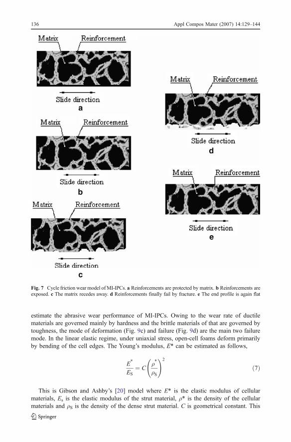
The overall wear processes that can be considered to be a quasi-steady state process aredivided into four stage as initial stage, continual stage, middle stage and final stage andeach individual stage is not steady state process. This cyclic wear process is illustratedschematically in Fig. 7. In initial abrasive wear process, the wear surface is surrounded bymatrix material that is subjected to compressive loading. Owing to relatively soft andductile performance of the matrix (Fig. 7a), this stage is relatively short and considered asthe conventional wear mechanism. With the continuing abrasive wear, the reinforcementphase is gradually exposed and the compressive load is carried by matrix and reinforcementtogether. Owing to the high modulus of reinforcement relative to the matrix, however, thisstage is hold for long time (Fig. 7b). With the wear processes going on, the soft and ductilematrix gradually recedes away and the compressive load is carried primarily byreinforcement phase (Fig. 7c). In the finial stage, the exposed reinforcement phase finallyfailed by fracture due to its brittleness (Fig. 7d). Then the wear surface turn flat and the firststage repeat again. This cyclic processes result in the removal of materials and occurrenceof abrasive wear.
Whether the brittle phase is introduced into the ductile-matrix or the soft phase is mixedinto the brittle-matrix, the wear resistance of composites reduced significantly. Figure 8predicted the abrasive wear of single-phase materials and multi-phase materials. Equations 1and 2 represent the lower and upper limit of composites. Equation 5 under the condition ofC=0 represent the wear rate of ductile matrix. In brittle-matrix materials, Eq. 5 can bemodified as follows:
1WC
¼ VRWR
þ C VMWM
VM � 0:5 ð6Þ
Equation 6 under the condition of C=0 represent the wear rate of brittle matrix. Abovepredictions is perfect and limited but not suit the predicted abrasive wear of MI-IPCs.
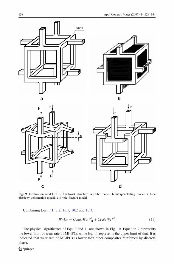
Owing to the special topology structure of MI-IPCs, the distributions of compressiveloads carried by reinforcement are different from the discrete phase reinforcement.Idealization models of 3-D network structure (which were shown in Fig. 9) can be usedto estimate their mechanical properties based on the mechanisms of deformation andfailure. The cubic model of 3-D network structure (Fig. 9a) exhibits the larruping propertieswhile another cubic model interpenetrated by secondary phase (Fig. 9b) can be used to
Fig. 6 3-D geometry model of MI-IPCs and its reinforcement (a reinforcement with network structure;b MI-IPCs)
Appl Compos Mater (2007) 14:129–144 135
estimate the abrasive wear performance of MI-IPCs. Owing to the wear rate of ductilematerials are governed mainly by hardness and the brittle materials of that are governed bytoughness, the mode of deformation (Fig. 9c) and failure (Fig. 9d) are the main two failuremode. In the linear elastic regime, under uniaxial stress, open-cell foams deform primarilyby bending of the cell edges. The Young’s modulus, E* can be estimated as follows,
E*
ES¼ C
ρ*
ρS
!2
ð7Þ
This is Gibson and Ashby’s [20] model where E* is the elastic modulus of cellularmaterials, Es is the elastic modulus of the strut material, ρ* is the density of the cellularmaterials and ρS is the density of the dense strut material. C is geometrical constant. This
a
b
c
d
e
Fig. 7 Cycle friction wear model ofMI-IPCs. a Reinforcements are protected by matrix. b Reinforcements areexposed. c The matrix recedes away. d Reinforcements finally fail by fracture. e The end profile is again flat
136 Appl Compos Mater (2007) 14:129–144

equation is valid for completely open cellular materials. The relative density ρ*=ρS� �
isequal to the volume fraction of reinforcement,
E*MEMS
¼ CMρ*MρMS
!2
¼ CMV2M ð7:1Þ
E*RERS
¼ CRρ*RρRS
!2
¼ CRV2R ð7:2Þ
Equation 3 can be modified as follows,
WCEC ¼ VMWME*M þ VRWRE
*R ð8Þ
Combing Eqs. 3, 7, 7.1 and 7.2,
WCEC ¼ CMWMEMSV3M þ CRWRERSV
3R ð9Þ
When only considered single phase the wear rate can be described as
WCR ¼ E*REC
WR ð10:1Þ
WCM ¼ E*MEC
WM ð10:2Þ
According to the mixing rule,
WC ¼ WCM þWCR ð10:3Þ
Fig. 8 Predicted abrasive wearof composites
Appl Compos Mater (2007) 14:129–144 137
Combining Eqs. 7.1, 7.2, 10.1, 10.2 and 10.3,
WCEC ¼ CMEMWMV2M þ CRERWRV
2R ð11Þ
The physical significance of Eqs. 9 and 11 are shown in Fig. 10. Equation 9 representsthe lower limit of wear rate of MI-IPCs while Eq. 11 represents the upper limit of that. It isindicated that wear rate of MI-IPCs is lower than other composites reinforced by discretephase.
Fig. 9 Idealization model of 3-D network structure. a Cube model. b Interpenetrating model. c Lineelasticity deformation model. d Brittle fracture model
138 Appl Compos Mater (2007) 14:129–144

3.2 Wear Model Validation
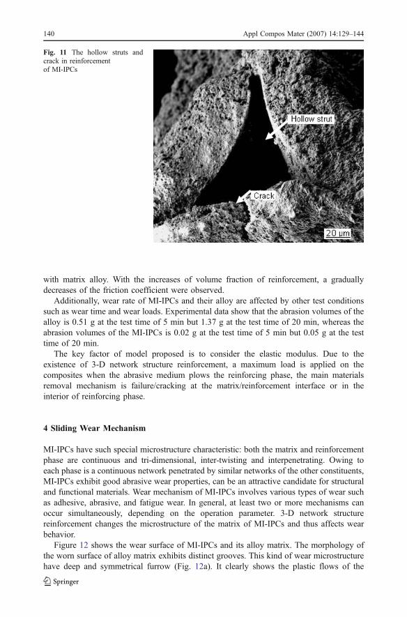
The validity of the proposed wear model can be examined by comparing its theoreticalpredictions with experimental data. Yen [17] measured the wear resistance of unidirectionalfiber-reinforced polymer composites and Lee [12] measured the wear resistance ofaluminum particulate-reinforced epoxy-matrix composites, the results of experimental datavalidate the proposed model. Similarly, the test results from the wear measurements andmodel forecast for MI-IPCs were summarized in Table 1. Specific wear rate WC, which isthe measure of removed volume per unit slide distance and unit load, was estimated by twodifferent methods [21]. Firstly, WCm was calculated from the mass loss of the specimen,determined by weighing the specimen before and after the test. Secondly, WCC wasestimated from the wear curves in Fig. 10. It is indicated that the wear rate of MI-IPCsdecreases gradually with the increases of volume fraction of reinforcement. The wear rateof the alloy matrix increases rapidly while MI-IPCs turn slowly. Obviously, wear ratedecrease with the increasing of the content of Al3Ti phase. Owing to the cracking in strutsof preform or at the matrix/reinforcement interface and existing hollow structure in struts(Fig. 11), causing the decreases of fracture toughness and elastic modulus, the experimentaldata partly exceed the upper limit of the model and mostly fall in the upside of the region. Itis also indicated that friction coefficient of MI-IPCs is substantially changed in comparison
Table 1 Test results from the wear measurements and model forecast
Specimen Wcm Wcc f[mm3/(km)−1] [mm3/(km)−1]
Al matrix 8.6±0.3 7.9 0.338% Al3Ti/Al 7.5±0.3 6.8–7.7 0.2612% Al3Ti/Al 6.9±0.3 5.5–7.4 0.2215% Al3Ti/Al 5.1±0.3 4.4–6.0 0.1820% Al3Ti/Al 4.9±0.3 3.8–5.5 0.1625% Al3Ti/Al 4.5±0.3 3.0–4.8 0.1330% Al3Ti/Al 3.6±0.3 2.7–4.0 0.10
Fig. 10 Predicted abrasive wearof MI-IPCs
Appl Compos Mater (2007) 14:129–144 139
with matrix alloy. With the increases of volume fraction of reinforcement, a graduallydecreases of the friction coefficient were observed.
Additionally, wear rate of MI-IPCs and their alloy are affected by other test conditionssuch as wear time and wear loads. Experimental data show that the abrasion volumes of thealloy is 0.51 g at the test time of 5 min but 1.37 g at the test time of 20 min, whereas theabrasion volumes of the MI-IPCs is 0.02 g at the test time of 5 min but 0.05 g at the testtime of 20 min.
The key factor of model proposed is to consider the elastic modulus. Due to theexistence of 3-D network structure reinforcement, a maximum load is applied on thecomposites when the abrasive medium plows the reinforcing phase, the main materialsremoval mechanism is failure/cracking at the matrix/reinforcement interface or in theinterior of reinforcing phase.
4 Sliding Wear Mechanism
MI-IPCs have such special microstructure characteristic: both the matrix and reinforcementphase are continuous and tri-dimensional, inter-twisting and interpenetrating. Owing toeach phase is a continuous network penetrated by similar networks of the other constituents,MI-IPCs exhibit good abrasive wear properties, can be an attractive candidate for structuraland functional materials. Wear mechanism of MI-IPCs involves various types of wear suchas adhesive, abrasive, and fatigue wear. In general, at least two or more mechanisms canoccur simultaneously, depending on the operation parameter. 3-D network structurereinforcement changes the microstructure of the matrix of MI-IPCs and thus affects wearbehavior.
Figure 12 shows the wear surface of MI-IPCs and its alloy matrix. The morphology ofthe worn surface of alloy matrix exhibits distinct grooves. This kind of wear microstructurehave deep and symmetrical furrow (Fig. 12a). It clearly shows the plastic flows of the
Fig. 11 The hollow struts andcrack in reinforcementof MI-IPCs
140 Appl Compos Mater (2007) 14:129–144

matrix accompanied by the wear debris are observed. The depths of the plastic flow regionwhich was found to be 50 μm were measured. This wear mechanism belongs to adhesivewear which is shown in Fig. 13.
The formation of a hard surface consisting of fragmented and dispersed Al3Ti debrishelps in preventing adhesion. As a result, transition from adhesive wear to abrasion wearoccurs (Fig. 14) and concomitantly the wear rate is reduced as a result of removal of wear
Fig. 13 Adhesion wear mechanism of MI-IPCs
Fig. 12 Wear surface of a Alalloy and b Al3Ti–Al interpene-trating composites
Appl Compos Mater (2007) 14:129–144 141

debris at a lower rate. During the abrasion wear process, the reinforced phases were crushedinto small fragments regardless of their original length, during sliding wear as a result ofcontact pressure and frictional effects. It is shown from Fig. 12b that the depth of furrow ofMI-IPCs becomes narrower and shallower, the furrow becomes non-distinct but somepulling injures caused by the big grain breaking off from the Al3Ti intermetallicreinforcement phase.
Another wear mechanism is defined to occur when two contacting surfaces are subjectedto reciprocating motion. Fatigue stress under reciprocating load cause fatigue cracks in MI-IPCs not only matrix but also reinforcement. Fatigue cracks expand and cause materialsfracture finally. This called surface fatigue wear failure mechanism which is shown inFig. 15. Some wear debris caused by fatigue wear failure were observed in wear surface(arrow in Fig. 12b).
5 Conclusions
A model for abrasive wear of MI-IPCs is proposed based on the lower and upper extremecyclic wear behavior. Owing to the special topology structure characteristic, aluminumalloy reinforced with Al3Ti network structure can improve dry sliding wear resistance.Reinforcements inhibit plastic flow and restrict propagation of wear cracks. However, due
Fig. 15 Surface fatigue wear failure mechanism of MI-IPCs
Fig. 14 Abrasion wear mecha-nism of MI-IPCs
142 Appl Compos Mater (2007) 14:129–144

to the cracking in struts or at matrix/reinforcement interface and hollow struts, the fracturetoughness and elastic modulus of MI-IPCs deceased, therefore, the wear rate increaseappreciably compared with the theoretical model. Increase in the volume fraction ofreinforcement leads to improvement in the wear resistance. Reinforcements are crushed intosmall pieces regardless of the morphology of original reinforcement present in thecomposite, hence wear resistance of composite is marginally affected by the reinforcementvolume fraction. The wear mechanisms in MI-IPCs could be classified into three modes:adhesive wear, abrasion wear and fatigue wear failure.
Acknowledgements This work was supported by the Natural Science Foundation of Shandong Province(Y2006F03, Y2003F01) and scientific research development project of Shandong Education Office(J05B02). Part of this research was done at the Institute of Materials Science Jinan University. The authorsare owing a debt of gratitude to the technical staff of institutions for their help.
References
1. San Marchi, C., Kouzeli, M., Rao, R., Lewis, J.A., Dunand, D.C.: Alumina aluminium interpenetratingphase composites with three-dimensional periodic architecture. Scr. Mater. 49, 861–866 (2003)
2. Hoffman, M., Skirl, S., Pompe, W.: Thermal residual strain and stresses in Al2O3/Al composites withinterpenetrating networks. Acta Mater. 47, 565–577 (1999)
3. Eustathopoulos, N., Nicholas, M.G., Drevet, B.: Wettability at High Temperatures. Pergamon MaterialsSeries, vol. 3. Elsevier, UK (1999)
4. Nayak, S.S., Murty, B.S.: Synthesis and stability of L12–A13Ti by mechanical alloying. Mater. Sci. Eng.A 367(1/2), 218–224 (2004)
5. Yu, H., Chen, H., Sun, L., Min, G.: Preparation of AI–Al3Ti in situ composites by direct reactionmethod. Rare Met. 25(1), 32–35 (2006)
6. Watanabe, Y., Eryu, H., Matsuura, K.: Evaluation of three-dimensional orientation of A13Ti platelet inAl-based functionally graded materials fabricated by a centrifugal casting technique. Acta Mater. 49(5),775–783 (2001)
7. Zhu, X., Schoenitz, M., Dreizin, E.L.: Oxidation processes and phase changes in metastable Al–Timechanical alloys. Mater. Res. Soc. Symp. Proc. 800, AA3.4.1–AA3.4.6 (2005)
8. Wang, X., Zeng, S., Song, R., Zhang, E.: Dry sliding friction and wear behaviors of TiCp/ ZA212composites. Trans. Nonferr. Met. Soc. China 12(3), 419–423 (2002)
9. Shipway, P.H., Kennedy, A.R., Wilkes, A.J.: Silding wear behaviour of aluminium-based metal matrixcomposites produced by a novel liquid route. Wear 216, 160–171 (1998)
10. Sahin, Y.: The prediction of wear resistance model for the metal matrix composites. Wear 258, 1717–1722 (2005)
11. Cenna, A.A., Allen, S., Page, N.W., Dastoor, P.: Modelling the three-body abrasive wear of UHMWPEparticle reinforced composites. Wear 254, 581–588 (2003)
12. Lee, G.Y., Dharan, C.K.H., Ritchie, R.O.: A physically-based abrasive wear model for compositesmaterials. Wear 252, 322–331 (2002)
13. Fu, H., Han, K., Song, J.: Wear properties of Saffil/Al, Saffil/Al2O3/Al and Saffil/SiC/Al hybrid metalmatrix composites. Wear 256-4, 705–713 (2004)
14. Khruschov, M.M., Babichev, M.A.: Resistance to abrasive wear of structurally heterogeneous materials.Friction Wear Mach. 12, 5–24 (1958)
15. Zum-Gahr, K.H.: Abrasive wear of two-phase metallic materials with a coarse microstructure. In:Ludema, K.C. (ed.) International Conference on Wear of Materials, p. 793. American Society of MaterialEngineering, Vancouver (1985)
16. Axen, N., Jacobson, S.: A model for the abrasive wear resistance of multiphase materials. Wear 174,187–199 (1994)
17. Yen, B.K., Dharan, C.K.H.: Amodel for the abrasive wear of fiber-reinforced polymer composites. Wear195, 123–127 (1996)
18. Lee, G.Y., Dharan, C.K.H., Ritchie, R.O.: A physically-based abrasive wear model for compositesmaterials. Wear 252, 322–331 (2002)
Appl Compos Mater (2007) 14:129–144 143

19. Queheillalt, D.T., Sypeck, D.J., Wadley, H.N.G.: Ultrasonic characterization of cellular metal structures.Mater. Sci. Eng A 323, 138–147 (2002)
20. Gibson, L.J., Ashby, M.F.: Cellular Solids: Structure and Properties, 2nd edn. Cambridge UniversityPress, Cambridge (1997)
21. Ocelık, V., Matthews, D., De Hosson, J.Th.M.: Sliding wear resistance of metal matrix composite layersprepared by high power laser. Surf. Coat. Technol. 197, 303–315 (2005)
144 Appl Compos Mater (2007) 14:129–144