THE DIRECT ANALYSIS METHOD MADE SIMPLE
73
1 THE DIRECT ANALYSIS METHOD MADE SIMPLE Matthew Newton – President Jason Ericksen, SE – Technical Manager CSC Inc
-
Upload
khangminh22 -
Category
Documents
-
view
0 -
download
0
Transcript of THE DIRECT ANALYSIS METHOD MADE SIMPLE
1
THE DIRECT ANALYSIS
METHOD MADE SIMPLE
Matthew Newton – President
Jason Ericksen, SE – Technical Manager
CSC Inc

2
Before We Start
Maximize Screen
Screen saver
Black screen

3
Before We Start
Posing Questions
Listen to Audio:
Use speakers
or
Use telephone

4
Certificate administrationThis Webinar provides 1.0 PDH (0.1 CEU)Provide details at the end
Shared Q&ADistributed following the event
Free Composite Beam Software for each attendeeProvide details at the end
Websitehttp://www.cscworld.com/fastrak/us/
Contact [email protected]: 877 710 2053

5
THE DIRECT ANALYSIS
METHOD MADE SIMPLE
Matthew Newton – President
Jason Ericksen, SE – Technical Manager
CSC Inc

6
Corporate Info
Established in 1975
Structural Engineering Software
Successful, Focussed Business
6,000 customers
60+ employees
Lead Products
TEDDS
Hand Calculations in MS Word
FASTRAK Building Designer…

7
Worldwide Customers

8
Corporate Information
GlobalCSC offices in UK, Malaysia, Singapore, Australia and USA
Partner network
US support office in Chicago
Reputation for quality
Technical presentations commonChief Engineer presents regularly
Jason Ericksen (former-AISC) contributes to AISC technical committees

THE DIRECT ANALYSIS
METHOD MADE SIMPLE
Matthew Newton – President
Jason Ericksen, SE – Technical Manager
CSC Inc
10
Why are we here today?
AISC has made significant changes
Initial imperfections, inelasticity, 2nd
Order Analysis
Direct Analysis Method (DAM)

11
Why are we here today?
Model courtesy of Fisher Engineering

12
What does the DAM mean to you?
Straight-forward Analysis and Design
Improved Results
Less potential for error
K=1.0
13
2005 AISC Specification
Brings ASD and LRFD together
Same nominal strength, Rn
Little change to LRFD
ASD reformatted substantially
No significant change to limit states

14
2005 AISC Specification
Updates Stability Design Requirements
New requirements for analysis
Recognizes current analysis options
Addresses shortcomings of previous methods (K = ?)
Provides straight-forward methods

Seminar Topics
Real world effects in steel buildings
Previous methods
2005 AISC Requirements
Stability Analysis and Design with Modern Software
DAM using FASTRAK Building Designer
15

Real World Effects
P- Delta Effects
Initial Geometric Imperfections
Reduced member stiffness due to inelasticity
16

Real World Effects
P- Delta Effects
P- (Structure Effect)
17
H
P P

Real World Effects
P- Delta Effects
P- (Member Effect)
18
P
H
P

Real World Effects
P- Delta Effects
Nonlinear Response
19
HP P
P, H
First-Order Elastic
Second-Order Elastic
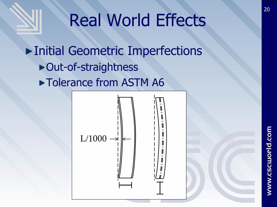
Real World Effects
Initial Geometric Imperfections
Out-of-straightness
Tolerance from ASTM A6
20
L/1000
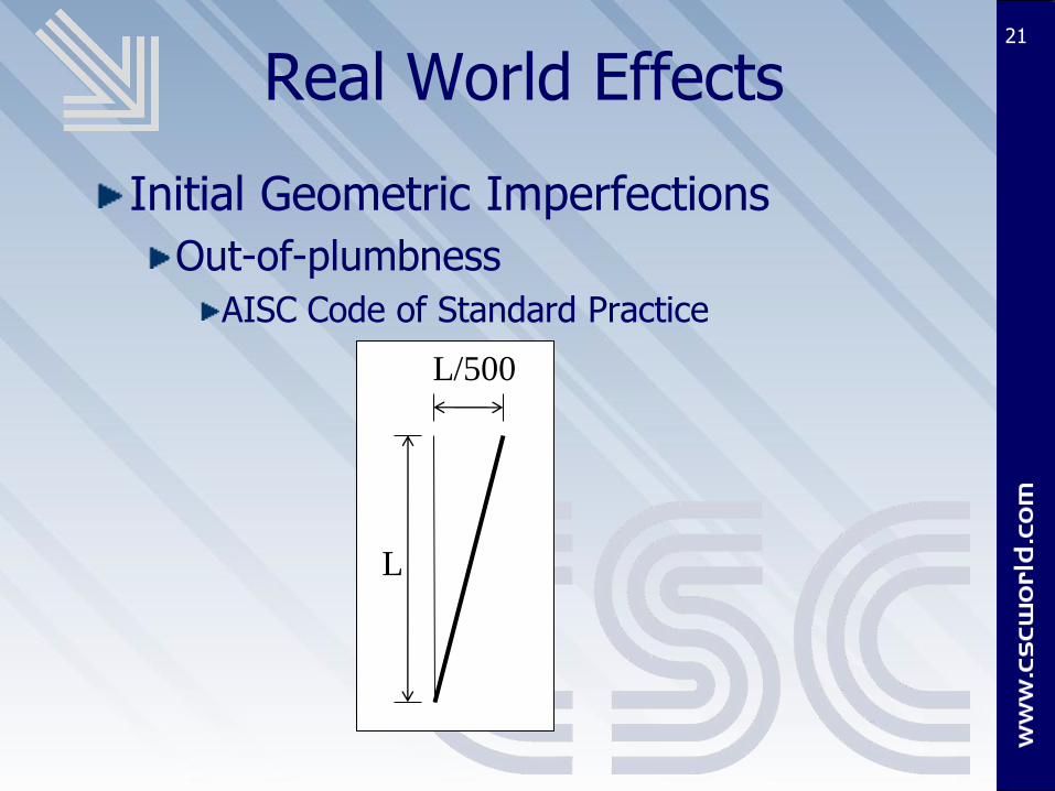
Real World Effects
Initial Geometric Imperfections
Out-of-plumbness
AISC Code of Standard Practice
21
L
L/500
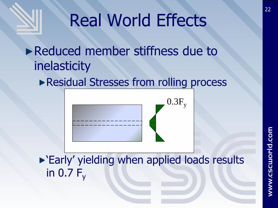
Real World Effects
Reduced member stiffness due to inelasticity
Residual Stresses from rolling process
‘Early’ yielding when applied loads results in 0.7 Fy
22
0.3Fy

Real World Effects
Reduced member stiffness due to inelasticity
Overall stiffness of the section is reduced (tangent modulus)
23
ET
strain
stre
ss

Seminar Topics
Real world effects in steel buildings
Previous methods
2005 AISC Requirements
Stability Analysis and Design with Modern Software
Example using Fastrak Building Designer
24

Before 2005
Analysis Requirements (Demand)
2nd Order Analysis was required!
B1, B2 method been in Specification since 1st
LRFD in 1986
Required in 1989 ASD
Effect of initial imperfections not considered
Effect of inelasticity not considered
25

Before 2005
Design Requirements (Capacity)
Accounts for inelasticity
Accounts for initial imperfections
26
Yielding
Buckling
Theoretical response
Design Curve
KL/r
Pn

Before 2005
Design Requirements (Capacity)
Effective Length Factor, K
Used to compensate for neglecting effects in the analysis
Relates the analysis and design method to ‘actual’ buckling behavior
27
Before 2005
Does K compensate?
Likely will give adequate columns size
Underestimates moments in surrounding members/elements
Underestimates displacements at strength level, including effect on stability
28

Before 2005
Does K compensate? – Example
29
P Even with 2nd Order analysis, base moment = 0 k*ft
K = 2.1 compensates for column design
Base plate (or other supporting elements) will have understated moments

Before 2005
Modern Buildings: Stability Analysis more critical
30

Before 2005
Modern Buildings: Stability Analysis more critical
Higher Strength Steel
More complex geometry
Less often have substantial walls
Less redundancy
Longer spans
Frames are working harder!
31
Before 2005
Other problems with K
Tedious to calculate
Difficult to calculate correctly
Alignment charts based on 9 assumptions that are rarely met in real structures
Behavior is purely elastic
Rotations at opposite ends of restraining beams are equal producing reverse curvature
All columns buckle at the same time
Leaning columns violates this assumption
32

Before 2005
Other problems with K
Can be overly conservative
If not all effects are considered, can be unconservative
33

Seminar Topics
Real world effects in steel buildings
Previous methods
2005 AISC Requirements
Stability Analysis and Design with Modern Software
DAM using FASTRAK Building Designer
34

35
What does the 2005 AISC Specification/DAM mean to you?
K=1.0
Straight-forward Analysis and Design
Real world effects accounted for
When combined with modern software
Improved Results
Less potential for error

2005 AISC Specification
AISC 360-05 (2005 Specification) Chapter C
C1. Stability Design Requirements
C2. Calculation of Required Strength
36

2005 AISC Specification
C1.1 Stability Design Requirements
Any method that considers the influence of the following on the stability of the structure and its elements is permitted.
Second-order effects (P- and P- )
Flexural, shear and axial deformations
Geometric imperfections
Member stiffness reduction due to inelastic behavior (inelasticity)
37

2005 AISC Specification
Second-Order effects
Any analysis that considers both P- and P- is allowed
Direct (rigorous) analysis
Amplified first-order analysis (B1,B2 method)
Flexural, Axial and Shear deformation
Included in most analysis software
Geometric imperfections and inelasticity
Any rational method or those presented in C2.
38
2005 AISC Specification
What is really NEW?
Second-Order analysis
Not new, but more specific
Initial out-of-plumbness
Inelastic behavior (including Residual stress)
Only the influence on the stability of the structure
39

2005 AISC Specification
C2.2 Design Requirements
Second-order analysis (C2.2a)
Limited application
Effective Length Method (uses K>1.0)
First-order analysis (C2.2b)
Limited application
Simplest approach
Direct Analysis Method (Appendix 7)
Applies to all buildings
Preferred method
40
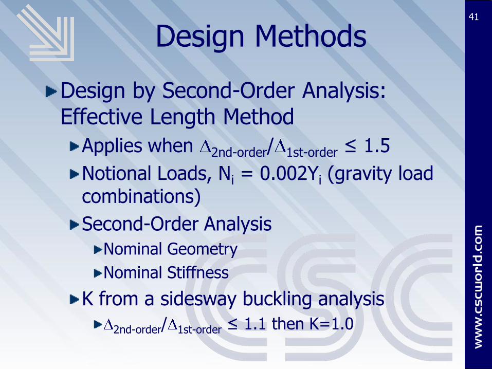
Design Methods
Design by Second-Order Analysis: Effective Length Method
Applies when 2nd-order/ 1st-order ≤ 1.5
Notional Loads, Ni = 0.002Yi (gravity load combinations)
Second-Order Analysis
Nominal Geometry
Nominal Stiffness
K from a sidesway buckling analysis
2nd-order/ 1st-order ≤ 1.1 then K=1.0
41

Design Methods
Design by First-Order Analysis
Applies when 2nd-order/ 1st-order ≤ 1.5 and
Pr ≤ 0.5Py for all lateral members
Notional Loads
Ni = 2.1( 1st-order/L)Yi ≥ 0.0042Yi
First-Order Analysis on Nominal Geometry using Nominal Stiffness
Apply B1 to total member moments
Use K=1.0
42

Design Methods
Direct Analysis Method
Applies to all structures
Required when 2nd-order/ 1st-order > 1.5
K = 1.0
Applies to all lateral systems or combination of systems w/o distinction
Most accurate determination of internal forces when combined with rigorous second-order analysis
43

Direct Analysis Method
Second Order Analysis
Consider both P- and P-
Any general second-order analysis
Amplified first-order analysis (B1,B2 method)
ASD
Carried out under 1.6 times ASD load combination
Results divided by 1.6 to obtain required strengths
44

Direct Analysis Method
Second Order Analysis - ASD
45
wASD
1.6wASD
Analyze
Mult. by 1.6
Divide by 1.6
RASD
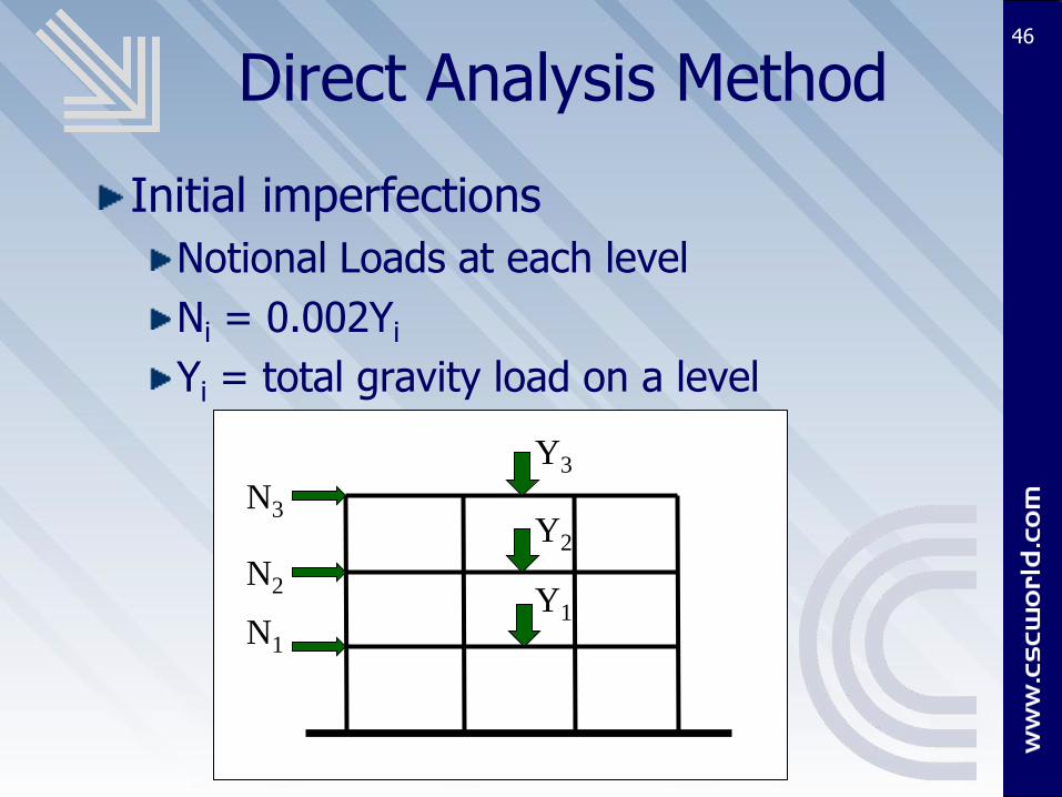
Direct Analysis Method
Initial imperfections
Notional Loads at each level
Ni = 0.002Yi
Yi = total gravity load on a level
46
Y3
Y2
Y1
N3
N2
N1

Direct Analysis Method
Initial imperfections
Notional Loads at each level
Ni = 0.002Yi
Yi = total gravity load on a level
Correlates to maximum initial out-of-plumbness allowed for columns in COSP of 1/500
Smaller value can be used if out-of-plumbness is known
47

Direct Analysis Method
Notional Loads
Applied to all load combinations
If 2nd-order/ 1st-order < 1.5 they can be treated as a minimum (gravity load combos only)
48

Direct Analysis Method
Stiffness Reductions (Inelasticity)
Axial Stiffness
EA* = 0.8 EA
Flexural Stiffness
EI* = 0.8 bEI
b ≤ 1.0
Ultimately this allows for K=1.0
49

Direct Analysis Method
Stiffness Reductions
b depends on the axial stress
for Pr ≤ 0.5Py
b = 1.0
for Pr > 0.5Py
b = 4( Pr/Py*(1- Pr/Py))
= 1.0 (LRFD), = 1.6 (ASD)
b = 1.0 may be used for all members provided an additive notional load of 0.001Yi is applied
50

Direct Analysis Method
Member design
Design all individual members using the provisions in Chapters E, F, G, H and I
K=1.0 For compression design
51
Direct Analysis Method
Procedure Summary
Model the structure (no change)
Apply Notional Loads
Perform second-order analysis on nominal geometry with reduced stiffness
Design all members for resulting forces
Design compression members with K=1.0
52

2005 AISC Specification
AISC has clarified requirements for stability analysis and design
DAM applies to all buildings
DAM is most general and accurate approach
When combined with modern software and structural analysis the DAM is straight-forward and eliminates problems with previous methods
53

Seminar Topics
Real world effects in steel buildings
Previous methods
2005 AISC Requirements
Stability Analysis and Design with Modern Software
DAM using FASTRAK Building Designer
54

Modern Software
Buildings have changed over the years
Frame is working harder (less redundancy)
Less substantial permanent walls
Architecture creates irregular lateral framing (differing systems)
55

Modern Software
Sophisticated structural analysis tools are readily available
Rigorous second-order analysis is practical in the average engineering office
Hand methods (such as B1, B2 method) can be replaced with more accurate analyses
56

Modern Software
Stability analysis is more critical in modern buildings
Rigorous Second-Order analysis is practical
DAM was developed in recognition of these issues
requirements easily automated
57
Modern Software
Second-Order Analysis
General second-order analysis that considers both P- and P- effects
Amplified first-order analysis (B1, B2)
58
Modern Software
Limitations of Amplified First-Order Analysis (AISC Commentary)
AISC does not recommend when
2nd-order/ 1st-order > 1.2
Difficult to distribute moments where several members join
Complex geometry cause difficulties
Sloping beams and columns
Floor levels not readily identifiable
59

Modern Software
Limitations of Amplified First-Order Analysis
Have to separate translation and no-translation moments
Engineering judgment often required (can’t be automated!)
Distribution of moments where B2 factors vary at a joint
60

Modern Software
General Second-Order Analysis
Free of limitations of amplified first-order method
More accurate determination of internal forces and strength level deformations
Complex geometry
irregular lateral framing
Structure Analyzed for Load Combinations
ASD with a 1.6 factor
Stable model required
61
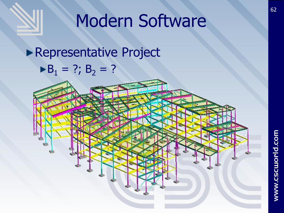
Modern Software
Representative Project
B1 = ?; B2 = ?
62

Seminar Topics
Real world effects in steel buildings
Previous methods
2005 AISC Requirements
Stability Analysis and Design with Modern Software
DAM using FASTRAK Building Designer
63

FASTRAK Building Designer64
Fastrak Building Designer is design modeling software focusing on the analysis and design of structural steel buildings
Example implementation of Stability and Analysis requirements

FASTRAK Building Designer65
Stability Analysis and Design in Fastrak
Direct Analysis Method Applied
Rigorous Second-Order Analysis Performed
Member stiffness reductions applied automatically ( b = 1.0)
Notional Loads applied automatically
Ni = 0.003Yi

FASTRAK Building Designer66
AISC Requirements
Flexural, shear, and axial deformations
All component and connection deformation
Second-order effects (both P- and P- )
Geometric imperfections
Member stiffness reductions due to inelasticity
FASTRAK

FASTRAK Building Designer67
EXAMPLE IMPLEMENTATION

FASTRAK Building Designer
When using FASTRAK, how does all this affect your design practice?
Very little!
FASTRAK does all the work
A Rigorous Second-Order analysis performed automatically
Initial out-of-plumbness considered automatically with notional loads
Inelastic behavior considered automatically with stiffness reductions (and notional loads)
68
FASTRAK Building Designer
When using FASTRAK, how does all this affect your design practice?
Understanding is key
AISC Requirements
Details of DAM implementation
Effects of second-order analysis on modeling and results
Tools provided to help create stable analysis model
69

FASTRAK Building Designer
When using FASTRAK, how does all this affect your design practice?
More accurate results and more efficient designs on a wider range of building structures
No need to assess whether the building is suitable for DAM
K=1.0
70

2010 AISC
The next AISC specification comes out in 2010
DAM will be default method in body of code
CSC will summarize the changes to Stability Analysis and the Direct Analysis Method in an upcoming webinar
71
Contact Info
Jason Ericksen – Technical Manager
Contact me for
Link to download State of the Industry paper on Stability Analysis from CSC
Questions on today’s material
72

73
Q&A
Certificates within 1-week
Free Composite Beam Softwarehttp://www.cscworld.com/fastrak/us/composite_download.html
Direct Analysis Paper
Survey
Websitehttp://www.cscworld.com/fastrak/us/
Contact [email protected]: 877 710 2053