
THE ART OF SYSTEMS ARCHITECTING - National Academic ...
308
SECOND EDITION THE ART OF SYSTEMS ARCHITECTING 2000 CRC Press LLC
-
Upload
khangminh22 -
Category
Documents
-
view
0 -
download
0
Transcript of THE ART OF SYSTEMS ARCHITECTING - National Academic ...
S E C O N D E D I T I O N
THE ART OFSYSTEMS
ARCHITECTING
2000 CRC Press LLC
Mark W. MaierAerospace Corporation
Chantilly, Virginia
Eberhardt RechtinUniversity of Southern California
Los Angeles, California
S E C O N D E D I T I O N
Boca Raton London New York Washington, D.C.CRC Press
THE ART OFSYSTEMS
ARCHITECTING
2000 CRC Press LLC

This book contains information obtained from authentic and highly regarded sources. Reprinted materialis quoted with permission, and sources are indicated. A wide variety of references are listed. Reasonableefforts have been made to publish reliable data and information, but the author and the publisher cannotassume responsibility for the validity of all materials or for the consequences of their use.
Neither this book nor any part may be reproduced or transmitted in any form or by any means, electronicor mechanical, including photocopying, microfilming, and recording, or by any information storage orretrieval system, without prior permission in writing from the publisher.
The consent of CRC Press LLC does not extend to copying for general distribution, for promotion, forcreating new works, or for resale. Specific permission must be obtained in writing from CRC Press LLCfor such copying.
Direct all inquiries to CRC Press LLC, 2000 N.W. Corporate Blvd., Boca Raton, Florida 33431.
Trademark Notice: Product or corporate names may be trademarks or registered trademarks, and areused only for identification and explanation, without intent to infringe.
© 2000 by CRC Press LLC
No claim to original U.S. Government worksInternational Standard Book Number 0-8493-0440-7
Library of Congress Card Number 00-03948Printed in the United States of America 1 2 3 4 5 6 7 8 9 0
Printed on acid-free paper
Library of Congress Cataloging-in-Publication Data
The art of systems architecting / edited by Mark W. Maier, Eberhardt Rechtin.—2nd ed.p. cm.
Pre. ed. entered under RechtinIncludes bibliographical references and index.ISBN 0-8493-0440-7 (alk. paper)1. Systems Engineering. This book is no longer in a series. I Maier, Mark. Rechtin, Eberhardt. III. Rechtin, Eberhardt. Art of systems architecting. TA168 .R368 2000620′.001′171—dc21 00-03948
CIP
2000 CRC Press LLC

Dedications
To Leigh, Stuart, and Charlie, my anchors and inspiration.
Mark Maier
To Deedee, for whom life itself is an art.
Eberhardt Rechtin
2000 CRC Press LLC
Preface
The continuing development of systems architecting
Architecting, the planning and building of structures,is as old as human societies — and as modern as theexploration of the solar system.
So began this book’s 1991 predecessor.* The earlier work was based on thepremise that architectural methods, similar to those formulated centuriesbefore in civil works, were being used, albeit unknowingly, to create andbuild complex aerospace, electronic, software, command, control, and man-ufacturing systems. If so, then other civil works architectural tools and ideas— such as qualitative reasoning and the relationships between client, architectand builder — should be found even more valuable in today’s more recentengineering fields. Five years later, at the time of the first edition of this book,judging from several hundred retrospective studies at the University ofSouthern California of dozens of post-World War II systems, the originalpremise has been validated. With another five years of perspective the obser-vations only hold more strongly. Today’s systems architecting is indeed driv-en by, and serves, much the same purposes as civil architecture — to createand build systems too complex to be treated by engineering analysis alone.
Of great importance for the future, the new fields have been creatingarchitectural concepts and tools of their own and at an accelerating rate. Thisbook includes a number of the more broadly applicable ones, among themheuristic tools, progressive design, intersecting waterfalls, feedback archi-tectures, spiral-to-circle software acquisition, technological innovation, andthe rules of the political process as they affect system design.
Arguably, these developments could, even should, have occurred soonerin this modern world of systems. Why now?
* Rechtin, E., Systems Architecting, Creating & Building Complex Systems, Prentice-Hall, Engle-wood Cliffs, NJ, 1991. Hereafter called Rechtin, 1991.
2000 CRC Press LLC
Architecting in the systems worldA strong motivation for expanding the architecting process into new fieldshas been the retrospective observation that success or failure of today’swidely publicized systems often seems preordained; that is, traceable to theirbeginnings. It is not a new realization. It was just as apparent to the ancientEgyptians, Greeks, and Romans who originated classical architecting in re-sponse to it. The difference between their times and now is in the extraor-dinary complexity and technological capability of what could then and nowbe built.
Today’s architecting must handle systems of types unknown until veryrecently; for example, systems that are very high quality, real-time, closed-loop, reconfigurable, interactive, software-intensive, and, for all practicalpurposes, autonomous. New domains like personal computers, intersatellitenetworks, health services, and joint service command and control are callingfor new architectures — and for architects specializing in those domains.Their needs and lessons learned are in turn leading to new architectingconcepts and tools and to the acknowledgment of a new formalism, andevolving profession, called systems architecting; a combination of the prin-ciples and concepts of both systems and of architecting.
The reasons behind the general acknowledgment of architecting in thenew systems world are traceable to that remarkable period immediately afterend of the Cold War in the mid-1980s. Abruptly, by historical standards, a50-year period of continuity ended. During the same period, there was adramatic upsurge in the use of smart, real-time systems, both civilian andmilitary, which required much more than straightforward refinements ofestablished system forms. Long-range management strategies and designrules, based on years of continuity, came under challenge. It is now apparentthat the new era of global transportation, global communications, globalcompetition, and global turmoil is not only different in type and direction,it is unique technologically and politically. It is a time of restructuring andinvention, of architecting new products and processes, and of new ways ofthinking about how systems are created and built.
Long-standing assumptions and methods are under challenge. For ex-ample, for many engineers, architectures were a given; automobiles, air-planes, and even spacecraft had had the same architectural forms for de-cades. What need was there for architecting? Global competition soonprovided an answer. Architecturally different systems were capturing mar-kets. Consumer product lines and defense systems are well-reported exam-ples. Other questions include: how can software architectures be created thatevolve as fast as their supporting technologies? How deeply should a sys-tems architect go into the details of all the system’s subsystems? What is thedistinction between architecting and engineering?
2000 CRC Press LLC
Distinguishing between architecting and engineeringBecause it is the most asked by engineers in the new fields, the first issue toaddress is the distinction between architecting and engineering in general;that is, regardless of engineering discipline. Although civil engineers andcivil architects, even after centuries of debate, have not answered that ques-tion in the abstract, they have in practice. Generally speaking, engineeringdeals almost entirely with measurables using analytic tools derived frommathematics and the hard sciences; that is, engineering is a deductive pro-cess. Architecting deals largely with unmeasurables using nonquantitativetools and guidelines based on practical lessons learned; that is, architectingis an inductive process. At a more detailed level, engineering is concernedwith quantifiable costs, architecting with qualitative worth. Engineeringaims for technical optimization, architecting for client satisfaction. Engineer-ing is more of a science, architecting more of an art.
In brief, the practical distinction between engineering and architectingis in the problems faced and the tools used to tackle them. This same dis-tinction appears to apply whether the branch involved is civil, mechanical,chemical, electrical, electronic, aerospace, software, or systems.* Both archi-tecting and engineering can be found in every one. Architecting and engi-neering are roles which are distinguished by their characteristics. They rep-resent two edges of a continuum of systems practice. Individual engineersoften fill roles across the continuum at various points in their careers or ondifferent systems. The characteristics of the roles, and a suggestion for anintermediate role, are shown in Table 1.1.
As the table indicates, architecting is characterized by dealing with ill-structured situations, situations where neither goals nor means are knownwith much certainty. In systems engineering terms, the requirements for thesystem have not been stated more than vaguely, and the architect cannotappeal to the client for a resolution as the client has engaged the architectprecisely to assist and advise in such a resolution. The architect engages ina joint exploration of requirements and design, in contrast to the classicengineering approach of seeking an optimal design solution to a clearlydefined set of objectives.
Because the situation is ill-structured, the goal cannot be optimization.The architect seeks satisfactory and feasible problem-solution pairs. Goodarchitecture and good engineering are both the products of art and science,and a mixture of analysis and heuristics. However, the weight will fall onheuristics and “art” during architecting.
One way to clearly see the distinction is in the approach to interfacesand system integrity. When a complex system is built (say one involving10,000 person-years of effort) only absolute consistency and completenessof interface descriptions and disciplined methodology and process can suf-fice. When a system is physically assembled it matters little whether an
* The systems branch, possibly new to some readers, is described in Rechtin, 1991, and inChapter 1 of this book.
2000 CRC Press LLC
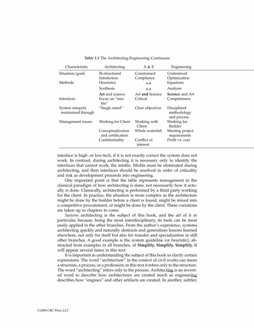
interface is high- or low-tech, if it is not exactly correct the system does notwork. In contrast, during architecting it is necessary only to identify theinterfaces that cannot work, the misfits. Misfits must be eliminated duringarchitecting, and then interfaces should be resolved in order of criticalityand risk as development proceeds into engineering.
One important point is that the table represents management in theclassical paradigm of how architecting is done, not necessarily how it actu-ally is done. Classically, architecting is performed by a third party workingfor the client. In practice, the situation is more complex as the architecturemight be done by the builder before a client is found, might be mixed intoa competitive procurement, or might be done by the client. These variationsare taken up in chapters to come.
Systems architecting is the subject of this book, and the art of it inparticular, because, being the most interdisciplinary, its tools can be mosteasily applied in the other branches. From the author’s experience, systemsarchitecting quickly and naturally abstracts and generalizes lessons learnedelsewhere, not only for itself but also for transfer and specialization in stillother branches. A good example is the system guideline (or heuristic), ab-stracted from examples in all branches, of Simplify. Simplify. Simplify. Itwill appear several times in this text.
It is important in understanding the subject of this book to clarify certainexpressions. The word “architecture” in the context of civil works can meana structure, a process, or a profession; in this text it refers only to the structure.The word “architecting” refers only to the process. Architecting is an invent-ed word to describe how architectures are created much as engineeringdescribes how “engines” and other artifacts are created. In another, subtler,
Table 1.1 The Architecting-Engineering Continuum
Characteristic Architecting A & E Engineering
Situation/goals Ill-structured Constrained UnderstoodSatisfaction Compliance Optimization
Methods Heuristics ↔ Equations
Synthesis ↔ Analysis
Art and science Art and Science Science and ArtInterfaces Focus on “mis-
fits”Critical Completeness
System integrity maintained through
“Single mind” Clear objectives Disciplined methodologyand process
Management issues Working for Client Working with Client
Working for Builder
Conceptualizationand certification
Whole waterfall Meeting project requirements
Confidentiality Conflict of interest
Profit vs. cost
2000 CRC Press LLC

distinction from conventional usage, an “architect” is meant here to be anindividual engaged in the process of achitecting, regardless of domain, jobtitle, or employer; by definition and practice both. From time to time anarchitect may perform engineering and an engineer may perform architect-ing — whatever it takes to get the job done.
Clearly, both processes can and do involve elements of the other. Archi-tecting can and does require top-level quantitative analysis to determinefeasibility, and quantitative measures to certify readiness for use. Engineer-ing can and occasionally does require the creation of architecturally differentalternatives to resolve otherwise intractable design problems. For complexsystems, both processes are essential.* In practice, it is rarely necessary todraw a sharp line between them.
Criteria for mature and effective systems architectingAn increasingly important need of project managers and clients is for criteriato judge the maturity and effectiveness of systems architecting in theirprojects — criteria analogous to those developed for software developmentby Carnegie Mellon’s Software Engineering Institute. Based upon experienceto date, criteria for systems architecting appear to be, in rough order ofattainment:
• A recognition by clients and others of the need to architect complexsystems
• An accepted discipline to perform that function; in particular, theexistence of architectural methods, standards, and organizations
• A recognized separation of value judgments and technical decisionsbetween client, architect, and builder
• A recognition that architecture is an art as well as a science; in par-ticular, the development and use of nonanalytic as well as analytictechniques
• The effective utilization of an educated professional cadre; that is, ofmasters-level, if not doctorate-level, individuals and teams engagedin the process of systems-level architecting.
By those criteria, systems architecting is in its adolescence, a time ofchallenge, opportunity, and controversy. History and the needs of globalcompetition would seem to indicate adulthood is close at hand.
* For further elaboration on the related questions of the role of the architect, see Rechtin, 1991,pp. 11–14; on the architect’s tools, Parts One and Three of this book; and on architecting as aprofession, Part Four of this book and Systems Engineering, the Journal of the InternationalCouncil on Systems Engineering.
2000 CRC Press LLC
The architecture of this bookThe first priority of this book has been to restate and extend into the futurethe retrospective architecting paradigm of Rechtin, 1991.* An essential partof both retrospective and extended paradigms is the recognition that systemsarchitecting is part art and part science. Part One of this book further devel-ops the art and extends the central role of heuristics. Part Two introducesfive important domains that both need and contribute to the understandingof that art. Part Three helps bridge the space between the science and theart of architecting. In particular, it develops the core architecting process ofmodeling and representation by and for software. Part Four concentrates onarchitecting as a profession: the political process and its part in systemdesign, and the professionalization of the field through education, research,and peer-reviewed journals.
The architecture of Part Two deserves an explanation. Without one, thereader may inadvertently skip some of the domains — builder-architectedsystems, manufacturing systems, social systems, software systems, and col-laborative systems — because they are outside the reader’s immediate fieldof interest. These chapters, instead, recognize the diverse origins of heuris-tics, illustrating and exploiting them. Heuristics often first surface in a spe-cialized domain where they address an especially prominent problem. Then,by abstraction or analogy, they are carried over to others and become generic.Such is certainly the case in the selected domains. In these chapters the usualformat of stating a heuristic and then illustrating it in several domains isreversed. Instead, it is stated, but in generic terms, in the domain where itis most apparent. Readers are encouraged to scan all the chapters of PartTwo. The chapters may even suggest domains, other than the reader’s, wherethe reader’s experience can be valuable in these times of vocational change.References are provided for further exploration. For professionals alreadyin one of the domains, the description of each is from an architectural per-spective, looking for those essentials that yield generic heuristics and pro-viding, in return, other generic ones that might help better understand thoseessentials. In any case, the chapters most emphatically are not intended toadvise specialists about their specialties.
Architecting is inherently a multidimensional subject, difficult to de-scribe in the linear, word-follows-word format of a book. Consequently, it isoccasionally necessary to repeat the same concept in several places, internallyand between books. A good example is the concept of systems. Architecting
* This second book is an extension of Rechtin, 1991, not a replacement for it. However, thisbook reviews enough of the fundamentals that it can stand on its own. If some subjects, suchas examples of specific heuristics, seem inadequately treated, the reader can probe further inthe earlier work. There are also a number of areas covered there that are not covered here,including the challenges of ultraquality, purposeful opposition, economics and public policy;biological architectures and intelligent behavior; and assessing architecting and architectures.A third book, “Systems Architecting of Organizations, Why Eagles Can’t Swim,” E. Rechtin, CRCPress, Boca Raton, FL, 1999, introduces a part of systems architecting related to, but differentfrom, the first two.
2000 CRC Press LLC

can also be organized around several different themes or threads. Rechtin,1991, was organized around the well-known waterfall model of systemprocurement. As such, its applicability to software development was limited.This book, more general, is organized by fundamentals, tools, tasks, do-mains, models, and vocation. Readers are encouraged to choose their ownpersonal theme as they go along. It will help tie systems architecting to theirown needs.
Exercises are interspersed in the text, designed for self-test of under-standing and critiquing the material just presented. If the reader disagrees,then the disagreement should be countered with examples and lessonslearned — the basic way that mathematically unprovable statements areaccepted or denied. Most of the exercises are thought problems, with nocorrect answers. Read them, and if the response is intuitively obvious, chargestraight ahead. Otherwise, pause and reflect a bit. A useful insight may havebeen missed. Other exercises are intended to provide opportunities for long-term study and further exploration of the subject. That is, they are roughlythe equivalent of a masters thesis.
Notes and references are organized by chapter. Heuristics, by tradition,are bold faced when they appear alone, with an appended list of themcompleting the text.
Changes since the first editionSince the publication of the first edition it has become evident that somesections of the book could be clearer, and new subjects have come to beimportant in the discussion of architecting. The authors have benefited fromextensive feedback from working systems architects through seminars andother contacts. Where appropriate, that feedback has been incorporated intothe book in the form of clearer explanations, better examples, and correctionsto misunderstandings.
In several areas we have added new material. Two new chapters covercollaborative systems (a.k.a. systems-of-systems) and architecture descrip-tion frameworks. The tremendous growth of the Internet and World WideWeb have led to greater appreciation for truly collaborative systems. Acollaborative system is one in which the components voluntarily operatejointly to form a greater whole. The degree of independence of operationand management can subclassify systems of this overall type, and theyappear to have methods and heuristic applications specific to this class.
The second new chapter discusses architecture description frameworks.As the importance of architectures has become more broadly accepted, stan-dards work has begun to codify good practices. A major area for suchstandards work is architecture description, the equivalent of blueprint stan-dards. Most of the emerging standards are roughly similar in intellectualapproach, but they use distinctly different terminology and make quite dif-ferent statements about what features are important.
2000 CRC Press LLC
In addition, the chapters on software and modeling have been substan-tially reworked, and the chapter on professionalization has been updated.The pace of work in software architecture has been very fast, and the chapterupdated to reflect this. Also since the publication of this book, new universityeducational programs have begun that incorporate system architecture asan important element.
The intended readership for this bookThis book is written for present and future systems architects, for experi-enced engineers interested in expanding their expertise beyond a single field,and for thoughtful individuals concerned with creating, building, or usingcomplex systems.
From experience with its predecessor, the book can be used as a referencework for graduate studies, for senior capstone courses in engineering andarchitecture, for executive training programs, and for the further educationof consultants, systems acquisition and integration specialists, and as back-ground for legislative staffs. It is a basic text for a Masters of Science degreein Systems Architecture and Engineering at the University of Southern Cal-ifornia.
AcknowledgmentsSpecial acknowledgment for contributions to the second edition is due fromthe authors to three members of the USC faculty, Associate Dean RichardMiller, now President of Olin College; Associate Dean Elliot Axelband, whooriginally requested this book and now directs the USC Master’s Programin Systems Engineering and Architecture; and to Professor Charles Weber ofElectrical Engineering Systems. And to two members of the School of Engi-neering staff, Margery Berti and Mary Froehlig, who architected the Masterof Science in Systems Architecture and Engineering from an experimentalcourse and a flexible array of multidisciplinary courses at USC. Perhaps onlyother faculty members can appreciate how much such support means to anew field and its early authors.
To learn, teach — especially to industry-experienced, graduate-level stu-dents. Much indeed has been learned by the authors of this book in a decadeof actively teaching the concepts and processes of systems architecting toover a thousand of these students. At least a dozen of them deserve specialrecognition for their unique insights and penetrating commentary: MichaelAsato, Kenneth Cureton, Susan Dawes, Norman P. Geis, Douglas R. King,Kathrin Kjos, Jonathan Losk, Ray Madachy, Archie W. Mills, Jerry Olivieri,Tom Pieronek, and Marilee Wheaton. The quick understanding and exten-sion of the architecting process by all the students has been a joy to beholdand is a privilege to acknowledge.
Following encouragement from Professor Weber in 1988 to take the firstclass offered in systems architecting as part of his Ph.D. in Electrical Engi-
2000 CRC Press LLC

neering Systems, Mark Maier, its finest student according to its originator,went on to be an associate professor at the University of Alabama in Hunts-ville, a senior staff member at the Aerospace Corporation, and the first authorof this edition. He, in turn, thanks his colleagues at Hughes Aircraft who,years earlier, introduced him to system methods, especially Dr. Jock Rader,Dr. Kapriel Krikorian, and Robert Rosen; and his current colleagues at theAerospace Corporation who have worked with him on the Aerospace Sys-tems Architecting Program: Dr. Mal Depont, Dr. William Hiatt, Dr. BruceGardner, Dr. Kevin Kreitman, and Ms. Andrea Amram.
The authors owe much to the work of Drs. Larry Druffel, David Garlan,and Mary Shaw* of Carnegie Mellon University’s Software EngineeringInstitute, Professor Barry Boehm of USC’s Center for Software Engineering,and Dr. Robert Balzer of USC’s Information Sciences Institute, softwarearchitects all, whose seminal ideas have migrated from their fields both toengineering systems in general and its architecting in particular. Dr. BrendaForman, then of USC, now retired from the Lockheed Martin Corporationand the author of Chapter 12, accepted the challenge of creating a uniquecourse on the “facts of life” in the national political process and how theyaffect — indeed often determine — architecting and engineering design.
Manuscripts may be written by authors, but publishing them is a pro-fession and contribution unto itself requiring judgment, encouragement, tact,and a considerable willingness to take risk. For all of these we thank NormStanton, a senior editor of CRC Press, Inc., editor of the first edition of thisbook, who has understood and supported the field beginning with the pub-lication of Frederick Brooks’ classic architecting book, The Mythical Man-Month, more than two decades ago.
And a concluding acknowledgment to those who inspire and sustain us,our wives and families: without you this book was inconceivable. With you,it came to life.
Eberhardt Rechtin Mark MaierMarch, 2000
Southern California The Aerospace Corporation Northern Virginia
* Authors of the watershed book, Software Architecture, Perspectives on an Emerging Discipline,Prentice-Hall, Englewood Cliffs, NJ, 1996.
2000 CRC Press LLC
The Authors
Mark W. Maier, Ph.D., is a senior engineering specialist at The AerospaceCorporation, Reconnaissance Systems Division, an architect-engineeringfirm specializing in space systems for the United States government. Hisspecialty is systems architecture. He teaches and consults in that subject forThe Aerospace Corporation, its clients, and corporations throughout theUnited States and Europe. He has done pioneering work in the field, espe-cially in collaborative systems, socio-technical systems, modeling, and ap-plication to distributed systems-of-systems. He is senior member of the IEEE,a member of the author team for IEEE P1471 Recommended Practice for Archi-tecture Description, and co-chair of the systems architecture working groupof the International Council on Systems Engineering.
Dr. Maier received his B.S. degree in engineering and applied scienceand an M.S. in electrical engineering from Caltech in 1983 and 1984, respec-tively. He joined the Hughes Aircraft Company in El Segundo, CA, ongraduation from Caltech in 1983. At Hughes he was a section head respon-sible for signal processing algorithm design and systems engineering. Whileat Hughes he was awarded a Howard Hughes Doctoral Fellowship, on whichhe completed a Ph.D. in electrical engineering, specializing in radar signalprocessing, at USC. At USC he began his collaboration with Dr. EberhardtRechtin, who was beginning the first systems architecture academic pro-gram. In 1992 he joined the faculty of the University of Alabama in Huntsvillein the Electrical and Computer Engineering Department. As an AssociateProfessor at UAH he carried out research in system architecture, stereo imagecompression, and radar signal processing. He has published several dozenjournal and conference papers in these fields. He was also the faculty advisorto the SEDSAT-1 student satellite project which was launched in 1998.
Eberhardt Rechtin, Ph.D., recently retired from the University of South-ern California (USC) as a professor with joint appointments in the depart-ments of Electrical Engineering/Systems, Industrial and Systems Engineer-ing, and Aerospace Engineering. His technical specialty is systemsarchitecture in those fields. He had previously retired (1987) as President-emeritus of The Aerospace Corporation, an architect–engineering firm spe-cializing in space systems for the U.S. Government.
Rechtin received his B.S. and Ph.D. degrees from Caltech in 1946 and1950, respectively. He joined Caltech’s Jet Propulsion Laboratory in 1948 as
2000 CRC Press LLC

an engineer, leaving in 1967. At JPL he was the chief architect and directorof the NASA/JPL Deep Space Network. In 1967 he joined the Office of theSecretary of Defense as the Director of the Advance Research Projects Agencyand later as Assistant Secretary of Defense for Telecommunications. He leftthe Defense Department in 1973 to become chief engineer for Hewlett-Pack-ard. He was elected as the president and CEO of Aerospace in 1977, retiringin 1987, and joining USC to establish its graduate program in systems archi-tecture.
Rechtin is a member of the National Academy of Engineering and aFellow of the Institute of Electrical and Electronic Engineers, the AmericanInstitute of Aeronautics and Astronautics, and the American Association forAdvancement of Science, and is an academician of the International Acad-emy of Astronautics. He has been further honored by the IEEE with itsAlexander Graham Bell Award, by the Department of Defense with its Dis-tinguished Public Service Award, NASA with its Medal for ExceptionalScientific Achievement, the AIAA with its Robert H. Goddard Award,Caltech with its Distinguished Alumni Award, The International Council onSystems Engineering with its Pioneer Award, and by the (Japanese) NECwith its C&C Prize. Rechtin is also the author of Systems Architecting, Creatingand Building Complex Systems, Prentice-Hall, 1991, and The Art of SystemsArchitecting, CRC Press LLC, 1997.
2000 CRC Press LLC
Contents
Part One Introduction — The Art of ArchitectingA brief review of classical architecting methods
Different methods for different phases of architecting
Chapter 1 Extending the Architecting ParadigmIntroduction: the classical architecting paradigm
Responding to complexityThe high rate of advances in the computer and
information sciencesThe foundations of modern systems architecting
A systems approachA purpose orientationA modeling methodologyUltraquality implementationCertificationInsights and heuristics
The architecture paradigm summarizedThe waterfall model of systems acquisitionSpirals, increments, and collaborative assemblySummary and conclusionsNotes and references
Chapter 2 Heuristics as ToolsIntroduction: a metaphorHeuristics as abstractions of experienceSelecting a personal kit of heuristic toolsUsing heuristicsHeuristics on heuristics
Generating useful heuristicsApplying heuristics
A taxonomy of heuristicsNew directionsSummaryNotes and references
2000 CRC Press LLC
Part Two New Domains, New Insights
Chapter 3 Builder-Architected SystemsIntroduction: the form-first paradigm
Incremental development for an existing customerNew markets for existing productsNew products, new markets
Technological substitutions within existing systemsConsequences of uncertainty of end purpose
Reducing the risks of uncertainty of end purposeRisk management by intermediate goals
The “what next” quandaryControlling the critical features of the architectureAbandonment of an obsolete architecture
Creating innovative teamsArchitecting “revolutionary” systemsSystems architecting and basic researchHeuristics for architecting technology-driven systems
GeneralSpecialized
SummaryExercisesNotes and references
Chapter 4 Manufacturing SystemsIntroduction: the manufacturing domainArchitectural innovations in manufacturing
Ultraquality systemsDynamic manufacturing systems
Intersecting waterfallsThe spiral-to-circle modelConcurrent engineeringFeedback systemsLean productionFlexible manufacturing
Heuristics for architecting manufacturing systemsIn conclusionExercisesNotes and references
Chapter 5 Social SystemsIntroduction: defining sociotechnical systems
Public participationThe foundations of sociotechnical systems architecting
The separation of client and userSocioeconomic insights
2000 CRC Press LLC
The interaction between the public and private sectorsFacts vs. perceptions: an added tensionHeuristics for social systemsIn conclusionExercisesNotes and references
Chapter 6 Software and Information Technology SystemsIntroduction: The status of software architectingSoftware as a system component
Software for modern systemsSystems, software, and process models
Waterfalls for software?Spirals for hardware?Integration: spirals and circles
The problem of hierarchyObject-orientationLayered designLarge, autonomous componentsReconciling the hierarchies
The role of architecture in software-centered systemsProgramming languages, models, and expressionsArchitectures, “unifying” models, and visions
Directions in software architectingArchitectural stylesArchitecture through composition
Heuristics and guidelines in softwareExercisesNotes and references
Chapter 7 Collaborative SystemsIntroduction: collaboration as a categoryCollaborative system examples
The InternetIntelligent transportation systemsJoint air defense systems
Analogies for architecting collaborative systemsCollaborative system heuristics
Stable intermediate formsPolicy triageLeverage at the interfacesEnsuring cooperation
Variations on the collaborative themeMisclassificationStandards and collaborative systemsConclusions
2000 CRC Press LLC
ExercisesNotes and references
Exercise to Close Part Two
Part Three Models and ModelingIntroduction to Part Three
A civil architecture analogyGuide to part three
Chapter 8 Representation Models and System ArchitectingIntroduction: roles, views, and modelsRoles of modelsModels, viewpoints, and viewsClassification of models by view
Note to the readerObjectives and purpose modelsModels of form
Scale modelsBlock diagrams
Behavioral (functional) models.Threads and scenariosData and event flow networkMathematical systems theoryAutonomous agent, chaotic systemsPublic choice and behavior models
Performance modelsFormal methods
Data modelsManagerial models
Examples of interated modelsSummaryExercisesNotes and references
Chapter 9 Design Progression in System ArchitectingIntroduction: architecting process componentsDesign progression
Introduction by examplesDesign as the evolution aof modelsEvaluation criteria and heuristic refinementProgression of emphasisConcurrent progressionsEpisodic nature
Design concepts for systems architecture
2000 CRC Press LLC
Historical approaches to architectingSpecialized and formalized heuristicsScoping, aggregation, partitioning, and certification
ScopingAggregation and partitioningCertification
Certainty, rationality, and choiceStopping or progressing?
Architecture and design disciplinesArchitecture and patterns
ConclusionsExercisesNotes and references
Chapter 10 Integrated Modeling MethodologiesIntroductionGeneral integrated models
Hatley/Pirbhai — computer-based reactive systemsExample: microsatellite imaging systemQuantitative QFD (Q2FD) — performance-driven systems
Integrated modeling and softwareStructured analysis and designADARTSOMTUMLPerformance integration: scheduling
Integrated models for manufacturing systemsIntegrated models for sociotechnical systemsConclusionsExercisesNotes and references
Chapter 11 Architecture FrameworksIntroductionDefining an architecture framework
Goals of the frameworkUnderstanding “architectural level”Organization of an architecture description framework
Current architecture frameworksU.S. DoD C4ISR
Summary informationOperational viewSystem viewTechnical viewEvaluation of the C4ISR framework
ISO RM-ODP
2000 CRC Press LLC
Proprietary and semi-open information technology standardsIEEE P1471
P1471 conceptsP1471 normative requirements
Research directionsConclusionsNotes and references
Part Four The Systems Architecting Profession
Chapter 12 The Political Process and Systems ArchitectingIntroduction: the political challengePolitics as a design factorThe first skill to masterHeuristics in the political process: “the facts of life”
Fact of life #1Fact of life #2Fact of life #3Fact of life #4Fact of life #5
A few more skills to masterConclusion
Chapter 13 The Professionalization of Systems ArchitectingIntroductionThe profession of systems engineeringSystems architecting and systems standards
The origins of systems standardsThe ballistic missile program of the 1950s
The beginning of a new era of standardsEIA/IS 632, an architectural perspective
Commercial standardsIEEE 1220, an architectural perspective
Company standardsA summary of standards developments, 1950–1995
Systems architecting graduate educationSystems engineering universities and systems architectingCurriculum designAdvanced study in systems architecting
Professional societies and publicationsConclusion: an assessment of the professionNotes and references
2000 CRC Press LLC
Appendices
Appendix A: Heuristics for Systems-Level ArchitectingIntroduction: organizing the listHeuristic tool list
Multitask heuristicsScoping and planningModelingPrioritizing (trades, options, and choices)Aggregating (“chunking”)Partitioning (decompositioning)IntegratingCertifying (system integrity, quality, and vision)
Assessing performance, cost, schedule, and riskRearchitecting, evolving, modifying, and adaptingExercisesNotes and references
Appendix B: Reference Texts for Suggested for Institutional Libraries
Architecting backgroundManagementModelingSpecialty areasSoftwareSystem sciencesSystem thinking
Appendix C: On Defining Architecture and Other TermsDefining “Architecture”
Webster’s Dictionary definitionThis bookIEEE Architecture Working Group (AWG)INCOSE SAWGMIL-STD-498Perry-GarlanMaier’s tongue-in-cheek rule of thumbInternet discussionSummary
Models, viewpoints, and viewsWorking definitionsConsistency and completeness
Notes and references
Glossary
2000 CRC Press LLC
Part one
Introduction — the artof architecting
A brief review of classical architecting methods
Architecting: the art and science of designing andbuilding systems.1
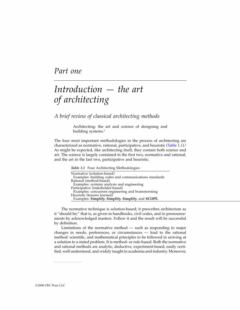
The four most important methodologies in the process of architecting arecharacterized as normative, rational, participative, and heuristic (Table 1.1).2As might be expected, like architecting itself, they contain both science andart. The science is largely contained in the first two, normative and rational,and the art in the last two, participative and heuristic.
The normative technique is solution-based; it prescribes architecture asit “should be;” that is, as given in handbooks, civil codes, and in pronounce-ments by acknowledged masters. Follow it and the result will be successfulby definition.
Limitations of the normative method — such as responding to majorchanges in needs, preferences, or circumstances — lead to the rationalmethod: scientific, and mathematical principles to be followed in arriving ata solution to a stated problem. It is method- or rule-based. Both the normativeand rational methods are analytic, deductive, experiment-based, easily certi-fied, well understood, and widely taught in academia and industry. Moreover,
Table 1.1 Four Architecting Methodologies
Normative (solution-based)Examples: building codes and communications standards
Rational (method-based)Examples: systems analysis and engineering
Participative (stakeholder-based)Examples: concurrent engineering and brainstorming
Heuristic (lessons learned)Examples: Simplify. Simplify. Simplify. and SCOPE.
2000 CRC Press LLC
the best normative rules are discovered through engineering science (thinkof modern building codes), truly a formidable set of positives.
However, because science-based methods are absolutely necessary partsof architecting, they are not the focus of this book. They are already welltreated in a number of architectural and engineering texts. Equally necessary,and the focus of this part of the book, is the art, or practice, needed tocomplement the science for highly complex systems.
In contrast with science-based methodologies, the art or practice of archi-tecting — like the practice of medicine, law, and business — is nonanalytic,inductive, difficult to certify, less understood, and, at least until recently, isseldom taught formally in either academia or industry. It is a process ofinsights, vision, intuitions, judgment calls, and even “taste.”3 It is key tocreating truly new types of systems for new and often unprecedented appli-cations. Here are some of the reasons why it is key.
For unprecedented systems, past data is of limited use. For others, analysiscan be overwhelmed by too many unknowns, too many stakeholders, toomany possibilities, and too little time for data gathering and analysis to bepractical. To cap it off, many of the most important factors are not measurable.Perceptions of worth, safety, affordability, political acceptance, environmentalimpact, public health, and even national security provide no realistic basis fornumerical analyses — even if they weren't highly variable and uncertain. Yet,if the system is to be successful, these perceptions must be accommodatedfrom the first, top-level, conceptual model down through its derivatives.
The art of architecting, therefore, complements its science where scienceis weakest: in dealing with immeasurables, in reducing past experience andwisdom to practice, in conceptualization, in inspirationally putting disparatethings together, in providing “sanity checks,” and in warning of likely butunprovable trouble ahead. Terms like reasonable assumptions, guidelines,indicators, elegant design, and beautiful performance are not out of place inthis art; nor are lemon, disaster, snafu, or loser. These are hardly quantifiable,but as real in impact as any science.
The participative methodology recognizes the complexities created bymultiple stakeholders. Its objective is consensus. As a notable example,designers and manufacturers need to agree on a multiplicity of details if anend product is to be manufactured easily, quickly, and profitably. In simplebut common cases, only the client, architect, and contractor have to be inagreement; but as systems become more complex, new and different partic-ipants have to agree as well.
Concurrent engineering, a recurrently popular acquisition method, wasdeveloped to help achieve consensus among many participants. Its greatestvalue, and its greatest contentions, are for systems in which widespreadcooperation is essential for acceptance and success; for example, systemswhich directly impact on the survival of individuals or institutions. Its well-known weaknesses are undisciplined design by committee, diversionarybrainstorming, the closed minds of “group think,” and members withoutpower to make decisions but with the unbridled right to second guess.
2000 CRC Press LLC
Arguably, the greatest mistake that can be made in concurrent engineeringis to attempt to quantify it. It is not a science. It is a very human art.
The heuristics methodology is based on “common sense,” that is, onwhat is sensible in a given context. Contextual sense comes from collectiveexperience stated in as simple and concise a manner as possible. Thesestatements are called heuristics, the subject of Chapter 2, and are of specialimportance to architecting because they provide guides through the rocksand shoals of intractable, “wicked” system problems. Simplify is the firstand probably most important of them. They exist in the hundreds if notthousands in architecting and engineering, yet they are some of the mostpractical and pragmatic tools in the architect’s kit of tools.
Different methods for different phases of architecting
The nature of classical architecting changes as the project moves from phaseto phase. In the earliest stages of a project it is a structuring of an unstructuredmix of dreams, hopes, needs, and technical possibilities when what is mostneeded has been called an inspired synthesizing of feasible technologies. Itis a time for the art of architecting. Later on, architecting becomes an inte-gration of, and mediation among, competing subsystems and interests — atime for rational and normative methodology. And, finally, there comescertification to all that the system is suitable for use, when it may take allthe art and science to that point to declare the system as built is completeand ready for use.
Not surprisingly, architecting is often individualistic, and the end resultsreflect it. As Frederick P. Brooks put it in 19824 and Robert Spinrad stated in1987,5 the greatest architectures are the product of a single mind — or of avery small, carefully structured team. To which should be added, in allfairness: a responsible and patient client, a dedicated builder, and talenteddesigners and engineers.
Notes and references1. Webster’s II New Riverside University Dictionary, Riverside Publishing, Boston,
1984. As adapted for systems by substitution of “building systems” for “erect-ing buildings.”
2. For a full discussion of these methods, see Lang, J., Creating ArchitecturalTheory, The Role of the Behavioral Sciences in Environmental Design, Van NostrandReinhold Company, New York, 1987; and Rowe, P. G., Design Thinking, MITPress, Cambridge, MA, 1987. They are adapted for systems architecting inRechtin, E., Systems Architecting, Creating & Building Complex Systems, Prentice-Hall, Englewood Cliffs, NJ, 1991, 14.
3. Spinrad, R. J., In a lecture to the University of Southern California, 1988.4. Brooks, F. P., The Mythical Man-Month, Essays on Software Engineering, Addison-
Wesley, Reading, MA, 1983.5. Spinrad, R. J., at a Systems Architecting lecture at the University of Southern
California, fall 1987.
2000 CRC Press LLC
Part two
New domains, new insights
Part Two explores, from an architectural point of view, five domains beyondthose of aerospace and electronics, the sources of most examples and writingsto date. The chapters can be read for several purposes. For a reader familiarwith a domain, there are broadly applicable heuristics for more effectivearchitecting of its products. For ones unfamiliar with domains, there areinsights to be gained from understanding problems differing in the degreebut not in kind from one’s own. To coin a metaphor, if the domains can beseen as planets, then this part of the book corresponds to comparative plan-etology — the exploration of other worlds to benefit one’s own. The chapterscan be read for still another purpose: as a template for exploring otherequally instructive domains. An exercise for that purpose can be found atthe end of Chapter 7, Collaborative Systems.
From an educational point of view, Part Two is a recognition that oneof the best ways of learning is by example, even if the example is in a differentfield or domain. One of the best ways of understanding another disciplineis to be given examples of problems it solves; and one of the best ways oflearning architecting is to recognize that there are architects in every domainand at every level from which others can learn and with whom all can work.At the most fundamental level, all speak the same language and carry outthe same process: systems architecting. Only the examples are different.
Chapter 3 explores systems for which form is predetermined by abuilder’s perceptions of need. Such systems differ from those that are drivenby client purposes by finding their end purpose only if they succeed in themarketplace. The uncertainty of end purpose has risks and consequenceswhich are the responsibility of architects to help reduce or exploit. Centralto doing so are the protection of critical system parameters and the formationof innovative architecting teams. These systems can be either evolutionaryor revolutionary. Not surprisingly, there are important differences in thearchitectural approach.
Chapter 4 highlights the fact that manufacturing has its own waterfall,quasi-independent of the more widely discussed product waterfall, and thatthese two waterfalls must intersect properly at the time of production. Aspiral-to-circle model is suggested to help understand the integration of
2000 CRC Press LLC
hardware and software. Ultraquality and feedback are shown to be the keysto both lean manufacturing and flexible manufacturing, with the latter need-ing a new information flow architecture in addition.
Chapter 5, Social Systems, introduces a number of new insights to thoseof the more technical domains. Economic questions and value judgmentsplay a much stronger role here, even to the point of an outright veto ofotherwise worthwhile systems. A new tension comes to center stage, onecentral to social systems but too often downplayed in others until too late— the tension between facts and perceptions. It is so powerful in definingsuccess that it can virtually mandate system design and performance, solelybecause of how that architecture is perceived.
Chapter 6, Software Systems, serves to introduce this rapidly expandingdomain as it increasingly becomes the center of almost all modern systemsdesigns. Consequently, whether stand-alone or as part of a larger system,software systems must accommodate to continually changing technologiesand product usage. In very few other domains is annual, much less monthly,wholesale replacement of a deployed system economically feasible or evenconsidered. In point of fact, it is considered normal in software systems,precisely because of software’s unique ability to continuously and rapidlyevolve in response to changes in technology and user demands. Softwarehas another special property; it can be as hard or as soft as needed. It canbe hard-wired if certification must be precise and unchanging, or it can beas soft as a virtual environment molded at the will of a user. For these andother reasons, software practice is heavily dependent on heuristic guidelinesand organized, layered modeling. It is a domain in which architecting devel-opment is very active, particularly in progressive modeling and rapid pro-totyping.
Chapter 7 introduces an old but newly significant class of systems,collaborative systems. Collaborative systems exist only because the partici-pants actively and continuously work to keep it in existence. A collaborativesystem is a dynamic assemblage of independently owned and operatedcomponents, each one of which exists and fulfills its owner’s purposeswhether or not it is part of the assemblage. These systems have been aroundfor centuries in programs of public works. Today we find wholly new formsin communications (the Internet and World Wide Web), transportation (intel-ligent transportation systems), military (multinational reconnaissance-strikeand defensive systems), and software (open source software). The architect-ing paradigm begins to shift in collaborative systems because the architectno longer has a single client who can make and execute decisions. Thearchitect must now deal with more complex relationships, and he must findarchitectures in less familiar structures, such as architecture through com-munication or command protocol specification.
The nature of modern software and information-centric systems, andtheir central role in new complex systems, makes a natural lead-in to PartThree, Models and Representations.
2000 CRC Press LLC
Exercise to close part two
Explore another domain much as builder-architected, sociotechnical, manu-facturing, software, and collaborative systems are explored in this part. Whatare the domain’s special characteristics? What more broadly applicable les-sons can be learned from it? What general heuristics apply to it? Below aresome suggested heuristic domains to explore.
1. Telecommunications in its several forms: point-to-point telephonenetwork systems, broadcast systems (terrestrial and space), and pack-et-switched data (the Internet)
2. Electric power, which is widely distributed with collaborative control,is subject to complex loading phenomena (with a social component),and is regulated (Hill, D. J., Special Issue on Nonlinear Phenomenain Power Systems: Theory and Practical Implications, Proc. IEEE, 83,11, November 1995)
3. Transportation, in both its current form and in the form of proposedintelligent transportation systems
4. Financial systems, including global trading mechanisms, and the op-eration of regulated economics as a system
5. Space systems, with their special characteristics of remote operation,high initial capital investment, vulnerability to interference and at-tack, and their effects on the design and operation of existing earth-borne systems performing similar functions
6. Existing and emerging media systems, including the collection ofcompeting television systems of private broadcast, public broadcast,cable, satellite, and video recording
2000 CRC Press LLC
Part three
Models and modeling
Introduction to part threeWhat is the product of an architect? While it is tempting to regard thebuilding or system as the architect’s product, the relationship is necessarilyindirect. The system is actually built by the developer. The architect acts totranslate between the problem domain concepts of the client and the solutiondomain concepts of the builder. Great architects go beyond the role of inter-mediary to make a visionary combination of technology and purpose thatexceeds the expectation of builder or client. But the system cannot be builtas envisioned unless the architect has a mechanism to communicate thevision and track construction against it. The concrete, deliverable productsof the architect, therefore, are models of the system.
Individual models alone are point-in-time representations of a system.Architects need to see and treat each as a member of one of several progres-sions. The architect’s first models define the system concept. As the conceptis found satisfactory and feasible, the models progress to the detailed, tech-nology-specific models of design engineers. The architect’s original modelscome into play again when the system must be certified.
A civil architecture analogy
Civil architecture provides a familiar example of modeling and progression.An architect is retained to ensure that the building is pleasing to the clientin all senses (aesthetically, functionally, and financially). The product of thearchitect is intangible; it is the conceptual vision which the physical buildingembodies and which satisfies the client. But the intangible product is worth-less without a series of increasingly detailed tangible products — all modelsof some aspect of the building. Table 1 lists some of the models and theirpurposes.
The progression of models during the design life cycle can be visualizedas a steady reduction of abstraction. Early models may be quite abstract.They may convey only the basic floor plan, associated order-of-magnitudebudgets, and renderings encompassing only major aesthetic elements. Early
2000 CRC Press LLC
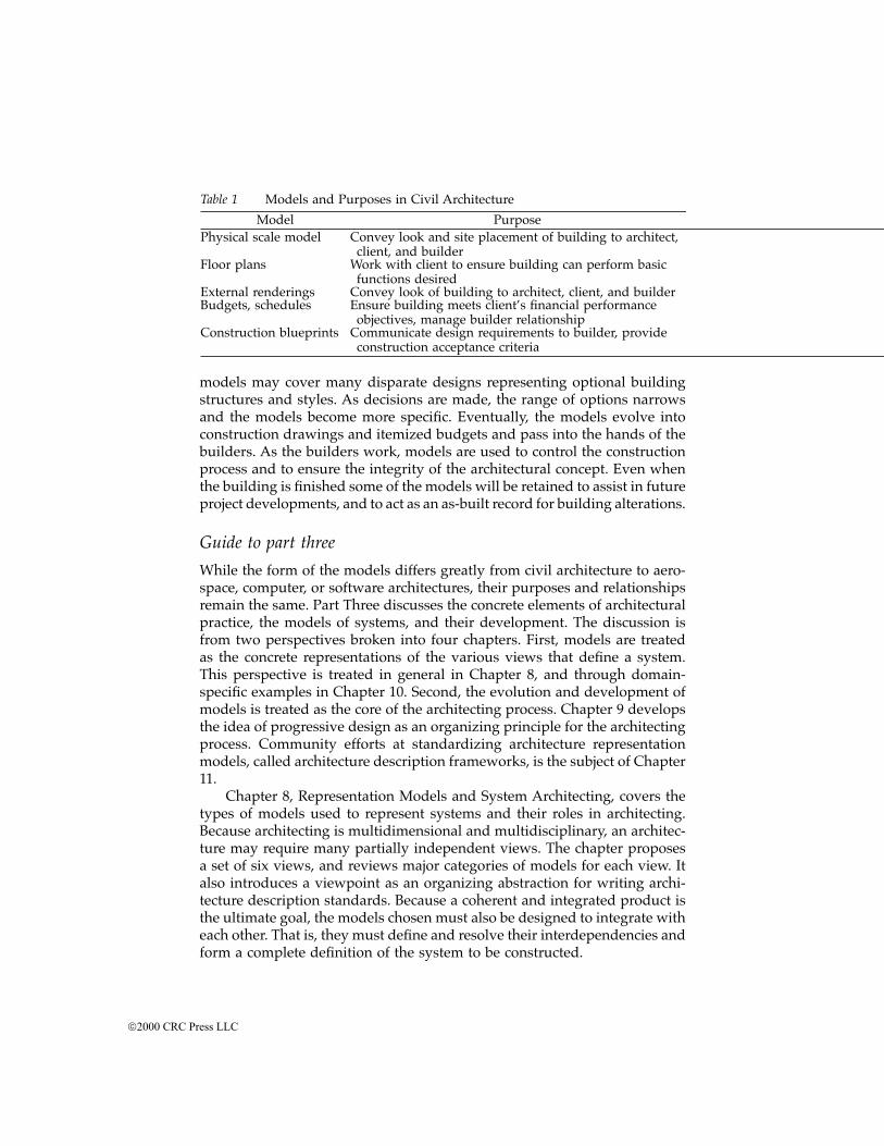
models may cover many disparate designs representing optional buildingstructures and styles. As decisions are made, the range of options narrowsand the models become more specific. Eventually, the models evolve intoconstruction drawings and itemized budgets and pass into the hands of thebuilders. As the builders work, models are used to control the constructionprocess and to ensure the integrity of the architectural concept. Even whenthe building is finished some of the models will be retained to assist in futureproject developments, and to act as an as-built record for building alterations.
Guide to part three
While the form of the models differs greatly from civil architecture to aero-space, computer, or software architectures, their purposes and relationshipsremain the same. Part Three discusses the concrete elements of architecturalpractice, the models of systems, and their development. The discussion isfrom two perspectives broken into four chapters. First, models are treatedas the concrete representations of the various views that define a system.This perspective is treated in general in Chapter 8, and through domain-specific examples in Chapter 10. Second, the evolution and development ofmodels is treated as the core of the architecting process. Chapter 9 developsthe idea of progressive design as an organizing principle for the architectingprocess. Community efforts at standardizing architecture representationmodels, called architecture description frameworks, is the subject of Chapter11.
Chapter 8, Representation Models and System Architecting, covers thetypes of models used to represent systems and their roles in architecting.Because architecting is multidimensional and multidisciplinary, an architec-ture may require many partially independent views. The chapter proposesa set of six views, and reviews major categories of models for each view. Italso introduces a viewpoint as an organizing abstraction for writing archi-tecture description standards. Because a coherent and integrated product isthe ultimate goal, the models chosen must also be designed to integrate witheach other. That is, they must define and resolve their interdependencies andform a complete definition of the system to be constructed.
Table 1 Models and Purposes in Civil Architecture
Model PurposePhysical scale model Convey look and site placement of building to architect,
client, and builderFloor plans Work with client to ensure building can perform basic
functions desiredExternal renderings Convey look of building to architect, client, and builderBudgets, schedules Ensure building meets client’s financial performance
objectives, manage builder relationshipConstruction blueprints Communicate design requirements to builder, provide
construction acceptance criteria
2000 CRC Press LLC
Chapter 9, Design Progression in Systems Architecting, looks for prin-ciples to organize the eclectic architecting process. A particularly usefulprinciple is that of progression — the idea that models, heuristics, evaluationcriteria, and many other aspects of the system evolve on parallel tracks fromthe abstract to the specific and concrete. Progression also helps tie architect-ing into the more traditional engineering design disciplines. While this booklargely treats system architecting as a general process, independent ofdomain, in practice it necessarily is strongly tied to individual systems anddomains. Nevertheless, each domain contains a core of problems not ame-nable to rational, mechanistic solutions which are closely associated withreconciling customer or client need and with technical capability. This coreis the province of architecting. Architects are not generalists; they are systemspecialists, and their models must refine into the technology-specific modelsof the domains in which their systems are to be realized.
Chapter 10 returns to models, now tying the previous two chapterstogether by looking at specific modeling methods. This chapter examines aseries of integrating methodologies that illustrate the attributes discussed inthe previous chapters: multiple views, integration across views, and progres-sion from abstract to concrete implementation. Examples of integrated mod-els and methods are given for computer-based systems, performance-ori-ented systems, software-intensive systems, manufacturing systems, andsociotechnical systems. The first part of Chapter 10 describes two general-purpose integrated modeling methods: Hatley/Pirbhai and QuantitativeQuality Function Deployment. The former specializes in combining behav-ioral and physical implementation models, the latter in integrating quanti-tative performance requirements with behavioral and implementation mod-els. Subsequent sections describe integrated models for software,manufacturing systems, and sociotechnical systems.
Chapter 11 looks outward to the community interested in architectureto review recent work in standardizing architecture descriptions. Standardsfor architecture description are usually referred to as architecture descriptionframeworks. The chapter reviews three of the leading ones, with some men-tion of others. They are the U. S. Department of Defense Command ControlCommunications Computing Intelligence Surveillance and Reconnaissancearchitecture framework, the ISO Reference Model for Open Distributed Pro-cessing, and the IEEE’s P1471 Recommended Practice for ArchitecturalDescription.
2000 CRC Press LLC
Part four
The systems architecting profession
The first three parts of this book have been about systems architecting as anactivity or as a role in systems development. This part is about systemsarchitecting as a profession; that is, as a recognized vocation in a specializedfield. Two factors are addressed here. The first, the political process,* isimportant because it interacts strongly with the architecting process, directlyaffecting the missions and designs of large-scale, complex systems. Thesecond, the professionalization of systems architecting, is important becauseit affects how the government, industry, and academia perceive systemsarchitects as a group.
Chapter 12 is based on a course originated and taught at the Universityof Southern California by Dr. Brenda Forman of USC and the LockheedMartin Corporation. The chapter describes the political process of the Amer-ican government and the heuristics that characterize it. The federal process,instead of company politics or executive decision making,** was chosen forthe course and for this book on architecting for three reasons.
First, federal governments are major sponsors and clients of complexsystems and their development. Second, the American federal political pro-cess is a well-documented, readily available open source for case studies tosupport the heuristics given here. And third, the process is assumed by fartoo many technologists to be uninformed, unprofessional, and self-serving.Nothing could be worse, less true, nor more damaging to a publicly sup-ported system and its creators than acting under such assumptions. In actu-ality, the political process is the properly constituted and legal mechanismby which the general public expresses its judgments on the value to it of thegoods and services that it needs. The fact that the process is time-consuming,
* By “political process,” it is meant the art and science of government, especially the processby which it acquires large-scale, complex systems.** Company politics were felt to be too company-specific, too little documented, and tooarguable for credible heuristics. Executive decisions are the province of decision theory and arebest considered in that context.
2000 CRC Press LLC

messy, litigious, not always fair to all, and certainly not always logical in atechnical sense, is far more a consequence of inherent conflicts of interestsand values of the general public than of base motives or intrigue of itsrepresentatives in government.
The point that has been made many times in this book is that valuejudgments must be made by the client, the individual or authority who paysthe bills, and not by the architect. For public services in representative dem-ocratic countries, that client is represented by the legislative, and occasionallythe judicial, branch of the government.* Chapter 12 states a number ofheuristics, the “facts of life,” if you will, describing how that client operates.In the political domain, those rules are as strong as any in the engineeringworld. The architect should treat them with at least as much respect as anyengineering principle or heuristic. For example, one of the facts of life states:
The best engineering solutions are not necessarilythe best political solutions.
Ignoring such a fact is as great a risk as ignoring a principle of mathe-matics or physics — one can make the wrong moves and get the wronganswers.
Chapter 13 addresses the challenge in the Preface to this book to profes-sionalize the field; that is, to establish it as a profession** recognized by itspeers and clients. In university terms, this means at least a graduate-leveldegree, specialized education, successful graduates, peer-reviewed publica-tions, and university-level research. In industry terms, it means the existenceof acknowledged experts and specialized techniques. Dr. Elliott Axelband***reports on progress toward such professionalization by tracing the evolutionof systems standards toward architectural guidelines, by describing archi-tecture-related programs in the universities, and by indicating professionalsocieties and publications in the field. Axelband concludes the book with anassessment of the profession and its likely future.
* In the U.S., the executive branch implements the value judgments made by the Congress unlessthe Congress expressly delegates certain ones to the executive branch.** “Any occupation or vocation requiring training in the liberal arts or the sciences and advancedstudy in a specialized field.” Webster’s II New Riverside University Dictionary, Riverside PublishingCompany, Boston, MA, 1984, p. 939.*** Associate Dean, School of Engineering, University of Southern California and the directorof the Systems Architecting and Engineering program. Dr. Axelband previously was an exec-utive of the Hughes Aircraft Company until his retirement in early 1994.
2000 CRC Press LLC
chapter one
Extending the architecture paradigm
Introduction: the classical architecting paradigmThe recorded history of classical architecting, the process of creating archi-tectures, began in Egypt more than 4000 years ago with the pyramids, thecomplexity of which had been overwhelming designers and builders alike.This complexity had at its roots the phenomenon that as systems becameincreasingly more ambitious, the number of interrelationships among theelements increased far faster than the number of elements themselves. Pyr-amids were no longer simple burial sites; they had to be demonstrations ofpolitical and religious power, secure repositories of god-like rulers and theirwealth, and impressive engineering accomplishments. Each demand, ofitself, would require major resources. When taken together, they generatednew levels of technical, financial, political, and social complications. Com-plex interrelationships among the combined elements were well beyondwhat the engineers’ and builders’ tools could handle.
From that lack of tools for civil works came classical civil works archi-tecture. Millennia later, technological advances in shipbuilding created thenew and complementary fields of marine engineering and naval architecture.In this century, rapid advances in aerodynamics, chemistry, materials, elec-trical energy, communications, surveillance, information processing, andsoftware have resulted in systems whose complexity is again overwhelmingpast methods and paradigms. One of those is the classical architecting par-adigm.
Responding to complexity
Complex: composed of interconnected or interwovenparts.1
© 2000 by CRC Press LLC
System: a set of different elements so connected orrelated as to perform a unique function not perform-able by the elements alone.2
It is generally agreed that increasing complexity* is at the heart of the mostdifficult problems facing today’s systems architecting and engineering.When architects and builders are asked to explain cost overruns and sched-ule delays, by far the most common, and quite valid, explanation is that thesystem is much more complex than originally thought. The greater the com-plexity, the greater the difficulty. It is important, therefore, to understandwhat is meant by system complexity if architectural progress is to be madein dealing with it.
The definitions of complexity and systems given at the start of thissection are remarkably alike. Both speak to interrelationships (interconnec-tions, interfaces, etc.) among parts or elements. As might be expected, themore elements and interconnections, the more complex the architecture andthe more difficult the system-level problems.
Less apparent is that qualitatively different problem-solving techniquesare required at high levels of complexity than at low ones. Purely analyticaltechniques, powerful for the lower levels, can be overwhelmed at the higherones. At higher levels, architecting methods, experience-based heuristics,abstraction, and integrated modeling must be called into play.3 The basicidea behind all of these techniques is to simplify problem solving by con-centrating on its essentials. Consolidate and simplify the objectives. Staywithin guidelines. Put to one side minor issues likely to be resolved by theresolution of major ones. Discard the nonessentials. Model (abstract) thesystem at as high a level as possible, then progressively reduce the level ofabstraction. In short, Simplify!
It is important in reading about responses to complexity to understandthat they apply throughout system development, not just to the conceptualphase. The concept that a complex system can be progressively partitionedinto smaller and simpler units — and hence into simpler problems — omitsan inherent characteristic of complexity, the interrelationships among theunits. As a point of fact, poor aggregation and partitioning during develop-ment can increase complexity, a phenomenon all too apparent in the organi-zation of work breakdown structures.
This primacy of complexity in system design helps explain why a single“optimum” seldom if ever exists for such systems. There are just too manyvariables. There are too many stakeholders and too many conflicting inter-ests. No practical way may exist for obtaining information critical in makinga “best” choice among quite different alternatives.
* A system need not be large or costly to be complex. The manufacture of a single mechanicalpart can require over 100 interrelated steps. A $10 microchip can contain thousands, evenmillions, of interconnected active elements.
© 2000 by CRC Press LLC
The high rate of advances in the computer and information sciences
Unprecedented rates of advance in the computer and information scienceshave further exacerbated an already complex picture. The advent of smart,software-intensive systems is producing a true paradigm shift in systemdesign. Software, long treated as the glue that tied hardware elementstogether, is becoming the center of system design and operation. We see itin personal computers. The precipitous drop in computer hardware costshas generated a major design shift, from “keep the computer busy” to “keepthe user busy.” We see it in automobiles, where microchips increasinglydetermine the performance, quality, cost, and feel of cars and trucks.
We see the paradigm shift in the design of spacecraft and personalcomputers where complete character changes can be made in minutes. Ineffect, such software-intensive systems “change their minds” on demand. Itis no longer a matter of debate whether machines have “intelligence;” theonly real questions are of what kinds of intelligence and how best to useeach one. And, because its software largely determines what and how theuser perceives the system as a whole, its design will soon control and precedehardware design much as hardware design controls software today. Thisshift from “hardware first” to “software first” will force major changes onwhen and how system elements are designed, and who, with what expertise,will design the system as a whole. The impact on the value of systems tothe user has been and will continue to be enormous.
One measure of this phenomenon is the proportion of developmenteffort devoted to hardware and software for various classes of product.Anecdotal reports from a variety of firms in telecommunications and con-sumer electronics commonly show a reversal of the proportion from 70%hardware and 30% software to 30% hardware and 70% software. This shifthas created major challenges and destroyed some previously successful com-panies. When the cost of software development dominates, developmentsystems should be organized to simplify software development. But goodsoftware architectures and good hardware architectures are often quite dif-ferent. Good architectures for complex software usually emphasize layeredstructures that cross many physically distinct hardware entities. Good soft-ware architectures also emphasize information hiding and close parallelsbetween implementation constructs and domain concepts at the upper lay-ers. These are in contrast to the emphasis on hierarchical decomposition,physical locality of communication, and interface transparency in good hard-ware architectures. Organizations find trouble when their workload movesfrom hardware- to software-dominated but their management and develop-ment skills no longer “fit” the systems they should support.
Particularly susceptible to these changes are systems that depend uponelectronics, and information systems and that do not enjoy the formal part-nership with architecting that structural engineering has long enjoyed. Thisbook is an effort to remedy that lack by showing how the historical principlesof classical architecting can be extended to modern systems architecting.
© 2000 by CRC Press LLC
The foundations of modern systems architectingAlthough the day-to-day practice may differ significantly,4 the foundationsof modern systems architecting are much the same across many technicaldisciplines. Generally speaking, they are a systems approach, a purposeorientation, a modeling methodology, ultraquality, certification, and insight.5Each will be described in turn.
A systems approach
A systems approach is one that focuses on the system as a whole, particularlywhen making value judgments (what is required) and design decisions (whatis feasible). At the most fundamental level, systems are collections of differentthings which together produce results unachievable by the elements alone. Forexample, only when all elements are connected and working together doautomobiles produce transportation, human organs produce life, and space-crafts produce information. These system-produced results, or so-called“system functions,” derive almost solely from the interrelationships amongthe elements, a fact that largely determines the technical role and principalresponsibilities of the systems architect.
Systems are interesting because they achieve results, and achieving thoseresults requires different things to interact. Based on experience with systemsover the last decade, it is difficult to underestimate the importance of thisspecific definition of systems to what follows, literally, on a word-by-wordbasis. Taking a systems approach means paying close attention to results orthe reasons we build a system. Architecture must be grounded in the cli-ent’s/user’s/customer’s purpose. Architecture is not just about the structureof components.
It is the responsibility of the architect to know and concentrate on thecritical few details and interfaces that really matter and not to become over-loaded with the rest. It is a responsibility that is important not only for thearchitect personally, but for effective relationships with the client and builder.To the extent that the architect must be concerned with component designand construction, it is with those specific details that critically affect thesystem as a whole.
For example, a loaded question often posed by builders, project manag-ers, and architecting students is, “How deeply should the architect delveinto each discipline and each subsystem?” A graphic answer to that questionis shown in Figure 1.1, exactly as sketched by Bob Spinrad in a 1987 lectureat the University of Southern California. The vertical axis is a relative mea-sure of how deep into a discipline or subsystem an architect must delve tounderstand its consequences to the system as a whole. The horizontal axislists the disciplines, such as electronics or stress mechanics, and/or thesubsystems, such as computers or propulsion systems. Depending upon thespecific system under consideration, a great deal of , or a very little under-standing may be necessary.
© 2000 by CRC Press LLC
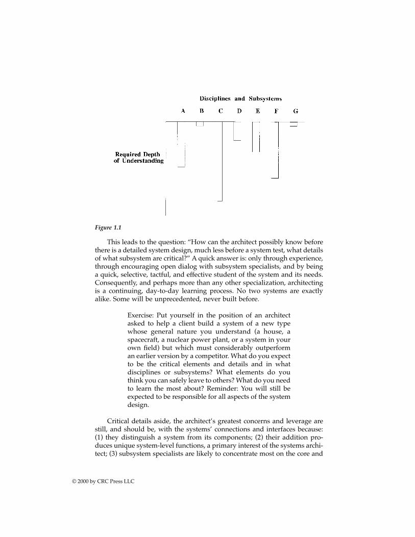
This leads to the question: “How can the architect possibly know beforethere is a detailed system design, much less before a system test, what detailsof what subsystem are critical?” A quick answer is: only through experience,through encouraging open dialog with subsystem specialists, and by beinga quick, selective, tactful, and effective student of the system and its needs.Consequently, and perhaps more than any other specialization, architectingis a continuing, day-to-day learning process. No two systems are exactlyalike. Some will be unprecedented, never built before.
Exercise: Put yourself in the position of an architectasked to help a client build a system of a new typewhose general nature you understand (a house, aspacecraft, a nuclear power plant, or a system in yourown field) but which must considerably outperforman earlier version by a competitor. What do you expectto be the critical elements and details and in whatdisciplines or subsystems? What elements do youthink you can safely leave to others? What do you needto learn the most about? Reminder: You will still beexpected to be responsible for all aspects of the systemdesign.
Critical details aside, the architect’s greatest concerns and leverage arestill, and should be, with the systems’ connections and interfaces because:(1) they distinguish a system from its components; (2) their addition pro-duces unique system-level functions, a primary interest of the systems archi-tect; (3) subsystem specialists are likely to concentrate most on the core and
Figure 1.1
© 2000 by CRC Press LLC
least on the periphery of their subsystems, viewing the latter as (generallywelcomed) external constraints on their internal design. Their concern forthe system as a whole is understandably less than that of the systems archi-tect — if not managed well, the system functions can be in jeopardy.
A purpose orientation
Systems architecting is a process driven by a client’s purpose or purposes.A president wants to meet an international challenge by safely sendingastronauts to the moon and back. Military services need nearly undetectablestrike aircraft. Cities call for pollutant-free transportation.
Clearly, if a system is to succeed, it must satisfy a useful purpose at anaffordable cost for an acceptable period of time. Note the explicit valuejudgments in these criteria: a useful purpose, an affordable cost, and an accept-able period of time. Each and every one is the client’s prerogative and respon-sibility, emphasizing the criticality of client participation in all phases ofsystem acquisition. Of the three criteria, satisfying a useful purpose is pre-dominant. Without it being satisfied, all others are irrelevant. Architectingtherefore begins with, and is responsible for maintaining, the integrity of thesystem’s utility or purpose.
For example, the Apollo manned mission to the moon and back had aclear purpose, an agreed cost, and a no-later-than date. It delivered on allthree. Those requirements, kept up front in every design decision, deter-mined the mission profile of using an orbiter around the moon and not anearth-orbiting space station, and on developing electronics for a lunar orbitrendezvous instead of developing an outsize propulsion system for a directapproach to the lunar surface.
As another example, NASA headquarters, on request, gave theNASA/JPL Deep Space Network’s huge ground antennas a clear set ofpriorities: first performance, then cost, then schedule, even though the pri-mary missions they supported were locked into the absolute timing of plan-etary arrivals. As a result, the first planetary communication systems weredesigned with an alternate mode of operation in case the antennas were notyet ready. As it turned out, and as a direct result of the NASA risk-takingdecision, the antennas were carefully designed, not rushed, and not onlysatisfied all criteria for the first launch, but for all launches for the next 40years or so.
The Douglas Aircraft DC-3, though originally thought by the airline(now TWA) to require three engines, was rethought by the client and thedesigners in terms of its underlying purpose — to make a profit on providingaffordable long-distance air travel over the Rocky and Sierra Nevada moun-tains for paying commercial passengers. The result was the two-engine DC-3, the plane that introduced global air travel to the world.
In contrast, the promises of the shuttle as an economically viable trans-porter to low earth orbit were far from met, although in fact the shuttle did
© 2000 by CRC Press LLC

turn out to be a remarkably reliable and unique launch vehicle for selectedmissions.
As of this date, the presumed purposes of the space station do not appearto be affordable and a change of purpose may be needed. The unacceptablecost/benefit ratios of the supersonic transport, the space-based ballistic mis-sile defense system, and the superconducting supercollider terminated allthese projects before their completion.
Curiously, the end use of a system is not always what was originallyproposed as its purpose. The F-16 fighter aircraft was designed for visualair-to-air combat, but in practice it has been most used for ground support.The ARPANET-INTERNET communication network originated as a govern-ment-furnished computer-to-computer linkage in support of universityresearch; it is now most used, and paid for, by individuals for e-mail andinformation accessing. Both are judged as successful. Why? Because, ascircumstances changed, providers and users redefined the meaning of useful,affordable, and acceptable. A useful heuristic comes to mind: Design thestructure with “good bones.” It comes from the architecting of buildings,bridges, and ships where it refers to structures that are resilient to a widerange of stresses and changes in purpose. It could just as well come fromphysiology and the remarkably adaptable spinal column and appendagesof all vertebrates — fishes, amphibians, reptiles, birds, and mammals.
Exercise: Identify a system whose purpose is clear andunmistakable. Identify, contact, and, if possible, visitits architect. Compare notes and document what youlearned.
Technology-driven systems, in notable contrast to purpose-driven sys-tems, tell a still different story. They are the subject of Chapter 3.
A modeling methodology
Modeling is the creation of abstractions or representations of the system topredict and analyze performance, costs, schedules, and risks, and to provideguidelines for systems research, development, design, manufacture, andmanagement. Modeling is the centerpiece of systems architecting — a mech-anism of communication to clients and builders, of design management withengineers and designers, of maintaining system integrity with project man-agement, and of learning for the architect, personally.
Examples: The balsa wood and paper scale models ofa residence, the full-scale mockup of a lunar lander,the rapid prototype of a software application, the com-puter model of a communication network, or the men-tal model of a user.
© 2000 by CRC Press LLC
Modeling is of such importance to architecting that it is the sole subjectof Part Three. At this point it is important to clear up a misconception. Therehas been a common perception that modeling is solely a conceptual process;that is, its purpose is limited to representing or simulating only the generalfeatures of an eventual system. If so, a logical question can be raised: whento stop modeling and start building? (It could almost have been asked as:when to stop architecting and begin engineering?)
Indeed, just that question was posed by Mark Maier in the first USCgraduate class. Thinking had just begun on the so-called “stop question”when it was realized that modeling did not stop at the end of conceptual-ization in any case. Rather, it progressed, evolved, and solved problems fromthe beginning of a system’s acquisition to its final retirement. There are, ofcourse, conceptual models, but there are also engineering models and sub-system models; models for simulation, prototypes, and system test; demon-stration models, operational models, and mental models by the user of howthe system behaves.
Models are, in fact, created by many participants, not just by architects.These models must somehow be made consistent with overall system imper-atives. It is particularly important that they be consistent with the architect’ssystem model, a model that evolves, becoming more and more concrete andspecific as the system is built. It provides a standard against which consis-tency can be maintained, and is a powerful tool in maintaining the largerobjective of system integrity. And, finally, when the system is operationaland a deficiency or failure appears, a model — or full-scale simulator if oneexists — is brought into play to help determine the causes and cures of theproblem. The more complete the model, the more accurately possible failuremechanisms can be duplicated until the one and only cause is identified.
In brief, modeling is a multipurpose, progressive activity, evolving andbecoming less abstract and more concrete as the system is built and used.
Ultraquality implementation
Ultraquality is defined as a level of quality so demanding that it is impracticalto measure defects, much less certify the system prior to use.6 It is a limitingcase of quality driven to an extreme, a state beyond acceptable quality limits(AQL) and statistical quality control. It requires a zero-defect approach notonly to manufacturing, but to design, engineering, assembly, test, operation,maintenance, adaptation, and retirement — in effect, the complete life cycle.
Some examples are a new-technology spacecraft with a design lifetimeof at least 10 years, a nuclear power plant that will not fail catastrophicallywithin the foreseeable future, and a communication network of millions ofnodes, each requiring almost 100% availability. Ultraquality is a recognitionthat the more components there are in a system, the more reliable eachcomponent must be to a point where, at the element level, defects becomeimpractical to measure within the time and resources available. Yet, thereliability goal of the system as a whole must still be met. In effect, it reflects
© 2000 by CRC Press LLC
the not unreasonable demand that a system, regardless of size or complexity,should not fail to perform more than about 1% or less of the time. An ICBMshouldn’t. A shuttle, at least 100 times more complex, shouldn’t. An auto-mobile shouldn’t. A passenger airliner, at least 100 times more complex,shouldn’t; as a matter of fact, we expect the airliner to fail far, far less thanthe family car.
Exercise: Trace the histories of commercial aircraft andpassenger buses over the last 50 years in terms of thenumber of trips that a passenger would expect to makewithout an accident. What does that mean to vehiclereliability as trips lengthen and become more frequent,as vehicles get larger, faster, and more complex? Howwere today’s results achieved? What trends do youexpect in the future? Did more software help or hindervehicle safety?
The subject would be moot if it were not for the implications of this“limit state” of zero defects to design. Zero defects, in fact, originated aslong ago as World War II, largely driven by patriotism. As a motivator, thezero defects principle was a prime reason for the success of the Apollomission to the moon.
To show the implications of ultraquality processes, if a manufacturingline operated with zero defects there would be no need, indeed it would beworthless, to build elaborate instrumentation and information processingsupport systems. This would reduce costs and time, instead, by 30%. If anautomobile had virtually no design or production defects, then sales outletswould have much less need for large service shops with their high capitaland labor costs. Indeed, the service departments of the finest automobilemanufacturers are seldom fully booked, resembling something like thefamous Maytag commercial. Very little repair or service, except for routinemaintenance, is required for 50 to 100,000 miles. Not coincidentally, theseshops invariably are spotlessly clean, evidence of both the professional prideand discipline required for sustaining an ultraquality operation. Conversely,a dirty shop floor is one of the first and best indicators to a visitor or inspectorof low productivity, careless workmanship, reduced plant yield, and poorproduct performance. The rocket, ammunition, solid state component, andautomotive domains all bear witness to that fact.
As another example, microprocessor design and development has main-tained the same per-chip defect rate even as the number and complexity ofoperations increased by factors of thousands. The corresponding failure rateper individual operation is now so low as to be almost unmeasurable.Indeed, for personal computer applications, a microprocessor hardware fail-ure more than once a year borders on the unacceptable.
Demonstrating this limit state in high quality is not a simple extensionof existing quality measures, though the latter may be necessary in order to
© 2000 by CRC Press LLC
get within range of it. In the latter there is an heuristic: (measurable) accep-tance tests must be both complete and passable. How, then, can an inher-ently unmeasurable ultraquality be demanded or certified? Most of theanswer seems to be in surrogate procedures, such as a zero defects program,and less in measurements, not because finer measurements would not beuseful but because system complexity has outpaced instrument accuracy.
In that respect, a powerful addition to pre-1990 ultraquality techniqueswas the concept, introduced in the last few years, that each participant in asystem acquisition sequence is both a buyer and a supplier. The originalapplication, apparently a Japanese idea, was that each worker on a produc-tion line was a buyer from the preceding worker in the production line aswell as a supplier to the next. Each role required a demand for high quality;that is, a refusal to buy a defective item and a concern not to deliver adefective one likely to be refused.7 In effect, the supplier-buyer conceptgenerates a self-enforcing quality program with built-in inspection. Therewould seem to be no reason why the same concept should not apply through-out system acquisition — from architect to engineer to designer to producerto seller to end user. As with all obvious ideas, the wonder is why it wasn’tself-evident earlier.
When discussing ultraquality it may seem odd to be discussing heuris-tics. After all, isn’t something as technologically demanding as qualitybeyond measure, the performance of things like heavy space boosters, notthe domain of rigorous, mathematical engineering? In part, of course, it is.But experience has shown that rigorous engineering is not enough to achieveultraquality systems. Ultraquality is achieved by a mixture of analytical andheuristic methods. The analytical side is represented by detailed failureanalysis and even the employment of proof techniques in system design. Insome cases these very rigorous techniques have been essential in allowingcertain types of ultraquality systems to be architected.
Flight computers are a good example of the mixture of analytical andheuristic considerations in ultraquality systems. Flight control computers forstatically unstable aircraft are typically required to have a mean time betweenfailures (where a failure is one which produces incorrect flight control com-mands) on the order of 10 billion hours. This is clearly an ultraqualityrequirement since the entire production run of a given type of flight com-puter will not collectively run for 10 billion hours during their operationallifetimes. The requirement certainly cannot be proved by measurement andanalysis. Nevertheless, aircraft administration authorities require that sucha reliability requirement be certified.
Achieving the required reliability would seem to require a redundantcomputer design as individual parts cannot reach that reliability level. Theproblem with redundant designs is that introducing redundancy also intro-duces new parts and functions, specifically the mechanisms that manage theredundancy and must lock out the signals from redundant sections that havefailed. For example, in a triple redundant system the redundant componentsmust be voted to take the majority position (locking out a presumptive single
© 2000 by CRC Press LLC
failure). The redundancy management components are themselves subjectto failure, and it possible that a redundant system is actually more likely tofail than one without redundancy. Further, “fault tolerance” depends uponthe fault to be tolerated. Tolerating mechanical failure is of limited value ifthe fault is human error.
Creating redundant computers has been greatly helped by better anal-ysis techniques. There are proof techniques that allow pruning of theunworkable failure trees by assuming so called “Byzantine” failure* models.These techniques allow strong statements to be made about the redundancyproperties of designs. The heuristic part is trying to verify the absence of“common-mode-failures,” or failures in which several redundant and sup-posedly independent components fail at the same time for the same reason.
The Ariane 5 space launch vehicle was destroyed on its initial flight ina classic common mode failure. The software on the primary flight controlcomputer caused the computer to crash shortly after launch. The dual redun-dant system then switched to the backup flight control computer, which hadfailed as well moments before for exactly the same reason that the primarycomputer failed. Ironically, the software failure was due to code leftoverfrom the Ariane 4 and not actually necessary for the phase of flight in whichit was operating. Arguably, in the case of the Ariane 5, more rigorous proof-based techniques of the mixed software and systems design might havefound and eliminated the primary failure.
The analytical side is not enough, however. The best analysis of failureprobabilities and redundancy can only verify that the system as built agreeswith the model analyzed, and that the model possesses desired properties.It cannot verify that the model corresponds to reality. Well-designedultraquality systems fail, but they typically fail for reasons not anticipatedin the reliability model.
Certification
Certification is a formal statement by the architect to the client or user thatthe system, as built, meets the criteria both for client acceptance and forbuilder receipt of payment, i.e., it is ready for use (to fulfill its purposes).Certification is the grade on the “final exams" of system test and evaluation.To be accepted it must be well-supported, objective, and fair to client andbuilder alike.
Exercise: Pick a system for which the purposes arereasonably clear. What tests would you, as a client,demand be passed for you to accept and pay for thesystem? What tests would you, as a builder, contractto pass in order to be paid? Whose word would each
* A Byzantine failure is one in which the failed component does the worst possible thing to thesystem. It is as if the component were possessed by a malign intelligence. The power of thetechnique is that it lends itself to certification, at least within the confines of well-defined models.
© 2000 by CRC Press LLC
of you accept that the tests had or had not been passed?When should such questions be posed? (In first con-cept.)
Clearly, if certification is to be unchallenged, then there must be noperception of conflict of interest of the architect. This imperative has led tothree widely accepted, professionally understood, constraints8 on the role ofthe architect:
1. A disciplined avoidance of value judgments, that is, of intruding in ques-tions of worth to the client; questions of what is satisfactory, what isacceptable, affordable, maintainable, reliable, etc. Those judgmentsare the imperatives, rights, and responsibilities of the client. As amatter of principle, the client should judge on desirability and thearchitect should decide (only) on feasibility. To a client’s question of“What would you do in my position?” the experienced architect re-sponds only with further questions until the client can answer theoriginal one. To do otherwise makes the architect an advocate and, insome sense, the “owner” of the end system, preempting the rightsand responsibilities of the client. It may make the architect famous,but the client will feel used. Residences, satellites, and personal com-puters have all suffered from such preemption (Frank Lloyd Wrighthouses, low earth orbiting satellite constellations, and the Lisa com-puter, respectively).
2. A clear avoidance of perceived conflict of interest through participation inresearch and development, including ownership or participation inorganizations that can be, or are, building the system. The most evi-dent conflict here is the architect recommending a system elementfrom which the architect will supply and profit. This constraint isparticularly important in builder-architected systems (Chapter 3).*
3. An arms-length relationship with project management, that is, with themanagement of human and financial resources other than of the ar-chitect’s own staff. The primary reason for this arrangement is theoverload and distraction of the architect created by the time-consum-ing responsibilities of project management. A second conflict, similarto that of participating in research and development, is created when-ever architects give project work to themselves. If clients, for reasonsof their own, nonetheless ask the architect to provide project manage-ment, it should be considered as a separate contract for a differenttask requiring different resources.
* Precisely this constraint led Congress to mandate the formation in 1960 of a non-profitengineering company, The Aerospace Corporation, out of the for-profit TRW Corporation, abuilder in the aerospace business.
© 2000 by CRC Press LLC
Insights and heuristics
A picture is worth a thousand words. Chinese Proverb. 1000 BC
One insight is worth a thousand analyses. Charles Sooter, April 1993
Insight, or the ability to structure a complex situation in a way that greatlyincreases understanding of it, is strongly guided by lessons learned fromone’s own or others’ experiences and observations. Given enough lessons,their meaning can be codified into succinct expressions called “heuristics,”a Greek term for guide. Heuristics are an essential complement to analytics,particularly in situations where analysis alone cannot provide either insightsor guidelines.9 In many ways they resemble what are called principles inother arts; for example, the importance of balance and proportion in a paint-ing, a musical composition, or the ensemble of a string quartet. Whether asheuristics or principles, they encapsulate the insights that have to beachieved and practiced before a masterwork can be achieved.
Both architecting and the fine arts clearly require insight and inspirationas well as extraordinary skill to reach the highest levels of achievement. Seenfrom this perspective, the best systems architects are indeed artists in whatthey do. Some are even artists in their own right. Renaissance architects likeMichaelangelo and Leonardo da Vinci were also consummate artists. Theynot only designed cathedrals, they executed the magnificent paintings inthem. The finest engineers and architects, past and present, are often musi-cians; Simon Ramo and Ivan Getting, famous in the missile and space field,and, respectively, a violinist and pianist, are modern day examples.
The wisdom that distinguishes the great architect from the rest is thatinsight and inspiration, combined with well-chosen methods and guidelinesand fortunate circumstances, creates masterworks. Unfortunately, wisdomdoes not come easily. As one conundrum puts it:
Success comes from wisdom.Wisdom comes from experience.Experience comes from mistakes.
Therefore, because success comes only after many mistakes, somethingfew clients would willingly support, it presumably is either unlikely or mustfollow a series of disasters.
This reasoning might well apply to an individual. But applied to theprofession as a whole, it clearly does not. The required mistakes and expe-rience and wisdom gained from them can be those of one’s predecessors,not necessarily one’s own.
And from that understanding comes the role of education. It is the placeof education to research, document, organize, codify, and teach those lessonsso that the mistakes need not be repeated as a prerequisite for future suc-
© 2000 by CRC Press LLC
cesses. Chapter 2, Heuristics as Tools, is a start in that direction for the artof systems architecting.
The architecture paradigm summarizedThis book uses the terms architect, architecture, and architecting with fullconsciousness of the “baggage” that comes with their use. Civil architectureis a well-established profession with its own professional societies, trainingprograms, licensure, and legal status. Systems architecting borrows from itits basic attributes.
1. The architect is principally an agent of the client, not the builder.Whatever organization the architect is employed by, the architect mustact in the best interests of the client for whom the system is beingdeveloped.
2. The architect works jointly with the client and builder on problemand solution definition. System requirements are an output of archi-tecting, not really an input. Of course, the client will provide thearchitect some requirements, but the architect is expected to jointlyhelp the client determine the ultimate requirements. An architect whoneeds complete and consistent requirements to begin work, thoughperhaps a brilliant builder, is not an architect.
3. The architect’s product, or “deliverable,” is an architecture represen-tation, a set of abstracted designs of the system. The designs are not(usually) ready to use to build something. They have to be refined,just as the civil architect’s floorplans, elevations, and other drawingsmust be refined into construction drawings.
4. The architect’s product is not just physical representations. As anexample, the civil architect’s client certainly expects a “ballpark” costestimate as part of any architecture feasibility question. So, too, insystems architecting where an adequate system architecture descrip-tion must cover whatever aspects of physical structure, behavior, cost,performance, human organization, or other elements are needed toclarify the clients’ priorities.
5. An initial architecture is a vision. An architecture description is a setof specific models. The architecture of a building is more than theblueprints, floorplans, elevations, and cost estimates. It includes ele-ments of ulterior motives, beliefs, and unstated assumptions. Thisdistinction is especially important in creating standards. Standardsfor architecture, like community architectural standards, are differentfrom blueprint standards promoted by agencies or trade associations.
Architecting takes place within the context of an acquisition process. Thetraditional way of viewing hardware acquisitions is known as the waterfallmodel. The waterfall model captures many important elements of architect-ing practice, but it is also important in understanding other acquisition
© 2000 by CRC Press LLC
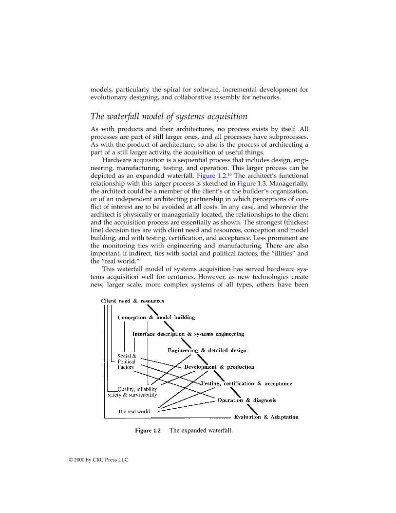
models, particularly the spiral for software, incremental development forevolutionary designing, and collaborative assembly for networks.
The waterfall model of systems acquisitionAs with products and their architectures, no process exists by itself. Allprocesses are part of still larger ones, and all processes have subprocesses.As with the product of architecture, so also is the process of architecting apart of a still larger activity, the acquisition of useful things.
Hardware acquisition is a sequential process that includes design, engi-neering, manufacturing, testing, and operation. This larger process can bedepicted as an expanded waterfall, Figure 1.2.10 The architect’s functionalrelationship with this larger process is sketched in Figure 1.3. Managerially,the architect could be a member of the client’s or the builder’s organization,or of an independent architecting partnership in which perceptions of con-flict of interest are to be avoided at all costs. In any case, and wherever thearchitect is physically or managerially located, the relationships to the clientand the acquisition process are essentially as shown. The strongest (thickestline) decision ties are with client need and resources, conception and modelbuilding, and with testing, certification, and acceptance. Less prominent arethe monitoring ties with engineering and manufacturing. There are alsoimportant, if indirect, ties with social and political factors, the “illities” andthe “real world.”
This waterfall model of systems acquisition has served hardware sys-tems acquisition well for centuries. However, as new technologies createnew, larger scale, more complex systems of all types, others have been
Figure 1.2 The expanded waterfall.
© 2000 by CRC Press LLC
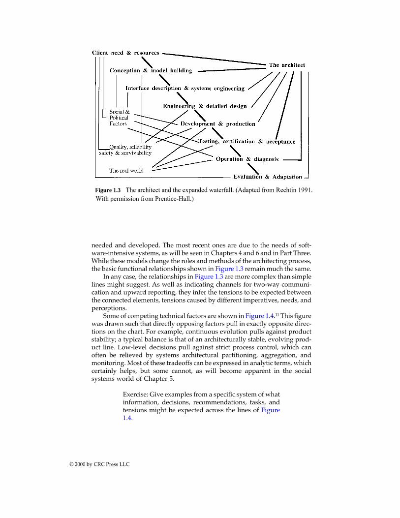
needed and developed. The most recent ones are due to the needs of soft-ware-intensive systems, as will be seen in Chapters 4 and 6 and in Part Three.While these models change the roles and methods of the architecting process,the basic functional relationships shown in Figure 1.3 remain much the same.
In any case, the relationships in Figure 1.3 are more complex than simplelines might suggest. As well as indicating channels for two-way communi-cation and upward reporting, they infer the tensions to be expected betweenthe connected elements, tensions caused by different imperatives, needs, andperceptions.
Some of competing technical factors are shown in Figure 1.4.11 This figurewas drawn such that directly opposing factors pull in exactly opposite direc-tions on the chart. For example, continuous evolution pulls against productstability; a typical balance is that of an architecturally stable, evolving prod-uct line. Low-level decisions pull against strict process control, which canoften be relieved by systems architectural partitioning, aggregation, andmonitoring. Most of these tradeoffs can be expressed in analytic terms, whichcertainly helps, but some cannot, as will become apparent in the socialsystems world of Chapter 5.
Exercise: Give examples from a specific system of whatinformation, decisions, recommendations, tasks, andtensions might be expected across the lines of Figure1.4.
© 2000 by CRC Press LLC
Figure 1.3 The architect and the expanded waterfall. (Adapted from Rechtin 1991.With permission from Prentice-Hall.)
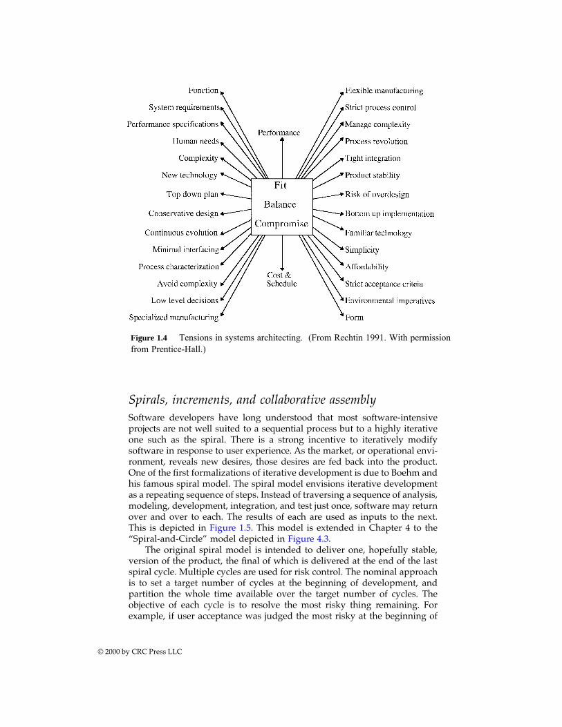
Spirals, increments, and collaborative assemblySoftware developers have long understood that most software-intensiveprojects are not well suited to a sequential process but to a highly iterativeone such as the spiral. There is a strong incentive to iteratively modifysoftware in response to user experience. As the market, or operational envi-ronment, reveals new desires, those desires are fed back into the product.One of the first formalizations of iterative development is due to Boehm andhis famous spiral model. The spiral model envisions iterative developmentas a repeating sequence of steps. Instead of traversing a sequence of analysis,modeling, development, integration, and test just once, software may returnover and over to each. The results of each are used as inputs to the next.This is depicted in Figure 1.5. This model is extended in Chapter 4 to the“Spiral-and-Circle” model depicted in Figure 4.3.
The original spiral model is intended to deliver one, hopefully stable,version of the product, the final of which is delivered at the end of the lastspiral cycle. Multiple cycles are used for risk control. The nominal approachis to set a target number of cycles at the beginning of development, andpartition the whole time available over the target number of cycles. Theobjective of each cycle is to resolve the most risky thing remaining. Forexample, if user acceptance was judged the most risky at the beginning of
© 2000 by CRC Press LLC
Figure 1.4 Tensions in systems architecting. (From Rechtin 1991. With permissionfrom Prentice-Hall.)
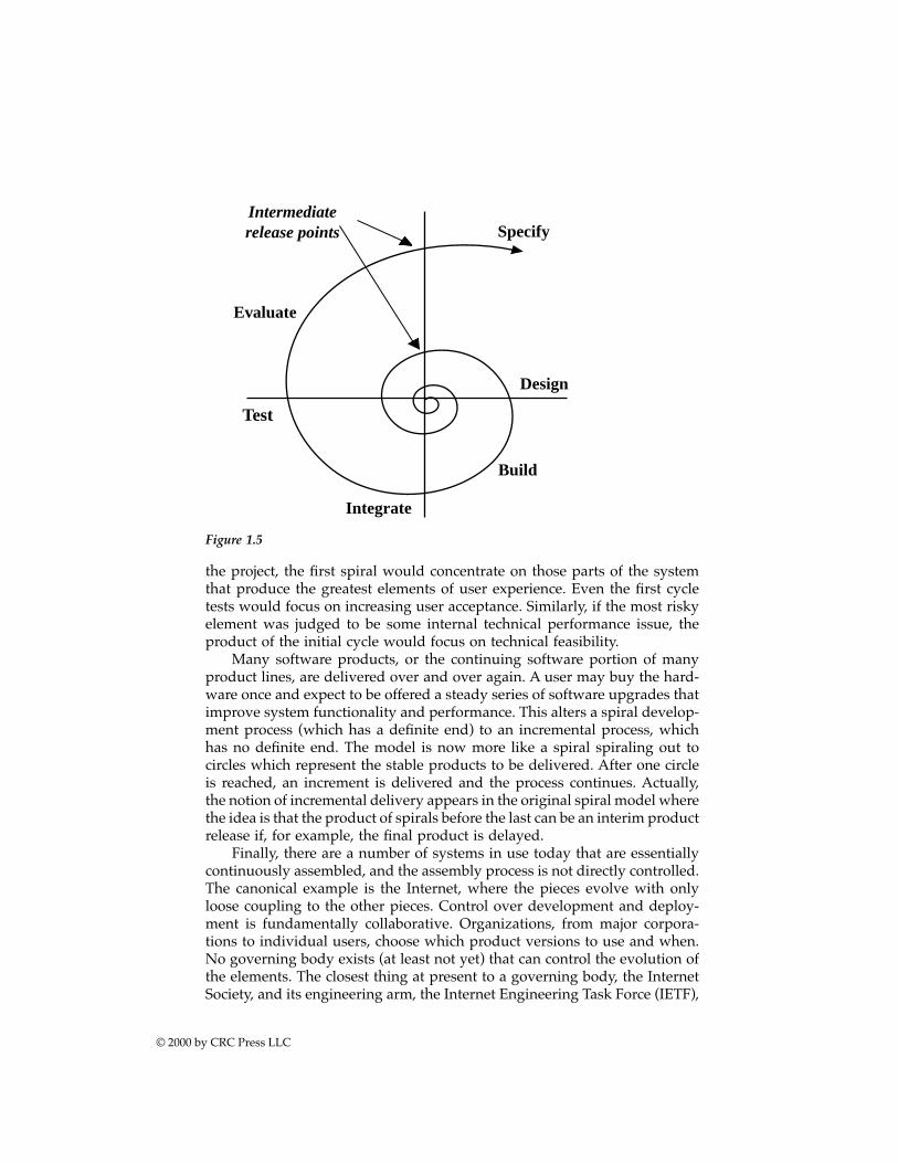
the project, the first spiral would concentrate on those parts of the systemthat produce the greatest elements of user experience. Even the first cycletests would focus on increasing user acceptance. Similarly, if the most riskyelement was judged to be some internal technical performance issue, theproduct of the initial cycle would focus on technical feasibility.
Many software products, or the continuing software portion of manyproduct lines, are delivered over and over again. A user may buy the hard-ware once and expect to be offered a steady series of software upgrades thatimprove system functionality and performance. This alters a spiral develop-ment process (which has a definite end) to an incremental process, whichhas no definite end. The model is now more like a spiral spiraling out tocircles which represent the stable products to be delivered. After one circleis reached, an increment is delivered and the process continues. Actually,the notion of incremental delivery appears in the original spiral model wherethe idea is that the product of spirals before the last can be an interim productrelease if, for example, the final product is delayed.
Finally, there are a number of systems in use today that are essentiallycontinuously assembled, and the assembly process is not directly controlled.The canonical example is the Internet, where the pieces evolve with onlyloose coupling to the other pieces. Control over development and deploy-ment is fundamentally collaborative. Organizations, from major corpora-tions to individual users, choose which product versions to use and when.No governing body exists (at least not yet) that can control the evolution ofthe elements. The closest thing at present to a governing body, the InternetSociety, and its engineering arm, the Internet Engineering Task Force (IETF),
Figure 1.5
SpecifyIntermediaterelease points
Evaluate
Build
Design
Integrate
Test
© 2000 by CRC Press LLC
can affect other behavior only through persuasion. If member organizationsdo not choose to support IETF standards the IETF has no authority to compelcompliance or block noncomplying implementations.
We call systems like this “collaborative systems.” The development pro-cess is collaborative assembly. Whether or not such an uncontrolled processcan continue for systems like the Internet as they become central to dailylife is unknown, but the logic and heuristics of such systems now is thesubject of Chapter 7.
Summary and conclusionsA system is a collection of different things that together produce resultsunachievable by themselves alone. The value added by systems is in theinterrelationships of their elements.
Architecting is creating and building structures, i.e., “structuring.” Sys-tems architecting is creating and building systems. It strives for fit, balance,and compromise among the tensions of client needs and resources, technol-ogy, and multiple stakeholder interests.
Architecting is both an art and a science — synthesis and analysis,induction and deduction, and conceptualization and certification — usingguidelines from its art and methods from its science. As a process, it isdistinguished from systems engineering in its greater use of heuristic rea-soning, lesser use of analytics, closer ties to the client, and particular concernwith certification of readiness for use
The foundations of systems architecting are a systems approach, a pur-pose orientation, a modeling methodology, ultraquality, certification, andinsight. To avoid perceptions of conflict of interest, architects must avoidvalue judgments, avoid perceived conflicts of interest, and keep an arms-length relationship with project management.
A great architect must be as skilled as an engineer and as creative as anartist or the work will be incomplete. Gaining the necessary skills andinsights depends heavily on lessons learned by others, a task of educationto research and teach.
The role of systems architecting in the systems acquisition processdepends upon the phase of that process. It is strongest during conceptual-ization and certification, but never absent. Omitting it at any point, as withany part of the acquisition process, leads to predictable errors of omissionat that point to those connected with it.
Notes and references1. Webster II, New Riverside University Dictionary, Riverside Publishing, Boston,
1984, p. 291.2. Rechtin, 1991, p. 7.
© 2000 by CRC Press LLC

3. Another factor in overruns and delays is uncertainty, the so-called unknownsand unknown unknowns. Uncertainty is highest during conceptualization,less in design, still less in redesign, and least in an upgrade. As with com-plexity, the higher the level, the more important become experience-basedarchitecting methods. See Carpenter, R. G., System Architects’ Job Characteristicsand Approach to the Conceptualization of Complex Systems, Doctoral dissertationin Industrial and Systems Engineering, University of Southern California, LosAngeles, CA, 1995.
4. Cuff, D., Architecture: The Story of Practice, MIT Press, Cambridge, MA, 1991.5. Rechtin, E., Foundations of systems architecting, Sys. Eng. J. Nat. Counc. Sys.
Eng., 1(1), 35, July/September 1994.6. Discussed extensively in Juran, J. M., Juran on Planning for Quality, Free Press,
New York, 1988; Phadke, M. S., Quality Engineering Using Robust Design,Prentice-Hall, Englewood Cliffs, NJ, 1989; and Rechtin, E., Systems Architect-ing, Creating & Building Complex Systems, Prentice-Hall, Englewood Cliffs, NJ,1991.
7. See also Chapter 4, Manufacturing Systems.8. From Cantry, D., What architects do and how to pay them, Arch. Forum, 119,
92, September 1963; and from discussions with Roland Russell, AIA.9. See King, D. R., The Role of Informality in System Development or, A Critique
of Pure Formality, University of Southern California 1992 (unpublished butavailable through USC).
10. Rechtin, E., Systems Architecting, Creating & Building Complex Systems, Prentice-Hall, Englewood Cliffs, NJ, 1991, 4.
11. Rechtin, E., Systems Architecting, Creating & Building Complex Systems, Prentice-Hall, Englewood Cliffs, NJ, 1991, 156.
© 2000 by CRC Press LLC
chapter two
Heuristics as tools
Introduction: a metaphorMathematicians are still smiling over a gentle self-introduction by one oftheir famed members. “There are three kinds of mathematicians,” he said,“those that know how to count and those that don’t.” The audience waitedin vain for the third kind until, with laughter and appreciation, they caughton. Either the member couldn’t count to three — ridiculous — or he wassomeone who believed that there was more to mathematics than numbers,important as they were. The number theorists appreciated his acknowledg-ment of them. The “those that don’ts” quickly recognized him as one of theirown, the likes of a Gödel who, using thought processes alone, showed thatno set of theorems can ever be complete.
Modifying the self-introduction only slightly to the context of this chap-ter, there are three kinds of people in our business: those who know how tocount and those who don’t, including the authors.
Those who know how to count (most engineers) approach their designproblems using analysis and optimization, powerful and precise toolsderived from the scientific method, and calculus. Those who don’t (mostarchitects) approach their qualitative problems using guidelines, abstrac-tions, and pragmatics generated by lessons learned from experience; that is,heuristics. As might be expected, the tools each use are different because thekinds of problems they solve are different. We routinely and accuratelydescribe an individual as “thinking like an engineer” or architect, or scientist,or artist. Indeed, by their tools and works ye shall know them.
This chapter, metaphorically, is about architects’ heuristic tools. As withthe tools of carpenters, painters, and sculptors, there are literally hundredsof them — but only a few are needed at any one time and for a specific jobat hand. To continue the metaphor, although a few tool users make theirown, the best source is usually a tool supply store, whether it be for hard-ware, artists’ supplies, software, or heuristics. Appendix A, Heuristics forSystems-Level Architecting, is a heuristics store, organized by task, just likeany good hardware store. Customers first browse, then select a kit of tools
©2000 CRC Press LLC
based on the job, personal skill, and a knowledge of the origin and intendeduse of each tool.
Heuristic has a Greek origin, heuriskein, a word meaning “to find a way”or “to guide” in the sense of piloting a boat through treacherous shoals.Architecting is a form of piloting. Its rocks and shoals are the risks andchanges of technology, construction, and operational environment that char-acterize complex systems. Its safe harbors are client acceptance and safe,dependable, long life. Heuristics are guides along the way — channel mark-ings, direction signs, alerts, warnings, and anchorages — tools in the largersense. But they must be used with judgment. No two harbors are alike. Theguides may not guarantee safe passage, but to ignore them may be fatal.The stakes in architecting are just as high — reputations, resources, vitalservices, and, yes, lives. Consonant with their origin, the heuristics in thisbook are intended to be trusted, time-tested guidelines for serious problemsolving.
Heuristics as thus defined are narrower in scope, subject to more criticaltest and selection, and intended for more serious use than other guidelines;for example, conventional wisdom, aphorisms, maxims, and rules of thumband the like. Also, a pair of mutually contradictory statements like look beforeyou leap and he who hesitates is lost are hardly useful guides when encounter-ing a cliff while running for your life. In this book, neither of these exampleswould be a valid heuristic because they offer contradictory advice for thesame problem.
The purpose of this chapter is, therefore, to help the reader — whetherarchitect, engineer, or manager — find or develop heuristics that can betrusted, organize them according to need, and use them in practice. The firststep is to understand that heuristics are abstractions of experience.
Heuristics as abstractions of experienceOne of the most remarkable characteristics of the human race is its abilitynot only to learn, but to pass on to future generations sophisticated abstrac-tions of lessons learned from experience. Each generation knows more, learnsmore, plans more, tries more, and succeeds more than the previous onebecause it needn’t repeat the time-consuming process of reliving prior expe-riences. Think of how extraordinarily efficient are such quantifiable abstrac-tions as F = ma, E = mc2 and x = F(y,z,t); of algorithms, charts, and graphs;and of the basic principles of economics. This kind of efficiency is essentialif large, lengthy, complex systems and long-lived product lines are to suc-ceed. Few architects ever work on more than two or three complex systemsin a lifetime. They have neither the time nor the opportunity to gain theexperience needed to create first-rate architectures from scratch. By muchthe same process, qualitative heuristics, condensed and codified practicalexperience, came into being to complement the equations and algorithms ofscience and engineering in the solving of complex problems. Passed from
©2000 CRC Press LLC
architect to architect, from system to system, they worked and helped satisfya real need.
In contrast to the symbols of physics and mathematics, the format ofheuristics is words expressed in the natural languages. Unavoidably, theyreflect the cultures of engineering, business, exploration, and human rela-tions in which they arose. The birth of a heuristic begins with anecdotes andstories, hundreds of them, in many fields which become parables, fables,and myths,1 easily remembered for the lessons they teach. Their impact, evenat this early stage, can be remarkable not only on politics, religion, andbusiness, but on the design of technical systems and services. The lessonsthat have endured are those that have been found to apply beyond theoriginal context, extended there by analogy, comparison, conjecture, andtesting.* At their strongest they are seen as self-evident truths requiring noproof.
There is an interesting human test for a good heuristic. An experiencedlistener, on first hearing one, will know within seconds that it fits thatindividual’s model of the world. Without having said a word to the speaker,the listener almost invariably affirms its validity by an unconscious nod ofthe head, and then proceeds to recount a personal experience that strength-ens it. Such is the power of the human mind.
Selecting a personal kit of heuristic tools
The art in architecting lies not in the wisdom of the heuris-tics, but in the wisdom of knowing which heuristics apply,a priori, to the current project.2
All professions and their practitioners have their own kits of tools, physicaland heuristic, selected from their own and others’ experiences to match theirneeds and talents. But, in the case of architecting and engineering prior tothe late 1980s, selections were limited and, at best, difficult to acquire. Aneffort was therefore made in the USC graduate course in systems architectingto create a much wider selection by gathering together lessons learnedthroughout the West Coast aerospace, electronics, and software industriesand expressing them in heuristic form for use by architects, educators,researchers, and students.
An initial collection3 of about 100 heuristics was soon surpassed bycontributions from over 200 students, reaching nearly 1000 heuristics within6 years.4 Many, of course, were variations on single, central ideas — just asthere are many variations of hammers, saws, and screwdrivers — repeated
* This process is one of inductive reasoning, “a process of truth estimation in the face ofincomplete knowledge which blends information known from experience with plausible con-jecture.” Klir, G. J., Architecture of Systems Problem Solving, Plenum Press, New York, 1985, 275.More simply, it is an extension or generalization from specific examples. It contrasts withdeductive reasoning, which derives solutions for specific cases from general principles.
©2000 CRC Press LLC
time and time again in different contexts. The four most widely applicableof these heuristics were, in decreasing order of popularity:
• Don’t assume that the original statement of the problem is neces-sarily the best, or even the right one.
Example: The original statement of the problem for theF-16 fighter aircraft asked for a high supersonic capa-bility, which was difficult and expensive to produce.Discussions with the architect, Harry Hillaker, broughtout that the reason for this statement was to providea quick exit from combat, something far better provid-ed by a high thrust-to-weight, low supersonic design.In short, the original high speed statement was re-placed by a high acceleration one, with the added ad-vantage of exceptional maneuverability.
• In partitioning, choose the elements so that they are as independentas possible; that is, elements with low external complexity and highinternal complexity.
Example: One of the difficult problems in the designof microchips is the efficient use of their surface area.Much of that area is consumed by connections betweencomponents; that is, by communications rather thanby processing. Professor Carver Mead of Caltech hasnow demonstrated that a design based on minimumcommunications between process-intensive nodes re-sults in much more efficient use of space, with theinteresting further result that the chip “looks elegant”— a sure sign of a fine architecture and another con-firmation of the heuristic, the eye is a fine architect.Believe it.
• Simplify. Simplify. Simplify.
Example: One of the best techniques for increasingreliability while decreasing cost and time is to reducethe piece part count of a device. Automotive engineers,particularly recently, have produced remarkable re-sults by substituting single castings for multiple as-semblies and by reducing the number of fasteners andtheir associated assembly difficulties by better place-ment. A comparable result in computer software is theuse of reduced instruction set computers (RISC) which
©2000 CRC Press LLC
increase computing speed for much the same hard-ware.
• Build in and maintain options as long as possible in the design andimplementation of complex systems. You will need them.
Example: In the aircraft business they are called“scars.” In the software business they are called“hooks.” Both are planned breaks or entry points intoa system which can extend the functions the systemcan provide. For aircraft, they are used for lengtheningthe fuselage to carry more passengers or freight. Forsoftware, they are used for inserting further routines.
Though these four heuristics do not make for a complete tool kit, theydo provide good examples for building one. All are aimed at reducingcomplexity, a prime objective of systems architecting. All have been trustedin one form or another in more than one domain. All have stood the test oftime for decades if not centuries.
The first step in creating a larger kit of heuristics is to determine thecriteria for selection. The following were established to eliminate unsubstan-tiated assertions, personal opinions, corporate dogma, anecdotal specula-tion, mutually contradictory statements, etc. As it turned out, they alsohelped generalize domain-specific heuristics into more broadly applicablestatements. The strongest heuristics passed all the screens easily. The criteriawere
• The heuristic must make sense in its original domain or context. Tobe accepted, a strong correlation, if not a direct cause and effect, mustbe apparent between the heuristic and the successes or failures ofspecific systems, products, or processes. Academically speaking, boththe rationale for the heuristic and the report that provided it weresubject to peer and expert review. As might be expected, a validheuristic seldom came from a poor report.
• The general sense, if not the specific words, of the heuristic shouldapply beyond the original context. That is, the heuristic should beuseful in solving or explaining more than the original problem fromwhich it arose. An example is the foregoing don’t assume heuristic.Another is before the flight it’s opinion; after the flight it’s obvious.In the latter, the word “flight” can be sensibly replaced by test, exper-iment, fight, election, proof, or trial. In any case, the heuristic shouldnot be wrong or contradictory in other domains where it could leadto serious misunderstanding and error. This heuristic applies in gen-eral to ultraquality systems. When they fail, and they usually fail afterall the tests are done and they are in actual use, we wonder how wemissed such an obvious failure of our assumptions.
©2000 CRC Press LLC
• The heuristic should be easily rationalized in a few minutes or on lessthan a page. As one of the heuristics itself states: “If you can’t explainit in five minutes, either you don’t understand it or it doesn’t work(Darcy McGinn 1992, from David Jones). With that in mind, the moreobvious the heuristic is on its face, and the fewer the limitations onits use, the better. Example: A model is not reality.
• The opposite statement of the heuristic should be foolish, clearly not“common sense.” For example: The opposite of Murphy’s Law — “Ifit can fail, it will” — would be “If it can fail, it won’t,” which is patentnonsense.
• The heuristic’s lesson, though not necessarily its most recent formu-lation, should have stood the test of time and earned a broad consen-sus. Originally this criterion was that the heuristic itself had stood thetest of time, a criterion that would have rejected recently formulatedheuristics based on retrospective understanding of older or lengthyprojects. Example: The beginning is the most important part of thework (Plato 4th Century B. C.), reformulated more recently as All theserious mistakes are made in the first day (Robert Spinrad, 1988).
It is probably true that heuristics can be even more useful if they can beused in a set, like wrenches and screwdrivers, hammers and anvils, or filesand vises. The taxonomy grouping to follow achieves that possibility in part.
It is also probably true that a proposed action or decision is stronger ifit is consistent with several heuristics rather than only one. A set of heuristicsapplicable to acceptance procedures substantiates that proposition.
And it would certainly seem desirable that a heuristic, taken in a suffi-ciently restricted context, could be specialized into a design rule; a quanti-fiable, rational evaluation; or a decision algorithm. If so, heuristics of thistype would be useful bridges between architecting, engineering, and design.
Using heuristicsVirtually everybody, after brief introspection, sees that heuristics play animportant role in their design and development activities. However, even ifwe accept that everyone uses heuristics, it is not obvious that those heuristicscan be communicated to and used by others. This book takes the approachthat heuristics can be effectively communicated to others. One lesson fromstudent use of Rechtin, 1991, and the first edition of this book, is that heu-ristics do transfer from one person to another, but not always in simple ways.It is useful to document heuristics and teach from them, but learning stylesdiffer.
People typically use heuristics in three ways. First, they can be used asevocative guides. They work as guides if they evoke new thoughts in thereader. Some readers have reported that they use the catalog of heuristics inthe appendices at random when faced with a difficult design problem. If oneof the heuristics seems suggestive, they follow up by considering how that
©2000 CRC Press LLC
heuristic could describe the present situation, what solutions it might sug-gest, or what new questions it suggests.
The second usage is as codifications of experience. In this usage theheuristic is like an outline heading, a guide to the detailed discussion thatfollows. In this case the stories behind the heuristics can be more importantthan the basic statement. The heuristic is a pedagogical tool, a way of teach-ing lessons not well captured in other engineering teaching methods.
The third usage, of special interest in this second edition, is the moststructured. It is when heuristics are integrated into development processes.A good example is in software. A number of software development methodshave a sequence of models, from relatively abstract to code in a programminglanguage. Object-oriented methods, for example, usually begin with a set oftextual requirements: build a model of classes and objects, and then refinethe class/object model into code in the target programming environment.There are often intermediate steps in which the problem domain derivedobjects are augmented with objects and characteristics from the target envi-ronment. A problem in all such methods is knowing how to construct themodels at each step. The transformation from a set of textual requirementsto classes and objects is not unique; it involves extensive judgment by thepractitioner. Some methods provide assistance to the practitioner by givingexplicit, prescriptive heuristics for each step.
Heuristics on heuristicsA phenomenon observed as heuristics was discovered by the USC graduatestudents when the discoverers themselves began thinking heuristically. Theyfound themselves creating heuristics directly from observation and discus-sion, then trying them out on professional architects and engineers, some ofwhose experiences had suggested them. (Most interviewees were surprisedand pleased at the results.) The resultant provisional heuristics were thensubmitted for academic review as parts of class assignments.
Kenneth L. Cureton, carrying the process one step further, generated aset of heuristics on how to generate and apply heuristics,5 from which thefollowing were chosen.
Generating useful heuristics
• Humor (and careful choice of words) in a heuristic provide an emo-tional bite that enhances the mnemonic effect (Karklins).
• Use words that transmit the “thrill of insight” into the mind of thebeholder.
• For maximum effect, try embedding both descriptive and prescriptivemessages in a heuristic.
• Many heuristics can be applied to heuristics themselves; e.g., Simpli-fy. Scope.
©2000 CRC Press LLC
• Don’t make a heuristic so elegant that it only has meaning to itscreator, thus losing general usefulness.
• Rather than adding a conditional statement to a heuristic, considercreating a separate but associated heuristic that focuses on the insightof dealing with that conditional situation.
Applying heuristics
• If it works, then it’s useful.• Knowing when and how to use a heuristic is as important as knowing
the what and why.• Heuristics work best when applied early to reduce the solution space.• Strive for balance — too much of a good thing or complete elimination
of a bad thing may make things worse, not better!• Practice, practice, practice.• Heuristics aren’t reality, either.
A taxonomy of heuristicsThe second step after finding or creating individual heuristics is to organizethem for easy access so that the appropriate ones are at hand for the imme-diate task. The collection mentioned earlier in this chapter was accordinglyrefined and organized by architecting task.* In some ways, the resultant list— presented in Appendix A — was self-organizing. Heuristics tended tocluster around what became recognized as basic architecting tasks. For exam-ple, although certifying is shown last and is one of the last formal phases ina waterfall, it actually occurs at many milestones as “sanity checks” are madealong the way and subsystems are assembled. The tasks, elaborated in Chap-ter 9, pages 177–186, are
• Scoping and planning• Modeling• Prioritizing• Aggregating• Partitioning• Integrating• Certifying• Assessing• Evolving and rearchitecting
The list is further refined by distinguishing between two forms of heu-ristic. One form is descriptive; that is, it describes a situation but does not
* The original 100 of Rechtin, 1991, were organized by the phases of a waterfall. The list inAppendix A of this book recognizes that many heuristics apply to several phases, that the spiralmodel of system development would in any case call for a different categorization, and thatmany of the tasks described here occur over and over again during systems development.
©2000 CRC Press LLC

indicate directly what to do about it. Another is prescriptive; that is, itprescribes what might be done about the situation. An effort has been madein the appendix to group prescriptions under appropriate descriptions withsome, but not complete, success. Even so, there are more than enough gen-erally applicable heuristics for the reader to get started.
Then there are sets of heuristics that are domain-specific to aircraft,spacecraft, software, manufacturing, social systems, etc. Some of these canbe deduced or specialized from more general ones given here; or, they canbe induced or generalized from multiple examples in specialized subdo-mains. Still more fields are explored in Part Three, adding further heuristicsto the general list.
The readers are encouraged to discover still more, general and special-ized, in much the same way the more general ones here were — by spottingthem in technical journals, books,6 project reports, management treatises,and conversations.
The Appendix A taxonomy is not the only possible organizing schemeany more than all tool stores are organized in the same way. In AppendixA, one heuristic follows another, one dimensionally, as in any list; but someare connected to others in different categories, or could just as easily beplaced there. Some are “close” to others and some are further away. Dr. RayMadachy, then a graduate student, using hypertext linking, converted thelist into a two-dimensional, interconnected “map” in which the main nodeswere architecting themes: conception and design; the systems approach;quality and safety; integration, test, and certification; and disciplines.7 Tothese were linked each of the 100 heuristics in the first systems architectingtext,8 which in turn were linked to each other. The ratio of heuristic-to-heuristic links to total links was about 0.2; that is, about 20% of the heuristicsoverlapped into other nodes.
The Madachy taxonomy, however, shared a limitation common to allhypertext methods — the lack of upward scalability into hundreds of objects— and, consequently, was not used for Appendix A. Nonetheless, it couldbe useful for organizing a modest-sized personal tool kit or for treatingproblems already posed in object-oriented form; for example, computer-aided design of spacecraft.9
New directionsHeuristics are a popular topic in systems and software engineering, thoughthey don’t often go by that name. A notable example is the pattern language.The idea of patterns and pattern languages comes from Christopher Alex-ander and has been adapted to other disciplines by other writers. Most ofthe applications are to software engineering.
A pattern is a specific form of prescriptive heuristic. A number of formshave been used in the literature, but all are similar. The basic form is a patternname, a statement of a problem, and a recommended form of solution (tothat problem). For example, a pattern in civil architecture has the title Masters
©2000 CRC Press LLC

and Apprentices, the problem statement describes the need for junior work-ers to learn from senior master workers while working and the recom-mended solution consists of suitable arrangements of work spaces.
When a number of patterns in the same domain are collected togetherthey can form a pattern language. The idea of a pattern language is that itcan be used as a tool for synthesizing complete solutions. The architect andclient use the collected problem statements to choose a set that is well-matched to the client’s concerns. The resulting collection of recommendedsolutions is a collection of fragments of a complete solution. It is the job ofthe architect to harmoniously combine the fragments into a whole.
In general, domain-specific, prescriptive heuristics are the easiest forapprentices to explain and use. So, patterns on coding in programming arerelatively easy to teach and to learn to use. This is borne out by the observedutility of coding pattern books in university programming courses. Similarly,an easy entry to the use of heuristics in when they are attached as step-by-step guides in a structured development process. At the opposite end,descriptive heuristics on general systems architecting are the hardest toexplain and use. They typically require the most experience and knowledgeto apply successfully. The catalog of heuristics in Appendix A has heuristicsacross the spectrum.
SummaryHeuristics, as abstractions of experience, are trusted, nonanalytic guidelinesfor treating complex, inherently unbounded, ill-structured problems. Theyare used as aids in decision making, value judgments, and assessments. Theyare found throughout systems architecting, from earliest conceptualizationthrough diagnosis and operation. They provide bridges between client andbuilder, concept and implementation, synthesis and analysis, and systemand subsystem. They provide the successive transitions from qualitative,provisional needs to descriptive and prescriptive guidelines and, hence, torational approaches and methods.
This chapter has introduced the concept of heuristics as tools — how tofind, create, organize, and use them for treating the qualitative problems ofsystems architecting. Appendix A provides a ready source of them organizedby architecting task; in effect, a tool store of systems architecting heuristictools.
Notes and references1. For more of the philosophical basis of heuristics, see Asato, M., The Power of
the Heuristic, USC, 1988; and Rowe, A. J., The meta logic of cognitively basedheuristics, in Expert Systems in Business and Finance: Issues and Applications,Watkins, P. R. and Eliot, L. B., Eds., John Wiley & Sons, New York, 1988.
2. Williams, P. L., 1992 Systems Architecting Report, University of SouthernCalifornia, unpublished.
©2000 CRC Press LLC

3. Rechtin, E., Systems Architecting, Creating & Building Complex Systems, Prentice-Hall, Englewood Cliffs, NJ, 1991, 312.
4. Rechtin, E.,Ed., Collection of Student Heuristics in Systems Architecting, 1988-93, University of Southern California, unpublished, 1994.
5. Cureton, K. L., Metaheuristics, USC Graduate Report, December 9, 1991.6. Many of the ones in Appendix A come from a similar appendix in Rechtin,
E., Systems Architecting, Creating & Building Complex Systems, Prentice-Hall,Englewood Cliffs, NJ, 1991, Appendix.
7. Madachy, R. Thread Map of Architecting Heuristics, USC 4/21/91; and For-mulating Systems Architecting Heuristics for Hypertext, USC, April 29, 1991.
8. Rechtin, E., Systems Architecting, Creating & Building Complex Systems, Prentice-Hall, Englewood Cliffs, NJ, 1991, Appendix A.
9. As an example, see Asato, M., Final Report. Spacecraft Design and Cost Model,USC, 1989.
©2000 CRC Press LLC
chapter three
Builder-architected systems
No system can survive that doesn’t serve a useful purpose.Harry Hillaker*
Introduction: the form-first paradigmThe classical architecting paradigm is not the only way to create and buildlarge complex systems, nor is it the only regime in which architects andarchitecting is important. A different architectural approach, the “form first,”begins with a builder-conceived architecture in mind, rather than with a setof client-accepted purposes. Its architects are generally members of the tech-nical staff of the company. Their client is the company itself; although theintention is to reach a customer base in the market.
Incremental development for an existing customer
Most builder-initiated architectures are variations of existing ones; as exam-ples consider jet aircraft, personal computers, smart automobiles, and follow-on versions of existing software applications. The original architectures hav-ing proved by use to be sound, variations and extensions should be of lowrisk. Extensive reuse of existing modules should be expected because designassumptions, system functions, and interfaces are largely unchanged.
The architect’s responsibilities remain much the same as under the clas-sical paradigm, but with an important addition: the identification of propri-etary architectural features deemed critical to maintaining competitiveadvantage in the marketplace. Lacking this identification, the question “whoowns what?” can become so contentious for both builder and customer thatproduct introduction can be delayed for years.
Far more important than these relatively low risks is the paradigm shiftfrom function-to-form (purpose driven) to one of form-to-function (formdriven). Unlike the classical paradigm, in form-first architecting, one’s cus-
* Chief architect, General Dynamics F-16 Fighter. As stated in a USC Systems Architectinglecture, November, 1989.
©2000 CRC Press LLC
tomers judge the value of the product after rather than before the producthas been developed and produced, much less “test-driven.” The resultantrisk has spawned several risk-reduction strategies. The simplest is an earlyprototype demonstration to present customers, with its associated risks ofpremature rejection. The most recent strategy is probably the Open Sourcemethod for designing software — an “anyone can play,” unbelievably openprocess in which anyone even marginally interested can participate, com-ment, submit ideas, develop software, and use the system, all at no cost tothe participant. With the project being tied together by the Internet (andsome unique social conventions), everyone — and particularly the builderand potential clients — knows and can judge its utility. The risk of rejectionis sharply reduced at the possible cost of control of design. The open sourcecommunity is a principal example of collaborative system assembly. Wediscuss that topic specifically in Chapter 7.
New markets for existing products
The next level of architecting intensity is reached when the builder’s moti-vation is to reach uncertain or “latent” markets in which the unknowncustomer must acquire the product before judging its value. Almost certainly,the product will have to be at least partially rearchitected in cost, perfor-mance, availability, quantities produced, etc. To succeed in the new venture,architecting must be particularly alert, making suggestions or proposingoptions without seriously violating the constraints of an existing productline. Hewlett-Packard in the 1980s developed this architecting technique ina novel way. Within a given product line, say that of a “smart” analyticinstrument, a small set of feasible “reference” architectures are created, eachof which is intended to appeal to a different kind of customer. Small changesin that architecture then enable tailoring to customer-expressed priorities.Latent markets discovered in the process can then be quickly exploited byexpansion of the product line.
The original product line architecture can be maintained with few mod-ifications or risks until a completed system is offered to the market. Becausebuyers determine the real value of a system, end purpose and survival aredetermined last, not first.
New products, new markets
Of greatest risk are those form-first, technology-driven systems that createmajor qualitative changes in system-level behavior, changes in kind ratherthan of degree. Systems of this type almost invariably require across-the-board new starts in design, development, and use. They most often arisewhen radically new technologies become available such as jet engines, newmaterials, microprocessors, lasers, software architectures, and intelligentmachines. Although new technologies are infamous for creating unpleasanttechnological and even sociological surprises, by far the greatest single risk
©2000 CRC Press LLC
in these systems is one of timing. Even if the form is feasible, introducing anew product either too early or too late can be punishing. Douglas AircraftCompany was too late into jet aircraft, losing out for years to the BoeingCompany. Innumerable small companies have been too early, unable tosustain themselves while waiting for the technologies to evolve into engi-neered products. High tech defense systems, most often due to a prematurecommitment to a critical new technology, have suffered serious cost overrunsand delays.
Technological substitutions within existing systemsThe second greatest single risk is in not recognizing that before they arecompleted, technology-driven architectures will require much more than justreplacing components of an older technology one at a time. Painful experi-ence shows that without widespread changes in the system and its manage-ment, technology-driven initiatives seldom meet expectations and too oftencost more for less value. As examples, direct replacements of factory workerswith machines,1 of vacuum tubes with transistors, of large inventories withJust-In-Time deliveries, and of experienced analysts with computerized man-agement information systems, all collapsed when attempted by themselvesin systems that were otherwise unchanged. They succeeded only when incor-porated in concert with other matched and planned changes. It is not muchof an exaggeration to say that the latter successes were well architected, theformer failures were not.
In automobiles, the most recent and continuing change is the insertionof ultraquality electronics and software between the driver and the mechan-ical subsystems of the car. This remarkably rapid evolution removes thedriver almost completely from contact with, or direct physical control of,those subsystems. It considerably changes such overall system characteristicsas fuel consumption, aerodynamic styling, driving performance, safety, andservicing and repair, as well as the design of such possibly unexpectedelements as engines, transmissions, tires, dashboards, seats, passengerrestraints, and freeway exits. As a point of fact, the automotive industryexpects that by the turn of the century more than 93% of all automotiveequipment will be computer-controlled,2 a trend evidently welcomed andused by the general public. A telling indicator of the public’s perception ofautomotive performance and safety is the recent, virtually undisputedincrease in national speed limits. Safe, long-distance highway travel at 70mph (117 km/h) was rare, even dangerous, a decade ago. Even if the high-ways were designed for it, conventional cars and trucks were not. It is nowcommon, safe, and legal. Perhaps the most remarkable fact about this rapidevolution is that most customers were never aware of it. This result camefrom a commitment to quality so high that a much more complex systemcould be offered that, contrary to the usual experience, worked far betterthan its simpler predecessor.
©2000 CRC Press LLC
In aircraft, an equivalent, equally rapid, technology-driven evolution is“fly by wire,” a change that, among other things, is forcing a social revolutionin the role of the pilot and in methods of air traffic control. More is involvedthan the form-fit-function replacement of mechanical devices with a combi-nation of electrical, hydraulic, and pneumatic units. Aerodynamically stableaircraft, which maintain steady flight with nearly all controls inoperative,are steadily being replaced with ones which are less stable, more maneuver-able, and computer-controlled in all but emergency conditions. The gain ismore efficient, potentially safer flight; but the transition has been as difficultas that between visual- and instrument-controlled flight.
In inventory control, a remarkable innovation has been the very profit-able combination in one system of point-of-sale terminals, of a shift of inven-tory to central warehouses, and of Just-In-Time deliveries to the buyer. Notethe word combination. None of the components has been particularly suc-cessful by itself. The risk here is greater susceptibility to interruption ofsupply or transportation during crises.
In communications, satellites, packet switching, high-speed fiber opticlines, e-mail, the World Wide Web, and electronic commerce have combinedfor easier access to a global community, but with increasing concerns aboutprivacy and security. The innovations now driving the communications rev-olution were not, individually, sufficient to create this revolution. It has beenthe interaction of the innovations, and the changes in business processes andpersonal habits connected to them, that have made the revolution.
In all of these examples, far more is affected than product internals.Affected also are such externals as manufacturing management, equityfinancing, government regulations, and the minimization of environmentalimpact — to name but a few. These externals alone could explain the growinginterest by innovative builders in the tools and techniques of systems archi-tecting. How else can a well-balanced, well-integrated, financially successful,and socially acceptable total system be created?
Consequences of uncertainty of end purpose
Uncertainty of end purpose, no matter what the reason, can have seriousconsequences. The most serious is the likelihood of serious error in decisionsaffecting system design, development, and production. Builder-architectedsystems are often solutions looking for a problem and, hence, are particularlyvulnerable to the infamous “error of the third kind”: working on the wrongproblem.
Uncertainty in system purposes also weakens them as criteria for designmanagement. Unless a well-understood basis for configuration control existsand can be enforced, system architectures can be forced off course by accom-modations to crises of the moment. Some of the most expensive cases ofrecord have been in attempts to computerize management information sys-tems. Lacking clear statements of business purposes and market priorities,irreversible ad hoc decisions were made which so affected their performance,
©2000 CRC Press LLC
cost, and schedule that the systems were scrapped. Arguably, the best pre-vention against “system drift” is to decide on provisional or baseline pur-poses and stick to them. But what if those baseline purposes prove to bewrong in the marketplace?
Reducing the risks of uncertainty of end purposeA powerful architecting guide to protect against the risk of uncertain pur-poses is to build in and maintain options. With options available, earlydecisions can be modified or changed later. One possibility is to build inoptions to stop at known points to guarantee at least partial satisfaction ofuser purposes without serious losses in time and money; for example, indatabases for accounting and personnel administration. Another possibilityis to create architectural options that permit later additions, a favorite strat-egy for automobiles and trucks. Provisions for doing so are hooks in softwareto add applications and peripherals, scars in aircraft to add range and seats,shunts in electrical systems to isolate troubled sections, contingency plansin tours to accommodate cancellations, and forgiving exits from highwaysto minimize accidents.
In software, a general strategy is use open architectures. You will needthem once the market starts to respond. As will be seen, a further refinementof this domain-specific heuristic will be needed, but this simpler versionmakes the point for now.
And then there is the always welcome heuristic: every once in a while,pause and reflect. Reexamine the cost effectiveness of system features suchas high-precision pointing for weather satellites or crosstalk levels for tacticalcommunication satellites.* Review why interfaces were placed where theywere. Check for unstated assumptions such as the cold war continuingindefinitely** or the Sixties Generation turning conservative as it grew older.
Risk management by intermediate goals
Another strategy to reduce risk in the development of system-critical tech-nologies is by scheduling a series of intermediate goals to be reached byprecursor or partial configurations. For example, build simulators or proto-types to tie together and synchronize otherwise disparate research efforts.3Building partial systems, demonstrators, or models to help assess the sensi-tivity of customer acceptance to the builder’s or architect’s value judgments4
is a widely used market research technique. As will be seen in Chapter 4, ifthese goals result in stable intermediate forms, they can be powerful toolsfor integrating hardware and software.
* In real life, both features proved to be unnecessary but could not be eliminated by the timethat truth was discovered.** A half-joking question in defense planning circles in the early 1980s used to be, “What ifpeace broke out?” Five years later, it did.
©2000 CRC Press LLC
Clearly, precursor systems have to be almost as well architected as thefinal product. If not, their failure in front of a prospective customer can playhavoc with future acceptance and ruin any market research program. As oneheuristic derived from military programs warns “the probability of anuntimely failure increases with the weight of brass in the vicinity.” Ifprecursors and demonstrators are to work well “in public,” they had betterbe well designed and well built.
Even if a demonstration of a precursor succeeds, it can generate excessiveconfidence, particularly if an untested requirement is critical. In one case, aUSAF satellite control system successfully and very publicly demonstratedthe ability to manage one satellite at a time; the critical task, however, wasto control multiple, different satellites, a test which it subsequently flunked.Massive changes in the system as a whole were required. In a similar case,a small launch vehicle, arguably successful as a high-altitude demonstratorof single-stage-to-orbit, could not be scaled up to full size or full capabilityfor embarrassingly basic mechanical and materials reasons.
These kinds of experiences led to the admonition: do the hard parts first.This is an extraordinarily difficult heuristic to satisfy if the hard part is aunique function of the system as a whole. Such has been the case for a nearimpenetrable missile defense system, stealthy aircraft, a general aviation airtraffic control system, a computer operating system, and a national taxreporting system. The only credible precursor, to demonstrate the hard parts,had to be almost as complete as the final product.
In risk management terms, if the hard parts are, perhaps necessarily, leftto last, then the risk level remains high and uncertain to the very end. Thejustification for the system therefore must be very high and the support forit very strong or its completion will be unlikely. For private businesses thismeans high-risk venture capital. For governments it means support by thepolitical process, a factor in system acquisition for which few architects,engineers, and technical managers are prepared. Chapter 12, The PoliticalProcess and Systems Architecting, is a primer on the subject.
The “what next?” quandaryOne of the most serious long-term risks faced by a builder of a successful,technology-driven system is the lack of, or failure to win a competition for,a successor or follow-on to the original success.
The first situation is well exemplified by a start-up company’s lack of asuccessor to its first product. Lacking the resources in its early, profitlessyears to support more than one research and development effort, it couldonly watch helplessly as competitors caught up and passed it by. Ironically,the more successful the initial product, the more competition it will attractfrom established and well-funded producers anxious to profit from a surething. Soon the company’s first product will be a “commodity,” somethingwhich many companies can produce at a rapidly decreasing cost and risk.Unable to repeat the first success, the start-up enterprise fails or is bought
©2000 CRC Press LLC
up at fire-sale prices when the innovator can no longer meet payroll. Com-mon. Sad. Avoidable? Possibly.
The second situation is the all-too-frequent inability of a well-establishedcompany which had been successfully supplying a market-valued systemto win contracts for its follow-on. In this instance, the very strength of thesuccessful system, a fine architecture matched with an efficient organizationto build it, can be its weakness in a time of changing technologies and shiftingmarket needs. The assumptions and constraints of the present architecturecan become so ingrained in the thinking of participants that options simplydon’t surface. In both situations the problem is largely architectural, as is itsalleviation.
For the innovative company, it is a matter of control of critical architec-tural features. For the successful first producer, it is a matter of knowing,well ahead of time, when purposes have changed enough that major re-architecting may be required. Each situation will be considered in turn.
Controlling the critical features of the architecture
The critical part of the answer to the start-up company’s “what next” quan-dary is control of the architecture of its product through proprietary own-ership of its basic features.5 Examples of such features are computer operat-ing systems, interface characteristics, communication protocols, microchipconfigurations, proprietary materials, and unique and expensive manufac-turing capabilities. Good products, while certainly necessary, are not suffi-cient. They must also arrive on the market as a steadily improving productline, one that establishes, de facto, an architectural standard.
Surprisingly, one way to achieve that objective is to use the competitioninstead of fighting it. Because success invites competition, it may well bebetter for a start-up to make its competition dependent, through licensing,upon a company-proprietary architecture rather than to have it incentivizedto seek architectural alternatives. Finding architectural alternatives takestime; but licensing encourages the competition to find new applications, addperipherals, and develop markets, further strengthening the architecturalbase, adding to the source company’s profits and its own development base.6Heuristically:
Successful architectures are proprietary, but open.*
This strategy was well exemplified by Microsoft in opening and licensingits personal computer (PC) operating system while Apple refused to do sofor its Macintosh. The resultant widespread cloning of the PC expanded notonly the market as a whole, but Microsoft’s share of it. The Apple sharedropped. The dangers of operating in this kind of open environment, how-ever, are also illustrated in the case of PC hardware. The PC standard proved
* “Open” here means adaptable, friendly to add-ons, and selectively expandable in capability.
©2000 CRC Press LLC
much more open than IBM intended. Where it was assumed they couldmaintain a price advantage through the economies of scale, the advantagedisappeared. The commiditization of the PC also drove down profit marginsuntil even a large share proved substantially unprofitable, at least for acompany structured as IBM. IBM struggled for years (unsuccessfully) tomove the PC market in a direction that would allow it to retain some degreeof proprietary control and return profits. In contrast, Microsoft and Intelhave struck a tremendously profitable balance between proprietary protec-tion and openness. The Intel instruction set architecture has been copied, butno other company has been able to achieve a market share close to Intel’s.Microsoft has grown both through proprietary and open competition, theformer in operating systems and the latter in application programs.
A different kind of architectural control is exemplified by the Bell tele-phone system with its technology generated by the Bell Laboratories, itsequipment produced largely by Western Electric, and its architectural stan-dards maintained by usage and regulation. Others include Xerox in copiers,Kodak in cameras, Hewlett-Packard in instruments, etc. All of these productline companies began small, controlled the basic features, and prospered.
Thus, for the innovator the essentials for continued success are not onlya good product, but also the generation, recognition, and control of its basicarchitectural features. Without these essentials there may never be a succes-sor product. With them, many product architectures, as architecturally con-trolled product lines, have lasted for years following the initial success,which adds even more meaning to there’s nothing like being the firstsuccess.7
Abandonment of an obsolete architecture
A different risk reduction strategy is needed for the company which hasestablished and successfully controlled a product line architecture8 and itsmarket, but is losing out to a successor architecture that is proving to bebetter in performance, cost, and/or schedule. There are many ways that thiscan happen. Perhaps the purposes that original architecture has satisfied canbe done better in other ways. Typewriters have largely been replaced bypersonal computers. Perhaps the conceptual assumptions of the originalarchitecture no longer hold. Energy may no longer be cheap. Perhaps com-petitors found a way of bypassing the original architectural controls with adifferent architecture. Personal computers destroyed the market for Wangword processors. The desktop metaphor for personal computers revolution-ized their user friendliness and their market. And, as a final example, costrisk considerations precluded building larger and larger spacecraft for theexploration of the solar system.
To avoid being superceded architecturally requires a strategy, workedout well ahead of time, to set to one side or cannibalize that first architecture,including the organization matched with it, and to take preemptive action tocreate a new one. The key move is the well-timed establishment of an
©2000 CRC Press LLC
innovative architecting team, unhindered by past success and capable ofcreating a successful replacement. Just such a strategy was undertaken byXerox in a remake of the corporation as it saw its copier architecture startto fade. It thereby redefined itself as “The Document Company.”9
Creating innovative teamsClearly the personalities of members of any team, particularly an innovativearchitecting team, must be compatible. A series of USC Research Reports10
by Jonathan Losk, Tom Pieronek, Kenneth Cureton, and Norman P. Geis,based on the Myers-Briggs Type Indicator (MBTI), strongly suggests that thepreferred personality type for architecting team membership is NT.11 Thatis, members should tend toward systematic and strategic analysis in solvingproblems. As Cureton summarizes, “Systems architects are made and notborn, but some people are more equal than others in terms of natural abilityfor the systems architecting process, and MBTI seems to be an effectivemeasure of such natural ability. No single personality type appears to be the‘perfect’ systems architect, but the INTP personality type often possessesmany of the necessary skills.”
Their work also shows the need for later including an ENTP, a “fieldmarshal” or deputy project manager, not only to add some practicality tothe philosophical bent of the INTPs, but to help the architecting team worksmoothly with the teams responsible for building the system itself.
Creating innovative teams is not easy, even if the members work welltogether. The start-up company, having little choice, depends on good for-tune in its recruiting of charter members. The established company, to putit bluntly, has to be willing to change how it is organized and staffed fromthe top, down based almost solely on the conclusions of a presumablyinnovative team of “outsiders,” albeit individuals chartered to be such. Thecharter is a critical element, not so much in defining new directions as indefining freedoms, rights of access, constraints, responsibilities, and prerog-atives for the team. For example, can the team go outside the company forideas, membership, and such options as corporate acquisition? To whomdoes the team had respond and report, and to whom does it not? Obviously,the architecting team had better be well designed and managed. Remember,if the team does not succeed in presenting a new and accepted architecture,the company may well fail.
One of the more arguable statements about architecting is the one byFrederick P. Brooks, Jr. and Robert Spinrad that "the best architectures arethe product of a single mind." For modest-sized projects that statement isreasonable enough, but not for larger ones. The complexity and work loadof creating large, multidisciplinary, technology-driven architectures wouldoverwhelm any individual. The observation of a single mind is most easilyaccommodated by a simple but subtle change from “a single mind” to “ateam of a single mind.” Some would say “of a single vision” composed ofideas, purposes, concepts, presumptions, and priorities.
©2000 CRC Press LLC
In the simplest case, the single vision would be that of the chief architectand the team would work to it. For practical as well as team cohesivenessreasons, the single vision needs to be a shared one. In no system is that moreimportant than in the entreprenurially motivated one. There will always bea tension between the more thoughtful architect and the more action-ori-ented entrepreneur. Fortunately, achieving balance and compromise of theirnatural inclinations works in the system’s favor.
An important corollary of the shared vision is that the architecting teamitself, and not just the chief architect, must be seen as creative, communica-tive, respected, and of a single mind about the system-to-be. Only then canthe team be credible in fulfilling its responsibilities to the entrepreneur, thebuilder, the system, and its many stakeholders. Internal power struggles,basic disagreements on system purpose and values, and advocacies of specialinterests can only be damaging to that credibility.
As Ben Bauermeister, Harry Hillaker, Archie Mills, Bob Spinrad,12 andother friends have stressed in conversations with the authors, innovativeteams need to be cultural in form, diverse in nature, and almost obsessivein dedication.
Cultural is meant as a team characterized by informal creativity, easyinterpersonal relationships, trust, and respect — all characteristics necessaryfor team efficiency, exchange of ideas, and personal identification with ashared vision. To identify with a vision, they must deeply believe in it andin their chief. The members either acknowledge and follow the lead of theirchief or the team disintegrates.
Diversity in specialization is to be expected; it is one of the reasons forforming a team. Equally important, a balanced diversity of style and pro-grammatic experience is necessary to assure open-mindedness, to sparkcreative thinking in others, and to enliven personal interrelationships. It isnecessary, too, to avoid the “groupthink” of nearly identical members withthe same background, interests, personal style, and devotion to past archi-tectures and programs. Indeed, team diversity is one of the better protectionsagainst the second-product risks mentioned earlier.
Consequently, an increasingly accepted guideline is that, to be trulyinnovative and competitive in today’s world, the team that created and builta presently successful product is often the best one for its evolution —but seldom for creating its replacement.
A major challenge for the architect, whether as an individual or as theleader of a small architecting team, is to maintain dedication and momentumnot only within the team but also within the managerial structure essentialfor its support. The vision will need to be continually restated as new par-ticipants and stakeholders arrive on the scene such as engineers, managersactive and displaced, producers, users, even new clients. Even more difficult,it will have to be transformed as the system proceeds from a dream to aconcrete entity, to a profit maker, and finally to a quality production. Culturalcollegiality will have to give way to the primacy of the bottom line and,
©2000 CRC Press LLC
finally, to the necessarily bureaucratic discipline of production. Yet the integ-rity of the vision must never be lost or the system will die.
The role of organizations in architectures, and the architecture of orga-nizations, is taken up at much greater length by one of the present authors.13
Architecting “revolutionary” systemsA key distinction to be made at this point is between architecting in prece-dented, or evolutionary, environments, and architecting unprecedented sys-tems. One of the most notable features of the first book by one of the presentauthors14 was an examination of the architectural history of clearly successfuland unprecedented systems. A central observation is that all such systemshave a clearly identifiable architect or small architect team. They were notconceived by the consensus of a committee. Their basic choices reflect aunified and coherent vision of one individual or a very small group. Furtherreflection, and study by students, has only reinforced this basic conclusion,while also filling in some of the more subtle details.
Unprecedented systems have been both purpose- and technology-driven. In the purpose-driven case the architect has sometimes been part ofthe developer’s organization and sometimes not. In the technology-drivencase the architect is almost always in the developer’s organization. Thisshould be expected as technology-driven systems typically come from inti-mate knowledge of emerging technology, and someone’s vision of where itcan be applied to advantage.15 This person is typically not a current user,but is rather a technology developer. It is this case that is the concern of thissection.
The architect has a lead technical role, but this role cannot be properlyexpressed in the absence of good project management. Thus the pattern ofa strong duo, project manager and system architect, is also characteristic ofsuccessful systems. In systems of significant complexity it is very difficultto combine the two roles. A project manager is typically besieged by short-term problems. The median due date of things on the project manager’s deskis probably yesterday. In this environment of immediate problems it isunlikely that a person will be able to devote the serious time to longer-termthinking and broad communicating that are essential to good architecting.
The most important lesson in revolutionary systems, at least those whichare not inextricably tied to a single mission, is that success is commonly notfound where the original concept thought it would be. The Macintosh com-puter was a success because of desktop publishing, not the market assumedin its original rollout (which was as a personal information appliance).Indeed, desktop publishing did not exist as a significant market when theMacintosh was introduced. This pattern of new systems becoming successfulbecause of new applications has been common enough in the computerindustry to have acquired a nickname, the “killer app(lication).” Taken nar-rowly, a killer app is an application so valuable that it drives the sales of aparticular computer platform. Taken more broadly, a killer app is any new
©2000 CRC Press LLC
system usage so valuable that, by itself, it drives the dissemination of thesystem.
One approach to unprecedented systems is to seek the killer applicationthat can drive the success of a system. A recent noncomputer example thatillustrates the need, and the difficulty, is the search for a killer applicationfor reusable space launch vehicles. Proponents believe that there is a stableeconomic equilibrium with launch costs an order of magnitude lower, andflight rates around an order of magnitude higher, than currently used. But,if flight rates increase and space payload costs remain the same, then totalspending on space systems will be far higher. For there to be a justificationfor high flight rate launch there has to be an application that will realisticallyexploit it.
Various proposals have been floated, including large constellations ofcommunication satellites, space power generation, and space tourism. If thecost of robotic payloads was reduced at the same time, their flight rate mightincrease without total spending going up so much. The only clear way ofdoing that is to move to much larger-scale serial production of space hard-ware to take advantage of learning curve cost reductions.16 This clearlyindicates a radical change to the architecture not only of launch, but tosatellite design, satellite operations, and probably to space manufacturingcompanies as well; and all of these changes need to take place synchronouslyfor the happy consequence of lowered cost to result. Thus far, this line ofreasoning has not produced success. Launches remain expensive, and themost efficient course appears to be greater reliability and greater function-ality per pound of payload.
Sometimes such synchronized changes do occur. The semiconductorindustry has experienced decades of 40% annual growth because such syn-chronized changes have become ingrained in the structure of the computerindustry. The successful architect exploits what the market demonstrates asthe killer application. The successful innovator exploits the first-to-marketposition to take advantage of the market’s demonstration of what it reallywants faster than does the second-to-market player. The successful followerbeats the first-to-market by being able to exploit the market’s demonstrationmore quickly.
Systems architecting and basic researchOne other relationship should be established, that between architects andthose engaged in basic research and technology development. Each groupcan further the interests of the other. The architect can learn without conflictof interest. The researcher is more likely to become aware of potential spon-sors and users.
New technologies enable new architectures, though not singly nor bythemselves. Consider solid state electronics, fiber optics, software languages,and molecular resonance imaging, for starters. Also, innovative architecturesprovide the rationale for underwriting research, often at a very basic level.
©2000 CRC Press LLC
Although both innovative architecting and basic research explore theunknown and unprecedented, there seems to be little early contact betweentheir respective architects and researchers. The architectures of intelligentmachines, the chaotic aerodynamics of active surfaces, the sociology of intel-ligent transportation systems, and the resolution of conflict in multimedianetworks are examples of presumably common interests. Universities mightwell provide a natural meeting place for seminars, consulting, and the cre-ation and exchange of tools and techniques.
New architectures, driven by perceived purposes, sponsor more basicresearch and technology development than is generally acknowledged.Indeed, support for targeted basic research undoubtedly exceeds that moti-vated by scientific inquiry. Examples abound in communications systemswhich sponsor coding theory, weapons systems which sponsor materialsscience and electromagnetics, aircraft which sponsor fluid mechanics, andspace systems which sponsor the fields of knowledge acquisition and under-standing.
It is therefore very much in the mutual interest of professionals in R&Dand systems architecting to know each other well. Architects gain newoptions while researchers gain well-motivated support. Enough said.
Heuristics for architecting technology-driven systemsGeneral
• An insight is worth a thousand market surveys.• Success is defined by the customer, not by the architect.• In architecting a new program, all the serious mistakes are made in
the first day.• The most dangerous assumptions are the unstated ones.• The choice between products may well depend upon which set of
drawbacks the users can handle best.• As time to delivery decreases, the threat to user utility increases.• If you think your design is perfect, it’s only because you haven’t
shown it to someone else.• If you don’t understand the existing system, you can’t be sure you
are building a better one.• Do the hard parts first.• Watch out for domain-specific systems. They may become traps in-
stead of useful system niches, especially in an era of rapidly devel-oping technology.
• The team that created and built a presently successful product is oftenthe best one for its evolution, but seldom the best one for creating itsreplacement. (It may be locked into unstated assumptions that nolonger hold.)
©2000 CRC Press LLC
Specialized
From Morris and Ferguson, 1993:
• Good products are not enough. (Their features need to be owned.) • Implementations matter. (They help establish architectural control.)• Successful architectures are proprietary, but open. (Maintain control
over the key standards, protocols, etc., that characterize them, butmake them available to others who can expand the market to every-one’s gain.)
From Chapters 2 and 3:
• Use open architectures. You will need them once the market starts torespond.
SummaryTechnology-driven, builder-architected systems, with their greater uncer-tainty of customer acceptance, encounter greater architectural risks thanthose that are purpose-driven. Risks can be reduced by the careful inclusionof options, the structuring of innovative teams, and the application of heu-ristics found useful elsewhere. At the same time, they have lessons to teachin the control of critical system features and the response to competitionenabled by new technologies.
Exercises
1. The architect can have one of three relationships to the builder andclient. The architect can be a third party, can be the builder, or can bethe client. What are the advantages and disadvantages of each rela-tionship? For what type of system is one of the three relationshipsnecessary?
2. In a system familiar to you, discuss how the architecture can allowfor options to respond to changes in client demands. Discuss the prosand cons of product vs. product-line architecture as strategies in re-sponding to the need for options. Find examples among systemsfamiliar to you.
3. Architects must be employed by builders in commercially marketedsystems because many customers are unwilling to sponsor long-termdevelopment; they purchase systems after evaluating the finishedproduct according to their then perceived needs. But placing thearchitect in the builder’s organization will tend to dilute the indepen-dence needed by the architect. What organizational approaches can
©2000 CRC Press LLC

help to maintain independence while also meeting the needs of thebuilder organization?
4. The most difficult type of technology-driven system is one that doesnot address any existing market. Examine the history of both success-ful and failed systems of this type. What lessons can be extracted fromthem?
Notes and references1. Majchrzak, A., The Human Side of Automation, Jossey-Bass Publishers, San
Francisco, 1988, pp. 95-102. The challenge: 50-75% of the attempts at intro-ducing advanced manufacturing technology into U.S. factories are unsuccess-ful, primarily due to lack of human resource planning and management.
2. Automobile Club of Southern California speaker, Los Angeles, August 1995.3. The Goldstone California planetary radar system of the early 1960s tied to-
gether antenna, transmitter, receiver, signal coding, navigation, and commu-nications research and development programs. All had to be completed andintegrated into a working radar at the fixed dates when target planets wereclosest to the Earth, and well in advance of commitment for system supportof communication and navigation for an as-yet-not-designed spacecraft to beexploring the solar system. Similar research coordination can be found inNASA aircraft, applications software, and other rapid prototyping efforts.
4. Hewlett-Packard marketers have long tested customer acceptance of pro-posed instrument functions by presenting just the front panel and asking forcomment. Both parties understood that what was behind the panel had yetto be developed, but could be. A more recent adaptation of that technique isthe presentation of “reference architectures.”
5. Morris, C. R. and Ferguson, C. H., How architecture wins technology wars,Harvard Business Review, March–April 1993; and its notably supportive follow-up review, Will architecture win the technology wars?, Harvard Business Re-view, May-June 1993. A seminal article on the subject.
6. Morris, C. R. and Ferguson, C. H.7. Rechtin, E., Systems Architecting, Creating & Building Complex Systems, Prentice-
Hall, Englewood Cliffs, NJ, 1991, 301.8. It is important to distinguish between a product line architecture and a prod-
uct in that line. It is the first of these that is the subject here. Hewlett-Packardis justly famous for the continuing creation of innovative products to the pointwhere half or less of their products on the market were there five years earlier.Their product lines and their architectures, however, are much longer lived.Even so, these, too, were replaced in due course, the most famous of whichwas the replacement of “dumb” instruments with smart ones.
9. Described by Robert Spinrad in a 1992 lecture to a USC systems architectingclass. Along with Hewlett-Packard, Xerox demonstrates that it is possible tomake major architectural, or strategic, change without completely dismantlingthe organization. But the timing and nature of the change is critical. Again, aproduct architecture and the organization that produces it must match, notonly as they are created but as they are in decline. For either of the two tobe too far ahead or behind the other can be fatal.
©2000 CRC Press LLC
10. Geis, N. P., Profiles of Systems Rearchitecting Teams, USC Research Report,June 1993, extends and summarizes the earlier work of Losk, Pieronek, andCureton.
11. It is beyond the scope of this book to show how to select individuals forteams, only to mention that widely used tools are available for doing so. Forfurther information on MBTI and the meaning of its terms see Myers, I.,Briggs, K., and McCaulley, Manual: A Guide to the Development and Use of theMyers-Briggs Type Indicator, Consulting Psychologists Press, Palo Alto, CA,1989.
12. Benjamin Bauermeister is an entrepreneur and architect in his own softwarecompany. He sees three successive motivations as product development pro-ceeds: product, profit, and production corresponding roughly to cultural,bottom line, and bureaucratic as successive organization forms. Harry Hill-aker is the retired architect of the Air Force F-16 fighter and a regular lecturerin systems architecting. Archie W. Mills is a middle-level manager at RockwellInternational and the author of an unpublished study of the practices ofseveral Japanese and American companies over the first decades of this cen-tury in aircraft and electronics systems. Bob Spinrad is a Xerox executive andformer director of Xerox Palo Alto Research Center (PARC).
13. Rechtin, E., Systems Architecting of Organizations, Why Eagles Can’t Swim, CRCPress, Boca Raton, FL, 1999.
14. Rechtin, E., Systems Architecting, Creating & Building Complex Systems, Prentice-Hall, Englewood Cliffs, NJ, 1991.
15. In contrast, and for reasons of demonstrated avoidance of conflict of interest,independent architects rarely suggest the use of undeveloped technology.Independent architects, interested in solving the client’s purposes, are inher-ently conservative.
16. This isn’t the first time these arguments have happened. See Rechtin, E., AShort History of Shuttle Economics, NRC Paper, April, 1983; which demon-strated this case in detail.
©2000 CRC Press LLC
chapter four
Manufacturing systems
Introduction: the manufacturing domainAlthough manufacturing is often treated as if it were but one step in thedevelopment of a product, it is also a major system in itself. It has its ownarchitecture.1 It has a system function that its elements cannot perform bythemselves: making other things with machines. And it has an acquisitionwaterfall for its construction quite comparable to those of its products.
From an architectural point of view, manufacturing has long been a quietfield. Such changes as were required were largely a matter of continual,measurable, incremental improvement — a step at a time on a stable archi-tectural base. Though companies came and went, it took decades to see amajor change in its members. The percentage of sales devoted to researchand advanced development for manufacturing, per se, was small. The needwas to make the classical manufacturing architecture more effective; that is,to evolve and engineer it.
A decade or so ago the world that manufacturing had supported foralmost a century changed, and at a global scale. Driven by new technologiesin global communications, transportation, sources, markets, and finance,global manufacturing became practical and then, shortly thereafter, domi-nant. It quickly became clear that qualitative changes was required in man-ufacturing architectures if global competition was to be met. In the order ofconception, the architectural innovations were ultraquality,2 dynamic man-ufacturing,3 lean production,4 and “flexible manufacturing.”* The results todate, demonstrated first by the Japanese, have greatly increased profits andmarket share, and sharply decreased inventory and time-to-market. Each ofthese innovations will be presented in turn.
Even so, rapid change is still underway. As seen on the manufacturingfloor, manufacturing research as such has yet to have a widespread effect.Real-time software is still a rarity. Trend instrumentation, self-diagnosis, andself-correction, particularly for ultraquality systems, are far from common-
* Producing different products on demand on the same manufacturing line.
©2000 CRC Press LLC
place. Thus far, the most sensitive tool for ultraquality is the failure of theproduct being manufactured.
Architectural innovations in manufacturingUltraquality systems
At the risk of oversimplification, a common perception of quality is thatquality costs money; that is, that quality is a tradeoff against cost and/orprofit. Not coincidentally, there is an accounting category called “cost ofquality.” A telling illustration of this perception is the “DeSoto story.” As thestory goes, a young engineer at a DeSoto automobile manufacturing plantwent to his boss with a bright idea on how to make the DeSoto a morereliable automobile. The boss’s reply: “Forget it, kid. If it were more reliableit would last more years and we would sell fewer of them. It’s called plannedobsolescence.” DeSoto is no longer in business, but the perception remainsin the minds of many manufacturers of many products.
The difficulty with this perception is partly traceable to the two differentaspects of quality. The first is quality associated with features like leatherseats and air conditioning. Yes, those features cost money, but the buyerperceives them as value added and the seller almost always makes moneyon them. The other aspect of quality is absence of defects. As it has nowbeen shown, absence of defects also makes money, and for both seller andbuyer, through reductions in inventory, warranty costs, repairs, documenta-tion, testing, and time-to-market provided that the level of product quality ishigh enough* and that the whole development and production process isarchitected at that high level.
To understand why absence of defects makes money, imagine a faultlessprocess that produces a product with defects so rare that it is impractical tomeasure them; that is, none are anticipated within the lifetime of the product.Testing can be reduced to the minimum required to certify system-levelperformance of the first unit. Delays and their costs can be limited to thoseencountered during development; if and when later defects occur, they canbe promptly diagnosed and permanently eliminated. “Spares” inventory,detailed parts histories, and statistical quality control can be almost nonex-istent. First-pass manufacturing yield can be almost 100% instead of today’shighly disruptive 20-70%. Service in the field is little more than replacingfailed units, free.
The only practical measurement of ultraquality would then be an endsystem-level test of the product itself. Attempting to measure defects at anysubsystem level would be a waste of time and money — defects would haveto be too rare to determine with high confidence. Redundancy and fault-tolerant designs would be unnecessary. Indeed, they would be impractical
* Roughly less than 1% per year rate of failure at the system level regardless of system size.The failure rate for subsystems or elements clearly must be much less.
©2000 CRC Press LLC
because, without an expectation of a specific failure (which then should befixed), protection against rare and unspecified defects is not cost effective.
To some readers, this ultraquality level may appear to be hopelesslyunrealistic. Suffice to say that it has been approached for all practical pur-poses. For decades, no properly built unmanned satellite or spacecraft failedbecause of a defect known before launch (any defect would have been fixedbeforehand). Microprocessors with millions of active elements, sold in themillions, now outlast the computers for which they were built. Like thesatellites, they become technically and financially obsolete long before theyfail. Television sets are produced with a production line yield of over 99%,far better than the 50% yield of a decade ago, with a major improvement incost, productivity, and profit.
Today’s challenge, then, is to achieve and maintain such ultraqualitylevels even as systems become more complex. Techniques have been devel-oped which certainly help.* More recently, two more techniques have beendemonstrated that are particularly applicable to manufacturing.
1. Everyone in the production line is both a customer and a supplier,a customer for the preceding worker and a supplier for the next. Itseffect is to place quality assurance where it is most needed, at thesource.
2. The Five Whys, a diagnostic procedure for finding the basic cause ofa defect or discrepancy. Why did this occur? They why did that, inturn, occur. Then, why that?, and so on until the offending causes arediscovered and eliminated.
To these techniques can be added a relatively new understanding: someof the worst failures are system failures; that is, they come from the inter-action of subsystem deficiencies which of themselves do not produce an endsystem failure, but together can and do. Four catastrophic civil space systemfailures were of this kind: Apollo 1, Apollo 13, Challenger, and the HubbleTelescope. For Tom Clancy buffs, just such a failure almost caused WorldWar III in his Debt of Honor. In all these cases, had any one of the deficienciesnot occurred, the near catastrophic end result could not have occurred. Thatis, though each deficiency was necessary, none were sufficient for end failure.As an admonition to future failure review boards, until a diagnosis is madethat indicates that the set of presumed causes are both necessary and suffi-
* Rechtin, E., Systems Architecting, Creating & Building Complex Systems, Prentice-Hall, EnglewoodCliffs, NJ, 1991, Chapter 8, 160-187. One technique mentioned there — fault tolerance throughredundancy — has proved to be less desirable than proponents had hoped. Because fault-tolerant designs “hide” single faults by working around them, they accumulate until an overallsystem failure occurs. Diagnostics then become very much more difficult. Symptoms are inter-twined. Certification of complete repair cannot be guaranteed because successful-but-partialoperation again hides undetected (tolerated) faults. The problem is most evident in servicingmodern, microprocessor-rich automobile controls. The heuristic still holds, fault avoidance ispreferable to fault tolerance in system design.
©2000 CRC Press LLC
cient — and that no other such set exists — the discovery-and-fix process isincomplete and ultraquality is not assured.
Successful ultraquality has indeed been achieved, but there is a pricethat must be paid. Should ultraquality not be produced at any point in thewhole production process, the process may collapse. Therefore, when some-thing does go wrong, it must be fixed immediately; there are no cushions ofinventory, built-in holds, full-time expertise, or planned workarounds.Because strikes and boycotts can have instantaneous effects, employee, cus-tomer, and management understanding and satisfaction is essential. Pridein work and dedication to a common cause can be of special advantage, ashas been seen in the accomplishments of the zero defect programs of WorldWar II, the American Apollo lunar landing program, and the Japanese driveto world-class products.
In a sense, ultraquality-built systems are fine-tuned to near perfectionwith all the risks thereof. Just how much of a cushion or insurance policy isneeded for a particular system is an important value judgment that thearchitect must obtain from the client, the earlier the better. That judgmenthas strong consequences in the architecture of the manufacturing system.Clearly, then, ultraquality architectures are very different from the statisticalquality assurance architectures of only a few years ago.*
Most important for what follows, it is unlikely that either lean produc-tion or flexible manufacturing can be made competitive at much less thanultraquality levels.
Dynamic manufacturing systems
The second architectural change in manufacturing systems is from compar-atively static configurations to dynamic, virtual real-time, ones. Two basicarchitectural concepts now become much more important. The first concernsintersecting waterfalls and the second, feedback systems.
Intersecting waterfallsThe development of a manufacturing system can be represented as a separatewaterfall, distinct from, and intersecting with, that of the product it makes.Figure 4.1 depicts the two waterfalls, the process (manufacturing) diagonallyand the product vertically intersecting at the time and point of production.The manufacturing one is typically longer in time, often decades, and con-tains more steps than the relatively shorter product sequence (months toyears) and may end quite differently (the plant is shut down and demol-ished). Sketching the product development and the manufacturing process
* One of the authors, a veteran of the space business, recently visited two different manufac-turing plants and correctly predicted the plant yields (acceptance vs. start rates) by simplylooking at the floors and at the titles (not content) and locations of a few performance chartson the walls. In the ultraquality case the floors were painted white, the charts featured days-since-last-defect instead of running average defect rates, and the charts were placed at the exitsof each work area. Details, but indicative.
©2000 CRC Press LLC
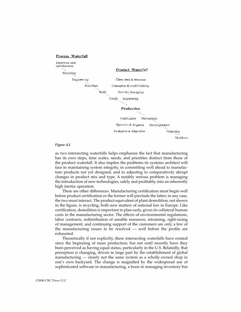
as two intersecting waterfalls helps emphasize the fact that manufacturinghas its own steps, time scales, needs, and priorities distinct from those ofthe product waterfall. It also implies the problems its systems architect willface in maintaining system integrity, in committing well ahead to manufac-ture products not yet designed, and in adjusting to comparatively abruptchanges in product mix and type. A notably serious problem is managingthe introduction of new technologies, safely and profitably, into an inherentlyhigh inertia operation.
There are other differences. Manufacturing certification must begin wellbefore product certification or the former will preclude the latter; in any case,the two must interact. The product equivalent of plant demolition, not shownin the figure, is recycling, both now matters of national law in Europe. Likecertification, demolition is important to plan early, given its collateral humancosts in the manufacturing sector. The effects of environmental regulations,labor contracts, redistribution of useable resources, retraining, right-sizingof management, and continuing support of the customers are only a few ofthe manufacturing issues to be resolved — well before the profits areexhausted.
Theoretically if not explicitly, these intersecting waterfalls have existedsince the beginning of mass production; but not until recently have theybeen perceived as having equal status, particularly in the U.S. Belatedly, thatperception is changing, driven in large part by the establishment of globalmanufacturing — clearly not the same system as a wholly owned shop inone’s own backyard. The change is magnified by the widespread use ofsophisticated software in manufacturing, a boon in managing inventory but
Figure 4.1
©2000 CRC Press LLC
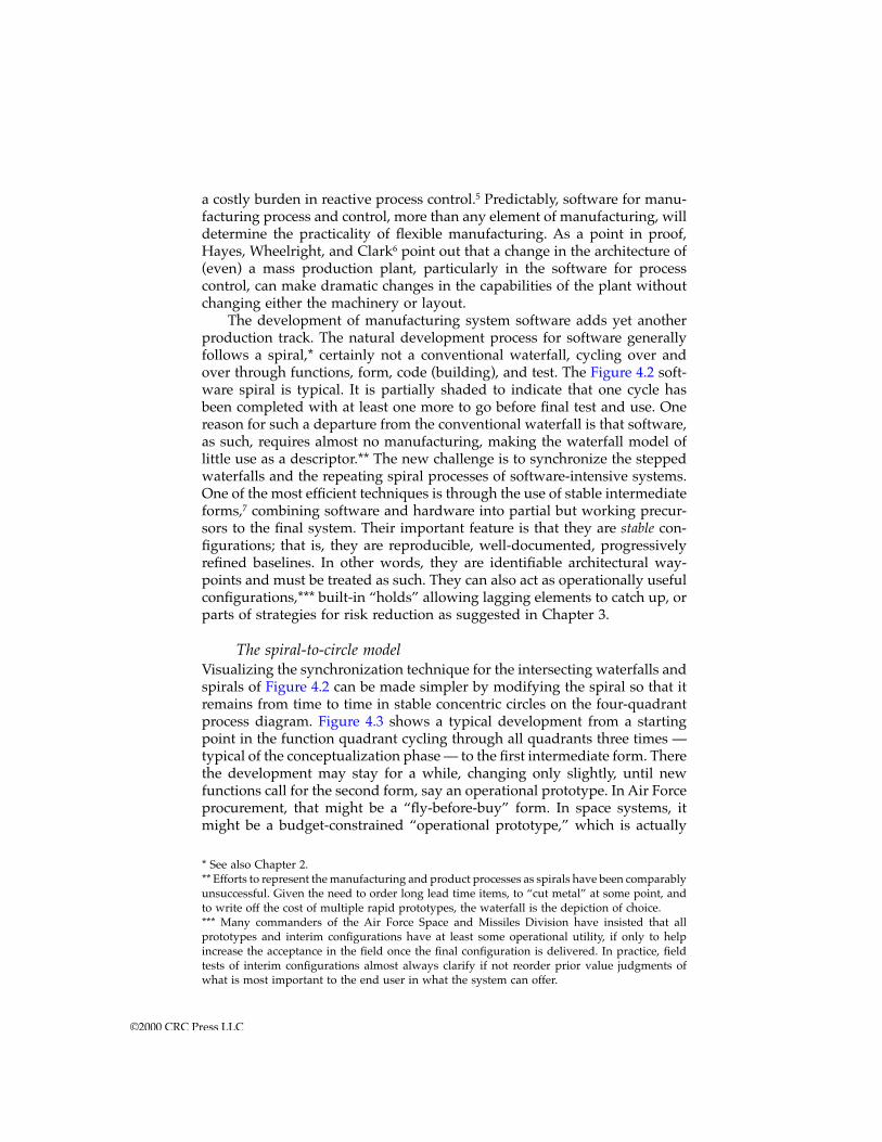
a costly burden in reactive process control.5 Predictably, software for manu-facturing process and control, more than any element of manufacturing, willdetermine the practicality of flexible manufacturing. As a point in proof,Hayes, Wheelright, and Clark6 point out that a change in the architecture of(even) a mass production plant, particularly in the software for processcontrol, can make dramatic changes in the capabilities of the plant withoutchanging either the machinery or layout.
The development of manufacturing system software adds yet anotherproduction track. The natural development process for software generallyfollows a spiral,* certainly not a conventional waterfall, cycling over andover through functions, form, code (building), and test. The Figure 4.2 soft-ware spiral is typical. It is partially shaded to indicate that one cycle hasbeen completed with at least one more to go before final test and use. Onereason for such a departure from the conventional waterfall is that software,as such, requires almost no manufacturing, making the waterfall model oflittle use as a descriptor.** The new challenge is to synchronize the steppedwaterfalls and the repeating spiral processes of software-intensive systems.One of the most efficient techniques is through the use of stable intermediateforms,7 combining software and hardware into partial but working precur-sors to the final system. Their important feature is that they are stable con-figurations; that is, they are reproducible, well-documented, progressivelyrefined baselines. In other words, they are identifiable architectural way-points and must be treated as such. They can also act as operationally usefulconfigurations,*** built-in “holds” allowing lagging elements to catch up, orparts of strategies for risk reduction as suggested in Chapter 3.
The spiral-to-circle modelVisualizing the synchronization technique for the intersecting waterfalls andspirals of Figure 4.2 can be made simpler by modifying the spiral so that itremains from time to time in stable concentric circles on the four-quadrantprocess diagram. Figure 4.3 shows a typical development from a startingpoint in the function quadrant cycling through all quadrants three times —typical of the conceptualization phase — to the first intermediate form. Therethe development may stay for a while, changing only slightly, until newfunctions call for the second form, say an operational prototype. In Air Forceprocurement, that might be a “fly-before-buy” form. In space systems, itmight be a budget-constrained “operational prototype,” which is actually
* See also Chapter 2.** Efforts to represent the manufacturing and product processes as spirals have been comparablyunsuccessful. Given the need to order long lead time items, to “cut metal” at some point, andto write off the cost of multiple rapid prototypes, the waterfall is the depiction of choice.*** Many commanders of the Air Force Space and Missiles Division have insisted that allprototypes and interim configurations have at least some operational utility, if only to helpincrease the acceptance in the field once the final configuration is delivered. In practice, fieldtests of interim configurations almost always clarify if not reorder prior value judgments ofwhat is most important to the end user in what the system can offer.
©2000 CRC Press LLC
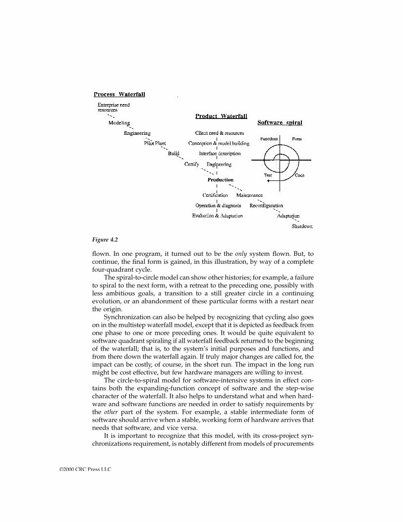
flown. In one program, it turned out to be the only system flown. But, tocontinue, the final form is gained, in this illustration, by way of a completefour-quadrant cycle.
The spiral-to-circle model can show other histories; for example, a failureto spiral to the next form, with a retreat to the preceding one, possibly withless ambitious goals, a transition to a still greater circle in a continuingevolution, or an abandonment of these particular forms with a restart nearthe origin.
Synchronization can also be helped by recognizing that cycling also goeson in the multistep waterfall model, except that it is depicted as feedback fromone phase to one or more preceding ones. It would be quite equivalent tosoftware quadrant spiraling if all waterfall feedback returned to the beginningof the waterfall; that is, to the system’s initial purposes and functions, andfrom there down the waterfall again. If truly major changes are called for, theimpact can be costly, of course, in the short run. The impact in the long runmight be cost effective, but few hardware managers are willing to invest.
The circle-to-spiral model for software-intensive systems in effect con-tains both the expanding-function concept of software and the step-wisecharacter of the waterfall. It also helps to understand what and when hard-ware and software functions are needed in order to satisfy requirements bythe other part of the system. For example, a stable intermediate form ofsoftware should arrive when a stable, working form of hardware arrives thatneeds that software, and vice versa.
It is important to recognize that this model, with its cross-project syn-chronizations requirement, is notably different from models of procurements
Figure 4.2
©2000 CRC Press LLC
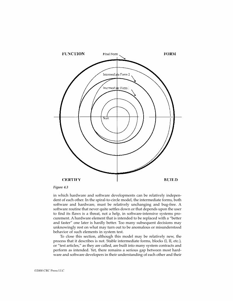
in which hardware and software developments can be relatively indepen-dent of each other. In the spiral-to-circle model, the intermediate forms, bothsoftware and hardware, must be relatively unchanging and bug-free. Asoftware routine that never quite settles down or that depends upon the userto find its flaws is a threat, not a help, in software-intensive systems pro-curement. A hardware element that is intended to be replaced with a “betterand faster” one later is hardly better. Too many subsequent decisions mayunknowingly rest on what may turn out to be anomalous or misunderstoodbehavior of such elements in system test.
To close this section, although this model may be relatively new, theprocess that it describes is not. Stable intermediate forms, blocks (I, II, etc.),or “test articles,” as they are called, are built into many system contracts andperform as intended. Yet, there remains a serious gap between most hard-ware and software developers in their understanding of each other and their
Figure 4.3
©2000 CRC Press LLC
joint venture. As the expression goes: “These guys just don’t talk to eachother.” The modified spiral model should help both partners bridge that gap,to accept the reasons both for cycling and for steps, and to recognize thatneither acquisition process can succeed without the success of the other.
There should be no illusion that the new challenge will be easy to meet.Intermediate software forms will have to enable hardware phases at specifiedmilestones, not just satisfy separate software engineering needs. The formsmust be stable, capable of holding at that point indefinitely, and practical asa stopping point in the acquisition process if necessary. Intermediate hard-ware architectures must have sufficient flexibility to accommodate changesin the software as well as in the hardware. And, finally, the architects andmanagers will have a continuing challenge in resynchronizing the severalprocesses so that they neither fall behind nor get too far ahead. Well-archi-tected intermediate stable forms and milestones will be essential.
Concurrent engineering The intersecting waterfall model in Figure 4.2 also helps identify the sourceof some of the inherent problems in concurrent (simultaneous, parallel)engineering in which product designers and manufacturing engineers worktogether to create a well-built product. Concurrent engineering in practice,however, has proven to be more than modifying designs for manufactura-bility. However defined, it is confronted with a fundamental problem, evi-dent from Figure 4.2; namely, coordinating the two intersecting waterfallsand the spirals, each with different time scales, priorities, hardware, soft-ware, and profit-and-loss criteria. Because each track is relatively indepen-dent of the others, the incentives for each are to optimize locally even ifdoing so results in an impact on another track or on the end product. Afterall, it is a human and organizational objective to solve one’s own problems,to have authority reasonably commensurate with responsibilities, and to besuccessful in one’s own right. Unfortunately, this objective forces even minortechnical disagreements to higher, enterprise management where consider-ations other than just system performance come into play.
A typical example: A communications spacecraft de-sign was proceeding concurrently in engineering andmanufacturing until the question came up of the space-craft antenna size. The communications engineeringdepartment believed that a 14-ft diameter was neededwhile the manufacturing department insisted that 10feet was the practical limit. The difference in systemperformance was a factor of two in communicationscapability and revenue. The reason for the limit, itturned out, was that the manufacturing departmenthad a first-rate subcontractor with all the equipmentneeded to build an excellent antenna, but no largerthan 10 feet. To go larger would cause a measurable
©2000 CRC Press LLC
manufacturing cost overrun. The manufacturing man-ager was adamant about staying within his budget,having taken severe criticism for an overrun in theprevious project. In any case, the added communica-tions revenue gain was far larger than the cost of re-equipping the subcontractor. Lacking a systems archi-tect, the departments had little choice but to escalatethe argument to a higher level where the larger anten-na was eventually chosen and the manufacturing bud-get increased slightly. The design proceeded normallyuntil software engineers wanted to add more memorywell after manufacturing had invested heavily in theoriginal computer hardware design. The argument es-calated, valuable time was lost, department preroga-tives were again at stake … and so it went.
This example is not uncommon. A useful management improvementwould have been to set up a trusted, architect-led team to keep balancingthe system as a whole within broad top-management guidelines of cost,performance, risk, and schedule.
If so established, the architectural team’s membership should include acorporate-level (or “enterprise") architect, the product architect, the manu-facturing architect, and a few specialists in system-critical elements and nomore.8 Such a structure does exist implicitly in some major companies,though seldom with the formal charter, role, and responsibilities of systemsarchitecting.
Feedback systemsManufacturers have long used feedback to better respond to change. Feed-back from the customer has been, and is, used directly to maintain manu-facturing quality, and indirectly to accommodate changes in design. Com-parably important are paths from sales to manufacturing and frommanufacturing to engineering.
What is new is that the pace has changed. Multiyear is now yearly, yearlyis now monthly, monthly is now daily, and daily, especially for ultraqualitysystems, has become hourly if not sooner. What was a temporary slowdownis now a serious delay. What used to affect only adjacent sectors can nowaffect the whole. What used to be the province of planners is now a matterof real-time operations.
Consequently, accustomed delays in making design changes, correctingsupply problems, responding to customer complaints, introducing newproducts, and reacting to competitors’ actions and the like were no longeracceptable. The partner to ultraquality in achieving global competitivenesswas to counter the delays by anticipating them. In other words, to useanticipatory feedback in as close to real-time as practical. The most dramaticindustrial example to date has been in lean production9 in which feedback
©2000 CRC Press LLC
to suppliers, coupled with ultraquality techniques, cut the costs of inventoryin half and resulted in across-the-board competitive advantage in virtuallyall business parameters. More recently, criteria for certification, or those ofits predecessor, quality assurance, is routinely fed back to conceptual designand engineering — one more recognition that quality must be designed in,not tested in.
A key factor in the design of any real-time feedback system is loop delay,the time it takes for a change to affect the system “loop" as a whole. In afeedback system, delay is countered by anticipation based on anticipatedevents (like a failure) or on a trend derived from the integration of pastinformation. The design of the anticipation, or “correction," mechanism,usually the feedback paths, is crucial. The system as a whole can go sluggishon the one hand or oscillatory on the other. Symptoms are inventory chaos,unscheduled overtime, share price volatility, exasperated sales forces, frus-trated suppliers, and, worst of all, departing long-time customers. Designquestions are: What is measured? How is it processed? Where is it sent?And, of course, to what purpose?
Properly designed, feedback control systems determine transient andsteady-state performance, reduce delays and resonances, alleviate nonlinear-ities in the production process, help control product quality, minimize inven-tory, and alleviate nonlinearities in the production process. By way of expla-nation, in nonlinear systems, two otherwise independent input changesinteract with each other to produce effects different from the sum of theeffects of each separately. Understandably, the end results can be confusingif not catastrophic. An example is a negotiated reduction in wages followedimmediately by an increase in executive wages. The combination results ina strike; either alone would not.
A second key parameter, the resonance time constant, is a measure ofthe frequency at which the system or several of its elements tries to oscillateor cycle. Resonances are created in almost every feedback system. The morefeedback paths, the more resonances. The business cycle, related to inventorycycling, is one such resonance. Resonances, internal and external, can interactto the point of violent, nonlinear oscillation and destruction, particularly ifthey have the same or related resonant frequencies. Consequently, a warning:avoid creating the same resonance time constant in more than one locationin a (production) system.
Delay and resonance times, separately and together, are subject todesign. In manufacturing systems, the factors that determine these param-eters include inventory size, inventory replacement capacity, informationacquisition and processing times, fabrication times, supplier capacity, andmanagement response times. All can have a strong individual and collectiveinfluence on such overall system time responses as time to market, materialand information flow rates, inventory replacement rate, model change rate,and employee turnover rate. Few, if any, of these factors can be chosen ordesigned independently of the rest, especially in complex feedback systems.
©2000 CRC Press LLC
Fortunately, there are powerful tools for feedback system design. Theyinclude linear transform theory, transient analysis, discrete event mathemat-ics, fuzzy thinking, and some selected nonlinear and time-variant designmethods. The properties of at least simple linear systems designed by thesetechniques can be simulated and adjusted easily. A certain intuition can bedeveloped based upon long experience with them. For example:
• Behavior with feedback can be very different from behavior without it. Positive example: Provide inventory managers with timely sales in-formation and drastically reduce inventory costs. Negative example:Ignore customer feedback and drown in unused inventory.
• Feedback works. However, the design of the feedback path is critical. Indeed,in the case of strong feedback, its design can be more important than that ofthe forward path. Positive example: Customer feedback needs to be supplemented byanticipatory projections of economic trends and of competitors’ re-sponses to one’s own strategies and actions to avoid delays and sur-prises. Negative examples: If feedback signals are “out of step" or ofthe wrong polarity, the system will oscillate, if not go completely outof control. Response that is too little, too late is often worse than noresponse at all.
• Strong feedback can compensate for many known vagaries, even nonlinear-ities in the forward path, but it does so “at the margin.” Example: Production lines can be very precisely controlled aroundtheir operating points; that is, once a desired operating point isreached, tight control will maintain it, but off that point or on the wayto or from it (e.g., start up, synchronization,10 and shut down) off-optimum behavior is likely. Example: Just in Time response workswell for steady flow and constant volume. It can oscillate if flow isintermittent and volume is small.
• Feedback systems will inherently resist unplanned or unanticipated change,whether internal or external. Satisfactory responses to anticipatedchanges, however, can usually be assured. In any case, the response willlast at least one time constant (cycle time) of the system. These propertiesprovide stability against disruption. On the other hand, abrupt man-dates, however necessary, will be resisted and the end results may beconsiderably different in magnitude and timing from what advocatesof the change anticipated. Example: Social systems, incentive programs, and political systemsnotoriously “readjust" to their own advantage when change is man-dated. The resultant system behavior is usually less than, later than,and modified from that anticipated.
• To make a major change in performance of a presently stable system is likelyto require a number of changes in the overall system design. Example: The change from mass production to lean production toflexible production11 and the use of robots and high technology.
©2000 CRC Press LLC
Not all systems are linear, however. As a warning against overdepen-dence on linear-derived intuition, typical characteristics of nonlinear systemsare:
• In general, no two systems of different nonlinearity behave in exactly thesame way.
• Introducing changes into a nonlinear system will produce different (andprobably unexpected) results if they are introduced separately than if theyare introduced together.
• Introducing even very small changes in input magnitude can produce verydifferent consequences even though all components and processes are deter-ministic. Example: Chaotic behavior (noiselike but with underlying structure)close to system limits is such a phenomenon. Example: When thephone system is saturated with calls and goes chaotic, the plannedstrategy is to cut off all calls to a particular sector (e.g., California afteran earthquake) or revert back to the simplest mode possible (firstcome, first serve). Sophisticated routing is simply abandoned as it ispart of the problem. Example: When a computer abruptly becomeserratic as it runs out of memory, the simplest and usually successfultechnique is to turn it off and start it up again (reboot), hoping thatnot too much material has been lost.
• Noise and extraneous signals irreversibly intermix with and alter normal,intended ones, generally with deleterious results. Example: Modification of feedback and control signals is equivalentto modifying system behavior; that is, changing its transient andsteady-state behavior. Nonlinear systems are therefore particularlyvulnerable to purposeful opposition (jamming, disinformation, over-loading).
• Creating nonlinear systems is of higher risk than creating well-understood,linear ones. The risk is less that the nonlinear systems will fail undercarefully framed conditions than that they will behave strangely oth-erwise. Example: In the ultraquality spacecraft business there is a heuristic:If you can’t analyze it, don’t build it — an admonition against un-necessarily nonlinear feedback systems.
The two most common approaches to nonlinearity are first, when non-linearities are both unavoidable and undesirable, minimize their effect onend system behavior through feedback and tight control of operating param-eters over a limited operating region. Second, when nonlinearity can improveperformance as in discrete and fuzzy control systems, be sure to model andsimulate performance outside the normal operating range to avoid “non-intuitive” behavior.
The architectural and analytic difficulties faced by modern manufactur-ing feedback systems are that they are neither simple nor necessarily linear.
©2000 CRC Press LLC
They are unavoidably complex, probably contain some nonlinearities (lim-iters and fixed time delays), are multiply-interconnected, and are subject tosometimes drastic external disturbances, not the least of which are suddendesign changes and shifts in public perception. Their architectures musttherefore be robust and yet flexible. Though inherently complex, they mustbe simple enough to understand and modify at the system level without toomany unexpected consequences. In short, they are likely to be prime candi-dates for the heuristic and modeling techniques of systems architecting.
Lean production One of the most influential books on manufacturing in recent years is the1990 best seller, The Machine that Changed the World, The Story of Lean Produc-tion.12 Although the focus of this extensive survey and study was on auto-mobile production in Japan, the U.S., and Europe, its conclusions are appli-cable to manufacturing systems in general; particularly the concepts ofquality and feedback. A 1994 follow-up book, Comeback, The Fall & Rise ofthe American Automobile Industry,13 tells the story of the American responseand the lessons learned from it, though calling it a “comeback” may havebeen premature. The story of lean production systems is by no means neatand orderly. Although the principles can be traced back to 1960, effectiveimplementation took decades. Lean production certainly did not emerge full-blown. Ideas and developments came from many sources, some prematurely.Credits were sometimes misattributed. Many contributors were very old bythe time their ideas were widely understood and applied. Quality was some-times seen as an end result instead of as a prerequisite for any change. Theremarkable fact that virtually every critical parameter improved by at least20%, if not 50%,14 does not seem to have been anticipated. Then, within afew years, everything worked. But when others attempted to adopt theprocess, they often failed. Why?
One way to answer such questions is to diagram the lean productionprocess from an architectural perspective. Figure 4.4 is an architect’s sketchof the lean production waterfall derived from the texts of the just-mentionedbooks, highlighting (bold facing) its nonclassical features and strengtheningits classical ones.* The most apparent feature is the number and strength ofits feedback paths. Two are especially characteristic of lean production: thesupplier waterfall loop and the customer-sales-delivery loop. Next evidentis the Quality Policies box, crucial not only to high quality but to the prof-itable and proper operation of later steps, Just in Time inventory, rework,and implicit warranties. Quality policies are active elements in the sequenceof steps, are a step through which all subsequent orders and specifications
* Strictly speaking, though the authors of the lean production books did not mention it, anarchitect’s perspective should also include the intersecting product waterfalls and softwarespirals. Interestingly, because it seems to be true for all successful systems, it is possible to findwhere and by whom systems architecting was performed. Two of the more famous automotiveproduction architects were Taiichi Ohno, the pioneer of the Toyota Motor Company ProductionSystem, and Yoshiki Yamasaki, head of automobile production at Mazda.
©2000 CRC Press LLC
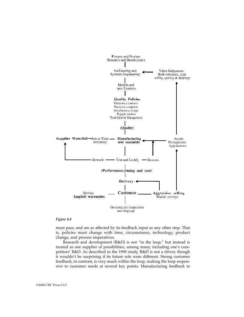
must pass, and are as affected by its feedback input as any other step. Thatis, policies must change with time, circumstance, technology, productchange, and process imperatives.
Research and development (R&D) is not “in the loop,” but instead istreated as one supplier of possibilities, among many, including one’s com-petitors’ R&D. As described in the 1990 study, R&D is not a driver, thoughit wouldn’t be surprising if its future role were different. Strong customerfeedback, in contrast, is very much within the loop, making the loop respon-sive to customer needs at several key points. Manufacturing feedback to
Figure 4.4
©2000 CRC Press LLC
suppliers is also a short path, in contrast with the standoff posture of muchU.S. procurement.
The success of lean production has induced mass producers to copymany of its features, not always successfully. Several reasons for lack ofsuccess are apparent from the figure. If the policy box does not implementultraquality, little can be expected from changes further downstream, regard-less of how much they ought to be able to contribute. Just in Time inventoryis an example. Low-quality supply mandates a cushion of inventory roughlyproportional to the defect rate; shifting that inventory from the manufacturerback to the supplier without a simultaneous quality upgrade simplyincreases transportation and financing costs. To decrease inventory, decreasethe defect rate, then apply the coordination principles of Just in Time, notbefore.
Another reason for limited success in converting piecemeal to lean pro-duction is that any well-operated feedback system, including those used inclassical mass production, will resist changes in the forward (waterfall) path.The “loop” will attempt to self-correct, and it will take at least one loop timeconstant before all the effects can be seen or even known. To illustrate, ifsupply inventory is reduced, what is the effect on sales and service inven-tory? If customer feedback to the manufacturing line is aggressively sought,as it is in Japan, what is the effect on time-to-market for new product designs?
A serious question raised in both books is how to convert mass produc-tion systems into lean production systems. It is not, as the name “lean" mightimply, a mass production system with the “fat" of inventory, middle man-agement, screening, and documentation, taken out. It is to recognize leanproduction as a different architecture based on different priorities and inter-relationships. How, then, to begin the conversion? What is both necessaryand sufficient? What can be retained?
The one and only place to begin conversion, given the nature of feedbacksystems, is in the Quality Policies step. In lean production, quality is not aproduction result determined post-production and post-test, it is a prereq-uisite policy imperative. Indeed, Japanese innovators experienced years offrustration when TQM, JIT, and the Taguchi methods at first seemed to dovery little. The level of quality essential for these methods to work had notyet been reached. When it was, the whole system virtually snapped intoplace with results that became famous. Even more important for other com-panies, unless their quality levels are high enough, even though all theforegoing methods are in place, the famous results will not — and cannot— happen.
Conversely, at an only slightly lower level of quality, lean systems spo-radically face at least temporary collapse.15 As a speculation, there appearsto be a direct correlation between how close to the cliff of collapse the systemoperates and the competitive advantage it enjoys. Backing off from the cliffwould seem to decrease its competitive edge, yet getting too close risksimminent collapse: line shutdown, transportation jam-up, short-fuse cus-
©2000 CRC Press LLC
tomer anger, and collateral damage to suppliers and customers for whomthe product is an element of a still larger system production.
To summarize, lean production is an ultraquality, dynamic feedbacksystem inherently susceptible to any reduction in quality. It depends uponwell-designed, multiple feedback. Given ultraquality standards, lean pro-duction arguably is less complex, simpler, and more efficient than massproduction; and, by its very nature, it is extraordinarily, fiercely, competitive.
Flexible manufacturingFlexible manufacturing is the capability of sequentially making more thanone product on the same production line. In its most common present-dayform, it customizes products for individual customers, more or less ondemand, by assembling different modules (options) on a common base (plat-form). Individually tailored automobiles, for example, have been comingdown production lines for years. But with one out of three or even one outof ten units having to be sent back or taken out of a production stream,flexible manufacturing in the past has been costly in inventory, complex inoperation, and high-priced per option compared to all-of-a-kind production.
What has changed is customer demands and expectations, especially inconsumer products. Largely because of technological innovation, more capa-bility for less cost now controls purchase rate rather than wearout andincreasing defect rate. An interesting epilog to the DeSoto story.* One con-sequence of the change is more models per year with fewer units per model,the higher costs per unit being offset by use of techniques such as preplannedproduct improvement, standardization of interfaces and protocols, and leanproduction methods.
A natural architecture for the flexible manufacturing of complex prod-ucts would be an extension of lean production with its imperatives — addi-tional feedback paths and ultraquality-produced simplicity — and an imper-ative all its own, human-like information command and control.
At its core, flexible manufacturing involves the real-time interaction ofa production waterfall with multiple product waterfalls. Lacking an archi-tectural change from lean production, however, the resultant multiple infor-mation flows could overwhelm conventional control systems. The problemis less that of gathering data than of condensing it. That suggests that flexiblemanufacturing will need judgmental, multiple-path control analogous tothat of an air traffic controller in the new “free flight” regime. Whether theresultant architecture will be fuzzy, associative, neural, heuristic, or largelyhuman is arguable.
To simplify the flexible manufacturing problem to something more man-ageable, most companies today would limit the flexibility to a product linethat is forward- and backward-compatible, uses similar if not identical mod-
* Parenthetically, the Japanese countered the automobile obsolescence problem by quadrennialgovernment inspections so rigorous that it was often less expensive to turn a car in and purchasea new one than to bring the old one up to government standards. Womack, et al., 1990, 62.
©2000 CRC Press LLC
ules, keeps to the same manufacturing standards, and is planned to be inbusiness long enough to write off the cost of the facility out of product lineprofits. In brief, production would be limited to products having a singlebasic architecture; for example, producing either Macintosh computers, Hita-chi TV sets, or Motorola cellular telephones, but not all three on demand onthe same production line.
Even that configuration is complex architecturally. To illustrate: a centralissue in product line design is where in the family of products, from low-to high-end, to optimize. Too high in the series and the low end is needlesslycostly; too low and the high end adds too little value. A related issue arisesin the companion manufacturing system. Too much capability and its over-head is too high; too little, and it sacrifices profit to specialty suppliers.
Another extension from lean production to flexible manufacturing ismuch closer coordination between the design and development of the prod-uct line and the design and development of its manufacturing system. Failureto achieve this coordination, as illustrated by the problems of introducingrobots into manufacturing, can be warehouses of unopened crates of robotsand in-work products that can’t be completed as designed. Clearly, theproduct and its manufacturing system must match. More specifically, theirtime constants, transient responses, and product-to-machine interfaces mustmatch, recognizing that any manufacturing constraint means a product con-straint, and vice versa.
As suggested earlier, the key technological innovation is likely to be thearchitecture of the joint information system.16 In that connection, one of thegreatest determinants of the information system’s size, speed, and resolutionis the quality of the end product and the yield of its manufacturing process;that is, their defect rates. The higher these defect rates, the greater the size,cost, complexity, and precision of the information system that will be neededto find and eliminate them quickly.
Another strong determinant of information system capacity is piece-partcount, another factor dependent on the match of product and manufacturingtechniques. Mechanical engineers have known for years that whenever pos-sible, replace a complicated assembly of parts with a single, specialized piece.Nowhere is the advantage of piece-part reduction as evident as in the con-tinuing substitution of more and more high-capacity microprocessors fortheir lower-capacity predecessors. Remarkably, this substitution, for approx-imately the same cost, also decreases the defect rate per computationaloperation.
Also, especially for product lines, the fewer different parts from modelto model, the better, as long as that commonality doesn’t decrease systemcapability unduly. Once again, there is a close correlation between reduceddefect rate, reduced information processing, reduced inventory, and reducedcomplexity — all by design.
Looking further into the future, an extension of a lean production archi-tecture is not the only possibility for flexible manufacturing. It is possiblethat flexible manufacturing could take quite a different architectural turn
©2000 CRC Press LLC
based on a different set of priorities. Is ultraquality production really neces-sary for simple, low cost, limited warranty products made largely fromcommercial off-the-shelf (COTS) units; e.g., microprocessors and flat screens?Or is the manufacturing equivalent of parallel processors (pipelines) theanswer? Should some flexible manufacturing hark back to the principles ofspecial, handcrafted products; one-of-a-kind planetary spacecraft? Theanswers should be known in less than a decade, considering the profit to bemade in finding them.
Heuristics for architecting manufacturing systems
• The product and its manufacturing system must match (in manyways).
• Keep it simple (ultraquality helps).• Partition for near autonomy (a tradeoff with feedback).• In partitioning a manufacturing system, choose the elements so that
they minimize the complexity of material and information flow (Sav-agian, Peter J., 1990, USC).
• Watch out for critical misfits (between intersecting waterfalls).• In making a change in the manufacturing process, how you make it
is often more important than the change itself (management policy).• When implementing a change, keep some elements constant to pro-
vide an anchor point for people to cling to (Schmidt, Jeffrey H., 1993,USC; a tradeoff when a new architecture is needed).
• Install a machine that even an idiot can use, and pretty soon everyoneworking for you is an idiot (Olivieri, J. M., 1991, USC; an unexpectedconsequence of mass production Taylorism). See next heuristic.
• Everyone a customer, everyone a supplier.• To reduce unwanted nonlinear behavior, linearize.• If you can’t analyze it, don’t build it.• Avoid creating the same resonance time constant in more than one
location in a (production) system. • The five whys (a technique for finding basic causes, and one used by
every inquisitive child to learn about the world at large).
In conclusionModern manufacturing can be portrayed as an ultraquality, dynamic feed-back system intersecting with that of the product waterfall. The manufac-turing systems architect’s added tasks, beyond those of all systems architects,include: (1) maintaining connections to the product waterfall and the soft-ware spiral necessary for coordinated developments; (2) assuring qualitylevels high enough to avoid manufacturing system collapse or oscillation;(3) determining and helping control the system parameters for stable and
©2000 CRC Press LLC
timely performance and, last but not least, (4) looking farther into the futurethan do most product-line architects.
Exercises
1. Manufacturing systems are themselves complex systems which needto be architected. If the manufacturing line is software-intensive, andrepeated software upgrades are planned, how can certification ofsoftware changes be managed?
2. The feedback lags or resonances of a manufacturing system of acommercial product interact with the dynamics of market demand.Give examples of problems arising from this interaction and possiblemethods for alleviating them.
3. Examine the following hypothesis: increasing quality levels in man-ufacturing enable architectural changes in the manufacturing systemwhich greatly increase productivity, but may make the system increas-ingly sensitive to external disruption. For a research exercise, use casestudies or a simplified quantitative model.
4. Does manufacturing systems architecture differ in mass productionsystems (thousands of units) and very low-quantity production sys-tems (fewer than ten produced systems)? If so, how and why?
5. Current flexible manufacturing systems usually build very small lotsizes from a single product line in response to real-time customerdemand; for example, an automobile production line that builds eachcar to order. Consider two alternative architectures for organizingsuch a system, one centralized and one decentralized. The first woulduse close centralized control, centralized production scheduling, andresource planning. The other would use fully distributed controlbased on disseminating customer/supplier relationships to each workcell. That is, each job and each work cell interact individually throughan auction for services. What would be advantages and disadvantagesof both approaches? How would the architecture of the supportinginformation systems (extending to sales and customer support) haveto differ in the two cases?
Notes and references1. Hayes, R. H., Wheelwright, S. C., and Clark, K. B., Dynamic Manufacturing,
Creating the Learning Organization, Free Press, New York, 1988, chap. 7, “TheArchitecture of Manufacturing: Material and Information Flows," p. 185, de-fines a manufacturing architecture as including its hardware, material, andinformation flows, their coordination, and managerial philosophy. This text-book is highly recommended, especially Chapters 7–9.
©2000 CRC Press LLC

2. Rechtin, E., Systems Architecting, Creating & Building Complex Systems, Prentice-Hall, Englewood Cliffs, NJ, 1991, chap. 8, 160-187. Ultraquality: Quality (ab-sence of defects) so high as to be impractical to prove by measure withconfidence.
3. Hayes, R. H., Wheelwright, S. C., and Clark, K. B., Dynamic Manufacturing,Creating the Learning Organization, Free Press, New York, 1988.
4. Womack, J. P., Jones, D. T., and Roos, D., The Machine that Changed the World,The Story of Lean Production, Harper Collins Publishers, New York, 1990, pa-perback, p. 4.
5. See also Hayes et al., 1988, Chap. 8, “Controlling and Improving the Manu-facturing Process."
6. Hayes et al., 1988, Chap. 7, p. 185.7. See Brooks, F. P., Jr., No silver bullet, essence and accidents of software engi-
neering, Computer, April 1987, pp. 10-19, especially p. 18; and Simon, H., TheSciences of the Artificial, 2nd ed., MIT Press, Cambridge, MA, 1987, pp. 200-209.
8. For the equivalent in a surgical team, see Brooks’ Mythical Man-Month.9. See Womack et al., The Machine that Changed the World, The Story of Lean
Production. 10. See Lindsey, W. C., Synchronization Systems in Communication and Control,
Prentice-Hall, Englewood Cliffs, NJ, 1972.11. Hayes et al., 1988, p. 204.12. Womack et al., 1990.13. For an update, see Ingrassia, P. and White, J. B., Comeback, The Fall & Rise of
the American Automobile Industry, Simon & Schuster, New York, 1994.14. Womack et al., 1994, Title page.15. Womack et al., 1990, p. 62.16. Hayes et al., 1988, Chap. 7, p. 185.
©2000 CRC Press LLC
chapter five
Social systems
Introduction: defining sociotechnical systems
Social: concerning groups of people or the general public
Technical: based on physical sciences and their application
Sociotechnical systems: technical works involving signifi-cant social participation, interests, and concerns.
Sociotechnical systems are technical works involving the participation ofgroups of people in ways that significantly affect the architectures and designof those works. Historically, the most conspicuous have been the large civilworks — monuments, cathedrals, and urban developments, dams and road-ways among them. Lessons learned from their construction provide the basisfor much of civil (and systems) architecting and its theory.1
More recently, others, physically quite different, have become muchmore sociotechnical in nature than might have been contemplated at theirinception — ballistic missile defense, air travel, e-mail, information networks,welfare and health delivery, for example. Few can even be conceived, muchless built, without major social participation, planned or not. Experienceswith them have generated a number of strategies and heuristics of impor-tance to architects in general. Several are presented here. Among them arethree heuristics: the four whos, economic value, and the tension betweenperceptions and facts. In the interests of informed use, as with all heuristics,it is important to understand the context within which they evolved, thesociotechnical domain. At the end of this chapter are a number of generalheuristics of applicability to sociotechnical systems in particular.
Public participation
At the highest level of social participation, members of the public directlyuse — and may own a part of — the system’s facilities. At an intermediate
©2000 CRC Press LLC
level they are provided a personal service, usually by a public or privateutility. Most important, individuals and not the utilities — the architect’sclients — are the end users. Examples are highways, communication andinformation circuits, general aviation traffic control, and public power. Publiccooperation and personal responsibility are required for effective operation.That is, users are expected to follow established rules with a minimum ofpolicing or control. Drivers and pilots follow the rules of the road. Commu-nicators respect the twin rights of free access and privacy.
At the highest level of participation, participating individuals chooseand collectively own a major fraction of the system structure such as cars,trucks, aircraft, computers, telephones, electrical and plumbing hardware,etc. In a sense, the public “rents” the rest of the facilities through accesscharges, fees for use, and taxes. Reaction to a facility failure or a price changetends to be local in scope, quick, and focused. The public’s voice is heardthrough specialized groups such as automobile clubs for highways, retiredpersons associations for health delivery, professional societies for power, andcommunications services, etc.
Market forces are used to considerable advantage through adverse pub-licity in the media, boycotts, and resistance to stock and bond issues on theone hand, and through enthusiastic acceptance on the other. Recent examplesof major architectural changes strongly supported by the public are super-highways, satellite communications, entertainment cable networks, jet air-craft transportation, health maintenance organizations, and a slow shift frompolluting fossil fuels to alternative sources of energy.
Systems of this sort are best described as collaborative systems, systemswhich operate only through the partially voluntary initiative of their com-ponents. This collaboration is an important subject in its own right since theInternet, the World Wide Web, and open source software are collaborativeassemblages. We address this topic in detail in Chapter 7.
At the other extreme of social participation are social systems used solelyby the government, directly or through sponsorship, for broad social pur-poses delegated to it by the public; for example, NASA and DoD systemsfor exploration and defense, Social Security and Medicare management sys-tems for public health and welfare, research capabilities for national well-being, and police systems for public safety. The public pays for these servicesand systems only indirectly, through general taxation. The architect’s clientand end user is the government itself. The public’s connection with thedesign, construction, and operation of these systems is sharply limited. Itsvalue judgments are made almost solely through the political process, thesubject of Chapter 10. They might best be characterized as “politicotechni-cal.”
The foundations of sociotechnical systems architectingThe foundations of sociotechnical systems architecting are much the sameas for all systems: a systems approach, purpose orientation, modeling, cer-
©2000 CRC Press LLC

tification, and insight. Social system quality, however, is less a foundationthan a case-by-case tradeoff; that is, the quality desired depends on thesystem to be provided. In nuclear power generation, modern manufacturing,and manned space flight, ultraquality is an imperative. But in public health,pollution control, and safety, the level of acceptable quality is only one ofmany economic, social, political, and technical factors to be accommodated.
But if sociotechnical systems architecting loses one foundation,ultraquality, it gains another — a direct and immediate response to thepublic’s needs and perceptions. Responding to public perceptions is partic-ularly difficult, even for an experienced architect. The public’s interests areunavoidably diverse and often incompatible. The groups with the strongestinterests change with time, sometimes reversing themselves based on asingle incident. Three Mile Island was such an incident for nuclear powerutilities. Pictures of the earth from a lunar-bound Apollo spacecraft suddenlyfocused public attention and support for global environmental management.An election of a senator from Pennsylvania avalanched into widespreadpublic concern over health insurance and Medicare systems.
The separation of client and user
In most sociotechnical systems, the client, the buyer of the architect’s ser-vices, is not the user. This fact can present a serious ethical, as well astechnical, problem to the architect: how to treat conflicts between the pref-erences, if not the imperatives, of the utility agency and those of the public(as perceived by the architect) when preferences strongly affect systemdesign.
It is not a new dilemma. State governments have partly resolved theproblem by licensing architects and setting standards for systems that affectthe health and safety of the public. Buildings, bridges, and public powersystems come to mind. Information systems are already on the horizon. Theissuing or denial of licenses is one way of making sure that public interestcomes first in the architect’s mind. The setting of standards provides thearchitect some arguments against overreaching demands by the client. Butthese policies do not treat such conflicts as the degree of traffic control desiredby a manager of an Intelligent Transportation System (ITS) as compared withthat of the individual user/driver, nor the degree of governmental regulationof the Internet to assure a balance of access, privacy, security, profitmaking,and system efficiency. One of the ways of alleviating some of these tensionsis through economics.
Socioeconomic insights
Social economists bring two special insights to sociotechnical systems. Thefirst insight, which might be called the four whos, asks four questions thatneed to be answered as a self-consistent set if the system is to succeed eco-
©2000 CRC Press LLC
nomically; namely, who benefits? who pays? who provides? and, as appro-priate, who loses?
Example: The answers to these questions of the BellTelephone System were: (1) the beneficiaries were thecallers and those who received the calls; (2) the callerspaid based on usage because they initiated the callsand could be billed for them; (3) the provider was amonopoly whose services and charges were regulatedby public agencies for public purposes; and (4) thelosers were those who wished to use the telephonefacilities for services not offered or to sell equipmentnot authorized for connection to those facilities. Thetelephone monopoly was incentivized to carry outwidely available basic research because it generatedmore and better service at less cost, a result the regu-latory agencies desired. International and national se-curity agreements were facilitated by having a singlepoint of contact, the Bell System, for all such matters.Standards were maintained and the financial strategywas long-term, typically 30 years. The system was dis-mantled when the losers evoked antitrust laws, creat-ing a new set of losers, complex billing, standardsproblems, and a loss of research. Arguably, it enabledthe Internet sooner than otherwise. Subsequently, sep-arate satellite and cable services were established, fur-ther dismantling what had been a single servicesystem.
Example: The answers to the four whos for the priva-tized Landsat System, a satellite-based, optical-infra-red surveillance service, were: (1) the beneficiarieswere those individuals and organizations who couldintermittently use high-altitude photographs of theearth; (2) because the value to the user of an individualphotograph was unrelated to its cost (just as is the casewith weather satellite TV), the individual users couldnot be billed effectively; (3) the provider was a private,profit-making organization which understandably de-manded a cost-plus-fixed-fee contract from the gov-ernment as a surrogate customer; and (4) when thegovernment balked at this result of privatization, theLandsat system faced collapse. Research had been crip-pled, a French government-sponsored service (SPOT)had acquired appreciable market share, and legitimate
©2000 CRC Press LLC
customers faced loss of service. Privatization was re-versed and the government again became the provider.
Example: Serious debates over the nature of their pub-lic health systems are underway in many countries,triggered in large part by the technological advancesof the last few decades. These advances have made itpossible for humanity to live longer and in betterhealth, but the investments in those gains are consid-erable. The answers to the four whos are at the cruxof the debate. Who benefits — everyone equally at alllevels of health? Who pays — regardless of personalhealth or based on need and ability to pay? Who pro-vides — and determines cost to the user? Who loses— anyone out of work or above some risk level, andwho determines who loses?
Regardless of how the reader feels about any of these systems, there isno argument that the answers are matters of great social interest and concern.At some point, if there are to be public services at all, the questions must beanswered and decisions made. But who makes them and on what basis?Who and where is the architect in each case? How and where is the archi-tecture created? How is the public interest expressed and furthered?
The second economics insight is comparably powerful: in any resource-limited situation, the true value of a given service or product is determinedby what a buyer is willing to give up to obtain it. Notice that the subjecthere is value, not price or cost.
Example: The public telephone network provides agood example of the difference between cost and val-ue. The cost of a telephone call can be accurately cal-culated as a function of time, distance, routing(satellite, cable, cellular, landline, etc.), location (urbanor rural), bandwidth, facility depreciation, etc. But thevalue depends on content, urgency, priority, personalcircumstance, and message type, among other things.As an exercise, try varying these parameters and thenestimating what a caller might be willing to pay (giveup in basic needs or luxuries). What is then a fairallocation of costs among all users? Should a sick, re-mote, poor caller have to pay the full cost of remoteTV health service, for example? Should a businesswhich can pass costs on to its customers receive vol-ume discounts for long-distance calling via satellite?Should home TV be pay-per-view for everyone? Whoshould decide on the answers?
©2000 CRC Press LLC
These two socioeconomic heuristics, used together, can alleviate theinherent tensions among the stakeholders by providing the basis for com-promise and consensus among them. The complainants are likely to be thosewhose payments are perceived as disproportionate to the benefits theyreceive. The advocates, to secure approval of the system as a whole, mustgive up or pay for something of sufficient value to the complainants thatthey agree to compromise. Both need to be made to walk in the others’ shoesfor a while. Therein can be the basis of an economically viable solution.
The interaction between the public and private sectorsA third factor in sociotechnical systems architecting is the strong interplaybetween the public and private sectors, particularly in the advanced democ-racies where the two sectors are comparable in size, capability, and influence,but differ markedly in how the general public expresses its preferences.
By the middle of the 1990s, the historic boundaries between public andprivate sectors in communications, health delivery, welfare services, electricpower distribution, and environmental control were in a state of flux. Thischapter is not the place to debate the pros and cons. Suffice to say theimperatives, interests, and answers to the economists’ questions are sharplydifferent in the two sectors.2 The architect is well advised to understand theimperatives of both sectors prior to suggesting architectures that mustaccommodate them. For example, the private sector must make a profit tosurvive; the public sector does not and treats profits as necessary evils. Thepublic sector must follow the rules; the private sector sees rules and regu-lations as constraints and deterrents to efficiency. Generally speaking, theprivate sector does best in providing well-specified things at specified times.The public sector does best at providing services within the resources pro-vided.
Because of these differences, one of the better tools for relieving thenatural tension between the sectors is to change the boundaries betweenthem in such negotiable areas as taxation, regulation, services provided,subsidies, billing, and employment. Because perceived value in each of theseareas is different in the two sectors and under different circumstances, pos-sibilities can exist where each sector perceives a net gain. The architect’s roleis to help discover the possibilities, achieve balance through compromise onpreferences, and assure a good fit across boundaries.
Architecting a system, such as a public health system, which involvesboth the public and private sectors can be extraordinarily difficult, particu-larly if agreement does not exist on a mutually-trusted architect, on theanswers to the economist’s questions, or on the social value of the systemrelative to that of other socially desirable projects.
©2000 CRC Press LLC
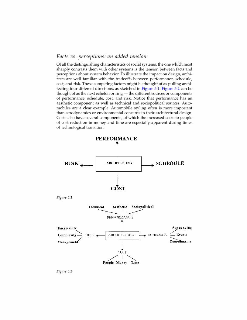
Facts vs. perceptions: an added tensionOf all the distinguishing characteristics of social systems, the one which mostsharply contrasts them with other systems is the tension between facts andperceptions about system behavior. To illustrate the impact on design, archi-tects are well familiar with the tradeoffs between performance, schedule,cost, and risk. These competing factors might be thought of as pulling archi-tecting four different directions, as sketched in Figure 5.1. Figure 5.2 can bethought of as the next echelon or ring — the different sources or componentsof performance, schedule, cost, and risk. Notice that performance has anaesthetic component as well as technical and sociopolitical sources. Auto-mobiles are a clear example. Automobile styling often is more importantthan aerodynamics or environmental concerns in their architectural design.Costs also have several components, of which the increased costs to peopleof cost reduction in money and time are especially apparent during timesof technological transition.
Figure 5.1
Figure 5.2
©2000 CRC Press LLC
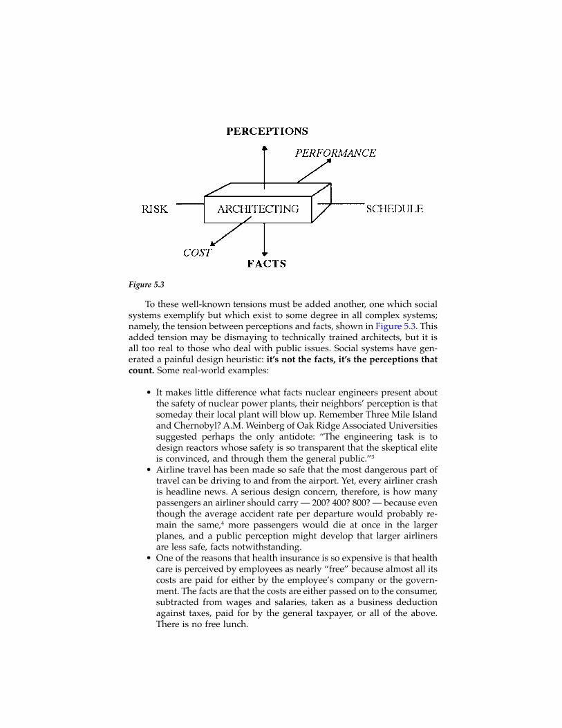
To these well-known tensions must be added another, one which socialsystems exemplify but which exist to some degree in all complex systems;namely, the tension between perceptions and facts, shown in Figure 5.3. Thisadded tension may be dismaying to technically trained architects, but it isall too real to those who deal with public issues. Social systems have gen-erated a painful design heuristic: it’s not the facts, it’s the perceptions thatcount. Some real-world examples:
• It makes little difference what facts nuclear engineers present aboutthe safety of nuclear power plants, their neighbors’ perception is thatsomeday their local plant will blow up. Remember Three Mile Islandand Chernobyl? A.M. Weinberg of Oak Ridge Associated Universitiessuggested perhaps the only antidote: “The engineering task is todesign reactors whose safety is so transparent that the skeptical eliteis convinced, and through them the general public.”3
• Airline travel has been made so safe that the most dangerous part oftravel can be driving to and from the airport. Yet, every airliner crashis headline news. A serious design concern, therefore, is how manypassengers an airliner should carry — 200? 400? 800? — because eventhough the average accident rate per departure would probably re-main the same,4 more passengers would die at once in the largerplanes, and a public perception might develop that larger airlinersare less safe, facts notwithstanding.
• One of the reasons that health insurance is so expensive is that healthcare is perceived by employees as nearly “free” because almost all itscosts are paid for either by the employee’s company or the govern-ment. The facts are that the costs are either passed on to the consumer,subtracted from wages and salaries, taken as a business deductionagainst taxes, paid for by the general taxpayer, or all of the above.There is no free lunch.
Figure 5.3
©2000 CRC Press LLC
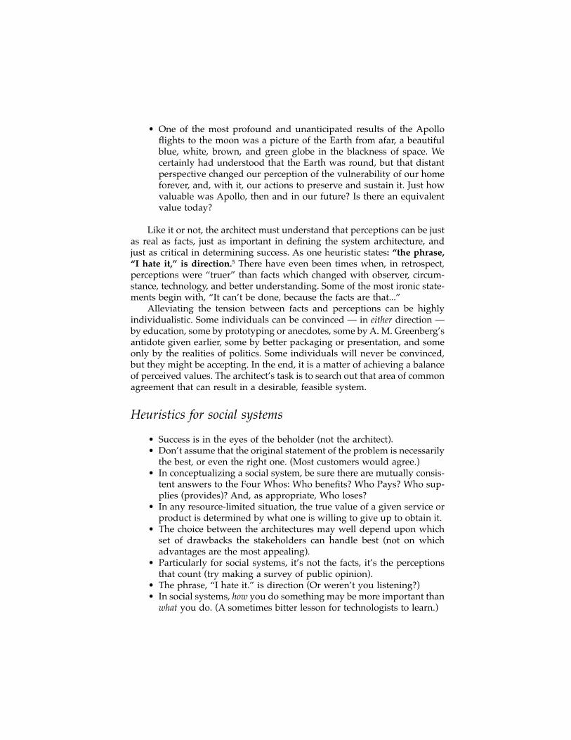
• One of the most profound and unanticipated results of the Apolloflights to the moon was a picture of the Earth from afar, a beautifulblue, white, brown, and green globe in the blackness of space. Wecertainly had understood that the Earth was round, but that distantperspective changed our perception of the vulnerability of our homeforever, and, with it, our actions to preserve and sustain it. Just howvaluable was Apollo, then and in our future? Is there an equivalentvalue today?
Like it or not, the architect must understand that perceptions can be justas real as facts, just as important in defining the system architecture, andjust as critical in determining success. As one heuristic states: “the phrase,“I hate it,” is direction.5 There have even been times when, in retrospect,perceptions were “truer” than facts which changed with observer, circum-stance, technology, and better understanding. Some of the most ironic state-ments begin with, “It can’t be done, because the facts are that...”
Alleviating the tension between facts and perceptions can be highlyindividualistic. Some individuals can be convinced — in either direction —by education, some by prototyping or anecdotes, some by A. M. Greenberg’santidote given earlier, some by better packaging or presentation, and someonly by the realities of politics. Some individuals will never be convinced,but they might be accepting. In the end, it is a matter of achieving a balanceof perceived values. The architect’s task is to search out that area of commonagreement that can result in a desirable, feasible system.
Heuristics for social systems
• Success is in the eyes of the beholder (not the architect).• Don’t assume that the original statement of the problem is necessarily
the best, or even the right one. (Most customers would agree.)• In conceptualizing a social system, be sure there are mutually consis-
tent answers to the Four Whos: Who benefits? Who Pays? Who sup-plies (provides)? And, as appropriate, Who loses?
• In any resource-limited situation, the true value of a given service orproduct is determined by what one is willing to give up to obtain it.
• The choice between the architectures may well depend upon whichset of drawbacks the stakeholders can handle best (not on whichadvantages are the most appealing).
• Particularly for social systems, it’s not the facts, it’s the perceptionsthat count (try making a survey of public opinion).
• The phrase, “I hate it.” is direction (Or weren’t you listening?)• In social systems, how you do something may be more important than
what you do. (A sometimes bitter lesson for technologists to learn.)
©2000 CRC Press LLC
• When implementing a change, keep some elements constant as ananchor point for people to cling to (at least until there are some newanchors).
• It’s easier to change the technical elements of a social system than thehuman ones (enough said).
In conclusionSocial systems, in general, place social concerns ahead of technical ones.They exemplify the tension between perception and fact. More than mostsystems, they require consistent responses to questions of who benefits?;who pays?; who supplies (provides, builds, etc.); and, sociologically at least,who loses?
Perhaps more than other complex systems, the design and developmentof social ones should be amenable to insights and heuristics. Social factors,after all, are notoriously difficult to measure, much less predict. But, likeheuristics, they come from experience, from failures as well as successes,and from lessons learned.
Exercises
1. Public utilities are examples of sociotechnical systems. How are theheuristics discussed in this chapter reflected in the regulation, design,and operation of a local utility system?
2. Apply the four whos to a sociotechnical system familiar to you. Ex-amples: Internet, air travel, communication satellites, a social service.
3. Many efforts are underway to build and deploy intelligent transportsystems using modern information technologies to improve existingnetworks and services. Investigate some of the current proposals andapply the four whos to the proposal.
4. Pollution and pollution control are examples of a whole class of so-ciotechnical systems where disjunctions in the four whos are com-mon. Discuss how governmental regulatory efforts, both throughmandated standards and pollution license auctions, attempt to recon-cile the four whos. To what extent have they been successful? Howdid you judge success?
5. Among the most fundamental problems in architecting a system withmany stakeholders is conflicts in purposes and interests. What archi-tectural options might be used to reconcile them?
6. Give an example of the application of the heuristic: in introducingtechnological change, how you do it is often more important thanwhat you do.
©2000 CRC Press LLC

Notes and references1. Lang, J., Creating Architectural Theory, The Role of the Behavioral Sciences in
Environmental Design, Van Nostrand Reinhold, New York, 1987.2. See Rechtin, E., Systems Architecting, Creating & Building Complex Systems,
Prentice-Hall, Englewood Cliffs, NJ, 1991, pp. 270-274; and “Why Not MoreStraight Commercial Buying,” Government Executive, October 1976, pp. 46-8.
3. Weinberg, A. M., Engineering in an age of anxiety: the search for inherentsafety, in Engineering and Human Welfare NAE 25, Proc. 25th Annual Meeting,National Academy of Engineering, Washington, D.C.
4. U.S. airline safety, scheduled commercial carriers, in The World Almanac® andBook of Facts 1994, Funk and Wagnalls Corporation © 1993. According to theNational Transportation Safety Board source, the fatal accidents per 100,000miles have remained at or less than 0.l00 from 1977 through 1992 despite a40% increase in departures, major technological change, and the addition ofincreasingly larger aircraft to the airline fleets.
5. Gradous, L. I., USC, October 18, 1993.
©2000 CRC Press LLC
chapter six
Software and information technology systems
Today I am more convinced than ever. Conceptual integrityis central to product quality. Having a system architect isthe most important step toward conceptual integrity.Frederick P. Brooks, Jr., The Mythical Man-Month AfterTwenty Years
Introduction: the status of software architectingSoftware is rapidly becoming the centerpiece of complex system design, inthe sense that an increasing fraction of system performance and complexityis captured in software. Software is increasingly the portion of the systemthat enables the unique behavioral characteristics of the system. Competitivedevelopers of end-user system products find themselves increasingly devel-oping software, even though the system itself combines both hardware andsoftware. The reasons stem from software’s ability to create intelligent behav-ior and to quickly accommodate technical-economic trends in hardwaredevelopment.
Although detailed quantitative data is hard to come by, anecdotal storiestell a consistent story. A wide variety of companies in different industries(e.g., telecommunications, consumer electronics, industrial controls) havereported a dramatic shift in the relative engineering efforts devoted to hard-ware and software.* Where 10 to 15 years ago the ratio was typically 70%hardware and 30% software, it is now typically reversed, 30% hardware and70% software, and the software fraction is continuing to grow. This shouldnot be surprising given how the semiconductor industry has changed. Whereproduct developers used to build from relatively simple parts (groups oflogic gates), they now use highly integrated microprocessors with mostperipheral devices on the chip. The economies of scale in semiconductor
* The numbers are anecdotal, but reflect private communications to the one of the presentauthors from a wide variety of sources.
©2000 CRC Press LLC
design and production have pushed the industry toward integrated solu-tions where the product developer primarily differentiates through software.Moreover, microcontrollers have become so inexpensive and have such lowpower consumption that they can be placed in nearly any product, eventhrowaway products. The microprocessor-based products acquire their func-tionality by the software that executes on them. The product developer istransformed from a hardware designer to a hardware integrator and softwaredeveloper. As software development libraries become larger, more capable,and accepted, many of the software developers will be converted to softwareintegrators.
The largest market for software today is usually termed “informationtechnology,” which is a term encompassing the larger domain of computersand communications applied to business and public enterprises. We considerboth here as software architecture, which as a field is becoming a distinctspecialty. What is usually called software architecture, at least in the researchcommunity, is usually focused on developing original software rather thanbuilding information-processing systems through integration of large soft-ware and hardware components. Information technology practice is less andless concerned with developing complete original applications and more andmore concerned with building systems through integration.
The focus of this chapter is less on the architecting of software (thoughthat is discussed here and in Part Three) than it is on the impact of softwareon system architecting. Software possesses two key attributes that affectarchitecting. First, well-architected software can very rapidly evolve. Evolu-tion of deployed software is much more rapid than that of deployed hard-ware, because an installed base of software can be regularly replaced —annual and even quarterly replacement is common. Annual or more frequentfield software upgrades are normal for operating systems, databases, end-user business systems, large-scale engineering tools, and communication andmanufacturing systems. This puts a demanding premium on software archi-tectures because they must be explicitly designed to accommodate futurechanges and to allow repeated certification with those changes.
Second, software is an exceptionally flexible medium. Software can eas-ily be built which embodies many logically complex concepts such as layeredlanguages, rule-driven execution, data relationships, and many others. Thisflexibility of expression makes software an ideal medium with which toimplement system “intelligence.” In both the national security and commer-cial worlds, intelligent systems are far more valuable to the user and farmore profitable for the supplier than their simpler predecessors.
In addition, a combination of technical and economic trends favor build-ing systems from standardized computer hardware and system-unique soft-ware, especially when computing must be an important element of thesystem. Building digital hardware at very high integration levels yieldsenormous benefits in cost per gate, but it requires comparably large capitalinvestments in design and fabrication systems. These costs are fixed, givinga strong competitive advantage to high production volumes. Achieving high
©2000 CRC Press LLC

production volumes requires that the parts be general purpose. For a systemto reap the benefits of very high integration levels, its developers must eitheruse the standard parts (available to all other developers as well) or be ableto justify the very large fixed expense of a custom development. If standardhardware parts are selected, the remaining means to provide unique systemfunctionality is software.
Logically, the same situation applies to writing software. Software pro-duction costs are completely dominated by design and test. Actual produc-tion is nearly irrelevant. Thus, there is likewise an incentive to make use oflarge programming libraries or components and amortize the developmentcosts over many products. In fact, this is already taking place. While muchof the software engineering community is frustrated with the pace of soft-ware reuse, there are many successful examples. One obvious one is oper-ating systems. Very few groups who use operating systems write one fromscratch anymore. Either they use an off-the-shelf product from one of theremaining vendors, or they use an open source distribution and customizeit for their application. Databases, scripting languages, and Web applicationsare all examples of successful reuse of large software infrastructures.
A consequence of software’s growing complexity and central role is arecognition of the importance of software architecture and its role in systemdesign. An appreciation of sound architectures and skilled architects is takinghold. The soundness of the software architecture will strongly influence thequality of the delivered system and the ability of the developers to furtherevolve the system. When a system is expected to undergo extensive evolutionafter deployment, it is usually more important that the system be easilyevolvable than that it be exactly correct at first deployment.
Architects, architectures, and architecting are terms increasingly seen inthe technical literature, particularly in the software field.1 Software architec-ture is frequently, though inconsistently, discussed. Many groups have for-mally defined the term software architecture. Although those definitions alldiffer, a distillation of commonly used ideas is that the architecture is theoverall structure of a software system in terms of components and interfaces.This definition would include the major software components, their inter-faces with each other and the outside world, and the logic of their execution(single-threaded, interrupted, multithreaded, combination). To this is oftenadded principles defining the system’s design and evolution, an interestingcombination of heuristics with structure to define architecture. A softwarearchitectural “style” is seen as a generic framework of components or inter-faces that defines a class of software structures. The view taken in this book,and in some of the literature,2 is somewhat more expansive and also includesother high-level views of the system: behavior, constraints, and applications.
High-level advisory bodies to the Department of Defense are calling forarchitects of ballistic missile defense, CI4 (command, control, communica-tions, computers, and intelligence), global surveillance, defense communi-cations, internetted weapons systems, and other “systems-of-systems.” For-mal standards are in process defining the role, milestones, and deliverables
©2000 CRC Press LLC
of system architecting.* Many of the ideas and terms of those standards comedirectly from the software domain, e.g., object-oriented, spiral process model,and rapid prototyping. The carryover should not be a surprise; the systemsfor which architecting is particularly important are behaviorally complex,data-intensive, and software-rich. Examples of software-centered systems ofsimilar scope are appearing in the civilian world, such as the InformationSuperhighway, Internet, global cellular telephony, healthcare, manned spaceflight, and flexible manufacturing operations.
The consequences of this accelerating trend to smarter systems to soft-ware design are now becoming apparent. For the same reason that guidanceand control specialists became the core of systems leadership in the past,software specialists will become the core in the future. In the systems world,software will change from having a support role (usually after the hardwaredesign is fixed) to becoming the centerpiece of complex systems design andoperation. As more and more of the behavioral complexity of systems isembodied in software, software will become the driver of system configu-ration. Hardware will be selected for its ability to support software insteadof the reverse. This is now common in business information systems andother applications where compatibility with a software legacy is important.
If software is becoming the centerpiece of system development, it isparticularly important to reconcile the demands of system and softwaredevelopment. Even if 90% of the system-specific engineering effort is putinto software, the system is still the end product. It is the system, not thesoftware inside, the client wishes to acquire. The two worlds share manycommon roots, but their differing demands have led them in distinctlydifferent directions. Part of the role of systems architecting is to bring themtogether in an integrated way.
Software engineering is a rich source for integrated models; models thatcombine, link, and integrate multiple views of a system. Many of the for-malisms now used in systems engineering had their roots in software engi-neering. This chapter discusses the differences between system architectingand software architecting, current directions in software architecting andarchitecture, and heuristics and guidelines for software. Chapter 10 providesfurther detail on four integrated software modeling methods, each aimed atthe software component of a different type of system.
Software as a system componentHow does the architecture and architecting of software interact with that ofthe system as a whole? Software has unique properties that influence overallsystem structure.
* The IEEE has recently upgraded a planning group to a working group to develop architectingstandards. U. S. Military Standards work is also still in progress; see Chapter 11.
©2000 CRC Press LLC

1. Software provides a palette of abstractions for creating system behav-ior. Software is extensible through layered programming to provideabstracted user interfaces and development environments. Throughthe layering of software it is possible to directly implement conceptssuch as relational data, natural language interaction, and logic pro-gramming that are far removed from their computational implemen-tation. Software does not have a natural hierarchical structure, at leastnot one that mirrors the system-subsystem-component hierarchy ofhardware.
2. It is economically and technically feasible to use evolutionary deliveryfor software. If architected to allow it, the software component of adeployed system can be completely replaced on a regular schedule.
3. Software cannot operate independently. Software must always beresident on some hardware system and, hence, must be integratedwith some hardware system. The interactions between, and integra-tion with, this underlying hardware system become key elements insoftware-centered system design.
For the moment there are no emerging technologies that are likely totake software’s place in implementing behaviorally complex systems. Per-haps some form of biological or nano-agent technology will eventuallyacquire similar capabilities. In these technologies, behavior is expressedthrough the emergent properties of chaotically interacting organisms. Butthe design of such a system can be viewed as a form of logic programmingin which the “program” is the set of component construction and interfacerules. Then the system, the behavior that emerges from component interac-tion, is the expression of an implicit program, a highly abstracted form ofsoftware.
System architecting adapts to software issues through its models andprocesses. To take advantage of the rich functionality there must be modelsthat capture the layered and abstracted nature of complex software. If evo-lutionary delivery is to be successful, and even just to facilitate successfulhardware/software integration, the architecture must reconcile continuouslychanging software with much less frequently changing hardware.
Software for modern systems
Software plays disparate roles in modern systems. Mass-market applicationsoftware, one-of-a-kind business systems, real-time analysis and control soft-ware, and human interactive assistants are all software-centered systems,but each is distinct from the other. The software attributes of rich function-ality and amenability to evolution match the characteristics of modern sys-tems. These characteristics include:
1. Storage of, and semiautonomous and intelligent interpretation of,large volumes of information.
©2000 CRC Press LLC
2. Provision of responsive human interfaces that mask the underlyingmachines and present their operation in metaphor.
3. Semiautonomous adaptation to the behavior of the environment andindividual users.
4. Real-time control of hardware at rates beyond human capability withcomplex functionality.
5. Constructed from mass-produced computing components and system-unique software, with the capability to be customized to individualcustomers.
6. Coevolution of systems with customers as experience with systemtechnology changes perceptions of what is possible.
The marriage of high-level language compilers with general-purposecomputers allows behaviorally complex, evolutionary systems to be devel-oped at reasonable cost. While the engineering costs of a large softwaresystem are considerable, they are much less than the costs of developing apure hardware system of comparable behavioral complexity. Such a purehardware system could not be evolved without incurring large manufactur-ing costs once again. Hardware-centered systems do evolve, but at a slowerpace. They tend to be produced in similar groups for several years, thenmake a major jump to new architectures and capabilities. The time of thejump is associated with the availability of new capabilities and the program-matic capability of replacing an existing infrastructure.
Layering of software as a mechanism for developing greater behavioralcomplexity is exemplified in the continuous emergence of new softwarelanguages and in Internet and Web applications being built on top of dis-tributed infrastructures. The trend in programming languages is to movecloser and closer to application domains. The progression of language isfrom machine level (machine and assembly languages) to general purposecomputing (FORTRAN, Pascal, C, C++, Ada) to domain-specific (MatLab,Visual Basic for Applications, dBase, SQL, PERL, and other scripting lan-guages). At each level the models are closer to the application and thelanguage components provide more specific abstractions. By using higher-and higher-level languages, developers are effectively reusing the codingefforts that went into the language’s development. Moreover, the new lan-guages provide new computational abstractions or models not immediatelyapparent in the architecture of the hardware on which the software executes.Consider a logic programming language like PROLOG. A program in PRO-LOG is more in the nature of hypothesis and theorem proof than arithmeticand logical calculation. But it executes on a general-purpose computer asinvisibly as does a FORTRAN program.
Systems, software, and process models
An architectural challenge is to reconcile the integration needs of softwareand hardware to produce an integrated system. This is both a problem of
©2000 CRC Press LLC
representation or modeling and of process. Modeling aspects are taken upsubsequently in this chapter and in Part Three. On the process side, hardwareis best developed with as little iteration as possible, while software can (andoften should) evolve through much iteration. Hardware should follow awell-planned design and production cycle to minimize cost, with large scaleproduction deferred to as close to final delivery as possible (consistent withadequate time for quality assurance). But software cannot be reliably devel-oped without access to the targeted hardware platform for much of itsdevelopment cycle. Production takes place nearly continuously, with releasecycles often daily in many advanced development organizations.
Software distribution costs are comparatively so low that repeated com-plete replacement of the installed base is normal practice. When softwarefirms ship their yearly (or more frequent) upgrades they ship a completeproduct. Firms commonly “ship” patches and limited updates on the Inter-net, eliminating even the cost of media distribution. The cycle of plannedreplacement is so ingrained that some products (for example, software devel-opment tools) are distributed as subscriptions; a quarterly CD-ROM with anew version of the product, application notes, documentation, and pre-release components for early review.
In contrast, the costs of hardware are often dominated by the physicalproduction of the hardware. If the system is mass-produced this will clearlybe the case. Even when production volumes are very low, as in uniquecustomized systems, the production cost is often comparable to or higherthan the development cost. As a result, it is uneconomic, and hence imprac-tical, to extensively replace a deployed hardware system with a relativelyminor modification. Any minor replacement must compete against a fullreplacement, a replacement with an entirely new system designed to fulfillnew or modified purposes.
One important exception to the rule of low deployment costs for softwareis where the certification costs of new releases are high. For example, onedoes not casually replace the flight control software of the Space Shuttle anymore than one casually replaces an engine. Extensive test and certificationprocedures are required before a new software release can be used. Certifi-cation costs are analogous to manufacturing costs in that they are costsrequired to distribute each release but do not contribute to product devel-opment.
Waterfalls for software?For hardware systems, the process model of choice is a waterfall (in one ofits pure or more refined incarnations). The waterfall model tries to keepiterations local, that is, between adjacent tasks such as requirements anddesign. Upon reaching production there is no assumption of iteration, exceptthe large-scale iteration of system assessment and eventual retirementand/or replacement. This model fits well within the traditional architectingparadigm as described in Chapter 1.
©2000 CRC Press LLC
Software can, and sometimes does, use a waterfall model of develop-ment. The literature on software development has long embraced the sequen-tial paradigm of requirements, design, coding, test, and delivery. But dissat-isfaction with the waterfall model for software led to the spiral model andvariants. Essentially all successful software systems are iteratively delivered.Application software iterations are expected as a matter of course. Weaponsystem and manufacturing software is also regularly updated with refinedfunctionality, new capabilities, and fixes to problems. One reason for soft-ware iterations is to fix problems discovered in the field. A waterfall modeltries to eliminate such problems by doing a very high-quality job of therequirements. Indeed, the success of a waterfall development is stronglydependent on the quality of the requirements. But in some systems theevolvability of software can be exploited to reach the market faster and avoidcostly, and possibly fruitless, requirements searches.
Example: Data communication systems have an effec-tive requirement of interoperating with whatever hap-pens to be present in the installed base. Deployedsystems from a global range of companies may notfully comply with published standards, even if thestandards are complete and precise (which they oftenare not). Hence, determining the “real” requirementsto interoperate is quite difficult. The most economicalway to do so may be to deploy to the field and compilereal experience. But that, in turn, requires that the sys-tems support the ability to determine the cause of in-teroperation problems and be economically modifiableonce deployed to exploit the knowledge gained.
But, in contrast, a casual attitude toward evolution in systems with safetyor mission-critical requirements can be tragic.
Example: The Therac 25 was a software-controlled ra-diation treatment machine in which software and sys-tem failures resulted in six deaths.3 It was anevolutionary development from a predecessor ma-chine. The evidence suggests that the safety require-ments were well understood, but that the system andsoftware architectures both failed to maintain the prop-erties. The system architecture was flawed in that allhardware safety interlocks (which had been present inthe predecessor model) were removed, leaving soft-ware checks as the sole safeguard. The software archi-tecture was flawed because it did not guarantee theintegrity of treatment commands entered and checkedby the system operator.
©2000 CRC Press LLC
One of the most extensively described software development problemsis customized business systems. These are corporate systems for accounting,management, and enterprise-specific operations. They are of considerableeconomic importance, are built in fairly large numbers (though no two areexactly alike), and are developed in an environment relatively free of gov-ernment restrictions. Popular and widely published development methodshave strongly emphasized detailed requirements development, followed bysemi-automated conversion of the requirements to program code — an appli-cation-specific waterfall.
While this waterfall is better than ad hoc development, results have beendisappointing. In spite of years of experience in developing such businesssystems, large development projects regularly fail. As Tom DeMarco hasnoted,4 “somewhere, today, an accounts payable system development isfailing” in spite of the thousands of such systems that have been developedin the past. Part of the reason is the relatively poor state of software engi-neering compared to other fields. Another reason is failure to make effectiveuse of methods known to be effective. An important reason is the lack of anarchitectural perspective and the benefits it brings.5
The architect’s perspective is to explicitly consider implementation,requirements, and long-term client needs in parallel. A requirements-cen-tered approach assumes that a complete capture of documentable require-ments can be transformed into a satisfactory design. But existing require-ments modeling methods generally fail to capture performance requirementsand ill-structured requirements like modifiability, flexibility, and availability.Even where these nonbehavioral requirements are captured, they cannot betransformed into an implementation in any even semiautomated way. Andit is the nature of serious technological change that the impact will be unpre-dictable. As technology changes and experience is gained, what is demandedfrom systems will change as well.
The spiral model as originally described did not embrace evolution. Itsspirals were strictly risk based and designed to lead to a fixed system deliv-ery. Rapid prototyping envisions evolution, but only on a limited scale.Newer spiral model concepts do embrace evolution.6 Software processes, asimplemented, spiral through the waterfall phases, but do so in a sequentialapproach to moving release levels. This modified model was introduced inChapter 4, in the context of integrating software with manufacturing sys-tems, and it will be further explored below.
Spirals for hardware?To use a spiral model for hardware acquisition is equivalent to repeatedprototyping. A one-of-a-kind, hardware-intensive system cannot be proto-typed in the usual sense. A complete "prototype" is, in fact, a completesystem. If it performs inadequately it is a waste of the complete manufac-turing cost of the final system. Each one, from the first article, needs to beproduced as though it were the only one. A prototype for such a systemmust be a limited version or component intended to answer specific devel-
©2000 CRC Press LLC

opmental questions. The development process needs to place strong empha-sis on requirements development and attention to detailed purpose through-out the design cycle. Mass-produced systems have greater latitude inprototyping because of the prototype-to-production cost ratio, but still lessthan in software. However, the initial “prototype” units still need to beproduced. If they are to be close to the final articles they need to be producedon a similar manufacturing line. But setting up a complete manufacturingline when the system is only in prototype stage is very expensive. Settingup the manufacturing facilities may be more expensive than developing thesystem. As a hardware-intensive system itself, the manufacturing line cannotbe easily modified, and leaving it idle while modifying the product to beproduced represents a large cost.
Integration: spirals and circlesWhat process model matches the nature of evolutionary, mixed technology,behaviorally complex systems? As was suggested earlier, a spiral and circleframework seems to capture the issues. The system should possess stableconfigurations (represented as circles) and development should iterativelyapproach those circles. The stable configurations can be software releaselevels, architectural frames, or hardware configurations.
This process model matches the accepted software practice of movingthrough defined release levels, with each release produced in cycles ofrequirements-design-code-test. Each release level is a stable form that is usedwhile the next release is developed. Three types of evolution can be identi-fied. A software product, like an operating system or shrink-wrapped appli-cation, has major increments in behavior indicated by changes in the releasenumber, and more minor increments by changes in the number after the“point.” Hence a release 7.2 product would be major version seven, secondupdate. The major releases can be envisioned as circles, with the minorreleases cycling into them. On the third level are those changes that resultin new systems or rearchitected old systems. These are conceptually similarto the major releases, but represent even bigger changes. The process withsoftware annotations is illustrated in Figure 6.1. By using a side view onecan envision the major releases as vertical jumps. The evolutionary spiralprocess moves out to the stable major configurations, then jumps up to thenext major change. In practice, evolution on one release level may proceedconcurrently with development of a major change.
Example: The Internet and World Wide Web providenumerous examples of stable intermediate forms pro-moting evolution. The architecture of the Internet, inthe sense of an organizing or unifying structure, isclearly the Internet Protocol (IP), the basic packetswitching definition. IP defines how packets are struc-tured and addressed, and how the routing networkinteracts with the packets. It determines the kinds of
©2000 CRC Press LLC
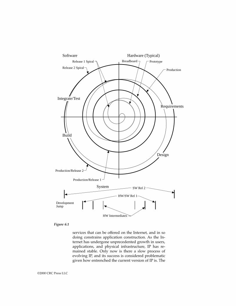
services that can be offered on the Internet, and in sodoing constrains application construction. As the In-ternet has undergone unprecedented growth in users,applications, and physical infrastructure, IP has re-mained stable. Only now is there a slow process ofevolving IP, and its success is considered problematicgiven how entrenched the current version of IP is. The
Figure 6.1
Production
PrototypeBreadboardRelease 1 Spiral
Release 2 Spiral
Production/Release 2
Production/Release 1
SW Rel 2
HW/SW Rel 1
HW Intermediates
DevelopmentJump
System
Design
Requirements
Integrate/Test
Software Hardware (Typical)
Build
©2000 CRC Press LLC
World Wide Web has similarly undergone tremendousgrowth and evolution on top of a simple set of ele-ments, the hypertext transfer protocol (http) and thehypertext markup language (html). Both the Internetand the World Wide Web are classic examples of sys-tems with nonphysical architecture, a topic that be-comes central in the discussion of collaborativesystems in Chapter 7.
Hardware-software integration adds to the picture. The hardware con-figurations must also be stable forms, but should appear at different pointsthan the software intermediates on the development timeline. Some stablehardware should be available during software development to facilitate thatdevelopment. A typical development cycle for an integrated hardware-soft-ware system illustrates parallel progressions in hardware and software witheach reaching different intermediate stable forms. The hardware progressionmight be wire-wrap breadboard, production prototype, production, then(possibly) field upgrade. The software moves through a development spiralaiming at a release 1.0 for the production hardware. The number of softwareiterations may be many more than for the hardware. In late developmentstages, new software versions may be built weekly.7 Before that, there willnormally be partial releases that run on the intermediate hardware forms(the wire-wrap breadboards and the production prototypes). Hard-ware/software co-design research is working toward environments in whichdeveloping hardware can be represented faithfully enough so that physicalprototypes are unnecessary for early integration. Such tools may becomeavailable, but iteration through intermediate hardware development levelsis still the norm in practice.
A related problem in designing a process for integration is the properuse of the heuristic do the hard part first. Because software is evolved oriterated, this heuristic implies that the early iterations should address themost difficult challenges. Unfortunately, honoring the heuristic is often dif-ficult. In practice, the first iterations are often good-looking interface dem-onstrations or constructs of limited functionality. If interface construction isdifficult, or user acceptance of the interface is risky or difficult, this may bea good choice. But if operation-to-time constraints under loaded conditionsis the key problem, some other early development strategy should be pur-sued. In that case the heuristic suggests gathering realistic experimental dataon loading and timing conditions for the key processes of the system. Thatdata can then be used to set realistic requirements for components of thesystem in its production configuration.
Example: Call Distribution Systems manage largenumbers of phone personnel and incoming lines, as intechnical support or phone sales operation. By tyingthe system into sales databases it is possible to develop
©2000 CRC Press LLC
sophisticated support systems that ensure that full cus-tomer information is available in real-time to the phonepersonnel. To be effective, the integration of data sourc-es and information handling must be customized toeach installation and evolve as understanding devel-ops of what information is needed and available. But,because the system is real-time and critical to customercontact, it must provide its principal functionality re-liably and immediately upon installation.
Thus, an architectural response to the problems of hardware-softwareintegration is to architect both the process and the product. The process ismanipulated to allow different segments of development to match them-selves to the demands of the implementation technology. The product isdesigned with interfaces that allow separation of development efforts wherethe efforts need to proceed on very different paths. How software architec-ture becomes an element of system architecture, and more details on howthis is to be accomplished, are the subjects to come.
The problem of hierarchy
A central tenet of systems engineering is that all systems can be viewed inhierarchies. A system is composed of subsystems, which are themselvescomposed of small units. A system is also embedded in higher-level systemsin which it acts as a component. One person’s system is another person’scomponent. A basic strategy is to decompose any system into subsystems,decompose the requirements until they can be allocated to subsystems, care-fully specify and control the interfaces among the subsystems, and repeatthe process on every subsystem until you reach components you can buy orare the products of disciplinary engineering. Decomposition in design isfollowed by integration in reverse. First, the lowest-level components areintegrated into the next level subsystems, those subsystems are integratedinto larger subsystems, and so on until the entire system is assembled.
Because this logic of decomposition and integration is so central toclassical systems engineering, it is difficult for many systems engineers tounderstand why it often does not match software development very well.To be sure, some software systems are very effectively developed this way.The same logic of decomposition and integration matches applications builtin procedural languages (like C or Pascal*) and where the development effortwrites all of the application’s code. In these software systems the code beginswith a top-level routine, which calls first-level routines, which call second-level routines, and so forth, to primitive routines that do not call others. Ina strictly procedural language the lower-level routines are contained within
* Strictly speaking, C is not a procedural language and some of what follows does not preciselyapply to it. Those knowledgeable in comparative programming languages can consider thedetails of the procedural vs. object-oriented paradigms in the examples to come.
©2000 CRC Press LLC
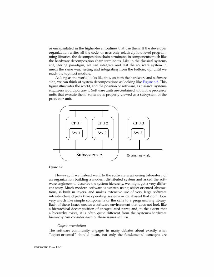
or encapsulated in the higher-level routines that use them. If the developerorganization writes all the code, or uses only relatively low-level program-ming libraries, the decomposition chain terminates in components much likethe hardware decomposition chain terminates. Like in the classical systemsengineering paradigm, we can integrate and test the software system inmuch the same way, testing and integrating from the bottom, up, until wereach the topmost module.
As long as the world looks like this, on both the hardware and softwareside, we can think of system decompositions as looking like Figure 6.2. Thisfigure illustrates the world, and the position of software, as classical systemsengineers would portray it. Software units are contained within the processorunits that execute them. Software is properly viewed as a subsystem of theprocessor unit.
However, if we instead went to the software engineering laboratory ofan organization building a modern distributed system and asked the soft-ware engineers to describe the system hierarchy, we might get a very differ-ent story. Much modern software is written using object-oriented abstrac-tions, is built in layers, and makes extensive use of very large softwareinfrastructure objects (like operating systems or databases) that don’t lookvery much like simple components or the calls to a programming library.Each of these issues creates a software environment that does not look likea hierarchical decomposition of encapsulated parts; and, to the extent thata hierarchy exists, it is often quite different from the systems/hardwarehierarchy. We consider each of these issues in turn.
Object-orientationThe software community engages in many debates about exactly what“object-oriented” should mean, but only the fundamental concepts are
Figure 6.2
©2000 CRC Press LLC
important for systems architecting. An object is a collection of functions (oftencalled methods) and data. Some of the functions are public, that is, they areexposed to other software objects and can be called by them. Depending onthe specific language and run-time environment, calling a function may bea literal function call, or it may simply mean sending a message to the targetobject, which interprets it and takes action. Objects can be “active,” that is,they can run concurrently with other objects. In some software environmentsconcurrent objects can freely migrate from computer to computer over anintervening network. Often, the software developer does not know, and doesnot want to know, on which machine a particular object is running, and doesnot want to directly control its migration. Concurrent execution of the objectsis passed to a distributed operating system, which may control object exe-cution through separately defined policies.
In object-oriented systems the number of objects existing when the soft-ware executes can be indeterminate. An object has a defining “template”(although the word template means something slightly different in manyobject-oriented languages) known as a “class.” A class is analogous to a typein procedural programming. Thus, just as one can declare many variablesof type “float,” so one can declare many objects corresponding to a givenclass. In most object-oriented languages the creation of objects from classeshappens at run-time, when the software is executing. If objects are not createduntil run-time the number of them can be controlled by external events.
This is a very powerful method of composing a software system. Eachobject is really a computational machine. It has its own data (potentially avery large amount) and as much of its own program code as the class authordecides. This sort of dynamic, object-oriented software can essentially man-ufacture logical machines, in arbitrary numbers, and set them to work on anetwork in response to events that happen during program execution. Tocompare this to classical notions of decomposition, it is as though one couldcreate subsystems on the fly during system operation.
Layered designThe objects are typically composed in a layered design. Layers are a form ofhierarchy, with a critical difference. In a layered system the lower-levelelements (those making up a lower layer) are not contained in the upperlayer elements. The elements of a layer interact to produce a set of services,which are made available to the next higher layer (in a strictly layeredsystem). Objects in the next higher layer can use the services offered by thenext lower layer, but cannot otherwise access the lower layer objects. Withina layer the objects normally treat each other as peers. That is, no object iscontained within another object. However, object-orientation does have thenotion of encapsulation. An object has internals, and the internals (functionsand data) belong to that object alone, although they can be duplicated inother objects with the same class.
A modern distributed application may be built as a set of interacting,concurrent objects. The objects themselves interact with a lower layer, often
©2000 CRC Press LLC
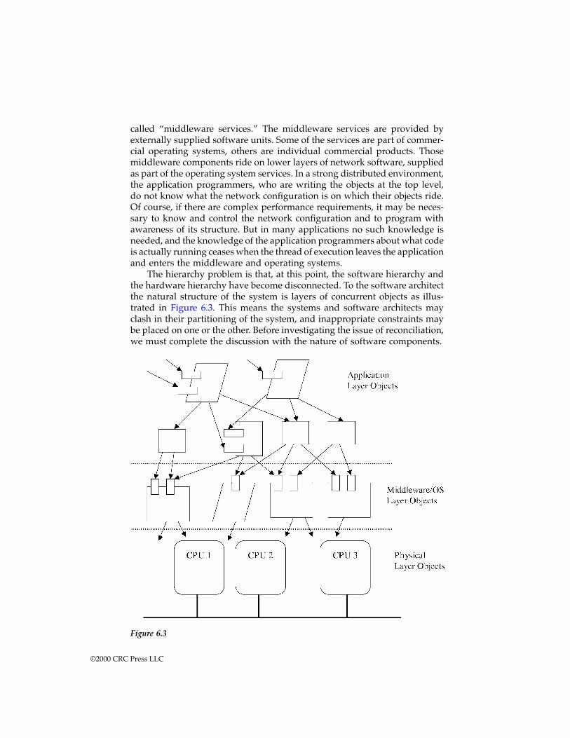
called “middleware services.” The middleware services are provided byexternally supplied software units. Some of the services are part of commer-cial operating systems, others are individual commercial products. Thosemiddleware components ride on lower layers of network software, suppliedas part of the operating system services. In a strong distributed environment,the application programmers, who are writing the objects at the top level,do not know what the network configuration is on which their objects ride.Of course, if there are complex performance requirements, it may be neces-sary to know and control the network configuration and to program withawareness of its structure. But in many applications no such knowledge isneeded, and the knowledge of the application programmers about what codeis actually running ceases when the thread of execution leaves the applicationand enters the middleware and operating systems.
The hierarchy problem is that, at this point, the software hierarchy andthe hardware hierarchy have become disconnected. To the software architectthe natural structure of the system is layers of concurrent objects as illus-trated in Figure 6.3. This means the systems and software architects mayclash in their partitioning of the system, and inappropriate constraints maybe placed on one or the other. Before investigating the issue of reconciliation,we must complete the discussion with the nature of software components.
Figure 6.3
©2000 CRC Press LLC
Large, autonomous componentsWhen taking a decompositional approach to design, the designer decom-poses until he or she reaches components that can be bought or easily built.In both hardware and software some of the components are very large. Insoftware, in particular, the design decomposition are often very large soft-ware units, such as operating systems and databases. Both of these are nowoften millions of lines of programming language code and possess richfunctionality. More significantly, they act semiautonomously when used ina system. An operating system is not a collection of functions to be passivelycalled by an application. To be sure, that is one of the services offered bymodern operating systems; but modern operating systems also manage pro-gram memory, schedule program units on processors, and synchronize con-current objects across multiple processors. An advanced operating systemmay present unified services that span many individual computers, possiblygeographically widespread.
These large and autonomous components change architecting becausethe architect is forced to adapt to the components. In principle, of course,the architect and client need not adapt. They can choose to sponsor a from-scratch development instead. But the cost of attempting to replicate theenormous software infrastructure that applications now commonly reuse isprohibitive. For example, the market dominance and complexity of verylarge databases forces us to use commercial products in these applications.The commercial products support particular kinds of data models, but donot support others. The architecture must take account of the kinds of datamodels supported, even when those are not a natural choice for the problem.
Reconciling the hierarchiesOur challenge is to reconcile the systems and software worlds. Becausesoftware is becoming the dominant element, in terms of its cost pacing whatcan be developed, one might argue for simply adopting software’s modelsand abandoning the classic systems view. This is inappropriate for severalreasons. First, the migration of software to object-oriented, layered structuresis only partial. Much software is procedurally structured, and is likely toremain so for many years to come. The infrastructure for supporting distrib-uted, concurrent, object-oriented applications is not mature. While leading-edge applications take this path, many others with strong reliability or justpredictability requirements will use more traditional structures.
Second, both approaches are fundamentally valid. Both Figures 6.2 and6.3 are correct views of the system; they just represent different aspects. Nosingle view can claim primacy. As we move into complex, information-centric systems we will have to accept the existence of many views, eachrepresenting different concerns, and each targeted at a different stakeholderaudience. The architect, and eventually systems engineers, will have to besure the multiple views are consistent and complete with respect to thestakeholders’ concerns.
©2000 CRC Press LLC
Third, every partitioning has its advantages and drawbacks. Building asystem in which each computational unit has its own software confinedwithin it has distinct advantages. In that case, each unit will normally havemuch greater autonomy (because it has its own software and doesn’t dependon others). That means each unit can be much more easily outsourced orindependently developed. Also, the system does not become dependent ofthe presence of some piece of software infrastructure. Software infrastructureelements (operating systems and middleware) have a poor record for on-schedule delivery and feature completeness. Anybody depending on anadvanced feature of an operating system to be delivered more than a yearin the future runs a high risk of being left with nothing when the scheduleddelivery date comes.
Nevertheless, the modern approaches have tremendous advantages inmany situations. Consider the situation when the units in Figure 6.2 sharea great deal of functionality. If separate development teams are assigned toeach, the functionality is likely to be independently developed as many timesas there are units. Redundant development is likely to be the least of theproblems, however, because those independent units probably interact witheach other; the test burden has the potential for rising as the square of thenumber of units. Appropriate code sharing, that is, the use of layered archi-tectures for software, can alleviate both problems.
The role of architecture in software-centered systemsIn software as in systems, the architect's basic role is the reconciliation of aphysical form with the client’s needs for function, cost, certification, andtechnical feasibility. The mindset is the same as described for system archi-tecting in general, though the areas of concentration are different. Systemarchitecting heuristics are generally good software heuristics, though theymay be refined and specialized. Several examples are given in Chapter 9. Inaddition, there are heuristics that apply particularly to software. Some ofthese are mentioned at the end of this chapter.
The architect develops the architecture. Following Brooks’ term,8 thearchitect is the user’s advocate. As envisioned in this book, the architect’sresponsibility goes beyond the conceptual integrity of the systems as seenby the user, to the conceptual integrity of the system as seen by the builderand other stakeholders. The architect is responsible for both what the systemdoes as well as how the system does it. But that responsibility extends, onboth counts, only as far as is needed to develop a satisfactory and feasiblesystem concept. After all, the sum of both is nearly the whole system, andthe architect’s role must be limited if an individual or small team is to carryit out. The latter role, of defining the overall implementation structure of thesystem, is closer to some of the notions of software architecture in recentliterature.
The architect’s realm is where views and models combine. Where modelsthat integrate disparate views are lacking, the architect can supply the
©2000 CRC Press LLC
insight. When disparate requirements must interact if satisfaction is to beachieved, the architect’s insight can insure that the right characteristics areconsidered foremost; and, moreover, to develop an architecture that canreconcile the disparate requirements. The perspective required is predomi-nantly a system perspective. It is the perspective of looking at the softwareand its underlying hardware platforms as an integrated whole that deliversvalue to the client. Its performance as a whole, behavioral and otherwise, iswhat gives it its value.
Architecting for evolution is also an example of the greatest leverage isat the interfaces heuristic. Make a system evolvable by paying attention tothe interfaces. In software, interfaces are very diverse. With a hardwareemphasis, it is common to think of communication interfaces at the bit, byte,or message level. But in software communication, interfaces can be muchricher and capture extensively structured data, flow of control, and applica-tion-specific notions. Current work in distributed computing is a good exam-ple. The trend in middleware is to find abstractions well above the networksocket that allow flexible composition. Network portable languages like Javaallow each machine to express a common interface for mobile code (the Javavirtual machine).
Programming languages, models, and expressions
Models are languages. A programming language is a model of a computingmachine. Like all languages they have the power to influence, guide, andrestrict our thoughts. Programmers with experience in multiple languagesunderstand that some problems will decompose easily in one language, butonly with difficulty in another, an example of fitting the architecture of thesolution to that of a prescriptive solution heuristic. The development ofprogramming languages has been the story of moving successively higherin abstraction from computing hardware.
The layering of languages is essential to complex software developmentbecause a high-level language is a form of software reuse. Assembly lan-guages masked machine instructions while procedural languages modeledcomputer instructions in a language more like prose. Modern languagescontaining object and strong structuring concepts continue the pattern byproviding a richer palette of representation tools for implementing comput-ing constructs. Each statement in FORTRAN, Pascal, or C reuses the compilerwriter’s machine-level implementation of that construct. Even more impor-tant examples are the application of specific languages like mathematicallanguages or databases. A statement in a mathematical language like MatLabor Mathematica may invoke a complex algorithm requiring long-term devel-opment and deep expertise. A database query language encapsulates com-plex data storage and indexing codes.
One way of understanding this move up the ladder of abstraction is afamous software productivity heuristic on programmer productivity. Apurely programming oriented statement of the heuristic is:
©2000 CRC Press LLC

Programmers deliver the same number of lines ofcode per day regardless of the language they are writ-ing in.
Hence, to achieve high software productivity, programmers must workin languages that require few lines of code.9 This heuristic can be used toexamine various issues in language and software reuse. The nature of aprogramming language, and the available tools and libraries, will determinethe amount of code needed for a particular application. Obviously, writingmachine code from scratch will require the most code. Moving to high-levellanguages like C or Ada will reduce the amount of original code needed,unless the application is fundamentally one that interacts with the comput-ing hardware at a very low level. Still less original code will be required ifthe language directly embodies application domain concepts, or, equiva-lently, application-specific code libraries are available.
Application-specific languages imitate domain language already in useand make it suitable for computing. One of the first and most popular isspreadsheets. The spreadsheet combines a visual abstraction and a compu-tational language suited to a range of modeling tasks in business offices,engineering, and science. An extremely important category is database querylanguages. Today it would be quite unusual to undertake an applicationrequiring sophisticated database functionality and not use an existing data-base product and its associated query language. Another more recent cate-gory is mathematical languages. These languages, such as Mathematica,MacSyma, and MatLab, use well-understood mathematical syntax and thenprocess those languages into computer-processable form. They allow themathematically literate user to describe solutions in a language much closerto the problem than in a general-purpose programming language.
Application-specific programming languages are likely to play anincreasingly important role in all systems built in reasonably large numbers.The only impediment in using these abstractions in all systems is the invest-ment required to develop the language and its associated application gen-erator and tools. One-of-a-kind systems will not usually be able to carry theburden of developing a new language along with a new system unless theyfit into a class of system for which a “meta-language” exists. Some workalong these lines has been done, for example, in command and controlsystems.10
Architectures, “unifying” models, and visions
Architectures in software can be definitions in terms of tasks and modules,language or model constructs, or, at the highest abstraction level, metaphors.Because software is the most flexible and ethereal of media, its architecture,in the sense of a defining structure, can be equally flexible and ethereal.
The most famous example is the Macintosh desktop metaphor, a truearchitecture. To a considerable degree, when the overall human interface
©2000 CRC Press LLC
guidelines are added, this metaphor defines the nature of the system. Itdefines the types of information that will be handled, and it defines muchof the logic or processing. The guidelines force operation to be human-centered; that is, the system continuously parses user actions in terms of theeffects on objects in the environment. As a result, Macintosh, and nowMicrosoft Windows, programs are dominated by a main event loop. Theforemost structure the programmer must define is the event loop, a loop inwhich system-defined events are sequentially stripped from a queue,mapped to objects in the environment, and their consequences evaluatedand executed.
The power of the metaphor as architecture is twofold. First, the metaphorsuggests much that will follow. If the metaphor is a desktop, its componentsshould operate similarly to their familiar physical counterparts. This resultsin fast and retentive learning “by association” to the underlying metaphor.Secondly, it provides an easily communicable model for the system that allcan use to evaluate system integrity. System integrity is being maintainedwhen the implementation to metaphor is clear.
Directions in software architectingSoftware architecture and architecting has received considerable recent atten-tion. There have been several special issues of IEEE Software Magazinedevoted to software architecture. Starting with Shaw and Garlan’s book,11 awhole series has appeared. Much of the current work in software architecturefocuses on architectural structures and their analyses. Much as the term“architectural style” has definite meaning in civil architecture, usage isattached to style in current software work. In the terminology of this book,work on software architecture styles is attempting to find and classify thehigh-level forms of software and their application to particular softwareproblems.
Focusing on architecture is a natural progression of software and pro-gramming research that has steadily ascended the ladder of abstraction.Work on structured programming led to structured design and to the mul-titasking and object-oriented models to be described in Chapter 10. The nextstage of the progression is to further classify the large-scale structures thatappear as software systems become progressively larger and more complex.
Current work in software architecture primarily addresses the productof architecting (the structure or architecture) rather than the process of gen-erating it. The published studies cover topics such as classifying architec-tures, mapping architectural styles to particularly appropriate applications,and the use of software frameworks to assemble multiple related softwaresystems. However, newer books are addressing process and the work onsoftware architecture patterns is effectively work on process in that it pro-vides directive guidance in forming a software architecture. This book pre-sents some common threads of the architectural process that underlie thegeneration of architectures in many domains. Once a particular domain is
©2000 CRC Press LLC

entered, such as software, the architect should make full use of the under-stood styles, frameworks, or patterns in that domain.
The flavor of current work in software architecture is best captured byreviewing some of its key ideas. These include the classification of architec-tural styles, patterns and pattern languages in software, and software frame-works.
Architectural styles
At the most general level, a style is defined by its components, connectors,and constraints. The components are the things from which the softwaresystem is composed. The connectors are the interfaces by which the compo-nents interact. A style sets the types of components and connectors that willmake up the system. The constraints are the requirements that define systembehavior. In the current usage, the architecture is the definition in terms ofform, which does not explicitly incorporate the constraints. To understandthe constraints one must look to additional views.
As a simple example, consider the structured design models describedpreviously. A pure structured style would have only one component type,the routine, and only one connector type, invocation with explicit data pass-ing. A software system composed only using these components and connec-tors could be said to be in the structured style; but the notion of style canbe extended to include considerations of its application and deviations.
David Garlan and Mary Shaw give this discussion of what constitutesan architectural style*:
“An architectural style then defines a family of suchsystems in terms of a pattern of structural organiza-tion. More specifically, an architectural style deter-mines the vocabulary of components and connectorsthat can be used in instances of that style. Additionally,a style might define topological constraints on archi-tectural descriptions (e.g., no cycles). Other constraints— say, having to do with execution semantics — mightalso be part of the style definition.
“Given this framework, we can understand what astyle is by answering the following questions: What isthe structural pattern — the components, connectors,and topologies? What is the underlying computationalmodel? What are the essential invariants of the style— its ‘load bearing walls?’ What are some commonexamples of its use? What are the advantages and dis-
* Garlan, D., and Shaw, M., An Introduction to Software Architecture, Technical Report, Schoolof Computer Science, Carnegie Mellon University, p. 6.
©2000 CRC Press LLC
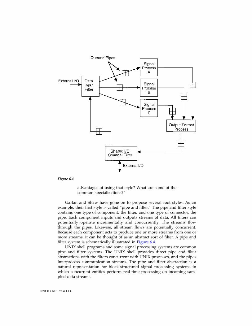
advantages of using that style? What are some of thecommon specializations?”
Garlan and Shaw have gone on to propose several root styles. As anexample, their first style is called “pipe and filter.” The pipe and filter stylecontains one type of component, the filter, and one type of connector, thepipe. Each component inputs and outputs streams of data. All filters canpotentially operate incrementally and concurrently. The streams flowthrough the pipes. Likewise, all stream flows are potentially concurrent.Because each component acts to produce one or more streams from one ormore streams, it can be thought of as an abstract sort of filter. A pipe andfilter system is schematically illustrated in Figure 6.4.
UNIX shell programs and some signal processing systems are commonpipe and filter systems. The UNIX shell provides direct pipe and filterabstractions with the filters concurrent with UNIX processes, and the pipesinterprocess communication streams. The pipe and filter abstraction is anatural representation for block-structured signal processing systems inwhich concurrent entities perform real-time processing on incoming sam-pled data streams.
Figure 6.4
©2000 CRC Press LLC
Some other styles proposed include object-oriented, event-based, lay-ered, and blackboard. An object-oriented architecture is built from compo-nents that encapsulate both data and function and exchange messages. Anevent-based architecture has as its fundamental structure a loop whichreceives events (from external interfaces or generated internally), interpretsthe events in the context of system state, and takes actions based on thecombination of event and state. Layered architectures emphasize horizontalpartitioning of the system with explicit message passing and function callingbetween layers. Each layer is responsible for providing a well-defined inter-face to the layer above. A blackboard architecture is built from a set ofconcurrent components which interact by reading and writing asynchro-nously to a common area.
Each style carries its advantages and weaknesses. Each of these stylesare descriptions of implementations from an implementer’s point of view,and specifically from the software implementer’s point of view. They are notdescriptions from the user’s point of view, or even from the point of viewof a hardware implementer on the system. A coherent style, at least of thetype currently described, gives a conceptual integrity that assists the builder,but may be no help to the user. Having a coherent implementation style mayhelp in construction, but it is not likely to yield dramatic improvements inproductivity or quality because it does not promise to dramatically cut thesize of what must be implemented.
This is reflective of a large fraction of the current software architectureliterature. The primary focus is on the structure of the software, not on thestructure of the problem that the software is to solve. The architecturedescription languages being studied are primarily higher-level or moreabstracted descriptions of programming language constructs. Where userconcerns enter the current discussion is typically through analysis. For exam-ple, an architecture description language developer may be concerned withhow to analyze the security properties of a system description written in thelanguage. This approach might be termed “structuralist.” It places the struc-ture of the software first in modeling, and attempts to derive all other viewsfrom it. There is an intellectual attraction to this approach since the structuralmodel becomes the root. If the notation for structure can be made consistent,then the other views derived from it should retain that consistency. There isno problem of testing consistency across many views written in differentmodeling languages. The weakness of the approach is that it forces thestakeholders other than the software developers to use an unfamiliar lan-guage and trust unfamiliar analyses. In the security example, instead of usingstandard methods from the security community, those concerned with secu-rity must trust the security analysis performed in the architectural language.This approach may grow to be accepted by broad communities of stakehold-ers, but it is likely to be a difficult sell.
In contrast to the perspective that places structure first in architecture,this book has repeatedly emphasized that only the client’s purpose can befirst. The architect should not be removed from the purpose or requirements,
©2000 CRC Press LLC

the architect should be immersed in them. This is a distinction betweenarchitecting as described here and as is often taught in software engineering.We do not assume that requirements precede architecture. The developmentof requirements is part of architecting, not part of its preconditions.
The ideal style is one that unifies both the user’s and builder’s views.The mathematical languages mentioned earlier are examples. They structurethe system from both a user’s and an implementer’s point of view. Of course,the internals of the implementation of such a complex software system willcontain many layers of abstraction. Almost certainly, new styles and abstrac-tions specific to the demands of implementation in real computers will haveto be created internally. When ideal styles are not available, it is still reason-able to seek models or architectural views which unify some set of consid-erations larger than just the software implementer. For implementation ofcomplex systems it would be a useful topic of research to find models orstyles that encompass a joint hardware-software view.
Architecture through composition
Patterns, styles, and layered abstraction are inherent parts of software prac-tice. Except for the rare machine-level program, all software is built fromlayered abstractions. High-level programming languages impose an intel-lectual model on the computational machine. The nature of that modelinevitably influences what kinds of programs (systems) are built on themachine.
The modern trend is to build systems from components at higher andhigher levels of abstraction. This is necessary as no other means is availableto build very large and complex systems within acceptable time and effortlimits. Each high-level library of components imposes its own style and lendsitself to certain patterns. The patterns that match the available libraries areencouraged, and it may be very difficult to implement architectures that arenot allowed for in the libraries.
Example: Graphical Macintosh and Windows pro-grams are almost always centrally organized aroundan event loop and handlers, a type of event-drivenstyle. This structure is efficient because the operatingsystems provide a built-in event loop to capture useractions such as mouse clicks and keypresses. However,since neither has multithreading abstractions (at leastbefore 1995), a concurrent, interacting object architec-ture is difficult to construct. Many applications wouldbenefit from a concurrent interaction object architec-ture, but these architectures are very difficult to imple-ment within the constraints of existing libraries.
©2000 CRC Press LLC
The logical extension is to higher and higher level languages, and fromlibraries to application-specific languages that directly match the nature ofthe problem they were meant to solve. The modern mathematical softwarepackages are, in effect, very high-level software languages designed to mimicthe problem they are meant to solve. The object of the packages is to dotechnical mathematics. So, rather than provide a language into which thescientist or engineer must translate mathematics, the package does the math-ematics. This is similar for computer-aided design packages and, indeed,most of the shrink-wrap software industry. These packages surround thecomputer with a layered abstraction that closely matches the way users arealready accustomed to work.
Actually, the relationship between application-specific programminglanguage, software package, and user is more symbiotic. Programmers adapttheir programs to the abstractions familiar to the users, but users eventuallyadapt their abstractions to what is available and relatively easy to implement.The best example is the spreadsheet. The spreadsheet as an abstractionpartially existed in paper form as the general ledger. The computer-basedabstraction has proven so logical that users have adapted their thinkingprocesses to match the structure of spreadsheets. It should probably beassumed that this type of interactive relationship will accelerate when thefirst generation of children to grow up with computers reaches adulthood.
Heuristics and guidelines in softwareThe software literature is a rich source for heuristics. Most of those heuristicsare specific to the software domain and are often specific to restricted classesof software-intensive systems. The published sets of software heuristics arequite large. The newer edition of Brooks's The Mythical Man-Month: Essaysin Software Engineering,12 includes a new chapter, The Propositions of theMythical Man-Month: True or False?, which lists the heuristics proposed inthe original work. The new chapters reinforce some of central heuristics andreject a few others as incorrect.
The heuristics given in "Man-Month" are broad-ranging, covering man-agement, design, organization, testing, and other topics. Several othersources give specific design heuristics. The best sources are detailed designmethodologies that combine models and heuristics into a complete approachto developing software in a particular category or style. Chapter 10 discussesthree of the best documented: ADARTS,* structured design,** and object-
* The published reference on ADARTS, which is quite thorough, is available through theSoftware Productivity Consortium, ADARTS Guidebook, Version 2.00.13, Vols. 1-2, September,1991. ADARTS is an Ada language specific method, though its ideas generalize well to otherlanguages. In fact, this has been done, although the resulting heuristics and examples areavailable only to Software Productivity Consortium members.** Structured design is covered in many books. The original reference is Yourdon, E. andConstantine, L L., Structured Design: Fundamentals of a Discipline of Computer Program and SystemsDesign, Yourdon Press, 1979.
©2000 CRC Press LLC

oriented.* Even more specific guidelines are available for the actual writingof code. A book by McConnell13 contains guidelines for all phases and adetailed bibliography.
From this large source-set, however, there are a few heuristics that par-ticularly stand out as broadly applicable and as basic drivers for softwarearchitecting.
• Choose components so that each can be implemented independentlyof the internal implementation of all others.
• Programmer productivity in lines of code per day is largely indepen-dent of language. For high productivity, use languages as close to theapplication domain as possible.
• The number of defects remaining undiscovered after a test is propor-tional to the number of defects found in the test. The constant ofproportionality depends on the thoroughness of the test, but is rarelyless than 0.5.
• Very low rates of delivered defects can be achieved only by very lowrates of defect insertion throughout software development, and bylayered defect discovery — reviews, unit test, system test.
• Software should be grown or evolved, not built.• The cost of removing a defect from a software system rises exponen-
tially with the number of development phases since the defect wasinserted.
• The cost of discovering a defect does not rise. It may be cheaper todiscover a requirements defect in customer testing than in any otherway, hence the importance of prototyping.
• Personnel skill dominates all other factors in productivity and quality.• Don’t fix bugs later, fix them now.
As has been discussed, the evolvability of software is one of its mostunique attributes. A related heuristic is: a system will develop and evolvemuch more rapidly if there are stable intermediate forms than if there arenot. In an environment where wholesale replacement is the norm, whatconstitutes a stable form? The previous discussion has already talked aboutreleases as stable forms and intermediate hardware configurations. From adifferent perspective, the stable intermediate forms are the unchanging com-ponents of the system architecture. These elements that do not change pro-vide the framework within which the system can evolve. If they are wellchosen, that is, if they are conducive to evolution, they will be stable andfacilitate further development. A sure sign the architecture has been badlychosen is the need to change it on every major release. The architecturalelements involved could be the use of specific data or control structures,
* Again, there are many books on object-oriented design, and many controversies about itsprecise definition and the best heuristics or design rules. Object-Oriented Modeling and Design,by Rumbaugh, discussed in Chapter 10, is a good introduction, as is the UML documentationand associated books.
©2000 CRC Press LLC
internal programming interfaces, or hardware-software interface definitions.Some examples illustrate the impact of architecture on evolution.
Example: The Point-to-Point Protocol (PPP) is a pub-licly defined protocol for computer networking overserial connections (such as modems). Its goal is to fa-cilitate broad multivendor interoperability and to re-quire as little manual configuration as possible. Theheart of the protocol is the need to negotiate the oper-ating parameters of a changing array of layered pro-tocols (for example, physical link parameters,authentication, IP control, AppleTalk control, compres-sion, and many others). The list of protocols is contin-uously growing in response to user needs and vendorbusiness perceptions. PPP implements negotiationthrough a basic state machine that is reused in all pro-tocols, coupled with a framework for structuring pack-ets. In a good implementation, a single implementationof the state machine can be “cloned” to handle eachprotocol, requiring only a modest amount of work toadd each new protocol. Moreover, the common formatof negotiations facilitates troubleshooting during testand operation. During the protocols development thestate machine and packet structure have been mappedto a wide variety of physical links and a continuouslygrowing list of network and communication supportprotocols.
Example: In the original Apple Macintosh operatingsystem the architects decided not to use the feature oftheir hardware to separate “supervisor” and “user”programs. They also decided to implement a varietyof application programming interfaces through accessto global variables. These choices were beneficial to theearly versions because they improved performance.But these same choices (because of backward compat-ibility demands) have greatly complicated efforts toimplement advanced operating system features suchas protected memory and preemptive multitasking.Another architectural choice was to define the hard-ware-software interface through the Macintosh Tool-box and the published Apple programming guidelines.The combination has proven to be both flexible andstable. It has allowed a long series of dramatic hard-ware improvements, and now a transfer to a new hard-ware architecture, with few gaps in backward
©2000 CRC Press LLC
compatibility (at least for those developers whoobeyed the guidelines).
Example: The Internet Protocol, combined with therelated Transport Control Protocol (TCP/IP), has be-come the software backbone of the global Internet. Itspartitioning of data handling, routing decisions, andflow control has proven to be robust and amenable toevolutionary development. The combination has beenable to operate across extremely heterogeneous net-works with equipment built by countless vendors.While there are identifiable architects of the protocolsuite, control of protocol development is quite distrib-uted with little central authority. In contrast, the pro-prietary networking protocols developed andcontrolled by several major vendors have frequentlydone relatively poorly at scaling to diverse networks.One limitation in the current IP protocol suite that hasbecome clear is the inadequacy of its 32-bit addressspace. However, the suite was designed from the be-ginning with the capability to mix protocol versionson a network. As a result, the deployed protocol ver-sion has been upgraded several times (and will beagain to IPv6) without interfering with the ongoingoperation of the Internet.
Exercises
1. Consult one or more of the references for software heuristics. Extractseveral heuristics and use them to evaluate a software-intensive sys-tem.
2. Requirements defects that are delivered to customers are the mostcostly because of the likelihood they will require extensive rework.But discovering such defects anytime before customer delivery islikewise very costly because only the customers’ reaction may makethe nature of the defect apparent. One approach to this problem isprototyping to get early feedback. How can software be designed toallow early prototyping and feedback of the information gained with-out incurring the large costs associated with extensive rework?
3. Pick three software-intensive systems of widely varying scope. Forexample, a pen computer-based data entry system for warehouses,an internetwork communication server, and the flight control softwarefor a manned space vehicle. What are the key determinants of successand failure for each system? As an architect, how would these deter-
©2000 CRC Press LLC

minants change your approach to concept formulation and certifica-tion?
4. Examine some notably successful or unsuccessful software-intensivesystems. To what extent was success or failure due to architectural(conceptual integrity, feasibility of concept, certification) issues andto what extent was it due to other software process issues.
5. Are their styles analogous to those proposed for software that jointlyrepresent hardware and software?
Notes and references1. IEEE Software Magazine, Special issue on the The Artistry of Software Archi-
tecture, November 1995. This issue contains a variety of papers on softwarearchitecture, including the role of architecture in reuse, comparisons of styles,decompositions by view, and building-block approaches.
2. Kruchten, P. B., A 4+1 view model of software architecture, IEEE SoftwareMagazine, p. 42, November 1995.
3. Leveson, N. G. and Turner, C. S., An investigation of the Therac 25 accidents,Computer, p. 18, July 1993.
4. DeMarco and Lister, Peopleware: Productive Projects and Teams, Dorset House,New York, 1987.
5. Lambert, B., Beyond Information Engineering: The Art of Information SystemsArchitecture, Technical Report, Broughton Systems, Richmond, VA, 1994.
6. Software Productivity Consortium, Herndon, VA, Evolutionary Spiral Process,Vol. 1-3, 1994.
7. Maguire, S., Debugging the Development Process, Microsoft Press, Redmond,WA, 1994.
8. Brooks, F., The Mythical Man Month, Addison-Wesley, Reading, MA, 1975. Thisclassic book has recently been republished with additional commentary byBrooks on how his observations have held up over time; p. 256 in the newedition.
9. Data associated with this heuristic can be found in several books. Two sourcesare Programming Productivity and Applied Software Measurement, both by Ca-pers Jones, McGraw Hill, New York.
10. Domain-Specific Software Architectures, USC Information Sciences Institute,Technical Report, 1996.
11. Shaw, M. and Garlan, D., Software Architecture: Perspectives on an EmergingDiscipline, Prentice-Hall, Englewood Cliffs, NJ, 1996.
12. Brooks, F., The Mythical Man Month, Addison-Wesley, Reading, MA, 1975.13. McConnell, S., Code Complete: A Practical Handbook of Software Construction,
Microsoft Press, Redmond, WA, 1993.
©2000 CRC Press LLC
chapter seven
Collaborative systems
Introduction: collaboration as a categoryMost of the systems discussed thus far have been the products of deliberateand centrally controlled development efforts. There was an identifiable clientor customer (singular or plural), clearly identifiable builders, and users.Client, in the traditional sense, means the person or organization who spon-sors the architect and who has the resources and authority to construct thesystem of interest. The role of the architect existed, even if it was hard totrace to a particular individual or organization. The system was the resultof deliberate value judgment by the client and existed under the control ofthe client. However, many systems are not under central control, either intheir conception, their development, or their operation. The Internet is thecanonical example, but many others exist, including electrical power sys-tems, multinational defense systems, joint military operations, and intelli-gent transportation systems. These systems are all collaborative in the sensethat they are assembled and operate through the voluntary choices of theparticipants, not through the dictates of an individual client. These systemsare built and operated only through a collaborative process.
A problem in this area is the lack of standard terminology for categoriesof system. Any system is an assemblage of elements that possesses capabil-ities not possessed by an element. This is just saying that a system possessesemergent properties, indeed that possessing emergent properties is the defin-ing characteristic of a system. A microwave oven, a laptop computer, andthe Internet are all systems, but each can have radically different problemsin design and development.
This chapter discusses systems distinguished by the voluntary nature ofthe systems assembly and operation. Examples of systems in this categoryinclude most intelligent transport systems,1 military C4I and Integrated Bat-tlespace,2 and partially autonomous flexible manufacturing systems.3 Thearguments here apply to most of what are often referred to as systems-of-systems, a term some readers may prefer. One of the authors (Maier) hasdiscussed the contrast between the concepts elsewhere.4
©2000 CRC Press LLC
What exactly is a collaborative system? In this chapter a system is a“collaborative system” when its components:
1. Fulfill valid purposes in their own right, and continue to operate tofulfill those purposes if disassembled from the overall system
2. Are managed (at least in part) for their own purposes rather than thepurposes of the whole; the component systems are separately ac-quired and integrated but maintain a continuing operational existenceindependent of the collaborative system
Misclassification as a “conventional” system vs. a collaborative system(or vice versa) leads to serious problems. Especially important is a failure toarchitect for robust collaboration when direct control is impossible or inad-visable. This can arise when the developers believe they have greater controlover the evolution of a collaborative system than they actually do. In believ-ing this, they may fail to ensure that critical properties or elements will beincorporated by failing to provide a mechanism matched to the problem.
As with other domains, collaborative systems have their own heuristics,and familiar heuristics may have new applications. To find them for collab-orative systems we look first at important examples, and then we generalizeto find the heuristics. A key point is the heightened importance of interfacesand the need to see interfaces at many layers. The explosion of the Internetand the World Wide Web is greatly facilitating collaborative system construc-tion, but we find that the “bricks and mortar” of Internet-based collaborativesystems are not at all physical. The building blocks are communicationprotocols, often at higher layers in the communications stack that is familiarfrom past systems.
Collaborative system examplesSystems built and operated voluntarily are not unusual, even if they seemvery different from classical systems engineering practice. Most of the read-ers of this book will be living in capitalist democracies where social orderthrough distributed decisions is the philosophical core of government andsociety. Nations differ in the degree to which they choose to centralize vs.decentralize decision making, but the fundamental principle of organizationis voluntary collaboration. This book is concerned with technological sys-tems, albeit sometimes systems with heavy social or political overtones. So,we take as our examples systems whose building blocks are primarily tech-nical. The initial examples are the Internet, intelligent transportation systems(for road traffic), and joint air defense systems.
The Internet
When we say “the Internet” we are not referring to the collection of appli-cations that have become so popular (e-mail, World Wide Web, chats, etc.).
©2000 CRC Press LLC
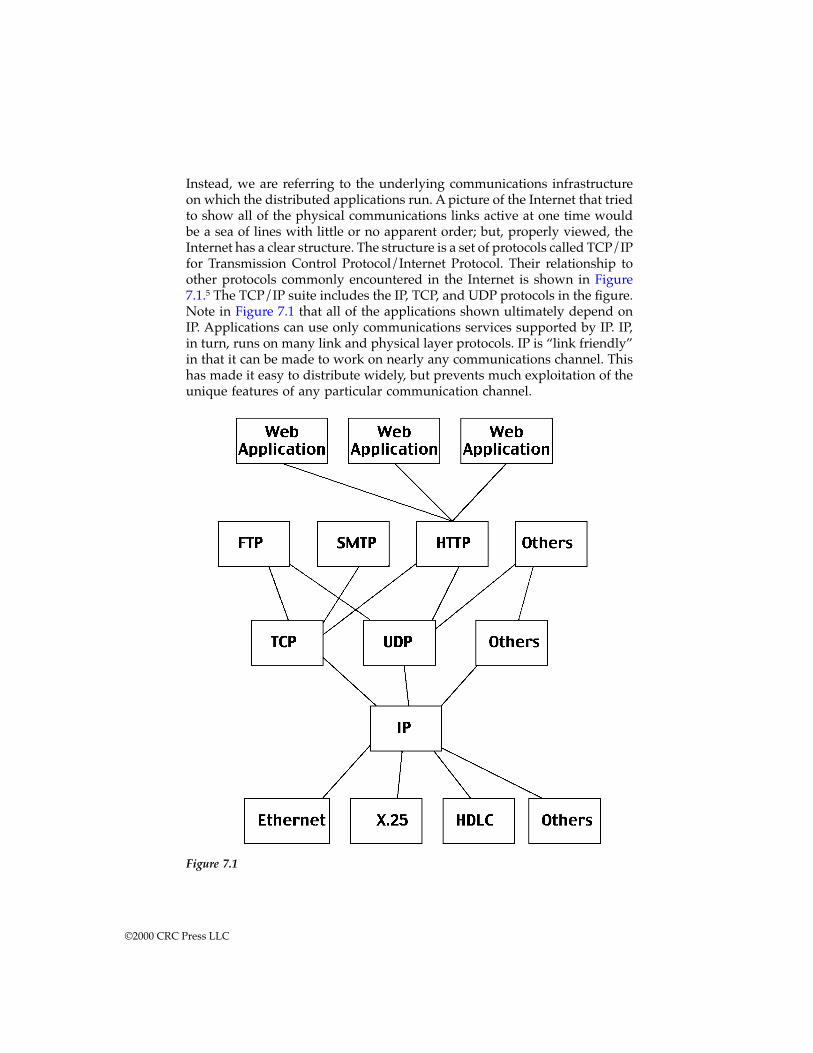
Instead, we are referring to the underlying communications infrastructureon which the distributed applications run. A picture of the Internet that triedto show all of the physical communications links active at one time wouldbe a sea of lines with little or no apparent order; but, properly viewed, theInternet has a clear structure. The structure is a set of protocols called TCP/IPfor Transmission Control Protocol/Internet Protocol. Their relationship toother protocols commonly encountered in the Internet is shown in Figure7.1.5 The TCP/IP suite includes the IP, TCP, and UDP protocols in the figure.Note in Figure 7.1 that all of the applications shown ultimately depend onIP. Applications can use only communications services supported by IP. IP,in turn, runs on many link and physical layer protocols. IP is “link friendly”in that it can be made to work on nearly any communications channel. Thishas made it easy to distribute widely, but prevents much exploitation of theunique features of any particular communication channel.
Figure 7.1
©2000 CRC Press LLC
The TCP/IP family protocols are based on distributed operation andmanagement. All data is encapsulated in packets, which are independentlyforwarded through the Internet. Routing decisions are made locally at eachrouting node. Each routing node develops its own estimate of the connectionstate of the system through the exchange of routing messages (also encap-sulated as IP packets). The distributed estimates of connection state are not,and need not be, entirely consistent or complete. Packet forwarding worksin the presence of some errors in the routing tables (although introduction ofbad information can also lead to collapse).
The distributed nature of routing information, and the memoryless for-warding, allows the Internet to operate without central control or direction.A decentralized development community matches this decentralized archi-tecture. There is no central body with coercive power to issue or enforcestandards. There is a central body which issues standards, the Internet Engi-neering Task Force (IETF), but its practices are unlike nearly any otherstandards body. The IETF approach to standards is, fundamentally, to issueonly those which have already been developed and deployed. Almost any-body can go to the IETF and try and form a working group to build standardsin a given area. The organization accepts nearly any working group that hasthe backing of a significant subset of participants. The working group canissue “internet-drafts” with minimal overhead. For a draft to advance to theInternet equivalent of a published standard it must be implemented anddeployed by two or more independent organizations. All Internet standardsare available for free, and very strong efforts are made to keep them unen-cumbered by intellectual property. Proprietary elements are usually acceptedonly as optional extensions to an open standard.
Distributed operation, distributed development, and distributed man-agement are linked. The Internet can be developed in a collaborative waylargely because its operation is collaborative. Because the Internet uses best-effort forwarding and distributed routing, it can easily offer new serviceswithout changing the underlying protocols. Those new services can beimplemented and deployed by groups that have no involvement in devel-oping or operating the underlying protocols; but only so long as those newservices do not require any new underlying services. For example, groupswere able to develop and deploy IP-Phone (a voice over the Internet appli-cation) without any cooperation from TCP/IP developers or even Internetservice providers. However, the IP-Phone application cannot offer any qual-ity of service guarantees because the protocols it is built on do not offersimultaneous delay and error rate bounding.
In contrast, networks using more centralized control can offer richerbuilding block network services, including quality of service guarantees.However, they are much less able to allow distributed operation. Also, thecollaborative environments that have produced telecommunications stan-dards have been much slower moving than the Internet standards bodies.They have not adopted some of the practices of the Internet bodies that haveenabled them to move quickly and rapidly capture market share. Of course,
©2000 CRC Press LLC
some of those practices would threaten the basic structure of the existingstandards organizations.
In principle, a decentralized system like the Internet should be lessvulnerable to destructive collective phenomena and be able to locally adaptaround problems. In practice, both the Internet with its distributed controlmodel and the telephone system with its greater centralization have provenvulnerable to collective phenomena. It turns out that distributed controlprotocols like TCP/IP are very prone to collective phenomena in both trans-mission and routing (Bertsekas, 1992, Chapter 6). Careful design and selec-tion of parameters has been necessary to avoid network collapse phenomena.One reason is that the Internet uses a “good intentions” model for distributedcontrol which is vulnerable to nodes that misbehave either accidentally ordeliberately. There are algorithms known which are robust against bad inten-tions faults, but they have not been incorporated into network designs. Thedecentralized nature of the system has made it especially difficult to defendagainst coordinated distributed attacks (e.g., distributed denial of serviceattacks). Centralized protocols often deal more easily with these attacks sincethey have strong knowledge of where connections originate, and can per-form aggressive load-shedding policies under stress.
Wide area telephone blackouts have attracted media attention andshown that the more centralized model is also vulnerable. The argumentabout decentralized vs. centralized fault tolerance has a long history in theelectric power industry, and even today it has not reached full resolution.
Intelligent transportation systems
The goal of most initiatives in intelligent transportation is to improve roadtraffic conditions through the application of information technology. Thissubject is large and cannot be addressed in detail here.6 We picked out oneissue to illustrate how a collaborative system may operate, and the architec-tural challenges in making it happen.
One intelligent transportation concept is called “fully coupled routingand control.” In this concept a large fraction of vehicles are equipped withdevices that determine their position and periodically report it to a trafficmonitoring center. The device also allows the driver to enter his or herdestination when beginning a trip. The traffic center uses the traffic condi-tions report to maintain a detailed estimate of conditions over a large met-ropolitan area. When the center gets a destination message it responds witha recommended route to that destination, given the vehicle’s current posi-tion. The route could be updated during travel if warranted. The concept isreferred to as fully coupled because the route recommendations can becoupled with traditional traffic controls (e.g., traffic lights, on-ramp lights,reversible lanes, etc.).
Obviously, the concept brings up a wide array of sociotechnical issues.Many people may object to the lack of privacy inherent in their vehicleperiodically reporting its position. Many people may object to entering their
©2000 CRC Press LLC
destination and having it reported to a traffic control center. Although thereare many such issues, we narrow down, once again, to just one concept thatbest illustrates collaborative system principles. The concept only works if:
1. A large fraction of vehicles have, and use, the position reportingdevice.
2. A large fraction of drivers enter their (actual) destination when be-ginning a trip.
3. A large fraction of drivers follow the route recommendations they aregiven.
Under current conditions, vehicles on the roads are mostly privatelyowned and operated for the benefit of their owners. With respect to thecollaborative system conditions, the concept meets it if using the routingsystem is voluntary. The vehicles continue to work whether or not they reporttheir position and destination; and vehicles are still operated for their own-ers’ benefit, not for the benefit of some “collective” of road users. So, if weare architecting a collaborative traffic control system, we have to explicitlyconsider how the three conditions above needed to gain the emergent capa-bilities are ensured.
One way to ensure them is to not make the system collaborative. Undersome social conditions we can ensure all of the above conditions by makingthem legally mandatory and providing enforcement. It is a matter of judg-ment whether or not such a mandatory regime could be imposed.
If one judges that a mandatory regime is impossible, then the systemmust be collaborative. Given that it is collaborative, there are many archi-tectural choices that can enhance the cooperation of the participants. Forexample, we can break apart the functions of traffic prediction, routingadvice, and traditional controls and allocate some to private markets. Imag-ine an urban area with several “Traffic Information Provider” services. Theseservices are private and subscription-based, receive the position and desti-nation messages, and disseminate the routing advice. Each driver voluntarilychooses a service, or none at all. If the service provides accurate predictionsand efficient routes, it should thrive. If it cannot provide good service, it willlose subscribers and die.
Such a distributed, market-based system may not be able to implementall of the traffic management policies that a centralized system could. How-ever, it can facilitate social cooperation in ways the centralized system can-not. A distributed, market-based system also introduces technical complex-ities into the architecture that a centralized system does not. In a privatesystem it must be possible for service providers to disseminate their infor-mation securely to paying subscribers. In a public, centralized system, infor-mation on conditions can be transmitted openly.
©2000 CRC Press LLC
Joint air defense systems
A military system may seem like an odd choice for a collaborative system.After all, military systems work by command, not voluntary collaboration.Leaving aside the social issue that militaries must always induce loyalty,which is a social process, the degree to which there is a unified commandon military systems or operations is variable. A system acquired and oper-ated on a single service can count on central direction. A system that comestogether only in the context of a multiservice, multinational, joint militaryoperation cannot count on central control.
All joint military systems and operations have a collaborative element,but here we consider just air defense. An air defense system must fuse acomplex array of sensors (ground radars, airborne radars, beacon systems,human observers, and other intelligence systems) into a logical picture ofthe airspace and then allocate weapon systems to engage selected targets. Ifthe system includes elements from several services or nations, conflicts willarise. Nations, and services, may want to preferentially protect their ownassets. Their command channels and procedures may affect greater self-protection, even when ostensibly operating solely for the goals of the collec-tive.
Taking a group of air defense systems from different nations and differ-ent services and creating an effective integrated system from them is thechallenge. The obvious path might be to try and convert the collection intosomething resembling a single service air defense system. This would entailunifying the command, control, and communications infrastructure. Itwould mean removing the element of independent management that char-acterizes collaborative systems. If this could be done, it is reasonable toexpect that the resulting integrating system would be closer to a kind ofpoint optimum. But, the difficulties of making the unification are likely tobe insurmountable.
If, instead, we accept the independence, then we can try and forge aneffective collaborative system. The technical underpinnings are clearlyimportant. If the parts are going to collaborate to create integrated capabil-ities greater than the sum of the parts, they are going to have to communicate.So, even if command channels are not fully unified, communications mustbe highly interoperable. In this example, as in other sociotechnical examples,the social side should not be ignored. It is possible that the most importantunifying elements in this example will be social. These might include sharedtraining or educational background, shared responsibility, or shared socialor cultural background.
Analogies for architecting collaborative systemsOne analogy that may apply is the urban planner. The urban planner, likethe architect, develops overall structures. While the architect structuresbuildings for effective use by the client, the urban planner structures effective
©2000 CRC Press LLC
communities. The client of an urban planner is usually a community gov-ernment or one of its agencies. The urban planner’s client and the architect’sclient differ in important respects. The architect’s client is making valuejudgments for him or herself, and presumably has the resources to put intoaction whatever plan is agreed to with the architect. When the architect’splan is received, the client will hire a builder. The urban planner’s clientdoes not actually build the city. The plan is to constrain and guide manyother developers and architects who will come later, and hopefully guidetheir efforts into a whole greater than if there had been no overall plan. Theurban planner and client are making value judgments for other people, thepeople who will one day inhabit the community being planned. The urbanplanner’s client usually lacks the resources to build the plan, but can certainlystop something from being built if it is not in the plan. To be successful, theurban planner and client have to look outward and sell their vision. Theycannot bring it about without others’ aid, and they normally lack theresources and authority to do it themselves.
Urban planning also resembles architecting in a spiral or evolutionarydevelopment process more than in the waterfall. An urban plan must becontinuously adapted as actual conditions change. Road capacity that wasadequate at one time may be inadequate at another. The mix of businessesthat the community can support may change radically. As actual eventsunfold, the plan must adapt and be resold to those who participate in it, orit will be irrelevant.
Another analogy for collaborative systems is in business relationships.A corporation with semi-independent division is a collaborative system ifthe divisions have separate business lines, individual profit and loss respon-sibilities, and also collaborate to make a greater whole. Now consider theproblem of a post-merger company. Before the merger the components (thecompanies that are merging) were probably centrally run. After the mergerthe components may retain significant independence. Now if they are tojointly create something greater they must do it through a collaborativesystem instead of their traditional arrangement. If the executives do notrecognize this and adapt, it is likely to fail. A franchise that grants its fran-chisees significant independence is also like a collaborative system. It is madeup of independently owned and operated elements which combine to besomething greater than they would achieve individually.
Collaborative system heuristicsAs with builder-architecting, manufacturing, sociotechnical, and software-intensive systems, collaborative systems have their own heuristics. The heu-ristics discussed here have all been given previously, either in this book orits predecessor. What is different is their application. Looking at how heu-ristics are applied to different domains gives a greater appreciation for theiruse and applicability in all domains.
©2000 CRC Press LLC
Stable intermediate forms
The heuristic on stable intermediate forms is given (Rechtin, E., 1991) as:
Complex systems will develop and evolve within anoverall architecture much more rapidly if there arestable intermediate forms than if there are not.
It is good practice in building a home or bridge to have a structure thatis self-supporting during construction. So, in other systems it is importantto design them to be self-supporting before they reach the final configuration.For better or worse, in collaborative systems it cannot be assumed that allparticipants will continue to collaborate. The system will evolve based oncontinuous self-assessments of the desirability for collaboration by the par-ticipants.
Stability means that intermediate forms should be technically, econom-ically, and politically self-supporting. Technical stability means that the sys-tem operates to fulfill useful purposes. Economic stability means that thesystem generates and captures revenue streams adequate to maintain itsoperation. Moreover, it should be in the economic interests of each partici-pant to continue to operate rather than disengage. Political stability can bestated as the system has a politically decisive constituency supporting itscontinued operation, a subject we return to in Chapter 12.
• Integrated air defense systems are subject to unexpected and violent“reconfiguration” in normal use. As a result, they are designed withnumerous fallback modes, down to the anti-aircraft gunner workingon his own with a pair of binoculars. Air defense systems built fromweapon systems with no organic sensing and targeting capabilityhave frequently failed in combat when the network within which theyoperate has come under attack.
• The Internet allows components nodes to attach and detach at will.Routing protocols adapt their paths as links appear and disappear.The protocol encapsulation mechanisms of IP allow an undeterminednumber of application layer protocols to simultaneously coexist.
Policy triage
This heuristic gives guidance in selecting components, and in setting prior-ities and allocating resources in development. It is given (Rechtin, E., 1991)as:
The triage: Let the dying die. Ignore those who willrecover on their own. And treat only those who woulddie without help.
©2000 CRC Press LLC

Triage can apply to any systems, but especially applies to collaborativesystems. Part of the scope of a collaborative system is deciding what not tocontrol. Attempting to overcontrol will fail for lack of authority. Under-control will eliminate the system nature of the integrated whole. A goodchoice enhances the desired collaboration.
• Motion Picture Experts Group (MPEG) chose to only standardize theinformation needed to decompress a digital video stream.7 The stan-dard defines the format of the data stream and the operations requiredto reconstruct the stream of moving picture frames. However, thecompression process is deliberately left undefined. By standardizingdecompression, the usefulness of the standard for interoperability wasassured. By not standardizing compression, the standard leaves opena broad area for the firms collaborating on the standard to continueto compete. Interoperability increases the size of the market, a benefitto the whole collaborative group, while retaining a space for compe-tition eliminates a reason to not collaborate with the group. Broadcollaboration was essential both to ensure a large market, and toensure that the requisite intellectual property would be offered forlicense by the participants.
Leverage at the interfaces
Two heuristics, here combined, discuss the power of the interfaces. Thegreatest leverage in system architecting is at the interfaces. The greatestdangers are also at the interfaces.
When the components of a system are highly independent, operationallyand managerially, the architecture of the system is the interfaces. The archi-tect is trying to create emergent capability. The emergent capability is thewhole point of the system; but, the architect may only be able to influencethe interfaces among the nearly independent parts. The components areoutside the scope and control of an architect of the whole.
• The Internet oversight bodies concern themselves almost exclusivelywith interface standards. Neither physical interconnections nor appli-cations above the network protocol layers are standardized. Actually,both areas are the subject of standards, but not the standards processof the IETF.
One consequence is attention to different elements than in a conventionalsystem development. For example, in a collaborative system, issues like lifecycle cost are of low importance. The components are developed collabora-tively by the participants, who make choices to do so independently of anycentral oversight body. The design team for the whole cannot choose tominimize life cycle cost, nor should they, because the decisions that deter-mine costs are outside their scope. The central design team can choose
©2000 CRC Press LLC
interface standards, and can choose them to maximize the opportunities forparticipants to find individually beneficial investment strategies.
Ensuring cooperation
If a system requires voluntary collaboration, the mechanism and incentivesfor that collaboration must be designed in.
In a collaborative, the components actively choose to participate or not.Like a market, the resulting system is the web of individual decisions by theparticipants. Thus, the economists’ argument that the costs and benefits ofcollaboration should be superior to the costs and benefits of independencefor each participant individually should apply. As an example, the Internetmaintains this condition because the cost of collaboration is relatively low(using compliant equipment and following addressing rules) and the benefitsare high (access to the backbone networks). Similarly in MPEG video stan-dards, compliance costs can be made low if intellectual property is pooled,and the benefits are high if the targeted market is larger than the participantscould achieve with proprietary products. Without the ability to retain acompetitive space in the market (through differentiation on compression inthe case of MPEG), the balance might have been different. Alternatively, thecost of noncompliance can be made high, though this method is used lessoften.
An alternative means of ensuring collaboration is to produce a situationin which each participant’s well-being is partially dependent on the well-being on the other participants. This joint utility approach is known, theo-retically, to produce consistent behavior in groups. A number of social mech-anisms can be thought of as using this principle. For example, strong socialindoctrination in military training ties the individual to the group and servesas a coordinating operational mechanism in integrated air defense.
Another way of looking at this heuristic is through the metaphor of thefranchise. The heuristic could be rewritten for collaborative systems as:
Consider a collaborative system a franchise. Alwaysask why the franchisees choose to join, and choose toremain.
Variations on the collaborative themeThe two criteria provide a sharp definition of a collaborative system, butthey still leave open many variations. Some collaborative systems are reallycentrally controlled, but the central authority has decided to devolve author-ity in the service of system goals. In some collaborative systems a centralauthority exists, but power is expressed only through collective action. Theparticipants have to mutually decide and act to take the system in a newdirection. And, finally, some collaborative systems lack any central authority.They are entirely emergent phenomena.
©2000 CRC Press LLC
A collaborative system where central authority exists and can act iscalled a closed collaborative system. Closed collaborative systems are thosein which the integrated system is built and managed to fulfill specific pur-poses. It is centrally managed during long-term operation to continue tofulfill those purposes and any new ones the system owners may wish toaddress. The component systems maintain an ability to operate indepen-dently, but their normal operational mode is subordinated to the centralmanaged purpose. For example, most single-service air defense networksare centrally managed to defend a region against enemy systems, althoughthe component systems retain the ability to operate independently, and doso when needed under the stress of combat.
“Open” collaborative systems are distinct from the closed variety in thatthe central management organization does not have coercive power to runthe system. The component systems must, more or less, voluntarily collab-orate to fulfill the agreed-upon central purposes. The Internet is an opencollaborative system. The IETF works out standards, but has no power toenforce them. IETF standards work because the participants choose to imple-ment them without proprietary variations, at least for the most part.
As the Internet becomes more important in daily life, in effect as itbecomes a new utility like electricity or the telephone, it is natural to wonderwhether or not the current arrangement can last. Services on which publicsafety and welfare depend are regulated. Public safety and welfare, at leastin industrial countries, is likely to depend on Internet operation in the nearfuture, if it does not already. So, will the Internet and its open processeseventually come under regulation? It may, although the most recent trendshave actually been away from centralization. For example, authority overdomain naming, which is central to Internet management, has been brokenup among competing companies at the insistence of the U.S. government ininternational negotiations.
Virtual collaborative systems lack both a central management authorityand centrally agreed-upon purposes. Large-scale behavior emerges, and maybe desirable, but the overall system must rely upon relatively invisible mech-anisms to maintain it.
A virtual system may be deliberate or accidental. Some examples arethe current form of the World Wide Web and national economies. Both“systems” are distributed physically and managerially. The World Wide Webis even more distributed than the Internet in that no agency ever exerteddirect central control, except at the earliest stages. Control has been exertedonly through the publication of standards for resource naming, navigation,and document structure. Although essentially just by social agreement, majordecisions about Web architecture filter through very few people. Web siteschoose to obey the standards or not, at their own discretion. The system iscontrolled by the forces that make cooperation and compliance to the corestandards desirable. The standards do not evolve in a controlled way, ratherthey emerge from the market success of various innovators. Moreover, thepurposes the system fulfills are dynamic and change at the whim of the users.
©2000 CRC Press LLC
National economies can be thought of as virtual systems. There areconscious attempts to architect these systems through politics, but the long-term nature is determined by highly distributed, partially invisible mecha-nisms. The purposes expressed by the system emerge only through thecollective actions of the system’s participants.
MisclassificationTwo general types of misclassification are possible. One is to incorrectlyregard a collaborative system as a conventional system, or the reverse.Another is to misclassify a collaborative system as directed, voluntary, orvirtual.
In the first case, system vs. collaborative system, consider open sourcesoftware. Open source software is often thought of as synonymous withLinux, a particular open source operating system. Actually, there is a greatdeal of open source, “free” software. Software is usually considered opensource if anybody can obtain the source code, use it, modify it, and redis-tribute it for free. Because Linux has been spectacularly successful in marketshare growth, and (not incidentally) in creating initial public offering riches,many others have tried to emulate the open source model. The open sourcemodel is built on a few basic principles,8 perhaps heuristics. These include:
1. Designs, and initial implementations, should be carried out by giftedindividuals or very small teams.
2. Software products should be released to the maximum possible au-dienc, as quickly as possible.
3. Users should be encouraged to become testers, and even co-develop-ers by providing source code.
4. Code review and debugging can be arbitrarily parallalized, at least ifyou distribute source code to your reviewers and testers.
5. Incremental delivery of small increments, with a very large us-er/tester population, leads to very rapid development of high-qualitysoftware.*
Of course, a side effect of this model is losing the ability to make anysignificant amount of money distributing software you have written. Theopen source movement advocates a counterpoint that effective businessmodels may still be built on service and customization, but some participantsin the process are accustomed to the profit margins normally gained frommanufacturing software. A number of companies and groups outside of theLinux community have tried to exploit the success of the Linux model forother classes of products, with very mixed results.
* The speed and quality of Linux releases can be measured and it is clearly excellent. Groupsof loosely coordinated programmers achieve quality levels equivalent to those of well-controlleddevelopment processes in corporations. This point is even admitted in the Microsoft “Hallow-een” memos on Linux published at http://www.opensource.org/.
©2000 CRC Press LLC
Some of this can be understood by realizing that open source softwaredevelopment is a collaborative system. Companies or groups that have open-sourced their software without success typically run into one of two prob-lems that limit collaboration. First, many of the corporate open source effortsare not fully open. For example, both Apple and Sun Microsystems haveopen-sourced large pieces of strategic software; but both have released themunder licenses that significantly restrict usage compared to the licenses inthe Linux community. They (Apple and Sun) have argued that their licensestructure is necessary to their corporate survival and can lead to a morepractical market for all involved. Their approach is more of a cross betweentraditional proprietary development and true open source development.However, successful open source development is a social phenomenon, andeven the perception that it is less attractive or unfair may be sufficient todestroy the desired collaboration.
Second, the hypothesis that the quality of open source software is dueto the breadth of its review may simply be wrong. The real reason for thequality may be that Darwinian natural selection is eliminating poor-qualitypackages, the disappointed companies among them. In a corporation a man-ager can usually justify putting maintenance money into a piece of softwarethe company is selling, even when the piece is known to be of very lowquality. It will usually seem easier, and cheaper, to pay for “one more fix”than to start over and rewrite the bad software from scratch, this timecorrectly. But in the open source community there are no managers who caninsist that a programmer maintain a particular piece of code. If the code isbadly structured, hard to read, prone to failure, or otherwise unattractive, itwill not attract the volunteer labor needed to keep it in the major distribu-tions and will effectively disappear. If nobody works on the code it doesn’tget distributed and natural selection has culled it.
For the second case, classification within the types of collaborative sys-tem, consider a multiservice integrated battle management system. MilitaryC4I systems are normally thought of as closed collaborative systems. As thelevels of integration cross higher and higher administrative boundaries, theability to centrally control the acquisition and operation of the system less-ens. In a multiservice battle management system there is likely to be muchweaker central control across service boundaries then within those bound-aries. A mechanism that ensures components will collaborate within a singleservice’s system-of-systems, say a set of command operational procedures,may be insufficient across services.
In general, if a collaborative system is misclassified as closed, the build-ers and operators will have less control over purpose and operation thanthey may believe. They may use inappropriate mechanisms for insuringcollaboration, and may assume cooperative operations across administrativeboundaries that will not reliably occur in practice. The designer of a directedsystem-of-systems can require that an element behave in a fashion not to itsown advantage (at least to an extent). In a collaborative system it is unlikely
©2000 CRC Press LLC
that a component will be induced to behave to its own detriment, but morelikely to the detriment of the system as a whole.
A virtual collaborative system misclassified as open may show veryunexpected emergent behaviors. In a virtual system neither the purpose norstructure are under direct control, even of a collaborative body. Hence, newpurposes and corresponding behaviors may arise at any time. The large-scale distributed applications on the Internet, for example, USENET and theWorld Wide Web, exhibit this. Both were originally intended for exchangeof research information in a collaborative environment, but are now usedfor diverse purposes, some undesired and even illegal.
Standards and collaborative systemsThe development of multicompany standards is a laboratory for collabora-tive systems. A standard is a framework for establishing some collaborativesystems. The standard (e.g., a communication protocol or programminglanguage standard) creates the environment within which independentimplementations can coexist and compete.
Example: Telephone standards allow equipment pro-duced by many companies in many countries to oper-ate together in the global telephone network. A callplaced in one country can traverse switches from dif-ferent manufacturers and media in different countrieswith nearly the same capabilities as if the call werewithin a single country on one company’s equipment.
Example: Application programming interface (API)standards allow different implementations of bothsoftware infrastructure and applications to coexist. So,operating systems from different vendors can supportthe same API and allow compliant applications to runon any systems from any of the vendors.
Historically, there has been a well-established process for setting stan-dards. There are recognized national and international bodies with theresponsibility to set standards, such as the International Standards Organi-zation (ISO), the American National Standards Institute (ANSI), etc. Thesebodies have detailed processes that have to be followed. The process defineshow standards efforts are approved, how working groups operate, howvoting is carried out, and how standards are approved. Most of these pro-cesses are rigorously democratic (if significantly bureaucratic). The intentionis that a standard should reflect the honest consensus of the concernedcommunity and is thus likely to be adopted.
Since 1985 this established process has been run over, at least within thecomputer field, by Internet, Web, and open source processes. The IETF, which
©2000 CRC Press LLC
never votes on a standard, has completely eclipsed the laboriously con-structed Open Systems Interconnect (OSI) networking standard. The officialstandards for operating systems interface have trivial market share com-pared to the proprietary standards (from Microsoft, Apple, and others) andthe open source standards (Linux).
Since the landscape is still evolving, it may be premature to concludewhat the new rules are. It may be that we are in a time of transition, andthat after the computing market settles down we will return to more tradi-tional methods. It may be that when the computer and network infrastruc-ture is recognized as a central part of the public infrastructure (like electricityand telephones), it will be subjected to similar regulation and will respondwith similar bureaucratic actions. Or, it may be that the traditional standardsbodies will recognize the principles that have made the Internet efforts sosuccessful and will adapt. Some fusion may prove to be the most valuableyet. In that spirit, we consider what heuristics may be extracted from theInternet experience. These heuristics are important not only to standardsefforts, but to collaborative systems as a whole as standards are a specialcase of a collaborative system.
Economists call something a “network good” if it increases in value thewider it is consumed. For example, telephones are network goods. A tele-phone that doesn’t connect to anybody is not valuable. Two cellular tele-phone networks that can’t interoperate are much less valuable than if theycan interoperate. The central observation is that:
Standards are network goods, and must be treated assuch.
Standards are network goods because they are useful only to the extentthat other people use them. One company’s networking standard is of littleinterest unless other companies support it (unless, perhaps, that companyis a monopoly). What this tells standards groups is that achieving largemarket penetration is critically important. Various practices flow from thisrealization. The IETF, in contrast to most standards groups, gives its stan-dards away for free. A price of zero encourages wide dissemination. Also,the IETF typically gives away reference implementations with its standards.That is, a proposal rarely becomes a standard unless it has been accompaniedby the release of free source code that implements the standard. The freesource code may not be the most efficient, it may not be fully featured, itprobably does not have all the extras in interface that a commercial productshould have, but it is free and it does provide a reference case against whicheverybody else can work. The IETF culture is that proponents of an approachare rarely given much credibility unless they are distributing implementa-tions.
The traditional standards organizations protest that they can’t give stan-dards away because the revenue from standard sales is necessary to supporttheir development efforts. But the IETF has little trouble supporting its
©2000 CRC Press LLC
efforts. Its working conferences are filled to overflowing and new proposalsand working groups are appearing constantly. Standards bodies don’t needto make a profit, indeed, they should not. If they can support effectivestandards development they are successful, though removing the income ofstandards sales might require substantial organizational change.
Returning to collaborative systems in general, the example of standardsshows the importance of focusing on real collaboration, not the image of it.Commitment to real participation in a collaboration is not indicated byvoting; it is indicated by taking action that costs. Free distribution of stan-dards and reference implementations lowers entrance costs. The existenceof reference implementations provides clear conformance criteria that canbe explicitly tested.
ConclusionsCollaborative systems are those which exist only through the positive choicesof component operators and managers. These systems have long existed aspart of the civil infrastructure of industrial societies, but have come intogreater prominence as high-technology communication systems haveadopted similar models, centralized systems have been decentralizedthrough deregulation or divestiture, and formerly independent systems havebeen loosely integrated into larger wholes. What sets these systems apart istheir need for voluntary actions on the part of the participants to create andmaintain the whole. This requires that the architect revisit known heuristicsfor greater emphasis and additional elaboration. Among the heuristics thatare particularly important are:
1. Stable intermediate forms: A collaborative system designer must paycloser attention to the intermediate steps in a planned evolution. Thecollaborative system will take on intermediate forms dynamically andwithout direction as part of its nature.
2. Policy triage: The collaborative system designer will not have coercivecontrol over the system’s configuration and evolution. This makeschoosing the points at which to influence the design more important.
3. Leverage at the interfaces: A collaborative system is defined by itsemergent capabilities, but its architects have influence on its interfac-es. The interfaces, whether thought of as the actual physical intercon-nections or as higher-level service abstractions, are the primary pointsat which the architect can exert control.
4. Ensuring cooperation: A collaborative system exists because the par-tially independent elements decide to collaborate. The designer mustconsider why they will choose to collaborate and foster those reasonsin the design.
5. A collaboration is a network good; the more of it there is the better.Minimize entrance costs and provide clear conformance criteria.
©2000 CRC Press LLC
Exercises
1. The Internet, multimedia video standards (MPEG), and the GSM dig-ital cellular telephone standard are all collaborative systems. All ofthem also have identifiable architects, a small group of individualswho carried great responsibility for the basic technical structures.Investigate the history of one of these cases and consider how thepractices of the collaborative system architect differ from architects ofconventional systems.
2. In a collaborative system the components can all operate on their ownwhether or not they participate in the overall system. Does this rep-resent a cost penalty to the overall system? Does it matter? Discussfrom the perspective of some of the examples.
3. Collaborative systems in computing and communication usuallyevolve much more rapidly than those controlled by traditional regu-latory bodies, and often more rapidly than those controlled by singlecompanies. Is this necessary? Could regulatory bodies and companiesadopt different practices that would make their systems as evolvableas collaborative (e.g., Internet or Linux) while retaining the advantag-es of the traditional patterns of control?
Notes and references1. IVHS America, Strategic Plan for Intelligent Vehicle-Highway Systems in the
United States, IVHS America, Report No. IVHS-AMER-92-3, Intelligent Vehi-cle-Highway Society of America, Washington, D.C., 1992; and USDOT, Na-tional Program Plan for ITS, 1995.
2. Butler, S., Diskin, D., Howes, N., and Jordan, K., The architectural design ofthe common operating environment for the global command and controlsystem, IEEE Software, p. 57, November 1996.
3. Hayes, R. H., Wheelwright, S. C., and Clark, K. B., Dynamic Manufacturing,Free Press, a Division of Macmillan, New York, 1988.
4. Maier, M. W., Architecting principles for systems-of-systems, Systems Engi-neering, 2:1, p. 1, 1999.
5. Modeled after Peterson, L., and Davie, B., Computer Networks: A Systems Ap-proach, Morgan-Kaufmann, New York, 1996.
6. See the IVHS America and USDOT references above. Also, Maier, M. W., Onarchitecting and intelligent transport systems, Joint Issue IEEE Transactions onAerospace and Electronic Systems/System Engineering, AES33:2, p. 610, April,1997 by one of the present authors discusses the architectural issues specifi-cally.
7. Chiariglione, L., Impact of MPEG Standards on Multimedia Industry, IEEEProc., 86:6, p. 1222, June 1998.
8. The Cathedral and the Bazaar by Eric Raymond has become the most famousessay on principles. It is available at http://www.tuxedo.org/~esr/writ-ings/cathedral-bazaar.
©2000 CRC Press LLC
chapter eight
Representation models and system architecting
By relieving the mind of all unnecessary work, a good no-tation sets it free to concentrate on more advanced problems, and in effect increases the mental power of the [human] race.
Alfred North Whitehead
Introduction: roles, views, and modelsModels are the primary means of communication with clients, builders, andusers; models are the language of the architect. Models enable, guide, andhelp assess the construction of systems as they are progressively developedand refined. After the system is built, models, from simulators to operatingmanuals, help describe and diagnose its operation.
To be able to express system imperatives and objectives and managesystem design, the architect should be fluent, or at least conversant, with allthe languages spoken in the long process of system development. Theselanguages are those of system specifiers, designers, manufacturers, certifiers,distributors, and users.
The most important models are those which define the critical acceptancerequirements of the client and the overall structure of the system. The formerare a subset of the entirety of the requirements while the latter are a subsetof the complete, detailed system design. Because the architect is responsiblefor total system feasibility, the critical portions may include highly detailedmodels of components on which success depends, and abstract, top-levelmodels of other components.
Models can be classified by their roles or by their content. Role is impor-tant in relating models to the tasks and responsibilities not only of architects,but of many others in the development process. Of special importance toarchitects are modeling methods that tie otherwise separate models into aconsistent whole.
©2000 CRC Press LLC
Roles of modelsModels fill many roles in system architecting, including:
1. Communication with client, users, and builders2. Maintenance of system integrity through coordination of design ac-
tivities3. Assisting design by providing templates, and organizing and record-
ing decisions4. Exploration and manipulation of solution parameters and character-
istics; guiding and recording aggregation and decomposition of sys-tem functions, components, and objects
5. Performance prediction and identification of critical system elements6. Providing acceptance criteria for certification for use
These roles are not independent; each relates to the other. But the fore-most role is to communicate. The architect discusses the system with theclient, the users (if different), the builders, and possibly many other interestgroups. Models of the system are the medium of all such communication.After all, the system itself won’t come into being for some time to come. Themodels used for communication become documentation of decisions anddesigns and, thus, vehicles for maintaining design integrity. Powerful, well-chosen models will assist in decision making by providing an evocativepicture of the system in development. They will also allow relevant param-eters and characteristics to be manipulated and the results seen in termsrelevant to client, user, or builder.
Communication with the client has two goals. First, the architect mustdetermine the client’s objectives and constraints. Second, the architect mustinsure that the system to be built reflects the value judgments of the clientwhere perfect fulfillment of all objectives is impossible. The first goal requireseliciting information on objectives and constraints and casting it into formsuseful for system design. The second requires that the client perceive howthe system will operate (objectives and constraints) and that the client canhave confidence in the progress of design and construction. In both casesmodels must be clear and understandable to the client, expressible in theclient’s own terminology. It is desirable that the models also be expressivein the builder’s terms, but because client expressiveness must take priority,proper restatement from client to builder language usually falls to the archi-tect.
User communication is similar to client communication. It requires theelicitation of needs and the comparison of possible systems to meet thoseneeds. When the client is the user this process is simplified. When the clientand the users are different (as was discussed in Chapter 5 on sociotechnicalsystems) their needs and constraints may conflict. The architect is in theposition to attempt to reconcile these conflicts.
©2000 CRC Press LLC
In two-way communication with the builder, the architect seeks to insurethat the system will be built as conceived and that system integrity is main-tained. In addition, the architect must learn from the builder those technicalconstraints and opportunities that are crucial in insuring a feasible andsatisfactory design. Models that connect the client and the builder are par-ticularly helpful in closing the iterations from builder technical capability toclient objectives.
One influence of the choice of a model set is the nature of its associated“language” for describing systems. Given a particular model set and lan-guage, it will be easy to describe some types of systems and awkward todescribe others, just as natural languages are not equally expressive of allhuman concepts. The most serious risk in the choice is that of being blindto important alternate perspectives due to long familiarity (and often suc-cess) with models, languages, and systems of a particular type.
Models, viewpoints, and viewsChapters 8-10 discuss this book’s approach to modeling in systems archi-tecting. Chapter 11 looks outward to the community to review other impor-tant approaches and draw contrasts. Unfortunately, there is a lot of variationin the usage of important terms. There are three terms that are important insetting up a modeling framework: model, view, and viewpoint. We use thedefinitions of model, view, and viewpoint taken from IEEE standards. Amodel is an approximation, representation, or idealization of selected aspectsof the structure, behavior, operation, or other characteristics of a real-worldprocess, concept, or system (IEEE 610.12-1990). A view is a representation ofa system from the perspective of related concerns or issues (IEEE 1471-2000).A viewpoint is a template, pattern, or specification for constructing a view(IEEE 1471-2000).
As discussed above, a model is just a representation of something, inour case some aspect of the architecture of a system. The modeling languagesof interest have a vocabulary and a grammar. The words are the parts of amodel, and the grammar defines how the words can be linked. Beyond that,a modeling language has to have a method of interpretation, and the modelsproduced have to mean something, typically within some domain. For exam-ple, in a block diagramming method, the words are the kinds of blocks andlines and the grammar is the allowed patterns by which they can be con-nected. The method also has to define some correspondence between theblocks, lines, and connections to things in the world. A physical method willhave a correspondence to physically identifiable things. A functional dia-gramming technique has a correspondence to more abstract entities — thefunctions that the system carries out.
A view is just a collection of models that share the property that theyare relevant to the same concerns of a system stakeholder. For example, afunctional view collects the models that represent a system function. Anobjectives view collects the models which define the objectives to be met by
©2000 CRC Press LLC
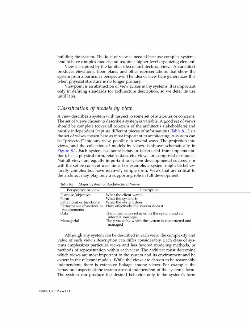
building the system. The idea of view is needed because complex systemstend to have complex models and require a higher-level organizing element.
View is inspired by the familiar idea of architectural views. An architectproduces elevations, floor plans, and other representations that show thesystem from a particular perspective. The idea of view here generalizes thiswhen physical structure is no longer primary.
Viewpoint is an abstraction of view across many systems. It is importantonly in defining standards for architecture description, so we defer its useuntil later.
Classification of models by viewA view describes a system with respect to some set of attributes or concerns.The set of views chosen to describe a system is variable. A good set of viewsshould be complete (cover all concerns of the architect’s stakeholders) andmostly independent (capture different pieces of information). Table 8.1 liststhe set of views chosen here as most important to architecting. A system canbe “projected” into any view, possibly in several ways. The projection intoviews, and the collection of models by views, is shown schematically inFigure 8.1. Each system has some behavior (abstracted from implementa-tion), has a physical form, retains data, etc. Views are composed of models.Not all views are equally important to system developmental success, norwill the set be constant over time. For example, a system might be behav-iorally complex but have relatively simple form. Views that are critical tothe architect may play only a supporting role in full development.
Although any system can be described in each view, the complexity andvalue of each view’s description can differ considerably. Each class of sys-tems emphasizes particular views and has favored modeling methods, ormethods of representation within each view. The architect must determinewhich views are most important to the system and its environment and beexpert in the relevant models. While the views are chosen to be reasonablyindependent, there is extensive linkage among views. For example, thebehavioral aspects of the system are not independent of the system’s form.The system can produce the desired behavior only if the system’s form
Table 8.1 Major System or Architectural Views
Perspective or view DescriptionPurpose/objective What the client wantsForm What the system isBehavioral or functional What the system doesPerformance objectives or requirements
How effectively the system does it
Data The information retained in the system and its interrelationships
Managerial The process by which the system is constructed and managed
©2000 CRC Press LLC
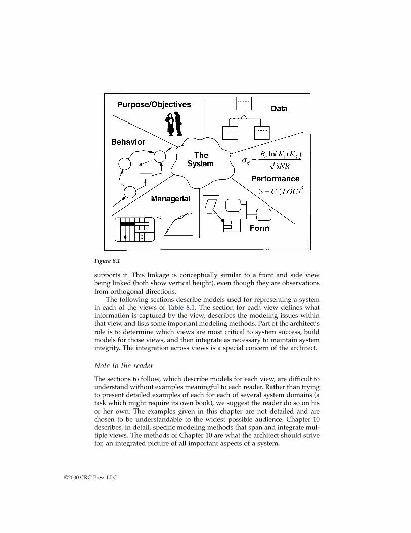
supports it. This linkage is conceptually similar to a front and side viewbeing linked (both show vertical height), even though they are observationsfrom orthogonal directions.
The following sections describe models used for representing a systemin each of the views of Table 8.1. The section for each view defines whatinformation is captured by the view, describes the modeling issues withinthat view, and lists some important modeling methods. Part of the architect’srole is to determine which views are most critical to system success, buildmodels for those views, and then integrate as necessary to maintain systemintegrity. The integration across views is a special concern of the architect.
Note to the reader
The sections to follow, which describe models for each view, are difficult tounderstand without examples meaningful to each reader. Rather than tryingto present detailed examples of each for each of several system domains (atask which might require its own book), we suggest the reader do so on hisor her own. The examples given in this chapter are not detailed and arechosen to be understandable to the widest possible audience. Chapter 10describes, in detail, specific modeling methods that span and integrate mul-tiple views. The methods of Chapter 10 are what the architect should strivefor, an integrated picture of all important aspects of a system.
Figure 8.1
©2000 CRC Press LLC
As stated in the introduction, Part Three can be read several ways. Thechapters can be read in order, which captures the intellectual thread of modelconcepts, modeling processes and heuristics, specific modeling methods, andorganizing frameworks. In this case it is useful to read ahead to Exercises 1and 2 at the end of this chapter and work them while reading each section tofollow. The remaining exercises are intended for after the chapter is read,although some may be approached as each section is completed. An alterna-tive is to read Chapters 8 and 10 in parallel, reading the specific examples ofmodels in Chapter 10 as the views are covered in Chapter 8. Because theapproach of Chapter 10 is to look at integrated models, models that spanviews, a one-for-one correspondence is impossible. The linear approach isprobably best for those without extensive background in modeling methods.Those with a good background in integrated modeling methods can use either.
Objectives and purpose models
The first modeling view is that of objectives and purposes. Systems are builtfor useful purposes; that is for what the client wants. Without them the systemcannot survive. The architect’s first and most basic role is to match thedesirability of the purposes with the practical feasibility of a system to fulfillthose purposes. Given a clearly identifiable client, the architect’s first step isto work with that client to identify the system’s objectives and priorities.Some objectives can be stated and measured very precisely. Others will bequite abstract and impossible to express quantitatively. A civil architect isnot surprised to hear a client’s objective is for the building to “be beautiful”or to “be in harmony with the natural state of the site.” The client will bevery unhappy if the architect tells the client to come back with unambiguousand testable requirements. The architect must prepare models to help theclient to clarify abstract objectives. Abstract objectives require provisionaland exploratory models, models which may fall by the wayside later as thedemands and the resulting system become well understood. Ideally, alliterations and explorations become part of the systems document set. How-ever, to avoid drowning in a sea of paper, it may be necessary to focus on alimited set. If refinement and tradeoff decisions (the creation of concreteobjectives from abstract ones) are architectural drivers, they must be main-tained as it is likely the key decisions will be repeatedly revisited.
Modeling therefore begins by restating and iterating those initial uncon-strained objectives from the client’s language until a modeling language andmethodology emerges, the first major step closer to engineering develop-ment. Behavioral objectives are restated in a behavioral modeling language.Performance requirements are formulated as measurable satisfaction mod-els. Some objectives may translate directly into physical form, others intopatterns of form that should be exhibited by the system. Complex objectivesalmost invariably require several steps of refinement and, indeed, mayevolve into characteristics or behaviors quite different from their originalstatement.
©2000 CRC Press LLC
A low technology example (though only by modern standards) is theEuropean cathedrals of the Middle Ages. A cathedral architect considered abroad range of objectives. First, a cathedral must fulfill well-defined com-munity needs. It must accommodate celebration day crowds, serve as asuitable seat for the bishop, and operate as a community centerpiece. But,in addition, cathedral clients of that era emphasized that the cathedral “com-municate the glory of God and reinforce the faithful through its very pres-ence.”
Accommodation of holiday celebrants is a matter of size and floor layout.It is an objective that can be implemented directly and requires no furthersignificant refinement. The clients — the church and community leaders —because of their personal familiarity with the functioning of a cathedral,could determine for themselves the compliance of the cathedral by examin-ing the floor plan. But what of defining a building that “glorifies God?” Thisis obviously a property only of the structure as a whole — its scale, mass,space, light, and integration of decoration and detail. Only a person with anexceptional visual imagination is able to accurately envision the aestheticand religious impact of a large structure documented only through drawingsand renderings. Especially in those times, when architectural styles werenew and people traveled little, an innovative style would be an unprece-dented experience for perhaps all but the architect.
While refinement of objectives through models is central to architecting,it is also a source of difficulty. A design that proceeds divorced from directclient relevance tends to introduce unnecessary requirements that complicateits implementation. Experience has shown that retaining the client’s lan-guage throughout the acquisition process can lead to highly efficient,domain-specific architectures; for example, in communication systems.
Example: domain-specific software architectures1 aresoftware application generation frameworks in whichdomain concepts are embedded in the architecturalcomponents. The framework is used to generate aproduct line of related applications in which the clientlanguage can be used nearly directly in creating theproduct. For a set of message handler applicationswithin command and control systems the specificationcomplexity was reduced 50:1.
One measure of the power of a design and implementation method isits ability to retain the original language. But this poses a dilemma. Retentionimplies the availability of proven, domain-specific methods and engineeringtools. But unprecedented systems by definition are likely to be working innew domains, or near the technical frontiers of existing domains. By the verynature of unprecedented system development, such methods and tools areunlikely to be available. Consequently, models and methodologies must bedeveloped and pass through many stages of abstraction, during which the
©2000 CRC Press LLC
original relevance can easily be lost. The architect must therefore search outdomain-specific languages and methods that can somehow maintain thechain of relevance throughout.
An especially powerful, but challenging, form of modeling converts theclient/user’s objectives into a meta-model or metaphor that can be directlyimplemented. A famous example is the desktop metaphor adopted for Mac-intosh computers. The user’s objective is to use a computer for daily, office-oriented task automation. The solution is to capture the user’s objectivesdirectly by presenting a simulation of a desktop on the computer display.Integrity with user needs is automatically maintained by maintaining thefidelity of a desktop and file system familiar to the user.
Models of form
Models of form represent physically identifiable elements of, and interfacesto, what will be constructed and integrated to meet client objectives. Modelsof form are closely tied to particular construction technologies, whether theconcrete and steel of civil architecture or the less tangible codes and manualsof software systems. Even less tangible physical forms are possible, such ascommunication protocol standards, a body of laws, or a consistent set ofpolicies.
Models of form vary widely in their degree of abstraction and role. Forexample, an abstract model may convey no more than the aesthetic feel ofthe system to the client. A dimensionally accurate but hollow model canassure proper interfacing of mechanical parts. Other models of form may betightly coupled to performance modeling, as in the scale model of an airplanesubjected to wind tunnel testing. The two categories of models of form mostuseful in architecting are scale models and block diagrams.
Scale modelsThe most literal models of form are scale models. Scale models are widelyused for client and builder communication, and may function as part ofbehavioral or performance modeling as well. Some major examples areshown below:
1. Civil architects build literal models of buildings, often producingrenderings of considerable artistic quality. These models can be ab-stracted to convey the feel and style of a building, or can be preciselydetailed to assist in construction planning.
2. Automobile makers mock-up cars in body-only or full running trim.These models make the auto show circuit to gauge market interest,or are used in engineering evaluations.
3. Naval architects model racing yachts to assist in performance evalu-ation. Scale models are drag tested in water tanks to evaluate dragand handling characteristics. Reduced or full-scale models of the decklayout are used to run simulated sail handling drills.
©2000 CRC Press LLC

4. Spacecraft manufacturers use dimensionally accurate models in fitcompatibility tests and in crew extra-vehicular activity rehearsals.Even more important are ground simulators for on-orbit diagnosticsand recovery planning.
5. Software developers use prototypes that demonstrate limited charac-teristics of a product that are equivalent to scale models. For example,user interface prototypes that look like the planned system but do notpossess full functionality, non-real-time simulations that carry exten-sive functionality but do not run in real-time, or just a set of screenshots with scenarios for application use.
Physical scale models are gradually being augmented or replaced byvirtual reality systems. These “scale” models exist only in a computer andin the viewer’s mind. They may, however, carry an even stronger impressionof reality than a physical scale model because of the sensory immersionachievable.
Block diagramsA scale model of a circuit board or a silicon chip is unlikely to be of
much interest alone, except for expanded scale plots used to check for layouterrors. Nonetheless, physical block diagrams are ubiquitous in the electronicsindustry. To be a model of form, as distinct from a behavioral model, theelements of the block diagram must correspond to physically identifiableelements of the system. Some common types of block diagrams include:
1. System interconnect diagrams that show specific physical elements(modules) connected by physically identifiable channels. On a high-level diagram a module might be an entire computer complex, and achannel might be a complex internetwork. On a low level the modulescould be silicon chips with specific part numbers and the channels’pin-assigned wires.
2. System flow diagrams that show modules in the same fashion asinterconnect diagrams but illustrate the flow of information amongmodules. The abstraction level of information flow defined might behigh (complex messaging protocols) or low (bits and bytes). The twotypes of diagrams (interconnect and flow) are contrasted in Figure10.3.
3. Structure charts,2 task diagrams,3 and class and object diagrams4 thatstructurally define software systems and map directly to implemen-tation. A software system may have several such logically indepen-dent diagrams, each showing a different aspect of the physical struc-ture; for example, diagrams that show the invocation tree, theinheritance hierarchy, or the “withing” relationships in an Ada pro-gram. Examples of several levels of physical software diagram aregiven in Figures 10.5 and 10.6.
©2000 CRC Press LLC
5. Manufacturing process diagrams are drawn with a standardized setof symbols. These represent manufacturing systems at an intermedi-ate level of abstraction, showing specific classes of operation but notdefining the machine or the operational details.
Several authors have investigated formalizing block diagrams over aflexible range of architectural levels. The most complete, with widely pub-lished examples, is that of Hatley and Pirbhai.5 Their method is discussedin more depth in Chapter 10 as an example of a method for integrating amultiplicity of architectural views across models. A number of other meth-ods and tools that add formalized physical modeling to behavioral modelingare appearing. Many of these are commercial tools, so the situation is fluidand their methodologies are often not fully defined outside of the toolsdocumentation. Some other examples are the system engineering extensionsto ADARTS (described later in the context of software), RDD-100,6 andStateMate.7
An attribute missing in most block diagram methods is the logic of dataflow. The diagram may show that a data item flow from module A to moduleB, but does not show who controls the flow. Control can be of many types.A partial enumeration includes:
Soft push: The sender sends and the item is lost if the receiver is notwaiting to receive it
Hard push: The sender sends and the act of sending interrupts thereceiver who must take the data
Blocking pull: The receiver requests the data and waits until the senderresponds
Non-blocking pull: The receiver requests the data and continues onwithout it if the sender does not send
Hard pull: When the receiver requests the data the sender is interruptedand must send
Queuing channel: The sender can push data onto the channel withoutinterrupting the receiver and with data being stored in the channel;the receiver can pull data from the channel’s store
Of course, there are many other combinations as well. The significanceof the control attribute is primarily in interfacing to disciplinary engineers,especially software engineers. In systems whose development cost is dom-inated by software, which is now virtually all complex systems, it is essentialthat systems activities provide the information needed to enable softwarearchitecting as quickly as possible. One of the elements of a software archi-tecture is the concurrency and synchronization model. The constraints onsoftware concurrency and synchronization are determined by the data flowcontrol logic around the software-hardware boundary. So, it is just the kindof information on data flow control that is needed to better match systemsactivities to software architecture.
©2000 CRC Press LLC
Behavioral (functional) models
Functional or behavioral models describe specific patterns of behavior bythe system. These are models of what the system does (how it behaves) asopposed to what the system is (which are models of form). Architects increas-ingly need behavioral models as systems become more intelligent and theirbehavior becomes less obvious from the systems form. Unlike a building, aclient cannot look at a scale model of a software system and infer how thesystem behaves. Only by explicitly modeling the behavior can it be under-stood by the client and builder.
Determining the level of detail or rigor in behavioral specificationneeded during architecting is an important choice. Too little detail or rigorwill mean the client may not understand the behavior being provided (andpossibly be unsatisfied) or the builder may misunderstand the behavioractually required. Too much detail or rigor may render the specificationincomprehensible — leading to similar problems — or unnecessarily delaydevelopment. Eventually, when the system is built, its behavior is preciselyspecified (if only by the actual behavior of the built system).
From the perspective of architecting, what level of behavioral refinementis needed? The best guidance is to focus on the system acceptance require-ments; to ensure the acceptance requirements are passable but complete. Askwhat behavioral attributes of the system the client will demand be certifiedbefore acceptance and determine through what tests those behavioralattributes can be certified. The certifiable behavior is the behavior the clientwill get, no more and no less.
Example: In software systems with extensive user in-terface components, it has been found by experiencethat only a prototype of the interface adequately con-veys to users how the system will work. Hence, toensure not just client acceptance, but user satisfaction,an interface prototype should be developed very earlyin the process. Major office application developershave videotaped office workers as they use prototypeapplications. The tapes are then examined and scoredto determine how effective various layouts were atencouraging users to make use of new features, howrapidly they were able to work, etc.
Example: Hardware and software upgrades to militaryavionics almost always must remain backward com-patible with other existing avionics systems and main-tain support for existing weapon systems. Thearchitecture of the upgrade must reflect the behavioralrequirements of existing system interface. Some mayimply very simple behavioral requirements, like pro-
©2000 CRC Press LLC
viding particular types of information on a communi-cation bus. Others may demand complex behaviors,such as target handover to a weapon requiring targetacquisition, queuing of the weapon sensor, real-timesynchronization of the local and weapon sensor feeds,and complex launch codes. The required behaviorneeds to be captured at the level required for clientacceptance, and at the level needed to extract architec-tural constraints.
Behavioral tools of particular importance are threads or scenarios, dataand event flow networks, mathematical systems theory, autonomous systemtheory, and public choice and behavior models.
Threads and scenariosA thread or scenario is a sequence of system operations. It is an ordered listof events and actions which represents an important behavior. It normallydoes not contain branches; that is, it is a single serial scenario of operation,a stimulus/response thread. Branches are represented by additional threads.Behavioral requirements can be of two types. The first type is to require thatthe system must produce a given thread; that is, to require a particular systembehavior. The alternative is to require that a particular thread not occur. Forexample, that a hazardous command never be issued without a positiveconfirmation having occurred first. The former is more common, but thelatter is just as important.
Threads are useful for client communication. Building the threads canbe a framework for an interactive dialog with the client. For each input, posethe question, “When this input arrives what should happen?” Trace theresponse until an output is produced. In a similar fashion, trace outputsbackward until inputs are reached. The list of threads generated in this waybecomes part of the behavioral requirements.
Threads are also useful for builder communication. Even if not complete,they directly convey desired system behavior. They also provide useful toolsduring design reviews and for test planning. Reviewers can ask that design-ers walk through their design as it would operate in each of a set of selectedthreads. This provides a way for reviewers to survey a design using criteriavery close to the client’s own language. Threads can be used similarly astemplates for system tests, ensuring that the tests are directly tied to theclient’s original dialog.
Another name for behavioral specification by threads and scenarios isuse-cases. Use-case has become the popular term for behavioral specificationby example. The term originally comes from the object-oriented softwarecommunity, but it has been applied much more widely. The normal form ofa use-case is the listing of an example dialog between the system and anactor. An actor is a human user of the system. The use-case consists of thesequence of messages passed between the system and actor, augmented by
©2000 CRC Press LLC
additional explanation in ways specific to each method. Use-cases areintended to be narrative. That is, they are specifically intended to be writtenin the language of users and to be understandable by them. When a systemis specified by many use-cases, and the use-cases interact, there are a numberof diagrams which can be used to specify the connections. Chapter 10 brieflydiscusses these within the section on UML.
Data and event flow networksA complex system can possess an enormous (perhaps infinite) set of threads.A comprehensive list may be impossible, yet without it the behavioral spec-ification is incomplete. Data and event flow networks allow threads to becollapsed into more compact but complete models. Data flow models definethe behavior of a system by a network of functions or processes that exchangedata objects. The process network is usually defined in a graphical hierarchy,and most modern versions add some component of finite state machinedescription. Current data flow notations are descendants either of DeMarco’sdata flow diagram (DFD) notation8 or Functional Flow Block Diagrams(FFBD).9 Chapter 10 gives several examples of a data flow models and theirrelationships with other model types. Figures 10.1 and 10.2 show examplesof data flow diagrams for an imaging system. Both the DFD and FFBDmethods are based on a set of root principles.
1. The systems functions are decomposed hierarchically. Each functionis composed of a network of subfunctions until a “simple” descriptioncan be written in text.
2. The decomposition hierarchy is defined graphically.3. Data elements are decomposed hierarchically and are separately de-
fined in an associated “data dictionary.”4. Functions are assumed to be data-triggered. A process is assumed to
execute any time its input data elements are available. Finer controlis defined by a finite state control model (DFD formalism) or in thegraphical structure of the decomposition (FFBD formalism).
5. The model structure avoids redundant definition. Coupled withgraphical structuring, this makes the model much easier to modify.
Mathematical systems theoryThe traditional meaning of system theory is the behavioral theory of multi-dimensional feedback systems. Linear control theory is an example of systemtheory on a limited, well-defined scale. Models of macroeconomic systemsand operations research are also system theoretic models, but on a muchlarger scale.
System theoretic formalisms are built from two components:
1. A definition of the system boundary in terms of observable quantities,some of which may be subject to user or designer control
©2000 CRC Press LLC

2. A mathematical machinery that describes the time evolution (thebehavior) of the boundary quantities given some initial or boundaryconditions and control strategies
There are three main mathematical system formalisms. They are distin-guished by how they treat time and data values.
1. Continuous systems: These are the systems classically modeled bydifferential equations, linear and nonlinear. Values are continuousquantities and are computable for all times.
2. Temporally discrete (sampled data) systems: These are systems withcontinuously valued elements measured at discrete time points. Theirbehavior is described by difference equations. Sampled data systemsare increasingly important since they are the basis of most computersimulations and nearly all real-time digital signal processing.
3. Discrete event systems: These are systems in which some or all of thequantities take on discrete values at arbitrary points in time. Queuingnetworks are the classical example. Asynchronous digital logic is apure example of a discrete event system. The quantities of interest(say, data packets in a communication network) move around thenetwork in discrete units, but they may arrive or leave a node at anarbitrary, continuous time.
Continuous systems have a large and powerful body of theory. Linearsystems have comprehensive analytical and numerical solution methods,and an extensive theory of estimation and control. Nonlinear systems arestill incompletely understood, but many numerical techniques are available,some analytical stability methods are known, and practical controlapproaches are available. Similar results are available for sampled data sys-tems. Computational frameworks exist for discrete event systems (based onstate machines and Petri Nets), but are less complete than those for differ-ential or difference equation systems in their ability to determine stabilityand synthesize control laws. A variety of simulation tools is available for allthree types of systems. Some tools attempt to integrate all three types intoa single framework, though this is difficult.
Many modern systems are a mixture of all three types. For example,consider a computer-based temperature controller for a chemical process.The complete system may include continuous plant dynamics, a sampleddata system for control under normal conditions, and discrete event control-ler behavior associated with threshold crossings and mode changes. A com-prehensive and practical modern system theory should answer the classicquestions about such a mixed system — stability, closed loop dynamics, andcontrol law synthesis. No such comprehensive theory exists, but constructingone is an objective of current research. Manufacturing systems are a specialexample of large-scale mixed systems for which qualitative system under-standing can yield architectural guidance.
©2000 CRC Press LLC
Autonomous agent, chaotic systemsSystem-level behavior, as defined in Chapter 1, is behavior not contained inany system component, but which emerges only from the interaction of allthe components. A class of system of recent interest is that in which a fewtypes of multiply-replicated, individually relatively simple, componentsinteract to create essentially new (emergent) behaviors. Ant colonies, forexample, exhibit complex and highly organized behaviors that emerge fromthe interaction of behaviorally simple, nearly identical, sets of components(the ants). The behavioral programming of each individual ant, and its cha-otic local interactions with other ants and the environment, is sufficient forcomplex high-level behaviors to emerge from the colony as a whole. Thereis considerable interest in using this truly distributed architecture, but tra-ditional top-down, decomposition-oriented models and their bottom-up,integration-oriented complements do not describe it. Some attempts havebeen made to build theories of such systems from chaos methods. Attemptshave also been made to find rules or heuristics for the local intelligence andinterfaces necessary for high-level behaviors to emerge.
Example: In some prototype flexible manufacturingplants, instead of trying to solve the very complexwork scheduling problem, autonomous controllersschedule through distributed interaction. Each workcell independently “bids” for jobs on its input. Eachjob moving down the line tries to “buy” the productionand transfer services it needs to be completed.10 In-stead of central scheduling, the equilibrium of thepseudo-economic bid system distributes jobs and fillswork cells. Experiments have shown that rules can bedesigned that result in stable operation, near optimal-ity of assignment, and very strong robustness to jobchanges and work cell failure. But the lack of centraldirection makes is difficult to assure particular opera-tional aspects; for example, to assure that “oddball”jobs won’t be ignored for the apparent good of themean.
Public choice and behavior modelsSome systems depend on the behavior of human society as part of thesystem. In such cases the methods of public choice and consumer analysismay need to be invoked to understand the human system. These methodsare often ad hoc, but many have been widely used in marketing analysis byconsumer product companies.
Example: One concept in intelligent transportation sys-tems proposals is the use of centralized routing. In a
©2000 CRC Press LLC
central routing system each driver would inform thecenter (via some data network) of his beginning loca-tion and his planned destination for each trip. Thecenter would use that information to compute a routefor each vehicle and communicate the selected routeback to the driver. The route might be dynamicallyupdated in response to accidents or other incidents. Inprinciple, the routing center could adjust routes to op-timize the performance of the network as a whole. Butwould drivers accept centrally-selected routes, espe-cially if they thought the route benefited the networkbut not them? Would they even bother to send in routeinformation?
A variety of methods could be used to address such questions. At thesimplest level are consumer surveys and focus groups. A more involvedapproach is to organize multiperson driving simulations with the perfor-mance of the network determined from individual driver decisions. Overthe course of many simulations, as drivers evaluate their own strategies,stable configurations may emerge.
Performance models
A performance model describes or predicts how effectively an architecturesatisfies some function. Performance models are usually quantitative, andthe most interesting performance models are those of system-level functions;that is, properties possessed by the system as a whole but by no subsystem.Performance models describe properties like overall sensitivity, accuracy,latency, adaptation time, weight, cost, reliability, and many others. Perfor-mance requirements are often called “nonfunctional” requirements becausethey do not define a functional thread of operation, at least not explicitly.Cost, for example, is not a system behavior, but it is an important propertyof the system. Detection sensitivity to a particular signal, however, does carrywith it implied functionality. Obviously, a signal cannot be detected unlessthe processing is in place to produce a detection. It will also usually beimpossible to formulate a quantitative performance model without con-straining the systems behavior and form.
Performance models come from the full range of engineering and man-agement disciplines. But the internal structure of performance models gen-erally falls into one of three categories:
1. Analytical: These models are the products of the engineering sciences.A performance model in this category is a set of lower-level systemparameters and a mathematical rule of combination that predicts theperformance parameter of interest from lower-level values. The modelis normally accompanied by a “performance budget” or a set of nom-
©2000 CRC Press LLC
inal values for the lower-level parameters to meet a required perfor-mance target.
2. Simulation: When the lower-level parameters can be identified, butan easily computable performance prediction cannot, a simulation cantake the place of the mathematical rule of combination. In essence, asimulation of a system is an analytical model of the system’s behaviorand performance in terms of the simulation parameters. The connec-tion is just more complex and difficult to explicitly identify. A widevariety of continuous, discrete time and discrete event simulators areavailable, many with rich sets of constructs for particular domains.
3. Judgmental: Where analysis and simulation are inadequate or infea-sible, human judgment may still yield reliable performance indicators.In particular, human judgment, using explicit or implicit design heu-ristics, can often rate one architecture as better than another, evenwhere a detailed analytical justification is impossible.
Formal methodsThe software engineering community has taken a specialized approach toperformance modeling known as formal methods. Formal methods seek todevelop systems that provably produce formally defined functional and non-functional properties. In formal development the team defines system behav-ior as sets of allowed and disallowed sequences of operation, and may addfurther constraints, such as timing, to those sequences. They then developthe system in a manner that guarantees compliance to the behavioral andperformance definition. Roughly speaking, the formal methods approach is:
1. Identify the inputs and outputs of the system. Identify a set of math-ematical and logical relations that must exist between the input andoutput sequences when the system is operating as desired.
2. Decompose the system into components, identifying the inputs andoutputs of each component. Determine mathematical relations oneach component such that their composition is equivalent to the orig-inal set of relations one level up.
3. Continue the process iteratively to the level of primitive implemen-tation elements. In software this would be programming languagestatements. In digital logic this might be low-level combinational orsequential logic elements.
4. Compose the implementation backward, up the chain of inferencefrom primitive elements in a way that conserves the decomposedcorrectness relations. The resulting implementation is then equivalentto the original specification.
From the point of view of the architect, the most important applicationsof formal methods are in the conceptual phases and in the certification ofhigh assurance and ultraquality systems. Formal methods require explicitdetermination of allowed and disallowed input/output sequences. Trying
©2000 CRC Press LLC
to make that determination can be valuable in eliciting client information,even if the resulting information is not captured in precise mathematicalterms. Formal methods also hold out the promise of being able to certifysystem characteristics that can never be tested. No set of tests can certifywith certainty that certain event chains cannot occur, but theorems to thateffect are provable within a formal model.
Various formal and semiformal versions of the process are in limited usein software and digital system engineering.11 While a fully formal versionof this process is apparently impractical for large systems at the present time(and is definitely controversial), semiformal versions of the process havebeen successfully applied to commercial products.
A fundamental problem with the formal methods approach is that thesystem can never be more “correct” than the original specification. Becausethe specification must be written in highly mathematical terms, it is partic-ularly difficult to use in communication with the typical client.
Data models
The next dimension of system complexity is retained data. What data doesthe system retain and what relationships among the data does it developand maintain? Many large corporate and governmental information systemshave most of their complexity in their data and its internal relationships.The most common data models have their origins in software development,especially large database developments. Methods for modeling complex datarelationships were developed in response to the need to automate data-intensive, paper-based systems. While data-intensive systems are most oftenthought of as large, automated database systems, many working examplesare actually paper-based. Automating legacy paper-based systems requirescapturing the complex interrelationships among large amounts of retaineddata.
Data models are of increasing importance because of the greater intelli-gence being embedded in virtually all systems, and the continuing automa-tion of legacy systems. In data-intensive systems, generating intelligentbehavior is primarily a matter of finding relationships and imposing persis-tent structure on the records. This implies that the need to find structure andrelationships in large collections of data will be determinants of systemarchitecture.
Example: Manufacturing software systems are nolonger responsible just for control of work cells. Theyare part of integrated enterprise information networksin which real-time data from the manufacturing floor,sales, customer operations, and other parts of the en-terprise are stored and studied. Substantial competi-tive advantages accrue to those who can makeintelligent judgments from these enormous data sets.
©2000 CRC Press LLC
Example: Intelligent transport systems are a complexcombination of distributed control systems, sensor net-works, and data fusion. Early deployment stages willemphasize only simple behavioral adaptation, as inlocal intelligent light and on-ramp controllers. Full de-ployment will fuse data sources across metropolitanareas to generate intelligent prediction and controlstrategies. These later stages will be driven by prob-lems of extracting and using complex relationships invery large databases.
The basis for modern data models are the Entity-Relationship diagramsdeveloped for relational databases. These diagrams have been generalizedinto a family of object-oriented modeling techniques. An object is a set of“attributes” or data elements and a set of “methods” or functions which actupon the attributes (and possibly other data or objects as well). Objects areinstances of classes that can be thought of as templates for specific objects.Objects and classes can have relationships of several types. Major relation-ship types include aggregation (or composition); generalization, specializa-tion, or inheritance; and association (which may be two-way or M-way).Object-oriented modeling methods combine data and behavioral modelinginto a single hierarchy organized along and driven by data concerns. Behav-ioral methods like those described earlier also include data definitions, butthe hierarchy is driven by functional decomposition.
One might think of object-oriented models as turning functional decom-position models inside out. Functional decomposition models like data flowdiagramming describe the system as a hierarchy of functions, and hang adata model onto the functional skeleton. The only data relationship sup-ported is aggregation. An object-oriented model starts with a decompositionof the data and hangs a functional model on it. It allows all types of datarelationships. Some problems decompose cleanly with functional methodsand only with difficulty in object-oriented methods, and some other prob-lems are the opposite.
An example of a well-developed, object-oriented data modeling tech-nique (OMT) is given in Chapter 10. Figure 10.7 shows a typical example ofthe type of diagram used in that method, which combines conventionalentity relationship diagram and object-oriented abstraction. OMT has furtherevolved into unified modeling language (UML), which is also discussed inChapter 10.
Data-oriented decompositions share the general heuristics of systemarchitecture. The behavioral and physical structuring characteristics havedirect analogs — composing or aggregation, decomposition, minimal com-munications, etc. There are also similar problems of scale. Very large datamodels must be highly structured with limited patterns of relationship (anal-ogous to limited interfaces) to be implementable.
©2000 CRC Press LLC
Managerial models
To both the client and architect, a project may be as much a matter of planningmilestones, budgets, and schedules as it is a technical exercise. In sociotech-nical systems, planning the system deployment may be more difficult thanassembling its hardware. The managerial or implementation view describesthe process of building the physical system. It also tracks construction eventsas they occur.
Most of the models of this view are the familiar tools of project manage-ment. In addition, management-related metrics that can be calculated fromother models are invaluable in efforts to create an integrated set of models.Some examples include:
1. The waterfall and spiral system development meta-models; they arethe templates on which project-specific plans are built
2. PERT/CPM and related task and scheduling dependency charts3. Cost and progress accounting methods4. Predictive cost and schedule metrics calculable from physical and
behavioral models5. Design or specification time quality metrics — defect counts, post-
simulation design changes, rate of design changes after each review.
The architect has two primary interests in managerial models. First, theclient usually cannot decide to go ahead with system construction withoutsolid cost and schedule estimates. Usually, producing such estimates requiresa significant effort in management models. Second, the architect may becalled upon to monitor the system as it is developed to ensure its conceptualintegrity. In this monitoring process managerial models will be very impor-tant.
Examples of integrated modelsAs noted earlier, models which integrate multiple views are the specialconcern of the architect. These integrating models provide the synthesizedview central to the architect’s concerns. An integrated modeling method isa system of representation that links multiple views. The method consists ofa set of models for a subset of views, and a set of rules or additional modelsto link the core views. Most integrated modeling methods apply to a partic-ular domain. Table 8.2 lists some representative methods. These models aredescribed in greater detail, with examples, in Chapter 10. The references aregiven there as well.
These methods use different models and cover different views. Theircomponents and dimensions are summarized in Table 8.3.
©2000 CRC Press LLC
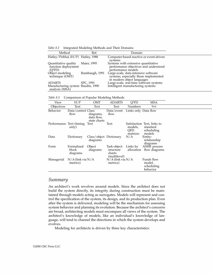
SummaryAn architect’s work revolves around models. Since the architect does notbuild the system directly, its integrity during construction must be main-tained through models acting as surrogates. Models will represent and con-trol the specification of the system, its design, and its production plan. Evenafter the system is delivered, modeling will be the mechanism for assessingsystem behavior and planning its evolution. Because the architect’s concernsare broad, architecting models must encompass all views of the system. Thearchitect’s knowledge of models, like an individual’s knowledge of lan-guage, will tend to channel the directions in which the system develops andevolves.
Modeling for architects is driven by three key characteristics:
Table 8.2 Integrated Modeling Methods and Their Domains
Method Ref. DomainHatley/Pirbhai (H/P) Hatley, 1988 Computer-based reactive or event-driven
systemsQuantitative quality function deployment (Q2FD)
Maier, 1995 Systems with extensive quantitative performance objectives and understood performance models
Object modeling technique (OMT)
Rumbaugh, 1991 Large-scale, data-intensive software systems, especially those implemented in modern object languages
ADARTS SPC, 1991 Large-scale, real-time software systemsManufacturing system analysis (MSA)
Baudin, 1990 Intelligent manufacturing systems
Table 8.3 Comparison of Popular Modeling Methods
View H/P OMT ADARTS Q2FD MSAObjectives Text Text Text Numbers Text
Behavior Data/control flow
Class diagrams, data flow, state charts
Data/event flow
Links only Data flow
Performance Text (timing only)
Text Text Satisfaction models, QFD matrices
Text, links to standard scheduling models
Data Dictionary Class/object diagrams
Dictionary N/A Entity-relationship diagrams
Form Formalized block diagrams
Object diagrams
Task-object-structure charts (multilevel)
Links by allocation
ASME process flow diagrams
Managerial N/A (link via metrics)
N/A N/A (link via metrics)
N/A Funds flow model, scheduling behavior
©2000 CRC Press LLC
1. Models are the principal language of the architect. Their foremost roleis to facilitate communication with client and builder. By facilitatingcommunication they carry out their other roles of maintaining designintegrity and assisting synthesis.
2. Architects require a multiplicity of views and models. The basic onesare objective, form, behavior, performance, data, and management.Architects need to be aware of the range of models that are used todescribe each of these views within their domain of expertise, andthe content of other views that may become important in the future.
3. Multidisciplinary, integrated modeling methods tie together the var-ious views. They allow the design of a system to be refined in stepsfrom conceptually abstract to the precisely detailed necessary forconstruction.
The next chapter reconsiders the use of modeling in architecture byplacing modeling in a larger set of parallel progressions from abstract toconcrete. There, the field of view will expand to the whole architecturaldesign process and its parallel progressions in heuristics, modeling, evalu-ation, and management.
Exercises
1. Choose a system familiar to you. Formulate a model of your systemin each of the views discussed in the chapter. How effectively doeseach model capture the system in that view. How effectively do themodels define the system for the needs of initial concept definitionand communication with clients and builders? Are the models inte-grated? That is, can you trace information across the models andviews?
2. Repeat Exercise 1, but with a system unfamiliar to you, and preferablyembodying different driving issues. Investigate models used for theviews most unfamiliar to you. In retrospect, does your system inExercise 1 contain substantial complexity in the views you are unfa-miliar with?
3. Investigate one or more popular computer-aided system or softwareengineering (CASE) tools. To what extent do they support each of theviews? To what extent do they allow integration across views?
4. A major distinction in behavioral modeling methods and tools is theextent to which they support or demand executability in their models.Executability demands a restricted syntax and up-front decision aboutdata and execution semantics. Do these restrictions and demands helpor hinder initial concept formulation and communication with build-ers and clients? If the answer is variable with the system, is there away to combine the best aspects of both approaches?
©2000 CRC Press LLC

5. Models of form must be technology-specific because they representactual systems. Investigate modeling formalisms for domains not cov-ered in the chapter. For example, telecommunication systems, busi-ness information networks, space systems, integrated weapon sys-tems, chemical processing systems, or financial systems.
Notes and references1. Balzer, B. and Wile, D., Domain-Specific Software Architectures, Technical
Reports, Information Sciences Institute, University of Southern California.2. Yourdon, E. and Constantine, L L., Structured Design: Fundamentals of a Disci-
pline of Computer Program and Systems Design, Yourdon Press, EnglewoodCliffs, NJ, 1979.
3. ADARTS Guidebook, SPC-94040-CMC, Version 2.00.13, Vols. 1-2, September,1991. Available through the Software Productivity Consortium, Herndon, VA.
4. Rumbaugh, J. et. al., Object-Oriented Modeling and Design, Prentice-Hall, En-glewood Cliffs, NJ, 1991.
5. Hatley, D. J. and Pirbhai, I., Strategies for Real-Time System Specification, DorsetHouse, New York, 1988.
6. A comprehensive system modeling tool marketed by Ascent Logic, Inc.7. A tool with both discrete event behavioral modeling and physical block dia-
grams marketed by i-Logix.8. DeMarco, T., Structured Analysis and System Specification, Yourdon Press, En-
glewood Cliffs, NJ, 1979.9. Functional Flow Diagrams, AFSCP 375-5 MIL-STD-499, USAF, DI-S-3604/S-
126-1, Form DD 1664, June 1968. Much more modern implementations exist,for example, the RDD-100 modeling and simulation tool developed and mar-keted by Ascent Logic Corp.
10. Morley, R. E., The chicken brain approach to agile manufacturing, Proc. Man-ufacturing, Engineering, Design, Automation Workshop, Stanford, Palo Alto, p.19, 1992.
11. Two references can be noted, for theory: Hoare, C. A. R., CommunicatingSequential Processes, Prentice-Hall, Englewood Cliffs, NJ, 1985. For applicationin software: Mills, H. D., Stepwise refinement and verification in box-struc-tured systems, IEEE Computer, p. 23, June 1988.
©2000 CRC Press LLC
chapter nine
Design progression in system architecting
Introduction: architecting process componentsHaving outlined the products of architecting (models) in Chapter 8, thischapter turns to its process. The goal is not a formal process definition.Systems are too diverse to allow a fixed or dogmatic approach to architecting.Instead of trying for a formal process definition, this chapter develops a setof meta-process concepts for architecting activities and their relationships.Architectural design processes are inherently eclectic and wide-ranging,going abruptly from the intensely creative and individualistic to the moreprescribed and routine. While the processes may be eclectic, they can beorganized. Of the various organizing concepts, one of the most useful isstepwise progression or “refinement.”
First, a brief review of the architecting process itself. The architect devel-ops system models that span the range of system concerns, from objectivesto implementation. The architectural approach is, from beginning to end,concerned with the feasibility as well as the desirability of the system imple-mentation. It strives for fit, balance, and compromise between client prefer-ences and builder capabilities. Compromise can only be assured by an inter-play of activities, including both high-level structuring and such detaileddesign as is critical to overall success.
This chapter presents a three-part approach to the process of systemarchitecting.
1. One approach is a conceptual model connecting the unstructuredprocesses of architecture to the rigorous engineering processes of thespecialty domains or disciplines. This model is based on stepwisereduction of abstraction (or progression) in models, evaluation crite-ria, heuristics, and purposes from initial architecting to formal sys-tems engineering.
©2000 CRC Press LLC
2. There is an introduction to and review of the general concepts ofdesign, including theories of design, the elements of design, and theprocesses of creating a design. These frame the activities that makeup the progressions.
3. There is a guide to the place of architecting and its methods with thespecialized design domains and the evolutionary development ofdomain-specific methods. Architecting is recursive within a systemas it is defined in terms of its implementation domains. A split be-tween architecting and engineering is an irreducible characteristic ofevery domain, though the boundaries of that split cannot be clearuntil the scientific basis for the methods in a domain are known.
The progressions of architecting are inextricably bound with the pro-gressions of all system development. Architecting is not only iterative, it canbe recursive. As a system progresses, architecting may recur on subsystems.The goal here is to understand the intellectual nature of its conduct, whetherit happens at a very high level or within a subsystem.
Design progressionProgressive refinement of design is one of the most basic patterns of engi-neering practice. It permeates the process of architecting from models toheuristics, information acquisition, and management. Its real power, espe-cially in systems architecting, is that it provides a way to organize theprogressive transition from the ill-structured, chaotic, and heuristic processesneeded at the beginning to the rigorous engineering and certification pro-cesses needed later. All can be envisioned as a stepwise reduction of abstrac-tion from mental concept to delivered physical system.
In software the process is known as “stepwise refinement.” Stepwiserefinement is a specific strategy for top-down program development. Thesame notion applies to architecting, but is applied to complex multidisci-plinary system development. Stepwise refinement is the progressive removalof abstraction in models, evaluation criteria, and goals. It is accompanied byan increase in the specificity and volume of information recorded about thesystem, and a flow of work from general to specialized design disciplines.Within the design disciplines the pattern repeats as disciplinary objectivesand requirements are converted into the models of form of that discipline.In practice, the process is neither so smooth nor continuous. It is bettercharacterized as episodic, with episodes of abstraction reduction alternatingwith episodes of reflection and purpose expansion.
Stepwise refinement can be thought of as a meta-process model, muchas the waterfall and spiral. It is not an enactable process for a specific project,but it is a model for building a project-specific process. Systems are toodiverse to follow a fixed process or dogmatic formula for architecting.
©2000 CRC Press LLC
Introduction by examples
Before treating the conceptually difficult process of general systems archi-tecting, look to the roots. When a civil architect develops a building, doeshe or she go directly from client words to construction drawings? Obviouslynot. There are many intermediate steps. The first drawings are rough floorplans showing the spatial relationships of rooms and sizes, or external ren-derings showing the style and feel of the building. Following these areintermediate drawings giving specific dimensions and layouts. Eventuallycome the construction drawings with full details for the builder. The archi-tect’s role does not have a universally applicable stopping point, but themost common case is based on the needs of the client. When the designs aresufficiently refined (in enough views) for the client to make a decision toproceed with construction, the architect’s conceptual development job iscomplete. The architect may be busy with the project for some time to comein shepherding the conceptual design through detailed design, overseeingconstruction, and advising the client on certification; but the initial conceptrole is complete when the client can make the construction decision.
In a different domain, the beginning computer programmer is taught asimilar practice. Stepwise refinement in programming means to write thecentral controlling routine first. Anywhere high complexity occurs, ignore itby giving it a descriptive name and making it a subroutine or function. Eachsubroutine or function is “stubbed,” that is, given a dummy body as aplaceholder. When the controlling routine is complete, it is compiled andexecuted as a test. Of course, it doesn’t do anything useful since its subrou-tines are stubbed. The process is repeated recursively on each subroutineuntil routines can be easily coded in primitive statements in the program-ming language. At each intermediate step an abstracted version of the wholeprogram exists that has the final program’s structure but lacks internaldetails.
Both examples show progression of system representation or modeling.Progression also occurs along other dimensions. For example, both the civilarchitect and the programmer may create distinct alternative designs in theirearly stages. How are these partial designs evaluated to choose the superiorapproach? In the earliest stages both the programmer and the civil architectuse heuristic reasoning. The civil architect can measure rough size (to esti-mate cost), judge the client’s reaction, and ask the aesthetic opinion of others.The programmer can judge code size, heuristically evaluate the couplingand cohesion of the resulting subroutines and modules, review applicablepatterns from catalogs, and review functionality with the client. As theirwork progresses, both will be able to make increasing use of rational andquantitative evaluation criteria. The civil architect will have enough detailsfor proven cost models, and the programmer can measure execution speed,compiled size, behavioral compliance, and invoke quantitative softwarequality metrics.
©2000 CRC Press LLC
Design as the evolution of models
All architects, indeed all designers, manipulate models of the system. Thesemodels become successively less abstract as design progresses. The inte-grated models discussed in Chapter 10 exhibit stepwise reduction of abstrac-tion in representation and in their design heuristics.
In Hatley/Pirbhai the reduction of abstraction is from behavioral modelto technology-specific behavioral model to architecture model. There is alsohierarchical decomposition within each component. The technology of mod-ules is indeterminate at the top level, and becomes technology-specific asthe hierarchy develops. The Q2FD performance modeling technique showsstepwise refinement of customer objectives into engineering parameters. Asthe QFD chain continues, the engineering parameters get closer to imple-mentation until, ultimately, they may represent machine settings on thefactory floor. Likewise, the structure of integrated models in software andmanufacturing systems follows the same logic or progression.
Evaluation criteria and heuristic refinement
The criteria for evaluating a design progresses or evolves in the same manneras design models. In evaluation, the desirable progression is from generalto system-specific to quantitative. For heuristics, the desirable progressionis from descriptive and prescriptive qualitatives to domain-specific quanti-tatives and rational metrics. This progression is best illustrated by followingthe progression of a widely recognized heuristic into quantitative metricswithin a particular discipline. Start with the partitioning heuristic:
In partitioning, choose the elements so that they areas independent as possible, that is, elements withlow external complexity and high internal complex-ity.
This heuristic is largely independent of domain. It serves as an evalua-tion criterion and partitioning guide whether the system is digital hardware,software, human-driven, or otherwise. But, the guidance is nonspecific; nei-ther independence nor complexity is defined. By moving to a more restricteddomain, computer-based systems in this example, this heuristic refines intomore prescriptive and specific guidelines. The literature on structured designfor software (or, more generally, computer-based systems) includes severalheuristics directly related to the partitioning heuristic.1 The structure of theprogression is illustrated in Figure 9.1.
1. Module fan-in should be maximized. Module fan-out should gener-ally not exceed 7 ± 2.
2. The coupling between modules should be — in order of preference— data, data structure, control, common, and content.
©2000 CRC Press LLC
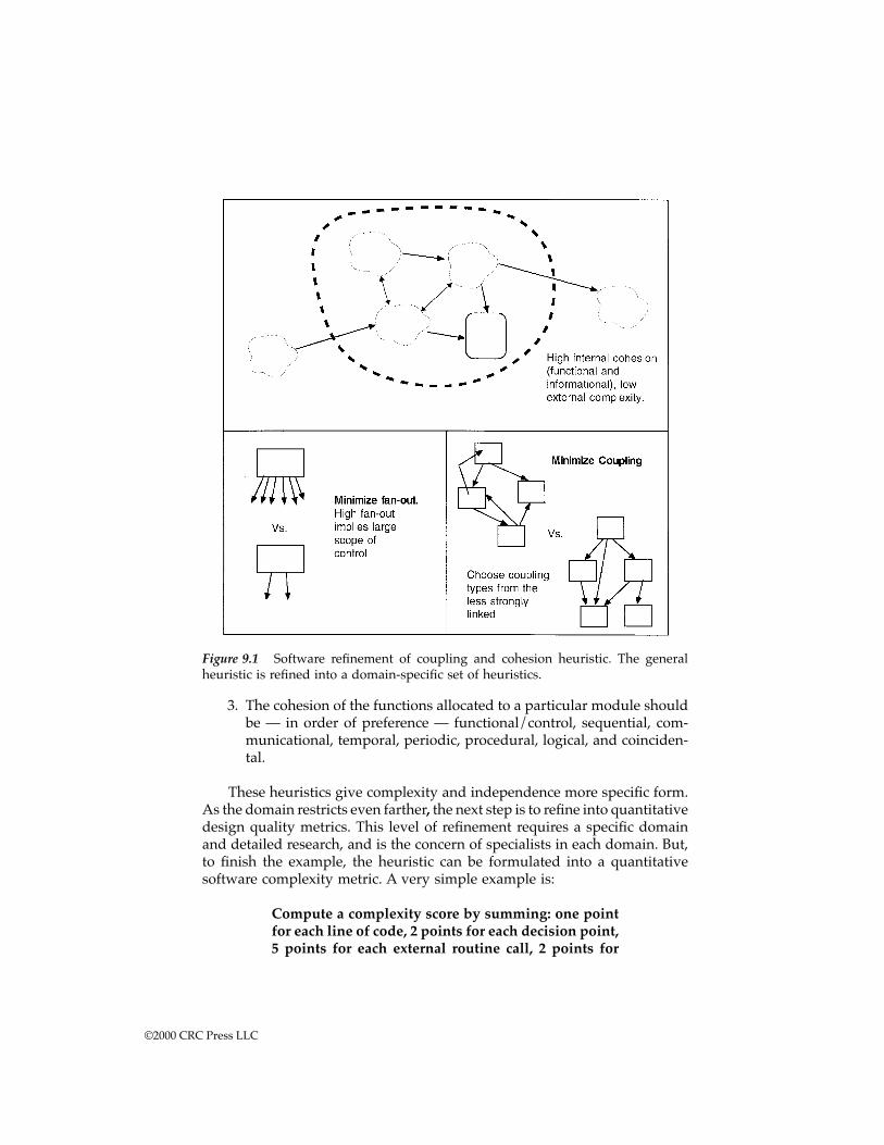
3. The cohesion of the functions allocated to a particular module shouldbe — in order of preference — functional/control, sequential, com-municational, temporal, periodic, procedural, logical, and coinciden-tal.
These heuristics give complexity and independence more specific form.As the domain restricts even farther, the next step is to refine into quantitativedesign quality metrics. This level of refinement requires a specific domainand detailed research, and is the concern of specialists in each domain. But,to finish the example, the heuristic can be formulated into a quantitativesoftware complexity metric. A very simple example is:
Compute a complexity score by summing: one pointfor each line of code, 2 points for each decision point,5 points for each external routine call, 2 points for
Figure 9.1 Software refinement of coupling and cohesion heuristic. The generalheuristic is refined into a domain-specific set of heuristics.
©2000 CRC Press LLC
each write to a module variable, 10 points for eachwrite to a global variable.*
Early evaluation criteria or heuristics must be as unbounded as thesystem choices. As the system becomes constrained, so do the evaluationcriteria. What was a general heuristic judgment becomes a domain-specificguideline, and, finally, a quantitative design metric.
Progression of emphasis
On a more abstract level, the social or political meaning of a system to itsdevelopers also progresses. A system goes from being a product (somethingnew) to a source of profit or something of value to a policy (something ofpermanence). In the earliest stages of a system’s life it is most likely viewedas a product. It is something new, an engineering challenge. As it becomesestablished and its development program progresses, it becomes an objectof value to the organization. Once the system exists it acquires an assumptionof permanence. The system, its capabilities, and its actions become part ofthe organization’s nature. To have and operate the system becomes a policythat defines the organization.
With commercial systems the progression is from product innovation tobusiness profit to corporate process.2 Groups innovate something new, suc-cessful systems become businesses, and established corporations perpetuatea supersystem that encompasses the system, its ongoing development, andits support. Public systems follow a similar progression. At their inceptionthey are new, at their development they acquire a constituency, and theyeventually become a bureaucratic producer of a commodity.
Concurrent progressions
Other concurrent progressions include risk management, cost estimating,and perceptions of success. Risk management progresses in specificity andgoals. Early risk management is primarily heuristic with a mix of rationalmethods. As prototypes are developed and experiments conducted, riskmanagement mixes with interpretation. Solid information begins to replaceengineering estimates. After system construction, risk management shifts topostincident diagnostics. System failures must be diagnosed, a process thatshould end in rational analysis but may have to be guided by heuristicreasoning.
Cost estimating goes through an evolution similar to other evaluationcriteria. Unlike other evaluation criteria, cost is a continually evolving char-acteristic from the systems inception. At the very beginning the need for anestimate is highest and the information available is lowest. Little information
* Much more sophisticated complexity metrics have been published in the software engineeringliterature. One of the most popular is the McCabe metric, for which there is a large automatedtoolset.
©2000 CRC Press LLC
is available because the design is incomplete and no uncertainties have beenresolved. As development proceeds, more information is available, bothbecause the design and plans become more complete and because actualcosts are incurred. Incurred costs are no longer estimates. When all costs arein (if such an event can actually be identified) there is no longer a need foran estimate. Cost estimating goes through a progression of declining needbut of continuously increasing information.
All of the “ilities” are part of their own parallel progressions. Thesesystem characteristics are known precisely only when the system isdeployed. Reliability, for example, is known exactly when measured in thefield. During development, reliability must be estimated from models of thesystem. Early in the process the customer’s desires for reliability may bewell known, but the reliability performance is quite uncertain. As the designprogresses to lower levels, the information needed to refine reliability esti-mates become known, information like parts counts, temperatures, andredundancy.
Perceptions of success evolve from architect to client and back to archi-tect. The architect’s initial perception is based on system objectives deter-mined through client interaction. The basic measure of success for the archi-tect becomes successful certification. But once the system is delivered, theclient will perceive success on his or her own terms. The project may producea system that is successfully certified but that nonetheless becomes a disap-pointment. Success is affected by all other conditions affecting the client atdelivery and operation, whether or not anticipated during design.
Episodic nature
The emphasis on progression appears to define a monotonic process. Archi-tecting begins in judgment, rough models, and heuristics. The heuristics arerefined along with the models as the system becomes bounded until rational,disciplinary engineering is reached. In practice, the process is more cyclic orepisodic, with alternating periods of synthesis, rational analysis, and heu-ristic problem solving. These episodes occur during system architecting, andmay appear again in later, domain-specific stages.
The occurrence of the episodes is integral to the architect’s process. Anarchitect’s design role is not restricted solely to “high-level” considerations.Architects dig down into specific subsystem and domain details where nec-essary to establish feasibility and determine client-significant performance(see Chapter 1, Figure 1.1, and the associated discussion). The overall processis one of high-level structuring and synthesis (based on heuristic insight)followed by rational analysis of selected details. Facts learned from thoseanalyses may cause reconsideration of high-level synthesis decisions andspark another episode of synthesis and analysis. Eventually, there should beconvergence to an architectural configuration, and the driving role passes tosubsystem engineers.
©2000 CRC Press LLC
Design concepts for systems architectureWhile systems design is an inherently complicated and irregular practice, ithas well-established and identifiable characteristics and can be organizedinto a logical process. As discussed in the Preface, the activities of architectingcan be distinguished from other engineering activities, even if not crisply.Architecting is characterized by the following:
1. Architecting is, predominantly, an eclectic mix of rational and heuris-tic engineering. Other elements, such as normative rules and groupprocesses, enter in lesser roles.
2. Architecting revolves around models, but is composed of the basicprocesses of scoping, aggregation, partitioning, integration, and cer-tification. Few complete rational methods exist for these processes,and the principal guidelines are heuristic.
3. Uncertainty is inherent in complex system design. Heuristics are spe-cialized tools to reduce or control, but not eliminate, uncertainty.
4. Continuous progression on many fronts is an organizing principle ofarchitecting, architecture models, and supporting activities.
Civil engineering and architecture are perhaps the most mature of allengineering disciplines. Mankind has more experience with engineering civilstructures than any other field. If any area could have the knowledge nec-essary to make it a fully rational and scientific endeavor it should be civilengineering. But it is in civil practice that the distinction between architectureand engineering is best established. Both architects and engineers have theirroles, often codified in law, and their professional training programs empha-size different skills. Architects deal particularly with those problems thatcannot be entirely rationalized by scientific inquiry. The architect’s approachdoes not ignore science; it combines it with art. Civil engineers must likewisedeal with unrationalizable problems, but the focus of their concerns is withwell-understood, rational design and specification problems. By analogy, thissuggests that all design domains contain an irreducible kernel of problemsthat are best addressed through creative and heuristic approaches that com-bine art and science. This kernel of problems, it might be called the archi-tectonic kernel, is resistant to being subsumed into engineering sciencebecause it inherently binds together social processes (client interaction) withengineering and science. The social side is how we determine and under-stand people’s needs. The engineering and science side is determining thefeasibility of a system concept. The bridge is the creative process of imaginingsystem concepts in response to expressions of client need.
Historical approaches to architecting
As indicated in the introduction to Part One, civil architects recognize fourbasic theories of design: the normative or pronouncement, the rational, the
©2000 CRC Press LLC
argumentative or participative, and the heuristic. While all have their rootsin the civil architecture practice, they are recognizable in modern complexsystems as well. They have been discussed before, in particular in Rechtin,1991,3 and in the Introduction to Part One. The purpose in returning to themhere is to indicate their relationship to progressive modeling and to bring intheir relevance to software-oriented development.* To review, normativetheory is built from pronouncements (statements of what should be, a set ofhard rules), most often given as restrictions on the content of particular views(usually form). A pronouncement demands that a particular type of form beused, essentially unchanged, throughout. Alternatively, one may pronouncethe reverse and demand that certain types of form not be used. In either case,success is defined by accurate implementation of the normative pronounce-ments, not by measures of fitness.
Rational system design is tightly integrated with modeling since it seeksto derive optimal solutions, and optimality can only be defined within astructured and mathematical framework. To be effective, rational methodsrequire modeling methods which are broad enough to capture all evaluationaspects of a problem, deep enough to capture the characteristics of possiblesolutions, and mathematically tractable enough to be solved for problemsof useful size. Given these, rational methods “mechanically” synthesize adesign from a series of modeled problem statements in progressively moredetailed subsystems.
Consensual or participative system design uses models primarily as ameans of communicating alternative designs for discussion and negotiationamong participants. From the standpoint of modeling, consensuality is oneof several techniques for obtaining understanding and approval of stake-holders, rather than of itself a structured process of design.
General heuristics are guides to — and are sometimes obtained from —models, but they are not models themselves. Heuristics are employed at alllevels of design, from the most general to domain-specific. Heuristics areneeded whenever the complexity of the problem, solutions, and issues over-whelms attempts at rational modeling. This occurs as often in software ordigital logic design as in general system design. Within a specific domainthe heuristic approach can be increasingly formalized, generating increas-ingly prescriptive guidance. This formalization is a reflection of the progres-sion of all aspects of design — form, evaluation, and emphasis — fromabstract to concrete.
The power of the Chapter 2 heuristics comes by cataloging heuristicswhich apply in many domains, giving them generality in those domains,likely extensibility in others, and a system-level credibility. Applied consis-tently through the several levels of system architecture, they help insuresystem integrity. For example, “quality cannot be tested in, it must bedesigned in” is equally applicable from the top-level architectural sketch to
* Stepwise refinement is a term borrowed from software that describes program developmentby sequential construction of programs, each complete unto itself, but containing increasingfractions of the total desired system functionality.
©2000 CRC Press LLC
the smallest detail. However, the general heuristic relies on an experiencedsystem-level architect to select the ones appropriate for the system at hand,interpret their application-specific meaning, and to promulgate themthroughout its implementation. A catalog of general heuristics is of muchless use to the novice; indeed, an uninformed selection among them couldbe dangerous. For example, “if it ain’t broke, don’t fix it,” questionable atbest, can mislead one from making the small incremental changes that oftencharacterize successful continuous improvement programs, and can blockone from recognizing the qualitative factors, like ultraquality, that redefinethe product line completely.
Specialized and formalized heuristics
While there are many very useful general heuristics, there really is not ageneral heuristic method as such.* Heuristics most often are formalized aspart of more formalized methods within specific domains. A formalizedheuristic method gives up generality for more direct guidance in its domain.Popular design methods often contain formalized heuristics as guidelinesfor design synthesis. A good example is the ADARTS** software engineeringmethodology. ADARTS provides an extensive set of heuristics to transforma data-flow-oriented behavioral model into a multitasking, modular softwareimplementation. Some examples of formalized ADARTS prescriptive heu-ristics include:
Map a process to an active I/O process if that trans-formation interfaces to an active I/O device4
Group processes that read or update the same datastore or data from the same I/O device into a singleprocess5
As the ADARTS method makes clear, these are recommended guidelinesand not the success-defining pronouncements of the normative approach.These heuristics do not produce an optimal, certifiable, or even unique result,much less success-by-definition. There is ambiguity in their application.Different heuristics may produce conflicting software structuring. The soft-ware engineer must select from the heuristics list and interpret the designconsequences of a given heuristic with awareness of the specific demandsof the problem and its implementation environment.
Conceptually, general and domain-specific, formalized heuristics mightbe arranged in a hierarchy. In this hierarchy, domain-specific heuristics arespecializations of general heuristics, and the general are abstractions of the
* On the other hand, knowledge of a codified set of heuristics can lead to new ways of thinkingabout problems. This could be described as heuristic thinking or qualitative reasoning.** This method is described in the ADARTS Guidebook, SPC-94040-CMC, Version 2.00.13, Volume1, September 1991, available from the Software Productivity Consortium, Herndon, VA.
©2000 CRC Press LLC
specific. Architecting in general and architecting in specific domains may belinked through the progressive refinement and specialization of heuristics.To date, this hierarchy can be clearly identified only for a limited set ofheuristics. In any case, the pattern of refining from abstract to specific is abroadly persistent pattern, and it is essential for understanding life cycledesign progression.
Scoping, aggregation, partitioning, and certification
A development can be envisioned as the creation and transformation of aseries of models. For example, to develop the systems requirements is todevelop a model of what the system should do and how effectively it shoulddo it. To develop a system design is to develop a model of what the systemis. In a pure waterfall development there is rough alignment between water-fall steps and the views defined in Chapter 8. Requirements developmentdevelops models for objectives and performance, functional analysis devel-ops models of behavior, and so on down the waterfall chain. Architectsdevelop models for all views, though not at equal levels of detail. In uncriticalviews or uncritical portions of the system the models will be rough. In someareas the models may need to be quite detailed from the beginning.
Models are best understood by view because the views reflect theircontent. While architecting is consistent with waterfall or spiral develop-ment, it does not traverse the steps in the conventional manner. Architectsmake use of all views and traverse all development steps, but at varyinglevels of detail and completeness. Because architects tend to follow complexpaths through design activities, some alternative characterization of designactivities independent of view is useful. The principal activities of the archi-tect are scoping, partitioning, aggregation, and certification. Figure 9.2 liststypical activities in each category and suggests some relationships.
ScopingScoping procedures are methods for selecting and rejecting problem state-ments, for defining constraints, and for deciding on what is “inside” or“outside” the system. Scoping implies the ability to rank alternative state-ments and priorities on the basis of overall desirability or feasibility. Scopingshould not design system internals, though some choices may implicitly doso for lack of design alternatives. Desirably, scoping limits what needs to beconsidered and why.
Scoping might alternatively be referred to as purpose analysis. Purposeanalysis is an inquiry into why someone wants the system. Purpose precedesrequirements. Requirements are determined by understanding how havinga system is valuable to the client, and what combination of fulfilled purposesand systems costs represents a satisfactory and feasible solution.*
* Dr. Kevin Kreitman has pointed out the extensive literature in soft systems theory that appliesto purpose analysis.
©2000 CRC Press LLC
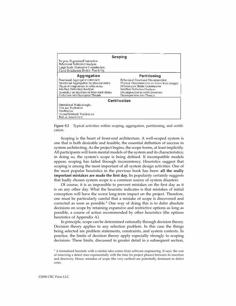
Scoping is the heart of front-end architecture. A well-scoped system isone that is both desirable and feasible, the essential definition of success insystem architecting. As the project begins, the scope forms, at least implicitly.All participants will form mental models of the system and its characteristics;in doing so, the system's scope is being defined. If incompatible modelsappear, scoping has failed through inconsistency. Heuristics suggest thatscoping is among the most important of all system design activities. One ofthe most popular heuristics in the previous book has been: all the reallyimportant mistakes are made the first day. Its popularity certainly suggeststhat badly chosen system scope is a common source of system disasters.
Of course, it is as impossible to prevent mistakes on the first day as itis on any other day. What the heuristic indicates is that mistakes of initialconception will have the worst long-term impact on the project. Therefore,one must be particularly careful that a mistake of scope is discovered andcorrected as soon as possible.* One way of doing this is to defer absolutedecisions on scope by retaining expansive and restrictive options as long aspossible, a course of action recommended by other heuristics (the optionsheuristics of Appendix A).
In principle, scope can be determined rationally through decision theory.Decision theory applies to any selection problem. In this case the thingsbeing selected are problem statements, constraints, and system contexts. Inpractice, the limits of decision theory apply especially strongly to scopingdecisions. These limits, discussed in greater detail in a subsequent section,
Figure 9.2 Typical activities within scoping, aggregation, partitioning, and certifi-cation.
* A formalized heuristic with a similar idea comes from software engineering. It says: the costof removing a defect rises exponentially with the time (in project phases) between its insertionand discovery. Hence, mistakes of scope (the very earliest) are potentially dominant in defectcosts.
©2000 CRC Press LLC
include the problems of utility for multiple system stakeholders, problemscale, and uncertainty. The judgments of experienced architects, at least asexpressed through heuristics (see Appendix A for a detailed list), is that themost useful techniques to establish system scope are qualitative.
Scoping heuristics and decision theory share an emphasis on carefulconsideration of who will use the system and who will judge success. Deci-sion theory requires a utility function, a mathematical representation ofsystem value as a function of its attributes. A utility function can be deter-mined only by knowing whose judgments of system value will have priorityand what the evaluation criteria are. Compare the precision of the utilitymethod to related heuristics:
Success is defined by the beholder, not by the archi-tect.
The most important single element of success is tolisten closely to what the customer perceives as hisrequirements and to have the will and ability to beresponsive (Steiner, J. E., 1978).
Ask early about how you will evaluate the successof your efforts (Hayes-Roth et al., 1983).
Scoping heuristics suggest approaches to setting scope that are outsidethe usual compromise procedures of focused engineering. One way toresolve intractable problems of scope is to expand. The heuristic is:
Moving to a larger purpose widens the range of so-lutions (Nadler, G., 1990).
The goal of scoping is to form a concept of what the system will do, howeffectively it will do it, and how it will interact with the outside world. Thelevel of detail required is the level required to gain customer acceptance,first of continued development and ultimately of the built system. Thus thescope of the architect’s activities are governed not by the ultimate needs ofsystem development, but by the requirements of the architect's further role.The natural conclusion to scoping is certification, where the architect deter-mines that the system is fit for use. Put another way, the certification is thatthe system is appropriate for its scope.
Scoping is not solely a requirements-related activity. For scope to besuccessfully determined, the resulting system must be both satisfactory andfeasible. The feasibility part requires some development of the systemdesign. The primary activities in design by architects are aggregation andpartitioning, the basic structuring of the system into components.
©2000 CRC Press LLC
Aggregation and partitioningAggregation and partitioning are the grouping and separation of relatedsolutions and problems. They are two sides of the same coin. Both are theprocesses by which the system is defined as components. While one canargue about which precedes the other, they are, in fact, used so iterativelyand repeatedly that neither can be usefully said to precede the other. Con-ventionally, the components are arranged into hierarchies with a modestnumber of components at each level of the hierarchy (the famous 7 ± 2structuring heuristic). The most important aggregation and partitioning heu-ristics are to minimize external coupling and maximize internal cohesion,usually worded as6:
In partitioning, choose the elements so that they areas independent as possible, that is, elements withlow external complexity and high internal cohesion.
Group elements that are strongly related each other,separate elements that are unrelated.
These two heuristics are especially interesting because they are part ofthe clearest hierarchy in heuristic refinement. Design is usefully viewed asprogressive or stepwise refinement. Models, evaluation criteria, heuristics,and other factors are all refined as design progresses from abstract to concreteand specific. Ideally, heuristics exist in hierarchies that connect generaldesign guidance, such as the two preceding heuristics, to domain-specificdesign guidelines. The downward direction of refinement is the deductionof domain-specific guidelines from general heuristics. The upward abstrac-tion is the induction of general heuristics from similar guidelines acrossdomains.
The deductive direction asks, taking the coupling heuristic as an exam-ple, how can coupling be measured? Or, for the cohesion heuristic, givenalternative designs, which is the most cohesive? Within a specific domainthe questions should have more specific answers. For example, within thesoftware domain these questions are answered with greater refinement,though still heuristically. Studies have demonstrated quantitative impact onsystem properties as the two heuristics are more and less embodied in asystems design. A generally accepted software measure of partitioning isbased on interface characterization and has five ranked levels. A relatedmetric for aggregation quality (or cohesion) has seven ranked levels of cohe-sion.* Studies of large software systems show a strong correlation betweencoupling and cohesion levels, defect rates, and maintenance costs. A majorstudy7 found that routines with the worst coupling-to-cohesion ratios (inter-
* The cohesion and coupling levels are carefully discussed in Yourdon, E. and Constantine, L.L., Structured Design: Fundamentals of a Discipline of Computer Program and Systems Design,Yourdon Press, Englewood Cliffs, 1979. They were introduced earlier by the same authors andothers in several papers.
©2000 CRC Press LLC
face complexity to internal coherence) had 7 times more errors and 20 timeshigher maintenance costs than the routines with the best ratios.
Aggregation and partitioning with controlled fan-out and limited com-munication is a tested approach to building systems in comprehensible hier-archies. Numerous studies in specific domains have shown that choosingloosely coupled and highly cohesive elements leads to systems with lowmaintenance cost and low defect rates. However, nature suggests that muchflatter hierarchies can yield systems of equal or greater robustness in certaincircumstances.
Chapter 8 introduced an ant colony as an example of a flat hierarchysystem that exhibits complex and adaptive behavior. The components of anant colony, a few classes of ants, interact in a very flat system hierarchy.Communication is loose and hierarchically unstructured. There is no intel-ligent central direction. Nevertheless, the colony as a whole produces com-plex system-level behavior. The patterns of local, nonhierarchical interactionproduce very complex operations. The colony is also very robust in that largenumbers of its components (except the queen) can be removed catastrophi-cally and the system will smoothly adapt. A related technological example,perhaps, is the Internet. Again, the system as a whole has a relatively flathierarchy and no strong central direction; however, the patterns of localcommunication and resulting collaboration are able to produce complex,stable, and robust system-level behavior.
The observations that controlled and limited fan-out and interaction (the7 ± 2 heuristic and coupling and cohesion studies) and that extreme fan-outand high distributed communication and control (ant colonies and the Inter-net) can both lead to high-quality systems is not contradictory. Rather, theyare complementary observations of the refinement of aggregation and par-titioning into specific domains. In both cases a happy choice of aggregationsand partitions yield good systems. But the specific indicators of what con-stitutes good aggregation and partitioning vary with the domain. The gen-eral heuristic stands for all, but prescriptive or formalized guidance must beadapted for the domain.
CertificationTo certify a system is to give an assurance to the paying client that the systemis fit for use. Certifications can be elaborate, formal, and very complex, orthe opposite. The complexity and thoroughness are dependent on the sys-tem. A house can be certified by visual inspection. A computer flight controlsystem might require highly detailed testing, extensive product and processinspections, and even formal mathematical proofs of design elements. Cer-tification presents two distinct problems. The first is determining that thefunctionality desired by the client and created by the builder is acceptable.The second is the assessment of defects revealed during testing and inspec-tion, and the evaluation of those failures with respect to client demands.
Whether or not a system possesses a desired property can be stated asa mathematically precise proposition. Formal methods develop and track
©2000 CRC Press LLC

and verify such propositions throughout development, ideally leading to aformal proof that the system as designed possesses the desired properties.However, architecting practice has been to treat such questions heuristically,relying on judgment and experience to formulate tests and acceptance pro-cedures. The heuristics on certification criteria do not address what suchcriteria should be, but the process for developing the criteria. Essentially,certification should not be treated separately from scoping or design. Certi-fiability must be inherent in the design. Two summarizing heuristics, actuallyon scoping and planning, are:
For a system to meet its acceptance criteria to thesatisfaction of all parties, it must be architected, de-signed, and built to do so — no more and no less.
Define how an acceptance criterion is to be certifiedat the same time the criterion is established.
The first part of certification is intimately connected to the conceptualphase. The system can be certified as possessing desired criteria only to theextent it is designed to support such certification. The second element ofcertification, dealing with failure, carries its own heuristics. These heuristicsemphasize a highly organized and rigorous approach to defect analysis andremoval. Once a defect is discovered it should not be considered resolveduntil it has been traced to its original source, corrected, the correction testedat least as thoroughly as was needed to find the defect originally, and theprocess recorded. Deming’s famous heuristic summarizes:
Tally the defects, analyze them, trace them to thesource, make corrections, keep a record of what hap-pens afterwards, and keep repeating it.
A complex problem in ultraquality systems is the need to certify levelsof performance that cannot be directly observed. Suppose a missile systemis required to have a 99% success rate with 95% confidence. Suppose furtherthat only 50 missiles are fired in acceptance tests (perhaps because of costconstraints). Even if no failures are experienced during testing, the require-ment cannot be quantitatively certified. Even worse, suppose a few failuresoccurred early in the 50 tests but were followed by flawless performanceafter repair of some design defects. How can the architect certify the system?It is quite possible that the system meets the requirement, but it cannot beproven.
Certification of ultraquality might be deemed a problem of requirements.Many would argue that no requirement should be levied that cannot bequantitatively shown. But the problem will not go away. The only acceptablefailure levels in one-of-a-kind systems and those with large public safety
©2000 CRC Press LLC

impacts will be immeasurable. No such systems can be certified if certifica-tion in the absence of quantitatively provable data is not possible.
Some heuristics address this problem. The Deming approach, given asa heuristic above, seeks to achieve any quality level by continuous incre-mental improvement. Interestingly, there is a somewhat contradictory heu-ristic in the software domain. When a software system is tested, the numberof defects discovered should level off as testing continues. The amount ofadditional test time to find each additional defect should increase, and thetotal number of discovered defects will level out. The leveling out of thenumber of defects discovered gives an illusion that the system is now defectfree. In practice, testing or reviews at any level rarely consistently find morethan 60% of the defects present in a system. But if testing at a given levelfinds only a fixed percentage of defects, it likewise leaves a fixed percentageundiscovered. The size of that undiscovered set will be roughly proportionalto the number found in that same level of test or review. The heuristic canbe given in two forms:
The number of defects remaining in a system after agiven level of test or review (design review, unit test,system test, etc.) is proportional to the number foundduring that test or review
Testing can indicate the absence of defects in a sys-tem only when: (1) the test intensity is known fromother systems to find a high percentage of defects,and (2) few or no defects are discovered in the systemunder test.
So the discovery and removal of defects is not necessarily an indicationof a high-quality system. A variation of the “zero-defects” philosophy is thatultraquality requires ultraquality throughout all development processes.That is, certify a lack of defects in the final product by insisting on a lack ofdefects anywhere in the development process. The ultraquality problem isa particular example of the interplay of uncertainty, heuristics, and rationalmethods in making architectural choices. That interplay needs to be exam-ined directly to understand how heuristic and rational methods interact inthe progression of system design.
Certainty, rationality, and choice
All of the design processes — scoping, partitioning, aggregation, and certi-fication — require decisions. They require decisions on which problem state-ment to accept, what components to organize the system into, or when thesystem has reached an acceptable level of development. A by-product of aheuristic-based approach is continuous uncertainty. Looking back on theirprojects, most architects interviewed for the USC program concluded that
©2000 CRC Press LLC
the key choices they made were rarely obvious decisions at the time.Although, in retrospect, it may be obvious that a decision was either a verygood or a very bad one, at the time the decision was actually made it wasnot clear at all. The heuristic summarizing is before the flight it was opinion,after the flight it was obvious. The members of the teams were constantlyarguing and decision was reached only through the authority of the leadingarchitect for the project.*
A very considerable effort has been made to develop rational decision-making methods. The goal of a fully rational or scientific approach is to makedecisions optimally with respect to rigorously determined criteria. Again,the model of architecting practice presented here is a pragmatic mixture ofheuristic and rigor. Decision theory works well when the problem can beparameterized with a modest number of values, uncertainty is limited andestimates are reliable, and the client or users possess consistent utility func-tions with tractable mathematical expression. The absence of any of theseconditions weakens or precludes the approach. Unfortunately, some or allof the conditions are usually absent in architecting problems (and even inmore restricted disciplinary design problems). To understand why, one mustunderstand the elements of the decision theoretic approach. The decisiontheoretic framework is:
1. Identify the attributes contributing to client satisfaction and an algo-rithm for estimating the value of sets of attributes. More formally, thisis determining the set over which the client will express preference.
2. Determine a utility function, a function that combines all the attributesand represents overall client satisfaction. Weighted, additive utilityfunctions are commonly used, but not required. The utility functionconverts preferences into a mathematically useful objective function.
3. Include uncertainty by determining probabilities, calculating the util-ity probability distribution, and determining the client’s risk aversioncurve. The risk aversion curve is a utility theory quantity that mea-sures the client’s willingness to trade risk for return.
4. Select the decision with the highest-weighted expected utility.
The first problem in applying this framework to architecting problemsis scale. To choose an optimum, the decision theory user must be able tomaximize the utility functions over the decision set. If the set is very large,the problem is computationally unfeasible. If the relationship between theparameters and utility is nonlinear, only relatively small problems are solv-able. Unfortunately, both conditions commonly apply to the architecting andcreation of complex systems.
The second problem is to workably and rationally include the effects ofuncertainty or risk. In principle, uncertainty and unreliability in estimatescan be folded into the decision theoretic framework through probability and
* Comments by Harry Hillaker at USC on his experience as YF-16 architect.
©2000 CRC Press LLC

assessment of the client’s risk aversion curve. The risk aversion curve mea-sures the client’s willingness to trade risk and return. A risk-neutral clientwants the strategy that maximizes expected return. A risk-averse client pre-fers a strategy with certainty over opportunity for greater return. A risk-disposed client prefers the opposite, wanting the opportunity for greaterreturn even if the expectation of the return is less.
In practice, however, the process of including uncertainty is heavilysubjective. For example, how can one estimate probabilities for unprece-dented events? If the probabilities are inaccurate, the whole framework losesits claim to optimality. Estimation of risk aversion curves is likewise subjec-tive, at least in practice. When so much subjective judgment has been intro-duced, it is unclear if maintaining the analytical framework leads to muchbenefit or if it is simply a gloss.
One clear benefit of the decision theory framework is that it makes thedecision criteria explicit and, thus, subject to direct criticism and discussion.This beneficial explicitness can be obtained without the full framework. Thisapproach is to drop the analytic gloss, make decisions based on heuristicsand architectural judgment, but (and this is more honored in the breach)require the basis be explicitly given and recorded.
A third problem with attempting to fully rationalize architectural deci-sions is that for many of them there will be multiple clients who have someclaim to express a preference. Single clients can be assumed to have consis-tent preferences and, hence, consistent utility functions. However, consistentutility functions do not generally exist when the client or user is a group asin sociotechnical systems.* Even with single clients, value judgments maychange, especially after the system is delivered and the client acquires directexperience.**
Rational and analytical methods produce a gloss of certainty, but oftenhide highly subjective choices. No hard-and-fast guideline exists for choos-ing between analytical choice and heuristic choice when unquantified uncer-tainties exist. Certainly, when the situation is well understood and uncer-tainties can be statistically measured, the decision theoretic framework isappropriate. When even the right questions are in doubt it adds little to theprocess to quantify them. Intermediate conditions call for intermediate cri-teria and methods. For example, a system might have as client objectives“be flexible” and “leave in options.” Obviously, these criteria are open tointerpretation. The refinement approach is to derive or specialize increas-ingly specific criteria from very general criteria. This process creates a con-
* This problem with multiple clients and decision theory has been extensively studied inliterature on public choice and political philosophy. A tutorial reference is Mueller, D. C., PublicChoice, Cambridge University Press, 1979.** Non-utility theory based decision methods, such as the Analytic Hierarchy Process, have manyof the same problems. Most writers have discussed that the primary role of decision theoreticmethods should be to elucidate the underlying preferences. See Saaty, T., The Analytic NetworkProcess, RWS Publications, 1996, Preface and Chapter 1.
©2000 CRC Press LLC
tinuous progression of evaluation criteria from general to specific, and even-tually measurable.
Example: The U.S. Department of Transportation hasfinanced an Intelligent Transport System (ITS) archi-tecture development effort. Among their evaluationcriteria was “system flexibility,” obviously a very loosecriterion.8 An initial refinement of the loose criterioncould be:
1. Architecture components should fit in many alter-native architectures.
2. Architecture components should support multipleservices.
3. Architecture components should expand with linearor sublinear cost to address greater load.
4. Components should support non-ITS services.
These refined heuristic evaluation criteria can be applied directly tocandidate architectures, or they can be further refined into quantitative andmeasurable criteria. The intermediate refinement on the way to quantitativeand measurable criteria creates a progression that threads through the wholedevelopment process. Instead of thinking of design as beginning and stop-ping, it continuously progresses. Sophisticated mixtures of the heuristics andrational methods are part of architecting practice in some domains. Thisprogression is the topic of the next section.
Stopping or progressing?
When does architecting and modeling stop? The short answer is that givenearlier: they never stop, they progress. The architecting process (along withmany other parallel tracks) continuously progresses from the abstract to theconcrete in a steady reduction of abstraction. In a narrow sense, there arerecognizable points at which some aspects of architecting and modeling muststop. To physically fabricate a component of a system, its design must befrozen. It may not stop until the lathe stops turning or the final line of codeis typed in, but the physical object is the realization of some design. In thebroader sense, even physical fabrication does not stop architecting. Opera-tions can be interpreted only through recourse to models, though thosemodels may be quite precise when driven by real data. In some systems,such as distant space probes, even operational modeling is still somewhatremote.
The significant progressions in architecting are promoted by the role ofthe architect. The architect's role makes two decisions foremost, the selectionof a system concept and the certification of the built system. The formerdecision is almost certain to be driven by heuristic criteria, the latter is more
©2000 CRC Press LLC
open, depending on how precisely the criteria of fitness for use can bedefined. A system concept is suitable when it is both satisfactory and feasible.Only the client can judge the system “satisfactory,” though the client willhave to rely on information provided by the architect. In builder-architectedsystems the architect must often make the judgment for the client (who willhopefully appear after the system reaches the market). Feasible means thesystem can be developed and deployed with acceptable risk. Certificationrequires that the system as built adequately fulfills the client’s purposes,including cost, as well as the contract with the builder.
Risk, a principal element in judging feasibility, is almost certain to bejudged heuristically. The rational means of handling risk is through proba-bility, but a probabilistic risk assessment requires some set of precedents toestimate over. That is, a series of developments of similar nature for whichthe performance and cost history is known. By definition, such a historycannot be available for unprecedented systems, so the architect is left toestimate risk by other means. In well-defined domains, past history shouldbe able to provide a useful guide; it certainly does for civil architects. Civilarchitects are expected to control cost and schedule risk for new structures,and they can do so because construction cost estimation methods are rea-sonably well developed. The desired approach is to use judgment, andperhaps a catalog of domain-specific heuristics, to size the developmenteffort against past systems, and use documented development data fromthose past systems to estimate risk. For example, in software systems, costmodels based on code size estimates are known, and they are often calibratedagainst past development projects in builder organizations. If the architectcan deduce code size and possible variation in code size reliably, a traceableestimate of cost risk is possible.
The judgment of how satisfactory a concept is, and the certificationprocess, both depend on how well customer purposes can be specified. Herethere is great latitude for both heuristic and rational means. If customerpurposes can be precisely specified, it may be possible to precisely judgehow well a system fulfills them, either in prospect or retrospect. In prospectit depends on having behavior and performance models that are firmlyattached to customer purposes. With good models with certain connectionbetween the models and implementation technology, the architect can con-fidently predict how well the planned system will fulfill the desired pur-poses. The retrospective problem is that of certification, of determining howwell the built system fulfills the customer purposes. Again, well-founded,scientific models and mature implementation technologies make systemassessment relatively certain.
More heuristic problems arise when the same factors do not apply.Mainly, this occurs when it is hard to formulate precise customer purposemodels, when it is hard to determine whether or not a built system fulfillsa precisely stated purpose, or when there is uncertainty about the connectionbetween model and implemented system. The second two are related since
©2000 CRC Press LLC
they both concern retrospective assessment of architecture models against abuilt system in the presence of uncertainty.
The first case applies when customer purposes are vague or likely tochange in response to actual experience with the system. When the customeris relatively inexperienced with systems of the type, his or her perception ofthe system’s value and requirements is likely to change, perhaps radically,with experience. Vague customer purposes can be addressed through thearchitecture; for example, an emphasis on options in the architecture and adevelopment plan that includes early user prototypes with the ability to feedprototype experience back into the architecture. This is nicely captured intwo heuristics:
Firm commitments are best made after the prototypeworks.9
Hang on to the agony of decision as long as possi-ble.10
The second case, problems in determining whether or not a built systemfulfills a given purpose, is mainly a problem when requirements are funda-mentally immeasurable or when performance is demanded in an environ-ment that cannot be provided for test. For example, a space system mayrequire a failure rate so low it will never occur during any practical test (theultraquality problem); or, a weapon system may be required to operate inthe presence of hostile countermeasures that will not exist outside a realcombat environment. Neither of these requirements can be certified by testor analysis. To certify a system with requirements like these it is necessaryto either substitute surrogate requirements agreed to by the client, or to findalternative certification criteria.
To architect-in certifiable criteria essentially means to substitute a refinedset of measurable criteria for the client's immeasurable criteria. This requiresthe architect to be able to convince the client of the validity of a model forconnecting the refined criteria to the original criteria. One advantage of athird-party architect is the independent architect’s greater credibility in mak-ing just such arguments, which may be critical to developing a certifiablesystem. A builder-architect, with an apparent conflict of interest, may nothave the same credibility. The model that connects the surrogate criteria tothe real, immeasurable criteria may be a detailed mathematical model ormay be quite heuristic. An example of the former category is failure treeanalysis that tries to certify untestable reliability levels from testable sub-system reliability levels. A more heuristic model may be more appropriatefor certifying performance in uncertain combat environments. While theperformance required is uncertain, criteria like flexibility, reprogrammability,performance reserve, fallback modes, and ability to withstand damage canbe specified and measured.
©2000 CRC Press LLC
Rational and heuristic methods can be combined to develop ultraqualitysystems. A good example is a paper by Jaynarayan.11 This paper discussesthe architectural principles for developing flight control computers withfailure rates as low as 10-10/h. Certification of such systems is a major prob-lem. The authors discuss a two-pronged approach. First, instead of usingbrute-force failure modes and effects analysis with its enormous fault trees,they design for “Byzantine failure.” Byzantine failure means failure in whichthe failed element actively, intelligently, and malevolently attempts to causesystem failure. They go on to describe formal methods for designing systemsresistant to a given number of Byzantine faults, thus replacing the need totrace fault trees for each type of failure. The analysis of failure trees is thenbrought down to tractable size. The approach is based on designs that donot allow information or energy from a possibly failed element to propagateoutside an error confinement region. The second prong is a collection ofguidelines for minimizing common mode failures. In a common mode fail-ure, several nominally independent redundant units fail simultaneously forthe same reason. These are the system failures due to design errors ratherthan component failures. Because one cannot design-in resistance to designfailure, other means are necessary. The guidelines, partially a set of heuristics,provide guidance in this otherwise nonmeasurable area.
The third and last case is uncertainty about the connection between themodel and the actual system. This is an additional case where informedjudgment and heuristics are needed. To reduce the uncertainty in modelingrequires tests and prototypes. The best guidance on architecting prototypesis to realize that all prototypes should be purpose-driven. Even when thepurposes of the system are less than clear, the purposes of the prototypeshould be quite clear. Thus, the architecting of the prototype can beapproached as architecting a system, with the architect as the client.
Architecture and design disciplinesNot very many years ago the design of a system of the complexity of severaltens of thousands of logic gates was a major undertaking. It was an archi-tectural task in the sense it was probably motivated by an explicit purposeand required the coordination of a multidisciplinary design effort. Today,components of similar and much higher complexity are the everyday build-ing blocks of the specialized digital designer. No architectural effort isrequired to use such a component, or even to design a new one. In principle,art has been largely removed from the design process because the disciplinehas a firm scientific basis. In other words, the design discipline or domainis well worked out, and the practitioners are recognized specialists. Todayit is common to discuss digital logic synthesis directly from fairly levelspecifications, even if automated synthesis is not yet common practice. Sothere should be no surprise if systems that today tax our abilities and requirearchitectural efforts one day become routine with recognized design meth-odologies taught in undergraduate courses.
©2000 CRC Press LLC
The discussion of progression leads to further understanding of thedistinctions between architecture and engineering. The basic distinction wasreviewed in the Preface, the types of problems addressed and the tools usedto address them. A refinement of the distinction was discussed in Chapter1, the extent to which the practitioner is primarily concerned with scoping,conceptualizing, and certification. By looking at the spectrum of architectureand engineering across systems disciplines, these distinctions become clearerand can be further refined. First, the methods most associated with archi-tecting (heuristics) work best one step beyond where rational design disci-plines have been worked out. This may or may not be at the forefront ofcomponent technology. Large-scale systems, by their nature, push the limitsof scientific engineering at whatever level of technology development iscurrent. But, as design and manufacturing technology change the level ofintegration that is considered a component, the relative working position ofthe architect inevitably changes. Where the science does not exist thedesigner must be guided by art. With familiarity and repetition, much thatwas done heuristically can now be done scientifically or procedurally.
However, this does not imply that where technology is mature architect-ing does not exist. If it did, there would be no need for civil architects. Onlysystems that are relatively unique need to be architected. Development issuesfor unique systems contain a kernel of architectural concerns that transcendwhatever technology or scientific level is current. This kernel concerns thebridge between human needs (which must be determined through socialinteraction and are not the domain of science) and technological systems. Inlow-technology systems, like buildings, only the nonroutine building needsto be architected. But dealing with the nonroutine, the unique, the cli-ent/user-customized, is different from other engineering practices. It con-tains an irreducible component of art. A series of related unprecedentedsystems establishes a precedent. The precedent establishes recognized pat-terns, sometimes called architectures, of recognized worth. Further, systemsin the field will commonly use those established architectures, with varia-tions more on style than in core structure.
Current development in software engineering provides an example ofevolution to a design discipline. Until relatively recently the notion of soft-ware engineering hardly existed; there was only programming. Program-ming is the process of assembling software from programming languagestatements. Programming language statements do not provide a very richlanguage for expressing system behaviors. They are constrained to basicarithmetic, logical, and assignment operations. To build complex systembehaviors, programs are structured into higher-level components that beginto express system domain concepts; but in traditional programming each ofthe components must be handcrafted from the raw material of programminglanguages.
The progression in software is through the construction and standard-ization of components embodying behaviors closer and closer to problemdomains. Instead of programming in what was considered a “high-level
©2000 CRC Press LLC

language,” the engineer can now build a system from components close tothe problem domain. The programming language is still used, but it may beused primarily to knit together prebuilt components. Programming librarieshave been in common use for many years. The libraries shipped with com-mercial software development environments are often very large and containextensive class or object libraries. In certain domains the gap has grown verysmall.
Example: The popular mathematics package MatLaballows direct manipulation of matrices and vectors. Italso provides a rich library of functions targeted atcontrol engineers, image processing specialists, andother fields. One can dispense with the matrices andvectors altogether by “programming” with a graphicalblock diagram interface that hides the computationaldetails and provides hundreds of prebuilt blocks. Fur-ther extensions allow the block diagram to be compiledinto executable programs that run on remote machines.In fact, direct connection to operating real-time sys-tems for real-time control is possible.
Wherever a family of related systems is built, a set of accepted modelsand abstractions appears and forms the basis for a specialized design disci-pline. If the family becomes important enough, the design discipline willattract enough research attention to build scientific foundations. It will trulybecome a design discipline when universities form departments devoted toit. At the same time, a set of common design abstractions will be recognizedas “architectures” for the family. Mary Shaw, observing the software field,finds components and patterns constrained by component and connectorvocabulary, topology, and semantic constraints. These patterns can be termed“styles” of architecture in the field, as discussed in Chapter 6, for software.
Architecture and patterns
The progression from “inspired” architecture to formal design method isthrough long experience. Long experience in the discipline by its practitio-ners eventually yields tested patterns of function and form. Patterns, patternlanguages, and styles are a formalization of this progression. Architecting ina domain matures as architects identify reusable components and repeatingstyles of connection. Put another way, they recognize recurring patterns ofform and their relationships to patterns in problems. In a mature domain,patterns in both the problem and solution domain develop rigorous expres-sion. In digital logic (a relatively mature design domain) problems are statedin formal logic and solutions in equally mathematically well-founded com-ponents. In a less mature domain the patterns are more abstract or heuristic.
©2000 CRC Press LLC
A formalization of patterns in architecture is due to Christopher Alex-ander.12 Working within civil architecture and urban design, Alexanderdeveloped an approach to synthesis based on the composition of formalizedpatterns. A pattern is a recurring structure within a design domain. Theyconsist of both a problem or functional objective for a system and a solution.Patterns may be quite concrete (such as “a sunny corner”) or relativelyabstract (such as “masters and apprentices”). A template for defining apattern is
1. A brief name that describes what the pattern accomplishes2. A concise problem statement3. A description of the problem including the motivation for the pattern
and the issues in resolving the problem4. A solution, preferably stated in the form of an instruction5. A discussion of how the pattern relates to other patterns in the lan-
guage
A pattern language is set of patterns complete enough for design withina domain. It is a method for composing patterns to synthesis solutions todiverse objectives. In the Alexandrian method the architect consults sets ofpatterns and chooses from them those patterns which evoke the elementsdesired in a project. The patterns become the building blocks for synthesis,or suggest important elements that should be present in the building. Thepatterns each suggest instructions for solution structure, or contain a solutionfragment. The fragments and instructions are merged to yield a systemdesign.
Because the definition of a pattern and a pattern language are quitegeneral, they can be applied to other forms of architecture. The ideas ofpatterns and pattern languages are now a subject of active interest in soft-ware engineering.* Software architects often use the term style to refer torecurring patterns in high-level software design. Various authors have sug-gested patterns in software using a pattern template similar to that of Alex-ander. An example of a software pattern is “callbacks and handlers,” acommonly used style of organizing system-dependent bindings of code tofixed behavioral requirements.
The concept of a style is related to Alexandrian patterns since each stylecan be described using the pattern template. Patterns are also a special classof heuristic. A pattern is a prescriptive heuristic describing particular choicesof form and their relationship to particular problems. Unlike patterns, heu-ristics are not tied to a particular domain.
Although the boundaries are not sharp, heuristics, patterns, styles, andintegrated design methods can be thought to form a progression. Heuristicsare the most general, spanning domains and categories of guidance. How-
* A brief summary with some further references is Bercuzk, C., Hot topics, finding solutionsthrough pattern languages, IEEE Computer, pp. 75-76, 1995.
©2000 CRC Press LLC
ever, they are also the least precise and give the least guidance to the novice.Patterns are specially documented, prescriptive heuristics of form. Theyprescribe (perhaps suggest) particular solutions to particular problemswithin a domain. A style is still more precisely defined guidance, this timein the form of domain-specific structure. Still farther along the maturity curveare fully integrated design methods. These have domain-specific models andspecific procedures for building the models, transforming models of onetype into another type, and implementing a system from the models.
Thus, the largest scale progression is from architecting to a rigorous anddisciplined design method; one that is essential to the normative theory ofdesign. Along the way the domain acquires heuristics, patterns, and stylesof proven worth. As the heuristics, patterns, and styles become more specific,precise, and prescriptive, they give the most guidance to the novice andcome closest to the normative (what should be) theory of design. As designmethods become more precise and rigorous they also become more amenableto scientific study and improvement. Thus the progression carries from aperiod requiring (and encouraging) highly creative and innovative architect-ing to one defined by quantifiable and provable science.
Civil architecture experience suggests that at the end of the road therewill still be a segment of practice that is best addressed through a fusion ofart and science. This segment will be primarily concerned with the clientsof a system, and will seek to reconcile client satisfaction and technical fea-sibility. The choice of method will depend on the question. If you want toknow how a building will fare in a hurricane, you know to ask a structuralengineer. If you want the building to express your desires, and do so in away beyond a rote calculation of floor space and room types, you know toask an architect.
ConclusionsA fundamental challenge in defining a system architecting method or asystem architecting tool kit is its unstructured and eclectic nature. Architect-ing is synthesis-oriented and operates in domains and with concerns thatpreclude rote synthesis. Successful architects proceed through a mixture ofheuristic and rational or scientific methods. One meta-method that helpsorganize the architecting process is that of progression.
Architecting proceeds from the abstract and general to the domain-specific. The transition from the unstructured and broad concerns of archi-tecting to the structured and narrow concerns of developed design domainsis not sharp. It is progressive as abstract models are gradually given formthrough transformation to increasingly domain-specific models. At the sametime, all other aspects of the system undergo concurrent progressions fromgeneral to specific.
While the emphasis has been on the heuristic and unstructured compo-nents of the process, that is not to undervalue the quantitative and scientificelements required. The rational and scientific elements are tied to the specific
©2000 CRC Press LLC
domains where systems are sufficiently constrained to allow scientific study.The broad outlines of architecting are best seen apart from any specificdomain. A few examples of the intermediate steps in progression were givenin this chapter. The next chapter brings these threads together by showingspecific examples of models and their association with heuristic progression.In part, this is done for the domains of Part Two, and in part for otherrecognized large domains not specifically discussed in Part Two.
Exercises
1. Find an additional heuristic progression by working from the specificto the general. Find one or more related design heuristics in a tech-nology-specific domain. Generalize those heuristics to one or moreheuristics that apply across several domains.
2. Find an additional heuristic progression by working from the generalto the specific. Choose one or more heuristics from the Appendix.Find or deduce domain-specific heuristic design guidelines in a tech-nology domain familiar to you.
3. Examine the hypothesis that there is an identifiable set of “architec-tural” concerns in a domain familiar to you. What issues in the domainare unlikely to be reducible to normative rules or rational synthesis?
4. Trace the progression of behavioral modeling throughout the devel-opment cycle of a system familiar to you.
5. Trace the progression of physical modeling throughout the develop-ment cycle of a system familiar to you.
6. Trace the progression of performance modeling throughout the de-velopment cycle of a system familiar to you.
7. Trace the progression of cost estimation throughout the developmentcycle of a system familiar to you.
Notes and references1. Yourdon, E. and Constantine, L. L., Structured Design: Fundamentals of a Dis-
cipline of Computer Program and Systems Design, Yourdon Press, EnglewoodCliffs, NJ, 1979.
2. Ben Baumeister, personal communication.3. Rechtin, E., Systems Architecting, Creating & Building Complex Systems, Prentice-
Hall, Englewood Cliffs, NJ, 1991, 14.4. ADARTS Guidebook, p. 8-4.5. ADARTS Guidebook, p. 8.6. Rechtin, E., Systems Architecting, Creating & Building Complex Systems, Prentice-
Hall, Englewood Cliffs, NJ, 1991, 312.7. Selby, R. W. and Basili, V. R., “Analyzing error-prone system structure,” IEEE
Trans. Software Eng., SE-17, (2), 141, February 1991.
©2000 CRC Press LLC

8. Discussed further by one author in Maier, M. W., On Architecting and Intel-ligent Transport Systems, Joint Issue IEEE Transactions on Aerospace and Elec-tronic Systems/System Engineering, AES33:2, p. 610, April 1997.
9. Comments to the authors on Rechtin, 1991 by L. Bernstein in the context oflarge network software systems.
10. Rechtin, E., Systems Architecting, Creating & Building Complex Systems, Prentice-Hall, Englewood Cliffs, NJ, 1991, 315.
11. Jaynarayan, H. and Harper, R., Architectural principles for safety-critical real-time applications, Proc. IEEE, 82:1, 25, January 1994.
12. Alexander, C., The Timeless Way of Building, Oxford University Press, NewYork; and A Pattern Language: Towns, Buildings, Construction, Oxford Univer-sity Press, New York, 1977.
©2000 CRC Press LLC
chapter ten
Integrated modeling methodologies
IntroductionThe previous two chapters explored the concepts of model views, modelintegration, and progression along parallel paths. This chapter bringstogether these threads by presenting examples of integrated modeling meth-odologies. Part Three concludes in the next chapter where we review thearchitecture community’s standards for architecture description. The meth-odologies are divided by domain-specificity, with the first models morenearly domain-independent and later models more domain-specific.
Architecting clearly is domain dependent. A good architect of avionicssystems, for example, may not be able to effectively architect social systems.Hence, there is no attempt to introduce a single set of models suitable forarchitecting everything. The models of greatest interest are those tied to thedomain of interest, although they must support the level of abstractionneeded in architecting. The integrated models chosen for this chapter includetwo principally intended for real-time, computer-based, mixed hard-ware/software systems (H/P and Q2FD), three methods for software-basedsystems, one method for manufacturing systems, and, conceptually at least,some methods for including human behavior in sociotechnical systemdescriptions.
The examples for each method were chosen from relatively simple sys-tems. They are intended as illustrations of the methods and their relevanceto architectural modeling, and to fit within the scope of the book. They arenot intended as case studies in system architecting.
General integrated modelsThe two most general of the integrated modeling methods are Hatley-Pirbhai(H/P) and Q2FD. The Unified Modeling Language (UML) is also quite gen-eral, although in practice it is used mostly in software systems and is dealt
2000 CRC Press LLC
with there. As the UML evolves, it is likely that it will become of generalapplicability in systems engineering.
Hatley/Pirbhai — computer-based reactive systems
A computer-based reactive system is a system that senses and reacts to eventsin the physical world, and in which much of the implementation complexityis in programmable computers. Multifunction automobile engine controllers,programmable manufacturing robots, and military avionics systems (amongmany others) all fall into this category. They are distinguished by mixingcontinuous, discrete, and discrete-event logics, and being implementedlargely through modern computer technology. The integrated models usedto describe these systems emphasize detailed behavior descriptions, andform descriptions matched to software and computer hardware technologiesand some performance modeling. Recent efforts at defining an Engineeringof computer-based Systems discipline1 are directed at systems of this type.
Several different investigators have worked to build integrated modelsfor computer-based reactive systems. The most complete example of suchintegration is the Hatley-Pirbhai (H/P) methodology.* Other methods, nota-bly the FFBD method used in computer tools by Ascent Logic and theStateMate formalism, are close in level of completeness. The UML is alsoclose to this level of completeness, and may surpass it, but is not yet widelyused in systems applications. This section concentrates on the structure ofH/P. With the concepts of H/P in mind, it is straightforward to make acomparative assessment of other tools and methods.
H/P defines a system through three primary models: two behavioralmodels — the Requirements Model (RM) and the Enhanced RequirementsModel (ERM) — and a model of form called the Architecture Model (AM).The two behavioral models are linked through an embedding process. Staticallocation tables link the behavioral and form models. The performance viewis linked statically through timing allocation tables. More complex perfor-mance models have been integrated with H/P, but descriptions have onlyrecently been published. A dictionary defines the data view. This dictionaryprovides a hierarchical data element decomposition, but does not provide asyntax for defining dynamic data relationships. No managerial view is pro-vided, although managerial metrics have been defined for models of theH/P type.
Both behavioral models are based on DeMarco-style data flow diagrams.The data flow diagrams are extended to include finite state and event pro-cessing through what is called the control model. The control model uses
* Wood, D. P. and Wood, W. G., Comparative Evaluation of Four Specification Methods forReal-Time Systems, Software Engineering Institute Technical Report, CMU/SEI-89-TR-36, 1989.This study compared four popular system modeling methods. Their conclusion was that theHatley-Pirbhai method was the most complete of the four, though similarities were moreimportant than the differences. In the intervening time, many of the popular methods havebeen extended and additional tools reflecting multiview integration have begun to appear.
2000 CRC Press LLC
data flow diagram syntax with discrete events and finite state machineprocessing specifications. The behavioral modeling syntax is deliberatelynonrigorous and is not designed for automated execution. This “lack” ofrigor is deliberate; it is intended to encourage flexibility in client/user com-munication. The method believes the flexibility rather than rigor at this stageenhances communication with clients and users. The method also believes,through its choice of data flow diagrams, that functional decompositioncommunicates to stakeholders better than specification by example methods,such as use-cases. The ERM is a superset of the requirements model. Itsurrounds the core behavioral model and provides a behavioral specificationof the processing necessary to resolve the physical interfaces into problemdomain logical interfaces. The ERM defines implementation-dependentbehaviors, such as user interface and physical I/O.
Example: microsatellite imaging system
Some portions of an H/P model formulated for the imaging (camera) sub-system of a microsatellite provide an illustration of the H/P concepts. Thisexample is to present the flavor of the H/P idiom for architects, not to fullydefine the imaging system. The level chosen is representative of that of asubsystem architecture (not all architecting has to be done on systems ofenormous scale). Figure 10.1 shows the top-level behavioral model of theimaging system, defined as a data flow diagram (DFD). Each circle on thediagram represents a data-triggered function or process. For example, pro-cess Number 2, Evaluate Image, is triggered by the presence of a Raw Imagedata element. Also from the diagram, process Number 2 produces a dataelement of the same type (the outgoing arrow labeled Raw Image) andanother data element called Image Evals.
Each process in the behavior model is defined either by its own dataflow diagram or by a textual specification. During early development, pro-cesses may be defined with brief and nonrigorous textual specifications.Later, as processes are allocated to physical modules, the specifications areexpanded in greater detail until implementation of appropriate rigor isreached. Complex processes may have more detailed specifications evenearly in the process. For example, in Figure 10.2 process Number 1, FormImage, is expanded into its own diagram.
Figure 10.2 also introduces control flow. The dotted arrows indicate flowof control elements, and the solid line into which they flow is a controlspecification. The control specification is shown as part of the same figure.Control flows may be interpreted either as continuous time, discrete valueddata items, or discrete events. The latter interpretation is more widely used,although it is not preferred in the published H/P examples. The controlspecification is a finite state machine, here shown as a state transition dia-gram, although other forms are also possible. The actions produced by thestate machine are to activate or deactivate processes on the associated dataflow diagram.
2000 CRC Press LLC
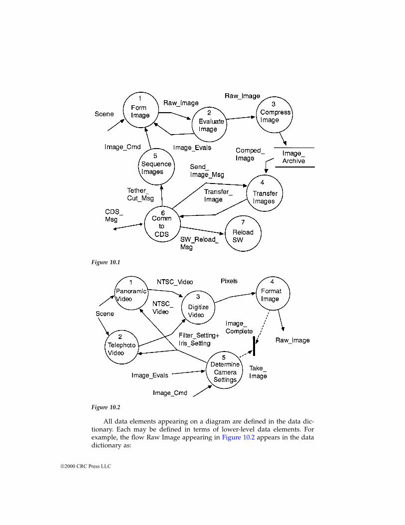
All data elements appearing on a diagram are defined in the data dic-tionary. Each may be defined in terms of lower-level data elements. Forexample, the flow Raw Image appearing in Figure 10.2 appears in the datadictionary as:
Figure 10.1
Figure 10.2
2000 CRC Press LLC
Raw Image = 768{484{Pixel}}
Indicating, in this case, that Raw Image is composed of 768 × 484 repe-titions of the element Pixel. At early stages, Pixel is defined qualitatively asa range of luminance values. In later design stages the definition will beaugmented, though not replaced, by a definition in terms of implementation-specific data elements.
In addition to the two behavior models, the H/P method contains anAM. The AM is the model of form that defines the physical implementation.It is hierarchical and it allows sequential definition in greater detail byexpansion of modules. Figure 10.3 shows the paired architecture flow andinterconnect models for the microsatellite imaging system.
The H/P block diagram syntax partitions a system into modules, whichare defined as physically identifiable implementation elements. The flowdiagram shows the exchange of data elements among the modules. Whichdata elements are exchanged among the modules is defined by the allocationof behavioral model processes to the modules.
The interconnection model defines the physical channels through whichthe data elements flow. Each interconnect is further defined in a separatespecification. For example, the interconnect T-Puter Channel 1 connects theprocessor module and the camera control module. Allocation requires cam-era commands to flow over the channel. Augmentations to the data dictio-nary define a mapping between the logical camera commands and the linecodes of the channel. If the channel requires message framing, protocolprocessing, or the like, it is defined in the interconnection specification.Again, the level of detail provided can vary during design based on theinterface’s impact on risk and feasibility.
Quantitative QFD (Q2FD) — performance-driven systems
Many systems are driven by quantitatively stated performance objectives.These systems may also contain complex behavior or other attributes, buttheir performance objectives are of most importance to the client. For thesesystems it is common practice to take a performance-centered approach tosystem specification, decomposition, and synthesis. A particularly attractiveway of organizing decomposition is through extended Quality FunctionDeployment (QFD) matrices.2
QFD is a Japanese-originated method for visually organizing the decom-position of customer objectives.3 It builds a graphical hierarchy of howcustomer objectives are addressed throughout a system design, and it carriesthe relevance of customer objectives throughout design. A Q2FD-basedapproach requires that the architect:
1. Identify a set of performance objectives of interest to the customer.Determine appropriate values or ranges for meeting these objectivesthrough competitive analysis.
2000 CRC Press LLC
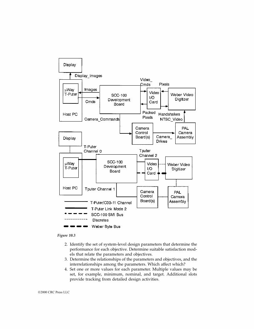
2. Identify the set of system-level design parameters that determine theperformance for each objective. Determine suitable satisfaction mod-els that relate the parameters and objectives.
3. Determine the relationships of the parameters and objectives, and theinterrelationships among the parameters. Which affect which?
4. Set one or more values for each parameter. Multiple values may beset, for example, minimum, nominal, and target. Additional slotsprovide tracking from detailed design activities.
Figure 10.3
2000 CRC Press LLC
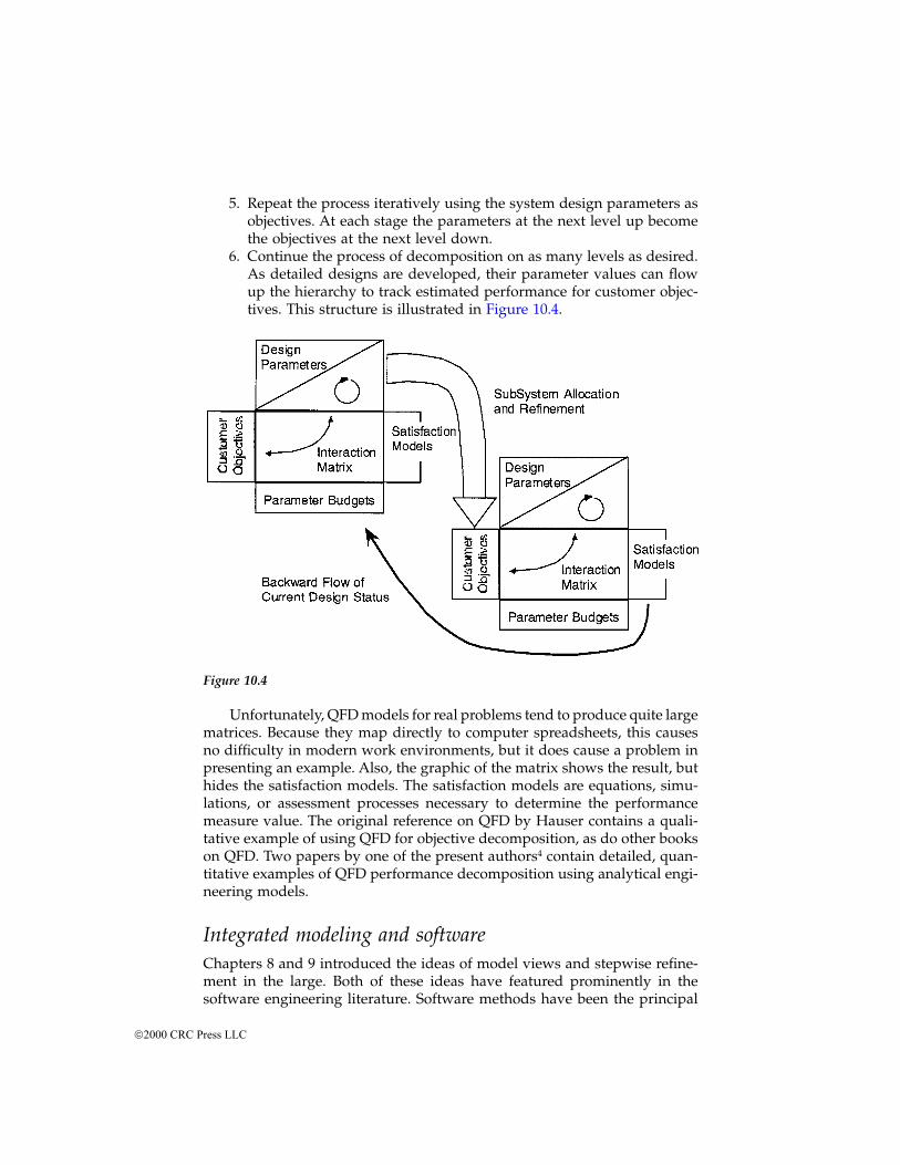
5. Repeat the process iteratively using the system design parameters asobjectives. At each stage the parameters at the next level up becomethe objectives at the next level down.
6. Continue the process of decomposition on as many levels as desired.As detailed designs are developed, their parameter values can flowup the hierarchy to track estimated performance for customer objec-tives. This structure is illustrated in Figure 10.4.
Unfortunately, QFD models for real problems tend to produce quite largematrices. Because they map directly to computer spreadsheets, this causesno difficulty in modern work environments, but it does cause a problem inpresenting an example. Also, the graphic of the matrix shows the result, buthides the satisfaction models. The satisfaction models are equations, simu-lations, or assessment processes necessary to determine the performancemeasure value. The original reference on QFD by Hauser contains a quali-tative example of using QFD for objective decomposition, as do other bookson QFD. Two papers by one of the present authors4 contain detailed, quan-titative examples of QFD performance decomposition using analytical engi-neering models.
Integrated modeling and softwareChapters 8 and 9 introduced the ideas of model views and stepwise refine-ment in the large. Both of these ideas have featured prominently in thesoftware engineering literature. Software methods have been the principal
Figure 10.4
2000 CRC Press LLC

sources for detailed methods for expressing multiple views and developmentthrough refinement. Software engineers have developed several integratedmodeling and development methodologies that integrate across views andemploy explicit heuristics. Three of those methods are described in detail:structured analysis and design, ADARTS, and OMT. We also take up thecurrent direction in an integrated language for software-centric systems, theUML.
The three methods are targeted at different kinds of software systems.Structured analysis and design was developed in the late 1970s and early1980s and is intended for single-threaded software systems written in struc-tured procedural languages. ADARTS is intended for large, real-time, multi-threaded systems written in Ada. Its methods do generalize to other envi-ronments. OMT is intended for database-intensive systems, especially thosewritten in object-oriented programming languages. The UML is a merger ofobject-oriented concepts from OMT and other sources.
Structured analysis and design
The first of the integrated models for software was the combination ofstructured analysis with structured design.5 The software modeling anddesign paradigms established in that book have continued to the present asone of the fundamental approaches to software development. Structuredanalysis and design models two system views, uses a variety of heuristicsto form each view, and connects to the management view through measur-able characteristics of the analysis and design models (metrics).
The method prescribes development in three basic steps. Each step isquite complex and is composed of many internal steps of refinement. Thefirst step is to prepare a data flow decomposition of the system to be built.The second step is to transform that data flow decomposition into a functionand module hierarchy that fully defines the structure of the software insubroutines and their interaction. The design hierarchy is then coded in theprogramming language of choice. The design hierarchy can be mechanicallyconverted to software code (several tools do automatic forward and back-ward conversion of structured design diagrams and code). The internals ofeach routine are coded from the included process specifications, though thisrequires human effort.
The first step, known as structured analysis, is to prepare a data flowdecomposition of the system to be built. A data flow decomposition is a treehierarchy of data flow diagrams, textual specifications for the leaf nodes ofthe hierarchy, and an associated data dictionary. This method was first pop-ularized by DeMarco,6 though the ideas had appeared previously, and it hassince been extensively modified and re-presented. Figures 10.1 and 10.2,discussed in the previous example, show data flow diagrams. Behavioralanalysis by data flow diagram originated in software and has since beenapplied to more general systems. The basic tenets of structured analysis are:
2000 CRC Press LLC
1. Show the structure of the problem graphically, engaging the mind’sability to perceive structure and relationships in graphics.
2. Limit the scope of information presented in any diagram to five tonine processes and their associated data flows.
3. Use short (<1 page) free-form and textual specifications at the leafnodes to express detailed processing requirements.
4. Structure the models so each piece of information is defined in oneand only one place. This eases maintenance.
5. Build models in which the processes are loosely coupled, stronglycohesive, and obey a defined syntax for balance and correctness.
Structured design follows structured analysis and transforms a struc-tured analysis model into the framework for a software implementation. Thebasic structured design model is the structure chart. A structure chart, oneis illustrated in Figure 10.5, shows a tree hierarchy of software routines. Thearrows connecting boxes indicate the invocation of one routine or subroutineby another. The circles, arrows, and names show the exchange of variablesand are known as data couples. Additional symbols are available for patho-logical connection among routines, such as unconditional jumps. Each boxon the structure chart is linked to a textual specification of the requirementsfor that routine. The data couples are linked to a data dictionary.
Structure charts are closely aligned with the ideas and methods of struc-tured programming, which was a major innovation at the time structureddesign was introduced. Structure charts can be mechanically converted tonested subroutines in languages that support the structured programmingconcepts. In combination, the chart structure, the interfaces shown on thechart, and the linked module specifications define a compilable shell for theprogram and an extended set of code comments. If the module specificationsare written formally, they can be the module’s program design language, orthey can be compiled as module pre- and postcondition assertions.
The structured analysis and design method goes farther in providingdetailed heuristics for transformation of an analysis model into a structurechart, and for evaluation of alternative designs. The heuristics are stronglyprescriptive in the sense that they are stated procedurally. However, theyare still heuristics because their guidance is provisional and subject to inter-pretation in the overall context of the problem. The transformation is a typeof refinement or reduction of abstraction. The data flow network of theanalysis phase defines data exchange, but it does not define execution orderbeyond that implied by the data flow. Hence the structure chart removes theabstraction of flow of control by fixing the invocation hierarchy. The heuris-tics provided are of two types. One type gives guidelines for transforminga data flow model fragment into a module hierarchy. The other type mea-sures comparative design quality to assist in selection among alternativedesigns. Examples of the first type include:
2000 CRC Press LLC
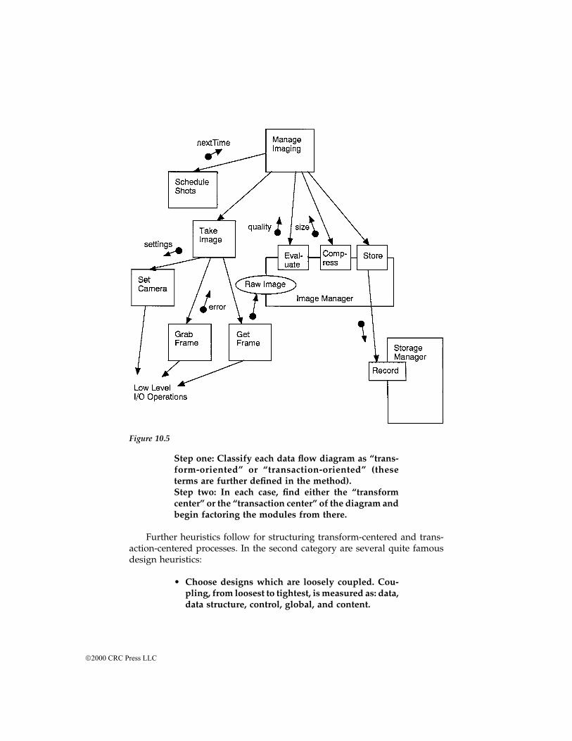
Step one: Classify each data flow diagram as “trans-form-oriented” or “transaction-oriented” (theseterms are further defined in the method).Step two: In each case, find either the “transformcenter” or the “transaction center” of the diagram andbegin factoring the modules from there.
Further heuristics follow for structuring transform-centered and trans-action-centered processes. In the second category are several quite famousdesign heuristics:
• Choose designs which are loosely coupled. Cou-pling, from loosest to tightest, is measured as: data,data structure, control, global, and content.
Figure 10.5
2000 CRC Press LLC
• Choose designs in which the modules are stronglycohesive. Cohesion is rated as (from strongest toweakest): functional, sequential, communication-al, procedural, temporal, logical, and coincidental.
• Choose modules with high fan-in and low fan-out.
As discussed in Chapter 9, very general and domain-specific heuristicsmay be related by chains of refinement. In structured analysis and design,the software designer transforms rough ideas into data flow diagrams, dataflow diagrams into structure charts, and structure charts into code. At thesame time, heuristic guidelines like “strive for loose coupling” are givenmeasurable form as the design is refined into specific programming con-structs.
Various efforts have also been made to tie structured analysis and designto managerial models by predicting cost, effort, and quality from measurableattributes of data flow diagrams or structure charts. This is done both directlyand indirectly. A direct approach computes a system complexity metric fromthe data flow diagrams or the structure charts. That complexity metric thenmust be correlated to effort, cost, schedule, or other quantities of manage-ment interest. A later work by DeMarco7 describes a detailed approach onthese lines, but the suggested metrics have not become popular nor havethey been widely validated on significant projects. Other metrics, such asfunction or feature points, that are more loosely related to structured analysisdecompositions have found some popularity. Software metrics is an ongoingresearch area, and there is a growing body of literature on measurementsthat appear to correlate well with project performance.
An alternative linkage is indirect by using the analysis and design mod-els to guide estimates of the most widely accepted metrics, the constructivecost model (COCOMO) and effective lines of code (ELOC). COCOMO isBarry Boehm’s famous effort estimation formula. The model predicts devel-opment effort from a formula involving the total lines of code, an exponentdependent on the project type, and various weighting factors. One problemwith the original COCOMO model is that it does not differentiate betweennewly written lines of code and reused code. One method (there are others)of extending the COCOMO model is to use ELOC in place of total lines ofcode. ELOC measures the size of a software project, giving allowance formodified and reused code. A new line of code counts for one ELOC, modifiedand unmodified reused code packages count for somewhat less. The weightfactors given to each are typically determined organization-by-organizationbased on past measurements. The counts by subtype are summed with theirweights and the total treated as new lines in the COCOMO model.
The alternative approach is to use the models to guide ELOC estimation.Early in the process, when no code has been written, the main source oferror in COCOMO is likely to be errors in the ELOC estimate. With a dataflow model in hand, engineers and managers can go through it process-by-process and compare the requirements to past efforts by the organization.
2000 CRC Press LLC
This, at least, structures the estimation problem into identifiable pieces.Similarly, the structured design model can be used in the same way, withestimates of the ELOC for each module flowing upward into a system-levelestimate. As code is written the estimates become facts and, hopefully, theestimated and actual efforts will converge. Of course, if the organization isincapable of producing a given ELOC level predictably, then any linkage ofanalysis and design models to managerial models is moot.
The architect needs to be cognizant of these issues insofar as they affectjudgments of feasibility. As the architect develops models of the system, theyshould be used jointly by client and builder. The primary importance of costmodels is in the effect they have on the client’s willingness to go forwardwith a project. A client’s resources are always limited, and an intelligentdecision on system construction can be made only with knowledge of theresources it will consume. Of course, there will be risk, and in immaturefields like software the use of risk mitigation techniques (such as spiraldevelopment) may partially replace accurate early estimates. Both the client’svalue judgments and the builder’s estimates should be made in the contextof the models. If builder organizations have a lot of variance in what effortis required to deliver a fixed complexity system, then that variance is a riskto the client.
ADARTS
Ada-based Design Approach for Real-Time Systems (ADARTS) is an exten-sively documented example of a more advanced integrated modelingmethod for software. The original work on data flow techniques was directlytied to the advanced implementation paradigms of the day. In a similar way,the discrete event, system-oriented specification methods like H/P can beclosely tied to implementation models. In the case of real-time, event-drivensoftware, one of the most extensive methods is the ADARTS8 methodologyof the Software Productivity Consortium. The ADARTS method combines adiscrete event-based behavioral model with a detailed, stepwise refined,physical design model. The behavioral model is based on data flow diagramsextended with the discrete event formalisms of Ward and Mellor9 (which aresimilar to those of H/P). The physical model includes evolving abstractionsfor software tasks or threads, objects, routines, and interfaces. It also includesprovisions for software distributed across separate machines and their com-munication. ADARTS includes a catalog of heuristics for choosing and refin-ing the physical structure through several levels of abstraction.
ADARTS links the behavioral and physical models through allocationtables. Performance decomposition and modeling is considered specifically,but only in the context of timing. There are links to sophisticated schedulingformalisms and SPC-developed simulation methodologies as part of thisperformance link. Again, managerial views are supported through metricswhere they can be calculated from the models. Software domain-specificmethods can more easily perform the management metric integration since
2000 CRC Press LLC
a variety of cost and quality metrics that can be (at least roughly) calculatedfrom software design models are known.
The example shown is a simplified version of the first two design refine-ments required by ADARTS applied to the microsatellite imaging systemoriginally discussed in the Hatley/Pirbhai example. The resulting diagramsare shown in Figure 10.6. The ADARTS process takes the functional hierarchyof the behavioral model and breaks it into undifferentiated components. Eachcomponent is shown on the diagram by a cloud-shaped symbol, indicatingits specific implementation structure has not yet been decided. The cloudsexchange data elements dependent on the behavior allocated to each cloud.Various heuristics and engineering judgment guide the choice of clouds.
The next refinement specializes the clouds to tasks, modules or objects,and routines. ADARTS actually uses several discrete steps for this, but theyare combined into one for the simple example given here. Again, the designeruses ADARTS-provided heuristics and individual judgment in making therefinements. In the example, the two tasks result from the need to provideasynchronous external communications and overall system control. Theclouds which hide the physical and logical interfaces to hardware are multi-entry modules. The entries are chosen from the principal user functionsaddressed by the interface. For example, the Camera I/O module has entriesthat correspond to its controls (camera shutter speed, camera gain, filterwheel position, etc.). The single-thread sequence of taking an image is imple-mented as a simple routine-calling tree.
To avoid diagram clutter the diagram is not fully annotated with thedata elements and their flow directions. In complex systems diagram clutteris a serious problem, and one not well addressed by existing tools. Thearchitect needs to suppress some detail to process the larger picture. Butcorrect software ultimately depends on getting each detail right. In thesecond part of the figure the arrowed lines indicate direction of control, notdirection of data flow. Additional enhancements specify flow. The next stepin the ADARTS process, not shown here, is to refine the task and moduledefinitions once again into language- and system-specific software units.ADARTS as published assumes the use of the Ada language for implemen-tation. When implementing in the Ada language, tasks become Ada tasksand multientry modules become packages. The public/private interfacestructure of the modules is implemented directly using constructs of the Adalanguage. Other languages can be accommodated in the same frameworkby working out language- and operation-specific constructs equivalent totasks, modules, and routines. For example, in the C language there is nolanguage construct for tasks or multientry modules. But multientry modulescan be implemented in a nearly standard way using separately compilablefiles on the development system, the static declaration, and suitable headerfiles. Similarly, many implementation environments support multitasking,and some development environments supply task abstractions for the pro-grammer’s use.
2000 CRC Press LLC
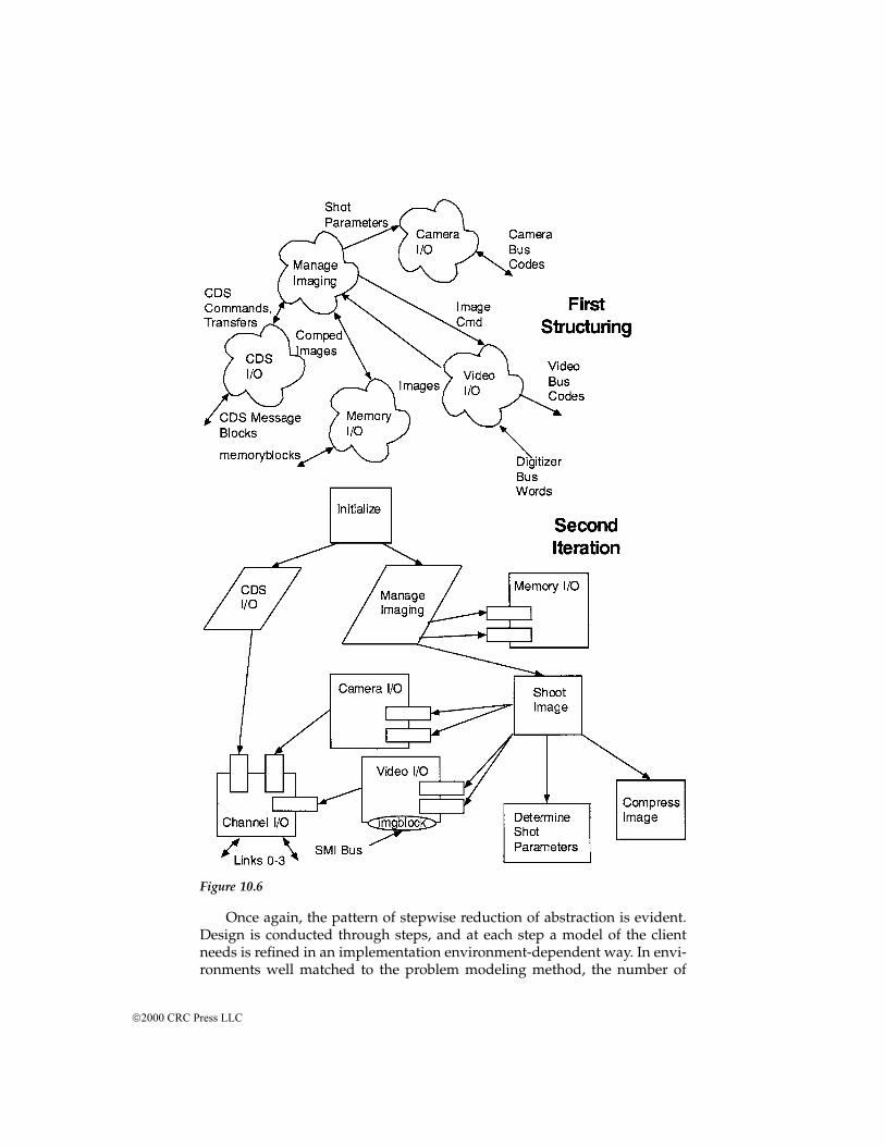
Once again, the pattern of stepwise reduction of abstraction is evident.Design is conducted through steps, and at each step a model of the clientneeds is refined in an implementation environment-dependent way. In envi-ronments well matched to the problem modeling method, the number of
Figure 10.6
2000 CRC Press LLC
steps is small; client-relevant models can be nearly directly implemented. Inless well-suited environments layers of implementation abstraction becomenecessary.
OMT
The Hatley/Pirbhai method and its cousins are derived from structuredfunctional decomposition, structured software design, and hardware systemengineering practice. The object-oriented methods, of which OMT10 is aleading member, derive from data-oriented and relational database softwaredesign practice. Relational modeling methods focus solely on data structureand content and are largely restricted to database design (where they arevery powerful). Object-oriented methods package data and functionaldecomposition together. Where structured methods build a functionaldecomposition backbone on which they attempt to integrate a data decom-position, the object-oriented methods emphasize a data decomposition onwhich the functional decomposition is arranged. Some problems naturallydecompose nicely in one method and not in the other. Complex systems canbe decomposed with either, but either approach will yield subsections wherethe dominant decomposition paradigm is awkward.
OMT combines the data (relational), behavioral, and physical views. Thephysical view is well captured for software-only systems, but specificabstractions are not given for hardware components. While, in principle,OMT and other object-oriented methods can be extended to mixed hard-ware/software systems, and even more general systems, there is a lack ofreal examples to demonstrate feasibility. Broad, real experience has beenobtained only for predominantly software-based systems.
Neither the OMT nor other object-oriented methods substantially inte-grate the performance view. Again, managerial views can be integrated tothe extent that useful management metrics can be derived from the objectmodels. Because of the software orientation of object-oriented methods, therehave been some efforts to integrate formal methods into object models.
As an example of the key ideas of object-oriented methods we presentpart of an object model. Object modeling starts by identifying classes. Classescan be thought of (for those unfamiliar with object concepts) as templatesfor objects or types for abstract data types. They define the object in termsof associated simple data items and functions associated with the object.Classes can specialize into subclasses which share the behavior and data oftheir parent while adding new attributes and behavior. Objects may becomposed of complex elements or relate to other objects. Both compositionor aggregation and association are part of a class system definition. Themicrosatellite imager described in the preceding section will produce imagesof various types. Consider an image database for storing the data producedby the imager. A basic class diagram is shown in Figure 10.7 to illustratespecific instances of some of the concepts.
2000 CRC Press LLC
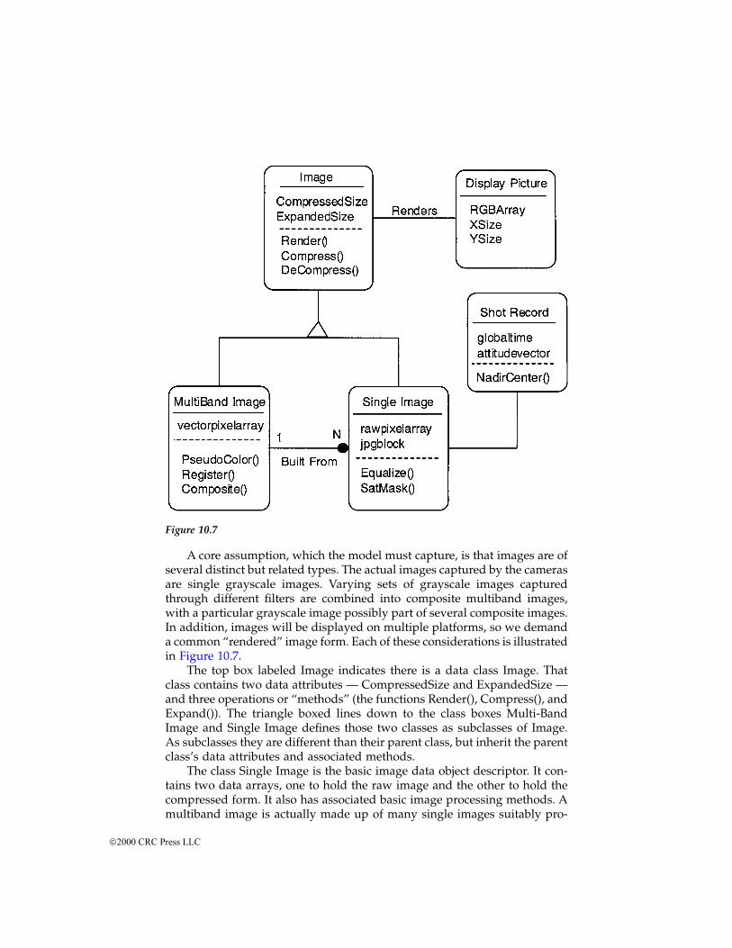
A core assumption, which the model must capture, is that images are ofseveral distinct but related types. The actual images captured by the camerasare single grayscale images. Varying sets of grayscale images capturedthrough different filters are combined into composite multiband images,with a particular grayscale image possibly part of several composite images.In addition, images will be displayed on multiple platforms, so we demanda common “rendered” image form. Each of these considerations is illustratedin Figure 10.7.
The top box labeled Image indicates there is a data class Image. Thatclass contains two data attributes — CompressedSize and ExpandedSize —and three operations or “methods” (the functions Render(), Compress(), andExpand()). The triangle boxed lines down to the class boxes Multi-BandImage and Single Image defines those two classes as subclasses of Image.As subclasses they are different than their parent class, but inherit the parentclass’s data attributes and associated methods.
The class Single Image is the basic image data object descriptor. It con-tains two data arrays, one to hold the raw image and the other to hold thecompressed form. It also has associated basic image processing methods. Amultiband image is actually made up of many single images suitably pro-
Figure 10.7
2000 CRC Press LLC
cessed and composited. This is defined on the diagram by the round-headedline connecting the two class boxes. The labeling defines a 1 to N wayassociation named Built From. The additional methods associated withMulti-Band Image build the image from its associated simple images.
The two additional associations define other record keeping and display.The associated line between Single Image and Shot Record associates animage with a potentially complicated data record of when it was taken andthe conditions at that moment. The association line to Display Picture showsthe association of an image with a common display data structure. Bothassociations, in these cases, are one-to-one.
Figure 10.7 is considerably simplified on several points. A completedefinition in OMT would require various enhancements to show actual typesassociated with data attributes and operations. In addition, several enhance-ments are required to distinguish abstract methods and derived attributes.A brief explanation of the former is in order. Consider the method Compressin the class Image. The implementation of image compression may be quitedifferent for a single grayscale image and for a composited multiband image.A method that is reimplemented in subclasses is called either virtual orabstracted and may be noted by a diagrammatic enhancement.
The logic of object-oriented methods is to decompose the system in adata-first fashion, with functions and data tightly bound together in classes.Instead of a functional decomposition hierarchy we have a class hierarchy.Functional definition is deferred to the detailed definition of the classes. Theobject-oriented logic works well where data, and especially data relationcomplexity, dominates the system.
Object-oriented methods also follow a stepwise reduction of abstractionapproach to design. From the basic class model, we next add implementa-tion-specific considerations. These will determine whether or not additionalmodel refinements or enhancements are required. If the implementationenvironment is strongly object-oriented there will be direct implementationsfor all of the model constructs. For example, in an object-oriented databasesystem one can declare a class with attributes and methods directly and havelong-term storage (or “persistence”) automatically managed. In non-objectenvironments it may be necessary to manually flatten class hierarchies andadd manual implementations of the model features. Manual adjustmentscan be captured in an intermediate model of similar type. The steps ofabstraction reduction depend on the environment. In a favorable implemen-tation environment the model nearest to the client’s domain can be imple-mented almost directly. In unfavorable environments we have no choice butto add additional layers of refinement.
UML
As object-oriented methods became popular in the 1990s, there emergedseveral distinctive styles of notation. These notations differed enough tomake tools incompatible and automated translation difficult; but the nota-
2000 CRC Press LLC
tions did not capture fundamentally different concepts. The basic conceptsof class, object, and relationship were present in all of them, with only slightnotational differences. The differences were more in the additional viewsand how the parts were integrated. They also differed somewhat more fun-damentally in their approach to the design process and which portions theychose to emphasize. For example, some of the object-oriented methodsemphasized front-end problem analysis through use-cases. Others weremore design oriented and focused on building information models afterthere was a well-understood problem statement.
Because the profusion of notations was not helpful to the community,there was some pressure to settle on a collective standard. This was donepartially through several of the leading “gurus” of the different methods, allmoving to work for one company (the Rational Corporation). The productof their collaboration, and a large standards effort, is the Unified ModelingLanguage11 (UML). Because UML has successfully incorporated most of thebest features of its roots, and has gained a fairly broad industry consensus,it is increasingly popular. Probably the most significant complaint about theUML is its complexity. It is certainly true that if you tried to model a systemusing all the parts of the UML the resulting model would be quite complex.But the content of the UML should not be confused with a process. Adesigner is no more compelled to use all the parts of the UML than is awriter compelled to use all the words in the English language. Of course, itisn’t simple to figure out which parts should be used in any given situation,and it can take fairly deep knowledge of the UML to know how to ignorefeatures.
The primary importance of UML is that it may lead to more broadlyaccepted standardization of software and systems engineering notations. Thenotations are fundamentally software-centric, but as the software fraction(measured as percentage of development effort) makes up the majority of adevelopment effort, this will seem appropriate. The two viewpoints withinUML, use-cases and class-object models, most commonly discussed are thetwo that are the most software-centric. There are several other views thatare more clearly systems oriented.
The use-case view within UML has two parts, the textual use-cases anddiagrams that show the relationships among use-cases and actors. The tex-tual form of a use-case is not strictly defined. In general it is a narrativelisting of messages that pass between an “actor,” a system stakeholder, andthe system. Thus a use-case, in its pure form, follows the definition of thesystems boundary. The use-case diagram shows the relationships betweenactors and use-cases, including linkages among use-cases.
A simple form for a textual use-case has four required parts and a groupof optional parts.* They are
* There are many different formats for use-cases in use. The forms described here are inspiredby various UML documents, and Dr. Kevin Kreitman in private communication.
2000 CRC Press LLC
1. Title (preferably evocative)2. Actors — A list3. Purpose — What the actors accomplish through this use-case, why
the actors use the system4. Dialog — A step-by-step sequence of messages exchanged across the
actor-system boundary. The use-case gives the normal sequence, al-ternative sequences (from errors or other choices) can be integratedinto the use-case, given as different use-cases, or organized into theoptional section
5. Optional material — Some useful adjuncts include type (such as es-sential, optional, phase X, etc.), an overview for a very complex use-case, and alternative paths
UML uses class-object models very similar to those described in the OMTsection. The differences are primarily details of notation, such as the graphicelement used to indicate a particular type of relationship. There is also afairly complex set of textual notations for showing the components of theclasses (data and methods). For example, there are textual indications forpublic, private, and virtual elements. The discussion of class-object notationsin the OMT section gives the flavor of how a model of the same sort wouldwork if written in UML.
UML does introduce some modeling elements not discussed to this pointand of high interest to system architects. On the behavioral side, the UMLdefines sequence diagrams. A sequence diagram depicts both the pattern ofmessage-passing among the system’s objects, and the timing relationships.The sequence diagram is useful both for specification and for diagnosis.When the client has a complex legacy system with which the new systemmust interface, or when the client’s problems are primarily expressed interms of deficiencies in a current system, the sequence diagram is a methodfor visually presenting time relationships. This is often quite important inreal-time software-intensive systems.
Another avenue for standardization in which UML might assist is inphysical block diagrams. UML defines “deployment diagrams” to show howsoftware objects relate to physical computing nodes. The diagram style forthe nodes and their links could be enhanced suitably (as discussed withmodels of form) to handle systems-level concerns. This is a possible refine-ment in the next major revision to the UML, designated UML 2.0.
Performance integration: scheduling
One area of nonfunctional performance that is very important to software,and for which there is large body of science, is timing and scheduling. Real-time systems must perform their behaviors within a specified timeline. Abso-lute deadlines produce “hard real-time systems.” More flexible deadlinesproduce “soft real-time systems.” The question of whether or not a given
2000 CRC Press LLC
software design will meet a set of deadlines has been extensively studied.*To integrate these timing considerations with the design requires integrationof scheduling and scheduling analysis.
In spite of the extensive study, scheduling design is still at least partlyart. Theoretical results yield scheduling and performance bounds and asso-ciated scheduling rules, but they can do so only for relatively simple systems.When system functions execute interchangeably on parallel processors,when run times are random, and when events requiring reaction occurrandomly, there are no deducible, provably optimal solutions. Some measureof insight and heuristic guidance is needed to make the system both efficientand robust.
Integrated models for manufacturing systemsThe domain of manufacturing systems contains nice examples of integratedmodels. The modeling method of Baudin12 integrates four modeling compo-nents (data flow, data structure, physical manufacturing flow, and cash flow)into an interconnected model of the manufacturing process. Baudin furthershows how this model can then be used to analyze production schedulingunder different algorithms. The four parts of the core model are:
1. A data flow model using the notations of DeMarco and state transitionmodels
2. A data model based on entity-relationship diagrams3. A material flow model of the actual production process, the model of
physical form, using ASME and Japanese notations4. A funds flow model
These parts, which mostly use the same component models familiar fromthe previous discussion, form an integrated architect’s tool kit for the man-ufacturing domain. They are shown in Figure 10.8. The data flow modelsare in the same fashion as the requirements model of Hatley/Pirbhai. Thedata model is more complex and uses basic object-oriented concepts. In thematerial flow model, the progression of removal of abstraction is taken to alogical conclusion. Because the physical architecture of manufacturing sys-tems is restricted, the architecture model components are similarly restricted.Baudin incorporates, in fact exploits, the restricted physical structure ofmanufacturing systems by using a standardized notation for the physical orform model.
Baudin further integrates domain-specific performance and systemmodels by considering the relationship to production planning in its severalforms (MRP-II, OPT, JIT). As he shows, these formalisms can be usefully
* Stankovic, J. A., Spuri, M., Di Natale, M., and Buttazzo, G. C., Implications of classicalscheduling results for real-time systems, IEEE Computer, p. 16, June 1995. This provides a goodtutorial introduction to the basic results and a guide to the literature.
2000 CRC Press LLC
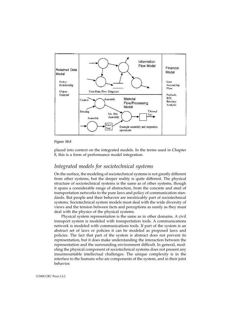
placed into context on the integrated models. In the terms used in Chapter8, this is a form of performance model integration.
Integrated models for sociotechnical systemsOn the surface, the modeling of sociotechnical systems is not greatly differentfrom other systems, but the deeper reality is quite different. The physicalstructure of sociotechnical systems is the same as of other systems, thoughit spans a considerable range of abstraction, from the concrete and steel oftransportation networks to the pure laws and policy of communication stan-dards. But people and their behavior are inextricably part of sociotechnicalsystems. Sociotechnical system models must deal with the wide diversity ofviews and the tension between facts and perceptions as surely as they mustdeal with the physics of the physical systems.
Physical system representation is the same as in other domains. A civiltransport system is modeled with transportation tools. A communicationsnetwork is modeled with communications tools. If part of the system is anabstract set of laws or policies it can be modeled as proposed laws andpolicies. The fact that part of the system is abstract does not prevent itsrepresentation, but it does make understanding the interaction between therepresentation and the surrounding environment difficult. In general, mod-eling the physical component of sociotechnical systems does not present anyinsurmountable intellectual challenges. The unique complexity is in theinterface to the humans who are components of the system, and in their jointbehavior.
Figure 10.8
2000 CRC Press LLC
In purely technical systems the environment and the system interact,but it is uncommon to ascribe intelligent, much less purposively hostile,behavior to their environments.* But human systems constantly adapt. If anintelligent transport system unclogs highways, people may move fartheraway from work and re-clog the highways until a new equilibrium isreached. A complete model of sociotechnical system behavior must includethe joint modeling of system and user behavior, including adaptive behavioron the part of the users.
This joint behavioral modeling is one area where modeling tools arelacking. The tools that are available fall into a few categories: econometrics,experimental microeconomics and equilibrium theory, law and economics,and general system dynamics. Other social science fields also provide guid-ance, but not generally descriptive and predictive behavior.
Econometrics provides models of large-scale economic activity asderived from past behavior. It is statistically based and usually operates bytrying to discover models in these data rather than imposing models onthem. In contrast, general system dynamics** builds dynamic models ofsocial behavior by analysis of what linkages should be present and then teststheir aggregated models against history. System dynamics attempts to findlarge-scale behavioral patterns that are robust to the quantitative details ofthe model internals. Econometrics tries to make better quantitative predic-tions without having an avenue to abstract larger-scale structural behavior.
Experimental economics and equilibrium theory try to discover andmanipulate a population's behavior in markets through use of microeco-nomic theory. As a real example, groups have applied these methods topricing strategies for pollution licenses. Instead of setting pollution regula-tions, economists have argued that licenses to pollute should be auctioned.This would provide control over the allowed pollution level (by the numberof licenses issued) and be economically efficient. This strategy has beenimplemented in some markets and the strategies for conducting the auctionswere tested by experimental groups beforehand. The object is to produce anauction system that results in stable equilibrium price for the licenses.
Law and economics is a branch of legal studies that applies micro- andmacroeconomic principles to the analysis of legal and policy issues. Itendeavors to assure economic efficiency in policies, and to find least coststrategies to fulfill political goals. Although the concepts have gained fairlywide acceptance, they are inherently limited to those policy areas wheremarket distribution is considered politically acceptable.
* See Rechtin, E., Systems Architecting, Creating & Building Complex Systems, Prentice-Hall, En-glewood Cliffs, NJ, 1991, chap. 9.** An introductory reference on system dynamics is Wolstenholme, E. F., System Enquiry: ASystem Dynamics Approach, Wiley, Chichester, 1990, which explains the rationale, gives examplesof application, and references the more detailed writings.
2000 CRC Press LLC
ConclusionsA variety of powerful integrated modeling methods already exist in largedomains. These methods exhibit, more or less explicitly, the progressions ofrefinement and evaluation noted as the organizing principle of architecting.In some domains, such as software, the models are very well organized,cover a wide range of development projects, and include a full set of views.However, even in these domains the models are not in very wide use andhave less than complete support from computer tools. In some domains,such as sociotechnical systems, the models are much more abstract anduncertain. But in these domains the abstraction of the models matches therelative abstraction of the problems (purposes) and the systems built to fulfillthe purposes.
Exercises
1. For a system familiar to you, investigate the models commonly usedto architecturally define such systems. Do these models cover allimportant views? How are the models integrated? Is it possible totrace the interaction of issues from one model to another?
2. Build an integrated model of a system familiar to you, covering atleast three views. If the models in any view seem unsatisfactory, orintegration is lacking, investigate other models for those views to seeif they could be usefully applied.
3. Choose an implementation technology extensively used in a systemfamiliar to you (software, board-level digital electronics, microwaves,or any other). What models are used to specify a system to be built?That is, what are the equivalents of buildable blueprints in this tech-nology? What issues would be involved in scaling those models upone level of abstraction so they could be used to specify the systembefore implementation design?
4. What models are used to specify systems (again, familiar to you) toimplementation designers? What transformations must be made onthose models to specify an implementation? How can the two levelsbe better integrated?
Notes and references1. White, S. et. al., Systems engineering of computer-based systems, IEEE Com-
puter, p. 54, November 1993.2. Maier, M. W., Quantitative engineering analysis with QFD, Quality Eng., 7(4),
733, 1995.3. Hauser, J. R. and Clausing, D., The house of quality, Harvard Bus. Rev., 66(3),
63, May-June 1988.4. The abovementioned 1995, as well as Maier, M. W., Integrated modeling: a
unified approach to system engineering, J. Syst. Software, February 1996.
2000 CRC Press LLC

5. Yourdon, E. and Constantine, L. L., Structured Design: Fundamentals of a Dis-cipline of Computer Program and Systems Design, Yourdon Press, EnglewoodCliffs, NJ, 1979.
6. DeMarco, T., Structured Analysis and System Specification, Yourdon Press, En-glewood Cliffs, NJ, 1979.
7. DeMarco, T., Controlling Software Projects, Yourdon Press, Englewood Cliffs,NJ, 1982.
8. ADARTS Guidebook, SPC-94040-CMC, Version 2.00.13, Vols. 1-2, September,1991. Available through the Software Productivity Consortium, Herndon, VA.
9. Ward, P. T. and Mellor, S. J., Structured Development for Real-Time Systems, Vol.1-3, Yourdon Press, Englewood Cliffs, NJ, 1985.
10. Rumbaugh, J. et. al., Object-Oriented Modeling and Design, Prentice-Hall, En-glewood Cliffs, NJ, 1991.
11. There is a great deal of published material on UML. The Rational CorporationWeb site (http://www.rational.com/) has online copies of the basic languageguides, including the language reference and user guides.
12. Baudin, M., Manufacturing Systems Analysis, Yourdon Press Computing Series,Englewood Cliffs, NJ, 1990.
2000 CRC Press LLC
chapter eleven
Architecture frameworks
IntroductionArchitecture has become a popular term in systems and software circles.There are now many “Architecture Frameworks,” “Architecture ProcessModels,” and the like to be found in government and corporate documents.The purpose of this book is not to provide a comprehensive tour of all ofthese approaches. Any such tour would be out of date the day after it waswritten, and most of it would be of little interest to most readers. Neverthe-less, some review of community approaches is essential, especially thosewhich have advanced to official standards. The practices advocated by thesestandards, for good or ill, have to be recognized. And we, the authors of thisbook, need to compare and contrast the approach here with what is in thestandards.
The standards that concern architecture, and that have advanced toofficial status, are primarily architecture description standards. These areoften referred to as Architecture Frameworks. Architecture frameworks arestandards for the description of architectures. Architecture frameworks areanalogous to blueprint standards or, more loosely, building codes. The anal-ogy to building codes is very loose as much of what building codes define,specific physical forms, is not what most architecture frameworks define. Aframework defines what products the architect must deliver (to the client orto some other agency with authority) and how those products must beconstructed. The framework generally does not constrain the contents of anyof those products, although such constraints could be incorporated.
Architecture frameworks serve much the same purposes as blueprintstandards, although their developers have had additional purposes in mindas well. It is hoped these standards will improve the quality of architectingefforts by institutionalizing best practices and fostering communicationabout architectures through standardizing languages. Standardized architec-tural description languages may also facilitate architecture evaluation bystandardizing the elements that must be considered in the evaluation.
2000 CRC Press LLC
Defining an architecture frameworkTo evaluate an architecture description framework we need to understandits goals, its definition of “architectural level” (as opposed to other designlevels), and its organizing concepts. We treat each of these in turn, althoughthe description concepts (viewpoints and views) have largely been discussedpreviously in Chapter 8, and are discussed in more detail in Appendix C.
Goals of the framework
Each group developing and promulgating a standard has asserted differentgoals, but they generally fall into a few, common categories.
1. Codify best practices for architectural description and, by so doing,improve the state of the practice
2. Ensure that the sponsors of the framework receive architectural in-formation in the format they desire
3. Facilitate comparative evaluation of architectures through standard-ization of their means of description
4. Improve the productivity of development teams by presenting basicdesigns in a standard way
5. Improve interoperability of information systems by requiring thatinteroperation critical elements be described, and be described in acommon way
The fairest way of evaluating different frameworks is against their owngoals. Of course, the goals of any given framework may or may not matchthe goals of a project or adopting organization. To the extent they don’tmatch it is poor choice, perhaps a poor “architectural” choice, on the partof the adopters or the framework developers.
Understanding “architectural level”
An architecture framework specifies information about architectures, asopposed to about detailed design, program management, or some other setof concerns. Thus, a framework needs to distinguish what information is“architectural” as opposed to something else. In this book the separation isconnected to purpose. Information is architectural if it is needed to resolvethe purposes of the client. The distinction is pragmatic, not theoretical. More-over, we recognize that architecting and engineering are on a continuum ofpractice and sharp distinctions cannot be drawn. Other frameworks takedifferent positions.
2000 CRC Press LLC
Organization of an architecture description framework
The architecture frameworks described here use a few basic concepts, thoughthey use them differently and sometimes with different terminology. All ofthem organize architecture descriptions into collections of related models.We call a collection of logically related models a “view,” as do several of theframeworks. Which views they choose and which modeling languages theyrequire for specifying a view are different.
All of the frameworks have views that capture the high-level design ofthe system. High-level design means the physical implementation compo-nents (whether hardware or software) at the upper parts of a system/sub-system hierarchy.
All of the frameworks make some effort to put the client/user/customerin the architecture description, although they do so to different degrees. Someof the frameworks also explicitly pull the sponsor of the architecture (oftennot the user or customer) into the description. The more architecture descrip-tion languages for software are academically oriented, usually the morestrongly they are biased toward the design of the implementation.
The frameworks differ in how strongly they address consistency amongthe views. Some are informal and make no explicit provision, while othershave built consistency checks into their choice of language.
Current architecture frameworksSeveral standards explicitly labeled architecture frameworks have emergedin the 1990s. These frameworks are targeted at computer-based and infor-mation technology systems rather than more general systems. The threestandards we consider here are the U. S. Department of Defense (DoD) C4ISRarchitecture framework, the International Standards Organization’s RM-ODP standard, and the IEEE’s P1471 Recommended Practice for Architec-tural Description. All three use the basic concepts given above, but take quitedifferent approaches to the formalization and rigor required. We also discuss,very briefly, commercial information technology frameworks.
U.S. DoD C4ISR
In the early 1990s the DoD undertook the development of an architectureframework for Command, Control, Communications, Computing, Intelli-gence, Surveillance, and Reconnaissance (C4ISR) systems. The stated goalfor this project was to improve interoperability across commands, services,and agencies by standardizing how architectures of C4ISR systems are rep-resented. It also became a response to U. S. Congressional requirements forreform in how information technology systems are acquired.
The Architecture Working Group (AWG) published a version 1.0 of theframework in June 1996. This was followed by a version 2.0 document inDecember 1997. The version 2.0 document was published and is available
2000 CRC Press LLC
through the U.S. DoD World Wide Web sites. The 2.0 framework requiresthat the architecture description be organized into summary information andthree “architecture views.” The three views are called the Operational Archi-tecture View, the System Architecture View, and the Technical ArchitectureView. These are often contracted in discussion to the Operational Architec-ture, the System Architecture, and the Technical Architecture. Speaking ofthe “operational view of the architecture” would really be more in line withthe notion of view and more consistent with the C4ISR Framework Technol-ogy. The version 2.0 document is commonly referred to as the C4ISR Archi-tecture Framework (CAF).
Each view within the framework is composed of required (called “essen-tial”) and optional elements. A conformant description is obliged to provideall of the essential elements, and may pick from the optional elements asseen fit by the architects. Each of the essential and optional elements is amodeling method.
The CAF is a blueprint standard in that it defines how to represent asystem’s architecture, but it does not restrict the contents of the architecture.In practice, however, content restrictions have appeared with the CAF. TheU.S. DoD has also sponsored the development of the Joint Technical Archi-tecture (JTA). The JTA is a particular instance of a CAF technical architectureview. The JTA chooses particular standards. It has been current policy thatall DoD systems should be compliant with the JTA, hence their technicalarchitecture view is constrained to be that of the JTA. However, the JTA hasalso been extended with various annexes that cover specific militarydomains. There is also, at the time of this writing, an effort to develop a JointOperational Architecture (JOA) that would further constrain the contents ofa CAF conformant description.
Summary informationThe required summary information is denoted AV-1 Overview and SummaryInformation and AV-2 Integrated Dictionary. Both are simple, textual objects.The first is information on scope, purpose, intended users, findings, etc. Thesecond is definitions of all terms used in the description.
Operational viewThe operational view shows how military operations are carried out throughthe exchange of information. It is defined as a description of task and activ-ities, operation elements, and information flows integrated to accomplishsupport military operations. It has three required elements and six optionalelements. Each of the elements is a model written in a particular modelinglanguage. None of the languages is defined very formally. Some are entirelyinformal, as in the required High Level Concept Graphic (OV-1), while others(such as the Logical Data Model, OV-7) suggest the use of more formalizednotations, though they do not require it. The essential products are
2000 CRC Press LLC
High-Level Operational Concept Graphic (OV-1): A relatively unstruc-tured graphical description of all aspects of the systems operation,including organizations, missions, geographic configuration, and con-nectivity. The rules for composing this are loose with no real require-ments.
Operational Node Connectivity Description (OV-2): Defines the oper-ational nodes, and activities at each node, and the information flowsbetween nodes. The rules for composing this are more structured thanfor OV-1, but are still loose.
Operational Information Exchange Matrix (OV-3): A matrix descriptionof the information flows among nodes. This is normally done as anaugmented form of data dictionary table.
The optional products are
Command Relationships Model (OV-4): A modestly structured modelof command relationships.
Activity Model (OV-5): Very similar to a data flow diagram for opera-tional activities.
Operational Rules Model (OV-6a): Defines the sequencing and timingof activities and information exchange through textual rules.
Operational State Transition Model (OV-6b): Defines the sequencingand timing of activities and information exchange through a statetransition model, which is usually quite formal.
Operational Event/Trace Description (OV-6a): Defines the sequencingand timing of activities and information exchange through scenariosor use-cases. This is behavioral specification by example, as discussedin Chapter 8.
Logical Data Model (OV-7): Usually a class-object model or other typeof relational data model. No specific notation is required, but most ofthe popular notations used are fairly formal. Defines the data require-ments and relationships.
System viewThe system view is defined as a description, including graphics, of a systemand interconnections providing for, and supporting, warfighting functions.The system view is described with one essential product and twelve optionalproducts. As with the operational view, these modeling methods span a widerange of methods and concerns. The one required element is
System Interface Description (SV-1): This model identifies the system’sphysical nodes and their interconnections. It is similar to an architec-ture interconnection diagram in the Hatley/Pirbhai sense as describedin Chapters 8 and 10. A graphic representation method is called outin the CAF, but is not formally defined.
2000 CRC Press LLC
The twelve optional supporting products are mostly concerned withmore detailed descriptions of system-level data interchange or operation.However, some of the supporting products wander very far afield from theseconcerns. For example, the System Technology Forecast (SV-9) is a tabularcompilation of the technologies expected to be available, broken out by timeframe, for the system.
Technical viewThe technical view is defined as a minimal set of rules governing the arrange-ment, interaction, and interdependence of system parts or elements, whosepurpose is to ensure that a conformant system satisfies a specified set ofrequirements. It has two elements, one required and one optional or sup-porting.
The required element is
Technical Architecture Profile (TV-1): A listing of the standards man-datory for the system being described. In most applications of theCAF the technical architecture comes from the JTA, a standards profileintended for all U. S. DoD systems.
The supporting element is the Standards Technology Forecast (TV-2), aprojection of how standards and products compliant with standards willemerge during the time the system is developed and operated.
Evaluation of the C4ISR frameworkThe CAF has only been published for a few years and is only beginning togenerate a body of experience. One clear issue is that it is often being usedfor purposes for which it was not intended. Recall that the purpose wasprimarily to facilitate interoperability through commonality of description.The goals, at least as discussed in the CAF documentation, did not includedefining a standard that was complete with respect to an acquirer’s concerns.For example, there is no place in the views for performance models, costmodels, or other management models. Yet all of those are clearly necessarywhen the client is an acquirer and must make acquisition decisions.
Likewise, the CAF does not contain the elements necessary to cover theconcerns of a builder of, for example, software-intensive systems. We havea fairly good understanding of best practices in software architecture descrip-tion, and those practices are not mirrored in the CAF; but the purpose of theCAF is not to provide complete architecture “blueprints” for building.
Just as an architecture must be fit for purpose, so must an architecturedescription framework. If the CAF is misused, the fault is much more in themisuser than in the framework. Nevertheless, it can be cited as a weaknessof the CAF that its parts are very loosely related. Very disparate concernsand models are lumped together into the views. Neither intra-view nor inter-view consistency is addressed at all. The individual models are so loosely
2000 CRC Press LLC
defined, especially in some of the required elements, that ostensibly compli-ant descriptions can be produced that will not come close to guaranteeinginteroperability. Because the CAF adopts such a neutral stance to method-ology, it cannot enforce stronger consistency and completeness checks. It isprobably not possible to strengthen consistency and completeness propertieswithout adopting much more formal modeling methods, which would neg-atively impact ongoing programs on which the CAF might be mandated.
ISO RM-ODP
The International Standards Organization (ISO) has also developed an archi-tecture description framework known as Reference Model for Open Distrib-uted Processing (RM-ODP).1 As the name implies, RM-ODP is computationand software-centric. It addresses open distributed processing that is multi-vendor, multiorganization, heterogeneous computing systems whose pro-cessing nodes are spatially distributed. As defined in RM-ODP, a distributedsystem is generally characterized by one which is spatially distributed, doesnot have a global state or clock, may have individual node failures, andoperates concurrently.
The scope of RM-ODP is larger than just architectural description. RM-ODP makes extensive normative statements about how systems should bedescribed, but also goes on to specify functions they should provide, andstructuring rules to provide those functions. The architecture concerns ofRM-ODP include both description (through viewpoints) and the provisionof what are considered critical functions, called “transparencies,” in the RM-ODP model.
The RM-ODP defines*:
1. A division of an ODP system specification into viewpoints in orderto simplify the description of complex systems
2. A set of general concepts for the expression of those viewpoint spec-ifications
3. A model for an infrastructure supporting, through the provision ofdistribution transparencies, the general concepts it offers as specifica-tion tools
4. Principles for assessing conformance for ODP systems
This is certainly larger than just description of architectures. Points 1and 2 of RM-ODP are our concern here. RM-ODP is much more stronglynormative than the other architecture frameworks discussed in this chapter.It takes a more normative approach both because of the inclinations of theauthors (and their beliefs about best practices) and because the domain ofapplication is narrower. RM-ODP applies to a particular class of computing
* ISO/IEC 10746-1: 1995 DIS (E), p. 8.
2000 CRC Press LLC
systems (albeit a broad class) and it seeks to be both a consistent and com-plete approach to describing such systems.
The heart of RM-ODP regarding descriptions is its five normative view-points. RM-ODP uses viewpoint to mean essentially what view means here,although it also carries the meaning of a generic specification method to beapplied to any system. The RM-ODP notion of viewpoint is really a mixtureof the language specification, the concerns covered, and the actual modelinstances for a particular system. The five ODP viewpoints are enterprise,information, computational, engineering, and technology. ODP adopts thenotion that each viewpoint is a “projection” of the system’s whole specifi-cation onto some set of concerns (using a specific language). The five view-points are chosen to be complete with respect to the concerns assumed tobe relevant for an open distributed processing system. The definitions of thefive viewpoints are*
1. An enterprise specification of an ODP system is a model of the systemand the environment with which the system interacts. It covers therole of the system in the business, and the human user roles andbusiness policies related to the system. The enterprise viewpoint is aviewpoint on the system and its environment that focuses on thepurpose, scope, and policies of the system.
2. The information specification of an ODP system is a model of theinformation that it holds, and of the information processing that itcarries out. The information model is extracted from the individualcomponents and provides a consistent common view which can bereferenced by the specifications of information sources and sinks, andthe information flows between them. The information viewpoint onthe system and its environment focuses on the semantics of the infor-mation and information processing performed.
3. The computational specification of an ODP system is a model of thesystem in terms of the individual, logical components which aresources and sinks of information. Using the computational language,computational specifications can express the requirements of the fullrange of distributed systems, providing the maximum potential forportability and interworking, and enabling the definition of con-straints on distribution while not specifying the detailed mechanismsinvolved. The computational viewpoint is a viewpoint on the systemand its environment that enables distribution through functional de-composition of the system into objects which interact at interfaces.
4. The engineering specification of an ODP system defines a networkedcomputing infrastructure that supports the system structure definedin the computational specification and provides the distribution trans-parencies that it identifies. It describes mechanisms corresponding tothe elements of the programming model, effectively defining an ab-
* ISO/IEC 10746-1: 1995 DIS (E), pp. 8-9, 16.
2000 CRC Press LLC
stract machine that can carry out the computational actions and theprovision of the various transparencies needed to support distribu-tion. The engineering viewpoint is a viewpoint on the system and itsenvironment that focuses on the mechanisms and functions requiredto support distributed interaction between objects in the system.
5. The technology specification defines how a system is structured interms of hardware and software components. The technology view-point is a viewpoint on the system and its environment that focuseson the choice of technology in that system.
Each viewpoint has a language associated with it and defined in the RM-ODP standard. The language specification in the standard is less specificthan a typical programming language. The language specification consistsof the definitions of the terms used to compose the language and constraintson constructing statements. All terms and constructions are in-built on objectmodeling concepts. The RM-ODP standard uses OMT conventions, althoughthey could as easily be transferred to UML. Because RM-ODP is a componentof the Object Management Group (OMG) of standards (UML is also a prom-inent component), such a transfer is already under way. ISO/IEC 10746-4has mappings between the viewpoint language concepts and mathematicallybased formal languages from computer science.
RM-ODP recognizes the problem of inter-view and inter-view consis-tency. A conformant description must perform a number of cross-viewchecks for consistency. These checks are not a true guarantee, and the modelsinvolved don’t have a precise notion of consistency built in, but the checksserve as an explicit attempt to look for inconsistencies.
Proprietary and semi-open information technology standards
Architecture has been widely addressed through proprietary and semi-openstandards in information technology. Many firms have architectural stan-dards, and many have developed their own description standards, typicallyas part of a development process standardization activity. The architecturaldescription standards are tied to making specific go-ahead decisions aboutsystem development. Standardization of description products helps makethose go-ahead decisions more consistent and facilitates process standard-ization.
One of the more widely known architecture description frameworks ininformation technology is usually called the Zachman framework, after thename of the author. The Zachman framework is not fixed as it has evolvedwith Zachman’s writings. There are a number of similarities between thevarious Zachman frameworks and the RM-ODP standard as some of Zach-man’s early work popularized some notions of viewpoints and viewpointlanguages. More recent published works by Zachman have added manymore views than five, and have particularly emphasized the enterprise and
2000 CRC Press LLC
business management aspects of choosing information technology architec-tures.
IEEE 1471
In April 1995 the IEEE Software Engineering Standards Committee (SESC)convened an Architecture Planning Group (APG) to study the developmentof an architecture standard for software-intensive systems. After publicationof their report, the APG upgraded to the Architecture Working Group andwas charged with the development of a Recommended Practice for archi-tectural description — a particular type of standard. A Recommended Prac-tice is one form of standard commonly used for relatively immature fieldsas it provides more general guidance rather than normative requirements.After extended debate and community consensus-building, a RecommendedPractice for architecture description was published.*
The 1471 project was intended to codify the areas of community consen-sus on architecture description. Originally, it was envisioned that the stan-dard would codify the notion of view and prescribe the use of particularviews. In the end, consensus only developed around a framework of viewsand viewpoints and an organizing structure for architecture descriptions,but there was no prescription of any particular views. As a recommendedpractice it is assumed that community experience will eventually lead togreater detail within the standard.
P1471 conceptsBecause the ontology of P1471 is independent of a specific framework ofviews and viewpoints, its ideas have been threaded into the discussion ofthis book. P1471 codifies the structure of an architecture description and thedefinitions of its parts. The terminology of P1471 is shown in Figure 11.1.The diagram is written in UML, but it can be easily interpreted, even withoutknowledge of UML. In the P1471 ontology every system has one architecture.That architecture can have several architecture descriptions. This expressesthe idea that an architecture is a conceptual property of a thing, while anarchitecture description is a representation of the conceptual object. Severalmutually consistent representations of a thing can exist so we need notspecify that there be a single representation. P1471 does not make a distinc-tion between types of system, so the relationship of architecture and archi-tecture description could hold for an individual system, a family of systems,a system of systems, or a subsystem.
Returning to Figure 11.1, an architecture description is composed ofstakeholders, concerns, viewpoints, views, and models. Stakeholders haveconcerns. Viewpoints cover stakeholders and concerns by their choice oflanguage with which to represent the system. Views are groups of models
* IEEE P1471 Recommended Practice for Architecture Description, 2000. P1471 is part of theComputer Society’s software engineering standards set.
2000 CRC Press LLC
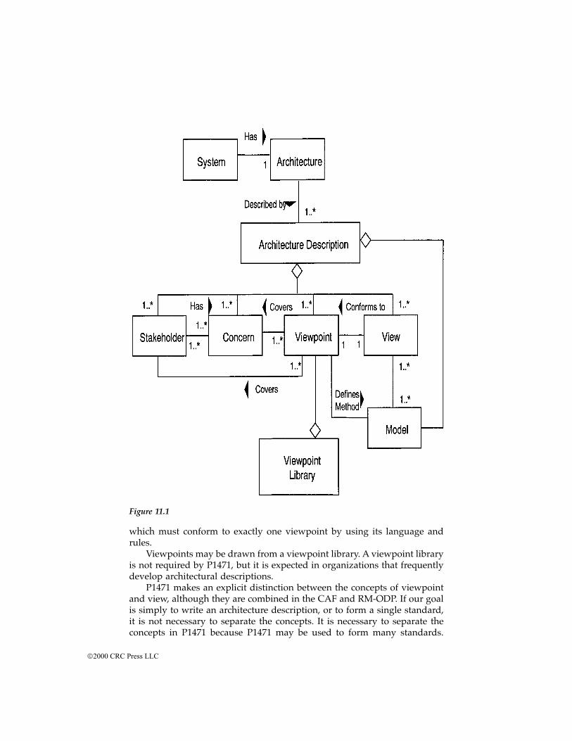
which must conform to exactly one viewpoint by using its language andrules.
Viewpoints may be drawn from a viewpoint library. A viewpoint libraryis not required by P1471, but it is expected in organizations that frequentlydevelop architectural descriptions.
P1471 makes an explicit distinction between the concepts of viewpointand view, although they are combined in the CAF and RM-ODP. If our goalis simply to write an architecture description, or to form a single standard,it is not necessary to separate the concepts. It is necessary to separate theconcepts in P1471 because P1471 may be used to form many standards.
Figure 11.1
2000 CRC Press LLC
Viewpoints are the vehicle for forming a standard. Indeed, viewpoints maybe placed into a library to be drawn from at the discretion of the architectand the specific stakeholders involved in a particular project. Thus, theseorganizing elements must be separately named and defined to allow themto be separately assembled for the needs of different sets of clients.
The viewpoints of RM-ODP are examples of P1471 compliant view-points. The only distinction between the viewpoint concept in RM-ODP andP1471 is that the RM-ODP version combines the abstraction (the P1471viewpoint) and the actual instance of a representation of a particular system(the P1471 view).
P1471 normative requirementsThe normative requirements of P1471 are limited, particularly compared toRM-ODP, and even the CAF. An architecture description conformant toP14712 must meet the following main requirements:
1. The stakeholders identified must include users, acquirers, developers,and maintainers of the system.
2. The architecture description must define its viewpoints, with somespecific elements required.
3. The system’s architecture must be documented in a set of views inone-to-one correspondence with the selected viewpoints, and eachview must be conformant to the requirements of its associated view-point.
4. The architecture description document must include any known inter-view inconsistencies and a rationale for the selection of the describedarchitecture.
There are a variety of other relatively minor normative requirements,along with various recommendations. Many of these are to make P1471consistent with other IEEE software engineering standards, notably the over-arching software engineering standard 12207.
Research directionsThe current state of the art and practice in architecture description leavesmuch work undone. As the RM-ODP example shows, the basic architecturalconcepts of viewpoint, view, stakeholder, and concern can be extensivelyrefined and tied to modeling formalisms if the domain of application isnarrowed. A cost is the intellectual complexity of the resulting methods. RM-ODP is a complex standard. Its conceptual makeup is not complex in com-parison to other areas in computer science, but it is quite complex comparedto common practice in information technology. There may be strong benefitsin mastering the complexity, but it acts as a barrier to the adoption of thistechnology. To make it more widely used we need better tools and better
2000 CRC Press LLC
explanation and training mechanisms to pass these ideas on to the profes-sional community.
As we move to more general systems, the range of formalized modelsdrops off dramatically. It seems very unlikely that we can develop a reallygeneral architecture framework that will simultaneously be formalizable. Itseems more likely that we must continue to work up from the engineeringdisciplines to create more general notations. One problem will be dealingwith the disjunction between models common in the hardware (and someof the systems engineering) world and those coming from computer scienceand software. The hardware models are typically performance-centric andphysics based. They work from physical objects. The computer science mod-els are now commonly based on object-orientation and encapsulation offunctionality within data models. It is not obvious how these will be recon-ciled, or to what extent it will be necessary. It may be a better approach toleave the modeling techniques as they are — taking the modeling techniquesas they have been validated within the engineering disciplines. The higher-level challenge will then be to develop inter-view consistency checking tech-niques that don’t require the disciplinary modeling methods to be altered,instead of working with them as they are.
ConclusionsThe problem of blueprint standards for complex systems architectures hasyielded a number of prototypical architecture frameworks. None of them isan ideal solution, but all contain important ideas. The architect faced witha normative requirement to use one of the frameworks must keep in mindtheir limitations and the architect’s core role. The architect’s core role is toassist the system’s client in making the key technical decisions, particularlywith which system concept to go on construction. This places a premium onmodels and methods that communicate effectively with the client, regardlessof their correspondence (or lack thereof) to engineering models. Only as thearchitect’s role evolves to transitioning the system to development and main-taining conceptual integrity during development does that correspondenceto engineering methods become foremost.
Notes and references1. ISO/IEC JTC1/SC21/WG7 Reference Model for Open Distributed Processing
officially titled ITU-T X.901 ISO/IEC 10746 Reference Model, Parts 1-4.2. The complete details are in the standard itself, IEEE P1471 Recommended
Practice for Architectural Description, issued in 2000.
2000 CRC Press LLC
chapter twelve
The political process and systems architecting*
Brenda Forman, Ph.D.
Introduction: the political challengeThe process of systems architecting requires two things above all others:value judgments by the client and technical choices by the architect. Thepolitical process is the way that the general public, when it is the end client,expresses its value judgments. High-tech, high-budget, high-visibility, pub-licly supported programs are therefore far more than engineering challenges;they are political challenges of the first magnitude. A program may have thetechnological potential of producing the most revolutionary weapon systemsince gunpowder, elegantly engineered and technologically superb, but if itis to have any real life expectancy or even birth, its managers must take itspolitical element as seriously as any other element. It is not only possiblebut likely that the political process will not only drive such design factorsas safety, security, produceability, quantity, and reliability, but may eveninfluence the choice of technologies to be employed. The bottom line is:
If the politics don’t fly, the system never will.
* This chapter is based on a course originated and taught at the University of Southern Californiaby Dr. Forman, now with Lockheed Martin Corporation in Washington, D.C. As indicated inthe Introduction to Part Four, the political process of the American federal government waschosen for the course for three reasons: it is the process by which the general public expressesits value judgments as a customer, it is well-documented and publicized, and it is seriouslymisunderstood by the engineering community, to the detriment of effective architecting.
shaindys

Politics as a design factorPolitics is a determining design factor in today’s high-tech engineering. Itsrules and variables must be understood as clearly as stress analysis, elec-tronics, or support requirements. However, its rules differ profoundly fromthose of Aristotelian logic. Its many variables can be bewildering in theircomplexity and often downright orneriness.
In addition to the formal political institutions of Congress and the WhiteHouse, a program must deal with a political process that includes inter-agency rivalries, intra-agency tensions, dozens of lobbying groups, influen-tial external technical review groups, powerful individuals both inside andoutside of government, and, always and everywhere, the media.
These groups, organizations, institutions, and individuals interact in aprocess of great complexity. This confusing and at times chaotic activity,however, determines the budgetary funding levels that either enable theengineering design process to go forward or threatens outright concellation.More often of late, it directly affects the design in the form of detailed budgetallocations, assignments of work, environmental impact statements, and thereporting risks or threats.
Understanding the political process and dealing successfully with it istherefore crucial to program success.
Example: Perhaps no major program has seen as manycuts, stretchouts, reviews, mandated designs, and riskof cancellation as the planetary exploration programof the 1970s and 1980s. Much of the cause was the needto fund the much larger Shuttle program. For morethan a decade there were no planetary launches andvirtually no new starts. From year to year, changeswere mandated in spacecraft design, the launch vehi-cles to be used, and even the planets and asteroids tobe explored. The collateral damage to the planetaryprogram of the Shuttle Challenger loss was enormousin delayed opportunities, redesigns, and wasted ener-gy. Yet, the program was so engineered that it stillproduced a long series of dramatic successes, widelypublicized and applauded, using spacecraft designedand launched many years before.
Begin by understanding that power is very widely distributed in Washington.There is no single, clear-cut locus of authority to which to turn for supportfor long-term, expensive programs. Instead, support must be continuouslyand repeatedly generated from widely varying groups, each of which mayperceive the program’s expected benefits in quite different ways, and manyof whose interests may diverge rather sharply when the pressure is on.
shaindys
Example: The nation’s space program is confrontedwith extraordinary tensions, none of which are resolv-able by any single authority, agency, branch, or indi-vidual. There are tensions between civilian andmilitary, between science and application, betweenmanned and unmanned flight, between completeopenness and the tightest security, between the mili-tary services, between NASA centers, and between thecommercial and government sectors, to name a few.Typical of the contested issues are launch vehicle de-velopment, acquisition, and use; allocations of work todifferent sections of the country and the rest of theworld; and the future direction of every program. Noone, anywhere, has sufficient authority to resolve anyof these tensions and issues, much less to resolve themall simultaneously.
This broad dispersion of power repeatedly confuses anyone expectingthat somebody will really be in charge. Rather, the opposite is true — any-thing that happens in Washington is the result of dozens of political vectors,all pulling in different directions. Everything is the product of maneuverand compromise. When those fail, the result is policy paralysis, and, all toopossibly, program cancellation by default or failure to act.
There are no clear-cut chains of command in the government. It is noth-ing like the military, or even a corporation. The process gets even morecomplicated because power does not stay put in Washington. Power relation-ships are constantly changing, sometimes quietly and gradually, at othertimes suddenly, under the impact of a major election or a domestic or inter-national crisis. These shifts can alter the policy agenda, and therefore fundingpriorities, abruptly and with little advance warning. A prime example is theever-changing contest over future defense spending levels in the wake ofthe welcomed end of the Cold War.
The entire process is far better understood in dynamic than in staticterms. There is a continuous ebb and flow of power and influence betweenthe Congress and the White House, among and within the rival agencies,and among ambitious individuals. And through it all, everyone is playingto the media, particularly to television, in efforts to change public percep-tions, value judgments, and support.
The first skill to masterTo deal effectively with this process, the first skill to master is the ability to thinkin political terms. And that requires understanding that the political processfunctions in terms of an entirely different logic system than the one in which
shaindys

scientists, engineers, and military officers are trained. Washington functionsin terms of the logic of politics. It is a system every bit as rigorous in its wayas any other, but its premises and rules are profoundly different. It willtherefore repeatedly arrive at conclusions quite different from those of engineeringlogic, but based on the same data.
Scientists and engineers are trained to marshal their facts and proceedfrom them to proof. For them, proof is a matter of firm assumptions, accuratedata, and logical deduction. Political thinking is structured entirely differ-ently. It depends not on logical proof but on past experiences, negotiation,compromise, and perceptions. Proof is a matter of “having the votes.” If amajority of votes can be mustered in Congress to pass a program budget,then, by definition, the program has been judged to be worthy, useful, andbeneficial to the nation. If the program cannot, then no matter what itstechnological merits, the program will lose out to other programs which can.
Mustering the votes depends only in part on engineering or technolog-ical merit. These are always important, but getting the votes frequentlydepends as much or even more on a quite different value judgment — theprogram’s benefits in terms of jobs and revenues among the Congressionaldistricts.
Example: After the Lockheed Corporation wonNASA’s Advanced Solid Rocket Motor (ASRM) pro-gram, the program found strong support in the Con-gress because Lockheed located its plant in theMississippi district of the then Chairman of the HouseAppropriations Committee. Lockheed’s factory wasonly partially built when the Chairman suffered a crip-pling stroke and was forced to retire from his Congres-sional duties. Shortly thereafter, the Congress, nolonger obliged to the Chairman, reevaluated and thencanceled the program.
In addition to the highest engineering skills, therefore, the successfularchitect-engineer must have at least a basic understanding of this politicalprocess. The alternative is to be repeatedly blindsided by political eventsand, worse yet, not even to comprehend why.
Heuristics in the political process: “the facts of life”Following are some basic concepts for navigating these rocky rapids: TheFacts of Life. They are often unpleasant for the dedicated engineer, but theyare perilous to ignore. Understanding them, on the other hand, will go farin helping anticipate problems and cope more effectively with them. Theyare as follows and will be discussed in turn.
shaindys
• Politics, not technology, sets the limits of what technology is allowedto achieve.
• Cost rules.• A strong, coherent constituency is essential.• Technical problems become political problems.• The best engineering solutions are not necessarily the best political
solutions.
Fact of life # 1
Politics, not technology, sets the limits of what technology is allowed toachieve.
If funding is unavailable for it, any program will die, and getting thefunding — not to mention keeping it over time — is a political undertaking.Furthermore, funding — or rather, the lack of it — sets limits that areconsiderably narrower than what our technological and engineering capa-bilities could accomplish in a world without budgetary constraints. Ourtechnological reach increasingly exceeds our budgetary grasp. This can be intenselyfrustrating to the creative engineer working on a good and promising pro-gram.
Example: The space station program can trace its ori-gins to the mid-1950s. By the early 1960s it was a pre-ferred way station for traveling to and from the moon.But when, for reasons of launch vehicle size and sched-ule, the Apollo program chose a flight profile that by-passed any space station and elected instead a directflight to lunar orbit, the space station concept went intolimbo until the Apollo had successfully accomplishedits mission. The question then was, what next inmanned spaceflight? A favored concept was a mannedspace station as a waypoint to the moon and planets,built and supported by a shuttle vehicle to and fromorbit. Technologically, the concept was feasible; someargued that it was easier than the lunar mission. Con-gress balked. The President was otherwise occupied.Finally, in 1972, the Shuttle was born as an overprom-ised, underbudgeted fleet, without a space station toserve. Architecturally speaking, major commitmentsand decisions were made before feasibility and desir-ability had been brought together in a consistentwhole.
shaindys
Fact of life #2
Cost rules.High technology gets more expensive by the year. As a result, the only
pockets deep enough to afford it are increasingly the government’s.* Thefundamental equation to remember is Money = Politics. While reviews andhearings will spend much time on presumably technical issues, the funda-mental and absolutely determining consideration is always affordability; andaffordability is decided by whichever side has the most votes.
Funding won in one year, moreover, does not stay won. Instead, it mustbe fought for afresh every year. With exceedingly few exceptions, no programin the entire federal budget is funded for more than one year at a time. Eachand every year is therefore a new struggle to head off attackers who wantthe program’s money spent somewhere else, to rally constituents, to per-suade the waverers, and, if possible, to add new supporters.
This is an intense, continuous, and demanding process requiring hugeamounts of time and energy. And after one year’s budget is finally passed,the process starts all over again. There is always next year. Keeping a pro-gram “sold,” in short, is a continuous political exercise, and like the heroinein the old movie serial, The Perils of Pauline, some programs at the raggededge will have to be rescued from sudden death on a regular basis. Rescue,if and when, may be only partial — not every feature can or will be sustained.If one of the lost features is a system function, the end may be near.
Example: After the Shuttle had become operational,the question again was, what next in manned space-flight? Although a modestly capable space station hadbeen successfully launched by a Saturn launch vehicle,the space station program had otherwise been shelvedonce the Shuttle began its resource-consuming devel-opment. With developmental skill again available, thespace station concept was again brought forward.However, order-of-magnitude life-cycle cost estimatesof the proposed program placed the cost at approxi-mately that of the Apollo, which in 1990-decade dollarswould have been about $100 billion — clearly toomuch for the size of the constituency it could com-mand. The result has been an almost interminable se-ries of designs and redesigns, all unaffordable asjudged by Congressional votes. Even more serious, thecost requirement has resulted in a spiraling loss of
* The economic expansion through the end of the 1990s sets an interesting counterpoint. Thegovernment is less and less able to influence technology in certain areas, for example, comput-ing, simply because the commercial market has become so large relative to the federal market.Similarly, some of the most ambitious space and launch ventures in the 1990s have beenprivately funded.
shaindys
system functions, users, and supporters. Microgravityexperiments, drug testing, on-board repair of on-orbitsatellites, zero-g manufacturing, optical telescopes, an-imal experiments, military research and development— one after another had to be reduced to the point oflack of interest by potential users. A clearly impliedinitial purpose of the space station, to build one be-cause the Soviet Union had one, was finally put to restwith the U.S. government’s decision to bring Russiainto a joint program with the U.S., Japan, Canada, andthe European Space Agency. Another space station re-design (and probably a new launch program design)is likely; however, the uncertainty level in the programremains high, complicating that redesign. One appar-ent certainty: the U.S. Congress has made the valuejudgment that a yearly cap of U.S. $2.1 billion is allthat a space station program is worth. The design mustcomply or risk cancellation. Cost rules.
Fact of life #3
A strong, coherent constituency is essential.No program ever gets funded solely, or even primarily, on the basis of
its technological merit or its engineering elegance. By and large, the Congressis not concerned with its technological or engineering content (unless, ofcourse, those run into problems — see Fact of Life #4). Instead, programfunding depends directly on the strength and staying power of its support-ers, i.e., its constituency.
Constituents support programs for any number of reasons, from theconcrete to the idealistic. At times, the reasons given by different supporterswill even seem contradictory. From the direct experience of one of theauthors, some advocates may support defense research programs becausethey are building capability; others because research in promising bettersystems in the future permits reduction, if not cancellation, of present pro-duction programs.
Example: The astonishing success of the V-22 tilt-rotorOsprey aircraft program in surviving four years of hos-tility during the 1988-1992 period is directly attribut-able to the strength of its constituency, one thatembraced not merely its original Marine Corps constit-uency but other Armed Services as well — plus groupsthat see it as benefiting the environment (by diminish-ing airport congestion), as improving the balance oftrade (by tapping a large export market), and as main-
shaindys
taining U.S. technological leadership in the aerospacearena.
Assembling the right constituency can be a delicate challenge because aconstituency broad enough to win the necessary votes in Congress can alsoeasily fall prey to internal divisions and conflicts. Such was the case for theShuttle and is the case for the Space Station. The scientific community provedto be a poor constituency for major programs; the more fields that werebrought in, the less the ability to agree on mission priorities. On the otherhand, a tight, homogeneous constituency is probably too small to win thenecessary votes. The superconducting supercollider proved to be such. Theart of politics is to knit these diverse motivations together firmly enough tosurvive successive budget battles and keep the selected program funded.Generally speaking, satellites for national security purposes have succeededin this political art. It can require the patience of a saint coupled with thewiliness of a Metternich, but such are the survival skills of politics.
Fact of life #4
Technical problems become political problems.In a high-budget, high-technology, high-visibility program, there is no
such thing as a purely technical problem. Program opponents will be con-stantly on the lookout for ammunition with which to attack the program,and technical problems are tailor-made to that end.
The problems will normally be reported in a timely fashion. As manyprograms have learned, mistakes are understandable; failing to report themis inexcusable. In any case, reviews are mandated by the Congress as anatural part of the program’s funding legislation. Any program that isstretching the technological envelope will inevitably encounter technicaldifficulties at one stage or another. The political result is that “technical”reports inevitably become political documents as opponents berate andadvocates defend the program for its real or perceived shortcomings.
Judicious damage prevention and control, therefore, are constantlyrequired. Reports from prestigious scientific groups such as the NRC or DSBwill routinely precipitate Congressional hearings in which hostile andfriendly Congressmen will pit their respective expert witnesses against oneanother; the program’s fate may then depend not only on the expertise, buton the political agility and articulateness of the supporting witnesses. Fur-thermore, while such hearings will spend much time on ostensibly technicalissues, the fundamental and absolutely determining consideration is alwaysaffordability; and affordability is decided by whichever side has the mostvotes.
Examples: Decades-long developments are particular-ly prone to have their technical problems become po-litical. Large investments have to be made each and
shaindys

every year before any useful systems appear. Thewidely reported technical difficulties of the B-1 and B-2 bombers, the C-17 cargo carrier, the Hubble tele-scope, and the Galileo Jupiter spacecraft became mat-ters of public as well as legislative concern. The futureof long-distance air cargo transport, of space explora-tion, and even of NASA are all brought up for debateand reconsideration every year. Architects, engineers,and program managers have good reason to be con-cerned.
Fact of life #5
The best engineering solutions are not necessarily the best political solu-tions.
Remember that we are dealing with two radically different logic systemshere. The requirements of political logic repeatedly run counter of those of engi-neering logic. Take construction schedules, for example. In engineering terms,an optimum construction schedule is one that makes the best and mosteconomical use of resources and time and yields the lowest unit cost. Inpolitical terms, the optimum construction schedule is the one that the polit-ical process decides is affordable in the current fiscal year. These two defi-nitions routinely collide; the political definition always wins.
Example: NASA and other agencies often refer to whatis called the program cost curve. It plots total cost ofdevelopment and manufacture as a function of its du-ration as follows (Figure 12.1):
The foregoing example leads to another provisional heuristic:
With few exceptions, schedule delays are acceptedgrudgingly; cost overruns are not, and for good rea-son.
The reason is basic. A cost overrun, that is, an increase over budget ina given year, will force the client to take the excess from some other programand that is not only difficult to do, it is hard to explain to the blameless loserand to that program’s supporters. Schedule delays mean postponing benefitsat some future cost, neither of which affect anyone today.
Example: Shuttle cost overruns cost the unmannedspace program and its scientific constituency two de-cades of unpostponeable opportunities, timely missionanalyses, and individual careers based on presidential-ly supported, wide-consensus planning.
shaindys
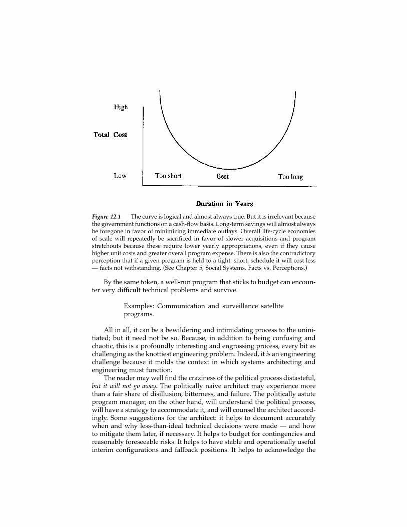
By the same token, a well-run program that sticks to budget can encoun-ter very difficult technical problems and survive.
Examples: Communication and surveillance satelliteprograms.
All in all, it can be a bewildering and intimidating process to the unini-tiated; but it need not be so. Because, in addition to being confusing andchaotic, this is a profoundly interesting and engrossing process, every bit aschallenging as the knottiest engineering problem. Indeed, it is an engineeringchallenge because it molds the context in which systems architecting andengineering must function.
The reader may well find the craziness of the political process distasteful,but it will not go away. The politically naive architect may experience morethan a fair share of disillusion, bitterness, and failure. The politically astuteprogram manager, on the other hand, will understand the political process,will have a strategy to accommodate it, and will counsel the architect accord-ingly. Some suggestions for the architect: it helps to document accuratelywhen and why less-than-ideal technical decisions were made — and howto mitigate them later, if necessary. It helps to budget for contingencies andreasonably foreseeable risks. It helps to have stable and operationally usefulinterim configurations and fallback positions. It helps to acknowledge the
Figure 12.1 The curve is logical and almost always true. But it is irrelevant becausethe government functions on a cash-flow basis. Long-term savings will almost alwaysbe foregone in favor of minimizing immediate outlays. Overall life-cycle economiesof scale will repeatedly be sacrificed in favor of slower acquisitions and programstretchouts because these require lower yearly appropriations, even if they causehigher unit costs and greater overall program expense. There is also the contradictoryperception that if a given program is held to a tight, short, schedule it will cost less— facts not withstanding. (See Chapter 5, Social Systems, Facts vs. Perceptions.)
shaindys

client’s right to have a change of mind or to make difficult choices withoutcomplaint from the supplier. Above all, it helps to acknowledge that livingin the client’s world can be painful, too. And finally, select a kit of prescrip-tions for the pain such as the following from Appendix A:
• The Triage: when there is only so much that can be done, let the dyingdie. Ignore those who will recover on their own. And treat only thosewho would die without help.
• The most important single element of success is to listen closely towhat the customer (in this case, the Congress) perceives as his re-quirements and to have the will and ability to be responsive (J.E.Steiner, The Boeing Company, 1978)
• Look out for hidden agendas. • And so on.
That doesn’t mean that architects and engineers have to become expertlobbyists; but it does mean having an understanding of the political contextwithin which programs must function, the budget battle’s rules of engage-ment, and of those factors that are conducive to success or failure. Thepolitical process is not outside, it is an essential element of, the process ofcreating and building systems.
A few more skills to masterThe following are a few more basic coping skills for the successful systemsarchitect. First and foremost, understand that the Congress and the politicalprocess are the owners of your project. They are the ultimate clients. It is absolutelyessential to deal with them accordingly by making sure they understandwhat you are trying to do, why it is important, and why it makes politicalsense for them to support you.
Be informed. This is your life, so be active. Learn the political processfor yourself and keep track of what’s going on. Figure out what informationthe political system needs in order to understand what the program needsand arrange to supply it to them. A chief engineer has utterly differentinformation requirements than a Congressional oversight committee. Learnwhat sort of information furthers your program’s fortunes in Washingtonand then get it to your program managers so they can get it to the politicaldecisionmakers who determine your program’s funding. Maybe your pro-gram has a great job-multiplier effect in some crucial lawmaker’s district.Maybe its technology has some great potential commercial applications inareas where the U.S. is losing a competitive battle with another country.
The point is that the political process bases its decisions on very differentinformation than the engineering process does. Learn to satisfy both those setsof requirements by plan.
shaindys

ConclusionThe political process is a necessary element of the process of creating andbuilding systems. It is not incomprehensible; it is different. Only when theyare not understood do the political Facts of Life instill cynicism or a senseof powerlessness. Once understood, they become tools like any others in thehands of an astute architect. It is a compliment to the client to use them well.
shaindys
chapter thirteen
The professionalization of systems architecting
Elliott Axelband, Ph.D.
Profession: Any occupation or vocation requiring trainingin the liberal arts or the sciences and advanced study in aspecialized field.1
IntroductionTo readers who have progressed this far, the existence of systems architectingas a process, regardless of who performs it, can be taken for granted. Func-tions and forms have to be matched, system integrity has to be maintainedthroughout development, and systems have to be certified for use. Visionshave to be created, realized, and demonstrated.
This chapter, in contrast, covers the evolution of the systems architectingprofession. An appropriate place to begin is with the history of the closelyrelated profession of systems engineering, the field from which systemsarchitecting evolved.
The profession of systems engineeringSystems engineering as a process began in the early 1900s in the communi-cation and aircraft industries. It evolved rapidly during and after World WarII as an important contributor to the development of large, innovative, andincreasingly complex systems. By the early 1950s systems engineering hadreached the status of a recognized, valued profession. Communication net-works, ballistic missiles, radars, computers, and satellites were all recognizedas systems. The “systems approach” entered into everyday language in manyfields, social as well as technical. Government regulations and standardsexplicitly addressed systems issues and techniques. Thousands of engineers
2000 CRC Press LLC
called systems engineering their vocation. Professional societies formed sec-tions with journals devoted to systems and their development.2 Universitiesestablished systems engineering departments or systems-oriented pro-grams.* Books addressing the process, or aspects of it, started to appear.3Most recently, the profession became formally represented with the estab-lishment of the International Council on Systems Engineering (INCOSE).4
The core of the systems approach from its beginnings has been thedefinition and management of system interfaces and tradeoffs, of which therecan be hundreds in any one system. Systems analysis, systems integration,systems test, and computer-aided system design were progressively devel-oped as powerful and successful problem-solving techniques. Some havebecome self-standing professions of their own under the rubric of systemsengineering. Their academic, industrial, and governmental credentials arenow well established.
All are science based; that is, based on measurables and a set of assump-tions. In brief, these are that requirements and risks can be quantified, solu-tions can be optimized, and compliance specified. But these same assump-tions are also constraints on the kinds of problems that can be solved. Inparticular, science-based systems engineering does not do well in problemsthat are abstract, data-deficient, perceptual, or for which the criteria areimmeasurable.
For example, the meanings of such words as safe, survivable, affordable,reliable, acceptable, good, and bad are either outside the scope of systemsengineering — “ask the client for some numbers” — or are force-fitted to itby subjective estimates. Yet these words are the language of the clients.Quantifying them can distort their inherent vagueness into an unintendedconstraint.
There is no group of professionals that better understands these diffi-culties than systems engineers and executives; nor who wish more to convertimmeasurable factors to quantitatively stateable problems by whatever tech-niques can help. The first step they made was to recognize the nature of theproblems. The second was to realize that almost all of them occur at the front(and back) ends of the engineering cycle. Consider the following descriptiveheuristics, developed long ago from systems engineering experience:
• All the serious mistakes are made in the first day.• Regardless of what has gone before, the acceptance criteria determine
what is actually built.• Reliability has to be designed in, not tested in.
* Among the best known are the University of Arizona at Tucson, Boston University, CarnegieTech, Case Western Reserve, the University of Florida, Georgia Tech, the University of Maryland,George Mason University, Ohio State, MIT (Aerospace), New York Polytech, the University ofTel Aviv, the University of Southern California, Virginia Polytechnic Institute, and the Universityof Washington.
2000 CRC Press LLC

It is no coincidence that many systems engineers, logically enough, nowconsider systems architecting to be “the front end of systems engineering”and that architectures are “established structures.” More precisely, systemsarchitecting can be seen as setting up the necessary conditions for systemsengineering and certifying its results. In short, systems architecting providesconcepts for analysis and criteria for success. In evolving systems the func-tions of systems architecting, systems engineering, and disciplinary engi-neering are all more episodic. Concepts for analysis and criteria for successare established in early phases, but are revised with each new spiral throughthe development process. Systems engineers must control interfaces throughmany cycles of design, development, and integration, not just through one.In addition to conducting classical architecting episodically, the systemsarchitect must also consider the issue of stable forms. The evolving systemshould not change everything on each cycle; it needs to retain stable sub-structures to evolve effectively. The definition of these substructures is partof the architect’s role.
The immediate incentive for making architecting an explicit process, thenecessary precursor to establishing it as a self-standing profession comple-mentary to systems engineering, was the recognition in the late 1980s bysystems executives that “something was missing” in systems developmentand acquisition, and that the omission was causing serious trouble: systemrejection by users, loss of competitive bids to innovators, products stuck inunprofitable niches, military failures in joint operations, system overruns incost and schedule, etc. — all traceable to their beginnings. Yet, there was astrong clue to the answer. Retrospective examinations of earlier, highly suc-cessful systems showed the existence in each case of an overarching vision,created and maintained by a very small group, which characterized theprogram from start to finish.5
Software engineers and their clients were among the first to recognizethat the source of many of their software system problems were structural;that is, architectural.* Research in software architecture followed in suchuniversities as Carnegie Mellon; the University of North Carolina, ChapelHill; the University of California at Irvine; and the University of SouthernCalifornia. Practitioners began identifying themselves as software architectsand forming architectural teams. Communication, electronics, and aerospacesystems architects followed shortly thereafter.
Societies established architecture working groups, notably the INCOSESystems Architecting Working Group6 and the IEEE Software EngineeringStandards Committee’s Architecture Working Group,7 to formulate standard
* One of the earliest and most famous books on systems architecting is The Mythical Man-Month,Essays on Software Engineering by Frederick P. Brooks, Jr. (Addison-Wesley Publishing Company,1974), which not only recognized the structural problems in software but, explicitly, on page37, calls for a system architect, a select team, conceptual integrity, and for the architect to “confinehimself scrupulously to architecture” and to stay clear of implementation. Brooks’s analogy forthe architectural team was a surgical team. He credits a 1971 Harlan Mills proposal as the sourceof these precepts.
2000 CRC Press LLC
definitions of terms and descriptions for systems and software architectures.These activities are essential to the development of a common internal lan-guage for systems architecting, and the integration of software architecturemodels and overall systems architectures in complex, software-intensivesystems.
At the scale of the profession of engineering, the recognition that some-thing was missing led to identifying it, by direct analogy with the processesof the classical architectural profession, as systems architecting.8 Not surpris-ingly, the evolution of systems architecting tools was found to be alreadyunderway in model building, discussed in Part Three, and systems stan-dards,* discussed in the next section.
Systems architecting and systems standardsEarlier chapters have pointed out that the abstract problems of the concep-tual and certification phases require different tools from the analytic ones ofsystem development, production, and test. One of the most important setsof tools is that of systems standards. Chapter 11 discussed one type ofarchitecture standard: standards for architecture description. Here, we dis-cuss a different category of standards, those that define development pro-cesses. For historical reasons, architectural process standards were not devel-oped as a separate set. Instead, general systems process standards weredeveloped which included systems architecting elements and principlesunderstood at the time, most of them induced from lessons learned in indi-vidual programs. As will be seen, some key elements appeared as early asthe 1950s.
Driven by much the same needs, the recognition of systems architectingin the late 1980s was paralleled, independently, by a recognition that existingsystems standards needed to be modified or supplemented to respond tolong-standing, systems-level structuring problems. Bringing the two tracks,architecting and standards, together should soon help both. Architecting canimprove systems standards. Systems standards can provide valuable toolsfor the systems architecting profession.
Some of the earliest systems standards in which elements of systemsarchitecting appeared were those of system specification, interface descrip-tion, and interface management. They proliferated rapidly. A system speci-fication can beget ten subsystem specifications, each of which is supportedby ten lower-level subsystem specifications, etc. All of these had to be knittedtogether by a system of 100 or so interface specifications.
Even though modern computer tools (Computer-Assisted System Engi-neering or CASE tools) have been developed to help keep track of the
* Systems standards, for the purposes of this book, are those engineering standards havingimpact on the system as a whole, whether explicitly identified as such in their titles or not.They are a relatively small part of the totality of engineering standards. Many, if not most, areinterface and test standards.
2000 CRC Press LLC
systems engineering process, extraordinarily disciplined efforts are stillrequired to maintain the systems integrity.9
As systems complexity increased, systems engineers were faced withincreasingly difficult tasks of assuring that the evolving form of the systemmet client needs, guaranteeing that tradeoffs maintained system intent inthe face of complications arising during development, and finally assuringthat the system was properly tested and certified for use. In due course, theproliferation of detailed specifications led to a need for overarching guide-lines, an overview mechanism for “structuring” the complexity that hadbegun to obscure system intent and integrity.
Before continuing it should be pointed out that overarching guidelinesare not, and cannot be, a replacement for quantitative system standards andspecifications. The latter represent decades of corporate memory, measurableacceptance criteria, and certified practices. Guidelines — performance spec-ifications, tailorable limits, heuristics, and the like — have a fundamentallimitation. They cannot be certified by measurables. They are too “soft” andtoo prone to subjective perceptions to determine to the nearest few percent-age points whether a system performs, or costs, what it should. At somepoint the system has to be measured if it is to be judged objectively.
From the standpoint of an architecting profession, the most importantfact about system standards is that they are changing. To understand thetrend, their development will be reviewed in some detail, recognizing thatsome of them are continuing to be updated and revised.
The origins of systems standards
The ballistic missile program of the 1950sUrgent needs induce change and, eventually, improvement. The U.S./Sovietballistic missile race begun in the mid-to-late 1950s brought about significantchange as it led to the development and fielding of innovative and complexsystems in an environment where national survival was threatened. To itscredit, the U.S. Air Force recognized the urgent need to develop and managethe process of complex system evolution, and did so.* The response in thearea of standards was the “375” System Standard, subsequently applied tothe development of all new complex Air Force equipment and systems.
“375” required several things that are now commonplace in systemsarchitecting and engineering. Timelines depicting the time-sequenced flowof system operation were to be used as a first step in system analysis.** From
* Those responsible for this development, Dr. Simon Ramo and General Bernard Schriever inparticular, from time to time referred to their respective organizations as architects as well assystem integrators. “Architecture,” as a formalism, was largely bypassed in the urgency to buildballistic missiles as credible deterrents. Nonetheless, the essential “architectural” step of certi-fication of readiness for launch was incorporated from the beginning and executed by allsuccessor organizations. It became a centerpiece for the space launch programs of the 1960sand thereafter.** This is not necessarily appropriate for all systems, but it was well suited to the missile,airplane, and weapon systems the Air Force had in mind at the time.
2000 CRC Press LLC
these, system functional block diagrams and functional requirements wereto be derived as a basis for subsequent functional analysis and decomposi-tion. The functional decomposition process in turn generated the subsystemsthat, with their connections and constraints, comprised the system andallowed the generation of subsystem requirements via tradeoff processes.
“375” was displaced in 1969 by a MILSTD 499 (Military Standard – 499)*which was applied throughout the Department of Defense (DoD). MILSTD499A, an upgrade, was released in 1974 and was in effect for 20 years.MILSTD 499B, a later upgrade, was unofficially released in 1994, and it wasalmost immediately replaced by EIA/IS 632 Interim Systems EngineeringStandard.10
The beginning of a new era of standards
The era of MILSTDs 499/499A/499B was an era in which military standardsbecame increasingly detailed. It was not only these documents which gov-erned system architecting and engineering, but they in turn referencednumerous other DoD MILSTDs, which addressed aspects of system engi-neering, and which were imposed on the military system engineering pro-cess as a consequence. To cite a few: MILSTD 490, Specification Practices,1972; MILSTD 481A, Configuration Control – Engineering Changes, Devia-tions and Waivers (Short Form), 1972; MILSTD 1519, Test RequirementsDocument, 1977; and MILSTD 1543, Reliability Program Requirements forSpace and Missile Systems, 1977. See Eisner, H., 199411 for additional exam-ples.
This mindset changed with the end of the cold war in the late 1980s.Cost became an increasingly important decisive factor in competitions formilitary programs, supplanting performance, which had been the dominantfactor in the prior era. Lowest cost, it was argued, could only be achieved ifthe restrictions of the military standards were muted. The detailed process(“how to”) standards of the past, which specified how to conduct systemsengineering and other program operations, needed to be replaced by stan-dards that only provided guidelines,** leaving the engineering specifics tothe proposing companies which would select these to be able to offer a low-cost product.12 Further supporting this reasoning was the reality that themost sophisticated components and systems in fields such as electroniccomputer chips and computers were now available at low cost from com-mercial sources, whereas in the past the state of the art was only availablefrom MILSTD-qualified sources. It was in this environment that EIA/IS 632was born.
* The official form is “Mil. Std. – 499,” but for ease of reading in a text an alternate form,“MILSTD 499,” will be used here.** As noted earlier, replacement is a questionable motivation for guidelines. Nonetheless, theestablishment of a high-level guideline document — a key architecting technique — was amilestone.
2000 CRC Press LLC
EIA/IS 632, an architectural perspectiveEIA/IS 632 is short by comparison with other military standards. Its mainbody is 36 pages. Including appendices, its total length is 60 pages, and theseinclude several which have been left intentionally blank. And, most signif-icantly, no other standards are referenced.
The scope and intent of the document is best conveyed by the followingquotes from its contents:
• “The scope …. of systems engineering (activities) are defined in termsof what should be done, not how to do ... (them)..” p. i
• “... (EIA/IS - 632) identifies and defines the systems engineering tasksthat are generally applicable throughout the system life cycle for anyprogram ....” p. 7
From a systems architecting perspective it is clear that the scope of thelife cycle perspective includes the modern understanding of systems archi-tecting.
One of the major activities of the systems architect, that of giving formto function, is addressed in pages 9–11. These pages summarize, in their ownwords and style, the client/architect relationship, the establishment of thedefining system functions, the development of the system’s architecture, andthe process of allocating system functions to architectural elements viatradeoffs. By implication, the tradeoffs continue, with varying degrees ofconcentration, throughout the life cycle.
Curiously, test and validation are deferred to a later section entitled “4.0Detailed Requirements.” This is consistent with the historical organizationof the preceding military standards, wherein Section 4 was dedicated toproduct assurance, a term which included a system test. It is, however, asignificant departure from the systems architecting point of view. A basictenet of systems architecting is that certification for use is one of its mostimportant functions, and that this should be developed in parallel with, andas a part of, the development of a system’s architecture. Consider, for exam-ple, some of the architecting heuristics that could apply:
• To be tested, a system must be designed to be tested.• Regardless of what has gone before, the acceptance (and test) criteria
determine what is actually built.
There are other sound and basic architecting principles which, suitablyexplained, could and should have been included as historically validatedguiding principles in EIA/IS 632 which, in its own words, “provides guid-ance for the conduct of a systems engineering effort.” Some applicable heu-ristics would include:
• Simplify. Simplify. Simplify.• The greatest leverage in systems architecting is at the interfaces.
2000 CRC Press LLC
• Except for good and sufficient reasons, functional and physical struc-turing should match.
• In partitioning a system into subsystems, choose a configuration withminimal communications between subsystems.
• It is easier to match a system to the human one that supports it thanthe reverse.
Beyond these, the need for an unbiased agent, the system architect, torepresent the client and technically guide the process is absent and is aserious omission.
Commercial standards
While EIA/IS 632 applies only to military systems engineering, that was notits original intent. The objective was to develop a universal standard forsystems engineering, which would apply to both the military and commer-cial worlds and be ratified by all of industry. However, there was an urgencyto publish a new military standard, and in the four-month schedule that wasassigned only it could be developed. This led to two consequences. First,IEEE P1220,13 a commercial systems engineering standard, was separatelypublished. Second, the merging of EIA/IS 632 with IEEE P1220 to create thefirst universal standard for system engineering was planned for publicationin 1997. The development of this universal system engineering standardinvolves personnel from several organizations including the AmericanNational Standards Institute (ANSI) and EIA, and is expected to be namedEIA/ANSI 632.14 Beyond that, the International Standards Organization(ISO) plans to issue a standard in 2000+ that will merge EIA/ANSI 632 withISO 12207. This latter will be published soon and will provide a universalsoftware engineering standard. In passing, software is included in the defi-nition of a system as used in the prior mentioned systems engineeringstandards, but not with the same level of intensity as can be found in separateexisting software engineering standards.
IEEE P 1220, an architectural perspectiveThe IEEE working group which generated P 1220 was sponsored by the IEEEComputer Society and included representatives from INCOSE, the EIA, andthe IEEE AES Society. It is the first commercial standard to formally addresssystems engineering. P 1220’s similarity with EIA/IS 632 derives from a fairdegree of common authorship plus a deliberate effort to: (1) coordinateefforts in order to present a common view of systems engineering, and (2)anticipate the eventual merger of the two documents. While the similaritiesare therefore not surprising, there are significant differences that are worthyof mention.
To begin with similarities, both standards are guides and not “how to”instruction manuals. Both address the entire life cycle of a product. Bothshare a common architecture, addressing in similar ways things that are
2000 CRC Press LLC

becoming similar: the processes of system engineering in the military andcommercial environments. This extends to a fair degree of common vocab-ulary, although mercifully P 1220 is freer of acronyms.
Compared to EIA/IS 632, P 1220 is more complex and longer (58 pagesin the body of the report vs. 36, and 66 pages overall vs. 60). It is much morerigorous in its definitions and use of system hierarchical structures. It hasseveral significant differences that tend to favor the recognition and pro-cesses of systems architecting.
• The subsystems which comprise a system are understood and treatedas systems. pp. 2, 4, 13
• The customer (client) is explicitly identified along with a need todetermine and quantify his expectations. p. 35
• External constraints including public and political constraints are rec-ognized as part of the process. p. 35
• The role of system boundaries and constraints in system evolution isconsidered. p. 36
• The need to evolve test plans with product evolution is expressed.pp. 18, 19
• The explicit need to generate functional and physical architectures isrecognized, unfortunately (from a system architect’s view) in thesame section of the document which through usage defines systemarchitecture as the sum of the product and its defining data package.p. A-3.
In summary, P 1220 better recognizes the systems architecting processthan does EIA/IS 632. It does, however, have significant systems architectingshortfalls and would better serve as a systems engineering guide if the roleof the systems architect were included, and if the architecting heuristics givenin this chapter were added.
A continuing problem in all of these systems standards, highlighted inChapter 6, is the difference in system/subsystem hierarchies across hardwareand software. Both can be thought of hierarchically, but the hierarchicalmodel for software is often changed to become layered, and the hierarchyof software units in a distributed system often does not match the associatedhardware. This often leads to significant problems in development, andcontributes to poorly structured software in systems where software devel-opment cost dominates total development cost. Standards for distributedsystem development, such as RM-ODP and UML, recognize the disjunctionand allow the software and hardware elements to be represented in theirown hierarchies. This frees the software architects from an imposed, andoften damaging, hardware-based hierarchy, but introduces new problems inreconciling the two models to assure consistency. Engineering process stan-dards have only begun to address this issue.
2000 CRC Press LLC
Company standards
Each company has its own set of standards and practices that incorporateunique core competencies, practices, and policies. These need to evolve fora company to improve its performance and competitive posture. Companystandards serve two other functions: instructing its initiates and relating toits customers. The latter function is stimulated whenever customers changetheir standards, and it is from this perspective that the systems engineeringstandards of several companies were examined. This was not an easy tasksince systems architecting and engineering are viewed by those companiesengaged in them as an enabler of efficient product generation, and, as such,applicable practices providing a competitive advantage are considered tradesecrets.
Several generalizations are possible. Today’s competitive pressures havecaused self-examination and particularly reengineering to become a regularway of life. This has also been encouraged by popularized business litera-ture.15 Process, as opposed to product, is the focus of such institutionalizedactivity. In reviewing the process of product generation and support, systemsarchitecting and, in some cases, systems architects are gaining recognition,although not always in a way clearly separated from systems engineering.
The Harris Corporation Information Systems Division recently culmi-nated four years of activity by publishing their revised Systems EngineeringGuide Book. A generalized description is provided in Honour, 1993.16 The128-page book is company proprietary. Discussions with its author, EricHonour, indicated that while systems architecting is not delineated per se,the processes that constitute systems architecting account for approximately25% of its pages.
Sarah Sheard and Elliot Margolis reported on the evolving systems engi-neering process within The Loral Federal Systems Organization.17 Their con-clusion is that there is an important relationship between the nature of aproduct and the team developing it, and that, as such, there is no one bestorganization for product development. However, their recent experienceindicates success with a team structure that includes a distinct architectureteam with a clearly identified chief architect working in conjunction with amanagement team and both software and hardware development teams.Their use of the terms architect, architectures, and architecting are consistentwith those of this book.
Hughes Aircraft published its 3-inch thick Systems Engineering Handbookin 1994.18 Its objective, stated on page P-1, is to “.... improve both the qualityand efficiency of systems engineering at Hughes.” The handbook describesthe then applicable MILSTD 499B and the Hughes systems engineeringprocesses for both DoD and non-DoD programs, including Hughes’ organi-zational and other resources available to implement these. It is a very com-prehensive, user-friendly book, clearly adapted from MILSTD 499B, andincludes the activities of the systems architect — who is never identified bythat name — within the framework of systems engineering. The systems
2000 CRC Press LLC
engineering function and organization is identified as the technical leadorganization for product development and is provided a unique identity inall forms of organization discussed: functional, projectized, and matrix. Inthat the handbook is patterned after MILSTD 499B which has a strongresemblance to EIA/IS 632, the comments made earlier with respect toEIA/IS 632 apply.
A summary of standards developments, 1950-1995
For a variety of reasons and by a number of routes, system standards andspecifications are evolving consistent with the principles and techniques ofsystems architecting. The next step is the use of system architects to helpimprove systems standards, particularly in system conception, test, andcertification. At the same time, improved systems standards can providepowerful tools for the systems architecting profession.
A cautionary note: the recent and understandable enthusiasm of the DoDto streamline standards and eliminate all references to prior MILSTDs couldmake systems architecting considerably more difficult. Useful as guidelinesare, they are no substitute for quantitative standards for bidding purposes,for certifying a system for use, or for establishing responsibility and liability.*MILSTDs in many instances incorporate specific philosophical and quanti-tative requirements based on lessons dearly learned in the real world. Theyreduce uncertainty in areas that should not or need not be uncertain. Toignore these by omission is to run the risk of learning them all over againat great cost. To the extent that the lessons relearned are architectural, therisks can be enormous. As the heuristic states, all the serious mistakes aremade on the first day.
Systems architecting graduate educationSystems engineering universities and systems architecting
Graduate education, advanced study, and research give a profession itscharacter. They distinguish it from routine work by making it a vocation, acalling of the particularly qualified.
The first university to offer masters and doctorate degrees in systemsengineering was the University of Arizona, beginning in 1961. The programbegan as a graduate program; an undergraduate program, and the additionof industrial engineering to the department title, came later. Still in existence,the graduate department has well over 1000 alumni.
The next to offer advanced degrees was the Virginia Institute of Tech-nology in 1971, but not until after 1984 did additional universities join thesystems engineering ranks. They included Boston University, George MasonUniversity, the Massachusetts Institute of Technology (MIT), the University
* In this connection, the DoD has explicitly retained interface and certification standards asessential, not to be considered as candidates for elimination.
2000 CRC Press LLC
of Maryland, the University of Southern California (USC), the University ofTel Aviv, and the University of Washington. It is worth noting that all arelocated at major centers of industry or government, the principal clients andusers of systems engineering.
To the best knowledge of the authors of this book, USC is the first tooffer a graduate degree in systems architecting and engineering with thefocus on systems architecting. However, of the universities offering graduatedegrees in systems engineering, some half dozen now include systems achi-tecting within their curricula. Notable among them is the MIT SystemsDesign and Management (SDM) program. This program, which is intendedas a new kind of graduate education program for technical professionals, isbuilt on three core subjects: systems engineering, systems architecture, andproject management. While the degree is not focused on systems architect-ing, that subject forms a major part of the curriculum’s core. The MIT SDMcurriculum is becoming more of a national model as it is spread through theProduct Development in the 21st century (PD21) program. PD21 is creatingprograms that are very similar to MIT’s SDM program in universities acrossthe country. The current universities involved are the Rochester Institute ofTechnology, the University of Detroit-Mercy, and the Naval PostgraduateSchool.
Architecting is also becoming a strong interest in universities offeringadvanced degrees in computer science with specializations in software andcomputer architectures, notably, Carnegie Mellon University, the Universi-ties of California at Berkeley and Irvine, and USC. At USC, the systemsarchitecture and engineering degree began with an experimental course in1989; it formally became a masters degree program in 1993 following itsstrong acceptance by students and industry.
In the last 10 years there has been growing recognition of the value ofinterdisciplinary programs, which of itself would favor systems architectingand engineering. These have been soul-searching years for industry, and thevalue of system architecting and engineering has become appreciated as afactor in achieving a competitive advantage. Also, the restructuring of indus-try has caused a rethinking of the university as a place to provide industry-specific education. These trends, augmented by the success of the systemarchitecting and engineering education programs, have caused universityarchitect-engineering programs to prosper.
The success of these programs can be measured in several ways. First,the direction is one of growth as 7 out of the 8 existing masters programswere started in the last 15 years; and the Universities of Maryland, Tel Aviv,and Southern California are all considering expanding their programs toinclude a Ph.D. Second, systems architecting and systems architecting edu-cation are making a positive difference in industry, as supported by industrysurveys. In point of fact, company-sponsored systems architecting enroll-ments increased even when there was industrial contraction.
2000 CRC Press LLC
Curriculum design
It is not enough in establishing a profession to show that universities areinterested in the subject. The practical question is what is actually taught;that is, the curriculum. Because USC is apparently the first university to offeran advanced degree specifically in systems architecture and engineering, itscurriculum is described. It should be pointed out that this curriculum is atthe graduate level. To date, no undergraduate degree is offered or planned.
The USC masters program admits students satisfying the School of Engi-neering’s academic requirements and having a minimum of three yearsapplicable industrial experience. Students propose a 10-course curriculumwhich is reviewed, modified if required, and accepted as part of their admis-sion. The curriculum requires graduate-level courses as follows:
• An anchor systems architecting course• An advanced engineering economics course• One of several specified engineering design courses• Two elective courses in technical management from a list of eleven
which are offered• One of eight general technical area elective courses• Four courses from one of eleven identified technical specialization
areas, each of which has six or more courses offered
The structure of this MS in Systems Architecture and Engineering cur-riculum has been designed based on both industrial and academic advice.Systems architecture is better taught in context. It is too much to generallyexpect a student to appreciate the subtleties of the subject without someexperience; and the material is best understood through a familiar specialtyarea in which the student already practices. The three-year minimum expe-rience requirement and the requirement of four courses in a technical spe-cialty area derive from this reasoning.
The need for an anchor course is self-evident. Systems architecturederives from inductive and heuristic reasoning, unlike the deductive reason-ing used in most other engineering courses. To fully appreciate this differ-ence, the anchor course is taken early, if not first, in the sequence. The coursecontains no exams as such, but requires two professional quality reports sothat the student can best experience the challenges of systems architectingand architecture by applying his knowledge in a dedicated and concentratedway.
Experience has shown that a design experience course, the advancedeconomics course, and courses in technical management are valuable to thesystem architect and, therefore, they are curriculum requirements. The addi-tional course in a general technical area allows the student to select a coursethat most rounds out the student’s academic experience. Possibilities includea systems architecting seminar, a course on decision support systems, anda course on the political process in systems architecture design.
2000 CRC Press LLC
To date within the USC program there have been 60 masters graduates.Over 300 have taken the anchor course, and 40 students are enrolled masterscandidates. A library of over 150 research papers has been produced fromthe best of the student papers, and is available as a research library for thosein the program. Several students are proceeding toward a Ph.D. in SystemsEngineering with a specialty in Systems Architecting.
Advanced study in systems architecting
A major component of advanced study in any profession is graduate-levelresearch and refereed publications at major universities. In systems archi-tecting, advanced study can be divided into two relatively distinct parts:that of its science, closely related to that of systems engineering, and of itsart. The universities committed to systems engineering education were givenearlier. Advanced study in its art, though often illustrated by engineeringexamples, has many facets, including research in:
• Complexity, by Flood and Carson19 at City University, London, En-gland
• Problem solving, by Klir20 at the State University of New York atBinghamton, and by Rubinstein21 at the University of California atLos Angeles
• Systems and their modeling, by Churchman22 at the University ofCalifornia at Berkeley, and Nadler23 and Rechtin24 at the University ofSouthern California
• The behavioral theory of architecting, by Lang25 at the University ofPennsylvania, Rowe26 at Harvard, and Losk, Carpenter, Cureton, Geis,and Carpenter27 at USC
• The practice of architecture by Alexander28 and Kostof29 at Universityof California at Berkeley
• Machine (artificial) intelligence and computer science by Geneserethand Nilsson30 at Stanford, Newell31 and Simon32 at Carnegie MellonUniversity, and Brooks33 at the University of North Carolina at ChapelHill
• Software architecting by Garlan and Shaw34 at Carnegie Mellon Uni-versity, and Barry Boehm at USC
All have contributed basic architectural ideas to the field. Many arestandard references for an increasing number of professional articles by agrowing number of authors. Most deal explicitly with systems, architectures,and architects, although the practical art of systems architecting was seldomthe primary motivation for the work. That situation predictably will changerapidly as both industry and government face international competition ina new era.
2000 CRC Press LLC
Professional societies and publicationsExisting journals and societies were the initial professional media for thenew fields of systems architecting and engineering. Since much early workwas done in aerospace and defense, it is understandable that the IEEE Societyon Systems Man and Cybernetics, the IEEE Aerospace Electronics Society,and the American Institute of Aeronautics and Astronautics and their jour-nals, along with others, became the professional outlets for these fields. Oneexcellent sample paper from this period (Boonton and Ramo, 198435)explained the contributions that systems engineering had made to the U.S.ballistic missile program.
The situation changed in 1990 when the first National Council on SystemEngineering conference was held and attracted 100 engineers. INCOSEbecame the first professional society dedicated to systems engineering andsoon established a Systems Architecting Working Group.
The society, with a current membership of 3500 (one third of which areoutside the U.S.), publishes a quarterly newsletter and a journal. The journalfirst appeared in 1994 and it published jointly with The IEEE AES Society in1996. Since then it has become a stand-alone, quarterly publication.
Conclusion: an assessment of the professionThe profession of systems architecting has come a long way, and its journeyhas just begun. Its present body of professionals in industry and academia— beginning most often in electronics, control and software systems, soonbroadening into systems engineering — formed the core of small designteams and now consider themselves as architects. The profession has beennurtured within the framework of systems engineering, and no doubt willmaintain a tight relationship with it. A masters-level university curriculanow exists, and the material and ideas are suffusing into many other systems-oriented programs. Applicable research is underway in universities. Appli-cable standards and tools are being developed at the national level. It hasan acknowledged home within INCOSE as well as other professional soci-eties that, together with their publications, provide a medium for profes-sional expression and development.
It is interesting to speculate on where the profession might be going andhow it might get there. The cornerstone thought is that the future of aprofession of systems architecting will be largely determined by the percep-tions of its utility by its clients. If a profession is useful, it will be sponsoredby them and prosper. To date, all indicators are positive.
Judging by the events that have led to its status today, and by comparabledevelopments in the history of classical architecture, systems architectingcould well evolve as a separate business entity. The future could hold moresystems architecting firms that bid for the business of acting as the technicalrepresentative or agent of clients with their builders. There are related pre-
2000 CRC Press LLC

cedents today in Federally Funded Research and Development Centers(FFRDCs) and Systems Engineering and Test Assistance Contractors (SET-ACs), which are independent entities selected by the DoD to represent itwith defense contractors that build end products. Similar precedents existin NASA and the Department of Energy.
The role of graduate education is likely to grow and spread. Today’sproducts and processes are more netted and interrelated than those of tenyears ago, and tomorrow’s will be even more so. System thinking is provingto be fundamental to commercial success, and systems architecting willincreasingly become a crucial part of new product development. It is incum-bent upon universities to capture the intellectual content of this phenomenonand embody it in their curricula. This will require a tight coupling withindustry to be aware of important real-world problems, a dedication toresearch to provide some of the solutions, and an education program thattrains students in relevant architectural thinking.
Publishe, peer-reviewed research has stood the test of time, providingthe best medium for the rapid dissemination of state-of-the-art thinking.Today INCOSE’s Systems Architecting Working Group provides one suchoutlet. Still others will be needed for further growth.
In summary, all the indicators point to a future of high promise andvalue to all stakeholders.
Notes and references1. Webster’s II New Riverside University Dictionary, Riverside Publishing, Boston,
MA, 1984, p. 939.2. The Institute of Electrical and Electronic Engineers (IEEE) Transactions on Systems,
Man, and Cybernetics, Institute of Electrical and Electronic Engineers, NewYork; IEEE Transactions on Aerospace and Electronic Systems, Institute ofElectrical and Electronic Engineers, New York; J. Amer. Inst. Aeronautics As-tronautics, American Institute of Aeronautics and Astronautics, Washington,D.C.
3. Machol, R.E., Systems Engineering Handbook, McGraw-Hill, New York, 1965;Chestnut, H., System Engineering Methods, John Wiley & Sons, New York, 1967;Blanchard, B. S. and Fabrycky, Systems Engineering and Analysis, Prentice-Hall,Englewood Cliffs, NJ, 1981.
4. Proc. First Annual Symp. Nat. Systems Engineering, Seattle, WA, 1990; J. Nat.Counc. Syst. Eng., Inaugural Issue, National Council on Systems Engineering,Seattle, WA, 1994; Tools for System Engineering, A Brochure. Ascent LogicCorporation, San Jose, CA, 1995.
5. Rechtin, E., Systems Architecting, Creating & Building Complex Systems, Prentice-Hall, Englewood Cliffs, NJ, 1991, 299.
6. See the Inaugural Issue of Systems Engineering, J. Nat. Counc. Syst. Eng., 1(1),July/September 1994.
7. See “Toward a Recommended Practice for Architectural Description” of theIEEE SESC Architecture Planning Group, April 9, 1996.
8. Rechtin, E., Systems Architecting, Creating & Building Complex Systems, Prentice-Hall, Englewood Cliffs, NJ, 1991.
2000 CRC Press LLC
9. Doors, a brochure, Zycad Corporation, Freemont, CA, 1995; SEDA — SystemEngineering and Design Automation, a brochure, Nu Thena Systems, McLean,VA, 1995.
10. EIA Standard IS - 632, Electronic Industries Association Publication, Washing-ton, D.C., 1994.
11. Eisner, H., Computer-Aided Systems Engineering, Prentice-Hall, EnglewoodCliffs, NJ, 1988.
12. Perry, W. J., Specifications and Standards — A New Way of Doing Business, DODI5000.2, Part 6, Section I, Department of Defense, Washington, D.C., 1995.
13. IEEE P1220 Trail Use Standard for Application and Management of the SystemsEngineering Process, IEEE Standards Department, New York, 1994.
14. Martin, J. N., American national standard on systems engineering, NCOSEINSIGHT, Issue 9, International Council on Systems Engineering, Seattle, WA,September 1995.
15. Hammer, M. and Champy, J., Reengineering the Corporation, Harper, New York,1994; Hamel, G. and Prahalad, C. K., Competing for the Future, Harvard Busi-ness School Press, Boston, MA, 1994.
16. Honour, E. C., TQM development of a systems engineering process, Proc.Third Annual Symp. National Council Systems Engineering, National Council onSystems Engineering, Sunnyvale, CA, 1993.
17. Sheard, S. A. and Margolis, E. M., Team structures for systems engineeringin an IPT environment, Proc. Fifth Annual Symp. National Council on SystemsEngineering, National Council on Systems Engineering, Sunnyvale, CA, 1995.
18. Systems Engineering Handbook, Hughes Aircraft Company, Culver City, CA,1994.
19. Flood, R. L. and Carson, E. R., Dealing with Complexity, An Introduction to theTheory and Application of Systems Science, Plenum Press, New York, 1988.
20. Klir, G. J., Architecture of Problem Solving, Plenum Press, New York, 1988.21. Rubinstein, M. F., Patterns of Problem Solving, Prentice-Hall, Englewood Cliffs,
NJ, 1975.22. Churchman, C. W., The Design of Inquring Systems, Basic Books, New York,
1971.23. Nadler, G., The Planning and Design Approach, John Wiley & Sons, New York,
1981.24. Rechtin, E., Systems Architecting, Creating & Building Complex Systems, Prentice-
Hall, Englewood Cliffs, NJ, 1991.25. Lang, J., Creating Architectural Theory, The Role of the Behavioral Sciences in
Environmental Design, Van Nostrand Reinhold, New York, 1987.26. Rowe, P. G., Design Thinking, MIT Press, Cambridge, MA, 1987.27. Losk, Pieronek, Cureton, Geis, and Carpenter graduate reports are unpub-
lished but available through the USC School of Engineering, Los Angeles, CA.28. Alexander, C., Notes on the Synthesis of Form, Harvard University Press, Cam-
bridge, MA, 1964. The first in a series of books on the subject29. Kostof, S., The Architect, Chapters in the History of the Profession, Oxford Uni-
versity Press, New York, 1977.30. Genesereth, M. R. and Nilsson, N. J., Logical Foundations of Artificial Intelligence,
Morgan Kaufmann Publishers, Los Altos, CA.31. Newell, A., Unified Theories of Cognition, Harvard University Press, Cambridge,
MA, 1990.32. Simon, H. A., The Sciences of the Artificial, MIT Press, Cambridge, MA, 1988.
2000 CRC Press LLC

33. Brooks, F. P., Jr., The Mythical Man-Month, Addison-Wesley Publishing, Read-ing, MA, 1982.
34. Garlan, D. and Shaw, M., An Introduction to Software Architecture, CarnegieMellon University, Pittsburgh, PA, 1993.
35. Booton, R. C., Jr. and Ramo, S., The development of systems engineering,IEEE Transac. Aerospace Electronic Syst., AES - 20, 4, 306, July 1984.
2000 CRC Press LLC
Appendix A
Heuristics for systems-level architecting
Experience is the hardest kind of teacher. It gives you the test first and the lesson afterward.(Susan Ruth 1993)
Introduction: organizing the listThe heuristics to follow were selected from Rechtin, 1991, the Collection ofStudent Heuristics in Systems Architecting, 1988-93,1 and from subsequentstudies in accordance with the selection criteria of Chapter 2. The list isintended as a tool store for top-level systems architecting. Heuristics con-tinue to be developed and refined not only for this level, but for domain-specific applications as well, often migrating from domain-specific to systemlevel, and vice versa.*
For easy search and use, the heuristics are grouped by architectural taskand categorized by being either descriptive or prescriptive; that is, bywhether they describe an encountered situation or prescribe an architecturalapproach to it, respectively.
There are over 180 heuristics in the listing to follow, far too many tostudy at any one time; nor were they intended to be.The listing is intendedto be scanned as one would scan software tools on software store shelves,looking for ones that can be useful immediately but remembering that othersare also there. Although some are variations of other heuristics, the vastmajority stand on their own, related primarily to others in the near vicinityon the list. Odds are that the reader will find the most interesting heuristicsin clusters, the location of which will depend on the reader’s interests at thetime. The section headings are by architecting task. A “D” signifies a descrip-tive heuristic; a “P”signifies a prescriptive one. When readily apparent, pre-
* The manufacturing, social, communication, software, management, business, and economicsfields are particularly active in proposing and generating heuristics — though they usually arecalled principles, laws, rules, or axioms.
2000 CRC Press LLC
scriptions are grouped by insetting under appropriate descriptions or alter-nate prescriptions; otherwise, not. In the interest of brevity, an individualheuristic is listed in the task where it is most likely to be used most often.As noted in Chapter 2, some 20% can be tied to related ones in other tasks.
A major difference between a heuristic and an unsupported assertion isthe credibility of the source. To the extent possible, the heuristics are creditedto the individuals who, to the authors’ knowledge, first suggested them. Tofurther aid the reader in judging credibility or in finding the sources, theheuristics to follow are given symbols. These symbols indicate the following:
[ ] An informal discussion with the individual indicated, unpublished. ( ) A formal, dated source, with examples, located in the USC MS-SAE
program archive, especially in the Collection of Student Heuristics inSystems Architecting, 1988-93. For further information, contact theMaster of Science Program in Systems Architecture and Engineering,USC School of Engineering, University Park, Los Angeles, CA 90089-1450.*Rechtin, 1991, where it is sourced more formally. By permission ofPrentice-Hall, Englewood Cliffs, NJ.
Bold Key words useful for quick search. Otherwise, heuristics to followare in plain type to make page reading easier. Real-world examplesof each can be found in the references indicated.
The authors apologize in advance for any miscrediting of sources. Cor-rections are welcome. The readers are reminded that not all heuristics applyto all circumstances, just most to most.
Heuristic tool listMultitask heuristics
D Performance, cost, and schedule cannot be specified independently.At least one of the three must depend on the others.*
D With few exceptions, schedule delays will be accepted grudgingly;cost overruns will not, and for good reason.
D The time to completion is proportional to the ratio of the time spentto the time planned to date. The greater the ratio, the longer the timeto go.
D Relationships among the elements are what give systems their addedvalue.*
D Efficiency is inversely proportional to universality. (Douglas R. King,1992)
* As indicated in the introduction to this appendix, an asterisk indicates that this heuristic istaken from Rechtin, E., Systems Architecting, Creating & Building Complex Systems, Prentice-Hall,Englewood Cliffs, NJ, 1991. With permission of Prentice-Hall, Englewood Cliffs, NJ 07632.
2000 CRC Press LLC
D Murphy’s Law, “If anything can go wrong, it will.”*P Simplify. Simplify. Simplify.*P The first line of defense against complexity is simplicity of de-sign. P Simplify, combine, and eliminate. (Suzaki, 1987)P Simplify with smarter elements. (N. P. Geiss, 1991)P The most reliable part on an airplane is the one that isn’t there— because it isn’t needed. [DC-9 Chief Engineer, 1989]
D One person’s architecture is another person’s detail. One person’ssystem is another’s component. [Robert Spinrad, 1989]*
P In order to understand anything, you must not try to under-stand everything. (Aristotle, 4th cent. B.C.)
P Don’t confuse the functioning of the parts for the functioning of thesystem. (Jerry Olivieri, 1992)
D In general, each system level provides a context for the level(s) below.(G. G. Lendaris, 1986)
P Leave the specialties to the specialist. The level of detail requiredby the architect is only to the depth of an element or componentcritical to the system as a whole. (Robert Spinrad, 1990) But thearchitect must have access to that level and know, or be informed,about its criticality and status. (Rechtin, 1990)P Complex systems will develop and evolve within an overallarchitecture much more rapidly if there are stable intermediateforms than if there are not. (Simon, 1969)*
D Particularly for social systems, it’s the perceptions, not the facts, thatcount.
D In introducing technological and social change, how you do it isoften more important than what you do.*
P If social cooperation is required, the way in which a system isimplemented and introduced must be an integral part of its archi-tecture.*
D If the politics don’t fly, the hardware never will. (Brenda Forman,1990)
D Politics, not technology, sets the limits of what technology isallowed to achieve.D Cost rules.D A strong, coherent constituency is essential.D Technical problems become political problems.D There is no such thing as a purely technical problem. D The best engineering solutions are not necessarily the best po-litical solutions.
D Good products are not enough. Implementations matter. (Morris andFerguson, 1993)
P To remain competitive, determine and control the keys to thearchitecture from the very beginning.
2000 CRC Press LLC
Scoping and planning
The beginning is the most important part of the work.(Plato, 4th cent. B.C.)Scope! Scope! Scope! (William C. Burkett, 1992)
D Success is defined by the beholder, not by the architect.*P The most important single element of success is to listen closelyto what the customer perceives as his requirements and to havethe will and ability to be responsive. (J. E. Steiner, 1978)*P Ask early about how you will evaluate the success of yourefforts. (Hayes-Roth et al., 1983)P For a system to meet its acceptance criteria to the satisfactionof all parties, it must be architected, designed, and built to do so— no more and no less.*P Define how an acceptance criterion is to be certified at the sametime the criterion is established.* D Given a successful organization or system with valid criteria forsuccess, there are some things it cannot do — or at least not dowell. Don’t force it!P The strengths of an organization or system in one context canbe its weaknesses in another. Know when and where.*D There’s nothing like being the first success.*P If at first you don’t succeed, but the architecture is sound, try,try again. Success sometimes is where you find it. Sometimes itfinds you.*D A system is successful when the natural intersection of technol-ogy, politics, and economics is found. (A. D. Wheelon, 1986)*D Four questions, the Four Whos, need to be answered as a self-consistent set if a system is to succeed economically; namely, whobenefits?, who pays? and, as appropriate, who loses?
D Risk is (also) defined by the beholder, not the architect. P If being absolute is impossible in estimating system risks, thenbe relative.*
D No complex system can be optimum to all parties concerned, nor allfunctions optimized.*
P Look out for hidden agendas.*P It is sometimes more important to know who the customer isthan to know what the customer wants. (Whankuk Je, 1993)D The phrase, “I hate it,” is direction. (Lori I. Gradous, 1993)
P Sometimes, but not always, the best way to solve a difficult problemis to expand the problem, itself.*
P Moving to a larger purpose widens the range of solutions. (Ger-ald Nadler, 1990)P Sometimes it is necessary to expand the concept in order tosimplify the problem. (Michael Forte, 1993)
2000 CRC Press LLC
P [If in difficulty,] reformulate the problem and re-allocate thesystem functions. (Norman P. Geis, 1991)P Use open architectures.You will need them once the marketstarts to respond.
P Plan to throw one away. You will anyway. (F. P. Brooks, Jr., 1982)P You can’t avoid redesign. It’s a natural part of design.*
P Don’t make an architecture too smart for its own good.* D Amid a wash of paper, a small number of documents become critical
pivots around which every project’s management revolves. (F. P.Brooks, Jr., 1982)*
P Just because it’s written, doesn’t make it so. (Susan Ruth, 1993) D In architecting a new [software] program all the serious mistakes are
made in the first day. [Spinrad, 1988] P The most dangerous assumptions are the unstated ones. (Dou-glas R. King, 1991)D Some of the worst failures are systems failures.
D In architecting a new [aerospace] system, by the time of the firstdesign review, performance, cost, and schedule have been predeter-mined. One might not know what they are yet, but to first order allthe critical assumptions and choices have been made which will de-termine those key parameters.*
P Don’t assume that the original statement of the problem is necessarilythe best, or even the right, one.*
P Extreme requirements, expectations, and predictions should re-main under challenge throughout system design, implementation,and operation.P Any extreme requirement must be intrinsic to the system’s de-sign philosophy and must validate its selection. “Everything mustpay its way on to the airplane.” [Harry Hillaker, 1993]P Don’t assume that previous studies are necessarily complete,current or even correct. (James Kaplan, 1992)P Challenge the process and solution, for surely someone else willdo so. (Kenneth L. Cureton, 1991)P Just because it worked in the past there’s no guarantee that itwill work now or in the future. (Kenneth L. Cureton, 1991)P Explore the situation from more than one point of view. A seem-ingly impossible situation might suddenly become transparentlysimple. (Christopher Abts, 1988)
P Work forward and backward. (A set of heuristics from Rubinstein,1975.)*
Generalize or specialize.Explore multiple directions based on partial evidence.Form stable substructures.Use analogies and metaphors.Follow your emotions.
2000 CRC Press LLC
P Try to hit a solution that, at worst, won’t put you out of business.(Bill Butterworth as reported by Laura Noel, 1991)
P The order in which decisions are made can change the architectureas much as the decisions themselves. (Rechtin, 1975, IEEE SPEC-TRUM)
P Build in and maintain options as long as possible in the design andbuild of complex systems. You will need them. OR...Hang on to theagony of decision as long as possible. [Robert Spinrad, 1988]*
P Successful architectures are proprietary, but open. [Morrisonand Ferguson, 1993]
D Once the architecture begins to take shape, the sooner contextualconstraints and sanity checks are made on assumptions and require-ments, the better.*
D Concept formulation is complete when the builder thinks the systemcan be built to the client’s satisfaction.*
D The realities at the end of the conceptual phase are not the modelsbut the acceptance criteria.*
P Do the hard parts first.P Firm commitments are best made after the prototype works.
Modeling (see also Chapters 3 and 4)
P If you can’t analyze it, don’t build it.D Modeling is a craft and at times an art. (William C. Burkett, 1994)D A vision is an imaginary architecture…no better, no worse than the
rest of the models. (M. B. Renton, Spring, 1995)D From psychology: if the concepts in the mind of one person are very
different from those in the mind of the other, there is no commonmodel of the topic and no communication. [Taylor, 1975] OR... Fromtelecommunications: The best receiver is one that contains an internalmodel of the transmitter and the channel. [Robert Parks and FrankLehan, 1954]*
D A model is not reality.* D The map is not the territory. (Douglas R. King, 1991)*P Build reality checks into model-driven development. [Larry Du-mas, 1989]* P Don’t believe nth order consequences of a first order [cost]model. [R. W. Jensen, circa 1989]
D Constants aren’t and variables don’t. (William C. Burkett, 1992)D One insight is worth a thousand analyses. (Charles W. Sooter, 1993)
P Any war game, systems analysis, or study whose results can’teasily be explained on the back of an envelope is not just worthless,it is probably dangerous. [Brookner-Fowler, circa 1988]
D Users develop mental models of systems based [primarily] upon theuser-to-system interface. (Jeffrey H. Schmidt)
2000 CRC Press LLC
D If you can’t explain it in five minutes, either you don’t understand itor it doesn’t work. (Darcy McGinn, 1992 from David Jones)
P The eye is a fine architect. Believe it. [Wernher von Braun, 1950]D A good solution somehow looks nice. (Robert Spinrad, 1991)
P Taste: an aesthetic feeling which will accept a solution as rightonly when no more direct or simple approach can be envisaged.[Robert Spinrad, 1994]P Regarding intuition, trust but verify. (Jonathan Losk, 1989)
Prioritizing (trades, options, and choices)
D In any resource-llimited situation, the true value of a given serviceor product is determined by what one is willling to give up to obtain it.
P When choices must be made with unavoidably inadequate informa-tion, choose the best available and then watch to see whether futuresolutions appear faster than future problems. If so, the choice was atleast adequate. If not, go back and choose again.*
P When a decision makes sense through several different frames, it’sprobably a good decision. (J. E. Russo, 1989)
D The choice between architectures may well depend upon which setof drawbacks the client can handle best.*
P If trade results are inconclusive, then the wrong selection criteria wereused. Find out [again] what the customer wants and why they wantit, then repeat the trade using those factors as the [new] selectioncriteria. (Kenneth Cureton, 1991)
P The triage: Let the dying die. Ignore those who will recover on theirown. And treat only those who would die without help.*
P Every once in a while you have to go back and see what the real worldis telling you. [Harry Hillaker, 1993]
Aggregating (“chunking”)
P Group elements that are strongly related to each other, separate ele-ments that are unrelated.
D Many of the requirements can be brought together to complementeach other in the total design solution. Obviously the more the designis put together in this manner, the more probable the overall success.(J. E. Steiner, 1978)
P Subsystem interfaces should be drawn so that each subsystem can beimplemented independently of the specific implementation of thesubsystems to which it interfaces. (Mark Maier, 1988)
P Choose a configuration with minimal communications between thesubsystems. (computer networks)*
P Choose the elements so that they are as independent as possible;that is, elements with low external complexity (low coupling) and
2000 CRC Press LLC
high internal complexity (high cohesion). (Christopher Alexander,1964 modified by Jeff Gold, 1991)* P Choose a configuration in which local activity is high speed andglobal activity is slow change. (Courtois, 1985) *
P Poor aggregation results in gray boundaries and red performance.(M. B. Renton, Spring, 1995)
P Never aggregate systems that have a conflict of interest; parti-tion them to ensure checks and balances. (Aubrey Bout, 1993)P Aggregate around “testable” subunits of the product; partitionaround logical subassemblies. (Ray Cavola, 1993)P Iterate the partition/aggregation procedure until a model con-sisting of 7 ± 2 chunks emerge. (Moshe F. Rubinstein, 1975)P The optimum number of architectural elements is the amountthat leads to distinct action, not general planning. (M. B. Renton,Spring, 1995)
P System structure should resemble functional structure.*P Except for good and sufficient reasons, functional and physicalstructuring should match.*P The architecture of a support element must fit that of the systemwhich it supports. It is easier to match a support system to thehuman it supports than the reverse.*
P Unbounded limits on element behavior may be a trap in unexpectedscenarios. [Bernard Kuchta, 1989]*
Partitioning (decompositioning)
P Do not slice through regions where high rates of information ex-change are required. (computer design)*
D The greatest leverage in architecting is at the interfaces.*P Guidelines for a good quality interface specification: they mustbe simple, unambiguous, complete, concise, and focus on sub-stance. Working documents should be the same as customer deliv-erables; that is, always use the customer’s language, not engineer-ing jargon. [Harry Hillaker, 1993]P The efficient architect, using contextual sense, continually looksfor likely misfits and redesigns the architecture so as to eliminateor minimize them. (Christopher Alexander, 1964)* It is inadequateto architect up to the boundaries or interfaces of a system; onemust architect across them. (Robert Spinrad, as reported by SusanRuth, 1993)P Since boundaries are inherently limiting, look for solutions out-side the boundaries. (Steven Wolf, 1992)P Be prepared for reality to add a few interfaces of its own.*
P Design the structure with good “bones.”*P Organize personnel tasks to minimize the time individuals spend
interfacing. (Tausworthe, 1988)*
2000 CRC Press LLC
Integrating
D Relationships among the elements are what give systems their addedvalue.*
P The greatest leverage in system architecting is at the interfaces.*P The greatest dangers are also at the interfaces. [Raymond, 1988]P Be sure to ask the question: “What is the worst thing that otherelements could do to you across the interface? [Kuchta, 1989]
D Just as a piece and its template must match, so must a system andthe resources which make, test, and operate it; or, more briefly, theproduct and process must match. Or, by extension, a system archi-tecture cannot be considered complete lacking a suitable match withthe process architecture.*
P When confronted with a particularly difficult interface, trychanging its characterization.*
P Contain excess energy as close to the source as possible.*P Place barriers in the paths between energy sources and the ele-ments the energy can damage. (Kjos, 1988)*
Certifying (system integrity, quality, and vision)
D As time to delivery decreases, the threat to functionality increases.(Steven Wolf, 1992)
P If it is a good design, insure that it stays sold. (Dianna Sammons,1991)
D Regardless of what has gone before, the acceptance criteria determinewhat is actually built.*
D The number of defects remaining in a (software) system after agiven level of test or review (design review, unit test, system test,etc.) is proportional to the number found during that test or review.P Tally the defects, analyze them, trace them to the source, makecorrections, keep a record of what happens afterward, and keeprepeating it. [Deming] P Discipline. Discipline. Discipline. (Douglas R. King, 1991) P The principles of minimum communications and proper parti-tioning are key to system testability and fault isolation. (DanielLey, 1991)*P The five whys of Toyota’s lean manufacturing. (To find the basiccause of a defect, keep asking “why” from effect to cause to causefive times.)
D The test setup for a system is itself a system.*P The test system should always allow a part to pass or fail on itsown merit. [James Liston, 1991]*P To be tested, a system must be designed to be tested.*
2000 CRC Press LLC
D An element “good enough” in a small system is unlikely to be goodenough in a more complex one.*
D Within the same class of products and processes, the failure rate ofa product is linearly proportional to its cost.*
D The cost to find and fix an inadequate or failed part increases by anorder of magnitude as it is successively incorporated into higherlevels in the system.
P The least expensive and most effective place to find and fix aproblem is at its source.
D Knowing a failure has occurred is more important than the actualfailure. (Kjos, 1988)
D Mistakes are understandable, failing to report them is inexcusable. D Recovery from failure or flaw is not complete until a specific mecha-
nism, and no other, has been shown to be the cause.*D Reducing failure rate by each factor of two takes as much effort as
the original development.* D Quality can’t be tested in, it has to be built in.*
D You can’t achieve quality...unless you specify it. (Deutsch, 1988) P Verify the quality close to the source. (Jim Burruss, 1993)P The five whys of Japan’s lean manufacturing. (Hayes, et al.,1988)2
D High quality, reliable systems are produced by high qualityarchitecting, engineering, design, and manufacture, not by inspec-tion, test, and rework.*P Everyone in the development and production line is both acustomer and a supplier.
D Next to interfaces, the greatest leverage in architecting is in aidingthe recovery from, or exploitation of, deviations in system perfor-mance, cost, or schedule.*
Assessing performance, cost, schedule, and risk
D A good design has benefits in more than one area. (Trudy Benjamin,1993)
D System quality is defined in terms of customer satisfaction, not re-quirements satisfaction. (Jeffrey Schmidt, 1993)
D If you think your design is perfect, it’s only because you haven’tshown it to someone else. [Harry Hillaker, 1993]
P Before proceeding too far, pause and reflect. Cool off periodi-cally and seek an independent review. (Douglas R. King, 1991)
D Qualification and acceptance tests must be both definitive and pass-able.*
P High confidence, not test completion, is the goal of successfulqualification. (Daniel Gaudet, 1991)
2000 CRC Press LLC
P Before ordering a test decide what you will do if it is: (l) positiveor (2) it is negative. If both answers are the same, don’t do the test.(R. Matz, M. D., 1977)
D “Proven” and “state of the art” are mutually exclusive qualities. (LoriI. Gradous, 1993)
D The bitterness of poor performance remains long after the sweetnessof low prices and prompt delivery are forgotten. (Jerry Lim, 1994)
D The reverse of diagnostic techniques are good architectures. (M.B.Renton, 1995)
D Unless everyone who needs to know does know, somebody, some-where will foul up.
P Because there’s no such thing as immaculate communication,don’t ever stop talking about the system. (Losk, 1989)*
D Before it’s tried, it’s opinion. After it’s tried, it’s obvious. (William C.Burkett, 1992)
D Before the war it’s opinion. After the war, it’s too late! (AnthonyCerveny, 1991)
D The first quick look analyses are often wrong.*D In correcting system deviations and failures it is important that all
the participants know not only what happened and how it happened,but why as well.*
P Failure reporting without a close out system is meaningless.(April Gillam, 1989)P Common , if undesirable, responses to indeterminate outcomesor failures:*
If it ain’t broke, don’t fix it.Let’s wait and see if it goes away or happens again.It was just a random failure. One of those things.Just treat the symptom. Worry about the cause later.Fix everything that might have caused the problem.Your guess is as good as mine.
D Chances for recovery from a single failure or flaw, even with complexconsequences, are fairly good. Recovery from two or more indepen-dent failures is unlikely in real-time and uncertain in any case.*
Rearchitecting, evolving, modifying, and adapting
The test of a good architecture is that it will last.The sound architecture is an enduring pattern.[Robert Spinrad, 1988]
P The team that created and built a presently successful product is oftenthe best one for its evolution — but seldom for creating its replace-ment.
2000 CRC Press LLC
D If you don’t understand the existing system, you can’t be sure you’rere-architecting a better one. (Susan Ruth, 1993)
P When implementing a change, keep some elements constant to pro-vide an anchor point for people to cling to. (Jeffrey H. Schmidt, 1993)
P In large, mature systems, evolution should be a process of in-gress and egress. (IEEE, 1992; Jeffrey Schmidt, 1992)P Before the change, it is your opinion. After the change it is yourproblem. (Jeffrey Schmidt, 1992)
D Unless constrained, re-architecting has a natural tendency to proceedunchecked until it results in a substantial transformation of the sys-tem. (Charles W. Sooter, 1993)
D Given a change, if the anticipated actions don’t occur, then there isprobably an invisible barrier to be identified and overcome. (SusanRuth, 1993)
Exercises
Exercise: What favorite heuristics, rules of thumb, facts of life, or justplain common sense do you apply to your own day-to-day living —at work, at home, at play? What heuristics, etc., have you heard onTV or the radio; for example, on talk radio, action TV, children’sprograms? Which ones would you trust?
Exercise: Choose a system, product, or process with which you arefamiliar and assess it using the appropriate foregoing heuristics. Whatwas the result? Which heuristics are or were particularly applicable?What further heuristics were suggested by the system chosen? Wereany of the heuristics clearly incorrect for this system? If so, why?
Exercise: Try to spot heuristics and insights in the technical literature.Some are easy; they are often listed as principles or rules. The moredifficult ones are buried in the text but contain the essence of thearticle or state something of far broader application than the subjectof the piece.
Exercise: Try to create a heuristic of your own — a guide to action,decision making, or to instruction of others.
Notes and references1. Rechtin, E., Editor, University of Southern California, Los Angeles, CA, March
15, 1994 (unpublished but available to students and researchers on request).2. Hayes, R. H., Wheelwright, S. C., and Clark, K. B., Dynamic Manufacturing,
Creating the Learning Organization, Free Press, New York, 1988.
2000 CRC Press LLC
Appendix B
Reference texts suggested for institutional libraries
The following list of texts is offered as a brief guide to books that would beparticularly appropriate to an architecting library.
Architecting backgroundAlexander, C., A Pattern Language: Towns, Buildings, Construction, Oxford
University Press, New York, 1977.Alexander, C., The Timeless Way of Building, Oxford University Press, New
York, 1979.Alexander, C., Notes on the Synthesis of Form, Harvard University Press,
Cambridge, MA, 1964.Kostoff, Spiro, The Architect, Oxford University Press, 1977, paperback.Lang, Jon, Creating Architectural Theory, van Nostrand Reinhold Company,
1987.Rowe, P.G., Design Theory, The MIT Press, Cambridge, MA, 1987.Vitruvius, The Ten Books on Architecture, translated by Morris Hicky Morgan,
Dover Publications, 1960, paperback.
ManagementAugustine, N.R., Augustine's Laws, AIAA, Inc., 1982.Deal, Terrence E. and Kennedy, A. A., Corporate Cultures, The Rites and Rituals
of Corporate Life, Addison-Wesley, Reading, MA, 1988.DeMarco, T. and Lister, T., Peopleware: Productive Projects and Teams, Dorset
House, New York, 1987.Juran, J.M., Juran on Planning for Quality, The Free Press, A Division of
Macmillan, Inc., New York, 1988.
â!"""#$%$#&'())#**$
ModelingEisner, H., Computer Aided Systems Engineering, Prentice-Hall, Englewood
Cliffs, NJ, 1988.Hatley, D. J. and Pirbhai, I., Strategies for Real-Time System Specification, Dorset
House, New York, 1988.Rumbaugh, J., Blaha, M., Premerlani, W., Eddy, F., and Lorensen, W., Object-
Oriented Modeling and Design, Prentice-Hall, Englewood Cliffs, NJ, 1991.Ward, P.T. and Mellor, S. J., Structured Development for Real-Time Systems,
Volume 1: Introduction and Tools, Yourdon Press (Prentice-Hall), Engle-wood Cliffs, NJ, 1985.
Specialty areasBaudin, M., Manufacturing Systems Analysis, Yourdon Press Computing
Series, (Prentice-Hall), Englewood Cliffs, NJ, 1990.Hayes, R. H., Wheelwright, S. C., and Clark, K. B., Dynamic Manufacturing,
The Free Press A Division of Macmillan, Inc., New York, 1988.Miller, J.G., Living Systems, McGraw Hill, New York, 1978.Simon, H.A., Sciences of the Artificial, The MIT Press, Cambridge, MA, 1981.Thome, B., editor, Systems Engineering: Principles and Practice of Computer-
Based Systems Engineering, John Wiley, Baffins Lane, Chichester, WileySeries on Software Based Systems, 1993.
SoftwareBoehm, B., Software Engineering Economics, Prentice-Hall, Englewood Cliffs,
NJ, 1981.Brooks, F. P., Jr., The Mythical Man-month, Essays on Software Engineering, 20th
Anniversary Edition, Addison-Wesley, Reading, MA, 1995.Gajski, D. D., Milutinovic´, V. M., Siegel, H. J., and Furht, B. P., Computer
Architecture, The Computer Society of the IEEE, 1987 (tutorial).Gamma, E. et. al., Design Patterns: Elements of Reusable Object-Oriented Software
Architecture, Addison Wesley, Reading, MA, 1994.Deutsch, M. S. and Willis, R. R., Software Quality Engineering, Prentice-Hall,
Englewood Cliffs, NJ, 1988.Software Productivity Consortium, ADARTS Guidebook, SPC-94040-CMC,
Version 2.00.13, Vols. 1-2, September, 1991. Shaw, M. and Garlan, D., Software Architecture: Perspectives on an Emerging
Discipline, Prentice-Hall, Englewood Cliffs, NJ, 1996.Yourdon, E. E. and Constantine, L. L., Structured Design: Fundamentals of a
Discipline of Computer Program and Systems Design, Yourdon Press, (Pren-tice-Hall) Englewood Cliffs, NJ, 1979.
â!"""#$%$#&'())#**$
System sciencesFlood, R. L. and Carson, E. R., Dealing with Complexity, an Introduction to the
Theory and Application of System Sciences, Plenum Press, New York, 1988.Genesereth, M. S. and Nilsson, N. J., Logical Foundations of Artificial Intelli-
gence, Morgan Kaufmann, San Francisco, CA, 1987.Gerstein, D. R. et al., Editors, The Behavioral and Social Sciences, Achievements
and Opportunities, National Academy Press, Washington, D.C., 1988.Klir, G. J., Architecture of Systems Problem Solving, Plenum Press, New York,
1985.
System thinkingArbib, M. A., Brains, Machines, and Mathematics, Second ed., Springer-Verlag,
New York, 1987.Beam, W. R., Systems Enginering, Architecture and Design, McGraw-Hill, New
York, 1990.Boorstin, D. J., The Discoverers, Vintage Books, New York, 1985.Boyes, J. L., Editor, Principles of Command and Control, AFCEA International
Press, Washington, D.C., 1987.Davis, S. M., Future Perfect, Addison Wesley, Reading, MA, 1987.Gause, D. C. and Weinberg, G. M., Exploring Requirements, Quality Before
Design, Dorset House Publishing, New York, 1989.7Hofstadter, D. R., Gödel, Escher, Bach: An Eternal Golden Braid, Vintage Books,
New York, 1980, paperback.Norman, D. A., The Psychology of Everyday Things, Basic Books, New York,
1988.Pearl, J., Heuristics, Addison-Wesley, Reading, MA, 1984.Rechtin, E., Systems Architecting: Creating and Building Complex Systems, Pren-
tice-Hall, Englewood Cliffs, NJ, 1991.Rubinstein, M. F., Patterns of Problem Solving, Prentice-Hall, Englewood Cliffs,
NJ, 1975.Weinberg, G. M., Rethinking Systems Analysis and Design, Dorset House, New
York, 1988.
â!"""#$%$#&'())#**$
Appendix C
On defining architecture and other terms
This appendix is for those who need to come to a consensus in a group ona definition for architecture or other major terms used in this book. Thereare many who might have such a need, and for those who have a need thisappendix might be very useful. Deciding on formal definitions is commonlypart of setting up an official corporate training course, or documenting astandard (public or corporate). In these situations an inordinate amount oftime can be spent arguing about fine details of definitions. It may be hardto pick and choose among the definitions offered by different standards sincethey usually do not record the reasoning that brought them to a decision.This appendix is a record of some of the definition related discussions oneof the authors (Maier) has been involved in over several years. It is offeredto help others who need to arrive at a group consensus on definitions witha ready-made set of choices and reasoning.
Defining “architecture”One might think that, with 5000 years of history, the notion of architecturein buildings would be clearly and crisply defined. Presumably then thedefinition could be extended to give a clear and crisp definition to architec-ture in other fields. However, this is not the case. A formal definition ofarchitecture is elusive even in the case of buildings. And if the definition iselusive in its original domain, is it surprising that a wholly satisfactorydefinition is elusive in more general domains?
The communities involved in architecture in systems, software, hard-ware, and other domains have struggled with finding a formal definition.Each group who has set out a formal definition has usually made a uniquechoice. The choices are often similar, but reflect significantly different ideas.The sections to follow review some of the more distinctive choices. Of course,there are many small variations on each one.
2000 CRC Press LLC

To make sense of the different definitions it is important to review themwith some criteria in mind. In reviewing these definitions try to answer thefollowing questions with respect to each definition:
1. How does the definition establish what is the concern of the architectand what is not?
2. What is the purpose of the definition? Some purposes might be de-fining an element of design, education, organizational survival orpolitics, setting legal boundaries, or even humor.
3. Choose a building with which you are familiar. What is its architec-ture, according to the definition? How well does the definitions im-plied architecture match what you would expect to be the buildingarchitect’s scope of work?
4. Choose a system with which you are familiar. What is its architecture,according to the definition? What things are uniquely determinedabout the system from the application of that definition?
5. What is the architecture of the Internet, according to the definition?
Webster’s dictionary definition
We begin with the dictionary’s definition.1
Architecture: 1. The art or science of building; specifi-cally, the art or practice of designing and buildingstructures and esp. habitable ones. 2a. Formation orconstruction as or as if the result of conscious act <the~ of the garden> b. a unifying or coherent form orstructure <the novel lacks ~> 3. Architectural productor work 4. A method or style of building 5. The mannerin which the components of a computer or computersystem are organized and integrated.
The interesting part of this definition, for our purposes, is part 2. Thefirst definition uses architecture in the sense of the profession, not what weare looking for here. This definition say to speak of the architecture of a thingis to speak of its “unifying or coherent form.” Unfortunately, it is not obviouswhat aspect of form is “unifying or coherent.” It is something that can bejudged, but is hard to define crisply. The civil building example suggestsseveral other ideas about architecture:
1. Architecture is tied to the structure of components, but if a novel canhave an architecture the notion of components is relatively abstract.Components may need to be interpreted broadly in some contexts.No one would confuse the structure of a novel with its organizationinto chapters — which is the “packaging” of that structure, and is
2000 CRC Press LLC

analogous to confusing the architecture of a system with its modulestructure.
2. The distinction between an architectural level of description and someother level of design description is not crisp. Architectural descriptionis concerned with unifying characteristics or style, while an engineer-ing description is concerned with construction or acquisition.
3. In common use architecture can mean a conceptual thing, the workof architects, and architectural products. Other definitions makesharper distinctions.
This book
The definition of architecture given in the glossary of this book is
Architecture: The structure (in terms of components,connections, and constraints) of a product, process, orelement
This definition is specific, it is talking about structure (although that termis itself open to some interpretation). Components, connections, and con-straints are the descriptive terms for architecture; and we can talk about thearchitecture of a wide variety of things. This book is primarily about archi-tecting, rather than architecture. The reason is that the most important con-straints come from the process of doing the architect’s role. The most impor-tant things come from working with clients to understand purpose andlimitations. Architecture should, by the tenets of this book, proceed from theclients needs rather than a presupposed notion of what constitutes an archi-tectural level definition of a system.
IEEE architecture working group (AWG)
After extended discussion in 1995-1996 in association with developing P1471Recommended Practice for Architectural Description the IEEE WorkingGroup chose:
An Architecture is the highest-level concept of a systemin its environment.
“System” in this definition refers back to the official IEEE definition, “acollection of components organized to accomplish a specific function or setof functions.” This definition of architecture was intended to capture severalideas.
1. An architecture is a property of a thing or a concept, not a structure.The term structure is avoided specifically to avoid any connotation
2000 CRC Press LLC
that architecture was solely a matter of physical structure. Concept,which is obviously much more generic, is used instead.
2. The term highest-level is used to indicate that architecture is an ab-straction, and that it is fundamental abstraction. A major defect ofthis definition is that highest level carries a connotation of levels ofhierarchy, and in particular a single hierarchy, which is exactly oneof the connotations to be avoided. Also, “highest-level concept” leavesa great deal of room for interpretation.
3. The definition says that architecture is not a property of the systemalone, but that the system’s environment must be included in a def-inition of the system’s architecture. This has often been referred to as“architecture in context” as opposed to “architecture as structure.” Itwas there to capture the idea that architecture has to encompasspurpose and the relationship of the system to its stakeholders. Thereader must judge whether or not that interpretation is clear.
This definition was used in several drafts of the P1471 standard, but wasreplaced in the final balloted version. The definition in the final ballotedversion was
Architecture: the fundamental organization of a sys-tem embodied in its components, their relationships toeach other and to the environment and the principlesguiding its design and evolution.
This definition is a refinement of definitions from the software engineer-ing community, as discussed below. Those who don’t like it might be moreinclined to say it was a compromise between conflicting points of view thatsuffers from the usual problems of a committee decision. The definition startswith the software communities definitions (discussed shortly) and then addsback some of the ideas of the original P1471 definition. The primary refine-ment is the de-emphasis on physical structure and to say that architectureis “embodied” in components, relationships, and principles. Put anotherway, the definition tries to recognize that, for most systems, most of the time,the architecture is in the arrangement of physical components and theirrelationships; but, sometimes, the fundamental organization is on a moreabstract level.
INCOSE SAWG
The International Council on Systems Engineering (INCOSE) Systems Archi-tecture Working Group (SAWG) adopted a definition for system architecture.It could as well be read as a definition for “Architecture, of a system.” It reads:
2000 CRC Press LLC
Systems architecture: The fundamental and unifyingsystem structure defined in terms of system elements,interfaces, processes, constraints, and behaviors
This definition borrows the core of the dictionary definition that archi-tecture represents fundamental, unifying, or essential structure. Exactly whatconstitutes fundamental, unifying, or essential is not easily defined. It ispresumed that recognizing it is partially art and up to the participants. Inthis definition the role of multiple aspects making up the architecture is madeexplicit through the listing of elements, interfaces, processes, constraints, andbehaviors. This definition makes, or facilitates making, a sharper separationbetween an architecture as a conceptual object, an architecture descriptionas concrete object, and the process or act of creating architectures (architect-ing).
MIL-STD-498
MIL-STD-498, now canceled, had a definition of architecture that specificallypertained to a designated development task.
Architecture: The organizational structure of a systemor CSCI, identifying its components, their interfaces,and a concept of execution among them
Here architecture is described specifically in three parts, components,interfaces, and a concept of execution. In this sense it supports the idea ofarchitecture as inherently multi-view, although it specifically defines theviews where others leave them open. The meaning of “organizational struc-ture” as opposed to some other structure (conceptual, implementation,detailed, etc.) is not made clear, although the idea is congruent to the com-mon usage of architecture. It also uses “concept” within the definition, butonly in referring to execution. Like most definitions, it doesn’t clearly makea distinction between architectural and design concerns.
This definition is also “structuralist” in the sense that it emphasizes thestructure of the system rather than its purposes or other relationships. Onecould interpret the definition to mean that the architect was not concernedwith the systems purpose, that architecture came after requirements werefully defined. In fact, that is exactly the interpretation it should be given, atleast in the way the associated standards envisioned the systems engineeringprocess executing.
The original IEEE definition (in IEEE 610.12-1990) is a shorter version ofthis. It reads:
The organizational structure of a system or component
2000 CRC Press LLC
Perry-Garlan
A widely used definition in the software community is due to Perry andGarlan, although the exact place it first appeared is somewhat obscure.
Architecture: The structure of the components of a sys-tem, their interrelationships, and principles and guide-lines governing their design and evolution over time.
An almost identical definition is used as the definition of architecture inthe U.S. DoD C4ISR Architecture Framework, where it is incorrectly creditedto the IEEE 610.12 standard for terminology. This definition is another three-part specification — components, interrelationships, and principles-guide-lines. As this definition is commonly used, components and interrelation-ships usually refer to physically identifiable elements. This definition ismostly used in the software architecture community, and there it is commonto see components identified as code units, classes, packages, tasks, and othercode abstractions. The interrelationships would be calls or lines of inherit-ance.
The two basic objections to this definition are that it implies (if primarilythrough use rather than the words) that architecture is the same as physicalstructure, and that it makes no distinction in level of abstraction. The com-mon usage of architecture is in reference to abstracted properties of things,not to the details. The Perry-Garlan definition can presumably apply to thestructure of components at any level of abstraction. While applicability tomultiple levels is, in part, desirable, it is also desirable to distinguish betweenwhat constitutes an architectural level description (whether of a whole sys-tem or of a component) from descriptions at lower levels of abstraction.
Maier’s tongue-in-cheek rule of thumb
A slightly flip, but illustrative way of defining architecture is to go back towhat architects are supposed to do.
An architecture is the set of information that defines asystems value, cost, and risk sufficiently for the pur-poses of the systems sponsor.
Obviously, this definition reflects the issue back to architecting, whenthe definition of architecture reflects back to architecture. The point of thisdefinition is that architecture is what architects produce, and that whatarchitects do is help clients make decisions about building systems. Whenthe client makes acquisition decisions, architecture has been done (perhapsunconsciously, and perhaps very badly, but done).
2000 CRC Press LLC
Internet discussion
One of the questions given at the beginning was “What is the architectureof the Internet?” The point of the question is that no reasonable notion ofunifying, organizing, or coherent form will produce a physical descriptionof the Internet. The specific pattern of physical links is continuously changingand of little interest. However, there is a very clear unifying structure, butit is a structure in protocols. It is not even a structure in software components,as exactly what software components implement the protocols is not knowneven to the participating elements. The point about protocols being theorganizing structure of the Internet, and in particular the IP, was made inChapter 7 and Figure 7.1.
Summary
Those who must choose definitions have a lot to work with, probably morethan they would want. The precise form of the definition is less importantthan the background of what architecture should be about. What architectingshould be was discussed at length in Chapter 1. The specifics of what archi-tects will produce, that is what an architecture actually looks like, will differfrom domain to domain. Ideally, the definition for a given organizationshould come from that knowledge — the knowledge of what is needed tosuccessfully define a system concept and take it through development. If theorganization has that knowledge it should be able to choose a formal defi-nition that encapsulates it. If the organization does not have that knowledgethen no formal definition will produce it.
Models, viewpoints, and viewsThe terms model, view, and viewpoint are important in setting architecturedescription standards, or architecture frameworks using the community ter-minology of Chapter 11. The meaning of these terms changes from standardto standard. The discussion below is intended to capture an argument for adistinction between the two meanings. The distinction can be useful inwriting standards, though it is not important in writing architecture descrip-tions, nor is it extensively used in this book.
Why do we need some organizing abstraction beyond just models?Experience teaches that particular collections of models are logically relatedby the kinds of issues or concerns they address. The idea of a view comesfrom architectural drawings. In a drawing we talk about the top view or theside view of an object in referring to its physical representation as seen froma point. A view is the representation of a system from a particular point orperspective. A view is a representation of the whole system with respect toa set of related concerns. A viewpoint is the abstraction of many relatedviews, it is the idea of viewing something from “the front,” for example.
2000 CRC Press LLC

A view need not correspond to physical appearance. A functional viewis a representation of a system abstracting away all non-functional or non-behavioral details. A cutaway view shows some mixture of internal andexternal physical features in a mixture defined by the illustrator.
A view can be thought of both projectively and constructively. In theprojective sense a view is formed by taking the system and abstracting awayall the details unnecessary to the view. It is analogous to taking a multidi-mensional object and projecting it onto a lower dimensional space (like aviewing plane). For example, a behavioral view is the system pared downto only its behaviors, its set of input to output traces.
In the constructive sense we build a complete model of the system bybuilding a series of views. Each represents the system from one perspective,with enough the system should be “completely” defined. It is like sketchinga front view, a side view, a top view, and then inferring the structure of thewhole object. In more general systems, we might build a functional view,then a physical view, then a data view, then return to the functional view,etc. until a complete model is formed from the joint set of views.
In practice it usually takes several models to represent that whole systemrelative to typical concerns, at least for high technology systems. So, a viewis usually a collection of models. For example, physical representation seemssimple enough, but how many different models are needed to represent thecomponents of an information intensive system? A complete physical viewmight need conventional block diagrams of information flow, block dia-grams of communication interconnection, facilities layouts, and softwarecomponent diagrams.
Viewpoints are motivated noticing that we build similar views, usingsimilar methods, for many systems. By analogy, we will want to draw a topview of most systems we build. The civil architect always draws a set ofelevations, and elevation drawings share common rules and structures. Andan information system architect will build information models using stan-dard methods for each system. This similarity is because related systemswill typically have similar stakeholders, and these stakeholders find theirconcerns consistently addressed by particular types of models and analysismethods. Hence, a viewpoint can be thought of as a set of modeling oranalysis methods together with the concerns those methods address and thestakeholders possessing those concerns.
Working definitions
These are summarizing definitions, augmented with the notions of consis-tency and completeness. The concepts here refer to the P1471 informationmodel in Figure 11.1.
Model: An approximation, representation or idealization of selectedaspects of the structure, behavior, operation or other characteristicsof a real-world process, concept, or system (IEEE 610.12-1990).
2000 CRC Press LLC
Viewpoint: A template, pattern, or specification for constructing a view(IEEE 1471-2000).
View: A representation of a system from the perspective of related con-cerns or issues (IEEE 1471-2000).
Consistency, of views: Two or more views and consistent if at least onecan exist that possesses the given views.
Completeness, of view: A set of views is complete if they satisfy (or“cover”) all of the concerns of all stakeholders of interest.
Consistency and completeness
Given multiple views (like top, front, and side) of a physical object the ideasof consistency and completeness are clear. A set of views is consistent if theyare abstractions of the same object. A little more generally, they are consistentif at least one real object exists which has the given views. Consistency forphysical object and views can be checked through solid geometry. FigureC.1 illustrates the point. The views are consistent if the geometrical objectproduces them when project onto the appropriate subspace. Even withoutthe actual object we can perform geometric checks on the different views.
We can’t (yet) treat consistency in the same rigorous manner if the viewsare functional and physical and of a complex system. As we describe morecomplex views in the sections to come for systems it is useful to return tothe heuristic notion of consistency. Given a few models of a system beingarchitected, we say they are consistent if at least one implementation existswhich has the models as abstractions of itself.
Completeness can also be heuristically understood through the geomet-ric analogy. Suppose we have set of visual representations of a materialobject. What does it mean to claim that the set of representations (views) is“complete?” Logically, it means that the views completely define the object.But, any set of external visual representations can only define the externalshape of the object, it can’t define the internal structure, if any. This trivialobservation is actually extremely important for understanding architecture.No set of representations is ever truly complete. A set of representations canonly be complete with respect to something, say with respect to some set ofconcerns. If the concerns are an external shape, then some set of externalvisual representations can be complete. If the concerns are extended toinclude internal structures, or strength properties, or weight, or any numberof other things then the set of views must likewise be extended to be “com-plete.”
Notes and references1. Merriam Webster’s Collegiate Dictionary, Tenth Edition, p. 61.
2000 CRC Press LLC
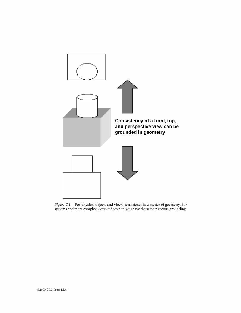
Figure C.1 For physical objects and views consistency is a matter of geometry. Forsystems and more complex views it does not (yet) have the same rigorous grounding.
Consistency of a front, top,and perspective view can begrounded in geometry
2000 CRC Press LLC

Glossary
The fields of system engineering and systems architecting are sufficientlynew that many terms have not yet been standardized. Common usage isoften different among different groups and in different contexts. However,for the purposes of this book, we have provided the meanings of the followingterms:
Abstraction A representation in terms of presumed essentials, with a cor-responding suppression of the non-essential.
ADARTS Ada-based Design Approach for Real Time Systems. A softwaredevelopment method (including models, processes, and heuristics)developed and promoted by the Software Productivity Consortium.
Aggregation The gathering together of closely related elements, purposes,or functions.
Architecting The processing of creating and building architectures.Depending on one’s perspective, architecting may or may not be seenas a separable part of engineering. Those aspects of system developmentmost concerned with conceptualization, objective definition, and certifi-cation for use.
Architecture The structure — in terms of components, connections, andconstraints — of a product, process, or element.
Architecture, open An architecture designed to facilitate addition, exten-sion, or adaptation for use.
Architecture, (communication, software, hardware, etc.) The architectureof the particular designated aspect of a large system.
Architectural style A form or pattern of design with a shared vocabularyof design idioms and rules for using them (see Shaw and Garlan, 1996,p. 19).
ARPANET/INTERNET The global computer internetwork, principallybased on the TCP/IP packet communications protocol. The ARPANETwas the original prototype of the current INTERNET.
Certification A formal, but not necessarily mathematical, statement thatdefined system properties or requirements have been met.
Client The individual or organization that pays the bills. May or may notbe the user.
Complexity A measure of the numbers and types of interrelationshipsamong system elements. Generally speaking, the more complex a sys-tem, the more difficult it is to design, build, and use.
2000 CRC Press LLC
Deductive reasoning Proceeding from an established principle to its appli-cation.
Design The detailed formulation of the plans or instructions for making adefined system element; a follow-on step to systems architecting andengineering.
Domain A recognized field of activity and expertise, or of specializedtheory and application.
Engineering Creating cost-effective solutions to practical problems byapplying scientific knowledge to building things in the service of man-kind (Shaw and Garlan, 1996, p. 6). May or may not include the art ofarchitecting.
Engineering, concurrent Narrowly defined (here) as the process by whichproduct designers and manufacturing process engineers work togetherto create a manufacturable product.
Heuristic A guideline for architecting, engineering, or design. Lessonslearned expressed as a guideline. A natural language abstraction ofexperience which passes the tests of Chapter 2.
Heuristic, descriptive A heuristic that describes a situation.Heuristic, prescriptive A heuristic that prescribes a course of action.IEEE P 1220 An Institute of Electrical and Electronic Engineers standard
for system engineeringInductive reasoning Extrapolating the results of examples to a more gen-
eral principleManufacturing, flexible Creating different products on demand using the
same manufacturing line. In practice, all products on that line come fromthe same family.
Manufacturing, lean An efficient and cost-effective manufacturing or pro-duction system based on ultraquality and feedback. See Womack et al.,1990.
MBTI Meyer-Briggs Type Indicator. A psychological test for indicating thetemperaments associated with selected classes of problem solving. SeeMeyers, Briggs, and McCaulley, 1989.
Metaphor A description of an object or system using the terminology andproperties of another. For example, the desktop metaphor for comput-erized document processing.
MIL-STD Standards for defense system acquisition and development.Model An abstracted representation of some aspect of a system.Model, satisfaction A model which predicts the performance of a system
in language relevant to the client.Modeling Creating and using abstracted representations of actual systems,
devices, attributes, processes, or software.Models, integrated A set of models, representing different views, forming
a consistent representation of the whole systemNormative method A design or architectural method based on “what
should be,” that is, on a predetermined definition of success.
2000 CRC Press LLC
OMT Object Modeling Technique. An object-oriented software develop-ment method. See Rumbaugh et al., 1991
Objectives Client needs and goals, however stated.Paradigm A scheme of things, a defining set of principles, a way of looking
at an activity, for example, classical architecting.Participative method A design method based on wide participation of
interested parties. Designing through a group process.Partitioning The dividing up of a system into subsystems.Progressive design The concept of a continuing succession of design activ-
ities throughout product or process development. The succession pro-gressively reduces the abstraction of the system through models untilphysical implementation is reached and the system used.
Purpose A reason for building a system.Rational method A design method based on deduction from the principles
of mathematics and science.Requirement An objective regarded by the client as an absolute; that is,
either passed or not.Scoping Sizing; defining the boundaries and/or defining the constraints
of a process, product, or project.Spiral A model of system development which repeatedly cycles from func-
tion to form, build, test, and back to function. Originally proposed as arisk-driven process, particularly applicable to software developmentwith multiple release cycles.
System A collection of things or elements which, working together, pro-duce a result not achievable by the things alone.
Systems, builder-architected Systems architected by their builders, gener-ally without a committed client.
Systems, feedback Systems which are strongly affected by feedback of theoutput to the input.
Systems, form first Systems which begin development with a defined form(or architecture) instead of a defined purpose. Typical of builder-archi-tected systems.
Systems, politicotechnical Technological systems the development anduse of which is strongly influenced by the political processes of govern-ment.
Systems, sociotechnical Technological systems the development and useof which is strongly affected by diverse social groups. Systems in whichsocial considerations equal or exceed technical ones.
Systems engineering A multidisciplinary engineering discipline in whichdecisions and designs are based on their effect on the system as a whole.
Systems architecting The art and science of creating and building complexsystems. That part of systems development most concerned with scop-ing, structuring, and certification.
Systems architecting, the art of That part of systems architecting based onqualitative heuristic principles and techniques; that is, on lessonslearned, value judgments, and unmeasurables.
2000 CRC Press LLC

Systems architecting, the science of That part of systems architectingbased on quantitative analytic techniques; that is on mathematics andscience and measureables.
Technical decisions Architectural decisions based on engineering feasibil-ity.
Ultraquality Quality so high that measuring it in time and at reasonablecost is impractical. (See Rechtin, 1991, Chap. 8)
Waterfall A development model based a single sequence of steps; typicallyapplied to the making of major hardware elements.
Value judgments Conclusions based on worth (to the client and otherstakeholders).
View A perspective on a system describing some related set of attributes.A view is represented by one or more models.
Zero defects A production technique based on an objective of makingeverything perfectly. Related to the “everyone a supplier, everyone acustomer” technique for eliminating defects at the source. Contrasts withacceptable quality limits in which defects are accepted providing theydo not exceed specified limits in number or performance.
2000 CRC Press LLC