Characteristics of cometary dust tracks in Stardust aerogel and laboratory calibrations
Upload
khangminh22Category
view
1download
0
1
The Art of Spacecraft Demise: Day 1
Stijn Lemmens
Space Debris Office
2021-03-17

22
Abstract
Even since the re-entry of Apollo command modules being trailed by fragmenting service modules in the 60'ies,there has been a sense of awareness of the risks associated with having objects meant for spaceflight returnthrough the Earth's atmosphere in a destructive event. The theory associated with these events are within thedomain of fluid dynamics connected to material sciences, and generally difficult to reproduce faithfully in on-ground test facilitates or numerical simulations. As such, the knowledge build up during the early decades ofspaceflight was mostly derived from empirical observations of the behaviour of complex structures linked withthe better understood methodologies coming from the design of thermal protection systems for geometricallysimpler shapes and individual material characteristics. With the increased awareness of space debrismitigation issues and consequential increasing amount of re-entering objects, the last decade has seen arevival testing and modelling in the field, including ablating and numerically rebuilding the behaviour of complexspacecraft components and steps towards uncertainty quantification in survivability assessments. Theselectures will aim to provide the audience with a background on the problem and its applications, the theoreticalframework in which it is to be addressed by testing and modelling techniques, and end with a focus on themajor open problems.

33
Objectives
Introduce the topic of destructive atmospheric Earth entry:
• Provide an overview of the physics involved: Classical mechanics, aero-thermo-dynamics, and material science.
• Provide an overview of the engineering questions and problems involved.
• Look at the applications that require input and the open problems in the field.

4
Mathematician (Logician) by education, turned general “space”engineer after finding out about Active Debris Removal concepts.
With the European Space Agency’s Space Debris Office since2011, first as scientific software developer, since 2015 as spacedebris mitigation analyst, now as senior analyst involved technologydevelopments and working towards space sustainability.
Role: The development and maintenance of an infrastructure insupport of ESA’s commitment on space debris mitigation and riskreduction for ESA and its member states (and the world at large).
Relevant for this course: I collect re-entered space debris and workon methods to predict it’s existence, aimed at implementing “Designfor Demise” and controlled re-entry strategies for launch vehiclesand satellite.

5
Outline
Day 1:• An overview from intact spacecraft back to bits and pieces• Aerothermodynamics and Orbital Theory• Some Testing
Day 2:• Re-entry safety, formalism and applications• Some more testing and modelling• Open points

6
Forces
𝜶𝜶: Angle of attack (AoA)R=N+A=L+D : Resultant
D: Drag (component parallel to the flow)L: Lift (component normal to the flow)
N: Normal Force (component normal to the vehicle axis)A: Axial Force (component parallel to the vehicle axis)
M: MomentumCoP: Center of pressureCoG: Center of Gravity
Fluid dynamic forces are due to pressure andviscous effects acting on the surface of the body
Momentcoefficient
Aerodynamic coefficients
Dragcoefficient
𝐶𝐶𝐷𝐷 =𝐷𝐷
12𝜌𝜌𝑉𝑉
2𝑆𝑆𝑟𝑟𝑟𝑟𝑟𝑟Liftcoefficient
𝐶𝐶𝐿𝐿 =𝐿𝐿
12𝜌𝜌𝑉𝑉
2𝑆𝑆𝑟𝑟𝑟𝑟𝑟𝑟
𝐶𝐶𝑀𝑀 =𝑀𝑀
12𝜌𝜌𝑉𝑉
2𝑆𝑆𝑟𝑟𝑟𝑟𝑟𝑟𝐿𝐿𝑟𝑟𝑟𝑟𝑟𝑟

7
Trajectories without Lift influence
Under certain conditions, analytic approximations forthe re-entry equations (trajectory and heating) canbe constructed:
Allen-Eggers, spherical object with radius R):
�̇�𝑣 𝑧𝑧 = −12𝐷𝐷𝜌𝜌0𝑣𝑣1202 exp −
𝑧𝑧𝐻𝐻𝜌𝜌,0
−𝜌𝜌0𝐻𝐻𝜌𝜌,0𝐷𝐷
sin 𝛾𝛾exp −
𝑧𝑧𝐻𝐻𝜌𝜌,0
.
With 𝛾𝛾 the flight path angle (angle between local horizontal and velocity)z the altitude, v the velocity, 𝜌𝜌 the density, and 𝐻𝐻 a scale height.
𝛾𝛾 < 0.1 deg for most space object re-entries, < 2 deg for controlledHigh 𝛾𝛾 angles possible for ballistic and deep space entries
Ballistic trajectorySpace object orbit
Deep space orbit

8
Trajectories with Lift influence
https://history.nasa.gov/conghand/atmosphe.htm, https://www.wikipedia.org
For non-negligible L/D ratio: 𝑉𝑉𝑒𝑒𝑒𝑒𝑒𝑒𝑉𝑉𝑖𝑖𝑒𝑒𝑖𝑖𝑖𝑖𝑖𝑖𝑖𝑖𝑖𝑖
= 𝑒𝑒2𝛾𝛾𝑖𝑖𝑒𝑒𝑖𝑖𝑖𝑖𝑖𝑖𝑖𝑖𝑖𝑖
𝐿𝐿/𝐷𝐷 lead to skip (boost/glide) trajectories. Lower atmosphere glide not
considered here.
• Used to reduce speed ( missiles, Moon missions )• “Random tumbling motion” implies L = 0.

9
Apollo 8, 9, and 10 re-entries
The plan:1. Before re-entry to Earth, Service and Command module separate2. Command module (with astronauts, ablative blunt heat shield, and
control over its lift by orienting its angle of attack) controls it path to impact
3. The service module uses its thrusters to target a skip trajectory and re-enter and orbit later.
The problem:Moving parts and unbalance firing of roll and directional thrusters, meant that Lift was no achieved (i.e. uncontrolled movement occurred).

10
Apollo 8, 9, 10, and 12 re-entries
From the observation place for Apollo 11 (F. A. Brown):
“I see the two of them, one above the other. One is the CommandModule; the other is the Service Module. … I see the trail behind them …what a spectacle! You can see the bits flying off. Notice that the top oneis almost unchanged while the bottom one is shattering into pieces. Thatis the disintegrating Service Module.”
It was not spotted for Apollo 8 and 9, and only fixed for 13.
The destructive re-entry could have taken out the commandmodule, and poses a risk for people, infrastructure, and theenvironment on ground.

11
Aerothermodynamics
Aerothermodynamics is the study of the exchange of heat between solids andgases, especially of the heating effect on vehicle flying through the air atvery high speeds

12
Atmospheric (re-)entry
When a re-entering vehicle hits the atmosphere:
• kinetic energy associated to the (hypersonic) flight isconverted into increasing the temperature of thesurrounding gas
• Endothermic reactions such as dissociation andionization of the gas.
• Heat is then transferred from the high temperaturegas to the surface of the object.
• aerodynamic forces and heating can causeatmospheric breakup capable of completelydisintegrating the vehicle.

13
The atmosphere, a dynamic environment below 120km
Source: wikipedia

14
The atmosphere, a dynamic environment above 120km
Source: wikipedia

15
Key (Non-Dimensional) Parameters
Do what humans do best, categorise and break down the problem of interacting with theatmosphere:
Mach (M) is a measure of the flow speed relative to the speed of sound
Reynolds (Re) indicates the relative importance of the inertial forces versus the viscous ones
Knudsen (Kn) indicates the collision path length relative to a flow scale
Damkohler (Da) is the ratio of the characteristic flow time to a characteristic chemical reaction time
Prandtl (Pr) measures the thermal diffusion time relative to the viscous diffusion time
Schmidt (Sc) indicates the species diffusion time relative to the viscous diffusion time
Eckert (E) indicates the relative magnitudes of kinetic and thermal energy for the flow
…

16
Key Parameters: Mach
Mach number is ratio of velocity V to the localspeed of sound 𝒂𝒂(∗)
M < 1 subsonic flowM ≈ 1 transonic flowM > 1 supersonic flowM > 5 hypersonic flow
𝑴𝑴 =𝑽𝑽𝒂𝒂
(*) For ideal gas 𝑎𝑎 = 𝛾𝛾𝛾𝛾𝛾𝛾where 𝛾𝛾 is the adiabatic index, R is the gas constant, T is the temperature
Mach contour lines developed within HEXAFLY

17
Subsonic / Supersonic / Hypersonic flow Subsonicno shock waveno compressible effectschemistry is not relevant
Supersonicweak shock waves are generated by the objectcompressibility effects are important for high supersonic speed, 3 < M < 5, aerodynamic
heating becomes important
Hypersonicstrong (thin) shock layerviscous interactionhigh temperature flowhigh temperature effects
Shock layer of hypersonic vehicle (NASA picture)
Marco Polo AEDB

18
Key Parameters: Reynolds number
Reynolds number is the ratio of inertial to viscous fluid dynamic forces
𝑹𝑹𝑹𝑹 =𝝆𝝆𝑽𝑽𝝆𝝆𝝁𝝁
𝝆𝝆: density, 𝑽𝑽: velocity, 𝝆𝝆: reference length, 𝝁𝝁: dynamic viscosity
𝑹𝑹𝑹𝑹 < 𝑹𝑹𝑹𝑹𝑪𝑪𝑪𝑪𝑪𝑪𝑪𝑪 laminar flow𝑹𝑹𝑹𝑹 > 𝑹𝑹𝑹𝑹𝑪𝑪𝑪𝑪𝑪𝑪𝑪𝑪 turbulent flow
- 𝑹𝑹𝑹𝑹𝑪𝑪𝑪𝑪𝑪𝑪𝑪𝑪 ≈ 𝟐𝟐𝟐𝟐𝟐𝟐𝟐𝟐 for circular pipe
- 𝑹𝑹𝑹𝑹𝑪𝑪𝑪𝑪𝑪𝑪𝑪𝑪 ≈ 𝟓𝟓 � 𝟏𝟏𝟐𝟐𝟓𝟓 for a flat plate
The effect of the Reynold number on the drag coefficient of a smooth sphere of diameter d

19
Laminar / Turbulent flow
Laminar FlowThe adjacent layers of the fluid do not mix with each other and moves parallel to each
other in straight lineThe velocity of the fluid is constant at any point in the fluidShear stress depends only on the viscosity of the fluid and independent of the density.
Turbulent FlowIt is irregular characterized by tiny whirlpool regionsThe flow could be described as the uneven, unfrequented movement of fluidThe fluid does not flow in definite order.There is a mixing of different layers and they do not move parallel to each other but
crosses each otherThe velocity of this fluid is not constant at every pointThe shear stress in turbulent flow depends upon its density.

20
Key Parameters: Knudsen Number
𝑲𝑲𝑲𝑲 =𝝀𝝀𝝆𝝆
Knudsen number is the ratio of gas mean free path (𝝀𝝀) to vehicle characteristic length (𝝆𝝆)

21
Continuum / transitional / free molecular flow
Free-Molecular Regime (highly rarefied)Mean free path is significantly larger than a characteristic body dimensionMolecules emitted from the surface do not collide with free stream molecules until quite far from the bodyFlow phenomenon mostly governed by molecule-surface interactionsShock and boundary layer both disappearShear stresses and heat flux can no longer be expressed in terms of macroscopic quantitiesApplication of gas kinetic theory methods is required (Molecular Dynamics)

22
Continuum / transitional / free molecular flow
Continuum RegimeThe mean free path is much smaller than the body dimensionGas acts as a continuous medium i.e. flow properties (e.g. velocity, density, pressure, temperature) can be modelled at
macroscopic scale identified with appropriate average At body surface, flow velocity is zero (no-slip condition)Molecules reflected from the surface interact heavily with molecules in the shock layerEuler and Navier-Stokes equations apply
Transitional Regime (moderately rarefied)The mean free path becomes of the same order of the body dimensionSurface collisions and free stream intermolecular collisions become equally importantParticles reflected from the surface interact only marginally with particles in the freestreamShock begins to smear out and merge with boundary layerEuler and Navier-Stokes equations cannot be used and DSMC method is necessary

23
Continuum / transitional / free molecular flow

24
Gas modelling classification
Calorically Perfect Gas has constant values of specific heat (𝐶𝐶𝑝𝑝,𝐶𝐶𝑣𝑣), independent of temperature, obeys the ideal gas equation of state 𝑝𝑝 = 𝜌𝜌𝛾𝛾𝛾𝛾
Thermally Perfect Gas has specific heat dependent only of temperature (𝐶𝐶𝑝𝑝 = 𝐶𝐶𝑝𝑝 𝛾𝛾 , 𝐶𝐶𝑣𝑣 =𝐶𝐶𝑣𝑣 𝛾𝛾 ) obeys the ideal gas equation of state 𝑝𝑝 = 𝜌𝜌𝛾𝛾𝛾𝛾 (the gas is in thermodynamic equilibrium)
Chemical reacting mixture of perfect gases: multispecies mixture where each individual species obey the perfect gas equation 𝑝𝑝𝑖𝑖 = 𝜌𝜌𝑖𝑖𝛾𝛾𝑖𝑖𝛾𝛾
- reacting mixture of chemical and thermal equilibrium- reacting mixture of chemical non-equilibrium and thermal equilibrium- reacting mixture of chemical and thermal non-equilibrium *
Real gas has specific heat dependent on temperature and pressure (𝐶𝐶𝑃𝑃 = 𝐶𝐶𝑝𝑝 𝛾𝛾, 𝑝𝑝 , 𝐶𝐶𝑉𝑉 =𝐶𝐶𝑉𝑉 𝛾𝛾,𝑉𝑉 ) Repr
esen
tativ
enes
sCom
plex
ity
In a perfect gas intermolecular forces are negligible
Intermolecular forces need to be taken into account

25
Key Parameters: Damkohler Number
Damkohler number is the ratio of the characteristic flow time (𝝉𝝉𝒇𝒇) (such as a residence time) to a characteristic chemicalreaction time (𝝉𝝉𝒄𝒄)
𝑫𝑫𝒂𝒂 =𝝉𝝉𝒇𝒇𝝉𝝉𝒄𝒄
When 𝑫𝑫𝒂𝒂 is very small, the chemical reactions will not be complete and the flow chemistry is considered to befrozen.
When it is very large, the chemical reactions can be complete, and the flow will likely be in chemical equilibrium.
When 𝝉𝝉𝒇𝒇 and 𝝉𝝉𝒄𝒄 are of the same magnitude (i.e. 𝑫𝑫𝒂𝒂 ≈ 𝟏𝟏), the flow is in non-equilibrium

26
Frozen / equilibrium / non-equilibrium flow
Frozen Flow: limiting case of a mixture of chemically reacting gases, the time requiredto complete the chemical reactions is very large (reaction rates are extremely low).The flow can be treated as the non-reacting
• Equilibrium Flow: This is other extreme conditionof the chemically reacting flows when all chemicalreactions are in balance (reaction rates areextremely fast) and the distribution of species isuniquely described by two thermodynamicvariables, such as density and temperature.
• Non-equilibrium Flow: the reaction time scale isof the same order as that of the flow time scale:modelling and solving for the non-equilibrium flowbecomes necessary (and difficult)
Equilibrium composition of air at 10−2 atm (Hilsenra, and Woolley, 1959)

2727
Most relevant conditions for (destructive) re-entry
Subsonic / Transonic / Supersonic / Hypersonic
Laminar / Turbulent
Free Molecular / Rarefied / Continuum
Frozen / Chemical equilibrium / Chemical Non-equilibrium
Very important, Important and negligible for atmospheric re-entry

28
Heat exchange
Convection occurs when a fluid flows by anobject and transfers (absorbs) energy to it
Radiation involves the transfer of energy fromone point to another throughelectromagnetic waves
Conduction moves heat energy from onepoint to another through a physical medium
The kinetic energy of an entry vehicle is transformed into thermal energy as theentry system decelerates but only a small fraction of this thermal energy istransferred to the vehicle - most of it is carried away by the flow
Planetary EDL courseR.D. Brown

29
How to calculate all relevant quantities (pressure, density , temperature, chemical composition, …) of the flow and the forces and heat transfer to the vehicle?
Methods of calculation
DSMC (rarefied flow) CFD (Navier-Stokes -
continuum flow) Engineering methods Analytic approximation

30
Direct Simulation Monte Carlo (DSMC) MethodParticle based method developed by Bird in 1960: The gas is represented by a set of Nsimulated molecules
𝑋𝑋 𝑡𝑡 = (𝑟𝑟1 𝑡𝑡 , �⃗�𝑣1 𝑡𝑡 , … 𝑟𝑟𝑁𝑁 𝑡𝑡 , �⃗�𝑣𝑁𝑁 𝑡𝑡 )
position 𝑟𝑟1 𝑡𝑡 , velocities �⃗�𝑣1 𝑡𝑡 of gas molecules are random variables.The gas flow is simulated as a change of 𝑋𝑋 𝑡𝑡 in time due to:- Free motion of molecules (or motion under the effect of external forces (e.g. gravity)- Pair interactions (collisions) between gas molecules- Interaction of molecules with surfaces of the vehicle
Number of collisions between molecules is defined by the collision frequency 𝜈𝜈 = 𝑛𝑛𝑛𝑛𝑛𝑛where:𝑛𝑛: number molecule𝑛𝑛: cross sectiong: relative velocity.
Choose 𝑛𝑛2𝑛𝑛2 such that 𝑛𝑛2𝑛𝑛2 =𝑛𝑛1𝑛𝑛1then the collision frequenciesare the same in both flows.Ex
tract
ed fr
om w
ww.
peop
le.v
irgin
ia.e
du/~
lz2n
/mse
627/
note
s/D
SMC

31
Direct Simulation Monte Carlo (DSMC) Method
The evolution of the gas flow is divided into short time intervals (witha time steps Δ𝑡𝑡)
• 𝑋𝑋𝑛𝑛 = �⃗�𝑋 𝑡𝑡𝑛𝑛 state of simulated molecules at time 𝑡𝑡𝑛𝑛• 𝑋𝑋𝑛𝑛+1 = �⃗�𝑋 𝑡𝑡𝑛𝑛+1 state at time 𝑡𝑡𝑛𝑛+1 = 𝑡𝑡𝑛𝑛 + Δ𝑡𝑡
At every time step, the change of 𝑋𝑋𝑛𝑛 into 𝑋𝑋𝑛𝑛+1 is split into a sequenceof three basic stages;
• Stage I. Collision less motion of molecules (solution of the motion equations)• Stage II. Collision sampling (pair collisions between molecules)• Stage III. Implementations of boundary conditions (interactions of molecules
with surfaces, free inflow/outflow of molecules through boundaries, etc.)
Interaction between particles is described by means of• a special stochastic algorithm• the gas-surface interaction model (e.g. sticking coefficient, energy
accommodation factor and specular/diffuse reflection).

32
Computational Fluid Dynamics (CFD)
Computer simulation for prediction of fluid-flow phenomena:
The objective of CFD is to • Model the continuous fluids with Partial Differential
Equations (PDEs, namely the Navier-Stoke equations)• Describing the conservation of mass, momentum, and
energy, discretize them into an algebra problem• Solve the equation.

33
One acronym(CFD), but code for every need
Different CFD codes exist to take into account specific flow phenomenon− Euler, Reynolds Averaged Navier-Stokes (RANS), Large
Eddy Simulation (LES)− Turbulent vs. laminar− Viscous vs. inviscid− Incompressible vs. compressible− Hypersonic / supersonic / subsonic− Thermal/density effects and energy equation− Chemical reactions, mass transfer− Single- vs. multi-phase− etc…
Different discretization approach– Finite Difference Method
(approximating derivatives with finite differences).
– Finite Volume Method (volume integrals in a partial differential equation that contain a divergence term are converted to surface integrals).
– Finite Element Method (discretization in the space dimensions and solve locally)
– Spectral methods (Harmonic decomposition of the equations)

34
The Navier Stokes equation(viscous, compressible, single specie, not reacting)
Conservation of mass(continuity equation)
Conservation of moments(3 components)(Cauchy formulation)
Conservation of energy
ρ is the density,V is the flow velocity (u unit),∇ ⋅ is the divergence operator,p is the pressure,t is time,𝝉𝝉 is the stress tensor,f represents accelerations acting on the continuume is internal energyq is heat flux
Viscous: I.e. the can have a resistance to shear stress.Compressible: Density can vary
Extracted from Computational Fluid Dynamics, J.D Anderson

35
The Navier Stokes equation(viscous, compressible, single specie, not reacting)
Conservation of mass
Conservation of moments(3 components)
Conservation of energy
This is a system of PDEscontaining 5 equations and6 unknown variable.
A sixth equation can be usedfor a perfect gas𝒑𝒑 = 𝝆𝝆𝑹𝑹𝝆𝝆which introduce also aseventh unknown, thetemperature 𝝆𝝆.
A seventh equation to closethe entire system must be athermodynamic relationbetween the state variable,i.e., 𝑹𝑹 = 𝑹𝑹 𝝆𝝆,𝒑𝒑 .
For a calorically perfect gas(first law of thermodynamics)
𝑒𝑒 = 𝑐𝑐𝑣𝑣𝛾𝛾.Extracted from Computational Fluid Dynamics, J.D Anderson

36
The Navier Stokes equation(viscous, compressible, single specie, not reacting)

37
The Navier Stokes equation(viscous, compressible, multispecies, chemical reacting, T/C Non Equilibrium)
AGARD-FDP-VKI Special course “Capsule Aerothermodynamics”, Real Gas: CFD Prediction Methodology for Cislunar AeroSpace Transfer Vehicle. Deiwert, S.G. (1997).

38
Radiative & Convective heatingPhysical processes behind shock layer radiation and gas-surface interactions at hypervelocity entry (P. Leyland et al., “Radiation-Ablation Coupling for Capsule Reentry Heating via Simulation and Expansion Tube Investigations,”)

39
Example: Phoebus an entry probe calculation
Phoebus was conceived as first ESA Demonstrator for high speed entry applicationsaiming at the maturation and demonstration of critical technologies such as materials for TPS, Aerothermodynamics Tools (uncertainties), Entry Decent Landing Systems, …
Launch
Impact on land: Kanin
Peninsula1st stage separation
2nd stage separation
3rd stage separation+ stabilisation
Coast phase booster + capsule
Booster phase
Entry into Atmosphere
h=100km
SeparationCapsule coast
RussiaLaunch
Impact on land: Kanin
Peninsula1st stage separation
2nd stage separation
3rd stage separation+ stabilisation
Coast phase booster + capsule
Booster phase
Entry into Atmosphere
h=100km
SeparationCapsule coast
RussiaØ 510
45o
Hayabusa shape

40
Example: Phoebus an entry probe calculation
non-equilibrium reacting CFD analysis:• The chemical and thermal non-equilibrium model has been
represented by 11 species (N2, N, O2, O, NO, N2+, N+,O2+, O+, NO+, E)
• Catalycity refers to recombination efficiency at the wall.• Forward and reverse reactions (Park model)• Relative (pre-exponential, temperature exponent, activation
energy) coefficients, species viscosities and conductivities
time (s)
altitude (m)
density (kg/m3)
temperature (K)
pressure (Pa)
velocity (m/s) mach
test 1: low pressure 18.4 64981 1.64E-04 233.3 10.96 10916 35.65
test 2: max rad 21.8 55449 5.38E-04 259.5 40.1 10348 32.04
test 3: max conv 24.1 49464 1.10E-03 270.6 85.28 9518 28.86
test 4: high
pressure26 45004 2.00E-03 264.2 149.1 8456 25.95
Source: Fire II radiation heat flux computation, Fourth Radiation Workshop,2010, Test Case 6.

41
Example: Phoebus an entry probe calculation
Mesh
Mach Temperature
N2+ Electrons

42
Example: Radiative & Convective heating
Hayabusa trajectory

43
Engineering methods
DSMC and CFD can be very accurate but time and resource(computational and time) consuming. Numerical (e.g.convergence) issues can impede scaling solutions.
• In many situations a less precise evaluation of the forces andheat fluxes might be acceptable if they can be computed in“negligible” time.
• Force calculation: (modified) Newtonian theory• Heat exchange: convective and radiative correlations (for
stagnation point)
Example of a re-entry simulation (credit SCARAB-HTG)

44
Newtonian AerodynamicsNewton proposed that force on any object generated by the impacting fluid is proportional with square of sine angle of the flow deflection. However this proposition was made for low speed flows but it is highly applicable for (continuum) hypersonic situations.Assumptions:• Interaction among particle is negligible• After impinging, the normal momentum of the particle is entirely lost while the tangential is conserved
If 𝑉𝑉∞ is the velocity of the fluid approaching the inclined surface (of dimension A) tilted by an angle θ then:
• the velocity normal to the surface 𝑉𝑉∞ sin𝜃𝜃• the mass flux impacting the surface is 𝜌𝜌∞𝐴𝐴 𝑉𝑉∞ sin𝜃𝜃• the variation (loss) of momentum per unit time is
F =𝑑𝑑𝑑𝑑𝑡𝑡 𝑚𝑚𝑉𝑉 = 𝑉𝑉∞ sin𝜃𝜃 � 𝜌𝜌∞𝐴𝐴 𝑉𝑉∞ sin𝜃𝜃 = 𝜌𝜌∞𝐴𝐴𝑉𝑉∞2𝑠𝑠𝑠𝑠𝑛𝑛2𝜃𝜃
𝐹𝐹12 𝜌𝜌∞𝑉𝑉∞
2𝐴𝐴= 2𝑠𝑠𝑠𝑠𝑛𝑛2𝜃𝜃 𝑪𝑪𝒑𝒑 = 𝟐𝟐𝒔𝒔𝑪𝑪𝑲𝑲𝟐𝟐𝜽𝜽

45
Modified Newtonian aerodynamics
The Newtonian model has been improved introducing the stagnation pressure behind a normal shock
𝐶𝐶𝑝𝑝 = 2 𝑠𝑠𝑠𝑠𝑛𝑛2𝜃𝜃 → 𝐶𝐶𝑝𝑝 = 𝐶𝐶𝑝𝑝𝑚𝑚𝑖𝑖𝑚𝑚 𝑠𝑠𝑠𝑠𝑛𝑛2𝜃𝜃
where
flow Shadow region: 𝐶𝐶𝑝𝑝 = 0(more accurate expressions exist)

46
Engineering method: Panel Methods
Using a simple computer program the (modified) Newtonian methods can be used to calculate the aerodynamic forces over complex geometries:• Discretize the body with a series of panel• Solve the force contribution for each panel• Sum all panel contributions to obtain the total force (and
moments)
Issues: • Determination of streamlines for heating• Shadowing
Shadowing of Space Shuttle panel at 𝛼𝛼 = 30°,𝛽𝛽 = 2°from Continuous Aerodynamic Modelling of Entry Shapes (AIAA 2011-6575)

47
Stagnation point convective heating correlations
Pioneered by Fay & Riddell(1) and Lee(2) the computation of the heat transfer rate �̇�𝑞 is given by
Simpler and more practical correlations have been then introduced; most have the form
�̇�𝑞 = 𝐶𝐶 � 𝛾𝛾𝑁𝑁𝐴𝐴� 𝜌𝜌𝐵𝐵 � ℱ(𝑉𝑉)
• 𝛾𝛾𝑁𝑁 is the (effective) radius of the capsule at stagnation point,• 𝜌𝜌 is the density,• 𝑉𝑉 is the velocity• the exponents 𝐴𝐴 < 0 , 𝐵𝐵 > 0 and the functions ℱ differ from author to author.
(1) Fay, J.A. and Riddell, F.R., “Theory of Stagnation Point Heat Transfer in Dissociated Air,” Journal of Aeronautical Sciences, Feb. 1958(2) Laminar Heat Transfer Over Blunt-Nosed Bodies at Hypersonic Flight Speeds, Journal of Jet Propulsion, Vol. 26, No. 4 (1956), pp. 259-269.

48
Few examples of convective heating correlations
[1] Sutton J, Graves RA (1972) A general stagnation point convective heat equation for arbitrary gas mixtures. NASA TR-R-376[2] Tauber, M. E. (1989): A review of high-speed, convective, heat-transfer computation methods. Technical Report Technical Paper 2914, NASA, 1989. [3] Detra RW, Hidalgo H. Generalized heat transfer formulas and graphs for nose cone re-entry into the atmosphere. ARS J 1961[4] Detra RW, Kemp NH, Riddell FR. "Addendum to heat transfer to satellite vehicles re-entering the atmosphere," Jet Propulsion 1957; 27:1256-1257[5] Yoshikawa, K.K.: “Linearized Theory of Stagnation Point Heat and Mass Transfer at Hypersonic Speeds”, NASA TN D-5246, August 1969[6] Scala, S. M., "A Study of Hypersonic Ablation," , Proceedings of the Xth. International Aeronautical Congress(1959) Vol. II, Springer-Verlag, Berlin, 1960[7] Scott, C. D., Ried, R. C., Maraia, R. J., Li, C. P., and Derry,S. M., "An AOTV Aeroheating and Thermal Protection Study," H. F. Nelson (ed.), Thermal Design of Aeroassisted Orbital Transfer Vehicles, Vol. 96 of Progress in Astronautics and Aeronautics, AIAA, New York, 1985, pp. 198-229[8] E Zoby. Empirical stagnation-point heat-transfer relation in several gas mixtures at high enthalpy levels. Technical Report TN D-4799,. NASA, 1968
�̇�𝑞 = 1.74 � 10−4𝜌𝜌𝛾𝛾𝑁𝑁
� 𝑉𝑉3
Detra and Hildago [3]
Sutton and Graves [1]
Tauber [2] �̇�𝑞 = 1.83 � 10−4𝜌𝜌𝛾𝛾𝑁𝑁
� 𝑉𝑉3
�̇�𝑞 = 5.16 � 10−5𝜌𝜌𝛾𝛾𝑁𝑁
� 𝑉𝑉3.15

49
Stagnation point radiative heating correlations
Although less intuitive, the same form �̇�𝑞 = 𝐶𝐶 � 𝛾𝛾𝑁𝑁𝐴𝐴� 𝜌𝜌𝐵𝐵 � ℱ(𝑉𝑉)
applies also for radiative heating ( but A > 0, B > 1 and F(V) tabulated function ).
Detra and Hidalgo [1]
Tauber and Sutton [2]
[1] Detra RW, Hidalgo H. Generalized heat transfer formulas and graphs for nose cone re-entry into the atmosphere. ARS J 1961.[2] Tauber, M. E.; Sutton, K. Stagnation-point radiative heating relations for earth and Mars entries, Journal of Spacecraft and Rockets, 28, 40-42 [3] Martin, J. J., "Atmospheric Reentry: An Introduction to its Science and Engineering," Prentice Hall, Inc.,. Englewood Cliffs , New Jersey, 1966[4] Program TRAJ3D V2.3 three degree of freedom planetary entry and descent trajectory simulation user manual. Fluid Gravity Engineering LTD[5] Crabtree L. F., Dommett R. L. Estimation of Heat Transfer to Flat Plates, Cones and Blunt Bodies. REPORTS AND MEMORANDA. R. & M. No. 3637[6] Johnson, J.E., Starkey, R.P., and Lewis, M.J.: “Aerothermodynamic Optimization of Reentry heat Shield Shapes for a Crew Exploration Vehicle”, Journal of Spacecraft and Rockets, Vol. 44, No. 4, July-August, 2007, pp. 849-859

50
Verification and validation
Schlesinger, S., et al. (1979) Terminology for Model Credibility. Simulation, 32, 103-104.
Are we solving the right equation?(comparison with experimental data)
Are we solving the equation right?(accuracy, i.e. minimize discretization errors)

51
Aerothermodynamics facilities
Wind Tunnels (WT)• Suitable for aerodynamic studies but not reaching relevant enthalpy (e + pV)• Seldom capable to accommodate full size model (disturbed by support)• Many WT available in Europe from subsonic to hypersonic conditions• Testing conditions well defined and large instrumentation possible• Long test possible (min)
Ballistic range, ballistic tunnel (free fall test) • Used for testing free flight models (no support)• Reduced model size• Only few facilities available in Europe (ISL in France, DRDC in Canada)• Relative short test (sec)
Advanced Hypersonic Test Facilities, Progress in Astronautics and Aeronautics, 2002
Different facilities are available to cover different aerothermodynamics aspects but no facility can fully reproduce flight environment

52
Aerothermodynamics facilities
Plasma Wind Tunnel (Arc heated or inductively heated)- Suitable for aerothermodynamics studies (high heat-flux)- Not representative (usually) of Mach number - Reduced model size- Expensive- Long test possible (min)- Few facilities available in Europe (PWK’s at IRS, LBK at DLR;
SCIROCCO, SIMOUN)
Shock tubes- attractive for investigating chemical kinetics, thermal relaxation,
ionization and radiation - several shock tubes (and tunnels) available in Europe (TCM2 at
IUSTI Marseille; HEG at DLR Göttingen; TH2 at RWTH Aachen; LONGSHOT at VKI, ESTHER at IST in Lisbon)
- Capable to reach very high Enthalpy but only for a very short timeAdvanced Hypersonic Test Facilities, Progress in Astronautics and Aeronautics, 2002
Different facilities are available to cover different aerothermodynamics aspects but no facility can fully reproduce flight environment

53
Aerothermodynamics facilities
Shock tunnels coverage for suborbital re-entryKordulla, W., Bouis, X., and Eitelberg, G., Wind tunnels for space applications at DLR and ONERA, 1st International Symposium on Atmospheric Reentry Vehicles and Systems, Arcachon, France, March 1999.
Capabilities of different facilities (F4, HEG, TH2) comparing to suborbital entries of different vehiclesJ. C. Traineau, C. Pelissier, V.M. Fomin, A. M. Kharitonov, V. I Lapygin, and V. A. Gorelov, “Review of European facilities for space aerothermodynamics,” Tech. Rep. RT 1/06302, DMAE, ONERA, 2003.
Stagnation point envelopes of some European facilities for TPS testing and reentry trajectory of StardustSurvey of European andMajor ISC Facilities for Supporting Mars and Sample ReturnMission Aerothermodynamics and Tests Required for Thermal Protection System and Dynamic Stability; Bugel M., Reynier P., Smith A. International Journal of Aerospace Engineering.
F4 and HEG reference conditions Review of the aerothermodynamics facilities in Europe: the high enthalpy facilities example. C. Pélissier et al. ICMAR, Novosibrirsk, 2002

54
Examples: Calibration of “simple” shapes
Annaloro et al; AEROTHERMODYNAMICS MODELLING OF COMPLEX SHAPES IN THE DEBRISK ATMOSPHERIC REENTRY TOOL: METHODOLOGY AND VALIDATION
R. TECH, HTG-SC4-PRES-200629-2737-RTECH-D04 (ESA)

55
Examples: Calibration of “simple” shapes
1. Correlations are derived and calibrated on experiment, leading to differences if not bridged.2. CFD can create databases, rooted in experiment, but still a high cost (and potentially extrapolating)3. Can we skip the engineering (panel) method step?
R. TECH, HTG-SC4-PRES-200629-2737-RTECH-D04 (ESA)F. Zander, et al; NUMERICAL FLOW ANALYSIS OF THE ISS RE-ENTRY

56
Atmospheric re-entries, simple orders of magnitude
For simple shapes, all formulas can be solved analytically or by numerical integration. Example: 5.5 ton cylinder with length to diameter ratio 6, from circular orbit at 120km, b as flight path angle.
But what about the effect of deposited heat?

57
Material ablation: SimpleFor a single material object with exposed area A and infinite conductivity the thermal equilibrium can be approximated as
�̇�𝑄 = 𝐴𝐴�̇�𝑞 = 𝜌𝜌𝑐𝑐𝑝𝑝𝑉𝑉�̇�𝛾 + 𝜖𝜖𝑛𝑛𝐴𝐴𝛾𝛾4
Object can survive a re-entry via:• effective re-radiation, i.e. a high emissivity 𝜖𝜖
• Absorbing the heat, i.e. high heat capacity 𝑐𝑐𝑝𝑝
Metal Composite
melting
Heating Re-radiationHeating
~ outgassing Re-radiation
Combustion Erosion
Pyrolysis
Char Layer
Virgin material
Virgin material

58
Material ablation: SimpleFor a single material object with exposed area A and infinite conductivity the thermal equilibrium can be approximated as
�̇�𝑄 = 𝐴𝐴�̇�𝑞 = 𝜌𝜌𝑐𝑐𝑝𝑝𝑉𝑉�̇�𝛾 + 𝜖𝜖𝑛𝑛𝐴𝐴𝛾𝛾4
Object can survive a re-entry via:• effective re-radiation, i.e. a high emissivity 𝜖𝜖
• Absorbing the heat, i.e. high heat capacity 𝑐𝑐𝑝𝑝
Metal Composite
melting
Heating Re-radiationHeating
~ outgassing Re-radiation
Combustion Erosion
Pyrolysis
Char Layer
Virgin material
Virgin material

59
Material ablation: Real (for destructive re-entries)
Limited amounts of test data to calibrate models (ESTIMATE), plus:• Surface catalysis can only be fitted (poorly)• Oxidation influences emmisivity and ablation• CFRP ablation mode is poorly understood in
practice (unlike TPS)• Practical ablation models for glasses or
mixed materials are absent• Emissivity drives ablation for metals, but
needs specialised equipment at high temperature
https://estimate.sdo.esoc.esa.int/A. Pagan, et. al, “REVIEW AND ANALYSIS OF EXPERIMENTAL ACTIVITIES ON THE DEMISABILITY OF PRESSURE VESSELS

60
Example Engineering model: SCARAB (3.1L)Modified Newtonian panel method:
• arbitrary geometric representation:• 6 Degrees of Freedom analysis• Temperature dependent ablation
mode• Lees correlation based heating• Ablation based on melting• (structural analysis)

61
Example Engineering model: SCARAB (3.1L)CFD is validate by laboratory test, but what about engineering models?
• What we see?• What we find?
Physics to capture:• Eccentric orbits: up to 10 km/s ( or higher for return trajectories) LEO: 7.3 – 7.9 km/s• Hypersonic velocity regime 𝑣𝑣 > Mach 5 and up to Mach 25 and above• Bow shocks form for supersonic velocities (> Mach 1) and shock heats up• Convective and radiative heating, dependency on nose radius• Surfaces heat up and can oxidise, afterwards ablate and melt if the heat load is high enough• Fragmentation by melting or acting forces on heated/weakened material• For (non-empty) tanks, tank bursting (explosion) can occur• After initial fragmentation, generated fragments continue to heat up (and smaller radius of curvature
supports demise of small fragments), further fragmentation

62
Where does a spacecraft break-up?
Vehicle Atmospheric Survivability Project:• Six satellite re-entries were extensively
tracked by tracking aircraft, tracking ships, and ground-based sensors equipped with radar, optical, and spectrographic instruments.
• The first four: Keyhole weakly attached to an Agena-D upper stage (VAST)
• The last two featured a large optical payload satellite of the monocoque Keyhole type (VASP)
• From the four VAST tests, the lack of significant impact on the break-up of the actual re-entry attitude of the objects is notable.
• Controlled, i.e. non-neglible g

63
ATV-1 – Re-entry observation campaign
Destructive re-entry of ATV-1 “Jules Verne” on September 29, 2008Joint ESA/NASA airborne observation campaign, to collect data to:
• Characterize fragmentation and explosive events, including altitude of explosion, identification of likely cause (e.g. fuel tank rupture) and resulting fragments
• Measure tumble rate of vehicle and fragments during reentry• Characterize wake emissions and ablation products• Reconstruct entry trajectory, within limits of instrument capabilities
Simultaneous observations from two aircraft (GV - Gulfstream V, DC-8)• Allows accurate trajectory reconstruction based on optical 3D position triangulation• 22 instruments for imaging, spectroscopy and photometry

64
ATV-1 – Re-entry observation campaign

65
ATV-1 – Re-entry observation campaign
GV view DC-8 view

66
Where does a spacecraft break-up?ATV-1: Explosive (?) Break-up Cygnus-OA6: Gradual Shedding
S. Löhle, et al; AIRBORNE OBSERVATIONS OF RE-ENTRY BREAK-UP: RESULTS AND PROSPECTS

67
Where does a spacecraft break-up?
Airborne re-entry campaigns:• Prime source for spectrographic data on re-
entry break-up events, attempt fragment identification and re-entry environment characterisation.
• Observations where made from JAXA’s Hayabusa re-entry capsule in 2010, with the break-up of the spacecraft is visible in the data (accident, superorbital velocity)
• Presumed space debris object WT1190F returned to Earth on an eccentric orbit with a superorbital entry speed of 10.61 km/s and of g 20.6º
Ballistic EPC trajectories observed with radar.

68
Where does a spacecraft break-up?
Break-up recorders:• Making in-situ observations of the
acceleration, pressure and temperature during a re-entry event. (however, such data can’t be simulated for the destructed object)
• These sensors have been installed on cargo vessels for the International Space Station.
• Of the seven models used to date, three REBR models have consistently returned data.
• Controlled, i.e. non-neglible g

69
Qualitative validation of engineering methods
Fragment size and dispersion prediction Fragment Survivability
B. Virgili, et al, SIMULATION OF THE ATV RE-ENTRY OBSERVATIONS T. Lips, et al, RESULTS OF THE IAASS RE-ENTRY ANALYSIS TEST CAMPAIGN 2012

70
Qualitative validation of engineering methods

71
Summary
High fidelity numerical method, rooted in testing are, available for well posed problem, but require long running times and calibration.
Engineering methods, rooted in high fidelity methods, are available for system level analysis, but their validation is qualitative.
Further simplified method provide insight for sizing (or do they?)
Scientifically, the macroscopic break-up under atmospheric re-entry still has major open points ( Ablation , Kinematics, Uncertainty Quantification )
72
The Art of Spacecraft Demise: Day 2
Stijn Lemmens
Space Debris Office
2021-03-15

73
Outline
Day 1:• An overview from intact spacecraft back to bits and pieces• Aerothermodynamics and Orbital Theory• Some Testing
Day 2:• Re-entry safety, formalism and applications• Some more testing and modelling• Open points

74
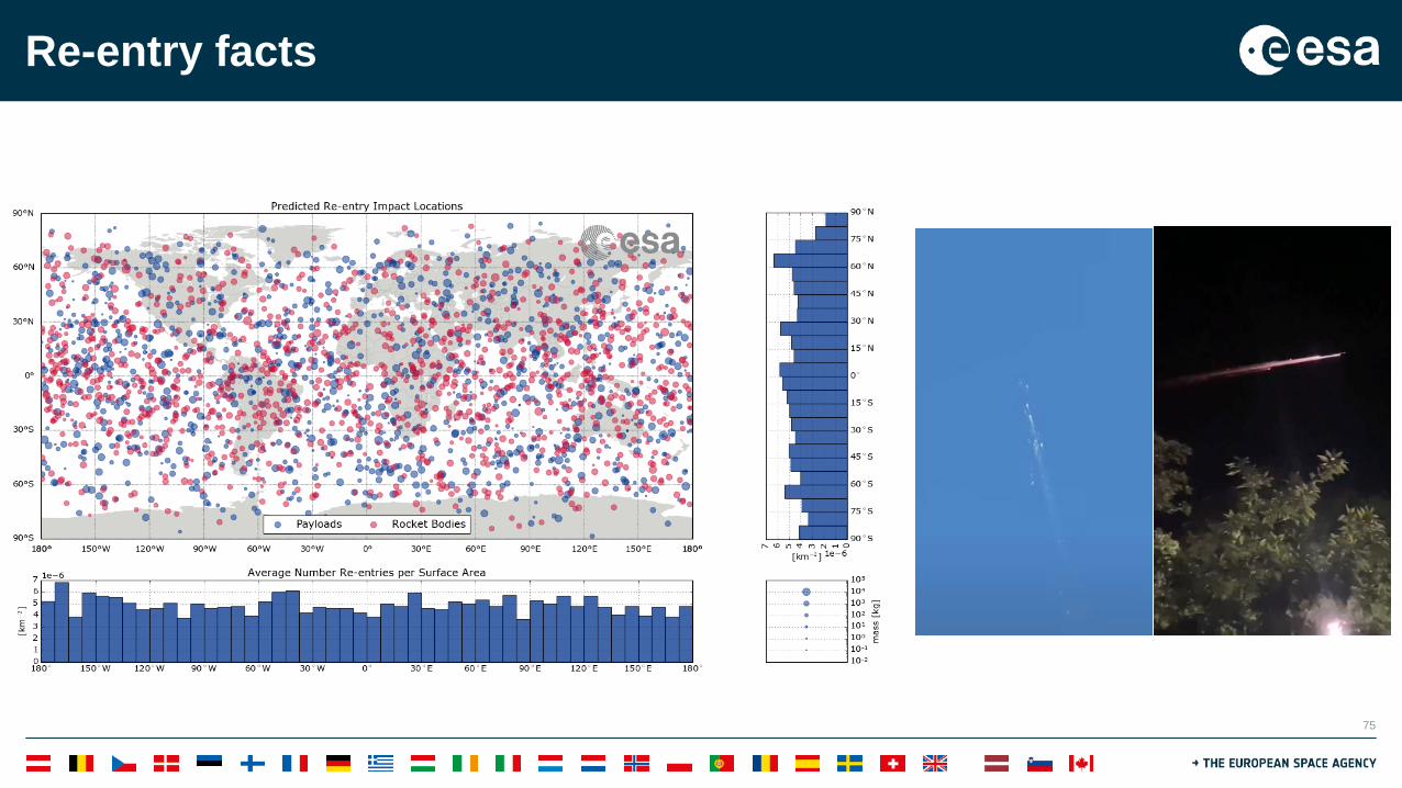
Re-entry facts
As a consequence of space debris mitigation, objects are re-entering( ~ 150 ton annually, only a limited amount controlled)
https://reentry.esoc.esa.int/home
75
Re-entry facts

76
Re-entry facts

77
Re-entry facts• More than 70 re-entry events involving recovered on-ground (> 50% were rocket bodies), but only 50 can be
linked to source objects with some certainty.
• Most often pressure vessels (about 60) and unidentifiable metal shrapnel found.
• The Delta-II second stage and PAM-D duo is the most identified source of re-entry debris (respectively 6 (4) and 5 times).

78
On-ground risk assessment: Law
United nation Liability convention:
• Re-entry from space (controlled, uncontrolled, and all in between)• Launch range safety• Airspace

79
On-ground risk assessment: STD
ISO 24113:2019 (ECSS-U-AS-10C Rev 1):

80
On-ground risk assessment: ESASince 2014, ADMIN-IPOL-2014-002e:
Since 2018, ESA Re-entry Safety Requirements (ESSB-ST-U-004):Applies to the re-entry of any ESA uninhabited space system, i.e. procured by ESA or operated under ESA responsibility: • Spacecraft, including mated configurations of space debris remediation missions,• Launch vehicle orbital stages (e.g. upper stages),• Unmanned steered vehicles,• Return items, either recoverable or non-recoverable
81
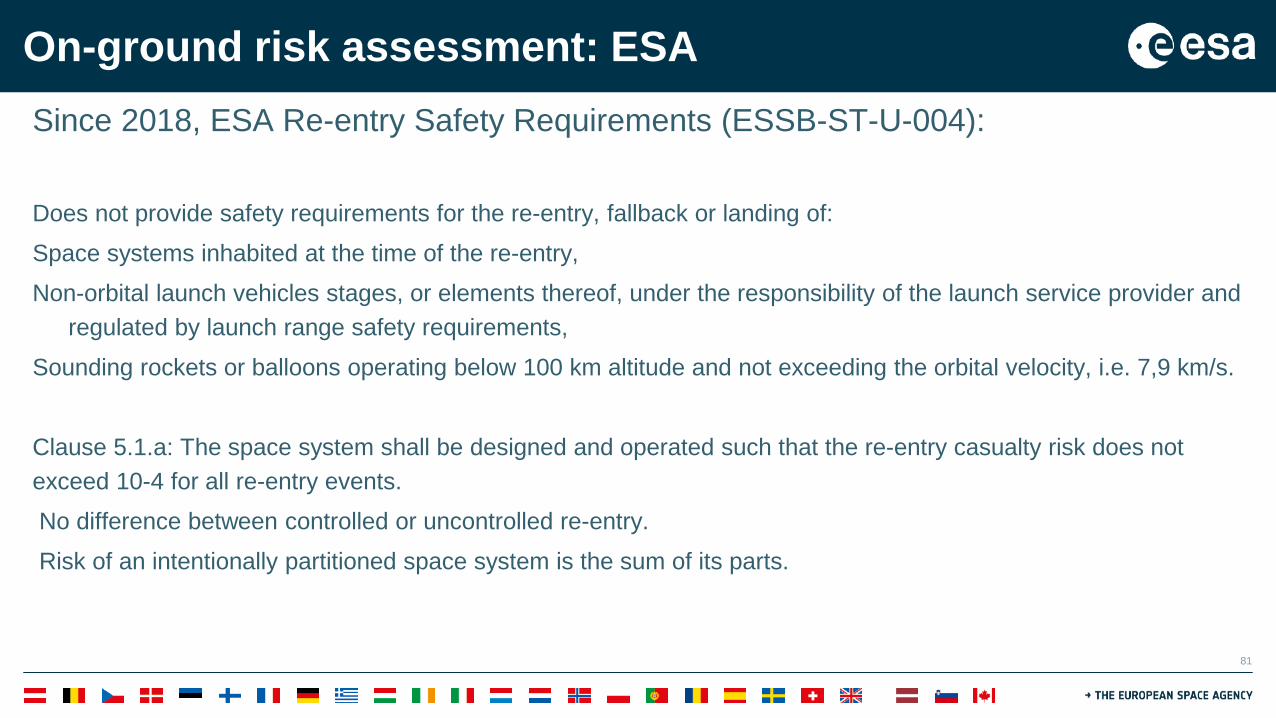
On-ground risk assessment: ESASince 2018, ESA Re-entry Safety Requirements (ESSB-ST-U-004):
Does not provide safety requirements for the re-entry, fallback or landing of: Space systems inhabited at the time of the re-entry,Non-orbital launch vehicles stages, or elements thereof, under the responsibility of the launch service provider and
regulated by launch range safety requirements,Sounding rockets or balloons operating below 100 km altitude and not exceeding the orbital velocity, i.e. 7,9 km/s.
Clause 5.1.a: The space system shall be designed and operated such that the re-entry casualty risk does not exceed 10-4 for all re-entry events.No difference between controlled or uncontrolled re-entry.Risk of an intentionally partitioned space system is the sum of its parts.

82
On-ground risk assessment: Practice
Eyewitness video posted to YouTube

83
(Re-)entry HazardsImpacting fragments
A fraction of the mass can survive re-entry depending on its design, trajectory, and atmospheric conditions.
Physical, chemical, thermal and mechanical properties of the structures and components, e.g. heat capacity, melting temperature, heat of melting, heat of ablation, thermal conductivity, density strength, fracture toughness and fatigue crack, and system configuration have a significant role on the re-entry survivability.
Sufficient kinetic energy to cause human casualties or damages to assets. Casualties can also result from indirect effects, e.g. secondary fragments, splatter, bounce, and
crater ejecta.
Floating fragments Fragments which survive a re-entry and have a mass to volume ratio allowing them to float over water .Hazard for human population, ships or assets in case of an accidental contact. Pressure vessels from spacecraft and launch vehicle stages can float.

84
(Re-)entry HazardsPressurized or explosive fragments
Pressurized fluids or explosive substances contained in re-entering pressure vessels. Violent release of energy, potentially leading to damages to constructions, creation of secondary
hazardous fragments, or injuries for human population (e.g. soft tissue effects involving eardrum).
Hazardous chemical substancesUncontrolled release of hazardous chemical substancesAtmospheric effects due to ablation and dispersion of chemical substances during re-entry events at
high altitudes (e.g. 100-60 km) are, currently, considered less critical due to relatively low mass of the re-entering objects and fast dilution into air.
Earth surface eco-toxicity and impact on human health. Dilution of hazardous fluids substances in the oceans is currently considered of lower concern.Dilution of some chemical substances into local watercourses or basins is a hazard for the local
ecosystem.

85
(Re-)entry HazardsRadioactive substances
Uncontrolled release of radioactive substances, which can be present in a re-entering space system, represent a risk for human health and Earth environment.
Nuclear Power Sources: Radioisotope Heater Units or Radioisotope Thermo-electric Generators .Sealed radioactive substances, which usually involve small quantities of radioactive material and are part
of some payload instruments.
Plutonium payload on board Apollo 13 lunar module which ended up in the Pacific Ocean close to the coast of New Zealand68 pounds of uranium-235 from the Russian Cosmos 954 which were spread over Canada’s Northwest Territories in 1978;In 1996 the Russian MARS96 disintegrated over Chile releasing its plutonium payload, which has never been found

86
Space Debris Mitigation Requirements
Space Debris Mitigation Requirements
The probability of serious injury or death on ground (casualty risk) shall not exceed 1 in 10,000 for any re-
entry event
End-Of-Life Measuresin Low Earth Orbit
ATMOSPHERIC RE-ENTRY
ON-GROUND CASUALTY
RISK
Design for Demise
Atmospheric re-entry within 25 years of mission completion.

87
Application: End of Life technology needs
LEOOn-ground
casualty risk < 10-4
YES
Deorbit maneuver
Low thrust Propulsive manoeuvre
Deorbit Device
Passivation
Power Subsystem
Propulsion Subsystem
NO
Design for Demise
Controlled reentry
High thrust propulsive maneuvers

88
On-ground risk assessment• (ESA’s) numerical perspective on casualty/fatality risks:
• (Straightforward) ways for risk reductions:• Stay away from populated regions, i.e. controlled re-entries,• Limit the debris generations, i.e. design for demise, • Question the calculation of the contributing terms.
Casualty expectancy per fragment
Impact probabilityPopulation density
Casualty cross-sectionCasualty indexBins on Earth surface
∑∑∑ ⋅⋅⋅=i
mnfmnCmnpn m
mniif APE ,,,,, )()()()( ηρ

89
On-ground risk assessmentCasualty risk for uncontrolled re-entry (EC,unc):
Total casualty area
Average population densityDepending on orbit inclination, latitude step size (circular orbits), argument of perigee
(elliptic orbit)
Depending on space system design and fragmentation process

90
On-ground risk assessmentCasualty risk for uncontrolled re-entry (EC,unc):
Casualty risk for controlled re-entry (EC,con):
Total casualty area
Average population densityDepending on orbit inclination, latitude step size (circular orbits), argument of perigee
(elliptic orbit)
Depending on space system design and fragmentation process
Local casualty area
Local population density
Local impact probability

91
On-ground risk assessment
Casualty risk for a failed controlled re-entry (EC,con,fail):
Failure probability

92
The question for early mission phases
(phased)(design for demise)

93
On-ground risk assessment: STD

94
VS
• Additional complexity • Additional mass• Additional costs
• Simpler system• Reduction in mass• Reduction in costs
NO DEMISE - Controlled reentry DEMISE - Uncontrolled reentry
D4D
Application: End of Life - Controlled vs Uncontrolled

95
Design for Demise
System level – the system has to ensure the break-up and the exposure of the equipment to the heat flux
Equipment level – the equipment have to ensure the demise of all the parts/fragments
𝑪𝑪𝒂𝒂𝒔𝒔𝑪𝑪𝒂𝒂𝑪𝑪𝑪𝑪𝑪𝑪 𝑪𝑪𝑪𝑪𝒔𝒔𝒓𝒓 < 𝟏𝟏𝟐𝟐−𝟒𝟒
Application: Strategy to develop the technologies

96
On-ground risk assessment: η• Casualty index η:
• Gradual change between 0 and 1 based on energy• Shielding effects, type of fractures, secondary impacts, …• Keep it conservative & simple: 0 when impact energy < 15J, else 1.
Safety Design for Space Operations, 2014

97
On-ground risk assessment: AC
• Casualty area:
• Ac union of a human Ah, 0.36m2,and the fragment Ai• The fragment area is computed as the average projected area of the fragment.• Attitude difficult to predict in advance.• Human area is defined by varying out over various postures against a re-entry trajectory.
( )2ihC AAA += Ai
Ah

98
On-ground risk assessment: AC (tools)• What is required to compute AC ?
• Description of the methodology of the computation• Description of the model assumptions and uncertainties• Description of the initial and boundary conditions• Determination of the re-entry probability• Determination of the failure conditions, in case of controlled re-entry• Determination of the geometrical and physical characteristics of all surviving fragments:
• Size, shape, cross-section• Mass, Material• Velocity, Kinetic energy

99
On-ground risk assessment: AC (tools)Object-oriented (approximations) re-cap:
• The break-up altitude is fixed, release of all components is sequential• All released components are pre-determined and have elementary shapes• All released components have pre-defined attitude and melt from the outside layer-by-layer
maintaining their shape type.• The trajectory of all fragments is computed as translational motion only (3 DOF).
• Defacto standardized

100
On-ground risk assessment: AC (tools)Spacecraft-oriented (engineering method) re-cap:
• Geometry, Centre of Mass and moments of inertia in a full-force and torque 6 DOF analysis are.
• Detailed model of the spacecraft is built in discrete volumepanels.
• Aerothermodynamic loads and heat transfer by convection,conduction and radiation, aerodynamic and dynamic forcesand structural loads are considered for each volume panel.
• Geometry evolution due to ablation of the panels, and theconsequences on the attitude.
• Expert tool for specific analysis

101
On-ground risk assessment: AC (tools)Explosion altitude assessment:
• An assessment of the probability of explosion vs altitude• Estimation of the residual quantity of fuel(s) and pressurized
fluids after the disposal phase and before the re-entry andfragmentation in atmosphere
• Probability of explosion with respect to altitude andfragmentation events during the re-entry, if residual fuels and/orpressurized fluids are still on-board
• Effects on the footprint extension due to the explosionaltitude(s)

102
Object oriented approach Spacecraft oriented approach
Modeling the S/C as a set of simple geometric objects (spheres, cylinders, plates, and boxes), parent object as a container for the internal components
Aerodynamic analysis based on the aero-dynamic parameters of the simple geometric shapes
Dynamic analysis simplified to assumed stable attitude motion or random tumbling (3 DoF equations of motion), ballistic re-entry
Aerothermal analysis for each object separately, heating based on shape specific heat transfer
Fragmentation analysis with assumed break-altitude and subsequently calculated exposure altitudes
Modeling the S/C as close as possible to the real design as one consistent object with a panelized geometry model
Aerodynamic analysis based on the estimated aerodynamic parameters of the real geometry
Full dynamic analysis for re-entry trajectory and attitude motion (6 DoFequations of motion)
Aerothermal analysis for the complete panelized geometry, panel-wise meltinganalysis
Fragmentation analysis based on ablation, stress and structural integritychecks
Component oriented approach
Modeling the S/C as a set of simple geometric objects, with connections and inclusions between those.
Aerodynamic analysis based on the aero-dynamic parameters of the simple geometric shapes and combinations
Dynamic analysis simplified to an assumed attitude motion or random tumbling (3 DoFor partly 6 DoF equations of motion)
Aerothermal analysis for each object accounting for connections, heating based on shape specific heat transfer
Fragmentation analysis with physics based break-up triggers (including melt or force) and subsequently calculated exposure trajectories
On-ground risk assessment: AC (tools)

103
Example: On-ground risk assessment AC
Object Oriented tools:• Hides away the underlying uncertainties of the re-entry process,• Excellent procedural tools, more difficult to interpret as engineering tools.
Spacecraft Oriented tools:• Alleviate the object-oriented issues from a research point of view,• But is not (yet) in a position to derive stochastic conclusions.
Gedankenexperiment: Model a spacecraft in both methodlogies:• Variations for material properties• Variations for attitude• Monte-Carlo mean and bootstrap mean

104
Example: On-ground risk assessment AC
The desirable agreement between methodologies is ‘lost’ in the stochastic domain.A thorough and expert review of the assumptions are of paramount importance when near the risk threshold.
Component based methods enable stochastics, design for demise, and knowledge transfer

105
Examples: On-ground risk assessment: AC

106
Example: On-ground risk assessment: AC

107
Example: On-ground risk assessment UncertaintiesParameter Uncertainty Comments Uncertainty reduction methodsAerodynamic dragContinuum
±10% uniform Could be systematically low for slender objects at low AoA
Delivery of a dedicated CFD, panel based, or test analysis for a specific shape
Aerodynamic drag and heating, Free molecular
±10% uniform Errors introduced by speed ratio and mutual shading
Delivery of a dedicated CFD, panel based, or test analysis for a specific shape
Heat FluxContinuum
±30% uniform Still very limited data available with which to make assessment. 30% is a conservative estimate
Delivery of a dedicated CFD or test analysis for a specific shape
Transitional dragand heating
±50% on characteristic length scale used for Knudsen number definition, uniform
Provide reasonable variation in transitional heating and aerodynamics whilst remaining continuous
Delivery of a dedicated CFD or test analysis for a specific shape
Oxidised Emissivity ±25%, triangular. Maximum does not exceed 1
Based on characterisation of demisable materials in ESTIMATE
Delivery of a dedicated test analysis for a specific material for inclusion in ESTIMATE
Specific heatcapacity
±5% normal three sigma limit Effect likely to be insignificant w.r.t. heating uncertainty
Delivery of a dedicated test analysis for a specific material for inclusion in ESTIMATE
Latent heat of melt ±5% normal three sigma limit Effect likely to be insignificant w.r.t. heating uncertainty
Delivery of a dedicated test analysis for a specific material for inclusion in ESTIMATE
Alloys melttemperature
±30 K uniform Capture non-eutectic effects based on the current tests in ESTIMATE
Delivery of a dedicated test analysis for a specific material for inclusion in ESTIMATE
Atmospheric density ±10% normal one sigma Based on seasonal variations not captured in a static model such as the recommended US76
In absence of dedicated atmosphere models it is not intended to be reducible for the time being,

108
Example: On-ground risk assessment Uncertainties
Parameter Uncertainty CommentsCritical joint temperature ±100K uniform Derived from test conditionsCritical joint dynamic pressure ±25% uniform Consistent with observation Critical joint break-up altitude ±10km uniform Consistent with observation
Parameter Uncertainty CommentsAerodynamic moments, free molecular and continuum
±10% uniform Analogy with space capsule studies. Uncertainty should be at least as large as for aerodynamic forces.
Adhesive joint Force: ±5N +20N, asymmetric triangularTemperature ±100K, uniform
Derived from test conditions
Insert joint Force: -5N, +20N, asymmetric triangularTemperature: ±100K, uniform
Derived from test conditions

109
Example: On-ground risk assessment Uncertainties
Observations Ground tests
(Aerospace Corp., IRS Stuttgart, ESA) (DLR/ESA, BRL/ESA)
Models
Approximations

110
Example: On-ground risk assessment Uncertainties
Observed Ground-test compatible
At system level, the fragmentation model (code dependent) does matter!

111
Example: On-ground risk assessment Uncertainties
Main break-up with 𝑠𝑠, BC, release conditions andsurviving and heating variation. (dummy)
Release conditions and surviving mass of a reaction wheel
At astrodynamics level, the perturbations and initial state do matter!

112
On-ground risk assessment: ρ• Gridded Population of the World v4 (2015)

113
On-ground risk assessment: ρUnited Nation Probabilistic Population Projections:
• Based on country/region-wise fertility, mortality, and migration• Risk calculations have to account for regional differences• The median model is adopted.

114
On-ground risk assessment: PNominal parameters, e.g. controlled or uncontrolled re-entry as planned.Off-nominal parameters, e.g. degraded controlled re-entry and uncontrolled re-entry
due to failure.• Epoch, initial orbital state vector at atmospheric entry, e.g. at least 120-130 km• Attitude (e.g. uncontrolled random tumbling, controlled stabilization, gravity gradient stabilization,
atmospheric drag stabilization)• Atmospheric density • Drag coefficient• Break-up/explosion altitude(s)• State vector, position/timing and Delta-v for direct re-entry boosts • Thrust level and pitch angle for direct re-entry boosts
Orbit type

115
On-ground risk assessment: PPre-entry = 1
for objects with permanent or periodic presence in LEOHighly eccentric orbits
Pre-entry ≈ 0Objects in GEO (classical), InterplanetaryNo indicated re-entry after centuries of orbit analysis (propagation)
0 ≤ Pre-entry ≤ 1Statistical risk indicated by Monte-Carlo analysis on limited (but long) time scaleObjects in GTO, Lagrange points

116
On-ground risk assessment: P• Circular re-entry:
• Re-entry driven by atmospheric drag.• Circularisation due to higher drag at perigee before re-entry.• Possible re-entry location in symmetric latitude band defined by the inclination (uniform longitude
band, average projected argument or latitude).

117
On-ground risk assessment: P• Eccentric re-entry:
• Re-entry driven by third body perturbations.• Ideally no circularisation before re-entry.• Possible re-entry location in limited latitude band defined by the break-up.• No analytic approximation.• Fragments can escape.

118
On-ground risk assessment: P & AC
• Eccentric re-entry:

119
On-ground risk assessment: P• Eccentric re-entry:
Observation Prediction

120
On-ground risk assessment: P• Re-entry from Earth-Sun Lagrange Points:
• All latitude bands and re-entry angles can theoretically be reached (depending on the energy of the orbit and perturbation by the moon).
• Stochastic analysis required.

121
On-ground risk assessment: P• Re-entry from Earth-Sun Lagrange Points:

122
On-ground risk assessment: P & AC
• Re-entry from Earth-Sun Lagrange Points:
Standard re-entry break-up models consider convective heating and thermal re-radiation
• 𝑄𝑄𝑐𝑐 ~ 𝑣𝑣3 𝜌𝜌𝑅𝑅
1/2
• 𝑄𝑄𝑡𝑡 ~ 𝜀𝜀𝑛𝑛𝛾𝛾4
At high velocities, 𝑣𝑣 >≈10 𝑘𝑘𝑚𝑚/𝑠𝑠, radiative heating can’t be omitted
• 𝑄𝑄𝑟𝑟 ~ 𝛾𝛾>0𝜌𝜌>1𝑓𝑓(𝑣𝑣)

123
On-ground risk assessment: P & AC
• Re-entry from Earth-Sun Lagrange Points:

124
On-ground risk assessment: P• Re-entry with a predictable ground-track:
• When following a particular object close to re-entry or semi-(un)controlled re-entries.• Fixed footprint length with cross-track components in the order or tens of km.
• 𝑃𝑃(𝑖𝑖,𝑚𝑚,𝑛𝑛) = 12𝜋𝜋Δ𝑥𝑥Δ𝑦𝑦
exp −12
𝑛𝑛𝑛𝑛𝑥𝑥Δ𝑥𝑥
2+ 𝑚𝑚𝑛𝑛𝑦𝑦
Δ𝑦𝑦
2𝛿𝛿𝛿𝛿𝛿𝛿𝛿𝛿
• Folded un top with the ±20%remaining orbital lifetime uncertainty.• More on controlled re-entries later

125
On-ground risk assessment: P• Re-entry with a predictable ground-track:

126
Activity Personal risk of fatalityCoal mining 9.3 x 10⁻³ 1/107
Cancer 1.8 x 10⁻³ 1/545
Fire fighting 8.0 x 10⁻⁴ 1/1250
Motor vehicle operation 2.2 x 10⁻⁴ 1/4500
Home accidents 1.2 x 10⁻⁵ 1/83000
Air travel 2.0 x 10⁻⁶ 1/500000
Lightning 5.0 x 10⁻⁷ 1/2000000
Space object re-entry 8.0 x 10⁻¹² 1/1200000000000
• Risk perception is a key issue for spaceflight.
• Annual personal risk of fatality due to common causes and activities (based on 1995 data).
• Large constellation could distort this picture.
On-ground risk assessment: Context

127
On-ground risk assessment: Context
• So far only one person ‘hit’ by a re-entryfragment, without injury.
• Risk of casualty for the Columbia disasterbetween 9 and 24 %.
• A few houses were reported to have been hit byre-entry fragments, but no claims so far.

128
The strategy for demise assessment

129
The strategy for demise assessment: Model limitsMODELS:
FLIGHT DYNAMICS
AERO-THERMO-DYNAMICS
HEAT TRANSFERS
MECHANICAL STRESS
FRAGMENTATION
CASUALTY RISK
Simulations are able to assess the re-entry trajectories, heating flux, casualty risk…but there are many uncertainties in the models assumptions
Example of a re-entry simulation (credit SCARAB-HTG)

130
The strategy for demise assessment: Ground test limits
PLASMA WIND TUNNEL AEROTHERMAL TESTS
On-ground tests are able to assess material properties, melting behaviors, shape effects…but there are many uncertainties in the test conditions
STATIC FACILITY THERMOMECHANICAL TESTS

131
The strategy for demise assessment: Flight test limits
RE-ENTRY CAPSULE
Flight experimentation are able to assess the break-up events, tumbling behavior, aerothermodynamic effects…but there are many uncertainties in the experiment
set-up
RE-ENTRY OBSERVATION

132
On-ground risk assessment: ModelsRisk models Physics models
• Active research field with many open ends implies a conservative approach when estimating the risk• On the other, not all aspects can be captured• Re-entry risk methods are determined by the risk taker.

133
On-ground risk assessment: Models
ROM assessment only helpful for limited set of orbits and clear cut-cases:• E.g. 2+ ton science mission in LEO -> controlled re-entry• E.g. CubeSat without large optical instruments -> uncontrolled re-entry
In other cases, the uncertainties are significant and require analysis:1. Aerothermodynamics (can be quantified and accounted for stochastically)2. Break-up phenomenology (Can be fixed at phase 0/A, D4D)3. The modeller’s interpretation of the task

134
Example: On-ground risk assessment ModelsElectronic cards have been found surviving re-entryThe design is out of scope for models (incl. CFD), i.e. proxies are developedAll casing (conservative), Amalgam material (guess), Combinations.

135
Example: On-ground risk assessment Models
An order of preference is available for the material properties to use:
1. Tested and calibrated properties from ESTIMATE2. For metallic alloys, use specialist databases such as NIST-JANAF
• Emissivity values are hard to find. In case of doubt: 0.8• For a alloys with same base metals, modify melt temperature
3. For inorganic compounds, use specialist databases such as NIST-JANAF4. Material properties for demise are ill defined for composites and glasses
• Glasses, use silicon carbide • CFRP tends to be calibrated on COPV overwraps, not structures

136
Example: On-ground risk assessment ModelsAn order of preference is available for the material properties to use:
5. “Equivalent” materials can be unavoidable (1/2)• For CFRP models, the baseline “burn through” approach is conservative• Establish a demise criteria on case-by-case basis.
Detachment
Burn through

137
Example: On-ground risk assessment ModelsAn order of preference is available for the material properties to use:
5. “Equivalent” materials can be unavoidable (2/2)• Often materials are mixed and properties are unclear• Use geometric or conservative reasoning to “nest” object, e.g. electronic boxes with aluminium
walls, star trackers containing titanium supports and silicate lenses• When nesting runs out, create an amalgam model for the mass, e.g. Electric material.
System level modelling should minimise mass deviation at sub-system and equipment level.• Avoid density modifications where possible

138
Example: On-ground risk assessment ModelsEquipment which can’t be represented faithfully and aren’t considered critical, are merged based on mass conservation with a larger component
• Joints in panels, CFRP face-sheets, harness/cabling and screws/bolts, …
As a conservative baseline, demise of a component is only achieved at full melt.
Connections between elements need to be mapped in order to determine expected fragmentation events by means of triggers.
• E.g. component melt, mechanical fragmentation, fragmentation altitude.• Capturing classical “solar panel break-off” as well as “Design for Demise”

139
Examples: On-ground risk assessment Models
• Include parts of known critical elements that could have a terminal energy above 15J.

140
Examples: On-ground risk assessment Models• Represent any approximate, or complex, shape with a simple primitive following the order of precedence:
1. Matching convex heating area,2. Matching ballistic coefficient,3. Matching aspect ratio,4. Matching real object dimensions.

141
Examples: On-ground risk assessment Models• Representation of any approximate, or complex, shape with a simple primitive should follow an order of
precedence.
• No conduction between modelled components should be assumed as baseline unless justified otherwise.
• Thermal conduction between different parts of an equipment or the equipment and the system can occur in practice, e.g. wall connection to the outside of the S/C
• Re-entry heating is fast, and conduction modes are not well established

142
Minimize Required Heat
Maximize Available Heat
Optimize Heat Transfer
Minimize Casualty Area
Minimize mass
Replacing materials Cp Tm ε qm
Ballistic coefficient
Increase local heat flux
Shapes of objects
Add energy Exothermic
reactions
Early break-up -Fragmentation Dedicated
mechanism Demisable
attachment points
Orifices, lattice structure
Keeping re-entry fragments together -Containment
The design for demise (D4D) techniques

143
D4D: The critical elements identified

144
Design for Demise – Current status @ System Level
Issues:Today it is estimated that the spacecraft structure break-up happens between 80 and 75 km altitude. In order to have a significant impact new structural designs should promote a control of the break-up/ fragmentation • Guarantee early fragmentation• Release altitude is used as requirement for equipment• Position of critical equipment• Minimize casualty risk of surviving fragments
Potential solutions• Early break-up structural joints• Containment

145
Demisable structural joints
Early break-up

146
Design for Demise – Current status @ Equipment level
Propellant tanks
Issues:Propellant tanks are contributors for the on-ground casualty risk, up
to 20% of platform footprint.• high melting point materials (titanium).• high area to mass ratio, that makes the tank decelerate
fast after being released from the spacecraft.• Normally located close to CoG and shielded by the
structure.Propellant tanks are used in all medium and large LEO platforms.Long term compatibility tests is necessary:
Shell material, diaphragm, sealing, welds.

147
Propellant tanks
Replacing materials
Material Ti6Al4V Al2219Qin=m*Cp*ΔT [kJ]20kg, 20°C to Tm
14455 5826
Qout=ε*σ*(Th4 -
Tc4)*A*t [kJ]
33682 2609
Qm[kJ] 8000 7700Qtotal[kJ] 56137 16135

148
Design for Demise – Current status @ Equipment level
Reaction Wheel
Issues:Reaction wheels are one of the major contributors for the on-ground casualty risk, up to 40% of the platform footprint.
• High melting point materials (stainless steel).• Dense ball bearing unit shielded by casing/outer
ring/spokes• Wheel can be shielded by panel to which they are
mounted• Four per spacecraft
Reaction wheels are used in virtually all LEO platforms.

149
Reaction wheelStep 1: Aluminum flywheelStep 2: Improve BBU/motor disintegrationStep 3: Oil chamber material change
Test on not-demisable RW, to verify simulations

150
Design for Demise – Current status @ Equipment levelMagnetorquers
Issues:The demise of magnetorquers largely depends on their accommodation, size and structural interface.It can account for up to 10% of the casualty risk of the platform.The main reason for the non-demise of the magnetorquers is:
• the late exposure to the external flow due to the attachment to the structural panels
• The nested design not allowing the metallic core to be exposed until very late during the reentry

151
MagnetorquersIncrease core exposureReplacing housing materials
Test on not-demisable MTQ, to verify simulations
152
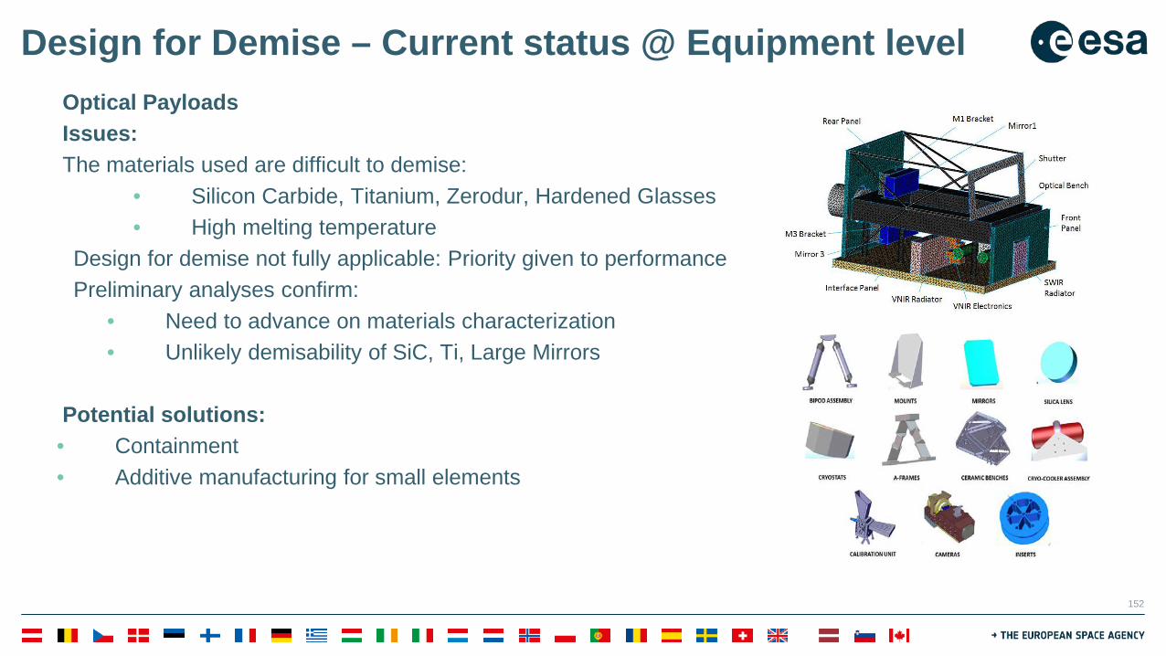
Design for Demise – Current status @ Equipment levelOptical PayloadsIssues: The materials used are difficult to demise:
• Silicon Carbide, Titanium, Zerodur, Hardened Glasses• High melting temperature
Design for demise not fully applicable: Priority given to performancePreliminary analyses confirm:
• Need to advance on materials characterization• Unlikely demisability of SiC, Ti, Large Mirrors
Potential solutions: • Containment• Additive manufacturing for small elements

153
Design for Demise – Current status @ Equipment levelMore elements have been tested and will be
tested to develop demisable technologies:
• Electronic box• Batteries• BBU (RW part)• Payload• Thursters• …

154
Summary
Risk models are constructed based on higher fidelity physics models, but are not necessarily the same, i.e. to allow uncertainty quantification and acceptance of residual risk.
The 10-4 casualty risk threshold is demanding for large spacecraft, imply a shift towards “design for demise” engineering or controlled re-entries.
There plenty of research lines open to on the on hand understand the sum of all uncertainties in the process, and on the other hand construct truly demisable spacecraft accounting for those uncertainties.

155
Thank you!

156
The material produced is property of the European Space Agency (ESA) or ESA's
licensors. No part of this material may be reproduced, displayed, amended, distributed or
otherwise used in any form or by any means, without written permission of ESA or ESA's
licensors. Any unauthorised activity or use shall be an infringement of ESA's or ESA
licensors' intellectual property rights and ESA reserves the right to defend its rights and
interests, including to seek for remedies.
Copyright © 2022 FDOKUMEN