The Analysis of Technical Trend in Islanding Operation ... - MDPI
28
resources Article The Analysis of Technical Trend in Islanding Operation, Harmonic Distortion, Stabilizing Frequency, and Voltage of Islanded Entities Thanh Son Tran 1,2, * , Duc Tuyen Nguyen 2 and Goro Fujita 3 1 Graduate School of Engineering and Science, Shibaura Institute of Technology, Tokyo 135-8548, Japan 2 Department of Power System, Hanoi University of Science and Technology, Hanoi 11615, Vietnam; [email protected] 3 Department of Electrical Engineering, Shibaura Institute of Technology, Tokyo 135-8548, Japan; [email protected] * Correspondence: [email protected]; Tel.: +81-806-188-9630 Received: 12 October 2018; Accepted: 18 December 2018; Published: 8 January 2019 Abstract: This paper focuses on autonomous multi-islanded entities and the seamless reconnection to the main grid as the self-healing ability of the future power system. The minimization of power quality issues (mainly that of voltage, frequency, and harmonics) in such entities based on controllers, with or without intercommunication, is also an important part of this paper. The future power system, with the significant penetration of distributed generations (DGs), can rapidly respond to any problem occurring within it by separating into autonomous islanded entities to prevent the disconnection of DGs. As a result, high-quality and continuous power is supplied to consumers. Finally, future research that is necessary for the realization of the future power system is discussed. Keywords: islanded operation; power quality; seamless reconnection; microgrid; distributed generation; droop control; hierarchical control; Energy Internet 1. Introduction The microgrid (MG) has been developed based on the important concept of distributed generation (DG) with high penetration of renewable energy integrated with energy storage systems (ESSs). In MGs, consumers forming parts of the grid invested in DG are able to generate, store, control, and manage a portion of the energy that they consume, resulting in a cheaper and more efficient energy supply solution [1]. To improve power system security, the distribution network can separate from the main power system and operate autonomously as an island during any unusual phenomena and then reconnect to the main grid if needed. Although the incorporation of technological advancements in digital control into modern communications has facilitated the islanding scheme, it presents challenges related to power quality, protection, out-of-synchronism reclosure, and earthing [2]. The IEEE standard 1547.4 enumerates the benefits of the islanded operation of MGs: (i) improving reliability for customers, (ii) relieving electric power system overload problems, (iii) resolving power quality issues, and (iv) allowing for maintenance of power system components without interrupting service to customers [3]. Therefore, autonomous operation subsequent to islanding will be very important in future grids with high DG penetration. Thus, advanced DGs with “plug and play” characteristics should be integrated with distribution systems. These DGs can operate seamlessly in grid-connected mode, islanding mode during the transient-to-islanded mode, and islanded operation, which reduces the chance of a load being unnecessarily excluded from the island and permits maximum flexibility of the multi-islanded system. The future power system can robustly respond to any fault occurring within by dividing Resources 2019, 8, 14; doi:10.3390/resources8010014 www.mdpi.com/journal/resources
-
Upload
khangminh22 -
Category
Documents
-
view
1 -
download
0
Transcript of The Analysis of Technical Trend in Islanding Operation ... - MDPI
resources
Article
The Analysis of Technical Trend in IslandingOperation, Harmonic Distortion, StabilizingFrequency, and Voltage of Islanded Entities
Thanh Son Tran 1,2,* , Duc Tuyen Nguyen 2 and Goro Fujita 3
1 Graduate School of Engineering and Science, Shibaura Institute of Technology, Tokyo 135-8548, Japan2 Department of Power System, Hanoi University of Science and Technology, Hanoi 11615, Vietnam;
[email protected] Department of Electrical Engineering, Shibaura Institute of Technology, Tokyo 135-8548, Japan;
[email protected]* Correspondence: [email protected]; Tel.: +81-806-188-9630
Received: 12 October 2018; Accepted: 18 December 2018; Published: 8 January 2019�����������������
Abstract: This paper focuses on autonomous multi-islanded entities and the seamless reconnectionto the main grid as the self-healing ability of the future power system. The minimization of powerquality issues (mainly that of voltage, frequency, and harmonics) in such entities based on controllers,with or without intercommunication, is also an important part of this paper. The future powersystem, with the significant penetration of distributed generations (DGs), can rapidly respond toany problem occurring within it by separating into autonomous islanded entities to prevent thedisconnection of DGs. As a result, high-quality and continuous power is supplied to consumers.Finally, future research that is necessary for the realization of the future power system is discussed.
Keywords: islanded operation; power quality; seamless reconnection; microgrid; distributed generation;droop control; hierarchical control; Energy Internet
1. Introduction
The microgrid (MG) has been developed based on the important concept of distributed generation(DG) with high penetration of renewable energy integrated with energy storage systems (ESSs). In MGs,consumers forming parts of the grid invested in DG are able to generate, store, control, and managea portion of the energy that they consume, resulting in a cheaper and more efficient energy supplysolution [1]. To improve power system security, the distribution network can separate from the mainpower system and operate autonomously as an island during any unusual phenomena and thenreconnect to the main grid if needed. Although the incorporation of technological advancements indigital control into modern communications has facilitated the islanding scheme, it presents challengesrelated to power quality, protection, out-of-synchronism reclosure, and earthing [2]. The IEEE standard1547.4 enumerates the benefits of the islanded operation of MGs: (i) improving reliability for customers,(ii) relieving electric power system overload problems, (iii) resolving power quality issues, and (iv)allowing for maintenance of power system components without interrupting service to customers [3].Therefore, autonomous operation subsequent to islanding will be very important in future grids withhigh DG penetration. Thus, advanced DGs with “plug and play” characteristics should be integratedwith distribution systems. These DGs can operate seamlessly in grid-connected mode, islanding modeduring the transient-to-islanded mode, and islanded operation, which reduces the chance of a loadbeing unnecessarily excluded from the island and permits maximum flexibility of the multi-islandedsystem. The future power system can robustly respond to any fault occurring within by dividing
Resources 2019, 8, 14; doi:10.3390/resources8010014 www.mdpi.com/journal/resources

Resources 2019, 8, 14 2 of 28
itself into several islanded entities without stopping the DG operation. This paper focuses on suchseparated multi-islanded entities and their seamless reconnection as a self-healing ability of the futurepower system. Controllers with/without intercommunication mitigate power quality problems inthese entities, and, eventually, the consumers will receive continuous power of high quality.
2. Flexible Operation of the Future Power System
Renewable energy (RE) has received attention worldwide due to its fantastic advantages: it is acheap/free fundamental fuel with no emissions. In particular, the 2011 Fukushima nuclear disasternecessitated the use of RE to compensate for the lack of power after shutting down Japan’s nuclearreactors and the sudden increases in CO2 emissions. With the high DG penetration of the distributionpower system, cost and reliability constraints may motivate a multi-functional power electronicinterface (PEI) for DG, where a single DG unit can perform many tasks, such as identifying andpreventing potential trends, islanding detection, synchronizing to the main grid, and black startoperation. Also, it is characterized by voltage ride-through capability, self-adaptive control, the powerquality of islanded entities, the flexibility to integrate DG by management and control, etc. Therefore,a reliable islanding detection method and a powerful PEI of DG will contribute to boosting the“proactive DG grids” concept.
2.1. Multi-Agent System for the Energy Internet
As stated in [4], the concept of the “Energy Internet”, as in Figure 1, has been recentlyproposed. The components of the Energy Internet consist primarily of RE, ESSs, and other partsof generations, which are not mentioned here. The Energy Internet has the ability to operate in eitherthe grid-connected or islanded mode. High RE penetration will inevitably change the way powerflows, transitioning from passive to active generation. In Figure 1, the Energy Internet is isolatedand cut off from the power supply due to a fault that occurred on a feeder which resulted in theopening of solid-state transfer switch (SSTS). The isolated entity can be reconnected with the utilityonce any RE is closed during the isolated period running as in an autonomous operation. The criticaldesign and control objectives of the Energy Internet during this mode are: (i) maintaining flexible andproportional power-sharing among REs; (ii) maintaining the system’s continuous synchronizationwith the utility in the presence of load variations; (iii) minimizing circulating currents betweenDGs; and (iv) achieving seamless energy transitions between the Energy Internet and the utility ifnecessary. The conventional power system uses the supervisory control and data acquisition (SCADA)system to exchange status and control signals of components. This centralized SCADA system wasoriginally designed for traditional passive networks; it thus may be inadequate to cope with complexcontrol decisions because it lacks flexibility and extensibility [5]. The designation of the controllerstructure used in an Energy Internet is based on the “multi-agent system” (MAS) structure, whereina different agent controls each component. The MAS helps monitor and control the new complexpower system. In the MAS, one centralized control is separated into simpler single entities thatwork in collaboration pursuing assigned tasks to achieve the overall goal of the system. It is asystem based on the advantages of the agents’ properties: flexibility, scalability, autonomy, sociality,reactivity, proactivity, and reduced complexity. Under the control of the MAS scheme, the powersystem performs demand-side management to secure critical loads, shedding low-priority loads insevere cases. Various RE units and other components of the grid communicate with the islanded entitythrough the IP-based local control model (IP = Internet Protocol). The entity disconnects itself from theutility and operates autonomously to maintain the integrity of the system.
Figure 1 shows three different agents designed for the distributed coordinated controller, includingthe upper-level coordinated control strategies, MG agent (MGA), and the RE agents (REAs). An REA,comprising a primary REA (PREA), secondary REA (SREA), and energy storage agents (ESAs),implements local decentralized continuous control. The MGA executes its functions according toinformation provided by all agents, and tasks are implemented by sending logic control commands

Resources 2019, 8, 14 3 of 28
to the unit control agents through a master/slave communication mode. The MGA is also called theenergy router and is used to regulate the power flow between the Energy Internet and the utility.The ESA and SREA together are called the energy switcher, which is used to regulate the power flowwithin the Energy Internet. Also, to improve the Energy Internet management, load agents (LAs)should also be considered. The Energy Internet operates under two modes: (i) the utility-connectedmode, in which the stiff utility compensates for power unbalance within the Energy Internet; (ii) theisolated mode, in which one of the DGs or REs should be chosen as the control master. Advanceddroop control is distributed to implement proportional power sharing among DGs in the EnergyInternet as a primary control. Then, a secondary control via a centralized or distributed method isadded to restore the voltage and frequency to nominal values. The centralized control, which requiresproper communication systems to realize the control goals, sometimes presents a single point failure.In such a scenario, the MAS acts as a kind of distributed control structure to make control decisionsfor each DG according to its neighbor’s information, demonstrating its flexibility for faster andcomputational efficiency.
Figure 1. Architecture of the Energy Internet.
Another approach is presented in Figure 2, which shows the architecture of an MAS. The MAScomprises four types of agent, namely, a control agent, a DER agent, an additional user agent, and adatabase agent. Each agent has a unique objective and responsibility, as defined explicitly in [6].The principle of agent structure is presented in Figure 3 [7]. According to information which is externalto the agent, the agent management creates a database, processes these data, and then outputs a controlsignal to its components regarding the response from the other agents.
An event-triggered hybrid control for the Energy Internet was proposed in [8]. In this paper,by developing an MAS-based event-triggered hybrid control scheme, the Energy Internet couldcomprehensively use the RERs when encountering load demand with high security. The MAScould be used to implement hierarchical hybrid control in a coordinated way based on four types ofcontrol strategies, such as hierarchical load shedding and the hierarchical switching control of RERs,designed as event-triggered functions (ETFs), or local switching control and distributed dynamicalcontrol, designed as constraint violation functions (CVFs), which are completely dependent on thelogical resource-grid-load-storage relationship.

Resources 2019, 8, 14 4 of 28
Figure 2. The microgrid (MG) multi-agent architecture.
Algorithm
Data
base
Processes
(Analysis and
Decision)
Other Agents
Communication
Environment
Information
Control
Command
Figure 3. Agent structure.
2.2. Flexible Operation
With the general theme “Flexible islanded operation of proactive DG grids”, the DG unit canoperate seamlessly in the grid-connected mode (by current control), islanding mode during thetransient-to-islanded mode (by energy storage), and islanded operation (by droop control) [9–11].Autonomous operation subsequent to islanding will be very important in future DG grids [12–17].The desired PEI-DGs with “plug and play” characteristics should be integrated into distributionsystems. As a result, the whole power system can robustly respond to any fault occurring withinby dividing itself into several islanded entities without stopping the DG operation. With DGs, inorder to fulfill these goals, the PEI plays the main role in control. Power electronic equipment reactsvery quickly, which can overcome severe transient events. Thus, besides interfacing with utility grids,PEIs have the potential to mitigate power quality problems (such mitigation includes active filtering,voltage unbalance compensation, grid support, and ride-through control under voltage dips, amongother functions) and carry out other duties, such as identifying and preventing potential trends.
Recent approaches focus on separated multi-islanded entities and seamless reconnectionto continuously supply power of high quality. It is not only self-control conducted without

Resources 2019, 8, 14 5 of 28
intercommunication [18,19]; some PEI-DGs of the DG grid are to be managed using a central controllerlinked by communicated signals [2,20,21]. Then, the power system operating with DG should emergeas a convergence of electrical, information, and technological engineering. Three operation modes ofthe DG grid are discussed herein, as follows:
• Grid-connected mode: To a large extent, grid-connected mode system dynamics are fixed by theutility because of the small size of the DG units. MGs aim to satisfy demand by local DGs. Excessor deficient active and reactive power in an MG can be absorbed or supplied by the utility grid,respectively.
• Autonomous/islanded operation mode: The disconnected scenarios include intentional (e.g.,maintenance or detection of a permanent fault) and unintentional disconnection (e.g., blackoutdue to disconnection from the utility). In this mode, the system dynamics are depicted by itsown DG units. The power balance within the islanded entity between generation and demandmust be observed to maintain system frequency and voltage within acceptable limits and ensurestability. Reactive power compensation and harmonic current are shared within an islanded entityby applying droop control to DGs. The virtual impedance method as an advanced techniqueis further used to reduce active power control errors, enhance fast dynamic control during thetransient, and minimize the circulating power among controllers, as seen in Figure 4.
• Transient mode: into-islanded and back into-utility: Power balance should be provided by powerstorage systems, such as batteries, super-capacitors, or flywheels. An intelligent bypass switch(IBS) [12] continuously supervises both grid-connected and islanded modes. When the IBS detectsthat maintenance is needed or a fault is present at the utility side, the islanded entity mustbe disconnected, and then a restoration process is activated to ensure high reliability. The IBScan detect the main grid’s fault-free stability and synchronize voltage amplitude, phase, andfrequency, which are utilized for the reconnecting procedure. In the event that islanded mode isforced to run for a long time, synchronization of voltage, frequency, and phase between islandedentities and the utility is implemented to seamlessly reconnect after an approximate zero-pointreclosing of smooth and soft synchronization.
Figure 4. Multi-loop control droop strategy with the virtual output impedance approach.
2.3. Hierarchical Control
Hierarchical control of islanded entities basically includes three main levels [12,22]. Primarycontrol is the droop control used to share loads between PEI-DGs in order to adjust the islandedfrequency or amplitude output voltage, as seen in Figure 5 hereafter. Local controllers in DG are

Resources 2019, 8, 14 6 of 28
operated primarily for speed and reliability. Secondary control is responsible for removing anysteady-state errors imposed by the primary control to guarantee the stabilization of voltage andfrequency for loads. It links all of the DG’s controllers to let the system respond consistently in widerareas. Power flow modeling of droop-controlled distributed generation units with secondary frequencyand voltage restoration control for hierarchically controlled islanded microgrids was introduced in [23].Tertiary control, which involves more global responsibilities, determines the import or export ofenergy among islanded entities to compensate for voltage harmonics in the point of common coupling(PCC) and generates synchronization loops to transfer from islanded mode back to grid-connectedmode. A simple illustration of the three-level hierarchical control is in Figure 5. All DGs in thehierarchy respond to disturbances as one set or, in the most appropriate manner, all DGs respondto a disturbance, and there will be a speedier return to a stable synchronous islanded operation.However, the whole control system must be resilient to a telecommunication delay and be robustto temporary communication outages. The communication bandwidth chosen for the entity is acompromise between the amount of data that is transferred along the network infrastructure and thetransient response that is required from the secondary control loops. A high data bandwidth implies afast transient response for the secondary control loops while providing a high data transfer rate alongthe network. Since the restoration of the voltage and frequency of the MG are noncritical, bandwidthcommunications of as low as 1 Hz can be used to achieve the required functionality.
Figure 5. Three-level hierarchical control strategy for the Energy Internet.
2.4. Load Sharing without Communication—Droop Control
As one level of the hierarchical mechanism, droop control concepts have been widely adoptedto provide decentralized power-sharing control between DGs without relying on communications.Assuming the line is mainly inductive, the P-f and Q-V droop strategies provide stable active andreactive power sharing. However, in a low-voltage distribution system, where the X/R ratio is small,especially for transformer-less inverters that have very small output inductance, droop control issubject to real and reactive power coupling and steady-state reactive power sharing errors. Additionalcompensation schemes for the traditional droop control, such as opposite droop, virtual inductance,average power control, or virtual impedance compensation, have been proposed for accurate powercontrol [20]. Moreover, in addition to droop control, communication can be used as a noncriticalelement in a higher control layer, such as the secondary control of the hierarchical structure, to enhancethe performance of the islanded entities without reducing system reliability. Therefore, each DG unitshould have the ability to exchange information with the central energy management system (EMS) toreceive the reference values through a communication link.

Resources 2019, 8, 14 7 of 28
Although the P-f droop technique can achieve accurate real power sharing, voltage droop controlQ-V commonly results in poor reactive power sharing. This is due to the mismatch in the voltagedrops across the DG unit feeders, which is induced by the mismatch in the feeder impedances (virtualoutput impedances of the closed-loop voltage controller of the DG units or feeder physical impedances,including the transformers, cables, and interface reactors, or even the variation of droop slope kQ)and even the differences in the power ratings of the units. The time delays in communicationsmay also significantly reduce the reactive power-sharing accuracy, which can also be affected bylost communication [24]. A complex configuration of an entity (looped or mesh networks) will alsomake reactive power-sharing more challenging and often degrade not only the voltage but alsofrequency quality due to a harmonic injection. In one study aiming to solve the reactive power-sharingproblem [19], small real-reactive power coupling disturbances (the real and reactive power are coupledtogether for frequency and voltage droop control) were injected to obtain accurate reactive powersharing before automatically switching back to conventional droop control. This method is effectivefor all types of configurations, and detailed structural information of these entities is not needed toachieve the “plug and play” operation of DGs and loads.
Two new problems need to be solved immediately in a cascade-type microgrid: the synchronizationand power balance of distributed generators. An f-P/Q droop control strategy is proposed in [25]to solve this problem. This proposed droop control can achieve power balance under bothresistive-inductive and resistive-capacitive loads autonomously. It has a clear advantage in extendingthe scope of application compared with the inverse power factor droop control.
2.4.1. Conventional Droop Control
In the grid-connected mode, the supply–demand balance of an MG is less restrictive since thegrid behaves like a large energy reservoir for buffering any mismatches between the power supply andload demand. The buffering effect is, however, not available in the islanded operation mode, whichrequires a stricter supply–demand balance. Also, a load-sharing function among the DGs is needed toavoid stressing a particular DG. As a result, the control of DGs needs a decentralized technique (i.e.,droop control), which is tuned according to the individual DG rating. The operation of DGs relies onlyon locally measured quantities and, hence, does not require communication links [26].
Figure 6 shows the typical configuration of an MG which consists of a number of REs or DGsand loads. Each DG is interfaced to an MG with a power conditioner system (PCS) consisting of aninverter, which then connects to a common AC bus by its own feeder. A central controller monitorsthe status of all components inside this MG to decide whether to operate in grid-connected mode orislanding mode by controlling the SSTS at PCC. While in the grid-connected mode, real and reactivepower references are normally assigned by the central controller, and conventional droop control canbe used for power tracking. The deficient or excess power can be easily compensated for by the utility.Then, typically, DG will generate its maximum power, and power sharing is not a concern in this mode.In the islanding mode, the total load demand must be properly shared by the DG units within theislanded entity by applying two well-known mechanism-based equations, as seen in Figure 7:
ω = ω0 − kPP (1)
E = E0 − kQQ (2)
where ω0 and E0 are the nominal values of DG angular frequency and DG voltage magnitude; P andQ are the measured real and reactive powers; kP and kQ are the real and reactive power droop slopes.

Resources 2019, 8, 14 8 of 28
Figure 6. Phase angle difference estimation.
Figure 7. Conventional droop control.
2.4.2. Advanced Droop Control
Since conventional droop control faces several drawbacks in term of sharing accuracy, improveddroop techniques have been proposed by many papers, year after year. In [18], a three-layer controlscheme was proposed for inverters operating in parallel without intercommunication. In [7], the droopcontrol method is proposed as a good solution to the outer loop power controller in an MG. However,the method itself is not suitable for the upcoming flexible MG. The inner loop controller (PI controller,robust controller, prescribed performance) ensures that frequency and voltage deviations are regulatedrobustly toward zero after every change in load or generation inside the MG. When nonlinear loadsexist, besides balancing active and reactive power, controlling that load sharing is a challenge. Thus,harmonic-current-sharing techniques have been proposed recently to avoid the circulating distortionpower that occurs when sharing nonlinear loads. Novel control loops that adjust the output impedanceof the units by adding output virtual reactors or resistors have been included in the droop method withthe purpose of sharing the harmonic-current content properly [1]. Further, by using the droop method,power sharing is affected by the output impedance of the units and the line impedances. Hence, thesevirtual output-impedance loops can also solve this problem. In this sense, the output impedancecan be seen as another control variable [1]. In case of paralleling DC power converters, the droopmethod consists of subtracting a proportional part of the output current from the output voltagereference of each module. Thus, a virtual output resistance can be implemented through this controlloop. This loop, also called the adaptive voltage position, has been applied to improve the transientresponse of the voltage regulation modules in low-voltage high-current applications. In addition, thedroop method has an inherent trade-off between voltage regulation and current sharing between theconverters. To cope with this problem, an external control loop, named secondary control, has been

Resources 2019, 8, 14 9 of 28
proposed to restore the nominal values of the voltage inside the MG. Further, additional tertiary controlcan be used to bidirectionally control the power flow when the MG is connected to a stiff utility (in thecase of AC MGs) [1].
2.5. Intelligent Controlled Islanding Scheme
During stressed conditions of power systems, such as peak load periods, a fault can causecascading problems that lead to grid collapse. To prevent a blackout, a power system can beintentionally split into separated self-healing islanded entities that await a reconnection condition.However, to establish an effective islanding scheme, many obstacles need to be overcome. Islandinglocations, time of disconnection, and the moment to reclose based on the network’s operating topologyor local relays are determined coordinately. The aim is to stabilize each islanding at the highest powerbalance, considering generator coherency. This configuration, where the number of islanding entitiesis known ahead of time, could facilitate autonomous operation within each entity. In a study by [27],one islanding execution algorithm and topology was performed. The procedure for determining thetime of islanding is performed at three different points: offline, online, and in real-time. The number ofstable islands with appropriate security levels is pre-determined by monitoring the dominant inter-areaoscillations between the initial groups (IGs), as depicted in Figure 8.
Figure 8. Determined initial groups (IGs) and islands boundaries in advance.
For the MAS, to exchange information and to coordinate control, the entities are connected tightlyin a cyber-communication network [28]. In the autonomous operation mode, each entity operatesindependently by controlling DGs, ESSs, and loads for economic and self-adequate objectives. Ideally,no information exchange or power flow exchange is needed among MGs. When a fault occurs in anentity, it receives power support from another entity in the self-healing mode. There are two layers in

Resources 2019, 8, 14 10 of 28
the cyber-communication and control network. The lower layer is in the entities to control DGs, ESSs,and loads locally, while the upper layer communicates with neighboring counterparts by broadcastingits power support request or response to other requests to obtain actual aggregated support until thefault is cleared to achieve overall reliability. Figure 9 shows autonomous networked MGs. The networkconsists of both strong cyber-links for communication and physical connections via a common pointfor power exchange. The connection could be a DC line to separate each MG completely.
Figure 9. Concept of networked MGs.
2.6. Role of ESS in Islanded Entities
Technically, controlling autonomous islanded entities is complicated. Due to its small physicalinertia, even a small interruption, such as the output power fluctuations of photovoltaics (PVs) or windturbines (WTs) and switching in/out of loads, may lead to voltage and frequency problems or MGinstability. With the crucial presence of an ESS, the frequency and voltage of an entity can be maintainedstably through an appropriate ESS controller by flexibly releasing or absorbing active/reactive power.For a small entity, one ESS as a constant voltage/frequency source can manage MG operation. Withthe larger entity, where many ESSs exist, coordinated control is relatively complex. Droop controlfor an ESS has been considered a solution in recent studies. The voltage angle and amplitude ofeach ESS are regulated according to their output active and reactive power, respectively. Therefore,the active/reactive power can be shared according to a preset droop coefficient among the parallelESSs. Unfortunately, since the real and reactive power coupling among ESSs is due to a predominantresistive MG, the control scheme is more difficult. As mentioned, advanced virtual output impedancemethods could enhance load sharing, but it reduces the control bandwidth, resulting in deteriorationof the system dynamic stability. Also, combining the traditional V/f droop control (VFDC) with P/Qdroop control (PQDC) to prevent the interference of line impedance uncertainty could enhance currentsharing among ESSs and system dynamic stability. An energy management system combined withhierarchical control based on smart communication for droop gain optimization also can be used toimprove the quality of voltage/frequency with secondary and even tertiary control. However, thedependence on communication will lead to another problem, such as increased cost and decreasedreliability [29].
DC MGs have recently drawn great attention for applications such as building electrical systems,data centers, and plug-in hybrid electric vehicles, due to their higher efficiency than AC MGs, theirflexible control capability, and the convenience of integrating DC resources and loads. A schematic ofa DC MG with the integration of RESs, battery energy storage systems (BESSs), and loads is shown inFigure 10. During autonomous operation, an ESS unit is also utilized in a DC entity to compensate for

Resources 2019, 8, 14 11 of 28
the power fluctuation between power generation and consumption. Bidirectional DC/DC convertersare used to control the output of battery banks. RESs, including solar PV and wind turbine generators,are integrated through DC/DC and AC/DC converters, respectively. RES converters normally operatein a maximum power point tracking (MPPT) mode to harvest maximum renewable sources. Abidirectional DC/AC converter as a link converter is used to interlink the utility with the DC bus.A contactor at the DC side can be installed between the link converter and the DC entity to controltheir connection. A contactor is an electrically controlled switch used for switching an electrical powercircuit, similar to a relay except with higher current ratings. The functionality and control method ofthe contactor is similar to that of an SSTS at the AC side in conventional AC entities. The contactor isclosed in the grid-connected state and opened during islanded operation in case of a utility grid fault.The linked DC/AC converter monitors the AC-side power quality (voltage magnitude, frequency,phase unbalance) to enhance the system’s response speed.
In an islanded DC entity, a coordinated energy management strategy, such as hierarchical control,should be used for power balance to prevent the ESS from overcharging and over-discharging.The state of charge (SOC) of an ESS is therefore monitored. Depending on different SOC scenarios,the coordinated operation of a DC islanded entity is achieved by managing all power flow from RESs,ESSs, and loads. The hierarchical structure is responsible for this coordinated control based on areliable communication link. Under hierarchical control, the lower control level receives commandsfrom the higher control level to take action. The secondary controller regulates the bus voltage at thenominal value. The central controller makes decisions based on the SOC condition of the ESS unitscollected from the primary level and then sends control mode signals to the other units. When one ESSis not fully charged, it is operated at the maximum power point (MPP) to utilize renewable energyeffectively. On the other hand, the controller limits the input power of an ESS unit when it is fullycharged. Simultaneously, RES units reduce their power output. When an ESS discharges during highpower consumption, RES units should operate at MPP. In cases where it is unavoidable, noncriticalload shedding can be conducted when power consumption is too high [30].
Figure 10. Schematic of a DC MG.
In the islanded mode, ESS units operate in voltage regulation mode and a linked DC/AC converteroperates in the idle mode. In term of the return-to-utility state, the voltage quality of the utility isfirst checked at the central controller to ensure the disturbance has been cleared. When it has metthe criteria, the signal for disturbance clearance is sent to the central controller through the SCADA.The link converter is activated to regulate the DC-side output voltage. It is checked again until the

Resources 2019, 8, 14 12 of 28
parameters are satisfactory. The voltage difference across the contactor should be minimized beforethe contactor is closed.
3. Future Perspective of Power Systems with High DG Penetration
Recent smart MGs are run based on small WT and PV sources, ESSs, and distributed loads whichare connected to the PCC of the utility through the intelligent bypass switch (IBS) or the conventionalSSTS. The overall system consists of a number of REs that require power electronic inverters. Becauseof the high penetration of REs, the integrated power system with a complicated physical connectionand multi-layer cyber-link might easily suffer cascading outages. Faults may have conventional causes,such as a short circuit, lightning, or huge load changes; faults may also have unconventional causes,such as a natural disaster or terrorist attack. Some recent research efforts with advanced technologiesare trying the address these problems: load forecasts to adjust the power balance during the day is akey power-saving solution which enables smart power communities [16]; a distribution network withresidential DG units should be actively made more flexible and dynamic where bidirectional powerflow occurs, as new reconfigurations could be frequently observed [17]; a networked communication,computation, and sensing system facilitates all robust controllers to make the grid more secure, efficient,and reliable by quickly responding to any abnormal phenomenon based on adaptive self-healing andself-organizing mechanisms [13].
To build a robust power system with high RE penetration, the main idea is to connect many reliableMGs to the main grid or interconnect them through tie lines, thus forming MG clusters. This canmake the control bulk system simpler, similar to the scheme in Figure 9. Each cluster is definedclearly, and the data of that cluster are sufficient and compensated whenever any new components,such as DGs or loads, are installed. The maximum number of elements within one cluster should bedetermined for easily handling tasks. In the distribution grid, to guarantee that the voltage of terminalloads is within limits, the number of elements from the substation cannot be too high. The conventionalpower system will be divided into many clusters. If a DC tie link cannot be made, the substation canbe considered the common coupling point of one cluster. In the future grid, with more smart elementsand sensitive load increases, cyber-attacks will increase, and the switch of elements will frequentlyoccur. Also, the current configuration of the power distribution system can lead to a cascade fault andblackout. A fundamental MG can be defined as a part of the grid consisting of prime energy movers,power electronics converters, distributed energy storage systems, and local loads. MGs should beable to operate autonomously but also interact with the main grid. The seamless transfer from thegrid-connected mode to islanded mode is also a desirable feature. A sequence for the seamless transferhas been described and implemented [31,32]. These tie DC lines will act as interchange energy channelsto balance the energy required by each MG; thus, the power flow of these lines will be further reduced.The clear operation of all elements of all grids could facilitate the flexible and reliable operation ofthe power system. Moreover, MGs represent a new paradigm of low-voltage distribution systems,since the generation is not only based on small generation machines but also on small prime movers,such as PVs, small wind turbines, or fuel cells, that require power electronic interfaces, such as AC/ACor DC/AC inverters. These power electronic devices act very quickly and have full control of thetransient response. However, in contrast with the generation machines, power electronics do not haveinherent inertia that ensures the stability of the system and the steady-state synchronization of eachunit. To compensate for this disadvantage, virtual inertias are often implemented through a controlloop—the droop method. This method consists of reducing the frequency and the amplitude of theinverter output voltage proportionally to the active and reactive power. Voltage and frequency droopcontrol has become disseminated and is regarded as a potential method [33–35]. Thus, MGs will beable to maintain an active and reactive power balance, as well as avoid voltage collapses.
Advancing toward a secured power system since the integration of renewable energies,reconfigured power systems require future research on: (i) resilient controllers for a stronger andsmarter grid by means of complex dynamical systems, forecasting uncertainty, and consideration of the
Resources 2019, 8, 14 13 of 28
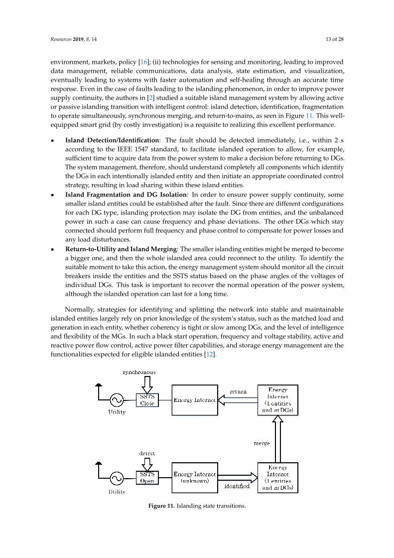
environment, markets, policy [16]; (ii) technologies for sensing and monitoring, leading to improveddata management, reliable communications, data analysis, state estimation, and visualization,eventually leading to systems with faster automation and self-healing through an accurate timeresponse. Even in the case of faults leading to the islanding phenomenon, in order to improve powersupply continuity, the authors in [2] studied a suitable island management system by allowing activeor passive islanding transition with intelligent control: island detection, identification, fragmentationto operate simultaneously, synchronous merging, and return-to-mains, as seen in Figure 11. This well-equipped smart grid (by costly investigation) is a requisite to realizing this excellent performance.
• Island Detection/Identification: The fault should be detected immediately, i.e., within 2 saccording to the IEEE 1547 standard, to facilitate islanded operation to allow, for example,sufficient time to acquire data from the power system to make a decision before returning to DGs.The system management, therefore, should understand completely all components which identifythe DGs in each intentionally islanded entity and then initiate an appropriate coordinated controlstrategy, resulting in load sharing within these island entities.
• Island Fragmentation and DG Isolation: In order to ensure power supply continuity, somesmaller island entities could be established after the fault. Since there are different configurationsfor each DG type, islanding protection may isolate the DG from entities, and the unbalancedpower in such a case can cause frequency and phase deviations. The other DGs which stayconnected should perform full frequency and phase control to compensate for power losses andany load disturbances.
• Return-to-Utility and Island Merging: The smaller islanding entities might be merged to becomea bigger one, and then the whole islanded area could reconnect to the utility. To identify thesuitable moment to take this action, the energy management system should monitor all the circuitbreakers inside the entities and the SSTS status based on the phase angles of the voltages ofindividual DGs. This task is important to recover the normal operation of the power system,although the islanded operation can last for a long time.
Normally, strategies for identifying and splitting the network into stable and maintainableislanded entities largely rely on prior knowledge of the system’s status, such as the matched load andgeneration in each entity, whether coherency is tight or slow among DGs, and the level of intelligenceand flexibility of the MGs. In such a black start operation, frequency and voltage stability, active andreactive power flow control, active power filter capabilities, and storage energy management are thefunctionalities expected for eligible islanded entities [12].
Figure 11. Islanding state transitions.

Resources 2019, 8, 14 14 of 28
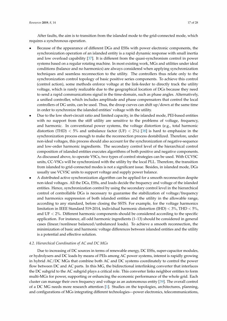
Because of the high penetration of RE with intermittent fundamental input energy andvariable power outputs, consideration must be given to the ability of controllers to maintainfrequency and voltage within limits; this is especially important for frequency variation, whichis particularly restricted in the synchronous islanded operation mode. In Figure 12, after the islandfragmentation transient, the ’gas-wind’ island can be held within. When island merging occurs withthe faster-responding diesel engine, control is improved and phase can be moderated. Therefore,faster-responding DG is beneficial. Additional phase control support for the island could be providedby other types of renewable technology, such as doubly fed induction generators (DFIGs) for the fastresponse of storage in the converter, energy storage with high-performance batteries, or a flywheelwhich can quickly balance a load–generation mismatch, and a load management system.
-60
-30
0
30
60
Ph
ase
dif
fere
nce
(d
eg)
Gas-wind
Diesel
Island
segment
Island control
improvedIsland
UnifyIsland
control
improved
Connect
to Utility Connect
to Utility
Detected
0.3
0.4
0.5
0.6
0.7
0.8
50 55 60 65 70 75 80 85 90 95 100 105 110 115 120
Rea
l p
ow
er
(p.u
)
Time (s)
Gas Diesel
Wind
Figure 12. Mechanism of Island segmentation, unifying, and connect to utility.
3.1. Improved Functions to Flexible Grids
In order to adapt to high-penetration RE power system, the following improvements to theconventional MG are fundamental:
• Reliable islanding detection;• Accurate grid impedance estimation to facilitate droop control;• Improvement in the transient response of each component itself as well as the entire collaborative
controller of MG;• Effective utilization of virtual impedance to share active/reactive power and harmonic
components;• Improvement in adaptive droop control laws to increase the interactivity of the system;• Hierarchical controls applied smoothly to improve self-healing ability;• Enhanced voltage ride-through and power quality in the PCC regulated by DG units;• Consider black start operation of each islanded entity to facilitate synchronous
multi-islanded operation;• More high-performance energy management support of ESSs.
These features will impart MGs with more intelligence and flexibility to integrate RE resourcesinto the future smart grid.
3.2. Communication System
The modern communication network is more critical to the power system operation. It is expectedto be secure, robust, scalable, and reliable, making it resilient to failures. The reconfigured gridhas a two-way flow, not only of electricity but also information, leading to an automated power
Resources 2019, 8, 14 15 of 28
network. The messages exchanged through the communication networks consist of either informationabout the status of the grid or commands that enable status changes in the configuration of thenetwork. Information and communication technology (ICT), Internet of Things (IoT), and ArtificialIntelligence (AI) will thus play a major role in realizing modern power grids [17]. The communicationmechanism can use power line signaling, smart meter technologies, or other commercial infrastructures(e.g., satellite, telephone, wireless, power line carrier, fiber optics, or microwaves based on LAN orWAN) [19]. Sensors need to be deployed in large numbers among MGs in order to efficiently monitorMG conditions, such as faults at the transformers, the status of the breakers, power flow magnitude,and flow directions in distribution lines.
In the multi-islanded operation, all entities are connected physically by interconnecting tielinks and communicatively based on the high-bandwidth communication link. New communicationprotocols provide new functionalities, such as data routing, broadcasting, multicasting, and so on.In the paper by [14], reliability communication is stated to have several facets: (i) probability that agiven message will be lost entirely; (ii) use of redundant communication paths; (iii) automatic failureto protect against message loss; (iv) the expected time delay in delivering a message and the expectedvariability of that time delay; and (v) how competing messages may (or may not) be given prioritywhen communication channels are saturated, known as quality of service.
When all information of the power system is stored online by IoT, protecting personal informationrelated to utility customers and information about the utility itself is important. Since customer-levelinformation is typically not very time-critical, slower and more computationally intensive mechanismscan typically be used to secure this information. A relatively critical protection requirement is placedon confidential information and the commands used to monitor and control the power system.To implement the best security, all the details of the security system should be published and wellknown, but the keys should be kept secret, where only the owner or another authorized party hasthe key. Applying a layered protection approach, with multiple levels of firewalls and “demilitarizedzones”, requires more secure corporative firewall data.
4. Hierarchical Control and Seamless Mode Transfer
4.1. Seamless Mode Transfer
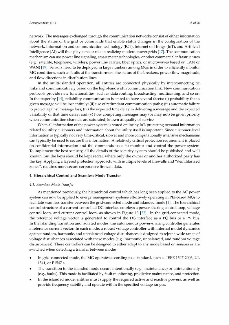
As mentioned previously, the hierarchical control which has long been applied to the AC powersystem can now be applied to energy management systems effectively operating in PEI-based MGs tofacilitate seamless transfer between the grid-connected mode and islanded mode [1]. The hierarchicalcontrol structure of a current-controlled DG interface employs a power-sharing control loop, voltagecontrol loop, and current control loop, as shown in Figure 13 [22]. In the grid-connected mode,the reference voltage vector is generated to control the DG interface as a PQ bus or a PV bus.In the islanding transition and isolated modes, the autonomous power-sharing controller generatesa reference current vector. In each mode, a robust voltage controller with internal model dynamicsagainst random, harmonic, and unbalanced voltage disturbances is designed to reject a wide range ofvoltage disturbances associated with these modes (e.g., harmonic, unbalanced, and random voltagedisturbances). These controllers can be designed to either adapt to any mode based on sensors or areswitched when detecting a transfer between modes.
• In grid-connected mode, the MG operates according to a standard, such as IEEE 1547-2003, UL1541, or P1547.4.
• The transition to the islanded mode occurs intentionally (e.g., maintenance) or unintentionally(e.g., faults). This mode is facilitated by fault monitoring, predictive maintenance, and protection.
• In the islanded mode, entities must supply the required active and reactive powers, as well asprovide frequency stability and operate within the specified voltage ranges.

Resources 2019, 8, 14 16 of 28
• Reconnection of the islanded entities to the utility will proceed as soon as the synchronizationoperation is made (matching the voltage, frequency, and phase angle between islanded entitiesand utility).
During the transient-to-islanded mode, the switching effect will impose voltage disturbances anda power angle on the output voltage of DG units, leading to the instability of power-sharing dynamics.This happens in conventional power controllers due to their lack of transient damping to react to largeswings and is a large-signal stability problem. For a smooth transition, a possible countermeasure isadaptive transient droop control, which simultaneously facilitates a stable and reliable DG operationin both the grid-connected mode and autonomous operation.
Figure 13. A hierarchical control structure of a current-controlled DG interface.
Two categories can be distinguished to achieve seamless transitions. (i) The first category employsprimary control loops implemented in the inverters, which make use of complex inverter topologies orcontrol algorithms to complete the transitions. (ii) The second category uses a hierarchical architecture,as explained for MGs.
• A study by [36] combined a single-phase MG composed of voltage-controlled voltage sourceinverters (VC-VSIs) (for batteries and other energy storage technologies) and current-controlledvoltage source inverters (CC-VSIs) (for renewable energy sources, such as PVs and microwind turbines, to maximize power output), which worked together in both operation modes.The primary control structures for VC-VSIs and CC-VSIs were considered together with secondarycontrol loops, which are used to synchronize the MG, as a single unit to the utility, ratherthan considering each unit separately. The integration of CC-VSIs into the MGs enables faultride-through capabilities for these inverters which can continue to generate power for the MG,even during islanded operation; this MG can then seamlessly disconnect from the grid andoperate autonomously, forming an island entity.
• If the energy sources are RE, one of the VC-VSIs should also ideally include an ESS due tothe intermittency of the power input. In such cases, an additional loop integrated into theprimary control loops of the inverters monitors the state of charge for the ESS, MPPT for thePV and micro-WTs, etc. The primary control implemented in the VC-VSIs enables operationin the islanded mode or grid-connected mode through the use of the droop control techniqueand islanding detection algorithms. Secondary control loops optimizing MG operation areused to minimize the reactive power flows between these inverters and achieve reactive powersharing between the inverters in the islanded mode while also providing voltage and frequencyrestoration. The tertiary control layer considers the interaction between multiple MGs universallyand the regulation of power flows across these MGs.
Resources 2019, 8, 14 17 of 28
After faults, the aim is to transition from the islanded mode to the grid-connected mode, whichrequires a synchronous operation.
• Because of the appearance of different DGs and ESSs with power electronic components, thesynchronization operation of an islanded entity is a rapid dynamic response with small inertiaand low overload capability [37]. It is different from the quasi-synchronism control in powersystems based on a regular rotating machine. In most existing work, MGs and utilities under idealconditions (balance and no harmonics) are always considered when applying synchronizationtechniques and seamless reconnection to the utility. The controllers thus relate only to thesynchronization control topology of basic positive series components. To achieve this control(control action), some methods enforce voltage at the link-feeder to directly track the utilityvoltage, which is rarely realizable due to the geographical location of DGs because they needto send a rapid communications signal in the time-domain, such as phase angles. Alternatively,a unified controller, which includes amplitude and phase compensators that control the localcontrollers of DG units, can be used. Thus, the droop curves can shift up/down at the same timein order to synchronize the islanded entities’ voltage with the utility.
• Due to the low short-circuit ratio and limited capacity, in the islanded mode, PEI-based entitieswith no support from the stiff utility are sensitive to the problems of voltage, frequency,and harmonic. In conventional power systems, the voltage distortion (e.g., total harmonicdistortion (THD) < 5% and unbalance factor (UF) < 2%) [38] is hard to emphasize in thesynchronization process enough to make the reconnection process destabilized. Therefore, undernon-ideal voltages, this process should also account for the synchronization of negative-sequenceand low-order harmonic ingredients. The secondary control level of the hierarchical controlcomposition of islanded entities executes algorithms of both positive and negative components.As discussed above, to operate VSCs, two types of control strategies can be used. With CCVSCunits, CC-VSCs will be synchronized with the utility by the local PLL. Therefore, the transitionfrom islanded to grid-connected modes is not a significant issue. Besides, in islanded mode, DGsusually use VCVSC units to support voltage and supply power balance.
• A distributed active synchronization algorithm can be applied for a smooth reconnection despitenon-ideal voltages. All the DGs, ESSs, and loads decide the frequency and voltage of the islandedentities. Hence, synchronization control by using the secondary control level in the hierarchicalcontrol of controllable DGs is necessary to guarantee the stabilization of voltage/frequencyand harmonics suppression of both islanded entities and the utility in the allowable range,according to any standard, before closing the SSTS. For example, for the voltage harmonicslimitation in IEEE Standard 519-2014, individual harmonic distortion (IHD) < 3%, THD < 5%,and UF < 2%. Different harmonic components should be considered according to the specificapplication. For instance, all odd harmonic ingredients (1–13) should be considered in generalcases (linear/nonlinear balanced/unbalanced loads). To achieve a smooth reconnection, theminimization of basic and harmonic voltage differences between islanded entities and the utilityis a potential and effective solution.
4.2. Hierarchical Coordination of AC and DC MGs
Due to increasing of DC sources in terms of renewable energy, DC ESSs, super-capacitor modules,or hydrolysers and DC loads by means of PEIs among AC power systems, interest is rapidly growingin hybrid AC/DC MGs that combine both AC and DC systems coordinately to control the powerflow between DC and AC parts. In this MG, the bidirectional interlinking converter that interfacesthe DC subgrid to the AC subgrid plays a critical role. This converter links neighbor entities to formmulti-MGs for power, supporting or enhancing the economic performance of the whole grid. Eachcluster can manage their own frequency and voltage as an autonomous entity [39]. The overall controlof a DC MG needs more research attention [1]. Studies on the topologies, architectures, planning,and configurations of MGs integrating different technologies—power electronics, telecommunications,

Resources 2019, 8, 14 18 of 28
generation, and ESSs—are necessary for ensuring a smooth transition between grid-connected andislanded modes. Compared with hierarchical control for large power systems with high inertiaand inductive networks, in PEI-based MGs, there is no inertia, and the nature of the networks ismainly resistive. Contrary to that previously mentioned, in the control of a DC MG, a zero-layer of azero-to-three level hierarchical controller has been adopted and organized, according to the literature,as follows.
• Level 0 (inner control loops): current and voltage, feedback and feed-forward, and linear andnonlinear control loops of each module can be performed to regulate the output voltage and tocontrol the current while keeping the system stable.
• Level 1 (primary control): the droop control method is used to emulate physical behaviors thatmake the system stable and more damped. A resistive virtual output impedance loop is includedthat integrates the soft-start approach.
• Level 2 (secondary control): maintains the normal values of frequency and voltage amplitudeinside the DC entity by the virtual inertia and output virtual impedance, which is related to theother control loops, such as inner current, voltage loops, and the droop control, in order to run asynchronization operation for seamlessly reconnecting to the utility.
• Level 3 (tertiary control): controls the power flow among DC or AC entities and utilities.
Figure 14 shows the primary, secondary, and tertiary controls of a DC MG. Once the DC MG isconnected to the DC source, the power flow can be controlled by changing the voltage inside the DCMG. By measuring the current iG (or the power) through the SSTS, it can be compared with the desiredpositive or negative current (i ∗ G) (or power), depending on whether energy is imported or exported.
Figure 14. Primary and secondary controls of a DC MG.
In Figure 15 is a multi-MG cluster which, in a universal view, constitutes a proactive DG gridregardless of whether it is a DC or AC configuration. Each MG has its own hierarchical controller.Communication among MGs uses hierarchical controllers. The tertiary control of a cluster can providehigh-level inertia to interconnect more MGs and fix the active and reactive power to be provided bythis cluster, or it can act as the primary control to interconnect more clusters. The secondary controlsends all references to each cluster of MGs to restore the frequency and amplitude. As a result, we canscale the control hierarchy as necessary. Using this approach, the system becomes more flexible andexpandable, and, consequently, it can integrate increasingly more MGs, without changing the localhierarchical control system associated with each MG.

Resources 2019, 8, 14 19 of 28
Figure 15. Clusters of multiple MGs forming a smart grid (SG) configuration.
4.3. Synchronous Operation for Reconnection
After a fault is cleared, an islanded entity is normally required to change its operational mode togrid-connected by reconnecting to the utility after synchronizing its operation. Contrary to a singlemachine using a synchronizer (phase angle, slip frequency, and voltage difference), the synchronizationof islanded entities operating with many active components (such as REs, ESSs, and conventionalgenerators) needs to be controlled in a coordinated way. This complicated scheme utilizes variousPEI-based DGs, as well as the collaboration of alternator-based generators, which determines thefrequency and voltage of entities. The common synchronization method, which waits for the fulfillmentof synchronizing criteria while maintaining the entity’s frequency and voltage at fixed values, does notalways yield consistent results. For example, it takes a very long time until the phase differencematches the criteria. Also, an important factor in measuring the synchronizing criteria is the estimationof the phase and frequency during non-ideal conditions. During synchronous operation, since theentity operates as an independent system, fast and robust voltage and frequency control must beprovided even under harmonics, unbalanced loads, and noise [40]. Recently, most control strategieshave been droop-based methods and/or master/slave control methods. DG units can be classifiedin power-controlled and voltage-controlled units. In the islanded mode, to maintain the voltageand frequency within the acceptable limits, at least one of the DG units is required to operate by avoltage-controlled mechanism. In droop-based methods, all DG units are involved in regulating thevoltage and frequency of islanded entities. In the master/slave method, a DG unit with the highestpower rating is responsible for regulating the voltage and frequency, as the master unit and the otherslave units produce pre-specified amounts of active and reactive power. Master/slave control schemesare found to be both costly and unreliable [41].
In islanded entities, controllable energy sources consider the battery energy storage system (BESS)and diesel generators while REs, including PV, WTs, fuel cell, etc., are regarded as uncontrollable dueto intermittent input energy. If an islanded entity has no rotational DG, the smart PCS of a PV or WTsystem will manage the frequency and voltage. The fuel cell generator, which needs a long time tochange its output, is responsible for the lowest frequency band using a low-pass filter. The dieselgenerator takes charge of the middle-frequency band using a bandpass filter. The BESS, which hasthe fastest response, should control the higher frequency band. In another scheme, diesel generatorswith a larger capacity (50 kW) are used for the lowest band, and smaller diesel generators (20 kW) takecharge of the middle-frequency bands.
To facilitate a synchronous operation, the SSTS connecting the utility and an islanded entitynormally use an intelligent electronic device (IED). The IED compares the criteria parameters of two
Resources 2019, 8, 14 20 of 28
sides for synchronizing criteria and switching the SSTS. It senses and compares the magnitude,frequency, and phase of the voltage of both sides during parallel operation to determine thesynchronizing criteria. Signals can be measured by using a reference frame (fixed or rotating)transformation-based method under balanced or even unbalanced conditions [21]. In the islandedmode, the BESS acts as one of several controllers for frequency and voltage control. Unlike thegrid-connected mode, the BESS does not strictly follow the reference values but uses the droopstrategy [20]. A number of feedback signals, such as the voltage, current, frequency, and power,must be measured or calculated to support the BESS controller. During autonomous operation,many inverter-based DGs adopt the droop strategy for stable power-sharing. Determining preciselythe components of unintentional entities in this mode is important for a central controller. Thatcontroller is used for active synchronizing control through the communication network. At first, itdecides on the system’s operational mode according to the SSTS connection status sensed by theIED. Then, it sends the operational command to every controllable DG to control the frequency andvoltage of the synchronized entity. In this mode, the REs operate with MPP tracking to maximize thegeneration efficiency. Not only is it uncontrollable, but it also acts as a disturbance in the maintenanceof the stable voltage and frequency of the islanded entity.
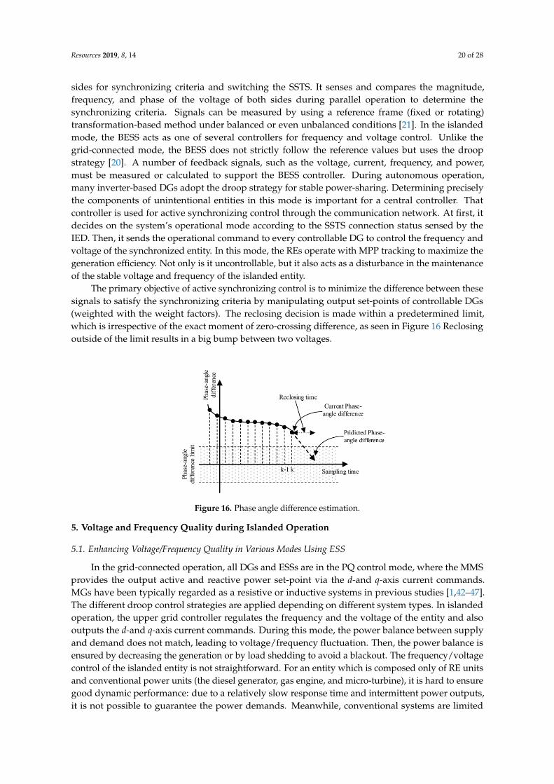
The primary objective of active synchronizing control is to minimize the difference between thesesignals to satisfy the synchronizing criteria by manipulating output set-points of controllable DGs(weighted with the weight factors). The reclosing decision is made within a predetermined limit,which is irrespective of the exact moment of zero-crossing difference, as seen in Figure 16 Reclosingoutside of the limit results in a big bump between two voltages.
Figure 16. Phase angle difference estimation.
5. Voltage and Frequency Quality during Islanded Operation
5.1. Enhancing Voltage/Frequency Quality in Various Modes Using ESS
In the grid-connected operation, all DGs and ESSs are in the PQ control mode, where the MMSprovides the output active and reactive power set-point via the d-and q-axis current commands.MGs have been typically regarded as a resistive or inductive systems in previous studies [1,42–47].The different droop control strategies are applied depending on different system types. In islandedoperation, the upper grid controller regulates the frequency and the voltage of the entity and alsooutputs the d-and q-axis current commands. During this mode, the power balance between supplyand demand does not match, leading to voltage/frequency fluctuation. Then, the power balance isensured by decreasing the generation or by load shedding to avoid a blackout. The frequency/voltagecontrol of the islanded entity is not straightforward. For an entity which is composed only of RE unitsand conventional power units (the diesel generator, gas engine, and micro-turbine), it is hard to ensuregood dynamic performance: due to a relatively slow response time and intermittent power outputs,it is not possible to guarantee the power demands. Meanwhile, conventional systems are limited

Resources 2019, 8, 14 21 of 28
by their insufficient dynamic performance for load tracking. In particular, the local frequency of theislanded entities may change rapidly due to the low inertia of the entire system. To overcome theselimitations, the introduction of an ESS is considered an effective solution to ensure power balance sincethis device is based on a power electronic device and has a very fast response time (in ms). The storagesystem in the entity is analogous to the spinning reserve of large generators in the conventional grid.The intermediate ESS is an inverter-interfaced battery ESS bank (BESS), compressed air energy storage(CAES), superconducting magnetic energy storage (SMES), electrochemical capacitor energy storage(ECES), supercapacitor, or flywheel energy storage (FES) [48].
A properly designed ESS can allow a system to stabilize by absorbing and injecting instantaneouspower. In previous studies, some ESS models have been proposed [49–53]. A cooperative controlscheme between the ESS and other DGs is needed to effectively achieve the goal in islandedoperation. A two-level control concept, which consists of primary and secondary control, has beenproposed to stabilize the frequency of islanded entity: the primary control action in the ESS and thesecondary control action in the entity management system (EMS). Fast-acting ESSs can effectively dampelectromechanical oscillations because they provide storage capacity in addition to the kinetic energy ofthe generator rotors, which can share sudden changes in power requirements [9]. Additionally, the EMSof the central controller of islanded entities deals with management functions, such as disconnectionduring faults, switching to other controllers of all components of the entity, resynchronization afterfault clearance, and the load-shedding process. This central controller is also responsible for thesupervisory control of DGs and the ESS units by universal communication. By using collected localinformation, the controller generates a power output set-point and provides it to the primary controllerof each DG unit and ESS unit to ultimately control the power output according to the given values.Fundamentally, the control capability of the ESS for balancing between generation and consumptionmay be limited by its available capacity. Therefore, the power output of the ESS should be brought backto zero as soon as possible by the secondary control in order to secure the maximum spinning reserve.
The secondary control algorithm of the central controller compares the measured power output ofESS (PESS and QESS) and the reference value (Pre f
ESS and Qre fESS) to obtain the error. This error generates
the total required power and sends the commands to dispatch power output set-points for eachindividual controllable DG unit based on its participant/weighted factor, which normally depends onits capacity. During islanded operation, the power output of diesel generators is also changed froman initial constant value to a new power set-point calculated by the secondary control, as shown inFigure 17 at t = 5 s. In this figure, the BESS is specifically tested to represent the ESS system. In thesecond event, 10 kW of active load change at t = 15 s, the ESS can afford to inject the necessary activepower into the entity to ensure power balance because the power output of the ESS is bringing it backto zero; thus, it has sufficient spinning reserve margin. The power outputs of the diesel generators arechanged from the initial constant values to new set points by the central controller. Facilitated by thiscooperative control, the frequency and the voltage can be regulated at nominal values successfully,as shown in Figure 18. Like a BESS, the PEI-DG can respond quickly enough to implement droopcontrol during the islanded operation. PEI-DG, however, depends on primary resources and a BESSdepends on the SOC. Therefore, both BESS and PEI-DG need to depend on slow-response DG units,such as a diesel or gas generator, for secondary control.

Resources 2019, 8, 14 22 of 28
Figure 17. Power outputs of an energy storage system (ESS) and microsources [9].
Figure 18. Frequency and voltage of an MG [9].

Resources 2019, 8, 14 23 of 28
5.2. Load-Sharing Operation of Distributed MGs
Generally speaking, in an islanded entity, unbalanced and/or nonlinear loads such as motorsmight exist. Normally, the impedance load can absorb a sudden change in instantaneous real andreactive power, such as an infinite sink. However, with motor loads, a sudden change in the terminalvoltage leads to a large oscillation in the real and reactive power level. Furthermore, the lineimpedances are not purely resistive or inductive, and the control of active and reactive power isnot totally decoupled in nature. Therefore, in terms of total harmonic distortion and voltage imbalanceindexes, the islanded entity should share the common loads entirely to ensure that quality within theislanding entity is maintained as it is in the grid-connected mode.
The conventional method for local load sharing is the droop characteristic using feedback localsignals. The droop coefficients are chosen to meet the voltage requirements at PCC points and basedon the rating of DGs. With non-ideal loads, both active and reactive power have double the frequencyand distorted components over the average components. Thus, DG units should supply double thefrequency and distorted components to compensate for the unbalance and harmonics. The centralcontroller is informed clearly of the status of all loads, DG units, and other parts among islandedentities by using a reliable communication system [10].
Calculating the output impedance of DG units, the feeder, and local loads can affect power-sharing,especially in Q-V droop control. However, due to the complex structure of an islanded entity, thesystem impedance cannot be straightforwardly estimated. Communication-based solutions are utilizedto improve the sharing accuracy. Although the diverged locations of DG units challenge this methodnow, it is expected to be solved soon by improved communication technology at low cost, such aswireless solutions. In another approaches, the whole MG system is proposed to be composed ofa certain physical network and several DG units in order to have most islanded entities in a clearconfiguration. Each DG unit can be equivalent to a droop-controlled voltage source (DVS) in serieswith a DG feeder. The DG feeder can be either a coupling inductor or a virtual feeder if the virtualimpedance method is applied. By separating DVS units from the system, the equivalent network of anMG is obtained. For example, the equivalent network in its entirety contains s DG feeders, n networkfeeders, s DVS nodes and m network nodes, where s is the number of DG units. Finally, the systemimpedance can be estimated in any islanding case [54].
5.3. Voltage Quality
The droop control used to share loads during the islanded mode was conventionally designedfor large synchronous generators in the balanced condition. Therefore, while applying it to a systemwith unbalanced loads, the unbalanced load currents flow through line and converter impedances,giving rise to unbalanced terminal voltages which can trip off sensitive loads. When the voltageunbalanced factor (VUF) thresholds of local buses are exceeded, to eliminate any tripping, one costlysolution is to install additional equipment, such as active power filters (APFs), static synchronouscompensators (STATCOMs), dynamic voltage restorers (DVRs), or unified power quality conditioners(UPQCs). A less costly but complicated alternative is to slightly enhance the capacity of existingconverters of DG units and to modify their control algorithms to include some compensation functions.Through proper control, unbalanced voltage is mitigated by injecting negative-sequence currentsthrough the current-controlled DG converters. Unbalanced voltage can also be compensated for byusing multiple DGs.
In order to achieve negative-sequence reactive power sharing, each DG is controlled as anegative-sequence conductor with its conductance drooping, along with the negative-sequencereactive power flow. However, the negative-sequence current sharing performance is affected byline impedance and droop coefficient mismatches. In this case, a droop controller can insert negative-and zero-sequence tunable virtual impedances, in addition to the usual positive-sequence impedance,allowing the DGs to perform selective voltage compensation. Normally, the enabled DG units maintain

Resources 2019, 8, 14 24 of 28
VUFs of the buses of interest at their thresholds, which can help to limit the currents passing throughthe enabled DGs while protecting their local sensitive loads.
In the case of a three-phase four-wire system, where four-leg converters are used for supplyingsingle- and three-phase loads with an additional zero-sequence current return path, sharing anunbalanced load current among those four-leg converters also needs to take the zero-sequencecomponent into account. It is necessary that the critical loads are placed close to converters with thecompensation ability whenever their VUF exceeds certain thresholds. A three-phase four-wire islandedentity with n DG units is shown in Figure 19. Each DG is tied to its local bus by a three-phase four-legconverter. The four-leg converters must regulate their respective bus voltages and share the loadsby applying droop control. The positive-sequence current component and negative-, zero-sequencecurrent components under unbalanced loads need to be addressed separately. All DGs are set to havethe same p.u. power ratings and the control scheme is implemented in the dq0 synchronous referenceframe. The central controller facilitated by communication links measures the voltage of the commonbus, makes the management decision, and then transmits the compensation references to the DGunits [26].
Figure 19. Illustrative three-phase four-wire islanded entity.
The configuration of a multi-functional inverter (MFI) with an ancillary service ofvoltage/frequency quality enhancement is depicted in Figure 20. With this system, extravoltage/frequency quality conditioners may no longer be essential in an inverter-dominated entity,avoiding additional investment and operational cost. Since it is the auxiliary function of an MFI,its capacity for voltage/frequency quality enhancement is limited and related to its working condition.Optimally utilizing the limited capacity of an MFI for harmonic and reactive power issues should beassigned with independent weights to enhance the voltage/frequency quality of the islanded entity asmuch as possible [55].
To integrate multiple MFIs into one power entity, a universal controller (UC) needs to bedeployed. This controller utilizes a multi-objective optimal compensation model to assign the optimalcompensation coefficients to each MFI based on the given initial information of the optimal model.In general, this control might use a hierarchical mechanism, and the optimal compensation may be

Resources 2019, 8, 14 25 of 28
embedded in the tertiary control to provide optimal voltage/frequency quality services. With the guideof the UC, each MFI partly compensates for these issues in the MG according to the multi-objectiveoptimal model in the tertiary control. Each MFI can autonomously work as an individual modulewithout needing information from the other ones. In secondary control, the power output of MFIs isexchanged and modified by the UC to ensure the safe and economic operation of the islanded entity.In the local primary controller of the MFI, an output current-tracking controller is embedded so thatthe MFI generates the desired active, reactive, and harmonic current that fulfill the functions requiredby the DERs interfacing with the utility and enhances the quality of voltage/frequency of the entity.
Figure 20. Microgrid feeder with a multi-functional inverter (MFI).
6. Conclusions
This paper discusses the islanding phenomenon and the subsequent required actions to maintainpower supply with high penetration of RE. The self-control of a DG unit and central control using ahierarchical scheme are explained in detail. The ability to operate in the conventional grid-connectedmode or islanded mode and the smooth transition between the two based on an advanced controllerare highlighted.
Many objects are discussed in this paper, including multi-agent systems for the Energy Internet,flexible operation in the “flexible islanded operation of proactive DG grids”, hierarchical controlof islanded entities, droop control (both conventional and advanced) for load sharing withoutcommunication, the intelligent controlled islanding scheme, and the role of the ESS in islandedentities, all of which show the flexible operation of the future power system.
Future perspectives of the power system with high DG penetration are also presented on the basisof discussions about improved functions for flexible grids and communication systems.
Moreover, knowledge surrounding hierarchical control and seamless mode transfer, such asseamless mode transfer, hierarchical coordination of AC and DC MGs, and synchronous operation forreconnection, is also considered to be an important part of this paper.
Furthermore, discussions regarding power quality (voltage, frequency, and harmonic) duringislanded operation are given to cover some important aspects of power generation.
Finally, for the smart and resilient operation of the emerging power system, many researchdirections which need investigation are presented, such as robust hierarchical controllers, advanceddroop control, active/reactive power sharing, harmonic mitigation within an islanded entity,high-performance ESS and its controller, and reliable communication systems.
Author Contributions: T.S.T. and D.T.N. extensively reviewed the literature and drafted the manuscript andG.F. provided feedback and critical comments for inclusions and finally helped in revising the manuscript toimprove the quality of paper. All authors provided critical feedback and helped shape the research, analysis andmanuscript. Besides, all authors discussed the results and contributed to the final manuscript.
Funding: This research received no external funding.
Conflicts of Interest: The authors declare no conflict of interest.
Resources 2019, 8, 14 26 of 28
References
1. Guerrero, J.M.; Vasquez, J.C.; Matas, J.; de Vicuna, L.G.; Castilla, M. Hierarchical control of droop-controlledAC and DC microgrids—A general approach toward standardization. IEEE Trans. Ind. Electron. 2011, 58,158–172. [CrossRef]
2. Best, R.J.; Morrow, D.J.; Laverty, D.M.; Crossley, P.A. Techniques for multiple-set synchronous islandingcontrol. IEEE Trans. Smart Grid 2011, 2, 60–67. [CrossRef]
3. IEEE Standards Coordinating Committee 21 (SCC21). IEEE Guide for Design, Operation, and Integration ofDistributed Resource Island Systems with Electric Power Systems; IEEE Std 1547.4; IEEE: New York, NY, USA,2011; pp. 1–54.
4. Sun, Q.; Han, R.; Zhang, H.; Zhou, J.; Guerrero, J.M. A multiagent-based consensus algorithm for distributedcoordinated control of distributed generators in the energy internet. IEEE Trans. Smart Grid 2015, 6, 3006–3019.[CrossRef]
5. Eddy, Y.S.F.; Gooi, H.B.; Chen, S.X. Multi-agent system for distributed management of microgrids. IEEE Trans.Power Syst. 2015, 30, 24–34. [CrossRef]
6. Pipattanasomporn, M.; Feroze, H.; Rahman, S. Multi-agent systems in a distributed smart grid: Design andimplementation. In Proceedings of the 2009 IEEE/PES Power Systems Conference and Exposition, Seattle,WA, USA, 15–18 March 2009; pp. 1–8.
7. Dou, C.; Lv, M.; Zhao, T.; Ji, Y.; Li, H. Decentralised coordinated control of microgrid based on multi-agentsystem. IET Gener. Transm. Distrib. 2015, 9, 2474–2484. [CrossRef]
8. Dou, C.; Yue, D.; Han, Qi.; Guerrero, J.M. Multi-Agent System-Based Event-Triggered Hybrid ControlScheme for Energy Internet. IEEE Access 2017, 5, 3263–3272. [CrossRef]
9. Kim, J.Y.; Jeon, J.H.; Kim, S.K.; Cho, C.; Park, J.H.; Kim, H.M.; Nam, K.Y. Cooperative control strategy ofenergy storage system and microsources for stabilizing the microgrid during islanded operation. IEEE Trans.Power Electron. 2010, 25, 3037–3048.
10. Majumder, R.; Ghosh, A.; Ledwich, G.; Zare, F. Load sharing and power quality enhanced operation of adistributed microgrid. Renew. Power Gener. IET 2009, 3, 109–119. [CrossRef]
11. Blaabjerg, F.; Teodorescu, R.; Liserre, M.; Timbus, A.V. Overview of control and grid synchronization fordistributed power generation systems. IEEE Trans. Ind. Electron. 2006, 53, 1398–1409. [CrossRef]
12. Vasquez, J.C.; Guerrero, J.M.; Miret, J.; Castilla, M.; de Vicuna, L.G. Hierarchical control of intelligentmicrogrids. IEEE Ind. Electron. Mag. 2010, 4, 23–29. [CrossRef]
13. Anderson, D.; Zhao, C.; Hauser, C.H.; Venkatasubramanian, V.; Bakken, D.E.; Bose, A. A Vitural SmartGrid. IEEE Power Energy Mag. 2012, 33–40. Available online: http://magazine.ieee-pes.org/files/2011/12/jan2012_anderson.pdf (accessed on 7 January 2019).
14. Nordell, D.E. Terms of protection: The many faces of smart grid security. IEEE Power Energy Mag. 2012, 10,18–23. [CrossRef]
15. Hull, J.; Khurana, H.; Markham, T.; Staggs, K. Staying in control. IEEE Power Energy Mag. 2012, 10, 41–48.[CrossRef]
16. Amin, S.M.; Giacomoni, A.M. Smart grid-safe, secure, self-healing. IEEE Power Energy Mag. 2012, 10, 33–40.[CrossRef]
17. Bouhafs, F.; Mackay, M.; Merabti, M. Links to the future. IEEE Power Energy Mag. 2012, 10, 24–32. [CrossRef]18. Hua, M.; Hu, H.; Xing, Y.; Guerrero, J.M. Multilayer control for inverters in parallel operation without
intercommunications. IEEE Trans. Power Electron. 2012, 27, 3651–3663. [CrossRef]19. He, J.; Li, Y.W. An enhanced microgrid load demand sharing strategy. IEEE Trans. Power Electron. 2012, 27,
3984–3995. [CrossRef]20. Cho, C.; Jeon, J.H.; Kim, J.Y.; Kwon, S.; Park, K.; Kim, S. Active synchronizing control of a microgrid.
IEEE Trans. Power Electron. 2011, 26, 3707–3719. [CrossRef]21. Cho, C.; Kim, S.K.; Jeon, J.H.; Kim, S. New ideas for a soft synchronizer applied to CHP cogeneration.
IEEE Trans. Power Deliv. 2011, 26, 11–21. [CrossRef]22. Mohamed, Y.A.R.I.; Radwan, A.A. Hierarchical control system for robust microgrid operation and seamless
mode transfer in active distribution systems. IEEE Trans. Smart Grid 2011, 2, 352–362. [CrossRef]

Resources 2019, 8, 14 27 of 28
23. Agundis-Tinajeroa, G.; Segundo-Ramíreza, J.; Visairo-Cruza, N.; Savaghebib, M.; Guerrerob, J.M.; Barocio, E.Power flow modeling of islanded AC microgrids with hierarchical control. Electr. Power Energy Syst. 2019,105, 28–36. [CrossRef]
24. Mahmood, H.; Michaelson, D.; Jiang, J. Reactive power sharing in islanded microgrids using adaptivevoltage droop control. IEEE Trans. Smart Grid 2015, 6, 3052–3060. [CrossRef]
25. Sun, Y.; Shi, G.; Li, X.; Yuan, W.; Su, M.; Han, H.; Hou, X. An f-P/Q Droop Control in Cascaded-TypeMicrogrid. IEEE Trans. Power Syst. 2017, 33, 1136–1138. [CrossRef]
26. Zhou, X.; Tang, F.; Loh, P.C.; Jin, X.; Cao, W. Four-leg converters with improved common current sharing andselective voltage-quality enhancement for islanded microgrids. IEEE Trans. Power Deliv. 2016, 31, 522–531.[CrossRef]
27. Isazadeh, G.; Khodabakhshian, A.; Gholipour, E. New intelligent controlled islanding scheme in largeinterconnected power systems. IET Gener. Transm. Distrib. 2015, 9, 2686–2696. [CrossRef]
28. Wang, Z.; Chen, B.; Wang, J.; Chen, C. Networked microgrids for self-healing power systems. IEEE Trans.Smart Grid 2016, 7, 310–319. [CrossRef]
29. Tang, X.; Hu, X.; Li, N.; Deng, W.; Zhang, G. A novel frequency and voltage control method for islandedmicrogrid based on multienergy storages. IEEE Trans. Smart Grid 2016, 7, 410–419. [CrossRef]
30. Wu, D.; Tang, F.; Dragicevic, T.; Guerrero, J.M.; Vasquez, J.C. Coordinated control based on bus-signalingand virtual inertia for islanded DC microgrids. IEEE Trans. Smart Grid 2015, 6, 2627–2638. [CrossRef]
31. Tirumala, R.; Mohan, N.; Henze, C. Seamless transfer of grid-connected PWM inverters betweenutility-interactive and stand-alone modes. In Proceedings of the Seventeenth Annual IEEE Applied PowerElectronics Conference and Exposition, Dallas, TX, USA, 10–14 March 2002; pp. 1081–1086.
32. Jung, S.; Bae, Y.; Choi, S.; Kim, H. A low cost utility interactive inverter for residential fuel cell generation.IEEE Trans. Power Electron. 2007, 22, 2293–2298. [CrossRef]
33. Borup, U.; Blaabjerg, F.; Enjeti, P.N. Sharing of nonlinear load in parallel-connected three-phase converters.IEEE Trans. Ind. Appl. 2001, 37, 1817–1823. [CrossRef]
34. Reza, M.; Sudarmadi, D.; Viawan, F.A.; Kling, W.L.; van der Sluis, L. Dynamic stability of power systemswith power electronic interfaced DG. In Proceedings of the 2006 IEEE PES Power Systems Conference andExposition, Atlanta, GA, USA, 29 October–1 November 2006; pp. 1423–1428.
35. Slootweg, J.G.; Kling, W.L. Impacts of distributed generation on power system transient stability.In Proceedings of the Power Engineering Society Summer Meeting, Chicago, IL, USA, 21–25 July 2002;Volume 2, pp. 862–867.
36. Micallef, A.; Apap, M.; Spiteri-Staines, C.; Guerrero, J.M. Single-phase microgrid with seamless transitioncapabilities between modes of operation. IEEE Trans. Smart Grid 2015, 6, 2736–2745. [CrossRef]
37. Tang, F.; Guerrero, J.M.; Vasquez, J.C.; Wu, D.; Meng, L. Distributed active synchronization strategy formicrogrid seamless reconnection to the grid under unbalance and harmonic distortion. IEEE Trans. Smart Grid2015, 6, 2757–2769. [CrossRef]
38. 519-2014—IEEE Recommended Practice and Requirements for Harmonic Control in Electric Power Systems; IEEE:New York, NY, USA, 11 June 2014; ISBN 978-0-7381-9005-1.
39. Che, L.; Shahidehpour, M.; Alabdulwahab, A.; Al-Turki, Y. Hierarchical coordination of a communitymicrogrid with AC and DC microgrids. IEEE Trans. Smart Grid 2015, 6, 3042–3051. [CrossRef]
40. Rezaei, M.M.; Soltani, J. Robust control of an islanded multi-bus microgrid based on input-output feedbacklinearisation and sliding mode control. IET Gener. Transm. Distrib. 2015, 9, 2447–2454. [CrossRef]
41. Abdelaziz, M.M.A.; Farag, H.E.; El-Saadany, E.F. Optimum reconfiguration of droop-controlled islandedmicrogrids. IEEE Trans. Power Syst. 2016, 31, 2144–2153. [CrossRef]
42. Lopes, J.A.P.; Moreira, C.; Madureira, A. Defining control strategies for microgrids islanded operation.IEEE Trans. Power Syst. 2006, 21, 916–924. [CrossRef]
43. Vandoorn, T.L.; Renders, B.; Degroote, L.; Meersman, B.; Vandevelde, L. Active load control in islandedmicrogrids based on the grid voltage. IEEE Trans. Smart Grid 2011, 2, 139–151. [CrossRef]
44. Barklund, E.; Pogaku, N.; Prodanovic, M.; Hernandez-Aramburo, C.; Green, T.C. Energy management inautonomous microgrid using stability-constrained droop control of inverters. IEEE Trans. Power Electron.2008, 23, 2346–2352. [CrossRef]
45. Diaz, G.A.; Gonzalez-Moran, C.; Gomez-Aleixandre, J.; Diez, A. Scheduling of droop coefficients forfrequency and voltage regulation in isolated microgrids. IEEE Trans. Power Syst. 2010, 25, 489–496. [CrossRef]

Resources 2019, 8, 14 28 of 28
46. Delghavi, M.B.; Yazdani, A. A unified control strategy for electronically interfaced distributed energyresources. IEEE Trans. Power Deliv. 2012, 27, 803–812. [CrossRef]
47. Delghavi, M.B.; Yazdani, A. An adaptive feedforward compensation for stability enhancement indroop-controlled inverter-based microgrids. IEEE Trans. Power Deliv. 2011, 26, 1764–1773. [CrossRef]
48. Ortega, Á.; Milano, F. Generalized Model of VSC-Based Energy Storage Systems for Transient StabilityAnalysis. IEEE Trans. Power Syst. 2015, 31, 3369–3380. [CrossRef]
49. Pal, B.C.; Coonick, A.H.; Jaimoukha, I.M.; El-Zobaidi, H. A linear matrix inequality approach to robustdamping control design in power systems with superconducting magnetic energy storage device. IEEE Trans.Power Syst. 2000, 15, 356–362. [CrossRef]
50. Wu, J.; Wen, J.; Sun, H.; Cheng, S. Feasibility study of segmenting large power system interconnections withAC link using energy storage technology. IEEE Trans. Power Syst. 2012, 27, 1245–1252. [CrossRef]
51. Sui, X.; Tang, Y.; He, H.; Wen, J. Energy-storage-based low-frequency oscillation damping control usingparticle swarm optimization and heuristic dynamic programming. IEEE Trans. Power Syst. 2014, 29,2539–2548. [CrossRef]
52. Singh, V.P.; Mohanty, S.R.; Kishor, N.; Ray, P.K. Robust H-infinity load frequency control in hybrid distributedgeneration system. Electr. Power Energy Syst. 2013, 46, 294–305. [CrossRef]
53. Fang, J.; Yao, W.; Chen, Z.; Wen, J.; Cheng, S. Design of anti-windup compensator for energy storage-baseddamping controller to enhance power system stability. IEEE Trans. Power Syst. 2014, 29, 1175–1185. [CrossRef]
54. Zhu, Y.; Zhuo, F.; Wang, F.; Liu, B.; Gou, R.; Zhao, Y. A virtual impedance optimization method for reactivepower sharing in networked microgrid. IEEE Trans. Power Electron. 2016, 31, 2890–2904. [CrossRef]
55. Zeng, Z.; Li, H.; Tang, S.; Yang, H.; Zhao, R. Multi-objective control of multi-functional grid-connectedinverter for renewable energy integration and power quality service. IET Power Electron. 2016, 9, 761–770.[CrossRef]
c© 2019 by the authors. Licensee MDPI, Basel, Switzerland. This article is an open accessarticle distributed under the terms and conditions of the Creative Commons Attribution(CC BY) license (http://creativecommons.org/licenses/by/4.0/).