The ABC's of Lightning
12
The ABC’s of Lightning DEHN, INC. TO BE SURE, USE DEHN ®
Transcript of The ABC's of Lightning

The ABC’s of Lightning
D E H N, I N C .
TO BE SURE, USE DEHN®

Lightning represents a stunning combination of nature’s beauty
and awesome power
The information contained in this catalog is as complete and accurate as possible. However DEHN® Inc., reserves the right to make changes to product specification and data without advance notice or obligation.
© COPYRIGHT 2002 DEHN®, Inc.
Lightning currents conducted in modern electrical circuits can cause immediate and catastrophic equipmentfailure. Surges from induced lightning and power switching operations are smaller but are more numerousand can result in equipment misoperation, lockup or damage.
DEHN®’s mission is “to protect life and property from the hazards of lightning and surges.” Lightning cannotbe prevented, but proper use of DEHN®’s Lightning and Surge protection can safely divert lightning currentsaway from ourselves, our homes and our businesses.
DEHN® has been providing Surge and Lightning Protection around the world for over 90 years. Currentlyemploying a staff of over 1000 highly qualified personnel throughout the world, DEHN® is active in over 50 countries.
DEHN® invests heavily in research and development, and is active in contributing and exchanging informationwith others at international technical conferences.

3
A surge is a very short burst of voltage, which if not suppressed, can cause equipment failure or lockup. The duration of a surge is less than 1/1000 of a second.Measurements of actual lightning strikes have shownthat the 10/350 µs waveform is a reasonable approximationfor the current waveform for the primary lightningstroke. Both the IEC and the IEEE have chosen the10/350 µs waveform to represent the electrical andmechanical stress associated with direct conducted lightning. This waveform, along with characteristic magnitudes, is detailed in IEC 61643-1, First Edition,1998, Surge Protective Devices Connected to Low-Voltage Power Distribution Systems, and the most recentlyapproved edition of IEEE C62.41.2, RecommendedPractice on Characterization of Surge Voltages in Low-Voltage (1000 V and less) AC Power Circuits.
Lightning occurs throughout the world, but someareas receive far more lightning than others. The UnitedStates, Mexico, Central America, and the northern part of South America are known as high lightning areas.Lightning occurs primarily in the northern hemisphere in the summer months, in the equatorial regions duringthe spring and fall, and in the southern hemisphere duringthe north’s winter.
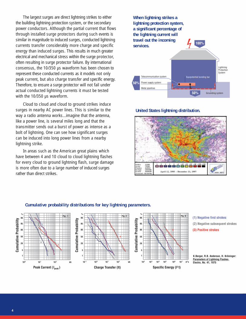
Lightning strokes can be either positive or negative.Worldwide, approximately 10% of all lightning strikesinvolve a positive stroke, and 90% of all lightning strikes involve a negative stroke. Although fewer in number, the positive strokes can pack a much greaterpunch as they have higher peak currents (Ipeak), transfer more charge (It), and have higher specific energy (I2t). Positive strokes occur much more often during cold front storms than warm front storms.
Within the United States, the highest incidence of lightning occurs in the southeast, with the “hot spot”being Florida. Although this area receives the highestincidence of lightning, it is predominately due to warmfront storms which produce almost entirely negativelighting strokes.
Although the mountain regions receive less lightning,they receive more of the large positive lightning strikesassociated with cold front storms.
In addition, the Rocky, Appalachian, and SierraNevada mountain ranges have low ratio of cloud to cloud vscloud to ground which means that a higher percentage of strikes reach the ground. As a result, even though thegreat plains have a higher lightning flash incidence thanthe Rocky Mountains, the mountain sites can often havemore severe direct strike lightning problems.
Time
The 10/350 µs waveform is used to represent conducted lightning currents.
Nominal Sag Swell Noise
Surge
Volta
ge
A surge is a short burst of voltage.
The ABC’s of Lightning and Surges
4
United States lightning distribution.
When lightning strikes alightning protection system, a significant percentage ofthe lightning current willtravel out the incoming services.
Cumulative probability distributions for key lightning parameters.
The largest surges are direct lightning strikes to eitherthe building lightning protection system, or the secondarypower conductors. Although the partial current that flowsthrough installed surge protectors during such events issimilar in magnitude to induced surges, conducted lightningcurrents transfer considerably more charge and specificenergy than induced surges. This results in much greaterelectrical and mechanical stress within the surge protector,often resulting in surge protector failure. By internationalconsensus, the 10/350 µs waveform has been chosen torepresent these conducted currents as it models not onlypeak current, but also charge transfer and specific energy.Therefore, to ensure a surge protector will not fail underactual conducted lightning currents it must be testedwith the 10/350 µs waveform.
Cloud to cloud and cloud to ground strikes inducesurges in nearby AC power lines. This is similar to theway a radio antenna works...imagine that the antenna,like a power line, is several miles long and that the transmitter sends out a burst of power as intense as abolt of lightning. One can see how significant surges can be induced into long power lines from a nearbylightning strike.
In areas such as the American great plains whichhave between 4 and 10 cloud to cloud lightning flashesfor every cloud to ground lightning flash, surge damageis more often due to a large number of induced surgesrather than direct strikes.

Comparison of direct and induced lightning currentwave forms.
placed between the surge source and the equipment to be protected. A surge suppressor on the main panel, no matter how good it is, will not provide protection if theequipment to be protected and the surge source are on a subpanel, or on the same branch circuit. Total facility protection requires coordinated main panel and sub panel protection.
Detrimental Effects of SurgesThe undesired consequences of surges include both
equipment damage and equipment malfunction or lockup.Equipment damage occurs when excessive surge voltageflashes over or punctures semiconductor junctions.Semiconductors are also sensitive to accumulated overvoltagestress. Successive surges chip away at the insulating layersin a process referred to as “electronic rust”. When theequipment finally fails it is often not attributed to surgesbecause there was no known major event such as a lightningstorm coincident with the damage.
Surges can cause equipment malfunction or lockup without causing damage. A small surge in a digital circuitcan cause a false data pulse and lock up the operating system. Although only a nuisance with a home computer,this same event with medical instrumentation, 911 emergency services equipment, or industrial processescan be very serious.
Both the IEC and the IEEE have standardized on the 8/20 µs waveform to represent induced lightning effects. The 8/20 µs waveform, along with characteristic magnitudes, is detailed in IEC 61643-1, First Edition,1998, Surge Protective Devices Connected to Low-Voltage Power Distribution Systems, and IEEEC62.41.2, Recommended Practice on Charactrization of Surge Voltages in Low-Voltage (1000 V and less) AC Power Circuits.
Surges are also generated due to self-inductance whenever power is switched on or off during a non-zerocrossing point of the sine wave. Although smaller thanlightning derived surges, these switching surges can be frequent enough to result in long term cumulative damage to solid state circuitry.
Surges that occur from the switching of electricalcurrent include power factor correction capacitors, heavyequipment cycling, and even small swiches. The powercompany switches power factor correction capacitors on or off the power line to compensate for the large inductiveload of industrial motors. If surge problems regularlyoccur in relation to industrial plant operating hours,power factor correction capacitors may be the cause.
Within the facility, surges can be caused by elevatormotors, air conditioning compressors, copy machines,and other equipment. These internally generated surgesare both smaller in magnitude and more numerous thanexternally generated surges. To protect equipment frominternal surges requires that the surge protector be
5
Direct lightning current 10/350 µs
Induced lightning current 8/20 µs

A recent study showed that property damage was attributable to Lightning and Surges one out of three times.
Modern equipment is much more susceptible to surge damage than equipment of the past. This isbecause the number of semiconductor junctions perdevice continues to increase, while the insulation distances between traces within a semiconductor continue to decrease.
A surge protector works like an overpressure reliefvalve, reducing voltage at the equipment by allowing excess current to flow to ground.
More transistors per chip and smaller trace widths make modern equipment increasingly susceptible to surges.
1971 4004 2,300 0.1 MHz 10.00 micron
1974 8080 6,000 2.0 MHz 6.00 micron
1978 8086 29,000 5.0 MHz 3.00 micron
1982 80286 134,000 8.0 MHz 1.50 micron
1985 80386 275,000 16 MHz 1.00 micron
1989 80486DX 1,200,000 25 MHz 0.80 micron
1993 Pentium 3,100,000 60 MHz 0.60 micron
1998 Pentium II 7,500,000 400 MHz 0.25 micron
2001 Pentium IV 42,000,000 2000 MHz 0.13 micron
Year Model Transistors Speed Trace Width
Surge Protector BasicsA surge protector is an overvoltage voltage pressure
relief valve. At normal system voltages, the valve is closed.When a dangerous overvoltage occurs, the surge protector operates and reduces voltage to the protectedequipment by allowing current to flow to ground.
To be effective, the surge protector must be placedbetween the source of the overvoltage surge, and theequipment to be protected.
Two different types of surge protection componentsare used: crowbar components and clamping components.Each of these different types has unique properties and considerations.
Crowbar type components include solid state thyristors and gas tubes. A crowbar surge protectioncomponent is an on/off switch. At normal voltage it acts
as an insulator. Above its turn–on point, it crowbars, creating a short circuit. Gas tubes can handle large surgecurrents in a very compact design with a very lowcapacitance, which makes them ideal for use on high density signal and data circuits.
6

Individual surge protector components have limitedsurge capability and surge pulse life. In order to increasesurge capability and pulse life, designers typically combinemultiple surge protection components in parallel. Non-linearcomponents such as MOVs (metal oxide varistors) andSADs (silicon avalanche diodes) share more equally at higher peak currents than at lower peak currents. For individual components, engineering scaling factors are
V
A crowbar device crowbars the surge voltage below the circuit voltage.
A clamping device clamps the surge voltage above the circuit voltage.
A clamping type surge protector is a variable resistor.Clamping type components include silicon avalanchediodes (SADs) and metal oxide varistors (MOVs). At normal circuit voltage a clamping component has a low leakage current and acts as an insulator. Above its turn– onpoint, its resistance drops dramatically. When a clampingdevice operates, it clamps the surge voltage to a valueabove the nominal operating voltage of the circuit. Unlikea crowbar protector, a clamping protector does not havean impulse voltage overshoot, and thus typically has a lower peak let-through voltage. However, clampingcomponents have a relatively large capacitance, which limits their use on signal and data circuits.
7
Placing MOVs in parallel increases surge capabilityand pulse life.
often used between different surge current waveforms.Because non-linear components do not share as well on lower amplitude longer duration waveforms, scaling factors cannot be used for multiple component paralleldesigns. Parallel component designs for use against conducted lightning currents must be tested with the10/350 µs waveform rather than relying on an 8/20 µsscaling factor.
Both MOVs and SADs fail in a low impedance orshorted state. This means that when used on power circuits, an overcurrent disconnect device must be providedwithin the protector. When used on a multiple componentparallel design, use of a single disconnect means that theentire surge protector will be taken off line if a singlecomponent fails. Modern surge protectors often usefuses or thermal elements on each of their paralleledprotection components (MOVs/SADs) so that when asingle component fails the remainder still provide protection for the load. When combined with individual component monitoring, use of this paralleled disconnectscheme allows replacement of the failed component without ever losing surge and lightning protection.
Single thermal disconnect removes entire surge protection.

Individual thermal disconnects provide individual isolation of failed units.
Parallel MOVs increase surge capability and pulse life
Coordinated hybrid designs such as the DEHN® Inc.BLITZDUCTOR® provide high surge capacity and lowclamping voltage in a compact low capacitance design.
Modern surge protectors such as the DEHN® model S200A use paralleled MOV’s in each circuit, with individual thermal disconnects and monitoring circuitry for each MOV. In the event of an individual MOV failure, theremaining MOV’s continue to function, providing uninterrupted surge protection. The monitoring circuit indicatesa failed MOV, which can then be replaced without ever losing surge protection.
8
In order to reduce size and capacitance, surge protectors for signal and data circuits are based on a coordinated decoupled hybrid design.
Such a design uses one or more high capacity gastubes to provide brute force protection. Gas tubes handlelarge surges, have a very low parasitic capacitance, andare very compact, however they have a slow responseand relatively high sparkover voltage.
A fast acting suppression diode is added to the circuit to provide high-speed response and tightclamping voltages. Since the diode acts faster andclamps lower than the gas tube, a decoupling impedanceis used between the two components. The voltage dropacross the decoupling impedance ensures the gas tubewill fire before the diode’s surge capability is exceeded.
Since the voltage drop across the decoupling impedance is dependent on peak current, lower amplitude longerduration waveforms than the protector was designedand tested for can result in diode failure. Therefore,decoupled hybrid component designs for use against conducted lightning currents must be tested with the 10/350µs waveform rather than relying on an 8/20 µs scaling factor.

Clamping voltage as a function of peak current for a typical surge protector.
Surge Protector CharacteristicsThe ideal surge protector must meet three basic goals:
1. Do a good job2. Last a long time3. Be easy to use and maintain
A Surge Protector Should Do a Good JobTo do a good job the surge protector needs to protect
the equipment. This means that when the surge protectoris subjected to surges representative of the environment in which it will be installed, it must reduce the voltage at the protected equipment to a level the equipment can withstand without damage or upset. To verify that the surge protector will do a good job, we need to establish:
1. What surges are characteristic of the environmentin which the surge arrester will be installed.
2. The maximum residual voltage the equipment cantolerate without damage or upset.
The surge environment is defined by IEEE C62.41.2,Recommended Practice on Characterization of Surges in Low Voltage (1000 V and Less) AC Power Circuits.Although this IEEE standard defines test waveforms, it does not specify the required let-through voltage necessary to protect equipment. Required values for let-through voltage are contained in Telcordia TR-TSY-0001011 Generic Requirements for Surge ProtectiveDevices (SPDs) on AC Power Circuits. This Telecordiaspecification, which is widely recognized throughout the
telecommunications industry, places a let-through voltagelimit of 1340 volts for a 10 kA 8/20 µs surge on a 120 Vacpower system.
In order to meet this limit, the surge arrester must be installed with short, straight, closely coupled connectionleads to minimize the inductive voltage drops. The voltage drop across a 120 Vac surge arrester is typicallyaround 600 V. Any additional voltage drop across theconnection leads adds to this voltage. The wave front of a 10 kA 8/20 µs surge generates 1250 V/µH across the inductance of the connection leads. For leads separated by six inches, this results in a voltage drop of approximately 400 V/ft of connection leads. If theleads are closely tied together, this voltage drop can be reduced to approximately 200 V/ft. Hence for closelycoupled leads, the surge arrester needs to be installedwithin three feet of the power bus.
Within the protector, the protection elements shouldbe connected from line to neutral, and if the protector is not installed at the neutral to ground bond point (service entrance) protection elements should also beinstalled between neutral and ground. Installation of additional protection components between line andground is unnecessary and can needlessly inject noiseinto the ground plane.
A Surge Protector Should Last a Long TimeIn order to last a long time, we need to ensure the
surge protector can withstand the extremes of its electrical environment throughout its expected service life. Toaccomplish this we need to ensure that it has sufficient maximum surge capability, surge pulse life, and ac overvoltage swell immunity.
Maximum Surge Capability:A surge protector should withstand the maximum
surge expected without damage.
For service entrance surge protectors subject to conducted lightning current it is important that thesurge protector be tested to the 10/350 µs waveform.Conducted lightning current transfers more charge andspecific energy than induced surges, and because of thisplaces much greater electrical and mechanical stress onthe surge protector than induced surges. The 10/350 µswaveform has been chosen by international consensus torepresent conducted lightning current as it represents all
9

the key lightning current parameters which cause electricaland mechanical stress within the surge protector. IEEE C62.41.2 recommends values of 2.5 to 10 kA10/350 µs for modeling conducted lightning currents.
All surge protectors are subject to induced surgesand should be tested using the internationally accepted8/20 µs waveform. Typical values are 10 kA 8/20 µs(IEEE) and 20 kA 8/20 µs (Telcordia and IEC). Althoughmany surge protectors are rated much higher, only a fewmanufacturers have actually tested these higher ratings,and many fail at much lower values.
Factors that limit the maximum surge capability of asurge protector include in-line fusing, electromechanicalintegrity, and protection components. When the maximumsurge current rating is based solely on the sum of thesurge current ratings of the protection components (as many are), the protector can often fail in the fieldwhen subjected to much lower surges. Common weakpoints which can fail include in-line fuses blowing, circuitboard traces vaporizing or separating from the circuitboard, and high magnetic forces ripping wiring terminalsapart. These failures often occur at 1/10 the manufacturersrated surge current value.
To ensure a protector can meet its specification withoutblowing fuses or failure of other internal components,performance must be verified by actual testing.
•Surge protectors rated for high 8/20 µs currentsmust be tested to their full manufacturers specifiedsurge current.
•Surge protectors designed for lightning currentsmust be tested with the 10/350 µs waveform.
Testing with the incorrect waveform for the application,testing of individual components at lower surge levels,and/or reliance on scaling factors will not ensure acceptableperformance in the field.
Surge Pulse Life:Telcordia TR-TSY-0001011 Generic Requirements for
Surge Protective Devices (SPDs) on AC Power Circuits,requires a surge life of 2 operations of 20 kA 8/20 µs, plus90 operations of 10 kA 8/20 µs, plus 2100 operations of3 kA 8/20 µs. Experience has shown that this is sufficientfor inductively coupled surges.
Overvoltage Immunity:If a swell should exceed the turn on voltage of the
MOVs, the MOVs will conduct until they overheat and fail.To minimize this, surge arresters for use in remote andindustrial areas should have a maximum continuousoperating voltage of 125% of the nominal service voltage.
Even with the 125% MCOV, there will be anoccasional failure of the MOVs due to excessive ACovervoltage. The AC surge suppressor should bedesigned to disconnect the MOVs before they canoverheat to point of creating a fire hazard. UL safetytesting requires limited current abnormal overvoltagetesting at 5 A and below. When the internal surgeprotector fusing is rated for over 5 A steady state(and most are), this leaves a blind spot between 5 Aand the actual rating of the inline fusing. To prevent a protector operating within the blind spot from creating a safety hazard, a thermal sensing deviceneeds to be added in addition to the current fusing.When the AC overvoltage heats the MOV above thethermal device set temperature, a soldered joint meltsand a spring loaded disconnect activates, safely disconnecting the MOV from the line.
A Surge Protector Should Be Easy to Use and Maintain
Major factors which make a surge protector easy touse and maintain include self monitoring of performancecapability, ease of parts replacement, and user safety.
There are two types of monitoring currently used;go/no go and reduced protection indications. Byindividually monitoring each individual MOV, servicecan be ordered if a single MOV on a single phaseconductor should fail. This allows for the surgearrester to be repaired before all protection is lost.
Replacement parts, including surge protectionmodules and fuses, should be replaceable withouttools or the need to power down the unit.
The surge protector should provide the same levelof safety against accidental contact with live contactsas adjacently mounted equipment. Hinged cover surge protectors, like circuit breaker panels, should have adead front cover to provide finger safety.
10

DEHN® manufactures a
comprehensive line of
Lightning & Surge protection
devices. for protection of
AC/DC power, signal and
data lines, RF antennas,
and cathodic protection
systems.
For further information on
other products, contact
DEHN® or your local DEHN®
representative.
BLITZDUCTOR® for protection of measurement and control circuits
Model DEHNgate for protection of RF antennas
Typical Products
11
Other DEHN® Products
S series UL listed AC protectors

PO Box 2040Wickford,Rhode Island 02852Phone: 401.294.8823Fax: 401.294.9360www.dehn-usa.com
DEHN®, Inc.
TO BE SURE, USE DEHN ®
D E H N, I N C .