TFC™ – Touch Force Control - Cascade Corporation
144
-
Upload
khangminh22 -
Category
Documents
-
view
2 -
download
0
Transcript of TFC™ – Touch Force Control - Cascade Corporation

c
TFC™ – Touch Force Control
TechnicalDocumentation
Document Number 6863789
Cascade is a Registered Trademark of Cascade Corporation
cascadecorporationDisplay Version 6.0.3
Tool Version 335
CE_Logo.eps
Cascade Corp.File No. AU3546

6863789 1
2 HOW TO ...3 IMPORTANT INFORMATION4 INTRODUCTION & GENERAL FAQ Introduction FAQs – General (6854629)5 PRODUCT DATA SUMMARY Customer Data6 INSTALLATION & TECHNICAL FAQ Installation FAQs – Technical (6854628)7 TESTING SYSTEM PRIOR TO USE Testing The System Prior To Use (On-Site)8 ESTABLISHING CLAMP FORCE9 OPERATION Quick Start Guide (6868517) Operator’s Guide (6868516)10 TROUBLESHOOTING11 SERVICE12 PARTS13 NEW PRODUCT DATA FORM Blank Presale Form (6856445)14 TFC™ DATA TOOL Using The TFC™ Data Tool15 DATALOGGER™ – TOUCH HISTORY16 CONFIGURATION SETTINGS
Save TFC™ Load Data File (page 3)Upload New/Updated TFC™ Load Data File (page 5)Save Configurations Settings (page 7)Upload Configurations Settings File (page 9)Change Default Pressure Value (page 11)Adjust Pressure Factors (page 12)Turn Manual Mode On/Off (page 15)
Contents continued on next page
ONTENTSCSECTION:
Section 1

68637892
ONTENTSC16 CONFIGURATION SETTINGS (continued)
Change Manual Mode Pressure Values (page 16)Download Touch History (page 18)Change Language (page 19)Change Password (page 20)Change Date And/Or Time (page 21)Change Pressure Units Between psi, bar and MPa (page 22)Change Transition Alert Time (Or Disable) (page 23)Show/Hide Pressure (page 24)Upload New Display Images (page 26)Enable/Disable Driver Identification (page 27)Upload Driver Identification File (page 28)
17 APPENDIX Glossary NOTE: Review the glossary before reading this manual.
SECTION (CONTINUED):
Section 1

6863789 3
UICK REFERENCE GUIDEQHOW TO... REFER TO SECTION:
Review kit components 4 Introduction & General FAQ
Adjust TFC™ system performance 7 Testing System Prior To Use
Change a load’s target pressure value 14 TFC™ Data Tool
Change the Default Pressure value 16 Configuration Settings
Change the pressure value units (psi, bar or MPa) 16 Configuration Settings
Change Confirmation Screen timer 14 TFC™ Data Tool
Make a one touch option 14 TFC™ Data Tool
Determine a load’s target (clamp) pressure 8 Establishing Clamp Force
Test a load’s existing pressure value 8 Establishing Clamp Force
Enable or disable Manual Mode 16 Configuration Settings
Change Manual Mode pressure values 16 Configuration Settings
Add, modify or remove a load description 14 TFC™ Data Tool
Start from the beginning with data collection 13 New Product Data Form
Setup driver identification login 16 Configuration Settings
Enable or disable existing driver identification login 16 Configuration Settings
Load an updated driver identification list 16 Configuration Settings
Download the display’s touch history 16 Configuration Settings
Review the display’s touch history 15 DATALOGGER™ – Touch History
Enable or disable transition alert 16 Configuration Settings
Change transition alert time 16 Configuration Settings
Show or hide pressure values on display 16 Configuration Settings
Reset custom password 16 Configuration Settings (page 20)
Section 2
6863789 1
MPORTANT INFORMATIONI
WARNING: Operators (Drivers) must read and understand the Operator’s Guide (Part No. 6868516) before being allowed to operate the TFC™ system equipped attachment. If the operator does not understand any part of the operator’s guide, a supervisor should be asked for an explanation. If it is still not understood, the equipment should not be used. This product is intended for trained operators only.
WARNING: Residual risk exists to pedestrians and to bystanders in the work area. Operate lift truck and accessory equipment in a safe work area and in compliance with facility, local and national standards and rules.
WARNING: The determination of the appropriate pressure for secure load handling is the responsibility of the end user.
WARNING: The TFC™ system is not a safety device. It is intended as a pressure/force control device to reduce load damage and aid operators.
WARNING: Available maximum clamp pressure is dependent on the truck relief setting. Set the truck relief higher than the highest TFC™ pressure setting.
WARNING: Any piece of equipment can present a hazard when used inappropriately or by an untrained operator (driver) or service technician. This equipment must be serviced by qualified, properly trained personnel only.
WARNING: Perform “Daily Inspection” as described in the Operator’s Guide (Part No. 6868516).
WARNINGS
SPECIAL DEFINITIONSThe statements shown appear throughout this binder where special emphasis is required. Read all WARNINGS and CAUTIONS before proceeding with any work. Statements labeled IMPORTANT and NOTE are provided as additional information of special significance or to make the job easier.
Section 3
CAUTION – A statement preceded by CAUTION is information that should be acted upon to prevent machine damage.
IMPORTANT – A statement preceded by IMPORTANT is information that possesses special significance.
NOTE – A statement preceded by NOTE is information that is handy to know and may make the job easier.
WARNING – A statement preceded by WARNING is information that should be acted upon to prevent bodily injury. A WARNING is always inside a ruled box.

68637892
MPORTANT INFORMATIONISPECIFICATIONS & SYSTEM REQUIREMENTS• The attachment(s) and truck(s) must be in good working
condition, properly serviced and maintained.
• Hydraulic requirements (for each truck/attachment combination):
– CLAMP circuit input flow of 25 GPM (95 L/min.) maximum.
– A connection into the truck main hydraulic circuit for a dedicated return-to-tank line kit.
– A connection (in series) between the truck auxiliary valve CLAMP circuit and attachment valve for the TFC™ Pressure Control Valve.
• Electrical requirements (for each truck/attachment combination):
– A connection into the truck electrical system for power. The electrical circuit should be 12V, 3A nominal power supply or be installed with a voltage converter kit. The TFC™ system includes a constant power and a keyed power connection. The keyed power is required for best results and instant “On” features.
NOTE: Typical TFC™ system current draw is 0.5 to 1A at 12V.
DATA AS RECEIVEDThe TFC™ system is delivered with data as specified by the customer on the pre-sale form.
IMPORTANT: The end-user must verify the pressures specified for each load description before the truck and attachment are put into operation. Target pressure values are the responsibility of the end-user of the TFC™ system and are not the responsibility of Cascade Corporation. Refer to Section 5 Product Data Summary.
OTHER EQUIPMENT• A computer with a USB port and Excel 2010 (or newer)
software. A USB flash drive is provided with TFC™ Data Tool to make data changes and additions.
IMPORTANT: Earlier versions of Excel will not work with the Tool provided.
• Clamp Force Indicator (optional) – Used to measure the amount of force (lbf or kN) applied to a product being clamped. This can be used for TFC™ System setup and clamp force verification.
NOTE: Clamp force applied to a load depends on clamp geometry, friction and condition as much as the CLAMP circuit pressure.
Section 3
6863789 1
NTRODUCTIONIThis binder provides all the technical documentation necessary to install, setup, operate and service the TFC™ – Touch Force Control system. Refer to the sections (tab dividers) for the appropriate documents. For additional information or assistance, refer to the back cover for Cascade Corporation contact information.
TFC™ SYSTEM DESCRIPTIONThe TFC™ system is a touch screen system that allows the driver to select the product and load configuration to automatically apply proper clamp force, based on pressure, to the load. The TFC™ system is an improvement over the three-position valve option, offering many more settings. Settings are based on customer specific application and product. The driver does not have to remember the correct clamp pressure (or resulting clamp force) for handling each load. The driver uses the touch screen display to select product category, product type and load configuration (typical sequence).
TFC™ SYSTEM FEATURES• Interactive and easy-to-use touch screen display that is
simple for the driver to use.
• Driver identification login (if enabled) restricts unauthorized operators from using the TFC™ system.
• Eliminates the driver’s need to remember clamp force settings or consult complicated charts.
• With minimal training time, a new driver can learn the system in typically 60 minutes or less.
• As simple or as powerful as needed to deal with many unique load configurations.
• The system can be programmed to jump from the Home screen directly to the Confirmation screen in just one touch, when product allows.
• Repeat button easily allows driver to select the same load type with just one touch, improving driver efficiency and productivity.
• Allows the system to remain on a selected setting for a time period determined by management.
• An alert (warning), if enabled, flashes on the screen when the timer is zero and the system returns to the Home screen. CLAMP pressure adjusts to the default pressure setting (after the load is unclamped). Clamped loads remain secure.
• Automatically and continuously records and stores every touch selection the driver makes. Months of data is stored, allowing management to review and verify driver conformance.
• After the driver identifies product and load configurations, a Confirmation screen appears for the driver to verify that the load to be picked up matches what is on the screen.
• RAM® mounting optimizes ergonomics with easy-to-mount display that’s easy to use and encourages driver’s proper use of the device.
Section 4
68637892
CLAMPOUT
CHECK
VALVE
GAUGE
AC2877.eps
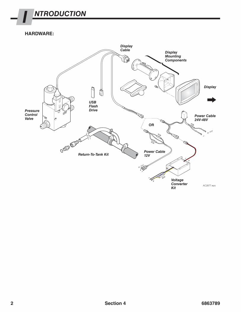
NTRODUCTIONIHARDWARE:
OR
Power Cable24V-48V
Voltage Converter Kit
Power Cable12VReturn-To-Tank Kit
Pressure Control Valve
Display Cable
USB Flash Drive
Display Mounting Components
Display
Section 4
6863789 3
Category1
Category2
Category3
AC2777.eps
ProductType 1
ProducType 4
ProducTy 7
t tpe
ProductType 2
ProductType 5
ProductType 3
ProductType 6
ProductType 8
AC2778.eps
Load Cfg 1 Load Cfg 4
Load Cfg 2 Load Cfg 5
Load Cfg 3 Load Cfg 6
Product Type 2
AC2779.eps
Clamp Fully
2 seconds
1500PSI
20Category 1
Product Type 2
Load Cfg 3
AC2780.eps
Category1
Category2
Category3
gory
gory
gory
AC2781.eps
Category1
Category2
Category3
AC2782.eps
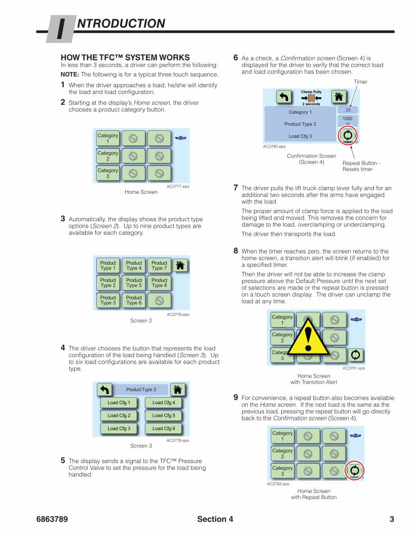
HOW THE TFC™ SYSTEM WORKSIn less than 3 seconds, a driver can perform the following:
NOTE: The following is for a typical three touch sequence.
1 When the driver approaches a load, he/she will identify the load and load configuration.
2 Starting at the display’s Home screen, the driver chooses a product category button.
4 The driver chooses the button that represents the load configuration of the load being handled (Screen 3). Up to six load configurations are available for each product type.
7 The driver pulls the lift truck clamp lever fully and for an additional two seconds after the arms have engaged with the load.
The proper amount of clamp force is applied to the load being lifted and moved. This removes the concern for damage to the load, overclamping or underclamping.
The driver then transports the load.
8 When the timer reaches zero, the screen returns to the home screen, a transition alert will blink (if enabled) for a specified timer.
Then the driver will not be able to increase the clamp pressure above the Default Pressure until the next set of selections are made or the repeat button is pressed on a touch screen display. The driver can unclamp the load at any time.
9 For convenience, a repeat button also becomes available on the Home screen. If the next load is the same as the previous load, pressing the repeat button will go directly back to the Confirmation screen (Screen 4).
6 As a check, a Confirmation screen (Screen 4) is displayed for the driver to verify that the correct load and load configuration has been chosen.
5 The display sends a signal to the TFC™ Pressure Control Valve to set the pressure for the load being handled.
3 Automatically, the display shows the product type options (Screen 2). Up to nine product types are available for each category.
Home Screen
Home Screenwith Repeat Button
Home Screenwith Transition Alert
Screen 2
Screen 3
Confirmation Screen(Screen 4)
Timer
Repeat Button - Resets timer
NTRODUCTIONI
Section 4

68637894
AC2577.eps
• Pressure Unit – psiWhen this is set to psi, the display shows psi and the output to the system is adjusted for the appropriate value.
When this is set to bar, the display shows bar and the output to the system is adjusted for the appropriate value.
When this is set to MPa, the display shows MPa and the output to the system is adjusted for the appropriate value.
• Language – EnglishThe display can be set to use in another language. There are thirteen languages available:
English Russian FinishSpanish French ItalianPortuguese German TurkishChinese DutchJapanese Swedish
• Pressure – ShowWhen this is set to Show, the display shows the pressure value on the Confirmation screen.
When this is set to Hide, the display will not show on the Confirmation screen.
• Transition Alert – 2 secondsAfter the timer runs out on the Confirmation screen or Manual Mode screen, the screen will flash a caution sign, for a specified amount of time (adjustable), as the screen returns to the Home screen. This feature can be disabled.
• Driver Identification – offWhen set to off, the driver is not required to input identification before using the TFCTM system.
When set to on, the driver is required to input identification before using the TFCTM system. A file containing driver identifications is required to be loaded onto the TFCTM display to use this option.
• Timer value – 60 secondsThis value is applied to all sections and can be changed for specific loads in the “TFCloadData.csv” file.
• Pressure Factors – High: 1.0, Med: 1.0, Low: 1.0Each of the three values has an assigned pressure range. A load’s target pressure value, is adjusted by the assigned Pressure Factor value (for the range the target pressure value falls into) to correspond directly with a truck’s CLAMP pressure based on gauge readout.
Pressure Factor Ranges: High – 1600-2300 psi (110-160 bar, 11.0-16.0 MPa)Medium – 1100-1599 psi (76-109 bar, 7.6-10.9 MPa)Low – 500-1099 psi (34-75 bar, 3.4-7.5 MPa)
INITIAL TFCTM SETTINGSThe TFC™ system is delivered with the following preloaded: load descriptions (refer to screens shown on previous page for example), target pressure settings and system settings. They are based on the information supplied from the pre-sale form. All of these variables are adjustable. Changes can be made for any reason, at any time.
Preloaded values and variables include:
• Default Pressure – 900 psi (62 bar, 6.2 MPa)This value is the pressure supplied to position the arms when no specific load is selected. A value that is too high may crush a load when the system is not used as intended. A value that is too low may result with undesirable slow arm speed.
• Manual Mode – Off
When this is set to Off the “Manual Mode” button will not show on the display.
When this is set to On the “Manual Mode” button will show on the display.
The primary purpose of Manual Mode is to aid in establishing the appropriate pressure for each product load configuration. The system allows for real time changes to clamping pressure in ±50 psi (3 bar, 0.34 MPa) increments for trials while establishing clamp force.
Manual Mode Button
NTRODUCTIONI
Section 4
6863789 5
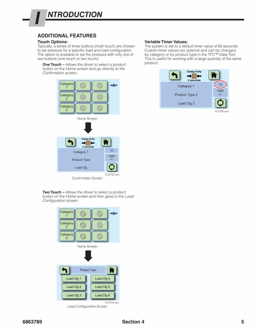
ADDITIONAL FEATURESTouch Options:Typically, a series of three buttons (multi touch) are chosen to set pressure for a specific load and load configuration. The option is available to set the pressure with only one or two buttons (one touch or two touch).
One Touch – Allows the driver to select a product button on the Home screen and go directly to the Confirmation screen.
Variable Timer Values:The system is set to a default timer value of 60 seconds. Custom timer values are optional and can be changed by category or by product type in the TFC™ Data Tool. This is useful for working with a large quantity of the same product.
Two Touch – Allows the driver to select a product button on the Home screen and then goes to the Load Configuration screen.
Confirmation Screen
Home Screen
Home Screen
Load Configuration Screen
NTRODUCTIONI
Section 4
Clamp Fully
2 seconds
Load Cfg
Product Type
Category 11500
PSI
52
AC2783.eps
Category1
Category2
Category3
AC2784.eps
Load Cfg 1 Load Cfg 4
Load Cfg 2 Load Cfg 5
Load Cfg 3 Load Cfg 6
Product Type
Category1
Category2
Category3
Clamp Fully
2 seconds
Load Cfg 3
Product Type 2
Category 11500
PSI
52
AC2785.eps

68637896
DATA MANAGEMENTTFC™ Data Tool: The load data (provided from the pre-sale form) is stored in a table for the display to access. The TFC™ Data Tool is found on the provided USB flash drive and used to change the load data information. The Tool allows the user to add descriptions of product categories, product types, load configurations and corresponding pressure values along with timer values and touch options. Instructions on how to use the Tool are available.
TFC™ Data Tool Input:• Descriptions: up to two lines, limited to about eleven
characters per line.
• Load data is in pressure (psi, bar or MPa).
– Pressure Range: 500–2300 psi (34–160 bar, 3.4–16 MPa)
• Input areas for up to 81 different loads with up to 6 load configurations for each.
USB Flash Drive:The provided USB flash drive is specifically configured to communicate with the touch screen display. It includes any files that are used to maintain and modify the TFC™ system.
Section 14 TFC™ Data Tool covers how to use this tool.
DATALOGGER™ – TOUCH HISTORYEvery touch on the display’s screen is recorded and can be reviewed by management. Up to four touch history files (text files) can be stored on the display. Each touch history file can record more than 300,000 touches.
NOTE: Touch history files can be sent from the display to the provided USB flash drive or another properly configured USB flash drive.
Section 15 DATALOGGER™ – Touch History covers how to access and read the touch history log.
Touch History Example
NTRODUCTIONI
Section 4
AC2879.eps

TFC™ General FAQs
1. How is the data displayed on the touch screen entered or modified?Data is entered or modified using the TFC™ Data Tool which is provided as part of the TFC™ kit.
2. Can the load data file be emailed?Yes.
3. What is the total number of unique load types that can be handled using TFC™ ?486 (9 categories x 9 product types x 6 load configurations).
4. Can each of the 486 load types have a separate clamp pressure?Yes.
5. When is the clamp circuit active to allow clamping on a load?Clamping is possible when the load confirmation screen is displayed showing the details of the load that is to be clamped. Clamping on a load should only be done when you see the load confirmation screen.
6. What setting do I use for mixed loads?Mixed loads should only be handled if approved by management and only if the configuration screen confirms that the particular mixed load has a suitable pressure.
7. Can a partial pull (referred to as feathering the auxiliary handle) be used to clamp a load?No. The system is designed to clamp every load uniquely without feathering. Feathering will prevent proper clamp force from being applied. Refer to the Owner’s Manual.
8. Can the driver re-clamp the load after the timer countdown reaches zero?The driver will not be able to re-clamp at the previous chosen clamp pressure. To clamp with the previous pressure, the driver can touch the repeat button.
TOUCH FORCE CONTROL

FAQ’s-General TFC™ General FAQs
9. Does the setup procedure need to be performed for every truck and clamp combination:Yes. Combining the hydro-mechanical variability of the truck and clamp results in a unique operating environment that will require the set up variables to be set individually from truck to truck.
10. Can the same load and pressure data set be used for all attachments and trucks in a warehouse?Yes, the load and pressure data remains constant as long as it is used with attachments that are the same size.
11. Will I be able to clamp if I do not agree to the acknowledgment statement on the opening screen?No, the pressure relief is set to an ultra-low pressure. The attachment arms will probably not move.
12. What is the pressure if I do not select a load?After you press OK on the acknowledgment screen, the default pressure is active. The default value is meant to be adequate to move the arms at an acceptable speed but not enough to crush the low clamp force loads.
13. How is the default pressure set?This pressure, which is available when a load configuration is not chosen, is set during the set up procedure.
14. What is the recommended default pressure?This pressure is the lowest value that will move the arms at an acceptable speed and minimizes the chance of load damage if it is used on a load without choosing a preset load configuration. A good starting pressure is 800 to 1000 psi (55 to 70 bar, 5.5 to 7.0 MPa). The default pressure can be lowered or raised depending on the minimum pressure required that balances arm speed and clamp force.
15. What is the purpose of the countdown timer on the confirmation screen?The timer is a reminder to the driver to check and confirm that the product being handled is the same as that shown on the confirmation screen. This assures the correct clamp force is being used.
TFC™ General FAQs
16. What happens when the timer reaches ‘zero’?The hydraulic pressure reverts to the default pressure, which then requires the driver to confirm the load configuration.
17. Can the timer be set to different values for different products and categories?Yes, the amount of time is preset when the system ships. The time can be changed as required for each specific load selection using the TFC™ Data Tool. This is useful if loading or unloading large quantities of the same product on a repetitive basis.
18. Can the timer be shut off?No. This is a critical aspect to assuring the proper clamp force is being used for each load configuration.
19. Does the clamp lose clamp force (hydraulic pressure) after clamping when the timer countdown reaches zero and the load is being moved?No. The clamping pressure is maintained in the clamp cylinders by hydraulic check valves.
20. What happens if the driver does not wait for the arms to stop moving while clamping or does not continue to clamp for 1-2 seconds?Adequate clamping pressure to hold the load may not be developed which then may allow the load to drop. This potential is the same as on all mechanical based pressure control systems.
21. What unit of measure will the display use to show hydraulic pressures?The display will show pressure in either psi, bar or MPa, as chosen during the setup procedure.
22. What unit of measure is used when entering the clamping pressure in the TFC™ Data Tool?Either psi, bar, or MPa can be used. Conversions are done internally.
23. What is the clamp pressure if the TFC™ unit is OFF or there is no power to the unit?The pressure setting is ultra-low and the arms will normally not close.
TFC™ General FAQs
24. Can I wear gloves?Yes, the touch screen is pressure activated. The only requirement is that the glove finger must be small enough to not activate two buttons at once.
25. What voltage is required to run the TFC™ system? The TFC™ components require 12 volts. If 12 volts is not available, a voltage converter will be required.
26. How many unique screen touches will the DATALOGGER™ store?The total number of screen touches exceeds 300,000 per file x 4 files.
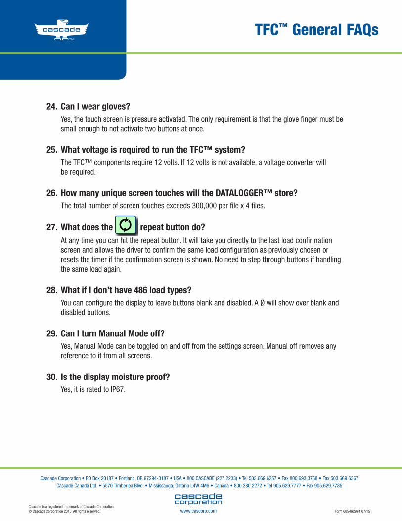
27. What does the repeat button do?At any time you can hit the repeat button. It will take you directly to the last load confirmation screen and allows the driver to confirm the same load configuration as previously chosen or resets the timer if the confirmation screen is shown. No need to step through buttons if handling the same load again.
28. What if I don’t have 486 load types?You can configure the display to leave buttons blank and disabled. A Ø will show over blank and disabled buttons.
29. Can I turn Manual Mode off?Yes, Manual Mode can be toggled on and off from the settings screen. Manual off removes any reference to it from all screens.
30. Is the display moisture proof?Yes, it is rated to IP67.
Cascade Corporation • PO Box 20187 • Portland, OR 97294-0187 • USA • 800 CASCADE (227.2233) • Tel 503.669.6257 • Fax 800.693.3768 • Fax 503.669.6367 Cascade Canada Ltd. • 5570 Timberlea Blvd. • Mississauga, Ontario L4W 4M6 • Canada • 800.380.2272 • Tel 905.629.7777 • Fax 905.629.7785
Form 6854629 r4 07/15www.cascorp.comCascade is a registered trademark of Cascade Corporation.© Cascade Corporation 2015. All rights reserved.

SECTION 5:
CUSTOMER DATA SUMMARY CAN BE FOUND IN THE OWNER’S MANUAL BINDER
6863789 1
NSTALLATIONI 12V-48V UL® Classified Kits
CHEC
K
VALV
EGAU
GE
SOL
AC2675.eps
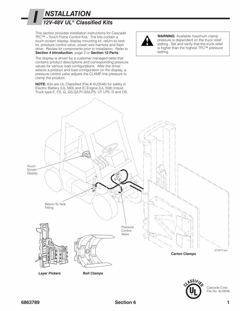
This section provides installation instructions for Cascade TFC™ – Touch Force Control Kits. The kits contain a touch screen display, display mounting kit, return-to-tank kit, pressure control valve, power wire harness and flash drive. Review kit components prior to installation. Refer to Section 4 Introduction, page 2 or Section 12 Parts.
The display is driven by a customer managed table that contains product descriptions and corresponding pressure values for various load configurations. After the driver selects a product and load configuration on the display, a pressure control valve adjusts the CLAMP line pressure to clamp the product.
Return-To-Tank Fitting
Pressure ControlValve
Touch Screen Display
WARNING: Available maximum clamp pressure is dependent on the truck relief setting. Set and verify that the truck relief is higher than the highest TFC™ pressure setting.
Layer Pickers Roll Clamps
Carton Clamps
LP0411.epsRC2921.eps
NOTE: Kits are UL Classified (File # AU3546) for safety in Electric Battery (UL 583) and IC Engine (UL 558) Indust. Truck type E, ES, G, GS,G/LP/ GS/LPS, LP, LPS, D and DS.
Cascade Corp.File No. AU3546
Section 6
68637892
NSTALLATIONI 12V-48V UL® Classified Kits
CH
ECK
VALV
EGAU
GE
SOL
AC2674.eps
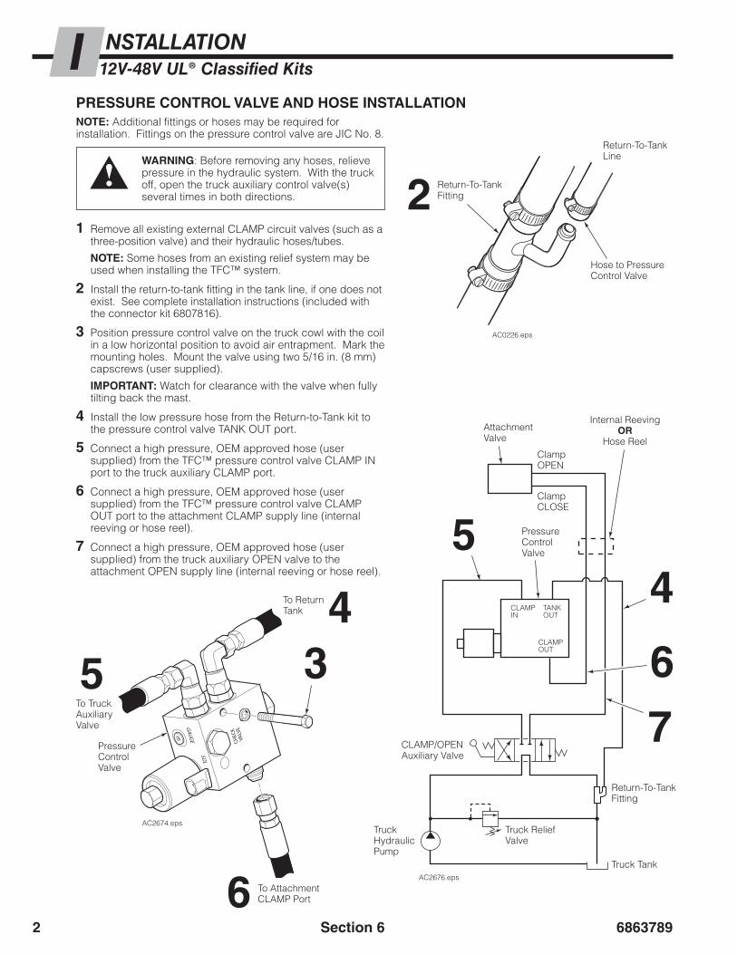
1 Remove all existing external CLAMP circuit valves (such as a three-position valve) and their hydraulic hoses/tubes.
NOTE: Some hoses from an existing relief system may be used when installing the TFC™ system.
2 Install the return-to-tank fitting in the tank line, if one does not exist. See complete installation instructions (included with the connector kit 6807816).
3 Position pressure control valve on the truck cowl with the coil in a low horizontal position to avoid air entrapment. Mark the mounting holes. Mount the valve using two 5/16 in. (8 mm) capscrews (user supplied).
IMPORTANT: Watch for clearance with the valve when fully tilting back the mast.
4 Install the low pressure hose from the Return-to-Tank kit to the pressure control valve TANK OUT port.
5 Connect a high pressure, OEM approved hose (user supplied) from the TFC™ pressure control valve CLAMP IN port to the truck auxiliary CLAMP port.
6 Connect a high pressure, OEM approved hose (user supplied) from the TFC™ pressure control valve CLAMP OUT port to the attachment CLAMP supply line (internal reeving or hose reel).
7 Connect a high pressure, OEM approved hose (user supplied) from the truck auxiliary OPEN valve to the attachment OPEN supply line (internal reeving or hose reel).
PRESSURE CONTROL VALVE AND HOSE INSTALLATIONNOTE: Additional fittings or hoses may be required for installation. Fittings on the pressure control valve are JIC No. 8.
WARNING: Before removing any hoses, relieve pressure in the hydraulic system. With the truck off, open the truck auxiliary control valve(s) several times in both directions.
AC0226.eps
Return-To-Tank Fitting
Return-To-Tank Line
Hose to Pressure Control Valve
2
4
6
35Pressure Control Valve
To Attachment CLAMP Port
To Return Tank
To Truck Auxiliary Valve
CLAMPOUT
CLAMPIN
TANKOUT
AC2676.eps
Return-To-Tank Fitting
Truck Tank
Truck Relief Valve
Truck Hydraulic Pump
CLAMP/OPENAuxiliary Valve
4
7
5
6
Attachment Valve
ClampOPEN
ClampCLOSE
Pressure Control Valve
Internal ReevingOR
Hose Reel
Section 6
6863789 3
NSTALLATIONI 12V-48V UL® Classified Kits
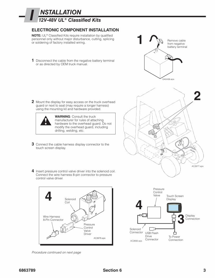
ELECTRONIC COMPONENT INSTALLATIONNOTE: UL® Classified Kits require installation by qualified personnel only without major disturbance, cutting, splicing or soldering of factory installed wiring.
1 Disconnect the cable from the negative battery terminal or as directed by OEM truck manual.
2 Mount the display for easy access on the truck overhead guard or next to seat (may require a longer harness) using the mounting kit and hardware provided.
3 Connect the cable harness display connector to the touch screen display.
4 Insert pressure control valve driver into the solenoid coil. Connect the wire harness 8-pin connector to pressure control valve driver.
Remove cable from negative battery terminal
GA0436.eps
1
2
USB Flash Drive Connector
Solenoid Connector
Pressure Control Valve Touch Screen
Display
Display Connection
To Power Connection
43
Procedure continued on next page
CH
ECK
VALV
EGAU
GE
SOL
AC2677.eps
GAUG
ESO
L
CH
EC
KVA
LVE
CLAMP IN
TANK OUT
AC2678.eps
Wire Harness 8-Pin Connector
Pressure Control Valve Driver
Solenoid Coil
4
AC2692.eps
Section 6
WARNING: Consult the truck manufacturer for rules of attaching hardware to the overhead guard. Do not modify the overhead guard, including drilling, welding, etc.

68637894
AC2680.eps
B
4
7
A
NSTALLATIONI 12V-48V UL® Classified Kits
Truck Bat-tery
Fuse, 5A
Fuse, 5A
Key, 12V+
12V
5
6
Voltage Converter Kit(24V-48V Electric Trucks)
Switched
Ground
Truck Battery
Fuse, 2A
Fuse, 2AKey,24V-48V
Relay
Electric Trucks – Use battery ground.
24V-48V
6
5
5 Connect power cable to the cable harness. Connect the power cable to the power source.
ELECTRONIC COMPONENT INSTALLATION (CONTINUED)
12V Trucks – Connect the “Key“ wire to a 12V switched power source. Connect the ground wire. Connect the “Truck 12V+” wire to 12V source.
24V-48V Trucks – Mount the converter kit and relay to the truck. Connect the fused positive wire from the converter kit to a 24V-48V power source. Connect the two ground (as shown) wires. Connect fused “Key” wire to 24V-48V key switched power source.
Check cable routing for pinch points and clearance. Use wire ties as needed.
NOTE: Connecting the “Key” wire to a keyed power source allows the display to turn on without reboot.
6 Connect battery cable(s) to their proper terminal(s).
WARNING: To reduce risk of fire, replace only with the same type and ratings of fuse. The fused power cable is polarity sensitive. The positive wire must be connected to a positive power source.
Section 6

6863789 5
NSTALLATIONI 12V-48V UL® Classified Kits
DISABLING THE TFC™ SYSTEMThe TFC™ system can be temporarily disabled by performing the following steps:
• Disconnect the hose from the TFC™ pressure control valve "Tank Out" port. Plug the Return-to-Tank hose.
• Cap the "Tank Out" port with a high pressure, steel no. 8 cap on the TFC™ valve.
• Remove the positive (+) and negative (-) TFC™ power wires at the truck battery.
To enable the TFC™ system:
• Install hose to TFC™ pressure control valve "Tank Out" port.
• Connect the positive (+) and negative (-) TFC™ power wires at the truck battery. Refer to installation schematic on previous page.
Cap "Tank Out" Port
Disconnect hose and plug
CH
ECK
VALV
EGAU
GE
SOL
AC2681.epsCHECK TFC™ SYSTEM OUTPUT – VALIDATING SCREEN TARGET PRESSURE MATCHES ACTUAL GAUGE PRESSUREThis procedure is used to verify that the gauge pressure measured at the TFC™ control valve (or attachment gauge port) are within a ±100 psi (7 bar, 0.68 MPa) tolerance of the pressure shown on the display.
NOTE: The Manual Mode option is needed for this procedure and may be disabled. To enable for this procedure, refer to Section 16 Configuration Settings, “Turn On/Off Manual Mode”.
Tools Required:Pressure gauge – 5000 psi (345 bar, 34 MPa)
1 Install a pressure gauge and supplied fitting in the TFC™ pressure control valve No. 4 O-ring gauge port or attachment gauge port.
www.cascorp.com
I agree to operate th
is attachment in
conjunction with
the Operator’s
Guide,
which I have re
ad and understand.
OK?
AC2598.eps
2
2Ten cycles
CH
ECK
VALV
EGAU
GE
SOL
AC2682.eps
Section 6
2 Warm up the hydraulic system:
• On the display, touch the "OK" button. If prompted, enter driver identification login. Pressurize the CLAMP circuit and then OPEN circuit (attachment not installed) or close and open the arms fully. Repeat for ten cycles or more. Hold the CLAMP pressure for an additional 3 seconds during each cycle. Check that the temperature of the TFC™ pressure control valve is warm to touch.
Procedure continued on next page
1

68637896
NSTALLATIONI 12V-48V UL® Classified Kits
4 First Time Air Removal – Hold the CLAMP lever open to activate the CLAMP circuit. Start at the lowest pressure, 500 psi (34 bar, 3.4 MPa) and increase the pressure by 50 psi (3.44 bar, 0.34 MPa) to the maximum value. Continue to hold the CLAMP lever open and decrease the pressure by 50 psi (3.44 bar, 0.34 MPa) to the lowest value. Repeat.
Category
1
Category
2
Category
3
AC2637.eps
3 Manual Mode
3 Touch the Manual Mode button (up and down arrows).
Arrow Buttons
5 Change the pressure to 1800 psi (124 bar, 12.4 MPa) (target pressure) using the High button or arrow buttons.
High Button
Arrow Buttons
6 Pull the CLAMP handle all the way at full throttle and hold for an additional two seconds. Record the gauge pressure reading, below. Repeat two more times, recording the gauge pressure readings.
GAUGE PRESSURE READINGS
High – 1800 psi (124 bar, 12.4 MPa)
Reading 1
Reading 2
Reading 3
7 Of the three readings (Step 6), choose the value that falls in the middle of the three. For example (High values shown):
8 Compare the middle value against the target pressure of 1800 psi (124 bar, 12.4 MPa).
• If the middle value is within ±100 psi (7 bar, 0.7 MPa) of the target pressure, no further adjustment is required.
• If the middle value is outside of ±100 psi (7 bar, 0.7 MPa) of the target pressure, adjust the Pressure Factor. Refer to “Fine Tune Output Pressure”, on page 8. Use 1800 psi (124 bar, 12.4 MPa) for the target pressure to determine the Pressure Factor range and adjustment.
9 Change the pressure to 1300 psi (90 bar, 9.0 MPa) (target pressure) using the Medium button or arrow buttons.
Medium Button
Arrow Buttons
CHECK TFC™ SYSTEM OUTPUT –VALIDATING SCREEN TARGET PRESSURE MATCHES ACTUAL GAUGE PRESSURE (CONTINUED)
Reading 1 –1825 psi(126 bar, 12.6 MPa)
Middle Value
Reading 2 –1875 psi(129 bar,12.9 MPa)
Highest Value
Reading 3 –1785 psi(123 bar,12.3 MPa)
Lowest Value
Procedure continued on next page
Section 6
500PSI
30
AC2786.eps
1800PSI
30
AC2787.eps
AC2788.eps
1300PSI
30

6863789 7
NSTALLATIONI 12V-48V UL® Classified Kits
Low Button
12 Compare the middle value against the target pressure of 1300 psi (90 bar, 9.0 MPa).
• If the middle value is within ±100 psi (7 bar, 0.7 MPa) of the target pressure, no further adjustment is required.
• If the middle value is outside of ±100 psi (7 bar, 0.7 MPa) of the target pressure, adjust the Pressure Factor. Refer to “Fine Tune Output Pressure”, on the following page. Use 1300 psi (90 bar, 9.0 MPa) for the target pressure to determine the Pressure Factor range and adjustment.
13 Change the pressure to 800 psi (55 bar, 5.5 MPa) (target pressure) using the Low button or arrow buttons.
Arrow Buttons
14 Pull the CLAMP handle all the way at full throttle and hold for an additional two seconds. Record the gauge pressure reading, below. Repeat two more times, recording the gauge pressure readings.
GAUGE PRESSURE READINGS
Low – 800 psi (55 bar, 6 MPa)
Reading 1
Reading 2
Reading 3
15 Of the three readings (Step 14), choose the value that falls in the middle of the three.
16 Compare the middle value against the target pressure of 800 psi (55 bar, 5.5 MPa).
• If the middle pressure value is within ±100 psi (7 bar, 0.7 MPa) of the target pressure, no further adjustment is required.
• If the middle value is outside of ±100 psi (7 bar, 0.7 MPa) of the target pressure, adjust the Pressure Factor. Refer to “Fine Tune Output Pressure”, on the following page. Use 800 psi (55 bar, 5.5 MPa) for the target pressure to determine the Pressure Factor range and adjustment.
11 Of the three readings (Step 10), choose the value that falls in the middle of the three.
IMPORTANT: After the installation and the system is tested, turn Manual Mode 'Off' (accessed in the Configuration screen), unless specified by the customer to remain 'On'.
10 Pull the CLAMP handle all the way at full throttle and hold for an additional two seconds. Record the gauge pressure reading, below. Repeat two more times, recording the gauge pressure readings.
GAUGE PRESSURE READINGS
Med – 1300 psi (90 bar, 9.0 MPa)
Reading 1
Reading 2
Reading 3
Section 6
AC2789.eps
800PSI
30
CHECK TFC™ SYSTEM OUTPUT –VALIDATING SCREEN TARGET PRESSURE MATCHES ACTUAL GAUGE PRESSURE (CONTINUED)
68637898
NSTALLATIONI 12V-48V UL® Classified Kits
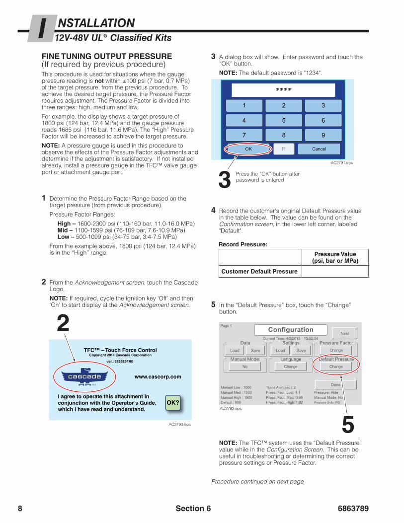
FINE TUNING OUTPUT PRESSURE(If required by previous procedure)This procedure is used for situations where the gauge pressure reading is not within ±100 psi (7 bar, 0.7 MPa) of the target pressure, from the previous procedure. To achieve the desired target pressure, the Pressure Factor requires adjustment. The Pressure Factor is divided into three ranges: high, medium and low.
For example, the display shows a target pressure of 1800 psi (124 bar, 12.4 MPa) and the gauge pressure reads 1685 psi (116 bar, 11.6 MPa). The “High” Pressure Factor will be increased to achieve the target pressure.
NOTE: A pressure gauge is used in this procedure to observe the effects of the Pressure Factor adjustments and determine if the adjustment is satisfactory. If not installed already, install a pressure gauge in the TFC™ valve gauge port or attachment gauge port.
Section 6
2 From the Acknowledgement screen, touch the Cascade Logo.
NOTE: If required, cycle the ignition key ‘Off’ and then ‘On’ to start display at the Acknowledgement screen.
1 Determine the Pressure Factor Range based on the target pressure (from previous procedure).
Pressure Factor Ranges:
High – 1600-2300 psi (110-160 bar, 11.0-16.0 MPa)Mid – 1100-1599 psi (76-109 bar, 7.6-10.9 MPa)Low – 500-1099 psi (34-75 bar, 3.4-7.5 MPa)
From the example above, 1800 psi (124 bar, 12.4 MPa) is in the “High” range.
3 A dialog box will show. Enter password and touch the “OK” button.
NOTE: The default password is "1234".
3 Press the “OK” button after password is entered
1 3
****
4 5
2
6
7 8 9
OK RR Cancel
AC2791.eps
2TFC™ – Touch Force Control
Copyright 2014 Cascade Corporation
ver.: 6865854R0
www.cascorp.com
I agree to operate this attachment inconjunction with the Operator’s Guide,which I have read and understand.
OK?
AC2790.eps
5 In the “Default Pressure” box, touch the “Change” button.
4 Record the customer's original Default Pressure value in the table below. The value can be found on the Confirmation screen, in the lower left corner, labeled "Default".
5
Record Pressure:
Pressure Value(psi, bar or MPa)
Customer Default Pressure
Procedure continued on next page
Current Time: 4/2/2015
Manual High : 1900
Manual Low : 1000Manual Med : 1500
Default : 900Press. Fact. Med: 0.98
Trans Alert(sec): 2Press. Fact. Low: 1.1
Press. Fact. High: 1.02Manual Mode: NoPressure: Hide
Pressure Units: PSI
13:52:54
Change
Data Settings Pressure Factor
Manual Mode:ChangeNo
LanguageChange
Default Pressure
Done
Next
Page 1
Load Save Load Save
Configuration
AC2792.eps
NOTE: The TFC™ system uses the “Default Pressure” value while in the Configuration Screen. This can be useful in troubleshooting or determining the correct pressure settings or Pressure Factor.

6863789 9
NSTALLATIONI 12V-48V UL® Classified Kits
Section 6
FINE TUNING OUTPUT PRESSURE (CONTINUED)6 A dialog box will show. Enter the target pressure
(example: 1800 psi, 124 bar, 12.4 MPa). When finished, touch the “OK” button.
7
67 In the “Pressure Factor” box, touch the “Change”
button.
8 A dialog box will open for adjusting Pressure Factors.
• Use a pressure gauge to monitor the pressure changes to the system, during clamping, as a Pressure Factor is adjusted.
• Confirm that the "Use" button for range being adjusted is selected (white). The range was determined in Step 1.
Default PressureMinimum: 500 PSI - Maximum: 2300 PSI
147OK
2580
369
Cancel
AC2793.eps
1.00Press. Fact. Low
Touch and Hold
1.00Press. Fact. Med
Touch and Hold
1.00Press. Fact. High
Touch and Hold
Save Minus0.01
Add0.01 Use
Minus0.01
Add0.01 Use
Minus0.01
Add0.01 Use
AC2795.eps
1800
Current Time: 4/2/2015
Manual High : 1900
Manual Low : 1000Manual Med : 1500
Default : 900Press. Fact. Med: 0.98
Trans Alert(sec): 2Press. Fact. Low: 1.1
Press. Fact. High: 1.02Manual Mode: NoPressure: Hide
Pressure Units: PSI
13:52:54
Change
Data Settings Pressure Factor
Manual Mode:ChangeNo
LanguageChange
Default Pressure
Done
Next
Page 1
Load Save Load Save
Configuration
AC2794.eps
1800
8
9 For the range to be adjusted, press the “Minus” (decrease pressure) and “Add” (increase pressure) buttons to adjust, in 0.01 increments. Limit the adjustment to values between 0.5 and 1.50. The default value is 1.00.
• After each adjustment, release pressure and reclamp.
• No further adjustment is needed when the gauge pressure value is within ±100 psi (7 bar, 0.7 MPa) of the target pressure.
NOTE: Each increment of 0.01 change equals approximately one percent change in pressure.
Adjustment Buttons9
1.00Press. Fact. Low
Touch and Hold
1.00Press. Fact. Med
Touch and Hold
1.00Press. Fact. High
Touch and Hold
Save Minus0.01
Add0.01 Use
Minus0.01
Add0.01 Use
Minus0.01
Add0.01 Use
AC2796.eps
NOTE: For large changes, touch and hold the "Add" or "Minus" button.
10 After the target pressure is achieved, touch the “Save” button.
13
13 When no further changes are required, touch the “Done” button.
12 To save all settings values for future use, refer to Section 16 Configuration Settings, “Save Configuration Settings”.
11 Repeat Step 5 and 6 to change the default pressure back to the customer’s original Default Pressure, as noted in Step 4.
Current Time: 4/2/2015
Manual High : 1900
Manual Low : 1000Manual Med : 1500
Default : 900Press. Fact. Med: 0.98
Trans Alert(sec): 2Press. Fact. Low: 1.1
Press. Fact. High: 1.02Manual Mode: NoPressure: Hide
Pressure Units: PSI
13:52:54
Change
Data Settings Pressure Factor
Manual Mode:ChangeNo
LanguageChange
Default Pressure
Done
Next
Page 1
Load Save Load Save
Configuration
AC2797.eps

686378910 Section 6
BLANK

TFC™ Technical FAQs
1. If a customer puts a gauge into the G port of the Carton Clamp valve OR in the clamp line at the auxiliary valve, will he see the same pressure as on the display? Yes. Within the tolerance range of the system after proper setup.
2. Will the arms on the clamp move slower when lower pressure settings are in effect?Yes and this is normal. Slower arm speed is noticeable at pressures beginning in the range of 600 psi to 1000 psi (41 bar to 70 bar, 4.1 MPa to 7.0 MPa) depending on the attachment. The pressure range depends on the friction in the clamp structure and can be improved with cleaning and then using an approved lubricant on a consistent basis.
3. How does the TFC™ touch screen control the hydraulic pressure sent to the clamp.The touch screen’s built in controller sends an electronic signal over a CAN bus wire to the pressure control valve. The pressure control valve then adjusts the hydraulic pressure being delivered to the clamp.
4. How does the pressure on the display relate to Clamp Force?Hydraulic pressure creates clamp force. Different clamp models generate different forces at given pressures because they use different cylinder sizes. The effective Clamp Force of a clamp is the closing force of the cylinder minus the efficiency loss from friction in all the moving parts of the clamp. Significant factors that impact the efficiency are the load center of the load causing deflection of the clamp frame and also the friction of the arm bars against the bearings. Each clamp is different. To determine the exact measure of clamp force it must be measured by a clamp force indicator.
5. What if I make a mistake while entering load configurations in the TFC™ Data Tool and notice the mistake after modifying and saving the data file?The TFC™ Data Tool automatically backs up the original file when the file is saved to a location with a file of the same name. Open the file with the mistake, enter the correct data and save the file.
TOUCH FORCE CONTROL
FAQ’s-GeneralTFC™ Technical FAQs
Form 6854628 R3 07/2015
Cascade Corporation • PO Box 20187 • Portland, OR 97294-0187 • USA • 800 CASCADE (227.2233) • Tel 503.669.6257 • Fax 800.693.3768 • Fax 503.669.6367
Cascade Canada Ltd. • 5570 Timberlea Blvd. • Guelph, Ontario L4W 4M6 • Canada • 800.380.2272 • Tel 905.629.7777 • Fax 905.629.7785
6. Can TFC™ be programmed to go direct from the category screen to the confirmation screen?Yes. The display can easily be configured using the TFC™ Data Tool to skip two touches and go directly to the confirmation screen (One Touch) or skip one step and go directly to the load configuration screen (Two Touch).
7. What other functions are set by using the access code?Default pressure, low/med/high pressure values, pressure units, date and time, clamp pressure factors. See the TFC™ Owner’s Manual for a complete description and instructions for making changes. These settings can be saved.
8. Will the Clamp Force shown on a Clamp Force Indicator be the same as the pressure setting on the display? No, the amount of clamp force at the pressure displayed will vary depending on the clamp model and the efficiency of the clamp structure.
9. What if the lift truck has a 12 volt tap or other power port for accessories, can this port be used?This port can be used if the installation follows the TFC™ Owner’s Manual and supplies a minimum of 3 A.
www.cascorp.comCascade is a registered trademark of Cascade Corporation.© Cascade Corporation 2015. All rights reserved.

6863789 1
ESTING THE SYSTEM PRIOR TO USE (ON-SITE)TThis section provides instruction on verifying and adjusting TFC™ system performance. The following procedures verify that the actual pressure or clamp force values match the target values. Use these instructions after the TFC™ system is installed.
Perform one of the following:
• Validate target pressure – Perform this procedure if the pressure was not validated when installed at the dealer or to verify target pressure matches gauge pressure. Refer to Section 6 Installation, “Check TFC™ System Output”, page 5.
• Validate clamp force values – Perform this procedure to verify specific clamp force values are achieved.
NOTE: The Manual Mode option is required for this procedure and may be disabled. To enable for this procedure, refer to Section 16 Configuration Settings, “Turn Manual Mode On/Off”.
WARNING: Available maximum clamp pressure is dependent on the truck relief setting. Set the truck relief higher than the highest TFC™ pressure setting.
Continue to next page for tables
Section 7
VALIDATE CLAMP FORCE VALUESThe following procedure is for adjusting the hydraulic pressure to achieve specific clamp force values for specific loads. This procedure covers two scenarios of attachments:
• Single attachments – Only one attachment on-site equipped with TFC™. Refer to page 3-4.
• Fleet of attachments – More than one attachment on-site equipped with TFC™. Refer to page 5-7.
IMPORTANT: If specific clamp force values were provided to Cascade for programming, prior to the product shipping, the values should be validated.IMPORTANT: Only perform this procedure after the CLAMP circuit has been adjusted (as required) to deliver the target pressure value (within ±100 psi, ±7 bar, ±0.7 MPa) to the attachment.
About Clamp Force andClamp Pressure with TFC™The actual clamp force delivered to the load depends on the pressure delivered from the CLAMP circuit and other attachment specific factors. These factors include the attachment rating (15D vs 50D), bearing wear, bearing lubrication/friction, manufacturing variances and possible attachment damage.
The same CLAMP circuit pressure delivered to various attachments of different ratings, results in different clamp forces.
IMPORTANT: To prevent significant variations in clamp force values between attachments of the same rating, maintain the fleet in good working condition so that all attachments will perform similarly. Using the average values between attachments, usually gives acceptable results.
Hydraulic Pressure and Resulting Clamp ForceTypical clamp force values resulting from specific hydraulic pressures are shown in Table A. Pressure values, preloaded in the “TFCloadData.csv” file, were determined by using average clamp efficiencies that are expected to achieve the target clamp forces.
After the validation procedure is performed, the hydraulic pressure values in the “TFCloadData.csv” file may require adjustment to deliver the required clamp force.
IMPORTANT: Do not change the “TFCloadData.csv” file for each attachment in a fleet. Each attachment can be adjusted by changing Pressure Factors. Refer to “Fine Tuning Output Clamp Force”, page 8.

68637892
ESTING THE SYSTEM PRIOR TO USE (ON-SITE)T
Section 7
VALIDATE CLAMP FORCE VALUES (CONTINUED)
TABLE A
TARGET PRESSURE
TARGET CLAMP FORCE
CARTON CLAMP MODEL
15D 25D 35D 50D
800 psi(55 bar, 5.5 MPa)
880 lbf(3.90 kN)
1200 lbf (5.34 kN)
1600 lbf (7.12 kN)
2400 lbf (10.68 kN)
1300 psi(90 bar, 9.0 MPa)
1450 lbf(6.45 kN)
2000 lbf (8.90 kN)
2600 lbf (11.56 kN)
3900 lbf (17.35 kN)
1800 psi(124 bar, 12.4 MPa)
2000 lbf(8.90 kN)
2700 lbf (12.00 kN)
3600 lbf (16.00 kN)
5400 lbf (24.02 kN)
NOTE: Refer to Table B for clamp force value tolerance.
TABLE B
ATTACHMENT CLAMP FORCE TOLERANCES
CARTON CLAMP ±A
15D25D30D50D
100 lbf (0.44 kN)150 lbf (0.67 kN)200 lbf (0.89 kN)300 lbf (1.33 kN)
NOTE: For other attachments, consult Cascade.
6863789 3
ESTING THE SYSTEM PRIOR TO USE (ON-SITE)T
Section 7
VALIDATE CLAMP FORCE VALUES (CONTINUED)
Single Attachment ProcedureNOTE: For a fleet of attachments, refer to page 7.
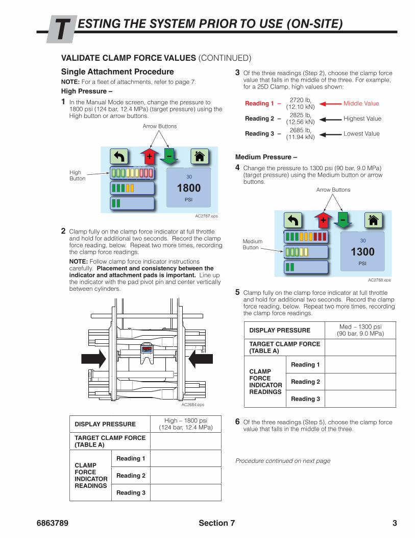
High Pressure –
1 In the Manual Mode screen, change the pressure to 1800 psi (124 bar, 12.4 MPa) (target pressure) using the High button or arrow buttons.
2 Clamp fully on the clamp force indicator at full throttle and hold for additional two seconds. Record the clamp force reading, below. Repeat two more times, recording the clamp force readings.
NOTE: Follow clamp force indicator instructions carefully. Placement and consistency between the indicator and attachment pads is important. Line up the indicator with the pad pivot pin and center vertically between cylinders.
AC2684.eps
DISPLAY PRESSUREHigh – 1800 psi
(124 bar, 12.4 MPa)
TARGET CLAMP FORCE (TABLE A)
CLAMP FORCE INDICATOR READINGS
Reading 1
Reading 2
Reading 3
DISPLAY PRESSUREMed – 1300 psi
(90 bar, 9.0 MPa)
TARGET CLAMP FORCE (TABLE A)
CLAMP FORCE INDICATOR READINGS
Reading 1
Reading 2
Reading 3
3 Of the three readings (Step 2), choose the clamp force value that falls in the middle of the three. For example, for a 25D Clamp, high values shown:
6 Of the three readings (Step 5), choose the clamp force value that falls in the middle of the three.
Reading 1 – 2720 lbf (12.10 kN) Middle Value
Reading 2 – 2825 lbf (12.56 kN) Highest Value
Reading 3 – 2685 lbf (11.94 kN) Lowest Value
High Button
Arrow Buttons
Medium Pressure –
4 Change the pressure to 1300 psi (90 bar, 9.0 MPa)(target pressure) using the Medium button or arrow buttons.
Medium Button
Arrow Buttons
5 Clamp fully on the clamp force indicator at full throttle and hold for additional two seconds. Record the clamp force reading, below. Repeat two more times, recording the clamp force readings.
Procedure continued on next page
1800PSI
30
AC2787.eps
AC2788.eps
1300PSI
30

68637894
ESTING THE SYSTEM PRIOR TO USE (ON-SITE)T
Section 7
DISPLAY PRESSURELow – 800 psi
(55 bar, 5.5 MPa)
TARGET CLAMP FORCE (TABLE A)
CLAMP FORCE INDICATOR READINGS
Reading 1
Reading 2
Reading 3
9 Of the three readings (Step 8), choose the clamp force value that falls in the middle of the three.
8 Clamp fully on the clamp force indicator at full throttle and hold for additional two seconds. Record the clamp force reading, below. Repeat two more times, recording the clamp force readings.
10 Determine one of the following:
• If all three middle clamp force value readings are within the clamp force tolerance ±A (Table B, page 2) of Table A (page 2), this procedure is complete. Skip Step 11.
• If some or all of the three middle clamp force value readings do not match the target clamp force values of Table A (page 2) and are not within the clamp force tolerance ±A (Table B, page 2), service the clamp to make sure it is operating correctly and arm bearings are in good condition. Continue to Step 11.
IMPORTANT: For proper TFC™ system performance, the attachment and truck must be in good working condition, properly serviced and maintained.
11 After servicing the attachment, redo Steps 1 through 9 for High, Medium and Low pressure settings. Determine one of the following:
• If all three middle clamp force value readings are within the clamp force tolerance ±A (Table B, page 2) of the target force (Table A, page 2), no further action is required.
• If some or all of the three middle clamp force value readings are not within the clamp force tolerance ±A (Table B, page 2) of the target force (Table A, page 2), continue using the clamp force indicator and the Manual Mode screen to determine the pressure required to provide the target clamp force (refer to Section 8 Establishing Clamp Force). Record the new pressure. Change the pressure values in the “TFCloadData.csv” file to match the new recorded pressures.
NOTE: If a pressure value is changed in the “TFCloadData.csv” file for one clamp force. Check all other pressure values.
NOTE: To roughly estimate a new pressure values use the following method:
New Pressure 1 = Current
Pressure X( Target Clamp Force )Measured Clamp Force
1 This value is to be entered into the “TFCloadData.csv” file.
Low Pressure –
7 Change the pressure to 800 psi (55 bar, 5.5 MPa) (target pressure) using the Low button or arrow buttons.
Low Button
Arrow Buttons
AC2789.eps
800PSI
30
Single Attachment Procedure (continued)
VALIDATE CLAMP FORCE VALUES (CONTINUED)
6863789 5
ESTING THE SYSTEM PRIOR TO USE (ON-SITE)T
Section 7
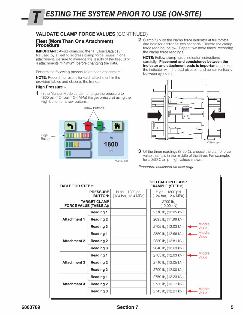
Fleet (More Than One Attachment) ProcedureIMPORTANT: Avoid changing the “TFCloadData.csv” file used by a fleet to address clamp force issues in one attachment. Be sure to average the results of the fleet (3 or 4 attachments minimum) before changing the data.
Perform the following procedure on each attachment:
NOTE: Record the results for each attachment in the provided tables and observe the trends.
High Pressure –
1 In the Manual Mode screen, change the pressure to 1800 psi (124 bar, 12.4 MPa) (target pressure) using the High button or arrow buttons.
2 Clamp fully on the clamp force indicator at full throttle and hold for additional two seconds. Record the clamp force reading, below. Repeat two more times, recording the clamp force readings.
NOTE: Follow clamp force indicator instructions carefully. Placement and consistency between the indicator and attachment pads is important. Line up the indicator with the pad pivot pin and center vertically between cylinders.
AC2684.eps
High Button
Arrow Buttons
1800PSI
30
AC2787.eps
TABLE FOR STEP 2:
PRESSUREBUTTON:
High – 1800 psi(124 bar, 12.4 MPa)
TARGET CLAMP FORCE VALUE (TABLE A):
Attachment 1
Reading 1
Reading 2
Reading 3
Attachment 2
Reading 1
Reading 2
Reading 3
Attachment 3
Reading 1
Reading 2
Reading 3
Attachment 4
Reading 1
Reading 2
Reading 3
3 Of the three readings (Step 2), choose the clamp force value that falls in the middle of the three. For example, for a 25D Clamp, high values shown:
25D CARTON CLAMPEXAMPLE (STEP 3):
High – 1800 psi(124 bar, 12.4 MPa)
2700 lbf (12.00 kN)
2710 lbf (12.05 kN)
2695 lbf (11.99 kN)
2705 lbf (12.03 kN)
2850 lbf (12.68 kN)
2880 lbf (12.81 kN)
2840 lbf (12.63 kN)
2705 lbf (12.03 kN)
2710 lbf (12.05 kN)
2700 lbf (12.00 kN)
2750 lbf (12.23 kN)
2735 lbf (12.17 kN)
2745 lbf (12.21 kN)
Middle ValueMiddle Value
Middle Value
Middle Value
Procedure continued on next page
VALIDATE CLAMP FORCE VALUES (CONTINUED)

68637896
ESTING THE SYSTEM PRIOR TO USE (ON-SITE)T
Section 7
Medium Pressure –
4 Change the pressure to 1300 psi (90 bar, 9.0 MPa)(target pressure) using the Medium button or arrow buttons.
Medium Button
Arrow Buttons
5 Clamp fully on the clamp force indicator at full throttle and hold for additional two seconds. Record the clamp force reading, below. Repeat two more times, recording the clamp force readings.
Procedure continued on next page
AC2788.eps
1300PSI
30
PRESSUREBUTTON:
Med – 1300 psi(90 bar, 9.0 MPa)
TARGET CLAMP FORCE VALUE (TABLE A):
Attachment 1
Reading 1
Reading 2
Reading 3
Attachment 2
Reading 1
Reading 2
Reading 3
Attachment 3
Reading 1
Reading 2
Reading 3
Attachment 4
Reading 1
Reading 2
Reading 3
6 Of the three readings (Step 5), choose the clamp force value that falls in the middle of the three. 9 Of the three readings (Step 8), choose the clamp force
value that falls in the middle of the three.
8 Clamp fully on the clamp force indicator at full throttle and hold for additional two seconds. Record the clamp force reading, below. Repeat two more times, recording the clamp force readings.
Low Pressure –
7 Change the pressure to 800 psi (55 bar, 5.5 MPa) (target pressure) using the Low button or arrow buttons.
Low Button
Arrow Buttons
AC2789.eps
800PSI
30
PRESSUREBUTTON:
Low – 800 psi(55 bar, 5.5 MPa)
TARGET CLAMP FORCE VALUE (TABLE A):
Attachment 1
Reading 1
Reading 2
Reading 3
Attachment 2
Reading 1
Reading 2
Reading 3
Attachment 3
Reading 1
Reading 2
Reading 3
Attachment 4
Reading 1
Reading 2
Reading 3
Fleet (More Than One Attachment) Procedure (continued)
VALIDATE CLAMP FORCE VALUES (CONTINUED)

6863789 7
ESTING THE SYSTEM PRIOR TO USE (ON-SITE)T
Section 7
10 Determine one of the following for each attachment:
• If all three middle clamp force value readings are within the clamp force tolerance ±A (Table B, page 2) of the target force (Table A, page 2), this procedure is complete. Continue to Step 11.
• If some or all of the three middle clamp force value readings are not within the clamp force tolerance ±A (Table B, page 2) of the target force (Table A, page 2), service the clamp to make sure it is operating correctly and bearings are in good condition. After servicing the attachment, repeat Steps 1-9 and then continue to Step 11.
IMPORTANT: For proper TFC™ system performance, the attachment and truck must be in good working condition, properly serviced and maintained.
11 For the fleet of attachments, determine one of the following:
• If all middle clamp force value readings are within the clamp force tolerance ±A (Table B, page 2) of the target force (Table A, page 2) no further action is required.
• If the middle clamp force values for each attachment are all high or all low of the target clamp force values, adjust all the pressure values in the “TFCloaddata” table.
• If one attachment has measured middle clamp force values that are high or low for the target clamp force value, the Pressure Factor(s) requires adjusting. This will not affect the “TFCloaddata” file used by the fleet. Refer to “Fine Tuning Output Clamp Force”, page 8.
NOTE: Changing the Pressure Factor affects the pressure output, resulting in a change to the clamp force applied to the load.
NOTE: The display pressure value may no longer correspond to the measured gauge pressure.
Fleet (More Than One Attachment) Procedure (continued)
VALIDATE CLAMP FORCE VALUES (CONTINUED)

68637898
ESTING THE SYSTEM PRIOR TO USE (ON-SITE)T
Section 7
FINE TUNING OUTPUT CLAMP FORCE(If required by a previous procedure)This procedure is only used for situations where clamp force indicator reading(s) of one attachment from a fleet are not within the clamp force tolerance.
To achieve the desired target clamp force, the Pressure Factor requires adjustment. The Pressure Factor is divided into three ranges: high, medium and low.
For example, the display shows a target pressure of 1800 psi (124 bar, 12.4 MPa), target clamp force of 2700 lbf (12.00 kN) (Table A, page 2), tolerance of ±150 lbf (0.67 kN) (Table B, page 2) and the clamp force indicator’s clamp force value is 2880 lbf (12.81 kN). The “High” Pressure Factor will be increased to achieve the target clamp force.
NOTE: A clamp force indicator is used in this procedure to observe the effects of the Pressure Factor adjustments and determine if the adjustment is satisfactory.
2 From the Acknowledgement screen, touch the Cascade Logo.
NOTE: If required, cycle the ignition key ‘Off’ and then ‘On’ to start display at the Acknowledgement screen.
1 Determine the Pressure Factor Range based on the target clamp force (from previous procedure).
Pressure Factor Ranges:
High – 1600-2300 psi (110-160 bar, 11.0-16.0 MPa)Mid – 1100-1599 psi (76-109 bar, 7.6-10.9 MPa)Low – 500-1099 psi (34-75 bar, 3.4-7.5 MPa)
From the example above, 1800 psi (124 bar, 12.4 MPa) is in the “High” range.
3 A dialog box will show. Enter password and touch the “OK” button.
NOTE: The default password is "1234".
3 Press the “OK” button after password is entered
1 3
****
4 5
2
6
7 8 9
OK RR Cancel
AC2791.eps
2TFC™ – Touch Force Control
Copyright 2014 Cascade Corporation
ver.: 6865854R0
www.cascorp.com
I agree to operate this attachment inconjunction with the Operator’s Guide,which I have read and understand.
OK?
AC2790.eps
4 Record the customer's original Default Pressure value in the table below. The value can be found on the Confirmation screen, in the lower left corner, labeled "Default".
Record Pressure:
Pressure Value(psi, bar or MPa)
Customer Default Pressure
Procedure continued on next page
NOTE: The TFC™ system uses the “Default Pressure” value while in the Configuration Screen. This can be useful in troubleshooting or determining the correct pressure settings or Pressure Factor.
5 In the “Default Pressure” box, touch the “Change” button.
5
Current Time: 4/2/2015
Manual High : 1900
Manual Low : 1000Manual Med : 1500
Default : 900Press. Fact. Med: 0.98
Trans Alert(sec): 2Press. Fact. Low: 1.1
Press. Fact. High: 1.02Manual Mode: NoPressure: Hide
Pressure Units: PSI
13:52:54
Change
Data Settings Pressure Factor
Manual Mode:ChangeNo
LanguageChange
Default Pressure
Done
Next
Page 1
Load Save Load Save
Configuration
AC2792.eps

6863789 9
ESTING THE SYSTEM PRIOR TO USE (ON-SITE)T
Section 7
FINE TUNING OUTPUT CLAMP FORCE (CONTINUED)6 A dialog box will show. Enter the target pressure for
the clamp force to adjusted. When finished, touch the “OK” button.
For example, for a clamp force of 2700 lbf (12.00 kN), enter 1800 psi (124 bar, 12.4 MPa).
7
67 In the “Pressure Factor” box, touch the “Change”
button.
Default PressureMinimum: 500 PSI - Maximum: 2300 PSI
147OK
2580
369
Cancel
AC2793.eps
1800
Current Time: 4/2/2015
Manual High : 1900
Manual Low : 1000Manual Med : 1500
Default : 900Press. Fact. Med: 0.98
Trans Alert(sec): 2Press. Fact. Low: 1.1
Press. Fact. High: 1.02Manual Mode: NoPressure: Hide
Pressure Units: PSI
13:52:54
Change
Data Settings Pressure Factor
Manual Mode:ChangeNo
LanguageChange
Default Pressure
Done
Next
Page 1
Load Save Load Save
Configuration
AC2794.eps
1800
8 A dialog box will open for adjusting Pressure Factors.
• Use a clamp force indicator to monitor the changes to the system, during clamping, as a Pressure Factor is adjusted.
• Confirm that the "Use" button for range being adjusted is selected (white). The range was determined in Step 1.
1.00Press. Fact. Low
Touch and Hold
1.00Press. Fact. Med
Touch and Hold
1.00Press. Fact. High
Touch and Hold
Save Minus0.01
Add0.01 Use
Minus0.01
Add0.01 Use
Minus0.01
Add0.01 Use
AC2795.eps
8
9 For the range to be adjusted, press the “Minus” (decrease pressure) and “Add” (increase pressure) buttons to adjust, in 0.01 increments. Limit the adjustment to values between 0.5 and 1.50. The default value is 1.00.
• After each adjustment, release pressure and reclamp.
• No further adjustment is needed when the clamp force value is within the clamp force tolerance ±A (Table B, page 2) of the target force (Table A, page 2).
NOTE: Each increment of 0.01 change equals approximately one percent change in pressure.
Adjustment Buttons9
1.00Press. Fact. Low
Touch and Hold
1.00Press. Fact. Med
Touch and Hold
1.00Press. Fact. High
Touch and Hold
Save Minus0.01
Add0.01 Use
Minus0.01
Add0.01 Use
Minus0.01
Add0.01 Use
AC2796.eps
NOTE: For large changes, touch and hold the "Add" or "Minus" button.
10 After the target pressure is achieved, touch the “Save” button.
13
13 When no further changes are required, touch the “Done” button.
12 To save all settings values for future use, refer to Section 16 Configuration Settings, “Save Configuration Settings”.
11 Repeat Step 5 and 6 to change the default pressure back to the original Default Pressure, as noted in Step 4.
Current Time: 4/2/2015
Manual High : 1900
Manual Low : 1000Manual Med : 1500
Default : 900Press. Fact. Med: 0.98
Trans Alert(sec): 2Press. Fact. Low: 1.1
Press. Fact. High: 1.02Manual Mode: NoPressure: Hide
Pressure Units: PSI
13:52:54
Change
Data Settings Pressure Factor
Manual Mode:ChangeNo
LanguageChange
Default Pressure
Done
Next
Page 1
Load Save Load Save
Configuration
AC2797.eps

686378910 Section 7
BLANK

6863789 1
STABLISHING CLAMP FORCE FOR A LOADE
AC2703.eps
This section provides guidelines on establishing clamp force for a load. The TFC™ system adjusts the truck CLAMP pressure (not clamp force) to enable Cascade attachments to apply a resulting amount of clamp force. Use these instructions for new product or when a product’s pressure or force value needs to verified.
WARNING: The determination of the appropriate pressure for secure load handling is the responsibility of the end user.
CLAMP FORCE VS TRUCK PRESSUREForce Equation Definition: F = (P x A) - f, where F is force, P is pressure, A is area and f is friction force.
Force F is the effect of hydraulic pressure P being applied to the surface area A of a piston. Friction force f is generated by the movement of attachment components such as arms and cylinders. The amount of clamp force applied to a load depends on the area of the cylinder and the amount of hydraulic pressure input into the cylinders. Pressure is measured using a pressure gauge in the hydraulic circuit. Clamp force is measured between the clamp arms using a clamp force indicator.
Definition of Clamp Force: The force F (measured in pounds-force or Newtons) transmitted to a load by the clamp arm surfaces. Clamp force is a function of the truck supply pressure P and the attachment cylinder piston area A, geometry, efficiency and attachment condition.
Definition of Clamp Pressure: The hydraulic pressure P (measured in psi, bar or MPa) generated by the lift truck system that powers the attachment cylinders.
PPressure Gauge A
Cylinder Pistons
FClamp Force Indicator
GA0461.eps
Section 8
PPSI, bar, MPa
Force = (Pressure x Area) - friction
Flbf, N
flbf, N A in2, mm2
A
68637892
STABLISHING CLAMP FORCE FOR A LOADE
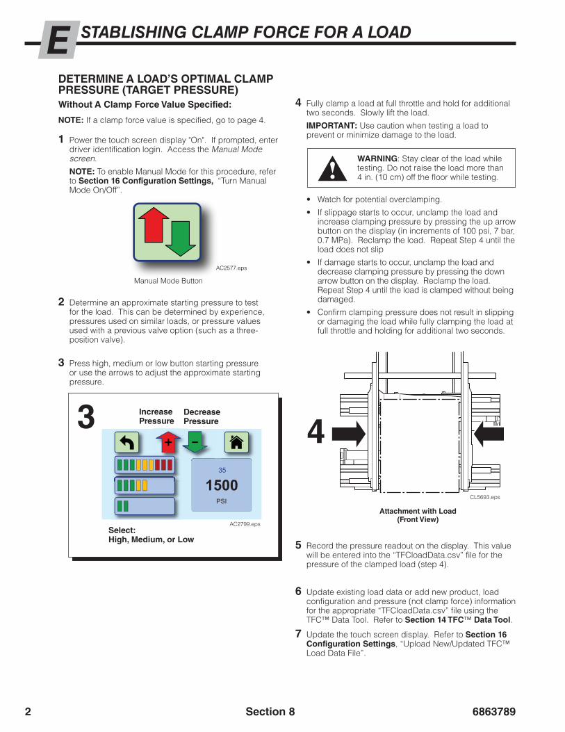
2 Determine an approximate starting pressure to test for the load. This can be determined by experience, pressures used on similar loads, or pressure values used with a previous valve option (such as a three-position valve).
AC2577.eps
DETERMINE A LOAD’S OPTIMAL CLAMP PRESSURE (TARGET PRESSURE)Without A Clamp Force Value Specified:
1 Power the touch screen display "On". If prompted, enter driver identification login. Access the Manual Mode screen.
NOTE: To enable Manual Mode for this procedure, refer to Section 16 Configuration Settings, “Turn Manual Mode On/Off”.
Manual Mode Button
NOTE: If a clamp force value is specified, go to page 4.
3 Press high, medium or low button starting pressure or use the arrows to adjust the approximate starting pressure.
3 Increase Pressure
Decrease Pressure
Select:High, Medium, or Low
4 Fully clamp a load at full throttle and hold for additional two seconds. Slowly lift the load.
IMPORTANT: Use caution when testing a load to prevent or minimize damage to the load.
• Watch for potential overclamping.
• If slippage starts to occur, unclamp the load and increase clamping pressure by pressing the up arrow button on the display (in increments of 100 psi, 7 bar, 0.7 MPa). Reclamp the load. Repeat Step 4 until the load does not slip
• If damage starts to occur, unclamp the load and decrease clamping pressure by pressing the down arrow button on the display. Reclamp the load. Repeat Step 4 until the load is clamped without being damaged.
• Confirm clamping pressure does not result in slipping or damaging the load while fully clamping the load at full throttle and holding for additional two seconds.
4
Attachment with Load(Front View)
CL5693.eps
WARNING: Stay clear of the load while testing. Do not raise the load more than 4 in. (10 cm) off the floor while testing.
6 Update existing load data or add new product, load configuration and pressure (not clamp force) information for the appropriate “TFCloadData.csv” file using the TFC™ Data Tool. Refer to Section 14 TFC™ Data Tool.
7 Update the touch screen display. Refer to Section 16 Configuration Settings, “Upload New/Updated TFC™ Load Data File”.
5 Record the pressure readout on the display. This value will be entered into the “TFCloadData.csv” file for the pressure of the clamped load (step 4).
Section 8
1500PSI
35
AC2799.eps

6863789 3
STABLISHING CLAMP FORCE FOR A LOADE
AC2577.eps
If A Clamp Force Value Is Specified:Tools Required −Clamp force indicator (for Carton Clamps) - Calibrated for 5500 lbf (24.5 kN)Pressure gauge - 5000 psi (345 bar, 34 MPa)
1 Install a pressure gauge and supplied fitting in the TFC™ pressure control valve No. 4 O-ring gauge port or attachment gauge port.
2 Power the touch screen display “On”. Access the Manual Mode screen.
NOTE: To enable Manual Mode for this procedure, refer to Section 16 Configuration Settings, “Turn Manual Mode On/Off”.
DETERMINE A LOAD’S OPTIMAL CLAMP PRESSURE (TARGET PRESSURE) (CONTINUED)
Manual Mode Button
3 Determine an approximate starting pressure to test on the load. Use the chart below to match the clamp force to the starting pressure found in the “Approximate CLAMP Circuit Pressure” column.
CAUTION: Use OEM recommended clamp force values and follow OEM rules for handling multiple boxes or contact the manufacturer. If necessary, test multi-loads to determine the optimal clamp force.
Procedure continued on next page
Required Clamp Force Approximate CLAMP Circuit Pressure15D 25D 35D 50D
lbf kN lbf kN lbf kN lbf kN psi bar MPa
800 3.56 1200 5.37 1600 7.12 2400 10.68 800 55 5.51000 4.45 1500 6.67 2000 8.90 3000 13.34 1000 69 6.91200 5.34 1800 8.01 2400 10.68 3600 16.01 1200 83 8.31400 6.23 2100 9.34 2800 12.46 4200 18.68 1400 96 9.61500 6.67 2250 10.01 3000 13.34 4500 20.02 1500 103 10.31600 7.12 2400 10.68 3200 14.23 4800 21.35 1600 110 11.01800 8.01 2700 12.01 3600 16.01 5400 24.02 1800 124 12.42000 8.90 3000 13.34 4000 17.80 6000 26.69 2000 138 13.8
Section 8

68637894
STABLISHING CLAMP FORCE FOR A LOADE
4
4 Press low, mid or high button, as a starting point or use the arrows to adjust to the approximate starting pressure.
5 Clamp fully on the clamp force indicator at full throttle and hold for an additional two seconds. On the display, use the upward/downward arrow buttons to increase/decrease the pressure until the desired product clamp force is achieved on the clamp force indicator display. Open and close on the clamp force indicator several times.
NOTE: Follow clamp force indicator instructions carefully. Placement and consistency between the indicator and attachment pads is important. Line up the indicator with the pad pivot pin and center vertically between cylinders.
6 Record the pressure readout on the pressure gauge corresponding to the desired clamp force shown on the clamp force indicator.
NOTE: This pressure should be within ±100 psi (7 bar, 0.7 MPa) of the pressure shown on the display.
7 Use the Load Data Management Tool to update product data or add a product, load configuration(s) and pressure value(s) (not clamp force). Refer to Section 14 TFC™ Data Tool. Be sure to make a new “TFCloadData.csv” file once all the information has been added or updated.
8 The TFC™ display will require an updated “TFCloadData.csv” file to be uploaded. Refer to Section 16 Configuration Settings, “Upload New/Updated TFC™ Load Data File”.
AC2588.eps
Pressure Gauge5
Attachment with Clamp Force Indicator(Front View)
If A Clamp Force Value Is Specified (continued)
Section 8
Increase Pressure
Decrease Pressure
Select:High, Medium, or Low
1500PSI
35
AC2799.eps
DETERMINE A LOAD’S OPTIMAL CLAMP PRESSURE (TARGET PRESSURE) (CONTINUED)

6863789 5
STABLISHING CLAMP FORCE FOR A LOADE
Attachment with Load(Front View)
TEST A LOAD’S EXISTING CLAMP (TARGET) PRESSURE VALUETo test the existing CLAMP (target) pressure value for a product, perform the following:
1 Power the touch screen display "On", if necessary.
2 Choose the button(s) for the load.
3 Fully clamp the load at full throttle.
• If the load slips or is damaged at the target pressure, a new pressure value needs to be determined. Refer to previous page(s), “Determine A Load’s Optimal CLAMP Pressure (Target Pressure)”.
3
CL5693.eps
Section 8

68637896 Section 8
BLANK

Quick Start Guide
c
Load Cfg 1 Load Cfg 4
Load Cfg 2 Load Cfg 5
Load Cfg 3 Load Cfg 6
Product Type 2Clamp Fully
2 seconds
1500PSI
20Category 1
Product Type 2
Load Cfg 3
TFC™ – Touch Force ControlCopyright 2014 Cascade Corporation
www.cascorp.com
I agree to operate this attachment inconjunction with the Operator’s Guide,which I have read and understand. OK?
ProductType 1
ProducType 4
ProducTy 7
t tpe
ProductType 2
ProductType 5
ProductType 3
ProductType 6
ProductType 8
Category1
Category2
Category3
TFC™ – Touch Force ControlCopyright 2014 Cascade Corporation
www.cascorp.com
I agree to operate this attachment inconjunction with the Operator’s Guide,which I have read and understand. OK?
TFC™ – Touch Force ControlCopyright 2014 Cascade Corporation
www.cascorp.com
I agree to operate this attachment inconjunction with the Operator’s Guide,which I have read and understand. OK?
Cancel
1
q
2
w
0
p
3
e
4
r
5
t
6
y
7
u
8
i
9
o
a ls d f g h j k
z x c v b n m
OK
AC2846.eps
Use this Quick Start Guide as a reference. Read and use this Quick Start Guide with Operator Guide 6868516. The truck is equipped with a TFC™ Pressure Control Valve. To properly clamp each load, perform the following procedure:
TFC™ –Touch Force Control
Operation
Read and accept to continue
If enabled: Enter driver login and press “OK” button
Press a category button Press a product type button
Press a load configuration button
Verify data shown matches load.
Fully clamp load at full throttle. After contact with the load, continue to pull handle for an additional two seconds. Do not partially pull the handle. Do not feather.
Home Screen
Screen 4Screen 3
Screen 2
Step 1 Step 2
Step 4
Step 6Step 5
Step 7
Step 3
IMPORTANT: Some Home screen buttons may be programed for one touch or two touch options. One Touch option buttons goes to the Confirmation screen. Two touch option buttons goes to Screen 3 (Load Configuration screen).

AC2516.eps
Manual Mode Screen (if activated)
Additional Display Buttons
Increase Pressure
Decrease Pressure
Select:High, Medium, or Low as a starting point
Information area:
Timer – Time in “X” seconds without input and returns to Home screen
Pressure Setting (current setting shows)
Cascade Corporation 2015 07-2015 Part Number 6868517
Manual Mode Button –This button will show on the Home Screen and Screen 2, if activated.
Return – Returns to previous screen
Home – Returns to Home Screen
Repeat – • Repeats the
previous load and load configuration on the Home screen.
• Resets the timer in Screen 4 (Confirmation screen).
Use this mode with caution. Verify that the pressure setting is adequate to handle the load to be lifted. This mode is used for load pressure testing or obtaining the target pressure of a load.
AC2577.eps
AC2577.eps
Pressure changes in increments of ±50 psi (3.44 bar, 0.34 MPa)
1500PSI
35
AC2799.eps

c
For Technical Support . . . To Order Parts . . . Call: 1-800-227-2233 Fax: 1-888-329-8207 Call: 1-888-227-2233 Fax: 1-888-329-0234 Internet: www.cascorp.com Internet: www.cascorp.com Write: Cascade Corporation, PO Box 20187, Portland, OR 97294 Write: Cascade Corporation, 2501 Sheridan Ave., Springfield, OH 45505
cascadecorporation
TFC™ –Touch Force ControlThis sheet provides operating instructions for Cascade TFC™ – Touch Force Control system used in conjunction with Cascade attachments. The system requires additional instructions as outlined below. Refer to the attachment’s Operator Guide for safety rules and standard operation procedures:
Operator Guides Part No.
C, D & E-Series Carton ClampsG-Series Carton ClampsD, F, G, & H-Series Roll ClampsLayer Picker
2102736038012210135222225
Operator’s Guide
WARNING: Operators (Drivers) must read and understand the Operator’s Guide before being allowed to operate the TFC™ system equipped attachment. If the operator does not understand any part of the operator’s guide, a supervisor should be asked for an explanation. If it is still not understood, the equipment should not be used. This product is intended for trained operators only.
WARNING: The determination of the appropriate pressure for secure load handling is the responsibility of the end user.
WARNING: Available maximum clamp pressure is dependent on the truck relief setting. Set the truck relief higher than the highest TFC™ pressure setting.
WARNING: Any piece of equipment can present a hazard when used inappropriately or by an untrained operator (driver) or service technician. This equipment must be serviced by qualified, properly trained personnel only.
Daily InspectionBefore using the TFC™ system, perform the following daily:
• Perform truck safety check list.
• Verify attachment is working properly. Refer to the attachment’s operator guide.
• Check hoses for leaks.• Verify the maximum pressure/clamp force is achievable using a
pressure gauge or clamp force indicator.
WARNING: Residual risk exists to pedestrians and to bystanders in the work area. Operate lift truck and accessory equipment in a safe work area and in compliance with facility, local and national standards and rules.
WARNING: The TFC™ system is not a safety device. It is intended as a pressure/force control device to reduce load damage and aid operators.

2
Category
AC2589.eps
Display Buttons
Return – Returns to previous screen.
Home – Returns to Home screen.
Repeat – • Repeats the
previous load and load configuration on the Home screen.
• Resets the timer in Screen 4 (Confirmation screen).
Product Category or Product Type buttons – Choose a product category button or a product type button to continue to the next screen.
How To Use The TFC™ Display
Read Acknowledgement statement and press the “OK?” button to continue.
If enabled, enter the driver login and press the “OK” button to continue
1
2
TFC™ – Touch Force ControlCopyright 2014 Cascade Corporation
www.cascorp.com
I agree to operate this attachment inconjunction with the Operator’s Guide,which I have read and understand. OK?
AC2642.eps
TFC™ – Touch Force ControlCopyright 2014 Cascade Corporation
www.cascorp.com
I agree to operate this attachment inconjunction with the Operator’s Guide,which I have read and understand. OK?
TFC™ – Touch Force ControlCopyright 2014 Cascade Corporation
www.cascorp.com
I agree to operate this attachment inconjunction with the Operator’s Guide,which I have read and understand. OK?
Cancel
1
q
2
w
0
p
3
e
4
r
5
t
6
y
7
u
8
i
9
o
a ls d f g h j k
z x c v b n m
OK
AC2847.eps
abc9876
Continue to next page
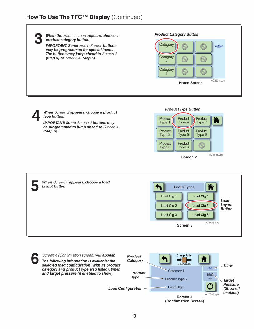
3
When the Home screen appears, choose a product category button.
IMPORTANT: Some Home Screen buttons may be programmed for special loads. The buttons may jump ahead to Screen 3 (Step 5) or Screen 4 (Step 6).
IMPORTANT: Some Screen 2 buttons may be programmed to jump ahead to Screen 4 (Step 6).
3
When Screen 2 appears, choose a product type button.4
Category1
Category2
Category3
AC2591.eps
Product Category Button
Home Screen
Product Type Button
Screen 2
ProductType 1
ProducType 4
ProducTy 7
t tpe
ProductType 2
ProductType 5
ProductType 3
ProductType 6
ProductType 8
AC2645.eps
How To Use The TFC™ Display (Continued)
Clamp Fully
2 seconds
1500PSI
20Category 1
Product Type 2
Load Cfg 5
AC2849.epsScreen 4
(Confirmation Screen)
Timer
Target Pressure(Shows if enabled)
Product Category
Product Type
Load Configuration
Screen 4 (Confirmation screen) will appear.
The following information is available: the selected load configuration (with its product category and product type also listed), timer, and target pressure (if enabled to show).
6
When Screen 3 appears, choose a load layout button5
Load LayoutButton
Screen 3
Load Cfg 1 Load Cfg 4
Load Cfg 2 Load Cfg 5
Load Cfg 3 Load Cfg 6
Product Type 2
AC2848.eps

4
AC2639.eps
Basic Operation With An Attachment
Read Acknowledgement statement and press the “OK?” button to continue.
If enabled, enter the driver login and press the “OK” button to continue
NOTE: The attachment will not operate until the operator accepts the Acknowledgement statement by pressing the “OK?” button.
3
1
2
Display
Load
3 A) Approach the load and stop.
B) Perform one of the following:
Carton Clamps – Align bottom of attachment with bottom of load.
Roll Clamps – Position the roll clamp parallel to and centered to the roll.
Layer Pickers – Verify pad clearance lowering over tiers. Center pads on lowest tier to be picked.
TFC™ – Touch Force ControlCopyright 2014 Cascade Corporation
www.cascorp.com
I agree to operate this attachment inconjunction with the Operator’s Guide,which I have read and understand. OK?
AC2642.eps
A
3
33
B
BB
Layer Picker
Carton Clamp
Roll Clamp
Continue to next page
TFC™ – Touch Force ControlCopyright 2014 Cascade Corporation
www.cascorp.com
I agree to operate this attachment inconjunction with the Operator’s Guide,which I have read and understand. OK?
TFC™ – Touch Force ControlCopyright 2014 Cascade Corporation
www.cascorp.com
I agree to operate this attachment inconjunction with the Operator’s Guide,which I have read and understand. OK?
Cancel
1
q
2
w
0
p
3
e
4
r
5
t
6
y
7
u
8
i
9
o
a ls d f g h j k
z x c v b n m
OK
AC2847.eps
abc9876
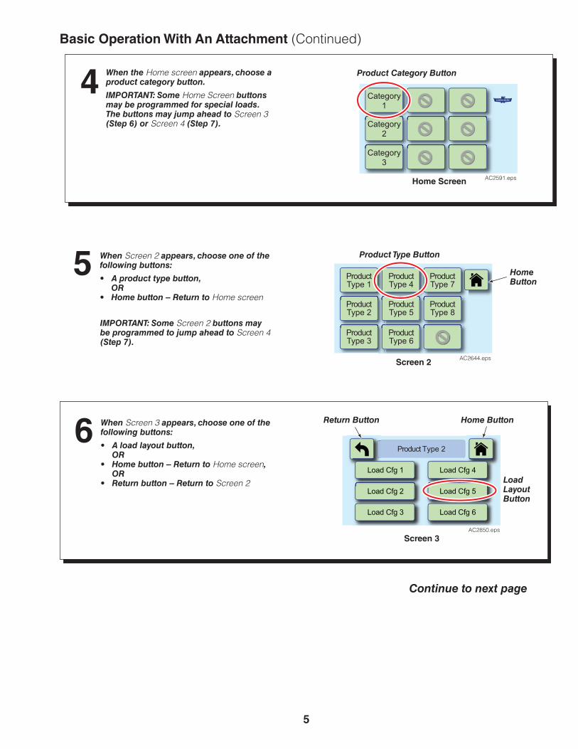
5
Home ButtonReturn ButtonWhen Screen 3 appears, choose one of the following buttons:
• A load layout button,OR
• Home button – Return to Home screen,OR
• Return button – Return to Screen 2 Load LayoutButton
6
Screen 3
Basic Operation With An Attachment (Continued)
Continue to next page
When Screen 2 appears, choose one of the following buttons:
• A product type button,OR
• Home button – Return to Home screen
Product Type Button
Home Button
5
Screen 2
ProductType 1
ProducType 4
ProducTy 7
t tpe
ProductType 2
ProductType 5
ProductType 3
ProductType 6
ProductType 8
AC2644.eps
Category1
Category2
Category3
AC2591.eps
Product Category Button4
Home Screen
Load Cfg 1 Load Cfg 4
Load Cfg 2 Load Cfg 5
Load Cfg 3 Load Cfg 6
Product Type 2
AC2850.eps
IMPORTANT: Some Screen 2 buttons may be programmed to jump ahead to Screen 4 (Step 7).
When the Home screen appears, choose a product category button.
IMPORTANT: Some Home Screen buttons may be programmed for special loads. The buttons may jump ahead to Screen 3 (Step 6) or Screen 4 (Step 7).

6
Clamp Fully
2 seconds
1500PSI
20Category 1
Product Type 2
Load Cfg 5
AC2851.eps
Transport the load and unclamp the load as described in the attachment’s operator guide (part numbers listed on front page).
8 Fully clamp load at full throttle. After contact with the load, continue to pull handle for an additional two seconds. Do not partially pull the handle.Do not feather.
NOTE: Once the timer reaches zero, the selected load is no longer available. Choose the Repeat button to go directly to the previous load settings.
9
Basic Operation With An Attachment (Continued)Screen 4 (Confirmation screen) will appear. The following information is available: the selected load configuration (with its product category and product type also listed), timer, and target pressure (if enabled to show). Verify data shown matches the load.
To leave Screen 4, before the timer ends, press one of the following:
• Home button – Return to Home screen,OR
• Return button – Return to Screen 3
If desired, choose the repeat button to reset the timer. This will allow more time at the specified pressure.
7
Return Button
Home Button
Timer
Repeat ButtonScreen 4
(Confirmation Screen)
Continue to next page
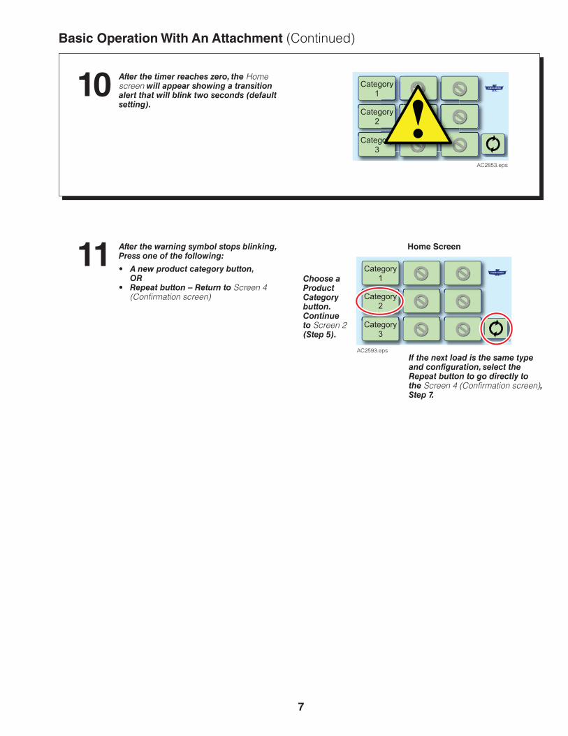
7
Basic Operation With An Attachment (Continued)
Category1
Category2
Category3
AC2593.eps
After the timer reaches zero, the Home screen will appear showing a transition alert that will blink two seconds (default setting).
After the warning symbol stops blinking, Press one of the following:
• A new product category button,OR
• Repeat button – Return to Screen 4 (Confirmation screen)
10
11
If the next load is the same type and configuration, select the Repeat button to go directly to the Screen 4 (Confirmation screen), Step 7.
Choose a Product Category button. Continue to Screen 2 (Step 5).
Home Screen
Category1
Category2
Category3
gory
gory
gory
AC2853.eps

8
1500PSI
35
AC2852.eps
Manual Mode Operation (if activated)Use this mode with caution. This mode has three purposes:• Manually set the clamp pressure.• Determine a load’s target clamp pressure.• Test a load’s existing target clamp pressure.Always verify that the pressure setting is adequate to handle the load being lifted.
NOTE: When the timer reaches zero, the display returns to the Home screen.
Information area:
Timer – Time in“X” seconds without input and returns to home screen
Pressure Setting (current setting shows, if enabled)
1Choose pressure level
2 Arrow buttons
To leave Manual Mode screen, before the timer ends, press one of the following:• Return button,
OR• Home button – Return to the
Home screen,OR
• Another pressure (using the buttons)
Fully clamp the load3
5
Transport load 4
Manual Mode Button –This button will show on the Home Screen and Screen 2, if activated.
AC2577.eps
AC2577.eps
1 Choose a pressure level of High, Medium or Low. The screen will show the timer and the current clamp pressure setting.
2 If necessary, use the arrow buttons to increase or decrease the clamp pressure shown on the display. Pressure changes in increments of ±50 psi (3.44 bar, 0.34 MPa).
3Transport the load and unclamp the load as described in the attachment’s operator guide (part numbers listed on front page).
4Return Home
Fully clamp load at full throttle. Continue to pull handle for an additional two seconds. Do not partially pull the handle.Do not feather.
© Cascade Corporation 2015 07-2015 Part Number 6868516

6863789 1
ROUBLESHOOTINGTThis section provides troubleshooting for Cascade TFC™ – Touch Force Control system.
TRUCK SYSTEM REQUIREMENTS• Truck hydraulic flow and pressure should be set within
the range specified in the appropriate service manual for the attachment. Maximum CLAMP circuit hydraulic flow is 25 GPM (95 L/min.).
• Hydraulic fluid supplied to the TFC™ system must meet the requirements specified in the appropriate service manual for the attachment.
• Electrical power to the TFC™ system must be from a circuit that can supply 12 Volts @ 3 Amps and includes a truck key/ignition circuit.
TOOLS REQUIRED• USB Flash Drive – Provided with TFC™ kit.
• Pressure Gauge Kit – Includes 5000 psi (345 bar) pressure gauge and hose, No. 4 & 6 connect-under-pressure test fittings, and adapters (Service Kit 6004960)
• Clamp Force Indicator (if measuring clamp force)
GA0150.eps
Quick-Connect Pressure Gauge Kit 6004960
USB Flash DriveNOTE: Part number based on customer data.
AC2636.eps
Clamp Force Indicator Part Numbers:Carton Clamps Roll Clamps
35G-CFI-8RF 135G-DFI-8RF 2
300G-CFI-812C (Split) 1300G-CFI-824C (Solid) 1300G-DFI-812C (Split) 2300G-DFI-824C (Solid) 2
1 Analog2 Digital
WARNING: Before servicing any hydraulic component, relieve pressure in the attachment system. Turn the truck off and move the truck auxiliary control lever several times in both directions.
For electro-hydraulic systems, pulse the attachment open to relieve pressure trapped in the clamp circuit before turning truck off.
After completing any service procedure, always test the attachment through several cycles. First test empty to bleed any air trapped in the system to the truck tank. Then test with a load to make sure that the attachment operates correctly before returning to the job. Stay clear of the load while testing. Do not raise the load more than 4 in. (10 cm) off the floor while testing.
Clamp Force Indicator
AC1100.eps
Section 10
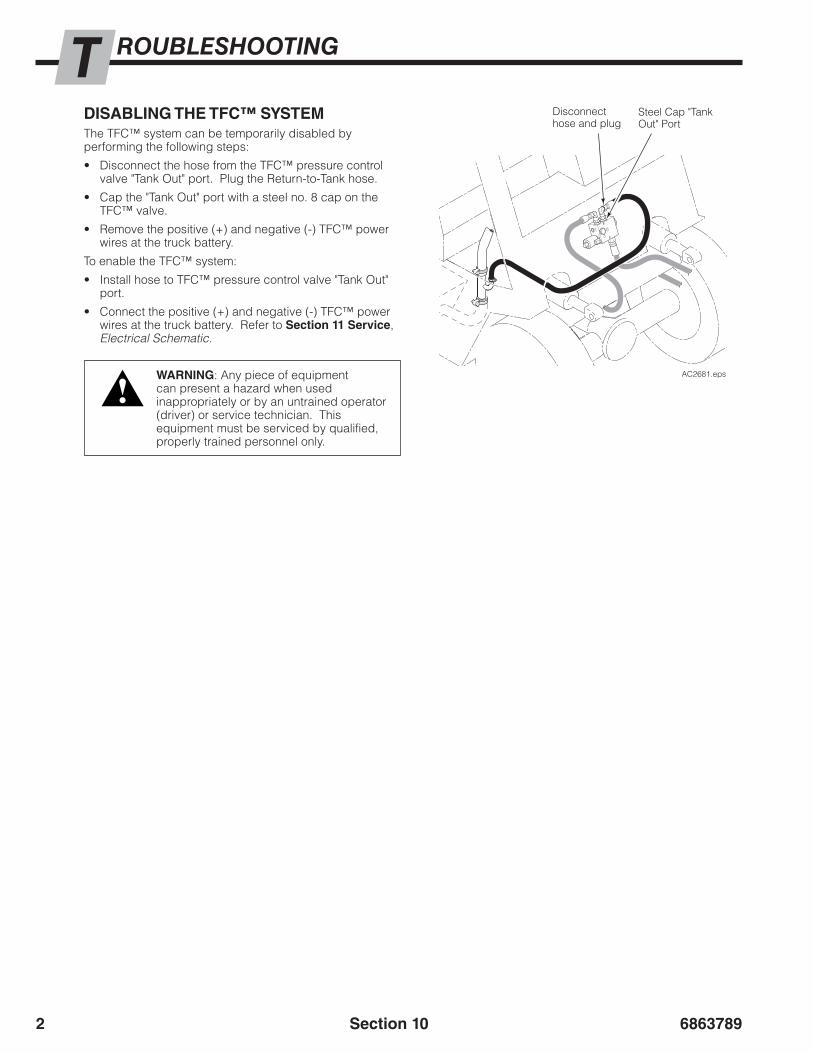
68637892
ROUBLESHOOTINGTDISABLING THE TFC™ SYSTEMThe TFC™ system can be temporarily disabled by performing the following steps:
• Disconnect the hose from the TFC™ pressure control valve "Tank Out" port. Plug the Return-to-Tank hose.
• Cap the "Tank Out" port with a steel no. 8 cap on the TFC™ valve.
• Remove the positive (+) and negative (-) TFC™ power wires at the truck battery.
To enable the TFC™ system:
• Install hose to TFC™ pressure control valve "Tank Out" port.
• Connect the positive (+) and negative (-) TFC™ power wires at the truck battery. Refer to Section 11 Service, Electrical Schematic.
Steel Cap "Tank Out" Port
Disconnect hose and plug
CH
ECK
VALV
EGAU
GE
SOL
AC2681.eps
Section 10
WARNING: Any piece of equipment can present a hazard when used inappropriately or by an untrained operator (driver) or service technician. This equipment must be serviced by qualified, properly trained personnel only.

6863789 3
AC2800.eps
ROUBLESHOOTINGTBASIC FUNCTION TROUBLESHOOTINGIMPORTANT: Before beginning this procedure, the installation must be complete. Turn the truck ignition key "On" and wait for the display to complete the boot up cycle. Then turn the truck ignition key "Off" and then "On" again.
Start
Boot screen displayed for approximately
twentyseconds?
Boot screen displayed for approximately
twentyseconds?
Attachment clamps at
high pressure only?
Attachment clamps at
high pressure?
Is tank line blocked?
Disconnectvalve driverconnector
Go to “System PowerTroubleshooting”
Go to “System PowerTroubleshooting”
Cycle truck ignitionkey “Off”/”On”.
Replace display and/or valve driver
Continue to Aon next page
ReplaceTFC™ ValveAssembly
Separate main powerwires from truck keypower circuit. Refer toSection 6 Installation & Technical FAQ.
Correct hydraulicconnection. Refer toSection 6 Installation & Technical FAQ.
YES
YES
YES
YES
YES
YES
NO
NO
NO NO
NO
NO
Acknowledgementscreen turns on within
one second?
Section 10
A
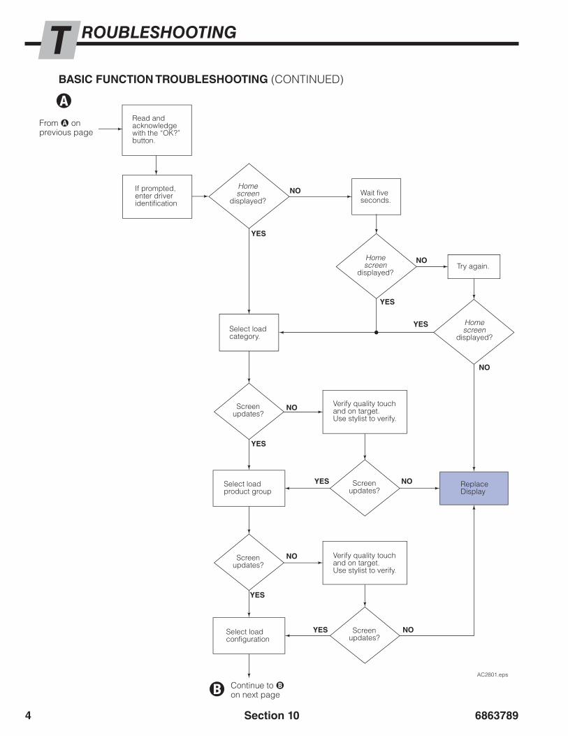
68637894
ROUBLESHOOTINGT
Section 10
BASIC FUNCTION TROUBLESHOOTING (CONTINUED)
AC2801.eps
Screenupdates?
Screenupdates?
Screenupdates?
Screenupdates?
Homescreen
displayed?
Homescreen
displayed?
Homescreen
displayed?
Select loadconfiguration
Select loadproduct group
Verify quality touchand on target.Use stylist to verify.
Verify quality touchand on target.Use stylist to verify.
Try again.
Select loadcategory.
Wait fiveseconds.
Read andacknowledgewith the “OK?”button.
If prompted, enter driver identification
YES
YES
YES
YES
YES
YES
YES
NO
NO
NO
NO
NO
NO
NO
ReplaceDisplay
From A onprevious page
A
Continue to Bon next pageB

6863789 5
AC2802.eps
ROUBLESHOOTINGT
Section 10
BASIC FUNCTION TROUBLESHOOTING (CONTINUED)
Returnbuttonworks?
Transition alert works
(if enabled)?
Homebuttonworks?
Backbuttonworks?
Timerworks?
Load isclamped atthe correct pressure?
ConfirmationScreen
displayed?
Screenupdates?
TFC™ Systemis OK
ReplaceDisplay
YES
YES
YES
YES
YES
YES
YES
YES
NO
NO
NO
NO
NO
NO
NO
NO
From B onprevious page
B
Test the system performance. Refer to Section 7 Testing System Prior To Use
Verify quality touchand on target.Use stylist to verify.

68637896
AC2803.eps
ROUBLESHOOTINGTSYSTEM POWER TROUBLESHOOTINGIMPORTANT: Before beginning this procedure, the installation must be complete. Turn the truck ignition key 'On' and wait for the display to complete the boot up cycle. Then turn the truck ignition key 'Off' and then 'On' again.
NOTE: Vehicles with 24-48VDC require a DC/DC converter and relay. The TFCTM system is 12 Vdc.
Is therea voltage
reading of 12VDC between Pin 1
and Pin 3
Is there avoltage reading
of 12VDC betweenPin 2 and Pin 3with ignition key
‘ON’?
DisplayPower ‘ON’?
DisplayPower ‘ON’?
Upon turningthe ignition key,
does the display turn‘ON’ within one
second?
Does theKey turn power
‘ON’/’OFF’ at pin 2
Replace wireharness.
Replace wireharness.
Verify electrical component installation. Refer to Section 6 Installation & Technical FAQ, “Electrical Component Installation”, Step 5.
Verify electrical component installation. Refer to Section 6 Installation & Technical FAQ, “Electrical Component Installation”, Step 5.
Power to TFC™Display is correctlyapplied.
Pin 1 (+)Pin 3 (-)
17
2026
Pin 2 (Key +12v)
YES
YES
YES
YES
YES
YES
NO
NO
NO
NO
NO
NO
Start
Section 10
ReplaceDisplay
Wire Harness Connector (Display)

6863789 7
ROUBLESHOOTINGTDISPLAY TROUBLESHOOTING
Problem Solution
Refer to “System Power Troubleshooting”, page 6.
After a reboot the "OK?" button (Acknowledgement Screen) can take up to three or more seconds to respond. Try again.
The display screen is pressure sensitive and works well with gloves, stylist or other appropriate tools. If heavy gloves are used, the touch to the screen may not be accurate and mis-touch a button.
If display appears ‘frozen’, try power cycle at the main battery terminal (reboot).
The display screen is pressure sensitive and works well with gloves, stylist or other appropriate tools. If heavy gloves are used, the touch to the screen may not be accurate and mis-touch a button.
If display appears ‘frozen’, try power cycle at the main battery terminal (reboot).
The Manual Mode button is toggled on and off from the Configuration screen. Refer to Section 16 Configuration Settings.
These values can be adjusted from the configuration screen. Refer to Section 16 Configuration Settings.
Ignition key does not turn on the display
Display does not respond to touch
Touch resulted in incorrect selection
Display is frozen
Can’t find Manual Mode
Manual and Default pressure values are wrong
Section 10
Display Troubleshooting continued on the next page

68637898
ROUBLESHOOTINGT
Enter ‘9999’ and then touch the “R” to reset the password to the default ‘1234’.
Touch the Cascade logo and enter the password
Replace the Display.NOTE: Screen brightness is not adjustable
Refer to "Basic Function Troubleshooting" (page 3) and "System Power Troubleshooting" (page 6).
Refer to supervisor or manager.
Disconnect ALL power and reboot.
Refer to supervisor or manager.
Disable the driver identification feature. Refer to Section 16 Configuration Settings.
Custom password forgotten
Can’t find Configuration Screen
Display is damaged, cracked, not functioning correctly
Display does not turn off with ignition key
The load desired to select is not an option on the screen.
The display’s screen is dim or dark and does not respond to touch.
Forgot driver identification password
Problem Solution
DISPLAY TROUBLESHOOTING (CONTINUED)
Section 10

6863789 9
ROUBLESHOOTINGTCLAMP CIRCUIT TROUBLESHOOTING
Problem Solution
On the Acknowledgement Screen, read and touch the "OK?" button.
Verify Default Pressure is set high enough for the attachment. Recommended value is 900 psi (62 bar, 6.2 MPa). Refer to Section 16 Configuration Settings.
On the Acknowledgement Screen, read and touch the “OK?” button.
Verify Default Pressure is set high enough for the attachment. Recommended value is 900 psi (62 bar, 6.2 MPa). Refer to Section 16 Configuration Settings.
Verify correct hydraulic installation. Refer to Section 6 Installation & Technical FAQ.
Verify the truck auxiliary CLAMP and OPEN circuit lines are not crossed. Trace the line from the vehicle auxiliary valve clamp function energy port, through the TFC™ valve and into the attachment valve port marked “Clamp”.
Remove air by performing the procedure Section 6 Configuration Settings, “Check TFCTM System Output”, Steps 2,3 and 4.
Arms close too slowly
Arms will not open
Pressure values are not consistent
Arms will not close
Section 10
CLAMP Circuit Troubleshooting continued on the next page

686378910
ROUBLESHOOTINGTCLAMP CIRCUIT TROUBLESHOOTING (CONTINUED)
Use the Pressure Factors (Refer to Section 16 Configuration Settings) to make calibration adjustments to the pressure output.
Refer to supervisor or manager to verify pressure values are correct. Use Load Data Management Tool.
All pressures are too High and loads are crushed
Section 10
Problem Solution
Clean and lubricate the attachment arms and bearings.
Verify the clamp FORCE vs Input clamp PRESSURE relationship for the attachment model (consult Cascade) and that the correct correlating pressure value is set in the TFC™ data. Refer Section 8 Establishing Clamp Force, for examples.
Use the Pressure Factors (Refer to Section 16 Configuration Settings) to make calibration adjustments to the pressure output.
Verify that the truck's auxiliary valve maximum pressure relief is set above or equal to the max pressure value used in the TFC™ data.
Refer to supervisor or manager to verify pressure values are correct. Use Load Data Management Tool.
Measured clamp force, using a Clamp Force Indicator, is too high or too low
Pressure settings for a particular load are wrong! The load is crushed or the load slips.
CLAMP Circuit Troubleshooting continued on the next page

6863789 11
ROUBLESHOOTINGT
Section 10
CLAMP CIRCUIT TROUBLESHOOTING (CONTINUED)
Problem Solution
Use the Pressure Factors (Refer to Section 16 Configuration Settings) to make calibration adjustments to the pressure output.
Refer to supervisor or manager to verify pressure values are correct. Use Load Data Management Tool.
All pressures are too low and loads slip

686378912 Section 10
BLANK

6863789 1
ERVICESThis section provides a periodic maintenance schedule, describes servicing the TFC™ Pressure Control Valve and also provides hydraulic and electrical schematics of the system.
PERIODIC MAINTENANCE SCHEDULE100-Hour MaintenanceEvery time the lift truck is serviced or every 100 hours of truck operation, whichever comes first, complete the following maintenance procedures:
• Check for worn or damaged hoses and hydraulic leaks.
• Check for secure electrical connections and that the cables are not damaged by pinching or fraying.
500-Hour MaintenanceAfter each 500 hours of truck operation, in addition to the 100-hour maintenance, perform the following procedures:
• Check TFC™ system pressure output by verifying that the screen target pressure matches the actual gauge pressure (or desired clamp force using clamp force indicator). Make adjustments as required. Refer to Section 7 Testing System Prior To Use.
CH
ECK
VALV
EGAU
GE
SOL
AC2749.eps
Check system output
Section 11
DAILY INSPECTION• Perform truck safety check list.
• Verify attachment is working properly. Refer to the attachment’s operator guide.
• Check hoses for leaks.• Verify the maximum pressure/clamp force is achievable
using a pressure gauge or clamp force indicator.

68637892
ERVICESVALVE REMOVAL AND INSTALLATION
1 Disconnect the hoses from the valve. Plug the ends and tag for reassembly.
2 Disconnect the solenoid connector from the solenoid driver.
3 Disconnect the solenoid driver from the solenoid coil.
4 Remove the valve mounting capscrews. For reassembly, tighten the capscrews to 15 ft.-lbs. (20 Nm).
5 For reassembly, reverse the above procedures with the following exceptions:
• Service the valve as described in “Valve Service”.
VALVE SERVICEIMPORTANT: Service the valve in a clean work area.
1 Remove the valve from the truck as described above.
2 Remove the solenoid coil, cartridges, fittings and plugs from the valve.
3 Remove the O-rings and back-up rings from the cartridges.
4 Clean all parts with clean solvent.
5 For reassembly, reverse the above procedures with the following exceptions:
• Replace O-rings and back-up rings as shown on the following page.
• Lubricate cartridges, fittings and plugs with O-ring lube or petroleum jelly prior to installation.
• Make sure the solenoid coil is properly installed with the lettering upward.
• Tighten cartridges to the following torque value:
Solenoid Cartridge – 22 ft.-lbs. (30 Nm)Solenoid Nut – 9 ft.-lbs. (12 Nm)Check Valve – 18 ft.-lbs. (25 Nm)Priority Flow Control – 47 ft.-lbs. (64 Nm)
WARNING: Before removing any hoses, relieve pressure in the hydraulic system. With the truck off, open the truck auxiliary control valve(s) several times in both directions. Solenoid
Connector
Solenoid Driver
Check Valve Cartridge
Priority Flow Control Valve Cartridge
Solenoid Coil
Solenoid Cartridge
AC2653.eps
Section 11

6863789 3
ERVICES
AC2545.eps
Solenoid Valve Cartridge
Check Valve CartridgePriority Flow Control Cartridge
AC0684.epsCL0342.eps
O-Rings
O-RingsSolenoid Coil
Solenoid Cartridge
Retaining Nut
Back-up Rings
Back-up Ring
Back-up Ring
WARNING: After completing any service procedure, always test the attachment through several cycles. First test empty to bleed any air trapped in the system to the truck tank. Then test with a load to make sure that the attachment operates correctly before returning to service. Stay clear of the load while testing. Do not raise the load more than 4 in. (10 cm) off the floor while testing.
O-Rings
VALVE SERVICE (CONTINUED)
Section 11

68637894
ERVICES
Section 11
AC2594.eps
Return-To-Tank Fitting
Truck Tank
Truck Relief Valve
Truck Hydraulic Pump
CLAMP/OPENAuxiliary Valve
Attachment Valve
Check Valve
Priority Flow Control Valve
Solenoid Valve
OPEN
CLAMP
TFC™ Pressure Control Valve
InternalReeving
ORHose Reel
GaugePort
HYDRAULIC SCHEMATIC
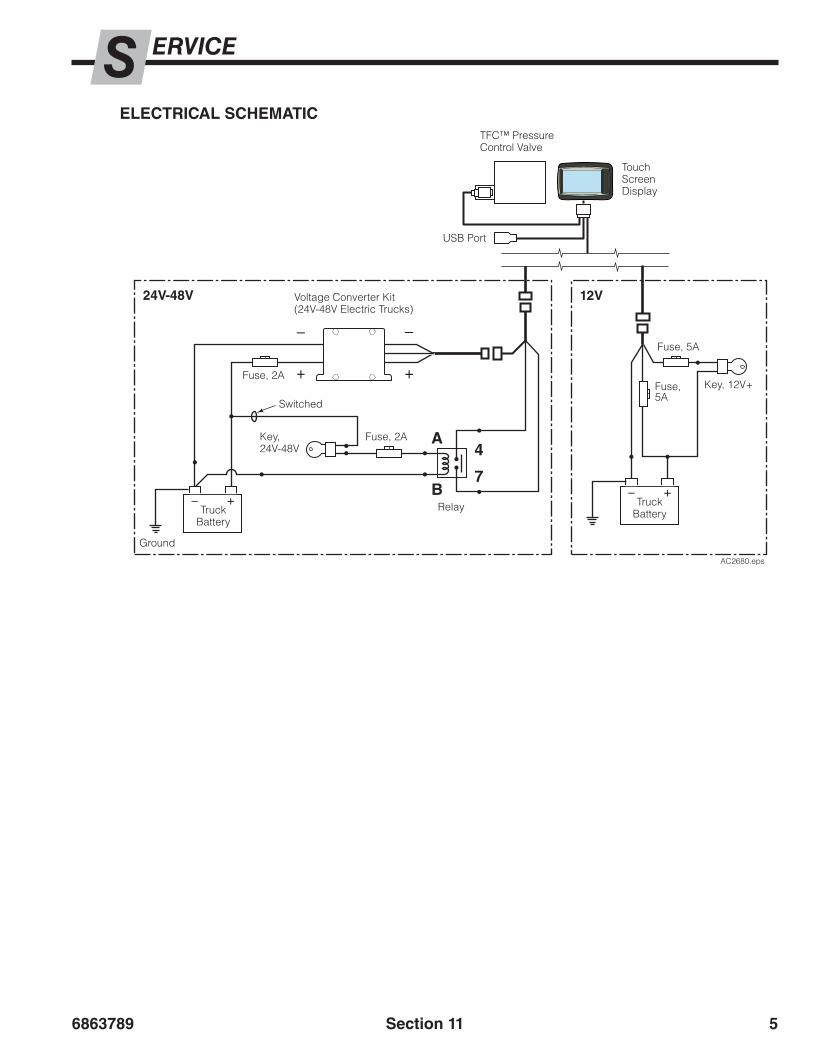
6863789 5
AC2680.eps
B
4
7
A
ERVICES
Section 11
ELECTRICAL SCHEMATIC
Truck Battery
Fuse, 5A
Fuse, 5A
Key, 12V+
12VVoltage Converter Kit(24V-48V Electric Trucks)
Switched
Ground
Truck Battery
Fuse, 2A
TFC™ Pressure Control Valve
USB Port
Touch Screen Display
Fuse, 2AKey, 24V-48V
Relay
24V-48V

68637896
BLANK
Section 11

6863789 1
ARTSPTFC™ – Touch Force Control Kits
AC0919.eps
∕ Return-To-Tank Kit
12V
Section 12
CLAMPOUT
CHECK
VALVE
GAUGE
CLAMPOUT
CHECK
VALVE
GAUGE
1
#
#
9@
%
2
43
0&
*
)⁄
(
¤
‹›fi
7
7
8
$#
5
!
^
AC2882.eps
6

68637892
ARTSP
REF QTY
12V 24-48V
DESCRIPTIONPART NO. PART NO.
1 1 6854511 — Power Harness, UL – 12V2 2 6806708 — Fuse, 5A
31 — 6855855 Key Power Relay Kit, 24V1 — 6851614 Key Power Relay Kit, 36V1 — 6855856 Key Power Relay Kit, 48V
41 — 6855748 Relay, 24V1 — 6852671 Relay, 36V1 — 6855749 Relay, 46V
5 1 — 6854600 Relay Harness6 1 — 6855815 Power Harness, UL – 24-48V7 1 — 6806701 Fuse, 2A8 1 — 6863188 Converter Kit
Common PartsREF QTY PART NO. DESCRIPTION
9 1 6865855 Touch Screen Display ◆10 1 ◆ Flash Drive with Data Table11 1 6843778 Cable Harness12 1 6849706 Mounting Adapter ▲13 10 6405497 Capscrew, M5 x 12 ▲14 2 685901 Washer, M5 ▲15 1 6849486 Mounting Bracket ▲16 1 6850578 Mounting Bracket ▲17 1 6849752 Pressure Control Valve Driver18 1 6849377 Pressure Control Valve ●19 1 6843724 Valve Body20 1 6516055 Cartridge21 1 6849378 Coil, 12V22 3 601377 Fitting, 8-823 1 6018248 Cartridge, Check Valve24 1 6061801 Cartridge, Flow Control25 2 609234 Plug, 426 1 6807816 Return-To-Tank Kit
◆ Part number based on customer data. Contact Cascade to order with original configured data.
▲ Included in Display Mounting Kit 6849297.● Includes items 19-25.
TFC™ – Touch Force Control Kits
Section 12
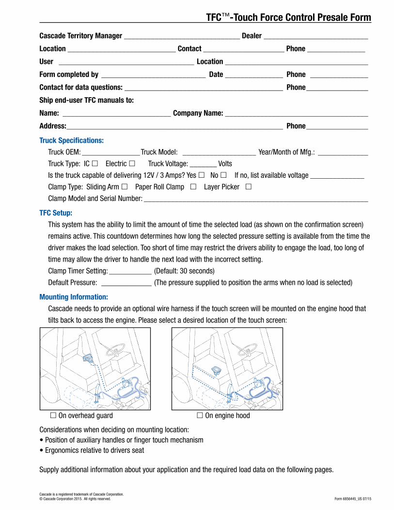
Cascade Territory Manager ______________________________ Dealer ___________________________
Location ____________________________ Contact _____________________ Phone _______________
User ___________________________________ Location _____________________________________
Form completed by ___________________________ Date _______________ Phone _______________
Contact for data questions: _________________________________________ Phone ________________
Ship end-user TFC manuals to:
Name: ____________________________ Company Name: _____________________________________
Address: ________________________________________________________ Phone ________________
Truck Specifications:
Truck OEM: _______________Truck Model: ___________________ Year/Month of Mfg.: _____________
Truck Type: IC £ Electric £ Truck Voltage: _______ Volts
Is the truck capable of delivering 12V / 3 Amps? Yes £ No £ lf no, list available voltage ______________
Clamp Type: Sliding Arm £ Paper Roll Clamp £ Layer Picker £
Clamp Model and Serial Number: __________________________________________________________
TFC Setup:
This system has the ability to limit the amount of time the selected load (as shown on the confirmation screen)
remains active. This countdown determines how long the selected pressure setting is available from the time the
driver makes the load selection. Too short of time may restrict the drivers ability to engage the load, too long of
time may allow the driver to handle the next load with the incorrect setting.
Clamp Timer Setting: ___________ (Default: 30 seconds)
Default Pressure: _____________ (The pressure supplied to position the arms when no load is selected)
Mounting Information:
Cascade needs to provide an optional wire harness if the touch screen will be mounted on the engine hood that
tilts back to access the engine. Please select a desired location of the touch screen:
£ On overhead guard £ On engine hood
Considerations when deciding on mounting location:• Position of auxiliary handles or finger touch mechanism• Ergonomics relative to drivers seat
Supply additional information about your application and the required load data on the following pages.
TFC™-Touch Force Control Presale Form
Form 6856445_US 07/15Cascade is a registered trademark of Cascade Corporation.© Cascade Corporation 2015. All rights reserved.

Providing Clamp Force or Clamping Hydraulic Pressure Data to Cascade:In order to program TFC, the clamp force data for every product to be clamped will need to be provided.
Cascade is very flexible in how it receives the data. The following outlines the various ways the one-to-one relationship between clamp force or clamp pressure and the product to be clamped is communicated.
When submitting the pre sale worksheet, please fill it out using the most accurate data available. More accurate data will limit the on-site adjustment process. If precision data is currently unavailable, TFC provides an easy way to determine the pressure after installation and provide the clamp force needed to securely handle the load.
1. Provide the clamp force data as required to pick up the unit load.• The amount of clamp force should be specific to how many products are to be clamped at one time.
The manufacturer may specify different clamp force for 1 product compared to 2 or 4 or more handled at one time.
2. Provide the clamp pressures that are currently being applied. • If a 3-position regulator is being used for many different products, then simply outline which
pressure setting is being used for which products and in what configuration (quantity).
3. If no device is being used to control pressure, and the driver guesses each time a load is clamped, the best way to provide the data may be to install a pressure gauge into the system and record the pressure that securely handles each load. Refer to Cascade’s ‘How to properly establish clamp force for carton clamps’ when using this method.
TFC™-Touch Force Control Presale Form

Carton Clamps
Examples when load data is known in terms of clamp pressure (psi, bar or MPa)
Product NameQuantity Handled
Clamp Hydraulic Pressure
Unit of Measure
Clamp Force Specified
Unit of Measure Category Name (optional)
1 Washer 4 1500 psi NA NA Laundry
2 TV 42"-58" 6 1200 psi NA NA Audio Visual
3 Microwave 1 800 psi NA NA Kitchen
Examples when load data is known in terms of clamp force (lbf or kN)
Product NameQuantity Handled
Clamp Hydraulic Pressure
Unit of Measure
Clamp Force Specified
Unit of Measure Category Name (optional)
1 Washer 4 NA NA 1400 lbf Laundry2 TV 42"-58" 6 NA NA 1200 lbf Audio Visual3 Microwave 12 NA NA 1000 lbf Kitchen
Please enter your data into the blank form on the following page.
Layer Pickers
Examples when load data is known in terms of clamp pressure (psi, bar or MPa)
Product NameQuantity Handled
Clamp Hydraulic Pressure
Unit of Measure
Clamp Force Specified
Unit of Measure Category Name (optional)
1 Soda Layer 1100 psi NA NA Beverage
2 Tissue Rolls Layer 800 psi NA NA Paper
Examples when load data is known in terms of clamp force (lbf or kN)
Product NameQuantity Handled
Clamp Hydraulic Pressure
Unit of Measure
Clamp Force Specified
Unit of Measure Category Name (optional)
1 Soda Layer NA NA 800 lbf Beverage
2 Tissue Rolls Layer NA NA 600 lbf Paper
Please enter your data into the blank form on the following page.
TFC™- Examples of Data Structure
Paper Roll Clamps
Examples when load data is known in terms of clamp pressure (psi, bar or MPa)
Product NameQuantity Handled
Clamp Hydraulic Pressure
Unit of Measure
Clamp Force Specified
Unit of Measure Category Name (optional)
1 Kraft 42" 1 1100 psi NA NA Keywest Printing
2 News 50" 2 1800 psi NA NA Preprint
Examples when load data is known in terms of clamp force (lbf or kN)
Product NameQuantity Handled
Clamp Hydraulic Pressure
Unit of Measure
Clamp Force Specified
Unit of Measure Category Name (optional)
1 Kraft 42" 1 NA NA 800 lbf Keywest Printing
2 News 50" 2 NA NA 600 lbf Preprint
Please enter your data into the blank form on the following page.
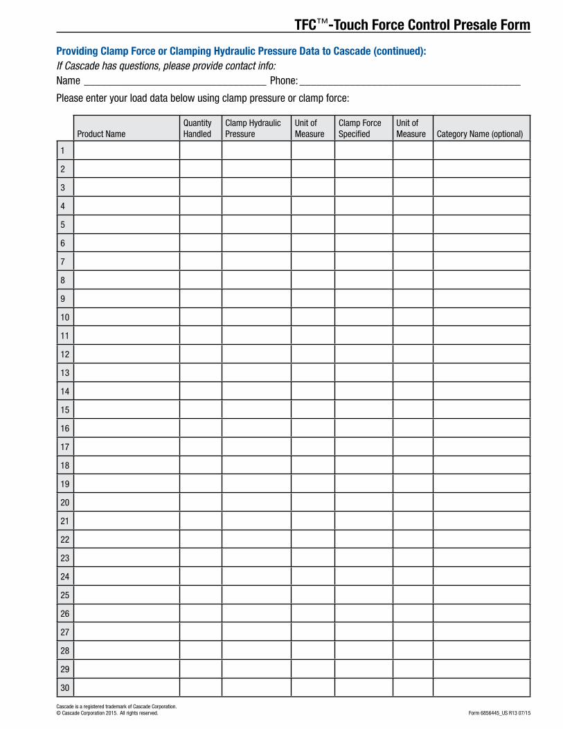
TFC™-Touch Force Control Presale Form
Providing Clamp Force or Clamping Hydraulic Pressure Data to Cascade (continued): If Cascade has questions, please provide contact info:Name _________________________________ Phone: ________________________________________
Please enter your load data below using clamp pressure or clamp force:
Product NameQuantity Handled
Clamp Hydraulic Pressure
Unit of Measure
Clamp Force Specified
Unit of Measure Category Name (optional)
1
2
3
4
5
6
7
8
9
10
11
12
13
14
15
16
17
18
19
20
21
22
23
24
25
26
27
28
29
30
Form 6856445_US R13 07/15Cascade is a registered trademark of Cascade Corporation.© Cascade Corporation 2015. All rights reserved.

6863789 1
SING THE TFC™ DATA TOOLUThis section provides instruction on using the TFC™ Data Tool (requires Excel 2010 or newer) found on the USB flash drive provided with the TFC™ system.
IMPORTANT: Be familiar with Excel prior to use.
ABOUT THE TFC™ DATA TOOLLoad data entered into this Tool is converted into a CSV (comma-separated value) file format for the display’s internal software to utilize. If the values need to be changed or new product added to an existing “TFCLoadData.csv” file, use this Tool to begin the process of updating the TFC™ system.
INFORMATION TO NOTE• All text fields, up to two lines, are limited to about eleven
characters per line for best viewing results. The number of characters per line may vary depending on selected language.
• Grayed out fields can not be used.
• Blanks are allowed but will disable the display’s button. Do not use a “space”. Use clear or delete to remove content.
• Time values are in seconds.
• Touch “shortcut“ options are available as a drop down menu. One touch or two touch options will gray out fields.
Section 14
Tool Version 335
Available procedures/topics:
To learn the layout of the TFC™ Data Tool, go to page 2 and 3, “TFC™ Data Tool Layout”
To open the TFC™ Data Tool, go to page 4, “Opening The TFC™ Data Tool”
START WITHOUT LOAD DATA CHANGE LOAD DATA
Reset the current data, go to page 15, “Reset To Default Data”.
To change the language, go to page 5, “Change Language”.
Add, modify or remove a Product Category or Product, go to page 6, “Add/Modify/Remove a Product Category or Product”.
Add, modify or remove a Product Type, go to page 7, “Add/Modify/Remove a Product Type”.
Changes to the load data file requires saving, go to page 12, “Saving Data”.
Optionally, create a back up file of a “TFCloadData.csv” file, go to page 13, “Backup Saved CSV Data File”.
Options:• Loads that require more or less time for
clamping, go to page 9, “Change A Timer Option”.
• Fewer touch options are needed for selecting a load, go to page 10, “Change Touch Options”
Import an existing “TFCloadData.csv” file, go to page 14, “Importing Existing Load Data File”.
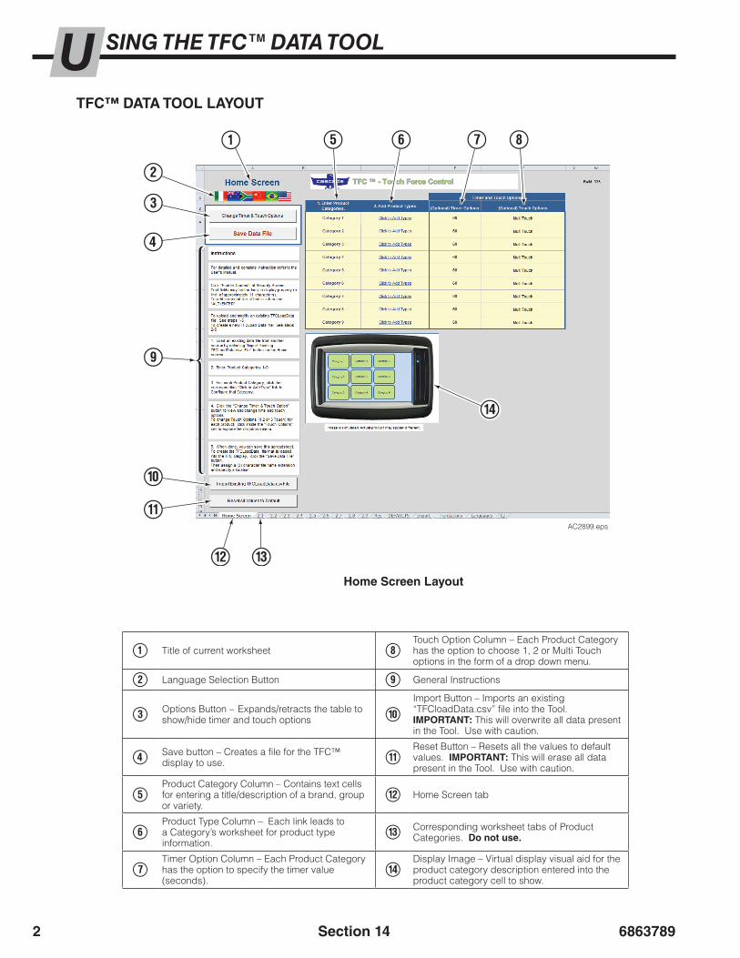
68637892
SING THE TFC™ DATA TOOLUTFC™ DATA TOOL LAYOUT
1 Title of current worksheet 8Touch Option Column – Each Product Category has the option to choose 1, 2 or Multi Touch options in the form of a drop down menu.
2 Language Selection Button 9 General Instructions
3 Options Button – Expands/retracts the table to show/hide timer and touch options 0
Import Button – Imports an existing “TFCloadData.csv” file into the Tool. IMPORTANT: This will overwrite all data present in the Tool. Use with caution.
4 Save button – Creates a file for the TFC™ display to use. !
Reset Button – Resets all the values to default values. IMPORTANT: This will erase all data present in the Tool. Use with caution.
5Product Category Column – Contains text cells for entering a title/description of a brand, group or variety.
@ Home Screen tab
6Product Type Column – Each link leads to a Category’s worksheet for product type information.
# Corresponding worksheet tabs of Product Categories. Do not use.
7Timer Option Column – Each Product Category has the option to specify the timer value (seconds).
$Display Image – Virtual display visual aid for the product category description entered into the product category cell to show.
Home Screen Layout
Section 14
1
3
2
4
5 6 7 8
9
0
!
@ #
$
AC2899.eps
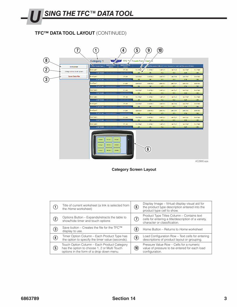
6863789 3
TFC™ DATA TOOL LAYOUT (CONTINUED)
1 Title of current worksheet (a link is selected from the Home worksheet) 6
Display Image – Virtual display visual aid for the product type description entered into the product type cell to show.
2 Options Button – Expands/retracts the table to show/hide timer and touch options 7
Product Type Titles Column – Contains text cells for entering a title/description of a variety, character or classification.
3 Save button – Creates the file for the TFC™ display to use. 8 Home Button – Returns to Home worksheet
4 Timer Option Column – Each Product Type has the option to specify the timer value (seconds). 9 Load Configuration Row – Text cells for entering
descriptions of product layout or grouping.
5Touch Option Column – Each Product Category has the option to choose 1, 2 or Multi Touch options in the form of a drop down menu.
0Pressure Value Row – Cells for a numeric value of pressure to be entered for each load configuration.
Category Screen Layout
Section 14
1
2
3
47 5
8
9 0
6
AC2900.eps
SING THE TFC™ DATA TOOLU

68637894
IMPORTANT: Use Microsoft Excel 2010 (or newer) with the tool. Earlier versions of Excel will not work and could prevent the Tool from functioning properly.
1 Insert the USB flash drive into a computer USB port.
OPENING THE TFC™ DATA TOOL LAYOUT
5 Start using the Tool.
3 A security warning will appear. Click on the button “Enable Content”.
2 Launch the TFC™ Data Tool found on the root directory of the drive, called “TFC Data Tool.xlsm”.
Section 14
AC2901.eps
2
Root Directory on USB Flash Drive:
AC2902.eps
4 A “Terms of Use” dialog box will appear. Read and acknowledge the terms of use.
3
AC2903.eps
4
SING THE TFC™ DATA TOOLU
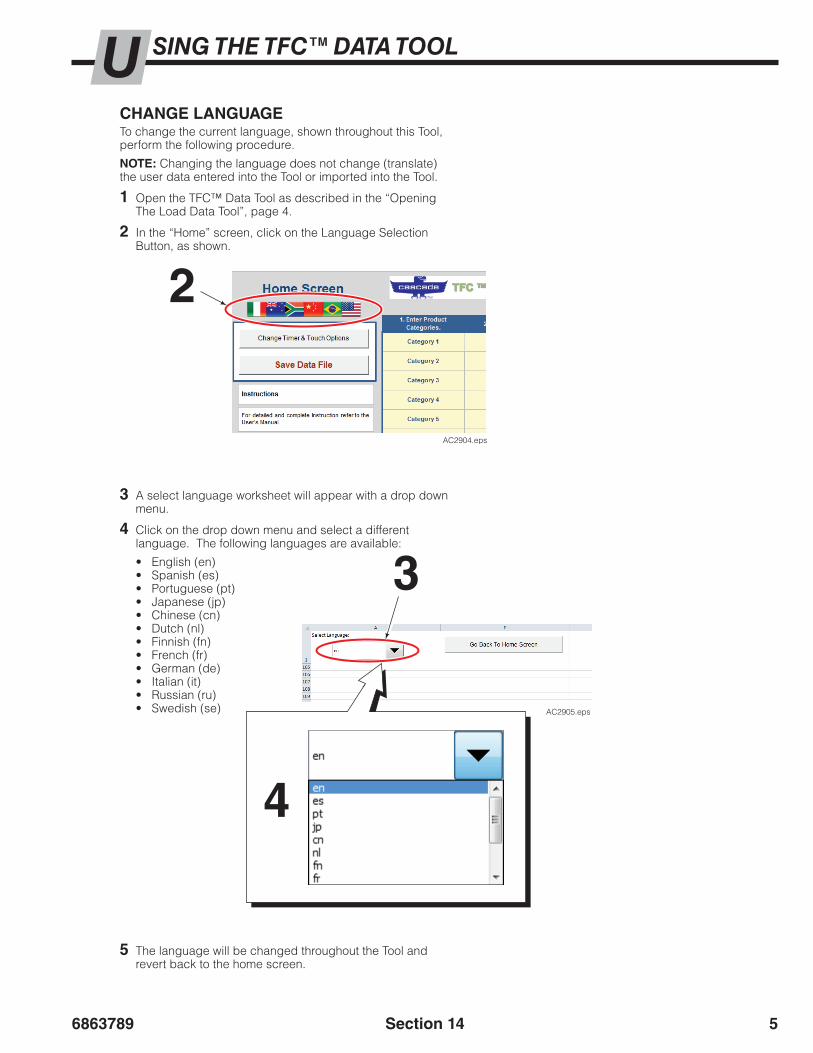
6863789 5
AC2905.eps
CHANGE LANGUAGETo change the current language, shown throughout this Tool, perform the following procedure.
NOTE: Changing the language does not change (translate) the user data entered into the Tool or imported into the Tool.
1 Open the TFC™ Data Tool as described in the “Opening The Load Data Tool”, page 4.
2 In the “Home” screen, click on the Language Selection Button, as shown.
3 A select language worksheet will appear with a drop down menu.
4 Click on the drop down menu and select a different language. The following languages are available:
• English (en)• Spanish (es)• Portuguese (pt)• Japanese (jp)• Chinese (cn)• Dutch (nl)• Finnish (fn)• French (fr)• German (de)• Italian (it)• Russian (ru)• Swedish (se)
5 The language will be changed throughout the Tool and revert back to the home screen.
3
4
2
Section 14
AC2904.eps
SING THE TFC™ DATA TOOLU

68637896
AC2906.eps
2 Change Product Category Name Cells(approximately 11 character maximum per line)
Display Image
ADD/MODIFY/REMOVE A PRODUCT CATEGORY OR PRODUCTTo add, modify or remove a product category or product, perform the following procedure. For a written account, log changes using the table on page 16.
1 Open the TFC™ Data Tool as described in the “Opening The TFC™ Data Tool”, page 4.
2 In the “Home” worksheet, add, modify or remove Product Category text into the yellow cells of column labeled “1. Enter Product Categories”.
• If needed, to add a second line, use the keyboard’s ALT + ENTER key combination.
NOTE: If a cell is left blank, it will not be selectable on the touch screen display. The cell content must be deleted/cleared. Do not use spaces.
NOTE: As shown, the text entered into the Product Category column cells will show on the display image.
NOTE: For information on Timer and Touch Options columns, refer to “Change Timer Option” or “Change Touch Options”.
Section 14
To add a second line, use the keyboard’s ALT + ENTER key combination.
SING THE TFC™ DATA TOOLU

6863789 7AC2907.eps
Section 14
ADD/MODIFY/REMOVE A PRODUCT TYPETo add, modify or remove a product type, perform the following procedure. For a written account, log changes using the table on page 16.
1 Each Product Category (or Product) listed on the “Home” worksheet, has a corresponding link to the right adjacent cell. Click the link to go to the Product Category’s (or Product’s) worksheet (as shown below).
2 Add, modify or remove text into the Product Type yellow cells of column labeled “1. Enter Product Type”
• If needed, to add a second line, use the keyboard’s ALT + ENTER key combination.
NOTE: If a cell is left blank, it will not be selectable on the touch screen display. Cell content must be deleted/cleared. Do not use spaces.
NOTE: As shown, the text entered into Product Type category cells will show on the display image.
Display Image
Product TypeColumn
Click the Product Category’s (or Product’s) Product Type link
2
1
SING THE TFC™ DATA TOOLU
To add a second line, use the keyboard’s ALT + ENTER key combination.
Procedure continued on next page

68637898
Load Cfg 1 Load Cfg 4
Load Cfg 2 Load Cfg 5
Load Cfg 3 Load Cfg 6
Product Type 1
AC2916.eps
A
A
B
C
D
E
F
B C D E F
Section 14
SING THE TFC™ DATA TOOLUADD/MODIFY/REMOVE A PRODUCT TYPE (CONTINUED)
3 Add, modify or remove text for up to six Load Configuration yellow cells for each Product Type row section.
• If needed, to add a second line, use the keyboard’s ALT + ENTER key combination.
NOTE: If a cell is left blank, it will not be selectable on the touch screen display. Cell content must be deleted/cleared. Do not use spaces.
4 Add, modify or remove numeric target Pressure value in the green cells for each Load Configuration listed.
NOTE: When determining the target pressure for a new load or to test current target pressure value, refer to Section 8 Establishing Clamp Force. Always start with the manufacturer’s recommendation.
Load descriptions and corresponding target pressure value (up to 6 options)3,4
WARNING: Pressure values must not exceed the maximum pressure generated by the truck or rated by the attachment. Consult the truck manufacturer. Never enter a value greater than 2300 psi (160 bar, 16 MPa).
To add a second line, use the keyboard’s ALT + ENTER key combination.
Display’s Load Configuration Layout:

6863789 9Section 14
SING THE TFC™ DATA TOOLU
AC2908.eps
CHANGE TIMER OPTIONThe timer option changes the default time (60 seconds) to clamp a load to a specified time in a Product Category group or specific Product Type.
To change the timer option on one or more Product Category or Product Type, perform the following procedure. For a written account, log changes using the table on page 16.
“Home” Worksheet:1 In the “Home” worksheet, click on the “Change Timer &
Touch Options” button to show the options, if necessary.
2 To change the timer for an entire Product Category (or Product), enter a time value (in seconds) or leave blank to use default time value.
Timer and Touch Option columns
1 2
“Product Type” Worksheet:1 In the Product Category’s (or Product’s) worksheet, click
on the “Change Timer & Touch Options” button to show the options, if necessary.
2 To change the timer for a specific Product Type, enter a time value (in seconds) or leave blank to use default time value.
1
2
AC2909.eps

686378910 Section 14
SING THE TFC™ DATA TOOLU
AC2910.eps
CHANGE TOUCH OPTIONSTouch options are “shortcuts” from the standard sequence of button selections (multi touch).
To change touch options, perform the following procedure. For a written account, log changes using the table on page 16.
“Home” Worksheet:1 In the “Home” worksheet, click on the “Change Timer &
Touch Options” button to show the options, if necessary.
2 For each Product Category (or Product) that requires a change in touch options, click on the corresponding cell in the “Touch Options” column. An arrow button will appear on the lower right corner of the cell and click on the arrow. In the drop down menu, select “1 Touch” or “2 Touch” for each category. “Multi Touch” is default.
• “1 Touch“ takes the driver to the Confirmation screen on the touch screen display.
• “2 Touch“ takes the driver to the Load Configuration screen on the touch screen display.
Category’s Product Type Worksheet:
Timer and Touch Option columns
1 2
Enter description of Product Type (Optional)
Enter description of Product Type (Optional)
Enter up to 6 load descriptions and corresponding pressures
One load description and one corresponding pressure is needed. NOTE: All following cells in the rows will be grayed out.
All other rows will be grayed out
All other rows will be grayed out
“1 Touch” Selected on “Home” Worksheet
“2 Touch” Selected on “Home” Worksheet
NOTE: For “1 Touch” or “2 Touch” selection, the product type description field is optional.
Category’s product type procedure on next page
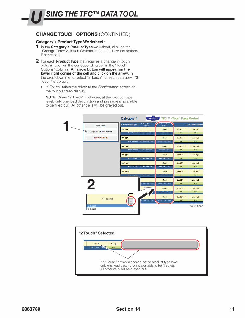
6863789 11Section 14
SING THE TFC™ DATA TOOLU
AC2911.eps
Category’s Product Type Worksheet:1 In the Category’s Product Type worksheet, click on the
“Change Timer & Touch Options” button to show the options, if necessary.
2 For each Product Type that requires a change in touch options, click on the corresponding cell in the “Touch Options” column. An arrow button will appear on the lower right corner of the cell and click on the arrow. In the drop down menu, select “2 Touch” for each category. “3 Touch” is default.
• “2 Touch“ takes the driver to the Confirmation screen on the touch screen display.
NOTE: When “2 Touch” is chosen, at the product type level, only one load description and pressure is available to be filled out. All other cells will be grayed out.
1
2
“2 Touch” Selected
If “2 Touch” option is chosen, at the product type level, only one load description is available to be filled out. All other cells will be grayed out.
CHANGE TOUCH OPTIONS (CONTINUED)

686378912 Section 14
SING THE TFC™ DATA TOOLU
AC2912.eps
SAVING LOAD DATAThe following procedure creates a file (CSV file format) to update load data on the TFC™ display.
1 Choose the “Save Data File” button (located on all screens for convenience).
4 A dialog box will show. Click the “OK” to continue.
5 Choose the root directory (top level) on the provided USB flash drive to save the file for upload to the touch screen display. Click the “OK” button.
NOTE: The TFC™ display will only find and read files that are on the root directory (top level) of the installed flash drive.
6 Once the file is saved, a confirmation dialog box will show with the name of the file. Click the “OK” button.
2 Enter a three digit suffix (required), a combination of characters and/or numbers. For example, this suffix can be:
Example Suffix Name
Dock 1ShippingReceiving
DK1SHPREC
3 Click the “OK” button.
7 If desired, save the TFC™ Data Tool file and close the file.
8 Remove and secure the USB flash drive.
NOTE: Cascade recommends making a copy on separate file storage (such as a computer). Refer to “Backup Saved CSV Data File”, page 13.
Choose the “Save Data File” Button
Enter a three digit identifier number
Choose file location on root directory of USB flash drive.
File name shows
Click the “OK” button
Click the “OK” button
Click the “OK” button
1
2 3
5
6
4

6863789 13Section 14
SING THE TFC™ DATA TOOLUBACKUP SAVED CSV DATA FILECreating A Copy And Rename A File From Its Original Name:1 Insert the USB flash drive into a computer USB port.
2 Open the USB flash drive directory.
3 Move (“Copy” or “Cut” and “Paste”) the file to separate location (such as a computer).
4 Rename the moved file keeping the original name and adding, for example, today’s date (Example date: 03042014).
File Rename Example:Original file name “TFCloadData_001.csv” would be renamed to “TFCloadData_001_03042014.csv”.
To Return A File To Its Original Name:If the file is needed at a later time, in order for the display to recognize the file, the file will need to be returned to its original name.
1 If necessary, move (“Copy” or “Cut” and “Paste”) the file to a USB Flash Drive root directory.
NOTE: A file with the same original name can not be on the root directory. Back up the file on the root directory (if required) and delete.
2 Remove any additional text from the file name after the three digit suffix (such as the date, if used) but ending with “.csv”.
Example: On the USB flash drive,“TFCloadData_123_04052014.csv” would be returned to its original name “TFCloadData_123.csv”.

686378914 Section 14
SING THE TFC™ DATA TOOLU
AC2584.eps
Choose the Import Button
Choose the file to import.
Confirm import by clicking the “Yes” button.
1
2 3
4
5
IMPORT EXISTING DATA FILEThe following procedure imports an existing “TFCloadData.csv” file into the TFC™ Data Tool . This will overwrite the current values in the TFC™ Data Tool. If needed, save a copy of the current values. Refer to the “Saving Data”, page 12.
5 Once the file has finished importing, a dialog box will appear to confirm that the import is complete. Click the “OK” button.
4 A dialog box will appear to verify to continue importing the file. Click “Yes” to confirm and continue import.
2 Choose the desired “TFCloadData.csv” file to import from any file location (USB flash drive, backup computer, network, etc.).
3 Choose the “OK” button to continue.
1 In the “Home” worksheet, choose the “Import Existing TFCloadData.csv File” button.

6863789 15Section 14
SING THE TFC™ DATA TOOLURESET TO DEFAULT DATAThe following procedure resets the TFC™ Data Tool to it’s original load data values. This is used in situations when a user starts from the beginning and has all new load data.
3 A dialog box will appear to confirm the values have been reset. Click the “OK” button.
2 A dialog box will appear to verify resetting the values to default. Click the “Yes” button.
1 In the “Home” worksheet, choose the “Reset All Values to Default” button.
IMPORTANT: All user (customer) data will be erased.
AC2914.eps
Choose the Reset Button
Choose the “Yes” button to reset
Click the “OK” button to confirm the reset is complete
1
2
3

686378916 Section 14
SING THE TFC™ DATA TOOLUT
FC
™ –
To
uch
Fo
rce
Co
ntr
ol
Dat
a To
ol F
ile C
han
ges
Lo
g(I
MP
OR
TAN
T: Im
port
load
dat
a fil
e in
to th
e TF
C™
Dat
a To
ol w
hen
mak
ing
chan
ges.
Alw
ays
crea
te a
bac
kup
copy
of p
revi
ous
vers
ions
of t
he fi
le.)
Tru
ck &
Att
ach
men
t:
Lo
ad D
ata
File
Nam
e:
Dat
e/S
et B
y
Ch
oo
se O
ne
Ho
me
Scr
een
Pro
du
ct T
ype
Scr
een
1
Mo
dif
icat
ion
OR
Ad
dit
ion
OR
Rem
ova
l
Pro
du
ct
Cat
ego
ryN
ame
Tim
er
(sec
on
ds)
Tou
chO
pti
on
s
Pro
du
ctTy
pe
Nam
eT
imer
(s
eco
nd
s)To
uch
Op
tio
ns
Lo
ad
Co
nfig
ura
tio
nP
ress
ure
1 A
ny c
hang
es n
oted
in th
is s
ectio
n re
quire
the
“Pro
duct
Cat
egor
y N
ame”
to a
lso
be s
peci
fied.

6863789 1
ATALOGGER™ – TOUCH HISTORYDThis section provides instructions to import and review touch history log(s) downloaded from the TFC™ display. The log(s) contain every touch on the display’s screen, including date, time, screen name and description. A log file can create up to four log files, each containing 300,000 touches.
NOTE: Touch history log(s) can be downloaded from the display to the provided USB flash drive or another properly configured USB flash drive.
DOWNLOAD TOUCH HISTORY1 Plug the USB flash drive into the USB connector found
on the TFC™ harness near the display.
2 Touch the Cascade Logo.
2
3
3 A dialog box will show. Enter password and touch the “OK” button.
Section 15
TFC™ – Touch Force ControlCopyright 2014 Cascade Corporation
ver.: 6865854R0
www.cascorp.com
I agree to operate this attachment inconjunction with the Operator’s Guide,which I have read and understand.
OK?
AC2790.eps
1 3
****
4 5
2
6
7 8 9
OK RR Cancel
AC2791.eps
Current Time: 4/2/2015
Manual High : 1900
Manual Low : 1000Manual Med : 1500
Default : 900Press. Fact. Med: 0.98
Trans Alert(sec): 2Press. Fact. Low: 1.1
Press. Fact. High: 1.02Manual Mode: NoPressure: Hide
Pressure Units: PSI
13:52:54
Change
Data Settings Pressure Factor
Manual Mode:ChangeNo
LanguageChange
Default Pressure
Done
Next
Page 1
Load Save Load Save
Configuration
AC2823.eps
Current Time: 4/2/2015
Manual High : 1900
Manual Low : 1000Manual Med : 1500
Default : 900Press. Fact. Med: 0.98
Trans Alert(sec): 2Press. Fact. Low: 1.1
Press. Fact. High: 1.02Manual Mode: NoPressure: Hide
Pressure Units: PSI
13:52:54
PSIChange Download
Manual Pressures Data Log “BAR, PSI, Mpa”
VisualsChangeLoad
PasswordChange
Date and Time
Done
NextBackConfiguration
Logs uploaded successfully
AC2828.eps
5
4
Message will appear to confirm whether the log downloaded or not.
Serial Number Location
Display (back)
4 Touch the “Next” button.
5 In the “Data Log” box, touch the “Download” button.
• The message “Logs uploaded successfully” should appear.
• If the message “Unable to find USB device” appears, wait 5 seconds and press the “Download” button again.
NOTE: When the “Download” button is pressed (in the “Data Log” box), a subfolder (in the logs folder) is created on the USB flash drive and named with the serial number of the display. This allows the touch history logs from many displays to be stored on a single USB flash drive. The subfolder is overwritten with all data each download.
Press the “OK” button after password is entered
AC2876.eps
Procedure continued on next page
Display Version 6.0.3
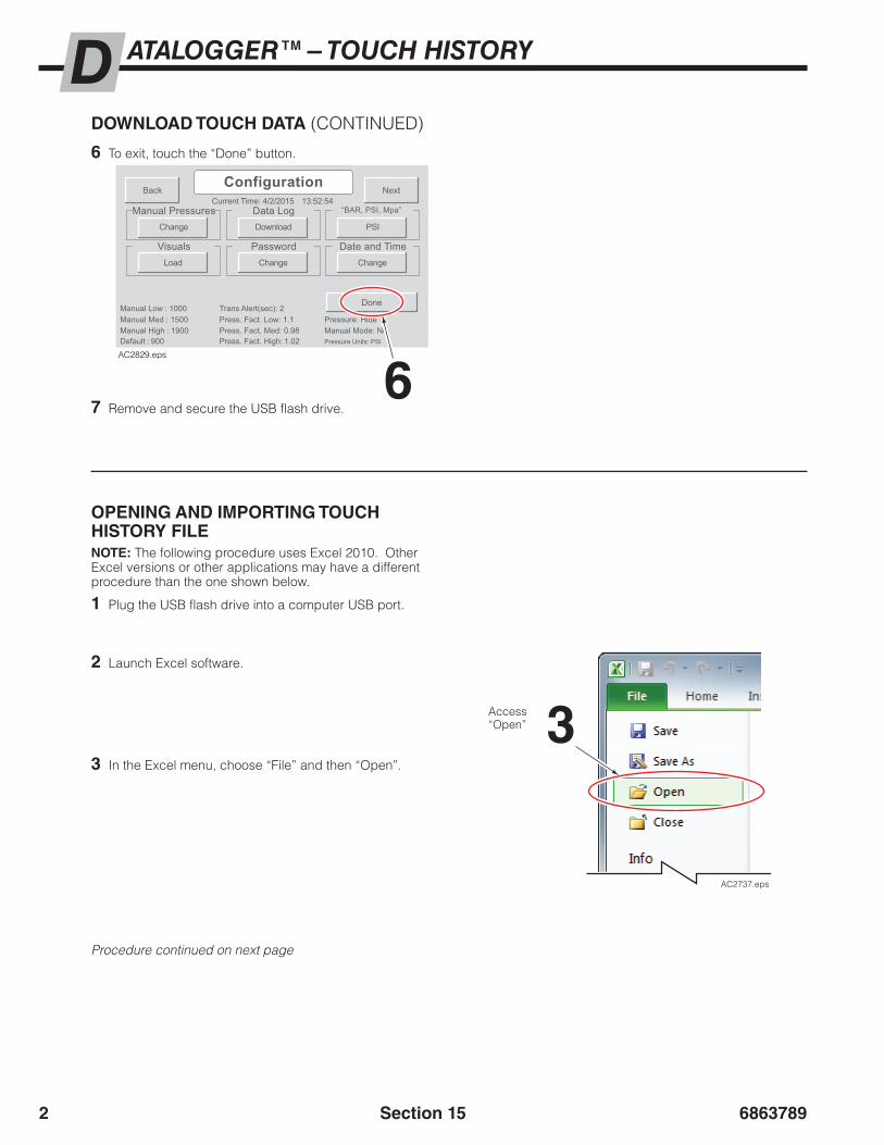
68637892
ATALOGGER™ – TOUCH HISTORYD
Current Time: 4/2/2015
Manual High : 1900
Manual Low : 1000Manual Med : 1500
Default : 900Press. Fact. Med: 0.98
Trans Alert(sec): 2Press. Fact. Low: 1.1
Press. Fact. High: 1.02Manual Mode: NoPressure: Hide
Pressure Units: PSI
13:52:54
PSIChange Download
Manual Pressures Data Log “BAR, PSI, Mpa”
VisualsChangeLoad
PasswordChange
Date and Time
Done
NextBackConfiguration
AC2829.eps
6 To exit, touch the “Done” button.
7 Remove and secure the USB flash drive.6
DOWNLOAD TOUCH DATA (CONTINUED)
OPENING AND IMPORTING TOUCH HISTORY FILENOTE: The following procedure uses Excel 2010. Other Excel versions or other applications may have a different procedure than the one shown below.
1 Plug the USB flash drive into a computer USB port.
2 Launch Excel software.
3 In the Excel menu, choose “File” and then “Open”.
AC2737.eps
3Access “Open”
Procedure continued on next page
Section 15

6863789 3
OPENING AND IMPORTING TOUCH HISTORY FILE (CONTINUED)
6
5
Procedure continued on next page
4 In the “Open” dialog box, change the filter to “All Files (*.*)”.
5 Navigate to the root directory (top level) of the USB flash drive.
6 Left, double click on the “Logs” folder.
4AC2883.eps
AC2884.eps
7 Open the desired folder based on the display’s serial number.
7
Section 15
ATALOGGER™ – TOUCH HISTORYD

68637894 Section 15
AC2885.eps
8 Locate and choose the desired file: “Log0000X.txt”.
9 Click the “Open” button.
Procedure continued on next page
8 9 10 If the “Test Import Wizard” dialog
box appears, verify that the following options are selected:
A Original Data Type: Delimited
B Delimiters: Tab
C Column Data Format: General
11 Choose the “Finish” button. The file will open.
A
B
C
10
11AC2886.eps
NOTE: Skip to Step 12, if the “Text Import Wizard” does not appear.
OPENING AND IMPORTING TOUCH HISTORY FILE (CONTINUED)
ATALOGGER™ – TOUCH HISTORYD
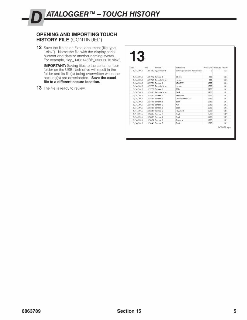
6863789 5Section 15
12 Save the file as an Excel document (file type “.xlsx”). Name the file with the display serial number and date or another naming syntax. For example, “log_1408143BB_05202015.xlsx”.
IMPORTANT: Saving files to the serial number folder on the USB flash drive will result in the folder and its file(s) being overwritten when the next log(s) are downloaded. Save the excel file to a different secure location.
13 The file is ready to review.
13
AC2879.eps
OPENING AND IMPORTING TOUCH HISTORY FILE (CONTINUED)
ATALOGGER™ – TOUCH HISTORYD

68637896
AC2897.eps
Section 15
REVIEWING TOUCH HISTORYThe information below explains the basics of reviewing touch history logs.
NOTE: There are many features in Excel that can be used to manipulate the touch screen data. Processing the data for charts, reports, etc., is up to the user.
For every button pressed on the display, the following is recorded:
• Date• Time• Display’s screen name• Selected display button name• Pressure the CLAMP circuit line is set to• Pressure Factor applied to the current pressure
Acknowledgment ScreenFor every button pressed on the Acknowledgement screen, the following is recorded:
1 Pressing the “OK?” Button:
Driver ID not enabled:• Screen column: “Agreement” A• Selection column: “Safe Operations Agreement” A• One blank row is added A
About Excel ColumnsWhen a button is pressed the following data (touch history) is recorded:
• Date Column – Date (mm/dd/yyyy)
• Time Column – Time (hh:mm:ss)
• Screen Column – Screen name (driver screens) or box name (configuration screens)
• Selection Column – Name of the button pressed
• Pressure Column – Target load pressure or default pressure (the truck CLAMP circuit is set to) is listed depending on the screen and button pressed. Pressure changes occur after a button is pressed.
• Pressure Factor Column – Assigned pressure factor depending on the pressure value. This value is applied to the target pressure.
TFC™ – Touch Force ControlCopyright 2014 Cascade Corporation
ver.: 6865854R0
www.cascorp.com
I agree to operate this attachment inconjunction with the Operator’s Guide,which I have read and understand.
OK?
AC2887.eps
Acknowledgement Screen
A
A A
A B C D E
Screencolumn
Selectioncolumn
ATALOGGER™ – TOUCH HISTORYD

6863789 7
TFC™ – Touch Force ControlCopyright 2014 Cascade Corporation
ver.: 6865854R0
www.cascorp.com
I agree to operate this attachment inconjunction with the Operator’s Guide,which I have read and understand.
OK?
Cancel
1
q
2
w
0
p
3
e
4
r
5
t
6
y
7
u
8
i
9
o
a ls d f g h j k
z x c v b n m
OKabc9876
AC2888.eps
Section 15
Acknowledgment Screen (Continued)
1 Pressing the “OK?” Button (Continued):
Driver ID is enabled:• First, records that the “OK?” Button is pressed:
– Screen column: “Agreement” A – Selection column: “Safe Operations Agreement” A
• Then, records activity on Driver ID dialog box:
– Screen column: “Driver ID Keyboard” B – Selection column: A letter or number – each letter or
number button pressed is represented by a row. C – Selection column: “backspace“ – the backspace arrow
button was pressed D – Selection column: “OK -” + driver ID – the “OK”
button was pressed and listing the accepted driver’s identification. A blank row is also added. E
– Selection column: “OK - Invalid Operator” – the “OK” button was pressed and operator (driver) identification was denied. F
– Selection column: “Cancel“ – the “Cancel” button was pressed. G
Acknowledgement Screen
Driver ID Dialog Box
A
B
D
DA
G
FG
C
CE
EF
E
REVIEWING TOUCH HISTORY (CONTINUED)
Screencolumn
Selectioncolumn
ATALOGGER™ – TOUCH HISTORYD

68637898 Section 15
Acknowledgment Screen (Continued)
2 Pressing the Cascade Logo:
• First, records that the Cascade Logo is pressed:
– Screen column: “Agreement” A – Selection column: “Access Keypad” A
• Then, records activity on password dialog box:
– Screen column: “Agreement” B – Selection column: Number – each number button
pressed is represented by a row. C – Selection column: “OK” – the “OK” button was
pressed. D – Selection column: “Cancel” – the “Cancel” button was
pressed. E
A
TFC™ – Touch Force ControlCopyright 2014 Cascade Corporation
ver.: 6865854R0
www.cascorp.com
I agree to operate this attachment inconjunction with the Operator’s Guide,which I have read and understand.
OK?
1 3
****
4 5
2
6
7 8 9
OK RR Cancel
AC2889.eps
Acknowledgement Screen
Password Dialog Box
A B
C
A
DE
E
C
D
Screencolumn
Selectioncolumn
REVIEWING TOUCH HISTORY (CONTINUED)
ATALOGGER™ – TOUCH HISTORYD

6863789 9
Category1
Category2
Category3
Category4
Category7
Category5
Category6
Category1
Category2
Category3
Laundry
Furniture
SeasonalRanges
Dishwashers
SpecialRefrigeration
AC2890.eps
ProductType 1
ProducType 4
ProducTy 7
t tpe A/C HeatersOutdoor
Grills
AC2891.eps
Section 15
Driver Selection ScreensFor every button pressed on the operator (driver) selection screens (Home screen, Screen 2, Screen 3 and the Confirmation Screen), the following is recorded:
1 Home Screen (category/product screen, Screen 1)
• Screen column: “Screen 1” A• Selection column: Name of category/product button that
was pressed. For example, the Selection column will list “Seasonal”. B
• Selection column: “Repeat” – the repeat button was pressed. C
2 Screen 2 (product type screen)
• Screen column: “Screen 2” A• Selection column: Name of product type button that was pressed.
For example, the Selection column will list “Outdoor Grills”. B• Selection column: “Back” – the “Home” button was pressed. C
Name of Category/Product (appears on the display)
Name of Product Type (appears on the display)
Home Screen (Screen 1)
C B
B C
A
BC
C
A
B
Screen 2
Screencolumn
Selectioncolumn
Screencolumn
Selectioncolumn
REVIEWING TOUCH HISTORY (CONTINUED)
ATALOGGER™ – TOUCH HISTORYD

686378910
1 Unit 8+ Units
2 Units
4 Units
Outdoor Grills
AC2892.eps
Section 15
Driver Selection Screens (Continued)
3 Screen 3 (load layout screen)
• Screen column: “Screen 3” A• Selection column: Name of the load layout button that
was pressed. For example, the Selection column will list “4 Units”. B
• Selection column: “Home” – the “Home” button was pressed. C
• Selection column: “Back” – the “Back” button was pressed. D
Screen 3
Name of Load Layout (appears on the display)
C B D
D B C
A
Screencolumn
Selectioncolumn
Clamp Fully
2 seconds
800PSI
20Seasonal
Outdoor Grill
4 UnitsAC2893.eps
B C D
B
DA
C
Confirmation Screen
Screencolumn
Selectioncolumn
4 Confirmation Screen
• Screen column: “Results Scrn” A• Selection column: “Back” – the “Back“ button was pressed. B• Selection column: “Home” – the “Home” button was pressed. C• Selection column: “Repeat” – the “Repeat” button was pressed. D
REVIEWING TOUCH HISTORY (CONTINUED)
ATALOGGER™ – TOUCH HISTORYD

6863789 11Section 15
Category1
Category2
Category3
Category4
Category7
Category5
Category6
Category1
Category2
Category3
Laundry
Furniture
SeasonalRanges
Dishwashers
SpecialRefrigeration
ProductType 1
ProducType 4
ProducTy 7
t tpe A/C HeatersOutdoor
Grills
AC2894.eps
Manual Mode (if enabled)
For every manual mode button pressed on the driver selection screens, Home screen and Screen 2, and buttons pressed on Manual Mode Screen, the following is recorded:
1 Pressing the Manual Mode button:
• Screen column: “Screen 1” or “Screen 2” A• Selection column: “Manual Mode:” B
Screen 2
A
B
B
B
Screencolumn
Selectioncolumn
REVIEWING TOUCH HISTORY (CONTINUED)
1500PSI
35
AC2895.eps
2 Manual Mode Screen:
• Screen column: “Manual Mode:” A• Selection column: “High” – “High” button was
pressed. B• Selection column: “Med” – “Medium” button was
pressed. B• Selection column: “Low” – “Low” button was
pressed. B• Selection column: “Home” – “Home” button was
pressed. C
2 Manual Mode Screen (continued):
• Selection column: “Plus” – “Up Arrow” button was pressed. D
• Selection column: “Minus” – “Down Arrow” button was pressed. D
• Selection column: “Back” – “Back” button was pressed. E
Manual Mode Screen
High
Med
Low
MinusPlus
A E
E
D C
C
B
B
D
D
Screencolumn
Selectioncolumn
Home Screen (Screen 1)
ATALOGGER™ – TOUCH HISTORYD

686378912
1.00Press. Fact. Low
Touch and Hold
1.00Press. Fact. Med
Touch and Hold
1.00Press. Fact. High
Touch and Hold
Save Minus0.01
Add0.01 Use
Minus0.01
Add0.01 Use
Minus0.01
Add0.01 Use
AC2898.eps
Current Time: 4/2/2015
Manual High : 1900
Manual Low : 1000Manual Med : 1500
Default : 900Press. Fact. Med: 0.98
Trans Alert(sec): 2Press. Fact. Low: 1.1
Press. Fact. High: 1.02Manual Mode: NoPressure: Hide
Pressure Units: PSI
13:52:54
Change
Data Settings Pressure Factor
Manual Mode:ChangeNo
LanguageChange
Default Pressure
Done
Next
Page 1
Load Save
Driver IDYes Load
Load Save
Configuration
Current Time: 4/2/2015
Manual High : 1900
Manual Low : 1000Manual Med : 1500
Default : 900Press. Fact. Med: 0.98
Trans Alert(sec): 2Press. Fact. Low: 1.1
Press. Fact. High: 1.02Manual Mode: NoPressure: Hide
Pressure Units: PSI
13:52:54
Show
PressureChange
Trans Alert(sec)
Done
Back
Page 3Configuration
Current Time: 4/2/2015
Manual High : 1900
Manual Low : 1000Manual Med : 1500
Default : 900Press. Fact. Med: 0.98
Trans Alert(sec): 2Press. Fact. Low: 1.1
Press. Fact. High: 1.02Manual Mode: NoPressure: Hide
Pressure Units: PSI
13:52:54
PSIChange Download
Manual Pressures Data Log “BAR, PSI, Mpa”
VisualsChangeLoad
PasswordChange
Date and Time
Done
NextBackConfiguration
AC2896.eps
Section 15
Configuration ScreensWhile in the Configuration Screens 1, 2 and 3, button(s) pressed are recorded as follows:
• Configuration Buttons
– Screen column: “Configuration” A – Selection column: “Next” – “Next” button was pressed
on the display. B – Selection column: “Back” – “Back” or “Done” button
was pressed on the display. C• Configuration Screen Box Buttons
– Screen column: Box name. DFor example, the Screen column will list “Pressure Factor”.
– Selection column: Name of button that was pressed. D For example, the Selection column will list “Change”.
• Dialog Screen Buttons
– Screen column: Dialog screen name or box name. EFor example, the Screen column will list “Pressure Factor” (dialog screen name) or “Press. Fact. Low” (box name).
– Selection column: Name of button that was pressed. E For example, the Selection column will list “Save” or “Change”.
REVIEWING TOUCH HISTORY (CONTINUED)
Box NameButton Name
Configuration ScreensA D BC
B
BCD
D C
C
E
E
Screencolumn
Selectioncolumn
Example Dialog Screen – Pressure Factor:
ATALOGGER™ – TOUCH HISTORYD
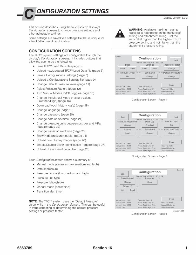
6863789 1
Current Time: 4/2/2015
Manual High : 1900
Manual Low : 1000Manual Med : 1500
Default : 900Press. Fact. Med: 0.98
Trans Alert(sec): 2Press. Fact. Low: 1.1
Press. Fact. High: 1.02Manual Mode: NoPressure: Hide
Pressure Units: PSI
13:52:54
Change
Data Settings Pressure Factor
Manual Mode:ChangeNo
LanguageChange
Default Pressure
Done
Next
Page 1
Load Save
Driver IDYes Load
Load Save
Configuration
Current Time: 4/2/2015
Manual High : 1900
Manual Low : 1000Manual Med : 1500
Default : 900Press. Fact. Med: 0.98
Trans Alert(sec): 2Press. Fact. Low: 1.1
Press. Fact. High: 1.02Manual Mode: NoPressure: Hide
Pressure Units: PSI
13:52:54
Show
PressureChange
Trans Alert(sec)
Done
Back
Page 3Configuration
Current Time: 4/2/2015
Manual High : 1900
Manual Low : 1000Manual Med : 1500
Default : 900Press. Fact. Med: 0.98
Trans Alert(sec): 2Press. Fact. Low: 1.1
Press. Fact. High: 1.02Manual Mode: NoPressure: Hide
Pressure Units: PSI
13:52:54
PSIChange Download
Manual Pressures Data Log “BAR, PSI, Mpa”
VisualsChangeLoad
PasswordChange
Date and Time
Done
NextBackConfiguration
AC2804.eps
ONFIGURATION SETTINGSCThis section describes using the touch screen display’s Configuration screens to change pressure settings and other adjustable settings.
Some settings are saved to a settings file that is unique for a truck/attachment combination.
Each Configuration screen shows a summary of:
• Manual mode pressures (low, medium and high)
• Default pressure
• Pressure factors (low, medium and high)
• Pressure unit type
• Pressure (show/hide)
• Manual mode (show/hide)
• Transition alert timer
Configuration Screen – Page 1
Configuration Screen – Page 3
Configuration Screen – Page 2
WARNING: Available maximum clamp pressure is dependent on the truck relief setting and attachment rating. Set the truck relief higher than the highest TFC™ pressure setting and not higher than the attachment pressure rating.
CONFIGURATION SCREENSThe TFC™ system settings are configurable through the display’s Configuration screens. It includes buttons that allow the user to do the following:
• Save TFC™ Load Data file (page 3)
• Upload new/updated TFC™ Load Data file (page 5)
• Save a Configurations Settings (page 7)
• Upload a Configurations Settings file (page 9)
• Change Default Pressure value (page 11)
• Adjust Pressure Factors (page 12)
• Turn Manual Mode On/Off (toggle) (page 15)
• Change the Manual Mode pressure values (Low/Med/High) (page 16)
• Download touch history log(s) (page 18)
• Change language (page 19)
• Change password (page 20)
• Change date and/or time (page 21)
• Change pressure units between psi, bar and MPa (toggle) (page 22)
• Change transition alert time (page 23)
• Show/Hide pressure (toggle) (page 24)
• Upload new display images (page 26)
• Enable/Disable driver identification (toggle) (page 27)
• Upload driver identification file (page 28)
NOTE: The TFC™ system uses the “Default Pressure” value while in the Configuration Screen. This can be useful in troubleshooting or determining the correct pressure settings or pressure factor.
Section 16
Display Version 6.0.3
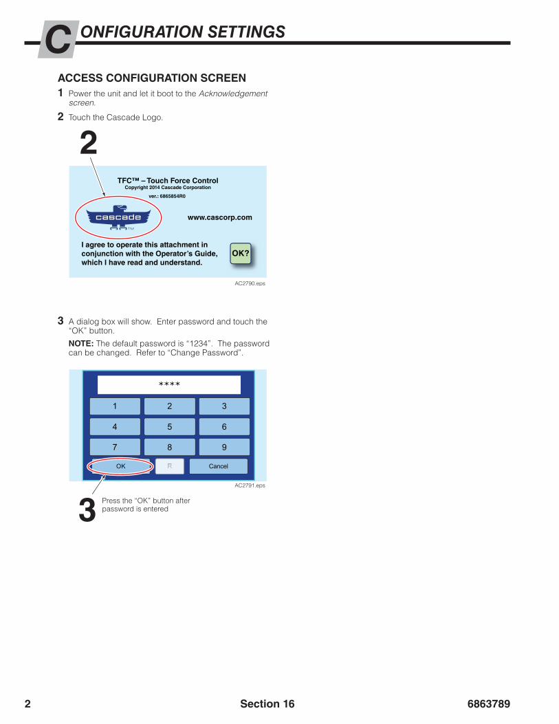
68637892
ONFIGURATION SETTINGSCACCESS CONFIGURATION SCREEN1 Power the unit and let it boot to the Acknowledgement
screen.
2 Touch the Cascade Logo.
2
3
3 A dialog box will show. Enter password and touch the “OK” button.
NOTE: The default password is “1234”. The password can be changed. Refer to “Change Password”.
Section 16
TFC™ – Touch Force ControlCopyright 2014 Cascade Corporation
ver.: 6865854R0
www.cascorp.com
I agree to operate this attachment inconjunction with the Operator’s Guide,which I have read and understand.
OK?
AC2790.eps
1 3
****
4 5
2
6
7 8 9
OK RR Cancel
AC2791.eps
Press the “OK” button after password is entered

6863789 3
0
Cancel OK
1 2 3 4 5 6 7 8 9
l
q
a s d f g h j k
z x c v b n m
pw e r t y u i o
TFCloadData_000.csv
AC2806.eps
ONFIGURATION SETTINGSC
Section 16
SAVE TFC™ LOAD DATA FILEPerform the following steps to create a copy of the current TFC™ load data file on the display.
1 Plug a USB flash drive into the USB connector found on the TFC™ harness near the TFC™ display.
2 Touch the Cascade Logo.
4 In the “Data” box, touch the “Save” button.
3 A dialog box will show. Enter password and touch the “OK” button.
4
Current Time: 4/2/2015
Manual High : 1900
Manual Low : 1000Manual Med : 1500
Default : 900Press. Fact. Med: 0.98
Trans Alert(sec): 2Press. Fact. Low: 1.1
Press. Fact. High: 1.02Manual Mode: NoPressure: Hide
Pressure Units: PSI
13:52:54
Change
Data Settings Pressure Factor
Manual Mode:ChangeNo
LanguageChange
Default Pressure
Done
Next
Page 1
Load Save Load Save
Configuration
AC2805.eps
5 A dialog box with a keyboard will show. Enter a three digit suffix as part of naming the file. All files begin with “TFCloadData_” and end with file type “.csv”. Use the arrow button to undo typing.
6 Choose the “Done” button to proceed with saving the file.
7 The Configuration Screen will show with a status indicator.
ArrowButton
65
Keyboard Dialog Box
7
Current Time: 4/2/2015
Manual High : 1900
Manual Low : 1000Manual Med : 1500
Default : 900Press. Fact. Med: 0.98
Trans Alert(sec): 2Press. Fact. Low: 1.1
Press. Fact. High: 1.02Manual Mode: NoPressure: Hide
Pressure Units: PSI
13:52:54
Change
Data Settings Pressure Factor
Manual Mode:ChangeNo
LanguageChange
Default Pressure
Done
Next
Page 1
Load Save Load
Saving
Save
Please Wait
AC2807.eps
Procedure continued on next page
2
3
TFC™ – Touch Force ControlCopyright 2014 Cascade Corporation
ver.: 6865854R0
www.cascorp.com
I agree to operate this attachment inconjunction with the Operator’s Guide,which I have read and understand.
OK?
AC2790.eps
1 3
****
4 5
2
6
7 8 9
OK RR Cancel
AC2791.eps
Press the “OK” button after password is entered

68637894
ONFIGURATION SETTINGSC
Section 16
8 9
8 Once the file saves onto the USB flash drive, a message will show “Data Saved Successfully”.
NOTE: If the message “Cannot write data file...” appears, verify that the USB flash drive is plugged into USB connector. Repeat Steps 4-8.
9 To leave the Configuration screen, touch the “Done” button.
10 Remove and secure the USB flash drive.
Current Time: 4/2/2015
Manual High : 1900
Manual Low : 1000Manual Med : 1500
Default : 900Press. Fact. Med: 0.98
Trans Alert(sec): 2Press. Fact. Low: 1.1
Press. Fact. High: 1.02Manual Mode: NoPressure: Hide
Pressure Units: PSI
13:52:54
Change
Data Settings Pressure Factor
Manual Mode:ChangeNo
LanguageChange
Default Pressure
Done
Next
Page 1
Load Save Load Save
Configuration
Data Saved Successfully
AC2808.eps
SAVE TFC™ LOAD DATA FILE (CONTINUED)

6863789 5
ONFIGURATION SETTINGSC
Section 16
UPLOAD NEW/UPDATED TFC™ LOAD DATA FILEPerform the following steps to upload a “TFCloadData.csv” file the TFC™ display. This file is created using the Load Data Tool.
NOTE: The file must be on the root directory (top level) of the USB flash drive in order for the display to find the file.
1 Plug the USB flash drive, containing the desired new/updated file, into the USB connector found on the TFC™ harness near the TFC™ display.
2 Touch the Cascade Logo.
Current Time: 4/2/2015
Manual High : 1900
Manual Low : 1000Manual Med : 1500
Default : 900Press. Fact. Med: 0.98
Trans Alert(sec): 2Press. Fact. Low: 1.1
Press. Fact. High: 1.02Manual Mode: NoPressure: Hide
Pressure Units: PSI
13:52:54
Change
Data Settings Pressure Factor
Manual Mode:ChangeNo
LanguageChange
Default Pressure
Done
Next
Page 1
Load Save Load Save
Configuration
AC2809.eps
4 In the “Data” box, touch the “Load” button.
4
5 A dialog box will show. Choose the data file to upload to the display and touch the “OK” button. The file should begin with “TFCloadData_”.
• If the message “Unable to find USB device...” appears, wait 5 seconds and press the “Upload” button again.
• If the message “Error finding/opening file...Error 1” appears, refer to Section 10 Troubleshooting.
NOTE: If a file has more than three characters/numbers after the underscore, the file will not show. For example: “TFCloadSata_Tr1234.csv” – will not show“TFCloadData_T01.csv” – will show
Choose File Dialog Box
Selected file will highlight
Choose “OK” after file is selected
Procedure continued on next page
Cancel
Choose file
OK
Next pagePrevious page
TFCloadData_001.csv
TFCloadData_002.csv
TFCloadData_003.csv
AC2810.eps
3 A dialog box will show. Enter password and touch the “OK” button.
2
3
TFC™ – Touch Force ControlCopyright 2014 Cascade Corporation
ver.: 6865854R0
www.cascorp.com
I agree to operate this attachment inconjunction with the Operator’s Guide,which I have read and understand.
OK?
AC2790.eps
1 3
****
4 5
2
6
7 8 9
OK RR Cancel
AC2791.eps
Press the “OK” button after password is entered
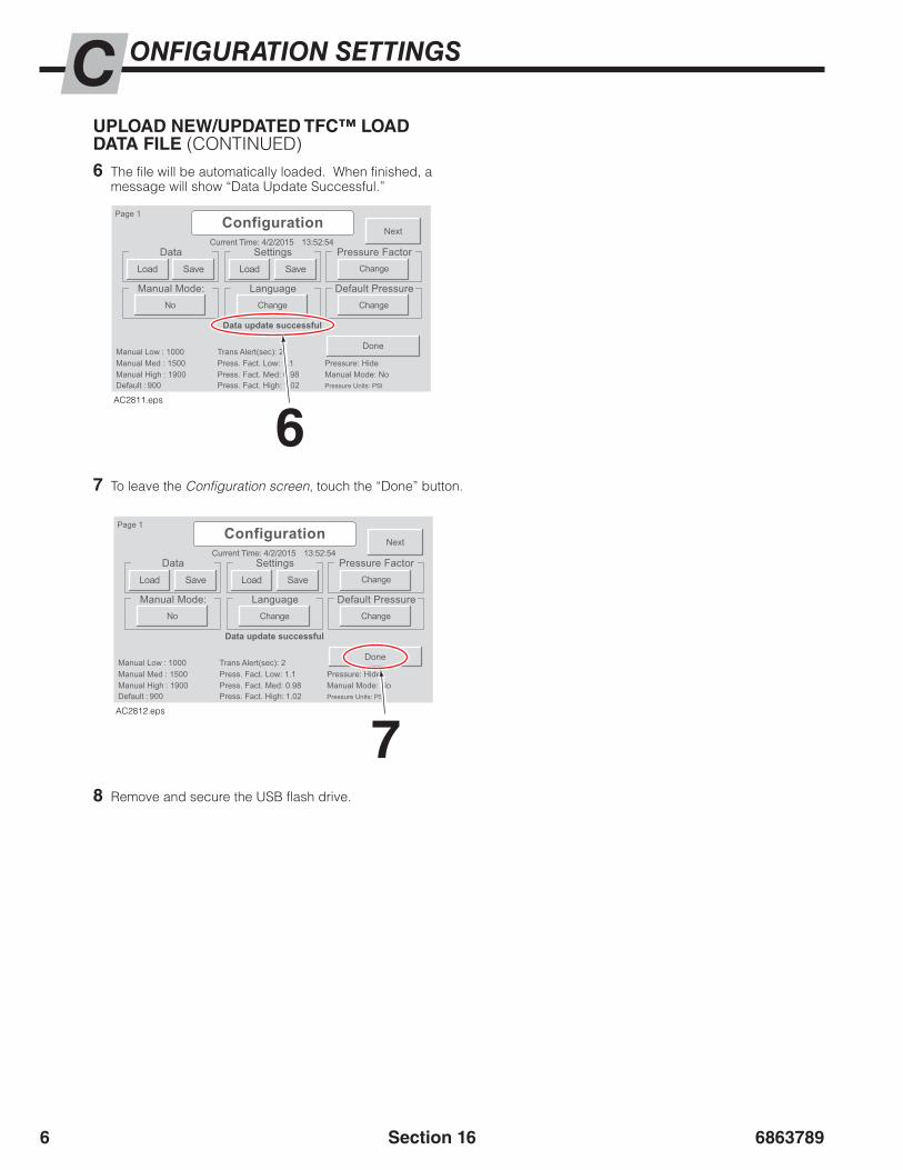
68637896
Current Time: 4/2/2015
Manual High : 1900
Manual Low : 1000Manual Med : 1500
Default : 900Press. Fact. Med: 0.98
Trans Alert(sec): 2Press. Fact. Low: 1.1
Press. Fact. High: 1.02Manual Mode: NoPressure: Hide
Pressure Units: PSI
13:52:54
Change
Data Settings Pressure Factor
Manual Mode:ChangeNo
LanguageChange
Default Pressure
Done
Next
Page 1
Load Save Load Save
Configuration
Data update successful
AC2811.eps
Current Time: 4/2/2015
Manual High : 1900
Manual Low : 1000Manual Med : 1500
Default : 900Press. Fact. Med: 0.98
Trans Alert(sec): 2Press. Fact. Low: 1.1
Press. Fact. High: 1.02Manual Mode: NoPressure: Hide
Pressure Units: PSI
13:52:54
Change
Data Settings Pressure Factor
Manual Mode:ChangeNo
LanguageChange
Default Pressure
Done
Next
Page 1
Load Save Load Save
Configuration
Data update successful
AC2812.eps
ONFIGURATION SETTINGSC
Section 16
6 The file will be automatically loaded. When finished, a message will show “Data Update Successful.”
8 Remove and secure the USB flash drive.
7 To leave the Configuration screen, touch the “Done” button.
6
7
UPLOAD NEW/UPDATED TFC™ LOAD DATA FILE (CONTINUED)

6863789 7
ONFIGURATION SETTINGSC
Section 16
SAVE CONFIGURATION SETTINGSConfiguration settings are settings for the TFC™ system. Changes to Configuration settings include:
• Show or hide Manual Mode
• Changes to High, Medium or Low Pressure Factors values
• Changes to High, Medium or Low Manual Mode pressures values
• Changes to Default Pressure value
• Pressure units have changed between psi, bar or MPa
• Change to transition alert timer
• Show or hide target pressure on the display’s Confirmation Screen
These settings are stored in a separate file from the load data. To save the current settings on the display or after changes have been made, perform the following:
1 Plug the USB flash drive into the USB connector found on the TFC™ harness near the display.
2 Touch the Cascade Logo.
3 A dialog box will show. Enter password and touch the “OK” button.
NOTE: The default password is “1234”. The password can be changed. Refer to “Change Password”.
4 In the “Settings” box, touch the “Save” button.
4Current Time: 4/2/2015
Manual High : 1900
Manual Low : 1000Manual Med : 1500
Default : 900Press. Fact. Med: 0.98
Trans Alert(sec): 2Press. Fact. Low: 1.1
Press. Fact. High: 1.02Manual Mode: NoPressure: Hide
Pressure Units: PSI
13:52:54
Change
Data Settings Pressure Factor
Manual Mode:ChangeNo
LanguageChange
Default Pressure
Done
Next
Page 1
Load Save Load Save
Configuration
AC2813.eps
5 A dialog box with a keyboard will show. Enter a three digit suffix as part of naming the file. All files begin with “Settings_” and end with file type “.csv”. Use the arrow button to undo typing.
6 Choose the “Done” button to proceed with saving the file.
0
Cancel OK
1 2 3 4 5 6 7 8 9
l
q
a s d f g h j k
z x c v b n m
pw e r t y u i o
Settings_000.csv
AC2814.eps
ArrowButton
65
Procedure continued on next page
2
3
TFC™ – Touch Force ControlCopyright 2014 Cascade Corporation
ver.: 6865854R0
www.cascorp.com
I agree to operate this attachment inconjunction with the Operator’s Guide,which I have read and understand.
OK?
AC2790.eps
1 3
****
4 5
2
6
7 8 9
OK RR Cancel
AC2791.eps
Press the “OK” button after password is entered
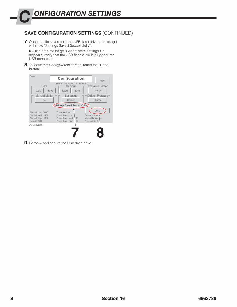
68637898
ONFIGURATION SETTINGSC
Section 16
SAVE CONFIGURATION SETTINGS (CONTINUED)
7 Once the file saves onto the USB flash drive, a message will show “Settings Saved Successfully”.
NOTE: If the message “Cannot write settings file...” appears, verify that the USB flash drive is plugged into USB connector.
8 To leave the Configuration screen, touch the “Done” button.
9 Remove and secure the USB flash drive.
Current Time: 4/2/2015
Manual High : 1900
Manual Low : 1000Manual Med : 1500
Default : 900Press. Fact. Med: 0.98
Trans Alert(sec): 2Press. Fact. Low: 1.1
Press. Fact. High: 1.02Manual Mode: NoPressure: Hide
Pressure Units: PSI
13:52:54
Change
Data Settings Pressure Factor
Manual Mode:ChangeNo
LanguageChange
Default Pressure
Done
Next
Page 1
Load Save Load Save
Configuration
Settings Saved Successfully
AC2815.eps
7 8
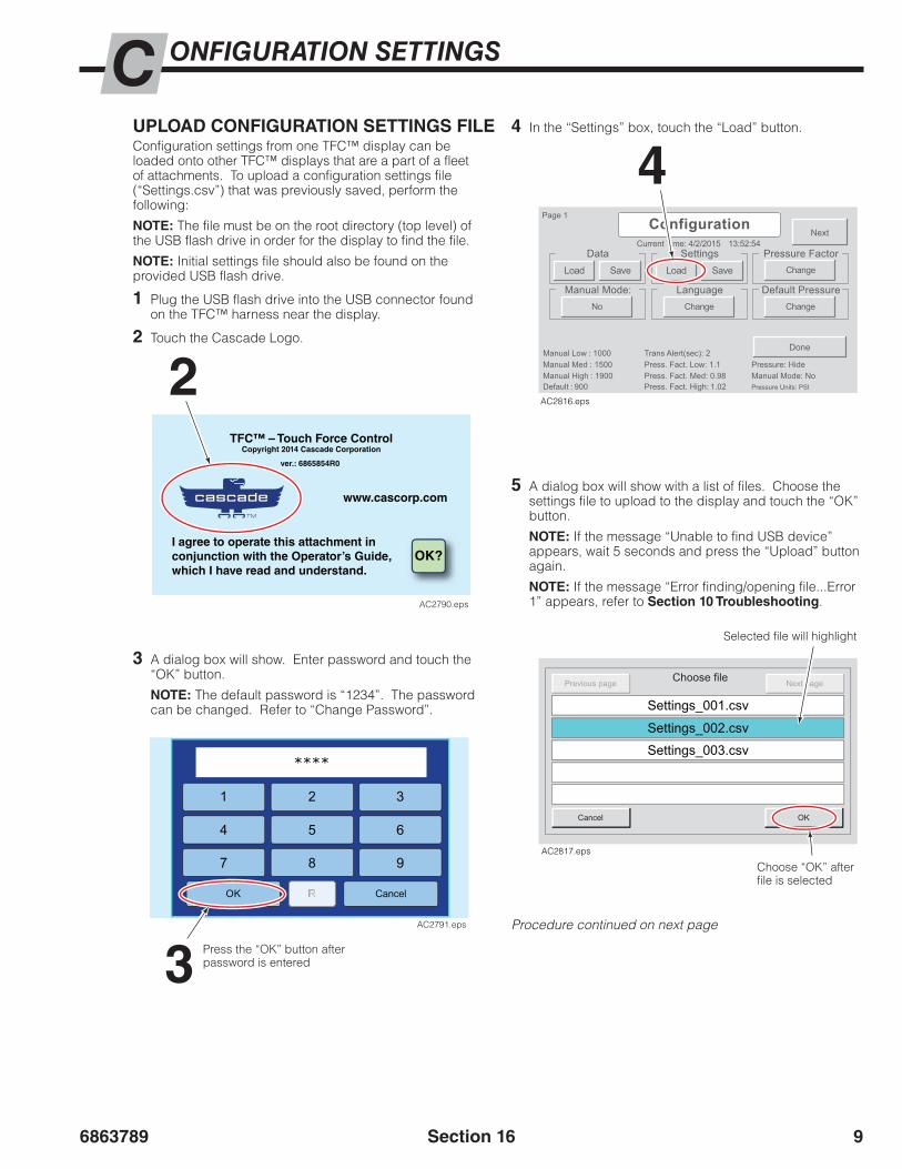
6863789 9
ONFIGURATION SETTINGSC
Section 16
UPLOAD CONFIGURATION SETTINGS FILEConfiguration settings from one TFC™ display can be loaded onto other TFC™ displays that are a part of a fleet of attachments. To upload a configuration settings file (“Settings.csv”) that was previously saved, perform the following:
NOTE: The file must be on the root directory (top level) of the USB flash drive in order for the display to find the file.
NOTE: Initial settings file should also be found on the provided USB flash drive.
1 Plug the USB flash drive into the USB connector found on the TFC™ harness near the display.
2 Touch the Cascade Logo.
4 In the “Settings” box, touch the “Load” button.
Current Time: 4/2/2015
Manual High : 1900
Manual Low : 1000Manual Med : 1500
Default : 900Press. Fact. Med: 0.98
Trans Alert(sec): 2Press. Fact. Low: 1.1
Press. Fact. High: 1.02Manual Mode: NoPressure: Hide
Pressure Units: PSI
13:52:54
Change
Data Settings Pressure Factor
Manual Mode:ChangeNo
LanguageChange
Default Pressure
Done
Next
Page 1
Load Save Load Save
Configuration
AC2816.eps
4
5 A dialog box will show with a list of files. Choose the settings file to upload to the display and touch the “OK” button.
NOTE: If the message “Unable to find USB device” appears, wait 5 seconds and press the “Upload” button again.
NOTE: If the message “Error finding/opening file...Error 1” appears, refer to Section 10 Troubleshooting.
Cancel
Choose file
OK
Next pagePrevious page
Settings_001.csv
Settings_002.csv
Settings_003.csv
AC2817.eps
Selected file will highlight
Choose “OK” after file is selected
Procedure continued on next page
3 A dialog box will show. Enter password and touch the “OK” button.
NOTE: The default password is “1234”. The password can be changed. Refer to “Change Password”.
2
3
TFC™ – Touch Force ControlCopyright 2014 Cascade Corporation
ver.: 6865854R0
www.cascorp.com
I agree to operate this attachment inconjunction with the Operator’s Guide,which I have read and understand.
OK?
AC2790.eps
1 3
****
4 5
2
6
7 8 9
OK RR Cancel
AC2791.eps
Press the “OK” button after password is entered
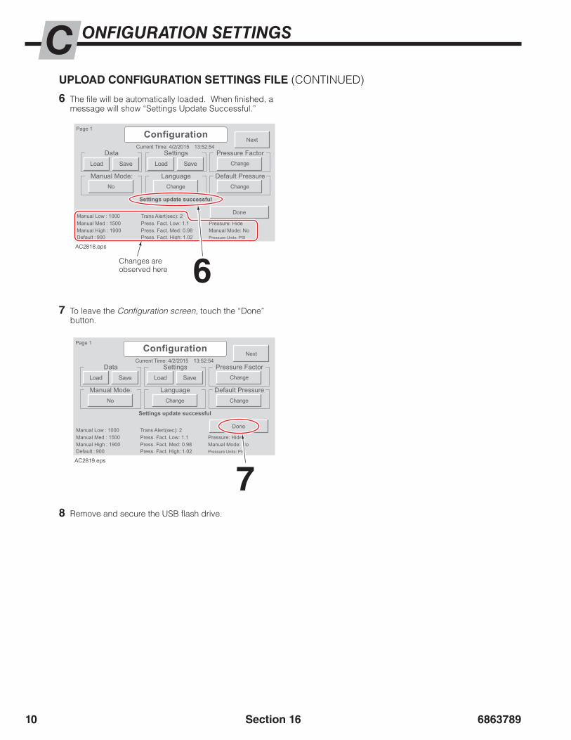
686378910
ONFIGURATION SETTINGSC
Section 16
8 Remove and secure the USB flash drive.
6 The file will be automatically loaded. When finished, a message will show “Settings Update Successful.”
7 To leave the Configuration screen, touch the “Done” button.
UPLOAD CONFIGURATION SETTINGS FILE (CONTINUED)
6
7
Current Time: 4/2/2015
Manual High : 1900
Manual Low : 1000Manual Med : 1500
Default : 900Press. Fact. Med: 0.98
Trans Alert(sec): 2Press. Fact. Low: 1.1
Press. Fact. High: 1.02Manual Mode: NoPressure: Hide
Pressure Units: PSI
13:52:54
Change
Data Settings Pressure Factor
Manual Mode:ChangeNo
LanguageChange
Default Pressure
Done
Next
Page 1
Load Save Load Save
Configuration
Settings update successful
AC2818.eps
Current Time: 4/2/2015
Manual High : 1900
Manual Low : 1000Manual Med : 1500
Default : 900Press. Fact. Med: 0.98
Trans Alert(sec): 2Press. Fact. Low: 1.1
Press. Fact. High: 1.02Manual Mode: NoPressure: Hide
Pressure Units: PSI
13:52:54
Change
Data Settings Pressure Factor
Manual Mode:ChangeNo
LanguageChange
Default Pressure
Done
Next
Page 1
Load Save Load Save
Configuration
Settings update successful
AC2819.eps
Changes are observed here
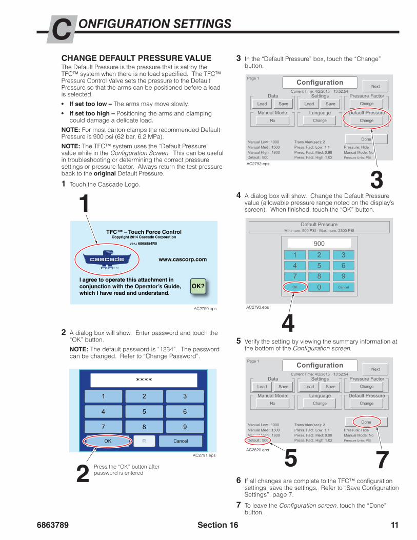
6863789 11
ONFIGURATION SETTINGSC
Section 16
CHANGE DEFAULT PRESSURE VALUEThe Default Pressure is the pressure that is set by the TFC™ system when there is no load specified. The TFC™ Pressure Control Valve sets the pressure to the Default Pressure so that the arms can be positioned before a load is selected.
• If set too low – The arms may move slowly.
• If set too high – Positioning the arms and clamping could damage a delicate load.
NOTE: For most carton clamps the recommended Default Pressure is 900 psi (62 bar, 6.2 MPa).
NOTE: The TFC™ system uses the “Default Pressure” value while in the Configuration Screen. This can be useful in troubleshooting or determining the correct pressure settings or pressure factor. Always return the test pressure back to the original Default Pressure.
1 Touch the Cascade Logo.
3 In the “Default Pressure” box, touch the “Change” button.
4 A dialog box will show. Change the Default Pressure value (allowable pressure range noted on the display’s screen). When finished, touch the “OK” button.
5 Verify the setting by viewing the summary information at the bottom of the Configuration screen.
6 If all changes are complete to the TFC™ configuration settings, save the settings. Refer to “Save Configuration Settings”, page 7.
7 To leave the Configuration screen, touch the “Done” button.
4
5 7
3
Current Time: 4/2/2015
Manual High : 1900
Manual Low : 1000Manual Med : 1500
Default : 900Press. Fact. Med: 0.98
Trans Alert(sec): 2Press. Fact. Low: 1.1
Press. Fact. High: 1.02Manual Mode: NoPressure: Hide
Pressure Units: PSI
13:52:54
Change
Data Settings Pressure Factor
Manual Mode:ChangeNo
LanguageChange
Default Pressure
Done
Next
Page 1
Load Save Load Save
Configuration
AC2792.eps
Default PressureMinimum: 500 PSI - Maximum: 2300 PSI
147OK
2580
369
Cancel
AC2793.eps
Current Time: 4/2/2015
Manual High : 1900
Manual Low : 1000Manual Med : 1500
Default : 900Press. Fact. Med: 0.98
Trans Alert(sec): 2Press. Fact. Low: 1.1
Press. Fact. High: 1.02Manual Mode: NoPressure: Hide
Pressure Units: PSI
13:52:54
Change
Data Settings Pressure Factor
Manual Mode:ChangeNo
LanguageChange
Default Pressure
Done
Next
Page 1
Load Save Load Save
Configuration
AC2820.eps
900
2 A dialog box will show. Enter password and touch the “OK” button.
NOTE: The default password is “1234”. The password can be changed. Refer to “Change Password”.
1
2
TFC™ – Touch Force ControlCopyright 2014 Cascade Corporation
ver.: 6865854R0
www.cascorp.com
I agree to operate this attachment inconjunction with the Operator’s Guide,which I have read and understand.
OK?
AC2790.eps
1 3
****
4 5
2
6
7 8 9
OK RR Cancel
AC2791.eps
Press the “OK” button after password is entered
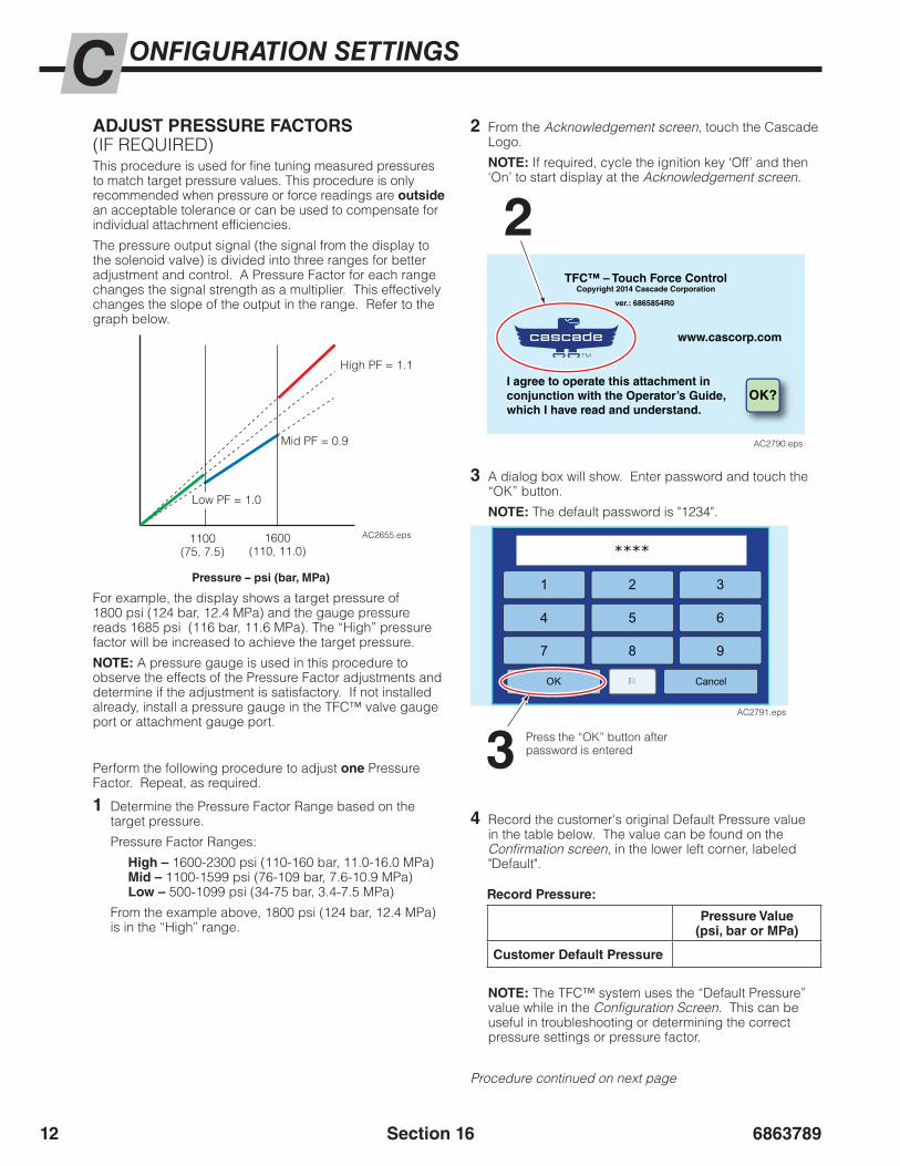
686378912
ONFIGURATION SETTINGSC
Section 16
ADJUST PRESSURE FACTORS(IF REQUIRED)This procedure is used for fine tuning measured pressures to match target pressure values. This procedure is only recommended when pressure or force readings are outside an acceptable tolerance or can be used to compensate for individual attachment efficiencies.
The pressure output signal (the signal from the display to the solenoid valve) is divided into three ranges for better adjustment and control. A Pressure Factor for each range changes the signal strength as a multiplier. This effectively changes the slope of the output in the range. Refer to the graph below.
AC2655.eps
High PF = 1.1
Mid PF = 0.9
1100(75, 7.5)
1600(110, 11.0)
Low PF = 1.0
Pressure – psi (bar, MPa)
For example, the display shows a target pressure of 1800 psi (124 bar, 12.4 MPa) and the gauge pressure reads 1685 psi (116 bar, 11.6 MPa). The “High” pressure factor will be increased to achieve the target pressure.
NOTE: A pressure gauge is used in this procedure to observe the effects of the Pressure Factor adjustments and determine if the adjustment is satisfactory. If not installed already, install a pressure gauge in the TFC™ valve gauge port or attachment gauge port.
Perform the following procedure to adjust one Pressure Factor. Repeat, as required.
1 Determine the Pressure Factor Range based on the target pressure.
Pressure Factor Ranges:
High – 1600-2300 psi (110-160 bar, 11.0-16.0 MPa)Mid – 1100-1599 psi (76-109 bar, 7.6-10.9 MPa)Low – 500-1099 psi (34-75 bar, 3.4-7.5 MPa)
From the example above, 1800 psi (124 bar, 12.4 MPa) is in the “High” range.
2 From the Acknowledgement screen, touch the Cascade Logo.
NOTE: If required, cycle the ignition key ‘Off’ and then ‘On’ to start display at the Acknowledgement screen.
2TFC™ – Touch Force Control
Copyright 2014 Cascade Corporation
ver.: 6865854R0
www.cascorp.com
I agree to operate this attachment inconjunction with the Operator’s Guide,which I have read and understand.
OK?
AC2790.eps
3 A dialog box will show. Enter password and touch the “OK” button.
NOTE: The default password is "1234".
3 Press the “OK” button after password is entered
1 3
****
4 5
2
6
7 8 9
OK RR Cancel
AC2791.eps
4 Record the customer's original Default Pressure value in the table below. The value can be found on the Confirmation screen, in the lower left corner, labeled "Default".
Record Pressure:
Pressure Value(psi, bar or MPa)
Customer Default Pressure
Procedure continued on next page
NOTE: The TFC™ system uses the “Default Pressure” value while in the Configuration Screen. This can be useful in troubleshooting or determining the correct pressure settings or pressure factor.
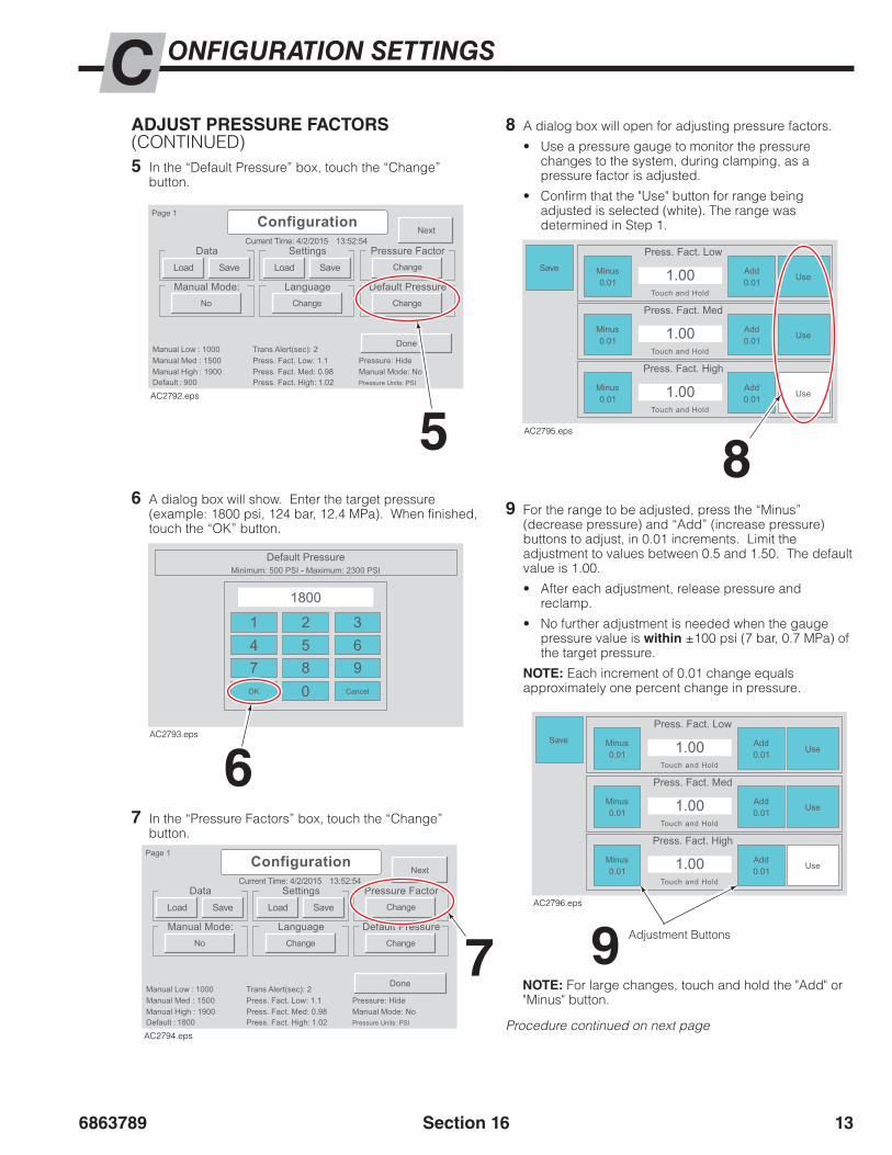
6863789 13
ONFIGURATION SETTINGSC
Section 16
ADJUST PRESSURE FACTORS (CONTINUED)5 In the “Default Pressure” box, touch the “Change”
button.
5
Current Time: 4/2/2015
Manual High : 1900
Manual Low : 1000Manual Med : 1500
Default : 900Press. Fact. Med: 0.98
Trans Alert(sec): 2Press. Fact. Low: 1.1
Press. Fact. High: 1.02Manual Mode: NoPressure: Hide
Pressure Units: PSI
13:52:54
Change
Data Settings Pressure Factor
Manual Mode:ChangeNo
LanguageChange
Default Pressure
Done
Next
Page 1
Load Save Load Save
Configuration
AC2792.eps
6 A dialog box will show. Enter the target pressure (example: 1800 psi, 124 bar, 12.4 MPa). When finished, touch the “OK” button.
7
67 In the “Pressure Factors” box, touch the “Change”
button.
8 A dialog box will open for adjusting pressure factors.
• Use a pressure gauge to monitor the pressure changes to the system, during clamping, as a pressure factor is adjusted.
• Confirm that the "Use" button for range being adjusted is selected (white). The range was determined in Step 1.
Default PressureMinimum: 500 PSI - Maximum: 2300 PSI
147OK
2580
369
Cancel
AC2793.eps
1.00Press. Fact. Low
Touch and Hold
1.00Press. Fact. Med
Touch and Hold
1.00Press. Fact. High
Touch and Hold
Save Minus0.01
Add0.01 Use
Minus0.01
Add0.01 Use
Minus0.01
Add0.01 Use
AC2795.eps
1800
Current Time: 4/2/2015
Manual High : 1900
Manual Low : 1000Manual Med : 1500
Default : 900Press. Fact. Med: 0.98
Trans Alert(sec): 2Press. Fact. Low: 1.1
Press. Fact. High: 1.02Manual Mode: NoPressure: Hide
Pressure Units: PSI
13:52:54
Change
Data Settings Pressure Factor
Manual Mode:ChangeNo
LanguageChange
Default Pressure
Done
Next
Page 1
Load Save Load Save
Configuration
AC2794.eps
1800
89 For the range to be adjusted, press the “Minus”
(decrease pressure) and “Add” (increase pressure) buttons to adjust, in 0.01 increments. Limit the adjustment to values between 0.5 and 1.50. The default value is 1.00.
• After each adjustment, release pressure and reclamp.
• No further adjustment is needed when the gauge pressure value is within ±100 psi (7 bar, 0.7 MPa) of the target pressure.
NOTE: Each increment of 0.01 change equals approximately one percent change in pressure.
Adjustment Buttons9
1.00Press. Fact. Low
Touch and Hold
1.00Press. Fact. Med
Touch and Hold
1.00Press. Fact. High
Touch and Hold
Save Minus0.01
Add0.01 Use
Minus0.01
Add0.01 Use
Minus0.01
Add0.01 Use
AC2796.eps
NOTE: For large changes, touch and hold the "Add" or "Minus" button.
Procedure continued on next page

686378914
ONFIGURATION SETTINGSC
Section 16
10 After the target pressure is achieved, touch the “Save” button.
13
12 If all changes are complete to the TFC™ configuration settings, save the settings. Refer to “Save Configuration Settings”, page 7.
13 To leave the Configuration screen, touch the “Done” button.
11 Repeat Step 5 and 6 to change the default pressure back to the customer’s original Default Pressure, as noted in Step 4.
Current Time: 4/2/2015
Manual High : 1900
Manual Low : 1000Manual Med : 1500
Default : 900Press. Fact. Med: 0.98
Trans Alert(sec): 2Press. Fact. Low: 1.1
Press. Fact. High: 1.02Manual Mode: NoPressure: Hide
Pressure Units: PSI
13:52:54
Change
Data Settings Pressure Factor
Manual Mode:ChangeNo
LanguageChange
Default Pressure
Done
Next
Page 1
Load Save Load Save
Configuration
AC2797.eps
ADJUST PRESSURE FACTORS (CONTINUED)

6863789 15
ONFIGURATION SETTINGSC
Section 16
TURN MANUAL MODE ON/OFF
AC2577.eps
Manual Mode is normally turned off. This mode is used primarily to aid in establishing the appropriate pressure for each product load configuration. Perform the following steps to turn Manual Mode on or off:
1 Touch the Cascade Logo.
2 A dialog box will show. Enter password and touch the “OK” button.
NOTE: The default password is “1234”. The password can be changed. Refer to “Change Password”.
1
2
TFC™ – Touch Force ControlCopyright 2014 Cascade Corporation
ver.: 6865854R0
www.cascorp.com
I agree to operate this attachment inconjunction with the Operator’s Guide,which I have read and understand.
OK?
AC2790.eps
1 3
****
4 5
2
6
7 8 9
OK RR Cancel
AC2791.eps
Press the “OK” button after password is entered
3 In the “Manual Mode:” box, touch the “Yes”/”No” button. This is a toggle.
3 Yes = OnNo = Off
Current Time: 4/2/2015
Manual High : 1900
Manual Low : 1000Manual Med : 1500
Default : 900Press. Fact. Med: 0.98
Trans Alert(sec): 2Press. Fact. Low: 1.1
Press. Fact. High: 1.02Manual Mode: NoPressure: Hide
Pressure Units: PSI
13:52:54
Change
Data Settings Pressure Factor
Manual Mode:ChangeNo
LanguageChange
Default Pressure
Done
Next
Page 1
Load Save Load Save
Configuration
AC2821.eps
4 Verify the setting by viewing the summary information at the bottom of the Configuration screen.
4
6
VerifyYes = OnNo = Off
Current Time: 4/2/2015
Manual High : 1900
Manual Low : 1000Manual Med : 1500
Default : 900Press. Fact. Med: 0.98
Trans Alert(sec): 2Press. Fact. Low: 1.1
Press. Fact. High: 1.02Manual Mode: NoPressure: Hide
Pressure Units: PSI
13:52:54
Change
Data Settings Pressure Factor
Manual Mode:ChangeNo
LanguageChange
Default Pressure
Done
Next
Page 1
Load Save Load Save
Configuration
AC2822.eps
Current Time: 4/2/2015
Manual High : 1900
Manual Low : 1000Manual Med : 1500
Default : 900Press. Fact. Med: 0.98
Trans Alert(sec): 2Press. Fact. Low: 1.1
Press. Fact. High: 1.02Manual Mode: NoPressure: Hide
Pressure Units: PSI
13:52:54
Change
Data Settings Pressure Factor
Manual Mode:ChangeNo
LanguageChange
Default Pressure
Done
Next
Page 1
Load Save Load Save
Configuration
AC2797.eps
5 If all changes are complete to the TFC™ configuration settings, save the settings. Refer to “Save Configuration Settings”, page 7.
6 To leave the Configuration screen, touch the “Done” button.

686378916
ONFIGURATION SETTINGSC
Section 16
Manual PressuresMinimum: 500 PSI - Maximum: 2300 PSI
High
Med
Low
147OK
2580
369
Cancel
1900
1500
900
1000
AC2825.eps
CHANGE MANUAL MODE PRESSURE VALUESTo set the Low, Medium and High pressure values used in Manual Mode, perform the following:
NOTE: If previously equipped with a Three-Position Valve, these pressure values can be used for the Manual Mode values.
3 Touch the “Next” button.
4 In the “Manual Pressures” box, touch the “Change” button.
3
4
Current Time: 4/2/2015
Manual High : 1900
Manual Low : 1000Manual Med : 1500
Default : 900Press. Fact. Med: 0.98
Trans Alert(sec): 2Press. Fact. Low: 1.1
Press. Fact. High: 1.02Manual Mode: NoPressure: Hide
Pressure Units: PSI
13:52:54
Change
Data Settings Pressure Factor
Manual Mode:ChangeNo
LanguageChange
Default Pressure
Done
Next
Page 1
Load Save Load Save
Configuration
AC2823.eps
Current Time: 4/2/2015
Manual High : 1900
Manual Low : 1000Manual Med : 1500
Default : 900Press. Fact. Med: 0.98
Trans Alert(sec): 2Press. Fact. Low: 1.1
Press. Fact. High: 1.02Manual Mode: NoPressure: Hide
Pressure Units: PSI
13:52:54
PSIChange Download
Manual Pressures Data Log “BAR, PSI, Mpa”
VisualsChangeLoad
PasswordChange
Date and Time
Done
NextBackConfiguration
AC2824.eps
Procedure continued on next page
5 A dialog box will show. Change the High, Med and Low pressure values.
• For each setting, press High, Med or Low pressure box.
• Change the value using the number box.
• Touch the “OK” button after each entry.
Press to change pressure setting
Press after the pressure value is changed to accept the value
Selected pressure will be highlighted
2 A dialog box will show. Enter password and touch the “OK” button.
NOTE: The default password is “1234”. The password can be changed. Refer to “Change Password”.
1
2
TFC™ – Touch Force ControlCopyright 2014 Cascade Corporation
ver.: 6865854R0
www.cascorp.com
I agree to operate this attachment inconjunction with the Operator’s Guide,which I have read and understand.
OK?
AC2790.eps
1 3
****
4 5
2
6
7 8 9
OK RR Cancel
AC2791.eps
Press the “OK” button after password is entered
1 Touch the Cascade Logo.
1500PSI
35
AC2799.eps
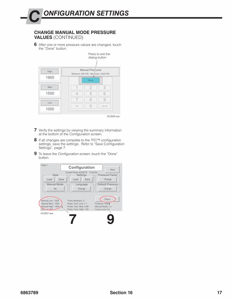
6863789 17
ONFIGURATION SETTINGSC
Section 16
7 Verify the settings by viewing the summary information at the bottom of the Configuration screen.
8 If all changes are complete to the TFC™ configuration settings, save the settings. Refer to “Save Configuration Settings”, page 7.
9 To leave the Configuration screen, touch the “Done” button.
6 After one or more pressure values are changed, touch the “Done” button.
Press to exit the dialog button
Manual PressuresMinimum: 500 PSI - Maximum: 2300 PSI
147OK
2580
369
Cancel
High
Med
Low
1900
1500
1000
Done
AC2826.eps
Current Time: 4/2/2015
Manual High : 1900
Manual Low : 1000Manual Med : 1500
Default : 900Press. Fact. Med: 0.98
Trans Alert(sec): 2Press. Fact. Low: 1.1
Press. Fact. High: 1.02Manual Mode: NoPressure: Hide
Pressure Units: PSI
13:52:54
Change
Data Settings Pressure Factor
Manual Mode:ChangeNo
LanguageChange
Default Pressure
Done
Next
Page 1
Load Save Load Save
Configuration
AC2827.eps
7 9
CHANGE MANUAL MODE PRESSURE VALUES (CONTINUED)
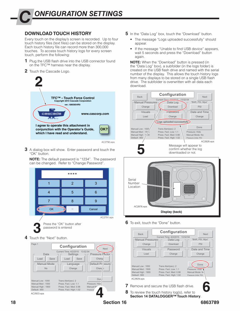
686378918
ONFIGURATION SETTINGSC
Section 16
DOWNLOAD TOUCH HISTORYEvery touch on the display’s screen is recorded. Up to four touch history files (text files) can be stored on the display. Each touch history file can record more than 300,000 touches. To access touch history logs for every screen touch, perform the following:
1 Plug the USB flash drive into the USB connector found on the TFC™ harness near the display.
2 Touch the Cascade Logo.
4 Touch the “Next” button.
Current Time: 4/2/2015
Manual High : 1900
Manual Low : 1000Manual Med : 1500
Default : 900Press. Fact. Med: 0.98
Trans Alert(sec): 2Press. Fact. Low: 1.1
Press. Fact. High: 1.02Manual Mode: NoPressure: Hide
Pressure Units: PSI
13:52:54
Change
Data Settings Pressure Factor
Manual Mode:ChangeNo
LanguageChange
Default Pressure
Done
Next
Page 1
Load Save Load Save
Configuration
AC2823.eps
3 A dialog box will show. Enter password and touch the “OK” button.
NOTE: The default password is “1234”. The password can be changed. Refer to “Change Password”.
2
3
TFC™ – Touch Force ControlCopyright 2014 Cascade Corporation
ver.: 6865854R0
www.cascorp.com
I agree to operate this attachment inconjunction with the Operator’s Guide,which I have read and understand.
OK?
AC2790.eps
1 3
****
4 5
2
6
7 8 9
OK RR Cancel
AC2791.eps
Press the “OK” button after password is entered
Current Time: 4/2/2015
Manual High : 1900
Manual Low : 1000Manual Med : 1500
Default : 900Press. Fact. Med: 0.98
Trans Alert(sec): 2Press. Fact. Low: 1.1
Press. Fact. High: 1.02Manual Mode: NoPressure: Hide
Pressure Units: PSI
13:52:54
PSIChange Download
Manual Pressures Data Log “BAR, PSI, Mpa”
VisualsChangeLoad
PasswordChange
Date and Time
Done
NextBackConfiguration
Logs uploaded successfully
AC2828.eps
5 Message will appear to confirm whether the log downloaded or not.
Serial Number Location
Display (back)
AC2876.eps
5 In the “Data Log” box, touch the “Download” button.
• The message “Logs uploaded successfully” should appear.
• If the message “Unable to find USB device” appears, wait 5 seconds and press the “Download” button again.
NOTE: When the “Download” button is pressed (in the “Data Log” box), a subfolder (in the logs folder) is created on the USB flash drive and named with the serial number of the display. This allows the touch history logs from many displays to be stored on a single USB flash drive. The subfolder is overwritten with all data each download.
4
6 To exit, touch the “Done” button.
7 Remove and secure the USB flash drive.
8 To review the touch history log(s), refer to Section 14 DATALOGGER™ Touch History.
6
Current Time: 4/2/2015
Manual High : 1900
Manual Low : 1000Manual Med : 1500
Default : 900Press. Fact. Med: 0.98
Trans Alert(sec): 2Press. Fact. Low: 1.1
Press. Fact. High: 1.02Manual Mode: NoPressure: Hide
Pressure Units: PSI
13:52:54
PSIChange Download
Manual Pressures Data Log “BAR, PSI, Mpa”
VisualsChangeLoad
PasswordChange
Date and Time
Done
NextBackConfiguration
AC2829.eps

6863789 19
ONFIGURATION SETTINGSC
Section 16
CHANGE LANGUAGETo change the language that appears on the display, perform the following:
NOTE: This procedure does not change the customer data text.
1 Touch the Cascade Logo.
35
4 Choose the desired language.
3 In the “Language” box, touch the “Change” button.
5 The display will require a reboot. Touch the “Reboot” button.
Hora actual: 4/2/2015
Alto manual : 1900
Bajo manual : 1000Media manual : 1500
Predeterminado : 900Fact. Pres. Medio: 0.98
Alerta trans. (seg.): 2Fact. Pres. Bajo: 1.1
Fact. Pres. Alto: 1.02Modo manual: NoPresión: Ocultar
Unidades de presión: PSI
13:52:54
Cambiar
Datos Ajustes Factor de presión
Modo manualCambiarNo
IdiomaCambiar
Reiniciar
Siguiente
Página 1
Carga Guardar Carga Guardar
Configuración
esión predetermina
Idioma cambiado. Es necesario reiniciar
English Español Português
Pyccкий Français
Deutsch Svenska Suomi
Italiano Türkçe
Nederlands Cancel
AC2830.eps
The “Espanol” button is touched.
The Configuration screen (shown) and operator screens (not shown) will change to the selected language.
Current Time: 4/2/2015
Manual High : 1900
Manual Low : 1000Manual Med : 1500
Default : 900Press. Fact. Med: 0.98
Trans Alert(sec): 2Press. Fact. Low: 1.1
Press. Fact. High: 1.02Manual Mode: NoPressure: Hide
Pressure Units: PSI
13:52:54
Change
Data Settings Pressure Factor
Manual Mode:ChangeNo
LanguageChange
Default Pressure
Reboot
Next
Page 1
Load Save Load Save
Configuration
Language Changed. Reboot Required
AC2831.eps
Current Time: 4/2/2015
Manual High : 1900
Manual Low : 1000Manual Med : 1500
Default : 900Press. Fact. Med: 0.98
Trans Alert(sec): 2Press. Fact. Low: 1.1
Press. Fact. High: 1.02Manual Mode: NoPressure: Hide
Pressure Units: PSI
13:52:54
Change
Data Settings Pressure Factor
Manual Mode:ChangeNo
LanguageChange
Default Pressure
Done
Next
Page 1
Load Save Load Save
Configuration
AC2845.eps
2 A dialog box will show. Enter password and touch the “OK” button.
NOTE: The default password is “1234”. The password can be changed. Refer to “Change Password”.
1
2
TFC™ – Touch Force ControlCopyright 2014 Cascade Corporation
ver.: 6865854R0
www.cascorp.com
I agree to operate this attachment inconjunction with the Operator’s Guide,which I have read and understand.
OK?
AC2790.eps
1 3
****
4 5
2
6
7 8 9
OK RR Cancel
AC2791.eps
Press the “OK” button after password is entered
Example:
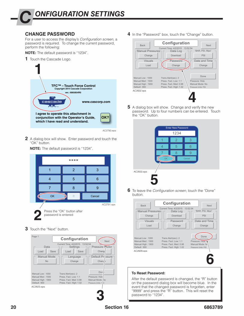
686378920
ONFIGURATION SETTINGSC
Section 16
CHANGE PASSWORDFor a user to access the display’s Configuration screen, a password is required. To change the current password, perform the following:
NOTE: The default password is “1234”.
1 Touch the Cascade Logo.
4 In the “Password” box, touch the “Change” button.
5 A dialog box will show. Change and verify the new password. Up to four numbers can be entered. Touch the “OK” button.
6 To leave the Configuration screen, touch the “Done” button.
3 Touch the “Next” button.
3
Current Time: 4/2/2015
Manual High : 1900
Manual Low : 1000Manual Med : 1500
Default : 900Press. Fact. Med: 0.98
Trans Alert(sec): 2Press. Fact. Low: 1.1
Press. Fact. High: 1.02Manual Mode: NoPressure: Hide
Pressure Units: PSI
13:52:54
Change
Data Settings Pressure Factor
Manual Mode:ChangeNo
LanguageChange
Default Pressure
Done
Next
Page 1
Load Save Load Save
Configuration
AC2823.eps
After the default password is changed, the “R” button on the password dialog box will become blue. In the event that the changed password is forgotten, enter “9999” and press the “R” button. This will reset the password to “1234”.
Current Time: 4/2/2015
Manual High : 1900
Manual Low : 1000Manual Med : 1500
Default : 900Press. Fact. Med: 0.98
Trans Alert(sec): 2Press. Fact. Low: 1.1
Press. Fact. High: 1.02Manual Mode: NoPressure: Hide
Pressure Units: PSI
13:52:54
PSIChange Download
Manual Pressures Data Log “BAR, PSI, Mpa”
VisualsChangeLoad
PasswordChange
Date and Time
Done
NextBackConfiguration
AC2832.eps
1 2 3
4 5 6
7 8 9OK Cancel
1234Enter New Password
AC2833.eps
6
Current Time: 4/2/2015
Manual High : 1900
Manual Low : 1000Manual Med : 1500
Default : 900Press. Fact. Med: 0.98
Trans Alert(sec): 2Press. Fact. Low: 1.1
Press. Fact. High: 1.02Manual Mode: NoPressure: Hide
Pressure Units: PSI
13:52:54
PSIChange Download
Manual Pressures Data Log “BAR, PSI, Mpa”
VisualsChangeLoad
PasswordChange
Date and Time
Done
NextBackConfiguration
AC2829.eps
2 A dialog box will show. Enter password and touch the “OK” button.
NOTE: The default password is “1234”.
1
2
TFC™ – Touch Force ControlCopyright 2014 Cascade Corporation
ver.: 6865854R0
www.cascorp.com
I agree to operate this attachment inconjunction with the Operator’s Guide,which I have read and understand.
OK?
AC2790.eps
1 3
****
4 5
2
6
7 8 9
OK RR Cancel
AC2791.eps
Press the “OK” button after password is entered
To Reset Password:
4
5

6863789 21
ONFIGURATION SETTINGSC
Section 16
CHANGE DATE AND/OR TIMEThis feature is used as a time and date for the touch history log(s). To change, perform the following:
1 Touch the Cascade Logo.
4 In the “Date and Time” box, touch the “Change” button.
5 A dialog box will show. To change the date and/or time, use the “–” and “+” buttons.
6 Touch the “Done” button.
7 To leave the Configuration screen, touch the “Done” button.
6
7
5
3 Touch the “Next” button.
3
4
Current Time: 4/2/2015
Manual High : 1900
Manual Low : 1000Manual Med : 1500
Default : 900Press. Fact. Med: 0.98
Trans Alert(sec): 2Press. Fact. Low: 1.1
Press. Fact. High: 1.02Manual Mode: NoPressure: Hide
Pressure Units: PSI
13:52:54
Change
Data Settings Pressure Factor
Manual Mode:ChangeNo
LanguageChange
Default Pressure
Done
Next
Page 1
Load Save Load Save
Configuration
AC2823.eps
Current Time: 4/2/2015
Manual High : 1900
Manual Low : 1000Manual Med : 1500
Default : 900Press. Fact. Med: 0.98
Trans Alert(sec): 2Press. Fact. Low: 1.1
Press. Fact. High: 1.02Manual Mode: NoPressure: Hide
Pressure Units: PSI
13:52:54
PSIChange Download
Manual Pressures Data Log “BAR, PSI, Mpa”
VisualsChangeLoad
PasswordChange
Date and Time
Done
NextBackConfiguration
AC2834.eps
Date and TimeCurrent Time: 4/2/2015
Year
2015 12
4
2
52
Hour
Month Minute
Day
13:52:54
Done
AC2835.eps
Current Time: 4/2/2015
Manual High : 1900
Manual Low : 1000Manual Med : 1500
Default : 900Press. Fact. Med: 0.98
Trans Alert(sec): 2Press. Fact. Low: 1.1
Press. Fact. High: 1.02Manual Mode: NoPressure: Hide
Pressure Units: PSI
13:52:54
PSIChange Download
Manual Pressures Data Log “BAR, PSI, Mpa”
VisualsChangeLoad
PasswordChange
Date and Time
Done
NextBackConfiguration
AC2829.eps
2 A dialog box will show. Enter password and touch the “OK” button.
NOTE: The default password is “1234”. The password can be changed. Refer to “Change Password”.
1
2
TFC™ – Touch Force ControlCopyright 2014 Cascade Corporation
ver.: 6865854R0
www.cascorp.com
I agree to operate this attachment inconjunction with the Operator’s Guide,which I have read and understand.
OK?
AC2790.eps
1 3
****
4 5
2
6
7 8 9
OK RR Cancel
AC2791.eps
Press the “OK” button after password is entered
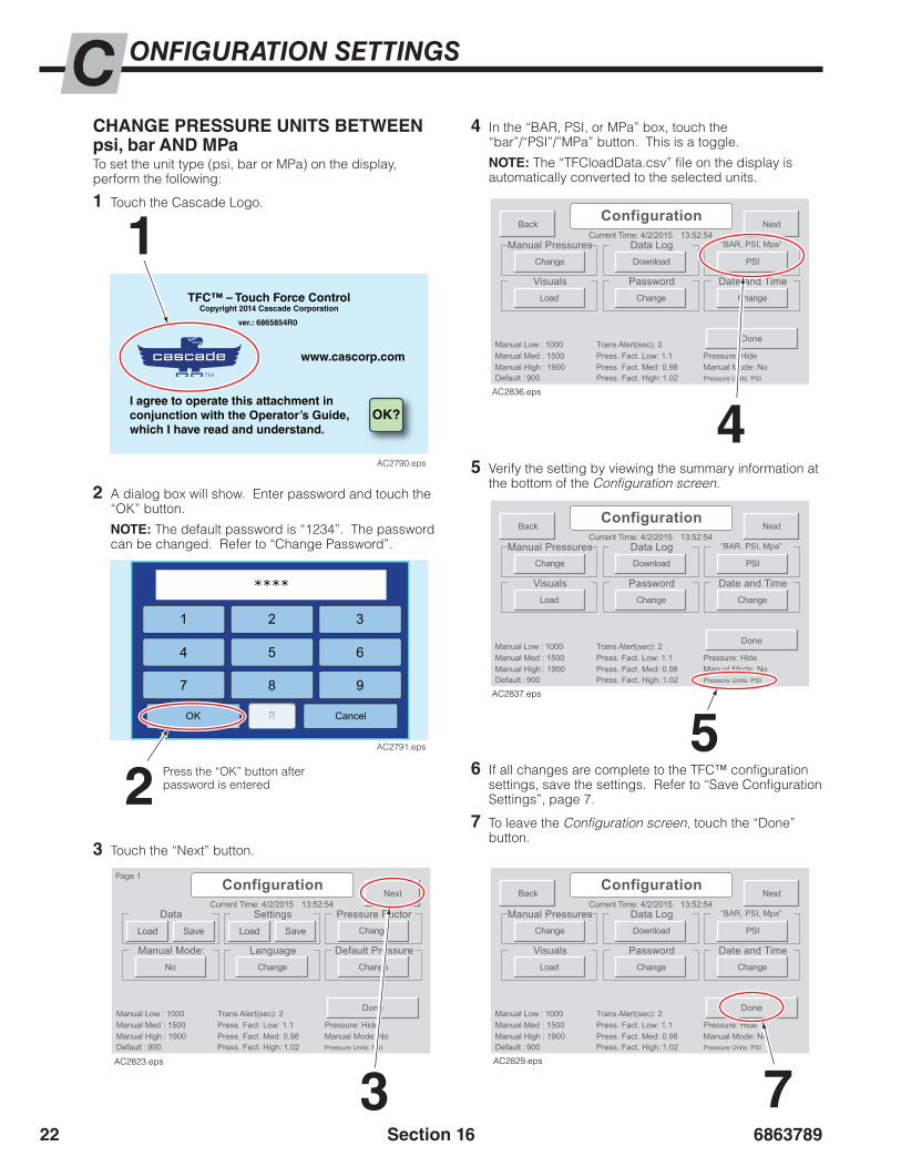
686378922
ONFIGURATION SETTINGSC
Section 16
CHANGE PRESSURE UNITS BETWEEN psi, bar AND MPaTo set the unit type (psi, bar or MPa) on the display, perform the following:
1 Touch the Cascade Logo.
4 In the “BAR, PSI, or MPa” box, touch the “bar”/“PSI”/”MPa” button. This is a toggle.
NOTE: The “TFCloadData.csv” file on the display is automatically converted to the selected units.
5 Verify the setting by viewing the summary information at the bottom of the Configuration screen.
6 If all changes are complete to the TFC™ configuration settings, save the settings. Refer to “Save Configuration Settings”, page 7.
7 To leave the Configuration screen, touch the “Done” button.
3 Touch the “Next” button.
3
4
5
Current Time: 4/2/2015
Manual High : 1900
Manual Low : 1000Manual Med : 1500
Default : 900Press. Fact. Med: 0.98
Trans Alert(sec): 2Press. Fact. Low: 1.1
Press. Fact. High: 1.02Manual Mode: NoPressure: Hide
Pressure Units: PSI
13:52:54
Change
Data Settings Pressure Factor
Manual Mode:ChangeNo
LanguageChange
Default Pressure
Done
Next
Page 1
Load Save Load Save
Configuration
AC2823.eps
Current Time: 4/2/2015
Manual High : 1900
Manual Low : 1000Manual Med : 1500
Default : 900Press. Fact. Med: 0.98
Trans Alert(sec): 2Press. Fact. Low: 1.1
Press. Fact. High: 1.02Manual Mode: NoPressure: Hide
Pressure Units: PSI
13:52:54
PSIChange Download
Manual Pressures Data Log “BAR, PSI, Mpa”
VisualsChangeLoad
PasswordChange
Date and Time
Done
NextBackConfiguration
AC2836.eps
Current Time: 4/2/2015
Manual High : 1900
Manual Low : 1000Manual Med : 1500
Default : 900Press. Fact. Med: 0.98
Trans Alert(sec): 2Press. Fact. Low: 1.1
Press. Fact. High: 1.02Manual Mode: NoPressure: Hide
Pressure Units: PSI
13:52:54
PSIChange Download
Manual Pressures Data Log “BAR, PSI, Mpa”
VisualsChangeLoad
PasswordChange
Date and Time
Done
NextBackConfiguration
AC2837.eps
7
Current Time: 4/2/2015
Manual High : 1900
Manual Low : 1000Manual Med : 1500
Default : 900Press. Fact. Med: 0.98
Trans Alert(sec): 2Press. Fact. Low: 1.1
Press. Fact. High: 1.02Manual Mode: NoPressure: Hide
Pressure Units: PSI
13:52:54
PSIChange Download
Manual Pressures Data Log “BAR, PSI, Mpa”
VisualsChangeLoad
PasswordChange
Date and Time
Done
NextBackConfiguration
AC2829.eps
2 A dialog box will show. Enter password and touch the “OK” button.
NOTE: The default password is “1234”. The password can be changed. Refer to “Change Password”.
1
2
TFC™ – Touch Force ControlCopyright 2014 Cascade Corporation
ver.: 6865854R0
www.cascorp.com
I agree to operate this attachment inconjunction with the Operator’s Guide,which I have read and understand.
OK?
AC2790.eps
1 3
****
4 5
2
6
7 8 9
OK RR Cancel
AC2791.eps
Press the “OK” button after password is entered
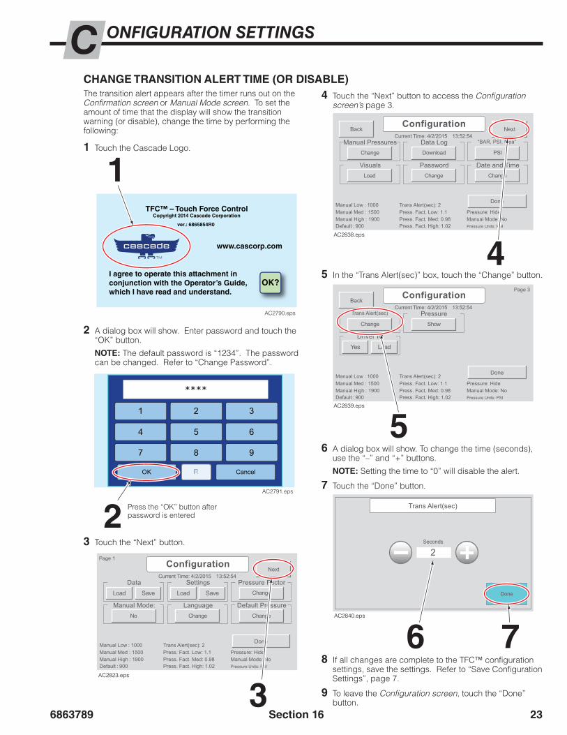
6863789 23
ONFIGURATION SETTINGSC
Section 16
The transition alert appears after the timer runs out on the Confirmation screen or Manual Mode screen. To set the amount of time that the display will show the transition warning (or disable), change the time by performing the following:
CHANGE TRANSITION ALERT TIME (OR DISABLE)
3 Touch the “Next” button.
4 Touch the “Next” button to access the Configuration screen’s page 3.
3
4
5
6 7
Current Time: 4/2/2015
Manual High : 1900
Manual Low : 1000Manual Med : 1500
Default : 900Press. Fact. Med: 0.98
Trans Alert(sec): 2Press. Fact. Low: 1.1
Press. Fact. High: 1.02Manual Mode: NoPressure: Hide
Pressure Units: PSI
13:52:54
Change
Data Settings Pressure Factor
Manual Mode:ChangeNo
LanguageChange
Default Pressure
Done
Next
Page 1
Load Save Load Save
Configuration
AC2823.eps
Current Time: 4/2/2015
Manual High : 1900
Manual Low : 1000Manual Med : 1500
Default : 900Press. Fact. Med: 0.98
Trans Alert(sec): 2Press. Fact. Low: 1.1
Press. Fact. High: 1.02Manual Mode: NoPressure: Hide
Pressure Units: PSI
13:52:54
PSIChange Download
Manual Pressures Data Log “BAR, PSI, Mpa”
VisualsChangeLoad
PasswordChange
Date and Time
Done
NextBackConfiguration
AC2838.eps
Current Time: 4/2/2015
Manual High : 1900
Manual Low : 1000Manual Med : 1500
Default : 900Press. Fact. Med: 0.98
Trans Alert(sec): 2Press. Fact. Low: 1.1
Press. Fact. High: 1.02Manual Mode: NoPressure: Hide
Pressure Units: PSI
13:52:54
Show
PressureChange
Trans Alert(sec)
Done
Back
Page 3Configuration
Driver IDYes Load
AC2839.eps
5 In the “Trans Alert(sec)” box, touch the “Change” button.
6 A dialog box will show. To change the time (seconds), use the “–” and “+” buttons.
NOTE: Setting the time to “0” will disable the alert.
7 Touch the “Done” button.
Trans Alert(sec)
2Seconds
Done
AC2840.eps
2 A dialog box will show. Enter password and touch the “OK” button.
NOTE: The default password is “1234”. The password can be changed. Refer to “Change Password”.
1
2
TFC™ – Touch Force ControlCopyright 2014 Cascade Corporation
ver.: 6865854R0
www.cascorp.com
I agree to operate this attachment inconjunction with the Operator’s Guide,which I have read and understand.
OK?
AC2790.eps
1 3
****
4 5
2
6
7 8 9
OK RR Cancel
AC2791.eps
Press the “OK” button after password is entered
1 Touch the Cascade Logo.
8 If all changes are complete to the TFC™ configuration settings, save the settings. Refer to “Save Configuration Settings”, page 7.
9 To leave the Configuration screen, touch the “Done” button.

686378924
ONFIGURATION SETTINGSC
Section 16
SHOW/HIDE PRESSUREThis procedure shows or hides the pressure values on the display’s Confirmation Screen. To show or hide the pressure value on the display’s Confirmation Screen, perform the following:
1 Touch the Cascade Logo.
3 Touch the “Next” button.
4 Touch the “Next” button to access page 3 of the Configuration screen.
3
Current Time: 4/2/2015
Manual High : 1900
Manual Low : 1000Manual Med : 1500
Default : 900Press. Fact. Med: 0.98
Trans Alert(sec): 2Press. Fact. Low: 1.1
Press. Fact. High: 1.02Manual Mode: NoPressure: Hide
Pressure Units: PSI
13:52:54
Change
Data Settings Pressure Factor
Manual Mode:ChangeNo
LanguageChange
Default Pressure
Done
Next
Page 1
Load Save Load Save
Configuration
AC2823.eps
4
Current Time: 4/2/2015
Manual High : 1900
Manual Low : 1000Manual Med : 1500
Default : 900Press. Fact. Med: 0.98
Trans Alert(sec): 2Press. Fact. Low: 1.1
Press. Fact. High: 1.02Manual Mode: NoPressure: Hide
Pressure Units: PSI
13:52:54
PSIChange Download
Manual Pressures Data Log “BAR, PSI, Mpa”
VisualsChangeLoad
PasswordChange
Date and Time
Done
NextBackConfiguration
AC2838.eps
5
5 In the “Pressure” box, touch the “Show”/”Hide” button. This is a toggle.
• If “Show” is showing, the pressure currently does not show on the display’s Confirmation Screen.
• If “Hide” is showing, the pressure currently shows on the display’s Confirmation Screen.
Current Time: 4/2/2015
Manual High : 1900
Manual Low : 1000Manual Med : 1500
Default : 900Press. Fact. Med: 0.98
Trans Alert(sec): 2Press. Fact. Low: 1.1
Press. Fact. High: 1.02Manual Mode: NoPressure: Hide
Pressure Units: PSI
13:52:54
Show
PressureChange
Trans Alert(sec)
Done
Back
Page 3Configuration
Driver IDYes Load
AC2841.eps
2 A dialog box will show. Enter password and touch the “OK” button.
NOTE: The default password is “1234”. The password can be changed. Refer to “Change Password”.
1
2
TFC™ – Touch Force ControlCopyright 2014 Cascade Corporation
ver.: 6865854R0
www.cascorp.com
I agree to operate this attachment inconjunction with the Operator’s Guide,which I have read and understand.
OK?
AC2790.eps
1 3
****
4 5
2
6
7 8 9
OK RR Cancel
AC2791.eps
Press the “OK” button after password is entered
“Show” = currently hidden“Hide” = currently showing
Pressure HiddenPressure Shown
Clamp Fully
2 seconds
Clamp Fully
2 seconds
1500PSI
20Category 1
Product Type 2
Load Cfg 3
20Category 1
Product Type 2
Load Cfg 3
AC2915.eps
Procedure continued on next page
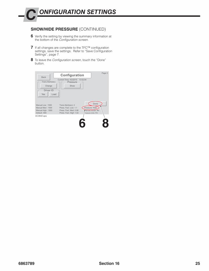
6863789 25
ONFIGURATION SETTINGSC
Section 16
SHOW/HIDE PRESSURE (CONTINUED)
7 If all changes are complete to the TFC™ configuration settings, save the settings. Refer to “Save Configuration Settings”, page 7.
8 To leave the Configuration screen, touch the “Done” button.
6 8
6 Verify the setting by viewing the summary information at the bottom of the Configuration screen.
Current Time: 4/2/2015
Manual High : 1900
Manual Low : 1000Manual Med : 1500
Default : 900Press. Fact. Med: 0.98
Trans Alert(sec): 2Press. Fact. Low: 1.1
Press. Fact. High: 1.02Manual Mode: NoPressure: Hide
Pressure Units: PSI
13:52:54
Show
PressureChange
Trans Alert(sec)
Done
Back
Page 3Configuration
Driver IDYes Load
AC2842.eps

686378926
ONFIGURATION SETTINGSC
Section 16
5 In the “Visuals” box, touch the “Load” button.
6 The message, “Reboot required for changes to take effect.” will appear.
• If the message “Unable to find USB device” appears, wait 5 seconds and press the “Load” button again.
7 The display will require a reboot. Touch the ‘Reboot” button.
UPLOAD NEW DISPLAY IMAGESTo update the images displayed or add a logo, perform the following:
IMPORTANT: Contact Cascade for custom images.
1 Plug the USB flash drive, containing the desired new/updated “VISU” file folder, into the USB connector found on the TFC™ harness near the TFC™ display.
2 Touch the Cascade Logo.
5
6 7
4 Touch the “Next” button.
4
Current Time: 4/2/2015
Manual High : 1900
Manual Low : 1000Manual Med : 1500
Default : 900Press. Fact. Med: 0.98
Trans Alert(sec): 2Press. Fact. Low: 1.1
Press. Fact. High: 1.02Manual Mode: NoPressure: Hide
Pressure Units: PSI
13:52:54
Change
Data Settings Pressure Factor
Manual Mode:ChangeNo
LanguageChange
Default Pressure
Done
Next
Page 1
Load Save Load Save
Configuration
AC2823.eps
Current Time: 4/2/2015
Manual High : 1900
Manual Low : 1000Manual Med : 1500
Default : 900Press. Fact. Med: 0.98
Trans Alert(sec): 2Press. Fact. Low: 1.1
Press. Fact. High: 1.02Manual Mode: NoPressure: Hide
Pressure Units: PSI
13:52:54
PSIChange Download
Manual Pressures Data Log “BAR, PSI, Mpa”
VisualsChangeLoad
PasswordChange
Date and Time
Done
NextBackConfiguration
AC2843.eps
Current Time: 4/2/2015
Manual High : 1900
Manual Low : 1000Manual Med : 1500
Default : 900Press. Fact. Med: 0.98
Trans Alert(sec): 2Press. Fact. Low: 1.1
Press. Fact. High: 1.02Manual Mode: NoPressure: Hide
Pressure Units: PSI
13:52:54
PSIChange Download
Manual Pressures Data Log “BAR, PSI, Mpa”
VisualsChangeLoad
PasswordChange
Date and Time
Reboot
NextBackConfiguration
Reboot required for changes to take effect.
AC2844.eps
3 A dialog box will show. Enter password and touch the “OK” button.
NOTE: The default password is “1234”. The password can be changed. Refer to “Change Password”.
2
3
TFC™ – Touch Force ControlCopyright 2014 Cascade Corporation
ver.: 6865854R0
www.cascorp.com
I agree to operate this attachment inconjunction with the Operator’s Guide,which I have read and understand.
OK?
AC2790.eps
1 3
****
4 5
2
6
7 8 9
OK RR Cancel
AC2791.eps
Press the “OK” button after password is entered

6863789 27
ONFIGURATION SETTINGSC
Section 16
ENABLE/DISABLE DRIVER IDENTIFICATIONA driver can be prompted to enter his/her identification login before entering the Home screen. This restricts unauthorized operators from using the TFC™ system. To enable or disable driver identification login, perform the following:
NOTE: If the driver identification is enabled, a driver identification file must be loaded. Refer to “Upload Driver Identification File”, page 27.
1 Touch the Cascade Logo.
2 A dialog box will show. Enter password and touch the “OK” button.
NOTE: The default password is “1234”. The password can be changed. Refer to “Change Password”.
1
2
TFC™ – Touch Force ControlCopyright 2014 Cascade Corporation
ver.: 6865854R0
www.cascorp.com
I agree to operate this attachment inconjunction with the Operator’s Guide,which I have read and understand.
OK?
AC2790.eps
1 3
****
4 5
2
6
7 8 9
OK RR Cancel
AC2791.eps
Press the “OK” button after password is entered
3 Touch the “Next” button.
Current Time: 4/2/2015
Manual High : 1900
Manual Low : 1000Manual Med : 1500
Default : 900Press. Fact. Med: 0.98
Trans Alert(sec): 2Press. Fact. Low: 1.1
Press. Fact. High: 1.02Manual Mode: NoPressure: Hide
Pressure Units: PSI
13:52:54
Change
Data Settings Pressure Factor
Manual Mode:ChangeNo
LanguageChange
Default Pressure
Done
Next
Page 1
Load Save Load Save
Configuration
AC2823.eps 3
4 Touch the “Next” button to access page 3 of the Configuration screen.
4
Current Time: 4/2/2015
Manual High : 1900
Manual Low : 1000Manual Med : 1500
Default : 900Press. Fact. Med: 0.98
Trans Alert(sec): 2Press. Fact. Low: 1.1
Press. Fact. High: 1.02Manual Mode: NoPressure: Hide
Pressure Units: PSI
13:52:54
PSIChange Download
Manual Pressures Data Log “BAR, PSI, Mpa”
VisualsChangeLoad
PasswordChange
Date and Time
Done
NextBackConfiguration
AC2838.eps
5
5 In the “Driver ID” box, touch the “Yes”/”No” button. This is a toggle.
• If “Yes” is showing, the Truck ID dialog box is disabled.
• If “No” is showing, the Truck ID dialog box is enabled.
Current Time: 4/2/2015
Manual High : 1900
Manual Low : 1000Manual Med : 1500
Default : 900Press. Fact. Med: 0.98
Trans Alert(sec): 2Press. Fact. Low: 1.1
Press. Fact. High: 1.02Manual Mode: NoPressure: Hide
Pressure Units: PSI
13:52:54
Show
PressureChange
Trans Alert(sec)
Done
Back
Page 3Configuration
Driver IDNo Load
AC2859.eps
6 If all changes are complete to the TFC™ configuration settings, save the settings. Refer to “Save Configuration Settings”, page 7.
7 To leave the Configuration screen, touch the “Done” button.
7
Current Time: 4/2/2015
Manual High : 1900
Manual Low : 1000Manual Med : 1500
Default : 900Press. Fact. Med: 0.98
Trans Alert(sec): 2Press. Fact. Low: 1.1
Press. Fact. High: 1.02Manual Mode: NoPressure: Hide
Pressure Units: PSI
13:52:54
Show
PressureChange
Trans Alert(sec)
Done
Back
Page 3Configuration
Driver IDYes Load
AC2860.eps
“Yes” = currently disabled“No” = currently enabled
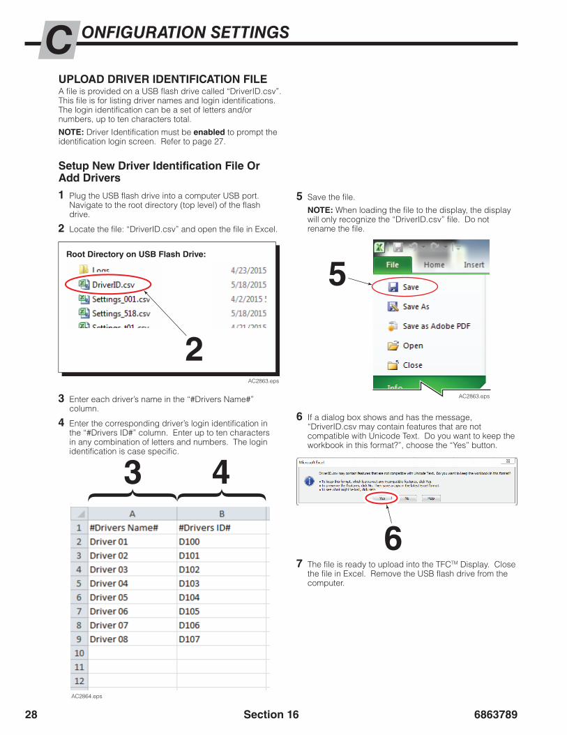
686378928
ONFIGURATION SETTINGSC
Section 16
UPLOAD DRIVER IDENTIFICATION FILEA file is provided on a USB flash drive called “DriverID.csv”. This file is for listing driver names and login identifications. The login identification can be a set of letters and/or numbers, up to ten characters total.
NOTE: Driver Identification must be enabled to prompt the identification login screen. Refer to page 27.
1 Plug the USB flash drive into a computer USB port. Navigate to the root directory (top level) of the flash drive.
2 Locate the file: “DriverID.csv” and open the file in Excel.
3 Enter each driver’s name in the “#Drivers Name#” column.
4 Enter the corresponding driver’s login identification in the “#Drivers ID#” column. Enter up to ten characters in any combination of letters and numbers. The login identification is case specific.
5 Save the file.
NOTE: When loading the file to the display, the display will only recognize the “DriverID.csv” file. Do not rename the file.
6 If a dialog box shows and has the message, “DriverID.csv may contain features that are not compatible with Unicode Text. Do you want to keep the workbook in this format?”, choose the “Yes” button.
7 The file is ready to upload into the TFCTM Display. Close the file in Excel. Remove the USB flash drive from the computer.
AC2864.eps
5
6
43
AC2863.eps
AC2863.eps
2
Root Directory on USB Flash Drive:
Setup New Driver Identification File Or Add Drivers
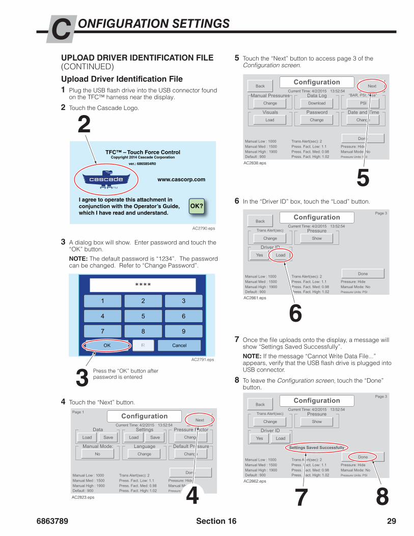
6863789 29
ONFIGURATION SETTINGSC
Section 16
5 Touch the “Next” button to access page 3 of the Configuration screen.
5
Current Time: 4/2/2015
Manual High : 1900
Manual Low : 1000Manual Med : 1500
Default : 900Press. Fact. Med: 0.98
Trans Alert(sec): 2Press. Fact. Low: 1.1
Press. Fact. High: 1.02Manual Mode: NoPressure: Hide
Pressure Units: PSI
13:52:54
PSIChange Download
Manual Pressures Data Log “BAR, PSI, Mpa”
VisualsChangeLoad
PasswordChange
Date and Time
Done
NextBackConfiguration
AC2838.eps
UPLOAD DRIVER IDENTIFICATION FILE (CONTINUED)Upload Driver Identification File1 Plug the USB flash drive into the USB connector found
on the TFC™ harness near the display.
2 Touch the Cascade Logo.
4 Touch the “Next” button.
3 A dialog box will show. Enter password and touch the “OK” button.
NOTE: The default password is “1234”. The password can be changed. Refer to “Change Password”.
2
3
TFC™ – Touch Force ControlCopyright 2014 Cascade Corporation
ver.: 6865854R0
www.cascorp.com
I agree to operate this attachment inconjunction with the Operator’s Guide,which I have read and understand.
OK?
AC2790.eps
1 3
****
4 5
2
6
7 8 9
OK RR Cancel
AC2791.eps
Press the “OK” button after password is entered
Current Time: 4/2/2015
Manual High : 1900
Manual Low : 1000Manual Med : 1500
Default : 900Press. Fact. Med: 0.98
Trans Alert(sec): 2Press. Fact. Low: 1.1
Press. Fact. High: 1.02Manual Mode: NoPressure: Hide
Pressure Units: PSI
13:52:54
Change
Data Settings Pressure Factor
Manual Mode:ChangeNo
LanguageChange
Default Pressure
Done
Next
Page 1
Load Save Load Save
Configuration
AC2823.eps 4 7 8
6
6 In the “Driver ID” box, touch the “Load” button.
Current Time: 4/2/2015
Manual High : 1900
Manual Low : 1000Manual Med : 1500
Default : 900Press. Fact. Med: 0.98
Trans Alert(sec): 2Press. Fact. Low: 1.1
Press. Fact. High: 1.02Manual Mode: NoPressure: Hide
Pressure Units: PSI
13:52:54
Show
PressureChange
Trans Alert(sec)
Done
Back
Page 3Configuration
Driver IDYes Load
AC2861.eps
Current Time: 4/2/2015
Manual High : 1900
Manual Low : 1000Manual Med : 1500
Default : 900Press. Fact. Med: 0.98
Trans Alert(sec): 2Press. Fact. Low: 1.1
Press. Fact. High: 1.02Manual Mode: NoPressure: Hide
Pressure Units: PSI
13:52:54
Show
PressureChange
Trans Alert(sec)
Done
Back
Page 3Configuration
Driver IDYes Load
AC2862.eps
Settings Saved Successfully
7 Once the file uploads onto the display, a message will show “Settings Saved Successfully”.
NOTE: If the message “Cannot Write Data File...” appears, verify that the USB flash drive is plugged into USB connector.
8 To leave the Configuration screen, touch the “Done” button.

686378930 Section 16
BLANK

6863789 31
ONFIGURATION SETTINGSC
Section 16
TFC™ – Touch Force ControlSettings Changes Log
(IMPORTANT: Always create a backup copy of previous versions of the file.)
Truck & Attachment:
Settings File Name:
Date/Set ByPressure Factor Values Manual Mode Pressures Default
PressureLOW MID HIGH LOW MED HIGH

686378932
ONFIGURATION SETTINGSC
Section 16
TFC™ – Touch Force ControlSettings Changes Log
(IMPORTANT: Always create a backup copy of previous versions of the file.)
Truck & Attachment:
Settings File Name:
Date/Set ByManual Mode Psi/Bar/MPa
Toggle Language Transition Alerts
Pressure Toggle
YES OR NO psi, bar or MPa Show/Hide

6863789 1
PPENDIXA GLOSSARY
Section 17
1 Touch OptionAn option, that when selected, takes the driver directly to the Confirmation screen.
2 Touch OptionAn option, that when selected, takes the driver directly to a load’s Configuration screen.
3 Touch OptionThe standard button option, that requires three display touches: category, product type and load configuration.
Clamp ForceThe force (measured in pounds-force or Newtons) transmitted to a load by the clamp. Clamp force is a function of the truck supply pressure, the attachment geometry, efficiency and condition.
Clamp Force, TargetThe desired force that a clamp applies to a load.
Clamp Force IndicatorA device used to measure clamp force (lbf or kN) applied to a product being clamped.
Clamp PressureThe hydraulic pressure generated by the lift truck that powers the clamp and is regulated to control the clamping force on the load.
Configuration ScreensThree screens on the display with TFC™ system settings.
Confirmation ScreenA screen that shows the result of driver selections, a timer and target pressure (if enabled).
Default PressureThe pressure supplied to position the arms when no specific load is selected.
Driver ID File (“DriverID.csv”)A list of authorized users.
Fully ClampedTo achieve target clamp pressure, the driver pulls the handle or lever or pushes the CLAMP activation button, all the way with full throttle to fully engage the load. After the arms stop moving, continue clamping an additional two seconds.
Load ConfigurationThe layout or grouping of product.
Manual ModeA toggled ‘On’ or ‘Off’ that aids with establishing the appropriate pressure for each load configuration. The system allows for real time changes to clamping pressure in ±50 psi (3.44 bar, 0.34 Mpa) increments while establishing clamp force.
Pressure Control ValveAdjusts the pressure supplied to the clamp cylinders for appropriate target clamp force. It requires a Return-To-Tank line.
Pressure Control Valve DriverReceives input from the display to then adjust the valve to a specified pressure (or clamp force).
Pressure FactorThree variables, assigned to low, mid and high ranges, are used to adjust the truck’s output pressure to correspond more directly with the target clamp pressure.
Product CategoryButton options that are typically a brand line, grouping or variety.
Product TypeSubsets of a category selected. These typically are the variety, character or classification of the category selected.
Root DirectoryThe first point or top level directory of a file system, such as USB flash drive, containing files and file folders.
Settings File (“Settings.csv”)Eleven basic settings in a file to make setup consistent and faster.
Target PressureThe pressure that the Pressure Control Valve is set to for clamping a specific load.
TFC™ − Touch Force ControlA touch screen system that allows a driver to select the product and load configuration to automatically set the proper clamp force for the load.
TFC™ Data ToolA tool used with Excel to add or modify data for product categories, product types and load configurations.
TFCloadData File (“TFCloadData.csv”)A file loaded from the USB flash drive to the display that contains load descriptions and corresponding pressures.
TimerThe amount of time (seconds) a pressure is set before resetting to the Default Pressure. This value can be adjusted for various loads.
TouchThe act of touching the display screen with a finger or stylus.
Appendix continued on next page

68637892
PPENDIXA GLOSSARY
Section 17
Touch HistoryA record of every screen touch with data and time stamp.
Touch Screen DisplayAn interactive display for the driver to select the product and load configuration through a sequence of button selections.
Transition AlertA warning that flashes on the display to advise the driver the system has transitioned back to the default pressure.
Return-to-Tank LineHydraulic line that returns excess oil flow back to truck tank.
Voltage Converter KitKit contains a voltage converter and filter combination. The converter steps down the truck’s power source voltage to provide 12V.

BLANK
c© Cascade Corporation 2015 07-2015 Part Number 6863789
Do you have questions you need answered right now? Call your nearest Cascade Service Department.Visit us online at www.cascorp.com
AMERICASCascade CorporationU.S. Headquarters2201 NE 201stFairview, OR 97024-9718Tel: 800-CASCADE (227-2233)Fax: 888-329-8207
Cascade Canada Inc.5570 Timberlea Blvd.Mississauga, OntarioCanada L4W-4M6Tel: 905-629-7777Fax: 905-629-7785
Cascade do BrasilPraça Salvador Rosa,131/141-Jordanópolis, São Bernardo do Campo - SPCEP 09891-430Tel: 55-13-2105-8800Fax: 55-13-2105-8899
EUROPE-AFRICACascade Italia S.R.L.European HeadquartersVia Dell’Artigianato 137030 Vago di Lavagno (VR) ItalyTel: 39-045-8989111Fax: 39-045-8989160
Cascade (Africa) Pty. Ltd.PO Box 625, Isando 160060A Steel RoadSparton, Kempton ParkSouth AfricaTel: 27-11-975-9240Fax: 27-11-394-1147
ASIA-PACIFICCascade Japan Ltd.2-23, 2-Chome,Kukuchi NishimachiAmagasaki, Hyogo Japan, 661-0978Tel: 81-6-6420-9771Fax: 81-6-6420-9777
Cascade Korea121B 9L Namdong Ind. Complex, 691-8 Gojan-DongNamdong-KuInchon, KoreaTel: +82-32-821-2051Fax: +82-32-821-2055
Cascade-XiamenNo. 668 Yangguang Rd. Xinyang Industrial ZoneHaicang, Xiamen CityFujian ProvinceP.R. China 361026Tel: 86-592-651-2500Fax: 86-592-651-2571
Cascade India Material Handling Private LimitedNo 34, Global Trade Centre 1/1 Rambaugh ColonyLal Bahadur Shastri Road, Navi Peth, Pune 411 030(Maharashtra) IndiaPhone: +91 020 2432 5490Fax: +91 020 2433 0881
Cascade Australia Pty. Ltd.1445 Ipswich RoadRocklea, QLD 4107AustraliaTel: 1-800-227-223Fax: +61 7 3373-7333
Cascade New Zealand15 Ra Ora DriveEast Tamaki, AucklandNew ZealandTel: +64-9-273-9136Fax: +64-9-273-9137
Sunstream IndustriesPte. Ltd.18 Tuas South Street 5Singapore 637796Tel: +65-6795-7555Fax: +65-6863-1368