
TENDER DOCUMENT FOR WAP/PMD/2018-19/13 Date
455
TENDER NO: WAP/PMD/2019-20/13 3 rd Floor, SKV Tower Plot No.- 57, Sector - 18 Gurugram-122015, Haryana TENDER DOCUMENT FOR CONSTRUCTION 300 BEDDED HOSTEL AT SAI, IMPHAL, MANIPUR WAP/PMD/2018-19/13 Date: 26-07-2019 WAPCOS Signature of Bidder -1- WAPCOS Signature of Bidder
-
Upload
khangminh22 -
Category
Documents
-
view
3 -
download
0
Transcript of TENDER DOCUMENT FOR WAP/PMD/2018-19/13 Date
TENDER NO: WAP/PMD/2019-20/13
3rd Floor, SKV TowerPlot No.- 57, Sector - 18
Gurugram-122015, Haryana
TENDER DOCUMENT FOR
CONSTRUCTION 300 BEDDED HOSTEL ATSAI, IMPHAL, MANIPUR
WAP/PMD/2018-19/13Date: 26-07-2019
WAPCOSSignature of Bidder -1- WAPCOSSignature of Bidder
TENDER NO: WAP/PMD/2019-20/13
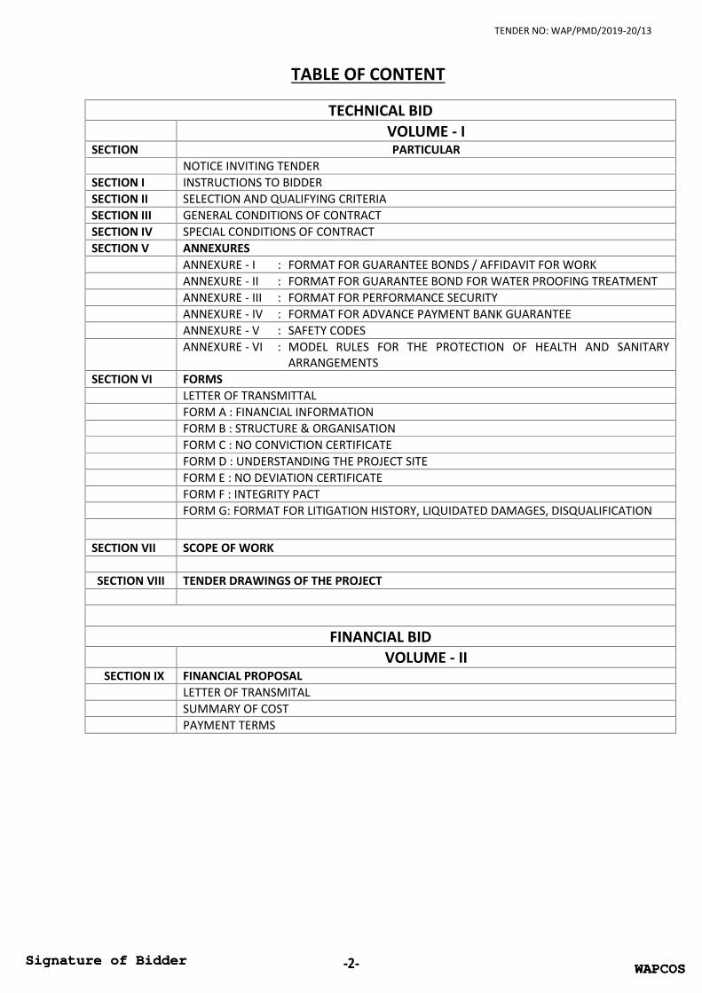
TABLE OF CONTENT
TECHNICAL BIDVOLUME - I
SECTION PARTICULARNOTICE INVITING TENDER
SECTION I INSTRUCTIONS TO BIDDERSECTION II SELECTION AND QUALIFYING CRITERIASECTION III GENERAL CONDITIONS OF CONTRACTSECTION IV SPECIAL CONDITIONS OF CONTRACTSECTION V ANNEXURES
ANNEXURE - I : FORMAT FOR GUARANTEE BONDS / AFFIDAVIT FOR WORKANNEXURE - II : FORMAT FOR GUARANTEE BOND FOR WATER PROOFING TREATMENTANNEXURE - III : FORMAT FOR PERFORMANCE SECURITYANNEXURE - IV : FORMAT FOR ADVANCE PAYMENT BANK GUARANTEEANNEXURE - V : SAFETY CODESANNEXURE - VI : MODEL RULES FOR THE PROTECTION OF HEALTH AND SANITARY
ARRANGEMENTSSECTION VI FORMS
LETTER OF TRANSMITTALFORM A : FINANCIAL INFORMATIONFORM B : STRUCTURE & ORGANISATIONFORM C : NO CONVICTION CERTIFICATEFORM D : UNDERSTANDING THE PROJECT SITEFORM E : NO DEVIATION CERTIFICATEFORM F : INTEGRITY PACTFORM G: FORMAT FOR LITIGATION HISTORY, LIQUIDATED DAMAGES, DISQUALIFICATION
SECTION VII SCOPE OF WORK
SECTION VIII TENDER DRAWINGS OF THE PROJECT
FINANCIAL BIDVOLUME - II
SECTION IX FINANCIAL PROPOSALLETTER OF TRANSMITALSUMMARY OF COSTPAYMENT TERMS
WAPCOSSignature of Bidder -2- WAPCOSSignature of Bidder

TENDER NO: WAP/PMD/2019-20/13
NOTICE INVITING TENDER (NIT)
WAPCOSSignature of Bidder -3- WAPCOSSignature of Bidder

TENDER NO: WAP/PMD/2019-20/13
NOTICE INVITING TENDER (NIT)
WAPCOS Limited (A Govt. of India Undertaking), for and behalf of Office of Sports Authority of India(SAI) invites “Online Electronic Tenders” on “Engineering Procurement and Construction (EPC)mode” from experienced and competent bidders, meeting prescribed qualifying criteria asmentioned in tender document.
1. Name of Work / Project : Construction of 300 bedded hostel at SAI, Imphal,Manipur
2. Site / Location : SAI, Imphal, Manipur
3. Website for viewing tender : www.wapcos.co.in and www.eprocure.gov.inhttps://www.mstcecommerce.com/eprochome/wapcos
4. Website for Registration/uploading of Tender and alsoviewing of Corrigendum/Addendum, if any.
https://www.mstcecommerce.com/eprochome/wapcos
5. Estimated Cost of Work : Rs. 28.40 Cr. excluding GST6. Cost of Tender Document : Rs. 10,000/- (in form of Demand Draft in favour of
WAPCOS LIMITED payable at Gurugram)7. Amount of Earnest Money Deposit : Rs. 38.40 Lakhs (Refundable) in the form of
RTGS/NEFT/D.D./Banker’s cheque/FDR in favors of‘WAPCOS Limited’ payable at Gurugram, Haryana
A part of earnest money is acceptable in the form ofbank guarantee also. In such cases 50% of earnestmoney or Rs. 20 lakh whichever is less, will have tobe deposited in form RTGS/NEFT/DD/ Banker’sCheque/FDR and balance can be accepted in form ofbank Guarantee in prescribed format issued by ascheduled bank.
8. Site Visit (Mandatory for bidders) 05/08/2019 from 10:00 to 17:00 hours in presenceof WAPCOS representative (Mr. Manik Bansal:9711926578). Bidder representative shall comealong with authorization letter on behalf of bidderfirm and handover the same to WAPCOSrepresentative. It is advised to send seniorrepresentative during site visit as location, depth offoundation, plinth level as per nearby road level etc.are
9. Project Completion Period : 18 Months from the Date of Award10. Validity of Bid/Tender 120 Days11. Pre Bid Meeting : 07/08/2019 at 16:00 hours to be held in the office of
NIT No. WAP/PMD/2019-20/13 Dated : 26-07-2019
WAPCOSSignature of Bidder -4-
General Manager, Project Management Division.
WAPCOSSignature of Bidder

TENDER NO: WAP/PMD/2019-20/13
12. Offline Submission of Technicaldocument, Tender Fees, EMD etc.as detail in Tender for bidders.
16/08/2019 up to 17:00 hours in the office ofGeneral Manager, Project Management Division
13. Last date & time for onlinesubmission of Technical &Financial Bid
: 19/08/2019 up to 12:00 Noon
14. Online opening of Technical Bid : 19/08/2019 up to 16:45 hours15. Online opening of Financial Bid : Intimated to Technical Qualified Bidders.16. WAPCOS Communication address
during Tendering and execution ofworks
: General ManagerWAPCOS Limited.3rd Floor, SKV Tower, Plot no.- 57, Sector- 18,Gurugram-122015, HaryanaEmail: [email protected] No. +91-124-2973685
Exemption in Tender document fee & EMD by Micro, Small & Medium Enterprises registeredwith NSIC: The companies who are registered with Micro, Small & Medium Enterprises and alsohave the NSIC Certificate under Government Store Purchase Programme having certificate clearlyindicating the amount of “Quantitative Capacity Per Annum” (amount of Quantitative CapacityPer Annum shall be more than the estimated cost of Work) are exempted from the submissionof Tender document fee / EMD on submission of requisite proof in the form of valid certificationfrom MSME and NSIC.If the office of WAPCOS Limited, New Delhi happens to be closed on the last date and timementioned for any of the event, the said event will take place on the next working day at the sametime and venue.
The tender document has to be downloaded from above specified websites. Bidders are advised tovisit above specified websites regularly for updates /Amendments/ Corrigendum, if any. TheUpdates/Corrigendum/Addendum shall be followed up to submission of tender and it will be thepart of tender. The full details about the work, specifications, Drawings, terms and conditions shallbe available in the Tender Document. The tender document has to be submitted online on websiteshttps://www.mstcecommerce.com/eprochome/wapcos.
The purpose of this NIT is to provide interested parties with information to assist the preparationof their bid. While WAPCOS Limited has taken due care in the preparation of the informationcontained herein, and believe it to be complete and accurate, neither it nor any of its authorities oragencies nor any of its respective officers, employees, agents or advisors give any warranty or makeany representations, expressed or implied as to the completeness or accuracy of the informationcontained in this document or any information which may be provided in association with it.
Further, WAPCOS Limited does not claim that the information is exhaustive. Respondents to thisNIT are required to make their own inquiries/ surveys and will be required to confirm, in writing,that they have done so and they did not rely solely on the information in NIT. WAPCOS Limited isnot responsible if no due diligence is performed by the bidders.
WAPCOSSignature of Bidder -5- WAPCOSSignature of Bidder

TENDER NO: WAP/PMD/2019-20/13
IMPORTANT POINTS
1.1 The bidder should be an Indian Registered Company under Companies Act 1956/ 2013,Proprietorship Firm/ Partnership Firm.
1.2 All Bidders are hereby cautioned that Bids containing any deviation or reservation asdescribed in Clauses of “Instructions to Bidders” shall be considered as non-responsive andshall be summarily rejected.
1.3 WAPCOS Ltd. reserves the right to accept or reject any or all bids without assigning anyreasons. No Bidder shall have any cause of action or claim against the WAPCOS Ltd. Forrejection of his Bid and will not be bound to accept the lowest or any other tender.
1.4 No reimbursement of cost of any type or on any account will be paid to persons or entitiessubmitting their Bid.
1.5 All information submitted in response to this NIT shall be the property of WAPCOS Limitedand it shall be free to use the concept of the same at its will.
1.6 It is hereby declared that WAPCOS is committed to follow the principle of transparency,equity and competitiveness in public procurement. The subject Notice Inviting Tender (NIT)is an invitation to offer made on the condition that the Bidder will sign the integrityAgreement, which is an integral part of tender/bid documents, failing which thetenderer/bidder will stand disqualified from the tendering process and the bid of the bidderwould be summarily rejected. This declaration shall form part and parcel of the IntegrityAgreement and signing of the same shall be deemed as acceptance and signing of theIntegrity Agreement on behalf of the WAPCOS.
For and on behalf of WAPCOS LIMITED
General Manager
WAPCOSSignature of Bidder -6- WAPCOSSignature of Bidder

TENDER NO: WAP/PMD/2019-20/13
SECTION– I
INSTRUCTIONS TO BIDDER
WAPCOSSignature of Bidder -7- WAPCOSSignature of Bidder

TENDER NO: WAP/PMD/2019-20/13
SECTION– I
INSTRUCTIONS TO BIDDER
1.0 SPECIAL INSTRUCTIONS TO BIDDERS FOR E-TENDERING
1.1 GENERAL
The Special Instructions (for e-Tendering) supplement ‘Instruction to Bidders’, as given inthese Tender Documents. Submission of Online Bids is mandatory for this Tender.
1. E-Tendering is a new methodology for conducting Public Procurement in a transparent andsecured manner. For conducting electronic tendering, bidders shall use the portalhttps://www.mstcecommerce.com/eprochome/wapcos . Tender is invited in Single Stage -TwoEnvelope system, one Technical Bid and second as Financial bid.
1.2 SPECIAL INSTRUCTIONS TO BIDDERS FOR E-TENDERING
2. Use Internet Explorer to go to https://www.mstcecommerce.com/eprochome/wapcos
WAPCOSSignature of Bidder -8- WAPCOSSignature of Bidder

TENDER NO: WAP/PMD/2019-20/13
3. On the right side of the page click on Register as a Vendor:
4. Fill the form that appears to create username and password.
5. Once the registration is done, login with your user name and password:
6. System will ask you to verify your digital signature
WAPCOSSignature of Bidder -9- WAPCOSSignature of Bidder

TENDER NO: WAP/PMD/2019-20/13
7. Press Ok and select your digital signature from the List:
8. Your digital signature will be verified
9. Once login is complete, a bidder can access My Menu through the left side of the page:
10. Here click on Download NIT/Corrigendum button to download the NIT/Corrigendums. Select Eventnumber and click on download to download the files:
WAPCOSSignature of Bidder -10- WAPCOSSignature of Bidder

TENDER NO: WAP/PMD/2019-20/13
11. To submit the bid a bidder can proceed to Bid Floor through the left side My menu. In Bid Floor clickon live events to view a list of Live events. In live events select the tender number where you wishto submit a bid.
12. On clicking the event number, if the bidder has not paid transaction fee, system will prompt them topay the transaction fee. They can pay the transaction fee by going to Transaction Fee payment linkin their login, and pay the same through online payment (debit card, credit card, net banking etc) orRTGS/NEFT (Challan).
13. Tender can be of multiple types with price bid uploading in Excel or Technical-Price type. The bidfloor for each type of event will change automatically.
On clicking the tender number one of the following screens will appear:
For 2 cover with price bid in excel
E-Tender Technical Cum Price Bid
WAPCOSSignature of Bidder -11- WAPCOSSignature of Bidder

TENDER NO: WAP/PMD/2019-20/13
14. For each type of event the event details including start time and close time the details will be givenon the top of the page.
15. To submit the tender the bidder has to start from top left and submit the details one by one.16. For 2 cover with price bid in excel, the bidder has to submit technical bid, by filling the details and
clicking the save button.
a) After the technical bid is saved, a bidder can proceed to uploading documents through the linkupload docs:
b) Please note that under no circumstance the price bid excel has to be uploaded here.c) After the documents have been uploaded, the bidder can click on download excel to download the
excel format.d) Fill up the excel sheet as per the details given therein and tender document.e) To upload the filled up excel click on Upload Price Button, click on browse to select the file and then
click on Upload and Save encrypt file.
f) The bidder can then click on final submit to finally submit the bid. In case of any amendments afterfinal submit, click on delete bid button to delete the techno-commercial and price bids and resubmitthe same. Please note that at the end the bid must be final submit, otherwise the same will not beconsidered.
WAPCOSSignature of Bidder -12- WAPCOSSignature of Bidder

TENDER NO: WAP/PMD/2019-20/13
17. For E-Tender Technical Cum Price Bid:a. In the manner similar to above the bidder has to fill up Common terms, then press save
button to submit.b. Then the bidder has to upload documents as per the list shown therein.c. Once the documents are uploaded the bidder has to submit the Technical and Price bids.d. The bidder can then click on final submit to finally submit the bid. In case of any
amendments after final submit, click on delete bid button to delete the techno-commercialand price bids and resubmit the same. Please note that at the end the bid must be finalsubmit, otherwise the same will not be considered.
Bidder’s may note that in each case using the Delete bid button will only delete the bids and then the biddercan resubmit upload tender closing time.
Using the withdraw button the bid will be withdrawn and the bidder will not be allowed to submit any furtherbid in that event.
For any assistance regarding the Tender Document and/or term and conditions the bidders may contact atWAPCOS:
For any assistance during bid submission, system settings etc. bidders may contact at MSTC:
Phone Number03322901004, 01123212357, 01123215163, 01123217850
[email protected] mention “Helpdesk” as subject while sending emails
Availability10 AM to 5:30 PM on all working days.
2.0 INSTRUCTIONS TO BIDDER
The purpose of these instructions to serve as a guide to Bidders for preparing offer forcarrying out the project in all respect.
a) Submission of a tender by a tenderer implies that the tenderer has read this notice andall other Tender Documents and has made himself aware of the scope, thespecifications, conditions of contract, local conditions and other factors having bearingson the execution of the work.
b) WAPCOS Limited desires that the bidders, suppliers, and Sub-contractors under theProject, observe the highest standard of ethics during the performance, procurementand execution of such contracts. In pursuance of this requirement, WAPCOS Limited,defines, for the purposes of this provision, the terms set forth below:
i. “Corrupt Practice” means the offering, giving, receiving, or soliciting, directly orindirectly, anything of value to influence improperly the actions of another party;
ii. “Fraudulent Practice” means any act of submission of forged documentation, oromission, including a misrepresentation, that knowingly or recklessly misleads, orattempts to mislead, a party to obtain a financial or other benefit or to avoid anobligation, or to succeed in a competitive bidding process;
WAPCOSSignature of Bidder -13- WAPCOSSignature of Bidder

TENDER NO: WAP/PMD/2019-20/13
iii. “Coercive Practice” means impairing or harming, or threatening to impair or harm,directly or indirectly, any party or the property of the party to influence improperlythe actions of a party;
iv. “Collusive Practice” means an arrangement between two or more parties designedto achieve an improper purpose, including influencing improperly the actions ofanother party.
Will reject the award of Contract, even at a later stage, if it determines that the bidderrecommended/ selected for award/awarded has, directly or through an agent, engagedin Corrupt, Fraudulent, Collusive, Or Coercive Practices incompeting for the Contract;
Will sanction a party or its successors, including declaring ineligible, either indefinitelyor for a stated period of time, to participate in any further bidding/procurementproceedings under the Project, if it at any time determines that the party has, directly orthrough an agent, engaged in Corrupt, Fraudulent, Collusive, Or Coercive Practices incompeting for, or in executing, the contract; and
The party may be required to sign an Integrity Pact, if required; and WAPCOS Limitedwill have the right to require the bidders, or its suppliers, contractors and consultants topermit WAPCOS Limited to inspect their accounts and records and other documentsrelating to the bid submission and contract performance and to have them audited byauditors appointed by WAPCOS Limited at the cost of the bidders.
The Bidder must obtain for himself on his own responsibility and at his own expenses allthe information which may be necessary for the purpose of making a bid and for enteringinto a contract, must examine the Drawings, must inspect the sites of the work, acquainthimself with all local conditions, means of access to the work, nature of the work and allmatters pertaining thereto. WAPCOS Limited will in no case be responsible or liable forthose costs, regardless of the conduct or outcome of the bidding process.
c) The Contract shall be governed by each SECTION OF TENDER DOCUMENT i.e.instructions to bidders, selection & qualifying criteria, scope of works, GeneralConditions for Contract (GCC), Special Conditions for Contract (SCC), Annexures, Forms,Drawings, Technical Specification, Addendum / Clarification / Corrigendum etc. and allother Conditions mentioned in the tender documents.
d) All Bidders are hereby explicitly informed that conditional offers or offers with deviationsfrom the Conditions of Contract, the bids not meeting the minimum eligibility criteria,Technical Bids not accompanied with EMD and Tender Document Fees of requisiteamount in acceptable format, Bids in altered/modified formats, or in deviation with anyother requirements stipulated in the tender documents are liable to be rejected.
e) The company reserves the right to waive minor deviations if they do not materially affectthe capability of the Tenderer to perform the contract
f) The bidders shall not tamper or modify any part of the tender documents in any manner.In case in part of the bid is found to be tampered or modified at any stage, the bids areliable to be rejected, the contract is liable to be terminated and the full earnestdeposit/retention money/performance guarantee will be forfeited and the bidder willbe liable to be banned from doing any business with WAPCOS Limited.
g) Incomplete Price bid shall be liable to be rejected, at the discretion of WAPCOS Limited.The total bid price shall cover the entire scope of works covered in the tender.
WAPCOSSignature of Bidder -14- WAPCOSSignature of Bidder

TENDER NO: WAP/PMD/2019-20/13
3.0 EARNEST MONEY DEPOSIT (EMD)
The Earnest Money Deposit in favor of WAPCOS Ltd payable at Gurgaon, Haryana of theamount as mentioned in NIT will be submitted only in the following forms:
Through RTGS/ NEFT in the name of WAPCOS Limited, Name of Bank: IndianOverseas Bank, Bank Account Number: 193502000000287 and IFSC Code:IOBA0001935
Banker's cheque of a Scheduled Bank. Demand Draft of a Scheduled Bank. Fixed Deposit Receipt (FDR) of a Scheduled Bank in the name of WAPCOS Ltd.
A part of earnest money is acceptable in the form of bank guarantee also. In such cases50% of earnest money or Rs. 20 lakh whichever is less, will have to be deposited inshape prescribed above and balance can be accepted in form of bank Guarantee issuedby a scheduled bank as per the format mentioned in Enclosure-I of this Section. TheBank Guarantee submitted as a part of Earnest Money shall be valid for a period offour months or more from the date of submission of the tender.
The EMD of unsuccessful tenderer(s) will be refunded after finalization of tender process.The Earnest Money deposit submitted by the successful tenderer shall be retained byWAPCOS Limited until the Performance Bank Guarantee (PBG) is submitted.
The successful Tenderer shall accept the LOI within 15 (Fifteen) days from receipt of thesame, failing which the EMD shall be forfeited and the award of work may be liable to becancelled.
If any tenderer withdraws or make any changes in his offer already submitted before theexpiry of the above validity period or any extension thereof without the written consent ofthe company, the EMD amount will be forfeited for such act of the tenderer.
WAPCOS Limited reserves the right of forfeiture of Earnest Money deposit (EMD) in case ofthe successful tenderer.i. After opening of Tender, revokes his tender within the validity period or increases his
earlier quoted rates.ii. Does not commence the work within the period as per LOI/Contract. In case the
LOI/Contract is silent in this regard then within 15 days after award of contract.iii. EMD shall not carry any interest.
4.0 COST OF BIDDING
The Bidder shall bear all costs associated with the preparation and submission of the Bid aswell as costs associated for facilitating the evaluation. WAPCOS Limited shall in no case beresponsible or liable for these costs, regardless of the conduct or outcome of the biddingprocess.
5.0 LANGUAGE OF BID
The Bid and all related correspondence and documents relating to the Project shall be inEnglish language only. Supporting documents and printed literature furnished by the Bidder
WAPCOSSignature of Bidder -15- WAPCOSSignature of Bidder

TENDER NO: WAP/PMD/2019-20/13
may be in another language provided they are accompanied by an accurate Englishtranslation which shall be certified by a qualified translator. Any material that is submittedin a language other than English and which is not accompanied by an accurate Englishtranslation will not be considered.
6.0 CURRENCY OF BID
Bid prices shall be quoted in Indian Rupees. Tender submitted by tenderer shall remain validfor acceptance as mentioned in NIT from the date set for submission of the tender. Thetenderer shall not be entitled within the said period to revoke or cancel or vary the tendergiven or any item thereof, without the consent of WAPCOS Limited. In case tendererrevokes, cancels, or varies his tender in any manner without the consent of WAPCOSLimited, within this period, his earnest money will be forfeited.
7.0 ANNEXURES
The successful Bidder shall submit the following formats and also follow the guidelines asper “Section of Annexures” mentioned in tender document.
ANNEXURE - I : FORMAT FOR GUARANTEE BONDS / AFFIDAVIT FOR WORKANNEXURE - II : FORMAT FOR GUARANTEE BOND FOR WATER PROOFING TREATMENTANNEXURE - III : FORMAT FOR PERFORMANCE SECURITYANNEXURE - IV : FORMAT FOR ADVANCE PAYMENT BANK GUARANTEEANNEXURE - V : SAFETY CODESANNEXURE - VI : MODEL RULES FOR THE PROTECTION OF HEALTH AND SANITARY
ARRANGEMENTS
WAPCOS Limited reserves the right to reject any or all the bids or to cancel the Tender,without assigning any reason(s) whatsoever.
For & on behalf of Tenderer
WAPCOSSignature of Bidder -16- WAPCOSSignature of Bidder

TENDER NO: WAP/PMD/2019-20/13
Enclosure-IBANK GUARANTEE FORMAT FOR EMD
WHEREAS, M/s ……………………………………….. having their Registered/Head Office at…………………………………………….. (hereinafter called “the Bidder”) has submitted his Bid dated…………………… for the ………………………………………………… [hereinafter called “the Bid”] to M/sWAPCOS Limited (hereinafter called the Employer)
KNOW ALL PEOPLE by these presents that we ………………………………………………… (name of the Bank)having our head office at ………………………………………………… (hereinafter called “the Bank”) are boundunto Employer in the sum of ……………………………………… for which payment well and truly to be madeto the Employer, the Bank binds itself, its successors and assigns by these presents.
SEALED with the Common Seal of the said Bank this ………………… day of ……………month……… year.
THE CONDITIONS of this obligation are:
(1) If after Bid opening the Bidder withdraws his bid during the period of Bid validity specified;OR
(2) If the Bidder having been notified of the acceptance of his bid by ……………………………… duringthe period of Bid Validity:
We undertake to pay to the ……………………………… up to the above amount upon receipt of his firstwritten demand, without the Employer having to substantiate his demand, provided that in hisdemand the Bidder will note that the amount claimed by him is due to him owing to the occurrenceof one or any of the above mentioned two conditions and specify the occurred condition orconditions.
This Guarantee will remain in force up to and including the date ……………………………… after thedeadline for submission of Bids as is stated in the instructions to Bidders or as it may be extendedby the ………………………………………… notice of which extension(s) to the Bank is hereby waived andnotice to the bidder would constitute sufficient notice to the Bank. Any demand in respect of thisguarantee should reach the Bank not later than the above date.
Notwithstanding anything contained hereini) Liability under this guarantee shall not exceed ……………………………………………ii) This bank guarantee shall be valid upto ………………………………………… and;iii) Our liability to make payment shall arise and we are liable to pay the guaranteed amount or any
part thereof under this guarantee only and only if you serve upon us a written claim or demandin terms of the guarantee on or before ……………………………………… (indicate a period twelvemonths after the date of issue of Bank Guarantee).
DATE: SIGNATURE:(Signature of Witness) SEAL
WAPCOSSignature of Bidder -17- WAPCOSSignature of Bidder

TENDER NO: WAP/PMD/2019-20/13
SECTION– II
SELECTION AND QUALIFYING CRITERIA
WAPCOSSignature of Bidder -18- WAPCOSSignature of Bidder

TENDER NO: WAP/PMD/2019-20/13
SECTION-II
SELECTION AND QUALIFYING CRITERIA
1.0 SITE VISIT
Intending Bidder(s) are advised to inspect and examine the site at his own cost and itssurroundings and satisfy themselves before submitting their bids as to the nature of theground and sub-soil (so far as is practicable), the form and nature of the site, the means ofaccess to the site, the accommodation they may require and in general shall themselvesobtain all necessary information as to risks, contingencies and other circumstances whichmay influence or affect their bid as it is “Engineering Procurement & Construction (EPC)Contract”. A bidder(s) shall be deemed to have full knowledge of the site whether heinspects it or not and no extra charge consequent on any misunderstanding or otherwiseshall be allowed. The bidder(s) shall be responsible for arranging and maintaining at his owncost all materials, tools & plants, water, electricity access, facilities for workers and all otherservices required for executing the work unless otherwise specifically provided for in thecontract documents. Submission of a bid by a bidder(s) implies that he has read this noticeand all other contract documents and has made himself aware of the scope andspecifications of the work to be done and of conditions and rates at which stores, tools andplant, etc. will be issued to him by the Government and local conditions and other factorshaving a bearing on the execution of the work.
Site visit is mandatory to understand the actual scope of work/ site condition and will beheld as dates and time mentioned in NIT of this tender in the presence of WAPCOSrepresentative. The submission of tender will not be accepted by the WAPCOS without sitevisit of tenderer. Accordingly it is directed to bidders to visit the site with properauthorization letter of bidder representative from Bidder Company/ agencies. Bidderrepresentative will submit the authorization letter to WAPCOS representative.
2.0 PRE-BID MEETING
The pre-bid meeting will be held as mentioned in the NIT in the office of Chief Engineer,Project Management Division, WAPCOS Limited, 3rd Floor, SKV Tower, Plot no.- 57, Sector-18, Gurugram-122015, Haryana
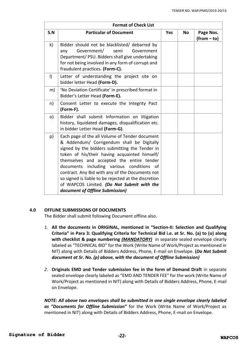
3.0 QUALIFYING CRITERIA: ONLINE TECHNICAL BID SUBMISSIONThe intending bidders must read the terms & conditions of tender documents carefully. Heshould only submit bid if he considers himself eligible and he is in possession of all thedocuments required.The Technical Bid shall be uploaded with coloured scanned copies of following documents.All the documents must be Serial wise as stated below along with check list and clearlymarked page no. on each page (MANDATORY).
Format of Check ListS.N Particular of Document Yes No Page Nos.
(from – to)a) Authorization Letter to sign the Tender on
bidder’s original letter head or Power of attorneyb) Scanned copy of EMD of amount as mentioned in
NIT.
WAPCOSSignature of Bidder -19- WAPCOSSignature of Bidder

TENDER NO: WAP/PMD/2019-20/13
Format of Check ListS.N Particular of Document Yes No Page Nos.
(from – to)c) Scanned copy of Demand Draft for Tender Fees of
the amount as mentioned in NIT.d) Letter of Transmittal on bidder’s original letter
Head to submit Technical Bid.e) Yearly sales Turnover and Audited Balance Sheet
for Last 5 (five) years ending on the financial year2017-18 The contractor should not have incurred any
loss (profit after tax should be positive) inmore than two years during last five yearsending 2017-18 duly audited and Attested bythe Independent Chartered Accountant.(Form-A)
Turnover: Average annual financial turnoveron Construction works should be at least 50%of the estimated cost of work during theimmediate last 3 consecutive financial yearsending 2017-18. This should be duly auditedby the Chartered Accountant doing StatutoryAudit .
Full Balance Sheet and Profit & loss Statementof Bidder should be verified by CharteredAccountant.
The contractor should also have satisfactorilycompleted the similar types of works asmentioned below during the last seven yearsending previous day of last date of submissionof tender.
i) One similar completed work costing not lessthan 80% of the estimated cost of work.
Orii) Two similar completed works of order value
each not less than 60% of the estimated costof work.
Oriii) Three similar completed works of order value
not less than 40% of the estimated cost ofwork.
Note:“Similar work” refers to a work involving ofconstruction of residential buildings, officebuilding, complex, hostel with all relevantprovision OR work involving minimum quantity
WAPCOSSignature of Bidder -20- WAPCOSSignature of Bidder

TENDER NO: WAP/PMD/2019-20/13
Format of Check ListS.N Particular of Document Yes No Page Nos.
(from – to)of 3500 cum Reinforced Cement Concrete (RCC).The bidder’s shall submit CompletionCertificate(s) mentioning name, nature ofwork(s), value(s) of the job(s), date(s) ofcommencement, stipulated date(s) ofcompletion and actual date(s) of completionalong-with LOI(s)/W.O(s) from respectiveOwner(s)/Client(s).
f) The bidder should not be insolvent, inreceivership, bankrupt or being wound up, nothave had their business activities suspended.Accordingly, Bidder shall submit Solvencycertificate with details of Financial Status i.e.Name of the Banker & Current Solvency fromBanker for a sum of at least 40% of the estimatedcost of work Certificate in Original. The SolvencyCertificate shall be issued by the bank after thedate of publishing of Tender document.
g) Name, Address, details of the Organization,Name(s) of the Owner/Partners/Promoters andDirectors of the firm / company. (Form-B)
h) Copy of P.F and PAN Number.i) Goods and Service Tax (GST): Bidders are advised
to get themselves registered for GST in atdifferent place, which are mandatory, as perGovt. of India notification regarding GST.Accordingly bidder shall submit relevantdocuments if already registered. If not registeredtill date of submission of bid, bidder will giveundertaking on bidder letter head stating thatthey will get registered in GST as per Govt. normsbefore submission of bills.
j) The bidder should be an Indian RegisteredCompany under Companies Act 1956/Proprietorship Firm/ Partnership Firm. JointVentures are not accepted. Copy of Certificate ofIncorporation/ Registration/ Partnership DeedRegistration or any other relevant document, asapplicable, should be submitted along with a copyof address proof.NOTE: Proprietor firms shall submit registrationdetails or shall submit the copy of relevant pageof Pass book for the Current Account in the nameof Proprietor Firm.
WAPCOSSignature of Bidder -21- WAPCOSSignature of Bidder
TENDER NO: WAP/PMD/2019-20/13
Format of Check ListS.N Particular of Document Yes No Page Nos.
(from – to)k) Bidder should not be blacklisted/ debarred by
any Government/ semi GovernmentDepartment/ PSU. Bidders shall give undertakingfor not being involved in any form of corrupt andfraudulent practices. (Form-C).
l) Letter of understanding the project site onbidder letter Head (Form-D).
m) ‘No Deviation Certificate’ in prescribed format inBidder’s Letter Head (Form-E).
n) Consent Letter to execute the Integrity Pact(Form-F).
o) Bidder shall submit Information on litigationhistory, liquidated damages, disqualification etc.in bidder Letter Head (Form-G).
p) Each page of the all Volume of Tender document& Addendum/ Corrigendum shall be Digitallysigned by the bidders submitting the Tender intoken of his/their having acquainted himself/themselves and accepted the entire tenderdocuments including various conditions ofcontract. Any Bid with any of the Documents notso signed is liable to be rejected at the discretionof WAPCOS Limited. (Do Not Submit with thedocument of Offline Submission)
4.0 OFFLINE SUBMISSIONS OF DOCUMENTSThe Bidder shall submit following Document offline also.
1. All the documents in ORIGINAL, mentioned in “Section-II: Selection and QualifyingCriteria” in Para 3: Qualifying Criteria for Technical Bid i.e. at Sr. No. (a) to (o) alongwith checklist & page numbering (MANDATORY) in separate sealed envelope clearlylabeled as “TECHNICAL BID” for the Work (Write Name of Work/Project as mentioned inNIT) along with Details of Bidders Address, Phone, E-mail on Envelope. (Do Not Submitdocument at Sr. No. (p) above, with the document of Offline Submission)
2. Originals EMD and Tender submission fee in the form of Demand Draft in separatesealed envelope clearly labeled as “EMD AND TENDER FEE” for the work (Write Name ofWork/Project as mentioned in NIT) along with Details of Bidders Address, Phone, E-mailon Envelope.
NOTE: All above two envelopes shall be submitted in one single envelope clearly labeledas “Documents for Offline Submission” for the Work (Write Name of Work/Project asmentioned in NIT) along with Details of Bidders Address, Phone, E-mail on Envelope.
WAPCOSSignature of Bidder -22- WAPCOSSignature of Bidder
TENDER NO: WAP/PMD/2019-20/13
The offline submissions as mentioned above shall be submitted on WAPCOS addressmentioned in NIT as per date & time mentioned in NIT otherwise bids are liable to berejected.
5.0 CONTENTS OF FINANCIAL BID
The Financial Bid should be uploaded separately along with Technical bid before last date& time of submission of Tender Document.
The quoted cost filled in Summary of Cost, by bidders, should include all associated costswith the project including any out of pocket / mobilization expenses/ Custom duty (ifany) , Buildings and other construction workers welfare cess, TDS, taxes (except GST) if anyapplicable as per Govt. terms, shall be paid by the Contractor. The Goods and Services Tax(GST) shall be paid extra over quoted cost.
It is mandatory to bidders to deposit GST within time limit framed by Govt. of India, ifapplicable. The Goods and Services Tax (GST), shall be reimbursed to the Agency only afteruploading of bills by Contractor on GST Portal “ to avail Input benefit of GST” .
The company shall be performing all its duties of deduction of TDS and other deduction onpayment made to the contractor as per applicable legislation in force on the date ofsubmission of bid or to be newly / amended introduced during the execution of theContract.
The tenderer shall quote cost up to zero decimal and as well as in words. In case of anydiscrepancy rate quoted in words shall prevail.
The payment will be made in percentage as per the schedule of stage wise payment.
The Summary of cost to be filled for this tender is attached in Microsoft Excelformat, bidder shall quote the amount only in soft format to avoid mistakes. Thebidder will upload same filled soft Microsoft Excel copy during uploading offinancial bid.
6.0 OPENING OF FINANCIAL BID
The financial bids of the technically qualified bidders shall be opened at the notified date &time mentioned in NIT.
For & on behalf of Tenderer
WAPCOSSignature of Bidder -23- WAPCOSSignature of Bidder

TENDER NO: WAP/PMD/2019-20/13
SECTION – III
GENERAL CONDITIONS OF CONTRACT
WAPCOSSignature of Bidder -24- WAPCOSSignature of Bidder

TENDER NO: WAP/PMD/2019-20/13
SECTION – IIIGENERAL CONDITIONS TO CONTRACT
1.0 GENERAL RULES AND DIRECTIONS
General Rules &Directions
1. The work proposed for execution by contract will be notified in a formof invitation to tender by publication in News papers and / or posted onwebsite as the case may be.This form will state the work to be carried out, as well as the date forsubmitting and opening tenders and the time allowed for carrying outthe work, also the amount of earnest money to be deposited with thetender, and the amount of the security deposit and Performanceguarantee to be deposited by the successful tenderer and thepercentage, if any, to be deducted from bills.
2. In the event of the tender being submitted by a Partnership firm, it mustbe signed separately by each partner thereof or in the event of theabsence of any partner, it must be signed on his behalf by a personholding a Power of Attorney authorizing him to do so, such power ofattorney to be produced with the tender, and it must disclose that thefirm is duly registered under the Indian Partnership Act, 1952.
3. Receipts for payment made on account of work, when executed by afirm, must also be signed by all the partners, except where contractorsare described in their tender as a firm, in which case the receipts mustbe signed in the name of the firm by one of the partners, or by someother person having due authority to give effectual receipts for the firm
4 Any person who submits a tender shall fill up the usual printed form,stating at what rate he is willing to undertake each item of the work.Tenders, which propose any alteration in the work specified in the saidform of invitation to tender, or in the time allowed for carrying out thework, or which contain any other conditions of any sort, includingconditional rebates, will be summarily rejected. No single tender shallinclude more than one work, but contractors who wish to tender fortwo or more works shall submit separate tender for each. Tender shallhave the name and number of the works to which they refer, written onthe envelopes.The rate(s) must be quoted in decimal coinage. Amounts must be quotedin full rupees by ignoring fifty paisa and considering more than fifty paisaas rupee one.In case the lowest tendered amount (worked out on the basis of quotedrate of Individual items) of two or more contractors is same, then suchlowest contractors may be asked to submit sealed revised online offer(through limited tender process) quoting rate/ cost of work of eachitem of the schedule of quantity for all sub sections/sub heads as thecase may be, but the revised quoted rate of each item of schedule ofquantity for all sub sections/sub heads should not be higher than theirrespective original rate quoted already at the time of submission oftender. The lowest tender shall be decided on the basis of revised offer.
WAPCOSSignature of Bidder -25- WAPCOSSignature of Bidder

TENDER NO: WAP/PMD/2019-20/13
If the revised tendered amount (worked out on the basis of quoted rateof individual items) of two or more contractors received in revised offeris again found to be equal, then the lowest tender, among suchcontractors, shall be decided by draw of lots and the lowest contractorsthose have quoted equal amount of their tenders.In case of any such lowest contractor in his revised offer quotes rate ofany item more than their respective original rate quoted already atthe time of submission of tender, then such revised offer shall betreated invalid. Such case of revised offer of the lowest contractor orcase of refusal to submit revised offer by the lowest contractor shallbe treated as withdrawal of his tender before acceptance and 50% of hisearnest money shall be forfeited.In case all the lowest contractors those have same tendered amount (asa result of their quoted rate of individual items), refuse to submit revisedoffers, then tenders are to be recalled after forfeiting 50% of EMD ofeach lowest contractors.Contractor, whose earnest money is forfeited because of non-submission of revised offer, or quoting higher revised rate(s) of anyitem(s) than their respective original rate quoted already at the time ofsubmission of his bid shall not be allowed to participate in theretendering process of the work.
5. The designated committee will open tenders in the presence of anyintending contractors who may be present at the time, and will enter theamounts of the several tenders in a comparative statement in a suitableform. In the event of a tender being accepted, a receipt for the earnestmoney shall thereupon be given to the contractor who shall thereuponfor the purpose of identification sign copies of the specifications andother documents. In the event of a tender being rejected, the earnestmoney shall thereupon be returned to the contractor remitting thesame, without any interest.
6. WAPCOS shall have the right of rejecting all or any of the tenders andwill not be bound to accept the lowest or any other tender
7. The receipt of an accountant or clerk for any money paid by thecontractor will not be considered as any acknowledgment or paymentto the officer inviting tender and the contractor shall be responsible forseeing that he procures a receipt signed by the officer inviting tender ora duly authorized Cashier.
NOT APPLICABLE 8. The memorandum of work tendered for and the schedule of materialsto be supplied by the WAPCOS and their issue-rates, shall be filled andcompleted in the office of the officer inviting tender before the tenderform is issued. If a form is issued to an intending tenderer without havingbeen so filled in and incomplete, he shall request the officer to have thisdone before he completes and delivers his tender.
9. The tenderers shall sign a declaration under the officials Secret Act 1923,for maintaining secrecy of the tender documents drawings or otherrecords connected with the work given to them.
NOT APPLICABLE 10. In the case of Item Rate Tenders, only rates quoted shall be
WAPCOSSignature of Bidder -26- WAPCOSSignature of Bidder

TENDER NO: WAP/PMD/2019-20/13
considered. Any tender containing percentage below/above the ratesquoted is liable to be rejected. Rates quoted by the contractor initem rate tender in figures and words shall be accurately filled in sothat there is no discrepancy in the rates written in figures and words.However, if a discrepancy is found, the rates which correspond withthe amount worked out by the contractor shall unless otherwise provedbe taken as correct. If the amount of an item is not worked out by thecontractor or it does not correspond with the rates written either infigures or in words, then the rates quoted by the contractor in wordsshall be taken as correct. Where the rates quoted by the contractor infigures and in words tally, but the amount is not worked out correctly,the rates quoted by the contractor will unless otherwise proved betaken as correct and not the amount. In event no rate has been quotedfor any item(s), leaving space both in figure(s), word(s), and amountblank, it will be presumed that the contractor has included the cost ofthis/these item(s) in other items and rate for such item(s) will beconsidered as zero and work will be required to be executed accordingly.
NOT APPLICABLE 11. In the case of any tender where unit rate of any item/items appearunrealistic, such tender will be considered as unbalanced and in case thetenderer is unable to provide satisfactory explanation, such a tender isliable to be disqualified and rejected.
12. All rates shall be quoted on the tender form. The amount for each itemshould be worked out and requisite totals given. Special care should betaken to write the rates in figures as well as in words and the amount infigures only, in such a way that interpolation is not possible. The totalamount should be written both in figures and in words. In case offigures, the word ‘Rs.’ should be written before the figure of rupeesand word ‘P’ after the decimal figures, e.g. ‘Rs. 2.15 P’ and in case ofwords, the word, ‘Rupees’ should precede and the word ‘Paise’ shouldbe written at the end. Unless the rate is in whole rupees and followedby the word ‘only’ it should invariably be upto two decimal places. Whilequoting the rate in schedule of quantities, the word ‘only’ should bewritten closely following the amount and it should not be written in thenext line.
13. i. The Contractor, whose tender is accepted, will be required tofurnish performance guarantee of 5% (Five Percent) of the tenderedamount within the period specified in Special Conditions ofContract. This guarantee shall be in the form of cash (in caseguarantee amount is less than Rs. 10,000/-) or Deposit at call receiptof any scheduled bank/Banker’s cheque of any scheduledbank/Demand Draft of any scheduled bank/Pay order of anyscheduled bank (in case guarantee amount is less than Rs.1,00,000/-) or Government Securities or Fixed Deposit Receipts orGuarantee Bonds of any Scheduled Bank or the State Bank of Indiain accordance with the prescribed form.
ii. The contractor whose tender is accepted will also be required tofurnish by way of Security Deposit for the fulfillment of his contract,
WAPCOSSignature of Bidder -27- WAPCOSSignature of Bidder

TENDER NO: WAP/PMD/2019-20/13
an amount equal to 2.5% of the tendered value of the work. TheSecurity deposit will be collected by deductions from the runningbills as well as final bill of the contractor at the rates mentionedabove. The Security amount will also be accepted in cash or in theshape of Government Securities. Fixed Deposit Receipt of aScheduled Bank or State Bank of India will also be accepted for thispurpose provided confirmatory advice is enclosed.
14. On acceptance of the tender, the name of the accreditedrepresentative(s) of the contractor who would be responsible for takinginstructions from the Engineer-in-Charge shall be communicated inwriting to the Engineer-in-Charge.
15. All the taxes except GST applicable in respect of this contract shall bepayable by the Contractor and WAPCOS will not entertain any claimwhatsoever in respect of the same.
16. The contractor shall give a list of WAPCOS employees related to him.
17. The tender for the work shall not be witnessed by a contractor orcontractors who himself/themselves has/have tendered or who mayand has/have tendered for the same work. Failure to observe thiscondition would render, tenders of the contractors tendering, as well aswitnessing the tender, liable to summary rejection.
18. The tender for composite work includes, in addition to building work, allother works such as sanitary and water supply installations drainageinstallation, electrical work, horticulture work, roads and paths etc. Thetenderer apart from being a registered contractor (B&R) of appropriateclass, must associate himself with agencies of appropriate class whichare eligible to tender for sanitary and water supply drainage, electricaland horticulture works in the composite tender.
NOT APPLICABLE 19. The contractor shall submit list of works which are in hand (progress) inthe following form :-Name ofWork
Name andparticularswhere work isbeingexecuted
Value ofWork
Position ofworks inprogress
Remarks
(1) (2) (3) (4) (5)
20. The contractor shall comply with the provisions of the Apprentices Act1961, and the rules and orders issued thereunder from time to time. Ifhe fails to do so, his failure will be a breach of the contract and WAPCOSmay in his discretion, without prejudice to any other right or remedyavailable in law, cancel the contract. The contractor shall also be liablefor any pecuniary liability arising on account of any violation by him ofthe provisions of the said Act.
WAPCOSSignature of Bidder -28- WAPCOSSignature of Bidder

TENDER NO: WAP/PMD/2019-20/13
2.0 CONDITIONS OF CONTRACT
Definitions 1. The Contract means the documents forming the tender and acceptancethereof and the formal agreement executed between the WAPCOS andthe Contractor, together with the documents referred to thereinincluding these conditions, the specifications, designs, drawings andinstructions issued from time to time by the Engineer-In-Charge and allthese documents taken together, shall be deemed to form one contractand shall be complementary to one another.
2. In the contract, the following expressions shall, unless the contextotherwise requires, have the meanings, hereby respectively assigned tothem:-“Client / Employer” shall mean “WAPCOS Limited”, A Government ofIndia undertaking- Ministry of Water Resources, River Development &Ganga Rejuvenation, for execution of the Work / Project as mentionedin NIT.
i. having their Registered office at 5th floor, Kailash building, 26-Kasturba Gandhi Marg, New Delhi-110001, India & include theirsuccessors & permitted assigns as well as their authorized officer /representatives
ii. The “COMPANY / WAPCOS” shall mean WAPCOS Limited.iii. The expression works or work shall, unless there be something
either in the subject or context repugnant to such construction, beconstrued and taken to mean the works by or by virtue of thecontract contracted to be executed whether temporary orpermanent, and whether original, altered, substituted or additional.
iv. The Site shall mean the land/or other places on, into or throughwhich work is to be executed under the contract or any adjacentland, path or street through which work is to be executed under thecontract or any adjacent land, path or street which may be allottedor used for the purpose of carrying out the contract.
v. The Bidder /Contractor shall mean the individual, firm or company,whether incorporated or not, undertaking the works and shallinclude the legal personal representative of such individual or thepersons composing such firm or company, or the successors of suchfirm or company and the permitted assignees of such individual, firmor company who are participating in Bidding process and willExecution the project after award of the works as Contractor.
vi. The Engineer-in-Charge means the Engineer Officer appointed byWAPCOS or his duly authorized representative who shall direct,supervise and be incharge of the work for the purpose of thisContract
vii. Accepting Authority shall mean the authority mentioned in SpecialConditions of Contract.
viii.Tenderer / Bidder shall mean the firm/party who intends toparticipate in this Notice Inviting Tender
ix. Excepted Risk are risks due to riots (other than those on account ofcontractor’s employees), war (whether declared or not) invasion, act
WAPCOSSignature of Bidder -29- WAPCOSSignature of Bidder

TENDER NO: WAP/PMD/2019-20/13
of foreign enemies, hostilities, civil war, rebellion revolution,insurrection, military or usurped power, any acts of Government,damages from aircraft, acts of God, such as earthquake, lighteningand unprecedented floods, and other causes over which thecontractor has no control and accepted as such by the AcceptingAuthority or causes solely due to use or occupation by Governmentof the part of the works in respect of which a certificate ofcompletion has been issued or a cause solely due to Government’sfaulty design of works.
x. Market Rate shall be the rate as decided by the Engineer-in-Chargeon the basis of the cost of materials and labour at the site where thework is to be executed plus the percentage mentioned in SpecialConditions of Contract to cover, all overheads and profits.
xi. Schedule(s) referred to in these conditions shall mean the relevantschedule(s) annexed to the tender papers or the standard Scheduleof Rates of the government mentioned in Special Conditions ofContract hereunder, with the amendments thereto issued upto thedate of receipt of the tender.
xii. District Specifications means the specifications followed by the StateGovernment in the area where the work is to be executed.
xiii. The Contractor/Successful Bidder shall mean the firm or companywhose bid has been accepted by WAPCOS.
xiv. Consultant shall mean any consultant nominated by the WAPCOSxv. Tendered value means the value of the entire work as stipulated in
the letter of award.xvi. Date of commencement of work: The date of commencement of
work shall be the date of start as specified in Special Conditions ofContract or the first date of handing over of the site, whichever islater, in accordance with the phasing if any, as indicated in the tenderdocument.
Scope andPerformance
3. Where the context so requires, words imparting the singular only alsoinclude the plural and vice versa. Any reference to masculine gendershall whenever required include feminine gender and vice versa.
4. Headings and Marginal notes to these General Conditions of Contractshall not be deemed to form part thereof or be taken into considerationin the interpretation or construction thereof or of the contract.
5. The contractor shall be furnished, free of cost one certified copy of thecontract documents except standard specifications, (Not Applicable) andsuch other printed and published documents, together with all drawingsas may be forming part of the tender papers. None of these documentsshall be used for any purpose other than that of this contract.
Works to becarried out
6. The work to be carried out under the Contract shall, except as otherwiseprovided in these conditions, include all labour, materials, tools, plants,equipment and transport which may be required in preparation of andfor and in the full and entire execution and completion of the works.The descriptions given in the Schedule of Quantities/ BuildingComponents shall, unless otherwise stated, be held to include wastageon materials, carriage and cartage, carrying and return of empties,
WAPCOSSignature of Bidder -30- WAPCOSSignature of Bidder

TENDER NO: WAP/PMD/2019-20/13
hoisting, setting, fitting and fixing in position and all other laboursnecessary in and for the full and entire execution and completion of thework as aforesaid in accordance with good practice and recognizedprinciples.
Sufficiencyof Tender
7. The Contractor shall be deemed to have satisfied himself beforetendering as to the correctness and sufficiency of his tender for theworks and of the (Not Applicable) Cost quoted in the Schedule ofQuantities/ Building Components, which rates and prices shall, except asotherwise provided, cover all his obligations under the Contract and allmatters and things necessary for the proper completion andmaintenance of the works.
Discrepanciesand Adjustmentof Errors
8. The several documents forming the Contract are to be taken as mutuallyexplanatory of one another, detailed drawings being followed inpreference to small scale drawing and figured dimensions in preferenceto scale and special conditions in preference to General Conditions.
8.1 In the case of discrepancy between the schedule of Quantities/BuildingComponents, the Specifications and/ or the Drawings, the followingorder of preference shall be observed:-i. Description of Schedule of Quantities/ Building Components.ii. Particular Specification and Special Condition, if any.iii. Drawings.iv. CPWD Specifications.v. Indian Standard Specifications of B.I.S.
8.2 If there are varying or conflicting provisions made in any one documentforming part of the contract, the Accepting Authority shall be thedeciding authority with regard to the intention of the document and hisdecision shall be final and binding on the contractor.
8.3 Any error in description, quantity or rate in Schedule of Quantities or anyomission therefrom shall not vitiate the Contract or release theContractor from the execution of the whole or any part of the workscomprised therein according to drawings and specifications or from anyof his obligations under the contract.
Signing ofContract
9. The successful tenderer/contractor, on acceptance of his tender by theAccepting Authority, shall, within 15 days from the stipulated date ofstart of the work, sign the contract consisting of:-i. The notice inviting tender, all the documents including drawings, if
any, forming the tender as issued at the time of invitation of tenderand acceptance thereof together with any correspondence leadingthereto.
ii. Special Conditions of Contract consisting of:a) Various standard clauses with corrections up to the date
stipulated in Special Conditions of Contract along with annexuresthereto.
b) Safety Code.c) Model Rules for the protection of health, sanitary arrangements
for workers employed WAPCOS or its contractors.d) Contractor’s Labour Regulations.e) List of Acts and omissions for which fines can be imposed.
WAPCOSSignature of Bidder -31- WAPCOSSignature of Bidder

TENDER NO: WAP/PMD/2019-20/13
iii. No payment for the work done will be made unless contract is signedby the contractor.
WAPCOSSignature of Bidder -32- WAPCOSSignature of Bidder

TENDER NO: WAP/PMD/2019-20/13
3.0 CLAUSES OF CONTRACT
CLAUSE 1: PERFORMANCE GUARANTEE
i. The contractor shall submit an irrevocable Performance Guarantee of 5% (Five percent) ofthe tendered amount in addition to other deposits mentioned elsewhere in the contract forhis proper performance of the contract agreement, (not withstanding and/or withoutprejudice to any other provisions in the contract) within period specified in SpecialConditions of Contract from the date of issue of letter of acceptance. This period can befurther extended by the Engineer-in-Charge up to a maximum period as specified in SpecialConditions of Contract on written request of the contractor stating the reason for delays inprocuring the Performance Guarantee, to the satisfaction of the Engineer-in-Charge. Thisguarantee shall be in the form of Cash (in case guarantee amount is less than Rs. 10,000/-)or Banker’s Cheque of any scheduled bank/Demand Draft of any scheduled bank/Pay Orderof any scheduled bank (in case guarantee amount is less than Rs. 1,00,000/-) or FixedDeposit Receipts or Guarantee Bonds of any Scheduled Bank or the State Bank of India inaccordance with the form annexed hereto. In case a fixed deposit receipt of any Bank isfurnished by the contractor to the WAPCOS as part of the performance guarantee and theBank is unable to make payment against the said fixed deposit receipt, the loss causedthereby shall fall on the contractor and the contractor shall forthwith on demand furnishadditional security to the WAPCOS to make good the deficit.
ii. The Performance Guarantee shall be initially valid up to the stipulated date of completionplus 1 year claim period beyond that. In case the time for completion of work gets enlarged,the contractor shall get the validity of Performance Guarantee extended to cover suchenlarged time for completion of work. After recording of the completion certificate for thework by the competent authority, the performance guarantee shall be returned to thecontractor, without any interest. However, in case of contracts involving maintenance ofbuilding and services/any other work after construction of same building and services/otherwork, then 50% of Performance Guarantee shall be retained as Security Deposit. The sameshall be returned year wise proportionately.
iii. In the event of the contract being determined or rescinded under provision of any of theClause/Condition of the agreement, the performance guarantee shall stand forfeited in full.
iv. The Performance Guarantee shall be refunded to the Contractor soon after the completionof works and issuance of the completion certificate.
CLAUSE 1A: RECOVERY OF SECURITY DEPOSIT
The person/persons whose tender(s) may be accepted (hereinafter called the contractor) shallpermit WAPCOS at the time of making any payment to him for work done under the contract todeduct a sum at the rate of 2.5% of the gross amount of each running and final bill till the sumdeducted will amount to security deposit of 2.5% of the tendered value of the work. Suchdeductions will be made and held by WAPCOS by way of Security Deposit unless he/they has/havedeposited the amount of Security at the rate mentioned above in cash or in the form of GovernmentSecurities or fixed deposit receipts. In case a fixed deposit receipt of any Bank is furnished by thecontractor to the WAPCOS as part of the security deposit and the Bank is unable to make paymentagainst the said fixed deposit receipt, the loss caused thereby shall fall on the contractor and the
WAPCOSSignature of Bidder -33- WAPCOSSignature of Bidder

TENDER NO: WAP/PMD/2019-20/13
contractor shall forthwith on demand furnish additional security to the WAPCOS to make good thedeficit.
All compensations or the other sums of money payable by the contractor under the terms of thiscontract may be deducted from, or paid by the sale of a sufficient part of his security deposit orfrom the interest arising therefrom, or from any sums which may be due to or may become due tothe contractor by WAPCOS on any account whatsoever and in the event of his Security Depositbeing reduced by reason of any such deductions or sale as aforesaid, the contractor shall within 10days make good in cash or fixed deposit receipt tendered by the State Bank of India or by ScheduledBanks endorsed in favour of WAPCOS LIMITED, any sum or sums which may have been deductedfrom, or raised by sale of his security deposit or any part thereof. The security deposit shall becollected from the running bills and the final bill of the contractor at the rates mentioned above.
The security deposit as deducted above can be released against bank guarantee issued by ascheduled bank, on its accumulations to a minimum of Rs. 5 lac subject to the condition that amountof such bank guarantee, except last one, shall not be less than Rs. 5 lac. Provided further that thevalidity of bank guarantee including the one given against the earnest money shall be in conformitywith provisions contained in clause 17 which shall be extended from time to time depending uponextension of contract granted under provisions of clause 2 and clause 5.
The Security Deposit shall be released after successful completion of Defect Liability Period
CLAUSE 2: COMPENSATION FOR DELAY
If the contractor fails to maintain the required progress in terms of clause 5 or to complete the workand clear the site on or before the contract or extended date of completion, he shall, withoutprejudice to any other right or remedy available under the purview of the Contract on account ofsuch breach, pay as agreed compensation the amount calculated at the rates stipulated below asthe authority specified in Special Conditions of Contract (whose decision in writing shall be final andbinding) may decide on the amount of tendered value of the work for every completed day/month(as applicable) that the progress remains below that specified in Clause 5 or that the work remainsincomplete.
This will also apply to items or group of items for which a separate period of completion has beenspecified.
i. Compensation for delay of work @ 1.5 % per month of delay to becomputed on per day basis
Provided always that the total amount of compensation for delay to be paid under this Conditionshall not exceed 10% of the Tendered Value of work or of the Tendered Value of the item or groupof items of work for which a separate period of completion is originally given.
The amount of compensation may be adjusted or set-off against any sum payable to the Contractorunder this or any other contract with the WAPCOS. In case, the contractor does not achieve aparticular milestone mentioned in Special Conditions of Contract, or the re-scheduled milestone(s)in terms of Clause 5.4, the amount shown against that milestone shall be withheld, to be adjustedagainst the compensation levied at the final grant of Extension of Time. Withholding of this amounton failure to achieve a milestone, shall be automatic without any notice to the contractor. However,if the contractor catches up with the progress of work on the subsequent milestone(s), the withheldamount shall be released. In case the contractor fails to make up for the delay in subsequentmilestone(s), amount mentioned against each milestone missed subsequently also shall bewithheld. However, no interest, whatsoever, shall be payable on such withheld amount.
WAPCOSSignature of Bidder -34- WAPCOSSignature of Bidder

TENDER NO: WAP/PMD/2019-20/13
CLAUSE 2A: INCENTIVE FOR EARLY COMPLETION -----NOT APPLICABLE
In case, the contractor completes the work ahead of updated stipulated date of completionconsidering the effect of extra work (to be calculated on pro-rata basis as cost of extra work Xstipulated period/tendered cost), a bonus @ 1% (one per cent) of the tendered value per monthcomputed on per day basis, shall be payable to the contractor, subject to a maximum limit of 5%(five per cent) of the tendered value. The amount of bonus, if payable, shall be paid along with finalbill after completion of work. Provided always that provision of the Clause 2A shall be applicableonly when so provided in ‘Special Conditions of Contract’.
CLAUSE 3: WHEN CONTRACT CAN BE DETERMINED
Subject to other provisions contained in this clause, the Engineer-in-Charge may, without prejudiceto his any other rights or remedy against the contractor in respect of any delay, inferiorworkmanship, any claims for damages and/or any other provisions of this contract or otherwise,and whether the date of completion has or has not elapsed, by notice in writing absolutelydetermine the contract in any of the following cases:
i. If the contractor having been given by the Engineer-in-Charge a notice in writing to rectify,reconstruct or replace any defective work or that the work is being performed in aninefficient or otherwise improper or unworkman like manner shall omit to comply with therequirement of such notice for a period of seven days thereafter.
ii. If the contractor has, without reasonable cause, suspended the progress of the work or hasfailed to proceed with the work with due diligence so that in the opinion of the Engineer-in-Charge (which shall be final and binding) he will be unable to secure completion of the workby the date for completion and continues to do so after a notice in writing of seven daysfrom the Engineer-in-Charge.
iii. If the contractor fails to complete the work within the stipulated date or items of work withindividual date of completion, if any stipulated, on or before such date(s) of completion anddoes not complete them within the period specified in a notice given in writing in that behalfby the Engineer-in-Charge.
iv. If the contractor persistently neglects to carry out his obligations under the contract and/ orcommits default in complying with any of the terms and conditions of the contract and doesnot remedy it or take effective steps to remedy it within 7 days after a notice in writing isgiven to him in that behalf by the Engineer-in-Charge.
v. If the contractor shall offer or give or agree to give to any person in WAPCOS service or toany other person on his behalf any gift or consideration of any kind as an inducement orreward for doing or forbearing to do or for having done or forborne to do any act in relationto the obtaining or execution of this or any other contract for WAPCOS.
vi. If the contractor shall enter into a contract with WAPCOS in connection with whichcommission has been paid or agreed to be paid by him or to his knowledge, unless theparticulars of any such commission and the terms of payment thereof have been previouslydisclosed in writing to the Engineer-in-Charge.
vii. If the contractor had secured the contract with WAPCOS as a result of wrong tendering orother non-bonafide methods of competitive tendering or commits breach of IntegrityAgreement.
viii. If the contractor being an individual, or if a firm, any partner thereof shall at any time beadjudged insolvent or have a receiving order or order for administration of his estate madeagainst him or shall take any proceedings for liquidation or composition (other than avoluntary liquidation for the purpose of amalgamation or reconstruction) under any
WAPCOSSignature of Bidder -35- WAPCOSSignature of Bidder

TENDER NO: WAP/PMD/2019-20/13
Insolvency Act for the time being in force or make any conveyance or assignment of hiseffects or composition or arrangement for the benefit of his creditors or purport so to do,or if any application be made under any Insolvency Act for the time being in force for thesequestration of his estate or if a trust deed be executed by him for benefit of his creditors.
ix. If the contractor being a company shall pass a resolution or the court shall make an orderthat the company shall be wound up or if a receiver or a manager on behalf of a creditorshall be appointed or if circumstances shall arise which entitle the court or the creditor toappoint a receiver or a manager or which entitle the court to make a winding up order.
x. If the contractor shall suffer an execution being levied on his goods and allow it to becontinued for a period of 21 days.
xi. If the contractor assigns, transfers, sublets (engagement of labour on a piece-work basis orof labour with materials not to be incorporated in the work, shall not be deemed to besubletting) or otherwise parts with or attempts to assign, transfer, sublet or otherwise partswith the entire works or any portion thereof without the prior written approval of theEngineer-in-Charge.
When the contractor has made himself liable for action under any of the cases aforesaid, theEngineer-in-Charge on behalf of the WAPCOS shall have powers:
a) To determine the contract as aforesaid (of which termination notice in writing to thecontractor under the hand of the Engineer-in-Charge shall be conclusive evidence). Uponsuch determination, the Security Deposit already recovered and Performance Guaranteeunder the contract shall be liable to be forfeited and shall be absolutely at the disposal ofthe WAPCOS.
b) After giving notice to the contractor to measure up the work of the contractor and to takesuch whole, or the balance or part thereof, as shall be un-executed out of his hands and togive it to another contractor to complete the work. The contractor, whose contract isdetermined as above, shall not be allowed to participate in the tendering process for thebalance work.
In the event of above courses being adopted by the Engineer-in-Charge, the contractor shall haveno claim to compensation for any loss sustained by him by reasons of his having purchased orprocured any materials or entered into any engagements or made any advances on account or witha view to the execution of the work or the performance of the contract. And in case action is takenunder any of the provision aforesaid, the contractor shall not be entitled to recover or be paid anysum for any work thereof or actually performed under this contract unless and until the Engineer-in-Charge has certified in writing the performance of such work and the value payable in respectthereof and he shall only be entitled to be paid the value so certified.
CLAUSE 3A -----NOT APPLICABLEIn case, the work cannot be started due to reasons not within the control of the contractor within1/8th of the stipulated time for completion of work or one month whichever is higher, either partymay close the contract. In case contractor wants to close the contract, he shall give notice to theWAPCOS stating the failure on the part of WAPCOS. In such eventuality, the Performance Guaranteeof the contractor shall be refunded within following time limits :
a) Tendered value of work is up to Rs. 45 lac 15 daysb) If the Tendered value of work is more than Rs.45 lac and up to Rs. 2.5 Crore 21 daysc) If the Tendered value of work exceeds Rs. 2.5 Crore : 30 days
WAPCOSSignature of Bidder -36- WAPCOSSignature of Bidder
TENDER NO: WAP/PMD/2019-20/13
If Performance Guarantee is not released within prescribed time limit, then a simple interest @0.25% per month shall be payable on Performance Guarantee amount to the contractor from thedate of expiry of prescribed time limit.
A compensation for such eventuality, on account of damages etc. shall be payable @ 0.25% oftendered amount subject to maximum limit of Rs. 10 lacs.
CLAUSE 4: CONTRACTOR LIABLE TO PAY COMPENSATION EVEN IF ACTION NOT TAKEN UNDERCLAUSE 3
In any case in which any of the powers conferred upon the Engineer-in-Charge by Clause-3 thereof,shall have become exercisable and the same are not exercised, the non-exercise thereof shall notconstitute a waiver of any of the conditions hereof and such powers shall notwithstanding beexercisable in the event of any future case of default by the contractor and the liability of thecontractor for compensation shall remain unaffected. In the event of the Engineer-in-Chargeputting in force all or any of the powers vested in him under the preceding clause he may, if he sodesires after giving a notice in writing to the contractor, take possession of (or at the sole discretionof the Engineer-in-Charge which shall be final and binding on the contractor) use as on hire (theamount of the hire money being also in the final determination of the Engineer-in-Charge) all or anytools, plant, materials and stores, in or upon the works, or the site thereof belonging to thecontractor, or procured by the contractor and intended to be used for the execution of the work/orany part thereof, paying or allowing for the same in account at the contract rates, or, in the case ofthese not being applicable, at current market rates to be certified by the Engineer-in-Charge, whosecertificate thereof shall be final, and binding on the contractor, clerk of the works, foreman or otherauthorized agent to remove such tools, plant, materials, or stores from the premises (within a timeto be specified in such notice) in the event of the contractor failing to comply with any suchrequisition, the Engineer-in-Charge may remove them at the contractor’s expense or sell them byauction or private sale on account of the contractor and his risk in all respects and the certificate ofthe Engineer-in-Charge as to the expenses of any such removal and the amount of the proceedsand expenses of any such sale shall be final and conclusive against the contractor.
CLAUSE 5: TIME AND EXTENSION FOR DELAYThe time allowed for execution of the Works as specified in the Special Conditions of Contract orthe extended time in accordance with these conditions shall be the essence of the Contract. Theexecution of the works shall commence from such time period as mentioned in Special Conditionsof Contract or from the date of handing over of the site whichever is later. If the Contractor commitsdefault in commencing the execution of the work as aforesaid, WAPCOS shall without prejudice toany other right or remedy available in law, be at liberty to forfeit the performance guaranteeabsolutely.
5.1 As soon as possible after the Contract is concluded, the Contractor shall submit a Time andProgress Chart for each mile stone and get it approved by the WAPCOS. The Chart shall beprepared in direct relation to the time stated in the Contract documents for completion ofitems of the works. It shall indicate the forecast of the dates of commencement andcompletion of various trades of sections of the work and may be amended as necessary byagreement between the Engineer-in-Charge and the Contractor within the limitations oftime imposed in the Contract documents, and further to ensure good progress during theexecution of the work, the contractor shall in all cases in which the time allowed for any
WAPCOSSignature of Bidder -37- WAPCOSSignature of Bidder

TENDER NO: WAP/PMD/2019-20/13
work, exceeds one month (save for special jobs for which a separate programme has beenagreed upon) complete the work as per mile stones given in Special Conditions of Contract.
(a) Project Management shall be done by using project management software for workscosting more than Rs. 5 Crore.
(b) The project management shall be done using M.S. Project software for works costingmore than Rs. 5 Crore and up to Rs. 20 Crore.
(c) For works costing more than Rs. 20 Crore, project management shall be done usingPrimavera Software.
PROGRAMME CHART(i) The Contractor shall prepare an integrated programme chart in MS Project/Primavera
software for the execution of work, showing clearly all activities from the start of work tocompletion, with details of manpower, equipment and machinery required for thefulfillment of the programme within the stipulated period or earlier and submit the samefor approval to the Engineer-in- Charge within ten days of award of the contract. A recoveryof Rs. 2500/- (for works costing upto Rs. 20 Crores) / Rs. 5000/- (for works costing more thanRs. 20 Crores) shall be made on per day basis in case of delay in submission of the aboveprogramme.
(ii) The programme chart should include the following:
(a) Descriptive note explaining sequence of the various activities.(b) Network (PERT / CPM / BAR CHART).(c) Programme for procurement of materials by the contractor.
Programme of procurement of machinery / equipments having adequate capacity,commensurate with the quantum of work to be done within the stipulated period, by thecontractor. In addition to above, to achieve the progress of Work as per programme, thecontractor must bring at site adequate shuttering material required for cement concreteand R.C.C. works etc. for three floors within one month from the date of start of work tillthe completion of RCC work as per requirement of work. The contractor shall submitshuttering schedule adequate to complete structure work within laid down physicalmilestone.
(iii) If at any time, it appears to the Engineer-in-Charge that the actual progress of work doesnot conform to the approved programme referred above or after rescheduling ofmilestones, the contractor shall produce a revised programme within 7 (seven) days,showing the modifications to the approved programme to ensure timely completion of thework. The modified schedule of programme shall be approved by the Engineer in Charge. Arecovery of Rs. 2500/- (for works costing upto Rs. 20 Crores) / Rs. 5000/- (for works costingmore than Rs. 20 Crores) shall be made on per day basis in case of delay in submission ofthe modified programme.
(iv) The submission for approval by the Engineer-in-Charge of such programme or suchparticulars shall not relieve the contractor of any of the duties or responsibilities under thecontract. This is without prejudice to the right of Engineer-in-Charge to take action againstthe contractor as per terms and conditions of the agreement.
(v) The contractor shall submit the progress report using MS Project/Primavira software withbase line programme referred above for the work done during previous month to theEngineer-in-charge on or before 5th day of each month failing which a recovery Rs. 2500/ -
WAPCOSSignature of Bidder -38- WAPCOSSignature of Bidder

TENDER NO: WAP/PMD/2019-20/13
(for works costing upto Rs. 20 Crores) / Rs. 5000/- (for works costing more than Rs. 20Crores) shall be made on per day basis in case of delay in submission of the monthly progressreport.
5.2 If the work(s) be delayed by :-(i) force majeure, or(ii) abnormally bad weather, or(iii) serious loss or damage by fire, or(iv) civil commotion, local commotion of workmen, strike or lockout, affecting any of
the trades employed on the work, or(v) delay on the part of other contractors or tradesmen engaged by Engineer-in-
Charge in executing work not forming part of the Contract, or(vi) non-availability of stores, which are the responsibility of WAPCOS to supply or(vii) non-availability or break down of tools and Plant to be supplied or supplied by
WAPCOS or(viii) any other cause which, in the absolute discretion of the Engineer-in-Charge is
beyond the Contractor’s control.
then upon the happening of any such event causing delay, the Contractor shall immediatelygive notice thereof in writing to the authority as indicated in Special Conditions of Contractbut shall nevertheless use constantly his best endeavours to prevent or make good the delayand shall do all that may be reasonably required to the satisfaction of the Engineer-in-Chargeto proceed with the works.
5.3 Request for rescheduling of Mile stones and extension of time, to be eligible forconsideration, shall be made by the Contractor in writing within fourteen days of thehappening of the event causing delay on the prescribed form to the authority as indicatedin Special Conditions of Contract. The Contractor may also, if practicable, indicate in such arequest the period for which extension is desired.
5.4 In any such case the authority as indicated in Special Conditions of Contract may give a fairand reasonable extension of time and reschedule the mile stones for completion of work.Such extension or rescheduling of the milestones shall be communicated to the Contractorby the authority as indicated in Special Conditions of Contract in writing, within 3 months or4 weeks of the date of receipt of such request respectively. Non application by thecontractor for extension of time/ rescheduling of the milestones shall not be a bar for givinga fair and reasonable extension/ rescheduling of the milestones by the authority as indicatedin Special Conditions of Contract and this shall be binding on the contractor.
CLAUSE 6 : MEASUREMENTS OF WORK DONEEngineer-in-Charge shall, except as otherwise provided, ascertain and determine by measurement,the value in accordance with the contract of work done.
All measurement of all items having financial value shall be entered in Measurement Book and/orlevel field book so that a complete record is obtained of all works performed under the contract.
All measurements and levels shall be taken jointly by the Engineer-in-Charge or his authorizedrepresentative and by the contractor or his authorized representative from time to time during theprogress of the work and such measurements shall be signed and dated by the Engineer- in-Chargeand the contractor or their representatives in token of their acceptance. If the contractor objectsto any of the measurements recorded, a note shall be made to that effect with reason and signed
WAPCOSSignature of Bidder -39- WAPCOSSignature of Bidder

TENDER NO: WAP/PMD/2019-20/13
by both the parties. If for any reason the contractor or his authorized representative is not availableand the work of recording measurements is suspended by the Engineer-in-Charge or hisrepresentative, the Engineer-in-Charge and the WAPCOS shall not entertain any claim fromcontractor for any loss or damages on this account. If the contractor or his authorizedrepresentative does not remain present at the time of such measurements after the contractor orhis authorized representative has been given a notice in writing three (3) days in advance or fails tocountersign or to record objection within a week from the date of the measurement, then suchmeasurements recorded in his absence by the Engineer-in-Charge or his representative shall bedeemed to be accepted by the Contractor.
The contractor shall, without extra charge, provide all assistance with every appliance, labour andother things necessary for measurements and recording levels.
Except where any general or detailed description of the work expressly shows to the contrary,measurements shall be taken in accordance with the procedure set forth in the specificationsnotwithstanding any provision in the relevant Standard Method of measurement or any general orlocal custom. In the case of items which are not covered by specifications, measurements shall betaken in accordance with the relevant standard method of measurement issued by the Bureau ofIndian Standards and if for any item no such standard is available, then a mutually agreed methodshall be followed.
The contractor shall give, not less than seven days’ notice to the Engineer-in-Charge or hisauthorized representative in charge of the work, before covering up or otherwise placing beyondthe reach of measurement any work in order that the same may be measured and correctdimensions thereof be taken before the same is covered up or placed beyond the reach ofmeasurement and shall not cover up and place beyond reach of measurement any work withoutconsent in writing of the Engineer-in-Charge or his authorized representative in charge of the workwho shall within the aforesaid period of seven days inspect the work, and if any work shall becovered up or placed beyond the reach of measurements without such notice having been given orthe Engineer-in-Charge’s consent being obtained in writing, the same shall be uncovered at theContractor’s expense, or in default thereof no payment or allowance shall be made for such workor the materials with which the same was executed.
Engineer-in-Charge or his authorized representative may cause either themselves or throughanother officer of the WAPCOS to check the measurements recorded jointly or otherwise asaforesaid and all provisions stipulated herein above shall be applicable to such checking ofmeasurements or levels.
It is also a term of this contract that recording of measurements of any item of work in themeasurement book and/or its payment in the interim, on account or final bill shall not beconsidered as conclusive evidence as to the sufficiency of any work or material to which it relatesnor shall it relieve the contractor from liabilities from any over measurement or defects noticed tillcompletion of the defects liability period.
CLAUSE 6A : COMPUTERIZED MEASUREMENT BOOKEngineer-in-Charge shall, except as otherwise provided, ascertain and determine by measurementthe value of work done in accordance with the contract.
All measurements of all items having financial value shall be entered by the contractor and compiledin the shape of the Computerized Measurement Book having pages of A-4 size as per the format ofthe WAPCOS so that a complete record is obtained of all the items of works performed under thecontract.
WAPCOSSignature of Bidder -40- WAPCOSSignature of Bidder

TENDER NO: WAP/PMD/2019-20/13
All such measurements and levels recorded by the contractor or his authorized representative fromtime to time, during the progress of the work, shall be got checked by the contractor from theEngineer-in-Charge or his authorized representative as per interval or program fixed in consultationwith Engineer-in-Charge or his authorized representative. After the necessary corrections made bythe Engineer-in-Charge, the measurement sheets shall be returned to the contractor forincorporating the corrections and for resubmission to the Engineer-in- Charge for the datedsignatures by the Engineer-in- Charge and the contractor or their representatives in token of theiracceptance.
Whenever bill is due for payment, the contractor would initially submit draft computerizedmeasurement sheets and these measurements would be got checked/test checked from theEngineer-in-Charge and/or his authorized representative. The contractor will, thereafter,incorporate such changes as may be done during these checks/test checks in his draft computerizedmeasurements, and submit to the WAPCOS a computerized measurement book, duly bound, andwith its pages machine numbered. The Engineer-in- Charge and/or his authorized representativewould thereafter check this MB, and record the necessary certificates for their checks/test checks.
The final, fair, computerized measurement book given by the contractor, duly bound, with its pagesmachine numbered, should be 100% correct, and no cutting or over-writing in the measurementswould thereafter be allowed. If at all any error is noticed, the contractor shall have to submit a freshcomputerized MB with its pages duly machine numbered and bound. The contractor shall submittwo spare copies of such computerized MB’s for the purpose of reference and records.
The contractor shall also submit to the WAPCOS separately his computerized Abstract of Cost andthe bill based on these measurements, duly bound, and its pages machine numbered along withtwo spare copies of the bill. Thereafter, this bill will be processed by the Engineer-In-Charge
The contractor shall, without extra charge, provide all assistance with every appliance, labour andother things necessary for checking of measurements/levels by the Engineer-in- Charge or hisrepresentative.
Except where any general or detailed description of the work expressly shows to the contrary,measurements shall be taken in accordance with the procedure set forth in the specificationsnotwithstanding any provision in the relevant Standard Method of measurement or any general orlocal custom. In the case of items which are not covered by specifications, measurements shall betaken in accordance with the relevant standard method of measurement issued by the Bureau ofIndian Standards and if for any item no such standard is available then a mutually agreed methodshall be followed.
The contractor shall give not less than seven days’ notice to the Engineer-in-Charge or hisauthorized representative in charge of the work before covering up or otherwise placing beyondthe reach of checking and/or test checking the measurement of any work in order that the samemay be checked and/or test checked and correct dimensions thereof be taken before the same iscovered up or placed beyond the reach of checking and/or test checking measurement and shallnot cover up and place beyond reach of measurement any work ithout consent in writing of theEngineer-in-Charge or his authorized representative in charge of the work who shall within theaforesaid period of seven days inspect the work, and if any work shall be covered up or placedbeyond the reach of checking and/or test checking measurements without such notice having beengiven or the Engineer-in-Charge’s consent being obtained in writing the same shall be uncovered atthe Contractor’s expense, or in default thereof no payment or allowance shall be made for suchwork or the materials with which the same was executed.
WAPCOSSignature of Bidder -41- WAPCOSSignature of Bidder

TENDER NO: WAP/PMD/2019-20/13
Engineer-in-Charge or his authorized representative may cause either themselves or throughanother officer of the WAPCOS to check the measurements recorded by contractor and allprovisions stipulated herein above shall be applicable to such checking of measurements or levels.It is also a term of this contract that checking and/or test checking the measurements of any itemof work in the measurement book and/or its payment in the interim, on account of final bill shallnot be considered as conclusive evidence as to the sufficiency of any work or material to which itrelates nor shall it relieve the contractor from liabilities from any over measurement or defectsnoticed till completion of the defects liability period.
CLAUSE 7 : PAYMENT ON INTERMEDIATE CERTIFICATE TO BE REGARD AS ADVANCE ------NOTAPPLICABLE
No payment shall be made for work, estimated to cost Rs. Twenty thousand or less till after thewhole of the work shall have been completed and certificate of completion given. For worksestimated to cost over Rs. Twenty thousand, the interim or running account bills shall be submittedby the contractor for the work executed on the basis of such recorded measurements on the formatof the WAPCOS in triplicate on or before the date of every month fixed for the same by the Engineer-in-Charge. The contractor shall not be entitled to be paid any such interim payment if the grosswork done together with net payment/ adjustment of advances for material collected, if any, sincethe last such payment is less than the amount specified in Special Conditions of Contract, in whichcase the interim bill shall be prepared on the appointed date of the month after the requisiteprogress is achieved. Engineer-in-Charge shall arrange to have the bill verified by taking or causingto be taken, where necessary, the requisite measurements of the work. In the event of the failureof the contractor to submit the bills, Engineer-in-Charge shall prepare or cause to be prepared suchbills in which event no claims whatsoever due to delays on payment including that of interest shallbe payable to the contractor. Payment on account of amount admissible shall be made by theEngineer-in- Charge certifying the sum to which the contractor is considered entitled by way ofinterim payment at such rates as decided by the Engineer-in-Charge. The amount admissible shallbe paid by 10th working day after the day of presentation of the bill by the Contractor to theEngineer-in-Charge together with the account of the material issued by the WAPCOS, or dismantledmaterials, if any. In the case of works outside the headquarters of the Engineer- in-Charge, theperiod of ten working days will be extended to fifteen working days.
All such interim payments shall be regarded as payment by way of advances against final paymentonly and shall not preclude the requiring of bad, unsound and imperfect or unskilled work to berejected, removed, taken away and reconstructed or re-erected. Any certificate given by theEngineer-in-Charge relating to the work done or materials delivered forming part of such payment,may be modified or corrected by any subsequent such certificate(s) or by the final certificate andshall not by itself be conclusive evidence that any work or materials to which it relates is/are inaccordance with the contract and specifications. Any such interim payment, or any part thereofshall not in any respect conclude, determine or affect in any way powers of the Engineer-in-Chargeunder the contract or any of such payments be treated as final settlement and adjustment ofaccounts or in any way vary or affect the contract.
Pending consideration of extension of date of completion, interim payments shall continue to bemade as herein provided without prejudice to the right of the WAPCOS to take action under theterms of this contract for delay in the completion of work, if the extension of date of completion isnot granted by the competent authority.
The Engineer-in-Charge in his sole discretion on the basis of a certificate from the Engineer-In-Charge to the effect that the work has been completed up to the level in question make interim
WAPCOSSignature of Bidder -42- WAPCOSSignature of Bidder

TENDER NO: WAP/PMD/2019-20/13
advance payments without detailed measurements for work done (other than foundations, itemsto be covered under finishing items) up to lintel level (including sunshade etc.) and slab level, foreach floor working out at 75% of the assessed value. The advance payments so allowed shall beadjusted in the subsequent interim bill by taking detailed measurements thereof.
In case of composite tenders, running payment for the major component shall be made by Engineer-In-Charge of major discipline to the main contractor. Running payment for minor component shallbe made by the Engineer-in-Charge of the discipline of minor component directly to the maincontractor.
In case main contractor fails to make the payment to the contractor associated by him within 15days of receipt of each running account payment, then on the written complaint of contractorassociated for such minor component, Engineer in charge of minor component shall serve the showcause to the main contractor and if reply of main contractor either not received or foundunsatisfactory, he may make the payment directly to the contractor associated for minorcomponent as per the terms and conditions of the agreement drawn between main contractor andassociate contractor fixed by him. Such payment made to the associate contractor shall berecovered by Engineer-in-charge of major or minor component from the next R/A/ final bill due tomain contractor as the case may be.
CLAUSE 8 : COMPLETION CERTIFICATE AND COMPLETION PLANSWithin ten days of the completion of the work, the contractor shall give notice of such completionto the Engineer-in-Charge and within thirty days of the receipt of such notice, the Engineer-in-Charge shall inspect the work and if there is no defect in the work, shall furnish the contractor witha final certificate of completion, otherwise a provisional certificate of physical completion indicatingdefects (a) to be rectified by the contractor and/or (b) for which payment will be made at reducedrates, shall be issued. But no final certificate of completion shall be issued, nor shall the work beconsidered to be complete until the contractor shall have removed from the premises on which thework shall be executed all scaffolding, surplus materials, rubbish and all huts and sanitaryarrangements required for his/their work people on the site in connection with the execution ofthe works as shall have been erected or constructed by the contractor(s) and cleaned off the dirtfrom all wood work, doors, windows, walls, floor or other parts of the building, in, upon, or aboutwhich the work is to be executed or of which he may have had possession for the purpose of theexecution; thereof, and not until the work shall have been measured by the Engineer-in-Charge. Ifthe contractor shall fail to comply with the requirements of this Clause as to removal of scaffolding,surplus materials and rubbish and all huts and sanitary arrangements as aforesaid and cleaning offdirt on or before the date fixed for the completion of work, the Engineer-in-Charge may at theexpense of the contractor remove such scaffolding, surplus materials and rubbish etc., and disposeof the same as he thinks fit and clean off such dirt as aforesaid, and the contractor shall have noclaim in respect of scaffolding or surplus materials as aforesaid except for any sum actually realizedby the sale thereof.
CLAUSE 8A : CONTRACTOR TO KEEP SITE CLEANWhen the annual repairs and maintenance of works are carried out, the splashes and droppingsfrom white washing, colour washing, painting etc., on walls, floor, windows, etc shall be removedand the surface cleaned simultaneously with the completion of these items of work in the individualrooms, quarters or premises etc. where the work is done: without waiting for the actual completionof all the other items of work in the contract. In case the contractor fails to comply with therequirements of this clause, the Engineer-in-Charge shall have the right to get this work done at the
WAPCOSSignature of Bidder -43- WAPCOSSignature of Bidder

TENDER NO: WAP/PMD/2019-20/13
cost of the contractor either WAPCOS or through any other agency. Before taking such action, theEngineer-in-Charge shall give ten days notice in writing to the contractor.
CLAUSE 8B : COMPLETION PLANS TO BE SUBMITTED BY THE CONTRACTORThe contractor shall submit completion plan as required vide General Specifications for Electricalworks (Part-I internal) 2005 and (Part-ll External) 1994 as applicable within thirty days of thecompletion of the work.In case, the contractor fails to submit the completion plan as aforesaid, he shall be liable to pay asum equivalent to 2.5% of the value of the work which shall be final and binding on the contractor.The contractor shall submit completion plan for water, sewerage and drainage line plan within thirtydays of the completion of the work.In case, the contractor fails to submit the completion plan as aforesaid, the WAPCOS will get it donethrough other agency at his cost and actual expenses incurred plus 1.0% of the value of the workfor the same shall be recovered from the contractor.
CLAUSE 9 : PAYMENT OF FINAL BILLThe final bill shall be submitted by the contractor in the same manner as specified in interim billswithin one month of the date of the final certificate of completion furnished by the Engineer-in-Charge. No further claims shall be made by the contractor after submission of the final bill and theseshall be deemed to have been waived and extinguished. Payments of those items of the bill inrespect of which there is no dispute and of items in dispute, for quantities and rates as approvedby Engineer-in-Charge, will, as far as possible be made within the period specified hereinunder, theperiod being reckoned from the date of receipt of the bill by the Engineer-in-Charge or hisauthorized Engineer, complete with account of materials issued by the WAPCOS and dismantledmaterials.
a) Tendered value of work is up to Rs. 45 lac 2 monthsb) If the Tendered value of work is more than Rs. 45 lac and up to Rs. 2.5 Crore 3 months
c) If the Tendered value of work exceeds Rs. 2.5 Crore : 6 months
CLAUSE 9A : PAYMENT OF CONTRACTOR’S BILLS TO BANKSPayments due to the contractor may, if so desired by him, be made to his bank, registered financial,co-operative or thrift societies or recognized financial institutions instead of direct to him providedthat the contractor furnishes to the Engineer-in-Charge (1) an authorization in the form of a legallyvalid document such as a power of attorney conferring authority on the bank; registered financial,co-operative or thrift societies or recognized financial institutions to receive payments and (2) hisown acceptance of the correctness of the amount made out as being due to him by WAPCOS or hissignature on the bill or other claim preferred against WAPCOS before settlement by the Engineer-in-Charge of the account or claim by payment to the bank, registered financial, co-operative or thriftsocieties or recognized financial institutions. While the receipt given by such banks; registeredfinancial, co-operative or thrift societies or recognized financial institutions shall constitute a fulland sufficient discharge for the payment, the contractor shall whenever possible present his billsduly receipted and discharged through his bank, registered financial, co-operative or thrift societiesor recognized financial institutions.
Nothing herein contained shall operate to create in favour of the bank; registered financial, co-operative or thrift societies or recognized financial institutions any rights or equities vis-à-vis theWAPCOS.
WAPCOSSignature of Bidder -44- WAPCOSSignature of Bidder

TENDER NO: WAP/PMD/2019-20/13
CLAUSE 10 : MATERIALS SUPPLIED BY WAPCOS ---------NOT APPLICABLEMaterials which WAPCOS will supply are shown in Special Conditions of Contract (SCC) which alsostipulates quantum, place of issue and rate(s) to be charged in respect thereof. The contractor shallbe bound to procure them from the Engineer-in-Charge.
As soon as the work is awarded, the contractor shall finalise the programme for the completion ofwork as per clause 5 of this contract and shall give his estimates of materials required on the basisof drawings/or schedule of quantities of the work. The Contractor shall give in writing hisrequirement to the Engineer-in-Charge which shall be issued to him keeping in view the progress ofwork as assessed by the Engineer-in-Charge, in accordance with the agreed phased programme ofwork indicating monthly requirements of various materials. The contractor shall place his indent inwriting for issue of such materials at least 7 days in advance of his requirement.
Such materials shall be supplied for the purpose of the contract only and the value of the materialsso supplied at the rates specified in the aforesaid schedule shall be set off or deducted, as and whenmaterials are consumed in items of work (including normal wastage) for which payment is beingmade to the contractor, from any sum then due or which may therefore become due to thecontractor under the contract or otherwise or from the security deposit. At the time of submissionof bills, the contractor shall certify that balance of materials supplied is available at site in originalgood condition.
The contractor shall submit along with every running bill (on account or interim bill) material wisereconciliation statements supported by complete calculations reconciling total issue, totalconsumption and certified balance (diameter/section-wise in the case of steel) and resultingvariations and reasons therefore. Engineer-in-Charge shall (whose decision shall be final andbinding on the contractor) be within his rights to follow the procedure of recovery in clause 42 atany stage of the work if reconciliation is not found to be satisfactory.
The contractor shall bear the cost of getting the material issued, loading, transporting to site,unloading, storing under cover as required, cutting assembling and joining the several partstogether as necessary. Notwithstanding anything to the contrary contained in any other clause ofthe contract and (or the CPWA Code) all stores/materials so supplied to the contractor or procuredwith the assistance of the WAPCOS shall remain the absolute property of WAPCOS and thecontractor shall be the trustee of the stores/materials, and the said stores/materials shall not beremoved/disposed off from the site of the work on any account and shall be at all times open toinspection by the Engineer-in-Charge or his authorized agent. Any such stores/materials remainingunused shall be returned to the Engineer-in- Charge in as good a condition in which they wereoriginally supplied at a place directed by him, at a place of issue or any other place specified by himas he shall require, but in case it is decided not to take back the stores/materials the contractorshall have no claim for compensation on any account of such stores/materials so supplied to him asaforesaid and not used by him or for any wastage in or damage to in such stores/materials.
On being required to return the stores/materials, the contractor shall hand over the stores/materials on being paid or credited such price as the Engineer-in-Charge shall determine, havingdue regard to the condition of the stores/materials. The price allowed for credit to the contractor,however, shall be at the prevailing market rate not exceeding the amount charged to him, excludingthe storage charge, if any. The decision of the Engineer-in-Charge shall be final and conclusive. Inthe event of breach of the aforesaid condition, the contractor shall in addition to throwing himselfopen to account for contravention of the terms of the licenses or permit and/or for criminal breachof trust, be liable to WAPCOS for all advantages or profits resulting or which in the usual course
WAPCOSSignature of Bidder -45- WAPCOSSignature of Bidder

TENDER NO: WAP/PMD/2019-20/13
would have resulted to him by reason of such breach. Provided that the contractor shall in no casebe entitled to any compensation or damages on account of any delay in supply or non-supplythereof all or any such materials and stores provided further that the contractor shall be bound toexecute the entire work if the materials are supplied by the WAPCOS within the original scheduledtime for completion of the work plus 50% thereof or schedule time plus 6 months whichever is moreif the time of completion of work exceeds 12 months, but if a part of the materials only has beensupplied within the aforesaid period, then the contractor shall be bound to do so much of the workas may be possible with the materials and stores supplied in the aforesaid period. For thecompletion of the rest of the work, the contractor shall be entitled to such extension of time as maybe determined by the Engineer-in-Charge whose decision in this regard shall be final and bindingon the contractor.
The contractor shall see that only the required quantities of materials are got issued. Any suchmaterial remaining unused and in perfectly good/original condition at the time of completion ordetermination of the contract shall be returned to the Engineer-in-Charge at the stores from whichit was issued or at a place directed by him by a notice in writing. The contractor shall not be entitledfor loading, transporting, unloading and stacking of such unused material except for the extra lead,if any involved, beyond the original place of issue.
CLAUSE 10A: MATERIALS TO BE PROVIDED BY CONTRACTORThe contractor shall, at his own expense, provide all materials, required for the works other thanthose which are stipulated to be supplied by the WAPCOS
The contractor shall, at his own expense and without delay, supply to the Engineer-in- Chargesamples of materials to be used on the work and shall get these approved in advance. All suchmaterials to be provided by the Contractor shall be in conformity with the specifications laid downor referred to in the contract. The contractor shall, if requested by the Engineer-in-Charge furnishproof, to the satisfaction of the Engineer-in-Charge that the materials so comply. The Engineer-in-Charge shall within thirty days of supply of samples or within such further period as he may requireintimate to the Contractor in writing whether samples are approved by him or not. If samples arenot approved, the Contractor shall forthwith arrange to supply to the Engineer-in-Charge for hisapproval, fresh samples complying with the specifications laid down in the contract. When materialsare required to be tested in accordance with specifications, approval of the Engineer-in-Charge shallbe issued after the test results are received.
The Contractor shall at his risk and cost submit the samples of materials to be tested or analyzedand shall not make use of or incorporate in the work any materials represented by the samples untilthe required tests or analysis have been made and materials finally accepted by the Engineer-in-Charge. The Contractor shall not be eligible for any claim or compensation either arising out of anydelay in the work or due to any corrective measures required to be taken on account of and as aresult of testing of materials.
The contractor shall, at his risk and cost, make all arrangements and shall provide all facilities as theEngineer-in-Charge may require for collecting, and preparing the required number of samples forsuch tests at such time and to such place or places as may be directed by the Engineer-in-Chargeand bear all charges and cost of testing unless specifically provided for otherwise elsewhere in thecontract or specifications. The Engineer-in- Charge or his authorized representative shall at all timeshave access to the works and to all workshops and places where work is being prepared or fromwhere materials, manufactured articles or machinery are being obtained for the works and thecontractor shall afford every facility and every assistance in obtaining the right to such access.
WAPCOSSignature of Bidder -46- WAPCOSSignature of Bidder

TENDER NO: WAP/PMD/2019-20/13
The Engineer-in-Charge shall have full powers to require the removal from the premises of allmaterials which in his opinion are not in accordance with the specifications and in case of default,the Engineer-in-Charge shall be at liberty to employ at the expense of the contractor, other personsto remove the same without being answerable or accountable for any loss or damage that mayhappen or arise to such materials. The Engineer-in-Charge shall also have full powers to requireother proper materials to be substituted thereof and in case of default, the Engineer-in-Charge maycause the same to be supplied and all costs which may attend such removal and substitution shallbe borne by the Contractor.
The contractor shall at his own expense, provide a material testing lab at the site for conductingroutine field tests. The lab shall be equipped at least with the testing equipment as specified inSpecial Conditions of Contract.
Minimum 01 year warranty for Mechanical & Electrical Equipments and other bought out items, atthe discretion of WAPCOS Limited, if supplied directly by the contractor. The standard warrantyperiod offered by the Manufacturer shall be retained, in case the original warranty period is morethan one year.
CLAUSE 10B :
(i) SECURED ADVANCE ON NON-PERISHABLE MATERIALSThe contractor, on signing an indenture in the form to be specified by the Engineer-in-Charge, shall be entitled to be paid during the progress of the execution of the work up to90% of the assessed value of any materials which are in the opinion of the Engineer-in-Charge non-perishable, non-fragile and non-combustible and are in accordance with thecontract and which have been brought on the site in connection therewith and areadequately stored and/or protected against damage by weather or other causes but whichhave not at the time of advance been incorporated in the works. When materials on accountof which an advance has been made under this sub-clause are incorporated in the work, theamount of such advance shall be recovered/ deducted from the next payment made underany of the clause or clauses of this contract.
Such secured advance shall also be payable on other items of perishable nature, fragile andcombustible with the approval of the Engineer-in-Charge provided the contractor providesa comprehensive insurance cover for the full cost of such materials. The decision of theEngineer-in-Charge shall be final and binding on the contractor in this matter. No securedadvance, shall however, be paid on high-risk materials such as ordinary glass, sand, petrol,diesel etc.
(ii) MOBILISATION ADVANCEMobilization advance not exceeding 10% of the tendered value may be given, if requestedby the contractor in writing within one month of the order to commence the work. Suchadvance shall be in two or more installments to be determined by the Engineer-in- Chargeat his sole discretion. The first installment of such advance shall be released by the Engineer-in-charge to the contractor on a request made by the contractor to the Engineer-in-Chargein this behalf. The second and subsequent installments shall be released by the Engineer-in-Charge only after the contractor furnishes a proof of the satisfactory utilization of the earlierinstallment to the entire satisfaction of the Engineer-in-Charge.
Before any installment of advance is released, the contractor shall execute a Bank GuaranteeBond from Scheduled Bank for the amount equal to 110% of the amount of advance and
WAPCOSSignature of Bidder -47- WAPCOSSignature of Bidder

TENDER NO: WAP/PMD/2019-20/13
valid for the contract period. This (Bank Guarantee from Scheduled Bank for the amountequal to 110% of the balance amount of advance) shall be kept renewed from time to timeto cover the balance amount and likely period of complete recovery.
(iii) PLANT MACHINERY & SHUTTERING MATERIAL ADVANCE --------NOT APPLICABLE
An advance for plant, machinery & shuttering material required for the work and broughtto site by the Contractor may be given if requested by the contractor in writing within onemonth of bringing such plant and machinery to site. Such advance shall be given on suchplant and machinery which in the opinion of the Engineer-in-charge will add to theexpeditious execution of work and improve the quality of work. The amount of advance shallbe restricted to 5% percent of the tender value. In the case of new plant and equipment tobe purchased for the work, the advance shall be restricted to 90% of the price of such newplant and equipment paid by the contractor for which the contractor shall produce evidencesatisfactory to the Engineer-in-Charge. In the case of second hand and used plants andequipment, the amount of such advance shall be limited to 50% of the depreciated value ofplant and equipment as may be decided by the Engineer-in-Charge. The contractor shall, ifso required by the Engineer-in-Charge, submit the statement of value of such old plant andequipment duly approved by a Registered Valuer recognized by the Central Board of DirectTaxes under the Income- Tax Act, 1961. No such advance shall be paid on any plant andequipment of perishable nature and on any plant and equipment of a value less than Rs.50,000/- Seventy five per cent of such amount of advance shall be paid after the plant &equipment is brought to site and balance twenty five percent on successfully commissioningthe same.
Leasing of equipment shall be considered at par with purchase of equipment and shall becovered by tripartite agreement with the following:
1. Leasing company which gives certificate of agreeing to lease equipment to thecontractor.
2. Engineer in Charge, and3. The contractor.
This advance shall further be subject to the condition that such plant and equipment (a) areconsidered by the Engineer-in-Charge to be necessary for the works; (b) and are in workingorder and are maintained in working order; (c) hypothecated to the WAPCOS as specifiedby the Engineer-in-Charge before the payment of advance is released. The contractor shallnot be permitted to remove from the site such hypothecated plant and equipment withoutthe prior written permission of the Engineer-in-Charge. The contractor shall be responsiblefor maintaining such plant and equipment in good working order during the entire period ofhypothecation failing which such advance shall be entirely recovered in lump sum. For thispurpose, steel scaffolding and form work shall be treated as plant and equipment.
The contractor shall insure the Plant and Machinery for which mobilization advance issought and given, for a sum sufficient to provide for their replacement at site. Any amountsnot recovered from the insurer will be borne by the contractor.
WAPCOSSignature of Bidder -48- WAPCOSSignature of Bidder
TENDER NO: WAP/PMD/2019-20/13
(iv) INTEREST & RECOVERYThe mobilization advance in (i) above bear simple interest at the rate of 10 per cent perannum and shall be calculated from the date of payment to the date of recovery, both daysinclusive, on the outstanding amount of advance. Recovery of such sums advanced shall bemade by the deduction from the contractors bills commencing after first 10% of the grossvalue of the work is executed and paid, on pro-rata percentage basis to the gross value ofthe work billed beyond 10% in such a way that the entire advance is recovered by the time80% of the gross value of the contract is executed and paid, together with interest due onthe entire outstanding amount up to the date of recovery of the installment.
CLAUSE 10C : PAYMENT ON ACCOUNT OF INCREASE IN PRICE / WAGES DUE TO STATUTORYORDER --------NOT APPLICABLE
If after submission of the tender, the price of any material incorporated in the works (excluding thematerials covered under Clause 10CA and not being a material supplied from the Engineer-in-Charge’s stores in accordance with Clause 10 thereof) and/or wages of labour increases as a directresult of the coming into force of any fresh law, or statutory rule or order (but not due to anychanges of rate in sales tax/VAT, Central/State Excise/Custom Duty) beyond the prices/wagesprevailing at the time of the last stipulated date of receipt of tenders including extensions, if any,for the work during contract period including the justified period extended under the provisions ofclause 5 of the contract without any action under clause 2, then the amount of the contract shallaccordingly be varied and provided further that any such increase shall be limited to theprice/wages prevailing at the time of updated stipulated date of completion considering effect ofextra work (extra time to be calculated on prorata basis only as cost of extra work x stipulatedperiod/tendered amount).
If after submission of the tender, the price of any material incorporated in the works (excluding thematerials covered under Clause 10CA and not being a material supplied from the Engineer-in-Charge’s stores in accordance with Clause 10 thereof) and/or wages of labour as prevailing at thetime of last stipulated date of receipt of tender including extensions, if any, is decreased as a directresult of the coming into force of any fresh law or statutory rules or order (but not due to anychanges of rate in sales tax/VAT, Central/State Excise/Custom Duty), WAPCOS shall in respect ofmaterials incorporated in the works (excluding the materials covered under Clause 10CA and notbeing material supplied from the Engineer-in-Charge’s stores in accordance with Clause 10 hereof)and/or labour engaged on the execution of the work after the date of coming into force of such lawstatutory rule or order be entitled to deduct from the dues of the contractor, such amount as shallbe equivalent to the difference between the prices of the materials and/or wages as prevailed atthe time of the last stipulated date for receipt of tenders including extensions if any for the workand the prices of materials and/or wages of labour on the coming into force of such law, statutoryrule or order. This will be applicable for the contract period including the justified period extendedunder the provisions of clause 5 of the contract without any action under clause 2.
Engineer-in-Charge may call books of account and other relevant documents from the contractorto satisfy himself about reasonability of increase in prices of materials and wages. The contractorshall, within a reasonable time of his becoming aware of any alteration in the price of any suchmaterials and/or wages of labour, give notice thereof to the Engineer-in-Charge stating that thesame is given pursuant to this condition together with all information relating thereto which he maybe in position to supply.
WAPCOSSignature of Bidder -49- WAPCOSSignature of Bidder

TENDER NO: WAP/PMD/2019-20/13
For this purpose, the labour component of the work executed during period under considerationshall be the percentage as specified in Special Conditions of Contract, of the value of work doneduring that period and the increase/decrease in labour shall be considered on the minimum dailywages in rupees of any unskilled adult male mazdoor, fixed under any law, statutory rule or order.
CLAUSE 10CA : PAYMENT DUE TO VARIATION IN PRICES OF MATERIALS AFTER RECEIPT OFTENDER --------NOT APPLICABLE
If after submission of the tender, the price of materials specified in Special Conditions of Contractincreases/ decreases beyond the base price(s) as indicated in Special Conditions of Contract for thework, then the amount of the contract shall accordingly be varied and provided further that anysuch variations shall be effected for stipulated period of Contract including the justified periodextended under the provisions of Clause 5 of the Contract without any action under Clause 2.
However for work done/during the justified period extended as above, it will be limited to indicesprevailing at the time of updated stipulated date of completion considering the effect of extra work(extra time to be calculated on pro-rata basis only as cost of extra work x stipulated period/tenderedcost).
The increase/decrease in prices of cement, steel reinforcement, structural steel and POL shall bedetermined by the Price indices Economic Advisor to Government of India, Ministry of Commerceand Industry. For other items provided in the Special Conditions of Contract, this shall bedetermined by the All India Wholesale Price Indices of materials as published by Economic Advisorto Government of India, Ministry of Commerce and Industry. Base price for cement, steelreinforcement, structural steel and POL shall be as issued by the state / Central Govt. from time totime. In case, price index of a particular material is not issued by Ministry of Commerce and Industry,then the price index of nearest similar material as indicated in Special Conditions of Contract shallbe followed.
The amount of the contract shall accordingly be varied for all such materials and will be worked outas per the formula given Clause 10CA, Conditions of Contract of CPWD.
CLAUSE 10CC : PAYMENT DUE TO INCREASE/DECREASE IN PRICES/WAGES (EXCLUDINGMATERALS COVERED UNDER CLAUSE 10 CA) AFTER RECEIPT OF TENDER FORWORKS --------NOT APPLICABLE
If the prices of materials (not being materials supplied or services rendered at fixed prices by theWAPCOS in accordance with clause 10 & 34 thereof) and/or wages of labour required for executionof the work increase, the contractor shall be compensated for such increase as per provisionsdetailed below and the amount of the contract shall accordingly be varied, subject to the conditionthat that such compensation for escalation in prices and wages shall be available only for the workdone during the stipulated period of the contract including the justified period extended under theprovisions of clause 5 of the contract without any action under clause 2. However, for the workdone during the justified period extended as above, the compensation as detailed below will belimited to prices/wages prevailing at the time of updated stipulated date of completion consideringthe effect of extra work ( extra time to be calculated on pro-rata basis only as cost of extra work xstipulated period/tendered cost). No such compensation shall be payable for a work for which thestipulated period of completion
is equal to or less than the time as specified in Special Conditions of Contract. Such compensationfor escalation in the prices of materials and labour, when due, shall be worked out based on theprovisions mentioned in the Clause 10CC of CPWD Conditions of Contract.
WAPCOSSignature of Bidder -50- WAPCOSSignature of Bidder

TENDER NO: WAP/PMD/2019-20/13
CLAUSE 10D : DISMANTLED MATERIAL WAPCOS PROPERTYThe contractor shall treat all materials obtained during dismantling of a structure, excavation of thesite for a work, etc. as WAPCOS’s property and such materials shall be disposed off to the bestadvantage of WAPCOS according to the instructions in writing issued by the Engineer-in-Charge.
CLAUSE 11 : WORKS TO BE EXECUTED IN ACCORDANCE WITH SPECIFICATIONS, DRAWINGS,ORDERS ETC.
The contractor shall execute the whole and every part of the work in the most substantial andworkmanlike manner both as regards materials and otherwise in every respect in strict accordancewith the specifications. The contractor shall also conform exactly, fully and faithfully to the design,drawings and instructions in writing in respect of the work signed by the Engineer-in-Charge andthe contractor shall be furnished free of charge one copy of the contract documents together withspecifications, designs, drawings and instructions as are not included in the standard specificationsspecified in Special Conditions of Contract or in any Bureau of Indian Standard or any other,published standard or code or, Schedule of Rates or any other printed publication referred toelsewhere in the contract.
The contractor shall comply with the provisions of the contract and with the care and diligenceexecute and maintain the works and provide all labour and materials, tools and plants including formeasurements and supervision of all works, structural plans and other things of temporary orpermanent nature required for such execution and maintenance in so far as the necessity forproviding these, is specified or is reasonably inferred from the contract. The Contractor shall takefull responsibility for adequacy, suitability and safety of all the works and methods of construction.
At least to 10% of prescribed Tests as per Central Public Works Department Manual/IS Codes ofconstruction materials shall be carried out from the outside approved/NABL recognized Laboratoryas may be approved by WAPCOS without any extra expenditure to WAPCOS.
The Contractor shall establish a field test laboratory on the site with latest equipment’s for carryingout field tests of construction materials and will maintain proper records of all the test results.
CLAUSE 12 : DEVIATIONS / VARIATIONS EXTENT AND PRICINGThe Engineer-in-Charge shall have power (i) to make alteration in, omissions from, additions to, orsubstitutions for the original specifications, drawings, designs and instructions that may appear tohim to be necessary or advisable during the progress of the work, and (ii) to omit a part of the worksin case of non-availability of a portion of the site or for any other reasons and the contractor shallbe bound to carry out the works in accordance with any instructions given to him in writing signedby the Engineer-in-Charge and such alterations, omissions, additions or substitutions shall form partof the contract as if originally provided therein and any altered, additional or substituted workwhich the contractor may be directed to do in the manner specified above as part of the works,shall be carried out by the contractor on the same conditions in all respects including price on whichhe agreed to do the main work except as hereafter provided.
12.1 The time for completion of the works shall, in the event of any deviations resulting inadditional cost over the tendered value sum being ordered, be extended, if requested bythe contractor, as follows:(i) In the proportion which the additional cost of the altered, additional or substituted
work, bears to the original tendered value plus(ii) 25% of the time calculated in (i) above or such further additional time as may be
considered reasonable by the Engineer-in-Charge.
WAPCOSSignature of Bidder -51- WAPCOSSignature of Bidder

TENDER NO: WAP/PMD/2019-20/13
12.2(a) Deviations, Extra Items And PricingThe In the case of extra item(s) (items that are completely new, and are in addition to the itemscontained in the contract), the contractor may within fifteen days of receipt of order or occurrenceof the item(s) claim rates, supported by proper analysis, for the work and the engineer-in-chargeshall within prescribed time limit of the receipt of the claims supported by analysis, after givingconsideration to the analysis of the rates submitted by the contractor, determine the rates on thebasis of the market rates and the contractor shall be paid in accordance with the rates sodetermined.
12.2(b) Deviations, Substituted Items And Pricing.In the case of substituted items (items that are taken up with partial substitution or in lieu of itemsof work in the contract), the rate for the agreement item (to be substituted) and substituted itemshall also be determined in the manner as mentioned in the following para.(a) If the market rate for the substituted item so determined is more than the market rate of
the agreement item (to be substituted), the rate payable to the contractor for the substituteditem shall be the rate for the agreement item (to be substituted) so increased to the extentof the difference between the market rates of substituted item and the agreement item (tobe substituted).
(b) If the market rate for the substituted item so determined is less than the market rate of theagreement item (to be substituted), the rate payable to the contractor for the substituteditem shall be the rate for the agreement item (to be substituted) so decreased to the extentof the difference between the market rates of substituted item and the agreement item (tobe substituted).
12.2(c) Deviations, Deviated Quantities, Pricing-------- Not ApplicableIn the case of contract items, substituted items, contract cum substituted items, which exceed thelimits laid down in Special Conditions of Contract, the contractor may within fifteen days of receiptof order or occurrence of the excess, claim revision of the rates, supported by proper analysis forthe work in excess of the above mentioned limits, provided that if the rates so claimed are in excessof the rates specified in the schedule of quantities, the Engineer-in-Charge shall within prescribedtime limit of receipt of the claims supported by analysis, after giving consideration to the analysisof the rates submitted by the contractor, determine the rates on the basis of the market rates andthe contractor shall be paid in accordance with the rates so determined.
a) Tendered value of work is up to Rs. 45 lac 30 daysb) If the Tendered value of work is more than Rs. 45 lac and up to Rs. 2.5 Crore 45 daysc) If the Tendered value of work exceeds Rs. 2.5 Crore : 60 days
12.3 The provisions of the preceding paragraph shall also apply to the decrease in the rates ofitems for the work in excess of the limits laid down in Special Conditions of Contract, andthe Engineer-in-Charge shall after giving notice to the contractor within one month ofoccurrence of the excess and after taking into consideration any reply received from himwithin fifteen days of the receipt of the notice, revise the rates for the work in questionwithin one month of the expiry of the said period of fifteen days having regard to the marketrates. . ( This clause 12.3 is Not Applicable)
WAPCOSSignature of Bidder -52- WAPCOSSignature of Bidder

TENDER NO: WAP/PMD/2019-20/13
12.4 The contractor shall send to the Engineer-in-Charge once every three months, an up to dateaccount giving complete details of all claims for additional payments to which the contractormay consider himself entitled and of all additional work ordered by the Engineer-in-Chargewhich he has executed during the preceding quarter failing which the contractor shall bedeemed to have waived his right. ( This clause 12.4 is Not Applicable)
12.5 For the purpose of operation of Special Conditions of Contract, the following works shall betreated as works relating to foundation unless & otherwise defined in the contract:
(i) For Buildings: All works up to 1.2 metres above ground level or up to floor 1 levelwhichever is lower.
(ii) For abutments, piers and well staining: All works up to 1.2 m above the bed level.(iii) For retaining walls, wing walls, compound walls, chimneys, over head reservoirs/ tanks
and other elevated structures: All works up to 1.2 metres above the ground level.(iv) For reservoirs/tanks (other than overhead reservoirs/tanks): All works up to 1.2
metres above the ground level.(v) For basement: All works up to 1.2 m above ground level or up to floor 1 level
whichever is lower.(vi) For Roads, all items of excavation and filling including treatment of sub base.( This clause 12.5 is Not Applicable)
12.6 Any operation incidental to or necessarily has to be in contemplation of tenderer while filing.tender, or necessary for proper execution of the item included in the Schedule of quantitiesor in the schedule of rates mentioned above, whether or not, specifically indicated in thedescription of the item and the relevant specifications, shall be deemed to be included inthe rates quoted by the tenderer or the rate given in the said schedule of rates, as the casemay be. Nothing extra shall be admissible for such operations. (This clause 12.6 is NotApplicable)
CLAUSE 13 : FORECLOSURE OF CONTRACT DUE TO ABANDONMENT OR REDUCTION IN SCOPE OFWORK
If at any time after acceptance of the tender, Engineer-in-charge shall decide to abandon or reducethe scope of the works for any reason whatsoever and hence not require the whole or any part ofthe works to be carried out, the Engineer-in-Charge shall give notice in writing to that effect to thecontractor and the contractor shall act accordingly in the matter. The contractor shall have no claimto any payment of compensation or otherwise whatsoever, on account of any profit or advantagewhich he might have derived from the execution of the works in full but which he did not derive inconsequence of the foreclosure of the whole or part of the works.
The contractor shall be paid at contract rates, full amount for works executed at site and, inaddition, a reasonable amount as certified by the Engineer-in-Charge for the items hereundermentioned which could not be utilized on the work to the full extent in view of the foreclosure;
(i) Any expenditure incurred on preliminary site work, e.g. temporary access roads, temporarylabour huts, staff quarters and site office; storage accommodation and water storage tanks.
(ii) WAPCOS shall have the option to take over contractor’s materials or any part thereof eitherbrought to site or of which the contractor is legally bound to accept delivery from suppliers(for incorporation in or incidental to the work). For materials taken over or to be taken over
WAPCOSSignature of Bidder -53- WAPCOSSignature of Bidder

TENDER NO: WAP/PMD/2019-20/13
by WAPCOS, cost of such materials as detailed by Engineer-in- Charge shall be paid. Thecost shall, however, take into account purchase price, cost of transportation anddeterioration or damage which may have been caused to materials whilst in the custody ofthe contractor.
(iii) If any materials supplied by WAPCOS are rendered surplus, the same except normalwastage shall be returned by the contractor to WAPCOS at rates not exceeding those atwhich these were originally issued, less allowance for any deterioration or damage whichmay have been caused whilst the materials were in the custody of the contractor. Inaddition, cost of transporting such materials from site to WAPCOS stores, if so required byWAPCOS, shall be paid.
(iv) Reasonable compensation for transfer of T & P from site to contractor’s permanent storesor to his other works, whichever is less. If T & P are not transported to either of the saidplaces, no cost of transportation shall be payable.
The contractor shall, if required by the Engineer- in-Charge, furnish to him, books of account, wagebooks, time sheets and other relevant documents and evidence as may be necessary to enable himto certify the reasonable amount payable under this condition.
The reasonable amount of items on (i), (iv) and (v) above shall not be in excess of 2% of the cost ofthe work remaining incomplete on the date of closure, i.e. total stipulated cost of the work as peraccepted tender less the cost of work actually executed under the contract and less the cost ofcontractor’s materials at site taken over by the WAPCOS as per item (ii) above. Provided always thatagainst any payments due to the contractor on this account or otherwise, the Engineer-in-Chargeshall be entitled to recover or be credited with any outstanding balances due from the contractorfor advance paid in respect of any tool, plants and materials and any other sums which at the dateof termination were recoverable by the WAPCOS from the contractor under the terms of thecontract.
A compensation for such eventuality, on account of damages etc. shall be payable @ 0.5% of costof work remaining incomplete on date of closure i.e. total stipulated cost of the work less the costof work actually executed under the contract shall be payable.
CLAUSE 14 : CARRYING OUT PART WORK AT RISK & COST OF CONTRACTORIf contractor:(i) At any time makes default during currency of work or does not execute any part of the work
with due diligence and continues to do so even after a notice in writing of 7 days in thisrespect from the Engineer-in-Charge; or
(ii) Commits default in complying with any of the terms and conditions of the contract and doesnot remedy it or takes effective steps to remedy it within 7 days even after a notice in writingis given in that behalf by the Engineer-in-Charge; or
Fails to complete the work(s) or items of work with individual dates of completion, on or before thedate(s) so determined, and does not complete them within the period specified in the notice givenin writing in that behalf by the Engineer-in-Charge. The Engineer- in-Charge without invoking actionunder clause 3 may, without prejudice to any other right or remedy against the contractor whichhave either accrued or accrue thereafter to WAPCOS, by a notice in writing to take the part work /part incomplete work of any item(s) out of his hands and shall have powers to:(a) Take possession of the site and any materials, constructional plant, implements, stores,
etc., thereon; and/or
WAPCOSSignature of Bidder -54- WAPCOSSignature of Bidder

TENDER NO: WAP/PMD/2019-20/13
(b) Carry out the part work / part incomplete work of any item(s) by any means at the risk andcost of the contractor.
The Engineer-in-Charge shall determine the amount, if any, is recoverable from the contractor forcompletion of the part work/ part incomplete work of any item(s) taken out of his hands andexecute at the risk and cost of the contractor, the liability of contractor on account of loss or damagesuffered by WAPCOS because of action under this clause shall not exceed 10% of the tendered valueof the work.
In determining the amount, credit shall be given to the contractor with the value of work done inall respect in the same manner and at the same rate as if it had been carried out by the originalcontractor under the terms of his contract, the value of contractor's materials taken over andincorporated in the work and use of plant and machinery belonging to the contractor. Thecertificate of the Engineer-in-Charge as to the value of work done shall be final and conclusiveagainst the contractor provided always that action under this clause shall only be taken after givingnotice in writing to the contractor. Provided also that if the expenses incurred by the WAPCOS areless than the amount payable to the contractor at his agreement rates, the difference shall not bepayable to the contractor.
Any excess expenditure incurred or to be incurred by WAPCOS in completing the part work/ partincomplete work of any item(s) or the excess loss of damages suffered or may be suffered byWAPCOS as aforesaid after allowing such credit shall without prejudice to any other right or remedyavailable to WAPCOS in law or per as agreement be recovered from any money due to thecontractor on any account, and if such money is insufficient, the contractor shall be called upon inwriting and shall be liable to pay the same within 30 days.
If the contractor fails to pay the required sum within the aforesaid period of 30 days, the Engineer-in-Charge shall have the right to sell any or all of the contractors' unused materials, constructionalplant, implements, temporary building at site etc. and adjust the proceeds of sale thereof towardsthe dues recoverable from the contractor under the contract and if thereafter there remains anybalance outstanding, it shall be recovered in accordance with the provisions of the contract.
In the event of above course being adopted by the Engineer-in-Charge, the contractor shall have noclaim to compensation for any loss sustained by him by reason of his having purchased or procuredany materials or entered into any engagements or made any advance on any account or with a viewto the execution of the work or the performance of the contract.CLAUSE 15 : SUSPENSION OF WORK(i) The contractor shall, on receipt of the order in writing of the Engineer-in-Charge, (whose
decision shall be final and binding on the contractor) suspend the progress of the works orany part thereof for such time and in such manner as the Engineer-in-Charge may considernecessary so as not to cause any damage or injury to the work already done or endangerthe safety thereof for any of the following reasons:(a) on account of any default on the part of the contractor or;(b) for proper execution of the works or part thereof for reasons other than the default of
the contractor; or(c) for safety of the works or part thereof.
The contractor shall, during such suspension, properly protect and secure the works to theextent necessary and carry out the instructions given in that behalf by the Engineer-in-Charge.
WAPCOSSignature of Bidder -55- WAPCOSSignature of Bidder
TENDER NO: WAP/PMD/2019-20/13
(ii) If the suspension is ordered for reasons (b) and (c) in sub-para (i) above:
(a) the contractor shall be entitled to an extension of time equal to the period of every suchsuspension PLUS 25%, for completion of the item or group of items of work for which aseparate period of completion is specified in the contract and of which the suspendedwork forms a part, and;
(b) If the total period of all such suspensions in respect of an item or group of items or workfor which a separate period of completion is specified in the contract exceeds thirty days,the contractor shall, in addition, be entitled to such compensation as the Engineer-in-Charge may consider reasonable in respect of salaries and/or wages paid by thecontractor to his employees and labour at site, remaining idle during the period ofsuspension, adding thereto 2% to cover indirect expenses of the contractor provided thecontractor submits his claim supported by details to the Engineer-in-Charge withinfifteen days of the expiry of the period of 30 days.
(iii) If the works or part thereof is suspended on the orders of the Engineer-in-Charge for morethan three months at a time, except when suspension is ordered for reason (a) in subpara(i) above, the contractor may after receipt of such order serve a written notice on theEngineer-in-Charge requiring permission within fifteen days from receipt by the Engineer-in-Charge of the said notice, to proceed with the work or part thereof in regard to whichprogress has been suspended and if such permission is not granted within that time, thecontractor, if he intends to treat the suspension, where it affects only a part of the works asan omission of such part by WAPCOS or where it affects whole of the works, as anabandonment of the works by WAPCOS, shall within ten days of expiry of such period of 15days give notice in writing of his intention to the Engineer-in-Charge. In the event of thecontractor treating the suspension as an abandonment of the contract by WAPCOS, he shallhave no claim to payment of any compensation on account of any profit or advantage whichhe might have derived from the execution of the work in full but which he could not derivein consequence of the abandonment. He shall, however, be entitled to such compensation,as the Engineer-in-Charge may consider reasonable, in respect of salaries and/or wages paidby him to his employees and labour at site, remaining idle in consequence adding to thetotal thereof 2% to cover indirect expenses of the contractor provided the contractorsubmits his claim supported by details to the Engineer-in-Charge within 30 days of the expiryof the period of 3 months.
CLAUSE 15A : COMPENSATION IN CASE DELAY OF SUPPLY OF MATERIAL ------- NOT APPLICABLEThe contractor shall not be entitled to claim any compensation from WAPCOS for the loss sufferedby him on account of delay by WAPCOS in the supply of materials in Special Conditions of Contractwhere such delay is covered by the difficulties relating to the supply of wagons, force majeure orany reasonable cause beyond the control of the WAPCOS. This clause 15 A will not be applicable forworks where no material is stipulated.
CLAUSE 16 : ACTION IN CASE WORK NOT DONE AS PER SPECIFICATIONSAll works under or in course of execution or executed in pursuance of the contract, shall at all timesbe open and accessible to the inspection and supervision of the Engineer-ln-charge, his authorizedsubordinates in charge of the work and all the superior officers, officer of the Quality AssuranceUnit of the WAPCOS or any organization engaged by the WAPCOS for Quality Assurance and of theChief Technical Examiner’s Office, and the contractor shall, at all times, during the usual workinghours and at all other times at which reasonable notice of the visit of such officers has been given
WAPCOSSignature of Bidder -56- WAPCOSSignature of Bidder

TENDER NO: WAP/PMD/2019-20/13
to the contractor, either himself be present to receive orders and instructions or have a responsibleagent duly accredited in writing, present for that purpose. Orders given to the Contractor’s agentshall be considered to have the same force as if they had been given to the contractor himself.
If it shall appear to the Engineer-in-charge or his authorized subordinates incharge of the work orto the Chief Engineer in charge of Quality Assurance or his subordinate officers or the officers ofthe organization engaged by the WAPCOS for Quality Assurance or to the Chief Technical Examineror his subordinate officers, that any work has been executed with unsound, imperfect, or unskillfulworkmanship, or with materials or articles provided by him for the execution of the work which areunsound or of a quality inferior to that contracted or otherwise not in accordance with the contract,the contractor shall, on demand in writing which shall be made within twelve months (six monthsin the case of work costing Rs. 10 Lac and below except road work) of the completion of the workfrom the Engineer-in-Charge specifying the work, materials or articles complained ofnotwithstanding that the same may have been passed, certified and paid for forthwith rectify, orremove and reconstruct the work so specified in whole or in part, as the case may require or as thecase may be, remove the materials or articles so specified and provide other proper and suitablematerials or articles at his own charge and cost. In the event of the failing to do so within a periodspecified by the Engineer-in- Charge in his demand aforesaid, then the contractor shall be liable topay compensation at the same rate as under clause 2 of the contract (for non-completion of thework in time) for this default.
In such case the Engineer-in-Charge may not accept the item of work at the rates applicable underthe contract but may accept such items at reduced rates as the authority specified in SpecialConditions of Contract may consider reasonable during the preparation of on account bills or finalbill if the item is so acceptable without detriment to the safety and utility of the item and thestructure or he may reject the work outright without any payment and/or get it and otherconnected and incidental items rectified, or removed and re-executed at the risk and cost of thecontractor. Decision of the Engineer-in-Charge to be conveyed in writing in respect of the same willbe final and binding on the contractor.
CLAUSE 17 : CONTRACTOR LIABLE FOR DAMAGES, DEFECTS DURING DEFECT LIABILITY PERIODIf the contractor or his working people or servants shall break, deface, injure or destroy any part ofbuilding in which they may be working, or any building, road, road kerb, fence, enclosure, waterpipe, cables, drains, electric or telephone post or wires, trees, grass or grassland, or cultivatedground contiguous to the premises on which the work or any part is being executed, or if anydamage shall happen to the work while in progress, from any cause whatever or if any defect,shrinkage or other faults appear in the work within twelve months (six months in the case of workcosting Rs. Ten lacs and below except road work) after a certificate final or otherwise of itscompletion shall have been given by the Engineer-in- Charge as aforesaid arising out of defect orimproper materials or workmanship the contractor shall upon receipt of a notice in writing on thatbehalf make the same good at his own expense or in default the Engineer-in-Charge cause the sameto be made good by other workmen and deduct the expense from any sums that may be due or atany time thereafter may become due to the contractor, or from his security deposit or the proceedsof sale thereof or of a sufficient portion thereof. The security deposit of the contractor shall not berefunded before the expiry of twelve months (six months in the case of work costing Rs. Ten lacsand below except road work) after the issue of the certificate final or otherwise, of completion ofwork, or till the final bill has been prepared and passed whichever is later.
WAPCOSSignature of Bidder -57- WAPCOSSignature of Bidder

TENDER NO: WAP/PMD/2019-20/13
Provided that in the case of road work, if in the opinion of the Engineer-in-Charge, half of thesecurity deposit is sufficient, to meet all liabilities of the contractor under this contract, half of thesecurity deposit will be refundable after six months and the remaining half after twelve months ofthe issue of the said certificate of completion or till the final bill has been prepared and passedwhichever is later.The defects liability period will be one year from the date of completion of development andconstruction works. During this period the Contractor will get the defects rectified without any costto WAPCOS. For the item of water proofing roof treatment the Contractor will give guarantee bondfor ten years. Similarly for other items, like electrical/mechanical equipment which haveguarantee/warranty period beyond one year, wherever applicable as per manufacturerrecommendations, will also be given guarantee bond by the Contractor to WAPCOS.
CLAUSE 18 : CONTRACTOR SUPPLY TOOLS & PLANTS ETC.The contractor shall provide at his own cost all materials (except such special materials, if any, asmay in accordance with the contract be supplied from the Engineer-in-Charge’s stores), machinery,tools & plants as specified in Special Conditions of Contract. In addition to this, appliances,implements, other plants, ladders, cordage, tackle, scaffolding and temporary works required forthe proper execution of the work, whether original, altered or substituted and whether included inthe specifications or other documents forming part of the contract or referred to in these conditionsor not, or which may be necessary for the purpose of satisfying or complying with the requirementsof the Engineer-in-Charge as to any matter as to which under these conditions he is entitled to besatisfied, or which he is entitled to require together with carriage therefore to and from the work.The contractor shall also supply without charge the requisite number of persons with the meansand materials, necessary for the purpose of setting out works, and counting, weighing and assistingthe measurement for examination at any time and from time to time of the work or materials.Failing his so doing, the same may be provided by the Engineer-in-Charge at the expense of thecontractor and the expenses may be deducted, from any money due to the contractor, under thiscontract or otherwise and/or from his security deposit or the proceeds of sale thereof, or of asufficient portions thereof.
CLAUSE 18A : RECOVERY OF COMPENSATION PAID TO WORKMENIn every case in which by virtue of the provisions sub-section (1) of Section 12, of the Workmen’sCompensation Act, 1923, WAPCOS is obliged to pay compensation to a workman employed by thecontractor, in execution of the works, WAPCOS will recover from the contractor, the amount of thecompensation so paid; and, without prejudice to the rights of the WAPCOS under sub-section (2) ofSection 12, of the said Act, WAPCOS shall be at liberty to recover such amount or any part thereofby deducting it from the security deposit or from any sum due by WAPCOS to the contractorwhether under this contract or otherwise. WAPCOS shall not be bound to contest any claim madeagainst it under sub-section (1) of Section 12, of the said Act, except on the written request of thecontractor and upon his giving to WAPCOS full security for all costs for which WAPCOS mightbecome liable in consequence of contesting such claim.
CLAUSE 18B : ENSURING PAYMENT AND AMENITIES TO WORKERS, IF CONTRACTOR FAILSln every case in which by virtue of the provisions of the Contract Labour (Regulation and Abolition)Act, 1970, and of the Contract Labour (Regulation and Abolition) Central Rules, 1971, WAPCOS isobliged to pay any amounts of wages to a workman employed by the contractor in execution of theworks, or to incur any expenditure in providing welfare and health amenities required to beprovided under the above said Act and the rules under Clause 19H or under the C.P.W.D.
WAPCOSSignature of Bidder -58- WAPCOSSignature of Bidder

TENDER NO: WAP/PMD/2019-20/13
Contractor’s Labour Regulations, or under the Rules framed by Government from time to time forthe protection of health and sanitary arrangements for workers employed by C.P.W.D. Contractors,WAPCOS will recover from the contractor, the amount of wages so paid or the amount ofexpenditure so incurred; and without prejudice to the rights of the WAPCOS under sub-section(2)of Section 20, and sub-section (4) of Section 21, of the Contract Labour (Regulation and Abolition)Act, 1970, WAPCOS shall be at liberty to recover such amount or any part thereof by deducting itfrom the security deposit or from any sum due by WAPCOS to the contractor whether under thiscontract or otherwise WAPCOS shall not be bound to contest any claim made against it under sub-section (1) of Section 20, sub-section (4) of Section 21, of the said Act, except on the written requestof the contractor and upon his giving to the WAPCOS full security for all costs for which WAPCOSmight become liable in contesting such claim.
CLAUSE 19 : LABOUR LAWS TO BE COMPLIED BY CONTRACTORThe contractor shall obtain a valid license under the Contract Labour (R&A) Act, 1970, and theContract Labour (Regulation and Abolition) Central Rules, 1971, before the commencement of thework, and continue to have a valid license until the completion of the work. The contractor shallalso abide by the provisions of the Child Labour (Prohibition and Regulation) Act, 1986.The contractor shall also comply with the provisions of the building and other Construction Workers(Regulation of Employment & Conditions of Service) Act, 1996 and the building and otherConstruction Workers Welfare Cess Act, 1996.Any failure to fulfil these requirements shall attract the penal provisions of this contract arising outof the resultant non-execution of the work.
CLAUSE 19ANo labour below the age of fourteen years shall be employed on the work.
CLAUSE 19B : PAYMENT OF WAGES5.1 The contractor shall pay to labour employed by him either directly or through
subcontractors, wages not less than fair wages as defined in the C.P.W.D. Contractor’sLabour Regulations or as per the provisions of the Contract Labour (Regulation andAbolition) Act, 1970 and the contract Labour (Regulation and Abolition) Central Rules, 1971,wherever applicable.
5.2 The contractor shall, notwithstanding the provisions of any contract to the contrary, causeto be paid fair wage to labour indirectly engaged on the work, including any labour engagedby his sub-contractors in connection with the said work, as if the labour had beenimmediately employed by him.
5.3 In respect of all labour directly or indirectly employed in the works for performance of thecontractor’s part of this contract, the contractor shall comply with or cause to be compliedwith the Contractor’s Labour Regulations made by WAPCOS from time to time in regard topayment of wages, wage period, deductions from wages recovery of wages not paid anddeductions unauthorizedly made, maintenance of wage books or wage slips, publication ofscale of wages and other terms of employment, inspection and submission of periodicalreturns and all other matters of the like nature or as per the provisions of the ContractLabour (Regulation and Abolition) Act, 1970, and the Contract Labour (Regulation andAbolition) Central Rules, 1971, wherever applicable.
5.4 (a) The Engineer-in-Charge concerned shall have the right to deduct from the moneys dueto the contractor any sum required or estimated to be required for making good the loss
WAPCOSSignature of Bidder -59- WAPCOSSignature of Bidder
TENDER NO: WAP/PMD/2019-20/13
suffered by a worker or workers by reason of non-fulfilment of the conditions of thecontract for the benefit of the workers, non-payment of wages or of deductions madefrom his or their wages which are not justified by their terms of the contract or non-observance of the Regulations.
(b) Under the provision of Minimum Wages (Central) Rules, 1950, the contractor is boundto allow to the labours directly or indirectly employed in the works one day rest for 6days continuous work and pay wages at the same rate as for duty. In the event of default,the Engineer-in-Charge shall have the right to deduct the sum or sums not paid onaccount of wages for weekly holidays to any labours and pay the same to the personsentitled thereto from any money due to the contractor by the Engineer-in-Chargeconcerned.In the case of Union Territory of Delhi, however, as the all inclusive minimum daily wagesfixed under Notification of the Delhi Administration No.F.12(162)MWO/DAB/ 43884-91,dated 31-12-1979 as amended from time to time are inclusive of wages for the weeklyday of rest, the question of extra payment for weekly holiday would not arise.
5.5 The contractor shall comply with the provisions of the Payment of Wages Act, 1936,Minimum Wages Act, 1948, Employees Liability Act, 1938, Workmen’s Compensation Act,1923, Industrial Disputes Act, 1947, Maternity Benefits Act, 1961, and the Contractor’sLabour (Regulation and Abolition) Act 1970, or the modifications thereof or any other lawsrelating thereto and the rules made thereunder from time to time.
5.6 The contractor shall indemnify and keep indemnified WAPCOS against payments to be madeunder and for the observance of the laws aforesaid and the C.P.W.D. Contractor’s LabourRegulations without prejudice to his right to claim indemnity from his sub-contractors.
5.7 The laws aforesaid shall be deemed to be a part of this contract and any breach thereof shallbe deemed to be a breach of this contract.
5.8 Whatever is the minimum wage for the time being, or if the wage payable is higher thansuch wage, such wage shall be paid by the contractor to the workmen directly without theintervention of Jamadar and that Jamadar shall not be entitled to deduct or recover anyamount from the minimum wage payable to the workmen as and by way of commission orotherwise.
5.9 The contractor shall ensure that no amount by way of commission or otherwise is deductedor recovered by the Jamadar from the wage of workmen.
CLAUSE 19CIn respect of all labour directly or indirectly employed in the work for the performance of thecontractor’s part of this contract, the contractor shall at his own expense arrange for the safetyprovisions as per C.P.W.D. Safety Code framed from time to time and shall at his own expenseprovide for all facilities in connection therewith. In case the contractor fails to make arrangementand provide necessary facilities as aforesaid, he shall be liable to pay a penalty of Rs.200/- for eachdefault and in addition, the Engineer-in- Charge shall be at liberty to make arrangement and providefacilities as aforesaid and recover the costs incurred in that behalf from the contractor.
CLAUSE 19 DThe contractor shall submit by the 4th and 19th of every month, to the Engineer-in-Charge, a truestatement showing in respect of the second half of the preceding month and the first half of thecurrent month respectively:-(1) The number of labourers employed by him on the work,(2) Their working yours,
WAPCOSSignature of Bidder -60- WAPCOSSignature of Bidder

TENDER NO: WAP/PMD/2019-20/13
(3) The wages paid to them,(4) The accidents that occurred during the said fortnight showing the circumstances under
which they happened and the extent of damage and injury caused by them, and(5) The number of female workers who have been allowed maternity benefit according to
Clause 19F and the amount paid to them.Failing which the contractor shall be liable to pay to WAPCOS, a sum not exceeding Rs.200/- foreach default or materially incorrect statement. The decision of the Engineer-In-Charge shall be finalin deducting from any bill due to the contractor; the amount levied as fine and be binding on thecontractor.
CLAUSE 19 EIn respect of all labour directly or indirectly employed in the works for the performance of thecontractor’s part of this contract, the contractor shall comply with or cause to be complied with allthe rules framed by Government from time to time for the protection of health and sanitaryarrangements for workers employed by the WAPCOS and its contractors.
CLAUSE 19 FLeave and pay during leave shall be regulated as follows:-1. Leave :
(i) in the case of delivery - maternity leave not exceeding 8 weeks, 4 weeks up to andincluding the day of delivery and 4 weeks following that day,
(ii) in the case of miscarriage - upto 3 weeks from the date of miscarriage.2. Pay :
(i) in the case of delivery - leave pay during maternity leave will be at the rate of thewomen’s average daily earnings, calculated on total wages earned on the days when fulltime work was done during a period of three months immediately preceding the dateon which she gives notice that she expects to be confined or at the rate of Rupee oneonly a day whichever is greater.
(ii) in the case of miscarriage - leave pay at the rate of average daily earning calculated onthe total wages earned on the days when full time work was done during a period ofthree months immediately preceding the date of such miscarriage.
3. Conditions for the grant of Maternity Leave:No maternity leave benefit shall be admissible to a woman unless she has been employedfor a total period of not less than six months immediately preceding the date on which sheproceeds on leave.
4. The contractor shall maintain a register of Maternity (Benefit) in the Prescribed Form asshown in appendix -I and II, and the same shall be kept at the place of work.
CLAUSE 19 GIn the event of the contractor(s) committing a default or breach of any of the provisions of theWAPCOS, Contractor’s Labour Regulations and Model Rules for the protection of health andsanitary arrangements for the workers as amended from time to time or furnishing any informationor submitting or filing any statement under the provisions of the above Regulations and’ Ruleswhich is materially incorrect, he/they shall, without prejudice to any other liability, pay to theGovernment a sum not exceeding Rs.200/- for every default, breach or furnishing, making,submitting, filing such materially incorrect statements and in the event of the contractor(s)defaulting continuously in this respect, the penalty may be enhanced to Rs.200/- per day for each
WAPCOSSignature of Bidder -61- WAPCOSSignature of Bidder

TENDER NO: WAP/PMD/2019-20/13
day of default subject to a maximum of 5 per cent of the estimated cost of the work put to tender.The decision of the Engineer-in-Charge shall be final and binding on the parties.Should it appear to the Engineer-in-Charge that the contractor(s) is/are not properly observing andcomplying with the provisions of the C.P.W.D. Contractor’s Labour Regulations and Model Rulesand the provisions of the Contract Labour (Regulation and Abolition) Act 1970, and the ContractLabour (R& A) Central Rules 1971, for the protection of health and sanitary arrangements for work-people employed by the contractor(s) (hereinafter referred as “the said Rules”) the Engineer-in-Charge shall have power to give notice in writing to the contractor(s) requiring that the said Rulesbe complied with and the amenities prescribed therein be provided to the work-people within areasonable time to be specified in the notice. If the contractor(s) shall fail within the period specifiedin the notice to comply with and/observe the said Rules and to provide the amenities to the work-people as aforesaid, the Engineer-in-Charge shall have the power to provide the amenitieshereinbefore mentioned at the cost of the contractor(s). The contractor(s) shall erect, make andmaintain at his/their own expense and to approved standards all necessary huts and sanitaryarrangements required for his/their work-people on the site in connection with the execution ofthe works, and if the same shall not have been erected or constructed, according to approvedstandards, the Engineer-in-Charge shall have power to give notice in writing to the contractor(s)requiring that the said huts and sanitary arrangements be remodelled and/or reconstructedaccording to approved standards, and if the contractor(s) shall fail to remodel or reconstruct suchhuts and sanitary arrangements according to approved standards within the period specified in thenotice, the Engineer-in-Charge shall have the power to remodel or reconstruct such huts andsanitary arrangements according to approved standards at the cost of the contractor(s).
CLAUSE 19 HThe contractor(s) shall at his/their own cost provide his/their labour with a sufficient number ofhuts (hereinafter referred to as the camp) of the following specifications on a suitable plot of landto be approved by the Engineer-in-Charge.(i) (a) The minimum height of each hut at the eaves level shall be 2.10m (7 ft.) and the floor
area to be provided will be at the rate of 2.7 sq.m. (30 sq.ft.) for each member of theworker’s family staying with the labourer.(b) The contractor(s) shall in addition construct suitable cooking places having a minimum
area of 1.80m x 1.50m (6’x5') adjacent to the hut for each family.(c) The contractor(s) shall also construct temporary latrines and urinals for the use of the
labourers each on the scale of not less than four per each one hundred of the totalstrength, separate latrines and urinals being provided for women.
(d) The contractor(s) shall construct sufficient number of bathing and washing places, oneunit for every 25 persons residing in the camp. These bathing and washing places shallbe suitably screened.
(ii) (a) All the huts shall have walls of sun-dried or burnt-bricks laid in mud mortar or othersuitable local materials as may be approved by the Engineer-in-Charge. In case of sun-driedbricks, the walls should be plastered with mud gobri on both sides. The floor may be kutchabut plastered with mud gobri and shall be at least 15 cm (6") above the surrounding ground.The roofs shall be laid with thatch or any other materials as may be approved by theEngineer-in-Charge and the contractor shall ensure that throughout the period of theiroccupation, the roofs remain water-tight.(b) The contractor(s) shall provide each hut with proper ventilation.
WAPCOSSignature of Bidder -62- WAPCOSSignature of Bidder

TENDER NO: WAP/PMD/2019-20/13
(c) All doors, windows, and ventilators shall be provided with suitable leaves for securitypurposes.
(d) There shall be kept an open space of at least 7.2m (8 yards) between the rows of hutswhich may be reduced to 6m (20 ft.) according to the availability of site with the approvalof the Engineer-in-Charge. Back to back construction will be allowed
(iii) Water Supply - The contractor(s) shall provide adequate supply of water for the use oflabourers. The provisions shall not be less than two gallons of pure and wholesome waterper head per day for drinking purposes and three gallons of clean water per head per dayfor bathing and washing purposes. Where piped water supply is available, supply shall be atstand posts and where the supply is from wells or river, tanks which may be of metal ormasonry, shall be provided. The contractor(s) shall also at his/ their own cost makearrangements for laying pipe lines for water supply to his/ their labour camp from theexisting mains wherever available, and shall pay all fees and charges therefore.
(iv) The site selected for the camp shall be high ground, removed from jungle.(v) Disposal of Excreta - The contractor(s) shall make necessary arrangements for the disposal
of excreta from the latrines by trenching or incineration which shall be according to therequirements laid down by the Local Health Authorities. If trenching or incineration is notallowed, the contractor(s) shall make arrangements for the removal of the excreta throughthe Municipal Committee/authority and inform it about the number of labourers employedso that arrangements may be made by such Committee/authority for the removal of theexcreta. All charges on this account shall be borne by the contractor and paid direct by himto the Municipality/authority. The contractor shall provide one sweeper for every eightseats in case of dry system.
(vi) Drainage - The contractor(s) shall provide efficient arrangements for draining away sullagewater so as to keep the camp neat and tidy.
(vii) The contractor(s) shall make necessary arrangements for keeping the camp area sufficientlylighted to avoid accidents to the workers.
(viii) Sanitation - The contractor(s) shall make arrangements for conservancy and sanitation inthe labour camps according to the rules of the Local Public Health and Medical Authorities.
CLAUSE 19 IThe Engineer-in-Charge may require the contractor to dismiss or remove from the site of the workany person or persons in the contractors’ employ upon the work who may be incompetent ormisconduct himself and the contractor shall forthwith comply with such requirements. In respectof maintenance/repair or renovation works etc. where the labour have an easy access to theindividual houses, the contractor shall issue identity cards to the labourers, whether temporary orpermanent and he shall be responsible for any untoward action on the part of such labour. AE/JEwill display a list of contractors working in the colony/Blocks on the notice board in the colony andalso at the service centre, to apprise the residents about the same.
CLAUSE 19JIt shall be the responsibility of the contractor to see that the building under construction is notoccupied by any body unauthorizedly during construction, and is handed over to the Engineer-in-Charge with vacant possession of complete building. If such building though completed is occupiedillegally, then the Engineer-in-Charge shall have the option to refuse to accept the saidbuilding/buildings in that position. Any delay in acceptance on this account will be treated as thedelay in completion and for such delay, a levy upto 5% of tendered value of work may be imposed
WAPCOSSignature of Bidder -63- WAPCOSSignature of Bidder

TENDER NO: WAP/PMD/2019-20/13
by the WAPCOS whose decision shall be final both with regard to the justification and quantum andbe binding on the contractor.
However, WAPCOS, through a notice, may require the contractor to remove the illegal occupationany time on or before construction and delivery.
CLAUSE 19K : Employment of Skilled / Semi Skilled WorkersThe contractor shall, at all stages of work, deploy skilled/semi skilled tradesmen who are qualifiedand possess certificate in particular trade from Industrial Training Institute/National Institute ofconstruction Management and Research (NICMAR)/ National Academy of Construction, CIDC or anysimilar reputed and recognized Institute managed/ certified by State/Central Government. Thenumber of such qualified tradesmen shall not be less than 20% of total skilled/semi skilled workersrequired in each trade at any stage of work. The contractor shall submit number of man daysrequired in respect of each trade, its scheduling and the list of qualified tradesmen along withrequisite certificate from recognized Institute to Engineer in charge for approval. Notwithstandingsuch approval, if the tradesmen are found to have inadequate skill to execute the work of respectivetrade, the contractor shall substitute such tradesmen within two days of written notice fromEngineer-in-Charge. Failure on the part of contractor to obtain approval of Engineer-in-Charge orfailure to deploy qualified tradesmen will attract a compensation to be paid by contractor at therate of Rs. 100 per such tradesman per day. Decision of Engineer in Charge as to whether particulartradesman possesses requisite skill and amount of compensation in case of default shall be finaland binding.
Provided always, that the provisions of this clause, shall not be applicable for works with estimatedcost put to tender being less than Rs. 5 crores.
CLAUSE 20 : MINIMUM WAGES ACT TO BE COMPLIED WITHThe contractor shall comply with all the provisions of the Minimum Wages Act, 1948, and ContractLabour (Regulation and Abolition) Act, 1970, amended from time to time and rules framedthereunder and other labour laws affecting contract labour that may be brought into force fromtime to time.
CLAUSE 21 : WORK NOT TO BE SUBLET. ACTION IN CASE OF INSOLVENCYThe contract shall not be assigned or sublet without the written approval of the Engineer-in Charge.And if the contractor shall assign or sublet his contract, or attempt to do so, or become insolvent orcommence any insolvency proceedings or make any composition with his creditors or attempt todo so, or if any bribe, gratuity, gift, loan, perquisite, reward or advantage pecuniary or otherwise,shall either directly or indirectly, be given, promised or offered by the contractor, or any of hisservants or agent to any public officer or person in the employ of WAPCOS in any way relating tohis office or employment, or if any such officer or person shall become in any way directly orindirectly interested in the contract, the Engineer-in-Charge on behalf of the WAPCOS shall havepower to adopt the course specified in Clause 3 hereof in the interest of WAPCOS and in the eventof such course being adopted, the consequences specified in the said Clause 3 shall ensue.
CLAUSE 22All sums payable by way of compensation under any of these conditions shall be considered asreasonable compensation to be applied to the use of WAPCOS without reference to the actual lossor damage sustained and whether or not any damage shall have been sustained.
CLAUSE 23 : CHANGES IN FIRM’S CONSTITUTION TO BE INTIMATED
WAPCOSSignature of Bidder -64- WAPCOSSignature of Bidder

TENDER NO: WAP/PMD/2019-20/13
Where the contractor is a partnership firm, the previous approval in writing of the Engineer-in-Charge shall be obtained before any change is made in the constitution of the firm. Where thecontractor is an Proprietor Firm, such approval as aforesaid shall likewise be obtained before thecontractor enters into any partnership agreement where under the partnership firm would havethe right to carry out the works hereby undertaken by the contractor. If previous approval asaforesaid is not obtained, the contract shall be deemed to have been assigned in contravention ofClause 21 hereof and the same action may be taken, and the same consequences shall ensue asprovided in the said Clause 21.
CLAUSE 24All works to be executed under the contract shall be executed under the direction and subject tothe approval in all respects of the Engineer-in-Charge who shall be entitled to direct at what pointor points and in what manner they are to be commenced, and from time to time carried on.
CLAUSE 25 : SETTLEMENT OF DISPUTES & ARBITRATION
Amicable Resolution and MediationSave where expressly stated to the contrary in the Contract, any dispute, difference or controversyof whatever nature between the Parties, howsoever arising under, out of or in relation to theContract including disputes, if any, with regard to any acts, decision or opinion of WAPCOS LimitedRepresentative and so notified in writing by either Party to the other (the “Dispute”) shall in thefirst instance be attempted to be resolved amicably in accordance with the procedure set out inClause 25.1 [Amicable Resolution and Mediation] below.
Clause 25.1 :
Either Party may require such Dispute to be referred to a person nominated by each Party, foramicable settlement. Upon such reference, the two shall meet at the earliest mutual convenienceand in any event within [15 (fifteen)] days of such reference to discuss and attempt to amicablyresolve the Dispute.
In the event that the Dispute in question is not resolved amicably within 15 (fifteen) days of suchmeeting between the Parties in accordance with Clause 25.1 [Amicable Resolution and Mediation]either Party may refer the Dispute to arbitration in accordance with Clause 25.2 [ArbitrationProcedure].
Clause 25.2 : Arbitration Procedure
Save where expressly stated to the contrary in the Contract, any Dispute shall be finally settled bybinding arbitration under the Arbitration and Conciliation Act 1996 by sole arbitrators appointed byCMD, WAPCOS.
Place of ArbitrationThe place of arbitration shall be New Delhi.
English LanguageThe request for arbitration, the answer to the request, the terms of reference, any writtensubmissions, any orders and awards shall be in English and, if oral hearings take place, English shallbe the language to be used in the hearings.
Enforcement of Award
WAPCOSSignature of Bidder -65- WAPCOSSignature of Bidder

TENDER NO: WAP/PMD/2019-20/13
The Parties agree that the decision or award resulting from arbitration shall be final and bindingupon the Parties and shall be enforceable in accordance with the provisions of the Arbitration andConciliation Act.
Performance during ArbitrationPending the submission of and/or decision on a Dispute and until the arbitral award is published,the Parties shall continue to perform their respective obligations under the Contract withoutprejudice to a final adjustment in accordance with such award.
CLAUSE 26 : CONTRACTOR INDEMNIFY WAPCOS AGAINST PATENT RIGHTSThe contractor shall fully indemnify and keep indemnified the WAPCOS against any action, claim orproceeding relating to infringement or use of any patent or design or any alleged patent or designrights and shall pay any royalties which may be payable in respect of any article or part thereofincluded in the contract. In the event of any claims made under or action brought against WAPCOSin respect of any such matters as aforesaid, the contractor shall be immediately notified thereofand the contractor shall be at liberty, at his own expense, to settle any dispute or to conduct anylitigation that may arise therefrom, provided that the contractor shall not be liable to indemnify theWAPCOS if the infringement of the patent or design or any alleged patent or design right is thedirect result of an order passed by the Engineer-in-Charge in this behalf.
CLAUSE 27 : LUMPSUM PROVISIONS IN TENDER ---------NOT APPLICABLEWhen the estimate on which a tender is made includes lump sum in respect of parts of the work,the contractor shall be entitled to payment in respect of the items of work involved or the part ofthe work in question at the same rates as are payable under this contract for such items, or if thepart of the work in question is not, in the opinion of the Engineer-in-Charge payable ofmeasurement, the Engineer-in-Charge may at his discretion pay the lump-sum amount entered inthe estimate, and the certificate in writing of the Engineer-in-Charge shall be final and conclusiveagainst the contractor with regard to any sum or sums payable to him under the provisions of theclause.
CLAUSE 28 : ACTION WHERE NO SPECIFICATIONS ARE SPECIFIEDIn the case of any class of work for which there is no such specifications as referred to in Clause 11,such work shall be carried out in accordance with the Bureau of Indian Standards Specifications. Incase there are no such specifications in Bureau of Indian Standards, the work shall be carried out asper manufacturers’ specifications, if not available then as per District Specifications. In case thereare no such specifications as required above, the work shall be carried out in all respects inaccordance with the instructions and requirements of the Engineer-in-Charge.
CLAUSE 29 : WITHOLDING AND LIEN IN RESPECT OF SUM DUE FROM CONTRACTORa) Whenever any claim or claims for payment of a sum of money arises out of or under the
contract or against the contractor, the Engineer-in-Charge or the WAPCOS shall be entitledto withhold and also have a lien to retain such sum or sums in whole or in part from thesecurity, if any deposited by the contractor and for the purpose aforesaid, the Engineer-in-Charge or the WAPCOS shall be entitled to withhold the security deposit, if any, furnishedas the case may be and also have a lien over the same pending finalisation or adjudicationof any such claim. In the event of the security being insufficient to cover the claimed amountor amounts or if no security has been taken from the contractor, the Engineer-in-Charge or
WAPCOSSignature of Bidder -66- WAPCOSSignature of Bidder

TENDER NO: WAP/PMD/2019-20/13
the WAPCOS shall be entitled to withhold and have a lien to retain to the extent of suchclaimed amount or amounts referred to above, from any sum or sums found payable orwhich may at any time thereafter become payable to the contractor under the samecontract or any other contract with the Engineer-in-Charge of the WAPCOS or anycontracting person through the Engineer-in-Charge pending finalization of adjudication ofany such claim.
It is an agreed term of the contract that the sum of money or moneys so withheld orretained under the lien referred to above by the Engineer-in-Charge or WAPCOS will be keptwithheld or retained as such by the Engineer-in-Charge or WAPCOS till the claim arising outof or under the contract is determined by the arbitrator(if the contract is governed by thearbitration clause) by the competent court, as the case may be and that the contractor willhave no claim for interest or damages whatsoever on any account in respect of suchwithholding or retention under the lien referred to above and duly notified as such to thecontractor. For the purpose of this clause, where the contractor is a partnership firm or alimited company, the Engineer-in-Charge or the WAPCOS shall be entitled to withhold andalso have a lien to retain towards such claimed amount or amounts in whole or in part fromany sum found payable to any partner/limited company as the case may be, whether in hisindividual capacity or otherwise.
b) WAPCOS shall have the right to cause an audit and technical examination of the works andthe final bills of the contractor including all supporting vouchers, abstract, etc., to be madeafter payment of the final bill and if as a result of such audit and technical examination anysum is found to have been overpaid in respect of any work done by the contractor underthe contract or any work claimed to have been done by him under the contract and foundnot to have been executed, the contractor shall be liable to refund the amount of over-payment and it shall be lawful for WAPCOS to recover the same from him in the mannerprescribed in sub-clause (i) of this clause or in any other manner legally permissible; and ifit is found that the contractor was paid less than what was due to him under the contract inrespect of any work executed by him under it, the amount of such under payment shall beduly paid by WAPCOS to the contractor, without any interest thereon whatsoever.Provided that the Government shall not be entitled to recover any sum overpaid, nor thecontractor shall be entitled to payment of any sum paid short where such payment has beenagreed upon between the WAPCOS on the one hand and the contractor on the other underany term of the contract permitting payment for work after assessment by WAPCOS.
CLAUSE 29A : LIEN IN RESPECT OF CLAIMS IN OTHER CONTRACTSAny sum of money due and payable to the contractor (including the security deposit returnable tohim) under the contract may be withheld or retained by way of lien by the Engineer-in-Charge orthe WAPCOS or any other contracting person or persons through Engineer-in-Charge against anyclaim of the Engineer-in-Charge or WAPCOS or such other person or persons in respect of paymentof a sum of money arising out of or under any other contract made by the contractor with theEngineer-in-Charge or the WAPCOS or with such other person or persons.
It is an agreed term of the contract that the sum of money so withheld or retained under this clauseby the Engineer-in-Charge or the WAPCOS will be kept withheld or retained as such by the Engineer-in-Charge or the WAPCOS or till his claim arising out of the same contract or any other contract iseither mutually settled or determined by the arbitration clause or by the competent court, as thecase may be and that the contractor shall have no claim for interest or damages whatsoever on this
WAPCOSSignature of Bidder -67- WAPCOSSignature of Bidder

TENDER NO: WAP/PMD/2019-20/13
account or on any other ground in respect of any sum of money withheld or retained under thisclause and duly notified as such to the contractor.
CLAUSE 30 : EMPLOYMENT OF COAL MINING OR CONTROLLED AREA LABOUR NOT PERMISSIBLE---------NOT APPLICABLE
The contractor shall not employ coal mining or controlled area labour falling under any categorywhatsoever on or in connection with the work or recruit labour from area within a radius of 32 km(20 miles) of the controlled area. Subject as above the contractor shall employ imported labour onlyi.e., deposit imported labour or labour imported by contractors from area, from which import ispermitted.
Where ceiling price for imported labour has been fixed by State or Regional Labour Committees notmore than that ceiling price shall be paid to the labour by the contractor.
The contractor shall immediately remove any labourer who may be pointed out by the Engineer-in-Charge as being a coal mining or controlled area labourer. Failure to do so shall render thecontractor liable to pay to WAPCOS a sum calculated at the rate of Rs.10/- per day per labourer.The certificate of the Engineer-in-Charge about the number of coal mining or controlled arealabourer and the number of days for which they worked shall be final and binding upon all partiesto this contract.
It is declared and agreed between the parties that the aforesaid stipulation in this clause is one inwhich the public are interested within the meaning of the exception in Section 74 of Indian ContractAct, 1872.Explanation:- Controlled Area means the following areas:Districts of Dhanbad, Hazaribagh, Jamtara - a Sub-Division under Santhal Pargana Commissionery,Districts of Bankuara, Birbhum, Burdwan, District of Bilaspur.
Any other area which may be declared a Controlled Area by or with the approval of the CentralGovernment.
CLAUSE 31 : UNFILTERED WATER SUPPLYThe contractor(s) shall make his/their own arrangements for water required for the work andnothing extra will be paid for the same. This will be subject to the following conditions.(i) That the water used by the contractor(s) shall be fit for construction purposes to the
satisfaction of the Engineer-in-Charge.(ii) The Engineer-in-Charge shall make alternative arrangements for supply of water at the risk
and cost of contractor(s) if the arrangements made by the contractor(s) for procurement ofwater are in the opinion of the Engineer-in- Charge, unsatisfactory.
CLAUSE 31A :WATER SUPPLY, IF AVAILABLEWater if available may be supplied to the contractor by the WAPCOS subject to the followingconditions:-(i) The water charges @ 1 % shall be recovered on gross amount of the work done.(ii) The contractor(s) shall make his/their own arrangement of water connection and laying of
pipelines from existing main of source of supply.(iii) The WAPCOS do not guarantee to maintain uninterrupted supply of water and it will be
incumbent on the contractor(s) to make alternative arrangements for water at his/ theirown cost in the event of any temporary break down in the water main so that the progress
WAPCOSSignature of Bidder -68- WAPCOSSignature of Bidder

TENDER NO: WAP/PMD/2019-20/13
of his/their work is not held up for want of water. No claim of damage or refund of watercharges will be entertained on account of such break down.
CLAUSE 32 : ALTERNATE WATER ARRANGEMENTS ---------NOT APPLICABLE(i) Where there is no piped water supply arrangement and the water is taken by the
contractor from the wells or hand pump constructed by the Government, no charge shallbe recovered from the contractor on that account. The contractor shall, however, drawwater at such hours of the day that it does not interfere with the normal use for which thehand pumps and wells are intended. He will also be responsible for all damage andabnormal repairs arising out of his use, the cost of which shall be recoverable from him.The Engineer-in-Charge shall be the final authority to determine the cost recoverable fromthe contractor on this account and his decision shall be binding on the contractor.
(ii) The contractor shall be allowed to construct temporary wells in the proposed land forConstruction for taking water for construction purposes only after he has got permissionof the Engineer-in- Charge in writing. No charges shall be recovered from the contractor onthis account, but the contractor shall be required to provide necessary safety arrangementsto avoid any accidents or damage to adjacent buildings, roads and service lines. He shall beresponsible for any accidents or damage caused due to construction and subsequentmaintenance of the wells and shall restore the ground to its original condition after thewells are dismantled on completion of the work.
CLAUSE 33 : RETURN OF SURPLUS MATERIALS ---------NOT APPLICABLENotwithstanding anything contained to the contrary in this contract, where any materials for theexecution of the contract are procured with the assistance of WAPCOS either by issue fromWAPCOS stocks or purchase made under orders or permits or licences issued by WAPCOS, thecontractor shall hold the said materials economically and solely for the purpose of the contract andnot dispose of them without the written permission of the WAPCOS and return, if required by theEngineer-in-Charge, all surplus or unserviceable materials that may be left with him after thecompletion of the contract or at its termination for any reason whatsoever on being paid or creditedsuch price as the Engineer-in-Charge shall determine having due regard to the condition of thematerials. The price allowed to the contractor however shall not exceed the amount charged to himexcluding the element of storage charges. The decision of the Engineer-in-Charge shall be final andconclusive. In the event of breach of the aforesaid condition, the contractor shall in addition tothrowing himself open to action for contravention of the terms of the license or permit and/or forcriminal breach of trust, be liable to WAPCOS for all moneys, advantages or profits resulting orwhich in the usual course would have resulted to him by reason of such breach.
CLAUSE 34 : HIRE OF PLANT & MACHINERY ---------NOT APPLICABLE(i) The contractor shall arrange at his own expense all tools, plant, machinery and equipment
(hereinafter referred to as T&P) required for execution of the work except for the Plant &Machinery listed in Schedule ‘C’ and stipulated for issue to the contractor. If the contractorrequires any item of T&P on hire from the T&P available with the WAPCOS over and abovethe T&P stipulated for issue, the WAPCOS will, if such item is available, hire it to thecontractor at rates to be agreed upon between him and the Engineer-in-Charge. In such acase, all the conditions hereunder for issue of T&P shall also be applicable to such T&P as isagreed to be issued.
(ii) Plant and Machinery when supplied on hire charges shown in Schedule ‘C’ shall be madeover and taken back at the WAPCOS equipment yard/shed shown in Schedule ‘C’ and the
WAPCOSSignature of Bidder -69- WAPCOSSignature of Bidder

TENDER NO: WAP/PMD/2019-20/13
contractor shall bear the cost of carriage from the place of issue to the site of work and back.The contractor shall be responsible to return the plant and machinery with condition inwhich it was handed over to him, and he shall be responsible for all damage caused to thesaid plant and machinery at the site of work or elsewhere in operation and otherwise duringtransit including damage to or loss of plant and for all losses due to his failure to return thesame soon after the completion of the work for which it was issued. The Engineer-In-Chargeshall be the sole judge to determine the liability of the contractor and its extent in this regardand his decision shall be final and binding on the contractor.
(iii) The plant and machinery as stipulated above will be issued as and when available and ifrequired by the contractor. The contractor shall arrange his programme of work accordingto the availability of the plant and machinery and no claim, whatsoever, will be entertainedfrom him for any delay in supply by the WAPCOS.
(iv) The hire charges shall be recovered at the prescribed rates from and inclusive of the datethe plant and machinery made over upto and inclusive of the date of the return in goodorder even though the same may not have been working for any cause except majorbreakdown due to no fault of the contractor or faulty use requiring more than three workingdays continuously (excluding intervening holidays and Sundays) for bringing the plant inorder. The contractor shall immediately intimate in writing to the Engineer-in- Charge whenany plant or machinery gets out of order requiring major repairs as aforesaid. The Engineer-in-Charge shall record the date and time of receipt of such intimation in the log sheet of theplant or machinery. Based on this if the breakdown before lunch period or major breakdownwill be computed considering half a day’s breakdown on the day of complaint. If thebreakdown occurs in the post lunch period of major breakdown will be computed startingfrom the next working day. In case of any dispute under this clause, the decision of theWAPCOS shall be final and binding on the contractor.
(v) The hire charges shown above are for each day of 8 hours (inclusive of the one hour lunchbreak) or part thereof.
(vi) Hire charges will include service of operating staff as required and also supply of lubricatingoil and stores for cleaning purposes. Power fuel of approved type, firewood, kerosene oiletc. for running the plant and machinery and also the full time chowkidar for guarding theplant and machinery against any loss or damage shall be arranged by the contractor whoshall be fully responsible for the safeguard and security of plant and machinery. Thecontractor shall on or before the supply of plant and machinery sign an agreementindemnifying the WAPCOS against any loss or damage caused to the plant and machineryeither during transit or at site of work.
(vii) Ordinarily, no plant and machinery shall work for more than 8 hours a day inclusive of onehour lunch break. In case of an urgent work however, the Engineer-in-Charge may, at hisdiscretion, allow the plant and machinery to be worked for more than normal period of 8hours a day. In that case, the hourly hire charges for overtime to be borne by the contractorshall be 50% more than the normal proportionate hourly charges (1/8th of the daily charges)subject to a minimum of half day’s normal charges on any particular day. For working outhire charges for over time, a period of half an hour and above will be charged as one hourand a period of less than half an hour will be ignored.
(viii) The contractor shall release the plant and machinery every seventh day for periodicalservicing and/or wash out which may take about three to four hours or more. Hire charges
WAPCOSSignature of Bidder -70- WAPCOSSignature of Bidder

TENDER NO: WAP/PMD/2019-20/13
for full day shall be recovered from the contractor for the day of servicing/ wash outirrespective of the period employed in servicing.
(ix) The plant and machinery once issued to the contractor shall not be returned by him onaccount of lack of arrangements of labour and materials, etc. on his part, the same will bereturned only when they are required for major repairs or when in the opinion of theEngineer-in-Charge, the work or a portion of work for which the same was issued iscompleted.
(x) Log Book for recording the hours of daily work for each of the plant and machinery suppliedto the contractor will be maintained by the WAPCOS and will be countersigned by thecontractor or his authorized agent daily. In case the contractor contests the correctness ofthe entries and/or fails to sign the Log Book, the decision of the Engineer-in-Charge shall befinal and binding on him. Hire charges will be calculated according to the entries in the LogBook and will be binding on the contractor. Recovery on account of hire charges for roadrollers shall be made for the minimum number of days worked out on the assumption thata roller can consolidate per day and maximum quantity of materials or area surfacing asnoted against each in the annexed statement (see attached annexure).
(xi) In the case of concrete mixers, the contractors shall arrange to get the hopper cleaned andthe drum washed at the close of the work each day or each occasion.
(a) In case rollers for consolidation are employed by the contractor himself, log book forsuch rollers shall be maintained in the same manner as is done in case of WAPCOS’srollers, maximum quantity of any items to be consolidated for each roller-day shall alsobe same as in Annexure to Clause 34(x). For less use of rollers, recovery for the less rollerdays shall be made at the stipulated issue rate.
(xii) The contractor shall be responsible to return the plant and machinery in the condition inwhich it was handed over to him and he shall be responsible for all damage caused to thesaid plant and machinery at the site of work or elsewhere in operation or otherwise orduring transit including damage to or loss of parts, and for all losses due to his failure toreturn the same soon after the completion of the work for which it was issued. The Engineer-In-Charge shall be the sole judge to determine the liability of the contractor and its extentin this regard and his decision shall be final and binding on the contractor.
(xiii) The contractor will be exempted from levy of any hire charges for the number of days he iscalled upon in writing by the Engineer-in-Charge to suspend execution of the work, providedWAPCOS plant and machinery in question have, in fact, remained idle with the contractorbecause of the suspension
(xiv) In the event of the contractor not requiring any item of plant and machinery issued byWAPCOS though not stipulated for issue in Schedule ‘C’ any time after taking delivery at theplace of issue, he may return it after two days written notice or at any time without noticeif he agrees to pay hire charges for two additional days without, in any way, affecting theright of the Engineer-in-Charge to use the said plant and machinery during the said periodof two days as he likes including hiring out to a third party.
CLAUSE 35 : CONDITION RELATING TO USE OF ASPHALTIC MATERIALS(i) The contractor undertakes to make arrangement for the supervision of the work by the firm
supplying the tar or bitumen used.
WAPCOSSignature of Bidder -71- WAPCOSSignature of Bidder

TENDER NO: WAP/PMD/2019-20/13
(ii) The contractor shall collect the total quantity of tar or bitumen required for the work as perstandard formula, before the process of painting is started and shall hypothecate it to theEngineer-in-Charge. If any bitumen or tar remains unused on completion of the work onaccount of lesser use of materials in actual execution for reasons other than authorizedchanges of specifications and abandonment of portion of work, a corresponding deductionequivalent to the cost of unused materials as determined by the Engineer-in-Charge shall bemade and the material return to the contractors. Although the materials are hypothecatedto WAPCOS, the contractor undertakes the responsibility for their proper watch, safecustody and protection against all risks. The materials shall not be removed from site ofwork without the consent of the Engineer-in- Charge in writing.
(iii) The contractor shall be responsible for rectifying defects noticed within a year from the dateof completion of the work and the portion of the security deposit relating to asphaltic workshall be refunded after the expiry of this period.
CLAUSE 36 : EMPLOYMENT OF TECHNICAL STAFF AND EMPLOYEESContractors Superintendence, Supervision, Technical Staff & Employees(i) The contractor shall provide all necessary superintendence during execution of the work
and all along thereafter as may be necessary for proper fulfilling of the obligations underthe contract.
The contractor shall immediately after receiving letter of acceptance of the tender andbefore commencement of the work, intimate in writing to the Engineer-in-Charge, thename(s), qualifications, experience, age, address(s) and other particulars along withcertificates, of the principal technical representative to be in charge of the work and othertechnical representative(s) who will be supervising the work. Minimum requirement of suchtechnical representative(s) and their qualifications and experience shall not be lower thanspecified in Special Conditions of Contract. The Engineer-in-Charge shall within 3 days ofreceipt of such communication intimate in writing his approval or otherwise of such arepresentative(s) to the contractor. Any such approval may at any time be withdrawn andin case of such withdrawal, the contractor shall appoint another such representative(s)according to the provisions of this clause. Decision of the tender accepting authority shallbe final and binding on the contractor in this respect. Such a principal technicalrepresentative and other technical representative(s) shall be appointed by the contractorsoon after receipt of the approval from Engineer-in-charge and shall be available at sitebefore start of work.
All the provisions applicable to the principal technical representative under the Clause willalso be applicable to other technical representative(s) The principal technical representativeand other technical representative(s) shall be present at the site of work for supervision atall times when any construction activity is in progress and also present himself/themselves,as required, to the Engineer-in-Charge and/or his designated representative to takeinstructions. Instructions given to the principal technical representative or other technicalrepresentative(s) shall be deemed to have the same force as if these have been given to thecontractor. The principal technical representative and other technical representative(s) shallbe actually available at site fully during all stages of execution of work, duringrecording/checking/test checking of measurements of works and whenever so required bythe Engineer-in-Charge and shall also note down instructions conveyed by the Engineer-in-Charge or his designated representative(s) in the site order book and shall affix his/theirsignature in token of noting down the instructions and in token of acceptance of
WAPCOSSignature of Bidder -72- WAPCOSSignature of Bidder

TENDER NO: WAP/PMD/2019-20/13
measurements/ checked measurements/ test checked measurements. Therepresentative(s) shall not look after any other work. Substitutes, duly approved byEngineer-in-Charge of the work in similar manner as aforesaid shall be provided in event ofabsence of any of the representative(s) by more than two days.
If the Engineer-in-Charge, whose decision in this respect is final and binding on thecontractor, is convinced that no such technical representative(s) is/are effectively appointedor is/are effectively attending or fulfilling the provision of this clause, a recovery(nonrefundable) shall be effected from the contractor as specified in Special Conditions ofContract and the decision of the Engineer-In-Charge as recorded in the site order book andmeasurement recorded checked/test checked in Measurement Books shall be final andbinding on the contractor. Further if the contractor fails to appoint suitable technicalPrincipal technical representative and/or other technical representative(s) and if suchappointed persons are not effectively present or are absent by more than two days withoutduly approved substitute or do not discharge their responsibilities satisfactorily, theEngineer-in-Charge shall have full powers to suspend the execution of the work until suchdate as suitable other technical representative(s) is/are appointed and the contractor shallbe held responsible for the delay so caused to the work. The contractor shall submit acertificate of employment of the technical representative(s) (in the form of copy of Form-16or CPF deduction issued to the Engineers employed by him) alongwith every on account billfinal bill and shall produce evidence if at any time so required bythe Engineer-in-Charge.
(ii) The contractor shall provide and employ on the site only such technical assistants as areskilled and experienced in their respective fields and such foremen and supervisory staff asare competent to give proper supervision to the work. The contractor shall provide andemploy skilled, semiskilled and unskilled labour as is necessary for proper and timelyexecution of the work.The Engineer-in-Charge shall be at liberty to object to and require the contractor to removefrom the works any person who in his opinion misconducts himself, or is incompetent ornegligent in the performance of his duties or whose employment is otherwise consideredby the Engineer-in-Charge to be undesirable. Such person shall not be employed again atworks site without the written permission of the Engineer-in-Charge and the persons soremoved shall be replaced as soon as possible by competent substitutes.
CLAUSE 37 : LEVY / TAXES PAYABLE BY CONTRACTOR(i) All the taxes except GST applicable in respect of this contract shall be payable by the
Contractor and WAPCOS will not entertain any claim whatsoever in respect of the same.(ii) The contractor shall deposit royalty and obtain necessary permit for supply of the red bajri,
stone, kankar, etc. from local authorities.
If pursuant to or under any law, notification or order any royalty, cess or the like becomes payableby the WAPCOS and does not any time become payable by the contractor to the State Government,Local authorities in respect of any material used by the contractor in the works, then in such a case,it shall be lawful to the WAPCOS and it will have the right and be entitled to recover the amountpaid in the circumstances as aforesaid from dues of the contractor
CLAUSE 38 : CONDITIONS FOR REIMBURSEMENT OF LEVY/TAXES IF LEVIED AFTER RECIEPT OFTENDERS
WAPCOSSignature of Bidder -73- WAPCOSSignature of Bidder
TENDER NO: WAP/PMD/2019-20/13
(i) All tendered cost shall be inclusive of all taxes and levies (except GST) payable underrespective statutes. However, if any further tax or levy or cess is imposed by Statute, afterthe last stipulated date for the receipt of tender including extensions if any and thecontractor thereupon necessarily and properly pays such taxes/levies/cess, the contractorshall be reimbursed the amount so paid, provided such payments, if any, is not, in theopinion of the WAPCOS attributable to delay in execution of work within the control of thecontractor.
(ii) The contractor shall keep necessary books of accounts and other documents for the purposeof this condition as may be necessary and shall allow inspection of the same by a dulyauthorized representative of the WAPCOS and/or the Engineer-in-Charge and shall alsofurnish such other information/document as the Engineer-in-Charge may require from timeto time.
(iii) The contractor shall, within a period of 30 days of the imposition of any such further tax orlevy or cess, give a written notice thereof to the Engineer-in-charge that the same is givenpursuant to this condition, together with all necessary information relating thereto.
CLAUSE 39 : TERMINATION OF CONTRACT ON DEATH OF CONTRACTORWithout prejudice to any of the rights or remedies under this contract, if the contractor dies, theEngineer-In-Charge on behalf of the WAPCOS shall have the option of terminating the contractwithout compensation to the contractor.
CLAUSE 40 : IF RELATIVE WORKING IN WAPCOS THEN THE CONTRACTOR NOT ALLOWED TOTENDER
The contractor shall not be permitted to tender for works in the WAPCOS responsible for awardand execution of contracts in which his near relative is posted in WAPCOS. He shall also intimatethe names of persons who are working with him in any capacity or are subsequently employed byhim and who are near relatives to any Officer in the WAPCOS. Any breach of this condition by thecontractor would render him liable to be debarred from tendering in WAPCOS any breach of thiscondition.
NOTE: By the term “near relatives” is meant wife, husband, parents and grand parents, children andgrand children, brothers and sisters, uncles, aunts and cousins and their corresponding in-laws.
CLAUSE 41 : NO GAZETTED ENGINEER TO WORK AS CONTRACTOR WITHIN ONE YEAR OFRETIREMENT
No engineer of gazetted rank or other gazetted officer employed in engineering or administrativeduties in an engineering department of the Government of India shall work as a contractor oremployee of a contractor for a period of one year after his retirement from government servicewithout the previous permission of Government of India in writing. This contract is liable to becancelled if either the contractor or any of his employees is found at any time to be such a personwho had not obtained the permission of Government of India as aforesaid, before submission ofthe tender or engagement in the contractor’s service, as the case may be.
CLAUSE 42 : RETURN OF MATERIALS & RECOVERY FOR MATERIAL ISSUED ---------NOT APPLICABLE(i) After completion of the work and also at any intermediate stage in the event of non-
reconciliation of materials issued, consumed and in balance - (see Clause 10), theoretical
WAPCOSSignature of Bidder -74- WAPCOSSignature of Bidder

TENDER NO: WAP/PMD/2019-20/13
quantity of materials issued by the WAPCOS for use in the work shall be calculated on thebasis and method given hereunder:-
(a) Quantity of cement & bitumen shall be calculated on the basis of quantity of cement &bitumen required for different items of work as shown in the Schedule of Ratesmentioned in Special Conditions of Contract. In case any item is executed for whichstandard constants for the consumption of cement or bitumen are not available in theabove mentioned schedule/statement or cannot be derived from the same shall becalculated on the basis of standard formula to be laid down by the Engineer-in-Charge.
(b) Theoretical quantity of steel reinforcement or structural steel sections shall be taken asthe quantity required as per design or as authorized by Engineer-in-Charge, includingauthorized lappages, chairs etc. plus 3% wastage due to cutting into pieces, suchtheoretical quantity being determined and compared with the actual issues eachdiameter wise, section wise and category wise separately.
(c) Theoretical quantity of G.I. & C.I. or other pipes, conduits, wires and cables, pig lead andG.I./M.S. sheets shall be taken as quantity actually required and measured plus 5% forwastage due to cutting into pieces (except in the case of G.I./M.S. sheets it shall be 10%),such determination & comparison being made diameter wise & category wise.
(d) For any other material as per actual requirements.
(ii) Over the theoretical quantities of materials so computed a variation shall be allowed asspecified in Special Conditions of Contract. The difference in the net quantities of materialactually issued to the contractor and the theoretical quantities including such authorizedvariation, if not returned by the contractor or if not fully reconciled to the satisfaction of theEngineer-in-Charge within fifteen days of the issue of written notice by the Engineer-in-charge to this effect shall be recovered at the rates specified in Special Conditions ofContract, without prejudice to the provision of the relevant conditions regarding return ofmaterials governing the contract. Decision of Engineer-in-Charge in regard to theoreticalquantities of materials, which should have been actually used as per the Annexure of thestandard schedule of rates and recovery at rates specified in Special Conditions of Contract,shall be final & binding on the contractor.For non scheduled items, the decision of the Engineer-In-Charge regarding theoreticalQuantities of materials which should have been actually used, shall be final and binding onthe contractor.
(iii) The said action under this clause is without prejudice to the right of the WAPCOS to takeaction against the contractor under any other conditions of contract for not doing the workaccording to the prescribed specifications.
CLAUSE 43 : COMPENSATION DURING WARLIKE SITUATION --------NOT APPLICABLEThe work (whether fully constructed or not) and all materials, machines, tools and plants,scaffolding, temporary buildings and other things connected therewith shall be at the risk of thecontractor until the work has been delivered to the Engineer-in-Charge and a certificate from himto that effect obtained. In the event of the work or any materials properly brought to the site forincorporation in the work being damaged or destroyed in consequence of hostilities or warlikeoperation, the contractor shall when ordered (in writing) by the Engineer-in-Charge to remove anydebris from the site, collect and properly stack or remove in store all serviceable materials salvagedfrom the damaged work and shall be paid at the contract rates in accordance with the provision ofthis agreement for the work of clearing the site of debris, stacking or removal of serviceable material
WAPCOSSignature of Bidder -75- WAPCOSSignature of Bidder

TENDER NO: WAP/PMD/2019-20/13
and for reconstruction of all works ordered by the Engineer-in-Charge, such payments being inaddition to compensation upto the value of the work originally executed before being damaged ordestroyed and not paid for. In case of works damaged or destroyed but not already measured andpaid for, the compensation shall be assessed by the Engineer-In-Charge upto Rs. 5,000/- and by theWAPCOS for a higher amount. The contractor shall be paid for the damages/destruction sufferedand for restoring the material at the rate based on analysis of rates tendered for in accordance withthe provision of the contract. The certificate of the Engineer-in-Charge regarding the quality andquantity of materials and the purpose for which they were collected shall be final and binding onall parties to this contract.
Provided always that no compensation shall be payable for any loss in consequence of hostilities orwarlike operations (a) unless the contractor had taken all such precautions against air raid as aredeemed necessary by the A.R.P. Officers or the Engineer-in-Charge (b) for any material etc. not onthe site of the work or for any tools, plant, machinery, scaffolding, temporary building and otherthings not intended for the work.
In the event of the contractor having to carry out reconstruction as aforesaid, he shall be allowedsuch extension of time for its completion as is considered reasonable by the Engineer-In-Charge.
CLAUSE 44 : APPRENTICES ACT PROVISIONS TO BE COMPLIED WITHThe contractor shall comply with the provisions of the Apprentices Act, 1961 and the rules andorders issued thereunder from time to time. If he fails to do so, his failure will be a breach of thecontract and the WAPCOS may, in his discretion, cancel the contract. The contractor shall also beliable for any pecuniary liability arising on account of any violation by him of the provisions of thesaid Act.
CLAUSE 45 : RELEASE OF SECURITY DEPOSIT AFTER LABOUR CLEARANCERelease of Security Deposit of the work shall not be refunded till the contractor produces aclearance deposit after labour certificate from the Labour Officer. As soon as the work is virtuallycomplete the contractor shall apply for the clearance certificate to the Labour Officer underintimation to the Engineer-in-Charge. The Engineer-in-Charge, on receipt of the saidcommunication, shall write to the Labour Officer to intimate if any complaint is pending against thecontractor in respect of the work. If no complaint is pending, on record till after 3 months aftercompletion of the work and/or no communication is received from the Labour Officer to this effecttill six months after the date of completion, it will be deemed to have received the clearancecertificate and the Security Deposit will be released if otherwise due.
CLAUSE46: INSURANCE1. Requirements
Before commencing execution of works, unless stated otherwise in the special conditions ofcontract, it shall be obligatory for the contractor to obtain at his own cost stipulated insurancecover under the following requirements:a) Contractor’s all risk and Third Party Cover.b) Liability under the workmen’s compensation Act, 1923, Minimum Wages Act, 1948 and
Contract Labour (Regulation and Abolition) Act, 1970.c) Accidents to staff, Engineers, Supervisors and others who are not governed by workmen’s
compensation Act.d) Damage to material, machinery and works due to fire theft etc.e) Any other risk to be covered by insurance as may be specified by the employer in the special
conditions of contract.
WAPCOSSignature of Bidder -76- WAPCOSSignature of Bidder

TENDER NO: WAP/PMD/2019-20/13
2. Policy in Joint Names of Contractor and EmployerThe policy referred to under sub-clause 46(1) above shall be obtained in the joint names of thecontractor and the employer and shall inter-alia provide coverage against the following, arisingout of or in connection with execution of works, their maintenance and performance of thecontract.a) Loss of life or injury involving public, employee of the contractor, or that of employer and
Engineer, labour etc.b) Injury, loss or damage to the works or property belonging to public, government bodies,
local authorities, utility organizations, contractors, employer or others.
3. Currency of PolicyThe policies shall remain in force throughout the period of execution of the works and till theexpiry of the defect liability period. The contractor shall, whenever called upon, produce to theengineer or his representative the various insurance policies obtained by him as also the ratesof premia and the premia paid by him to ensure that the polices indeed continue to be in force.If the contractor fails to effect or keep in force or provide adequate cover in the insurancepolicies mentioned in the sub clause 46(1) or any other insurance he might be required to effectunder the contract, then in such cases, the employer may effect and keep in force any suchinsurance or further insurance and the cost and expenses incurred by him in this regard shall bedeductible from payments due to the contractor or from the contractor’s performance security.
CLAUSE 47: CONDITIONS SPECIFIC TO GREEN BUILDINGS PRACTICESCLAUSEThe contractor shall strictly adhere to the following conditions as part of his contractual obligations:
1. SITE1.1 The contractor shall ensure that adequate measures are taken for the prevention of erosion
of the top soil during the construction phase. The contractor shall implement the Erosionand Sedimentation Control Plan (ESCP) provided to him by the Engineer-in-charge as part ofthe larger Construction Management Plan (CMP). The contractor shall obtain the Erosionand Sedimentation Control Plan (ESCP) Guidelines from the Engineer-in-charge and thenprepare “working plan” for the following month’s activities as a CAD drawing showing theconstruction management, staging & ESCP. At no time soil should be allowed to erode awayfrom the site and sediments should be trapped where necessary.
1.2 The contractor shall ensure that all the top soil excavated during construction works is neatlystacked and is not mixed with other excavated earth. The contractors shall take theclearance of the architects / Engineer-in-charge before any excavation. Top soil should bestripped to a depth of 20 cm (centimetres) from the areas to be disturbed, for exampleproposed area for buildings, roads, paved areas, external services and area required forconstruction activities etc. It shall be stockpiled to a maximum height of 40 cm in designatedareas, covered or stabilised with temporary seeding for erosion prevention and shall bereapplied to site during plantation of the proposed vegetation. Top soil shall be separatedfrom subsoil, debris and stones larger than 50 mm (millimetre) diameter. The stored top soilmay be used as finished grade for planting areas.
1.3 The contractor shall carry out the recommendations of the soil test report for improving thesoil under the guidance of the Engineer-in-charge who would also advise on the timing ofapplication of fertilizers and warn about excessive nutrient levels.
WAPCOSSignature of Bidder -77- WAPCOSSignature of Bidder

TENDER NO: WAP/PMD/2019-20/13
1.4 The contactor shall carry out post-construction placement of topsoil or other suitable plantmaterial over disturbed lands to provide suitable soil medium for vegetative growth. Priorto spreading the topsoil, the sub-grade shall be loosened to a depth of 50mm to permitbonding. Topsoil shall be spread uniformly at a minimum compacted depth of 50mm ongrade 1:3 or steeper slopes, a minimum depth of 100mm on shallower slopes. A depth of300mm is preferred on relatively flatter land.
1.5 The Contractor should follow the construction plan as proposed by the Engineer-in-chargeto minimize the site disturbance such as soil pollution due to spilling. Use staging and spillprevention and control plan to restrict the spilling of the contaminating material on site.Protect top soil from erosion by collection storage and reapplication of top soil, constructingsediment basin, contour trenching, mulching etc.
1.6 No excavated earth shall be removed from the campus unless suggested otherwise byEngineer-in-charge. All subsoil shall be reused in backfilling/landscape, etc as per theinstructions of the Engineer-in-charge
1.7 The contractor shall not change the natural gradient of the ground unless specificallyinstructed by the architects / landscape consultant. This shall cover all natural features likewater bodies, drainage gullies, slopes, mounds, depressions, rocky outcrops, etc. Existingdrainage patterns through or into any preservation area shall not be modified unlessspecifically directed by the Engineer-in-charge.
1.8 The contractor shall not carry out any work which results in the blockage of natural drainage.1.9 The contractor shall ensure that existing grades of soil shall be maintained around existing
vegetation and lowering or raising the levels around the vegetation is not allowed unlessspecifically directed by the Engineer-in-charge
1.10 Contractor shall reduce pollution and land development impacts from automobiles useduring construction.
1.11 Overloading of trucks is unlawful and creates and erosion and sedimentation problems,especially when loose materials like stone dust, excavated earth, sand etc. are moved.Proper covering must take place. No overloading shall be permitted.
2. CONSTRUCTION PHASE AND WORKER FACILITIES
2.1 The contractor shall specify and limit construction activity in preplanned/ designated areasand shall start construction work after securing the approval for the same from theEngineer-in-charge. This shall include areas of construction, storage of materials, andmaterial and personnel movement.
2.2 Preserve and Protect Landscape during Construction
a) The contractor shall ensure that no trees, existing or otherwise, shall be harmed anddamage to roots should be prevented during trenching, placing backfill, driving orparking heavy equipment, dumping of trash, oil, paint, and other materials detrimentalto plant health. These activities should be restricted to the areas outside of the canopyof the tree, or, from a safe distance from the tree/plant by means of barricading. Treeswill not be used for support; their trunks shall not be damaged by cutting and carving orby nailing posters, advertisements or other material. Lighting of fires or carrying out heator gas emitting construction activity within the ground, covered by canopy of the tree isnot to be permitted.
b) The contractor shall take steps to protect trees or saplings identified for preservationwithin the construction site using tree guards of approved specification.
WAPCOSSignature of Bidder -78- WAPCOSSignature of Bidder

TENDER NO: WAP/PMD/2019-20/13
c) The contractor shall conserve existing natural areas and restore damaged areas toprovide habitat and promote biodiversity. Contractor should limit all constructionactivity within the specified area as per the Construction Management Plan (CMP)proposed by the Engineer-in-charge. All the existing trees should be preserved, if notpossible than compensate the loss by re-planting trees in the proportion of 1:3.
d) The contractor shall avoid cut and fill in the root zones, through delineating and fencingthe drip line (the spread limit of a canopy projected on the ground) of all the trees orgroup of trees. Separate the zones of movement of heavy equipment, parking, orexcessive foot traffic from the fenced plant protection zones.
e) The contractor shall ensure that maintenance activities shall be performed as needed toensure that the vegetation remains healthy. The preserved vegetated area shall beinspected by the Engineer-in-charge at regular intervals so that they remainundisturbed. The date of inspection, type of maintenance or restorative action followedshall be recorded in the logbook.
2.3 Contractor shall be required to develop and implement a waste management plan,quantifying material diversion goals. He shall establish goals for diversion from disposal inlandfills and incinerators and adopt a construction waste management plan to achieve thesegoals. A project-vide policy of “Nothing leaves the Site” should be followed. In such a casewhen strictly followed, care would automatically be taken in ordering and timing ofmaterials such that excess doesn’t become “waste”. The Contractor’s ingenuity is especiallycalled towards meeting this prerequisite/ credit (GRIHA). Consider recycling cardboard,metal, brick, acoustical tile, concrete, plastic, clean wood, glass, gypsum wallboard, carpetand insulation. Designate a specific area(s) on the construction site for segregated orcommingled collection of recyclable material, and track recycling efforts throughout theconstruction process. Identify construction haulers and recyclers to handle the designatedmaterials. Note that diversion may include donation of materials to charitable organizationsand salvage of materials on-site.
2.4 Contractor shall collect all construction waste generated on site. Segregate these wastesbased on their utility and examine means of sending such waste to manufacturing unitswhich use them as raw material or other site which require it for specific purpose. Typicalconstruction debris could be broken bricks, steel bars, broken tiles, spilled concrete andmortar etc.
2.5 The contractor shall provide clean drinking water for all workers
2.6 The contractor shall provide the minimum level of sanitation and safety facilities for theworkers at site. The contractor shall ensure cleanliness of workplace with regard to thedisposal of waste and effluent; provide clean drinking water and latrines and urinals as perapplicable standard. Adequate toilet facilities shall be provided for the workman within easyaccess of their place of work. The total no. to be provided shall not be less than 1 per 30employs in any one shift. Toilet facilities shall be provided from the start of buildingoperations, connection to a sewer shall be made as soon as practicable. Every toilet shall beso constructed that the occupant is sheltered from view and protected from the weatherand falling objects. Toilet facilities shall be maintained in a sanitary condition. A sufficientquantity of disinfectant shall be provided. Natural or artificial illumination shall be provided.
2.7 The contractor shall ensure that air pollution due to dust/generators is kept to a minimum,preventing any adverse effects on the workers and other people in and around the site. Thecontractor shall ensure proper screening, covering stockpiles, covering brick and loads of
WAPCOSSignature of Bidder -79- WAPCOSSignature of Bidder

TENDER NO: WAP/PMD/2019-20/13
dusty materials, wheel-washing facility, gravel pit, and water spraying. Contractor shallensure the following activities to prevent air pollution during construction:
Clear vegetation only from areas where work will start right away
Vegetate / mulch areas where vehicles do not ply.
Apply gravel / landscaping rock to the areas where mulching / paving is impractical
Identify roads on-site that would be used for vehicular traffic. Upgrade vehicularroads (if these are unpaved) by increasing the surface strength by improving particlesize, shape and mineral types that make up the surface & base. Add surface gravelto reduce source of dust emission. Limit amount of fine particles (smaller than0.075mm) to 10 – 20%
Water spray, through a simple hose for small projects, to keep dust under control.Fine mists should be used to control fine particulate. However, this should be donewith care so as not to waste water. Heavy watering can also create mud, which whentracked onto paved public roadways, must be promptly removed. Also, there mustbe an adequate supply of clean water nearby to ensure that spray nozzles don’t getplugged. Water spraying can be done on:
a) Any dusty materials before transferring, loading and unloading
b) Area where demolition work is being carried out
c) Any un-paved main haul road
d) Areas where excavation or earth moving activities are to be carried out
The contractor shall ensure that the speed of vehicles within the site is limited to 10km/hr.
All material storages should be adequately covered and contained so that they arenot exposed to situations where winds on site could lead to dust / particulateemissions.
Spills of dirt or dusty materials will be cleaned up promptly so the spilled materialdoes not become a source of fugitive dust and also to prevent of seepage of pollutantladen water into the ground aquifers. When cleaning up the spill, ensure that theclean-up process does not generate additional dust. Similarly, spilled concreteslurries or liquid wastes should be contained / cleaned up immediately before theycan infiltrate into the soil / ground or runoff in nearby areas
Provide hoardings of not less than 3m high along the site boundary, next to a roador other public area
Provide dust screens, sheeting or netting to scaffold along the perimeter of thebuilding Cover stockpiles of dusty material with impervious sheeting
Cover dusty load on vehicles by impervious sheeting before they leave the site
2.8 Contractor shall be required to provide an easily accessible area that serves the entirebuilding and is dedicated to the separation, collection and storage of materials for recyclingincluding (at a minimum) paper, corrugated cardboard, glass, plastics, and metals. He shallcoordinate the size and functionality of the recycling areas with the anticipated collectionsservices for glass, plastic, office paper, newspaper, cardboard, and organic wastes to
WAPCOSSignature of Bidder -80- WAPCOSSignature of Bidder
TENDER NO: WAP/PMD/2019-20/13
maximize the effectiveness of the dedicated areas. Consider employing cardboard balers,aluminium can crushers, recycling chutes, and collection bins at individual workstations tofurther enhance the recycling program.
2.9 The contractor shall ensure that no construction leach ate (Ex: cement slurry), is allowed topercolate into the ground. Adequate precautions are to be taken to safeguard against thisincluding, reduction of wasteful curing processes, collection, basic filtering and reuse. Thecontractor shall follow requisite measures for collecting drainage water run-off fromconstruction areas and material storage sites and diverting water flow away from suchpolluted areas. Temporary drainage channels, perimeter dike/swale, etc. shall beconstructed to carry the pollutant-laden water directly to the treatment device or facility(municipal sewer line).
2.10 Staging (dividing a construction area into two or more areas to minimize the area of soil thatwill be exposed at any given time) should be done to separate undisturbed land from landdisturbed by construction activity and material storage.
2.11 The contractor shall Comply with the safety procedures, norms and guidelines (asapplicable) as outlined in the document Part 7 _Constructional practices and safety, 2005,National Building code of India, Bureau of Indian Standards. A copy of all pertinentregulations and notices concerning accidents, injury and first-aid shall be prominentlyexhibited at the work site. Depending upon the scope & nature of work, a person qualifiedin first-aid shall be available at work site to render and direct first-aid to causalities. Atelephone may be provided to first-aid assistant with telephone numbers of the hospitalsdisplayed. Complete reports of all accidents and action taken thereon shall be forwarded tothe competent authorities.
2.12 The contractor shall ensure the following activities for construction workers safety, amongother measures:- Guarding all parts of dangerous machinery.- Precautionary signs for working on machinery- Maintaining hoists and lifts, lifting machines, chains, ropes, and other lifting tackles in
good condition.- Durable and reusable formwork systems to replace timber formwork and ensure that
formwork where used is properly maintained.- Ensuring that walking surfaces or boards at height are of sound construction and are
provided with safety rails or belts.- Provide protective equipment; helmets etc.- Provide measures to prevent fires. Fire extinguishers and buckets of sand to be provided
in the fire-prone area and elsewhere.- Provide sufficient and suitable light for working during night time.
2.13 Adopt additional best practices, prescribed norms in construction industry.
2.14 The storage of material shall be as per standard good practices as specified in Part 7, Section2 – Storage, Stacking and Handling practices, NBC 2005 and shall be to the satisfaction ofthe Engineer-in-charge to ensure minimum wastage and to prevent any misuse, damage,inconvenience or accident. Watch and ward of the Contractor’s materials shall be his ownresponsibility. There should be a proper planning of the layout for stacking and storage ofdifferent materials, components and equipments with proper access and propermanoeuvrability of the vehicles carrying the materials. While planning the layout, therequirements of various materials, components and equipments at different stages of
WAPCOSSignature of Bidder -81- WAPCOSSignature of Bidder

TENDER NO: WAP/PMD/2019-20/13
construction shall be considered. The Owner shall not take any responsibility on anyaccount.
2.15 The contractor shall provide for adequate number of garbage bins around the constructionsite and the workers facilities and will be responsible for the proper utilisation of these binsfor any solid waste generated during the construction. The contractor shall ensure that thesite and the workers facilities are kept litter free. Separate bins should be provided forplastic, glass, metal, biological and paper waste and labelled in both Hindi and English.
2.16 The contractor shall prepare and submit ‘Spill prevention and control plans’ before the startof construction, clearly stating measures to stop the source of the spill, to contain the spill,to dispose the contaminated material and hazardous wastes, and stating designation ofpersonnel trained to prevent and control spills. Hazardous wastes include pesticides, paints,cleaners, and petroleum products.
2.17 Contractor shall collect the relevant material certificates for materials with high recycled(both post-industrial and post-consumer) content, including materials for structural use likeTMT steel rolled with high percentage of recycled steel, and RMC mix with fly-ash etc. (seeappendix)
2.18 Contractor shall collect the relevant material certificates for rapidly renewable materialssuch as bamboo, wool, cotton insulation, agrifiber, linoleum, wheat board, strawboard andcork.
2.19 Contractor shall adopt an IAQ (Indoor Air Quality) management plan to protect the systemduring construction, control pollutant sources, and interrupt pathways for contamination.He shall sequence installation of materials to avoid contamination of absorptive materialssuch as insulation, carpeting, ceiling tile, and gypsum wallboard. He shall also protect storedon-site or installed absorptive materials from moisture damage.
2.20 The contractor shall ensure that a flush out of all internal spaces is conducted prior toandover. This shall comprise an opening of all doors and windows for 14 days to vent outany toxic fumes due to paints, varnishes, polishes, etc.
2.21 Contractor shall make efforts to reduce the quantity of indoor air contaminants that aredorous or potentially irritating harmful to the comfort and well-being of installer andbuilding occupants. Contractor shall ensure that the VOC (Volatile Organic Compounds)content of paints, coatings and primers used must not exceed the VOC content limitsmentioned below:PaintsNon-flat - 150 g/LFlat (Mat) - 50 g/LAnti corrosive/ anti rust - 250 g/LCoatingsClear wood finishesVarnish - 350 g/LLacquer - 550 g/LFloor coatings - 100 g/LStains - 250 g/LSealersWaterproofing sealer - 250 g/LSanding sealer - 275 g/LOther sealers - 200 g/L
WAPCOSSignature of Bidder -82- WAPCOSSignature of Bidder
TENDER NO: WAP/PMD/2019-20/13
The VOC (Volatile Organic Compounds) content of adhesives and sealants used must be lessthan VOC content limits mentioned:
Architectural Applications VOC Limit(g/l less water)Indoor Carpet adhesives - 50Carpet Pad Adhesives - 50Wood Flooring Adhesive - 100Rubber Floor Adhesives - 60Sub Floor Adhesives - 50Ceramic Tile Adhesives - 65VCT and Asphalt Tile adhesives - 50Dry Wall and Panel Adhesives - 50Structural Glazing Adhesives - 100Multipurpose Construction Adhesives - 70Substrate Specific Application VOC Limit (g/l less water)Metal to Metal - 30Plastic Foams - 50Porous material (except wood) - 50Wood - 30Fiber Glass – 80
2.22 Wherever required, Contractor shall meet and carry out documentation of all activities onsite, supplementation of information, and submittals in accordance with GRIHA programstandards and guidelines. Towards meeting the aforementioned building environmentalrating standard(s) expert assistance shall be provided to him up on request.
2.23 Water Use during ConstructionContractor should spray curing water on concrete structure and shall not allow free flow ofwater. After liberal curing on the first day, all the verticals surfaces of concrete structuresshould be painted with curing chemical to save water nothing extra shall be paid. Concretestructures should be kept covered with thick cloth/gunny bags and water should be sprayedon them. Contractor shall do water ponding on all sunken slabs using cement and sandmortar.
2.24 The Contractor shall remove from site all rubbish and debris generated by the Works andkeep Works clean and tidy throughout the Contract Period. All the serviceable andnonservice able (malba) material shall be segregated and stored separately. The malbaobtained during construction shall be collected in well-formed heaps at properly selectedplaces, keeping in a view safe condition for workmen in the area. Materials which are likelyto cause dust nuisance or undue environmental pollution in any other way, shall be removedfrom the site at the earliest and till then they shall be suitable covered. Glass & steel shouldbe dumped or buried separately to prevent injury. The work of removal of debris should becarried out during day. In case of poor visibility artificial light may be provided.
2.25 MATERIALS & FIXTURES FOR THE PROJECT
2.26 The contractor shall endeavour to source most of the materials for construction at thisproject within a distance of 800 km radius from the project site. Contractor shall collect therelevant material certificates to prove the same
WAPCOSSignature of Bidder -83- WAPCOSSignature of Bidder

TENDER NO: WAP/PMD/2019-20/13
h) Any material that is to be sourced from outside the prescribed radius shall be done aftersecuring the necessary approval from the Engineer-in-charge.
i) All cement used at site for reinforced concrete, precast members, mortar, plaster, buildingblocks, etc shall be PPC (Ordinary Portland Cement). The PPC must meet the requirementsof IS 1489: 1991. (Minimum 25% replacement of cement with fly ash in PPC (PortlandPozzolona Cement) by weight of the cement used in the overall RC for meeting theequivalent strength requirements).
j) As a measure to reduce wastage and water consumption during construction, the contractorshall source or set up the infrastructure for a small scale ready mix concrete, all concretingworks at site shall utilise only batch mix concrete.
k) The contractor has to comply as per MoEF issued notification 8.0.763(E) dated 14th
Sept.1999 containing directive for greater fly ash utilization, where it stipulates that ii. Everyconstruction agency engaged in the construction of buildings within a radius of 50 km radiusof a Thermal Power Plant, have to use of 100% fly ash based bricks/blocks in theirconstruction. Any brick/block containing more than 25% fly ash is designated as fly ashbrick/block. As per GRIHA credits, bricks / blocks should contain more than 40% fly ash.
l) The contractor shall ensure that sand from approved source is used in place of sand in an allconcreting works unless specifically instructed otherwise by the Engineer-in-charge.
m) Timber and aluminum use should be minimised in the project. If used, timber shallconstitute of reclaimed timber and aluminum shall constitute recycled content. The sourceof such reclaimed timber shall be approved by the Engineer-in-charge.
n) The contractor shall ensure that nontoxic anti-termite and other pest control is strictly used.o) The contractor shall ensure that all paints, polishes, adhesives and sealants used both
internally and externally, on any surface, shall be Low VOC products. The contractor shallget prior approval from the Engineer-in-charge before the application of any such material.
p) All plumbing and sanitary fixtures installed shall be as per the requirement of the of theGRIHA and shall adhere to the minimum LPM and LPF mentioned.
q) The contractor shall employ 100% zero ODP (ozone depletion potential) insulation; HCFChydro-chlorofluorocarbon)/ and CFC (chlorofluorocarbon) free HVAC and refrigerationequipment’s and/halon-free fire suppression and fire extinguishing systems.
r) The contractor shall ensure that all composite wood products/agro-fibre products used forcabinet work, etc do not contain any added urea formaldehyde resin.
2.28 CONSTRUCTION WASTEa) Contractor shall ensure that wastage of construction material is kept to a maximum of 3%.b) All construction debris generated during construction shall be carefully segregated and
stored in a demarcated waste yard. Clear, identifiable areas shall be provided for each wastetype. Employ measures to segregate the waste on site into inert, chemical, or hazardouswastes.
c) All construction debris shall be used for road preparation, back filling, etc, as per theinstructions of the Engineer-in-charge, with necessary activities of sorting, crushing, etc.
d) No construction debris shall be taken away from the site, without the prior approval of theEngineer-in-charge.
e) The contractor shall recycle the unused chemical/hazardous wastes such as oil, paint,batteries, and asbestos
f) If and when construction debris is taken out of the site, after prior permissions from theProject Manager, then the contractor shall ensure the safe disposal of all wastes and willonly dispose of any such construction waste in approved dumping sites.
WAPCOSSignature of Bidder -84- WAPCOSSignature of Bidder

TENDER NO: WAP/PMD/2019-20/13
g) Inert waste to be disposed off by Municipal Corporation/ local bodies at landfill sites.
2.29 Documentation
a) The contractor shall, during the entire tenure of the construction phase, submit thefollowing records to the Engineer-in-charge on a monthly basis:i) Water consumption in litresii) Electricity consumption in ‘kwh’ unitsiii) Diesel consumption in litresiv) Quantum of waste generated at site and the segregated waste types divided into
inert, chemical and hazardous wastes.v) Digital photo documentation to demonstrate compliance of safety guidelines as
specified here.b) The contractor shall, during the entire tenure of the construction phase, submit the
following records to the Engineer-in-charge on a weekly basis:i) Quantities of material brought into the site, including the material issued to the
contractor by the client.ii) Quantities of construction debris (if at all) taken out of the siteiii) Digital photographs of the works at site, the workers facilities, the waste and other
material storage yards, pre-fabrication and block making works, etc as guided by theEngineer-in-charge.
c) The contractor shall submit one document after construction of the buildings, a briefdescription along with photographic records to show that other areas have not beendisrupted during construction. The document should also include brief explanation andphotographic records to show erosion and sedimentation control measures adopted.(Document CAD drawing showing site plan details of existing vegetation, existing buildings,existing slopes and site drainage pattern, staging and spill prevention measures, erosion andsedimentation control measures and measures adopted for top soil preservation duringconstruction
d) The contractor shall submit to the Engineer-in-charge after construction of the buildings, adetailed as built quantification of the following:i) Total materials used,ii) Total top soil stacked and total reusediii) Total earth excavated,iv) Total waste generated,v) Total waste reused,vi) Total water used,vii) Total electricity, andviii) Total diesel consumed.
e) The contractor shall submit to the Engineer-in-charge, before the start of construction, asite plan along with a narrative to demarcate areas on site from which top soil has to begathered, designate area where it will be stored, measures adopted for top soil preservationand indicate areas where it will be reapplied after construction is complete.
f) The contractor shall submit to the Engineer-in-charge, a detailed narrative (not more than250 words) on provision for safe drinking water and sanitation facility for constructionworkers and site personnel.
g) Provide supporting document from the manufacturer of the cement specifying the fly-ashcontent in PPC used in reinforced concrete.
WAPCOSSignature of Bidder -85- WAPCOSSignature of Bidder

TENDER NO: WAP/PMD/2019-20/13
h) Provide supporting document from the manufacturer of the pre-cast building blocksspecifying the fly ash content of the blocks used in an infill wall system.
i) The contractor shall, at the end of construction of the buildings, submit to the Engineer-in-charge, submit following information, for all material brought to site for constructionpurposes, including manufacturer’s certifications, verifying information, and test data,where Specifications sections require data relating to environmental issues including butnot limited to:
Source of products: Supplier details and location of the supplier and brand name.
ii) Project Recyclability: Submit information to assist Owner and Contractor in recyclingmaterials involved in shipping, handling, and delivery, and for temporary materialsnecessary for installation of products.
iii) Recycled Content: Submit information regarding product post industrial recycled andpost consumer recycled content. Use the “Recycled Content Certification Form”, tobe provided by the Commissioning Authority appointed for the Project.
iv) Product Recyclability: Submit information regarding product and product’scomponent’s recyclability including potential sources accepting recyclable materials.
v) Clean tech: Provide pollution clearance certificates from all manufacturers ofmaterials
vi) Indoor Air quality and Environmental Issues: Submit following certificates:
a) Certifications from manufacturers of Low VOC paints, adhesives, sealant andpolishes used at this particular project site.
b) Certification from manufacturers of composite wood products/agro fibreproducts on the absence of added urea formaldehyde resin in the productssupplied to them to this particular site.
c) Submit environmental and pollution clearance certificates for all dieselgenerators installed as part of this project.
j) Provide total support to the Engineer-in-charge appointed by the owner in completing allGreen Building Rating related formalities, including signing of forms, providing signed lettersin the contractor’s letterhead.
2.30 EQUIPMENT
a) To ensure energy efficiency during and post construction all pumps, motors and enginesused during construction or installed, shall be subject to approval and as per thespecifications of the architects.
b) All lighting installed by the contractor around the site and at the labour quarters duringconstruction shall be CFL/LED bulbs of the appropriate illumination levels. This condition isa must, unless specifically prescribed.
The contractor is expected to go through all other conditions of the GRIHA ratingstipulations, which can be provided to him by the architects.
WAPCOSSignature of Bidder -86- WAPCOSSignature of Bidder

TENDER NO: WAP/PMD/2019-20/13
Failure to adhere to any of the above mentioned items, without necessary clearances fromthe architects and the Engineer-in-charge, shall be deemed as a violation of contract and thecontractor shall be held liable for penalty as determined by the architects.
CLAUSE 48: PAYMENT
1. Payment ScheduleThe Payment Schedule includes a schedule setting out each Milestone Event to be achievedin a month for the Works.
2. Contractor's Application for PaymentFrom the date of issue of the Notice to Proceed, on the 5th (fifth) Business Day of any month,the Contractor may submit a Request for Payment, to WAPCOS Limited Representative inrespect of the preceding month.
Within each Request for Payment the Contractor shall show separately:(i) the amounts which the Contractor claims to be payable as the cost of the Works
completed during that month; and(ii) the cumulative amount of all prior payments made by WAPCOS Limited; and(iii) any amounts to which the Contractor considers are due and payable to it in
accordance with the provisions of the Contract.
The Contractor's Request for Payment shall:(i) be prepared on forms in the form and in a number advised by WAPCOS Limited
Representative; and(ii) contain confirmation of the relevant Milestone Events which, in the opinion of the
Contractor have been achieved in that month which applies to each such MilestoneEvent; and
(iii) be accompanied by:(a) Copy of relevant records of measurement of works, jointly taken and signed by
both the parties;(b) A status report describing in such detail as may reasonably request, the
percentage of any uncompleted Milestone Event for the month in question andthe work to be undertaken by the Contractor prior to the next Request forPayment;
(c) Certification by WAPCOS Limited Representative confirming that the MilestoneEvents referred to in the Request for Payment have been achieved.
(d) Confirmation by the Contractor of any amounts due and owing from theContractor to WAPCOS Limited pursuant to the Contract;
(e) The Contractor's certification that the quality of all completed Works accordswith the requirements of the Contract;
(f) The Contractor's certification that each obligation, item of cost or expensementioned in that Request for Payment has not been the basis of any previouspayment.
(g) The Contractor's certification that it has reviewed all financial and budget datacontained in the Request for Payment;
(h) The Contractor's certification that the quality of all completed Works accordswith the requirements of the Contract;
WAPCOSSignature of Bidder -87- WAPCOSSignature of Bidder
TENDER NO: WAP/PMD/2019-20/13
(i) The Contractor's certification that each obligation, item of cost or expensementioned in that Request for Payment has not been the basis of any previouspayment; and
(j) The Contractor's certification that each Subcontractor who performed part of theWorks which was included in the immediately preceding Certificates of Paymentwas paid all amounts then due to it for such Works
(k) The Contractor providing evidence of the validity of the Contractor’s Insurances.
3. Certificates of PaymentWithin [14 (fourteen)] Business Days of receipt of the Contractor's Request for Paymentunder Clause 48(2) [Contractor's Application for Payment], WAPCOS Limited and WAPCOSLimited Representative shall review such request and, shall issue to the Contractor, aCertificate of Payment certifying what amounts WAPCOS Limited shall pay. Each Certificateof Payment shall be for an amount which in the opinion of WAPCOS Limited, is the basis ofthe Request for Payment and pursuant to the Contract, is properly due to the Contractor(the “Gross Certifiable Amount”) less (i) the cumulative amounts of payments previouslycertified as due to the Contractor, (ii) any deduction on account of recovery of AdvancePayment, and (iii) Retention Amount.
In the event that the Contractor fails to achieve any Milestone Event specified in thePayment Schedule, the Contractor shall not be entitled to the payment value attributable tothat Milestone Event until the relevant Milestone Event has been achieved. When therelevant Milestone Event is achieved, the Contractor may include the payment valueattributable to the Milestone Event in the next Request for Payment.
No sum shall be included in the Certificate of Payment in respect of Materials yet to beincorporated into the Permanent Works unless the WAPCOS Limited Representative issatisfied that:(i) such Materials have been properly acquired and properly and not prematurely
delivered to the Project Site;(ii) such Materials have been properly stored on the Project Site and fully protected
against loss, damage or deterioration;(iii) the Contractor’s records of the requisitions, orders, receipts and use of any Materials
are kept in a form approved by the WAPCOS Limited Representative, and suchrecords are available for inspection by the WAPCOS Limited Representative; and
(iv) The Contractor has submitted a proper statement of the cost of acquiring theMaterials together with such documents as may be required for evidencing suchcost.
Without prejudice to any other rights of WAPCOS Limited to withhold payment to theContractor, WAPCOS Limited may withhold from any payment due to the Contractor suchamount as WAPCOS Limited deems reasonably necessary or appropriate:(i) if in the opinion of the WAPCOS Limited Representative the progress of the Works
at the time of the Request for Payment is behind the progress of the Works as setout in the Programme; and/or
(ii) to protect it from any losses, expenses, costs or liability because of any one or moreof the following reasons:(a) defects and deficiencies in any Works, whether or not payment has been made;
WAPCOSSignature of Bidder -88- WAPCOSSignature of Bidder
TENDER NO: WAP/PMD/2019-20/13
(b) unsatisfactory performance of the Contract;(c) the filing of third party claims relating to the Works or any of its commitment
parts for which the Contractor is liable;(d) the Contractor's failure to make payments to Subcontractors;(e) failure by the Contractor to provide or procure replacement Performance
Security in accordance with the Contract;(f) failure by the Contract to provide evidence of insurance coverage in
accordance with the Contract;(g) reasonable evidence that Completion will not occur by the Time for
Completion;(h) any overpayments made by WAPCOS Limited with respect to a previous
payment;(i) failure by the Contractor to submit a properly updated monthly Programme;
and(j) failure by the Contractor to provide satisfactory evidence that the costs of all
labour and Materials and other obligations arising out of the Contract havebeen fully satisfied and discharged by the Contractor and/or to otherwise failto submit adequate supporting documentation for any Request for Payment.
Any Provisional Sum Works shall only be executed in whole or part upon the WAPCOSLimited Representative’s instruction. If the WAPCOS Limited Representative issues no suchinstruction, the Provisional Sum Works shall not form part of the Works and the Contractorshall not be entitled to payment for it. The Contractor shall be deemed to have allowed thenecessary time and resources to enable design and Execution of the Provisional Sum Worksin so far as the scope and nature of the Provisional Sum Works was reasonably foreseeable.
The Contractor shall be entitled only to such amount in respect of the Provisional Sum Worksas the WAPCOS Limited Representative determines in accordance with this Clause 48(3).The WAPCOS Limited Representative shall notify the Contractor of any such determination.The WAPCOS Limited Representative shall have the authority to issue instructions to theContractor for every Provisional Sum Works for which the Contractor shall be entitled to apart of the Provisional Sum as determined by the WAPCOS Limited Representative.
The Contractor shall produce to the WAPCOS Limited Representative all quotations,vouchers, invoices, accounts or receipts in connection with the expenditure in respect of theProvisional Sum Works, except where the Provisional Sum Works is valued in accordancewith the item wise rates quoted by the Contractor in its bid submitted to the Employer.
In respect of every Provisional Sum the WAPCOS Limited Representative shall have authorityto issue instructions for the execution of work or for the supply of goods, materials, PlantSums or services by the Contractor, in which case the Contractor shall be entitled to anamount equal to the value thereof determined in accordance with Clause 48(3).
4. PaymentWAPCOS Limited shall pay the amount certified in a Certificate of Payment less the amountpaid earlier in accordance with Clause 48(3) [Certificate of Payment], no later than [15(fifteen)] Business Days from the date of such Certificate of Payment.
WAPCOSSignature of Bidder -89- WAPCOSSignature of Bidder
TENDER NO: WAP/PMD/2019-20/13
SECTION– IV
SPECIAL CONDITIONS OF CONTRACT
WAPCOSSignature of Bidder -90- WAPCOSSignature of Bidder

TENDER NO: WAP/PMD/2019-20/13
SECTION–IV
SPECIAL CONDITIONS OF CONTRACT
1.0 SPECIAL CONDITIONS OF CONTRACTThe Special Condition of Contract (SCC) shall be followed by the Contractor in addition tothe General Condition of Contract (GCC) of tender document. The following GeneralCondition of Contract of this tender are modified/added as detailed below. In case of anydiscrepancy between GCC and SCC, the SCC will succeed over GCC.
Clause No. Description Applicability/Modified/ AddedGENERAL RULES AND DIRECTIONS
4 Any person-------process of thework
Modified asFirst two paragraphs “Any person------ asrupee one” Not ApplicableRest all “In case -------process of thework” Applicable.
8 Schedule of Materials to be issuedto the Contractor
Not Applicable
10 In the case-------- executedaccordingly
Not Applicable
11 In the case-------- disqualified andrejected
Not Applicable
19 List of works from Not ApplicableDEFINITIONS
Added Owner/Client / SAI shall means Sport Authority of India2(iii) Work / Project Means:
As Mentioned in NIT2(iv) Site / Location Means
As Mentioned in NIT
2 (vi &Vii)
Engineer-In-Charge & Accepting AuthorityWill be intimated to the successful Bidder at the time of issue of Notice toProceed the works.
2 (x) Market RatePercentage on cost of materialsand labour to cover all overheadsand profits
15%
2(xi) Standard Schedule of RatesSchedule of Rates (Civil)Schedule of Rates (Electrical)
DSR 2018DSR (E&M) 2018SR (Horticulture & Landscaping) 2018
2(xvi) Date of Commencement of work 5 days after date of award of WorkCLAUSES OF CONTRACT
Clause 1 Performance Guaranteei. Performance Guarantee.
Applicable5% of Tendered Value
The amount of 5% of Performance BankGuarantee (PBG) will increase if L1 Bidder
WAPCOSSignature of Bidder -91- WAPCOSSignature of Bidder

TENDER NO: WAP/PMD/2019-20/13
ii. Performance guarantee ifcontractor quotes abnormallylow
iii. Time allowed for submissionof Performance Guaranteefrom the date of issue ofletter of acceptance.
iv. Validity of PerformanceGuarantee
will quote abnormally low cost. Theadditional amount of PBG will be thedifference of average quoted cost of allthe other bidders who have participatedin the bidding process and cost quotedby the L1 bidder who has quotedabnormally low. The decision to decideabnormally low cost will be in fulldiscretion of the tender evaluationcommittee of WAPCOS.
20 days
The Performance Guarantee shall beinitially valid up to the stipulated date ofcompletion plus 1 year claim periodbeyond that.
Clause 1A Security Deposit Applicable2.5% of Tendered Value
Release of security Deposit Successful Completion of Defect Liabilityperiod
Clause 2 Compensation for Delay Applicable0.50% of the cost of Balance work perweek. (Maximum up to 10% of theContract price)
Clause 2A Incentive for Early Completion Not Applicable
Clause 3A Start of Work Not ApplicableClause 5 Time and Extension for Delay Applicable
Number of days from the date ofissue of letter of acceptance forreckoning date of start
5 days
Stipulated time of completion ofproject
As Mentioned in NIT
Clause 6 Measurements of Work Done ApplicableClause 6A Computerized Measurement
BookApplicable
Clause 7 Payment on IntermediateCertificate to be Regarded asadvance
Not Applicable
NewClause 7A(Added)
Payment It is clearly agreed and understood bythe Contractor that notwithstandinganything to the contrary that may bestated in the Agreement between
WAPCOSSignature of Bidder -92- WAPCOSSignature of Bidder

TENDER NO: WAP/PMD/2019-20/13
WAPCOS and the Contractor; thecontractor shall become entitled topayment only after WAPCOS has receivedthe corresponding payment(s) from theClient/ Owner for the work done bythe contractor. Any delay in therelease of payment by the Client/Owner to WAPCOS leading to a delayin the release the correspondingpayment by WAPCOS to the contractorshall not entitle the contractor to anycompensation/ interest from WAPCOS.
All payments shall be released by way ofe-transfer through RTGS in India directly
at their Bank account by WAPCOSClause 10 Materials Supplied by WAPCOS Not Applicable
Clause10A
Materials to be Provided byContractorList of Testing Equipment to beprovided by the Contractor atsite lab1. Cube Testing Machine along
with sufficient numbers ofcube moulds
2. Set of Sieves for testing ofCoarse & fine aggregate alongwith shaker
3. Slump Cone4. Vernier Calliper, Screw Gauge,
Wire gauge5. Weighing Balance with
weights6. Rebound Hammer7. For testing of Design Mix
Concrete at site, necessarytesting equipment and facility(as per BIS) shall be madeavailable by Contractor as andwhen required by Engineer-In-Charge or his authorizedrepresentative and nothingextra shall be paid on accountof this.
(Note: The listed equipment /instruments will be installed athis own cost by Contractor inlaboratory room which to be
Applicable
WAPCOSSignature of Bidder -93- WAPCOSSignature of Bidder

TENDER NO: WAP/PMD/2019-20/13
constructed by the Contractor athis own cost).
Clause 10B(i)
Secured Advance on Non-Perishable Materials
Applicable(“Percentage 90% is modified as 80% ofthe assessed value of any material)
Recovery of Secured Advance:Recovery shall be made by the deductionfrom the contractors bills commencingafter first 10% of the gross value of thework is executed and paid, on pro-ratapercentage basis to the gross value of thework billed beyond 10% in such a waythat the entire advance is recovered bythe time 80% of the gross value of thecontract is executed and paid.
Clause 10B(ii)
Mobilization Advance Applicable10% of the tendered value on submissionof Bank Guarantee Bond from ScheduledBank for the amount equal to 110% of theamount of advance and valid for thecontract period.
Clause 10B(iii)
Plant Machinery & ShutteringMaterial Advance
Not Applicable
Clause 10B(iv)
Recovery of Mobilizationadvance
ApplicableAdded - 14.75% interest per annum forthe period in case of non-return ofmobilization advance after stipulateddue date.
Clause 10C
Payment on Account of Increasein Price / Wages due to StatutoryOrder
Not Applicable
Clause 10CA
Payment due to Variation inPrices of Materials after Receiptof Tender
Not Applicable
Clause 10CC
Payment due to Increase /Decrease in Prices / Wages(Excluding Materials coveredunder Clause 10 CA) after Receiptof Tender for Works
Not Applicable
Clause 11 Works to be Executed inAccordance with Specifications,Drawings, Orders Etc.Specifications to be followed forexecution of work
ApplicableThe following is added:All works are to be executed inaccordance with the specifications, alldrawings, details of items etc. given withthis tender document and vetted
WAPCOSSignature of Bidder -94- WAPCOSSignature of Bidder

TENDER NO: WAP/PMD/2019-20/13
design/drawing by WAPCOS & dulyapproved by IIT/NIT.
In case specification of any item is notclear, CPWD Specifications 2009 Vol. I toII with upto date correction slips issuedon the last date of submission of tenderfor Civil work is applicable.
Clause 12 Deviations / Variations Extentand PricingClause 12.1 Not applicableClause 12.2(a) Modified as “In the case of extra item(s)
(items that are completely new and notin the scope of works as per tendercondition and non-scheduled item withinDSR-2018), the contractor shall submitproper analysis on the basis of themarket rates as per the direction ofEngineer-in –charge and shall be paid inaccordance with rate approved byWAPCOS plus applicable Goods andService Tax (GST).
In case the extra item being theScheduled Item (Delhi Schedule of rates-2018), these shall be paid 89.29% ofschedule rate including applicable costindex on the date of publication of tenderplus applicable GST and as approved byWAPCOS.
Clause 12.2(b) Modified as “The specificationmentioned in Tender may be substitutedas per the requirement of Owner/WAPCOS.
In this case of substituted item(s)being DSR item (Delhi Schedule ofrates-2018), these shall be paid89.29% of schedule rate includingapplicable cost index on the date ofpublication of tender plus applicableGST and as approved by WAPCOS.
In this case of substituted item(s)being Non DSR item, the contractorshall submit proper analysis on the
WAPCOSSignature of Bidder -95- WAPCOSSignature of Bidder

TENDER NO: WAP/PMD/2019-20/13
basis of the market rates afterdirection engineer-in-charge.
The rate of tendered item to besubstituted will also be assessed bysame above manner.
The plus/minus difference of rates ofmutually substituted items will besubmitted by Contractor and approvedby WAPCOS. Accordingly the plus/minusdifference of payment will be made tothe Contractor for the substitutedquantities.
Clause 12.2(c) Not ApplicableClause 12.3, 12.4, 12.5, 12.6 Not Applicable
Clause15A
Compensation in case delaysupply of material
Not Applicable
Clause 17 Contractor liable for Damages,Defects during Defect LiabilityPeriodDefect Liability Period
ApplicableAdded/Modified: One year from the dateof successful completion of eachcomponent of the project in all respect
Clause 27 Lumpsum Provisions in Tender Not ApplicableClause 30 Employment of coal mining or
controlled area labour notpermissible
Not Applicable
Clause 32 Alternate water arrangements Not ApplicableClause 33 Return of surplus material Not ApplicableClause 34 Hire of plant and Machinery Not ApplicableClause 42 Return of Material & Recovery
for Material IssuedNot Applicable
Clause 43 Compensation During War LikeSituation
Not Applicable
Clause 46 Insurance ApplicableClause 47 Conditions Specific to Green
Buildings PracticesApplicable for minimum GRIHA 3 Star
RatingClause 48(Sr. no 3 &
4)
Sr. No. 3: Certificates ofPayment and Sr. No. 4: Payment
Not Applicable
WAPCOSSignature of Bidder -96- WAPCOSSignature of Bidder

2.0 ADDITIONAL CONDITIONS1. The Contractor shall be responsible for consequential effects arising out during the
inspection done by the Chief Technical Examiner Cell, Central Vigilance Commission orProject Management Group (PMG) constituted by the Sports Authority of India (SAI) orconstruction site visiting team of Sports Authority of India (SAI) or head of concernedRegional Center of SAI or by the Building Works Committee or third party authorized byWAPCOS or any statuary committee or by any duly authorized representative of WAPCOS,during the progress or any time after the construction and development of project up to thedefect liability period, and will take appropriate action for rectification of defective workand modifications as suggested by the above teams/ group/ individual. Rectification ofdefective works or replacement of sub-standard materials or articles or modifications, aspointed out by the Chief Technical Cell, Central Vigilance Commission, Project ManagementGroup (PMG) constituted by the Sports Authority of India (SAI), construction site visitingteam of Sports Authority of India (SAI), Head of concerned Regional Center of SAI, BuildingWorks Committee or authorized representative of WAPCOS or third party authorized byWAPCOS/ SAI or any statuary committee, will be carried out or replaced/ modified by theContractor at his own risk and cost.
2. Handing Over of the Project: Contractor will hand over the project to Owner /Client aftersuccessful completion of each component of the project in all respect and completesatisfaction of SAI/ Engineer-In-charge. Contractor shall also provide necessary CompletionCertificate/NOC from all local Government/ Statuary Authorities including Fire, Forest,Electrical, Environment, Lift, DG Set, Complete inventory list, duly signed as-build drawings,required before handing over the project to the client. The defect liability period will be oneyear after such handing over. Completion certificate for the work will only be issued to thecontractor after complete handing over of the project to the client and issuance ofcompletion certificate by Owner /Client to WAPCOS. The partial handing over of workscomponents shall not be considered.
3. The payment of final bill will be made after successful completion and handing over of theworks to the client with complete satisfaction of Sports Authority of India (SAI)
4. The contractor shall deploy the resources at site to start the construction after clearancefrom the Owner of the project and subsequent written approval from WAPCOS. No claimshall be entertained for idle labour, idle machinery, idle technical / non-technical staff, idleT&P if any, due to delay in start of the works.
5. If any dispute/ hindrance may arise during construction due to any reason whatsoever, thecontractor is not liable for any financial claim or damages due to such circumstances.
6. All mass Reinforced Cement Concrete work shall be design mix concrete of specified gradeand initial design mix shall be carried out from the Govt. approved Laboratory/NABLaccredited lab/ NIT/IIT.
7. The contractor shall provide fully equipped office for Engineer- in-charge/ site engineer/client along with facility of 24 hours electric and drinking water supply, sanitary facilities,one inspection vehicle, furniture and desktop computers of latest version along with printersand internet connection at construction site and any other miscellaneous requirement asdirected by Engineer-in-charge for finalizing immediate technical solutions/decisions on thesite, so that the work progress may not be hampered. An amount equal to 1% of the grossamount of running account bills and final bill will be deducted, if above facilities are notprovided at site.
8. The Contractor shall render all help and assistance in documenting the total sequence ofthis project by way of photography, slides, etc. nothing extra shall be payable to the
TENDER NO: WAP/PMD/2019-20/13
-97- WAPCOSSignature of Bidder

TENDER NO: WAP/PMD/2019-20/13
agency on this account.
9. Contractor should provide R.O. Plant sufficient for workers employed at site, his technicalstaff and site staff.
10. Quoted amount by contractor shall be firm and fixed for entire contract period as well asextended period for completion of the works. No escalation shall be applicable on thiscontract.
11. Quoted amount by the contractor shall be all inclusive and shall apply to all heights lifts,leads and depths of the building and nothing extra shall be payable on this account.
12. The contractor shall make his own arrangements for obtaining electric connection andwater Connection/arrangement (if required). The water charges and electricity charges ascharged by Regional Sports Authority of India center and Local Authorities will be paid bythe Contractor. No dispute in this regard shall be entertained.
13. The contractor shall deploy the resources at site to start the construction after clearancefrom the Owner of the project and subsequent written approval from WAPCOS. No claimshall be entertained for idle labour, idle machinery, idle technical / non-technical staff, idleT&P if any, due to delay in start of the works.
14. The Contractor shall dispose of all the dismantled materials, debris, garbage, waste outsideof the campus of the works at his own cost and provide clear and clean site at the time ofhanding over the works
15. Some restrictions may be imposed by the security staff etc. on the working and formovement for labour materials etc. The contractor shall be bound to follow all suchrestrictions / instructions and nothing extra shall be payable on this account.
16. The contractor shall be entirely and exclusively responsible for the horizontal, vertical andother alignment, the level and correctness of every part of the work and shall rectifyeffectively any errors or imperfections therein. Such rectifications shall be carried out by thecontractor at his own cost to the instructions and satisfaction of the Engineer-in-Charge.
17. The cost/rates quoted by the contractor are deemed to be inclusive of site clearance, settingout work, profile, establishment of reference bench mark, spot levels, construction of allsafety and protection devices, barriers, earth embankments, preparatory works, all testingof materials working during monsoon, working at all depths, height and locations etc. unlessspecified in the schedule of quantities.
18. Royalty at the prevailing rates wherever payable shall have to be paid by the contractor onthe boulders, metal, shingle, sand and bajri etc. Or any other material collected by him forthe work direct to revenue authorities and nothing extra shall be paid by the departmentfor the same.
19. The contractor shall provide at his own cost suitable weighing, surveying and leveling andmeasuring arrangements as may be necessary at site for checking. All such equipment shallbe got calibrated in advance from laboratory, approved by the Engineer-in-Charge. Nothingextra shall be payable on this account.
20. The contractor shall comply with proper and legal orders and directions of the local or publicauthority or municipality and abide by their rule and regulations and pay all fees and chargeswhich he may be liable.
21. The contractor shall give a performance test of the entire installation (s) as per standing
WAPCOSSignature of Bidder -98- WAPCOSSignature of Bidder

TENDER NO: WAP/PMD/2019-20/13
specification before the work is finally accepted and nothing extra whatsoever shall bepayable to the contractor for the test.
22. Any cement slurry added over base surface (or) for continuation of concreting for betterbond is deemed to have been in-built in the items and nothing extra shall be payable (or)extra cement considered in consumption on this account.
23. Samples of various materials required for testing shall be provided free of charges by thecontractor. Testing charges, if any, unless otherwise provided shall be borne by theContractor. All other expenditure required to be incurred for taking the samples,conveyance, packing etc. shall be borne by the contractor himself.
24. The contractor shall have to make approaches road to the site, if so required and keep themin good condition for transportation of labour and materials as well as inspection of worksby the Engineer-in-charge. Nothing extra shall be paid on this account.
25. No payment shall be made for any damage caused by rain, snowfall, flood or any othernatural calamity, whatsoever during the execution of the work. The contractor shall be fullyresponsible for any damage to the govt. property and work for which the payment has beenadvanced to him under the contract and he shall make good the same at his risk and cost.The contractor shall be fully responsible for safety and security of his material, T&P,Machinery brought to the site by him.
26. The terms machine batched, machine mixed and machine vibrated concrete used elsewherein agreement shall mean the concrete produced in concrete batching and mixing plant andif necessary transported by transit concrete mixers, placed in position by the concretepumps, tower crane and vibrated by surface vibrator /needle vibrator / plate vibrator, asthe case may be to achieve required strength and durability.
27. Wherever work is specified to be done or material procured through specialized agencies,their names shall be got approved well in advance from Engineer in charge. Failure to do soshall not justify delay in execution of work. It is suggested that immediately after award ofwork, contractor should negotiate with concerned specialist agencies and send their namesfor approval to Engineer in charge. Any material procured without prior approval of Engineerin charge in writing is liable to be rejected. Engineer in charge reserves right to get thematerials tested in laboratories of his choice before final acceptance. Non standardmaterials shall not be accepted.
28. The construction joints shall be provided in predetermined locations only as decided byEngineer in charge. The cost of shuttering for these construction joints shall be included initem of Concrete work / RCC work and nothing extra shall be payable on this account to thecontractor.
29. The gradation of fine sand to be used in plaster work, shall be strictly as per Table 3.1 (clause3.1.3) of CPWD Specification 2009 Vol.-I conforming to IS 1542-1977. The plastered surfaceshall be fairly smooth without any undulation of any kind for applying paint/white wash.
30. No chase cutting/dismantling of plaster/RCC/CC shall be allowed, so contractor has toexecute the electrical work accordingly.
31. The contractor shall invariably prepare the samples of finishing items i.e. flooring of differenttypes, external & internal finishing i/c colour scheme of paint, tiles in dado, flooring inplatforms & staircase, water supply & sanitary fittings and any other item as per directionof Engineer-in-charge. The contractor shall proceed with further finishing items only after
WAPCOSSignature of Bidder -99- WAPCOSSignature of Bidder

TENDER NO: WAP/PMD/2019-20/13
getting the samples of these items approved in writing from Engineer-in-charge.
32. One sample room complete in all shape for each category, shall be prepared by thecontractor and got approved from Engineer-in-charge in writing. The contractor shall beallowed to proceed with further rooms only after getting the sample room approved inwriting from Engineer-in-charge No extra claim whatsoever beyond the payments due atagreement rates will be entertained from the contractor on this account.
33. Royalty at the prevalent rates shall be payable by the contractor on all the boulders, metals,shingle, sand and bajri etc. collected by him for the execution of the work, direct to theRevenue authority or authorized agent of the state Government concerned or CentralGovernment. No such claim of Contractor on royalty shall be entertained by the WAPCOS.
34. The contractor shall establish a fully equipped site laboratory and shall provide electricallyoperated cube crushing and testing machine appliance at site, such as weighing, scale,graduated cylinder, standard sieves, thermometer, slump cones etc. all relevant tests forBMC / RMC as per prescribed IS codes in order to enable the Engineer in charge to conductfield tests to ensure that the quality is consistent with the prescribed specifications andnothing extra shall be paid on this account.
35. The contractor or his authorized representative shall associate in collection, preparation,forwarding and testing of such samples. In case, he or his authorized representative is notpresent or does not associate himself, the results or such tests and consequences thereonshall be binding on the contractor.
36. The contractor shall get the water tested with regard to its suitability of use in the worksand get written approval from the Engineer in charge before he proceeds with the use ofsame of execution of works. The suitable water for construction shall be arranged byContractor at his own cost and nothing extra shall be paid to the contractor on this account.
37. The material shall conform to the quality and make as per attached list in Annexure IX.However for the items not appearing in the list preference shall be given to those articleswhich bear ISI certification marks. In case articles bearing ISI certification marks are notavailable the quality of sample brought by the Contractor shall be judged by the standardlaid down in the relevant ISI specification/CPWD specification. All materials and articlesbrought by the contractor to the site for use shall conform to the samples approved, whichshall be preserved till the completion of the work. However, such articles which bear ISImark but stand banned by CPWD will not be used. Not withstanding the case of materials of"Preferred Make" as given provisions of Clause 10A of the General Conditions of Contractfor Central PWD works shall be applicable on the materials of "Preferred Make" also.
38. It must be ensure that all materials to be used in work bear BIS certification mark. In caseswhere BIS certification system is available for a particular material/product but not even asingle producer has so far approached BIS for certification the material can be used subjectto the condition that it should confirm to CPWD specification and relevant BIS codes. In suchcase written approval of the Engineer-In-Charge may be obtained before use of suchmaterial in the work.
39. The final approval of the brand to be used shall be as per the direction of Engineer-in-Charge.The brand used shall be one of the brands in case specified in the list of preferred make /materials.
40. In case of non-availability of material of the brands specified in the list of approved materialsan equivalent brand may be used after getting written approval of WAPCOS giving details to
WAPCOSSignature of Bidder -100- WAPCOSSignature of Bidder

TENDER NO: WAP/PMD/2019-20/13
indicate that the brand proposed to be used is equivalent to the brands mentioned in theagreement.
41. Special conditions for CementThe contractor shall procure 43 grade Ordinary Portland Cement (conforming to IS : 8112),Portland pozzolona cement (confirming to IS : 1489 : Part –I) as required in the work, fromreputed manufacturers of cement as per the list of approved makes or from any otherreputed cement manufacturer, having a production capacity not less than one million tonesper annum as approved by WAPCOS. The tenderers may also submit a list of names ofcement manufacturers which they propose to use in the work. The tender acceptingauthority reserves right to accept or reject name(s) of cement manufacture(s) which thetenderer proposes to use in the work. No change in the tendered rates will be accepted ifthe tender accepting authority does not accept the list of cement manufactures, given bythe tenderer, fully or partially. The cement brought to the site for execution of work shall bein bags bearing manufacturer's name & ISI marking. Weight of cement in each bag shall be50 kg. Samples of cement arranged by the contactor shall be taken by the Engineer- in-Charge and got tested in accordance with provisions of relevant BIS codes. In case the testresults indicate that the cement arranged by the contractor does not conform to therelevant BIS codes, the same shall stand rejected and it shall be removed from the site bythe contractor at his own cost within 7 days of written order from the Engineer-in-Chargeto do so.
42. Special Conditions for Steel:-The contractor shall procure TMT bars of Fe500/Fe500D/Fe550/Fe550D grade (the grade toprocured is to be specified) from primary steel producers as per the list of approved makesor any other producer as approved by WAPCOS who are using iron ore as the basic rawmaterial / input and having crude steel capacity of 2.0 Million tonnes per annum and above.
43. Removal of rejected/sub-standard materials.The following procedure shall be followed for the removal of rejected/sub-standardmaterials from the site of work:
(i) Whenever any material brought by the contractor to the site of work is rejected, entrythereof should invariably be made in the Site Order Book under the signature of theEngineer-In-Charge, giving the approximate quantity of such materials.
(ii) As soon as the material is removed, a certificate to that effect shall be recorded by theEngineer-In-Charge against the original entry, giving, the date of removal and mode ofremoval, i.e., whether by truck, carts, or by manual labour. If the removal is by truck,the registration number of the truck should be recorded.
(iii) When it is not possible for the Engineer-In-Charge to be present at the site of work atthe time of actual removal of the rejected/sub-standard materials from the site, therequired certificate should be recorded by the Authorized Representative of WAPCOS,and the Engineer-In-Charge should countersign the certificate recorded by theAuthorized Representative.
44. In case of works where a ready mix concrete (RMC) is stipulated to be used from anapproved source/manufacturer, cement register need not be maintained. However, thecomputerized dispatch slips that are sent with each dispatch of RMC shall be kept as record.
45. If the work is carried out in more than one shift or during night, no claim on this accountshall be entertained. The contractor has to take permission from the police & localauthorities etc. if required for work during night hours. No claim / hindrance on this account
WAPCOSSignature of Bidder -101- WAPCOSSignature of Bidder

TENDER NO: WAP/PMD/2019-20/13
shall be considered if work is not allowed during night time. The requisite supervision shallbe made available by the WAPCOS along with necessary issue of material under jointcustody.
46. Contractor should hand over the warranty of the specialized items to the WAPCOS.
47. Contractor shall submit all the Guarantee/ Warranty bond for the water proofing and Anti-Termite Treatment works with 10 years of service warranty
48. The contractor is required to deploy resources as per availability of site. However no claimwill be entertained for idle labour, idle machinery, idle technical/no-technical staff, idle T&Petc.
49. Contractor shall not divert any advance payments or part thereof for any work other thanthat needed for completion of the contracted work. All advance payments received as perterms of the contract (i.e. mobilization advance, secured advance against materials broughtat site, secured advance against plant & machinery and/or for work done during interimstages, etc.) are required to be re-invested in the contracted work to ensure advanceavailability of resources in terms of materials, labour, plant & machinery needed forrequired pace of progress for timely completion of work.
WAPCOSSignature of Bidder -102- WAPCOSSignature of Bidder
TENDER NO: WAP/PMD/2019-20/13
SECTION – V
ANNEXURES
ANNEXURE - I : FORMAT FOR GUARANTEE BONDS / AFFIDAVIT FOR WORKANNEXURE - II : FORMAT FOR GUARANTEE BOND FOR WATER PROOFING TREATMENTANNEXURE - III : FORMAT FOR PERFORMANCE SECURITYANNEXURE - IV : FORMAT FOR ADVANCE PAYMENT BANK GUARANTEEANNEXURE - V : SAFETY CODESANNEXURE - VI : MODEL RULES FOR THE PROTECTION OF HEALTH AND SANITARY ARRANGEMENTS
WAPCOSSignature of Bidder -103- WAPCOSSignature of Bidder

TENDER NO: WAP/PMD/2019-20/13
Annexure – IGUARANTEE TO BE EXECUTED BY THE CONTRACTOR FOR REMOVAL OF DEFECTS AFTER
COMPLETION IN RESPECT OF WATER SUPPLY AND SANITARY INSTALLATIONS, UPVC WINDOWS,ROCK WOOL INSULATION AND POLYURETHENE FOAM
The agreement made this ___________________ day of __________ two thousand and__________ between __________ S/o ___________________ (hereinafter called the GUARANTORof the one part) and the WAPCOS LIMITED (hereinafter called the WAPCOS of the other part).
WHEREAS THIS agreement is supplementary to a contract. (Herein after called the Contract) dated_________ and made between the GUARANTOR OF THE ONE PART AND the WAPCOS of the otherpart, whereby the contractor interalia, under look to render the work in the said contract recitedstructurally stable workmanship and use of sound materials.
AND WHEREAS THE GUARANTOR agreed to give a guarantee to the effect that the said work willremain structurally stable and guarantee against faulty workmanship, finishing, manufacturingdefects of materials and leakages etc.
NOW THE GUARANTOR hereby guarantee that work executed by him will remain structurally stable,after the expiry of maintenance period prescribed in the contract for the minimum life of ten years,to be reckoned from the date after the expiry of maintenance period prescribed in the contract.
The decision of the Engineer-in-charge with regard to nature and cause of defects shall be final.During the period of guarantee the guarantor shall make good all defects to the satisfaction of theEngineer in charge calling upon him to rectify the defects, failing which the work shall be got doneby the WAPCOS by some other contractor at the guarantor’s cost and risk. The decision of theEngineer in charge as to the cost payable by the Guarantor shall be final and binding.
That if the guarantor fails to make good all the defects, commits breach thereunder then theguarantor will indemnify the Principal and his successor against all loss, damage cost expense orotherwise which may be incurred by him by reason of any default on the part of the GUARANTORin performance and observance of this supplementary agreement. As to the amount of loss and /or damage and / or cost incurred by the WAPCOS the decision of the Engineer-in-charge will be finaland binding on the parties.
IN WITHNES WHEREOF those presents have been executed by the obligator _______________ and_________________________ by for and on behalf of the WAPCOS LIMITED on the day, month andyear first above written.
Signed sealed and delivered by OBLIGATOR in presence of :1. _____________________2. _____________________SIGNED FOR AND ON BEHALF OF THE WAPCOS LIMITED BY____________ ________________ in thepresence of:1. _____________________2. _____________________
WAPCOSSignature of Bidder -104- WAPCOSSignature of Bidder

TENDER NO: WAP/PMD/2019-20/13
Annexure – IIGUARANTEE BOND TO BE EXECUTED BY THE CONTRACTOR FOR WATER PROOFING TREATMENT
FOR BASEMENT / TERRACE / TOILETSThe agreement made this ______________ day of __________ two thousand and __________between __________ S/o ___________________ (hereinafter called the GUARANTOR of the onepart) and the WAPCOS Limited (hereinafter called the WAPCOS of the other part).
WHEREAS THIS agreement is supplementary to a contract. (Herein after called the Contract) dated_________ and made between the GUARANTOR OF THE ONE PART AND the WAPCOS of the otherpart, whereby the contractor interalia, undertook to render the structures in the said contract thework in the said contract recited completely water and leak proof.
THE GUARANTOR hereby guarantee that the water proofing treatment given by him will render thestructures completely leak proof and the minimum life of such water proofing treatment shall beten years to be reckoned from the date after the expiry of maintenance period prescribed in thecontract.
Provided that the guarantor will not be responsible for leakage caused by earthquake or structuraldefects.
The decision of the Engineer in charge with regard to cause of leakage shall be final.
During the period of guarantee the guarantor shall make good all defects and in case of any defectsbeing found render the structure water proof to the satisfaction of the Engineer in charge at hiscost and shall commence the work for such rectification within seven days from the date of issueof notice from the Engineer in charge calling upon him to rectify the defects, failing which the workshall be got done by the WAPCOS through some other contractor at the guarantor’s cost and risk.The decision of the Engineer in charge as to the cost payable by the Guarantor shall be final andbinding.
That if the guarantor fails to execute the water proofing, or commits breach thereunder then theguarantor will indemnify the Principal and his successor against all loss, damage, cost of expensesor otherwise which may be incurred by him by reason of any of any default on the part of theGUARANTOR in performance and observance of this supplementary agreement . As to the amountof loss and / or cost incurred by the WAPCOS on the decision of the Engineer-in-charge will be finaland binding on the parties.
IN WITHNES WHEREOF those presents have been executed by the obligator __________________and _______________________________ by for and on behalf of the WAPCOS LIMITED on the day, month and year first above written.
Signed sealed and delivered by OBLIGATOR in presence of :.1. _____________________2. _____________________
SIGNED FOR AND ON BEHALF OF THE WAPCOS LIMITED BY______________ in the presence of :1. _____________________2. _____________________
WAPCOSSignature of Bidder -105- WAPCOSSignature of Bidder

TENDER NO: WAP/PMD/2019-20/13
Annexure – IIIFORM OF PERFORMANCE GUARANTEE
WAPCOS Limited,76-C, Sector 18, Institutional AreaGurgaon, Haryana-122015.
In consideration of ____________________ (Employer’s name) (hereinafter referred to as “theEmployer”) which expression shall, unless repugnant to the context or meaning thereof include itssuccessors, administrators and assigns) having awarded to _____________________ (Contractor’sname & address) (hereinafter referred to as “the Contractor” which expression shall unlessrepugnant to the context or meaning thereof, include its successors, administrators, executors andassigns) a contract, by issue of Employer’s Notification of Award No. _______________ dt._____________ and the same having been unequivocally accepted by the Contractor, resulting intoa contract valued at Rs. _____________(Rupees ________________________only) for________________(name of work) (hereinafter called “the contract”) and the Contractor havingagreed to provide a Contract Performance Guarantee for the faithful performance of the entirecontract equivalent to Rs. _____________ (Rupees ______________________only) (5 % of the saidvalue of the Contract to the Employer).
We, ____________________ (name & address of bank) (hereinafter referred to as "the Bank" whichexpression shall, unless repugnant to the context or meaning thereof, include its successors,administrators, executors and assigns) do hereby guarantee and undertake to pay the Employer, ondemand any or, all monies payable by the Contractor to the extent of Rs. _____________ (Rupees__________________only) as aforesaid at any time upto ___________ without any demur,reservation, contest , recourse or protest and/or without any reference to the Contractor orcourt. Any such demand made by the Employer on the bank shall be conclusive and bindingnotwithstanding any difference between the Employer and the Contractor or any dispute pendingbefore any Court, Tribunal, Arbitrator or any other authority. The Bank undertakes not to revokethis guarantee during its currency without previous consent of the Employer and further agreesthat the guarantee herein contained shall continue to be enforceable till the Employer dischargesthis guarantee.
We the said Bank further agree that the guarantee herein contained shall remain in full force andeffect during the period that would be taken for the performance of the said Contract and that itshall continue to be enforceable till all the dues of the Employer under or by virtue of the saidcontract have been fully paid and its claims satisfied or discharged or till the Employer certifies thatthe terms and conditions of the said Contract have been fully and properly carried out by the saidContractor and accordingly discharges the guarantee.
The Employer shall have the fullest liberty without affecting in any way the liability of the Bankunder this guarantee, from, time to time to extend the time for performance of the Contract by theContractor. The Employer shall have the fullest liberty without affecting this guarantee, topostpone from time to time the exercise of any powers vested in them or of any right which theymight have against the Contractor and to exercise the same at any time in any manner and eitherto enforce or to forbear to enforce any covenants, contained or implied, in the Contract betweenthe Employer and the Contractor or any other course or remedy or security available to theEmployer. The bank shall not be released of its obligations under these presents by any exercise bythe Employer of its liberty with reference to the matters aforesaid or any of them or by reason ofany other act or forbearance or other acts of omission or commission on the part of the Employer
WAPCOSSignature of Bidder -106- WAPCOSSignature of Bidder

TENDER NO: WAP/PMD/2019-20/13
or any other indulgence shown by the Employer or by any other matter or thing whatsoever whichunder law would but for this provision, have the effect of relieving the Bank. The guarantee shallnot be affected by a change in the constitution of the bank or of the employer.
The bank also agrees that the Employer at its option shall be entitled to enforce this Guaranteeagainst the Bank as a principal debtor, in the first instance, without proceeding against theContractor and notwithstanding any security or other guarantee that the Employer may have inrelation to the Contractor's liabilities.
We The Said Bank do hereby declare that we have absolute and unconditional power to issue thisguarantee in your favour under the Memorandum and Articles of Association or such otherconstitutional documents of the Bank and the undersigned have full power to execute thisguarantee under the Power of Attorney / Post Approval Authorization dated_____________________ of the bank granted to him / us by the Bank. We the said bank do herebydeclare and undertake that your claim under the guarantee shall not be affected by any deficiencyor other defect in the powers of the bank or its officials and the guarantee shall be deemed to havebeen issued as if the bank and its officials have all the powers and authorization to give thisguarantee on behalf of the bank.
We the said bank do hereby certify the genuineness and appropriateness of the Stamp paper andstamp value used for issuing the guarantee. We the said bank do hereby declare and undertake thatyour claim under the guarantee shall not be affected by any deficiency or other defect in the stamppaper or its stamp value.
We the said bank do hereby declare that our payments hereunder shall be made to you , free andclear of and without and deduction, reduction on account of any reasons including any and allpresent and future taxes, levies, charges of withholding whatsoever imposed or collected withrespect thereto.
Notwithstanding anything contained hereinabove our liability under this guarantee is restricted toRs. _____________(Rupees ____________________ only) and it shall remain in force upto andincluding _____________ and shall be extended from time to time for such period as may bedesired by M/s WAPCOS Limited to whom this bank guarantee has been given.
Notwithstanding anything contained hereini) Our liability under this guarantee shall not exceed Rs. __________________
(Rupees_______________________________________ only);ii) This bank guarantee shall be valid upto _____________; andiii) our liability to make payment shall arise and we are liable to pay the guaranteed amount or any
part thereof under this guarantee, only and only if you serve upon us a written claim ordemand in terms of the guarantee on or before ____________ (indicate a date twelvemonth after validity of Guarantee)
Dated this ________day of ________ at New Delhi.
WAPCOSSignature of Bidder -107- WAPCOSSignature of Bidder

TENDER NO: WAP/PMD/2019-20/13
Annexure – IVFORM OF ADVANCE PAYMENT GUARANTEE
WAPCOS Limited,76-C, Sector 18, Institutional AreaGurgaon, Haryana-122015
In consideration of WAPCOS LTD. (hereinafter referred to as “the Employer”) which expressionshall, unless repugnant to the context or meaning thereof include its successors, administrators andassigns) having awarded to _______________________ (Contractor’s name) with its Registered/Head Office at __________________(hereinafter referred to as “the Contractor” which expressionshall unless repugnant to the context or meaning thereof, include its successors, administrators,executors and assigns) a contract, by issue of Employer’s Notification of Award No.____________________ dt. __________ and the same having been unequivocally accepted by theContractor, resulting into a contract valued at Rs.____________________(Rupees_____________________________________________________only) for_______________ (hereinafter called “the contract”) and the Employer having agreed to make anadvance payment to the Contractor for performance of the above Contract amounting to Rs._________________ (Rupees ______________only) as an advance against bank guarantee to befurnished by the Contractor.We, __________________ (name & address of bank) having its Head Office at _____________(hereinafter referred to as “the Bank” which expression shall, unless repugnant to the context ormeaning thereof, include its successors, administrators, executors and assigns) do herebyguarantee and undertake to pay the Employer immediately on demand any or, all monies payableby the Contractor to the extent of Rs. ______________ (Rupees ________________only) asaforesaid at any time upto ___________ without any demur, reservation, contest, recourse orprotest and/or without any reference to the Contractor. Any such demand made by the Employeron the bank shall be conclusive and binding notwithstanding any difference between the Employerand the Contractor or any dispute pending before any Court, Tribunal, Arbitrator or any otherauthority. We agree that the Guarantee herein contained shall be irrevocable and shall continue tobe enforceable till the Employer discharges this guarantee. We further agree that no change in theconstitution of the Bank or of the Employer shall affect this guarantee.The Employer shall have the fullest liberty without affecting in any way the liability of the Bankunder this guarantee, from time to time, to vary the advance or to extend the time for performanceof the Contract by the Contractor. The Employer shall have the fullest liberty without affecting thisguarantee, to postpone from time to time the exercise of any powers vested in them or of any rightwhich they might have against the Contractor and to exercise the same at any time in any manner,and either to enforce or to forbear to enforce any covenants, contained or implied, in the Contractbetween the Employer and the Contractor or any other course or remedy or security available tothe Employer. The bank shall not be released of its obligations under these presents by any exerciseby the Employer of its liberty with reference to the matters aforesaid or any of them or by reasonof any other act or forbearance or other acts of omission or commission on the part of the Employeror any other indulgence shown by the Employer or by any other matter or thing whatsoever whichunder law would but for this provision, have the effect of relieving the Bank.The bank also agrees that the Employer at its option shall be entitled to enforce this Guaranteeagainst the Bank as a principal debtor, in the first instance without proceeding against theContractor and notwithstanding any security or other guarantee that the Employer may have inrelation to the Contractor's liabilities.
WAPCOSSignature of Bidder -108- WAPCOSSignature of Bidder

TENDER NO: WAP/PMD/2019-20/13
We the Said Bank do hereby declare that we have absolute and unconditional power to issue thisguarantee in your favour under the Memorandum and Articles of Association or such otherconstitutional documents of the Bank and the undersigned have full power to execute thisguarantee under the Power of Attorney/ Post Approval Authorization dated ____________ of thebank granted to him / us by the Bank. We the said bank do hereby declare and undertake that yourclaim under the guarantee shall not be affected by any deficiency or other defect in the powers ofthe bank or its officials and the guarantee shall be deemed to have been issued as if the bank andits officials have all the powers and authorization to give this guarantee on behalf of the bank.We the said bank does hereby certify the genuineness and appropriateness of the Stamp paper andstamp value used for issuing the guarantee. We the said bank does hereby declare and undertakethat your claim under the guarantee shall not be affected by any deficiency or other defect in thestamp paper or its stamp value.We the said bank do hereby declare that our payments hereunder shall be made to you , free andclear of and without and deduction, reduction on account of any reasons including any and allpresent and future taxes, levies, charges of withholding whatsoever imposed or collected withrespect thereto.Notwithstanding anything contained hereinabove our liability under this guarantee is limited toRs.______________ (Rupees ________________ only) and it shall remain in force upto andincluding _______________ and shall be extended from time to time for such period (not exceedingone year), as may be desired by M/s _____________ on whose behalf this bank guarantee has beengiven.Notwithstanding anything contained hereini) Our liability under this guarantee shall not exceed Rs.__________(Rupees
_______________________only);ii) This bank guarantee shall be valid upto ________________ andiii) our liability to make payment shall arise and we are liable to pay the guaranteed amount or
any part thereof under this guarantee, only and only if you serve upon us a written claimor demand in terms of the guarantee on or before ___________ (indicate a date twelvemonths after the validity of the guarantee).
Dated this ________ day of _________ at New Delhi.
WITNESS________________________ ________________________(Signature) (Signature)________________________ ________________________(Name) (Name)________________________ ________________________(Official address) (Designation with bank stamp)________________________ Attorney as Power of Attorney(Signature) No.__________ dt._______________________________(Name)________________________
WAPCOSSignature of Bidder -109- WAPCOSSignature of Bidder

TENDER NO: WAP/PMD/2019-20/13
ANNEXURE – VSAFETY CODES
1. Suitable scaffolds should be provided for workmen for all works that cannot safely be donefrom the ground, or from solid construction except such short period work as can be donesafely from ladders. When a ladder is used, an extra mazdoor shall be engaged for holdingthe ladder and if the ladder is used for carrying materials as well suitable footholds andhand-hold shall be provided on the ladder and the ladder shall be given an inclination notsteeper than ¼ to 1(¼ horizontal and 1 vertical).
2. Scaffolding of staging more than 3.6 m (12ft.) above the ground or floor, swung orsuspended from an overhead support or erected with stationary support shall have a guardrail properly attached or bolted, braced and otherwise secured at least 90 cm. (3ft.) highabove the floor or platform of such scaffolding or staging and extending along the entirelength of the outside and ends thereof with only such opening as may be necessary for thedelivery of materials. Such scaffolding or staging shall be so fastened as to prevent it fromswaying from the building or structure.
3. Working platforms, gangways and stairways should be so constructed that they should notsag unduly or unequally, and if the height of the platform or the gangway or the stairway ismore than 3.6 m (12ft.) above ground level or floor level, they should be closely boarded,should have adequate width and should be suitably fastened as described in (2) above.
4. Every opening in the floor of a building or in a working platform shall be provided withsuitable means to prevent the fall of person or materials by providing suitable fencing orrailing whose minimum height shall be 90 cm. (3ft.).
5. Safe means of access shall be provided to all working platforms and other working places.Every ladder shall be securely fixed. No portable single ladder shall be over 9m. (30ft.) inlength while the width between side rails in rung ladder shall in no case be less than 29 cm.(11½") for ladder upto and including 3 m. (10 ft.) in length. For longer ladders, this widthshould be increased at least ¼” for each additional 30 cm. (1 foot) of length. Uniform stepspacing of not more than 30 cm shall be kept. Adequate precautions shall be taken toprevent danger from electrical equipment. No materials on any of the sites or work shall beso stacked or placed as to cause danger or inconvenience to any person or the public. Thecontractor shall provide all necessary fencing and lights to protect the public from accidentand shall be bound to bear the expenses of defence of every suit, action or otherproceedings at law that may be brought by any person for injury sustained owing to neglectof the above precautions and to pay any damages and cost which may be awarded in anysuch suit; action or proceedings to any such person or which may, with the consent of thecontractor, be paid to compensate any claim by any such person
6. (a) Excavation and Trenching - All trenches 1.2 m. (4ft.) or more in depth, shall at all timesbe supplied with at least one ladder for each 30 m. (100ft.) in length or fraction thereof,Ladder shall extend from bottom of the trench to at least 90 cm. (3ft.) above the surfaceof the ground. The side of the trenches which are 1.5 m. (5ft.) or more in depth shall bestepped back to give suitable slope or securely held by timber bracing, so as to avoid thedanger of sides collapsing. The excavated materials shall not be placed within 1.5 m.(5ft.) of the edges of the trench or half of the depth of the trench whichever is more.Cutting shall be done from top to bottom. Under no circumstances, undermining orundercutting shall be done.
WAPCOSSignature of Bidder -110- WAPCOSSignature of Bidder

TENDER NO: WAP/PMD/2019-20/13
(b) Safety Measures for digging bore holes:-i. If the bore well is successful, it should be safely capped to avoid caving and collapse
of the bore well. The failed and the abandoned ones should be completely refilled toavoid caving and collapse;
ii. During drilling, Sign boards should be erected near the site with the address of thedrilling contractor and the Engineer in-charge of the work;
iii. Suitable fencing should be erected around the well during the drilling and after theinstallation of the rig on the point of drilling, flags shall be put 50m all round thepoint of drilling to avoid entry of people;
iv. After drilling the borewell, a cement platform (0.50m x 0.50m x 1.20m) 0.60m aboveground level and 0.60m below ground level should be constructed around the wellcasing;
v. After the completion of the borewell, the contractor should cap the bore wellproperly by welding steel plate, cover the bore well with the drilled wet soil and fixthorny shrubs over the soil. This should be done even while reparing the pump;
vi. After the borewell is drilled the entire site should be brought to the ground level.
7. Demolition - Before any demolition work is commenced and also during the progress of thework,(i) All roads and open areas adjacent to the work site shall either be closed or suitably
protected.(ii) No electric cable or apparatus which is liable to be a source of danger or a cable or
apparatus used by the operator shall remain electrically charged.(iii) All practical steps shall be taken to prevent danger to persons employed from risk of
fire or explosion or flooding. No floor, roof or other part of the building shall be sooverloaded with debris or materials as to render it unsafe.
8. All necessary personal safety equipment as considered adequate by the Engineer-in-Chargeshould be kept available for the use of the person employed on the site and maintained ina condition suitable for immediate use, and the contractor should take adequate steps toensure proper use of equipment by those concerned. The following safety equipment shallinvariably be provided.(i) Workers employed on mixing asphaltic materials, cement and lime mortars shall be
provided with protective footwear and protective goggles.(ii) Those engaged in white washing and mixing or stacking of cement bags or any
material which is injurious to the eyes, shall be provided with protective goggles.(iii) Those engaged in welding works shall be provided with welder’s protective
eyeshields.(iv) Stone breaker shall be provided with protective goggles and protective clothing and
seated at sufficiently safe intervals.(v) When workers are employed in sewers and manholes, which are in active use, the
contractors shall ensure that the manhole covers are opened and ventilated atleastfor an hour before the workers are allowed to get into the manholes, and themanholes so opened shall be cordoned off with suitable railing and provided withwarning signals or boards to prevent accident to the public. In addition, thecontractor shall ensure that the following safety measure are adhered to :-(a) Entry for workers into the line shall not be allowed except under supervision of
the JE or any other higher officer.
WAPCOSSignature of Bidder -111- WAPCOSSignature of Bidder
TENDER NO: WAP/PMD/2019-20/13
(b) At least 5 to 6 manholes upstream and downstream should be kept open for atleast 2 to 3 hours before any man is allowed to enter into the manhole forworking inside.
(c) Before entry, presence of Toxic gases should be tested by inserting wet leadacetate paper which changes colour in the presence of such gases and givesindication of their presence.
(d) Presence of Oxygen should be verified by lowering a detector lamp into themanhole. In case, no Oxygen is found inside the sewer line, workers should besent only with Oxygen kit.
(e) Safety belt with rope should be provided to the workers. While working insidethe manholes, such rope should be handled by two men standing outside toenable him to be pulled out during emergency.
(f) The area should be barricaded or cordoned of by suitable means to avoidmishaps of any kind. Proper warning signs should be displayed for the safety ofthe public whenever cleaning works are undertaken during night or day.
(g) No smoking or open flames shall be allowed near the blocked manhole beingcleaned.
(h) The malba obtained on account of cleaning of blocked manholes and sewerlines should be immediately removed to avoid accidents on account of slipperynature of the malba.
(i) Workers should not be allowed to work inside the manhole continuously. Heshould be given rest intermittently. The Engineer-in-Charge may decide thetime up to which a worker may be allowed to work continuously inside themanhole.
(j) Gas masks with Oxygen Cylinder should be kept at site for use in emergency.(k) Air-blowers should be used for flow of fresh air through the manholes.
Whenever called for, portable air blowers are recommended for ventilating themanholes. The Motors for these shall be vapour proof and of totally enclosedtype. Non sparking gas engines also could be used but they should be placed atleast 2 metres away from the opening and on the leeward side protected fromwind so that they will not be a source of friction on any inflammable gas thatmight be present.
(l) The workers engaged for cleaning the manholes/sewers should be properlytrained before allowing to work in the manhole.
(m) The workers shall be provided with Gumboots or non sparking shoes bumphelmets and gloves non sparking tools safety lights and gas masks and portableair blowers (when necessary). They must be supplied with barrier cream foranointing the limbs before working inside the sewer lines.
(n) Workmen descending a manhole shall try each ladder stop or rung carefullybefore putting his full weight on it to guard against insecure fastening due tocorrosion of the rung fixed to manhole well.
(o) If a man has received a physical injury, he should be brought out of the sewerimmediately and adequate medical aid should be provided to him.
(p) The extent to which these precautions are to be taken depend on individualsituation but the decision of the Engineer-in-Charge regarding the steps to betaken in this regard in an individual case will be final.
(q) The Contractor shall not employ men and women below the age of 18 years onthe work of painting with products containing lead in any form. Wherever men
WAPCOSSignature of Bidder -112- WAPCOSSignature of Bidder
TENDER NO: WAP/PMD/2019-20/13
above the age of 18 are employed on the work of lead painting, the followingprecaution should be taken:-
(a) No paint containing lead or lead products shall be used except in the form ofpaste or readymade paint.
(b) Suitable face masks should be supplied for use by the workers when paint isapplied in the form of spray or a surface having lead paint is dry rubbed andscrapped.
(c) Overalls shall be supplied by the contractors to the workmen and adequatefacilities shall be provided to enable the working painters to wash during andon the cessation of work.
9. The Contractor shall not employ women and men below the age of 18 on the work ofpainting with product containing lead in any form, wherever men above the age of 18 areemployed on the work of lead painting, the following principles must be observed for suchuse :(i) White lead, sulphate of lead or product containing these pigment, shall not be used
in painting operation except in the form of pastes or paint ready for use.(ii) Measures shall be taken, wherever required in order to prevent danger arising from
the application of a paint in the form of spray.(iii) Measures shall be taken, wherever practicable, to prevent danger arising out of from
dust caused by dry rubbing down and scraping.(iv) Adequate facilities shall be provided to enable working painters to wash during and
on cessation of work.(v) Overall shall be worn by working painters during the whole of working period.(vi) Suitable arrangement shall be made to prevent clothing put off during working hours
being spoiled by painting materials.(vii) Cases of lead poisoning and suspected lead poisoning shall be notified and shall be
subsequently verified by medical man.(viii) WAPCOS may require, when necessary medical examination of workers.(ix) Instructions with regard to special hygienic precautions to be taken in the painting
trade shall be distributed to working painters.
10. When the work is done near any place where there is risk of drowning, all necessaryequipments should be provided and kept ready for use and all necessary steps taken forprompt rescue of any person in danger and adequate provision, should be made for promptfirst aid treatment of all injuries likely to be obtained during the course of the work.
11. Use of hoisting machines and tackle including their attachments, anchorage and supportsshall conform to the following standards or conditions :-(i) (a) These shall be of good mechanical construction, sound materials and adequate
strength and free from patent defects and shall be kept repaired and in goodworking order.
(b) Every rope used in hoisting or lowering materials or as a means of suspensionshall be of durable quality and adequate strength, and free from patent defects.
(ii) Every crane driver or hoisting appliance operator, shall be properly qualified and noperson under the age of 21 years should be in charge of any hoisting machineincluding any scaffolding winch or give signals to operator.
WAPCOSSignature of Bidder -113- WAPCOSSignature of Bidder

TENDER NO: WAP/PMD/2019-20/13
(iii) In case of every hoisting machine and of every chain ring hook, shackle swivel andpulley block used in hoisting or as means of suspension, the safe working load shallbe ascertained by adequate means. Every hoisting machine and all gear referred toabove shall be plainly marked with the safe working load. In case of a hoistingmachine having a variable safe working load each safe working load and thecondition under which it is applicable shall be clearly indicated. No part of anymachine or any gear referred to above in this paragraph shall be loaded beyond thesafe working load except for the purpose of testing.
(iv) In case of departmental machines, the safe working load shall be notified by theElectrical Engineer-in-Charge. As regards contractor’s machines the contractors shallnotify the safe working load of the machine to the Engineer-in-Charge whenever hebrings any machinery to site of work and get it verified by the Electrical Engineerconcerned.
12. Motors, gearing, transmission, electric wiring and other dangerous parts of hoistingappliances should be provided with efficient safeguards. Hoisting appliances should beprovided with such means as will reduce to the minimum the risk of accidental descent ofthe load. Adequate precautions should be taken to reduce to the minimum the risk of anypart of a suspended load becoming accidentally displaced. When workers are employed onelectrical installations which are already energized, insulating mats, wearing apparel, suchas gloves, sleeves and boots as may be necessary should be provided. The worker shouldnot wear any rings, watches and carry keys or other materials which are good conductors ofelectricity.
13. All scaffolds, ladders and other safety devices mentioned or described herein shall bemaintained in safe condition and no scaffold, ladder or equipment shall be altered orremoved while it is in use. Adequate washing facilities should be provided at or near placesof work.
14. These safety provisions should be brought to the notice of all concerned by display on anotice board at a prominent place at work spot. The person responsible for compliance ofthe safety code shall be named therein by the contractor.
15. To ensure effective enforcement of the rules and regulations relating to safety precautionsthe arrangements made by the contractor shall be open to inspection by the Labour Officeror Engineer-in-Charge of the department or their representatives.
16. Notwithstanding the above clauses from (1) to (15), there is nothing in these to exempt thecontractor from the operations of any other Act or Rule in force in the Republic of India.
WAPCOSSignature of Bidder -114- WAPCOSSignature of Bidder

TENDER NO: WAP/PMD/2019-20/13
ANNEXURE – VIMODEL RULES FOR THE PROTECTION OF HEALTH AND SANITARY ARRANGEMENTS
FOR WORKERS EMPLOYED BY CONTRACTORS
1. APPLICATIONThese rules shall apply to all buildings and construction works in which twenty or moreworkers are ordinarily employed or are proposed to be employed in any day during theperiod during which the contract work is in progress.
2. DEFINITIONWork place means a place where twenty or more workers are ordinarily employed inconnection with construction work on any day during the period during which the contractwork is in progress.
3. FIRST-AID FACILITIES
(i) At every work place, there shall be provided and maintained, so as to be easilyaccessible during working hours, first-aid boxes at the rate of not less than one boxfor 150 contract labour or part thereof ordinarily employed.
(ii) The first-aid box shall be distinctly marked with a red cross on white back ground andshall contain the following equipment:-
(a) For work places in which the number of contract labour employed does notexceed 50- Each first-aid box shall contain the following equipments :-
1) 6 small sterilised dressings.2) 3 medium size sterilised dressings.3) 3 large size sterilised dressings.4) 3 large sterilised burn dressings.5) 1 (30 ml.) bottle containing a two per cent alcoholic solution of iodine.6) 1 (30 ml.) bottle containing salvolatile having the dose and mode of
administration indicated on the label.7) 1 snakebite lancet.8) 1 (30 gms.) bottle of potassium permanganate crystals.9) 1 pair scissors.10) 1 copy of the first-aid leaflet issued by the Director General, Factory Advice
Service and Labour Institutes, Government of India.11) 1 bottle containing 100 tablets (each of 5 gms.) of aspirin.12) Ointment for burns.13) A bottle of suitable surgical antiseptic solution
(b) For work places in which the number of contract labour exceed 50. Each first-aidbox shall contain the following equipments.
1) 12 small sterilised dressings.2) 6 medium size sterilised dressings.3) 6 large size sterilised dressings.
WAPCOSSignature of Bidder -115- WAPCOSSignature of Bidder

TENDER NO: WAP/PMD/2019-20/13
4) 6 large size sterilised burn dressings.5) 6 (15 gms.) packets sterilised cotton wool.6) 6.1 (60 ml.) bottle containing a two per cent alcoholic solution iodine.7) 1 (60 ml.) bottle containing salvolatile having the dose and mode of
administration indicated on the label8) 1 roll of adhesive plaster.9) 1 snake bite lancet.10) 1 (30 gms.) bottle of potassium permanganate crystals.11) 1 pair scissors.12) 1 copy of the first-aid leaflet issued by the Director General Factory Advice
Service and Labour Institutes / Government of India.13) A bottle containing 100 tablets (each of 5 gms.) of aspirin.14) Ointment for burns.15) A bottle of suitable surgical antiseptic solution.
(iii) Adequate arrangements shall be made for immediate recoupment of the equipmentwhen necessary
(iv) Nothing except the prescribed contents shall be kept in the First-aid box.
(v) The first-aid box shall be kept in charge of a responsible person who shall always bereadily available during the working hours of the work place.
(vi) A person in charge of the First-aid box shall be a person trained in First-aid treatmentin the work places where the number of contract labour employed is 150 or more.
(vii) In work places where the number of contract labour employed is 500 or more andhospital facilities are not available within easy distance from the works. First-aidposts shall be established and run by a trained compounder. The compounder shallbe on duty and shall be available at all hours when the workers are at work.
(viii) Where work places are situated in places which are not towns or cities, a suitablemotor transport shall be kept readily available to carry injured person or personsuddenly taken ill to the nearest hospital.
4. DRINKING WATER(i) In every work place, there shall be provided and maintained at suitable places, easily
accessible to labour, a sufficient supply of cold water fit for drinking.(ii) Where drinking water is obtained from an Intermittent public water supply, each
work place shall be provided with storage where such drinking water shall be stored.(iii) Every water supply or storage shall be at a distance of not less than 50 feet from any
latrine drain or other source of pollution. Where water has to be drawn from anexisting well which is within such proximity of latrine, drain or any other source ofpollution, the well shall be properly chlorinated before water is drawn from it fordrinking. All such wells shall be entirely closed in and be provided with a trap doorwhich shall be dust and waterproof.
(iv) A reliable pump shall be fitted to each covered well, the trap door shall be keptlocked and opened only for cleaning or inspection which shall be done at least oncea month.
WAPCOSSignature of Bidder -116- WAPCOSSignature of Bidder

TENDER NO: WAP/PMD/2019-20/13
5. WASHING FACILITIES(i) In every work place adequate and suitable facilities for washing shall be provided
and maintained for the use of contract labour employed therein.(ii) Separate and adequate cleaning facilities shall be provided for the use of male and
female workers.(iii) Such facilities shall be conveniently accessible and shall be kept in clean and hygienic
condition.
6. LATRINES AND URINALS(i) Latrines shall be provided in every work place on the following scale namely :-
(a) Where female are employed, there shall be at least one latrine for every 25females.
(b) Where males are employed, there shall be at least one latrine for every 25 males.Provided that, where the number of males or females exceeds 100, it shall besufficient if there is one latrine for 25 males or females as the case may be uptothe first 100, and one for every 50 thereafter.
(ii) Every latrine shall be under cover and so partitioned off as to secure privacy, andshall have a proper door and fastenings.
(iii) Construction of latrines: The inside walls shall be constructed of masonry or somesuitable heat-resisting nonabsorbent materials and shall be cement washed insideand outside at least once a year, Latrines shall not be of a standard lower thanborehole system.
(iv) (a) Where workers of both sexes are employed, there shall be displayed outside eachblock of latrine and urinal, a notice in the language understood by the majorityof the workers “For Men only” or “For Women Only” as the case may be.
(b) The notice shall also bear the figure of a man or of a woman, as the case may be.(v) There shall be at least one urinal for male workers upto 50 and one for female
workers upto fifty employed at a time, provided that where the number of male orfemale workmen, as the case may be exceeds 500, it shall be sufficient if there is oneurinal for every 50 males or females upto the first 500 and one for every 100 or partthereafter.
(vi) (a) The latrines and urinals shall be adequately lighted and shall be maintained in aclean and sanitary condition at all times.
(b) Latrines and urinals other than those connected with a flush sewage system shallcomply with the requirements of the Public Health Authorities.
(vii) Water shall be provided by means of tap or otherwise so as to be convenientlyaccessible in or near the latrines and urinals.
(viii) Disposal of excreta: - Unless otherwise arranged for by the local sanitary authority,arrangements for proper disposal of excreta by incineration at the work place shallbe made by means of a suitable incinerator. Alternately excreta may be disposed ofby putting a layer of night soil at the bottom of a pucca tank prepared for the purposeand covering it with a 15 cm. layer of waste or refuse and then covering it with alayer of earth for a fortnight (when it will turn to manure).
(ix) The contractor shall at his own expense, carry out all instructions issued to him bythe Engineer-in-Charge to effect proper disposal of night soil and other conservancy
WAPCOSSignature of Bidder -117- WAPCOSSignature of Bidder

TENDER NO: WAP/PMD/2019-20/13
work in respect of the contractor’s workmen or employees on the site. Thecontractor shall be responsible for payment of any charges which may be levied byMunicipal or Cantonment Authority for execution of such on his behalf.
7. PROVISION OF SHELTER DURING RESTAt every place there shall be provided, free of cost, four suitable sheds, two for meals andthe other two for rest separately for the use of men and women labour. The height of eachshelter shall not be less than 3 metres (10 ft.) from the floor level to the lowest part of theroof. These shall be kept clean and the space provided shall be on the basis of 0.6 sqm (6sft) per head.
Provided that the Engineer-in-Charge may permit subject to his satisfaction, a portion of thebuilding under construction or other alternative accommodation to be used for the purpose.
8. CRECHES(i) At every work place, at which 20 or more women worker are ordinarily employed, there
shall be provided two rooms of reasonable dimensions for the use of their children underthe age of six years. One room shall be used as a play room for the children and the otheras their bedroom. The rooms shall be constructed with specifications as per clause 19H(ii) a,b & c.
(ii) The rooms shall be provided with suitable and sufficient openings for light andventilation. There shall be adequate provision of sweepers to keep the places clean.
(iii) The contractor shall supply adequate number of toys and games in the play room andsufficient number of cots and beddings in the bed room.
(iv) The contractor shall provide one ayaa to look after the children in the creche when thenumber of women workers does not exceed 50 and two when the number of womenworkers exceed 50.
(v) The use of the rooms earmarked as creches shall be restricted to children, theirattendants and mothers of the children.
9. CANTEENS(i) In every work place where the work regarding the employment of contract labour is
likely to continue for six months and where in contract labour numbering onehundred or more are ordinarily employed, an adequate canteen shall be provided bythe contractor for the use of such contract labour.
(ii) The canteen shall be maintained by the contractor in an efficient manner.
(iii) The canteen shall consist of at least a dining hall, kitchen, storeroom, pantry andwashing places separately for workers and utensils.
(iv) The canteen shall be sufficiently lighted at all times when any person has access toit.
(v) The floor shall be made of smooth and impervious materials and inside walls shall belimewashed or colour washed at least once in each year.
Provided that the inside walls of the kitchen shall be lime-washed every four months.
(vi) The premises of the canteen shall be maintained in a clean and sanitary condition.
WAPCOSSignature of Bidder -118- WAPCOSSignature of Bidder

TENDER NO: WAP/PMD/2019-20/13
(vii) Waste water shall be carried away in suitable covered drains and shall not be allowedto accumulate so as to cause a nuisance.
(viii) Suitable arrangements shall be made for the collection and disposal of garbage.
(ix) The dining hall shall accommodate at a time 30 per cent of the contract labourworking at a time.
(x) The floor area of the dining hall, excluding the area occupied by the service counterand any furniture except tables and chairs shall not be less than one square metre(10 sft) per diner to be accommodated as prescribed in sub-Rule 9.
(xi) (a) A portion of the dining hall and service counter shall be partitioned off andreserved for women workers in proportion to their number.
(b) Washing places for women shall be separate and screened to secure privacy.
(xii) Sufficient tables stools, chair or benches shall be available for the number of dinersto be accommodated as prescribed in sub-Rule 9.
(xiii) (a) 1. There shall be provided and maintained sufficient utensils crockery, furnitureand any other equipments necessary for the efficient running of the canteen.
2. The furniture utensils and other equipment shall be maintained in a cleanand hygienic condition.
(b) 1. Suitable clean clothes for the employees serving in the canteen shall beprovided and maintained.
2. A service counter, if provided, shall have top of smooth and imperviousmaterial.
3. Suitable facilities including an adequate supply of hot water shall be providedfor the cleaning of utensils and equipments.
(xiv) The food stuffs and other items to be served in the canteen shall be in conformitywith the normal habits of the contract labour.
(xv) The charges for food stuffs, beverages and any other items served in the canteenshall be based on ‘No profit, No loss’ and shall be conspicuously displayed in thecanteen.
(xvi) In arriving at the price of foodstuffs, and other article served in the canteen, thefollowing items shall not be taken into consideration as expenditure namely:-
(a) The rent of land and building.
(b) The depreciation and maintenance charges for the building and equipmentprovided for the canteen.
(c) The cost of purchase, repairs and replacement of equipment includingfurniture, crockery, cutlery and utensils.
(d) The water charges and other charges incurred for lighting and ventilation
(e) The interest and amounts spent on the provision and maintenance ofequipment provided for the canteen.
(xvii) The accounts pertaining to the canteen shall be audited once every 12 months byregistered accountants and auditors.
WAPCOSSignature of Bidder -119- WAPCOSSignature of Bidder

TENDER NO: WAP/PMD/2019-20/13
10. ANTI-MALARIAL PRECAUTIONSThe contractor shall at his own expense, conform to all anti-malarial instructions given tohim by the Engineer-in-Charge including the filling up of any borrow pits which may havebeen dug by him.
11. The above rules shall be incorporated in the contracts and in notices inviting tenders andshall form an integral part of the contracts.
12. AMENDMENTSGovernment may, from time to time, add to or amend these rules and issue directions - itmay consider necessary for the purpose of removing any difficulty which may arise in theadministration thereof.
WAPCOSSignature of Bidder -120- WAPCOSSignature of Bidder

TENDER NO: WAP/PMD/2019-20/13
SECTION – VI
FORMS
LETTER OF TRANSMITTAL
FORM-A : FINANCIAL INFORMATION
FORM-B : STRUCTURE & ORGANISATION
FORM C : NO CONVICTION CERTIFICATE
FORM D : UNDERSTANDING THE PROJECT SITE
FORM E : NO DEVIATION CERTIFICATE
FORM F : INTEGRITY PACT WITH INTEGRITY AGREEMENT
FORM G : FORMAT FOR LITIGATION HISTORY, LIQUIDATED DAMAGES, DISQUALIFICATION
WAPCOSSignature of Bidder -121- WAPCOSSignature of Bidder

TENDER NO: WAP/PMD/2019-20/13
LETTER OF TRANSMITTAL(on Bidder Original Letter Head)
ToThe General Manager,Projects Management DivisionWAPCOS Limited,
Subject: Submission of bids for (Name of the Work/ Project)Sir,
Having examined the details given in tender document for the above work, I/we herebysubmit the relevant information.
1. I/we hereby certify that all the statement made and information supplied in the “Forms”enclosed with the tender and accompanying statement are true and correct.
2. I/we have furnished all information and details necessary for eligibility and have no furtherpertinent information to supply.
3. I/we submit the requisite certified solvency certificate and authorize the WAPCOS Ltd. toapproach the Bank issuing the solvency certificate to confirm the correctness thereof. I/wealso authorize WAPCOS Ltd. to approach individuals, employers, firms and corporation toverify our competence and general reputation.
4. I/we submit the following certificates in support of our suitability, technical knowledge andcapability for having successfully completed the following eligible similar works:
Name of work Certificate from
Certificate:It is certified that the information given in the enclosed eligibility bid are correct. It is also certifiedthat I/we shall be liable to be debarred, disqualified / cancellation of enlistment in case anyinformation furnished by me/us found to be incorrect.
Enclosures:Seal of bidder
Date of submission: Signature(s) of Bidder(s).
WAPCOSSignature of Bidder -122- WAPCOSSignature of Bidder

TENDER NO: WAP/PMD/2019-20/13
FORM-AFINANCIAL INFORMATION
[To be submitted on Original Letter Head of Bidder OR Original Letter Head of CA ]
1. Financial Analysis: Details to be furnished duly supported by figures in balance sheet/ profit &loss account for the last five years duly certified by the Chartered Accountant, as submitted bythe applicant to the Income Tax Department (Copies to be attached).
Years Gross Annual turnover onconstruction works
Profit/Loss(After Tax)
2013-2014
2014-2015
2015-2016
2016-2017
2017-2018
2. Financial arrangements for carrying out the proposed work : It is hereby declared that ------------------- (Name of firm with address) has enough financial resources to execute the proposedwork.
3. Solvency Certificate from Bankers of the bidder: It is hereby certified that attached SolvencyCertificate is in Original OR in copy ( Originally attested from concern Bank after date of Tender) as per the criteria mentioned in tender Document.
Signature of Chartered Accountant(with Seal)
Signature of Bidder(s)(with Seal)
WAPCOSSignature of Bidder -123- WAPCOSSignature of Bidder

TENDER NO: WAP/PMD/2019-20/13
FORM- BSTRUCTURE & ORGANISATION
S.No. Particulars Details Submitted by Bidder1. Name & address of the bidder2. Telephone no./Telex no./Fax no.3. Legal status of the bidder (attach copies of original
document defining the legal status)(a) A proprietary firm(b) A partnership firm(c) A limited company or Corporation(d)A Company registered under company’s Act
1956/20134. Particulars of registration with various Government
Bodies (attach attested photocopy)Organization/Place of Registration1.2.3.
Registration No.
5. Names and titles of Directors & Officers withdesignation to be concerned with this work.
6. Designation of individuals authorized to act for theorganization
7. Has the bidder, or any constituent partner in case ofpartnership firm Limited Company/ Joint Venture,ever been convicted by the court of law? If so, givedetails.
8. In which field of Civil Engineering construction thebidder has specialization and interest?
9. Any other information considered necessary but notincluded above.
Signature of Bidder(s)
WAPCOSSignature of Bidder -124- WAPCOSSignature of Bidder

TENDER NO: WAP/PMD/2019-20/13
FORM-C
FORMAT FOR NO-CONVICTION CERTIFICATE
[To be submitted on Bidder’s Original Letter Head]
Subject: No-Conviction Certificate for --- (Name of the work / project)
This is to certify that _______________________ (Name of the organization), having registeredoffice at ______________________________ (Address of the registered office) has never beenblacklisted or restricted to apply for any such activities by any Central / State GovernmentDepartment or Court of law anywhere in the country.
This is also to certify that M/s _______________________ (Name of the organization), is notinvolved in any form of Corrupt and Fraudulent Practices in past and will never be involved infuture.
Yours faithfully,
Date: (Signature, name and designationof the Authorized signatory)
Place: Name and seal of Bidder
WAPCOSSignature of Bidder -125- WAPCOSSignature of Bidder

TENDER NO: WAP/PMD/2019-20/13
FORM-DFORMAT FOR UDERSTANDING THE PROJECT SITE[To be submitted on Bidder’s Original Letter Head]
ToThe General ManagerProject Management DivisionWAPCOS Limited
Subject: Undertaking of the Site Visit for --- (Name of the work / project)Sir,
I/we hereby certify that I/we have examined & inspected the site & its surroundingsatisfactorily, where the project is to be executed as per the scope of works. I/ We are well awareabout the following Location of the proposed building and its allied works. Site clearance and location of matured trees. Safety of Surrounding structures during excavation and during execution of work Assessment of Topography and contouring of the land where the project is to be executed
to understand the cutting & filling during the construction and about depth of column/foundation below the plinth beam.
Nature of the ground & sub-soil of the site and accessibility to the site.
Assessment of depth & type of foundation on the basis of foundation & depth of the nearbyconstructed buildings.
Existing surrounding road level to finalize plinth beam level. Location of local Sewer line, local Water pipe line and local electrical supply line to connect
the proposed building and allied works to make the building functional after taking properpermission and approvals from the concerned Departments
Hindrances, if any, which may arise during the execution of work Matured trees within the construction area.
I / We hereby submit our BID considering above all facts gathered during site visit and each& every aspect have been considered in the Quoted cost of the project. I / We hereby confirm thatno extra/additional cost shall be claimed on above aspects
Yours faithfully,
Date: (Signature, name and designationof the Authorized signatory)
Place: Name and seal of Bidder
WAPCOSSignature of Bidder -126- WAPCOSSignature of Bidder

TENDER NO: WAP/PMD/2019-20/13
FORM-EFORMAT FOR NO DEVIATION CERTIFICATE
[To be submitted on Bidder’s Original Letter Head]
To,The General ManagerProject Management DivisionWAPCOS Limited
Subject: No Deviation Certificate for ------(name of Work /Project)
Dear Sir,
With reference to above this is to confirm that as per Tender conditions we have visited site beforesubmission of our Offer and noted the job content and site condition etc. We also confirm that wehave not changed/modified the above tender document and in case of observance of the same atany stage it shall be treated as null and void.
We hereby also confirm that we have not taken any deviation from Tender Clause together withother reference as enumerated in the above referred Notice Inviting Tender and we hereby conveyour unconditional acceptance to all terms & conditions as stipulated in the Tender Document.
In the event of observance of any deviation in any part of our offer at a later date whether implicitor explicit, the deviations shall stand null and void.
Yours faithfully,
Date: (Signature, name and designationof the Authorized signatory)
Place: Name and seal of Bidder
WAPCOSSignature of Bidder -127- WAPCOSSignature of Bidder

TENDER NO: WAP/PMD/2019-20/13
FORM-FFORMAT FOR INTEGRITY PACT
[To be submitted on Bidder’s Original Letter Head]
To,WAPCOS Limited,76-C, Sector 18,Institutional AreaGurgaon, Haryana-122015
Sub: Integrity Pact for ------ (Name of Work / Project)
Dear Sir,I/We acknowledge that WAPCOS is committed to follow the principles thereof as enumerated inthe Integrity Agreement enclosed with the tender/bid document at Enclosure-I.
I/We agree that the Notice Inviting Tender (NIT) is an invitation to offer made on the condition thatI/We will sign the enclosed integrity Agreement, which is an integral part of tender documents,failing which I/We will stand disqualified from the tendering process. I/We acknowledge that THEMAKING OF THE BID SHALL BE REGARDED AS AN UNCONDITIONAL AND ABSOLUTE ACCEPTANCE ofthis condition of the NIT.
I/We confirm acceptance and compliance with the Integrity Agreement in letter and spirit andfurther agree that execution of the said Integrity Agreement shall be separate and distinct from themain contract, which will come into existence when tender/bid is finally accepted by WAPCOS. I/Weacknowledge and accept the duration of the Integrity Agreement, which shall be in the line withArticle 1 of the enclosed Integrity Agreement.
I/We acknowledge that in the event of my/our failure to sign and accept the Integrity Agreement,while submitting the tender/bid, WAPCOS shall have unqualified, absolute and unfettered right todisqualify the tenderer/bidder and reject the tender/bid is accordance with terms and conditionsof the tender/bid.
Yours faithfully,
Date: (Signature, name and designationof the Authorized signatory)
Place: Name and seal of Bidder
WAPCOSSignature of Bidder -128- WAPCOSSignature of Bidder

TENDER NO: WAP/PMD/2019-20/13
Enclosure-IINTEGRITY AGREEMENT
[To be submitted on Stamp paper of At least Rs.100]
This Integrity Agreement is made at ............... on this ........... day of ........... 20......
BETWEEN
WAPCOS Limited, New Delhi (Hereinafter referred as the ‘Principal/Owner’, which expression shallunless repugnant to the meaning or context hereof include its successors and permitted assigns)AND.........................................................................................................................................................(Name and Address of the Individual/firm/Company)through ................................................................................................... (Hereinafter referred to asthe(Details of duly authorized signatory)
“Bidder/Contractor” and which expression shall unless repugnant to the meaning or context hereofinclude its successors and permitted assigns)
PreambleWHEREAS the Principal / Owner has floated the Tender (NIT No. ................................) (hereinafterreferred to as “Tender/Bid”) and intends to award, under laid down organizational procedure,contract for............................................................................................... (Name of work) hereinafterreferred to as the “Contract”.
AND WHEREAS the Principal/Owner values full compliance with all relevant laws of the land, rules,regulations, economic use of resources and of fairness/transparency in its relation with its Bidder(s)and Contractor(s).
AND WHEREAS to meet the purpose aforesaid both the parties have agreed to enter into thisIntegrity Agreement (hereinafter referred to as “Integrity Pact” or “Pact”), the terms and conditionsof which shall also be read as integral part and parcel of the Tender/Bid documents and Contractbetween the parties.
NOW, THEREFORE, in consideration of mutual covenants contained in this Pact, the parties herebyagree as follows and this Pact witnesses as under:-
Article 1: Commitment of the Principal/Owner(1) The Principal/Owner commits itself to take all measures necessary to prevent corruption
and to observe the following principles:(a) No employee of the Principal/Owner, personally or through any of his/her family
members, will in connection with the Tender, or the execution of the Contract, demand,take a promise for or accept, for self or third person, any material or immaterial benefitwhich the person is not legally entitled to.
(b) The Principal/Owner will, during the Tender process, treat all Bidder(s) with equity andreason. The Principal/Owner will, in particular, before and during the Tender process,
WAPCOSSignature of Bidder -129- WAPCOSSignature of Bidder

TENDER NO: WAP/PMD/2019-20/13
provide to all Bidder(s) the same information and will not provide to any Bidder(s)confidential / additional information through which the Bidder(s) could obtain anadvantage in relation to the Tender process or the Contract execution.
(c) The Principal/Owner shall endeavour to exclude from the Tender process any person,whose conduct in the past has been of biased nature.
(2) If the Principal/Owner obtains information on the conduct of any of its employees which isa criminal offence under the Indian Penal code (IPC)/Prevention of Corruption Act, 1988 (PCAct) or is in violation of the principles herein mentioned or if there be a substantive suspicionin this regard, the Principal/Owner will inform the Chief Vigilance Officer and in addition canalso initiate disciplinary actions as per its internal laid down policies and procedures.
Article 2: Commitment of the Bidder(s)/Contractor(s)(1) It is required that each Bidder/Contractor (including their respective officers, employees and
agents) adhere to the highest ethical standards, and report to the WAPCOS all suspectedacts of fraud or corruption or Coercion or Collusion of which it has knowledge or becomesaware, during the tendering process and throughout the negotiation or award of a contract.
(2) The Bidder(s)/Contractor(s) commits himself to take all measures necessary to preventcorruption. He commits himself to observe the following principles during his participationin the Tender process and during the Contract execution:
(a) The Bidder(s)/Contractor(s) will not, directly or through any other person or firm, offer,promise or give to any of the Principal/Owner’s employees involved in the Tenderprocess or execution of the Contract or to any third person any material or other benefitwhich he/she is not legally entitled to, in order to obtain in exchange any advantage ofany kind whatsoever during the Tender process or during the execution of the Contract.
(b) The Bidder(s)/Contractor(s) will not enter with other Bidder(s) into any undisclosedagreement or understanding, whether formal or informal. This applies in particular toprices, specifications, certifications, subsidiary contracts, submission or non-submissionof bids or any other actions to restrict competitiveness or to cartelize in the biddingprocess.
(c) The Bidder(s)/Contractor(s) will not commit any offence under the relevant IPC/PC Act.Further the Bidder(s)/ Contract(s) will not use improperly, (for the purpose ofcompetition or personal gain), or pass on to others, any information or documentsprovided by the Principal/Owner as part of the business relationship, regarding plans,technical proposals and business details, including information contained or transmittedelectronically.
(d) The Bidder(s)/Contractor(s) of foreign origin shall disclose the names and addresses ofagents/ representatives in India, if any. Similarly Bidder(s)/Contractor(s) of IndianNationality shall disclose names and addresses of foreign agents/representatives, if any.Either the Indian agent on behalf of the foreign principal or the foreign principal directlycould bid in a tender but not both. Further, in cases where an agent participate in atender on behalf of one manufacturer, he shall not be allowed to quote on behalf ofanother manufacturer along with the first manufacturer in a subsequent/parallel tenderfor the same item.
(e) The Bidder(s)/Contractor(s) will, when presenting his bid, disclose any and all paymentshe has made, is committed to or intends to make to agents, brokers or any otherintermediaries in connection with the award of the Contract.
WAPCOSSignature of Bidder -130- WAPCOSSignature of Bidder

TENDER NO: WAP/PMD/2019-20/13
(3) The Bidder(s)/Contractor(s) will not instigate third persons to commit offences outlinedabove or be an accessory to such offences.
(4) The Bidder(s)/Contractor(s) will not, directly or through any other person or firm indulge infraudulent practice means a willful misrepresentation or omission of facts or submission offake/forged documents in order to induce public official to act in reliance thereof, with thepurpose of obtaining unjust advantage by or causing damage to justified interest of othersand/or to influence the procurement process to the detriment of the WAPCOS interests.
(5) The Bidder(s)/Contractor(s) will not, directly or through any other person or firm useCoercive Practices (means the act of obtaining something, compelling an action orinfluencing a decision through intimidation, threat or the use of force directly or indirectly,where potential or actual injury may befall upon a person, his/her reputation or property toinfluence their participation in the tendering process).
Article 3 : Consequences of BreachWithout prejudice to any rights that may be available to the Principal/Owner under law or theContract or its established policies and laid down procedures, the Principal/Owner shall have thefollowing rights in case of breach of this Integrity Pact by the Bidder(s)/Contractor(s) and the Bidder/Contractor accepts and undertakes to respect and uphold the Principal/Owner’s absolute right :
(2) If the Bidder(s)/Contractor(s), either before award or during execution of Contract hascommitted a transgression through a violation of Article 2 above or in any other form, suchas to put his reliability or credibility in question, the Principal/Owner after giving 14 daysnotice to the contractor shall have powers to disqualify the Bidder(s)/Contractor(s) from theTender process or terminate/determine the Contract, if already executed or exclude theBidder/Contractor from future contract award processes. The imposition and duration ofthe exclusion will be determined by the severity of transgression and determined by thePrincipal/Owner. Such exclusion may be forever or for a limited period as decided by thePrincipal/Owner.
(3) Forfeiture of EMD/Performance Guarantee/Security Deposit: If the Principal/Owner hasdisqualified the Bidder(s) from the Tender process prior to the award of the Contract orterminated/determined the Contract or has accrued the right to terminate/determine theContract according to Article 3(1), the Principal/Owner apart from exercising any legal rightsthat may have accrued to the Principal/Owner, may in its considered opinion forfeit theentire amount of Earnest Money Deposit, Performance Guarantee and Security Deposit ofthe Bidder/Contractor.
(4) Criminal Liability: If the Principal/Owner obtains knowledge of conduct of a Bidder orContractor, or of an employee or a representative or an associate of a Bidder or Contractorwhich constitutes corruption within the meaning of IPC Act, or if the Principal/Owner hassubstantive suspicion in this regard, the Principal/Owner will inform the same to lawenforcing agencies for further investigation.
Article 4: Previous Transgression(1) The Bidder declares that no previous transgressions occurred in the last 5 years with any
other Company in any country confirming to the anticorruption approach or with Central
WAPCOSSignature of Bidder -131- WAPCOSSignature of Bidder

TENDER NO: WAP/PMD/2019-20/13
Government or State Government or any other Central/State Public Sector Enterprises inIndia that could justify his exclusion from the Tender process.
(2) If the Bidder makes incorrect statement on this subject, he can be disqualified from theTender process or action can be taken for banning of business dealings/ holiday listing ofthe Bidder/Contractor as deemed fit by the Principal/ Owner.
(3) If the Bidder/Contractor can prove that he has resorted / recouped the damage caused byhim and has installed a suitable corruption prevention system, the Principal/Owner may, atits own discretion, revoke the exclusion prematurely.
Article 5: Equal Treatment of all Bidders/Contractors/Subcontractors(1) The Bidder(s)/Contractor(s) undertake(s) to demand from all subcontractors a commitment
in conformity with this Integrity Pact. The Bidder/Contractor shall be responsible for anyviolation(s) of the principles laid down in this agreement/Pact by any of itsSubcontractors/sub-vendors.
(2) The Principal/Owner will enter into Pacts on identical terms as this one with all Bidders andContractors.
(3) The Principal/Owner will disqualify Bidders, who do not submit, the duly signed Pactbetween the Principal/Owner and the bidder, along with the Tender or violate its provisionsat any stage of the Tender process, from the Tender process.
Article 6 : Duration of the Pact(1) This Pact begins when both the parties have legally signed it. It expires for the
Contractor/Vendor 12 months after the completion of work under the contract or till thecontinuation of defect liability period, whichever is more and for all other bidders, till theContract has been awarded.
(2) If any claim is made/lodged during the time, the same shall be binding and continue to bevalid despite the lapse of this Pacts as specified above, unless it is discharged/determinedby the Competent Authority, WAPCOS
Article 7 : Other Provisions
(1) This Pact is subject to Indian Law, place of performance and jurisdiction is the Head quartersof the Principal/Owner, who has floated the Tender.
(2) Changes and supplements need to be made in writing. Side agreements have not beenmade.
(3) If the Contractor is a partnership or a consortium, this Pact must be signed by all the partnersor by one or more partner holding power of attorney signed by all partners and consortiummembers. In case of a Company, the Pact must be signed by a representative duly authorizedby board resolution.
(4) Should one or several provisions of this Pact turn out to be invalid; the remainder of thisPact remains valid. In this case, the parties will strive to come to an agreement to theiroriginal intensions.
(5) It is agreed term and condition that any dispute or difference arising between the partieswith regard to the terms of this Integrity Agreement / Pact, any action taken by the
WAPCOSSignature of Bidder -132- WAPCOSSignature of Bidder

TENDER NO: WAP/PMD/2019-20/13
Owner/Principal in accordance with this Integrity Agreement/ Pact or interpretation thereofshall not be subject to arbitration.
Article 8 : LEGAL AND PRIOR RIGHTS
All rights and remedies of the parties hereto shall be in addition to all the other legal rights andremedies belonging to such parties under the Contract and/or law and the same shall be deemedto be cumulative and not alternative to such legal rights and remedies aforesaid. For the sake ofbrevity, both the Parties agree that this Integrity Pact will have precedence over the Tender/Contactdocuments with regard any of the provisions covered under this Integrity Pact.
IN WITNESS WHEREOF the parties have signed and executed this Integrity Pact at the place anddate first above mentioned in the presence of following witnesses:
...............................................................(For and on behalf of Principal/Owner)
................................................................(For and on behalf of Bidder/Contractor)
WITNESSES:1. ..............................................(signature, name and address)
2. ...............................................(signature, name and address)
Place:
Dated :
WAPCOSSignature of Bidder -133- WAPCOSSignature of Bidder

TENDER NO: WAP/PMD/2019-20/13
FORM-GFORMAT FOR LITIGATION HISTORY, LIQUIDATED DAMAGES, DISQUALIFICATION
[To be submitted on Bidder’s Original Letter Head]
To,The General ManagerProject Management DivisionWAPCOS Limited
Subject: Litigation History, Liquidated Damages, Disqualification for ----------------(Name of Work/Project)
It is hereby declared that our firm (Name of firm with address--------) neither disqualified, nor haveany Litigation history and no Liquidated Damage imposed on the firm by any Department.
Yours faithfully,
Date: (Signature, name and designationof the Authorized signatory)
Place: Name and seal of Bidder
WAPCOSSignature of Bidder -134- WAPCOSSignature of Bidder

TENDER NO: WAP/PMD/2019-20/13
SECTION – VII
SCOPE OF WORK
WAPCOSSignature of Bidder -135- WAPCOSSignature of Bidder

TENDER NO: WAP/PMD/2019-20/13
SECTION – VII
SCOPE OF WORK
1.0 BRIEF SCOPE OF WORKS
The Scope of work of project in this Section shall include, but not limited to the followingworks, in accordance with Detailed Specifications of all the works; Architectural, ApprovedStructural & Services Drawings, list of Approved makes of works, General Technicalspecifications of works. The works / items / Specification /equipment though not specificallymentioned in tender document, but needed to make the project complete in all respectsand reliable for safe and smooth operation and guaranteed performance as per norms ofbuildings to make building functional, shall be considered and shall be included in thequoted cost by the bidder. Bidder shall consider all scope of works given in this sectionwhile quoting the cost.
A. DESIGN AND DRAWAINGS OF PROJECT / WORKSThe Scope of work, shall include execution of work as per the following Specificationmentioned in tender document and tender drawings. The scope of work is not limited tothese Specification & tender drawings. The EPC Contractor will consider all othernecessary Specification and Items of works, while quoting the cost, which are essential tocomplete the work in all respect, for the smooth/ safe running of the project as per thenorms of Government along with safety of structure. No claim of Contractor in respect ofextra Specification & items of works which are essential and not mentioned in tenderdocument, shall be entertained. The modifications/ improvements may be made by theWAPCOS as per the requirement of Client during execution of work.
Contractor will submit the detailed Architectural drawings including Layout Plans, FloorPlans, Sections, Elevations, Façade, 3-D Views etc of project considering the enclosedtender drawings. Contractor will also submit Architectural drawings of the finishingworks(flooring pattern/ color combinations/ type of tiling), external & Internal services,external & Internal development, Shop drawings for special items of works, HVACdrawings etc. as per the specifications of work.
All the Civil/ Structural Design and drawings are within the scope of contractor. TheContractor shall submit column layout plan, detailed structural drawings, electricaldrawings in synchronization with furniture arrangement, details Plumbing & Fire-Fightingdrawings, Under Ground Tank & Over Head tanks drawings and all the other necessaryworking drawings on the basis of vetted Architectural drawings, technical specification,topographical survey, geo-technical investigation and considering all design loads as perthe Indian Standard Codes at his own cost.
All above architectural drawings and Structural Design & Drawings etc. of each and everyaspect of the project shall be got vetted from Architect Consultant appointed byWAPCOS. Thereafter the contractor shall get the Structural Design & Drawings proofchecked from the IIT/ NIT. The fee payable for proof checking/vetting by IIT/NIT shall beborne by Contractor. The approval of IIT/NIT shall be submitted to WAPCOS on letter
WAPCOSSignature of Bidder -136- WAPCOSSignature of Bidder

TENDER NO: WAP/PMD/2019-20/13
head of the Institute (forwarding letter) along with the stamped and duly signeddrawings.
The vetting of drawings from WAPCOS architect and approval of drawings / IIT/ NIT doesnot means, Contractor shall not be absolved of their responsibility of structural stabilityand correctness of structural design. The contractor shall bear all the losses if arises outof the failure of any part of the project.
Design on appropriate software like Staad-Pro and drawing on a software like AuotCADincluding fabrication drawings, shop drawings, bar bending schedule etc. of each andevery component of buildings/spaces within Scope of work of Contractor on suitablescale of Drawings.
It is entirely the responsibility of the contractor to get the above designs approved andfinalized. The contractor shall submit 2 sets of laminated and 2 sets non-laminated abovedrawings to WAPCOS.
In addition to above sets of drawings, contractor shall keep necessary sets of drawingsrequired at site for its execution as directed by the Engineer-in-charge.
S.No. Description. Duration.1 Detailed Architectural drawings including
Layout Plans, Floor Plans, Sections,Elevations, Façade, 3-D Views etc. of hostelbuilding according to the tender drawingsin hard as well as in soft copy and its vettingfrom WAPCOS Architect
Submit to WAPOCS within 2weeks from the date of
award of the work
2 Column layout plan of the Hostel buildingon the basis of Architect drawings toWAPCOS in hard as well as in soft copy
Submit to WAPOCS within 2weeks from the date ofaward of the work
3 Structural drawings on the basis ofArchitect drawings for vetting fromWAPCOS Architect in hard as well as in softcopy along with STADD model
Submit to WAPOCS within 2weeks from the vetting ofdrawings at Sr. No.1 & 2
4 IIT/ NIT Vetted Structural drawings in hardas well as in soft copy along with STADDmodel
2 weeks from the date ofvetting of Structuraldrawings by WAPCOS.
4 Services drawings, electrical drawings,finishing drawing, external developmentand all the other necessary workingdrawings in synchronization with eachother as per the scope of Work
Within 2 month from thedate of handing over of siteor before as per theprogress of work
WAPCOSSignature of Bidder -137- WAPCOSSignature of Bidder

TENDER NO: WAP/PMD/2019-20/13
B. TOPOGRAPHICAL SURVEY
After award of work, Contractor shall carry out detailed Topographical survey ofsurrounding area where proposed building is to be constructed at its own cost throughreputed survey agency as per following scope of works.
Area which is to be surveyed shall be 4.0 Ha to cover all surrounding infrastructure. Mobilization of survey unit with Total Station and GPS System. Topographical Survey work of site components with electronic total station and
survey software forming grid at 5 m intervals with contours at 0.25 meter indicatingall natural and physical features i.e. internal road, main road, trees, hutment, houses(indicating Pucca and Kucha), electric pole, electric lines, nala culverts, bridges, riverbanks, hand pump, well and any other existing infrastructures in and around the areaand submission of drawing as directed by Engineer-in-charge.
Preparation and submission of topographical report and drawings (4 nos. hardbound final reports and soft copy). Contractor will submit these reports anddrawings within 7 days from the date of award of work.
For the tendering purpose, bidder shall make own assessment about topography of site,before quoting cost. No claim of Contractor in this respect shall be entertained.
C. GEO-TECHNICAL INVESTIGATIONAfter award of work, Contractor shall carry out detailed Geo technical investigation atits own cost through reputed NABL accredited laboratory only. The Scope of work shallcomprise of in general, but not limited to the following for Geotechnical investigations.
a. Sinking of 5 nos boreholes upto a depth of 25m or refusal.b. Conducting standard Penetration tests and collection of disturbed, undisturbed soil
samples from boreholes.c. Recording water table in the boreholes.d. Laboratory tests on soil and water samples collected from boreholes.e. Any other tests/works not specifically mentioned in this document but are required
to fully assess the engineering properties of the soil to the satisfaction of the Owner/WAPCOS.
Preparation and submission of soil reports ( 4 nos. hard bound final reports and softcopies). Contractor will submit soil report within 15 days from the date of awardof work.
All standards, specification and codes of practice referred to herein shall be the latesteditions including all applicable official amendments and revisions. In case of conflictbetween this specification and those (IS codes and standards etc) referred to herein, theformer shall prevail. All work shall be carried out as per the specification and the followingstandards and codes.
WAPCOSSignature of Bidder -138- WAPCOSSignature of Bidder

TENDER NO: WAP/PMD/2019-20/13
IS: 1080 Code of practice for design and construction of simple spreadfoundation
IS: 1498 Classification and identification of soils for general engineeringpurposesIS: 1892 Code of practice for subsurface Investigation for foundation
IS: 1904 Code of practice for design and construction of foundations in soils:General requirements
IS: 2131 Method of standard penetration test for soilsIS: 2132 Code of practice for thin walled tube sampling of soilsIS: 2720 Method of test for soils (Relevant parts)
IS: 2911 Code of practice for design and construction of pile foundations(Relevant parts)
IS: 2950Part-I
Code of practice for design and construction of Raft Foundation
IS: 3025 Methods of Sampling and Testing (Physical and Chemical) for Water usedin Industry
IS: 6403 Code Of Practice For Determination Of Allowable Bearing PressureOn Foundations
IS: 6935 Method of Determination of Water Level in a Bore Hole
IS: 8009Part-I
Code of practice for calculation of settlement of foundation subjected tosymmetrical vertical loads – Shallow Foundations
IS: 8009Part-II
Code of practice for calculation of settlement of foundation subjected tosymmetrical vertical loads – Deep Foundations
For the purpose of tendering, bidder shall make own assessment about the depth & type offoundation on the basis of foundation and depth of the nearby constructed building. at thetime of site visit.
WAPCOSSignature of Bidder -139- WAPCOSSignature of Bidder

TENDER NO: WAP/PMD/2019-20/13
S. No. Description Unit Qty
1 Boring in Soil Boring holes of 100mm of 150 mmdia. in all type of soil (sand, silt, clay, mixture of allthese) by shell and auger method to the specifieddepth or refusal as per the specifications in relevantIS codes
nos 5
a Collection of SPT samples in bore holes at 1.5minterval or at every change of strata whichever isearlier as per IS:2131-1981
b Collection of UDS samples from each bore hole at3m interval or at every change of strata whicheveroccurs using straight open end sampling tubes andstandard SPT test setup as per IS:2132
c Recording water table in the boreholes aftercompletion of boring and withdrawing casing pipesin case if its occurrence
2 Lab Test-Soil samplesa Grain Size (Sieve+ Hydrometer ) nos. 4b Density & Moisture Content nos. 4c Atterberg Limits nos. 4d Shrinkage Limit nos. 4e Free Swell Index nos. 4f Triaxial shear test(UU/UC) nos. 4g Consolidation Test nos. 4h Direct Shear nos. 3i Specific Gravity nos. 3J Chemical test on Soil for Sulphates, Carbonates,
Chlorides and Nitrates of Magnesium, Calcium,Sodium & Potassium
Nos. 3
k Chemical test water for Ph , Sulphate & Chloride. nos. 2l Compaction Test ( Standard Proctor) nos. 23 Liquefaction Analysis If required
WAPCOSSignature of Bidder -140- WAPCOSSignature of Bidder

TENDER NO: WAP/PMD/2019-20/13
D. NOC’S / APPROVALS/ CLEARANCE FROM LOCAL BODIES/ AUTHORITIES
All the necessary Statuary Approvals/ NOCs/ Clearances such as Forest NoC, if necessary;approval of local Development Authority for architectural plans; Approval of groundwater board, if necessary; clearance of height from concerned authority, if any; etc. whichare required from any Govt. Department, before start of the work / during execution ofwork / after execution of work & before handing over the project, are the responsibilityof the Contractor and are in the scope of work of the Contractor.
If any modification/revision is required in all the above mentioned Statuary Approvals/NOCs/ Clearances, before start of the work / during the work / after execution of workare the responsibility of the Contractor and are in the scope of work of the Contractor.The fee deposited for getting approvals, shall be deposited by the Contractor to theconcerned Department / Authorities and will be reimbursable to the Contractor onproducing of original receipt of deposited fee and no extra cost for the same shall beclaimed by the contractor.
E. CIVIL WORKS OF THE PROJECT AND ALLIED WORKS
Construction and completion of all Civil, Electrical, Mechanical, Plumbing, SiteDevelopment Works of the hostel building and allied work.
Construction and completion of all Civil, Electrical, Mechanical (pumps, panels &fittings), Plumbing, Works of Underground tanks which include RCC Flushing WaterTank of Capacity 38400 liter, domestic water tank of capacity-57600 liters and alliedwork.
Construction and completion of all Civil, Electrical, Mechanical (pumps & panels &fittings) , Plumbing, Works of the Overhead tanks which include RCC Domestic WaterTank of Capacity 28800 liter, RCC Flushing Water Tank of Capacity 19200 liter andRCC Fire tank of Capacity 5000 liter & allied work.
Water Treatment Plant / Water Softener complete in all respect Construction and completion of internal road, external development and allied
works. Front Signage board of Hostel Building on SS signage letters (minimum 12” high) and
Regulatory Signage board inside & outside of Hostel building on Stainless steel plates Rainwater Harvesting pits and its connection with rain water outlet of hostel building
as per the standard norm. Connection of building water supply works from all concerned area of hostel
building, Underground tank, Overhead Tank including all pumps, pipes, fittings, ,fixtures, accessories and construction of pump house.
Connection of building sanitary works from all concerned area of hostel building upto the new constructed man hole of hostel building including all pipes, fittings,fixtures, accessories.
Tubewell and complete Pumping system & pump house with suction and deliverypipes and valves for water supply and its connection from the proposedunderground tank.
Other relevant works which are essentials to make the hostel building complete inall respect
WAPCOSSignature of Bidder -141- WAPCOSSignature of Bidder

TENDER NO: WAP/PMD/2019-20/13
WATER DEMAND SHEET (FOR REFERENCE ONLY)
SN DESCRIPTION Water Demand
1.1 THIRD FLOOR28rooms x 3 persons/room & water requirement @ 135lpd/person
11340 lpd
1.2 SECOND FLOOR36 rooms x 3 persons/room & water requirement @ 135lpd/person
14580 lpd
1.3 FIRST FLOOR36 rooms x 3 persons/room & water requirement @ 135lpd/person
14580 lpd
1.4 GROUND FLOOR24 rooms x 2 persons/room & water requirement @ 135lpd/person
6480 lpd
1.5 GROUND FLOORDining Area 372 persons (diversity @ 50%)= 186 persons @ 70 lpd/ person
13020 lpd
1.6 40 StaffStaff@ 40 persons/ room & water requirement @ 135 lpd/person 5400 lpd
1.7 LAUNDRYDry weight of soiled linen / towel generated per day @ 7 kg per key= 372 x 7 = 2604 kg (diversity @ 50%)= 1302 kg per day @ 23lpd/KG
29946 lpd
TOTAL DAILY WATER REQUIREMENTS 95346 lpd(Say 96000 lpd)
Total daily water requirement Under Ground Tank (UGT)
a) Domestic water @ 60% of 96m3 - 57600 LTRS
b) Flushing water @ 40% of 96m3 - 38400 LTRSSay - 96000 LTRS
Total daily water requirement Over Head Tank (OHT)
HALF DAY STORAGEa) Domestic water @ 50% of 57600 - 28800 LTRSb) Flushing water @ 50% of 38400 - 19200 LTRSc) Fire water tank - 5000 LTRS
WAPCOSSignature of Bidder -142- WAPCOSSignature of Bidder

TENDER NO: WAP/PMD/2019-20/13
F. ELECTRICAL WORKS
DIESEL GENSET: 300 KVA DG SET and its Civil & foundation works
L.T. PANELS, floor distribution panels
All conducting, cabling/wiring works up to main LT panel of hostel building and interconnection of LT panel and DG sets complete in all respect.
MCB Distribution Boards including MCB, RCCB
Light Fixtures, switch sockets, fans, exhaust fans
2TR split ACs in Studio unit
Geysers in all bathing area of required capacity
TV, Telephone System
Earthling
Lighting arrestor
Safety equipment
WAPCOSSignature of Bidder -143- WAPCOSSignature of Bidder

TENDER NO: WAP/PMD/2019-20/13
ELECTRICAL LOAD CALCULATION SHEET(without considering Electric Load for Split ACs in Hostel Room, Common Room, Dinning Area
and Reception Area)
Inventory Sheet of Electrical Points
S.N
o.
LOCA
TIO
N
FAN
PO
INT
EX. F
AN P
OIN
T
16A
SWIT
CHED
SOCK
ET O
UTL
ET
6A. S
OCK
ETO
UTL
ET20
A R
aw P
ower
sock
et fo
r AC
10W
LED
15W
LED
20W
TU
BELI
GHT
GYS
ER P
OIN
T
9W M
IRRO
R LI
GHT
TELE
PHO
NE
POIN
T
ROO
M M
ASTE
RSW
ITCH
DATA
PO
INT
Ground Floor
1 SUIT Rooms 1 to24 Including Toilet
48 24 48 312 24 72 96 24 24 1 24 1
2 Reception 4 4 5 2 6 1 23 Dinning Area 16 2 1 6 20 14 Kitchen Area 4 2 10 2 2 115 Hand Wash Area 2 1 46 Common Room 2 2 4 1 6 1
7 Drinking WaterArea 2 nos. 2 2 2 2
8 Corridor 579 Furniture Store 1 1 1 2
10 Wet Wash Area 1 2 2 1
11 MaintenanceStore 1 1 1 2
12 FemaleDormatory 2 1 3 4
13 Female Toilets 1 2 1 5 1 114 Linen Store 1 1 215 Laundary 1 5 416 Male Dormatory 2 2 3 417 Cold Store 2 218 Vegetable Store 2 219 Kitchen Store 1 1 220 MaleToilets 1 1 4 1 121 Common Toilet 1 1 1 2 1
22 Store NearReception 1 1 1 1
23 Stairs 16Total 87 29 91 340 33 156 6 168 28 26 3 24 4
First Floor1 Hostel Rooms 1 to
36 72 324 36 36 108 36
2 CommonToilet (6nos.) 6 12 42 18 12 12
WAPCOSSignature of Bidder -144- WAPCOSSignature of Bidder

TENDER NO: WAP/PMD/2019-20/13
Inventory Sheet of Electrical PointsS.
No.
LOCA
TIO
N
FAN
PO
INT
EX. F
AN P
OIN
T
16A
SWIT
CHED
SOCK
ET O
UTL
ET
6A. S
OCK
ETO
UTL
ET20
A R
aw P
ower
sock
et fo
r AC
10W
LED
15W
LED
20W
TU
BELI
GHT
GYS
ER P
OIN
T
9W M
IRRO
R LI
GHT
TELE
PHO
NE
POIN
T
ROO
M M
ASTE
RSW
ITCH
DATA
PO
INT
3 Common Room 4 4 8 1 12 2
4 Drinking WaterArea 2 nos. 2 2 2 2
5 Corridor 4 636 Stairs 16
Total 78 6 10 346 37 157 12 128 12 12 0 36 2
Second Floor1 Hostel Rooms 1 to
36 72 324 36 36 108 36
2 Common Toilet 6 12 42 18 12 123 Common Room 4 4 8 1 12 2
4 Drinking WaterArea 2 nos. 2 2 2 2
5 Corridor 4 636 Stairs 16
Total 78 6 10 346 37 157 12 128 12 12 0 36 2
Third Floor1 Hostel Rooms 1 to
28 56 252 28 28 84 28
2 Common Toilet 6 12 42 18 12 123 Common Room 4 4 8 1 12 2
4 Drinking WaterArea 2 nos. 2 2 2 2
5 Corridor 636 Stairs 16
Total 62 6 6 274 29 149 12 104 12 12 0 28 2Total Points in
Hostel 305 47 117 1306 136 619 42 528 64 62 3 124 10
Note: Above points considered in the list are as per minimum requirement. No extrawill be paid to the contractor if any additional points to be provided at the time ofexecution of work as per site requirements.
G. FIRE FIGHTING SYSTEM AND FIRE ALARM WORKS
H. CCTV
I. HANDING OVER THE PROJECT AFTER MAKING THEM HABITABLE IN ALL ASPECTS
WAPCOSSignature of Bidder -145- WAPCOSSignature of Bidder
TENDER NO: WAP/PMD/2019-20/13
J. OPERATION AND MAINTENANCE DURING DEFECT LIABILITY PERIOD (DLP)
The operation and maintenance of all the works carried out by the contractor, shall betaken by the contractor during 1 year of defect- liability period as per the standard normsof operation and maintenance. The contractor will deploy sufficient manpower(supervisor, mason, carpenter, electrician, plumber, sweeper, gardener etc. materials,accessories tools and plants required for the maintenance of the Hostel building,landscaping works, external development works and other works carried out by thecontractor during execution of project. No extra charge for this AMC shall be paid to thecontractor. Therefore, contractor is advised to quote the cost accordingly.
K. IMPORTANT POINTS AND WORKS RELATED TO THE PROJECT
The location/ orientation of proposed building will be finalized as per the availabilityof land in the SAI campus after consultation with Officials of Sports Authority of India.
1 No. of Bore well/ tube well shall be executed by the contractors as detailed in thedescription of items. The Contractor shall take necessary approvals/ clearancesfrom the concerned authorities at his own cost if required. The statutory feesdeposited towards the above works shall be reimbursable to the Contractor subjectto the submission of original receipt of the deposited fees from the department andno extra amount shall be paid to the Contractor. The contractor while quoting thecost for the works well may consider the depth of bore as 160 m.
The hostel building is to be constructed inside the running campus of SportsAuthority of India and other buildings may surround proposed site where hostelbuilding is to be constructed. Contractor is advised to confirm the same during sitevisit. The safety & security of these buildings/properties is solely the responsibilityof the Contractor during the excavation and execution of the project. The Contractorwill consider all safety measures & make use of latest technology, to ensure thesame, and quote the cost of the project accordingly. If any damage occurs to thebuildings/properties during the execution of the project, the same will be rectifiedor will be newly built by the Contractor at his own cost.
If any existing services lines (i.e., electric lines, telephone conduits, sewer lines, gaspipelines, water pipelines and other cables/lines) passing thorough the plot area ofporoposed building and appear during the excavation below ground level, will bediverted/rerouted by the Contractor at his own cost. Therefore, Contractor isadvised to assess the same from the concern departments / CPWD/ SAI office andquote the cost accordingly. If any damage occurs to the existing services lines/cablesduring the excavation, the same will be rectified or replaced by the Contractor at hisown cost.
The provision of connecting cables from existing electrical source to hostel buildingAND additional sub-station works at existing sub-station is not considered in thescope of work of contractor. However, if it is essential and directed to Contractor totake up this work, contractor have to take these works. The additional cost for thesame will be paid to the contractor after submission of detailed estimate along with
WAPCOSSignature of Bidder -146- WAPCOSSignature of Bidder

TENDER NO: WAP/PMD/2019-20/13
all supporting documents to justify the rates & quantities as per condition mentionedin “ Section of Special Condition of Contract” after approval of competent authority.
The contractor must take up all the additional works without any dispute/ claimwhich are essential to make the project habitable, if directed by WAPCOS
2.0 AREA OF HOSTEL BUILDING
The area wise detail of the hostel buildings as per the drawings is as follows:
The area of the hostel building will be as per the enclosed layout plan, floor plans, elevationand 3D views of the building are as below excluding fins, planters area, entrance porch area,back side entrance of kitchen area, open ampitheatre area at ground floor, open terrace areaof block-3,4,5 and 6 of third floor and mumty area over the staricase . The contractor mayquote the cost accordingly
Ground Floor 2312.30 Sqm
First Floor 1815.50 Sqm
Second Floor 1815.50 Sqm
Third Floor 1565.59 Sqm
NOTE :-In case of extra addition/ deduction of area by the WAPCOS / SAI, out of above area, thearea of revised proposal will be calculated on the same above methodology. In this case, persquare meter cost will be assessed after dividing the quoted cost of the work by above totalarea (i.e. Assessed per square meter cost).
In case of extra addition of area, additional cost will be paid after multiplying the additionalarea by 90% of Assessed per square meter cost. In case of reduction of area, deduction incost will be made after multiplying the reduced area by 90% of Assessed per square metercost. No extra cost will be paid for the lead and lift up to six storeys as per CPWD PAR. (Note:Per square meter cost is reduced by 90% as quoted cost also include cost of works of commonworks).
3.0 PLINTH LEVEL OF HOSTEL BUILDING
The plinth level of building shall be 0.75 m above the existing nearby road level of the SAIcampus or as decided by the Engineer-in -charge
4.0 EXTERNAL DEVELOPMENT WORKSThe following external development works are not in the scope of the contractor and notconsidered in the estimated cost of tender (however, other works which are not taken inthis para and essential to make the building habitable are under scope of work ofcontractor). Following external development works are to be taken by contractor as perdirection of Engineer-in-charge. The detailed layout plan of these works will be prepared bythe contactor and submitted to WAPCOS architect for vetting. After approval of layout plan,contractor shall submit detailed estimate along with BoQ, of external development workson the basis of DSR-2018 and according to the “Schedule of Rates, Analysis of Rates andSpecifications(Horticulture & Landscaping)-2018”.
The cost index will also be applicable as per the CPWD which is prevailing on the date of
WAPCOSSignature of Bidder -147- WAPCOSSignature of Bidder

TENDER NO: WAP/PMD/2019-20/13
publication of this tender. The cost achieved after cost index, will be reduced accordingpercentage quoted below by the bidder during tendering in comparison to the estimatedcost of tender. If parentage quoted is above the estimated cost, then cost achieved aftercost index will only be considered during finalization of the cost. GST implication will betaken, if it is not considered in the DSR rates.
Contractor shall take items of works mentioned in DSR (civil & electrical) and Schedule ofRates for Horticulture & Landscaping during preparation of layout plan and estimate forexternal development works.
1 Paver block 60mm thick factory made cement concreteinterlocking paver block of M-30/35 grade. (forparking, footpath and roads)
2 Cement concrete roadworks
CC Road as per requirement
3 Horticulture works Laying of carpet grass Planting of trees Planters as per approved drawings.
4 External Sewer Line Sewer line network from man hole of the building tothe existing Sewer line/ STP/ Tanks
5 Connection of proposed UGTank
Connection of proposed UG Tank with existing watersupply line, if required
6 External street lighting Electric poles and lampsNOTE: for external street lighting, if any item is notavailable in DSR, then it will be paid as NonScheduled items according to the relevant clause ofSpecial Condition of Contract.
5.0 DETAILED SPECIFICATIONS OF WORKS
The Detailed specifications of Works of the building are given below which will be executedby the contractor as detailed in the description of items. If any item is not mentioned in theDescription of Items, shall be executed by the Contractor as per latest CPWD standardnorms/ Technical specifications of works.
S.No. Particular Specification1 Site Jungle clearance, required levelling, dressing, cutting,
filling upto plinth level and approach road uptoconstruction site, barricading surrounding toconstruction site to isolate site from running campus ofSAI
2 Excavation Earth work in all kind of soil/semi rock/ hard rock uptorequired depth as per the approved Drawings includingde- watering.
3 Anti-Termite Treatment
WAPCOSSignature of Bidder -148- WAPCOSSignature of Bidder

TENDER NO: WAP/PMD/2019-20/13
S.No. Particular SpecificationPre Anti- TermiteTreatment
After excavation for foundation, below PCC level byDiluting and injecting chemical emulsion @ one litre perhole, 300 mm apart including drilling 12 mm diameterholes With Chlorpyriphos/Lindane E.C. 20% with 1%concentration from specialsied agency with 10 yearswarranty period
Post Anti-TermiteTreatment
After earth filling at plinth level, below PCC of flooringby Diluting and injecting chemical emulsion @ one litreper hole, 300 mm apart including drilling 12 mmdiameter holes with Chlorpyriphos/ Lindane E.C. 20%with 1% concentration from specialsied agency with 10years warranty period
Peripheral Post Anti-Termite Treatment
Along external wall where the apron is not providedusing chemical emulsion @ 7.5 litres / sqm to a depthof 300mm with Chlorpyriphos/ Lindane E.C. 20% with1% concentrationfrom specialsied agency with 10 years warranty period
4 RCC sub and superstructure
Depth of foundation as per the structuralrequirement/ design and soil investigation.
Design as per IS Codes and as per EarthquakeSeismic Zone Complaint.
Structural load will be as per Standard IS Codes Required design Mix as per the structural
requirement/ design and approved drawings. RCC Framed Structure Shuttering and scaffolding for RCC works RCC Under Ground and Over head tank with all
necessary connections Construction/ expansion joints between RCC
members by PVC Water stops confirming to IS:12200 along with machine moulded Aluminiumsheet for horizontal and vertical joints (80 to300mm size)
RCC fins as per the tender and approved drawings
NOTE: At the time of design, it should be ensured,beam and column should match with wall and shouldnot come/pass through inside carpet area of room andshould run along the walls. Contractor shall useminimum cement content which are essential forparticular grade of concrete. If cement contentincreased in mix design above minimum cementcontent, then no extra cost will be paid to thecontractor.
5 Reinforcement Thermo-Mechanically Treated bars of 500 D or moregrade.
6 FILLER WALLS
WAPCOSSignature of Bidder -149- WAPCOSSignature of Bidder
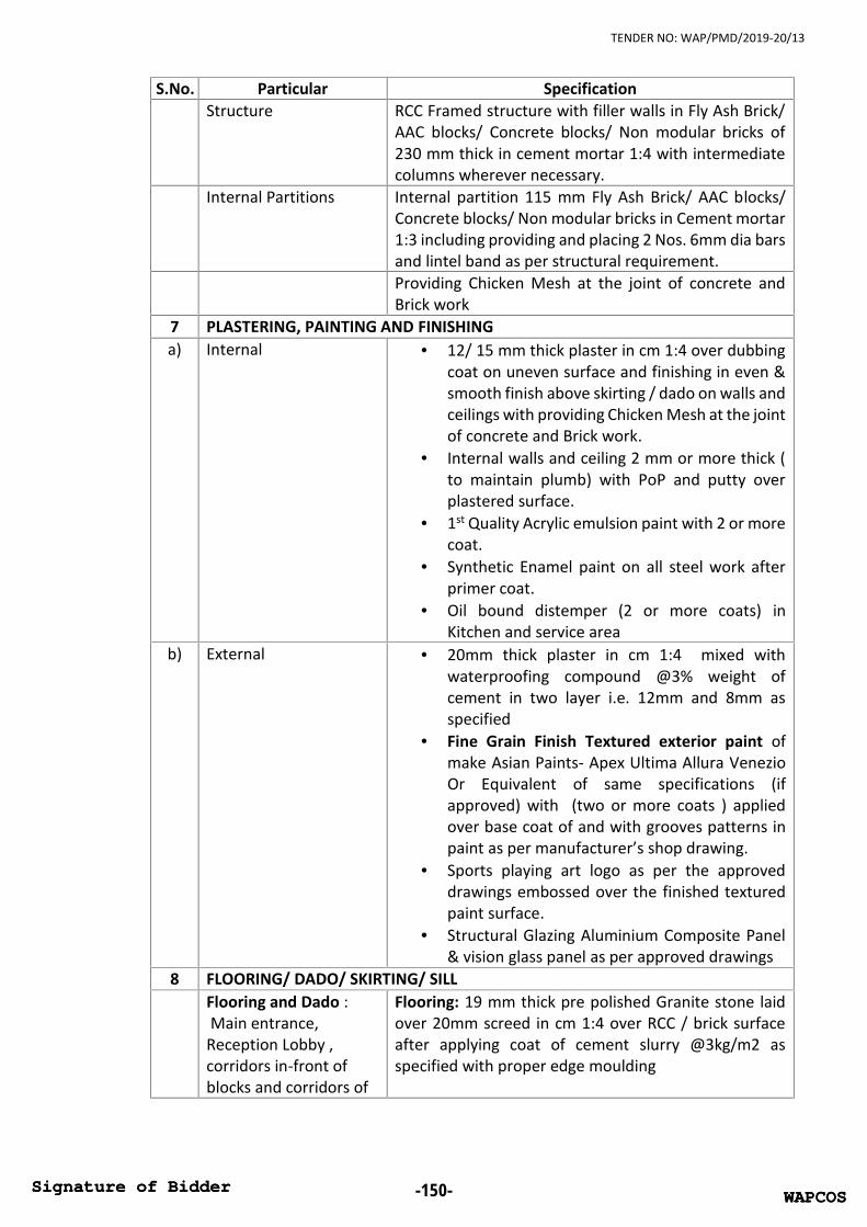
TENDER NO: WAP/PMD/2019-20/13
S.No. Particular SpecificationStructure RCC Framed structure with filler walls in Fly Ash Brick/
AAC blocks/ Concrete blocks/ Non modular bricks of230 mm thick in cement mortar 1:4 with intermediatecolumns wherever necessary.
Internal Partitions Internal partition 115 mm Fly Ash Brick/ AAC blocks/Concrete blocks/ Non modular bricks in Cement mortar1:3 including providing and placing 2 Nos. 6mm dia barsand lintel band as per structural requirement.Providing Chicken Mesh at the joint of concrete andBrick work
7 PLASTERING, PAINTING AND FINISHINGa) Internal 12/ 15 mm thick plaster in cm 1:4 over dubbing
coat on uneven surface and finishing in even &smooth finish above skirting / dado on walls andceilings with providing Chicken Mesh at the jointof concrete and Brick work.
Internal walls and ceiling 2 mm or more thick (to maintain plumb) with PoP and putty overplastered surface.
1st Quality Acrylic emulsion paint with 2 or morecoat.
Synthetic Enamel paint on all steel work afterprimer coat.
Oil bound distemper (2 or more coats) inKitchen and service area
b) External 20mm thick plaster in cm 1:4 mixed withwaterproofing compound @3% weight ofcement in two layer i.e. 12mm and 8mm asspecified
Fine Grain Finish Textured exterior paint ofmake Asian Paints- Apex Ultima Allura VenezioOr Equivalent of same specifications (ifapproved) with (two or more coats ) appliedover base coat of and with grooves patterns inpaint as per manufacturer’s shop drawing.
Sports playing art logo as per the approveddrawings embossed over the finished texturedpaint surface.
Structural Glazing Aluminium Composite Panel& vision glass panel as per approved drawings
8 FLOORING/ DADO/ SKIRTING/ SILLFlooring and Dado :Main entrance,
Reception Lobby ,corridors in-front ofblocks and corridors of
Flooring: 19 mm thick pre polished Granite stone laidover 20mm screed in cm 1:4 over RCC / brick surfaceafter applying coat of cement slurry @3kg/m2 asspecified with proper edge moulding
WAPCOSSignature of Bidder -150- WAPCOSSignature of Bidder

TENDER NO: WAP/PMD/2019-20/13
S.No. Particular Specificationrooms and stage area ofamphitheater.
Skirting: 100 mm high 19 mm thick pre polished granitestone with polishing.
Flooring and skirting:Hostel rooms, studiounits and commonrooms
Flooring: 25 mm thick pre polished kota stone (size550mmx 550 mm) with mirror finish with white marblestrips in combination laid over 15mm screed in cm 1:4over RCC / brick surfaceSkirting:18mm thick pre polished anti-skid kota stonewith mirror finish 100 mm high skirting over 10 mmthick screed in CM 1:4.
Flooring and Dado:Toilet area, diningHand wash area, wetwash area of kitchen,water cooler area
Flooring: 25 mm thick pre polished kota stone (size550mmx 550 mm) with mirror finish laid over 15mmscreed in CM 1:4 over RCC / brick surface
Dado: Full height glazed Wall tiles of size 300mmx450mm with high lighters tiles
Flooring and Dado:Dining area, kitchenarea, surroundingstores & rooms ofkitchen, dormatries,back entrance & stairs
Flooring : 25mm thick pre polished kota stone (size550mmx 550 mm) in combination with white marblestrips with mirror finish laid over 15mm screed in CM1:4 over RCC / brick surface
Dado: 1.2 meters high glazed wall tiles of size 300mmx450 mm with high lighters
Flooring :Ramps flooring atEntrance
Flooring : Non- skid/ flamed 19 mm thick polishedGranite stone Flooring with 200 mm skirting laid over20mm screed in cm 1:4
Flooring and skirting:Staircases of all blocksand stairs at entrance
Flooring: 19mm thick with combination of flamed andpolished Granite stone (single piece) on tread & riserwith proper edge moulding/ nosing and polishing withthe arrangement of anti-skid grooves.
Skirting: 19 mm thick pre polished granite stone 200mm High Skirting over 20 mm thick screed in CM 1:4skirting
Flooring :Staircases ofamphitheater area inbetween of blocks
Flooring: 25mm thick pre polished kota stone on treadand risers with mirror finish laid over 15mm screed inCM 1:4 over RCC / brick surface with proper edgemoulding/ nosing and polishing
SILL :Windows sill, balconiessill and all other sills ofbuilding
19 mm thick polished Granite stone with proper edgemoulding/ nosing and polishing.
9 FALSE CEILING NOTE: Contractor shall also do the work of min. 12mmthick plaster in cm 1:4 in the ceiling areas where falseceilings is to be installed
Common toilets 12.5 mm thick Grid ceiling PVC coated tiles with frames,fittings and fixtures
WAPCOSSignature of Bidder -151- WAPCOSSignature of Bidder

TENDER NO: WAP/PMD/2019-20/13
S.No. Particular SpecificationCorridors and receptionarea
16mm thick Mineral Fiber tiles with frames, fittings andfixtures in combination with thick tapered edge gypsumfire resistant board/ Decorative Designer GypsumCeiling in surroundings / joints
10 DOOR & WINDOWS FRAME AND FITTINGS & FINISHINGDoor Frame &finishing:Hostel rooms, studiounits, common rooms,main gate of commontoilet, dormatries andback gate of kitchenarae
Double rebate Second Class teak wood Frame withprovision of ventilator/skylight. Size of frame150mmx65mm.
Final finishing of frame will be melamine polishedafter rubbing, smoothing and primer coat etc.
Wooden edge moulding / architectural mouldedbeading surrounding to door frames at inside andoutside of door frame
Door Frame & finishing:Surrounding stores &rooms of kitchen, backentrance
Single rebate Second Class teak wood Frame withprovision of ventilator/skylight. Size of frame150mmx65mm. Final finishing of frame will bemelamine polished after rubbing, smoothing andprimer coat etc.
Door Frame & finishing:WC, Bathing area
Single rebate Second Class teak wood Frame. Size offrame 150mmx65mm. Final finishing of frame will bemelamine polished after rubbing, smoothing andprimer coat etc.
Door & window Frame& finishing:Balcony of Hostelrooms, studio units,
Factory made champagne anodized ‘z’ sectionAluminum double rebate door frame of size 250x100mm with necessary aluminium fittings and relatedworks
Door & window Frame& finishing:
Main gate of dining hall,windows of dining area,window of kitchen andsurrounding store area
Factory made champagne anodized ‘z’ sectionAluminum double rebate door frame of size 250x100mm with necessary aluminium fittings and relatedworks
11 DOOR & WINDOWS SHUTTERS
Door shutter &finishing:Hostel rooms, studiounits, common rooms,main gate of commontoilet, dormitories andback gate of kitchenarea
35 mm thick flush door shutter fixed with all aroundwooden beading minimum 25 mm depth and bothside 1.0 mm thick laminated sheet
WAPCOSSignature of Bidder -152- WAPCOSSignature of Bidder

TENDER NO: WAP/PMD/2019-20/13
S.No. Particular SpecificationJali shutter &finishing:Hostel rooms, studiounits, common rooms,main gate of commontoilet, dormitories andback gate of kitchenarea
Designer Mild steel door shutter of Fly proof stainlesssteel grade 304 wire gauge with 0.5 mm dia. Wire and1.4mm wide aperture with painting and accessories ofMild steel (minimum weight-25 Kg)
Door shutter &finishing:
Surrounding stores &rooms of kitchen, backentrance, WC, Bathingarea
35mm thick flush door shutter fixed with all aroundwooden beading minimum 25 mm depth and both side1.0 mm thick laminated sheet
Door & windowshutter & finishing:
Balcony of Hostelrooms & studio units,main gate of dining hall,windows of dining area,window of kitchen andsurrounding store area
Factory made champagne anodized ‘z’ sectionAluminum shutter of side and top style 100x35mm,middle style 150 x35 mm and bottom style 150x 35 mm,fixed with float glass 5 mm thick OR particle boardpaneling with necessary aluminium beading andfittings, locking arrangements, grills etc. complete asper approved drawings
Ventilator / Skylightabove Doors
Covered with MS grill with painting and 5mm thick clearglass where provision of skylight above doors
Door Fittings &Accessories:All Fittings &accessories for allabove wooden doorsexcept studio units
Stainless Steel heavy duty matt finish such as Hinges,tower bolt 8 inches and 6 inches, L- drop, Handles, doorStopper, rubber spacer etc. and fitted by SS Screwsonly.
Door Fittings &Accessories:All Fittings &accessories for studiounits
Stainless Steel heavy duty matt finish such as Hinges,tower bolt 8 inches and 6 inches, Mortice Lock (Basicmin. MRP. Rs. 3500/-), door Stopper, rubber spacer etc.and fitted by SS Screws only.
Corridor windows Full size Fixed toughened glass (6mm thick) fixed withFactory made champagne anodized ‘z’ Aluminumsection
All other windows andventilators
Float glass of 5mm thickness fixed with Factory madechampagne anodized ‘z’ Aluminum section/ woodensection as per approved drawings. Windows may befixed OR movable or openable
Reception/ Entrancearea
Full size Double door of toughened glass 12mm thickwith stainless steel floor spring and fittings
WAPCOSSignature of Bidder -153- WAPCOSSignature of Bidder

TENDER NO: WAP/PMD/2019-20/13
S.No. Particular Specification12 FIRE DOORS On each staircase of each floor and as per NBC fire
safety norms.13 CUPBOARD OF HOSTEL ROOM / STUDIO UNIT
Cupboard Shutter 18 mm thick Commercial Board shutter with 1mm thickLaminate on front and back side with lipping and allStainless Steel heavy duty matt finish such as pianoHinges, handles, lock, hanger rod, tower bolt, SS screwsetc.
Cupboard shelves/partition
18mm thick Kota stone partition slabs as per approveddrawings with proper edge moulding and polishing
14 Parapet wall / RAILINGStaircase Railing Designed Stainless steel railings (Grade 304) in &
BalconyParapet wall in Corridorat GF, FF,SF and TFtowards amphitheateropening and balconiesof rooms
300mm high half brick wall, Granite sill then 750 mmStainless steel railings (Grade 304)
Roof of Kitchen anddining area
700 mm half brick wall, Granite sill then 500 mm MSrailing and special arrangements for drying of clothesby mild steel hooks , supports and pipes.
15 TOILETS AND DINING HAND WASH AREACounters 19 mm thick gang saw cut, mirror polished, pre-
moulded and pre-polished, machine cut Granite stoneMirror Frameless mirrors with SS fittings along full length of
counter.WC in toilets exceptstudio unit
Floor mounted single peace European.
WC in studio unit Wall mounted with concealed flush systemWash basins Wash basin fixed with Granite counterUrinals boys European typeSpecial Provision forhandicappedbathrooms
All related fittings and fixtures as per the standardnorms and Grab Bars provision
Other fittings As detailed in PHE worksNOTE: Modification in common bathroom / toilets may be made by client /WAPCOS as per the requirement of hostel building
16 KITCHEN OF STUDIO UNIT AND KITCHEN/ PANTRY / DINING/STORES/ COUNTERS& SURROUNDING AREAAll Counters of Kitchen,Pantry, Serving andHand wash
19 mm thick gang saw cut, mirror polished, pre-moulded and pre-polished, machine cut Granite stone
Shelves in differentstores and belowkitchen counter as perthe requirement,
18 mm thick Kota stone/ white marble partition slabswith proper edge moulding and polishing
WAPCOSSignature of Bidder -154- WAPCOSSignature of Bidder

TENDER NO: WAP/PMD/2019-20/13
S.No. Particular Specificationstandards and approveddrawingsCupboard Shutterbelow kitchen, pantry,serving counter and tocover Shelves indifferent stores andbelow kitchen counteras per the requirement,standards and approveddrawings
18 mm thick Commercial Board shutter with 1mm thickLaminate on front and back side with lipping and allStainless Steel heavy duty matt finish such as pianoHinges, handles, lock, hanger rod, tower bolt, SS screwsetc.
Kitchen shelves overkitchen counter ofstudio unit
18 mm thick Commercial Board shutter and partitionwith 1mm thick Laminate on front and back side withlipping and all Stainless Steel heavy duty matt finishsuch as piano Hinges, handles, lock, hanger rod, towerbolt, SS screws etc.
17 Water proofingAbove plinth level Damp Proof course as per standard norms and
specificationsUG TankWater Proofing outside Kota Stone water Proofing in UG tank on Horizontal
and Vertical wallWater Proofing Inside Ist quality Ceramic Glazed Wall/ Floor Tiles of Size
300X300 mm on inside Horizontal and Vertical wallOH TanksWater Proofing outside Integral Crystalline Slurry in OH Tanks Horizontal &
VerticalWater Proofing Inside Ist quality Ceramic Glazed Wall/ Floor Tiles of Size
300X300 mm on inside Horizontal and Vertical wallTerrace and Mumtytreatment
120 mm th. Brick bat coba over app modifies polymericmembranes water proofing treatment on rcc surfaceafter applying a coat of cement slurry @3kg/m2 asspecified. Gola on terrace all around parapet wall.Heat reflecting tiles will be laid over above waterproofing works to reflect the as per the green buildingnorms
18 WATER TREATMENT PLANT OR WATER SOFTENERSupply Installation Testing and Commissioning of WaterTreatment Plant OR Water Softener as per the qualityof available water to run the Hostel Building.
Contractor will submit the specifications/design ofWater Treatment Plant OR Water Softener according tothe to quality of available water and cater the waterdemand of hostel building for approval to WAPCOS.
19 PLUMBING WORK
WAPCOSSignature of Bidder -155- WAPCOSSignature of Bidder

TENDER NO: WAP/PMD/2019-20/13
S.No. Particular SpecificationWater supply pipes andfittings and joints
Chlorinated Polyvinyl Chloride (CPVC) for concealedworks and GI for exposed works of required Pressure anddiameter as per design and drawing (having thermalstability for hot & cold water supply including all CPVCplain and brass threaded fitting, valves etc. & includingfixing the pipes with clampsate)
Fire Fighting Tank-PipeConnection and fittingsand joints
Galvanized Iron (GI) of required Pressure and diameter asper design and drawing
Soil waste pipes, RainWater Pipes, vent pipes,anti-siphonage pipes,fittings & joints
Unplasticized Polyvinyl Chloride (UPVC) PIPES of requiredPressure and diameter as per design and drawing
Rain Water pipe end toRain water harvesting pit/Catch Basin Connection
RCC Pipes of required Pressure and diameter as per designand drawing
Gully Trap and ManholeConnections
Stoneware Pipes
Note: The soil and waste pipe system shall be executed as “two piped system” asdefined in IS:5329.
Borewell
Providing 6" dia tube well including boring, providingwith rigid PVC encasing pipe & 3.00 H.P. Submergibleelectrical motor pump set with starter etc. the workincludes connecting with electrical power cables fromnearest electrical power point to the pump set.Connecting the delivery lines with main lines etccomplete as required for proper completion of thework.
Pumps
Filter feed pump (200 lpm) - 2 Nos. Treated water supply pump (250 lpm) - 2 Nos. Flushing water supply pump (200 lpm) - 2 Nos. Submersible Drainage Pumps (200 lpm) - 2 Nos. Storm water pump (1000 lpm) - 2 Nos.
Water Cooler &Commercial RO (1 No.in dining area)
Supplying, fixing, testing and commissioning of WaterCooler of Storage Capacity of 150 litres and NormalCooling Capacity of 150 litres per hour with features ofstainless steel body, stainless steel tank, externallymounted thermostat makes it easy to set watertemperature; speedy drainage; eco-friendly; fastercooling; silent during operation; auto-cut off at DiningArea of the Hostel Building with all fittings & accessoriescomplete.
Commercial Ro with Purification Production Rate 100L/hr., Wall Mounted, Filter Cartridge-Sediment,Activated Carbon, UF, Post Carbon, Membrane Type-Thin Film Composite RO.
WAPCOSSignature of Bidder -156- WAPCOSSignature of Bidder

TENDER NO: WAP/PMD/2019-20/13
S.No. Particular Specification
Water Cooler &Commercial RO (1 Nos.on ground floor and 2nos. Water Cooler onother floors)
Supplying, fixing, testing and commissioning of WaterCooler of Storage Capacity of 40 litres and NormalCooling Capacity of 40 litres per hour with features ofstainless steel body, stainless steel tank, externallymounted thermostat makes it easy to set watertemperature; speedy drainage; eco-friendly; fastercooling; silent during operation; auto-cut off at eachfloor above ground floor of the Hostel Building with allfittings & accessories complete.
Commercial Ro with Purification Production Rate 50L/hr., Wall Mounted, Filter Cartridge-Sediment,Activated Carbon, UF, Post Carbon, Membrane Type-Thin Film Composite RO.
Bathroom FixturesC.P. pillar cock long neck Jaquar Cat. No. CON-021 or approved equivalent makeC.P. brass waste Jaquar Cat. No. ALD-709 or approved equivalent makeC.P. bottle trap Jaquar Cat. No. ALD-769B or approved equivalent
make.Urinal senso urinal HSI.Cat. No. 60018 or approved equivalent
with C.I. hangers with built-in electronic solenoid valveoperated auto flushing system complete with allelectrical works required for completion of work withall required accessories.
C.P. brass Bib Cock(Straight Line Model)With Wall Flange
Jaquar Cat NO. FLR-5047N or approved equivalent
C.P. brass Bib Cock withWall Flange
Jaquar Cat NO. OPL-15037 or equivalent make
Stainless steel sink Jaquar Cat. No. 767 or approved equivalent makeParko/Kingston with complete in all respect
Single bowl with singledrain board
940mm x 465mm x 178mm deep JAYNA JUPITER Cat.No. SBSD 02 or approvaled equivalent with CP brassmixing fittings Jaquar Cat. NO. 309 or approvedequivalent
C.P. brass towel ring JAQUAR Cat No. ACN-1121N (CONTINENTAL SERIES) orapproved equivalent complete with C.P. brass bracketsfixed to rawl plug of approved design with C.P. brassscrews
S.S. hinged grating 1.5mm thick with frame (Neer Cat. No. - NRG 7006 orequivalent make CHILLY-CRG-R-127 (SquareClassic)/JAYNA NEW HEAVY GRATINGS Cat. No. NHG140 or approved equivalent
Robe hooks, JAQUAR Cat. No. 1161 or approved equivalent makeGlass Bottle Liquid SoapDispenser
JAQUAR Cat No. ACN-1135N Make or approvedequivalent
WAPCOSSignature of Bidder -157- WAPCOSSignature of Bidder

TENDER NO: WAP/PMD/2019-20/13
S.No. Particular SpecificationCP wall mixer nontelephonic type
Jaguar Cat No. CON-CHR-219KN or approved equivalent
shower rose withshower arm
Jaguar Cat No. OHS-1989 & SHA-477 or approvedequivalent.
Health Faucet JAQUAR Cat. No. 573 (ALLIED SERIES) or equivalentmake
soap dish Jaquar Cat. No. CAN-1131N or approved equivalentTowel Rail 24" JAQUAR Cat. No. ACN-1111NM or approved
equivalentconcealed stop cock Jaquar Cat No. CON-089KN or approved equivalentAngle Valve with C.P.brass connection pipe
15mm C.P. brass Angle Valve with C.P. brass connectionpipe Jaquar Cat No. CON-053KN & ALD-803B orequivalent make
Toilet Paper Holder JAQUAR Cat. No. ACN-1151N or equivalent make20 FIRE FIGHTING
FIRE HYDRANT SYSTEM
Fire hydrants fabricated from 16 gauge CRCA M.S.sheet double door including 2 nos allen key lock forlocking along with padlock arrangement & fully glazedwith 5 mm thick float glass approved by local FireAuthority, stove enameled fire red finish with " firehose' written on front with radium strip suitable tohouse 15 m long four length of canvas hose withcouplings, one no of branch pipe, one fire mans axeand two numbers of portable extinguishers, first aidfire hose and supports for hoses, branch pipes, Axeand hose reel as per approved design includingnecessary fixing arrangement for hoses & axe andbranch pipe including 1 no. Fire booster pump (450lpm). The nos. of fire hydrant system shall be as perthe latest NBC norms.
FIRE EXTINGUISHERS
ABC powder stored pressure type fire extinguishersconsisting of welded MS cylindrical body, squeezelever discharge valve fitted with pressure indicatinggauge internal discharge tube, 30 cms long highpressure discharge hose, discharge nozzle, suspensionbracket, conforming to ISI finished externally with redenamel paint and fixed to wall with brackets completewith internal charge. Capacity 6 kg. IS 13849. The nos.of fire extinguisher will be as per the latest NBC norms.Carbon-di-oxide fire extinguishers consisting of weldedM.S cylinderical body,squeeze lever discharge valvefitted with internal dischargetube, 30cms long highpressure discharge hose, discharge nozzle, suspensionbracket, confirming to IS : 934 finished externallywith red enamel paint and fixed to wall withbrackets with rawl plug/dash fasteners complete withinternal charge. Capacity 4.5 kg. I.S.I. Marked. The
WAPCOSSignature of Bidder -158- WAPCOSSignature of Bidder

TENDER NO: WAP/PMD/2019-20/13
S.No. Particular Specificationnos. of fire extinguisher will be as per the latest NBCnorms.
Fire Alarm System Manually operated electric Fire Alarm System for thehostel Building including MCP, Hooters, Control Panelwith batteries & Charger etc. The nos. of fire alarmsystem will be as per the latest NBC norms.
21 AIRCONDITIONERS
For studio unit (24 nos.)
Supplying, Installation, Testing an Commissioning of 2TR, 5 star rated inverter split units with outdoormachines by means of hangers on the wall with 4 kVAstabilizer range 160 V to 250 V and other alliedelectrical accessories with all copper pipes withinsulation, drain pipes, electric fittings etc. All pipes tobe concealed within the rooms and balconies.
For other rooms anddining area
Only provision for electrical power points and wiringfor ACs are to be kept
22 OTHER IMPORTANT
CCTV Cameras incorridor, entry,common room &dinning
Supply, installation, testing and commissioning of “4SETS of CCTVs” each having 16 nos. Indoor 1/3"colorauto iris very focal lenses WDR CCD Cameras (high-resolution cameras) fitted enclosed in a discrete mirrordome complete with sockets as per specification.Including all necessary power supply units,16 channelDVR with two video outputs & 32" or more totally flatcolor LCD/LED monitor, BNC and DC connector, Powersupply 12V/5 Amp,3 TB HDD WD/Seagate(for 20-30days recording), CCTV Wire (3+1) copper, PVC Conduit25 MM, 20"LED Monitor Screen Acer.
Passenger Lift1 Nos. of Capacity 544 kgs. /8 passengers MRL Lift (only provision of lift well is to be made, installation oflift not in scope of contractor)
Provision For BarrierFree Building
Ramps, toilets for physically challenged, Chequeredtiles use of Braille signages & lifts etc. as per themandatory norms
Plinth Protectionsurrounding building
50 mm thick of cement concrete 1:3:6 (1 cement: 3coarse sand : 6 graded stone aggregate 20 mm nominalsize) over 75mm thick bed of dry brick ballast 40 mmnominal size, well rammed and consolidated andgrouted with fine sand, including finishing the topsmooth.(1250 mm Wide) with half brick masonry atcorner of CC
WAPCOSSignature of Bidder -159- WAPCOSSignature of Bidder
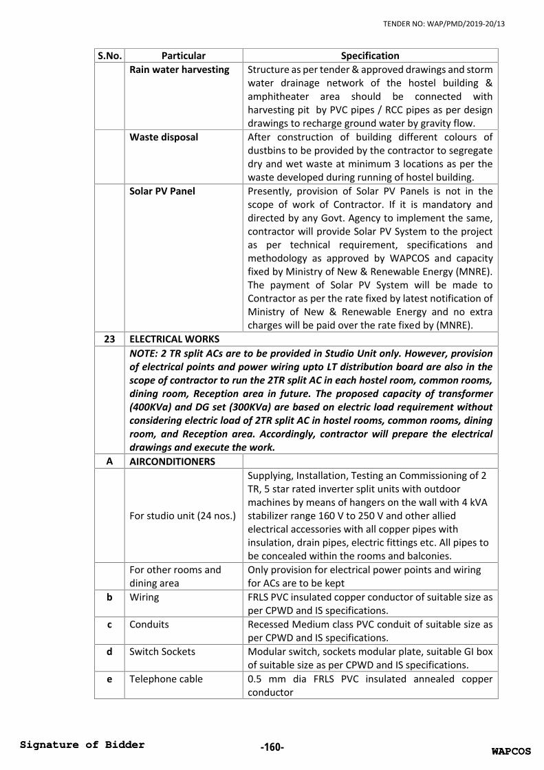
TENDER NO: WAP/PMD/2019-20/13
S.No. Particular SpecificationRain water harvesting Structure as per tender & approved drawings and storm
water drainage network of the hostel building &hitheater area should be connected withharvesting pit by PVC pipes / RCC pipes as per designdrawings to recharge ground water by gravity flow.
Waste disposal After construction of building different colours ofdustbins to be provided by the contractor to segregatedry and wet waste at minimum 3 locations as per thewaste developed during running of hostel building.
Solar PV Panel Presently, provision of Solar PV Panels is not in thescope of work of Contractor. If it is mandatory anddirected by any Govt. Agency to implement the same,contractor will provide Solar PV System to the projectas per technical requirement, specifications andmethodology as approved by WAPCOS and capacityfixed by Ministry of New & Renewable Energy (MNRE).The payment of Solar PV System will be made toContractor as per the rate fixed by latest notification ofMinistry of New & Renewable Energy and no extracharges will be paid over the rate fixed by (MNRE).
23 ELECTRICAL WORKSNOTE: 2 TR split ACs are to be provided in Studio Unit only. However, provisionof electrical points and power wiring upto LT distribution board are also in thescope of contractor to run the 2TR split AC in each hostel room, common rooms,dining room, Reception area in future. The proposed capacity of transformer(400KVa) and DG set (300KVa) are based on electric load requirement withoutconsidering electric load of 2TR split AC in hostel rooms, common rooms, diningroom, and Reception area. Accordingly, contractor will prepare the electricaldrawings and execute the work.
A AIRCONDITIONERS
For studio unit (24 nos.)
Supplying, Installation, Testing an Commissioning of 2TR, 5 star rated inverter split units with outdoormachines by means of hangers on the wall with 4 kVAstabilizer range 160 V to 250 V and other alliedelectrical accessories with all copper pipes withinsulation, drain pipes, electric fittings etc. All pipes tobe concealed within the rooms and balconies.
For other rooms anddining area
Only provision for electrical power points and wiringfor ACs are to be kept
b Wiring FRLS PVC insulated copper conductor of suitable size asper CPWD and IS specifications.
c Conduits Recessed Medium class PVC conduit of suitable size asper CPWD and IS specifications.
d Switch Sockets Modular switch, sockets modular plate, suitable GI boxof suitable size as per CPWD and IS specifications.
e Telephone cable 0.5 mm dia FRLS PVC insulated annealed copperconductor
WAPCOSSignature of Bidder -160- WAPCOSSignature of Bidder

TENDER NO: WAP/PMD/2019-20/13
S.No. Particular Specificationf TV cable co-axial TV cable RG-6 grade, 0.7 mm solid copper
conductor PE insulated, shielded with fine tinnedcopper braid and protected with PVC sheath
g Distribution board Suitable way, horizontal/ vertical type three pole andneutral/single pole, sheet steel, MCB distributionboard, 415 V/220 V, on surface/ recess, complete withtinned copper bus bar, neutral bus bar, earth bar, dinbar, interconnections, powder painted includingearthing etc. Separate DB for Light, Power and AC to bekept for each block on each floor as per latest CPWDspecifications and IS codes
h MCB/RCCB "C" curve, miniature circuit breaker suitable forinductive load of suitable poles
i Earthling (body) G.I. earth plate 600 mm X 600 mm X 6 mm thickincluding accessories, and providing masonry enclosurewith cover plate having locking arrangement andwatering pipe of required length etc. with charcoal/coke and salt as required.
j Earthling (neutral of DGand Transformers)
Copper earth plate 600 mm X 600 mm X 3 mm thickincluding accessories, and providing masonry enclosurewith cover plate having locking arrangement andwatering pipe of required length etc. with charcoal/coke and salt as required.
k Earth strip G.I and copper of suitable size as per IS Standardsl Cable PVC insulated and PVC sheathed / XLPE power cable of
1.1 kV grade of suitable size as per CPWD and ISspecifications
m Lighting Fixtures andFans
Slim surface mounted LED lighting fixture Havellsmake -LHEAAVP5IL1W012 or equivalent.
Slim surface mounted LED lighting fixture Havellsmake -LHEAAVP5IL1W018 or equivalent.
Surface mounted LED lighting fixture Havells make –LHEXBLP7PN1W020 or equivalent.
Surface mounted LED mirror lighting fixture Havellsmake -LHEXARP6PN1W009 or equivalent.
1200mm 5 star rated Ceiling fan sweep completemodel no. White FHCES5SWHT48 of Havells makeor equivalent
Exhaust fan with 250 mm and 300 mm sweep withrust proof body and noise less operation completewith louvers.
4 star electric hot water 25 liters geyser Havells makecatalogue no. PURO-PLUS-25 L or equivalent ( min. 36nos.)
n Main Distribution Panel CRCA sheet of 2 mm thick for frame work and covers ,3 mm thick for gland plates i/c cleaning and finishingcomplete with 7 tank process for powder coating in
WAPCOSSignature of Bidder -161- WAPCOSSignature of Bidder

TENDER NO: WAP/PMD/2019-20/13
S.No. Particular Specificationapproved shade having suitable capacity extendabletype TPN aluminium alloy bus-bars of high conductivity,DMC/SMC bus bar support with short circuit withstandcapacity of 31 MVA for 1 sec. including suitable ratingMCCBs and MCBs and control circuit for transformer,DG sets and suitable number of outgoings as per CPWD,IS Specifications and site requirements.-Main LT Panel of hostel-Floor panels, light and power- AC Panels
o Lighting arrestor Lighting arrestor with suitable nos of earth pits,horizontal and vertical run of earth strip on parapet wallof hostel and up to the earth pits as per Indianstandards
p Safety Equipment Suitable nos. of Rubber mat, fire extinguisher, dangerboard etc. as per IS.
q 300 KVa DIESEL GENSETSUPPLY & INSTALLATION OF DG SETS (RADIATOR COOLED)
a Supplying, installation, testing & commissioning of Radiator Cooled type DieselGenerating Set comprising of multi- cylinder diesel oil engine with radiator, flywheel, exhaust piping upto silencer, residential type silencer, electric startingequipments, batteries, battery charger, directly coupled to an alternator ofsuitable capacity at 0.8 P.F. 3 phase, 4 wire 50 Hz 415 volts, A.C supply completewith brass plate anti-vibration mountings foundations for installation of D.G. Set,terminating arrangement for outgoing cables, control panel, controlling MCCBetc, complete as required as per specifications, Drawings and specified ambientconditions.DG Sets shall be suitable for Auto Start, Auto Stop and Auto LoadManagement.300 KVA D.G. set with canopyNote:The Foundation shall be in the scope of the Contractor. The DG set is to beinstalled on the ground floor.
b) The supply, supervision, testing and commissioning of the AMF logic in the LTPanel, shall be in the scope of the Contractor.
c) The DG set should be supplied with cable end box to terminate suitable size ofcable on alternator complete as required.
d) Fuel Oil required for Testing the DG set as per IS shall be supplied by thecontractor
e) The canopy should be designed in such a way that the Noise level is not morethan 75 db level at a distance of 1 meter away from the DG set as per Indianstandards.
f) Isolation Panel with breaker for each DG Set shall be in the scope of contractorg) The Control Panel shall have the following:
Genset controller unit with totally enclosed, steel construction control panelsuitable for indoor floor / wall mounting installation should following safetiesand display parameters:Gen-set Display Parameters
WAPCOSSignature of Bidder -162- WAPCOSSignature of Bidder

TENDER NO: WAP/PMD/2019-20/13
S.No. Particular Specificationi) Phase Voltageii) Line currentiii) Frequencyiv) Average Voltagev) Average Currentvi) Phase kW & Total Kwvii) kWHviii) kVAix) kVARx) PFxi) Earth Leakagexii) Earth Leakage Current
Engine Display parametersi) Oil Pressureii) Engine Temperatureiii) Fuel Statusiv) Engine Speedv) Battery Voltage, Minimum Battery Voltagevi) Oil Temperaturevii) Canopy Temperatureviii) Engine Hoursix) Total starts
Electrical Safeties (along with Display)i) Genset Under/Over voltageii) Under/Over Battery voltageiii) Under/Over frequencyiv) Phase Failurev) Phase sequence reversevi) Over Currentvii) Over kWviii) High Earth Current
Mechanical Safeties (along with Display)i) Under/Over speedii) Low Lube oil pressureiii) High Lube oil Temperatureiv) High engine coolant temperaturev) Low Coolant temperaturevi) Low coolant levelvii) Low fuel levelviii) High canopy temperatureix) Start/Stop failx) Charge Alternator failxi) Annunciator Panel shall be as per the specificationsh Supply, installation, testing and commissioning of exhaust pipe fabricated out of
6 mm thick B Class MS pipe including providing suitable bends, reducers &
WAPCOSSignature of Bidder -163- WAPCOSSignature of Bidder

TENDER NO: WAP/PMD/2019-20/13
S.No. Particular Specificationsupporting arrangement at suitable intervals, painting etc. as required and withall fixing accessories and hardwares.Suitable Dia (NB) MS ERW Pipe
i Supply, installation, testing and commissioning of Rockwool insulation on theexhaust pipes of suitable sizes as per IS codes / as per norms including claddingwith aluminium sheet of 26SWG and covering from outside complete asrequired.
j FUEL SYSTEMSupplying, installation, testing and commissioning of heavy duty Handcranking oil pump with 3 mtr. Long flexible oil hose.Supplying, installation, testing and commissioning of 990 Day Oil fuel steel tankof under mentioned capacities made out of 5 mm thick M.S. sheet with floatvalve and low level alarm arrangement including fuel oil piping up to the setvalves etc. complete as required.Supplying, installation, testing and commissioning of Suitable rating Fuel Oilpump including foundations, piping, valves, indications, safety devices etc.complete as required. (Crompton / GE / Kirloskar make)Providing & fixing of "Class-C" 25 mm MS Fuel Pipe complete as required.Providing & fixing of Ball Valve (Brass) 25 mm complete as required.The contractor shall submit back-pressure calculations in support of exhaustpipe size for each DG Set.
NOTE FOR ELECTRICAL AND PLUMBING FITTINGS AND FIXTURES:
In the tender and above specifications “item catalogue No. of the Electrical and plumbingfittings of particular brand or equivalent” has been mentioned. Here “equivalent” meansitem which is within 10% +/- variation in MRP and meet the specification, same or moreaesthetic quality of the brand mentioned in the List of Acceptable Makes.
6.0 ACCEPTABLE MAKES OF MATERIALS
Acceptable makes of materials for work to be used in the work are detailed below. In caseof non-availability of these makes, after the approval of WAPCOS, the Contractor can usethe alternative makes only BIS marked materials. Non BIS marked materials may bepermitted by the WAPCOS only when BIS marked materials are not manufactured.
CIVIL WORKS
S.NO. NAME OF ITEM MAKE APPROVED1 ORDINARY PORTLAND CEMENT
GRADE 43/53, PORTLANDPOZZOLONA CEMENT
JK, ACC, ULTRATECH, JAYPEE, AMBUJA
2 WHITE CEMENT JK, BIRLA, ACC, JAYPEE, AMBUJA3 REINFORCEMENT STEEL TATA , SAIL, RINL, JINDAL, JSW STEEL,
SRMB,
WAPCOSSignature of Bidder -164- WAPCOSSignature of Bidder

TENDER NO: WAP/PMD/2019-20/13
S.NO. NAME OF ITEM MAKE APPROVED4 PLY / BOARD / MDF DURO, MERINO, GREEN PLY, AGNI ,
CENTURY5 LOCK/BRASS FITTING DORSET, DORMA, OZONE, GODREJ,
HARISON6 WALL PUTTY JK/BIRLA7 STRUCTURAL STEEL/TUBULAR
TRUSSTATA , SAIL, RINL, JINDAL, JSW STEEL
8 PAINT/POLISH/ PRIMER/ WATERPROOFING PAINT
BERGER, ASIAN, DULUX, NEROLAC
9 POWDER COATING AKZONOBEL, ASIAN10 EPOXY PAINT FIBREX/BASF/ SIKA/FOSROC11 FLOOR & WALL TILE(VITRIFIED &
CERAMIC)KAJARIA, ORIENTBELL ,SOMANY, NITCO
12 GLASS / MIRROR ASAHI, SAINT GOBAIN, PILKINGTON, MODIGUARD
13 CONSTRUCTION/WATERPROOFING CHEMICAL, ADMIXTURES
ROFFE, FOSROC, SIKA, ULTRACON
14 ANTI TERMITE VAM ORGANICS, PYRAMID, TERMISOL15 GRID FALSE CEILING & WALL
PARTITIONARMSTRONG, DEXUNE, NEW AGE,HUNTER DOUGLAS
16 GYPSUM WALLPARTITION/CEILING
BORAL, INDIA GYPSUM, GYPROC
17 FLUSH DOOR DURO, CENTURY, MERINO, ARCHIDPLY,AGNI
18 DOOR FITTINGS & FIXTURES DORMA, OZONE, HARISON, JOLLY19 GLASS/SS HANDRAIL DORMA, OZONE, DOORSET20 ALUMINIUM SECTIONS JINDAL, BHAROUKA21 XPS INSULATION OWENS CORNING22 GLASS PROCESSING GOLDPLUS, GSC23 MODULAR FURNITURE GODREJ, BP ERGO, FEATHERLITE, WIPRO24 VENEER/LAMINATE MERINO, CENTURY, AGNI, DURO,
GREEN,ARCHIDPLY25 SIGNAGES 3M26 Upvc Doors and Window FENESTA, LINGAL, DECEUNINCK, ENCRAFT27 PAVER BLOCK/KERB STONE of
M30 Grade and 60 mm thickNITCO,UNITILE OR EQUIVALENT
28 FIRE RETARDANTPAINT NULLIFIER/SIGNUM/GODREJ29 FIREDOOR SUKRI, NAVAIR, DORMA
30 FIRE RATED GLASS SCHOTT (GERMANY) AND EQUIVALENT
31 PIPES RELATED WORKS REFRE MAKE LIST FOR PHE WORKS
32 STAINLESS STEEL ( GRADE 304)RAILING MADE OF HOLLOWTUBES, CHANNELS, PLATES ETC
JINDAL, TATA, MONNET
WAPCOSSignature of Bidder -165- WAPCOSSignature of Bidder

TENDER NO: WAP/PMD/2019-20/13
ELECTRICAL AND FIRE ALARM WORKS
ITEM MANUFACTURERS NAMEAir Circuit Breaker Schneider /Siemens/ L&T/ABB/Moulded Case Circuit Breaker Withrotary operating handle.
Schneider/ Siemens/ L&T/ ABB/ Havells/Polycab
Contactors, Timers Schneider/ ABB/ L & T/ LegrandCapacitors Schneider/ EPCOS/ L & TVoltmeter & Ammeter Conzerve/ Enersol/ HPLSelector Switch Kaycee/ L & TCurrent Transformer Matrix/AE/KappaIndicating Lamp L & T/ Siemens/Protective Relays L & T /Siemens/SchneiderAPFC Relay (Microprocessor based) Syntron/ Enercon/ L & T/ DucatiBatteries Exide/Amar Raja/OKAYA/LUMINOUSBattery Charger Uptron/Voltstat ElectronicsL.T. / H.T. Cable Polycab/ KEI/ HavellsDC Miniature Circuit Breaker Schneider/ L & T/Siemens/ LegrandCable Lug (Tinned Copper) Dowells/ Multi/CapitalCable Gland Peeco/ Commet/ Gripwell/ PowerMain L.T. Panel, Capacitor Panel &Distribution Panel
SPC Electrotech/ Tricolite/ Adlec/Application Control
Cable Tray / Raceway Pilco/CTM Engineers/KME/Slotco/SteelwaysFire Extinguishers Zenith/Minimax/Newage/ Cease FireEnergy Analyzer Meter Conzerve/Elemeasure/EnersolVoltmeter & Ammeter Conzerve/ Elmeasure/ EnersolDistribution Boards with MiniatureCircuit Breakers, RCCB
Hager/Legrand/ L & T/ Havells
PVC Insulated copper conductor singlecore Stranded wires of 650/1100 voltgrade
Havells/KEI/Polycab
Telephone Tag Block Krone/ TVS R&MPVC / M.S. Conduit BEC/AKG/RMCONModular Switches & Sockets Legrand/Havells/polycab/GMLV System Wire Siemens/Legrand/ Amp/ Havells/polycabTV/Telephone outlet Siemens/Legrand/ Havells/polycabData Outlet Siemens/Legrand/ Havells/polycabData Rack Siemens/APW/LegrandLight Fixture Philips/Havells/polycab/ syskaLamps Philips/ Havells/ polycab/ syskaCeiling Fan Orient/Havells/Crompton Greaves/BajajExhaust Fan with louvers Orient/Havells/Crompton Greaves/BajajGeyser Havells/ Bajaj/V-Guard/ A-O Smith/ JaguarFire Alarm System Notifier Honeywell/ Siemens/ Tyco/
Edwards/ Agni
WAPCOSSignature of Bidder -166- WAPCOSSignature of Bidder

TENDER NO: WAP/PMD/2019-20/13
Presence Detector Hagger/Legrand/PhilipsRCC Hume Pipe for Electrical Works ISI Marked of Reputed CompanyPLC Siemens/Allen BradleyTelephone / Co axial Wire Polycab/Delton/HavellsProfessional LED Panel Panasonic/ Samsung/SonyPublic Address System Honeywell/ Bosch/Tyco/EdwardsD.G. Set (Engine) Cummins/Catterpillar/Stamford/KirloskarD.G. Set (Alternator) Stamford/ LerroySommer/ CatterpillarD.G. Accoustic Enclosure Jakson/Sterling/CatterPiller/SudhirH.T. Panel ABB/ Schneider/Siemens/ PrecisionTransformer ABB/ Schneider/Crompton/KriloskarH.T. Termination Kit Raychem/DensonSmoke Detectors Notifier Honeywell/ Tyco/ Siemens
Cerberus-Pro/ShrackHeat Detectors Notifier Honeywell/ Tyco/ Siemens
Cerberus-Pro/ShrackManual Call Box Notifier Honeywell/ Tyco/ Siemens
Cerberus-Pro/ShrackHooter/ Sounder Notifier Honeywell/ Tyco/ Siemens
Cerberus-Pro/ShrackResponse Indicator Notifier Honeywell/ Tyco/ Siemens
Cerberus-Pro/ShrackFire Panel Notifier Honeywell/ Tyco/ Siemens
Cerberus-Pro/ShrackPa Amplifier Honeywell/ Bosch/Heinrich/AtiesPa Speakers Honeywell/ Bosch/Heinrich/AtiesLine Matching Transformer Honeywell/ Bosch/Heinrich/AtiesGoose Neck Mike Honeywell/ Bosch/Heinrich/AtiesInverter Topaz International/ Luminous/ HytesCamera With All Accessories Axis / Inpulse/ Idis/ Bosch/PelcoRoad Barrier Nice/ Magnetics/ Godrej/ Ge/CameCard Reader Sensormatic-Usa/ Motorola /Honeywell(Xls-
3000)/DdsMonitor Lg/ Samsung/SonyMultiplexer Sensormatic Or EquivalentSequencer Alba/ VantageProximity Card Motorola/ Hughes/
Honeywell/Ge/Siemens/HidTelephone Tag Block Ctm Engg/Systimax/Schneider/PanduitTelephone Cables Delton / Skytone/ Clipsal/ havellsCo-Axial Cables Finolex/ Delton/SkytoneEpabx Alkatel/ Siemens/ Nec/ AvayaCctv System Axis / Impulse/ Idis/ Bosch/ Honneywell
/TycoAccess Control System Honeywell/ Siemens/SyrisNurses Call System Amtek/Rauland/Afcon/DakshVideo Conference System Polycom/Sony/Sysco
WAPCOSSignature of Bidder -167- WAPCOSSignature of Bidder

TENDER NO: WAP/PMD/2019-20/13
Audio Processor Bose/Bss/ClearoneBmsController/Software Central Control BmsServer
Ibm/Hp/Dell
Building Management System, Buildingmanagement Web Based ServerSoftware, Programmable & ApplicationSpecifier Controller
Siemens/Honeywell Ebi/Tyco
Sensor & Field DevicesImmersion Type Temperature Sensors,Flow Meter,Ultra Sonic Thermal EnergyMeter , Outside T+Rh Sensor
Siemens/Kele/Sauiter Race
Water Level Switches, Flame Proof LevelSwitches
Kele/ Veskler/Flipro
Dc Voltage Transducer, Current Relay Kele/Situ/OmicronRoom Type Temp. Sensor, Co2 Sensor,Ambient Temp. Sensor
Siemens/Kele/Trane
Co Sensor Dwyer/Kale/Msr GermanPressure Transmitter Siemens/Trane/OmicronDifferential Pressure Sensor Siemens/Trane/VesklerFire Suppression System Siemens/Kidde/TycoService/ Passenger Elevators Kone/Schindler/OTISPHE AND SANITATION MATERIALS
S.NO. ITEM MANUFACTURERS NAME1. VITREOUS CHINA AND FIRECLAY
SANITARYWARE WITH COVERJAQUAR/HINDWARE/PARRYWARE/ ROCA/ KOHLER
3. STAINLESS STEEL SINKS JAYNA/ PARRYWARE/NEELKANTH/NIRALI4. C.P. FITTINGS & ACCESSORIES JAQUAR/HINDWARE/PARKO/ROCA5. C.P. WASTE, SPREADERS, URINAL
FLUSH PIPESJAQUAR/ HINDWARE/ PARRYWARE/ROCA
6. SS COCKROACH TRAPS, GRATINGS FORFLOOR DRAINS, FLOOR TRAPS ANDRAIN WATER GRATINGS
CHILLY/ JAYNA/ CAMRY
7. SOIL, WASTE & FITTINGS(a) CENTRIFUGALLY CAST SPUN CASTIRON PIPES (IS:3989)
SKF/ NECO/BIC/ISI MARKS OF REPUTEDCOMPANY
8. RCC PIPES PRAGATI / JAIN SPUN/ ISI MARKS OFREPUTED COMPANY
9. PVC/ CPVC PIPES & FITTINGS ASTRAL/ ASHIRVAD /PRINCE/ FINOLEX/PRAKASH/ SUPREME
10. HAND DRIER JAQUAR/ HINDWARE/EURONICS11. BALL VALVES ZOLOTO/ LEADER/ AIP12 RAIN WATER PIPES & FITTINGS UPVC
PIPES AND FITTINGSPRINCE/ SUPREME/ PRAKASH/FINOLEX/ORI-PLAST
13. WAFER TYPE BUTTERFLY VALVES ZOLOTO/ LEADER/ AIP/DANFOSS14. WAFER TYPE NON-RETURN VALVES ZOLOTO/ LEADER/ AIP/DANFOSS
WAPCOSSignature of Bidder -168- WAPCOSSignature of Bidder

TENDER NO: WAP/PMD/2019-20/13
S.NO. ITEM MANUFACTURERS NAME15. WATER METRES CAPSTAN/KRANTI/KAYCEE/AQUAMET16. BALL COCKS GPA/ DRP/ SANT/ L & K17. STONEWARE PIPES & GULLY TRAPS PERFECT/ BURN/ RK18. C.I. MANHOLES COVERS AND FRAMES NECO/ RIF/ BIC/SKF/BIC/ ISI MARKS OF
REPUTED COMPANY19. RCC MANHOLE COVERS & FRAMES KK/ PRAKASH/ ISI MARKS OF REPUTED
COMPANY20. FASTNERS HILTI/ INTELLOTEC21. WATER HEATER HAVELLS/ BAJAJ/CROMPTON GREAVES22. HOT WATER NEOPRENE INSULATION KAIFLEX23. GATE/ FULLLL WAY VALVES AND
GLOBE VALVESLEADER/ZOLOTO/SANT
24 AIR RELEASE VALVES SANT/ LEADER/DANFOSS25. PIPECOAT IWL LIMITED/ PYPKOTE26. C. I. PIPE RIF, NECO, SKF27. G. I. PIPE JINDAL, TATA, SWASTIK, GI PIPES INDIA,
APL APOLLO, SURYA PRAKASH28. G.I. FITTINGS (MALLEABLE CAST IRON) JINDAL / SURYA PRAKASH /DRP-M/
ZOLOTO-M/ UNIK29 M.S. FITTINGS (FORGED) DRP/ VS30 OVERHEAD WATER TANK SINTEX OR EQUIVALENT31 WATER COOLER BLUE STAR/VOLTAS/GODREJ32 R.O WATER PURIFIER KENT/ EUREKA FORBES33 WATER TREATMENT PLANT ION EXCHANGE/THERMAX/ BRISANZIA
FIRE FIGHTING WORKS
S.NO. MATERIALS BRAND NAME1. M.S. PIPES JINDAL HISSAR / PRAKASH SURYA/TATA2. G.I. PIPES JINDAL HISSAR / PRAKASH SURYA3. FORGED STEEL FITTINGS DRP / SS / VS /METLINE/TRUE FORGE4. GUN METAL BALL VALVES ZOLOTO / LEADER / AIP/SANT/CASTLE5. BUTTERFLY VALVES ZOLOTO / LEADER / AIP/KSB/SKS6. NON-RETURN VALVES. ZOLOTO / LEADER / AIP7. FIRE HYDRANT LANDING VALVES,
FIRE BRIGADE CONNECTION (ISIMARKED)
MINIMAX / NEWAGE / FLAME GUARD
8. OTHER VALVES ZOLOTO / LEADER / AIP/ SANT/KRILOSKAR / AUDCO/ SKS
9. FIRE HOSE PIPES, FIRST AID HOSEREEL (ISI MARKED)
MINIMAX / NEWAGE / PADMINI/ FLAME GUARD/MITRA
10. BRANCH PIPE, NOZZLE ANDCOUPLINGS
MINIMAX / NEWAGE/ FLAME GUARD
11. FIRE EXTINGUISHERS MINIMAX / NEWAGE/ FLAME GUARD12. PUMPS KIRLOSKAR /CROPMTON GREAVES/
MATHER + PLATT13. MOTORS KIRLOSKAR / SIEMENS /CROMPTON
WAPCOSSignature of Bidder -169- WAPCOSSignature of Bidder

TENDER NO: WAP/PMD/2019-20/13
14. STARTERS GE / L & T / CONTROL & SWITCHGEAR15. SINGLE PHASING PREVENTOR /
OVER LOAD PROTECTION UNITSIEMENS / MINILEC
16. PRESSURE SWITCH DANFOSS / SWIZER17. PRESSURE GAUGE H. GURE / FIEBIG18. RELAYS L & T / SIEMENS19. CONTRACTORS L & T / SIEMENS20. CONTROL CABLE SKYTONE / POLYCAB / GRANDLAY21. ELECTRICAL PANEL DIAMOND ELECTRICALS / SPC
ELECTROTECH PVT. LTD. / NEPTUNE22. MOULDED CASE CIRCUIT BREAKERS L & T / SIEMENS
23. FUSE DISCONNECTOR SWITCH /SWITCH FUSE UNITS
L & T / MDS / SIEMENS / GE POWER /ABB / INDO ASIAN SCHNEIDER /CONTROL & SWITCH GEAR.
24. HRC FUSES L & T / SIEMENS25. AMMETER, VOLTMETER UNIVERSAL26. SELECTOR SWITCH, PUSH BUTTON
SWITCH / EMERGENCY SWITCHL & T /SIEMENS
27. 1.1 KV LT CABLES (ISI MARKED) SKYTONE / POLYCAB / GRANDLAY28. PIPE COAT IWL LIMITED / STP / PYPKOTE29. FASTENERS HILTI / INTELLOTECH30. SUSPENDERS INTELLOTECH / CAMRY
AIR CONDITIONING WORKS
S.No. Items Standard Makes1 Air Cooled AC Units/ Split ACs CARRIER/ HITACHI/DAIKIN/BLUE STAR2 DX Type AHU Zeco / Edgtech / VTS / Monash3 Closed cell electrometric Pipe insulation Armaflex/Supreme/A-Flex/K-Flex4 Refrigerant Piping Mandev/Total Line/ Rajco/Metube5 Duct Acoustic Insulation UP Twiga/ Owens Corning6 Duct Insulation Supreme/Paramount7 Room Acoustic Insulation UP Twiga/ Owens Corning8 Grilles, Diffusers, Dampers, Laminar Tristar/Carryaire/AFC9 Fire Dampers Tristar/Carryaire/AFC
10 G.I.Sheets for Ducts SAIL/Jindal/Bhushan11 Power/Control Cables Polycab/Libron/Havells12 Hard PVC pipes Polycab/Supreme/Prince13 Armoured Power Cables Gloster/Polycab/ Havells/ Libron14 Starters/Contactors/ Overload Relay L&T/ Siemans15 Electrical Control Panel As per approval From Consultant/ Client16 Inline Fan Caryair / Vents / Ostberg / Sphere
WAPCOSSignature of Bidder -170- WAPCOSSignature of Bidder

TENDER NO: WAP/PMD/2019-20/13
7.0 GENERAL TECHNICAL SPECIFICATIONS
CIVIL WORKSThe General Technical Specification of Civil Works are given at Appendix-I.
ELECTRICAL AND OTHER WORKSThe General Technical Specification of electrical and other works are given at Appendix-II.
PHE WORKSThe general technical specification of phe works are given at Appendix-III
FIRE FIGHTING WORKSThe General Technical Specification of Fire Fighting Works are given at Appendix-IV
OTHER WORKSOther works shall be executed by the contractor as per the standard guidelines, manualsand provisions in CPWD
8.0 NOTE ABOUT INCONSISTENCY
The work specified in the tender will be executed as per Detailed Specification of Works,General Technical Specifications, Approved Drawings and CPWD standards & methodology.In case of any inconsistency about the “Type of Item(s) which are to be executed” betweenDetailed Specification of Works, General Technical Specifications, Approved Drawings andCPWD standards & methodology, the contents of following will be the order of priority.
1. Detailed Specifications of works.2. Approved Drawings3. General Technical Specifications4. CPWD standards & methodology
WAPCOSSignature of Bidder -171- WAPCOSSignature of Bidder

TENDER NO: WAP/PMD/2019-20/13
APPENDIX-I
TECHNICAL SPECIFICATIONS OF CIVIL WORKS
WAPCOSSignature of Bidder -172- WAPCOSSignature of Bidder

TENDER NO: WAP/PMD/2019-20/13
CHAPTER 1: GENERAL
1.1 ScopeThis specification applies to the Civil, Structural, Finishing, and External Development Works andbuilding works to be executed by the Contractor. It is to be read in conjunction with and subject to thegeneral conditions of contract and in conjunction with the drawings, the schedule of rates and such otherdocuments as may from time to time be agreed upon as comprising part of this contract. Where thesespecifications are not clear, relevant BIS codes and CPWD specifications shall be followed with priorpermission of Engineer-in-Charge.
1.2 ClearingThe contractor shall clear the site of all rubbish and old buildings, remove all grass and low vegetationand remove all bush wood, trees, stumps of trees, and other vegetation only after consultation withthe Engineer-in-Charge as to which bushes and trees shall be saved. All disused foundations, drai nsor other obstructions met with during excavation shall be dug out and cleared.
1.3 Site LevelsThe contractor shall carry out the survey of the site and shall establish sufficient number of grids and levelmarks to the satisfaction of the Engineer-in-Charge, who shall decide on the basis of this information, thegeneral level of the plot and the plinth.
1.4 Bench-marksPrior to commencement of construction, the contractor shall in consultation with the Engineer-in-Charge, establish several site datum bench-marks, their number depending on the extent of the site. Thebench-marks shall be sited and constructed so as to be undisturbed throughout the period ofconstruction.
1.5 Site investigationThe Engineer-in-Charge might have got the soil investigation done and if so, the report will be handedover to the contractor for their scrutiny. The contractor shall however inspect the site and study thefindings from the trial pits or bores in order to assess the problems involved in and methods to be adoptedfor excavation and earthwork. The contractor shall ascertain for himself all information concerning thesub-soil conditions, Ground water table periods and intensity of rainfall, flooding of the site and all dataconcerning excavation and earthwork. Any extra work required on this account, nothing will be paid extra.
1.6 Setting out the workThe contractor shall set out the works and during the progress of the building shall amend at his own costany errors arising from inaccurate setting out.
During the execution of the work contractor must cross check his work with the drawings. The contractorshall be responsible for all the errors in this connection and shall have to rectify all defects and/or errors athis own cost, failing which the Engineer-in-Charge reserves the right to get the same rectified at the riskand cost of the contractor.
1.7 Cleaning up and handing overUpon completion of the work all the areas should be cleaned. All floors, doors, windows, surface,
WAPCOSSignature of Bidder -173- WAPCOSSignature of Bidder

TENDER NO: WAP/PMD/2019-20/13
etc. shall be cleaned down in a manner which will render the work acceptable to the Engineer-in-Charge. All rubbish due to any reason, shall be removed daily from the site and an area of up to ten metreson the outer boundaries of the premises will be cleaned by the contractor as a part of the contract. Uponcompletion of the project, the contractor shall turn over to the Engineer-in-Charge the following:
Written guarantee and certificates, Maintenance manuals, if any, and Keys.
1.8 SamplesThe contractor shall submit to the Engineer-in-Charge samples of all materials for approval and no workshall commence before such samples are duly approved. Samples of precast concrete panels,masonry units, building insulation, finished hardware, metal window and door frames, kota stone,marble etc. and every other work requiring samples in the opinion of the Engineer-in-Charge shall besupplied to the Engineer-in-Charge, and these samples will be retained as standards of materials andworkmanship. The cost of the samples shall be borne by the contractor.
Throughout this specification, types of material may be specified by manufacturers' name in order toestablish standard of quality, price and performance and not for the purpose of limiting competition.Unless specifically stated otherwise, the tenderers may assume the price of approved equivalent' exceptthat the burden is upon the contractor to prove such equality, in writing.
1.9 TestsAll materials and methods of tests shall conform to the latest rules, regulation and/or specifications of thefollowing authorities where specified herein as applicable. Bureau of Indian Standards (BIS), BritishStandards Code of Practice (BS) in case no equivalent BIS is available.
The Engineer-in-Charge will have the option to have any of the materials tested and if the test resultsshow that the materials do not conform to the specifications, such materials shall be rejected. Areasonable number of representative tests will be deemed to be included in the rates tendered.
1.10 Mode of MeasurementsAll measurements will be taken in accordance with IS 1200 latest issue unless otherwise specified.
WAPCOSSignature of Bidder -174- WAPCOSSignature of Bidder

TENDER NO: WAP/PMD/2019-20/13
CHAPTER 2: SITE DEVELOPMENT AND EARTH WORK
2.0 SITE DEVELOPMENT AND EARTH WORK
2.1 GeneralThis specification deals with the clearance of the Site of Works and preparation of the same tocommence the proposed construction activities. Wherever applicable, this is deemed to include allpreliminary works like Site Clearance, General Levelling etc.
The contractor shall visit the site, inspect the same and decide for himself the nature of the groundand the sub-soil to be excavated. No claim on account of extras will be entertained in consequences ofany misunderstanding or incorrect information or ignorance of the existing conditions.
2.2 Classification of SoilsThe earth shall be classified under the following categories and measured separately for each category:
2.2.1 Hard dense soilGenerally any soil which requires the close application of picks or jumpers or scarifiers and rippers toloosen the same such as:
1. Stiff clay, hard shale or compact moorum requiring grafting tool and/or pick and shovel.2. Shingle and river or nallah bed boulders.3. Lime concrete, stone masonry in lime or cement mortar below ground level.4. Soft, conglomerate or soft laterite when the stone can be detached from the matrix with picks and
shovel.5. Existing WBM roads, pavements etc.
2.2.2 Ordinary/Soft/Decomposed rock (not requiring blasting)Rock or boulders, which may be quarried or split with crowbars or wedges/picks; such as lime stone,sand stone, hard laterite, hard conglomerate or other soft or disintegrated rock.
2.2.3 Hard rock (requiring blasting) :Rock which is in solid beds, which can only be removed either by wedging or chiseling, shall be treated ashard rock. An isolated boulder or detached rock, measuring one cubic meter or more, shall also be treatedas hard rock, if the same cannot be removed without wedging or chiseling. (If required, approved chemicalmay be used for loosening the materials). Blasting is totally prohibited and will not be allowed under anycircumstances.
2.2.4 Authority for classification of Soils/RocksThe classification of excavation shall be decided by the Engineer-in-Charge and his decision shall be finaland binding on the contractor.
2.2.5 BlastingBlasting shall not be permitted under any circumstances. Alternately chemicals can be used to split rock.The tenderer/contractor shall submit with his tender, the method which he intends to adopt for executionof the work of rock excavation. A list of specialized tools and plants to be used for rock excavation shall beenclosed.
WAPCOSSignature of Bidder -175- WAPCOSSignature of Bidder

TENDER NO: WAP/PMD/2019-20/13
2.2.6 Trimming of SlopesAll slopes shall be trimmed by hand or mechanically true to line and profile and consolidated to theEngineer-in-Charge's satisfaction. Any rock or boulders appearing on the face or likely to be unstable,shall be removed and the void thereof filled with approved material and compacted.
2.2.7 Shoring/Earth work supportThe contractor shall shore and strut the sides of excavation to the satisfaction of the Engineer-in-Charge. Should there be any slips or settlement, not withstanding the shoring, the contractor shall makegood the same at his own expense, with concrete or other approved material, as directed by theEngineer-in-Charge. Shoring shall be removed gradually side by side with backfilling to prevent anysettlement and under no circumstances, until such time as the foundation concrete has hardened enough,to take any loads brought on by the removal. Under special circumstances, shoring shall be left in place, ifso directed by the Engineer-in-Charge. No extra payment shall be made for shoring. The rate for the sameshall be included in the excavation items.
2.2.8 DewateringAll excavation shall be kept free from water from any source. The contractor shall provide and clear awayon completion, all drains, pumps and other equipment, for this purpose. The contractor shall beresponsible for preventing any subsidence of adjoining ground due to pumping. Dewatering would berequired to be continued till casting of ground floor (upper basement roof) slab.
Contractor shall keep site dewatered till all construction works in basement and all other areas arecompleted, including waterproofing. The dewatering (well point system) would be required to becontinued till casting of ground floor (upper basement roof) slab and as advised by the StructuralConsultant / Engineer-in-Charge. No extra amount shall be claimed by the contractor on this account andhis quoted rates shall be deemed to have been included for total dewatering.
2.2.9 Contractor to keep excavation clearShould any sand, mud, weed, rubbish or other materials be deposited on excavated area, bysandstorm, rain, flood, landslips or from any cause, whatsoever, such materials shall be removed by thecontractor at his own expense.
2.2.10 Back fillingAll materials used as fill shall be to the Engineer-in-Charge's approval and shall be well consolidated inlayers not more than 200 mm thick. Final compacting must be done just before concrete is to be laid.
All fill materials shall be compacted at a moisture content appropriate to the material being used. Thecompacted filling shall achieve a density, which shall not be less than 95% of the maximum dry densityobtained. Filling shall be free of any wood, organic matter or any other deleterious material.
Sand, soil, gravel etc. from the excavation may be used for backfilling of pits and trenches or for making uplevels subject to approval of the Engineer-in-Charge and subject to selection of proper materials. Thecontractor shall take instructions of the Engineer-in-Charge regarding the location in which each type ofexcavated material is to be used according to its quality.
WAPCOSSignature of Bidder -176- WAPCOSSignature of Bidder

TENDER NO: WAP/PMD/2019-20/13
In case the excavated materials are not approved for backfilling, either totally or in part or if their quantityfalls short of the quantity required for filling, suitable materials shall be brought to site from an approvedsource.
2.2.11 Disposal of surplusSurplus excavated materials and all excavated materials rejected for backfilling, shall be carted awayfrom the site by the Contractor.
2.3 Excavation in all Soils
Excavation and/or removal of any other material on the site, shall be carried out accurately to the lines,levels and dimensions shown in the drawings or as ordered by the Engineer-in-Charge, so as to allowproper and efficient concrete work and other work in clean and dry condition. The method ofexcavation shall be at the discretion of the Engineer-in-Charge but should the dimensions of any excavationexceed those shown on the drawings or ordered by the Engineer-in-Charge or should the sides collapse,the contractor shall fill such extra space with concrete or other approved material, at his own expenses.
All founding levels will be inspected by the Engineer-in-Charge and suitability for bearing of the bottomshall be determined before the concrete is placed. Records of all foundation levels shall be submitted bythe contractor to the Engineer-in-Charge.
The final 150 mm depth of excavation shall be taken out by hand unless otherwise permitted by theEngineer-in-Charge. Extra depth of excavation, if any, beyond those shown in the drawings or ordered bythe Engineer-in-Charge, shall be filled up with Grade 10 concrete for which payment shall not be madeto the contractor.
The contractor shall excavate any soft patches or rock outcrops below the founding level and refill withM-10 concrete. The founding stratum shall be trimmed to required level and rammed to the satisfaction ofthe Engineer-in-Charge before concrete is placed.
Foundations within any one building shall not rest on soil strata with differential bearing capacities. Stripfoundations shall not be stepped along the length of the foundations. When excavating for individualfootings at different levels care shall be taken not to disturb the bearing stratum of the higher foundations.The excavation bottom shall be watered as directed by the Engineer-in-Charge before the foundations arelaid.
2.4 Pre-construction Anti-termite treatment
i) ChemicalsThe chemicals used for the soil treatment shall be any one or a combination of the following withconcentration shown against each in adequous emulsion:
Chemicals (EC's) ConcentrationChlorpyriphos / Landane 20% EC By weight
WAPCOSSignature of Bidder -177- WAPCOSSignature of Bidder

TENDER NO: WAP/PMD/2019-20/13
Chemicals are available in concentrated form in the market and concentration is indicated on the sealedcontainers. To achieve the percentage of concentration specified above, chemical should be diluted withwater in required quantity before it is used. Graduated containers shall be used for dilution of chemicalwith water in the required proportion to achieve the desired percentage of concentration. e.g. to dilutechemical of 30% concentration add 59 parts of water to one part of chemical to achieve 0.5%concentration.
Chemical shall be brought to site of work in sealed original containers. The material shall be brought inat a time in adequate quantity to suffice for the whole or at least a fortnight's work. The materials shallbe kept in the joint custody of the contractor and the Engineer-in-Charge. The empties shall not beremoved from the site of work, till the relevant item of work has been completed and permission obtainedfrom Engineer-in-Charge.
Hand operated pressure pump shall be used to carry out spraying operations to facilitate properpenetration of chemicals in the earth. To have proper check for uniform spraying of chemical, graduatedcontainers shall be used. Proper check should be kept that the specified quantity of chemical is used forthe required area during the operation.
ii) Time of applicationSoil treatment should start when foundation trenches and pits are ready to take mass concrete infoundations. Laying of mass concrete should start when the chemical emulsion has been absorbed by thesoil and the surface is quite dry. Treatment should not be carried out when it is raining or soil is wet withrain or sub-soil water. The foregoing applies also in the case of treatment to the filled earth surfacewith the plinth before laying the sub grade for the floor.
The treated soil barrier shall not be disturbed after they are formed. If by chance, treated soil barriersare disturbed, immediate steps shall be taken to restore the continuity and completeness of the barriersystem.
iii) Treatment for basement & foundationThe bottom surface and sides at the excavation made shall be treated with the chemical emulsionmentioned above at 5 litre per sqm of surface area.
iv) Treatment to backfill earthAfter the retaining walls of the basement come up, the back fill in immediate contact with thefoundation structure shall be treated with the chemical emulsion at the rate of 7.5 Ltrs. per Sq.m. of thevertical surface of the sub-structure for each side. The earth is usually returned in layers and thetreatment shall be carried out in similar stages. The chemical emulsion shall be directed towards theconcrete surface of the columns and walls so that the earth in contact with these surface is well treatedwith the chemical.
v) Treatment of top surface of plinth / basement fillingThe top surface of the consolidated earth within the walls shall be treated with the chemical emulsionat the rate of 5 Ltrs. per sq.m. of the surface before the sand bed or sub-grade is laid. If the filled earth hasbeen well rammed and the surface does not allow the emulsion to seep through, holes up to 50 to 75
WAPCOSSignature of Bidder -178- WAPCOSSignature of Bidder

TENDER NO: WAP/PMD/2019-20/13
mm deep at 150 mm centres both ways may be made with 12 mm dia MS rod on the surface to facilitateabsorption of the emulsion.
vi) Treatment at junction of walls and floorSpecial care shall be taken to establish continuity of the vertical chemical barrier on inner wallsurfacesfrom the ground level (where it has stopped with the treatment described in (iv) above up to the level ofthe filled earth surface. To achieve this, a small channel 3 x 3 cm shall be made at all the junctions of walland columns with the floor (before laying the subgrade) and rod holes to be made in the channel up to theground level 15 cm. apart and the rod moved back ward and forward to break up the earth and chemicalemulsion poured along the channel at the rate of 7.5 Ltrs. per Sq.m. of the vertical wall or column surfaceof the sub structure so as to soak the soil right to the bottom. The soil should be tamped back in to placeafter this operation.
vii) Treatment to soil along external perimeter of buildingAfter the building is complete, the earth along the external perimeter of the building should be roded atintervals of 15 cm. and to a depth of 30 cm. The rods should be moved back ward and forward parallel tothe wall to break up the earth and chemical emulsion poured along the wall at the rate of 7.5 Ltrs. perSq.m. of vertical surfaces. After the treatment, the earth should be tamped back in to place. Shouldthe earth outside the building be graded on completion of building, this treatment should be carried outon the completion of such grading. In the event of filling being more than 30 cm. the external perimetertreatment shall extend to the full depth of filling up to the ground level so as to ensure continuity of thechemical barrier.
viii) Treatment for walls retaining soil above floor levelRetaining walls like the basement walls or outer walls above the floor level retaining soil need to beprotected by providing chemical barrier by treatment of retained soil in the immediate vicinity of the wall,so as to prevent entry of termites through the voids in masonry, cracks and crevices etc. above the floorlevel. The soil retained by the walls shall be treated at the rate of 7.5 Ltrs. Per sq.m. of the vertical surfaceso as to effect a continuous outer chemical barrier in continuation of the one formed under (iii).
ix) Treatment of soil surrounding pipes, wastes and conduitsWhen pipes, wastes and conduits enter the soil inside the area of the foundation, the soilsurrounding the point of entry must be loosened around each such pipe waste or conduits for a distanceof 15 cm. and up to a depth of 7.5 cm before the treatment is commenced. When they enter the soilexternal to the foundations, they shall be similarly treated unless they stand clear of the walls of thebuilding by about 7.5 cm. for a distance of over 30 cm.
x) Treatment for expansion jointsExpansion joints at ground floor level are one of the biggest hazards for termite infestation. The soilbeneath these joints should receive special attention when the treatment under (V) is carried out. Thistreatment should be supplemented by treating through the expansion joint after the sub-grade has beenlaid, at the rate of 2 Litre per linear metre.
xi) Safety precautionsAll chemicals used for anti termite treatment are poisonous and hazardous to health. These chemicalscan have an adverse effect upon health when absorbed through the skin, in haled as vapours or spray
WAPCOSSignature of Bidder -179- WAPCOSSignature of Bidder

TENDER NO: WAP/PMD/2019-20/13
mists or swallowed. Person using or handling these chemicals should be warned of these dangers andadvised that absorption through the skin is the most likely source of accidental poisoning. They should becautioned to observe carefully the safety precautions givenbelow:These chemicals are usually brought to site in the form of emulsifiable concentrates. The containers shouldbe clearly labelled and should be stored carefully so that children and pet cannot get at them. Theyshould be kept securely closed.
Particular care should be taken to prevent skin contact with concentrates. Prolonged exposure to diluteemulsions should also be avoided. Workers should wear clean clothing and should wash thoroughly withsoap and water, especially before eating and smoking. In the event of severe contamination, clothingshould be removed at once and the skin washed with soap and water. If chemicals splash in to the eyesthey shall be flushed with plenty of soap and water and immediate medical attention should be sought.
The concentrates are oil solutions and present a fire hazard owing to the use of petroleum solvents. Flamesshould not be allowed during mixing.
Care should be taken in the application of chemicals to see that they are not allowed to contaminate wellsor springs, which serve as sources of drinking water.
xii) Spraying equipmentA pressure pump shall be used to carry out spraying operations to facilitate proper penetration ofchemicals in to the earth.
WAPCOSSignature of Bidder -180- WAPCOSSignature of Bidder

TENDER NO: WAP/PMD/2019-20/13
CHAPTER 3: CONCRETE (PLAIN AND REINFORCED)
3.0 CONCRETE WORKS (PLAIN AND RCC)
3.1 All concrete included in the works shall comply with the General requirements of this section ofthe specification except where those requirements are modified by the provisions of later Clauses relatingto specialized uses for concrete in which case the requirements of those Clauses shall take precedence.
3.2 Quality Assurance Plans and Supervision :A competent person shall be employed full time whose first duty will be to supervise all stages in thepreparation and placing of the concrete. All test on materials, the making and testing of cubes and themaintenance and calibration of all mixing and measuring plant shall be carried out under his directsupervision in the presence of the Engineer-in-Charge. Contractor shall set up a laboratory with all testingarrangement at site. On award of the work contractor shall submit their quality assurance plans,complete methodology, list of testing equipment & sequence of construction for all activities.
3.3 Materials
a) CementCement shall in general comply the following specifications :-
i) TypesThe cement used shall be ordinary portland cement conforming to IS 8112 (Latest revision) of grade43 for all works except where specifically mentioned in the Drawings, Bill of Quantities, and/or directedby the Engineer-in-Charge.
All cement shall be fresh when delivered. Cement shall be delivered in sound and properly secured bags orother packages ready for immediate use and shall be used direct from the bag. The contractor shallmaintain for Engineer-in-Charge' inspection a record of receipts and consumption of cement indicatingthe source, the age and the date of receipt of cement. Cement containing lumps which cannot bebroken by a light touch of fingers shall not be used in the works. Admixtures shall not be used withoutwritten consent of the Engineer-in-Charge.
ii) SourcesCement shall be obtained from sources, which are approved by the Engineer-in-Charge. Makes andsources of cement shall not be varied from those used for trial mixes; should a change be unavoidable thecontractor shall submit his proposals for the prior approval of the Engineer-in-Charge and then carry outnew trial mixes unless otherwise directed by the Engineer-in-Charge. Cement of different kinds shall not bemixed at any stage.
iii) Manufacturers' Test Certificates for CementThe Contractor shall request the cement manufacturer to forward to his site office the Certificate ofconformity in accordance with IS. 269 (Latest Revision), and he shall cause a copy to be supplied to theEngineer-in-Charge within 48 hours of the arrival of the certificate, which shall not be later than 14days from the day of delivery of the relevant consignment. The test certificate shall be related to the
WAPCOSSignature of Bidder -181- WAPCOSSignature of Bidder

TENDER NO: WAP/PMD/2019-20/13
date of delivery at site of consignment. The frequency of deliveries shall be such as to ensure that nocement is more than 3 months old when used in the works.
iv) Samples of CementSamples of cement to be used in the works shall be deposited with the Engineer-in-Charge for his approvaltogether with a certificate stating the name and address of the Manufacturer, the name and address of thesupplier from whom it was purchased. The Engineer-in-Charge may from time to time take samples of thecement being used in the works for testing.
v) Storage of CementThe contractor shall provide a proper separate weatherproof store building with raised floor for cementstorage on the site and shall at all times protect the cement from damp or any other deleterious influences.Each consignment of cement shall be kept separately and the contractor shall be careful to ensure theconsignments are used in the order in which they are received.
Incase cement gets affected from damp or any other deleterious influence, such cement shall not be usedfor construction work.
b) Aggregatesi) Materials used as aggregates shall be obtained from a source known to produce aggregatessatisfactory for concrete and shall be chemically inert, strong, hard, durable, of limited porosity andfree from adherings, coating, clay lumps, coal residues and organic or other impurities that may causecorrosion of reinforcement or may impair the strength or durability of the concrete. Aggregates shall betested in accordance with the requirements of IS. 383 or IS. 515 and the results of such tests shall be ashereinafter specified, the percentages being by weight unless the context indicates otherwise.
ii) Fine aggregates shall be natural sand or sand derived by crushing material like gravel or stoneand shall be free from coagulated lumps. Sand derived from stone unsuitable for coarse aggregates shallnot be used as fine aggregates. The caustic soda test for organic impurities shall show a colour notdeeper than that of the Standard solution. The amount of fine particles as ascertained by theLaboratory Sedimentation test shall not exceed 10% for crushed stones. The settling test for natural sandor crushed stone shall be made, and after being allowed to set in for three hours the thickness of thelayer of silt deposited on the coarser material shall not exceed 8%.
The grading of a natural sand or crushed stone i.e. fine aggregates shall be such that not more than 5 (five)percent shall exceed 5 mm in size, not more than 10% shall pass IS sieve No. 150 not less than 45% or morethan 85% shall pass IS sieve No. 1.18 mm and not less than 25% or more than 60% shall pass IS Sieve No.600 micron.
Only washed sand of quality and grading specified herein above shall be used. Admixture of sand obtainedby crushing natural stone may be permitted by the Engineer-in-Charge, provided the mixture satisfies therequirements for the fine aggregates here in above specified. But not more than one part of the sandobtained by crushing natural stone may be added to two parts of washed sand.
iii) Coarse Aggregate
WAPCOSSignature of Bidder -182- WAPCOSSignature of Bidder

TENDER NO: WAP/PMD/2019-20/13
Coarse Aggregates shall be crushed stone. The pieces shall be angular, rounded in shape and shall havegranular or crystalline or smooth (but not glossy) non-powdery surface. Fragile, flaky and laminatedpieces, and mica shall not be present.
The "Aggregates Crushing Value" shall not exceed 45%. The amount of fine particles occurring in a freestate or as a loose adherent shall not exceed 1%. When determined by the laboratory sedimentation test,after twenty four hours immersion in water. A previously dried sample of the coarse aggregates shall nothave gained in weight more than 5%.
Size of coarse aggregate shall be maintained within tolerance limit of 2.5%.
The grading of coarse aggregate shall be such that not more than 5% shall be larger than 20 mm and notmore 10% shall be smaller than 5 mm and not less than 25% or more than 55% shall be smaller than 10mm.
Maximum nominal size of coarse aggregate shall be of 20 mm unless otherwise noted. The grading ofcoarse aggregate of nominal size of 40 mm shall be such that not more than 5% shall be larger than 40 mmand not more than 5% shall be smaller than 5 mm and not less than 10% or more than 35% shall be of 10mm size.Aggregate (Fine and Coarse) shall be thoroughly washed with clean water if so directed by the Engineer-in-Charge.
Fragile, flaky and laminated pieces, and mica shall not be present. Aggregate should be free from fineholes and stone should not be weathered.
3.4 Steel ReinforcementThe reinforcement steel shall in general comply the following specifications, these specificationsshall also be binding on the contractor incase reinforcement steel is supplied by the Owner /Engineer-in-Charge.
TypeSteel for bar and fabric reinforcement shall conform to mild steel of tested quality conforming to IS. 432(Latest), or high yield strength deformed bar conforming to IS. 1786 or 1139 (Latest) as specified in thedrawings. The steel shall be kept clean and free from pitting, loose rust, mill scale, oil, grease, earth,paint or any material which may impair the bond between the concrete and the reinforcement or whichmay cause corrosion of the reinforcement or deterioration of the concrete. Fabric reinforcement (IRC weldmesh or equivalent) shall be delivered to site in flat sheets only.Storage of ReinforcementBefore and after bending, reinforcement shall be stored on raised racks in separate lots by size and typeand protected from damage, contamination and the effects of the weather. For the purposes ofidentification each lot shall be marked plainly and securely by approved methods.
FabricationFabrication shall be accurately done to the dimensions, spacing and minimum cover as per structuraldrawings. Spacers shall be of cement mortar (1:2) cubes however shall not be leaner than the approveddesign mix. Steel chairs, spacer bars shall be used in order to ensure accurate positioning of
WAPCOSSignature of Bidder -183- WAPCOSSignature of Bidder
TENDER NO: WAP/PMD/2019-20/13
reinforcement. All joints in steel reinforcement shall be overlapped. The length of over lap for tension andcompression joints in mild steel reinforcement above 16 mm diameter may be welded if permitted by theEngineer-in-Charge in writing.
Welded LapsWherever specified, welded laps shall be provided and paid for separately unless specifically includedin the item of work. No payment shall be made to the contractor for welding as per Engineer-in-Chargerequirements, if the same is necessitated due to the reasons attributable to the Contractor. The welding ofbars shall be carried out as per IS: 2751-1979, IS:9417-1979. Before doing welding of bars at site, thecontractor shall make minimum 3 joints and get them tested in an approved laboratory at his own cost.The following precautions shall be taken:
If the cold twisted deformed bar has an untwisted end at lapping point, then this portion shall be cut offprior to welding.Bars shall be free from rust at joints to be welded.Bars shall be aligned and kept in proper axis in order to minimize crookedness in bar after welding.
3.5 Water
TypeWater for mixing concrete shall be clean and free from harmful material and comply with therequirements of Clause 5.4 of IS:456:latest.
Water shall be only from sources / bore wells approved by the Engineer-in-Charge, and shall be used ina manner as directed by the Engineer-in-Charge.
Testing of WaterPrior to the commencement of the works, or whenever there is a change in the source of supply or whendirected by the Engineer-in-Charge, the contractor shall arrange for samples of water, for mixingconcrete, to be submitted to an independent Government authorised testing laboratory, acceptable tothe Engineer-in-Charge for tests to determine that the water complies with this specification and issatisfaction in all other respects for the manufacture of high quality concrete.
3.6 Grades and Strength Requirements of Concrete
GeneralConcrete shall consist of the material described under previous sections, using separate coarse and fineaggregate in an appropriate combination determined in the course of the preparation of mix designdescribed hereinafter. The overall grading shall be such as to produce a concrete of the specified quality,which will work readily in to position without segregation and without the use of excessive water. In thecase of mass concrete or blinding concrete specified by nominal mix the use of "all-in" (20 mm anddown) aggregate may be approved by the Engineer-in-Charge. No addition of water shall be made at site.It shall be a homogeneous mix before use at site.
Slump
WAPCOSSignature of Bidder -184- WAPCOSSignature of Bidder

TENDER NO: WAP/PMD/2019-20/13
Only specified quantity of water shall be added to the cement and aggregate during mixing toproduceconcrete having a sufficient workability to enable it to be well consolidated, to be worked in to thecorners of the shuttering and around the reinforcement to give the specified surface finish, and to havethe specified strength. Water cement ratio shall be maintained as per IS. 456-(latest) unless specifiedotherwise. When a suitable amount of water has been determined, the resulting consistency shall bemaintained through out the corresponding parts of the work and tests shall be conducted to ensure themaintenance of this consistency according to the standard method of test for consistencies of concrete(slump test) as below:
Description of work Maximum slump in mm.Beams and slabs 25 to 75 mmColumns & Walls 50 to 100 mmSlabs & Staircase upto 25 mmFootings upto 25 mm
Incase of pumpable concrete the slump & workability required for pumping the concrete shall be achievedby the contractor at his own cost. Nothing extra shall be paid for use of extra cement and / or plasticisers.
Concrete GradesGrade of concrete used in the works shall be shown on the drawings or as directed by the Project Manager.Minimum cement contents shall be as per IS 456- (latest) or specified otherwise. The grade of concrete tobe adopted in the construction shall be as follows:-
a) For mud mat, lean concrete , mass filling the concrete mix will be nominal mix concrete of 1:5:10, 1:4:8 , 1: 3:6 ( Cement : Coarse sand : 20mm Down aggregates ) grade as specified in the constructiondrawings These mixes may be prepared using mechanical mixer .
b) For all RC.C work concrete used will be controlled concrete with grade of concrete M15 ormore as per construction drawings. The cement contents in the mix design shall not be lesser than asindicated in the table below. The water cement ratio and other parameters shall be strictly adhered to asper the table below:
GradeMin. cement
Water Cement RatioCompressive Strength (Kg/Sq.cm.)
7 days 28 daysKg/Cum.(*) Field Test
M - 10 170 0.6 70 100M - 15 240 0.6 105 150M - 20 320 0.55 140 200M - 25 350 0.50 175 250M - 30 400 0.45 210 300M - 35 450 0.45 245 350
*Note:- the actual requirements of cement contents are likely to be more than the minimumindicated. The limit has been fixed strictly from the concrete durability point of view.
WAPCOSSignature of Bidder -185- WAPCOSSignature of Bidder
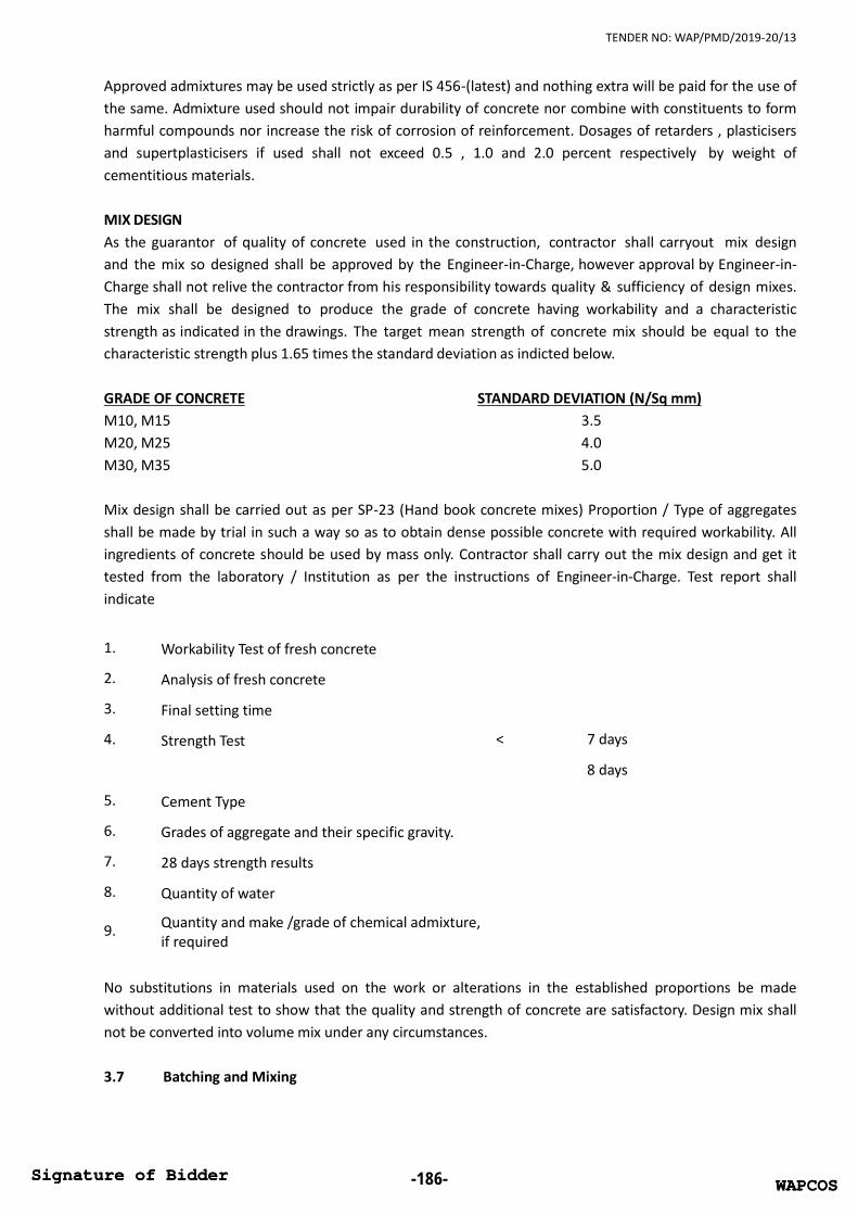
TENDER NO: WAP/PMD/2019-20/13
Approved admixtures may be used strictly as per IS 456-(latest) and nothing extra will be paid for the use ofthe same. Admixture used should not impair durability of concrete nor combine with constituents to formharmful compounds nor increase the risk of corrosion of reinforcement. Dosages of retarders , plasticisersand supertplasticisers if used shall not exceed 0.5 , 1.0 and 2.0 percent respectively by weight ofcementitious materials.
MIX DESIGNAs the guarantor of quality of concrete used in the construction, contractor shall carryout mix designand the mix so designed shall be approved by the Engineer-in-Charge, however approval by Engineer-in-Charge shall not relive the contractor from his responsibility towards quality & sufficiency of design mixes.The mix shall be designed to produce the grade of concrete having workability and a characteristicstrength as indicated in the drawings. The target mean strength of concrete mix should be equal to thecharacteristic strength plus 1.65 times the standard deviation as indicted below.
GRADE OF CONCRETE STANDARD DEVIATION (N/Sq mm)M10, M15 3.5M20, M25 4.0M30, M35 5.0
Mix design shall be carried out as per SP-23 (Hand book concrete mixes) Proportion / Type of aggregatesshall be made by trial in such a way so as to obtain dense possible concrete with required workability. Allingredients of concrete should be used by mass only. Contractor shall carry out the mix design and get ittested from the laboratory / Institution as per the instructions of Engineer-in-Charge. Test report shallindicate
1. Workability Test of fresh concrete
2. Analysis of fresh concrete
3. Final setting time
4. Strength Test < 7 days
8 days
5. Cement Type
6. Grades of aggregate and their specific gravity.
7. 28 days strength results
8. Quantity of water
9. Quantity and make /grade of chemical admixture,if required
No substitutions in materials used on the work or alterations in the established proportions be madewithout additional test to show that the quality and strength of concrete are satisfactory. Design mix shallnot be converted into volume mix under any circumstances.
3.7 Batching and Mixing
WAPCOSSignature of Bidder -186- WAPCOSSignature of Bidder

TENDER NO: WAP/PMD/2019-20/13
Only controlled design mix will be used for concrete with strength more or equal to M15. Volumebatching may be allowed (using mechanical mixers) for mixes up to M10 , for these leaner mixes massvolume relationship shall be checked frequently to ensure specified grading is maintained.
For the production of controlled concrete contractor shall set up, on site, automatic microchipcontrolled batching plant of capacity 10Cum/Hr or more, complete with silos / stock piles for cementand aggregates and D.G sets to be provided to have uninterrupted supply of concrete. The batching plantshall be tested and calibrated as per manufacturers manual and to the satisfaction of Engineer-in-Charge,before starting the production of concrete, to provide uniform & consistent cement concrete mixconforming to approved mix design Batching / Mixing plant shall conform to the requirements of IS 4925& 4926. Batching plant shall have facilities for presetting the quantities to be weighed with automaticcut off when the same is achieved and also shall be equipped with sensors to control water ratio asper moisture contents of aggregates. Printed reports of all the components of all the batches ofconcrete as separated by on line computer of batching plant, shall be presented to Engineer-in-Charge forhis approval and records. Cube samples from each batch shall be taken as per the requirement of IS 456-(latest), in the presence of Engineer-in-Charge. Cubes shall be tested to record 7days & 28Days cubestrength. Contractor shall be responsible for the quality of concrete which will be indicated as per thecube strength results at the end of 7days & 28days. However 28days strength results will be treated asfinal.
Contractor shall make his own trial mixes for different grade and submit the report of the final design mixto be adopted for different grades to Engineer-in-Charge for his approval and records (Contractor shall takein cognisance while designing concrete mixes, time required for transporting and placing the cementconcrete mix at final position ). Contractor shall specify along its bid the type and make of the proposedbatching plant with brief specifications.
The accuracy of the measuring equipment should be within plus or minus 2% of the quantity of cementbeing measured and within plus or minus 3% of the quantity of aggregate , water , admixture beingmeasured. All measuring equipment should be maintained in a clean, serviceable condition.
Mixing with mechanical mixer (for M15 or richer) will only be permitted in exceptional circumstances andthen with the specific arrangement of the Engineer-in-Charge. No water shall be added to mixed concreteother than the quantity of water allowed for in the mix design and incorporated in batching..
Concrete or mortar which has commenced to set shall not be remixed with additional water and in nocircumstances shall such concrete or mortar be used in the work.
3.8 Concrete Admixtures & PlastisizersAdmixtures are materials added to the concrete before or during mixing with a view to modify one ormore properties of concrete in plastic or hardened state. Concrete admixtures are proprietary items ofmanufacturers and shall be obtained from established manufacturers having proven track record, withEngineer-in-Charge approval.
3.9 Transporting Concrete
WAPCOSSignature of Bidder -187- WAPCOSSignature of Bidder

TENDER NO: WAP/PMD/2019-20/13
From batching plant concrete to the location of proposed construction shall be transported through transitmixers or concrete pumps only . Contractor shall specify the make & type and number of transit mixers tobe deployed along with concrete pumps with their make , capacity .
The path to be used by transit mixers will be strictly as per the instructions of Engineer-in-Charge. From thetransit mixers concrete shall be transported to the final floor level / position through pumping or buildershoist only .Concrete and mortar shall be transported speedily and deposited in its place in the workswithout contamination, loss of ingredients or segregation.. Buckets of builders hoist shall be large enoughto contain an integral number of batches .No concrete shall be placed in the works until the contractors'proposed method of transporting concrete have been approved. When concrete is conveyed in chutesfrom transit mixers , the equipment shall be of such size and design as to ensure a continuous flow inthe chute. The chute shall be of metal or metal lined, and if two or more lengths are used they all shallhave approximately the same slope. If the distance of the discharge end of the chute above the surface ofthe concrete is more than 1 metre, a spout or "elephant trunk" shall be used and the lower endpositioned as near to the surface of deposit as practicable. The chute or "elephant trunk" shall bethoroughly cleaned before and after each run. The debris and any water shall be discharged outside theforms.
3.10 Concrete placementGeneral
Concrete, when deposited, shall have a temperature of not less than 5oC (41oF) and not more than 32oC
(90oF).
The concrete shall be placed in the positions and sequences indicated on the drawings, in this specificationand/or as directed by the Engineer-in-Charge in writing.
Contractor shall give adequate notice to the Engineer-in-Charge of his intention to concrete any section ofthe works.
Except where otherwise directed, concrete shall not be placed unless the representative of the Engineer-in-Charge is present and has previously examined and approved the positioning, fixing and condition of thereinforcement or any other items to be embedded and the cleanliness, positioning and suitability of theconcreting surface.
The concrete shall be deposited as nearly as possible in its final position. It shall be placed in such amanner as to avoid segregation of the concrete and displacement of the reinforcement, other embeddeditems, or formwork. It shall be brought up in horizontal layers not exceeding 450 mm in compactedthickness unless otherwise authorised or directed by Engineer-in-Charge. Concrete shall not be placedsimultaneously on each side of large horizontal specified or approved construction joints.
Shutters for walls or thin sections of considerable height shall be provided with openings or otherdevices that will facilitate the cleaning of the accumulation of hardened concrete on the shutters or on themetal reinforcement above the level of the concrete and the removal of concrete in the case ofsegregations.
Placing concrete in cold weather
WAPCOSSignature of Bidder -188- WAPCOSSignature of Bidder

TENDER NO: WAP/PMD/2019-20/13
No concrete shall be mixed or placed while the ambient temperature is above 40 degree C. on a risingthermometer or below 5 degree C. on a falling thermometer. The contractor shall supply an accuratemaximum and minimum thermometer and hang it in an approved position on the works. Aggregatesthat have been exposed to frost shall not be used until completely thawed. Concrete shall bemaintained by approved means at a temperature of not less than 4 degree C. during placing, and for aperiod of three days thereafter. All concrete placed during cold weather or when a frost is predicated oris likely to occur or occurs contrary to expectation, shall be protected from freezing by approved means.
Placing of concrete in wet weatherConcrete shall not be mixed and or placed in rainy weather or when there is likelihood ofimpending heavy showers. If it becomes necessary to place concrete during rainy weather, the contractorshall provide adequate protection by means of tarpaulin or similar other water proof material toimmediately cover fresh concrete to prevent rain falling over it. This protection shall be left on theconcrete for a period of 24 hours after placing of concrete.
3.11 Concrete placement under waterConcrete placed under water shall be deposited through a tremmie pipe the diameter of which shall beatleast 8 times the size of the largest aggregate used in the concrete mix.
The construction of and the method of handling the tremmie pipes shall be approved by the Engineer-in-Charge. The pipes shall be waterproof and sufficiently strong to withstand severe handling conditionsand any joints must be sealed with adequate gaskets.
At the commencement of tremmie work the bottom of the pipe shall be sealed before being lowered in toposition. The seal shall only be broken by the concrete being placed. The concrete placed in contact with ahorizontal construction joint shall have a lower proportion of coarse aggregate and a higher proportionof cement than the remainder of the concrete. The proportion shall be agreed with the Engineer-in-Charge's Representative.
All underwater concrete shall be placed in still water within a cofferdam or formwork which shall extendabove water level.
The proportions of the mixes shall be agreed in accordance with the strength and workability requiredby the specification. To allow for losses an addition of 10% of cement shall be added to mixes of concretescheduled to be placed under water.
3.12 Maintenance of Plant and EquipmentThe contractor shall keep Bathing Plant , weight batching machines, mixing machines, compressors,vibrators and other plant and equipment for concrete and mortar work clean, well maintained andadjusted and where appropriate, shall check the accuracy of the measuring devices at regularintervals, all to the approval of the Engineer-in-Charge's Representative. Mixer blades shall be replacedwhen worn down by 20 mm.
3.13 Night WorkConcrete shall not be mixed, placed, compacted or finished during the hours of darkness, except wherenecessary to complete a pour. However, concreting in darkness for these exceptions shall be only after
WAPCOSSignature of Bidder -189- WAPCOSSignature of Bidder

TENDER NO: WAP/PMD/2019-20/13
obtaining the express permission in writing from the Architect/Engineer-in-Charge's representative and inhis presence only.
3.14 Compacting ConcreteThe concrete shall be fully compacted through out the full extent of the layer. It shall be thoroughlyworked against the moulds, and around any reinforcement and other embedded items without displacingthem, and in to corners of the moulds. Successive layers of the same lift shall be thoroughly workedtogether adjacent to the common face. The date of laying concrete shall be marked for curing and removalof form work.
Immersion vibrators shall be of approved type and shall have frequency of not less than 10000 oscillationsper minute. They shall penetrate the full depth of the concrete to be vibrated and be immersed atsufficiency close spacing so that the whole volume of the concrete is satisfactorily and uniformlycompacted.
Where the underlying layer is of fresh concrete, immersion vibrators shall also penetrate that layer toensure homogeneity. Immersion vibrators shall be withdrawn slowly to prevent formation of voids.Vibrators shall not be used to work the concrete along the moulds or in such a way as to damageshuttering or other parts of the structure or to displace the reinforcement or other embedded items.Immersion vibrators shall only be operated by those who have received proper instruction and training intheir use.
External vibrators shall be of approved type and shall have a frequency of not less than 3000 oscillationsper minute. They shall be securely and rigidly clamped to the shuttering. External vibrators shall only beused on shuttering which is strong enough to withstand the vibration without displacement, distortion orother damage.
The contractor shall ensure that sufficient standby vibrators and ancillary equipment are available duringconcreting operations.
3.15 Quality Controli) In order to ensure that the quality of materials and the mix proportions are suitable for the particulargrade of concrete required are so maintained, sampling and testing shall be carried out regularly during thecourse or the works.
ii) As frequently as the Engineer-in-Charge's representative may require and in any case at least once a daywhile concreting is in progress, the contractor shall sample and carry out a determination of themoisture content and a mechanical analysis of the fine aggregate and each nominal size of coarseaggregate shall lie within the respective limits specified. The surface moisture test of aggregates should becarried out a number of times during the day and necessary adjustments in the water content of theconcrete mix should be made.
iii) Workability testing shall be carried out in accordance with IS:456. The results shall lie within therange upon which the accepted mix design is based. Testing shall be carried out at such a frequency thatthe required workability is consistently achieved.
WAPCOSSignature of Bidder -190- WAPCOSSignature of Bidder

TENDER NO: WAP/PMD/2019-20/13
iv) Samples of concrete shall be taken at random in accordance with IS: 516 at the time and place ofdeposition of the concrete.
v) Notwithstanding the foregoing, additional samples shall be taken by the contractor when directed by theEngineer-in-Charge. The test cube procedure shall be in accordance with IS:516 throughout.
vi) Compliance with the specified characteristic strength shall be assumed if: Each of the six cubes in a group has a test strength not less than the characteristic strength or, Not more than one cube has a test strength less than the specified characteristic strength but not
less than 85% of the specified characteristic strength and the average strength of the group of fourtest results is not less than the specified characteristic strength plus the standard deviation of thegroup.
3.16 Cube TestsAcceptance of concrete is based on the 28th day results. However, the contractor shall establish a relationship between 7 days and 28 days strengths by carrying out 7 days tests at the time of performing thelaboratory testing and from subsequent quality control testing. This relation ship shall be used ininterpreting any further test results to predict the probable value of the corresponding 28 days cubestrengths. The contractor shall without delay advise the Engineer-in-Charge of any sample that appearslikely to fail to meet the specification and the contractor shall take any necessary action to minimize theeffect of such failure.
3.17 Acceptance CriteriaThe general Acceptance Criteria of any and all of the concrete work shall be as per the relevantClauses of IS. 456.
If any of the works tests are not up to the standard, the Engineer-in-Charge shall have the power to stopthe work until the reason is investigated and steps taken to prevent further low results. The contractor shallnot be entitled to any claims on account of such delays. Any concrete carried out from the batch that isafterwards found to be faulty, will be liable for rejection and if so directed, the contractor shall at his ownexpenses dismantle and replace the defective work and any work built thereon or shall take such othermeasures as may be deemed necessary by the Engineer-in-Charge. At the discretion of the Engineer-in-Charge, the contractor may be allowed to prove by means of a load test to be carried out at his ownexpense, that the concrete is capable of safely withstanding the loads as specified in the test.
3.18 Construction jointsConstruction joints shall be provided in the position described on the drawings or elsewhere and wherenot so described on the drawings or else shall be in accordance with the following: -
a) A joint shall be formed horizontally at the top of a foundation and 75 mm below the lowestsoffit of the beams meeting at the head of a column.
b) A joint shall be formed in the rib of a large tee beam and all beams 25 mm below the soffit ofthe slab.
WAPCOSSignature of Bidder -191- WAPCOSSignature of Bidder

TENDER NO: WAP/PMD/2019-20/13
c) Concrete in a haunch or a splay on beam or a brace, and in the head of a column where one ormore beams meet, shall be placed without a joint at the same time as that in the beam or beamsor brace.
d) Concrete in the splay at the junction of a wall and slab shall be placed throughout without ajoint, but if the provisions of a joint is unavoidable, the joint shall be vertical and the middle of aspan.
e) A joint in a slab shall be vertical and parallel to the principal reinforcement, where it isunavoidable, at the right angles to the principal reinforcement, the joint shall be vertical and at themiddle of the span.
f) Expansion joints, hinges or other permanent structural joints shall be provided in the positionsand of the form described in the drawings or elsewhere. Before placing new concrete againstconcrete that has already hardened the face of old concrete shall be cleaned and roughened andscrubbed and loose aggregate removed from the form. Immediately before placing the newconcrete the face shall be thoroughly wetted and a coating of neat cement grout applied thereto.The new concrete shall be well rammed against the prepared face before the grout sets.
3.19 Form Work and scaffolding / StagingForm work to the fresh concrete shall be sufficiently rigid and shall be such as to prevent loss of slurry fromthe concrete and details and design of the form work shall conform to IS 14687. The tolerances on theshape , lines and dimensions shall be as per CL. 11 of IS 456 –2000.
All staging and scaffolding work shall comprise of MS .Pipes / Structural steel sections withnecessary coupling arrangement. (NO WOODEN BALLIES / PROPS WILL BE PERMITTED). Adequate sizefoundation blocks / base plates shall be provide below staging members to disperse the loads as per thefounding strata.
Form work constructioni) The contractor should submit detailed drawing of the centering & shuttering and get the same
approved from the Engineer-in-Charge before laying concrete also he should get the centeringshuttering approved in writing before start of concreting. The concreting should be done in thescientific and methodical manner so as to give a uniform finish in line and level, so that minimumrendering or plastering is done. The work found defective, should be dismantled & redone and sitecleared.
ii) Form work shall be so constructed that concrete can be properly placed and thoroughly compacted.Form work shall be firmly supported and adequately strutted, braced or tied to maintain position andsize . Forms shall have sufficient strength and rigidity to with stand the weight of wet concrete andnecessary pressure due to ramming and vibration of concrete and movement of men material andother loads without excessive deflection from prescribed limits. It shall be capable of adjustment tothe lines , levels and dimensions of the finished concrete.
iii) All form work shall be constructed to be rigid during the casting of concrete and constructedso that the surfaces adjacent to the concrete are with plus minus 6 mm or the required surfaces
WAPCOSSignature of Bidder -192- WAPCOSSignature of Bidder

TENDER NO: WAP/PMD/2019-20/13
when supporting the concrete and sufficiently watertight to prevent loss of liquid from the concrete,and it shall be capable of being removed without shock or vibration to the concrete. Forms shall becleaned with compressed air immediately before placing concrete to remove all rubbish. The insidefaces of the form work shall be treated with a mould oil of type to be approved by the Engineer-in-Charge and every care shall be taken to prevent mould oil from getting on to the reinforcement.
iv) Beams boxes shall be erected with an upward camber of 6 mm for each 3 M. of span.
v) Around the periphery of the building beyond building line , staging shall be erected by the contractorfree of cost , using structural steel members duly braced to sustain all loads , with all safety measures likenetting , temporary railings / parapets , platforms etc. to provide free access to external façade of thebuilding at each floor level for construction and inspection. . Staging shall grow along with the building .
Removal of Form work (Striking Time)Unless certainly specified in the drawing, or directed by the Engineer-in-Charge, the following shall beminimum intervals of time, which should be allowed between the placing of the concrete and the strikingof the mould where ordinary portland cement is used and ambient temperature does not fall below 15degree Celsius.
a) Walls, column & vertical faces 16 to 24 hours as may be decidedof all structural members by the Engineer-in-Charge.
b) Slabi) Spanning upto 4.50 m 7 daysii) Spanning over 4.50 M 14 days
Note: Soffit forms of the slab may be removed after 3 days , props to be fixed immediately after removal ofshuttering .c) Beams and arches
i) Spanning upto 6 M 14 daysii) Spanning 6 M to 9 M 21 Daysiii) Spanning over 9 M 28 Days
Note:1. For other types of cement, the stripping time recommended for ordinary portland cement may besuitably modified. Forms shall not be released un till the concrete has achieved a strength of at leasttwice the stress to which concrete may be subjected to after removal of the form.
2. The number of props left under, their sizes and disposition shall be such as to be able to safelycarry the full dead load of the slabs, beam or arch as the case may be together with any live load likely tooccur during curing or further construction.
However, the Contractor shall delay the removal of shuttering as long as necessary in order to avoiddamaging the work. Where shuttering to soffit is removed prior to the props this is only permissible if thedesign of the shuttering allows such a sequence of operations without the props being in any waydisturbed. If the shuttering and props are not independent, both must be left in place until propping is nolonger required.
WAPCOSSignature of Bidder -193- WAPCOSSignature of Bidder

TENDER NO: WAP/PMD/2019-20/13
Where shuttering to sides is removed prior to the shuttering soffit, the side shuttering shall be removedwithout disturbing the shuttering to the soffit.
No concrete structure shall be loaded until the concrete is at least 21 days old and only then with theapproval of the Engineer-in-Charge and subject to such conditions as may be imposed.
The contractor may be required to produce evidence that the concrete has attained a strengthsufficient to support the live and dead loads to which that part of the structure may be subjected. Thisevidence shall consist of reports of compression tests made on job cured test cubes. The cost of suchtests shall be borne by the contractor. The foregoing provisions of this clause shall not relieve theContractor of his responsibility to ensure that the stability and strength of any structure or part of astructure is not impaired by the release of shuttering.
Proposals for form workNot less than 8 days before the contractor proposes to construct any form work his detailed proposalsthereof shall be delivered to the Engineer-in-Charge. Proposals shall comprise all relevant informationincluding calculations, detailed drawings, rates of placing of concrete, sequence of placing of concreteand details of any external vibrators which are proposed to be used.
No form work shall be constructed until the Contractors' proposals have been received and approved bythe Engineer-in-Charge.
Type of form workWrought frame work wherever used should be of film faced marine ply for a good quality concretework. The frame work for the ply should not be of timber / wood and shall be of MS frame work only.
Wrought form work, to all surfaces for which a smooth fair faced finish is required, shall be constructed ofpurpose-made metal, water proof marine ply wood panel, hardboard lined form work or of planed timberwith edges shot so that tight joints can be formed which will prevent loss of liquid from the concrete. Theuse of a particular material for wrought form work shall be consistently maintained throughout thestructure. The surfaces of the form work in contact with the concrete shall be smooth and free from allblemishes. The number of times wrought form work may be used shall be subject to the surfaces, jointsand edges being clean and undamaged.
Surfaces of concreteThe contractor shall ensure that the finished face of concrete offers a suitable keyed surface for theapplication of the finishing media, e.g. plaster, sand and cement screed, etc. The contractor shall alsoensure that where thin films of finished, e.g. skim coats "Snowcem", paint, etc. are to be applied that theprevious provisions regarding supporting of form work are complied with, so that the concrete faces to betreated are left smooth, unblemished and true to line both vertically and horizontally and require nomaking good before applying the finish.
Should the contractor fail however, to comply with the provision of this Clause, he shall submit details ofhis proposed method of redoing the situation to the Engineer-in-Charge and must obtain written consentfrom the Engineer-in-Charge to the proposals before continuing with any further work on the affectedsurfaces.
WAPCOSSignature of Bidder -194- WAPCOSSignature of Bidder

TENDER NO: WAP/PMD/2019-20/13
Tolerances in concrete surfacesThe permissible tolerance in the surface of the hardened concrete shall not exceed the followinglimits :
Type of irregularity
Departure of member planes from position and level + 12 mmVariation in cross-sections + 6 mmSharp changes in plane + 2 mmDeparture from 3 M. template of any part of planes + 3 mm
3.20 CuringCanvass, Hessian or other approved screens shall be erected at all points where concrete is being placed toprotect the concrete from the direct sun or from drying winds and such screens shall be kept in positionuntil the surface of the concrete has been protected as specified in the following Clauses. The contractorshall be responsible for removing such screens and preparing surface of concrete .
As soon as possible after it has been placed and concrete shall be covered with Hessian or other approvedmaterial to protect it from the sun and all concrete surfaces shall be kept visibly wet continuously for 14days after placement, the Hessian being kept in position throughout this period. Surfaces cast against formsshall also be kept moist and covered with Hessian for these periods if the form work is removed before theperiods have elapsed.
The top surface of slab shall be kept flooded with water at all times till the curing period of 14 days is over.Columns, wall and beam sides and other surface shall be completely covered by gunny bags and keptthoroughly wet continuously for the period specified for curing. The ceiling of slabs shall be frequentlysprayed with water until the end of curing period.
The contractor shall ensure that all times there is an adequate supply of fresh water available for curing theconcrete.
3.21 Examinations and RepairsThe contractor shall not proceed with the surface finish or making good of concrete surfaces until hehas received the Engineer-in-Charge's written permission to do so and he shall not apply cement slurryor mortar or any other coating to the concrete surfaces as struck from the shuttering or do anything elsewhich would hinder the proper inspection of the concrete by the Engineer-in-Charge.
Concrete which is defective, has honeycombs, or which contains defective parts shall be cut out completelyunless the Engineer-in-Charge agrees that a repair may be satisfactorily effected. This agreement shallnot preclude subsequent condemnation of the repaired work.
The method of repairing defective concrete which the contractor proposes to adopt shall be submitted tothe Engineer-in-Charge for his prior written agreement in each particular case.
No repairs or remedial work shall be carried out without prior inspection and instructions of the Engineer-in-Charge. (No extra shall be paid to the contractor for the repair works).
WAPCOSSignature of Bidder -195- WAPCOSSignature of Bidder

TENDER NO: WAP/PMD/2019-20/13
3.22 Fair face finish to concrete surfacesConcrete surfaces shall be finished smooth fair faced where indicated as such on the drawings. Theseareas shall be entirely free from honey combing, stains, fins, lipping, nail or screw marks, raised grainmarks, air holes or any other imperfections. They shall also be of even texture throughout. Very slightvariations between member and member may be acceptable but any such variations within a singlemember cannot be tolerated. The concrete faces shall not be marked with mould oil.
The form work to these areas shall be wrought form work as specified herein.
Following inspection by the Engineer-in-Charge the whole surface shall be rubbed down by hand. Anysurfaces with major imperfections, i.e. greater than can be easily, completely and permanently obliteratedby rubbing down shall be reported immediately to the Engineer-in-Charge.
Remedial work is not normally possible to the above fair faced finish surfaces and the Contractor will berequired to demolish and recast defective works.
3.23 Reinforcement FabricationBending SchedulesThe Contractor shall submit to the Engineer-in-Charge, for the Engineer-in-Charge's approval, bendingschedule for all the works, not less than Ten days before the contractor intends to bend the reinforcingsteel.
The Approval of the Engineer-in-Charge shall in no way absolve the contractor of his responsibilities underthe Contract.
Programme of reinforcement details requiredThe Contractor shall provide a programme which gives the Engineer-in-Charge at least 28 days priornotification of any reinforcement details required. The contractor shall justify the practicabilityof his programme to the Engineer-in-Charge should it seem unreasonable before the programme beregarded as valid notification. If progress on site falls behind the contractors' programme, theissue of reinforcement details may be delayed by a period corresponding to the delay inconstruction.
Bending and placing reinforcementReinforcement shall be cut and bent to the shapes and dimensions shown on the finally agreedbending schedules in accordance with the requirements of IS: 2502 and to the tolerances set outtherein.
Bending shall be carried out with an appliance which provides a continuous and uniform application of thebending deformation at every section of the bend. There shall be provision for the free movement of thesurface of the bar during bending and the bends shall follow the contour of the former without peaking.
High Yield reinforcement must be bent without the application of artificial heating.
WAPCOSSignature of Bidder -196- WAPCOSSignature of Bidder

TENDER NO: WAP/PMD/2019-20/13
Mild steel reinforcement may be sent either hot or cold but shall not be heated to a temperature greater
than 850 C., and if heated not cooled by quenching.
Mild steel reinforcement temporary left projecting from the concrete at construction or other joints shallnot be bent out of position unless shown on the drawings or agreed by the Engineer-in-Charge. Wheresuch bending and subsequent rebinding takes place the radius of the bend shall not be less than 4 bardiameters.
Reinforcement shall be fixed without forcing in the position shown on the drawings within a tolerance of 5mm or 5% of the minimum dimension of cross section, whichever be the greater and maintained so that itis not displaced during concreting or other operations.
Horizontal bars shall be supported sufficiently to prevent displacement. This may be plastic spacers, chairsbent from steel bar, or by concrete blocks. The method and sufficiency of the support shall be subject tothe approval of the Engineer-in-Charge.Where concrete blocks are used, they shall be precast from concrete (not mortar) of the same class asthe concrete in which they are to be embedded, except that the largest size of aggregate shall be 10 mm.Each block shall be secured to the reinforcement with wire or a clip embedded in the centre of the blockso that, it shall not be in contact with the shuttering or subsequently cause rust marks on the concrete.Intersections of reinforcement shall be bound together with16 gauge annealed soft iron binding wire.
Unless otherwise noted on the drawings, no intersections of reinforcement may be fixed by weldingwithout the permission of the Engineer-in-Charge. High yield and cold worked steel shall, in nocircumstances, be welded together.
Should any difficulty arise during the placing of steel in obtaining the appropriate cover, the contractor shallimmediately draw the attention of the Engineer-in-Charge to the difficulty and shall carryout such correctivemeasures as the Engineer-in-Charge may suggest.
Protection of reinforcement and concreteThe Contractor shall ensure that movement of men and material subsequent to steel fixing is organizedso that reinforcement is not thereby displaced.
Reinforcement left projecting from any concrete shall be protected so that there is no risk of corrosionstaining to any exposed concrete surface or to any other part of the works. For this purpose a stiff groutwash will normally be acceptable to the Engineer-in-Charge, this wash shall be wire-brushed vigorouslybefore further concrete is placed to remove any ill- bonded material.
3.24 Precast concrete unitsPrecast concrete materials and workmanship shall be in accordance with specifications unless indicatedotherwise. Where different tolerances are indicated in this specification or on the drawings fromthese in the more severe tolerances shall apply. The units shall all be cast in properly made strongmoulds to form the shapes required. For work described as "finished fair" the mould shall be lined withsheet steel or other approved material and care should be taken to ensure no damage is caused to edgesor surfaces when units are removed from the moulds.
WAPCOSSignature of Bidder -197- WAPCOSSignature of Bidder

TENDER NO: WAP/PMD/2019-20/13
The concrete shall be of the mixes given on the drawings and shall be thoroughly vibrated in the moulds.
All precast work shall be cast under cover and shall so remain for seven days and shall be kept damp inorder that the units are properly matured. No units shall be lifted until 18 days have elapsed sincecasting and no unit shall be erected until it has been approved by the Engineer-in-Charge as free fromdefects.
No cracked units will be accepted for incorporation in the works.
All reinforced structural precast units shall have the tops clearly marked.
Un-reinforced precast units, such as sills and copings, shall be lightly reinforced as necessary to facilitatehandling.
WAPCOSSignature of Bidder -198- WAPCOSSignature of Bidder
TENDER NO: WAP/PMD/2019-20/13
CHAPTER 4: MASONRY WORKS
4.1 STONE MASONARY – Not Applicable4.2 SOLID CONCRETE BLOCK
4.2.1 DescriptionThis section covers the requirements for furnishing of all material and the construction of solid concreteblock masonry load bearing and filler / partition walls using the type, dimensions, arrangement and thecoursing as required complete with reinforcing anchorage, mortar, jointing grouting, pointing, and masonryaccessories.
4.2.2 Application Codes and StandardsIS: 269 Ordinary and low heat portland cement.IS: 383 Aggregates, coarse and fine from natural source for concrete.IS: 456 Code of practice for plain and reinforced concrete.IS: 2185 specifications for concrete masonry units. Part - I Solid and solid concrete block.IS: 2250 Code of practice for the preparation and use of masonry mortars.
4.2.3 Products4.2.3.1 Solid Concrete masonry blocksSolid concrete masonry blocks shall be of approved make conforming to IS : 2185. The concrete mix usedfor blocks shall not be richer than 1 cement : 3 combined aggregate by volume before mixing. Cement usedin making concrete masonry unit shall conform IS : 269 and the aggregates used shall conform to IS : 383.All units shall be cured in curing tank / curing yard or steam cured.
A. Physical Requirementsi) GeneralAll units shall be sound and free from cracks, honey combing, broken edges and other defects. Howeverminor chipping resulting from the customary methods of handling during delivery shall not be deemedground for rejection.
The face of masonry units shall be flat and rectangular, opposite faces shall be paralleled and all rises shallbe square. The bedding surface shall be at right angle to the face of the blocks.
ii) TextureConcrete masonry units used in constructing exposed walls shall be of the specified surface texture, freefrom stains and discoloration blemished and defects which detract the desired appearance of the finishedwall.
iii) DimensionsUnless specified otherwise the nominal dimensions of solid concrete masonry units shall be as follows :
Length: 400mm Height: 200mm Width: As specified in the drawings.
WAPCOSSignature of Bidder -199- WAPCOSSignature of Bidder

TENDER NO: WAP/PMD/2019-20/13
The maximum variation in dimension shall not be more than ± 1.5 mm in height and breadth and ±3mm in length.
iv) Special UnitsSolid concrete block masonry units shall include closer jamb, header and bond beam units and specialshapes and sizes required to complete the work indicated.
v) Block DensityThe density of solid concrete block shall be as prescribed in Table below :-
TypeDensity of Block
kg/M3Min. Avg.
Strength of UnitsMin Strength
Individual Unitsa) Load bearing Not less than 1500 5.5 N/Sqmm 4.4 N / Sqmm
b) Non-load bearingLess than 1500 butnot less than 1000
1.5 N / Sqmm 1.2 N/Sqmm
vi) Compressive StrengthThe minimum compressive strength at 28 days being the average of 8 units, and the minimum compressivestrength at 28 days of individual units shall be as prescribed in Table above.
vii) Water AbsorptionThe water absorption, being the average of 3 units, shall not be more than 10% by mass.
viii) Drying ShrinkageThe drying shrinkage, being average of 3 units shall not exceed 0.1 percent.
ix) Moisture movementThe moisture movement of the dried blocks on immersion in water being the average of 3 units, shall notexceed 0.09%.
B Product Handlingi) TransportationThe contractor shall be responsible for transporting solid concrete masonry units in such a manner that theunits are adequately protected during transportation cracked, chipped, or otherwise damaged concretemasonry units, delivered at the site shall be considered unacceptable and shall be delivery to the site in airdry condition.
ii) Handling and storageConcrete block masonry units shall be handled, stored and protected with care in an approved manner toavoid any contact with moisture on the site, soiling, chipping or damage of any kind. They shall be stockpiled in neat piles on planks or other supports free from contact with the ground and covered to protectagainst wetting. Broken chipped or otherwise damaged units will be rejected and shall not be used on theworks.
C TestsTests shall be conducted on samples of units selected according to the sampling productive given in D
WAPCOSSignature of Bidder -200- WAPCOSSignature of Bidder

TENDER NO: WAP/PMD/2019-20/13
below, to ensure conforming with the physical requirement laid down in A. The cost of the tests shall beborne by the contractor.
D Samplingi) A sample of 20 blocks shall be taken from every consignment of 4000 blocks or part thereof thesame size and same batch of manufacture. From these samples, the blocks shall be taken at random forconducting the tests. The sample of block shall be marked for future identification of the consignment itrepresents. The blocks shall be kept under cover and protect from extreme condition of temperaturerelative humidity and wind until they are required for test. The tests shall be undertaken as soonpracticably after the sample has been taken.
ii) Number of TestsAll the 20 blocks shall be checked for dimension and inspected for visual defects. Out of 20 blocks, 3blocks shall be subjected to the testing for block density, 8 blocks to the test for compressive strength, 3blocks to the test for drying shrinkage and later to the test for moisture movement. The remaining 3 blocksshall be reserved for retest for drying shrinkage and moisture movement if a need arises.
E Criteria for conformityThe lot shall be considered as conforming to the requirements of the specifications if the conditionsmentioned below are satisfied.
a) The number of blocks with dimensions outside the tolerance limit and / or visual defects, amongthose inspected shall not be more than two.
b) For block density and compressive strength, the mean value determined shall be greater than or equalat the minimum limit specified in A (v) and (vi) respectively.
c) For drying shrinkage and moisture movement, all the test specimens shall satisfy the requirements of thetest. If one or more specimens fail to satisfy the requirements, the remaining three blocks shall besubjected to these tests. All these blocks shall satisfy the requirements.
d) For water absorption, the mean value determined shall be equal or less than the maximum as specified.
F MarkingConcrete masonry units shall be marked for the following information. a) The identification of themanufacture.b) The grade of the unit i.e. load bearing or non-load bearing. c) The year of manufacture if required.
4.2.3.2 MortarMortar shall be composed of cement and sand, unless otherwise specified. All mortar shall be preparedin accordance with IS : 2250. Solid concrete blocks shall be embedded with a mortar which is relativelyweaker than the mix used in making blocks in order to avoid the formation of cracks. The proportions ofmortar measured by volume shall be as specified.
4.2.3.3 ConcreteConcrete used for filling cells in solid concrete block masonry when reinforced shall be composed of 1 part
WAPCOSSignature of Bidder -201- WAPCOSSignature of Bidder

TENDER NO: WAP/PMD/2019-20/13
of cement : 2 ½ parts of sand and 3 parts of coarse aggregate of size ranging4.75 mm to 12.5 mm. The water cement ratio shall not exceed 0.6. When the cells exceed 10 cm in theleast side, the coarse aggregate size shall be graded between 4.75 and 20 mm and the proportion of mixshall be 1:2 ½ : 3½ for reinforcements of IS : 456 shall be complied with.
Superstructurei) First Course
The first course of concrete block masonry shall be laid with great care making sure that it is properlyaligned, leveled and plumbed. Before laying the first course, the alignment of the wall shall be marked onthe foundation, footings. The blocks for this course shall first be laid dry along a string lighting stretchedbetween properly located corners of the wall in order to determine the correct position of the blocksincluding those of cross walls joining it and also to adjust their spacing. When the blocks are set in properposition the two corner blocks shall be removed a full mortar bed spread on the footing and these blockslaid back in place truly level and plumb. The string shall then be stretched tightly along the faces of thetwo corner blocks and the faces of the intermediate ones adjusted to coincide with the line. Thereforeeach block shall be removed and re-laid over a bed of mortar. After every 3 or 4 blocks have been laid theircorrect alignment, level and vertically shall be carefully checked.
ii) Horizontal JointsMortar shall be spread over the entire top surface of the block including front and rear as well as the websto a uniform layer of 1 cm thickness. Full mortar bedding shall be adopted for load bearing walls but fornon-load bearing walls. The mortar may be spread only over.
iii) Vertical JointsFor vertical joints, the mortar shall be applied on the vertical edges of the front and rear shells of theblocks. The mortar may be applied either on the unit already placed on the wall or aggregate size shall begraded between 4.75 and 20mm and the proportion of mix shall be 1:2 ½ : 3 ½ for reinforced concrete and1:3:6 for unreinforced concrete. Generally, in making the concrete, the requirements of IS : 456 shall becomplied with.
4.2.3.4 Anchors and TiesThe ties for laying concrete block masonry partitions to intersecting masonry and the anchorage ofinterior walls to abutting walls and columns shall be as indicated on the drawings.
4.2.4 Execution
4.2.4.1 PreparationThe blocks shall be wetted before or during laying in the walls. In case the climatic conditions require thetop and the side of the blocks may only be slightly moistured so as to prevent absorption of water from themortar and ensure development of the required bond with the mortar. No unit having a film of water on itssurface shall be laid.
4.2.4.2 FoundationsIn foundation courses, plinth and basement walls, solid concrete blocks shall preferably be used. If solidblocks are used, their solid must be filled with cement concrete 1:3:6 ( 1 cement : 3 sand : 6 gravel or
WAPCOSSignature of Bidder -202- WAPCOSSignature of Bidder

TENDER NO: WAP/PMD/2019-20/13
crushed stone 5 to 20mm size). In special cases, the solids may be left unfilled if so approved by theNPCC.
In damp soils the foundation and basement masonry shall be laid in richer mortar as directed by the NPCC.
i) Masonry shall not be spread so much ahead of the actual laying of the units that it tends to stiffen andloss its plasticity, thereby resulting on poor bond. For most of the work, the joints both horizontal andvertical shall be 1 cm thick. When the mortar has stiffened somewhat, it shall be firmly compacted withthe jointing tool. It may be necessary to add mortar, particularly to the vertical joints, to ensure that theyare well filled. Each units shall be adjusted to final position while the mortar is still soft and plastic. Any unitthat is disturbed after mortar has stiffened shall be removed and re-laid with fresh mortar.
ii) The construction of walls may be started either at the corners first or started form one end proceedingin the other direction. If the corners of the wall are built first, they shall be built 4 to5 courses higher than the centre of the wall. After each course is laid at the corner, it shall be checked foralignment, level and for being in plumb. Each block shall be carefully checked with a level or straight edgeto make certain that the faces of the block are all in the same plane. All mortar joints shall be 1 cm thick.Each course, in binding the corners, shall be stepped back by a half - block and the horizontal spacing of theblock shall be checked by placing a mason's level diagonally across the corners of the blocks.
iii) When filling in the wall, between corners, the mason's line shall be stretched from corner to corner foreach course and the top outside edge of the each block shall be laid to this line. The manner of handling orgripping the block shall be such as to position the block properly with minimum adjustment. Dead mortarthat has been picked up from the scaffold or from the floor shall not be used.
iv) Closure BlocksWhen installing the closure block, all edges of the opening and all four vertical edges of the closureblock shall be buttered with mortar. The closure block shall be carefully lowered into place. If any of themortar falls out leaving as open joint, the closure block shall be removed, fresh mortar applied and theoperation repeated.
v) Provisions for lintelsLintels shall consist of either a single pre-cast units or a number of units. They shall be reinforcedas per structural drawings. In situ concrete used for forming a composite lintel with the use of a numberof units, shall preferably be of the same mix as of the concrete that is used in the pre-cast units and thecomposite unit shall also be reinforced as per structural drawings. Where openings occur close to oneanother a continuous lintel shall be provided.
4.3 BRICKS/BRICK TILES/BRICK BATS/MECHANIZED AUTOCLAVE FLY ASH LIME BRICK
Bricks used in the masonry may be of the following type.
(a) The Common Burnt Clay Bricks shall conform to IS:1077 and shall be hand moulded or machinemoulded. They shall be free from nodules of free lime, visible cracks, flaws warpage and organic matter,have a frog 100 mm in length 40 mm in width and 10 mm to 20 mm deep on one of its flat sides. Bricks
WAPCOSSignature of Bidder -203- WAPCOSSignature of Bidder

TENDER NO: WAP/PMD/2019-20/13
made by extrusion process and brick tiles may not be provided with frogs. Each brick shall be marked (inthe frog where provided) with the manufacturer’s identification mark or initials.
(b) Fly Ash Lime Bricks (FALG Bricks) : The Fly Ash Lime Bricks (FALG Bricks) shall conform to IS 12894.Visually the bricks shall be sound, compact and uniform in shape free from visible cracks, warpage, flawsand organic matter. The bricks shall be solid and with or without frog on one of its flat side.
Fly Ash: Fly ash shall conform to IS 3812.
Note: This item will be operated only for load bearing structure upto 2 storeys and for non-load bearingwalls 23 cms thick for multi-storeyed building's.
Bottom ash used as replacement of sand shall not have more than 12% loss on ignition when tested.
Sand: Deleterious materials, such as clay and silt in the sand shall preferably be less than 5%.
Lime: Lime shall conform to class ‘C’ hydrated lime of IS 712.
Additives: Any suitable additive considered not detrimental to the durability of bricks may be used.
(c) Clay Fly Ash Bricks: The clay fly ash bricks shall conform to IS 13757. The bricks shall be sound, compactand uniform in shape and colour. Bricks shall have smooth rectangular faces with sharp and square corners.The bricks shall be free from visible cracks, flaws, warpage, nodules of free lime and organic matter, thebricks shall be hand or machine moulded. The bricks shall have frog of 100 mm in length 40 mm width and10 to 20 mm deep on one of its flat sides. If made by extrusion process may not be provided with frogs. FlyAsh shall conform to grade I or grade II of IS 3812.
(d) Calcium Silicate Bricks: The bricks shall conform to IS 4139. The Calcium silicate bricks shall be sound,compact and uniform in shape. Bricks shall be free from visible cracks, warpage, organic matter, largepebbles and nodules of free lime. Bricks shall be solid and with or without frog. The bricks shall be made offinely grounded sand siliceous rock and lime. In addition limited quantity of fly ash conforming to IS 3812may be used in the mix. These bricks are also known as Fly Ash Sand Lime bricks in the constructionindustry.
(e) Tile Brick: The bricks of 4 cm height shall be moulded without frogs. Where modular tiles are not freelyavailable in the market, the tile bricks of F.P.S. thickness 44 mm (1-3/4") shall be used unless otherwisespecified.
(f) Brick Bats: Brick bats shall be obtained from well burnt bricks.
(g) Mechanized Autoclave Fly Ash Lime Brick: These bricks shall be machine moulded and prepared in plantby appropriate proportion of fly ash and lime. The autoclave fly ash bricks shall conform to IS 12894.Visually, the bricks shall be sound, compact and uniform shape, free from visible cracks, warpage andorganic matters. The brick shall be solid with or without frog, and of 100/80 mm in length, 40 mm widthand 10 to 20 mm deep one of its flat side as per IS 12894. The brick shall have smooth rectangular faces
WAPCOSSignature of Bidder -204- WAPCOSSignature of Bidder

TENDER NO: WAP/PMD/2019-20/13
with sharp corners and shall be uniform in shape and colour. Fly ash shall conform to IS 3812 and lime shallconform to class ‘C’ hydrated lime of IS 712.
4.3.1 Dimensions
The brick may be modular or non-modular. Sizes for both types of bricks/tiles shall be as per Table 1. Whileuse of modular bricks/tiles is recommended, non-modular (FPS) bricks/tiles can also be used where sospecified. Non-modular bricks/tiles of sizes other than the sizes mentioned in Table 1 may also be usedwhere specified.
TABLE 1
Type of Bricks/ Tiles Nominal Size mm Actual Size mm
Modular Bricks 200 × 100 × 100 mm 190 × 90 × 90 mm
Modular tile bricks 200 × 100 × 40 mm 190 × 90 × 40 mm
Non-modular tile bricks 229 × 114 × 44 mm 225 × 111 × 44 mm
Non-modular bricks 229 × 114 × 70 mm 225 × 111 × 70 mm
4.3.2 ClassificationBricks/Brick tiles shall be classified on the basis of their minimum compressive strength as given below:
TABLE 2
ClassDesignation
Average compressive strength
Not less than Less than
N/mm2 (kgf/cm2) N/mm2 (Kgf/cm2)
12.5 (125) 12.5 (125) 15.0 150
10 (100) 10 (100) 12.5 125
7.5 (75) 7.5 (75) 10 100
5 (50) 5 (50) 7.5 75
3.5 (35) 3.5 (35) 5.0 50
The bricks shall have smooth rectangular faces with sharp corner and shall be uniform in colour and emitclear ringing sound when struck.
(Note: Upper limits specified in Table 2 are for calculating the average compressive strength in accordancewith Appendix B of Chapter 6 of CPWD Specifications Vol. 1).
4.3.3 Sampling and Tests
Samples of bricks shall be subjected to the following tests:(a) Dimensional tolerance.(b) Water absorption.(c) Efflorescence.(d) Compressive strength.
WAPCOSSignature of Bidder -205- WAPCOSSignature of Bidder

TENDER NO: WAP/PMD/2019-20/13
4.3.3.1 Sampling: For carrying out compressive strength, water absorption, efflorescence and dimensionaltests, the samples of bricks shall be taken at random according to the size of lot as given in Table 6.3 below.The sample thus taken shall be stored in a dry place until tests are made. For the purpose of sampling, thefollowing definition shall apply.
(a) Lot: A collection of bricks of same class and size, manufactured under relatively similar conditions ofproduction. For the purpose of sampling a lot shall contain a maximum, of 50,000 bricks. In case aconsignment has bricks more than 50,000 of the same classification and size and manufactured underrelatively similar conditions of production, it shall be divided into lots of 50,000 bricks or part thereof.
(b) Sample: A collection of bricks selected for inspection and/or testing from a lot to reach the decisionregarding the acceptance or rejection of the lot.
(c) Defective: A brick failing to meet one or more of the specified requirements.
4.3.3.2 The samples shall be taken as below:
(i) Sampling from a Stack: When it is necessary to take a sample from a stack, the stack shall be divided intoa number of real or imaginary sections and the required number of bricks drawn from each section. For thispurpose bricks in the upper layers of the stack shall be removed to enable units to be sampled from placeswithin the stack.
Note: For other methods of sampling i.e. sampling in motion and sampling from lorries or trucks, IS:5454may be referred.
Scale of sampling and criteria for conformity for visual and dimensional characteristics:-Visual characteristics: The bricks shall be selected and inspected for ascertaining their conformity to therequirements of the relevant specification.The number of bricks to be selected from a lot shall depend on the size of lot and shall be in accordance ofCol. 1 and 2 of Table 6.3 for visual characteristics in all cases and dimensional characteristics if specified forindividual bricks.
(ii) Visual Characteristics: All the bricks selected above in accordance with Col. 1 and 2 of Table 3 shall beexamined for visual characteristics. If the number of defective bricks found in the sample is less than orequal to the corresponding number as specified in Col. 3 of Table 3 the lot shall be considered as satisfyingthe requirements of visual characteristics, otherwise the lot shall be deemed as not having met the visualrequirements.
(iii) Dimensional Characteristics: The number of bricks to be selected for inspecting the dimensions andtolerance shall be in accordance with Col. 1 and 4 of Table.3. These bricks will be divided into groups of 20bricks at random and each of the group of 20 bricks thus formed will be tested for all the dimensions andtolerances. A lot shall be considered having found meeting the requirements of dimensions and tolerance ifnone of the groups of bricks inspected fails to meet the specified requirements.
WAPCOSSignature of Bidder -206- WAPCOSSignature of Bidder

TENDER NO: WAP/PMD/2019-20/13
TABLE 3: SCALE OF SAMPLING AND PERMISSIBLE NUMBER OF DEFECTIVES FOR VISUAL AND DIMENSIONALCHARACTERISTICS
No. of bricks in thelot
For characteristics specified for individual bricksFor dimensional
characteristics for groupof 20 bricks
No. ofbricks to be
selected
Permissibleno. of defective in the
sample
No. of bricks to beselected
(1) (2) (3) (4)
2001—10000 20 1 40
10001—35000 32 2 60
35001—50000 50 3 80
Note: In case the lot contains 2000 or less bricks the sampling shall be as per decision of the Engineer-in-Charge.
(iv) Scale of Sampling and Criteria for Physical Characteristics: The lot which has been found satisfactory inrespect of visual and dimensional requirements shall be next tested for physical characteristics likecompressive strength, water absorption, efflorescence as specified in relevant material specification. Thebricks for this purpose shall be taken at random from those already selected above. The number of bricksto be selected for each of these characteristics shall be in accordance with relevant columns of Table 4.
TABLE 4: SCALE OF SAMPLING FOR PHYSICAL CHARACTERISTICS
Lot Size
Sample size forcompressive
strength, waterabsorption andefflorescence
Permissibly no. ofdefectives forefflorescence
Warpage
Sample Size Permissible no. ofdefects
(1) (2) (3) (4) (5)2001-10000 5 0 10 0
10001-35000 10 0 20 135001-50000 15 1 30 2
Note: In case the lot contains 2000 or less bricks, the sampling shall be as per decision of Engineer-in-Charge.
(v) A lot shall be considered having satisfied the requirements of physical characteristics if the conditionstipulated here in are all satisfied.(a) From the test results for compressive strength, the average shall be calculated and shall satisfy therequirements specified in relevant material specification.Note: In case any of the test results for compressive strength exceeds the upper limit for the class of bricks,the same shall be limited to the upper limit of the class for the purpose of averaging.
WAPCOSSignature of Bidder -207- WAPCOSSignature of Bidder

TENDER NO: WAP/PMD/2019-20/13
(b) Wherever specified in the material specification, the compressive strength of any individual brickstested in the sample shall not fall below the minimum average compressive strength specified for thecorresponding class of brick by more than 20 per cent.(c) From the test results for water absorption, the average for the bricks in the sample shall be calculatedand shall satisfy the relevant requirements specification in material specification.(d) The number of bricks failing to satisfy the requirements of the efflorescence specified in the relevantspecification should not be more than the permissible no. of defectives given in Col. 3 of Table 4.
4.3.3.3 Dimensional Tolerances: The dimensions of, modular bricks when tested as described above as perprocedure described in Appendix A of Chapter 6 of CPWD Specifications Vol. 1 shall be within the followinglimits per 20 bricks or locally available size as approved by Engineer-in-charge.
(a) For modular sizeLength 7320 to 3880 mm (3800 ± 80 mm)Width 1760 to 1840 mm (1800 ± 40 mm)Height 1760 to 1840 mm (1800 ± 40 mm) for 90 mm high bricks760 to 840 mm (800 ± 40 mm) for 40 mm high bricks
(b) For non modular bricksLength 4520 to 4680 mm (4600 ± 80 mm)Width 2240 to 2160 mm (2200 ± 40 cm)Height 1440 to 1360 mm (1400 ± 40 mm) for 70 mm high bricks640 to 560 mm (600 ± 40 mm) for 30 mm high bricks
Brick Tiles
760 to 840 mm (800 ± 40 mm) for 40 mm high brick tilesIn case of non-modular bricks, % age tolerance will be ± 2% for group of 20 numbers of class 10 bricks, and± 4% for other class of bricks.
4.3.3.4 Compressive Strength: The bricks, when tested in accordance with the procedure laid down inAppendix B of Chapter 6 shall have a minimum average compressive strength for various classes as given inTable 6.2. The compressive strength of any individual brick tested shall not fall below the min. averagecompressive strength specified for the corresponding class of brick by more than 20%. In case compressivestrength of any individual brick tested exceeds the upper limit specified in Table 2 for the correspondingclass of bricks, the same shall be limited to upper limit of the class as specified in Table 2 for the purpose ofcalculating the average compressive strength.
4.3.3.5 Water Absorption: The average water absorption of bricks when tested in accordance with theprocedure laid down in Appendix C of Chapter 6 of CPWD Specifications Vol. 1 shall be not more than 20%by weight.
4.3.3.6 Efflorescence: The rating of efflorescence of bricks when tested in accordance with the procedurelaid down in Appendix D of Chapter 6 of CPWD Specifications Vol. 1 shall be not more than moderate.
4.3.4 Sewer Bricks
WAPCOSSignature of Bidder -208- WAPCOSSignature of Bidder

TENDER NO: WAP/PMD/2019-20/13
4.3.4.1 Sewer bricks are intended for the lining of walls, roofs and floors of sewers used for ordinarysanitary (domestic) sewage. The general practice in the country is also to utilize common building bricks inthe construction of sewers which is not satisfactory. However, these sewer bricks may not be suitable forsewers dealing with industrial effluent (sewage) for which the use of acid resistant bricks in accordancewith IS 4860 may be considered. Sewer bricks shall conform to IS 4885.
4.3.4.2 Dimensions and Tolerances
Dimensions: The standard sizes of the sewer bricks shall be as follows:
TABLE 5
Length mm Width mm Height mm
190 90 90
190 90 40
For sewers of special shapes, such as the oval sewers, the bricks may have to be suitable tapered toconform to the radii of curvature of the arches and barrels and sides of sewers.
Tolerance: The permissible tolerance on the dimensions specified in 4.3.4.2 shall be as follows :
TABLE 6
Dimensionsmm
Total tolerance for 20 bricksMm
190 ± 8090 ± 4040 ± 40
4.3.4.3 Compressive Strength: The average compressive strength obtained on a sample of sewer brickswhen tested in accordance with the procedure laid down in IS 3495 (Part I) shall be not less than 17.5N/mm2 (175 kgf/cm2 approximately) and the individual strength of any brick shall be not less than 16N/mm2 (160 kgf/cm2 approximately).
4.3.4.4 Water Absorption: The average value of water absorption for five bricks after 24 h cold waterimmersion test when tested in accordance with IS 3495 (Part 2) shall not exceed 10 per cent of the averagedry weight of the brick and the absorption for any individual brick shall not exceed 12 per cent.
4.3.4.5 Efflorescence: When the bricks are tested in accordance with the method laid down in IS 3495 (Part3), the rating of efflorescence shall not be more than ‘slight’.
4.3.5 Burnt Clay Perforated Building Bricks
4.3.5.1 General Quality: The bricks shall be made of suitable clay and shall be thoroughly burnt at thematuring temperature of clay. They shall be free from cracks, flaws and nodules of free lime. They shall
WAPCOSSignature of Bidder -209- WAPCOSSignature of Bidder

TENDER NO: WAP/PMD/2019-20/13
have rectangular face with sharp straight edge at right angle. They shall be of uniform colour and texture.These bricks generally should conform to IS 2222.
4.3.5.2 Dimensions and Tolerances: The standard size of burnt clay perforated bricks shall be as follows:TABLE 7
Length (L)mm
Width (W)mm
Height (H)mm
Modular 190 90 90
Non Modular 230 110 70
The permissible tolerances on the dimensions shall be as follows:
TABLE 8
Dimension mm Tolerance mm
70, 90 ± 4
110, 190 ± 7
230 ± 10
Note: The tolerances specified above shall apply to measurements on individual bricks.
4.3.5.3 Perforations: The area of perforation shall be between 30% and 45% of the total area of thecorresponding face of the bricks.
The perforation shall be uniformly distributed over the surface. In the case of rectangular perforations, thelarger dimension shall be parallel to the longer side of the brick. The shorter side of the perforation shall beless than 20 mm incase of rectangular perforations and less than 25 mm diameter in case of circularperforations.
The area of each perforation shall not exceed 500 mm2.
The thickness of any shell shall not be less then 15 mm and that of any web not less than 10 mm.
4.3.5.4 Compressive Strength: The bricks when tested in accordance with the procedure laid down in IS3495 (Parts 1 to 4) shall have a minimum average compressive strength of 7 N/ mm2 on net area. Thecompressive strength of any individual brick tested shall not fall below the minimum compressive strengthspecified for the corresponding class of bricks. The lot shall then be checked for next lower class of brick.
4.3.5.5 Water Absorption: The bricks when tested in accordance with the procedure laid down in IS 3495(parts 1 to 4): after immersion in cold water for 24 hours water absorption shall not be more than 20percent by weight.
4.3.5.6 Efflorescence: The bricks when tested in accordance with the procedure laid down in IS 3495 (Parts1 to 4) shall have a rating of efflorescence not more than ‘slight’.
WAPCOSSignature of Bidder -210- WAPCOSSignature of Bidder

TENDER NO: WAP/PMD/2019-20/13
4.3.5.7 Warpage: The bricks when tested in accordance with the procedure laid down in IS 3495 (parts 1 to4) the average warpage shall not exceed 3%.
4.4 BRICK WORK
4.4.1 Classification
The brick work shall be classified according to the class designation of bricks used.
4.4.2 Mortar
The mortar for the brick work shall be as specified, and conform to accepted standards. Lime shall not beused where reinforcement is provided in brick work.
4.4.3 Soaking of Bricks
Bricks shall be soaked in water before use for a period for the water to just penetrate the whole depth ofthe bricks. Alternatively bricks may be adequately soaked in stacks by profusely spraying with clean waterat regular intervals for a period not less than six hours. The bricks required for masonry work using mudmortar shall not be soaked. When the bricks are soaked they shall be removed from the tank sufficientlyearly so that at the time of laying they are skin-dry. Such soaked bricks shall be stacked on a clean placewhere they are not again spoiled by dirt earth etc.
Note I: The period of soaking may be easily found at site by a field test in which the bricks are soaked inwater for different periods and then broken to find the extent of water penetration. The least period thatcorresponds to complete soaking will be the one to be allowed for in construction work.
Note II : If the bricks are soaked for the required time in water that is frequently changed the soluble salt inthe bricks will be leached out, and subsequently efflorescence will be reduced.
4.4.4 Laying
4.4.4.1 Bricks shall be laid in English Bond unless otherwise specified. For brick work in half brick wall,bricks shall be laid in stretcher bond. Half or cut bricks shall not be used except as closer where necessaryto complete the bond. Closers in such cases, shall be cut to the required size and used near the ends of thewall. Header bond shall be used preferably in all courses in curved plan for ensuring better alignment.
Note: Header bond shall also be used in foundation footings unless thickness of walls (width of footing)makes the use of headers impracticable. Where thickness of footing is uniform for a number of courses, thetop course of footing shall be headers.
4.4.4.2 All loose materials, dirt and set lumps of mortar which may be lying over the surface on which brickwork is to be freshly started, shall be removed with a wire brush and surface wetted. Bricks shall be laid ona full bed of mortar, when laying, each brick shall, be properly bedded and set in position by gently pressingwith the handle of a trowel. Its inside face shall be buttered with mortar before the next brick is laid and
WAPCOSSignature of Bidder -211- WAPCOSSignature of Bidder

TENDER NO: WAP/PMD/2019-20/13
pressed against it. Joints shall be fully filled and packed with mortar such that no hollow space are leftinside the joints.
4.4.4.3 The walls shall be taken up truly in plumb or true to the required batter where specified. All coursesshall be laid truly horizontal and all vertical joints shall be truly vertical. Vertical joints in the alternatecourse shall come directly one over the other. Quoin, Jambs and other angles shall be properly plumbed asthe work proceeds. Care shall be taken to keep the perpends properly aligned within following maximumpermissible tolerances :(a) Deviation from vertical within a storey shall not exceed 6 mm per 3 m height.(b) Deviation in verticality in total height of any wall of building more than one storey in height shall notexceed 12.5 mm.(c) Deviation from position shown on plan of any brick work shall not exceed 12.5 mm.(d) Relative displacement between load bearing wall in adjacent storeys intended to be vertical alignmentsshall not exceed 6 mm.(e) A set of tools comprising of wooden straight edge, masonic spirit levels, square, 1 metre rule line andplumb shall be kept on the site of work for every 3 masons for proper check during the progress of work.
4.4.4.4 All quoins shall be accurately constructed and the height of brick courses shall be kept uniform. Thiswill be checked using graduated wooden straight edge or storey rod indicating height of each courseincluding thickness of joints. The position of damp proof course, window sills, bottom of lintels, top of thewall etc. along the height of the wall shall be marked on the graduated straight edge or storey rod. Acuteand obtuse quoins shall be bonded, where practicable in the same way as square quoins. Obtuse quoinsshall be formed with squint showing three quarters brick on one face and quarter brick on the other.
4.4.4.5 The brick work shall be built in uniform layers.No part of the wall during its construction shall rise more than one metre above the general constructionlevel. Parts of wall left at different levels shall be raked back at an angle of 45 degrees or less with thehorizontal. Toothing shall not be permitted as an alternative to raking back. For half brick partition to bekeyed into main walls, indents shall be left in the main walls.
4.4.4.6 All pipe fittings and specials, spouts, hold fasts and other fixtures which are required to be built intothe walls shall be embedded, as specified, in their correct position as the work proceeds unless otherwisedirected by the Engineer-in-Charge.
4.4.4.7 Top courses of all plinths, parapets, steps and top of walls below floor and roof slabs shall be laidwith brick on edge, unless specified otherwise. Brick on edge laid in the top courses at corner of walls shallbe properly radiated and keyed into position to form cut (maru) corners. Where bricks cannot be cut to therequired shape to form cut (maru) corners, cement concrete 1:2:4 (1 cement : 2 coarse sand : 4 gradedstone aggregate 20 mm nominal size) equal to thickness of course shall be provided in lieu of cut bricks.
4.4.4.8 Bricks shall be laid with frog (where provided) up. However, when top course is exposed, bricks shallbe laid with frog down. For the bricks to be laid with frog down, the frog shall be filled with mortar beforeplacing the brick in position.
WAPCOSSignature of Bidder -212- WAPCOSSignature of Bidder

TENDER NO: WAP/PMD/2019-20/13
4.4.4.9 In case of walls one brick thick and under, one face shall be kept even and in proper plane, while theother face may be slightly rough. In case of walls more than one brick thick, both the faces shall be kepteven and in proper plane.
4.4.4.10 To facilitate taking service lines later without excessive cutting of completed work, sleeves (to bepaid separately) shall be provided, where specified, while raising the brick work. Such sleeves in externalwalls shall be sloped down outward so as to avoid passage of water inside.
4.4.4.11 Top of the brickwork in coping and sills in external walls shall be slightly tilted. Where brick copingand sills are projecting beyond the face of the wall, drip course/throating (to be paid separately) shall beprovided where indicated.
4.4.4.12 Care shall be taken during construction that edges of jambs, sills and projections are not damagedin case of rain. New built work shall be covered with gunny bags or tarpoulin so as to prevent the mortarfrom being washed away. Damage, if any, shall be made good to the satisfaction of the Engineer-in-Charge.
4.4.4.13 Vertical reinforcement in the form of bars (MS or high strength deformed bars orthermomechanically treated bars as per direction of Engineer-in-Charge)), considered necessary at thecorners and junction of walls and jamb opening doors, windows etc. shall be encased with cement mortarnot leaner than 1:4 (1 cement : 4 coarse sand), or cement concrete mix as specified. The reinforcementshall be suitably tied, properly embedded in the foundation and at roof level. The dia. of bars shall not beless than 8 mm and concrete grade shall be minimum 1:3:6 (1 cement : 3 coarse sand : 6 graded stoneaggregate 20 mm nominal size).
4.4.4.14 In retaining walls and the like, where water is likely to accumulate, weep holes, 50 to 75 mmsquare shall be provided at 2 m vertically and horizontally unless otherwise specified. The lowest weep holeshall be at about 30 cm above the ground level. All weep holes shall be surrounded by loose stones andshall have sufficient fall to drain out the water quickly.Note : Work of providing loose stone will be payable extra.
4.4.4.15 Work of cutting chases, wherever required to be made in the walls for housing G.I. pipe, CI pipe orany other fixtures shall be carried out in various locations as per guidelines given below:(a) Cutting of chases in one brick thick and above load bearing walls.(i) As far as possible services should be planned with the help of vertical chases. Horizontal chases shouldbe avoided.(ii) The depths of vertical chases and horizontal chases shall not exceed one-third and one-sixth of thethickness of the masonry respectively.(iii) When narrow stretches of masonry (or short length of walls) such as between doors and windows,cannot be avoided they should not be pierced with openings for soil pipes or waste pipes or timber joints,etc. Where there is a possibility of load concentration such narrow lengths of walls shall be checked forstresses and high strength bricks in mortar or concrete walls provided, if required.(iv) Horizontal chases when unavoidable should be located in the upper or lower one-third of height ofstorey and not more than three chases should be permitted in any stretch of a wall. No continuoushorizontal chase shall exceed one metre in length. Where unavoidable, stresses in the affected area shouldbe checked and kept within the permissible limits.
WAPCOSSignature of Bidder -213- WAPCOSSignature of Bidder

TENDER NO: WAP/PMD/2019-20/13
(v) Vertical chases should not be closer than 2 m in any stretch of a wall. These shall be kept away frombearings of beams and lintels. If unavoidable, stresses in the affected area should be checked and keptwithin permissible limits.(vi) Masonry directly above a recess, if wider than 30 cm horizontal dimension) should be supported onlintel. Holes in masonry may be provided upto 30 cm width and 30 cm height without any lintel. In the caseof circular holes in the masonry, no lintel need be provided for holes upto 40 cm in diameter.(b) Cutting of chases in half brick load bearing walls.No chase shall be permitted in half brick load bearing walls and as such no reccessed conduits andconcealed pipes shall be provided with half brick thick load bearing walls.(c) Cutting of chases in half brick non-load bearing wall:Services should be planned with the help of vertical chases. Horizontal chase should be provided only whenunavoidable.
4.4.5 Joints
The thickness of all types of joints including brick wall joints and cross joints shall be such that four courseand three joints taken consecutively shall measure as follows:(i) In case of modular bricks conforming to IS 1077 specification for common burnt clay buildingsbricks, equal to 39 cm.(ii) In case of non-modular bricks, it shall be equal to 31 cm.
Note: Specified thickness of joints shall be of 1 cm. Deviation from the specified thickness of all joints shallnot exceed one-fifth of specified thickness.
4.4.5.1 Finishing of Joints: The face of brick work may be finished flush or by pointing. In flush finishingeither the face joints of the mortar shall be worked out while still green to give a finished surface flush withthe face of the brick work or the joints shall be squarely raked out to a depth of 1 cm while the mortar isstill green for subsequently plastering. The faces of brick work shall be cleaned with wire brush so as toremove any splashes of mortar during the course of raising the brick work. In pointing, the joints shall besquarely raked out to a depth of 1.5 cm while the mortar is still green and raked joints shall be brushed toremove dust and loose particles and well wetted, and shall be later refilled with mortar to give ruled finish.Some such finishes are ‘flush’, ‘weathered’, ruled, etc.
4.4.6 Curing
The brick work shall be constantly kept moist on all faces for a minimum period of seven days. Brick workdone during the day shall be suitably marked indicating the date on which the work is done so as to keep awatch on the curing period.
4.4.7 Scaffolding
Scaffolding shall be strong to withstand all dead, live and impact loads which are likely to come on them.Scaffolding shall be provided to allow easy approach to every part of the work.
4.4.7.1 Single Scaffolding: Where plastering, pointing or any other finishing has been indicated for brickwork, single scaffolding may be provided, unless otherwise specified. In single scaffolding, one end of the
WAPCOSSignature of Bidder -214- WAPCOSSignature of Bidder

TENDER NO: WAP/PMD/2019-20/13
put-logs/pole shall rest in the hole provided in the header course of brick masonry. Not more than oneheader for each put-log/pole shall be left out. Such holes shall not be allowed in the case of pillars, brickwork less than one metre in length between the openings or near the skew backs of arches or immediatelyunder or near the structural member supported by the walls. The holes for putlogs/poles shall be madegood with brick work and wall finishing as specified.
4.4.7.2 Double Scaffolding: Where the brick work or tile work is to be exposed and not to be finished withplastering etc. double scaffolding having two independent supports, clear of the work, shall be provided.
4.4.8 Measurements
4.4.8.1 Brick work shall be measured in cubic metres unless otherwise specified. Any extra work over thespecified dimensions shall be ignored. Dimensions shall be measured correct to the nearest 0.01 m i.e. 1cm. Areas shall be calculated to the nearest 0.01 sq mtrs and the cubic contents shall be worked out to thenearest 0.01 cubic metres.
4.4.8.2 Brick work shall be measured separately in the following stages:(a) From foundation to floor one level (Plinth level)(b) Plinth (floor one) level to floor two level(c) Between two specified floor levels above floor two levelNote : (i) Brick work in parapet walls, mumty, lift machine room and water tanks constructed on the roofupto 1.2 m height above roof shall be measured together with the corresponding work of the floor nextbelow.
4.4.8.3 No deductions or additions shall be done and no extra payment made for the following:
Note : Where minimum area is defined for deduction of an opening, void or both, such areas shall referonly to opening or void within the space measured.(a) Ends of dissimilar materials (that is, joists, beams, lintels, posts, girders, rafters, purlins, trusses, corbels,steps, etc.); up to 0.1 m2 in section;(b) Opening up to 0.1 m2 in area (see Note);(c) Wall plates, bed plates, and bearing of slabs, chajjas and the like, where thickness does not exceed 10cm and bearing does not extend over the full thickness of wall;(d) Cement concrete blocks as for hold fasts and holding down bolts;(e) Iron fixtures, such as wall ties, pipes upto 300 mm diameter and hold fasts for doors and windows; and(f) Chases of section not exceeding 50 cm in girth.(g) Bearing portion of drip course, bearing of moulding and cornice.
Note : In calculating area of an opening, any separate lintel or sills shall be included with the size of theopening but end portions of lintel shall be excluded. Extra width of rebated reveals, if any, shall also beexcluded.
4.4.8.4 Walls half brick thick and less shall each be measured separately in square metres stating thickness.
WAPCOSSignature of Bidder -215- WAPCOSSignature of Bidder

TENDER NO: WAP/PMD/2019-20/13
4.4.8.5 Walls beyond half brick thickness shall be measured in multiples of half brick which shall be deemedto be inclusive of mortar joints. For the sizes of bricks specified in 6.1.1, half brick thickness shall mean 100mm for modular and 115 mm for non-modular bricks.
Where fractions of half brick occur due to architectural or other reasons, measurement shall be as follows :
(a) upto 1/4th brick-actual measurements and
(b) exceeding 1/4 brick-full half bricks.
4.4.8.6 String courses, projecting pilasters, aprons, sills and other projections shall be fully described andmeasured separately in running metres stating dimensions of each projection.
4.4.8.7 Square or rectangular pillars shall be measured separately in cubic metres in multiple of half brick.
4.4.8.8 Circular pillars shall be measured separately in cubic metres as per actual dimensions.
4.4.8.9 Brick work curved on plan shall be measured like the brick work in straight walls and shall include allcutting and wastage of bricks, tapered vertical joints and use of extra mortar, if any. Brick work curved onplan to a mean radius not exceeding six metres shall be measured separately and extra shall be payableover the rates for brick work in straight walls. Nothing extra shall be payable if the mean radius of the brickwork curved in plan exceeds six metres.
4.4.8.10 Tapered walls shall be measured net as walls and extra payment shall be allowed for makingtapered surface for brick work in walls.
4.4.8.11 Brick work with brick tiles shall be measured and paid for separately.
4.4.9 Rate
The rate shall include the cost of materials and labour required for all the operations described aboveexcept the vertical reinforcement and its encasement in cement mortar or cement concrete. The rate shallalso include the following :(a) Raking out joints or finishing joints flush as the work proceeds;
(b) Preparing tops of existing walls and the like for raising further new brick work.
(c) Rough cutting and waste for forming gables, splays at eaves and the like.
(d) Leaving holes for pipes upto 150 mm dia. and encasing hold fasts etc.
(e) Rough cutting and waste for brick work curved in plan and for backing to stone or other types of facing.
(f) Embedding in ends of beams, joists, slabs, lintels, sills, trusses etc.
(g) Bedding wall plates, lintels, sills, roof tiles, corrugated sheets, etc. in or on walls if not covered inrespective items and
(h) Leaving chases of section not exceeding 50 cm in girth or 350 sq cm in cross-section.
(i) Brick on edge courses, cut brick corners, splays reveals, cavity walls, brick works curved on plan to amean radius exceeding six metres.
WAPCOSSignature of Bidder -216- WAPCOSSignature of Bidder

TENDER NO: WAP/PMD/2019-20/13
4.5 BRICK WORK IN ARCHES4.5.0 The detailed specifications for brick work mentioned in 4.4 shall apply, in so far as these areapplicable. Arch work shall include masonry for both gauged as well as plain arches. In gauged arches, cutor moulded bricks shall be used. In plain arches, uncut bricks shall be used.
Brick forming skew-backs shall be dressed or cut so as to give proper radial bearing to the end voussiors.Defects in dressing of bricks shall not be covered by extravagant use of mortar, nor shall the use of chips orbats etc. be permitted.
The bricks of the spandrel wall at their junctions with the extrudes of the arch shall be cut to fit thecurvature of the arch.
4.5.1 Circular Arches
These shall be either (a) plain arches, and shall be built in half brick concentric rings with break joints, or (b)gauged arches built with bricks cut or moulded to proper shape. The arch work shall be carried up fromboth ends simultaneously and keyed in the centre. The bricks shall be flush with mortar and well pressedinto their positions so as to squeeze out a part of their mortar and leave the joints thin and compact. Alljoints shall be full of mortar and thickness of joints shall not be less than 5 mm nor more than 15 mm.
After the arch is completed, the haunches shall be loaded by filling up the spandrels upto the crown level ofthe arch. Care shall be taken to load the haunches on two sides of the spandrels.
When the arch face is to be pointed (and not plastered), the face bricks shall be cut to proper shape ormoulded, so as to have the joints not more than 5 mm thick. These shall be laid with radial joints to the fulldepth of the arch. The voussoirs shall break joints to the full depth of the arch.
4.5.2 Flat Arches
These shall be gauged arches of brick cut or moulded to proper shape. The extrados shall be kept horizontaland the intrados shall be given slight camber of 1 in 100 of the span. The centre of the arch from whichjoints shall radiate, shall be determined by the point of the inter-section of the two lines drawn from theends of the arch at the springing level and at 60° to horizontal.
In flat arches, bricks shall be laid with radial joints to the full depth of arch and voussoirs breaking jointswith each other. The arch work shall be carried up from both ends simultaneously and keyed in the centre.The thickness of the joints shall not exceed 5 mm. Flat arches may be used for the sake of appearance butfor purpose of carrying loads of the wall above, these shall be used in conjunction with relieving arches,lintels placed below.
4.5.3 Centring and Shuttering
The centring and shuttering for the arch shall be got approved by the Engineer-in-Charge before the archwork is started. It shall be strong enough to bear the dead load of the arch and the live loads that are likelyto come upon it during construction, without any appreciable deflections.
WAPCOSSignature of Bidder -217- WAPCOSSignature of Bidder

TENDER NO: WAP/PMD/2019-20/13
The shuttering shall be tightened with hard wood wedged or sand boxes, so that the same could be easedwithout jerks being transmitted to the arch. The sequence of easing the shuttering shall be got approvedfrom the Engineer-in-Charge. The shuttering shall be struck within 48 hours of the completion of the archbut not before 24 hours. This shall be done after the spandrel has been filled in and the arch loaded.
4.5.4 Measurements
The length of the arch shall be measured as the mean of the extrados and intrados of the arch correct to acm. The thickness of the arch shall be measured in multiples of the half brick. The breadth in the directionof the thickness of wall shall be measured as specified.
The cubical contents shall be calculated in cubic metre, correct to two places of decimal. For archesexceeding 6 m in spans extra payment shall be made on the actual area of the soffit for additional cost ofcentring including all strutting, bolting, wedging, easing, striking and its removal.
4.5.5 Rate
The rate is inclusive of the cost of the materials and labour required for all the operations described above.
4.6 HALF BRICK WORK
Brick work in half brick walls shall be done in the same manner as described above in 4.2.4 except that thebricks shall be laid in stretcher bond. When the half brick work is to be reinforced, 2 Nos. M.S. bars of 6 mmdia., shall be embedded in every third course as given in the item (the dia of bars shall not exceed 8 mm).These shall be securely anchored at their end where the partitions end. The free ends of the reinforcementshall be keyed into the mortar of the main brick work to which the half brick work is joined. The mortarused for reinforced brick work shall be rich dense cement mortar of mix 1:4 (1 cement: 4 coarse sand). Limemortar shall not be used. Over laps in reinforcement, if any shall not be less than 30 cm.
The mortar interposed between the reinforcement bars and the brick shall not be less than 5 mm. Themortar covering in the direction of joints shall not be less than 15 mm.
4.6.1 Measurements
The length and height of the wall shall be measured correct to a cm. The area shall be calculated in sq.m.where half brick wall is joined to the main walls of one brick or greater thickness and measurements forhalf brick wall shall be taken for its clear length from the face of the thicker wall.
4.6.2 Rate
The rate includes the cost of the materials and labour involved in all the operations described above exceptreinforcement which is to be paid for separately.
4.7 BRICK TILE WORK4.7.0 The work shall be done in the same manner as described above except that brick tile shall be usedinstead of bricks. The measurement and rate shall be same as specified under 4.4.
WAPCOSSignature of Bidder -218- WAPCOSSignature of Bidder
TENDER NO: WAP/PMD/2019-20/13
4.8 HONEY COMB BRICK WORK
The honeycomb brick work shall be done with specified class of brick, laid in specified mortar. All joints andedges shall be struck flush to give an even surface.
The thickness of the brick honeycomb work shall be half-brick only, unless otherwise specified. Openingsshall be equal and alternate with half brick laid with a bearing of 2 cm on either side.
4.8.1 Measurements
The length and height shall be measured correct to a cm. Area shall be calculated in square metres correctto two places of decimal. Honeycomb openings shall not be deducted.
4.8.2 Rate
The rate includes the cost of materials and labour involved in all the operations described above.
4.9 JOINING OLD BRICK WORK WITH NEW BRICK WORK
4.9.1 In case the height of the bricks of old as well as new work is same, the old work shall be toothed tothe full width of the new wall and to the depth of a quarter of brick in alternate courses. In case the heightof the bricks is unequal, then the height of each course of new work shall be made equal to the height ofthe old work by adjusting thickness of horizontal mortar joints in the new wall. Where necessary,adjustment shall be made equal to thickness of old wall by adjusting the thickness of vertical joints.
4.9.2 For joining new cross wall to old main walls, a number of rectangular recesses of width equal to thethickness of cross wall, three courses in height and half a brick in depth shall be cut in the main walls. Aspace of the three courses shall be left between two consecutive recesses. The new cross wall shall bebonded into the recesses to avoid any settlement.
4.9.3 Joining of old brick work with the new brick work shall be done in such a way that there shall not beany hump or projection at the joint.
4.9.4 Measurement
The height and thickness of vertical face in contact with new work shall be measured to the nearest 0.01 mand the area shall be calculated to the nearest 0.01 sqm.
4.9.5 Rate
The rate includes the cost of labour and material involved in all the operations described above.
4.10 MOULDING AND CORNICES
4.10.0 The specifications described under 4.4 shall apply in so far these are applicable. Mouldings andcornices shall be made with bricks as specified for brick work. The bricks shall be cut and dressed to the
WAPCOSSignature of Bidder -219- WAPCOSSignature of Bidder
TENDER NO: WAP/PMD/2019-20/13
required shape as shown in the architectural drawings.
4.10.1 Cornices shall not ordinarily project by more than 15 cm to 20 cm and this projection shall beobtained by projecting each brick course by more than one fourth of the length. For cornices projectingmore than 20 cm and requiring more than quarter bricks projection, metal cramps shall be used and paidfor separately.
4.10.2 Corbelling shall be brought roughly to shape by plastering with the specified mortar. When themortar is still green, the mouldings shall be finished straight and true with the help of metal templates.
4.10.3 Curing and Protection
The mouldings and cornices shall be cured for at least seven days. These shall be protected from the effectsof sun and rain by suitable covering and also from damage during the execution of the work.
4.10.4 Measurements
For the purpose of measurements, the sectional periphery of mouldings and cornices (excluding theportion in contact with wall) shall be measured in centimetres and length in metres. The girth and lengthshall be measured correct to a cm. No deduction shall be made from the masonry of wall for the bearing ofthe moulding and cornices.
4.10.5 Rate
The rate includes the cost of materials and labour involved in all the operations described above.
4.11 BRICK WORK UNDER WATER OR FOUL CONDITIONS
Brick Work under following conditions :(i) Work in or under water/or liquid mud;(ii) Work in or under foul positions
Shall be measured separately for payment of extra rate over and above the quantity measured and paidunder para 4.4.8.
4.12 EXPOSED BRICK WORK
4.12.1 Facing Bricks
The facing bricks made from suitable soils shall be free from cracks, flaws, nodules of free lime warpage andorganic matter. These shall be thoroughly burnt and shall have plane rectangular faces with parallel sidesand sharp straight right angled edges. Facing bricks shall have uniform colour and even texture. Unlessotherwise specified, facing bricks shall be machine moulded only. As far as possible, total requirement offacing bricks for a work shall be arranged from the same kiln. Bricks with chipped edges and broken cornersshall not be used.
WAPCOSSignature of Bidder -220- WAPCOSSignature of Bidder

TENDER NO: WAP/PMD/2019-20/13
4.12.2 Dimensions and Tolerances
The standard sizes of machine moulded facing bricks shall be as specified in 4.3.1.
4.12.2.1 The permissible tolerances shall be as under:
Dimensionmm
Tolerance (for machine moulded bricks)mm
Length 190 or 225 ± 3
Width 90 or 111 ± 1.5
Thickness 40 or 44 ± 1.5
Note: Tolerance and Dimensions for selected hand moulded bricks + 4 mm in length and + 3 mm in widthand thickness).
4.12.3 Sampling
As per Para 4.3.3 and 4.3.3.2.
4.12.4 Physical Requirements
Facing bricks shall be of class designation 75 unless otherwise specified. Average compressive strength shallnot be less than 7.5 N/mm2, water absorption shall not exceed 20 per cent by weight and efflorescencerating shall be nil when tested in accordance with the procedure laid down and tolerance in dimensionsshall be checked as per the procedure laid down in Appendix A-2 of Subhead 6.0 of CPWD SpecificationsVol. 1.
Mortar, Soaking of Bricks and laying shall be as specified in Para 4.4.2, 4.4.3 and 4.4.4 respectively.
4.12.5 Joints in the exposed brick work shall be truly horizontal and vertical and kept uniform with the helpof wooden or steel strips. The thickness of joints shall be as per 4.4.5.
4.12.6 Curing and scaffolding shall be as specified in 4.4.6 and 4.4.7 to 4.4.7.2 respectively.
4.12.7 Measurements
Exposed brick work in face using machine moulded bricks and selected hand moulded bricks shall bemeasured separately and the measurement shall be as specified in 4.4.8.
4.12.8 Rate
The rates shall be as specified in 4.4.9 and shall also include the following:(a) Labour for selecting bricks and wastage of bricks where use of selected hand moulded brick is specified.(b) Leaving uniform horizontal and vertical grooves of specified depth and providing joints of requiredthickness using wooden or steel strips as the work proceeds.
WAPCOSSignature of Bidder -221- WAPCOSSignature of Bidder

TENDER NO: WAP/PMD/2019-20/13
4.12.11 CAVITY WALL
It is a wall comprising of two leaves, each leaf being built of masonry units and separated by a cavity so asto provide an air space within the wall and tied together with metal ties or bonding units to ensure thattwo leaves act as one structural unit. The width of the cavity shall not be less than 50 mm and not morethan 115 mm. Each leaf of the cavity wall shall not be less than 75 mm. The space between the leaves beingeither left as cavity or filled with non-load bearing insulating and water proofing material.
4.12.1 Metal Ties
These may be of galvanised iron, wrought iron, gun metal, brass, copper, stainless steel or any suchcorrosion resistant metal, made of flats 20 x 5 mm cranked or twisted at their mid point with ends split andfish tailed. The ties shall be built into horizontal bed joints during erection, placed sloping towards theexterior side to prevent water from flowing along it from outer to inner leaf side (For details refer Fig. 6.6 ofChapter 6 of CPWD Specifications Vol. 1).
4.12.2 Bonding Units
These shall be preferably precast R.C.C. units having cross-section as per Fig. No. 6.6 of Chapter 6 of CPWDSpecifications Vol. 1. Length of the Bonding units will be sum of thickness of both leaves plus width of cavityif the leaves are 75 mm or 115 mm. If the leaves are more than 115 mm thick, then the length of a unit willbe 2 × 115 + width of cavity as shown in Fig. 6 Chapter 6 of CPWD Specifications Vol. 1. Precast RCC unitsshall be provided with 2 no., 6 mm mild steel reinforcement bars tied with 2 no. 3 mm. dia. M.S. wire/harddrawn wire cross bars (As shown in Fig. 6 of Chapter 6 of CPWD Specifications Vol. 1) placed in the centre ofunits.
Cement concrete used in the bonding units shall not be leaner than 1:3:6 (1 cement : 3 coarse sand : 6graded stone aggregate 20 mm nominal size).
4.12.3 Spacing
Metal ties/bonding units shall be spaced not more than 90 cm apart horizontally and 45 cm vertically andstaggered in each course. Additional ties shall be used near openings.
4.12.4 Restrictions
Cavity walls shall not normally be built more than 7.5 metres in height and 9 metres in length. Where largelengths and heights are desired, the wall shall be divided into panels with strengthening measures such aspillars etc. Cavity shall be covered at the top with at least two courses of masonry unit and/or a coping overit.
Adoption of cavity walls is not recommended when heavy concentrated load from beam etc. are to besupported by walls.
4.12.5 Measurements and Rate
WAPCOSSignature of Bidder -222- WAPCOSSignature of Bidder

TENDER NO: WAP/PMD/2019-20/13
(a) Brick work in cavity walls shall be included and measured with general brick work. The width of thecavity shall not be measured. Skin of cavity wall, half brick thickness shall be measured as and paid asdescribed in para 4.4.8 and 4.7.
(b) The forming of the cavity shall be given in square metres stating the width of the cavity and shall includethe metal ties/bonding unit specifying the numbers per square metre.
(c) Labour and material for closing cavities at the jambs, sills and heads of opening shall be as describedand measured separately in running metres.
(d) The item shall include use of device for keeping cavity clear and forming the requisite weep and ventholes and nothing extra on this account shall be payable.
4.13 BRICK EDGING
4.13.1 The edging shall be of bricks of class specified in the item. The specifications of bricks shall be asdescribed in 4.3. Trenches of required depth and width shall first be made along the edge of the plinthprotection to receive the bricks for edging. The bed of trenches shall be compacted to a firm and evensurface. The brick shall be laid true to line in cement mortar 1:4 (1 cement: 4 fine sand) with length paralleland butting the plinth protection. The top face of the brick edging shall be in one level to conform to thefinished level of the plinth protection adjacent to the edging. After the concreting is done, no portion of thebrick edging shall project above the adjacent concrete surface. Cement mortar shall conform to thespecification described in chapter 3.0 of CPWD Specifications Vol. 1.
WAPCOSSignature of Bidder -223- WAPCOSSignature of Bidder

TENDER NO: WAP/PMD/2019-20/13
CHAPTER 5: STEEL WORK
1. IS CODESQuality of steel shall confirm to the following specifications :-
(a) Mild steel (miscellaneous) - IS:432-1982 (Part-I)(b) M.S. reinforcement bars - IS:432-1982 (Part-II)(c) High strength deformed steel bars
for concrete reinforcement- IS:1786-1985
(d) Structural steel works - IS:226-1962(e) M.S. Tubes - IS:1161-1979
2. PROCUREMENTThe entire structural steel required for incorporation in the work shall be procured directly from themanufacturer from the list of approved makes and as specified in subsequent paras. The contractor mustintimate in advance the Architect and Engineer-in-Charge in writing his intention to procure steel from anyof the manufacturers. As far possible the Contractor must make efforts to procure steel from two or threemanufacturers.
3. DOCUMENTATION3.1 The contractor shall produce original purchase vouchers from the manufacturer for the totalquantity of steel supplied under each consignment to be incorporated in the work. The Engineer-in-Chargealong with relevant documents before acceptance shall inspect all the consignments received at the worksite. The original purchase vouchers and test certificates shall be defaced by Engineer-in-Charge and kepton record in the office of the Engineer-in-Charge duly authenticated and with cross reference to the controlnumber recorded in the steel acceptance register.
3.2 The Steel Acceptance Register shall be signed by the Architect, Engineer-in-Charge and Contractor.The entire quantity of steel shall be suitably recorded in the Measurement Book “not to be abstracted”,before incorporation in the work, and shall be signed by the Engineer-in-Charge and Contractor.
4. TESTING OF STEEL4.1 The contractor shall submit the manufacturer’s test certificate in original along with test sheetgiving the results of physical and chemical characteristics as applicable or authenticated copy thereof, dulysigned by the manufacturer with each consignment.
4.2 The Engineer-in-Charge shall record these details in Steel Acceptance Register as given inAnnexure after due verification and shall send a certified true copy of test sheet to the Engineer-in-Chargefor record.
4.3 The Engineer-in-Charge shall also organize independent testing of random samples of each lot ofsteel from accredited labs/reputed labs approved by the Engineer-in-Charge. Samples from each lot shouldbe tested for quality and elongation. In case of failure on random sampling, the complete lot shall beremoved from the site by the Contractor. Any additional cost for testing removal/replacement shall beborne by the Contractor.
WAPCOSSignature of Bidder -224- WAPCOSSignature of Bidder

TENDER NO: WAP/PMD/2019-20/13
4.4 Independent testing of reinforcement steel shall be ordered at the discretion of the Engineer-in-Charge at no extra cost.
4.5 Contractor shall provide the chemical solution at site for ring testing of TMT bars in respect of allthe lots of TMT bars for all sections of steel. The record of testing shall be maintained in material testingregister duly signed by the Contractor and the Engineer-in-Charge.
4.6 In all cases, the contractor at his own cost, shall provide all facilities required for testing and costof material consumed in tests and transportation charges shall be borne by the Contractor.
4.7 MINIMUM FREQUENCY TABLE
Srl. Nominal size of steel Frequencyi. Bars of size less than
10mm1 sample (3 specimen) for each test for every
25 tonne of steel or part thereofii. Bars size 10mm to
16mm1 sample (3 specimen) for each test for every
35 tonne of steel or part thereofiii. Bars size over 16mm 1 sample (3 specimen) for each test for every
45 tonne of steel or part thereofStructural Steel
iv. Tensile Test 1 Test for every 25 tonne of steel or part thereofv. Bend Test 1 Test for every 10 tonne of steel or part thereof
5. STEEL IN COILS ETC.5.1 Any bar of any dia for reinforcement may be procured in round bundles or coils and the cost ofstraightening the same shall be borne by the contractor.
5.2 When bars are procured in bundles, the length of each bundle shall be worked out on the basis ofunit weight predetermined by the Engineer-in-Charge by getting suitable length (not less than 3 metres)out of each consignment received, getting it straightened, length measured and weighed in presence ofContractor’s accredited representative. The said length and the weight shall be recorded from which unitweight (weight per unit length) shall be calculated.
5.3 The length of bars worked out on the basis of unit weight determined as above shall form thebasis for the purpose of calculating quantity of steel used/to be used in work and making payment ofmaterials lying at site. However if the unit weight works out more than the unit weight given in IS, then unitweight given in IS shall be followed for computing weight of steel for the purpose of making payment ofsteel lying at site.
6. STORAGE6.1 Steel of different sizes shall be stacked separately. For each classification of steel, separate areasshall be earmarked. Steel shall be marked with distinct painting marks for easy identification.
6.2 All steel shall be so stored that it is always at least 15cm above the GL Steel shall be stored in amanner so as to prevent distortion and corrosion. Any section that has deteriorated and corroded or if
WAPCOSSignature of Bidder -225- WAPCOSSignature of Bidder

TENDER NO: WAP/PMD/2019-20/13
considered defective by the Engineer-in-Charge shall not be used in the works and shall be removed by thecontractor without any extra cost.
6.3 It will be the responsibility of the contractor to make sure that all possible arrangements aremade for the safe custody of the steel. In case of any loss of steel, only the Contractor shall be responsibleand the loss shall be made good without any delay or claim what so ever.
7. SCHEDULING AND SUPPLY7.1 Schedule of supply of steel shall be finalized by contractor with Engineer-in-Charge and shall beincorporated in CPM chart so that supply of steel can be monitored, to avoid any delay in completion of thework.
7.2 The complete requirement of steel of various sizes will be worked out before making any RARpayment and procurement of steel by the Contractor shall be completed sufficiently in advance of the dateof completion, No extension of time shall be considered for the reason of non availability of any section ofsteel.
7.3 Assembly of reinforcement shall be as per clause 12 of IS 456-2000.
7.4 The steel procured at site will be recorded and documented in the steel supply acceptance form.
8. BINDING WIREBinding wire shall be black annealed steel wire conforming to IS:280 and of minimum 18 gauge, except forgalvanized reinforcement the wire shall be galvanized steel wire. Reinforcement crossing each other shallbe tied together at every intersection with two strands of annealed steel wire 0.9 to 1.6mm thicknesstwisted tight to make the skelton of steel work rigid so that the reinforcement does not get displacedduring deposition of concrete.
9. WELDINGElectrodes used for welding of steel bars shall be ordinary mild steel grade electrodes confirming to IS:814and shall be of the best quality approved by the Architect and Engineer-in-Charge. Welding shall be done byelectric process with precautions for health and safety. The places to be welded shall be cut angularly sothat the welding material does not protrude and the members to be welded join properly. The welds shallbe ground clean to give a single piece appearance. The welds shall run around the contact surfaces of twomeeting sections. Throat thickness shall not be less than 4 mm.
10. FABRICATION10.1 Reinforcement steel shall be carefully and accurately cut, bent or formed to the dimensions andconfigurations as shown on the drawings and approved bar bending schedules.
10.2 All reinforcement shall be bent cold using appropriate pin sizes (bars maybe preheated only onapproval of the Architect and Engineer-in-Charge. Bars shall not be cooled by quenching. Bends andtolerances shall be in accordance with IS:2502.
WAPCOSSignature of Bidder -226- WAPCOSSignature of Bidder

TENDER NO: WAP/PMD/2019-20/13
10.3 It shall be ensured that the bars not bent or straightened in any manner that will injure the material.Any bars incorrectly bent shall be used only if means for straightening and re-bending be such as not toaffect adversely the material.
10.4 Reinforcement shall be fixed without forcing in the position shown on the drawings with a toleranceof 5mm or 5% of the minimum dimension of cross section which ever be the greater and maintained sothat it is not displaced during concreting or other operations.
11. LAPPING11.1 As far as possible bars of maximum length available shall be used. All bars shall be in one lengthunless otherwise shown on the drawings or agreed with the Architect and Engineer-in-Charge.
11.2 Laps shown on the drawings or otherwise specified shall be based on the use of bars of maximumlength by the contractor. Laps in reinforcement for columns, beams and slabs etc. shall be as stipulated inIS:456-2000 and in the structural drawings.
11.3 Not more than 1/3rd of the bars or as specified in the drawings shall be lapped at one section. Lapsand crossing shall be tied with mild steel drawn wire of size not less than 0.9 mm dia.
11.4 Reinforcement bars shall be 8 mm dia M.S. round bars in half brick work only and shall be deemed tobe part of the lump sum. All reinforcement bars 8 mm and above shall be high strength deformed steel barsbe Fe 500 for concrete reinforcement as per IS:1786-1985.
12. PLACEMENT12.1 All reinforcement shall be placed accurately and maintained in the position indicated on the drawings.The contractor shall provide approved type of supports for maintaining the bars in position and ensuringrequired spacing and correct cover of concrete to the reinforcement as called for in the drawings. Pre- castcement concrete blocks as approved, PVC chairs of required shape and size, MS or other approved chairsand spacer bars shall be used in order to ensure accurate positioning of reinforcement. Pre-cast concreteblocks shall be cast well in advance and shall be at least equal in quality to the class of concrete specified inthe work.
12.2 Should any difficulty arise during the placing of steel in obtaining the appropriate cover the contractorshall immediately draw the attention of the Architect and Engineer-in-Charge to the difficulty and shallcarry out such corrective measures as per Architect and Engineer-in-Charge.
12.3 All intersections of the reinforcements shall be securely tied with two or more strands of binding wiretwisted tight to make skeleton or net work rigid so that the reinforcement is not displaced during placing ofconcrete.
12.4 Tack welding of crossing bars shall be done as authorized or directed by theArchitect and Engineer-in-Charge. No extra amount shall be paid for tack welding.
12.5 The contractor shall take all reasonable precautions to ensure that when handling or erectingreinforcement no damage shall be done to finished concrete. Bars that are partially embedded in concreteshall not be filed bend unless concurrence has been obtained from the Architect and Engineer-in-Charge.
WAPCOSSignature of Bidder -227- WAPCOSSignature of Bidder

TENDER NO: WAP/PMD/2019-20/13
12.6 Walkways and borrow runs for placing and compacting the concrete shall be independent of thereinforcement.
12.7 Loose binding wire and other extraneous matter shall be removed from inside the form work prior toconcrete placing.
12.8 Without relieving the contractor of the responsibilities for the correctness thereof, the reinforcementshall be inspected and approved by the Architect and Engineer-in-Charge in writing before any concrete isplaced and the contractor shall allow sufficient time for such inspection and any subsequent remedialaction to be carried out.
12.9 No part of the reinforcement shall be used for conducting electrical currents.
13. CLEANING13.1 After placing, the reinforcement shall be maintained in a clean condition until the concrete is placed.On no account the bars shall be oiled or painted or mould oil used on the form work be allowed to come incontact with the bars.
13.2 Before the concreting is commenced, the base shall be thoroughly cleaned with dry Gunny bags ifthey are coated tightly with rust or other impurities.
14. MISSING DETAILSIn case of any reinforcement detail is missing i.e. neither shown on drawings nor specified in tenderdocument, the same shall be provided as per relevant details shown at another location or as minimumrequirement as per relevant IS, CPWD specifications (latest with up to date amendments) to complete thework as per normal engineering practice.
WAPCOSSignature of Bidder -228- WAPCOSSignature of Bidder

TENDER NO: WAP/PMD/2019-20/13
CHAPTER 6: WATERPROOFING WORKS
1 WATER PROOFING1.1 GeneralIt is the intent of this specification to secure a completely water tight basement, toilets and terracesetc. guaranteed for at least 10 (Ten) years from the date of final completion. The guarantee shall beexecuted & extended by the Contractor & not by the water proofing agency. The contractor shall provide allmaterials, labour, plant, equipment, incidentals and everything necessary for securing a fully waterproof jobas called for above.
All water proofing work shall be carried out by specialists as approved by the Engineer-in-Charge.Installation and materials shall be as per best practices for obtaining water proof work and asrecommended by the manufacturer.
Water proofing work shall be commenced only after the surface is prepared, smooth rendered, cleanedfree of dirt, dust and foreign matters, inspected and approved. Compressed air shall be used for effectivecleaning of all surfaces. The vents and other projections through the roof shall be made absolutely securebefore flashing.
1.2 Roof (Mud Phuska waterproofing and terracing)The procedure is to clean the RCC slab off dust and loose material. Spread hot bitumen at 1.70 kgbitumen per square metre.Immediately spread a layer of coarse sand over hot bitumen at 0.6 m3 of sand over 100 square metre.Paddled clay mixed with hay (bhusa) is laid in 10 cm thick layer giving a proper slope (1:40). This layeris thoroughly consolidated. Mud-phuska layer is plastered with mud-cow dung mortar (3:1). 35 mm thk Tilebricks are laid flat on plastered surface and joints are sealed and grouted in 1:3 cement mortar and finishedneat.
1. INJECTION GROUTING1. DESCRIPTION:1.1. GeneralFurnish all labor, equipment, and materials necessary and incidental thereto to perform all requiredoperations to eliminate the flow of water by pressure injection to fill cracks, voids, and joints in concretesubstrates.1.2. Definition of TermsRefusal when a crack or void area will accept no more grout under the prevailing
pumping conditions (for reasons other than the pumpability of the grout)Return time the time taken for a grout, under certain application conditions to
completely penetrate a crack, void, or network of cracks.Gel time the time required for the grout to cure following the reaction with the
acceleratorGel time or cure time can be affected by temperature and amount(percentage) of accelerator mixed in the component A.
WAPCOSSignature of Bidder -229- WAPCOSSignature of Bidder

TENDER NO: WAP/PMD/2019-20/13
1.3. INJECTION PROCESS:Fully examine the existing site conditions to ensure that all associated work can be performed withoutremoving or relocating existing utilities, structures or structural members.1) Remove all standing water.2) Drill at a 45˚ degree angle where possible to intersect the wall/floor joint interface halfway throughthe thickness of the substrate (e.g. 4” deep for 8” thick slab)3) Drilling depth should be half the thickness of the concrete member.4) Install mechanical injection ports and secure in place at a spacing of 6-12” inches apart (6” for hairline and 12” for wider cracks). Alternatepositioning from left side to right side as you move along the crack where possible.
Extremely wide cracks (if any exist) should be covered with a surface seal prior to injection in order tocontain the injection resin until cured. Under proper pumping conditions in active leak injection, thefollowing signs should be observed in the order listed:
1.4. INJECTION PROCESS (Continued)(a) Water displaced from crack/joint by the resin(b) Water and resin mix (foamy) appearing at the crack/joint area(c) Pure resin from crack/joint
If the joint surface exhibits immediate free flow of resin while working the first packer, pause for a fewminutes. In most cases the resin will react fast enough with the water and expand rapidly. The resultingresin product will heal the joint and provide a surface seal to contain the material to follow.
The contractor is responsible for estimating what duration time is adequate for grouting the voids and isresponsible to prove that the void is full by attempting to inject each port to refusal.
Once the contractor is assured that the resin has reached the next injection packer or has sufficientlystopped the water as evidenced by the grout oozing out of the joint area, he should shut off the resin flowand disconnect pump pressure line and proceed to the next packer.Follow the injection process for one to three packers, the contractor shall return to the first packer andattempt to re-inject it again. Some of the packers will take more grout, filling up more of the crack/jointarea and creating a higher density void filler and water stop.The contractor shall continue this procedure until refusal.
1.5.. MATERIALSA. Injection PortsProvide suitable injection ports (stainless steel/brass/zinc/plastic), buttonhead or zerk fittings, shaftand rubberized expandable grommet.
B. Grout Injection MaterialHydrophobic water cut-off grout based on MDI (methylene-diphenyl- isocyanate) polyurethane. (e.g.SealBoss 1510, 1570, 1572)Grout material is to be 100% solvent free and 100% solids.Gel time of the product is adjustable by adding a certain percentage of accelerator per the manufacturer’srecommendations. Grout material shall not shrink or swell.
WAPCOSSignature of Bidder -230- WAPCOSSignature of Bidder

TENDER NO: WAP/PMD/2019-20/13
Grout material shall cure to a semi-flexible foam structure which is not affected by water or dryness.
Grout material shall have the capacity to expand upon contact with water to a volume of30 to 40 times. The composition of the material is one that water is not a component of the cured foamstructure.
C. Pump EquipmentAll chemical grouting equipment shall be of a type, capacity, and mechanical condition suitable for doing thework. The equipment shall be compatible with the chemicals to be handled and shall be maintained inproper operating conditions at all times.
D. SUBMITTALS1) Submit all technical literature covering the chemical grout material including complete manufacturer’sspecifications, recommendations and test data.2) Provide Material Safety Data Sheets on any chemical products utilized during the work of this section.3) Injection port pattern and/or grouting method statement to Architect for approval prior to startinggrouting operations.4) Samples(a) Stainless steel, brass, zinc, or plastic button/zerk injection packers.
F. Quality Assurance1)Qualifications: Company specializing in structural repairs, crack injection and waterproofing of cracks shallbe trained by the waterproofing material’s manufacturer and certified in the application of the materials.
G. Delivery, Storage and Handling1) Deliver all materials in the manufacturer’s sealed original containers bearing the manufacturer’s nameand product identification in a manner to prevent damage, breakage, water or moisture intrusion.
2) Store and handle all products of this section in strict accordance with the manufacturer’s instructions andproduct safety regulations.
3) All equipment shall meet or exceed OSHA safety requirements and be of a size and nature which doesnot conflict with safe accessibility to the site.
H. Project Conditions1)Do not execute the Work of this section unless the Site Engineer or Authorized Representative is presentand has authorized the work to commence.2)Do not remove any utility equipment or piping in the area while executing the work.
I. Environmental Requirements1)Do not apply if the temperature is below 32°F or above 90°F unless the material manufacturer isconsulted for recommendations.
J. Owner’s Requirements1)Execute all work in accordance with all safety requirements, approved written procedures and with theleast amount of interference with the work of other trades as possible.
WAPCOSSignature of Bidder -231- WAPCOSSignature of Bidder
TENDER NO: WAP/PMD/2019-20/13
2) Equipment should be confined to the delivery area and all components shall be in good workingorder as approved manufacturer for use with the specified materials.3) Immediately notify the Site Engineer/Owner’s representative in the event of any processinterruption or environmental concerns which could affect the service or application conditions relativeto this work.
Protection, Cleaning and Safety1) Following a complete injection of all mechanical packers to refusal and where the visible leakage hasbeen completely eradicated, remove all injection packers. Remove cured material where applicable and fillinjection hole with rapid cement.2) Clean all adjacent areas of excess material, powder, cement and/or droppings. Chemicals used forcleaning shall be non hazardous and non flammable such as the SealBoss R70 pump flush3) Process grout materials using appropriate protective gear including gloves, masks, or goggles, andappropriate clothing as described and in accordance with the manufacturer’s MSDS sheets.
Protection, Cleaning and Safety (Cont’d)1) Follow manufacturer’s recommendations for product safety and disposal of material.2) Comply with all OSHA regulations for drilling procedure using protective gear including highlighted vests,face shields, or goggles.
Q. Field Quality Control1) The Engineer shall inspect the surface and reject any port holes that are unacceptably filled or anysurface area which displays other defects related to the completion of this work.2) All work is to be done under the supervision of the jobsite supervisor or owner’s representative.
1.6 PLINTH PROTECTIONWherever specified/shown in drawings, PCC 1:3:6 (1 cement : 3 coarse sand : 6 graded stone aggregate12.5 mm nominal size). 50 mm thick 600 mm wide shall be laid in slope in alternative panels over 75 mmthick, base of well rammed & consolidated dry brick ballast around the buildings at ground floor except inportions covered by steps, ramps & platforms. Plinth protection shall be laid as shown in drawing. The PCCin plinth protection shall have 10 mm wide joints through depth of concrete along brick wall and at eachturnings and across at every 2400 mm be filled with bitumen of 85-25 grade.
WAPCOSSignature of Bidder -232- WAPCOSSignature of Bidder

TENDER NO: WAP/PMD/2019-20/13
CHAPTER 7: PLASTER & WALL FINISHES
7.1 GeneralThe work of cement plastering to be done under these specifications shall comprise of furnishing of allmaterial, labour, T&P and scaffolding etc., and preparing the surface as directed by the Engineer-In-Chargeand carrying out all operations needed for the execution of this item of work.
7.2 MaterialsThe mortar shall consist of ordinary Portland cement conforming to IS: 269 (latest edition) and sand mixedby volume in proportion of 1:4. The sand shall be clean, fine, sharp siliceous silicon particles free fromloam, clay, salts and organic matters and shall conform to the requirement of IS: 1542-1977. Water shall beclean, free from alkalies, oils, salts, acids and injurious amount of organic matters. Potable water isgenerally considered suitable for this type of work (IS: 456-2000).
7.3 MixingThe cement and sand shall be separately measured in wooden boxes (prepared for the purpose) inproportions specified in the schedule of quantities and or in drawings. The cement and the sand shall thenbe mixed dry thoroughly until the colour and the consistency of the mixture is uniform and shows completemixing. The quantity of the water to be added shall be between 30-40 litres per bag of cement. Mortaronce mixed shall be used preferably within 15 minutes but in no case later than 30 minutes. No mortarwhich, has begun to cake or set shall be used. Such mortar shall beimmediately removed from the work site.
7.4 Surface PreparationThe masonry surface, which are to receive plaster shall be cleaned by removing loose particles, dust,adhering mortar, grease oil, efflorescence and other foreign matter. The joints in the masonry shall be rakedto a minimum depth of 12 mm for providing a key to the plaster. A wire brush may be used with advantagesfor this purpose. The surface then shall be sprinkled with water and dumped evenly but not soaked, andkept as such for two days before plastering. Dry spots, if any, shall be moistened again to ensure a uniformbond.
7.5 PlasteringThe plaster over the masonry work shall be as specified in the schedule of quantities or as given on therelevant drawings. To ensure even thickness and a true surface small patches of plaster measuring 15 cm x15 cms shall first be applied horizontally and vertically and or not more than 2 meter interval over theentire surface to serve as gauges. The plaster shall then be applied in between the gauges slightly morethan the specified thickness and shall then be brought to a true and even surface by working a woodenstraight edge reaching across the gauges.
7.6 FinishingFrequently as the work proceeds with a true straight edge not less than 2.5 meters long and a plumb bob.All horizontal lines and surfaces shall be tested with a spirit level and all joints and corners with a plumbbob. All corners, angles and junctions shall be truly vertical or horizontal as the case may
WAPCOSSignature of Bidder -233- WAPCOSSignature of Bidder
TENDER NO: WAP/PMD/2019-20/13
be and shall be carefully finished without rounding or chamfering. Whenever there is a break in thecontinuity, the two portions of the plaster shall be separated by a neat cut through the plaster at thejunction.In supporting the work at the end of the day, the plaster shall be left cut clean to line, bothhorizontally and vertically. When recommending the plaster, the edges of the oldwork shall be scrapped,cleaned and wetted with cement slurry before the plaster is applied to the adjacent areas, to enable thetwo to join together. Plastering work shall be closed at the end of the day on the body of the wall and notnearer than 15 cm to any corner. It shall not be closed on the body of such features as bends or corners.Horizontal joints shall not occur in parapet tops and coping as these invariably lead to leakage. No portionof the surface shall be left out initially to be patched up later.
7.7 CuringCuring shall be commenced as soon as the plaster has hardened sufficiently not to be damaged whenwatered. The plaster shall be kept wet for a period of atleast 7 days. During the period it shall be suitablyprotected from sun, rain and frost at the contractor‟s expense and by such means as the Engineer-In-Charge may approve. Ordinarily to protect the plaster from the sun, the entire surface shall be covered withwet gunny bags. The dates of plaster shall be legibly marked on the various sections of the plasteredsurface so that curing for the specified period thereafter could be ensured.
7.8 Defective PlasterAny crack which appears in the plaster or any part which sounds solid, or is found to be soft or otherwisedefective, shall be cut out in rectangular shape and replastered at the contractor’s expense.
WAPCOSSignature of Bidder -234- WAPCOSSignature of Bidder

TENDER NO: WAP/PMD/2019-20/13
CHAPTER 8: PAINTING
The specification of painting works will be as specified per the “Detailed Specification of CiviLWorks. Following are the general guidelines to execute the work in proper manner
1. PAINTING WORK
1.1. PUTTY WORKFor new work the surface shall be thoroughly cleaned of dust, old white or colour wash by washingand scrubbing. The surface shall then be allowed to dry for at least 48 hours. It shall then be sand paperedto give a smooth and even surface. 2 mm thick putty of approved make mixed with water shall be appliedon the entire surface including filling up the undulations and then sand papering the same after it is dry.
1.2. LIME/WHITE WASHING(a) Lime/White wash shall be applied with brush, each coat consisting of vertical stroke from topdown wards followed by opposite stroke upwards over the first stroke and horizontal stroke from left toright followed by stroke from right to left. Each coat must be allowed to dry, before the next coat isapplied. On completion, the surface when it becomes dry, shall present a uniform white appearance. Whendry, no coat of white wash shall show any patches, hair cracks or strokes nor shall it come off whenrubbed with hand. White wash shall be done in three coats unless otherwise specified in the bill ofquantities. Doors and windows, floors etc. must be protected from white wash splashes. Any splashes anddroppings shall be removed and cleaned immediately.
(b) Preparation of Surface : Before the wash is laid, the surface shall be well cleaned andbrushed. After cleaning the surface, all holes, cracks and patches shall be made good with putty.
(c) Slaking : Slaking of lime shall conform to IS: 1635. The lime shall be placed about 300 mm deep in adrum with about 1200 mm deep with standing in the drum. Lime shall be added to the water to the lime.The lime in water shall then be vigorously stirred. Lime shall be considered to be completely slaked whenthe temperature of the lime and water shall cease to rise and any further addition of water shall notproduce any further chemical action or heat. Water shall then be allowed to stand on for 12 hours or moreuntil the normal temperature is restored.
(d) Mixing : The slaked lime shall be dissolved in a tub with sufficient quantity of water and shallbe well mixed to give a thin creamy consistency. It shall then be strained through a clean coarse cloth andgum dissolved in hot water shall be added to it at the rate of 2 Kg for each cum. of lime and ultramarine blue added to the mixture in small proportion just sufficient to give a very light bluish tint.
1.3. EXTERNAL/INTERNAL TEXTURE PAINTThe Textured exterior/interior paint of approved brand and manufacture shall be brought to the site of
work by the Contractor in its original containers in sealed condition.
Preparation of Surface : The surface shall be thoroughly cleaned off all mortar dropping, dirt dust, algae,fungus or moth, grease and other foreign matter of brushing and washing, pitting in plaster shall makegood, surface imperfections such as cracks, holes etc. should be repaired using white cement.
WAPCOSSignature of Bidder -235- WAPCOSSignature of Bidder

TENDER NO: WAP/PMD/2019-20/13
Paint shall be applied with a brush/roller on the cleaned and smooth surface. Horizontal strokes shall begiven, First and vertical strokes shall be applied immediately afterwards. This entire operation willconstitute one coat. The surface shall be finished as uniformly as possible leaving no brush marks.Three coats of Polymer Based Texture paint shall be applied to give even shade on plaster of externalfascias of building, internal columns in stilts, internal cement plaster surfaces of balconies, parapets,soffits of chajjas & balconies, lintels, beams and all other specified locations. The shade of paint shall beused as approved by Architect and as per colour scheme.
1.4. PAINTING/POLISHING TO WOODEN SURFACESAll door frame and door shutters & all the wooden surfaces to be painted with synthetic enamel paint ofcolour to be approved by Engineer-in-Charge. All wooden surfaces which are in contact with cement &brickwork etc. are required to be given anti-termite treatment with ASCU/Borax Boric Acid chemicalpressurized treatment for wood preservation and matched for colour and grain. The surface shall becleaned. All unevenness shall be rubbed down smooth with sand paper and well dusted. Knots if visibleshall be covered with a preparation of red lead and glue size laid on while hot. Holes and indentationson the surface shall be stopped with glazier’s putty. The surface shall then be given a coat of wood fillermade by mixing whiting (ground chalk) in paint. The surface shall again be rubbed down perfectly smoothwith glass paper and wiped clean. Three coats of paint are to be applied to get the desired finish.
1.5. PAINTING TO STEEL SURFACESAll exposed steel surfaces shall be prepared, cleaned with sand paper to completely remove scales andrusts and shall be painted with three coats of synthetic enamel paint to give an even shade over onecoat of steel primer. The shade of synthetic enamel paint shall be as approved by Engineer-in-Charge/Architect.
1.6. PAINTING TO C.I. AND G.I. PIPESAll exposed C.I. and G.I. pipes shall be painted by applying three coats of synthetic enamel paint overone coat of red oxide. The shade and quality shall be approved by Engineer-in-Charge/Architect.Synthetic enamel paints and primer out of the approved manufacturers shall be used.
1 . 7 . ALUMINUM PAINT :All rolling shutters shall be painted by applying three coats ofaluminum paint over one coat of red oxide
primer jointed with white cement paste mixed with pigment of matching shade to match the shade oftiles complete for finished item of work.
WAPCOSSignature of Bidder -236- WAPCOSSignature of Bidder

TENDER NO: WAP/PMD/2019-20/13
CHAPTER 9: MULTIWALL PVC CLADDING
Description1. One side UV protected polycarbonate sheet in 40 mm thickness, weight 4.0 kg/m2, having 5
horizontal layers plus X-structure and a center-to-center width of 500 mm.2. The sheets with hammered glass look should be connected to each other by means of a special
designed tongue and groove connection.3. The sheets should have a thermal insulation value of 1.27 W/m2.K according ISO10077(EN673),
adhering to the specifications in the tables below.
Property Profile Value Test MethodPanel width ctc 500 mm ±2.5 mm -Standard length ≤ 6 meter -0 +20 mm -
> 6 meter -0 +30 mm -Panel total thickness 40 mm ±0.8 mm -
Weight 4 kg/m2 ±5% -Hail impact diam. 20 mm v ≥ 21m/sec TNO Test
Temperature resistance -40 up to +100°C UL 746 BENU-Value 1.27 W/m2 K ISO 10077 (EN673)
Coefficient of linear thermalexpansion
7 x 10⁻⁵ 1/°C DIN 53752
1. Light transmission and Total Solar transmission are to be measured according EN410 on 600x600mm samples.
2. Contractor to submit samples for approval of sheet and colour along with technical specifications.
Sheet Composition and Appearance1. 5 horizontal walls with X-structure and vertical ribs with a distance of 40 mm, extruded from
polycarbonate, with one side co-extruded UV protecting layer.
Fire Performance1. B, S2, d0, according the European fire standard EN13501 and self extinguishing.
Thermal Performance1. Coefficient of Thermal expansion to be less than 7x10E-5 according DIN 53752.2. Heat conduction to be less 0.21 W/m.K according DIN 52612.3. U-value less than 1.27 W/m2K according ISO 10077 (EN673).4. Use temperature range to be -40°C to +100°C according UL746BEN.
Optical Properties1. Sheet to have a UV stabilizer, blocking wavelengths below 385 nanometer and partially block
infrared light above 1500 nanometer.
Acoustic Properties1. Sound insulation 21 dB according DIN 52210-75.
Warranty
WAPCOSSignature of Bidder -237- WAPCOSSignature of Bidder

TENDER NO: WAP/PMD/2019-20/13
1. Minimum 10 years warranty on the following properties:2. Hail damage, acc. TNO test (nylon ball with diameter 20 mm, v >= 21 m/sec))3. Change in Yellowness Index of 10∆ or less for clear (112) and 15∆ for opal color (WH7A092X)4. Loss of light transmission less or equal than 6%
WAPCOSSignature of Bidder -238- WAPCOSSignature of Bidder

TENDER NO: WAP/PMD/2019-20/13
APPENDIX-II
TECHNICAL SPECIFICATIONS OF ELECTRICAL WORKS AND OTHERWORKS
WAPCOSSignature of Bidder -239- WAPCOSSignature of Bidder

TENDER NO: WAP/PMD/2019-20/13
ELECTRICAL WORKS:
A centralised electrical system shall be designed, installed & commissioned to provide theelectrical power for the project.
Electrical system design shall be based on compliance with the local and national codes,standards, bye-laws & regulations such as NBC 2016 and amended up to 2015, ECBC, CPWDSpecifications, NEC, BIS, NFPA, NFC and IEC etc.
a) Earthing System:The earthing system to be provided for the Switch Yard, Transformer, LT panels, distributionand sub distribution panels etc. complete as required, as per IS: 3043.
b) Main LT Panel:Main L.T. Panels to be installed for power distribution for entire building. Main L.T. Panel withchangeover and interlocking facility is proposed to install to control & distribute the Grid andD.G. Power. The panels shall be suitable for 415V, 50Hz, 3 phase 4 wire system having faultlevel of 50 KA. The main LT panel shall receive incoming connections from the transformer andDG panel. The size of feeders and cables may be so, selected to have economy in overalldistribution as well as to have minimum voltage drop in the system.
c) Distribution Network Switching:In consideration to achieve the isolation and level of fault protection, switching arrangement atvarious locations shall be planned as follow.
In the Main L.T. Panel, switching on incoming & outgoing circuits up to 800 amps shall bemoulded case circuit breaker (MCCB) and above 800 amps shall be ACB’s. Air circuitsbreakers (ACB) moulded case circuit breakers (MCCB) and miniature circuit breakers (MCB)shall be of 4 pole for 3 phase power distribution.
Main Distribution Boards and Sub-distribution Boards shall incorporate moulded casecircuit breakers. Final distribution boards shall incorporate miniature circuit breakers &residual current devices (also known as “earth leakage circuit breakers”) and shall have aminimum interrupting capacity of 10 kA. ELCB shall be of 30mA.
d) LT Power Distribution:LT Power from the D.G. Set to Main L.T. Panel and Transformer to Main L.T. Panel shall bebrought through XLPE insulated PVC sheathed aluminium armoured cables as per CPWDspecifications.Power from the Main LT panel to building shall be fed through combination of XLPE/ PVCinsulated aluminum / copper cables. MDBs shall be provided at each floor dedicated for bothportion of the building. 20% min spare capacity over maximum demand shall be provided in allservices including cables.
e) Light & Power Wiring System:The wiring in all the areas of the Building shall be provided with FRLS insulated flexible CopperWiring in recessed / surface steel conduits. The wiring installations shall conform to IS-732:1989. The wiring for lights shall be with FRLS insulated flexible Copper Conductor wires of1.5 sq. mm size (minimum) and power wiring shall be carried out with 4.0/6.0 sq. mm FRLSflexible Copper Conductor wires. Color Codes shall be maintained for the entire wiring
WAPCOSSignature of Bidder -240- WAPCOSSignature of Bidder

TENDER NO: WAP/PMD/2019-20/13
installations, i.e. Red, Yellow and Blue for the phases, Black for the neutral and Green for earth.Wiring for all the computers point and 6A raw point shall be 2.5 sq.mm PVC wire.
All electrical wires shall run through one side of the corridor ceiling and communication / datawiring shall run through other side of the ceiling to keep distance between electrical and lowcurrent cables. Minimum distance between LV/LT cables would be kept as per stipulatednorms incase electrical & data cables are running parallel to each other.
f) Recommended Illumination Levels in Various Area of Building:The general lighting of various spaces shall be planned to as per NBC 2005 & Latest CPWDspecification.
g) Lighting Control System for Common Area:It is recommended that lighting fixtures in common area may be provided with switch controlfor all Building.
h) Lightning Protection System:The entire building shall be protected from lightning as per latest IS code.
i) Low Voltage Distribution Network:A dedicated room and associated riser shaft for ELV Services and IDF shall be used fortelephone riser cables, Data cable, Fire Detection & Alarm System, Public Address System andsecurity cabling. The effects of electromagnetic radiation on LV System shall be considered inlocating of all LV system and cable. Shielding shall be provided where necessary.
j) Uninterrupted power supply wiring provisionOnly wiring provision in distribution network with separate distribution panels as per buildingrequirements shall be done by EPC contractor. Capital equipment (UPS, Battery, battery rack,inter connection cables) shall be supplied by client.
k) Fire Detection& Alarm SystemThe UL/EN approved addressable microprocessor based intelligent addressable fire alarmsystem shall be provided as per NBC, IS Codes, and CPWD Specifications. The panel shall havesuitable loop with 20% extra loop capacity for future expansion.
To submit detailed design & drawings of fire detection & alarm system. The addressableanalogue system shall be installed. SLD of the total distribution system of Fire alarm,intelligent fire & smoke detection, public address system, control wiring etc shall berequired. The drawing and design for actual position of smoke & heat detectors, MCP(manual call points), Hooter, and Addressable Automatic control Panel as per firedepartment requirement.
Repeater panel shall be installed in guard room only. The fire control room shall be showed on the drawing at ground floor level and as
requirement of local fire authority. Conduit for Fire Alarm & PA system shall be PVC if Recessed and shall be MS if Surface.
l) Computer NetworkConduiting & wiring for data networking system from each point to LV shaft / Hub Room shallbe done by contractor building wise as per requirement. Conduit for Low Voltage system shallbe Steel.
WAPCOSSignature of Bidder -241- WAPCOSSignature of Bidder

TENDER NO: WAP/PMD/2019-20/13
m) Lightning Conductor InstallationThe bidder should design a suitable lightning conductor to save the installation from lightningfor all building according to relevant code requirement.
n) Electrical Landscape LightingSpecial lighting fixture with color LED lighting may be used in the portico, waiting areas etc. forbeautification. Special light fixtures such as, solar lights, bollard, post top lanterns, path/roadlights with octagonal steel pole etc. shall be used to illuminate landscaping areas & internalroads.
o) Internal Area Lighting SystemLED light fixture shall be used in all area as per lux level requirement (As per NBC 2005) and asper standard and false ceiling.
UPS Power Supply
Central UPS power shall be planned to support critical services such as Security systems,Building automation system, Data networks, emergency lighting, workstation computers, printersetc. It is proposed to provide centralized modular UPS in N+1 configuration to support the aboveservices.
Distribution Network Switching: Main Distribution Boards and Sub-distribution Boards shall incorporate moulded case circuitbreakers. Final distribution boards shall incorporate miniature circuit breakers & residual currentdevices (also known as “earth leakage circuit breakers”) and shall have a minimum interruptingcapacity of 10 kA. ELCB shall be of 30mA.
LT Power Distribution:Sub main protection shall be provided by moulded case circuit breakers, which will discriminatewith upstream protective devices. All switch boards shall be Form 3b construction and switching ofincoming & outgoing circuits up to 800 amps shall be moulded case circuit breakers and above 800amps shall be air circuit breakers. Aluminium bus bar shall be provided for all power distributionpanels and for all motor control centres. Independent lighting distribution panel shall be providedthroughout the building.
10 – 15% spare capacity over maximum demand shall be provided in all services including cables.All riser shafts/ openings at each floor shall be sealed and all floor wall penetration shall be sealedby using fire sealant as a fire protection measure. Main Distribution Boards and Sub-distributionBoards shall incorporate moulded case circuit breakers. Final distribution boards shall incorporateminiature circuit breakers of 10 KA minimum interrupting capacities (MCB) & residual current circuitbreaker of 30 mA (RCCB).
Distribution boards shall be located in accessible positions to suit the area of each floor within thebuilding. Sub Distribution Boards (SDB’s) shall be located on area basis including metering system.Final Distribution Boards shall be fed from these MDB’s & SDB’s by means of either XLPEinsulated aluminiumarmoured cables or PVC insulated copper wires in appropriately sized MS/PVC conduits. FRLS cables of appropriate size shall be provided for emergency systems like UPS,ventilation fans, fire fighting pumps etc.
WAPCOSSignature of Bidder -242- WAPCOSSignature of Bidder

TENDER NO: WAP/PMD/2019-20/13
For major utility loads like AC Units, lifts and pumps etc. power shall be fed directly from main LTPanel through cables.
Light & Power Wiring System:The wiring in all the area as of the Building shall be provided with FRLS insulated flexible CopperWiring in recessed PVC conduits. The wiring installations shall conform to IS-732:1963. Thewiring for lights shall be with FRLS insulated flexible Copper Conductor wires of 1.5sq.mm sizeand power wiring shall be carried out with 2.5/4.0/6.0 sq.mm FRLS flexible Copper Conductorwires.Color Codes shall be maintained for the entire wiring installations, i.e. Red, Yellow and Bluefor the phases, Black forthe neutral and Green for earth.All electrical wires shall run through one side of the corridor ceiling and communication /datawiring shall run through other side of the ceiling to keep distance between electrical and lowcurrent cables. Minimum distance between LV/LT cables would be kept as per stipulated normsin case electrical & data cables are running parallel to each other.
Electrical Point Detail in Various Areas as Per Drawing
Internal Area Lighting Fixture & Recommended Illumination Levels:
LED lighting fixture may be used in all area as per lux level requirement and as per standard andfalse ceiling. The lux level of various spaces shall be planned as per NBC 2016 & Latest CPWDspecification. Clean room LED Light Fixture shall be provided for all sterile area.
Lighting Control System for Common Area:It is recommended that lighting fixtures in common area may be provided with centralized controlfrom distribution boards. Keeping in view the flexibility and a practical means to conserve energy,general lighting in the common / parking area shall have the lighting fixtures on two parallel circuits,in a ‘staggered (alternate) pattern, so that lighting level is varied based on time & day.
Lighting Control System for Office Area:It is recommended that lighting fixtures in periphery area of office and cabins may be provided withinfra red based lux level cum presence sensor to control / switching the light automatically.
Escape route Emergency Lighting System:Emergency lights through centralized Inverter system with 90 minute battery backup (As per NBC)shall be provided for 50% of the Stairways and 10% of circulation space, corridor, lift lobby, indoorcar parking, plant room and all the aviation lamps shall be provided. Self illuminated Exit Signsshall be provided on all entry and exit locations. Minimum 10% light fixture shall be connected withinverter circuit for all rooms / hall and minimum one light point in all small room.
Lightning Protection System:The entire building shall be protected from lightning by providing the lightning protection system asper latest IEC/ NBC-2016.
Cable Support System:
The following shall be used for carrying wires / cables from the electrical distribution boards toloads:
GI cable trays and G.I. raceways for carrying multi conductor cables to workstations.
WAPCOSSignature of Bidder -243- WAPCOSSignature of Bidder

TENDER NO: WAP/PMD/2019-20/13
The fire partitions penetrations by raceways/cable trays shall be protected by approved sealingmethods, maintaining the same fire resistance rating as the partition.
Computer Networking & Telephone System:
The bidder should design a efficient computer network including a Data Centre with networking forstorage of electronic copies of all documents created from admission to discharge of a patient withelectronic reports, usually clinical testing or billing information, into a single electronic folder toreduce labour, eliminate lost files and ‘Loose sheets,’ improve access to authorized users, increasesecurity and provide documentation for claims more quickly showing exact position of eachcomponent in the blue print.
The objective of this report is to give an overview of services designed for the proposedUniversitys. The scope of design is in the areas of:
a) Local Area Network (LAN), Wireless Network Access, Telephone, Closed Circuit Television(CCTV), Access Control, Servers & Data Storage, Data Security.
b) Cat 6 cable shall be used for LAN and Telephone outlet from point to hub room. From hubroom to main server room fibre cable shall be used.
c) EPABX system.d) In the server room where server rakes are planned to be placed, flooring should be raised by
min, 300mm. Load bearing capacity of false floor should be 1000 kg/ SqM. All material shouldbe fire resistant.
e) All Servers/ Network rakes are backed by UPS to provide stabilised and uninterrupted powersupply. They are also on DG set power in the event of regular power outages. Power cableswith adequate rating should be provided. Sufficient Electrical outlets of 6 & 15 Amp should beprovided.
f) The temperature of Data/ Server centre shall be maintained between 22 to 24 DegC.g) Smoke detector & Fire fighting should be provided in the Server room.h) Fire extinguisher system shall be provided as per the latest standards for the server rooms.
Public Address SystemIP Based Digital Public address system shall be provided in buildings as per requirement of NBC-2016. The PA system for all buildings shall be interconnected. Public address system comprisingspeakers, amplifier, microphone and control panel shall be provided. The speakers shall beinstalled in all the areas. This system is required in order to make emergency announcements incase of fire or any other emergency. The Public Address can also be integrated with FireDetection system.
CCTV
IP Based low wattage CCTVs and Access Control systems using open and non-proprietarystandards powered by the network switch (PoE), Hybrid energy efficient Road Blockers and boombarriers for outdoor access control, Metal Detection Systems, Perimeter Intrusion DetectionSystems, and Events based Remote Site Monitoring and storage. CCTV shall be provided forcovering the each entry/exit and waiting area, lift lobby, corridors at each floor of University /Academic & Admin building and entry/exit, lift lobby, common room and terrace floor entry/exit forHostels, Common Mess, Ghandhi Memorial, Yoga & Auditorium building. Main campus entry / exit
WAPCOSSignature of Bidder -244- WAPCOSSignature of Bidder

TENDER NO: WAP/PMD/2019-20/13
gate shall be captured by Bullet / PTZ camera. The control station of CCTV for University buildingshall be in University & for balance building shall be in academic block.
Installation Work
Electrical Installation
a. Preparation of necessary Single line diagram (SLD), Power Distribution etc. of all electricalinstallation for each floor as well as electrical conduit layout drawing of each room, corridor,verandas etc. as per requirement of the University as per MCI norms.
b. Submit shop drawings to the Engineer-In-Charge in respect of internal & external electrificationconsidering all electrical requirements of all electrical loads such as luminaries, fans, lifts ,HVAC etc. with distribution panels, distribution boxes showing their actual positions indrawings for incorporating suggested changes, additions and alterations and secure approvalof the Project Consultant.
Fire Detection & Alarm and Public Address System
The addressable fire detection system shall be provided in the buildings as per NBC-2016.Each building shall have their Main Fire Alarm panel. Repeater panel shall be installed in GaurdRoom. All the Buildings Fire Alarm panel shall be interconnected including repeater panel.
a. To submit detailed design & drawings of fire detection & alarm system. The addressableanalogue system with floor vise repeater panel to installed. SLD of the total distribution systemof Fire alarm, intelligent fire &smoke detection, public address system, control wiring etc shallbe required. The drawing and design for actual position of smoke & heat detectors, MCP(manual call points), Hooter, Addressable Automatic control Panel & floor wise repeaterpanels as per fire department requirement.
b. The fire control room shall be showed on the drawing at ground floor level and as requirementof local fire authority.
Computer Network
The bidder should design a efficient computer network including a Data Centre with networking forstorage of electronic copies of all documents created from admission to discharge of a patient withelectronic reports, usually clinical testing or billing information, into a single electronic folder toreduce labour, eliminate lost files and ‘Loose sheets,’ improve access to authorized users, increasesecurity and provide documentation for claims more quickly showing exact position of eachcomponent in the blue print.
Video Conferencing System
Design a HD video conferencing system suitable for real-time interactive communication. Actualposition each component like Definition Video Conferencing Codec, Camera and license,Microphone array, presentation sharing to remote sites, Infrared Remote control & standard cablesshould be shown in the drawings.
WAPCOSSignature of Bidder -245- WAPCOSSignature of Bidder

TENDER NO: WAP/PMD/2019-20/13
Vertical Transportation System
a) Identifying elevator system options for Developers in order to create the most efficienttransportation solution for a specific building.
b) Designing elevator systems traffic studies, component specifications, and providing thedrawings.
Measurement and Power Verification:
As requirement of LEED, the following metering arrangement through dual source electronicenergy meter (EB & DG Power) shall be provided along with a provision of bulk metering andmaximum demand indicator:
Mains supply Individual DG Power Internal Lighting Power Small Power & Fans UPS Power External Lighting Consumption Chillers Air Handling Units, PACs etc Elevators Water Supply System Sewage Treatment Plant Jockey Pump for Fire Fighting System
Earthing System:
Considering the hazardous nature of electrical energy, safety measures in using this energy is ofparamount importance. Earthing system shall be provided in accordance with Indian Standards IS-3043-1987 / BS 7430 and other statutory regulations.
All non current carrying metal parts forming the Electrical System shall be connected to the EarthingSystem as per the requirements of Indian Electricity Rules and local statutory requirements. Theearthing system shall be so designed that the resistance of the earthing network shall be less thanvalue specified in CPWD specification at any point of the system.
All the Cable Trays shall be provided with suitable size of 2 Nos. G.I. strip in full length. SeparateEarthing shall be provided for Computers/UPS Network and entire earthing shall be insulated withPVC sleeve.
The Earthing System is proposed as follows:
Substation Equipments:
a. Transformer Neutral Earthing : Copperb. Transformer Body Earthing : G.I.c. H.T. Switch-Gear Earthing : G.I.d. D. G. Set Neutral Earthing : Coppere. D.G. Set Body Earthing : G.I.
WAPCOSSignature of Bidder -246- WAPCOSSignature of Bidder

TENDER NO: WAP/PMD/2019-20/13
Panel and other Equipment:
a. L.T. Panels Earthing : G.I.b. Distribution Boards Earthing : Copper Wiresc. UPS Neutral Earthing : Copperd. Lighting / Power Point : PVC Cu Wiree. EPABX/Server etc : Copper
WAPCOSSignature of Bidder -247- WAPCOSSignature of Bidder

TENDER NO: WAP/PMD/2019-20/13
1. ELECTRICAL SPECIFICATIONS
GENERAL
To provide a complete electrical system for the distribution of electric power from the point of supply(SEB), D.G.s to the utilization equipment, and described in these specifications.
SCOPE
The bidder shall supply, install and commission along with requisite spare, maintenance tools andtackles the following equipments and system in the Building.
1. Specification for Lighting Protection system.2. Specification of L.T. Cables & Wires3. Specification for Internal Electrical Works.4. Specification for wiring.5. Specification for Intelligent Reporting Fire Detection System6. Specification for PA system7. Surveillance Closed Circuit Television (CCTV) System.8. Specification for Conduiting and Wiring for Telephone System.9. Solar System10. UPS System11. Specification of Audio Visual System12. Specification of EPABX System
Bidder shall be responsible for:
a) Detailed co-ordination with other services, shop drawings for various electrical layouts suchas equipment layout, lighting layouts, cabling layouts, earthing and lightning protectionlayouts, including equipment installation and cable termination details etc. prior to start ofwork.
b) Preparation of as built drawings.c) Any other work/activity which is not listed above however is necessary for completeness of
electrical system.
CODES & STANDARDS
The design engineering manufacturing and the installation shall be in accordance with establishedcodes, sound engineering, practices, and specifications and shall conform to the statutoryregulations applicable in the country. Contractor shall obtain all approvals from statutory authorities’e.g. Electrical inspector, pollution control boards, SEB as applicable before commissioning ofelectrical/DGs, Indian Electricity Act, Indian Electricity Rules, Factory Act, Pollution Control Act,Central Pollution Control Act. Various codes to be followed are as under:
IS-732: Code of practice for electrical wiring installation system voltage not exceeding 650V.
WAPCOSSignature of Bidder -248- WAPCOSSignature of Bidder

TENDER NO: WAP/PMD/2019-20/13
IS-3043: Earthing.
IS-2309: Code of practice for the protection of buildings and allied structure against Lightning
IS-7689: Guide for control of undesirable static electricity.
IS-3716: Insulation co-ordination application guide.
IS-8130: Conductors for insulated electrical cables and flexible cords.
IS-5831: PVC insulation and sheath of electric cables.
IS-3975: Mild steel wire, strips & tapes for armouring cable.
IS-3961: Current rating of cables
IS-694: PVC insulated (heavy duty) electric cables for working Voltage up to and including 1100volts.
IS-424- 1475 (F-3): Power cable flexibility test.
IEC-439/IS-7098: Specification for cross linked polyethylene insulated PVC sheathed cable forworking voltage up to 1.1 KV.
IS-1554: PVC insulated cables up to 1100 volts.
IS-10810: Test procedures for cables.
IS-6121: Cable glands.
IS-10418: Cable drums.
IEC-754(1): FRLS PVC insulated cable.
ASTM-D-2863: Standard method for measuring minimum oxygen concentration to support candlelike combustion of plastic (oxygen index).
ASTM-D-2843: Standard test method for measuring the density of smoke from burning ordecomposition.
ASTM E-662/IEC 754(A)
IEEE-383: Standard for type test class-IE, electric cables, field splicers and connections for powergeneration station.
IS 13947/IEC 947: Air circuit breaker/moulded case circuit breaker.
IS-8623: Specification for factory built assemblies of switch gear and control gear for voltage uptoand including 1000vac/1200vdc
IS 1018: Switchgear and control gear selection/installation and maintenance
IS-1248: Direct acting indicating analogue electrical measuring instruments and testing accessories.
IS-13779: Digital measuring instruments and testing accessories.
IS-3156: Voltage transformer
WAPCOSSignature of Bidder -249- WAPCOSSignature of Bidder

TENDER NO: WAP/PMD/2019-20/13
IS-2705: Current transformer for metering and protection with classification burden and insulation.
IS -2147: Degree of protection provided by enclosures for low voltage.
PART 1,11,111 Switchgear and control gear
IS-3427: Metal enclosed switchgear and controlgear
BS-162: Safety clearance
IS-3202: Code of practice for climate proofing of electrical equipment.
IS-375: Marking and arrangement for switchgear, busbars, main connections and auxiliary wiring.
IS-722: Ac electric meters
IS-3231: Electrical relays for power system protection.
IEC-255: Electrical Relays
IS-5082: Electrolytic copper/aluminium bus bars
IS-2834: Capacitors
IS-2713: Steel tubular pole
IS-335: Specification for insulating oil
IS-3837: Specifications for accessories for rigid steel conduit for electrical wiring.
IS-2026&335: Distribution transformer
(PART I,II,III)GI/STEEL /PVC conduit pipe for electrical wiring.
IS-2274: Code of practice for electrical wiring installation system voltages exceeding 650 volts.
IS-6665: Code of practice for industrial lighting
IS-3646: Interior insulation part 1&2
IS-1944: Code of practice for lighting of public through fares.
IS-7752: Guide for improvement of power factor consumers installation.
IS-13346: General requirement for electrical for explosive gas atmosphere.
IS-13408: Code of practice for the selection, installation and maintenance of electrical apparatus foruse in potentially explosive atmospheres
IS-12360: Voltage and frequency for ac transmission & distribution system.
IS-5572: Classification of hazardous area for electrical installations.
IS-5571: Guide for selection of electrical equipment for hazardous area.
IS-4201: Application guide for Current Transformer
IS-4146: Application guide for Voltage Transformer
WAPCOSSignature of Bidder -250- WAPCOSSignature of Bidder

TENDER NO: WAP/PMD/2019-20/13
IS-10028: Code of practice for installation and maintenance of transformer
IS-8478: Application guide for on load tap changer
IS-10561: Application guide for power transformer
IS-1646: Code of practice for fire safety of buildings electrical installation
IS-3034: Code of practice for fire safety of industrial building-electrical generating and distributionstation
IP-30: National electrical code (NEC) BIS publication.
IS-4722: Rotating electrical machines.
IS-4889: Method of determination of efficiency of rotating electrical machines.
IS-325: Three phase induction motors.
IS-4729: Measurement and evaluation of vibration of rotating electrical machines.
IS-900: Installation and maintenance of induction motors.
IS-4029: Air break switches.
IS-2208-9224: HRC cartridge fuses.
IS-2959: Contactors.
IS-9537: Rigid steel conduit.
IS-1030-1982: Specification for carbon steel castings for general engineering purpose.
IS-1601/ BS-649: Performance& testing of Internal Combustion (IC) engines for general purpose.
AIEE-606(1959): Recommended specification for speed governing of I.C. engine generator units.
BS-5514/IS-3046 8528(Part-2): Reciprocating IC engine driven A.C. generators. Any other standardmay be followed provided it is equivalent or more stringent than the standards specified above. Incase of any deviation /conflict of this specification with the codes & standards, the following order ofprecedence shall govern. Specification, particular specification if any, and drawings. Indianregulations/codes and standards.
2.1. CABLE WORK
DESCRIPTION OF WORK
Supply, laying, testing and commissioning of cables as per specifications, schedule of quantities anddrawings.
APPLICABLE CODES & STANDARDS
IS: 10242(Part-3,Section-12) : Installation ofcables forlow voltage System
WAPCOSSignature of Bidder -251- WAPCOSSignature of Bidder

TENDER NO: WAP/PMD/2019-20/13
IS: 7098(Part-1&2)/IS: 5831/ : Cross linked polyethylene insulated PVCsheathedcables
IEC: 60502/BS: 6746/BS: 5467part-I
: Forworkingvoltagesupto&including1100 volts
IEC: 60502/BS: 6746/BS: 5467part-II : For workingvoltage from 3.3KV upto&
including 33 KVIS: 10810 : Methodoftest forcables
IS: 1255 :Code ofpractice forinstallation &maintenance ofpowercables upto&including 33 KV rating
IS: 8130/IEC: 60228 : Conductors forcablesIS: 10418 : Drums forelectric cablesIS: 2062,IS: 800,IS: 816 : Structuralweddingsteel
SUBMITTALS
Cable schedule as per site conditions & good for construction drawings.
Layout of various cables on cable tray / trench along with sections showing no. of cables, distancebetween cables etc, size of cable trays etc.
Cable tray layout, as per site condition, duly coordinated with other services.
TEST REPORTSRoutine test certificates for each drum of cable brought to site.
SPECIFICATIONS
GENERAL
Cable shall be supplied inspected, laid, tested and commissioned in accordance with drawings,specifications, relevant Indian Standards Specifications and cable manufacturer's instructions. Thecable shall be delivered at site in original drums with manufacturer's name clearly written on thedrum.
MATERIALThe MV power cable of 1100 V. grade shall be FRLS Aluminium conductor armoured cable as perrelevant IS.
The MV control cables shall be PVC insulated copper conductor armoured cable.
The HT power cable of 11 KV grade shall be XLPE insulated Aluminium conductor armoured cable.
INSTALLATION
GENERALThe cable installation including necessary joints shall be carried out in accordance with thespecifications given herein. For details not covered in these specifications, I.S. 1255 shall be
WAPCOSSignature of Bidder -252- WAPCOSSignature of Bidder

TENDER NO: WAP/PMD/2019-20/13
followed. No straight through joint shall be permitted in the system. The cables shall be supplied asper cable schedule submitted by the contractor & approved by Engineer-in-Charge.
PROXIMITY TO COMUNICATION CABLESPower and communication cables shall as far as possible cross at right angles. Where power cablesare laid in proximity to communication cables the horizontal and vertical clearances shall not normallybe less than 30 cm.
CABLE LAYING DIRECT IN GROUND
GENERALThis method shall be adopted where the cable route is through open country along roads/lanes etc.and where no frequent excavation are encountered and where excavation is easily possible withoutaffecting other services.
TRENCHINGWIDTH OF TRENCH: - The width of trench shall be determined on the following basis:
a) The minimum width of trench for laying single cable shall be 35 cm.b) Where more than one cable is to be laid in the same trench in horizontal formation, the width
of trench shall be increased such that the inter-axial spacing between the cables, exceptwhere otherwise specified shall be at least 20 cm.
c) There shall be a clearance of at least 15 cm between axis of the end cables and the sides ofthe trench.
DEPTH OF TRENCH: - The depth of trench shall be determined on the following basis:
a) Where cables are laid in single tier formation, the total depth of trench shall not be less than75 cm. for cables up to 1.1 KV and 1.20 m for cables 33 KV.
b) When more than one tier of cables is unavoidable and vertical formation of laying is adopted,depth of trench in a (i) above shall be increased by 30 cm. for each additional tier to beformed.
EXCAVATION OF TRENCHES
a) The trenches shall be excavated in reasonably straight lines. Wherever there is a change indirection, suitable curvature shall be provided complying with the requirements.
b) Where gradients and changes in depth are unavoidable, these shall be gradual.c) Excavation shall be done by any suitable means-manual or mechanical. The excavated soil
shall be stacked firmly by the side of the trench such that it may not fall back into the trench.d) Adequate precautions shall be taken not to damage any existing cables, pipes or other such
installations in the proposed route during excavation. Wherever bricks, tiles or protectivecovers or bare cables are encountered, further excavation shall not be carried without theapproval of the Engineer-in-Charge.
e) Existing property exposed during trenching shall be temporarily supported or proppedadequately as directed by the Engineer in charge. The trenching in such cases shall be donein short lengths, necessary pipes laid for passing cables therein and the trench refilled.
f) If there is any danger of a trench collapsing and endangering adjacent structures, the sidesshould be well shored up with timbering and/or sheeting as the excavation proceeds. Wherenecessary, these may even be left in places when back filling the trench.
g) Excavation through lawns shall be done in consultation with the staff of the department/Ownerconcerned.
WAPCOSSignature of Bidder -253- WAPCOSSignature of Bidder

TENDER NO: WAP/PMD/2019-20/13
h) The bottom of the trench shall be level and free from stone, brick bats etc. The trench shallthen be provided with a layer of clean, dry sand cushion of not less than 8 cm. in depth.
LAYING OF CABLE IN TRENCH
a) At the time of issue of cable for laying, the cores shall be tested for continuity and insulationresistance.
b) The cable drum shall be properly mounted on jacks or on a cable wheel, at a suitable location,making sure that the spindle, jack etc. are strong enough to carry the weight of the drumwithout failure and that the spindle is horizontal in the bearings so as to prevent the drumcreeping to one side while rotating.
c) The cable shall be pulled over rollers in the trench steadily and uniformly without jerks andstrains. The entire cable length shall as far as possible be pulled of in one stretch. However,where this is not possible the remainder of the cable may be removed by 'Flaking' i.e. bymaking one long loop in the reverse direction.
d) i) After the cable has been uncoiled and laid into the trench over the rollers, the cable shall belifted slightly over the rollers beginning from one end by helpers standing about 10 m apartand drawn straight. The cable should then be taken off the rollers by additional helpers liftingthe cable and then laid in a reasonably straight line.
ii)For short runs and sizes up to 50 Sq. mm of cables up to 1.1 KV grade, any other suitablemethod of direct handling and laying can be adopted with the prior approval of the Engineer-in-Charge.
e) When the cable has been properly straightened, the cores shall be tested for continuity andinsulation resistance. In case of PVC cables, suitable moisture seal tape shall be used for thispurpose.
f) i) Cable laid in trenches in a single tier formation shall have a covering of clean, dry sand of notless than 17 cm above the base cushion of sand before the protective cover is laid.
ii) In the case of vertical multi-tier formation after the first cable has been laid, a sand cushionof 30 cm shall be provided over the initial bed before the second tier is laid. If additional tiersare formed, each of the subsequent tiers also shall have a sand cushion of 30 cm. as statedabove. The top most cable shall have a final sand covering not less than 17 cm. before theprotective cover is laid.
g) At the time of original installation, approximately 3 m of surplus cable shall be left on each endthe cable and on each side of underground joints (Straight through/Tee/Termination) and atentries and places as may be decided by the Engineer-in-Charge. The surplus cable shall beleft in the form of a loop. Where there are long runs of cable length loose cable may be left atsuitable intervals as specified by the Engineer-in-Charge.
h) A final protection to cables shall be laid in accordance with Clause j to provide warning tofuture excavators of the presence of the cable and also to protect the cable against accidentalmechanical damage by pick-axe blows etc.
i) Unless otherwise specified, the cables shall be protected by second class bricks of not less than20 cm x 10 cm x 10 cm (nominal size) as per CPWD Building Specification or protectioncovers placed on top of the sand, (bricks to be laid breadth wise) for the full length of the cableto the satisfaction of the Engineer-in-Charge. Where more than one cable is to be laid in the
WAPCOSSignature of Bidder -254- WAPCOSSignature of Bidder

TENDER NO: WAP/PMD/2019-20/13
same trench, this protective covering shall cover all the cables and project at least 5 cm. overthe sides of the end cables.
BACK FILLING
a) The trenches shall be back-filled with excavated earth free from stones or other sharp edgeddebris and shall be rammed and watered, if necessary, in successive layers not exceeding 30cm. Unless otherwise specified, a crown of earth not less than 50 mm. in the centre andtapering towards the sides of the trench shall be left to allow for subsidence. The crown ofearth however should not exceed 10 cm. so as not to be a hazard to vehicular traffic. Thetemporary re-instatements of roadways should be inspected at regular intervals, particularlyduring the wet weather, and any settlement should be made good. Further trenches cutthrough roadways or other paved areas shall be restored to the same density and material asthe surrounding area and repaved in accordance with the relevant Specifications to thesatisfaction of the Engineer-in-Charge.
b) Where road berm or lawns have been cut or kerb stones displaced, the same shall berepaired and made good except turfing/asphalting to the satisfaction of the Engineer-in-Charge and all surplus earth or rock removed to places as specified.
ROUTE MARKERS:
a) Route markers shall be provided along straight runs of the cables at locations approved bythe Engineer-in-Charge and generally at intervals not exceeding 100 m. Markers shall alsobe provided to identify change in the direction of the cable route and also for location of everyunderground joint.
b) Route markers shall be made out of 100 mm x 100 mm x 5 mm GI/Aluminium plate, weldedor bolted on to 35 mm x 35 mm x 6 mm angle iron 60 cm. long. Such plate markers shall bemounted parallel to and 0.5 m or so away from the edge of the trench.
Alternatively cement concrete 1:2:4 (1 cement : 2 coarse sand : 4 graded stone aggregate of20 mm nominal size) marker 60 cm x 60 cm 10 cm in size shall be laid flat and centred overthe cable. The concrete markers unless otherwise instructed by the Engineer-in-Charge shallproject over the surrounding surface so as to make the cable route easily identifiable.
c) The work 'cable' and other details such as voltage grading, size etc. as furnished by theEngineer-in-Charge shall be inscribed on the marker.
LAYING IN PIPES/CLOSED DUCTS:
In location such as road crossing, entry to building, on poles, in paved areas etc. cables shall be laidin pipes or closed ducts.
GI or Hume Pipes (spun reinforced concrete pipes) shall be used for such purposes. In the case ofnew construction, pipes as required shall be laid along with the Civil works and jointed according tothe instructions of the Engineer-in-Charge as the case may be. The size of pipe shall be as indicatedin the electrical drawings. GI pipe shall be laid directly in ground without any special bed. Hume pipe(Spun reinforced concrete pipe) shall be laid over 10 cm. thick cement concrete 1:5:10 (1 cement: 5coarse sand: 10 graded stone aggregate of 40mm nominal size) bed, after which it shall becompletely embedded in concrete. No sand cushioning or tiles need be used in such situations.Unless otherwise specified, the top surface of pipes shall be at a minimum depth of 1mtr. from theground level when laid under roads, pavement etc.
WAPCOSSignature of Bidder -255- WAPCOSSignature of Bidder

TENDER NO: WAP/PMD/2019-20/13
Where steel pipes are employed for protection of single core cables feeding AC load, the pipe shouldbe large enough to contain both cables in the case of single phase system and all cables in the caseof poly phase system.
The pipes on road crossing shall preferably be on the skew to reduce the angle of bends as the cableenters and leaves the crossings. This is particularly important for high voltage cables.
Manholes of adequate size as decided by the Engineer-in-Charge shall be provided to facilitatefeeding/drawing in of cables and to provide working space for persons. They shall be covered bysuitable manhole covers with frame of proper design.
Pipes shall be continuous and clear of debris or concrete before cable is drawn. Sharp edges at endsshall be smoothened to prevent injury to cable insulation or sheathing.
Pipes for cable entries to the building shall slope downwards from the building and suitably sealed toprevent entry of water inside the building. Further the mouth of the pipes at the building end shall besuitably sealed to avoid entry of water. This seal in addition to being waterproof shall also befireproof.
All chases and passages necessary for laying of service cable connections to buildings shall be cutas required and made good to the original finish and to the satisfaction of the Engineer-in-Charge.
Cable grips/draw wires and winches etc. may be employed for drawing cables through pipes/closedducts etc.
LAYING ON CABLE TRAY
Cables, where indicated in approved shop drawings, shall be laid on overhead cable trays which aresuspended from ceiling or supported from wall, by anchor fasteners as required.
The Contractor shall provide for all accessories for the installation of the cable trays, such as bends,tees, reducers coupler plates, and structural steel members (comprising of channels, angles, flats,rods) for structural supports for cable trays etc.
CABLE TRAY MOUNTING
Unless otherwise specifically noted on the relevant layout drawing, all cable tray mounting works tobe carried out ensuring the following:
a) Cable tray mounting arrangement type to be as marked on layout drawing.b) Assembly of tray mounting structure shall be supplied, fabricated, erected & painted by the
contractor.c) Cable tray running along the wall should be supported at intervals not exceeding 1.5 m. In
case of branching, there should be a support on all branches at a distance of 30 cm from thepoint of branching. Support should not be less than 40 mm x 40 mm x 5 mm MS angle-secured in an approved manner where runs are along the walls. In case of ceiling suspendedcable tray horizontal supports made of 40 mm x 40 mm 5 mm MS angle iron shall beprovided. The horizontal interval between two such supports shall be 1.0 meter. Thesesupports shall be suspended from C.I. boxes or suitable approved suspension devices suchas dash fastener of suitable sizes in the ceiling by means of 10 mm diameter GI threadedrods. All above mounting accessories form part of installation of cable trays.
TESTING & COMMISSIONING
WAPCOSSignature of Bidder -256- WAPCOSSignature of Bidder

TENDER NO: WAP/PMD/2019-20/13
INSPECTION
All cables shall be inspected upon receipt at site and checked by the Engineer-in-Charge forany damage during transit.
TESTINGi. All 650/1100 Volt grade cables before laying shall be tested with a 500 V megger or with a
2,500/5,000 V megger for cables of higher voltages. The cable cores shall be tested forcontinuity, absence of cross phasing, insulation resistance to earth/sheath/amour andinsulation resistance between conductors.
ii. All cables shall be subject to above mentioned tests during laying, before covering thecables by protective covers and back filling and also before the jointing operations.
COMPLETION PLAN AND COMPLETION CERTIFICATE
After completion of the work the Contractor shall draw completion plans to a suitable scaleand shall submit to the Engineer-in-Charge. The completion plans shall, inter-alia, give thefollowing details
i. Layout of cable workii. Length, size, type and grade of cables.iii. Method of laying i.e. direct in ground, in pipes etc.iv. Location of each joint with jointing method followed.v. Route marker and joint maker with respect to permanent land marks available at site.vi. Wherever the previously laid cable is cut and additional joints are introduced etc., the cable
records shall suitably be amended.
TESTING OF CABLES
The cables shall be tested before and after laying. The Megger value in normal dry weathershall be 50 Mega ohm for 1.1 KV grade cable. This value shall be more than 200 Mega ohmfor 11 KV grade cable.
CABLE TAGS
Cable tags shall be made out of 2mm thick aluminium sheets. Each tag shall be 2” in dia or 3”x 3” square with one hole of 2.5mm dia, 6 mm below the periphery, or as approved byConsultant. Cable designations are to be punched with letters / number punches and the tagsare to be tied to cables with piano wires of approve quality & size. Tags shall be tied inside thepanels beyond the glanding as well as above the glands at cable entries. Along trays tags areto be tied at all bends. On straight lengths, tags shall be provided at every 5 meters.
Cables shall be secured to cable trays with 3mm thick x 25mm wide aluminium strips/suitableGI clamp, or as approved by Consultant, at 1000 mm intervals and screwed by means of rustproof screws and washers, of adequate but not excessive lengths. Cable trays for horizontalruns suspended from the ceiling will be supported with mild steel straps or brackets, at 1000mm intervals and the overall tray arrangement shall be of a rigid construction. External cablingroute marker with C.I. plate marked with “DANGER 1.1 KV CABLE” with 0.6 meter long GIangle iron grouting bracket including 1:3:6 ratio cement concrete base block of minimum size200 x 200 x 350 mm to be provided or as approved by Elect. Supply Company.
CABLE TRAY
WAPCOSSignature of Bidder -257- WAPCOSSignature of Bidder

TENDER NO: WAP/PMD/2019-20/13
All cables trays shall be made of M.S. sheet.
Cable trays shall be complete with bends, joints, coupler plates and accessories as may berequired for joining the cable trays. The bends, Tee joint, Cross joint for all sizes of cable trayshall be factory fabricated.
Cable trays shall be either perforated or ladder type as called for in the schedule of quantities.
PERFORATED CABLE TRAY
Standard dimensions of perforated cable trays shall be as follows:
1. Width : 100 mm to 1200 mm2. Length : 2500 mm3. Thickness : 2mm up to 750 mm width and
3mm from 900mm to 1200 mm
4. Collar height : 50 mm up to 600 mm and 75 mm from 750mm to 1200mm
LADDER TYPE CABLE TRAYStandard dimensions of ladder type cable trays shall be as follows:
SIZE OF TRAY SIZE OF MAIN CHANNEL SIZE OF RUNG /SPACING BETWEEN RUNGS
900mm to 1200mm 25 x100 x 25 x 3mm 20 x 50 x 20 x 2 @ 200C/C
Up to 750mm 25 x 75 x 25 x 2mm 20 x 50 x 20 x 2 @ 200C/C
Sizes of angle for cable tray supports shall be minimum 40 x 40 x 5 mm up to 600mm & 50 x 50 x5mm minimum as specified in the drawings/schedule of quantities for sizes above 600 mm.Hangers shall be of minimum 10 mm dia steel round bars up to 600 mm & 12 mm dia steel from750 mm to 1200 mm as specified in the drawings/schedule of quantities. All the support shall beG.I.
Fixing arrangement shall be as approved by the Consultant.
Hardware to be used in cable tray system shall be galvanized or zinc passivated.
The testing on galvanized material if required shall be carried out as per IS: 2633, amended todate.
SAFETY MATERIALS
DESCRIPTION OF WORKA. Insulation MatsB. First Aid charts and First Aid BoxC. Danger PlateD. Fire ExtinguishersE. Fire BucketsF. Tool BoxG. Caution Board
WAPCOSSignature of Bidder -258- WAPCOSSignature of Bidder

TENDER NO: WAP/PMD/2019-20/13
H. Key Board
APPLICABLE CODES & STANDARDSA. IS: 15652 Insulation mats
B. IS: 2878 Portable C02 Fire Extinguisher
C. IS:2546: Fire Buckets
D. ANSI/NFPA 70 - National Electrical Code.
SUBMITTALSA. Product Catalogues.
SPECIFICATION
INSULATION MATS
A. Insulation mats conforming to IS: 15652 shall be provided in front of main switch boards and othercontrol equipment as specified.
FIRST AID CHART AND FIRST AID BOX
A. Charts (one in English, one in Hindi, one in Regional Language), displaying methods of givingartificial respiration to a recipient of electrical shock shall be prominantly provided at appropriateplaces. Standard First Aid Boxes containing materials as prescribed by St. John Ambulancebrigade or Indian Red Cross should be provided in sub-station.
DANGER PLATE
A. Danger plates shall be provided on HV and LV equipments. LV danger notice plate shall be 200mm x 200 mm made of mild steel atleast 2 mm thick vitreous enamelled white on both sides andwith inscriptions in signal red colour on front side as required.
B. Size of the HV Danger Notice plate shall be 250 mm x 200 mm and 2 mm thick.
FIRE EXTINGUISHERS
A. Portable CO2 conforming to IS: 2878-1976 dry chemical (conforming to IS 2171-1976)extinguishers shall be installed in the sub-station at suitable places (like HT/LT panel rooms) asspecified.
B. Foam type fire extinguisher shall be installed in Transformer Room.
FIRE BUCKETS
A. Fire buckets conforming to IS: 2546-1974 shall be installed with the suitable stand for storageof water and sand.
TOOL BOX
A. A standard tool box containing necessary tools required for operation and maintenance shallbe provided in sub-station.
WAPCOSSignature of Bidder -259- WAPCOSSignature of Bidder

TENDER NO: WAP/PMD/2019-20/13
CAUTION BOARD
A. Necessary number of caution boards such as "Man on Line" "Don't switch on" etc. shall beavailable in the sub-station.
B. The Caution Board shall be of size 300 mm x 200mm made of mild steel, 2mm thick, vitreousenamelled white on both sides and with inscriptions in original red colour on front side asrequired.
KEY BOARD
A. A key board of required size shall be provided at a proper place containing castel keys, and allother keys of sub-station and allied areas.
B. The Key board shall be made of 12mm thick first class teak wood shall be of size 400 mm x300m and with adequate depth to hold the keys. It shall be provided with a lockable typehinged glass door made of 12 mm. thick first class teakwood frame with 3 mm thick sheetglass fixed with piano hinges. The key board shall enough number of hooks for hanging thecastle keys and all other keys of the sub-station and allied areas. It shall be painted with onecoat of wood primer and two coats of white enamel paint.
WAPCOSSignature of Bidder -260- WAPCOSSignature of Bidder

TENDER NO: WAP/PMD/2019-20/13
2.02 MOULDED CASE CIRCUIT BREAKER
GENERAL
Moulded Case Circuit Breakers shall be incorporated in sub distribution boards whereverspecified. MCCB’s shall conform to IS 13947-2 and / or IEC 947-2 in all respects. MCCB’sshall be suitable either for single phase AC 230 volts or three phase 415 volts. All MCCB upto 250 amp shall have termal magnetic release with adjustable short circuit & overloadprotection & above shall have microprocessor release with adjustable over current & earthfault protection. MCCB above 100A rating shall have copper spreader and phase barrier. AllMCCB shall be provided with rotary operating mechanism.
FRAME SIZES
The MCCB’s shall have the following frame sizes subject to meeting the fault level specifiedelsewhere.
i) Up to 100A rating …………. 100Amp frame.
ii) Above 100A to 200A …………. 200Amp frame.
iii) Above 200A to 250A …………. 250Amp frame.
iv) Above 250A to 400A …………. 400Amp frame.
v) Above 400A to 630A …………. 630Amp frame.
CONSTRUCTIONS
The MCCB cover and case shall be made of high strength heat treatment and flame retardantthermo-setting insulating material. Operating handle shall be of rotary type quick make/quickbreak, trip-free type. The operating handle for simultaneous operation and tripping of all thethree phases.
Suitable fire extinguishing device shall be provided for each contact. Tripping unit shall be ofmicroprocessor type provided in each pole and connected by a common trip bar such thattripping of any one pole operates all three poles to open simultaneously. MCCB shall be lineload reversible type. MCCB shall be current limiting type.
Contacts trips shall be made of suitable are resistant, silver alloy for long electrical life.Terminals shall be of liberal design with adequate clearance.
RUPTURING CAPACITY
The Moulded Case Circuit Breaker shall have a minimum fault breaking capacity (Ics) of notless than 50KA RMS at 415 volts or as actual requirement.
WAPCOSSignature of Bidder -261- WAPCOSSignature of Bidder

TENDER NO: WAP/PMD/2019-20/13
TESTING
Test certificate of the MCCB as per relevant Indian Standards (IS) shall be furnished.
Pre-commissioning tests on the sub distribution boards incorporating the MCCB shall bedone as per standard.
MEASURING INSTRUMENT FOR METERING
GENERAL
The specifications herein-after laid down shall also cover all the meters, instrument andprotective devices required for the electrical works. The ratings, type and quantity of meters,instruments and protective devices shall be in compliance with Employer requirements.
DIGITAL AMMETERS
Digital Ammeters shall be confirmed to IS: 13875. It shall be digital type 7 segment LEDdisplay. Ammeter shall be suitable for accuracy class 1.0 and burden 0.2 VA approx. Theammeters shall be capable of carrying sustained overloads during fault conditions withoutdamage or loss of accuracy. The meter shall be suitable for working in ambient temp 0degree to 50 degree and 95% humidity condition.
DIGITAL VOLTMETERS
Digital Voltmeters shall be confirm to IS: 13875. It shall be digital type 7 segment LEDdisplay. Voltmeter shall be suitable for accuracy class 1.0 and burden 0.2 VA approx. Therange for 3 phase voltmeters shall be 0 to 500 volts. The meter shall be suitable for workingin ambient temp 0 degree to 50 degree and 95% humidity condition. The voltmeter shall beprovided with protection MCB of suitable capacity.
CURRENT TRANSFORMERS
Current transformers shall be in conformity with IS: 2705 (Part I, II & III) in all respects. Allcurrent transformers used for medium voltage applications shall be rated for 1KV Currenttransformers shall have rated primary current, rated burden and class of accuracy asrequired. However, the rated secondary current shall be 15A unless otherwise specified.The acceptable minimum class of various applications shall be as given below.
Measuring : Class 1.0
Protection : Class 5 P10
Current transformers shall be capable of withstanding without damage, magnetic and thermalstresses due to short circuit fault of 50KA on medium voltage system. Terminals of thecurrent transformer shall be marked permanently for easy identification of poles. SeparateCT shall be provided for measuring instruments and protection relays. Each C.T. shall beprovided with rating plate.
Current transformers shall be mounted such that they are easily accessible for inspection,maintenance and replacement. The wiring for CT’s shall be copper conductor, PVC insulatedwires with proper termination lugs and wiring shall be bunched with cable straps and fixed tothe panel structure in a neat manner.
WAPCOSSignature of Bidder -262- WAPCOSSignature of Bidder

TENDER NO: WAP/PMD/2019-20/13
CONTROL SWITCHESControl switches shall be of the heavy duty rotary type with escutcheon plates clearly markedto show the operating position. They shall be semi-flush mounting with only the front plateand operating handle projecting.
Indicating lamps shall be of the LED type, and with translucent lamps covers. Bulbs & lensesshall be easily replaced from the front.
Push buttons shall be on the momentary contact, push to actuate type fitted with self resetcontacts & provided with integral escutcheon plates marked with its functions.
CABLE TERMINATION
Cable entries and terminals shall be provided in the sub distribution boards to suit thenumber, type and size of aluminium conductor power cable and copper conductor controlcable specified.
Provision shall be made for top or bottom entry of cables as required. Generous size ofcabling chambers shall be provided, with the position of cable gland and terminals such thatcables can be easily and safely terminated. Cable glands shall be brass compression type,barriers or shrouds shall be provided to permit safe working at the terminals of one circuitwithout accidentally touching that of another live circuit.
Cable risers shall be adequately supported to withstand the effects of rated short circuitcurrents without damage and without causing secondary faults.
CONTROL WIRING
All control wirings shall be carried out with 1100V grade single core PVC cable conforming toIS 694/IS 8130 having stranded copper conductors of minimum 1.5 sq. mm for potentialcircuits and 2.5 sq. mm for current transformer circuits. Wiring shall be neatly bunched,adequately supported and properly routed to allow for easy access and maintenance. Wiringshall be identified by numbering ferrules at each end. All control fuses shall be mounted infront of the panel and shall be easily accessible.
TERMINAL BLOCK
Terminal blocks shall be 500 Volts grade of the stud type. Insulating barriers shall beprovided between adjacent terminals. Terminals block shall have a minimum current rating of10 Amps and shall be shrouded. Provisions shall be made for label inscriptions.
LABELS
Labels shall be of anodized aluminium, with white engraving on black background. Theyshall be properly secured with fasteners.
MISCELANEOUS
Push buttons shall be of the momentary contact, push to actuate type fitted with self resetcontacts & provided with integral escutcheon plates marked with its functions.
WAPCOSSignature of Bidder -263- WAPCOSSignature of Bidder
TENDER NO: WAP/PMD/2019-20/13
2.3 SUB DISTRIBUTION PANEL
GENERALSub Distribution Board shall be metal clad totally enclosed, rigid, floor mounting, air insulated,cubicle type for use on 415 volts, 3 phase, 50 cycle system. Equipment shall be designed foroperation in high ambient temperature and high humidity tropical atmospheric conditions.
STANDARDSThe equipment shall be designed to conform to the requirements of:
IS 8623 – Factory Built Assemblies of switchgear and control gear.
IS 4237 – General requirements for switchgear and control gear for voltages not exceeding1000 volts.
IS 2147 – Degrees of protection provided by enclosures for low voltage switchgear and controlgear.
IS 375 – Marking and arrangement of bus bars.
Individual equipment housed in the sub distribution boards shall conform to the following ISspecifications:
a) Moulded Case Circuit Breakers - IS: 13947-2/IEC 947-2
b) Miniature Circuit Breaker - IEC - 60898
c) Contractors - IEC – 947-4-1, IS 13947-4-1
d) Current Transformers - IS: 2705
e) Indicating Instruments (Analogue) - IS: 1248,
f) Indicating Instruments (Digital) - IS: 13875
g) Integrating Instruments (Analogue) - IS: 722, IS: 13779-1999
h) Integrating Instruments (Digital) - IS: 13779- 1999, IS: 14697
i) HRC fuse links - IS: 13703 / IEC 269
SUBMITTALS
Shop Drawings and Technical Data-
The tenderer shall furnish relevant technical data of switchgears and associated equipmentalong with the offer.
The Contractor shall furnish relevant descriptive and illustrative literature on switchgears andassociated equipment and the following for approval before manufacture of the panel.
a) Complete assembly drawings of the panel showing plan, elevation and typical sectionviews and locations of cable boxes, bus bar chamber, metering compartment andterminal blocks for external wiring connections.
WAPCOSSignature of Bidder -264- WAPCOSSignature of Bidder

TENDER NO: WAP/PMD/2019-20/13
b) Typical and recommended schematic diagrams and control wiring.
c) Foundation plan showing location of foundation channels, anchor bolts and anchors,floor plans and openings for cables etc.
d) All drawings and data shall be in English.
CONSTRUCTIONS
Sub Distribution boards shall be metal enclosed, indoor, floor mounted free standing and/orwall mounted type made up of the required vertical section, which when coupled together shallform continuous dead front. Sub distribution boards shall be dust and damp protected, thedegree of protection being no less than IP: 52 to IS:2147. Sub distribution boards shall befabricated with a framed structure with rolled/folded sheet steel channel section of Sheet steelshroud and partitions shall be of minimum 2mm thickness, doors and covers shall also be of2mm thickness. All panel doors shall be pad lockable type. All sheet steel work forming theexterior of sub distribution boards shall be smoothly finished, leveled and free from flaws. Thecorners to be rounded. Front and rear doors to be fitted with dust proof including neoprenegasket with fasteners designed to ensure proper compression of the gaskets. When covers areprovided in place of doors, generous overlap shall be ensured between sheet steel surfaceswith closely spaced fasteners to preclude the entry of dust.
Following minimum clearance to be maintained after taking into account connecting bolts,clamps etc.
i) Between Phases - 32mm
ii) Between Phases and neutral - 26mm
iii) Between Phases and earth - 26mm
iv) Between Neutral & earth - 26mm
All insulating, materials used in the construction of the equipment shall be of non hygroscopicmaterials, duly treated to withstand the effect of high humidity, high temperatures, tropicalambient service conditions. SMC (Sheet Moulded Compound) supports & shrouds shall beused.
Functional units such as moulded case circuit breakers shall be arranged in multi-tier formation.The design of the sub distribution boards shall be such that each MCCB unit shall be fullycompartmentalized.
Insulated barriers shall be provided with vertical section and between adjacent section toensure prevention of accidental contact with main bus bars and vertical risers during operation,inspection or maintenance of functional units. All doors/covers providing access to live powerequipment/circuits shall be provided with tool operated fastness to prevent unauthorizedaccess. Sub distribution boards shall be so constructed that the cable alley shall be sufficientenough to accommodate all the outgoing and incoming cables.
For each cable alley, there shall be separate cable gland plate of detachable type at the bottomand/or top of the panel as required. Gland plate shall be 3 mm thick.
A base frame made out of 75mm x 40mm x 5.0mm M.S. Channel to be provided.
WAPCOSSignature of Bidder -265- WAPCOSSignature of Bidder

TENDER NO: WAP/PMD/2019-20/13
METAL TREATMENT AND FINISH
All metal work used in the construction of the sub distribution boards should have under gone arigorous metal treatment process as follows:
a) Effective cleaning by hot non alkaline degreasing solution followed by cold water rinsing toremove traces of alkaline solution
b) Picking in dilute sulphuric acid to remove oxide scales & rust formation, if any, followed bycold water rinsing to remove traces of acidic solution.
c) A recognized phosphating process to facilitate durable coating of the paint on the metalsurfaces and also to prevent the spread of rusting in the event of the paint film beingmechanically damaged. This again, shall be followed by hot water rinsing to remove traces ofphosphate solution.
d) Passivating in de-oxalite solution to retain and augment the effects of phosphating.
e) Drying with compressed air in a dust free atmosphere.
f) A finishing coat of powder coating of Siemens grey colour and thickness of powder coatingshall not be less than 50 micron.
BUS BARS
The bus bars shall be air insulated and made of high conductivity, high strength Aluminiumcomplying with the requirement of grade E-91E.
The bus bars shall be suitably braced with non-hygroscopic SMC supports to provide a throughfault withstand capacity of 50KA RMS symmetrical for one second or as specified inDrawingand a peak short circuit with stand capacity of 105 KA.
The neutral as well as the earth bar should be capable of withstanding the above level. Ridgesshall be provided on the SMC supports to prevent tracking between adjacent bus bars. Largeclearances and creepage distance shall be provided on the bus bar system to minimize thepossibility of fault. The main phase bus bars shall have continues current rating throughout thelength of the panel. The cross section of neutral bus bars shall be same as that of the phasebus bar for bus bars of capacity up to 250 Amp; for higher capacities, the neutral bus bar shallnot be less than half (50%) the cross section of that of the phase bus bars. Connections fromthe main bus bars to functional circuits shall be so arranged and supported to withstand withoutany damage or deformation the thermal and dynamic stresses due to short circuit currents.Bus bars shall be colour coded with PVC heat shrinkable sleeves.
The sub distribution boards shall be designed that the cables are not directly terminated on theterminals of MCCB etc. but are terminated on cable termination links. Capacity of aluminiumbus bars shall be considered as 1.0 Amp per sq. mm of cross section area of the bus bars.
MOULDED CASE CIRCUIT BREAKER
GENERAL
WAPCOSSignature of Bidder -266- WAPCOSSignature of Bidder

TENDER NO: WAP/PMD/2019-20/13
Moulded Case Circuit Breakers shall be incorporated in sub distribution boards whereverspecified. MCCB’s shall conform to IS 13947-2 and / or IEC 947-2 in all respects. MCCB’s shallbe suitable either for single phase AC 230 volts or three phase 415 volts. All MCCB up to 250amp shall have termal magnetic release with adjustable short circuit & overload protection &above shall have microprocessor release with adjustable over current & earth fault protection.MCCB above 100A rating shall have copper spreader and phase barrier. All MCCB shall beprovided with rotary operating mechanism.
FRAME SIZES
The MCCB’s shall have the following frame sizes subject to meeting the fault level specifiedelsewhere.
i) Up to 100A rating …………. 100Amp frame.
ii) Above 100A to 200A …………. 200Amp frame.
iii) Above 200A to 250A …………. 250Amp frame.
iv) Above 250A to 400A …………. 400Amp frame.
v) Above 400A to 630A …………. 630Amp frame.
CONSTRUCTIONS
The MCCB cover and case shall be made of high strength heat treatment and flame retardantthermo-setting insulating material. Operating handle shall be of rotary type quick make/quickbreak, trip-free type. The operating handle for simultaneous operation and tripping of all thethree phases.
Suitable fire extinguishing device shall be provided for each contact. Tripping unit shall be ofmicroprocessor type provided in each pole and connected by a common trip bar such thattripping of any one pole operates all three poles to open simultaneously. MCCB shall be lineload reversible type. MCCB’s shall have site adjustable release (40% to 100%) of ratedcurrent. Device shall have IDMT characteristics for sustained overload, and short circuits.MCCB shall be current limiting type.
Contacts trips shall be made of suitable are resistant, silver alloy for long electrical life.Terminals shall be of liberal design with adequate clearance.
RUPTURING CAPACITY
The Moulded Case Circuit Breaker shall have a minimum fault breaking capacity (Ics) of notless than 50KA RMS at 415 volts or as specified in Drawing.
TESTING
Test certificate of the MCCB as per relevant Indian Standards (IS) shall be furnished.
Pre-commissioning tests on the sub distribution boards incorporating the MCCB shall bedone as per standard.
MEASURING INSTRUMENTS, FOR METERING
WAPCOSSignature of Bidder -267- WAPCOSSignature of Bidder
TENDER NO: WAP/PMD/2019-20/13
GENERAL
Direct reading electrical instruments shall be in conform to IS 1248. The accuracy of directreading shall be 1.0 for voltmeter and 1.5 for ammeters. Other type of instruments directreading shall be 1.0 for voltmeter and 1.5 for ammeters. Other type of instruments shall haveaccuracy of 1.5. The errors due to variations in temperature shall be limited to a minimum.The meter shall be of flush mounting type of 96mm square pattern. The meter shall beenclosed in a dust tight housing. The housing shall be of steel or phenolic mould. The designand manufacture of the meters shall ensure the prevention of fogging of instruments glass.Instruments meters shall be sealed in such a way that access to the measuring element and tothe accessories with in the case shall not be possible without removal of the seal. The metersshall be provided with white dials and black scale markings.
The pointer shall be black in colour and shall have zero position adjustment device which couldbe operated from outside. The direction of deflection shall be from left to right.
Suitable selector switches shall be provided for all ammeters and voltmeters intended to beused on three phase supply.
The specifications herein-after laid down shall also cover all the meters, instrument andprotective devices required for the electrical works. The ratings, type and quantity of meters,instruments and protective devices shall be in compliance with Employer requirements.
DIGITAL AMMETERS
Digital Ammeters shall be confirmed to IS: 13875. It shall be digital type 7 segment LEDdisplay. Ammeter shall be suitable for accuracy class 1.0 and burden 0.2 VA approx. Theammeters shall be capable of carrying sustained overloads during fault conditions withoutdamage or loss of accuracy. The meter shall be suitable for working in ambient temp 0 degreeto 50 degree and 95% humidity condition.
DIGITAL VOLTMETERS
Digital Voltmeters shall be confirmed to IS: 13875. It shall be digital type 7 segment LEDdisplay. Voltmeter shall be suitable for accuracy class 1.0 and burden 0.2 VA approx. Therange for 3 phase voltmeters shall be 0 to 500 volts. The meter shall be suitable for working inambient temp 0 degree to 50 degree and 95% humidity condition. The voltmeter shall beprovided with protection MCB of suitable capacity.
CURRENT TRANSFORMERS
Current transformers shall be in conformity with IS: 2705 (Part I, II & III) in all respects. Allcurrent transformers used for medium voltage applications shall be rated for 1KV Currenttransformers shall have rated primary current, rated burden and class of accuracy as required.However, the rated secondary current shall be 5A unless otherwise specified. The acceptableminimum class of various applications shall be as given below.
Measuring : Class 1.0
Protection : Class 5 P10
Current transformers shall be capable of withstanding without damage, magnetic and thermalstresses due to short circuit fault of 50KA on medium voltage system. Terminals of the current
WAPCOSSignature of Bidder -268- WAPCOSSignature of Bidder

TENDER NO: WAP/PMD/2019-20/13
transformer shall be marked permanently for easy identification of poles. Separate CT shall beprovided for measuring instruments and protection relays. Each C.T. shall be provided withrating plate.
Current transformers shall be mounted such that they are easily accessible for inspection,maintenance and replacement. The wiring for CT’s shall be copper conductor, PVC insulatedwires with proper termination lugs and wiring shall be bunched with cable straps and fixed tothe panel structure in a neat manner.
CONTROL SWITCHES
Control switches shall be of the heavy duty rotary type with escutcheon plates clearly marked toshow the operating position. They shall be semi-flush mounting with only the front plate andoperating handle projecting.
Indicating lamps shall be of the LED type, and with translucent lamps covers. Bulbs & lensesshall be easily replaced from the front.
Push buttons shall be on the momentary contact, push to actuate type fitted with self resetcontacts & provided with integral escutcheon plates marked with its functions
CABLE TERMINATIONS
Cable entries and terminals shall be provided in the sub distribution boards to suit the number,type and size of aluminium conductor power cable and copper conductor control cable specified.
Provision shall be made for top or bottom entry of cables as required. Generous size of cablingchambers shall be provided, with the position of cable gland and terminals such that cables canbe easily and safely terminated. Cable glands shall be brass compression type, barriers orshrouds shall be provided to permit safe working at the terminals of one circuit withoutaccidentally touching that of another live circuit.
Cable risers shall be adequately supported to withstand the effects of rated short circuit currentswithout damage and without causing secondary faults.
CONTROL WIRING
All control wirings shall be carried out with 1100V grade single core ZHFR cable conforming to IS694/IS 8130 having stranded copper conductors of minimum 1.5 sq. mm for potential circuits and2.5 sq. mm for current transformer circuits. Wiring shall be neatly bunched, adequatelysupported and properly routed to allow for easy access and maintenance. Wiring shall beidentified by numbering ferrules at each end. All control fuses shall be mounted in front of thepanel and shall be easily accessible.
TERMINAL BLOCK
WAPCOSSignature of Bidder -269- WAPCOSSignature of Bidder

TENDER NO: WAP/PMD/2019-20/13
Terminal blocks shall be 500 Volts grade of the stud type. Insulating barriers shall be providedbetween adjacent terminals. Terminals block shall have a minimum current rating of 10 Ampsand shall be shrouded. Provisions shall be made for label inscriptions.
LABELS
Labels shall be of anodized aluminium, with white engraving on black background. They shall beproperly secured with fasteners.
TESTING AT MANUFACTURING WORK
All routine tests specified is IS: 8623-1977 shall be carried out and test certificates submitted tothe Engineer – in –Charge.
TESTING AND COMMISSIONING
Commissioning checks and tests shall be included all wiring checks and checking up ofconnections. Primary/secondary injection tests for the relays adjustment/setting shall be donebefore commissioning in addition to routine meggar test. Checks and tests shall include thefollowing:
a) Operation checks and lubrication of all moving parts.
b) Interlocking function check
c) Insulation test: When measured with 500 V meggar, the insulation resistance shall not be lessthan 100 mega ohms.
d) Trip tests & protection gear test.
AUTOMATIC TRANSFER SWITCH
General requirements
The following covers the Automatic Transfer Switch Equipment (ATSE) and its By-Passequipment.
The ATSE shall be composed of
two separate Load Break Switches, a mechanism to operate and mechanically interlock the switches, an actuator made of a motorized unit or a double solenoid mechanism (both momentarily
energized) a 3 phases monitoring device and control module (MDCM) for monitoring supply circuits
and for transferring the load circuit from one supply to another.
The ATSE shall be fully integrated in one device. No additional wiring other than the powerconnection shall be allowed to facilitate the proper functioning of the ATSE with the MDCM.
All the elements of the transfer switch equipment and control module shall be of the samemanufacturer.
WAPCOSSignature of Bidder -270- WAPCOSSignature of Bidder

TENDER NO: WAP/PMD/2019-20/13
The ATSE shall be of the PC type.
The ATSE shall have 3 stables positions: Normal, Isolated and Emergency.
The ATSE shall be of a Disconnector type with fully visualized breaking.
The ATSE shall be able to do On Load Manual switching.
The ATSE must be proposed in 3 and 4 poles versions.
Technical Requirements
The transfer switch unit shall be electrically operated and mechanically held.
It shall be no power consumption while in a stable position other than the one required for thecontrol unit.
The electrical actuator shall be a motorized unit or a double solenoid mechanism, which ismomentarily energized.
The switches shall be inherently mechanically interlocked to ensure at any moment only oneout of the three stable positions.
The system shall incorporate a position indicator for the 3 stable positions.
To prevent source overlapping the transfer is operated through distinct isolated positions. Thesensing and logic shall be built-in microprocessor for maximum reliability and with option ofserial communications feature. To facilitate flexibility of installation there shall be provision ofLine/ Load reversibility.
The switching contact shall be silver plated and maintenance free in various environments. Itshall be of self cleaning capability to optimize the quality of the contact during operation
The Neutral pole of ATS shall be fully rated (100% rating as that of all 4 poles).
The 4 poles shall switch simultaneously.
Standards & Codes
The ATSE shall conform to the requirements of the IEC Standard 60947-6-1 for the sourcetransfer function and 60947–3 for Disconnection and manual on load switching.
The MDCM shall comply with the following standards:.
Emission General standard
EN 55022 Conductor Emission EN 55022 Radiated Emission
Immunity General standard
EN 61000-4-2 Electrostatic Discharge (ESD) EN 61000-4-3 Radiated electromagnetic field EN 61000-4-4 Electrical fast transient (EFT) EN 61000-4-5 Surges
WAPCOSSignature of Bidder -271- WAPCOSSignature of Bidder

TENDER NO: WAP/PMD/2019-20/13
EN 61000-4-6 Conducted radio frequency field EN 61000-4-8 Power frequency magnetic field EN 61000-4-11 Voltage dips, short interruptions and variations EN 61000-4-13 Harmonics and inter harmonics IEC 61010-1 Electromagnetic compatibility
Safety requirements & features
The ATS shall be of Disconnector type as per IEC 947-3
It shall not be possible to mix the two supplies (Normal supply and Emergency supply) in caseof any failure of the equipment. This characteristic must be guaranteed by a proper design ofthe mechanism.
Opening and Closing operations of the contacts must be independent from the drivingmechanism. The speed of the contacts shall be independent of the speed of motor or manualoperation to ensure the safety of the operator.
In case of contacts welding, the ATSE must remain in its actual position, in Manual orAutomatic operation, according to IEC 60947-3. Neither the manual nor the automatic operationcan lead to a failure of the mechanism or of the interlocking. The mechanical indicator shallshow the actual position in contact welded situation.
The ATSE shall have a Manual and Automatic mode: the swap between both modes shall bepossible only with a key or selector on the front face. Manual operation shall be prohibited inautomatic and Automatic operation shall be inhibited in Manual mode.
The ATSE shall have a built-in provision for padlocking in the Isolation position for the safetyof the operators. A provision for a padlocking in Normal or Emergency positions shall also beprovided.
Automatic commands shall be inhibited when the product is padlocked
The padlocking shall be possible only in Manual position.
The ATSE shall be able to accommodate up to three padlocks at the same time.
A handle for manual operation shall be provided for emergency transfer purposes.
The handle shall be located on the ATSE itself to ensure a safe and quick operation duringpower outages. The handle shall be easily removable for automatic operation.
Manual transfer shall be possible on load, without any upstream disconnection, with respect tothe safety of the operator. This feature is essential in case of emergency and panic.
It shall be possible to block the re-transfer process via programming. When selected,retransferring to the Main source must be validated locally or remotely via keypad or externalcontact.
The replacement of the motor operated actuator shall be possible under live condition withrespect to the operator safety (isolation distances, easy access to the fixing elements).
Operations
WAPCOSSignature of Bidder -272- WAPCOSSignature of Bidder

TENDER NO: WAP/PMD/2019-20/13
The ATSE shall be supplied by any present source. It shall allow the ATSE to be controlled inthe 3 positions with only one source present.
The ATSE shall have high short time current withstand capability (Icw 1 second in accordanceto IEC 60947-3).
Manual retransfer function can be inhibited and must be possible either locally or from remote.
The ATSE shall have the possibility to be electrically controlled in any of the 3 positions bymean of dry contacts. It overrides the automatic sequence. Once back in Auto mode, the ATSEshall come back to the proper position.
Automatic operation via the MDCM
The monitoring device and control module (MDCM) must be integrated within the ATSE.
Electrical Control of the product position must be possible and controlled locally or remotely.Any automatic command must be inhibited during control operation (takeover).
Parameters sensing & setting
The MDCM shall include 3 phases sensing for monitoring of voltage and frequency to detectthe presence and loss of the power supply for activation of the automatic transfer. The settingsare as following:
PARAMETER SOURCES THRESHOLD HYSTERISIS
Under voltage Mains and Backup, 3
phases
80 to 98% 81 to 99%
Over voltage Mains and Backup, 3
phases
102 to 120% 101 to 119%
Under frequency Mains and Backup 80 to 99% 80.5 t0 99.5%
Over frequency Mains and Backup 101 to 120 % 100.5 to 119.5%
Voltage settings shall be field adjustable in 1% increments either locally with the display andkeypad, or remotely through serial communication. Frequency settings shall be adjustable in0.1% increments either locally with the display and keypad, or remotely through serialcommunication. All settings shall be adjustable directly from the front face, opening of theMDCM is strictly forbidden for obvious reasons of safety and possible damages. The MDCMshall have a phase sequence detection to ensure the proper voltage vectors sequence onboth power supplies. The MDCM shall have programming for selection of network type4NBL/41NBL/42NBL/3NBL/2NBL/2BL/1BL and capability to monitor the minimum andmaximum voltages and frequencies threshold and hysteresis. The MDCM shall allow thesetting of the sources priority. The MDCM shall be equipped with the activation of manual re-transfer mode. The MDCM must be equipped with a permutation counter to enable to record
WAPCOSSignature of Bidder -273- WAPCOSSignature of Bidder

TENDER NO: WAP/PMD/2019-20/13
the life span of the ATSE represented by the number of transfer operations. Resetting of thiscounter shall be conditioned by 4 digits numerical password with 2 levels of security. Interfacewith the MDCM The MDCM must be easily configurable via a HMI dialogue interface completewith a 2 levels security 4 digits numerical Password for programming access right. The MDCMshall be equipped with local visualization of threephase currents, powers (P, Q, S), frequencyand power factor through 3 current transformers measurement from the 2 sources. Sourcestatus shall be clearly visible on the front of the unit for both normal & emergency, stated in aclear schematics diagram. The controller shall provide digital readout of voltage on all 3phases, frequency and phase rotation. Inputs/outputs, communication.
The MDCM shall be able to provide up to four Inputs (Programmable NO or NC) and fourOutputs (NO Type) for interfacing with control system. The inputs and outputs functions shallbe versatile (no uniquefunction), the assignment being done by the HMI or the communication.The MDCM can be equipped with an option to enable communication via RS485 moduleMODBUS protocol with a transmission speed up to 38400 bps. The link shall be capable ofreading the voltages, timers and inputs values, setting all parameters values andinputs/outputs functions.
Timers settings
An adjustable timer of 0 to 60 seconds shall be provided to detect the priority network failure,to override any transient outages of the normal supply. (Main Failure Timer, MFT). A timer of0 to 60 seconds shall be provided to validate the stability of emergency network beforetransfer, once the Generator Set supply is available. (Delay to Transfer, DTT). Whiletransferring to emergency, a possibility to stay in position 0 shall be provided from 0 to 20seconds (O Main Failure timer, 0MF). An adjustable timer of 0 to 30 minutes shall be providedto detect priority network return to normal, to override any false availability of the normalsupply. (Main Return Timer, MRT). While transferring back to primary source, a possibility tostay in position 0 shall be provided from 0 to 20 seconds (O Main Return timer, 0MR). Anadjustable timer of 0 to 30 minutes shall be provided to allow the generator cooling down afterload retransfer from standby source to Mains source (Cool Down Timer, CDT). The controllershall provide the ability to prevent retransfer to Mains from happening, except if the uservalidates manually the retransfer. (Manual Re-Transfer).
Maintenance & testing
The MDCM shall provide the possibility to run a test ON load and OFF load.
It shall be possible to actuate these sequences from the front face HMI or via the Modbus link.
Maintenance of the electrical parts (Controller or Motorization unit) shall be possible withoutdisconnection of the power conductors.
It shall be possible to change any actuator unit based on a motor technology in less than 10minutes without disconnection of the power conductors. During this operation, it shall still bepossible to operate manually the switch with the MDCM and motorization removed.
Both Local and Remote control of test sequences shall be possible on the Switch.
Inspection at factory
The inspection / testing of all the ATS / STS shall be done at manufacturer works beforedispatch by Engineer-in-Charge.
WAPCOSSignature of Bidder -274- WAPCOSSignature of Bidder

TENDER NO: WAP/PMD/2019-20/13
Factory testing and certification
The complete ATSE shall be factory tested to ensure proper operation of the individualcomponents together and correct overall sequence of operations. The test must also ensurethat the operating transfer time, voltage, frequency and time delay settings are incompliancewith the specification requirements.
The manufacturer shall be certified ISO 9001 : 2003 International Quality Standard and themanufacturer shall have third party certification verifying its quality assurance in design /development, production, installation and servicing in accordance with ISO 9001.
Training
The manufacturer / supplier shall ensure the training for Operating staff in the local nationallanguage, by means of fully configured Training kits to impart hands-on training to simulatevarious parameters and for trouble shooting exercise.
2.04 DISTRIBUTION BOARDS
GENERAL
a) Distribution Board shall be double door type with extended loose wire box & M.S.Junction Box at the top and suitable for flush installation. All distribution boards shall beof three phases (415 Volts) or single phase (240 Volts) type with incoming isolator orMCB and/or RCCB or as per the actual requirement. Distribution boards shall containplug in type miniature circuit breaker mounted on bus bars. Miniature circuit breakersshall be quick make & quick break type with trip free mechanism. MCB shall havethermal & magnetic short circuit protection. MCB shall conform with IS 8828-1978 & IS8828 - 1996. Bus bars shall be of electrolytic copper. Neutral bus bars shall be providedwith the same number of terminals as there are single ways on the board, in addition tothe terminals for incoming mains. An earth bar of similar size as the neutral bar shallalso be provided. Separate neutral & earth bus bar link to be provided for each phase.Phase barrier shall be fitted and all live parts shall be screened from the front. Ampleclearance shall be provided between all live metal and the earth case and adequatespace for all incoming and outgoing cables. All distribution board enclosures shall havean etched zinc base stove painted followed by synthetic stove enamel, colour light gray.A circuit identification card in clear plastic cover shall be provided for eachdistribution board. IK (Mechanical Stress) rating of distribution board enclosure shallnot be less than IK –07/ 08 / 09.
b) Distribution Board with single phase outgoings requirement shall be Horizontal type.Distribution Board with three phase outgoings requirement shall be Vertical/ Horizontaltype. Distribution Board installed in indoor dry locations shall conform to IP-42.Distribution Board installed in outdoor & wet locations shall conform to IP- 65.
c) Miniature Circuit Breakers for lighting circuits shall be of "B" series where as the circuitsfeeding discharge lamps (HPMV or HPSV) halogen lamps, all power outlet points,equipment/ machinery shall be of "C/D" series (Motor circuit) types. All miniature circuitbreakers shall be of not less than 10KA rated rupturing capacity. All miniature circuitbreaker terminal shall have safety shutter.
d) Distribution board shall be provided with isolator or MCB and/or earth leakage circuitbreaker as mentioned in drawings. Earth leakage circuit breaker shall be currentoperated type and of 30mA sensitivity unless otherwise stated. RCCB shall be mounted
WAPCOSSignature of Bidder -275- WAPCOSSignature of Bidder

TENDER NO: WAP/PMD/2019-20/13
within distribution board box for single phase distribution board while in three phasedistribution board RCCB shall be either mounted within distribution board box or in aseparate MS box below distribution board. Width and depth of RCCB box shall besame as that of distribution board box and of same finish. Height of RCCB box shall besufficient to accommodate RCCB & termination of incoming & outgoing wires.Distribution board box, isolator, MCB'S used shall be of one/same manufacturer.Standard size manufactured by approved manufacturer shall be used. In case sizespecified is not standard size of manufacturer, in that case next standard sizedistribution board box shall be used with incoming & outgoing MCB as specified.Additional cutout/space for outgoing MCB shall be plugged with blank plates. No extracost shall be paid for using bigger/higher size distribution board box and blank plates.
2.05 CONDUIT AND WIRING SYSTEM
PVC CONDUIT
Conduits shall be heavy gauge rigid PVC of minimum thickness of 2mm. Conduits shall be ISImarked confirming to IS: 9537 (Part-3)-1983. All conduit and conduit accessories shall be ofPVC. Conduit shall be jointed together by a vinyle type cement/solvents. Minimum size ofconduit shall be 25mm unless otherwise mentioned in drawing. Conduit shall be fixed onceiling or wall. All conduits shall be concealed in wall/ceiling etc. or fixed on surface of wall withclamps at regular interval as called for elsewhere. For termination of PVC conduits into switchoutlet box, PVC female adopters shall be used. Wherever conduit run exceeds 10 metre,circular junction boxes shall be provided to facilitate pulling & inspection of wires. Inspectionboxes shall be suitably located in co-ordination with the Engineer-in-charge. Conduits shall bebend using suitable size springs. Long radius bends shall be provided. Heating shall not beused to bend the conduits. Size of conduit shall depend upon number and size of wires to bedrawn.
RECESS / CONCEALED CONDUIT
The chase in the wall shall be neatly made and of ample dimensions to permit the conduit to befixed in the manner desired. In the case of building under construction, conduit shall be buriedin the wall before plastering and shall be finished neatly after erection of conduit. In case ofexposed brick/rubble masonry work, special care shall be taken to fix the conduit andaccessories in position along with the building work. Entire work of chasing the wall, fixing theconduit in chases, and during the conduit in mortar before plastering shall form part of pointwiring work. (For chase cutting-chase cutting machine shall be used and no manual cuttingshall be allowed).
The conduit pipe shall be fixed by means of stapples or by means of saddles not more than60cm apart or by any other approved means of fixing. Fixing of standard bends and elbowsshall be avoided as far as practicable and all curves maintained by bending the conduit pipeitself with the long radius which shall permit easy drawing in of conductors. All threaded joint ofconduit pipe shall treated with some approved preservative compound to secure protectionagainst rust. Suitable inspection boxes to the barest minimum requirements shall be providedto permit periodical inspection and to facilitate replacement of wires, if necessary. These shallbe mounted flush with the wall. Suitable ventilating holes shall be provided in the inspection
WAPCOSSignature of Bidder -276- WAPCOSSignature of Bidder

TENDER NO: WAP/PMD/2019-20/13
box covers. Wherever the length of conduit run is more than 10 metres, then circular junctionbox shall be provided to facilitate pulling of wires. The chicken wire mesh shall be provided bycivil agency.
OUTLET BOXES
Switch/outlet boxes shall be made of metal on all sides except on the front. Boxes shall be hotdip galvanized mild steel. Up to 20 x 30cm size M.S. Box shall have wall thickness of 16 SWGand MS boxes above 20x30cm size shall be of 14 SWG. The metallic boxes shall be paintedwith anticorrosive paint before erection. Clear depth of the box shall not be less than 60mm allfitting shall be fitted in flush pattern. Switch/outlet boxes shall be suitable to house modulartype light and power accessories. Earthing stud to be provided for connection of earthing wirein side of box at near any corner. Nakka shall be 3 mm thick.
FAN BOX
Fan Box shall be made out of 14 gauge M.S. sheet in hexagonal shape. The dia of box shall be150 mm and depth of box shall be 80 mm. A M.S. cover plate size 160 mm x 160mm x 16gauge to be provided in the back of fan box. 12 mm dia M.S.Rod to be provided for fanhanging arrangement in the box. A 28 mm dia knockout To be made in all six hexagonalvertical part for conduit entry in the box. The box shall be painted with 2 coat of primer. A 180mm dia , 2 mm thick hylem sheet Cover to be provided. (The sample to be approved beforeprocurement / execution by owner / consultant.)
JUNCTION TEE / DEEP TEE
The tee shall be made out of C.I. material. The dia of tee shall be 60 mm and the Depth of teeshall be 70 mm. The thickness of deep tee wall shall be 1.3mm to 1.5mm. (The sample to beapproved before procurement/execution by owner / consultant.)
ERECTION AND EARTHING OF CONDUITS
The conduit of each circuit or section shall be completed before conductors are drawn in. Theentire system of conduit after erection shall be tested for mechanical and electrical continuitythroughout and permanently connected to earth conforming to the requirement by means ofspecial approved type of earthing clamp effectively fastened to conduit pipe in a workmen likemanner for a perfect continuity between the earth and conduit. Gas, water pipe shall not beused as earth medium.
All the surface conduit shall be MS and recess conduit shall be PVC.
2.06 LIGHT & POWER ACCESSORIES
GENERAL
All light & power accessories shall be of modular range of plate switch type and shall be of onemanufacturer (brand) and type.
LIGHT SWITCHES
All switches for control of light shall be of 6/10 Amp unless otherwise stated. All switches shallbe modular range of plate switch type. The switches shall be rocker mechanism type withsilver contract. All switches shall be of white finish or as sample approved by owner/consultant.
WAPCOSSignature of Bidder -277- WAPCOSSignature of Bidder
TENDER NO: WAP/PMD/2019-20/13
6/16 AMP SWITCH SOCKET OUTLET
Switch socket outlet on lighting circuit shall be of 3 pin 6Amp outlet shall have safety shutters.The switch shall be of rocker mechanism type with silver contact. Socket outlet shall be shuttertype and of modular range of plate type and having white finish. Switch and socket outlet shallbe mounted on a suitable size GI box with suitable size modular cover plate.
Switch socket outlet on power circuit shall be of 6 pin 16/6 Amp outlet (Universal Socket) shallhave safety shutters. The switch shall be of rocker mechanism type with silver contacts.Socket outlet shall be shutter type and of modular range of plate type and having white finish.Switch and socket outlet shall be mounted on a suitable size G I box with suitable size modularcover plate.
TELEPHONE OUTLET
Each Telephone outlet location shall be provided with 1 No. telephone Jack type outlet (RJ11).The telephone outlet shall be of modular range of plate switch type and shall be mounted on asuitable size G I Box with modular range cover plate.
WIRING
All FRLS insulated copper conductor multi-stranded wires shall conform to relevant IS codes.Cable conductor size and material shall be as specified.
All internal wiring shall be carried out with FRLS insulated wires of 1100 volts grade. Thecircuit wiring for points shall be carried out in looping in system and no joint shall be allowed inthe length of the conductors. Circuit wiring shall be laid in separate conduit originating fromdistribution board to switch board for light/fan. A light/fan switch board may have more thanone circuit but shall have to be of same phase. Looping circuit wiring shall be drawn in sameconduit as for point wiring. Each circuit shall have a separate neutral wire. Neutral loopingshall be carried out from point to point or in light/fan switch boards. A separate earth wire shallbe provided along with circuit wiring for each circuit. For point wiring red or yellow or bluecolour wire shall be used for phase and black colour wire for neutral. Circuit wiring shall becarried out with red, yellow or blue colour FRLS insulated wire for RYB phase wire respectivelyand black colour FRLS insulated wire for the neutral wires. FRLS insulated green colour wireshall be used as earth continuity conductor and shall be drawn along with other wires. No wireshall be drawn into any conduit until all work of any nature, that may cause injury to wire iscompleted. Care shall be taken in pulling the wires so that no damage occurs to the insulationof the wire.
Before the wires are drawn into the conduit, the conduits shall be thoroughly cleaned ofmoisture, dust and dirt. Drawing & jointing of copper conductor wires & cables shall be as perCPWD specifications.
Point wiring in MS Conduit shall be done in University, Academic & Auditorium Building and inPVC conduit shall be done in all residential / hostel building. Conduit for fire detection & alarmsystem and Public Address system shall be MS only. PVC conduit / GP Raceway shall also beused for all the Low Voltage system like CCTV, Data, Telephone, Call system, Q managementsystem etc. Also Pl consider MS conduit for surface medium voltage wiring and PVC conduit forrecess medium voltage wiring wherever required.
WAPCOSSignature of Bidder -278- WAPCOSSignature of Bidder

TENDER NO: WAP/PMD/2019-20/13
For other building like hostels, guest house, auditorium, gaurd room, services building, thepoints shall be provided as per requirement and standards.
For residential building, the Electrical & LV point shall be as per CPWD latest specification &PAR.
Any additional point / equipment as required by Engineer-in-Charge shall be provided bybidder.
Internal Electrical Point matrix shall be submitted by bidder along with bid.
All the wire & cables shall be copper up to 16 sq.mm and above 16 sq.mm shall bealuminium except UPS cables. For UPS Incomming & outgoing, only copper cable/ wireshall be used.
JOINTS
All joints shall be made at main switches, distribution board socket and switch boxes only. Nojoint shall be made in conduits & junction boxes. Conductors shall be continuous from outlet tooutlet.
SUB MAINS
Sub-main wiring shall be carried out with FRLS Insulated Copper multi-stranded wires/cables insuitable M.S Conduit unless otherwise specified in drawing.
Sub-main cable where called for shall be of the rated capacity and approved make. Every sub-main shall be drawn into an independent adequate size conduit. Adequate size draw boxesshall be provided at convenient locations to facilitate easy drawings of the sub-main cables.Cost of junction box/drawn box is deemed to be included in the rates of sub-main wiring. Anindependent FRLS insulated copper earth wire of proper rating shall be provided for every sub-main. Single phase sub-main shall have single earth wire whereas three phase sub-main shallbe provided with two earth wire.
Where sub-mains cables are connected to the switchgear, sufficient extra lengths of sub-mainand mains cable shall be provided to facilitate easy connections and maintenance. Fortermination of cables crimping type cable socket/lugs shall be provided. Same colour code asfor circuit wiring shall be followed.
LOAD BALANCING
Balancing of circuits in three phase installation shall be planned before the commencement ofwiring and shall be strictly adhered to.
Maximum number of PVC insulated 650/1100 V grade aluminium / copper conductor cableconforming to IS: 694 – 1990, that can be drawn into rigid PVC/MS conduit.
WAPCOSSignature of Bidder -279- WAPCOSSignature of Bidder
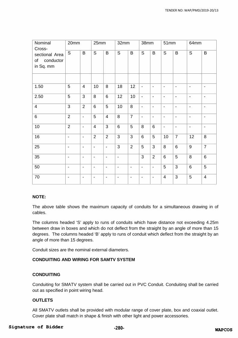
TENDER NO: WAP/PMD/2019-20/13
NominalCross-sectional Areaof conductorin Sq. mm
20mm 25mm 32mm 38mm 51mm 64mm
S B S B S B S B S B S B
1.50 5 4 10 8 18 12 - - - - - -
2.50 5 3 8 6 12 10 - - - - - -
4 3 2 6 5 10 8 - - - - - -
6 2 - 5 4 8 7 - - - - - -
10 2 - 4 3 6 5 8 6 - - - -
16 - - 2 2 3 3 6 5 10 7 12 8
25 - - - - 3 2 5 3 8 6 9 7
35 - - - - - 3 2 6 5 8 6
50 - - - - - - - - 5 3 6 5
70 - - - - - - - - 4 3 5 4
NOTE:
The above table shows the maximum capacity of conduits for a simultaneous drawing in ofcables.
The columns headed ‘S’ apply to runs of conduits which have distance not exceeding 4.25mbetween draw in boxes and which do not deflect from the straight by an angle of more than 15degrees. The columns headed ‘B’ apply to runs of conduit which deflect from the straight by anangle of more than 15 degrees.
Conduit sizes are the nominal external diameters.
CONDUITING AND WIRING FOR SAMTV SYSTEM
CONDUITING
Conduiting for SMATV system shall be carried out in PVC Conduit. Conduiting shall be carriedout as specified in point wiring head.
OUTLETS
All SMATV outlets shall be provided with modular range of cover plate, box and coaxial outlet.Cover plate shall match in shape & finish with other light and power accessories.
WAPCOSSignature of Bidder -280- WAPCOSSignature of Bidder

TENDER NO: WAP/PMD/2019-20/13
JUNCTION BOX
Suitable size of metallic junction box shall be provided for termination of conduit for SAMTVsystem. Box shall be made of 1.6mm thick MS sheet and shall be treated before painting.Front of the junction box shall be provided with 3mm thick phenolic laminated sheet cover.
COAXIAL CABLES
The coaxial cable shall be of wideband type (RG-11 for Riser & RG-6 for distribution)
TAP OFF
These shall be of ultra wide bandwidth and of hybrid type. These shall have a flat frequencyresponse over the entire operating range. These shall have a aluminium cast housing for highfrequency radiation resistance.
The Tap offs shall be in one way, two way and four way configurations.
SPLITTERS
These shall be of ultra wide band width and of hybrid type. These shall have a flat frequencyresponse over the entire operating range. These shall have a aluminium cast housing for highfrequency radiation resistance.
The splitters shall be in 2 way, 3 way & 4 way configurations
2.07 FIRE ALARM SYSTEM
GENERAL
STANDARDS
The system shall be designed, installed, commissioned & maintained to meet the country specificrecommendations. All normative references of this document shall be considered.
System conformity shall be tested & approved according to EN54-13:2005.
All fire detection & control equipment shall be approved to the relevant parts of EN54. Declaration ofconformity according to the relevant EU directives shall be provided.
The electrical installation shall be installed & tested in accordance with the latest edition of IEERegulations.
SUMMARY
Scope
This specification describes an addressable Fire Detection and alarm signaling system. The controlpanel shall be intelligent device addressable, analog detecting, low voltage and modular, with digitalcommunication techniques, in full compliance with all applicable codes and standards. The featuresand capacities described in this specification are required as a minimum for this project and shall befurnished by the successful contractor.
The system shall be in full compliance with European standards and country specific codes.
WAPCOSSignature of Bidder -281- WAPCOSSignature of Bidder

TENDER NO: WAP/PMD/2019-20/13
The system shall include all required hardware, raceways, interconnecting wiring and software toaccomplish the requirements of this specification and the contract drawings, whether or not specificallyitemized herein.
All equipment furnished shall be new and the latest state of the art products of a single manufacturer,engaged in the manufacturing and sale of analog fire detection devices.
The system as specified shall be supplied, installed, tested and approved by the local Authority HavingJurisdiction, and turned over to the owner in an operational condition.
In the interest of job coordination and responsibilities the installing contractor shall contract with asingle supplier for fire alarm equipment, engineering, programming, inspection and tests, and shall becapable of providing a LPCB, VDS, and FM certificate” for the complete system.
The system specified shall be that of Siemens Fire Safety which meets the project requirements.Other systems shall be submitted 10 days prior to bid date for approval by the Engineer. All systemapproved shall meet all the requirements spelled out in this specification. System approval shall be inwriting by the Engineer and a copy shall be submitted with the system submittals.
QUALIFICATIONS
The fire detection system supplier will be a company with a minimum of 10 years experience in firedetection.
SYSTEM DESCRIPTION
Basic FS-20 System - The system shall be a complete, electrically supervised fire detection system,with a microprocessor based operating system having the following capabilities, features, andcapacities:
System shall provide an output port for monitoring purposes by external systems. Communications toan external system shall be Ethernet, RS-232 or RS-485 communications.
At least 32 panels shall be networkable on C-WEB/SAFEDLINK.
Multiple C-WEB/SAFEDLINK clusters shall be networked on C-WEB/LAN and shall be approved inaccordance with EN54-13.
At least 64 panels shall be networked in a multi-cluster C-WEB/LAN
The networked panels shall provide peer to peer communication and support system wide automaticinteractions to fulfill smoke control or evacuation functionalities.
The homogenous network structure shall be such that only a single remote transmission to emergencyservices is necessary.
Any panel shall be configurable to display and operate all messages from other panels in the network.
Full redundancy shall be provided at all levels of the network structure.
The system shall provide the remote access connection via Ethernet to completely program andcontrol the fire detection system.
The local system shall provide status indicators and control switches for all of the following functions:
WAPCOSSignature of Bidder -282- WAPCOSSignature of Bidder

TENDER NO: WAP/PMD/2019-20/13
Audible and visual notification alarm circuit zone control.
Status indicators for sprinkler system water-flow and valve supervisory devices.
Any additional status or control functions as indicated on the drawings, including but not limited to;emergency generator functions, fire pump functions, door unlocking and security with bypasscapabilities.
Each intelligent addressable device or conventional zone on the system shall be displayed at theCentral Alarm Receiving Terminal and the local fire alarm control panel by a unique alphanumeric labelidentifying its location.
The Fire Panel system shall have the ability to connect to the Danger Management System (DMS).Danger Management System shall be a PC based, display and software package EN listed for thisapplication. The DMS shall have as a minimum, the following:
Intuitive graphical user interface
Global and local command abilities
Time based control for entire system
Multi-level passwords.
The system shall have the ability for up to 30 command centers pro server with full control of the firedetection.
Special Smoke Detection Requirements
A very early smoke detection system similar to VESDA Laser Focus shall be installed throughout theareas indicated on the floor plans.
SYSTEM OPERATION
The system shall monitor and act accordingly for the following conditions:
Fire alarm condition:
The system shall enter the fire alarm condition upon:
Activation of any manual call point.
Receipt of an alarm signal from any individual automatic detector.
Receipt of pre alarm signals from more than one detector.
Activation of sprinkler pressure switch.
Fire alarm signal from sub system.
The fire alarm condition shall:
Illuminate the general fire alarm indicator.
Be indicated on the control panel display giving details of the device & zone number, alarm type,number of devices in alarm and a programmable location text with a minimum of 40 characters.
WAPCOSSignature of Bidder -283- WAPCOSSignature of Bidder

TENDER NO: WAP/PMD/2019-20/13
Sound the control panel internal warning sounder.
Activate the required sounders as per the attached cause & effect schedule.
Activate the required outputs as per the attached cause & effect schedule.
Activate the required detector remote LED outputs as per the attached cause & effect schedule.
Activate fire brigade communication equipment or start alarm verification concept as required inattached cause & effect schedule.
Display alarm verification concept delay time remaining.
Return all lifts to the ground floor.
Close all fire doors in the building normally held open by door release units.
Close all fire doors on the floor of the initiating alarm device normally held open by door release units.
Release all external fire doors.
Operate fire dampers as described in the attached cause and effect schedule.
Shut down air handling equipment as described in attached cause & effect schedule.
Activate boiler cut off switch.
Activate boiler cut off switch after a delay of 3 minutes.
The pre-alarm condition:
The system shall enter the pre alarm condition upon:
Receipt of a pre-alarm signal from any automatic detector.
The pre-alarm condition shall:
Be indicated on the control panel display giving details of the device & zone number, number ofdevices in alarm and a programmable location text with a minimum of 40 characters.
Sound the control panel internal warning sounder.
Activate the required sounders as per the attached cause & effect schedule.
Activate the required outputs as per the attached cause & effect schedule.
The fault condition:
The system shall enter the fault condition upon:
Any short circuit, open circuit on the detection loops, sounder circuits and fire brigade connectionequipment.
Any earth fault capable of affecting the reliable operation of the system.
Any CPU fault as per EN54-2.
Any power supply fault.
WAPCOSSignature of Bidder -284- WAPCOSSignature of Bidder

TENDER NO: WAP/PMD/2019-20/13
Any network fault.
Removal of any addressable device.
Fault signals from connected input modules.
Any fault signal generated by internal monitored functions of addressable devices.
The fault condition shall:
Display the device number and/or description of the fault.
Sound the control panel internal warning sounder.
Activate the required outputs as per the attached cause & effect schedule.
Activate fire brigade communication fault output or initiate the fault intervention concept as required inattached cause & effect schedule.
Display fault intervention concept delay time remaining.
Degrade mode functionality:
The system shall include a degrade mode functionality such that should a network participant fail orthe network cease to function a common fire alarm may still be generated such that the fire brigadecommunication equipment is still activated.
Software redundancy
The system shall include a software redundancy mode such that in case of failure, a reboot istriggered. Should reboots fail, the panel goes into software redundancy mode. As last resort, the panelgoes in degrade mode.
Fire brigade communication: The system shall be connected to a secure fire brigade communicationsystem via separate monitored fire & fault outputs. The system shall also be capable of receiving acommon fault signal from the fire brigade communication equipment.
The system shall provide signals to the fire brigade communication system in accordance with thefollowing alarm verification concept:
Mode Manned – Alarms from automatic detectors will activate the system sounders and initiate a timer(T1) programmable from 10s to 5 minutes. Providing a responsible person acknowledges the panelwithin this time period no signal will be sent to the fire brigade communication equipment. Uponacknowledgement a second timer (T2) programmable from 10s to 10 minutes will be initiated. Againproviding the system can be reset within this time period no signal will be sent to the fire brigadecommunication equipment.
Operation of any manual call point will immediately cancel the delay timers and a signal will be sent tothe fire brigade communication equipment.
Mode unmanned – Alarms from any manual call point or automatic detector will immediately send asignal to the fire brigade communication equipment.
WAPCOSSignature of Bidder -285- WAPCOSSignature of Bidder

TENDER NO: WAP/PMD/2019-20/13
Confirmation signals: All critical auxiliary devices requiring activation from the fire detection system willsend a confirmation signal to the control panel confirming correct operation. Any non confirmedoperations will be reported on the control panel as a fault.
SUBMITTAL
The contactor shall include the following information with their offer:
Power & battery calculations. Battery & power supply size will be a minimum of 125% of the calculatedrequirement.
Complete product catalogue with manufacturers’ data including Quiescent & alarm powerrequirements, physical dimensions, and finish and mounting requirements.
All necessary installation drawings and as built drawings.
Complete floor plans in a CAD compatible format showing all equipment required to meet thisspecification as well as interconnecting wiring marked for size & quantity of conductors.
Fire alarm function matrix illustrating output events in relation to alarm, pre-alarm, drift application &fault signals.
Full list of all departures, exceptions, variances or substitutions from this specification.
Incomplete submittals shall be returned without review unless with prior written approval.
QUALITY ASSURANCE
Manufacturer Qualifications: The publications listed below form a part of this publication to the extentreferenced. The publications are referenced in the text by the basic designation only. The latestversion of each listed publication shall be used as a guide unless the authority having jurisdiction hasadopted an earlier version.
The manufacturer shall have a minimum of 15 years production experience in the manufacture anddesign of high sensitivity aspiration-type smoke detection systems.
ISO 9002
FM Global (Factory Mutual (FM)): FM Approval Guide
Supplier Qualifications
The manufacturer of the supplied products must utilize product distribution on a national basis to beconsidered for this bid. The manufacturer must have factory branches as well as independentdistributors to allow the end user with the ability to utilize factory trained and authorized competitiveservice providers after system installation and commissioning.
Provide the services of a factory trained and certified representative or technician, experienced in theinstallation and operation of the type of system provided. The representative shall be licensed in theState if required by law.
The technician shall supervise installation, software documentation, adjustment, preliminary testing,final testing and certification of the system. The technician shall provide the required instruction to theowner's personnel in the system operation and maintenance.
WAPCOSSignature of Bidder -286- WAPCOSSignature of Bidder

TENDER NO: WAP/PMD/2019-20/13
The supplies shall furnish evidence they have an experienced service organization, which carries astock of spare and repair parts for the system being furnished.
The equipment supplier shall be authorized and trained by the manufacturer to calculate, design,install, test, and maintain the air sampling system and shall be able to produce a certificate statingsuch upon request.
Installer Qualifications:
Before commencing work, submit data showing that the manufacturer has successfully installed firealarm systems of the same scope, type and design as specified.
The contractor shall submit copies of all required Licenses and Bonds as required in the Countryhaving jurisdiction.
The contractor shall be qualified to certify fire alarm systems. Upon completion of the installation thecontractor shall certify the final system meets the country regulation for ongoing maintenance.
Contractors unable to comply with the provisions of Qualification of Installers shall present proof ofengaging the services of a subcontractor qualified to furnish the required services.
Source Limitations for fire alarm equipment: Obtain fire alarm equipment from single source.
Electrical Components, Devices, and Accessories: Listed and labeled as defined by countryregulation, by a qualified testing agency, and marked for intended location and application.
Preinstallation Conference: Conduct conference at Project site.
DELIVERY, STORAGE, AND HANDLING
Deliver products to project site in original, unopened packages with intact and legible manufacturers’labels identifying product and manufacturer, date of manufacture, and shelf life if applicable.
Store materials inside, under cover, above ground, and kept dry and protected from physical damageuntil ready for use. Remove from site and discard wet or damaged materials.
PROJECT CONDITIONS
Installed products or materials shall be free from any damage including, but not limited to, physicalinsult, dirt and debris, moisture, and mold damage.
Environmental Limitations: Do not deliver or install products or materials until spaces are enclosedand watertight, wet work in spaces is complete and dry, and temporary HVAC system is operating andmaintaining ambient temperature and humidity conditions at occupancy levels during the remainder ofthe construction period.
WARRANTY
The contactor shall provide a warranty for the entire system for electrical & mechanical failures for oneyear. The warranty shall begin on completion of the acceptance certificate.
The following maintenance contract will be offered:
WAPCOSSignature of Bidder -287- WAPCOSSignature of Bidder

TENDER NO: WAP/PMD/2019-20/13
The fire alarm system manufacture or subcontractor shall offer for the owners consideration at the timeof submittal a priced inspection, maintenance test & repair contract complying with country regulation.
SERVICE AGREEMENT
Technical Support: Beginning with Substantial Completion, provide software support for 2 years.
Upgrade Service: Update software to latest version at Project completion. Install and programsoftware upgrades that become available within two years from date of Substantial Completion.Upgrading software shall include operating system. Upgrade shall include new or revised licenses foruse of software.
Provide 30 days' notice to Owner to allow scheduling and access to system and to allow Owner toupgrade computer equipment if necessary.
EXTRA MATERIALS
Furnish extra materials that match products installed and that are packaged with protective coveringfor storage and identified with labels describing contents.
PART 2 – Products
MANUFACTURERS
Manufacturers: Subject to compliance with requirements all equipment shall be Siemens.
CONTROL AND TERMINALS REPEATER PANELS
Control and Terminal Repeater Panels must provide at least the following:
Integrated Ethernet interface for connection to danger management, building management or systemmanagement tools.
Secure network connection for the connection of further control and / or terminal panels into aredundant peer to peer network of up to 64 participants.
In addition to the indicators required for compliance with EN54-2 the panels shall provide the followingadditional indicators:
Premises manned LED (Amber)
Alarm display scroll highlight button (Red).
Four freely programmable amber LED’s for site specific functions.
Two amber LED’s for free programmable site specific control buttons.
Sprinkler pump running LED (Amber).
Boiler shut off activated LED (Amber).
Maintenance page sent LED (Amber).
Up to 96 indicator groups, each one red and one yellow LED
Display: In addition to the LED indications the panel shall include an integral 128 x 635 pixel LCD withthe following features:
WAPCOSSignature of Bidder -288- WAPCOSSignature of Bidder

TENDER NO: WAP/PMD/2019-20/13
Header area giving details on the type of event, number of events and the time remaining before anydelay to the fire brigade communication equipment runs out.
Simultaneous display of up to two devices in alarm including information on zone number, deviceaddress, type of alarm and up to 40 characters of free programmable descriptive text.
Alarm display shall automatically show the first device to alarm at the top and last to alarm in the fieldsbelow. A scroll button shall allow display of all other alarm events.
Additional information shall be available via context specific soft keys allowing further deviceinformation to be obtained as well as up to x intervention texts of x characters each
In addition to the controls required to meet the requirements of EN54-2 the panel shall provide thefollowing:
Decimal keypad including star & hash buttons.
Sound alarms button.
Two freely programmable buttons.
3 x context specific soft keys adjacent to the display to assist in ease of use.
Individual fire & fault LED’s for each zone c/w adjacent area for zone description texts.
Bomb alert activate button.
Extend working hour’s button.
Cancel working hour’s extension button.
User access shall be via:
4-6 digit access code.
Key switch.
Future upgrades – Fire alarm control panels shall include a facility to allow future software & firmwareupdates to be downloaded via the control panel programming tool. This facility will include updates toall other control panels on the system network, connected floor repeaters.
Full function repeater panels – The control panel shall have the facility for the connection of a repeaterpanel as a network participant. This panel shall have the ability to provide all the control, indication andprogrammability of the control panels.
Network – Control panels shall be capable of being connected into a single homogenous networkedsystem. This network shall be a secure proprietary network being fully monitored and connected in aloop for fault tolerance. The network shall include degrade mode functionality such that should anetwork participant fail or the network cease to function a common fire alarm may still be generatedsuch that the fire brigade communication equipment is still activated.
All network components required for the backbone cluster structure (including the Ethernet switches)shall be included in the EN54 approval certification.
It shall be possible to increase the cable distance possible between panels by adding a networkrepeater facility.
WAPCOSSignature of Bidder -289- WAPCOSSignature of Bidder
TENDER NO: WAP/PMD/2019-20/13
The communication between panels shall be possible via fiber optic connections.
All control panels shall have the possibility to include an integral 40 column thermal printers.
BacNET – Fire alarm control panels shall be BacNET/ISA compatible.
Ethernet – Fire alarm control and terminal repeater panels shall have an integrated Ethernetconnection to enable system connection, reporting & control functions from associated managementsystems.
Cerberus Engineer – The system shall be connected to Cerberus Engineer software enabling remoteoperation from a PC.
Remote servicing – Fire control and terminal repeater panels shall allow remote servicing viatelephone modem or internet connection.
In the case of a malfunction of the main control panel, a standby fire panel or terminal will take over thesystem’s visibility. Standby functionality shall be also possible by the management station.
CONTROL PANELS – ADDRESSABLE TYPE
Self contained addressable control panels capable of operating in a network of at least 32 panels andterminals. Panels shall have LPCB, VDS and FM approval to EN54 and meet the relevantrequirements of country regulation.
Control panels must provide at least the following:
Type FC 726 with housing for four expandable up to twelve detection loops for the connection of up to126 devices each.
In addition, the loop extension card allows doubling the number of loops keeping unchanged thenumber of addresses.
One monitored sounder circuit.
Designated monitored fire output for connection to remote ARC communication equipment. This circuitalso provides operation in degrade mode according to EN54 requirements for systems with more than512 detectors.
Designated fire output with clean contacts. Provides operation in degrade mode according to EN54requirements for systems with more than 512 detectors.
Designated monitored fault output for connection to remote ARC communication equipment.
Designated fault output with clean contacts.
Eight free programmable input/outputs.
Integral 24Vdc monitored power supply to EN54-4 with integral battery back up for up to 72hrs +30minutes full alarm.
The panel construction shall allow for:
Sufficient cable entries for all connectable detection loops, sounder circuits, network cables & mainssupplies.
WAPCOSSignature of Bidder -290- WAPCOSSignature of Bidder

TENDER NO: WAP/PMD/2019-20/13
Attractive removable molded front cover with metal back box providing minimum ingress protection ofIP30.
Surface or semi-flush mounting.
Manned / Unmanned operation:
Control panels shall have a dedicated monitored fire brigade communication output and shall becapable of operating in two distinct modes:
Mode Manned – Alarms from automatic detectors will activate the system sounders and initiate a timer(T1) programmable from 10s to 5 minutes. Providing a responsible person acknowledges the panelwithin this time period no signal will be sent to the fire brigade communication equipment. Uponacknowledgement a second timer (T2) programmable from 10s to 10 minutes will be initiated. Againproviding the system can be reset within this time period no signal will be sent to the fire brigadecommunication equipment. Operation of any manual call point will immediately cancel the delay timersand a signal will be sent to the fire brigade communication equipment.
Mode unmanned – Alarms from any manual call point or automatic detector will immediately send asignal to the fire brigade communication equipment.
It shall be possible to select mode manned by any of the following:
Automatically selected during working hours using internal system clock with automatic switching ofsummer / winter time. It may be possible to extend working hours by up to 4 hours (programmable) bypressing a separate control. (Extend working hours control). This extension can be subsequentlycancelled by pressing a (cancel working hour’s extension control). Or
Manually selected with premises manned control button. Or
Automatically selected when intrusion system unset. Or
Automatically selected with input from Access control system.
Delays to the fire brigade communication equipment can be cancelled by pressing the alarm delay offcontrol on the control panel.
Fault attendance monitoring: Control panels shall have a dedicated monitored output to communicatewith fault communication equipment this shall work in two distinct modes manned & unmanned.
Mode manned - A fault activates local alarming and starts the delay t1 for attendance monitoring. Theoperating personnel acknowledge the fault at the operating terminal prior to the expiry of t1, thussilencing the local alarming equipment. If the fault is not acknowledged, global alarming is activatedbefore the expiry of t1. Simultaneously to the delay t1, the service intervention time ts starts in the'intervention monitoring' part. If the fault is not eliminated prior to the expiry of ts, the maintenancepersonnel are called up.
Mode unmanned – Faults are reported directly.
Conditions: Fire alarm control panels shall be capable of receiving and handling all of the followingconditions from field devices:
Alarm.
Pre-alarm.
WAPCOSSignature of Bidder -291- WAPCOSSignature of Bidder

TENDER NO: WAP/PMD/2019-20/13
Device fault.
Device impaired.
Device isolated.
Device isolator activated
Detector drift compensation limit exceeded.
Detector application warning.
Programmable functions: Fire alarm control panels shall be capable of being configured to do all of thefollowing:
Manned / unmanned mode:
Selectable by time of day.
Selectable on specific days.
Selectable by remote input.
Selectable manually.
Programmable times for presence & investigation times.
Selectable for sounders during first timer, off, on or pulsed.
Detector behavior:
It shall be possible to select the required parameter set for each detector at the panel via theprogramming tool.
It shall be possible to configure each individual device to work within the manned/unmanned conceptor not.
Control cause & effect:
Fire alarm control panels shall have the possibility to create complex cause & effect controls includingAND, OR & NOT functions or combinations thereof.
In addition, controls can be programmed with respect to panel functions and be time related.
Sounders:
It shall be possible to select sounder tones and volume from the control panel. Up to two differenttones shall be selectable for each sounder and configured to operate with different cause & effectscenarios.
Alarm indicators:
It shall be possible to configure an individual extension LED to be activated from any of severaldetectors.
Disablement – Fire alarm control panels shall allow the isolation of any individual device, zone, sectionor area. Any isolation shall have the ability to be restored after a pre-defined time period.
WAPCOSSignature of Bidder -292- WAPCOSSignature of Bidder

TENDER NO: WAP/PMD/2019-20/13
Test Modes – Fire alarm control panels shall allow the following tests to be performed:
Lamp test – The control panel shall include a control button that will illuminate all panel indicators andhighlight the complete display.
Detector test – The control panel can set zones into detector test mode. This increases the sensitivityof all detectors within that zone with robust parameter setting. On test the detector alarm indicator shallbe illuminated but sounders & controls shall not be activated. Base sounders directly connected to thedetector tested shall operate briefly.
Installation test - The control panel can set zones into detector test mode. This increases the sensitivityof all detectors within that zone with robust parameter setting. On test the detector alarm indicator shallbe illuminated and all programmed sounders and controls shall operate as required.
Floor repeater panels with control – The control panel shall allow connection of up to 4 repeater panelson each detection loop. These panels will repeat the indication of the main display and allow forsilencing and reset of the system. In addition these repeaters will have 6 freely programmable buttonsand associated indicators. Repeater panels may be powered from the detection loop or from a remote24Vdc power supply.
Indicating only floor repeater panels – The control panel shall allow connection of up to 4 repeaterpanels on the detection loop. These panels will repeat the indication of the main display. Repeaterpanels may be powered from the detection loop or from a remote 24Vdc power supply.
Additional cards – Fire alarm control panels shall allow the integration of the following additional cards:
2 x detection loop card
Loop extension card
I/O card
2 x 4 way sounder cards.
RS232 interface card
RS485 interface card.
Network cards.
The fire alarm panel shall allow the exchange of defect module bus cards in a running system.
The Control Panel shall allow to configure which event categories should be displayed
Up to 4 alarm concepts within a Fire alarm control panel shall be available
Programmable time for inputs before it is evaluated as active.
Alarm counter, which can be set with parameters for:
Alarms counter from one or more fire control panel
Test alarms will be counted as yes / no
TERMINALS REPEATER PANELS
WAPCOSSignature of Bidder -293- WAPCOSSignature of Bidder

TENDER NO: WAP/PMD/2019-20/13
FT724 self contained addressable terminal repeater panels capable of operating in a network of atleast 64 controls and terminals panels. Panels shall have LPCB, VDS, and FM approval to EN54 andmeet the relevant requirements of country regulation.
Terminal Repeater Panels must provide at least the following:
Power supply option:
From one control panel
Optional local power supply with battery backup
Additional cards – terminal repeater panels shall allow the integration of the following additional cards:
RS232 interface card
RS485 interface card.
Network cards.
DETECTION LOOP POWERED ADDRESSABLE REPEATER PANELS
Addressable repeater panels shall provide remote indication of system status. The indications givenwill be programmable so that it is possible to only view essential information at each display. Therepeater shall connect directly to the detection loop it shall be possible to power the display directlyfrom the loop. It shall also be possible to remotely provide power as an option where loop powercapacity has been exceeded.
PC REMOTE CONTROL AND INDICATION SOFTWARE
The system shall be capable of being controlled by remote PC using software that can dial into aconnected panel to allow remote interrogation and operation. The software shall be arranged so as toappear as a direct replica of the control panel and shall be capable of displaying all the information andcontrolling all the features of the panel itself.
EVENT PRINTER
The system shall be capable to connect an event printer. The printer shall be supervised and printerfault are reported to the control or terminal repeater panel.
The control and terminal repeater panel shall have the option to program which category event ofalarm, fault or messages have to be printed
The event printer shall be possible to be connected via:
Internal printer via RS 232
External printer via serial connection RS232
External printer via Ethernet
PERIPHERALS
Detectors (general):
WAPCOSSignature of Bidder -294- WAPCOSSignature of Bidder

TENDER NO: WAP/PMD/2019-20/13
Point type smoke & heat detectors shall mount on a common base such that they can be readilyexchanged should the need occur.
Detectors shall have a locking facility to stop un-authorized removal.
Where a detector is exchanged for one of a different type a fault warning shall be given.
Removal of a detector shall not lead to the loss of any other device.
All detectors shall be intelligent with integrated algorithms for comparison with actual sensor signals.
All detectors shall have an integral short circuit isolator.
The detection loops should be wired without tees, spurs or stubs but the system should be able toaccept such wiring to give enhanced levels of flexibility during the systems lifetime.
OP720 Optical Smoke Detector:
Smoke detectors shall be intelligent devices with integrated algorithms for comparison with actualsensor signals ensuring fast & reliable detection. Detectors shall fulfill and be approved to EN54-7including test fire 1. The detector should have been designed to have high tolerance to dust, dirt,temperature fluctuations and air currents. In addition the detector shall include:
Selectable application specific parameter sets.
For the communication of 3 different danger levels for differentiated alarm activation.
The facility to detect if the detector is in an unsuitable environment and give a separate warning ofsuch to the panel.
Compensation for the gradual build up of dust & dirt to ensure a consistent level of detection over time.When the detector reaches a point where it can no longer retain this consistent detection a separatewarning signal shall be given to the control equipment.
Internal fault monitoring with faults reported with separate signals to the control panel.
An integral short circuit isolator.
A separately controllable remote indicator output for activation from this or other detectors.
An integral response indicator with 360° viewing angle.
Operation in the temperature ranges -10°C to + 50°C
EMC compatibility of 50V/m
Heat Detector (Static+RoR):
Heat detectors shall be intelligent devices with integrated algorithms for comparison with actual sensorsignals ensuring reliable detection. Detectors should fulfill and be approved to EN54-5. In addition thedetector shall include:
Selectable application specific parameter sets.
Communication of 3 different danger levels for differentiated alarm activation.
Internal fault monitoring with faults reported with separate signals to the control panel.
WAPCOSSignature of Bidder -295- WAPCOSSignature of Bidder

TENDER NO: WAP/PMD/2019-20/13
An integral short circuit isolator.
A separately controllable remote indicator output for activation from this or other detectors.
An integral response indicator with 360° viewing angle.
Operation in the temperature ranges -10°C to + 50°C
EMC compatibility of 50V/m
Air Duct Smoke Detectors.
Air duct smoke detector shall be provided to protect air handling ducts ans shall have the followingfeatures:
Usable in air speeds from 1 to 20m/s
Ambient temperature operation range -20 to +50°C
Ingress protection to IP54
Capable of detecting in ducts between 100mm – 2.8m
Aspirating Smoke Detectors.
Aspirating smoke detection shall be addressable and integrated directly onto the detection loop. Thedetector shall have the following functions:
4 alarm state indicators
Smoke level indicator
Fault & disabled indication
Pre alarm/info alarm selectable between 0.025 & 2%/m
Fire 1 & Fire 2 alarm selectable between 0.025 & 20%/m
3 x 30Vdc 2A rated contacts for alarm, pre-alarm and fault
Integral short circuit isolation
VLF-250 type with an area of coverage up to 250 m2
Ex Heat Detector.
Hazardous area smoke detectors shall operate using the thermal sensor detection principal and besuitable for use up to 70°C in Hazardous Area Zones 1 and 2.
Operation in the temperature ranges -25°C to + 70°C
EMC compatibility of 50V/m
Ingress protection: IP44.
Ex Manual Call Point, single action.
WAPCOSSignature of Bidder -296- WAPCOSSignature of Bidder

TENDER NO: WAP/PMD/2019-20/13
Manual call points will be break glass type suitable for flush or surface mounting. The call point shallinclude a test key feature for the rapid testing of the device without removing the glass. The call pointshall also incorporate the following:
Alarm response indicator.
Facility for adding additional protective flap.
Operating temperature: -25°C to + 70°C
Ingress protection of at least IP54 (IP65 with protection seal)
One Input / Output Modules
Input / output modules shall comply with the requirements of and be approved to EN54-17. Input /output modules should connect directly to the loop and not require further power supply connections.Each input / output module shall take one address. Input / output modules shall additionally include:
Inputs monitored for short & open circuit.
Inputs can be configured for normally open or normally closed operation.
Outputs to be rated at 250VAC 4A resistive & 30VDC 4A clean contacts.
Output to be selectable as continuous or as pulsed operation. Pulse duration to be selectable between1 & 20 seconds.
Integral short circuit isolator.
LED indication of normal, fault, test, & activation conditions.
Module can be configured as fail safe.
Modules to be mounted in an IP66 housing with clear lid for device status indication.
Modules should additionally be suitable for DIN rail mounting.
Operating temperature: -25°C to +60°C
EMC compatibility: 50V/m
Four Input Modules
Input modules shall comply with the requirements of and be approved to EN54-17. Input modules shallconnect directly to the loop and not require further power supply connections. Each input module shalltake one address but have four separate programmable inputs. Input modules shall additionallyinclude:
Inputs monitored for short & open circuit.
Inputs can be configured for normally open or normally closed operation.
Integral short circuit isolator.
LED indication of normal, fault, test, & activation conditions.
Option for configuration as fail safe operation.
WAPCOSSignature of Bidder -297- WAPCOSSignature of Bidder

TENDER NO: WAP/PMD/2019-20/13
Programmable activation delay filter from 0-240 seconds.
Modules to be mounted in IP54 housing with clear lid for device status indication.
Where modules are to be mounted outside or in other areas likely to be subject to damp or water spraythey are to be mounted in IP66 housing with clear lid for device status indication.
Modules should additionally be suitable for DIN rail mounting.
Operating temperature: -25°C to +60°C
EMC compatibility: 50V/m
Four Input / Output Modules
Input / output modules shall comply with the requirements of and be approved to EN54-17. Input /output modules should connect directly to the loop and not require further power supply connections.Each input / output module shall take one address but have four separate programmable inputs andfour separate programmable outputs. Input / output modules shall additionally include:
Inputs monitored for short & open circuit.
Inputs can be configured for normally open or normally closed operation.
Outputs to be rated at 250VAC 4A resistive & 30VDC 4A clean contacts.
Output to be selectable as continuous or as pulsed operation. Pulse duration to be selectable between1 & 20 seconds.
Integral short circuit isolator.
LED indication of normal, fault, test, & activation conditions.
Module can be configured as fail safe.
Programmable activation delay filter from 0-240 seconds.
Modules to be mounted in an IP54 housing with clear lid for device status indication.
Where modules are to be mounted outside or in other areas likely to be subject to damp or water spraythey are to be mounted in an IP66 housing with clear lid for device status indication.
Modules should additionally be suitable for DIN rail mounting.
Operating temperature: -25°C to +60°C
EMC compatibility: 50V/m
Addressable combined sounder controller / zone monitor.
Addressable combined sounder controllers/ zone monitors shall comply with the requirements of andbe approved to EN54-17. These modules shall have two circuits each and be configurable either as aconventional zone monitor or a sounder controller. The modules shall connect directly to the loop andbe powered from a separate monitored EN54-4 compliant power supply. Each module will take oneaddress but identify both sub circuits separately. In addition the module will include:
Two independent circuits monitored for short & open circuit.
WAPCOSSignature of Bidder -298- WAPCOSSignature of Bidder

TENDER NO: WAP/PMD/2019-20/13
The ability to be programmed as a zone monitor. The module circuits will monitor up to 32 conventionaldetectors and call points each.
The ability to be programmed as a sounder controller. The module can control sounders and visualwarning devices with a maximum current of 2A divided across both circuits.
Integral short circuit isolator.
LED indication of normal, fault, test, & activation conditions.
Module can be configured as fail safe.
Modules to be mounted in an IP54 housing with clear lid for device status indication.
Where modules are to be mounted outside or in other areas likely to be subject to damp or water spraythey are to be mounted in an IP66 housing with clear lid for device status indication.
Modules should additionally be suitable for DIN rail mounting.
Operating temperature: -25°C to +60°C
EMC compatibility: 50V/m
Manual Call Points
Manual call points will be break glass type suitable for flush or surface mounting and approved toEN54-11 and EN54-17. The call point shall include a test key feature for the rapid testing of the devicewithout removing the glass. The call point shall also incorporate the following:
Integral short circuit isolator.
Alarm response indicator.
Facility for adding additional protective flap.
Wireless communication device to facilitate testing; enable readout of current status and wiringdiagnostics.
Operating temperature: -25°C to + 70°C
An EMC Compatibility of at least 50V/m
Ingress protection of at least IP44.
Detector Base
Detector base shall include the following features:
Cable capacity 0.2 – 1.5 mm2
Space for auxiliary terminals as micro terminals 0.5 mm2 or connection terminals 2.5 mm2
Pure white RAL 9010
Detector Base with Integral Sounder
WAPCOSSignature of Bidder -299- WAPCOSSignature of Bidder

TENDER NO: WAP/PMD/2019-20/13
Detector base sounders shall fulfill the requirements of and be approved to EN54-3. The soundersshall also:
Have 11 programmable tones selectable from the control panel.
Have the ability to switch between one tone for alert & one tone evacuate purposes.
Be fully synchronized with other sounders connected to the control panel.
Have 2 programmable sound levels selectable from the control panel.
Be able to provide an output of at least 88dBA at 1m.
Have minimum EMC compatibility of 50V/m
Have an operating temperature in the range of -25°C to +70°C
PART 3 – EXECUTION
EXAMINATION
Examine areas and conditions for compliance with requirements for installation tolerances and otherconditions affecting performance of the Work.
Proceed with installation only after unsatisfactory conditions have been corrected.
INSTALLATION:
The installation will be in accordance with the latest edition IEE Regulations and conform to thecountry requirements.
Surface cabling should be neatly run and securely fixed at suitable intervals in accordance with themanufacturers recommendations.
Joints in cables, other than those within equipment enclosures should be avoided wherever possible.
Where a cable passes through an external wall it should be contained in a smooth bore sleeve ofmetal or other non-hygroscopic material sealed into the wall. This material will slope downwardstowards the outside and should be sealed with a suitable waterproof compound.
Where cables, conduits or trunking pass through floors, walls, partitions or ceilings the surroundinghole shall be made good with a fire stopping material with sufficient fire resistance to maintain theintegrity of the construction.
Each junction box will include the legend “Fire Alarm System” on its cover.
All wires shall be provided with an identifying permanent label within 25mm of its termination.
A consistent color code for fire alarm conductors will be used throughout the installation.
Wiring within enclosures will be arranged to allow accessibility to equipment for adjustment &maintenance.
BOXES, ENCLOSURES AND WIRING DEVICES
Boxes shall be installed plumb and firmly in position.
WAPCOSSignature of Bidder -300- WAPCOSSignature of Bidder

TENDER NO: WAP/PMD/2019-20/13
Extension rings with blank covers shall be installed on junction boxes where required.
Junction boxes served by concealed conduit shall be flush mounted.
Upon initial installation, all wiring outlets, junction, pull and outlet boxes shall have dust coversinstalled. Dust covers shall not be removed until wiring installation when permanent dust covers ordevices are installed.
"Fire alarm system" decal or silk-screened label shall be applied to all junction box covers.
CONDUCTORS
Each conductor shall be identified as shown on the drawings at each with wire markers at terminalpoints. Attach permanent wire markers within 5 cm of the wire termination. Marker legends shall bevisible.
All wiring shall be supplied and installed in compliance with the requirements of the National ElectricCode and that of the manufacturer.
Wiring for strobe and audible circuits shall be a minimum 1.5 mm, signal line circuits; 1.0 mm twisted.
All splices shall be made using solderless connectors. All connectors shall be installed in conformancewith the manufacturer recommendations.
Crimp-on type spade lugs shall be used for terminations of stranded conductors to binder screw orstud type terminals. Spade lugs shall have upset legs and insulation sleeves sized for the conductors.
The installation contractor shall submit for approval prior to installation of wire, a proposed color codefor system conductors to allow rapid identification of circuit types.
Wiring within sub panels shall be arranged and routed to allow accessibility to equipment foradjustment and maintenance.
DEVICES
Relays and other devices to be mounted in auxiliary panels are to be securely fastened using DIN railsor other mechanically stable methods.
Wiring within enclosures will be arranged to allow accessibility to equipment for adjustment &maintenance.
All devices shall be mounted to or in a suitable electrical box.
IDENTIFICATION
Permanently label or mark each conductor at both ends with permanent alphanumeric wire markers.
A consistent color code for fire alarm system conductors throughout the installation.
COMMISSIONING
WAPCOSSignature of Bidder -301- WAPCOSSignature of Bidder

TENDER NO: WAP/PMD/2019-20/13
The entire system shall be inspected & tested to ensure that it operates in accordance with thisspecification and the country requirements. In particular that:
All manual call points & automatic fire detectors function correctly.
All devices carry an accurate identification label.
All manual call points and automatic fire detectors when operated result in the correct text & zoneindications at all necessary indicating equipment.
That sound pressure levels meet the country requirements.
That the connection to the ARC (Fire brigade) is functioning correctly.
That the systems cause and effects match the requirements of this specification.
The sitting of all manual call points & automatic fire detectors meet the country requirements.
All auxiliary functions such as lift returns, boiler shut off’s and door release mechanisms are functioningcorrectly.
Secondary supply will be proven by:
A full testing of the secondary power supply is performed by creating a mains failure for 24 hours &simulating a full alarm for 30 minutes.
All fault indicators and their relevant circuits are checked by simulation of suitable fault conditions.
Readings taken & recorded of all insulation resistance, earth continuity and circuit impedance.
DOCUMENTATION
On completion of the system the contractor shall provide the following documentation:
One set of system record drawings & wiring details in printed & CAD formats.
Two sets of System Operation, Installation & Maintenance manuals.
Complete listings of fitted devices, their programmed parameters, texts and assignments.
Documentation of all programmed cause & effects.
Documentation of actual field wiring topology.
Copy of the system programming in CD or floppy disc format.
System log book.
TRAINING
Training shall be provided as follows:
The contractor shall provide full training on system operation & user responsibilities to at least twopersons nominated by the customer.
CERTIFICATION
WAPCOSSignature of Bidder -302- WAPCOSSignature of Bidder

TENDER NO: WAP/PMD/2019-20/13
Upon completion the contractor will provide the following certificates in accordance with the countryregulation:
Design certificate.
Installation certificate.
Commissioning certificate.
Acceptance certificate.
Verification certificate
2.08 CCTV SYSTEM
1.0CAMERA
1.1 IP DOMECAMERA
2 megapixels resolution Network Dome Camera for trueHD quality images,2.8 – 12 mm varifocal lens,TrueDay/Night (TDN) functionality for true color image ,MotionDetection 4 Zones, Multi- Level Sensitivity Privacy Zones 4Zones,Snapshoot Support JPEG format PasswordProtection Support Character Display Support(Channel/Date) ONVIF Yes,IR Illumination20-30M IR illuminators forclear images in low light conditions Wide Dynamic Range3D noise reduction for sharper images and lower bandwidthuse in low light ONVIF compliant complete in all respect.
IP BulletCamera
2 megapixels resolution Network Bullet cameracamera,Imager 1/2.8” Progressive Scan CMOS,VideoCompression. .H.264/MJPEG,Day/Night-IR CutFilter,Minimum Illumination-0Lux/F1.4(IR ON) IR Range-Upto 50 Meter,Electronic Shutter-Auto/Manual(1/25~1/10000),Lens 2.8 to 12 mm Motorized zoom Lens,Resolution Main-1920x1080p,Digital Noise Reduction-3D,Wide DynamicRange-120db, Behavior Analysis-Line crossing detection,intrusion detection, unattended baggage detection, objectremoval detection.Support Face Detection. Region ofInterest Support 1 ROI per stream.Power Consumption andCurrent- 12 VDC, 1.2A, max. 14.5W PoE (802.3at, 42.5V to57V), 0.5A to 0.1A, max. 16.5W.Protection Level IP67, IK10TVS 2000V Lightning Protection, Surge Protection andVoltage Transient Protection.Regulatory UL, CE,FCC.Operating Conditions Temperature: -30 °C to +60 °C
WAPCOSSignature of Bidder -303- WAPCOSSignature of Bidder

TENDER NO: WAP/PMD/2019-20/13
(-22 °F to +140 °F).Humidity: 95% or less.
2.0 NETWORK VIDEO RECORDER - NVR
NVR Live view/Resolution 5MP/3MP/1080p/720p,MotionDetection Control Privacy Mask Control. USB interface-1 ×USB 2.0 and 1 × USB 3.0,Security-HTTPS, SSL,Watermark, User Authentication, Miscellaneous-N+1 hotspare. Alarm in/out -4 / 1,Network interface-1 RJ-45 10 /100/1000 Mbps self-adaptive Ethernet interface, Security-HTTPS, SSL,Video/Audio output-VAG,HDMI and Audio.Watermark, User Authentication,Incoming bandwidth-100Mbps,Outgoing bandwidth-80Mbps,HDMI output,VGAOutput,Protocol-IPv4, IPv6, TCP/IP protocol, PPPoE,DHCP, DNS, DDNS, NTP, SADP, SMTP, SNMP, NFS,and iSCSI are supported.TCP, UDP and RTP for unicast,UPnPTM, ONVIF, PSIA,Support 16 IP Camera, 2 SATAinterfaces for 4 HDDs Upto 4TB for each disk.
2.4 VMS Video Management System (VMS) software shall be usedto view live and recorded video from capture cards and IPdevices connected to local and wide area networks. TheVMS software shall have a client/server-based architecturethat can be configured as a standalone VMS system withthe client software running on the server hardware and/orthe client running on any network-connected TCP/IPworkstation. Multiple client workstations shall be capable ofsimultaneously viewing live and/or recorded video from oneor more servers. Multiple servers shall also be able tosimultaneously provide live and/or recorded video to one ormore workstations. The VMS server software shall alsohave the ability to be installed on an IP edge device—suchas an IP camera or encoder that allows for 3rd partyapplications—allowing the device to serve as both a server
WAPCOSSignature of Bidder -304- WAPCOSSignature of Bidder

TENDER NO: WAP/PMD/2019-20/13
and IP video recording device.The VMS shall not charge forthe number of concurrent clients (min. 50 thick clients and16 mobile clients to be provided along with VMS).
3.0 CCTV COLOR MONITOR
3.1 Display 55 " LED Full HD TV Resolution 1920 x 1080 ,ContrastRatio (Typical) 5000:1,Built-in Speaker (10W + 10W),Magic Clone (to USB), Auto Source Switching & Recovery,Lamp Error Detection, Super Clear Coating, TemperatureSensor, Plug and Play (DDC2B), Pivot Display, ClockBattery, PIP/PBP, Video Wall (10x10), Image Rotation,Button Lock, HDCP Support, Smart Scheduling, SmartF/W update, Built-In MagicInfo Premium-Swith MountingBrackets as per Technical Specification complete in allrespect.
Workstation Intel(R) Core(TM) i7-3770 Processor (8M Cache, up to 3.90GHz); Memory: 4GB, NON-ECC, 1600MHZ; RAM: 4GB(1x4GB) Non-ECC DDR3 1600MHz SDRAM Memory;Keyboard: 12 function keys; Chassis: Tower/Workstation;DVD: 8X Slimline DVD+/-RW, Data Only; 20" TFT Monitor;Dual Graphics Card; Network interface card: IntegratedIntel(R) 82579LM Gigabit1 Ethernet LAN 10/100/1000;Hard disk: 250GB, 7200 RPM 3.5" SATA 6Gb/s Hard Drive;Operating system: Windows 7 Professional 64 Bit.
4.0 ETHERNET SWITCHES
4.3 12 Port PoE+ Switch with 2 SFP slots 12 x 10/100/1000Base-T PoE+ ports and additional 2 100/1000X SFPPORTS Should support PoE+ as per IEEE 802.3 at withPoE budget of 100W.Should support STP, RSTP, MSTP,IGMP v1/v2/v3 snooping, STP root guard, Voice VLAN,MLD snooping (MLDv1 and v2), IEEE 802.3ac VLANtagging IEEE 802.17/equivalent for sub 50ms ringprotection in following scenario : single, dual fibre cuts inring and when fibre cut at common shared link in between
WAPCOSSignature of Bidder -305- WAPCOSSignature of Bidder

TENDER NO: WAP/PMD/2019-20/13
two or more rings.
.
2.09 Access Control System
1. Multi Door Networked Intelligent Access Controller
General Specifications & Requirements
1The Bidder shall propose IP Enabled Access Controllers for the project. The Accesscontroller shall be completely field upgradeable or by remote access on IP Network withoutchanging the software or effecting any database information.
2 The same shall be true for remote diagnostics purposes, wherein the service provider shallrender services for monitoring / improvement / up gradation / trouble shooting.
3
The Networked Intelligent Controller shall utilize true distributed processing technology withthe capability of local processing based on the local storage of Cardholders, all systemaccess groups and time schedules, and input and output information shall be maintained inthe controller’s RAM memory.
4The Intelligent Access Controller modules shall be support the monitoring and control of four(4) reader, with either or combination of various types of readers, keypads and BiometricReaders in any types and combinations.
5 Each Networked Intelligent Controller shall utilize on-board self -diagnostic LEDs, and aconnection diagram overlay for ease of installation and service.
6
The controller shall also support technology feature which shall retain the last complete paneldatabase as a default until the update has been confirmed, ensuring the integrity of thedatabase in the field panel. The technology shall ensure corruptions due to hang-ups duringdownloads are accommodated and the field panel always has a complete and fully functionaldatabase.
7 Each Networked Intelligent Controller shall be supplied with an enclosure with an enclosuretamper switch.
WAPCOSSignature of Bidder -306- WAPCOSSignature of Bidder

TENDER NO: WAP/PMD/2019-20/13
8 The controller should be network intelligent with the following specifications:
No. of readers per Controller (Max.) 4 Reader
No. of door locks / Controller (Max.) 2 or 4 as required
Access decisions shall be made at each door controller
Communications links TCP/IP
Cable type Cat 6
Data transfer between each equipment Encrypted
Error Checking, parity checking & message Required
Communication through TCP/IP, RS 485 or RS 232
Facility for accepting Fire alarm input as Hardware input Required
Facility for opening the all doors and Pedestrian barrier incase of Fire Required
Minimum card handling capacity in each control Panel Should be 2000, expandableto 40,000
Minimum No. of Transaction records at each control panel Should be 10,000 expandableup to 45,000
The communications links shall be on-line at all times
Communications link failure Shall be monitored & Alarmraised
Number of holidays definable 180
On Board RTC On board
Multi Reader Technology: Face, Biometric, Smart,Proximity, etc
Watch dog both Hardware & Software
Output relays (freely Programmable) min 4 expandable up to 64
Input on Controller (Supervised) min 8 Expandable up to 16
Dedicated Technical Input to Monitor: Enclosure tamper, PSUfailure, Low Battery
Max number of controller on RS485 32
Battery Backup:Provision to Charge battery(1.2AH)to take care duringNetwork Outage
WAPCOSSignature of Bidder -307- WAPCOSSignature of Bidder

TENDER NO: WAP/PMD/2019-20/13
Power Supply 12VDC
Operating Temperature: 0 oC to 55 oC
Operational Humidity: 10 to 95% RH
Certification: CE/UL/FCC/EN
Compliance: ROHS
Enclosure Lockable Steel
ACCESS CONTROL SOFTWARE
The basic components of the Security Access Control and Alarm Monitoring System shall include:
Data Management System Complete with Specified Servers and Client hardware and Software allrequired database management Modules, configuration software, database storage system softwareand hardware, as well as complete browser based Access Control and Alarm Monitoring softwarepackage including a dynamic and interactive graphical user interface.
The ACCESS CONTROL APPLICATION system shall also support a fully integrated VisitorManagement System, CCTV System Interface, Time & Attendance, Intrusion Detection Functionalityand other System functions as defined in the specifications and contract documents. ACCESSCONTROL APPLICATION File Server shall communicate with ACCESS CONTROL APPLICATIONClient Workstations over an industry standard Ethernet Local Area Network (LAN).
ACCESS CONTROL APPLICATION Client workstation shall be color monitor and keyboard fordatabase entry, operator requested reports and alarm/event reporting.
ACCESS CONTROL
Operator interface at the ACCESS CONTROL APPLICATION client shall be easy to understandscreens with point and click buttons.
Access control Integration with BMS shall allow for Dynamic and Interactive Color Graphics userinterface with full graphic map/floor plan import and display capability. The interfaced GUI system shallhave the capability to simultaneously display floor plan maps or photos with coded interactive alarm,reader, and relay icons and indications, together with audible alarm, descriptive text and operatorinstructions.
WAPCOSSignature of Bidder -308- WAPCOSSignature of Bidder
TENDER NO: WAP/PMD/2019-20/13
Intelligent Access controllers shall be capable of utilizing both central processing and true distributedprocessing technology.
Local processing shall be based on the full local storage of cardholders, access groups, time zones,input and output information in controller RAM. In the event that database information has not beendownloaded, is corrupted or is insufficient to make necessary local transaction decisions, thecontrollers shall access the Main ACCESS CONTROL APPLICATION server.
The Controllers shall be a microprocessor-based device, with 32-bit processor.
The controller shall feature a direct Ethernet connection to the controller bus structure in addition to anRS-232 and an RS-485 connection, all of which may be designed for use in communication with theACCESS CONTROL APPLICATION server.
The Access controller shall be capable of supporting directly connected readers as well as combinedreader/keypads, and or Biometric Readers, and Biometric-cum-keypad-cum Proximity Readers.
The Access Controller shall be capable of dynamically allocating its memory between databaseinformation and transaction history, which shall be stored if the controller has lost communication withthe ACCESS CONTROL APPLICATION server(s).
Such transaction history shall be automatically uploaded to the ACCESS CONTROL APPLICATIONserver(s) once communication has been restored in the event of link failure.
Alternately, the Access controller may have Input and output Module cards directly sitting on thecontrollers Motherboard. Quantity and location of Access Controllers shall be as specified in contractdocuments and drawings.
Card Readers, Keypads and Access Control Cards shall be provided as per quantities specified in theTender BOQ documents and drawings. Door contacts switches, request-to-exit devices, electric locks,local alarm horns, status indicators and other devices shall also be provided as shown on Tender BOQdocuments and drawings.
SYSTEM COMPONENTS
SYSTEM IT HARDWARE
ACCESS CONTROL APPLICATION Servers
WAPCOSSignature of Bidder -309- WAPCOSSignature of Bidder

TENDER NO: WAP/PMD/2019-20/13
The basic minimum Configuration of the Main Server shall be as under:
For ACCESS CONTROL Server(s):-
SITC of Server Hardware for Application & Data Base Management 19" rack mount with a minimum ofQuad Core Xeon Processor at 2.00GHz, 1333MHz FSB with 16 GB of RAM, 500GB SAS HDDs forApplication Server & 2TB SAS HDDs for Database Server 1 Gigabit Network Controller, DVD ComboDrive, Monitor and Keyboard Windows Server 2008 or higher which ever is latest for both Applicationserver and database server Microsoft SQL Server 2008 or Higher, standard edition License forDatabase server.
The Main server shall be provided with 19-inch color monitor, standard 101-key keyboard and Scrollmouse, and DVD Combo Drive. The server computer system shall be of accepted make as given inthe tender.
The Servers shall be supplied with Ethernet Network Interface Card supporting both 10BaseT and10base2 topologies.
ACCESS CONTROL APPLICATION Client Workstation:-
The Client workstation requirement shall be as follows:
Intel Dual core 2GHz Processor with minimum 2GB RAM, min 250 GB HDD, Graphics Card, DVDCombo Drive, 19" Monitor and Keyboard. Complete with Windows 7 premium license.
The client workstation shall be provided with 19 -inch color monitor, standard 101-key keyboard andScroll mouse. The computer system shall be as per approved makes.
Each client workstation shall be capable of supporting the Client Software installed on it for Access /Visitor / and Vehicle Management as described above.
On-Line Event & Report Printers
On-line Alarm Reports and Event Transactions shall be printed on the On-Line Events Printer. Theprinter shall be a Laser printer utilizing tray feed A4 paper and capable of a print speed of at least 18PPS.
SYSTEM SOFTWARE
The software system design shall be object oriented, and shall support Server- Client Architecture.
WAPCOSSignature of Bidder -310- WAPCOSSignature of Bidder

TENDER NO: WAP/PMD/2019-20/13
The Access Control Software shall be a native 32-bit application running under the Windows ServerEnvironment. All client workstations and the Server(s) shall have full system functionality and shall notbe segregated in any way by function, except as defined by the user authentications of sign on andpassword.
The system shall have a simple, easy to use graphical user interface, browser based. Help text shallbe provided for each screen function, and shall be sufficiently interactive that a user may access pagehelp directly and be provided with explicit information relevant to the particular screen being displayed.
The system shall have a distributed architecture; however the central server(s) shall have thecapability to make transaction decisions for access requests, alarm handling and output control. Thesoftware shall be provided with a high-speed real time functionality, which allows the server to takeover the transaction handling function of Access Controllers, which are being downloaded, or whosedatabase is incomplete or corrupted, and thus maintain the fully functional access and securityresponse of the Access controllers under these circumstances.
It is vitally important that the access and alarm functionality of the system shall in no way be impairedduring periods when database information is being downloaded to Access Controllers or other fielddevices, or when these Access Controllers or other field devices have insufficient information to makenecessary transaction decisions. Thus, it is unacceptable for the performance of Access Controllers tobe degraded in any way. Access decisions based solely on company codes or facility codes or even acombination of the two are not acceptable.
Functional Features of ACS software:
The ACS software system shall have the modules that connect the controllers on TCP/IP or RS-485,scans all the units defined for any events/alarms, and downloads any settings configured by theoperator.
The ACS shall be designed and configured in such a way so that single point failure shall have nodegradation in overall functionality.
It shall be the responsibility of the installer to ensure that the hardware and software solution using thePC specified meets the standards and performance criteria as set down in this bid.
The system software architecture shall be designed not only to provide a high speed open architectureplatform for individual single server applications, but also be specifically designed to insure high speedand high integrity partitioning.
The ACS architecture should store its data in MS – SQL Database
WAPCOSSignature of Bidder -311- WAPCOSSignature of Bidder

TENDER NO: WAP/PMD/2019-20/13
Access Control system software shall, as a minimum, support the following features:
Integration with a wide range of data collection devices such as biometric, smart card (iClass & Mifare),PIN and Proximity.
User defined role and operations
255 time zones for multi-shift operation support.
180 Holidays
Configure up to 8 digit Pin for Keypad
Global and local, hard, soft and timed anti-pass back/anti-tailgate capability.
Bulk addition of cards
Navigation window to facilitate easily access to employee details, remote controlling of controlleroperations & operating modes etc.
Configurable alarm-to-relay linking downloaded to field controllers for local operation
Configurable automatic, time controlled report generation and/or disk backup commands.
Communication monitoring
Address book of Employees at security station
History/audit trail.
Ability to respond to access requests/alarm conditions before and during download
Automatic card activation and deactivation
Global and local alarm masking by operator or cardholder
Access activity analysis by card reader
English language software, user friendly and menu driven operator screens
On screen help and /or manual
Support for different category like employee/ contract employee/ visitors etc.
Login and authority rights to the software for each operator
cardholder fields updating, deletion & addition
User defined database fields per card user.
Data searching parameters as and where require
anti-pass back/anti-tailgate feature definition
Access card enable and disable, Expired card deletion
Database backup ,restore, export ,import, archival ,validation
WAPCOSSignature of Bidder -312- WAPCOSSignature of Bidder

TENDER NO: WAP/PMD/2019-20/13
Access group definition , assignment, activation, deactivation
It should define different transaction status like access denied, access granted, Egress pressed, invalidenable or expiry date for card user, anti-pass back violation etc.
Windows options like tile horizontal /vertical or cascade open form windows
Generation of various reports for Admin evaluation.
Ability to Customise the Report
Export of report to text, PDF, excel ,CSV, Tif, XML format
Should be capable of integrating with following as a part of this Tender , and / Or in Future as per thedirective of the Consultant / Client :
• ERP,HR and legacy Systems
• Time attendance
• Basic Visitor management
• Vehicle Management Systems
• Asset tracking system
• Canteen management system
• IP Modbus integration with BMS
• IP CCTV integration
The access control system software shall, as a minimum, support the following features:
Cardholder records – 2,000 expandable up to 250,000 as per user requirement.
Escort Functionality for any specified Zone / Reader Set / Access controller defined to the directives ofthe client/ consultant.
Alarm input points – 1,024 minimum
Relay outputs - 1,024 minimum
Client workstations - 32 minimum
255 time schedules and multiple Shift Capability.
User-defined alarm categories.
WAPCOSSignature of Bidder -313- WAPCOSSignature of Bidder
TENDER NO: WAP/PMD/2019-20/13
Local, hard and soft anti-pass back / anti-tailgate Configurable alarm-to-relay linking, downloaded tofield controllers for local operation.
Configurable automatic time zone controlled commands, downloaded to the field controller forautomatic local operation.
History/audit trail.
Alarm masking by operator
Capability to define within the system variable card formats.
Optional elevator control functions
Capability to support multiple site and facility codes at card readers
Capability to support biometric access control and verification readers.
On-Line System Management & Reporting
The system shall maintain, on disk, an Event Transaction Log File, and be capable of Historical DataReports as well as Cardholder Report Listings in a variety of formats
System Event Transaction Log File.
The system shall maintain an Event Transaction Log File on hard disk for the recording of all historicalevent log data.
The historical data file shall maintain the most recent 120,000 log file physical records without havingto resort to archived media.
The system shall warn the user of the need to archive historical data before data is over-written.
The system shall provide the utilities by which the historical event log file may be backed up to aremovable disk cartridge of not less than 100-Mbyte capacity, which may be accessed on-line, withoutthe need to copy the archived data back to hard disk. The system shall be capable of recallinghistorical events directly from the backup magnetic media without the need to interrupt normal on-lineactivity of the ACCESS CONTROL APPLICATION system.
Historical Reports.
The system shall be capable of producing the following reports, based on logged historical events overa specified date and time period, both individually and in any combination.
WAPCOSSignature of Bidder -314- WAPCOSSignature of Bidder

TENDER NO: WAP/PMD/2019-20/13
Report of valid accesses for a selected cardholder, selected card reader, on selected area.
Report of rejected access attempts for a selected cardholder, selected card reader, and selected alarmactivation’s for a selected alarm point, on selected area.
Report of alarm acknowledgments for a selected alarm or group of alarms.
In addition, the system shall offer the user the option of directing the historical reports to a clientworkstation color monitor for display or to the report printer.
The system shall have the flexibility to customize Report which are not easily available in the standardreport with MDB/SQL Query.
Cardholder Reports.
The system shall be capable of producing lists of selected cardholder data records on a clientworkstation color monitor and/or a report printer. The system shall allow the user to select sorting bycard number, cardholder name or other fields.
Standard Cardholder Record Reports may be requested by an operator, with the data records sortednumerically by encoded card number, alphabetically by cardholder name, numerically by employeenumber, and numerically by the embossed card serial number. Such listings may also be requested toinclude only those cardholders who are authorized access to a specified area (list by security area).
Special Employee Report Generator reports may be created by the operator to provide cardholderrecord listings that include only operator specified data fields. Each report may include conditionaltesting on up to two (2) data fields in order to include data for only those cardholders that comply withthose conditions specified. Each report shall be capable of being sorted in alphabetical or numericorder.
OPERATIONAL OBJECTIVES
Card Access Control
The Security Access Control System shall provide the following card access control operationalobjectives:
Controlled entry, via access card readers, of only authorized personnel to secured areas based oncardholder information entered and stored in the system database.
The access request response time from card presentation, database verification, to electric lock unlockshall be no more than one second in normal operating mode on a fully loaded system.
WAPCOSSignature of Bidder -315- WAPCOSSignature of Bidder

TENDER NO: WAP/PMD/2019-20/13
All access requests, both authorized and denied, shall be sent to the host for storage andannunciation, as required, with the cardholder number, name, and access point/area where accesswas attempted or gained.
The software package shall provide for Local Anti-Pass back, and also provide a facility for “soft” Anti-Pass back (i.e. allowing entry following an Anti-Pass back violation but still report and log the violation.)The system shall also be capable of providing timed Local Anti-Pass back for security areas.
The system shall provide for automatic lock/unlock of access-controlled doors on a scheduled basisusing time schedule.
Each card and cardholder shall be entered into the database prior to their use. Each card can bemanually disabled at any time without the requirement to delete the card. Each card can then besubsequently re-enabled at a later time.
Card records shall include the entry of activation and deactivation dates to provide for the automaticenabling and expiring of the card record.
The operating mode of access controlled doors shall be indicated as locked, unlocked, or controlled.The door status shall be indicated as open or closed
The system shall provide for the monitoring of the reader controlled door position in order to detect andreport Door Forced Open and Door Held Open alarm conditions. Door Held Open condition shall bebased on a user-adjustable time period. The act of opening the door shall initiate the door timer, andalso cause the immediate reset of the door lock. Shall be able to activate the In-Built Buzzer on theReader during the said Conditions
The system shall provide for the designation of certain calendar days to be holidays, with specialaccess privileges and system activity to be specified for those days.
The system shall provide the capability to unlock the door and/or mask (shunt) the door alarm, as user-configured, via a request-to-exit door motion sensor device or exit push-button. The capability shall besoftware programmable to allow selectable exit reporting.
All system controlled electric locks shall be capable of being unlocked via a client workstation colormonitor/keyboard and request-to-exit devices.
The system shall provide for a completely downloaded and distributed database such that accesscontrol decision are made locally at the access controller and, in the event of the failure of the host
WAPCOSSignature of Bidder -316- WAPCOSSignature of Bidder

TENDER NO: WAP/PMD/2019-20/13
computer or loss of communication to the host computer, the access control system shall continue tooperate using full database information for all cardholders including security areas authorizations, timeschedules, expiration dates of cards, holidays, etc. At no time after a card has been entered into thedatabase of the file server and validated, shall the system fail to respond to an access request by avalid cardholder. (Restricted subsets of access control privileges and time schedule facilities in thedistributed database shall not be accepted).
Alarm Monitor Points
The Security Access Control System shall provide the following alarm monitoring and reportingfunctions:
All door contacts and request-to-exit devices shall be connected in such a manner to providesupervised alarm monitoring. They shall be terminated at the remote reader module local to the door,and shall not be required to be routed back to the networked intelligent controller, unless it is moreadvantageous to do so. The input points used for door contact and request-to-exit device shall beuser-configurable.
The system shall provide for special purpose alarm monitoring and/or transaction reporting for specificevents, such as, but not limited to the following:
Duress condition at a card reader
Anti-Pass back
Rejected access request
Controller Cabinet Tampered
Commercial AC Power Failure
Controller Failure
Low battery at UPS power supply
RELAY OUTPUT Points
The Security Access Control System shall provide the following relay output control and operationalfunctions:
Each security system output point (door lock, gate controller and other associated relay outputs) shallhave a user-specified 16 character, minimum, text identifier.
Each point shall be software programmable for activation and deactivation.
The system shall allow activation and deactivation of output points manually by the operator,automatically by time schedule, automatically by the activation of an alarm point.
DataBASE Management
WAPCOSSignature of Bidder -317- WAPCOSSignature of Bidder

TENDER NO: WAP/PMD/2019-20/13
The system shall provide for the following Database Management capabilities:
The software shall be capable of providing for the recall of system historical transactions with aminimum of 6,000 transactions recallable by operator command from the main event transaction file onthe file server hard disk. Additional events may be recalled directly from an archived history log file ona removable hard disk cartridge.
Data searching parameters shall be provided in the ACCESS CONTROL APPLICATION systemsoftware. The search capability shall include, but is not limited to the following:
Card Number, Serial Number, Employee Number or Name.
Card readers.
Security Areas.
Alarm Points.
Alarm Categories.
Date and time periods.
The software shall provide report creation capabilities which offer search, organize and sortingaccording to the operator instructions, and have the ability to print, spool, or display a full report at aprinter or client workstation.
All operator commands and database entry functions shall be Internet Browser driven with plainEnglish text and prompts, and the system shall provide on-screen ‘Help’ information by one click of abutton. It shall also include multi-media help for certain critical functions.
All access to the operator system functions shall require the entry of a valid password. A passwordshall be used by the operator, manager, or administrator to access the system, with each passwordaccess authority being completely user-selectable by individual menu selection.
Key Points for all bidders to follow:
API should be provided along with the software for integration with 3rd party software’s.
Upgrade to new Access Software version or upgrade of Windows OS to latest versions shall not callfor change in hardware by any means for a period of minimum 5 years.
2.10 PUBLIC ADDRESS SYSTEM
The Networked Digital Public address system is configured for broadcasting information andemergency announcements to the public. A public address system which will be provided should be IPnetworked system. The public address system shall also be integrated to Voice evacuation module ofFire Alarm & detection system and suitable for use during all emergency conditions.
General Description
Public Address system provided should be completely networkable over IP. The system will distributebackground music and pre-recorded messages through the graphical user interface and live
WAPCOSSignature of Bidder -318- WAPCOSSignature of Bidder

TENDER NO: WAP/PMD/2019-20/13
announcements from the call stations. The recessed ceiling-type loudspeakers are to be used mostlyproviding PA coverage in where the false ceiling is present. For areas without false ceiling, wall mountloudspeakers will be installed
to provide PA coverage. The PA system should be installed at the Fire Control Room in OPD Building.The system is supplied with user-friendly software for system configuration. This allows all systemfunctions to be configured. The software is based on web technology, which gives authorized users fullfreedom of configuration in terms of time and
location. The system architecture should be daisy chain in nature complying with the followingstandards.
BS 5839-8 – Code practice for the design, installation and servicing of voice alarm system.
IEC 60849 – Sound systems for emergency purposes
BS EN 54 -16 -Voice control indicating equipment and alarms
Emergency according to EN60849/EN54-16/ISO 7240-16
EN-54 - For entire Public Address system.
The PA system should be capable of integration with BMS system seamlessly. It provides digital audiosignal processing and transmission of audio signals via a simple IP network system. The audiotransmission in the system is in digital form except for the 100V line from the power amplifiers to theloudspeakers. The PA system is comprised of the following basic elements:
• Network controller
• Power Amplifiers
• PA call stations
• Network cables
• Loudspeakers
• Background Music Source
The PA system elements are connected by the daisy chain principle. The interconnection between thesystem units is achieved by using optical fibre cable. The system cabling can be implemented in ringnetwork whereby a single failure on the network cable will not affect the functioning of the system.
The equipment for the PA system, i.e. network controller, power amplifiers, and PA call stations, havebuilt-in audio processing facilities, the audio processing is done in the digital domain.
The distribution of PA cables is configured to ensure that the failure of an amplifier, a cable or aspeaker does not render the PA system inoperative or result in the total loss of PA facility in any part ofany zone.
6W Recessed Ceiling speakers with following features:-Speaker Drive 6", Complete Aluminium grilleand Metal baffle, line matching transformer 100/70V line. Variable wattage tapings of 6 / 3 / 1.5,
WAPCOSSignature of Bidder -319- WAPCOSSignature of Bidder

TENDER NO: WAP/PMD/2019-20/13
Effective frequency range 110-15kHz (BS6840), SPL@1m/1W=91dB, Peak SPL 97dB complete withnecessary mounting hardware & accessories.
10W Wall Mount Speaker with Frequency Response 150Hz - 15 kHz, with Line Matching transformer100V. Variable tapping 10W/5W, SPL@1M/1W - 90dB, Peak SPL 98dB.
Digital Voice Evacuation system for 8 Zones expandable to 120 Zones. The System shall meet thestandards of BS EN54 - 32 & EN 60849. The System shall have built in 500W Class-D Amplifier and itshould be capable for the EVAC, Paging, PA and BGM functions. The Controller shall have SD cardoption to store the EVAC and Alert Voice Message. The Controller shall have Speaker line supervisionand amplifier auto changeover. The Controller shall have following features: Separate Zone volumecontrol at the front side of panel, Status indications on the Panel for EVAC, Fault ,AC,DC ,Fault,ALERT & Fireman Mic, Zone capacity up to 96 Zones, 8 programmable Control Input and output,Fireman Microphone with High Priority, THD<1%, Frequency response 80Hz - 20kHz, Up to 1000Record files, 100V Class-AB Speaker Output.
Remote Paging microphone with minimum 12 buttons and Busy/Hole Indication. The MicrophoneShould be suitable for Desktop mounting.
500W RMS Dual Channel Class-D Digital Power Amplifier with Switch power technology for powerelectricity saving, Separate PFC Design for highest reliability, Separate Power Supply System.Amplifier shall have Following Features: 500W RMS per Channel, Amplifier Output 100V, Supply inputAC 220 +/- 10% - 50/60Hz, Short Circuit, Power, Tempreature, Overload Protection, Auto CoolingFans. THD <0.1%, Frequency Response 40Hz - 20kHz, AC & DC Fuse, SNR >89dB.
2.11 IT EQUIPMENT SPECIFICATION
Technical details of 19” Floor Standing Rack: 42U
Dimension: The maximum dimension of the rack should be 800W X 42U X 1000D (mm)
Basic Structure: Frame Of sturdy 1.5mm frame section construction, consisting of sixteen folded rolledhollow frame section punched in 25mm DIN pitch pattern. All profile edges are radiuses. The cornersare stiffened with welded zinc die-cast corner connectors, gland plates in 3 parts, which are removableand interchangeable
Doors: 1.5mm sheet steel Glass Door, with foamed seal polyurethane gasket, square section tubularframe with punching in DIN pitch pattern, rod-type 4 point lock system and Key inserts to DIN 43668(with single door: hinge fitting r/h or l/h freely selectable on site). Hinges with captive hinge pins, dooropening angle 130ø to VDI, can be retrofitted for 180ø. Enclosure fitted with 2 sets of 19” angles, pairsof depth rails (73 X 23mm rails) fitted with swivel spring load lock handles.
Rear Door: 1.5mm sheet steel perforated door, with foamed-on seal, with 3 point locking mechanismergo - form handle system.
Roof panel: with foamed-on seal, removable. Vented roof plate with option of having cable entryprovision from top.
Load Carrying Capacity: 1000KG Static Load, Seismic Rated Zone-4 Certified
Surface finish: Sheets cleaned, degreased, phosphate, electro- Dip coat primed and electro staticallypowder coated with textured Polyester paint RAL 7035..
WAPCOSSignature of Bidder -320- WAPCOSSignature of Bidder

TENDER NO: WAP/PMD/2019-20/13
Supply Include: Floor Standing Rack, Front and rear perforated doors, screw fixed side panels, top andbottom covers with cable entry, castor wheels, 4 fan with fan tray and thermostat, , PDU 6 Point, 5AUniversal- 2No., 1 Fix Tray, Keyboard Tray, earthing kit and 5 Nos of 1U open MS Cable manager withPVC Loops. Swivel handles on front and rear doors.
Approvals: The product should be approved by the following approved organizations:
UL, Underwriters Laboratories /USA
Technical details of 19” Floor Standing Rack: 24U
Dimension: The maximum dimension of the rack should be 800W X 24U X 1000D (mm)
Basic Structure: Frame Of sturdy 1.5mm frame section construction, consisting of sixteen folded rolledhollow frame section punched in 25mm DIN pitch pattern. All profile edges are radiuses. The cornersare stiffened with welded zinc die-cast corner connectors, gland plates in 3 parts, which are removableand interchangeable
Doors: 1.5mm sheet steel Glass Door, with foamed seal polyurethane gasket, square section tubularframe with punching in DIN pitch pattern, rod-type 4 point lock system and Key inserts to DIN 43668(with single door: hinge fitting r/h or l/h freely selectable on site). Hinges with captive hinge pins, dooropening angle 130ø to VDI, can be retrofitted for 180ø. Enclosure fitted with 2 sets of 19” angles, pairsof depth rails (73 X 23mm rails) fitted with swivel spring load lock handles.
Rear Door: 1.5mm sheet steel perforated door, with foamed-on seal, with 3 point locking mechanismergo - form handle system.
Roof panel: with foamed-on seal, removable. Vented roof plate with option of having cable entryprovision from top.
Load Carrying Capacity: 800KG Static Load, Seismic Rated Zone-4 Certified
Surface finish: Sheets cleaned, degreased, phosphate, electro- Dip coat primed and electro staticallypowder coated with textured Polyester paint RAL 7035..
Supply Include: Floor Standing Rack, Front and rear perforated doors, screw fixed side panels, top andbottom covers with cable entry, castor wheels, 4 fan with fan tray and thermostat, , PDU 6 Point, 5AUniversal- 2No., 1 Fix Tray, Keyboard Tray, earthing kit and 4 Nos of 1U open MS Cable manager withPVC Loops. Swivel handles on front and rear doors.
Approvals: The product should be approved by the following approved organizations:
UL, Underwriters Laboratories /USA
LAN & TELEPHONE NETWORK
RJ 45 data outlets points will be provided for Computers, Networking, Telephones, Wi-Fi, AccessControl, CCTV, Information Display system etc. as per requirement in rooms and other areas atvarious floors in all the blocks / buildings.
The Data Outlet points shall be connected to Rack Panel/Computer hub with 4 pair CAT 6 wiring inRaceways, recessed/ surface conduit as required. UPS Power supply shall be provided to NetworkRack, Servers & Computers wherever required.
WAPCOSSignature of Bidder -321- WAPCOSSignature of Bidder

TENDER NO: WAP/PMD/2019-20/13
The maximum length of the CAT 6 cable from end user point to the Hub or Edge switches shall not bemore than 90 M. Beyond 90 M length Fibre Optic Cable shall be used.
The Rack Panel/computer hub at various floors will be connected to Main rack of the building/ blockwith Fibre Optic Cable through conduit or raceways on surface/ recess.
Suitable Data Centre with false flooring shall be established in the Building, which comprises both LANserver & IPABX server. There shall be proper redundant (24 X 7) cooling facility in the Data Centre tomaintain the desired temperature, humidity & Indoor air quality for smooth operation of the System.
The server shall be connected to Distribution switch through Optical Fibre cable. Distribution switchshall be connected to Edge switches of buildin with optical fiber cable in underground DWC HDPE pipeof suitable size for outside connectivity or in cable raceway/conduit inside the buildings.
The Server shall have Firewall protection, Bandwidth management & required client Access license.
The incoming Fibre cable from Service provider for the Campus Broadband connectivity shall beterminated in the Server room. The laying and termination of Fibre optic cable within the campus willbe provided.
The Rack panel comprising of jack/Patch panels, Network switches, patch cords, power supply units,Cooling Fans, Wire managers, LIUs, Trans-receivers, Fiber patch cord etc. of individualbuildings/Blocks/ floors.
LAN Infrastructure at different Floors of various building shall be used commonly for EPABX, AccessControl System, CCTV, etc. along with LAN.
For Building, only wire/cable network with copper cables/CAT6/Optical Fiber Cable shall be providedas required.
Wireless access points for Wi-Fi connectivity with suitable data speed are proposed in building areaetc.
Every floor in this Building has hub room. The hub rooms in floor plans are marked as
LV Rooms. The horizontal cables in the particular zone of the floor will be connected
to the LV Room in the same zone/floor. These LV rooms will be connected to the data
center marked as “Info Comm Center” in the Ground floor.
For this inter-connectivity purpose, there will be two runs of Muiti Mode fiber cable for data connectivityand two runs of 100/50/20 pair voice riser for voice connectivity between InfoComm Centers of buildingnetwork with HUB room. Each floor in the building has two equipment rooms named as LV Room. Thezones are created around the LV rooms to ensure that every single point within the zone is not morethan 90m from LV room. All the work locations in the particular floor/zone will be terminated into one ofthese LV Rooms in the same floor. Each of these LV rooms will be connected back to the respectiveInfoComm Center. Please refer to the “Wiring Closet Connectivity” diagram given above for moredetails. The LV Room wise port breakup details and distribution of the ports at each floor.
The length of the vertical data backbone cable from InfoComm Center in Ground floor
WAPCOSSignature of Bidder -322- WAPCOSSignature of Bidder

TENDER NO: WAP/PMD/2019-20/13
to LV Rooms in each floor to be estimated and quoted by the bidders. The service provides lines willbe extended to the InfoComm Center. The voice riser cable will be extended to each LV room fromInfoComm room.
The length of the vertical voice riser backbone cable from InfoComm Center to LV Room to beestimated and quoted by the bidders.
Cat 6 , Tool less Information outlet for Data & Voice. Cat6 U/UTP built in crimping hands-free,minimum 5 times reconnection possibilities. LCS2 Toolless RJ45 Information outlet where insertiontest (in & out) must be 2500 times (I/O) along with front side Label holded and transparent shutter forprojection Arteor category white in colour, including front plate and anodised GI box in concealedmanner of adequate sizes, including all fixing accessories.
Single Faceplate Shall be Duplex Port (RJ45) square plate, dimension as per commercially availablemodular office furniture.Shall have spring shuttered front access for preventing ingress of dust,Shall besupplied with Gang Box of the same size by System Integrator complete in all respect.
24 port Cat 6 patch panels available with block of four equipped with tool less IO, Rack Mountable. 19"Modular Patch Panel, loaded CAT6 U/UTP 24 port LCS2 rack mountable to be compatible in 4nos of 6X RJ 45 Tool less connector U/UTP unit in a block Category 6, UTP patch cords shall be constructedof 24-27 AWG unshielded twisted pair stranded copper cable with an enhanced performance modularplug at each end. Patch cord cable shall be offered in multiple colored UTP cable for design flexibilitywith a clear strain relief boot on each modular plug. All patch cords shall be compatible with bothT568A and T568B wiring schemes. UTP Cable will be 1.0 mtr. complete in all respect. Jacket – LSZH.
Category 6, UTP patch cords shall be constructed of 24-27 AWG unshielded twisted pair strandedcopper cable with an enhanced performance modular plug at each end. Patch cord cable shall beoffered in multiple colored UTP cable for design flexibility with a clear strain relief boot on eachmodular plug. All patch cords shall be compatible with both T568A and T568B wiring schemes. UTPCable will be 2.0 mtr. complete in all respect. Jacket – LSZH.
CAT 6 LAN Cable in the existing surface/ recessed steel/ PVC conduit as required. 4 Pair CAT6Unshielded, Twisted Pair (U/UTP) Cable 305 mtr per Box. Blue in colour conforming to the followingstandards like ANSI/TIA 568 C.2, EN50173, IEC 11801 2nd ED, 700Mhz etc. in Cat 6 U/UTP LCS2cable with 23AWG.
LIU 24 port LC type LCS2. Rack Mount 19" modular type unloaded to be compatible for 4nos of 6 X RJ45 UTP unit in a block or 6 port SC/LC/ST adapter unit.
Fiber Optic Patch Cable (LC-LC), 3 Mtrs. Long, ISO/IEC-11801-OM3 50μ Duplex, LSZH,All patchcords shall conform to EIA/TIA-568C.3 and ISO/IEC-11801,Shall be Duplex Multi Mode Fiber OpticPatch Cords OM3 50μ,Shall support network line speeds up to 10 Gbps.Shall have LC-LC Connectorconnectors at the ends complete in all respect.
OM3 50/125μ Type Pigtails of ISO/IEC-11801-OM3 Pigtails with LC Type Connectors, pigtails forterminating fibers on the FOPP complete in all respect.
50μ, 6-core Multi mode OM3 metallic armored Fiber cable as per ISO/IEC-11801, Shall be able tomeet Gigabit & 10 Gigabit Ethernet performance up to 300 meters requirement specified by IEEE802.3z (1000 Base-X) & IEEE 802.3ae (10G Base-X) Tensile load should be 4000 Newton or higherand crush resistance should be 4000 Newton or higher ,The attenuation @ 850 nm should be ≤ 2.7
WAPCOSSignature of Bidder -323- WAPCOSSignature of Bidder

TENDER NO: WAP/PMD/2019-20/13
(Max) db/Km and @ 1300 nm should be ≤ 0.7 (Max) dB/Km, the fiber construction can be unitube ormultitube, but tensile and crush resistance parameters should be matched, the jacket shall be FRLSZHcomplete in all respect.
50 Pair annealed tinned copper conductor PVC insulated and sheathed armoured copper telephonecables with suitable clamps, saddles and including making terminal joints complete as required.
100 Pair annealed tinned copper conductor PVC insulated and sheathed armoured copper telephonecables with suitable clamps, saddles and including making terminal joints complete as required.
12 Port PoE+ Switch with 2 SFP slots , 12 x 10/100/1000 Base-T PoE+ ports, support STP,RSTP, MSTP, IGMP v1/v2/v3 snooping, STP root guard, Voice VLAN, MLD snooping (MLDv1 and
v2). Switch OEM should have 8 spare depots in India. Switch OEM should be in Gartner Leaderquadrant of Datacentre Networking quadrant.
24 port 10/100/1000BASE-T POE ports and four GbE/10GbE SFP/SFP+ uplink ports, layer 3 fromday1 having static & RIP ,stackable upto 10 switches, should support Internal/external redundantpower supply, certified , each switch should be provided with stacking port/cable complete in allrespect.one GB RAM and one GB DRAM. Switch OEM should have 8 spare depots in India. OEMshould be in Gartner Leader quadrant of Datacentre Networking quadrant.
48 port 10/100/1000BASE-T POE ports and four GbE/10GbE SFP/SFP+ uplink ports, layer 3 fromday1 having static & RIP ,stackable upto 10 switches, should support Internal/external redundantpower supply, certified , each switch should be provided with stacking port/cable complete in allrespect. one GB RAM and one GB DRAM. Switch OEM should have 8 spare depots in India. OEMshould be in Gartner Leader quadrant of Datacentre Networking quadrant.
32 Port Fiber Switch 10/100/1000BASE-T ports, with up to 4X 10GbE uplinks and 2X 40GbEuplinks, Switch should support stacking bandwidth of minimum 160gbps, Modular operating system,32 1 Gig SFP port with additional 4 no. of 10g SFP+PORT, redundant power supply, layer3 switch,each switch should be provided with stacking port/cable complete in all respect. Switch OEM shouldhave 8 spare depots in India. OEM should be in Gartner Leader quadrant of Datacentre Networkingquadrant.
Network/Server Rack - 42U / 800w / 800d, with Heavy Duty Extruded Aluminium Frame for rigidity.Top cover with FHU provision. Top & Bottom cover with cable entry gland plates. Two pairs of 19”mounting angles with ‘U’ marking. Depth support channels - 3 pairs. With a Overall Weight CarryingCapacity of 500Kgs. Side Panels - 42U/800d Front MS Door Perforated honeycomb 42U/800w RearMS Door Split Perforated honeycomb 42U/800wFan 90CFM 230V AC, 4” dia Castors with Brake (setof 4) Vertical Cable manager 80mmW 42U Shelf, Stationery 700mm N/W PDU 12Sockets 5/15Ampswith MCB Mounting Hardware (Pkt. Of 20) earthing Kit 150mmH Cable manager 1U MS with Loopscomplete in all respect.
Network Rack -22U / 600w / 800d, with Heavy Duty Extruded Aluminium Frame for rigidity. Top coverwith FHU provision. Top & Bottom cover with cable entry gland plates. Two pairs of 19” mountingangles with ‘U’ marking. Depth support channels - 3 pairs. With a Overall Weight Carrying Capacity of500Kgs. Side Panels - 22U/800d Front MS Door perforated honeycomb 22U/600w Rear MS Door(Fully Perforated - Mesh) 22U/600w Fan 90CFM 230V AC, 4” dia Castors with Brake (set of 4) Cable
WAPCOSSignature of Bidder -324- WAPCOSSignature of Bidder

TENDER NO: WAP/PMD/2019-20/13
manager 1U MS with Loops Shelf, Stationery 475mm N/W PDU 7Sockets 5Amps with MCB MountingHardware (Pkt. Of 20) Vertical Cable Channel 50mmW 22U complete in all respect.
2.12 EPABX SYSTEM
Server Based EPABX Fully Computerized IP System, SIP Compliant. 2U Rack Mountable,Expandableupto 700Ports.and configured as for below Ports
P & T(CO Trunk) Line 16 Nos.
PRI(30 Channel) 2 Nos.
IPExtension Circuit 25 Nos.Digital Extension Circuit 48 NosAnalog Extension Circuit 240 Nos
SIP Trunking 48 Nos.
PC Based centralized Operator Console with all dignostic Software of IP EPABX System
4 Level IVR software with 6 different languages and 4 time schedule.
License for web integration for aspire net license integrated with hub exchange
(24Key+ 60-line DSS Console) Backlit keypad Hands-free, full duplex ,Headset support Easy to usesoft keys/LCD prompts,Directory dialling,Navigation wheel,Call history,Backlit LCD screen,Bluetoothsupport (BCAZ),Security lock key XMopen interface
24Key Digital Phone Backlit keypad Hands-free, full duplex Headset support Easy to use softkeys/LCD prompts,Directory dialling,Navigation wheel,Call history,Backlit LCD screen,Bluetoothsupport (BCAZ),Security lock key XML open interface
Digital Phone (12Key)Backlit keypad Hands-free, full duplex Headset support Easy to use softkeys/LCD prompts Directory dialling Navigation wheel Call history , Backlit LCD screen,Bluetoothsupport (BCAZ),Security lock key XML open interface.
Digital Phone (6Key)Backlit keypad Hands-free, full duplex Headset support Easy to use softkeys/LCD prompts Directory dialling Navigation wheel Call history , Backlit LCD screen,Bluetoothsupport (BCAZ),Security lock key XML open interface.
2.13 AV SYSTEM
Audio-Visual System for Smart Class Room
Projector Single 0.7" DLP® Technology having Resolution WUXGA (1920 x 1200),Brightness - 6000ANSI Lumens and Contrast Ratio -2000:1 ,Lamp Life and Type -1,500/3,500 hours (Normal/Eco Mode)370W/280W,Projection Lens -F = 2.46 - 2.56 f = 22.82 - 28.49mm (std lens) ,Zoom Ratio -1.25x (stdlens) Aspect Ratio -4:3 Native, 16:10 and 16:9 Compatible ,DisplayPort connector for digital audio andvideo signals ,Built-in 12V trigger for external wireless module connection ,Audio ready with 2x3Wstereo speakers. Motorised front Projection Screen, wide(8ft) X hight (6ft) with Remote Control.
Box type low profile High SPL Fill Loudspeaker with Compact Low profile with LF drivers as 2 x 6.5-inch woofers and 1.5-inch voice coil ;HF drivers as 1 x 2 inch midband high-frequency compression
WAPCOSSignature of Bidder -325- WAPCOSSignature of Bidder

TENDER NO: WAP/PMD/2019-20/13
driver; frequency range of 80 Hz - 16 kHz, Nominal coverage pattern of 120° x 60° with rotatable highfrequency horn, Power handling of 200W @ 8 Ohm, Sensitivity of 92 dB SPL, Max SPL of 121 dBSPL, with U-bracket for Pitch adjustment.
4 channel class D Power amplifier with a Max Output Power of 4x250W@8 ohms, or bridged modeoutput power of 2 x 500W @ 8/4 ohms. 20Hz - 20 KHz, SNR of 102dB and THD + N of <0.4% withbuilt in protection such as Limiters, Temperature, DC, Short Circuit, Peak Current Limiters, Turn ondelay etc. Built in DSP for Matrix routing, Speaker equalization, Delays, Array EQs etc complete withstandard accessories as required. Shall offer optional Network audio connectivity (Dante or CobraNet)through expansion slot.
AEC capable Digital Audio Conferencing Processor with at least 12 AEC Mic/Line inputs & 8 analogoutputs, 24 Bit A-D and D-A Convertors; Sampling Rate : 48 kHz; THD : < 0.002 % ; ChannelSeparation (Crosstalk) : < 108 dB ; Frequency Response 20 Hz - 20 kHz ; Signal-to-Noise Ratio 90 dB;Dynamic Range > 115 dB; 5 Control Inputs and Outputs; RS-232 and Ethernet Port for third partyControl and Monitoring; 64x64 Bidirectional DANTE Audio Networking ports, Shall include standardConnectivity features like VOIP, POTS, USB Audio etc. inbuilt DSP features like Conference roomRouters, Input Equalizers, Router, Band Pass filter, Output Equalizer, Delay, Limiters, gates , Sourceselectors etc. Shall Support at least 15 remote Zone controllers.
Wireless Handheld microphone: Frequency response : 80Hz - 18kHz (Mic); Maximum SPL : 154 dB;Bandwidth: 42MHz; Total harmonic distortion (THD) : < 0.9%; Signal to noise ratio : > 110 dB; 8 hoursof operation; 12 presets; Microphone type: Dynamic.
Wireless Headset microphone : Frequency response : 80Hz - 18kHz (Mic) Microphone type:Condenser; Polar Pattern : Cardioid; Max SPL : 150dB; THD : <0.9%; Signal to noise ratio : > 110dB;RF Output power : 30mW.
Gooseneck Microphone: Cardioid polar pattern; Frequency Response: 50 Hz to 20 kHz; Impedance<100 Ohms; Max Sound Pressure level: 130 dB; RF shielding against intermodulation from wirelessdevices with Base stand: a table stand with microphone modes like Toggle on/off, Push to mute, Pushto talk.
500W RMS Dual Channel Class-D Digital Power Amplifier with Switch power technology for powerelectricity saving, Separate PFC Design for highest reliability, Separate Power Supply System.Amplifier shall have Following Features: 240W RMS per Channel, Amplifier Output 100V, Supply inputAC 220 +/- 10% - 50/60Hz, Short Circuit, Power, Tempreature, Overload Protection, Auto CoolingFans. THD <0.1%, Frequency Response 40Hz - 20kHz, AC & DC Fuse, SNR >89dB.
10-12 Channel Digital Mixer with at least 8x Combo XLR-¼" inputs, 1x Stereo inputs, 2 x Aux sends,Balanced stereo outputs, dedicated headphone output, USB A and B type connectors for WAV/MP3files playback and PC connection, Protective magnetic cover. Shall also offer built-in Advanced digitalaudio processing with Studio-quality effects, Independent effects per channel, Master output EQ, Tap-tempo delay, Chromatic tuner and recallable scenes, illuminated LED display and controls, Switchablephantom power. Digital Lectern System with complete inbuit audio system and wired GoosecnecMicrophone.
Audio-Visual System for Board Room
90'' Videowall Full HD resolution LED Full array (Direct LED) Contrast ratio 5000:1,Response time4ms,Audio Codec - Dolby Digital / DTS, IP Control,Input Terminals - HDMI 1.4 X 3, USB X 1,Component x 1, Composite x 2, D-Sub x 1 ,Output Terminals-Optical, RCA L/R,Wake on
WAPCOSSignature of Bidder -326- WAPCOSSignature of Bidder

TENDER NO: WAP/PMD/2019-20/13
LAN,Input/Output Terminals-RS23SC X 1 , LAN X 1,Public Mode / Hotel Mode,Quad Viewprocessor,Bezel Size-25mm,Power Consumption 290 W.Viewing Angle (H/V)- 176°/176° (CR ≥ 10)complete in all respects.
55'' Full HD resolution LED Full array (Direct LED) Contrast ratio 5000:1 Response time 4ms,AudioCodec - Dolby Digital / DTS,IP Control Input Terminals - HDMI/USB/Composite/Component/D-Sub.
Ceilingspeaker 2-way built-in loudspeaker,Power rated-40W/20W/15W/8ohm, “the referenceloudspeaker”. It can be used with a standard Hifi amplifier and provides you with a Pro HiFi sound. Theloudspeaker has an enforced 6 ½” woofer and 1” tweeter.suitable for the distribution of Back GroundMusic.The housing is made of high quality ABS.SPL 1 watt/1 m-92db,SPL Max peak-106db,Frequency Range-60Hz to 20Hz Dispersion @ 1 kH-180Deg,@4KHz-80Deg,@8KHz-45Deg,IP-54 Rated.
240W RMS Dual Channel Class-D Digital Power Amplifier with Switch power technology for powerelectricity saving, Separate PFC Design for highest reliability, Separate Power Supply System.Amplifier shall have Following Features: 240W RMS per Channel, Amplifier Output 100V, Supply inputAC 220 +/- 10% - 50/60Hz, Short Circuit, Power, Tempreature, Overload Protection, Auto CoolingFans. THD <0.1%, Frequency Response 40Hz - 20kHz, AC & DC Fuse, SNR >89dB.
Handheld Wireless Mic system set dynamic, hypercardioid 55-18,000 Hz Max. SPL 146 dB 1 -channeltrue diversity receiver (UHF),Rugged 9.5" metal housing,16 pre-programmed UHF frequencies,AutoScan/ACT-function,PLL-synthesised technology,Pilot tone recognition:
Table Top boundry layer Digital conference delegate microphone.Frequency response : 40-16000Hz,Sensitivity : -42dB±2dB,Speaking reference distance 20-120cm, Built-in 1W 8Ωloudspeaker,The indicative lamp will on when open the microphone, Microphone was supplied powerby main unit, Has TALK button and indicative lamp, it can control speaking status freely. Hasautomatic closed function : Microphone will off after speech in 45 seconds.
Table Top boundry layer Digital conference Chairman microphone.Chairman Unit has priority buttonwhich can cut the signal of the delegate units, so that it can control the order for conference.Frequencyresponse : 40-16000Hz,Sensitivity : -42dB±2dB,Speaking reference distance 20-120cm, Built-in 1W8Ω loudspeaker,The indicative lamp will on when open the microphone, Microphone was suppliedpower by main unit, Has TALK button and indicative lamp, it can control speaking status freely. Hasautomatic closed function : Microphone will off after speech in 45 seconds.
Digital conference Controller.it can support 60 units delegate and chairman microphone, it could beextended to support 200 units microphone by adding more Extension power supply unit.With fourgroup 8-DIN socket for multi-line connection With one group wired microphone input port, independentvolume adjusted,High fidelity sound quality,With audio input signal and REC output Built-in 1W monitorloudspeaker volume adjusted,System volume independent adjusted RCA input. For telephonecoincidence,XLR output Mix output two group—TRS/RCA,Special “T” type single cable with DINsocket,220V/50Hz ,Power consumption of main unit 450W.
Compact, Lightweight Video Conference System Full HD 1080p 60 fps*1 smooth and fine video imagewith View-D Superb audio quality with new echo canceller,Convenient RFZ RemoteCommanderTM,Wireless LAN connectivity*2 backed by Sony’s Intelligent QoS Camera Sensor 1/2.8
WAPCOSSignature of Bidder -327- WAPCOSSignature of Bidder

TENDER NO: WAP/PMD/2019-20/13
Exmor CMOS Image Sensor (Number of Effective Pixels) Approx. 2.1 Megapixels Output Pixels (H xV) 1920 x 1080 Frame Rate 60 fps S/N Ratio 50 dB Exposure Control Auto/Manual Optical Zoom 12xDigital Zoom 12x Focusing System Auto/Manual Horizontal Viewing Angle 71 degree (Wide) FocalLength f=3.9mm(wide) to 46.8 mm(Tele) F1.8 to 2.0 Minimum Object Distance 10 mm(Wide) ~1500mm(Tele) Pan/Tilt Angle Pan ±100°/Tilt ±25° Preset Position 100 positions.
12 Channels of AEC Processing with Auto Gain Control and Noise Cancellation digital signalprocessor,8 Analog Outputs, Configurable Signal Processing.Clear Front Panel LED Indication,Bi-Directional Locate Functionality,12 Control Inputs and 6 Logic Outputs for GPIO Integration,Soundweb London Interface Kit for Third Party ControlSystem Integration (Documentation),HiQnetDevice Configuration, Control and Monitoring from HiQnet complete in all respects.
Motorize Floor box enclosure with 2Nos power sockets,1Nos HDMI,1Nos VGA & 1Nos Network Port.
8X8 HDMI Cross Point Matrix Switcher,it should be capable to Routes high definition Audio/Videosignals from any Eight Input Sources to any Eight Display units.
2.14 UPS SYSTEM
SYSTEM COMPONENTS
PWM IGBT with high frequency (25 KHz or more) or better Technology.
POWER
On-Line UPS with upgradability minimum 50% (specify the limit, process and cost implication forexpanding the power rating).
PRODUCT CERTIFICATION/TESTING
The product shall have certification from any one of the following -
a) ERTL
b) ETDC
c) Sameer
d) STQC
e) I E C
f) ISO 9001
OPERATING TEMPERATURE
0-40 degree Centigrade
WAPCOSSignature of Bidder -328- WAPCOSSignature of Bidder
TENDER NO: WAP/PMD/2019-20/13
HUMIDITY
Upto 95%
OUTPUT FREQUENCY
50 Hz +/- 0.01% Hz
WAVE FORM
Pure Sine Wave
TRANSIENT RESPONSE
+/- 1% maximum under following conditions:
a) Loss or Return of Input AC supply
b) 100% step load
RECOVERY TIME
To nominal voltage in less than 10 milli second.
RECOVERY TIME
Minimum 95% at full load.
LOAD POWER FACTOR
0.8 lag to unity.
CREST FACTOR
Greater than 3:1
MTBF
Minimum 100000 hrs.
SWITCH OVER TIME
Zero
OVERLOAD RATING
110% for 30 minutes
125% for 10 minutes
200% for 1 minutes
WAPCOSSignature of Bidder -329- WAPCOSSignature of Bidder
TENDER NO: WAP/PMD/2019-20/13
NOISE
Less than 65 dB at 1 mtr.
SWITCHING SPEED
Minimum 2 KHZ
INDICATION
Mains ON/OFF, /Battery HIGH/LOW, Battery ON, Invertor ON/TRIP, O/P HIGH/LOW, Battery HIGH/LOW,Alarm for Battery Discharge.
PROTECTION
Input - Over/Under voltage, Over Current.
Battery - Over/Under Voltage, Over Current, Battery Low Alarm/Trip.
Output - Over/Under Voltage, Over Current.
Output - Short Circuit Over Temperature DC Over Current
CONTROL CIRCUITORY
Microprocessor based control circuitory be provided and all indications will be digitally displayed usingmicroprocessor based software.
METERING
Digital display with multifunctional key panel indicate.
Output Voltage/Current
DC Voltage/Current
Output Frequency
COMMUNICATION PORT
RS 232
DIAGNOSIS & CONFIGURATION SOFTWARE
Compatible with Unix/Windows.
OUT LOOK
Compact size with aesthetically good look (specify the size and weight)
WAPCOSSignature of Bidder -330- WAPCOSSignature of Bidder

TENDER NO: WAP/PMD/2019-20/13
UPS FAILURE
During failure in the UPS equipment the static switch automatically transfer the A.C. load directly to theAC. line in less than 1/4 cycle so that transfer does not affect critical equipment operation.
HARMONIC DISTORTION OF WAVE FORM
Total harmonic distortion (THD) should be below 2% for linear load and below 3% for nonlinear load.
MAINTENANCE BY PASS SWITCH
The portion of UPS module used to connect the alternator supply to critical load while electricallyisolating static switch and inverter for maintenance purpose.
BATTERY DISCONNECT SWITCH
The switch used to electrically isolate the storage batteries from UPS module.
STATIC TRANSFORMER SWITCH
The switch senses an inverter shutdown signal or degradation of inverter output item. It shallautomatically transfer the loads from one inverter to the alternative AC power without interruption.
RETRANSFER TO INVERTOR
The static transfer switch shall be capable of automatically retransferring the load back to inverter afterthe inverter has returned to normal voltage and stabilized for period of time.
QUALITY ASSURANCE
The manufacturer shall have quality assurance program with check on incoming parts and finalproducts. A final test procedure for product shall include a check of all performance specifications anda minimum 24 hour running.
INSTALLATION DRAWING
After the receipt of order a minimum two sets of installation drawings showing outline dimension,weights and connections and a one line drawing of the UPS shall be sent to the purchaser to be usedin planning the installation of the system.
PRODUCT DOCUMENTATION
Manufacturer shall supply a comprehensive set of product documentation for:
1. Installation
2. Operation
3. Maintenance
WAPCOSSignature of Bidder -331- WAPCOSSignature of Bidder

TENDER NO: WAP/PMD/2019-20/13
This should include complete outline and external connection drawings and schematic and physicalwiring diagrams as well as parts list and parts layout down to the smallest components level. It shouldinclude startup and service manuals with complete privation and remedial maintenance and troubleshowing instructions. This should include all ancillary equipment and accessories.
TRAINING
It is important that at least -2 personnel who are to be responsible for operation and maintenance ofUPS be trained at the manufacturer site.
SPARE PARTS
The recommended spare parts for 5 years of maintenance are to be listed and should be quoted alongwith main modules.
MATERIAL AND WORKMANSHIP
1) Workmanship shall be first class in every respect.
2) All material shall be new and of best commercial grade.
3) Brackets and securing hardware shall be electroplated with corrosion resistance material.
4) Internal wiring conductors shall be combined into cable or bundles and shall be tied securelytogether and numbered or coded to correspond with documentation.
STORAGE BATTERY
The storage battery shall be furnished with racks connecting hardware and standard serviceresistance material accessories. The battery shall be delivered charged and filled ready for service.
SERVICE REPORT
Assigned field service report describing start-up and on site testing shall be furnished.
MAINTENANCE
If the battery is taken out of service for maintenance by manually opening battery disconnect switchthe UPS shall continue to function and meet all the performance criteria specified except.
INVERTOR EFFICIENCY
96% minimum
PROTECTION CLASS
IP – 20
WAPCOSSignature of Bidder -332- WAPCOSSignature of Bidder

TENDER NO: WAP/PMD/2019-20/13
2.15 SOLAR POWER GENERATION SYSTEM
SOLAR PHOTO VOLTAIC MODULES
1. Solar photo voltaic module array shall consist of high efficiency SolarPhotovoltaic Modules, each utilizing 72 numbers of 6 inch Poly / Mono Crystalline highpower Silicon Photovoltaic cells.
2. Individual Solar photovoltaic module shall be minimum of 335 Wp (STC) or higher.
3. Each module must have low iron tempered glass front for strength and superior lighttransmission. The glass should be ARC type only.
4. The module shall be Resistant to water, abrasion, hail impact, humidity & otherenvironment factor for the worst situation at site.
5. The module should be of Indian origin only.
6. Solar Photovoltaic module efficiency shall be 17 % or higher. Preference will be there forhigher efficiency modules.
7. Solar module output power tolerance shall be positive only. The rated output power ofany supplied module shall not have negative tolerance.
8. The Solar cells used in the solar modules should be of 5 bus bar type only.
9. Solar modules are designed to operate and perform in relative humidity up to 85% withtemperatures between -40 Deg C and +85 Deg C and with stand gust up to 150km/h fromback side of the panel.
10. The module frame must be made of corrosion resistant materials, preferably anodizedaluminium.
11. Solar module offered should carry a Linear power output warranty. Degradation of powergenerated by solar PV module should not exceed 0.7% per annum from the 2nd yearonwards.
12. The PV module shall be equipped with IP67 or better junction box with in-built bypassdiodes to minimize power drop caused by shades.
13. PV modules must qualify (enclose certificate from IEC accredited laboratory) as perrelevant IEC standard. The PV modules must conform to the IEC 61215 and IEC61730 standards certified by any reputed labs i.e. TUV / UL / VDE.
IDENTIFICATION AND TRACEABILITY of SOLAR MODULE
Each PV module must use a RE identification tag (RFID), which must contain thefollowing information. RFID shall be mandatorily placed inside the module laminate
1. Name of the manufacturer of PV Module2. Name of the Manufacturer of Solar cells3. Month and year of the manufacture (separately for solar cells and module)4. Country of origin (separately for solar cells and module)5. I-V curve for the module6. Peak Wattage, Im, Vm and FF for the module7. Unique Serial No and Model No of the module8. Date and year of obtaining lEC PV module qualification certificate9. Name of the test lab issuing lEC certificate
Summary of Specification of Solar PV Modules
Solar PV modules shall be of the polycrystalline silicon type, manufactured in India. Detailed
WAPCOSSignature of Bidder -333- WAPCOSSignature of Bidder

TENDER NO: WAP/PMD/2019-20/13
specifications of the solar PV modules are given below:
Type of cells Poly / Mono Crystalline silicon cells of 6 inch eachModule Efficiency >= 17%
Degradation warranty Solar module should have linear output warranty with degradationnot exceeding 0.7% from 2nd year onwards. Minimum 80% poweroutput must be assured at end of 25 years.
Front glass The Front glass of solar module should be low iron temperedglass ARC type.
Termination box Thermo-plastic, IP 67 or better, UV resistant with built-in bypassdiodes
Module minimum ratedpower The nominal power of a single PV module shall be minimum 335 Wp
or higher.
Solar Module powertolerance
Positive power tolerance modules only to be used. No negativetolerance modules to be used.
RF Identification tag foreach solar module Shall be provided inside the module and must be able to withstand
environmental conditions and last the life time of the solar module.
Compliance withstandards and codes IEC 61215, IEC 61730 certified by TUV Rheinland / UL
Module Mounting Structure
a. Module mounting structure, for mounting SPV modules on R C C rooftop.
b. Module mounting structure shall be made up of hot dipped MSgalvanized material. Structures to be coated with hot dip (Galvanized) minimum80 microns galvanizing. Super structure shall be designed & fabricated according tosite condition. Structural material (galvanized MS or aluminum) shall be corrosionresistant and electrically compatible with the materials used in the module frame.
c. The array structure shall be grounded properly with earthing system.
d. All fasteners shall be of Stainless steel.
e. Structure shall be complete with all members to be compatible for allowing easyinstallation at site. The structure shall be designed to allow easy replacement of anymodule.
Solar Inverter
As SPV array produces DC, it is necessary to convert this DC into AC and adjust thevoltage levels to operate on grid-tie mode with nominal mains AC supply. The solar inverterrefers to combination of Solar MPPT controller and inversion circuit.
The vendor to offer only string inverters in power rating 30kw to 56kw.
The solar Inverter should be designed and installed in a way that Solar PV DC to InverterAC Output ratio does not exceed 1.12
WAPCOSSignature of Bidder -334- WAPCOSSignature of Bidder

TENDER NO: WAP/PMD/2019-20/13
Main features of Solar Inverter / PCU
i. The S o l a r i n v e r t e r shall be of on-grid type (grid-tie type) capable of completeautomatic operation.
ii. The solar inverters should be string inverters in power rating 30kw to 56 KW (AC)iii. The Solar inverter shall give pure sine wave output.iv. The Solar inverter should be IGBT based.v. The solar inverter should have User friendly LCD display for viewing parameters.vi. Integral design with MPPT solar inputvii. Inverter output voltage : 3 phase, 415V AC +/-15%,viii. Inverter output frequency : 50HZ +/- 3 Hzix. Should be suitable for operating temperature 0 to 45 degC and Relative humidity 0 to 95%.x. The Euro efficiency of solar inverter should be 97% or higher & the solar inverter shall be
designed to extract maximum energy from solar Photovoltaic array.xi. Total Harmonic distortion should be less than 3% at rated power for reactive loads.xii. The solar inverter shall be designed for continuous reliable power supply as per
specifications.xiii. It should have RS485 / RS232 port for communication to provide the parameters like DC
input voltage of each MPPT, DC input Current of each MPPT, AC output voltage, ACpower, AC frequency and AC output current.
xiv. Inverter should have ACTIVE and REACTIVE POWER CONTROL FEATURE.xv. The inverter should have anti-islanding feature.xvi. The Inverter should have a DC Disconnection switch / device.xvii. Inverter should be certified to following standards :-
a. IEC 61727b. IEC 62116c.IEC 62109-1 and IEC 62109-2d. IEC-60068-2-1, IEC-60068-2-2, IEC 60068-2-14, IEC 60068-2-30
DC Protection system & Array junction boxes
The Solar array input should be provided with Short-circuit by suitable voltage and current rating PVfuse to be used. Further the Solar array input to also be protected and Surge protection for Solar PVstrings by suitable rating of SPD devices. Only 1000VDC rated components to be used for thesame.
SPD Devices should be DIN Mount type MOV based from reputed makes only.
The short circuit protection should be by means of Solar PV suitable fuse or Circuit breakers.
Each individual string should be protected for short-circuit.
Seperate SPD to be provided for MPPT Input of individual string inverters separately.
The Array junction boxes to be Dust, water and vermin proof.
Data Logging system (Online web based)
The performance and generation data of SPV is t o b e recorded using a data monitoringsystem.
i. It should capture the solar inverter and digital energy meter data and transmits the sameto online (web-portal) monitoring system. The DC voltage, DC Current and AC voltage,AC Current and AC frequency, AC power, AC energy parameters should be captured bythe data logging system.
WAPCOSSignature of Bidder -335- WAPCOSSignature of Bidder

TENDER NO: WAP/PMD/2019-20/13
ii. This web based monitoring system will be included in the system by vendor and suitable logincredentials will have to be provided by vendor.
iii. The data logging system access should be provided for 5 years.iv. Communication / Interface cabling from solar inverters, etc to data logging sysem is to be
provided.
Sensors for data logging system
The vendor to provide Solar radiation sensor and ambient temperature sensor. These sensors shouldbe connected to data logging system and provide accurate real time values which should be capturedby data logging system.
AC LT Panel / AC Distribution Box
An AC LT panel shall be mounted close to the solar grid inverter. The AC distribution box shallcomprise the following components and cable terminations:
i. Incoming 3 / 4-core (three-phase) cable from the solar inverter
ii. AC MCB / MCCB, 3/4-pole (10kA or higher) on each incomer (each input from solar inverter). Incase of multiple inverters, the AC LT panel should have common MCCB (25kA or higher) onoutgoing side of suitable current rating.MCB and MCCB should be from Siemens / Schneider / GE / L&T / Legrand / Hager only.
iii. AC surge protection device (SPD), class 2 or better from reputed makesiv. Outgoing cable to the building electrical distribution board.v. The ACDB should incorporate digital energy meter (As mentioned below in this document) and 3
numbers of suitable rating CT of accuracy class 0.5 should be provided in the ACDB.vi. The ACDB enclosure should be made of Sheet steel with minimum 2mm thickness and should
have suitable gland plates at bottom and earth studs on sides.vii. The busbars in the ACDB should be rated for minimum 2 times of the peak AC current rating
being connected to the ACDB at ambient temperature of 50 Deg C.viii. Two separate ACDB to be provided separately for 500KWp of solar system each.
Caution Signs and Fire extinguishers
Standard caution labels / signs should be fixed at appropriate locations. The same should beclearly visible and also meet the safety requirements as per Electrical inspector. It should beensure caution signs.
Fire extinguishers of Dry Powder type approved to ISI / BIS standards should be provided nearthe ACDB and also near the inverters.
Metering
A multifunction digital energy meter shall be fitted inside the AC LT Panel to measure grosssolar AC energy production as per requirement of DISCOM.
This Meter shall be of 0.5 accuracy class or higher.
Meter to be from reputed makes = Socomec, Secure, L&T only.
Cables and Accessories
WAPCOSSignature of Bidder -336- WAPCOSSignature of Bidder

TENDER NO: WAP/PMD/2019-20/13
i. All wires and cables shall be supplied conforming to T U V / IEC / ISI standards.
ii. For the DC cabling, Solar PV (TUV / VDE approved cable) ONLY should be used. Thesolar cables should be of Tinned copper construction.
iii. For the AC cabling from solar inverter to ACDB, PVC or XLPE insulated and PVCsheathed multi-core flexible copper cables shall be used. Outdoor AC cables shall have aUV-stabilised outer sheath.
v. For the AC cabling from ACDB onwards to owner feeder, 3 / 3.5 / 4 Core AluminiumXLPE insulated cable of appropriate rating should be used so that losses do not exceed2% in total.
vi. The AC Cables should be from reputed makes such as KEI / Havells / RR / Finolex only.
v. The total voltage drop on the cable segments from the solar PV modules to the solarinverter shall not exceed 2.0%.
vii. Cables and wires used for the interconnection of solar PV modules shall be providedwith solar PV connectors (MC4 compatible) or MC4 compatible couplers. All Solar andDC terminations should be IP65 or better and finger safe.
viii. All AC cables should be terminated through lugs and incoming and outgoing connectionsto ACDB should be through Glands only.
Earthing and Protectioni. The solar Module mounting structure, PCU/Inverter and SPD of the solar PV system shall be
grounded properly using adequate earthing system. All metal casing / shielding of the plantshall be thoroughly grounded to ensure safety of the solar system.
ii. Earthing shall be done in accordance with IS / IEC standards.iii. Earthing rods should be of Copper / Copper bonded type only.iv. Chemical type earthing pits (With earthing enhancing chemicals) shall be used.v. Earthing resistance of earthing grid to be maintained below 1 Ohm.vi. Lightning arrestor should be provided for each rooftop which shall be connected to an
independent dedicated earthing pit .
Surge Protectioni. Surge protection shall be provided on the DC side and the AC side of the solar
system.
ii. The DC surge protection devices (SPDs) shall be installed either in the solar gridinverter or separate DC DB boxes. DC SPDs should be of 1000VDC rating and shouldbe MOV Based with maximum discharge current of 40kA for 8/20ms.
iii. The AC SPD shall be installed in the AC distribution box. The AC SPD should besuitable for 3 phase Indian electrical grid with maximum discharge current of 40ka for8/20ms per phase.
iv. The SPD should be properly connected to earthing.vii. SPD should be from reputed makes = Citel / Dehn / Mersen / Obo
CIVIL WORKSThe scope of these specifications includes all civil works or anchoring works related withthe foundation or installation of the module mounting structure on the RCC rooftop.
SOLAR GRID GENSET CONTROLLERThe vendor is to provide an intelligent and real time based Controller which can monitorthe following sources and consumptions:
WAPCOSSignature of Bidder -337- WAPCOSSignature of Bidder

TENDER NO: WAP/PMD/2019-20/13
Electrical grid supply Diesel generators (1000 Kva x 4 Nos and 500 Kva X 1 No.) Solar Photovoltaic power system as specified above Electrical power consumption
The controller should be able to take current inputs from the various sources such as EBgrid supply, DG sets and also the Electrical loads. Further it should be able tocommunicate with the solar inverters and be able to control the power of the solarinverters in REAL TIME based on the predefined conditions.
Any required communication cabling from the various solar inverters will be in scope ofvendor. Further any communication cabling from CTs and other sensors will be in scopeof vendor.
It will be responsible for solar vendor to integrate the controller with the complete solarsystem as well as connect
SOLAR MODULE CLEANING SYSTEMThe vendor is to provide an appropriate water based cleaning system so that modulescan be washed regularly. Any required water piping, pump, etc will be in scope ofvendor. Owner will provide water supply at single point on rooftop.
SPARESThe vendor is to provide relevant spares so that the solar system uptime is maintained. Typicalspares should include Fuse links for solar PV, DC SPD, AC SPD, MCB.
OTHER TECHNICAL PARAMETERSThe vendor to ensure all equipment provided is brand new and of high quality. Any otheraccessories or items required for completion of project will be in scope of vendor.
The solar system should maintain a Performance ratio of minimum 78% or better. Theperformance ratio will be measured by the ratio of AC energy output to solar radiation.Vendor should establish the meeting of 78% PR Ratio for a minimum of 15 days beforehanding over the system. However the non availability of AC grid on AC busbar will bereduced from PR ratio consideration as solar inverter will not be able to generate powerduring this period. Vendor to maintain minimum 98% solar system uptime.
2.16 EXTERNAL & STRUCTURAL LIGHTNING PROTECTION SYSTEM AS PERINTERNATIONAL & NATIONAL STANDARDS- IS / IEC 62305-3/IS 3043
Earthing system shall confirm the following regulation and standards
CEA regulations for Measures relating to Safety and Electric Supply 2010IS 3043, IS 732, NEC:2011(SP30) & NBC 2016
TN-S system with PME - Double earthing
Earthing for safety, voltage reference, shielding and Lightning current dissipation shall confirmthe requirement as per the above standards. TN-S with double earthing for transformer,electrical panels and major equipment satisfying IS 3043, IS 732, IEC 60364
WAPCOSSignature of Bidder -338- WAPCOSSignature of Bidder

TENDER NO: WAP/PMD/2019-20/13
Earthing shall satisfy the requirement of PE conductor, Supplementary PE and reduceresistance less than 10 m, Less than 1 and less than 0.2 depending upon the applicationas per the above standards. Earthing shall include type B Earthing for Lightning Protection aswell as include protective provisions to provide STAR/MESH/RING/IBN or other definedearthing topologies for IT enabled areas/buildings
The earthing system shall ensure that protection is achieved in the prescribed time specified inIS 732. After completion of the electrical installation, resistance need to be measured for eachpanel / equipment and the fault clearance time need to be recorded to ensure safety. Earthingand Structural bonding system shall confirm to the requirements of IS/IEC 62305 (all parts) aswell as NBC 2016.
Structural bonding system consists of an additional conductor installed inside an RCC columnalong with structural steel. The grid thus formed shall be used for the interconnection of PEconductor with the structure and shall reduce over voltages due to fault inside the building. Theconductor shall be of continuous length from basement to the top of the building. Thisconductor shall support the electrical installation and act as supplementary PE conductor.Sizing of the conductor shall be as per the loop resistance/fault current requirement of theinstallation confirming the standards. The conductor shall have minimum joints and all jointsshall be exothermically welded for application in soil and under foundation. Clamp joints arepermitted only inside concrete / exposed in air. All conductors for this purpose shall be coppercoated and the coating thickness of conductor shall confirm to NBC-2016 and shall beminimum 100 microns.
Use of galvanised steel material is not allowed inside concrete as the zinc coating in steeldamages concrete in most atmospheres (ref IS/IEC 62305-3 E.4.3.).
Exothermic weld shall confirm the requirements of IEEE 837:2014. Every component used shallbe able to withstand the fault current with minimum temperature raise. Fault duration shallbe calculated as per electrical system design and approximate heat generation shall besubmitted to the user for evaluation by the structural engineer.
The earth studs shall be 100 % corrosion resistant and shall confirm the requirements of IEC62561.
Earth Conductor & Earth Stud: The earth conductor (eg - 10 mm round or other sizesspecified based on transformer short circuit level. Copper coated steel tested to IEC62561 shall be used as dedicated earth conductor in concrete as well as ring earth incase if the foundation has water proof plastic membrane. Earth studs are for the purposeof bringing the electrical connection between structural steel with other steel installationsin the building. Both earth conductor as well as earth stud shall be corrosion resistant andshall be tested acc. to IEC 62561. Earth stud shall be connected to earth conductor byexothermic welding.
Execution:
Building with plastic waterproof membrane: The installation need to be carried out beforeinstalling the waterproof membrane, preferably below PCC. The earth conductor shall
run under waterproof membrane as a grid of 10 meter by 10 meter. The grid shall beextended up to floor level outside the plastic membrane at every 10 meter. All joints shall be
WAPCOSSignature of Bidder -339- WAPCOSSignature of Bidder

TENDER NO: WAP/PMD/2019-20/13
exothermically welded and in addition wrapped with corrosion protection bandage.Puncturing of water proof membrane is not permitted in case if this “under foundation earthing”is not carried before laying the waterproof membrane. Alternatively ring earthing with verticalearth electrodes at floor level can be done with special care. At floor level / above waterproof membrane, the conductor shall be connected to Steel in RCC columns, plinthbeams.
Buildings without waterproofing: In case of raft / mat foundation which is in electrical contactwith soil (without water proof plastic membrane) earth conductor running throughout theRCC as a mesh of 10 meter X 10 meter exothermically welded in all joints, connected tofoundation steel at every 5 meter with a tested connector and every 1 meter with braid wireneed to be installed.
Buildings with foundation other than raft / mat foundation: the earth conductor shall runthroughout the interconnected plinth beam. Plinth beam at the outer wall / perimeter of
the building shall have earth studs at every 10 meter for the purpose of ring earthinginterconnections.
Grid Sizing: For industrial and commercial buildings, the earth grid design shall satisfy NBC-2016 (5meter* 5meter grid) for improvement of the Earth termination system in a powersource.
Down Conductor for Lightning Protection as well as Bonding conductor for electricalinstallations (RCC Building): The dedicated copper coated 10 mm solid round
conductor shall run inside columns on the periphery of the building and must be connected tothe reinforced steel available in the columns will serve the purpose of down conductor forlightning protection as well as base for Equipotential bonding in every floor of a multi-storeyed building. If the distance between 2 columns are lesser than 5 meter, alternatecolumns shall be selected to route the down conductors. If the distance is more than 10 meter,all the columns shall be used for down conductor routing.
Provisions for interconnection of metal frame of wall cladding shall be provided at every 5meters in vertical and horizontal sections based on the architectural design. Training formaking this interconnection shall be provided to façade supplier / installer.
Down Conductor for Lightning Protection as well as Bonding conductor for electricalinstallations (PEB Building): Steel Columns and / or metal façade interconnected to
foundation Conductor through earth stud / foundation bolt satisfying the requirements ofIS/IEC 62305 need not require separate down conductor.
Earthing for safety of LV network: Additional earth studs need to be installed in places whereelectrical panels & electronic equipment are installed. All electrical rooms as well as
every floor level in electrical shaft must have a local equipotential bonding earth studextended from the structural earthing. Sizing of earth stud for electrical room shall be based onthe Short circuit current requirements of the electrical system considering TN-S network. Inaddition earth studs for the purpose of testing the efficiency of protection system shall beprovided in easily accessible places at top and bottom of the building at every 20 metersaround the periphery of the building.
WAPCOSSignature of Bidder -340- WAPCOSSignature of Bidder

TENDER NO: WAP/PMD/2019-20/13
Testing of Down conductor: Structural earthing used as a part of lightning protection system,overall resistance shall not be more than 0.2 ohm when measured between the air
termination and the earthing test point provided at the ground level.
Testing of Earth conductor as supplementary PE: Structural earthing used assupplementary PE conductor, overall resistance of each stud shall be measured, faultclearance time of switchgear need to be established and expected heat generation in cablesas well as earth stud / conductors during a fault has to be calculated. This data becomes theprimary date for electrical safety in the building.
Air termination system: Air termination system (Horizontal/Vertical) in the roof shall beaccording to Lightning Protection Level specified in NBC 2016. The air termination systemconsisting of vertical rods and/or mesh shall be connected to the structural conductor throughearth studs provided at the parapet / columns of the building. For this purpose, sufficient earthstuds with provision of mechanically strong connection need to be provided at the parapet / wall/ column at the top of the building. Air termination system shall be installed strictly aftercompletion of the installation of all roof mounted electrical / metal installations.
For building with metal roof, the air terminal shall be directly connected to the steel roofingsheet with special leak proof screws. Bonding of roof steel and structural support columns shallbe ensured by installing braided wires at every 10 meters
Installation, Testing and Certification: The total installation need to be carried out by an ULlisted Lightning Protection Installer as per IS/IEC 62035. The installation also need to betested and certified by a qualified lightning protection expert as specified in IS/IEC 62305with more than 10 years’ experience.
2.17 TECHNICAL REQUIREMENT OF ELECTRICAL WORK
General
The special conditions of contract given below shall be read in conjunction with the otherdocuments forming part of the contract. In case of any variance, these conditions shallsupersede any other conditions mentioned in any contract document.
The materials, design and workmanship shall satisfy the specifications contained herein andcodes referred to. Where the technical specifications stipulate the requirement in addition tothose contained in the Standard Codes and specifications those additional requirements shallalso be satisfied. In the absence of any Standard / Specifications covering any part of the workcovered in this tender document, the instructions / directions of engineer-in-charge will bebinding on the contractor.
All Electrical installations shall be of high quality, complete and dully operational including allnecessary items and accessories whether or not specified herein. All Electrical work shall becompleted in accordance with the regulations and standard to the satisfaction of the Engineer-in-charge.
The followings technical documents shall be submitted during the submission of the tender.
i) Deviations / Assumptions, if any from Tender specifications.
WAPCOSSignature of Bidder -341- WAPCOSSignature of Bidder

TENDER NO: WAP/PMD/2019-20/13
Tender Drawings
Tender drawings shall be supplied to Contractor. Working / Shop drawings shall be prepared bythe successful Contractor after due co-ordination with other services & shall be approved byEngineer-in-Charge before commencement of site work. The Contractor has to ensure thattheir proposal will meet with all the current rules & regulations pertaining to the relevant local /national statutory.
Shop Drawings
On the award of the work, the Contractor shall immediately proceed with the preparation ofdetailed working / shop drawings showing the detail of each equipment that are to be installedand the ancillary works that are to be carried out. All the works are deemed to be included invarious items.
Three sets of all such working / shop drawings dully signed by the head of the planning &design department of the tenderer shall be submitted to the Engineer-in-charge for approval toensure that the works will be carried out in accordance with the specifications and drawings,including such changes as may have been mutually agreed upon. All the drawings shall bereceived by the Engineer-in-charge for approval within 04 (Four) weeks from the date of awardof work. The approval of the drawings by the Consultants / Engineer-in-charge shall in no wayrelieve the Contractor form his obligations to provide a complete and satisfactory plantinstallation, testing and commissioning as per intent and purpose as laid down in thespecifications.
Any omissions and / or errors shall be made good or rectified whether or not the drawings areapproved. Contractor shall obtain written approval for samples and other materials beforeplacing the order. Prior to the erection of Equipments, the contractor shall furnish to theemployer (2) two sets of a comprehensive manual for all equipments etc. describing allcomponents furnishing a list of spare parts and setting forth in details the instructions for theoperation and maintenance of the plant.
The Contractor shall also fix in the Operating / Maintenance Room, neatly typed and framed,instructions in details, for the starting and running of the plant.
The Contractor for approval- shall prepare the shop drawings for approval.
As Built Drawings
The Contractor shall submit six sets of paper prints of the as-built drawings & one soft copy,showing accurate record of the work as installed to the Employer for his reference. Thecontractor shall also submit three copies of an Operating Manuals in ring binder describing thebrief write up on the system installed, operating instruction for all equipments, catalogues,maintenance of equipments etc
Instruction / Maintenance Manual
The Contractor shall prepare and produce instruction, operation and maintenance manuals inEnglish for use, operation and the maintenance of the supplied equipment and installations,and submit to the Engineer-in-charge in three copies at the time of handing over. The manualshall generally consist of the following:
a) Description of the Project.
WAPCOSSignature of Bidder -342- WAPCOSSignature of Bidder

TENDER NO: WAP/PMD/2019-20/13
b) Operating instructions.c) Maintenance instructions including procedures for preventive maintenance.d) Manufacturers catalog.e) Spare parts list.f) Trouble shooting charts.g) Drawings.h) Type and routine test certificates of major items.i) Six sets of as built drawings along with soft copy of drawings in CD.
Repairs / Replacement of Parts During Guarantee
Any defects or other faults which may appear within defect liability / guarantee period of twelvemonths from the date of handing over the plant in a satisfactory working conditions to theDepartment (except for normal wear and tear) arising in the plant from material or workmanshipnot in accordance with the contract specification will be rectified by the contractors free of cost& nothing shall be paid extra on any account.
Complaints:- The contractor shall receive all calls for any or all problems experienced in theoperation of the system under this contract & shall attend these within 24 Hours of receiving thecomplaints & shall take steps to immediately correct any deficiencies that may exist.
Testing
All testing instruments, shall be arranged by contractor at his own cost.
All types of specified & routine tests of the equipments shall be carried out at the works of theContractor or the manufacturers of the components. The Department shall be free to witnessany or all tests, if they so desired. The Contractor has to inform to the Engineer-in-Chargebefore dispatch of any material / equipment.
On the completion of the installation, the Contractor shall arrange to carry out various initialtests as detailed below, in the presence of and to the complete satisfaction of the Department /Engineer-in-Charge / Consultants, any defect or short-coming found during the tests shall bespeedily rectified or made good by the Contractor at his own expenses. The initial tests shallinclude, but not be limited to the following:
It is clarified that guarantee period shall start after successful completion ofcommissioning & handing over.
Discrepancies
In case of conflicts between Bill of Quantities, Drawings & Specification / Basis of Design; BOQshall take precedence over the all, in keeping with the general intent of the scope of work in thecontract document same. Tender order of reference shall be BOQ, Tender Specification / Basisof Design , Drawings. In all such cases, the Engineer-in-Charge / Consultant will interpret therequirements of the design intent & the Contract Documents & their decision shall be final &binding. The contractor shall not be entitled to any extension of time or any compensation dueto such determination. Any contradiction within the tender document & drawings, stringent oneshall be followed.
Variation in Quantities
WAPCOSSignature of Bidder -343- WAPCOSSignature of Bidder

TENDER NO: WAP/PMD/2019-20/13
The quantities for ancillary works given in the schedule and / or in drawings are for theguidance of the tenderer. The contractor shall be paid on the basis of actual quantities of workscarried out. However the contractor shall check these quantities before quoting and will bring tothe notice of Consultants / Engineer-In charge for any major variation. Drawings issued with thetender are diagrammatic only and indicate the general arrangement only. The data given in thedrawings and specifications is as exact as could be secured, but its accuracy is not guaranteed.Contractor shall carry out his own computations and provide all such equipment, as required toachieve the specified conditions. Employer reserves the right to add / delete any items of workduring the currency of contract.
Performance Bound Contract
The contract will be a performance bound contract and therefore the Bidder shall make theirindependent check for selection of equipments etc. The drawings enclosed with the tenderdocuments shall be only tentative layout plans and for guidance purpose only. The detailedworking / shop drawings shall be prepared and submitted for approval to the Department /Engineer-in-Charge / Consultant.
The contractor shall guarantee that the capacity of various equipments as well as the wholesystem shall be inline with the required capacity.
Operation of Plant
The tenderer shall arrange to operate the plant for a period of ONE MONTH from the date ofcommissioning of plant and successful completion of initial test free of cost.
Training of Personal
The contractor shall impart training to the minimum three technical staffs appointed by theEmployer free of cost during erection and commissioning of the plant.
Inspections & Testing
All the major equipments may be got inspected & tested before dispatch if desired by theEngineer-in-Charge at the manufacturers work.
The Contractor shall intimate the Engineer-in-Charge minimum 21 days in advance about thedate of readiness of equipment for inspection & testing at a date to be mutually agreed upon bythe Engineer-in-Charge & the Contractor.
The manufacturer of these equipments must have a facility of testing the quipments at the testbed on full load at their works. All the test readings mutually taken shall be recorded &evaluated with the technical data furnished by the Contractor.
WAPCOSSignature of Bidder -344- WAPCOSSignature of Bidder

TENDER NO: WAP/PMD/2019-20/13
7.11 Solar Power Generation System
S. No Item List Of Make1 Solar Power Generation
EquipmentsBhel / Novergy / Websol / Central Electronics Ltd
WAPCOSSignature of Bidder -345- WAPCOSSignature of Bidder
TENDER NO: WAP/PMD/2019-20/13
Technical Specifications for Plumbing Page : Spc-1Works
APPENDIX-III
TECHNICAL SPECIFICATIONS FOR PHE WORKS.
CONTENTS
Section A. General Requirements
Section B. Sanitary Fixtures
Section C. Soil, Waste, Vent & Rainwater Pipes & Fittings
Section D. Water Supply System
Section E. Drainage (Sewers & Storm Water Drains)
Section F. Garden Irrigation System
Section G. Pipe Colour Code
Section H. I.S. Codes and Reference Standards
WAPCOSSignature of Bidder -346- WAPCOSSignature of Bidder

TENDER NO: WAP/PMD/2019-20/13
Section A: GENERAL REQUIREMENTS
1 Scope of work
1.1 The form of Contract shall be according to the "Conditions of Contract". The followingclauses shall be considered as an extension and not in limitation of the obligation of theContractor.
1.2 Work under this Contract shall consist of furnishing all labour, materials, equipment andappliances necessary and required. The Contractor is required to completely furnish all theplumbing and other specialised services as described hereinafter and as specified in theschedule of quantities and/or shown on the plumbing drawings.
1.3 Without restricting to the generality of the foregoing, the sanitary installations shall includethe following:-
Plumbing Works
- Sanitary Fixtures- Soil, Waste, Vent, Rainwater Pipes & Fittings- Water Supply System- Internal Sewerage & Storm Water Drainage
1.4 Services rendered under this section shall be done without any extra charge.
2 Specifications
2.1 Work under this Contract shall be carried out strictly in accordance with specificationsattached with the tender.
2.2 Items not covered under these specifications or due to any ambiguity or misprints, oradditional works, the work shall be carried out as per specifications of the latest CentralPublic Works Department with upto date amendments as applicable in the Contract.
2.3 Works not covered under para 2.1 and 2.2 shall be carried out as per relevant Codes &Bureau of Indian Standards and in case of its absence as per British Standard Code ofPractice.
3 Execution of work
3.1 The Contractor should visit and examine the site of work and satisfy himself as to thenature of the existing roads and other means of communication and other detailspertaining to the work and local conditions and facilities for obtaining his own informationon all matters affecting the execution of work. No extra charge made in consequence ofany misunderstanding, incorrect information on any of these points or on ground ofinsufficient description will be allowed.
3.2 The work shall be carried out in conformity with the Plumbing drawings and within therequirements of architectural, HVAC, electrical, structural and other specialised servicesdrawings.
3.3 The Contractor shall cooperate with all trades and agencies working on the site. He shallmake provision for hangers, sleeves, structural openings and other requirements well inadvance to prevent hold up of progress of the construction schedule. All supports to thecivil structure shall be provided with dash fasteners.
WAPCOSSignature of Bidder -347- WAPCOSSignature of Bidder

TENDER NO: WAP/PMD/2019-20/13
3.4 On award of the work, Contractor shall submit a schedule of construction in the form of aPERT chart or BAR chart for approval of the Project Manager/Architect/ Consultant. Alldates and time schedule agreed upon shall be strictly adhered to within the stipulated timeof completion/ commissioning along with the specified phasing, if any.
4 Drawings
4.1 Contract drawings are diagrammatic but shall be followed as closely as actual constructionpermits. Any deviations made shall be in conformity with the architectural and otherservices drawings.
4.2 Architectural drawings shall take precedence over plumbing or other services drawings asto all dimensions.
4.3 Contractor shall verify all dimensions at site and bring to the notice of the Project Managerall discrepancies or deviations noticed. Decision of the Project Manager shall be final.
4.4 Large size details and manufacturers dimensions for materials to be incorporatedshall take precedence over small scale drawings.
4.5 Any drawings issued by the Architects/Consultant for the work are the property of theArchitects/ Consultant and shall not be lent, reproduced or used on any works other thanintended without the written permission of the Architects/Consultant.
5 Inspection and testing of materials
5.1 Contractor shall be required, if requested, to produce manufacturers test certificate for theparticular batch of materials supplied to him. The tests carried out shall be as per therelevant Bureau of Indian Standards.
5.2 For examination and testing of materials and works at the site Contractor shall provide alltesting and gauging equipment necessary but not limited to the following:
a) Steel tapesb) Weighing machinec) Plumb bobs, sprit levels, hammerd) Micrometerse) Hydraulic machine
5.3 All such equipment shall be tested for calibration at any approved laboratory, if required bythe Project Manager. All testing equipment shall be preferably located in special roommeant for the purpose.
5.4 Samples of all materials shall be got approved before placing order and the approvedsamples shall be deposited with the Project Manager.
6 Metric conversion
6.1 All dimensions and sizes of materials and equipment given in the tender document arecommercial metric sizes.
6.2 Any weights, or sizes given in the tender having changed due to metric conversion, thenearest equivalent sizes accepted by Indian Standards shall be acceptable without anyadditional cost.
7 Reference points
WAPCOSSignature of Bidder -348- WAPCOSSignature of Bidder

TENDER NO: WAP/PMD/2019-20/13
7.1 Contractor shall provide permanent bench marks, flag tops and other reference pointsand check that with other agencies to confirm the same reference point for all the properexecution of work and these shall be preserved till the end of the work.
7.2 All such reference points shall be in relation to the levels and locations, given in thearchitectural and plumbing drawings.
8 Reference drawings
8.1 The Contractor shall maintain one set of all drawings issued to him as reference drawings.These shall not be used on site. All important drawings shall be mounted on boards andplaced in racks indexed. No drawings shall be rolled.
8.2 All corrections, deviations and changes made on the site shall be shown on thesereference drawings for final incorporation in the completion drawings to be submitted bythe contractor in fulfilment of the conditions of this contract.
8.3. On award of the work the contractor shall be issued four sets of consultant’s workingdrawings stamped “good for construction” by the Project Manager. The consultant’sdrawings shall be the basis of contractor’s shop drawings. In addition, the Project Managershall also issue one copy of the Interior Designer’s; Electrical & HVAC approved shopdrawings relevant to his work
8.4 Shop drawings are detailed working drawings which incorporate the contractor's details forexecution of the work and incorporate equipment manufacturer's details and dimensions toensure that the same can be installed in the space provided.
8.5 All shop drawings should detailed pipe routing and levels, showing location of otherservices at crossings etc., cable runs, route cable trays and all allied works and mustbe fully co-ordinated with other services and approved by the Project Manager beforeexecution of the works. Project Manager shall arrange to issue two copies/prints ofservices drawings from the respective contracting agencies. Additional copies/prints maybe provided on payment of actual cost of the copies/ prints. All drawings will valid onlywhen stamped and issued by the Project Manager.
8.6 Shop drawings shall also be furnished for detailed layout of all equipment, foundation,bolting and vibration elimination details along with information on dead and dynamic load,vibration etc.
8.7 Six sets of manufacturer's equipment drawings, roughing in and wiring diagrams shall besubmitted.
8.8 Contractor shall submit shop drawings furnishing all details of MCC panels, cable routes,wiring diagrams and connection details as required.
8.9 Three copies of each set of shop drawings shall be submitted for initial scrutiny, discussionand approval.
8.10 Each submission shall be accompanied by contractor's certificate stating that the shopdrawings meet all the contract requirements and that the piping and equipment can besatisfactorily installed without any obstructions in the space available.
8.11 On approval of the above the contractor shall furnish six sets of the approved shopdrawings for execution of the work.
WAPCOSSignature of Bidder -349- WAPCOSSignature of Bidder

TENDER NO: WAP/PMD/2019-20/13
9 Completion drawings
9.1 On completion of work, Contractor shall submit one complete set of original tracingsand two prints of "as built" drawings to the Project Manager. These drawings shall havethe following information.
a) Run of all piping, diameters on all floors, vertical stacks and location of externalservices.
b) Ground and invert levels of all drainage pipes together with location of all manholesand connections upto outfall.
c) Run of all water supply lines with diameters, locations of control valves, access panels.
d) Location of all mechanical equipment with layout and piping connections andmechanical equipment.
f) All shop drawings shall be updated from time to time for the purpose ofmaking completion drawings.
No completion certificate shall be issued unless the above drawings are submitted.
9.2 Contractor shall provide four sets of catalogues, service manuals, manufacturer'sdrawings, performance data and list of spare parts together with the name and address ofthe manufacturer for all electrical and mechanical equipment provided by him.
9.3 All "warranty cards" given by the manufacturers shall be handed over to the ProjectManager.
10. Contractor's rates
10.1 Rates quoted in this tender shall be inclusive of cost of materials, labour, supervision,erection, tools, plant, scaffolding, service connections, transport to site, taxes, octroi andlevies, breakage, wastage and all such expenses as may be necessary and required tocompletely do all the items of work and put them in a working condition.
10.2 Rates quoted are for all heights and depths and in all positions as may be required for thiswork.
10.3 All rates quoted must be for complete items inclusive of all such accessories, fixtures andfixing arrangements, nuts, bolts, hangers as are a standard part of the particular itemexcept where specially mentioned otherwise.
10.4 All rates quoted are inclusive of cutting holes and chases in walls and floors and makinggood the same with cement mortar/concrete/water proofing of appropriate mix andstrength as directed by the Project Manager. Contractor shall provide holes, sleeves,recesses in the concrete and masonry work as the work proceeds. All hot and cold watersupply pipes crossing masonry walls shall be provided with G.I. pipe sleeves. The annularspace between the pipe and sleeve shall be filled up with fire proof sealant after testing.Contractor shall give the pipe sleeves to the civil contractor well in time so that the samecan be fixed along with civil works. Any co-ordination gap shall be of contractor’sresponsibility.
10.5 The Contractor shall furnish the Project Manager with vouchers & test certificates, onrequest, to prove that the materials are as specified and to indicate that the rates at
WAPCOSSignature of Bidder -350- WAPCOSSignature of Bidder

TENDER NO: WAP/PMD/2019-20/13
which the materials are purchased in order to workout the rate analysis of nontendered items which he may be called upon to carryout.
11 Testing
11.1 Piping and drainage works shall be tested as specified under the relevant clauses of thespecifications.
11.2 Tests shall be performed in presence of the Project Manager and test records for the testsshall be duly signed by Contractor and the Project Manager.
11.3 All materials and equipment found defective shall be replaced and whole work tested tomeet the requirements of the specifications.
11.4 Contractor shall perform all such tests as may be necessary and required by the localauthorities to meet municipal or other bye-laws in force.
11.5 Contractor shall provide all labour, equipment and materials for the performance of thetests.
12 Site clearance and cleanup
12.1 The Contractor shall, from time to time, clear away all debris and excess materialsaccumulated at the site.
12.2 After the fixtures, equipment and appliances have been installed and commissioned,Contractor shall clean-up the same and remove all plaster, paints, stains, stickers andother foreign matter or discolouration leaving the same in a ready to use condition.
12.3 On completion of all works, Contractor shall demolish all stores, remove all surplusmaterials and leave the site in a broom clean condition, failing which the same shall bedone by the Project Manager at the Contractor’s risk and cost. Cost of the cleanup shall bededucted from the contractor's bills on pro-rata basis in proportion to his contract value.
13 Licence permits and authorities
13.1 Contractor must hold a valid plumbing or any other as required licence by the municipalauthority or other competent authority under whose jurisdiction the work falls.
13.2 Contractor must keep constant liaison with the local development, municipal/statutoryauthority and obtain approval of all drainage, water supply, fire suppression and otherworks carried out by him.
13.3 Contractor shall obtain, from the municipal and other authorities 'C' & 'D' & other forms asrequired for approval of drainage and water supply works during execution and thecompletion certificate with respect to his work as required for occupation of the building.Contractor shall obtain permanent water supply and drainage connections from authoritiesconcerned. OWNER’S shall re-imburse the fees paid to the authorities towards theconnection charges on production of receipts for money paid.
13.5 Contractor shall get any materials tested from the appropriate authority if so required withno cost to the OWNER’S.
WAPCOSSignature of Bidder -351- WAPCOSSignature of Bidder

TENDER NO: WAP/PMD/2019-20/13
14 Recovery of cost for materials issued to Contractors free of cost
If any material issued free of cost by the OWNER’S to the contract for use on the work andthe same is lost, stolen ,pilfered or broken while in contractor’ possession, the cost of thesame shall be recovered from the Contractor on the basis of actual cost to OWNER’S. Thecost shall include the cost paid, freight, transportation, excise duty, sales tax, octroi, importduty and other levies, plus 100% as penalty. The decision on the actual cost given by theOWNER’S shall be final and binding on the Contractor.
14.1 Contractor has to keep full records of material issued by the OWNER’S with reference andchallans etc. Contractor has to give account of all such materials to the Project Manager.
15 Cutting of Water Proofing Membrane:
No walls terraces shall be cut for making and opening after water proofing has been donewithout written approval of project manager. Cutting of water proofing membrane shall bedone very carefully so as other portion of water proofing is not damaged. On completion ofwork at such place the water proofing membrane shall be made good and ensured thatthe opening/cutting is made fully water proof as per specifications and details of waterproofing approved by Project Managers.
16 Cutting of structural members
No structural member shall be chased or cut without the written permission of the ProjectManager.
17 Materials supplied by OWNER’S
The Contractor shall verify that all materials supplied by the OWNER’S conform to thespecifications of the relevant item in the tender. Any discrepancy found shall be brought tothe notice of the Project Manager.
18 Materials
18.1 Unless otherwise specified and expressly approved in writing by the Project Manager,only materials of makes and specification as mentioned in the list of approved makesattached with the specifications shall be used.
18.2 If required, the Contractor shall submit samples of materials proposed to be used in theworks. Approved samples shall be kept in the office of the Project Manager.
END OF SECTION A: GENERAL REQUIREMENTS
WAPCOSSignature of Bidder -352- WAPCOSSignature of Bidder

TENDER NO: WAP/PMD/2019-20/13
TECHNICAL SPECIFICATIONS FOR PLUMBING WORKS
SECTION B: SANITARY FIXTURES (All Sanitary fixtures shall be as per Green building bylaw)
1 Scope of work
1.1 Work under this section shall consist of furnishing all materials & labour necessary andrequired to completely install all sanitary fixtures, chromium plated fittings and accessoriesas required by the drawings specified hereinafter and given in the Schedule of Quantities.
1.2 Without restricting to the generality of the foregoing the sanitary fixtures shall include thefollowing:-
a) Sanitary fixturesb) Chromium plated fittingsc) Porcelain or stainless steel sinksd) Accessories e.g towel rods, toilet paper holders, soap dish, towel rails, coat hooks etc
as specified in the schedule of quantities.e) Connections to all kitchens, equipment, pump headers and other equipment requiring
water and drainage connections.
1.3 Whether specifically mentioned or not all fixtures and appliances shall be provided with allfixing devices, nuts, bolts, screws, hangers as required.
1.4 All exposed pipes within toilets and near fixtures shall be chromium plated brass or copperunless otherwise specified.
2 General requirements
2.1 All fixtures and fittings shall be provided with all such accessories as are required tocomplete the item in working condition whether specifically mentioned or not in theSchedule of Quantities, specifications, drawings. Accessories shall include proper fixingarrangement, brackets, nuts, bolts, screws and required connection pieces, WC flexibleconnectors etc.
2.2 Fixing screws shall be half round head chromium plated brass screws with C.P. washerswhere necessary.
2.3 Contractor shall furnish without cost all such accessories and fixing devices that arenecessary and required but not supplied along with the Plumbing Fixtures & CP Fittings bythe manufacturers as a part of the original and standard supply.
2.4 All fittings and fixtures shall be fixed in a neat workmanlike manner true to level andheights shown on the drawings and in accordance with the manufacturer’srecommendations. Care shall be taken to fix all inlet and outlet pipes at correct positions.Faulty locations shall be made good and any damage to the finished floor, tiling or terraceshall be made good at Contractor's cost.
2.5 Contractor shall seal all fixtures fixed near wall, marble and edges with an approved type ofpoly-sulphide sealant appropriate for its application.
3 European W.C
3.1 European W.C. shall be wash down or syphonic type floor or wall mounted set flushedby means of porcelain/ plastic flushing cistern or concealed type flush valves/cisterns,
WAPCOSSignature of Bidder -353- WAPCOSSignature of Bidder
TENDER NO: WAP/PMD/2019-20/13
which will be an integral part of the WC system. Framework, walling and finishing will notform a part of the contractor’s work. Where applicable flush pipe/ bend shall be connectedto the W.C. by means of a suitable rubber adapter. Wall hung W.C. shall be supported byC.I. floor mounted chair or wall brackets with dash fasteners as per manufacturer’srecommendations. Connection between water closet and waste pipe shall be made usingW.C. connector with rubber insertion.
3.2 Each W.C. set shall be provided with a plastic seat shall be with rubber buffers andchromium plated hinges.
3.3 Plastic seat shall be so fixed that it remains absolutely stationary in vertical position withoutfalling down on the W.C. Each W.C. shall be suitable for flushing in low volume of water 2-4 litres.
3.4 Flushing cistern when provided shall be provided with all internal flushing mechanism, 15mm dia ball cock with unbreakable polythene float and overflow pipe. Any frame workrequired for fixing cistern has to be provided by the contractor.
3.5 Indian W.C.
Indian WC shall be Orissa pattern of size 500 x 630 mm. Each WC shall be provided witha 100 mm dia C.I. P or S trap with or without vent horn. The WC shall be flushed bymeans of an concealed / exposed type flush valve. Flush pipe/bend shall be connected tothe WC by means of suitable rubber adapter.
The Indian WC shall be fixed in level in a neat workman like manner. The WC and trapshall be set in cement concrete 1:2:4 mix (1 cement: 2 coarse sand: 4 stone aggregate 20mm nominal size).
3.6 Urinals
3.6.1 Urinals shall be white glazed vitreous china of size, shape and type specified in theSchedule of Quantities.
3.6.2 Bowl urinals shall be provided with 15 mm dia C.P. spreader, 32 mm dia stainless steeldomical waste and C.P. cast brass bottle trap with pipe and wall flange, and shall befixed to wall by C.I. brackets and C.I. wall clips as recommended by manufacturerscomplete as directed by Project Manager.
3.6.3 Urinals shall be fixed with C.P. brass screws and shall be provided with 32 mm dia domicalwaste leading to urinal's trap.
3.6.4 Flush pipes shall be uPVC pipes concealed in wall chase but with chromium plated bendsat inlet and outlet or as given in Schedule of Quantities.
3.6.5 Urinals shall be flushed by means of auto push (pressmatic) tap/ fully automatic no-touchflush valve with solenoid valves as specified in the schedule of quantities.
3.6.6 Waste pipes for urinals shall be uPVC class III (6 kg/sqcm) or G.I pipes (Medium class) toIS: 1239 conforming to IS : 4985 as given in schedule of quantities.
Waste pipes may be concealed in chase or exposed on wall as directed by the ProjectManager. Specifications for waste pipes shall be same as given in Section II.
WAPCOSSignature of Bidder -354- WAPCOSSignature of Bidder

TENDER NO: WAP/PMD/2019-20/13
3.7 Lavatory basin
3.7.1 Lavatory basins shall be white glazed vitreous china of size, shape and type specifiedin the Schedule of Quantities.
3.7.2 Each basin shall be provided with brackets and clips of approved and securely fixed.Placing of basins over the brackets without secure fixing shall not be accepted.
3.7.3 Each basin shall be provided with 32 mm dia C.P. waste with overflow, pop-up waste orrubber plug and chain as specified in the Schedule of Quantities, 32 mm dia C.P. brassbottle trap with C.P pipe to wall and flange.
3.7.4 Each basin shall be provided with pillar tap or hot and cold mixer fitting as specified in theSchedule of Quantities.
3.7.5 Basins shall be fixed at proper heights as shown on drawings. If height is not specified,the rim level shall be 79 cms or as directed by Project Manager.
3.8 Sinks
3.8.1 Sinks shall be stainless steel or any other material as specified in the Schedule ofQuantities.
3.8.2 Each sink shall be provided with brackets of approved and securely fixed. Counter topsinks shall be fixed with suitable brackets or clips as recommended by the manufacturer.Each sink shall be provided with 40 mm dia C.P. waste with chain and plug as given in theSchedule of Quantities. Fixing shall be done as directed by Project Manager.
3.8.3 Supply fittings for sinks shall be mixing fittings or C.P. taps as specified in the Schedule ofQuantities.
3.9 Hand Drier (Where Specified)
3.9.1 The hand drier shall be no touch operating type with solid state time delay to allow user tokeep hand in any position.
3.9.2 The hand drier shall be fully hygienic, rated for continuous repeat use.
3.9.3 The rating of hand drier shall be such that time required to dry a pair of hands upto wristsis approximately 30 seconds.
3.9.4 The hand drier shall be wall mounting type suitable for 230 volts, single phase, 50 Hz, A.C.power supply.
3.10 Toilets for Disabled (Where Specified)
3.10.1 Where specified in washroom facilities designed to accommodate physically handicapped,accessories should be provided as directed by the Project Manager.
3.10.2 Stainless steel grab bars of required size suitable for concealed or exposed mounting andnon-slip gripping surface shall be provided in all washrooms to be used by physicallyhandicapped as directed by the Project Manager.
WAPCOSSignature of Bidder -355- WAPCOSSignature of Bidder

TENDER NO: WAP/PMD/2019-20/13
3.11 Accessories
3.11.1 Contractor shall install all chromium plated and porcelain accessories as shown on thedrawings or directed by the Project Manager.
3.11.2 All C.P. accessories shall be fixed with C.P. brass half round head screws and cupwashers in wall with rawl plugs or nylon sleeves and shall include cutting and making goodas required or directed by Project Manager.
3.11.3 Recessed porcelain accessories shall be fixed in walls and set in cement mortar 1:2 (1cement: 2 coarse sand) and fixed in relation to the tiling work as per Interior Designer’sdrawings.
3.12 Urinal partitions
3.12.1 Urinal partitions shall be white glazed vitreous china, glass, marble, granite or any othermaterial selected by the Project Manager.
3.12.2 Urinal partitions shall be fixed at proper heights with C.P. brass bolts, anchor fasteners andM.S. clips as recommended by the manufacturer and directed by Project Manager.
3.13 Measurement
3.13.1 Sanitary fixtures and accessories shall be measured by numbers in the unit given in theSchedule of Quantities.
3.13.2 Rates for all items shall be inclusive of cutting holes and chases and making good thesame, C.P Brass screws, nuts, bolts and any fixing arrangements required andrecommended by manufacturers, testing and commissioning.
END OF SECTION B: SANITARY FIXTURES
WAPCOSSignature of Bidder -356- WAPCOSSignature of Bidder

TENDER NO: WAP/PMD/2019-20/13
SECTION C: SOIL, WASTE, VENT & RAINWATER PIPES & FITTINGS
1. Scope of work
1.1 Work under this section shall consist of furnishing all labour, materials, equipment andappliances necessary and required to completely install all soil, waste, vent and rainwaterpipes and fittings as required by the drawings, and given in the Schedule of Quantities.
1.2 Without restricting to the generality of the foregoing, the soil, waste, vent pipes systemshall include the following:-
a) Vertical and horizontal soil, waste, vent pipes, and fittings, joints, clamps, connectionsto fixtures.
c) Connection of all pipes to sewer lines as shown on the drawings at ground floor levels.d) Drainage, channels, gratings & floor drains.e) Floor and urinal traps, cleanout plugs, inlet fittings and rainwater heads/ Khurras.f) Testing of all pipe lines.
2 General requirements
2.1 All materials shall be new of the best quality conforming to specifications and subject to theapproval of Project Manager.
2.2 Pipes and fittings shall be fixed truly vertical, horizontal or in slopes as required in a neatworkmanlike manner.
2.3 Pipes shall be fixed in a manner as to provide easy accessibility for repair andmaintenance and shall not cause obstruction in shafts, passages etc.
2.4 Pipes shall be securely fixed to walls and ceilings by suitable clamps intervals specified.
2.5 Access doors for fittings and clean outs shall be so located that they are easily accessiblefor repair and maintenance. Any access panel required in the civil structure, false ceiling ormarble cladding etc. shall be clearly reported to the OWNER’S in the form of shop drawingso that other agencies are instructed to provide the same.
3 Piping System
3.1 Schedule of Pipes Use shall be as below or as specified in the schedule of quantities.
1 uPVC pipes 75,110 & 160 mm dia Vt. stacks for Soil, Waste and Vent(O rings joints SWR system Pipes and main headers atIS 13592 Type B) basement ceiling
2 uPVC pipes 40, 50 & 63 mm OD Waste lines for Wash basin, Urinal,(welded joints) 6 kg/sqcm class III Floor drain & Sink
Or
1A. Centrifugally Cast spun iron S&S Pipes Vt. stacks for Soil, Waste. & VentPipes As per I.S. 3989
2A. G.I. pipes conforming to IS 1239 Waste lines for Wash basin, Urinal,(Heavy class) Floor drain & Sink.
WAPCOSSignature of Bidder -357- WAPCOSSignature of Bidder

TENDER NO: WAP/PMD/2019-20/13
3 uPVC pipes 75 mm to 200 mm OD Rain Water Pipes.(O rings joints SWR system IS 13592 Type A)
4. CI (Class LA) pipes to IS 1536 or Pipes under building floorD.I. class K-7
5. uPVC Class III (6 kg/sqcm) or Sump Rising MainG.I. pipes conforming to IS 1239 (Medium class)
3.1 Soil, Waste & Vent Pipes
a) The Soil & Waste Pipe System above ground has been planned as a "Two Pipe Systemwith all soil appliances ventilated" as defined in IS : 5329 having common pipes for soil andwaste for W.C. W.B. kitchen sinks, showers, washbasins, AHU’s condensate drains andfloor drains with a ventilating pipe for all soil appliances.
b) Where applicable all waste water from AHU's plant and pump rooms, floor channels willbe provided with a deep seal trap before connecting to the main drain or vertical stack.
c) Vertical soil & waste stacks shall be connected to a separate horizontal drain at basementceiling generally where applicable and shown on the drawings.
d) Toilet layouts have been so arranged that the W.C. outlets shall be with “P” trap abovefloor wherever possible.
e) All soil/waste from areas in basement (where applicable) will be collected in sumps andafter treatment in STP shall be recycled for flushing and gardening. Excess water shall bepumped into sewer line.
f) Head (Starting point) of drains and sewage / Waste Water Sumps (as and whereapplicable) having a length of greater than 4 m up to it connection to the main drain ormanhole shall be provided with a 50/75/100 mm vent pipe terminating above roof or asdirected by Project Manager.
3.2 Rainwater Pipes
a) All open terraces shall be drained by rain water down takes.
b) Rainwater down takes is separate and independent of the soil and waste system andwill discharge into the Storm water Drainage system of the Complex.
c) Rain water in open courtyards shall be collected in catch basins and connected to thestorm water drainage system.
d) Any dry weather flow from waste appliances e.g. AHU’s pump rooms, waste watersumps shall connect to sewers after traps and not in the storm water drainage system.
3.3 Balcony/Planter drainage
Wherever required, all balconies, terraces, planters and other formal landscape areas willbe drained by vertical down takes or other type of drainage system shown on the drawingsand directed by the Architect/Project Manager
WAPCOSSignature of Bidder -358- WAPCOSSignature of Bidder
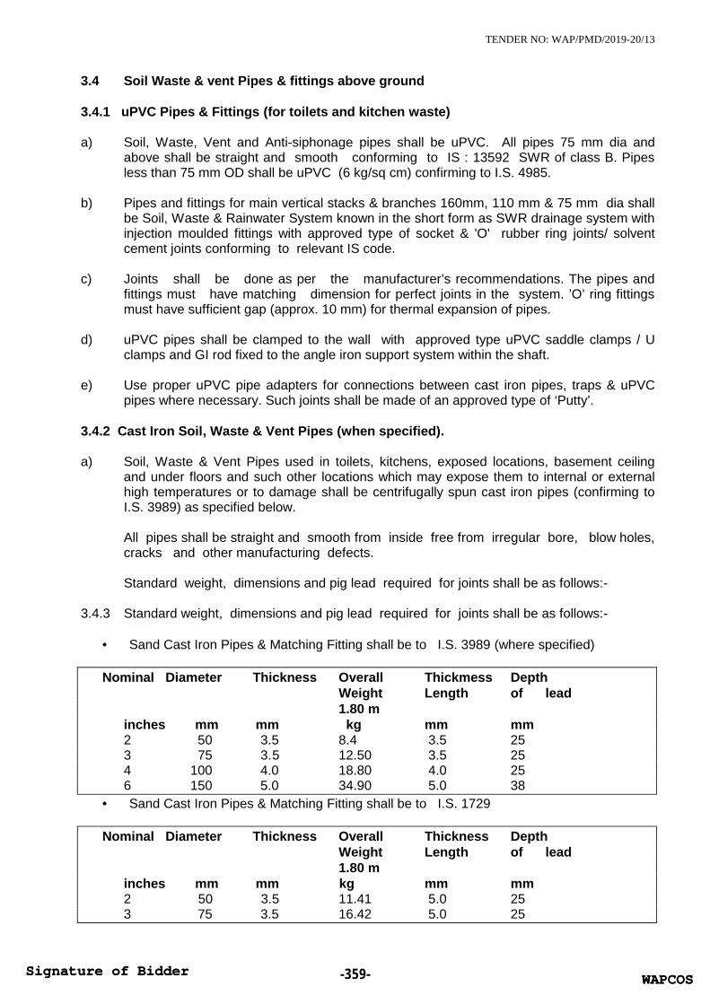
TENDER NO: WAP/PMD/2019-20/13
3.4 Soil Waste & vent Pipes & fittings above ground
3.4.1 uPVC Pipes & Fittings (for toilets and kitchen waste)
a) Soil, Waste, Vent and Anti-siphonage pipes shall be uPVC. All pipes 75 mm dia andabove shall be straight and smooth conforming to IS : 13592 SWR of class B. Pipesless than 75 mm OD shall be uPVC (6 kg/sq cm) confirming to I.S. 4985.
b) Pipes and fittings for main vertical stacks & branches 160mm, 110 mm & 75 mm dia shallbe Soil, Waste & Rainwater System known in the short form as SWR drainage system withinjection moulded fittings with approved type of socket & 'O' rubber ring joints/ solventcement joints conforming to relevant IS code.
c) Joints shall be done as per the manufacturer’s recommendations. The pipes andfittings must have matching dimension for perfect joints in the system. ’O’ ring fittingsmust have sufficient gap (approx. 10 mm) for thermal expansion of pipes.
d) uPVC pipes shall be clamped to the wall with approved type uPVC saddle clamps / Uclamps and GI rod fixed to the angle iron support system within the shaft.
e) Use proper uPVC pipe adapters for connections between cast iron pipes, traps & uPVCpipes where necessary. Such joints shall be made of an approved type of ‘Putty’.
3.4.2 Cast Iron Soil, Waste & Vent Pipes (when specified).
a) Soil, Waste & Vent Pipes used in toilets, kitchens, exposed locations, basement ceilingand under floors and such other locations which may expose them to internal or externalhigh temperatures or to damage shall be centrifugally spun cast iron pipes (confirming toI.S. 3989) as specified below.
All pipes shall be straight and smooth from inside free from irregular bore, blow holes,cracks and other manufacturing defects.
Standard weight, dimensions and pig lead required for joints shall be as follows:-
3.4.3 Standard weight, dimensions and pig lead required for joints shall be as follows:-
Sand Cast Iron Pipes & Matching Fitting shall be to I.S. 3989 (where specified)
Nominal Diameter Thickness Overall Thickmess DepthWeight Length of lead1.80 m
inches mm mm kg mm mm2 50 3.5 8.4 3.5 253 75 3.5 12.50 3.5 254 100 4.0 18.80 4.0 256 150 5.0 34.90 5.0 38
Sand Cast Iron Pipes & Matching Fitting shall be to I.S. 1729
Nominal Diameter Thickness Overall Thickness DepthWeight Length of lead1.80 m
inches mm mm kg mm mm2 50 3.5 11.41 5.0 253 75 3.5 16.42 5.0 25
WAPCOSSignature of Bidder -359- WAPCOSSignature of Bidder

TENDER NO: WAP/PMD/2019-20/13
4 100 4.0 21.67 5.0 256 150 5.0 31.92 5.0 38
3.4.4 Tolerance
Acceptable tolerance for pipes to I.S. 3989 and I.S 1729 shall be as follows:-a) Wall thickness -15%b) Length ± 20 mmc) Weight -10%
3.5. Fittings
3.5.1 Fittings shall conform to the same Indian Standard as for pipes. Pipes and fittings mustbe of matching I.S. Specification. Interchange of pipes of one standard with fittings onthe other standard will not be permitted.
3.5.2 Fittings shall be of the required degree of curvature with or without access door.
3.5.3 Access door shall be made up with 3 mm thick insertion rubber washer and whitelead. The bolts shall be lubricated with grease or white lead for easy removal later.The fixing shall be air and water tight.
3.5.4 Connection from a vertical stack or position to a horizontal line shall be made only by a “Y”junction.
3.6 Fixing
3.6.1 All vertical pipes shall be fixed by galvanized clamps truly vertical. Branch pipes shallbe connected to the stack at the same angle as that of the fittings. No collars shallbe used on vertical stacks. Each stack shall be terminated at top with a cowl (terminalguard).
3.6.2 Horizontal pipes running along ceiling shall be fixed on galvanized structural adjustableclamps (Clevis clamps) of special design shown on the drawings or as directed.Horizontal pipes shall be laid to uniform slope and the clamps adjusted to theproper levels so that the pipes fully rest on them.
3.6.3 Contractor shall provide all sleeves, openings, hangers, inserts during the construction.He shall provide all necessary information to the PMC / Building Contractor for makingsuch provisions in the structure as necessary. All damages shall be made good torestore the surfaces at no extra cost.
4 Clamps
4.1 Holder bat clamps shall be of standard design and fabricated from galvanized M.S.standard flats 40x3 mm thick and 12 mm dia M.S. Rod and 6 mm nuts and bolts. Holderbat clamps shall be fixed in cement concrete 1:2:4 mix blocks 10x10x10 cms deep.
4.2 Where holder bat clamps are to be fixed in RCC column or slotted angles, walls or beamthey shall be fixed with galvanized 40x3 mm flat iron "U" type clamps with anchorfasteners of approved design or 6 mm nuts and bolts.
4.3 Structural clamps shall be fabricated by electro-welding from M.S. structural members e.g.rods, angles, channels flats as per detailed drawing. Contractor shall provide all nuts &bolts, welding material. All fabricated clamps, nuts, bolts and washers shall be not dippedgalvanized.
WAPCOSSignature of Bidder -360- WAPCOSSignature of Bidder

TENDER NO: WAP/PMD/2019-20/13
4.4 Galvanized slotted angle/channel supports on walls shall be provided wherever shown ondrawings. Angles/channels shall be of sizes shown on drawings or specified in scheduleof quantities. Angles/channels shall be fixed to brick walls with bolts embedded in cementconcrete blocks and to RCC walls with suitable anchor fasteners. The spacing of supportbolts horizontally shall not exceed 1 m.
4.5 Wherever M.S. clamps are required to be anchored directly to brick walls, concrete slabs,beams or columns, nothing extra shall be payable for clamping arrangement andmaking good with cement concrete 1:2:4 mix (1 cement :2 coarse sand :4 mm stoneaggregate 20 mm nominal size) as directed by the PMC.
4.6 For sleeves, anchor fasteners and clamp spacing chart shall be as follows:
CLAMP AND PIPE SUPPORT SPACING
<--------------- Commercial Pipe Dia.( Spacing in m ) ------------------>S.No. Type of Pipes & Position 15/20 20/25 32/40 50 75/80 100/110 150/160 200
1 Vertical Pipes1.1 GI /MS Pipes 2.4 2.4 3 3.6 4.5 5.4 5.41.2 Cast Iron Pipes
SWR Pipes x x <---------------------- 3 m --------------------------->IS 1729/3989Water Supply PipesIS 1536 /1538/7181/8329 x x <---------------------- 3.6 m --------------------------->
1.3 uPVC /cPVC PipesIS 4985 for Water Supply x x 0.5 0.7 0.9 0.9
IS 13585 for SWR x x 0.5 0.7 0.9 0.92 Horizontal Pipes
2.1 GI /MS Pipes <------2.0 m ------> 2.4 m 3 3.6 4 <--- 4.5 m--->2.2 Cast Iron Pipes
SWR Pipes <---------------------- 3.0 m -------------------------------->IS 1729/3989Water Supply Pipes 3 3.6 3.6 4.5IS 1536 /1538/7181/8329
5 Traps
5.1 Floor traps
Floor traps shall be siphon type full bore uPVC (SWR) ‘P’ / ‘S’ type having a minimum 50mm deep seal. The trap and waste pipes shall be set in cement concrete blocksfirmly supported on the structural floor. The blocks shall be in 1:2:4 mix (1 cement :2coarse sand :4 stone aggregate 20 mm nominal size) and extended to 40 mm belowfinished floor level. Contractor shall provide all necessary shuttering and centering forthe blocks. Size of the block shall be 30x30 cms of the required depth.
5.2 Urinal traps
Urinal traps shall be uPVC (SWR) ‘P’ / ‘S’ traps with or without vent and set in cementconcrete block specified for floor traps.
5.3 Floor trap inlet
Bath room traps and connections shall ensure free and silent flow of dischargingwater. Where specified, Contractor shall provide a uPVC height raiser with one, two or
WAPCOSSignature of Bidder -361- WAPCOSSignature of Bidder

TENDER NO: WAP/PMD/2019-20/13
three inlet sockets welded on side to connect the waste pipe. Joint between waste andhopper inlet socket shall be rubber ring / cement solvent. Floor trap inlet hoppers andthe traps shall be set in cement concrete blocks as specified in para above withoutextra charge.
5.4 Floor Gratings
Floor and urinal traps shall be provided with 100-150 mm square or round C.P./Stainlesssteel grating, with rim of approved design and shape. Minimum thickness shall be 4 mmor as specified in the Schedule of Quantities.
5.5 Jointing
Soil, waste vent, anti-syphonage and rainwater pipes shall be jointed with rubber ring /cement solvent.
6 Cleanout Plugs
6.1 Clean out plug for Soil, Waste or Rainwater pipes laid under floors shall be provided nearpipe junctions bends , tees , “Ys” and on straight runs at such intervals as required as persite conditions. Cleanout plugs shall terminate flush with the floor levels . They shall bethreaded and provided with key holes for opening. Cleanout plugs shall be uPVCsuitable for the Pipe dia. screwed / flanged joint to a threaded PVC socket .
6.2 Cleanout on Drainage Pipes
a) Cleanout plugs shall be provided on starting point of each drain and in between atlocations indicated on plans or directed by the PMC. Cleanout plugs shall be of sizematching the full bore of the pipe but not exceeding 150 mm dia. FCO Plugs on drains ofgreater diameters shall be 150 mm dia. Fixed with a suitable reducing adapter.
b) Cleanouts at ceiling level pipe shall be provided with a bend terminating at floor levelabove. The brass plug shall be screwed type flush with the floor.
7 Waste pipe from appliances
7.1 General
a) Waste pipe from appliances e.g. washbasins, sinks and urinals shall be of uPVC class III,6 kg/sq cm or galvanized steel, as given in the Schedule of Quantities or shown on thedrawings.
b) All pipes shall be fixed in gradient towards the outfalls of drains. Pipes inside a toilet roomshall be in chase unless otherwise shown on drawings. Where required pipes may be runat ceiling level in suitable gradient and supported on galvanized structural clamps.Spacing for clamps for such pipes shall be as per the pipe spacing chart given in section1.
8 Cast iron pipes for drainage
8.1 All drainage lines passing under building shall be CI (LA) pipes, in exposed position aboveground etc.. or as specified in the schedule of quantities. Position of such pipes shallgenerally be shown on the drawings.
WAPCOSSignature of Bidder -362- WAPCOSSignature of Bidder

TENDER NO: WAP/PMD/2019-20/13
8.2 Cast iron pipes shall be spigot & socket (S&S) centrifugally spun iron pipes conforming toI.S. 1536 (Class LA) suitable for pre-moulded rubber Tyton joints. Quality certificates shallbe furnished.
8.3 Fittings
b) Fittings used for C.I. drainage pipe shall conform to I.S.1538 (Heavy class).Connections from vertical branch pipes shall be made by a “Y” tee.
8.4 Joints
a) Joints between pipes shall be made with pre-molded rubber joints (Tyton Joints)supplied by the manufacturer to ensure compatibility and water tightness.
b) Joints between pipes and fittings shall be made by caulked spun yarn dipped in tar andmolten pig lead 45 mm deep by hammering with caulking tools.
9 Encasing pipe in Cement Concrete
uPVC (SWR) soil and waste pipes and drainage under floor in sunken slabs and in wallchases (when cut specially for the pipe) shall be encased in cement concrete 1:2:4 mix(1 cement :2 coarse sand : 4 stone aggregate 12 mm size) 75 mm in bed and all-round.When pipes are running well above the structural slab, the encased pipes shall besupported with suitable cement concrete pillars of required height at intervals of 1.8 m.Rate for concrete round pipes shall be inclusive of pillars, supports, shuttering andcentering.
10 Painting
10.1 All cast iron, soil, waste vent, anti-syphonage and rainwater pipes in exposed locationin shafts and pipe spaces shall be painted with two or more coats of syntheticenamel paint to give an even shade.
10.2 Paint shall be of approved quality and shade. Where directed pipes shall be paintedin accordance with approved pipe colour code.
10.3 G.I. waste pipes in chase shall be painted with two coats of bitumen paint, covered withpolythene tape and a final coat of bitumen paint. Exposed pipes shall be painted withtwo or more coats of synthetic enamel paint.
10.4 C.I. soil and waste pipes below ground shall be covered all-round with cement conc. andshall not be painted.
11 Cutting and making good
11.1 Contractor shall provide all necessary holes cut outs and chases in structural members asbuilding work proceeds. Wherever holes are cut or left originally, they shall be madegood with cement concrete 1:2:4 (1 cement: 2 coarse sand: 4 stone aggregate 20 mmnominal size) or cement mortar 1:2 (1 cement: 2 coarse sand) and the surfacerestored as in original condition.
12 Testing
12.1 Testing procedure specified below apply to all soil, waste and vent pipes above groundincluding C.I. LA pipes laid in basement ceiling.
WAPCOSSignature of Bidder -363- WAPCOSSignature of Bidder

TENDER NO: WAP/PMD/2019-20/13
12.2 Entire drainage system shall be tested for water tightness during and aftercompletion of the installation. No portion of the system shall remain untested.Contractor must have adequate number of expandable rubber/bellow plugs,manometers, smoke testing machines, pipe and fitting work test benches and anyother equipment necessary and required to conduct the tests. All testing shall becertified for its calibration by an approved laboratory.
12.3 All materials obtained and used on site must have manufacturer's hydraulic testcertificate for each batch of materials used on the site.
12.4 Testing soil, waste and rainwater pipes.
12.4.1 Testing Procedure for uPVC SWR drainage pipes for soil waste vent and / or Rain WaterPipes.
a) Testing procedure specified below apply to all soil, waste and vent pipes above groundincluding pipes laid in basement ceiling. Horizontal lines with in bathrooms should becement encased and tested before compacting of sunken floor to avoid any accidentaldamages. Smoke test should be avoided.
b) Entire drainage system shall be tested for water tightness during and after completion ofthe installation. No portion of the system shall remain untested. Contractor must haveadequate number of expandable rubber bellow plugs / socket plugs or any otherequipment necessary and required to conduct the tests.
c) All materials obtained and used on site must have manufacturers hydraulic test certificatefor each batch of materials used on the site.
d) After installation all connections from fixtures, vertical stacks and horizontal drains includingpipes along ceiling shall be tested to a hydraulic pressure not exceeding 3 m. Such tests shallbe conducted for each floor separately by suitable plugs. Seal hermetically all openings belowthe top of section to be tested. The water level shall then be raised to a height of not less than3 meters above the highest point of the section being tested. Every Joint shall be carefullyexamined for leaks.
e) After the installation is fully complete, it should be also tested by flushing the toilets, running atleast 20% of all taps simultaneously and ensuring that the entire system is self draining, hasno leakages, blockages etc. Rectify and replace where required.
f) Contractor shall maintain a test register identifying date and time of each area. All tests shallbe conducted in presence of Project Manager and signed by both.
12.4.2 Testing Procedure for C.I. drainage pipes for soil waste vent and / or Rain Water Pipes.(Wherever required)
a) Apart from factory test all pipes and fittings shall be hydraulically tested for a head of 3m preferably on a specially set up work bench. After applying pressure, strike thepipe with a wooden pallet and inspect for blow holes and cracks. Pressure may beapplied for about 2 minutes. Reject and remove all defective pipes.
b) After installation all connections from fixtures, vertical stacks and horizontal drainsincluding C.I. LA pipes shall be tested to a hydraulic pressure not exceeding 3 m. Suchtests shall be conducted for each floor separately by suitable plugs.
c) The entire installation shall be tested by smoke testing machine. The test can beconducted after the plumbing fixtures are installed and all traps have water seal or by
WAPCOSSignature of Bidder -364- WAPCOSSignature of Bidder

TENDER NO: WAP/PMD/2019-20/13
plugging all inlets by bellow plugs. Apply dense smoke keeping the top of stack openand observe for leakages. Rectify or replace defective sections.
d) After the installation is fully complete, it should be tested by flushing the toilets, runningatleast 20% of all taps simultaneously and ensuring that the entire system is self draining,has no leakages, blockages etc. Rectify and replace where required.
12.5 Contractor shall maintain a test register identifying date and time of each area. All testsshall be conducted in presence of PMC and signed by both.
13 Measurements
13.1 General
a) Rates for all items quoted shall be inclusive of all work and items given in thespecifications and Schedule of Quantities.
b) Rates are applicable for the work in basements, under floors, in shafts at ceiling levelarea for all heights and depths.
c) Rates are inclusive of cutting holes and chases in RCC and masonry work and makinggood the same.
d) Rates are inclusive of pre testing, on site testing, of the installations, materials andcommissioning of the works.
e) Pipes (unit of measurement. Linear meter to the nearest centimeter).
13.2 All uPVC soil, waste, vent, anti-syphonage and rain water pipes shall be measured netwhen fixed correct to a centimetre including all fittings along its length. No allowanceshall be made for the portions of pipe lengths entering the sockets of the adjacentpipes or fittings. The above will apply to both case i.e. whether pipes are fixed on wallface or pillars or embedded in masonry or pipes running at ceiling level.
13.3 Pipes shall measured per running metre correct to a centimetre for the finished workwhich shall include fittings e.g. bends, tees, elbows, reducers, crosses, sockets, nipplesand nuts. The length shall be taken along centre line of the pipes and fittings. Allpipes and fittings shall be classified according to their diameter, method ofjointing and fixing substance, quality, and finish. The diameters shall be nominaldiameter of internal bore. The pipes shall be described as including all cutting andwaste. In case of fittings of un equal bore, the largest bore shall be measured.
13.4 Cement concrete around pipes shall be measured along the centre of the pipe linemeasured per linear metre and include any masonry supports, shuttering and centeringcutting complete as described in the relevant specifications.
13.5 Slotted angles/channels shall be measured per linear metre of finished length andshall include support bolts, nuts and clamps embedded in masonry walls with cementconcrete blocks and nothing extra will be paid for making good the same.
13.6 Fittings
Unit of measurement shall be the number of pieces. Pipe fittings are included in therate for pipes. Urinal traps, trap gratings, hoppers, cleanout plugs shall bemeasured by number per piece and shall include all items described in the relevantspecifications and Schedule of Quantities.
WAPCOSSignature of Bidder -365- WAPCOSSignature of Bidder

TENDER NO: WAP/PMD/2019-20/13
13.7 Painting
Painting of pipes shall be measured per running meter and shall be inclusive of allfittings and clamps. No deduction for fittings shall be made.
13.8 Excavation for soil pipes
No payment shall be admissible with respect to excavation, refilling and disposal ofsurplus earth for cast iron soil and waste pipes laid below ground, in sunken slabs orover basement rafts.
13.9 PMC’s decision with respect to the correct interpretation regarding mode of measurementshall be final and binding on the contractor .
14.1 uPVC Pipes & Fittings as specified in the schedule of quantities.
a) Soil, Waste and Anti-siphonage pipes and fittings shall be uPVC. All pipes shall be straightand smooth conforming to IS: 13592 or as specified in Schedule of Quantities.
b) Pipes and fittings for main vertical stacks & branches 110 mm, & 75 mm dia shall be Soil,Waste & Rainwater System known in the short form as SWR drainage system withinjection moulded fittings with approved type of socket & ‘O’ rubber ring joints.
c) Joints shall be done as per the manufacturer’s recommendations. The pipes and fittingsmust have matching dimension for perfect joints in the system. ‘O’ ring fittings must havesufficient gap (approx. 10 mm) for thermal expansion of pipes.
d) uPVC pipes shall be clamped to the wall with approved type uPVC saddle clamps/Uclamps and G.I. rod fixed to the angle iron support system within the shaft.
e) Use proper uPVC pipe adapters for connections between cast iron pipes, traps & uPVCpipes where necessary. Such joints shall be made of an approved type of ‘Putty’.
14.2 Clamps
14.2.1 For UPVC pipes standard UPVC clamps shall be used. For other pipes M.S. clamps,supports and hangers provided shall be galvanised. Factory made Pre fabricated clampsshall be preferred. Contactor may fabricate the clamps of special nature and galvanisethem after fabrication but before installation.(Clamps shall be fabricated from mild steelsections) All nuts, bolts, washers and other fasteners shall be factory galvanised.
14.2.2 Clamps shall be of approved designs and fabricated from M.S. flats and other sections ofthickness and sizes as per drawings or contractor’s shop drawings. Clamps shall be fixedin accordance to manufacturer’s details/shop drawings to be submitted by the contractors.
14.2.3 When required to be fixed on RCC columns, walls or beam they shall be fixed withapproved type of galvanised expansion anchor fasteners (Dash fasteners) of approveddesign and size according to load.
14.2.4 Structural clamps e.g. trapeze or cluster hangers shall be fabricated by electro-weldingfrom M.S. structural members e.g. rods, angles, channels flats as per Contractors shopdrawing shall be galvanised after fabrication. All nuts, bolts and washers shall begalvanised.
WAPCOSSignature of Bidder -366- WAPCOSSignature of Bidder

TENDER NO: WAP/PMD/2019-20/13
14.2.5 Galvanised slotted angle/channel supports on walls shall be provided wherever shown ondrawings. Angles/channels shall be of sizes shown on drawings or specified in scheduleof quantities. Angles/channels shall be fixed to brick walls with bolts embedded in cementconcrete blocks and to RCC walls with anchor fasteners mentioned above. The spacing ofsupport bolts on support members fixed horizontally shall not exceed 1 m.
14.3 Traps
14.3.1 Floor traps
a) Floor traps where specified shall be of multi inlet or 100 x 100 mm deep seal type uPVCtraps (SWR) having a minimum 50 mm deep seal. The trap and waste pipes when buriedbelow ground shall be set and encased in cement concrete blocks firmly supported on firmground or when installed on a sunken RCC structural slab. The blocks shall be in 1:2:4 mix(1 cement: 2 coarse sand: 4 stone aggregate 20 mm nominal size).
c) Contractor shall provide all necessary shuttering and centring for the blocks. Size of theblock shall be 30x30 cms of the required depth.
14.3.2 Urinal traps
Urinal traps/horn shall be uPVC deep seal 100 x 100 mm traps with or without vent and setin cement concrete block specified for floor traps.
14.3.3 Cleanout plugs
a) Floor Clean out Plug.
Clean out plug for Soil, Waste or Rainwater pipes laid under floors shall be provided nearpipe junctions bends, tees, “Ys” and on straight runs at such intervals as required as persite conditions. Cleanout plugs shall terminate flush with the floor levels. They shall bethreaded and provided with key holes for opening. Cleanout plugs shall be Cast Brassfixed by means of screwed to a G.I. socket/ uPVC . The socket shall be cement solvent /lead caulked / drip seal joint to the drain pipes.
END OF SECTION C: SOIL, WASTE, VENT & RAINWATER PIPES & FITTINGS
WAPCOSSignature of Bidder -367- WAPCOSSignature of Bidder

TENDER NO: WAP/PMD/2019-20/13
SECTION D: WATER SUPPLY SYSTEM
1. Scope of work
1.1 Work under this section consists of furnishing all labour, materials equipment andappliances necessary and required to completely install the water supply system asrequired by the drawings, specified hereinafter and given in the Schedule of Quantities.
1.2 Without restricting to the generality of the foregoing, the water supply system shall includethe following:-
a) Distribution system from main supply headers from pump to all fixtures and appliancesfor cold & hot water.
b) Cold water supply lines from tube wells and city water connections to Fire and UnderGround Water Tanks.
c) Excavation and refilling of pipes trenches.d) Insulation to hot water pipese) Pipe protection and painting.f) Control valves, masonry chambers and other appurtenances.g) Connections to all plumbing fixtures, tanks, appliances and municipal mainshi) Inserts for R.C.C. tanks
2 General requirements
2.1 All materials shall be new of the best quality conforming to specifications. All worksexecuted shall be to the satisfaction of the Project Manager.
2.2 Pipes and fittings shall be fixed truly vertical, horizontal or in slopes as required in a neatworkmanlike manner.
2.3 Short or long bends shall be used on all main pipe lines as far as possible. Use of elbowsshall be restricted for short connections.
2.4 Pipes shall be fixed in a manner as to provide easy accessibility for repair andmaintenance and shall not cause obstruction in shafts, passages etc.
2.5 Pipes shall be securely fixed to walls and ceilings by suitable clamps at intervals specified.
2.6 Clamps, hangers and supports on RCC walls, columns & slabs shall be fixed only bymeans of approved made of expandable metal fasteners inserted by use of power drills.
2.7. All pipe clamps, supports, nuts, bolts, washers shall be galvanised MS steel throughout thebuilding. Painted MS clamps & MS nuts, bolts & washers shall not be accepted.
2.8 Valves and other appurtenances shall be so located as to provide easy accessibility foroperations, maintenance and repairs.
3 Water Supply System
3.1 Contractor should study the site plan and the water supply systems separate for Domesticand flushing water from O.H.T. near under ground water tank and STP.
3.1.1 SourceWater supply will be acquired from local municipal and captive tube wells within the siteand collected in water storage tanks located underground.
WAPCOSSignature of Bidder -368- WAPCOSSignature of Bidder

TENDER NO: WAP/PMD/2019-20/13
3.1.2 The system has been connected to a gravity feed system from overhead tanks to all partsof the building
3.1.3 It is proposed to provide flushing cistern / flush valves for all WCs and Infra red NO-TOUCH flush valves / auto push type shall be provided for Urinals. These will be fed fromflushing over head tank by gravity.
3.1.4 Domestic water supply shall be provided with cold and hot water system only. Hot waterprovisions are limited to kitchen and toilets connected to a local electric hot water storagegeyser.
4 CPVC / PPR / G.I. pipes, fittings & valves
4.1 CPVC Pipes for hot water application.
4.1.1 All pipes inside the toilets for domestic hot water supply shall be CPVC conforming to CTSSDR-11 at a working pressure of 27.8 kg/sqcm PSI at 23 deg C & 100 PSI at 82 deg. C.
4.1.2 Solvent welded CPVC fittings etc. tees, elbows, couplers, unions, reducers, brushing etc.including transition fittings (connection between CPVC and metal pipes/G.I. ie. Brassadopters conforming to ASTM D-2846) shall be provided.
4.1.3 All pipes shall be fixed in accordance with layout and alignment shown on the drawings.Care shall be taken to avoid air pockets. CPVC /G.I. pipes inside toilets shall run abovefalse ceiling with vertical drop in wall chases for all fixtures. No pipes to run inside sunkenfloor as far as possible. Pipes may run in wall chase, under the ceiling or floors and otherareas as shown on drawings.
4.1.4 uPVC Pressure Pipes for cold water application.
All pipes inside the toilets for domestic and flushing cold water supply shall be uPVCunthreaded pressure class Sch 40 pipes as per ASTM–D standard 1785 pressure pipessuitable for jointing with cement solvent of approved grade. Fittings shall be solvent weldsocketed and threaded with brass inserts for connection to threaded metal fixtures.
4.2 PP-R Pipes. (Alternate item when specified)
4.2.1 All Pipes upto 100 mm nominal size inside the buildings, and pipe shafts and wherespecified shall be anti bacterial UV stabilized (Green Colour), Polypropylene RandomCopolymer (PP-R) rigid pipes of PN-16 grade confirming to DIN 8077 with matchinngfittings to DIN 16962 suitable for fusion joints. The pipe shall have fire retardant property.
4.2.1 Fittings shall be as per DIN 16962. Each fitting shall have manufacturer's trade markstamped on it.
4.2.2 Pipes and fittings shall be jointed by Heat Fusion (no use of solvent ensuring leak proofjoint) using welding machine and suitable die, by heating the outer surface of the pipe andinner surface of the fitting simultaneously and inserting the pipe in the fitting to achievehomogeneous joint. For making connection to metallic fittings PP-R fitting having threadedmetal insert shall be used.
4.2.3 All pipes shall be fixed in accordance with layout and alignment shown on the drawings.Care shall be taken to avoid air pockets. Pipes inside toilets shall be fixed in wallchases well above the floor. No pipes be run inside a sunken floor as far as possible.Pipes may be run under the ceiling or floors and other areas as shown on drawings.
WAPCOSSignature of Bidder -369- WAPCOSSignature of Bidder

TENDER NO: WAP/PMD/2019-20/13
4.3 Joining Pipes & Fittings
a) Cutting
Pipes shall be cut either with a wheel type plastic pipe cutting or hacksaw blade and careshall be taken to make a square cut. All burrs should be removed for proper contactbetween pipe and fittings during jointing.
b) Solvent Cement Application
Only CPVC solvent cement conforming to ASTM-F-493 should be used for joining pipewith fittings. An even coat of solvent cement should be applied on the pipe end and a thincoat inside the fitting socket. Solvent cement for uPVC sch 40 pipes shall be pipeconfirming to ASTM D 2563 medium bodied or as per manufacture’s recommendations.
c) Assembly
After applying the solvent cement on both pipe and fitting socket, pipe should be insertedinto the fitting socket within 30 seconds, and rotating the pipe ¼ to ½ turn while insertingso as to ensure even distribution of solvent cement with the joint. The assembled systemshould be held for 10 seconds (approximately) in order to allow the joint to set up.
d) Testing
The system should be hydrostatically pressure tested at 150 psi (10 Bar) for one hour.During pressure testing, the system should be fitted with water and if a leak is found, thejoint should be cut out the replaced with new one.
4.4 Transition of Flowguard cPVC in metals
When making a transition connection to metal threads, special brass/plastic transitionfitting (Male and female adapters) should be used. Plastic threaded connections shouldnot be over torqued.
4.5 Threaded sealants
Teflon tape shall be used to make threaded connections leak proof.
4.6 Solvent Cement
Only cPVC solvent cement conforming to ASTMF 493 should be used for joining pipe withfittings and valves. Solvent cement for uPVC sch 40 pipes shall be confirming to ASTM D2563 medium bodied or as per manufacture’s recommendations
4.7 Hangers and supports
For Horizontal runs, support should be given at 3 feet (90 cms) intervals for diameters ofone inch and below and at 4 feet (1.2 m) intervals for larger sizes.
Supports should be as per the below mentioned table:
Size of pipe 20ºC 49ºC 71ºC 82ºCInch Ft. Ft. Ft. Ft.
WAPCOSSignature of Bidder -370- WAPCOSSignature of Bidder

TENDER NO: WAP/PMD/2019-20/13
½” 5.5 4.5 3.0 2.5¾” 5.5 5.0 3.0 2.51” 6.0 5.5 3.5 3.0
1¼” 6.5 6.0 3.5 3.51¼” 7.0 6.0 3.5 3.52” 7.0 6.5 4.0 3.5
4.7. Anchor Fasteners4.7.1 All pipe supports, hangers and clamps to be fixed on RCC walls, beams, columns, slabs
and masonry walls 230mm thick and above by means of galvanised expandable anchorfasteners in drilled holes of correct size and model to carry the weight of pipes. Drillingshall be made only by approved type of power drill as recommend and approved bymanufacturer of the anchor fasteners. Failure of any fastening devices shall be the entireresponsibility and contractor shall redo or provide additional supports at his own cost. Heshall also compensate the OWNER’S for any damage that may be caused by suchfailures.
4.8 Unions
Contractor shall provide adequate number of unions on all pipes to enable easydismantling later when required. Unions shall be provided near each gunmetal valve, stopcock, or check valve and on straight runs as necessary at appropriate locations as requiredand/or directed by Project Manager.
4.9 Flanges
Flanged connections shall be provided on pipes as required or where shown on thedrawings, all equipment connections as necessary and required or as directed by theProject Manager. Connections shall be made by correct number and size of GI nuts, bolts& washers with 3 mm thick gasket. Where hot water connections are made insertiongasket shall be of suitable high temperature grade and quality approved by the ProjectManager. Bolt hole dia for flanges shall conform to match the specification for C.I. sluicevalve to I.S. 780. and C.I. butterfly valve to IS: 13095.
4.10 Painting (Painting for PP-R & CPVC pipes not required)
Pipe protection (Protection for CPVC pipes not required)
4.11 G.I. Pipes and Fittings. (For risers and terrace when specified)
4.11.1 All pipes inside the buildings and where specified, outside the building shall begalvanized steel tubes conforming to I.S. 1239 of class specified in the schedule ofquantities. When class is not specified they shall be heavy class.
4.11.2 Fittings shall be of malleable iron galvanized of approved make. Each fitting shallhave manufacturer's trade mark stamped on it. Fittings for G.I. pipes shall includecouplings, bends, tees, reducers, nipples, unions, and bushes. Fittings shall conform toI.S.1879- (Part I to X).
4.11.3 Pipes and fittings shall be jointed with screwed joints. After cutting a pipe with a hacksawor a cutting machine care shall be taken to remove burr from the end of the pipe afterreaming with a proper file.
WAPCOSSignature of Bidder -371- WAPCOSSignature of Bidder

TENDER NO: WAP/PMD/2019-20/13
4.11.4 Pipe threaded joints will be made by applying suitable grade of pipe sealing cord nontoxic pipe sealant used for drinking water supply. (Use of red or white lead and sutli willnot be permitted for screwed joints).
4.11.5 All pipes shall be fixed in accordance with layout and alignment shown on the drawings.Care shall be taken to avoid air pockets. G.I. pipes inside toilets shall be fixed in wallchases well above the floor. No pipes shall be run inside a sunken floor as far aspossible. Pipes may be run under the ceiling or floors and other areas as shown ondrawings.
4.12 Clamps
G.I. Pipes in shafts and other locations shall be supported by galvanized M.S.clamps of design approved by Project Manager. Pipes in wall chases shall beanchored by G.I. hooks. Pipes at ceiling level shall be supported on structuralclamps fabricated from M.S. structurals. Pipes in typical shafts shall be supportedon slotted angles/channels as per standard drawings.
4.12.1 For sleeves, anchor fasteners and clamp spacing chart (See 4.2 for clamp spacing chartSection 3 above) .
4.13 UnionsContractor shall provide adequate number of unions on pipes 40 mm and below to enableeasy dismantling later when required. Unions shall be provided near each gunmetalvalve, stop cock, or check valve and on straight runs as necessary at appropriatelocations as required and/or directed by PMC.
5 Flanges
5.1 Flanged connections shall be provided on pipes 65 mm and above as required orwhere shown on the drawings generally as follows:
a) On straight runs not exceeding 30 m, near bends and at connections to mainbranch lines.
b) On all valves endsc) On equipment /pump connections as necessary and required or as directed by
PMC.
5.2 Flanged connections shall be made by the correct number and size of the bolts andmade with 3 mm thick insertion neoprene gaskets Bolt hole dia for flanges shall conformto match the specification for C.I. sluice valve to I.S. 780. and C.I. butterfly valve to IS:13095.
5.3 Trenches
All water supply pipes below ground shall be laid in trenches with a minimum cover of60 cms. The width and depth of the trenches shall be as follows:-
5.4 Dia of pipe Width of trench Depth of trench
15 mm to 50 mm 30 cms 75 cms65 mm to 100 mm 45 cms 100 cms
5.5 Sand filling
WAPCOSSignature of Bidder -372- WAPCOSSignature of Bidder

TENDER NO: WAP/PMD/2019-20/13
All G.I./PVC/M.S. pipes in trenches shall be protected with fine sand 15 cms. all-roundbefore filling in the trenches.
5.6 Where shown on the drawings main pipe lines may be run in masonry trenches from thepump house to the buildings, filled up with sand and buried in ground as per architectural/landscape details.
5.7 Painting
5.7.1 All pipes above ground shall be painted with one coat of primer and two coats ofsynthetic enamel paint of approved shade and quality. Pipes shall be painted tostandard colour code specified in Section 7.
5.8 Pipe protection
5.8.1 All pipes in chase or below floor shall be protected against corrosion by theapplication of two coats of bitumen paint covered with bitumen tape and a final coatof bitumen paint before covering up the pipe.
5.8.2 All G.I. & M.S. water supply pipes below ground shall be protected against corrosion byapplying one layer of 4 mm thick multilayer anticorrosive polymeric mix tape applied over acoat of primer as per recommendations of the manufacturers. (Pypekote)
6 Insulation (not required for CPVC & PPR pipes)
Hot water pipes in exposed shall be insulated with 13 mm thick “Vidoflex/Kaiflex” preformed insulation to be installed as per manufacturer’s instruction.
7. Valves
7.1 Ball Valves
Valves upto 40 mm dia. shall be screwed type Ball Valves with stainless steel balls,spindle, teflon seating and gland packing tested to a hydraulic pressure of 500 psig, andaccompanying couplings and steel handles.(to BS 5351)
7.2. Butterfly Valves
7.2.1 Valves 50 mm dia and above shall be cast iron butterfly valve to be used for isolation. Thevalves shall be bubble tight, resilient seated suitable for flow in either direction and seal inboth direction with accompanying flanges and steel handle.
7.2.2 Butterfly valve shall be of best quality conforming to IS: 13095.
7.3 Non Return Valve (Slim Type)
Where specified non return valve (dual plate slim type) shall be provided through whichflow can occur in one direction only. It shall be single door swing check type of bestquality.
7.3.1 Each Butterfly and Slim Type Check (NRV) Valve shall be provided with a pair of flangesscrewed or welded to the main line and having the required number of galvanised nuts,bolts and washers of correct length.
7.3.2 Storage tanks Underground & Overhead Tank. (Accessories & Connections)
WAPCOSSignature of Bidder -373- WAPCOSSignature of Bidder

TENDER NO: WAP/PMD/2019-20/13
7.3.3 Storage tanks for water supply shall be in reinforced cement concrete built by the buildingContractor.
7.3.4 Each tank shall be provided with lockable type manhole cover fabricated from M.S. sheets.Manhole covers shall be 450-500 mm dia and fully galvanised after fabrication or asapproved by the Project Manager.
7.4 Storage Tanks
7.4.1 Underground
Underground storage tanks for water supply shall be reinforced cement concrete built bythe building contractor.
Each tank shall be provided with lockable type manhole cover fabricated from M.S. sheetor standard cost iron tank covers. Manhole covers shall be 450-500 mm dia or asapproved by local municipal authority.
7.5 Outlets and overflow
All nozzles for puddle flanges in RCC tank for inlet, outlet, overflow and scour etc. shall beprovided by civil contractor or as given in the Schedule of Quantities. Further connectionsand accessories shall be provided under this contract.
7.5 Testing
7.5.1 All pipes, fittings and valves after fixing at site, shall be tested by hydrostatic pressure of1.5 times the working pressure or 10 kg/cm2 whichever is more.Pressure shall be maintained for a period of at least thirty minutes without any drop.
A test register shall be maintained and all entries shall be signed and dated by Contractor(s) and Project Manager.
7.5.2 In addition to the sectional testing carried out during the construction, Contractor shall testthe entire installation after connections to the overhead tanks or pumping system or mains.He shall rectify all leakages and shall replace all defective materials in the system. Anydamage done due to carelessness, open or burst pipes or failure of fittings, to thebuilding, furniture and fixtures shall be made good by the Contractor during the defectsliability period without any cost.
7.5.3 After commissioning of the water supply system, Contractor shall test each valve byclosing and opening it a number of times to observe if it is working efficiently. Valves whichdo not effectively operate shall be replaced by new ones at no extra cost and the sameshall be tested as above.
7.6 Measurement
a) PP-R / CPVC / uPVC or G.I. pipes above ground shall be measured per linear meter (tothe nearest cm) and shall be inclusive of
i) all fittings e.g. coupling, tees, bends, elbows, unions, flanges and U clamps with nuts,bolts & washers fixed to wall or other standard supports.
ii) Jointing with teflon tape, white lead and insertion gasket of appropriate temperaturegrade.
WAPCOSSignature of Bidder -374- WAPCOSSignature of Bidder

TENDER NO: WAP/PMD/2019-20/13
iii) Cutting holes, and chases in walls, floors, any pipe support required for pipes belowground & making good the same.
iv) Excavation, back filling, disposal of surplus earth and restoring the ground & floor inoriginal condition.
7.7 Pipe Supports.
a) Fabricated and galvanised supports shall be measured by weight. Weight for each type ofclamp shall be calculated on basis of the quantity of structural and MS used from thetheoretical weight calculated on basis of the components theoretical weight of the sections.
7.7.1 Rate quoted for supports & hangers shall be inclusive of:-
a) Expandable anchor fastens.b) Galvanising of all supports & hangers.c) Cutting holes in walls, ceilings on floors and making good where permitted.d) Nuts, bolts and washers for fixing and assembling.e) Wooden/PVC pipe saddles for vertical or horizontal runs.
7.7.2 ValvesGunmetal, cast iron, butterfly and non return valves and puddle flanges shall be measuredby numbers and shall include wheels/caps, GI nuts, bolts, washers and insertion gasket.
7.7.3 Painting/pipe protection/insulation
Painting/pipe protection/insulation for pipes shall be measured per linear metre overfinished surface and shall include all valves and fittings for which no deduction shall bemade. No extra payment shall be made for fittings, valves or flanges.
END OF SECTION D: WATER SUPPLY SYSTEM
WAPCOSSignature of Bidder -375- WAPCOSSignature of Bidder

TENDER NO: WAP/PMD/2019-20/13
SECTION E: DRAINAGE (SEWERS & STORM WATER DRAINS)
1 Scope of work
1.1 Work under this section shall consist of furnishing all labour, materials, equipment andappliances necessary and required to completely install all the drainage system asrequired by the drawings and specified hereinafter or given in the Schedule of Quantities.
1.2 Without restricting to the generality of the foregoing, the drainage system shall include:-
a) Sewer lines including excavations, pipe lines, manholes, drop connections andconnections to the Sewage Treatment Plant.
b) Storm water drainage, excavation, pipe lines, manholes, catch basins, drain channels,recharging pits and overflows to external low areas
2 General requirements
2.1 All materials shall be new of the best quality conforming to specifications andsubject to the approval of the
2.2 Drainage lines and open drains shall be laid to the required gradients and profiles.
2.3 All drainage work shall be done in accordance with the local municipal bye-laws.
2.4 Contractor shall obtain necessary approval and permission for the drainage system fromthe municipal or any other competent authority.
2.5 Location of all manholes, etc. shall be as per site plan drawings. No drains or sewers shallbe laid in the middle of road unless otherwise specifically shown on the drawings ordirected by the Project Manager.
3 Excavation
3.1 Alignment and grade
The sewer pipes shall be laid to alignment and gradient shown on the drawings but subjectto such modifications as shall be ordered by the Project Manager. No deviations from thelines, depths of cutting or gradients of sewers shown on the plans and sections shall bepermitted except by the express direction in writing of the Project Manager.
3.2 Excavation in tunnels
The excavation for sewer works shall be open cutting unless the permission of the ProjectManager is obtained for laying pipes in tunnel where sewers have to be constructed alongnarrow passages or difficult ground.
3.3 Opening out trenches
In excavating the trenches, etc. the solid road metalling, pavement, kerbing, etc. and turf isto be placed on one side and preserved for reinstatement when the trenches or otherexcavation shall be filled up. Before any road metal is replaced, it shall be carefully sifted.The surface of all trenches and holes shall be restored and maintained to the satisfactionof the Project Manager.
WAPCOSSignature of Bidder -376- WAPCOSSignature of Bidder
TENDER NO: WAP/PMD/2019-20/13
The Contractor shall grub up and clear the surface over the trenches and otherexcavations of all trees, stumps roots and all other encumbrances affecting execution ofthe work and shall remove them from the site to the approval of the Project Manager.
3.4 Obstruction of roads
The Contractor shall not occupy or obstruct by his operation more than one half of thewidth of any road or street and sufficient space shall then be left for public and privatetransit, he shall remove the materials excavated and bring them back again when thetrench is required to be refilled. The Contractor shall obtain the consent of the ProjectManager.
3.5 Removal of filth
All night soil, filth or any other offensive matter met with during the execution of the works,immediately after it is taken out of any trench, sewer or cess pool, shall not be depositedon to the surface of any street or where it is likely to be a nuisance or passed into anysewer or drain but shall be at once put into the carts and removed to a suitable place to beprovided by the Contractor.
3.6 Excavation to be taken to proper depths
The trenches shall be excavated to such a depth that the sewer shall rest on concreteas described in the several clauses relating there to and so that the inverts may be atthe levels given in the sections.
3.7 RefillingAfter the sewer or other work has been laid and proved to be water tight, the trench orother excavations shall be refilled. Utmost care shall be taken in doing this, so that nodamage shall be caused to the sewer and other permanent work. The filling in thehaunches and upto 75 cms above the crown of the sewer shall consist of the finestselected materials placed carefully in 15 cms layers and flooded and consolidated. Afterthis has been laid, the trench and other excavation shall be refilled carefully in 15 cmslayers with materials taken from the excavation, each layer being watered to assist in theconsolidation..
3.8 Contractor to restore settlement and damages
The Contractor shall, at his own costs and charges, make good promptly during thewhole period the works are in hand, any settlement that may occur in the surfaces ofroads, berms, footpaths, gardens, open spaces etc. whether public or private caused byhis trenches or by his other excavations and he shall be liable for any accidents causedthereby. He shall also, at his own expense and charges, repair and make good anydamage done to buildings and other property if in the opinion of the Project Manager thedamage is due to his negligence.
3.9 Disposal of surplus soil
The Contractor shall at his own costs and charges provide places for disposal of all surplusmaterials not required to be used on the works. As each trench is refilled the surplus soilshall be immediately removed, the surface properly restored and roadways and sides leftclear.
WAPCOSSignature of Bidder -377- WAPCOSSignature of Bidder

TENDER NO: WAP/PMD/2019-20/13
3.10 Timbering of sewer and trenches
a) The Contractor shall at all times support efficiently and effectively the sides of thesewer trenches and other excavations by suitable timbering, piling and sheeting andthey shall be closed timbered in loose or sandy strata and below the surface of the subsoil water level.
b) All timbering, sheeting and piling with their walling and supports shall be of adequatedimensions and strength and fully braced and strutted so that no risk of collapse orsubsidence of the walls of the trench shall take place.
c) The Contractor shall be held responsible and will be accountable for the sufficiency ofall timbering, bracings, sheeting and piling used as also for, all damage to personsand property resulting from improper quality, strength, placing, maintaining orremoving of the same.
3.11 Shoring of buildings
The Contractor shall shore up all buildings, walls and other structures, the stability of whichis liable to be endangered by the execution of the work and shall be fully responsible for alldamages to persons or property resulting from any accident.
3.12 Removal of water from sewer, trench etc.
a) The Contractor shall at all times during the progress of the work keep the trenchesand excavations free from water which shall be disposed of by him in a manner as willneither cause injury to the public health nor to the public or private property nor to thework completed or in progress nor to the surface of any roads or streets, nor causeany interference with the use of the same by the public.
b) If any excavation is carried out at any point or points to a greater width than thespecified cross section of the sewer with its envelope, the full width of the trenchshall be filled with concrete by the Contractor at his own expenses and charges to therequirements of the Project Manager.
3.13 Width of trench
3.13.1 Recommended width of trenches at the bottom shall be as follows:-
100 mm dia pipe 55 cms150 mm dia pipe 55 cms225-250 mm dia pipe 60 cms300 mm dia pipe 75 cms
Maximum width of the bed concrete shall also be as above. No additional payment isadmissible for widths greater than specified.
4 Salt glazed stoneware pipes4.1 Stoneware pipes shall be of first class quality salt glazed and free from rough texture inside
and outside and straight. All pipes shall have the manufacturers name marked on it andshall comply with I.S. 651 approved makes.
4.2 Laying and jointing of stoneware salt glazed pipes
a) Pipes are liable to be damaged in transit and notwithstanding tests that may havebeen made before despatch each pipe shall be examined carefully on arrival at site.Each pipe shall be rung with a wooden hammer or mallet and those that do not ring
WAPCOSSignature of Bidder -378- WAPCOSSignature of Bidder

TENDER NO: WAP/PMD/2019-20/13
true and clear shall be rejected. Sound pipes shall be carefully stacked to preventdamage. All defective pipes should be segregated, marked in a conspicuous mannerand their use in the works prevented.
b) The pipes shall be laid with sockets leading uphill and rest on solid and evenfoundations for the full length of the barrel. Socket holes shall be formed in thefoundation sufficiently deep to allow the pipe jointer room to work right round the pipeand as short as practicable to admit the socket and allow the joint to be made.
c) Where pipes are not bedded on concrete the trench bottom shall be left slightly highand carefully bottomed up as pipe laying proceeds so that the pipe barrels rest on firmground. If excavation has been carried too low it shall be made up with cementconcrete at the Contractor's cost and Charges.
d) If the bottom of the trench consists of rock or very hard ground that cannot be easilyexcavated to a smooth surface, the pipes shall be laid on cement concrete bed toensure even bearing.
4.3 Jointing of pipes
a) Tarred gaskin shall first be wrapped round the spigot of each pipe and the spigot shallthen be placed into the socket of the pipe previously laid, the pipe shall then beadjusted and fixed in its correct position and the gaskin caulked tightly home so as tofill not more than one quarter of the total length of the socket.
b) The remainder of the socket shall be filled with stiff mix of cement mortar (1 cement : 1clean sharp washed sand). When the socket is filled, a fillet should be formed roundthe joint with a trowel forming an angle of 450 with the barrel of the pipe. The mortarshall be mixed as needed for immediate use and no mortar shall be beaten up andused after it has begun to set.
c) After the joint has been made any extraneous materials shall be removed from insideof the joint with a suitable scraper of "badger". The newly made joints shall beprotected until set from the sun, drying winds, rain or dust. Sacking or other materialswhich can be kept damp shall be used. The joints shall be exposed and space left allround the pipes for inspection by the Project Manager. The inside of the sewer mustbe left absolutely clear in bore and free from cement mortar or other obstructionsthroughout its entire length, and shall efficiently drain and discharge.
4.4 Testing
a) All lengths of the sewer and drain shall be fully tested for water tightness by means ofwater pressure maintained for not less than 30 minutes. Testing shall be carried outfrom manhole to manhole. All pipes shall be subjected to a test pressure of at least 1.5metre head of water. The test pressure shall, however, not exceed 6 meter head atany point. The pipes shall be plugged preferably with standard design plugs withrubber plugs on both ends. The upper end shall, however, be connected to a pipe forfilling with water and getting the required head.
b) Sewer lines shall be tested for straightness by:(i) inserting a smooth ball 12 mm less than the internal diameter of the pipe. In theabsence of obstructions such as yarn or mortar projecting at the joints the ball shouldroll down the invert of the pipe and emerge at the lower end,(ii) means of a mirror at one and a lamp at the other end. If the pipe line is straight thefull circle of light will be seen otherwise obstruction of deviation will be apparent.
WAPCOSSignature of Bidder -379- WAPCOSSignature of Bidder

TENDER NO: WAP/PMD/2019-20/13
c) The Contractor shall give a smoke test to the drains and sewer at his own expenseand charges, if directed by the Project Manager.
d) A test register shall be maintained which shall be signed and dated by Contractor,
5 Salt glazed stoneware pipes
5.1 Stoneware pipes shall be of first class quality salt glazed and free from rough textureinside and outside and straight. All pipes shall have the manufacturers name markedon it and shall comply to I.S. 651.
5.2 Laying and jointing of stoneware salt glazed pipes
a) Pipes are liable to be damaged in transit notwithstanding tests that may have beenmade before despatch each pipe shall be examined carefully on arrival at site. Eachpipe shall be rung with a wooden hammer or mallet and those that do not ring true andclear shall be rejected. Sound pipes shall be carefully stacked to prevent damage.All defective pipes should be segregated, marked with permanent marker in aconspicuous manner and their use in the works prevented.All stoneware pipes should be fitted together on the surface of the ground to ensure properfit before they are lowered. The barrels, spigots and sockets are properly cleaned andbrushed.
b) The pipes shall be laid with sockets leading uphill and rest on solid and even foundationsfor the full length of the barrel. Socket holes shall be formed in the foundation sufficientlydeep to allow the pipe jointer room to work right round the pipe and as short aspracticable to admit the socket and allow the joint to be made.
Pipes shall be laid carefully to the alignment, levels and gradient as per drawings,specifications and as directed by PMC and care shall be taken to prevent any sand, earthor other matter from entering the pipes during laying. The pipes between manholes shallbe laid truly in straight line. The alignment shall be done by suitable ranging rods andlevels established by proper levelling instrument.
c) Where pipes are not bedded on concrete the trench bottom shall be left slightlyhigh and carefully bottomed up as pipe laying proceeds so that the pipe barrels reston firm ground. If excavation has been carried too low it shall be made up with cementconcrete of the same mix as specified for pipe bedding at the Contractor's cost andCharges.
d) If the bottom of the trench consists of rock or very hard ground that cannot be easilyexcavated to a smooth surface, the pipes shall be laid on cement concrete bed toensure even bearing.
5.3 Jointing of pipes
a) A gasket of Tarred yarn shall be wrapped round the spigot of each pipe and the spigotshall then be placed into the socket of the pipe previously laid, the pipe shall then beadjusted and fixed in its correct position and the gasket caulked tightly home so as to fillnot more than one quarter of the total length of the socket. The yarn will be moistened toavoid absorption of water from the mixed cement mortar.
b) The remainder of the socket shall be filled with stiff mix of cement mortar (1 cement: 1clear sharp washed sand). When the socket is filled, a fillet should be formed round thejoint with a trowel forming an angle of 45 degrees with the barrel of the pipe. The
WAPCOSSignature of Bidder -380- WAPCOSSignature of Bidder
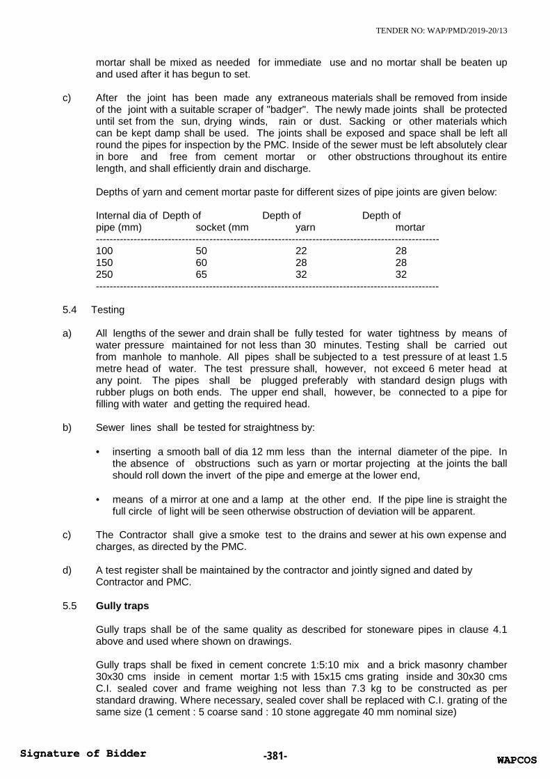
TENDER NO: WAP/PMD/2019-20/13
mortar shall be mixed as needed for immediate use and no mortar shall be beaten upand used after it has begun to set.
c) After the joint has been made any extraneous materials shall be removed from insideof the joint with a suitable scraper of "badger". The newly made joints shall be protecteduntil set from the sun, drying winds, rain or dust. Sacking or other materials whichcan be kept damp shall be used. The joints shall be exposed and space shall be left allround the pipes for inspection by the PMC. Inside of the sewer must be left absolutely clearin bore and free from cement mortar or other obstructions throughout its entirelength, and shall efficiently drain and discharge.
Depths of yarn and cement mortar paste for different sizes of pipe joints are given below:
Internal dia of Depth of Depth of Depth ofpipe (mm) socket (mm yarn mortar----------------------------------------------------------------------------------------------------100 50 22 28150 60 28 28250 65 32 32----------------------------------------------------------------------------------------------------
5.4 Testing
a) All lengths of the sewer and drain shall be fully tested for water tightness by means ofwater pressure maintained for not less than 30 minutes. Testing shall be carried outfrom manhole to manhole. All pipes shall be subjected to a test pressure of at least 1.5metre head of water. The test pressure shall, however, not exceed 6 meter head atany point. The pipes shall be plugged preferably with standard design plugs withrubber plugs on both ends. The upper end shall, however, be connected to a pipe forfilling with water and getting the required head.
b) Sewer lines shall be tested for straightness by:
inserting a smooth ball of dia 12 mm less than the internal diameter of the pipe. Inthe absence of obstructions such as yarn or mortar projecting at the joints the ballshould roll down the invert of the pipe and emerge at the lower end,
means of a mirror at one and a lamp at the other end. If the pipe line is straight thefull circle of light will be seen otherwise obstruction of deviation will be apparent.
c) The Contractor shall give a smoke test to the drains and sewer at his own expense andcharges, as directed by the PMC.
d) A test register shall be maintained by the contractor and jointly signed and dated byContractor and PMC.
5.5 Gully traps
Gully traps shall be of the same quality as described for stoneware pipes in clause 4.1above and used where shown on drawings.
Gully traps shall be fixed in cement concrete 1:5:10 mix and a brick masonry chamber30x30 cms inside in cement mortar 1:5 with 15x15 cms grating inside and 30x30 cmsC.I. sealed cover and frame weighing not less than 7.3 kg to be constructed as perstandard drawing. Where necessary, sealed cover shall be replaced with C.I. grating of thesame size (1 cement : 5 coarse sand : 10 stone aggregate 40 mm nominal size)
WAPCOSSignature of Bidder -381- WAPCOSSignature of Bidder
TENDER NO: WAP/PMD/2019-20/13
6 Reinforced cement concrete pipes
6.1 All underground storm water drainage pipes and sewer lines where specified (other thanthose specified cast iron) shall be centrifugally spun S & S RCC pipes of specified class.Pipes shall be true and straight with uniform bore, throughout. Cracked, warped pipes shallnot be used on the work. All pipes shall be tested by the manufacturer and the Contractorshall produce, when directed a certificate to that effect from the manufacturer.
6.2 LayingR.C.C. spun pipes shall be laid on cement concrete bed or cradles as specified and shownon the detailed drawings. The cradles may be precast and sufficiently cured to preventcracks and breakage in handling. The invert of the cradles shall be left 12 mm below theinvert level of the pipe properly placed on the soil to prevent any disturbance. The pipeshall then be placed on the bed concrete or cradles and set for the line and gradient bymeans of sight rails and bonding rods etc. Cradles or concrete bed may be omitted, ifdirected by the Project Manager.
6.3 JointingAfter setting out the pipes the socket shall be centred over the spigot and filled inwith tarred gaskin, so that sufficient space is left on either side of the collar to receive themortar. The space shall then be filled with cement mortar 1:2 (1 cement: 2 fine sand) andcaulked by means of proper tools. All joints shall be finished at an angle of 450 to thelongitudinal axis of the pipe on both sides of the collars neatly.
6.4 TestingAll pipes shall be tested to a hydraulic test of 1.5 m head for at least 30 minutes at thehighest point in the section under test. Test shall also be carried out similar to those forstoneware pipes given above the smoke test shall be carried out by the Contractor, ifdirected by the A test register shall be maintained which shall be signed and dated byContractor,/ Project Manager.
7 Cement concrete and masonry works (for manholes and chambers etc.)
7.1 Materialsa) Water
Water used for all the constructional purposes shall be clear and free from oil, acid,alkali, organic and other harmful matters, which shall deteriorate the strength and/ordurability of the structure. In general, the water suitable for drinking purposes shall beconsidered good enough for constructional purpose.
b) Aggregate for concreteThe aggregate for concrete shall be in accordance with I.S.383 and I.S. 515. Ingeneral, these shall be free from all impurities that may cause corrosion of thereinforcement. Before actual use these shall be washed in water, if required as per thedirection of Project Manager. The size of the coarse aggregate shall be done as perI.S.383.
c) SandSand for various constructional purposes shall conform to IS : 2687 and its grading
shall comply in all respects with I.S. 2116 and I.S. 1542. It shall be clean, coarse hardand stone, sharp, durable, uncoated, free from any mixture of clay, dust, vegetablematters, mica, iron impurities soft or flaky and elongated particles, alkali, organic
WAPCOSSignature of Bidder -382- WAPCOSSignature of Bidder

TENDER NO: WAP/PMD/2019-20/13
matters, salt, loam and other impurities which may be considered by the ProjectManager.
d) CementThe cement used for all the constructional purposes shall be ordinary Portland cementor rapid hardening Portland cement conforming to I.S.269.
d) Mild steel reinforcementThe mild steel for the reinforcement bars shall be in the form of round bars conformingto all requirements of I.S. 432 Grade I.
f) BricksBrick shall have uniform colour, thoroughly burnt but not over burnt, shall have plainrectangular faces with parallel sides and sharp right angled edges. They should giveringing sound when struck. Brick shall not absorb more than 20% to 22% of water,when immersed in water for 24 hours. Bricks to be used shall be approved by theProject Manager.The bricks used for construction of sewer manholes shall conform to IS : 4885.
g) Other materialsOther materials not fully specified in these specifications and which may be required
in the work shall conform to the latest I.S. All such materials shall be approved by theProject Manager.
7.2 Cement concrete (plain or reinforced)
a) Cement concrete for pipes bedding, cradles, foundations and R.C.C. slabs for all worksshall be mixed by a mechanical mixer where quantities of the concrete poured at one timepermit. Hand mixing on properly constructed platforms may be allowed for smallquantities by the Project Manager. Rate for cement concrete shall be inclusive of allshuttering and centring at all depth and heights.
b) Concrete work shall be of such thickness and mix as given in the Schedule of Quantities.
c) All concrete work shall be cured for a period of at least 7 days. Such work shall be keptmoist by means of gunny bags at all times.
7.3 Masonry workMasonry work for manholes, chambers, septic tanks, and such other works as requiredshall be constructed with bricks as specified in the Schedule of quantities in cement mortarof mix as specified in schedule of quantities. All joints shall be properly raked to receiveplaster.
7.4 Cement concrete for pipe support
a) Wherever specified or shown on the drawings, all pipes shall be supported in bed allround or haunches. The thickness and mix of the concrete shall be given in theSchedule of Quantities. Width of the bedding shall be the width of the trench asspecified.
b) Unless otherwise directed by the Project Engineer, cement concrete for bed, alroundor in haunches shall be laid as follows :-
WAPCOSSignature of Bidder -383- WAPCOSSignature of Bidder

TENDER NO: WAP/PMD/2019-20/13
upto 1.5 m upto 3 m beyond 3 mdepth depth depth
------------------------------------------------------------------------------------------Mix of concrete (1:4.8 ) (1:4:8 ) (1:4:8 )(no sub soil water)
Stone ware pipes All round upto Haunches All round
RCC Pipes All round upto Haunches upto Haunches)
Under sub-soil waterMix of concrete (1:3:6) (1:3:6) (1:3:6)R.C.C. Pipes or SW.pipes All round All round All round
Under the building (1:3:6) (1:3:6) (1:3:6)RCC Pipes or SW pipes All round All round All round
(Concrete mix refer to cement : coarse sand: stone aggregate 40 mm nominal size)
c) R.C.C. pipes or C.I. pipes may be supported on brick masonry or precast R.C.C. or insitu cradles. Cradles shall be as shown on the drawings.
d) Pipes in loose soil or above ground shall be supported on brick or stonemasonry pillars as shown on the drawings.
8 Manholes and chambers
8.1 All manholes, chambers and other such works as specified shall be constructed in brickmasonry in cement mortar 1:5 (1 cement : 5 coarse sand) or as specified in the Scheduleof Quantities.
8.2 All manholes and chambers etc. shall be supported on base of cement concrete of suchthickness and mix as given in the Schedule of Quantities or shown on the drawings.
Where not specified manholes shall be constructed as follows:-(all dimensions internal clear in cms)
Size of manhole 90x80 120x90 90 dia at bottom 122 dia at bottomtype Rect. Rect. Conical Conical
----------------------------------------------------------------------------------------------------------Maximum depth 150 240 167 239
Average thicknessof R.C.C slab 15 15 - -Size of cover and 60x45 50 dia 50 dia 50 diaframe mm 116 or 116 or 116 orWeight of cover 38 kg 225 kg 225 kg 225 kgand frame
---------------------------------------------------------------------------------------------------
8.3 All manholes shall be provided with cement concrete benching in 1:2:4 mix (1 cement : 2coarse sand : 4 stone aggregate 20 mm nom. Size) The benching shall have a slope of 10cms towards the channel. The depth of the channel shall be full diameter of the pipe.Benching shall be finished with a floating coat of neat cement. as per standard details.
WAPCOSSignature of Bidder -384- WAPCOSSignature of Bidder

TENDER NO: WAP/PMD/2019-20/13
8.4 All manholes shall be plastered with 12/15 mm thick cement mortar 1:3 (1 cement : 3coarse sand) and finished with a floating coat of neat cement inside. Manhole shall beplastered outside as above but with rough plaster mixed with water proofing compound.
8.5 All manholes with depths greater than 0.8m shall be provided with 20 mm square or 25mm round rods aoristic coated catch rings set in cement concrete blocks 25x10x10 cms in1:2:4 mix 30 cms vertically and staggered. Foot rests shall be coated with coal tar beforeembedding.
8.6 All manholes shall be provided with cast iron/steel fibre reinforced plastic (SFRC) coversand frames and embedded in reinforced cement concrete slab. Weight of cover, frame andthickness of slab shall be as specified in the Schedule of Quantities or given above.
8.7 Road gullies, ramp drains, gratings in basement shall be cast iron with M.S. frame or SteelFibre Reinforced Concrete (SFRC) with frame as specified in the Schedule of Quantities.
9 Making connections
9.1 Contractor shall connect the sewer line of the building to the main manhole by providingmaking holes and channels etc.
10. Measurement
10.1 Excavation
10.1.1 Measurement for excavation of pipe trenches shall be made per linear metre correct upto 1cm.Separately fora) all soilb) rocks
10.1.2 Trenches shall be measured between outside walls of manholes at top and the depth shallbe the average depth between the two ends to the nearest cm. The rate quoted shall befor a depth upto 1.5 m or as given in the Schedule of Quantities.
10.1.3 Payment for trenches more than 1.5 m in depth shall be made for extra depth as given inthe schedule of quantities and above the rate for depth upto 1.5 m.
10.1.4 Timbering and Shoring
Timbering and shoring as described above shall be measured per m2 and paid for as perthe type of timbering of shoring done at site and as per the relevant item in the Scheduleof Quantities. Rate for timbering and shoring shall be for all depths and types of soilclassifications including saturated soil.
10.1.5 Saturated SoilNo extra payment for pumping and bailing out water shall be made for excavation with anaverage depth of 1.5 m in saturated soil, surface water from rain falls or broken pipes lines,or sieves and other similar sources. An extra rate as quoted in the schedule of quantitiesshall be paid for excavation in saturated soil for pipe trenches above average depth of 1.5m. No payment is admissible for water collected from surface sources and broken pipelines or sewers.
10.1.6 Refilling, Consolidation and Disposal of Surplus Earth
WAPCOSSignature of Bidder -385- WAPCOSSignature of Bidder

TENDER NO: WAP/PMD/2019-20/13
Rate quoted for excavation of trenches shall be inclusive of refilling, consolidation anddisposal of surplus earth within a lead of 200 m.
10.2 Stoneware Pipes/RCC/C.I. pipes
Stoneware R.C.C./C.I. pipes shall be measured for the finished length of the pipeline inrunning metres nearest to a centimetre.
(a) Lengths between manholes shall be recorded from inside of one manhole to inside of othermanhole,
(b) Length between gully trap and manhole shall be recorded between socket of pipe neargully trap and inside of manhole. Rate shall include all items given in the schedule ofquantities and specifications.
10.3 Gully Traps
Gully traps shall be measured by the number and rate shall include all excavation,foundation, concrete brick masonry, cement plaster inside and outside, C.I. grating andsealed cover and frame.
10.4 Cement Concrete for Pipes
Cement concrete in bed and all round or in haunches shall be paid per running metrebetween the outside wall of manholes at bottom of the trench. No additional payment isadmissible in respect of concreting done for widths greater than specified, for shuttering orcentering and concreting in sub soil water conditions.
10.5 Manholes, Catch basins & Ramp drainsa) All manholes and catch basins shall be measured by numbers and shall include all
items specified above and necessary excavation, refilling & disposal of surplus earth.
b) Manholes with depths greater than specified under the main item shall be paid forunder "extra depth" and shall include all items as given for manholes. Measurementshall be done to the nearest cm. Depth of the manholes shall be measured from top ofthe manhole cover to bottom of channel.
c) Ramp drains shall be measured per metre length.
10.6 Making Connections
Item for making connection to municipal sewer shall be paid for by number and shallinclude all items given in the Schedule of Quantities and specifications.
END OF SECTION E: DRAINAGE (SEWER & STORM WATER DRAINS)
WAPCOSSignature of Bidder -386- WAPCOSSignature of Bidder

TENDER NO: WAP/PMD/2019-20/13
SECTION F: GARDEN IRRIGATION SYSTEM
1 Scope of work
1.1 Work under this section consists of furnishing all labour, materials equipment andappliances necessary and required to install garden hydrants and sprinklers and dripirrigation water supply system as required by the drawings, specified hereinafter and givenin the Schedule of Quantities.
1.2 Without restricting to the generality of the foregoing, the water supply system shall includethe following:-
a) Pipe work with connections to hydrants.b) Garden hydrants.c) Excavation and refilling of pipes trenches.d) Control valves, masonry chambers and other appurtenances.e) Connections to all pumps & appliances.
2 The System
2.1 The garden hydrant system should be executed for a total working system.
2.2 System components shall be pipes, valves, controllers, various types of sprinklers and dripirrigation lines with emitters as approved by the Project Manager.
3 General requirements
3.1 All materials shall be new of the best quality conforming to specifications. All worksexecuted shall be to the satisfaction of the Project Manager.
3.2 Pipes and fittings shall be fixed truly vertical, horizontal or in slopes as required in a neatworkmanlike manner.
3.3 Short or long bends shall be used on all main pipe lines as far as possible. Use of elbowsshall be restricted for short connections.
3.4 Pipes shall be laid in a manner as to provide as far as possible easy accessibility for repairand maintenance. Pipes under roads shall be laid in RCC pipe sleeves.
3.5 Valves and other appurtenances shall be so located as to provide easy accessibility foroperations, maintenance and repairs.
4 uPVC Pipes & Fittings
4.1 Garden hydrant mains shall be rigid uPVC pipes conforming to IS: 4985 of class specified.If class is not mentioned in the schedule of quantities the same shall be class IV (10kg/cm2).
4.2 Fittings for uPVC pipes shall be injection moulded fitting with spigot & sockets suitable forsolvent weld joints. Fittings must have suitable provision for expansion.
4.3 Solvent shall be of make and type approved by pipe and fittings manufacturer. Joint shallbe made in an approved manner as recommended by the manufacturer.
4.4 uPVC flanges at intervals of 20-25 m for all pipes 65 mm dia and above shall be providedfor easy maintenance.
WAPCOSSignature of Bidder -387- WAPCOSSignature of Bidder

TENDER NO: WAP/PMD/2019-20/13
4.5 Suitable uPVC thread adapter for connection between pipes & valves shall be provided.
4.6 Cement concrete supports and anchor blocks shall be provided at all bends, tees andother locations as directed by the Project Manager. Connections at garden hydrant outlet,near valves must also be anchored.
4.7 G.I. Pipes & Fittings
Vertical connection for garden hydrant points shall be galvanised steel tubes to IS: 1239(medium class) with matching malleable iron fittings of approved make.
5. Garden Hydrants
Garden hydrants shall be 25 mm dia gunmetal valves installed on G.I. pipes as per details.
6 Valves
Valves shall be as specified in section for Water Supply.
7. Trenches
All pipes below ground shall be laid in trenches with a minimum cover of 100 cms. Thewidth and depth of the trenches shall be as follows:-
Dia of pipe Width of trench Depth of trench15 mm to 50 mm 30 cms 100 cms65 mm to 100 mm 45 cms 100 cms
This will not apply to drip irrigation pipes which may be laid just below the surface or onsurface.
8. Testing
8.1 All pipes, fittings and valves, after fixing at site, shall be tested by hydrostatic pressure of 7kg/cm2 or 1.5 times the working pressure, whichever is higher. Pressure shall bemaintained for a period of at least thirty minutes without any drop. A test register shall bemaintained and all entries shall be signed and dated by Contractor(s) and the ProjectManager.
8.2 In addition to the sectional testing carried out during the construction, Contractor shall testthe entire installation after connections to the pumping system. He shall rectify all leakagesand shall replace all defective materials in the system. Any damage done due tocarelessness, open or burst pipes or failure of fittings, to the building, furniture and fixturesshall be made good by the contractor during the defects liability period without any cost.
8.3 After commissioning of the water supply system, Contractor shall conduct performance testto ensure that the system operates as specified. The test shall be conducted over a periodof 15 days.
WAPCOSSignature of Bidder -388- WAPCOSSignature of Bidder

TENDER NO: WAP/PMD/2019-20/13
9. Measurement
9.1 Pipes shall be measured in running meter (to the nearest cm) and shall be inclusive offittings, e.g. couplings, tees, bends, elbows, unions. Deductions for valves shall be made.Rates quoted shall be inclusive of all fittings.
9.2 Excavation, back filling & disposal of surplus earth is included in the rates for laying pipes.
9.3 Gunmetal, cast iron valves, sprinklers, emitters and masonry chambers shall be paid bynumbers.
END OF SECTION F: GARDEN IRRIGATION SYSTEM
WAPCOSSignature of Bidder -389- WAPCOSSignature of Bidder

TENDER NO: WAP/PMD/2019-20/13
SECTION G: PIPE COLOUR CODE
This Colour Code is as per I.S. 2379.
Ground Colour1st Colour Band2nd Colour band
Proportional width of band 4:1Note:-Arrow indicating the direction of flow.
Pipe lines Ground Colour 1st Colour 2nd ColourBand Band
1. Drinking water(all cold water Sea green French blue Signal redlines after filter)
2. Treated water Sea green Light orange(soft water)
3. Domestic hot Sea green Light greywater
4. Drainage BlackSewer /SWD
5. Fire Services Fire red
This Colour Code is as per I.S. 2379.
SECTION H: I.S. CODES AND REFERENCE STANDARDS.
A. Codes and reference standards referred to in the contract shall be understood toform a part of the contract.
B. Alternative reference standards produced by different standards authorities maybe specified in a Section. Standards of any of the specified authorities maybe acceptable, however, materials specified in the Section shall be incorporatedin the works from only one of the specified standards authority to ensure compatibilityin the performance of the materials.
C. The contractor shall be responsible for adherence to reference standardrequirements by subcontractors and suppliers.
D. Where edition date is not specified, consider that reference to manufacturer's andpublished codes, standards and specifications are made to the latest edition (revisionor amendment) approved by the issuing organization current at issue date of theTender.
WAPCOSSignature of Bidder -390- WAPCOSSignature of Bidder

TENDER NO: WAP/PMD/2019-20/13
E. The specified reference standards are INDIAN STANDARD CODES and areintended to establish the quality of materials and workmanship required for theworks. Reference standards published in other countries may, in the sole judgementof the owner's consultant, also be acceptable providing that the Contractorfurnishes sufficient data for the Owner's Consultant to determine if the quality ofmaterials and workmanship at least equals or exceeds all tests prescribed by thespecified reference Indian Standards codes.
Such other reference standards published by the following will be considered ;
BSI : British Standards InstituteAFNOR : Association Francaise de Normalisation
(French Standards Institute)
DIN : Deutsche Industries Norman (German Standards)ANSI : American National Standards InstituteASTM : American Society for Testing and Materials
F. Reference standards and specifications are quoted in the specification to establishminimum standards. Works of quality or of performance characteristics that exceedthese minimum standards will be considered to confirm.
Should regulatory requirements or the contract conflict with specified referencestandards or specifications, the more stringent in each case shall govern.
G. Where reference is made to manufacturer's directions, instructions or specificationsthey shall include full information on storing, handling, preparing, mixing,installing, erection, applying or other matters concerning the materials pertinent totheir use in the works and their relationship to materials with which they areincorporated.
H. Obtain copies of codes applying to the Work, manufacturer's directions andreference standards referred to in the contract within 90 days of signing the contract.
I. Submit a copy of each code, reference standard and specification, and manufacturer'sdirections, instructions and specifications, to which reference is made in thespecification to the Owner's Autghorized Representative's.
J. LIST OF CODES (INDIAN STANDARD CODES)
Standards, specifications, associations, and regulatory bodies are generally referredto throughout the specifications by their abbreviated designations. The materialsworkmanship shall be in accordance with the requirement of the appropriate CP,I.S code wherever applicable together with any building regulations or bye-lawsgoverning the works.
The following list is included for guidance only and the omission of any CP, I.S.codes from the list does not relieve the contractor from compliance therewith:
The more important Codes, Standards and Publications applicable to this sectionare listed hereinafter:
1. General
IS 1200 Mode of Measurement
WAPCOSSignature of Bidder -391- WAPCOSSignature of Bidder

TENDER NO: WAP/PMD/2019-20/13
IS 12183(Part 1) Code of practice for plumbing in multi-storeyed buildings (Water Supply)
IS 12251 Code of practice for drainage of building basements
IS 3844 Code of practice for installation and maintenance of internalfire hydrants and hose reel on premises
SP 7 National building code of India (Part IX plumbing services)
IS 27 Pig Lead
IS 325 Three phase induction motors
IS 554 Dimensions for pipe threads where pressure light joints arerequired on the threads
IS 694 PVC insulated cables for working voltages upto and including1100 V.
IS 779 Specification for water meters (domestic type)
IS 1172 Code of Basic requirements for water supply drainage andsanitation
IS 1367 Technical supply conditions for threaded(Part 1) steel fasteners: Part I Introduction and general information
IS 1367 Technical supply conditions for threaded(Part 2) steel fasteners: Part 2 Product grades and tolerances.
IS 1554 PVC insulated (heavy duty) electric cables:(Part 1) Part 1 For working voltages upto and including 1100 V.
IS 1554 PVC insulated (heavy duty) electric cables:(Part 2) Part 2 For working voltages from 3.3 KV upto and including
11 kV.
IS 1726 Specification for cast iron manhole covers and frames
IS 1979 High test line pipe
IS 1742 Code of practice for building drainage
IS 2064 Selection, installation and maintenance of sanitary appliances-Code of practice
IS 2065 Code of practice for water supply in buildings
IS 2643 Dimensions for pipe threads for fastening(Part 1) purposes: Part 1 Basic profile and dimensions
IS 2643 Dimensions for pipe threads for fastening(Part 2) purposes: Part 2 Tolerances
IS 2643 Dimensions for pipe threads for fastening
WAPCOSSignature of Bidder -392- WAPCOSSignature of Bidder

TENDER NO: WAP/PMD/2019-20/13
(Part 3) purposes: Part 3 Limits of sizes
IS 2104 Specification for water meter boxes (domestic type)
IS 2373 Specification for water meters (bulk type)
IS 2379 Colour code for the identification of pipe lines.
IS 7558 Code of practice for domestic hot water installations
IS 5329 Code of practice for sanitary pipe work above groundfor buildings
IS 2527 Code of practice for fixing rainwater gutters and down pipesfor roof drainage
IS 9668 Code of practice for provision and maintenanceof water supplies and fire fighting.
2. Pipes and Fittings
IS 1536 Centrifugally cast (spun) iron pressure pipes for water, gasand sewage
IS 7181 Specification for horizontally cast iron double flanged pipesfor water, gas and sewage.
IS 1729 Sand cast iron spigot and socket soil, waste and ventilating pipes,fittings and accessories
IS 3989 Centrifugally cast (spun) iron spigot and socket soil, waste andventilating pipes, fittings and accessories
IS 3486 Cast iron spigot & socket pipes
IS 1879 Malleable cast iron pipe fittings(Parts 1 to 10)
IS 1538 Cast iron fittings for pressure pipes for water, gas and sewage(Parts 1 to 23)
IS 6418 Cast iron and malleable cast iron flanges for general engineeringpractice.
IS 3589 Seamless or electrically welded steel pipes for water, gas and sewage(168.3 mm to 2032 mm outside diameter)
IS 1239 Mild steel tubulars and other wrought steel pipe fittings.
Part 1 Mild steel tubes
Part 2 Mild steel tubulars and other wrought steel pipe fittings.
IS 458 Specification for pressure concrete pipes (with and withoutreinforcement)
WAPCOSSignature of Bidder -393- WAPCOSSignature of Bidder

TENDER NO: WAP/PMD/2019-20/13
IS 2501 Copper tubes for general engineering purposes
IS 651 Salt glazed stone-ware pipes and fittings
3. Valves
IS 780 Specification for sluice valves for water works purposes(50 to 300 mm size)
IS 2906 Specification for sluice valves for water works purposes(350 to 1200 mm size)
IS 1703 Specification copper alloy float valves (horizontal plunger type)for water supply
IS 778 Specification for copper alloy gate, globe and check valves forwater works purposes
IS 3950 Specification for surface boxes for sluice valves
IS 5312 Specification for swing check type reflux(Part 1) (non return) valves: Part 1 Single door pattern
IS 5312 Specification for swing check type reflux(Part 2) (non return) valves: Part 2 Multi door pattern
WAPCOSSignature of Bidder -394- WAPCOSSignature of Bidder
TENDER NO: WAP/PMD/2019-20/13
4. Sanitary Fittings
IS 8931 Specification for cast copper alloy fancy bib taps and stop valvesfor water services
IS 8934 Specification for cast copper alloy fancy pillar taps and stop valvesfor water services
IS 781 Specification for cast copper alloy screw down bib taps andstop valves for water services
IS 782 Specification for caulking lead
IS 2692 Specification for ferrule for water services
IS 6249 Specification for flush valves and fittings for marine use
IS 2326 Specification for automatic flushing cistern for urinals
IS 774 Specification for flushing cisterns for water closets and urinals (otherthan plastic cistern)
IS 775 Specification for cast iron brackets and supports for wash basins
IS 6411 Specification for gel-coated glass fibre reinforced polyester resinbath tubs
IS 771 Specification for glazed fire clay sanitary appliances (Part 1 to 6)
IS 5961 Specification for cast iron gratings for drainage purposes.
IS 7231 Specification for plastic flushing cisterns for water closetsand urinals
IS 2548 Specification for plastic seats and covers(Part 1) for water closets, Thermoset seats and covers
Specification for plastic seats and covers(Part 2) for water closets, Thermoplastic seats and covers
IS 2556 Specification for vitreous sanitary(Part 1) appliances (vitreous china)
Part 1 : General requirements
IS 2556 Specification for vitreous sanitary(Part 2) appliances (vitreous china) Part 2 : Specific requirements of wash-
down water closets
IS 2556 Specification for vitreous sanitary(Part 3) appliances (vitreous china)
Part 3 : Specific requirements of squatting pans
IS 2556 Specification for vitreous sanitary (Part 4) appliances (vitreous china)Part 4 : Specific requirements of wash basins
WAPCOSSignature of Bidder -395- WAPCOSSignature of Bidder
TENDER NO: WAP/PMD/2019-20/13
IS 2556 Specification for vitreous sanitary (Part 6 Sec 2) appliances (vitreouschina) Part 6 : Specific requirements of urinals, Section 2 Halfstall urinals
IS 2556 Specification for vitreous sanitary (Part 6 Sec 4) appliances(vitreous china) Part 6 : Specific requirements of urinals,Section 4 Partition slabs
IS 2556 Specification for vitreous sanitary (Part 6 Sec 5) appliances (vitreouschina) Part 6 : Specific requirements of urinals, Section 5 wastefittings
IS 2556 Specification for vitreous sanitary (Part 6 Sec 6) appliances (vitreouschina) Part 6 : Specific requirements of urinals, Section 6 Waterspreaders for half stall urinals
IS 2556 Specification for vitreous sanitary (Part 6 Sec 7) appliances (vitreouschina) Part 7 : Specific requirements of half round channels
IS 2556 Specification for vitreous sanitary (Part 7 Sec 7) appliances (vitreouschina) Part 7 : Specific requirements of half round channels.
IS 2556 Specification for vitreous sanitary (Part 8) appliances (vitreous china)Part 8 : Specific requirements of siphonic wash down water closets.
IS 2556 Specification for vitreous sanitary (Part 11) appliances (vitreouschina) Part 11: Specific requirements for shower rose
IS 2556 Specification for vitreous sanitary (Part 12) appliances (vitreouschina) Part 12: Specific requirements floor traps
IS 2556 Specification for vitreous sanitary (Part 15) appliances (vitreouschina) Part 15: Specific requirements of universal water closets
5. Water Quality Tolerance
IS 10500 Drinking water
IS 4764 Tolerance limits for sewage effluents discharged into inland surfacewaters
IS 1700 Specification for drinking fountains
IS 1978 Line pipe
IS 2002 Steel plates for pressure vessels for intermediate & high temperatureservice including boilers
IS 2629 Recommended practice for hot dip galvanizing on iron and steel
IS 2717 Glossary of terms relating to vitreous enamelware and ceramic-metal systems
IS 2825 Code for unfired pressure vessels
IS 2963 Specifications for copper alloy waste-fittings for wash basins
WAPCOSSignature of Bidder -396- WAPCOSSignature of Bidder

TENDER NO: WAP/PMD/2019-20/13
and sinks
IS 3025 Method of sampling and test (physical and (Part 1 to 44) chemical)for water and waste water
IS 3114 Code of practice for laying of cast iron pipes
IS 3311 Specification for waste plug and its accessories for sinks and washbasins.
IS 3468 Pipe nuts
IS 3589 Seamless or electrically welded pipes for water, gas and sewage
IS 4127 Code of practice for laying glazed stoneware pipes
IS 4346 Specifications for washers for use with fittings for water services
IS 4711 Methods of sampling steel pipes, tubes and fittings
IS 4853 Recommended practice for radiographic inspection of fusionwelded butt joints in steel pipes
IS 6159 Recommended practice for design and fabrication of materialprior to galvanizing.
IS 6411 Specification for gel-coated glass fibre reinforced polyesterresin baths
IS 8090 Specification for coupling, branch pipe, nozzle, used in hose reeltubing for fire fighting
IS 8321 Glossary of terms applicable to plumbing work
IS 8419 Requirements for water filtration equipment (Part 1) Part 1Filtration media-sand and gravel requirements for rapid sandgravity filtration equipments.
IS 8419 Requirements for water filtration equipment (Part 2) Part 2Under drainage system
IS 6392 Steel pipe flanges
IS 9758 Specification for flush valves and fitting for water closetsand urinals
IS 9842 Preformed fibrous pipe insulation
IS 9912 Coal tar based coating materials and suitable primers for protectingiron and steel pipe lines
IS 10221 Code of practice for coating and wrapping of underground mild steelpipelines
IS 10234 Recommendations for general pipeline welding
WAPCOSSignature of Bidder -397- WAPCOSSignature of Bidder

TENDER NO: WAP/PMD/2019-20/13
IS 10446 Glossary of terms relating to water supply and Sanitation
IS 11149 Rubber Gaskets
IS 11790 Code of practice for preparation of butt-welding ends forpipes, valves flanges and fittings
IS 12011 Code of safety practice for domestic LPG installation
END OF SECTION I: I.S. CODES AND REFERENCE STANDARDS.
WAPCOSSignature of Bidder -398- WAPCOSSignature of Bidder

TENDER NO: WAP/PMD/2019-20/13
APPENDIX-IV
GENERAL TECHNICAL SPECIFICATIONS FORFIRE SUPPRESSION WORKS
CONTENTS
Section 1. General Instructions
Section 2. Fire Hydrant & Automatic Sprinkler System
Section 3. Fire Pumps & Ancillary Equipment
Section 4 . Commissioning and Guarantees
Section 5. Electrical Installations
Section 6 . Technical Specifications for FireAccessories & Fire Pumps
WAPCOSSignature of Bidder -399- WAPCOSSignature of Bidder

TENDER NO: WAP/PMD/2019-20/13
Section 1. General Instructions
1.1 Fire suppression works specified in the tender have to be executed in accordancewith:
1.1.1 The rules and regulations of Local Fire Authority as per the statutory regulationsapplicable for obtaining the occupation certificate from the Local Development / FireAuthority.
1.1.2 The contractor has also to ensure compliance of the Rules of the Tariff AdvisoryCommittee (TAC) of the Insurance Association of India, as amended up to date toenable the Project Managers to apply for getting the maximum rebate on insurancepremium for the building. Contractor’s responsibility for compliance will be only withrespect to the items of work put to tender. He will prepare and submit a set ofdrawings and calculations and such other information as required for making theapplication. He will also assist the Project Managers in providing all technicalclarifications, corrections to drawings and calculations as required by the TAC.
1.1.3 Applicable norms laid down by the National Building Code of Bureau of IndianStandards (B.I.S.) shall be followed as applicable.
1.1.4 The codes of the National Fire Protection Association of USA (N.F.P.A.) shall usedas a general guide for good engineering practice, design and workmanship norms. Nocertificate of compliance to NFPA codes will be required.
1.2 All materials used in the works shall have Bureau of Indian Standards validcertification stamped, marked or cast on the material in an acceptable and approvedmanner.
1.3 It is the contractor's responsibility to ensure the competence of design to meet theabove requirements.
1.4 Drawings issued with the tenders are schematic and indicate the concept. Contractorshall make his shop drawings on basis of Architectural and Interior design drawingsissued by the Engineer-in-Charge. Work will be executed only as per approved shopdrawings.
1.5 Quantities in the tender document are approximate worked out on the tenderdrawing issued.
1.6 Contractors are invited to highlight any aspects of the contract document that mayneed revision or reconsideration before the work is started. He must furnish a detailsof any variations in the specifications or the quantities that may be necessary for himto comply with the Code and statutory requirements. These may be identified andapproval of the Project managers taken before the start of the work.
1.7 Contractors shall furnish detailed Shop drawings, hydraulic and other designcalculations for submission and approval of the Local Fire Authority and for InsuranceCompanies
1.8 It is the sole responsibility of the contractor to get the approval of the Local FireAuthority for the work done by him and nothing extra shall be payable includingthe official and other charges.
WAPCOSSignature of Bidder -400- WAPCOSSignature of Bidder

TENDER NO: WAP/PMD/2019-20/13
2. System Design
2.1 Fire suppression system for the building is based on the concept of "total protection" bythe wet riser hydrant and sprinkler system for the entire premises with excepted areasidentified on the drawings or as instructed by the Project Managers.
2.2 Water Storage & Pump House
2.2.1 A static underground RCC water storage tank having capacity of 150 KL will beprovided. The tank will be provided with manholes, inserts, puddle flanges, laddersinside and outside the tanks.
2.2.2 One over head water storage tank of 10KLon terrace.as a secondary water source forthe sprinkler / hydrant system will be provided on the terrace.
2.2.3 The pump house is located inbasement so as to provide net positive suction to allpumps. Test lines from pumps shall discharge back into the fire tank to conservewater.
2.2.4 Configuration and operating conditions of pumps are given in the Specifications.
2.3. Wet Riser Hydrant System (Wherever specified)
2.3.1 The building will be provided with a wet riser system. Hydrants are fed from a 150 mmdia M.S. pipe ring main running inset back area. The ring main will be provided withthree isolation valves to enable atleast a part of the main to provide water in case asection is under repairs.
2.3.2 External fire hydrants with butterfly isolation valves will be provided on the ring main.Hydrants shall be located at least 2 m away from the building.Internal wet risers for the building shall be connected to the ring main withan nonreturn valve and a four way fire brigade inlet connection with isolation butterfly valvefor each wet riser connection. The system is considered a single zone feeding all thefloor..
2.3.3 Hydrant stations and cabinets shall be provided at all designated locations inside andalong with the external hydrants. The hydrant stations shall be located in a MS steelfire cabinets as per drawings and will contain all items described in the specifications.
2.4. Sprinkler System
2.4.1 A separate and independent riser fire sprinkler shall be provided as shown on thedrawings. The system will be divided in several zones (block and floor wise) with theirown installation valves, located in the basement or near the fire pump room.
2.4.2 The building > 45 mtr and entire basement shall be protected with automatic sprinklersystem with permitted exceptions e.g. electrical switch rooms, power transformers andD.G. rooms plant rooms as identified.
2.4.3 Types of sprinklers to be used shall be as given in specifications, BOQ and approvedby the Project Managers
WAPCOSSignature of Bidder -401- WAPCOSSignature of Bidder

TENDER NO: WAP/PMD/2019-20/13
2.5. Pumping System
2.5.1 The pumping system shall provide the water supply and pressure to the wet riser fireand sprinkler mains. Diesel Engine will be a common stand by.
2.5.3 Two sets of pumps are proposed one for tower A and another for Tower Band C.
2.5.2 Provide a full bore test valve on the by pass line with rate of flow meter on thecommon pump header to discharge in the water tank. Also provide an isolationvalve on headers outlet to each circuit to enable pressure setting and testing ofpumps.
--- xxx ---
WAPCOSSignature of Bidder -402- WAPCOSSignature of Bidder

TENDER NO: WAP/PMD/2019-20/13
Section 2. Fire Hydrant & Automatic Sprinkler System
2.1 Scope of work
2.1.1 Wet riser fire hydrant system (internal & external)
2.1.2 Automatic sprinkler system
2.1.3 Fire hydrant & sprinkler pumps.
2.1.4 Valves, suction and delivery connections and headers.
2.1.5 Hand appliances.
2.1.6 Pipe protection, painting, sleeves & minor civil works other than specificallymentioned in the tender.
2.1.7 Electrical installations.
2.1.8 Specilised protection as specified.
2.1.9 Testing and commissioning.
2.2. General Requirements
2.2.1 All materials shall be new of the best quality conforming to the specifications andsubject to the approval of the Project Managers.
2.2.2 Pipes and fittings shall be fixed truly vertical, horizontal or in slopes as required in aneat workmanlike manner.
2.2.3 Pipes shall be fixed in a manner as to provide easy accessibility for repair andmaintenance and shall not cause obstruction in shafts, passages etc.
2.2.4 Pipes shall be securely fixed to walls, and ceilings by suitable clamps at intervalsspecified. Only approved type of anchor fasteners shall be used for RCC ceilings andwalls.
2.2.5 Valves and other appurtenances shall be so located that they are easily accessible foroperations, repairs and maintenance.
2.3 Pipes
2.3.1 All pipes within and outside the building in exposed locations and shafts includingconnections buried under floor shall be M.S. Pipes as follows:
2.3.1 Pipes 150 mm dia and below IS: 1239 Heavy Class
2.3.2 Pipe 200 mm dia and above IS 3589 of thickness specified.
WAPCOSSignature of Bidder -403- WAPCOSSignature of Bidder

TENDER NO: WAP/PMD/2019-20/13
2.4 Pipe Fittings.
2.4.1 Pipes and fittings means tees, elbows, couplings, flanges, reducers etc. And all suchconnecting devices that are need to complete the piping work in its totality.
2.4.2 Screwed fittings shall be approved type malleable(when specified) or forged type withreinforced ring on edges of the fittings suitable for screwed joints.
2.4.3 Forged steel fittings of approved type with “V" groove for welded joints.
2.4.4 Fabricated fittings shall not be permitted for pipe diameters 40 mm and below.
2.4.5 When used, they shall be fabricated, welded and inspected in workshops undersupervision of Project Managers whose welding procedures have been approved bythe TAC as per TAC rule 4102 for sprinkler system and applicable to hydrant andsprinkler system. For "T" connections, pipes shall be drilled and reamed. Cutting bygas or electrical welding will not be appreciated.
2.5 Jointing
2.5.1 Screwed (40 mm dia pipes and below)
Joint for black steel pipes and fittings shall be metal-to-metal thread joints. A smallamount of red lead may be used for lubrication and rust prevention. Joints shall not bewelded or caulked.
2.5.2 Welded (50 mm dia and above)
Joints between M.S. and pipes and fittings shall be made with the pipes and fittingshaving "V" groove and welded with electrical resistance welding in an approvedmanner. Butt-welded joints are not acceptable. Buried pipes will be subject to X Raytest from an approved agency as per the TAC norms at the cost of contractor.
2.5.3 Flanges.
Flanged joints shall be provided on :
a) notStraight runs exceeding 30 m on pipelines 80 mm dia and above.
b) Both ends of fabricated fittings e.g. bends, tees etc. of 65 mm dia orlarger diameter.
c) For jointing all types of valves, appurtenances, pumps, connectionsWith other type of pipes, to water tanks and other places necessary andrequired as good for engineering practice.
d) Flanges shall be as per I.S. with appropriate number of G.I. nuts andbolts, 3 mm insertion neoprene gasket complete.
2.5.4 Unions
Provide approved type of dismountable unions on pipes lines 65 mm and below insimilar places as specified for flanges.
2.6 Excavation
WAPCOSSignature of Bidder -404- WAPCOSSignature of Bidder

TENDER NO: WAP/PMD/2019-20/13
2.6.1 Excavation for pipe lines shall be in open trenches to levels and grades shown on thedrawings or as required at site. Pipe lines shall be buried to a minimum depth of 1.2meter or as shown on drawings.
2.6.2 Wherever required contractor shall support all trenches or adjoining structures withadequate timber supports.
2.6.3 On completion of testing and pipe protection, trenches shall be refilled with excavatedearth in 15 cms layers and consolidated.
2.6.4 Contractor shall dispose off all surplus earth with in a lead of 200 m or as directed byProject Manager.
2.7 Anchor Thrust Blocks
a) Contractor shall provide suitably designed anchor blocks in cement concrete toencounter excess thrust due to water hammer & high pressure.
b) Thrust blocks shall be provided at all bends & tees & such other location asdetermined by the Project Manager.
c) Exact location, design, size and mix of the concrete block shall be approved by theProject Manager prior to execution of work.
2.8 Valves
2.8.1 Ball Valves
a) Valves 40 mm dia& below shall be heavy type nickel plated Brass body screwedtype, with chromium plated brass balls, PTFE Teflon seating and gland packingtested to a hydraulic pressure of 20 kg/sq cm including coupling and gunmetalhandle conforming to B.S. 5351 with female screwed ends.
b) All valves shall be approved by the Project Manager before they are allowed tobe used on work.
2.8.2 Butterfly Valves
Butterfly Valves shall be cast iron body IS-2010 and shall be of class P.N. 1.6tested to 20 kg/cm2 with following details :-
a) Disc shall be CI heavy duty electrolyses nickel plated abrasion resistant.
b) The shaft be EN-8 Carbon Steel with low friction nylon bearings.
c) The seat shall be drop tight constructed by bonding resilient elastometer inside arigid backing.
d) Built in flanged rubber seals.
e) Actuator to level operated for valves above ground and T Key operated forvalves below ground.
f) Built in flanges for screwed on flanged connections.
WAPCOSSignature of Bidder -405- WAPCOSSignature of Bidder

TENDER NO: WAP/PMD/2019-20/13
Manufacturer’s details on fixing and installation will be followed.
2.8.3 Non Return Valves (NRV)
Where specified non return valve (dual swing check type) shall be C.I. / MS. Wafertype, suitable for PN-1.6 pressure, EPDM / Nitrile seat, provided through which flowcan occur in one direction only. It shall be of best quality.
2.8.4 Air Cushion tank.
a) Air cushion tank shall be of size and capacity indicated in schedule of quantities. Itshall be provided at the top most point/points and/or in pump house (as specified).The tank shall be complete with 20 mm dia. Brass Air Valve (Ball type), Stop Valve(20mm dia), Drain valve (20mm dia) and pressure gauge including 20 mm dia. MildSteel Galvanised pipes and fittings, unions, etc. as required to complete the work asper site conditions.
2.8.5 Air Cushion tank shall be measured by numbers and shall include Air Valve, PressureGauge, Globe Valves for testing and draining, M.S. Clamps, Pipes, Fittings, TeesElbows Union and all other items required to complete the work.
2.8.6 Orifice Flanges
Provide orifice flanges fabricated from 6 mm thick stainless steel plate to reducepressure on individual hydrants to restrict the operating pressure to a maximum of7.0 Kg/sq.cm. and allow full discharge. The contractor shall submit design of theorifice flanges for approval before installation
2.8.7 Drain Valve
Provide 25 mm dia black steel pipe to IS: 1239 (heavy class) with 25 mm Ball valvefor draining any water in the system in low pockets.
2.8.8 Inspection & testing assembly
Inspection and testing of the sprinkler system shall be done by providing anassembly consisting of gunmetal valves, gunmetal sight glass, bye-pass valve. Thedrain pipe beyond the valve upto the drainage point shall be measured with the pipe.
2.8.9. Pump test assembly
Provide on the main fire sprinkler header a 150 mm dia bye pass valve located inan accessible manner along with a rate of flow rotometer calibrated in lpm andable to read 200 % of the rated pump capacity. The delivery shall be connected tothe fire tank.
2.8.9 Pressure Gauge
Pressure gauge shall be provided near all connections to hydrant system andisolation valves of sprinkler system and where required. Pressure gauge shall be 100mm dia gunmetal Bourden type with gunmetal isolation cock, tapping andconnecting pipe and nipple. The gauge shall be installed at appropriate level andheight for easy readability.
WAPCOSSignature of Bidder -406- WAPCOSSignature of Bidder

TENDER NO: WAP/PMD/2019-20/13
2.9 Hydrant/valve chambers
2.9.1 Contractor shall provide suitable brick masonry chambers (wherever required) incement mortar 1:5 (1 cement: 5 coarse sand) on cement concrete foundations 150mm thick 1:5:10 mix ( 1 cement: 5 fine sand: 10 graded stone aggregate 40 mmnominal size) 15 mm thick cement plaster inside and outside finished with afloating coat of neat cement inside with cast iron surface box approved by fire brigadeincluding excavation, back filling complete.
2.9.2 Valve chambers shall be 60x60 cms. for depths up to 100 cms.
2.10 Flow switch
a) Flow switches shall be provided on sectional mains and branch lines of sprinklersystems where indicated on drawings, or necessary and required and directed bythe Project Manager.
b) Flow switch should be suitable to actuate for opening of a single sprinkler andshall be suitable for connection to a central annunciation panel.
2.11 Fire brigade connections
Provide as shown on drawings separate gunmetal 4 way collecting head with four63 mm instantaneous type inlets with built in check valves and 150 mm dia outletconnected to the fire or / and sprinkler main . Collecting head shall be installed on astand post and provided with horizontal C.I. non return valve and location to beapproved by Project Manager. Provide etched gunmetal label plates with 50mmheight letter. The plates should be firmly fixed to the FB connection and any supportsystem.
2.12 Fire hydrants
2.12.1 External hydrants
a) Contractor shall provide external hydrants. The hydrants shall be controlled by acast iron butterfly valve installed in underground lockable chambers. Hydrants shallhave instantaneous type 63 mm dia outlets. The hydrants shall be single outletconforming to I.S.5290-1969 with C.I duck foot bend and flanged riser of requiredheight to bring the hydrant to correct level above ground.
b) Contractor shall provide for each external fire hydrant two numbers of 63 mm dia. 15m long rubberized perm line hose pipe with gunmetal male and femaleinstantaneous type couplings machine wound with G.I. wire (hose to I.S. 8423 andcouplings to I.S. 903 with M.S.Certification), gunmetal branch pipe with nozzle to I.S.903.
2.12.2 Internal hydrants
a) Contractor shall provide on each landing and other locations as shown onthe drawings one single headed Stainless Steel (S.S) landing valve with 63 mmdia outlet mounted on a common 80 mm inlet (I.S.5290-1969). Landing valveshall have flanged inlet and instantaneous type outlets as shown on the drawings.
b) Instantaneous outlets for fire hydrants shall be of standard pattern approved andsuitable for fire brigade hoses.
WAPCOSSignature of Bidder -407- WAPCOSSignature of Bidder

TENDER NO: WAP/PMD/2019-20/13
a) Contractor shall provide for each internal fire hydrant station two numbers of 63mm dia. 15 m long rubberized fabriclinen hose pipes with SS male and femaleinstantaneous type coupling machine wound with G.I. wire (hose to I.S. 636 Type2 and couplings to I.S. 903 with I.S. Certification), fire hose reel, SS branch pipewith nozzle I.S. 903 and Fire man's axe.
b) Each hose box shall be conspicuously painted with the letters "FIRE HOSE".
2.13 Fire hose reels
Contractor shall provide standard fire hose reels with 20 mm dia high pressurerubber hose 36.5 m long with gunmetal nozzle and control valve, shut off valve, allmounted on circular hose reel of heavy duty mild steel construction and cast ironbrackets. Hose reel shall be connected directly to the wet riser. Hose reel shallconform to IS:884-1969 and rubber hose to IS: 5132.
2.14 Hose Cabinets
2.14.2 Provide hose cabinets or door shutter with frame as the case may be for all internalfire hydrants. Hose cabinets shall be fabricated from 16 gauge M.S. sheet of fullywelded construction with hinged double front door partially glazed (4 mm thckglass) with locking arrangement, stove enameled fire red paint with "FIRE HOSE"written on it prominently.(Size as given in the Bill of Quantities).
2.15 Pipe protection
a) All pipes above ground and in exposed locations shall be painted with one coat ofzinc chromate primer and two or more coats of synthetic enamel paint of approvedshade.
b) Pipes in chase or buried underground shall be painted with two coats of zincchromate primer and wrapped with one layer of 4 mm thick PYPCOAT orequivalent multi layer sheet as per standard manufacturer's specifications.
2.16 Pipe Supports
2.16.1All pipe clamps and supports shall be galvanised steel. When fabricated from M.S.steel sections, the supports shall be factory galvanised before use at site. Welding ofgalvanised clamps and supports will not be permitted.
2.16.2Pipes shall be hung by means of expandable anchor fastner of approved makeand design (Dash Fastners or equivalent). The hangers and clamps shall befastened by means of galvanised nuts and bolts. The size/diameter of theanchor fastner and the clamp shall be suitable to carry the weight of water filledpipe and dead load normally accounted.
WAPCOSSignature of Bidder -408- WAPCOSSignature of Bidder

TENDER NO: WAP/PMD/2019-20/13
Pipe Spacing Table<----------------------- Pipe commercial dia.-----
-----------
-----------
--------
S.No. Pipes & Position 15/20 20/25 32/40 50 75/80 100/110
150/160
200
1 Vertical
1.1 GI /MS 2.4 2.4 3 3.6 4.5 4.5 5.4 5.41.2 CI Pipes IS 1729/3989 x X <------------------------- 3 m -----------
---------------
-------
1.3 CI Heavy Duty IS 1536 x X <---------------------- 3.6 m --------------
-----------
--------
1.4 uPVC SWR Systems x X 0.5 0.7 0.9 0.9 1.01.5 uPVC Water Supply1.6 Polybutylene <--- As per manufacturer's
Reccomendations-----------
---------- -------
1 Horizontal
1.1 GI /MS 2.0 2.0 2.4 3.0 3.6 4.0 4.5 4.51.2 CI Pipes IS 1729/3989 <------------ 3 m -----------------------
--->
1.3 CI Heavy Duty IS 1536 3.0 3.6 3.6 4.51.4 uPVC SWR Systems 1.2 1.8 1.8 1.81.5 uPVC Water Supply1.6 Polybutylene <--------------- As per manufacturer's
recommendations ------------->
2.17. Installation Valve
2.17.1 Installation valves shall be installed on the sprinkler circuits as shown on thedrawings.
2.17.2 Contractor shall submit his detailed shop drawings showing the exact location,details of installation of the valve and alarm in all its respects.
2.17.3 Installation valve shall comprise of a 150 mm dia vertical alarm valve complete with 50mm dia drain and 15mm dia test valve with a provision to install water operatedturbine alarm and an electrical alarm bell. A 150 mm dia slim seal butterfly valve shallbe provided on up stream of alarm valve, double seated clapper check valves asalarm valve with pressure gauge and orifice assembly and drain pipe with bye passon check valve to regulate differential pressure and false alarm, one wateroperated turbine alarm motor including all accessories necessary and required andas supplied by original equipment manufacturer and required for full and satisfactoryperformance of the system.
2.18 Sprinkler Heads
2.18.1 Sprinkler heads shall be provided at appropriate spacing to cover 9-12 m2 persprinkler head in the basements and 12 m2 per sprinkler on upper floors. The spacingshall however be in conformity with the drawings and properly co-ordinated with
WAPCOSSignature of Bidder -409- WAPCOSSignature of Bidder

TENDER NO: WAP/PMD/2019-20/13
electrical fixtures, ventilation ducts, grills, etc., The deflector of the sprinkler shallbe provided not more than 150 mm from the ceiling
2.18.2 Sprinkler heads shall be quartzoidbulb type with a temp. rating of 68deg. C. withgunmetal body fully approved and having current certification of the firelaboratory of the C.B.R.I. Roorkee, Underwriter's laboratory (UL) and under theapproved certified list of the Fire Office Committee (FOC) of U.K. or NFPA ofUSA. Any one of the certification as acceptable to the local fire authorities obtainedprior to the procurement and approved and accepted by the Project Manager.
2.18.2 Sprinkler heads shall be installed in conformity with approved shop drawings and inco-ordination with electrical fixtures, ventilation ducts, cable galleries and otherservices along the ceiling.
2.18.3 Following type of sprinklers shall be used:
S.No. Type of Sprinkler Temp rating
1. Conventional, Pendant, or Upright 680 C
2. Special application side wall type with throw suitable for 680 Croom size of 8 m length (Extended throw type)
3. Pendent type (recessed / rosette) 680C
4. High temperature (for kitchen) 720C
2.18.4 Spacing and coverage of sprinkler shall be in accordance with risk classification ofarea in which they are installed, design density and TAC regulation.
2.19 Spare Sprinklers
2.19.1 Provide a lockable enamel painted steel cabinet including following type of sparesprinklers
a) Conventional/Pendent type 20b) Upright 10c) Semi concealed. 0d) Sidewall 10
b) The cabinet should also contain one pair of wrenches (of each size of the same aredifferent) for the sprinklers.
c) Spare sprinklers shall be of the same specifications as that of the original sprinklersspecified.
2.20 Testing
2.20.1 All piping in the system shall be tested to a hydrostatic pressure of 1.5 timesthe working pressure or 14 kg/sq.cm( whichever is more) without drop in pressure forat-least 2 hours.
2.20.2 Rectify all leakages, make adjustments and retest as required and directed.
2.21 Cables
WAPCOSSignature of Bidder -410- WAPCOSSignature of Bidder
TENDER NO: WAP/PMD/2019-20/13
2.21.1 Contractor shall provide control cables from supervisory valves and switches to theannunciation panels.
2.21.2 All control cables shall be copper conductor PVC insulated armoured and PVCsheethed 1100 volt grade.
2.21.3 All cables shall have stranded conductors. The cables shall be in drums as far aspossible and bear manufacturer's name.
2.21.3 All cable joints shall be made in an approved manner as per standard practice.
2.22 Cable Trays
2.22.1 All cables shall be routed in approved locations in coordination with all otherservices in a proper manner.
2.22.2 Cable trays shall be of galvanized steel and hung from the ceiling by galvanised rodssupported by appropriate size and type of expandable expansion fastners drilled intothe slabs and walls by an electric drill.
2.23 Annunciation Panel
a) Provide one solid state electronic annunciation panel, fully wired with visualdisplay unit to indicate:
b) Flow condition in any flow indicating valve
c) The panel should give a visual and audible alarm for any of the above conditions.
d) The panel should be standard manufacturer's factory made. All details shall besubmitted with the tender.
2.24. Measurement
2.24.1Mild steel pipes shall be measured per linear meter of the finished length and shallinclude all fittings, flanges, welding, jointing, clamps for fixing to walls or hangers,anchor fasteners, painting and testing complete in all respects.
2.24.2 Sluice and fullway valves, check valves, installation valves, air valves & flowswitches shall be measured by numbers and shall include all items necessary andrequired for fixing and as given in the specifications and bill of quantities.
2.24.3 Fire hydrants, hose reels, fire brigade connections, orifice flanges shall be measuredby number and include all items given in the specifications and bill of quantities.
2.24.4 Fire hose and boxes specified shall be measured by number and include all itemsgiven in specifications and Bill of Quantities.
2.24.5 Fire extinguishers shall be measured by number and shall include full charge.
2.24.6 Spare sprinkler cabinets with spare sprinklers specified and spanners shall bemeasured as per actual item given in the specifications and Bill of Quantities.
2.24.7 Sprinkler heads shall be measured by numbers.
WAPCOSSignature of Bidder -411- WAPCOSSignature of Bidder

TENDER NO: WAP/PMD/2019-20/13
2.24.8 Cables and cable trays shall be measured per linear meter shall include clamps,hangers, anchor fasteners complete in all respects.
WAPCOSSignature of Bidder -412- WAPCOSSignature of Bidder

TENDER NO: WAP/PMD/2019-20/13
Section3 Fire Pumps & Ancillary Equipment
3.1. Scope of Work
3.1.1 Work under this section shall consist of furnishing all labour, materials, equipmentand appliances necessary and required to completely install electrically operated anddiesel driven pumps as required by the drawings and specified hereinafter or givenin the schedule of quantities.
3.1.2 Without restricting to the generality of the foregoing, the pumps and ancillaryequipment shall include the following:-
a) Electrically operated and diesel driven pumps with motors, base plates andaccessories.
b) Alarm system with all accessories wiring and connections
c) Pressure gauges with isolation valves & piping, bleed and block valves.
d) M.S. pipes, valves, suction strainers, delivery headers & accessories.
e) Foundations, vibration eliminator pads and foundation bolts.
3.2 General Requirements
3.2.1 Pumps shall be installed true to level on suitable concrete foundations. Base plateshall be firmly fixed by foundation bolts properly grouted in the concretefoundations.
3.2.2 Pumps and motors shall be truly aligned by suitable instruments.
3.2.3 All pump connections shall be standard flanged type with appropriate number ofbolts. In case of non standard flanges companion flanges shall be provided withthe pumps.
3.2.4 Manufacturer's instructions regarding installation, connections and commissioningshall be followed with respect to all pumps and accessories.
Contractor shall provide necessary test certificates and performance charts withNPSH requirement of the pumps from the manufacturer. The Contractor shallprovide facilities to the Project Manager or their authorised representative forinspection of equipment during manufacturing and also to witness various tests atthe manufacturers works without any cost to the owners.
Each pump shall be provided with a 150 mm dia pressure gauge, isolation cock andconnecting piping, bleed and block valve.
Provide vibration eliminating pad and connectors for each pump.
3.2.8 The Contractor shall submit with this tender a list of recommended spare parts fortwo years of normal operation and quote the prices for the same.
3.3 Fire, Sprinkler & Jockey Pumps
3.3.1 Pumping Sets
WAPCOSSignature of Bidder -413- WAPCOSSignature of Bidder
TENDER NO: WAP/PMD/2019-20/13
Pumping sets shall be single stage horizontal centrifugal single outlet with cast ironbody and bronze dynamically balanced impellers. Connecting shaft shall be stainlesssteel with bronze sleeve and grease lubricated bearings.
Pumps shall be connected to the drive by means of spacer type love joycouplings which shall be individually balanced dynamically and statically.
3.3.2 The coupling joining the prime movers with the pump shall be provided with a sheetmetal guard.
3.3.3 Pumps shall be provided with approved type of mechanical seals.
3.3.4 Pumps shall be capable of delivering not less than 150% of the rated capacity ofwater at a head of not less than 65% of the rated head. The shut off head shall notexceed 120% of the rated head.
3.3.5 The pump shall meet the requirements of the Tariff Advisory Committee and theunit shall be design proven in fire protection services.
3.4 Electric drive
3.4.1 Electrically driven pumps shall be provided with totally enclosed fan cooled inductionmotors. For fire pumps the motors should be rated not to draw starting current morethan 3 times normal running current.
3.4.2 Motors for fire protection pumps shall be at least equivalent to the horse powerrequired to drive the pump at 150% of its rated discharge and shall be designed forcontinuous full load duty and shall be design proven in similar service.
3.4.3 Motors shall be wound for class B insulation and winding shall be vacuumimpregnated with heat and moisture resistant varnish glass fiber insulated.
3.4.4 Motors for fire pumps shall meet all requirements and specifications of the TariffAdvisory Committee.
3.4.5 Motors shall be suitable for 415 ± 10% volts, 3 phase 50 cycles a/c supply andshall be designed for 40 deg C ambient temperature. Motors shall conform to I.S.325.
3.4.6 Motors shall be designed for two start system.
3.4.7 Motors shall be capable of handling the required starting torque of the pumps.
3.4.8 Contractor shall provide inbuilt heating arrangements for the motors for mainpumps to ensure that motor windings shall remain dry.
3.4.9 Speed of the motor shall be compatible with the speed of the pump.
3.5 Diesel Engine
3.5.1 Diesel engine shall be of 6 cylinders with individual head assemblies. The engineshall be water cooled and shall include heat exchanger and connecting piping,strainer, isolating & pressure reducing valves, bye-pass line complete in all respects.
3.5.2 Engine shall be direct injection type with low noise and exhaust emission levels.
WAPCOSSignature of Bidder -414- WAPCOSSignature of Bidder

TENDER NO: WAP/PMD/2019-20/13
3.5.3 The speed of the engine shall match the pump speed for direct drive.
3.5.4 The engine shall be capable of being started without the use of wicks, cartridgeheater, plugs or either at engine room temperature of 7 deg.C. and shall take fullload within 15 seconds from the receipt of the signal to start.
3.5.5 The engine shall efficiently operate at 38 deg.C ambient temperature at 50 metresabove mean sea level.
3.5.6 Noise level of the engine shall not exceed 105 DBA (free field sound pressure) at 3meters distance.
3.5.7 The engine shall be self starting type upto 4 deg C and shall be provided with one24 volts heavy duty DC battery, starter, cut-out, battery leads complete in allrespects. One additional spare battery shall be provided. The battery shall have acapacity of 180 to 200 ampere hours and 640 amps cold cranking amperage.
3.5.8 A battery re-charger of 10 to 15 amperes capacity with trickle and boostercharging facility and regulator shall be provided.
3.5.9 The engine shall be provided with an oil bath or dry type air cleaner as permanufacturer's design.
3.5.10 Engine shall be suitable for running on high speed diesel oil.
3.5.11 The system shall be provided with a control panel with push button startingarrangement also and wired to the engine on a differential pressure gauge.
3.5.12 The entire system shall be mounted on a common structural base plate withant vibration mountings and flexible connections on the suction and delivery piping.
3.5.13 One self supported one day oil tank fabricated from 5 mm thick MS sheetelectrically welded with a capacity of 8 hours working load but not less than 200 litshall be provided. Level indicating gauge glass on the day oil tank and low fuel levelindication on the control panel shall also be provided.
3.5.14 One exhaust pipe with suitable muffler (residential type) to discharge theengine gases to outside open air as per site conditions shall be provided.
3.5.15 All other accessories fittings & fixtures necessary and required for a completeoperating engine set shall be provided.
3.5.16 Contractor shall indicate special requirements, if any, for the ventilation of thepump room.
3.5.17 The materials of construction for the major components are as follows:
Casting : Cast ironImpeller : BronzeShaft : EN-8Wear Rings : BronzeGland Packing: Graphite AsbestosType of Bearing : Ball bearing/Roll BearingType of coupling : Flexible couplings
WAPCOSSignature of Bidder -415- WAPCOSSignature of Bidder
TENDER NO: WAP/PMD/2019-20/13
3.5.18 Instrumentation
The diesel engine shall be provided with the following instrumentation:
a) Temperature indicator in cooling water inlet and outletb) Temperature indicator in lubricating oil outlet from the oil coolerc) Pressure gauge for lubricating oil systemd) Speed indicatore) Lubricating oil sump level indicatorf) Fuel oil tank level indicatorg) Voltmeter and ammeter in battery charging circuith) Cooling water high temperature alarmi) Oil pressure low alarm
A local instrument panel shall be provided with the engine for mounting all the aboveinstruments and annunciation.
3.5.19 Pumps and motor engine shall be mounted on a common base frames fabricated fromM.S. structural and placed in suitable concrete foundations with the help of approvedcushy foot mountings (Anti-vibration pads) to avoid vibrations. The anti vibration padsshall be of heavy duty type.
3.6 Air Vessel
3.6.1 Provide one air vessel fabricated from 10 mm M.S. plate with dished ends andsuitable supporting legs. Air vessel shall be provided with a 100 mm dia flangedconnection from pump, one 25 mm dia drain with valve, one gunmetal water levelgauge and 15 mm sockets for pressure switches. The vessel shall be 450 mm diax 2000 mm high and tested to 20 kg/sq cm pressure.
3.6.2 The fire pumps shall operate on drop of pressure in the mains as given in para 7below. The pump operating sequence shall be arranged in a manner to start thepump automatically but should be stopped manually by starter push buttons only.
3.6.3 Operating conditions for fire & sprinkler pumps.
a) Operating pressure 7.0 Kg/sq cm
Cut in Cut out
b) Jockey pump Hydrant 6.65 kg/sq cm 7.0 kg/sq.cmand Sprinkler
c) Fire Electric Hydrant Pump 5.65 Kg/sq cm manual
d) Fire Electric Sprinkler Pump 4.65 Kg/sq cm manual
e) Diesel Engine Driven 3.65 Kg/sq cm manualStand by
Notes:a) Jockey pump shall start and stop through pressure switch automatically.b) Jockey pump shall stop when main pump starts.c) Main pump shall start automatically on fall of pressure but stopping shall be
manual.
WAPCOSSignature of Bidder -416- WAPCOSSignature of Bidder

TENDER NO: WAP/PMD/2019-20/13
3.7 Vibration Eliminators
Provide on all suction and delivery lines double flanged reinforced neopreneflexible pipe connectors. Connectors should be suitable for a working pressure ofeach pump and tested to the test pressure given in the relevant head. Length of theconnector shall be as per manufactures details.
3.8 Measurements:
3.8.1 Fire, sprinkler pumps shall be measured by numbers and shall include all items asgiven in the specifications and schedule of quantities.
3.8.2 Air vessel, fire alarm, installation valve, sluice valves, non return valves, vibrationeliminators, flanges and suction strainer shall be measured by numbers and shallinclude all items as given in the schedule of quantities and specifications.
3.8.3 Pump headers, shall be measured per linear metre and shall include all items givenin the specifications and schedule of quantities.
WAPCOSSignature of Bidder -417- WAPCOSSignature of Bidder
TENDER NO: WAP/PMD/2019-20/13
Section 4 Commissioning and Guarantees
4.1 Scope of work
Work under this section shall consist of pre-commissioning, commissioning, testingand providing guarantees for all equipment, appliances and accessories suppliedand installed by the contractor under this contract.
4.2 General requirements:
4.2.1 The rates quoted in this tender shall be inclusive of the works given in this section.
4.2.2 Contractor shall provide al tools equipment, metering and testing devices required forthe purpose.
4.2.3 On award of work, contractor shall submit a detailed proposal giving methods oftesting and gauging the performance of the equipment to be supplied andinstalled under this contract.
4.3 Precommissioning
4.3.1 On completion of the installation of all pumps, piping, valves, pipe connections, andwater level controlling devices the contractor shall proceed as follows:-
A Fire protection system:
i) Check all hydrant valves and close if any valve is open. Also check hat allsuction and delivery connections are properly made.
ii) Test run and check rotation of each motor and correct the same if required.
B Pipe work
i) Check all clamps, supports and hangers provided for the pipes.
ii) Fill up pipes with water and apply hydrostatic pressure to the system asgiven in the relevant section of the specifications. If any leakage is found,rectify the same and retest the pipes.
4.4 Commissioning & testing
A. Fire hydrant system
i) Pressurise the fire hydrant system by running the main fire pump andafter attaining the required pressure shutoff the pump.
ii) Open byepass valve and allow the pressure to drop in the system. Checkthat the jockey pump cuts-in and cuts out at the pre-set pressures. Ifnecessary adjust the pressure switch for the jockey pump. Close bye-pass valve.
iii) Open hydrant valve and allow the water to flow into the fire water tank inorder to avoid wastage of water. The main fire pump should cut-in at thepre-set pressure and should not cutout automatically on reaching the normalline pressure. The main fire pump should stop only by manual pushbutton. However the jockey pump should cut-out as soon as the main pump
WAPCOSSignature of Bidder -418- WAPCOSSignature of Bidder

TENDER NO: WAP/PMD/2019-20/13
starts.
iv) Switch off the main fire pump and test check the diesel engine drivenpump in the same manner as the electrically driven pump.
v) When the fire pumps have been checked for satisfactory working onautomatic controls, open five hydrant valves simultaneously and allow thehose pipes to discharge water into the fire tank to avoid wastage. Theelectrically driven pump should run continuously for eight hours so thatits performance can be checked.
vi) Check each landing valve, male and female couplings and branch pipesfor compatibility with each other. Any fitting which is found to be incompatibleand does not fit into the other properly shall be replaced by the contractor.Landing valves shall also be checked by opening and closing underpressure.
B. Sprinkler system:
i) Start the pump and develop the required pressure in the sprinkler pipes.
ii) Open the test valve to test the automatic starting of the pump. Ifnecessary, make necessary adjustments in the setting of pressureswitch. The sprinkler fire alarm should also operate when the test valve isopen.
iii) After satisfactory operation of the pump the contractor shall set up mockfire and test the system.
C. Handing over
1) All commissioning and testing shall be done by the contractor to the completesatisfaction of the Project Manager, and the job handed over to the Project Manager,or his authorised representative.
2) Contractor shall also hand over, to the Project Manager, all maintenance &operation manuals and all other items as per the terms of the contract.
D. Guarantees
1) The contractor shall submit a warranty for all equipment, materials and accessoriessupplied by him against manufacturing defects, malfunctioning or under capacityfunctioning.
2) The form of warranty shall be as approved by the Project Manager.
3) The warranty shall be valid for a period of one year from the date of commissioningand handing over.
WAPCOSSignature of Bidder -419- WAPCOSSignature of Bidder

TENDER NO: WAP/PMD/2019-20/13
4) The warranty shall expressly include replacement of all defective or under capacityequipment. Project Manager may allow repair of certain equipment if the same isfound to meet the requirement for efficient functioning of the system.
5) The warranty shall include replacement of any equipment found to have capacitylesser that the rated capacity as accepted in the contract. The replacementequipment shall be approved by the Project Manager.
WAPCOSSignature of Bidder -420- WAPCOSSignature of Bidder

TENDER NO: WAP/PMD/2019-20/13
Section 5 Electrical Installations
5.1 Scope
The scope of this section comprises of fabrication, supply, erection, testing andcommissioning of electric control panels, wiring and earthing of all airconditioning equipment, components and accessories, including supply,installation and wiring of remote control-cum-indicating light panel.
5.2 General
Work shall be carried out in accordance with the Specifications, Local Rules,Indian Electricity Act 1910 as amended upto date, and rules issued thereunder,Regulations of the Fire Insurance Company and relevant BIS Code of Practice.
5.3 Wiring System
All power wiring shall be carried out with 1100 volts grade PVC insulated,armoured, overall PVC sheathed aluminium conductor cables for sizes above 6sq mm. Sizes 6 sqmm and below the power wiring shall be of copper conductoronly. Cables shall be sized by applying proper derating factor. All controlwiring shall be carried out by using 650 volts PVC insulated copper conductorwires in race ways or in conduit. Minimum size of control wiring shall be 1.5sq.mm PVC insulated copper conductor wires. Minimum size of conductor forpower wiring shall be 4 sq.mm 1100 volts grade PVC insulated copper conductorwires in conduit.
5.4 Construction Features
The control panel shall be metal enclosed sheet steel cubicle, indoor type, deadfront, floor mounting / wall mounting type. The control panel shall be totallyenclosed, and vermin proof. Gaskets between all adjacent units and beneath allcovers shall be provided to render the joints dust proof. Control panels shall bearranged in multi-tier formation. All doors and covers shall be suitable for doublepadlocking .All mild steel sheets used in the construction of control panels shall be14 SWG thick for floor mounted and 16 SWG for wall mounting and shall be foldedand braced as necessary to provide a rigid support for all components. Joints of anykind in sheet metal shall be seam welded, all welding slag grounded off andwelding pits wiped smooth with Plumber metal.
All panels and covers shall be properly fitted and square with the frame andholes in the panel correctly positioned. Fixing screws shall enter into holes tappedinto an adequate thickness of metal or provided with hank nuts. Self threadingscrews shall not be used in the construction of control panels. Base channel of 75mm x 75 mm x 5 mm thick shall be provided at the bottom. Minimum clear space of200 mm between the floor of control panel and bottom most unit (MCB or BusBar) shall be provided.
The control panels shall be of adequate size with a provision of 25% sparespace to accommodate possible future additional switch gear. Knockout holesof appropriate size and number shall be provided in the control panels inconformity with the location of incoming and outgoing conduits / cables. Allequipment such as meters and indicating lamps etc. shall be located adjacent tothe unit with which it is associated and care shall be taken to achieve a neatand symmetrical arrangement. Facility shall be provided for termination of cablesfrom top of the control panel. Clamps shall be provided to support the weight of
WAPCOSSignature of Bidder -421- WAPCOSSignature of Bidder
TENDER NO: WAP/PMD/2019-20/13
the cables. All power wiring inside the control panel shall becolour coded andcontrol wiring ferruled for easy identification. Circuit diagram showing thearrangement of circuits shall be pasted on the inside of panel door and coveredwith transparent plastic sheet and all labeling shall be provided in engravedanodized aluminium / bakelite strips on the front face of the panel board.
5.5 Circuit Compartment
Each circuit breaker, contactor and relay shall be housed in a separatecompartment and shall have steel sheets on top and bottom of compartment.Sheet steel hinged lockable door shall be duly interlocked with the breaker in the`ON' position. Safety interlocks shall be provided to prevent the breaker or contactorfrom being drawn out when the breaker is in `ON' position. The door shall not form anintegral part of the draw out portion of the panel. Sheet steel barriers shall beprovided between the tiers in a vertical section.
5.6 Instrument Accommodation
Adequate space shall be provided for accommodating instruments, indicatinglamps, control contactors and control fuses etc. These shall be accessible for testingand maintenance without any danger of accidental contact with live parts of thecircuit breaker and bus bar.
5.7 Bus Bars and Bus Bar Connections
The bus bar and interconnections shall be of aluminium and of rectangular crosssections suitable for full load current for phase bus bars, and half rated current forneutral bus bar and shall be extensible on either side. The bus bars andinterconnections shall be insulated with PVC sleeve / tapes and shall be colorcoded. Alternatively special insulating paints / materials may be used for thepurpose.
All bus bars shall be supported on unbreakable, non hygroscopic insulatedsupports at regular intervals, to withstand the forces arising in case of short circuit inthe system. All bus bars shall be provided in separate chamber and properlyventilated. All bus bars connections, in main control panels shall be done bydrilling holes with cadmium plated / hot dipped galvanized bolts, nuts andwashers.
All bus bars connections in smaller control panels shall be done by drilling hole andconnecting by brass bolts and nuts.
All connections between the bus bar and breaker, and between breaker andcontactor shall be through copper strips of proper size to carry rated current andshall be insulated with PVC sleeves.
5.8 Raceways
A horizontal race way with screwed covers shall be provided at the top to takeinterconnecting control wiring between different vertical sections.
5.9 Cable compartments
Cable compartment of adequate size shall be provided in the control panels foreasy termination of all incoming and outgoing cables entering from bottom or
WAPCOSSignature of Bidder -422- WAPCOSSignature of Bidder

TENDER NO: WAP/PMD/2019-20/13
top. Adequate and proper supports shall be provided in cable compartments tosupport cables.
5.10 Indications
1. `ON' lamps shall be provided on all outgoing feeders.
2. Cable alley and bus chamber shall be identified on all panels.
5.11 Rubber Mat
Rubber mat shall be provided to cover the full length of front of all panels and rearof panels where back space shall be available for working from the rear.
5.12 Materials
All materials shall be of the best quality complying with the BIS (Bureau of IndianStandards) specifications. Materials used shall be subject to the approval of theOwner's site representative and samples of the same shall be furnished whererequired.
a. Moulded Case Circuit Breaker
MCCB shall comprise of switching mechanism, contact system, are extinguishingdevice and the tripping unit, Contained in a Compact, high strength, heatresistant, flame retardant, insulating moulded case with high withstand capabilityagainst thermal and mechanical stress.
Switching mechanism shall be of Quick Make- Quick Break type and the tripcommand shall override all other commands. MCCB shall employ maintenancefree contact system to minimise the let thru `energies while handling abnormalcurrents.
The handle position shall give positive indication of `ON' `OFF' or tripped.
MCCB shall conform to IS- 2516 ( Part I & II/Sec.1) 1985.
b. Miniature Circuit Breaker
Miniature circuit breakers shall be quick make and break type, and shall conformto Relevant Indian Standards. The housing shall be heat resistant and having ahigh impact strength. The fault current shall not be less than 9 KA at 230 V andshall be BIS approved. MCBs shall be flush mounted and shall be provided withtrip free manual operating liver and `ON" and `OFF" indications. The contactsshall be provided to quench the arc immediately. MCB shall be provided withmagnetic thermal releases for over current and short circuit protection. The overload or short circuit device shall have a common trip bar in the case of D P, TPand TPN miniature circuit breakers.
c. Rotary Switches
Switches upto 60 amps shall be rotary type with compact and robust construction,built up from one or more stacks with contacts and a positioning mechanism withstop as required. Rotary switches shall have HRC fuse fittings of appropriate rating.
d Selector Switch
WAPCOSSignature of Bidder -423- WAPCOSSignature of Bidder

TENDER NO: WAP/PMD/2019-20/13
Where called for, selector switches of rated capacity shall be provided in controlpanels, to give the choice of operating equipment in selective mode.
e) Starters
Each motors shall be provided with a starter of suitable rating. Starters shall bein accordance with relevant BIS Codes. All Star Delta and ATS Starters shall befully automatic.
Starters contactors shall have 3 main and 2 Nos. NO / NC auxiliary contacts andshall be air break type suitable for making and breaking contact at minimum powerfactor of 0.35. For design consideration of contactors the starting current ofconnected motor shall be assumed to be 6 times the full load current of the motor incase of direct-on-line starters and 3 times the full load current of the motor in caseof Star Delta / Reduced Voltage Starters. The insulation for contactor coils shallbe of class "B".
Operating coils of contactors shall be suitable for 230 / 415 + 10% volts AC, 50cycles supply system. The contactors shall drop out when voltage drops to 90% ofthe rated voltage. The housing of the contactors shall be heat resistant andhaving high impact strength. Each starter shall have thermal overload protectionon all three phases.
f) Over Load Relays
Contactors shall be provided with a three element, positive acting ambienttemperature compensated time lagged hand-reset type thermal over load relayswith adjustable setting. Hand-reset button shall be flush with the front door forresetting with starter compartment door closed. Relays shall be directly connectedfor motors upto 35 HP capacity. C.T operated relays shall be provided formotors above 35 HP capacity. Heater circuit contactors may not be provided withoverload relays.
g) Current Transformers
Current transformers shall be of accuracy class I and suitable VA burden foroperation of the connected meters and relays. These shall be resin bonded andapoxy coated.
h) Single Phase Preventers
Single phase preventers shall be provided as per Bill of Quantities and shall be inconformity with relevant BIS Standards. Single phase preventers shall act when thesupply voltage drops down to 90% of the rated voltage or on failure of one or morephases.
i) Time Delay Relays
Time delay relays shall be adjustable type with time delay adjustment from 0-180seconds and shall have one set of auxiliary contacts for indicating lampconnections.
j) Indicating Led (22 mm dia) and Metering
WAPCOSSignature of Bidder -424- WAPCOSSignature of Bidder
TENDER NO: WAP/PMD/2019-20/13
All meters and indicating lamps shall be in accordance with BS 37 and BS 39.The meters shall be flush mounted and draw out type. The indicating lamp shall beof LED type. Each main panel shall be provided with voltmeter 0-500 volts withthree way and off selector switch, CT operated ammeter of suitable range withthree Nos. CTs of suitable ratio with three way and off selector switch, phaseindicating lamps, and other indicating lamps as called for. Each phase indicatinglamp shall be backed up with 5 amps fuse. Other indicating lamps shall be backed upwith fuses as called for.
k.) Toggle Switch
Toggle switches, where called for, shall be in conformity with relevant BIS Codesand shall be of 5 amps rating.
l). Push Button Stations
Push button stations shall be provided for manual starting and stopping of motors/ equipment as called for. Green and Red colour push buttons shall be provided for`Starting' and `Stopping' operations. `Start' or `Stop' indicating flaps shall beprovided for push buttons. Push buttons shall be suitable for panel mounting andaccessible from front without opening door, Lock lever shall be provided for `Stop'push buttons. The push button contacts shall be suitable for 6 amps currentcapacity.
m) Conduits
Conduits shall be of mild steel and shall be Hard drawn, stove enameled insideand outside with minimum wall thickness of 1.6 mm for conduits upto 32mmdiameter and 2 mm wall thickness for conduits above 32 mm diameter. GI pullwires shall be installed in the conduit while laying the conduit.
n) Cables
M.V.cables shall be PVC insulated aluminium conductor and armoured cablesconforming to BIS Codes. Cables shall be armoured and suitable for laying intrenches, duct, and on cable trays as required. M.V Cables shall be termiteresistant. Control cables and indicating panel cables shall be multi core PVCinsulated copper conductor and armoured cables.
p) Wires
1100 volts grade PVC insulated copper conductor wires in conduit shall be used.
5.13 Cable Laying
Cable shall be laid generally in accordance with BIS Code of Practice. Cablesshall be laid on 14 gage perforated MS sheet cable trays, and cable drops /risers shall be fixed to ladder type cable trays fabricated out of steel angle.Access to all cables shall be provided to allow cable withdrawal / replacement inthe future. Where more than one cable is running, proper spacing shall be providedto minimise the loss in current carrying capacity. Cables shall be suitablysupported with Galvanized saddles when run on walls / trays. When buried, theyshall be laid in 350 mm wide and 750 mm deep trench and shall be covered with 250mm thick layer of soft sifted sand & protected with bricks, tiles. Special care shall betaken to ensure that the cables are not damaged at bends. The radius of bend ofthe cables when installed shall not be less than 12 times the diameter of cable.1.1 KV cable shall be buried 600 mm below ground level.
WAPCOSSignature of Bidder -425- WAPCOSSignature of Bidder

TENDER NO: WAP/PMD/2019-20/13
5.14 Wire Sizes
For all single phase / 3 phase wiring, 1100 volts grade PVC insulated copperconductor wires shall be used. The equipment inside plant room and AHU roomshall be connected to the control panel by means of insulated aluminiumconductor wires of adequate size. An isolator shall be provided near each motor /equipment wherever the motor / equipment is separated from the supply panelthrough a partition barrier or through ceiling construction. PVC insulated singlestrand aluminium conductor wires shall be used inside the control panel forconnecting different components and all the wires inside the control panel shall beneatly dressed and plastic beads shall be provided at both the ends for easyidentification in control wiring.
. The minimum size of control wiring shall be 1.5 sq.mm PVC insulated stranded softdrawn copper conductor wires drawn through conduit to be provided forconnecting equipment and control panels.
Power wiring cabling shall be of the following sizes :i. Upto 5 HP motors/5 KW 3 x 4 sq.mm copper
heaters. conductor wires.
ii From 6 HP to 10 HP motors 3 x 6 sq.mm copper6 KW to 7.5 KW heaters. conductor wires.
iii. From 12.5 HP to 15 HP 2 Nos. 3 x 6 sq.mmmotors. copper conductor wires.
iv. From 20 HP to 25 HP 2 Nos. 3 x 10 sq.mmmotors. aluminium conductor
armoured cables.v. From 30 HP to 35 HP 2 Nos. 3 x 16 sq.mmmotors. aluminium conductor
armoured cables.
vi. From 40 HP to 50 HP 2 Nos. 3 x 25 sq.mmmotors. aluminium conductor
armoured cables.vii. From 60 HP to 75 HP 2 Nos. 3 x 50 sq.mmmotors. aluminium conductor
armoured cables.
viii. 100 HP motors. 1 No. 3 x 150 sq.mmaluminium conductorarmoured cables.
ix. 150 HP motor. 1 No.3 x 240 sq.mmaluminium conductorarmoured cables.
x. 250 HP motor. 2 Nos. 3 x 240 sq.mmaluminium conductorarmoured cables.
xi. 400 HP motor. 3 Nos. 3 x 240 sq.mmaluminium conductorarmoured cables.
WAPCOSSignature of Bidder -426- WAPCOSSignature of Bidder
TENDER NO: WAP/PMD/2019-20/13
xii. 600 HP motor. 3Nos. 3 x 400 sq.mmaluminium conductorarmoured cables.
All the switches, contactors, push button stations, indicating lamps shallbe distinctly marked with a small description of the service installed. Thefollowing capacity contactors and overload relays shall be provided fordifferent capacity motors.
TYPE OF CONTACTOR OVERLOAD RELAYSTARTER CURRENT CAPACITY RANGE
5 HP Motors D O L 16 amps 6-10 amps7.5HP Motors D O L 16 amps 10-16 amps10 HP Motors D O L 32 amps 13-21 amps12.5HP Motors Star Delta 16 amps 10-16 amps15 HP Motors Star Delta 25 amps 10-16 amps20 HP Motors Star Delta 32 amps 13-21 amps25 HP Motors Star Delta 32 amps 13-21 amps30 HP Motors Star Delta 40 amps 20-32 amps35 HP Motors Star Delta 40 amps 20-32 amps40 HP Motors Star Delta 40 amps 28-42 amps45 HP Motors Star Delta 63 amps 28-42 amps50 HP Motors Star Delta 63 amps 28-42 amps60 HP Motors Auto Transformers/ 125 amps 45-70 amps
Reduced Voltage.
75 HP Motors -do- 125 amps 90-150 amps100 HP Motors -do- 200 amps operated Relay135 HP Motors -do- 300 amps -do-150 HP Motors -do- 300 amps -do-200 HP Motors -do- 300 amps -do-250 HP Motors -do- 400 amps -do-300 HP Motors -do- 400 amps -do-400 HP Motors -do- 600 amps -do-600 HP Motors. -do- 900 amps -do-
5.15 Earthing
Earthingshall be copper strips / wires the main panel shall be connected tothe main earthing system of the building by means of 2 Nos. 25 mm x 3mm copper tapes. All single phase metal clad switches and control panelsbe earthed with minimum 2 mm diameter copper conductor wire. All 3phase motors and equipment shall be earthed with two numbers distinctand independent copper wires / tapes as follows :
i. Motors upto and including 2 Nos 3 mm dia copper10 HP rating. wires.
ii. Motors 12.5 HP to 40 HP 2 Nos.4 mm dia coppercapacity. wires.
iii. Motors 50 to 75 HP 2 Nos 6 mm dia coppercapacity. wires.
iv. Motors above 75 HP. 2 Nos 25 mm x 3 mm
WAPCOSSignature of Bidder -427- WAPCOSSignature of Bidder

TENDER NO: WAP/PMD/2019-20/13
copper tapes.
All switches shall be earthed with two numbers distinctand independent copper wires/tapes as follows :
i. 3 phase switches and 2 Nos 3 mm dia coppercontrol panelsupto 60 wires. amps rating.
ii. 3 phase switches and 2 Nos 4 mm dia coppercontrol panels 63 amps to wires.100 amps rating.
iii. 3 phase switches and 2 Nos 6 mm dia coppercontrol panels 125 amps wires.to 200 amps rating.
iv. 3 phase switches, control 2 Nos 3 mm x 25 mmpanels, bus ducts, above copper tapes.
200 Amps rating
The earthing connections shall be tapped off from the main earthing of electricalinstallation. The over-lapping in earthing strips at joints where required shall beminimum 75 mm. These straight joints shall be riveted with brass rivets & brazed inapproved manner. Sweated lugs of adequate capacity and size shall be used for alltermination of wires. Lugs shall be bolted to the equipment body to be earthed afterthe metal body is cleaned of paint and other oily substance and properly tinned.
5.16 Drawings
Shop drawings for control panels and wiring of equipment showing the route ofconduit/cable shall be submitted by the contractor for approval of ProjectManagers/ Consultant before starting the fabrication of panel and starting the work.On completion, four sets of complete "As-installed" drawings incorporating alldetails like, conduits routes, number of wires in conduit, location of panels,switches, junction/pull boxes and cables route etc. shall be furnished by theContractor.
5.17 Testing
Before commissioning of the equipment, the entire electrical installation shall betested in accordance with relevant BIS Codes and test report furnished by aqualified and authorised person. The entire electrical installation shall be gotapproved by Electrical Inspector and a certificate from Electrical Inspector shall besubmitted. All tests shall be carried out in the presence of Supervisor.
5.18 Painting
All sheet steel work shall undergo a process of degreasing, thorough cleaning, andpainting with a high corrosion resistant primer. All panels shall then be backed in anoven. The finishing treatment shall be by application of synthetic enamel paint ofapproved shade.
5.19 Labels and Tags
WAPCOSSignature of Bidder -428- WAPCOSSignature of Bidder

TENDER NO: WAP/PMD/2019-20/13
Engraved PVC labels shall be provided on all incoming and outgoing feedersswitches. Circuit diagram showing the arrangements of the circuit inside the controlpanel shall be pasted on inside of the panel and covered with transparent plasticsheet. All cables terminations at panels and at equipments shall be provided withtags as approved by Project Managers.
5.20 All panels to have provision for padlocking and all MCCB's / MCB's to haveprovision for locking in off position.
5.21 Measurement of Electrical Control Panels
Panels shall be counted as number of units. Quoted rates shall include aslump sum (NOT measurable lengths) for all internal wiring, power wiring andearthing connections from the control panel to the starter and to the motor, controlwiring for inter-locking, power and control wiring for automatic and safety controls,and control wiring for remote start/stop as well as indication as per thespecifications. The quoted rate for panel shall also include all accessories,switchgear, fuses, contactors, indicating meters and lights as per thespecifications.
Section 6 Technical Specifications for Fire Accessories & Fire Pumps
PUMPS1.1 Pumps Elec. Driven Fire Diesel Driven Jockey
Main Pump Pump Pump
1.1.1 Makes
1.1.2 Model No.
1.1.3 Rated Discharge (LPM)
1.1.4 Rated Head (M)
1.1.5 Speed (RPM)
1.1.6 No. of Stages
1.1.7 Efficiency at ratesCapacity & head
1.1.8 KW required at ratedCapacity & head
1.1.9 KW required at 150%Rated discharge
1.1.10 Shut off head (M)
1.1.11 Material of Construction
a) Bodyb) Impeller
WAPCOSSignature of Bidder -429- WAPCOSSignature of Bidder

TENDER NO: WAP/PMD/2019-20/13
c) Shaft
1.1.12 Whether pumnp is capableof discharging 150% ofrated capacity at a headnot less than 65% of ratedhead.
1.1.13 Whether Automatic PrimingArrangement included.
1.2 Pipes
1.2.1 Make
1.2.2 Standard/Class
1.2.3 Thickness
1.2.4 Painting detailsfor above ground& exposed pipes
1.2.5 Wrapping & coating
1.2.6 Whether ISI marked
1.3 Fittings
1.3.1 Type
1.3.2 Make
1.3.3 Material
1.3.4 Type of ends
1.3.5 Pressure rating
1.3.6 Whether ISI marked
1.4 Sluice Valves
1.4.1 Make & Type
1.4.2 Type of ends
1.4.3 Material of construction
1.4.4 Test Pressure
1.4.5 Provided with allAccessories includinggear system as perrelevant IS
WAPCOSSignature of Bidder -430- WAPCOSSignature of Bidder

TENDER NO: WAP/PMD/2019-20/13
1.4.6 Whether ISI marked/TAC approved
1.5 Engine/Motors Engine Main Pump Jockey Pump
1.5.1 MakeType & Model No
1.5.2 Frame Size
1.5.3 Speed (RPM)
1.5.4 ated Cap. (KW)
1.5.5 Efficiency (%)
1.6 Control Panel (MCC)
1.6.1 Manufacturer
1.6.2 Dimensions
1.6.3 Type of construction& mounting
1.6.4 Sheet Metal Enclosure
a) Materialb) Thickness
1.6.5 Electrical Rating
1.6.6 Make of starters/Contactors
1.6.7 Rating of Contactors
1.6.8 Size & material of Bus bar
1.6.9 Annunciation system
1.6.10 Approx. weight
1.6.11 Painting details
1.6.12 Whether all equipment/Components as perSpecification included
WAPCOSSignature of Bidder -431- WAPCOSSignature of Bidder

TENDER NO: WAP/PMD/2019-20/13
1.7 Non Return Valves
1.7.1 Make & Type
1.7.2 Type of ends
1.7.3 Material of construction
1.7.4 Test Pressure
1.7.5 Provided with allAccessories includinggear system as perrelevant IS
1.7.6 Whether ISI marked/TAC approved
1.8 G.M.Gate/Globe/Check Valve
1.8.1 Make & Type
1.8.2 Type of ends
1.8.3 Whether confirm toto& marked IS:778
1.9.1 Make & Type
1.9.2 Material of construction
1.9.3 Details of Flange
O.D. (MM)P.C.D (MM)No. of Holes
1.9.4 Whether ISI marked/TAC approved
1.10 Hose Pipes C.P.Hose RRL (Type A)
1.10.1 Make
1.10.2 Test Pressure
1.10.3 Dia (MM)
1.10.4 Length (M)
1.10.5 Material of couplings
1.10.6 Where hose &Couplings ISI marked
WAPCOSSignature of Bidder -432- WAPCOSSignature of Bidder

TENDER NO: WAP/PMD/2019-20/13
1.11 Branch Pipes & Nozzles
1.11.1 Make
1.11.2 Material
1.11.3 Dia. of Coupling
1.11.4 Dia of Nozzle
1.11.5 Where ISI marked
1.12 Hose Cabinet
1.12.1 Size
1.12.2 Material
1.12.3 Thickness of sheet
1.12.4 Thickness of glass
1.12.5 Whether Rubber GasketProvided
1.12.6 Painting Details
1.13 First Aid Hose Reel
1.13.1 Make & Material
a) Drumb) Hose
1.13.2 Size of Drum
(Dia x length)
1.13.3 Size of Hose
(Dia x length)
1.13.4 Hose test pressure
1.13.5 Size & material ofNozzle
1.13.6 Size & material ofShut off valve
1.13.7 Whether complete unitstrictly confirms toand marked IS:884TAC approved
WAPCOSSignature of Bidder -433- WAPCOSSignature of Bidder

TENDER NO: WAP/PMD/2019-20/13
1.14 Pressure Switch
1.14.1 Make & Type
1.14.2 Type of ends
1.14.3 Test Pressure
1.14.4 Electrical Rating
1.14.5 Whether ISI marked/TAC/UL approved
1.14.6 Whether complete withgland or other accessories
1.15 Pressure Gauge
1.15.1 Make & Type
1.15.2 Dial size (mm)
1.15.3 Range (kg/cm.sq.)
1.15.4 Whether ISI marked/TAC/UL approved
1.16 Level Switch
1.16.1 Make & Type
1.16.2 Electrical Rating
1.16.3 Whether ISI marked/TAC/UL approved
1.16.4 Whether complete withgland or other accessories
1.17 Flow Switch
1.17.1 Make & Type
1.17.1 Pressure Rating
1.17.2 Electrical Rating
1.17.3 Whether ISI marked/TAC/UL approved
2.1 Sprinkler Head Conventional/Pendant Side wall Concealed//Upright Semi concealed
2.1.1 Make
2.1.2 Material
WAPCOSSignature of Bidder -434- WAPCOSSignature of Bidder

TENDER NO: WAP/PMD/2019-20/13
2.1.3 Type of sensingElement & temperatureRating (C)
2.1.4 Orifice size (MM)
2.1.5 Type (UPRIGHT/PENDENT/CONVENTIONAL/SIDEWALL/EXTENDED RANGE)
2.1.6 Whether listed /Approved by UL/FH
2.2 Wet Alarm Valve
2.2.1 Make
2.2.2 Material
2.2.3 Size (MM)
2.2.4 Whether provided withelectric bell, test valve,drain valve, & all othertraining connections
2.2.5 Whether approvedhydraulic alarmmotor& gong provided
2.2.6 Whether valve & alarmMotor & gong listed/approved byUL/FM/FOC/TAC
WAPCOSSignature of Bidder -435- WAPCOSSignature of Bidder

TENDER DRAWING
WAPCOSSignature of Bidder -436- WAPCOSSignature of Bidder

TENDER DRAWING
WAPCOSSignature of Bidder -437- WAPCOSSignature of Bidder

TENDER DRAWING
WAPCOSSignature of Bidder -438- WAPCOSSignature of Bidder

TENDER DRAWING
WAPCOSSignature of Bidder -439- WAPCOSSignature of Bidder

UNIT PLANS
TENDER DRAWING
WAPCOSSignature of Bidder -440- WAPCOSSignature of Bidder

TENDER DRAWINGSECTION - AA & BB
WAPCOSSignature of Bidder -441- WAPCOSSignature of Bidder

TENDER DRAWINGSELEVATIONS -1 & 3
WAPCOSSignature of Bidder -442- WAPCOSSignature of Bidder

TENDER DRAWINGSELEVATIONS -2 & 4
WAPCOSSignature of Bidder -443- WAPCOSSignature of Bidder

WAPCOSSignature of Bidder -444- WAPCOSSignature of Bidder

WAPCOSSignature of Bidder -445- WAPCOSSignature of Bidder
TENDER NO: WAP/PMD/2019-20/13
3rd Floor, SKV TowerPlot no.- 57, Sector- 18
Gurugram-122015, Haryana
TENDER DOCUMENT FOR
CONSTRUCTION 300 BEDDED HOSTEL ATSAI, IMPHAL, MANIPUR
WAP/PMD/2018-19/13Date: 26-07-2019
Volume-IIFINANCIAL PROPOSAL
WAPCOSSignature of Bidder -446- WAPCOSSignature of Bidder
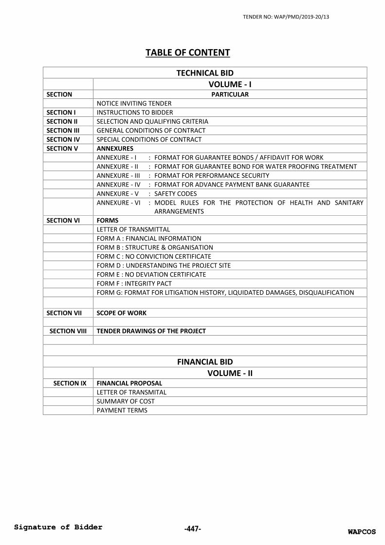
TENDER NO: WAP/PMD/2019-20/13
TABLE OF CONTENT
TECHNICAL BIDVOLUME - I
SECTION PARTICULARNOTICE INVITING TENDER
SECTION I INSTRUCTIONS TO BIDDERSECTION II SELECTION AND QUALIFYING CRITERIASECTION III GENERAL CONDITIONS OF CONTRACTSECTION IV SPECIAL CONDITIONS OF CONTRACTSECTION V ANNEXURES
ANNEXURE - I : FORMAT FOR GUARANTEE BONDS / AFFIDAVIT FOR WORKANNEXURE - II : FORMAT FOR GUARANTEE BOND FOR WATER PROOFING TREATMENTANNEXURE - III : FORMAT FOR PERFORMANCE SECURITYANNEXURE - IV : FORMAT FOR ADVANCE PAYMENT BANK GUARANTEEANNEXURE - V : SAFETY CODESANNEXURE - VI : MODEL RULES FOR THE PROTECTION OF HEALTH AND SANITARY
ARRANGEMENTSSECTION VI FORMS
LETTER OF TRANSMITTALFORM A : FINANCIAL INFORMATIONFORM B : STRUCTURE & ORGANISATIONFORM C : NO CONVICTION CERTIFICATEFORM D : UNDERSTANDING THE PROJECT SITEFORM E : NO DEVIATION CERTIFICATEFORM F : INTEGRITY PACTFORM G: FORMAT FOR LITIGATION HISTORY, LIQUIDATED DAMAGES, DISQUALIFICATION
SECTION VII SCOPE OF WORK
SECTION VIII TENDER DRAWINGS OF THE PROJECT
FINANCIAL BIDVOLUME - II
SECTION IX FINANCIAL PROPOSALLETTER OF TRANSMITALSUMMARY OF COSTPAYMENT TERMS
WAPCOSSignature of Bidder -447- WAPCOSSignature of Bidder

TENDER NO: WAP/PMD/2019-20/13
Volume-III
Section-IX
FINANCIAL PROPOSAL
Letter of Transmittal for Financial Bid Summary of Cost Payment Terms
WAPCOSSignature of Bidder -448- WAPCOSSignature of Bidder

TENDER NO: WAP/PMD/2019-20/13
Letter of Transmittal for Financial Bid
(On Original Letter Head of Bidder)Dated:
To,General Manager,Projects Management DivisionWAPCOS Limited,
Sub: Financial Bid for Construction of 300 Bedded Hostel at SAI, Imphal, Manipur.
Dear Sir,
With reference to your tender document of subjected work, I/we, having examined theBidding Documents and understood their contents, hereby submit my/our Bid for theaforesaid works. The Bid is unconditional and unqualified.1. I / We acknowledge that the WAPCOS will be relying on the information provided
in the BID and the documents accompanying the BID for selection of theContractor for the aforesaid Work, and we certify that all information provided inthe Bid are true and correct; nothing has been omitted which renders suchinformation misleading; and all documents accompanying the BID are true copiesof their respective originals.
2. The BID Price has been quoted by me / us after taking into consideration all theterms and conditions stated in the NIT, draft Agreement, our own estimates ofcosts and after a careful assessment of the site and all own the conditions thatmay affect the Work cost and implementation of the works.
3. I/ We acknowledge the right of the Authority to reject our BID without assigningany reason or otherwise and hereby waive, to the fullest extent permitted byapplicable law, our right to challenge the same on any account whatsoever.
4. In the event of my/ our being declared as the Selected Bidder, I/we agree to enterinto a Agreement in accordance with the draft that has been provided to me/usprior to the BID Due Date. We agree not to seek any changes in the aforesaid draftand agree to abide by the same.
5. I / We shall keep this offer valid as period specified in the NIT.6. I / We hereby submit our financial BID and offer BID Price excluding GST as filled in
excel format file of Summary Sheet of financial bid for undertaking the aforesaidWork in accordance with the Bidding Documents and the Agreement.
Yours faithfully,
Date: (Signature, name and designationof the Authorized signatory)
Place: Name and seal of Bidder
WAPCOSSignature of Bidder -449- WAPCOSSignature of Bidder

TENDER NO: WAP/PMD/2019-20/13
Summary of Cost
ParticularTotal Quoted Cost in Figure
(Excluding GST)(Rs.)
Construction of 300 Bedded Hostel at SAI, Imphal,Manipur
Total amount in words:
Note:-
The quoted cost filled in Summary of Cost, by bidders, should include allassociated costs with the project including any out of pocket / mobilizationexpenses/ Custom duty (if any) , Buildings and other construction workers welfarecess, TDS, taxes (except GST) if any applicable as per Govt. terms, shall be paid bythe Contractor. The Goods and Services Tax (GST) shall be paid extra over quotedcost
It is mandatory to bidders to deposit GST within time limit framed by Govt. ofIndia, if applicable. The Goods and Services Tax (GST), shall be reimbursed to theAgency only after uploading of bills by Contractor on GST Portal “ to avail Inputbenefit of GST
The company shall be performing all its duties of deduction TDS and otherdeduction on payment made to the contractor as per applicable legislation inforce on the date of submission of bid or to be newly / amended introducedduring the execution of the Contract.
The tenderer shall quote cost up to zero decimal and as well as in words. In caseof any discrepancy rate quoted in words shall prevail.
The payment will be made in percentage as per the schedule of stage wisepayment
Important Note for submission of online tender:
Do not filled above table of Summary of Cost at the time of submissionof technical bid.
The above financial proposal is to be filled by bidder in the excel fileattached in MSTC portal. After that, same filled excel file, will beuploaded by bidder at the submission of Price Bid.
WAPCOSSignature of Bidder -450- WAPCOSSignature of Bidder

TENDER NO: WAP/PMD/2019-20/13
PAYMENT TERMS
The Stage wise Payments shall be made in Percentage of the Total quoted Cost of works asquoted by the bidder/ contractor. The “STAGE OF CONSTRUCTION” for each component shall beas per the details below.
Mainly Payment will be made after completion of particular “STAGE OF CONSTRUCTION” as perthe detail in the Scope of Work in compliance of all the conditions mentioned in the TenderDocument. If any stage of construction is completed partially, then payment will be made on pro-rata basis, if agreed by Engineer- in-charge and WAPCOS . The pro-rata percentage will beanalyzed by the Engineer- in-charge and WAPCOS and no dispute in this regard will beentertained
The main scope of work for each component shall be governed as detailed in “SECTION of SCOPEOF WORK” of the tender document and final payment shall be made accordingly, to theContractor.
The works mentioned in column no. 2 of Stage of Construction, are milestone for progress ofwork. Percentage mentioned in column no. 3 &4 are to facilitate the payment to contractor aftercompletion of particular stage of construction. Percentage mentioned against particular Stage ofConstruction may not be actual cost of that particular stage of construction. The final 100%payment, depicts the total cost of work as per the scope of work and in compliance with allconditions mentioned in tender document.
If any works mentioned in the payment terms is not executed, then payment will be deducted asper the provision in DSR-2018 for scheduled items and Market Rate analysis for Non Scheduleitems.
The gross amount of running bill of Contractor for the executed works shall not be less than Rs.1.0 Cr.
S.No. Stage of Construction
% ofCost
for allHostelBlocks
% ofCostfor
Kitchenblock
%Cumulative
Cost
1 2 3 41 On completion of Geotechnical and Survey
Investigation and submission of reports of the same 0.30 0.3
2 On submission of IIT/ NIT vetted StructuralDrawings 0.20 0.5
3On completion of PCC work including excavation forfoundation in all respect and as per the Scope ofwork
0.80 0.20 1.5
4 On completion of all works up to plinth beam levelas per the scope of work 7.60 1.80 10.9
WAPCOSSignature of Bidder -451- WAPCOSSignature of Bidder

TENDER NO: WAP/PMD/2019-20/13
S.No. Stage of Construction
% ofCost
for allHostelBlocks
% ofCostfor
Kitchenblock
%Cumulative
Cost
5On casting of columns above Plinth beam Level andupto beams soffit of first floor as per the Scope ofwork
2.40 0.60 13.9
6 On casting of ground floor slab with beams andallied works as per the Scope of work 4.00 1.00 18.9
7On casting of columns above ground floor slab Leveland upto beams soffit of second floor as per theScope of work
3.00 21.9
8 On casting of First Floor slab with beams and alliedworks as per the Scope of work 5.00 26.9
9On casting of columns above first floor slab Leveland upto beams soffit of third floor as per theScope of work
3.00 29.9
10 On casting of second Floor slab with beams andallied works as per the Scope of work 5.00 34.9
11On casting of columns above Second floor slab Leveland upto beams soffit of terrace floor as per theScope of work
3.00 37.9
12On casting of Terrace Floor slab and Mumty Slabwith beams and allied works as per the Scope ofwork
5.00 42.9
13On completion filler wall work of ground floor alongwith provision of lintel etc. and providing and fixingdoor Frame, window frames & ventilator frame asper the Scope of work
1.60 0.40 44.9
14On completion filler wall work of first floor alongwith provision of lintel etc. and providing and fixingdoor Frame, window frames & ventilator frame asper the Scope of work
1.20 46.1
15On completion filler wall work of second floor alongwith provision of lintel etc. and providing and fixingdoor Frame, window frames & ventilator frame asper the Scope of work
1.20 47.3
16On completion filler wall work of third floor alongwith provision of lintel etc. and providing and fixingdoor Frame, window frames & ventilator frame asper the Scope of work
1.20 48.5
17
On completion filler wall work of Mumty along withprovision of lintel etc. and providing and fixing doorFrame, window frames & ventilator frame andinternal and external plaster as per the Scope ofwork
0.20 48.7
WAPCOSSignature of Bidder -452- WAPCOSSignature of Bidder

TENDER NO: WAP/PMD/2019-20/13
S.No. Stage of Construction
% ofCost
for allHostelBlocks
% ofCostfor
Kitchenblock
%Cumulative
Cost
18 On completion of internal plastering of ground flooras per the Scope of work 0.40 0.10 49.2
19 On completion of external plastering of groundfloor as per the Scope of work 0.40 0.10 49.7
20 On completion of internal plastering of first floor asper the Scope of work 0.50 50.2
21 On completion of external plastering of first floor asper the Scope of work 0.50 50.7
22 On completion of internal plastering of second flooras per the Scope of work 0.50 51.2
23 On completion of external plastering of secondfloor as per the Scope of work 0.50 51.7
24 On completion of internal plastering of Third floorand mumty as per the Scope of work 0.60 52.3
25 On completion of external plastering of Third floorand mumty as per the Scope of work 0.60 52.9
26On laying and fixing of Slab/ wall conducting & MSbox fixing in position of ground and first floor forelectrical works as per the Scope of work
0.80 0.20 53.9
27On laying and fixing of Slab/ wall conducting & MSbox fixing in position of second and third floor forelectrical works as per the Scope of work
1.00 54.9
28Overall laying of pipe network for internalPlumbing, fire fighting in position inside the hostelbuilding and connection with OHT and UGT as perthe Scope of work.
2.00 56.9
29Overall laying of pipe network for internal sanitary/sewage, in position inside the hostel building andconnection upto Man hole of the building as per theScope of work
1.00 57.9
30On completion of flooring/ dado/ skirting/ kitchenshelves works in ground floor including staircasecomplete in all respect and as per scope of work
2.30 0.70 60.9
31On completion of flooring/ dado/ skirting works infirst floor including staircase complete in all respectand as per scope of work
1.50 62.4
32On completion of flooring/ dado/ skirting works insecond floorincluding staircase complete in allrespect and as per scope of work
1.50 63.9
33On completion of flooring/ dado/ skirting works inthird floor including staircase complete in all respectand as per scope of work
1.00 64.9
WAPCOSSignature of Bidder -453- WAPCOSSignature of Bidder

TENDER NO: WAP/PMD/2019-20/13
S.No. Stage of Construction
% ofCost
for allHostelBlocks
% ofCostfor
Kitchenblock
%Cumulative
Cost
34 On fixing railing in staircases, balcony, corridors etc.complete in all respect and as per scope of work 1.50 0.30 66.7
35
Complete Electrical fitting including wiring,switching, distribution board, panels, fans, geysers,lights, etc. upto main distribution board of thebuilding complete in all respect and as per scope ofwork
2.30 0.20 69.2
36Supply, Testing and Commissioning of Fire AlarmSystem complete in all respect and as per scope ofwork
0.50 69.7
37
On providing and fixing door, window & ventilatorsshutters, cupboards, kitchen area cupboards,hardware fixtures & fittings, etc. on ground and firstfloor complete in all respect and as per scope ofwork
2.00 0.50 72.2
38On providing and fixing door, window & ventilatorsshutters, hardware fixtures & fittings, etc. on secondand third floors complete in all respect and as perscope of work
1.50 73.7
39On providing and fixing of frameless toughenedglass and structural glazing complete in all respectand as per scope of work
1.50 75.2
40 On completion of all Over- head Tanks complete inall respect and as per scope of work 1.00 76.2
41 Terrace water proofing & allied works complete inall respect and as per scope of work 1.60 0.40 78.2
42External finsihinig work of hostel building inbalance area apart from structural glazing workincluding embosed sports art logos on external wallscomplete in all respect and as per scope of work
1.80 0.20 80.2
43 Internal painting works of hostel building completein all respect and as per scope of works 0.70 0.10 81
44 On completion of Under ground Tanks complete inall respect and as per scope of work 1.50 82.5
45on completion of Bore Well/ Tube well along withpumps and eqipments and allied works complete inall respect and as per scope of work
0.50 83
46 Supply of DG Sets at project site as per scope ofwork 1.00 84
47Testing and commissioning of DG Sets along with allcabling/wiring works and connections with allaccessories from LT panel to Distribution boards to
1.00 85
WAPCOSSignature of Bidder -454- WAPCOSSignature of Bidder
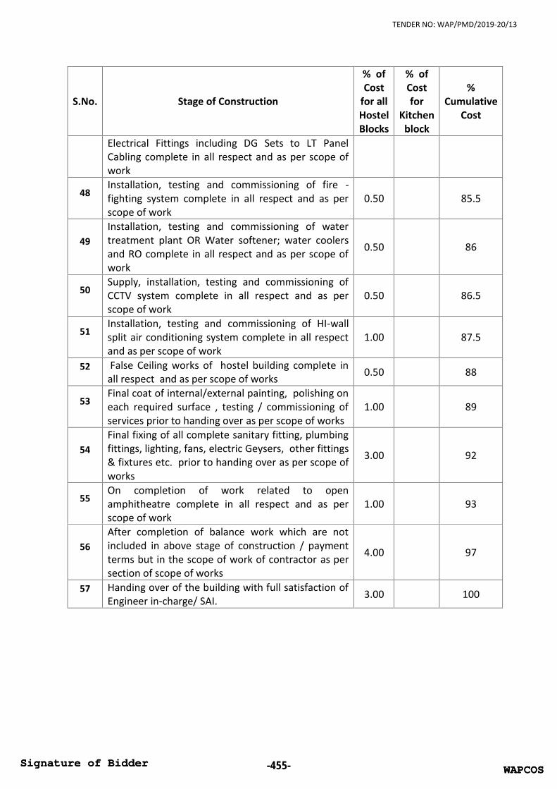
TENDER NO: WAP/PMD/2019-20/13
S.No. Stage of Construction
% ofCost
for allHostelBlocks
% ofCostfor
Kitchenblock
%Cumulative
Cost
Electrical Fittings including DG Sets to LT PanelCabling complete in all respect and as per scope ofwork
48Installation, testing and commissioning of fire -fighting system complete in all respect and as perscope of work
0.50 85.5
49Installation, testing and commissioning of watertreatment plant OR Water softener; water coolersand RO complete in all respect and as per scope ofwork
0.50 86
50Supply, installation, testing and commissioning ofCCTV system complete in all respect and as perscope of work
0.50 86.5
51Installation, testing and commissioning of HI-wallsplit air conditioning system complete in all respectand as per scope of work
1.00 87.5
52 False Ceiling works of hostel building complete inall respect and as per scope of works 0.50 88
53Final coat of internal/external painting, polishing oneach required surface , testing / commissioning ofservices prior to handing over as per scope of works
1.00 89
54Final fixing of all complete sanitary fitting, plumbingfittings, lighting, fans, electric Geysers, other fittings& fixtures etc. prior to handing over as per scope ofworks
3.00 92
55On completion of work related to openamphitheatre complete in all respect and as perscope of work
1.00 93
56After completion of balance work which are notincluded in above stage of construction / paymentterms but in the scope of work of contractor as persection of scope of works
4.00 97
57 Handing over of the building with full satisfaction ofEngineer in-charge/ SAI. 3.00 100
WAPCOSSignature of Bidder -455- WAPCOSSignature of Bidder