Templated growth of superparamagnetic iron oxide nanoparticles by temperature programming in the...
9
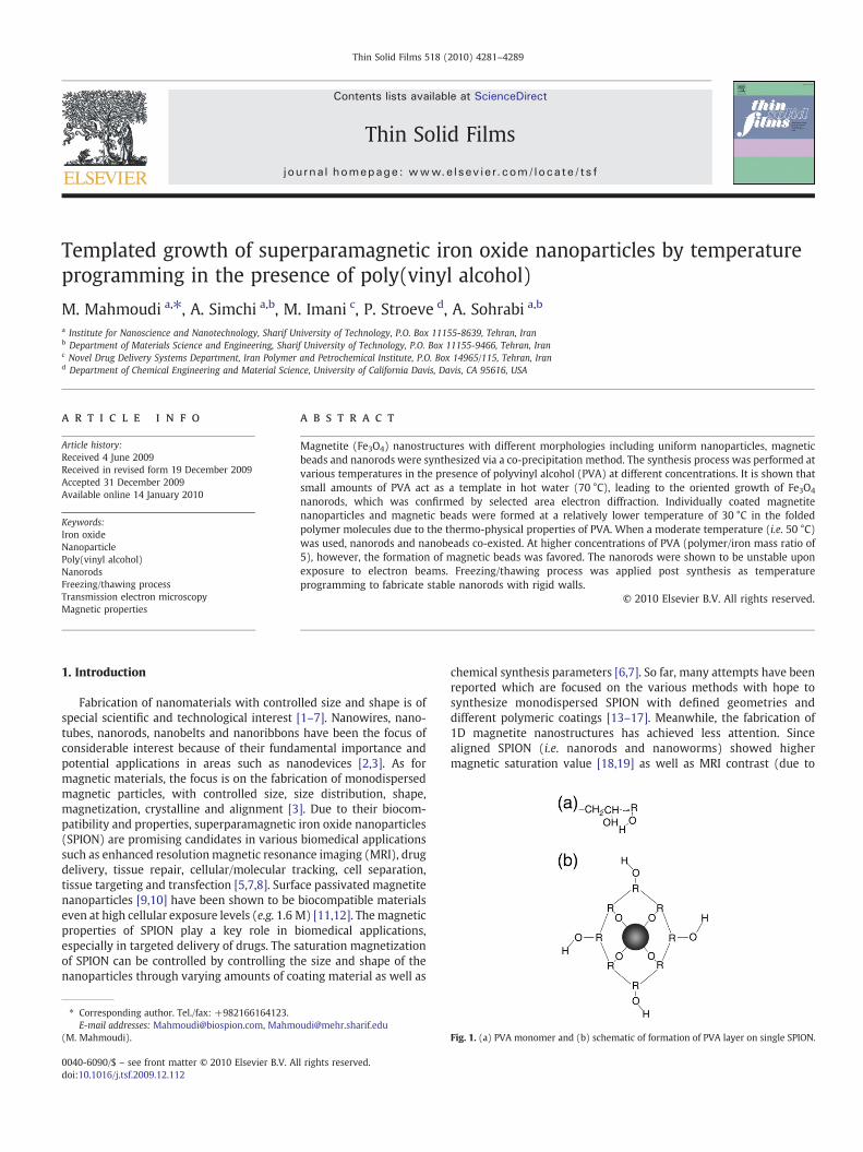
Templated growth of superparamagnetic iron oxide nanoparticles by temperature programming in the presence of poly(vinyl alcohol) M. Mahmoudi a, ⁎, A. Simchi a,b , M. Imani c , P. Stroeve d , A. Sohrabi a,b a Institute for Nanoscience and Nanotechnology, Sharif University of Technology, P.O. Box 11155-8639, Tehran, Iran b Department of Materials Science and Engineering, Sharif University of Technology, P.O. Box 11155-9466, Tehran, Iran c Novel Drug Delivery Systems Department, Iran Polymer and Petrochemical Institute, P.O. Box 14965/115, Tehran, Iran d Department of Chemical Engineering and Material Science, University of California Davis, Davis, CA 95616, USA abstract article info Article history: Received 4 June 2009 Received in revised form 19 December 2009 Accepted 31 December 2009 Available online 14 January 2010 Keywords: Iron oxide Nanoparticle Poly(vinyl alcohol) Nanorods Freezing/thawing process Transmission electron microscopy Magnetic properties Magnetite (Fe 3 O 4 ) nanostructures with different morphologies including uniform nanoparticles, magnetic beads and nanorods were synthesized via a co-precipitation method. The synthesis process was performed at various temperatures in the presence of polyvinyl alcohol (PVA) at different concentrations. It is shown that small amounts of PVA act as a template in hot water (70 °C), leading to the oriented growth of Fe 3 O 4 nanorods, which was confirmed by selected area electron diffraction. Individually coated magnetite nanoparticles and magnetic beads were formed at a relatively lower temperature of 30 °C in the folded polymer molecules due to the thermo-physical properties of PVA. When a moderate temperature (i.e. 50 °C) was used, nanorods and nanobeads co-existed. At higher concentrations of PVA (polymer/iron mass ratio of 5), however, the formation of magnetic beads was favored. The nanorods were shown to be unstable upon exposure to electron beams. Freezing/thawing process was applied post synthesis as temperature programming to fabricate stable nanorods with rigid walls. © 2010 Elsevier B.V. All rights reserved. 1. Introduction Fabrication of nanomaterials with controlled size and shape is of special scientific and technological interest [1–7]. Nanowires, nano- tubes, nanorods, nanobelts and nanoribbons have been the focus of considerable interest because of their fundamental importance and potential applications in areas such as nanodevices [2,3]. As for magnetic materials, the focus is on the fabrication of monodispersed magnetic particles, with controlled size, size distribution, shape, magnetization, crystalline and alignment [3]. Due to their biocom- patibility and properties, superparamagnetic iron oxide nanoparticles (SPION) are promising candidates in various biomedical applications such as enhanced resolution magnetic resonance imaging (MRI), drug delivery, tissue repair, cellular/molecular tracking, cell separation, tissue targeting and transfection [5,7,8]. Surface passivated magnetite nanoparticles [9,10] have been shown to be biocompatible materials even at high cellular exposure levels (e.g. 1.6 M) [11,12]. The magnetic properties of SPION play a key role in biomedical applications, especially in targeted delivery of drugs. The saturation magnetization of SPION can be controlled by controlling the size and shape of the nanoparticles through varying amounts of coating material as well as chemical synthesis parameters [6,7]. So far, many attempts have been reported which are focused on the various methods with hope to synthesize monodispersed SPION with defined geometries and different polymeric coatings [13–17]. Meanwhile, the fabrication of 1D magnetite nanostructures has achieved less attention. Since aligned SPION (i.e. nanorods and nanoworms) showed higher magnetic saturation value [18,19] as well as MRI contrast (due to Thin Solid Films 518 (2010) 4281–4289 ⁎ Corresponding author. Tel./fax: +982166164123. E-mail addresses: [email protected], [email protected] (M. Mahmoudi). Fig. 1. (a) PVA monomer and (b) schematic of formation of PVA layer on single SPION. 0040-6090/$ – see front matter © 2010 Elsevier B.V. All rights reserved. doi:10.1016/j.tsf.2009.12.112 Contents lists available at ScienceDirect Thin Solid Films journal homepage: www.elsevier.com/locate/tsf
-
Upload
independent -
Category
Documents
-
view
5 -
download
0
Transcript of Templated growth of superparamagnetic iron oxide nanoparticles by temperature programming in the...
Thin Solid Films 518 (2010) 4281–4289
Contents lists available at ScienceDirect
Thin Solid Films
j ourna l homepage: www.e lsev ie r.com/ locate / ts f
Templated growth of superparamagnetic iron oxide nanoparticles by temperatureprogramming in the presence of poly(vinyl alcohol)
M. Mahmoudi a,⁎, A. Simchi a,b, M. Imani c, P. Stroeve d, A. Sohrabi a,b
a Institute for Nanoscience and Nanotechnology, Sharif University of Technology, P.O. Box 11155-8639, Tehran, Iranb Department of Materials Science and Engineering, Sharif University of Technology, P.O. Box 11155-9466, Tehran, Iranc Novel Drug Delivery Systems Department, Iran Polymer and Petrochemical Institute, P.O. Box 14965/115, Tehran, Irand Department of Chemical Engineering and Material Science, University of California Davis, Davis, CA 95616, USA
⁎ Corresponding author. Tel./fax: +982166164123.E-mail addresses: [email protected], Mahmo
(M. Mahmoudi).
0040-6090/$ – see front matter © 2010 Elsevier B.V. Aldoi:10.1016/j.tsf.2009.12.112
a b s t r a c t
a r t i c l e i n f oArticle history:Received 4 June 2009Received in revised form 19 December 2009Accepted 31 December 2009Available online 14 January 2010
Keywords:Iron oxideNanoparticlePoly(vinyl alcohol)NanorodsFreezing/thawing processTransmission electron microscopyMagnetic properties
Magnetite (Fe3O4) nanostructures with different morphologies including uniform nanoparticles, magneticbeads and nanorods were synthesized via a co-precipitation method. The synthesis process was performed atvarious temperatures in the presence of polyvinyl alcohol (PVA) at different concentrations. It is shown thatsmall amounts of PVA act as a template in hot water (70 °C), leading to the oriented growth of Fe3O4
nanorods, which was confirmed by selected area electron diffraction. Individually coated magnetitenanoparticles and magnetic beads were formed at a relatively lower temperature of 30 °C in the foldedpolymer molecules due to the thermo-physical properties of PVA. When a moderate temperature (i.e. 50 °C)was used, nanorods and nanobeads co-existed. At higher concentrations of PVA (polymer/iron mass ratio of5), however, the formation of magnetic beads was favored. The nanorods were shown to be unstable uponexposure to electron beams. Freezing/thawing process was applied post synthesis as temperatureprogramming to fabricate stable nanorods with rigid walls.
[email protected]. 1. (a) PVA mono
l rights reserved.
© 2010 Elsevier B.V. All rights reserved.
1. Introduction
Fabrication of nanomaterials with controlled size and shape is ofspecial scientific and technological interest [1–7]. Nanowires, nano-tubes, nanorods, nanobelts and nanoribbons have been the focus ofconsiderable interest because of their fundamental importance andpotential applications in areas such as nanodevices [2,3]. As formagnetic materials, the focus is on the fabrication of monodispersedmagnetic particles, with controlled size, size distribution, shape,magnetization, crystalline and alignment [3]. Due to their biocom-patibility and properties, superparamagnetic iron oxide nanoparticles(SPION) are promising candidates in various biomedical applicationssuch as enhanced resolutionmagnetic resonance imaging (MRI), drugdelivery, tissue repair, cellular/molecular tracking, cell separation,tissue targeting and transfection [5,7,8]. Surface passivated magnetitenanoparticles [9,10] have been shown to be biocompatible materialseven at high cellular exposure levels (e.g. 1.6 M) [11,12]. Themagneticproperties of SPION play a key role in biomedical applications,especially in targeted delivery of drugs. The saturation magnetizationof SPION can be controlled by controlling the size and shape of thenanoparticles through varying amounts of coating material as well as
chemical synthesis parameters [6,7]. So far, many attempts have beenreported which are focused on the various methods with hope tosynthesize monodispersed SPION with defined geometries anddifferent polymeric coatings [13–17]. Meanwhile, the fabrication of1D magnetite nanostructures has achieved less attention. Sincealigned SPION (i.e. nanorods and nanoworms) showed highermagnetic saturation value [18,19] as well as MRI contrast (due to
mer and (b) schematic of formation of PVA layer on single SPION.
4282 M. Mahmoudi et al. / Thin Solid Films 518 (2010) 4281–4289
improvement of spin–spin relaxation of water molecules) in com-parison with the spherical one [20,21], aligned magnetic nanoparti-cles would be highly accepted in targeted delivery and imagingapplications [22,23]. Furthermore, the phagocytosis amounts ofnanorods are lower than the spherical one during their in vivoapplications [24]. In addition, magnetic fibers are promising materialsfor data storage systems, for giant magneto resistance sensors andbiomagnetics, ranging from biosensing to cell manipulation or cancertherapy [25,26]. Therefore, there is a great interest in the synthesis ofrod-shaped magnetite nanoparticles. Until now, the hydrothermalroute has mostly been used to fabricate magnetic nanorods [27–32].Recently we reported the synthesis of rod-shaped SPION using a co-precipitation method by variation of the synthesis parameters such asstirring rate and base molarities [6]. In this paper, we describe the
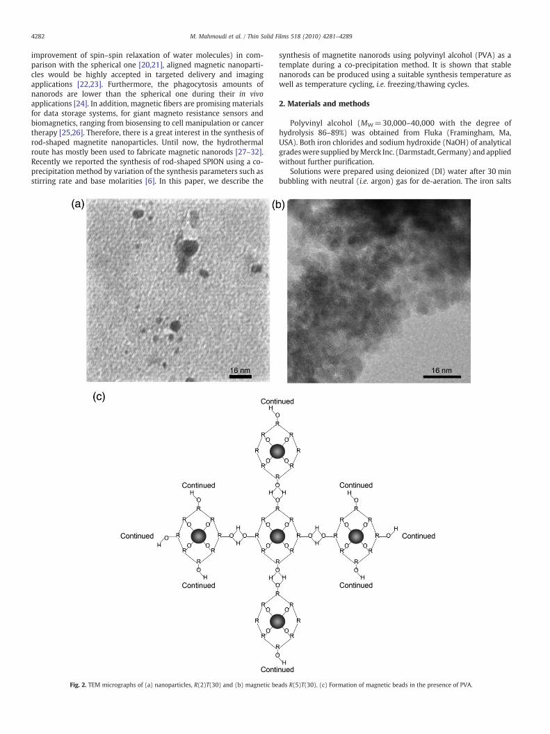
Fig. 2. TEM micrographs of (a) nanoparticles, R(2)T(30) and (b) magnetic be
synthesis of magnetite nanorods using polyvinyl alcohol (PVA) as atemplate during a co-precipitation method. It is shown that stablenanorods can be produced using a suitable synthesis temperature aswell as temperature cycling, i.e. freezing/thawing cycles.
2. Materials and methods
Polyvinyl alcohol (MW=30,000–40,000 with the degree ofhydrolysis 86–89%) was obtained from Fluka (Framingham, Ma,USA). Both iron chlorides and sodium hydroxide (NaOH) of analyticalgradeswere supplied byMerck Inc. (Darmstadt, Germany) and appliedwithout further purification.
Solutions were prepared using deionized (DI) water after 30 minbubbling with neutral (i.e. argon) gas for de-aeration. The iron salts
ads R(5)T(30). (c) Formation of magnetic beads in the presence of PVA.

4283M. Mahmoudi et al. / Thin Solid Films 518 (2010) 4281–4289
were dissolved in DI water containing 0.5 M HCl with the molefraction of Fe3+/Fe2+=2 (1 g FeCl3:0.368 g FeCl2) for all batches. Theprecipitationwas performed by dropwise addition of iron salt solutionto NaOH solution under an argon atmosphere. To facilitate masstransfer in the reactionmixture, turbulent flowwas formed by placingthe reaction flask in an ultrasonic bath and controlling the impellerstirring rate between 3600 rpm and 9000 rpm in the first 2 min of thereaction [6]. Three synthesis temperatures were examined (30, 50 and70 °C). After 30 min, PVA solution with the same temperature of theSPION solution (with different polymer to iron mass ratio (R) includ-ing 2 and 5) was added through a syringe as coating material fornanoparticles. The mixture was then stirred at the constant tem-perature for an additional 30 min at 3600 rpm. In order to form astable polymeric coating and orientation, the samples were rapidlycooled down to 5–10 °C i.e. far below the glass transition temperatureof the PVA [33,34]. Nanoparticles were collected by centrifugation at6000 rpm for 10 min after completion of the reaction and re-dispersed in DI water. The procedure was repeated several timesand finally the ferrofluid was kept at 4 °C for further use. The sampleswere labeled by R(x)T(y) where R indicates the polymer to iron massratio and x is the amount of R, while T indicates the synthesistemperature and y is the value of T in °C. For example, R(2)T(30)refers to the sample prepared with a polymer/iron mass ratio of 2 anda temperature of 30 °C. The aqueous R(2)T(70) and R(5)T(70)solutions were then exposed to eight freeze/thaw cycles, consistingof a freezing step (12 h at−25 °C) followed by a thawing step (12 h at25 °C).
Morphology of the nanoparticles was measured by transmissionelectronmicroscopy (TEM, H 9000NAR, Hitachi, Tokyo, Japan) operatedat 200 kV. To prepare samples for TEM, a drop of the suspension wasplaced on a copper grid and dried. Phase characterization wasaccomplished using X-ray diffraction (XRD, Siemens, D5000, Germany)with CuKα radiation. The magnetization of sample in a variable mag-netic field was considered using a vibrating sample magnetometer(VSM). The samples were prepared by drying the nanoparticles in avacuumoven at 40 °C for 12 h after centrifugation. The Scherrermethodwas used for particle size determination.
3. Results and discussion
Various shapes of SPION were observed due to changes in thesynthesis parameters: i.e. polymer amount R and synthesis temper-ature T. Fig. 1 illustrates a schematic for formation of single nano-particles with PVA chemisorption due to the presence of hydroxyl
Fig. 3. TEM micrographs of samples showing large magnetic bead a
groups. Single nanoparticles are seen in the TEM micrograph given inFig. 2a with the conditions R(2)T(30). Polymeric beads are shown inFig. 2b, with conditions R(5)T(30), and form due to the bridging ofPVA molecules from one nanoparticle to another as shown in Fig. 2c.Both magnetic beads and rods are both observed in Fig. 3a, forconditions R(2)T(50), and 3b, for R(5)T(50). The values of the T and Rparameters play an important role in the morphology and size of thenanoparticles. We have observed that increasing the synthesistemperature favors the formation of nanobeads and nanorodsregardless of the R amount. There are some other reports in theliterature on PVA-coated nanoparticles clusterswith particle shapes ofnanorods and wires. The possible mechanisms for formation of singlecoated nanoparticles, polymeric beads and magnetic rods areschematically shown in Figs. 1b, 2c and 4a, respectively. It is knownthat PVA molecules dispersed in hot water (70 °C) and under highhomogenization rates may undergo thermo-physical stretching [35].The PVA molecules are rich in OH functional groups, which enablethem to strongly chemisorb to reactive chemical species. For smallamounts of polymer together with a relatively low temperature, (e.g.,R(2)T(30)), formation of single magnetic coated nanoparticles isobserved (Fig. 2a). At a reaction temperature of 30 °C and R=5, theformation of magnetic beads i.e. random dispersion of SPION inpolymeric bead is favored (Fig. 2b). Thus it appears that at R=2 andT=30 °C, PVA protects the nanoparticles against aggregation.Nevertheless, at high R values (R=5), gel formation properties ofPVA is dominant which gives rise to magnetic beads. Poly(vinylalcohol) contains kinked chains. In order to participate in theformation of magnetic beads, the distortion of the main chain canbe expected and is governed by a combination of mutual repulsionforces between neighboring hydroxyl functional groups and complexhydrogen bonding mechanism [36].
By increasing the synthesis temperature to 50 °C, PVA acts as anon-stable template. The TEM micrograph demonstrates the forma-tion of magnetic beads as well as nanorods as depicted in Fig. 3a forthe R(2)T(50) sample. Fig. 3b clearly shows that the percentage offormed magnetic beads is increased by raising the R value [e.g., R(5)T(50)]. As a result, the formation of folded polymer chains becomesdominant in comparison to PVA stable template at high R values, i.e. 5,and moderate temperature, e.g. 50 °C. In dilute solutions of PVA, thepolymer molecules have fewer interactions with other chains, whichallow the polymer backbones to be relaxed in the synthesisenvironment. At higher temperatures, the polymer molecules chem-isorb moremagnetic nanoparticles. Hence, particles can be bridged bythe polymer due to the presence of OH groups on the polymer chains
mounts due to the R amount: (a) R(2)T(50) and (b) R(5)T(50).

Fig. 4. (a) Schematic of the nanorod formation due to chemisorption of PVA molecules and (b) TEM micrograph of nanorods.
4284 M. Mahmoudi et al. / Thin Solid Films 518 (2010) 4281–4289
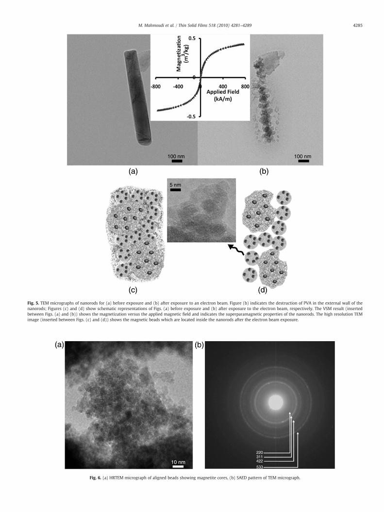
Fig. 5. TEM micrographs of nanorods for (a) before exposure and (b) after exposure to an electron beam. Figure (b) indicates the destruction of PVA in the external wall of thenanorods; Figures (c) and (d) show schematic representations of Figs. (a) before exposure and (b) after exposure to the electron beam, respectively. The VSM result (insertedbetween Figs. (a) and (b)) shows the magnetization versus the applied magnetic field and indicates the superparamagnetic properties of the nanorods. The high resolution TEMimage (inserted between Figs. (c) and (d)) shows the magnetic beads which are located inside the nanorods after the electron beam exposure.
Fig. 6. (a) HRTEM micrograph of aligned beads showing magnetite cores, (b) SAED pattern of TEM micrograph.
4285M. Mahmoudi et al. / Thin Solid Films 518 (2010) 4281–4289
4286 M. Mahmoudi et al. / Thin Solid Films 518 (2010) 4281–4289
and the magnetic particles. Presumably the kinked chains will nolonger be regular as a result of the disruption of hydrogen bondswithin the polymeric network [36]. As a result, by introducing thepolymer solution to SPIONwith active surface groups (OH groups) at atemperature of 70 °C, the temperature appears to be the keyparameter controlling the interaction rather than the R value.Fig. 4b illustrates the TEM micrograph of rod-shaped SPION forsample R(2)T(70) with no magnetic beads present.
As shown in the VSM graph of Fig. 5, the nanorods havemagnetization curves typical of single superparamagnetic magnetitenanoparticles, similar to our previous work [6]. The beads ofmagnetite nanoparticles in the nanorod appear to be aligned. Thesimilar growth of tellurium nanorods has been reported via longpolyvinyl chain of poly(vinyl pyrrolidone) [37]. The polymer in thewalls of nanorods (with helix shape) can be destroyed duringexposure to the electron beam during TEM operation (Fig. 5a andb). Fig. 5b reveals multiple magnetic beads, inside the rod, with themagnetic beads wrapped in thin PVA layers adhering to one anotherin bundles. The magnetic beads are in the stage of clustering andgrowth into a rod over the PVA matrix. Fig. 5c and d show anillustration of the structure of Fig. 5a and b. High resolution TEMmicrographs of the magnetic beads can be obtained and an example isshown in Fig. 6a. Individual beads are visible inside the core of the
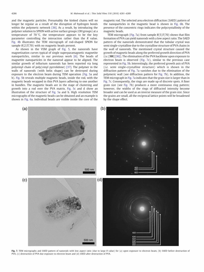
Fig. 7. TEM micrographs and SAED pattern of nanorods with low aspect ratio (due to larPVA, (c) destruction of PVA due exposure to electron beam and (d) SAED after destruction
magnetic rod. The selected area electron diffraction (SAED) pattern ofthe nanoparticles in the magnetic bead is shown in Fig. 6b. Thepresence of the concentric rings indicates the polycrystallinity of themagnetic beads.
TEM micrograph (Fig. 7a) from sample R(5)T(70) shows that filmformation of PVA can yield nanorodswith a low aspect ratio. The SAEDpattern of the nanorods demonstrated that the tubular crystal wassemi single-crystalline due to the crystalline structure of PVA chains inthe wall of nanorods. The mentioned crystal structure caused thegrowth ofmagnetic beads along the preferred growth direction of PVA(i.e. [10ī] [36]). The elimination of the PVA backbone upon exposure toelectron beam is observed (Fig. 7c), similar to the previous caserepresented in Fig. 5b. Interestingly, the preferred growth axis of PVA(i.e. semi single-crystalline structure) which is shown in thediffraction pattern of Fig. 7a vanishes due to the elimination of thepolymeric wall (see diffraction pattern for Fig. 7b). In addition, theTEMmicrograph in Fig. 7a indicates that the grain size is larger than inFig. 7c. Consequently, the rings are made up of discrete spots. A finergrain size (see Fig. 7b) produces a more continuous ring pattern;however, the widths of the rings of diffracted intensity becomebroader and can be used as an inverse measure of the grain size. Sincethe grains are small, all the reciprocal lattice points will be broadenedby the shape effect.
ge R value) for (a) upon exposure to electron beam, (b) SAED before destruction ofof PVA.
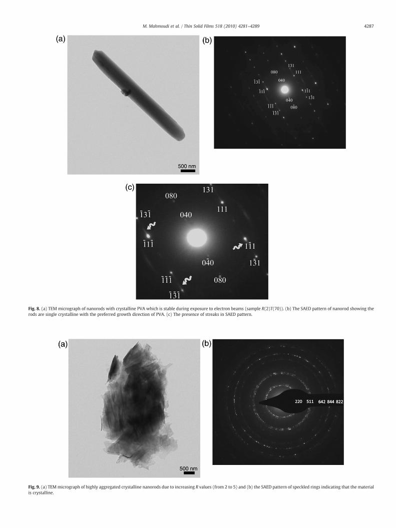
Fig. 9. (a) TEMmicrograph of highly aggregated crystalline nanorods due to increasing R values (from 2 to 5) and (b) the SAED pattern of speckled rings indicating that the materialis crystalline.
Fig. 8. (a) TEM micrograph of nanorods with crystalline PVA which is stable during exposure to electron beams (sample R(2)T(70)). (b) The SAED pattern of nanorod showing therods are single crystalline with the preferred growth direction of PVA. (c) The presence of streaks in SAED pattern.
4287M. Mahmoudi et al. / Thin Solid Films 518 (2010) 4281–4289
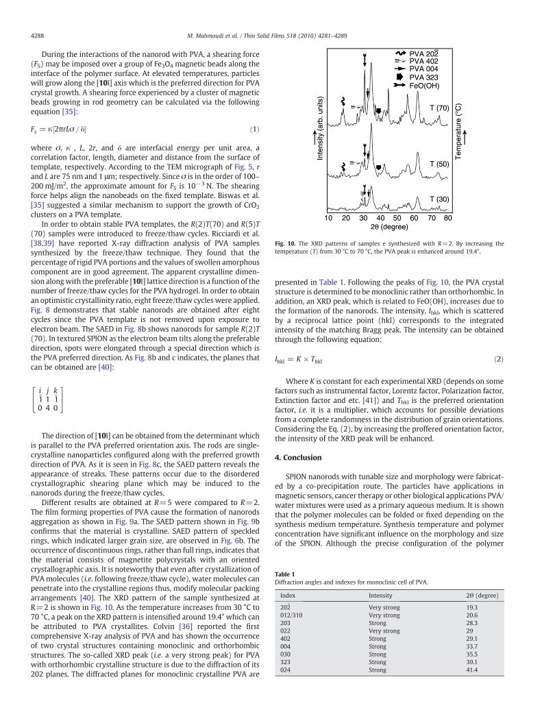
Table 1Diffraction angles and indexes for monoclinic cell of PVA.
Index Intensity 2Θ (degree)
202 ̄ Very strong 19.3012/310 Very strong 20.6203 Strong 28.3022 Very strong 29402 Strong 29.1004 Strong 33.7030 Strong 35.5323 Strong 39.1024 Strong 41.4
Fig. 10. The XRD patterns of samples e synthesized with R=2. By increasing thetemperature (T) from 30 °C to 70 °C, the PVA peak is enhanced around 19.4°.
4288 M. Mahmoudi et al. / Thin Solid Films 518 (2010) 4281–4289
During the interactions of the nanorod with PVA, a shearing force(FS) may be imposed over a group of Fe3O4 magnetic beads along theinterface of the polymer surface. At elevated temperatures, particleswill grow along the [10ī] axis which is the preferred direction for PVAcrystal growth. A shearing force experienced by a cluster of magneticbeads growing in rod geometry can be calculated via the followingequation [35]:
Fs = κ½2πrLσ = δ� ð1Þ
where σ, κ , L, 2r, and δ are interfacial energy per unit area, acorrelation factor, length, diameter and distance from the surface oftemplate, respectively. According to the TEM micrograph of Fig. 5, rand L are 75 nm and 1 μm; respectively. Since σ is in the order of 100–200 mJ/m2, the approximate amount for FS is 10−3 N. The shearingforce helps align the nanobeads on the fixed template. Biswas et al.[35] suggested a similar mechanism to support the growth of CrO2
clusters on a PVA template.In order to obtain stable PVA templates, the R(2)T(70) and R(5)T
(70) samples were introduced to freeze/thaw cycles. Ricciardi et al.[38,39] have reported X-ray diffraction analysis of PVA samplessynthesized by the freeze/thaw technique. They found that thepercentage of rigid PVA portions and the values of swollen amorphouscomponent are in good agreement. The apparent crystalline dimen-sion alongwith the preferable [10ī] lattice direction is a function of thenumber of freeze/thaw cycles for the PVA hydrogel. In order to obtainan optimistic crystallinity ratio, eight freeze/thaw cycles were applied.Fig. 8 demonstrates that stable nanorods are obtained after eightcycles since the PVA template is not removed upon exposure toelectron beam. The SAED in Fig. 8b shows nanorods for sample R(2)T(70). In textured SPION as the electron beam tilts along the preferabledirection, spots were elongated through a special direction which isthe PVA preferred direction. As Fig. 8b and c indicates, the planes thatcan be obtained are [40]:
i‐10
j14
k‐10
24
35
The direction of [10ī] can be obtained from the determinant whichis parallel to the PVA preferred orientation axis. The rods are single-crystalline nanoparticles configured along with the preferred growthdirection of PVA. As it is seen in Fig. 8c, the SAED pattern reveals theappearance of streaks. These patterns occur due to the disorderedcrystallographic shearing plane which may be induced to thenanorods during the freeze/thaw cycles.
Different results are obtained at R=5 were compared to R=2.The film forming properties of PVA cause the formation of nanorodsaggregation as shown in Fig. 9a. The SAED pattern shown in Fig. 9bconfirms that the material is crystalline. SAED pattern of speckledrings, which indicated larger grain size, are observed in Fig. 6b. Theoccurrence of discontinuous rings, rather than full rings, indicates thatthe material consists of magnetite polycrystals with an orientedcrystallographic axis. It is noteworthy that even after crystallization ofPVAmolecules (i.e. following freeze/thaw cycle), water molecules canpenetrate into the crystalline regions thus, modify molecular packingarrangements [40]. The XRD pattern of the sample synthesized atR=2 is shown in Fig. 10. As the temperature increases from 30 °C to70 °C, a peak on the XRD pattern is intensified around 19.4° which canbe attributed to PVA crystallites. Colvin [36] reported the firstcomprehensive X-ray analysis of PVA and has shown the occurrenceof two crystal structures containing monoclinic and orthorhombicstructures. The so-called XRD peak (i.e. a very strong peak) for PVAwith orthorhombic crystalline structure is due to the diffraction of its202 planes. The diffracted planes for monoclinic crystalline PVA are
presented in Table 1. Following the peaks of Fig. 10, the PVA crystalstructure is determined to bemonoclinic rather than orthorhombic. Inaddition, an XRD peak, which is related to FeO(OH), increases due tothe formation of the nanorods. The intensity, Ihkl, which is scatteredby a reciprocal lattice point (hkl) corresponds to the integratedintensity of the matching Bragg peak. The intensity can be obtainedthrough the following equation:
Ihkl = K × Thkl ð2Þ
Where K is constant for each experimental XRD (depends on somefactors such as instrumental factor, Lorentz factor, Polarization factor,Extinction factor and etc. [41]) and Thkl is the preferred orientationfactor, i.e. it is a multiplier, which accounts for possible deviationsfrom a complete randomness in the distribution of grain orientations.Considering the Eq. (2), by increasing the proffered orientation factor,the intensity of the XRD peak will be enhanced.
4. Conclusion
SPION nanorods with tunable size and morphology were fabricat-ed by a co-precipitation route. The particles have applications inmagnetic sensors, cancer therapy or other biological applications PVA/water mixtures were used as a primary aqueous medium. It is shownthat the polymer molecules can be folded or fixed depending on thesynthesis medium temperature. Synthesis temperature and polymerconcentration have significant influence on the morphology and sizeof the SPION. Although the precise configuration of the polymer
4289M. Mahmoudi et al. / Thin Solid Films 518 (2010) 4281–4289
chains within the crystalline regions is unresolved at present, thefiber-periodicities suggested a twisted or helical structure at lowtemperatures and a fixed relaxed-shape at high temperatures. Duringprocessing in warm water, the magnetic beads were forced to growunidirectionally along the interface with the fixed polymer molecules.The freeze/thaw technique was applied to increase the PVAcrystallinity. Furthermore; the materials show higher stability fornanorods during exposure to electron beam due to the PVA stability inthe wall of clusters. The X-ray diffraction patterns indicate theformation (10ī) oriented PVA plane. This observation confirms thecrystallinity enhancing effect of freezing/thawing process in PVA.
References
[1] U.O. Hafeli, G.J. Pauer, J. Magn. Magn. Mater. 194 (1999) 76.[2] T.S. Ahmadi, Z.L. Wang, T.C. Green, A. Henglein, M.A. El-Sayed, Science 272 (1996)
1924.[3] T. Hyeon, Chem. Commun. 9 (2003) 927.[4] U. Hafeli, M. Zborowski, J. Magn, Magn. Mater. 293 (2005) XI.[5] A.K. Gupta, M. Gupta, Biomaterials 26 (2005) 3995.[6] M. Mahmoudi, A. Simchi, M. Imani, A.S. Milani, P. Stroeve, J. Phys. Chem. B 112
(2008) 14470.[7] M. Mahmoudi, A. Simchi, A.S. Milani, P. Stroeve, J. Colloid Interface Sci. 336 (2009)
510.[8] M. Mahmoudi, A. Simchi, M. Imani, U.O. Hafeli, J. Phys. Chem. C 113 (2009) 8124.[9] M. Mahmoudi, A. Simchi, M. Imani, A.S. Milani, P. Stroeve, Nanotechnology 20
(2009) 225104.[10] M. Mahmoudi, A. Simchi, M. Imani, M.A. Shokrgozar, A.S. Milani, U. Hafeli, P.
Stroeve, Colloids Surf. B 75 (2010) 300.[11] M. Mahmoudi, A. Simchi, M. Imani, J. Phys. Chem. C 113 (2009) 9573.[12] M.Mahmoudi, M.A. Shokrgozar, A. Simchi, M. Imani, A.S. Milani, P. Stroeve, H. Vali,
U.O. H¤feli, S. Bonakdar, J. Phys. Chem. C 113 (2009) 2322.[13] Y.S. Kang, S. Risbud, J.F. Rabolt, P. Stroeve, Chem. Mater. 8 (1996) 2209.[14] R. Fan, X.H. Chen, Z. Gui, L. Liu, Z.Y. Chen, Mater. Res. Bull. 36 (2001) 497.[15] M. Ozaki, S. Kratohvil, E. Matijevic, J. Colloid Interface Sci. 102 (1984) 146.[16] N. Kallay, I. Fischer, E. Matijevic, Colloids Surf. 13 (1985) 145.
[17] T. Sugimoto, M.M. Khan, A. Muramatsu, Colloids Surf. A 70 (1993) 167.[18] J.H. Lee, Y.M. Huh, Y.W. Jun, J.W. Seo, J.T. Jang, H.T. Song, S. Kim, E.J. Cho, H.G. Yoon,
J.S. Suh, J. Cheon, Nat. Med. 13 (2007) 95.[19] Y.W. Jun, Y.M.Huh, J.S. Choi, J.H. Lee, H.T. Song, S. Kim, S. Yoon, K.S. Kim, J.S. Shin, J.S.
Suh, J. Cheon, J. Am. Chem. Soc. 127 (2005) 5732.[20] H. Ai, C. Flask, B. Weinberg, X. Shuai, M.D. Pagel, D. Farrell, J. Duerk, J. Gao, Adv.
Mater. (Weinheim, Ger.) (17) (2005) 1949.[21] J.M. Perez, L. Josephson, T. O'Loughlin, D. Hogemann, R. Weissleder, Nat.
Biotechnol. 20 (2002) 816.[22] J.H. Park, G. Von Maltzahn, L. Zhang, A.M. Derfus, D. Simberg, T.J. Harris, E.
Ruoslahti, S.N. Bhatia, M.J. Sailor, Small 5 (2009) 694.[23] J.H. Park, G. Von Maltzahn, L. Zhang, M.P. Schwartz, E. Ruoslahti, S.N. Bhatia, M.J.
Sailor, Adv. Mater. (Weinheim, Ger.) 20 (2008) 1630.[24] Y. Geng, P. Dalhaimer, S. Cai, R. Tsai, M. Tewari, T. Minko, D.E. Discher, Nat.
Nanotechnol. 2 (2007) 249.[25] A. Fert, L. Piraux, J. Magn. Magn. Mater. 200 (1999) 338.[26] D.H. Reich, M. Tanase, A. Hultgren, L.A. Bauer, C.S. Chen, G.J. Meyer, J. Appl. Phys.
93 (2003) 7275.[27] H. Naono, R. Fujiwara, J. Colloid Interface Sci. 73 (1980) 406.[28] R.V. Kumar, Y. Koltypin, X.N. Xu, Y. Yeshurun, A. Gedanken, I. Felner, J. Appl. Phys.
89 (2001) 6324.[29] S. Lian, Z. Kang, E. Wang, M. Jiang, C. Hu, L. Xu, Solid State Commun. 127 (2003)
605.[30] S. Lian, E. Wang, Z. Kang, Y. Bai, L. Gao, M. Jiang, C. Hu, L. Xu, Solid State Commun.
129 (2004) 485.[31] J. Wan, Y. Yao, G. Tang, Appl. Phys. A: Mater. Sci. Process. 89 (2007) 529.[32] J. Wan, X. Chen, Z. Wang, X. Yang, Y. Qian, J. Cryst. Growth 276 (2005) 571.[33] S. Biswas, S. Ram, Chem. Phys. 306 (2004) 163.[34] S. Ram, T.K. Mandal, Chem. Phys. 303 (2004) 121.[35] S. Biswas, V.K. Srivastava, S. Ram, H.J. Fecht, J. Phys. Chem. C 111 (2007) 7593.[36] B.G. Colvin, Nature 248 (1974) 756.[37] Z. Liu, S. Li, Y. Yang, Z. Hu, S. Peng, J. Liang, Y. Qian, New J. Chem. 27 (2003) 1748.[38] R. Ricciardi, F. Auriemma, C. De Rosa, F. Lauprêtre, Macromolecules 37 (2004)
1921.[39] R. Ricciardi, F. Auriemma, C. Gaillet, C. De Rosa, F. Lauprêtre, Macromolecules 37
(2004) 9510.[40] D.B. Williams, C.B. Carter, Transmission Electron Microscopy, Plenum, New-York
NY, U.S.A, 1996.[41] V.K. Pecharsky, P.Y. Zavalij, Fundamental of Powder Diffraction and Structural
Characterization of Materials, Springer, U.S.A, 2005.