
Template for paper proposals - WinWord format - ITU
300
Organized by: In partnership with: Hosted by: Technically co-sponsored by: ITU Kaleidoscope 2015 International Telecommunication Union Trust in the Information Society Barcelona, Spain, 9-11 December 2015 DRAFT
-
Upload
khangminh22 -
Category
Documents
-
view
0 -
download
0
Transcript of Template for paper proposals - WinWord format - ITU

Organized by:
In par tnership with:
Hosted by:
Technically co-sponsored by:
Proceedings of the 2015 ITU Kaleidoscope A
cademic C
onferenceT
RU
ST
IN T
HE IN
FO
RM
AT
ION
SO
CIE
TY
ITU Kaleidoscope 2015
I n t e r n a t i o n a l T e l e c o m m u n i c a t i o n U n i o n
Trust
in the
Info
rmat
ion
Socie
ty
Barcelo
na, S
pain,
9-11 D
ecem
ber 2
015
IEE
E C
atalog Num
ber: XXX0000X-XXXIS
BN
978-92-61-15821-7
Printed in SwitzerlandGeneva, 2015
9 7 8 9 2 6 1 1 5 8 2 1 7
ISBN 978-92-61-15821-7
DRAFT


I n t e r n a t i o n a l T e l e c o m m u n i c a t i o n U n i o n
IEEE Catalogue Number: CFP1538E-ART
Proceedings of the 2015
ITU Kaleidoscope Academic Conference
Trust in the Information
Society
Barcelona, Spain, 9-11 December 2015

Disclaimer
The opinions expressed in these Proceedings are those of the paper authors and do not necessarily reflect the views of the International telecommunication Union or of its membership.
ITU 2015
All rights reserved. No part of this publication may be reproduced, by any means whatsoever, without the prior written permission of ITU.

– i –
Foreword Chaesub Lee Director ITU Telecommunication Standardization Bureau
“If I have seen further it is by standing on the shoulders of giants.” These words famously used by Isaac Newton in a very humble examination of his achievements remind us that the creation of knowledge is an iterative process built on the collective efforts of an ecosystem of thinkers and innovators. Many of the best-known developments in information and communication technology (ICT) found their roots in the research community and, in the interests of the ICT ecosystem, ITU continues to make great efforts to encourage the participation of academic and research institutes in our work.
The Kaleidoscope conference is ITU’s flagship academic event. Now in its seventh edition, the conference has matured into one of the highlights of ITU’s calendar of events. These peer-reviewed academic conferences increase dialogue between academics and experts working on the standardization of ICTs, uncovering research at an early stage to assist the diffusion of research findings through the development of internationally recognized ITU standards.
Kaleidoscope 2015: Trust in the Information Society called for research into means of increasing the degree to which we can trust in the security of our exchanges within the Information Society. Achieving fair return on our financial and intellectual investment in ICTs will demand an ICT environment deserving of our trust. Visions of the socio-economic benefits to be enacted by ICTs assume a degree of trust in the Information Society that we have yet to achieve. This was the challenging task put to the participants in Kaleidoscope 2015; to interrogate the obstacles to be overcome if ICTs are to fulfill their potential in improving our quality of life.
I would like to thank Kaleidoscope’s participants for all they have done to drive the series’ success. The ITU academic membership category introduced in January 2011 was a natural formalization of academia’s contribution to the work of ITU. Academic and research institutes are now able to join all three sectors of ITU for a single fee, and more than 100 academia members are participating in ITU’s expert groups alongside industry-leading engineers, policymakers and business strategists.

– ii –
On behalf of ITU, I thank our generous host, Universitat Autònoma de Barcelona; our technical co-sponsors, the Institute of Electrical and Electronics Engineers (IEEE), IEEE Communications Society, and the Institute of Electronics, Information and Communication Engineers of Japan (IEICE); our supportive partners, Waseda University, the Institute of Image Electronics Engineers of Japan (I.I.E.E.J.), the European Academy for Standardization (EURAS), the University of the Basque Country, the Chair of Communication and Distributed Systems at RWTH Aachen University, and the Universidad Politécnica de Cartagena; our dedicated Steering Committee and Technical Programme Committee members; and, of course, our distinguished Chairman, Pilar Dellunde, Vice-Rector of Universitat Autònoma de Barcelona.
Chaesub Lee Director
ITU Telecommunication Standardization Bureau

– iii –
Chair's Message
Pilar Dellunde General Chair
The ITU Kaleidoscope series of conferences, launched in 2008, has grown into a well-recognized platform for the exchange of knowledge between researchers and standardization experts in the field of information and communication technology (ICT). The ITU academia membership category has reinforced the cause of the Kaleidoscope series and the conference is gaining in importance as academia increases its engagement in ITU work. I would like to express my appreciation to ITU for selecting Universitat Autònoma de Barcelona as this year’s host as well as the collaborative spirit with which ITU organized the event.
It has been a privilege to chair Kaleidoscope 2015: Trust in the Information Society. The conference’s theme was a very topical one. ICTs have become so pervasive that the associated implications for our economies and societies will feature as a theme common to a variety of academic disciplines for years to come. Universitat Autònoma de Barcelona was glad to assist ITU in offering a platform to debate this important issue.
The Kaleidoscope 2015 Technical Programme Committee, chaired by Kai Jakobs of RWTH Aachen University in Germany, selected 31 papers from the 96 submissions received from 30 countries. The committee selected papers on the basis of double-blind reviews with the help of over 100 international experts, and also took on the challenging task of identifying candidate papers for awards. I offer my sincere thanks to all reviewers and members of the Technical Programme Committee for their generous contribution of time and expertise.
A side-event held the day prior to the Kaleidoscope conference, a Consultation on ITU-Academia Collaboration, encouraged an exchange of views on the form of ITU services best-suited to meeting the needs and expectations of ITU Academia members.
Kaleidoscope 2015 featured four distinguished keynote speakers in Enrique Blanco, Global Chief Technology Officer of Telefónica, Spain; Jan Färjh, Global Head of Standardization and Member of the Technology Leadership Team at Ericsson, Sweden; Siani Pearson of the HP Security and Cloud Research Labs in Bristol, UK; and Eric Viardot of the Business School of Barcelona, Spain.
In addition to selected papers, Kaleidoscope 2015 hosted two invited papers.
The first invited paper – authored by Tai-Won Um of Korea’s Electronics and Telecommunications Research Institute (ETRI); Gyu Myoung Lee of the Liverpool John Moores University (LJMU), United Kingdom; and Jun Kyun Choi of the Korea Advanced Institute of Science & Technology (KAIST) – analyzed the concept of trust as it relates to future cyber-physical-social systems, in addition proposing a generic architectural framework for trust provisioning and the associated requirements on supporting standardization work.
– iv –
The second – authored by Antonio Skarmeta of Spain’s University of Murcia – responds to the urgent need to address trust in the context of the Internet of Things (IoT), proposing an integrated design to manage security and privacy concerns through the lifecycle of smart objects. Skarmeta’s approach is framed within an ARM-compliant (ARM processors require fewer transistors than typical processors, which reduces costs, heat and power use) security framework intended to promote the design and development of secure, privacy-aware IoT-enabled services.
Jules Verne’s corner (JVc) at this year’s Kaleidoscope conference asked futurists to forecast the future of data, exploring the new frontiers becoming within reach thanks to advances in data collection and analysis. JVc at Kaleidoscope 2015: Preparing for the Data Deluge featured two speakers with 60 years of academic and industry experience between them: Prof. Jun Kyun Choi of Korea’s Advanced Institute of Science and Technology, and Prof. Mahmoud Daneshmand of the Stevens Institute of Technology in New Jersey, US.
Thanks to an ITU agreement with IEEE Communications Society, selected papers from each year’s Kaleidoscope conference are considered for publication in a special-feature section of IEEE Communications Magazine. In addition, special issues of the International Journal of Technology Marketing (IJTMKT), the International Journal of IT Standards and Standardization Research (IJITSR), and the Journal of ICT Standardization are interested in publishing extended versions of Kaleidoscope papers.
All accepted and presented papers are accessible in the IEEE Xplore Digital Library. The Conference Proceedings from 2009 onwards can be downloaded free of charge from http://itu-kaleidoscope.org.
In closing, I would like to thank our technical co-sponsors, the Institute of Electrical and Electronics Engineers (IEEE), IEEE Communications Society, and the Institute of Electronics, Information and Communication Engineers of Japan (IEICE); our supportive partners, Waseda University, the Institute of Image Electronics Engineers of Japan (I.I.E.E.J.), the European Academy for Standardization (EURAS), the University of the Basque Country, the Chair of Communication and Distributed Systems at RWTH Aachen University, and the Universidad Politécnica de Cartagena; and, Alessia Magliarditi and her team from ITU for playing the leading role in the year-on-year progression of the Kaleidoscope series. Finally, I would also like to express my gratitude to the two colleagues of UAB who have worked in this event: Remo Suppi from the Department of Operating Systems and Computer Architecture and Pilar Orero from the Department of Translation.
Pilar Dellunde General Chair

– v –
TABLE OF CONTENTS Page
Foreword ............................................................................................................................................. i
Chair's message .................................................................................................................................... iii
Committees ........................................................................................................................................... xi
Keynote Summaries The Networked society – challenges and opportunities, Jan Färjh (Global Head of Standardization and Member of the Technology Leadership Team, Ericsson, Sweden) ........ 3 Accountability in the Cloud, Siani Pearson (HP Security and Cloud Research Labs, Bristol, UK) .......................................................................................................................................... 5 The role of trust and standardization in the adoption of innovation, Eric Viardot (Director of the Global Innovation Management Centre, EADA Business School, Spain) .................... 17
Session 1: Trust in the Infrastructure S1.1 Invited paper: Strengthening Trust in the Future ICT Infrastructure ........................ 27 Tai-Won Um (Electronics and Telecommunications Research Institute (ETRI),
Korea); Gyu Myoung Lee (Liverpool John Moores University (LJMU), United Kingdom); Jun Kyun Choi (Korea Advanced Institute of Science & Technology (KAIST), Korea)
S1.2 Wi-Trust: Improving Wi-Fi Hotspots Trustworthiness with Computational Trust Management. ............................................................................................................ 35
Jean-Marc Seigneur S1.3 WifiOTP: Pervasive Two-Factor Authentication Using Wi-Fi SSID Broadcasts .... 41 Emin Huseynov; Jean-Marc Seigneur S1.4 Vulnerability of Radar Protocol and Proposed Mitigation ....................................... 49 Eduardo Casanovas; Tomas Exequiel Buchaillot; Facundo Baigorria
Session 2: Trust through Standardization S2.1 Raising trust in security products and systems through standardisation and
certification: the CRISP approach.* ......................................................................... 57 Irene Kamara; Thordis Sveinsdottir; Simone Wurster S2.2 Drones. Current challenges and standardisation solutions in the field of privacy
and data protection .................................................................................................... 65 Cristina Pauner; Irene Kamara; Jorge Viguri
Session 3: Trust in the Cloud S3.1 Regulation and Standardization of Data Protection in Cloud Computing.*. ............ 75 Martin Löhe; Knut Blind S3.2 Autonomic Trust Management in Cloud-based and Highly Dynamic IoT
Applications. ............................................................................................................. 81 Suneth Namal; Hasindu Gamaarachchi; Gyu Myoung Lee; Tai-Won Um S3.3 The Impact of Cloud Computing on the Transformation of Healthcare System in
South Africa .............................................................................................................. 89 Thembayena Mgozi; Richard Weeks

– vi –
Session 4: Advances in networks and services I S4.1 WhiteNet: A White Space Network for Campus Connectivity Using Spectrum
Sensing Design Principles ........................................................................................ 99 Hope Mauwa; Antoine Bagula; Marco Zennaro S4.2 A DCO-OFDM system employing beneficial clipping method ............................... 107 Xiaojing Zhang; Peng Liu; Jiang Liu; Song Liu S4.3 Adaptive Video Streaming Over HTTP through 3G/4G Wireless Network
Employing Dynamic On The Fly Bit Rate Analysis. ............................................... 113 Dhananjay Kumar; Nandha Kishore Easwaran; A. Srinivasan; A. J. Manoj
Shankar; L. Arun Raj S4.4 Cloud Based Spectrum Manager for Future Wireless Regulatory Environment. ..... 121 Moshe Timothy Masonta; Dumisa Ngwenya
Session 5: Advances in networks and services II S5.1 Seamless Mobility in Data Aware Networking ........................................................ 131 Jairo López; Li Zhu; Zheng Wen; Takuro Sato; Mohammad Arifuzzaman S5.2 Proactive-caching based Information Centric Networking Architecture for
Reliable Green Communication in Intelligent Transport System.*. ......................... 139 Quang Ngoc Nguyen; Takuro Sato; Mohammad Arifuzzaman S5.3 Network Failure Detection System for Traffic Control using Social Information in
Large-Scale Disasters.* ............................................................................................ 147 Chihiro Maru; Miki Enoki; Akihiro Nakao; Shu Yamamoto; Saneyasu
Yamaguchi; Masato Oguchi
Session 6: The Need for Speed (Measurements) S6.1 5G Transport and Broadband Access Networks: The Need for New Technologies
and Standards.* ......................................................................................................... 157 Tien Dat Pham; Atsushi Kanno; Naokatsu Yamamoto; Tetsuya Kawanishi S6.2 A unified framework of Internet access speed measurements .................................. 165 Eduardo Saiz; Eva Ibarrola; Eneko Atxutegi; Fidel Liberal S6.3 Why we still need standardized internet speed measurement mechanisms for end
users.* ....................................................................................................................... 173 Eneko Atxutegi; Fidel Liberal; Eduardo Saiz; Eva Ibarrola
Session 7: Trust but verify!? S7.1 Connecting the World through Trustable Internet of Things.* ................................. 183 Ved P. Kafle; Yusuke Fukushima; Hiroaki Harai S7.2 Is Regulation the Answer to the Rise of Over the Top (OTT) Services? An
Exploratory Study of the Caribbean Market.* .......................................................... 191 Corlane Barclay
Session 8: Establishing Trust for Networked Things S8.1 Invited Paper: A Required Security and Privacy Framework for Smart Objects ..... 201 Antonio Skarmeta; José Hernandez-Ramos; Jorge Bernal Bernabe (University of
Murcia, Spain) S8.2 Smart Doorbell: an ICT Solution to Enhance Inclusion of Disabled People. ........... 209 Lucas M Alvarez Hamann; Luis Lezcano Airaldi; Maria E Baez Molinas;
Mariano Rujana; Juliana Torre; Sergio Gramajo
– vii –
Poster Session
P.1 MUNIQUE: Multi-view No-Reference Image Quality Evaluation .......................... 219
José Vinícius de Miranda Cardoso; Carlos Danilo Regis; Marcelo S. Alencar P.2 A presentation format of architecture description based on the concept of
multilayer networks. ................................................................................................. 227 Andrey Shchurov; Radek Marik P.3 Privacy, Consumer Trust and Big Data: Privacy by Design and the 3C's. ............... 233 Michelle Chibba; Ann Cavoukian P.4 SOSLite: Lightweight Sensor Observation Service (SOS) for the Internet of
Things (IoT) .............................................................................................................. 239 Juan Vicente Pradilla; Carlos Palau; Manuel Esteve P.5 Future Mobile Communication Services on Balance between Freedom and Trust. . 247 Yoshitoshi Murata P.6 Mauritius eHealth - Trust in the Healthcare Revolution ........................................... 255 Leckraj Bholah; Kemley Beharee
Abstracts ............................................................................................................................................. 263
Index of authors .................................................................................................................................... 279


COMMITTEES


– xi –
Steering Committee
• General Chairman: Pilar Dellunde (Vice-Rector, Universitat Autònoma de Barcelona, Spain)
• Christoph Dosch (ITU-R Study Group 6 Chairman; IRT GmbH, Germany)• Kai Jakobs (RWTH Aachen University, Germany)• Mitsuji Matsumoto (Waseda University Prof. Emeritus, Japan)• Mostafa Hashem Sherif (AT&T, USA)
Host Committee
• Chairman: Pilar Orero (Universitat Autònoma de Barcelona, Spain)
• Anna Matamala (Universitat Autònoma de Barcelona, Spain)
• Xavier Ribes (Universitat Autònoma de Barcelona, Spain)
• Remo Suppi (Universitat Autònoma de Barcelona, Spain)
Secretariat
• Alessia Magliarditi, Project Head
• Martin Adolph, Project Technical Advisor
• Leslie Jones, Logistics Coordinator

– xii –
Technical Programme Committee
• Chairman: Kai Jakobs (RWTH Aachen University, Germany)
• Mohammad Aazam (Kyung Hee University, Korea)
• Hossam Afifi (RST- Télécom SudParis, France)
• Ayesha Afzaal (Lahore College for Women University Lahore, Pakistan)
• Eyhab Al-Masri (University of Waterloo, Canada)
• Sivabaln Arumugam (Motorola India Research Lab, India)
• Chaodit Aswakul (Chulanlongkorn University, Thailand)
• Luigi Atzori (University of Cagliari, Italy)
• Antoine Bagula (University of the Western Cape, South Africa)
• Bartosz Balis (AGH University of Science and Technology, Poland)
• Paolo Bellavista (University of Bologna, Italy)
• Fernando Beltrán (University of Auckland, New Zealand)
• José Everardo Bessa Maia (State University of Ceará, Brazil)
• Mauro Biagi (University La Sapienza of Rome, Italy)
• Alessio Botta (University of Napoli Frederico II, Italy)
• Michael Bove (MIT, USA)
• Enrico Calandro (Research ICT Africa, South Africa)
• Vicente Casares Giner (Universidad Politécnica de Valencia, Spain)
• Periklis Chatzimisios (Alexander Technological Educational Institute of Thessaloniki, Greece)
• Zhuojun Joyce Chen (University of Northern Iowa, USA)
• Young B. Choi (Regent University, USA)
• Nicola Ciulli (Nextworks, Italy)
• Tasos Dagiuklas (Hellenic Open University, Greece)
• Ilker Demirkol (Universitat Politecnica de Catalunya, Spain)
• Christoph Dosch (ITU-R Study Group 6 Chairman; IRT GmbH, Germany)
• Frank Effenberger (Futurewei Technologies, USA)
• Tineke Mirjam Egyedi (Delft University of Technology, The Netherlands)
• Gerard Faria (TeamCast Inc., Singapore)
• Diego Ferreira dos Santos (Sao Paulo Institute of Education, Science and Technology, Brazil)
• Erwin Folmer (University of Twente & Kadaster, The Netherlands)
• Ivan Gaboli (Italtel SpA, Italy)
• Ivan Ganchev (University of Limerick, Ireland)
• Linda Garcia (Georgetown University, USA)
• Juan Garcia Haro (Universidad Politécnica de Cartagena, Spain)

– xiii –
• Osman Gebizlioglu (Huawei, USA)
• Molka Gharbaoui (Scuola Superiore Sant’Anna, Italy)
• Katja Gilly (Miguel Hernandez University, Spain)
• Ian Graham (University of Edinburgh, United Kingdom)
• Ayesha Haider Ali (Lahore College for Women University, Pakistan)
• Eva Ibarrola (University of the Basque Country, Spain)
• Kai Jakobs (RWTH Aachen University, Germany)
• Ved Kafle (National Institute of Information and Communications Technology, Japan)
• Tim Kelly (World Bank, USA)
• Kalev Kilkki (Aalto University, Finland)
• Katarzyna Kosek-Szott (AGH, University of Science and Technology, Poland)
• Ken Krechmer (University of Colorado, USA)
• Dhananjay Kumar (Anna University, India)
• Andreas Kunz (NEC, Germany)
• Steven Latre (University of Antwerp, Belgium)
• Gyu Myoung Lee (Liverpool John Moores University, United Kingdom)
• Heejin Lee (Yonsei University, Korea)
• João Leite (University of Brasilia, Brazil)
• Yangwen Liang (Samsung Modem Solutions Lab, USA)
• José Giovanni López Perafán (University of Cauca, Colombia)
• Luigi Logrippo (Université de Québec en Outaouais, Canada)
• Salvatore Loreto (Ericsson Research, Finland)
• José María Matías (UNMA, Mexico)
• Mitsuji Matsumoto (Waseda University, Japan)
• Florian Matusek (KiwiSecurity Software, Austria)
• Werner Mohr (Nokia, Germany)
• Antonella Molinaro (University of Reggio Calabria, Italy)
• Muhammad Mohsin Nazir (Lahore College for Women University, Pakistan)
• Fumitaka Ono (Tokyo Polytechnic University, Japan)
• Anand Prasad (NEC, Japan)
• Alberto Perotti (Huawei, Sweden)
• Francisco Portelinha (University of Campinas, Brazil)
• Antonio Puliafito (University of Messina, Italy)
• Sridar Rajagopal (Samsung, USA)
• Mubashir Rehmani (COMSATS Institute of Information Technology, Pakistan)
• Ana Riccioni (University of Bologna, Italy)
• Cesare Riillo (STATEC, Luxembourg)

– xiv –
• Mostafa Hashem Sherif (AT&T, USA)
• Ulrich Schoen (Nokia Siemens Networks, Germany)
• DongBack Seo (Chungbuk National University, Korea)
• Richard C. Simpson (New York Institute of Technology, USA)
• Manfred Sneps-Sneppe (Ventspils University College, Latvia)
• Michael Spring (University of Pittsburgh, USA)
• Ravi Sybrahmanyan (Invisage Technologies, USA)
• Andrea Tonello (University of Udine, Italy)
• Kurt Tutschku (University of Vienna, Austria)
• Manuel Urueña (Universidad de Carlos III de Madrid, Spain)
• Mathias Uslar (Institute for Information Technology (OFFIS), Germany)
• Mojtaba Vaezi (Princeton University, USA)
• Lorenzo Vangelista (University of Padova, Italy)
• Jari Veijalainen (University of Jyvaskyla, Finland)
• Vino Vinodrai (RIM, Canada)
• Robert Wojcik (AGH, University of Science and Technology, Poland)
• Wen Xu (Intel, Germany)
• Hideaki Yoshino (Nagoya Institute of Technology, Japan)

KEYNOTE SUMMARIES


THE NETWORKED SOCIETY – CHALLENGES AND OPPORTUNITIES Jan Färjh
Global Head of Standardization and Member of the Technology Leadership Team,
Ericsson, Sweden
The Networked Society introduces many challenges but even more opportunities for our industry. When everyone and everything is connected, the demand on e.g. capacity, coverage, flexibility and quality on the networks will increase as will that on security, data protection and privacy. The growth of Mobile Broadband and an environment for open innovation will provide systems that can deliver services and applications with high quality to many different industry-segments that will be useful and beneficial. Global standardization is a key part of the success of current global mobile broadband systems and will also in the coming years play an extremely important role. Instead of fragmentation, convergence and alignment will continue to be instrumental going further when different industries get digitalized and using mobility as a core necessity.
Evolution of technology and society will make the Networked society possible. In many aspects this
evolution is positive but it will also open up for possible threats that needs to be handled carefully and in a pro-active way.
In parallel with the evolution of technology, eco-systems and business models more sophisticated threats and attacks will evolve. Networks, devices, applications and data are all part of a chain that will be exposed and need to be secured.
The journey to the Networked Society has started and to continue this journey it is important that people, business and society can trust that our communication networks are secure, reliable and that information carried over the networks are not manipulated or miss-used. In this talk an overview of what currently is happening in our industry, a vision of the future and some important technical challenges will be presented.
Trust in the Information Society
– 3 –

ACCOUNTABILITY IN THE CLOUD
Siani Pearson
Hewlett Packard Labs, Bristol, UK [email protected]
ABSTRACT
Accountability is a complex notion used across different domains, for which there is no commonly agreed definition. In data protection regulation since the 1980s, accountability has been used in the sense that the ‘data controller’ is responsible for complying with particular data protection legislation and, in most cases, is required to establish systems and processes which aim at ensuring such compliance. This paper assesses this notion in the context of cloud computing and explains how accountability can be used to help overcome barriers to trust. Furthermore, a description is given of how better and more systematic accountability might be provided.
Keywords— Accountability, cloud computing, data protection, privacy, strong accountability, trust
1. INTRODUCTION
Accepting responsibility, providing accounts and holding to account are central to what is meant by accountability. The latter can play an important role in enhancing trust in information society; however, the relationship between the two concepts is complex because in some contexts accountability may be neither a necessary nor a sufficient condition for trust. For example, deployment of certain security or privacy techniques (such as strong encryption with the keys controlled by the user) may engender trust without the need to trust the service provider (although accountability can provide evidence about the usage of such techniques). Conversely, it might be claimed that an accountability-based approach was being adopted, but this could be a smokescreen for weak privacy, perhaps even compounded by collusion in the verification process and the downplaying of data subjects’ expectations, wishes and involvement in the service provision. In order to strengthen the link between accountability and trust, we propose a number of trustworthy mechanisms that support accountability, and argue for the notion of strong accountability, which encourages ethical characteristics (such as high transparency in balance with other interests) with trustworthy mechanisms for producing and verifying logs and adequate enforcement, in order to provide much stronger grounds for trustworthiness. The focus of this paper is on accountability for data protection in cloud computing. Some European context is very relevant to note. Since the introduction of the legislative framework for protection of personal data in the
European Union (EU) in 1995 [1], there has been a fast pace of technological change. In 2003 this was complemented by the e-privacy Directive [2], which, amongst other things, placed traffic and location data into the category of personal data subject to the regime. Web 2.0 and the rise of social networks shifted the balance of generation of Internet content from service providers to users, and thereby blurred the distinction between the data controller (who determines the means and purposes of processing of personal data) and the data subject (the individual whose data are being processed). Furthermore, over time, metadata is increasingly viewable as personal data, de-anonymisation has been made much easier, storage costs have decreased, the dangers of profiling have become evident, large-scale collection of personal data using opt out mechanisms has been carried out and differences between legislation applying where the data controller and data subject are in different countries could cause difficulties or potential harm to either (particularly in the sense of solutions being either ineffective or difficult to implement). As a result, a major revision of European data protection legislation is currently under discussion, called the General Data Protection Regulation (GDPR), which would introduce uniform requirements in all Member States [3]. This will include a new data protection principle: the principle of accountability. Data controllers will be compelled to adopt policies, organisational and technical measures to ensure and be able to demonstrate compliance with the legal framework. The expected benefits are threefold: to foster trust in personal data management practices of data controllers, to increase visibility of personal data processing activities and to raise data controllers’ privacy awareness. Furthermore, the European Commission (EC) is driving a number of initiatives around harmonisation across the member states for cloud [3-7]. These reflect concerns about trust in cloud computing [8], and include standards and mechanisms for interoperability and data portability, security, cloud and compliance. New requirements are coming through for cloud providers, for example with regard to breach notification and cyber incident notification, penalties are increasing and business environments are getting more complex. The structure of the paper is as follows. The meaning of accountability will be discussed in more detail in Section 2, both in the data protection and other contexts. The relationship between accountability and trust is discussed in Section 3, with particular emphasis on the cloud computing context that will be the focus of this paper, including an
978-92-61-15821-7/CFP1538E-ART © 2015 ITU Kaleidoscope– 5 –

assessment of how accountability might be used to help organisations realise the benefits of cloud computing. Section 4 considers accountability relationships within cloud service provision ecosystems, and the accountability-related roles and responsibilities of the various cloud actors involved. One important aspect is how legal restrictions on processing of personal data mean that it can be very hard to be compliant in cloud service provision ecosystems, even for those companies that put significant effort into this. Section 5 moves on to consider accountability at a number of levels and present a model for accountability that elucidates what is involved in being accountable. In this context some of the work being carried out within the Cloud Accountability Project (A4Cloud) [9] is positioned. Finally, conclusions are given in Section 6.
2. THE CONCEPT OF ACCOUNTABILITYAccountability is a complex notion for which there is no commonly accepted definition. Furthermore, the understanding of the term is evolving; in the data protection context, this evolution is towards an end to end data stewardship regime in which the enterprise that collects personal and business confidential data is responsible and liable for how the data is shared and used, including onward transfer to and from third parties. In this section an overview is given of the concept, with a focus on data protection but also considering its usage more broadly, and further analysis is provided that is useful to take into consideration especially when considering trust issues.
2.1. Accountability for Data Protection Accountability (for complying with measures that give effect to practices articulated in given guidelines) has been present in many core frameworks for privacy protection, most notably the Organisation for Economic Cooperation and Development (OECD)’s privacy guidelines (1980) [10], Canada’s Personal Information Protection and Electronic Documents Act (2000) [11], and Asia Pacific Economic Cooperation (APEC)’s Privacy Framework (2005) [12]. More recently, governance models are evolving to incorporate accountability and responsible information use, and regulators are increasingly requiring that companies prove they are accountable. In particular, legislative authorities are developing frameworks such as the EU’s Binding Corporate Rules (BCRs) [13] and APEC’s Cross Border Privacy Rules [14] to try to provide a cohesive and more practical approach to data protection across disparate regulatory systems. Accountability’s significance and utility in introducing innovations to the current legal framework in response to globalisation and new technologies is increasingly recognised, including in the current proposals under discussion for the GDPR [3], which build upon the recommendations of the Article 29 Working Party (WP) (for example, [15,16]). In particular, Article 29 WP 173, Opinion 3/2010 on the Principle of Accountability [16] highlights how data protection must move from ‘theory to practice’ and stresses (i) the need for a data controller to take appropriate and effective measures to implement data protection principles, as well as (ii) the need to demonstrate
upon request that appropriate and effective measures have been taken. The data controller therefore needs to provide evidence of (i) above.
2.2. Accountability in Other Domains Accountability is used in different sectors with a slightly different focus [17,18]. The notion can play an essential role across a range of sectors, including corporate social responsibility, public management and financial services regulation; in these sectors, organisations are expected to act responsibly by considering the impact of their activities towards individuals and society. Furthermore, to be accountable, adequate incentives and structures must be in place to enable traceability of decisions and decision-making processes [19]. In public services environments, there may be different types of accountability mechanisms for different layers of public accountability, but due to the relative lack of sanctions, accountability is often more akin to answerability, or story-telling. Enforcement strategies in the financial sector could be compliance-based (without sanctions) or deterrence-based (with sanctions). Data controllers, policymakers, civil society groups and regulators play complementary roles in fostering cultures of accountability [19].
2.3. Further Analysis of the Concept From the above, together with an analysis of the usage of the term ‘accountability’ in different fields [17], we propose the following definition:
Accountability: State of accepting allocated responsibilities (including usage and onward transfer of data to and from third parties), explaining and demonstrating compliance to stakeholders and remedying any failure to act properly. Responsibilities may be derived from law, social norms, agreements, organisational values and ethical obligations.
Thus, accountability relationships reflect legal and business obligations, and also can encompass ethical attitudes of the parties involved. Our analysis actually combines and extends two aspects, based upon ideas coming from the social sciences [20, 43] such that both commitment and enforcement are involved in accountability. Thus, the concept of accountability includes a normative aspect, whereby behaving in a responsible manner is perceived as a desirable quality and laid down in norms for the behaviour and conduct of actors. This can be applied to steer accountable behaviour of actors ex ante. We extend the type of approach developed for public actors to private actors, including cloud service providers and organisational cloud customers. Accountability also encompasses institutional mechanisms in which an actor can be held to account by a forum, that involve an obligation to explain and justify conduct and ensure the possibility of giving account ex post facto (via accountability tools). We broaden the notion of a forum to that of an accountee in a service provision chain, as explained further in Section 4. Commitment from organisations is needed for the first part. Regulators would typically need strong enforcement powers for the second
2015 ITU Kaleidoscope Academic Conference
– 6 –

part, to encourage organisations to adopt business models aligning with the first part. Accountability complements privacy and security, rather than replacing them. As shown in Figure 1, organisations operate under many norms, reflecting obligations and stakeholder expectations.
Fig. 1. Context These can be societal, regulatory or contractual in nature. They need to implement appropriate measures to comply with these norms and manage risks, and this information stewardship should involve privacy by design, adopting appropriate security controls and planning for remediation. So for example, accountability does not itself directly address generic data confidentiality requirements, other than providing information about mechanisms used or helping deal with data breaches; for that, targetted security and privacy mechanisms (namely encryption and anonymisation technologies) are needed. In addition, a central part of accountability that increases transparency is to demonstrate how the norms are met and risks managed. This risk assessment should include not only the standard organisational security risk assessment but also an assessment of the potential harm to data subjects. It is possible indeed to incorporate the latter into the former [21] or carry out a separate Privacy Impact Assessment (PIA) or Data Protection Impact Assessment (DPIA). In Section 4 we consider how this approach may be applied more specifically to the cloud context. First, we consider how accountability can, in certain circumstances, lead to increased trust.
3. THE RELATIONSHIP BETWEENACCOUNTABILITY AND TRUST
As mentioned in the introduction, the relationship between accountability and trust can be complex. In this section we will consider this in more detail. In particular, by enhancing accountability (including improved gathering and consideration of evidence relating to organisational practices, including at the operational level), an improved basis for trustworthiness can be created. It could be argued that if technologies were deployed where the trust model involves minimal trust in service providers and other associated actors – that is to say, if a combination
of privacy enhancing techniques and encryption were used – there would be no need for accountability, and accountability is only needed to fill the gap where some trust in the service provider is needed. However, there is a paucity of such ‘minimal trust’ cases occurring in practice and indeed potential for re-anonymisation using additional information and meta-information even in such cases, thus creating a role for accountability. Trust and trustworthiness (related but conceptually different concepts [22]) are concerned with making decisions (in particular contexts or situations) and exhibiting behaviour. The relationship between risk and trust has been considered (in particular, from the social and policy perspectives) to underpin the governance of privacy [23]. Both risk (management) and trust (promotion) provide alternative viewpoints of analysis. Having recognised that “the problem of privacy is socially and politically constructed” [23], it is necessary to balance objective evidence with subjective perceptions while dealing with policy governance. Objective evidence is derived from mechanisms that can be implemented and monitored in the cloud. For instance, the work in [24] provides an example of a mechanism that may be implemented by service providers and used by their customers in order to gather objective evidence and obtain assurance about running services (e.g. assurance that the services comply with relevant national jurisdictions). Other similar mechanisms can be utilised to provide further transparency (which as explained in Section 5 is part of accountability) to service users. Approaches promoting transparency (of information) would support “better understanding of exposures to privacy dangers, the distribution of risks, and the patterning of trusting [that] may be worth seeking” [23]. In this respect, accountability (as promoting transparency) is critical for supporting governance of privacy, data protection and security [25]. Trust is an important factor that has a close relationship with accountability, as for example a good accountability deployment into an organisation might increase its trustworthiness for potential clients. Trust has traditionally also been related to security, although trustworthiness is a much broader notion than security as it includes subjective criteria and experience, among other factors. For an organisation to be trusted, it should demonstrate accountable behaviour; defining governance, ensuring the implementation of trusted services, taking responsibility, remedying any failure, and being able to show justification of any action taken. Correspondingly, there exist both hard trust solutions (i.e. security-oriented trust focused on the degree to which a target object is considered secure e.g. credential-based authentication) and soft trust solutions (i.e. non-security oriented trust defined in terms of belief and behaviour and related to interaction records and reputation systems, for example, web of trust [26]). Verification is needed to encourage trust within an environment of market compliance. Trust issues will arise if levels of verification are perceived to be low [27].
Trust in the Information Society
– 7 –

We now focus our discussion more specifically on the case of cloud computing. There can be a trust issue, due to uneasiness by potential cloud customers (and other involved parties) about switching from non-cloud to cloud environments. Although cloud computing can bring many benefits for different parties, including for example decreased initial capital expenditure for cloud users and increased capacity for handling spikes in business demand, it can also bring new risks and vulnerabilities [28-30]. These increased risks are largely due to de-localisation and subprocessing (which of course may also happen in non-cloud environments), and there can be resultant worries from potential cloud users about lack of control and transparency, as well as about confidentiality [8]. As a result, organisations may be reluctant to let data flow outside their boundaries into the cloud, especially for public cloud, and are especially concerned in cloud environments with data breaches and data loss [31]. Issues include not only lack of consumer trust but also weak trust relationships between cloud actors and lack of consensus about trust management approaches to be used [30]. However, the perceptions of risk by organisations change over time: based on analysis carried out within different versions of the Cloud Security Alliance (CSA) top threats reports [31,32], there have been significant changes in ordering, including data breaches moving from fifth to the overall top threat between 2010 and 2013, and introduction of new threats, such as denial of service, which moved to be the fifth highest listed in 2013. And since then, fears about surveillance by foreign governments have had a big effect on customers’ fears, making this issue rise up the list [33]. This was triggered by the Snowden revelations, including that the United States (US) National Security Agency (NSA) ran a surveillance programme known as PRISM, which collected information directly from the servers of big technology companies such as Microsoft, Google and Facebook [34].
3.1. Potential Provision of Increased Trustworthiness As mentioned in the introduction, one of the main aims of the principle of accountability in the GDPR was to foster trust in personal data management practices of data controllers. Moreover, many of the requirements that need to be addressed in cloud environments are non-functional, as can be seen in Figure 2, which shows the top ranking of key actions to improve cloud adoption by business users, based on information from a recent International Data Corporation (IDC) report [35]. 80% of respondents nominated accountability, portability, connection or security certification within the top three proposed actions. Accountability was seen in this survey as the most important action of all to help improve cloud adoption [35].
3.2. Potential Provision of a False Basis for Trust It is important to acknowledge however that accountability will not necessarily increase trust, or might support a false basis for trust (for example, in the case of collusion). People can worry for example about ‘privacy whitewashing’,
whereby apparent accountability encourages a false basis for trust in data controllers by data subjects.
Fig. 2. Business Users’ Ranking of Key Actions to Improve Cloud Adoption (based on data obtained from [35])
More specifically, an objection to accountability is that it could be a means to produce harmful effects for society [36]: Big Data and Accountability can be regarded as two cycles of policy manoeuvre to try to accomplish the abolition of purpose limitation in pseudonymous data. This objection relates to the effects on both individual and society of a transition to continuous and ubiquitous data collection. Irrespective of the rules or algorithms governing how that data is used, this obviously would have legal effects on universal privacy rights such as the EC Human Rights Act Article 7, as well as a general “panoptic” effect of knowing that a record of individual behaviour exists inescapably. This is an entirely different social, political, and phenomenological situation that is incomparable with life without such (involuntary) life-logging. Even if this wider context is ignored or disputed, other routes to potential harm to society, and data subjects, may be considered. The trustworthiness of the process of verification of accounts produced ex post facto by that actor, and any associated remediation and penalties, are extremely important in affecting the strength of the accountability that evolves within a system. Moreover, there is a danger that individuals’ viewpoints might be overlooked and their choice and control reduced [18]. Strong Accountability To address these issues, we argue that an accountability-based approach should have the following characteristics: • Supporting externally agreed data protection
approach: Accountability should be viewed as a meansto an end (i.e. that organisations should be accountablefor the personal and confidential information that theycollect, store, process and disseminate), not as analternative to reframing basic privacy principles orlegal requirements. Thus, the accountability elements inthe GDPR provide a certain assurance of compliancewith the data protection principles, but do not replacethem.
2015 ITU Kaleidoscope Academic Conference
– 8 –

• Clarity and acceptance of responsibility:, Organisations must clearly allocate privacy and security responsibilities across service provision chains (e.g. between cloud service provision actors)
• Transparency: this should be increased, in ways that do not decrease privacy or security. This includes the nature of accounts being public where possible, and the need for the commitments of the data controller to be properly understood by the data subjects (and other parties). Cloud computing not only affects customers and end users, but society at large. Transparency should therefore also be aimed at the general public and the regulator. This contributes to the maintenance of ethical standards, rather than stimulating a race to the bottom (of cost and privacy protection).
• Trust in the verification process: Accounts must be adequately verified. This requires sufficient resource, expertise and penalties in the external enforcement process. Collusion between the accountor, its partners and the accountee must be prevented, and trustworthy evidence needs to be produced. There needs to be a strong enough verification process to show the extent to which commitments have been fulfilled. Missing evidence can pose a problem, and guarantees are needed about the integrity and authenticity of evidence supporting verification. In addition, the actor carrying out the verification checks needs to be trusted by the data subject and to have the appropriate authority and resources to carry out spot checking and other ways of asking organisations to demonstrate compliance with regulatory and contractual obligation by providing accounts that may take various forms (e.g. certificates, seals and audit reports). This is why the data protection authorities will need to play a key role in the trust verification, for example in data protection certification. In terms of external governance mechanisms, strong enforcement strategies, not only in terms of verification, but also in terms of increasing the likelihood of detection of unlawful practices and strong penalties if caught, seem to be a necessary part of accountability. Data protection impact assessments, codes of conduct and certifications are proposed to increase trust in cloud providers who adhere to them. It is thus of the utmost importance that regulatory and supervisory bodies have a primary role in the verification of the level of compliance of these tools. Furthermore, to give data subjects back some control it would be another level of interaction if the data subjects’ comments and needs receive a response and ideally even show some fundamental development in the application or organisational data processing. This form of feedback to the data subjects (in response to their feedback) is another form of verification.
• Avoidance of increased risk: Technical security measures (such as open strong cryptography involving secure logging techniques such as hash chains) can help prevent falsification of logs, and privacy-enhancing techniques and adequate access control should be used to protect personal information in logs. Note however that data that is collected for accountability might be itself data that can be abused and hence also needs to be protected. The potential conflict of accountability with privacy is somewhat reduced as the focus in data protection is not on the accountability of data subjects but rather of data controllers, which need to be accountable towards data subjects and trusted “intermediaries”.
• Avoidance of increased burden: Accountability must deliver effective solutions whilst avoiding where possible overly prescriptive or burdensome requirements.
• Avoidance of social harm: Accountability should have democratic and ethical characteristics. Transparency should be as high as possible, in balance with other interests (as considered above while describing transparency). Mechanisms should also be developed to help regulators do their job, notably with respect to enhancement of the verification process as discussed above.
The term ‘strong accountability’ was recently been proposed by Butin and co-authors [37] to describe a similar approach in which the effectiveness of the processing of personal data can be overseen (stressing a distinction between ‘reporting’ and ‘demonstrating’). This is supported by precise binding commitments enshrined in law and involves regular audits by independent entities. The proposers assert that this should not be contradictory with the need for flexibility that is required by the industry. Thus, accountability should complement the usage of appropriate privacy and security controls in order to support democratically determined principles that reflect societal norms, regulations and stakeholder expectations. Governance and oversight of this process is achieved via a combination of Data Protection Authorities, auditors and Data Protection Officers within organisations, the latter potentially supplemented by private accountability agents acting on their behalf. Although organisations can select from a variety of mechanisms and tools in order to meet their context, the choice of such tools needs to be justified to external parties. A strong accountability approach would include moving beyond accountability of policies and procedures, to accountability of practice giving accountability evidence. Accountability evidence can be defined as “a collection of data, metadata, routine information, and formal operations performed on data and metadata, which provide attributable and verifiable account of the fulfilment (or not) of relevant obligations; it can be used to support an argument on the validity of claims about appropriate functioning of an observable system.” [38].
Trust in the Information Society
– 9 –

Accountability evidence needs to be provided at a number of layers. At the organisational policies level, this would involve provision of evidence that the policies are appropriate for the context, which is typically what is done when privacy seals are issued. But this alone is rather weak; in addition, evidence can be provided about the measures, mechanisms and controls that are deployed and their configuration, to show that these are appropriate for the context. For example, evidence could be provided that Privacy Enhancing Technologies (PETs) have been used to support anonymisation requirements expressed at the policy level. For higher risk situations continuous monitoring may be needed to provide evidence that what is claimed in the policies is actually being met in practice; even if this is not sophisticated, some form of checking the operational running and feeding this back into the accountability management program in order to improve it is part of accountability practice, as described above, and hence evidence will need to be generated at this level too. In particular, technical measures should be deployed to enhance the integrity and authenticity of logs, and there should be enhanced reasoning about how these logs show whether or not data protection obligations have been fulfilled. The evidence from the above would be reflected in the account, and would serve as a basis for verification and certification by independent, trusted entities. The actual assessment of the effectiveness of the IT controls is performed during the service's operation. Different kinds of evidence need to be provided during the accountability lifecycle: in an initial phase of provisioning for accountability, assurance (based for example on assessment of capabilities) needs to be provided about the appropriateness and effectiveness of the cloud service providers under consideration; from an operational perspective, there needs to be both internal and external demonstration (to relevant stakeholders) that the organisation is operating in an accountable manner (for example, built on monitoring evidence and via accounts); external parties will be involved in audit and validation based on information made available to them. A connection between appropriateness and effectiveness can be made through the agreed service level agreement, which will contain committed security and privacy values relating to each metric selected [39].
4. ACCOUNTABILITY RELATIONSHIPS IN THECLOUD
In this section we consider how accountability notions may be applied to the cloud context, and how this can affect trust in cloud computing. The National Institute of Standards and Technology (NIST) defines cloud computing as being “a model for enabling ubiquitous, convenient, on-demand network access to a shared pool of configurable resources (e.g., networks, servers, storage, applications, and services) that can be rapidly provisioned and released with minimal management effort or service provider interaction” [40]. The service models defined by NIST are: Software as a Service (SaaS), where consumers use cloud service
providers’ (CSPs’) applications running on a cloud infrastructure; Platform as a Service (PaaS), where consumers deploy (onto a cloud infrastructure run by a CSP) applications that have been created using programming languages and tools supported by that provider; Infrastructure as a Service (IaaS), where consumers deploy and run software, with a CSP controlling the underlying cloud infrastructure. Deployment models encompass private, community, public and hybrid clouds [40]. The combination of such cloud computing features enables different business models, and hence different types of cloud ecosystem. A cloud ecosystem is a business ecosystem of interacting organisations and individuals − the actors of the cloud ecosystem – who provide and consume cloud services. These actors are controlled not only by internal factors of the system, such as codes of conduct and existing relations, but also by external factors such as regulations, the wider environment or even required skills. Within cloud ecosystems accountability is becoming an important (new) notion, defining the relations between various stakeholders and their behaviour towards data in the cloud. Our approach is towards further operationalisation of the way accountability should be embedded in the cloud ecosystem’s norms, practices and supporting mechanisms and tools. First, we steer accountability behaviour of cloud actors including cloud service providers ex ante. Second, we allow for a mechanism that entails the social relation between the accountor and accountee that involves an obligation to explain and justify conduct and ensures the possibility of giving account ex post facto (via accountability tools). Our model is that an accountor is accountable to an accountee for: • Norms: the obligations and permissions that define
data practices; these can be expressed in policies andthey derive from legislation, contracts and ethics.
• Behaviour: the actual data processing behaviour of anorganisation.
• Compliance: entails the comparison of anorganisation’s actual behaviour with the norms.
Hence, accountability is broader than (but also includes) norm compliance. By the accountor exposing the norms it subscribes to and the things it actually does, an external agent can check compliance. Typically in a cloud ecosystem in a data protection context, the accountors are cloud actors that are organisations (or individuals with certain responsibilities within those) acting as a data steward for other actors’ personal data or business secrets. The accountees are other cloud actors, that may include private accountability agents, consumer organisations, the public at large and entities involved in governance. The respective responsibility of cloud customers and cloud providers will need to be defined in contracts and the definition of standard clauses by the industry, as validated by regulators, will help cloud customers with lower negotiation capabilities. The commitments of the data controller should include all
2015 ITU Kaleidoscope Academic Conference
– 10 –

applicable legal obligations, together with any industry standards (forming part of the external criteria against which the organisation’s policies are defined) and any other commitment made by the data controller.
4.1. Cloud Accountability Roles There is a need to describe scenarios in terms of actors endorsing roles in a cloud provisioning ecosystem from an accountability-based perspective, using neutral terminology applicable both to data protection and business confidentiality domains. In the A4Cloud project, we created the following cloud accountability taxonomy composed of seven main roles: 1. Cloud Subject: An entity whose data are processed1 by
a cloud provider, either directly or indirectly. When necessary we may further distinguish between:
a. Individual Cloud Subject, when the entity refers to a person.
b. Organisational Cloud Subject, when the entity refers to an organisation.
2. Cloud Customer: An entity that (a) maintains a business relationship with, and (b) uses services from a Cloud provider. When necessary we may further distinguish:
a. Individual Cloud Customer, when the entity refers to a person.
b. Organisational Cloud Customer, when the entity refers to an organisation.
3. Cloud Provider: An entity responsible for making a (cloud) service available to Cloud Customers
4. Cloud Carrier: The intermediary entity that provides connectivity and transport of cloud services between Cloud Providers and Cloud Customers.
5. Cloud Broker: An entity that manages the use, performance and delivery of cloud services, and negotiates relationships between Cloud Providers and Cloud Customers.
6. Cloud Auditor: An entity that can conduct independent assessment of cloud services, information system operations, performance and security of the cloud implementation, with regards to a set of requirements, which may include security, data protection, information system management, regulations and ethics.
7. Cloud Supervisory Authority: An entity that oversees and enforces application of a set of rules.
We chose to extend the commonly adopted cloud supply chain taxonomy defined by NIST [41] because this has shortcomings in that parties that may be affected, own or be identified via data – and indeed the relevant supervisory authorities for a particular regulatory domain – are not adequately reflected in this taxonomy. Hence, in particular, we amended that taxonomy by adding the cloud subject and
1 Where processed means “any operation or set of operations which is performed upon data”, “such as collection, recording, organisation, storage, adaptation or alteration, retrieval, consultation, use, disclosure by transmission, dissemination or otherwise making available, alignment or combination, blocking, erasure or destruction”. (Inspired from article 2 of Directive 95/46).
cloud supervisory authority as distinct actors. For example, Data Protection Authorities (DPAs) and telecom regulators (NRAs) have the distinct characteristic of holding enforcement powers. The proposed GPDR [3] also provides for a European Data Protection Board. In some cases, in order to facilitate the discussion, we found it useful to further distinguish both cloud subjects and cloud customers as individuals or organisations. Furthermore, some actors may endorse more than one role. For example, in the original NIST model, cloud customers may also act as cloud providers. This is also true in our taxonomy where additionally cloud subjects may act as cloud customers, and the supervisory entity may act also as an auditor in some situations. Note that the original definition of cloud auditor proposed by NIST was altered to better encompass the scope of the A4Cloud project, which not only encompasses security but also compliance. Table 1: Cloud Actor Roles
Extended NIST Cloud Roles
Data Protection Roles
Cloud subject Data subject Cloud customer Data controller Cloud provider Data processor or joint
controller Cloud supervisory authority Supervisory authority
The accountability relationships between actors in a cloud ecosystem depend upon the data protection roles (and indeed, other regulatory roles) that those entities take in a given scenario. Typical options showing data protection roles that entities may take (in scenarios where personal information is processed) are shown in Table 1. To understand the table, at this point it is useful to explain some terminology commonly used in data protection. According to the current European data protection directive [1], a data controller (DC) essentially determines the purposes for which and the manner in which personal data is processed. A data processor (DP) processes personal data upon the instructions of the data controller. The data subject is the living person that can be identified by personal data, and the data protection authority (DPA) is the supervisory body. In other regulatory contexts, different roles may apply to entities, such as data owner, in a similar manner. In the cloud context, cloud subjects may be data subjects, cloud customers and cloud providers would be Data Controllers (DCs) or Data Processors (DPs), and cloud carriers and cloud brokers (and indeed other cloud providers along the service provision chain) may be DPs, or possibly DCs or else fall outside the controller/processor distinction, depending upon their function. The organisational cloud customer (which is a business or a legal person) is in general considered to be the DC and is regulated by the DPA. Even though in most cases cloud customers are not in a position to negotiate with cloud providers, they may still choose amongst offerings and hence are still considered a DC [8]. An individual cloud customer (who is a natural person) is likely to be considered
Trust in the Information Society
– 11 –

to be a data subject, although there are situations where they would be considered as a DC, for example where they use a cloud service for professional purposes involving processing data of other data subjects. Cloud providers are nearly always a DP but could be a DC (or even neither, in the case of cloud providers down the chain of service provision). They may need to assume co-controllership responsibilities, but may not know who the users are or what their services are being used for. If they process personal data which is not provided by a cloud customer, acting autonomously to define the means and the purpose of the processing, the cloud provider is a DC. On the other hand, the cloud provider is a DP if it processes personal data to provide a service requested by a cloud customer and does not further process the data for its own purposes. There are also cases where the cloud provider can be a joint DC, namely when it processes data to provide a service requested by a cloud customer but in addition further processes the data for its own purposes (e.g. advertising). In the proposed GDPR, DPs who process data beyond the DC’s instructions would be considered as a joint DC, and this case might include changing security measures or data handling practices. However, cloud providers would prefer to be considered to be a DP rather than a joint DC. In general, the exact role of cloud brokers and cloud carriers in processing is not clear and they could both be considered as DPs or even third parties. Every party of the cloud service is called to be accountable to other parties. There are different obligations according to the roles that apply in a given scenario, contractual agreements and promises made. The DC (normally the organisational cloud customer) is accountable for applicable data protection measures. The cloud service providers as DPs must provide security measures and be accountable to the DC, and their responsibilities in that regard will vary according to the combination of cloud service and deployment models, and be reflected in legal agreements. For example, in public cloud, there is a multi-tenant environment in which there is limited flexibility to customise the terms of the agreement with any specific customer, although customised changes may still be possible that do not affect how the public cloud operates or how the public cloud services are rendered. The cloud provider will still be accountable to the customer (DC) and will act on the DC’s instructions, but for the interests of all consumers of cloud services on that public cloud, there are limits to customisation as mentioned above. There is also the possibility that physical media may have to be made accessible to authorised third parties in certain situations to access content (e.g. subpoena), thereby potentially compromising co-tenants’ information. In all cases it is important that privacy and security responsibilities are clearly allocated across the cloud service provision chain (for example, to avoid a loss of governance), and in addition the ramifications of incidents due to those actors can have legal, business and social consequences for other entities along the chain (notably, data controllers and data subjects). For more background about legal aspects of cloud computing see [42].
5. A MODEL OF ACCOUNTABILITY IN THE CLOUD
It is necessary to operationalise the way accountability should be embedded in the cloud ecosystem’s norms, practices and supporting mechanisms and tools. In this section we present a model of accountability that explains how this can be done. Our model (illustrated in Figure 3) describes accountability at different levels of abstraction. The top level is the definition of accountability in the cloud already given. Moving down the model in terms of becoming less abstract, the other layers correspond in turn to the following aspects, which will be considered in further detail below. 1. Accountability attributes: the central conceptual
components of accountability, shown in Table 2. 2. Accountability practices: these define the central
behaviour of an organisation adopting an accountability-based approach.
3. Accountability mechanisms and tools: these offer enhanced accountability, in the sense that they support the attributes and practices. They may form part of a selection of services from which organisations can choose as appropriate, be (extensions of) existing business processes like auditing, risk assessment and the provision of a trustworthy account, or be non-technical procedures such as certain forms of remediation.
Fig. 3: Model of Accountability
We now consider these further in turn.
5.1. Accountability Attributes Accountability attributes capture concepts that are strongly related to and support the principle of accountability. We propose a number of attributes, coming from our analysis at the topmost layer, i.e. from our definition and related literature. The core (key) attributes are: transparency, responsiveness, responsibility and remediability. In addition, as we shall see, verifiability is a key property of an object of accountability, and accountability indicators about the measures used by an organisation include the key attributes of appropriateness and effectiveness. Definitions are given in Table 2, and further analysis about attributes that we consider to be of secondary relevance, in the sense that they are not necessary elements of accountability or have a strongly overlapping meaning to a key attribute, can be found in [43].
2015 ITU Kaleidoscope Academic Conference
– 12 –

With respect to transparency, a distinction can be made between ex ante transparency, which is concerned with “the anticipation of consequences before data is actually disclosed (e.g. in the form of a certain behaviour)” [44] and ex post transparency, which is concerned with informing “about consequences if data already has been revealed” [44]. Being transparent is required not only with respect to the identified objects of the cloud ecosystem (i.e. norms, behaviour and compliance) but also with respect to remediation.
Table 2: Attributes of Accountability
Core Attributes Transparency The property of a system, organisation or
individual of demonstrating and/or providing visibility of its governing norms, behavior and compliance of behavior to the norms
Responsiveness The property of a system, organisation or individual to take into account input from external stakeholders and respond to queries of those stakeholders
Responsibility The property of an organisation of individual in relation to an object, process or system of being assigned to take action to be in compliance with the norms
Remediability The property of a system, organisation or individual to take corrective action and/or provide a remedy for any party harmed in case of failure to comply with its governing norms
Attributes of Accountability Objects Verifiability The extent to which it is possible to
assess norm compliance Accountability Indicators
Appropriateness The extent to which the technical and organisational measures used have the capability of contributing to accountability
Effectiveness The extent to which the technical and organisational measures used actually contribute to accountability
5.2. Accountability Practices An accountable organisation should:
• Demonstrate willingness and capacity to be responsible and answerable for its data practices.
• Define policies regarding its data practices. The policies should incorporate relevant external norms, such as requirements derived from data protection regulation.
• Monitor its data practices. • Correct policy violations. • Demonstrate compliance to the cloud ecosystem’s
norms. This characterisation aligns well with the outcomes of the CIPL Galway and Paris projects [45] and the
recommendations of the Canadian privacy commissioners [46]. Similarly, the revised OECD privacy guidelines [47] state that a data controller should comply with three obligations to run a privacy management programme, demonstrate its effectiveness and provide data breach notification to DPAs and individuals. In article 22 of the GDPR [1], the data controller is given the responsibility to ensure and demonstrate compliance, and to verify effectiveness of the implemented accountability measures. Such accountability mechanisms centre on an obligation for documentation (article 28), an obligation of security (article 30), carrying out a data protection impact assessment where applicable (article 33), appointment of an impartial data protection officer (article 35) and, where required, obtaining an authorising action from a DPA prior to processing operations (article 34). For further analysis about accountability obligations within the GDPR, see [48]. Moving away from a checkbox mentality for compliance is part of the way that organisations should be proactive in terms of what they do for data protection, as part of an accountability based approach. They need to ensure that they take appropriate and effective measures, and this might require some analysis to determine what would work best in their context. This is part of what we called an ‘intelligent accountability’ approach, involving risk assessment and also reflected within a maturity model that can help organisations understand how to become more accountable.
Fig. 4: Functional Elements of Accountability in an Organisational Lifecycle
Figure 4 shows how the functional elements of accountability are triggered at different phases of an organisation’s operational security lifecycle, and how some of these (namely attribution of failure, notification and remediation) are triggered within exception loops corresponding in this case to non-satisfaction of obligations, for example by a data breach. It can be seen how there is involvement both of proactive elements (clarification and acceptance of responsibility, determination and implementation of appropriate measures and preparation of a demonstration that these meet the obligations involved for when it might be needed), as well as reactive elements
Trust in the Information Society
– 13 –

(corresponding to detection and handling of data breaches or other non-satisfaction of obligations).
5.3. Accountability Mechanisms and Tools Accountability mechanisms are instances of tools and techniques supporting accountability practices. Organisations can adopt different available mechanisms as appropriate for their contexts. They will use what suits their particular processes best, demonstrating that the appropriate mechanisms have been selected. Accountability mechanisms focus on the core aspects of accountability (e.g. remediation, notification and risk assessment) and as discussed above are expected to be used in conjunction with separate privacy and security mechanisms.
Fig. 5: Accountability Framework
A combination of legal requirements, governance mechanisms and technical measures can be used to enable chains of accountability to be built along cloud service provision chains. The aim in particular is to strengthen the accountability of organisations that use and provide cloud services to data subjects and regulators. Accountability promotes implementation of practical mechanisms whereby legal requirements and guidance are translated into effective protection for data. Legislation and policies tend to apply at the data level, but the mechanisms can exist at various levels, including the system and data level. Our approach is the provision of a hybrid accountability mechanism via a combination of policies, regulatory and technical means. It is a co-regulation strategy based on a corporate responsibility model underpinned primarily by contract. This approach places the onus upon the DC to take a more proactive approach to ensuring compliance, and encourages cloud service vendors and subcontractors to compete in providing services on the basis of evolving better privacy and security enhancing mechanisms and processes.
Figure 5 illustrates different functional aspects of accountability, with examples of corresponding mechanisms that can be used by different types of user (shown in the rows):
• Preventive – investigating and mitigating risk inorder to form policies and determine appropriatemechanisms to put in place; putting in placeappropriate policies, procedures and technicalmechanisms
• Detective – monitoring and identifying policyviolation; putting in place detection andtraceability measures, and
• Corrective – managing incidents and providingnotifications and redress.
These mechanisms might be procedural and human-based, or might encompass tools that organisations build, products and services that they use and tools that they extend and customise. In particular, technology has a role to play in enhancing the accountability of data controllers (although achieving meaningful accountability in practice is not an easy task and requires the right enforcement strategies). The A4Cloud project has been developing a set of tools enabling an accountability based-approach [50]; these can work independently or together, but do not comprehensively cover the possible space. For example, at the enforcement level of the privacy policies lifecycle, A4Cloud has designed and developed an engine called the A-PPLE engine. This engine has been specifically designed to put in effect policies while also producing the evidence needed to assess the compliance of the actions performed. A-PPLE is able to process and enforce policies specified through the policy language denoted as A-PPL. Other tools include a data protection assessment tool, a cloud brokerage took focusing on the degree of accountability and privacy offered, a data track tool that facilitates transparency, continuous monitoring by system plug-ins that monitor changes in the system in relation to selected policies) and an incident response tools for reporting non-compliance and incidents to relevant stakeholders. The project aims to support the current attempts to create a unified European data protection legal framework via technical and legal mechanisms, by enabling actors to operate effectively and to enable them to be accountable by a number of means, in the context of the GDPR. The aim is to ease accountability for cloud providers through technical support and automation, enable users to enforce and control vendors’ accountability and improve best practice. Since accountability goes beyond technical tools, guidelines are also produced because Cloud customers (especially SMEs), end users and cloud service providers need to be educated what responsible stewardship of data means and how this can be accomplished. We have also produced a reference architecture [49] that describes functional elements of accountability, accountability artifacts exchanged between actors and cloud-based accountability support services.
2015 ITU Kaleidoscope Academic Conference
– 14 –
6. CONCLUSIONS
In this paper it has been explained how strong accountability can contribute to supporting the development of trustworthy information infrastructures, especially within cloud computing, and how this relates to other complementary data protection mechanisms.
Acknowledgements. This work has been partly funded from the European Commission’s Seventh Framework Programme (FP7/2007-2013), grant agreement 317550, Cloud Accountability Project – http://www.a4cloud.eu/ – (A4Cloud). A4Cloud project research mentioned in this paper is the result of a collaborative activity involving a number of different parties.
REFERENCES
[1] European Commission (EC), “Directive 95/46/EC of theEuropean Parliament and of the Council of 24 October 1995on the protection of individuals with regard to the processingof personal data and on the free movement of such data”,1995.
[2] EC, “Electronic Communications Sector Directive 2002/58EC”, E-Privacy Directive, 2002.
[3] EC, “Proposal for a regulation of the European Parliamentand of the council on the protection of individuals withregard to the processing of personal data on the protection ofindividuals with regard to the processing of personal data andon the free movement of such data (General Data ProtectionRegulation),” January 2012.
[4] EC, “Unleashing the Potential of Cloud Computing inEurope”, 2012.
[5] Select Industry Group SLA Subgroup, “Cloud Service LevelAgreement Standardisation Guidelines”, Brussels, June 2014.
[6] EC, “Cybersecurity Strategy of the European Union: AnOpen, Safe and Secure Cyberspace”, 2013.
[7] EC, “Directive on Network and Information Security”, 2013.[8] European DG of Justice (Article 29 Working Party), “Opinion
05/12 on Cloud Computing”, 05/12/EN WP 196, 2012.[9] S. Pearson et al., “Accountability for Cloud and Other Future
Internet Services,” Proc. CloudCom 2012, IEEE, pp. 629-632, 2012.
[10] OECD, “Guidelines for the Protection of Personal Data andTransborder Data Flows,” 1980.
[11] PIPEDA, 2000. http://laws-lois.justice.gc.ca/eng/acts/P-8.6/[12]APEC Privacy Framework, 2005.
http://www.apec.org/Groups/Committee-on-Trade-and-Investment/~/media/Files/Groups/ECSG/05_ecsg_privacyframewk.ashx
[13] Information Commissioner’s Office (ICO), “Bindingcorporate rules”, 2012.
[14] APEC Data Privacy Sub-Group, “Cross-border privacyenforcement arrangement,” San Francisco, 2011.
[15] European DG of Justice (Article 29 Working Party), “Thefuture of privacy: joint contribution to the consultation of theEuropean Commission on the legal framework for thefundamental right to protection of personal data (WP168),”December 2009.
[16] European DG of Justice (Article 29 Working Party),“Opinion 3/2010 on the principle of accountability (WP173),” July 2010.
[17] N. Papanikolaou and S. Pearson, “A Cross-DisciplinaryReview of the Concept of Accountability,” Proc. TAFC, May2013.
[18] A. Charlesworth and S. Pearson, “DevelopingAccountability-based Solutions for Data Privacy in theCloud”, European Journal of Social Science Research,26(1):7-35, Taylor & Francis, 2013.
[19] B. Van Alsenoy, F. Coudert, L. Jasmontaite and V. Verdoodt(eds.), “Cultures of accountability: A cross culturalperspective on current and future accountabilitymechanisms”, Expert Workshop Report, August 2015.
[20] M. Bovens, “Two Concepts of Accountability:Accountability as a Virtue and as a Mechanism.” WestEuropean Politics 33 (5) (August 10) pp. 946–967, 2010.
[21] Trilateral Research and Consulting, “Privacy ImpactAssessment and Risk Management.” ICO report, May 2013.
[22] R. Hardin, Trust and Trustworthiness, Russell SageFoundation, 2002.
[23] C. J. Bennett and C. D. Raab, The Governance of Privacy:Policy Instruments in Global Perspective, MIT Press, 2006.
[24] J. Schiffman et al., “Cloud Verifier: Verifiable AuditingService for IaaS Clouds”, SERVICES 2013, pp. 239-246,IEEE Computer Society, 2013.
[25] D. Guagnin et al. (eds.), Managing Privacy throughAccountability, Palgrave Macmillan, 2012.
[26] Y. Wang and K.-J. Lin, “Reputation-Oriented TrustworthyComputing in Ecommerce Environments”, IEEE InternetComputing, 12(4):55–59, IEEE Computer Society, 2008.
[27] M. Felici and S. Pearson, “Accountability, Risk, and Trust inCloud Services,” SERVICES, IEEE, pp. 105-112, 2014.
[28] D. Catteddu and G. Hogben (eds.), “Cloud Computing:Benefits, Risks and Recommendations for InformationSecurity,” ENISA Report, November 2009.
[29] R. Gellman, “Privacy in the Clouds: Risks to Privacy andConfidentiality from Cloud Computing,” World PrivacyForum, 2009.
[30] S. Pearson, “Privacy, Security and Trust in CloudComputing,” Pearson, S., Yee, G. (eds.), Privacy andSecurity for Cloud Computing, Springer, pp. 3-42, 2012.
[31] Cloud Security Alliance (CSA), “The Notorious Nine: CloudComputing Top Threats in 2013”, Top Threats WorkingGroup, February 2013.
[32] CSA, “Top Threats to Cloud Computing,” v1.0, March, TopThreats Working Group, 2010.
[33] European Parliament (EP), “Fighting Cyber Crime andProtecting Privacy in the Cloud”, Directorate-General forInternal Policies, 2012.
[34] S. Landau, “Making Sense from Snowden: What’sSignificant in the NSA Surveillance Revelations,” IEEESecurity & Privacy, 11(4), 66-75, July/August 2013.
[35] International Data Corporation (IDC), “QuantitativeEstimates of the Demand of Cloud Computing in Europe,”2012.
[36] C.J. Bennett, “The Accountability Approach to Privacy andData Protection: Assumptions and Caveats,” D. Guagnin etal. (eds.), Managing Privacy through Accountability,MacMillan, pp. 33-48, 2012.
[37] D. Butin, M. Chicote and D. Le Métayer, “StrongAccountability: Beyond Vague Promises,” Reloading DataProtection: Multidisciplinary Insights and ContemporaryChallenges, Springer, 2014.
[38] T. Wlodarczyk (ed.), “DC-8.1 Framework of Evidence.”A4Cloud, 2014.
[39] S. Pearson, J. Luna and C. Reich, “Improving CloudAssurance and Transparency through AccountabilityMechanisms”, Guide to Security Assurance for CloudComputing, eds. Richard Hill, Shao Ying Zhu and MarcelloTrovati, Springer, 2015.
Trust in the Information Society
– 15 –

[40] P. Mell and T. Grance, “The NIST Definition of CloudComputing,” NIST Special Publication 800-145, September2011.
[41] F. Liu et al., “NIST Cloud Computing ReferenceArchitecture”, NIST Special Publication 500-292, September2011.
[42] C. Millard (ed.). Cloud Computing Law. Oxford UniversityPress, 2013.
[43] M. Felici and S. Pearson (eds.), “Conceptual Framework”,D32.1, A4Cloud, 2014.
[44] M. Hildebrandt (ed.), “Behavioural Biometric Profiling andTransparency Enhancing Tools”, D 7.12, FIDIS, 2009.
[45] Center for Information Policy Leadership (CIPL),“Accountability: A compendium for stakeholders,” TheGalway/Paris Project, 2011.
[46] Office of the Information and Privacy Commissioner ofAlberta, Office of the Privacy Commissioner of Canada andOffice of the Information and Privacy Commissioner forBritish Colombia, “Getting Accountability Right with aPrivacy Management Program,” 2012.
[47] OECD, “Guidelines Concerning the Protection of Privacyand Transborder Flows of Personal Data,” 2013.
[48] K. Hon (ed.), “White paper on new Data ProtectionFramework”, D25.1, A4Cloud, 2014.
[49] F. Gittler et al. (eds.), “Initial Reference Architecture”,D42.3, A4Cloud, 2015.
2015 ITU Kaleidoscope Academic Conference
– 16 –

THE ROLE OF TRUST AND STANDARDIZATION IN THE
ADOPTION OF INNOVATION
Eric Viardot
Director of the Global Innovation Management Centre.
EADA Business School.
ABSTRACT
In this presentation, we analyze the role of trust and
standardization in the adoption of innovation. After
recalling the importance of the adoption phase in the
innovation management process, we make a detailed
examination of three different categories of innovation
adopters: the early adopters, the early majority of
mainstream adopters and the late majority of mainstream
adopters. Then we define the role of trust with three main
components: integrity, credibility and benevolence; we
contemplate the association of trust with the two main
categories of risks, the internal risks and the transactional
risks and we study the importance of trust in the different
stages of the acceptance of innovation. Finally, we discuss
the association between standardization and trust and their
role in the adoption of innovation.
One originality of this presentation is a justification for the
needs for dynamic standards along the innovation lifecycle
from a user perspective instead of a technology viewpoint. A
second original element is the discussion of the importance
of the standardization of risks in order to foster trust in an
innovation. There is a significant effort to standardize the
risks associated with the lack of expertise from a supplier.
But regarding the standardization of the risks associated to
the lack of benevolence, there is still room for future
development for both researchers and practitioners.
Keywords- adoption of innovation, truth, standardization,
demand side innovation, innovation adopters.
1. INTRODUCTION
Innovation and standardization are two facets of economic
vitality and industry competitiveness. In networked
technologies and services, standards are essential for
manufacturers and service providers. In other sectors,
standards are needed for the protection of consumer
interests, governing commercial activities in public and
ethical domains (e.g. natural resources, communications,
security, advertising, entertainment) but also the control of
new technologies (and their impact on health, safety,
environmental and social factors).
Innovation is about creativity, and standardization is about
uniformity. Hence innovation has often been perceived to be
at loggerheads with standardization. But they may
complement each other as standardization is also a powerful
way to enforce trust in a solution. And trust is an essential
factor to drive the market acceptance of an innovation, more
than ever.
Indeed, according to a recent survey more than half of the
global informed public believe that the pace of development
and change in business today is too fast, that business
innovation is driven by greed and money rather than a desire
to improve people’s lives and that there is not enough
government regulation in many industry sectors [1]. In the
same survey, 69% of the people trust electronics and mobile
payment and 59% have confidence in personal health
trackers but only 55% trust cloud computing, while only
47% believe in Hydraulic fracturing and 32% rely on
genetically modified foods.
In this perspective, I am going to discuss the relationship
between Innovation, Standardization, and Trust, because
trust plays a fundamental role in the acceptance of
innovation, which is getting increasingly important in
Innovation Management [2].
So, I will first comment on the recent focus on the adoption
of innovation within the Innovation process. Secondly I will
consider how trust is a decisive element to facilitate the
adoption of innovation. In a third part, I will reflect on the
role of standardization in the acceptation of innovation.
Figure 1. The relationship between Innovation,
Standardization, and Trust
2. ADOPTION OF INNOVATION IS
BECOMING A PRIORITY
For the last 5 years at least, innovation has been one of the
top priorities for companies’ executives and chief marketing
officers [3] as well as an important topic in management
research (see for instance [4]). However, the focus of both
practitioners and academics has been mostly on how to
connect with external stakeholders in order to find new
sources of ideas, developing prototypes faster or more
simply, and finding new business models.
Trust in the Information Society
– 17 –

Concepts such as “open innovation “, “networked
innovation”, “design innovation”, or “lean innovation” for
example have emerged and are now mainstream in the
academic literature about innovation management. At the
same time, some companies have shown an extraordinary
ability to open their innovation process to external
partners—suppliers, distributors, customers, even individual
volunteers or members of social communities.
In other words, the emphasis was on the upstream activities
of the innovation management process and specifically on
how to obtain as well as to integrate new sources of
innovation beyond the traditional and internal R&D
function. One reason is that upfront creative idea generation
processes are more fun and satisfying than the downstream
commercialization processes which are hard work and
discipline.
Conversely, the adoption of innovation by the market with
the downstream activities of the innovation process,
specifically marketing and commercialization, has attracted
little research. For example, customers were considered
mostly as an additional source of innovation among others,
through the interaction process of co-creation, more than a
key component of the commercialization of innovation.
But this situation is changing now. Indeed, companies and
governments have realized that they have probably been
focusing on the wrong priority as a large percentage of
innovations are still failing to be successful in the market and
to be profitable [5].
It is not enough to have good new ideas: first and foremost,
an innovation must be adopted by the market. Without
market success, it is just a useless invention whose failure
will dent the profitability of the company which is selling it
or may even lead it to bankruptcy. And at the same time,
employees, suppliers, etc. must also be informed and
convinced that the innovation is beneficial for them.
The importance of strengthening the adoption of innovation
at the level of the consumers is illustrated by the recent
emergence of the conceptual model of Quadruple Helix
Innovation, where citizens are added as a fourth element to
the more traditional combination of partnership for
innovation between industry, government, and universities.
This conceptual evolution is strongly encouraged and put
into practice by some very large companies including Intel
and Rolls Royce. They have put the successful adoption of
their innovations on the top of their priorities. Hence, there
is now a renewed interest in the marketing of innovation and
especially in the adoption of original products or services
because one important function of marketing is to contribute
to the adoption of innovative solutions by potential
customers, which can be consumers or organizations.
Interestingly, trust plays an essential role to facilitate the
adoption of innovation among other drivers.
3. A MARKET VIEW OF THE ADOPTION OF
INNOVATION
The adoption of innovation follows the S curve defined by
Bass and others when looking at a market over time. This
curve measure the adoption of an innovation by considering
the number of users adopting the innovation. The S curve is
determined by the limited number of early users of an
innovation which reaches a tipping point where there is an
acceleration of the adoption of the innovation by a majority
of adopters up to a tripping point where the innovation is
now massively adopted and starts plateauing. This adoption
curve mirrors the S curve used to describe the lifecycle of a
technology along its five dimensions of emergence,
improvement, maturity, substitution and obsolescence. This
is because innovation acceptance depends on the innovation
itself but also on the individual who adopts or rejects such
an innovation [6].
The innovation adopters can be categorized into two
different groups: the early adopters and the mainstream
adopters; the latter group can be sub-categorized into early
majority or late majority depending on the timing of their
adoption of the innovation. Early adopters have a very
different profile and have very different expectations about
an innovation than mainstream adopters.
3.1 The early adopters
Early adopters, whether individuals or organizations, are
buying an innovation for social, functional, hedonic and/or
cognitive reasons [7]. One motivation for early adopters is
the self-assertive social need for differentiation and status
that comes with being the exclusive or one of the few owners
of a novelty. Hedonic innovativeness focusses on positive
feelings that accompany new product purchases. Cognitively
motivated innovativeness relates to consumers who
experience satisfaction when they encounter new and
complicated information or products. Functional
innovativeness focuses on the usefulness of new products
and on the question of whether new products accomplish
tasks better than existing ones.
Early adopters are also highly familiar with a specific
product class of innovation. They may already have a good
knowledge about the category of innovation they are going
to purchase and they are often eager to look for more
information.
Even if they are not immune to social interactions, early
adopters are influenced mostly by personal and private
assessment, as well as by trial in order to test the innovation.
They are also comfortable with technology and they are not
very averse to risk and ambiguity. They are tolerant with
technical issues in an innovation as they know that the
product or service is in its early phase. That does not mean
that they will tolerate a failure but they will understand and
accept that the innovation providers offer them a revised
version or an adjustment of the product if it has a problem.
Some of them, characterized in the literature as “lead users”,
are even ready to contribute to work with the provider to test
the innovation and to improve it. Early adopters have also
been shown to be not very sensitive to the price of an
innovation. They are much more sensitive to delayed market
introduction and may be less tolerant if the providers fails to
deliver on time an innovation that has been announced.
3.2. Mainstream adopters: early and late majority
Mainstream innovation adopters are the ones who can break
or make an innovation because they represent the biggest
2015 ITU Kaleidoscope Academic Conference
– 18 –
number of potential customers. The significant failure rate
of market acceptance of innovations reflects the difficulty
that some companies have to convince the mainstream
adopters to adopt an innovation because they behave very
differently than the early adopters.
It is interesting to distinguish the early majority from the late
majority of mainstream adopters. The former are usually
described as pragmatic [8].When considering the
innovation, they look for a measurable incremental benefit.
Regarding social pressure, they will buy to act as the rest of
the group and they will follow the advice of influent
“opinion leaders”, among their peer or external experts and
influencers.
Early majority adopters are less tolerant with respect to
technical failures in the innovation they have bought. One of
the reason for delaying their purchasing decision is to make
sure that the product is completely stabilized and works well.
They are more focused on the price of the innovation or at
least on its performance/price ratio. Consequently, they
prefer to see various competitors offering the same kind of
innovation because it allows for tougher negotiations on
price and it also guarantees the development of supporting
products and services around the innovation.
The price sensitivity tends to increase with the length of the
adoption time and especially after the tripping point of the
curve where price is the main determinant for adoption by
the late majority of purchasers. Those late adopters are risk
averse. They catch up with the rest of their reference group
(the “bandwagon effect”). Late adopters are also less
familiar with the product field. They are willing to spend a
limited amount of effort and time to acquire the innovation,
compared with early adopters, as conceptualized in the “lazy
user model”. They are not interested to spend too much time
looking for information about the new product as they are
using the experience of the early majority of adopters or
opinion leaders to save them time in making their evaluation
of the innovation.
4. THE ROLE OF TRUST IN THE ADOPTION
PROCESS OF INNOVATION
In an online environment, the absence of trust has long been
one of the most important obstacles to accepting online trade
[9]. Online trade is now widely accepted and I mentioned in
my introduction that electronic and mobile payments are
now widely trusted by the general public. But other
innovations in information technology still have a long way
to go to be accepted, like cloud computing for the consumer
market or “Big data” software for the business market.
I will start by providing a definition of trust; then I will
discuss the relationship between trust and risk; next I will
detail the role of trust in the adoption of an innovation.
4.1 The dimensions of trust
A widely accepted definition of trust in management
research is: “The willingness to rely on an exchange partner
in whom one has confidence” [10]. Individual trust can be
related to personality characteristics. It is deeply rooted in
the personality, with its origins in the individual early
psychological development. It is also related to individual
experiences. But besides individual trust there is also a
societal trust. It is related to the relations between individuals
and institutions or between organizations. Moreover trust
can be built based on a social environment.
The role of the individual trust relationship to a specific
exchange partner, such as a salesman or account manager,
has been often investigated in the past while trust in the
company is a topic that has only recently received increased
attention from a management and research perspective.
In marketing, specific attention has been paid to the role of
trust in the choice of brands. This is because consumer
attitude to perceived risk is an important driver for selecting
a brand, along quality and price. For instance, it has been
shown that increasing trust in the quality of retail brands has
a positive influence on their adoption among consumers.
Similarly, the perceived benefits of detergent retail brands
and products are positively related to the trust that
consumers have in these brands and products. Also it has
been demonstrated that the trust generated between a
consumer and a brand contributes to enhance customer
satisfaction and loyalty.
Three main characteristics are attached to trust in a business
partner or vendor: integrity, credibility, and benevolence
[11]. - Integrity - or reliability - indicates the characteristic of the
partner to stand by its words and to fulfill given promises.
Honesty is defined as the belief that the partner is open and
always telling the truth and may be considered as an element
defining the integrity of a partner. For instance, in the
information service industry, perceived integrity is
the confidence that merchants- will honour their
commitment to protect the security of transactions
and the confidentiality of information
-Credibility – or competence - is based on the customer’s
belief that the provider has the required expertise to perform
the job effectively. The customer’s confidence in the quality
of outcome product or service is an essential component of
trust. For example, in e-commerce, perceived credibility is
the belief that the electronic supplier has the required
knowledge and infrastructure to do his job effectively while
in the service business, in general, credibility focuses on the
expectancy that service personnel can be relied upon.
-Benevolence is based on the extent to which the customer
believes that the partner is motivated to act in the interest of
the customer’s welfare and that the partner is motivated to
seek joint gain and to establish a long-term relationship
rather than by self-interest. Benevolence can be understood
as part of the Hippocratic Oath taken by physicians which
states that “I will apply, for the benefit of the sick, all
measures which are required... and I will take care that they
suffer no hurt or damage”. Benevolence also includes a
problem solving orientation, i.e. the intentions of the
provider to act beneficially for the customer, e.g. when new
conditions arise for which a commitment was not made. In
e-business, benevolence is the belief that the electronic
merchant takes user interests serious.
Trust in the Information Society
– 19 –

4.2 Risk and trust
Trust – in an individual or an organization - is always
associated with risk, even if there are some cultural
variations between regions (Hofstede, 1980). Trust reduces
the perceived risk associated with a product or a service. The
classical example is surgery whose results cannot be
observed in advance and which often has an irreversible
outcome with sometimes negative long-term consequences.
Consequently, the customer has no other choice but to trust
the surgeon.
Researchers in finance and economics tend to distinguish
between the attitude of decision-makers to events with
known probability, defined as risk, and an unknown
probability defined as ambiguity [12]. Studies have shown
strong evidence for ambiguity aversion, i.e. a preference for
a clear bet over a vague bet.
Recent experimental results using functional magnetic
resonance imaging techniques show that different parts of
the brain are activated when individuals evaluate ambiguous
or risky choices. People start considering the worst possible
outcome associated with the emotional part of the brain, and
screen through the various options with calculated risk
associated with the computational part of the brain.
Risks can be categorized into universal risks and individual
risks. Universal risks are related to natural disasters (storm,
flood, hurricane...), macroeconomic shocks (recession,
international crisis ...) and financial crisis (inflation, interest
rate and, exchange rate fluctuations...), political risks (war,
restriction or prohibition of use, taxes...), security risks
(vandalism, crime, sabotage...).
Individual risks at the level of the buyer are internal and
transactional. Internal risks are related to the financial risk
and operational risks associated with the product and the
service –including the risk of errors, the loss of control or the
loss of availability - as well as the possible risk of
unanticipated requirement for additional resources. For
businesses, there is also the additional danger of a
commercial risk, such as complaints or even the loss of
customers who do not appreciate the new solution.
Transactional risks vis-à-vis an innovation provider are risks
due to a lack of expertise and a lack of motivation. The
internal risks combine with the transactional risk as for
example in the case of the lack of motivation of a provider
to effectively solve a technical issue.
Thus, individual risks are driving different kinds of trust. In
the case risks due to a lack of expertise, trust is reflected in
the confidence that an individual or an organization is
reliable and trustworthy and whether it is capable of
delivering good quality, and of being customer-oriented and
consistent. It is a trust which is cerebral and analytical, based
on facts. In the case of dealing with risks due to a lack of
motivation of the partner, trust is reflected by faith in the
integrity, benevolence, and honesty of the associate. This
sort of trust is more emotional and less rational.
Addressing both internal risks and transactional risks is
essential in order to establish a trusted relation with the
customers. A company can be completely upright and
benevolent in the sense of a customer’s needs, but does not
have the necessary capacities to deliver the right quality (e.g.
a small bank may strive to advise a customer honestly but
have a lack of competence regarding certain topics). On the
other hand, a company can have the capability to deliver the
required outcome in the right quality, but has selfish reasons
or motivations for not acting optimally in the sense of the
customer (e.g. a huge bank is capable of offering a wide
range of financial products, but offers only the products with
the biggest profit margins for the company).
This is equally valid for the adoption of innovation. If an
innovative company fails to deal with one category of risk,
either internal or transactional, it may jeopardize the
relationship with the adopters and complicate the adoption
of innovation.
4.3. Trust and innovation
There has been little research about the role of trust in the
innovation process. The wide majority of it focuses on the
upstream of the innovation process, mostly at the level of
generating ideas and developing new projects. At the level
of the firm, there is no doubt that the importance of trust
within the different departments of a company increases
during innovation due to high levels of uncertainty and need
for collaboration of employees from different functions.
Nowadays, with the development of open innovation or
collaborative innovation where different partners are
involved in the joint development of ideas, projects and
prototypes, trust between partners is important and is
positively associated with innovation [13].But, as we said
earlier, there has been even less research about the role and
place of trust in the downstream process of adoption, i.e. its
commercialization for adoption.
Before we move to the role of trust in the adoption of
innovation, let us first review briefly what the drivers of
adoption of an innovation are. To do so, I will use the unified
theory of acceptance and use of technology model (UTAUT)
[14] which is highly relevant for this kind of analysis,
especially in the case of technology driven innovation like
the ones in the Information society.
The UTAUT model has been developed to study the
acceptance of technology. It has four key constructs:
performance expectancy is defined as the degree to which
using an innovative technology will provide benefits to the
users in performing certain activities
effort expectancy describes the degree of ease associated
with the use of the system
social influence is the extent to which consumers perceive
that important others (e.g., family and friends) believe they
should use a particular technology;
and facilitating conditions that define the degree to which
an individual believes that an organizational and technical
infrastructure exists to support use of the innovation
According to UTAUT, performance expectancy, effort
expectancy, and social influence are theorized to influence
behavioral intention to use a technology, while behavioral
intention and facilitating conditions determine technology
use. Individual difference variables, namely age, gender, and
experience and voluntariness of use moderate various
UTAUT relationships. It is worthwhile to consider the
interplay of the three main characteristics of trust, i.e.
2015 ITU Kaleidoscope Academic Conference
– 20 –

credibility, integrity, and benevolence, with this model of
adoption (exhibit 2)
Figure 2. The impact of the component of trust on the
adoption drivers defined by the UTAUT Model
We may assume that the level of credibility of the supplier,
i.e. the belief that the provider has the required expertise to
perform the job effectively, will have an influence on the
performance of an innovation, especially if the supplier has
already a reputation of technical excellence from earlier
products. For example, in the case of Web-based shopping,
where there are only electronic exchanges and where the
user has to pay in advance, the consumer depends on the
merchant for ensuring that the exchange is complete,
including the delivery and the after sale service, and that the
payment system is safe.
To a lesser extent, the credibility of a supplier is a
determinant of the effort expectancy required for an
innovation, especially with technology based products or
services whose effective delivery requires some effort from
the user. This will depend on the reputation and or a previous
experience with the provider. Some innovation providers
have a proven track record to deliver easy to use innovative
product such as Apple or Amazon. Credibility of the partner
can also be a determinant of the facilitating conditions from
a material perspective. In case of web based services for
instance, the consumer depends on the electronic system to
conduct the transaction and on the safety of the payment
system implemented by the Web merchant.
Integrity will play a role in the perception of the effort
expectancy, especially in the case of an innovative solution
where the customer has no experience and may require the
support of the provider. In web based services, consumers
must typically pay in advance a transaction and in a virtual
environment; they are at risk should anything go wrong with
the transaction. They must believe in the integrity of the Web
merchant before engaging in any transaction.
Benevolence, based on the perceived generosity of the
provider, will also be a factor in evaluating the effort
expectancy to adopt an innovation. If something goes wrong,
users may prefer to go with a supplier who can help them
and who shows a problem solving orientation.
Early adopters and the majority of adopters have different
expectations when it comes to trusting an innovation
provider.
For the early adopters who are focusing on performance, the
technical credibility of a provider and the quality of the
innovation are obviously important and they will spend time
to check the credentials of the innovation provider. But the
integrity and the benevolence are probably more essential
because at that phase early adopters know that they will
probably experience some difficulties with an innovation
which is not yet completely stabilized. It is actually one of
the reason why they accept to enter in the acquisition process
so early; they are excited by the novelty and are interested to
contribute to the future of the innovation which has been
launched. In turn, they expect from the vendor that it will be
motivated to act in the customer´s interest (benevolence) and
that they will keep their promise (reliability) should any
problem arise.
The early and late majority of adopters are very sensitive
first to the credibility of the innovation provider and the
quality of the solution because they are looking more for
safety than performance. Following the advice of peers and
“opinion leaders”, they prefer to go with innovation vendors
which have already an established brand and a good
reputation in order to minimize the risk of malfunction. They
also pay a lot of attention to the reliability of the vendor as
they don´t want to spend money or time with the repair of a
potentially poor solution. It does not mean that benevolence
is a factor that they do not consider but as they have been
waiting quite a while before buying the innovation in
comparison to early adopters they expect the product to be
reliable enough so that the provider will not have to take
additional actions.
It is important to conclude that integrity carries identical
weight for early or late adopters as it is the basis of any
commercial exchange. Any breech of rectitude by the
provider, especially a trusted one, will negatively impact the
attitude and the behavior of the users, as a German car maker
has recently discovered. This is even truer for an innovative
products as it implies a level of risk higher than a traditional
product for a customer.
5. STANDARDIZATION AND TRUST IN THE
ADOPTION OF INNOVATION
While the reciprocal relationship between standardization
and innovation has been widely discussed in recent years,
few researches have considered the importance of trust in the
standardization process where it certainly plays a role. In this
last part, I am going to analyze how standardization increase
the trust of the different categories of adopters and thus
facilitates the adoption of innovation. I will then discuss how
trust can be standardized, at least in terms of risk
management, in order to contribute to the acceptance of
innovation.
5.1 Standardization supports trust to facilitate the
acceptance of innovation
Firstly, at organizational level, cooperation and alliance
between firms play an important role during standards
settings, which are made on a voluntary basis. For instance,
open collaboration with other partners such as suppliers or
universities has been positively correlated with the proclivity
to join standardization activities [15].
Secondly, and more interestingly for the audience of this
conference, standards are also important for acceptance of
innovation because they perform some fundamental
functions such as interoperability, quality assurance,
information and measurement. Thus, they contribute to
Trust in the Information Society
– 21 –
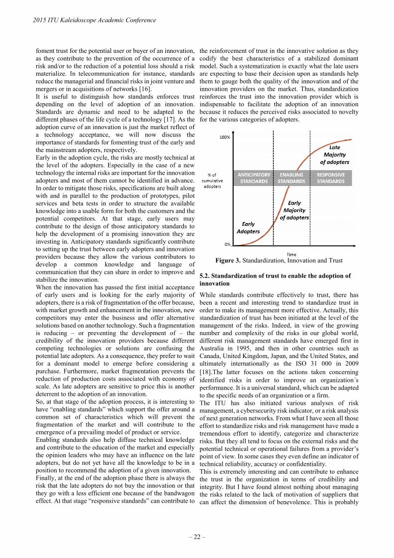
foment trust for the potential user or buyer of an innovation,
as they contribute to the prevention of the occurrence of a
risk and/or to the reduction of a potential loss should a risk
materialize. In telecommunication for instance, standards
reduce the managerial and financial risks in joint venture and
mergers or in acquisitions of networks [16].
It is useful to distinguish how standards enforces trust
depending on the level of adoption of an innovation.
Standards are dynamic and need to be adapted to the
different phases of the life cycle of a technology [17]. As the
adoption curve of an innovation is just the market reflect of
a technology acceptance, we will now discuss the
importance of standards for fomenting trust of the early and
the mainstream adopters, respectively.
Early in the adoption cycle, the risks are mostly technical at
the level of the adopters. Especially in the case of a new
technology the internal risks are important for the innovation
adopters and most of them cannot be identified in advance.
In order to mitigate those risks, specifications are built along
with and in parallel to the production of prototypes, pilot
services and beta tests in order to structure the available
knowledge into a usable form for both the customers and the
potential competitors. At that stage, early users may
contribute to the design of those anticipatory standards to
help the development of a promising innovation they are
investing in. Anticipatory standards significantly contribute
to setting up the trust between early adopters and innovation
providers because they allow the various contributors to
develop a common knowledge and language of
communication that they can share in order to improve and
stabilize the innovation.
When the innovation has passed the first initial acceptance
of early users and is looking for the early majority of
adopters, there is a risk of fragmentation of the offer because,
with market growth and enhancement in the innovation, new
competitors may enter the business and offer alternative
solutions based on another technology. Such a fragmentation
is reducing – or preventing the development of – the
credibility of the innovation providers because different
competing technologies or solutions are confusing the
potential late adopters. As a consequence, they prefer to wait
for a dominant model to emerge before considering a
purchase. Furthermore, market fragmentation prevents the
reduction of production costs associated with economy of
scale. As late adopters are sensitive to price this is another
deterrent to the adoption of an innovation.
So, at that stage of the adoption process, it is interesting to
have “enabling standards” which support the offer around a
common set of characteristics which will prevent the
fragmentation of the market and will contribute to the
emergence of a prevailing model of product or service.
Enabling standards also help diffuse technical knowledge
and contribute to the education of the market and especially
the opinion leaders who may have an influence on the late
adopters, but do not yet have all the knowledge to be in a
position to recommend the adoption of a given innovation.
Finally, at the end of the adoption phase there is always the
risk that the late adopters do not buy the innovation or that
they go with a less efficient one because of the bandwagon
effect. At that stage “responsive standards” can contribute to
the reinforcement of trust in the innovative solution as they
codify the best characteristics of a stabilized dominant
model. Such a systematization is exactly what the late users
are expecting to base their decision upon as standards help
them to gauge both the quality of the innovation and of the
innovation providers on the market. Thus, standardization
reinforces the trust into the innovation provider which is
indispensable to facilitate the adoption of an innovation
because it reduces the perceived risks associated to novelty
for the various categories of adopters.
Figure 3. Standardization, Innovation and Trust
5.2. Standardization of trust to enable the adoption of
innovation
While standards contribute effectively to trust, there has
been a recent and interesting trend to standardize trust in
order to make its management more effective. Actually, this
standardization of trust has been initiated at the level of the
management of the risks. Indeed, in view of the growing
number and complexity of the risks in our global world,
different risk management standards have emerged first in
Australia in 1995, and then in other countries such as
Canada, United Kingdom, Japan, and the United States, and
ultimately internationally as the ISO 31 000 in 2009
[18].The latter focuses on the actions taken concerning
identified risks in order to improve an organization´s
performance. It is a universal standard, which can be adapted
to the specific needs of an organization or a firm.
The ITU has also initiated various analyses of risk
management, a cybersecurity risk indicator, or a risk analysis
of next generation networks. From what I have seen all those
effort to standardize risks and risk management have made a
tremendous effort to identify, categorize and characterize
risks. But they all tend to focus on the external risks and the
potential technical or operational failures from a provider’s
point of view. In some cases they even define an indicator of
technical reliability, accuracy or confidentiality.
This is extremely interesting and can contribute to enhance
the trust in the organization in terms of credibility and
integrity. But I have found almost nothing about managing
the risks related to the lack of motivation of suppliers that
can affect the dimension of benevolence. This is probably
2015 ITU Kaleidoscope Academic Conference
– 22 –
due to the fact that those risks are more qualitative and less
easy to identify than the mere technical risks. The risks
related to the lack of expertise of a supplier can be more or
less easily identified and they can be managed pro-actively.
The risks arising from of lack of a supplier’s benevolence
are much more difficult to anticipate. They also need to be
considered more from the customer’s point of view than
from the organization´s perspective alone.
6. CONCLUSION
In this presentation, we have analyzed the role of trust and
standardization in the adoption of innovation, a stage which
is considered as essential for achieving success in the
market. We have examined the expectation and the behavior
of the three main categories of innovation users: the early
adopters, the early majority of mainstream adopters and the
late adopters. Then we have analyzed how the three main
components of trust - integrity, credibility and benevolence
- can be related to the two main categories of risks for an
innovation adopter: the internal risks and the transactional
risks; and we have studied the importance and dynamics of
trust along the different stages of the acceptance of
innovation.
Finally, we have considered the association between
standardization and trust and their role in the adoption of
innovation. We have first detailed the needs and use of
dynamic standards along the various stages of the innovation
life cycle. I think this is an original discussion as we have
done it from a customer/ user perspective while it has
typically been done mostly from a technology/supply
perspective. A second original element is my final reflection
about the importance of the standardization of risks in order
to facilitate their identification and mitigation. We have
identified a significant effort to standardize the risks
associated with the lack of expertise from a supplier. But
regarding the standardization of the risks associated with the
lack of benevolence, there is still room for future
development for both researchers and practitioners.
Among the questions to consider are first the type of criteria
which have to be used and their measurement. For example,
in order to consider the degree of engagement of suppliers,
one criteria could be the incentive policy for employees; but
is this information easily accessible? Another important
question is related to the cultural dimension of truth, as being
benevolent does not have the same implications in different
parts of the world. Finally, there are some limits to consider
which are intrinsic to Standard Development Organizations
(SDOs). The ultimate way to secure the commitment of an
innovation supplier and to mitigate a possible lack of
motivation is to have a legal control by regulators. But SDOs
are defining voluntary standards and do not have the
enforcement power of governmental administrations.
REFERENCES
[1] Edelman (2015).Trust and innovation. Retrieved on
November 2nd, 2015 at
http://www.edelman.com/insights/intellectual-
property/2015-edelman-trust-barometer/trust-and-
innovation-edelman-trust-barometer/
[2] Brem A., and Viardot E., (2015). Adoption of
Innovation Balancing Internal and External Stakeholders in
the Marketing of Innovation. Springer.
[3] Wagner Kim, Taylor Andrew, Zablit Hadi, and Foo
Eugene (2014). The Most Innovative Companies 2014:
Breaking Through is Hard to Do. BCG. Perspectives.
Retrieved on November 5, 2015 from
https://www.bcgperspectives.com/Images/Most_Innovative
_Companies_2014_Oct_2014_tcm80-174313.pdf
[4] Robins J. (2013). Managing Business Models for
Innovation, Strategic Change and Value Creation. Long
Range Planning. 46 (6), 417-488.
[5] Castellion G., and Markham S: (2013). New Product
Failure Rates: Influence of Argumentum ad Populum and
Self-Interest. Journal of Product Innovation Management.
Vol 30, No. 5, pp. 976–979.
[6] Rogers E.M. (2003). Diffusion of Innovations, 5th
edition. Free Press, NY.
[7] Reinhardt R., and Gurtner S. (2014). Differences
between Early Adopters of Disruptive and Sustaining
Innovations. Journal of Business Research Vol 68, No. 1,
pp. 137-145.
[8] Moore, G. (1991). Crossing the Chasm: Marketing and
Selling Technology Products to Mainstream Customers.
Harper Business: New York.
[9] Kaouher K., Ben Mansour K., and Utama R. (2014).
Determinants of online trust and their impact on online
purchase intention. International Journal of Technology
Marketing. Vol 9, No.3, pp.305 –319.
[10] Moorman, C., Deshpandé, R., & Zaltman, G. (1993),
“Factors affecting trust in market research relationships”,
Journal of Marketing, vol. 57, No. 1, pp. 81-101.
[11] Giovanis, A.N., and Athanasopoulou, P. (2014).
Gaining customer loyalty in the e-tailing marketplace: The
role of e-service quality, e-satisfaction and e-trust.
International Journal of Technology Marketing, Vol 9,
No.3, pp. 288-304.
[12] Bradford L., Barham B.L, Chavas J-P, Fitz D., Rio
Salas V., and Schechter L. (2014). The roles of risk and
ambiguity in technology adoption. Journal of Economic
Behavior & Organization. Vol 97, No1, pp. 204-218
[13] Revilla E., and Knoppen D. (2015). Building
knowledge integration in buyer-supplier relationships.
International Journal of Operations & Production
Management, Vol. 35, No. 10, pp. 1408-1436.
Trust in the Information Society
– 23 –

[14] Venkatesh, V., Morris, M.G., Davis, G.B. and Davis,
F.D. (2003). User acceptance of information technology:
toward a unified view. MIS Quarterly, Vol. 27, No.3, pp
425–478.
[15] Blind, K., Vries, H.J. de & Mangelsdorf, A. (2012).
External knowledge sourcing and involvement in
standardization - Evidence from the community innovation
survey. In Technology Management Conference (ITMC),
2012 IEEE International (pp. 1-9). New York: IEEE
[16] Sherif M.H. (2006). Managing Projects in
Telecommunication Services. Chapter 10. Wiley-IEEE
Press.
[17] Egyedy T.M., and Sherif M. H. (2010). Standards
dynamics through an innovation lens: Next-generation
Ethernet networks. Proceedings of the first ITU-T
Kaleidoscope Academic Conference, ‘Innovations in NGN’,
Geneva, 12-13 May 2008, Geneva: ITU, pp. 127-134.
[18] Belascu L., and Horobet A. (2015). The
Standardization of Risk Management Practices at the
International Level. Ovidius University Annals, Series
Economic Sciences .Vol. 15 No.1, pp.6-11
2015 ITU Kaleidoscope Academic Conference
– 24 –
SESSION 1
TRUST IN THE INFRASTRUCTURE
S1.1 Invited paper: Strengthening Trust in the Future ICT Infrastructure.
S1.2 Wi-Trust: Improving Wi-Fi Hotspots Trustworthiness with Computational Trust Management.
S1.3 WifiOTP: Pervasive Two-Factor Authentication Using Wi-Fi SSID Broadcasts.
S1.4 Vulnerability of Radar Protocol and Proposed Mitigation.


STRENGTHENING TRUST IN THE FUTURE ICT INFRASTRUCTURE
Tai-Won Um1, Gyu Myoung Lee2, Jun Kyun Choi3
1Electronics and Telecommunications Research Institute (ETRI), Korea (Rep. of), [email protected] 2Liverpool John Moores University (LJMU), United Kingdom, [email protected]
3Korea Advanced Institute of Science & Technology (KAIST), Korea (Rep. of), [email protected]
ABSTRACT
Moving towards a hyperconnected society in the
forthcoming “zettabyte” era requires a trusted ICT
infrastructure for sharing information and creating
knowledge. To advance the efforts to build converged ICT
services and reliable information infrastructures, ITU-T
has recently started a work item on future trusted ICT
infrastructures. In this paper, we introduce the concept of a
social-cyber-physical infrastructure from the social Internet
of Things paradigm and present different meanings from
various perspectives for a clear understanding of trust.
Then, the paper identifies key challenges for a trustworthy
ICT infrastructure. Finally, we propose a generic
architectural framework for trust provisioning and presents
strategies to stimulate activities for future standardization
on trust with related standardization bodies.
Keywords— Trust, social-cyber-physical infrastructure,
Internet of Things, ICT
1. INTRODUCTION
The widespread availability of feature-rich communications
is the result of end-user devices, advanced networks and
new services that exploit the developments in Information
and Communication Technology (ICT). Key technologies
are the Internet of Things (IoT), web services, cloud
computing (including distributed and embedded
computing), big data analytics, smart objects and sensing
technologies.
The IoT is one of the hottest and most promising topics in
ICT today. As more heterogeneous objects get connected to
the Internet, novel mechanisms to manage, describe,
discover and use these connected resources and the data
they produce become necessary. A number of initiatives are
available borrowing from the fields of autonomous systems,
intelligent systems and semantic technologies, etc.. One of
the main challenges of the IoT is to develop solutions that
are readable, recognizable, locatable, addressable and/or
controllable via the Internet. The convergence of
technologies like IoT and cloud computing will enable
innovative services. These involve technologies such as bio,
nano- and content technologies going beyond traditional
telecommunication services [1], [2].
From the perspective of connected devices, the introduction
of sensors and devices in physical spaces poses particular
challenges and increases the sensitivity of the data that are
being collected. Connected devices are effectively allowing
companies to digitally monitor our private activities.
Moreover, the sheer volume of generated data allows those
with access to the data to perform analyses and compile
detailed profiles of consumer behaviour [3].
From the perspective of big data analytics, the processing
and analysis of the large amount of data through cloud
computing are becoming an important resource that can
lead to increased knowledge, drive value creation, and
foster new products, processes and markets. However, the
large scale collection and analysis of data imposes difficult
privacy, security and trust issues, ranging from the risks of
unanticipated uses of consumer data to the potential
discrimination enabled by data analytics and the insights
offered into the movements, interests and activities of an
individual [4].
Although recent advances in ICT have brought changes to
our everyday lives [5],[6], various problems exist due to the
lack of trust. Therefore, it is important to process and
handle data in compliance with user needs and rights in
various application domains. Based on the significant
efforts made to build converged ICT services and a reliable
information infrastructure, ITU-T has recently started new
work on future trusted ICT infrastructures.
These infrastructures will be able to accommodate emerging
trends in ICT, while taking into account social and
economic considerations. Thus, this paper discusses an
effort to find a good solution to these problems while
developing advanced technologies for intelligent
autonomous networking and services. The aim is to create a
trusted environment for an ICT infrastructure in order to
share information and create knowledge.
Firstly, in Section 2 this paper introduces the concept of an
emerging social-cyber-physical infrastructure from the
social IoT paradigm. Secondly, Section 3 presents different
meanings of trust from various perspectives. In Section 4,
the paper identifies key challenges for trustworthy ICT
infrastructures. The paper proposes a generic architectural
framework for trust provisioning in Section 5 and presents
strategies to stimulate activities for future standardization
on trust with other standardization bodies.
2. FUTURE ICT INFRASTRUCTURE FOR A
HYPERCONNECTED SOCIETY
While traditional ICT infrastructures have focused on
computer-centric approaches to data processing as well as
network-centric approaches to information collection, the
978-92-61-15821-7/CFP1538E-ART © 2015 ITU Kaleidoscope– 27 –

emerging ICT infrastructures will use human-centric
approaches. The transformation toward a hyperconnected
society will contribute to our everyday lives with ICT
problem-solving support, and will (hopefully) change to a
more user-friendly, fun and enjoyable experience in terms
of ICT provision.
The advent of applications such as content distribution,
cloud computing and IoT requires the underlying network
to be able to understand the context of various services. An
emerging networking paradigm enables in-network
knowledge generation and distribution in order to develop
the necessary network control intelligence for handling
complexity and uncertainty of future networked services
and the multitude of users [7]. To support this paradigm,
telecommunication infrastructures must be enhanced to
make better use of the knowledge of networks, services, end
users and their devices.
The evolving trend of telecommunication systems and ICTs
has been to move from the living space of home appliances
to large-scale communities in buildings, such as workspaces
and digital infrastructures like smart cities. The IoT plays a
major role in the rapid development of these technologies.
The IoT initially focused on network connectivity for
supporting heterogeneous communications interfaces but
recently it has been developing to provide convergent
services that integrate ICT in various industrial areas to
offer a common service platform. These convergent services
have been required to obtain reliable knowledge from raw
data. As an aim of intelligent service provision is to make
autonomous decisions without human intervention, trust has
been highlighted as a key issue in the processing and
handling of data, as well as the provisioning of services
which comply with users’ needs and rights.
The social IoT 1 [8] transforms smart objects into social
entities which are capable of bridging human-to-object
interactions. In this way, a social network of objects is
created by intelligent reasoning/recommendation
mechanisms. These mechanisms extract the social
knowledge hidden in the rich profiles of humans and
services maintained by various social network services [8].
The paradigm of Cyber-Physical-Social Systems (CPSS)
[9],[10] has recently gained momentum as an environment
that combines knowledge from various smart spaces to form
an ecosystem, in which intelligence and reasoning about the
social aspects that are embedded in human behaviour in
smart spaces act as the glue for integrating physical, cyber
and social worlds.
Based on the CPSS, Figure 1 depicts the concept of a
social-cyber-physical (SCP) infrastructure as the future ICT
infrastructure. This infrastructure consists of three regions –
physical world, cyber world and social world. The main
elements of ICT infrastructures rely mostly on 3C (i.e.,
Computation, Communication, Control) to extract
knowledge from the information available in the data
obtained from various systems, including sensors and
1 The Social Internet of Things is defined as an IoT where things
are capable of establishing social relationships with other objects,
autonomously with respect to humans [8].
actuators. The social world in relation to a trusted
technology with an individual and communities is also
important. The three different areas need an infrastructure
that is more reliable and closely correlated through cross-
tier trust management.
Most importantly, the transition to the SCP infrastructure
depends upon how to acquire useful knowledge from data
and information. Trust is essential in this knowledge
acquisition process; also, for awareness and understanding
of a specific context it is really important to have
confidence in decision making. In other words, trust should
be additionally considered in systems that behave
intelligently and rationally to sense real-world behaviour,
perceive the world using information models, adapt to
different environments and changes, learn and build
knowledge, and act to control their environments [11]. This
is mainly related to the data, information, knowledge,
wisdom (DIKW)2 process in the cyber world, see Figure 1.
Social World
Cyber World
Physical World
Humans
DIKW*
Objects
Individuals, Communities, SW agents
Computation, Communication, Control
Physical Systems, Sensors, Actuators
*DIKW: Data, Information, Knowledge, Wisdom Social-Cyber-Physical Infrastructure
Figure 1. The concept of a social-cyber-physical
infrastructure
To strengthen trust while building a hyperconnected society,
a trustworthy SCP infrastructure will be a key work item for
international standardization working on the development of
technology and trust, while at the same time expanding the
functions of the core technology components.
3. UNDERSTANDING OF TRUST
Because trust can be interpreted in different ways, we
present its various meanings in the context of
telecommunication systems and ICTs and highlight the
relationship between knowledge and trust.
As a lexical-semantic, trust means reliance on the integrity,
strength, ability, etc., of a person or object. Generally, trust
is used as a measure of confidence that an entity will behave
in an expected manner, despite the lack of ability to monitor
or control the environment in which it operates [12].
2 DIKW (Data, Information, Knowledge and Wisdom): This refers
loosely to a class of models for representing purported structural
and/or functional relationships between data, information,
knowledge, and wisdom. “Typically information is defined in
terms of data, knowledge in terms of information, and wisdom in
terms of knowledge”.
Source: https://en.wikipedia.org/wiki/DIKW_Pyramid
2015 ITU Kaleidoscope Academic Conference
– 28 –

In computer science, trust hast two aspects “user trust” and
“system trust”. For a user, trust is based on psychological
and sociological considerations because it is “a subjective
expectation an entity has about another’s future behaviour”.
System trust is “the expectation that a device or system will
faithfully behave in a particular manner to fulfil its intended
purpose” [12].
For the IoT, trust relies on the integrity, ability or character
of an entity [13]. Trust can be further explained in terms of
confidence in the truth or worth of an entity. For example,
the EU uTRUSTit project defines trust as a user’s
confidence in an entity’s reliability, including a user's
acceptance of vulnerability in a potentially risky situation
[12].
From a technical perspective, trust could be classified along
three dimensions; technical trust (like data security),
business/trading/community trust (or credits), and human
trust (perceived by an individual human or group of
members).
Data collection, processing, management
Data interpretation
Expectation
Decision Making
Knowledge
Trust
Data & Information
Figure 2. Knowledge and Trust (illustration compiled from
trust pyramid [14])
The social and economic value of data is mainly reaped at
two stages: firstly when data and information are
transformed into knowledge (gaining insights) and secondly
when they are used for decision making (taking action). The
knowledge is accumulated over time by an individual or
systems through data analytics. Data processing,
management and interpretation for awareness and
understanding have been considered as fundamental
processes for obtaining knowledge. As shown in Figure 2,
trust is strengthened from accumulated knowledge and it
has a significant role as a link between knowledge (i.e.,
awareness and understanding) and action. It means that the
expectation process for trust should be additionally
considered before decision making.
4. CHALLENGES FOR THE TRUSTWORTHY ICT
INFRASTRUCTURE
In a highly interconnected ICT world such as the SCP
infrastructure, a number of independently developed,
operated and managed systems network autonomously
yielding a new kind of complex system that provides
various services. Assuring continuous trustworthiness,
taking into account such characteristics for future ICT
infrastructures with highly interconnected systems, is
becoming an essential issue. Therefore, this section
identifies key challenges for the trustworthy ICT
infrastructure.
4.1. Social-Cyber-Physical Trust Relationships
The SCP infrastructure comprise objects from the physical
world (physical objects), the cyber world (virtual objects)
and the social world (humans with attached devices), which
can be identified and integrated into information and
communication networks. All of these objects have their
associated information, which can be static and dynamic
[15]. Thus, social trust 3 between humans and objects is
quite important. As shown in Figure 3, trust may be human
to human, object to object (e.g., handshake protocols
negotiated), human to object (e.g., when a consumer
reviews a digital signature advisory notice) or object to
human (e.g., when a system relies on user input and
instructions without extensive verification). In addition to
individual trust, community trust also needs to be
considered. For social-cyber-physical relationships, trust as
a cross-domain relationship is needed, taking into
consideration coexistence, connectivity, interactivity and
spatio-temporal situations between vertical layers.
Trustworthy Social-Cyber-Physical Infrastructure
Humans
Humans
Human-to-Human Trust
Objects
Objects
Object-to-Object Trust
Human-to-Object Trust
Figure 3. Trust relationships in a trustworthy social-cyber-
physical infrastructure
4.2. Holistic Trust for Interconnected Systems
ICT services can be achieved through a chain of
interconnected systems and components that share the
responsibility for providing stable and robust services.
Furthermore, many systems are based on open system
architectures and their properties of interconnectivity and
autonomics remove system boundaries. Such characteristics
of interconnected systems lead to the introduction of
security deficiencies that can be very hard to find and
analyse. If this is not properly handled, the stability and
safety of the overall system can be seriously threatened.
How can the stability and safety of such highly
interconnected systems be achieved? Trust must be
addressed and evaluated in all services and infrastructures,
as well as in all system and component levels, in a holistic
manner. Trust management is also required to apply
between heterogeneous systems, service domains and
3 Social trust implies that members of a community act according
to the expectation that other members of the community are also
trustworthy and expect trust from other community members.
Trust in the Information Society
– 29 –
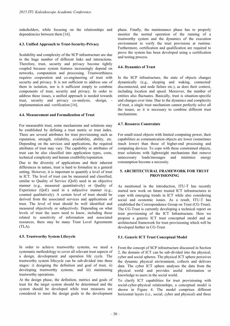
stakeholders, while focusing on the relationships and
dependencies between them [16].
4.3. Unified Approach to Trust-Security-Privacy
Scalability and complexity of the SCP infrastructure are due
to the huge number of different links and interactions.
Therefore, trust, security and privacy become tightly
coupled because system features increasingly depend on
networks, computation and processing. Trustworthiness
requires cooperation and co-engineering of trust with
security and privacy. It is not sufficient to address one of
them in isolation, nor is it sufficient simply to combine
components of trust, security and privacy. In order to
address these issues, a unified approach is needed towards
trust, security and privacy co-analysis, -design, -
implementation and -verification [16].
4.4. Measurement and Formalization of Trust
For measurable trust, some mechanisms and solutions may
be established by defining a trust metric or trust index.
There are several attributes for trust provisioning such as
reputation, strength, reliability, availability, ability, etc.
Depending on the services and applications, the required
attributes of trust may vary. The capability or attributes of
trust can be also classified into application types, costs,
technical complexity and human credibility/reputation.
Due to the diversity of applications and their inherent
differences in nature, trust is hard to formalize in a general
setting. However, it is important to quantify a level of trust
in ICT. The level of trust can be measured and classified,
similar to Quality of Service (QoS) used in an objective
manner (e.g., measured quantitatively) or Quality of
Experience (QoE) used in a subjective manner (e.g.,
counted qualitatively). A certain level of trust should be
derived from the associated services and applications of
trust. The level of trust should be well identified and
measured objectively or subjectively. Depending on what
levels of trust the users need to know, including those
related to sensitivity of information and associated
resources, there may be many Trust Level Agreements
(TLA).
4.5. Trustworthy System Lifecycle
In order to achieve trustworthy systems, we need a
systematic methodology to cover all relevant trust aspects of
a design, development and operation life cycle. The
trustworthy system lifecycle can be sub-divided into three
stages: i) designing the definition and goal of trust, ii)
developing trustworthy systems, and iii) maintaining
trustworthy operations.
At the design phase, the definition, metrics and goals of
trust for the target system should be determined and the
system should be developed while trust measures are
considered to meet the design goals in the development
phase. Finally, the maintenance phase has to properly
monitor the normal operation of the running of a
trustworthy system and the dynamics of the execution
environment to verify the trust provisions at runtime.
Furthermore, certification and qualification are required to
prove the system has been developed using a certification
and testing process.
4.6. Dynamics of Trust
In the SCP infrastructure, the state of objects changes
dynamically (e.g., sleeping and waking, connected/
disconnected, and node failure etc.), as does their context,
including location and speed. Moreover, the number of
entities also fluctuates. Basically, trust is situation-specific
and changes over time. Due to the dynamics and complexity
of trust, a single trust mechanism cannot perfectly solve all
the issues; so it is necessary to combine different trust
mechanisms.
4.7. Resource Constraints
For small-sized objects with limited computing power, their
capabilities as communication objects are lower (sometimes
much lower) than those of higher-end processing and
computing devices. To cope with these constrained objects,
trust solutions with lightweight mechanisms that remove
unnecessary loads/messages and minimize energy
consumption become a necessity.
5. ARCHITECTURAL FRAMEWORK FOR TRUST
PROVISIONING
As mentioned in the introduction, ITU-T has recently
started new work on future trusted ICT infrastructures to
cope with emerging trends in ICT while also considering
social and economic issues. As a result, ITU-T has
established the Correspondence Group on Trust (CG-Trust).
The CG-Trust is currently developing a technical report on
trust provisioning of the ICT Infrastructure. Here we
propose a generic ICT trust conceptual model and an
architectural framework for trust provisioning which will be
developed further in CG-Trust.
5.1. Generic ICT Trust Conceptual Model
From the concept of SCP infrastructure discussed in Section
2, the domain of ICT can be sub-divided into the physical,
cyber and social spheres. The physical ICT sphere perceives
the dynamic physical environment, collects and delivers
data. The cyber ICT sphere analyses the data from the
physical world and provides useful information or
knowledge to users in the social world.
To clarify ICT capabilities for trust provisioning with
social-cyber-physical relationships, a conceptual model is
shown in Figure 4. The model comprises different
horizontal layers (i.e., social, cyber and physical) and three
2015 ITU Kaleidoscope Academic Conference
– 30 –
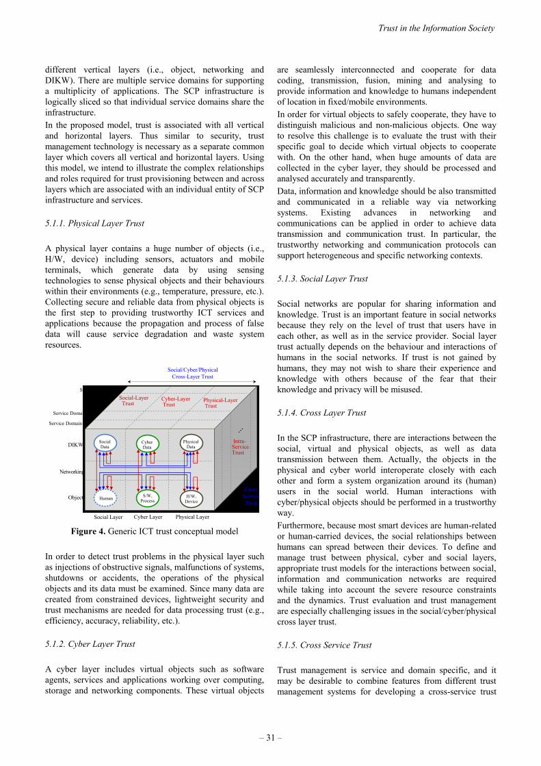
different vertical layers (i.e., object, networking and
DIKW). There are multiple service domains for supporting
a multiplicity of applications. The SCP infrastructure is
logically sliced so that individual service domains share the
infrastructure.
In the proposed model, trust is associated with all vertical
and horizontal layers. Thus similar to security, trust
management technology is necessary as a separate common
layer which covers all vertical and horizontal layers. Using
this model, we intend to illustrate the complex relationships
and roles required for trust provisioning between and across
layers which are associated with an individual entity of SCP
infrastructure and services.
5.1.1. Physical Layer Trust
A physical layer contains a huge number of objects (i.e.,
H/W, device) including sensors, actuators and mobile
terminals, which generate data by using sensing
technologies to sense physical objects and their behaviours
within their environments (e.g., temperature, pressure, etc.).
Collecting secure and reliable data from physical objects is
the first step to providing trustworthy ICT services and
applications because the propagation and process of false
data will cause service degradation and waste system
resources.
Object
Networking
DIKW
Social Layer Cyber Layer Physical Layer
Social-LayerTrust
Cyber-LayerTrust
Physical-LayerTrust
Social/Cyber/Physical
Cross-Layer Trust
Intra-ServiceTrust
Cross
Service
TrustHuman
S/W,Process
H/W,Device
SocialData
CyberData
PhysicalData
Service Domain #1
Service Domain #2
Service Domain #n
Figure 4. Generic ICT trust conceptual model
In order to detect trust problems in the physical layer such
as injections of obstructive signals, malfunctions of systems,
shutdowns or accidents, the operations of the physical
objects and its data must be examined. Since many data are
created from constrained devices, lightweight security and
trust mechanisms are needed for data processing trust (e.g.,
efficiency, accuracy, reliability, etc.).
5.1.2. Cyber Layer Trust
A cyber layer includes virtual objects such as software
agents, services and applications working over computing,
storage and networking components. These virtual objects
are seamlessly interconnected and cooperate for data
coding, transmission, fusion, mining and analysing to
provide information and knowledge to humans independent
of location in fixed/mobile environments.
In order for virtual objects to safely cooperate, they have to
distinguish malicious and non-malicious objects. One way
to resolve this challenge is to evaluate the trust with their
specific goal to decide which virtual objects to cooperate
with. On the other hand, when huge amounts of data are
collected in the cyber layer, they should be processed and
analysed accurately and transparently.
Data, information and knowledge should be also transmitted
and communicated in a reliable way via networking
systems. Existing advances in networking and
communications can be applied in order to achieve data
transmission and communication trust. In particular, the
trustworthy networking and communication protocols can
support heterogeneous and specific networking contexts.
5.1.3. Social Layer Trust
Social networks are popular for sharing information and
knowledge. Trust is an important feature in social networks
because they rely on the level of trust that users have in
each other, as well as in the service provider. Social layer
trust actually depends on the behaviour and interactions of
humans in the social networks. If trust is not gained by
humans, they may not wish to share their experience and
knowledge with others because of the fear that their
knowledge and privacy will be misused.
5.1.4. Cross Layer Trust
In the SCP infrastructure, there are interactions between the
social, virtual and physical objects, as well as data
transmission between them. Actually, the objects in the
physical and cyber world interoperate closely with each
other and form a system organization around its (human)
users in the social world. Human interactions with
cyber/physical objects should be performed in a trustworthy
way.
Furthermore, because most smart devices are human-related
or human-carried devices, the social relationships between
humans can spread between their devices. To define and
manage trust between physical, cyber and social layers,
appropriate trust models for the interactions between social,
information and communication networks are required
while taking into account the severe resource constraints
and the dynamics. Trust evaluation and trust management
are especially challenging issues in the social/cyber/physical
cross layer trust.
5.1.5. Cross Service Trust
Trust management is service and domain specific, and it
may be desirable to combine features from different trust
management systems for developing a cross-service trust
Trust in the Information Society
– 31 –

management that is able to cover social/cyber/physical trust
relationships between different service domains.
Trust dissemination means to distribute or broadcast trust
information. To disseminate trust information from one
service domain to another, a trust service brokering
mechanism can be used for efficient, effective and suitable
trust dissemination.
5.2. Trust Architectural Framework
Based on the generic ICT trust conceptual model, this
subsection describes a trust architectural framework
consisting of three parts as shown in Figure 5: i) Trust
Agent (TA) to gather trust-related data from social, virtual
or physical objects; ii) Trust Analysis and Management
Platform (TAMP) to model and analyse trust-related data
and the trust relationship; iii) Trust Service Broker (TSB) to
apply and disseminate trust-based knowledge to various
services.
PhysicalData
CyberData
S/W,Objects
H/W,Things
SocialData
Human
ServiceDomain#1
ServiceDomain#N
…
…
…
TrustData
Collecting
Trust Data Filtering and Preprocessing
TAInterface
Trust Agent
ContextData
DomainKnowledge
TrustIdM
Trust-basedRecommendation
TrustLinking
Trust Service Broker
Trust Analysis and Management Platform
Big data Engine
Cloud Computing
Trust Computation
Trust Modelling & Evaluation
Social/Cyber/PhysicalTrust Models
Trust Reasoning and Evaluation
Trust Repository and Extractor
Trust Metric Extractor
Trust Data Repository
Figure 5. Trust architectural framework
5.2.1. Trust Agent (TA)
TA is used to collect trust-related data from the social,
cyber and physical environments with the following
modules.
• TA Interface: The TA provides lightweight interfaces
to collect trust-related data from various types of objects
in the social, cyber and physical layers. Furthermore,
TA interfaces need to be easily connected to existing
platforms and devices in order to extract the required
data.
• Trust Data Collection: In order to evaluate a trust level
of an object, the Trust Analysis and Management
Platform (TAMP) identifies the required trust metrics
for the object and informs TA’s trust data collection
module accordingly, as the trust data collection module
is responsible for gathering the data required for the
trust evaluation.
• Trust Data Filtering and Preprocessing: This module
is used to refine trust data sets without including other
data that can be repetitive, irrelevant or even sensitive
for trust evaluation.
5.2.2. Trust Analysis and Management Platform (TAMP)
TAMP is used for modelling, reasoning and managing trust
data collected from TAs to check whether the physical
objects, virtual objects or humans satisfy certain trust
criteria.
TAMP consists of several modules: trust modelling, trust
reasoning and evaluation, trust data repository, trust metric
extractor, trust computation, and so on.
• Trust Modelling: A trust model is used to specify,
annotate and build trust relationships between objects
for the purpose of reasoning trust data. Trust modelling
is layer-specific and service domain-specific and there
are social, cyber and physical trust models to define a
trust model for each layer in the SCP infrastructure.
According to its layer and a particular service domain, a
suitable trust model is selected and applied for trust
modelling. The trust-related data collected from trust
agents can be transformed to structured and annotated
formats by using semantic and ontology technologies
through this trust modelling module.
• Trust Reasoning and Evaluation: Trust evaluation is
used to analyse and assess trust levels based on the trust
model. There are various types of reasoning methods
which depend on the layer and service domain, and a
proper reasoning method will be chosen for the specific
object. For example, policy-based trust reasoning makes
a binary decision according to which an object is trusted
or not. Because trust status could change with time and
circumstantial context, a trust reasoning method must
handle such dynamics of trust.
• Trust Data Repository: The structured trust data
including operations of objects and the history of
interaction between objects can be maintained in the
trust data repository. For trust evaluation, the necessary
data will be loaded from this repository to the
computation module.
• Trust Metric Extractor: A trust metric is used to judge
or decide the trustworthiness of an object and it is
separately defined in each service or each object. The
trust metric extractor recognizes trust characteristics,
accounts for factors influencing trust and determines
proper trust metrics for the trust modelling and
reasoning by analysing the metadata or semantic
ontologies.
• Trust Computation: This module is used for data
processing for trust evaluation. Trust computation
happens when the state of an object has changed or an
interaction occurs between objects. To process the large
amount of data related to trust evaluation, it can adopt
big data technologies, batch processing big data engines
for calculation of the trust level of objects and real-time
big data engines for examining the change of the trust
state of objects based on direct observation.
2015 ITU Kaleidoscope Academic Conference
– 32 –

5.2.3. Trust Service Broker (TSB)
TSB is used to provide trust knowledge of physical objects,
virtual objects and humans for various types of services and
applications in the ICT world. Furthermore, it can merge
and disseminate trust knowledge across service domains or
social/cyber/physical layers.
• Trust Linking: Trust linking is a module capable of
creating a link between data/information/knowledge
entities generated from a physical/cyber/social object
based on trust criteria.
• Trust IdM: The identity management (IdM) can be
used to manage digital identification/authentication of
physical objects, virtual objects and humans. Trust IdM
is able to involve trust knowledge to assure the identity
of trustworthy objects and support trust-based services
and applications.
• Trust-based Recommendation: This module provides
recommendations to other objects. More specifically, a
number of individual objects can be interconnected to
construct a complex system for providing various
services, and many objects with identical capabilities
will exist on the Internet. This module aims at providing
a recommendation for selecting a suitable object that
meets the trust level.
6. CONCLUSION AND FUTURE
STANDARDIZATION
This paper has looked at the future of converged ICT
services and information infrastructures for a
hyperconnected society and has provided the concept of an
SCP infrastructure from emerging social IoT paradigms.
From the understanding of trust, we have identified key
challenges for trustworthy ICT infrastructures and proposed
an architectural framework for trust provisioning as a key
activity of the ITU-T CG-Trust. In conclusion, the future of
ICT infrastructures is evolving towards a trustworthy SCP
infrastructure with trust-enabled, knowledge-centric
networking and services.
Until now, a number of standards focusing on network
security and cybersecurity technologies have been
developed in various standardization bodies including the
IETF. The scope of these standards needs to be expanded to
take into consideration trust issues in future ICT
infrastructures. There are a few preliminary activities taking
place, for instance in the Online Trust Alliance [17] and the
Trusted Computing Group [18]. However, as existing
research and standardization activities on trust are still
limited to social trust between humans, trust relationships
between humans and objects as well as across domains of
social-cyber-physical worlds should also be taken into
account for trustworthy autonomous networking and
services.
Based on this, we first need to find various use cases
considering user confidence, usability and reliability in ICT
ecosystems for new business models which reflect a sharing
economy. Then, a framework for trust provisioning
including requirements and architectures should be
specified in relation to the relevant standards. In addition,
global collaborations with related standardization bodies are
required to further stimulate trust standardization activities.
Acknowledgement
This research was supported by the ICT R&D program of
MSIP/IITP [R0190-15-2027, Development of TII (Trusted
Information Infrastructure) S/W Framework for Realizing
Trustworthy IoT Eco-system].
REFERENCES
[1] Gyu Myoung Lee, et al., “Internet of Things,” in a book
“Evolution of Telecommunication services,” LNCS, volume
7768, Springer, ISBN 978-3-642-41568-5, pp.257~282,
2013.
[2] Overview of Internet of Things, ITU-T Y.2060, June 2012.
[3] Edith Ramirez, Privacy and the IoT: Navigating Policy
issues, Opening remarks of CES, Jan. 2015,
https://www.ftc.gov/public-statements/2015/01/privacy-iot-
navigating-policy-issues-opening-remarks-ftc-chairwoman-
edith (visited on 2015-11-17).
[4] Data-driven Innovation for Growth and Well-being – Interim
synthesis report, OECD, Oct. 2014,
http://www.oecd.org/sti/inno/data-driven-innovation-interim-
synthesis.pdf (visited on 2015-11-17).
[5] Ovidiu Vermesan, Peter Friess, “Building the hyperconnected
society – IoT research and innovation value chains,
ecosystems and markets,” River Publishers, 2015.
[6] “The Zettabyte Era: Trends and Analysis,” Cisco white paper,
May 2015.
[7] KCN (Knowledge Centric Networking),
https://www.ee.ucl.ac.uk/kcn-project/ (visited on 2015-11-
17).
[8] L. Atzori, A. Iera, G. Morabito, and M. Nitti, “The Social
Internet of Things (SIoT) – When social networks meet the
Internet of Things: Concept, architecture and network
characterization,” Computer networks, vol. 56, no. 16, pp.
3594-3608, Nov. 2012.
[9] Fei-Yue Wang, “The Emergence of Intelligent Enterprises:
From CPS to CPSS,” IEEE Intelligent Systems, July 2010.
[10] Jay Lee, et al., “A Cyber-Physical Systems architecture for
Industry 4.0-based manufacturing systems,” Elsevier Journal,
Jan. 2015.
[11] George Vanecek, “The Internet of Things, ambient intelligent
and the moving towards intelligent systems,” IEEE Smart
Tech 2012, Sep. 2012.
[12] Wanita Sherchan, Surya Nepal, Cecile Paris “A survey of
trust in social networks”, ACM Computing Survey, vol.45,
issue 4, no. 47, August 2013.
[13] Zheng Yan, et al., “A survey on trust management for
Internet of Things,” Journal of Network and Computer
Applications, Mar. 2014.
[14] Trust pyramid, http://www.johnhaydon.com/how-make-
people-trust-your-nonprofit/ (visited on 2015-11-17).
[15] Trust Definition White Paper - “Defining, Understanding,
Explaining TRUST within the uTRUSTit Project”, August
2012.
[16] “Trustworthy Systems of Systems,” ERCIM News, no.102,
Jul. 2015.
Trust in the Information Society
– 33 –

[17] The Online Trust Alliance, https://otalliance.org/ (visited on
2015-11-17).
[18] The Trusted Computing Group,
http://www.trustedcomputinggroup.org/ (visited on 2015-11-
17).
2015 ITU Kaleidoscope Academic Conference
– 34 –

WI-TRUST: IMPROVING WI-FI HOTSPOTS TRUSTWORTHINESS WITH COMPUTATIONAL TRUST MANAGEMENT
Jean-Marc Seigneur
Réputaction SAS and CUI, Medi@LAB, ISS, Sociology Department, G3S, University of Geneva
ABSTRACT In its list of top ten smartphone risks, the European Union Agency for Network and Information Security ranks Network Spoofing Attacks as number 6. In this paper, we present how we have validated different computational trust management techniques by means of implemented prototypes in real devices to mitigate malicious legacy Wi-Fi hotspots including spoofing attacks. Then we explain how some of these techniques could be more easily deployed on a large scale thanks to simply using the available extensions of Hotspot 2.0, which could potentially lead to a new standard to improve Wi-Fi networks trustworthiness.
Keywords— Wi-Fi, public hotspot, computational trust
1. INTRODUCTIONThe European Union Agency for Network and Information Security (ENISA) gives the following definition for Network Spoofing Attacks: “An attacker deploys a rogue network access point (Wi-Fi) and users connect to it. The attacker subsequently intercepts (or tampers with) the user communication to carry out further attacks such as phishing”. This type of attack is ranked number 6 in its list of top ten smartphone risks [1]. In order to mitigate this risk, the Wi-Fi Alliance and Wireless Broadband Association have worked on a new standard called Hotspot 2.0 (HS 2.0) or Wi-Fi Certified Passpoint. Unfortunately, most hotspots currently deployed are legacy hotspots and it is going to take time and efforts to change them into Hotspot 2.0-enabled devices. In 2014, Ferreira et al. [2] underline regarding Hotspot 2.0 that “although technical security has improved in comparison with the previous hotspot version, many issues still need addressing before its full deployment and usage in parallel with that previous version (which will not quickly disappear)”. In addition, even a Hotspot 2.0 may be compromised or controlled by an untrustworthy provider who can carry out different types of man-in-the-middle attacks if the user does not use a VPN. Therefore, authentication alone is not enough because the authenticated hotspot may be controlled by an untrustworthy owner/provider or attacker who has broken into the hotspot: another layer of trust is necessary on top of authentication trust to make the decision to use one or another available hotspot in user range. Section 2 discusses what has been proposed so far to tackle remaining trust issues in hotspots, starting with computational trust management background and how it has been applied to hotspots by others and us. It also
includes how we have validated it as part of different research projects [3]–[6] that we have carried out funded by the European Commission under the Seventh Framework Programme. In Section 3, based on this previous work that has shown the usefulness of computational trust for increased hotspot trustworthiness, we present our proposal for new standard for trustworthy hotspots selection and promotion called Wi-Trust that can be easily applied on top of Hotspot 2.0. Section 4 concludes with future work towards that standard.
2. COMPUTATIONAL TRUST TO MITIGATEREMAINING HOTSPOTS SECURITY HOLES
In this section, we first explain how computational trust based on the human notion of trust is different from the traditional concept of trust in computer security. Then, we detail the remaining security holes in Wi-Fi hotspots and the previous attempts to tackle these security holes both by others and us.
2.1. Computational Trust Management In the human world, trust exists between two interacting entities and is very useful when there is uncertainty in result of the interaction. The requested entity uses the level of trust in the requesting entity as a mean to cope with uncertainty, to engage in an action in spite of the risk of a harmful outcome. There are many definitions of the human notion trust in a wide range of domains, with different approaches and methodologies: sociology, psychology, economics, pedagogy, etc. These definitions may even change when the application domain changes. However, it has been convincingly argued that these divergent trust definitions can fit together [7]. Romano’s definition tries to encompass the previous work in all these domains: “trust is a subjective assessment of another’s influence in terms of the extent of one’s perceptions about the quality and significance of another’s impact over one’s outcomes in a given situation, such that one’s expectation of, openness to, and inclination toward such influence provide a sense of control over the potential outcomes of the situation” [8]. Interactions with uncertain results between entities also happen in the online world. So, it would be useful to rely on trust in the online world as well. However, the terms trust, trusted, trustworthy and the like, which appear in the traditional computer security literature, have rarely been based on these comprehensive multi-disciplinary trust models and often correspond to an implicit element of trust – a limited view of the facetted human notion of trust. For
978-92-61-15821-7/CFP1538E-ART © 2015 ITU Kaleidoscope– 35 –

example, the trusted computing technology is assumed to be trusted once for all, full point. To go beyond a fixed mandatory trust assumption, a computational model of trust based on social research was first proposed by Marsh [9]. In social research, there are three main types of trust: interpersonal trust, based on past interactions with the trustee; dispositional trust, provided by the trustor’s general disposition towards trust, independently of the trustee; and system trust, provided by external means such as insurance or laws [7]. A trust metric consists of the different computations and communications, which are carried out by the trustor (and his/her network) to compute a trust value in the trustee. Trust evidence encompasses outcome observations, recommendations and reputation. A very well-known attack, which is difficult to mitigate in open environments such as the Internet because allocating only one digital identity per person in the world is still difficult to achieve on a worldwide scale, is called the Sybil attack [10]. There is not yet a perfect trust metric that is Sybil attack resistant in all situations and without any constraints but for example we created the “trust transfer” [11] trust metric that is resistant to Sybil attacks if onlypositive recommendations are propagated.The EU-funded SECURE project [11] represents a well-known example of a computational trust engine that uses evidence to compute trust values in entities and corresponds to dynamic evidence-based trust management systems. As depicted in Figure 1 below, the decision-making component can be called whenever a trusting decision has to be made. The Entity Recognition (ER) [11] module is used to recognize any entities and to deal with the requests from virtual identities. Relying on recognition rather than strong authentication, which means that the real-world identity of the user must be known, is also better from a privacy point of view because there is no mandatory required link to the real-world identity of the user if recognition is used rather than authentication. It may happen that the trusting decision is not triggered by any requesting virtual identity, for example, if the user device would like to select the trustworthiest Wi-Fi hotspot in range in the list of nearby found hotspots. Usually, the decision-making of the trust engine uses two sub-components [11]:
• a trust module that can dynamically assess thetrustworthiness of the requesting entity basedon the trust evidence of any type stored in theevidence store;
• a risk module that can dynamically evaluatethe risk involved in the interaction, again basedon the available evidence in the evidence store.
A common decision-making policy is to choose (or suggest to the user) the action that would maintain the appropriate cost/benefit. In the background, the evidence manager component is in charge of gathering evidence (e.g., recommendations, comparisons between expected outcomes of the chosen actions and real outcomes, etc.) This evidence is used to update risk and trust evidence. Thus, trust and risk follow a managed life-cycle.
2.2. Hotspots Security and Remaining Threats In a 2012 report [12], Cisco underlined the following remaining security holes in legacy Wi-Fi hotspots security that may lead to identity theft: legitimate hotspot spoofing, session hi-jacking or eavesdropping on unencrypted Wi-Fi. Common defense was to use 802.1X Port Access Control for robust mutual authentication. However, large-scale deployment was too tricky: “the most challenging part of deploying 802.1X involves installing and configuring client-side software and user credentials” [13]. Using a VPN on top of unencrypted communication solves eavesdropping, but most users do not have or know a VPN, and they even less want to spend time configuring it or pay for it since public Wi-Fi hotspot is more and more assumed to be free. The centralization of VPN servers is also not great from a privacy protection point of view. Private enterprise networks based on WPA2-Enterprise certification do not suffer from these attacks because they use IEEE 802.11i security and EAP authentication. Unfortunately, WPA2-Enterprise technology cannot be applied to legacy Wi-Fi hotspot networks because the access point’s 802.1X port blocks all communications prior to authentication. Due to the limitations of legacy Wi-Fi hotspots, the Wi-Fi Alliance started to work on Hotspot 2.0 and launched its first versions in 2012 in order to automate selecting Wi-Fi networks based on user preferences and network optimization, granting access to the network based upon credentials such as SIM cards, without user intervention, over-the-air encrypted transmissions with Certified WPA2-Enterprise. Regarding worldwide user strong authentication that would ensure giving only one digital identity to any user, it is not realistic. So far, all initiatives to achieve it have not succeeded; a global PKI (Public Key Infrastructure) has been deemed not feasible. Social and federated logins [14],
Figure 1. High-level View of a Computational Trust Engine
Trust Engine’s Security Perimeter
Decision-making
ER
VirtualIdentities
Trust ValueComputation
Risk Analysis
Decision
RequestEvidenceManager
EvidenceStore
2015 ITU Kaleidoscope Academic Conference
– 36 –
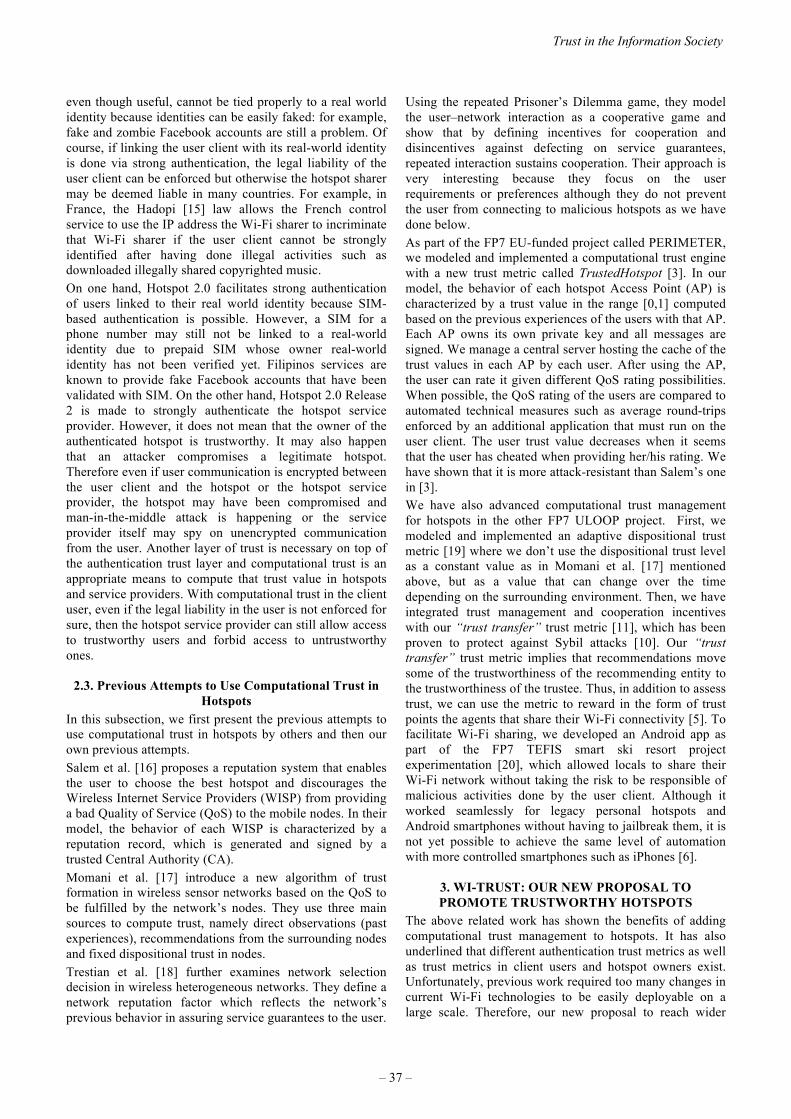
even though useful, cannot be tied properly to a real world identity because identities can be easily faked: for example, fake and zombie Facebook accounts are still a problem. Of course, if linking the user client with its real-world identity is done via strong authentication, the legal liability of the user client can be enforced but otherwise the hotspot sharer may be deemed liable in many countries. For example, in France, the Hadopi [15] law allows the French control service to use the IP address the Wi-Fi sharer to incriminate that Wi-Fi sharer if the user client cannot be strongly identified after having done illegal activities such as downloaded illegally shared copyrighted music. On one hand, Hotspot 2.0 facilitates strong authentication of users linked to their real world identity because SIM-based authentication is possible. However, a SIM for a phone number may still not be linked to a real-world identity due to prepaid SIM whose owner real-world identity has not been verified yet. Filipinos services are known to provide fake Facebook accounts that have been validated with SIM. On the other hand, Hotspot 2.0 Release 2 is made to strongly authenticate the hotspot service provider. However, it does not mean that the owner of the authenticated hotspot is trustworthy. It may also happen that an attacker compromises a legitimate hotspot. Therefore even if user communication is encrypted between the user client and the hotspot or the hotspot service provider, the hotspot may have been compromised and man-in-the-middle attack is happening or the service provider itself may spy on unencrypted communication from the user. Another layer of trust is necessary on top of the authentication trust layer and computational trust is an appropriate means to compute that trust value in hotspots and service providers. With computational trust in the client user, even if the legal liability in the user is not enforced for sure, then the hotspot service provider can still allow access to trustworthy users and forbid access to untrustworthy ones.
2.3. Previous Attempts to Use Computational Trust in Hotspots
In this subsection, we first present the previous attempts to use computational trust in hotspots by others and then our own previous attempts. Salem et al. [16] proposes a reputation system that enables the user to choose the best hotspot and discourages the Wireless Internet Service Providers (WISP) from providing a bad Quality of Service (QoS) to the mobile nodes. In their model, the behavior of each WISP is characterized by a reputation record, which is generated and signed by a trusted Central Authority (CA). Momani et al. [17] introduce a new algorithm of trust formation in wireless sensor networks based on the QoS to be fulfilled by the network’s nodes. They use three main sources to compute trust, namely direct observations (past experiences), recommendations from the surrounding nodes and fixed dispositional trust in nodes. Trestian et al. [18] further examines network selection decision in wireless heterogeneous networks. They define a network reputation factor which reflects the network’s previous behavior in assuring service guarantees to the user.
Using the repeated Prisoner’s Dilemma game, they model the user–network interaction as a cooperative game and show that by defining incentives for cooperation and disincentives against defecting on service guarantees, repeated interaction sustains cooperation. Their approach is very interesting because they focus on the user requirements or preferences although they do not prevent the user from connecting to malicious hotspots as we have done below. As part of the FP7 EU-funded project called PERIMETER, we modeled and implemented a computational trust engine with a new trust metric called TrustedHotspot [3]. In our model, the behavior of each hotspot Access Point (AP) is characterized by a trust value in the range [0,1] computed based on the previous experiences of the users with that AP. Each AP owns its own private key and all messages are signed. We manage a central server hosting the cache of the trust values in each AP by each user. After using the AP, the user can rate it given different QoS rating possibilities. When possible, the QoS rating of the users are compared to automated technical measures such as average round-trips enforced by an additional application that must run on the user client. The user trust value decreases when it seems that the user has cheated when providing her/his rating. We have shown that it is more attack-resistant than Salem’s one in [3]. We have also advanced computational trust management for hotspots in the other FP7 ULOOP project. First, we modeled and implemented an adaptive dispositional trust metric [19] where we don’t use the dispositional trust level as a constant value as in Momani et al. [17] mentioned above, but as a value that can change over the time depending on the surrounding environment. Then, we have integrated trust management and cooperation incentives with our “trust transfer” trust metric [11], which has been proven to protect against Sybil attacks [10]. Our “trust transfer” trust metric implies that recommendations move some of the trustworthiness of the recommending entity to the trustworthiness of the trustee. Thus, in addition to assess trust, we can use the metric to reward in the form of trust points the agents that share their Wi-Fi connectivity [5]. To facilitate Wi-Fi sharing, we developed an Android app as part of the FP7 TEFIS smart ski resort project experimentation [20], which allowed locals to share their Wi-Fi network without taking the risk to be responsible of malicious activities done by the user client. Although it worked seamlessly for legacy personal hotspots and Android smartphones without having to jailbreak them, it is not yet possible to achieve the same level of automation with more controlled smartphones such as iPhones [6].
3. WI-TRUST: OUR NEW PROPOSAL TOPROMOTE TRUSTWORTHY HOTSPOTS
The above related work has shown the benefits of adding computational trust management to hotspots. It has also underlined that different authentication trust metrics as well as trust metrics in client users and hotspot owners exist. Unfortunately, previous work required too many changes in current Wi-Fi technologies to be easily deployable on a large scale. Therefore, our new proposal to reach wider
Trust in the Information Society
– 37 –

adoption should be able to easily plug different trust metrics. It is the reason we have based our proposal on the common high-level view of a computational trust engine as depicted in Figure 1. In addition, to further facilitate worldwide adoption, it shouldn’t require forcing too many changes in current hotspots standards. For example, Apple smartphones with iOS7 and Samsung S5, as well as Android M 6.0 and above, already supports some versions of Hotspot 2.0. Hence, we have investigated how to integrate our proposal with Hotspot 2.0. Regarding the Entity Recognition (ER) component of a computational trust engine, fortunately, Hotspot 2.0 includes an Extensible Authentication Protocol (EAP) framework [21]. Therefore, we propose to map the ER module to this EAP part of Hotspot 2.0. Depending on the chosen authentication scheme selected between the client user and hotspot owner, then authentication trust can be computed. For example, SIM-based authentication is possible via EAP-SIM [22] and should get higher system trust than manual password-based only authentication. X509 certificates are also possible and the Wi-Fi Alliance has already allowed a few Certificate Authorities (CAs, e.g. Verizon, DigiCert and NetworkFX) to provide validated certificates for Wi-Fi hotspots providers to prove that their hotspot comes from a legitimate and trusted provider. In Hotspot 2.0 Release 2, a user client uses Online Sign-Up (OSU) to accomplish registration and credential provisioning to obtain secure network access. Each hotspot service provider has an OSU server, an Authentication Authorization and Accounting (AAA) server, and access to a CA, which is known by two attributes: its name and its public key. A user client trusts a hotspot if the OSU server has a certificate signed by a CA whose root certificate is issued by one of the CAs authorized by Wi-Fi Alliance, and that these trust root CA certificates are installed on the user client. Since Release 1, Hotspot 2.0 has introduced new capabilities for automatic Wi-Fi network discovery, selection and 802.1X authentication based on the Access Network Query Protocol (ANQP), which forms the basis for 802.11u, an amendment to the IEEE 802.11 published in February 2011, and is a query and response protocol that defines services offered by an access point (AP), typically at a Wi-Fi hotspot. The ANQP communicates metadata useful for hotspot/AP selection process including the AP operator’s domain name, the IP addresses available at the AP, and information about potential roaming partners accessible through the AP. When a subscriber queries an AP using the ANQP, that user receives a list of items that describe the services available, without having to commit to a network. In addition to the above-mentioned items, these elements can include geospatial and civic locations of the AP, capabilities of the network(s) being accessed, authentication types required by or available with the AP… Thus, we propose to use those extra already available ANQP metadata fields called elements to exchange signed computational trust information in the hotspot at time of network selection by the user client. Different types of computational trust information are possible depending on
the trust metric chosen but the main steps for exchanging computational trust information will follow the standard steps involved in the ANQP. Hence, our proposal to add computational trust management to hotspot is fully compatible with Hotspot 2.0 and can be seamlessly implemented in Hotspot 2.0 compatible hotspots by simply using the extra already available ANQP elements. For example, the OpenWrt [23] open source basis for hotspots, used by several hotspot providers such as FON, has already software components to be compatible with Hotspot 2.0. Figure 2 depicts the main sequence diagram of our proposal. In Step 1, on the bottom left corner of the diagram, the user client, extended with our computational trust engine consisting of special hotspot selection policies and a potential additional installed app locally caching trust values, probes nearby hotspot to check whether or not they are compatible with Hotspot 2.0 and receives one from the nearby Hotspot 2.0 in the middle. In Step 2, the user client sends an ANPQ request including potentially Vendor Specific elements needed by the chosen and plugged computational trust metric used by the client. For example, our Sybil attack-resistant trust metric [11] or Salem’s one [16]. In Step 3, the Hotspot 2.0 extended with our computational trust engine, initially implemented as an extension of OpenWrt Hotspot 2.0 implementation, checks the additional computational trust information sent in the ANPQ request elements and optionally gather during steps 4 and 5 other computational trust values in our new remote computational trust management (CTM) server. All trust values are signed by our CTM and can be passed back to the user client by the Hotspot 2.0 via ANPQ request answer Vendor Specific elements if needed. In Step 6, the user client receives the ANPQ request answer from the Hotspot 2.0 including optional Vendor Specific elements required by the trust metric. Locally cached and received computational trust values are used during step 7 by the user client to decide whether or not the Service Provider certified thanks to Hotspot 2.0 is trustworthy enough. Location coordinates of the Hotspot 2.0 may also be added in order to be able to trust not only the Service Provider owner of the Hotspot 2.0 but also the hotspot itself via the combination of location coordinates and Service Provider certification. If the user client decides to trust and select that Hotspot 2.0, the user client starts the normal Hotspot 2.0 authentication step with the Hotspot 2.0. In addition to carry out the normal authentication checks, the Hotspot 2.0 can optionally retrieve more trust information in the user client from the CTM server during steps 9 and 10 in order to decide during step 11 whether or not the user client is trustworthy enough to let it access the Internet through the Hotspot 2.0, for example, due to potential remaining legal liabilities of the hotspot owner when the user client accesses the Internet through the hotspot. If access is granted, then the user client accesses the Internet through the Hotspot 2.0 hotspot during Step 12 as usual. After its use, an optional step 13 is done by the user client to rate the QoS provided by the Hotspot 2.0 compared to what the Hotspot 2.0 proposed in the ANPQ answer. That new rating is turned into new trust evidence sent back to the CTM
2015 ITU Kaleidoscope Academic Conference
– 38 –

server in step 14 and the CTM server updates the trust value in the Hotspot 2.0 during step 15. Based on the chosen and plugged trust metric, the new user client rating may be
more or less trusted, for example, if the user client seems to consistently rate hotspots lower than others or other mechanisms are put in place to detect untrustworthy ratings as we demonstrated in [3]. Optionally, step 16 represents the case when an Internet fraud police institution, such as the French Hadopi institution created to monitor illegal Web activities by French users [15], contacts the Hotspot 2.0 owner due to illegal activity found at some stage from the Hotspot 2.0. In this case, the Hotspot 2.0 locally updates the trust value of the incriminated user client in step 17 and could inform the CTM server for further trust update on the server via steps 18 and 19. Thus, thanks to our computational trust extension of Hotspot 2.0, 3 types of trust values can be computed:
1. Trust values in Wi-Fi service providers: these trustvalues will help selecting the most trustworthyservice providers and encourage overall better Wi-Fi service quality because Wi-Fi providers will tryto remain trustworthy in order to keep more users;
2. Trust values in Wi-Fi service providers hotspots: iflocation coordinates are used in addition to thecertified service provider identity;
3. Trust values in user clients: user clients may beidentified by various strong means depending onthe EAP scheme used, for example, based on SIMnumber and trust values may concern theirtrustworthiness in rating service providers or notcarrying out illegal activities such as downloadingillegally shared copyrighted music.
In case of hotspots that are not easy to deploy according to Hotspot 2.0, such as personal hotspots shared by individuals because not everybody is able to manage extra
servers such as Radius ones, although it may be possible to modify their software hotspot client and server to take into account trust values exchanged and stored in a similar way, worldwide adoption would be more difficult than with Hotspot 2.0, which is already backed up by major Wi-Fi stakeholders. The following table summarizes the available features.
Table 1. Available features
Legacy Hotspot
Hotspot 2.0 Wi-Trust
Wi-Fi roaming authentication without initial manual intervention
* * Client/Hotspot encryption against eavesdropping * * Strong authentication of the hotspot service provider and user client
* * Automated hotspot selection * * * Automated hotspot selection based on computational trust in hotspots and service providers
*
Hotspot owner legal liability mitigation by malicious user client exclusion based on computational trust
*
Figure 2. Wi-Trust Main Sequence Diagram
Trust in the Information Society
– 39 –

4. CONCLUSIONMore and more users and devices want to use Wi-Fi to communicate and Wi-Fi may even be used to offload mobile data from telecom operator networks. Previous work has shown that computational trust management improves several security shortcomings of legacy hotspots but it was too difficult to deploy them on a large scale. We have presented how we could easily extend Hotspot 2.0 with computational trust management to even mitigate these shortcomings further. Legacy hotspots, which are likely to remain for a while, may also be extended with computational trust management, especially to secure collaborative Wi-Fi sharing with personal hotspots that cannot be achieved with Hotspot 2.0. However, there is much higher chance to achieve standardization of Wi-Trust based on Hotspot 2.0 because it doesn’t require deep changes and can use open elements of Hotspot 2.0. We hope that our contribution published in the 2015 ITU Kaleidoscope conference will encourage standardizing Wi-Trust in a potential Hotspot 3.0 standard for increased trust in Wi-Fi.
5. ACKNOWLEDGEMENTSThe research leading to these results has received funding from the EU IST Seventh Framework Programme under grant agreement n° 224024, project PERIMETER (User-centric Paradigm for Seamless Mobility in Future Internet), under grant agreement n° 257418, project ULOOP (User-centric Wireless Local Loop) and under grant agreement n° 258142, project TEFIS (Testbed for Future Internet Services) smart ski resort experiment.
REFERENCES
[1] “Top Ten Smartphone Risks — ENISA.” [Online].Available: https://www.enisa.europa.eu/activities/Resilience-and-CIIP/critical-applications/smartphone-security-1/top-ten-risks. [Accessed: 28-Jun-2015].
[2] A. Ferreira, J.-L. Huynen, V. Koenig, and G. Lenzini,“Socio-technical security analysis of wireless hotspots,” inHuman Aspects of Information Security, Privacy, and Trust,Springer, 2014, pp. 306–317.
[3] X. Titi, C. B. Lafuente, and J.-M. Seigneur, “TrustManagement for Selecting Trustworthy Access Points,”IJCSI Int. J. Comput. Sci. Issues, vol. 8, no. 2, pp. 22–31,2011.
[4] J.-M. Seigneur, C. Ballester Lafuente, and A. Matos, “Secureuser-friendly Wi-Fi access point joining,” in 2013 IEEEWireless Communications and Networking Conference(WCNC), 2013, pp. 4718–4723.
[5] C. B. Lafuente and J.-M. Seigneur, “Extending TrustManagement with Cooperation Incentives: AchievingCollaborative Wi-Fi Sharing Using Trust Transfer toStimulate Cooperative Behaviours,” in Trust ManagementVIII, J. Zhou, N. Gal-Oz, J. Zhang, and E. Gudes, Eds.Springer Berlin Heidelberg, 2014, pp. 157–172.
[6] C. Ballester Lafuente and J.-M. Seigneur, “CrowdAugmented Wireless Access,” in Proceedings of the 3rdAugmented Human International Conference, New York,NY, USA, 2012, pp. 25:1–25:2.
[7] D. McKnight and N. L. Chervany, “The Meanings of Trust.”MISRC 96-04, University of Minnesota, ManagementInformations Systems Research Center, 1996.
[8] D. M. Romano, “The Nature of Trust: Conceptual andOperational Clarification,” Louisiana State University, PhDThesis, 2003.
[9] S. Marsh, “Formalising Trust as a Computational Concept,”Department of Mathematics and Computer Science,University of Stirling, RP 1994.
[10] J. R. Douceur, “The Sybil Attack.” 2002.[11] J.-M. Seigneur, “Trust, Security and Privacy in Global
Computing,” Trinity College Dublin, Ph.D. Thesis, 2005.[12] Cisco, “The Future of Hotspots: Making Wi-Fi as Secure and
Easy to Use as Cellular,” 2012.[13] L. Phifer, “Deploying 802.1X for WLANs: EAP Types.”
[Online]. Available: http://www.wi-fiplanet.com/tutorials/article.php/10724_3075481_2/Deploying-8021X-for-WLANs-EAP-Types.htm.
[14] T. El Maliki and J.-M. Seigneur, “A Survey of User-centricIdentity Management Technologies,” in The InternationalConference on Emerging Security Information, Systems, andTechnologies, 2007. SecureWare 2007, 2007, pp. 12–17.
[15] S. Dejean, T. Pénard, and R. Suire, “Une première évaluationdes effets de la loi Hadopi sur les pratiques des Internautesfrançais,” Publ. Rennes FR Univ. Rennes, 2010.
[16] N. B. Salem, L. Buttyán, J.-P. Hubaux, and M. Jakobsson,“Node Cooperation in Hybrid Ad Hoc Networks,” IEEETrans Mob Comput, vol. 5, no. 4, pp. 365–376, 2006.
[17] M. Momani, J. Agbinya, G. P. Navarrete, M. Akache, andothers, “A New Algorithm of Trust Formation in WirelessSensor Networks,” in The 1st IEEE International Conferenceon Wireless Broadband and Ultra WidebandCommunications (AusWireless’ 06), 2006.
[18] R. Trestian, O. Ormond, and G.-M. Muntean, “Reputation-based network selection mechanism using game theory,”Phys. Commun., vol. 4, no. 3, pp. 156–171, 2011.
[19] C. B. Lafuente and J.-M. Seigneur, “Dispositional TrustAdaptation in User-Centric Networks,” in AdvancedInformation Networking and Applications (AINA), 2013IEEE 27th International Conference on, 2013, pp. 1121–1128.
[20] M. Yannuzzi, M. S. Siddiqui, A. Sällström, B. Pickering, R.Serral-Gracià, A. Martínez, W. Chen, S. Taylor, F. Benbadis,J. Leguay, J.-M. Seigneur, and others, “TEFIS: A singleaccess point for conducting multifaceted experiments onheterogeneous test facilities,” Comput. Netw., vol. 63, pp.147–172, 2014.
[21] B. Aboba, L. Blunk, J. Vollbrecht, J. Carlson, and H.Levkowetz, “Extensible Authentication Protocol (EAP).”Network Working Group, 2004.
[22] H. Haverinen and J. Salowey, “Extensible AuthenticationProtocol Method for Global System for MobileCommunications (GSM) Subscriber Identity Modules (EAP-SIM).” [Online]. Available:https://tools.ietf.org/html/rfc4186. [Accessed: 12-Jul-2015].
[23] F. Fainelli, “The OpenWrt embedded developmentframework,” in Proceedings of the Free and Open SourceSoftware Developers European Meeting, 2008.
2015 ITU Kaleidoscope Academic Conference
– 40 –

WIFIOTP: PERVASIVE TWO-FACTOR AUTHENTICATION USING WI-FI SSID
BROADCASTS
Emin Huseynov, Jean-Marc Seigneur
University of Geneva
ABSTRACT
Two-factor authentication can significantly reduce risks of
compromised accounts by protecting from weak passwords,
online identity theft and other online fraud. This paper
presents a new easy solution to implement two-factor
authentication without affecting user experience by
introducing minimum user interaction based on standard
Wi-Fi. It has been validated with different software and
hardware implementations in a real life environment to
show it can easily be deployed in many cases.
Keywords— user-friendly security, multi-factor
authentication
1. INTRODUCTION
Traditional two-factor authentication solutions use
standalone hardware or software tokens (often isolated from
the primary system, e.g. a mobile application running on a
smartphone) that generate one-time passwords (OTP) for
the second step of the login process [1]. Users need to
transfer these OTPs to the primary system to complete the
process. In most of the cases (with a few exceptions
described in Section 2), users need to type the OTP
manually. This introduces a certain level of inconvenience
that leads to negative user experience and ultimately user
resistance.
WifiOTP is a concept of simplifying user interaction with
systems requiring two-factor authentication by eliminating
the need of typing OTPs manually; instead, a special device
(WifiOTP Token) will generate and broadcast OTP as a
part of wireless network service set identifiers (SSID). This
SSID will contain a system ID (a prefix to distinguish
between other SSIDs) and an OTP part encrypted with a
symmetric algorithm.
In this paper we present the concept on WifiOTP. In
Section 2, we discuss related work. Section 3 presents the
model of our solution and Section 4 shows how we have
validated it with different software and hardware
implementations to show it can easily be deployed in many
cases. We conclude in Section 5.
2. RELATED WORK
We have reviewed a number of research and commercial
products in the same or similar area. We believe the
examples below have limited success in reaching the
balance of strong security and minimal user interaction.
2.1. Google Authenticator
As our proof-of-concept will be a “drop-in” replacement of
popular strong security systems, we review one of the most
commonly used two-factor authentication systems, Google
Authenticator, a mobile application concept used to secure
services provided by Google, as well as many other services
[2]. The application generates one-time passwords (OTP)
by calculating a hash based on a secret shared key (known
to mobile application and the authentication server) and the
current timestamp with a 30 seconds modulo as defined in
RFC 6238, Time-Based One-Time Password Algorithm
(TOTP) [14].
As per described procedures, the authentication process
assumes that user would manually type in the OTPs
generated by mobile application. Obviously, this process is
not very user friendly, and we will attempt to minimize user
interaction by keeping the same security level.
2.2. Zero Interaction Authentication
Zero Interaction Authentication (ZIA) is one example of an
effort for making security easy to use. A few academic
papers include concepts of using existing wireless or wired
network components for ZIA. However, the proposed
systems are based on actually connecting to common
wireless [3] or wired [4] networks which makes it
impossible to use in systems that do not allow multiple
wireless connections and presents additional risks of
network based attacks. These papers also use constant
characteristics of network components, such as BSSID of a
WLAN network or a MAC address of network routers,
which could make the systems vulnerable to replay attacks.
2.3. Context-aware application and Wi-Fi proximity
A system based on WIFI SSID is proposed by Namiot [5],
[6] where SSID is used as a context-aware application
concept. This paper describes using the information
exchanged between access points and client devices to
determine proximity data and using this proximity data to
978-92-61-15821-7/CFP1538E-ART © 2015 ITU Kaleidoscope– 41 –

send promotional information, similar to Apple’s iBeacon
technology but based on Wi-Fi rather than BLE (Bluetooth
Low Energy). This paper uses similar concept of utilizing
Wi-Fi SSID to relay information, but does not provide any
security analysis as the system is not intended to be used as
a security mechanism.
2.4. One-touch financial transaction authentication
SSID broadcasts based systems are researched by authors
[7], where they propose to channel the authentication data
via SSID, however their approach assumes two-way
communication between the client and the SSID Access
point. This approach is logical if the purpose is to be used
in a typical online banking system where the user interacts
with the second factor authentication system. In this
approach, the client device sends a packet and receives a
response from the system broadcasting SSID in both
directions. The limitation of this method is that the client
device will need to emit SSID broadcasts and not only scan
for SSIDs; this method is a significant obstacle for systems
using WLAN as their primary connection. This would not
be required for TOTP based systems as only one-way data
flow is needed for such systems.
2.5. Amigo: proximity-based authentication of mobile
devices
Amigo [8] is another example of proximity authentication
based on Wi-Fi proximity, which utilizes promiscuous
mode for 802.11 frame packet scanning. This system
requires at least three trusted devices in the close proximity
(few meters), which can be considered a major drawback
compared to WifiOTP which requires only one device
providing Wi-Fi coverage with minimal signal strength (up
to 100 meters).
2.6. BLE based OTP tokens
Another system with closer implementation is proposed [9],
where TOTP broadcasts are emitted by a BLE based token
beacon device. This concept may be further developed
using Eddystone, an open beacon format recently
announced by Google [10]. The drawbacks of these systems
are: BLE is only supported on limited types of devices and
also Bluetooth is usually not activated on devices as users
often perceive it as a battery hog.
2.7. Authy Bluetooth
Authy Bluetooth is a TOTP based implementation of two
factor authentication very similar to WifiOTP concept. As it
is based on BLE protocol, the use of Authy Bluetooth [11]
is limited to situations were both a client access system (e.g.
a laptop) and the system running the token (e.g. a mobile
phone with the Authy app) support the BLE protocol. For
this reason, Authy Bluetooth is only supported on recent
Mac devices as clients, iPhone 4s and above, plus Android
devices running version 4.4.4 and above with BLE support
as mobile device.
In addition, the current implementation can hardly be
considered as a system with “minimal user interaction” as
users need to: launch Authy application, select an account
and after the current OTP is copied to clipboard, users are
advised to paste it to the form requiring the OTP.
2.8. Yubico hardware tokens
Yubico offers a number of products appearing to be the
achieving the real minimum of user’s interaction required to
submit second factor [12]. Yubico’s Nano and Neo
hardware tokens are designed to send generated OTPs via
NFC or USB (emulating keyboard input). These devices are
indeed making two-factor authentication much easier for
end users, however there are still some disadvantages. The
USB based token is impossible to use in the majority of
mobile devices without additional equipment, and the
activity range of NFC token is limited to 15 centimeters
[13]. Furthermore, the number of accounts each token can
use is limited to maximum 2 keys per device (up to 2 keys
per device), whereas WifiOTP as a concept poses no such
restriction.
3. OUR WIFIOTP SOLUTION
3.1. System model
The client part will be an application running on user's
device that queries the WLAN network adapter for the list
of currently available SSIDs and finds the one with required
prefix (System ID) then decrypts the OTP part using shared
key and sends as text to the relevant input fields either
automatically or when requested by the user (e.g. by
pressing a button or a keyboard shortcut). As a result, the
final authentication credentials will contain three
authentication components: the username (entered by user),
password (entered by user) and OTP (automatically read
from SSIDs and decrypted instantly upon activation).
The solution consists of two main components:
- WifiOTP client: a connector application or a
service/daemon running on the client device that scans the
broadcasted SSIDs periodically or when initiated by users
- WifiOTP token: a Wi-Fi access point running that
broadcasts a periodically changing SSID that contains the
encrypted one-time password together with other data
(e.g. system ID etc.)
It is important to mention that WifiOTP concept does not
require the clients to be connected to the detected WifiOTP
network; in fact, it would be rather inconvenient as the
SSID broadcasted by WifiOTP token changes periodically
as mentioned above. The clients can be connected to any
other network, wired or wireless, or via cellular data
2015 ITU Kaleidoscope Academic Conference
– 42 –

connections. Therefore the type of the encryption used for
WifiOTP wireless network does not matter, in our
implementation we created secured WLAN with randomly
changing pre-shared key value.
The system’s principle is illustrated in Figure 1. The device
used as an access point is using a locally stored secret hash
to generate OTP values and broadcasts an SSID that
includes the system identifier and the current OTP. OTP
values change periodically (every 30 seconds as per TOTP
specification [14]), therefore the broadcasted SSID equally
changes.
Variables:Shared Key
Current TimeEncryption key
Prefix
Generate OTP using secret
shared key and current time
Encrypt OTP using
encryption key
Disable current SSID
Create new SSID with
Prefix+Encrypted OTP+ Increment
Create new increment value
(old value + 1 , or 1 if > 9999)
WiFiOTP Token WiFiOTP Client Application
Variables:Encryption key
Prefix
Broadcasted SSIDs
Scan broadcasted
SSIDs, search for prefix
Wi-FiBroadcast
Decrypt OTP using
encryption key
OTP Decrypted successfully
Send OTP to authentication
server
Yes
Authentication Server
Generate OTP based on Shared
Key and Timestamp
Variables:Shared Key
Current Time
HTTP/HTTPS
Compare generated OTP with
user’s OTP
OTPs match
Authentication Successful
Broadcast SSID
Figure 1. WifiOTP Logical diagram
The format of SSID broadcasted by WifiOTP token is
shown on Figure 2.
Figure 2. Format of SSIDs broadcasted by WifiOTP tokens
The connector application on the client device scans the
broadcasted SSIDs periodically searching for SSIDs starting
with predefined prefix (in the example above, “WOTP__”)
then parses the SSID name to extract the system ID and
encrypted OTP. The system ID is used to distinguish
between multiple WifiOTP accounts running in parallel on
the same token device. The last portion of SSID, Increment
ID, is required to overcome the SSID name “caching” on
the client systems. The value of Increment ID will
increment on every OTP change and the SSID with larger
increment value will be used as the current OTP (if the
increment reaches 99999, the SSID with increment equal to
1 will be considered the most current one). The client
application may use a predefined API to pass the
authentication data to the validating server, or just pass the
parsed data to another application (i.e. a web browser) using
keyboard shortcut or other methods. This data flow is
illustrated in Figure3.
WOTP_1234_A7AD8F096_1122
Web ApplicationUser
Login Form
Authentication Request
Authentication Response
SSID Broadcast
Use
rnam
e P
assw
ord
dec
ryp
ted
OTP
Username Password
WifiOTP Client
WiFiOTP token
Figure 3. WifiOTP Data flow model
In this example, the current OTP (decrypted by the client
application) is passed to the server together with the first
authentication factor (username and password). At the final
step, all submitted data is verified on the server: username
and password checked for validity, and submitted OTP
checked with the OTP generated on the server using the
same secret hash.
3.2. One-Time password generation and encryption
As described above, we will be using TOTP as the standard
for generating OTP. In principle, TOTP is a version of
HOTP where current time is used as a part of secret key
[14]. The value of OTP is calculated using function:
TOTP (K, T) =Truncate (Hash (K, T))
where:
T – The current timestamp’s increment value,
K – The shared secret key (stored on the authentication
server and the WifiOTP device),
Hash – a hash function (HMAC-SHA-256, HMAC-SHA-
512 or other HMAC-based functions),
Truncate- a function to select a certain portion of the
generated hash to be used as the OTP.
With WifiOTP, OTP is encrypted with a symmetric
encryption algorithm in order to avoid transmitting current
OTPs in plaintext. Due to the limitations of SSID name
length (maximum 64 characters), the algorithms that can be
Trust in the Information Society
– 43 –

used for this step are also limited. The value transmitted
using WifiOTP is calculated using the following function:
WifiOTPServer (K, T, E) = CiphEncr (TOTP (K, T), E)
where:
CiphEncr – a symmetric encryption function (e.g. RC4),
E - a key for encrypting the OTP (known to WifiOTP
device and the client application).
The client application will scan the broadcasted networks
and select one SSID matching the defined conditions (e.g.
having a specific prefix and the highest increment number).
Then, the OTP to be transferred to the authentication server
will be calculated using the function:
WifiOTPClient (COTP,E) = CiphDecr (COTP,E)
where:
COTP- ciphered value of OTP broadcasted as a part of
SSID,
CiphDecr - a decryption function utilizing the same key as
in WifiOTPServer function.
4. VALIDATION OF OUR WIFIOTP SOLUTION
In order to validate WifiOTP in practice we have created
the following system prototypes as a proof of concept:
- WifiOTP Token: a service running on a Windows 7
computer with a wireless network card,
- WifiOTP Client:
a) an application on Windows 7
b) an Android application
c) an Android custom keyboard
4.1. WifiOTP token
WifiOTP Token is the central component of the system. It
periodically generates the one-time passwords based on
stored secret hash key and current time and broadcasts it as
a part of a wireless network name (SSID) in encrypted
format.
As building or configuring a standalone WifiOTP Token
device might be rather complex, in order to ease the
validation a Windows application has been created to be
used as a WifiOTP Token. Windows application is based on
creating computer-to-computer (ad hoc) wireless network
using “netsh hostednetwork” command. An application has
been created using Autoit [15] that generates and encrypts
one-time passwords and passes SSID name as an argument
to netsh command. This application can run on any
computer equipped with a WLAN network card and a
recent Windows operating system (tested on Windows XP,
Windows 7, Windows 8.x and Windows 10 Preview). The
parameters, such as SSID prefix, secret shared key and
encryption key are stored in an ini file.
Figure 4. WifiOTP Token application for Windows
4.2. WifiOTP client applications
WifiOTP Client searches for the SSID with encrypted one-
time passwords broadcasted by WifiOTP Tokens. For this
proof of concept, we created a Windows client application
and an Android app. The user interaction model of each
application is explained within the use cases section of this
paper.
4.2.1. Windows application
Standard Windows netsh command is capable of scanning
the SSIDs broadcasted (“netsh wlan show networks”) [16].
The parsed SSID data needs to be decrypted and sent to
input field requesting OTP, which is then submitted the
validation server together with other data. A simple system
daemon has been developed using Autoit [15] monitors a
specific keyboard shortcut (e.g. Ctrl+Alt+X) to send
currently broadcasted OTP to active text input. Optionally,
it can send return character together with OTP to minimize
user’s interaction: e.g. when user is prompted to enter OTP
in a web application, pressing Ctrl+Alt+X will insert the
required OTP and submit the current form immediately. A
screenshot of a running WifiOTP Client application is
shown on Figure 5. The window below shows the current
OTP for demonstration purposes only; the client application
should run silently in the background with only an icon
displaying its activity in the tray area.
2015 ITU Kaleidoscope Academic Conference
– 44 –
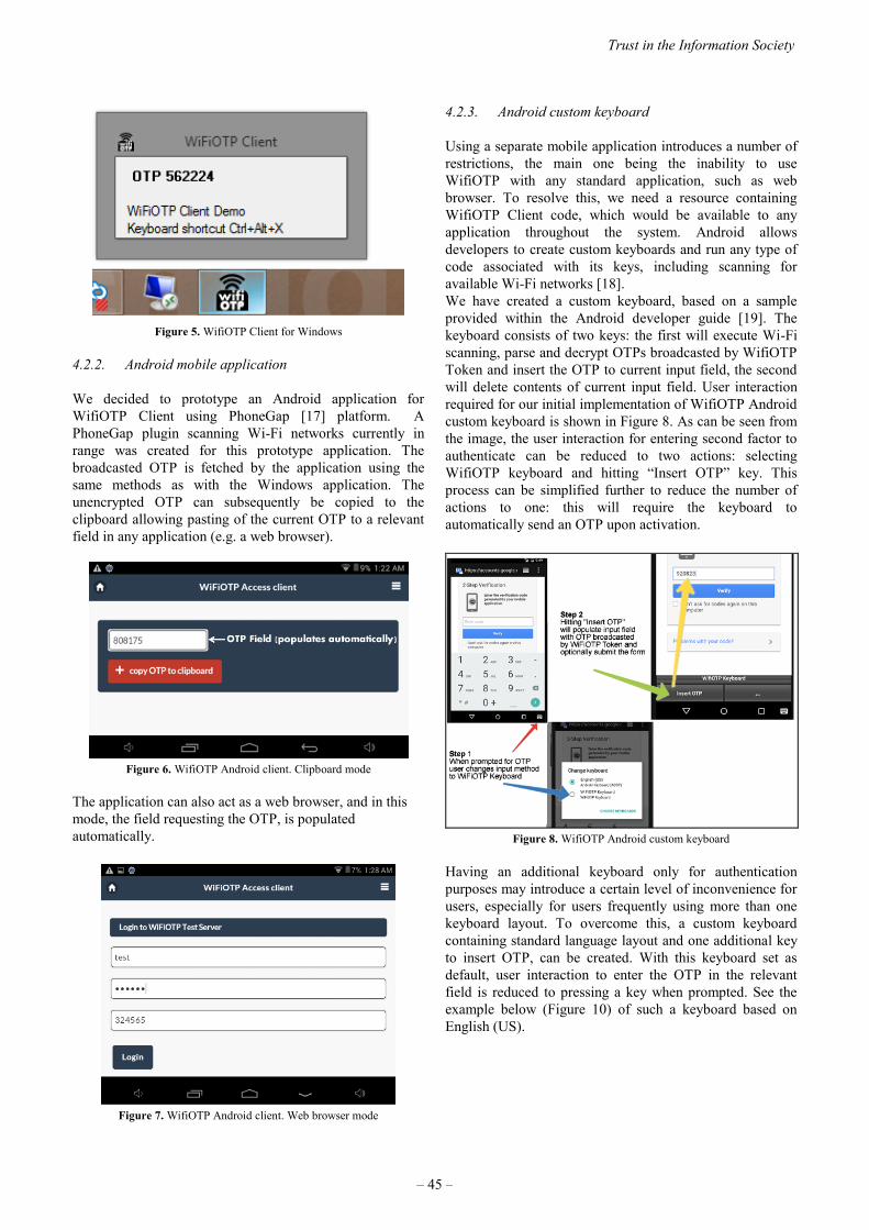
Figure 5. WifiOTP Client for Windows
4.2.2. Android mobile application
We decided to prototype an Android application for
WifiOTP Client using PhoneGap [17] platform. A
PhoneGap plugin scanning Wi-Fi networks currently in
range was created for this prototype application. The
broadcasted OTP is fetched by the application using the
same methods as with the Windows application. The
unencrypted OTP can subsequently be copied to the
clipboard allowing pasting of the current OTP to a relevant
field in any application (e.g. a web browser).
Figure 6. WifiOTP Android client. Clipboard mode
The application can also act as a web browser, and in this
mode, the field requesting the OTP, is populated
automatically.
Figure 7. WifiOTP Android client. Web browser mode
4.2.3. Android custom keyboard
Using a separate mobile application introduces a number of
restrictions, the main one being the inability to use
WifiOTP with any standard application, such as web
browser. To resolve this, we need a resource containing
WifiOTP Client code, which would be available to any
application throughout the system. Android allows
developers to create custom keyboards and run any type of
code associated with its keys, including scanning for
available Wi-Fi networks [18].
We have created a custom keyboard, based on a sample
provided within the Android developer guide [19]. The
keyboard consists of two keys: the first will execute Wi-Fi
scanning, parse and decrypt OTPs broadcasted by WifiOTP
Token and insert the OTP to current input field, the second
will delete contents of current input field. User interaction
required for our initial implementation of WifiOTP Android
custom keyboard is shown in Figure 8. As can be seen from
the image, the user interaction for entering second factor to
authenticate can be reduced to two actions: selecting
WifiOTP keyboard and hitting “Insert OTP” key. This
process can be simplified further to reduce the number of
actions to one: this will require the keyboard to
automatically send an OTP upon activation.
Figure 8. WifiOTP Android custom keyboard
Having an additional keyboard only for authentication
purposes may introduce a certain level of inconvenience for
users, especially for users frequently using more than one
keyboard layout. To overcome this, a custom keyboard
containing standard language layout and one additional key
to insert OTP, can be created. With this keyboard set as
default, user interaction to enter the OTP in the relevant
field is reduced to pressing a key when prompted. See the
example below (Figure 10) of such a keyboard based on
English (US).
Trust in the Information Society
– 45 –
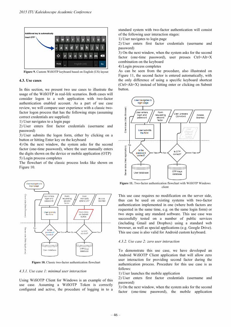
Figure 9. Custom WifiOTP keyboard based on English (US) layout
4.3. Use cases
In this section, we present two use cases to illustrate the
usage of the WifiOTP in real-life scenarios. Both cases will
consider logon to a web application with two-factor
authentication enabled account. As a part of use case
review, we will compare user experience with a classic two-
factor logon process that has the following steps (assuming
correct credentials are supplied):
1) User navigates to a login page
2) User enters first factor credentials (username and
password)
3) User submits the logon form, either by clicking on a
button or hitting Enter key on the keyboard
4) On the next window, the system asks for the second
factor (one-time password), where the user manually enters
the digits shown on the device or mobile application (OTP)
5) Login process completes
The flowchart of the classic process looks like shown on
Figure 10.
Figure 10. Classic two-factor authentication flowchart
4.3.1. Use case 1: minimal user interaction
Using WifiOTP Client for Windows is an example of this
use case. Assuming a WifiOTP Token is correctly
configured and active, the procedure of logging in to a
standard system with two-factor authentication will consist
of the following user interaction stages:
1) User navigates to login page
2) User enters first factor credentials (username and
password)
3) On the next window, when the system asks for the second
factor (one-time password), user presses Ctrl+Alt+X
combination on the keyboard
4) Login process completes
As can be seen from the procedure, also illustrated on
Figure 11, the second factor is entered automatically, with
the only difference of using a specific keyboard shortcut
(Ctrl+Alt+X) instead of hitting enter or clicking on Submit
button.
Figure 11. Two-factor authentication flowchart with WifiOTP Windows
client
This use case requires no modification on the server side,
thus can be used on existing systems with two-factor
authentication implemented in one (where both factors are
requested in the same time, e.g. on the same login form) or
two steps using any standard software. This use case was
successfully tested on a number of public services
(including Gmail and Dropbox) using a standard web
browser, as well as special applications (e.g. Google Drive).
This use case is also valid for Android custom keyboard.
4.3.2. Use case 2: zero user interaction
To demonstrate this use case, we have developed an
Android WifiOTP Client application that will allow zero
user interaction for providing second factor during the
authentication process. Procedure for this use case is as
follows:
1) User launches the mobile application
2) User enters first factor credentials (username and
password)
3) On the next window, when the system asks for the second
factor (one-time password), the mobile application
2015 ITU Kaleidoscope Academic Conference
– 46 –

automatically populates the relevant field with OTP and
submits the form without any user interaction
4) Login process completes
The flowchart shown on Figure 12, illustrates that there are
no additional actions required from the users to securely
authenticate, which makes the user experience similar to
one-factor authentication systems.
Figure 12. Zero user interaction two-factor authentication using Android
mobile application
4.3.3. Summary of reviewed use cases
Both use cases demonstrated that using WifiOTP simplifies
users’ interaction compared to classic two-factor
authentication systems. Although case 1 still requires
additional user action, it has its advantages, as it can be
used with existing client side applications without any
modification of authentication systems. With Use case 2,
user interaction is reduced to zero, but the method can only
be used via a special mobile application. A detailed
summary table of use cases is provided in Table 1 below.
Table 1. Use case comparison
Comparison
aspect
Classic two-factor
authentication
Use Case 1 Use Case 2
User
interaction
User should
manually type OTPs
generated by token
Minimal
(keyboard
shortcut)
Zero
Software
requirements
No additional
application on
client system.
Can be used
with any
application
on Windows
operating
system
Access to
systems can
only be done
via WifiOTP
Android
application
Server side
web application
Any Any Any
WifiOTP Token Any Any Any
Hardware
requirements
Network access
equipment
(wireless, wired or
cellular)
Wireless
Network
Card
Wireless
Module
Additionally, we would like to clarify that the platforms
chosen for both use cases are only examples chosen for our
validation and not based on any technical restriction: i.e.
Use Case 2 can be easily implemented as a Windows
application and vice versa. Due to the fact that the
interaction flows are similar for Windows Client and
Android custom keyboard based solution, we have not
reviewed it as a separate use case.
Both use cases demonstrated no interference or other
negative effect to any of existing wireless or wired
networks: we successfully tested the functionality on
systems connected over different networks (such as Wi-Fi,
wired network and cellular data network on mobile devices)
as per current and proposed connectivity standards [20] [21]
[22].
4.3.4. Security analysis and discussion
Generic security analysis of proposed two-factor
mechanism is already done by many authors, and we will
refer to existing work [23] as full analysis would be out of
scope of this paper.
An additional security risk is introduced by transmitting
OTPs via SSID name broadcast, which is publicly readable.
This risk is still minimal even if OTPs are transmitted in
plain text and equal to a situation when attackers gain
access to the OTP device (e.g. a hardware token). However,
even with this minimal risk, we attempted to eliminate it by
introducing symmetric encryption of broadcasted OTPs
using RC4 encryption algorithm. RC4 is rather weak
compared to other modern cryptographic methods [24],
however the limitation of the SSID length [22] does not
allow many options to choose from.
Applications for other platforms (such as MacOSX, Linux
and Windows Phone) could be also created. Only iOS
devices can't have WifiOTP as long as API methods for
scanning Wi-Fi networks are not publicly available. Future
versions of iOS may allow it though.
5. CONCLUSION
User authentication is a balance of security and user
experience. This paper presents the possibility of creating a
simple and low-cost two-factor authentication system that
simplifies user’s interaction compared to existing solutions
by minimizing or completely eliminating the actions
required to add the second factor for authentication.
The solution proposed also presents a possibility of
introducing an additional authentication factor – the
physical location of the user, which we will investigate in
future work.
Trust in the Information Society
– 47 –
REFERENCES
[1] F. Aloul, S. Zahidi and W. El-Hajj, "Two factor
authentication using mobile phones," IEEE/ACS
International Conference on Computer Systems and
Applications, pp. 641 - 644, 2009.
[2] Google Inc., "Open source version of Google
Authenticator," 15 June 2015. [Online]. Available:
https://github.com/google/google-authenticator/. [Accessed
20 July 2015].
[3] T. Christophersen, Zero Interaction Multi-factor
Authentication, Kongens Lyngby: Technical University of
Denmark, 2010.
[4] M. Corner and B. Noble, "Zero-Interaction Authentication,"
in SIGMobile, Ann Arbor, MI, 2002.
[5] D. Namiot, Network Proximity on Practice: Context-aware
Applications and Wi-Fi Proximity, Moscow: International
Journal of Open Information Technologies, 2013.
[6] D. Namiot, "Wi-Fi Proximity as a Service," SMART 2012:
The First International Conference on Smart Systems,
Devices and Technologies, pp. 62-68, 2012.
[7] D. V. Bailey, J. G. Brainard, S. Rohde and C. Paar, One-
touch Financial Transaction Authentication, Bochum:
SECRYPT, 2009.
[8] A. Varshavsky, A. Scannell, A. LaMarca and E. de Lara,
"Amigo: Proximity-Based Authentication of Mobile
Devices," UbiComp 2007: Ubiquitous Computing, pp. 253-
270, 2007.
[9] R. van Rijswijk-Deij, Simple Location-Based One-time
Passwords, Utrecht: Technical Paper, 2010.
[10] Google Inc., "Eddystone™, the open beacon format from
Google," 15 July 2015. [Online]. Available:
https://developers.google.com/beacons/. [Accessed 20 July
2015].
[11] Authy, "Authy | The Future," 22 04 2015. [Online].
Available: https://www.authy.com/thefuture#bluetooth.
[12] Yubico Inc., "YUBIKEY STANDARD & NANO," 2015.
[Online]. Available:
https://www.yubico.com/products/yubikey-
hardware/yubikey-2/.
[13] R. Want, "Near Field Communication," IEEE Pervasive
Computing vol.10, no. 3, pp. 4-7, 2011.
[14] D. M'Raihi, S. Machani, M. Pei and J. Rydell, "TOTP:
Time-Based One-Time Password Algorithm," May 2011.
[Online]. Available: http://www.rfc-editor.org/info/rfc6238.
[15] Autoit Consulting, "AutoIt : Overview," [Online].
Available: https://www.autoitscript.com/site/autoit/.
[Accessed 15 05 2015].
[16] Microsoft, "Netsh Command Reference," 2 07 2002.
[Online]. Available: https://technet.microsoft.com/en-
us/library/cc754516%28v=ws.10%29.aspx. [Accessed 27
05 2015].
[17] Y. Patel and R. Ghatol, Beginning PhoneGap: Mobile Web
Framework for JavaScript and HTML5, New York: Apress,
2012.
[18] Google Inc., "Android Developer Guides: Creating an Input
Method," 26 03 2015. [Online]. Available:
http://developer.android.com/guide/topics/text/creating-
input-method.html. [Accessed 28 05 2015].
[19] T. G. Takaoka and Google Inc., "Android samples:
SoftKeyboard," 15 10 2014. [Online]. Available:
https://android.googlesource.com/platform/development/+/
master/samples/SoftKeyboard/. [Accessed 28 05 2015].
[20] IEEE, 802.1X-2004 - IEEE Standard for Local and
Metropolitan Area Networks, IEEE, 2004.
[21] R. Valmikam, "EAP Attributes for Wi-Fi - EPC
Integration," 5 01 2015. [Online]. Available:
https://tools.ietf.org/html/draft-ietf-netext-Wifi-epc-eap-
attributes-16. [Accessed 26 05 2015].
[22] IEEE, 802.11 standard for LAN/MAN, 2012.
[23] A. Dimitrienko, C. Liebschen and C. Rossow, "Security
Analysis of Mobile Two-Factor Authentication Schemes,"
Intel Security Journal, vol. 18, no. 4, pp. 138-161, 2014.
[24] S. Fluhrer, M. Itsik and S. Adi, Weaknesses in the key
scheduling algorithm of RC4, Berlin: Springer , 2001.
[25] D. Tavares, M. Lima, R. Aroca, G. Caurin, A. C. de Oliveira
Jr, T. Santos Filho, S. Bachega, M. Bachega and S. da Silva,
"Access Point Reconfiguration Using OpenWrt," in
Proceedings of The 2014 World Congress in Computer
Science, Computer Engineering, Las Vegas, 2014.
[26] R. Swan, "SIMPLE OATH TOTP RFC 6238 IN PHP," 09
05 2013. [Online]. Available:
http://www.opendoorinternet.co.uk/news/2013/05/09/simple
-totp-rfc-6238-in-php. [Accessed 15 05 2015].
[27] OpenWRT, "Nexx WT3020," [Online]. Available:
http://wiki.openwrt.org/toh/nexx/wt3020. [Accessed 15 05
2015].
[28] D. Howett, "iPhone Development Wiki:
MobileWifi.framework," 12 07 2014. [Online]. Available:
http://www.iphonedevwiki.net/index.php/MobileWifi.frame
work. [Accessed 28 05 2015].
2015 ITU Kaleidoscope Academic Conference
– 48 –

VULNERABILITY OF RADAR PROTOCOL AND PROPOSED MITIGATION
Eduardo Esteban Casanovas1, Tomas Exequiel Buchaillot
2, Facundo Baigorria
3
1 Instituto Universitario Aeronáutico, [email protected]
Av. General Paz 142, 1° “B”, CP:5000 Córdoba, Argentina. 54-351-95-426291
2 Instituto Universitario Aeronáutico, [email protected]
Complejo Palmas del Claret, casa 165, CP:5000 Córdoba, Argentina. 54-351-6874923
3 Instituto Universitario Aeronáutico, [email protected]
Perez del Viso 4428, CP:5009 Córdoba, Argentina. 54-351-6821829
ABSTRACT
The radar system is extremely important. Each government
must ensure the safety of passengers and the efficiency of
the system. This is why it has to be considered by suitable
and high-performance professionals. In this paper, we have
focused on the analysis of a protocol used to carry the
information of the different flight parameters of an aircraft
from the radar sensor to the operation center. This protocol
has not developed any security mechanism which, itself,
constitutes a major vulnerability. Every country in the
world is going down this road, relying just on the security
provided by other layer connections that could mean a step
forward but definitely still not enough. Here we describe
different parts of the protocol and the mitigation politics
suggested to improve the security level for such an
important system.
Keywords— Air traffic control, Radar, Transport
protocol, Vulnerability, Mitigation
1. INTRODUCTION
ASTERIX is a standard protocol designed to exchange data
between radar sensors and the control centers (ATC
Systems) through means of a message structure. The
protocol was designed by Eurocontrol and its acronym
stands for “All Purpose STructured Eurocontrol
SuRveillance Information EXchange”.
ASTERIX has been developed bit by bit to provide and
optimize surveillance information exchange inside and
between countries (among other purposes) which makes the
aerial traffic control centers (ATC) ASTERIX’s main users.
Nowadays, almost every state of the ECAC (European Civil
Aviation Conference) – are using it at their ATCs.
This protocol defines a standard information structure
which is to be exchanged in a communication network,
going from the codification of every single bit of data to the
organization of the data in a data block.
These transactions can use any means of communication
available like LAN networks, Internet Protocols (IP), and
WAN. For this kind, data elements group up into Asterix
categories. At present there exist 256 different types of
categories.
The ASTERIX structure for the surveillance information
exchange can be defined like this:
Data Categories
The data to be exchanged by a means of communication
among different users must be standardized and classified
into categories. These categories define the information that
can be transmitted and encoded; in addition, its data will be
standard for all of Asterix users. The purpose of this
classification is to make easier the identification and the
consignment of the data and also to establish a hierarchy
based on their priority.
Data Item
It is the smallest unit of information in every category. For
each one of them a Data Item group is determined, which
constitutes the index of Data Items. Every Data Item has a
unique reference that identifies it in an unmistakable way.
The symbolic reference is made up of eight characters and
it is to be written in the following way: Innn / AAA
I stands for data item, nnn is a three-digit decimal number
which indicates the data category it belongs to and AAA is
a three-digit decimal number which indicates the data item
number.
Data Block
It is a unit of information that contains one or more
registers, each of which has the information about the same
category. It is made up of:
A data octet called Category (CAT) which indicates what
category the transmitted data belong to.
978-92-61-15821-7/CFP1538E-ART © 2015 ITU Kaleidoscope– 49 –

A 2 octet data field indicates the size of the data block
(LEN).
One or more register which contain the data of the same
category. Each register has a variable length but with a
defined octet limit. The length will always be multiple of an
octet.
The maximum size of a data block will be a mutual
agreement between the data source and the users.
Field Specification (FSPEC)
The FSPEC is a content table in a bits sequence where each
bit indicates the presence or absence of a determined Data
Field.
There exists the possibility of using a non-standard Data
Field. In order to do that, a bit is enabled and it indicates the
presence of a special purpose (SP). On the other side and in
this very field, another bit indicates the usage of a random
organization (RFS).
Figure 1: Example of a multi-octet FSPEC
We particularly focused on the Cat 48, a new version of the
Cat 01 and Cat 16 SSR Mode-S since now is the most used
for the civil aviation in our country.
Asterix CAT 48 is a category where the information about
target radars goes from a header to a radar data-process
system. In this category plot of tracks, messages can be
transmitted by a combination of the two.
In the following table, you can see standard data items of
the category.
Figure 2: Category 48 Data Block
As an example, in the following table it is shown the
standard UAP (User Application Profile) for the
information about tracks of category 48.
Table 1: example of standard UAP for the track
information
As shown in the table, each field has an integer amount of
octets where the information is represented.
In order to conclude the ASTERIX matter, we will
highlight one of the main protocol’s issues: The lack of
security.
The protocol does not include any security system in it,
meaning that it does not have a corroboration of the
information that is transmitted in the communication.
Since it is not able to assure the integrity or the authenticity
of the information, ASTERIX turns out to be a protocol
vulnerable to many different types of malicious attacks, as
for instance, a Man in the Middle attack.
New Technologies
In these days, several countries are trying out a new
technology surveillance in commercial aviation, know as
``ADS-B´´ (Automatic dependent surveillance-broadcast)
It is included in the US Next Generation Air Transportation
System (NextGen) and the Single European Sky ATM
Research (SESAR).
This cooperative technology is used in the aircraft setting
its position through satellite navigation and transmitting it
regularly so that it is possible to be tracked down. This
information can be read not only by air-traffic control
stations but also other aircrafts implementing such
technology. The objective of ADS-B is to replace the
secondary radars.
Even though this technology replaces the current system of
transposition, its low level of communication remains in
ASTERIX.
Using other ASTERIX categories like the Cat 21 will be the
only difference. Therefore, the objective of this work will
still be valid since all needed onwards is to encode / decode
a new ASTERIX category for every program to work
perfectly well.
3. MITM ATTACK
Man in the middle is a type of attack in which the attacker
has the ability to read, insert and modify the messages that
are being sent between the two hosts without either of them
knowing that the link has been violated. Once the data link
has been compromised, the attacker has the capacity of
sniffing and intercepting the messages that are exchanged
between the victims.
2015 ITU Kaleidoscope Academic Conference
– 50 –

Below are some of the most common techniques to commit
an MITM attack.
ARP Poisoning o ARP Spoofing: Is an MITM type of
attack for Ethernet networks which allows the attacker to
capture the network traffic exchanged over the LAN
network, stopping it and also being able to deny it.
DNS Spoofing: This type, uses fake responses to the DNS
resolution requests sent by a victim. There are two methods
that the attacker may use: “ID Spoofing” and “Cache
poisoning”.
Port Stealing: here, the attacker sends a large amount of
Ethernet frames (OSI Model Layer 2 packets), with the
MAC address of the victim as source and with the
attacker’s own MAC address as the target. This switch
makes the victim believe to be connected at the attacker’s
port.
DHCP Spoofing: The DCHP requirements are made up of
broadcast frames due to the fact that these must be heard by
all devices within the local network. If an attacker answers
the request before the server does, the former may send the
wrong information to the victim.
In this case, we use the ARP Poisoning method. This
technique is used in local networks aimed to acquire
network traffic destined for another host. Using this method
allows us to redirect the data intended for the original host
to our own network card and by doing this we are able to
block, modify or even add new data.
This technique is not based on a particular vulnerability that
may disappear over time, but on a TPC network design bug.
That is why this kind of attack shall remain in force unless
new specific security measures are taken.
4. SIMULATION
In order to do the testing in a controlled environment, there
have been conducted simulations of a communication
between a plane and an airport’s control turret. To recreate
each of the elements, custom software was coded. This
software was located in different virtual machines which, as
a unit, simulate the airport communication infrastructure.
The communication method we have chosen to use was
UDP sockets.
Figure 3: Network Simulation
The simulations are described in the following items:
Airplane Transponder
It is responsible for generating and sending the flight data
used by the radar tower. Through Asterix packets, this
information is transmitted to the operation center. In order
to get more accurate data, we used the simulator called
“FlightGear”.
FlightGear
It is a multiplatform open-sourced flight simulator. We used
this software getting after the objective of obtaining real-
time plane data, generated virtually using the software’s
GUI (graphical user interface).
Radar
It is the responsible of receiving the raw data from the
planes, using it for the creation of ASTERIX packets and
sending them through a UDP socket to the network. So as
to do this, we created a software called AGIUA (Asterix
Generator IUA), fully developed in C++.
AGIUA
It takes the raw data from a predefined port, analyzes and
makes the calculations to transform the information from
the plane, into ``Data Items´´ of a category ASTERIX to be
sent. After the length of the resulting fields is defined, they
can be inserted in the corresponding ASTERIX´s headboard
FSPEC in order to have the complete package that is going
to be transmitted by another UPD socket to the next node.
As for now, only AGIUA creates category 48 and category
34 ASTERIX packets most of which are the being used in
commercial aircraft.
Router
This router/firewall is responsible for redirecting the
ASTERIX´s packets to the operation center node, and drop
another packet. We do this through a script made with
iptables which have the following attributes:
Trust in the Information Society
– 51 –

DROP by default all the packets.
Redirect all the packets that are sent from the radar node IP,
from a specified UDP port, and which protocol is
ASTERIX to a specific port from the operation center node.
In order to do that, we created NAT, PRE-FORWARDING
and POST-FORWARDING rules.
We also took the security measures needed to achieve this
simulation as close to the reality of the airport routers as
possible, for instance: port blocks or an update of different
services to avoid known vulnerabilities.
Operation Center
The operation center is the responsible of receiving the
ASTERIX packets sent from the radar and at the same time,
of decoding their data and distributing the packets to the
different stakeholders. For example, send the location data
to the control tower so the ATC can manage the air traffic.
To simulate this system we made a C++ software, which is
in charge of making those decoding. It also has a GUI
(graphical user interface) in which is represented the
location of the aircraft in order to visualize all the different
tests that we made for the project.
To achieve this, it puts all the data in a queue where it will
consider whether the ASTERIX and FSPEC headboard
matches the rest of the saved package. If it is positive, it
will take FSPEC byte by byte and shall be taking elements
from the queue (which would come to form the ASTERIX
DATA ITEMS package) and analyzing information sent
for. At the same time, in another thread, the program will
correctly be formed by plotting the packages taking its
Aircraft Address and coordinates.
5. MITM APPLIED TO ASTERIX
In this section, we will explain how we applied this type of
attack to manipulate the ASTERIX protocol according to
our aims.
Basically, all the packets that are going to travel on this
network have the same structure: header – packet body. In
the header, we can find a different type of elements such as
the source IP, target IP, packet length, checksum, etc. The
packet body contains ASTERIX blocks (each one with its
specific category) and own registers of each block
specifying the flight data.
Having understood these concepts, we can approach the
custom software coded for this section: MITMAST (Man in
The Middle ASTerix). The main objective of this software
is to capture all the packets between two nodes (in our case,
the ASTERIX packet generator and the operation center)
and manipulate them. It is a simple software, developed in
C, that launches an MITM attack using the ARP Poison
technique between two hosts. To do this, the software uses
osdep, a tunnel creation library which is part of the air
crack project. With this, we can create an interface (mitm0)
in which the response packets will be written in order to be
easier to sniff.
MITMAST will receive the following parameters:
mitmast -i interface -t ip1 ip2 -o option
-i: It specifies the network interface to be used
which will get in the promiscuous mode to sniff
the network.
-t: It specifies the victims’ host IP network.
-o: Using this option, we specify one of three
options to determine the attack to make: BLOCK,
MOD or ADD.
BLOCK – Delete an aircraft: Once the
ASTERIX packets have been obtained, the
software will recognize the packets that
belong to a particular aircraft and will not
forward them to the operation center, by doing
so, the aircraft is deleted from the operation
center data.
MOD – Modify the track of aircraft: Once the
ASTERIX packets have been obtained, the
software will recognize the packets belonging
to a particular aircraft and by using an
algorithm it will pretend a detour to make it
look like the aircraft has changed its original
route.
ADD – Insert a ghost aircraft: The software
will generate new ASTERIX packets with
reliable data and will send them to the
operation center. This will make it look like
the radar is receiving an aircraft that does not
actually exist. This packet injection can be
made with many aircrafts at the same time.
Once all the parameters are determined, it will request some
information depending on the options we specified before:
BLOCK: It will request the Aircraft Address. This
is an element contained in each CAT 48 ASTERIX
packet and it identifies unequivocally the aircraft.
MOD: It will request the Aircraft Address and the
modification TYPE. This last option can be:
MANUAL or SIMULATED. If it is manual, it will
ask the aircraft’s final coordinates and the
simulator will automatically make a parable until it
arrives at the specified point and then, the aircraft
will disappear from the radar, becoming blocked.
If we choose the simulated option, within five
seconds another instance of FlightGear will take
over the flight coordinates, using them on a
specified port.
ADD: It will request the Aircraft Address, CANT
and DIST. The aircraft address is asked in order to
identify the aircraft, the CANT option is requested
to specify the number of ghost planes to be added
and the DIST option is requested to specify the
distance between the aircrafts.
Having finished this stage, the software will make an ARP
Poison attack to the specified hosts, misdirecting the
packets to the attacker host. If this attack is successful we
should be able to see in our screen confirmation message
2015 ITU Kaleidoscope Academic Conference
– 52 –

and the software will begin to transform the packets. It is
important to point out that before sending them, their
header is modified, changing the source/target of the packet
and making a new checksum leave no trace of our intrusion.
6. EXPAMPLES
In the following images, we will demonstrate how the
attack works.
Figure 4: Normal Radar
Figure 5: Radar in ADD Attack
Figure 6: Radar in MOD Attack
7. MITIGATION
An action that can make the attacker to the network is to
perform a listening on traffic established between radar and
the operations center and save it. This will allow the
attacker to subsequently perform a valid format inkjet
packages and features but will not be valid in time. This
indicates that within the mechanism proposed, we must
remember that the attacker may be interested in making
injection valid packets (Replay attack). Additionally, the
attacker can select the stored traffic and perform a selective
injection.
The main point is that Asterix packages have not
implemented any security mechanism. This means that
security mechanisms should be done outside Asterix. The
problem is that if the attacker can pass through these
security barriers, he will find all packages in plain text and
can perform attacks Block, Mod Add.
Many electronic countermeasures are used in radar. They
all seek to mitigate attacks that are made on the sensor, but
once the signal is validated, this signal goes into a network
protocol that has no additional security beyond the one that
can be provided at network level.
As we all know, the security at the network level is
continuously broken, you just see what happened with SSL-
TLS during the last years, therefore, put our security in this
protocol it is not enough.
Our first problem is to ensure the integrity of Asterix
package. Although, in reality, we shall see that for the
moment we will only guarantee the integrity of information
of certain flight parameters. Listed in Table 1: standard
UAP for the track information, we are going to focus on the
FRN:
2 Day time,
8 Aircraft`s Address,
9 Aircraft`s identification,
11 Track number,
12 Position velocity calculate,
13 Track calculate,
14 Track`s status,
We will focus on these fields because it’s on them that we
have raised our attack. However, this does not mean that we
cannot guarantee the integrity of any other field.
The mechanism to ensure the integrity of these fields is the
use as a hash function. Because of the replay attack, we will
add a field "time stamp". This field is added to the
aforementioned and all of them will do the hash calculation.
Due to our network characteristics, we can say that among
of different components of the network we can have a pre-
shared secret, this is going to allow the use of other
cryptographic functions such as the HMAC. The extra
advantage in the use of such functions is that we can
authenticate the sensor that is receiving the information.
Trust in the Information Society
– 53 –

Processing Time
A very important point in our analysis is if the processing
time in the incorporation of these security measures
compromises the normal flow of packet reception.
To verify this evidence, we apply this security method on
flows with different types of frequency. Even in the worst
situation, that is a scenario of maximum traffic, there can be
processed more than 30 packets per second per sensor, and
no bad effect appears, so no degradation in the flow of the
packets was performed.
These measurements make us think about how to develop
an additional security features.
Package encryption
While most importantly for this scheme is to ensure the
integrity of the packages, an additional feature is to have
confidentiality on the information we send. That is why we
also propose additional security features as it is to perform
encryption on the same fields on which it will ensure
integrity.
To verify that it is possible to perform, we applied on the
aforementioned fields, an encryption algorithm. Here we
use AES-CBC. Other encryption mechanisms can be used,
such as AEAD (Authenticated Encryption with Associated
Data). This mechanism is very attractive because it
provides confidentiality, integrity, and authenticity.
Once we complete the encryption process we replaced in
the selected field, the plain text information with the cipher
text.
And finally making a combination of both mechanisms, the
HMAC function or just the typical hash function is applied.
This allowed us to have guaranteed the integrity of the
previously encrypted fields.
Final tests
With the two mechanisms (integrity and confidentiality) in
place, we perform several tests in order to analyze the
impact of the application of the two security features.
Here also taken into account the characteristics of the type
of traffic we have between the sensor and the operation
center.
Two different situations were studied. Low traffic operation
can have 3 packets flow per second per sensor and in a high
traffic operation we have approximately 10 packets per
second per sensor.
During the complete operation, we can process 18 packets
per second per sensor without any kind of delay in the
normal flow. Therefore, the incorporation of the encryption
method in the required fields can do without compromising
the normal flow of traffic.
8. CONCLUSION
As a part of the critical infrastructure of a country, the radar
system is fundamental in the air transport system. That is
why we must make every effort to ensure the maximum
availability and security. Asterix protocol designed by
Eurocontrol is very efficient but lack of an adequate safety
mechanism itself. That is why you should have to move to
another link layer to obtain a security status, which seems
insufficient, considering the criticality of the information
handled.
The proposed mitigation presented in this paper covers
possibilities described attacks but also provides an
additional level of security thinking of an attack from inside
of the organization.
Our proposed mitigation against vulnerability raised
sharply covers actions that can be performed by an attacker
who has enough information to be able to listen the
communication channel between the radar sensor and the
operation center, because it will not be able to manipulate
any packages. Also, during a situation while implementing
encryption of packages, the attacker cannot display the
flight parameters that are being transmitted.
Last but not least, we highlight at this conclusion the
importance of processing times involved in the
cryptographic mechanism, to ensure the protocol`s
integrity and confidentiality, saying we have been highly
satisfied because there are no limits with the data flow
required to be transmitted at all times.
REFERENCES
[1] Adolf Mathias, Matthias Heß (2012). “Machine-Readable
Encoding Standard Specifications in ATC”.IEEE - Digital
Communications - Enhanced Surveillance of Aircraft and
Vehicles (TIWDC/ESAV), 2011 Tyrrhenian International
Workshop.
[2] Bruce Schneier. Schneier on Security.
https://www.schneier.com.
[3] Craig Hunt (1997). “TCP/IP Network Administration”.
O'Reilly & Associates.
[4] D. Brent Chapman & Elizabeth D. Zwicky (1995). “Building
Internet Firewalls”. O'Reilly & Associates.
[5] DEFCON. DEFCON Conferences.
https://www.youtube.com/channel/
UC6Om9kAkl32dWlDSNlDS9Iw.
[6] EUROCONTROL-European Organization for the Safety of
Air Navigation. Asterix protocol.
https://www.eurocontrol.int/asterix.
[7] Ministerio de Defensa de España. Ciberseguridad: Retos y
amenazas a la seguridad Nacional en el Ciberespacio.
http://bibliotecavirtualdefensa.es/
BVMDefensa/i18n/catalogo_imagenes/grupo.cmd?path=1702
9.
[8] Milw0rm Hacker Group. W4rri0r.http://www.w4rri0r.com/.
[9] Naga RohitSamineni, Ferdous A, Barbhuiya and Sukumar
Nandi (2012).“Stealth and Semi-Stealth MITM Attacks,
Detection and Defense in IPv4 Networks”. IEEE - Parallel
Distributed and Grid Computing (PDGC), 2012 2nd IEEE
International Conference.
[10] RenderMan. RenderLab.http://renderlab.net/.
[11] Zhe Chen, ShizeGuo, KangfengZheng and Yixian Yang
(2007). “Modeling of Man-in-the-Middle Attack in
theWireless Networks”.IEEE -Wireless Communications,
Networking and Mobile Computing, 2007.WiCom2007.
International Conference.
[12] ADS-B Technologies Website.
http://www.ads-b.com/[13] ADS-B and Asterix application for Eda.
http://era.aero/technology/ads-b-2/
2015 ITU Kaleidoscope Academic Conference
– 54 –

SESSION 2
TRUST THROUGH STANDARDIZATION
S2.1 Raising trust in security products and systems through standardisation and certification: the CRISP approach.*
S2.2 Drones. Current challenges and standardisation solutions in the field of privacy and data protection.


RAISING TRUST IN SECURITY PRODUCTS AND SYSTEMS THROUGH
STANDARDISATION AND CERTIFICATION: THE CRISP APPROACH
Irene Kamara
Vrije Universiteit Brussel –
Research Group on Law,
Science, Technology and Society
(LSTS), Brussels - Belgium
Thordis Sveinsdottir
Trilateral Research &
Consulting, London - United
Kingdom
Simone Wurster
Chair of Innovation Economics Berlin University of
Technology, Berlin - Germany
ABSTRACT
The need for security systems and related ICT
solutions poses new challenges to the individuals in
terms of fundamental rights such as the right to privacy.
Those challenges generate mistrust at the same time to
the end-users. Standardisation and certification can
have a significant role in changing the picture and help
reinstate the lost confidence. This paper examines the
concept of “trust” to ICT employed for security
purposes, identifies the needs of the stakeholders and
concludes with recommendations for the potential role
of standardisation and certification through the
implementation of a pan-European seal based on
robust standards.
Keywords—trust, security products and systems,
standards, certification, harmonisation, European seal
1. INTRODUCTION
The need for security systems and related ICT solutions
poses new challenges to the individuals in terms of
fundamental rights such as the right to privacy,
generating mistrust at the same time to the end-users [1].
These new challenges ask for upgraded tailored solutions
to mitigate risks, such as data breaches and leakage,
unauthorised access, automated profiling and differential,
discriminatory treatment. Due to the actual risks to the
freedoms and rights of the individuals, the levels of trust
towards Information Communication Technologies
(ICTs) have dropped. In a recent survey directed to
European citizens of all European Member States on the
protection of personal data, 67% of the respondents
replied that they are concerned about not having
complete control over the information they provide
online [2]. At the same time, a large majority (71%)
replied that providing personal information is an
increasing part of modern life and they accept that
there is no alternative other than to provide it if
they want to obtain products or service. Furthermore,
security breaches as events, which are communicated
widely by the media, feed the above mistrust of ICTs.
At the same time, ICTs are widely employed for security
purposes such as the combat against organised and local
crime, border and infrastructure security, and security of
citizens. Even though the actual contribution to the
increase of quality of provided security might in most of
the cases be high, the confidence of the citizens in such
products, systems and services often does not align with
the actual contribution. Respondents from the demand-
side to interviews conducted for the FP7 research project
CRISP, when asked about current standards and
certification of video surveillance agreed that the current
landscape is complex and may include national
standards, ISO and IEC standards, CENELEC
standards and various national codes of practice and
other government policy documents. In addition, video
surveillance is subject to national and regional specific
laws and regulations, which cover their use as well as
social implications such as privacy, data collection,
storage, integration and analysis. Technological
advancement in this sector is currently very fast, which
complicates matters even further as changes to
standardisation are too slow to keep up with technological
change. Overall, there is a sense among stakeholders
that the development of standards is too slow moving,
which is seen as a detriment to standardisation and
certification of security products, systems and services.
Technology, perceptions of risk and threat change
rapidly, and standards development is seen to be lagging
behind [3]. Respondents pointed to the fact that different
national security cultures conceptualised and understood
video surveillance in different ways and this might be a
reason for a slow uptake of European Standards. The
example of the UK, where the use of video surveillance
is highly regulated and other European states where it
was less so, was mentioned to further explain this lack of
uptake. Stakeholders also mentioned that added-value
was not clear and that it might take longer to realise full
uptake of the EN50132 standards series.
These findings demonstrate that the need for trustworthy
security solutions and related ICTs is strong. Citizen’s
trust in ICTs, especially the security employed
facilitates the acceptability of such security measures.
But the question remains: What does “trust” mean in that
context and by whom?
978-92-61-15821-7/CFP1538E-ART © 2015 ITU Kaleidoscope– 57 –

Technical standards play an important role not only to
support innovation in the fields of security and ICTs,
but also to develop trustworthy connections and
infrastructures. Furthermore, the use of “trustmarks”
and certificates, has been shown to enhance citizens’
trust. Standards and certificates can be a synonym of
reliability and assurance to the end user and citizen.
What are the needs of the end users in that respect and
what are the main challenges that existing security
standards and certification schemes need to overcome in
order to yield trust?
The current paper presents the findings of the FP7
research project CRISP on standardisation and
certification of security products [4]. The project seeks
to aide harmonisation efforts in certification across
Europe with regard to security products, systems and
services. It employs the STEFi methodology, which
encompasses societal aspects such as Security (S), Trust
(T), Efficiency (E) and Freedom infringements (Fi), in
order to further urge and guide the security
standardisation and certification stakeholders to
consider such aspects in their standards and certification
and evaluation schemes.1 In the context of CRISP,
trust encompasses the experience of the products,
systems, services (PSS) users such as employees as
well as those scrutinised by the PSS as for example
passengers at an airport. Beside the experience, the
subjective perception defines in which way a PSS
reaches an appropriate acceptance level.
Requirements for trust include transparency,
openness, fairness and accountability or by using a
more practical perspective, habitus (in the context of
e.g. usability), emotions and cognition (e.g. the
degree of discrimination regarding the use of
technology as well as the potential physiological and
psychological invasiveness such as body scanner and
claustrophobia)."2 In the paper we discuss the concept
1 The STEFi approach was developed in the EU-funded FP7
SIAM project (Security Impact Assessment Measures). Read
further: Hempel et al. , “Towards a multi-dimensional
technology assessment. The introduction of security
technologies at airports and public transport systems ” in
Fraunhofer Institute, International Conference on the
PRESCIENT project, 27-28 November 2012 2 When computer science and software engineering address
security, Confidentiality, Integrity, Availability (CIA) and trust
are relevant. In this context, trust can be defined as "a
subjective probability that defines the expectation of an actor
about profitable behaviour of another actor". Based on this, it is
related with (system) dependability (i.e., availability, safety,
reliability, maintainability and integrity). (Asnar, Y.; Giorgini,
P.; Massacci, F.; Zannone, N., "From Trust to Dependability
through Risk Analysis," in Availability, Reliability and
Security, 2007. ARES 2007. The Second International
Conference on , vol., no., pp.19-26, 10-13 April 2007). The
CRISP approach is not exclusively focussed on ICT. It has a
wider scope from a technological point of view but a narrow
scope regarding the purpose of the PSS. It only includes
security-related PSS. Based on this, our approach also
considers for example security-related systems of systems,
which can include hardware, software and services. Therefore a
of “trust” in relation to security products and systems by
presenting the results of the CRISP online surveys and
the stakeholder workshop. Following that, we approach
the role of standardisation and certification in building
trust; what are the elements that enhance trust and
should be incorporated/respected in security and
related ICT standards and certification? The paper
concludes with an overview of the forthcoming
harmonised certification methodology of the CRISP
project.
2. IDENTIFYING KEY STAKEHOLDER GROUPS
AND THEIR NEEDS FOR TRUSTWORTHY
SECURITY SOLUTIONS AND RELATED ICTs
The CRISP project carried out a stakeholder analysis and
interviews as part of the research and analytical work in
preparation for the new certification scheme [2]. Two
web surveys were sent out to supply- and demand-side
stakeholders across Europe in December 2014 and
January 2015. The surveys were informed by literature
reviews and interviews with stakeholders and were
intended to examine the prominence of views on and
needs from security standardisation and certification. 75
respondents from 23 European countries replied to the
supply side survey and 50 respondents from 14
European countries replied to the demand-side survey.
The objectives were to firstly identify the direct and
indirect stakeholders in the security products, systems
and services standardisation and certification sector and
understand their motivations within and views on current
system. Second, to gauge stakeholder views on a
security certification challenges, whether they felt any
changes were needed and if so, what their needs were
with respect to those changes. Two web-surveys, for
supply side (accreditation, certification and
standardisation bodies, insurance companies and security
industry stakeholders) and demand side (civil society
organisations, consumer rights groups, procurers of
security products, systems and services in private and
public sectors, operators of security products and
systems) were sent out to stakeholders across Europe.
2.1. Stakeholders views on security
standardisation
Stakeholders identified advantages and disadvantages in
the current system. Overall, both supply and demand-side
stakeholders demonstrate considerable trust in the current
system of certification as they selected as key benefits
being that it drives better practice and assures quality of
products and services. When asked to select three of its
most important benefits (from a list of 7 and other) the
notion of certification as a ‘seal of quality’ or assurance
to end users’ was rated highest by 82% of demand-side
stakeholders. Furthermore, 43% of respondents agreed
broader definition of “trust” is used. Nevertheless, the specific
ICT related attributes can be added to our holistic concept.
2015 ITU Kaleidoscope Academic Conference
– 58 –

that ‘certification improves service and product
standards.
Figure 1: Disadvantages of the current system of
certification (number of responses = 28)
This points to the importance of certification as a brand,
which signifies that a product or service has passed
rigorous testing and quality assurance. The interviews
also revealed that the certification seals are often
considered as an addition to branding, and some well-
established schemes are perceived to increase end-user
trust in products and services.
When asked about the benefits of the prospective pan-
European CRISP certification scheme, 53% of supply-
side and 71% of demand-side stakeholders selected that
its key benefit would be that it provided a recognisable
European seal.
With regard to disadvantages of the current system most
responses indicate frustration with an overly complex
system and 68% of demand-side stakeholders selected
that disadvantage is that difference between certification
schemes/seals is not clear. There is also a perception,
which was echoed in the interviews that national schemes
differ in the quality they assure and due to lack of
transparency it is difficult to compare and contrast
different schemes. In order to be able to distinguish a
strong scheme/seal and consequently high quality from
lower quality products and services, it is imperative that
standards, processes and evaluation criteria are clear to
all stakeholders involved (see Figure 1).
Figure 2: Does certification meet the needs of demand-side
stakeholders? (number of responses, 28)
Furthermore, it is not always clear what certification
seals stand for and what their foundations are in terms
of standards, evaluation criteria and process. When
asked whether the current certification landscape met
the needs of demand side stakeholders, a majority states
that it does not (see Figure 2).
When asked further about demand-side stakeholders’
needs with regard to certification of security products
and systems the following picture emerges (see Figure 3).
The preference for a robust foundation, in the form of a
European or international standard was also selected
as a key need by 69.6% of supply-side stakeholders and
preferred over that of a national standard.
Figure 3: Demand side needs regarding certification of
security products (number of responses, 28)
In your experience, what are the disadvantages of the
current certification system, for security products,
systems and services, in Europe? (Please select the
three most important disadvantages)
Answer Options Response Percent
The difference between certification schemes/seals is not clear 67.9%
National schemes differ in the quality they assure
67.9%
There are no disadvantages with current certification of security products, systems or services
10.7%
Certification schemes do not ensure quality of security
products, systems and services
28.6%
It is unclear for what evaluation dimensions certification
labels stand
64.3%
Other (please specify)
7.1%
What are your needs regarding the certification of
security products, systems and services? (Please select
three most important needs)
Answer Options Re sponse
Percent
Percent
Pe rce nt
That certification schemes are transparent in what they evaluate and certify
60.7%
That certification builds on robust national standards
28.6%
That certification builds on robust European/international standards
50.0%
That certification ensures quality and performance
75.0%
That certification ensure compliance with regulation and law 46.4%
Other (please specify)
3.6%
Trust in the Information Society
– 59 –
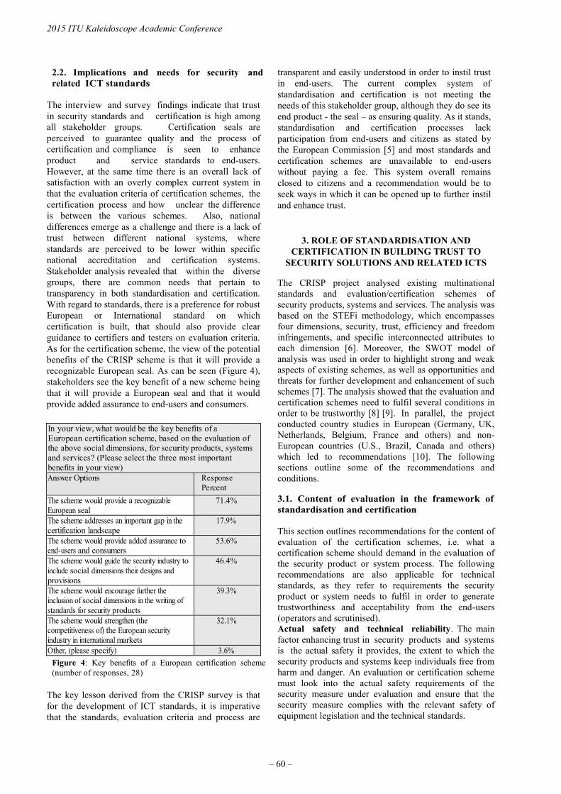
2.2. Implications and needs for security and
related ICT standards
The interview and survey findings indicate that trust
in security standards and certification is high among
all stakeholder groups. Certification seals are
perceived to guarantee quality and the process of
certification and compliance is seen to enhance
product and service standards to end-users.
However, at the same time there is an overall lack of
satisfaction with an overly complex current system in
that the evaluation criteria of certification schemes, the
certification process and how unclear the difference
is between the various schemes. Also, national
differences emerge as a challenge and there is a lack of
trust between different national systems, where
standards are perceived to be lower within specific
national accreditation and certification systems.
Stakeholder analysis revealed that within the diverse
groups, there are common needs that pertain to
transparency in both standardisation and certification.
With regard to standards, there is a preference for robust
European or International standard on which
certification is built, that should also provide clear
guidance to certifiers and testers on evaluation criteria.
As for the certification scheme, the view of the potential
benefits of the CRISP scheme is that it will provide a
recognizable European seal. As can be seen (Figure 4),
stakeholders see the key benefit of a new scheme being
that it will provide a European seal and that it would
provide added assurance to end-users and consumers.
Figure 4: Key benefits of a European certification scheme
(number of responses, 28)
The key lesson derived from the CRISP survey is that
for the development of ICT standards, it is imperative
that the standards, evaluation criteria and process are
transparent and easily understood in order to instil trust
in end-users. The current complex system of
standardisation and certification is not meeting the
needs of this stakeholder group, although they do see its
end product - the seal – as ensuring quality. As it stands,
standardisation and certification processes lack
participation from end-users and citizens as stated by
the European Commission [5] and most standards and
certification schemes are unavailable to end-users
without paying a fee. This system overall remains
closed to citizens and a recommendation would be to
seek ways in which it can be opened up to further instil
and enhance trust.
3. ROLE OF STANDARDISATION AND
CERTIFICATION IN BUILDING TRUST TO
SECURITY SOLUTIONS AND RELATED ICTS
The CRISP project analysed existing multinational
standards and evaluation/certification schemes of
security products, systems and services. The analysis was
based on the STEFi methodology, which encompasses
four dimensions, security, trust, efficiency and freedom
infringements, and specific interconnected attributes to
each dimension [6]. Moreover, the SWOT model of
analysis was used in order to highlight strong and weak
aspects of existing schemes, as well as opportunities and
threats for further development and enhancement of such
schemes [7]. The analysis showed that the evaluation and
certification schemes need to fulfil several conditions in
order to be trustworthy [8] [9]. In parallel, the project
conducted country studies in European (Germany, UK,
Netherlands, Belgium, France and others) and non-
European countries (U.S., Brazil, Canada and others)
which led to recommendations [10]. The following
sections outline some of the recommendations and
conditions.
3.1. Content of evaluation in the framework of
standardisation and certification
This section outlines recommendations for the content of
evaluation of the certification schemes, i.e. what a
certification scheme should demand in the evaluation of
the security product or system process. The following
recommendations are also applicable for technical
standards, as they refer to requirements the security
product or system needs to fulfil in order to generate
trustworthiness and acceptability from the end-users
(operators and scrutinised).
Actual safety and technical reliability. The main
factor enhancing trust in security products and systems
is the actual safety it provides, the extent to which the
security products and systems keep individuals free from
harm and danger. An evaluation or certification scheme
must look into the actual safety requirements of the
security measure under evaluation and ensure that the
security measure complies with the relevant safety of
equipment legislation and the technical standards.
In your view, what would be the key benefits of a
European certification scheme, based on the evaluation of
the above social dimensions, for security products, systems
and services? (Please select the three most important
benefits in your view)
Answer Options Response
Percent
The scheme would provide a recognizable
European seal
71.4%
The scheme addresses an important gap in the
certification landscape
17.9%
The scheme would provide added assurance to
end-users and consumers
53.6%
The scheme would guide the security industry to
include social dimensions their designs and
provisions
46.4%
The scheme would encourage further the
inclusion of social dimensions in the writing of
standards for security products
39.3%
The scheme would strengthen (the
competitiveness of) the European security
industry in international markets
32.1%
Other, (please specify) 3.6%
2015 ITU Kaleidoscope Academic Conference
– 60 –

Evaluation that takes into account freedoms and
rights. Users and those scrutinised need to rely on
evaluation that has specific requirements for protection
of fundamental rights and freedoms. The perception of
respect for human rights and freedoms by the security
measure brings confidence to the affected persons. A
certification scheme that takes into account the societal
aspects of STEFi and in particular the freedoms and
rights re-instates trust to the certified products.
End users and scrutinised should be made aware what the
certificate or the evaluation stands for; this entails that
the scheme needs to have an appropriate reach to the
market and a broadly recognised mark (trust-mark). In
the same context, privacy and personal data protection
have a significant role in affecting the trust to the
security measure. This is partly due to the potential
intrusive nature and impact that some of the security
technologies might have to these two fundamental rights.
In particular therefore, the need for protection of the two
rights needs to be enshrined in the evaluation of the
security measure. Privacy by Design requires the
adoption and implementation of principles such as
proactive instead of reactive protection of privacy, full
lifecycle protection, visibility and transparency, privacy
embedded into the design of the product or system [11].
Data Protection by Design suggests taking into account
protection of personal data in the whole lifecycle of the
product, starting from the design process by building
data protection safeguards in the product itself [12].
Another safeguard for the rights is the Privacy Impact
Assessment (or Data Protection Impact Assessment)
[13]. The European Union Agency for Network and
Information Security (ENISA) in a recent study
recommended that standardisation bodies need to include
privacy considerations in the standardisation process
[14]. According to the study, also privacy certification or
privacy seals provide also a framework for privacy
assessment. Finally, there is a growing development of
privacy and data protection related standards and
technical specification, which are technology-related and
could serve as normative basis for the evaluation [15].
Accountability and transparency. According to the
CRISP report on security standards and certification in
Europe, which discussed the concept of accountability in
European Standardisation, accountability in European
standardisation entails “that the system is open and
transparent, that the standard meets the consensus of all
major interested parties and that it is applied in a uniform
way throughout the territory of the Member States” [16].
The EU privacy Seals project identified accountability as
one of the added values of correctly implemented
privacy seal schemes [17]. An evaluation and
certification scheme that requires clear distribution of
responsibilities and liability issues, compliance with
norms and regulations and capability of demonstration of
the compliance offers a degree of confidence to the end
user and scrutinised [18][19][20].
If not compliant with the accountability requirements,
the certification should be subject to revocation.
Transparency is crucial for the end user of the security
product. Transparency should be met at least at two
levels: in relation to the security measure and in relation
to the evaluation or certification scheme itself. The
scheme should impose transparency obligations to the
security product under evaluation, such as open and
accessible security and information policies, auditable
processes and documentation. The transparency of the
results of a certification should be made publicly
available. The evaluation or certification scheme should
also be clear on the scope of the evaluation, its
procedures, the validity period of its evaluation, its rules,
criteria and methodology.
Reliable normative references. A very important
aspect for every scheme in the field is the normative
basis; the rules and regulations that form the basis for the
scheme requirements and the framework and scope of
testing and auditing. Both the CRISP Legal Analysis
of existing schemes and the CRISP Stakeholder
Analysis Report highlighted the importance of
building a certification scheme on reliable norms, such
as legal acts and robust international and European
standards [7][2].
3.2 Factors pertaining to organisation of the
certification system
Trustworthiness towards security systems and related
ICT solutions starts from a trustworthy evaluation system
itself. The following recommendations concern
certification and aim at increasing the trustworthiness of
certification as evaluation system.
Role of accreditation. The added value of certification
is well recognised by stakeholders so it would be
appropriate to invest efforts in the requirement of
certification by accredited entities (not voluntary but
mandatory). The role of the government (public
administration) is very important in this area (introducing
standards in legislation and supporting the accreditation
as a tool for the implementation of its policies). A good
point to reach transparency and fair competitiveness
among certification entities is the harmonisation for
accrediting auditors. Cross trainings of accreditation
auditors, mutual assistance between them and the
reduction of differences among accreditation programs
are needed in order to avoid substantial differences in the
same accreditation scheme.
Independence of certification bodies. Inextricably
related to transparency, the independence of the
Certification or Evaluation body in relation to the
manufacturer or service provider is also an element
substantial to increase the trust of the end users and the
scrutinised. EDRi, the European Digital Rights
organisation, points out that “commercial trustmark
schemes suffer from a tradeoff between being
sufficiently thorough (which requires an often off-putting
level of investment in terms of time and oversight) and
being sufficiently lenient for companies to be willing to
join (which can undermine the credibility of the system)
Trust in the Information Society
– 61 –
[21]. A third party evaluation therefore should provide
increased warranties of impartiality and integrity;
Certification bodies that are themselves accredited
according to the ISO/IEC 17021 for management
systems and relevant standards prove to be independent
and to comply with internationally accepted
requirements.
Involvement of stakeholders. As the CRISP
Stakeholder report highlighted, the involvement of the
stakeholders in standardisation and certification is of
paramount importance for the quality, acceptability and
trust in the end result. An evaluation or certification
scheme that consults the needs of different stakeholder
groups, especially the consumers, will be heard.
Participation in such procedures that have an impact,
boosts trust of the result, i.e. the scheme or the standard.
Regular review of the compliance and updating auditing
procedures. Post-evaluation is very important for the
certification procedure. Recent cases of certification
providers failing to meet their obligations emphasised the
importance of monitoring not only the certified
product after the first evaluation, but also the
certification body itself for the obligations they
undertake (e.g. the settlement of privacy certification
provider TRUSTe with the Federal Trade Commission,
over failure of the former to conduct annual re-
certifications) [22]. The certification body needs to
regularly review that the product, system or service
continues to be compliant. Outdated certifications and
control methods work in the opposite direction; they
foster general public mistrust on certification and
consequently to the certified security products and
systems.
Faster certification processes and a shorter
developmental period for standards. As the CRISP
research efforts have shown, the security market is
growing and demanding new secure, efficient,
trustworthy products and systems, which also take into
consideration the freedom and rights of citizens. In this
regard, faster certification processes and a shorter
developmental period for standards are needed. It is
necessary to establish a more flexible and rapid
standardisation process to allow the conformity
assessment to adapt to the development of new
technologies and markets. There is also a need for
certification organisations and institutions for better
solutions in order to continuously improve and speed up
their proposed services on certification for security
products, systems and services.
4. FINAL REMARKS
This paper briefly presented the key findings of the
CRISP project in the field of security standardisation and
certification with an emphasis on the trust
aspect, identifying stakeholder needs and
recommendations for security standards and certification
schemes.
The research is ongoing. CRISP is currently working
towards a harmonised approach and a certification
methodology for security products and systems in
Europe. The ongoing research aims to develop and
outline policy and certification procedures for security
certification, and test drive the proposed certification
model, evaluate its actual working and accordingly,
revise and refine the certification scheme. A CEN
Workshop Agreement (CWA) and a certification
roadmap are among the forthcoming CRISP deliverables.
5. ACKNOWLEDGEMENT
This contribution is based on research carried out for
the CRISP project. CRISP has received funding from
the European Union’s Seventh Framework Program for
research, technological development and demonstration
under grant agreement no 607941. Sole responsibility
for the content of this paper is with the authors.
REFERENCES
[1] Article 29 Data Protection Working Party, “Opinion
1/2007 on the Green Paper on Detection Technologies in
the Work of Law Enforcement, Customs and other
Security Authorities”, WP129, 9 January 2009
[2] European Commission, “Data protection
Eurobarometer out today”, 24 of June 2015
[3] Sveinsdottir, T. et al.,” Stakeholder Analysis Report”,
CRISP del. 3.1, 28 February 2015.
http://crispproject.eu/wpcontent/uploads/2015/03/CRISP
-D3.1-Stakeholder-Analysis- FINAL.pdf
[4] Evaluation and certification schemes for security
products – Capability Project, http://crispproject.eu/
[5] European Commission, A strategic vision for
European standards: Moving forward to enhance and
accelerate the sustainable growth of the European
economy by 2020, Communication from the
Commission to the European Parliament, the Council
and the European Economic and Social Committee,
COM (2011)311 final, Brussels, June 2011. http://eur-
lex.europa.eu/LexUriServ/LexUriServ.do?uri=COM:201
1:0311:FIN:EN:PDF
[6] Hempel L., Lammerant H., Ostermeier L., Schaaf T.,
“SIAM Final Conference Report”, SIAM project Del.
13.8
[7] European Commission, Joint Research Centre (JRC),
IPTS, For-Learn, “SWOT (Strengths Weaknesses
Opportunities and Threats) Analysis”, 2006
[8] Kamara I. et. al, “Legal Analysis of Existing
schemes”, CRISP Del 4.1, 30 April 2015
[9] Kamara I. et al., “STEFi based SWOT analysis of
existing schemes”, CRISP Del. 4.3, 30
June 2015, http://crispproject.eu/wp-
content/uploads/2015/05/CRISP_WP4_D.4.1._Legal-
analysis-of-schemes-30-April_.compressed.pdf
[10] Wurster S., “Consolidated report on security
standards, certification and accreditation- best practice
and lessons learnt”, CRISP Del. 2.2, 30 June 2015
[11] Burgess P., Kloza D., “Identification of practices
and procedures of compliance for the use of video
surveillance archives”, ADVISE Del. D2.3. v. 3.4
2015 ITU Kaleidoscope Academic Conference
– 62 –

[12] European Commission, “Proposal for a Regulation
of the European Parliament and of the Council on the
protection of individuals with regard to the processing of
personal data and on the free movement of such data-
(General Data Protection Regulation)”, COM (2012) 11
final, art. 23
[13] Wright David, De Hert Paul (eds.),
“Privacy Impact Assessment”, Springer, 2012
[14] ENISA, “Privacy and Data Protection by Design
– from policy to engineering”, December 2014
[15] Wurster S., “Security technologies for the
protection of critical infrastructures – ethical risks and
solutions offered by standardization”, ITU Kaleidoscope
Proceedings, 2013
[16] Wurster S., et. al., “Report on security
standards and certification in Europe - A
historical/evolutionary perspective”, CRISP Del.
2.1, 30 August 2014, http://crispproject.eu/wp-
content/uploads/2014/10/CRISP_Deliverable_2-
1_Sec_Standards_Certification_Europe-Compressed.pdf
[17] Rodrigues R., Barnard W. D., Wright D., De Hert
P., Papakonstantinou V., EU Privacy seals project.
Inventory and analysis of privacy certification schemes,
Final Report Study Deliverable 1.4., Publications Office
of the European Union, eds. 2013
[18] Sinclair A., “The chameleon of accountability:
forms and discources”, Accounting, organisations and
society, 1993, vol. 20, pp. 219-237
[19] Koops B., Hildebrandt M., Jaquet C. David O.,
2010, “Bridging the Accountability Gap. Rights for New
Entities in the Information Society” Minnessota Journal
of Law, Science and Technology (MJLST), issue 2,
vol.11, pp.497 – 561[20] De Hert P., “From the principle
of accountability to system responsibility? Key
concepts in data protection law and human rights law
discussions”, International Data Protection Conference,
2011, pp.88 - 120
[21] EDRi, “EDRi response to EC consultation on the
review of the Data Protection Directive”, 15 January
2011
[22] FTC, “TRUSTe Settles FTC Charges it Deceived
Consumers Through Its Privacy Seal Program”, Press
Release, 17 November 2014
Trust in the Information Society
– 63 –

DRONES. CURRENT CHALLENGES AND STANDARDISATION SOLUTIONS IN
THE FIELD OF PRIVACY AND DATA PROTECTION
Cristina Pauner, University Jaume I, Spain – Irene Kamara, Vrije Universiteit Brussel, Belgium –
Jorge Viguri. University Jaume I, Spain.
ABSTRACT
The issue of drones has burst onto the public agenda
due to the rapid expansion from their military and
enforcement use to the domestic market where
seemingly endless uses appear. This paper is focused on
the analysis of the risks to privacy and data protection
that arise from these devices and the efforts in Europe
to establish a framework to address the problems. The
paper’s thesis is double: first, the current data
protection rules in the European Union (EU) do not
adequately cover the implications for civil liberties of
the potential use of pervasive aerial surveillance
systems and second, the idea that privacy standards
have a supportive role to the regulations as they can
have added value by mitigating some privacy risks and
promoting compliance of the drone operators and data
controllers with data protection principles.
Keywords— drones, RPAS, standardisation, GDPR,
privacy, personal data protection, certification.
1. INTRODUCTION
The protection of personal data is an important concern
for EU citizens who want to better control their personal
data [1]. Simplifying the regulatory environment for
businesses is also important in order to increase legal
certainty. Thus, data protection rules must be fitted for
the purpose of addressing the risks of the new products
and services in the digital age. A new European privacy
framework is currently being designed to update and
replace the Directive 95/46/EC (Data Protection
Directive) by a new General Data Protection
Regulation (GDPR). In this study, we are focusing on
drones because they face many technological challenges
and their relevance in current and future data protection
regulation must be defined.
According to the International Civil Aviation
Organisation (ICAO), a drone – also known as
Remotely Piloted Aircraft System (RPAS), Unmanned
Aerial Vehicle (UAV) or Unmanned Aerial System
(UAS) – is a set of configurable elements consisting of
a remotely piloted aircraft, its associated remote pilot
station(s), the required command and control links and
any other system elements as may be required, at any
point during flight operation [2]. They are no longer
used solely by the military but a wide range of
applications such as; traffic monitoring, tracking and
surveillance, wilderness search and rescue, commercial
drones, disaster recovery, hazardous material recovery,
wildfire monitoring and many others are being
implemented [3]. As a consequence, manufacturers are
now making a variety of them of different designs, sizes
and functionalities to meet the specific needs of
companies and customers. They are increasingly
cheaper, and at times more capable of sustained flight.
Because of that, large as well as small and medium-
sized companies (SMEs) are starting to make use of
drones to provide a range of services.1
Until now, developments and challenges in analogous
products and services such as close-circuit television
(CCTV) had been analysed at a national level.2
However, RPAS is a revolutionary product the
implications of which are not yet fully understood and
their use is posing a threat to privacy and personal data
protection.
EU legislation is not covering all issues regarding to it
due to the following aspects: a lack of a common and
consistent framework, gaps in existing EU legislation,
the lack of mutual recognition for national certificates
due to substantial differences in national rules on
drones.3
In this sense, self-regulation through
1 A complete list of non-military use of RPAS can be checked
on European RPAS Steering Group, 2013, p. 5.
2 This is the case of UK where codes of practice were
implemented to provide guidance on the appropriate and
effective use of surveillance camera services. See Home Office
Surveillance Camera Code of Practice, presented to Parliament
Pursuant to Section 30 (1) (a) of the Protection of Freedoms
Act 2012, June 2013. 3 The following EU legislation regarding to RPAS will be analysed in this paper: Treaty on the functioning of the European Union (TFEU) in particular, Article 16 (The right to the protection of personal data), Charter of Fundamental Rights of the European Union (CFREU) in particular, Articles 8 (Protection of personal data) and 52 (Scope of guaranteed rights), European Convention of Human Rights (ECHR), in particular, Article 8 (Right to respect for private and family life), Directive 95/46/EC of the European Parliament and of the Council of 24 October 1995 on the protection of individuals with regard to the processing of personal data and
978-92-61-15821-7/CFP1538E-ART © 2015 ITU Kaleidoscope– 65 –
certification may be an alternative to detailed
legislation, but not to all legislation. This may work
best within a consistent legislative framework although
both complement each other in order to produce a result
which neither could achieve on its own. Apart from
legislation stricto sensu and private sector voluntary
initiatives, EU institutions are generating great interest
in adopting an effective implementation of privacy and
data protection. Given the importance of drones, the
European Commission (EC) initiated in September 2012
its first discussions on RPAS followed by a planning in
April 2014 and the adoption of the EC strategy on the
future regulation of RPAS in the EU, in order to
respond to the call of the European manufacturing and
service industry to remove barriers to the development
of RPAS for civil use while safeguarding the public
interest [4][5][6]. Moreover, the European aviation
community adopted the Riga Declaration establishing
the general principles to guide the regulatory framework
in Europe regarding to RPAS [7]. Finally, the recent
opinion 01/2015 of the Article 29 Data Protection
Working Party (WP29) on Privacy and Data Protection
Issues relating to the Utilisation of RPAS must be
noted. WP29 notes the lack of an adequate regulatory
framework in most Member States. In this context, the
harmonisation and the modernisation of Member States’
aviation policies in relation to RPAS should be
encouraged. In addition, it considers equally important
to highlight all the threats and risks to data protection
and privacy resulting from a large-scale deployment of
RPAS technology [2].
2. CHALLENGES POSED BY DRONES TO THE
FUNDAMENTAL RIGHTS TO PRIVACY AND
DATA PROTECTION
In the analysis below, attention is drawn to the risks that
drones, as a new surveillance technology which
processes personal data, present to privacy and data
protection rights, both not properly protected under the
current regulatory framework.
In the UK, the Information Commissioner’s Office has
included the use of drones within its 2014 CCTV Code
[8]. It points that operators shall perform robust privacy
impact assessments (PIAs) before operating drones for
surveillance purposes in order to prevent privacy
breaches.
on the free movement of such data (Data Protection Directive) in particular, Articles 6, 7, 10, 15 and 17, and the European Parliament legislative resolution of 12 March 2014 on the proposal for a regulation of the European Parliament and of the Council on the protection of individuals with regard to the processing of personal data and on the free movement of such data (Proposal for a General Data Protection Regulation, GDPR) in particular, Articles 20, 78 and 79.
Since they are able to carry out any type of surveillance,
it can be distinguished between 1. Mass or undirected
surveillance which is not targeted on any particular but
gathers images and information for possible future use
(CCTV and data bases are examples of mass
surveillance) and 2. Targeted or direct surveillance
which is addressed at particular individuals. It can
involve the use of specific powers by authorised public
agencies and can be carried out overtly or covertly
(interception of communications, visual surveillance
devices, sensors of movement, “traffic” data are
examples of targeting methods) [9].
In this sense, efforts are evolving to complete the law
enforcement and many initiatives address the issues of
privacy and data protection from ethical, social and
juridical perspectives [10][2]. We defend the idea that
privacy standards have a supportive role to the
regulations. Standards can have added value by
mitigating some privacy risks and promoting compliance
of the drone operators and data controllers with data
protection principles. The aim is “finding a balance
between the advantages inherent in the civilian use of
drones and possible harm to the right to privacy and data
protection (as well as other fundamental rights such as
freedom of expression)” [11].
Before introducing our reflections, clarification is needed
with regard to the categories of RPAS. These devices can
be equipped with a large and heterogeneous variety of
pieces, technologies and capabilities – from simple
devices such as on-board cameras or sensors to extreme
complex technologies such as high-power zoom lenses,
night vision, infrared, ultraviolet, thermal imaging, radar
technologies, video analytics technology, distributed
video or facial and other soft biometric recognition [12]
–. Due to this broad range of equipment’s, RPAS are
being used for very diverse civil applications (and,
undoubtedly, they will be used for still more
applications).
As it has been stressed by Article 29 WP, "The most
basic type of RPAS consisting only of vital components
may not be processing personal data but can still cause
annoyance and social disturbance to others. Adding other
sensors for other purposes such as to record audio or
video data raise obvious data protection and privacy
concerns”[2].
2.1. The impact of drones on the right to privacy
Although the concept of privacy is constantly evolving
as it depends on social and technological factors, the
right to privacy is recognized as a fundamental right
and an element of human dignity according to European
legislation and case law. But legitimate concerns about
the potential damages that drones may cause to privacy
have been side- lined because the combination of
technologies mounted on drones allow a totally new
type of surveillance in ways never possible before: it is
2015 ITU Kaleidoscope Academic Conference
– 66 –

a form of surveillance that is likely covert or hidden,
may be highly intrusive and potentially permanent on
persons and objects.
Threats to privacy may be grouped in a few categories
affecting physical privacy (which is concerned with the
integrity of the individual’s body), information privacy
(which is related to the content of communications:
data, images or voice, for example) privacy of
communications (which affects to any kind of
transmissions by email, sms, telephone communications,
etc.) and location privacy (which protect people from
being detected, identified or tracked) [13]. But, certainly,
an aspect is repeated in an almost unanimous way: drone
surveillance may affect behavioural privacy “that is
concerned with freedom of the individual to behave as
they wish, without undue observation and interference
from others” [14] and, consequently, may have a
"chilling effect" on citizens who must change their
behaviour in order to comply with social or political
conventions [15]. Liberties such as freedom of
expression or right to association might be seriously
affected by this effect.
2.2. The impact of drones on the right to data
protection
It is difficult to identify all the risks drones can pose on
the right to data protection because this depends on the
technologies with which they are fitted. But, in an
attempt to summarise, we can emphasize the following
ones.
First, lack of transparency in the collection, storage, and
even further transmission and data processing due to the
difficulty of perceiving their presence. This principle
of transparency demands to inform the data subject of
the processing carried out and it is an obligation that
drone operators are engaged to perform. In specific cases
regarding drones, lack of transparency may also affect to
the absence of data subject’s consent which must be
freely given, specific and informed (also “explicit” in
words of the GDPR) whenever the collection/processing
of personal data affects to private areas or events of
third parties and is not based on legitimate criteria.4
Furthermore, when individuals have no external sensory
perception of the devices, it may have a negative impact
on the exercise of their rights and on accountability. But
even in the case of drones are visible, a personal data
breach may result in substantial harm to the individual
affected if the controller does not notify the breach to
the supervisory authority in order to allow the individual
to take the necessary precautions against adverse effects
(such as identity theft or fraud, physical harm, significant
humiliation or damage to reputation).
4 Criteria for making data processing legitimate in Article 7 of
Data Protection Directive.
A second principle relating to data quality at stake is
purpose specification. Personal data must be collected
for specified, explicit and legitimate purposes and not
further processed in a way incompatible with those
purposes. Compared with other surveillance systems
such as CCTV, the characteristics of drone (mobility,
advance technologies, covert observance and potential
permanent surveillance) facilitate the capacity to process
and store vast amounts of data in an indiscriminate
manner. This indiscriminate nature of the capture of data
by drones is contrary not only to the purpose limitation
principle but also to the data minimisation and
proportionality principles and may lead to the possibility
of function creep. According to Directive 95/46/EC data
must be adequate, relevant and not excessive (“limited to
the minimum necessary”, as stated in the GDPR) in
relation to the purposes for which they are collected
and/or further processed. Drones aimed at monitoring
the safety of hazardous installations can gather massive
and unnecessary personal data from workers which go
further than needed to fulfil the legitimate aim being
pursued causing serious injury to the rights to privacy of
individuals in breach of Article 52.1 CFREU and
Article 8 ECHR.
A third critical point in relation to data quality principles
is data security. Illegal disclosure and unauthorised
access of data captured by drones are the risks associated
to the breach of this principle. Data security basically
means that it is necessary to implement the required
security measures and remove or anonymise those
personal data which are not strictly needed. Integrity and
confidentiality of the data stored by drones must be
assured as well as checked any potential transfer of data
to third countries. In fact, when data are collected and
processed via drones they have to be removed or
anonymised after the period to achieve its purpose is
expired. If storage of data is for a long period of time
there is a significant risk from loss or theft.5
The fourth challenge that drones pose is profiling which
can be defined as the process of assembling bulk data,
creating disproportionately large datasets that can be
used for anticipatory action.6 Profiling is considered by
WP29 a risky processing operation as far as the rights
and freedoms of data subjects are concerned and Article
20 GDPR stipulates the data subject’s right not to be
subject to a measure based on profiling.
Profile techniques have been used in the public sector to
predict a variety of risks patterns in the population
and taking, consequently, appropriately focused actions
and services by law enforcement agencies. But, on the
other hand, profiling may lead to discrimination by
5 Article 30 GDPR based on Art.17 (1) of Data Protection
Directive.
6 Currently, Art. 15.1 of Data Protection Directive only grants
individuals the right not to be subject to a decision which is
based solely on automated processing of data intended to
evaluate personal aspects of the data subject.
Trust in the Information Society
– 67 –

identifying individuals or social groups for adverse
treatment based upon flawed assumptions. Furthermore,
drones may engage in discriminations ticking off race,
ethnicity, gender, national origin, religion, sexual
orientation and gender identity. These categories of data
are considered sensitive data and they are out of bounds
for drone targeting as their collection and processing is
severely restricted.
The GDPR aims to tackle most of the problems that new
technological products and services face in the field of
privacy and data protection. However, this is not
enough. Other public and private initiatives such as
standardisation and certification schemes shall be
implemented. It will be better suited to technological
changes preventing damages and helping to create a
harmonized and consistent framework for rapid and
effective response to new threats.
3. STANDARDISATION OF DRONES: A
DEVELOPING FIELD
The majority of stakeholders highlights the need for
robust standards for civilian drones: from policy
regulators to civil protection organisations and
individuals. The EC, in the Roadmap for the integration
of civil Remotely-Piloted Aircraft Systems into the
European Aviation System published in 2013 [5],
stressed the need for new standards to regulate the
operation of RPAS particularly in relation to safety,
security, insurance, liability, data protection and
privacy. By the end of 2015, the draft regulatory
framework will be public. Nonetheless, as seen in the
previous section, the privacy and data protection risks at
stake go beyond the existing legal provisions, due to the
sophistication and complexity of the drone technologies.
As to the current standardisation activities and guidance
for drones at European level, the EASA has a new
regulatory approach, the “Concept of operations”,
developed with input from manufacturers and users [16].
The approach is “risk based”, which entails that safety
requirements depend on the risk an activity poses to the
operator and 3rd parties, such as the general public.
EASA acknowledges the significance of the privacy,
data protection and security implications of drones.
EUROCAE, has already established two working groups
related to drones, the WG-73 on UAV systems and the
WG-93 on Light Remotely Piloted Aircraft. Moreover,
JARUS has published a certification specification for
Light Unmanned Rotorcraft Systems consisting of an
airworthiness code and the acceptable means of
compliance [17].
At an international level, ISO established last year the
ISO/TC20/SC 16 on UAS. There are eight countries
participating in the TC and four observing.
Currently, there is no project in progress announced
for the TC. ISO is also in favour of the risk based
approach and has announced as priorities for
standardisation, standards for “detect and avoid” and
for “command and control” [18].
IEC has not developed specific standards on drones;
standards developed by several TCs are applicable for
components of drones, such as batteries and sensors.
The IEEE has published the “IEEE Draft Standard for
Discovery, Authentication, and Authorization in Host
Attachments of Storage Devices” [19], which defines
discovery, authentication, and authorization protocols
between hosts and storage devices over multiple
transports. The activity of the standardisation bodies and
civil aviation organisations shows a tendency to
consider drones as an area where standards are in
need and can have an added value, in terms of safety
but also security. Until now, there is no initiative on
standardisation addressing the specific privacy and data
protection risks posed by drones.
3.1. Overview of existing privacy and data
protection standards: core issues and risks
addressed.
The challenges and risks of the emerging technologies
to the protection of personal data and privacy have urged
for action, not only at a regulatory framework level with
the modernisation of the personal data protection
legislation in the EU, but also at self-regulation and co-
regulation level. Technical standards, guidelines, codes
of conduct and certification schemes have been
developed internationally and in Europe, in order to
complement the legislation and promote compliance and
awareness. In support of this activity, the forthcoming
GDPR endorses the standardisation and certification
activity in the field of data protection. Standards are seen
as a means to warrant security, interoperability,
transparency and trust among data subjects.
The existing privacy-related standards vary as to the
scope, objectives and target audience. ISO is active in
developing privacy-related standards via the ISO/IEC
JTC1/SC27 and the ISO 29100 series. The ISO/IEC
29100:2011 “Information technology - Security
techniques - Privacy framework” is a free standard
which provides a high-level framework for the
protection of personally identifiable information (PII)
within ICT systems. Such a standard, specifying
terminology and describing privacy principles and high
level requirements can be beneficial for any technology
with a potential privacy risk, including drones. A
“common principles” framework is needed to ensure that
every privacy-related technical specification builds on
the same foundations. The ISO/IEC JTC1/SC27 has also
developed the ISO/IEC 29101:2013 Information
Technology–Security Techniques–Privacy Architecture
Framework, a technical standard which concerns ICT
systems in general processing PII [20]. The standard
defines the different actors of a PII processing ICT
system and the different processing operations (called
2015 ITU Kaleidoscope Academic Conference
– 68 –
“Phases of the PII processing life cycle”) such as
collection, use transfer, use, storage, and disposal. When
it comes to drones as an ICT system, many of the
controls and management operations of the standard can
be applicable; the question however remains whether the
specificities of the drone as the vast collection of big
data through the flying capability for a long time over
large areas, the function creep and the security of all the
collected and transmitted data (including PII), are
addressed. The ISO/IEC 29101:2013 is developed for
any ICT system processing PII, independently of its
capabilities, functions and level of sophistication,
which when applied to the case of drones entails the risk
of not covering some of the specific risks that are
described in the second section of this paper. This was
the case with cloud computing, another challenging area
in terms of privacy and data protection; ISO and IEC
developed the ISO/IEC27018 standard, which builds on
existing standards related to information technology and
security techniques, but includes additional requirements
and controls to address the specific risks posed by cloud
computing [21][22].
At the level of the European Standardisation
Organisations, CEN and CENELEC, have not published
privacy-related European standards. The EC mandate
from CEN (M/530) [23] to develop European standards
that will address privacy and data protection issues
during the design, development, production and service
provision processes of security technologies and
services, has the dynamics to cover data protection risks
of drones as security technology [24]. However, the
function of drones for recreational, marketing or
journalistic purposes creates a whole new spectrum of
data protection risks, in particular relating to the
accountability and distribution of responsibilities of the
data controller and data processor. An operator of a civil
drone for domestic individual purposes on the one hand
might be beyond the applicability of the current
European data protection legislation (due to the
“household exemption” or data processing for
journalistic purposes exemption) and on the other hand
might even be unaware of any data protection
restrictions and risks. In such cases, a specific standard
that already takes into account the potential lack of
awareness of data protection regulations and restrictions
and incorporates core principles specifically at risk by
drones would be of great significance for the protection
of the two fundamental rights and for enhancing trust to
drones.
OASIS has developed two significant privacy related
standards: 1. The OASIS Privacy Management
Reference Model (PMRM) [25] and the 2. Privacy by
Design Documentation for Software Engineers [26].
PMRM provides guidance on how to develop operational
solutions to privacy issues and touches upon the broader
topics of privacy management functionality and
compliance controls. The Privacy by Design
Documentation (PbD-SE) standard provides a
specification to operationalise Privacy by Design (PbD)
in the context of software engineering. The PbD-SE
specification “translates the PbD principles to
conformance requirements within software engineering
tasks, and helps software development teams to produce
artifacts as evidence of PbD-principle adherence”.
3.2. Final remarks in identifying the gaps
The above discussion demonstrated that despite the
significant emerging standardisation activity in the area
of ICTs and privacy/data protection related issues, the
existing standards are not sufficient to cover the data
protection risks that are inherent in drones (collection
of data without a direct line of sight, covert
surveillance, wide constellation of stakeholders,
linkability of collected data to other pieces of
information). The development therefore of new
standards specific for drones and privacy and data
protection is imperative. The new standards would need
to be either codes of practice or technical specifications
covering the following high level principle issues:
• Notification of processing to data subjects
• Provision of information on the identity of the operator
and the purpose of the collection and processing of data
• Provision of information on the rights to access,
rectification, objection and erasure of the personal data
• Accountability models for drone operators
• Minimisation of collected data
• Data security, integrity and confidentiality of the
processed data, including unauthorised access and data
flows.
As several authorities, experts and institutions stress,
standards are complementary to legislation. As
voluntary means of self-regulation, it is crucial that the
protection of the fundamental rights of the privacy and
protection of personal data, is not left solely to the
industry players, but there is a comprehensive regulatory
framework and oversight that promotes and enforces the
rights. Technical standards are substantial in addressing
the specificities of the technologies that pose additional
risks to the protection of the rights and raising awareness
on the need for compliance with the rights. Their role
in that respect is urgent and an added value.
4. RECOMMENDATIONS
Ensuring privacy and effective data protection of EU
citizens is one of the main purposes for EU
institutions since loopholes exist in the field of
implementing privacy, balancing privacy against security
and introducing governance schemes in the area of
surveillance regarding to RPAS.
Trust in the Information Society
– 69 –

Current EU legislation does not cover new threats on
privacy and data protection. GDPR is intended to replace
Data Protection Directive to strengthen the existing legal
framework. However, specific and future challenges
shall be addressed in the following forms of governance:
a. EU data protection legislation must remain technology
neutral if it is to be flexible enough to apply to the
unique characteristics of RPAS and other mechanisms
such as guidance and recommendations developed by
Data Protection Agencies and delegated acts by the
Commission should be implemented to be adapted better
to changes of these products increasing legal certainty.
b. Standardisation activity in the area of drones with the
aim to mitigate the specific data protection and privacy
risks should be initiated at international and European
level.
c. Certification schemes based on the forthcoming
GDPR, delegated acts, guidance and recommendations
that meet high standards in privacy and data protection
will be a key component of the risk management
framework that will need to be developed for the systems
to operate safely and with due regard for third party
interests.
5. ACKNOWLEDGEMENT
This contribution is partially based on research carried
out for the CRISP project. CRISP has received
funding from the European Union’s Seventh Framework
Program for research, technological development and
demonstration under grant agreement no 607941. Sole
responsibility for the content of this paper is with the
authors.
REFERENCES
[1] European Commission, Data protection
Eurobarometer out today, June 24, 2015.
[2] Article 29 Data Protection Working Party,
“Opinion 01/2015 on Privacy and Data Protection
Issues relating to the Utilisation of Drones”, WP
231, June 16, 2015.
[3] Saleem Y., M. H. Rehmani and S. Zeadally
“Integration of Cognitive Radio Technology with
unmanned aerial vehicles: Issues, opportunities,
and future research challenges”, Journal of
Network and Computer Applications, n. 50, pp. 15-
31, 2015.
[4] European Commission, Commission Staff Working
Document, “Towards a European strategy for the
development of civil applications of Remotely
Piloted Aircraft Systems (RPAS)”, 259 final,
Brussels, September 4, 2013.
[5] European RPAS Steering Group, “Roadmap for the
integration of civil Remotely-Piloted Aircraft
Systems into the European Aviation System”, Final
Report, June 2013.
[6] European Commission, Communication from the
Commission to the European Parliament and the
Council, “A new era for aviation - Opening the
aviation market to the civil use of remotely piloted
aircraft systems in a safe and sustainable manner”,
COM(2014) 207 final.
[7] European Commission, “Riga Declaration on
Remotely Piloted Aircraft (drones). Framing the
Future of Aviation”, Riga, March 6, 2015.
[8] Information Commissioner’s Office (ICO), In the
picture: A data protection code of practice for
surveillance cameras and personal information,
2015.
[9] House of Lords, Constitution Committe, Second
Report on Surveillance. Citizens and the State, 21
January, 2009.
[10] European Group on Ethics in Science and New
Technologies to the European Commission, Opinion
n. 28 “Ethics on Security and Surveillance
Technologies”, May 24, 2013.
[11] Volovelsky, U., “Civilian uses of unmanned
aerial vehicles and the threat to the right to privacy
e An Israeli case study”, Computer Law & Security
Review, n. 30, 2014, pp. 306-320.
[12] House of Lords, European Union Committee,
“Civilian Use of Drones in the EU”, March 5, 2015.
[13] Finn, R. L., D. Wright and M. Friedewald, "Seven
Types of Privacy", European Data Protection:
Coming of Age, Ed. S. Gutwirth et al., Dordrecht
Springer, Science&Business Media, 2013.
[14] Clarke, R., “The regulation of civilian drones’
impacts on behavioural privacy”, Computer Law &
Security Review, n. 30, pp. 286-305, 2014.
[15] Finn, R. et. al, “Privacy, data protection and ethical
risks in civil RPAS operations”, November 7, 2014.
[16] EASA, “Concept of Operations. A risk based
approach to regulation of unmanned aircrafts”,
March 12, 2015.
[17] JARUS, WG-3 Airworthiness, Certification
Specification for Light Unmanned Rotorcraft
Systems (CS-LURS), v. 1.0, October 30, 2013.
[18] Gasiorowski, D. E., “Drone Innovation reached
new heights”, May 5, 2015.
[19] IEEE, “IEEE Draft Standard for Discovery,
Authentication, and Authorization in Host
Attachments of Storage Devices”.
[20] ISO/IEC29101:2013, “Information technology --
Security techniques -- Privacy architecture”
framework”.
[21] ISO/IEC27018:2014, “Information technology -
Security techniques -- Code of practice for
protection of personally identifiable information
(PII) in public clouds acting as PII processors”.
2015 ITU Kaleidoscope Academic Conference
– 70 –

[22] De Hert, P., V. N Papakonstantinou and I. Kamara,
“The New Cloud Computing ISO/IEC27018
Standard Through the Lens of the EU Legislation
on Data Protection”, Brussels Privacy Hub,
Working paper, December 23, 2014.
[23] European Commission, Commission Implementing
Decision of 20.1.2015 on a standardisation request
to the European standardisation organisations as
regards European standards and European
standardisation deliverables for privacy and
personal data protection management pursuant to
Article 10(1) of Regulation (EU) No 1025/2012 of
the European Parliament and of the Council in
support of Directive 95/46/EC of the European
Parliament and of the Council and in support of
Union’s security industrial policy, M/530,
C(2015)102 final, January 20, 2015.
[24] Kamara, I. et. al., “Legal Analysis of Existing
Schemes”, CRISP Del. 4.1, April 2015.
[25] OASIS, Privacy Management Reference Model and
Methodology (PMRM) Version 1.0, Committee
Specification Draft 01, March 26, 2012.
[26] OASIS, Privacy by Design Documentation for
Software Engineers Version 1.0, Committee
Specification Draft 01, June 25, 2014.
Trust in the Information Society
– 71 –


SESSION 3
TRUST IN THE CLOUD
S3.1 Regulation and Standardization of Data Protection in Cloud Computing.*
S3.2 Autonomic Trust Management in Cloud-based and Highly Dynamic IoT Applications.
S3.3 The Impact of Cloud Computing on the Transformation of Healthcare System in South Africa.


REGULATION AND STANDARDIZATION OF DATA PROTECTION IN CLOUD
COMPUTING
Martin G. Löhe a, Knut Blind
a, b, c
a Technische Universität Berlin, Faculty of Economics and Management, Chair of Innovation Economics
b Fraunhofer Institute for Open Communication Systems FOKUS, Innovation and Technology Transfer
c Chair of Standardisation at the Rotterdam School of Management, Erasmus University
ABSTRACT
Standards are often considered as an alternative form of
regulation to legislative rule setting. However, standards
also complement legislative acts, supporting their effective
implementation and providing precise definitions for
sometimes vague legal concepts. As we demonstrate,
standards are not mere technical regulations but relate to
sensitive political issues. The genesis and contents of
ISO/IEC 27018 illustrate the interaction between both
forms of regulation in the case of data protection in cloud
computing. While the standard has been written with
intensive consideration of the legal framework, we argue
that the standard could reciprocally influence legal rule-
making in the same domain.
Keywords— Regulation, Standards, Cloud
Computing, Data Protection, Privacy, ISO/IEC 27018
1. INTRODUCTION
Todays’ most advanced economies increasingly depend on
knowledge and information [1]. If data and information are
the oil that keeps our economies running, as it is often
argued, then the pipelines for this oil undoubtedly are
computing concepts. A fundamental concept for efficient
computing is cloud computing, a label for networking and
distributed computing solutions. For current and future
innovations in information and communication technology
(ICT), cloud computing is a key enabler and basic
innovation. Its regulation might thus be a limiting or
enabling factor for the adoption of important information
and communication technology innovations. However, like
the greenhouse gases associated with traditional oil, the
use of this new oil may have negative implications. In this
case, the challenges are in the realms of data protection
and privacy. Therefore, the regulation of information
systems regarding these issues gains economic and
political importance.
How much power do standards have in this field?
Potentially a lot, as we argue. To demonstrate this, we first
explain the significance of data protection. This reveals
that the subject touches on core regulative matters and is
not “merely technical”. Second, we explain how legal rule
setting and standardization intertwine in order to better
understand the peculiarity of the standardization process of
ISO/IEC 27018. We thus locate this standard on the map
of regulative approaches. Fourth, we show the
comprehensiveness of the standard, arguing that it captures
most of the important phases of a data life cycle in the light
of data protection. Finally we discuss potential effects of
this standard in the regulative landscape. In conclusion, we
find that this standard may regulate very effectively and
influence activities in other forms of regulation.
2. DATA PROTECTION AND CLOUD COMPUTING
Regulations of computing technologies regarding data have
to consider the issue of privacy. Though it is unclear how
much customers actually change their behavior (“privacy
paradox”, cp. [2]), the media coverage proves that by
citizens’ perceptions, privacy and data protection are of
utmost importance and the privacy concept appears in legal
systems around the globe. The common idea of these legal
entitlements and moral claims is that privacy is “the claim
of individuals, groups, or institutions to determine for
themselves when, how and to what extent information
about them is communicated to others” [3], or simply a
state in which one is not observed or disturbed by other
people. The rationale for privacy can be to ensure
preconditions of other fundamental rights (e.g. the freedom
of speech); to protect individuals against discrimination
(e.g. based on religious beliefs, sexual orientation, union
membership); to prevent identity theft or simply to respect
personal integrity.
Privacy is lacking when people or their behavior are under
observation, i.e. the collection of data about a person. Seen
from the opposite perspective, data that allows conclusions
about the behavior of people is personal data (“personally
identifiable information (PII)”, or “personal information”,
including information from which identities are reasonably
ascertainable). In this context, the function of data
protection is to control the distribution (or diffusion) of
personal data or to prevent the emergence of personal data
from “ordinary” data which might be possible by linking
data. Any measure towards that goal can therefore be
designated as “data protection”. Finally, the regulation of
data protection is (a set of) rule(s) that governs the
conditions of data protection. Thus, rules banning the
978-92-61-15821-7/CFP1538E-ART © 2015 ITU Kaleidoscope– 75 –

collection of data, rules about the processing of collected
data, and rules ordering a certain degree of data
transparency would all be some kind of data protection
regulation.
Moreover, privacy by itself also has a specific economic
dimension. On the one hand, referring to perfect markets
as markets with complete information, privacy could be
considered “fraud in ‘selling’ oneself” [4]. On the other
hand, privacy can be part of commercial confidentiality.
Earlier work in this field has studied the costs and benefits
of privacy in general but without regarding specific
regulation regimes. Amongst others, this research has
shown that producers have an interest in using knowledge
about their customers for pricing (e.g. the price of health
insurances for smokers), that Internet sellers use adverse
selection instruments for revealing identities [5], that
organizations which lose personal data experience negative
economic effects [6] but not in the long term [7]. Also,
external effects have been studied (individuals that disclose
personal information also reveal information about others
[8]), as well as bounded rationality issues (false
understanding of Facebook’s privacy settings even by
“digital natives” [9]).
In sum, data protection regulation appears as a pivotal
issue for the diffusion of innovations in ICT. While data
protection can be an obstacle to diffusion, it ensures a
democracy-conform market, safeguards open societies and
protects the economic interests of consumers.
Several important developments in ICT have been labeled
as cloud computing. While the definition of this term has
proven “remarkably elusive” [10], it can be characterized
by the core concept that IT services are not provided by one
computer, but instead virtualized by a network. Cloud
computing can be used by private or professional
customers alike. For example, data can be stored in a cloud
or the cloud can provide computing capacity. One of the
service or delivery models of cloud computing (“Software
as a Service”) allows using application software as a
service (provided by a server) instead of an installation on
a single computer.
On the one hand, cloud computing offers miscellaneous
benefits depending on how the concept is realized. For
instance, users may need less powerful hardware,
application software may always be up to date, and cloud
computing services are potentially available from
everywhere (“ubiquity”). On the other hand, cloud
computing requires access to the network that provides the
services, i.e. cloud computing via the Internet needs
sufficient bandwidth and resilience. Because the cloud is
independent from a single computer, data is not lost when
a computer is stolen. At the same time, the user
relinquishes some control over his or her data.
From an economic perspective, cloud computing allows
several advantages like cost reduction but also increased
reliability of services. Costs are cut by economies of scale
and outsourcing, because resources can be pooled (in the
cloud). These pools can be run be specialized experts in the
respective domain. Particularly the innovative and fast-
scaling enterprises require agile and flexible IT services.
Nevertheless, all corporations are subject to a plethora of
legal requirements that often come with liability and
compliance implications. Data protection issues are among
them.
Therefore, an effective and efficient regulation of data
protection in cloud computing is the foundation for the
adoption of clouds and cloud-based innovative ICT.
Regulation, however, is exacerbated as cloud computing
makes the physical control of data more difficult than
traditional forms of computing. From the perspective of the
data owner, there are more entities involved. In contrast,
cloud computing may also provide the opportunity to
professionalize data protection measures (services are run
by specialized experts).
As the economy of the 21st century will be built on the
processing of data, users want maximum benefits from
using the new ICT services without surrendering their
privacy rights. Strict privacy rules may “dumb down smart
devices” [11]. In short, what all these stakeholders want is
an efficient data market. The regulation of data protection
in cloud computing is thus the issue of key market
regulation.
3. RULES AND STANDARDS: THE GENESIS OF
ISO/IEC 27018
Shaping policies can be achieved by different forms of
regulation. The first form that may come to one’s mind is
to write down a normative proposition as a legal rule in a
law (statutory law). Legally binding texts can also be
decrees, ordinances or court decisions, all of which are acts
of the state. However, there are also forms of non-state
regulation and hybrid forms, like self-regulation (objects of
regulation impose the rules themselves), multi-stakeholder
regulation (involvement of different stakeholders in the
process) and co-regulation (state and non-state actors
collaborate, cp. [12]). Standards can be imposed by using
any of these rule setting approaches. Standardization by
standardization organizations is first an issue of (industry)
self-regulation.
Nevertheless, the linkage between an industry standard and
state regulation can convey a legally-binding status. The
link can be realized by a direct reference in a law (“the
standard x applies”) or by an indirect reference (e.g. “the
current state of the scientific and technical knowledge has
to be applied”). Moreover, standardization organizations
can be explicitly commissioned by official decision-making
authorities. For example, with the concept of the New
Approach, the EU institutions mandate CEN, CENELEC
or ETSI to compile a standard in order to harmonize
essential product requirements. In this case, the EU issues
a mandate with the relevant policy objectives and the
standardization organizations set up detailed regulations.
The legal effect is that compliance with this standard leads
2015 ITU Kaleidoscope Academic Conference
– 76 –

to the presumption of conformity with the respective
(legal) EU regulation – a directive (cp. [13]).
ISO/IEC 27018 addresses the issues of data protection in
cloud computing. Its full title is “Information technology –
Security techniques – Code of practice for protection of
personally identifiable information (PII) in public clouds
acting as PII processors”. The aims of this standard – as
stated within – are, first, to support providers of cloud
computing in meeting their legal obligations. Legally,
cloud providers act as processors of personal identifiable
information. The corresponding obligations might be
statutory or contractual. Second, the standard intends to
make the procedures of providers more transparent. Third,
it should ease the conclusion of contracts between cloud
providers and their clients. Finally, the standard should
facilitate compliance verification by allowing for audits
through professional auditors, as an individual review by a
client would not only be technically difficult but could also
introduce risks to the security of the cloud system as a
whole.
ISO/IEC 27018 aims at fostering legal compliance. The
genesis of the standard, though, has not been mandated by
the New Approach. Still, an important goal of this
particular standardization effort was to evoke a
presumption of conformity and this goal steered the
standardization process. The linchpin for ISO/IEC 27018
and its relation to the legal system is a provision from the
EU data protection regulation (95/46/EC) which is
implemented by national legislation in each EU member
state. Article 17 of this regulation stipulates that anyone
who is responsible for the processing of data has to take
appropriate measures to “protect personal data against
accidental or unlawful destruction or accidental loss,
alteration, unauthorized disclosure or access, in particular
where the processing involves the transmission of data
over a network, and against all other unlawful forms of
processing.” If the responsible party (the “data controller”)
is using a contractor for the data processing (a “data
processor”), it has to select a provider that applies
appropriate technical and organizational measures and it
has to verify that these measures will be observed.
Violations of data protection principles as laid down in the
relevant regulations can be sanctioned. Therefore,
enterprises that outsource data processing to others face
liability risks. ISO/IEC 27018 is designed to solve this
compliance problem. In order to meet the requirements of
the EU legal systems, the standard defines a number of
controls.
For the definition of the controls, the authors of the
standard have first identified the laws that govern cloud-
based data processing in the EU (Each member state has at
least one law implementing the EU directive. Germany, for
example, regulates with one federal law on data protection
and 16 state laws on the same issue). Based on the
requirements set out in the laws across the EU, the
standard establishes about 70 new controls, i.e. measures
for data processing. Moreover, the standard’s authors also
considered the statements of the “Article 29 Working
Party”. This body consists of representatives of the member
states’ data protection authorities, the EU commission and
the EU data protection supervisor. The group supervises
the implementation of the EU data protection regulation in
order to contribute to a consistent application in all
member states. The group also analyses the level of
protection in third countries and writes opinions and
reports to different issues arising around data protection.
Among these statements is also the opinion 05/2012 on
data protection in cloud computing [14].
While ISO/IEC 27018 is the first international standard for
privacy in cloud computing, it is embedded in the system
of information security standards of the ISO/IEC 27000-
series, the core of this framework being information
security management systems according to ISO/IEC
27001. The guidelines for organizational information
security standards and information security management
practices including the selection, implementation and
management of controls are set up in ISO/IEC
27002:2013. This standard contains controls on
information security but it is neither cloud specific nor
addresses the protection of private identifiable information.
Therefore, the drafting process of ISO/IEC 27018
compared the requirements of the EU legal system with the
contents of ISO/IEC 27002:2013. As a result, the former
provides guidelines on how to implement the latter’s
controls in the light of PII protection needs. Moreover, it
offers additional controls that are specific to cloud
computing and privacy issues, also being complemented by
guidelines on their implementation.
As mentioned above, ISO/IEC 27018 specifically focuses
on the legal regulations for data processors or – speaking
in the terminology of cloud computing – for providers of
cloud computing. Whether or not cloud providers comply
with the standard and thus indirectly with the legal
requirements can be assessed through an audit by
certification providers. Therefore, clients of these cloud
providers do not have to perform their own investigations
and receive an independent confirmation that cloud
providers fulfill the standard’s requirements. This may also
indicate a presumption of conformity with the EU data
protection regulation, its implementing national laws and
possibly also the Safe Harbor framework (a process by
which US companies can comply with EU data protection
regulation). Apart from these effects regarding existing EU
regulations, the implications of adherence to this standard
could extend to other jurisdictions. The level of protection
of private identifiable information in the EU is considered
to be high by international standards. Therefore,
companies that select ISO/IEC 27018 certified cloud
providers may also have fewer problems with data
protection compliance outside the EU.
Trust in the Information Society
– 77 –

4. ISO/IEC 27018 AND THE DATA LIFE CYCLE
To understand the requirements of data protection, it is
useful to study the life cycle of data (cp. figure 1). First,
data is generated or collected (e.g. by sensors,
questionnaires, a user filing out a form or merely clicking
on an item at a website). Then, data is transferred from one
information system to another (or within a system) to allow
for its use. A particular but very important aspect of data
use can be sharing. Here, third parties acquire access to the
data. If the data is not only processed in real time it
necessarily has to be stored at some point. For future use,
data may also have to be archived. If it the data is no
longer needed it may finally have to be destroyed
(destruction phase). Each of these phases of the data life
cycle can pose specific challenges from the perspective of
data protection. Therefore, a comprehensive system of data
protection would have to deal with all these phases.
ISO/IEC 27018 addresses most of them (cp. figure 1).
As mentioned above, ISO/IEC 27018 consists of two parts.
First, it references controls from ISO/IEC 27002 and
provides guidelines for their implementation regarding
processing PII in cloud computing. Second, ISO/IEC
27018 lists additional controls. These additional controls
are specific to the nature of processed data (relevancy of
privacy) and of commissioned data processing. While the
aim of ISO/IEC 27001 – and most of the 27000-series – is
the security of one’s own data, ISO/IEC 27018 addresses
the protection of the data of others (the cloud computing
client and third parties, e.g. clients of the service that the
cloud computing client provides). The idea behind
ISO/IEC 27018 is to take the protection of PII data into
account in the design phase of the cloud computing service
(“privacy by design”; cp. [15]).
For example, this standard intends to explicitly define the
tasks and responsibilities of cloud providers, cloud clients
and possible suppliers. Furthermore, the cloud provider
shall appoint a contact person for the issues of PII data.
Employees of the cloud provider should be trained in
possible consequences of privacy breeches for the cloud
provider, its staff and its customers. From a technical
perspective, providers of cloud computing should offer
secure log-in procedures and inform users about
encryption. When in doubt, storage media should be
treated as if it contained PII. Each access to data should be
logged. Cloud providers may also consider making these
log files accessible to clients, such that they can access logs
for their own data only.
Examples of the more cloud specific controls of ISO/IEC
27018 are that PII data may not be processed differently as
allowed for by the client. Particularly, this data may not be
used for marketing and advertising. Access to data by third
parties may only be allowed if the cloud provider is legally
obligated to do so. The provider also has to inform the
client about such access (unless conveying this information
is itself prohibited). The client should be notified about the
use of subcontractors by the cloud provider. If any
unauthorized access to data happens, the client should be
informed about it immediately. Temporary data should be
deleted regularly, print outs of data avoided and the
transfer of data through networks encrypted. Another
control suggests documenting the location (country) of
stored data.
Figure 1: Data life cycle and ISO/IEC 27018, cp. [16].
All of the above are examples for possible measures for
implementing the standard. For compliance with ISO/IEC
27018, cloud providers have to assess their particular
situation (nature of data, legal situation, etc.) and choose
the appropriate measures from the catalogue of controls
provided by the standard. The controls selected may vary
according to different types of clouds (e.g. SaaS- or PaaS-
clouds) or the roles of cloud providers and users (cp.
ISO/IEC 17789 on cloud computing reference
architectures). ISO/IEC 27018 does not specifically address
the data life cycle phase of archival (which could also be
seen as a particular form of the storage phase) and does not
address the issues of data generation. Although data
generation is an important phase of the data life cycle and
poses numerous risks to data protection, ISO/IEC 27018
cannot cover this phase, as the standard focuses on the
protection of data that is processed by another. The data
generation phase would thus have to be addressed by other
pieces of regulation. Therefore, it appears that ISO/IEC
27018 is a very comprehensive approach to its selected
scope.
5. POTENTIAL EFFECTS AND THE REGULATIVE
LANDSCAPE
In general, standards have a strong influence on
economies. For example, standards contribute to economic
growth (at least as much as patents) and provide
macroeconomic benefits – not only profits to companies
[17]. However, this paper wants to study the function of a
standard in a particular domain from a regulative
perspective, concentrating on ICT. While ISO/IEC 27001
focuses on the protection of an organization’s own
information assets, the new ISO/IEC 27018 provides
guidance for the protection of customers’ assets,
specifically the protection of PII in cloud computing. The
analysis of the genesis of ISO/IEC 27018 revealed the
2015 ITU Kaleidoscope Academic Conference
– 78 –

strong influence of legal regulation on the drafting process.
The standard has been written in order to relate cloud
computing to the vague legal concept of Article 17 of
95/46/EC: If the cloud customer is a corporation and exerts
legal control of the stored PII of a third party (the end
customer), the cloud customer is subject to the regulation
and needs to take appropriate measures for data protection.
Adhering to ISO/IEC 27018 eases compliance with these
data protection obligations and thus facilitates the use of
cloud computing services.
But what (reciprocal) effect does the standard have on legal
regulation? First, the standard provides assistance for the
implementation of the EU regulation and the member
states’ laws. The EU regulation was created twenty years
ago, in a time where the need for data protection had
already been recognized, but the concept of cloud
computing not yet known. Therefore, the EU regulation
could not take the specifics of cloud computing into
account. In this regard, ISO/IEC 27018 fills a gap in the
regulative system.
Second, the standard could extent the geographical
applicability of the material provisions of the EU
regulation. As demonstrated, the standard has been created
with the explicit goal of conformance with EU regulation.
The legal situations of the EU and its member states have
been thoroughly assessed. Thus, European ideas of data
protection receive greater recognition worldwide via their
incorporation into an international standard. The more
international market participants implement the standard,
the higher the de-facto level of data protection, regardless
of the legal situation in a given country. The standard does
not allow circumventing of legal rules. However, it
provides incentives to multinational corporations – be they
providers or clients of cloud computing services – to align
their product or requirements on the comparatively high
level of data protection of the EU system. In effect, a
higher level of protection in the standard may also result in
countries adjusting their legal situation and aligning with
the European Union (cp. figure 2).
Figure 2: Potential effects of a standard.
ISO/IEC 27018 has been published in 2014. By now, it
would be too early to expect significant effects.
Nevertheless, there are certain indications suggesting that
this is the case. Regarding the market situation, key
providers of cloud computing solutions have adopted the
standard (e.g. Microsoft for the products Azure and Office
365, Dropbox for Business). Moreover, national regulative
authorities refer to this standard [18]: The Office of the
Australian Information Commissioner (OAIC) referred to
it in its guide to securing personal information, the Belgian
privacy commission referred to it in its Guidance on
Security & Privacy in the Cloud, the Canadian Office of
the Information and Privacy Commissioner (OIPC)
mentioned it in a blog post, the Slovenian Information
Commissioner indicated the consistency of ISO/IEC 27018
with its requirements and Singapore’s Personal Data
Protection Commission (PDPC) is considering its use.
Korea recently passed a law on cloud computing [19].
Though it does not reference any standards explicitly, the
law is considered to be the first cloud-specific law and
contains provisions on data protection. This indicates that
legislative regulators have identified cloud computing as a
field of regulation.
6. CONCLUSION
If data is the oil of the 21st century, the regulation of data
protection and privacy becomes paramount. Cloud
computing is a key enabler for the use of this new oil.
When it comes to data protection, legal regulation has thus
far neglected the specifics of cloud computing. With
ISO/IEC 27018 these issues have now been addressed by a
non-legal form of regulation, linking it to the EU system of
data protection through Article 17 of 95/46/EC. This
reveals how standards can complement legal regulations
and fill in their gaps. A broad use of the standard will
harmonize the practice of handling PII in a globalized
economy and will advance PII-protection in jurisdictions
with low protection levels. Current developments indicate
that the standard might have a reciprocal influence on
legal rule setting.
REFERENCES
[1] OECD, and Eurostat, “Oslo Manual. Guidelines for
Collecting and Interpreting Innovation Data,”
http://www.oecd.org/sti/oslomanual, 2005.
[2] Spiekermann, Sarah, Jens Grossklags, and Bettina Berendt,
“E-privacy in 2nd Generation E-Commerce: Privacy
Preferences versus actual Behavior,”
http://people.ischool.berkeley.edu/~jensg/research/paper/gro
ssklags_e-Privacy.pdf, Tampa, 2001.
[3] Westin, Alan F., “Privacy and freedom,” Atheneum, New
York, 1967.
[4] Posner, Richard A., “The economics of privacy,” American
Economic Review, vol. 71, pp. 405–409, 1981.
[5] Acquisti, Alessandro, and Hal R. Varian, “Conditioning
Prices on Purchase History,” Marketing Science, vol. 24, pp.
367–381, 2005.
[6] Romanosky, Sasha, and Alessandro Acquisti, “Privacy Costs
and Personal Data Protection: Economic and Legal
Trust in the Information Society
– 79 –
Perspectives,” Berkeley Technology Law Journal, vol. 24,
pp. 1061–1101, 2009.
[7] Acquisti, Alessandro, Allan Friedman, and Rahul Telang, “Is
there a cost to privacy breaches? An event study,”
http://www.academia.edu/2830453/Is_there_a_cost_to_priva
cy_breaches_An_event_study, Milwaukee, 2006.
[8] Brown, Ian, “The Economics of Privacy, Data Protection and
Surveillance,” In: M. Latzer and J.M. Bauer (eds),
Handbook on the Economics of the Internet,
http://ssrn.com/abstract=2358392, Forthcoming, 2013.
[9] Debatin, Bernhard, Jennette P. Lovejoy, Ann-Kathrin Horn,
and Brittany N. Hughes, “Facebook and Online Privacy:
Attitudes, Behaviors, and Unintended Consequences,”
Journal of Computer-Mediated Communication, vol. 15, pp.
83–108, 2009.
[10] Yoo, Christopher S., “Cloud Computing: Architectural and
Policy Implications,” Review of Industrial Organization, vol.
38, No. 4 (June), pp. 405-421, 2011.
[11] Howard, Alex, “Privacy concerns about data collection may
lead to dumbing down smart devices,” TechRepublic,
http://www.techrepublic.com/article/privacy-concerns-about-
data-collection-may-lead-to-dumbing-down-smart-devices/,
April 2014.
[12] Schulz, Wolfgang, and Thorsten Held, “Regulierte
Selbstregulierung als Form modernen Regierens,“
http://www.hans-bredow-institut.de/webfm_send/53, Hans-
Bredow-Institut für Medienforschung an der Universität
Hamburg, 2011.
[13] Gleeson, Niamh Christina and Walden, Ian, “’It's a Jungle
Out There’?: Cloud Computing, Standards and the Law,”
http://dx.doi.org/10.2139/ssrn.2441182, 2014.
[14] Article 29 Working Party, “Opinion 05/2012 on Cloud
Computing,” 01037/12/EN, WP 196, 2012.
[15] Rubinstein, Ira S., “Regulating Privacy by Design,” Berkeley
Technology Law Journal, vol. 26, pp. 1409–1456, 2011.
[16] Chen, Deyan, and Hong Zhao, “Data security and privacy
protection issues in cloud computing,” Intl. Conference on
Computer Science and Electronics Engineering (ICCSEE),
IEEE, vol. 1, pp. 647-651, 2012.
[17] Swann, Peter, “The economics of standardization: an
update,” Report for the UK Department of Business,
Innovation and Skills (BIS),
https://www.gov.uk/government/uploads/system/uploads/atta
chment_data/file/461419/The_Economics_of_Standardizatio
n_-_an_update_.pdf, 2010.
[18] Hunter, Matthew and Daniel Jung, “ISO 27018 – the
international standard for protecting PII in the public cloud –
Where are we now?,” http://robbratby.com/2015/03/23/iso-
27018-the-international-standard-for-protecting-pii-in-the-
public-cloud-where-are-we-now/, 2015.
[19] Jung, Daniel, “Korea encourages cloud computing adoption
with world-first law,” http://datonomy.eu/2015/04/09/korea-
encourages-cloud-computing-adoption-with-world-first-law/,
2015.
2015 ITU Kaleidoscope Academic Conference
– 80 –

AUTONOMIC TRUST MANAGEMENT IN CLOUD-BASED ANDHIGHLY DYNAMIC IOT APPLICATIONS
Suneth Namal* , Hasindu Gamaarachchi* , Gyu Myoung Lee** , Tai-Won Um***
Department of Computer Engineering*University of Peradeniya , P.O. Box 20400 , Sri Lanka
Department of Computer Science**Liverpool John Moores University , Liverpool , United Kingdom
Broadcasting & Telecommunications Media Research Laboratory***Electronics and Telecommunications Research Institute, Daejeon, Korea
Email: [email protected]* , [email protected]* , [email protected]** , [email protected]***
ABSTRACT
In this paper, we propose an autonomic trust managementframework for cloud based and highly dynamic Internet ofThings (IoT) applications and services. IoT is creating aworld where physical objects are seamlessly integrated in or-der to provide advanced and intelligent services for human-beings in their day-to-day life style. Therefore, trust on IoTdevices plays an important role in IoT based services andapplications. Cloud computing has been changing the wayhow provides are looking into these issues. Many studieshave proposed different techniques to address trust manage-ment although non of them addresses autonomic trust man-agement in cloud based highly dynamic IoT systems. To ourunderstanding, IoT cloud ecosystems help to solve many ofthese issues while enhancing robustness and scalability. Onthis basis, we came up with an autonomic trust managementframework based on MAPE-K feedback control loop to eval-uate the level of trust. Finally, we presents the results thatverify the effectiveness of this framework.
Index Terms— Trust, Internet of Things, Cloud Networks,IoT cloud ecosystem, smart homes, MAPE-K
1. INTRODUCTION
One of the preliminary objectives of Internet of Things (IoT)is to deliver personalised or even autonomic services to in-dividuals, building on a pervasive digital ecosystem that col-lects information and offers control over devices that are em-bedded in every one of ours’ everyday lives [1]. The extraor-dinary power of this vision is expected to lead to fundamen-tal social change: it will affect the way in which we interactwith our environment and each other, and will result in thecreation of new business opportunities and innovative busi-ness models [2]. However, the embedded nature of this tech-nology and a lack of awareness of its potential level of trust
This research was supported by the ICT R&D program of MSIP/IITP[R0190-15-2027, Development of TII (Trusted Information Infrastructure)S/W Framework for Realizing Trustworthy IoT Eco-system].
and, social and personal consequences, as balanced againstthe more clearly articulated benefits, makes specific issuescorrespond to trust, security and privacy [3]. On the otherhand, cloud computing has virtually unlimited capabilitiesin terms of storage and processing power, is a much moremature technology, and has most of the IoT issues at leastpartially solved.
The IoT integrates a large amount of everyday life devicesfrom heterogeneous network environments, bringing a greatchallenge into trust, security, and reliability management. Indoing that, smart objects with heterogeneous characteristicsshould cooperatively work together [4]. It is a known factthat the Devices in IoT very often expose to public areasand communicate through wireless, hence vulnerable to ma-licious attacks [5, 6, 7]. Migrating IoT application specificdata into the Cloud offers great convenience, such as reduc-tion of cost and complexity related to direct hardware man-agement [8, 9, 10]. However, to evaluate the trustworthi-ness of their systems cannot use only the past experiences,since the novel autonomic systems nowadays are highly dy-namic and the behaviors are unpredictable. These restrictionsare detrimental to the adaptation of Trust Management Sys-tems (TMSs) to today’s emerging IoT architectures, whichare characterized with autonomic and heterogeneous nodesand services.
Clouds or cloud computing has picked up many researchers’attention, as such it is being a part of IoT. Undoubtedly,trust management is the most challenging issues in emergingcloud systems where millions of services, applications andnodes deployed together under a single umbrella to serveeach other [11]. Together with the current dynamism ofthe systems and the autonomous users’ behavior, the lattertask has been too complicated [12]. In reality, autonomictrust management is hard to be realized because the cloud ofthings is hard to control due to the scale of deployment, theirmobility and often their relatively low computation capac-ity [13, 14]. As a result, the trust manager itself should beadaptive to the autonomic conditions posed by the system.
In this paper, we propose a framework for autonomic trust
978-92-61-15821-7/CFP1538E-ART © 2015 ITU Kaleidoscope– 81 –

management based on Monitor, Analyse, Plan, Execute,Knowledge (MAPE-K) feedback loop to evaluate the levelof trust in a IoT cloud ecosystem. Even though many re-search activities were carried-out in the scope of autonomictrust management, non of them have addressed how an in-tegration between IoT and cloud would work. We utilizeMAPE-K feedback control loops to enhance consistency ofthe system while improving robustness and scalability withthe introduction of cloud concepts.
The rest of the paper is organized as follows; Section 2 de-scribes the related work. Section 3 describes challenges ofTMSs in IoT, next Section 4 describes cloud integration inIoT, Section 5 presents the system model and Section 7 de-scribes simulation and results. Finally, in Section 8, we con-clude the paper.
2. RELATED WORK
Yan et al. [15] have done a survey on trust management forIoT where they discuss the current state of art while elaborat-ing open issues and key challenges in IoT trust management.They have categorized trust properties into five categoriesand proposed ten objectives for trust management in IoT.Manuel [16] introduces a trust model for a cloud resourceprovider where they use four parameters namely availabil-ity, reliability, turnaround efficiency and data integrity for theevaluation of trust. Their model is based on the present valueas well as the history of the parameters.
Chen et al. [17] have created a trust model for IoT thatuses fuzzy sets. They focus mainly on different securitychallenges such as detecting malicious attacks. Firdhous etal. [18] have done a critical review of trust management inCloud Computing. They discuss existing TMSs for the cloudand compare them based on a set of parameters. Noor et al.[19] have introduced a framework for trust management incloud environments called Trust as a Service. Their workhelps to differentiate credible trust feedbacks from maliciousfeedbacks where feedbacks originate from consumers of thecloud service.
3. CHALLENGES OF TRUST MANAGEMENT INIOT
The current IoT systems challenge TMSs in following differ-ent aspects. First, the behavioral features of an IoT systemis expected to have huge amount of entities. The problemwith that is the existing trust management protocols do notscale well to accommodate this requirement because of thelimited storage and computation power. Second, an IoT sys-tem evolves with new applications, services, and nodes fre-quently joining and leaving the systems. Therefore, a trustmanagement protocol must address this issue at the sametime in order to allow newly joining elements to build uptrust quickly with a acceptable level of accuracy.
Third, the building blocks or entities of IoT systems aremostly human carried or human operated devices, which
implies that a TMS must be capable of compensating thehuman errors at some level. At this point that IoT may takeinto account the social relationships among entity ownersin order to maximize protocol performance. Lastly and ar-guably most importantly, like other Internet systems, an IoTsystem is frequently the target of many cyber attackers, sincemany IoT entities are accessible through wireless networks,the network itself is a point of failure in terms of the levelof trust offered. Therefore evaluating the level of trust insuch autonomic and hostile environments has been a criticalchallenge.
4. CLOUD INTEGRATION IN INTERNET OFTHINGS
Even though the worlds of cloud computing and IoT seemto evolve independently on their own paths, an integration ofClouds with IoT will lead to the production of large amountsof data, which needs to be securely stored, processed andaccessed. Cloud computing as a paradigm for big data stor-age and analytic needs the trustworthiness. Cloud can ben-efit from IoT by extending its scope to deal with real worldthings in a more distributed and dynamic manner, and for de-livering new services in a large number of real life scenarios.Essentially, the Cloud acts as intermediate layer between thethings and the applications, where it hides all the complexityand the functionalities necessary to implement the latter.
Trust is one of the most concerned obstacles for the adop-tion and growth of cloud computing. Although couple ofsolutions have been proposed, determination of credibilityof trust feedbacks is neglected in most of the cases whichlead to many security failures. TMSs usually experience ma-licious behaviors from its users. In addition, managing trustfeedbacks in cloud environments is a difficult problem due tounpredictable number of cloud service consumers and highlydynamic nature of cloud environments. On the integration ofclouds with IoT, there are many advantages. Adoption ofclouds enables new scenarios for smart services and appli-cations. New scenarios for smart services and applicationsbased on the extension of Cloud through the things deliversextensions in IoTs.
IoT is characterized by a very high heterogeneity of devices,technologies, and protocols. Therefore, scalability, interop-erability, reliability, efficiency, availability, and security canbe very difficult to obtain. Sensing as a service, sensing andactuation as a service, sensor events as a service, sensor as aservice, database as a service, data as a service, and Ethernetas a service are all different potential extensions to IoT basedclouds. IoT makes IP-enabled devices communicate throughdedicated hardware, where the support for such communica-tion can be expensive.
The applications of such systems could be extended tohealthcare, smart cities, smart homes and smart metering,smart grids, etc. However, so far non of the research activ-ities has been carried out in the scope of trust managementin cloud integrated IoT. Automation of management is oneof the essential characteristics of the cloud networks today.
2015 ITU Kaleidoscope Academic Conference
– 82 –

Autonomic computing is an approach to equip computersystems with capabilities to autonomously adapt their behav-ior and/or structure according to dynamic operating condi-tions. For effective self management, a system needs con-text awareness, self-configuration, self-optimization, self-protecting, self-management, self-healing, anticipatory, andopenness.
5. DECOMPOSITION OF THE SOLUTION
Figure 1. MAPE-K feedback loops for adaptive trust agents.
The system we are interested is highly dynamic which im-plies the need for adaptive decision making and autonomicagents with control loops to manage resources. A promis-ing approach to handle such dynamics is self-adaptation thatcan be realized by a MAPE-K feedback loop. To providean evidence that the system goals are satisfied, regarding thechanging conditions, state of the art advocates the use of for-mal methods. However, it is important to remark that the trustagents in Fig. 1 do not replace the monitoring phase of theMAPE-K, but instead it filters out the trust information fromother information while holding the required knowledge tosupport the autonomic decision-making process.
The distributed nature of the trust agents assure quick re-sponses and scalability of the solution. In Fig. 1, the mon-itor function aggregates, correlates and further filters the in-formation until it determines a symptom that needs to beanalyzed. Analyze function performs complex data analy-sis and reasoning on the symptoms provided by the monitorfunction. Analyze function would be influenced by storedknowledge data which, in fact, virtually centralized but phys-ically exists within the trust agents. If changes are required,a change request is logically passed to the plan function. Theplan function structures the actions needed to achieve goalsand objectives and creates or selects a procedure to enact adesired alteration in the managed resource. At the same timeit can take on many forms, ranging from a single commandto a complex work-flow. Execution phase changes the be-havior of the managed resource using effectors, based on theactions recommended by the plan function. In fact, the ex-
ecutors are open APIs to the trust managers’ feedback sys-tem. The knowledge in Fig. 1 is the standard data associatedwith the monitor, analyze, plan and execute functions. Theknowledge here is shared among the trust agents and couldbe virtually centralized using cloud techniques to facilitatedecision making. This would include data such as all trustrelated information, context information, topology informa-tion, historical logs, metrics, symptoms, policies, etc. Thissystem now becomes self-adaptive based on MAPE-K feed-back loops that deal with dynamic trust issues arising due toopenness. It is important to notice that our particular focusis on adaptations that require elevating or downgrading thelevel of trust in a system.
5.1. Trust as a Service (TaaS)
Cloud is a flexible framework to effectively implement ser-vices. Among many other services “Trust” can be thoughtof as a service offered by the cloud system to its users. Inan IoT system, multiple devices would associate with eachother as well with users. Internet and IoT play a significantrole in service deployment, especially in facilitating and au-tomating the human needs and requirements. An effectivetrust management system helps cloud service providers andconsumers reap the benefits brought about by cloud comput-ing technologies.
Despite the benefits of trust management, several issuesrelated to general trust assessment mechanisms, distrustedfeedbacks, poor identification of feedbacks, privacy of par-ticipants and the lack of feedbacks integration still need to beaddressed. Traditional trust management approaches such asthe use of Service Level Agreements (SLA) are inadequatefor complex IoT based cloud environments. Sometimes, thevague clauses and unclear technical specifications of SLAscan lead cloud service consumers to be unable to identifytrustworthy cloud services. For example, a smart home en-vironment could be one of the possible applications of cloudbased IoT system that implements services. Fig. 2 presents asmart home environment in which the proposed TMS couldbe applied. Nowadays, modern homes are equipped withmany IoT devices that are automated and controlled re-motely through Internet. For example, an owner may accessthe electrical devices at his home through his mobile device.
It could be like switching the security system on or monitor-ing through the surveillance cameras when he is away fromhis home. However, the risk behind such a solution is aboutproducing the wrongful information that mislead the owner.For example, at the time the owner remotely switch on thehome security system, a criminal may produce a faulty ac-knowledgment and send it to the owner to misguide him andburglarize. Because of that, the trust on IoT devices and theirapplications in real-world is critical. There have been manydifferent approaches to enhance the trust over informationand devices. These solutions address several trust related is-sues in common. They are;
• Trust plays a critical role in risky and uncertain envi-ronments that are not under control.
Trust in the Information Society
– 83 –
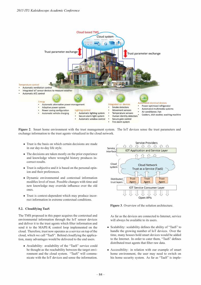
Figure 2. Smart home environment with the trust management system. The IoT devices sense the trust parameters andexchange information to the trust agents virtualized in the cloud network.
• Trust is the basis on which certain decisions are madein our day-to-day life style.
• The decisions are taken mostly on the prior experienceand knowledge where wrongful history produces in-correct results.
• Trust is subjective and it is based on the personal opin-ion and their preferences.
• Dynamic environmental and contextual informationmodifies level of trust. Possible changes with time andnew knowledge may override influence over the oldones.
• Trust is context-dependent which may produce incor-rect information in extreme contextual conditions.
5.2. Cloudifying TaaS
The TMS proposed in this paper acquires the contextual andenvironmental information through the IoT sensor devicesand deliver it to the trust agents which filter information andsend it to the MAPE-K control loop implemented on thecloud. Therefore, trust now operates as a service on top of thecloud, which we call “TaaS”. Behind cloudfying the applica-tion, many advantages would be delivered to the end users.
• Availability: availability of the “TaaS” service couldbe thought as the reachability between the target envi-ronment and the cloud system. “TaaS” will commu-nicate with the IoT devices and sense the information.
Figure 3. Overview of the solution architecture.
As far as the devices are connected to Internet, servicewill always be available to its users.
• Scalability: scalability defines the ability of “TaaS” tohandle the growing number of IoT devices. Over thetime, many houses hold smart devices would be addedto the Internet. In order to cater them, “TaaS” definesdistributed trust agents that filter raw data.
• Accessibility: in relation with our example of smarthome environment, the user may need to switch onhis home security system. As far as “TaaS” is imple-
2015 ITU Kaleidoscope Academic Conference
– 84 –

mented on a cloud network, the user may access theservice through Internet from wherever he is.
• Flexibility: MAPE-K control loop in the cloud aggre-gates trust parameters through the trust agents. Thecloud system enables the trust agents to be deployedin a flexible and distributed manner. By doing so, thesystem allows the IoT devices to communicate trustrelated information.
Fig. 3 describes the solution architecture of the proposed trustmanagement system that consists of distributed trust agents.They produce the trust parameters and filters them to theadaptive trust parameter pool which is on the cloud. The ser-vice consumer layer integrates the clients to the TMS. Thislayer consists of several distributed TMS nodes that exposeinterfaces to the clients. Cloud deploys trust as a service to-gether with the MAPE-K control loop. The feedback systemproduces results based on the past history. In doing that, wenormalize the impact of favorable abnormalities to reducethe expected dynamism. This is because the context has asignificant affect on the level of trust. The raw informationas it is will happen to produce incorrect decisions which weovercome with MAPE-K control loops.
6. SYSTEM MODEL
The systems model consists of three layers, service con-sumer layer, cloud network layer, and applications and ser-vice layer. Furthermore, the service consumer layer consistsof open Application Programmable Interfaces (APIs) onwhich clients access the services and trust agents that locallyfilters trust related information to the trust data pool. In sec-ond layer - cloud network is implemented with the service(“TaaS”) which utilizes cloud based computing intelligenceto obtain the corresponding parameters. These parametersare then fed to the MAPE-K feedback control loop that pro-duces the set of trust parameters on which the final decisionis made. However, the process runs over many iterations tomodify a final result based on the past history. Fig. 4 demon-strates this control loop which modifies the current level oftrust and make decisions. In fact, we consider four trustrelated parameters; availability, reliability, response time andcapacity.
• Availability is about making the resources available forusers. The trustworthiness of a system lies on whetherthe resources are available when it is required.
• Reliability defines the level of trust among two enti-ties. A reliable system always produces correct infor-mation.
• Irregularities in response time predicts possible intru-sions in the system. That helps to identify changesfrom normal.
• Finally, capacity contributes to the model by assuringaccessibility in one hand and scalability on the otherhand.
“TaaS” measures the level of trust in terms of these para-meters and finally aggregate them to make the decisions orto continue into a feedback loop that modifies current valuebased on past values. It is done by the analyzer which runsmultiple computing methods for reasoning based on the pro-vided set of parameters. “Planner” transforms reasoning toprocedures which could be directly forwarded to the execu-tors or adapters through which they are converted to deci-sions. If the decision does not fit in the context to be exe-cuted that can be modified with the past history and return itto another feedback loop for modifying. At last, all the para-meters are stored in the adaptive parameter pool on the cloudand accessible by the service providers through applicationand service layer.
Figure 4. State of art of trust agent.
This framework thus provides the flexibility on both clientsand operators and adjust the trust level according to the con-text. The IoT sensor devices send raw data that they collectwhere their representation would differ with respect to whichtrust parameter they are contributing to. For example, a sen-sor that senses the availability would sense the number ofsuccessful ping requests made in a unit time interval whilea sensor that senses reliability would measure the Bit ErrorRate (BER) in the target environment.
As a result, the raw data must be first normalized and trans-formed appropriately to generate the trust value that depictsthe current state with respective to the trust parameter. Sincethis value only describes the present status, we made an ex-tension to that to integrate it with the previous history ap-propriately. In a nutshell, this complete process, where werepresent the state as a combination of both history and thecurrent state can be thought of as a feedback loop. Thereby,the MAPE-K control feedback loop comes into the model.Herein, a trust parameter for a IoT device d at a time t can beevaluated using Eq. (1).
Pd,t = (αPd,t−1 + (1 − α)Cd,t)1b (1)
Trust in the Information Society
– 85 –

Cd,t =[−s(V0 − Vd,t)
V0 − Vminr1 +
s(Vd,t − V0)Vmax − V0
r2
](2)
Thus, the same parameter at time t − 1 is represented asPd,t−1. Cd,t represents the current value for the trust ob-tained via transformation of the sensor raw data using Eq. (2).In Eq. (1), α is the weight given on the history which shouldbe a value between 0 and 1. The value b is a parameter thatdefines by how much the calculated trust values are to be aug-mented or diminished. A value slightly greater than 1 wouldresult in an augmented trust level while a value slightly lessthan 1 would result in a diminished trust value. This parame-ter could be set based on the dynamic nature of the systemsuch that the effect on the trust due to the high variations arecompensated. In Eq. (2) parameters of the format Vk are withrespect to the raw data that is received from IoT sensor. Themaximum raw data value that can be generated by the sensoris given by Vmax while the minimum is given by Vmin. Theraw data value update sent by a sensor about the device d ata time t is given by Vd,t.
The Pd,t value evaluated by Eq. (1) always falls between -1 and 1. It reaches 1 at the highest level of trust while thevalue will remain around 0 when there is no trust on the de-vice (the fact that device is neutral with respect to others).At the same time, it remains at 0 when there is no data toevaluate the trust, for example when a device is just added tothe system. In case, if the device is untrustworthy and maycause a damage on others, then the value would reach -1. V 0
determines the value coming from the sensor that would re-sult a zero value when normalized and transformed. A valueVd,t which is less than V0 can lead to a negative value for thetrust parameter. The value for r1 and r2 in Eq. (2) must beselected as follows:
• if Vd,t < V0 then r1 = 1 and r2 = 0
• if Vd,t >= V0 then r1 = 0 and r2 = 1
The value for s must be selected based on the fact whetherthe raw data values received from the sensor is directly pro-portional or inversely proportional to the trust. When theparameter is directly proportional with trust, for examplethe number of successful ping request, s should be positive,i.e. 1. When it is inversely proportional to trust, for examplethe BER, then s should be negative, i.e. -1.
The formula we discussed so far only calculates a single trustparameter. The total trust of a system actually depends onmultiple such parameters. Therefore, finally all the differ-ent parameters evaluated using Eq. (1) must be integrated toevaluate the effective trust level. Total trust can be evaluatedby using weighted sum as given in Eq. (3). Here the effectivetotal trust for a device d at time t denoted by Td,t. A trustparameter calculated using Eq. (1) is depicted as (Pd,t)i andthere are n number of such different parameters. The respec-tive weights assigned to each of those trust parameters aredenoted by βi.
Td,t =n∑
i=1
βi(Pd,t)i (3)
7. SIMULATION AND RESULTS
We simulate the proposed model for a smart home environ-ment by using Matlab. We evaluate four parameters, namelyavailability, reliability, response time and capacity. First, forevaluating availability, we checked whether the devices arealive and reachable by sending out a fix number of ping re-quests. The number of responses thus, depends up on theroute to the target device. Furthermore, any hardware failurewill also happen not to receive any response. Then, evalu-ation of reliability was measured by simulating the possibleBER on the target environment. Next, the response time wasevaluated based on the round trip time whereas finally, thecapacity was evaluated based on the number of current ses-sions on a device and the maximum number of connectionsto an IoT device.
The calculations are based on Eq. (1) and Eq. (2) discussedin previous section. The value for α for the trust parame-ters availability, reliability, response time and capacity wasset to 0.8, 0.8, 0.8 and 0.9 respectively. The value for b wasset to 1.16. Fig. 5 describes level of trust against availabil-ity, reliability, response time and capacity. The graphs withfeedback demonstrate the level of trust when the trust proto-col is applied. Without feedback demonstrates when it is notapplied, where huge variation of level of trust can be seenover time. The significance here is the adaptation of MAPE-K control loop to improve the consistence of level of trust.That is because dynamic systems are highly vulnerable andmay change their behavior/level of trust quite fast. To complythese needs, the framework applies history across the MAPE-K control loop in order to reduce impulses that misguide theTMS.
Figure 6. Effective level of trust. (Aggregated availability,reliability, response time and capacity)
In doing so, we make sure the framework will not produce in-correct decisions at last. Finally, we integrate these trust pa-rameters to obtain the effective level of trust. Fig. 6 presentsthe effective level of trust on which the decisions would be
2015 ITU Kaleidoscope Academic Conference
– 86 –

Figure 5. The subplot describes level of trust against availability, reliability, response time and capacity.
made. Once, the results are integrated, the target environ-ment still produces highly varying set of information which isnot usable to make decisions. With our framework, we man-aged to normalize the results and let them fall within a shortrange which may alter based on the current state. Therefore,applied the framework the decisions made becomes trustwor-thy over the time. However, having a long history more ac-curate decisions could be made while reducing the seen dy-namism when no feedback is applied.
8. CONCLUSION
Based on in-depth understanding of trust establishmentprocess and quantitative comparison among trust establish-ment parameters, this paper presents an autonomic trustmanagement framework for cloud based and highly dynamicIoT applications and services. We are increasingly awareof the necessity of eliminating the influence upon the eval-uation results affected by malicious recommendation anddefamation behaviors of a third party. In this framework, weadopt MAPE-K feedback control loop to evaluate the levelof trust in an IoT cloud ecosystem. To evaluate the frame-work, we have developed a simulation framework. Thereby,we demonstrate consistency of the level of trust which isimportant with many IoT based dynamic applications andservices. Apart from that, referring to the history of therecords we enhance the level of trust at the same time. How-ever, deployed the system, we expect it to improve furtheras history will accumulate over time. The trust managementframework proposed for cloud based IoT system have beenextensively studied with respect to their capability, availabil-
ity, reliability and response time in practical heterogeneouscloud environment and their implementabilty. In the evalua-tion, it is evident that contributions from different parameterscould be customized to fit into a specific context as it wouldbe needed by a client. This enhances the flexibility of thesystem and let users to customize on their own need.
9. REFERENCES
[1] Luigi Atzori, Antonio Iera, and Giacomo Morabito,“The internet of things: A survey,” Computer networks,vol. 54, no. 15, pp. 2787–2805, 2010.
[2] Jayavardhana Gubbi, Rajkumar Buyya, Slaven Maru-sic, and Marimuthu Palaniswami, “Internet of Things(IoT): A vision, architectural elements, and future di-rections,” Future Generation Computer Systems, vol.29, no. 7, pp. 1645–1660, 2013.
[3] Fenye Bao and Ing-Ray Chen, “Dynamic trust man-agement for internet of things applications,” pp. 1–6,2012.
[4] Matt Blaze, Joan Feigenbaum, and Jack Lacy, “Decen-tralized trust management,” pp. 164–173, 1996.
[5] Riaz Ahmed Shaikh, Hassan Jameel, Brian J d’Auriol,Heejo Lee, Sungyoung Lee, and Young-Jae Song,“Group-based trust management scheme for clusteredwireless sensor networks,” IEEE Transactions on Par-allel and Distributed Systems, vol. 20, no. 11, pp. 1698–1712, 2009.
Trust in the Information Society
– 87 –

[6] Fenye Bao, Ing-Ray Chen, MoonJeong Chang, and Jin-Hee Cho, “Hierarchical trust management for wirelesssensor networks and its applications to trust-based rout-ing and intrusion detection,” IEEE Transactions on Net-work and Service Management, vol. 9, no. 2, pp. 169–183, 2012.
[7] Javier Lopez, Rodrigo Roman, Isaac Agudo, and Car-men Fernandez-Gago, “Trust management systems forwireless sensor networks: Best practices,” ComputerCommunications, vol. 33, no. 9, pp. 1086–1093, 2010.
[8] Sheikh Mahbub Habib, Sebastian Ries, and MaxMuhlhauser, “Towards a trust management system forcloud computing,” pp. 933–939, 2011.
[9] Hassan Takabi, James BD Joshi, and Gail-Joon Ahn,“Security and privacy challenges in cloud computingenvironments,” IEEE Security & Privacy, , no. 6, pp.24–31, 2010.
[10] Kai Hwang and Deyi Li, “Trusted cloud computingwith secure resources and data coloring,” Internet Com-puting, IEEE, vol. 14, no. 5, pp. 14–22, 2010.
[11] K.M. Khan and Q. Malluhi, “Establishing Trust inCloud Computing,” IT Professional, vol. 12, no. 5, pp.20–27, Sept 2010.
[12] Michael Armbrust, Armando Fox, Rean Griffith, An-thony D Joseph, Randy Katz, Andy Konwinski, GunhoLee, David Patterson, Ariel Rabkin, Ion Stoica, et al.,“A view of cloud computing,” Communications of theACM, vol. 53, no. 4, pp. 50–58, 2010.
[13] Siani Pearson and Azzedine Benameur, “Privacy, secu-rity and trust issues arising from cloud computing,” pp.693–702, 2010.
[14] Ryan KL Ko, Peter Jagadpramana, Miranda Mowbray,Siani Pearson, Markus Kirchberg, Qianhui Liang, andBu Sung Lee, “TrustCloud: A framework for account-ability and trust in cloud computing,” pp. 584–588,2011.
[15] Zheng Yan, Peng Zhang, and Athanasios V Vasilakos,“A survey on trust management for Internet of Things,”Journal of network and computer applications, vol. 42,pp. 120–134, 2014.
[16] Paul Manuel, “A trust model of cloud computing basedon Quality of Service,” Annals of Operations Research,pp. 1–12, 2013.
[17] Dong Chen, Guiran Chang, Dawei Sun, Jiajia Li, JieJia, and Xingwei Wang, “Trm-iot: A trust managementmodel based on fuzzy reputation for internet of things,”Computer Science and Information Systems, vol. 8, no.4, pp. 1207–1228, 2011.
[18] Mohamed Firdhous, Osman Ghazali, and Suhaidi Has-san, “Trust management in cloud computing: a criticalreview,” arXiv preprint arXiv:1211.3979, 2012.
[19] Talal H Noor and Quan Z Sheng, “Trust as a service:a framework for trust management in cloud environ-ments,” pp. 314–321, 2011.
2015 ITU Kaleidoscope Academic Conference
– 88 –
THE IMPACT OF CLOUD COMPUTING ON THE TRANSFORMATION OF
HEALTHCARE SYSTEM IN SOUTH AFRICA
Thembayena Mgozi
University of Pretoria, Graduate School of Technology Management, Department of Engineering and
Technology Management, South Africa
Richard Weeks
University of Pretoria, Graduate School of Technology Management, Department of Engineering and
Technology Management, South Africa
ABSTRACT
An increasing number of organisations around the world
are making use of information and communications
technology (ICT) for health (eHealth) to address healthcare
challenges. This includes aggregating vast amounts of data
from various sources to create evidence for policy and
decision making. However, the eHealth initiative in South
Africa is hindered by unreliable ICT platforms. This
research study is designed to leverage eHealth and propose
a conceptual cloud computing model to improve healthcare
service delivery. The aim of this research study is to
instigate new collaborative efforts for the creation of
evidence value-based healthcare system. The findings attest
that the sensitive nature of clinical data remains a
challenge. Similarly, the South African government should
resolve concerns on regulatory frameworks for proper
governance of eHealth standards implementation, whilst
accelerating healthcare improvements within the public
health sector in particular.
Keywords— Information and communications
technology, Cloud computing, Healthcare
1. INTRODUCTION
The following citation from the Department of Health
(DoH) puts matters into perspective concerning healthcare
system effectiveness in South Africa [6]: “Although large
sums of money have been used to procure health
Information and Communications Technology (ICT) and
Health Information Systems (HIS) in South Africa in the
past, the ICT and HIS within the public health system is not
meeting the requirements to support the business processes
of the health system thus rendering the healthcare system
incapable of adequately producing data and information
for proactive management and for monitoring and
evaluating the performance of the national health system.
This results from the lack of an overarching technology
policy framework and supporting regulations to inform ICT
procurement and management processes”.
Porter and Guth [18] also make similar observations in
relation to the efforts to reform the German healthcare
system by contending that, “the future demographic shifts
and innovations in medical technology threaten to further
accelerate spending and destabilise the system”. According
to [18], nearly every government is now asking “how can
we design a healthcare system that produces better value
for the money we spend”.
Based on these observations by [18] in relation to the
healthcare system reform in Germany, it could be argued
that the healthcare system challenges are not confined only
within the boundaries of the developing world. These
interpretations of evidence also hold true as reiterated by
[16] relative to the healthcare system reform in the United
States (U.S.) in that: “Despite many waves of debate and
piecemeal reforms, the U.S. health care system remains
largely the same as it was decades ago. We have seen no
convincing approach to changing the unsustainable
trajectory of the system, much less to offsetting the rising
costs of an aging population and new medical advances”.
As noted by [12], an inability to communicate and the lack
of information technology (IT) standards undermine the
ability of IT to enable value measurement and to restructure
care delivery around the integrated care for medical
conditions. These revelations conform to Porter’s [17]
strong belief that the fundamental issue in healthcare is not
necessarily access, volume, convenience or cost estimation;
but the value for patients.
2. NATIONAL E-HEALTH STRATEGY
The World Health Organisation defines eHealth as the use
of ICT for health to treat patients, conduct research, and
educate the health workforce, track diseases and monitor
public health related activities [28].
978-92-61-15821-7/CFP1538E-ART © 2015 ITU Kaleidoscope– 89 –

The DoH alludes that this short definition of eHealth covers
vast domains, which includes Electronic Health Records
(EHRs) for sharing of patient data at the points of care [5].
It is worth mentioning that the South African Medical
Research Council is at the centre of developments for
eHealth to deliver on its new role as a World Health
Organisation collaborating centre for the Family of
International Classifications [25]. In addition, the Technical
Advisory Committee of the National Health Council is
responsible to provide technical oversight required to
ensure proper implementation of eHealth strategy [5].
These initiatives in South Africa are in agreement with the
fifty-eighth World Health Assembly resolution adopted in
2005, established an eHealth strategy for World Health
Organisation member states. In a similar viewpoint, the
DoH adopted an eHealth strategy for South Africa to lay
solid requisite foundations for future integration and
coordination of eHealth initiatives in the country [5]. It was
noted that the implementation of the National Health
Insurance (NHI) was intended to provide universal
coverage through eHealth initiatives [8].
Basically, the DoH has embarked on strategies aimed at the
primary prevention of non-communicable and chronic
diseases through educating individuals, households and
communities on the benefits of healthy lifestyles [6]. The
programme involves the utilisation of community health
workers through a re-engineered and integrated Primary
Health Care system. This is a collective effort, which
involves other departments such as the Department of
Social Development as well as the Department of Trade and
Industry [7]. These programmes started after 1994, whereby
the information systems of the public health sector were
overhauled to support the new Primary Health Care
approach aimed at changing the South African healthcare
landscape. These initiatives were later endorsed in the
national parliament in 1997, by then, the Minister of Health
Dr. N.C. Dlamini Zuma, in the newly democratic South
African government of Dr. Nelson Mandela [4].
The NHI then becomes an integral part of a regenerated
initiative underpinned by Primary Health Care in changing
the face of care service delivery in South Africa [8]. This
initiative is based on a R300 billion NHI project, regarded
as one of the most complex and multi-disciplinary in nature
ever undertaken by the South African Department of Health
[22]. The suggestion by the South African National AIDS
Council (SANAC) is that the South African government
should increase the funding of public health services closer
to 5% of GDP [26].
The importance of ICT towards the implementation of the
NHI cannot be overemphasised. In a report, “The National
Strategic Plan 2012/16 on Human Immunodeficiency Virus
(HIV), and Tuberculosis (TB)”, SANAC states that, “The
primary focus of Strategic Objective 3 (SO 3) is to achieve
significant reduction in deaths and disability as a result of
HIV and TB”.
Through the adoption of eHealth strategy, ICT remains a
critical enabling factor to achieve the universal access to
affordable and good quality health outcomes, diagnosis,
treatment and care, as an essential part of the SANAC’s
Strategic Objective 3 [26]. It is not surprising for the DoH
to accentuate that globally, ICT has emerged as a critical
enabling mechanism to develop a HIS, capable of
strengthening healthcare system effectiveness [5]. Enthoven
and Tollen [1] are also in agreement that the evidence based
healthcare system can be supported by the state-of-the-art
IT platforms. However, [12] contend that although IT can
enable a new value-based approach to care delivery and
measurement; it alone cannot fix a broken healthcare
system.
As argued by [17] on the basis that part of the six
fundamentals strategic agendas to reform healthcare
delivery is to “Create an Enabling IT Platform”.
Correspondingly, [12] agrees with [17] and attests that the
organisations should utilise IT to enable restructuring of
care delivery and measuring results rather than treating it as
a solution itself. Notable in this regard, [10] similarly
conclude that cloud computing technologies provide a
promising approach to address the IT needs of integrated
care delivery structures in the future.
Furthermore, [2] quite pertinently states that cloud
computing will greatly impact the organisations that are
involved in a vast array of IT equipment, software, support,
and services. As illustrated in figure 1, it is important to
note that the healthcare service quality, accessibility,
reliability and affordability should be sustainable
throughout the care cycle of the healthcare system [17].
Figure 1. The 8 fundamental elements of cloud
computing [2].
2015 ITU Kaleidoscope Academic Conference
– 90 –

These noteworthy revelations are also supported by [9] due
to the fact that cloud computing enables platforms of
collaboration combined with rich abilities of
communications and coordination. This includes opening up
new and significantly more efficient business models. Frank
and Moore [9] make an observation that cloud computing
adoption models have a velocity, which has not been
witnessed in technology space before. The emergence of
cloud computing is observed as driving the need for better
collaboration, coordination and interaction in the health
sector [10].
3. OBJECTIVES OF THE STUDY
Preliminary investigations suggest that the healthcare
system is not meeting the requirements to harness the vast
amount of data to address multiple healthcare challenges in
South Africa. As cloud computing looks set to scale up
EHRs globally, in South Africa it is hindered by persistent
reliance on using unreliable ICT platforms.
To achieve a collaborative and coordinated care that
harnesses clinical data sharing, South Africa should find a
proper balance between protecting personal health data
from misuse and sharing data to accelerate healthcare
improvements. This includes resolving concerns on
regulatory frameworks for proper governance of eHealth
standards implementation, whilst creating evidence value-
based healthcare system.
The following list of formulated questions gives more
insight into the problem statement:
a) What is cloud computing’s real potential in the
health sector?
b) How has the evolution of healthcare ICT
infrastructure changed the nature of healthcare
service delivery in South Africa compare to
other developing countries?
c) What primary factors are inhibiting the use of
cloud computing services within the South
African healthcare environment?
d) What opportunities does cloud computing
present to health sector for IT managers, and
individuals?
e) What are the primary concerns for healthcare IT
executives have about implementing emerging
IT platforms especially one that may not be
entirely familiar with including cloud
computing solutions?
f) What are the challenges associated with
acquiring and implementing large software
applications, such as Electronic Medical
Records (EMRs) and EHRs?
g) What are the main challenges facing the
successful adoption and implementation of the
national eHealth strategy within the healthcare
environment in South Africa?
h) How has the lack of collaboration, coordination
and interaction affected the implementation and
adoption of the state-of-the-art ICT solutions
within the healthcare environment in South
Africa?
In order to address the research problem appropriately, the
primary objective of the study is to identify key factors that
are hindering the transformation of the healthcare system in
South Africa. The objectives also take into account the new
collaborative efforts for the creation of evidence value-
based healthcare system. A key focus of a cloud-based open
source computing platform is facilitating the flow of data
from disparate sources into the clinical care process.
This will ensure that optimal treatments are offered to each
individual patient at the point of care. Advances in cloud
computing are starting to facilitate the development of
platforms for effective data capture, creation, storage,
search, sharing, modelling, transfer, analysis, visualisation,
and manipulation of massive data.
4. CLOUD COMPUTING ADOPTION IN
HEALTHCARE
The emergence of cloud computing in healthcare is
increasingly gaining acceptance as an effective means of
improving healthcare service delivery globally. According
to [19], healthcare organisations are rapidly adopting cloud
computing to enhance competitiveness within the health
sector in China. This is part of the national health reform
plan in line with the “Healthy China 2020” vision. Shen,
Keskin and Yang [29] concur that cloud computing is being
developed everywhere in China to different extents.
Bojanova and Samba [11] quite pertinently note that cloud
computing is being adopted around the world by many
countries through government programmes. This includes
the U.S. Government’s “Cloud Computing Mall” for
government agencies, Japanese Government’s
“Kasumigaseki Cloud” and the U.K. Government’s “G-
Cloud” infrastructure project initiative. As a member of the
BRICS nations (Brazil, Russia, India, China and South
Africa), South Africa could stand to gain by tapping into
collaborative best practices from other countries.
Through the implementation of the “National Development
Plan: 2030 vision” on promoting health, the Presidency
Republic of South African Government can also follow on
the footsteps of other developing nations: Brazil, Russia,
India and China. This insightful consideration could help
South African government to leapfrog the leaders already
gained vast experiences on cloud computing adoption
within the healthcare environment in their respective
countries. This includes the implementation of strategic
partnerships to global health delivery system to reduce costs
and lower the difficulty of enabling ICT infrastructure.
In the same way Marston et al. [23] also explain that to
realise full potential of cloud computing services means
removing the roadblocks to enabling IT-as-a- Service and
overcoming the challenges of security, quality of experience
and governance [23].
Trust in the Information Society
– 91 –

In order to resolve the identified challenges, healthcare
organisations should collaborate with the world’s top IT
companies, international organisations and institutions that
possess a great deal of expertise on eHealth related
programmes. For that reason, it is important to note that the
foreign based companies must familiarise themselves to the
South African recommended eHealth interoperability
standards in table 1 [15]. The use of interoperability
standards is a core requirement to effectively integrate
patient health information (PHI) from different medical
systems.
As Rashid Al Masud [24] points out, in comparisons to
locally-housed IT resources, cloud computing may improve
security because Software as a Service (SaaS) providers are
able to devote resources to solve security issues that many
customers cannot afford. Cloud computing services are the
enabling fabric of Health IT platforms [11], dramatically
reducing the barriers to entry for developing economies.
This includes transforming the cost base, agility and
mobility of a well-developed HIS [11].
Table 1. Recommended standards for eHealth
interoperability in South Africa [15].
Porter’s [16] suggestion that transforming the healthcare
system requires a holistic and phased approach as opposed
to attempting to resolve all issues in one stroke, is duly
noted. The DoH supports Porter’s [16] suggestion by
contending that the eHealth strategy aims to support the
medium-term priorities of the public health service delivery,
whilst paving the way for future requirements [5].
This includes laying the requisite foundations for future
integration and coordination of eHealth initiatives in the
country. Figure 2 illustrates the execution of cloud
computing principles to guarantee national and international
compatibility, eHealth standards interoperability, open
architecture, modularity and capability for flexible capacity
upgrades.
Figure 2. Cloud computing architecture for adaptive
applications [21]
5. CLOUD COMPUTING CONCEPTUAL MODEL
The World Health Organisation put emphasis on the fact
that developing HIS will depend upon how institutions
function and interact, including ICT policy makers, in an
effort to improve healthcare coverage, availability,
dissemination and use of EHRs through the utilisation of
computers, e-mail and internet access [27]. The DoH further
reveals that the regulatory framework in South Africa is
designed to place emphasis on the inter-linkages between
quality assurances through regulation for the
implementation of quality standards [7].
Of further significance, [14] also attest that a single
organisation cannot provide all the technologies necessary
to address healthcare system challenges. The argument is
that interaction is needed between the medical schools and
organisations, as well as between institutions and internet
service providers, communication service providers and
medical device developers as illustrated in figure 3.
Figure 3. Proposed cloud computing model for the
transformation of healthcare system in South Africa
The DoH agrees that eHealth is still facing many cavities in
South Africa including the lack of clearly defined eHealth
interoperability standards [5].
2015 ITU Kaleidoscope Academic Conference
– 92 –

Other key concerns involve data integration as well as data
security and privacy, broadband coverage and internet
penetration, regulatory compliance standards, and the lack
of competent professionals. While recognising the
importance of instigating quality standards in the health
sector, the World Health Organisation further acknowledges
that there is a need to coordinate and align partners on an
agreed framework for the improvement of healthcare system
[27].
6. APPROACH TO RESEARCH DESIGN
To understand the dynamics associated with cloud
computing adoption, [13] conducted interviews in 15
software organisations. The questionnaires were selected for
an in-depth analysis based on a relatively progressive use of
cloud computing and testing.
By the same token, [14] highlight that it is important to
conduct interviews with the stakeholders concerned, to test
the validity and completeness of the proposed model. In
addition, Deloitte quite pertinently states that through
analysis of the three stakeholder perspectives, it is possible
to define an eHealth Architecture that identifies all the ICT
components necessary to deliver eHealth Vision [3].
The cognitive behind such claims is that the eHealth
architecture is structured into three segments that contain
interrelated components necessary to delivery eHealth
vision, highlighted as follows [3]:
a) The eHealth Solutions describe the systems and
tools that consumers, care providers and health
care managers will use to interact with the health
system.
b) The eHealth Infrastructure describes the specific
eHealth computing infrastructure components
necessary to support the collection and sharing of
structured and meaningful electronic information
across the health system.
c) The eHealth Enablers describe the ICT
components that must be in place to support the
delivery of the overall eHealth strategy.
In this study, the participants consist of Managing
Directors, Chief Technology Officers and Executives. The
participant’s roles were mapped according to the
corresponding research subjects in table 2.
Table 2. Research subjects
7. RESULTS
This section reviews responses from interviews conducted
with respondents as per respective research subjects
discussed in previous sections. The questionnaires were
designed in such a manner so as to address a particular
focus area, which is in agreement with proposed conceptual
model in figure 3.
7.1. Research Subject 1: Healthcare System in South
Africa
The collective viewpoint is that the eHealth strategy
implementation and adoption is facing major stumbling
blocks defined as challenges by the DoH within the South
African context. Privacy and security is described as the
biggest concern to the adoption of cloud computing within
the health sector.
Therefore, this clear indicates that privacy and security are
some of the critical areas that should be addressed and
controlled for proper adoption of cloud computing within
the South African healthcare environment.
South African government should advance regulatory policy
frameworks in order to ensure effective interoperability
standards to address key concerns surrounding privacy and
security of sensitive medical data for clinical decision
making.
7.2. Research Subject 2: Healthcare IT Service
Providers
The insight gained is that the healthcare IT service
providers have the capacity to delivery large-scale software
platforms. However, the respondents are concerned about
the key issues inhibiting the adoption of the state-of-the-art
ICT platforms within the health sector in South Africa.
The major challenges highlighted include ICT infrastructure
and high bandwidth costs, disparate systems and
fragmentation of PHI systems.
On numerous occasions the respondents mentioned that
there is a lack of governing principle on who owns the
patient records. This includes lack of local standards
adoption, policies which govern the EMRs, fundamental
interoperability standards, and integration of dissimilar
systems. If the identified issues are resolved and controlled,
the respondents are of the opinion that cloud computing is a
possible solution to improve healthcare service delivery.
The respondents consider eHealth strategy document as the
first step towards resolving the identified challenges.
7.3. Research Subject 3: Internet Service Provider
Overall, the respondents are of the view that the national
broadband landscape has not transformed or changed the
nature of healthcare service delivery in South Africa over
the past decade.
Trust in the Information Society
– 93 –

The respondents argued that South Africa needs to adopt
robust national eHealth policy standards and the
commitment to execute within the agreed policy
frameworks. There is a need for collaboration between the
stakeholders to improve healthcare service delivery through
ICT in South Africa. This includes a consolidated strategy
around how the healthcare system is going to be
implemented in South Africa.
To accelerate the adoption of cloud computing platforms,
the implementation of strategic partnerships will help South
African government to reduce costs and lower the difficulty
of enabling ICT infrastructure. This includes developing a
strategic vision on IT as an enabling platform for the
creation of value-based healthcare system.
7.4. Research Subject 4: Cloud Computing Service
Provider
The respondents were mainly concerned about the
legislative frameworks governing the health sector. The
respondents are of the view that the lack of coordinated
regulatory framework in South Africa is the biggest
challenge for the adoption of cloud computing. According
to the respondents, the legislative frameworks and
unwillingness for the companies to share information are
some of the main issues hindering cloud computing
adoption. This includes the sensitivity nature on PHI, which
makes the organisation reluctant to move to the cloud
computing platforms.
To resolve these challenges, it is necessary to achieve
consensus between government, healthcare organisations
and other key stakeholders to advance the development of
eHealth initiate. Although the ICT has evolved in the
private health sector, the respondents argued that the
advanced ICT platforms are still lacking in the public health
sector.
7.5. Research Subject 5: IT Specialist Company
The respondent mentioned that the organisations are now
focusing more on the benefits offered by cloud computing
and less on the challenges associated with ICT
infrastructure. Furthermore, the respondent talks about
enterprise mobility as one of the biggest benefits within the
healthcare environment. This includes providing flexibility
for health professionals and nurses to be more mobile
across regions and in different parts of the world.
The respondent notes that cloud computing based
applications are now available much easier and quicker. For
example, the applications can be developed in India and be
available in South Africa via cloud computing platforms.
This clearly indicates that rapid advances in enabling ICT
infrastructure can accelerate cloud computing adoption
through partnerships with IT specialist companies.
8. CONCLUSION
The DoH describes eHealth as an integral part of the
transformation and improvement of healthcare services in
South Africa [5]. This includes enabling the delivery on the
health sector’s Negotiated Service Delivery Agreement for
2010-2014. In order to best overcome key factors that are
hindering the transformation of the healthcare system, the
DoH has put the programme of work that will lead eHealth
strategy implementation. The DoH recognises that this
programme of work should be underpinned by certain key
principles at National and Provincial Departments of Health
respectively. Finding competent data scientists to analyse
healthcare data and extract value appear to be one of the
major challenges across healthcare organisations.
Following the interpretation of the findings and supported
arguments using existing literature review analysis, it can be
concluded that the stated research objectives were achieved.
Of further significance in this regard is the connection that
existed between the results obtained and the literature
review analysis. This noteworthy correlation was
demonstrated by discussing the findings with respect to the
research objectives.
The conclusive finding is that the HIS is not meeting the
requirements capable of improving health system’s
effectiveness. Although cloud computing looks set to scale
up EHRs globally, in South Africa it is hindered by
persistent reliance on using unreliable ICT platforms.
Therefore, it may seem counterintuitive for the South
African government to implement cloud computing in the
public health sector whereas the mandate to strengthen
healthcare system effectiveness is not met.
The DoH quite pertinently admitted that the eHealth is still
facing many cavities including the lack of clearly defined
eHealth interoperability standards. Hence, South African
government should advance regulatory policy frameworks
in order to ensure effective interoperability standards to
address key concerns surrounding privacy and security of
sensitive medical data for clinical decision making.
Furthermore, practitioners and researchers should consider
investigating and accumulating information to determine the
best possible ways of adopting cloud computing platforms
within the South African healthcare environment.
2015 ITU Kaleidoscope Academic Conference
– 94 –
REFERENCES
[1] A.C. Enthoven, and L.A. Tollen, “Competition In Health
Care: It Takes Systems To Pursue Quality and Efficiency”,
White paper, Health Affairs, 2012.
[2] D.C. Wyld, “The cloudy future of government it: Cloud
computing and the public sector around the world”,
International Journal of Web and Semantic Technology
(IJWesT), vol.1 no.1, pp.1-20, 2010.
[3] Deloitte, “National E-Health and Information Deloitte”,
Principal Committee, 30 September, Adelaide, Australia,
2008.
[4] Department of Health, "White Paper for the Transformation
of the Health System in South Africa”, 1997.
[5] Department of Health, “National eHealth Strategy: South
Africa 2012/13-2016/17”, 2012.
[6] Department of Health, “National Service Delivery Agreement
(NSDA) Report 2010-2014”, 2010.
[7] Department of Health, “Towards Quality Care for Patients:
National Core Standards for Health Establishments in South
Africa”, 2011.
[8] Focus Reports, “Leading the Pharma Model for a Continent”,
White paper, Pharma Dynamics, 2012.
[9] G. Moore, and M. Frank, “The Future of Work: A New
Approach to Productivity and Competitive Advantage”,
White paper, Cognizant, 2010.
[10] H.H. Chang, P.B. Chou, and S. Ramakrishnan, “An
Ecosystem Approach for Healthcare Services Cloud”, 2009
IEEE International Conference, 21-23 October.
[11] I. Bojanova, and A. Samba, “Analysis of Cloud Computing
Delivery Architecture Models”, 2011 IEEE Workshops of
International Conference, 22-25 March.
[12] J. Teperi, M.E. Porter, L. Vuorenkoski, and J.F. Baron, “The
Finnish Health Care System: A value based perspective”,
Sitra Reports 82, Helsinki, 2009.
[13] L. Riungu-Kalliosaari, O. Taipale, and K. Smolander,
“Testing in the Cloud: Exploring the Practice”, Software,
IEEE, vol.29 no. 2, pp.46-51, 2012.
[14] L. Van Dyk, M. Groenewald, and J.F. Abrahams, “Towards a
Regional Innovation System for Telemedicine in South
Africa”, 2010 Second International Conference, 10-16
February.
[15] M. Chetty, “Information and Communications Technology in
support of NHI, NHI. 4th Biennial Conference. Council for
Scientific and Industrial Research (CSIR), South Africa”,
2012.
[16] M.E. Porter, “A Strategy for Health Care Reform: Toward a
Value-Based System”, The New England Journal of
Medicine, vol.361 no.2, pp.109-112, 2009.
[17] M.E. Porter, “Value-Based Health Care Delivery, Yale
School of Management, Harvard Business School, 2010.
[18] M.E. Porter, and C. Guth, “Excerpts from Redefining German
Health Care: Institute for Strategy and Competitiveness”,
2012.
[19] N. Kshetri, “IT in the Chinese Healthcare Industry”, IT
Professional, vol.15 no.1, pp.12- 15, 2013.
[20] Presidency Republic of South African Government, “National
Development Plan: 2030 vision”, Republic of South Africa,
Cape Town, 2011.
[21] Q. Zhu and G. Agrawal, “Resource Provisioning with Budget
Constraints for Adaptive Applications in Cloud
Environments”, IEEE Transactions,vol.5 no.4, pp.497-
511,2012.
[22] R.V. Weeks, and S. Benade, “A service science and
technology healthcare framework: A South African
perspective”, Prospective paper submitted for consideration,
Graduate School of Technology Management, University of
Pretoria, 2013.
[23] S. Marston, L. Zhi, S. Bandyopadhyay, and A. Ghalsasi,
“Cloud Computing-The Business Perspective”, 2011 44th
Hawaii International Conference, 4-7 January.
[24] S.M. Rashid Al Masud, “A Novel Approach to Introduce
Cloud Services in Healthcare Sectors for the Medically
Underserved Populations in South Asia”, International
Journal of Engineering Research and Applications, vol.2
no.3, pp.1337-1346, 2012.
[25] South African Medical Research Council, “Medical Research
Council Strategic Plan: 2012/13-2016/17”, South Africa,
2012.
[26] South African National AIDS Council, “National Strategic
Plan (NSP) on HIV, STIs and TB: 2012-2016”, South Africa,
2012.
[27] World Health Organisation, “Health Metrics Network:
Framework and Standards for Country Health Information
Systems”, 2008.
[28] World Health Organisation, “Management of patient
information: Trends and challenges in Member States”,
Global Observatory for eHealth series, Switzerland, 2012.
[29] Y. Shen, J. Yang, and T. Keskin, “The evolution of IT
towards cloud computing in China and U.S.”, 2012
International Conference, 19-21 October.
Trust in the Information Society
– 95 –


SESSION 4
ADVANCES IN NETWORKS AND SERVICES I
S4.1 WhiteNet: A White Space Network for Campus Connectivity Using Spectrum Sensing Design Principles.
S4.2 A DCO-OFDM system employing beneficial clipping method.
S4.3 Adaptive Video Streaming Over HTTP through 3G/4G Wireless Network Employing Dynamic On The Fly Bit Rate Analysis.
S4.4 Cloud Based Spectrum Manager for Future Wireless Regulatory Environment.

WHITENET: A WHITE SPACE NETWORK FOR CAMPUS CONNECTIVITY USINGSPECTRUM SENSING DESIGN PRINCIPLES
Hope Mauwa, Antoine Bagula
University of the western CapeISAT Laboratory, Department of CS
Bellville, 7535, South [email protected], [email protected]
Marco Zennaro
International Centre for Theoretical PhysicsT / ICT4D Laboratory
Strada Costiera 11, Trieste, [email protected]
ABSTRACT
To this day, the technical challenges of accessing TV whitespaces through spectrum sensing can be summed up into itsinability to provide maximum protection to primary usersfrom interference. Yet, off-the-shelf spectrum sensing de-vices, which are emerging on the market at low cost, andthe low computation and implementation complexities of thesensing technique, make them more and more attractive tothe developing world. Building upon “WhiteNet”, a whitespace network management platform for campus connectiv-ity, this paper proposes design principles that can be incor-porated in a spectrum sensing-based white space identifica-tion system to minimise probability of causing interference toprimary users. The principles are designed around the coop-erative spectrum sensing model to further reduce chances ofinterference to primary users. Evaluation of the principleswas done using real-world indoor measurements and basedon a real TV transmitter-allocation at the University of theWestern Cape in Cape Town, South Africa. The results re-veal the relevance of using these design principles in whitespace networking using the emerging White-Fi protocol toboost the capacity of current Wi-Fi campus networks.
Keywords— White-Fi, cooperative spectrum sensing, detec-tion threshold, spectrum sensing principles
1. INTRODUCTION
It has been widely recognized that in many regions of thedeveloping world, poor Internet access in universities and re-search institutions is one of the causes of the scientific dividebetween developed and developing countries. In many ofthese regions, Wi-Fi has played a key role to connect campuscommunities by enabling inter-campus connectivity and ac-cess to the Internet but at lower access bandwidth comparedto research institutions of the developed world. The transi-tion from analog to digital television is a great opportunityto address this bandwidth issue in campus networks by us-ing emerging protocols such as IEEE 802.11af, also referred
Paper accepted for presentation at “Trust in the Information Society”ITU Kaleidoscope Conference, Barcelona, Spain, 9-11 December 2015,http://itu.int/go/K-2015.
to as White-Fi or Super Wi-Fi [1] to boost the current ca-pacity of Wi-Fi networks with bandwidth acquired throughsecondary access to white space (WS) frequency. However,technologies and protocols have yet to mature to provide theproper WS equipment at affordable prices and WS identifi-cation, quantification and allocation techniques have yet toimproved and move from the research boundaries to the im-plementation arena.
Two main approaches of accessing unused spectrum in theTV frequency band (white spaces) for secondary use havebeen suggested in the literature; geo-location database andspectrum sensing. At the moment, there is a trend towardsthe use of only geo-location database approach in the US andEurope [2] as it guarantees high protection of the spectrumincumbents from the interference. The trend is supported bythe development of the protocols such as Protocol to Ac-cess White Space (PAWS) [3] by the Internet EngineeringTask Force (IETF), the IEEE 802.11af standard [4] and theIEEE 802.22 standard [5] to access spectrum database. How-ever, in some regions of Africa, the use of a geo-locationdatabase has been questioned as the best approach to ac-cessing TV white spaces (TVWSs) [6] due to its limitationsand the abundance of TVWSs that nullify the need for strin-gent constraints on primary user protection. In such regions,therefore, spectrum sensing is expected to play a key role asan alternative method of accessing TVWSs.
To this day, technical challenges of accessing TVWSsthrough spectrum sensing without causing interference toprimary users have not been solved completely. In this pa-per, some design principles are being proposed that can beincorporated into a spectrum sensing-based WS identifica-tion system to minimise probability of causing interferenceto the primary users. These principles are designed aroundthe concept of cooperative spectrum sensing. The proposedprinciples are: i) the use of different threshold values andii) the deployment of virtual WSs pricing. These principlesadd an additional layer of protection to primary users afterthe cooperative spectrum sensing layer. The block diagramdepicting the hierarchical flow of how the principles work isdepicted in Figure 1.
The rest of the paper is structured as follows: Section 2 givesa background to some of the challenges of spectrum sensing
978-92-61-15821-7/CFP1538E-ART © 2015 ITU Kaleidoscope– 99 –
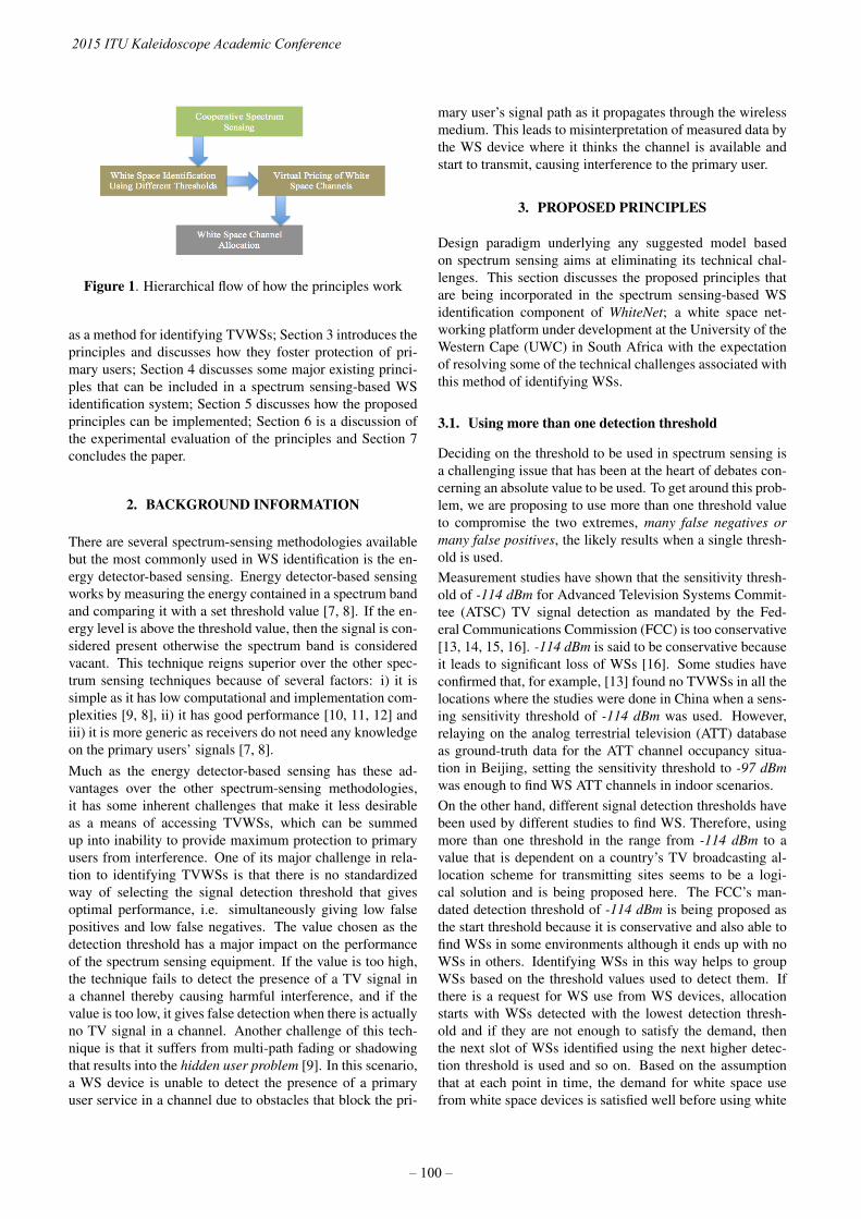
Figure 1. Hierarchical flow of how the principles work
as a method for identifying TVWSs; Section 3 introduces theprinciples and discusses how they foster protection of pri-mary users; Section 4 discusses some major existing princi-ples that can be included in a spectrum sensing-based WSidentification system; Section 5 discusses how the proposedprinciples can be implemented; Section 6 is a discussion ofthe experimental evaluation of the principles and Section 7concludes the paper.
2. BACKGROUND INFORMATION
There are several spectrum-sensing methodologies availablebut the most commonly used in WS identification is the en-ergy detector-based sensing. Energy detector-based sensingworks by measuring the energy contained in a spectrum bandand comparing it with a set threshold value [7, 8]. If the en-ergy level is above the threshold value, then the signal is con-sidered present otherwise the spectrum band is consideredvacant. This technique reigns superior over the other spec-trum sensing techniques because of several factors: i) it issimple as it has low computational and implementation com-plexities [9, 8], ii) it has good performance [10, 11, 12] andiii) it is more generic as receivers do not need any knowledgeon the primary users’ signals [7, 8].Much as the energy detector-based sensing has these ad-vantages over the other spectrum-sensing methodologies,it has some inherent challenges that make it less desirableas a means of accessing TVWSs, which can be summedup into inability to provide maximum protection to primaryusers from interference. One of its major challenge in rela-tion to identifying TVWSs is that there is no standardizedway of selecting the signal detection threshold that givesoptimal performance, i.e. simultaneously giving low falsepositives and low false negatives. The value chosen as thedetection threshold has a major impact on the performanceof the spectrum sensing equipment. If the value is too high,the technique fails to detect the presence of a TV signal ina channel thereby causing harmful interference, and if thevalue is too low, it gives false detection when there is actuallyno TV signal in a channel. Another challenge of this tech-nique is that it suffers from multi-path fading or shadowingthat results into the hidden user problem [9]. In this scenario,a WS device is unable to detect the presence of a primaryuser service in a channel due to obstacles that block the pri-
mary user’s signal path as it propagates through the wirelessmedium. This leads to misinterpretation of measured data bythe WS device where it thinks the channel is available andstart to transmit, causing interference to the primary user.
3. PROPOSED PRINCIPLES
Design paradigm underlying any suggested model basedon spectrum sensing aims at eliminating its technical chal-lenges. This section discusses the proposed principles thatare being incorporated in the spectrum sensing-based WSidentification component of WhiteNet; a white space net-working platform under development at the University of theWestern Cape (UWC) in South Africa with the expectationof resolving some of the technical challenges associated withthis method of identifying WSs.
3.1. Using more than one detection threshold
Deciding on the threshold to be used in spectrum sensing isa challenging issue that has been at the heart of debates con-cerning an absolute value to be used. To get around this prob-lem, we are proposing to use more than one threshold valueto compromise the two extremes, many false negatives ormany false positives, the likely results when a single thresh-old is used.Measurement studies have shown that the sensitivity thresh-old of -114 dBm for Advanced Television Systems Commit-tee (ATSC) TV signal detection as mandated by the Fed-eral Communications Commission (FCC) is too conservative[13, 14, 15, 16]. -114 dBm is said to be conservative becauseit leads to significant loss of WSs [16]. Some studies haveconfirmed that, for example, [13] found no TVWSs in all thelocations where the studies were done in China when a sens-ing sensitivity threshold of -114 dBm was used. However,relaying on the analog terrestrial television (ATT) databaseas ground-truth data for the ATT channel occupancy situa-tion in Beijing, setting the sensitivity threshold to -97 dBmwas enough to find WS ATT channels in indoor scenarios.On the other hand, different signal detection thresholds havebeen used by different studies to find WS. Therefore, usingmore than one threshold in the range from -114 dBm to avalue that is dependent on a country’s TV broadcasting al-location scheme for transmitting sites seems to be a logi-cal solution and is being proposed here. The FCC’s man-dated detection threshold of -114 dBm is being proposed asthe start threshold because it is conservative and also able tofind WSs in some environments although it ends up with noWSs in others. Identifying WSs in this way helps to groupWSs based on the threshold values used to detect them. Ifthere is a request for WS use from WS devices, allocationstarts with WSs detected with the lowest detection thresh-old and if they are not enough to satisfy the demand, thenthe next slot of WSs identified using the next higher detec-tion threshold is used and so on. Based on the assumptionthat at each point in time, the demand for white space usefrom white space devices is satisfied well before using white
2015 ITU Kaleidoscope Academic Conference
– 100 –

spaces identified with higher threshold values, the approachof identifying WSs using different thresholds and startingthe allocation with WSs identified with the lowest thresholdsminimizes the chances of interference to primary users due tofalse negatives than using random or haphazard allocation ofWSs identified with a single threshold. WSs identified withhigher thresholds are the most likely thresholds that may re-sult into interference. The approach also solved the prob-lem of resulting with either too many false negatives or toomany false positives when one threshold is used to identifythe TVWSs.
3.2. Virtual pricing of white spaces
Another principle being proposed in this work to minimizeinterference to primary users from WS devices is to virtual-price WS channels within each group based on some com-mon quantity associated with all WSs. For example, a virtualprice can be given to each WS channel based on the signalstrength detected in each channel with the highest price givento a channel with strongest signal and the lowest price givento a channel with the weakest signal within each group. Asmentioned in subsection 3.1, the groups of WSs are based onthe signal detection thresholds used to identify them. WhenWS devices submit requests for WS use, the cheapest WSchannels within each group are allocated first. In this way,the probability of a WS device causing interference to pri-mary incumbents if there is any false negative within thegroup is minimized since channels that may result into falsenegatives have stronger signals than channels that are actu-ally WSs, and as such, their virtual prices are higher than thechannels that are actually WSs. Consequently, they cannotbe allocated to any WS device unless all the channels thatare actually WSs in that WS channel group are exhausted.
4. EXISTING SPECTRUM SENSING DESIGNMETHODS
This section discusses existing spectrum sensing designmethods that this work considers relevant to the implementa-tion of a spectrum sensing-based WS identification system.
4.1. Cooperative spectrum sensing
Cooperation among sensing equipment is vital for the opti-mal performance of spectrum sensing when used as a methodof identifying white spaces because a network of spectrumsensors sharing sensing information obtained from their in-dividual locations with each other has a better chance of de-tecting the primary user compared to local spectrum sens-ing [9] by a single spectrum sensor. It is due to this rea-son why cooperation between sensing equipment is proposedin the literature as the solution to the hidden user problem[14, 15, 17, 18, 19] that may arise due to multi-path fadingor shadowing. As mentioned in the introduction, our pro-posed principles rely on the results generated from coopera-tive spectrum sensing as the first step to minimising chances
of interference to primary users. If there is a hidden userproblem after cooperative spectrum sensing, then the pro-posed principles help to protect further that hidden user frominterference.
4.2. Channel-clustering and location-clustering
As mentioned in [20] and [21], a spectrum sensing-based WSidentification system must also take spectrum sensor cost asa major consideration in the design of the system as they canbe expensive. To avoid random placement of the energy de-tectors, which could result into either waste of energy detec-tors, i.e., many unnecessary detectors deployed or not guar-antee coverage, i.e., insufficient detectors deployed [20], itis vital to perform channel-clustering and location-clusteringas proposed in [20]. Once the channel clustering and loca-tion clustering is done, the algorithm proposed in [20] canbe used to determine placement positions for the energy de-tectors. Implementing these principles means WSs are cal-culated according to location clusters. Therefore, secondaryusers are required to identify their positions before sending arequest for white space use. For detailed discussion of theseprinciples and how they can be implemented, consult [20].
5. ALGORITHM IMPLEMENTATION
The proposed principles and the existing methods that havebeen discussed in this paper are not environment specific.They are general principles and methods that can be imple-mented in a spectrum sensing-based WS identification sys-tem meant for outdoor or indoor environment. This sectionshows how the proposed principles can be implemented al-gorithmically.
5.1. WS identification using different thresholds
The method for computing TVWSs using different signaldetection thresholds is presented in Algorithm 1. The al-gorithm shows how cooperative spectrum sensing is imple-mented with the principle of varying the detection threshold.The inputs to the algorithm are signal strength values of allthe channels from the frequency spectrum sensors deployedand the channels under consideration. The algorithm firstchecks if a channel under consideration is an already identi-fied WS using any of the previously used threshold values ifany. This is done in lines 4 to 6. This helps to make sure thateach channel is not identified as WS more than once as thethreshold values keep changing. Once it is found that a chan-nel is not an already WS channel, the algorithm compares thesignal strength values for that channel from all the sensorsdeployed from line 9 to 13 to find the representative signalstrength value, which is the strongest signal measured in thatchannel from all the sensors deployed. The strongest signal isused to calculate the relative signal strength for that channelby subtracting the current threshold from it in line 14. Thenthe algorithm checks if the channel is WS by checking if itsrelative signal strength is less than or equal to zero in line 15.
Trust in the Information Society
– 101 –

If it is found to be WS, it is added to the set of WSs for thatdetection threshold in line 16. The process is repeated forall the channels using the current threshold value (lines 3 to20). Once all the channels are considered using the currentthreshold value, the next threshold value is considered (line24) and the process is repeated from the beginning (from line2). This process is repeated until all the threshold values havebeen considered. The output from this algorithm is the set ofsets of WS channels SC identified using different thresholdsand the set of sets of signal strength values SS correspondingto the set of sets of all WS channels SC.
Algorithm 1: Identify white space channels using differentthresholdsinput : Two-dimensional matrix st of size m by n of signal
strength values, setCH = {ch(1), ch(2), ch(3), ..., ch(m)} ofchannels. {m is the number of channels underconsideration; n is the number of sensors deployed}
output: SC = {SC(1), SC(2), SC(3), ..., SC(x)}, wherex is less than or equal to number of thresholdvalues, SS = {SS(1), SS(2), SS(3), ..., SS(x)}.{SC is a set of sets of white space channels; SS is acorresponding set of sets of signal strength valuesof the white space channels}
1 initialize t← startThreshold, x← 1;2 repeat3 for i← 1 to m do4 if SC is not empty then5 check if ch(i) is in any of SC subsets;6 end7 if ch(i) is not found in any SC subsets or SC is
empty then8 strongestSignal← 0;9 for j ← 1 to n do
10 if st[i][j] > strongestSignal then11 strongestSignal← st[i][j];12 end13 end14 rss(i)← strongestsignal − t // rss(i) is
representative relativesignal strength for channel i
15 if rss(i) <= 0 then16 add ch(i) to SC(x);17 add st[i][j] to SS(x)
18 end19 end20 end21 if WS(x) is not empty then22 add SC(x) to SC;23 add SS(x) to SS;24 end25 t← t+ increment, x← x+ 1
26 until t is equal to endThreshold;27 return SC, SS
5.2. Compute virtual prices of WS channels
Once WSs channels have been identified using the differentthreshold values, Algorithm 2 follows to compute their vir-tual prices based on signal strength recorded in each channel.
Algorithm 2: Compute virtual prices of white space chan-nels identifiedinput : SS = {SS(1), SS(2), SS(3), ..., SS(x)}.output: V P = {V P (1), V P (2), V P (3), ..., V P (x)}. {VP
is a corresponding set of sets of virtual prices ofwhite space channels}
1 initialize j ← 1, strongestSignal← 0;2 for i← 1 to x do3 while SS(i) has elements do4 if strongestSignal < ss(i)(j) then5 strongestSignal← ss(i)(j);6 j ← j + 1;7 end8 end9 for a← 1 to (j − 1) do
10 vp(i)(a) = |ss(i)(a)|/|strongestSignal|;11 add vp(i)(a) to V P (i);12 end13 initialize j ← 1
14 end15 return VP;
The input to the algorithm is SS, the output from Algorithm1. The algorithm first searches through the set of signalstrength values SS(i) to find the strongest signal in that setin lines 2 to 7. Then algorithm calculates the virtual price ofeach WS channel by dividing its absolute signal strength withthe absolute strongest signal in lines 9 to 12. The process isrepeated for each WS channel group SS(i) using the strongestsignal in that group and the signal strengths of WS channelsin the group until all WS channel groups are considered. Theoutput of the algorithm is the set of sets of virtual prices VPcorresponding to the set of sets SS of signal strength valuesfor the WS channels.
6. EXPERIMENTAL EVALUATION
To have a better understanding of how the principles canwork in real spectrum sensing-based WS identification sys-tem and evaluate their performance, we conducted shorttime indoor measurements at the University of the WesternCape in Cape Town, South Africa in the ultra-high frequency(UHF) band used for TV broadcasting and used the measure-ment data in the spectrum sensing-based WS identificationcomponent of WhiteNet. The Department of Computer Sci-ence, occupying the ground floor of Mathematical SciencesBuilding, was used as the experimental site. It has a floorarea of approximately 560 m2. The layout of the groundfloor of the building and the measurement points are shownin Figure 2. The environment for the measurement locations
2015 ITU Kaleidoscope Academic Conference
– 102 –

Figure 2. Layout of the building and measurement points
was regarded the same since all the locations were on thesame floor of the building and the locations covered a smallarea. We assumed that the spectrum sensors detected similarsignal strengths from all the locations such that the same WSchannels were identified from each location. That simplifiedthe experiment since WSs did not have to be calculated basedon location.The hand-held RF Explorer model WSUB1G was used in themeasurement process, which has a measurement frequencyrange of 240 MHz to 960 MHz. The complete technical spec-ification of the model can be found in [22]. The model wasfitted with a Nagoya NA- 773 wideband telescopic antennawith vertical polarization, which has wide band measurementcapability. The RF Explorer was connected to an Androidphone installed with an android code to measure spectrumon the go using an OTG cable.
6.1. Detection thresholds used
No WSs were detected when -114 dBm was used. Therefore,different threshold values were tried by incrementing the -114 dBm sequentially with 0.5 dBm each time. The first WSwas detected with -103 dBm threshold and it was taken as thestart threshold. For the final detection threshold, an adequatecriterion had to be used to select it to ensure maximum pro-tection of primary users. We looked at the Draft TerrestrialBroadcasting Plan 2013 from the Independent Communica-tions Authority of South Africa (ICASA) [23] to see how theUHF TV channels are arranged in the band. According toICASA [23], UHF ATT frequency band (470 MHz and 854MHz) contains 48 channels of each 8 MHz bandwidth. The48 channels are arranged into 12 groups of 4 channels each,which mean that 4 channels are available for assignments atany transmitting site on a national basis. In areas of greatdemand, 7 to 11 channels are assigned to a particular areaby either combining lattice node points or using both VHFand UHF channels [23]. The measurement site is a typicalurban area, and as such, we considered it an area of greatdemand. This was confirmed when we examined the Tyger-berg transmitting site in [23], which is the closest ATT trans-mitting site to UWC. There are 6 UHF channels being usedby different TV stations at the site with the first TV stationbroadcasting from channel 22. A close examination of howthese channels are allocated in the band shows that each al-located channel is spaced by at least 4 channels before thenext allocated channel. We believe this allocation scheme
was done to reduce interference coming from other transmit-ters from the same transmitting site. Based on this alloca-tion scheme, we concluded that at least the first 24 channelscould not be detected as WSs at the measurement site. Thatwas achieved with the maximum detection threshold of -102dBm, and was considered the end detection threshold. Sincesmall variations in threshold values have a very big impact onthe amount of white spaces found [24], our detection thresh-olds were spaced by an absolute value of 0.5 dBm difference,resulting into the following detection thresholds; -103 dBm,-102.5 dBm and -102 dBm.
6.2. Measurement results
Since we were interested with the temporal distribution ofWSs, the signal measurements were taken for only 120 sec-onds at each location. The 120 seconds included the signalamplitude stability time. Observation of the data showed thatafter about 90 seconds into the measurement, the signal am-plitude stabilised to within +/-5 dBm. Therefore, only thedata recorded in the last 30 seconds of the measurement ateach location was used for calculating the average receivedsignal strength, which was regarded as the temporal signalstrength for that channel at that location.Figure 3 shows the temporal signal strengths recorded ineach channel from the 14 locations where the measurementswere taken. The standard deviation of the signal strengthfor each channel recorded from the 14 locations is shown inTable 1. It is easy to see from the table that the standard de-viation of the signals for most of the channels was below 2dBm. The largest standard deviation was 3.8 dBm from chan-nel 27. The small standard deviations signify that the signalscollected in a particular channels from the 14 locations var-ied very little from one location to another. The results con-firm the validity of our assumption that the spectrum sensorsdetect similar signal strengths for each channel under consid-eration from the locations.The temporal signal strength recorded in each channel fromeach of the 14 locations was fed into the Algorithm 1 to cal-culate the WSs. Table 2 shows the the WS channels that were
Figure 3. Signal strengths recorded from all locations
Trust in the Information Society
– 103 –

Table 1. Standard deviation of signal strengths collected from the 14 measurement locations (+/- dBm)Channel 21 22 23 24 25 26 27 28 29 30 31 32 33 34 35 36STDEV 2.6 3.0 2.2 2.2 1.8 3.4 3.8 3.4 3.2 2.2 1.9 2.9 2.7 2.7 2.0 1,6
Channel 37 38 39 40 41 42 43 44 45 46 47 48 49 50 51 52STDEV 1.5 1.7 1.9 1.9 2.0 2.0 1.9 1.6 2.3 1.9 1.8 1.7 2.1 3.3 1.7 1.7
Channel 53 54 55 56 57 58 59 60 61 62 63 64 65 66 67 68STDEV 1.9 1.9 1.7 1.9 1.7 1.8 1.7 1.7 1.7 1.6 1.4 1.5 1.4 1.5 1.6 1.8
Table 2. White spaces identified with different thresholds
Threshold(dBm) No of WSsIdentified Channel(s)
-103 1 67
-102.5 8 54, 57, 60, 61, 62,65, 66, 68
-102 1243, 46, 47, 48, 49,52, 53, 56, 57, 58,
59, 64
Figure 4. Spectrum occupancy with -103 dBm threshold
found with the three thresholds. The relative spectrum occu-pancy for all the channels for each of the three threshold isshown from Figure 4 to Figure 6. The relative spectrum oc-cupancy for each channel was defined by the following threeequations:
ORS(i) = 100 ∗RSS(i, Tj)/M(i, Tj) (1)
RSS(i, Tj) = SS(i)− Tj (2)
M(i, Tj) = max(RSS(i, Tj)) (3)
where ORS(i) is the relative spectrum occupancyin channel i, RSS is the relative signal strength col-lected in channel i using threshold Tj , SS(i) is therepresentative signal strength in channel i, which isequal to the strongest signal measured in channel iout of the 14 locations and M(i,Tj) is the maximumrelative signal strength in the band collected in chan-nel i using threshold Tj .
The WS channels groups and the corresponding signalstrengths of WS channels groups were fed into Algorithm 2to calculate their virtual prices, which are shown in Table 3.
Figure 5. Spectrum occupancy with -102.5 dBm threshold
Figure 6. Spectrum occupancy with -102 dBm threshold
6.3. Discussion
The grouping of WS channels as show in Table 2 helps tostart allocating them to WS devices with the safest group,which is the one detected with -103 dBm in this case. Theleast safe group of WSs out of the three groups is the onedetected with -102 dBm threshold. WSs in this group is al-located only if the demand for WS use is not satisfied after
Table 3. Prices for white space channelsWS ChannelGroup WS Channels With Their Prices
-103 dBm 67:1.000
-102.5 dBm54:0.997, 57:0.996, 60:0.998,61:0.998, 62:0.997, 65:0.997,
66:0.998, 68:1.000
-102 dBm
43:0.998, 46:0.997, 47:1.000,48:0996, 49:0.998, 52:0.995,53:0.996, 56:0.999, 58:1.000,
59:0.997, 64:1.000
2015 ITU Kaleidoscope Academic Conference
– 104 –
using the WSs in the first two groups. If there are any falsenegatives in that group and the demand for WS use is met,then the primary users in those channels are protected frominterference, as the channels are not allocated for secondaryusage by WS devices. It is different if the WS channels aredetected using one threshold and they are also allocated ran-domly to WS devices.An additional layer of security is provided within a group ofWSs if the channels are priced based on the signal strengthsin the channels. Channels with stronger signals are pricedhigher than channels with weaker signals within each groupas shown in Table 2 because channels with stronger signalsare the ones that are more likely to have primary users inthem than channels with weaker signals. For example, WSchannel group detected with -102 dBm in Table 2, allocatingthe cheapest channels such as 52, 53, 48 first to WS devicesadds some protection to the expensive channels such as 47,58 and 64, which are the most likely channels to result intofalse negatives in that group. In this case, allocating the chan-nels sequentially based on the lowest prices, starting withchannel 52, protects primary users that may be broadcast-ing in the expensive channels such as channel 47 or channel58.
7. CONCLUSION AND FUTURE WORK
In this paper, we proposed two design principles that havebeen included in a spectrum sensing-based white space iden-tification system to reduce further chances of interference toprimary users due to false negatives after cooperative spec-trum sensing has been done. The principles were experi-mented in the white space network (WhiteNet) platform forcampus connectivity at the University of the Western Cape inSouth Africa using real measurement data in the UHF bandused for ATT broadcasting. The results show that the appli-cation of the principles can reduce the probability of interfer-ence to primary users to some extent.Spectrum sensing principles have been proposed and im-plemented as a first design step of WhiteNet; a white spacenetwork management platform for campus networking. Forour proposed principles to work efficiently, they will re-quire redesigning existing network management techniquesto manage white spaces. Cost-based traffic engineeringtechniques such as proposed in [25, 26] will also be re-designed as primary user protection mechanisms using costmetrics to reflect the white space availability under pri-mary and secondary usage. The integration of parallel pathmodels [27, 28] in white space bonding deployments andthe use of white space for long distance wireless deploy-ments [29, 30] are other avenues for future work. The designof market pricing mechanisms to protect primary users whilemanaging white spaces to meet quality of service (QoS)agreements between the offered traffic and the availablespectrum is another avenue for future research. The designof low cost white space gateway devices building around theemerging Raspberry pi hardware and the flexibility and ro-bustness principles proposed in [31, 32] is another direction
for future research.
REFERENCES
[1] IEEE WG802.11 Wireless LAN WorkingGroup, “IEEE Standard 802.11af-2013,” IEEE,http://standards.ieee.org/findstds/standard/802.11af-2013.html, 2013.
[2] V. Goncalves and S. Pollin, “The value of sensing forTV white spaces,” in New Frontiers in Dynamic Spec-trum Access Networks (DySPAN), 2011 IEEE Sympo-sium on. IEEE, 2011, pp. 231–241.
[3] L. Zhu, V. Chen, J. Malyar, S. Das, and P. McCann,“Protocol to access white-space (paws) databases,”2015.
[4] IEEE Standards Association, 802.11af - IEEE Stan-dard for Information technology - Telecommunicationsand information exchange between systems - Local andmetropolitan area networks - Specific requirements- Part 11: Wireless LAN Medium Access Control(MAC) and Physical Layer (PHY) SpecificationsAmendment 5: Television White Spaces (TVWS), IEEE,http://standards.ieee.org/getieee802/download/802.11af-2013.pdf, 2013.
[5] IEEE Standards Association, 802.22-2011 -IEEE Standard for Information technology– Lo-cal and metropolitan area networks– Specificrequirements– Part 22: Cognitive Wireless RANMedium Access Control (MAC) and PhysicalLayer (PHY) specifications: Policies and pro-cedures for operation in the TV Bands, IEEE,http://standards.ieee.org/getieee802/download/802.22-2011.pdf, 2011.
[6] E. Pietrosemoli and M. Zennaro, TV White Spaces.A pragmatic approach, vol. 1, chapter 4, pp. 35–40,ISTB, December 2013.
[7] H. Urkowitz, “Energy detection of unknown determin-istic signals,” Proceedings of the IEEE, vol. 55, no. 4,pp. 523–531, 1967.
[8] M. A. Abdulsattar and Z. A. Hussein, “Energy De-tector with Baseband Sampling for Cognitive Radio:Real-Time Implementation,” Wireless Engineering andTechnology, vol. 3, no. 04, pp. 229, 2012.
[9] T. Yucek and H. Arslan, “A survey of spectrum sensingalgorithms for cognitive radio applications,” Commu-nications Surveys & Tutorials, IEEE, vol. 11, no. 1, pp.116–130, 2009.
[10] P. Lingeswari, K. J. Prasanna Venkatesan, and V. Vi-jayarangan, “Legacy User Detection in OFDMbased Cognitive Radio,” in International Confer-ence on Recent Trends in Computational Meth-ods, Communication and Controls (ICON3C 2012),
Trust in the Information Society
– 105 –
http://research.ijcaonline.org/icon3c/number7/icon3c1053.pdf,2012.
[11] N. Yadav and S. Rathi, “A comprehensive study ofspectrum sensing techniques in cognitive radio,” Inter-national Journal of Advances in Engineering & Tech-nology, vol. 1, no. 3, pp. 85, 2011.
[12] Z. Sun, Design and Implementation of Sequence De-tection Algorithms for Dynamic Spectrum Access Net-works, Ph.D. thesis, University of Notre Dame, 2010.
[13] L. Yin, K. Wu, S. Yin, J. Li, S. Li, and L. M. Ni, “Dig-ital dividend capacity in China: A developing coun-try’s case study,” in Dynamic Spectrum Access Net-works (DYSPAN), 2012 IEEE International Symposiumon. October 2012, pp. 121–130, IEEE.
[14] T. Zhang, N. Leng, and S. Banerjee, “A vehicle-based measurement framework for enhancing whites-pace spectrum databases,” in Proceedings of the 20thannual international conference on Mobile computingand networking. September 2014, pp. 17–28, ACM.
[15] G. Naik, S. Singhal, A. Kumar, and A. Karandikar,“Quantitative assessment of TV white space in India,”in Communications (NCC), 2014 Twentieth NationalConference on. February 2014, pp. 1–6, IEEE.
[16] S. M. Mishra and A. Sahai, “How much white space hasthe FCC opened up?,” IEEE Communication Letters,2010.
[17] Y. Zeng, Y. C. Liang, A. T. Hoang, and R. Zhang, “Areview on spectrum sensing for cognitive radio: chal-lenges and solutions,” EURASIP Journal on Advancesin Signal Processing, vol. 2010, pp. 2, 2010.
[18] P. G. Scholar, “An overview of cognitive radio architec-ture,” Journal of Theoretical and Applied InformationTechnology, vol. 41, no. 1, 2012.
[19] J. Milanovic, S. Rimac-Drlje, and I. Majerski, “Ra-dio wave propagation mechanisms and empirical mod-els for fixed wireless access systems,” Tehnicki vjes-nik: znanstveno-strucni casopis tehnickih fakultetaSveucilista u Osijeku, vol. 17, no. 1, pp. 43–52, 2010.
[20] X. Ying, J. Zhang, L. Yan, G. Zhang, M. Chen,and R. Chandra, “Exploring indoor white spaces inmetropolises,” in Proceedings of the 19th annual inter-national conference on Mobile computing & network-ing. 2013, pp. 255–266, ACM.
[21] D. Liu, Z. Wu, F. Wu, Y. Zhang, and G. Chen, “FI-WEX: Compressive Sensing Based Cost-Efficient In-door White Space Exploration,” 2015.
[22] Nuts About Nets, http://rfexplorer.com/combo-specs/, RF Explorer: Handheld SpectrumAnalyser. RF Explorer Combo Devices SpecificationChart.
[23] ICASA, Draft Terestrial Broadcasting Frequency Plan2013, Independent Communications Authority ofSouth Africa (ICASA), April 2013.
[24] M. Lopez-Benitez and F. Casadevall, “Spectrum usagein cognitive radio networks: from field measurementsto empirical models,” IEICE Transactions on Commu-nications, vol. 97, no. 2, pp. 242–250, 2014.
[25] A. B. Bagula, “Hybrid routing in next generation IPnetworks,” Computer Communications, vol. 29, no. 7,pp. 879–892, 2006.
[26] A. B. Bagula, “On Achieveing Bandwidth-awareLSP//spl lambda/SP Multiplexing/Separation in Multi-layer Networks,” Selected Areas in Communications,IEEE Journal on, vol. 25, no. 5, pp. 987–1000, 2007.
[27] A. B. Bagula and A. E. Krzesinski, “Traffic engineeringlabel switched paths in IP networks using a pre-plannedflow optimization model,” in Modeling, Analysis andSimulation of Computer and Telecommunication Sys-tems, 2001. Proceedings. Ninth International Sympo-sium on. IEEE, 2001, pp. 70–77.
[28] A. B. Bagula, “Modelling and implementation of QoSin wireless sensor networks: a multiconstrained traf-fic engineering model,” EURASIP Journal on Wire-less Communications and Networking, vol. 2010, pp.1, 2010.
[29] M. Zennaro, A. Bagula, D. Gascon, and A. B. Nov-eleta, “Planning and deploying long distance wirelesssensor networks: The integration of simulation and ex-perimentation,” in Ad-Hoc, Mobile and Wireless Net-works, pp. 191–204. Springer, 2010.
[30] M. Zennaro, A. Bagula, D. Gascon, and A.B. Noveleta,“Long distance wireless sensor networks: simulationvs reality,” in Proceedings of the 4th ACM Workshopon Networked Systems for Developing Regions. ACM,2010, p. 12.
[31] M. Zennaro and A. B. Bagula, “Design of a flexibleand robust gateway to collect sensor data in intermittentpower environments,” International Journal of SensorNetworks, vol. 8, no. 3-4, pp. 172–181, 2010.
[32] A. Arcia-Moret, E. Pietrosemoli, and M. Zennaro,“Whisppi: White space monitoring with raspberry pi,”in Global Information Infrastructure Symposium, 2013.IEEE, 2013, pp. 1–6.
2015 ITU Kaleidoscope Academic Conference
– 106 –
A DCO-OFDM SYSTEM EMPLOYING BENEFICIAL CLIPPING METHOD
Xiaojing Zhang†, Peng Liu†∗, Jiang Liu‡, and Song Liu†
†North China Electric Power University, Beijing, China‡Waseda University, Tokyo, Japan∗Email: [email protected]
ABSTRACT
The existing clipping researches in direct current biasedoptical orthogonal frequency division multiplexing (DCO-OFDM) systems generally originate from insufficient DCbias and the nonlinear transmission characteristics of phys-ical devices which will distort the system performances. Incontrast to conventional clipping theories, the beneficialclipping method demonstrated in this paper aims to improvethe transmission effects of DCO-OFDM systems. Using theBussgang theorem, the signal to noise ratio (SNR) and biterror ratio (BER) of DCO-OFDM systems with the bene-ficial clipping method are modeled mathematically. It isfound that the beneficial clipping method can effectivelyreduce the system BER, compared with the no clipping situa-tion, when the clipping ratio is mapped over an appropriaterange. Also, the optimal clipping ratio changes with vari-ation of the modulation depth. These results illustrate thatthe beneficial clipping method can enhance the performanceof DCO-OFDM systems, although it does introduce clippingnoise.
Keywords— Visible light communication, light emittingdiode, orthogonal frequency division multiplexing, nonlin-ear distortion, clipping
1. INTRODUCTION
With the exponentially growing demand of the wireless com-munication, visible light communication (VLC) is deemedas a complement to the conventional radio frequency (R-F) communication [1]. The VLC standard, IEEE 802.15.7,has completed in December 2011. The physical layer andthe medium access control of VLC systems are presented inIEEE 802.15.7 [2]. In VLC systems, the light emitting diode(LED) is used as both lighting and communication device[1, 3, 4, 5, 6]. Unlike ordinary incandescent lamps, LEDshave excellent features such as long lifetimes, high intensi-ties, low power consumption, rapid response times, and lowcosts [6], all of them promote the development of VLC tech-nology. In addition, when compared with radio frequency(RF) signals, VLC optical signals are safer, more power ef-ficient, harmless to human, and have no frequency spectrumlimitations [7]. Therefore, VLC is a promising technologyfor indoor wireless communications, especially for applica-tions in areas such as hospitals, aircraft, and industrial and
nuclear facilities, where there are restrictions on the use ofRF signals [3]. There are obvious differences between RFsignals and VLC signals. In RF systems, the complex base-band signal is used to modulate the amplitude and phase ofthe carrier. In VLC systems, the envelope of optical signalconveys information. It is behaved as the variation of LEDlight intensity and named as intensity modulation (IM). Inthe receiver, the detection method using signal amplitude istermed as direct detection (DD). Then, the IM/DD techniqueis widely used in the VLC systems due to the simplicity ofimplementation [8, 9].
Orthogonal frequency division multiplexing (OFDM) is aform of multi-carrier modulation which has been used inmany communication standards, such as IEEE 802.11, IEEE802.20, 3GPP, power line communication and more [10].Here, OFDM is applied to VLC systems due to its hightransmission speed and resistance to intersymbol interfer-ence [9, 11, 12, 13, 14]. In OFDM systems, the use ofquadrature amplitude modulation (QAM) brings complexdata. Although RF systems can transmit complex signalsdirectly, only real and positive data signals can be used tomodulate the optical intensity in IM/DD VLC systems [11].Therefore, Hermitian symmetry is added to transform thecomplex data into real data in an inverse fast Fourier trans-form (IFFT) block. To obtain a positive signal, one knownmethod adds a direct current (DC) bias to the optical OFD-M signal, and is called DC-biased optical OFDM (DCO-OFDM). Another known method asymmetrically clips thenegative part of the optical OFDM signal and only trans-mits the positive part, and is called asymmetrically-clippedoptical OFDM (ACO-OFDM) [15, 16].
In this paper, the beneficial clipping method is investigated,which is based on the DCO-OFDM systems. It is differen-t from the pervious clipping studies because it is artificiallyformed, not the reasons of LED nonlinear transfer character-istic or others [15, 16, 17, 18]. In DCO-OFDM systems, theOFDM signal is the sum of multiple independently modulat-ed QAM subcarriers in IFFT operations and the summationresult is real. From the central limit theorem (CLT), the en-velope of an OFDM signal is considered to have an approxi-mately Gaussian distribution [8]. When using the Bussgangtheorem, the truncated Gaussian signal xc(t) can be modeledas xc(t) = Kx(t) + nclip(t). This is a linear attenuationof the original signal Kx(t) and an independent clipping ad-ditive white Gaussian noise (AWGN), nclip(t); K is an at-
978-92-61-15821-7/CFP1538E-ART © 2015 ITU Kaleidoscope– 107 –

QAM mapping
Serial to parallel Hermitian
symmetry IFFTN/2-1 Parallel
Toserial
DC bias LED
QAM mapping
Parallel to serial Hermitian
symmetry FFTN/2-1 Serial
toparallel
Delete DC PD
Optical channel
0 0
N-1
0
N-1
0
N-1N-1
00
Data source
Data source
D/A
A/D
( )x t ( )ccx t
kongbai
kongbai
Figure 1. Diagram of the IM/DD DCO-OFDM system.
tenuation parameter [16, 17, 18]. In this paper, both of theBussgang theorem and the approximately Gaussian distribu-tion are used to analysis the beneficial clipping process andthe BER variation derives from beneficial clipping method.The paper is organized as follows. In section 2, the IM/DDDCO-OFDM system model and the beneficial clipping pro-cess are presented. In section 3, according to the Bussgangtheorem and the approximate Gaussian distribution, the ben-eficial clipping process, and the corresponding system SNRand BER are analyzed. Section 4 presents and discusses thesimulated BER performances of the DCO-OFDM system.Finally, we give our conclusions in section 5.
2. SYSTEM MODE
Fig. 1 shows the diagram of the IM/DD DCO-OFDM systemusing the proposed clipping method. The original data sink ismodulated by a QAM mapping block with a complex output.The Hermitian symmetry block is used to produce the realtime domain signal at the output of the IFFT block. In thisblock, all modulation data from the QAM block is regard-ed as the first part of the IFFT input and the correspondingconjugate symmetric data conducts as the second part, whichcan be denoted as X(N −k) = X∗(k), k ∈ (0, N/2), whereN is the IFFT size [19, 20]. Here, X(0) = X(N/2) = 0, soas to the real data is obtained in the IFFT block. The DC biasturns the bipolar signal into a positive signal. Finally, the re-al and positive electric current is used to drive the LED forcommunication. Here, X(k) denotes the transmitted signal,which is carried by the kth subcarrier. The baseband signalof the DCO-OFDM is then derived as [9, 20]:
x(t) =1√N
N−1∑k=0
X(k)ej2πfkt, 0 ≤ t ≤ T (1)
where T is the duration of the OFDM symbol, and fk =k/T is the center frequency of the kth subcarrier [21]. Inthis diagram, the clip and expand block is critical because itrepresents the beneficial clipping procedure. In the following
part of this section, the detailed description of the beneficialclipping is presented.
-0.6 -0.4 -0.2 0 0.2 0.4 0.60
0.5
1
1.5
2
2.5
3
3.5
4
Amplitude
Gaussian distribution
Figure 2. PDF of the Gaussian distribution with zero meanand variance of 0.01085.
The actual DCO-OFDM signal has a finite amplitude scopethough the signal follows the approximately Gaussian distri-bution for large IFFT size [16]. In application, the amplituderange is limited to ±4.8σ, here σ is the standard deviation ofthe Gaussian distribution [22]. According to the probabilitydensity function (PDF) of the Gaussian distribution, the cu-mulative probability is 1.5866 × 10⁻⁶ when the amplitudeexpands beyond ±4.8σ. Therefore, it is reasonable that theamplitude of the DCO-OFDM signal without the DC biashas an approximately Gaussian distribution with a truncatedrange of ±4.8σ. The PDF of the Gaussian distribution withzero mean and variance σ2=0.01085 is presented in Fig. 2.Here, the amplitude is limited to ±0.5, i.e. the maximumsignal amplitude is A = 4.8σ = 0.5. As shown in Fig. 2,the probability of signal amplitude mapped over [−0.3, 0.3]is 99.6%. It illustrates that the majority of signal amplitudesare centered on a narrower scope, only fewer signal have thelarger amplitudes. In this way, if the large amplitude, suchas amplitude larger than 0.3, is clipped, its nonlinear distor-tion is little. In this context, the beneficial clipping is intro-
2015 ITU Kaleidoscope Academic Conference
– 108 –

x(t) xc(t)
0 0.5 1 1.5 2 2.5 3x 10⁴
-0.5
0
0.5Final clipped signal
Data
Am
plitu
de
Final clipped signal xcc(t)
(c)
0 0.5 1 1.5 2 2.5 3x 10⁴
-0.5
0
0.5Original signal
Data
Am
plitu
de
Original signal x(t)
(a)0 0.5 1 1.5 2 2.5 3
x 104
-0.5
0
0.5Primary clipped signal
Data
Am
plitu
de
Primary clipped signal xc(t)
(b)
C = 0.35
0 0.5 1 1.5 2 2.5 3x 10⁴
0
0.2
0.4
0.6
0.8
1Original signal with DC
Data
Am
plitu
de
Original signal with DC
(d)
Modulation depth m = 0.5DC bias DC = 0.5
0 0.5 1 1.5 2 2.5 3x 10⁴
0
0.2
0.4
0.6
0.8
1Clipped signal with DC
Data
Am
plitu
de
Clipped signal with DC
(e)
Modulation depth m = 0.5DC bias DC = 0.5
Figure 3. Process of the beneficial clipping method. (a) Original IM/DD DCO-OFDM signal x(t) with amplitude range of[−0.5, 0.5]. (b) Primary clipped signal xc(t) with C = 0.35. (c) Expanded clipped signal xcc(t) with same amplitude rangeas x(t). (d) Original signal with DC bias of 0.5 and modulation depth of 0.5. (e) Beneficial clipped signal with DC bias of0.5 and modulation depth of 0.5.
duced. The unclipped baseband DCO-OFDM signal is x(t),the clipped signal is xc(t), the amplitude of x(t) is limitedto ±A, and the clip is operated at C. Then the symmetryclipping is presented as:
xc(t) =
C x(t) > C
x(t) |x(t)| ≤ C
−C x(t) < −C
(2)
CR is the clipping ratio, where CR = C/A. In this step, thesignal amplitude scope is reduced from [−A,A] to [−C,C].For a certain modulation depth, expand the clipped signalamplitude to the original range can improve the signal pow-er and anti-noise property. Then the expansion procedure isintroduced.
xcc(t) =Axc(t)
C=xc(t)
CR(3)
where, xcc is the expanded signal and the final beneficialclipping signal. Then it is transmitted by the LED:
xtr(t) = xcc(t)m+DC (4)
m =Pmax − Pmin
PMAX(5)
Here, xtr is the transmitted signal as the light intensity, DCis the DC bias,m is the modulation depth, PMAX is the ratedmaximum power of the LED, and Pmax and Pmin are themaximum and minimum LED transmission powers in actualtransmission system.As shown in Fig. 3, it expresses the entire process of the ben-eficial clipping. Fig. 3(a) is the original DCO-OFDM signalx(t), here, the maximum signal amplitude is A = 0.5. Thenthe symmetry clipping process (2) is employed to x(t) withC = 0.35, and the primary clipping signal xc(t) is presentedin Fig. 3(b). Fig. 3(c) expresses the critical process of (3),it expands the signal amplitude from 0.35 to 0.5 and direct-ly shows the growth of signal amplitude and power. At lastthe Fig. 3(d) and (e) represent the modulation process fromelectric signal to optical intensity signal.
3. BER ANALYSIS OF BENEFICIAL CLIPPINGMETHOD
Equation (4) shows that the transmitted signal xtr(t) is com-posed of two independent parts: the signal component andthe DC component. Thus, in this paper, the DC bias is ig-nored and the analysis focuses on the bipolar signal. In gen-eral, the signal from the DCO-OFDM is an approximately
Trust in the Information Society
– 109 –

Gaussian distribution with zero mean, and the symmetricalclipping process of (2) is a nonlinear process. From the Buss-gang theorem, there is a linear relationship between the au-tocorrelation of x(t) and the cross-correlation between x(t)and xc(t), cov[x(t)xc(t)] = Kcov[x(t)x(t)], where cov[·]denotes the correlation function. In addition, xc(t) is alsocomposed of two parts: the linear attenuation Kx(t) and theclipping noise nc(t).
xc(t) = Kx(t) + nc(t) (6)
nc(t) is AWGN noise with a zero mean and variance of σ2nc.
Based on the approximately Gaussian distribution, the atten-uation parameter K can be derived from (2) as follows:
K =E[x(t)xc(t)]
E[x(t)x(t)]
=
∫ −C−∞ −Cxp(x)dx+
∫ C−C x
2p(x)dx+∫∞CCxp(x)dx
σ2
= 1− 2Q(C
σ)
(7)Here, p(x) is the PDF of x(t) with the Gaussian distribution,and σ2 is the corresponding variance, where
p(x) =1√2πσ
e−x2
2σ2 (8)
The Q-function is defined as:
Q(x) =1√2π
∫ ∞x
e−u2
2 du (9)
Because the clipping is symmetrical, the mean of xc(t) is thesame as the mean of x(t), and µc = E[x(t)] = 0. σ2
c and σ2nc
are the variances of xc(t) and nc(t), respectively, and can bedetermined based on the clipping function of (2):
σ2c = E[xc(t)xc(t)]
=
∫ −C−∞
C2p(x)dx+
∫ C
−Cx2p(x)dx+
∫ ∞C
C2p(x)dx
= 2(C2 − σ2)Q
(C
σ
)− 2Cσ√
2πexp
(− C
2
2σ2
)+ σ2
(10)
σ2nc = σ2
c −K2σ2 (11)
From (4) and (6), the effective electrical signal is xelec(t),which is mapped onto the drive currents of the LEDs:
xelec(t) = xcc(t)m =m
CRxc(t)
=Km
CRx(t) +
m
CRnc(t)
= xval(t) + nval(t)
(12)
xelec(t) is composed of a combination of the valid signalxval(t) and the valid clipping noise nval(t). Because the
clipping noise nc(t) is uncorrelated with the original signalx(t), there is an uncorrelated relationship between xval(t)and nval(t). The variances of xelec(t), xval(t), and nval(t)are denoted by σ2
elec, σ2val, and σ2
nval, respectively. Also,
σ2elec = σ2
val + σ2nval (13)
σ2val =
(Km
CR
)2
σ2 (14)
σ2nval =
( m
CR
)2σ2nc (15)
The system SNR is determined based on the valid signalpower σ2
val from xval(t) and the noise power σ2n. The noise
power is composed of the valid clipping noise power σ2nval
from nval(t) and the optical wireless channel noise σ2nvlc.
SNR =σ2val
σ2nval + σ2
nvlc
(16)
Then, based on (14), (15), and (16), the function of the SNRcan be derived as a function f(·), which is presented here asSNR = f(A,CR,m, σ, σnvlc). As shown in section 2,A =4.8σ, and thus the SNR function can be simplified further asf(CR,m, σ, σnvlc).The bit error ratio (BER) expression for the OFDM systemwith M-QAM in the AWGN channels is presented as [21]:
BER =2(√
M − 1)
√M log2
√MQ
(√6SNR
M − 1
)(17)
The BER can be expressed as a function g(·), and with all therequired parameters, the BER function can be presented asBER = g(CR,m, σ, σnvlc,M). This indicates that both theclipping ratio CR and the modulation depth m can influencethe BER performance.
4. SIMULATION RESULTS AND DISCUSSION
The BER simulation results based on the setup are illustratedin Fig. 4 and 5 in order to analyse the performance of thebeneficial clipping method in IM/DD DCO-OFDM system-s. The parameters of the simulation are set as follows. Theclipping ratio CR and modulation depth m are variables be-tween 0 and 1. The optical wireless channel noise σ2
nvlc andOFDM signal power σ2 are fixed. And the system SNR isset as 25dB, i.e. SNRV LC = 10 log
(σ2/σ2
nvlc
)= 25dB.
Meanwhile, the modulation mode is 64 QAM and the max-imum baseband signal amplitude is A = 4.8σ. From (16)and (17), when the modulation mode is 64 QAM, the systemSNR and the BER are only influenced by the clipping ratioCR and the modulation depth m.Fig. 4 presents the BER performance under the influence ofboth CR and m in the proposed IM/DD DCO-OFDM sys-tem. The concave surface indicates that the BER decreaseswhen m increases. However, for a certain m, when CR ris-es from 0 to 1, the BER shows a change in this trend, and it
2015 ITU Kaleidoscope Academic Conference
– 110 –

00.2
0.40.6
0.81
0
0.2
0.4
0.6
0.8
110-15
10-10
10-5
100
Modulation depth mClipping ratio CR
BER
Figure 4. BER performance with variation of the clippingratio CR and the modulation depth m.
changes from falling to rising. This trend shows that the ben-eficial clipping process can improve the system performanceto a certain degree, but that it also introduces a high BER per-formance when the CR is low. For example, with full mod-ulation m = 1, the BER decreases from 10−8 to 3 × 10⁻¹⁵
when CR decreases from 1 to 0.66. This shows that ben-eficial clipping can enhance the system performance whencompared with the performance without clipping. However,the BER increases when CR decreases from 0.66 to 0, andthe BER is more than 10−8 (no clipping) when CR is high-er than 0.52. This shows that the beneficial clipping methodis not always effective, because clipping also simultaneouslyintroduces nonlinear distortion.
0 0.1 0.2 0.3 0.4 0.5 0.6 0.7 0.8 0.9 110
-14
10-12
10-10
10-8
10-6
10-4
10-2
100
Modulaton depth m
BER
CR = 0.2CR = 0.4CR = 0.6CR = 0.8CR = 1
CR = 0.4CR = 0.6
CR = 0.8
CR = 1
CR = 0.2
Figure 5. BER performances for different clipping ratios.
To investigate the BER performances for different clippingratios, BER curves are plotted for CR = 0.2, 0.4, 0.6, 0.8,and 1.0 in Fig. 5. The curves clearly show that for a certainvalue of m (m > 0.22), the lowest BER is obtained not forCR = 1, but for CR = 0.6. When m = 0.6, the BERs for
CR = 0.6 and 1 are 10−7 and 3 × 10⁻⁴, respectively. Butthe BERs for CR = 0.2 and 0.4 are larger than the BER forCR = 1 at the same m. This is because there are two factorsthat affect the system performance: the proposed beneficialclipping method and the channel noise. As shown in (16),σ2val and σ2
nval are both affected by the beneficial clippingprocess, while σ2
nvlc is a constant when SNRV LC = 25dB.As mentioned above, for CR values of 0.6 and 0.8, the pro-posed clipping process is mainly used to expand the signalpower, although it also introduces clipping noise. Therefore,when CR = 0.6 and 0.8, the SNR values calculated usingSNR = σ2
val/(σ2nval + σ2
nvlc) are larger than in the no clip-ping situation for CR = 1 and there are lower BERs thanthat for CR = 1. Also, when CR = 0.8, the BER is larg-er than the BER for CR = 0.6, because the expanded levelin σ2
val is smaller when CR = 0.8. In addition, the clip-ping noise is mainly a noise source when CR = 0.2 and0.4, that is to say, the proposed clipping method degradesthe system performance. The corresponding BERs are thuslarger than the BERs without clipping, for example, whenm = 0.8, the BERs of CR = 0.2 (10−1) and 0.4 (3× 10⁻³)are larger than the BER of CR = 1 (3 × 10⁻⁶). In con-trast, the BER relationship among the different values of CRchanges with m. When m is larger than 0.44, the BER forCR = 1 is lower than the BER for CR = 0.4. Howev-er, when m is less than 0.44, the BER relationship betweenCR = 1 and 0.4 changes. This is because the lower modula-tion depth will lead to lower values of σ2
val and σ2nval, which
then changes the system SNR. This shows that the proposedbeneficial clipping method can enhance the system BER per-formance with a suitable clipping ratio and that the specificperformance varies with m.From the above discussion, bothm andCR have been shownto affect the BER performance. Under the proposed simula-tion conditions, the system has the lowest BER of 3× 10⁻¹⁵
whenm = 1 and CR = 0.66. In practical applications, if thesystem has a fixed BER requirement, then the lowest m andbest transmission speed can be obtained by varying the CR.For a specific m, a better transmission performance can alsobe attained by changing CR.
5. CONCLUSION
From a conventional perspective, the clipping process simplyintroduces nonlinear distortion without any merits. In con-trast, the beneficial clipping method is used to improve thetransmission performance of the IM/DD DCO-OFDM sys-tems. In accordance with the Bussgang theorem and usingan approximately Gaussian distribution, the clipping mode isillustrated. This shows that the system BER is affected bythe modulation depth, the clipping ratio, the signal power,and the channel noise. Also, the mathematical results provethat the proposed clipping method can not only improve thevalid signal power but can also enhance the system SNR. Animprovement in the system BER from 10−8 to 3×10⁻¹⁵ wasobtained for a clipping ratio of 0.6 with full modulation. Inpractical applications, the system modulation depth is limit-
Trust in the Information Society
– 111 –

ed to a narrow range for high transmission speed. However,lower modulation depths will lead to higher system BERsbecause of the reduction of the valid signal power. In thiscase, the system performance can be enhanced by the pro-posed beneficial clipping method. For example, when themodulation depth is 0.6, the BER decreases from 2 × 10⁻⁴
to 1.8 × 10⁻⁷ when the CR decreases from 1 to 0.6. There-fore, the proposed beneficial clipping method is an effectivetechnique to improve the system performance. In addition,the method also can be used to obtain low modulation depthsfor specific BER requirements. Since more international s-tandards are needed to support the VLC-OFDM system, inthe future we plan to further pursue contributions to the stan-dardization of VLC system.
REFERENCES
[1] H. Burchardt, N. Serafimovski, D. Tsonev, S. Videv,and H. Haas, “VLC: beyond point-to-point communi-cation,” IEEE Commun. Mag., vol. 52, no. 7, pp. 98–105, 2014.
[2] J. Gancarz, H. Elgala, and T. D. Little, “Impact oflighting requirements on VLC systems,” IEEE Com-mu. Mag., vol. 51, no. 12, pp. 34–41, 2013.
[3] W. Noonpakdee, J. Liu, and S. Shimamoto, “Position-based diversity transmission scheme employing opti-cal wireless communication,” IEEE Trans. ConsumerElectron., vol. 57, no. 3, pp. 1071–1078, 2011.
[4] T. Komine and M. Nakagawa, “Fundamental analy-sis for visible-light communication system using LEDlights,” IEEE Trans. on Consumer Electron., vol. 50,no. 1, pp. 100–107, 2004.
[5] R. Mesleh H. Elgala and H. Haas, “Indoor broadcast-ing via white LEDs and OFDM,” IEEE Trans. on Con-sumer Electron., vol. 55, no. 3, pp. 1127–1134, 2009.
[6] I. Neokosmidis, T. Kamalakis, J. W. Walewski, B. Inan,and T. Sphicopoulos, “Indoor broadcasting via whiteLEDs and OFDM,” J. Lightw. Technol., vol. 27, no. 22,pp. 4970–4978, 2009.
[7] X. Li, J. Vucic, V. Jungnickel, and J. Armstrong, “Onthe capacity of intensity-modulated direct-detectionsystems and the information rate of ACO-OFDM for in-door optical wireless applications,” IEEE Trans. Com-mun., vol. 60, no. 3, pp. 799–809, 2012.
[8] J.M. Kahn and J.R. Barry, “Wireless infrared commu-nications,” Proc. IEEE, vol. 85, no. 2, pp. 265–298,1997.
[9] J. Armstrong, “OFDM for optical communication,” J.Lightw. Technol., vol. 27, no. 3, pp. 189–204, 2009.
[10] I. poole, “OFDM orthogonal frequency divi-sion multiplexing tutorial,” http://www.radio-electronics.com/info/rf-technology-design/ofdm/ofdm-basics-tutorial.php.
[11] J. Armstrong and B. J. C. Schmidt, “Comparison ofasymmetrically clipped optical OFDM and DC-biasedoptical OFDM in AWGN,” IEEE Commun. Lett., vol.12, no. 5, pp. 343–345, 2008.
[12] J. Armstrong and A. Lowery, “Power efficient opticalOFDM,” Electron. Lett., vol. 42, no. 6, pp. 370–372,2006.
[13] R. Mesleh, H. Elgala, and H. Haas, “On the perfor-mance of different OFDM based optical wireless com-munication systems,” IEEE J. Opt. Commun. Netw.,vol. 3, no. 8, pp. 620–628, 2011.
[14] Y. Tanaka, T. Komine, S. Haruyama, and M. Nakagawa,“Indoor visible communication utilizing plural whiteLEDs as lighting,” in Proc. IEEE International Sym-p. Personal, Indoor Mobile Radio Commun., Marina,USA, Sept. 2001, pp. 81–85.
[15] S. Dimitrov and H. Haas, “On the clipping noise in anACO-OFDM optical wireless communication system,”in Proc. IEEE Global Telecommun. Conf., Miami, US-A, Dec. 2010, pp. 1–5.
[16] S. Dimitrov, S. Sinanovic, and H. Haas, “Clipping noisein OFDM-based optical wireless communication sys-tems,” IEEE Trans. on Commu., vol. 60, no. 4, pp.1072–1081, 2012.
[17] Z. Yu, R. J. Baxley, and G. T. Zhou, “Dynamic rangeconstrained clipping in visible light OFDM systemswith brightness control,” in Proc. IEEE Global Com-mu. Conf., Atlanta, USA, Dec. 2013, pp. 2461–2465.
[18] L. Chen, B. Krongold, and J. Evans, “Theoretical char-acterization of nonlinear clipping effects in IM/DD op-tical OFDM systems,” IEEE Trans. Comm., vol. 60, no.8, pp. 2304–2312, 2012.
[19] H. Lin and P. Siohan, “OFDM/OQAM with Hermitiansymmetry: design and performance for baseband com-munication,” in Proc. IEEE Int. Conf. on Commun.,Beijing, China, May 2008, pp. 652–656.
[20] T. Jiang, M. Guizani, H. H. Chen, W. Xiang, and Y. Wu,“Derivation of PAPR distribution for OFDM wirelesssystems based on extreme value theory,” IEEE Trans.Wireless Commun., vol. 7, no. 4, pp. 1298–1305, 2008.
[21] Y. S. Cho, J. Kim, W. Y. Yang, and C. G. Kang, MIMO-OFDM wireless communications with Matlab, JohnWiley & Sons (Asia), Singapore, 2010.
[22] A. J. Michaels and C. Lau, “Performance of percentGaussian orthogonal signaling waveforms,” in Proc.IEEE Int. Military Commu. Conf., Tampa, USA, Oct.2014, pp. 637–640.
2015 ITU Kaleidoscope Academic Conference
– 112 –

ADAPTIVE VIDEO STREAMING OVER HTTP THROUGH 3G/4G WIRELESS NETWORKS EMPLOYING DYNAMIC ON THE FLY BITRATE ANALYSIS
Dhananjay Kumar, Nandha Kishore Easwaran, A. Srinivasan, A. J. Manoj Shankar
Department of Information Technology, Anna University, MIT Campus, Chennai
[email protected], [email protected], [email protected], [email protected]
L. Arun Raj Department of Computer Science and Engineering
B. S. Abdur Rahman University, Chennai [email protected]
ABSTRACT The smooth video streaming over HTTP through 3G/4G wireless network is challenging as available bit rate in the internet changes due to sharing of network resources and time varying nature of wireless channels. The present popular technique Dynamic Adaptive Streaming over HTTP (DASH) provides solution up to some extent to stored video, but the effective adaptive streaming of a live video remains a challenge in a high fluctuating bit rate environment. In this paper, an intelligent algorithm based on client server model where client system analyses the incoming bit rate on the fly and periodically sends report to server which in turns adapts the outgoing stream as per the feed-back, is proposed. The bit rate analysis process at the receiver estimates the link data rate dynamically by comparing it with some pre-defined pattern. The proposed system was implemented and tested in real-time in CDMA 1xEVDO Rev-A network using internet dongle. An improvement of 37.53% in average PSNR and 5.7% increase in mean SSIM index over traditional buffer filling algorithm was observed on a live video stream. The proposed system was also evaluated on a stored video. Keywords: Video streaming, adaptation, client-server, Bit rate analysis, PSNR, SSIM
1. INTRODUCTION The adaptive video streaming over Hypertext Transfer Protocol (HTTP) in internet has become very popular today as HTTP is a widely used web technology, and it does not require any specific technique below it to support streaming. In this aspect to ensure interoperability, MPEG and 3GPP has developed a new standard called Dynamic Adaptive Streaming over HTTP (DASH) [1]. In DASH, each video is fragmented and stored with different quality parameters (e.g., resolution, frame rate etc.). The adaptation ------------------------------------------------------------------------------------------------------- The work presented here is supported by the University Grant Commission (UGC), Government of India, New Delhi, under a major research project.
process at the client request the server to stream the appropriate quality segment based on the prevailing network bandwidth [2]. The present heuristic algorithms fail to respond an abrupt change in network bandwidth, which leads to freeze in the video at play, thereby degrading the quality of experience [3]. Furthermore, a new approach is needed in DASH in implementing live streaming. In live streaming, even a highly adaptive buffer management technique which involves client monitoring the upper and lower threshold of the play out buffer, may not produce good result as content rate depends on live capturing mechanism at the source. This clearly justify the need for the on the fly Scalable Video Coding (SVC) mechanism. The SVC can support frame by frame adaptation provided the system permits to switch the video layers dynamically [4]. One of the main motivating reasons to develop an adaptive SVC based video streaming system here arises from the study of available bit rate in existing wireless internet dongles (3G and 4G). Although the system supporting these devices have been designed to meet the standard specification, in practice there is a lot of gap between what is mentioned by the service provider and the actual resource available to the end customer due to various reasons. Fig.1 shows the observation of a 3G dongle employing CDMA 1xEVDO Rev-A technique and a 4G dongle based on LTE TDD Category-3 system. The measured data rate not only varies from locations to locations but also fluctuate in time.
(a) Data rate observed on a Reliance Netconnect+ (CDMA
1xEVDO Rev-A) 3G dongle
978-92-61-15821-7/CFP1538E-ART © 2015 ITU Kaleidoscope– 113 –

(b) Data rate observed on a Airtel 4G Mobile Hotspot (LTE
TDD Category 3) dongle
Figure 1. Download and upload bit rate observed on wireless internet dongles at work place in a given time
So, there is enough incentive to develop a system which can cope up these impairments while offering best performance and hence quality to the end user. The system performance needs to be evaluated using standard parameters and procedures. As per the ITU-T recommendation (J.247) on “objective perceptual video quality measurement”, the full reference measurement method can be used when the original reference video signal is obtainable at the receiver (decoding point), and hence it is suitable to test an individual equipment or a chain in the laboratory [5]. The assessment techniques are applied on video in QCIF, CIF, and VGA format for testing. As listed in Table 1, these test factors provide a very low to high quality input to assess the system under test conditions. The proposed system intends to utilize these parameters with corresponding standard values for validation and testing.
Table 1. Test Factors as per the ITU-T J.247
S. No
Parameters Values
1 Transmission Errors with packet loss 2 Frame rate 5 fps to 30 fps 3 Video Codec H.264/AVC (MPEG-4 part
10), VC-1, Windows Media 9, Real Video (RV 10), MPEG-4 Part 2
4 Video Resolution: QCIF, CIF, and VGA
QCIF: 16 - 320 Kbps CIF: 64 - 2000 Kbps VGA: 128 - 4000 Kbps
5 Temporal errors (pausing with skipping)
Maximum of 2 seconds
The traditional approach of link bandwidth estimation at
the client/server used to send a ping packet to the server/ client and calculate the bandwidth with reference to the time taken by the packet to return back. This approach is not accurate as there are many factors like instant congestion that can delay the arrival rate of a ping packet. Thus the best approach to this problem will be to estimate the link capacity at the receiver/client by analyzing incoming bit stream on the fly. The incoming bit rate can be sampled periodically to send a feedback message to the server to carry out any remedial action on the outgoing stream such
Figure 2. The schematic of an adaptive video streaming
that the end user enjoys a best quality of content all the time. Fig.2 shows a schematic of proposed system where client applies a predefine algorithm to estimate the incoming bit rate and report to the server. The action in the loop needs to be fast enough to respond the real-time requirement of the video communication.
3. RELATED WORK
Understanding the theory behind the bit rate adaptation and analysing factors like video segment scheduling, selection of bit rate, and bandwidth assessment with respect to the performance of commercially available solutions like SmoothStreaming, Akamai HD, Netflix, and Adobe OSMF could be rewarding [6]. Further, a proper modelling of the main process i.e., automatic switching of video stream in the system adopted by these commercial (video streaming) service provider, helps in improving system design as it involves analysis of feed-back control loops [7]. In HTTP based Adaptive Streaming (HAS), the switching of video i.e., bit-rate stream at client dictates the main parameter of quality of experience (QoE) [8]. The analytical model/framework of QoE needs to include the probability of play out buffer getting drained, running playback time, average quality of video etc. The client system can estimate buffer level over time, and there is need to maintain balance between the stability of buffer and quality of play out video [9]. Hence, any adaptation on layer switching in SVC needs to accommodate the probability of buffer underflow of the receiver [4]. There has been considerable interest in MPEG – DASH by many researchers. A proper mapping between DASH layers and SVC layers can not only help in estimating needed bitrates, but also enhancing the video throughput with reduced overhead of the HTTP messages [2]. It could be further rewarding to work on scheduling and resource allocation through a cross-layer approach which include DASH and radio layer. The DASH can be implemented to support streaming to hand-held mobile devices through multiple wireless network interfaces, but not only the energy efficiency but also the cost of service becomes an important factor [10-11]. Some researchers [12] have argued that when HAS occupies a considerable fraction of the total internet traffic
2015 ITU Kaleidoscope Academic Conference
– 114 –

and multiple HAS clients start competing at a network resources, it will result in problem of its fair share of bandwidth and a possible solution could be a probe and adapt policy. Furthermore, a HAS client can apply machine learning of reinforcement type to adapts its behaviour leading to the optimization of its quality of experience [13].
4. PROPOSED SYSTEM 4.1 System Architecture The proposed system architecture consists of two modules at the server side (Fig.3) to acquire and stream live/stored video and three modules at the client side (Fig.4) to receive, analyze, and play video. The server captures the live video stream through a high-definition (HD) video camera connected locally. The video stream is then encoded by a H.264 based codec. The live video stream is then streamed to the client, which is connected through a 3G wireless network. After receiving N frames (say N=100) of video steam the client starts playing it and simultaneously it also estimates the incoming bit rate of the video. A pattern estimate algorithm is applied on the receiving bit rate to pass feedback to the sender. If the pattern suggests that the bitrates are either high or low and point towards a degradation, a response message is sent to the server to make suitable changes to the video stream. The system analyses the bitrates and categorize them into four different patterns (Fig.5) and adapts the ongoing session corresponding to each case. Case 1 represents a progressive type where the network bit rate will increase in time. After some fluctuation the bit may tend to become stable (Case 2). There may be a case when pattern of change in bit rate may diverge (Case 3). If the received bit rate continues to fall, it represents a serious problem in maintaining quality of service (Case 4). If the system is unable to resolve into any of these categories, it will resort to a root-mean-square (RMS) value. 4.2 Server side modules The server continuously monitors the client feedback and decides the parametric values of outgoing video stream. The server side implementation contains two basic modules: • The first module uses the vlcj framework including
H.264 codec to capture and stream the video data continuously to the client through the http port.
• The second module listens to the feedback messages received from the client for adjusting parameters (e.g., resolution, frame rate) of the video stream.
Figure 3. Server side modular flow diagram
Figure 4. Client side modular flow diagram
4.3 Client side modules The client analyses the incoming bit stream periodically to find out the pattern of variation of receiving bit rate. The client side contains three modules:
Trust in the Information Society
– 115 –

• The first module uses the vlcj framework to play the stream of data received from the server.
• The client system is responsible for estimating the bit rate from the received video and applying the algorithm to analyse the pattern of bit rate which is performed by module 2.
• The main job of the third module is to pack the feedback messages in agreed format and send to the server.
5. PROPOSED ALGORITHM
The proposed algorithm analyses periodically the sampled data (bit rate) and provide solution to the fluctuating available resource in the network. The fluctuating received bit rate is categorized it into any one of the predefined pattern (Fig.5). The algorithm at receive includes local maxima and minima of sampled data before it concludes the pattern as either of (i) progressive, (ii) stabilized, (iii) fluctuating, and (iv) degraded. Sometimes it may declare status as non-monotonic where it needs to find the RMS value. The algorithm at server side decodes the received message from the client and decides the video stream accordingly. The server also considers switching time as a metric in deciding change in outgoing stream. Any error in estimating pattern at client will result in non-remedial action by the server. 5.1 Client side algorithm 1) Read the bitrates and store in a buffer. 2) Find local maximum points and store it in an array “Lmax”
i) Read bitrates in pairs of 3 // i.e., v1, v2, v3 ii) If v1 < v2 > v3, add v2 to Lmax array // set max. iii) Continue the process for the all the frames
received. 3) Find local minimum points and store it in an array “Lmin”
i) Read bitrates in pairs of 3 // i.e., v1, v2, v3 ii) If v1 > v2 < v3, add v2 to Lmin array // set min. iii) Continue the process for the N (N=100) frames
received. 4) Max = Analyse (Lmax) // Call function to get α, β, γ 5) Min = Analyse (Lmin)
a) If max = β and min = β, set status as Progressive. b) Else if max = β and min = α, set status as
Stabilized. c) Else if max = α and min = β, set status as
Fluctuated d) Else if max = α and min = α, set status as
degraded. e) If max = γ or min = γ, Set status as non-monotonic
and call Find_rms(Bitrates)
5.1.1 Analyse (Bitrates) 1) Find start 2) Find end 3) Locate median 4) If (start, median, end) are monotonically increasing,
Return β 5) Else if (start, median, end) are monotonically decreasing, Return α 6) If (start, median and end) are neither monotonically increasing nor decreasing, return γ
Figure 5. Different bitrate patterns
5.1.2 Find_rms (Bitrate)
1) Find the RMS value of the bitrates. ( )xxx nrms nX 22
2
2
1 ....1 +++= (1)
2) Split the N different (N = 100) bitrates into M parts (M = 3).
3) Repeat the first step to find the RMS values of the each (three) parts. Let them be rms1, rms2, and rms3.
4) Find the difference between the total RMS value and the RMS values of the parts. i) Compute Diff1 = RMS - rms1 ii) Compute Diff2 = RMS - rms2 iii) Compute Diff3 = RMS - rms3
5) If (Diff1 <= Diff2 <= Diff3), then return 1 6) Else if (Diff1 >= Diff2 >= Diff3), then return 0 7) Else return 2
5.2 Server side algorithm // S = Spatial Resolution, T = Temporal Resolution S = {S1, S2, S3, S4}, T = {T1, T2, T3, T4, T5} 1) Initially set the resolution in QCIF at default value, Td 2) Repeat
i) Receive status from the client ii) If status = Good
2015 ITU Kaleidoscope Academic Conference
– 116 –

a) Continue with same configuration. iii) Else if status = Stable
b) Experiment with increased temporal resolution. iv) Else if status = Fluctuated
c) Find_Switching_time (bitrate). v) Else if status = Degraded
d) Reduce both spatial and temporal resolution. vi) Else if status is non-monotonic
e) Wait for next feedback to make change 3) Until connection is terminated 5.2.1 Find_Switching_Time (bitrate)
1) Quality switching time Tswitch = TQk+1 - TQk where TQk+1 is the time-instant at the end of kth quality request processed and TQk is the current time instant serving previous quality request.
2) Start a timer when each quality switch is encountered to find the time needed to switch from one quality level to another.
3) Wait till next feedback from the client. 4) If (Tswitch > Fluctuation_time)
Do not alter the quality and wait till next feedback from the client
5) Else Alter the quality as per the current request.
5.3 Buffer Filling Algorithm The buffer filling algorithm was implemented independently here which is based on traditional adaptive stream control method. The system at the client monitors the lower and upper threshold of the play out buffer and submits the report to the server. If the buffer reaches the upper threshold it ask for slowing down the stream rate but if the arriving contents approaches the lower threshold it signals the server to speed up the transfer rate. The server reduces or increases the stream bit rate by changing the video frame resolution and/or dropping frames accordingly.
6. IMPLIMENTATION ENVIRONMENT We considered four standard video resolutions namely SQCIF, QCIF, CIF, and QVGA to be adopted dynamically by the server based on client feed-back. The four temporal resolutions (in fps) was: 10, 15, 25, 30, and 35; whereas the default frame and also initial set-up was fixed at 30 fps. The server system was programmed using our proposed algorithm to choose any of these combinations (spatial and temporal) to match the available outgoing bit rate in the communication channel. The wireless internet connectivity was established by a dongle, Reliance Netconnect+ [14] which works on CDMA 1x RTT & CDMA 1xEVDO Rev A. As per the specification mentioned by the service provider it is intended to provide a download speed up to 3.1 Mbps and up to 1.8 Mbps in uplink, but according to a real-time test conducted with the help of an online tool by SpeedOf.Me [15] the average uplink speed was found to be 0.54 Mbps and the average downlink rate was 0.45 Mbps during the
experimentation. The internet bit rate fluctuation in Reliance Netconnect+ in real-time during test and measurement provided us the perfect platform to asses our proposed algorithms. The client and server were implemented on Dell Inspiron N5010 desktop computer separately which is configured with Intel® Core™ i7-3770 [email protected] GHz processor and 8 GB RAM. The Window7 Professional 32-bit operating system was installed to run the client/server program. The streaming operation was carried over http with UDP protocol. 6.1 Video Streaming and Bitrate Estimation in Java Framework The VLCJ in a Java framework is used here as an instance of a native VLC media player. It helped in a higher level framework while hiding a lot of the intricacies of working with VLC libraries. Since VLC supports many video/audio formats under libavcodec it play back the H.264 streamed video. JPCAP provide a packet capture function (library) for the network applications in Java specifically to analyse the real time network data. It is used here at client side to estimate the bitrate of the incoming video and to store it in a buffer (array) where the client program continuously evaluate it for further action. 6.2 Parameters Used to Evaluate the System Performance Since the targeted application here is a high quality video communication services including tele-medical video, the full reference (FR) methods were used to evaluate the system performance. Moreover FR metrics usually provide the most accurate result. The two commonly used FR parameters are: Peak Signal to Noise Ratio (PSNR) and Structural Similarity (SSIM) index. One of the main aims of implementation here is that the system response to the changing network resource should result in higher PSNR and SSIM provided the communication link is maintainable. 6.2.1 Peak Signal to Noise Ratio (PSNR) The PSNR reveals the overall degradation of processed video signals and it can be computed on luminance value (ITU-T recommendation [5]) and usually it is represented on a logarithmic scale as:
⎟⎟⎠
⎞⎜⎜⎝
⎛=
)(log20 10 mMSE
MaxPSNR (2)
where Max = 2no. of bit/sample - 1 and for 8-bit per luminance value it is 255. The MSE(m) is the mean square error which is the difference between the reference video and degraded video in the mth frame, and it is computed as:
[ ]∑∑= =
−×
=M
i
N
jinout mjiYmjiY
NMmMSE
1 1
2),,(),,(1)( (3)
Trust in the Information Society
– 117 –

The PSNR measurements were carried out on few selected decoded frame at the receiver resulting from the application of proposed adaptation algorithms. It was basically an offline process where at the end of experiment the recorded data were compared and analysed. The system was targeted to maintain an average PSNR of not less than 30 dB. 6.2.2 Structural Similarity (SSIM) Index The SSIM index provides knowledge about perceived degradation due to structural deformation in an image reconstruction. In video pixels have not only the temporal dependency but also the spatial inter-pixel dependency. The spatial dependency offers details about structure of the objects in an image and hence SSIM becomes important quality evaluation parameters in video communication. The SSIM index is evaluated on three different measures, the luminance, contrast, and structure comparison which is defined by the Joint Video Team (JVT) of ISO/IEC MPEG & ITU-T VCEG as [16]:
122
12),(
CC
lyx
yx
+++
=μμ
μμyx (4)
222
22),(
CC
cyx
yx
+++
=σσ
σσyx (5)
3
3),(C
Cs
yx
xy
++
=σσ
σyx (6)
where µx is the average of x, µy is the average of y, σx2 is the
variance of x, σy2 is the variance of y, σxy is the covariance
of x and y. The constants C1 , C2 , and C3 are given by C1 = (K1 L)2 , C2 = (K2 L)2 and C3 = C2 / 2, which are to stabilize the division with weak denominator. L is the dynamic range of the pixel values given by L = 2no. of bit/pixel - 1 and K1<<1 and K2<<1 are two scalar constants. Based on these metrics, the SSIM is formulated as
[ ] [ ] [ ]γβα ),(),(),(),( yxyxyxyx sclSSIM ⋅⋅= (7) where α, β, and γ state the different weightage assigned to each measure. The single scale SSIM is now formulated as [17]:
(8) The aim of the proposed system was to maintain the SSIM index above 0.95. Like PSNR the SSIM too was computed offline on stored data at the end of experimentation.
7. RESULTS AND DISCUSSION
7.1 Inter-packet Arrival Delay The variation of packet delay as a difference in end-to-end one-way delay between selected consecutive packets in a flow with any lost packets being ignored was observed during experimental set of video communication. The observed random variation in delay (Fig.6) is attributed to the prevailing internet traffic during test and measurement period on 3G wireless modem (dongle) used to connect with the internet. Although maximum delay requirement
was not directly dealt with the proposed algorithm, the bit rate was adjusted by the server to meet the targeted quality. For the data shown in Fig.6 the average inter-packet delay is 69µs.
Figure 6. Inter-packet delay
7.2 PSNR Measurement The PSNR measurement (Fig.7) was carried out on three approaches: (i) without any adaptation mechanism, (ii) buffer filling algorithm, and (iii) the proposed adaptation method. The proposed algorithm helps in achieving an average PSNR of 36.267 dB which is 37.53% higher compared to the buffer filling algorithm. Further it is much higher than the without adaptation approach. This reward of increase in PSNR is attributed to the high adaptation exhibited by the proposed method in real-time scenario which in turn permitted underlying networks to deliver packets with fewer losses.
Figure 7. PSNR Measurements 7.3 SSIM Index The SSIM index was computed in a similar way as that of PSNR on the three methods i.e., without adaptation, buffer filling algorithm, and proposed algorithm (Fig.8). The proposed algorithm offers 5.7% higher average SSIM value than the buffer filling algorithm and much higher than the without adaptation approach. Because of dynamic adaptation it was possible to retain and maintain the structural information thereby resulting in higher SSIM
2015 ITU Kaleidoscope Academic Conference
– 118 –
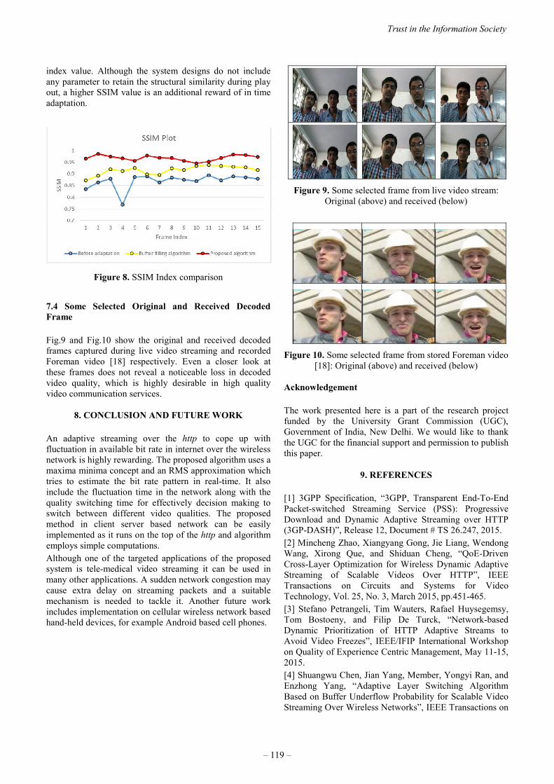
index value. Although the system designs do not include any parameter to retain the structural similarity during play out, a higher SSIM value is an additional reward of in time adaptation.
Figure 8. SSIM Index comparison
7.4 Some Selected Original and Received Decoded Frame Fig.9 and Fig.10 show the original and received decoded frames captured during live video streaming and recorded Foreman video [18] respectively. Even a closer look at these frames does not reveal a noticeable loss in decoded video quality, which is highly desirable in high quality video communication services.
8. CONCLUSION AND FUTURE WORK An adaptive streaming over the http to cope up with fluctuation in available bit rate in internet over the wireless network is highly rewarding. The proposed algorithm uses a maxima minima concept and an RMS approximation which tries to estimate the bit rate pattern in real-time. It also include the fluctuation time in the network along with the quality switching time for effectively decision making to switch between different video qualities. The proposed method in client server based network can be easily implemented as it runs on the top of the http and algorithm employs simple computations. Although one of the targeted applications of the proposed system is tele-medical video streaming it can be used in many other applications. A sudden network congestion may cause extra delay on streaming packets and a suitable mechanism is needed to tackle it. Another future work includes implementation on cellular wireless network based hand-held devices, for example Android based cell phones.
Figure 9. Some selected frame from live video stream: Original (above) and received (below)
Figure 10. Some selected frame from stored Foreman video [18]: Original (above) and received (below)
Acknowledgement The work presented here is a part of the research project funded by the University Grant Commission (UGC), Government of India, New Delhi. We would like to thank the UGC for the financial support and permission to publish this paper.
9. REFERENCES [1] 3GPP Specification, “3GPP, Transparent End-To-End Packet-switched Streaming Service (PSS): Progressive Download and Dynamic Adaptive Streaming over HTTP (3GP-DASH)”, Release 12, Document # TS 26.247, 2015. [2] Mincheng Zhao, Xiangyang Gong, Jie Liang, Wendong Wang, Xirong Que, and Shiduan Cheng, “QoE-Driven Cross-Layer Optimization for Wireless Dynamic Adaptive Streaming of Scalable Videos Over HTTP”, IEEE Transactions on Circuits and Systems for Video Technology, Vol. 25, No. 3, March 2015, pp.451-465. [3] Stefano Petrangeli, Tim Wauters, Rafael Huysegemsy, Tom Bostoeny, and Filip De Turck, “Network-based Dynamic Prioritization of HTTP Adaptive Streams to Avoid Video Freezes”, IEEE/IFIP International Workshop on Quality of Experience Centric Management, May 11-15, 2015. [4] Shuangwu Chen, Jian Yang, Member, Yongyi Ran, and Enzhong Yang, “Adaptive Layer Switching Algorithm Based on Buffer Underflow Probability for Scalable Video Streaming Over Wireless Networks”, IEEE Transactions on
Trust in the Information Society
– 119 –

Circuits and Systems for Video Technology, DOI 10.1109/TCSVT.2015.2437071, Year 2015. [5] ITU-T Recommendation Series J, “Objective Perceptual Multimedia Video Quality Measurement in the Presence of a Full Reference”, document # J.247, August 2008. [6] Junchen Jiang, Vyas Sekar, and Hui Zhang, “Improving Fairness, Efficiency, and Stability in HTTP-Based Adaptive Video Streaming With FESTIVE”, IEEE/ACM Transactions on Networking, Vol.22, No.1, February 2014, pp.326-340. [7] Luca De Cicco, and Saverio Mascolo, “An Adaptive Video Streaming Control System: Modeling, Validation, and Performance Evaluation”, IEEE/ACM Transactions on Networking, Vol.22, No.2, April. 2014, pp.526-539. [8] Yuedong Xu, Yipeng Zhou, and Dah-Ming Chiu, “Analytical QoE Models for Bit-Rate Switching in Dynamic Adaptive Streaming Systems”, IEEE Transaction on Mobile Computing, Vol.13, No.12, December 2014, pp. 2734-2748. [9] Hung T. Le, Duc V. Nguyen, Nam Pham Ngoc, Anh T. Pham, and Truong Cong Thang, “Buffer-based Bitrate Adaptation for Adaptive HTTP Streaming”, The 2013 International Conference on Advanced Technologies for Communications (ATC'13), 16 - 18 Oct. 2013, pp. 33 – 38. [10] Min Xing, Siyuan Xiang, and Lin Cai, “A Real-Time Adaptive Algorithm for Video Streaming over Multiple Wireless Access Networks”, IEEE Journal on Selected Areas in Communications, Vol.32, No.4, April 2014, pp. 795-805. [11] Yunmin Go, Oh Chan Kwon, and Hwangjun Song, “An Energy-efficient HTTP Adaptive Video Streaming with Networking Cost Constraint over Heterogeneous Wireless Networks”, IEEE Transaction on Multimedia, DOI 10.1109/TMM.2015.2451951, Year 2015. [12] Zhi Li, Xiaoqing Zhu, Joshua Gahm, Rong Pan, Hao Hu, Ali C. Begen, and David Oran, “Probe and Adapt: Rate Adaptation for HTTP Video Streaming At Scale”, IEEE Journal on Selected Areas in Communications, Vol.32, No. 4, April 2014. [13] Maxim Claeys, Steven Latr´e, Jeroen Famaey, and Filip De Turck “Design and Evaluation of a Self-Learning HTTP Adaptive Video Streaming Client” in IEEE Communication Letters, Vol.18, No.4, April 2014, pp.716-719. [14]http://www.rcom.co.in/Rcom/personal/internet/wireless_internet.html [15] http://speedof.me/ [16] ISO/IEC JTC1/SC29/WG11 and ITU-T SG16 Q.6, “New Video Quality Metrics in the H.264 Reference Software”, document # JVT-AB031, July, 2008. [17] Anush K. Moorthy and Alan C. Bovik, “Efficient Motion Weighted Spatio -Temporal Video SSIM Index”, Proc. SPIE 7527, Human Vision and Electronic Imaging XV, 75271I, February 17, 2010. [18] https://media.xiph.org/video/derf/
2015 ITU Kaleidoscope Academic Conference
– 120 –

CLOUD BASED SPECTRUM MANAGER FORFUTURE WIRELESS REGULATORY ENVIRONMENT
Moshe. T. Masonta
CSIR Meraka Instituteand Tshwane University of Technology
P O Box 395, Pretoria, 0001, South Africa
Dumisa W. Ngwenya
CSIR Meraka Instituteand University of Pretoria
Pretoria, 0001, South Africa
ABSTRACT
The regulatory environment in radio frequency spectrummanagement lags the advancement of wireless technolo-gies, especially in the area of cognitive radio and dynamicspectrum access. In this paper we argue that the solutiontowards spectrum Pareto optimal allocation lies with dy-namic spectrum management as a policy and regulatory toolfor addressing the dichotomy of technical, economic andsocio-economic considerations. Different radio frequencybands have different technical characteristics and economicmanifestation and, thus, a versatile tool would be desirableto deal with technical, economic and socio-economic ob-jectives in various bands. While approaches based on geo-location spectrum databases and radio environment maparchitecture have served the cognitive radio and dynamicspectrum access industry, their focus has been on networksand technologies. In this paper we propose a cloud basedspectrum manager as a tool focussed towards regulatoryprocesses. With the proposed approach it is possible to dealwith technical consideration of interference control resultingin achieving economic consideration of reducing rivalry andexclusivity with various spectrum policy and regulatory pre-scripts. The proposed spectrum manager should be able dealwith all regulatory processes favouring cognitive radio anddynamic spectrum access, while enhancing economic valueof radio frequency spectrum and achieving socio-economicbenefits.
Keywords— Cognitive radio, dynamic spectrum access, ra-dio environment map (REM), spectrum manager
1. INTRODUCTION
Cognitive radio (CR) and dynamic spectrum access (DSA)are important ingredients in efficient management of RFspectrum in order to address the current artificial radio fre-quency (RF) spectrum scarcity that is threatening the growthof wireless communications systems. However, the regu-latory environment in RF spectrum management lags theadvancement of these technologies.Traditionally, RF spectrum is managed by national regula-tory agencies through exclusive assignment of fixed portionsof spectrum to individual users or services through a licens-
ing process, also referred to as a command-and-control pro-cess, with the main goal being to control interference. Thecharacteristic definition of a pure command-and-control ap-proach is that a central body or agency is mandated to man-age and control the RF resources using administrative pro-cesses, typically informed by technical and political consid-erations and purporting, correctly or incorrectly, to addresssocio-economic obligations. Several studies have shown thatthis approach has led to inefficient utilization and manage-ment of RF spectrum and is not in tune with current advance-ment in technology. It is not based on principles of the mod-ern free market economy and, for most part, it does not evenaddress socio-economic aspects [1, 2].
In the past two decades there has been a movement towardsRF spectrum reforms. Unfortunately this has mostly beendriven by activism as opposed to technical and economicrigour and, thus, diminishing the cause. Further, the focushas been unduly favouring telecommunications or broadbandspectrum. Genuine reforms should take a holistic approachand include market or economic based approaches backedby unbiased technical and future-proof interventions, allow-ing spectrum sharing and trading across all bands. Fromeconomic point of view an optimal spectrum managementmodel, addressing both technical and socio-economic con-siderations, should reduce the rivalry and exclusivity whilepromoting appropriate competition based.
In this paper we argue that current technological advance-ment allows technical means to encourage spectrum shar-ing and facilitate appropriate spectrum trading environmentwhile addressing technical requirement of interference con-trol. What is required is taking advantage of recently de-veloped concepts in CR and DSA to facilitate a robust andversatile regulatory environment for spectrum management.The aim of this paper is not to provide or propose policy orregulatory prescripts, but to propose an economic and regu-latory frameworks and to define a versatile architecture to al-low regulators to adapt the progressive policy and regulatoryprescripts already promulgated or to be promulgated depend-ing on changing economic and socio-economic landscape aswell as advancement in technology.
The remainder of the paper is organised as follows. Section2 presents a perspective on RF spectrum chart, showing im-portant areas and possible value with respect to usage. Sec-
978-92-61-15821-7/CFP1538E-ART © 2015 ITU Kaleidoscope– 121 –

tion 3 presents the dichotomy of spectrum efficiency fromthe economic and technical perspectives. Section 4 presentsthe state-of-the art technical interventions towards DSA. Sec-tion 5 presents the proposed cloud based spectrum manager(CBSM). Section 6 concludes the paper.
2. RADIO FREQUENCY SPECTRUM
Most popular RF bands are Very High Frequency (VHF), Ul-tra High Frequency (UHF) and Super High Frequency (SHF)ranging from 30 MHz to 30 GHz as shown in Figure 1. Thepopularity is even higher between 100 MHz and 6 GHz,where most commercial operations reside. The said popu-lar spectrum has good characteristics, balancing geographiccoverage and bandwidth capacity.Frequencies below 600 MHz are suitable for narrowband ap-plications. The main advantage of the spectrum below 600MHz is the geographic coverage, which is the main deter-minant of its value. The spectrum range between 30 MHzto 600 MHz is predominantly used by Land mobile appli-cations, Public Protection and Disaster Relief (PPDR), fre-quency modulation (FM) and television (TV) broadcasting.The value starts diminishing below 30 MHz due to high sus-ceptibility to noise. However, due to its ability to cover longdistances - across several countries and continents - the spec-trum below 30 MHz has been attractive to amateur radio,short-wave and medium wave broadcasting, and long rangenavigation and communication in maritime and aviation. Theadvent of modern digital technologies is revitalising interestin this spectrum and all spectrum below 100 MHz for broad-casting and other narrow band applications, such as land mo-bile and broadcasting. However, it will always remain hardand costly to implement sharing in the lower bands without agood dynamic coordination. Appropriate coordinating toolswill be able to make the lower bands suitable for public good,and improve its socio-economic value outlook.Allocation of broadband access, broadcasting and otherpoint-to-multipoint (PTMP) applications is predominantlybetween 600 MHz and 6 GHz making the range very attrac-tive and suitable for spectrum sharing and carrier aggrega-tion, as shown in Figure 1. Allocation of Microwave point-to-point (PTP) and some PTMP is predominantly above 6GHz up to 40 GHz. There is a huge interest in spectrumbands higher than 30 GHz band for future wireless technolo-gies and services. For example, there is world-wide interestto use 60 GHz in Extremely High Frequency (EHF) for datarates higher than 2 Gbits/s covering more than a kilome-tre. Frequencies between 70 GHz to 95 GHz are currentlyexplored for PTP applications.The above analysis show that RF spectrum is a broad contin-uum. Managing RF resources from a point of view of plan-ning, interference control and licensing, as well as economicpoint of view, is very complex. RF spectrum regulatory pro-cesses include spectrum planning, assignment, licensing, in-terference control and enforcement. Spectrum planning in-volves allocation of spectrum to various services and allot-ment to type of users or technologies. Spectrum planning
also includes channel arrangements and band clearance [3].RF spectrum is policy related and should include technicaland socio-economic considerations which form the basis forradio regulations. Therefore a regulatory coordinating toolwill have to be modular and scalable to allow technical andeconomic considerations and ever changing socio-economicobjectives.
3. ECONOMIC AND TECHNICAL EFFICIENCYASPECTS OF RF SPECTRUM
The RF spectrum management issues go beyond engineer-ing science and require economic aspects. The primary eco-nomic objective for any resource is to maximize the net ben-efits to society that can be generated from that resource. Inspectrum management economic efficiency is achieved if re-distribution and use of spectrum result in an increase in over-all social welfare, achieving Pareto optimality.From microeconomic point of view spectrum managementmodels can be based on the concepts of exclusivity and ri-valry [3]. Exclusivity is the degree in which a good can berestricted to only those who pay for it, while rivalry is thedegree by which utilisation of a good by one individual di-minishes the value for another individual. There is generallyno reason to exclude if there is no rivalry, except for valuepreservation and creation.The command-and-control regime tends to view spectrum asrival and excludable. The rival argument is backed up by thefact that as the number of users increase the number of spec-trum bands available decreases and the potential for interfer-ence increases. The argument for exclusivity is based on theperceived requirement to guarantee exclusive access. The in-ability to diffuse the above arguments has primarily been dueto “misunderstanding by some economist” of capabilities ofnew technologies and “misunderstanding by some engineersof flexibility of property rights and markets” or free marketeconomy [4, 5].Property rights regimes can support both market-based ap-proaches and spectrum sharing regimes and vice-versa as ar-gued in [3–5]. The economics of spectrum sharing in generalare discussed in [6] and it is argued that successful spectrumsharing depends of property rights assigned, ensuring thateach user is able to derive required value from the spectrumassigned. A new concept of property rights, fluid propertyrights, is proposed in [7] as a legal tool to facilitate new ap-proaches in spectrum management. The fluid property rightsconcepts allow rivalry and exclusivity characteristics to bedepicted in property rights bundles.Reduction of rival and exclusivity is a function of economic,regulatory and technical considerations. Recent advance-ment in wireless technologies involving CR and softwaredefined radio (SDR) has made DSA a reality. This in turnhas a potential to address both economic and technical con-cerns, potentially remove a large degree of rivalry in the useof spectrum.Table 1 attempt to map the current regulatory environment
2015 ITU Kaleidoscope Academic Conference
– 122 –
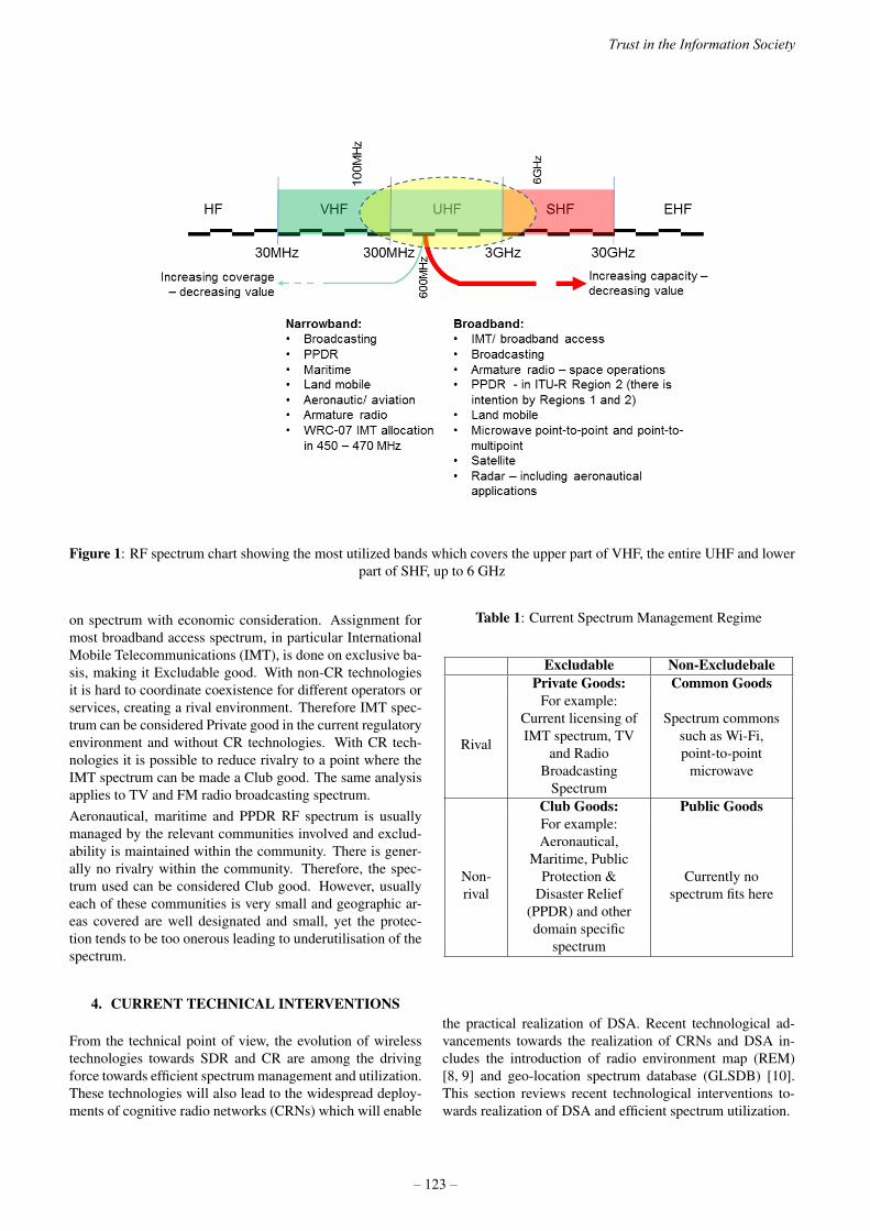
Figure 1: RF spectrum chart showing the most utilized bands which covers the upper part of VHF, the entire UHF and lowerpart of SHF, up to 6 GHz
on spectrum with economic consideration. Assignment formost broadband access spectrum, in particular InternationalMobile Telecommunications (IMT), is done on exclusive ba-sis, making it Excludable good. With non-CR technologiesit is hard to coordinate coexistence for different operators orservices, creating a rival environment. Therefore IMT spec-trum can be considered Private good in the current regulatoryenvironment and without CR technologies. With CR tech-nologies it is possible to reduce rivalry to a point where theIMT spectrum can be made a Club good. The same analysisapplies to TV and FM radio broadcasting spectrum.Aeronautical, maritime and PPDR RF spectrum is usuallymanaged by the relevant communities involved and exclud-ability is maintained within the community. There is gener-ally no rivalry within the community. Therefore, the spec-trum used can be considered Club good. However, usuallyeach of these communities is very small and geographic ar-eas covered are well designated and small, yet the protec-tion tends to be too onerous leading to underutilisation of thespectrum.
4. CURRENT TECHNICAL INTERVENTIONS
From the technical point of view, the evolution of wirelesstechnologies towards SDR and CR are among the drivingforce towards efficient spectrum management and utilization.These technologies will also lead to the widespread deploy-ments of cognitive radio networks (CRNs) which will enable
Table 1: Current Spectrum Management Regime
Excludable Non-ExcludebalePrivate Goods: Common Goods
Rival
For example:Current licensing ofIMT spectrum, TV
and RadioBroadcasting
Spectrum
Spectrum commonssuch as Wi-Fi,point-to-point
microwave
Club Goods: Public Goods
Non-rival
For example:Aeronautical,
Maritime, PublicProtection &
Disaster Relief(PPDR) and otherdomain specific
spectrum
Currently nospectrum fits here
the practical realization of DSA. Recent technological ad-vancements towards the realization of CRNs and DSA in-cludes the introduction of radio environment map (REM)[8, 9] and geo-location spectrum database (GLSDB) [10].This section reviews recent technological interventions to-wards realization of DSA and efficient spectrum utilization.
Trust in the Information Society
– 123 –
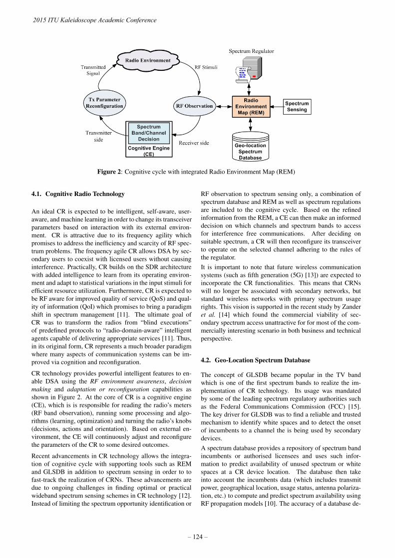
Figure 2: Cognitive cycle with integrated Radio Environment Map (REM)
4.1. Cognitive Radio Technology
An ideal CR is expected to be intelligent, self-aware, user-aware, and machine learning in order to change its transceiverparameters based on interaction with its external environ-ment. CR is attractive due to its frequency agility whichpromises to address the inefficiency and scarcity of RF spec-trum problems. The frequency agile CR allows DSA by sec-ondary users to coexist with licensed users without causinginterference. Practically, CR builds on the SDR architecturewith added intelligence to learn from its operating environ-ment and adapt to statistical variations in the input stimuli forefficient resource utilization. Furthermore, CR is expected tobe RF aware for improved quality of service (QoS) and qual-ity of information (QoI) which promises to bring a paradigmshift in spectrum management [11]. The ultimate goal ofCR was to transform the radios from “blind executions”of predefined protocols to “radio-domain-aware” intelligentagents capable of delivering appropriate services [11]. Thus,in its original form, CR represents a much broader paradigmwhere many aspects of communication systems can be im-proved via cognition and reconfiguration.
CR technology provides powerful intelligent features to en-able DSA using the RF environment awareness, decisionmaking and adaptation or reconfiguration capabilities asshown in Figure 2. At the core of CR is a cognitive engine(CE), which is is responsible for reading the radio’s meters(RF band observation), running some processing and algo-rithms (learning, optimization) and turning the radio’s knobs(decisions, actions and orientation). Based on external en-vironment, the CE will continuously adjust and reconfigurethe parameters of the CR to some desired outcomes.
Recent advancements in CR technology allows the integra-tion of cognitive cycle with supporting tools such as REMand GLSDB in addition to spectrum sensing in order to tofast-track the realization of CRNs. These advancements aredue to ongoing challenges in finding optimal or practicalwideband spectrum sensing schemes in CR technology [12].Instead of limiting the spectrum opportunity identification or
RF observation to spectrum sensing only, a combination ofspectrum database and REM as well as spectrum regulationsare included to the cognitive cycle. Based on the refinedinformation from the REM, a CE can then make an informeddecision on which channels and spectrum bands to accessfor interference free communications. After deciding onsuitable spectrum, a CR will then reconfigure its transceiverto operate on the selected channel adhering to the rules ofthe regulator.It is important to note that future wireless communicationsystems (such as fifth generation (5G) [13]) are expected toincorporate the CR functionalities. This means that CRNswill no longer be associated with secondary networks, butstandard wireless networks with primary spectrum usagerights. This vision is supported in the recent study by Zanderet al. [14] which found the commercial viability of sec-ondary spectrum access unattractive for for most of the com-mercially interesting scenario in both business and technicalperspective.
4.2. Geo-Location Spectrum Database
The concept of GLSDB became popular in the TV bandwhich is one of the first spectrum bands to realize the im-plementation of CR technology. Its usage was mandatedby some of the leading spectrum regulatory authorities suchas the Federal Communications Commission (FCC) [15].The key driver for GLSDB was to find a reliable and trustedmechanism to identify white spaces and to detect the onsetof incumbents to a channel the is being used by secondarydevices.A spectrum database provides a repository of spectrum bandincumbents or authorised licensees and uses such infor-mation to predict availability of unused spectrum or whitespaces at a CR device location. The database then takeinto account the incumbents data (which includes transmitpower, geographical location, usage status, antenna polariza-tion, etc.) to compute and predict spectrum availability usingRF propagation models [10]. The accuracy of a database de-
2015 ITU Kaleidoscope Academic Conference
– 124 –

Figure 3: REM system built by integrating multipleband-specific databases, spectrum sensing data and
regulation
pends on the reliability of incumbents data that is provided,in most cases, by the regulator as well as the validity of theRF propagation models used. Over the past few years, theaccuracy of GLSDB and prediction of white space has beenan open research question [16, 17]. Most of these literaturefound that field measurements remains the most reliablemethod for improving GLSDB accuracy. Thus, GLSDBwhich relies solely on RF propagation models have the highdegree of inaccuracy when it comes to white space predic-tion than those which uses field spectrum measurements.However, building a GLSDB using field measurements isan expensive and lengthy exercise especially if one needsto cover wider geographical area [10]. As such, a combina-tion of GLSDB and spectrum sensing promises to providehigh level of accuracy when it comes to white space iden-tification.Spectrum sensing becomes very useful when newincumbent transmitters are introduced in the field, or whenthe existing transmitter characteristics changes. Such com-bination can be achieve through a REM which is discussedin the next subsection.
4.3. Radio Environment Map
A REM is considered to be an enhancement of geo-locationspectrum database (GLSDB) in order to realize a full func-tional DSA concept in CRNs. Unlike GLSDB, REM buildslong-term knowledge map from real-time spectrum sensingdata, band specific GLSDB, propagation environment, ge-ographical terrain models and regulations [8]. In its sim-plest form, REM is built by integrating various band specificdatabases, spectrum sensing data, and national regulation.In this context, REM provides radio environment informa-tion in order to allow reliable spectrum access. It is viewedas a central database containing reliable information aboutthe location of radio nodes, white spaces, national and localspectrum regulations, incumbents information (such as sig-nal types, their location, activities, etc.), and history of pastexperiences [18].A REM is typically deployed at the core CRN level, andcan take the form of global or local REM [8]. Local REMsare mainly deployed to increase the response time and havelower processing capabilities compared to global REMs. Theassumption is that every core CRN and their respective base
stations (BS) or central node has some form of CE whichcommunicates directly with the REM. This lessen the com-plex processing burden from the CR nodes by allowing REMto make some extensive processing [8].
4.4. Dynamic Broadcasting
Dynamic broadcasting allows the TV content to be flexiblytransmitted using both broadcast and broadband networks inreal-time and non-real time, and the broadcast network trans-mission parameters can by dynamically modified [19]. Dy-namic broadcasting is easily realized in digital terrestrial TV(DTT) as opposed to the old analogue broadcasting. Theefficient spectrum utilization of DTT makes it possible forbroadband networks to broadcast TV content to a commonDTT receiver (such as smart TV or set-top box).While dynamic broadcast brings some level of flexibility inTV content transmission, it introduces new challenges forspectrum management [19]. These includes reconfigura-tion of multiplexers and transmission parameters, dynamicchannel allocations. Such challenges can then be addressedthrough DSA and dynamic spectrum management. This willlead to optimal and efficient utilization of spectrum.
4.5. Towards 5G and Beyond
There is currently a move towards the development of 5Gcellular networks which is viewed, by others, as the “con-vergence of evolved versions of current cellular networkswith other complementary radio access technologies” whichmakes it a “network of networks” [13]. 5G networks areexpected to use untapped mm-wave frequency spectrum inorder to provide high aggregate capacity for many simulta-neous users in licensed and unlicensed spectrum bands [20].Among the vision of 5G is the co-existence of heterogeneousnetworks operating at different frequency bands using differ-ent air interfaces. Thus the vision is more on how to com-bine existing wireless technologies using advanced and effi-cient spectrum management techniques. Thus, our proposedCBSM is one of the solutions paving ways for efficient spec-trum management for future wireless systems. It will allowspectrum regulators to dynamically manage existing and un-tapped frequency bands.
5. PROPOSED CLOUD BASED SPECTRUMMANAGER
The proposed Cloud Based Spectrum Manager (CBSM) isshown in Figure 4. The CBSM provides an end-to-end inte-gration of existing and new spectrum management solutionsto allow national spectrum regulatory authorities to automatethe RF spectrum management function. It aims to leveragea number of recently developed technologies and techniqueswith the aim of advancing the RF spectrum regulatory envi-ronment.At its core, the CBSM consists of five key components: 1)Core Spectrum Manager Decision Engine (DE), 2) RF Mon-
Trust in the Information Society
– 125 –

Table 2: Mapping CBSM to regulatory processes
CBSM Based Regulatory processes
Core Spectrum ManagerDecision Engine
Spectrum allocation andassignment and
workflowRF Monitoring and
EnforcementInterference control and
enforcementSpectrum Brokerage
ManagerSpectrum trading
(currently not usual)Spectrum Licensing
ManagerLicensing andauthorization
Spectrum PlanningWorkflow Spectrum engineering
itoring and Enforcement, 3) Spectrum Brokerage Manager,4) Spectrum Licensing Manager, and 5) Spectrum PlanningWorkflow. The spectrum planning workflow interfaces witha spectrum planning tool or tools owned by the regulatoryagency or by a third party.The CBSM interfaces with several networks through multi-ple REMs to obtain real time data on spectrum utilisationand to send commands and information for implementationof new policy and regulatory prescripts. A recently stan-dardized Protocol for Accessing White Space (PAWS) [22]can be one of the suitable interfaces between the CBSM andREM. The CBSM also interfaces with band-specific GLS-DBs which would typically consists of quasi-static alloca-tion and assignment data. Examples include TVWS GLSDBand GLSDBs that would keep assignments for aeronauticaland maritime. Specific and dynamic rules and regulatory el-ements for various bands and services could be implementedas for band/ service specific modules. A typical regulatoryactivity that could benefit from this feature is the clearingland mobile spectrum for security and emergency services.Another example is ability to dynamically switch spectrumusage based on some criteria. DSA is achieved by applyingRF band specific regulations using real-time RF environmentdata sourced from GLSDBs and REMs. The CBSM shouldbe able to facilitate spectrum brokerage based on surrenderspectrum or utilisation spectrum. Interface to the operatorswill enable automation of licensing and authorisation pro-cesses. Table 2 maps the CBSM to regulatory processes. Thenext subsections provide detailed description for each of thekey CBSM components.
5.1. Core Spectrum Manager Decision Engine (DE)
The decision engine (DE) is the main central nervous systemof our proposed CBSM. This is where the advanced and dy-namic spectrum management (DSM) intelligence sits. Thecore spectrum manager DE performs the actual DSA func-tion. Other functions includes RF spectrum allocation, RFassignment and general spectrum administration which in-cludes billing, security, authorizations, reporting, etc.
5.2. RF Monitoring and Enforcement
The RF Monitoring and Enforcement module is responsiblefor the policing of spectrum usage among the licensees andother spectrum users. It is also responsible for the resolutionof complaints regarding technical issues and public safety.Technical issues involves interference control and manage-ment, spectrum sharing, co-existence management, and theconcept of use-it or lose-it. The use-it or lose-it concept isa novel way towards efficient spectrum utilization, wherebylicense holders may lose portions of their spectrum if theyare not using it for a certain period of time in a given geo-graphic location. There are already technologies which per-forms most of these functions available in the market. Fur-thermore, the regulator can also decide to outsource some ofthese task to third party companies.
5.3. Spectrum Brokerage Manager
The main function of spectrum brokers is to control theamount of spectrum bandwidth and transmission power as-signed to wireless operators in order to keep the desired qual-ity of service and interference below the regulatory limits.An independent spectrum broker can act as an intermedi-ary between a national spectrum regulator and players, andnegotiates spectrum on their behalf of. The spectrum broker-age approach on the TV band was first proposed in Europethrough the COGnitive radio systems for efficient sharing ofTVWSs in EUropean context (COGEU) [21]. This createsthe secondary spectrum market which is managed in theform of auctions. Similar spectrum brokerage approach canbe applied in other RF spectrum bands to facilitate efficientsecondary usage market.
5.4. Spectrum Licensing Manager
The spectrum licensing manager interfaces with the networkoperators or existing and potential spectrum users. It al-lows online application of spectrum license whereby poten-tial spectrum users can apply or renew their short or long-term spectrum license online. The spectrum licensing man-ager also manages the type approval process, provides all li-censing administration and has a graphic user interface whichgives the regulators a full view of what is happen on the sys-tem in real-time.
5.5. Spectrum Planning Workflow
There are a number of commercial-of-the-shelf spectrumplanning tool available in the market which the regulator maydecide to own or outsource the such services. The spectrumplanning workflow is crucial in spectrum license assignmentssince it invokes the spectrum planning tool which makes useof propagation modules to validate whether a license canbe assigned for specific services and a given location. Thespectrum planning process is automated with little humanintervention.
2015 ITU Kaleidoscope Academic Conference
– 126 –

Figure 4: Conceptual view of cloud-based Spectrum Manager showing key building blocks
5.6. Interfaces
The CBSM supports a number of different interfaces with theexternal systems. Some of these interfaces are standardized,like the interface between a GLSDB and the CBSM or be-tween GLSDB and the REM, whereas other interfaces mightbe proprietary. Interface to GLSDB is through the PAWSdevices [22]. Interface to operators allows existing and po-tential spectrum users to interact with the CSBM system, forinstances, when applying for spectrum license.
5.7. Unique features of CBSM
Table 3 provides a summary of key differences between ourproposed CBSM with existing DSA technological solutionssuch as the REM and GLSDB. While CBSM provides reg-ulatory intervention to spectrum management, REM andGLSDB provides a technological intervention to efficientspectrum management.
6. CONCLUSION
In the paper we have outlined, based on literature review,that in the current policy and regulatory framework spectrumremains predominately private good, which is rival and ex-clusive. This is despite technological advancement in CRand DSA, allowing sharing of spectrum. Current focus, us-ing GLSDB and REMs, assume quasi-static and cooperative
Table 3: Explicit Differences between CBSM and existingREM and GLSDB
Cloud Based SpectrumManager REM and GLSDB
Concerned with RF areasterilization
Assumes total cooperativeenvironment betweendevices or operators
Global and long terminterference control
Location based, immediateinterference control
Scalable to cover the wholeRF spectrum range
Quasi-static in specificbands such as TVWS
(mainly GLSDB), whereasREM can address thequasi-static limitation
Policy and regulatoryprescripts (e.g. Use-it or
Lose-it policy)
Service and technologyspecific
Provides an integrated RFspectrum management
workflow
Used as an enabler for CRnetwork deployment
Focussed on regulatoryprocesses (i.e. primary
owner)
Network focussed - suitablefor network operators or
services providers
Trust in the Information Society
– 127 –

environment. The focus is network-based and technology-based.A regulatory focused approach can reduce rivalry and exclu-sivity and hence achieve Pareto optimality. We therefore pro-pose a cloud based spectrum manager (CBSM) architecturefocusing on regulatory processes and facilitating dynamicspectrum management in a DSA environment. Future workincludes the development of CBSM from simulated environ-ment to a small scale real-life or practical environment.
REFERENCES
[1] J. M. Peha, “Sharing spectrum through spectrum policyreform and cognitive radio,” Proceedings of the IEEE,vol. 97, no. 4, pp. 708 – 719, 2009.
[2] M. Song, C. Xin, Y. Zhao, and X. Cheng, “Dynamicspectrum access: from cognitive radio to networm ra-dio,” IEEE Wireless Communications, vol. 19, no. 1,pp. 23 – 29, Feb. 2012.
[3] B. Freyens, “The economics of spec-trum management: A review,” Available at:http://www.acma.gov.au/˜/media/mediacomms/Research%20library%20reports%20old/pdf/Economics%20of%20spectrum%20management%20pdf.pdf[Accessed: 28/04/2015], 2007.
[4] J. Brito, “The spectrum commons in theory and prac-tice,” Stanford Technology Law Review, vol. 1, no.2007, pp. 1–22, 2007.
[5] G. R. Faulhaber and D. Farber, “Spectrum manage-ment: Property rights, markets, and the commons,”Working Paper 02:12, AEI-Brookings Joint CenterPublications, 2002.
[6] G. McHenry and C. Bazelon, “The economics of spec-trum sharing,” in Conf. on Communication, Informa-tion & Internet Policy, Arlington, USA, Sept. 6–8 2013.
[7] B. B. Laender, “Spectrum regulation in brazil:The case for fluid property rights,” Available at:http://papers.ssrn.com/sol3/papers.cfm?abstract_id=2031193 [Accessed:30/04/2015], 2012.
[8] H. B. Yilmaz, T. Tugcu, F. Alagoz, and S. Bayhan, “Ra-dio environment map as enabler for practical cognitiveradio networks,” IEEE Communications Magazine, vol.51, no. 12, pp. 162 – 169, 2013.
[9] Y. Zhao, S. Mao, J. O. Neel, and J. H. Reed, “Perfor-mance evaluation of cognitive radios: Metrics, utilityfunctions, and methodology,” Proceedings of the IEEE,vol. 97, no. 4, pp. 642–659, Apr. 2009.
[10] R. Murty, R. Chandra, T. Moscibroda, and P. Bahl,“SenseLess: A database-driven white spaces network,”
IEEE Trans. on Mobile Computing, vol. 11, no. 2, pp.189–203, 2012.
[11] J. Mitola, “Cognitive radio architecture evolution,”Proc. of the IEEE, vol. 97, no. 4, pp. 626–641, 2009.
[12] J. Jia, Q. Zhang, and X. Shen, “HC-MAC: A hardware-constrained cognitive MAC for efficient spectrum man-agement,” IEEE Journal on Selected Areas in Commu-nications, vol. 26, no. 1, pp. 106–117, jan 2008.
[13] R. Ch´vez-Santiago, M. Szydelko, A. Kliks,F. Foukalas, Y. Haddad, K. E. Nolan, M. Y. Kelly, M. T.Masonta, and I. Balasingham, “5G: the convergenceof wireless communications,” Wireless PersonalCommunications, vol. 83, no. 3, pp. 1617–1642, 2015.
[14] J. Zander, L. K. Rasmussen, K. W. Sung, P. Mahonen,M. Petrova, R. Jantti, and J. Kronander, “On the scala-bility of cognitive radio: Assessing the commercial vi-ability of secondary spectrum access,” IEEE WirelessCommunications, vol. 20, no. 2, pp. 28 – 36, Apr. 2013.
[15] Federal Communications Commision, “Unlicensed op-eration in the TV broadcast band,” Federal Register:Rules and Regulations, vol. 77, no. 96, pp. 29236 –29247, 2012.
[16] A. Achtzehn, J. Riihijarvi, and P. Mahonen, “Improv-ing accuracy for TVWS geolocation databases: Resultsfrom measurement-driven estimation approaches,” inIEEE DySPAN, Mclean, USA, Apr. 1–4 2014.
[17] A. Chakraborty and S. R. Das, “Measurement-augmented spectrum databases for white space spec-trum,” in CoNEXT, Sydney, Australia, Dec. 2–5 2014.
[18] Y. Zhao, Enabling cognitive radios through radio envi-ronment maps, Ph.D. thesis, Virginia Polytechnic Insti-tute and State University, Blacksburg, Virginia, USA,2007.
[19] J. Qi, P. Neumann, and U. Reimers, “Dynamic broad-cast,” in 14th Conference on Electronic Media Technol-ogy, Dortmund, Germany, Mar. 23–24 2011.
[20] T. S. Rappaport, S. Sun, R. Mayzus, H. Zhao, Y. Azar,K. Wang, G. N. Wong, J. K Schulz, M. Samimi, andF. Gutierrez, “Millimeter wave mobile communicationsfor 5G cellular: It will work!,” IEEE Access, vol. 1, no.2013, pp. 335–349, May 2013.
[21] D. Lavaux, P. Marques, J. Mwangoka, J. Ribeiro,A. Gomes, H. Alves, C. Silva, and E. Charalambous,Final Architecture for TVWS Spectrum Sharing Sys-tems: COGEU Report - FP7 ICT-2009.1.1, 2011.
[22] V. Chen, S. Das, L. Zhu, J. Malyar, and P. McCann,“Protocol to access white-space (PAWS) databases,”IETF RFC: 7545, May 2015.
2015 ITU Kaleidoscope Academic Conference
– 128 –

SESSION 5
ADVANCES IN NETWORKS AND SERVICES II
S5.1 Seamless Mobility in Data Aware Networking.
S5.2 Proactive-caching based Information Centric Networking Architecture for Reliable Green Communication in Intelligent Transport System.*
S5.3 Network Failure Detection System for Traffic Control using Social Information in Large-Scale Disasters.*


SEAMLESS MOBILITY IN DATA AWARE NETWORKING
Jairo E. López1, Arifuzzaman. M*2, Li Zhu3, Zheng Wen4, and Sato Takuro**5 1Center for Technology Innovation – Systems Engineering, Research and Development Group, Hitachi, Ltd.,
2Memorial University of Newfoundland, Newfoundland and Labrador, Canada, 3- 5Graduate School of Information and Telecommunication Studies, Waseda University, Tokyo, Japan
1 [email protected], [email protected],[email protected], [email protected]
[email protected]; ** Fellow, IEEE; * Member, IEEE
ABSTRACT
The underlying networks (of the Internet) have been reworked to make way for new technologies, some serious inefficiencies and security problems have arisen. As a result, over the past years, fundamentally new network designs have taken shape and are being tested. In ITU Recommendation Y.3001 [1], four objectives are identified in line with the requirements for Future Network; one of them is data awareness. In ITU Recommandation Y.3033 [2], the 'Mobility' is addressed as one of the key problem spaces of data aware networking (DAN). This paper proposes Named-Node-Networking (3N), a novel architecture for DAN. We design a simulator (nnnSIM) [3] for evaluating our proposed 3N architecture which is the second major contribution of this paper. The nnnSIM simulator is written in C++ under the ns-3 framework [4] and has been made available as open-source software for the scientific community. Considering the importance of a unique DAN architecture, we propose a study for standardization work in the ITU as an initiative which can lead to its rapid adaptation.
Keywords— Information Centric Networking; Mobile Communication; Named-Node Networking; 3N
1. INTRODUCTION
Real time mobile information retrieving and sharing throughout the network has continuously increased due to the explosion in use of multimedia capable mobile devices, such as smart phones, in people’s daily life. Meanwhile, the current Internet's network architecture cannot handle the consumer’s data exchange demand since it operates by a network attachment centric way, mapping each user through their IP addresses. One of the major goals of future network architecture is to be able to seamlessly retrieve content while moving.
Data aware networking (DAN) draws significant interest to the research community recently. In 2006, the concept of the content-centric networking (CCN) [5] is introduced. In CCN paradigm, the network layer provides with content instead of providing communication channel between hosts. In the Publish-Subscribe Internet Routing Paradigm (PSIRP) [6], Identifiers are defined in an information-centric manner and with the Publish-Subscribe internet architecture, Information Centric Networking (ICN) is explained which focuses on content rather than end point communication. In the context of our paper we use the terms DAN, CCN and ICN interchangeably.
In International Telecommunication Union (ITU) Recommendation Y.3033 [2], the overview of data aware networking (DAN) and its problem spaces are addressed precisely. In the document, three problem spaces are defined namely 1) Scalable and cost-efficient content distribution; 2) Mobility and 3) Disruption tolerance. The capabilities and benefits of DAN over conventional IP-based Internet Architecture are widely recognized [7][8]. In DAN, even though many scenarios have been analyzed,
mobility support has not yet received enough attention despite wireless technologies being more widely adopted for Internet access. The common ICN technique of sending the desired content back through the breadcrumbs of the Interest route is challenging for the mobile user, since, while moving the access point may change before the user is able to satisfy their previous Interest. To address the issue, and with the objective of providing real-time mobility access, we are convinced that, in addition to naming the content, it is needed to assign names to the mobile nodes in a separate namespace. Our proposed scheme improves the way of information retrieval and addresses the mobility issue in ICN more efficiently. For evaluating performance, we simulate our proposal with nnnSIM in a scenario where the Mobile Node demands for live stream video service at various speeds. We compare our proposal with the Name Data Networking (NDN) [9] architecture. The simulation results showed the efficiency and feasibility of our proposed named-node based mobile ICN architecture.
The rest of the paper is organized as follows. In section 2 some related works are mentioned. In section 3, we focus on the standardization issue of ICN architectures. We explain our proposed Named-Node Networking architecture in section 4. We present the evaluation of our proposal through simulation in section 5. Finally, Section 6 concludes our paper and describes future work.
2. RELATED WORK
As early as 1982 in [10], the importance of network namespaces and the terminology that defines them is mentioned. This paper is considered a guideline to network naming and has been a fundamental point of consideration during the expansion of TCP/IP networks, eventually becoming RFC 1498 in 1993 [11]. In [12], authors proposed Opportunistic content pushing via Wi-Fi hotspots. In the work, the content delivery system predicts the routes of the roaming users and pre-locates the contents to Wi-Fi spots along their routes. However, their delivery scheme did not consider Wi-Fi spot conditions. In [13], the authors proposed proactive video caching scheme based on video popularity prediction. Authors use modeling tool, Latent Dirichlet Allocation, and frequent pattern mining algorithm, A priori. However the work doesn’t cover user mobility. Selective Neighbor Caching is exploited for enhancing seamless mobility in ICN in [14]. In the proposal an optimal subset of neighbor proxies are selected as a prefetching destination of the content. The mobility behavior of users is considered to select the prospective neighbors. In [15], the authors proposed a proactive caching approach for seamless mobility support in NDN. Authors extend the NDN access routers with additional functionality such as prefetching and caching content items on behalf of the user. In [16] various approaches to achieve seamless mobility are proposed, however they all include restrictions on the ICN namespace, attempting to use Points of Attachment (PoA) names within the ICN namespace. This paper does not include any experiment data on the proposals. In [17] a new namespace and its associated functions is introduced between
978-92-61-15821-7/CFP1538E-ART © 2015 ITU Kaleidoscope– 131 –

IP and TCP in TCP/IP networks to attempt to create a clean service-level control / data plane split. The paper indirectly demonstrates some benefits of having a separate namespace between the service and network layers.
In our previous work [18], we proposed a proactive content caching. We propose a proactive content caching scheme utilizing transportation systems, specifically trains. In our system, we place content servers with CCN capability on a train and in every station. Segments of video contents are pre-cached by the station servers before trains arrive at stations. Trains receive the contents via high-speed wireless transport while they stop at the stations. We develop a prototype system based on IP and CCN Hybrid protocols. We evaluated its performance by field experiment and compared with traditional CDN scenarios using cellular networks. Evaluations concluded that our system could achieve high-speed and high-reliable video delivery without freezing.
3. ICN PROJECTS
Though ICN is in its infancy, it is candidate architecture for the future Internet. Currently, numerous projects are going on under the ICN theme. They vary in their design aspects. We cite here a few differences between major Information Centric Networking projects. In case of naming the content, CCN [5] uses hierarchical naming and PSIRP [6] uses flat naming. For security, CCN needs to trust signing key to establish integrity, where in case of PSIRP it is self- certifying. For name resolution and routing, name based routing using longest prefix of hierarchical names is used in CCN. On the other hand, a rendezvous function is used, within a specified scope to solve the issue in PIRSP. For transport and caching, CCN transport using named based routing; finds cached object through local search as well as on the path to the publisher. For PIRSP, transport routing and forwarding use separate forwarding identifier. The Data-Oriented Network Architecture (DONA) project [19] argues for a redesign of the current Internet name resolution system to achieve an ICN, leveraging TCP/IP functioning protocols and routing. Network of Information (NetInf) [20] concentrates more on the naming of content, content searching and network transport issues related to ICNs. This ICN distinguishes itself for using a multilevel distributed hash table (DHT) for routing and name resolution. A final example, NDN [9] attempts to completely redesign the Internet by replacing the current IP network layer with content chunks as the universal component of transport.
Though some points like naming, security, etc. deserve early initiative of standardization, the interest of this article is on standardization issues of a common architecture of ICN which support seamless mobility. Mobility is one of the key areas where conventional ICN architecture is still struggling. In this paper we propose a DAN architecture which can ensure seamless mobility. At present there is no unique standard for a DAN architecture. Therefore early initiatives of ITU will significantly contribute in the maturation process of the DAN architecture as well as architecture for the Future Internet.
4. PROPOSED NAMED-NODE NETWORKING ARCHITECTURE
4.1. Basic Principle
We try to use a more fundamental way to solve the mobility problem in ICN. We propose adding two new completely independent namespaces to the ICN network layer.
We maintain ICN's standard content naming namespace without any modifications to its structure. To avoid confusion between network layers and namespaces, we rename the namespace used to
name content the Service namespace. The Service namespace is used to identify content or services that run within the network. These services run on top of nodes, which are identified by the Node name namespace. Names belonging to the Service namespace will be referred to as ICN names.
The Node name namespace is specifically created to name nodes participating in an ICN. Names belonging to this namespace will be called 3N names. This namespace complies with the requirements for being a metrizable topological space. This implies that names that are desired to be logically close, determined by a particular distance function, continue to be proportionally close to each other in any particular namespace mapping. The simplest type namespace that fits this requirement is a metrizable hierarchical namespace and is the one we use in our examples. The Node name namespace consists of a single, complex, multi-level structure into which all 3N names fit. The namespace is organized starting from a single root into which sectors are placed. Each sector can contain either individual 3N names or more specific sub-sectors. The name partitioning scheme used for a network will depend greatly on the network's physical distribution and its scale. We do not imagine any particular limit for the partitioning as long as topologically significant naming can be maintained. The Node name namespace will act as a level of indirection for the Service namespace and PoA namespace.
The PoA namespace consists of the names typically used by physical interfaces to identify themselves, such as the common Ethernet MAC address. Names belonging to this namespace will be referred to as PoA names.
With this new naming structure, a mobile node will get its 3N name from an edge node to which the mobile node is physically linked by any available medium. By getting a 3N name and having the network maintain updated mappings between the three defined namespaces, the mobile node can be reached, regardless of its current location as long as only one mapping at a time is changed. For instance, if a content packet returns from a content store, the content router finds the node’s 3N name, checks the mappings for any updates and then uses the updated 3N name to reach its destination.
The network elements we consider are Mobile Nodes (MN), Content Routers (CR), Edge Nodes (EdgeN), which are CRs to which serve as gateways for clients joining the network and Content Providers (CP). All nodes using the 3N architecture have a Node Name Signature Table (NNST) that records the PoA names, the lease time for the 3N name and the 3N name that neighbor nodes were given when enrolling into the network. Thus the NNST maintains the 3N name to PoA name mapping. Each node in the 3N network architecture also has a structure called the Node Name Pairs Table (NNPT) that keeps records of pairs of old 3N names given by an EdgeN and the new 3N name given by a different EdgeN to an enrolled node. The NNPT thus maintains an updated 3N name to 3N name mapping. Any node enrolled into the 3N architecture can be delegated to generate 3N names for newly enrolling nodes. In the case of MN, the 3N names given will always come from an EdgeN.
In section 4.2 we explain the Protocol Data Units (PDUs) used in the architecture. From section 4.2.1 to 4.2.4, we briefly explain how a MN enrolls into the 3N architecture for the first time to obtain its own 3N name, how the MN reenrolls when it moves into a new sector and how, once a MN obtains its 3N name, the network will use the 3N name, the NNST and the NNPT to ensure real-time communication. 4.2. Protocol Data Units (PDUs)
To realize our network architecture, we create a set of Protocol Data Units (PDUs) that we describe in more detail in Table 1. We distinguish between 2 particular types of PDUs: data transmission
2015 ITU Kaleidoscope Academic Conference
– 132 –
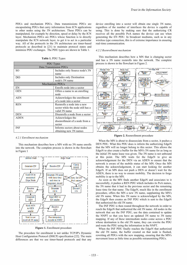
PDUs and mechanism PDUs. Data transmissions PDUs are encapsulating PDUs that carry information from ICN applications to other nodes using the 3N architecture. These PDUs can be manipulated, for example by direction, speed or delay by the ICN layer. Mechanism PDUs are PDUs whose function is to directly manipulate the ICN network layer, to get it to act in a particular way. All of the protocols in the 3N architecture are timer-based protocols as described in [21] to maintain protocol states and minimize PDU exchanges. The PDU types are shown in Table 1.
Table 1. PDU Types
PDU Types Data Transmission PDUs
SO Includes only Source node's 3N name
DO Includes only Destination node's 3N name
Mechanism PDUs EN Enrolls node into a sector OEN Offers a name to an enrolling
node AEN Acknowledges the enrollment
of a node into a sector REN Reenrolls a node into a new
sector while the node still has a valid 3N name
DEN Disenrolls a node from a sector ADEN Acknowledges the
disenrollment of a node from a sector
INF Informs sectors about nodes obtaining new 3N names
4.2.1 Enrollment mechanism
This mechanism describes how a MN with no 3N name enrolls into the network. The complete process is shown in the flowchart in Figure 1
Figure 1. Enrollment procedure
The procedure for enrollment is not unlike TCP/IP's Dynamic Host Configuration Protocol (DHCP) specification [22]. The main differences are that we use timer-based protocols and that any
device enrolling into a sector will obtain one single 3N name, regardless of the number of interfaces the device is capable of using. This is done by making sure that the authorizing CR receives all the possible PoA names the device can use when generating the EN PDU. In broadcast mediums, such as in any wireless type connection, this is of extreme importance in ensuring real-time communication. 4.2.2 Reenrollment mechanism
This mechanism describes how a MN that is changing sector and has a 3N name reenrolls into the network. The complete process is shown in the flowchart in Figure 2.
Figure 2. Reenrollment procedure
When the MN is about to disassociate from a sector, it pushes a DEN PDU. What this PDU does is inform the authorizing EdgeN that the MN will no longer belong to this sector. This allows the EdgeN to also create a buffer for the MN's 3N name for as long as the initial 3N name lease was given. The 3N name is not unbound at this point. The MN waits for the EdgeN to give an acknowledgement for the DEN via an ADEN to ensure that the network is aware of the mobile status of the MN. Once the MN obtains the acknowledgement, it can start looking for another EdgeN. If an MN does not push a DEN or doesn’t wait for the ADEN, there is no way to ensure mobility. The decision to forgo mobility is up to the MN.
As soon as the MN finds another EdgeN and associates to it successfully, it pushes a REN PDU which includes its PoA names, the 3N name that it had in the previous sector and the remaining lease time for that name. The EdgeN, much like in the enrollment procedure, offers the MN a new 3N name, supplanting the MN's old 3N name. When this 3N name is acknowledged by the MN, the EdgeN then creates an INF PDU which is sent to the EdgeN that authorized the old 3N name.
The INF PDU is then routed throughout the network in order to reach the EdgeN that authorized the old 3N name. All nodes in the network that see the INF PDU, use the data contained to update the NNPT so that you have an updated 3N name to 3N name mapping. If any of these intermediate nodes come across a PDU whose destination is the old 3N name, they can rewrite the PDU and route the PDU using the information in the NNPT.
When the INF PDU finally reaches the EdgeN that authorized the old 3N name, the buffer created on that node is flushed, rewriting all PDUs with the new mapping, ensuring that the MN's movement loses as little time as possible retransmitting PDUs.
Trust in the Information Society
– 133 –

Figure 3. Content receiving process with DO PDU
4.2.3 Content solicitation process
The solicitation of a particular content follows the same process as transmission of Interest packets described in [5] with two modifications. First, all Interest packets are now encapsulated in SO PDUs when the node is mobile. Second, in the moment that the ICN aggregates the Interest incoming Face data, it also aggregates the 3N names the CR has seen in SO PDUs. Due to using a metrizable hierarchical namespace, this aggregation for 3N names is easily accomplished.
In a similar fashion, when the producer is mobile, Interest packets are sent in DO PDUs so that the mobile node can be located. This can only be done if the producer has at some point sent a Data packet in a SO PDU, signaling to consumers its location within the network. 4.2.4 Content receiving process
If the MN has no movement, the receiving process is exactly the same as the Pending Interest Table (PIT) based Data packet return in ICN [5].
When the MN is a consumer, then all Data packets received will be encapsulated in DO PDUs. If the MN has changed sector during it's time in the network, the 3N name included in the DO PDU is used to check the route to take. In a normal ICN, the PIT would be the final arbiter for routing. In the 3N architecture, the PIT has 3N names aggregated, meaning that we know the 3N source names. Since we are using DO PDUs, we also know where the PDU is headed. In this case we check the PIT, then check the NNPT for 3N name updates. If there is an entry in the NNPT, we use the obtained 3N name to pick the closest route to take by reading the NNST. Due to the fact that we are overriding the PIT's decision, we may find that we are sending a DO PDU through a route that has no prior PIT entry. In this case, the NNST becomes the final arbiter. Whether the CR proactively caches the Data packet is up to the network configuration. We assume proactive caching is beneficial in these cases. This process is briefly summarized in Figure 3.
In the case the MN is a producer, consumers tied to this producer would receive Data packets encapsulated in SO PDUs. The 3N name in the SO PDU would then be used to locate the producer.
5. RESULTS AND DISCUSSIONS
We simulate our proposed 3N architecture for ICN with nnnSIM (Lopez, 2015). Like NDN's simulator, ndnSIM (Afanasyev, Moiseenko, & Zhang, 2012), our simulator is a ns-3 (ns-3 Developers, 2015) module that implements our network
architecture. The soundness of our proposed architecture is analyzed for the scenario where user on MN requires for live stream video service while moving. To ensure the quality of live stream video delivery, the Interest generation rate of MN should be equal to video bit rate divided by data payload size which is set as 1024 Bytes. We simulate for the tree topology in Figure 4.
Figure 4. Simulation topology
Table 2 displays all the important simulation parameters. We also defined a default latency metric of 500ms for the delay-sensitive traffic to represent associated servicing requirements.
From previous papers we knew that standard ICN forwarding strategies were relatively good at consumer mobility, although they came with an elevated network resource cost [24] [25]. In [26], the authors propose for ICN forwarding strategies to maintain a stateful forwarding plane in order to reduce network resource use and improve forwarding without having to manipulate what we have called the Service namespace or greatly modify the standard ICN architecture. Their work was implemented in ndnSIM as Smart-Flooding and demonstrated clear improvements when compared to standard ICN flooding. Due to Smart-Flooding’s properties we decided to test our 3N architecture against NDN Smart-Flooding.
Table 2. Simulation parameters
Simulation parameters Simulation time ( 400 m / Mobile node speed) +
10s Mobile node speed 1.4, 2.8, 5.6, 7, 8.4, 11.2 m/s Bandwidth / Link capacity (wired)
100 Mbps
Link delay (wired) 1 ms Link delay (wireless) Constant Speed Propagation
Three Log Distance Propagation Nakagami Propagation
Video bit rate 1200kbit/s Interest packet generation rate 148 /s Interest retransmit timer 50 ms 3N name lease time 300s Forwarding strategy Smart-Flooding Content store size 10 million objects
All Wi-Fi capable CRs have wireless interfaces. All nodes have
the standard Forwarding Information Base (FIB), Content Store (CS) and PIT [5] with the capability of turning on and off the 3N architecture components, the NNST, NNPT and the 3N name aggregation functions in the modified PIT. When all the 3N architecture components are turned off, the network works exactly like a NDN Smart-Flooding based architecture. We chose to set the CS at 10 million objects with a cache object eviction policy of Least Recently Used (LRU). All wireless interfaces have the ns-3 default settings and are separated from each other by a distance of
2015 ITU Kaleidoscope Academic Conference
– 134 –

100 meters. The wired connection between the CRs is done via Point to Point links.
The mobile terminal has one wireless interface which it uses to connect to the network and is always 50 meters away perpendicularly from the Wi-Fi capable nodes and moves horizontally. We created and implemented a simple Received Signal Strength Indicator (RSSI) based EdgeN switch procedure that is based on distance. This procedure basically checks when the mobile terminal has moved 100 meters. When that timer has fired, the mobile terminal checks and changes to the Wi-Fi capable EdgeN who scores the highest with our RSSI based calculation. The use of our mechanism PDUs is put into play using only the information of when the Wi-Fi associates or disassociates from an EdgeN. There are better handoff and EdgeN switching procedures that could be implemented, however we wished to test our naming strategy and mechanism PDUs in a way that didn’t require information leveraging from the wireless medium.
For our simulation the MN searches for a better EdgeN 4 times. This does not mean that the MN actually changes EdgeN 4 times as it could be possible that, at the given moment of EdgeN selection, the EdgeN to which the MN is already associated can be chosen. This method of EdgeN selection was favored for its simplicity. One interesting property of this selection method is that the MN could be associated with the first EdgeN in our simulation and then associates with a EdgeN that is on a different branch of the network distribution used. This would cause a huge delay for Data because the other network branch would have not seen any traffic and have nothing in its CS. Due to having connected to a network branch with no prior traffic the transmission would have to make a round trip to the server a second time. Interest retransmission from the MN becomes required and that only happens when the initial Interest retransmission time has been met. This would also have an impact on the MN's average data rate. In the 3N architecture, the notification of the MN's movement is expected to alleviate this delay.
We run two scenarios on this network distribution. In the first scenario we test out consumer mobility by placing an ICN Producer on node 7 and the ICN Consumer on the mobile terminal. In the second scenario we test out producer mobility by exchanging where we install the ICN Producer and Consumer. This means that for the second scenario, the ICN Producer is on the mobile terminal and the ICN Consumer is on node 7. We run both scenarios for the mobile terminal moving at 1.4, 2.8, 5.6, 7.0, 8.4, 9.8 and 11.2 m/s.
We evaluated the following performance metrics in our simulation. Delay experienced by the consumer: For the goal of seamless mobile communication, network delay is a key metric. The average values for consumer mobility in Figure 5 show that the naming scheme used in out 3N architecture outperforms NDN Smart-Flooding. In the case of a consumer with a mobile producer, as shown in Figure 6, demonstrates that producer mobility would not be a hindrance for consumers as the delay is kept very well within tolerable levels when using the 3N architecture. Average data rate experienced by consumer: The average data rate by the consumer, both when it is mobile and when the producer is mobile is a key metric to ensure a pleasant content viewing experience. As is shown in Figure 7, the data rate is affected by movement by how the MN associates to EdgeN. The faster a MN moves, the less times it may change its associated EdgeN but the more likely that the newly associated EdgeN is topologically distant from the prior EdgeN. It is however clear from Figure 7, that the 3N architecture outperforms NDN Smart-Flooding for consumer mobility even though it suffers proportionally from the EdgeN changes. In the case of producer mobility, shown in Figure 8, the 3N architecture far outperforms
NDN Smart-Flooding and demonstrates an almost uniform data rate, making producer mobility completely possible while using the 3N architecture. Average PDU percentage loss: The 500 ms delay sensitive cut-off point for sensitive real-time data demonstrates how the 3N architecture far outperforms NDN Smart-Flooding, both in consumer mobility, as shown in Figure 9 and in consumers with mobile producers, as shown in Figure 10. In both cases, the graph shows that the 3N architecture has a very low PDU loss throughout the whole scenario. The PDU percentage loss for NDN Smart-Flooding in consumer mobility is completely tolerable, but in producer mobility, even with a producer at walking speed you get a 3% PDU loss. The figures also hints to the importance of when a change of EdgeN occurs and how topologically distant the new EdgeN is compared to the prior one. Leveraging this information from the wireless medium would definitely improve both NDN’s PDU loss as well as 3N architecture’s PDU loss. However without this leveraging, it is clear that the 3N architecture alleviates this lack of information.
Figure 5. Consumer mobility - Delay vs Speed
Figure 6. Producer mobility - Delay vs Speed
6. CONCLUSIONS AND FUTURE WORK
In the conventional ICN architecture, routing uses the Service namespace which is directly associated to the Face ID which is completely node local name. Thus it is evident that a mobile node that lacks an identifier cannot be found if it changes its physical location. There exists no particular method to deal with a nameless object. As mobile terminals are dominating as the named data
Trust in the Information Society
– 135 –

object (NDO) access device, in the revised draft of (ITU-T, ITU-T Y.3033 Recommendation, 2014) it is requested to have functions to easily support mobile consumers attempting to access NDOs without stress. In particular, streaming, which is already a major service in current mobile communication, needs a smooth roaming mechanism. NDO consumer mobility should be inherently supported. In addition a mobility support function for producers support is requested.
Figure 7. Consumer mobility - Data rate vs Speed
Figure 8. Producer mobility - Data rate vs Speed
To address these ITU-R recommendations, in this article, we propose the Named-Node-Networking (3N) architecture for Mobile Information Centric Networking, describing the basic PDUs and mechanisms required to drastically improve mobility. In addition to naming a data object, the metrizable topological naming of mobile terminals is proposed. This method permits flexibility without modifying or restricting ICN names and is completely independent of the data transmission medium used. It is evident that a mobile node that lacks an identifier cannot be easily located after it changes its point of attachment. We also design a simulator (nnnSIM) for evaluating our proposed 3N architecture. The nnnSIM simulator is written in C++ under the ns-3 framework and we have made the simulator available as open-source software for the scientific community. Considering the importance of a unique DAN architecture, we propose a study for standardization work in the ITU as an initiative which can lead to its rapid adaptation.
Figure 9. Consumer mobility - PDU loss (%) vs Speed
Figure 10. Producer Mobility - PDU loss (%) vs Speed
The integration of a network naming scheme of global scope is
a laborious task. As the TCP/IP standardization procedure has shown, it is a task with many issues [27]. Part of the initial advantages of an ICN was the fact that we could do without a complicated naming structure, keeping only one global namespace. The choice of a simple scenario for simulation was done to demonstrate that even in the simplest of mobile scenarios, the unmanaged single namespace advantage does not hold. The simple symmetric network distribution with one mobile node moving in one direction shows that even a stateful ICN has issues, particularly if support for provider mobility is desired. We believe that the results show that a DAN, and any type of mobile network, is in need of a namespace to provide indirection when a node is mobile. The results show that this type of network naming architecture is worth further investigation.
As a scope of future work, we will do more extensive simulation to evaluate the performance of other applications like VoIP, HD Video Delivery etc. The implementation of this architecture under more practical network distribution settings will also be required. Among the tests that should be made is the leveraging of the ICN layer’s underlying handoff information, the use of a heterogeneous network and multiple and more complicated MN mobility with background traffic.
2015 ITU Kaleidoscope Academic Conference
– 136 –
ACKNOWLEDGEMENT
This work is supported by 1. The EU-JAPAN co-funded Project GreenICN; (FP7 grant
agreement N. 608518 and NICT Contract N. 167) 2. Research and Development on Fundamental and
Utilization Technologies for Social Big Data; (National Institute of Information and Communications Technology (NICT), JAPAN)
3. Research on big data dynamic parallel cooperative processing function using autonomous distributed M2M network;(MIC Scope Type II, Phase I, 2015)
This paper is a research achievement by authors at Waseda University.
REFERENCES [1] ITU-T, ITU-T Y.3001 Recommendation, ITU-T Future
networks: Objectives and design and goals, 2011. [2] ITU-T, ITU-T Y.3033 Recommendation, ITU-T Framework
of data aware networking for future networks, 2014. [3] J. E. Lopez, "nnnSIM: 3N based DAN network simulator,"
Waseda University - Sato Laboratory, 6 2015. [Online]. Available: https://bitbucket.org/nnnsimdev/nnnsim. [Accessed 9 2015].
[4] ns-3 Developers, "ns-3," NS-3 Consortium, 6 2015. [Online]. Available: https://www.nsnam.org/. [Accessed 25 9 2015].
[5] V. Jacobson, D. K. Smetters, J. D. Thornton, M. F. Plass, N. H. Briggs and R. L. Braynard, "Networking named content," in In Proceedings of the 5th international conference on Emerging networking experiments and technologies, ACM, 2009, pp. 1-12.
[6] M. Ain, Architecture Definition, Component Description and Requirements, PSIRP Project Deliverable, 2008.
[7] M. Arifuzzaman, Y. Keping and T. Sato, "Content distribution in Information Centric Network: Economic incentive analysis in game theoretic approach," in In Proceedings of ITU Kaleidoscope Academic Conference: Living in a converged world-Impossible without standards?, IEEE, 2014.
[8] M. Arifuzzaman, Y. Keping and T. Sato, "Collaboration between Network Players of Information Centric Network: An Engineering-Economic Analysis," in Journal of ICT Vol. 2, River Publishers, 2015, pp. 201-222.
[9] NDN Project Team, "NDN Technical Report NDN-001," Named Data Networking Project, 2010. [Online]. Available: http://named-dara.net/techreports.html. [Accessed 6 2015].
[10] J. Saltzer, "On the Naming and Binding of Network Destinations," in Local Computer Networks, Amsterdam, North-Holland Publishing company, 1982, pp. 311-317.
[11] J. Saltzer, RFC 1498 - On the Naming and Binding of Network Destinations, IETF - Network Working Group, 1993.
[12] T. Han and N. Ansari, "Opportunistic Content Pushing via Wifi Hotspots," in 2012 3rd IEEE International Conference on Network Infrastructure and Digital Content (IC-NIDC), Beijing, IEEE, 2012, pp. 680-684.
[13] W. Zeng and A. Lobzhanidze, "Proactive Caching of Online Video by Mining Mainstream Media," in 2013 IEEE International Conference on Multimedia and Expo (ICME), San Jose, CA, IEEE, 2013, pp. 1-6.
[14] X. Vasilakos, V. A. Siris, G. C. Polyzos and M. Pomonis, "Proactive Selective Neighbor Caching for Enhancing Mobility Support in Information-Centric Networks," in
ICN'12, Helsinki, Finland, ACM, 2012. [15] Y. Rao, H. Zhou, D. Gao, H. Luo and Y. Liu, "Proactive
Caching for Enhancing User-Side Mobility Support in Named Data Networking," in 2013 Seventh International Conference on Innovative Mobile and Internet Services in Ubiquitous Computing (IMIS), Taichung, IEEE, 2013, pp. 37-42.
[16] R. Ravindran, S. Lo, X. Zhang and G. Wang, "Supporting seamless mobility in named data networking," in 2012 IEEE International Conference on Communications(ICC), Ottawa, IEEE, 2012, pp. 584-5869.
[17] D. Shue, P. Gopalan, R. Kiefer, M. Arye, S. Y. Ko, J. Rexford and M. J. Freedman, "Serval: An End-Host Stack for Service-Centric Networking," in USENIX NSDI, San Jose, USENIX Association, 2012.
[18] K. Kanai, T. Muto, H. Kisara, J. Katto, T. Tsuda, W. Kameyama, Y.-J. Park and T. Sato, "Proactive Content Caching utilizing Transportation Systems and its Evaluation by Field Experiment," in 2014 IEEE Global Communications Conference (GLOBECOM), Austin, TX, IEEE, 2014, pp. 1382-1387.
[19] T. Koponen, M. Chawla, B.-G. Chun, A. Ermolinskiy, K. H. Kim, S. Shenker and I. Stoica, "A Data-oriented (and Beyond) Network Architecture," in Proceedings of the 2007 Conference on Applications, Technologies, Architectures, and Protocols for Computer Communications, Kyoto, Japan, ACM, 2007.
[20] 4WARD - Architecture and Design for the Future Internet, "Second NetInf Architecture Description," 2007. [Online]. Available: http://www.4ward-project.eu/index.php?s=file_download&id=70. [Accessed 6 2015].
[21] R. W. Watson, "The Delta-t Transport: Features and Experience," in 1989 Proceedings 4th Conference on Local Computer Networks , Mineapolis, MN, IEEE, 1989, pp. 399-407.
[22] Network Working Group, RFC-2131 - Dynamic Host Configuration Protocol, IETF, 1997.
[23] A. Afanasyev, I. Moiseenko and L. Zhang, "ndnSIM: NDN simulator for NS-3," 10 2012. [Online]. Available: http://named-data.net/techreports.html. [Accessed 6 2015].
[24] J. Lee, S. Cho and D. Kim, "Device Mobility Management in Content-Centric Networking," in IEEE Communications Magazine Volume 50 Issue 12, IEEE, 2012, pp. 28-34.
[25] J. Guan, W. Quan, C. Xu and H. Zhang, "The Comparison and Performance Analysis of CCN under Mobile Environments," in 2014 IEEE 3rd International Conference on Cloud Computing and Intelligence Systems (CCIS), Shenzhen, IEEE, 2014, pp. 292-296.
[26] C. Yi, A. Afanasyev, I. Moiseenko, L. Wang, B. Zhang and L. Zhang, "A case for stateful forwarding place," in Computer Communications Vol 37 Issue 7, Elsevier, 2013, pp. 779-791.
[27] A. L. Russell, Open Standards and the Digital Age: History, Ideology, and Networks, Cambridge University Press, 2014.
Trust in the Information Society
– 137 –


PROACTIVE-CACHING BASED INFORMATION CENTRIC NETWORKING ARCHITECTURE FOR RELIABLE GREEN COMMUNICATION IN
INTELLIGENT TRANSPORT SYSTEM
Quang. N. Nguyen1, Mohammad Arifuzzaman2* and Takuro Sato3**
1,3 Graduate School of Information and Telecommunication Studies, Waseda University, Tokyo, Japan
2 Memorial University of Newfoundland, Canada; ** Fellow, IEEE; * Student Member, IEEE [email protected], [email protected], [email protected]
ABSTRACT In this article, we construct a concrete model as the prototype of efficient and reliable wireless Information Centric Networking (ICN) within the context of Intelligent Transport System (ITS). This research proposes a novel proactive-caching technique in ICN providing the robust and effective content delivery to the mobile nodes (commuters) for transportation system and fitting numerous ICN mobility scenarios of transportation system thanks to our "smart scheduler". We also propose a wireless ICN architecture which can adapt the power consumption of network nodes to the actual values of their optimized utilizations for greening the transportation communication network. Moreover, we identify that there are currently various ICN-based models and emphasize the need of an official international standard for wireless communication in general and transportation system in particular. Then by evaluating our proposal, we show that our proposal is a promising and feasible contribution for the ITU standardization process of Data Aware Networking (DAN) by integrating Green networking into DAN to combine the benefits of innovated rate-adaptivity and proactive-caching based schemes for achieving highly scalable, reliable and energy-efficient network performance in future transportation Information-centric communication system with data-awareness.
Keywords—Data Aware Networking (DAN), Information Centric Networking (ICN), Standardization, Intelligent Transportation Systems (ITS), Green Networking, Next Generation Mobile Communication.
1. INTRODUCTION Information-Centric Networking (ICN) [1][2] has drawn substantial consideration over past few years and become a pioneer for the Future Internet architecture by deploying extensive cache structure to distribute and deliver information.
Although ICN will bring a lot of benefits for all the stakeholders, better support for mobility and especially for the scope of location and content, supporting smooth connection in ICN mobility is still a problem and ICN mobility concern has not been received adequate exploration, despite of the fact that wireless technology is becoming more and more popular for Internet users to get information/data. This problem becomes more challenging for mobile user in the case of wireless communication in transportation system because the period of time a transportation vehicle stops at a station is relatively short, then the Point of Attachment (PoA) may be changed before the content user gets satisfied content data. In ITU documentations, the concept of ICN is stated and reflected as Data Aware Networking (DAN) for future networks [3]. Then, in order to address the DAN architecture's mobility problem and enhance the reliability along with efficiency of DAN in case of transportation systems' wireless access, the aim of our work is building a proactive-cache based flexible DAN architecture to support the seamless wireless communication with energy saving for the Intelligent Transport System (ITS). By considering the different practical scenarios to prevent possible unnecessary content traffic and reduce congestion as well as low-cost feature of Wi-Fi technology, we believe our proposal can become a feasible and efficient pioneer solution to ITU DAN standardization for utilizing in transportation industry.
2. RELATED WORK Nowadays, mobility content access in real time has become a challenging issue due to bandwidth limitation and exponential Internet growth. Pre-caching/proactive caching is recognized as one of the major schemes to reduce the response time, latency and enhance the user experience. Regarding the proactive caching approaches for mobility, a selective neighbor caching (SNC) scheme is stated in [4] to reduce signaling overhead and handover delay in WLAN. The authors introduced a predefined threshold value of handoff probability considering handoff frequencies between APs (Access Points) to select neighbor APs for their SNC model. Another selective neighbor caching scheme is
This work has been supported by the EU-JAPAN Green ICN project initiative by the the EC Seventh Frame-work Programme (FP7/2007-2013) Grant Agreement No.608518 (GreenICN) and NICT under Contract No. 167.
978-92-61-15821-7/CFP1538E-ART © 2015 ITU Kaleidoscope– 139 –

exploited for enhancing seamless mobility in ICN as defined in [5]. In the proposal, an optimized subset of neighbor proxies are selected as a pre-fetching destination of the content and the mobility behavior of users is considered to select the prospective neighbors. For Green networking, Adaptive Link Rate (ALR)[6] is one of the well-known techniques to reduce the power consumption of network systems by dynamically varying link rate to its utilization, hence response to link utilization quickly. A real-time hardware-prototype ALR system is implemented and analyzed in [7] as a practical way to evaluate the real-time performance of ALR, instead of simulation. Though ALR technique is mainly applied to IP-based architecture at this moment, we consider its novel working mechanism is also useful for the future Internet architecture (ICN) by adapting network links to a rate which is proportional to the content interest traffic to save energy as our previous work for wired-connection network model [8]. To the best of our knowledge, this proposal is a pioneer work which integrate the benefit of Green networking into ICN by utilizing our novel rate-adaptivity and proactive-caching based schemes to offer content users more reliable and effective Information and Communication Systems (ICS) when they travel with public transportation.
3. VARIOUS ICN MODELS AND RESEARCH MOTIVATION FOR TRANSPORTATION
COMMUNICATION STANDARDIZATION IN DAN Currently, there are multiple recent works based on state-of-the-art ICN to realize the innovated mechanism of Information-Centric Internet for the Future Internet (FI) architecture. However, our proposal is mainly based on NDN (Named Data Networking) prototype since NDN is considered as the only architecture among these models that possesses the backward-compatible capability [1][9]. NDN also provides data integrity and authentication verification. In addition, NDN has a hourglass architecture with Content chunk layer as a "narrow waist" and top layers focus on streaming services rather than HTTP as in IP-based architecture. This matches the mobile users' growing content interest demand tendency of interactive services via their mobile devices, in case of transportation system. In this paper, we state the railway/train system for the case of ITS because of following reasons: Firstly, nowadays, train is considered as a popular public transportation vehicle especially in urban areas and big cities, e.g. Tokyo, London, Moscow, etc. because of its positive characteristics including punctuality and convenience. Besides, train's commuters have high tendency to use their mobile devices for getting their interested information/content from Internet during the period of time which they spend on train. Better still, the motion of a commuter can be predicted from the path of a train line and the moving direction, stopping time at a specific station along with the moving time between two different stations can be pre-determined in the normal case (relatively fixed schedule).
Fig. 1 Proposed network topology for ITS
In fact, some previous researches also deal with mobility issues of mobile nodes in transportation system. For example, the authors of [10] proposed a commuter router infrastructure for public transportation system, but their scheme is mainly equipping additional routers with store-and-forward rather than maintaining an uninterrupted connection via Internet. The “PUll and SHare (PUSH)” model is presented in [11] for the case of collaboration between users for content sharing based on a peer-to-peer (P2P) scheme to deliver video content. Its objective is to improve user's Quality of Experience (QoE) under expected periods of disruption, in case of commuter trains. However, this article is different from the above researches as we focus on both cost-efficiency (low energy consumption) and reliability perspective of wireless communication, as a practical approach in order to address and solve the key problem spaces of DAN, namely: scalable, cost-efficient content distribution, mobility and disruption tolerance as identified in ITU Recommendation Y.3033 [3]. The simulation results in ndnSIM corroborate our proposal efficiency by diminishing the delay time substantially for supporting seamless wireless communications and save about 20% energy consumption compared to conventional ICN model (NDN design). Thus, we do believe that our proposal is a promising and feasible contribution for the ongoing ITU standardization process of Data Aware Networking (DAN), which will lead to significant impact for the prevalent large-scale deployment of making ICN (DAN) as our next Internet architecture in the near future with lower energy consumption.
4. PROPOSED GREEN ICN TRANSPORTATION MODEL AND ITS WORKING MECHANISM
4.1. Communication Topology and Assumptions Our ICN system topology design for railway/train transportation communication system is shown in Fig. 1. We propose a 5-level tree based network topology including of a server as a root node and distinguished Content Routers (CRs) accompanying Wireless Access Point
2015 ITU Kaleidoscope Academic Conference
– 140 –

(Wireless APs) belong to remaining levels. We also assume that all contents have same size and each ICN CR can cache the same maximum number of contents. It can be seen from Fig.1 that we design ICN system topology of a prefecture with the idea that each prefecture has a central CR connected to the content server act as Content Provider (CP) for ITS. In this model, we assume one wireless AP is equipped at each part (railroad car) of a train, as a first-level CR. Hence, a commuter (mobile user) can connect to correspondent wireless AP of his/her current railroad car (Wifi) via connection between this AP and CR at a station when the train stop at a station. However, connection is not available during the moving periods of time. Due to the fact that the moving time is longer than the stopping time, the commuter is expected to endure the intermittent connection when connecting to wireless network of transportation system in current Internet architecture. CRs at stations (router level 2) are connected to higher level CRs including: Area (or city) CRs act as level 3 routers and prefecture (central) CRs act as level 4 routers via high-speed wired transmission. When the train arrives and stops at a station, suitable wireless AP will get the pre-cached content segments from CR of station via high speed wireless access based on proactive caching scheme. Consequently, the ratio of packet loss and latency in case of our proposal can be reduced compare to existing network system. Further detail of this proactive caching scheme and the way to divide the a content into segments are clarified in to next part of this section (part 4.2). 4.2. Proposed proactive-caching based strategy In our proactive caching scheme, we select Aggregation points as the location of proactive caching in the similar way as our previous work [12] and as can be seen from Fig.2, station routers act as Aggregation node (under the assumption that all the routers and wireless APs are CRs as defined in [9]). Let C be the set of all content. When a mobile device first expresses its interest for a specific content c C to its current railroad car's wireless AP, the interest goes to the CP through wireless AP, then Aggregation node (current CR station) and respective higher level content routers (CRs at level 3 and level 4). Our goal is to populate the different segments of content on the en-route of the interest path as well as the disjoin-neighbor path. When the CP receives an interest asked for a content, that content data is divided into several segments and then these segments are pre-cached to a number of appropriate Aggregation nodes (station CRs at level 2). Let N be the expected number of stations that one commuter stays on the train, then our proposed system pre-caches content's segments to total of (N-1) stations' CRs away from the first station location where the content request is sent to CP, according to the moving direction of the train line. With this mechanism, a commuter is expected to get his/her full content within a total of N stations and the value of N is also used to identify the size of different
Fig. 2 Flow of interest and content delivery path with proposed proactive caching in Station Router node for ITS
segments of content will be pre-cached to different stations' CRs. The way a content be pre-cached to stations is defined by a delivery scheduler, namely "smart scheduler". This "smart scheduler" decides the appropriate location (station) for pre-caching by applying our proposed proactive caching strategy and can calculate the amount of content segment should be cached. Moreover, in order to prevent the redundant content traffic, the pre-caching process for a suitable segment of a specific content c C to station N's CR only happens in the case that station (N-1) still gets the interest for that content from same user at the time train stops at a station to prevent possible congestion. Otherwise, the next segment is dropped, i.e. the time that the commuter expresses his/her interest for a content at station (N-1) is the time the next segment of content is pre-cached to the station N (the upcoming station of station (N-1) in the train line). This mechanism deals with the situation that a commuter leaves the train earlier than expected. In order to do that, the system generates fake interest (for same content) from the neighbor aggregation node (next/nearby station's CR). Thus, the both aggregation points (en-route and out of route) fetch the content and cache the content. Then the cached segments in APs can be accessed by all matched subsequent mobile content users, hence diminishes the network bandwidth consumption. In Fig.2, at first, there are three users who send three interests for three different contents from three APs (i.e. three wagons of the train) at a specified station (aggregation node 1) on train line: user 1 sends interest for content c1 to wireless AP1, user 2 sends interest for content c4 to wireless AP7 and user 3 expresses interest for content c2 to wireless AP2. However, only user 1 gets the full data of his interested content c1 by receiving the last segment of c1 from aggregation node N (user 2 and user 3 do not get the whole data they get interest because they leave the train earlier than expected). Thus, this proactive caching strategy provides a higher efficiency, better congestion control and reliability for the network system and mobile users. In addition, because we design the wireless AP for each railroad car of the train so during the period that train
Trust in the Information Society
– 141 –
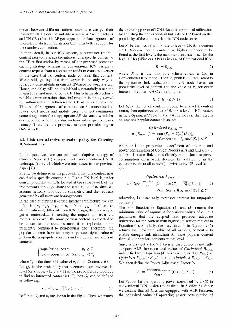
moves between different stations, users also can get their interested data from the suitable wireless AP which acts as an ICN CR (after this AP gets appropriate data segment of interested Data from the station CR), then better support for the seamless connection. In more detail, in our ICN system, a commuter (mobile content user) only sends the interest for a specific content to the CP at first station by reason of our proposed proactive caching strategy whereas in conventional ICN design, a content request from a commuter needs to come to a server in the case that no content node contains that content. Worse still, getting data from server is the only way to retrieve a content/data in current IP-based network system. Hence, the delay will be diminished substantially since the interest does not need to go to CP. This scheme also offers a reliable communication since information is firstly served by authorized and authenticated CP of service provider. Then suitable segments of contents can be transmitted to lower level nodes and mobile users can get continuous content segments from appropriate AP via smart scheduler during period which they stay on train with expected lower latency. Therefore, the proposed scheme provides higher QoS as well. 4.3. Link rate adaptive operating policy for Greening ICN-based ITS In this part, we state our proposed adaptive strategy of Content Node (CN) equipped with aforementioned ALR technique (some of which were introduced in our previous paper [8]). Firstly, we define pk as the probability that one content user can find a specific content c C at a CN level k, under consumption that all CNs located at the same level k of the tree network topology share the same value of pk since we assume network topology is symmetric and the requests generated by all users are homogeneous. In the case of current IP-based Internet architecture, we can infer that 0 and = 1 since as aforementioned, different from ICN design, the only way to get a content/data is sending the request to server via routers. Moreover, the more popular content is expected to be closer to the users because it is replicated more frequently compared to non-popular one. Therefore, the popular contents have tendency to possess higher value of
than the un-popular contents and we define two kinds of content: : :
where TP is the threshold value of p1 for all Content c C. Let Qk be the probability that a content user traverses k-level (or k hops, where k ≥ 1) of the proposed tree topology to find an interested content c C, then Qk can be defined as following: ∏ 1 (1)
Different Qk and pk are shown in the Fig. 1. Then, we match
the operating power of ICN CRs to its optimized utilization by adjusting the correspondent link rate of CR based on the popularity of the contents that the ICN node serves.
Let Rk be the incoming link rate to level-k CR for a content c C. Since a popular content has higher tendency to be found at the first levels, the maximum link rate is set for the level 1 CRs (Wireless APs) as in case of Conventional ICN:
(2)
where RICN is the link rate which enters a CR in Conventional ICN model. Then Rk (with k > 1) will adapt to the operating link utilization of ICN node based on popularity level of content and the value of R1 for every interest for content c C come to it, i.e.
1 (3)
Let be the set of content c come to a level k content router, then optimized value of Rk for a level k-ICN router, namely Optimized Rk,ICN (1 < k ≤ 4), in the case that there is at least one popular content is asked: , 1 min + ∑ (4) | |
where is the proportional coefficient of link rate and power consumption of Content Nodes (APs and CRs). α ≥ 1 and α = 1 means link rate is directly proportional to power consumption of network devices. In addition, c in the equation refers to all content(s) arrive to the CR level k. and , 1 min + ∑ (5) | |
otherwise, i.e. user only expresses interest for unpopular content(s). The min function in Equation (4) and (5) returns the minimum value of argument for various values of c, i.e it guarantees that the adapted link provides adequate utilization for the content with highest utilization request in Equation (4). Similarly, the max function in Equations (5) returns the maximum value of all arriving content c to enable enough link utilization for most popular content from all (unpopular) contents at that level. Since α may get value > 1 then in case device is not fully support ALR function and value of Optimized Rk,ICN indentified from Equation (4) or (5) is higher than RICN (i.e. Optimized Rk,ICN ≥ RICN) then let: Optimized Rk,ICN = RICN. We then define the Power Adjustment Factor PA: ,, 0 1 (6)
Let PR2-ICN be the operating power consumed by a CR in conventional ICN design (more detail in Section 5). Since we assume that all CRs are equipped with ALR function, the optimized value of operating power consumption of
2015 ITU Kaleidoscope Academic Conference
– 142 –
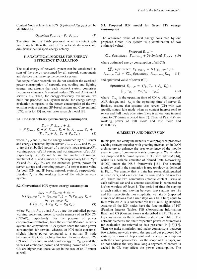
Content Node at level k in ICN (Optimized PR2-ICN,k) can be identified as:
Optimized PR2-ICN,k = PA PR2-ICN (7)
Therefore, for this DAN proposal, when a content gets more popular then the load of the network decreases and diminishes the transport energy notably.
5. ANALYTICAL MODELS FOR ENERGY-EFFICIENCY EVALUATION
The total energy of network system can be considered as sum of the energy consumed by all network components and devices that make up the network system. For scope of our research, we do not consider the overhead power consumption of network, e.g. cooling and lighting energy, and assume that each network system comprises two major elements: N content nodes (CRs and APs) and 1 server (CP). Then, for energy-efficiency evaluation, we build our proposed ICN system model for energy savings evaluation compared to the power consumption of the two existing system designs (IP-based system and Conventional ICN), refer to [13] and our prior research model [8]. 5.1. IP-based network system energy consumption + + + , + + + (8)
where ER-IP and ES are the energy consumed by a IP router and energy consumed by the server; PR1-IP, PR2-IP and PR2,AP-
IP are the embodied power of a network node (router/AP), working power of a IP router, and working power of an AP, respectively; N1, N2 and N are the number of routers, number of APs, and number of CNs respectively (N1 + N2 = N) and PS1, PS2, PS3 are the embodied power, power for server storage and operating power of a server (same value for both ICN and IP based network system), respectively. Besides, Tw is the working time of the whole network system. 5.2. Conventional ICN system energy consumption
+ + + + , + + + (9)
where PR1-ICN, PR2-ICN and PR3-ICN are the embodied power, working power and power to cache memory of an ICN CN (CR/AP), respectively. For the purpose of power consumption evaluation, both the current IP-based network system and conventional ICN system share the same power consumption for servers, whereas an ICN node consumes slightly higher power compared to a normal IP node because of the CN's caching function. In more detail, ICN CN need to endure an additional energy of PR3-ICN and the values of embodied power and working power of an ICN CR are higher than those values in the case of an IP router as well.
5.3. Proposed ICN model for Green ITS energy consumption The optimized value of total energy consumed by our proposed Green ICN system is a combination of two optimized values: ∑ , + (10)
where optimized energy consumption of all CNs: ∑ , + + ∑ , (11) and optimized value of server (CP): + + + (12)
where is the operating time of CN with proposed ALR design, and is the operating time of server S. Besides, assume that systems uses server (CP) with two specific states: Idle mode when no content interest send to server and Full mode otherwise (there is at least one interest come to CP during a period time T). Then let and are working power of Full mode and Idle mode and 0.3 .
6. RESULTS AND DISCUSSION In this part, we verify the benefits of our proposed proactive caching strategy together with greening mechanism in DAN architecture to enhance the user experience of the mobile users in case of commuter train's passengers. We simulate our proposed ICN based system in ITS with ndnSIM [14], which is a scalable emulator of Named Data Networking (NDN) under the NS-3 framework [15]. The network topology used in the simulation is tree topology as depicted in Fig.1. We assume that a train has seven distinguished railroad cars, and each car has its own dedicated wireless AP. There are two commuters (mobile content users) at each railroad car and a content user/client is connected to his/her wireless AP level 1. The period of time for staying at each station and moving between two stations are 18s and 90s, respectively. For simplicity, we take N (expected number of stations that a user stays on a train line) equal to four. Wireless APs is connected via IEEE 802.11g standard. Assume all the ICN nodes have the functionalities of PIT (Pending Interest Table), FIB (Forwarding Information Base) and CS (Content Store) as described in [9]. The other key-parameters for the simulation is shown in Table 1. The network elements and their respective power consumptions for evaluation are referred to data presented in [13][17]. Then we make simulation and make comparisons between two existing network system designs and our proposed ICN system, in terms of hop count and energy consumption with the above parameters. For the scope of this paper, we do not address the way how long a segment of content is cached in CR may affect the power consumption. The
Trust in the Information Society
– 143 –

Table 1. Key-parameters for simulation in ndnSIM
Simulation key-parameters
Connection bandwidth 1Gbps
Content Size 1000MB
Payload (content-chunk) size
1024 bytes
Content Store size 20,000 objects
Number of Station CRs (Aggregation Nodes)
4
Content request rate 25% of network available bandwidth
Cache object eviction policy
LRU (Least Recently Used)
Content popularity distribution
Zipf distribution (similar to the Zipf-like distribution in [16])
Fig. 3 Performance evaluation for Average Hop Count of proposed
ITS system
Fig. 4 Average power consumption of different network systems versus
the different cache size of ICN content router following metrics are evaluated: • Average Packet Hop count of proposed ITS system: the Average Packet Hop count is almost stable with the simulation time as showed in the Fig.3 except the cases that the Mobile Node (MN) is involved in the Hand-offs period
Fig 5. Average power consumption of network systems versus α value
when it moves to change the PoA to another Station node (when train stops at a station). The period taken to hand-off is very short, thanks to our "smart scheduler" and innovated proactive caching strategy. • Impact of ICN CN caching size on average power consumption: From our simulation result as shown in Fig. 4, the average power consumption of both Conventional ICN and our proposed ICN model increase when we increase the size of the content cache of each CN (five different ICN CN cache sizes: 64 GB, 96 GB, 128 GB, 192 GB and 256 GB with α = 1). This is because ICN system need to endure additional caching energy for the CN as stated in part 5.2 (the respective values of CNs' power consumptions can be found in [13]). Moreover, our proposed model can save significantly power consumption compared to other current network designs. • Impact of Alpha value (α) on average power: As can be seen in Fig. 5, the value of α and average power consumption of the network system have a linear relationship. Typically, we take value of α ranges from 1 to 1.3 for the evaluation. Though Conventional ICN consumes slightly higher energy consumption compared to our current IP-based architecture due to additional energy for caching capability, from Fig. 5, our proposed Green ITS model can substantially decrease energy consumption. In more detail with α = 1 (the ideal case with ALR-fully support CN), our proposed system can save about 21.16 % energy compared to conventional ICN in the same scenario, whereas this ratios are decreased to 18.57 % with α = 1.3.
7. CONCLUSION AND FUTURE WORK In this article, we have designed a model utilizing innovated dynamic pre-fetching and ALR based scheme together as a practical ITS solution to offer reliable and effective wireless content access for the commuters in transportation system (particularly railway system). Our proposed system also supports seamless communication to raise content robustness and reliability, then secure the mobile content user's security and can be used in a wide range of transportation system in the future to realize
2015 ITU Kaleidoscope Academic Conference
– 144 –
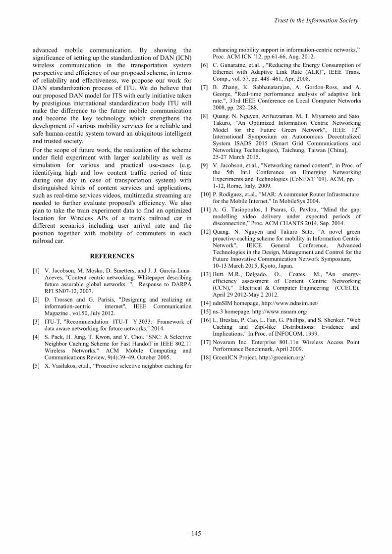
advanced mobile communication. By showing the significance of setting up the standardization of DAN (ICN) wireless communication in the transportation system perspective and efficiency of our proposed scheme, in terms of reliability and effectiveness, we propose our work for DAN standardization process of ITU. We do believe that our proposed DAN model for ITS with early initiative taken by prestigious international standardization body ITU will make the difference to the future mobile communication and become the key technology which strengthens the development of various mobility services for a reliable and safe human-centric system toward an ubiquitous intelligent and trusted society. For the scope of future work, the realization of the scheme under field experiment with larger scalability as well as simulation for various and practical use-cases (e.g. identifying high and low content traffic period of time during one day in case of transportation system) with distinguished kinds of content services and applications, such as real-time services videos, multimedia streaming are needed to further evaluate proposal's efficiency. We also plan to take the train experiment data to find an optimized location for Wireless APs of a train's railroad car in different scenarios including user arrival rate and the position together with mobility of commuters in each railroad car.
REFERENCES
[1] V. Jacobson, M. Mosko, D. Smetters, and J. J. Garcia-Luna-Aceves, "Content-centric networking: Whitepaper describingfuture assurable global networks. ", Response to DARPARFI SN07-12, 2007.
[2] D. Trossen and G. Parisis, "Designing and realizing aninformation-centric internet", IEEE CommunicationMagazine , vol.50, July 2012.
[3] ITU-T, "Recommendation ITU-T Y.3033: Framework ofdata aware networking for future networks," 2014.
[4] S. Pack, H. Jung, T. Kwon, and Y. Choi. "SNC: A SelectiveNeighbor Caching Scheme for Fast Handoff in IEEE 802.11Wireless Networks." ACM Mobile Computing andCommunications Review, 9(4):39–49, October 2005.
[5] X. Vasilakos, et.al., “Proactive selective neighbor caching for
enhancing mobility support in information-centric networks,” Proc. ACM ICN ’12, pp.61-66, Aug. 2012.
[6] C. Gunaratne, et.al. , "Reducing the Energy Consumption of Ethernet with Adaptive Link Rate (ALR)", IEEE Trans. Comp., vol. 57, pp. 448–461, Apr. 2008.
[7] B. Zhang, K. Sabhanatarajan, A. Gordon-Ross, and A. George, "Real-time performance analysis of adaptive link rate.", 33rd IEEE Conference on Local Computer Networks 2008, pp. 282–288.
[8] Quang. N. Nguyen, Arifuzzaman. M, T. Miyamoto and Sato Takuro, "An Optimized Information Centric Networking Model for the Future Green Network", IEEE 12th
International Symposium on Autonomous Decentralized System ISADS 2015 (Smart Grid Communications and Networking Technologies), Taichung, Taiwan [China], 25-27 March 2015.
[9] V. Jacobson, et.al., "Networking named content", in Proc. of the 5th Int.l Conference on Emerging Networking Experiments and Technologies (CoNEXT ’09). ACM, pp. 1-12, Rome, Italy, 2009.
[10] P. Rodiguez, et.al., "MAR: A commuter Router Infrastructure for the Mobile Internet." In MobileSys 2004.
[11] A. G. Tasiopoulos, I Psaras, G. Pavlou, “Mind the gap: modelling video delivery under expected periods of disconnection,” Proc. ACM CHANTS 2014, Sep. 2014.
[12] Quang. N. Nguyen and Takuro Sato, "A novel green proactive-caching scheme for mobility in Information Centric Network", IEICE General Conference, Advanced Technologies in the Design, Management and Control for the Future Innovative Communication Network Symposium, 10-13 March 2015, Kyoto, Japan.
[13] Butt. M.R., Delgado. O., Coates. M., "An energy-efficiency assessment of Content Centric Networking (CCN)," Electrical & Computer Engineering (CCECE), April 29 2012-May 2 2012.
[14] ndnSIM homepage, http://www.ndnsim.net/[15] ns-3 homepage, http://www.nsnam.org/[16] L. Breslau, P. Cao, L. Fan, G. Phillips, and S. Shenker. "Web
Caching and Zipf-like Distributions: Evidence and Implications." In Proc. of INFOCOM, 1999.
[17] Novarum Inc. Enterprise 801.11n Wireless Access Point Performance Benchmark, April 2009.
[18] GreenICN Project, http://greenicn.org/
Trust in the Information Society
– 145 –


NETWORK FAILURE DETECTION SYSTEM FOR TRAFFIC CONTROLUSING SOCIAL INFORMATION IN LARGE-SCALE DISASTERS
Chihiro Maru1, Miki Enoki1,2, Akihiro Nakao3, Shu Yamamoto3, Saneyasu Yamaguchi4, Masato Oguchi1
1Ochanomizu University, Bunkyo, Tokyo, Japan, {maru.chihiro, oguchi}@is.ocha.ac.jp2IBM Research - Tokyo, Chuo, Tokyo, [email protected]
3University of Tokyo, Bunkyo, Tokyo, Japan, {nakao, shu}@iii.u-tokyo.ac.jp4Kogakuin Univirsity, Shinjuku, Tokyo, Japan, [email protected]
ABSTRACT
When the Great East Japan Earthquake occurred in 2011, itwas difficult to grasp all network conditions immediately us-ing only information from sensors because the damage wasconsiderably heavy and the severe congestion control stateoccurred. Moreover, at the time of the earthquake, telephoneand Internet could not be used in many cases, although Twit-ter was still available. In an emergency such as an earth-quake, users take an interest in the network condition andprovide information on networks proactively through socialmedia. Therefore, the collective intelligence of Twitter is suit-able as a means of information detection complementary toconventional observation. In this paper, we propose a net-work failure detection system that detects candidates of fail-ures of telephony infrastructure by utilizing the collective in-telligence of social networking services. By using this sys-tem, more information, which is useful for traffic control, canbe detected.
Keywords— Twitter, social information, failures of tele-phony infrastructure, traffic control
1. INTRODUCTION
Large-scale disasters such as earthquakes often cause net-work failures because base stations and network facilities aredamaged and many users are trying to access the network atthe same time. In cases of emergency, it is important thattelephone and Internet be available. Therefore, the neces-sity for failure detection in large-scale disasters is high. Usu-ally, network conditions are monitored by sensors. However,when the Great East Japan Earthquake occurred in 2011, itwas difficult to grasp all network conditions immediately us-ing only information from sensors because the damage wasconsiderably heavy and the severe congestion control stateoccurred. [1].In subsequent research on the Great East Japan Earthquake[2], survey participants responded that they were able to useTwitter [3]. Twitter is also advantageous in that it can obtaininformation from users in real time. In an emergency such as
This work is partially supported by the Strategic Information and Com-munications R&D Promotion Programme (SCOPE).
an earthquake, users take an interest in the network conditionand provide information on networks proactively through so-cial media. Hence, Twitter can be used to obtain informationon the locations and causes of network failures and on thedegree of impact to users, which cannot be obtained usingonly sensors. Therefore, the collective intelligence of Twitteris suitable as a means of information detection complemen-tary to conventional observation. Against this background,we propose a network failure detection system that detectscandidates of failures of telephony infrastructure by utilizingthe collective intelligence of social networking services. Thissystem is targeted to network managers, who wish to detectfailures of telephony infrastructure automatically in case ofemergency.
Here, there is an issue if Twitter will be accessible when In-ternet services are down. However, if a wireless LAN accessis not available, other services such as 3G network and LTEmay be able to be used. Moreover, people in areas wherefailures don’t occur provide information on the failures oftelephony infrastructure.
Among the earthquakes that occurred in 2014, we detectedfailures of telephony infrastructure with a high degree of ac-curacy [4]. However, in the case of large-scale earthquakessuch as the Great East Japan Earthquake, more information,which is useful for traffic control, is needed. For example,when our system detects telephone trouble, we want to clas-sify whether users cannot get through to the detected loca-tion or cannot get through from the detected location. In thiscase, the areas where a failure is likely to occur should bethe former. Therefore, in this work, we investigated tweetssent out during the Great East Japan Earthquake and usedour findings to develop a method that uses machine learningto classify the detected locations into two groups.
The remainder of this paper is organized as follows. Section2 introduces related research studies and Section 3 gives anoverview of our proposed system. Sections 4 and 5 respec-tively discuss the candidate data detection method and thelocation classification method that are a part of our proposedsystem. In Section 6, we describe a visualization of the re-sults of the location classification method and the externalinformation. We conclude in Section 7 with a brief summaryand a mention of the future direction of our research.
978-92-61-15821-7/CFP1538E-ART © 2015 ITU Kaleidoscope– 147 –

2. RELATED WORK
There are currently a number of methods that detect eventsoccurring in the real world (earthquakes, landslides, fire, etc.)by analyzing the data in social media [5][6][7][8][9]. Sakakiet al. [5] introduced a method to detect earthquakes earlyand estimate their locations by considering each Twitter useras a sensor. The Ministry of Land, Infrastructure, Transportand Tourism [6] introduced a method to detect the signs andoccurrences of landslides early on the basis of the tweets ofresidents of the areas where a disaster is likely to occur. Ourcurrent work differs from these existing methods in that 1)the existing methods restrict their focus to the occurrence ofan event and do not detect more detailed information whenlarge events occur, and 2) they do not utilize the external in-formation issued by public agencies, which would be usefulin terms of increasing the accuracy.Our method is unique in that it 1) increases the accuracy ofnetwork failure detection using collective intelligence by fil-tering out irrelevant tweets, and 2) detects information fortraffic control. Moreover, we use social networking servicesfor network management. Tongqing et al. [10] reported thatusers posted messages on Twitter before they called a cus-tomer service center if they experienced network failures,and Takeshita et al. [11][12] had a similar motivation to ourown in that they use tweets related to network performanceissues in order to oversee network operation. However, ourpresent work differs from these in that 1) we focus on naturaldisasters and 2) we detect failures of telephony infrastructureusing more that just tweets.
3. OVERVIEW OF PROPOSED METHOD
An overview of our proposed network failure detection sys-tem is given in Figure 1. Figure 2 gives an overview of thecandidate data detection method that is a part of the proposedsystem.The process flow of the proposed method is as follows.
(1) Set specific keywords that can detect failures of tele-phony infrastructure and collect tweets containing thekeyword.
(2) Classify the tweets in accordance with location infor-mation into each location group.
(3) Collect tweets without location information but spec-ifying the same failure to increase the amount of can-didate data. We calculate characteristic words with thedata set of (2) and add tweets containing the words intothe data set of (2).
(4) Consider post time of each tweet and apply temporalfiltering to cut irrelevant tweets.
(5) Classify location from tweets detected by our systemas to whether the failure happened at this or anotherlocation.
(6) Obtain external information such as Earthquake EarlyWarning and match this with the failure informationdetected by (5).
(7) Visualize failure information on Google Maps.
Figure 1. Network failures detection system.
Figure 2. Candidate data detection.
It is important that failures of telephony infrastructure bedetected immediately. For real-time processing, we collecttweets every minute and use tweets in the last 60 minutes aspotential tweets for failure detection. This system then out-puts failure information for each detected location.
4. CANDIDATE DATA DETECTION METHODUSING SOCIAL NETWORKING SERVICES
4.1. Keyword Search
We set specific keywords that represent telephone trouble us-ing a Search API supported by Twitter Inc. to collect tweetsabout failures of telephony infrastructure. The keywords arephrases that mean users cannot get through by telephone inJapanese.
4.2. Location Information Detection
Various tweets can be associated with location. For example,Twitter users may register their location on their profile, andsometimes they attach Geotagging to a tweet. We conducteda morphological analysis of tweets and their registered Geo-tagging locations by using MeCab [14], which separates sen-tences into a set of words. Latitude and longitude details ofthe Geotagging are converted into a city name using the Ya-hoo! reverseGeoCoder API [15] supported by Yahoo! Inc.We counted the number of occurrences of location names and
2015 ITU Kaleidoscope Academic Conference
– 148 –

detected them that appeared more than a certain number oftimes. In this work, we define the threshold of occurrencesas five times. Then, we classified the tweets of Section 4.1 inaccordance with the detected location information into eachlocation group.
4.3. Characteristic Words Detection
To collect tweets that do not contain the same location butrefer to the same failure, we detect characteristic words inthe tweets. We then collect tweets that contain the detectedcharacteristic words and not the other location informationand add them to the tweets for each piece of location infor-mation.”Characteristic words” are found in tweets for each piece oflocation information by detecting only nouns using MeCab.We exclude byte symbols and half-width letters and numbers.Then, we calculate a TFIDF (Term Frecuency Inversed Doc-ument Frequency) value for each detected noun and define anoun that has a TFIDF value greater than or equal to 0.2 as acharacteristic word.TFIDF is a numerical statistic that is reflected how importanta word is to a document. TF value is the term frequency.Therefore, words that appear many times are important. IDFvalue is the inverse document frequency. The smaller it is, thegreater the number of tweets that a word appears is. There-fore, it has a role to increase the importance of words thatonly appear in specific tweets. TFIDF value is calculated bymultiplicating a TF value and a IDF value.In this study, TFIDF value is calculated as follows; where thenumber of detected nouns is N , experimental tweets that areclassified into each location group of Section 4.2 are TWe,and the roughly 100,000 tweets obtained using Twitter Inc.’sStreaming API [16] are TW10. These TW10 are tweets ofnormal period that are not be set any keywords, and they areutilized to calculate IDF value. By introducing TW10, N canbe compared with words of normal period.
TFvalue =the number of times N appears in TWe
the total number of words that appear in TWe(1)
IDFvalue =the total number of tweets of TWe and TW10
the number of tweets that contain N in TWe and TW10(2)
4.4. Temporal Filtering
In each piece of location information, there are a number oftweets that are unrelated to failures of telephony infrastruc-ture. Therefore, we consider the timestamps of tweets anddiscard any tweets that are unrelated. Twitter users tend tosimultaneously post similar tweets when large-scale disas-ters happen, and in this study, we consider this feature anddetermine a certain threshold of time to eliminate tweets. Todetermine this threshold, we examine the time variations ofthe number of tweets that refer to failures of telephony in-frastructure and generalize them.
(a) Earthquake in Hokkaido
(b) Earthquake in Ibaraki
(c) Earthquake in Nagano
Figure 3. Time variations of tweets that refer to failures oftelephony infrastructure.
Figure 3 shows each time variation of the number of tweetsthat refer to failures of telephony infrastructure in the case ofan earthquake in Hokkaido on July 8, 2014, an earthquake inIbaraki on September 16, 2014, and an earthquake in Naganoon November 22, 2014 (green bar graph).
As shown in Figure 3, the number of tweets increased rapidlyafter earthquakes occurred and then eventually saturated.
Trust in the Information Society
– 149 –

This result shows that time variations of the number of tweetsin earthquakes are characteristic. In this study, we considercumulative frequency since the number of samples is small.Figure 3 shows the actual data of cumulative frequencies(red line). The time variations of cumulative frequencies aresimilar to the cumulative distribution function of an expo-nential distribution. Hence, we fitted each time variation of acumulative frequency to the cumulative distribution functionof exponential distributions. This cumulative distributionfunction is defined as
f(x) = 1− e−λx (3)
Figure 4 shows the results of fitting earthquakes in Hokkaido,Ibaraki, and Nagano.
Figure 4. Results of fitting cumulative distribution functionsof an exponential distribution.
Results showed that all time variations of cumulative fre-quencies were fitted to the cumulative distribution functionsof an exponential distribution. This indicates that the timevariations of the number of tweets can be approximated toan exponential distribution. Moreover, since this is an expo-nential distribution, we can capture 80% of the events in 60minutes. Hence, for real-time processing, we collect tweetsevery minute and use tweets in the last 60 minutes as poten-tial tweets for failure detection.
5. LOCATION CLASSIFICATION METHOD USINGMACHINE LEARNING
Among the earthquakes that occurred in 2014, the candidatedata detection method (Section 4) was able to detect failuresof telephony infrastructure with a high degree of accuracy[4]. However, in the case of large-scale earthquakes such asthe Great East Japan Earthquake, more information, whichis useful for traffic control, is needed. For example, whenour system detects telephone trouble, we want to classifywhether users cannot get through to the detected location orcannot get through from the detected location. In this case,
the areas where a failure is likely to occur should be the for-mer. Therefore, on the basis of our analysis of tweets sentout during the Great East Japan Earthquake, we developed amethod that utilizes machine learning to classify the detectedlocations into two groups. Table 1 shows examples of tweetsthat were detected with the candidate data detection method.
Table 1. Examples of tweets of candidate data detectionmethod.
A.「宮城へ電話繋がらないよ...心配だ」( I cannot get through to Miyagi...I’m worried.)
B.「渋谷なう電話繋がらない」( I’m in Shibuya now. I cannot get through.)
Here, tweetA shows that the user cannot get through to thedetected location (Miyagi) while tweetB shows that the usercannot get through from the detected location (Shibuya).Therefore, tweetA and tweetB are different kinds of tweets.Classifying tweets in this way enables us to obtain moreinformation, which is useful for traffic control. Hence, weclassify tweets detected with the candidate data detectionmethod. The detected tweets can be classified into the fol-lowing three types:
(1) tweets that mean users cannot get through to the de-tected location (= Data Set A)
(2) tweets that mean users cannot get through from the de-tected location
(3) undeterminable tweets
There is a possibility that tweets from the location of the fail-ure are classified as (1). Therefore, we focus on Data Set Aof (1). In this paper, we classify the tweets into tweets thatmean either users cannot get through to the detected loca-tion of (1) or other tweets, which include both (2) and (3).We propose tweet detection with a rule-based approach andtweet classification using machine learning.
5.1. Tweet Detection by the Rule-Based Approach
Figure 5 shows the flow of tweet detection with the rule-based approach.
Figure 5. Flow of tweet detection with rule-based approach.
First, we perform the candidate data detection method andcollect the tweets that are obtained by the keyword search
2015 ITU Kaleidoscope Academic Conference
– 150 –

for each item of location information. Next, for each detectedlocation, we judge whether the tweets satisfy the extractionrules. We extracted the patterns common to Data Set A andthen made rules to classify the tweets. The extraction rulesare:
(1) words in person or family dictionary are in the tweet(2) to (the detected location) is in the tweet(3) the word worry is in the tweet
The person or family dictionary is a dictionary that includeswords related to people, e.g., mother, son, and sister. In thiswork, we selected these rules because an evaluated value wasthe best among other rules. Table 2 shows examples of tweetsthat satisfy these rules.
Table 2. Examples of tweets that satisfy these rules.(1)「岩手の母に電話がつながらない」
(I cannot get through to my mother in Iwate.)(2)「仙台に電話つながらないよ」
(I cannot get through to Sendai.)(3)「宮城のほうはかなり揺れてたみたいです。
今は電話しても繋がらないので、心配です。」(Miyagi seems to have shaken quite a lot.I cannot get through now, so I’m worried.)
If a tweet satisfies any one of these rules, the tweet is classi-fied as Data Set A.
5.2. Location Classification with the Machine Learning
In order to classify whether the detected tweets are Data SetA or other tweets, we created a classifier using a support vec-tor machine (SVM). SVM-light was used as a classifier. Inthe classification with machine learning, we use only Bag ofWords (BoW) and the rules of the tweet detection with therule-based approach as features. When rules are added asfeatures, the subjects of BoW are nouns, verbs, and adjec-tives.
5.3. Evaluation
Table 3 lists the results of tweet detection with the rule-basedapproach and the location detection with machine learning.Tweets in the Great East Japan Earthquake that were detectedwith the candidate data detection method were used as eval-uation data. These data are made up of 726 tweets that meanusers cannot get through to the location and 300 other tweets.We use leave-one-out cross validation as an assay method ofthe classification with machine learning.Adding the rules of the rule-based approach as features canincrease F-value, which demonstrates that adding rules is ef-fective. Furthermore, when rules were added in the classifi-cation of the machine learning, F-value increased by about 10points in comparison to tweet detection with the rule-basedapproach.
Table 3. Evaluation of data classification.
Method Precision Recall F-valueDetection with
rule-based approach 0.8170 0.8058 0.8114Classification with
machine learning (only BoW) 0.8166 0.9752 0.8889Classification with
machine learning (with rules) 0.8606 0.9862 0.9191
6. VISUALIZATION OUTPUT OF DETECTEDFAILURE
We match the disaster information issued by public agenciesin order to determine the cause and the location of failuresthat were detected using our proposed method. External in-formation such as Earthquake Early Warning (EEW) issuedvia Twitter was used here.In this study, we obtain EEW through tweets, which broad-cast EEW contents indirectly. We then analyze the warningsand obtain the time, position, and strength of the earthquake.We take the results detected with the candidate data detec-tion method and location classification method using the dataof Section 5, match them with the external information, andthen visualize them on Google Maps. We visualize the cor-rect classification results manually to obtain the correct dataon the location classification method. Therefore, we can con-firm the effectiveness of the proposed method. Figure 6(a)shows the results using the proposed method and Figure 6(b)shows the manual classification results.Colored pins represent the situation in the area where the pinis stuck, with red indicating that users cannot get through tothe area and blue indicating the other situation (users cannotget through from the area, etc.). Seismic intensity obtainedby EEW is set to the center of a circle, with the radius of thecircle dependent on the magnitude of the quake. In Figure6(a), the red pins are close to the circle, indicating that a ma-jor failure occurred near the seismic intensity. The blue pinsare located further away from the seismic center, indicatingthat a failure had not occurred in this area but that users couldnot get through to people near the seismic center.When we compared the results in Figures 6(a) and 6(b), nodifference could be seen. This demonstrates that our pro-posed method performs well.
7. CONCLUSION
When the Great East Japan Earthquake occurred in 2011, itwas difficult to quickly grasp all network conditions becausethe amount of information on the damage and the congestioncontrol state, which is needed to understand the damage, wasenormous. Moreover, at the time of the quake, telephone andInternet could not be used, although Twitter was still avail-able. In an emergency such as an earthquake, users take aninterest in the network condition and provide information onnetworks proactively. In this paper, we proposed a network
Trust in the Information Society
– 151 –

(a) Results using proposed method
(b) Results classified manually
Figure 6. Visualization results of Great East Japan Earth-quake.
failure detection system that detects candidates of failuresof telephony infrastructure by utilizing the collective intel-ligence of social networking services.
Among the earthquakes that occurred in 2014, we detectedfailures of telephony infrastructure with a high degree of ac-curacy. However, in the case of large-scale earthquakes suchas the Great East Japan Earthquake, more information, whichis useful for traffic control, is needed. Therefore, we pro-posed a method that uses machine learning to classify loca-tions that had been detected with the candidate data detectionmethod into two groups. By visualizing tweets sent out dur-ing the Great East Japan Earthquake, along with informationobtained by EEW on Google Maps, we showed that the lo-cation classification method using machine learning workseffectively.
In this work, network failure information was detected usingour system. As the next step, we plan to use the detected in-formation to construct a system that can control the network.
REFERENCES
[1] NTT DOCOMO, ”Improvement of Credibility for Op-eration System in the Case of Large Disaster”,https://www.nttdocomo.co.jp/binary/pdf/corporate/technology/rd/technical journal/bn/vol20 4/vol20 4 026jp.pdf
[2] NHK, ”Earthquake Disaster and Cellular Phones: Sum-mary of Survey Results”,http://www9.nhk.or.jp/kabun-blog/
[3] Twitter, http://twitter.com/
[4] Chihiro Maru, Miki Enoki, Akihiro Nakao, Shu Ya-mamoto, Saneyasu Yamaguchi, and Masato Oguchi.”Information Detection on Twitter for Network SystemControl in Large-Scale Disasters”, DEIM2015, C7-3,2015.
[5] Takeshi Sakaki, Makoto Okazaki, and Yutaka Mat-suo. ”Earthquake Shakes Twitter Users: Real-TimeEvent Detection by Social Sensors”, Proceedings of the19th International Conference on the World Wide Web,ACM, pp. 851-860, 2010.
[6] National Institute for Land and Infrastructure Manage-ment: A Study on Method for Detection of DisasterOutbreak by Means of Social Media Analysis, 2014.
[7] Shota Saito, Yohei Ikawa, and Hideyuki Suzuki. ”EarlyDetection of Disasters with Contextual Information onTwitter”, Technical Report of IEICE 114.81 (2014): 7-12.
[8] Sadilek, Adam, Henry A. Kautz, and Vincent Silenzio.”Predicting Disease Transmission from Geo-TaggedMicro-Blog Data”, AAAI, pp. 136-142, 2012.
[9] Metaxas, Panagiotis Takis, Eni Mustafaraj, and DanielGayo-Avello. ”How (not) to predict elections”, Privacy,Security, Risk, and Trust (PASSAT), 2011 IEEE ThirdInternational Conference on and 2011 IEEE Third In-ternational Conference on Social Computing (Social-Com), IEEE, pp. 165-171, 2011.
[10] Qiu, Tongqing, et al. ”Listen to me if you can: trackinguser experience of mobile network on social media”,Proceedings of the 10th ACM SIGCOMM Conferenceon Internet Measurement, ACM, pp. 288-293, 2010.
[11] Kei Takeshita, Masahiro Yokota, Ken Nishimatsu, andHaruhisa Hasegawa. ”Proposal of the Network Fail-ure Information Acquisition Method from Social Net-work Services”, IEICE Society Conference 2015, B-7-35, Sept. 2012.
[12] Kei Takeshita, Masahiro Yokota, Ken Nishimatsu, andHaruhisa Hasegawa. ”Evaluation of the Network Fail-ure Information Acquisition System from Social Net-work Services”, Proceedings of the 2013 IEICE Gen-eral Conference, B-7-44, Mar 2013.
2015 ITU Kaleidoscope Academic Conference
– 152 –

[13] Twitter Serch API,https://dev.twitter.com/rest/public/search
[14] MeCab, http://mecab.sourceforge.net/
[15] Yahoo! reverseGeoCoder API,http://developer.yahoo.co.jp/webapi/map/openlocalplatform/v1/reversegeocoder.html
[16] Twitter Streaming API,http://dev.twitter.com/docs/streaming-apis
Trust in the Information Society
– 153 –


SESSION 6
THE NEED FOR SPEED (MEASUREMENTS)
S6.1 5G Transport and Broadband Access Networks: The Need for New Technologies and Standards.*
S6.2 A unified framework of Internet access speed measurements.
S6.3 Why we still need standardized internet speed measurement mechanisms for end users.*


5G TRANSPORT AND BROADBAND ACCESS NETWORKS: THE NEED FOR NEWTECHNOLOGIES AND STANDARDS
Pham Tien Dat, Atsushi Kanno, Naokatsu Yamamoto
National Inst. of Inf. and Commun. Techno.Tokyo 184-8795, Japan
Tetsuya Kawanishi
Waseda UniversityTokyo 169-8050, Japan
ABSTRACT
In addition to new radio technologies, end-to-end transportnetworks will play a vital role in future 5G (and beyond) net-works. In particular, access transport networks connectingradio access with core networks are of critical importance.They should be able to support massive connectivity, su-per high data rates, and real time services in a ubiquitousenvironment. To attain these targets, transport networksshould be constructed on the basis of a variety of tech-nologies and methods, depending on application scenarios,geographical areas, and deployment models. In this paper,we present several technologies, including analog radio-over-fiber transmission, intermediate-frequency-over-fibertechnology, radio-on-radio transmission, and the conver-gence of fiber and millimeter-wave systems, that can facili-tate building such effective transport networks in many usecases. For each technology, we present the system concept,possible application cases, and some demonstration results.We also discuss potential standardization and developmentdirections so that the proposed technologies can be widelyused.
Keywords— 5G transport networks, fiber and wireless con-vergence, ubiquitous networks, coverging technologies.
1. INTRODUCTION
Recently, 5G networks and beyond are gaining a lot of in-terest from both industry and the academic community. Al-though an official definition of the 5G network has not yetbeen specified, there have been many efforts and propos-als regarding its targets and goals. Many research projectsand forums have been established worldwide with the aimof setting out a common platform, possible targets, and un-derlying technologies. Among the many forums and projectsrelated to 5G networks are the International Telecommunica-tion Union (ITU) ’s International Mobile Telecommunication(IMT) 2020, Next Generation Mobile Networks (NGMN),5G Forum (Korea), and 5G Mobile Communications Pro-motion Forum (5GMF) (Japan). On the basis of the currentstudies, 5G will be a user- and machine-centric communi-cation network in which access to information and sharingof data can be done anywhere and anytime by anyone andanything [1]. It should be capable of supporting a higher
number of simultaneously connected devices, better cover-age, higher spectral efficiency, lower battery consumption,lower outage probability, lower latencies, lower infrastruc-ture deployment costs, and higher reliability of communica-tions. It should also be able to provide a variety of serviceswith various features, including machine to machine, Inter-net of Things (IoT), delay-sensitive services such as real-time8K ultra high-definition video, and other new services. Con-sequently, 5G networks will pose significant requirementsand challenges to the transport networks. With continued sitedensification and larger numbers and various services to beprovisioned, the role of the transport network will becomeincreasingly crucial [2]. The transport network should beable to support a wide range of 5G services, massive num-bers of simultaneously connected devices, new radio accesstechnologies, and deployment models. It should be capableof supporting high-reliability communications at any timeand in any situation, even when aboard fast-moving vehicles,during major social events with massive numbers of users,or in the event of disasters or accidents. Such transport net-works should help to enhance the user experience and truston the information and communication infrastructure. How-ever, most ongoing research efforts on 5G are now focusingon radio technologies and interfaces, whereas the transportnetwork-related issues have not been paid much attention.
On the other hand, the development of broadband accessnetworks, especially to underserved communities and ruralremote areas, is another important issue that should be ad-dressed to improve the quality of lives by means of infor-mation and communication technology (ICT). Recently, ITUproposed a “Connect 2020” program with an ambitious vi-sion for the ICT sector for the year 2020 [3]. The visionhighlights the role of ICTs as a key enabler for social, eco-nomic, and environmentally sustainable growth and develop-ment. Among the ambitious goals, achieving 90% broadbandcoverage for the rural population worldwide by 2020 is a keytarget. In the developed countries, broadband services canbe provided to users by means of high-speed wired networkssuch as fiber or copper cables to homes. However, there aremany underserved areas, especially in the developing coun-tries, where broadband infrastructure is still lacking. Ser-vices provisioned by means of satellite communications canpartially satisfy basic demands, but it is still far from meet-ing the target of providing broadband services to end usersbecause of its limited available bandwidth.
978-92-61-15821-7/CFP1538E-ART © 2015 ITU Kaleidoscope– 157 –

Motivated by these significant facts, in this paper, we presentseveral technologies that can be used for future mobile trans-port and/or broadband access networks to achieve the targetsof 5G networks and the Connect 2020 program. We presentthe concept, possible use cases, and some demonstration re-sults for each technology. We also discuss potential stan-dardization and development directions that need further ef-forts in order to promote the technologies for future uses.The paper is organized as follows. In Section 2, we discusschallenges of 5G mobile transport and broadband access net-works. In Section 3.1, we present analog radio-over-fiber(RoF) technology. In Section 3.2, intermediate-frequency-over-fiber (IFoF) technology is discussed. In Section 3.3, wepresent the radio-on-radio (RoR) concept and related topics.In Section 3.4, the convergence of fiber and millimeter-wave(MMW) systems is presented. We also discuss other opentopics that need efforts both in research and standardizationto support future mobile networks. Finally, Section 4 con-cludes the paper.
2. CHALLENGES OF 5G TRANSPORT ANDACCESS NETWORKS
As mentioned previously, 5G transport networks will facemany challenges because of the requirements of new func-tions and capabilities to support various services, scenarios,use cases, and models. Recently, the EU METIS project[4], which is considered an official model of European 5Gnetworks, has defined five future use cases that the networkshould be able to support, including: (1) amazing speed, (2)great service in a crowd, (3) ubiquitous devices communi-cating, (4) super real-time and reliable connections, and (5)best experience follows you. Each of these use cases in-troduces a challenge to the transport networks. Future ap-plications may impose different challenges to the networksbecause they can be associated with one or several of thesescenarios [2]. Support for very high data rates will requireboth higher capacity radio access nodes as well as a densi-fication of radio access sites. This, in turn, translates intoa challenge to the transport networks that need to supportmore sites and higher capacity per site. The great servicein a crowd scenario will put requirements on the transportnetworks to provide very high capacity on-demand to somespecific geographical locations such as during social events.In the ubiquitous communications of things, the radio accessand in turn the transport networks should support a massivenumber of users and devices that are connected to the net-works simultaneously. Support for delay-sensitive serviceswould be one of the important aspects of 5G because it re-quires extremely high bandwidth in the underlying infras-tructure to deliver various delay-sensitive services. The over-all latency must be extremely low to deliver real-time contentsuch as ultra high-definition video. In the best experience fol-lows you use case, the transport resources should be able toflexibly and quickly re-configure resources.Together with these challenges, the transport networksshould be capable of providing seamless mobility for en-
hancing user experience even when they are on fast-movingvehicles. The networks should also support ultra-densesmall-cell deployment in ultra-dense urban areas. At thesame time, the expenditure and maintenance cost, powerconsumption, and timeline to service rollout should be aslow as those of the current networks. These requirementsand challenges motivate the development of new transportnetworks.
3. SOLUTIONS FOR FUTURE MOBILETRANSPORT AND ACCESS NETWORKS
In this section, we present some promising technologies thatcan be used for 5G transport and broadband access networksto realize a more cost effective, low latency, fast provision ofservices, to increase user experience and trust on informationand communication infrastructure.
3.1. Analog radio-over-fiber systems
3.1.1. The needs of radio-over-fiber systems
In macro-cell-based mobile networks, digital photonic linksare typically used owing to their relatively good perfor-mance. Interface protocols such as the common public radiointerface and the open base station architecture initiative arewidely used for data digitization and transmission. How-ever, the small cell-based network, which is considered oneof the key techniques in 5G, as shown in Fig. 1(a), posesmany challenges to digital photonic links. First, the bit rateof the links must be very high [5]. Second, simultaneoustransmission of multiple wireless standards and radio accesstechnologies (RATs) over the same system presents anotherchallenge. In addition, strict requirements on latency and jit-ter in emerging wireless standards ultimately limit the fiberdistances. The use of high-frequency radio signals such asin the MMW band will bring another challenge because veryhigh-speed analog-to-digital (A/D) and digital-to-analog(D/A) converters are needed at the remote sites. Consideringthese key challenges, new transmission methods should beconsidered for future mobile transport networks.Analog RoF technology is a promising choice for future mo-bile transport networks using MMW signals [6]. Comparedto digital transmission, as shown in Fig. 1(b), analog trans-mission of radio signals over photonic links, as shown inFig. 1(c), can greatly simplify remote radio heads (RRHs).By avoiding the digitization process, analog links help toreduce the transmission data rate, reduce latency, and avoidthe use of expensive A/D and D/A converters at RRHs. Thisapproach can enable a coexistence of multiple radio signalsin the same system simultaneously [6]. This helps to reducethe system cost, power consumption, and complexity, andenhances cooperation between cells. Nevertheless, manydrawbacks are also associated with this method becauseof its reduced dynamic range, nonlinearity distortion, andfiber dispersion effect. A comprehensive study of the sys-tem performance evaluation, especially for transmission of
2015 ITU Kaleidoscope Academic Conference
– 158 –

Core Network
BBU pool
Mobile backhaul Mobile fronthaul
Macro cell
Small cells RRH
RRH
RRH
RRH
Fiber
Millimeter-wave
Microwave
(a)
BBU: Baseband Unit RRH: Remote Radio Head IQ: In-phase/Quadrature
D/A: Digital to Analog BB to RF: Baseband to Radio Frequency Tx/Rx: Transmitter/Receiver
Optical Tx (Digital)
BBU RRH
IQ signals IQ Mod (b)
Optical Rx (Digital) D/A BB to RF
Optical Tx (Analog)
BBU RRH
IQ signals (c)
Optical Rx (Analog)
IQ Mod D/A
RRH
Figure 1: (a) Concept of using analog RoF for dense small-cell deployment. (b) Block diagram of digitized RoF system. (c)Analog RoF system.
-2 0 2 4 6 8 10 12-44
-40
-36
-32
-28
-26
RF Tx. Power (dBm)
EVM
(dB)
carrier fre. at 5GHz
carrier fre. at 10 Ghzcarrier fre. at 15 GHz
-6 -4 -2 0 2 4 6 8-44
-40
-36
-32
-28
Rx. Opt. Power (dBm)
EVM
(dB)
carrier fre. at 5GHzcarrier fre. at 10 GHzcarrier fre. at 15 GHz
(a) (b)
-15 -10 -5 0 5 10 150
2
4
6
8
Tx. RF. Power (dBm)
EV
M (%
)
Carrier at 2 GHz
Carrier at 6 GHzCarrier at 12 GHz
(c)
Figure 2: (a) 802.11ac signal performance versus transmission powers. (b) 802.11ac signal performance versus receivedoptical powers. (c) LTE-A signal performance versus transmission powers.
new wireless standards at high-frequency regions, should beconducted to confirm its potential.
3.1.2. Experiment demonstration
In this subsection, we present an experimental demonstrationof transmitting a very-high throughput IEEE 802.11ac signaland a high-speed long term evolution-advanced (LTE-A) sig-nal over an analog photonic link. The experimental setup issimilar to the diagram shown in Fig. 1(c). These standards-compliant signals are generated by signal studio software anddownloaded to vector signal generators (VSGs). The gener-ated signals in turn modulate a light-wave signal from a laserdiode by an optical modulator. The modulated optical sig-nal is amplified by an optical amplifier and transmitted overa 20-km single-mode fiber (SMF) to an optical receiver. Thesignal is then converted to the originally transmitted wirelesssignals by an optical to electrical (O/E) converter. The recov-
ered signal is connected to a vector signal analyzer (VSA)and finally demodulated offline by VSA software. It shouldbe noted that in practice, direct modulation of wireless sig-nals on an optical signal can be also performed using a directlaser modulator [7].
We evaluated the transmission performance using the errorvector magnitude (EVM) parameter, which is one of the mainperformance metrics for transmitter tests. Performance for a20-MHz IEEE 802.11ac signal and an LTE-A signal is shownin Fig. 2. Required EVM values for 256-QAM signals usingthe 3/4 and 5/6 code rates are -31 dB and -33 dB, respec-tively [8]. Measured results for different transmission pow-ers are shown in Fig. 2(a). Here the RF transmit power isthe power at the input of the optical transmitter. Comparedto the requirements, the transmission was successful for allsignals. However, transmission powers of high carrier fre-quency signals should be shifted to higher values because
Trust in the Information Society
– 159 –

-18 -16 -14 -12 -10 -82
3
4
5
6
7
8
9
10
Rx. Opt. Power (dBm)
EVM
(%)
20-m SMF20-km SMF40-km SMF
E/O
Amplifier
BBU
VSG
PD
RRH
ED
X PD
LNA
VSA
ATT
(a) E/O
(b)
IF signal
LO
LO
IF signal
BPF
BPF
Figure 3: (a) Experimental setup for IFoF and remote delivery of an LO signal. (b) Performance of LTE-A signaltransmission over the IFoF system.
of fiber dispersion effects. We should note that EVM valuedegradation in low transmission power regions is because oflow signal to noise ratio, and that in the high transmissionpower region is because of nonlinear distortion effects. Theperformance for different received optical powers is shown inFig. 2(b). It is observed that the performance degrades withincreasing signal carrier frequency. Fig. 2(c) presents theperformance of the carrier aggregation (CA) LTE-A signalfor different transmission powers. The required EVM valuefor a 64-QAM signal is 8% [9]. Similar to IEEE 802.11acsignals, LTE-A signals are successfully transmitted with sat-isfactory performance. However, the performance relativelydegrades with increasing carrier frequency because of fiberdispersion effects.From these results, it is confirmed that RoF systems canprovide satisfactory performance for emerging wireless stan-dards. However, its performance can be greatly degradedbecause of nonlinear distortion and fiber dispersion effects,especially for signals in the high-frequency bands. This willlimit its applications because high-frequency bands such asMMW are being considered as a key technology for 5Gnetworks [10]. From these observations, further study andinvestigation should be conducted to promote this promisingtechnology. Appropriate methods for nonlinear distortioncompensation, especially for high carrier frequency signals,fiber dispersion mitigation methods, and mapping algorithmsfor aggregating multiple signals are among the open topics.Currently, standardization of RoF technology is being dis-cussed at ITU S15/Q2. However, the focus is mainly on thedigital and RoF systems for transmission of wireless signalsin traditional microwave bands. Considering the potentialof analog RoF systems, standardization activities focusingon this technology, especially for transmission of signals inhigh-frequency bands, should also be considered.
3.2. Intermediate frequency over fiber technology
3.2.1. Techology overview
As presented in the previous subsections, it is challengingto transmit high carrier frequency signals using both digital
and analog photonic links. In this subsection, we present an-other technology, namely IFoF, for future mobile transportnetworks. In this system, radio signals at intermediate fre-quencies (IF) are transmitted over a photonic link to RRHs.At the RRHs, originally transmitted radio signals are recov-ered from optical signals and up-converted to a desired fre-quency before being transmitted into free space. With thisconfiguration, the drawbacks of direct transmission of radiosignals in high-frequency bands can be avoided. However,the inclusion of a local oscillator (LO) signal source at eachRRH would increase system complexity and cost. A central-izing system in which an LO source is located at central sta-tions (CSs) and shared with many small cells via fiber linkswould be preferable. This can be realized by an IFoF systemusing remote delivery of LO signals as shown in Fig. 3(a).In principle, it is similar to RoF systems; however, in addi-tion to the IF signals, an LO signal is also transmitted to theRRHs. At the CSs, the LO signal is modulated on an opti-cal signal and combined with the other optical signal that ismodulated by IF signals, and transmitted over a fiber link tothe RRHs. At the RRHs, the two optical signals are separatedand recovered using optical band-pass filters (BPFs). One ofthe signals is used to recover the transmitted IF signals; theother is to recover the LO signal. If the frequency of the LOsignal is too high, a lower-frequency synthesized signal canbe transmitted from the CSs to the RRHs. At the RRHs, af-ter being recovered, it can be up-converted to a desired LOsignal using an electrical multiplier. The recovered LO andIF signals are then mixed by an electrical mixer.
3.2.2. Experiment demonstration
We assume that a mobile signal at very high frequency of 96GHz must be transmitted from a BBU pool to RRHs. It is noteasy to transmit such a signal over a fiber link directly as dis-cussed previously. By using IFoF technology, we can trans-mit the mobile signal at a much lower frequency togetherwith a LO signal, and at RRHs, a mobile signal at high fre-quency can be formed using signal up-conversion. To provethe concept, we transmitted an LTE-A signal at 2 GHz to-
2015 ITU Kaleidoscope Academic Conference
– 160 –
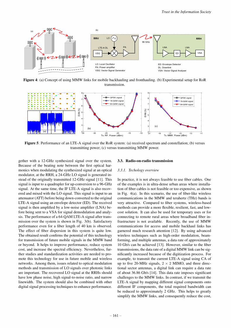
(a)
VSG
LTE-A DL
(b)
96 GHz
LOBBU
VSA
PA LNA
ED
LNA
RRH
LO: Local OscillatorPA: Power amplifierVSG: Vector Signal Generator
ED: Envelope DetectorDL: DownlinkVSA: Vector Signal Analyser
Figure 4: (a) Concept of using MMW links for mobile backhauling and fronthauling. (b) Experimental setup for RoRtransmission.
-35 -30 -25 -20 -15 -102
3
4
5
6
7
8
Tx. RF. Power (dBm)
EVM
(%)
QPSK signal
16-QAM signal
64-QAM signal
-21 -19 -17 -15 -13 -112
3
4
5
6
7
8
9
Tx. MMW. Power (dBm)
EVM
(%)
QPSK signal
16-QAM signal
64-QAM signal
(a) (b)
(c)
Figure 5: Performance of an LTE-A signal over the RoR system: (a) received spectrum and constellation; (b) versustransmitting power; (c) versus transmitting MMW power.
gether with a 12-GHz synthesized signal over the system.Because of the beating note between the first optical har-monics when modulating the synthesized signal at an opticalmodulator, at the RRH, a 24-GHz LO signal is generated in-stead of the originally transmitted 12-GHz signal [11]. Thissignal is input to a quadrupler for up-conversion to a 96-GHzsignal. At the same time, the IF LTE-A signal is also recov-ered and mixed with the LO signal. This signal is input to anattenuator (ATT) before being down-converted to the originalLTE-A signal using an envelope detector (ED). The receivedsignal is then amplified by a low-noise amplifier (LNA) be-fore being sent to a VSA for signal demodulation and analy-sis. The performance of a 64-QAM LTE-A signal after trans-mission over the system is shown in Fig. 3(b). Satisfactoryperformance even for a fiber length of 40 km is observed.The effect of fiber dispersion in this system is quite low.The obtained result confirms the potential of this technologyfor transmission of future mobile signals in the MMW bandor beyond. It helps to improve performance, reduce systemcost, and increase the spectral efficiency. Nevertheless, fur-ther studies and standardization activities are needed to pro-mote this technology for use in future mobile and wirelessnetworks. Among them, issues related to optical modulationmethods and transmission of LO signals over photonic linksare important. The recovered LO signal at the RRHs shouldhave low phase noise, high signal-to-noise ratio, and narrowlinewidth. The system should also be combined with otherdigital signal processing techniques to enhance performance.
3.3. Radio-on-radio transmission
3.3.1. Techology overview
In practice, it is not always feasible to use fiber cables. Oneof the examples is in ultra-dense urban areas where installa-tion of fiber cables is not feasible or too expensive, as shownin Fig. 4(a). In this scenario, the use of fiber-like wirelesscommunications in the MMW and terahertz (THz) bands isvery attractive. Compared to fiber systems, wireless-basedmethods can provide a more flexible, resilient, fast, and low-cost solution. It can also be used for temporary uses or forconnecting to remote rural areas where broadband fiber in-frastructure is not available. Recently, the use of MMWcommunications for access and mobile backhaul links hasgarnered much research attention [12]. By using advancedwireless techniques such as high-order modulation, beam-forming, and multiple antennas, a data rate of approximately10 Gb/s can be achieved [13]. However, similar to the fibertransmissions, the data rate of a digital MMW link can be sig-nificantly increased because of the digitization process. Forexample, to transmit the current LTE-A signal using CA ofup to five 20-MHz signals, 2 × 2 MIMO, and three direc-tional sector antennas, a digital link can require a data rateof about 36.86 Gb/s [14]. This data rate imposes significantchallenges to the MMW links. In contrast, if we transmit theLTE-A signal by mapping different signal components ontodifferent IF components, the total required bandwidth canbe reduced to approximately 2 GHz. This helps to greatlysimplify the MMW links, and consequently reduce the cost,
Trust in the Information Society
– 161 –

Control Office
MUX/ DEMUX
(c)
RAU RAU RAU
Core Network
Remote cell Fiber
Relay Relay
Core Network
(a)
Core Network
(b)
LTE-A
E/O DE-M
UX
Optical MMW Gen.
VSG
Amplifier PD
PA LNA
ED
LNA
VSA
BBU RAU
RRH (d)
RAU
RRH
Figure 6: Fiber-MMW systems for (a) remote femto cells and (b) mobile backhaul/fronthaul recovery. (c) High-capacitysystem for high-speed trains. (d) Experimental setup for a seamless fiber-MMW system.
power consumption, and complexity. Furthermore, an analogwaveform transmission helps to reduce the transmission la-tency and relax the requirement on transmission jitter. Fromthese discussions, the analog waveform transmission of radiosignals over MMW links, called RoR, is very promising.
3.3.2. Experiment demonstration
The RoR concept has been mentioned in previous research[15, 16]; however, an experimental investigation on signalperformance is not yet available. Here, we present a simpledemonstration on transmission of an LTE-A signal at 2 GHzover a 96-GHz link as shown in Fig. 4(b). The LTE-A sig-nal is the same as those in the previous experiments, and thedistance of the 96-GHz link is approximately 3 m. At theCS, the generated LTE-A signal is up-converted to 96 GHzusing an electrical mixer, which is driven by an electrical LOsignal at 96 GHz. The up-converted signal is amplified bya power amplifier (PA) before being fed to a 23-dBi hornantenna to transmit into free space. After transmission overfree space, the signal is received by another horn antenna,amplified by an LNA, and down-converted to the originallytransmitted LTE-A signal by an ED. The recovered signal isamplified by another LNA, sent to a VSA, and finally an-alyzed offline by VSA software. Examples of the receivedspectrum and constellations of 16-QAM and 64-QAM sig-nals are shown in Fig. 5(a). We can observe clear spectrumand clusters with constellation points located at ideal posi-tions. We measured the EVM performance, and the resultsfor different transmission powers are shown in Fig. 5(b). Sat-isfactory performance is achieved with EVM values muchbetter than the requirements. However, the performance alsoexperiences some degradation when increasing the transmis-sion power. This is caused by nonlinear distortion of the elec-trical components such as the mixer, PA, and ED.We also measured the performance for different transmissionpowers of the MMW signal at the input of the transmitterantenna. This measurement is conducted using a variable
attenuator inserted between the PA and the transmitter an-tenna. From these results, we confirm that a minimum powerof approximately -19 dBm should be transmitted in orderto recover the 64-QAM LTE-A signal successfully. Usingthe well-known Friss equation [17], we can estimate that thespace loss after 3-m transmission is approximately 82 dB.This means that a minimum power of -55 dBm should be re-ceived. If we use high-gain antennas for the transmission,for example 50-dBi parabolic antennas, the distance of theMMW link can be increased to approximately 1.5 km.Nevertheless, to further enhance the system performanceand to promote this technology for practical use, many otherissues should be further investigated and studied. Amongthese are techniques to compensate for nonlinear distortionat the electrical components. Development of a coherentdetection method that can help to enhance the performanceand increase the receiver sensitivity is another significanttopic. In addition, development of integrated circuits thatcombine different components will also be important forreducing the system noise and complexity, and improve per-formance. Currently, topics related to 100-Gb/s wirelesscommunication systems using MMW and THz bands are be-ing discussed in IEEE 802.15. However, activities on precisetechniques and high-performance systems for RoR transmis-sion have not been considered. Considering the potentialof the technology, we believe that it is worth involving it insome standards, such as ITU S15/Q2, or S13 for emergingtechnology.
3.4. Convergence of fiber and MMW systems
We have discussed the potential of fiber and wireless com-munications in high-frequency bands. However, in practice,it is not always feasible to use only one transmission medium.The first example is shown in Fig. 6(a), where a fiber cablecannot reach some underserved areas and MMW links arenot long enough. In this context, a combination of fiber andMMW links can provide a more useful solution. A combina-
2015 ITU Kaleidoscope Academic Conference
– 162 –

-10 -5 0 5 10 152
4
6
8
10
Tx. RF. Power (dBm)
EVM
(%)
16-QAM, 30-km SMF64-QAM, 30-km SMF16-QAM, 50-km SMF64-QAM, 50-km SMF
Figure 7: Performance of an LTE-A signal aftertransmission over a seamless fiber-MMW system.
tion of fiber and MMW systems can be also used in the eventof a fiber cable cut due to disasters or accidents, as shown inFig. 6(b). In this case, installation of new fiber cables cantake several weeks or months, which delays service provi-sion to users. In this case, a high-capacity wireless link cancombine with the intact fiber span to form a complete systemfor fast recovery of services. The other major applicationis shown in Fig. 6(c). To provide high-speed communica-tions to fast-moving vehicles such as high-speed trains, theuse of a dual-hop configuration system in which antennason the ground and antennas on the trains are connected byMMW links is an important approach [18]. In this configu-ration, an optical network should be used to connect differ-ent remote antenna units (RAUs) installed along the railwaytrack with a central control office where all signal process-ing and control functions are located. By using this system,the number of handovers can be significantly reduced owingto the use of centralized control. From above examples, wecan see the potential and importance of convergence of fiberand MMW systems. However, if the fiber and MMW linksare connected via a wired -wireless media converter [19], thelatency, power consumption, and complexity of the system,especially at the interface, will greatly increase. A photonic-based technology as shown in Fig. 6(d) is more promisingfor this convergence [20]. In this configuration, an opticalMMW signal is first generated, consisting of two optical sig-nals with a frequency difference equal the frequency of theMMW signal to be transmitted. The two optical signals canbe separated by a de-multiplexer (DE-MUX). One of the sig-nals is used for data modulation and the other is kept freeto work as a reference signal to generate an MMW signal.These two optical signals are then combined again and trans-mitted via a fiber link to the receiver. An optical amplifiercan be used to increase the power level when the transmis-sion distance is long. At the receiver, the signal is input into ahigh-speed photo-detector (PD). Because of the beating notebetween the two optical signals at the PD, an electrical sig-nal with a frequency equal to the frequency difference of theoptical signals is generated. This generated signal can befed directly to an antenna to transmit into free space withouthaving to perform any signal conversion and processing. Atthe receiver, the signal is received, down-converted, and pro-
cessed as in conventional fiber and wireless systems. Similarto fiber links, both digital and analog signals can be transmit-ted over the system. Fig. 7 presents an example of systemperformance for analog signal transmission. In this exam-ple, LTE-A signals are transmitted over a converged fiber and92.5-GHz MMW system. The distance of the MMW link is3 m. Satisfactory performance is achieved for 16-QAM and64-QAM LTE-A signals. The fiber dispersion effect is neg-ligible in this system. For digital signal transmission, high-order modulation formats such as M-QAM can be used withcoherent detection at the receiver to increase the transmis-sion data rate. This technology has attracted much interestrecently, and many demonstrations have been reported [21,22].However, there are still many issues that need further studyand investigation. Among the important ones are appropriatetechniques for generating stable MMW signals with smallfrequency fluctuation, low phase noise, and narrow linewidththat can follow radio regulations. Development of efficient,compact, and low-power-consumption signal processing al-gorithms at the receiver site is another key topic. In addition,high-speed real-time systems are essential for applicationsto practice, especially for transmission of real-time services.Recently, this technology has been introduced in some stan-dardization meetings of ASTAP as a possible solution for fu-ture access networks, especially for rural areas [19]. To bepromoted as a widely accepted technology for future mobileand access networks, however, other activities on the systemlevel and underlying technologies should be further consid-ered, especially in broader organizations such as ITU.In addition to the technologies discussed above, many otherrelated topics can be further studied and investigated todevelop an efficient transport network for future mobilenetworks, IoT, and smart cities, and to enhance the userexperience and trust on the information and communica-tion infrastructure. Convergence of fixed and mobile net-works is one of the important issues to develop an efficientnext-generation network. A co-design, co-operation, andco-optimization of fiber transport networks and RANs willhelp to achieve the targets of 5G as well as explore newcapabilities. Photonic-based technologies such as opticalbeamforming, optical multi-point co-operation, full coherentfiber-wireless, and adaptive and co-operative transmissionare among the possible methods that should be further in-vestigated. Development of a new control protocol for thenetwork convergence, and design of new interfaces and func-tional shift for the mobile fronthaul networks are other topicsthat need further study and standardization efforts.
4. CONCLUSION
Transport networks will play a vital role in the developmentof future mobile networks such as 5G and beyond. It shouldbe constructed using a variety of technologies and networkconfigurations, depending on the geographical areas, deploy-ment models, and application scenarios. In addition, devel-opment of new broadband access networks that can be de-
Trust in the Information Society
– 163 –

ployed in undeserved areas cost-effectively and quickly is an-other important issue to achieve the goal of Connect 2020. Inthis paper, we presented several promising solutions that canbe used to facilitate achieving the targets of 5G and Connect2020. Analog RoF systems can provide low-latency and low-cost transmission of future mobile signals, especially in thehigh-frequency bands. IFoF is another promising solution forlow-latency and high-spectrum-efficiency systems for trans-mission of mobile signals in the MMW band and beyond.RoR transmission can provide low cost, energy efficiency,and low latency for applications in ultra-dense urban or dead-zone areas. Finally, the convergence of fiber and MMW sys-tems can provide solutions to many use cases, including fastrecovery of services, broadband service provision to remoterural areas, or high-seed communications to fast moving ve-hicles. These technologies can be useful in many applica-tions in future mobile and access networks. They should bethe topics for further research and standardization efforts.
Acknowledgement
This work was conducted as a part of the Research and devel-opment for expansion of radio wave resources,” supported bythe Ministry of Internal Affairs and Communications (MIC),Japan.
REFERENCES
[1] “5G New wave towards future societies in the 2020S,”5G Forums White paper, March 2015.
[2] Matteo Fiorani et al., “Challenges for 5G TransportNetworks,” Proc. IEEE ANTS, 2014, pp1-6.
[3] ITU Connect 2020, http://www.itu.int/en/connect2020/Pages/default.aspx
[4] Jose F. Monserrat et al., “Rethinking the Mobile andWireless Network Architecture,” Proc. EuCNC, 2014.
[5] A. Nirmalathas et al., “Digitized Radio-over-FiberTechnologies for Converged Optical Wireless AccessNetwork,” J. Lightwave Technol. 28(16), 23662375(2010).
[6] Gee-Kung Chang, Cheng Liu, “1-100GHz MicrowavePhotonics Link Technologies for Next-Generation WiFiand 5G Wireless Communications,” Proc. IEEE MWP,2013 (Keynote).
[7] Philippos Assimakopoulos, “Statistical Distribution ofEVM Measurements for Direct-Modulation Radio-Over-Fiber Links Transporting OFDM Signals,” IEEETrans. on Microwave Theory and Techniques, Vo. 61,Iss. 4, pp. 1709 1717.
[8] 802.11ac working group documents: https://mentor.ieee.org/802.11/documents?is_group=00ac.
[9] LTE; Evolved Universal Terrestrial Radio Access (E-UTRA); Base Station (BS) conformance testing (3GPP
TS 36.141 version 10.1.0 Release 10, ETSI TS 136 141V10.1.0 (2011-01).
[10] Sundeep Rangan et al., “Millimeter-Wave CellularWireless Networks: Potentials and Challenges,” Proc.of the IEEE, Vol. 102, No. 3, March 2014, pp. 366-385.
[11] Pham Tien Dat et al., “High-Spectral EfficiencyMillimeter-Wave over Fiber System for Future MobileFronthaul,” to be presented at ECOC 2015.
[12] C. Dehos et al., “Millimeter-wave Access and Back-hauling: The Solution to The Exponential Data Traf-fic Increase in 5G Mobile Communications Systems?,”IEEE Communication Magazine, Vol. 52, Iss. 9, pp. 8895.
[13] R. J. Weiler et al., “ Enabling 5G Backhaul and Accesswith Millimeter-waves,” Proc. EuCNC, 2014, BolognaItaly, June 23-26, 2014.
[14] X. Liu et al., “Demonstration of Bandwidth-EfficientMobile Fronthaul Enabling Seamless Aggregation of36 EUTRA-Like Wireless Signals in a Single 1.1-GHzWavelength Channel,” Proc. OFC, 2015, M2J.2, LosAngeles.
[15] Jens Bartelt and Gerhard Fettweis, “Radio-Over-Radio:I/Q-Stream Backhauling for Cloud-Based Networks viaMillimeter Wave Links,” Proc. IEEE GLOBECOM,2013.
[16] S. Komak et al., “Proposal of Radio High-way Net-works for future multimedia-personal wireless commu-nications,” Proc. Intl. Conf. Personal Wireless Com-mun., pp. 240208 (1994).
[17] G. Giannattasio et al., A Guide to the Wireless Engi-neering Body of Knowledge (WEBOK), Wiley, 2009Edition.
[18] P. T. Dat et al., “Energy and Deployment Efficiency ofa Millimeter-Wave Radio-on-Radio-over-Fiber Systemfor Railways,” Proc. OFC/NFOEC 2013, JTh2A.61.
[19] APT Report on Wired and Wireless Seamless Connec-tions using Millimeter-Wave Radio over Fiber Technol-ogy for Resilient Access Networks, APT/ASTAP/REPT-11, March 2014.
[20] Pham Tien Dat et al., “High-Capacity Wireless Back-haul Network Using Seamless Convergence of Radio-over-Fiber and 90-GHz Millimeter-Wave,” IEEE/OSAJournal of Lightwave Technology, Vol. 32, ISS. 20, pp.0733-8724.
[21] A. Kanno et al., “Coherent Radio-Over-Fiber andMillimeter-Wave Radio Seamless Transmission, Sys-tem for Resilient Access Networks,” IEEE PhotonicsJournal, Vol. 4, No. 6, December 2012, pp. 2196-2204.
[22] R. Sambaraju et al., “100-GHz Wireless-over-FiberLinks with up to 16-Gb/s QPSK Modulation using Op-tical Heterodyne Generation and Digital Coherent De-tection,” IEEE Photon. Technol. Lett., vol. 22, no. 22,pp. 16501652, Nov. 2010.
2015 ITU Kaleidoscope Academic Conference
– 164 –

A UNIFIED FRAMEWORK OF INTERNET ACCESS SPEED MEASUREMENTS
Eduardo Saiz, Eva Ibarrola, Eneko Atxutegi, Fidel Liberal
Faculty of Engineering of Bilbao, University of the Basque Country UPV/EHU, Spain {eduardo.saiz, eva.ibarrola, eneko.atxutegi, fidel.liberal}@ehu.eus
ABSTRACT The evolution of Internet access technologies, together with the wide diversity of customer devices, has led to a complex scenario where measuring basic metrics with accuracy has become a rather complicated task. Although nowadays there are a lot of tools to assess the rate of Internet speed, most of them share neither the methodology nor the infrastructure to produce comparable results. In this regard, the development of a unified approach to measure the Internet speed would be beneficial for all ICT players. The establishment of such proposal would inspire better confidence in consumers through the provision of precise comparisons, and it would also be very useful to operators, regulators and providers. Towards this aim, the ITU-T has been working on the definition of a unified methodology and measurement framework to assess the rate of Internet speed. This paper presents a detailed description of the work that is being done at present in the definition of the aforementioned framework.
Keywords— Internet speed measurement, framework, bandwidth, access speed, latency.
1. INTRODUCTION From the best-effort era of Internet to the immersion stage of technology in our daily lives, an important transition has occurred interfering in the way we interact with the world. Nowadays, users demand the best quality in terms of speed, ubiquity and full-time connectivity [1] and react with frustration when any interruption or malfunctioning of the contracted service is perceived [2], especially in mobile scenarios where network variability is still a challenge [3]. Aware of the potential impact in the market, many ICT players have seen the necessity for reliable methods to assess the compliance of customer’s expectations to the contracted Service Level Agreement (SLA) [4]. As a result, many Quality of Service (QoS) measurement systems and tools [5-8] have emerged, focused on the most typical Internet metrics: download/upload transmission speed and latency. However, results comparison amongst them is not feasible due to several factors, including the purpose of the tests, the measurement infrastructures and the methodologies. In this regard, it is crucial for the users of these tests to be well informed about the meaning and scope of the measured parameters. Internet users usually estimate their
Internet access quality based on their experience in the Web navigation service. Hence, their judgment depends basically on their perception of the web pages loading times [9] and the download bit rate to an Internet resource. Measurement tools with servers in different countries [7-8] might be useful for the estimation of the access speed to an Internet resource, but not for verifying the compliance of the access speed to the Internet offered by the provider within the SLA. These two Internet speed concepts are often intermingled causing great confusion to users. The underlying reality to this situation is that, despite the widespread use of Internet, there is still no regulation promoted by standardization bodies about how to perform speed measurements in order to avoid these concerns. The ITU-T (International Telecommunication Union- Standardization Sector) has taken this challenge and is working on the definition of a new standard to fill the absence of a unified approach to Internet speed measurements (Q.Int_Speed_Test Recommendation [10]). In recent times, due to the complex task that has to be faced, the base draft of this recommendation has led to two different drafts. The first one attends to the definition of a framework for the standardized measurement of Internet speed (Q.FW_Int_sp_test [11]) and the second one, to the choice of the most adequate methodologies to be used within the defined framework (Q.TM_Int_sp_test [12]). Several research centers, regulators and operators are participating in this work item [13], with the support of the ITU-T Conformity and Interoperability Group (C&I) [14] and the collaboration of the Organization for Economic Co-operation and Development (OECD) [15]. It should be remarked that an ITU academia member, the University of the Basque Country (UPV/EHU), is the editor of these two recommendations, which makes evident that the position of academia is taking hold in the ITU-T. This paper aims to disseminate the work that is being done on the definition of the aforementioned framework.
2. BACKGROUND 2.1. Regulation on Internet access services Different Internet speed measurement approaches have become the “de-facto mechanisms” and are being used by operators and regulators in the evaluation of the SLA. As stated in the 2014th OECD report on Access Network Speed Tests, 19 countries participate in official projects to measure QoS performance including Internet speed, and three more are planning future projects [16].
978-92-61-15821-7/CFP1538E-ART © 2015 ITU Kaleidoscope– 165 –

Table 1. OECD countries with official measurement projects
Table 1 summarizes the main alternatives used in both fixed and mobile broadband connections in different countries:
• End-user Application Measurement (EAM): This method requires the customer, on his will, to access the tests from a browser or an application under his control.
• End-user Device Measurement (EDM): The tests are carried out from a device installed in the users’ network but controlled remotely by the project. In this case, the measurements are taken apart from the daily use of Internet by the customer.
• Project Self Measurement (PSM): This alternative does not require the client’s network for the measurements. An entity, different to the ISP, defines a set of devices (probes) for the solely use of testing. If these tests are carried out by the ISPs themselves, this alternative is known as PSM-ISP.
A simple reading of the description of the three alternatives evidences quite a complexity when trying to correlate results that satisfy both users and operators. Tests driven by users from their own devices (EAM), do offer closer results to the navigational experience of the user, in particular when executed at application level. However, operators require a deeper analysis of their access network, trying to avoid any dependency on the user’s hardware and software, and thus requiring controlled measurement tests such as PSM or even EDM, which may differ from the conditions perceived by the customers. In any case, and despite the adoption of any of these alternatives, the tests may “not always provide the information needed to inform specific policy and regulatory goals” [15]. Nowadays, existing standards define some basic guidelines for the measurement of Internet access speed [17], but most of them consider neither the multithreading capabilities of modern browsers nor any specific requirements of mobile
networks. Also, the adoption of these standards by local regulators often includes additional considerations not contemplated in the guidelines. Due to all these reasons, a standardized approach to define an Internet speed measurement may be really beneficial to all ICT players. 2.2. Scientific research In recent times, there has been a significant amount of scientific proposals on the measurement of Internet QoS performance. Many authors have designed tools with important contributions to this topic, such as Pathload in 2003 [18], Traceband in 2010 [19] together with new models and methods, like AProbing [20]. Besides these techniques, other infrastructures for the QoS evaluation [21-22] have also been developed to provide an environment to bring in and execute any QoS measurement tool. Many of the existing proposals are efficient in controlled environments and simulation. However, the heterogeneity of current networks may affect the accuracy of many of these contributions. As a conclusion, there is a need for further research in the design of measurement tools flexible to be adapted to multiple network conditions and different measurement scopes [23]. Meanwhile, Internet users have experienced higher speed connections and new data transmission services, unthinkable a few years back, such as high-definition video streaming and other cloud-based applications. Due to this wide range of offered services, users increasingly demand more quality of service at a higher rate than the providers can handle. As a result, operators and ISPs are displacing self developed projects in favor of publicly available Internet speed measurement tools, such as Ookla’s SpeedTest [8]. Orange, Vodafone and Telefónica, three well known telecom operators, are good sample of this position [24]. On an institutional level, there are also measurement tools as the one developed by SamKnows [25]. This project counts with the support of several international institutions such as the European Commission and the USA’s Federal Communications Commission (FCC). They have developed an EDM project to which customers freely sign up as volunteers to install a middlebox in their home network. This probe is set to monitor the Internet access quality through tests launched according to a defined schedule and a detailed report is provided to users on a monthly basis. Nevertheless, and despite the existing range of tools and their benefits, there are still very important issues that need to be analyzed. 2.3. Issues to be faced As a result of the different approaches and the diverse amount of the network segments used during a peer-to-peer testing, the results achieved by each of the measurement methods may be very different and no comparison is reliable enough to assure users conformance.
2015 ITU Kaleidoscope Academic Conference
– 166 –

In addition, the results may not be accurate due to the existence of one or many of the following factors:
- Overload of the measured server and its capabilities. - Dependency on hardware and performance of the
customer’s equipment. - Dependency on the installed software (e.g. operating
system, applications, etc.) and/or available performance of the user's terminal at the time of measurement.
- Existence of activated security software and/or hardware (e.g. firewalls, anti-virus, etc.) at the time of measurement.
- Network performance and the level of utilization of customer’s interface connected to the Internet at the time of measurement.
In order to increase accuracy and minimize some of the previous factors, some existing methods drop around 40% of the measurement results, which, in the end, may also have influence in obtaining a reliable result [26]. Other methods collect additional data in order to identify specific network conditions (e.g. busy hour), yet this information is highly dependent on each operator and can only be offered as an orientative reference to users. Finally, most of the measurement methods do not consider wireless or mobile environments. In such scenarios, any adjustment in the test parameters that was adequate on the available conditions at the beginning of the test might not be adequate during its execution. The huge dependency in coverage that a mobile device suffers, even being in a fixed place during the test, can invalidate the results. To sum up, all these factors must be regarded thoroughly in both the definition of a standardized framework and the specification of the most adequate methodology for the measurement of Internet access speed.
3. THE FRAMEWORK 3.1. Scope of the framework The future ITU-T Q.FW_Int_sp_test recommendation “describes the framework of Internet speed quality measurement and specifies the requirements and architecture of the measurement system to be used for assessing the Internet speed connection” [11]. Thus, the scope of this framework is to provide the architecture of the standard measurement scenarios, the measurement parameters, and the measurement procedure. In addition, it aims to describe the requirements for the measurement algorithm to be used on the fixed and mobile operators to estimate the access speed to the Internet resources. Under these considerations, a methodology or set of methodologies must be defined. These methodological procedures should converge into results comparability and provide more accurate information to both customers and operators on the compliance of the contracted SLAs. Therefore, “the framework is targeted at regulators, aiming to set up guiding principles regarding the establishment of the global standardized architecture to be used for the assessment of the Internet speed connection at the national
level. The key goal of the framework is to provide transparent, trust-based approach which measurement results can be accepted by all ICT players (e.g. Regulator, Operator, ISP, customer, etc.)”. [11]. 3.2. Measurement tests definition
The framework defines a dual testing based on the different points of view that customers and operators have on quality assessment [27]: Operators and regulators aim to evaluate Internet access speed within the barriers of the operator network to verify the level of compliance within the SLA, whereas customers usually evaluate the Internet access speed in terms of the Quality of Experience (QoE) [28] in the Web service. As a result of this, two measurement tests are proposed for the estimation of Internet speed quality: The Network Internet speed test and the Internet resource speed test. The first test considers the operator network itself and it may be used for SLA compliance monitoring and the second one considers the whole access speed to an Internet resource, since this measurement may be closer to the Internet speed quality as perceived by user. The definitions of each measurement are next detailed (figure 1): • The Network Internet speed test:
This test has been defined to measure the absolute value of the end-to-end data transmission speed (bit rate) between the customer’s Measurement Agent (MA) and an external interface of exchange point (peering point) (“A” in figure 1). This measurement should include the whole operator’s network (access, transport, service control segments) up to the Exchange Point (EP) and should be measured on the output of a specific exchange point interface (i.e. the exchange point with the highest data volume exchange used by operator).
• The Internet resource speed test: This test has been defined to measure the absolute value of the end-to-end data transmission speed (bit rate) amongst the customer’s Measurement Agent (MA) and a relevant Internet resource (“B” in figure 1). This measurement should include the whole network from the customer side to the relevant Internet Resource (IR).
In both cases, the measurement should be based on algorithms and protocols of the TCP/IP model and should be adaptable to the technologies that are used on the MA.
Telecom'Operator
Internet
Measurement Agent Internet'ResourceExchange'Point
Network(Internet(speed test'path
Internet(resource speed test'pathA
B
MA EP IR
Figure 1. Global scenario and test definition
Trust in the Information Society
– 167 –

RESULTDATA
CONTROLLER
RESULTS
MEASUREMENT,PEERS
DB
PARAMETERSMEASUREMENT
COLLECTOR
RESULTDATA
MEASUREMENTAGENT
CONTROLLING&2MEASUREMENT
RESULTS
DATAACQUISITION
Figure 2. Test facilities defined in the Framework
3.3. Basic measurement principles The measurement procedure should be based on a transparent approach which all ICT players can rely on. In this sense, regarding the location of the measurement system, two different options may be implemented:
- Outside operator’s facilities (independent premises). - On the existing operator’s networks.
Also, the measurement system might be implemented at the national and/or international level. The implementation on the international level is a better solution for the assessment of the Internet resources access speed, due to the accuracy of measurements, the comprehensive analyses of user’s hardware and software, the global visualization of measured results and some other aspects. In spite of the location, all involved ICT players must have the comprehensive access to the features of the measurement system in accordance with their rights. At least, each of them should have guaranteed the access to the measurement data. 3.4. Test facilities A measurement system has been defined for the two types of testing (Figure 2). This infrastructure will be composed of the following elements: • Controller: Software and/or hardware tool to control
testing procedures on a Measurement Agent (MA). The Controller should allow uploading test scripts on any MA and execute relevant test scenarios on it.
• Collector: Software and/or hardware tool to collect measurement and statistical data from all the Measurement Agents connected to the Controller.
Telecom'Operator(fixed /'mobile)
Internet
IREP
MPMPMA
CONTROLLER COLLECTOR
Internet0SpeedMeasurement System
At'regional/nationalor international level
LEGEND
Measurement AgentMeasurement PeerExchange'Point'Internet'Resource
CUSTOMER
MA0MP0EPIR0
Figure 3. Internet speed measurement system architecture
• Measurement Peer (MP): Software and/or hardware to
respond on testing messages sent from the MA. • Measurement Agent (MA): Software and/or hardware
that executes test scripts obtained from Controller. This equipment admits two different configurations: It can either be a single device owned by the user (Customer Equipment, CE), or involve a local measurement device, integrated in the CE or in the form of a middlebox (a probe). This layout has been considered for non user dependent measurements by operators and/or for the unwilling sacrifice of a hotspot limited resources [29].
3.5. Architecture of the measurement system Figure 3 illustrates the architecture of the measurement system. Depending on which of the two testing is being executed, the location of the measurement peer differs: • Measurement Peer in the Network Internet speed test:
The peer should be placed on the output of the exchange point interface (peering point) that connects the operator’s network to the rest of the Internet (figure 4, left). If any existing limitation implied that this location could not be contemplated, the operator is allowed to locate the MP within the operator’s network, as close to the internal interface of the EP as possible, assuring guaranteed bandwidth on this direction.
• Measurement Peer in the Internet resource speed test: In this case, the MP should generally be located within the same domains of the Internet resource (figure 4, right). However, this option may depend on the objectives of the test methodology and therefore result as a non feasible alternative. The definition of a separate ITU-T Recommendation has been accorded for this matter.
Telecom'Operator
(fixed /'mobile)
Internet
Network(Internet(speed test
ExternalInterface'of'EP
End9to9end testingMA MP
Telecom'Operator
(fixed /'mobile) Internet
Internet resource speed test
EP
MA
MP
IR
Closelocation
Figure 4. Network Internet speed test and Internet resource speed test schematics
2015 ITU Kaleidoscope Academic Conference
– 168 –

5. TEST PROCEDURE
5.1. General description For the execution of both measurement tests, several interactions amongst the test facilities and the measurement peers are required (figure 5):
• Step 1. Test Initialization: Users will have access to the measurement test scripts from their equipment throughout a web page or an application connected to the Controller. The test scripts will be uploaded from the Controller to the Measurement Agent. In case of complex MA with a detached measurement device configuration, the scripts are automatically downloaded to the middlebox without the user’s interaction.
• Step 2. Test Execution: Once the test is accessed in the MA, it will be executed towards different measurement peers located in the exchange point or in the Internet resource as required by the customer or the middlebox scheduling. The test methodologies to be used at this step will be specified in the ITU-T Q.TM_Int_sp_test Recommendation [12].
• Step 3. Test Finalization: The measurement results will be collected in the Collector (which can coexist with the Controller). In addition, the results of the test execution can be sent either directly from the equipment to the Collector or throughout the Controller, considering security and/or privacy issues (dotted line in figure 5 represents this situation). When the test is accessed directly by end users, hardware and/or software information (browser, operating system) may be collected for better statistical results and data comparison. Also, when in mobile environments, additional information on connectivity, signal to noise ratio or signal strength during the test could be collected (amongst other parameters). The framework should be capable of the measurement and transmission of any valuable information, as required by the test methodology to be applied.
DATAACQUISITION
MEASUREMENTAGENT
MEASUREMENTPEER CONTROLLERCOLLECTOR
WEBSITE
EXCHANGEPOINT
INTERNETRESOURCE
TEST5INITIALIZATION
TESTFINALIZATION
1
TEST5EXECUTION 2
3MEASUREMENT5RESULTS
2.1 LATENCY2.2 DOWNLINK5PRE:TEST2.3 DOWNLINK5TEST2.4 UPLINK5PRE:TEST2.5 UPLINK5TEST5
MEASUREMENTRESULTS
Figure 5. Basic test workflow
All collected data will be useful to detect unsuitable configurations and problems in the user’s local network or equipment that may lead to unreliable measurements. This way, users can be warned their results may neither be conclusive nor binding to the real SLA values. It must be taken into account that collecting user’s information can be a sensitive issue since it could threaten the privacy of the user if some delicate information is collected (i.e. geolocation). This is still an open issue to be defined in future recommendation. Once the statistics have been stored, all authorized users will have the possibility to display the available measurement results at a dedicated web page. If using the Controller for the outcome results comparison or reports presentation, a request path for data acquisition should be implemented between Controller and Collector. Asides from this basic workflow, additional functionalities could be offered to clients with the aim of collecting further information. For instance, user’s registration could be also available to facilitate users sharing and comparing their results and to access the historical of their measurements. User’s registration would also help to collect general information for statistical data analysis (region and country averages, ISPs results information...). Nevertheless, registration should not be a requirement to use the test. 5.2. Test parameters
There are certain aspects of the Internet speed measurement methodology draft [12] that are also included in the framework recommendation [11] as high level headlines. That is the case of the proper parameters to be measured and the basic approach to the methodology itself. There are three parameters that have been identified for both the Internet access speed test and the Internet resource access speed test: • Download data transmission speed: The data
transmission speed achieved in the downlink between the measurement agent and the correspondent measurement peer.
• Upload data transmission speed: The data transmission speed achieved in the uplink between the measurement agent and the correspondent measurement peer.
• Two-way delay: Also defined as the Round-Trip Time (RTT) delay, the two-way delay is twice “the time required for a packet to traverse the network or a segment of the network” (ITU-T Rec. G.1050 [30]).
5.3. Test methodology Finally, this paper aims to introduce some open issues and considerations of the parallel methodology draft that are still under study. Prior to division of the Q.Int_Speed_Test draft [10] into the framework [11] and methodology [12] paths, four different alternatives had been considered for the basic Internet speed measurement procedure: − Transmitting a fixed volume of data within a maximum
timeout limit.
Trust in the Information Society
– 169 –

− Transmitting a finite but variable/adaptable volume of data within a timeout limit.
− Transmitting unlimited data continuously for a limited period of time.
− Transmitting an unlimited volume of data with no time limit until the speed measurement is stabilized.
The fourth alternative seems the most adequate in terms of accuracy, as required in section 4 of this paper. However, some limitations must be observed, since the unified methodology is meant to be accessible to customers and, at this moment, loading time seems to be the key factor for them when measuring Internet access speed [9], especially in mobile networks, where transmitting high volumes of data is also a matter to consider. Multithreading capabilities of modern browsers and stability problems of wireless connections are also subject of study. Specifically in mobile networks, there is a dependency on user’s location and movements, environmental conditions and other factors. Measurements taken in mobile networks can only show a situation at a particular time and place of testing. Therefore, in order to obtain the characterization of a particular area, a lot of results have to be gathered by launching multiple measurement tests in that specific coverage zone. The study of these and other issues is paramount for the proper measurement methodology definition.
6. CONCLUSIONS
This paper introduces a novel unified framework for the measurement of Internet speed in both fixed and mobile networks. The ITU-T is carrying out the definition and standardization of this framework with the cooperation of research centers, regulators, operators, official telecom organizations and academia. The framework draft is expected to be approved in December 2015, as an ITU-T Q series recommendation. Its aim is to set guidelines and principles for the estimation of Internet speed through a neutral and trust-based approach for both operators and users. As a result, operators will have a reliable tool to verify SLA compliance and users will have the chance to compare their results with the ones offered by other ISPs and operators. Finally, the framework aims to improve the mobile access experience to customers by offering operators a mean to detect the strengths and weaknesses of their systems. In this regard, a global QoS observatory at a national or even international level could be established for the monitoring and evolution of Internet performance. In fact, the test facilities architecture defined in this framework could serve in the evaluation of other Internet based services asides from the measurement of Internet speed, such as VoIP and video streaming services, or even new cloud based services. The inclusion of evaluation tests for these other services would definitely enrich the global QoS observatory for all ICT players of the sector.
7. ACKNOWLEDGEMENTS This work has been partially funded by the Spanish Ministerio de Economía y Competitividad (MINECO) under grant TEC2013-46766-R: QoEverage - “QoE-aware optimization mechanisms for next generation networks and services”.
REFERENCES [1] ITU-D, “Measuring the Information Society Report 2014”,
November 2014. [2] American Customer Satisfaction Index (ACSI), “ACSI
Telecommunications and Information Report”, June 2015. [3] Marri K. et al, “4E Framework for Network Variability
Testing”, Testing Experience, no. 19, pp. 56-58, 2012. [4] ITU-T, “E.860: Framework of a Service Level Agreement”,
June 2002. [5] http://speedtest.t-online.de
T-Online, Deutsche Telekom AG (Telecom operator). [6] https://www.netztest.at/en/
RTR-GmbH (Austrian Regulatory Authority). [7] http://www.velocimetro.org
Univ. of the Basque Country UPV/EHU, Spain (Third party). [8] http://www.speedtest.net
Ookla (Company, Third party).
[9] Egger S. et al, “Waiting times in Quality of Experience for web based services”, Proceedings of 4th International Workshop on Quality of Multimedia Experience (QoMEX), pp. 86-96, 2012.
[10] ITU-T, DRAFT Q.Int_Speed_Test “Unified methodology of
Internet speed quality measurement usable by end-users on the fixed and mobile networks”.
[11] ITU-T, DRAFT Q Q.FW_Int_sp_test “Framework of Internet
speed measurements for the fixed and mobile networks”. [12] ITU-T, DRAFT Q.TM_Int_sp_test: “Testing methodologies
of internet speed measurement system to be used on the fixed and mobile networks”.
[13] ITU-T, SG-11. Q15/11 Contributions to Draft ITU-T
Q.Int_speed_test, http://www.itu.int/md/meetingdoc.asp?lang =en&parent=T13-SG11-C&question=Q15/11
[14] ITU-T Conformity and Interoperability Group (C&I),
“Measurements of Internet speed”. http://www.itu.int/ en/ITU-T/C-I/Pages/IM/Internet-speed.aspx
[15] OECD, “Broadband access network speed tests by country.
Speed tests: Official measurement projects in OECD area”. http://www.oecd.org/internet/speed-tests.htm
[16] OECD, “Access Network Speed Tests”, OECD Digital
Economy Papers, No. 237, OECD Publishing. June 2014.
2015 ITU Kaleidoscope Academic Conference
– 170 –

[17] ETSI, EG 202 057-4 V1.2.1: “Speech processing, transmission and Quality aspects (STQ); User related QoS parameter definitions and measurements; Part 4”, 2008.
[18] Jain M. et al, “End-to-end available bandwidth: measurement
methodology, dynamics, and relation with TCP throughput”, IEEE/ACM Transactions on Networking, vol. 11, issue 4, pp. 537-549, August 2003.
[19] Guerrero C.D. et al: “A fast, low overhead and accurate tool
for available bandwidth estimation and monitoring”, Computer Networks, vol. 54, issue 6, pp. 977-990, April 2010.
[20] Xie Y. et al, “AProbing: Estimating available bandwidth
using ACK pair probing”, International Conference on Smart Computing Workshops SMARTCOMP 2014; Hong Kong, China, November 2014.
[21] Partearroyo R. et al, “QoSmeter: Generic quality of service
measurement infrastructure”, in IFIP Networking 2006, workshop 'Towards the QoS Internet' (To-QoS'2006); Coimbra, Portugal, 2006.
[22] Aceto G. et al, “Unified architecture for network
measurement: The case of available bandwidth”, Journal of Network and Computer Applications, vol. 35, issue 5, pp. 1402-1404, September 2012.
[23] Guerrero C.D. et al, “On the applicability of available bandwidth estimation techniques and tools”, Computer Networks, vol. 33, issue 1, pp. 11-22, January 2010.
[24] Telecom operator speed tests by Ookla http://speedtest.orange.md/ http://speedtest.vodafone.es/ https://www.movistar.es/particulares/test-de-velocidad/ [25] SamKnows SQ309-002-EN White Paper, “Web-based
Broadband Performance White Paper”, July 2015. [26] ITU-T Conformity and Interoperability Group (C&I),
“Measurements of Internet speed: Description of Issue”. http://www.itu.int/en/ITU-T/C-I/Pages/IM/issues.aspx
[27] ITU-T, “G.1000: Communications quality of service: A
framework and definitions”, 2001. [28] ITU-T, “P.10/G.100 (2006) Amendment 2 (07/08): New
definitions for inclusion in Recommendation ITU-T P.10/G.100”, 2008.
[29] Xing X. et al, “A Highly Scalable Bandwidth Estimation of
Commercial Hotspot Access Points”, at IEEE INFOCOM 2011, Shanghai, China, April 2011.
[30] ITU-T, “G.1050: Network model for evaluating multimedia
transmission performance over Internet Protocol”, March 2011.
Trust in the Information Society
– 171 –

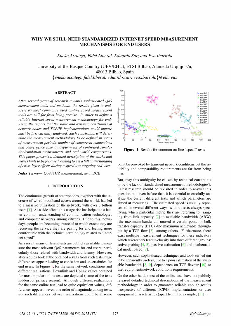
WHY WE STILL NEED STANDARDIZED INTERNET SPEED MEASUREMENTMECHANISMS FOR END USERS
Eneko Atxutegi, Fidel Liberal, Eduardo Saiz and Eva Ibarrola
University of the Basque Country (UPV/EHU), ETSI Bilbao, Alameda Urquijo s/n,48013 Bilbao, Spain
{eneko.atxutegi, fidel.liberal, eduardo.saiz, eva.ibarrola}@ehu.eus
ABSTRACT
After several years of research towards sophisticated QoSmeasurement tools and methods, the results given to end-users by most commonly used on-line speed measurementtools are still far from being precise. In order to define areliable Internet speed measurement methodology for end-users, the impact that the static and dynamic constraints ofnetwork nodes and TCP/IP implementations could imposemust be first carefully analyzed. Such constraints will deter-mine the measurement methodology to be defined in termsof measurement periods, number of concurrent connectionsand convergence time by deployment of controlled simula-tion/emulation environments and real world comparisons.This paper presents a detailed description of the works andleaves hints to be followed, aiming to get a full understandingof cross-layer effects during a speed test targeting end-user.
Index Terms— QoS, TCP, measurement, ns-3, DCE
1. INTRODUCTION
The continuous growth of smartphones, together with the in-crease of wired broadband access around the world, has ledto a massive utilization of the network, with over 3 billionusers [1]. As a side effect, this usage rise has helped to a bet-ter common understanding of communication technologiesand computer networks among citizens. Due to this, nowa-days, people are becoming aware of to which extent they arereceiving the service they are paying for and feeling morecomfortable with the technical terminology related to “Inter-net speed” .As a result, many different tests are publicly available to mea-sure the most relevant QoS parameters for end users, parti-cularly those related with bandwidth and latency. However,after a quick look at the obtained results from such tests, hugedifferences appear leading to confusion and uncertainties forend users. In Figure 1, for the same network conditions anddifferent realizations, Downlink and Uplink values obtainedfor most popular online tests are depicted (name of the testshidden for privacy reason). Although different realizationsfor the same online test lead to quite equivalent values, dif-ferences appear in even one order of magnitude among tests.So, such differences between realizations could be at some
Sample number0 20 40 60 80 100 120 140 160 180 200
Measure
d M
bps
0
10
20
30
40
50
60
70
80
90
100test1DWtest1UPtest2DWtest2UPtest3DWtest3UPtest4DWtest4UPtest5DWtest5UPtest6DWtest6UPtest7DWtest7UP
Figure 1: Results for common on-line “speed” tests
point be provoked by transient network conditions but the re-liability and comparability requirements are far from beingmet.
But, may this ambiguity be caused by technical constraintsor by the lack of standardized measurement methodologies?.Latest research should be revisited in order to answer thisquestion but, even before that, it is essential to carefully an-alyze the current different tests and which parameters areaimed at measuring. The estimated speed is usually repre-sented in several different ways, without tests always spec-ifying which particular metric they are referring to: rang-ing from link capacity [2] to available bandwidth (ABW)-the maximum bandwidth unused at certain point- or bulktransfer capacity (BTC) -the maximum achievable through-put by a TCP flow [3]- among others. Furthermore, thereexist multiple measurement techniques for these indicatorswhich researchers tend to classify into three different groups:active probing [4, 5], passive estimation [6] and mathemati-cal model based [7].
However, such sophisticated techniques and tools turned outto be apparently useless, due to a poor estimation of the avail-able bandwidth [8, 9], dependence on TCP flavour [10] oruser equipment/network conditions requirements.
On the other hand, most of the online tests have not publiclyreleased detailed technical descriptions of the measurementmethodology in order to guarantee reliable enough resultsirrespective of different TCP/IP implementations or userequipment characteristics (apart from, for example, [11]).
978-92-61-15821-7/CFP1538E-ART © 2015 ITU Kaleidoscope– 173 –

Thirdly, most Standards Developing Organizations (SDOs)have their own and usually overlapping definitions of “speed”related Key Performance Indicators (KPIs) and measure-ment mechanisms but none of them have prevailed versusthe users’ “de facto” standard of most famous online tests.Considering the cross–layer effects and dependance on un-derlying access and core technologies, a proper analysis ofspeed measurement methodologies should therefore learnfrom TCP’s behaviour and patterns. It is crucial to havethose mechanisms performing in different nowadays scenar-ios as to enable the definition of standardized measurementtechniques and reducing aforementioned uncertainties.For all those reasons, the purpose of this paper is manifold:
• To analyze standardization activities covering speedmeasurement mechanisms for end users.
• To describe how there exist several static and dynamicconstraints in TCP behaviour that may affect the relia-bility of any tests and prevent their usability for com-parison purposes.
• To provide real world evidences of the impact of theseconstraints into current networks, covering most ofTCP flavours today.
• Provide basic guidelines to minimize such constraintsand therefore, set the foundations for end users speedmeasurements standard development.
The structure of the paper is as follows: Section 2 describesthe most representative aspects of TCP based speed mea-surement tests to take into account and associated relevantworks. In order to clearly show the different points, the sec-tion has been divided into four subsections; TCP’s multi-ple faces to underline different TCP flavours’ behaviour, theimpact of TCP parallelization techniques in nowadays tests,TCP’s special events and effects, and finally, standardizationstatus. Later, Section 3 describes the methodology followedto identify TCP’s static and dynamic constraints and finalcomparison with live networks. Finally, based on the pre-vious demonstrations, the paper will conclude (Section 4)summarizing major results and obtained conclusions. Thisway, the paper aims to encourage other researchers to joinand follow the suggested path towards an unified methodo-logy.
2. BACKGROUND
[12] and more recently [13] surveys provide a particularlycomprehensive review of bandwidth estimation techniques,including a taxonomy and a brief analysis of pros and consfrom a technical point of view. Unfortunately, regardless theachieved accuracy, most of them demand a set of require-ments that prevent a widespread adoption, or at least, similarto that of web based speed test (just requiring a regular webbrowser and using HTTP/TCP/IP protocols). On the other
hand, both aforementioned and other previous studies pro-vide a good starting point to identify the different features totackle, which will be described in the following subsections.
2.1. TCP’s multiple faces
TCP has several flavours being the congestion control algo-rithm (CCA) an aspect to be particularly addressed due toits impact into the protocol performance. Considering diffe-rent CCA’s reactions to network conditions, an ideal mea-surement methodology should be capable of providing endusers with as “accurate and CCA independent” as possibleestimations. In order to further advance in the analysis ofCCA caused bias, both theoretical [14] and simulation basedstudies [15] have been carried out. Figure 2 on the top showsthe evolution of the congestion window (CWND) for diffe-rent CCAs over the same scenario and conditions. Consider-ing the relationship between CWND evolution and achievedspeed it can be easily concluded how different flavours showa extremely different behaviour in terms of not only bothmaximum and average CWND but also its temporal evolu-tion (i.e. time to reach the maximum and meaningful measu-rement period).
0 20 40 60 80 1000
100
200
300
400
500
600
700
Time(s)
CW
ND
valu
e
Comparison of CWND evolution for different Linux 3.14 TCP flavours
cubichighspeedhtcphyblaillinoislprenoscalablevegasvenowestwoodyeah
Figure 2: TCP flavours behaviour over the same conditions.
2.2. Multiple parallel TCP connection based tests
Even though some studies have shown that this technique isextremely invasive and uncontrollable [16], the use of morethan one flow in order to fully “fill the pipe” is the mostcommon trend nowadays.If a single TCP flow is often unpredictable and highlyflavour-dependent, multi-thread based measurement toolsresult therefore in a more challenging research task. To theoriginal problem of differences for a single isolated connec-tion due to TCP’s implementation, friendliness and fairnessaspects must be now added.Figure 3 shows the aggregate congestion window of multipleflows for different flavours. Resulting apparent randomnessmakes it difficult to foresee a straightforward common crite-ria for required measurement intervals or even some kind ofnormalization between flavours.
2015 ITU Kaleidoscope Academic Conference
– 174 –
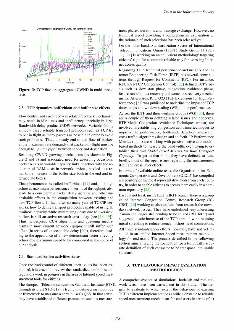
Time(ms) ×104
0 2 4 6 8 10 12 14 16
Ag
gre
ga
ted
CW
ND
va
lue
0
500
1000
1500Comparison of aggregated CWND for 5 parellel flows
cubichighspeedhtcphyblaillinoislprenoscalablevegasvenowestwoodyeah
Figure 3: TCP flavours aggregated CWND in multi-threadtests.
2.3. TCP dynamics, bufferbloat and buffer size effects
Flow control and error recovery related feedback mechanismmay result in idle times and inefficiency, specially in largeBandwidth-delay product (BDP) networks. Variable slidingwindow based reliable transport protocols such as TCP tryto put in flight as many packets as possible in order to avoidsuch problems. Thus, a steady end-to-end flow of packetsat the maximum rate demands that packets-in-flight must beenough to “fill the pipe” between sender and destination.Resulting CWND growing mechanisms (as shown in Fig-ure 2 and 3) and associated need for absorbing occasionalpacket bursts in variable capacity links, together with the re-duction of RAM costs in network devices, has led to a re-markable increase in the buffer size both in the end and in-termediate boxes.That phenomenon is called bufferbloat [17] and, althoughachieves maximum performance in terms of throughput, alsoleads to a considerable packet delay increase and other un-desirable effects in the competition between existing andnew TCP flows. In fact, after so many year of TCP/IP net-works, how to define transport protocols capable of using allavailable capacity while minimizing delay due to oversizedbuffers is still an active research area today (see [18, 19]).Thus, widespread CCA algorithms and queueing mecha-nisms in most current network equipment still suffer sucheffect (in terms of unacceptable delay [20]), therefore lead-ing to the appearance of a new determinant factor affectingachievable maximum speed to be considered in the scope ofour analysis.
2.4. Standardization activities status
Once the background of different open issues has been ex-plained, it is crucial to review the standardization bodies andregulators work in progress in the area of Internet speed mea-surement tools for citizens.The European Telecommunications Standards Institute (ETSI),through its draft STQ-219, is trying to define a methodologyor framework to measure a certain user’s QoS. In that sense,they have established different parameters such as measure-
ment phases, durations and message exchange. However, notechnical report providing a comprehensive explanation ofthe rationale of such selections has been released yet.On the other hand, Standardization Sector of InternationalTelecommunications Union (ITU-T) Study Group 11 (SG-11) [21] is working on an equivalent methodology targetingcitizens’ right for a common reliable way for assessing Inter-net access quality.Regarding TCP’ technical performance and insights, the In-ternet Engineering Task Force (IETF) has several contribu-tions through Request for Comments (RFC). For instance,RFC5681(TCP Congestion Control) [22] defined TCP’s ba-sis such as slow start phase, congestion avoidance phase,fast retransmit, fast recovery and some loss recovery mecha-nisms. Afterwards, RFC7323 (TCP Extensions for High Per-formance) [23] was published to underline the impact of TCPtimestamps and window scaling (WS) on the performance.Across the IETF and their working groups (WG) [24], thereare a couple of them defining related issues and concerns.RTP Media Congestion Avoidance Techniques (rmcat) areinvolved in establishing congestion avoidance techniques toimprove the performance, bottleneck detection, impact ofcross traffic, algorithms design and so forth. IP PerformanceMetrics (ippm) are working with passive, active and model-based methods to measure the bandwidth, even trying to es-tablish their own Model Based Metrics for Bulk TransportCapacity. To get to that point, they have defined, at leastbriefly, most of the open issues regarding the measurementitself and cross layer effects.In terms of available online tests, the Organisation for Eco-nomic Co-operation and Development (OECD) has compileda repository of the most representative tools from each coun-try, in order to enable citizens to access them easily in a com-mon repository [25].Last but not least, inside IETF’s IRTF branch, there is a groupcalled Internet Congestion Control Research Group (IC-CRG) [26] working to also explain from research the nowa-days network issues. They have underlined very interesting7 main challenges still pending to be solved (RFC6077) andsuggested a safe increase of the TCP’s initial window usinginitial spreading to reduce latency in short-lived connections.All these standardization efforts, however, have not yet re-sulted in an unified Internet Speed measurement methodo-logy for end users. The process described in the followingsection aims at laying the foundation for a technically accu-rate definition of such estimator to be transpose into usablestandard.
3. TCP FLAVOURS’ IMPACT EVALUATIONMETHODOLOGY
A comprehensive set of simulations, both lab and real net-work tests, have been carried out in this study. The tar-get: to evaluate to which extent the behaviour of existingTCP’s different implementations entitle a obstacle to reliablespeed measurement mechanism for end users in terms of a)
Trust in the Information Society
– 175 –

Size of the buffers and WS options b) time to reach maxi-mum effective window size c) bufferbloat effect into good-put vs. CWND evolution behaviour and d) resulting needsin terms of number of concurrent connections and measure-ment interval. In this Section, the methodology is going to bepresented, explaining which scenarios and targets have beenused and followed. Figure 4 shows the two different scenar-ios that have been used in the different stages of this analysis,apart from lab network dump.
(a) Live tests
(b) NS-3 dumbbell scenario
Figure 4: Different scenarios.
One of the initial considerations for the design of the measu-rement methodology are the duration of the test and numberof parallel connections. The ideal case would be that eachmeasurement could be completed within few seconds even in“challenging” network conditions (i.e. high BDP). However,considering CWND’ evolution first requirement must be en-suring that the test is long enough as to allow the maximumwindow size to be reached. This maximum window size canbe limited by different static and dynamic factors regardlesstheoretical limit, therefore the value of this Maximum Effec-tive Window Size (MEWS, involving both flow and conges-tion control mechanisms) will be also analyzed. In order toclarify the agents impacting on the MEWS, we decided todivide the research in the following different stages:
• Stage 1 - Static constraints: The main initial con-straints to analyze are operating system (OS) depen-dent factors, usually configurable and with impacton flow control. These include transmission bufferssizes (in terms of maximum allocable window in bothsender and receiver) and window scaling (WS, used toextend the 64 KB limit of flow control related adver-tised window field in TCP header) options. Since the
OS buffer size is dependent on end users and serversequipment, we have focused on window scaling nego-tiation.The WS negotiation was obtained by capturing in areal network: the subnet of the research group locatedin the University of the Basque Country. The networkdump took place without previous notification to ourcolleagues, to capture a normal day’s traffic flows.
• Stage 2 - Dynamic constraints are linked with the be-haviour of each TCP flavour under certain networkconditions in terms of congestion and flow controlmechanisms. In order to automate such analysis for asmany up-to-date realistic TCP flavours, we deployeda hybrid simulation/emulation framework based onNS-3 network simulator. Figure 4b scenario showsthe developed architecture, being a dumbbell topologywith multiple clients and a single server and havingthe bottleneck between the routers (R1 and R2).The use of Direct Code Execution (DCE) instead ofpure NS-3 simulated nodes allows the execution of afull Linux networking stack [27, 28]. and therefore allthe settings of nowadays TCP implementations wereavailable to be analyzed or changed. In this stage, wereproduced real world situations with cross traffic ofdifferent features for all TCP flavours available in theLinux kernel. Besides, we reproduced the bufferbloateffect to see and explain its impact into the measure-ment problem.
• Stage 3 - Real world comparison: The last step com-prised verifying the obtained conclusions with realworld performance, focusing on bufferbloat, goodput,TCP dynamics and latency. For that purpose, we car-ried out long transmissions during 3 complete daysbetween deployed servers in Virginia (USA), Ams-terdam (NL), Madrid and Bilbao (both in ES), seeFigure 4a.
Once the scenarios have been explained, every stage resultsand outcome will be presented.
3.1. Stage 1: WS analysis
In order to establish a sensible measurement methodology,the WS has to be taken into account to decide the number ofconcurrent connections needed to achieve MEWS. The maingoal of the real traffic dump was to capture every single TCPhandshake (where the WS is negotiated) to have a perspec-tive of nowadays WS range rates and resulting MEWS limi-tation since, once a negotiation is completely made, there isno room for reassigning (as stated in RFC7323).The hourly results are shown in Figure 5, being on the top,the WS related to the clients (including most end users OS:Windows XP, 7 and 8, different GNU/Linux distributions andMac OS X and Android, iOS and Windows Phone mobileOS), whereas on the bottom, the WS issued by the serverswhen researchers were browsing/accessing all over Internet.
2015 ITU Kaleidoscope Academic Conference
– 176 –

Just looking briefly at the graph, a huge difference in the ratedispersion can be noticed. On one hand, clients have shownvery scattered results, having multiple high and low WS. Onthe other hand, servers usually announce either very highvalues or no WS at all. Those results are consistent with ourprevious idea about the receiving buffer sizes.This is, servers have usually bigger buffers than clients andthis has a direct impact on the negotiation of WS, whichreflects the available buffer size and foreseen needs for WS.The spread of clients graph would be related to the hetero-geneity of our lab equipment and the buffer diverge capacity ,which consists of laptops, desktop computers, probes, smart-phones and so forth.Anyway, the final conclusion is that in a non-negligible num-ber of cases, either non-WS or WS 0 option were exchanged,resulting in the maximum capacity of the receiving bufferbeing 64 KB.As can be seen in Table 1 such low value becomes a hugeconstraint in high BDP networks either not allowing toachieve the real maximum capacity or demanding an un-realistic number of parallel connections.Additionally, the insertion of WS assessment in measure-ment tools should be recommended with a double purpose,to help in connections number decision and to check whetherthis constraints has prevent users from achieving maximumavailable bandwidth.
0 5 10 15 20
0
1
2
3
4
5
6
7
8
9
Different Window Scale appearances within 24 hours (Client => Server)
Hours of day
Win
dow
Scale
valu
es
0 5 10 15 20
0
1
2
3
4
5
6
7
8
9
Different Window Scale appearances within 24 hours (Client <= Server)
Hours of day
Win
do
w S
cale
valu
es
Figure 5: Window scaling negotiation.
Achievable goodput (mbps)WS 1 2 3 6 10 20 50 100 150 2000 1 1 1 2 3 6 15 29 43 581 1 1 1 1 2 3 8 15 22 292 1 1 1 1 1 2 4 8 11 153 1 1 1 1 1 1 2 4 6 84 1 1 1 1 1 1 1 2 3 45 1 1 1 1 1 1 1 1 2 26 1 1 1 1 1 1 1 1 1 17 1 1 1 1 1 1 1 1 1 1
Table 1: Number of concurrent TCP connections needed(RTT=150ms)
3.2. Stage 2: evaluation of TCP dynamics in emulatedscenario
In order to evaluate the actual impact on TCP’s goodput ofCCA mechanism under certain network conditions (w/wobufferbloat) several tests were launched in the simulationtool. Figure 6 shows only two significant graphs for shortand long buffer lengths for illustration purposes (Reno CCAis used). In green we can find the number of packets queuedin each moment and in dark blue there is represented theround-trip delay time (RTT). Finally, goodput is drawn inred.
0 10 20 30 40 50
RT
T
--
----
-g
oo
dp
ut
0
10
20
30
40
50
0 10 20 30 40 50
#p
acke
ts in
CW
ND
|ro
ute
r b
uff
er
0
100
200
300
CWND (#pkts)router queue length (#pkts)goodput (mbps)rtt (ms)
Time(s)0 10 20 30 40 50
0
100
200
300Evolution of Goodput,RTT, CWND and enqueued packets in SHORT router buffers
0 10 20 30 40 50
10
20
30
A
B
C
(a) Short Buffer
0 10 20 30 40 50
RT
T
--
----
-g
oo
dp
ut
0
10
20
30
40
50
60
0 10 20 30 40 50
#p
acke
ts in
CW
ND
|ro
ute
r b
uff
er
0
100
200
300
400
CWND (#pkts)router queue length (#pkts)goodput (mbps)rtt (ms)
Time(s)0 10 20 30 40 50
0
100
200
300
400Evolution of Goodput,RTT, CWND and enqueued packets in LONG router buffers
0 10 20 30 40 50
10
20
30
40
50
60
A
C
B
(b) Long Buffers (bufferbloat)
Figure 6: Impact of queue length
With short buffers (Figure 6a) resulting goodput is CWNDdependant (point A). This is caused by intermediate nodebuffer’s starvation (point C) letting enough time for the router
Trust in the Information Society
– 177 –

to dequeue every single packet. Another remarkable effectis RTT evolution, going back to transmission delay whenqueueing effect is removed (point B).On the contrary, the the bottom graph of Figure 6 shows theoverall performance under the same conditions but with longintermediate node queue size. In this case, we can find a cou-ple of different effects due to no buffer starvation (see pointC, the number of enqueued packets never drops to zero).Firstly, since the buffer always has packets to transmit, good-put remains stable (point A) immediately after slow-startphase and regardless the CWND evolution. Therefore, theeffect of CCA algorithm (and dependence on TCP flavour)is minimum. Secondly, RTT grows and falls following theCWND, but, it never falls back to base RTT due to queueingdelay always taking place (point B).Another important measurement set launched in this stagewas related to the congestion epoch time (time between twomayor congestion events). An estimation of such interval formost currently available TCP flavours is crucial in order tothe define a test stop criteria.As seen before, in bufferbloat situations slow-start phase maybe enough to maintain a stable goodput as soon as the inter-mediate oversized buffer is filled. However, such situationcan not be assumed in all the cases. Instead, considering theperiodic behaviour of TCP under static network conditions atleast one of this periods should be considered. Consideringcurrent TCP implementations and the dependence on actualspeed and RTT, there is no single expression available to cal-culate epoch times. In order to have a view of time scales tobe considered in the standardized methodology we deployeda set of single flow tests with different RTTs and same capac-ity and calculated out of network traces the resulting epochtimes.Again, such time scales (ranging from 10s to 100s of sec-onds depending on TCP flavour and BDP) could prevent fea-sibility of on-line tests targeting end users. Then, a multi-connection approach was evaluated in order to try to reducethe time spent.
1 2 3 6 10 20 50 100 150 2000
5
10
15
20
25
Bottleneck capacity (mbps)
Epoch tim
e(s
)
Comparison of Epoch Times (Cubic)
Single flow−30ms
Single flow−50ms
Single flow−80ms
Single flow−100ms
Single flow−150ms
Single f.−30ms/5
Single f.−50ms/5
Single f.−60ms/5
Single f.−100ms/5
Single f.−150ms/5
5 flows−30ms
5 flows−50ms
5 flows−80ms
5 flows−100ms
5 flows−150ms
Figure 7: Epoch times - single flow Vs. multiflow.
As a demonstration of this approach, we launched identicalmeasurements, but with 5 flows running in parallel from thesame node.
The congestion epoch times for all those tests are shown inFigure 7. The graph presents the results of all the connectionsfor one of the most representative CCA nowadays, Cubic (atleast in the downlink, due to GNU/Linux predominance inthe server market). The 5 lines on the top of the figure showthe congestion epoch times for a single flow and differentRTT in the bottleneck. Besides, below and in dashed lineswe can find the theoretical results for multi-TCP connectionbased tests.This is, the results obtained for single flow divided by thenumber of concurrent connections. In addition to all thesemeasurements and also below, we have the results gatheredfrom actual multi-threading assessments. Even though theresults of multi-thread do not exactly fit theoretical measure-ments, it is remarkable the reduction of the congestion epochdurations when comparing with single flow ones.As a conclusion it is clear that the use of parallel concurrentTCP connections reduces the “convergence time” for everyconsidered BDP.
3.3. Stage 3: evidences in Real World traffic
In the last stage we measured in real world the TCP dynamicsto understand the evolution and decide whether our previousstatements were correlated with the overall performance. Af-ter 3 days of measurements, we have selected a pair of graphsto explain the two main cases regarding test behaviour. Thefirst graph in Figure 8 shows the measurements between Am-sterdam and Virginia through a whole day.Every single sample’s obtained goodput (TCP level instan-taneous speed) and the average are depicted. The obtainedcurves result show very clearly a non sustained goodputthat follows the typical evolution of CWND. This may wellbe caused by no long enough intermediate or client/serverbuffers or the use of non-aggressive-enough TCP for thisscenario, resulting in a non-filled intermediate buffer.In addition to all those assumptions, the possibility of toomany competing flows in the same bottleneck, increasingthe RTT and having an impact on the final goodput can notbe discarded. Anyway, the relevance of properly definingthe measurement interval and its relationship with the epochtime is again remarked.Finally, the graph below in Figure 8 is a result of a whole daymeasurements between Amsterdam and Bilbao (from 00:00to 24:00). In this case the average value looks very stableonce the pipe is filled, due to no buffer starvation and havinga TCP flavour aggressive enough to continue ”feeding” thenetwork. In a situation like this one, even slow-start phase isalmost enough to estimate the speed accurately and properly.
4. CONCLUSIONS
The title of the paper was a true declaration of intentions andthe main conclusion is yes, we still need as technically accu-rate as possible standardized methodology to evaluate Inter-net speed, being end users the main target.
2015 ITU Kaleidoscope Academic Conference
– 178 –

0 10 20 30 40 50 600
10
20
30
40
50
60
70
80
90
100
Time(s)
go
od
pu
t (m
bp
s)
Samples of Goodput evolution for single TCP connections USA=>EUR during 24 hours
0 10 20 30 40 50 600
10
20
30
40
50
60
70
80
90
100
Time(s)
go
od
pu
t (m
bp
s)
Samples of Goodput evolution for single TCP connections Amsterdam=>Bilbao during 24 hours
Figure 8: Goodput evolution in real world measurements.
Out of the proven divergence in the results of existing on-linetests (even “de-facto” standard ones) different aspects andconstraints to be considered in the methodology have beenidentified.The analysis of such obstacles not only illustrates the diffi-culty of defining a single estimator and explain some of thecauses for aforementioned divergence but also aims at pro-viding guidelines for future definition of most relevant pa-rameters in the tests (i.e. duration, TCP implementation con-straints, effect of buffers, etc..).
Firstly, the role of WS negotiation as a static constraint thatmay establish a ceiling in the maximum achievable effectivewindow size (and therefore goodput) was shown. WS needstherefore to be considered in the future standard either as anessential parameter to establish a certain number of concur-rent connections or to verify the reliability of final results.Secondly, it has been proved that in several cases slow-startphase may be enough to fill large enough bottleneck linkqueue, resulting in stable goodput from that point on. How-ever in high BDP cases it is no longer true. Therefore, thenecessity to consider congestion epoch times as a stop crite-ria to ensure the achievement of the maximum available ca-pacity (and accuracy of the estimation) has been identified.
In order to shorten the test duration nowadays from 100s to10s, the use of multi-thread has been suggested based on thedifferent tests and measurements carried out. This researchwork shows the basic design guidelines a standardized Inter-net speed measurement tool for end users should follow.
In fact, stable network conditions have been assumed alongthe study in order to identify major limits. Randomness ofcurrent networks due to competing flows and, specially, vari-able capacity of wireless channels needs to be also incorpo-rated to the analysis. As future work, we identify two mainimmediate targets. On one hand, the study of different fea-tures flows interaction, underlining the impact on the finalmeasurement and the restrictions to adopt by developers. Onthe other hand, a deep study of the real deployments regard-ing the differences in software in terms of operating systemand web browser/mobile app technology.Finally, a comprehensive proposal of required signaling andstatistical processing of the different samples of the test ismandatory. Such exchange of information and the data pro-cessing algorithm will aim at removing as much as possibleTCP flavor dependence while assuring accurate enough esti-mation for end users.
5. ACKNOWLEDGEMENTS
This work has been partially funded by the Spanish Minis-terio de Economa y Competitividad (MINECO) under grantTEC2013-46766-R: QoEverage - “QoE-aware optimizationmechanisms for next generation networks and services”.
6. REFERENCES
[1] ITU, “ICT facts & figures,” http://www.itu.int/en/ITU-D/Statistics/Documents/facts/ICTFactsFigures2015.pdf/, 2015.
[2] R. Prasad, C. Dovrolis, M. Murray, and K. Claffy,“Bandwidth estimation: metrics, measurement tech-niques, and tools,” IEEE Network, vol. 17, no. 6, pp.27–35, Nov. 2003.
[3] Mark Allman, “Measuring End-to-End Bulk TransferCapacity,” in IN PROCEEDINGS OF ACM SIGCOMMINTERNET MEASUREMENT WORKSHOP, 2001.
[4] Jacob Strauss, Dina Katabi, and Frans Kaashoek, “AMeasurement Study of Available Bandwidth Estima-tion Tools,” in Proceedings of the 3rd ACM SIGCOMMConference on Internet Measurement, New York, NY,USA, 2003, IMC ’03, pp. 39–44, ACM.
[5] Alessio Botta, Alan Davy, Brian Meskill, and GiuseppeAceto, “DataTraffic Monitoring and Analysis,” pp. 28–43. Springer-Verlag, Berlin, Heidelberg, 2013.
[6] T. Arsan, “Review of bandwidth estimation toolsand application to bandwidth adaptive video stream-ing,” in 2012 9th International Conference on HighCapacity Optical Networks and Enabling Technologies(HONET), 2012, pp. 152–156.
[7] Xiaojun Hei, Brahim Bensaou, and Danny H. K. Tsang,“Model-based end-to-end available bandwidth infer-
Trust in the Information Society
– 179 –
ence using queueing analysis,” Computer Networks,vol. 50, no. 12, pp. 1916–1937, 2006.
[8] D. Croce, E. Leonardi, and M. Mellia, “Large-ScaleAvailable Bandwidth Measurements: Interference inCurrent Techniques,” IEEE Transactions on Networkand Service Management, vol. 8, no. 4, pp. 361–374,Dec. 2011.
[9] Giuseppe Aceto, Alessio Botta, Antonio Pescape, andMaurizio D’Arienzo, “Unified architecture for networkmeasurement: The case of available bandwidth,” Jour-nal of Network and Computer Applications, vol. 35, no.5, pp. 1402–1414, Sept. 2012.
[10] A Ghassan, Ismail Mahamod, and Jumari Kasmiran,“Experimented goodput measurement of standard tcpversions over large-bandwidth low-latency bottleneck,”JOURNAL OF COMPUTING, ISSN 2151-9617, vol. 4,no. 5, pp. 212–217, 2012.
[11] Manish Jain and Constantinos Dovrolis, “End-to-end Available Bandwidth: Measurement Methodo-logy, Dynamics, and Relation with TCP Throughput,”IEEE/ACM Trans. Netw., vol. 11, no. 4, pp. 537–549,2003.
[12] Fabien Michaut and Francis Lepage, “Application-oriented network metrology: Metrics and active mea-surement tools,” IEEE Communications Surveys & Tu-torials, vol. 7, no. 2, 2005.
[13] Shilpa Shashikant Chaudhari and Rajashekhar C. Bi-radar, “Survey of Bandwidth Estimation Techniques inCommunication Networks,” Wireless Personal Com-munications, vol. 83, no. 2, pp. 1425–1476, Mar. 2015.
[14] H.K. Molia and R. Agrawal, “A conceptual explorationof TCP variants,” in 2014 2nd International Conferenceon Emerging Technology Trends in Electronics, Com-munication and Networking (ET2ECN), 2014, pp. 1–6.
[15] Mohamed A. Alrshah, Mohamed Othman, Borhanud-din Ali, and Zurina Mohd Hanapi, “Comparative studyof high-speed Linux TCP variants over high-BDP net-works,” Journal of Network and Computer Applica-tions, vol. 43, pp. 66–75, 2014.
[16] Oana Goga and Renata Teixeira, “Speed Measurementsof Residential Internet Access,” in Proceedings of the13th International Conference on Passive and ActiveMeasurement, Berlin, Heidelberg, 2012, PAM’12, pp.168–178, Springer-Verlag.
[17] Jim Gettys and Kathleen Nichols, “Bufferbloat: DarkBuffers in the Internet,” Queue, vol. 9, no. 11, pp.40:40–40:54, Nov. 2011.
[18] D. Ghosh, K. Jagannathan, and G. Raina, “Rightbuffer sizing matters: Stability, queuing delay and traf-fic burstiness in compound TCP,” in 2014 52nd AnnualAllerton Conference on Communication, Control, andComputing (Allerton), Sept. 2014, pp. 1132–1139.
[19] E. Cocker, F. Ghazzi, U. Speidel, M.-C. Dong,V. Wong, A.J. Han Vinck, H. Yamamoto, H. Yokoo,H. Morita, H. Ferreira, A. Emleh, R. McFadzien,S. Palelei, and R. Eimann, “Measurement of bufferrequirement trends for real time traffic over TCP,” in2014 IEEE 15th International Conference on High Per-formance Switching and Routing (HPSR), July 2014,pp. 120–124.
[20] Oliver Hohlfeld, Enric Pujol, Florin Ciucu, Anja Feld-mann, and Paul Barford, “BufferBloat: how relevant?a QoE perspective on buffer sizing,” Technische Uni-versitat Berlin, Tech. Rep, 2012.
[21] “ITU-T Work Programme,” http://www.itu.int/ITU-T/workprog/wp_item.aspx?isn=9972.
[22] M. Allman, V. Paxson, and E. Blanton, “TCP Conges-tion Control,” RFC 5681 (Draft Standard), Sept. 2009.
[23] D. Borman, B. Braden, V. Jacobson, and R. Scheffeneg-ger, “TCP Extensions for High Performance,” RFC7323 (Proposed Standard), Sept. 2014.
[24] “Active IETF working groups,” https://datatracker.ietf.org/wg/.
[25] OECD, “Access Network Speed Tests,” OECD Dig-ital Economy Papers, Organisation for Economic Co-operation and Development, Paris, June 2014.
[26] “IETF Proceedings - ICCRG,” http://trac.tools.ietf.org/group/irtf/trac/wiki/ICCRG.
[27] Hajime Tazaki, Frederic Urbani, and Thierry Turletti,“DCE Cradle: Simulate Network Protocols with RealStacks for Better Realism,” in Proceedings of the 6thInternational ICST Conference on Simulation Tools andTechniques, ICST, Brussels, Belgium, Belgium, 2013,SimuTools ’13, pp. 153–158, ICST (Institute for Com-puter Sciences, Social-Informatics and Telecommuni-cations Engineering).
[28] Hajime Tazaki, Frederic Uarbani, Emilio Mancini,Mathieu Lacage, Daniel Camara, Thierry Turletti, andWalid Dabbous, “Direct Code Execution: RevisitingLibrary OS Architecture for Reproducible Network Ex-periments,” in Proceedings of the Ninth ACM Confer-ence on Emerging Networking Experiments and Tech-nologies, New York, NY, USA, 2013, CoNEXT ’13, pp.217–228, ACM.
2015 ITU Kaleidoscope Academic Conference
– 180 –
SESSION 7
TRUST BUT VERIFY!?
S7.1 Connecting the World through Trustable Internet of Things.*
S7.2 Is Regulation the Answer to the Rise of Over the Top (OTT) Services? An Exploratory Study of the Caribbean Market.*


CONNECTING THE WORLD THROUGH TRUSTABLE INTERNET OF THINGS
Ved P. Kafle, Yusuke Fukushima, and Hiroaki Harai
National Institute of Information and Communications Technology, Tokyo, Japan
ABSTRACT The Internet of Things (IoT) is envisioned to connect things of the physical world and the cyber world to make humans ever smart by greatly improving their efficiency, safety, health, and comforts, as well as solving numerous challenges related with the environment, energy, urbanization, industry, logistic, transportation, to name a few. Consequently, the IoT has been an important topic of study in the International Telecommunications Union (ITU) for several years in different Study Groups. The new ITU-T Study Group 20 has just been established in June 2015 for further promoting coordinated progress of global IoT technologies, services and applications. In this paper, we review the IoT related activities being pursued in ITU by presenting the IoT reference model. We then describe a number of key requirements the IoT infrastructure should satisfy to make it economically and technologically deployable for useful services and applications. We present some prospective technologies, such as software-defined networking, information-centric networking, and ID-based communication, while pointing out to the related technologies that are worth further study in ITU.
Keywords—Internet of things, machine-to-machine communication, trustable IoT, standardization,
1. INTRODUCTION The Internet of Things (IoT) has a great potential to bring about revolution in the business and applications of information and communication technologies (ICT). Until now the devices, such as computers and smartphones, connected to the network are operated or used by humans. If only the handheld or human operated devices are connected to the network, there would be no need to develop network equipment with new technologies to expand the Internet because the number of connected devices has already exceeded the world human population. For example, besides the fixed computer devices connected to the Internet, there are more than 7 billion mobile cellular subscriptions, corresponding to a penetration rate of 97% of the world population of 7.4 billion in 2015 [1]. So, the exploration of new technologies to integrate things or machines into networks without human involvement for realizing innovative services and applications, and solving a myriad of social, economic, and environmental problems has been necessity for the continuous expansion of ICT business opportunities and innovations. Machine-to-
machine (M2M) communication technologies requiring no human involvement in the communication loop have been thus considered as the base of the IoT platform. The IoT is considered as the major contributor of 50 billion devices that would get connected to the next generation (known as 5G) mobile networks in 2020 and beyond [2]. The IoT, by connecting things together to gather and process detail information about events and environments in the surrounding, would enable humans to effectively solve various challenges of modern society. It would thus make human lives safer, healthier, more efficient and comfortable. At the same time, it would create huge business opportunities for various vertical industries and social sectors such as automotive, energy and utilities, transport, logistics, healthcare, smart cities, fitness, sports, and public safety. Recognizing the huge potential of the IoT in terms of its applications to address several global problems such as climate change, healthcare, urbanization, pollution, energy, food and water, the International Telecommunication Union (ITU) has been studying the IoT as an important topic for some years in the Telecommunication Standardization Sector (ITU-T). Several ITU-T Study Groups (SGs) have been involved in the study of different aspects of the IoT, such as requirements, capabilities, architectural framework, use cases and applications in different areas, e.g. smart sustainable cities and healthcare, Furthermore, as the potentials of the IoT to generate new business opportunities and innovation are getting clearer, a new ITU-T Study Group 20 (http://itu.int/ITU-T/go/sg20) has just been established in June 2015 for further consolidation of the IoT related activities. It would develop international standards for promoting coordinated progress of the global IoT technologies, with an initial focus on IoT applications in smart sustainable cities and communities. In this paper, we first review the IoT related different activities currently being pursued in ITU-T by starting with the description of the IoT reference model. We observe that the majority of IoT related standards (i.e. Recommendations) produced or being developed in ITU-T are for the specification of requirements, frameworks, terminology, and collection of use cases. The detail technological specifications such as the functional architecture and protocol operations are still missing. Since the IoT is a broad area of study, encompassing various subjects in ICT such as big data, cloud computing, data mining, machine learning, sensing and actuating, visualization and augmented reality, in this paper we focus
978-92-61-15821-7/CFP1538E-ART © 2015 ITU Kaleidoscope– 183 –

on the communication related parts only. We therefore describe the communication network requirements and capabilities for building a reliable and trustable IoT infrastructure and review some prospective technologies, such as service-aware networking, data-aware networking, and ID-based communication, to fulfill these requirements. We explain about how these technologies would make the IoT infrastructure economically and technologically deployable for useful services and applications, while pointing out to some reference technologies that are worth further study in ITU. The remainder of this paper is organized as follows. Section 2 reviews the IoT related activities being pursued in ITU and presents the IoT reference model. Section 3 lists the key IoT requirements, while Section 4 describes the prospective technologies. Section 5 concludes the paper.
2. REVIEW OF THE IOT ACTIVITIES IN ITU Since ITU (formerly, CCIT and CCIR) came into existence 150 years ago in 1865, it has been leading the coordinated development of globally interoperable telecommunication technologies and policies. In the last decade, ITU-T has developed standards for the Next Generation Network (NGN) by importing the Internet Protocol (IP)-based packet switching and networking technologies into the telecommunication services. The NGN made the service-related functions independent of the underlying transport-related technologies of the converged fixed and mobile networks [3]. In this decade, ITU-T activities on the future networks, M2M, and IoT are noteworthy. ITU-T Study Group 13 has been collectively leading these activities and recently ITU-T Study Group 20 has been established for the exclusive study of the IoT related issues. Approval of the ITU-T Recommendation Y.2060 “Overview of the Internet of Things” [4] in 2012 has been followed by the approval of a number of IoT related Recommendations on common requirements, framework, capabilities, and use cases. In ITU-T Y.2060, the thing has been defined as an object of the physical world (physical thing) or the information world (virtual thing), which is capable of being identified and integrated into communication networks. Similarly, the IoT has been defined as a global infrastructure for the information society, enabling advanced services by interconnecting (physical and virtual) things based on existing and evolving interoperable information and communication technologies. Similarly, the device has been defined as a piece of equipment with the mandatory capabilities of communications and the optional capabilities of sensing, actuation, data capture, storage, and processing. From the definitions, it is clear that the things are not only the physical devices but also information (virtual) objects that are capable of being identified and integrated into networks. The physical things are capable of being sensed, actuated and connected, while the virtual things (e.g. data object, multimedia content, application software) are capable of being stored, processes, and transmitted through the network. The physical things can also associate with (or
represented by) virtual things in the information world through some mapping relationships, whereas some virtual things can also exist independently, i.e. without having any association with physical things. From the above definitions, it is also clear that the IoT is not a local infrastructure for interconnecting things only in a locality (e.g. a building, an enterprise, or a city) but a global infrastructure to connect things through interoperable underlying communication networks. In other words, ITU activities are focused on realizing a globally interoperable IoT infrastructure. The IoT adds a new fourth dimension of anything communication to ICT infrastructure besides the already existing three dimensions of anytime, anyplace, and anybody communications. In the IoT, devices communicate with other devices through the communication networks with or without a gateway. The devices can also communicate to each other directly, i.e. without going through a communication network. 2.1. IoT Reference Model Figure 1 shows the IoT reference model referenced from ITU-T Y.2060 [4]. ITU-T has specified this layered reference model with the objectives of providing the universally common understanding of the crucial functions and capabilities of the IoT architecture, helping in reducing the implementation complexity, and promoting interoperability between the IoT applications as well as the communication technologies. It consists of four horizontal layers and the cross layer management and security capabilities associated with all of the four layers. The top layer is the application layer that contains various IoT applications, e.g. smart home, intelligent transport system, e-health, smart grid, etc. The second from the top layer is the service and application support layer, which includes the generic support capabilities as well as application specific support capabilities. As the name indicates the generic support capabilities are common capabilities applicable to many applications, whereas the application
Application layer
Service and application support layer
Network layer
Device layer
IoT applications
Generic support capabilities
Networking capabilities
Transport capabilities
Device capabilities
Gateway capabilities
Managem
ent
capabilities
Security
capabilities
Specific m
anagem
ent cap
abilities
General m
anagem
ent cap
abilities
Specific secu
rity capabilities
General secu
rity capabilities
Specific support capabilities
Figure 1. IoT reference model.
2015 ITU Kaleidoscope Academic Conference
– 184 –

specific capabilities serve particular application requirements. The third layer from the top is the network layer, which includes the networking and transport capabilities. The networking capabilities come into action for connecting devices and things to the networks and maintaining the network connectivity. They include functions for access control, routing, mobility management, resource allocation, etc. Similarly the transport capabilities include functions for transporting data of IoT applications as well as control and management instructions. The bottom layer is the device layer which includes a collection of device capabilities and gateway capabilities. The device capabilities enable a device to interact with the network via a gateway or directly to transmit data it has generated by sensing the environment or events in the surrounding, or to receive control and management instructions from the network. They are composed of ubiquitous sensor networking functions. Similarly, the gateway capabilities enable the devices of diverse communication technology to connect with the network by performing protocol translation in the device layer and the network layer. The device layer technologies include ZigBee, Bluetooth, WiFi, etc., while the network layer technologies include PSTN, 2G, 3G, 4G networks, Ethernet, etc. Note that the network layer technologies of the IoT reference model are not only IPv4 and IPv6 protocols of the Internet. Similarly, the management capabilities relevant to all the layers are also categorized into generic and specific capabilities. The generic capabilities include device
management such as remote activation, status monitoring and control, software update, network topology management, traffic and congestion control, etc. The specific management capabilities satisfy particular application requirements such as e-health and smart grid. The security capabilities are also categorized into generic and specific classes. The generic security capabilities include access control, authorization, authentication, access control, privacy protection, confidentiality, integrity protection, etc. 2.2. ITU-T Focus Group on M2M Service Layer and Focus Group on IMT-2020 As mentioned earlier, M2M is a key enabler of the IoT applications and services. Consequently, the Focus Group on M2M Service Layer (FG M2M) was established in ITU-T in January 2012 to identify key requirements for a common M2M service layer by reviewing the related activities undertaken by various standards developing organizations (SDOs). As shown in Figure 2, FG M2M has specified an architectural framework of the M2M service layer that can be positioned between the application and network layers of the IoT reference model and covers a subset of different types of capabilities, including the service and application supporting generic and specific capabilities, as well as management and security capabilities of the IoT reference model [5]. These capabilities, such as discovery and registration,
Application layer
M2M service layer
Network layer
Device layer
IoT/M2M applications
Networking capabilities
Transport capabilities
Device capabilities Gateway capabilities
Managem
ent
capabilities
Security
capabilities
Specific m
gmt. cap
abilities
General m
gmt. cap
abilities
Specific secu
rity capabilities
General secu
rity capabilities
Application management capability
Communication management capability
Discovery and registration capability
Accounting and charging capability
Data processing capability
Device management capability
Diagnostics and fault recovery capability
Identification, naming, addressing capability
Location provisioning capability
Security capability
Group management capability
Specific support capabilities
Figure 2. M2M service layer in the IoT reference model.
Trust in the Information Society
– 185 –

identification, naming and addressing, group management, location provisioning, accounting and charging, are related with the devices, connectivity, data, and services. However, the key technologies supporting these capabilities are yet to be studied in ITU-T. ITU-T has also established a new Focus Group on IMT-2020 in May 2015 to identify the network standardization requirements and analyze the technological gaps for the development of the next generation of International Mobile Telecommunications (IMT) or the 5G mobile networks that would go into deployment in 2020 and beyond (http://www.itu.int/en/ITU-T/focusgroups/imt-2020/). This Focus Group has been studying the standardization needs of the wireline elements of 5G networks that can smoothly integrate a massive number of M2M and IoT devices and services, satisfying their stringent requirements such as highly reliable connectivity, ultralow latency, and low power consumption. 2.3. ITU-T IoT-GSI and Study Group 20 The IoT is a topic of interest to various parties such as equipment manufacturers, telecommunication companies, vertical service industries and users. So, when the IoT activities were initiated in ITU-T, they fell in the work scopes of various Study Groups: SG2, SG3, SG9, SG11, SG13, SG16, and SG17. Therefore, to provide a common platform where the experts of these Study Groups can work together for the development of communication standards enabling the IoT in the global scale, the Global Standards Initiative on Internet of Things (IoT-GSI) (http://www.itu.int/en/ITU-T/gsi/iot/) has been established. The IoT-GSI also works in collaboration with other SDOs to harmonize the different approaches to the IoT and promote unified IoT standards development worldwide. Joint Coordination Activity on IoT (JCA-IoT) also exists to provide working guidelines to the IoT-GSI, as well as monitor and supervise its work. To further strengthen the process of IoT standardization by carrying out exclusive studies of IoT technologies, services and applications in a single place, the new ITU-T Study Group 20 with the title of “IoT and its applications including smart cities and communities” has been established in June 2015 (http://itu.int/ITU-T/go/sg20). It has included the following work items under its scope:
Framework and roadmaps for the harmonized and coordinated development of the IoT, including M2M, ubiquitous sensor networks, and smart sustainable cities and communities, in ITU-T and in close cooperation with ITU-D, ITU-R, and other regional and international SDOs and industry forums
Requirements, capabilities, and use cases
Definitions, terminology, and functional architecture
User-centric networking and services
Applications and services for smart sustainable cities and communities
Guidelines, methodologies and best practices related to standards to help cities (including rural areas and villages) deliver services using the IoT, with an initial view to address city challenges
High-layer protocols and middleware for IoT systems and applications
Middleware for interoperability between IoT applications and components
QoS, signaling, and end-to-end performance
Security of IoT systems, services, and applications. Since some of the above work items have already been pursued in other Study Groups, ITU-T Study Group 20 would take the responsibilities for the continuation of these items by distributing them to among its six initial Questions. For example Question 1 “Requirements and user cases of IoT and its capabilities” and Question 2 “Functional architectures for IoT” will continue the IoT work items formerly carried out by ITU-T Study Group 13 Questions 2 and 3, respectively. Similarly Question 3 “IoT applications and services” would take the IoT related work from ITU-T Study Group 16 Question 25. Question 5 “IoT in smart sustainable cities and communities” would continue part of work of ITU-T Study Group 5 Question 20 and Focus Group on Smart Sustainable Cities and Communities. Question 6 “Signaling and protocol architectures for IoT” will continue work items taken from ITU-T Study Group 11 Question 1 regarding interoperability aspects for IoT and its applications. ITU-T Study Group 20 has also planned for close coordination with other Study Groups for the study of other aspects of IoT. For example, security considerations related with all the Questions will be studied in close collaboration with ITU-T Study Group 17. Similarly, requirements for identification, naming and addressing will be studied together with ITU-T Study Group 2, to ensure that either existing recommendations can meet the IoT requirements or new work items need to be initiated in ITU-T Study Group 2. Requirements for tariff and economic issues relating to the IoT and its applications including smart sustainable cities and communities will be studied in collaboration with ITU-T Study Group 3. 2.4. Work in Progress The majority of IoT related standards produced or being studied in ITU-T Study Groups are on the requirements, frameworks, terminology, and collection of use cases. Detail technical specifications such as functional architectures, protocol operations, implementation guidelines, interoperability and standard compliance testing are still missing. Thus, ITU-T needs proposals and contributions for the development of technical standards on reliable and trustable IoT infrastructure on the basis of new technologies as well as optimal combination/extension of currently available component technologies. In the following sections, we first discuss some requirements and
2015 ITU Kaleidoscope Academic Conference
– 186 –

capabilities for the IoT infrastructure and then discuss the prospective technologies.
3. KEY REQUIREMENTS OF THE IOT The IoT infrastructure should satisfy a number of requirements to make it economically and technologically deployable for useful services and applications. ITU-T Y.2066 [6] lists several common requirements of the IoT. These requirements have been categorized in two groups: non-functional and functional requirements. The non-functional requirements are related with the implementation and operation, while the functional requirements are related with the applications support, service, communication, devices, data management, and security. However, ITU-T has not yet specified any technologies to fulfill these requirements. Therefore, below we reiterate some of the important requirements related with the IoT communication network such as trust, reliability, sharable, supporting different modes of communications (e.g. service-aware, data-aware, user-centric), location-independent ID-based communication, heterogeneous communication, naming, numbering and identification, open application programing interfaces, remotely configurable and controllable, and discuss the prospective technologies in the next section. Sharable – The IoT infrastructure horizontally integrates various physical components, such as devices, communication networks, and cloud servers (data storages and computing), and it is likely that these components are deployed by different providers. For example, devices (sensors) may be deployed by local small providers, communication network by telecommunication companies, and the cloud servers by multi-national companies. The IoT infrastructure composed of these physical components should be vertically sharable among multiple types of application service providers or vertical industries so that the physical resources are optimally utilized at their full capacity while reducing the new service rollout time and cost. Trustable and reliable – From the user’s perspective, trust and reliability are two most important requirements for the dependable IoT infrastructure. Trust and reliability are directly linked with security and privacy protection. We are already highly dependent on the network for our business work, day-to-day family communication, education and entertainment. Moreover, various services we use daily such as public transportation, utility, and banking are also heavily dependent on communication networks for their operation. With the advent of the IoT, our network dependency would increase as several life-critical systems ranging from remote healthcare to traffic light control in the streets would be based on the network functionality. Service-aware, data-aware, and user-centric – The IoT networks would not just provide dumb connectivity to enable things to interact with themselves or to transmit data to the cloud, but would be service-aware, data-aware and user-centric. The service-aware networking would enable the IoT to understand the service type, and carryout
intelligent decision to allocate appropriate amount of network resources for automatic service provisioning so that the service requirements are optimally fulfilled. Similarly, the data-aware networking enables the IoT to capture and process (i.e. parse, classify, aggregate, cache, copy, analyze, discard, transmit, etc.) the data coming from the IoT devices, the service requests coming from the IoT users, or control instructions coming from the IoT service manager. Similarly, the user-centric networking should enable the IoT participants to have a complete control of their devices or data generated by their devices. Provisioning of different levels of security and privacy tools should exist to allow the users to choose the most suitable level for their requirements to be fulfilled. Scalable naming and identification – By the definition of IoT, all things existing in both the physical world and the cyber world are required to be capable of being identified and integrated into communication networks. Given the volume and diversity in usages and capabilities of the things, there should exist scalable naming and identification schemes that can handle heterogeneous namespaces. Location-independent heterogeneous communication – The IoT should be able to incorporate heterogeneous types of network layers such as IPv4, IPv6, cellular networks (2G, 3G, 4G, 5G), and PSTN, as well as the local area networking technologies such as ZigBee and Bluetooth. The devices should be able to smoothly move from one network to another among the heterogeneous networks. Moreover, devices located in one type of network should be able to communicate with other devices located in another type of network. Automatic and remotely configurable and controllable – Since most devices in the IoT would perform M2M communications, they should possess automatic configurable and remote controllable features. The automatic configuration enables the devices to dynamically attach with (or form) a network, and the remote control and management enable status monitoring, software update, as well as configuration update. Open application programming interfaces – To enable different types of applications and services on the shared IoT infrastructure, there should exist open application programming interfaces. They would enable sharing of the IoT infrastructure among numerous applications of different domains. 4. PROSPECTIVE TECHNOLOGIES FOR FURTHER
STUDY IN ITU
In this section, we present a few prospective technologies that have potentials to satisfy the IoT requirements listed in the previous section and that are worth further study in ITU. 4.1. Software-Defined Networking Developing the IoT infrastructure with software-defined networking (SDN) and network function virtualization
Trust in the Information Society
– 187 –

(NFV) capabilities would enable both the application service providers and the application subscribers to share the same infrastructure consisting of data servers, network switches, and communication links for different purposes. NFV allows segmentation of hardware (e.g. link bandwidth, computing, memory and storage) resources of network devices and isolation of the segments from each other so that each segment can be controlled, configured and deployed independently of others in a secure manner by an SDN control program remotely. The SDN support enables centralized control of virtualized network resources of different pieces of equipment for forming a network that would be most suitable for the given services. Figure 3 shows an example of how the network resources can be segmented vertically for different services in the shared IoT infrastructure. The NFV and SDN framework specified by ITU-T Study Group 13 Question 14 in ITU-T Y.3011 [7] and Y.3300 [8], and other work in progress on functional architecture, requirements and use-cases are worth exploring more about their extension to the IoT. 4.2. Security and Privacy Protection To make the IoT infrastructure trustable and reliable, it needs to be equipped with the capabilities of access control, authentication, authorization, device and data integrity protection, privacy protection, confidentiality, transaction auditing, etc. NFV is an important tool for enabling us to impose different levels of security requirements to match with the criticality of the services provided in each logically isolated network partitions (terminology used in ITU-T Y.3011 [7]). Similarly, the gateways can implement stringent security measures to isolate the user-premise network (e.g. body area network used for healthcare) from the untrusted outside domains. The gateways protect
resource-constrained user devices such as body sensors from being unauthorized accessed and compromised by a malicious entity from outside [9]. Security requirements and framework specified in ITU-T X.1314 [10] and work in progress for the IoT security framework in ITU-T Study Group 17 Question 6 are relevant to this issue. 4.3. Network Softwarization, Information-Centric Networking Network softwarization is a new networking platform that enables the data plane capabilities (e.g. protocols, resources) to be dynamically configured by software programs to meet with the given service requirements in terms of performance and security. It has been discussed in the ITU-T Focus Group on IMT-2020 (http://www.itu.int/en/ITU-T/focusgroups/imt-2020/) as a promising technology for the 5G networks. The information-centric networking introduces the data-awareness property, enabling the network to handle enormous amount of data efficiently (i.e. without getting congested) in a distributed environment and the user applications to access desired data quickly, accurately, and securely irrespective of the locations of the data stores and the user applications. Data-aware networking introduces identification to each data object and employs in-network caching to make the network more efficient than the current Internet’s host location-based communication for distributing data on demand to a huge number of mobile user applications. Introduction of data awareness to the IoT would require technologies for naming and addressing of the data objects, routing and resolution for finding the location of the data object matching with the user application requests (also known as interests), resource management for in-network caching, and key distribution for security and privacy protection. The identification framework for the future networks specified in ITU-T Y.3031 [11], and related Recommendations being developed in ITU-T Study Group 13 Question 15, such as ITU-T Y.3032 [12] for scalable name-to-address (or locator) mapping mechanism and ITU-T Y.3033 [13] for data-aware networking framework, are useful references for developing the IoT infrastructure possessing the data-awareness property. 4.4. Mobile Edge Computing Mobile edge computing [16] is a new networking concept to bring the computing and storage facilities, as well as services from the centralized cloud servers to the edge of the network, i.e. closer to the mobile user applications. It would basically reduce the network latency required to convert the raw data produced by resource-constraint mobile devices and sensors into knowledge or actionable instructions. Thus, mobile edge computing can be considered as an extension of the data-awareness property by bringing not only the data but also the computing facility closer the IoT devices and applications.
Vertical services in shared IoT infrastructure
Application layer
Devices
Service and application support layer
Network and device layers
Heterogeneous networks - wireless(licensed/unlicensed), wired
Cellular networks, PSTN (2G,3G,4G,5G)
Internet (IPv4, IPv6 )
Ethernet, WiFi, ZigBee, Bluetooth, etc.
Applications
Figure 3. Vertical segmentation of sharable IoT infrastructure for various services and applications.
2015 ITU Kaleidoscope Academic Conference
– 188 –

4.5. New Naming and Identification Schemes The IoT requires naming and identification of both the physical and cyber things of various types and enormous quantity. It would be almost impossible to assign names to the billions of things of diverse features and usages from a single namespace such as the domain names used in the current Internet, or the international mobile subscription identities (IMSIs), which are at most 15-digit long (as specified in ITU-T E.212), used for the globally uniquely identification of mobile subscribers in the public land mobile networks. The IoT names can be both hierarchical and flat. Moreover, it is likely that not only the mobile carriers but also individual organizations having access to the Internet can provide network connectivity to the new IoT devices. Therefore, not only IMSIs but also different types of names/IDs would come into existence for the identification and discovery of devices in the IoT networks. The hierarchical names (e.g. domain names) are good for designing scalable name assignment and resolution mechanisms, while the flat names (e.g. one generated from public keys of public-private key cryptography) are good for using as self-certifying IDs. ITU-T Y.3031 [11], which specifies an identification framework for future networks, is relevant to the IoT identification, but not sufficient. We propose to extend it as shown in Figure 4, so that it fits with the IoT requirements. IDs are assigned to various things such as devices, data or content, users, services, and others (e.g. application software, storage or computing resources). The major components of the IoT identification framework are ID allocation and revocation, multi-domain ID resolution, ID-based control for security and privacy, and ID-to-location mapping. The ID allocation function assigns IDs from the relevant ID namespaces to the things and the ID revocation
function removes the IDs from the things and the ID-resolution system when the things no longer exist. The ID resolution systems deal with mapping the IDs with other information related with the things, such as the owner’s name, lifetime, location and security parameters. Since there would coexist heterogeneous ID namespaces, there should exist an ID resolution system for each domain of IDs as well as their interworking mechanisms. The ID-based control functions use IDs not only for the identification of things, but also in myriad of networking functions, such as discovery, authentication, verification, registration, security, and privacy protection. The ID-to-location mapping works in conjunction with the ID-based control to find the most appropriate location of things in the underlying heterogeneous networks when the things do exist in multiple copies or associate with various networks. 4.6. ID-based Communication The ID-based communication is helpful to achieve location-independent communication in heterogeneous networks, automatic and remote configuration and control of things, and network-independent open programming interfaces as described below. The IoT requires location-independent communication in heterogeneous networks, which would be different from the current Internet’s IP address-based, i.e. host location-based communication. Since an IP address is dependent on the IP protocol version (i.e. IPv4, IPv6) as well as on the subnet where the device is associated with, it cannot be used for end-to-end communication when two endpoints are not located in the IP networks of the same version or when one or both change the subnet frequently due to mobility or link switching in multihoming connections. Use of location-independent and network protocol-independent IDs for the identification of communication endpoints, connections, or data packets would help in seamless communication between networks of heterogeneous protocols. ITU-T Y.3034 [14], which specifies a mechanism for interworking of heterogeneous networks by leveraging the ID/locator split concept and protocol translation functions in gateways, and the paper on ID-based communication for a dynamic mobile sensor network platform presented at the ITU Kaleidoscope conference in 2014 [15] are the relevant component technologies for the development of a location-independent ID-based communication platform of the IoT. The ID-based communication platform allows each device to possess a unique name/ID that would be independent of the network location. The IoT identification scheme provides security and other parameters related with the device ID from the ID resolution system. These parameters would be helpful for developing mechanisms for secure and dynamic network access by the devices wherever they move. Similarly, by leveraging the ID-resolution facility provided by the identification scheme, it would be easier to discover the current location and security parameters of mobile devices and establish secure connections for accessing data from them or remotely configuring and
Various “things”
Devices Services
ID allocation & revocation
Users
ID-to-location mapping
ID based control (security/privacy)
ID discovery/authentication
Multi-domainID resolution systems
ID selection
ID registration
Location of “things” in heterogeneous networks
Data
Heterogeneous ID namespace
Internet (IPv4, IPv6)
Cellular networks (2G,3G,4G,5G), PSTN
Ethernet, WiFi, ZigBee, Bluetooth, etc.
Others
Figure 4. Identification framework for the IoT.
Trust in the Information Society
– 189 –

controlling them as explained in [15]. Moreover, seamless integration of gateways in the ID-based communication platform and implementing advanced capabilities in the gateways would be helpful for the enforcement of secure access, remote configuration and control of the resource-constrained devices in the IoT. Tagging each device with a location-independent ID and using the ID in the identification functions of the communication services and applications would enable us to develop open application programming interfaces (APIs). The APIs would be made independent of the network protocols so that the same applications could be installed on various types of user devices located in the heterogeneous networks. However, since the IoT has already been a hot topic of discussion in different SDOs and consortiums, it is likely that they create their own APIs suitable for the service scenarios and use cases that fall in their focus. Therefore, it is necessary for ITU to promote the development of global standard APIs through liaisons with the related SDOs and consortiums. ITU-T Study Group 20 can lead this work.
6. CONCLUSION The IoT brings both opportunity and challenges. The opportunities are that it creates a new wave of innovations in ICT applications and business opportunities to make human life more comfortable, deliver services more efficiently, and manage scare resources (both natural and human-created) more effectively, while increasing productivity. The challenges are that it requires a more trustable and reliable network platform to connect a huge number of heterogeneous devices, ranging from resource-constraint tiny sensors to big data servers. As a contribution to help in generating new work items for the IoT standardization in ITU, this paper presented some prospective technologies, such as software-defined networking, information-centric networking, mobile edge computing, network softwarization, and ID-based communication, and mentioned about how they can be integrated into the communication network to create a trustable and reliable IoT infrastructure that would be economically and technologically deployable for proving various services and applications. This paper presented the review of IoT related technologies mainly focusing on the ITU activities. Because of the space limitation, it could not include the review of related work in other standards developing organizations or academic research projects. In future work, the authors will continuously research the IoT related network technologies in more detail and try to bring the research outcomes to ITU for the IoT standardization.
REFERENCES [1] ICT Facts and Figures – The world in 2015, ITU,
http://www.itu.int/en/ITU-D/Statistics/.
[2] A. Osseiran et al., “Scenarios for 5G mobile and wireless communications: The vision of the METIS project,” IEEE Comm. Mag., vol.52 no.5, pp. 26-35, 2014.
[3] Recommendation ITU-T Y.2001 (2004) “General overview of NGN”.
[4] Recommendation ITU-T Y.2060 (2012) “Overview of the Internet of things”.
[5] FG M2M Deliverable D2.1 “M2M service layer: Requirements and architectural framework,” ITU-T Focus Group on M2M Service Layer, 2014.
[6] Recommendation ITU-T Y.2066 (2014) “Common requirements of the Internet of things”.
[7] Recommendation ITU-T Y.3011 (2012) “Framework of network virtualization for future networks”.
[8] Recommendation ITU-T Y.3300 (2014) “Framework of software-defined networking”.
[9] Recommendation ITU-T Y.2067 (2014) “Common requirements and capabilities of a gateway for Internet of things applications”.
[10] Recommendation ITU-T X.1314 (2014) “Security requirements and framework of ubiquitous networking”.
[11] Recommendation ITU-T Y.3031 (2012) “Identification framework for future networks”.
[12] Recommendation ITU-T Y.3032 (2014) “Configurations of node identifiers and their mapping with locators in future networks”.
[13] Recommendation ITU-T Y.3033 (2014) “Framework of data aware networking for future networks”.
[14] Recommendation ITU-T Y.3034 (2015) “Architecture for interworking of heterogeneous component networks in ID/locator split-based future networks”.
[15] V. P. Kafle, Y. Fukushima, and H. Harai, “Dynamic mobile sensor network platform for ID-based communication,” ITU Kaleidoscope Academic Conference, Saint Petersburg, Russian Federation, June 2014.
[16] Mobile-Edge Computing – Introductory Technical White Paper, ETSI, 2014.
2015 ITU Kaleidoscope Academic Conference
– 190 –
IS REGULATION THE ANSWER TO THE RISE OF OVER THE TOP (OTT) SERVICES? AN EXPLORATORY STUDY OF THE CARIBBEAN MARKET
Corlane Barclay
University of Technology, Jamaica 237 Old Hope Road, Kingston 6
Jamaica W.I.
ABSTRACT
Over the Top (OTT) content has seen unprecedented growth in recent years that has disrupted the traditional telecommunication business model. As a consequence, countries have offered different regulatory responses. The Caribbean market has seen similar evolution in OTT content which has transformed the telecommunication market and has influenced the growth in access to technology. An analysis of this market has seen fractured regulatory responses with the telecommunication providers chiefly driving the process. It is argued that such an approach may result in an unbalanced ecosystem, limited consumer protection with privacy and security concerns. The purpose of this paper is to report on the regulatory responses in key countries in the Caribbean and propose a regulatory framework that may aid in the effective management of OTT services and its evolution in the region. The framework considers the perspectives of the multiple stakeholders including regulatory agencies, telecos and customers and includes domain understanding, OTT understanding, regulatory process understanding, regulatory design and development, evaluation, implementation and review and monitoring stages.
Keywords – OTT services, telecommunications, regulation, Caribbean.
1. INTRODUCTION
OTT services refer to the delivery of multimedia services i.e. audio, video and messaging services over the Internet[1]. This solution has rivaled telecommunicationproviders’ video, voice and messaging services throughimproved options including increased accessibility,customer-centric pricing and multiple social features.With the explosion of Voice over Internet Protocol (VoIP) and OTT services coupled with a largely unregulatedmarket, many countries including those in the Caribbeanare left to grapple with finding the most appropriate policy and regulatory framework to manage the proliferation ofwhat some consider “disruptive technology”. A review ofthe global responses has seen varied responses whichindicate divergence to whether regulation is the answer tothe OTT phenomenon. The TelecommunicationsRegulation Handbook[1] conveyed that the need forregulation depends on the conditions of the marketplace.While the debate ensues, the discourse has been largely
outside of the academic sphere. The opportunity to examine the regulatory conditions of the growing Caribbean market and recommend a more structured regulatory management is therefore presented.
The purpose of this study is two-fold: 1) To examine and report on the current forms of
regulatory responses to OTT services in theCaribbean; and
2) To introduce a regulatory framework thatsupports multi-stakeholder objectives and multi-dimensional issues that is representative of therealities of the conditions of the marketplace andtechnological landscape.
Since 2014 the local regional headlines have been dominated by the rift between Digicel, the leading telecommunications provider in the Caribbean, and Viber, a key global OTT player, where Digicel has blocked or has threaten to block Viber and other OTT providers such as NimBuzz and Tango on its network. Digicel argued that these providers are engaging in bypass operations as they do not pay for routing their traffic over Digicel’s network and are putting pressure on bandwidth which negatively impacts the customers’ data usage experience [3]. The immediate responses from the regulators were varied. Haiti and Trinidad regulators (i.e. Conatel (Comision Nacional de Telecomunicaciones) and Telecommunications Authority of Trinidad and Tobago (TATT) respectively) have intervened and have asked the telephone/telecommunications companies (telecos) to restore services or to put the block on hold at least until additional information is received. On the other hand, Jamaica’s Office of Utilities Regulation (OUR), the regulatory body responsible for oversight, instead have decided to engage in talks with both local telecos providers (Digicel & LIME) before making a decision to the blocking of the services. Such a stance may be viewed as yielding to the telecos, albeit temporarily. Since then there has been little regulatory development since there is no known formal enactment or measures to manage the continued growth of OTT services and the telecos’ reactions. Fast forward to the introduction of the Whatsapp call feature in early 2015 and Digicel has continued its stance and have prevented voice calling on its network.
978-92-61-15821-7/CFP1538E-ART © 2015 ITU Kaleidoscope– 191 –
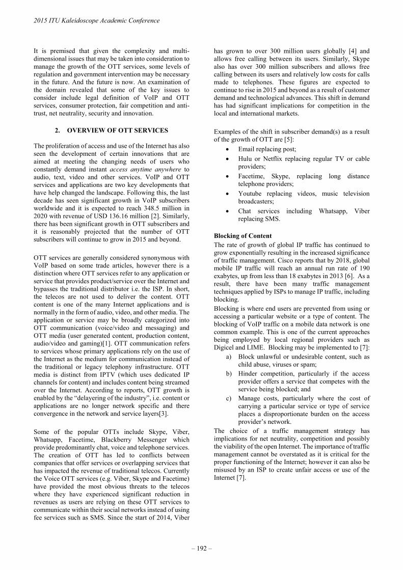
It is premised that given the complexity and multi-dimensional issues that may be taken into consideration to manage the growth of the OTT services, some levels of regulation and government intervention may be necessary in the future. And the future is now. An examination of the domain revealed that some of the key issues to consider include legal definition of VoIP and OTT services, consumer protection, fair competition and anti-trust, net neutrality, security and innovation.
2. OVERVIEW OF OTT SERVICES
The proliferation of access and use of the Internet has also seen the development of certain innovations that are aimed at meeting the changing needs of users who constantly demand instant access anytime anywhere to audio, text, video and other services. VoIP and OTT services and applications are two key developments that have help changed the landscape. Following this, the last decade has seen significant growth in VoIP subscribers worldwide and it is expected to reach 348.5 million in 2020 with revenue of USD 136.16 million [2]. Similarly, there has been significant growth in OTT subscribers and it is reasonably projected that the number of OTT subscribers will continue to grow in 2015 and beyond. OTT services are generally considered synonymous with VoIP based on some trade articles, however there is a distinction where OTT services refer to any application or service that provides product/service over the Internet and bypasses the traditional distributor i.e. the ISP. In short, the telecos are not used to deliver the content. OTT content is one of the many Internet applications and is normally in the form of audio, video, and other media. The application or service may be broadly categorized into OTT communication (voice/video and messaging) and OTT media (user generated content, production content, audio/video and gaming)[1]. OTT communication refers to services whose primary applications rely on the use of the Internet as the medium for communication instead of the traditional or legacy telephony infrastructure. OTT media is distinct from IPTV (which uses dedicated IP channels for content) and includes content being streamed over the Internet. According to reports, OTT growth is enabled by the “delayering of the industry”, i.e. content or applications are no longer network specific and there convergence in the network and service layers[3]. Some of the popular OTTs include Skype, Viber, Whatsapp, Facetime, Blackberry Messenger which provide predominantly chat, voice and telephone services. The creation of OTT has led to conflicts between companies that offer services or overlapping services that has impacted the revenue of traditional telecos. Currently the Voice OTT services (e.g. Viber, Skype and Facetime) have provided the most obvious threats to the telecos where they have experienced significant reduction in revenues as users are relying on these OTT services to communicate within their social networks instead of using fee services such as SMS. Since the start of 2014, Viber
has grown to over 300 million users globally [4] and allows free calling between its users. Similarly, Skype also has over 300 million subscribers and allows free calling between its users and relatively low costs for calls made to telephones. These figures are expected to continue to rise in 2015 and beyond as a result of customer demand and technological advances. This shift in demand has had significant implications for competition in the local and international markets. Examples of the shift in subscriber demand(s) as a result of the growth of OTT are [5]:
• Email replacing post; • Hulu or Netflix replacing regular TV or cable
providers; • Facetime, Skype, replacing long distance
telephone providers; • Youtube replacing videos, music television
broadcasters; • Chat services including Whatsapp, Viber
replacing SMS. Blocking of Content The rate of growth of global IP traffic has continued to grow exponentially resulting in the increased significance of traffic management. Cisco reports that by 2018, global mobile IP traffic will reach an annual run rate of 190 exabytes, up from less than 18 exabytes in 2013 [6]. As a result, there have been many traffic management techniques applied by ISPs to manage IP traffic, including blocking. Blocking is where end users are prevented from using or accessing a particular website or a type of content. The blocking of VoIP traffic on a mobile data network is one common example. This is one of the current approaches being employed by local regional providers such as Digicel and LIME. Blocking may be implemented to [7]:
a) Block unlawful or undesirable content, such as child abuse, viruses or spam;
b) Hinder competition, particularly if the access provider offers a service that competes with the service being blocked; and
c) Manage costs, particularly where the cost of carrying a particular service or type of service places a disproportionate burden on the access provider’s network.
The choice of a traffic management strategy has implications for net neutrality, competition and possibly the viability of the open Internet. The importance of traffic management cannot be overstated as it is critical for the proper functioning of the Internet; however it can also be misused by an ISP to create unfair access or use of the Internet [7].
2015 ITU Kaleidoscope Academic Conference
– 192 –

Net Neutrality The concept of “net neutrality” is still developing and as such there is no settled definition to date. With closer attention being paid to the governance of the Internet, net neutrality is becoming even more important. The different viewpoints nevertheless underline equality in the treatment of content and freedom from discrimination. Tim Berners-Lee [8] describes net neutrality as keeping the Internet free from political or commercial discrimination. It is also described as the principle that all electronic communication passing through a network is treated equally [7]. This means that all communication is treated as independent of (i) content, (ii) application, (iii) service, (iv) device, (v) sender address, and (vi) receiver address. Net neutrality is further defined as a network design principle where it is suggested that a useful public information network aspires to treat all content, sites, and platforms equally [9]. It is argued that the broad definitions of net neutrality are being challenged by the reality of an Internet where traffic management is critical to ensure efficient operation for all users and to prevent degradation of service [7]. Proponents of net neutrality have argued for increased protection and regulations because ISPs have a natural tendency to engage in discriminatory practices in the use of their networks [10]. On the other hand, opponents of net neutrality argue that there is no evidence of widespread abuse and the proposal to have an open unregulated Internet is a Pandora’s box which can lead to a reduction in the access providers’ ability to offer innovative packages of services [10]. While the debate rages on, it is important for policy makers to play a leading role in ensuring that discriminatory practices are minimized, consumers are protected and competition is nurtured.
3. REGULATORY LANDSCAPE
The regulatory issues relating to the VoIP/OTT market are not monolithic. According to a report from the International Telecommunication Union (ITU) [1], the issues may be categorized based on the maturity of the VoIP/OTT market in the respective country: early; maturing and mature [1]. The issue of illegal termination and bypass is consistent across all types of market and quality of service is significant to both early and maturing markets. Some of the other issues identified at the early stage include defining VoIP and considering its legality, licensing, numbering and quality of service (QoS). At the maturing stage issues of regulatory capture, universal service, number portability and access to emergency service numbers are considered. At the mature VoIP market, security of transmission, net neutrality and blocking, consumer protection, location correspondence and anti-competition issues are underlined.
Currently OTT services worldwide are predominantly unregulated. A global scan shows that countries generally adopt four main approaches to combat OTT: a full ban, in places such as China and the Middle East; operator restrictions, such as what currently exist in Jamaica; primarily unregulated such as environment that exists in Canada and USA; and a commercial approach where there is support and creation of commercial versions. Reports from ITU revealed that the incidences of the banning of VoIP services have been steadily declining although no formal update since 2009. USA The Federal Communications Commission (FCC) has sought to adopt what is considered a “light regulatory touch” with regards to VoIP and OTT services. The FCC does not consider VoIP a traditional telephone service, but a computer-based ‘information service’, that is relatively unregulated. The Telecommunications Act 1996 governs telecommunication and broadcasting services where Title 1 governs telecommunication and Title 2 governs broadcasting under which information services fall. Per the Telecommunications Act 1996, USA: The term `information service' means the offering of a capability for generating, acquiring, storing, transforming, processing, retrieving, utilizing, or making available information via telecommunications, and includes electronic publishing, but does not include any use of any such capability for the management, control, or operation of a telecommunications system or the management of a telecommunications service. The term `telecommunications service' means the offering of telecommunications for a fee directly to the public, or to such classes of users as to be effectively available directly to the public, regardless of the facilities used. The FCC believes that competition instead of regulation is the best strategy for these developments since it promotes innovation [11]. According to the FCC Chairman: “…Our mantra at the FCC is “Competition, Competition, Competition.”. We believe that competition is better than regulation at stimulating innovation and protecting consumers. I recognize that the broadcasting industry is subject to competition – more, in fact, today than ever before. And I recognize that more is coming...” Currently there are no licensing requirements, but a Universal Service contribution is required with respect to OTT Voice Providers. Additionally, a January 2014 Release from the FCC [12] outlined that there is a requirement that text services provide support for emergency services.
Trust in the Information Society
– 193 –

Canada Canada through its regulatory agency, the Canadian Radio-television and Telecommunications Commission (CRTC) has stated in that it has no immediate plans to impose any regulatory obligations on OTT providers[13]. It went further and stated that it also has no plans to reduce the obligations of regulated broadcasters and distributors in response to growing competition [13]. An analysis of events in 2014 revealed that not much has changed; however, the CRTC is still engaging stakeholders to determine the best course of action to the question of regulation in the face of continued competition from a wide spectrum of OTT media services [14]. Europe/Middle East Licences are not necessary but individual countries, e.g. in France and Spain, OTT providers have been blocked when offering voice services that connect with PSTN. The argument is that the OTT is behaving like a telco and should therefore fulfill the obligations of a telco, such as paying USO and offering emergency services. Some countries still have outright bans of VoIP and OTT services, particularly in the Middle East. The reasons range from an issue of revenue to the risk of corruption of the culture or plain censorship. Saudi Arabia has banned OTT services such as Viber which according to an ITU report is due to legal intercept problems. In Vietnam for example, Prime Minister Nguyen Tan Dung has outlined plans to regulate use of OTT messaging services in that country. This is attributed to the harm done to mobile operators by the free messaging services since there is a risk of loss in revenue [15]. Other regions have less blatant restrictions, where for example in the UK the operators cripple the OTT services by either slowing it down, raising the data costs, or by blocking it entirely , which may occur due to that being a part of the consumer contract [16]. The Caribbean Jamaica In Jamaica, OTT services although unregulated are currently treated by the telecos as bypass. Consequently, there have been different ranges of blocking undertaken by the telecos, such as the blocking of whole services (e.g. Viber in 2014) or blocking of specific services or features (e.g. Whatsapp call feature in 2015). Section 9(1)(d) of the Telecommunication Act, 2000 stipulates that a person shall not engage in bypass operations. The Act under section defines bypass operations and voice services where voice services may include VoIP: “bypass operations" means operations that circumvent the international network of a licensed international voice
carrier in the provisions of international voice services; and "voice service" means - (a) the provision to or from any customer of a specified service comprising wholly or partly of real time or near real time audio communications, and for the purpose of this paragraph, the reference to real time communications is not limited to a circuit switched service; (b) a service determined by the Office to be a voice service within the provisions of section 52, and includes services referred to as voice over the Internet and voice over IP. Section 52 further states: “(1) The Office may, where it considers necessary, decide that a particular service should be treated as a voice service and notice of that decision shall be published in such manner as the Office considers appropriate. (2) In making a decision under this section, the Office shall have regard to such factors as may be prescribed.” Section 2 of the Act defines telecommunication service and telecommunications network as follows: telecommunications service is “a service provided by means of a telecommunications network to any person for the transmission of intelligence from, to or within Jamaica without change in the content or form and includes any two way or interactive service that is provided in connection with a broadcasting service or subscriber television service”; and telecommunications network as “a system or any part thereof, whereby a person or thing can send or receive intelligence to or from any point in Jamaica, in connection with the provision of a specified service to any person”. Currently, there is no news as to the direction the government is going in relation to VoIP/OTT services. In June 2014, the regulatory body has stated that it has requested additional information from LIME and Digicel on their decision to block certain providers of VoIP services on their network and expected to get necessary information to move forward[17]. Since 2015, there has been no public update on the matter or information available on its website. This situation further underlined the challenges in the regulatory process and relatively delayed responses to changes in the telecommunications environment. Trinidad & Haiti Both countries’ regulators have requested that the telecommunication providers not ban users from using the OTT services, at least until they have received additional information. The Telecommunications Act of Trinidad & Tobago does not have a definition of bypass or any
2015 ITU Kaleidoscope Academic Conference
– 194 –

explicit mention of bypass or voice service. However section 21 of their Act states that no person shall operate a public telecommunications network, provide a public telecommunications service or broadcasting service without concession granted by the minister. Section 2 of Telecommunications Act, 2001 defines the following: “telecommunications service” includes a closed user group service, a private telecommunications service, a public telecommunications service; “public telecommunications network” means a telecommunications network used to provide a public telecommunications service; “public telecommunications service” means a telecommunications service, including a public telephone service, offered to members of the general public, whereby one user can communicate with any other user in real time, regardless of the technology used to provide such service; In Haiti, CONATEL in accordance with Articles of the Decree of 12 October 1977 and 10 June 1987 [18] has given directive to Digicel that it is the only body responsible for suspending or suppressing users’ services and therefore any ban should be lifted. Therefore, Haiti’s regulatory oversight seems to be much clearer in who is responsible for management of telecommunication services and who should have access to it.
4. THE CASE FOR REGULATION
It is therefore evident that there are numerous and varied strategies that have been adopted by countries to deal with VoIP/OTT services. However, they can be reduced to two general categories namely: regulation or non-regulation dependent on such issues as the promotion of competition, innovation, consumer protection, security and governance. There are different viewpoints in making the case for regulation. Regulation has the prospect of bringing structure and improved coordination to the marketplace. Alternatively, it is argued that the Internet has largely remained unregulated which has helped fueled its growth and this may be hindered with regulation of OTT services and applications such as OTT content. Secondly, regulation runs counter to the principles of net neutrality. Despite this, regulation is important for many reasons such as to avoid market failure, foster effective competition, protect consumer interest and increase access to technology and services [1]. The current environment scan shows a fiercely competitive market between the OTT service providers and telecos, and this is not forecasted to change soon.
According to Bhawan and Maarg [19], the current situation has led to regulatory imbalances because the telecos bear the costs for the infrastructure, spectrum management and licensing fees while having to adhere to Universal Service and other regulatory obligations. On the other hand, the OTT service providers are not obliged to adhere to any regulatory obligations and do not bear any infrastructural or spectrum costs. It is proposed that there are benefits to be gained from some form of regulation in the Caribbean. Whether regulation is the answer for countries in the Caribbean will depend however on the individual government’s vision for its respective Telecommunications/ICT market and the need for affordable broadband access for its citizens. In any event, a clear understanding of the multi-dimensional nature of VOIP and the issues raised by OTTs is required and it is imperative that we act quickly so that we do not lose the benefits that new emerging technologies offer. Some the key issues to consider: 1) Redefinition of bypass operation especially in the
context of the dramatic shift in how services are delivered to the customer as a result of the delayering and convergence of the networks. Many of the Telecommunications Acts in the Caribbean were passed before this new shift in delivery of services and have not been updated to reflect changes in the telecommunications environment;
2) The necessity of a definition of voice services within
the context of the pervasive development and use of multiple OTT services where the provision of a distinction between telecommunication and information services, similar to the US approach may be required and the determination of whether these types of services are voice or data services.
3) The provision of clear distinction between VoIP and
OTT services especially in the context of current global developments;
4) The issue of net neutrality, open internet and their
implications for stakeholders in the telecommunications industry;
5) The rights of the consumer in terms of access to
services and competition in a dynamic environment. 6) The balance of revenue and market protection versus
competition and innovation. Due consideration should be given on how to protect the revenues of the licensed telecos while promoting innovation, competition and consumer access and protection.
Trust in the Information Society
– 195 –

7) The continued development of telecommunications infrastructure and improved access to Internet services, particularly where there is still inequality of access and quality of services issues in countries in the Caribbean;
8) The movement towards development of new business
models in response to changing markets as a result of technological developments.
5. TOWARDS AN OTT REGULATORY FRAMEWORK FOR THE CARIBBEAN
The important features of an effective regulatory framework include a clear decision-making process, accountability, consumer protection, dispute resolution and enforcement process [1]. This may be facilitated by a clear structured process of activities. Motivated by these guidelines, a generic regulatory framework to manage OTT services is proposed, figure 1. The principles of CyberLeg-DPM [20] are adapted to the regulatory environment for OTT services in the Caribbean. The CyberLeg-DPM is a process model that includes steps that are representative of the lifecycle of legislative development and implementation [20]. The model is aimed at improving the efficiency and effectiveness of legislative process and therefore it is envisioned that similar benefits may result in the regulatory context. CyberLeg-DPM also embodies the principles of frugal innovation to address the current limitations in successfully applying a disciplined approach to developing and implementing new legislations. It promotes the effective use of resources and improvement in several legislative processes through defined steps and improved transparency to bring beneficial value to the legislative development value chain. It is argued that this view can also result in significant cost-savings to government, legislative and enforcement stakeholders, and others through a comprehensive process-oriented approach to designing and implementing cybercrime legislations. The CyberLeg-DPM specifies in logical order the set of key resources and procedures necessary in developing and implementing cybercrime legislation at the state or regional level. These characteristics are adopted within the regulatory development setting. The steps are adapted to include:
• Stage 1: Domain/market understanding • Stage 2: Field/OTT understanding • Stage 3: Regulatory process understanding • Stage 4: Regulatory design and development • Stage 5: Evaluation • Stage 6: Implementation • Stage 7: Review and monitor
Stage 1 - Domain understanding – refers to identification and accounting for the diverse stakeholders’ requirements in the telecommunications, VoIP and OTT domains. It involves due consideration of the issues relevant to the stakeholders including analysis of the relevant Acts and policies to identify gaps, limitations such as redefinition of bypass operation, OTT and VOIP services. Situation and feasibility assessment is done to account for the resource requirements and risk management. The regulatory development project design is the key outcome of this stage. Stage 2 - Field/OTT understanding - refers to a detailed examination of existing and related regulations and legislations at different levels such as globally, regionally, and locally. Relatedness accounts for any legislation, regulation or policy that can or may impact the telecommunications regulation. These related laws and rules can be closely connected such as the cybercrime laws. With growing trends, the interconnected network of related legislations and regulations will continue to grow and will require formal coordination and management. This stage also involves understanding of technical knowledge component of network and telecommunications, the types of likely actions and other technical competencies. The key output of this stage is the result of comparative legislative and regulatory frameworks that will aid in guiding the development of the relevant regulations. Stage 3 - Regulatory process understanding - sets the framework for building knowledge on and about the regulatory process for the specific country and the set of supporting processes that will facilitate all areas working in concert for an effective regulatory design and implementation with an efficient supportive environment. Each country may have specific set of processes/activities in developing regulatory process such as parliamentary approval. This process will also require involvement from multiple agencies and expertise from within the legal and regulatory fraternities for example. The key output at this stage includes a clear outline of the set of steps necessary in making, approving and implementing regulations, dependencies, and lines of accountabilities and governance structure. Stage 4 - Regulatory design and development – involves the process of developing the regulation and developing/refining the regulatory process. The results of the previous stages are used to inform the actual creation of the regulatory artifact, including any process changes based on analysis. The processes identified in the
2015 ITU Kaleidoscope Academic Conference
– 196 –
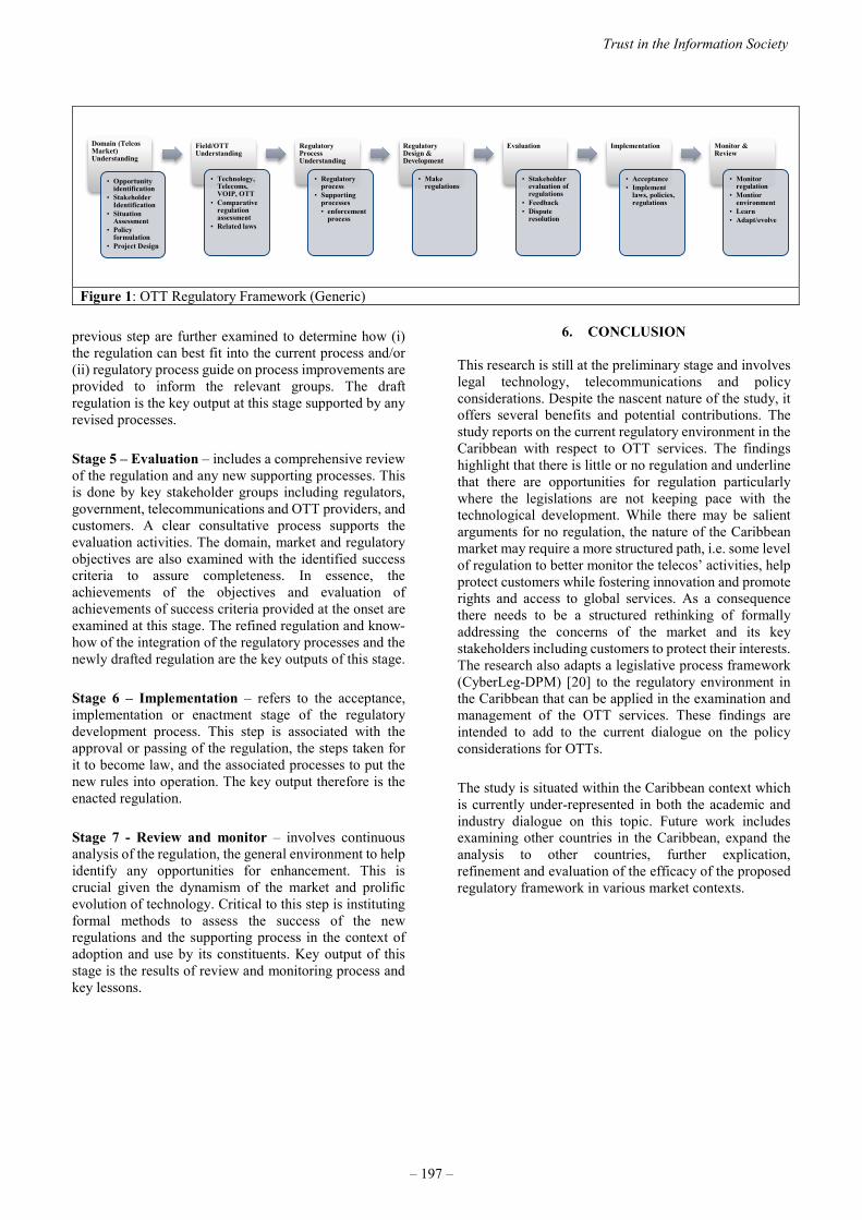
previous step are further examined to determine how (i) the regulation can best fit into the current process and/or (ii) regulatory process guide on process improvements are provided to inform the relevant groups. The draft regulation is the key output at this stage supported by any revised processes. Stage 5 – Evaluation – includes a comprehensive review of the regulation and any new supporting processes. This is done by key stakeholder groups including regulators, government, telecommunications and OTT providers, and customers. A clear consultative process supports the evaluation activities. The domain, market and regulatory objectives are also examined with the identified success criteria to assure completeness. In essence, the achievements of the objectives and evaluation of achievements of success criteria provided at the onset are examined at this stage. The refined regulation and know-how of the integration of the regulatory processes and the newly drafted regulation are the key outputs of this stage. Stage 6 – Implementation – refers to the acceptance, implementation or enactment stage of the regulatory development process. This step is associated with the approval or passing of the regulation, the steps taken for it to become law, and the associated processes to put the new rules into operation. The key output therefore is the enacted regulation. Stage 7 - Review and monitor – involves continuous analysis of the regulation, the general environment to help identify any opportunities for enhancement. This is crucial given the dynamism of the market and prolific evolution of technology. Critical to this step is instituting formal methods to assess the success of the new regulations and the supporting process in the context of adoption and use by its constituents. Key output of this stage is the results of review and monitoring process and key lessons.
6. CONCLUSION
This research is still at the preliminary stage and involves legal technology, telecommunications and policy considerations. Despite the nascent nature of the study, it offers several benefits and potential contributions. The study reports on the current regulatory environment in the Caribbean with respect to OTT services. The findings highlight that there is little or no regulation and underline that there are opportunities for regulation particularly where the legislations are not keeping pace with the technological development. While there may be salient arguments for no regulation, the nature of the Caribbean market may require a more structured path, i.e. some level of regulation to better monitor the telecos’ activities, help protect customers while fostering innovation and promote rights and access to global services. As a consequence there needs to be a structured rethinking of formally addressing the concerns of the market and its key stakeholders including customers to protect their interests. The research also adapts a legislative process framework (CyberLeg-DPM) [20] to the regulatory environment in the Caribbean that can be applied in the examination and management of the OTT services. These findings are intended to add to the current dialogue on the policy considerations for OTTs. The study is situated within the Caribbean context which is currently under-represented in both the academic and industry dialogue on this topic. Future work includes examining other countries in the Caribbean, expand the analysis to other countries, further explication, refinement and evaluation of the efficacy of the proposed regulatory framework in various market contexts.
Figure 1: OTT Regulatory Framework (Generic)
Domain (Telcos Market) Understanding
• Opportunity identification
• Stakeholder Identification
• Situation Assessment
• Policy formulation
• Project Design
Field/OTT Understanding
• Technology, Telecoms, VOIP, OTT
• Comparative regulation assessment
• Related laws
Regulatory Process Understanding
• Regulatory process
• Supporting processes• enforcement
process
Regulatory Design & Development
• Make regulations
Evaluation
• Stakeholder evaluation of regulations
• Feedback• Dispute
resolution
Implementation
• Acceptance• Implement
laws, policies, regulations
Monitor & Review
• Monitor regulation
• Montior environment
• Learn• Adapt/evolve
Trust in the Information Society
– 197 –

REFERENCES
[1] "Telecommunications Regulation Handbook," TheInternational Bank for Reconstruction and Development /The World Bank, InfoDev, and The International
Telecommunication Union 2011. [2] (July 20, 2015). Available: www.prnewswire.com/news-
releases/globa-voip-services-market-corporate-consumers-and-individual-consumers---forecast-to-2020-274897641.html
[3] ITU. (July 14, 2015). Regulating ‘Over-the-top’ Services,ICT Regulation Toolkit. Available:http://www.ictregulationtoolkit.org/2.5
[4] NT Balanarayan, Viber Sold For $900M; Has 105MMonthly Active Users, accessed fromhttp://www.medianama.com/2014/02/223-viber-sold-for-900m-has-105m-monthly-active-users/, July 14, 2014
[5] Accessed from http://ottsource.com/ott-blog/, July 15, 2014[6] Cisco VNI Global Mobile Data Traffic Forecast, 2013 –
2018.[ 7] Malcolm Webb, ITU GSR 2012 Discussion Paper – Net
Neutrality: A Regulatory Perspective[8] T. Berners-Lee, We Need a Magna Carta for the Internet
Internet, accessed fromhttp://www.huffingtonpost.com/tim-bernerslee/internet-magna-carta_b_5274261.html, June 12, 2015
[9] Tim Wu, Net Neutrality FAQ,http://www.timwu.org/network_neutrality.html
[10] ITU, Trends in Telecommunication Reform 2013[11] Remarks of FCC Chairman Tom Wheeler at the NAB
Show, April 8 2014,http://www.fcc.gov/document/remarks-fcc-chairman-tom-wheeler-nab-show
[12] FCC Sets Path For Widespread Text-To-911 Deployment,http://www.fcc.gov/document/fcc-sets-path-widespread-text-911-deployment
[13] D. Elder & L. Gwyer, CRTC says no regulation for “overthe top” programming – at least for now, October 2011
[14] How long can OTT services remain unregulated? – TheWire Report Blog, February 2014, accessed fromhttp://blog.thewirereport.ca/?p=211 , July 15, 2014
[15] K. Styles, Vietnam in Talks to Ban OTT Messaging Apps,Accessed fromhttp://mobilemarketingmagazine.com/vietnam-talks-ban-ott-messaging-apps/#UOT2guC8Y5Oym5YI.99, July 15,2014
[16] J. Stevenson, People who live in glass houses should notthrow stones, accessed from http://www.telco-ott.com/opinions/2013/07/people-who-live-in-glass-houses-should-not-throw-stones/, July 10, 2015
[17] Office of Utilities Regulation, accessed from,http://www.our.org.jm/ourweb/sites/default/files/documents/news/media_release_-_voip_update_july_18-2014_0.pdf, July 22, 2014
[18] The Conatel call to order the Digicel, accessed fromhttp://www.haitilibre.com/en/news-11600-haiti-telecommunicationsthe-conatel-call-to-order-the-digicel.html, July 25, 2014
[19] M. D. Bhawan and J.L.N Marg, March 2015, ConsultationPaper On Regulatory Framework for Over-the-top (OTT)services, TelecomRegulatory Authority of India.
[20] C. Barclay, "Using Frugal Innovations to SupportCybercrime Legislations in Small Developing States:Introducing the Cyber-Legislation Development andImplementation Process Model (CyberLeg-DPM),"Information Technology for Development, pp. 1-31, 2013
2015 ITU Kaleidoscope Academic Conference
– 198 –

SESSION 8
ESTABLISHING TRUST FOR NETWORKED THINGS
S8.1 Invited Paper: A Required Security and Privacy Framework for Smart Objects.
S8.2 Smart Doorbell: an ICT Solution to Enhance Inclusion of Disabled People.


A REQUIRED SECURITY AND PRIVACY FRAMEWORK
FOR SMART OBJECTS
Antonio Skarmeta, José L. Hernández-Ramos, Jorge Bernal Bernabe
Department of Information and Communications Engineering
Computer Science Faculty, University of Murcia (Spain)
ABSTRACT
The large scale deployment of the Internet of Things (IoT)
increases the urgency to adequately address trust, security
and privacy issues. We need to see the IoT as a collection of
smart and interoperable objects that are part of our personal
environment. These objects may be shared among or
borrowed from users. In general, they will have only
temporal associations with their users and their personal
identities. These temporary associations need to be
considered while at the same time taking into account
security and privacy aspects. In this work, we discuss a
selection of cur- rent activities being carried out by different
standardization bodies for the development of suitable
technologies to be deployed in IoT environments. Based on
such technologies, we propose an integrated design to
manage security and privacy concerns through the lifecycle
of smart objects. The presented approach is framed within
our ARM-compliant security framework, which is intended
to promote the design and development of secure and
privacy-aware IoT-enabled services
Keywords— Internet of Things, Security, Privacy, Trust
1. INTRODUCTION
The application of security mechanisms to manage the life
cycle of smart objects has received an increasing attention
from the research community. Millions of interconnected
constrained devices are starting to set up open and dynamic
environments, which are difficult to be managed directly by
humans. Indeed, this trend is expected to have increased in
the coming years to reach between 50 and 100 billion of de-
vices by 2020 [1]. In these environments, traditional
operational procedures for bootstrapping, authentication and
authorization are becoming obsolete, since they were not de-
signed to deal with the inherent requirements of IoT
ecosystems, in terms of scalability, heterogeneity, flexibility
and us- ability.
The extension of technology to everyday devices implies the
extension of identity management foundations to the
physical world, in order to foster the deployment of
Machine- to-Machine (M2M) communications [2] in which
smart objects will be able to interact with each other, as an
integral part of the IoT paradigm. In this sense, the IoT will
require more lightweight, decentralized and end-to-end
verification and authentication of the new devices deployed
in a network, and, on the other hand, extension of the trust
domain to such de- vices. This drives the need of new self-
managing models to allow IoT smart objects to establish trust
relationships among each other, while dealing with the new
security and privacy concerns, which are inherent in these
uncontrolled environments.
To this means, this work proposes the design of an integral
approach for managing security and privacy concerns
throughout the life cycle of a smart object. The design of the
proposed approach is framed within our security frame-
work [3] that is based on the Architectural Reference Model
(ARM) [4], in order to realize the M2M vision of the IoT
paradigm, while security and privacy are preserved.
Specifically, in this work, we consider the use of the Handle
System [5] as distributed information system for
identification and resolution purposes of smart objects, an
approach that is being currently considered by the ITU.
Furthermore, we base our proposal on the use of the Protocol
for Carrying Authentication for Network Access (PANA)
[6], which is being currently used by ZigBee Alliance and
ETSI M2M as IoT boot-strapping protocol. Moreover, we
propose the use of partial identities as mechanism in order to
conceal and minimize the private information revealed on a
daily basis operation. The partial identities are implemented
by applying anonymous credential systems (e.g. Idemix [7]),
which allow to prove a subset of the attributes associated to
the whole identity. Such privacy-preserving identity
management mechanism could be integrated with other
recent proposals, such as our Distributed Capability-based
Access Control (DCap-BAC) [8] approach, in order to
establish the notions of a se cure and privacy-preserving
M2M-enabled IoT.
The remainder of this work is organized as follows: Section
2 provides a general overview of concepts related to identity
management in IoT. Section 3 introduces some of the main
security and privacy challenges of the life cycle of smart
objects, and an overview of the main interactions of our
security framework to cope with such concerns.
Subsequently, section 4 proposes the use of different
candidate technologies that are currently considered by
standardization bodies to cope with security issues in IoT
environments. Furthermore, Section 5 focuses on the
This work has been sponsored by European Commission
through the FP7-SMARTIE-609062 and the FP7-SOCIOTAL-
609112 EU Projects.
978-92-61-15821-7/CFP1538E-ART © 2015 ITU Kaleidoscope– 201 –
privacy-preserving mechanisms that are envisioned to
support secure and privacy-aware M2M communications.
Finally, Section 6 concludes the paper with some remarks
and an outlook of our future work in this area.
2. IDENTIFICATION AND IDENTITY FOR
SUPPORTING SECURITY
2.1. Identities and Partial Identities in IoT
In the IoT ecosystem, identity management foundations must
be extended to consider smart objects as entities with
communication capabilities. While such smart objects may
have different networking identifiers, they have also to
possess their own identity to be distinguished from other
devices. This identity could make reference a core identifier
but also to specific features or attributes that point to the
object. Furthermore, smart objects could act on behalf of a
user. These objects could then be aware of the identity of
their owners disclosing sensitive information to other
devices. The identity management should be distributed in
order to authenticate objects between each other but, at the
same time, centralized enough to be able to establish a
hierarchical approach where identity credentials could be
issued and authenticated securely enabling a global digital
trust environment.
Privacy concerns are also of paramount importance in IoT,
where mechanisms for anonymity making use of partial
identities are required. A partial identity is a subset of the
attributes that comprise the complete or real identity of the
user. Thus, an identity of a particular user or object may be
composed of different partial identities. Each of these partial
identities can be used to identify the user or the object in
different circumstances according to the context or social
situation. The real identity is the union of all the attributes of
the partial identities of the user or object. Partial identities
may comprise not only traditional user personal attribute
values like names, identifiers, and addresses, but also object
at- tributes, such as hardware features or software version.
Thus, IoT ecosystems require suitable identity management
solutions to cope with new challenges due to inherent nature
and requirements of IoT, where the identities of a huge
amount of heterogeneous smart objects need to be properly
managed.
2.2. Object Naming, Resolution, Networking and
Addressing
In order to achieve a real IoT, an essential feature is to give
support to finding smart objects in order to be addressable,
named, and finally discovered. In the IoT paradigm, smart
objects cannot be configured with respect to a fixed set of
services. This is mainly due to the underlying dynamics of
the IoT system resulting from the mobility of such devices,
as well as the changing availability of services due to
constraints on the underlying resources and devices.
Therefore, a real need exists for a suitable infrastructure to
1 www.handle.net
be in place that allows addressing, naming and discovery of
IoT services:
IoT Addressing: an IoT address refers to an
identifier of a smart object and/or its virtual
representation. This feature entails the assignment
and management of ad- dresses/identifiers for smart
objects.
IoT Naming: it refers to mechanisms and
techniques for assigning names to objects and
supporting their resolution/mapping to IoT
addresses. IoT Naming pro- vides the means to
identify smart objects through a resolution
mechanism of a name according to a naming
system. Additionally, names can be organized
according to taxonomies or classifications in a
hierarchical fashion and according to a well-defined
naming system.
IoT Discovery: it refers to the process of locating
and retrieving IoT resources in the scope of a large
and complex space of smart objects.
Previous concepts are closely related, given that the
adherence to certain choices and solutions (e.g., standards,
mechanisms, algorithms, tools) for one area (e.g., choice of
addresses/identifiers) can directly affect the respective
choices and solutions in the other areas (e.g., naming system
used). As a consequence, the consideration of solutions for
one area cannot be seen as isolated from the others.
2.3. Handle and Identifiers
The realization of the concepts described in the previous section
implies the need for suitable infrastructures to enable addressing,
naming and discovery procedures for the IoT ecosystem. Indeed,
currently there are different proposed Internet identifier services
addressing some of these aspects. X.500 [9] is the OSI Directory
Standard defined by the ISO and the ITU. It defines a hierarchical
da ta model with a set of protocols to allow global name
lookup and search. In the same direction, The Lightweight
Directory Access Protocol (LDAP) [10] was developed as a
more lightweight alternative, but bringing different problems
related to the hierarchical data model, as well as to the complex
search/query process. Addressing some of these main concerns, the
Handle System (HS)1 is a general purpose distributed
information system that provides efficient, extensible, and
secure identifier and resolution services for use on networks, such
as the Internet [5]. While X.500 or LDAP could also be used,
HS provides additional features, outperforming previous
approaches due to its flexibility to enrich the resolution
infrastructure with security aspects. Furthermore, HS could be
used in tandem with LDAP providing efficient name resolution
service, and extended search capabilities, respectively [11]. It is
part of the Digital Object Architecture (DOA). A Digital
2015 ITU Kaleidoscope Academic Conference
– 202 –
Object (DO) has a machine and platform independent structure
that allows it to be identified, accessed and protected.
The HS was developed initially with digital documents in
mind, but it has evolved into a generic implementation of
the DOA, supporting multiple object types, not just ’digital
documents’. It is being taken into account by the ITU un-
der ITU-T Recommendation X.125. The HS incorporates an
operational security system based on both private/public key
pairs and passwords. It allows for the storage and resolution
of a set of attributes to a particular identifier, including an
infrastructure for authentication, signing, integrity
checking, public key operations as well as an authorization
mechanism to restrict the access to the attributes. A handle
consists of a prefix and a local identifier. The syntax of the
DO is a set of pairs (type, value). As with the Domain Name
Sys- tem (DNS) with its DNS Resource Directory (DNS-
RD), the Handle Resolver (i.e. handle server) will provide
a set of such pairs, some of which include well-known data
types, like URIs, INET HOST addresses, etc. The pairs can
be hierarchic, so that a DO contains descriptions and
identifiers of other DOs in its parameters. Clearly, some of
the parameters may contain IPv6 addresses, but there may
be several such addresses depending on different views of
the parameters.
The attributes managed by Handle and associated to an
identifier can be exploited by an identity management
system in order to allow the usage of partial identities
associated to such attributes. A claim-based anonymous
credential system, e.g. Idemix [7], can interact with Handle
to generate credentials based on the attributes associated
with the smart object. Subsequently, the smart object can
derive partial identities from such a credential to operate
against other smart objects in a privacy-preserving way.
Specifically, we envision the use of Handle for three main
purposes:
Restricting the access to Handle attributes to
authorized smart objects, based on a public key
infrastructure through the use of X.509 certificates.
Anonymous credential provisioning and partial
identity management based on the attributes that
are registered in the HS.
Generation of authorization credentials to enable
M2M secure communications, based on handle at-
tributes to make access control decisions.
3. TOWARDS A SECURITY FRAMEWORK FOR
SMART OBJET LIFE CYCLE
The secure management of the life cycle of IoT smart objects
imposes the need for considering architectural approaches,
taking into account the inherent requirements of the
application of security and privacy-preserving mechanisms
on IoT scenarios. Towards this end, IoT-A [4] was a large-
scale European project focusing on the design of an
Architectural Reference Model (ARM), in order to optimize
the interoperability among isolated IoT domains. Based on
ARM, our security framework [3] [12] is intended to address
security and privacy concerns in the IoT paradigm, by
instantiating and extending the security functional group of
ARM. Consequently, such framework promotes its
applicability and inter- operability in a wide range of IoT
scenarios, in which security and privacy are required.in
capital and lower case letters. Papers with multiple authors
and affiliations may require two or more lines for this
information.
Under the complete view of our IoT security framework, as
well as the main stages of the life cycle of smart objects [13],
below we provide an overview of the main interactions that
are required to address security and privacy concerns
through such phases. It should be pointed out that, while it
has been proposed in our framework, for the sake of clarity,
the interactions of the Group Manager functional component
are not addressed in this work [14]. Figure 1 shows the
required interactions to manage security during the smart
objects life cycle. The description of these interactions is
split according to the main stages of it. In particular, the life
cycle begins when a smart object is installed and
commissioned during the bootstrapping process. We propose
to extend this phase so the smart object is also registered
(Bootstrapping and registration), and consequently, it can be
discovered by other smart objects. This discovery process is
shown in the figure through the Discovery and provisioning
stage, in which a smart object additionally tries to obtain the
required security credentials for a secure and protected
access. In case this process is successfully completed, both
devices can communicate with each other during the
Operation stage, in which a smart object tries to get access to
the discovered device by using the credentials previously
obtained.
At this point, note that, while it is not shown, we assume
smart objects are supplied with statically configured crypto-
graphic material (e.g. symmetric keys or X.509 certificates)
before the bootstrapping process. Such cryptographic
material can be configured by the manufacturer (or the
device’s owner), and it can be considered as the root identity
that is employed for bootstrapping procedures. During this
stage, the smart object is commissioned and connected to the
net- work, which implies an authentication and authorization
process that is required before starting the sending or
receiving of data. Specifically, the purpose of this process is
twofold. On the one hand, the smart object can be registered
in or- der to be discovered by other smart objects to
communicate with each other. This functionality is already
considered by the ARM through the IoT Service Resolution
functional component, and it can be carried out by an
infrastructure entity (e.g. based on Handle). On the other
hand, a success authentication and authorization process
could derive other cryptographic material to be employed by
the smart object during its operation. In particular, we
Trust in the Information Society
– 203 –

Figure 1. Overview of the security framework interactions for Smart Objects Life cycle
envision that anonymous credentials (e.g. based on Idemix)
associated with identity attributes that are demonstrated
during the boot- strapping, could be supplied during this
process. However, while smart objects could use such
credentials for privacy-preserving communications, the
creation of an anonymous credential would be linked to the
root identity of the smart object. This process is intended to
preserve the accountability of the anonymity condition, in
order to avoid the misuse or abuse of it.
After the smart object has been successfully bootstrapped, it
enters the operation phase by providing (or trying to get
access to) the services for which it has been manufactured.
At operational level, security guarantees that only trusted and
legitimate smart objects can communicate with each other.
Consequently, the application of security and privacy-
preserving mechanisms is crucial to ensure a proper and
effective operation of the smart object. For these
interactions, we assume the existence of two smart objects
acting as a producer (providing a service), and a consumer
(trying to get access to such service). In addition, we assume
that these smart objects have already carried out the process
previously described. Before starting the operation stage, the
consumer initiates a discovery process to know the services
being pro- vided by the producer. This step involves
authentication and authorization procedures, in order to
determine whether the consumer is authorized to find that
service or not. Further- more, such authentication
mechanism can consider privacy concerns of the consumer
through the use of partial identities, which can be derived
from the anonymous credential. Furthermore, we envision
the extension of the discovery step in order that the
consumer, in the case of a successful authentication and
authorization process, can get the required credentials for a
secure M2M communication with the producer smart object.
Once this process is completed, such credentials are used by
consumers to access a resource being hosted by the producer.
On the one hand, from a consumer perspective, the operation
stage can take into account privacy concerns through the
selection of a different partial identity (or pseudonym),
according to contextual information being sensed. On the
other hand, from the producer perspective, the evaluation of
authorization credentials presented by the consumer could
consider additional information, such as trust and reputation
scores associated to the requesting smart object [15].
4. LIGHTWEIGHT SECURITY MECHANISMS FOR
IOT ENVIRONMENTS
Having highlighted the main required interactions of our IoT
security framework have been highlighted, below we give
an overview of candidate technologies being currently
considered by different standardization bodies, and how they
can be integrated to achieve the functionality previously
described. The integration of these mechanisms is intended
to provide a holistic view to support security and privacy
2015 ITU Kaleidoscope Academic Conference
– 204 –

aspects, which can be leveraged by smart objects during their
life cycle.
4.1. Security Bootstrapping
The bootstrapping process usually consists of a set of
procedures in which a node is installed and commissioned
within a network. Optionally, this stage can include
authentication and access control mechanisms to get security
parameters for trusted operation. For a successful and secure
bootstrapping process, well-known mechanisms need to be
on the basis. Additionally, in the context of IoT constrained
scenarios, the application of such procedures needs to be
analysed due to implicit requirements of these environments.
Towards this end, [16] provides some design considerations
that must be taken into account in the design of an
appropriate IoT boot- strapping protocol. In addition, [17]
presented three main alternatives for the security
bootstrapping of IoT devices: Host Identity Protocol Diet
EXchange (HIP-DEX) [18], PANA [6] and 802.1X.
Currently, PANA is widely accepted as the main candidate
for IoT security bootstrapping, and it is being employed by
ZigBee Alliance in conjunction with EAP-TLS as
authentication protocols. In this work, we consider that smart
objects are initially equipped with an identity certificate (e.g.
a X.509 certificate), which contains a set of attributes
associated with the smart object (e.g. manufacturer or
hardware features). Then, we propose the use of PANA as a
signaling protocol enabling smart objects, in an on-demand
way, to make smart objects to apply for security credentials
that can be used for secure M2M communications during
their operation.
4.2. Operational Security
At operational level, security guarantees that only trusted and
legitimate instances of an application running in the IoT can
communicate with each other, through the use of the
corresponding security mechanisms at the application layer.
Specifically, CoAP [19] defines a security binding to DTLS
[20] through the use of pre-shared keys, raw public keys or
certificates. However, it does not cover the use of
authorization and access control mechanisms at the
application level. Towards this end, our Distributed
Capability-Based Access Control model (Capac) has been
postulated as a realis- tic approach to be used on IoT
scenarios [8]. This approach is based on linking access
privileges or capabilities to smart objects, which are
identified by their public key. Capac is based on the use of
authorization tokens, containing capability that were
previously granted to the holder, as well as a set of access
conditions to be locally verified by the end de- vice when the
token is presented. Specifically, it makes use of the
JavaScript Object Notation (JSON) [21] as representation
format for the capability token, which is attached in access
requests by using the Constrained Application Protocol
(CoAP) [19].
In addition to the main authentication and authorization for
communication between two smart objects, given the global
scale of the IoT, it is likely that smart objects often operate
as groups of entities (e.g. interacting or collaborating for a
common purpose). Indeed, we consider the concept of group
as essential in the IoT to cope with environments with a high
number of smart objects interacting with each other, and the
application of security mechanisms involving groups of
devices with dynamic and ephemeral relation- ships as a
challenging aspect. In this sense, the Ciphertext-Policy
Attribute-Based Encryption (CP-ABE) [22] has been
recently proposed as a highly flexible cryptographic scheme,
which provides the ability to define groups and subgroups of
smart objects according to different combinations of identity
attributes. Indeed, unlike the use of symmetric key
cryptography, in which groups of entities must be
preconfigured, a smart object could encrypt each piece of
data under a different combination of attributes, allowing for
the creation of dynamic groups or subgroups. For example,
a smart object could encrypt information so that only the set
of objects from the same manufacturer or the same owner
could decrypt the information. The application of CP-ABE
for IoT scenarios is currently considered in our framework,
through the design of our proposed Group Manager
functional component, as well as the interactions with other
security components.
4.3. Supporting Security and Privacy features in the Life
Cycle of Smart Objects
After the overview of the main security and privacy
technologies addressing different aspects of the life cycle of
smart objects, this section shows an overview of how some
of the above mentioned technologies previously described
could be integrated into addressing such requirements.
According to the main stages described in the previous
section, the life cycle of a smart object begins with the boot-
strapping/registration phase. For this stage, we consider the
use of PANA due to its flexibility enabling the execution of
different authentication mechanisms or EAP methods. Once
the smart object is successfully authenticated through its root
identity (for example, by using a X.509 certificate), we pro-
pose to extend this phase so the smart object is registered
through the use of the Handle infrastructure to be discovered
by other smart objects. This process may involve the
registration of attributes or additional information that is
contained in the smart object’s certificate. After this process,
the device could try to obtain an Idemix credential that is
associated with the information previously registered in the
Handle server. Indeed, it can use the issuance Idemix
protocol as specified in [7].
In the discovery and operation stages, a smart object (acting
as a consumer) tries to access a resource being hosted by
another (acting as a producer). For this purpose, firstly, it
discovers the device by querying the Handle server. It should
Trust in the Information Society
– 205 –

be pointed out that this process may require authentication
and authorization procedures according to the information
that was registered during the bootstrapping and registration
stage of the smart object producer. In addition to the
discovery, the consumer tries to obtain the credentials that
are required for a secure and M2M operation. In this case,
we propose to extend the semantics of PANA notification
messages so that a device can apply for DCapBAC tokens to
get access to a resource being hosted by another device.
Obtaining these credentials implies an authorization process
driven by infrastructure components, which are responsible
for generating DCapBAC tokens to authorized smart objects.
For this purpose, we propose the use of CoAP/DTLS or
HTTPS as communication protocols, and the eXtensible
Access Control Markup Language (XACML) [23] as
standard access control technology. Finally, after the smart
object consumer obtains the required DCapBAC token, it can
make use of a CoAP-DTLS exchange attaching the
credential for a secure and protected M2M communication.
5. PRIVACY-PRESERVING M2M SUPPORT
The realization of the IoT ecosystem implies moving
towards automated and self-managing security mechanisms,
which allow IoT devices to set up trust relationships with
each other with a low degree of human intervention.
Furthermore, given the M2M nature of these emerging
scenarios, the application of current privacy-preserving
technologies needs to be reconsidered and adapted to be
deployed in such global ecosystem, addressing aspects such
as Privacy by Design (PbD) [24], in order to give people
maximum control over their personal data. As already
mentioned, privacy-enhancing technologies provide means
to achieve anonymity, data minimization, unlinkability as
well as other techniques to provide confidentiality and
integrity of sensitive data. In this regard, the usage of partial
identities as privacy-preserving identity management
scheme, allows users to define a subset of the personal
attributes, from their real identity, in order to identify them
in a given context. In order to realize this vision, some
solutions rely on the notion of Anonymous Credential
Systems [25] to deal with privacy concerns. Through the use
of these technologies, a consumer smart object could try to
get access to a producer device by proving a subset of
identity attributes from their whole identity, without the
involvement of an on- line Trusted Third Party (TTP) in
charge of authenticating the subject.
The use of partial identities and anonymous credential
systems, which has been previously proposed, could be
combined with authorization mechanisms, such as our
DCapBAC approach [8]. Specifically, in the original
DCapBAC proposal privacy aspects are not considered,
since it is based on the use of X.509 certificates, which are
used to identify smart objects making use of authorization
tokens. These considerations were addressed in our recent
work [26] by enhancing DCapBAC with anonymity features,
in order to deal with privacy concerns through the integration
with Idemix [7].
Specifically, with this approach, the smart object (acting as
a producer) could use its Idemix credential obtained during
the bootstrapping/registration phase to get an Anonymous
DCapBAC token from the Capability Manager (the entity
that is responsible for generating these credentials) in a
privacy-preserving-way. Specifically, the Idemix proof
generated by the producer could be associated with a
particular partial identity (i.e. a subset of identity attributes),
which could be used for authorization purposes by the
Capability Manager and the PDP. Such proof should also
contain a pseudonym generated by the smart object to be
specified in the token. Then, the smart object can make use
of such anonymous token, to get access to the producer smart
object through the Idemix proving protocol. This process
allows the consumer to prove it is the entity associated with
the token while concealing any other identity attributes. The
integration of this mechanism to the scenario proposed in the
previous section is being currently designed and
implemented, and it represents part of our ongoing work in
this area.
6. CONCLUSIONS AND FUTURE WORK
The realization of IoT scenarios imposes significant security
and privacy concerns due to the extension of Information
Technology to our everyday lives. These aspects must be
addressed by considering the whole picture of this paradigm,
so the enormous envisioned potential can be leveraged by the
society in the context of the future Smart Cities. Physical
objects of our surrounding environment are being enabled
with intelligence and communication abilities transforming
them into smart objects. In this work, we have reviewed the
main security and privacy challenges that are inherent in an
IoT ecosystem. These implications are considered crossing
all the stages of the life cycle of a smart object. We claim the
need to consider architectural approaches to cope with these
challenges in order to design appropriate mechanisms for
emerging environments. By considering our previous work
in this area, and some promising technologies that are
currently being contemplated for deployment in IoT
scenarios, we have provided the design of an integrated
approach in order to capture such requirements. This
scenario is being developed under our ARM-compliant
security framework, with the aim of providing a holistic
security approach as a step forward to realizing the vision of
a secure and privacy- preserving IoT.
REFERENCES
[1] Harald Sundmaeker, Patrick Guillemin, Peter Friess, and
Sylvie Woelfflé, “Vision and challenges for realising the
Internet of Things,” 2010.
[2] Zubair Md Fadlullah, Mostafa M Fouda, Nei Kato,
Akira Takeuchi, Noboru Iwasaki, and Yousuke Nozaki,
2015 ITU Kaleidoscope Academic Conference
– 206 –
“Toward intelligent Machine-to-Machine
communications in Smart grid,” Communications
Magazine, IEEE, vol. 49, no. 4, pp. 60–65, 2011.
[3] Jorge Bernal Bernabe, Jose Luis Hernández, M Victo- ria
Moreno, and Antonio F Skarmeta Gomez, “Privacy-
Preserving Security Framework for a Social-Aware Internet
of Things,” in Ubiquitous Computing and Ambient
Intelligence. Personalisation and User Adapted Services, pp.
408–415. Springer, 2014.
[4] Alessandro Bassi, Martin Bauer, Martin Fiedler,
Thorsten Kramp, Rob van Kranenburg, Sebastian
Lange, and Stefan Meissner, “Enabling Things to
Talk,” 2013.
[5] Robert Khan and Robert Wilensky, “A framework for
distributed digital object services,” International
Journal on Digital Libraries, vol. 6, no.2, pp. 115-123,
2006.
[6] D Forsberg, Y Ohba, B Patil, H Tschofenig, and A
Yegin, “RFC 5191 - Protocol for carrying Authentication
for Network Access (PANA),” Network Working Group,
2008.
[7] Jan Camenisch and Els Van Herreweghen, “Design and
Implementation of the Idemix Anonymous Credential
System,” in Proceedings of the 9th ACM Conference on
Computer and Communications Security, New York, NY,
USA, 2002, CCS ’02, pp. 21–30, ACM.
[8] José L Hernández-Ramos, Antonio J Jara, Leandro Marín,
and Antonio F Skarmeta, “DCapBAC: Em- bedding
Authorization logic into Smart Things through ECC
optimizations,” International Journal of Com- puter
Mathematics, , no. just-accepted, pp. 1–22, 2014.
[9] ITU-T Recommendation X.500, “The Directory:
Overview of Concepts, Models, and Services,” 1993.
[10] J Sermersheim, “RFC 4511 - Lightweight Directory
Access Protocol (LDAP): The Protocol,” Internet
Engineering Task Force (IETF), 2006.
[11] Sam Sun, Larry Lannom, and Brian Boesch, “RFC
3650: Handle System Overview,” Tech. Rep., 2003
[12] Jose L Hernandez-Ramos, Marcin Piotr Pawlowski,
Antonio J Jara, Antonio F Skarmeta, and Latif Ladid,
“Toward a Lightweight Authentication and Authoriza-
tion Framework for Smart Objects,” Selected Areas in
Communications, IEEE Journal on, vol. 33, no. 4, pp.
690–702, 2015.
[13] Tobias Heer, Oscar Garcia-Morchon, René Hummen,
Sye Loong Keoh, Sandeep S Kumar, and Klaus
Wehrle, “Security Challenges in the IP-based Internet of
Things,” Wireless Personal Communications, vol. 61,
no. 3, pp. 527–542, 2011.
[14] Jose L Hernandez-Ramos, Jorge Bernal Bernabe, Sal-
vador Perez Franco, and Antonio F Skarmeta, “Certifi-
cateless and Privacy-enhancing Group Sharing mech-
anism for the Future Internet,” in Innovative Mobile
and Internet Services in Ubiquitous Computing (IMIS),
2015 Ninth International Conference on. IEEE, 2015,
p. to appear.
[15] Jorge Bernal Bernabe, Jose Luis Hernandez Ramos,
and Antonio Skarmeta Gomez, “TACIoT:
multidimensional Trust-aware Access Control system
for the Internet of Things,” Soft Computing, vol. to be
published, 2015.
[16] A He and B Sarikaya, “IoT Security Bootstrapping:
Survey and Design Considerations,” IETF Internet
Draft, draft-he-6lo-analysis-iot-sbootstrapping-00,
2015.
[17] C O’Flynn, B Sarikaya, Y Ohba, Z Cao, and R
Cragie, “Security Bootstrapping of Resource-
Constrained Devices,” IETF Internet Draft, draft-
oflynn-core-bootstrapping-03, 2012.
[18] René Hummen, Jens Hiller, Martin Henze, and Klaus
Wehrle, “Slimfit–A HIP DEX compression layer for the
IP-based Internet of Things,” in Wireless and Mobile
Computing, Networking and Communications
(WiMob), 2013 IEEE 9th International Conference on.
IEEE, 2013, pp. 259–266.
[19] Z. Shelby, K. Hartke, and C. Bormann, “The Con-
strained Application Protocol (CoAP),” IETF RFC
7252, vol. 10, June 2014.
[20] E Rescola and N Modadugu, “RFC 4347 - Datagram
Transport Layer Security (DTLS),” Request for
Comments, IETF, 2006.
[21] D. Crockford, “RFC 4627: The application/json Media
Type for Javascript Object Notation (JSON),” July 2006.
[22] John Bethencourt, Amit Sahai, and Brent Waters,
“Ciphertext-Policy Attribute-Based Encryption,” in
Security and Privacy, 2007. SP’07. IEEE Symposium on.
IEEE, 2007, pp. 321–334.
[23] E Rissanen, “eXtensible Access Control Markup Language
(XACML) version 3.0 OASIS standard,” 2012.
[24] Marc Langheinrich, “Privacy by Design–Principles of
Privacy-Aware Ubiquitous Systems,” in Ubicomp 2001:
Ubiquitous Computing. Springer, 2001, pp. 273–291.
[25] Jan Camenisch and Anna Lysyanskaya, “An Efficient
System for Non-Transferable Anonymous Credentials with
Optional Anonymity Revocation,” in Advances in
Cryptology–EUROCRYPT 2001, pp. 93–118. Springer,
2001.
[26] J.L. Hernandez-Ramos, J.B. Bernabe, M.V. Moreno, and
A.F Skarmeta, “Preserving Smart Objects Privacy through
Anonymous and Accountable Access Control for a M2M-
Enabled Internet of Things,” Sensors, vol. 15, no. 7, pp.
15611–15639, July 2015.
Trust in the Information Society
– 207 –

SMART DOORBELL: AN ICT SOLUTION TO ENHANCE INCLUSION OF DISABLED
PEOPLE
Lucas M. Alvarez Hamann, Luis Lezcano Airaldi, María E. Báez Molinas,
Mariano Rujana, Juliana Torre, Sergio Gramajo
National Technological University – Resistencia Faculty
French 414, Resistencia, Chaco, Argentina
ABSTRACT
In daily life, people have the need to know the identity of
a visitor who comes to their homes, regardless of whether
they are there at that time. This need is even greater for
people who suffer from some kind of disability that prevents
them from meeting the visitor. To provide a solution in this
sense, this paper proposes a smart model that performs the
task of a doorbell, which should recognize the visitor and
alert the user. To achieve that, this proposal incorporates
technologies for facial recognition of people, notifications
to users and management of their responses. The process to
solve the problem was divided into interrelated stages and
standardization issues are discussed later. Finally, to test
the effectiveness of the model, three scenarios were
simulated; each one was composed by different households
over which the recognition of known and unknown
individuals was analyzed.
Keywords— Smart Doorbell, Social Inclusion, Internet
of Things, Face Detection and Recognition.
1. INTRODUCTION
Today, the world population is over seven billion people
and more than one billion people live with some form of
disability. International Telecommunication Union is
working in this sense to give equal opportunities for people
with disabilities and create accessibility guidelines for the
elder [1].
Argentina has a population of 40,117,096 inhabitants,
where the 12.9% present a disability or permanent
limitation (each province of the Argentinian North East is
above the national average). Of the total population, 10.2%
are 65 years or more, group in which the percentage of
permanent disability grows to 40.9% [2]. Regarding the use
of information and communication technologies (ICT)
within the country, it is known that 47% of households have
a personal computer and in 86% of them there is at least
one cell phone [2]. It should be noted that internet
penetration scales up to 62%, the third highest in South
America [3][4]. People with disabilities are constantly facing problems of
different complexity when they perform their daily tasks,
like opening the door to someone or finding out who is
outside their house. Innovative technologies can be
leveraged to assist individuals in these tasks or provide
tools to do so. In this paper we present a model for a smart doorbell
which, through the use of a camera and image recognition
software, can identify the visitor and send a notification
with his/her information to the owner of the house. This
notification is sent to the user’s mobile device, from where
he can respond by video or voice. The development of this smart doorbell model is
originated within the framework of a continuous
advancement of information systems over all kinds of tools,
updating them and contributing with improvements for
greater comfort for its users, also aiding in increasing life
quality by solving everyday problems.
The theoretical aspect of the proposed model is based in
the concept of Internet of Things (IoT) [5], for which smart
technologies are a key enabler [6]. The objective under IoT
is to provide intelligence and interconnectivity to daily
things in order to obtain social or economic benefits.
Furthermore, the model uses facial recognition through
Nearest Neighbour classifiers [7] to accomplish the core
functionality.
The proposed model is a progress in Things-to-Humans
collaboration; this kind of solutions are expected to be usual
from 2020 onwards [8], being it a key part in the
development of IoT.
Different domains have been proposed to classify IoT
applications; the model described in this paper aims to two
of them. The first is the “smart home” domain and the
second refers to “independent living” domain [9].
Combining those domains we have a home automation IoT
application oriented for the elderly and disabled.
This paper is structured as follows: Section 2 describes the
problem addressed with more detail and background. Then,
Section 3 presents the specifications for the proposed
model. Section 4 exposes some challenges to the model and
the standards. Section 5 shows simulations which intent to
probe the effectivity and reliability of the proposed system,
and finally, Section 6 concludes with a discussion about the
model and future work.
2. PROBLEMATIC SITUATION AND
BACKGROUND
For most people, answering the door when someone is
knocking is a simple and daily situation. However, for
978-92-61-15821-7/CFP1538E-ART © 2015 ITU Kaleidoscope– 209 –

Figure 1. Proposed stages for the model
elderly people or a person with physical, visual, hearing or
mental disabilities this task can be uncomfortable and
complex. For these individuals, moving to the point where
there is a conventional intercom buzzer can take a long time
and the person who visits could have retired by then.
In these situations, a notification system can avoid the
unnecessary displacement to the door to meet an
unimportant or unwanted visitor and would allow a much
faster response to the person outside.
In elderly people’s situation, the comfort of answering the
door immediately and without the need of movement is
desirable. Moreover a system that notifies to a mobile
device can be useful for security concerns in older people
living alone, either because nobody lives with them or
because they are temporally left alone in the house; in this
case the elder (or a relative somewhere else) can monitor
the visitors arriving and be aware of any unknown or
doubtful caller, preventing in this way any scam or
dangerous situation for the elder. For a person with visual impairments, recognition of the
visitor can be a problem. Recognizing someone by his or
her voice can be very difficult if there is not a daily contact
with that person. Given this situation, a doorbell able to
recognize those who visit provides an important assistance. Anyone with hearing disabilities can have, among others,
two problems: the first is the warning bell since they cannot
hear its sound. This situation is usually solved by wiring the
conventional doorbell to at least one light in every room in
the house so when a person rings the doorbell the lights
blink; the second problem which arises is the recognition of
the individual who rings the doorbell; a person who suffers
from hearing impairment must, inevitably, go to the door to
see who is there. Under these circumstances, it would be
desirable to have a system that identifies the visitor and
sends a notification to a mobile device making it vibrate
and alerting the owner, thus avoiding the wiring of flashing
lights. The importance of information technologies to contribute
to the social development is not subject of doubt. The
United Nations has issued documents where member states
are urged to take accessibility as an integral part of their
ICT programs and projects [10], and more specifically, the
Secretariat for the Convention on the Rights of Persons
with Disabilities has referred to the issue of improving life
quality through the use of information technologies [11]. There is a rich history of information and communication
technologies applied in order to improve the quality of life
and solve various problems of people with disabilities, to
name a few: a project in Stockholm called SmartBo had the
goal to adapt a home using ICT to enhance the
independence of people with disabilities [12]; a system to
control the computer’s mouse through head movements
designed for a quadriplegic user [13]. Also, products that
were not produced with inclusiveness in mind can be taken
to help the disabled, for example a remote door locking
system via Internet [14]. There are also records of systems related to the solution
presented in this work; Argus is a product that uses facial
recognition of individuals entering a building to,
subsequently, deliver notifications to people interested in
the arriving person [15], or systems using similar hardware
and software to detect persons through image processing to
issue notifications with their position [16].
3. PROPOSED MODEL
To solve these problems a smart doorbell which has the
ability to recognize the person who triggers it and then
notify the user in his mobile phone was devised. The following four stages represent the basic operations of
the system (see Figure 1):
Stage 1. Capture (Figure 1.A): The visitor presents
himself in front of the door and when he presses the
doorbell button, the camera captures an image of his
face.
Stage 2. Processing (Figure 1.B): The captured
image is sent to the doorbell server, where it is processed
to recognize the visitor.
Stage 3. Notification (Figure 1.C): Once the
person is recognized or not, a notification is generated
and sent through the network to the user's mobile device.
Stage 4. Response (Figure 1.D): Once the
notification is received, the user can choose to answer by
starting a conversation, as in a conventional bell, or to
ignore it.
2015 ITU Kaleidoscope Academic Conference
– 210 –
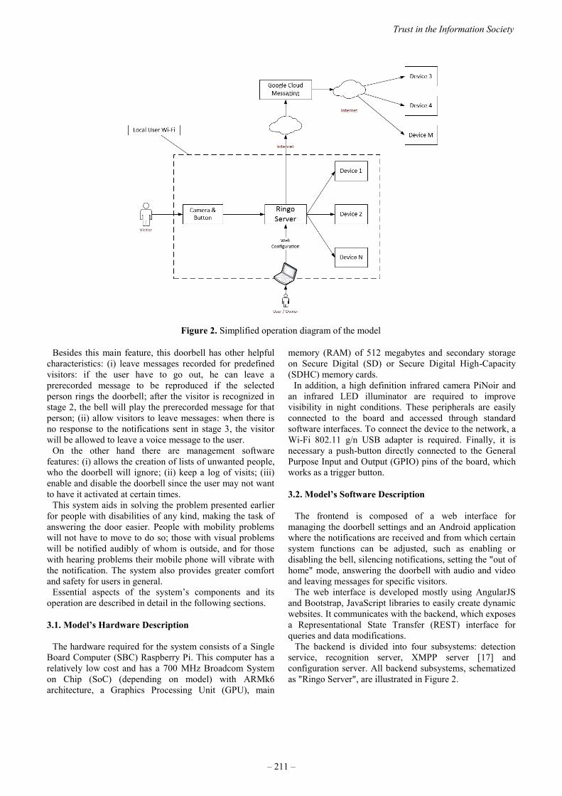
Besides this main feature, this doorbell has other helpful
characteristics: (i) leave messages recorded for predefined
visitors: if the user have to go out, he can leave a
prerecorded message to be reproduced if the selected
person rings the doorbell; after the visitor is recognized in
stage 2, the bell will play the prerecorded message for that
person; (ii) allow visitors to leave messages: when there is
no response to the notifications sent in stage 3, the visitor
will be allowed to leave a voice message to the user. On the other hand there are management software
features: (i) allows the creation of lists of unwanted people,
who the doorbell will ignore; (ii) keep a log of visits; (iii)
enable and disable the doorbell since the user may not want
to have it activated at certain times. This system aids in solving the problem presented earlier
for people with disabilities of any kind, making the task of
answering the door easier. People with mobility problems
will not have to move to do so; those with visual problems
will be notified audibly of whom is outside, and for those
with hearing problems their mobile phone will vibrate with
the notification. The system also provides greater comfort
and safety for users in general. Essential aspects of the system’s components and its
operation are described in detail in the following sections.
3.1. Model’s Hardware Description
The hardware required for the system consists of a Single
Board Computer (SBC) Raspberry Pi. This computer has a
relatively low cost and has a 700 MHz Broadcom System
on Chip (SoC) (depending on model) with ARMk6
architecture, a Graphics Processing Unit (GPU), main
memory (RAM) of 512 megabytes and secondary storage
on Secure Digital (SD) or Secure Digital High-Capacity
(SDHC) memory cards. In addition, a high definition infrared camera PiNoir and
an infrared LED illuminator are required to improve
visibility in night conditions. These peripherals are easily
connected to the board and accessed through standard
software interfaces. To connect the device to the network, a
Wi-Fi 802.11 g/n USB adapter is required. Finally, it is
necessary a push-button directly connected to the General
Purpose Input and Output (GPIO) pins of the board, which
works as a trigger button.
3.2. Model’s Software Description
The frontend is composed of a web interface for
managing the doorbell settings and an Android application
where the notifications are received and from which certain
system functions can be adjusted, such as enabling or
disabling the bell, silencing notifications, setting the "out of
home" mode, answering the doorbell with audio and video
and leaving messages for specific visitors.
The web interface is developed mostly using AngularJS
and Bootstrap, JavaScript libraries to easily create dynamic
websites. It communicates with the backend, which exposes
a Representational State Transfer (REST) interface for
queries and data modifications.
The backend is divided into four subsystems: detection
service, recognition server, XMPP server [17] and
configuration server. All backend subsystems, schematized
as "Ringo Server", are illustrated in Figure 2.
Figure 2. Simplified operation diagram of the model
Trust in the Information Society
– 211 –

The mobile application is developed using the Android
Software Development Kit (SDK) [18], Smack [19] a Java
library to communicate with Extensible Messaging and
Presence Protocol (XMPP) servers, and for local area
networks service discovery JmDNS [20] is used.
The event flow begins when a visitor activates the push-
button. At this time, the detection service begins capturing
images using the camera to detect the coordinates of
possible faces, stage 1. These results are sent to the
recognition server, which attempts to recognize or match to
any face pictures stored in the database, stage 2. Then, the
visitor information is sent with the photo (or only the
picture in case of no match) to the XMPP service, which
distributes the message as a notification to all mobile
devices connected at that moment, stage 3.
In case the user sets the "out of home" mode, the
notification is sent without charge through Google Cloud
Messaging (GCM) service [21]. This service allows the
device not to keep a persistent connection to a server for
receiving alerts, optimizing the use of battery and processor
(Figure 3). GCM imposes a limit of 4 KB of data per
notification, enough to send a small image and a person’s
information (i.e. name, lists to which he belongs, etc.). On
the other hand, devices connected to the local network can
use VoIP to establish a communication with the outside
visitor outside, stage 4.
Last, the configuration server provides a web interface for
administration and adjustment of the doorbell by the user.
The backend is developed using Django [22], a
framework written in Python for database-driven websites
and Django Rest Framework [23] to ease the development
of the REST interface. Face detection and recognition is
performed using Open Computer Vision (OpenCV) [24], a
library created by Intel and maintained by the community
through their open source license. Detection is achieved
through two algorithms incorporated in OpenCV: Local
Binary Patterns (LBP) [25] and Haar Cascades. LBP is also
used for recognition. Information about visitors is collected
progressively at different times when they arrive. This
means that the database starts empty and as people arrive,
their picture is saved and the user can later set the names
and other information concerning the visitors. Because of
this, on their first visit, each person is not recognized by the
system and the notification sent to the user will lack any
information other than the picture from the camera.
The XMPP service is a separate process running as a
daemon in the server and listening for TCP connections on
port 5222. The application chosen for this purpose is
ejabberd [26] for its ease of installation and configuration.
The connection and the sending of the visitor’s data are
performed with SleekXMPP [27], a XMPP library written
in Python.
The recognition and configuration subsystems run on the
Apache web server with a Web Server Gateway Interface
(WSGI) for applications [28]. The chosen database server is
PostgreSQL.
The backend runs on a Raspbian operating system in the
Raspberry Pi computer.
4. CHALLENGES TO THE MODEL AND
STANDARDS
Confidence is critical in applications as the one described
in this paper so the user can first, rely on the notifications
he is getting from the system and second, be sure that all
the information stored and processed is safe as it moves
through different networks. The success or failure of the
model is subject to the trust it can inspire in the user. In
order to build this trust, it has to be grounded over strong
Figure 3. Ringo Server component diagram
2015 ITU Kaleidoscope Academic Conference
– 212 –

recognition software and standards that empower security
and privacy. The recognition software of the model is described and
tested in this paper. As for the standards, the ITU-T has
published many recommendations regarding IoT
applications. In Recommendation Y.2060 [5] are expressed
many security capabilities that IoT applications should
have. In the Recommendation F.748.0 [29] the ITU-T
describes as a fundamental characteristic that “IoT
applications are required to support privacy protection
during data transmission, aggregation, storage, mining and
processing”. Recommendation Y.2066 [30] addresses again
the issue of security and privacy protection over the use of
the application. To comply with this, the presented model
uses well known and well tested software and software
libraries, and all communications between the server and
the different devices are protected with Transport Layer
Security (TLS). But not only is the success of this model tied to trust, the
only way IoT will grow and accomplish its full potential is
through trust. IoT will empower the Information Society
only if it is trustworthy. In order to allow IoT expansion,
the challenge of upcoming standards is the explicit
assurance of security and privacy.
5. SIMULATIONS
To evaluate the performance of the proposed system a
series of simulations have been developed, where the
reliability of face recognition is tested in a laboratory
environment using the AT&T database of faces [31], which
contains 10 different facial images of each of 40 distinct
subjects.
There are two groups of interest in the analysis of arriving
people: a group of known visitors and a group of unknown
visitors. For the known visitors group, the system may
identify correctly or fall into one of two error types:
identify the visitor as another person (false positive) or not
recognize him, labeling the visitor as a stranger (false
unknown). For the unknown visitors group, the system may
correctly label a person as stranger, or it could make a
mistake and identify him as a known visitor.
5.1. Procedure
In order to achieve the goal of this section, the use of the
system is simulated in three different houses, each with a
definite number of people loaded in the system (i.e. known
visitors). To do this, a portion of the available images of
every subject is used to train the system and the remaining
is used for testing. This experiment simulates an individual
ringing the doorbell. For example, a person with 6 images
used for training has rung the bell 6 times. Another group
of individuals is used as a group of strangers.
Three different experiments are performed with the three
houses:
First experience: 5 people are assigned to House A, 10
people to House B and 15 people to House C. 6 pictures of
each subject are used to train the system and the remaining
4 are used for testing, making a total of 20 tests per known
visitor on House A, 40 on House B and 60 on House C.
Second experience: after the previous experiment,
20% more individuals are added to each house, having now
House A with 7 known visitors, House B with 14 and
House C with 21. The amount of images is maintained: 6
are used for training and the remaining 4 are used for
testing, making a total of 28 tests for House A, 56 for
House B and 84 for House C.
Third experience: the amount of subjects and images
per subject are maintained, but the number of images used
for training is lowered to half, leaving 3 images for each
known person.
In all the experiments, a fixed set of images of unknown
individuals are used for testing: 4 tests for House A, 7 tests
for House B and 10 tests for House C.
5.2. Results
The three experiments were performed as discussed
before. The percentage of hits obtained for the different
homes in every experience when known and unknown
visitors arrived are summarized in Table 1.
Regarding the first experience, the amount of positive
recognitions obtained were no less than 80%. For House A,
16 of 20 tests were recognized correctly, the wrong results
were due to misclassification of individuals as strangers.
Regarding the test with strangers, a correct classification
was obtained in 100% of cases. For House B, 38 of 40 tests
were recognized correctly, equaling to 95% of cases, being
the two errors a false positive and a false unknown. The
tests with strangers yielded a success rate of 71.43%. For
House C, in 90% of the tests, the subjects were recognized
correctly. There were 6 errors due to two false positives,
and the others due to false unknowns. As to strangers
testing, 8 out of 10 subjects were correctly classified. The
average of successful recognition obtained in the three
homes was 88.33%.
In the second experience, when increasing the amount of
known individuals in each home, the recognition rate
Table 1. Hit rate summary
Trust in the Information Society
– 213 –

improves for the first two homes but not for the third one,
which has more subjects stored. Classification errors for
House A account for 14.29%, where there are one false
positive and three false unknown of a total of 28 tests. For
the second home, two errors were detected, reducing the
error rate to 3.57%. For House C, the percentage of correct
classifications got reduced to 88.10% because of 10 errors
which include 5 false positives. In this experience, the
average of successful recognitions in the three homes
increased to 90.08%.
In the third experience, reducing the number of training
images produced a decline in the rate of hits for every home
having lower rates in homes with a higher number of
known individuals. Figure 4 shows how the ratio of correct
recognition varies in each home for each experience. For
House A, 23 of 28 tests were classified correctly,
accounting for 82.14%, the 5 errors made were due to false
unknowns. For House B, the rate of hits was 85.71% of 56
tests, with 8 errors where half of these were false positives
and the other half were false unknowns. The tests for House
C had the lowest performance, recognizing only 61 of 84
tests, accounting for 72.62% where 9 of the errors were
false positives and 14 were false unknowns. The average of
correct recognitions obtained for this experience was
80.16%.
For tests with unknown individuals, the results of the first
experiment were repeated, both in the second and in the
third experiment, with 100% right identifications of
unknown subjects for House A, 5 correct out of 7 tests for
House B and 8 of 10 for the third home.
The evolution of the average rate of correct recognitions
for each kind of test, for both known and unknown people,
in the three experiences is shown in Figure 5.
The errors committed by the system can be manually
corrected by the user as visitors arrive and are
misclassified. This way, it is expected for system to
perform better over time and to improve recognition rate.
Because of this, the errors shown are a starting point for the
system for they will be reduced by the increase of
knowledge and training.
6. CONCLUSIONS AND FUTURE WORK
The Smart Doorbell introduced in this paper is able to
recognize previously stored individuals who knock on the
door, to later notify the user, through the network, to his or
her mobile device. As future work, the need to reduce the
error rate in the classification stands out, so as to increase
the confidence in the system, and improve recognition so
that its quality is maintained with an increasing number of
visitors in the database.
One possible approach to improve the model is to
implement fingerprint recognition as a backup and
validation method to identify the visitor. The
implementation and viability details of this approach are
left to be investigated.
Another thing about improving confidence in this kind of
systems is related to the standards. It is imperative that
future standards provide the mechanisms to guarantee the
security and privacy of Internet of Things applications in
order to build trust.
This system aims to promote social inclusion by solving a
set of problematic situations for people who suffer some
kind of disability, but also seeks to ease people’s daily
activities. This is an example of how ICTs are a means to
both technological and social progress, making clear the
need for solutions of this kind.
REFERENCES
[1] International Telecommunication Union,
“Recommendation ITU-T F.790:
Telecommunications accessibility guidelines for
older persons and persons with disabilities”, ITU-T,
2007.
[2] Argentina, Instituto Nacional de Estadística y
Censos, “Censo nacional de población, hogares y
viviendas 2010: censo del Bicentenario: resultados
definitivos”, Serie B 2, ISBN 978-950-896-421-2,
2012.
Figure 5. Evolution of the average rate of correct recognitions
Figure 4. Variation in the rate of correct recognition
2015 ITU Kaleidoscope Academic Conference
– 214 –
[3] Pew Research Center, “Internet Seen as Positive
Influence on Education but Negative Influence on
Morality in Emerging and Developing Nations”,
March, 2015.
[4] O. Messano, "Study in International Internet
Connectivity Focus on Internet connectivity in Latin
America and the Caribbean", Telecommunication
Development Sector Report, March 2013.
[5] International Telecommunication Union,
“Recommendation ITU-T Y.2060: Overview of the
Internet of Things”, ITU-T, 2012.
[6] International Telecommunication Union, “ITU
Internet Report 2005: The Internet of Things”,
International Telecommunication Union, Geneva,
2005.
[7] C. M. Bishop, “Neural Network for Pattern
Recognition”, Oxford University Press, pp. 55-57,
1995.
[8] I. Lee and K. Lee, “The Internet of Things (IoT):
Applications, investments, and challenges for
enterprises”, Business Horizons, Volume 58, Issue 4,
July–August 2015.
[9] E. Borgia, "The Internet of Things vision: Key
features, applications and open issues", Computer
Communications 54, 2014.
[10] Naciones Unidas, Consejo Económico y Social,
Comisión de Desarrollo Social. Informe sobre el 52°
período de sesiones. Nueva York. 2014.
http://www.un.org/Docs/journal/asp/ws.asp?m=E/20
14/26, last access date: October 2015.
[11] Un.org. UN Enable - United Nations Expert Group
Meeting on Building Inclusive Society and
Development through Promoting ICT Accessibility:
Emerging Issues and Trends (Tokyo Japan, 19-21
April 2012), http://www.un.org/disabilities/default
.asp?id=1596, 2015, last access date: October 2015.
[12] G. Elger and B. Furugren, "An ICT and computer-
based demonstration home for disabled people",
TIDE 1998 Conference, 1998.
[13] E. D. Coyle, M. Farrell, R. White, and B. Stewart,
"Design of a non-contact head-control mouse
emulator for use by a quadriplegic operator",
ECDVRAT ’98, 1998.
[14] Chowdhury, Nooman, and Sarker, "Access Control
of Door and Home Security by Raspberry Pi
Through Internet", International Journal of Scientific
and Engineering Research 4, 2013.
[15] R. Sukthankar and R. Stockton, “Argus the digital
doorman”, Intelligent Systems, IEEE, 16(2), pp. 14-
19, 2001.
[16] T. Ahmad, H. Studiawan, and T. Ramadhan,
"Developing a Raspberry Pi-based Monitoring
System for Detecting and Securing an Object".
[17] XMPP, XMPP Standards Foundation, “XMPP Open
Protocol”, https://xmpp.org/, last access date:
October 2015.
[18] Android SDK, Google, “Android Software
Development Kit”, https://developer.android.com/
sdk/index.html, last access date: October 2015.
[19] Smack API, Ignite Realtime, “Smack, Open Source
XMPP Client Library”, https://www.igniterealtime
.org/projects/smack/, last access date: October 2015.
[20] JmDNS, SourceForge, “JmDNS, DNS Service
Discovery”, http://jmdns.sourceforge.net/, last access
date: October 2015.
[21] Google Cloud Messaging, Google, “Google Cloud
Messaging”, https://developers.google.com/cloud-
messaging/, last access date: October 2015.
[22] Django, Django Software Foundation, “Django
Python Web Framework”, www.djangoproject.com/,
last access date: October 2015.
[23] Django REST, T. Christie, “Django REST
Framework”, www.django-rest-framework.org/, last
access date: October 2015.
[24] OpenCV, Itseez, “OpenCV, Computer Vision and
Machine Learning Software Library”,
http://opencv.org/, last access date: October 2015.
[25] T. Ahonen, A. Hadid, and M. Pietikäinen, "Face
recognition with local binary patterns", Computer
vision-eccv 2004, Springer Berlin Heidelberg, pp.
469-481, 2004.
[26] Ejaberd, Process One, “Ejabberd, XMPP Server”,
https://www.ejabberd.im/, last access date: October
2015.
[27] SleekXMPP, N. Fritz and L. Stout, “SleekXMPP”,
https://code.google.com/p/sleekxmpp/, last access
date: October 2015.
[28] WSGI, “Python Web Server Gateway Interface”,
http://wsgi.readthedocs.org/, last access date:
October 2015.
[29] International Telecommunication Union,
“Recommendation ITU-T F.748.0: Common
requirements for Internet of things (IoT)
applications”, ITU-T, 2014.
[30] International Telecommunication Union,
“Recommendation ITU-T Y.2066: Common
requirements of the Internet of Things”, ITU-T, 2014.
[31] Database of Faces, “AT&T Cambridge Database of
Faces”, https://www.cl.cam.ac.uk/research/dtg/
attarchive/facedatabase.html, last access date:
October 2015.
Trust in the Information Society
– 215 –

POSTER SESSION
P.1 MUNIQUE: Multi-view No-Reference Image Quality Evaluation.
P.2 A presentation format of architecture description based on the concept of multilayer networks.
P.3 Privacy, Consumer Trust and Big Data: Privacy by Design and the 3C's.
P.4 SOSLite: Lightweight Sensor Observation Service (SOS) for the Internet of Things (IoT).
P.5 Future Mobile Communication Services on Balance between Freedom and Trust.
P.6 Mauritius eHealth - Trust in the Healthcare Revolution.


MUNIQUE: MULTIVIEW NO-REFERENCE IMAGE QUALITY EVALUATION
Jose Vinıcius de Miranda Cardoso, Carlos Danilo Miranda Regis, and Marcelo Sampaio de Alencar
Federal University of Campina Grande, BrazilInstitute of Advanced Studies on Communications, Brazil
Federal Insitute of Education, Science, and Technology of Paraıba, Brazil
ABSTRACT
This paper presents a novel no-reference objective algo-rithm for stereoscopic image quality assessment, calledMUNIQUE, which is based on the estimation of both two-dimensional and stereoscopic features of images, namelylocal estimations of blockiness and blurriness and the dis-parity weighting technique. Applications of stereoscopic im-age and video quality assessment in surveillance systems arediscussed. Simulation results using LIVE 3D Image QualityDatabase Phase I, which includes Gaussian blur and fastfading degraded images, are presented and a comparisonof performance of MUNIQUE with several state of the artalgorithms is made. Correlation coefficients between subjec-tive and predicted scores indicate a superior performanceof the proposed algorithm, when it is compared with othersno-reference algorithms. An implementation of the proposedalgorithm coded in C# programming language is publiclyavailable at: https://sites.google.com/site/jvmircas/home/munique
Index Terms— Stereoscopic Image, Objective Algorithms,No-Reference, Multiview Surveillance, Disparity
1. INTRODUCTION
Smart video is an essential technology in the InformationSociety. It has been used in a wide variety of applicationsin smart cities, from public safety to personal connectivity.However, the image quality of those applications is still animportant concern. Almost every technique designed to pro-cess multimedia sources, and transmit, store, or visualize thefiles, cause impairments that usually degrade the quality ofcontent and finally compromise the Quality of Experience(QoE). Common artifacts in digital images are blurring andblocking, mainly due to coding, compression, and transmis-sion. Hence, evaluation, in quantitative and qualitative ways,of a particular degradation is a fundamental step which en-ables one to monitor, classify, compare, and improve multi-media services and processing techniques.In effect, models and algorithms for Image Quality Assess-ment (IQA) play a key role for industry, companies, and
The authors would like to state their gratitude to the Institute of Ad-vanced Studies on Communications (Iecom) and to the National Counsel ofTechnological and Scientific Development (CNPq), Brazil, for funding thisresearch project.
image/video applications, to establish the performance ofsystems and to obtain optimal parameters to maintain theQoE in specified conditions [1–3]. In practice, such ad-justment is performed according to technical requirementsthat have a significant impact on consumer electronics pa-rameters, namely, bandwidth, bit-rate, storage capacity, andpower consumption.Therefore, it is necessary to evaluate the quality of stereo-scopic image signals in a fast, accurate, and reliable way. Analternative is to use successful full reference objective algo-rithms that were developed along the past decade to evalu-ate 2D image/video quality [1]. Several publications haveshown that the performance of objective image/video qualityassessment algorithms may be increased, taking into accountthe effect of perceptual characteristics, such as visual atten-tion [4–9]. However, this approach has two main limitationsfor the stereoscopic image/video scenario, namely: 1) stereo-scopic images contain a disparity information, which is aninter-view relation that must to be considered for designingof objective algorithms [10, 11]; 2) original stereoscopic im-age signal is usually not available to be compared with thedegraded signal (which is a requirement for full-reference al-gorithms). No-reference algorithms, on the other hand, eval-uate the degraded image without any knowledge about theoriginal signal.Hence, this paper presents a novel no-reference objective al-gorithm for stereoscopic image quality assessment, calledMUNIQUE (MUltiview No-reference Image QUality Eval-uation). MUNIQUE combines a technique for estimationof blockiness and blurriness features, which was firstly de-veloped by Wang et. al. [12], with the disparity weightingtechnique developed by Regis et. al. [11], which has beenshown to effectively capture the relevant visual informationobtained by the human visual system from the stereoscopicimage. Also, MUNIQUE uses the fact that the visual impor-tance of a region in a stereoscopic image, assigned by thehuman visual system, is directly related to the disparity in-formation [10].The performance of the proposed objective algorithm wasevaluated using the subjective results provided by LIVE 3DImage Quality Database Phase I [13]. Several statistical in-ference methods were applied to compare the performance ofthe objective algorithms. Confidence intervals and hypothe-sis testing for Pearson correlation coefficients are also pre-sented.
978-92-61-15821-7/CFP1538E-ART © 2015 ITU Kaleidoscope– 219 –

The remaining of the paper is organized as follows. SectionII discusses the impact and applications of multiview imagequality assessment in video surveillance systems. SectionIII briefly presents Wang’s 2D no-reference framework, onwhich the proposed algorithm is based. Section IV details theunderlying mathematical model of the proposed no-referencealgorithm for multiview images. The experiments necessaryfor the validation of the proposed algorithm are presented inSection V. Section VI presents the criteria under that the per-formance of the algorithms were compared and analysis thesimulation results. Finally, Section VII states the conclusionsand future directions.
2. MULTI-VIEW IMAGE QUALITY AND SECURITYAPPLICATIONS
Video surveillance is a fundamental technology to smartcities, either used for public safety or for intelligent applica-tions such as object tracking and recognition. However, theachievement of high quality for multi -view video surveil-lance applications is still a challenging task. Specifically,some requirements for surveillance systems are: it shouldprovide a sufficient level of image detail (resolution); itshould perform well in extreme low light scenarios; also,users would like a consistent (high) image quality, but atlow bandwidth consumption. Those requirements lead toa very close relationship between image quality and sys-tems functionality. For instance, in case of object trackingor recognition, video surveillance systems should providea minimum image quality necessary such that those sys-tems will still be able to effectively and accurately track orrecognize a specified object.Multiview images have been suitable for a variety of se-curity applications, even despite their high hardware cost.Black et. al. [14], for instance, proposes a multiview imagesurveillance and tracking system based on the use of over-lapping and non-overlapping camera views. The proposedsystem operates as a framework that allows the integra-tion of image-tracking information from multiple sources.Moreover, it uses intelligent cameras, which provides a back-ground subtraction, jointly with 2D and 3D implementationsof Kalman filters in order to simultaneously detect mov-ing objects within each camera view, and finally combinethem to obtain a prediction of the 3D location of desiredobjects. In Fleck et. al. [15], a network of smart camerasfor 3D real time tracking and visualization, for both indoorand outdoor scenarios, is proposed. The described systemincludes an arbitrary number of camera nodes, a server node,and a visualization node. Maaloouf et. al. [16] discuss theunderlying issues about the definition of standards for 2Dvideo security and 2D video-surveillance systems to achievecomplete interoperability. But they also state that imagequality issues, even for 2D video-surveillance systems, arestill not addressed appropriately. Finally, they proposed anoffline system for image quality evaluation, which consistsin algorithms for tracking, for no-reference image qualityevaluation, and for super-resolution image reconstruction.
It has been noted that those systems need a figure of meritto accurately describe the multiview image quality in realtime, which is being provided for the end user; and for astandardization of the quality issues in image/video surveil-lance systems. Therefore, since multiview image quality is aconstraint for those systems, algorithms for multiview imagequality assessment must provide a reliable and accurate mea-surement, in a reasonable amount of time, in order to con-tribute for the achieving of optimality criteria in multiviewvideo surveillance systems. Additionally, no-reference al-gorithms are notably the only alternative in scenarios of realtime tracking, for each there is none original image available.
3. NO-REFERENCE IMAGE QUALITYASSESSMENT
Wang et al. [12] proposed a no-reference image quality al-gorithm based on estimations of blurring and blocking ef-fects. The features of blurring and blocking are extractedusing the differences of luminance in horizontal and verticaldirections, calculated as
dxhL(x, y) = hL(x+1, y)− hL(x, y), x ∈ [1, X − 1], (1)
in which dxhL(x, y) is the difference of the luminance of the
signal hL along of the x-axis.
Blockiness is estimated as the average of dxhL(x, y) for block
boundaries, i. e.,
BxhL=
1
Y(⌊X8
⌋− 1) Y∑y=1
bX8 c−1∑x=1
|dxhL(8x, y)|. (2)
The blurring is characterized by a reduction in the signalstandard deviation, called signal activity. The signal activ-ity is estimated as follows
AxhL= −1
7
[BxhL− 8
Y (X − 1)
Y∑y=1
X−1∑x=1
|dxhL(x, y)|
].
(3)
The Zero Crossing Rate (ZCR) is calculated as
ζxhL(x, y) = sign
(dxhL
(x, y) · dxhL(x+ 1, y)
), x ∈ [1, X − 2]
(4)
in which sign(·) is the signum function,
zcrxhL(x, y) =
{1, ζxhL
(x, y) = −1,0, ζxhL
(x, y) = 1.(5)
ZCRxhL=
1
Y (X − 2)
Y∑y=1
X−2∑x=1
zcrxhL(x, y). (6)
The vertical features for the left and right views are computed
2015 ITU Kaleidoscope Academic Conference
– 220 –

with similar methods. Finally, the overall features are
BH =1
2
(ByhL
+ BxhL
2+
ByhR+ BxhR
2
), (7)
AH =1
2
(AyhL
+ AxhL
2+
AyhR+ AxhR
2
), (8)
ZCRH =
1
2
(ZCRyhL
+ ZCRxhL
2+
ZCRyhR+ ZCRxhR
2
). (9)
The NR score is computed as
NRS(H) = α+ βBγ1H Aγ2H ZCRγ3H , (10)
in which, α = −245.8909, β = 261.9373, γ1 = −0.02398886,γ2 = 0.01601664, γ3 = 0.00642859 [12].
4. PROPOSED NO-REFERENCE ALGORITHM
In this section, two no-reference algorithms, based on thealgorithms of Wang [12] and Regis [11], are proposed. Ini-tially, a modification in Wang’s algorithm is made regardingthe computation of the zero crossing rate, i. e., the Equation(4) is modified as
ζxhL(x, y) =
sign{
dxhL(x, y) · [hL(x+ 2, y)− hL(x, y)]
}, (11)
after some mathematical manipulations,
ζxhL(x, y) =
sign{[
dxhL(x, y)
]2+ dxhL
(x, y) · dxhL(x+ 1, y)
}.
(12)
From Formula 12, two conditions must be satisfied for theexistence of a zero-crossing, namely{
sign{
dxhL(x, y) · dxhL
(x+ 1, y)}= −1
|dxhL(x+ 1, y)| > |dxhL
(x, y)|. (13)
It can be seen that this proposed algorithm includes the orig-inal condition of Equation (4), and the second condition en-sures that only relevant zero crossings are computed. Finally,the proposed NRS is computed as
NRS*(H) = α+ βBγ1H Aγ2H ZCR*γ3H . (14)
The main contribution of this paper, called MUNIQUE, in-troduces the disparity weighting technique in the blockinessand blurriness estimation as follows
DBxhL=
∑Yy=1
∑bX8 c−1
x=1 |dxhL(8x, y)| · D(H(8x, y))∑Y
y=1
∑bX8 c−1
x=1 D(H(8x, y)).
(15)
DAxhL=
1
7
[8∑Yy=1
∑X−1x=1 |d
xhL
(x, y)| · D(H(x, y))∑Yy=1
∑X−1x=1 D(H(x, y))
− DBxhL
].
(16)
Finally, MUNIQUE is computed as
MUNIQUE(H) = α+ βDBγ1H DAγ2H . (17)
5. VALIDATION SCENARIO
The statistical measures used to compare the performance ofthe objective algorithms were: Pearson Linear CorrelationCoefficient (PLCC), Spearman Rank-Order Correlation Co-efficient (SROCC), and Root Mean Square Error (RMSE). Inpractice, PLCC evaluates accuracy, SROCC evaluates mono-tonicity and RMSE measures consistency of an objectivemodel.The statistical figures of merit were computed after perform-ing a non-linear regression on the objective measures using alogistic function to fit the objective prediction to the subjec-tive quality scores. The logistic model used is as follows
DMOSpl = β1·(1
2− 1
1 + exp (β2 · (Ql − β3))
)+β4·Ql+β5
(18)in which Ql represents the quality that an objective algo-rithm predicts for the l-th stereoscopic image signal. Non-linear least squares optimization was performed using theMATLAB R©function nlinfit to find the optimal coeffi-cients β that minimizes the least squares error between thesubjective scores (DMOSl) and the fitted objective scores(DMOSpl ). The MATLAB function nlpredci was usedto obtain the DMOS predicted scores after the least squaresoptimization. The initial conditions used for the fitting pro-cedure were: β1 = max{DMOSl}, β2 = min(QL), β3 =1L
∑Ll=1Ql, β4 = 1.0, and β5 = 0.1.
5.1. LIVE 3D Image Quality Database Phase I
The LIVE 3D Image Quality Database Phase I [13] was usedto validate the performance of the objective algorithms. Thisdatabase is publicly available and provides original and dis-torted stereoscopic image signals (left and right views), aswell as the correspondent subjective score (DMOS). Twodistortion scenarios were considered in this research: Gaus-sian blur and Rayleigh fading, with 45 image signals cor-rupted using Gaussian blur and 80 image signals impairedby Rayleigh fading.
6. NUMERICAL RESULTS
Tables 1a and 1b present values of PLCC, SROCC, andRMSE obtained by several objective algorithms, for the sce-narios of Gaussian Blur and Fast Fading, respectively. Ob-jective algorithms were compared according to their classes,
Trust in the Information Society
– 221 –
namely, full-reference (FR) 2D, no-reference (NR) 2D, full-reference 3D, and no-reference 3D.Among the NR algorithms, it can be seen that MUNIQUEpresented the best performance for Gaussian blur scenario,while BIQI [17] presented the best results for images subjectto Fast Fading. Even so, MUNIQUE presented a perfor-mance comparable to FR 3D algorithms for the Fast fadingscenario. Comparing the results between NRS* and NRS,it is also clearly seen that the modification on the NRSalgorithm has improved its performance considerably. Fi-nally, Figure 1 presents the scatter plots of the proposedalgorithms.
6.1. Hypothesis Test for ρ
A statistical analysis was performed under the following hy-pothesis {
H0 : ρ = ρ0,H1 : ρ > ρ0,
(19)
in order to verify if the Pearson correlation coefficients (ρ)increased significantly.The procedure uses Fisher’s transformation
Z =1
2loge
(1 + r
1− r
)= arctanh(r), (20)
in which r is the sample correlation coefficient (PLCC).Indeed, Z follows approximately the Normal distributionN(µZ , σZ) with
µZ = arctanh(ρ0), σ2Z =
1
Ns − 3. (21)
The Critical Region (CR) for Z, for the significance level of95%, is
CR = {Z : Z > µZ+1.654·σZ} = {Z : Z > ZCR}. (22)
For each sample Pearson correlation coefficient (r), shown inTables 1a and 1b, CR and Z0 were computed using Formu-las (22) and (20). If Z0 6∈ CR, the hypothesisH0 is accepted,i.e., there is not evidence that the Pearson correlation coeffi-cient has increased, otherwise the hypothesisH1 is accepted,which means that the Pearson correlation coefficient has in-creased, with a confidence level of 95%.For example, let be ρ0 = 0.6521 (PLCC for NRS* in Fastfading scenario), thenZCR is computed according to the For-mula (22). The next step is to transform the other Pearsoncorrelation coefficients into Zi (the index i meaning the i-thalgorithm) according the Formula (20). If Zi > ZCR thenthe i-th algorithm presents a more significant PLCC than ρ0,with a confidence level of 95%.In Table 2 the values ‘0’ and ‘1’ mean that one of the hy-pothesis H0 or H1 was accepted, respectively. In practice, asymbol value of ‘1’ indicates that the statistical performanceof the objective algorithm in the row is superior to that ofthe objective algorithm in the column. On the other hand, a
symbol value of ‘0’ suggests that the statistical performanceof the objective algorithm in the row is equivalent to that ofthe objective in the column. The sequence of the values in acell corresponds to the hypothesis test for Gaussian blur andFast fading scenarios, respectively.
6.2. Confidence Interval for ρ
Figure 2 presents a 95% confidence interval for ρ in theGaussian Blur and Fast Fading scenarios under the hypothe-sis H0 : ρ = 0, H1 : ρ 6= 0. The Z Fisher’s transformationwas applied to the sample Pearson correlation coefficient (r)to produce the confidence interval.Under that hypothesis, Z follows the Normal distributionwith zero mean and with variance given by Formula (19).The confidence interval for this random variable is definedas
IC(z, 1− α) = (Z − z1−α · σZ , Z + z1−α · σZ). (23)
For α = 0.05, i.e., a confidence interval of 95%, z0.95 =1.96, and Formula (23) is rewritten as
IC(z, 0.95) = (Z − 1.96 · σZ , Z + 1.96 · σZ). (24)
The inverse of the Z Fisher’s transformation is
r =e2z − 1
e2z + 1= tanh(z), (25)
and the confidence interval in terms of r is defined as,
IC(r, 0.95) =(e2·(Z−1.96·σZ) − 1
e2·(Z−1.96·σZ) + 1,e2·(Z+1.96·σZ) − 1
e2·(Z+1.96·σZ) + 1
). (26)
Figure 2 suggests that, along with an increase in the corre-lation coefficient, there is a reduction in uncertainty, whichis represented by the length of the PLCC confidence inter-val, for the NRS* algorithm, compared with the its originalversion, NRS.It is also clear that MUNIQUE presented a better perfor-mance than Akhter’s 3D no-reference algorithm for all sta-tistical inferences used. Surprisingly, MUNIQUE was alsosuperior to You’s 3D full-reference algorithm for the fast fad-ing scenario. MUNIQUE showed a good performance even ifwhen it is compared to Benoit’s 3D full-reference algorithm.
7. DISCUSSION AND CONCLUSIONS
A novel no-reference objective algorithm for stereoscopicimage quality assessment was proposed, called MUNIQUE.It is based on a combination of blockiness and blurriness fea-ture estimation and disparity weighting.Stereoscopic image signals impaired with Fast Fading andGaussian Blur, provided by LIVE, were used on the vali-dation experiments. The numerical results indicate an im-proved performance for MUNIQUE in relation to the NRS
2015 ITU Kaleidoscope Academic Conference
– 222 –

MUNIQUE
9 10 11 12 13 14 15 16
DM
OS
-10
0
10
20
30
40
50
(a) Gaussian Blur
MUNIQUE
10 11 12 13 14 15 16 17
DM
OS
-10
0
10
20
30
40
50
60
(b) Fast Fading
NRS*
4.5 5 5.5 6 6.5 7 7.5 8 8.5 9 9.5
DM
OS
-10
0
10
20
30
40
50
(c) Gaussian Blur
NRS*
2 3 4 5 6 7 8 9 10
DM
OS
-10
0
10
20
30
40
50
60
(d) Fast Fading
Figure 1: Scatter plots for LIVE 3D IQA Database.
Table 1: Performance measures of the NR objective algorithms for the LIVE 3D IQA Database.
(a) Gaussian Blur
Algorithm PLCC SROCC RMSEFR 2D Algorithms
C4 [18] 0.9649 0.9361 3.8003UQI [19] 0.9565 0.9238 4.2222
NR 2D AlgorithmsNRS [12] 0.4960 0.4385 12.5681
NRS* 0.8476 0.8130 7.6812BIQI [17] 0.8995 0.8596 6.3238
FR 3D AlgorithmsBenoit [10] 0.9488 0.9308 4.5714
You [5] 0.9198 0.8822 5.6798NR 3D Algorithms
Akhter [20] 0.6177 0.5549 11.3872MUNIQUE 0.9006 0.8647 6.2918
(b) Fast Fading
Algorithm PLCC SROCC RMSEFR 2D Algorithms
C4 0.8754 0.8349 6.0067UQI 0.8788 0.8322 5.9207
NR 2D AlgorithmsNRS 0.4023 0.3572 11.3759NRS* 0.6521 0.6539 9.3787BIQI 0.7762 0.7067 7.8679
FR 3D AlgorithmsBenoit 0.7472 0.6989 8.2578
You 0.7300 0.5883 8.4923NR 3D Algorithms
Akhter 0.6603 0.6393 9.3321MUNIQUE 0.7421 0.4763 8.3288
Trust in the Information Society
– 223 –

Table 2: Hypothesis test for the correlation coefficient (Gaussian Blur – Fast Fading).
Algorithms C4 UQI NRS BIQI Benoit You Akhter NRS* MUNIQUEC4 – 1 – 1 1 – 1 1 – 1 1 – 1 1 – 1 1 – 1 1 – 1 1 – 1
UQI 0 – 0 – 1 – 1 1 – 1 1 – 1 1 – 1 1 – 1 1 – 1 1 – 1NRS 0 – 0 0 – 0 – 0 – 0 0 – 0 0 – 0 0 – 0 0 – 0 0 – 0BIQI 0 – 0 0 – 0 1 – 1 – 0 – 1 0 – 1 1 – 1 1 – 1 0 – 1
Benoit 0 – 0 0 – 0 1 – 1 1 – 0 – 1 – 1 1 – 1 1 – 1 1 – 1You 0 – 0 0 – 0 1 – 1 1 – 0 0 – 0 – 1 – 1 1 – 1 1 – 0
Akhter 0 – 0 0 – 0 1 – 1 0 – 0 0 – 0 0 – 0 – 0 – 1 0 – 0NRS* 0 – 0 0 – 0 1 – 1 0 – 0 0 – 0 0 – 0 1 – 0 – 0 – 0
MUNIQUE 0 – 0 0 – 0 1 – 1 1 – 0 0 – 0 0 – 1 1 – 1 1 – 1 –
0.2
0.3
0.4
0.5
0.6
0.7
0.8
0.9
1
C4 UQI NRS BIQI Benoit You Akhter NRS* MUNIQUE
PL
CC
(a) Gaussian Blur
0.2
0.3
0.4
0.5
0.6
0.7
0.8
0.9
1
C4 UQI NRS BIQI Benoit You Akhter NRS* MUNIQUE
PL
CC
(b) Fast Fading
Figure 2: The 95% confidence intervals for the populationalPearson correlation coefficient.
algorithm. MUNIQUE presented a PLCC higher than 0.7,for all scenarios.
Additionally, the performance of MUNIQUE is still com-parable, and in some cases better, to the performance offull-reference algorithms for multiview image quality assess-ment. Confidence intervals and hypothesis testing indicatesthat this improvement is truly significant. The performance,jointly with its simple design, makes MUNIQUE a com-petitive alternative for real-time multiview image qualityevaluation scenarios.
Therefore, MUNIQUE can be used for practical video pro-cessing systems and applications. For future research, theauthors plan to test their algorithm in real-time scenario formonitoring the quality of multiview video surveillance sys-tems.
8. REFERENCES
[1] K. Seshadrinathan, R. Soundararajan, A. C. Bovik, andL. K. Cormack, “Study of Subjective and ObjectiveQuality Assessment of Video,” IEEE Transactions onImage Processing, pp. 1427–1441, 2010.
[2] Z. Wang and A. C. Bovik, “Mean squared error: Loveit or leave it? A new look at Signal Fidelity Measures,”IEEE Signal Processing Magazine, vol. 26, no. 1, pp.98–117, jan. 2009.
[3] K. Seshadrinathan, R. Soundararajan, A. C. Bovik, andL. K. Cormack, “A subjective study to evaluate videoquality assessment algorithms,” SPIE Proceedings Hu-man Vision and Electronic Imaging, 2010.
[4] K. Wang, K. Brunnstrm, M. Barkowsky, M. Urvoy,M. Sjstrm, P. Le Callet, S. Tourancheau, and B. An-drn, “Stereoscopic 3D Video Coding Quality Evalu-ation with 2D Objective Metrics,” in Proceedings ofthe XXIV SPIE Stereoscopic Displays and Applications,2013.
[5] J. You, L. Xing, A. Perkis, and X. Wang, “Percep-tual Quality Assessment for Stereoscopic Images basedon 2D Image Quality Metrics and Disparity Analysis,”in Proceedings of the Fifth International Workshop onVideo Processing and Quality Metrics for ConsumerElectronics (VPQM’10), 2010.
[6] Zhou Wang and Qiang Li, “Information ContentWeighting for Perceptual Image Quality Assessment,”IEEE Transactions on Image Processing, vol. 20, no. 5,pp. 1185–1198, 2011.
[7] C. D. M. Regis, J. V. M. Cardoso, and M. S. Alen-car, “Effect of Visual Attention Areas on the Objec-tive Video Quality Assessment,” in Proceedings of the18th Brazilian Symposium on Multimedia and the Web.2012, WebMedia ’12, ACM.
[8] C. D. M. Regis, J. V. M. Cardoso, I. P. Oliveira, andM. S. Alencar, “Performance of the Objective VideoQuality Metrics with Perceptual Weighting Consider-ing First and Second Order Differential Operators,” inProceedings of the 18th Brazilian Symposium on Mul-timedia and the Web. 2012, WebMedia ’12, ACM.
2015 ITU Kaleidoscope Academic Conference
– 224 –

[9] H. Liu and I. Heynderickx, “Studying the Added Valueof Visual Attention in Objective Image Quality MetricsBased on Eye Movement Data,” in IEEE InternationalConference on Image Processing (ICIP’09), 2009.
[10] A. Benoit, P. Le Callet, P. Campisi, and R. Cousseau,“Quality Assessment of Stereoscopic Images,”EURASIP Journal on Image and Video Processing,vol. 2008, no. 1, pp. 1–13, 2008.
[11] C. D. M. Regis, J. V. M. Cardoso, I. P. Oliveira,and M. S. Alencar, “Objective Estimation of 3DVideo Quality: A Disparity-based Weighting Strat-egy,” in Proceedings of IEEE International Symposiumon Broadband Multimedia Systems and Broadcasting(BMSB’13), 2013.
[12] Z. Wang, H. R. Sheikh, and A. C. Bovik, “No-referencePerceptual Quality Assessment of JPEG CompressedImages,” in IEEE International Conference on ImageProcessing (ICIP’02), 2002.
[13] A. K. Moorthy, C. Su, A. Mittal, and A. C. Bovik,“Subjective Evaluation of Stereoscopic Image Quality,”Signal Processing: Image Communication, vol. 28, no.8, pp. 870 – 883, 2013.
[14] J. Black, T. Ellis, and P. Rosin, “Multi view imagesurveillance and tracking,” in IEEE Proceedings ofWorkshop on Motion and Video Computing, Dec 2002,pp. 169–174.
[15] S. Fleck, F. Busch, P. Biber, and W. Straber, “3d surveil-lance a distributed network of smart cameras for real-time tracking and its visualization in 3d,” in Conferenceon Computer Vision and Pattern Recognition, CVPR’06, June 2006, pp. 118–118.
[16] Aldo Maalouf, Mohamed-Chaker Larabi, and DidierNicholson, “Offline quality monitoring for legal evi-dence images in video-surveillance applications,” Mul-timedia Tools and Applications, vol. 73, no. 1, pp. 189–218, 2014.
[17] A.K. Moorthy and A.C. Bovik, “A two-step frameworkfor constructing blind image quality indices,” SignalProcessing Letters, IEEE, vol. 17, no. 5, pp. 513–516,May 2010.
[18] M. Carnec, P. Le Callet, and D. Barba, “An image qual-ity assessment method based on perception of structuralinformation,” in International Conference on ImageProcessing (ICIP’03), Sept 2003, vol. 3, pp. III–185–8 vol.2.
[19] Zhou Wang and A.C. Bovik, “A universal image qualityindex,” Signal Processing Letters, IEEE, vol. 9, no. 3,pp. 81–84, March 2002.
[20] Roushain Akhter, Z. M. Parvez Sazzad, Y. Horita, andJ. Baltes, “No-reference stereoscopic image quality as-sessment,” in Proc. SPIE, 2010, vol. 7524, pp. 75240T–75240T–12.
Trust in the Information Society
– 225 –


A PRESENTATION FORMAT OF ARCHITECTURE DESCRIPTIONBASED ON THE CONCEPT OF MULTILAYER NETWORKS
Andrey A. Shchurov, Radek Marik
Czech Technical University in PragueDepartment of Telecommunication Engineering, Faculty of Electrical Engineering
Technicka 2, 166 27, Prague, Czech Republic
ABSTRACT
Formal methods based on abstract models are becomingmore and more important in the domain of complex computernetworks. On the other hand, processes of design documen-tation transformation into the formal models are still boundto the skills and ingenuity of individual engineers. Moreover,the human factor involved in data transformation representsa major bottleneck due to the tendency of computer networksto be more and more complex. To address this problem,this work introduces a possible appropriate presentation for-mat of architecture descriptions as a part of detailed designdocumentation that could allow automated development oftrusted formal models for analysis and verifying of complexcomputer networks.
Keywords— architecture descriptions, computer networks,
formal models, multilayer networks
1. INTRODUCTION
Art and science have their meeting point in method.—Edward Bulwer-Lytton
Formal methods are mathematical techniques for develop-
ing software and hardware systems and can be used to con-
duct mathematical proofs of consistency of specification and
correctness of implementation. Mathematical rigor enables
users to analyze and verify abstract models at any part of the
system life-cycle: requirements engineering, architecture de-
sign, implementation, maintenance and evolution [1]. These
methods are particularly suitable for complex heterogeneous
systems and are becoming more and more important.
However, model analysis requires specialized training, both
in the models development - a model must be completely
relevant to a system (a trusted model) - and in the interpre-
tation of the analysis results. As a consequence, it depends
on the qualification, ingenuity and intuition of individual en-
gineers. The human work involved in data transformation
represents a major bottleneck due to its tendency to be rel-
atively unsophisticated and repetitive, but persistently tricky
and time-consuming at the same time [2]. Challenges in the
This article originated within the project VI1VS/304 “Comprehensive
fiber optic sensor security of critical infrastructures and objects using mod-
ern information systems” at the of the DTE FEE CTU in Prague.
analysis process that repeatedly occur in analysis efforts are:
(1) discover necessary data; (2) wrangle data into a desired
format; (3) profile data to verify its quality and suitability;
and (4) report procedures to consumers of the analysis.
Thus, to get full advantages of model analysis and verifying
in the domain of complex systems, it is necessary to allevi-
ate the burdens of learning model development and checking
techniques for engineers and other non-technical stakehold-
ers [3] or, ideally, completely eliminate the human factor.
There have been some attempts to make model development
accessible to those who are not trained in formal methods.
These include Formal Description Techniques (FDT) [4]
based on a technical language for unambiguous specification
and description of the behavior of telecommunication sys-
tems. However, FDTs are intended to specify the behavioral
aspects of software-intensive systems; the general parame-
ters, which determine heterogeneous architectures and prop-
erties, have to be described using different techniques. More-
over, FDTs still require a considerable degree of user training
because they do not eliminate the need for translating natural
language requirements into their specialized language before
applying model analysis.
To address this problem, we propose a possible appropriate
presentation format of architecture descriptions as a neces-
sary part of the detailed design documentation of complex
computer networks, which could allow automated develop-
ment of formal models based on this documentation for anal-
ysis and verifying of complex networks - particularly we fo-
cus on multilayer networks specifications.
The rest of this paper is structured as follows. Section 2
presents the background of the work. Section 3 introduces
the formal model of complex computer networks based on
the concept of multilayer networks. Section 4 focuses on the
presentation format of architecture descriptions. Section 5
discusses the correlation between the formal model and the
presentation format. Finally, conclusion remarks are given in
Section 6.
2. BACKGROUND
The universal requirement for design documentation is sim-
ple the documentation should be based on standards like
a formal document. Generally, the choice between interna-
978-92-61-15821-7/CFP1538E-ART © 2015 ITU Kaleidoscope– 227 –

tional and regional standards depends on the state and/or cor-
porate legislation but, fortunately, the majority of regional
standards replicate their international predecessors.
As mentioned above, the Formal Description Techniques [4]
are based on a technical language for unambiguous specifi-
cation and description of the behavior of telecommunication
systems. The main FDTs include: Specification and Descrip-
tion Language (SDL) [5], Message Sequence Chart (MSC)
[6], User Requirements Notation (URN) [7], and Testing and
Test Control Notation (TTCN) [8]. However, FDTs are in-
tended to specify the behavioral aspects of software-intensive
systems, not their architectures [5]. Furthermore, they do not
cover the structure of design documentation.
The current revision of IEEE Std. 1362-1998 (R2007) [9]
standard represents a Concept of Operations (ConOps).
ConOps is a user-oriented document that describes char-
acteristics of to-be-delivered systems from the end-users (or
integrated systems) point of view. It also specifies recom-
mended graphical tools (charts and diagrams).
The latest revision of ISO/IEC/IEEE Std. 15288:2015 [10]
standard establishes a common process framework for de-
scribing the life cycle of man-made systems. It defines a
set of processes and associated terminology for the full life
cycle, including Architectural Design Process (or the pro-
cess of elaboration of design documentation). In turn, the
standard ISO/IEC/IEEE Std. 15289:2011 [11] specifies
the purpose and content of service management informa-
tion items (documentation). It defines the life cycle data
of ISO/IEC/IEEE Std. 15288:2015 by relating tasks and
activities to the generic types of information items such as
descriptions and specifications (the main information com-
ponents of design documentation). Furthermore, conceptu-
alization of system architectures assists the understanding of
the system essence and key properties pertaining to its behav-
ior, composition and evolution, which in turn affect concerns
such as the feasibility, utility and maintainability of the sys-
tem. As a consequence, the standard ISO/IEC/IEEE Std.
42010-2011 [12] specifies architecture viewpoints, architec-
ture frameworks and architecture description languages for
use in architecture descriptions.
It is important to note that these international standards estab-
lish what should be contained in design documentation but
not how: possible formats of information items or, at least,
guidance on selecting appropriate presentations are NOT in-
cluded in the scope of these standards.
3. FORMAL MODEL
Applying a system methodology to network analysis [13]
is a relatively new approach, particularly in the Internet Pro-
tocol (IP) world. The fundamental concept is that network
architecture should take into account services/applications
which this network provides and supports. It is important
to note that this concept is completely supported by the most
recent practical approaches such as Business-Driven Design
[14] and Application Centric Design [15].
On the other hand, one of the major goals of modern physics
is providing proper and suitable representations of systems
with many interdependent components, which, in turn, might
interact through many different channels. As a result, inter-
disciplinary efforts of the last fifteen years have led to the
birth of complex networks theory [16] [17] [18] including
the concept of multilayer networks [19] [20] that explicitly
incorporate multiple channels of connectivity and constitute
the natural environment to describe systems interconnected
through different types of connections: each channel (rela-
tionship, activity, category, etc.) is represented by a layer
and the same node or entity may have different kinds of in-
teractions (different set of neighbors in each layer). Assum-
ing that all layers are informative, multilayer networks can
provide complementary information. Thus, the expectation
is that a proper combination of the information contained
in the different layers leads to a formal network represen-
tation (a formal model) appropriated for applying the system
methodology to network analysis.
A type of multilayer network of particular relevance for com-
plex computer networks is a hierarchical multilayer network[19], in which the bottom layer constitutes a physical net-
work (physical architecture layer) and the remaining layers
are virtual layers that operate on top of the physical layer (at
least logical and service architecture layers [21] [22]). From
this perspective, the formal basic definitions [20] (adapted to
the domain of computer networks [22]) denotes the complex
computer network as a hierarchical multilayer projection net-
work:
M = (V,E) (1)
where M is a labeled 3D graph; V (M) is a finite, non-empty
set of components (hardware and software); and E(M) is a
finite, non-empty set of component-to-component intercon-
nections. In turn:
V =
N⋃n=1
Vn (2)
and
E =
(N⋃
n=1
En
)⋃(N⋃
n=2
En,(n−1)
)(3)
where Vn is a finite, non-empty set of components (hardware
or software) on layer n; En is a finite, non-empty set of in-
tralayer component-to-component interconnections on layer
n; En,(n−1) is a finite, non-empty set of interlayer (or cross-
layers) relations (projections) between components of differ-
ent coexisting layers n and (n− 1); and N is the number of
layers (in our case N = 3).
In turn, a labeling of the vertices of M is a mapping [23]:
ψ : Vn → An (4)
where An is called the vertices label set on layer n. In our
case:
An =⋃
vni ∈Vn
Sni (5)
where Sni is a finite non-empty set of component technical
specifications or the label of the vertex vni ∈ Vn of M .
2015 ITU Kaleidoscope Academic Conference
– 228 –

Table 1. Layer component specification.Table columns
No. Name Description01 T1n.01 Record Record identification number
Number (component index)
02 T1n.02 Layer Physical, logical or service layer
Identifier (similar to T2n.02 and T3n.02)
03 T1n.03 Component Component functional
Assignment description
04 T1n.04 Component Component name
Identifier
05 T1n.05 Vendor Vendor contact name
Identifier (for COTS components)
06 T1n.06 Component Component technical specifications
Attributes such as supported connectors
(according to T2n.05 and T2n.07)
and protocols (according to T2n.08),
performance metrics, RMA, etc.
07 T1n.07 Notes Additional information
Similarly, a labeling of the intralayer edges of M is a map-
ping [23]:
ω : En → Bn (6)
where Bn is called the edges label set on layer n. In our case:
Bn =⋃
(vni ,vn
j )∈En
Snij (7)
where Snij is a finite, non-empty set of component-to-
component interconnections technical specifications or the
label of the edge (vni , vnj ) ∈ En of M . Generally:
Snij ⊆
(Sni ∩ Sn
j
)(8)
i.e. components can communicate iff they have common
specifications of interfaces and/or protocols.
It is important to note that the interlayer edges (vni , v(n−1)j ) ∈
En,(n−1) of M are not labeled edges.
As a consequence, this formal model of complex computer
networks can be represented in details by means of data
structures of graph theory [23].
4. PRESENTATION FORMAT
As mentioned above, the current revisions of international
standards establish what should be contained in design doc-
umentation but not how exactly. Nevertheless, Appendix I of
ITU-T Recommendation L.72 [24] represents the example
of a currently used presentation format of optical access net-
work infrastructure descriptions (it is important to note that
the appendix does not form an integral part of the Recom-
mendation). However, this format is optimized for represen-
tation network infrastructures (it covers the physical architec-
ture completely and the logical architecture partially) and, as
a consequence, cannot be used to define a whole/completed
system (i.e. a computer network and the distributed comput-
ing system it supports together) and represent technological
Table 2. Intralayer topology specification.Table columns
No. Name Description01 T2n.01 Record Record identification number
Number (link index)
02 T2n.02 Layer Physical, logical or service layer
Identifier (similar to T1n.02 and T3n.02)
03 T2n.03 Link Component-to-component
Assignment interconnection functional
description
04 T2n.04 Source Component name
Component according to T1n.04
Identifier
05 T2n.05 Source Component attribute
Connector (according to T1n.06):
Identifier (1) component interfaces
for the physical layer;
(2) IP addresses and masks
for the logical layers;
and (3) TCP/UDP ports for
the service layer
06 T2n.06 Target see T2n.04
Component
Identifier
07 T2n.07 Target see T2n.05
Connector
Identifier
08 T2n.08 Protocol Communication protocol
Identifier
09 T2n.09 Link Technical specifications of
Attributes component-to-component
interconnection such as
cable length (for the physical
layer only), performance
metrics, RMA, etc.
10 T2n.10 Notes Additional information
Table 3. Interlayer topology specification.Table columns
No. Name Description01 T3n.01 Record Record identification number
Number (link index)
02 T3n.02 Layer Physical, logical or service layer
Identifier (similar to T1n.02 and T2n.02)
03 T3n.03 Link Components interlayer relation
Assignment functional description
04 T3n.04 Source Component name
Component according to T1n.04
Identifier
05 T3n.05 Target see T3n.04
Component
Identifier
06 T3n.06 Distribution Cross-layer technologies:
Index (1) Nn : 1n−1 - virtualization
Identifier and replication;
(2) 1n : Nn−1 - clustering; and
(3) 1n : 1n−1 a special case of
dedicated components
07 T3n.07 Link Technical specifications of
Attributes components interlayer
relation (resources distribution
across the network)
technical specifications such
as capacity metrics
and modes (active/active,
active/standby, etc.)
08 T3n.08 Notes Additional information
Trust in the Information Society
– 229 –

solutions (hardware and software clusters, virtualization plat-
forms, etc.) which are used to build the system.
To fill the gap, this section represents a set of design patterns
for unambiguous architecture description as a possible part of
the detailed design documentation (the term design pattern[25] aims to explicitly represent design knowledge that can
be understood implicitly by skilled engineers and other non-
technical stakeholders).
Based on the concept of layered networks [26], the archi-
tecture of complex computer networks can be represented by
three main design patterns (tables) on each (physical, logical
and service) layer:
- Layer component specification. The layer component spec-
ification design pattern is used for the components detail
representation. It should cover: (1) software-based compo-
nents (services/applications) for the service layer; (2) virtual
components (VM, VLAN, etc.) for the logical layer; and (3)
hardware-based components (equipment) for the physical
layer. Table column structure includes (see Table 1):
• Record Number.
• Layer Identifier.
• Component Assignment.
• Component Identifier.
• Vendor Identifier.
• Component Attributes.
• Notes.
- Intralayer topology specification. The intralayer topology
specification design pattern is used for the layer topology de-
tail representation. It should cover architecture descriptions
of: (1) flow-based models [13] for the service layer; and (2)
topological models [13] for the logical and physical layers.
Table column structure includes (see Table 2):
• Record Identifier (record number).
• Layer Identifier.
• Link Assignment.
• Link Identifier:
– Source Identifier:
∗ Component Identifier.
∗ Connector Identifier.
– Target Identifier:
∗ Component Identifier.
∗ Connector Identifier.
• Protocol Identifier.
• Link Attributes.
• Notes.
Table 4. Formal model and Layer component specification.No. Design pattern record Formal model symbol1 T1n.01 i2 T1n.02 n3 T1n.04 vni ∈ Vn
4 T1n.06 Sni
- Interlayer topology specification. The intralayer topology
specification design pattern is used for the resources distri-
bution (cross-layer topology) detail representation. It strictly
relies on the concept of layered networks [26] that a node
in a given layer depends on a corresponding node (or nodes)
in the layer below. Table column structure includes (see Ta-
ble 3):
• Record Identifier (record number).
• Layer Identifier.
• Link Assignment.
• Link Identifier:
– Source Identifier:
∗ Component Identifier in a Given Layer.
– Target Identifier:
∗ Component Identifier in the Layer Below.
• Distribution Index Identifier.
• Link Attributes.
• Notes.
In turn, each table header structure should include:
• Table Identifier.
• Project Identifier.
• Facility Identifier.
In practice, these tables can be used (1) as independent doc-
uments or (2) as a database structure similar to ITU-T Rec
L.72 [24].
5. FORMAL MODEL AND DESIGN PATTERNSCORRELATION
A model is any incomplete representation of reality - an ab-
straction [27]. In practice it means that design documenta-
tion usually contains much more data then we need to create
models. In our case, from the perspective of the formal ab-
stract model:
• The layer component specification is a node list (see
Table 1): each row represents a node (vertex) in the
graph and columns contain attributes (node labels).
Data structures correlation between the formal model
and this design pattern is shown in Table 4.
2015 ITU Kaleidoscope Academic Conference
– 230 –

Table 5. Formal model and Intralayer topology specification.No. Design pattern record Formal model symbol1 T2n.01 k2 T2n.02 n
T2n.04 vni ∈ Vn
3 T2n.06 vnj ∈ Vn
enk = (vni , vnj ) ∈ En
T1n.05
4 T1n.07 Snij
T1n.08
T1n.09
Table 6. Formal model and Interlayer topology specification.No. Design pattern record Formal model symbol1 T3n.01 l2 T3n.02 n
T3n.04 vni ∈ Vn
3 T3n.05 vn−1j ∈ Vn−1
en,(n−1)l =
= (vni , v(n−1)j ) ∈ En,(n−1)
• The intralayer topology specification is an adjacency
list or a relational table (see Table 2): each row repre-
sents an edge in the graph and columns contain inci-
dent (source and target) nodes among other attributes
(edge labels). Data structures correlation between the
formal model and this design pattern is shown in Ta-
ble 5.
• The interlayer topology description is an adjacency list
or a relational table (see Table 3): each row repre-
sents an edge in the graph and columns contain inci-
dent (source and target) nodes among other attributes.
Data structures correlation between the formal model
and this design pattern is shown in Table 6.
It is obvious that the quality of formal methods based on ab-
stract models is limited by the quality of these models. In
our case, complex network architecture can be unambigu-
ously represented using a set of tables (design patterns) that
should be included as a necessary part of the detailed design
documentation of a computer network. In turn, this set of
tables provides unambiguous definition of the formal model
(3D graph) for analysis and verifying of the network structure
(such as model-based testing (MBT) [28] [29]). As a conse-
quence, we can completely eliminate the human factor from
the data transformation processes during the formal model
generation activities - the process can be done in automated
mode using the detailed design documentation as input data.
In this case, the formal model is completely relevant to the
design documentation (a trusted model from the viewpoint
of network/system designers).
Furthermore, MBT techniques can be used for automated
validation the formal model internal consistency with respect
to the end-user requirements [28]. In the case of success-
ful validation, the formal model is completely relevant to the
end-user requirements (a trusted model from the viewpoint
of end-users/customers). However, the techniques of trans-
forming informal end-user requirements into formal opera-
tion specifications are beyond the scope of this paper. The
problem requires a separate analysis in the case of complex
or non-standard systems, it may not be a routine exercise in
practice.
6. CONCLUSION
Formal methods based on abstract models are becoming
more and more important in the domain of complex com-
puter networks. On the other hand, processes of design
documentation transformation into the formal models are
still bound to the qualification and ingenuity of individual
engineers. But in the case of complex or non-standard sys-
tems, personal experience and/or intuition can be inadequate.
Moreover, the human work involved in data transformation
represents a major bottleneck due to: (1) its tendency to
be relatively unsophisticated and repetitive, but persistently
tricky and time-consuming at the same time; and (2) the ten-
dency of computer networks to be more and more complex.
To address this problem, in this work we determined: (1) an
appropriate formal model based on the concept of multilayer
networks; and (2) a possible appropriate presentation for-
mat of architecture descriptions as a part of detailed design
documentation that provides unambiguous interrelation be-
tween the documentation and the model. As a consequence,
this presentation could allow automated development of for-
mal models for analysis and verifying of complex computer
networks.
Using the models of that kind and the graph theoretical met-
rics, both static and dynamic network analyses can be per-
formed. The static analysis determines the characteristics of
each layer based on the in-tralayer and interlayer topologies.
It covers [30] [31]: (1) individual components; (2) compo-
nent interactions on each layer; and (3) resources distribution
across the system.
In turn, the dynamic analysis (or fault injection simulation)
provides a means for understanding how a network behaves
in the presence of faults. It includes [32]: (1) successive
removals of vertices/edges from the model; and (2) impact
assessments of those removals on the network internal con-
sistency - disruption on an arbitrary layer might destroy a
substantial part of the upper layers that are mapped on it,
rendering the whole network useless in practice.
REFERENCES
[1] Jim Woodcock, Peter Gorm Larsen, Juan Bicarregui,
and John Fitzgerald, “Formal methods: Practice and
experience,” ACM Comput. Surv., vol. 41, no. 4, pp.
19:1–19:36, October 2009.
[2] Sean Kandel, Andreas Paepcke, Joseph M. Hellerstein,
and Jeffrey Heer, “Enterprise data analysis and visu-
alization: An interview study,” IEEE Transactions on
Trust in the Information Society
– 231 –

Visualization and Computer Graphics, vol. 18, no. 12,
pp. 2917–2926, December 2012.
[3] Daniel Aceituna, Hyunsook Do, and Sudarshan Srini-
vasan, “A systematic approach to transforming system
requirements into model checking specifications,” in
Companion Proceedings of the 36th International Con-ference on Software Engineering, June 2014, pp. 165–
174.
[4] “ITU-T Rec. Z.110 - Z.119 Application of formal de-
scription techniques,” 2008.
[5] “ITU-T Rec. Z.100 - Z.109 Specification and Descrip-
tion Language (SDL),” 2011.
[6] “ITU-T Rec. Z.120 - Z.129 Message Sequence Chart
(MSC),” 2011.
[7] “ITU-T Rec. Z.150 - Z.159 User Requirements Nota-
tion (URN),” 2011.
[8] “ITU-T Rec. Z.160 - Z.179 Testing and Test Control
Notation (TTCN),” 2014.
[9] “IEEE Std. 1362-1998 (R2007) - IEEE Guide for In-
formation Technology - System Definition - Concept
of Operations (ConOps) Document,” 2007.
[10] “ISO/IEC/IEEE Std. 15288:2015 Systems and software
engineering - System life cycle processes,” 2015.
[11] “ISO/IEC/IEEE Std. 15289:2011 Systems and software
engineering - Content of life-cycle information prod-
ucts (documentation),” 2011.
[12] “ISO/IEC/IEEE Std. 42010:2011 Systems and software
engineering - Architecture description,” 2011.
[13] James D. McCabe, Network Analysis, Architecture, andDesign, Morgan Kaufmann Publishers Inc., 3rd edition,
2007.
[14] Russ White and Denise Donohue, The Art of NetworkArchitecture: Business-Driven Design, Cisco Press, 1st
edition, 2014.
[15] Shaun L. Hummel, Cisco Design Fundamentals: Mul-tilayered Design Approach For Network Engineers,
Cisco Press, 1st edition, 2015.
[16] Steven H. Strogatz, “Exploring complex networks,”
Nature, vol. 410, pp. 268–276, March 2001.
[17] Reka Albert and Albert-Laszlo Barabasi, “Statistical
mechanics of complex networks,” Rev. Mod. Phys., vol.
74, pp. 47–97, January 2002.
[18] Mark Newman, “The structure and function of complex
networks,” SIAM Review, vol. 45, no. 2, pp. 167–256,
May 2003.
[19] Mikko Kivela, Alex Arenas, Marc Barthelemy, James P.
Gleeson, Yamir Moreno, and Mason A. Porter, “Multi-
layer networks,” Journal of Complex Networks, vol. 2,
no. 3, pp. 203–271, July 2014.
[20] S. Boccaletti, G. Bianconi, R. Criado, C.I. del Ge-
nio, J. Gmez-Gardees, M. Romance, I. Sendia-Nadal,
Z. Wang, and M. Zanin, “The structure and dynamics
of multilayer networks,” Physics Reports, vol. 544, no.
1, pp. 1–122, November 2014.
[21] Andrey A. Shchurov, “A formal model of distributed
systems for test generation missions,” InternationalJournal of Computer Trends and Technology, vol. 15,
no. 3, pp. 128–133, September 2014.
[22] Andrey A. Shchurov, “A multilayer model of computer
networks,” International Journal of Computer Trendsand Technology, vol. 26, no. 1, pp. 12–16, August 2015.
[23] Maarten van Steen, Graph Theory and Complex Net-works: An Introduction, Maarten van Steen, 1st edition,
2010.
[24] “ITU-T Rec. L.72 Databases for optical access network
infrastructure,” 2008.
[25] Christopher Alexander, Sara Ishikawa, Murray Sil-
verstein, Max Jacobson, Ingrid Fiksdahl-King, and
Shlomo Angel, A Pattern Language: Towns, Buildings,Construction, Oxford University Press, 1977.
[26] Maciej Kurant and Patrick Thiran, “Layered complex
networks,” Phys. Rev. Lett., vol. 96, pp. 138701, April
2006.
[27] Dennis M. Buede, The Engineering Design of Systems:Models and Methods, Wiley Publishing, 2nd edition,
2009.
[28] Mark Utting, Alexander Pretschner, and Bruno Leg-
eard, “A taxonomy of model-based testing approaches,”
Softw. Test. Verif. Reliab., vol. 22, no. 5, pp. 297–312,
August 2012.
[29] Fredrik Abbors, Veli-Matti Aho, Jani Koivulainen,
Risto Teittinen, and Dragos Truscan, Applying Model-Based Testing in the Telecommunication Domain, pp.
487–524, CRC Press, 2011.
[30] Vladimir A. Khlevnoy and Andrey A. Shchurov, “A
formal approach to distributed system security test gen-
eration,” International Journal of Computer Trends andTechnology, vol. 16, no. 3, pp. 121–127, October 2014.
[31] Andrey A. Shchurov and Radek Marik, “Dependabil-
ity tests selection based on the concept of layered net-
works,” International Journal of Scientific & Engineer-ing Research, vol. 6, pp. 1165–1174, January 2015.
[32] Maciej Kurant, Patrick Thiran, and Patric Hagmann,
“Error and attack tolerance of layered complex net-
works,” Phys. Rev. E, vol. 76, pp. 026103, August 2007.
2015 ITU Kaleidoscope Academic Conference
– 232 –

PRIVACY, CONSUMER TRUST AND BIG DATA:
PRIVACY BY DESIGN AND THE 3 C’S
Michelle Chibba, Ann Cavoukian
Privacy and Big Data Institute, Ryerson University, Toronto, Canada
ABSTRACT
The growth of ICTs and the resulting data explosion could
pave the way for the surveillance of our lives and diminish
our democratic freedoms, at an unimaginable scale.
Consumer mistrust of an organization’s ability to safeguard
their data is at an all time high and this has negative
implications for Big Data. The timing is right to be
proactive about designing privacy into technologies,
business processes and networked infrastructures.
Inclusiveness of all objectives can be achieved through
consultation, co-operation, and collaboration (3 C’s). If
privacy is the default, without diminishing functionality or
other legitimate interests, then trust will be preserved and
innovation will flourish.
Keywords – Privacy by Design, Information and
communication technologies (ICTs), technological
innovation, information society, internet of things, Big
Data, trustworthiness, security, privacy.
1. INTRODUCTION
It is a world where everything is connected – not only
online, but also in the physical world of wireless and
wearable devices. Through the global convergence of ICTs
and the capability of these technologies to capture, digitize
and make sense of an unknown magnitude of data, we are
now in the era of Big Data. The digital universe is doubling
in size every 2 years — in fact, more data will be created
and captured this year than in all of human history. While a
significant portion of this vast digital universe is not of a
personal nature, there are inherent privacy and security risks
that cannot be overlooked.
The promise and value of Big Data extends beyond the
imagination and is limited only by our own human
capabilities and resourcefulness. Make no mistake,
organizations must seriously consider not just the use of Big
Data but also the implications of a failure to fully realize the
potential of Big Data. Big Data and big data analytics,
promise new insights and benefits such as medical/scientific discoveries, new and innovative economic drivers,
predictive solutions to otherwise unknown, complex
societal problems.
Yet, with each statement or discussion of the critical success
factors to unlocking or unleashing the benefits of Big Data,
privacy and security looms large. At the same time that
powerful computing devices are now literally ‘in the hands’
of individuals, the associated applications and services
providing connectivity, ubiquity and predictability provide
less control over one’s personal information. Since
informational self-determination is the basis for the
definition of data privacy, we must find ways to engender
trust in these technologies. The alternative would be a
future world devoid of any privacy, the very basis upon
which our individual freedoms are built. This is precisely
what we have to consider – the growth of ICTs and the
resulting data explosion could pave the way for the
surveillance of our lives, at an unimaginable scale, thereby
undermining any potential benefits. The purpose of this
paper is to reflect on the approach needed to prevent
privacy harms by embedding necessary privacy protective
measures into the design of ICTs, networked infrastructure
and business practices.
2. PRIVACY AND CONSUMER TRUST
Informational privacy refers to the right or ability of
individuals to exercise control over the collection, use and
disclosure by others of their personal information. No
doubt, ICTs present challenges to what constitutes personal
information, extending it from obvious tombstone data
(name, address, telephone number, date of birth, gender) to
the innocuous computational or meta data once the purview
of engineering requirements for communicating between
devices. [1] Addresses, such as the Media Access Control
(MAC) number that are designed to be persistent and
unique for the purpose of running software applications and
utilizing Wi-Fi positioning systems to communicate to a
local area network can now reveal much more about an
individual through advances in geo-location services and
uses of smart mobile devices. [2]
To be clear, however, where there is no reasonable
possibility of identifying a specific individual, either
directly, indirectly, through manipulation or linkage of
information, there is no privacy issue.
Sometimes, information security is taken to mean that
privacy has been addressed. While security certainly plays a
vital role in enhancing privacy, there is a distinction --
978-92-61-15821-7/CFP1538E-ART © 2015 ITU Kaleidoscope– 233 –

security is about protecting data assets. It is about achieving
the goals of confidentiality, integrity and availability.
Privacy related goals developed in Europe that complement
this security triad are: unlinkability, transparency and
intervenability. [3]
Notwithstanding the need for security, some of the key
privacy challenges in Big Data are: i) data maximization
(collection, storage, retention) rather than data
minimization; ii) emphasis on “unknown potential” uses of
information and results that override purpose limitation; iii)
ubiquity of the ICTs and flow of data leading to greater
opacity rather than transparency; iv) correlation, pattern
identification and sense-making algorithms that contribute
to increased risk of re-identification on poorly anonymized
or de-identified datasets; v) decisions based on questionable
data quality, false positives, lack of causality and vi)
inference-dependency leading to decision-making bias as
well as power imbalances. [4] [5]
At a broader societal level, privacy is viewed as a
fundamental human right and inextricably linked to freedom
and democracy. We do not often extend our thinking of
privacy to this end but we must as aptly noted in a report by
the UN Global Pulse on Big Data for Development:
“Because privacy is a pillar of democracy, we must remain
alert to the possibility that it might be compromised by the
rise of new technologies, and put in place all necessary
safeguards.” [6]
Trust not only influences decision-making for internet-
based applications and services but also security policy
specifications and may be defined as “the firm belief in the
competence of an entity to act dependably, securely and
reliably within a specified context,” [7] Not only have
consumer surveys revealed but also the after effects of a
privacy breach, that while it takes time to build a
relationship of trust and to build a positive reputation for
trustworthiness, it takes only an instant to lose it. [8] Indeed,
consumer confidence in an organization’s ability to protect
their online data is at an all-time low and the residual effect
is that over 90 percent of individuals avoid doing business
with organizations in which they have lost such confidence.
[9]
If we are to preserve any semblance of privacy, we must
ensure that it is built into the very systems that are being
developed. Otherwise, the interconnected nature of virtually
all that we do may lead us down a path of surveillance and
fear that will be too great to conquer after the fact.
3. PRIVACY BY DESIGN AND THE 3 C’S
Privacy by Design (PbD) is a set of seven foundational
principles that serves as an overarching framework for
inserting privacy and data protection early, effectively and
credibly into information technologies, organizational
processes, networked architectures and, indeed, entire
systems of governance and oversight. The goals are to
ensure user control, enhance transparency and establish
confidence and trust. Importantly, it does not rely solely on
regulatory measures, which serve as effective means for
enforcement and penalty determination and are often
technology neutral.
Since the early 1990’s, Privacy by Design has gained
international recognition and support. At a time when the
Data Protection Commissioner community was focused on
determining how best to address online privacy concerns, a
call to action was made for a united voice referring to the
fact that “….information is inherently global; it respects
neither geography nor legal boundaries.” [10] It was made
apparent that for Data Protection Commissioners to be
effective, their efforts “must cut across borders despite the
limitations of [their] individual authority.” [10] At the
October 2010 Assembly of International Privacy
Commissioners and Data Protection Authorities, Privacy by
Design was unanimously passed as an “essential component
of fundamental privacy protection.” Since then, the
principles have been translated into 37 languages, giving
Privacy by Design a true global presence by becoming an
internationally recognized framework for privacy standards
and the basis of several regulatory privacy regimes. [3] [11]
[12] In 2014, one of the declarations by the International
Data Protection Commissioners on the Internet of Things, is
that Privacy by Design should become a key selling point of
innovative technologies. On Big Data, at this same
meeting, it was resolved that Privacy by Design needs to be
implemented.
3.1. The 7 Foundational Principles
The 7 Foundational Principles that make up Privacy by
Design [13] (see Figure 1) express not only the universal
principles of the Fair Information Practices (FIPs) but
incorporate a design-thinking approach. Integrally linked,
the principles address the need for robust data protection
and an organization’s desire to unlock the potential of data-
driven innovation. The main features that set Privacy by
Design apart from existing privacy frameworks are as
follows:
- We must begin with an explicit recognition of the value
and benefits of proactively adopting strong privacy
practices, early and consistently rather than taking a
reactive stance when issues arise and trust is broken.
This means to address the risk of harm to individuals
before privacy intrusions or breaches can take place.
For example, when designing technical architecture or
Big Data algorithms that at the outset may not have any
privacy implications, the potential for possible
unintended uses that may lead to a privacy issue should
be explored as part of a privacy/security threat/risk
analysis. See for example, the European Commission’s
risk assessment tool for RFID application. [14]
2015 ITU Kaleidoscope Academic Conference
– 234 –

- Privacy is often positioned as a barrier, thereby having
to compete with other legitimate interests, design
objectives, and technical capabilities, in a given
domain. Its recognition at the early design stage should
not be at the expense of or to the detriment of other
valid objectives (e.g. security, public safety, improved
health, economic growth, effective government,
poverty reduction, ecological sustainability, to name a
few). To the extent possible, there should be no trade-
offs. When embedding privacy into a given
technology, process, or system, it should be done in
such a way that full functionality is not impaired, and
that all requirements are optimized.
- This principle of inclusiveness of objectives and
interests should be carried out with three key words in
mind — consultation, co-operation, and collaboration
(3 C’s). Consultation keeps the lines of communication
open. Co-operation is emphasized over confrontation to
resolve differences. Collaboration is sought proactively
by seeking partnerships to find joint solutions to
emerging privacy and security issues. This should
provide a macro view of the complete data lifecycle.
The development of a shared understanding assists in
facilitating a focus on the privacy rights of the
individual and the achievement of innovative, user-
centric results. In a Big Data context, such a
commitment must be demonstrably applied throughout
the ecosystem of players in the provision of Big Data
applications and services. Some examples are: the
Online Trust Alliance (OTA) IoT Trust Framework that
involved a collaborative global multi-stakeholder
approach to maximizing consumer trust with an
emphasis on security and privacy by design [24]; the
Pharmaceutical Users Software Exchange (PhUSE) de-
identification standard that involved input from a wide
range of stakeholders including privacy experts. [25]
- Another key principle is making privacy the default
where the individual user does not have to actively
engage privacy preserving features because such
features will be embedded into the design of the
application or service. We acknowledge that there will
be choices to make at the design stage whether or not a
feature is hard coded or configurable. Although this
principle is to be applied to business
processes/procedures, physical design, it also applies to
technology. The concept of building privacy
protections into ICTs, otherwise known as Privacy-
Enhancing Technologies (PETs) goes back to the
1990’s. A notable statement on privacy-enhancing
technologies for the Internet made by Goldberg,
Wagner and Brewer, in 1997 is still relevant, “If we can
guarantee privacy protection through the laws of
mathematics rather than the laws of men and whims of
bureaucrats, then we will have made an important
contribution to society. It is this vision which guides
and motivates our approach to Internet privacy.” [17]
- Visibility and transparency are essential to establishing
accountability and trust. Building trust is a result of
Figure 1. 7 Foundational Principles of Privacy by
Design
consciously designing applications and services around
the interests and needs of individual users, who have the
greatest vested interest in the management of their own
personal data. Empowering data subjects to play an
active role in the management of their own data may be
the single most effective check against abuses and
misuses of privacy and personal data. This extends to
the need for user interfaces to be user-friendly so that
informed privacy decisions may be reliably exercised.
3.2. Privacy Engineering
If Privacy by Design foundational principles provide the
“what” needs to be taken into account deliver privacy and
trust in ICTs and Big Data, then privacy engineering is
emerging as the response to “how” to implement them.
Essentially, privacy engineering shifts control over personal
1. Use proactive rather than reactive measures,
anticipate and prevent privacy invasive events
before they happen (Proactive not Reactive;
Preventative not Remedial).
2. Personal data must be automatically protected in
any given IT system or business practice. If an
individual does nothing, their privacy still remains
intact (Privacy as the Default).
3. Privacy must be embedded into the design and
architecture of IT systems and business practices. It
is not bolted on as an add-on, after the fact. (Privacy
Embedded into Design).
4. All legitimate interests and objectives are
accommodated. (Full Functionality — Positive-Sum,
not Zero-Sum).
5. Security is applied throughout the entire lifecycle
of the data involved. (End-to-End Security — Full
Lifecycle Protection).
6. For accountability, all stakeholders are assured
that whatever the business practice or technology
involved, it is in fact, operating according to the
stated promises and objectives, subject to
independent verification. (Visibility and
Transparency — Keep it Open).
7. Architects and operators must keep the interests
of the individual uppermost by offering such
measures as strong privacy defaults, appropriate
notice, and empowering user-friendly options
(Respect for User Privacy — Keep it User-Centric).
Trust in the Information Society
– 235 –
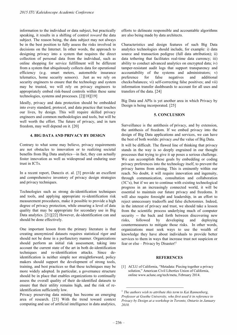
information to the individual or data subject, but practically
speaking, it results in a shifting of control toward the data
subject. The reason being, the data subject may not always
be in the best position to fully assess the risks involved in
decisions on the Internet. In other words, the approach to
designing privacy into a system that requires the direct
collection of personal data from the individual, such as
online shopping for service fulfillment will be different
from a system that ubiquitously collects data for operational
efficiency (e.g. smart meters, automobile insurance
telematics, home security sensors). Just as we rely on
security engineers to ensure that the technology and system
may be trusted, we will rely on privacy engineers to
appropriately embed risk-based controls within these same
technologies, systems and processes. [2][18][19]
Ideally, privacy and data protection should be embedded
into every standard, protocol, and data practice that touches
our lives, by design. This will require skilled privacy
engineers and common methodologies and tools, but will be
well worth the effort. The future of privacy, and in turn
freedom, may well depend on it. [20]
4. BIG DATA AND PRIVACY BY DESIGN
Contrary to what some may believe, privacy requirements
are not obstacles to innovation or to realizing societal
benefits from Big Data analytics—in fact, they can actually
foster innovation as well as widespread and enduring user
trust in ICTs.
In a recent report, Danezis et. al. [3] provide an excellent
and comprehensive inventory of privacy design strategies
and privacy techniques.
Technologies such as strong de-identification techniques
and tools, and applying appropriate re-identification risk
measurement procedures, make it possible to provide a high
degree of privacy protection, while ensuring a level of data
quality that may be appropriate for secondary use in Big
Data analytics. [21][22] However, de-identification can and
should be done effectively.
One important lesson from the primary literature is that
creating anonymized datasets requires statistical rigor and
should not be done in a perfunctory manner. Organizations
should perform an initial risk assessment, taking into
account the current state of the art in both de-identification
techniques and re-identification attacks. Since de-
identification is neither simple nor straightforward, policy
makers should support the development of strong tools,
training, and best practices so that these techniques may be
more widely adopted. In particular, a governance structure
should be in place that enables organizations to continually
assess the overall quality of their de-identified datasets to
ensure that their utility remains high, and the risk of re-
identification sufficiently low.
Privacy preserving data mining has become an emerging
area of research. [23] With the trend toward context
computing and use of artificial intelligence in data analytics,
efforts to delineate responsible and accountable algorithms
are also being made by data architects.
Characteristics and design features of such Big Data
analytics technologies should include, for example: i) data
source and transaction pedigree (full data attribution); ii)
data tethering that facilitates real-time data currency; iii)
ability to conduct advanced analytics on encrypted data; iv)
tamper-resistant audit logs that support transparency and
accountability of the systems and administrators; v)
preference for false negatives and additional
checks/balances; vi) self-correcting false positives; and vii)
information transfer dashboards to account for all uses and
transfers of the data. [24]
Big Data and APIs is yet another area in which Privacy by
Design is being incorporated. [25]
5. CONCLUSION
Surveillance is the antithesis of privacy, and by extension,
the antithesis of freedom. If we embed privacy into the
design of Big Data applications and services, we can have
the best of both worlds: privacy and the value of Big Data.
It will be difficult. The flawed line of thinking that privacy
stands in the way is so deeply engrained in our thought
processes that trying to give it up poses a serious challenge.
We can accomplish these goals by embedding or coding
privacy preferences into the technology itself, to prevent the
privacy harms from arising. This is eminently within our
reach. No doubt, it will require innovation and ingenuity,
through communication, consultation and collaboration
(3C’s), but if we are to continue with existing technological
progress in an increasingly connected world, it will be
essential to maintain our future privacy and freedoms. It
will also require foresight and leadership, in an effort to
reject unnecessary tradeoffs and false dichotomies. Indeed,
in the interest of privacy and trust, we should take a lesson
from the scientific process underlying much of computer
security -- the back and forth between discovering new
risks, followed by developing and deploying
countermeasures to mitigate those risks. In other words,
organizations must seek ways to use the wealth of
knowledge they have about individuals to provide better
services to them in ways that increase trust not suspicion or
fear or else – Privacy by Disaster!1
REFERENCES
[1] ACLU of California, “Metadata: Piecing together a privacy
solution,” American Civil Liberties Union of California,
online www.aclunc.org/tech/meta, February 2014.
1 The authors wish to attribute this term to Kai Rannenberg,
Professor at Goethe University, who first used it in reference to
Privacy by Design at a workshop in Toronto, Ontario in January
2010.
2015 ITU Kaleidoscope Academic Conference
– 236 –

[2] K. Cameron, “What harm can possibly come from a MAC
address?” Kim Cameron’s Identity Weblog,
https://www.identityblog.com/?p=1111, June 6, 2010.
[3] G. Danezis, J. Domingo-Ferrer, M. Hansen, J-H Hoepman, D.
Le Metayer, R. Tirtea, S. Schiffner, Privacy and Data
Protection by Design – from policy to engineering, ENISA,
December 2014.
[4] International Working Group on Data Protection in
Telecommunications, “Working Paper on Big Data and
Privacy: Privacy Principles under pressure in the age of Big
Data analytics,” 55th Meeting, Skopje, May 5-6, 2014.
[5] Article 29 Data Protection Working Party, “Opinion 03/2013
on purpose limitation,” European Commission, Directorate
General Justice, Brussels, 2013.
[6] E. Letouze, “Big Data Development: Challenges &
Opportunities,” UN Global Pulse, New York, May 2012
[7] T. Grandison, M. Sloman, “A Survey of Trust in Internet
Applications,” IEEE Communications Surveys and
Tutorials, Fourth Quarter 2000, January 24, 2001.C.
[8] Umhoefer, J. Rofe, S. Lemarchand, E. Baltassis, F.
Stragier, N. Telle, “Earning Consumer Trust in Big Data:
A European Perspective,” DLA Piper and Boston
Consulting Group, March 2015.
[9] Truste, US Consumer Confidence Index, 2015.
[10] A. Cavoukian, “A Report to the 22nd International
Conference of Data Protection Commissioners: Should the
OECD Guidelines Apply to Personal Data Online?”
Information and Privacy Commissioner’s Office, Ontario,
Canada, September 2000.
[11] Office of the Privacy Commissioner of Canada, “Privacy,
Trust and Innovation – Building Canada’s Digital
Advantage,” OPC Canada, July 2010.
[12] Federal Trade Commission (FTC), “Protecting Consumer
Privacy in an Era of Rapid Change: Recommendations for
Businesses and Policymakers,” US FTC, March 2012.
[13] A. Cavoukian, The 7 Foundational Principles:
Implementation and Mapping of Fair Information Practices,
Information and Privacy Commissioner’s Office, Ontario,
Canada, (Revised) January 2011.
[14] CORDIS, “Privacy and Data Protection Impact Assessment
Framework for RFID Applications,” Community Research
and Development Information Service, European
Commission, January 12, 2011.
[15] Online Trust Alliance, “IoT Trust Framework – Discussion
Draft,” Released August 11, 2015.
https://otalliance.org/initiatives/internet-things (visited on
2015-10-02).
[16] Pharmaceutical Users Software Exchange (PhUSE), “PhUSE
De-identification Standard for SDTM 3.2,”
http://www.phuse.eu/Data_Transparency.aspx (visited on
2015-10-02).
[17] I. Goldberg, D. Wagner and E. Brewer, “Privacy-enhancing
technologies for the Internet, University of California,
Berkley, 1997.
[18] M. Finneran Dennedy, J. Fox, T. Finneran. The Privacy
Engineer’s Manifesto: Getting from Policy to Code to QA to
Value. Apress, Berkeley, California, 2014.
[19] S. Guerses, C. Troncoso, and C.Diaz, “Engineering for
Privacy by Design,” International Conference on Privacy and
Data Protection (CPDP) Book, 2011.
[20] A. Cavoukian, S. Shapiro and J. Cronk, “Privacy
Engineering: Proactively Embedding Privacy, by Design,”
Information and Privacy Commissioner’s Office, Ontario,
Canada, January 2014.
[21] A. Cavoukian and D. Castro, “Big Data and Innovation:
Setting the Record Straight: De-identification Does Work,”
Information and Privacy Commissioner’s Office, Ontario,
Canada, June 16, 2014.
[22] K. El Emam, “Guide to the De-identification of Personal
Health Information,” CRC Press, Taylor & Francis Group,
Auerback Publications, Florida, 2013.
[23] H. Chen, R.H.L. Chiang, V.C. Storey, “Business
Intelligence and Analytics: From Big Data to Big Impact,”
Special Issue: Business Intelligence Research, MIS
Quarterly, Vo. 36, No. 4, pp. 1166-1188, 2012.
[24] J. Jonas, “Sensemaking on Streams – My G-2 Skunk Works
Project: Privacy by Design,” Jeff Jonas Blog,
http://bit.ly/1gIqcf8, February 14, 2011.
[25] R. Berjon and D. Appelquist, “Patterns for Privacy by Design
in Javascript APIs – Draft Finding,” W3C Technical
Architecture Group, W3C, June 6, 2012.
Trust in the Information Society
– 237 –


SOSLITE: LIGHTWEIGHT SENSOR OBSERVATION SERVICE (SOS) FOR THE INTERNET OF THINGS (IOT)
Juan Pradilla, Carlos Palau and Manuel Esteve
Universitat Politècnica de València, Spain
ABSTRACT The importance and reach of sensors networks grows every year, however, there are still many challenges that must be addressed. One of them, is the standardized interchange of information that enable interoperability between different networks and applications. To answer this challenge, the Open Geospatial Consortium (OGC) has created the Sensor Web Enablement (SWE) specification. SWE has given place to different mature implementations for the enterprise sector; however, they are usually over dimensioned alternatives that require robust systems. This differs from the capacity of small sensors networks like those used in domotics or eHealth, which are part of the Internet of Things (IoT). This work proposes a Sensor Observation Service (SOS) implementation, which is one of the fundamental components of the SWE specification, that fits small sensors networks environments and that does not require very robust systems to operate, thus providing a standard and agile platform. This implementation of the Sensor Observation Service provides independence from manufacturers and heterogeneous sensors networks, increasing interoperability because information is transmitted in a standard structure and through well-defined software interfaces. It also allows installation in devices of small capacity and low power consumption, reducing deployment costs and encouraging massive deployment of sensors networks and the Internet of Things (IoT).
Keywords— Internet of Things (IoT), Sensor Observation Service (SOS), Sensor Web Enablement (SWE), Sensor Networks, heterogeneous sensor sources, data interoperability.
1. INTRODUCTION There are many environments in which sensors are being omnipresent and the need to collect, store and analyze information provided by them is more tangible every day. Sensors networks consolidate as the medium by which data provided by the large amount of sensors deployed today is collected; however, storage and analysis of this information are research lines that are still in early development state. Collection of information by sensors networks is done at several levels. The lower levels are supported by different standard communication technologies such as: Wi-Fi,
Bluetooth, Zig-bee, 6LowPAN, TCP, UDP, etc.; however there is not a protocol stack or technology mainly imposed upon them, although a point has been reached in which many of these technologies coexist successfully with one another. In the upper levels, there are still few standardized alternatives widely used, being remarkable the Sensor Web Enablement (SWE) [1] initiative from the Open Geospatial Consortium (OGC). The Sensor Web Enablement (SWE) allows the integration of sensors and their data. Within the SWE the Sensor Observation Service (SOS) is very important because it is responsible for defining an interface for accessing sensor data and metadata [2]. The SOS provides a standardized web service interface that enables clients to interact with registered sensors and their observations [3]. This paper describes a system for handling the storage and sharing of the sensors information. The goal of this research is to provide interoperable services to guarantee access to heterogeneous data sources coming from Sensors Networks through a Sensor Observation Service (SOS) [4]. Allowing access to sensor observations in a standard way for any sensor system, either in-situ, remote, fixed or mobile sensors, complying with the “Observations & Measurements Schema” (O&M) [5] [6] specification for modeling sensor observations, and with the Sensor Model Language (SensorML)[7] specification for modeling sensors and sensors systems. Considering that sensors must make their measurements data accessible in a fast and reliable way, the SOS, as an intermediary element between the clients and the data collected by sensors, must provide an interface that allows storing and querying measurements in an efficient way. In addition, given that a great amount of use cases in sensors networks have limited resources, the SOS must be lightweight. The Internet of Things (IoT) was developed at the same time that sensors networks, and it involves uniquely identifiable objects and their virtual representations in an “internet-like” structure. On the other hand, sensors networks have become one of the most important sources of information in the IoT, allowing greater interaction with the environment. In this way, by making sensors networks’ data accessible in a standard manner within the IoT, heterogeneous equipments are allowed to interact with each other, so that the amount of information and knowledge generated from them is maximized. Unique possibilities are offered for the IoT deployment by making use of a low resource
978-92-61-15821-7/CFP1538E-ART © 2015 ITU Kaleidoscope– 239 –

consumption Sensor Observtion Service (SOS), because it enables the possibility of covering a greater amount of use cases with great performance by bringing closer the information storage and the place where it is generated and consumed. The rest of this paper is organized as follows: Section II presents the background about OGC standards and enumerates related work. Section III describes the outline of the system. Section IV describes one case study, and the paper ends with conclusions and further work.
2. RESEARCH BACKGROUND This section details the concepts that will be employed throughout the article, such as: Sensor Web Enablement (SWE) and Sensor Observation Service (SOS). Finally, some Sensor Observation Service implementations are presented and the new initiative of the OGC for Lightweight SOS is shown. 2.1. Sensor Web Enablement (SWE) Sensor Web Enablement is a framework and a set of standards that allow exploitation of sensors and sets of sensors connected to a communication network. SWE is founded on the concept of “Web Sensor” and aims at making them accessible using standard protocols and application interfaces. “A Web Sensor refers to web accessible sensors networks and archived sensor data that can be discovered and accessed using standard protocols and Application Program Interfaces (APIs)” [8]. The aim of supporting SWE is to make all kind of sensors accessible and controllable via web, making use of Internet Web protocols and the XML language. Thus enabling the capacity to publish sensor features like: sensor capacities, localization and interfaces. This information can be used by applications to geolocate and process data collected by the sensor without the need to previously know the sensor system. The SWE is a group of specifications covering sensors, related data models and services that offer accessibility and control over the Web. The SWE architecture is composed of two main models: the information model and the service model (Figure 1) [9]. The information model describes the conceptual models and encodings used, whereas the service model specifies related services specifications. In the information model, the conceptual models are: transducers, processes, systems and observations; and the encodings are: Observations & Measurements Schema (O&M) [5] [6], Sensor Model Language (SensorML) [7] and Transducer Markup Language (TransducerML or TML) [10]. In the service model, the four services specifications are: Sensor Observation Service (SOS) [4], Sensor Planning Service (SPS) [11], Sensor Alert Service (SAS) [12] and Web Notification Services (WNS) [13].
Figure 1. Sensor Web Enablement architecture
2.2. Sensor Observation Service (SOS) The Sensor Observation Service (SOS) defines a common model for all sensors, sensors systems and their observations, which is "horizontal" since it applies to all domains that use sensors to collect data [14]. “The SOS is the intermediary between a client and an observation repository or near real-time sensor channel. Clients can also access SOS to obtain metadata information that describes the associated sensors, platforms, procedures and other metadata associated with observations” [8]. The SOS 2.0 specification was adopted in 2012 and four extension are defined within the specification: Core, Enhanced, Transactional, and Result Handling. These group its different operations as described in Table 1. 2.3. Featured SOS implementations There are different Sensor Observation Service implementations in the literature that have been used in different projects and environments. The most notable SOS implementations are:
• 52°NORTH SOS: 52°North Initiative for Geospatial Open Source and released under the GPL license (GNU General Public License). The 52°North SOS is cross-platform because its implemented in Java, has a good software architecture, public documentation and a strong community that gives support. The SOS is part of a suite of sensor web service implementations by 52°North. [15].
• PySOS: PySOS, a python-based implementation of the OGC SOS standard. It was developed in the oceanic research community. PySOS has a simple architecture, it consists of one Python program file, a configuration file and three XML templates for each of the operations: GetCapabilities, GetObservation
2015 ITU Kaleidoscope Academic Conference
– 240 –

and DescribeSensor. When the request is attended, the single Python program parses the appropriate XML
template, generates dynamic content through database queries and outputs a completed XML document. [15].
Table 1. Sensor Observation Service 2.0 extensions Extension Operation Description
Core
GetCapabilities Requesting a self-description of the service GetObservation Requesting the pure sensor data encoded in Observations &
Measurements 2.0 (O&M) DescribeSensor Requesting information about a certain sensor, encoded in a Sensor
Model Language 1.0.1 (SensorML) instance document
Enhanced GetFeatureOfInterest Requesting the GML 3.2.1 encoded representation of the feature
that is the target of the observation GetObservationById Requesting the pure sensor data for a specific observation identifier
Transactional
InsertSensor Publishing new sensors UpdateSensorDescription Updating the description of a sensor DeleteSensor Deleting a sensor InsertObservation Publishing observations for registered sensors
Result Handling
InsertResultTemplate Inserting a result template into a SOS server that describes the structure of the values of an InsertResult or GetResult request
InsertResult Uploading raw values according to the structure and encoding defined in the InsertResultTemplate request
GetResultTemplate Getting the result structure and encoding for specific parameter constellations
GetResult Getting the raw data for specific parameter constellations
2.4. OGC Best Practice for Sensor Web Enablement Lightweight SOS Profile for Stationary In-Situ Sensors The original Sensor Observation Service (SOS) proposed in the Sensor Web Enablement is an excellent proposal, but it can be too complex to implement and use, which implies the need to count with a powerful hardware for its deployment. Besides, it can exceed the needs of most cases presented in different actual sensors networks that form part of the Internet of Things. This problem has affected the OGC, which has started to create a less complex profile for the case of stationary in-situ sensors. [2]. With this objective, specific elements that are not necessary for the majority of use cases that occur in practice have been removed, reducing the number of operations and their complexity and focusing on fixed in-situ sensors. "At the same time, the profile is designed in such a way that all SOS implementations that conform to this profile are also compliant to the OGC specifications” [2].
3. OUTLINE OF THE SYSTEM 3.1. Nature of the Information in the Sensors Network To achieve a good exploitation of resources, the nature of the information and the interactions that SOS will have with other systems must be understood. Based on that knowledge, an architecture that fits the nature of the system analyzed must be proposed. In the case of Sensor Observation Service (SOS), sensors report their data following two temporary patterns: in constant time intervals or when a specific event is
generated. In the same way, SOS clients can follow these same temporal patterns while querying data. The sensors data can be heterogeneous and is generally represented by small pieces of information (relative humidity, temperature, luminosity level, etc.) that are reported following the temporal patterns described before. Data querying by the contrary, is usually massive, although it keeps its diverse nature. With this in mind, to achieve a good performance, the proposed SOS implementation counts with a system that allows attending simultaneous requests with a low data load. The storage is able to adapt to heterogeneous data structures and respond quickly to multiple records queries, thus creating a unique implementation that provides a standard interface while consuming few resources and maintaining efficiency. 3.2. SOSLite Components To be able to offer a standard data storage and distribution service in sensors networks for use in the Internet of Things (IoT), the starting point is the OGC specifications for the development of a SOS and the characterization of the traffic that circulates on these networks. This would allow making modifications that adapt to the common cases in the IoT and to resources that are more restricted, making way for light, versatile and economic implementations. SOSLite is recommended for the development of light SOS because it’s based on SOAP web services that permit CRUD (Create, Remove, Update, Delete) interactions, it implements the operations inside the Core and Transactional specifications but with a limited capacity to
Trust in the Information Society
– 241 –

make them less complex, imitating the workings of the SWE Lightweight SOS Profile [2] proposal. Schematically, SOSLite is composed of (Figure 2): SOAP operations, WSDL descriptor file, NoSQL database and file system. SOAP operations are the ones that implement the Core and Transactional specifications adjusted to a light profile. The WSDL descriptor file enables SOSLite discovery and provides necessary information so that a SOAP client can make use of the service. The descriptor along with the SOAP operations are the public interfaces with which a client can interact. On their part, the private side of SOSLite is constituted by: the NoSQL database for sensors and events data, and the file system for sensor information backup in Sensor Model Language (SensorML) format. The use of a NoSQL database responds to the versatility necessary to store heterogeneous information of events coming from the sensors, allowing for the structure of the storing records to change, without losing previously stored records and making them compatible with one another. The storage of sensors descriptions in the file system, is linked to the fact that the operations DescribeSensors, InsertSensor, UpdateSensorDescription & DeleteSensor, return, insert, update or delete the sensor information in SensorML format as if it was an atomic data block without the need of transformations. Storing them this way makes the operations processing faster, because it prescinds from constructing the response in SensorML format from the database.
Figure 2. Sensor Web Enablement architecture
3.3. Operations of SOSLite
Operations provided by the SOSLite recommendation, are consistent with the SOS 2.0 Core and Transactional specifications (Table 1); however, adaptations for a light profile are made. In the operations of the Core specification, an adaptation is made according to the “Sensor Web Enablement
Lightweight SOS Profile for Stationary In-Situ Sensors”. [2], taking into account that in the case of a mobile sensor, it will report a location change using the UpdateSensorDescription from the Transactional profile. The transactional profile operations implement the SOS [4] standard but the same restrictions of the “Sensor Web Enablement Lightweight SOS Profile for Stationary In-Situ Sensors” [2] are made over the transmitted data in Sensor Model Language (SensorML) and Observations & Measurements Schema (O&M) format. In this way, the implementation is simplified and the standard compatibility is maximized at the same time.
3.4. Basic Operation
Any client that wishes to make use of SOSLite can start its interaction with the system by reading the WSDL descriptor file, from which the available operations in the SOS can be seen along with the supported interconnection interfaces and formats. Next, the available operations in the Core and Transactional specifications can be invoked. GetCapabilities is the operation that usually generates bigger responses, and in it, the service is self described; including information about the type of filters that can be used in the requests, the type of spatial and temporal response, the available properties, among others. It is also the operation that is initially invoked to auto-configure the clients. The sensors insert, update and delete operations (InsertSensor, UpdateSensorDescription & DeleteSensor) are invoked in the SOSLite so that the database is updated along with the associated files in SensorML format. In a similar way, it is the workings of the InsertObservation operation that makes the registry in the database and stores the file in O&M format (Figure 3).
Figure 3. Basic sequence diagram for InsertObservation operation
Meanwhile, the select operations: DescribeSensor and GetObservation (Figure 4); read and filter out the requested data from the database and construct the response from this information and from the stored files in the file system.
2015 ITU Kaleidoscope Academic Conference
– 242 –

Figure 4. Basic sequence diagram for GetObservation
operation It is necessary to understand that the sensors observations in the insert and select operations, have a useful information payload in SensorML or O&M format that usually stays unaltered during considerable periods of time. Thus, storing them in the hard drive and returning them directly, according to the filters applied in the database query, is a performance improvement. 3.5. Benefits of SOSLite SOSLite is recommended for the implementation of a light SOS, because it allows the deployment of a data storage and distribution system for sensors networks, making use of low resource devices, allowing these to be more affordable and available for massive distribution. With the consequence that this storage will be closer to the register and query of this data, thus making this operations faster. In addition, an implementation based on SOSLite is much easier to develop and has the advantage of being adaptable to different scopes of application without making significant changes. These benefits are in line with keeping standard and well defined interfaces for data transmission, so that the interconnection among heterogeneous systems is made possible.
4. CASE STUDY To ease the assimilation of the concepts presented in this article, an implementation of SOSLite [https://github.com/Juanvx/SOSLite] has been developed and its source code has been published under the GPL license. Code is written in PHP and can be deployed on Apache and NGINX servers among others. Using the published open source implementation, a use case is given within the Internet of Things focused on eHealth. This allows the interconnection of sensors in a body area network, a home network and a metropolitan network; with a personal alert system and a health system inside the hospital (Figure 5).
Figure 5. eHealth use case architecture As it can be appreciated, the system is hierarchical and distributed; and is constituted by four levels: Sensor Level, SOS Level, Integration Level and Application Level. In the Sensors Level are all the sensors networks that measure physical parameters (cardiac rhythm, blood oxygen, arterial pressure, etc.) which can be used to detect abnormalities in the patient, home sensors which measure ambient parameters (air quality, temperature, movement, etc.) and city sensors which also measure ambient parameters (air quality, temperature, etc.). In the SOS Level, every sensors network information is centralized in an independent way and is made accessible through a SOSLite in every network. In the same way, in the Integration Level, a SOSLite deployed on a higher capacity device, centralizes the information of the SOSs linked to every sensors network and creates a data bank accessible for the hospital applications. Finally, the Application Level has two different solutions that show the potential for a system built like this. The first solution is an alert service linked to the physical sensors network. This service reads the data from the SOSLite of this network and if it detects a pattern that shows a dangerous condition for the patient, emits alarms to the patient, to a contact person and to the family doctor. The second solution analyzes data associated to the Integration Level SOSLite, and through BigData, detects trends that can be used by doctors to make recommendations to their patients; i.e. in the moment the average air particles count in the city exceeds 50 μg/m3 (PM10), asthmatic patients increment their respiratory problems by a 30%.
5. INITIAL PERFORMANCE EVALUATION To verify the viability of SOSLite as a recommendation, and the possibility of testing a use case as the one discussed above, it has been made an initial performance test of the implementation of SOSLite on a Raspberry Pi 1 model B (CPU: 1176JZF-S a 700 MHz, SDRAM: 512 MB shared with GPU, Power ratings: 3.5 W).
Trust in the Information Society
– 243 –

Figure 6. Test set-up
A test case was made using Apache Jmeter on Ubuntu Linux 14.04 LTS and deploying the SOSLite implementation on the event driven NGINX server, using Raspbian as operating system and MongoDB as database. The JMeter client runs on a personal computer while the server uses the Raspberry Pi; on its part, the interconnection is made with category 5 UTP cable and a personal switch (Figure 6). The test case simulates the connection of 20 sensors that make 25 GetCapabilities operations to a SOSLite and evaluates the throughput as well as the average delay and standard deviation (Figure 7). As can be seen in Figure 7, the average delay values are close to 4 seconds with a deviation up to 1 second. However, there are three important factors to take into account: in a traditional case, the GetCapabilities operation calls (which has been chosen for being the most resource consuming) are usually very few, the amount of sensors associated to a deployment on the tested hardware will be less, and the hardware employed is very limited compared to the actual devices that can be used. In example, a Raspberry 2 model doubles the capabilities of the Respberry used.
6. CONCLUSIONS AND FUTURE WORK
Counting with some standard interfaces and data transmission formats is the big challenge of the current Internet of Things (IoT). Although there are many providers promoting their initiatives, an international organism that associate diverse companies from the field, is essential to ensure compatibility of these systems and to allow a beneficial development for the society. For this reason, this article is based on a standard with these characteristics, adapting it to adjust it to the most frequent cases faced by the actual IoT.
(a)
(b)
(c)
Figure 7. SOSLite GetCapabilities operation throughput (a) delay average (b) and delay standard deviation (c)
Today, there are many data sources coming from different sensor networks. The main concern about the huge amount of data provided by these sensor networks is the heterogeneity of the data. Likewise, with the overcrowding of the Internet of Things (IoT), the need to decrease deployment costs is fundamental to keep the current momentum. To achieve this goal, modest and economic hardware must be employed. This can be attained by making software that is efficient and adequate to the market needs, leaving aside the less used operations and simplifying the most used ones. Analysis of this information is beyond the scope of this work, however by giving a standard interface for information querying, the Sensor Observation Service (SOS) constitutes as the base to take full advantage of sensor networks. In future works, the actual SOSLite implementation will be tested to determine its performance and versatility in diverse use cases in a way that it proves that it is an appropriate candidate to empower the IoT. Besides, it will continue seeking ways to increase the systems efficiency, and at the same time, adjusting properly to the type of traffic generated within the Internet of Things (IoT).
2015 ITU Kaleidoscope Academic Conference
– 244 –

REFERENCES [1] OGC SWE Project Website [Online]. Available:
http://www.open-geospatial.org/ogc/markets-technologies/swe
[2] “OGC Best Practice for Sensor Web Enablement
Lightweight SOS Profile for Stationary In-Situ Sensors”. (2014). Open Geospatial Consortium. Best Practice.
[3] Trilles, S., Belmonte, O., Diaz, L., & Huerta, J. “Mobile
access to sensor networks by using GIS standards and restful services”. Sensors Journal, IEEE, 14(12), 4143-4153.
[4] A. Na and M. Priest, “OpenGIS sensor observation service
implementation specification,” in Open Geospatial Consortium (OGC), Wayland, MA, 2006, pp. 1-104, OGC Document, OGC 06-009r6.
[5] S. Cox, “Observations and Measurements - Part 1 -
Observation schema,” in Open Geospatial Consortium (OGC), Wayland, MA, 2007, pp. 1-85, OGC Document, OGC 07-022r1.
[6] S. Cox, “Observations and Measurements - Part 2 -
Sampling features,” in Open Geospatial Consortium (OGC), Wayland, MA, 2007, pp. 1-46, OGC Document, OGC 07-002r3.
[7] M. Botts and A. Robin, “OpenGIS Sensor Model Language
(SensorML) implementation specification,” in Open Geospatial Consortium (OGC), Wayland, MA, 2007, pp. 1-180, OGC Document, OGC 07-000.
[8] M. Botts, M., Percivall, G., Reed, C., & Davidson, J. (2007).
“OGC® sensor web enablement: Overview and high level architecture. OGC sensor web enablement: Overview and high level architecture” (pp. 175-190). Open Geospatial Consortium.
[9] Gimenez, P., Molina, B., Palau, C. E., & Esteve, M. (2013).
“SWE simulation and testing for the IoT”. In Systems, man, and cybernetics (SMC), 2013 IEEE international conference on (pp. 356-361). doi:10.1109/SMC.2013.6.
[10] S. Havens, “OpenGIS transducer markup language
implementation specification,” in Open Geospatial Consortium (OGC), Wayland, MA, 2006, pp. 1-136, OGC Document, OGC 06-010r2.
[11] I. Simonis and P. Dibner, “OpenGIS sensor planning service
implementation specification,” in Open Geospatial Consortium (OGC), Wayland, MA, 2007, pp. 1-186, OGC Document, OGC 07-014r3.
[12] I. Simonis and J. Echterhoff, “OpenGIS sensor alert service
implementation specification,” in Open Geospatial Consortium (OGC),Wayland, MA, 2006, pp. 1-144, OGC Document, OGC 06-028r5.
[13] I. Simonis and A. Wytzisk, “Web notification service,” in
Open Geospatial Consortium (OGC), Wayland, MA, 2003, pp. 1-46, OGC Document, OGC 03-008r2.
[14] Wang, H., Di, L., Yu, G., & Zhang, B. (2009).
“Implementation of sensor observation service for satellite
imagery sensors”. In Geoinformatics, 2009 17th international conference on (pp. 1-5).
[15] McFerren, G., Hohls, D., Fleming, G., & Sutton, T. (2009).
“Evaluating sensor observation service implementations”. In Geoscience and remote sensing symposium, 2009 IEEE international ,IGARSS 2009 (Vol. 5, pp. V-363-V-366).
Trust in the Information Society
– 245 –


FUTURE MOBILE COMMUNICATION SERVICES ON BALANCE BETWEEN FREEDOM AND TRUST
Yoshitoshi Murata
Faculty of Software and Information Science, Iwate Prefectural University
Takizawa, Iwate, 020-0693 Japan
ABSTRACT Some applications introduced in each 5G mobile
communication project (5G-P) assume special use cases such as when many people simultaneously use their mobile phone in a restricted area like a stadium or when using traffic safety systems are in common. And, some of them such as mobile healthcare and the Internet of things (IOT) have already been presented by many people. However, the reasons those applications will be widely used are uncertain. And then, most authors of articles related to future mobile communication made no mention of business schemes such as who deploys network infrastructure or who provides service content.
However, the histories of existing mobile communication markets may show applications that are different from the ones written in the above articles and new business schemes that are different from existing ones. In this article, I analyze the dominant non-voice applications of the existing mobile communication systems including paging services and identify the primary factors that made them dominant. I also analyze the business models of the network carriers. This analysis leads me to forecast that the next-generation of dominant mobile communication applications will be developed on the basis of a balance between the freedom of participants and suspicion, and the business models will become more liberal. Moreover, I forecast that a service that comes after SNS messaging services will be the one in which experiences are shared.
Keywords— mobile communication system, mobile evolution, 5G, context-aware communications and networking, user-centric networking
1. INTRODUCTION Several projects aimed at developing 5G mobile communication systems are underway in various parts of the world. 5G PPP [1] and METIS [2][3] in the EU and the 5G Forum [4] in Korea have already issued white papers. The 5GMF [5][6] in Japan has signed a memorandum of understanding with the 5G PPP. Most such projects are based on special use cases in the 5G mobile (5GM) era and address the performance requirements for those cases. Moreover, they focus on the technologies needed and the challenges that must be overcome to meet those requirements. The use cases include smart cars, traffic
collision avoidance, and heavy communication traffic volumes in a small area such as a stadium. Some use cases introduced in 5G-PPP, 5GMF and ETSI are in common. And, most applications in 5G Forum have already been presented by many people. However, reasons those applications will be widely used are uncertain. And then, most authors of articles related to future mobile communication made no mention of business schemes such as who deploys network infrastructure or who provides service content. Most major applications were developed at the last half of living mobile communication system, so a new generation system was required to handle the growing number of subscribers. For example, the i-mode mobile Internet service in Japan was developed in the 2G era, but the performance of 2G mobile was insufficient for full Internet service—performance of 3G mobile (3GM) was needed. It is still unclear which existing applications will need 5GM performance. However, the histories of existing mobile communication markets may show applications that are different from the ones written in the above articles and new business schemes that are different from existing ones. In this article, I analyze the dominant non-voice applications of the existing mobile communication systems including paging services and identify the primary factors that made them dominant. I also analyze the business models of the network carriers. This analysis leads me to forecast that the next-generation of dominant mobile communication applications will be developed on the basis of a balance between the freedom of participants and suspicion, and the business models will become more liberal. Moreover, I forecast that a service that comes after SNS messaging services will be the one in which experiences are shared. After introducing related work in Section 2, I analyze existing mobile communication applications and business models to clarify the primary factors that made them dominant in Section 3. On the basis of these primary factors, I forecast which mobile communication applications and business schemes will be dominant in Section 4. I conclude in Section 5 with a summary of the key points and a personal note.
978-92-61-15821-7/CFP1538E-ART © 2015 ITU Kaleidoscope– 247 –

2. RELATED WORK 2.1. 5G projects The 5G projects mentioned above sometimes compete and sometimes cooperate in taking the initiative on standardization and markets for 5GM. Their special use cases and applications target 2017–2020. They are listed in Table 1, along with their primary requirements. Most of the use cases and applications must be limited for usage. Some cases would be very rare, and others could be solved by implementing suitable application software. For example, about ten years ago in Japan, so many young people visiting a shrine or temple on the first day of the new year were simultaneously sending messages with New Year greetings that the network carriers had to control the traffic volume to keep their systems operating. This led to an increased usage of social networking applications (SNSs) such as Facebook and LINE, which solved the New Year’s Day traffic jam problem. This means that a huge amount of traffic in a stadium would not be a problem solved by 5GM. The traffic efficiency and safety use case of METIS and the smart cars use case of the 5G Forum require super low latency. Moreover, they also need the ability to identify vehicles and obstacles (including people) and to determine their locations. These latter two functions will be difficult to achieve. In addition, it is unclear whether these use cases and applications will be common in the 5GM era.
Table 1. Use cases, applications, and requirements of some 5G projects
2.2. Context-aware communications and networking A new trend in communication research is context-aware communications and networking (CACN). Most existing communication systems do not take into account the context of such entities as people, vehicles, phones, and
base stations. In contrast, in CACN, the contexts of entities (both real and virtual) are taken into account in end-to-end communication [7]. The concept of CACN is very wide and is applied in all communications and networking layers, from the physical and networking layers to the transport and application layers. Misra et al. applied this concept to the location of nodes and the rate of dissemination in wireless sensor networks and thereby effectively reduced the end-to-end delay of disseminated data with different priorities in an energy-efficient manner [8]. Researchers referred to the smart house, smart city, and so on would be included in CACN. Rao et al. proposed a context-event triggering mechanism in a smart cyber-physical space that works through energy harvesting [9]. Murata and Saito proposed a cloud service, called “cyber parallel traffic world” (CPTW), in which vehicles, pedestrians, and temporary obstacles exist and move in synchronization with their real-world counterparts [10]. In CPTW, drivers and pedestrians can communicate with other drivers and pedestrians by pointing to their positions rather than referring to an ID (e.g., a telephone number or address). 2.3. User-centric networking and device-to-device communication Other new trends in communication research are user-centric networking (UCN) and device-to-device (D2D) communication. While existing 1 to 4G communication networks (including paging system ones) were deployed by network carriers, UCNs and D2D networks are created by the users themselves, who cooperate by sharing network applications and resources. They are thus characterized by spontaneous and grassroots deployment of wireless architectures [11]. In an article entitled “Spontaneous Smartphone Networks as a User-Centric Solution for the Future Internet,” Aloi et al. describe building a local network using smartphones, WiFi access points (APs), Bluetooth devices, and network file systems that is organized in terms of spontaneous connectivity [12]. This approach could lead to low-cost operation, occasional super low latency, and high spectrum efficiency. However, if a malicious device terminal is implemented in a UCN as a relay node, that network would be risky to use. Important information could be stolen from a user’s terminal. Therefore, security and trust functions are necessary for UCNs. Frangoudis and Polyzos identified the challenges of user centricity in terms of their effect on wireless networking architectures, particularly security, in an article entitled “Security and Performance Challenges for User-Centric Wireless Networking” [13].
3. EVOLUTION IN MOBILE COMMUNICATION In biology, the evolution basically depends on the genetic mutation and the natural selection. The genetic mutation is caused by not only natural mutation but also viruses, radiation and so on [14]. Anyhow, whether new species of organisms can survive and thrive is dependent on coincidence. It is very difficult to predict which new species of organisms will thrive.
5G PPP/ 5GMF
METIS 5G Forum
Use cases and/or
applications
Stadium traffic
Stadium traffic; Traffic
efficiency and safety
Smart cars;Medical
education;Games; Disaster
relief Peak data
rate 10 Gb/s 10 Gb/s 50 Gb/s
Data volume
10 Tb/s/km2
9 Gbytes/h in busy periods;
500 GB/mo /subscriber
—
Number of devices
1 M/km2 300
K/access point
—
End-to-end latency
5 ms 5 ms 1 ms
2015 ITU Kaleidoscope Academic Conference
– 248 –

The other hand, in the mobile communication market, whether new applications, business models and so on are accepted by a lot of subscribers is mainly dependent on subscriber’s values or preferences and social rules. Subscriber’s values or preferences must not change so rapidly. This means that there would be solutions for which applications and so on will thrive in a history of mobile communication market. I analyze existing mobile communication applications and business models to clarify the primary factors that produce the dominant applications and business schemes. 3.1. Applications In most articles related to the evolution or future of mobile communication, 1G cellular phone systems, which provided only analog voice service, are considered to be the first mobile communication system. However, the paging system was actually the first mobile communication system for non-voice service. Prior to the introduction of 2GM phone systems, paging systems provided one-way messaging service in its half period. Users could send a message by using a push-button phone, a PC mail system such as Lotus Notes or Internet mail. Paging applications were mainly used by business people in the U.S. and the EU, and by young people, especially female high school students, in Japan. The advent of 2GM led to the integration of 1G mobile (1GM) phone systems and paging systems (2GP), enabling two-way messaging service (Internet mail) and limited World Wide Web (WWW) service in Japan, as shown in Figure 1. In the EU and U.S., the two-way short messaging service (SMS) became widely used as a consumer communication service. Full Internet service using smartphones started in the latter half of the 2GM era, and becomes popular in the 3GM era. One of most popular application in 3GM era is the SNSs such as Facebook and LINE. They suit for a mobile communication service in fact, most mobile mail user shifts to SNS’s messaging applications. Anyway, messaging applications are dominant in any mobile communication systems.
Figure 1. Evolution of non-voice applications in Japan
Researchers in both industry and academia university continue to develop new mobile communication systems, and network carriers are deploying them to enable subscribers to use their applications anytime and anywhere. Users can connect their smartphones to the Internet through not only 3GM and 4GM but also WiFi. Generally, users
can connect to the Internet at lower cost and with a higher data rate by using WiFi rather than 3GM or 4GM. When connecting through a carrier network, the user generally does not need to worry about security. However, when connecting through a WiFi access point, the user has to consider whether it is safe or not, because some of WiFi access points would be malicious [15]. Unfortunately, most users do not do this. The evolution of messaging service from the one-way messaging to two-way messaging to SNS messaging has been accelerated by seeking freedom for communication. However, in the period introducing unguaranteed network resources, keeping trust for participants is very important to expand the mobile communication market. 3.2. Business schemes In most countries, a specified organization such as AT&T, and NTT provided mobile communication service in the first era of mobile communication. The mobile market was closed, and there was no competition. Since then, mobile communication markets have been opened somewhat in most countries. The number of carriers is still limited, and operations are controlled by the government. This means that competition is restricted. The standard mobile communication business model is a vertically integrated one. I proposed an open heterogeneous mobile network (OHMN) model to accelerate competition in the mobile communication market at the first Kaleidoscope in 2008 [16]. In this model, mobile communication business activities are horizontally arranged on five layers, as shown in Figure 2. Each layer corresponds to a core activity; - Terminal layer: manufacturing and selling terminals. - Network layer: deploying and providing access networks. - Connection service layer: setting up voice communication
path between end terminals through different access networks. (Mobile virtual network operators are on this layer).
- Platform layer: user authentication and charging. - Contents & application layer: developing and providing
contents and applications for mobile users. In the standard business model (1.0), the market is closed while in the proposed business model (2.0) the market is open. While carriers continue have the right to provide wireless networks, connection applications, and billing applications, newcomers such as Skype and LINE now provide voice exchange applications over the Internet, and most billing applications for application software have shifted from carriers to credit service providers. This means that it is impossible to maintain a monopoly on a service business through laws or rules; outsiders are finding ways to break or circumvent such laws and rules so that they can provide targeted applications. Moreover, most business people want the freedom to start up and run any type of business.
Trust in the Information Society
– 249 –

4. FUTURE MOBILE COMMUNICATION SERVICE In this section, I forecast trends in service provision and business schemes. 4.1. Service provision I first forecast service provision from the standpoint of user freedom regarding “anytime, anywhere, anyone, and anything.” It is very difficult to completely achieve “anytime, anywhere and anything” freedom, and the 5G projects present very special use cased which need advanced technologies to achieve them. However, there are some problems which do not need advanced technologies. The 5G projects make no mention of them. For example, mobile subscribers have to pay high roaming charges when they are out of their home country. Frequent visitors to foreign countries often buy a pre-paid subscriber identity module (SIM) card for each country to enable use of a smartphone or tablet without having to pay roaming charges in each country. Less frequent visitors typically do not use the mobile communication system but use WiFi instead. A roaming charge is simply an unfavorable aspect of mobile communication. It is not a technical problem to be solved. Since the principle involved is the same as the “increase of entropy principle,” some network carriers could abolish the charge while others could continue to impose it. Systems that use users’ IDs to connect them do not provide “anyone” freedom. For example, a driver (A) stuck in a
traffic jam cannot connect to a driver (B) at the front of the jam, since A does not know B’s ID. This is one factor driving CACN research. It also led to my proposal to use the CPTW cloud service for solving traffic-related problems. Drivers using this service could learn the locations of other vehicles, pedestrians, and obstacles being tracked by the service and could communicate with each other by pointing to an object such as an automobile or pedestrian. The concept of CACN is a very broad; the use cases described above are only a few of its potential applications. I call the actions in the above use cases “context-aware messaging (CAM).” A context and ID exchange (CIDX) server is needed for CAM, as shown in Figure 3. Its database is used to relate a subscriber’s profile (including ID) to his or her context. When a person accesses the CIDX server, a graphical user interface such as a map on which context objects are plotted is displayed. The CPTW described in Section 2.2 is also one of CIDX servers. For example, if Mr. A, who has heart disease, falls down, his smartphone automatically sends an emergency signal including its location information. After receiving the signal, the CIDX server searches the context database for the IDs of doctors or other persons near Mr. A who have experience in the use of an automated external defibrillator (AED) and sends an appropriate person a message with a description of the problem and the location information.
Business model 1.0
Contents and
ApplicationsContents & Application
Layer
Platform Layer
ConnectionService Layer
Network Layer
Terminal LayerMobile
Terminal
Users
Various ubiquitous terminals
Various Usage
VerticalVertical
IntegrationIntegration
ModelModel
MobileMobileCommunicationCommunication
ServicesServices
Open Open
MarketMarket
ModelModel
FMC
Business model 2.0
BroadbnadAll-IP
Contents and
Applications
MobileMobileCommunicationCommunication
ServicesServices
FixedFixedCommunicationCommunication
ServicesServices
Ubiquitous netw
orkBusiness model 1.0
Contents and
ApplicationsContents & Application
Layer
Platform Layer
ConnectionService Layer
Network Layer
Terminal LayerMobile
Terminal
Users
Various ubiquitous terminals
Various Usage
VerticalVertical
IntegrationIntegration
ModelModel
MobileMobileCommunicationCommunication
ServicesServices
Open Open
MarketMarket
ModelModel
FMC
Business model 2.0
BroadbnadAll-IP
Contents and
Applications
MobileMobileCommunicationCommunication
ServicesServices
FixedFixedCommunicationCommunication
ServicesServices
Ubiquitous netw
ork
Figure 2. Open heterogeneous mobile network (OHMN) business layer model
2015 ITU Kaleidoscope Academic Conference
– 250 –
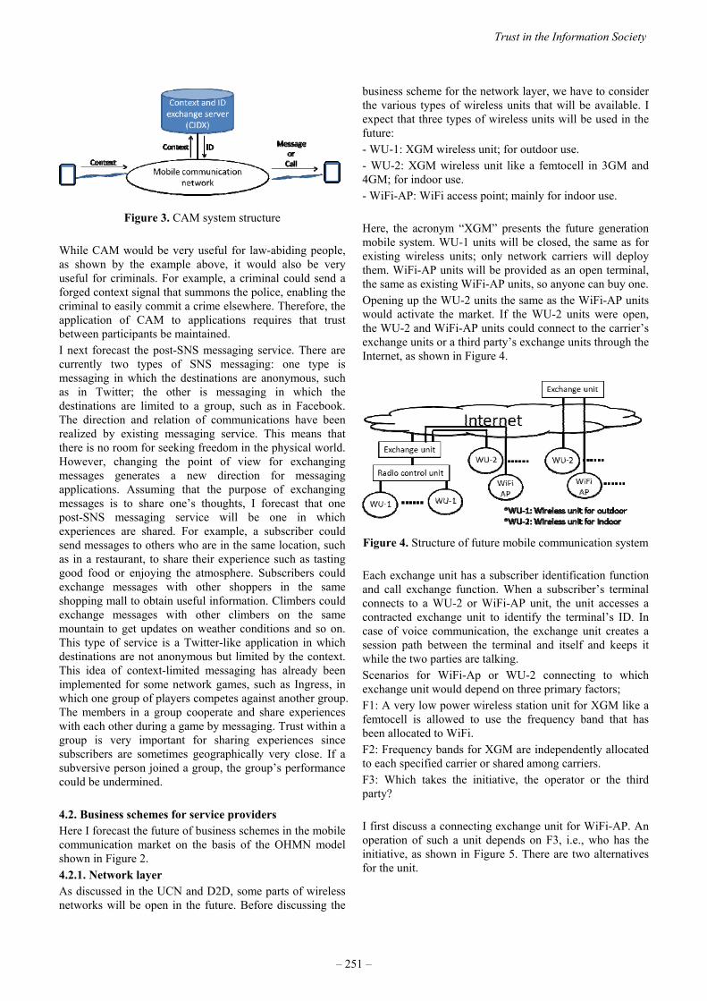
Figure 3. CAM system structure
While CAM would be very useful for law-abiding people, as shown by the example above, it would also be very useful for criminals. For example, a criminal could send a forged context signal that summons the police, enabling the criminal to easily commit a crime elsewhere. Therefore, the application of CAM to applications requires that trust between participants be maintained. I next forecast the post-SNS messaging service. There are currently two types of SNS messaging: one type is messaging in which the destinations are anonymous, such as in Twitter; the other is messaging in which the destinations are limited to a group, such as in Facebook. The direction and relation of communications have been realized by existing messaging service. This means that there is no room for seeking freedom in the physical world. However, changing the point of view for exchanging messages generates a new direction for messaging applications. Assuming that the purpose of exchanging messages is to share one’s thoughts, I forecast that one post-SNS messaging service will be one in which experiences are shared. For example, a subscriber could send messages to others who are in the same location, such as in a restaurant, to share their experience such as tasting good food or enjoying the atmosphere. Subscribers could exchange messages with other shoppers in the same shopping mall to obtain useful information. Climbers could exchange messages with other climbers on the same mountain to get updates on weather conditions and so on. This type of service is a Twitter-like application in which destinations are not anonymous but limited by the context. This idea of context-limited messaging has already been implemented for some network games, such as Ingress, in which one group of players competes against another group. The members in a group cooperate and share experiences with each other during a game by messaging. Trust within a group is very important for sharing experiences since subscribers are sometimes geographically very close. If a subversive person joined a group, the group’s performance could be undermined. 4.2. Business schemes for service providers Here I forecast the future of business schemes in the mobile communication market on the basis of the OHMN model shown in Figure 2. 4.2.1. Network layer As discussed in the UCN and D2D, some parts of wireless networks will be open in the future. Before discussing the
business scheme for the network layer, we have to consider the various types of wireless units that will be available. I expect that three types of wireless units will be used in the future: - WU-1: XGM wireless unit; for outdoor use. - WU-2: XGM wireless unit like a femtocell in 3GM and 4GM; for indoor use. - WiFi-AP: WiFi access point; mainly for indoor use. Here, the acronym “XGM” presents the future generation mobile system. WU-1 units will be closed, the same as for existing wireless units; only network carriers will deploy them. WiFi-AP units will be provided as an open terminal, the same as existing WiFi-AP units, so anyone can buy one. Opening up the WU-2 units the same as the WiFi-AP units would activate the market. If the WU-2 units were open, the WU-2 and WiFi-AP units could connect to the carrier’s exchange units or a third party’s exchange units through the Internet, as shown in Figure 4.
Figure 4. Structure of future mobile communication system Each exchange unit has a subscriber identification function and call exchange function. When a subscriber’s terminal connects to a WU-2 or WiFi-AP unit, the unit accesses a contracted exchange unit to identify the terminal’s ID. In case of voice communication, the exchange unit creates a session path between the terminal and itself and keeps it while the two parties are talking. Scenarios for WiFi-Ap or WU-2 connecting to which exchange unit would depend on three primary factors; F1: A very low power wireless station unit for XGM like a femtocell is allowed to use the frequency band that has been allocated to WiFi. F2: Frequency bands for XGM are independently allocated to each specified carrier or shared among carriers. F3: Which takes the initiative, the operator or the third party? I first discuss a connecting exchange unit for WiFi-AP. An operation of such a unit depends on F3, i.e., who has the initiative, as shown in Figure 5. There are two alternatives for the unit.
Trust in the Information Society
– 251 –

Figure 5. Scenarios of connecting exchange unit
for WiFi-AP In contrast, the operation of the connecting exchange unit for WU-2 depends on every factor. Therefore, its operation is rather complex, as shown in Figure 6. Scenario 8 (S8) is the one that will most activate the mobile communication market. I am looking forward to the government allowing WU-2 units to use the WiFi band and to standardization for XGM systems sharing the same frequency band. Two other problems related to opening the network layer are: - maintaining security while freely selling WU-2 and WiFi-
AP units. - sustaining the business of third parties who deploy WU-2
or WiFi-AP units for general subscribers.
At least, WU-2 or WiFi-AP units have to be provided the same as the mobile terminal. The ordinance of radio equipment for mobile terminals should be applied to WU-2 or WiFi-AP units. When they will be connected to an operator’s exchange unit, a chip like a SIM chip has to be mounted in the unit. If possible, an exchange unit should be able to examine whether a WU-2 or WiFi-AP unit has been contaminated with malicious programs such as computer viruses. Alternatives for sustaining a third party’s business are basically billing for usage and sending advertisements. They depend on the third party involved. A shopping mall, for example, could send information customized for each subscriber and shop. A restaurant could use a WU-2 or WiFi-AP unit to take orders or attract customers. In the “taking orders” example, the unit would need a function for charging for the provider’s service. In the “attracting customers” example, the unit would need a function for using cloud applications.
4.2.2. Connection layer As mentioned above, voice exchange applications are already being provided by several cloud service providers such as Skype and LINE. Skype can already handle exchanges between carriers for voice communication. However, they cannot handle fast hand-off service between WiFi routers. Technically, the IEEE has already standardized fast-hand-off for WiFi as IEEE 802.11r or 11ai [17]. The fast hand-off service between WiFi-AP and/or WU-2 units would be provided by some providers. 4.2.3. Platform layer Billing for smartphone applications already has been opened to outsiders, and many such applications are in the Google Play Store and the Apple Store. It is possible to buy them by credit cards and prepaid cards. IC/Mobile wallet applications are now widely used in several countries such as Japan. It is possible to pay by IC card or mobile phone. Apple provides the Apple-pay app for its iPhone. The Internet of Things (IOT) will be ubiquitous in the near future. For example, the fee for parking in most parking lots in Japan is paid using an on-site charging system, which is not cost effective. The application of IC/Mobile wallet or Apple-pay applications to them would be more convenient and effective. In the future, such charging systems will utilize the IOT and make our lives easier.
5. CONCLUSION The analysis I have presented of existing mobile communication applications clarified the primary factors that made such applications dominant. I hypothesized that the evolution of mobile communication service was accelerated on the basis of a balance between the freedom of participants and suspicion. My forecast of mobile communication applications on the basis of these factors shows that sharing experiences will be the next stage in the evolution of messaging applications. The spread of very low power wireless stations using the WiFi band and of standardized XGM systems sharing the same frequency band will activate the mobile communication market. Finally, fast hand-off applications between WiFi-access
WU‐2
Allowed
Prohibit
Connecting Ex.
Operator
Third party
WiFi band
Operator
Third party
Independent
ShareIndependent
ShareIndependent
ShareIndependent
Share
InitiativeXGM bandallocation
(S1) Contracted operator
(S2)Contracted operator
(S3) Contracted operator
(S4) Every operator(S5) Contracted operator(S6) Contracted operator(S7) Contracted operatorand every third party(S8) Every operatorand third party
Figure 6. Scenarios of connecting exchange unit for WiFi-AP
2015 ITU Kaleidoscope Academic Conference
– 252 –
points and very low power wireless stations, and billing applications to utilize the Internet of Things will be introduced in a future. These forecasted developments should result in improved human ability, more convenient living, and new markets.
REFERENCES [1] The 5G Infrastructure Public Private Partnership (5G PPP), http://5g-ppp.eu/. [2] Mobile and wireless communications Enablers for the
Twenty-twenty Information Society (METIS), https://www.metis2020.com/.
[3] A. Osseiran, et al., “Scenarios for 5G Mobile and Wireless Communications: The Vision of the METIS Project,” IEEE, Communications Magazine, May 2014, pp. 26–35.
[4] ICT-317669 METIS Project, “Scenarios, Requirements and KPIs for 5G Mobile and Wireless System,” Del. D1.1, May 2013.
https://www.metis2020.com/documents/deliverables/. [5] Y. Park, 5G Vision and Requirements Of 5G Forum,
Korea, Feb. 2014, https://www.itu.int/dms_pub/itu-r/oth/0a/06/R0A0600005F0001PDFE.pdf.
[6] The Fifth Generation Mobile Communications Promotion Forum (5GMF), http://5gmf.jp/en/.
[7] J. Wu, et al., “CONTEXT-AWARE NETWORKING AND COMMUNICATIONS: PART 1,” IEEE, Communications Magazine, pp. 14–15, June 2014.
[8] S. Misra, S. N. Das, and M. Obaidat, “Context-Aware Quality of Applications in Wireless Sensor Networks,” IEEE, Communications Magazine, pp. 16–23, June 2014.
[9] V. S. Rao, S. N. A. U. Nambi, R. V. Prasad, and I. Niemegeers, “On Systems Generating Context Triggers through Energy Harvesting,” IEEE, Communications Magazine, pp. 70–77, June 2014.
[10] Y. Murata, and S. Saito, “'Cyber Parallel Traffic World' Cloud Service in 5G Mobile Networks," Journal of ICT Standardization, River Publishers, Volume 2, No. 2, Special Issue on ITU Kaleidoscope 2014: “Towards 5G,” pp. 65–86, 2014.
[11] R. Sofia, et al., “USER-CENTRIC NETWORKING AND APPLICATIONS: PART 2,” IEEE, Communications Magazine, p. 16, December 2014.
[12] G. Aloi, et al., “Spontaneous Smartphone Networks as a User-Centric Solution for the Future Internet,” IEEE, Communications Magazine, pp. 26–33, December 2014.
[13] A. Frangoudis and G. C. Polyzos, “Security and Performance Challenges for User-Centric Wireless Networking,” IEEE, Communications Magazine, pp. 48–55, December 2014.
[14] F. Ryan, Virolution, FPR-Books Ltd, HarperCollins, 2009.
[15] WiFi ALLIANCE, Security, http://www.wi-fi.org/discover-wi-fi/security.
[16] Yoshitoshi Murata, Homare Murakami, Mikio Hasegawa, “Architecture and Business Model of Open
Heterogeneous Mobile Network”, ITU-T, Kaleidoscope, May 2008.
[17] 802.11r-2008 - IEEE Standard for Information technology-- Local and metropolitan area networks-- Specific requirements-- Part 11: Wireless LAN Medium Access Control (MAC) and Physical Layer (PHY) Specifications Amendment 2: Fast Basic Applicationset (BSS) Transition.
Trust in the Information Society
– 253 –

MAURITIUS EHEALTH – TRUST IN THE HEALTHCARE REVOLUTION
Leckraj Amal Bholah; Kemley Beharee
University of Edinburgh, United Kingdom
University of Mauritius, Mauritius
ABSTRACT
The aim of eHealth infrastructure is to harness innovations
in digital infrastructure that can enable the seamless access
to, sharing and reuse of data (e.g. clinical records, genomic
data and images) irrespective of source [1]. eInfrastructure
is comprised of networked, interoperable, service-oriented,
scalable computational tools and services. The key element
is the interaction of human users and computers so as to
facilitate discovery, linking and reasoning [2].
Keywords— Mauritius, eHealth, mHealth, Doctor
Assistant, Africa Health, Innovation, Medical, Information,
eInfrastructure, Big Data, Health Informatics, Global
eHealth
1. INTRODUCTION
During the 1990s, as the Internet gained public attention, a
number of e-terms began to appear and proliferate. The
introduction of eHealth represented a promise of
information and communication technologies to improve
health and the healthcare system. [3] eHealth infrastructures
are viewed as central to the future provision of safe,
efficient, high quality, citizen-centered health care. While
Western countries have raced forward in developing
eHealth, many developing countries remain on the start
line. There is evidence that better tapping ICT (Information
Communication Technology) could result in more effective
utilization of health services and increased efficiency [4]. A
communication revolution is brewing in the delivery of
health care and the promotion of health fueled by the
growth of powerful new health information technologies
[5]. Mauritius has one of the most successful and
competitive economies in Africa; 2008 GDP at market
prices was estimated at $8.128 billion (official exchange
rate) and per capita income at $ 12,100 (purchasing power
parity), one of the highest in Africa [6].
2. MAURITIUS EHEALTH POTENTIAL
Mauritius has a population of 1.2 million residents. There
are five regional hospitals and two district hospitals. The
number of beds in government health institutions was 3,581
at the end of 2013. In the private sector, there were
seventeen private health institutions with a total of 690
beds. The total number of beds in the public and private
sectors at the end of 2013 was thus 4271, that is, 285
inhabitants per bed. In 2013, a total of 5.2 million cases was
seen by doctors at the out-patient service points in the
public sector [7]. There is a need to extend healthcare
services beyond medical premises. Despite being built for
acute events, many hospitals allot a significant number of
their beds to chronically ill patients, with considerable cost
consequences. Mobile penetration rate was around 82% in
2009, paving way for intense competition among operators
to retain their customers and acquire new ones. Today,
mobile penetration is nearly 100%. HSPA (High Speed
Packet Access) and EV-DO (Evolution Data Optimized)
based 3G services are competing with fixed-line DSL
(Digital Subscriber Line) and other wireless broadband
offering, including WIMAX (Worldwide Interoperability
for Microwave Access) [8]. Efficient remote monitoring
and care has a great potential. Adopting a proper eHealth
infrastructure can strengthen our health systems by:
Improving the availability, quality and use of
information and evidence through strengthened
health information systems and public health
surveillance systems
Developing the health workforce and improving
performance by eliminating distance and time
barriers through telemedicine and continuing
medical education
Improving access to existing global and local
health information and knowledge
Fostering positive lifestyle changes to prevent and
control common diseases.
The Mauritian Government seeks to enhance prosperity for
its citizens and to ensure that it is available to everybody, to
develop the island further in order to compete with other
states in a globalized world and to expand and cultivate the
welfare and education systems to promote de facto equal
opportunity, regardless of gender, ethnicity, social class or
religion. This is the case too in terms of Mauritius ICT
policy and strategies where a holistic approach has led to
successive policies aimed at ensuring that ICTs contribute
to the wealth and prosperity of the country [9].
Since 1989, Mauritius has been a front-runner in an overall
comprehensive national ICT policy and liberalized
telecommunications framework, more recently in line with
the Millennium Development Goal (MDG) [10].
Despite all the opportunities that Mauritius have compared
to other African country, a proper eHealth infrastructure has
978-92-61-15821-7/CFP1538E-ART © 2015 ITU Kaleidoscope– 255 –

failed to be set up. Major barriers for successful
implementation are: [11].
Limited Awareness of eHealth
Policy makers, health authorities and health practitioners
are not fully aware of the potential benefits of the use of
ICT for health. The long-term strategic plans for developing
eHealth infrastructure is limited.
Lack of an enabling policy environment
National policies, strategies or regulatory framework are
necessary for establishing common technical infrastructure,
interoperability and standardization protocols. Mauritius
also needs to address ownership, confidentiality, security of
data and quality of information.
Weak leadership and coordination
The challenge is to strengthen coordination and
collaboration among stakeholders, partners and donors as
well as improve the capacity of the health sector to lead the
process.
Inadequate human capacity to plan and apply
eHealth solutions
Number of health workers capable of leveraging ICT in
their work remains limited. Health workers are not
systematically trained in use of ICT. Mauritius needs health
workers with the capacity to design, deploy and effectively
manage eHealth projects.
Weak ICT infrastructure and services within the
health sector
Ministries in charge of communications, technology and
finance are primarily responsible for national ICT
infrastructures. eHealth requires a dedicated team to sustain
eHealth initiatives.
Inadequate financial resources
Collaboration and coordination between multiple partners
from both private and public sectors is required.
Despite these challenges, opportunities exist for planning
and deploying eHealth solutions. These include the rapid
advances in ICT, increasing access to mobile phones and
broadband connectivity, increasing interest by donors and
countries in strengthening health systems, and the
partnerships being built by agencies such as WHO,
International Telecommunications Union (ITU), World
Bank, United Nations Economic Commission for Africa
and others. These partnerships seek to develop national
road maps for eHealth, and provide access to a suite of
eHealth applications and solutions for enhancing
professional capacity. Policy makers should see the eHealth
change as innovative, new and valuable. eHealth
innovations can gain momentum and acceptance rapidly in
the Mauritian society [12].
“We have beautiful hotels, beautiful beaches, and first-
class service. Why not make Mauritius a hub, a place where
people can combine a holiday and medical treatment”
(Former Minister of Health). [13]
“Involve the user” is a mantra in IT development, yet
numerous projects fail (some sources report 70% failure
[14] ) because of inability to capture user insights. It is
attributable to failure on the part of developers to
understand the workflow of health professionals and to
meaningfully involve users in the design, development and
implementation [15]. There is also resistance from
clinicians who perceive the project as an effort to introduce
technology for ‘policing’ their clinical practice. A possible
solution for this resistance, is to spend time and energy into
building a rapport with clinicians through informal chats,
gatherings and social activities.
eHealth infrastructure should support clinician and
researcher in time-consuming evaluation tasks to get
meaningful results faster and with less effort [16]. Data
protection is a major issue which eHealth has to address. It
is easy to being stuck in an endless “yes-no” debate
regarding Data protection. An interesting solution to the
problem is pseudonymisation which means de-
identification of medical data [17]. However, we should not
forget that not only persons or legal entities may has their
identity protected. This goes as well for systems or even
molecules (e.g. in drug discovery projects where
pharmaceutical research institutes have a need to share
basic research information, without exposing intellectual
property details).
Patients are now taking responsibility of their own health,
receiving information about health matters, and
participating in decision making related to personal health
issues from prevention to care and follow up [18]. The
application of Big Data into eHealth systems will generate a
new era of evidence-based medicine.
3.MHEALTH
mHealth interventions is on the rise. There is no ideal way
of deploying mobile technology. Learning from early
mHealth deployments is important so that ineffective
approaches are not duplicated. Successful projects need to
be replicated and scaled. In each mHealth thematic area,
the challenges, barriers, and gaps in mHealth manifest
themselves in unique and interrelated ways both in LMIC
(Low and Middle Income Countries) as well as in high-
income countries [19]. A general observation is that
mHealth interventions in high income countries focus on
chronic diseases while in LMIC on infectious diseases
mostly. In high income countries, mHealth addresses
mostly the following health conditions according to a
Global health report in 2006: [20]
Diabetes (blood sugar monitoring)
Breast cancer (telephone counseling)
Tuberculosis (adherence to medication)
Attendance to health facility appointments
2015 ITU Kaleidoscope Academic Conference
– 256 –

Depression outcomes
Immunization rates
Asthma management
Smoking cessation
Mobile technology plays an empowering role for patients.
They feel to have control over their health. The text
messaging support system “Sweet talk” was evaluated by
Franklin, Greene, Waller and Pagliari. C for its
effectiveness in encouraging good diabetes management in
young people. The randomized controlled trial (RCT)
consisted of sixty-four young diabetes patients. The study
concluded that “Sweet talk” effectively engaged young
people in self-management of diabetes [21]. Compared to
traditional paper and pen methods mobile technologies
provide several benefits namely:
Improved accuracy
Reduction in time
Reduction in human resources
Reduction in cost
Improved data quality
Potential for real time authentication of data
Less interviewer bias
In a paper entitled “Catalysing a perfect storm”, the authors
describe how mobile phones are equipping populations with
a convenient tool to become better informed, motivated and
self-managed to integrate more healthful daily activities
[22]. Medic Mobile has been described as Weapon
Number one for the war against AIDS [23]. Medic Mobile
developed an open source software which is a web-
application for sending and receiving messages as well as
scheduling time-targeted confirmation notes to
conventional $10 mobile phones. A parallel SIM transforms
inexpensive mobile phone into a sophisticated wireless data
collection terminal. Once the parallel SIM is installed
beneath a carrier’s normal SIM card, the software allows
for wireless data collection in remote or Internet
inaccessible locations (Medic Mobile, “Impact,” 2012).
The Ebola epidemic is a major recent crises. International
collaboration has a crucial role in tackling epidemic. The
technology company IBM launched a disease-mapping
system in October 2014. AirTel and IBM collaboration
allowed local people to send free text messages about Ebola
to the Government. Heat-maps that link emerging issues to
location information were created [24]. In Sierra Leone,
the Red Cross has worked in collaboration with AirTel to
launch a platform to send informative text messages to
people in most affected areas. 2 million people are thought
to have been reached via this platform with messages
encouraging simple hygiene measures such as regular hand
washing and appropriate personal protective equipment
when taking care of ill patients at home [25]. This clearly
shows the role of mHealth interventions as both preventive
and educational. The spread of cholera after 2012
earthquake in Haiti has been mapped by tracking
population movements via mobile phone [26]. The
Humanitarian OpenStreetMap Team (HOT), an NGO (Non-
Governmental Organisation) that works, train, coordinate
and organize mapping on OpenStreetMap for humanitarian,
disaster response and economic development has mobilized
volunteers from around the world to help map since the
Haiti earthquake. In the recent Nepal earthquakes, more
than 4300 mappers have made 86 000 edits to map, adding
up to 30 000 roads and 240 000 building [27]. Imagine
mapping all phone signals in a particular devastated area
and this helping rescuers to allocate resources to organize
help. Mobile phones can actually save lives and an
appropriate disaster management plan using mobile phone
resources contributes to disaster preparedness of the
country. SMS is an effective strategy to raise fund during
recovery phase of a disaster. 27 million Euros have been
raised for the United Nations Children’s Fund (UNICEF) in
Italy after the tsunami in December 2004 [28].
However mHealth interventions face many barriers namely:
Lack of data security
Difficulties for users in finding the right mHealth
solutions
Devices do not meet clinical requirements e.g.
hygiene
Lack of standardization
Missing or unknown legitimacy of mHealth
publishers
Mismatch of target group and smartphone owners
(elderly/chronic disease)
Missing regulations
Patient’s discomfort with change in their
healthcare routine
Lack of profitable business models
Resistance from traditional healthcare providers
Lack of high quality clinical studies
Lack of reimbursement for mHealth apps from
company funds and insurance
Lack of interoperability of mHealth app-based
solutions
Lack of high quality mHealth apps
The demand for wearables is on the rise namely with Apple
Watch and Samsung Gear. Soon, there will be an overflow
of patient data. The tsunami of information presents a
challenge for summarizing all data into usable and
meaningful format. In Mauritius, a patient Electronic
Health Record (EHR) can be used to collect data, follow up
on treatment compliance and draft disease management
programs on a national as well as an individual basis. The
shift toward integrated mHealth intervention is a new
strategy for healthcare providers to adopt technology.
4. MAURITIUS EHEALTH START-UP
A survey conducted in Mauritius by the authors, disclosed
that, according to patients, doctors have limited time to
communicate with them. Furthermore, the waiting time in
hospitals is increasing. In several cases, hospitals are
perceived by patients to be disorganised. Many patients
that were interviewed said that they are frustrated when
Doctors ask them the same questions repeatedly. It has also
Trust in the Information Society
– 257 –

been observed that patients have reported that they have not
been well informed about drug usage and follow ups.
Patients are unhappy that their medical folders are not
transferred across hospitals and when it is done among
some hospitals, the folders get lost all too often in the
process. They also complain that their blood results also get
lost often in the hospital and it is depressing to have blood
samples withdrawn several times.
According to patients the above points constitute the main
causes of medical negligence. Moreover the survey
disclosed that 66% of patients believe that the current
health system is the source of the problem. The issue of
medical negligence is further accentuated by poor
communication between patients and doctors. The authors
later developed Doctor Assistant which is a free Electronic
Medical Record (EMR) application available for free from
Google Play [29]. The application is now being used by
2240 users worldwide and bears a rating of 4.6 upon 5
among medical apps on Google play (Fig. 1). Doctor
Assistant will be published in the WHO Compendium of
Innovative Health Technologies 2014-2015. See annexed
illustrations regarding Doctor Assistant features. The
project has been taken up by the Mauritius Research
Council and State Informatics Limited for further
development and the main aims of the final software will
be.
Development of a National Healthcare Information
System (patient-centered) for Mauritius and for the
region, to improve health services in public and
private hospitals, as well as for private
practitioners
Provide a common robust and scalable platform to
stakeholders of the medical sector, which will
enable global visibility on issues and trends, and
contribute to an early health warning system
through timely access and secured sharing of
medical information (Smart Data, Big Data, Data
mining, Open Data)
Conceive a user interface which is adapted and
customised for the healthcare sector, with features
to minimise human errors and mitigate cognitive
overload (Fig. 2)
Enable self-monitoring of patient in real-time of
his/her health status and treatment history
Support and improve diagnosis and decision
making through the use of intelligent algorithms
and techniques (out-patient and casualty)
Make full use of mobile, tablet and cloud
technologies to support above objectives (Fig. 3, 4,
5, 6)
Mobile technologies are rapidly becoming an essential part
of all healthcare services. Mobile devices will be fully
integrated into the way that healthcare is designed and
delivered. Mobile phones could become the new
stethoscopes. Health-related apps have grown in numbers as
well as sophistication and impact, with some 100,000 now
on the market and many more to come. Whether it is
appointment reminders, video demonstrations, social
nudging, coaching interactions of any other potential
application, mobile is set to become the consumer healthcare
communications centerpiece.
In its wider sense, development is about the re-distribution
of wealth and growth, ensuring sustainable livelihoods,
integrating people who have been left at the margins of
society and bridging the digital divide. ICT is an ‘enabler’
and it will dramatically improve the chances of any given
country towards meeting its commitments under the
Millennium Development Goals (MDG).
2015 ITU Kaleidoscope Academic Conference
– 258 –
REFERENCES
1. Ure, J., et al., The Development of Data Infrastructures
for eHealth: A Socio-Technical Perspective. Journal of
the Association for Information Systems, 2009. 10(5): p.
415-429.
2. Gruber, T., TagOntology-a way to agree on the semantics
of tagging data. Retrieved October, 2005. 29: p. 2005.
3. Alvarez, R.C., The promise of e-Health - a Canadian
perspective. Ehealth International, 2002. 1(1): p. 4-4.
4. Chaudhry, B., et al., Systematic review: impact of health
information technology on quality, efficiency, and costs
of medical care. Annals Of Internal Medicine, 2006.
144(10): p. 742-752.
5. Kreps, G.L. and L. Neuhauser, New directions in eHealth
communication: opportunities and challenges. Patient
Education & Counseling, 2010. 78(3): p. 329-336.
6. Mauritius. Background Notes on Countries of the World:
Mauritius, 2009: p. 1-1.
7. Ministry of Health and Quality of Life Health Statitistics
Report, Island of Mauritius & Rodrigues. 2013.
8. ITU - Broadband Commission Strategies for the
Promotion of Broadband Services and Infrastructure: A
case study on Mauritius. 2012.
9. Bertelsmann Stiftung, Mauritius Country Report. 2012:
http://www.bti-project.org.
10. Southwoord R, The Case for "Open Access" in Africa:
Mauritius case study, A.f.P.C. (APC), Editor. 2008:
http://www.apc.org/en/pubs/research.
11. Merrill, M. Top 10 factors for successful EHR
implementation. 2010 November 2014]; Available from:
http://www.healthcareitnews.com/news/top-10-factors-
successful-ehr-implementation?single-page=true.
12. Sahin, I., Detailed Review of Rogers' Diffusion of
Innovations Theory and Educational Technology-Related
Studies Based on Rogers' Theory. Online Submission,
2006. 5(2).
13. Devi, S., Mauritius counts health successes. Lancet,
2008. 371(9624): p. 1567-1568.
14. Kaplan, B. and K.D. Harris-Salamone, Health IT Success
and Failure: Recommendations from Literature and an
AMIA Workshop. Journal of the American Medical
Informatics Association, 2009. 16(3): p. 291-299.
15. Wong, M.C., P. Turner, and K.C. Yee, Involving
Clinicians in the Development of an Electronic Clinical
Handover System - Thinking Systems Not Just
Technology. STUDIES IN HEALTH TECHNOLOGY
AND INFORMATICS, 2008. 136: p. 490-495.
16. Kessel, K.A., et al., Five-year experience with setup and
implementation of an integrated database system for
clinical documentation and research. COMPUTER
METHODS AND PROGRAMS IN BIOMEDICINE,
2014. 114(2): p. 206-217.
17. De Meyer, F., G. De Moor, and L. Reed-Fourquet,
Privacy protection through pseudonymisation in eHealth.
Studies in Health Technology & Informatics, 2008. 141:
p. 111-118.
18. Gatzoulis, L. and I. Iakovidis, Wearable and Portable
eHealth Systems. IEEE Engineering in Medicine &
Biology Magazine, 2007. 26(5): p. 51-56.
19. Mechael, P., et al., Barriers and gaps affecting mHealth
in low and middle income countries: Policy white paper.
2010: Columbia university. Earth institute. Center for
global health and economic development (CGHED): with
mHealth alliance.
20. Kaplan, W.A., Can the ubiquitous power of mobile
phones be used to improve health outcomes in developing
countries. Global Health, 2006. 2(9): p. 1-14.
21. Franklin, V.L., et al., Patients’ engagement with “Sweet
Talk”–a text messaging support system for young people
with diabetes. Journal of Medical Internet Research,
2008. 10(2).
22. Winchester III, W.W., COVER STORY Catalyzing a
perfect storm: mobile phone-based HIV-prevention
behavioral interventions. interactions, 2009. 16(6): p. 6-
12.
23. Jumreornvong, O., New Weapon In The War Against
AIDS: Your Mobile Phone. Intersect: The Stanford
Journal of Science, Technology and Society, 2014. 7(1).
24. O'Donovan, J. and A. Bersin, Controlling Ebola through
mHealth strategies. The Lancet. Global health, 2015.
3(1): p. e22.
25. Societies, C. Taking preventative action to stop the Ebola
outbreak in West Africa.
26. Bengtsson, L., et al., Improved response to disasters and
outbreaks by tracking population movements with mobile
phone network data: a post-earthquake geospatial study
in Haiti. PLoS medicine, 2011. 8(8): p. e1001083.
27. OpenStreetMap Community Helps With Nepal
Earthquake Response | Open Health News. 2015 May
2015]; Available from:
http://www.openhealthnews.com/story/2015-05-
19/openstreetmap-community-helps-nepal-earthquake-
response.
28. Coyle, D., Childs, M.B., The role of mobile phones in
disasters and emergencies. 2005, Enlightenment
Economics and the GSM Association.
29. Dr. Bholah Leckraj Amal and Dr. Beharee Kemley.
Doctor Assistant. March 2014; Available from:
https://play.google.com/store/apps/details?id=com.amak
emb.trialrelease.doctorassistanttrial&hl=en.
Trust in the Information Society
– 259 –

ANNEXED ILLUSTRATIONS OF DOCTOR ASSISTANT
ANDROID APPLICATION
Fig: 1 The Biodata template provides a practical and easily fits
clinician’s daily use
Fig: 2 Medical template helps clinicians reduce medical errors
2015 ITU Kaleidoscope Academic Conference
– 260 –

Fig: 3 Handwriting recognition is an integral part of the EMR thus
facilitating the task of clinicians
Fig: 4 The final page of the consultation process allows the
clinician to schedule an appointment, add attachments and print
the prescription using Cloud printing services.
Trust in the Information Society
– 261 –

Fig: 5 Attachments which can be made are: Picture, Audio
recording, Video recording and Sketch
Fig: 6 Drawing a sketch is a convenient method for clinicians to
document findings
2015 ITU Kaleidoscope Academic Conference
– 262 –

ABSTRACTS


Session 1: Trust in the Infrastructure1
S1.1 Invited paper: Strengthening Trust in the Future ICT Infrastructure. Tai-Won Um (Electronics and Telecommunications Research Institute (ETRI), Korea); Gyu Myoung Lee (Liverpool John Moores University (LJMU), United Kingdom); Jun Kyun Choi (Korea Advanced Institute of Science & Technology (KAIST), Korea)
Moving towards a hyperconnected society in the forthcoming “zettabyte” era requires a trusted ICT infrastructure for sharing information and creating knowledge. To advance the efforts to build converged ICT services and reliable information infrastructures, ITU-T has recently started a work item on future trusted ICT infrastructures. In this paper, we introduce the concept of a social-cyber-physical infrastructure from the social Internet of Things paradigm and present different meanings from various perspectives for a clear understanding of trust. Then, the paper identifies key challenges for a trustworthy ICT infrastructure. Finally, we propose a generic architectural framework for trust provisioning and presents strategies to stimulate activities for future standardization on trust with related standardization bodies.
S1.2 Wi-Trust: Improving Wi-Fi Hotspots Trustworthiness with Computational Trust Management. Jean-Marc Seigneur (University of Geneva, Switzerland)
In its list of top ten smartphone risks, the European Union Agency for Network and Information Security ranks Network Spoofing Attacks as number 6. In this paper, we present how we have validated different computational trust management techniques by means of implemented prototypes in real devices to mitigate malicious legacy Wi- Fi hotspots including spoofing attacks. Then we explain how some of these techniques could be more easily deployed on a large scale thanks to simply using the available extensions of Hotspot 2.0, which could potentially lead to a new standard to improve Wi-Fi networks trustworthiness.
S1.3 WifiOTP: Pervasive Two-Factor Authentication Using Wi-Fi SSID Broadcasts. Emin Huseynov, Jean-Marc Seigneur (University of Geneva, Switzerland)
Two-factor authentication can significantly reduce risks of compromised accounts by protecting from weak passwords, online identity theft and other online fraud. This paper presents a new easy solution to implement two-factor authentication without affecting user experience by introducing minimum user interaction based on standard Wi-Fi. It has been validated with different software and hardware implementations in a real life environment to show it can easily be deployed in many cases.
S1.4 Vulnerability of Radar Protocol and Proposed Mitigation.Eduardo Casanovas, Tomas Exequiel Buchaillot, Facundo Baigorria (Instituto Universitario Aeronautico, Argentina)
The radar system is extremely important. Each government must ensure the safety of passengers and the efficiency of the system. This is why it has to be considered by suitable and high-performance professionals. In this paper, we have focused on the analysis of a protocol used to carry the information of the different flight parameters of an aircraft from the radar sensor to the operation center. This protocol has not developed any security mechanism which, itself, constitutes a major vulnerability. Every country in the world is going down this road, relying just on the security provided by other layer connections that could mean a step forward but definitely still not enough. Here we describe different parts of the protocol and the mitigation politics suggested to improve the security level for such an important system.
– 265 –
Session 2 - Trust through Standardization
S2.1 Raising trust in security products and systems through standardisation and certification: the CRISP approach. Irene Kamara (Vrije Universiteit Brussel, Belgium); Thordis Sveinsdottir (Trilateral Research & Consulting, LLP, United Kingdom); Simone Wurster (Technische Universität Berlin, Germany)
The need for security systems and related ICT solutions poses new challenges to the individuals in terms of fundamental rights such as the right to privacy. Those challenges generate mistrust at the same time to the end-users. Standardisation and certification can have a significant role in changing the picture and help reinstate the lost confidence. This paper examines the concept of "trust" to ICT employed for security purposes, identifies the needs of the stakeholders and concludes with recommendations for the potential role of standardisation and certification through the implementation of a pan-European seal based on robust standards.
S2.2 Drones. Current challenges and standardisation solutions in the field of privacy and data protection. Cristina Pauner (Universitat Jaume I, Spain); Irene Kamara (Vrije Universiteit Brussel, Belgium); Jorge Viguri (Universitat Jaume I, Spain)
The issue of drones has burst onto the public agenda due to the rapid expansion from their military and enforcement use to the domestic market where seemingly endless uses appear. This paper is focused on the analysis of the risks to privacy and data protection that arise from these devices and the efforts in Europe to establish a framework to address the problems. The paper's thesis is double: first, the current data protection rules in the European Union (EU) do not adequately cover the implications for civil liberties of the potential use of pervasive aerial surveillance systems and second, the idea that privacy standards have a supportive role to the regulations as they can have added value by mitigating some privacy risks and promoting compliance of the drone operators and data controllers with data protection principles.
1 Papers marked with an “*” were nominated for the three best paper awards.
– 266 –

Session 3 - Trust in the Cloud
S3.1 Regulation and Standardization of Data Protection in Cloud Computing. Martin Löhe (Technical University Berlin & Fraunhofer FOKUS, Germany); Knut Blind (Berlin University of Technology, Germany)
Standards are often considered as an alternative form of regulation to legislative rule setting. However, standards also complement legislative acts, supporting their effective implementation and providing precise definitions for sometimes vague legal concepts. As we demonstrate, standards are not mere technical regulations but relate to sensitive political issues. The genesis and contents of ISO/IEC 27018 illustrate the interaction between both forms of regulation in the case of data protection in cloud computing. While the standard has been written with intensive consideration of the legal framework, we argue that the standard could reciprocally influence legal rule-making in the same domain.
S3.2 Autonomic Trust Management in Cloud-based and Highly Dynamic IoT Applications. Suneth Namal and Hasindu Gamaarachchi (University of Peradeniya, Sri Lanka); Gyu Myoung Lee (Liverpool John Moores University, United Kingdom); Tai-Won Um (Electronics and Telecommunications Research Institute, Korea)
In this paper, we propose an autonomic trust management framework for cloud based and highly dynamic Internet of Things (IoT) applications and services. IoT is creating a world where physical objects are seamlessly integrated in order to provide advanced and intelligent services for human beings in their day-to-day life style. Therefore, trust on IoT devices plays an important role in IoT based services and applications. Cloud computing has been changing the way how provides are looking into these issues. Many studies have proposed different techniques to address trust management although non of them addresses autonomic trust management in cloud based highly dynamic IoT systems. To our understanding, IoT cloud ecosystems help to solve many of these issues while enhancing robustness and scalability. On this basis, we came up with an autonomic trust management framework based on MAPE-K feedback control loop to evaluate the level of trust. Finally, we presents the results that verify the effectiveness of this framework.
S3.3 The Impact of Cloud Computing on the Transformation of Healthcare System in South Africa. Thembayena Mgozi and Richard Weeks (University of Pretoria, South Africa)
An increasing number of organisations around the world are making use of information and communications technology (ICT) for health (eHealth) to address healthcare challenges. This includes aggregating vast amounts of data from various sources to create evidence for policy and decision making. However, the eHealth initiative in South Africa is hindered by unreliable ICT platforms. This research study is designed to leverage eHealth and propose a conceptual cloud computing model to improve healthcare service delivery. The aim of this research study is to instigate new collaborative efforts for the creation of evidence value-based healthcare system. The findings attest that the sensitive nature of clinical data remains a challenge. Similarly, the South African government should resolve concerns on regulatory frameworks for proper governance of eHealth standards implementation, whilst accelerating healthcare improvements within the public health sector in particular.
– 267 –

Session 4: Advances in networks and services I
S4.1 WhiteNet: A White Space Network for Campus Connectivity Using Spectrum Sensing Design Principles. Hope Mauwa, Antoine Bagula (University of Western Cape, South Africa); Marco Zennaro (ICTP - The Abdus Salam International Centre for Theoretical Physics, Italy)
To this day, the technical challenges of accessing TV white spaces through spectrum sensing can be summed up into its inability to provide maximum protection to primary users from interference. Yet, off-the-shelf spectrum sensing devices, which are emerging on the market at low cost, and the low computation and implementation complexities of the sensing technique, make them more and more attractive to the developing world. Building upon "WhiteNet", a white space network management platform for campus connectivity, this paper proposes design principles that can be incorporated in a spectrum sensing-based white space identification system to minimise probability of causing interference to primary users. The principles are designed around the cooperative spectrum sensing model to further reduce chances of interference to primary users. Evaluation of the principles was done using real-world indoor measurements and based on a real TV transmitter-allocation at the University of the Western Cape in Cape Town, South Africa. The results reveal the relevance of using these design principles in white space networking using the emerging White-Fi protocol to boost the capacity of current Wi-Fi campus networks.
S4.2 A DCO-OFDM system employing beneficial clipping method. Xiaojing Zhang and Peng Liu (North China Electric Power University, P.R. China); Jiang Liu (Waseda University, Japan); Song Liu (North China Electric Power University & Waseda University, P.R. China)
The existing clipping researches in direct current biased optical orthogonal frequency division multiplexing (DCOOFDM) systems generally originate from insufficient DC bias and the nonlinear transmission characteristics of physical devices which will distort the system performances. In contrast to conventional clipping theories, the beneficial clipping method demonstrated in this paper aims to improve the transmission effects of DCO-OFDM systems. Using the Bussgang theorem, the signal to noise ratio (SNR) and bit error ratio (BER) of DCO-OFDM systems with the beneficial clipping method are modeled mathematically. It is found that the beneficial clipping method can effectively reduce the system BER, compared with the no clipping situation, when the clipping ratio is mapped over an appropriate range. Also, the optimal clipping ratio changes with variation of the modulation depth. These results illustrate that the beneficial clipping method can enhance the performance of DCO-OFDM systems, although it does introduce clipping noise.
– 268 –

S4.3 Adaptive Video Streaming Over HTTP through 3G/4G Wireless Network Employing Dynamic On The Fly Bit Rate Analysis. Dhananjay Kumar, Nandha Kishore Easwaran, A Srinivasan, Manoj Shankar (Madras Institute of Technology, Anna University, India); Arun Raj L (B. S. Abdur Rahman University, India)
The smooth video streaming over HTTP through 3G/4G wireless network is challenging as available bit rate in the internet changes due to sharing of network resources and time varying nature of wireless channels. The present popular technique Dynamic Adaptive Streaming over HTTP (DASH) provides solution up to some extent to stored video, but the effective adaptive streaming of a live video remains a challenge in a high fluctuating bit rate environment. In this paper, an intelligent algorithm based on client server model where client system analyses the incoming bit rate on the fly and periodically sends report to server which in turns adapts the outgoing stream as per the feed-back, is proposed. The bit rate analysis process at the receiver estimates the link data rate dynamically by comparing it with some pre-defined pattern. The proposed system was implemented and tested in real-time in CDMA 1xEVDO Rev-A network using internet dongle. An improvement of 37.53% in average PSNR and 5.7% increase in mean SSIM index over traditional buffer filling algorithm was observed on a live video stream. The proposed system was also evaluated on a stored video.
S4.4 Cloud Based Spectrum Manager for Future Wireless Regulatory Environment.
Moshe Timothy Masonta (Tshwane University of Technology & Centre for Scientific and Industrial Research (CSIR), South Africa); Dumisa Ngwenya (Council for Scientific and Industrial Research, South Africa)
The regulatory environment in radio frequency spectrum management lags the advancement of wireless technologies, especially in the area of cognitive radio and dynamic spectrum access. In this paper we argue that the solution towards spectrum Pareto optimal allocation lies with dynamic spectrum management as a policy and regulatory tool for addressing the dichotomy of technical, economic and socio-economic considerations. Different radio frequency bands have different technical characteristics and economic manifestation and, thus, a versatile tool would be desirable to deal with technical, economic and socio-economic objectives in various bands. While approaches based on geolocation spectrum databases and radio environment map architecture have served the cognitive radio and dynamic spectrum access industry, their focus has been on networks and technologies. In this paper we propose a cloud based spectrum manager as a tool focused towards regulatory processes. With the proposed approach it is possible to deal with technical consideration of interference control resulting in achieving economic consideration of reducing rivalry and exclusivity with various spectrum policy and regulatory prescripts. The proposed spectrum manager should be able deal with all regulatory processes favouring cognitive radio and dynamic spectrum access, while enhancing economic value of radio frequency spectrum and achieving socio-economic benefits.
– 269 –

Session 5: Advances in networks and services II
S5.1 Seamless Mobility in Data Aware Networking. Jairo López (Hitachi Ltd. Research & Development Group, Japan); Mohammad Arifuzzaman (Memorial University of Newfoundland, Canada); Li Zhu, Zheng Wen and Takuro Sato (Waseda University, Japan)
The underlying networks (of the Internet) have been reworked to make way for new technologies, some serious inefficiencies and security problems have arisen. As a result, over the past years, fundamentally new network designs have taken shape and are being tested. In ITU Recommendation Y.3001 [1], four objectives are identified in line with the requirements for Future Network; one of them is data awareness. In ITU Recommandation Y.3033 [2], the 'Mobility' is addressed as one of the key problem spaces of data aware networking (DAN). This paper proposes Named-Node- Networking (3N), a novel architecture for DAN. We design a simulator (nnnSIM) [3] for evaluating our proposed 3N architecture which is the second major contribution of thispaper. The nnnSIM simulator is written in C++ under the ns-3 framework [4] and has been madeavailable as open-source software for the scientific community. Considering the importance of aunique DAN architecture, we propose a study for standardization work in the ITU as an initiativewhich can lead to its rapid adaptation.
S5.2 Proactive-caching based Information Centric Networking Architecture for Reliable Green Communication in Intelligent Transport System. Quang Ngoc Nguyen, Takuro Sato (Waseda University, Japan); Mohammad Arifuzzaman (Memorial University of Newfoundland, Canada)
In this article, we construct a concrete model as the prototype of efficient and reliable wireless Information Centric Networking (ICN) within the context of Intelligent Transport System (ITS). This research proposes a novel proactive-caching technique in ICN providing the robust and effective content delivery to the mobile nodes (commuters) for transportation system and fitting numerous ICN mobility scenarios of transportation system thanks to our "smart scheduler". We also propose a wireless ICN architecture which can adapt the power consumption of network nodes to the actual values of their optimized utilizations for greening the transportation communication network. Moreover, we identify that there are currently various ICN-based models and emphasize the need of an official international standard for wireless communication in general and transportation system in particular. Then by evaluating our proposal, we show that our proposal is a promising and feasible contribution for the ITU standardization process of Data Aware Networking (DAN) by integrating Green networking into DAN to combine the benefits of innovated rate-adaptivity and proactive-caching based schemes for achieving highly scalable, reliable and energy-efficient network performance in future transportation Information-centric communication system with data-awareness.
– 270 –

S5.3 Network Failure Detection System for Traffic Control using Social Information in Large-Scale Disasters. Chihiro Maru (Ochanomizu Universiy, Japan); Miki Enoki (IBM Research - Tokyo, Japan); Akihiro Nakao and Shu Yamamoto (University of Tokyo, Japan); Saneyasu Yamaguchi (Kogakuin University, Japan); Masato Oguchi (Ochanomizu University, Japan)
When the Great East Japan Earthquake occurred in 2011, it was difficult to grasp all network conditions immediately using only information from sensors because the damage was considerably heavy and the severe congestion control state occurred. Moreover, at the time of the earthquake, telephone and Internet could not be used in many cases, although Twitter was still available. In an emergency such as an earthquake, users take an interest in the network condition and provide information on networks proactively through social media. Therefore, the collective intelligence of Twitter is suitable as a means of information detection complementary to conventional observation. In this paper, we propose a network failure detection system that detects candidates of failures of telephony infrastructure by utilizing the collective intelligence of social networking services. By using this system, more information, which is useful for traffic control, can be detected.
– 271 –
Session 6: The Need for Speed (Measurements)
S6.1 5G Transport and Broadband Access Networks: The Need for New Technologies and Standards. Tien Dat Pham, Atsushi Kanno and Naokatsu Yamamoto (National Institute of Information and Communications Technology, Japan); Tetsuya Kawanishi (Waseda University, Japan)
In addition to new radio technologies, end-to-end transport networks will play a vital role in future 5G (and beyond) networks. In particular, access transport networks connecting radio access with core networks are of critical importance. They should be able to support massive connectivity, super high data rates, and real time services in a ubiquitous environment. To attain these targets, transport networks should be constructed on the basis of a variety of technologies and methods, depending on application scenarios, geographical areas, and deployment models. In this paper, we present several technologies, including analog radio-over-fiber transmission, intermediate-frequency-over-fiber technology, radio-on-radio transmission, and the convergence of fiber and millimeter-wave systems, that can facilitate building such effective transport networks in many use cases. For each technology, we present the system concept, possible application cases, and some demonstration results. We also discuss potential standardization and development directions so that the proposed technologies can be widely used.
S6.2 A unified framework of Internet access speed measurements. Eduardo Saiz, Eva Ibarrola, Eneko Atxutegi and Fidel Liberal (University of the Basque Country, Spain)
The evolution of Internet access technologies, together with the wide diversity of customer devices, has led to a complex scenario where measuring basic metrics with accuracy has become a rather complicated task. Although nowadays there are a lot of tools to assess the rate of Internet speed, most of them share neither the methodology nor the infrastructure to produce comparable results. In this regard, the development of a unified approach to measure the Internet speed would be beneficial for all ICT players. The establishment of such proposal would inspire better confidence in consumers through the provision of precise comparisons, and it would also be very useful to operators, regulators and providers. Towards this aim, the ITU-T has been working on the definition of a unified methodology and measurement framework to assess the rate of Internet speed. This paper presents a detailed description of the work that is being done at present in the definition of the aforementioned framework.
S6.3 Why we still need standardized internet speed measurement mechanisms for end users. Eneko Atxutegi, Fidel Liberal, Eduardo Saiz and Eva Ibarrola (University of the Basque Country, Spain)
After several years of research towards sophisticated QoS measurement tools and methods, the results given to end users by most commonly used on-line speed measurement tools are still far from being precise. In order to define a reliable Internet speed measurement methodology for end users, the impact that the static and dynamic constraints of network nodes and TCP/IP implementations could impose must be first carefully analyzed. Such constraints will determine the measurement methodology to be defined in terms of measurement periods, number of concurrent connections and convergence time by deployment of controlled simulation/ emulation environments and real world comparisons. This paper presents a detailed description of the works and leaves hints to be followed, aiming to get a full understanding of cross-layer effects during a speed test targeting end-user.
– 272 –

Session 7: Trust but verify!?
S7.1 Connecting the World through Trustable Internet of Things. Ved P. Kafle (National Institute of Information and Communications Technology (NICT), Japan); Yusuke Fukushima and Hiroaki Harai (National Institute of Information and Communications Technology, Japan)
The Internet of Things (IoT) is envisioned to connect things of the physical world and the cyber world to make humans ever smart by greatly improving their efficiency, safety, health, and comforts, as well as solving numerous challenges related with the environment, energy, urbanization, industry, logistic, transportation, to name a few. Consequently, the IoT has been an important topic of study in the International Telecommunications Union (ITU) for several years in different Study Groups. The new ITU-T Study Group 20 has just been established in June 2015 for further promoting coordinated progress of global IoT technologies, services and applications. In this paper, we review the IoT related activities being pursued in ITU by presenting the IoT reference model. We then describe a number of key requirements the IoT infrastructure should satisfy to make it economically and technologically deployable for useful services and applications. We present some prospective technologies, such as software-defined networking, information-centric networking, and ID-based communication, while pointing out to the related technologies that are worth further study in ITU.
S7.2 Is Regulation the Answer to the Rise of Over the Top (OTT) Services? An Exploratory Study of the Caribbean Market. Corlane Barclay (University of Technology Jamaica, Jamaica)
Over the Top (OTT) content has seen unprecedented growth in recent years that has disrupted the traditional telecommunication business model. As a consequence, countries have offered different regulatory responses. The Caribbean market has seen similar evolution in OTT content which has transformed the telecommunication market and has influenced the growth in access to technology. An analysis of this market has seen fractured regulatory responses with the telecommunication providers chiefly driving the process. It is argued that such an approach may result in an unbalanced ecosystem, limited consumer protection with privacy and security concerns. The purpose of this paper is to report on the regulatory responses in key countries in the Caribbean and propose a regulatory framework that may aid in the effective management of OTT services and its evolution in the region. The framework considers the perspectives of the multiple stakeholders including regulatory agencies, telecos and customers and includes domain understanding, OTT understanding, regulatory process understanding, regulatory design and development, evaluation, implementation and review and monitoring stages.
– 273 –

Session 8: Establishing Trust for Networked Things
S8.1 Invited paper: A Required Security and Privacy Framework for Smart Objects. Antonio Skarmeta, José Hernandez-Ramos, Jorge Bernal Bernabe (University of Murcia, Spain)
The large scale deployment of the Internet of Things (IoT) increases the urgency to adequately address trust, security and privacy issues. We need to see the IoT as a collection of smart and interoperable objects that are part of our personal environment. These objects may be shared among or borrowed from users. In general, they will have only temporal associations with their users and their personal identities. These temporary associations need to be considered while at the same time taking into account security and privacy aspects. In this work, we discuss a selection of cur- rent activities being carried out by different standardization bodies for the development of suitable technologies to be deployed in IoT environments. Based on such technologies, we propose an integrated design to manage security and privacy concerns through the lifecycle of smart objects. The presented approach is framed within our ARM-compliant security framework, which is intended to promote the design and development of secure and privacy-aware IoT-enabled services.
S8.2 Smart Doorbell: an ICT Solution to Enhance Inclusion of Disabled People. Lucas M Alvarez Hamann, Luis Lezcano Airaldi, Maria E Báez Molinas, Mariano A. Rujana, Juliana Torre, Sergio Gramajo (Universidad Tecnológica Nacional - Facultad Regional Resistencia, Argentina)
In daily life, people have the need to know the identity of a visitor who comes to their homes, regardless of whether they are there at that time. This need is even greater for people who suffer from some kind of disability that prevents them from meeting the visitor. To provide a solution in this sense, this paper proposes a smart model that performs the task of a doorbell, which should recognize the visitor and alert the user. To achieve that, this proposal incorporates technologies for facial recognition of people, notifications to users and management of their responses. The process to solve the problem was divided into interrelated stages and standardization issues are discussed later. Finally, to test the effectiveness of the model, three scenarios were simulated; each one was composed by different households over which the recognition of known and unknown individuals was analyzed.
– 274 –

Poster Session
P.1 MUNIQUE: Multi-view No-Reference Image Quality Evaluation. José Vinícius de Miranda Cardoso (Federal University of Campina Grande - UFCG, Brazil); Carlos Danilo Regis (IFPB & Iecom, Brazil); Marcelo S. Alencar (Federal University of Campina Grande & Institute for Advanced Studies in Communications, Brazil)
This paper presents a novel no-reference objective algorithm for stereoscopic image quality assessment, called MUNIQUE, which is based on the estimation of both two dimensional and stereoscopic features of images, namely local estimations of blockiness and blurriness and the disparity weighting technique. Applications of stereoscopic image and video quality assessment in surveillance systems are discussed. Simulation results using LIVE 3D Image Quality Database Phase I, which includes Gaussian blur and fast fading degraded images, are presented and a comparison of performance of MUNIQUE with several state of the art algorithms is made. Correlation coefficients between subjective and predicted scores indicate a superior performance of the proposed algorithm, when it is compared with others no-reference algorithms. An implementation of the proposed algorithm coded in C# programming language is publicly available at: https://sites.google.com/site/jvmircas/home/ munique.
P.2 A presentation format of architecture description based on the concept of multilayer networks. Andrey Shchurov and Radek Marik (The Czech Technical University in Prague, Czech Republic)
Formal methods based on abstract models are becoming more and more important in the domain of complex computer networks. On the other hand, processes of design documentation transformation into the formal models are still bound to the skills and ingenuity of individual engineers. Moreover, the human factor involved in data transformation represents a major bottleneck due to the tendency of computer networks to be more and more complex. To address this problem, this work introduces a possible appropriate presentation format of architecture descriptions as a part of detailed design documentation that could allow automated development of trusted formal models for analysis and verifying of complex computer networks.
P.3 Privacy, Consumer Trust and Big Data: Privacy by Design and the 3C's. Michelle Chibba (Privacy and Big Data Institute, Ryerson University, Canada); Ann Cavoukian (Ryerson University, Canada)
The growth of ICTs and the resulting data explosion could pave the way for the surveillance of our lives and diminish our democratic freedoms, at an unimaginable scale. Consumer mistrust of an organization's ability to safeguard their data is at an all time high and this has negative implications for Big Data. The timing is right to be proactive about designing privacy into technologies, business processes and networked infrastructures. Inclusiveness of all objectives can be achieved through consultation, co-operation, and collaboration (3 C's). If privacy is the default, without diminishing functionality or other legitimate interests, then trust will be preserved and innovation will flourish.
– 275 –

P.4 SOSLite: Lightweight Sensor Observation Service (SOS) for the Internet of Things (IoT). Juan Vicente Pradilla, Carlos E Palau, Manuel Esteve (Universitat Politècnica de València, Spain)
The importance and reach of sensors networks grows every year, however, there are still many challenges that must be addressed. One of them, is the standardized interchange of information that enable interoperability between different networks and applications. To answer this challenge, the Open Geospatial Consortium (OGC) has created the Sensor Web Enablement (SWE) specification. SWE has given place to different mature implementations for the enterprise sector; however, they are usually over dimensioned alternatives that require robust systems. This differs from the capacity of small sensors networks like those used in domotics or eHealth, which are part of the Internet of Things (IoT). This work proposes a Sensor Observation Service (SOS) implementation, which is one of the fundamental components of the SWE specification, that fits small sensors networks environments and that does not require very robust systems to operate, thus providing a standard and agile platform. This implementation of the Sensor Observation Service provides independence from manufacturers and heterogeneous sensors networks, increasing interoperability because information is transmitted in a standard structure and through well defined software interfaces. It also allows installation in devices of small capacity and low power consumption, reducing deployment costs and encouraging massive deployment of sensors networks and the Internet of Things (IoT).
P.5 Future Mobile Communication Services on Balance between Freedom and Trust. Yoshitoshi Murata (Iwate Prefectural University, Japan)
Some applications introduced in each 5G mobile communication project (5G-P) assume special use cases such as when many people simultaneously use their mobile phone in a restricted area like a stadium or when using traffic safety systems are in common. And, some of them such as mobile healthcare and the Internet of things (IOT) have already been presented by many people. However, the reasons those applications will be widely used are uncertain. And then, most authors of articles related to future mobile communication made no mention of business schemes such as who deploys network infrastructure or who provides service content. However, the histories of existing mobile communication markets may show applications that are different from the ones written in the above articles and new business schemes that are different from existing ones. In this article, I analyze the dominant non-voice applications of the existing mobile communication systems including paging services and identify the primary factors that made them dominant. I also analyze the business models of the network carriers. This analysis leads me to forecast that the next-generation of dominant mobile communication applications will be developed on the basis of a balance between the freedom of participants and suspicion, and the business models will become more liberal. Moreover, I forecast that a service that comes after SNS messaging services will be the one in which experiences are shared.
P.6 Mauritius eHealth - Trust in the Healthcare Revolution. Leckraj Amal Bholah (University of Edinburgh, United Kingdom); Kemley Beharee (University of Mauritius, Mauritius)
The aim of eHealth infrastructure is to harness innovations in digital infrastructure that can enable the seamless access to, sharing and reuse of data (e.g. clinical records, genomic data and images) irrespective of source [1]. eInfrastructure is comprised of networked, interoperable, service-oriented, scalable computational tools and services. The key element is the interaction of human users and computers so as to facilitate discovery, linking and reasoning [2].
– 276 –

INDEX OF AUTHORS


– 279 –
Index of Authors
Alencar, Marcelo S ......................................... 219
Alvarez Hamann, Lucas M ............................... 209
Arifuzzaman, Mohammad ........................ 131, 139
Atxutegi, Eneko ........................................ 165, 173
Báez Molinas, María E ................................... 209
Bagula, Bigomokero Antoine ............................. 99
Baigorria, Facundo ............................................. 49
Barclay, Corlane ............................................... 191
Beharee, Kemley .............................................. 255
Bernal Bernabe, Jorge ...................................... 201
Bholah, Leckraj ................................................ 255
Blind, Knut ......................................................... 75
Buchaillot, Tomás Exequiel ............................... 49
Casanovas, Eduardo ......................................... 49
Cavoukian, Ann ................................................ 233
Chibba, Michelle .............................................. 233
Choi, Jun Kyun ................................................... 27
De Miranda Cardoso, José Vinicius ............... 219
Easwaran, Nandha Kishore ............................. 113
Enoki, Miki ....................................................... 147
Esteve, Manuel ................................................. 239
Färjh, Jan............................................................. 3
Fukushima, Yusuke .......................................... 183
Gamaarachchi, Hasindu.................................... 81
Gramajo, Sergio ................................................ 209
Harai, Hiroaki ................................................. 183
Hernandez-Ramos, José ................................... 201
Huseynov, Emin ................................................ 41
Ibarrola, Eva ........................................... 165, 173
Kafle, Ved P .................................................. 183
Kamara, Irene .............................................. 57, 65
Kanno, Atsushi ................................................ 157
Kawanishi, Tetsuya .......................................... 157
Kumar, Dhananjay ........................................... 113
Lee, Gyu Myoung ...................................... 27, 81
Lezcano Airaldi, Luis ...................................... 209
Liberal, Fidel............................................ 165, 173
Liu, Jiang ......................................................... 107
Liu, Peng .......................................................... 107
Liu, Song ......................................................... 107
Löhe, Martin ...................................................... 75
López, Jairo...................................................... 131
Marik, Radek ................................................. 227
Maru, Chihiro .................................................. 147
Masonta, Moshe Timothy ................................ 121
Mauwa, Hope ..................................................... 99
Mgozi, Thembayena .......................................... 89
Murata, Yoshitoshi .......................................... 247
Nakao, Akihiro ............................................... 147
Namal, Suneth.................................................... 81
Nguyen, Quang Ngoc ...................................... 139
Ngwenya, Dumisa ............................................ 121
Oguchi, Masato .............................................. 147
Palau, Carlos .................................................. 239
Pauner, Cristina.................................................. 65

– 280 –
Pearson, Siani ....................................................... 5
Pham, Tien-Dat................................................. 157
Pradilla, Juan Vicente ....................................... 239
Raj, Arun ........................................................ 113
Regis, Carlos Danilo ......................................... 219
Rujana, Mariano ............................................... 209
Saiz, Eduardo .......................................... 165, 173
Sato, Takuro ............................................. 131, 139
Seigneur, Jean-Marc ..................................... 35, 41
Shankar, Manoj................................................. 113
Shchurov, Andrey ............................................. 227
Skarmeta, Antonio ............................................ 201
Srinivasan, A .................................................... 113
Sveinsdottir, Thordis .......................................... 57
Torre, Juliana .................................................. 209
Um, Tai-Won ............................................. 27, 81
Viardot, Eric ..................................................... 17
Viguri, Jorge ...................................................... 65
Weeks, Richard ............................................... 35
Wen, Zheng...................................................... 131
Wurster, Simone ................................................ 57
Yamaguchi, Saneyasu .................................... 147
Yamamoto, Naokatsu ...................................... 157
Yamamoto, Shu ............................................... 147
Zennaro, Marco ................................................ 99
Zhang, Xiaojing ............................................... 107
Zhu, Li ............................................................. 131


Organized by:
In par tnership with:
Hosted by:
Technical co-sponsored by:
Proceedings of the 2015 ITU Kaleidoscope A
cademic C
onferenceT
RU
ST
IN T
HE IN
FO
RM
AT
ION
SO
CIE
TY
ITU Kaleidoscope 2015
I n t e r n a t i o n a l T e l e c o m m u n i c a t i o n U n i o n
Trust
in the
Info
rmat
ion
Socie
ty
Barcelo
na, S
pain,
9-11 D
ecem
ber 2
015
IEE
E C
atalog Num
ber: XXX0000X-XXXIS
BN
978-92-61-15821-7
Printed in SwitzerlandGeneva, 2015
9 7 8 9 2 6 1 1 5 8 2 1 7
ISBN 978-92-61-15821-7
DRAFT