tecumseh - Small Engine Discount
118
3 TO 11 HP 4-CYCLE L-HEAD ENGINES T E C H N I C I A N ' S H A N D B O O K TECUMSEH ENGINES & TRANSMISSIONS This manual covers engine models: ECV100 - 120, H22 - 80, HH40 - 70, HHM80, HM70 - 100, HMSK70 - 110, HMXL70, HS40 - 50, HSK30 - 70, HSSK40 - 50, HT30 - 35, HXL35, LAV30 - 50, LEV80 - 120, TNT100 - 120, TVM125 - 220, TVXL170 - 220, TVS75 - 120, TVXL105 - 115, V40 - 80, VH40 - 70, V60 - 70, VM70 - 100 Model numbers are located on the engine shroud. Not For Resale www.SmallEngineDiscount.com
-
Upload
khangminh22 -
Category
Documents
-
view
0 -
download
0
Transcript of tecumseh - Small Engine Discount

����������
���
�� ��
���� �
�� �� �� �� �� �� �� �� �� �� � � � � �� �� �� �� �� � � �
��������
���������������������
This manual covers engine models:ECV100 - 120, H22 - 80, HH40 - 70, HHM80, HM70 - 100,
HMSK70 - 110, HMXL70, HS40 - 50, HSK30 - 70, HSSK40 - 50,HT30 - 35, HXL35, LAV30 - 50, LEV80 - 120, TNT100 - 120,TVM125 - 220, TVXL170 - 220, TVS75 - 120, TVXL105 - 115,
V40 - 80, VH40 - 70, V60 - 70, VM70 - 100Model numbers are located on the engine shroud.
Not For Resale www.SmallEngineDiscount.com

i�������������� ������������
����
CONTENTSCHAPTER 1 GENERAL INFORMATION ...................................................................................................... 1ENGINE IDENTIFICATION ............................................................................................................................ 1INTERPRETATION OF MODEL NUMBER .................................................................................................... 1SHORT BLOCKS ........................................................................................................................................... 2FUEL .............................................................................................................................................................. 2ENGINE OIL ................................................................................................................................................... 3TUNE-UP PROCEDURE ............................................................................................................................... 3STORAGE ...................................................................................................................................................... 4
CHAPTER 2 AIR CLEANERS ...................................................................................................................... 5GENERAL INFORMATION ............................................................................................................................ 5OPERATION .................................................................................................................................................. 5COMPONENTS.............................................................................................................................................. 5TROUBLESHOOTING OR TESTING ............................................................................................................ 5SERVICE ....................................................................................................................................................... 6DISASSEMBLY PROCEDURE ...................................................................................................................... 6POLYURETHANE-TYPE FILTER ELEMENT ................................................................................................ 6PAPER-TYPE FILTER ELEMENT ................................................................................................................. 6
CHAPTER 3 CARBURETORS AND FUEL SYSTEMS ................................................................................. 7GENERAL INFORMATION ............................................................................................................................ 7OPERATION .................................................................................................................................................. 8FUEL PRIMERS ............................................................................................................................................. 8IMPULSE FUEL PUMPS ................................................................................................................................ 9FLOAT STYLE CARBURETORS ................................................................................................................... 9DIAPHRAGM (PRESSURE DIFFERENTIAL) CARBURETORS .................................................................... 9COMPONENTS............................................................................................................................................ 10CARBURETOR IDENTIFICATION ............................................................................................................... 11DUAL SYSTEM CARBURETORS................................................................................................................ 11SERIES 1 CARBURETORS ......................................................................................................................... 11SERIES 3 & 4 CARBURETORS .................................................................................................................. 11DIAPHRAGM CARBURETORS ................................................................................................................... 11SERIES 6 CARBURETORS 4-CYCLE......................................................................................................... 12SERIES 8 ..................................................................................................................................................... 12SERIES 9 ..................................................................................................................................................... 12SERIES 10 (EMISSION) .............................................................................................................................. 12SERIES 11 ................................................................................................................................................... 12SERIES 11 BRIDGED .................................................................................................................................. 13NON-TECUMSEH CARBURETORS -- DELLORTO CARBURETOR ......................................................... 12ENGINE TROUBLESHOOTING CHART ..................................................................................................... 13CARBURETION TROUBLESHOOTING CHART ......................................................................................... 14TESTING ...................................................................................................................................................... 15SERVICE ..................................................................................................................................................... 15CARBURETOR PRE-SETS AND ADJUSTMENTS ..................................................................................... 15FINAL ADJUSTMENTS (NON-EMISSION ENGINES) ................................................................................. 16NON-ADJUSTABLE CARBURETOR ........................................................................................................... 16DISASSEMBLY PROCEDURE .................................................................................................................... 17FLOAT STYLE CARBURETORS ................................................................................................................. 17DIAPHRAGM CARBURETORS ................................................................................................................... 19FLOAT ADJUSTING PROCEDURE............................................................................................................. 19INSPECTION ............................................................................................................................................... 20ASSEMBLY .................................................................................................................................................. 21STANDARD SERVICE CARBURETORS .................................................................................................... 24
CHAPTER 4 GOVERNORS AND LINKAGE ............................................................................................... 26GENERAL INFORMATION .......................................................................................................................... 26OPERATION ................................................................................................................................................ 26INTERNAL COMPONENTS (VARIOUS STYLES) ....................................................................................... 26TROUBLESHOOTING ................................................................................................................................. 26ENGINE OVERSPEEDING .......................................................................................................................... 27ENGINE SURGING ...................................................................................................................................... 27
Not For Resale www.SmallEngineDiscount.com

ii
SERVICE ..................................................................................................................................................... 27GOVERNOR ADJUSTMENT ....................................................................................................................... 27GOVERNOR ADJUSTMENT PROCEDURE FOR SHORT BLOCK INSTALLATIONS ............................... 27GOVERNOR GEAR AND SHAFT SERVICE ............................................................................................... 28SPEED CONTROLS AND LINKAGE ........................................................................................................... 29
CHAPTER 5 REWIND STARTERS ............................................................................................................. 35GENERAL INFORMATION .......................................................................................................................... 35OPERATION ................................................................................................................................................ 35COMPONENTS............................................................................................................................................ 35SERVICE ..................................................................................................................................................... 35ROPE SERVICE .......................................................................................................................................... 35RETAINER REPLACEMENT ....................................................................................................................... 36STYLIZED REWIND STARTER (TVS, HM, TVM, TVXL), AND STAMPED STEEL STARTER (HM, VM, TVM, TVXL) ............................................................................................................................. 36STYLIZED REWIND STARTER WITH PLASTIC RETAINER ...................................................................... 37STANDARD STAMPED STEEL AND CAST ALUMINUM STARTER (HM, VM) .......................................... 38VERTICAL PULL STARTER HORIZONTAL ENGAGEMENT TYPE ........................................................... 39VERTICAL PULL STARTER VERTICAL ENGAGEMENT TYPE ................................................................. 40
CHAPTER 6 ELECTRICAL SYSTEMS ..................................................................................................... 42GENERAL INFORMATION .......................................................................................................................... 42OPERATION ................................................................................................................................................ 42STARTING CIRCUIT AND ELECTRIC STARTERS .................................................................................... 42CHARGING CIRCUIT .................................................................................................................................. 42CONVERTING ALTERNATING CURRENT TO DIRECT CURRENT .......................................................... 43HALF WAVE RECTIFIER SINGLE DIODE .................................................................................................. 43FULL WAVE RECTIFIER BRIDGE RECTIFIER........................................................................................... 43COMPONENTS............................................................................................................................................ 43BATTERY ..................................................................................................................................................... 43WIRING ........................................................................................................................................................ 43ELECTRICAL TERMS.................................................................................................................................. 44BASIC CHECKS........................................................................................................................................... 45TROUBLESHOOTING ELECTRICAL STARTER CIRCUIT FLOW CHART ................................................ 46TROUBLESHOOTING ELECTRICAL CHARGING CIRCUIT FLOW CHART .............................................. 47TESTING PROCEDURE .............................................................................................................................. 48STARTING CIRCUIT .................................................................................................................................... 48CHARGING CIRCUIT .................................................................................................................................. 48VOLTAGE REGULATIONS .......................................................................................................................... 56LOW OIL SHUTDOWN SWITCHES ............................................................................................................ 56SERVICE ..................................................................................................................................................... 5712 VOLT OR 120 VOLT ELECTRIC STARTERS WITH EXPOSED SHAFT ............................................... 5712 VOLT D.C. OR 120 VOLT A.C. ELECTRIC STARTERS WITH THE STARTER GEAR UNDER THE CAP ASSEMBLY............................................................................................................................. 57INSPECTION ............................................................................................................................................... 58
CHAPTER 7 FLYWHEEL BRAKE SYSTEMS............................................................................................. 59GENERAL INFORMATION .......................................................................................................................... 59OPERATION ................................................................................................................................................ 59BOTTOM SURFACE SYSTEM .................................................................................................................... 59INSIDE EDGE SYSTEM .............................................................................................................................. 60COMPONENTS............................................................................................................................................ 60SERVICE ..................................................................................................................................................... 61FLYWHEEL REMOVAL ............................................................................................................................... 61BRAKE LEVER AND PAD ........................................................................................................................... 61IGNITION GOUNDOUT TERMINAL ............................................................................................................ 61STARTER INTERLOCK SWITCH ................................................................................................................ 62CONTROL CABLE ....................................................................................................................................... 62BRAKE BRACKET REPLACEMENT ........................................................................................................... 62
CHAPTER 8 IGNITION ................................................................................................................................ 63GENERAL INFORMATION .......................................................................................................................... 63OPERATION ................................................................................................................................................ 63SOLID STATE IGNITION SYSTEM (CDI) .................................................................................................... 63MAGNETO IGNITION SYSTEM (POINTS) .................................................................................................. 63Not For Resale
www.SmallEngineDiscount.com

iii
IDENTIFICATION OF TECUMSEH IGNITION SYSTEMS ........................................................................... 64COMPONENTS............................................................................................................................................ 64IGNITION TROUBLESHOOTING ................................................................................................................ 66TESTING PROCEDURE .............................................................................................................................. 67SERVICE ..................................................................................................................................................... 68SPARK PLUG SERVICE .............................................................................................................................. 68CONDITIONS CAUSING FREQUENT SPARK PLUG FOULING ................................................................ 68IGNITION TIMING PROCEDURE ................................................................................................................ 68SERVICE TIPS............................................................................................................................................. 71
CHAPTER 9 INTERNAL ENGINE AND CYLINDER ................................................................................... 72GENERAL INFORMATION .......................................................................................................................... 72OPERATION ................................................................................................................................................ 724-CYCLE ENGINE THEORY ....................................................................................................................... 72LUBRICATION SYSTEMS ........................................................................................................................... 73COUNTERBALANCE SYSTEMS ................................................................................................................. 73COMPONENTS............................................................................................................................................ 74ENGINE OPERATION PROBLEMS............................................................................................................. 75TESTING ...................................................................................................................................................... 77ENGINE KNOCKS ....................................................................................................................................... 77ENGINE OVERHEATS ................................................................................................................................ 77SURGES OR RUNS UNEVENLY ................................................................................................................ 77ENGINE MISFIRES ...................................................................................................................................... 77ENGINE VIBRATES EXCESSIVELY ........................................................................................................... 78BREATHER PASSING OIL .......................................................................................................................... 78EXCESSIVE OIL CONSUMPTION .............................................................................................................. 78LACKS POWER ........................................................................................................................................... 78SERVICE ..................................................................................................................................................... 79DISASSEMBLY PROCEDURE .................................................................................................................... 79CYLINDERS ................................................................................................................................................. 81CYLINDER HEADS ...................................................................................................................................... 82PISTONS, RINGS AND CONNECTING RODS ........................................................................................... 82CRANKSHAFTS AND CAMSHAFTS ........................................................................................................... 84VALVES ....................................................................................................................................................... 85CRANKCASE BREATHERS ........................................................................................................................ 86CYLINDER COVER, OIL SEAL, AND BEARING SERVICE ........................................................................ 87CRANKSHAFT BEARING SERVICE ........................................................................................................... 88COUNTERBALANCE SERVICE .................................................................................................................. 89FLYWHEEL SERVICE ................................................................................................................................. 89
CHAPTER 10 ENGINE SPECIFICATIONS ................................................................................................. 90FOUR CYCLE TORQUE SPECIFICATIONS ............................................................................................... 91ENGINE SPECIFICATIONS STANDARD POINT IGNITION ....................................................................... 93SOLID STATE AND EXTERNAL IGNITION ................................................................................................. 97
CHAPTER 11 EDUCATION MATERIALS AND TOOLS ........................................................................... 102DECIMAL / FRACTION CONVERSIONS ................................................................................................... 105
SEARS CRAFTSMAN CROSS REFERENCE SUPPLEMENT INCLUDED IN BACK OF BOOK
Not For Resale www.SmallEngineDiscount.com

1
CHAPTER 1 GENERAL INFORMATION
ENGINE IDENTIFICATION
Tecumseh engine model, specification, and serialnumbers or (date of manufacture, DOM) are stampedinto the blower housing or located on a decal on theengine in locations as illustrated (diag. 1 & 2).
NOTE: On some LEV engines, a cover bezel must beremoved to provide access to the identification decal(diag. 1).
The engine identification decal also provides theapplicable warranty code and oil recommendations (diag.3).
Emissionized engines that meet the California AirResource Board (C.A.R.B.) or the EnvironmentalProtection Agency (E.P.A.) standards will includeadditional required engine information on the engine decal(diag. 3).
INTERPRETATION OF MODEL NUMBER
The first letter designation in a model number indicatesbasic type of engine.
V - Vertical Shaft
LAV - Lightweight Aluminum Vertical
VM - Vertical Medium Frame
TVM - Tecumseh Vertical (Medium Frame)
VH - Vertical Heavy Duty (Cast Iron)
TVS - Tecumseh Vertical Styled
TNT - Toro N’ Tecumseh
ECV - Exclusive Craftsman Vertical
TVXL - Tecumseh Vertical Extra Life
LEV - Low Emissions Vertical
H - Horizontal Shaft
HS - Horizontal Small Frame
HM - Horizontal Medium Frame
HHM - Horizontal Heavy Duty (Cast Iron) Medium Frame
HH - Horizontal Heavy Duty (Cast Iron)
ECH - Exclusive Craftsman Horizontal
HSK - Horizontal Snow King������������������������ �
1
2
�������
���������
���������
�� ��
���������������
���������������
��������������������������
�
Not For Resale www.SmallEngineDiscount.com
2
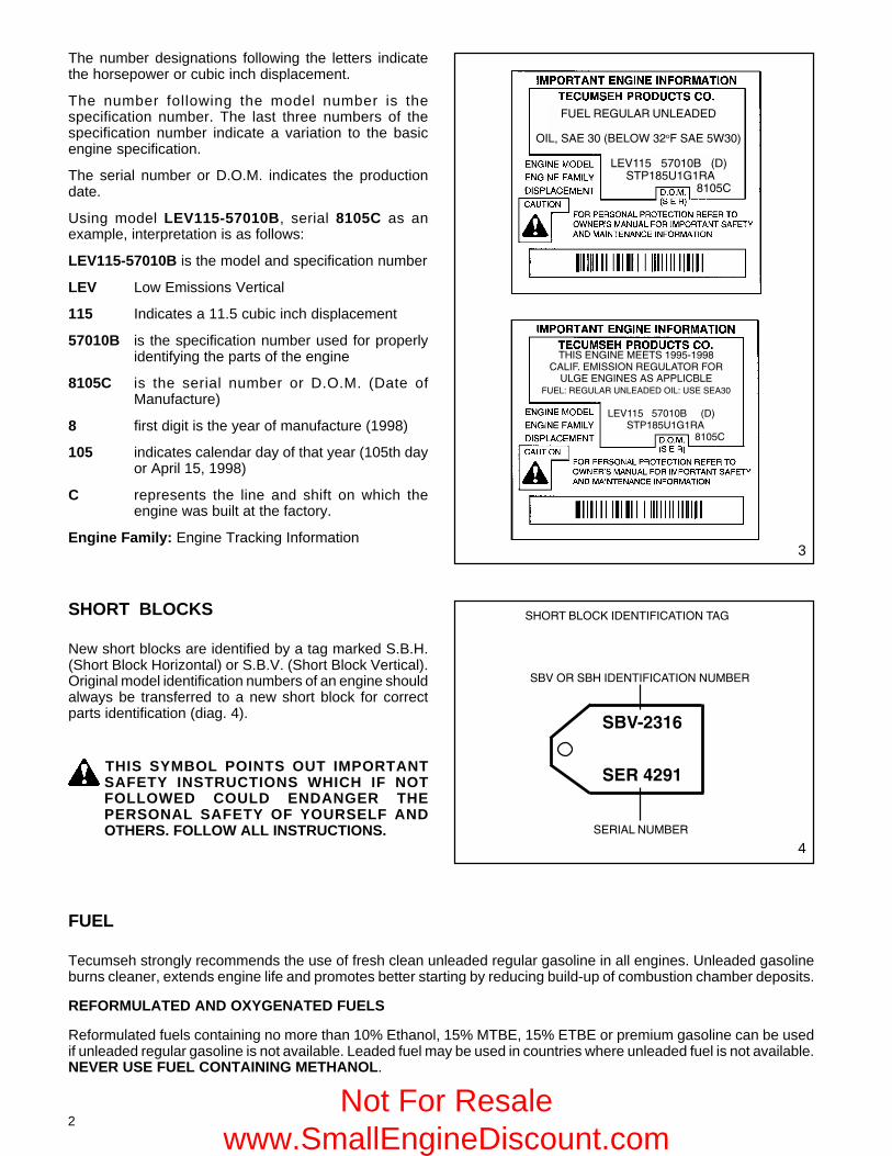
The number designations following the letters indicatethe horsepower or cubic inch displacement.
The number following the model number is thespecification number. The last three numbers of thespecification number indicate a variation to the basicengine specification.
The serial number or D.O.M. indicates the productiondate.
Using model LEV115-57010B, serial 8105C as anexample, interpretation is as follows:
LEV115-57010B is the model and specification number
LEV Low Emissions Vertical
115 Indicates a 11.5 cubic inch displacement
57010B is the specification number used for properlyidentifying the parts of the engine
8105C is the serial number or D.O.M. (Date ofManufacture)
8 first digit is the year of manufacture (1998)
105 indicates calendar day of that year (105th dayor April 15, 1998)
C represents the line and shift on which theengine was built at the factory.
Engine Family: Engine Tracking Information
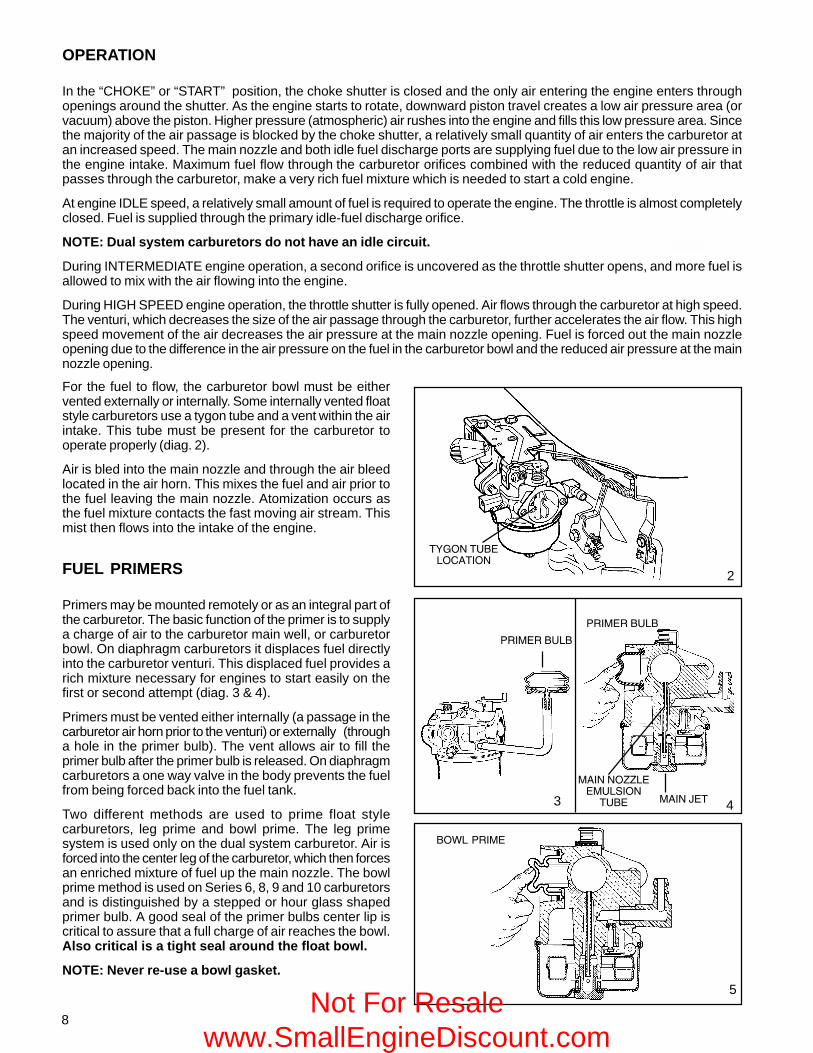
SHORT BLOCKS
New short blocks are identified by a tag marked S.B.H.(Short Block Horizontal) or S.B.V. (Short Block Vertical).Original model identification numbers of an engine shouldalways be transferred to a new short block for correctparts identification (diag. 4).
THIS SYMBOL POINTS OUT IMPORTANTSAFETY INSTRUCTIONS WHICH IF NOTFOLLOWED COULD ENDANGER THEPERSONAL SAFETY OF YOURSELF ANDOTHERS. FOLLOW ALL INSTRUCTIONS.
���������������
������������������ !���������"
��������������������� ������� �������"����������������������� #�� � �
�����������������������������������������������# ���
����������$��� ���% ��#�����&�$�������������������������������������
���'����������������'��������
�������������������� ������� ���������"������������������������ #�� � �
�����������������������������������������������������# ���
���������(������������������
��������
��������
�������$�
��������������������������$�
4
3
FUEL
Tecumseh strongly recommends the use of fresh clean unleaded regular gasoline in all engines. Unleaded gasolineburns cleaner, extends engine life and promotes better starting by reducing build-up of combustion chamber deposits.
REFORMULATED AND OXYGENATED FUELS
Reformulated fuels containing no more than 10% Ethanol, 15% MTBE, 15% ETBE or premium gasoline can be usedif unleaded regular gasoline is not available. Leaded fuel may be used in countries where unleaded fuel is not available.NEVER USE FUEL CONTAINING METHANOL.
Not For Resale www.SmallEngineDiscount.com

3
ENGINE OIL
Use a clean, high quality detergent oil. Be sure original container is marked: A.P.I. service SF thru SJ. The use ofmultigrade oil may increase oil consumption under high temperature, high load applications.
NOTE: DO NOT USE SAE10W40 OIL.
For summer (above 32°F, 0oC) use SAE 30 oil part # 730225 (1 quart, .946 liter container) in high temperature, highload applications.
S.A.E.10W30 is an acceptable substitute.
For winter (below 32°F, 0oC) use S.A.E. 5W30 oil part # 730226 (1 quart, .946 liter container)
S.A.E.10W is an acceptable substitute.
S.A.E. 0W30 should only be used when ambient temperature is below 0oF, -18oC.
CAPACITIES: EUROPA MODELSEngine Model Oz. mL. Oz. mL.LAV30-50, TVS75-120, LEV80-120 21 630 Vantage 21 630ECV100-120, TNT100-120 21 630 Prisma 21 630V & VH50, 60, 70 27 810 Synergy 21 630TVM 125, 140 27 810 Synergy "55" 27 810TVM & TVXL 170, 195, 220 32 960 Spectra 21 630VM70, 80, 100 32 960 Futura 21 630VH100 50 1500 Centura 21 630H & HSK30, 35, HS & HSSK40, 50 21 630 HTL 21 630H, HH & HSK50, 60, 70 19 570 BVS 21 630HM & HMSK70, 80, 100 26 720 BH Series 21 630
Geo Tech Series 35-50 21 630
Oil Change Intervals. Change the oil after the first two (2) hours of operation and every 25 hours thereafter, or moreoften if operated under dusty or dirty conditions, extreme temperature, or high load conditions.
Oil Check. Check the oil each time the equipment is used or every 5 hours. Position the equipment so the engine islevel when checking the oil.
CAUTION: REMOVE THE SPARK PLUG WIRE BEFORE DOING ANY SERVICE WORK ON THE ENGINE.
Oil Change Procedure: Locate the oil drain plug. On some units this plug is located below the deck through thebottom of the mounting flange. Other units drain at the base of the engine above the deck or frame. If access to thedrain plug is restricted by the equipment it may be necessary to drain the oil by tipping the mower in a position thatwould allow the oil to drain out of the fill tube.
On units that the drain plug is accessible, remove the plug and allow the oil to drain into a proper receptacle. Alwaysmake sure that drain oil is disposed of properly.
Once the oil is drained, reinstall the plug and fill the engine with new oil to the proper capacity.
TUNE-UP PROCEDURE.
The following is a minor tune-up procedure. When this procedure is completed, the engine should operate properly.Further repairs may be necessary if the engine's performance remains poor.
CAUTION: REMOVE THE SPARK PLUG WIRE BEFORE DOING ANY SERVICE WORK ON THE ENGINE.
1. Service or replace the air cleaner as needed.
2. Inspect the level and condition of the oil and change or add oil as required.
3. Remove the blower housing and clean all dirt, grass or debris from the intake screen, cylinder head, cylindercooling fins, carburetor, governor levers and linkage.
4. Make sure the fuel tank, fuel filter and fuel line are clean. Replace any worn or damaged governor springs orlinkage. Make the proper governor adjustments and carburetor presets where required.Not For Resale
www.SmallEngineDiscount.com

4
5. When replacing the spark plug, consult the parts breakdown for the proper spark plug to be used in the enginebeing serviced. Set the spark plug gap to .030" (.762 mm) and install the spark plug in the engine. Tighten thespark plug to 15 foot pounds of torque (20.4 Nm). If a torque wrench isn’t available, screw the spark plug in as faras possible by hand, and use a spark plug wrench to turn the spark plug 1/8 to 1/4 turn further if using the old sparkplug, or 1/2 turn further if using a new spark plug.
6. Make sure all ignition wires are free of abrasions or breaks and are properly routed so they will not rub on theflywheel.
7. Properly reinstall the blower housing, gas tank, fuel line and air cleaner assembly if removed.
8. Make sure all remote cables are properly adjusted for proper operation. See chapter 4 under "Speed Controls andLinkage".
9. Reinstall the spark plug wire, add fuel and oil as necessary, and start the engine.
STORAGE: (IF THE ENGINE IS TO BE UNUSED FOR 30 DAYS OR MORE)
CAUTION: NEVER STORE THE ENGINE WITH FUEL IN THE TANK INDOORS , IN ENCLOSED POORLYVENTILATED AREAS WHERE FUEL FUMES MAY REACH AN OPEN FLAME, SPARK OR PILOT LIGHTAS ON A FURNACE, WATER HEATER, CLOTHES DRYER OR OTHER GAS APPLIANCE.
Gasoline can become stale in less than 30 days and form deposits that can impede proper fuel flow and engineoperation. To prevent deposits from forming, all gasoline must be removed from the fuel tank and the carburetor. Anacceptable alternative to removing all gasoline is adding a fuel stabilizer to the gasoline. Fuel stabilizer (such asTecumseh's Part No. 730245) is added to the fuel tank or storage container. Always follow the mix ratio found on thestabilizer container. Run the engine at least 10 minutes after adding the stabilizer to allow it to reach the carburetor.
CAUTION: THE USE OF SOME ANTI-ICING ADDITIVES MAY CREATE A METHANOL FUEL BLEND. DONOT USE ADDITIVES THAT CONTAIN METHANOL. FUEL CONDITIONERS THAT CONTAIN ISOPROPYLALCOHOL IS RECOMMENDED.
Draining the Fuel System:
CAUTION: DRAIN THE FUEL INTO AN APPROVED CONTAINER OUTDOORS, AND AWAY FROM ANYOPEN FLAME OR COMBUSTION SOURCE. BE SURE THE ENGINE IS COOL.
1. Remove all gasoline from the fuel tank by running the engine until the engine stops, or by draining the fuel tank byremoving the fuel line at the carburetor or fuel tank. Be careful not to damage the fuel line, fittings, or fuel tank.
2. Drain the carburetor by pressing upward on the bowl drain (if equipped) which is located on the bottom of thecarburetor bowl. On carburetors without a bowl drain, the carburetor may be drained by loosening the bowl nut onthe bottom carburetor one full turn. Allow to completely drain and retighten the bowl nut being careful not todamage the bowl gasket when tightening.
3. If "Gasohol" has been used, complete the above procedure and then put one half pint of unleaded gasoline intothe fuel tank and repeat the above procedure. If Gasohol is allowed to remain in the fuel system during storage,the alcohol content will cause rubber gaskets and seals to deteriorate.
Change Oil: If the oil has not been changed recently, this is a good time to do it.
Oil Cylinder Bore:
1. Disconnect the spark plug wire and ground the wire to the engine. Remove the spark plug and put 1/2 ounce(14 ml) of clean engine oil into the spark plug hole.
2. Cover the spark plug hole with a shop towel.
3. Crank the engine over slowly several times.
CAUTION: AVOID SPRAY FROM SPARK PLUG HOLE WHEN SLOWLY CRANKING ENGINE OVER.
4. Install the spark plug and connect the spark plug wire.
Clean Engine: Remove the blower housing and clean all dirt, grass or debris from the intake screen, cylinder head,cylinder cooling fins, carburetor, governor levers and linkage.
Not For Resale www.SmallEngineDiscount.com

5
GENERAL INFORMATION
The air cleaner is the device used to eliminate dust and dirtfrom the air supply. Filtered air is necessary to assure thatabrasive particles are removed before entering the carburetorand combustion chamber. Dirt allowed into the engine willquickly wear the internal components and shorten the lifeof the engine.
Tecumseh engines use either a polyurethane or a paper-type air filter system. A polyurethane pre-cleaner or a flockedscreen may be used in conjunction with the main filter.Snow King® engines do not use an air filter.
Extremely dirty conditions may require more frequent filtercleaning or replacement.
OPERATION
The outer cover encapsulates the air filter element(s) andprevents large particles from entering the filter box. Air isfiltered through the pre-cleaner or flocked screen (if equipped)and the polyurethane or paper filter element. Pre-cleanersor flocked screens provide additional air cleaning capacity.
In Tecumseh's Kleen Aire® system, air is drawn in througha rotating screen or recoil cover to be centrifugally cleanedby the flywheel before the air is drawn into the air filter.
COMPONENTS
The cover holds the filter element and prevents large debrisfrom entering the filter element.
The polyurethane wrap pre-filter is used on XL or XL/Cengine models with paper filter elements.
The paper or polyurethane filter element is the mainfilter to trap dust and dirt. Dry-type paper elements havetreated paper folded for increased surface area and rubber-like sealing edges. The polyurethane filter uses an oil filmto trap fine particles found in dust.
The flocked screen is used as an additional filter on XL orXL/C engine models that use a polyurethane filter element.
TROUBLESHOOTING OR TESTING
If the engine's performance is unsatisfactory (needsexcessive carburetor adjustments, starts smokingabnormally, loses power), the first engine component to bechecked is the air cleaner. A dirt restricted or an oil soakedelement will cause noticeable performance problems. Apolyurethane element may be cleaned following the serviceprocedure listed under "Service" in this chapter. A paper-type air filter should only be replaced. A paper-type elementcannot have an oil film present on the paper. Follow theprocedure listed in the "Service" section of this chapter forreplacement. Re-try the engine after filter replacement orservice. If the problem persists after filter service, seeChapter 9 under "Engine Operation Problems" for additionalcauses.
CHAPTER 2 AIR CLEANERS
1
2
COVER
FOAMELEMENT
FLOCKED SCREEN
AIR CLEANERBODY
AIR CLEANERBODY
PAPERELEMENT
POLYURETHANEWRAP
COVER
(diag 1 & 2)
SEALING NUTS
Not For Resale www.SmallEngineDiscount.com

6
This type of air filter can be serviced when restricted with dust or dirt. Wash the filter or pre-cleaner in a liquid detergentand water solution until all the dirt is removed. Rinse in clear water to remove the detergent solution. Squeeze theelement (do not twist) to remove the excess water. Wrap the element in a clean cloth and squeeze it (do not twist) untilcompletely dry.
Re-oil the element by applying engine oil and squeezing it vigorously to distribute the oil. Roll the element in a cloth andsqueeze it (do not twist) to remove the excess oil.
Clean the air cleaner housing and cover being careful not to allow dirt to fall into the carburetor or intake pipe.
PAPER -TYPE FILTER ELEMENT
Paper type air filter elements can only be serviced by replacement. Do not attempt to clean a paper filter element.
3
AIR CLEANERBODY
1/2" (12.7 mm)FOAM
WITH FLOCKEDSCREEN
ATTACHED
FOAMELEMENT
1. Unlock the tabs or remove the screws, wingnuts orsnaps holding the air cleaner cover in place.
2. Remove the hex nuts holding the element down ifequipped. New nuts are supplied with a new filter andMUST be used for proper sealing.
3. Clean the excess contaminants out of the air cleanerbody before removing the old element.
4. Remove the old element and the polyurethane pre-cleaner if equipped.
5. On air cleaners that use a flocked screen under thepolyurethane element, remove the air cleaner assemblyfrom the carburetor before removing the flocked screen.This prevents dirt from entering the carburetor (diag 3).
6. Clean the inside of the cover and body, remove the oldgasket between the carburetor and the air cleanerassembly.
7. Reinstall the air cleaner assembly using a new gasket.
8. Use the reverse procedure for reassembly. Wheninstalling the foam polyurethane pre-cleaner, make surethe seam is installed to the outside to prevent gapsbetween the paper element and the pre-cleaner.
POLYURETHANE-TYPE FILTER ELEMENT
SERVICE
Service on the polyurethane element (cleaning and oiling) is recommended every three months or every twenty fiveoperating hours, whichever comes first. Extremely dirty or dusty conditions may require daily cleanings.
The paper filter element should be replaced at least once a year or more frequently if operated in dusty or dirty conditions.
NOTE: NEVER RUN THE ENGINE WITHOUT THE COMPLETE AIR CLEANER ASSEMBLY INSTALLED ON THEENGINE. ALWAYS REPLACE THE FILTER ELEMENT WITH THE PROPER TECUMSEH ORIGINAL REPLACEMENTPART.
DISASSEMBLY PROCEDURE
Not For Resale www.SmallEngineDiscount.com

7
CHAPTER 3 CARBURETORS AND FUEL SYSTEMS
GENERAL INFORMATION
Tecumseh uses two basic types of carburetors, float and diaphragm type carburetors. Float type carburetors use ahollow float to maintain the operating level of fuel in the carburetor. Diaphragm type carburetors use a rubber-like diaphragm.One side is exposed to intake manifold pressure and the other side to atmospheric pressure. The diaphragm provides thesame basic function (maintaining the proper fuel level in the carburetor) as the float.
An advantage of the diaphragm carburetor over the float style is that the diaphragm carburetor will allow the engine tooperate at a greater degree of tiltability.
Tecumseh carburetors are identified by a manufacturing number and date code stamped on the carburetor as illustrated(diag. 1).
When servicing carburetors, use the engine model andspecification number to obtain the correct carburetor partnumber. An alternate method of finding the correctcarburetor part number is to use the manufacturing numberstamped on the carburetor and convert this number to apart number. In the carburetor section of the Master PartsManual, Microfiche Catalog or computer parts look-upsystem, a cross reference chart will convert a carburetormanufacturing number to a Tecumseh part number.
Complete carburetor replacement may be accomplishedwith a standard service carburetor. A standard servicecarburetor is a basic carburetor that may require the useof original carburetor parts or additional new parts to adaptto the specification. An instruction sheet is provided withthe new service carburetor or see “SERVICE” in this chapter. 1
CAUTION: DRAIN THE FUEL INTO AN APPROVED CONTAINER OUTDOORS, AND AWAY FROM ANY OPENFLAME OR COMBUSTION SOURCE. BE SURE THE ENGINE IS COOL.
������������������� ������� ����������� �� � �� ��������� ����������������������� ���������������������������������������������������� �� �������� ��
1. Remove the air filter, heater box, or air cleaner assembly if applicable to visually check that the choke shuttercompletely closes or check to see if fuel comes out of the main nozzle during priming.
2. If the fuel flow from the tank is adequate and no fuel is evident during priming, the carburetor will need to beremoved for service. See “Service” in this chapter or consult the “Carburetion Troubleshooting” chart to diagnosecarburetor symptoms. Improper fuel flow indicates the fuel, fuel line, filter or tank require cleaning or replacement.
3. Check the engine compression using a commercially available compression tester and follow the tester’srecommended procedure. Low compression, a dry spark plug, adequate fuel flow, and a known good functionalcarburetor indicates an internal engine problem exists. See under “Troubleshooting.”
4. A wet spark plug indicates fuel is being supplied by the carburetor. The engine may be flooded by a restrictedair filter, carbon shorted or defective spark plug, excessive choking or over priming, improperly adjusted ordefective carburetor. With the spark plug removed and a shop towel over the spark plug hole, turn the engineover slowly 3 or 4 times to remove excess gasoline from the engine cylinder.
CAUTION: KEEP ALL COMBUSTIVE SOURCES AWAY. AVOID THE SPRAY FROM THE SPARK PLUGHOLE WHEN CRANKING THE ENGINE OVER.
5. Replace the air filter if restricted or oil soaked. Replace the spark plug if questionable. Install the spark plug andhigh tension lead and try to start the engine.
6. If the engine floods and fails to start, the carburetor will require service. See the proceeding “CarburetionTroubleshooting” chart for additional causes. If the carburetor is functioning properly the problem may be ignitiontiming related. See “Troubleshooting" under "Ignition”.
����������� !��" �# ��$��%#�!�%�"�&
�%$'��
�����
���
�
!��'%��� �(����! (�
$��%#�!�%�"�&�%$'��
Not For Resale www.SmallEngineDiscount.com
8
OPERATION
In the “CHOKE” or “START” position, the choke shutter is closed and the only air entering the engine enters throughopenings around the shutter. As the engine starts to rotate, downward piston travel creates a low air pressure area (orvacuum) above the piston. Higher pressure (atmospheric) air rushes into the engine and fills this low pressure area. Sincethe majority of the air passage is blocked by the choke shutter, a relatively small quantity of air enters the carburetor atan increased speed. The main nozzle and both idle fuel discharge ports are supplying fuel due to the low air pressure inthe engine intake. Maximum fuel flow through the carburetor orifices combined with the reduced quantity of air thatpasses through the carburetor, make a very rich fuel mixture which is needed to start a cold engine.
At engine IDLE speed, a relatively small amount of fuel is required to operate the engine. The throttle is almost completelyclosed. Fuel is supplied through the primary idle-fuel discharge orifice.
NOTE: Dual system carburetors do not have an idle circuit.
During INTERMEDIATE engine operation, a second orifice is uncovered as the throttle shutter opens, and more fuel isallowed to mix with the air flowing into the engine.
During HIGH SPEED engine operation, the throttle shutter is fully opened. Air flows through the carburetor at high speed.The venturi, which decreases the size of the air passage through the carburetor, further accelerates the air flow. This highspeed movement of the air decreases the air pressure at the main nozzle opening. Fuel is forced out the main nozzleopening due to the difference in the air pressure on the fuel in the carburetor bowl and the reduced air pressure at the mainnozzle opening.
�)& ���%'�� !��" �
2
*�"$���'%�'
4
*�"$���'%�'
3
$�"��� ++���$%�," ��%'� $�"��-��
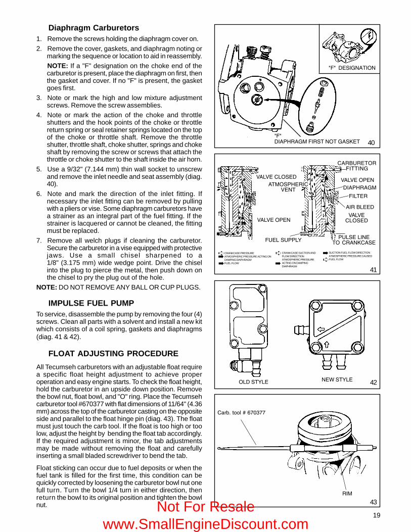
For the fuel to flow, the carburetor bowl must be eithervented externally or internally. Some internally vented floatstyle carburetors use a tygon tube and a vent within the airintake. This tube must be present for the carburetor tooperate properly (diag. 2).
Air is bled into the main nozzle and through the air bleedlocated in the air horn. This mixes the fuel and air prior tothe fuel leaving the main nozzle. Atomization occurs asthe fuel mixture contacts the fast moving air stream. Thismist then flows into the intake of the engine.
FUEL PRIMERS
Primers may be mounted remotely or as an integral part ofthe carburetor. The basic function of the primer is to supplya charge of air to the carburetor main well, or carburetorbowl. On diaphragm carburetors it displaces fuel directlyinto the carburetor venturi. This displaced fuel provides arich mixture necessary for engines to start easily on thefirst or second attempt (diag. 3 & 4).
Primers must be vented either internally (a passage in thecarburetor air horn prior to the venturi) or externally (througha hole in the primer bulb). The vent allows air to fill theprimer bulb after the primer bulb is released. On diaphragmcarburetors a one way valve in the body prevents the fuelfrom being forced back into the fuel tank.
Two different methods are used to prime float stylecarburetors, leg prime and bowl prime. The leg primesystem is used only on the dual system carburetor. Air isforced into the center leg of the carburetor, which then forcesan enriched mixture of fuel up the main nozzle. The bowlprime method is used on Series 6, 8, 9 and 10 carburetorsand is distinguished by a stepped or hour glass shapedprimer bulb. A good seal of the primer bulbs center lip iscritical to assure that a full charge of air reaches the bowl.Also critical is a tight seal around the float bowl.
NOTE: Never re-use a bowl gasket.5
' .��*�"$�
Not For Resale www.SmallEngineDiscount.com

9
#� ��
!/ 0�,/%����
�/� ����,/%����
"(�����"�'���(
"��������(����(�,���
7
IMPULSE FUEL PUMPS
Impulse fuel pumps may either be mounted externally ontothe carburetor fuel inlet or remotely mounted. These pumpsare connected in the fuel line between the fuel supply andthe carburetor or directly to the fuel inlet.
Impulse fuel pumps are operated by crankcase impulsescreated by the up and down movement of the piston. Ahose called a pulse line connects the fuel pump diaphragmchamber to the crankcase and transmits these impulsesto the pump diaphragm. The impulses actuate thediaphragm and flap valves to lift the fuel from the fuel tankto the carburetor (diag. 6).
FLOAT STYLE CARBURETORS
A float is used to maintain the operating volume of fuel inthe carburetor bowl. As the fuel is used by the engine, thefuel volume in the carburetor bowl drops and the float movesdownward. This allows the inlet needle valve to move offthe sealing seat. Fuel flows by gravity or a pulse pump intothe fuel bowl. As the fuel volume in the bowl again rises, itraises the float. This upward float motion moves the inletneedle valve to the closed position. When the needlecontacts the seat, the fuel flow is stopped. The taperedend of the inlet needle varies the fuel flow rate so that thefuel volume in the carburetor bowl will remain constant (diag.7). The float height is set according to the service procedure.
DIAPHRAGM (PRESSURE DIFFERENTIAL)CARBURETORS
This type of carburetor uses a rubber-like diaphragm whichis exposed to intake manifold pressure on one side and toatmospheric pressure on the other. Tecumseh diaphragmcarburetors use the diaphragm as a metering device. Asthe intake manifold pressure decreases due to downwardpiston travel, the atmospheric pressure on the vented sideof the diaphragm moves the diaphragm against the inletneedle. The diaphragm movement overcomes the springtension on the inlet needle and moves the inlet needle offthe seat. This permits the fuel to flow through the inletvalve to maintain the correct fuel volume in the fuel chamber.The inlet needle return spring closes the inlet valve whenthe pressure on the diaphragm equalizes or a pressurehigher than atmospheric exists on the intake side (upwardpiston travel). The diaphragm meters a correct fuel volumein the fuel chamber to be delivered to the mixing passagesand discharge ports (diag. 8).
A main or idle adjustment needle may be replaced by aninternally fixed jet on some models.
The main nozzle contains a ball check valve. The mainpurpose of this ball check is to eliminate air being drawndown the main nozzle during idle speeds and leaning theidle mixture.
An advantage of the diaphragm carburetor over the floatsystem is that the diaphragm carburetor increases the anglethat the engine may be operated at.
8
6
"(���(-%,�$���
$�"���"�'���(
�/� ����,/%����
!/ 0�,/%����
$�"��(-%,�$��� ("�*/��&$
!/�!0�'���
"(���(-%,�$���
���(�����(,�����,,�$'�)
$�"��� ++���$%�," ��%'�
$�"��(-%,�$���
"(�����(*� &��,," �
/ ��,
Not For Resale www.SmallEngineDiscount.com

10
*NON METALLIC ITEMS - CAN BE DAMAGED BY HARSH CARBURETOR CLEANERS
Check ball is not serviceable on somemodels.
Remove adjustment screw. To adjust20° slant engines, the engine must bemounted in its normal 20° slant posi-tion.
Loosen screw until it just clears throttlelever, then turn screw in 1 turn.
Place detent reference mark to properlocation.
Check spring for return action and bind-ing.
Remove welch plug and blow airthrough air passages.
WELCH PLUG (If Present)
*MAIN NOZZLE CHECK BALL (If Present)
*IDLE MIXTURE ADJUSTMENT SCREW AND "O" RING (If Present)
*MAIN MIXTURE ADJUSTMENT SCREW AND "O" RING (If Present)
THROTTLE SHAFTRETURN SPRING
THROTTLE SHAFT AND LEVER
DETENT REFERENCE MARKON THROTTLE SHUTTER
THROTTLE SHUTTER
IDLE SPEED ADJUSTMENT SCREWCheck shaft for binding. Position shut-ter opening towards inlet fitting side orair horn.
Blow air through passage.
Part of inlet fitting. If fuel is restricted,clean or replace fitting.
Bulb primer models have Viton* oneway valve, in or behind fitting.
Remove and replace.
Proper installation of assembly is im-portant.
Gasket and diaphragm sequence maybe reversed on some models. Head ofrivet must touch inlet needle. Rivet ishooked into inlet needle control lever onsome models.
Hole must be clean. On models withbulb primer, vent hole is very small andis located off center.
CHOKE SHAFT AND LEVER
CHOKE SHUTTER
MAIN NOZZLE
*DIAPHRAGM GASKET
*DIAPHRAGM
ATMOSPHERIC VENT HOLE
*INLETFITTINGSCREEN
*INLETFITTING
*INLET SEATGASKET
*INLET NEEDLESEAT ANDSPRINGASSEMBLY
9
COMPONENTS
IDLE AND INTERMEDIATEAIR BLEED
THROTTLE SHAFT AND LEVER
THROTTLE SHUTTER
DETENTREFERENCE MARK
THROTTLE SHAFTRETURN SPRING
IDLE AND INTERMEDIATEORIFICES
IDLE AND INTERMEDIATEFUEL CHAMBER (COVEREDWITH WELCH PLUG)
IDLE AND INTERMEDIATEFUEL MIXTURE PASSAGE
*IDLE ADJUSTMENT SCREWAND "O" RING
IDLE SPEED ADJUSTMENT
CHOKE SHAFTAND LEVER
CHOKE PLATE
ATMOSPHERIC VENT
SOFT BAFFLE PLUG
Blow air through passage. Loosen screw until it just clears throttlelever, then turn screw in one turn.
Removable on emission carbs. non-metallic only.
Check shaft for looseness or binding.Shutter must be positioned with detentreference marks on top parallel withshaft and to the right or 3 o'clock posi-tion.
Check spring for return actionand binding.
Remove idle adjustment screw. Checkneedle tip and condition of "O" ring.Remove welch plug and blow out allpassages.
FLOAT
FLOAT BOWL
*GASKET
IDLE FUEL TRANSFER PASSAGEAND ANNULAR GROOVE
Check shaft for binding position open-ing to bottom of air horn.
Blow air through passage. Do not re-move restrictor if present.
HIGH SPEEDAIR BLEED
INLETNEEDLE CLIP(If Present)
Must hook over float tab.
*FLOAT BOWL GASKET
Replace.
*INLET NEEDLE AND SEAT
INLETFITTING
FLOATSHAFT
Proper installation is important.
NUT AND MAIN ADJUSTMENT SEAT*MAIN ADJUSTMENT SCREW AND"O" RING SEAL
IDLE AND INTERMEDIATEFUEL TRANSFER PASSAGE
METERING ROD OR PIN INFUEL TRANSFER PASSAGE
BALL PLUG
CUP PLUG
IDLE AND INTERMEDIATEFUEL TRANSFER PASSAGE
IDLE AND MAIN FUEL PICK UP ORFICE*NON METALLIC ITEMS - CAN BE DAMAGEDBY HARSH CARBURETOR CLEANERS
NOTE: On models which have meteringrods, do not install idle adjustment screwwith carburetors upside down, as pinwill obstruct movement of adjustmentscrew causing damage
(DO NOT REMOVE) If the carburetor is used on a 20° slantengine, the engine must be in its normal20° slanted position for adjustment.
Check float for leaks or dents. Cleanbowl and adjust float level position gas-ket or gaskets.
Check needle for damage and "O" ringfor cracks. Clean all passages in nutwith compressed air.
10
IDLE
MAIN NOZZLE(EMULSION TUBE)
IDLE PROGRESSIONHOLE
IDLE AIR BLEED
Not For Resale www.SmallEngineDiscount.com

11
CARBURETOR IDENTIFICATION
Tecumseh has a variety of carburetors. To help identifythese carburetors here are some simple procedures tofollow.
DUAL SYSTEM CARBURETORS
The easiest way to identify the dual system carburetor isby the presence of a large primer bulb located on the sideof the carburetor. The absence of adjustment needles helpto identify the carb as well. The dual system carburetor isused on 4-cycle vertical crankshaft rotary mower engines.(diag. 11).
SERIES 1 CARBURETORS
Series 1 carburetors come in a variety of styles. They areused on both 2 and 4 cycle vertical and horizontal shaftengines in the 2 through 7 h.p. range. It is a float stylecarburetor with a smaller venturi than the Series 3 and 4carburetors. Some will have an adjustable idle and mainand others will have a fixed main with an adjustable idle.There are also some fixed speed applications that will onlyhave a fixed main system and the idle system will not bedrilled. (diag. 12).
NOTE: Emissionized carburetors will have a fixed jet.
SERIES 3 & SERIES 4 CARBURETORS
Series 3 and 4 carburetors are generally used on 8 through12.5 horsepower 4-cycle engines. The venturi size of thesecarburetors are larger than Series 1 and Dual SystemCarburetors. The quickest way to identify these carburetorsis by the presence of bosses on each side of the idle mixturescrew. To identify the Series 3 from a Series 4, view thecarburetor from the throttle end. The Series 3 has (1) screwsecuring the throttle plate and the Series 4 uses (2) screws.(diag. 13 - 15)
DIAPHRAGM CARBURETORS
The diaphragm carburetors are unique. These carburetorscan be operated at a more severe angle than float stylecarburetors. They still require that the fuel supply be locatedin a position that allows it to be gravity fed. Its mostdistinctive feature is the lack of a fuel bowl. (diag. 16).
NOTE: Emissionized carburetors will have a fixed jet.
11
12
13
14 15
16
,��"�,�1 ,��"�,�2
' ,,�,
Not For Resale www.SmallEngineDiscount.com

12
17
18
&��)!�**�(�#"3�(
-��
19
$"3"�&�.���!�,��'%��� �$�!/"��(
20
"(���-��!�,��'%��� �$�!/"��(
21
SERIES 6 CARBURETORS 4-CYCLE
Series 6 carburetors are used on 2 and 4-cycle engines.They have a larger venturi than the dual system carburetorand use a simple fixed idle system. Series 6 carburetorsused on both vertical and horizontal applications arenonadjustable. The 4 cycle version pictured has a steppedprimer bulb. (diag. 17).
SERIES 8
The Series 8 carburetor has both a fixed main and idlecircuit. The fixed idle system uses a restricted jet thatmeters the fuel. The idle restrictor jet will be capped toprevent access unless removed. The fixed main jet is partof the bowl nut. A ball plug is visible from the bottom, whichseals the metering passage. This carburetor also has aserviceable main nozzle emulsion tube. It also has astepped primer bulb to assist in starting. (diag. 18)
SERIES 9
The Series 9 carburetor uses the same body as the Series8 but has a simple fixed idle system, identical to the oneused on the Series 6 carburetor. It has the idle dischargeport located at the 7 o'clock position on the throttle end ofthe carburetor. Identify this carburetor by the stepped primerbulb, the presence of a non-drilled idle mixing well and aserviceable main nozzle emulsion tube. (diag. 19)
SERIES 10 (EMISSION)
The Series 10 carburetor is identical to the Series 8carburetor with the addition of a choke to assist in coldweather starts. It also has a fixed idle and main. The idlerestrictor jet is capped to prevent access unless the cap isremoved. The fixed main jet is part of the bowl nut. A ballplug is visible from the bottom, which seals the meteringpassage. This carburetor also has a serviceable main nozzleemulsion tube and a stepped primer bulb to assist instarting. (diag. 20)
SERIES 11
The Series 11 carburetor is used on most LEV modelengines. This carburetor contains a patented auto-enrichment system for improved starting and performanceof a cold engine. The system contains a fuel well that isfilled as part of the priming procedure and emptied as theengine runs in the first minute. This added fuel providessmooth operation of today’s emission grade engines. Thecarburetor can be identified externally by the BLACKcolored restrictor cap (diag. 21). Internally the standardSeries 11 is identified by the plugged passage as shown.
'��!0�!�*
/ ���*�%&&�(
Not For Resale www.SmallEngineDiscount.com

13
ENGINETROUBLESHOOTING
Engine Will Not Start
Check For Spark
Wet DryCheck If Spark Plug Is Wet or Dry
Defective Spark Plug Check Fuel Supply and FuelCap Vent
Restricted Air Filter Restriction in Fuel System(filter, screen)
Improper or Stale Fuel Carburetion Problem
Sheared or Partially ShearedFlywheel Key Poor Compression
Carburetion Problems Due toFlooding, Over Priming, etc.
Ignition System
SERIES 11 BRIDGED
Externally this carburetor looks identical to the standardseries 11 with the black restrictor cap. The difference isinternal through the addition of a second idle feed passagewith a restrictor as shown. This extra passage improvesrun quality during light load engine operation (diag. 22).
NON-TECUMSEH CARBURETORS
DELLORTO CARBURETOR
The Dellorto carburetor is similar to the dual systemcarburetor. It has no adjustments and has a primer assiststart. It has a noncorrosive float and the needle is vitontipped, eliminating the viton seat found in the dual systemcarburetor. The angle of the fuel inlet is adjustable andattached to the carburetor body with a banjo bolt. Thiscarburetor is used on some TVS rotary lawnmowerengines.
22
23
'��!0�!�*
�((�(��,��"!� �
Not For Resale www.SmallEngineDiscount.com

14
� ��������
��������
*���������#����
�����!�������
&����
�����������!���
,������.��
!�������
# ���� � �
*������
*����
�����������4 �
����'��
��������
(��������
�����5 5��� ��
� �������
������
�������
(�����
(��������
,�������(�����'���
!���
(��������
%�����(��
����������
�������
*������� �
#��������4 �
#��*���6�
��������
"���*���
��������
(�����
��7��� �
����
" �������#����
/����
$�� ���88�
��������
(������,���
����� ��,��
#��" ���*����
�����"��
����� ��������� ��� ����������������� � ��������
� � � �� � �
� � �
� � �
� �
�
� �
�
� � � � � � �
� � � � �
� � �
� � � � � �
� � � � �
�
� �
� � �
�
� � �� � �
� � �
� �
�� �
� � � ��
�
�
� � � ��
� � ��
��
�
�
�
� �
� �
�
.������� ���/���,��/������
/���
,����� �
#�������!�������
� �� #�����
.��������"��
"�����������!����
/ ���6�������"��
"���#����6��
.������������6��
9������������6���
���*���
/ �����/���,��
� ���������!����
� �� 9�6����
CARBURETIONTROUBLESHOOTING
Not For Resale www.SmallEngineDiscount.com

15
TESTING
1. After repeated efforts to start the engine using the procedure listed in the operator’s manual fail, check for spark byremoving the high tension lead and the spark plug. Install a commercially available spark plug tester and check forspark. If spark is evident and acceptable, proceed to step 2. If no or weak spark, see Chapter 8 under "Testing".
2. Visually inspect the spark plug for a wet condition indicating the presence of gasoline in the cylinder.
3. If the spark plug is dry, check for restrictions in the fuel system before the carburetor. If the spark plug is wet,continue with step # 7. Check to see if the fuel cap vent is open. With a proper draining receptacle, remove the fuelline clamp on the carburetor fuel inlet and pull the fuel line off the fitting to examine the fuel flow and fuel condition.
4. Remove the air cleaner element or air cleaner assembly to visually check that the choke shutter completely closesor check to see if fuel comes out from the main nozzle during priming.
5. If the fuel flow is adequate and no fuel is evident during priming, the carburetor will need to be removed for service. See“Service” in this chapter or consult the “Carburetion Troubleshooting” chart if other problems exist. Improper fuel flowindicates the fuel, fuel line, filter or tank require cleaning or replacement.
6. Check the engine compression using a commercially available compression tester and follow the tester’s recommendedprocedure. Low compression, a dry spark plug, adequate fuel flow, and a known good functional carburetor indicatesan internal engine problem exists. See Chapter 9 under “Engine Operation Problems.”
7. A wet spark plug indicates fuel is being supplied by the carburetor. The engine may be flooded by a restricted air filter,carbon shorted or defective spark plug, excessive choking or over priming, improperly adjusted or defective carburetor,or the wrong ignition timing. With the spark plug removed and a shop towel over the spark plug hole, turn the engineover slowly 3 or 4 times to remove excess gasoline from the engine cylinder.
CAUTION: KEEP ALL COMBUSTIVE SOURCES AWAY. AVOID THE SPRAY FROM THE SPARK PLUGHOLE WHEN CRANKING THE ENGINE OVER.
8. Replace the air filter if restricted or oil soaked. Replace the spark plug if questionable. Install the spark plug and hightension lead and retry starting the engine.
9. If the engine floods and fails to start, the carburetor may require service. See the preceding “Carburetion Troubleshooting”chart for additional causes. If the carburetor is functioning properly the problem may be ignition timing related. SeeChapter 8 under “Ignition Troubleshooting.”
SERVICE
CARBURETOR PRE-SETS AND ADJUSTMENT
NOTE: EMISSION GRADE CARBURETORS HAVE FIXED IDLE AND MAIN JETS. THE ABSENCE OF THE ADJUSTINGSCREW INDICATES A FIXED JET OR RESTRICTOR AND NO ADJUSTMENT IS NECESSARY. THE IDLE RESTRICTORON AN EMISSIONS CARBURETOR APPEARS AS AN ADJUSTABLE SCREW. THIS IS NOT ADJUSTABLE ANDMUST REMAIN TIGHT FOR PROPER OPERATION.
The idle on an emission is metered using a threadedrestrictor (see Illustration). Proper torque of this screw iscritical and should be torqued to 5-8 in. lbs. or .5 to 1 nm,if not, it may vibrate loose. When the restrictor is placed inthe idle circuit passage it is capped with a tamper resistantplastic cap. Tampering is considered the rejetting ormodification through resizing of the jet. If the jet isremoved for cleaning it must be recapped to preventtampering when it is re-installed.
"(�����,��"!� �
!�*
Before adjusting any mixture screws the necessary carburetor presets should be made. Check for the proper governoradjustments as outlined in Chapter 4. Identify the correct carburetor model and manufacturer to find locations of the highand low speed adjustment screws. Check the throttle control bracket for proper adjustment allowing a full choke shutterposition. See Chapter 4 under "Speed Controls and Linkage". Check to see if the normal maintenance procedures havebeen performed (oil changed, fresh fuel, air filter replaced or clean). Consult microfiche card #30 to find the correct R.P.M.settings for the engine, or consult Service Bulletin #107 for the revised safety specification for rotary type power lawnmowers. Start the engine and allow it to warm to operating temperature. The carburetor can now be adjusted.
Not For Resale www.SmallEngineDiscount.com

16
PRE-SETS AND ADJUSTMENTS
(TECUMSEH AND WALBROCARBURETORS)
NOTE: OVERTIGHTENING WILL DAMAGE THE TAPERPORTION OF THE NEEDLE. All adjustments should bemade with the carburetor in the operating position.
Turn both the main and idle mixture adjusting screws in(clockwise) until finger tight.
Now back the mixture screws out (counterclockwise) toobtain the pre-set figure in the chart shown at right.
"(���$"3�%��,!��.
SERIES 1 DIAPHRAGM
$�"��$"3�%��,!��.
"(���$"3�%��,!��.
$�"��$"3�%��,!��.
"(���$"3�%��,!��.
$�"��$"3�%��,!��.24 25 26
SERIES 3 & 4
$"3"�&�.���!�,��'%�� �$�!/"��(
(%���,),��$���(�,��"�,�:
� �6�(-%,��'��*�"$������� �!/ 0� 27 !�**�(�#"3�(�-�� 28
,��"�,�; ,��"�,�<=
29 30"(���-��
!�,��'%��� ��$�!/"��(
,��"�,�>��<<�?�'�"(&�(�<<
FINAL ADJUSTMENTS (NON EMISSION ENGINES)
Start the engine and allow it to warm up to normal operating temperature (3 - 5 minutes). Set the speed control to theHIGH or FAST position. From the recommended preset position, turn the main mixture adjustment screw in (clockwise)slowly until the engine begins to run erratic (lean). Note the position of the screw. Now, turn the screw out (counterclockwise)until the engine begins to run erratic (rich). Turn the screw in (clockwise) midway between these two positions. This willbe the best setting. (diag. 24, 25 & 26).
Set the speed control to the IDLE or SLOW position. Adjust the idle mixture screw following the same procedure used toadjust the main mixture adjustment screw.
TECUMSEH CARBURETORS
1 turn 1 turnAll models with diaphragm-typecarburetors
All models with float-typecarburetors
Engine Model Main Pre-set Idle Pre-set
1-1/2 turn 1 turn
Tecumseh Carburetors
Walbro Carburetors
Carburetor Model Number
LMH
LMK
WHG & LME
1-1/2 turn 1-1/2 turn
1-1/4 turn 1-1/4 turn
Fixed 1 turn
If further adjustment is required, the main adjustment should be made under a loaded condition.
If the engine stops or hesitates while engaging the load (lean), turn the main mixture adjusting screw out (counterclockwise)1/8 turn at a time, testing each setting with the equipment under load, until this condition is corrected.
If the engine smokes excessively (rich), turn the main adjusting screw in (clockwise) 1/8 turn at a time, testing eachsetting with the equipment under load, until this condition is corrected.
After the main mixture screw is set, move the speed control to the IDLE or SLOW position. If the engine does not idlesmoothly, turn the idle mixture screw 1/8 turn either in (clockwise) or out (counterclockwise) until engine idles smoothly.
Recheck the high and low R.P.M. setting and adjust as necessary.NON-ADJUSTABLE CARBURETORS
!�**�(�"(����,��"!� �
!/ 0�
Not For Resale www.SmallEngineDiscount.com

17
DISASSEMBLY PROCEDURE
NOTE: Engines which are identified as compliant with CARB (California Air Resources Board) or EPA (USEnvironmental Protection Agency) regulations can NOT be changed from the factory settings unless specificallyauthorized.
FLOAT STYLE CARBURETORS
� �&���(� #�!�"*� .��(�!/ 0�
!�"* *�����(� #�!�"*
�/� ������(
!/ 0���(
31
33
32
1. Note or mark the high and low mixture adjusting screwsto aid in reassembly (if applicable). Remove the highspeed adjusting screw, bowl nut, and float bowl.Remove the idle mixture screw assembly.
2. Note the position of the spring clip on the inlet needleand float, the long end of the clip must face toward thechoke end of the carburetor. Remove the float hingepin with a needlenose pliers. Some carburetors use afloat dampening spring to aid the inlet valve inmaintaining a steady position during rough serviceapplications. Note the position of the hooks beforeremoving the float hinge pin (diag. 31).
3. Remove the float, clip, and inlet needle.
4. Remove the inlet needle seat using the Tecumsehcarburetor tool #670377 as shown. Push the hookthrough the hole in the center of the seat to remove it.(diag. 32).
5. Note or mark the action of the choke and throttleshutters, and/or the hook points of the choke or throttlereturn spring, or seal retainer springs located on thetop of the choke and/or throttle shaft. Remove thethrottle shutter, throttle shaft, choke shutter, springsand choke shaft by removing the screw(s) that attachthe throttle or choke shutter to the shaft inside the airhorn.
6. Remove the primer bulb (if equipped) by grasping itwith a pliers and pulling and twisting out of the body.Remove the retainer by prying and lifting it out with ascrewdriver. Do not re-use the old bulb or retainer (diag.33).
7. Some Tecumseh float style carburetors have a damperspring which is installed as shown. (diag. 34)
34
Use carb. tool# 670377
Not For Resale www.SmallEngineDiscount.com

18
8. Remove all welch plugs if cleaning the carburetor.Secure the carburetor in a vise equipped with protectivejaws. Use a small chisel sharpened to a 1/8"(3.175 mm) wide wedge point. Drive the chisel into theplug to pierce the metal, then push down on the chiselto pry the plug out of the hole (diag. 35).
NOTE: DO NOT REMOVE ANY BALL OR CUP PLUGS(diag. 37).
9. Note the direction of the inlet fitting. If necessary theinlet fitting can be removed. (See page 24).
10. The main nozzle on Series 8 and Series 9 carburetorscan be removed by pressing the tube outward from theventuri thru the center leg. This nozzle is non-metallicand has an "O" ring seal on the top and bottom end ofthe tube. Do not remove a main nozzle that is made ofbrass from any Tecumseh carburetor. These arepressed in at the factory to a specific depth. Whenremoving the nozzle, the top "O" ring may not comeout with the tube. The "O" ring must be removed andplaced on the nozzle before it is placed back into thecenter leg or it will not seal properly. (diag. 38)
11. Servicing the standard series eleven and bridgedmodel.When servicing the series eleven DO NOT soak it indipping type carburetor cleaners, use only spraycleaner or standard solvent tank cleaners. Propercleaning requires removal of both welch plugs andcleaning of the restictor(s) as equipped.
The standard series eleven has one restictor in theextended prime well as shown (diag. 36). The Bridgedseries eleven has an additional restrictor on the idleleg of the carburetor as shown (diag. 37). Both arecleaned using spray carburetor cleaner, compressedair and soft tag wire no larger than .012 inch (.3mm) ordamage will occur.
The main nozzle on some Walbro carburetors areremovable for service. If you remove it, a service nozzlewith the under cut fuel passage must be installed orproblems will occur (diag. 39).
35
�"&"����$�"��� ++��( �� ����%,�
%�(��!%����%���&� 4�
39
38
37
5 5��"�&�"��&� 4�
5 5��"�& ��� *� #�,��*@"��&� 4�A
� ��%,�(� ��,��"�,�B ��4�!� ��!��',�
5 5��"�&
,$����!/",��
*�)� %�*�%&
( �� ����� .!/",���* "��� �,��"0�!��'%��� �' ()� �!/�������(%!�� ,$����!/",��
.��!/�*�%&�� �'���$ 4�(
*"��!��*�%&�."�/��"*
�' %��<C>5@1�<BD���A�."(�
( �� ����$ 4��*�%&,
'����*�%& ����,��"!� ��/ ��"#�'�"(&�(�,��"�,�<<
"(���#%���*�,,�&���(%!�" ��� (� "�,"(�
� ��$�!/"��(� ��,��"�,�<<
'��,,� ��'����*�%&
,��4"!��$�"��� ++����%,�'��
36
.��!/�*�%&
�3���(�(*�"$��#%��!/�$'��
�3�����(�*�"$�#%���*�,,�&�@,%**�"�,�#%���#������&"���,����A
$�"��-��#%��� "����
.��!/�*�%&
��,��"!� �
Not For Resale www.SmallEngineDiscount.com
19
43�"$
!����������E�:B=1BB
41
Diaphragm Carburetors1. Remove the screws holding the diaphragm cover on.
2. Remove the cover, gaskets, and diaphragm noting ormarking the sequence or location to aid in reassembly.
NOTE: If a "F" designation on the choke end of thecarburetor is present, place the diaphragm on first, thenthe gasket and cover. If no "F" is present, the gasketgoes first.
3. Note or mark the high and low mixture adjustmentscrews. Remove the screw assemblies.
4. Note or mark the action of the choke and throttleshutters and the hook points of the choke or throttlereturn spring or seal retainer springs located on the topof the choke or throttle shaft. Remove the throttleshutter, throttle shaft, choke shutter, springs and chokeshaft by removing the screw or screws that attach thethrottle or choke shutter to the shaft inside the air horn.
5. Use a 9/32" (7.144 mm) thin wall socket to unscrewand remove the inlet needle and seat assembly (diag.40).
6. Note and mark the direction of the inlet fitting. Ifnecessary the inlet fitting can be removed by pullingwith a pliers or vise. Some diaphragm carburetors havea strainer as an integral part of the fuel fitting. If thestrainer is lacquered or cannot be cleaned, the fittingmust be replaced.
7. Remove all welch plugs if cleaning the carburetor.Secure the carburetor in a vise equipped with protectivejaws. Use a small chisel sharpened to a1/8" (3.175 mm) wide wedge point. Drive the chiselinto the plug to pierce the metal, then push down onthe chisel to pry the plug out of the hole.
NOTE: DO NOT REMOVE ANY BALL OR CUP PLUGS.
IMPULSE FUEL PUMPTo service, disassemble the pump by removing the four (4)screws. Clean all parts with a solvent and install a new kitwhich consists of a coil spring, gaskets and diaphragms(diag. 41 & 42).
FLOAT ADJUSTING PROCEDURE
All Tecumseh carburetors with an adjustable float requirea specific float height adjustment to achieve properoperation and easy engine starts. To check the float height,hold the carburetor in an upside down position. Removethe bowl nut, float bowl, and "O" ring. Place the Tecumsehcarburetor tool #670377 with flat dimensions of 11/64" (4.36mm) across the top of the carburetor casting on the oppositeside and parallel to the float hinge pin (diag. 43). The floatmust just touch the carb tool. If the float is too high or toolow, adjust the height by bending the float tab accordingly.If the required adjustment is minor, the tab adjustmentsmay be made without removing the float and carefullyinserting a small bladed screwdriver to bend the tab.
Float sticking can occur due to fuel deposits or when thefuel tank is filled for the first time, this condition can bequickly corrected by loosening the carburetor bowl nut onefull turn. Turn the bowl 1/4 turn in either direction, thenreturn the bowl to its original position and tighten the bowlnut.
5#5("�*/��&$�#"�,��� ��&�,0�� 40
5#5��(�,"&���" �
42 �(�,�)�� ��.�,�)��
CRANKCASE PRESSUREATMOSPHERIC PRESSURE ACTING ONDAMPING DIAPHRAGMFUEL FLOW
CRANKCASE SUCTION ANDFLOW DIRECTIONATMOSPHERIC PRESSUREACTING ON DAMPINGDIAPHRAGM
SUCTION FUEL FLOW DIRECTIONATMOSPHERIC PRESSURE CAUSEDFUEL FLOW�
�
�
��
��
4��4��!� ,�(
��$ ,*/��"!4���
!��'%��� �#"��"�&
4��4�� *��
("�*/��&$
#"����
*%�,���"��� �!���0!�,�
4��4�!� ,�(
�"��'���(
#%���,%**�)
4��4�� *��
Not For Resale www.SmallEngineDiscount.com

20
INSPECTION
After careful disassembly of the carburetor and the removal of all non metallic parts, the carburetor body and all othermetallic parts should be cleaned with solvent, or commercial carburetor cleaner, no longer than 30 minutes. Use compressedair and soft tag wire to clean internal carburetor passages. To do a proper cleaning job, the welch plugs must be removedto expose the drilled passages.
NOTE: The nylon check balls used in some diaphragm carburetors are not serviceable. Nylon can be damaged if subjectedto harsh cleaners for prolonged periods.
Throttle and Choke
Examine the throttle lever and shaft, choke lever and shaft, and carburetor body at the bearing points and holes into whichthe linkage is fastened, and replace if worn or damaged. Any looseness in these areas can cause dirt to enter the engineand cause premature wear. If dust seals are present, these should be positioned next to the carburetor body.
Idle and High Speed Mixture Adjusting Screw
Examine the idle mixture needle tip and tapered surfacefor damage. The tip and tapered surface of the needle mustnot show any wear or damage at all. If either is worn ordamaged, replace the adjusting needle. Tension ismaintained on the screw with a coil spring. Examine andreplace the “O” ring seal if damaged (diag. 44).
Examine the tapered surface of the high speed mixtureneedle. If the tapered surface is damaged or shows wear,replace the needle (non-emissioned). Some Tecumsehcarburetors use serviceable jet main nozzles. These areidentified as being non-metallic.
Fuel Bowl Retaining Nut
The retaining nut contains the transfer passage or meteringjet through which fuel is delivered to the high speed andidle circuit of the carburetor. If a problem occurs with the
����"�����%�
,*�"�&
5 5��"�&
/"&/�,*��(�(-%,�$����,!��.
'��,,�.�,/���@���������������5 5��� �������������� �A
44
�.=6/ ����)*� ��6/ ����)*�
#%��6$����"�&* ��
#%��6"����* ��,
45
"(���#%������,#��*�,,�&�
idle circuit, examine the small fuel passage in the annular groove in the retaining (metering) nut. This passage must beclean for the proper transfer of fuel into the idle metering circuit. Torque retaining nut to 50 in. lbs. (5.65 Nm) whenreinstalling.
There are two different types of bowl nuts that are used on adjustable main, float style carburetors. One type has one fuelmetering port at the bottom of the nut, and the other has two fuel inlet ports at the bottom of the nut. This differencerelates to calibration changes to the carburetor and is dependent on the application (diag. 45).
NOTE: DO NOT INTERCHANGE BOWL NUTS.
The fuel inlet ports must be free of any debris to allow proper fuel flow.
Fuel Bowl, Float, Needle and Seat
The float bowl must be free of dirt and corrosion. Clean with solvent or carburetor cleaner.
Examine the float for damage. Check the float hinge bearing surfaces for wear, as well as the tab that contacts the inletneedle. Replace any damaged or worn parts.
The needle and seat should be replaced if any fuel delivery problems are experienced (flooding or starvation). Sealingproblems with the inlet needle seat may not be visible, so replacement is recommended.
Diaphragms, Pulse Pumps, and Primer Bulbs
Inspect diaphragms, gaskets, and primer bulbs for cracks, tears, hardness or brittleness. Replace if necessary.Not For Resale www.SmallEngineDiscount.com

21
ASSEMBLY
Welch Plugs
To install a new welch plug after cleaning the carburetor,secure the carburetor in a vise equipped with protectivejaws. Place the welch plug into the receptacle with theraised portion up. With a punch equal to, or greater thanthe size of the plug, merely flatten the plug. Do not dent ordrive the center of the plug below the top surface of thecarburetor. After installation of the welch plug, seal theouter diameter with finger nail polish or equivalent (diag.46).
Throttle Shaft and Plate
When reassembling, it is important that the lines or letteringon the throttle plate are facing out when in the closedposition. Position throttle plate with two lines at 12 and 3o’clock. If the throttle plate has only one line, the line shouldbe positioned in the 12 o’clock position on Series 1, 6, 8,and 9 carburetors, and positioned in the 3 o’clock positionon Series 3 and 4 carburetors (diag. 47 & 48).
Test the operation of the throttle and return spring (ifequipped). If binding occurs, correct by loosening screwsand repositioning throttle plate.
Always use a new screw(s) when reinstalling the throttleshutter (Tecumseh screws are treated with dry-typeadhesive to secure them in place).
NOTE: NEVER REUSE OLD SCREWS.
Choke Shaft and Plate
The choke plate is inserted into the air horn of the carburetorin such a position that the flat surface of the choke is down.Choke plates will operate in either direction. Make sure itis assembled properly for the engine. Test the operation ofthe choke and return spring function if equipped (diag. 49).
Always use a new screw(s) when reinstalling the chokeshutter as the screws are treated with dry-type adhesiveto secure them in place.
NOTE: NEVER REUSE OLD SCREWS.
The choke shaft and plate must be in the closed positionprior to tightening the screws. Hard starting may be due toinsufficient choking action because of a misaligned chokeplate. Correct by readjusting the choke plate to closecompletely. Note the cut-out position of choke shutter ifapplicable.
Fuel Inlet Fitting
Support the carburetor body with a wood block to avoiddamage to other parts. Use a bench vise or press to installthe fitting squarely. Insert the tip into the carburetor body,coat the exposed portion of the shank with Loctite gradeA, then press it in until the shoulder contacts the carburetorbody.
49
47
46
��.�.��!/�*�%&
�.��4�� F!� !0* ,"�" �
�/� ����*���� �/� �������4��
#���( .�
!/ 0��*����
,�$�� �����&��("�$����� #*�%&
#������(�*%�!/
,��"�,�<��:��>��;��<=
�/���� F!� !0* ,"�" �
,��"�,�1���(�2
48
50
!/ 0��*����
#����,"(��( .�
Not For Resale www.SmallEngineDiscount.com

22
High and Low Speed Adjusting Screw, Main Nozzle
When reassembling, position the coil spring on the adjustingscrews, followed by the small brass washer and the “O”ring seal. Turn the high speed adjustment screw inapproximately one turn into the bowl retainer nut to makean assembly (diag. 51).
On 2-7 hp. engines that use carburetors which have themetering rod in the idle circuit (carburetor should rattle whenshaking), make certain that the idle adjustment screw isinstalled when the carburetor is in an upright position orthe needle will damage the metering rod, adjustment screwand carburetor casting.
Some carburetors are of the fixed main type and would nothave a high speed adjusting screw.
Inlet Needle and Seat
On float type carburetors, make sure the seat cavity isclean. Moisten the seat with oil and insert the seat withthe grooved side down and away from the inlet needle.Press the seat into the cavity using the Tecumsehcarburetor tool #670377 making sure it is firmly seated(diag. 52).
The inlet needle hooks onto the float tab by means of aspring clip. To prevent binding, the long, straight end of theclip should face the air intake end of the carburetor asshown (diag. 53).
On diaphragm carburetors the inlet needle and seatassembly are installed by using a socket to tighten theassembly until seated.
Needle and Seat Pop-Off Test
To test the pop-off pressure, remove the carburetor fromthe engine. Be sure to drain any fuel into an approvedcontainer. Invert the carburetor and remove the float bowl.This test is best performed when the carburetor is placedupside down and level in a soft jawed vice. Lift the floatand needle assembly off of the seat in order to place adrop of WD-40 on the tip of the needle or on the seat surface.Reposition the float and needle assembly. Using theTecumseh Leak Tester part # 670340, connect the highpressure regulator to the low pressure regulator and attachthe clear low pressure air line to the carburetor fuel inlet.Apply approximately 5-6 psi of compressed air, close thegate valve and disconnect the low pressure guage from thehigh pressure guage. Monitor the low pressure guage tomake sure the needle shouldn't drop below 1.5 psi before1 minute of time elapses. If the minimum of 1.5 psi cannotbe maintained for this period of time, then replacement ofthe needle and seat is required.
/"&/�,*��(�(-%,�$����,!��.
,*�"�&
����"�����%� '��,,�.�,/��
5 5��"�&
51
*��,,�"��%��"�,������,�,� �' ()�,/ %�(��
52
"�,�����/",#�!��#"�,�
53
�/� ������(
*�����( #�!�"*
!�"*� �&���( #�!�"*
!/ 0���(
!��'�� ��E:B=1BB
,���
"��������(���$�0�,! ���!��/���
/"�&��*"�
54
#� ���,*�"�&
#� ��
"��������(��
Float Installation
Reinstall the inlet needle and float into the carburetor. The long end of the spring or clip on the inlet needle must pointtoward the air intake end of the carburetor. If a float dampening spring is used, reassemble using the following steps (diag.54).
1. Place the float upside down.
2. Position the spring on the float with the long end around and to the back side of the float’s center back tang. The endsmust point toward the choke end of the carburetor. Hook the inlet needle clip on the inside float tang so the clip endpoints to the choke end of the carburetor (diag. 54).
3. Place the float, float spring, clip and inlet needle in position between the hinge legs of the carburetor. As the floatassembly nears the hinge legs, wind the outside end of the spring so it goes to the outside of the leg (counterclockwiselooking from the choke end).
� �G%���%��� D=�"����',��@D�:D���A
Not For Resale www.SmallEngineDiscount.com

23
4. Install the hinge pin from the opposite hinge leg. Thebowl gasket must be positioned over the end of thespring (diag. 55).
5. Set the proper float height. See “Float AdjustingProcedure” in this chapter.
Diaphragm Assembly
The rivet head on the diaphragm must always face towardthe inlet needle valve. On carburetors with an “F” cast intothe carburetor flange as illustrated, the diaphragm goesnext to the carburetor body. Other diaphragm carburetorshave the gasket located between the diaphragm andcarburetor body. Install the cover retaining screws andtighten (diag. 56).
Fuel Bowl And Bowl Nut
Whenever a carburetor bowl is removed for service, thefuel bowl “O” ring must be replaced. For easier installation,lubricate the “O” ring with a small amount oil.
Install the float bowl by placing the detent portion oppositeof the hinge pin. Make sure the deepest end of the bowl isopposite of the inlet needle. The bowl has a small dimplelocated in the deepest part. The purpose of this dimple isto minimize the chances of the float sticking to the bottomof the bowl caused by stale fuel (diag. 57).
On some fixed jet (non-adjustable) and adjustablecarburetors, a fibered washer is required between thecarburetor bowl and the bowl retaining nut.
Occasionally, on engines equipped with the dual systemcarburetor, some rich starting conditions have occurredwhen the engine is warm. This condition can be correctedby inserting a non-metallic spacer in the center leg of thecarburetor, as shown (part # 632158). This spacer isdesigned to reduce the amount of prime charge in the mainnozzle area for better starting under warm engineconditions. It can only be used on Dual System carburetorsand does not lean out the carburetor mixture. (diag. 58)This spacer must be reinstalled if originally equipped inthe carburetor.
Impulse Fuel Pump
The diaphragms must be installed against the center bodywith the gaskets against the outside covers. The parts aredesigned so they cannot be misassembled without damage(diag. 58).
To test the unit, assemble the carburetor to the engine,leaving the fuel line from the pump off. Use a different fueltank remotely placed above the carburetor to provide gravityfuel flow to the carburetor inlet to run the engine while testingthe pump. Make sure fuel is available in both fuel tanksand that the original fuel tank's fuel line is connected to thefuel pump inlet. Place the pump outlet line in a properdraining receptacle. With the pulse line connected fromthe engine crankcase to the pump and the engine running,a definite fuel flow should result at the pump outlet.
If the flow is erratic or intermittent, the pump needs repairor replacement.
��(,� #�,*�"�&�* "��� .��(�!/ 0����( #�!��'%��� �
!/ 0����(� #!��'%��� �
&�,0���& �, 4���,*�"�&
55
�"(&����(�"4��/��(�%*
56
&�,0��
�"(&����(�"4���/��(
%*
&�,0��
58
� �6$�����"!,*�!��
(�����
57
Not For Resale www.SmallEngineDiscount.com

24
59
60
Inlet Fuel Fitting
To remove a leaking or damaged fuel inlet fitting, use a1/4"(6 mm) bolt, 1/4" (6 mm) nut and 1/4" (6 mm) washer,along with a 1/2" (12 mm) nut. Use a pliers or vise toremove the plastic part of the inlet fitting. Tap the insideof the remaining metal portion of the fitting using a1/4"- 20 (6 mm) tap. Place a 1/2" (12 mm) nut over thefuel fitting (it may be necessary to guide one side of thenut to seat it squarely to the carburetor). Next thread the1/4" (6 mm) nut on the bolt until it contacts the shank,add the washer, and thread the bolt into the fitting untilsnug. Tighten the 1/4"- 20 (6 mm) nut until the fitting isremoved. (diag. 60)
Primer Bulb
To install, start the retainer and bulb into the casting withthe retainer tabs pointed out. Firmly push the bulb andretainer into position using a 3/4'’ (19.05 mm) deep wellsocket (diag. 59).
Final Checks
Before reinstalling a newly overhauled carburetor, pre-setthe main mixture adjustment screw, the idle mixtureadjustment screw and the idle speed adjustment screw.See “Pre-sets and Adjustments” in this chapter.
STANDARD SERVICE CARBURETORSTecumseh supplies some replacement carburetors on which parts from the old carburetors can be reused or new partsadded. This Standard Service Carburetor helps to reduce dealer inventories.
Standard Service Carburetors are built in both float and diaphragm versions.
The parts from the original carburetor that are necessary to make a standard service carburetor are: choke shaft, shutterand spring, throttle lever and spring, fuel fitting, idle adjustment screw and spring. If any or all of these old parts are wornor damaged, replace each part with a new service part to assure proper function and prevent engine damage. Use thediagrams on the next page as a guide to facilitate the correct installation of parts (diag. 61 & 62).
Fuel Fitting
NOTE: MOST SERVICE CARBURETORS ARE MARKED “SVC CARB NF” IN THE PRICE LIST. THIS MEANS THATTHE CARBURETOR COMES WITH NO FUEL FITTING.
Use the parts manual to obtain the same fuel inlet fitting that was installed in the original carburetor. Install the fuel fittingin the new carburetor body in the same position as on the original carburetor. Support the carburetor body with a woodblock to avoid damage to other parts. Use a bench vise or press to install the fitting squarely. Press it in until it bottomsout.
NOTE: PRESS FUEL FITTING IN SQUARELY USING CAUTION SO THAT THE CARBURETOR BODY IS NOT DAMAGED.
Choke Shaft
NOTE: Never reuse choke or throttle shutter screws, always replace with new Tecumseh service screws.
Remove the choke shutter screw from the original carburetor and remove the choke shaft. Observe the position of theends of the choke return spring if one is present. Also observe the position of the cut-out and/or holes in choke shutter.Some chokes turn clockwise and some turn counterclockwise, note the position of the choke shaft prior to removal fromthe old carburetor.
If a choke stop spring is present on the new carburetor and is not used on the old carburetor, cut it off with a side cutteror pull it out using a pliers.
Test the action of choke shaft to make sure it moves freely and easily and does not bind in either open or closed position.If binding occurs, loosen the shutter screw; reposition the shutter and tighten the screw.
Not For Resale www.SmallEngineDiscount.com
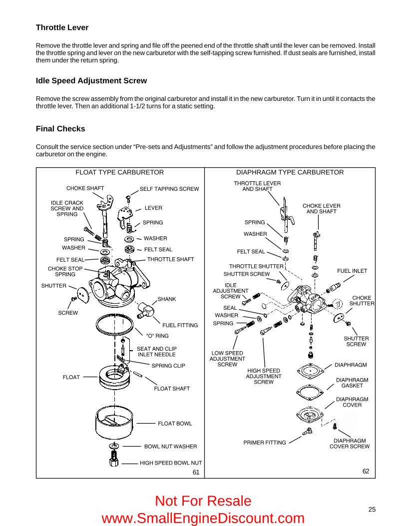
25
6261
FLOAT TYPE CARBURETOR DIAPHRAGM TYPE CARBURETOR
� .�,*��(�(-%,�$���,!��.
/"&/�,*��(�(-%,�$���,!��.
�/� �������4����(�,/�#�
,*�"�&
.�,/��
,���
.�,/��
,*�"�&
*�"$���#"��"�&
("�*/��&$! 4��
("�*/��&$&�,0��
,/%����,!��.
#%���"����
!/ 0����4����(�,/�#�
#����,���
�/� �����,/%����
("�*/��&$
"(���(-%,�$���,!��.
,/%�����,!��.
!/ 0��,/�#� ,��#���**"�&�,!��.
��4��
,*�"�&
.�,/��
#����,���
�/� �����,/�#�
"(���!��!0,!��.���(,*�"�&
,*�"�&
.�,/��
#����,���
!/ 0��,� *,*�"�&
,!��.
,/%����
,/��0
#%���#"��"�&
5 5��"�&
,������(�!�"*"��������(��
,*�"�&�!�"*
#� ���,/�#�
#� ��
#� ���' .�
/"&/�,*��(�' .���%�
' .���%��.�,/��("�*/��&$! 4���,!��.
!/ 0�,/%����
Throttle Lever
Remove the throttle lever and spring and file off the peened end of the throttle shaft until the lever can be removed. Installthe throttle spring and lever on the new carburetor with the self-tapping screw furnished. If dust seals are furnished, installthem under the return spring.
Idle Speed Adjustment Screw
Remove the screw assembly from the original carburetor and install it in the new carburetor. Turn it in until it contacts thethrottle lever. Then an additional 1-1/2 turns for a static setting.
Final Checks
Consult the service section under “Pre-sets and Adjustments” and follow the adjustment procedures before placing thecarburetor on the engine.
Not For Resale www.SmallEngineDiscount.com

26
CHAPTER 4 GOVERNORS AND LINKAGEGENERAL INFORMATION
This chapter includes governor assembly and linkage illustrations to aid in governor or speed control assembly.
Tecumseh 4 cycle engines are equipped with mechanical type governors. The governor’s function is to maintain aconstant R.P.M. setting when engine loads are added or taken away. Mechanical type governors are driven off theengine’s camshaft gear. Changes in engine R.P.M. cause the governor to move the solid link that is connected from thegovernor lever to the throttle in the carburetor. The throttle is opened when the engine R.P.M. drops and closes as theengine load is removed.
OPERATION
As the speed of the engine increases, the governor weights(on the governor gear) move outward by centrifugal force.The shape of the governor weights force the governor spoolto lift. The governor rod maintains contact with the governorspool due to the governor spring tension. As the spoolrises, the governor rod rotates, causing the attached outergovernor lever to pull the solid link and close the throttleopening. When the engine speed decreases, the lowercentrifugal force allows the governor weights to be pulledin by the governor spring. As the spool lowers, the governorrod rotates and the solid link pushes the throttle to a moreopen position (diag. 1).
������������
��� � ��
� ��
1
��� ��
�� ���
�������
������������
�������������
TROUBLESHOOTING
Engine problems where the governor is suspected to be the cause, may actually be the result of other engine systemproblems. Hunting (engine R.P.M. surging up and down) indicates that the engine is incapable of maintaining a constantR.P.M. with or without an engine load. Engine overspeeding (either with or without throttle movement) must be correctedimmediately before serious engine damage occurs. Use the following procedure to diagnose a suspected governorproblems.
�����
��� � ��
� ��
��������
������
����
���
�����
���
��������
������
����
��� � ��
� ��
�����
����
��� � ��
� ��
��������
������
����
�����
���
���
���
���
������
����
������
���
���������
��� � ��
� ��
�����
������
INTERNAL COMPONENTS (VARIOUS STYLES)
��������� �� ����� ���
�����
������ � ��
� ��
���������� 2 3 4 6
WASHER
SHAFT
GEAR ASSY.(GOV.)
SPOOL
5��� �������
Not For Resale www.SmallEngineDiscount.com

27
ENGINE OVERSPEEDING
1. If the engine runs wide open (faster than normal), shut the engine off immediately.
2. Check the condition of the external governor shaft, linkage, governor spring, and speed control assembly for breakage,stretching or binding. Correct or replace binding or damaged parts.
3. Follow the governor adjustment procedure and reset the governor - see "Service" in this chapter.
4. Run the engine. Be ready to shut the engine off if an overspeed problem still exists. If the problem persists, theengine will require disassembly to inspect the governor gear assembly for damage, binding, or wear.
5. See Chapter 9 under "Disassembly Procedure" to disassemble the engine.
6. Remove the governor gear assembly. Repair or replace as necessary.
ENGINE SURGING
1. Try to stabilize the engine R.P.M. by holding steady the solid link between the governor arm and the carburetorthrottle, using a pliers or fingers.
2. If the engine R.P.M. stabilizes, the governor or governor adjustment should be checked. See "Service" governoradjustment procedure in this chapter. If the engine R.P.M. does not stabilize, the engine will require additionalchecks, see Chapter 9 under "Troubleshooting".
3. If the problem persists after the governor adjustment, check the engine R.P.M. found on microfiche card # 30. TheR.P.M. settings are critical. If the R.P.M. setting for high and low speed are within specification and a slight surge isexperienced, increasing the engine idle R.P.M. setting slightly may eliminate this condition.
4. Check the governor shaft or linkages for binding, wear, or improper hookup. Check the governor spring for adequatetension. Repair or replace as necessary.
�
7
SERVICE
GOVERNOR ADJUSTMENT
8
�
�����������������������
������������
��������������
������������
���� ������� �� !"� �#$%%&�"'�()�"*
����� ��#$%%�+��,) �&�"'�()�"*
With the engine stopped, loosen the screw holding thegovernor clamp on the governor lever. Rotate the clamp ina direction that will force the throttle shaft open and allowthe governor follower arm to rest on the governor spool.Push the governor lever connected to the throttle to thewide open throttle position. Hold the lever and clamp inthis position while tightening the screw (diag. 7).
GOVERNOR ADJUSTMENT PROCEDURE FOR SHORT BLOCK INSTALLATIONS
Short block installation on 3-5 h.p. vertical shaft enginesbuilt prior to 1977 may require the governor clamp (tinnermanstyle) to be repositioned to work properly. The clamp mustbe removed from the governor rod and turned to the sameposition as the original engine. Hook the solid link andspring to the governor lever and position the clamp on thegovernor rod. Follow the above governor adjustmentprocedure to complete the short block governor set-up.Units built after 1977 use the normal governor set upprocedure. (diag. 8)
Not For Resale www.SmallEngineDiscount.com

28
GOVERNOR GEAR AND SHAFT SERVICE
After the cylinder cover is removed from the engine, the governor spool, gear, or governor shaft can be removed. On olderstyle governor assemblies, the retaining ring must be removed to allow the spool or gear to slide off the shaft. Newer stylegovernor shafts (3 - 6.75 model engines) use an upset to hold the governor spool on. If the gear requires replacement, thegovernor shaft will have to be removed.
Governor Spool Replacement With Upset Style Governor Shaft
9
ECH90ECV100H 30, 35HS 40, 50LAV 35LEV (all)OHH (all)OVRM (all)TNT 100, 120TVS (all)
TVM (all)V 50, 60, 70VH 50, 60, 70
HH 100, 120VH 100
H 50, 60, 70HH 60, 70HHM80HM 70, 80, 100 11
Mounting flange to Shoulder1.283 - 1.293"(32.588 - 32.842 mm)
Mounting flange to Top1.016 - 1.036"(25.806 - 26.314 mm)
Mounting flange to Top1.581 - 1.596"(25.806 - 26.314 mm)
Mounting flange to Top1.319 - 1.334"(33.502 - 33.883 mm)
ENGINE MODEL EXPOSED SHAFT LENGTH
10
GEAR
SHIM
SHAFT BOSS
WASHER
670297 (modified)
The spool can be replaced without removing the governorshaft. Grip the original spool in a vise and use a twistingand pulling motion on the flange until the spool is free.
Install the new spool by starting it on the shaft and thenturning the flange over. This will allow the weights to hangin the proper position. Place the spool on a solid surfaceand push on the flange until the spool seats. The governorweights must be in position under the spool afterinstallation. (diag. 9)
Governor Gear or Shaft Replacement, UpsetStyle Governor Shaft
1. Grip the original spool in a vise and use a twisting andpulling motion on the flange until the spool is free.
2. Clamp the shaft in a vise and pound gently on theflange with a wooden or plastic mallet to remove theshaft.
NOTE: DO NOT TWIST THE SHAFT WHEN REMOVING.THE SHAFT BOSS MAY BECOME ENLARGED, LEAVINGTHE NEW GOVERNOR SHAFT LOOSE AND CAUSINGSEVERE DAMAGE.
3. To install a new shaft, first assemble the gear andwasher on the shaft. Start the shaft into the hole witha few taps from a soft faced hammer.
4. Place the flange in a press with a solid piece supportingthe area below the shaft boss. Press the shaft in untila shim, part # 670297 just becomes snug [.010 - .020(.254 - .508 mm) clearance].
Governor Shaft Replacement, RetainingRing Style
1. Remove the retaining ring, spool, gear assembly, andwashers.
2. Clamp the shaft in a vise and pound gently on theflange with a wooden or plastic mallet to remove theshaft.
NOTE: DO NOT TWIST THE SHAFT WHEN REMOVING.THE SHAFT BOSS MAY BECOME ENLARGED AND THENEW GOVERNOR SHAFT WILL BE LOOSE AND MOVE.
3. Start the new shaft into the shaft boss by tapping witha soft faced hammer.
4. Refer to the chart at right for the proper shaft exposedlength. Add a drop of red Loctite 271 and press thegovernor shaft to the proper depth using a press or avise. Wipe the extra Loctite off after installation (diag.11).
5. Reassemble the governor and install the retaining ring.
Not For Resale www.SmallEngineDiscount.com

29
1. Loosen the two screws on the top of the panel.
2. Move the control lever to full wide open throttle positionand install a wire or aligning pin through the hole in thetop of the panel, the hole in the choke actuating lever,and the hole in the choke (diag. 12).
3. With the components aligned, tighten the two screwson the control panel.
The following pages illustrate common linkage attachment.Whenever the carburetor or the governor linkage is removedor replaced, the engine R.P.M.'s should also be checked.Use microfiche card #30 or the computer parts look-upsystem for the correct R.P.M. settings for the engine modeland specification.
SNAP IN "STYLE SPEED CONTROL"
This style of speed control is used on 3 - 6.75 model rotarymower engines and is adjusted by two bendable tabs. Usethe speed adjustment tool (part # 670326) as illustrated indiag.13 to adjust engine speed.
To adjust high speed, move the speed control lever to thehigh speed position and align the high speed pin holes.Place the adjustment tool on the high speed tab and movethe tab to achieve the correct engine speed. Move thespeed control lever to the low speed position, place theadjustment tool on the low speed tab and bend to eitherincrease or decrease to the correct speed.
12
�����������-��� � �����
�������������
LOW SPEED TAB HIGH SPEED TAB
HIGH SPEEDPIN POSITION
�
DECREASE
INCREASE�
13
SPEED CONTROLS AND LINKAGE
Many different types of speed controls and linkage are used for O.E.M. applications. Linkage attachment points are bestrecorded or marked prior to disassembly. This assures the correct placement during reassembly. On vertical shaftengines the solid link is always connected from the outermost hole in the governor lever to the throttle in the carburetor.The link with the governor spring attached is connected between the control lever and the lower hole in the governor lever.Horizontal engines use one location (non-adjustable) speed control brackets. Most vertical engines use an adjustablespeed control bracket mounted above the carburetor. The ignition ground out switch, idle R.P.M. and high speed R.P.M.adjustment screws are located on the speed control bracket. Some models use the idle R.P.M. adjustment on thecarburetor.
Most vertical shaft engines must have the speed control bracket aligned when installing. To align the control bracket, usethe following steps.
TOOL 670326
Not For Resale www.SmallEngineDiscount.com

30
14
15
������
�������
�������
��������-����������
�./.�0��.%.��#�.#1�0�#�%%2�33�������� ��
������-��� ����
������������
�������� ����� � ��
�������� �����-��� ��
�����
ADJUSTING RPM ON MEDIUM FRAMEVERTICAL SPEED CONTROL
This speed control is adjusted by aligning the slot in thespeed control lever with the alignment hole on the mountingbracket. Place a pin through the two holes, place theequipment throttle control to the wide open position, hookthe bowden cable end in the control as shown, and tightenthe cable housing clamp. In this position, the gap of .040"- .070" (1.016 - 1.778 mm) should exist at the gap locationas illustrated. This will assure that the carburetor will gointo full choke when the control is placed in the startposition.
ADJUSTING GOVERNED/NON-GOVERNED
With the engine running at its lowest speed, set thegoverned idle at the designated RPM by adjusting thegoverned idle screw or bending the idle tab. Next set thenon-governed idle by pushing the bottom of the governorlever away from the control brackets so the throttle levercontacts the idle speed crack screw (on the carburetor).Hold the lever in this position and turn the crack screw to600 RPM below the governed idle speed. This settingprevents the throttle plate from closing off when going fromhigh speed RPM to low speed RPM. If improperly adjusted,the engine could experience an over lean condition.
The idle speed is adjusted by turning the idle speed screwclockwise to increase engine R.P.M. and counter-clockwiseto decrease R.P.M. Use tool part # 670326 to adjust thehigh speed engine R.P.M. Place the slotted end of the toolonto the adjustment tab and bend the tab to the left (towardthe spark plug end) to increase engine R.P.M. (diag. 14).
NOTE: Some engines use nylon bushings on the throttleand choke linkage hook-up points to extend the life of thelinkage and to enhance the stability of the governor system.Make sure they are in good condition and in place.
ADJUSTING RPM ON MEDIUM FRAMEVERTICAL(up/down speed control)
To adjust the high speed RPM on Medium Frame Verticalengines, move the control lever to the high speed pinposition (align high speed pin holes in the speed controlbracket). Place the slot on the straight end of tool (number670326) onto the high speed adjustment tab as pictured.Rotate the bent end of the tool counterclockwise toincrease RPM and clockwise to decrease RPM. (diag.15).
��������-����������
�������������
�
�������� ����� � ��
������./.�0��.%.
�#�.#1�0�#�%%2�33�
�������� ���������������
�
����1%.451
����1%.451
Not For Resale www.SmallEngineDiscount.com

31
CONSTANT SPEED APPLICATIONS 20
HORIZONTAL LIGHTWEIGHT 16
HORIZONTAL MEDIUM FRAME
SMALL FRAME
19
18
HORIZONTAL SHAFT ENGINES
�������������������
�������������������
��������������������
������������-�������������
������������-�������������
17LIGHTWEIGHT R.V. TYPE
�������������������
����������
�-������������
����������
�-������������
����������
�-������������
�������������������
���� 6���������
� �� 6���������
Not For Resale www.SmallEngineDiscount.com

32
SNOW KING ENGINES24
TO INCREASE SPEED - CLOSE LOOPTO DECREASE SPEED - SPREAD LOOP
SNOW KING ENGINES
23
22
MEDIUM FRAME
HORIZONTAL SHAFT ENGINES (CONTINUED)
�������������������
������������-�������������
�������������������
� ��� 6���������
�����������������
������������ �
����� ������7�
25
MAIN MIXTURESCREWIDLE MIXTURE
SCREW
IDLE SPEEDSCREW
HMSK80-100HORIZONTAL MEDIUM FRAME 21
�������������������
������������-�������������
����� 6���������
Not For Resale www.SmallEngineDiscount.com

33
VERTICAL SHAFT ENGINES
STANDARD TVM ENGINE WITHOUT GOVERNOROVERRIDE
TVXL 220 WITH HORIZONTAL SPEED CONTROL3029
TVS 115/LEV ENGINESPEED CONTROL
����� 6���������
�������������������
TNT 100 VERTICAL ENGINES
28
27VERTICAL SHAFT ENGINES
��������-�������
�����
�������������������
������������� ��������������������������������������
26
Not For Resale www.SmallEngineDiscount.com

34
GOVERNOR OVERRIDE SYSTEM FORTVM170, 195 AND 220 ENGINES
This system will be found starting on 1985 productionmodels, and will not retrofit onto older engines. It is designedto allow the governor to regulate the low and high speedsof the engine. The high speed is adjusted at the top screwof the override lever; to increase R.P.M. turn the screw out(counterclockwise), to decrease R.P.M. turn the screw in(clockwise). The low speed is adjusted at the bottom screwof the override lever; to increase R.P.M. turn the screw in orclockwise, to decrease R.P.M. turn the screw out orcounterclockwise (diag. 31).
GOVERNED / NON-GOVERNED IDLE
With the engine throttle set at its lowest speed, set thegoverned idle at the designated RPM by bending the idleRPM tab or adjusting a screw. Next set the non-governedidle by pushing the bottom of the governor lever away fromthe control brackets, so the throttle lever contacts the idlespeed screw. Hold the lever in this position and turn theidle adjustment screw clockwise to increase orcounterclockwise to decrease engine idle speed. Thesetting on the carburetor screw should be set 600 RPMbelow the governed idle setting. This setting prevents thethrottle plate from closing when going from high speed RPMto low speed RPM. If improperly adjusted, the engine couldexperience an over lead condition.
TVM ENGINES WITH GOVERNOR OVERRIDE
��������-�������������
�����������-�������������
� ��� 6���������
31
Not For Resale www.SmallEngineDiscount.com

35
CHAPTER 5 REWIND STARTERSGENERAL INFORMATION
Rewind starters used on vertical shaft Tecumseh engines are top mount horizontal pull style or side mount vertical pullstyle. Horizontal shaft engines use side mounted starters which can be mounted to pull either vertically or horizontally.All rewind starters except the vertical pull style turn the engine over by engaging a dog(s) into the starter cup attached tothe engine flywheel. The vertical pull starter engages the starter gear into the ring gear of the flywheel to turn the engineover. All starters are spring loaded to retract the dog(s) or starter gear when the engine speed exceeds the turning speedof the starter.
OPERATION
As the starter rope is pulled, the starter pulley rotates on the center pin. The starter dog(s) is pinned or pocketed in thepulley hub and extends outward when the pulley's rotation forces the starter dog(s) to contact the ears on the retainer.The retainer ears act as a ramp to fully extend the starter dog(s). The fully extended starter dog(s) locks in contact withnotches in the starter cup. When the engine fires and the rotational speed of the starter cup exceeds the starter pulley,the starter dog(s) disengages from the starter cup. The starter dog spring(s) returns the starter dog(s) to the disengagedposition. The recoil spring turns the starter pulley in the opposite direction, retracting the starter rope until the handlecontacts the stop.
COMPONENTS
SERVICE
Starter related problems will require the starter to be removed from the engine to diagnose the cause. Visually inspect thestarter dog(s), starter cup, retainer, springs, rope, washers, and the starter pulley for wear or breakage. Use one of thefollowing procedures that applies to your application, to disassemble, repair, and assemble the starter. Always consultthe Tecumseh Master Parts Manual for the correct replacement parts.
ROPE SERVICE
Rope replacement should be done using the correct part number replacement rope or braided rope of the correct diameterand length. Consult the Tecumseh Master Parts Manual to obtain the correct part number, length, and size required. Usethe following rope chart to convert a numbered rope to a fractional diameter for bulk rope use.
# 4 1/2 rope = 9/64" (3.572 mm) diameter Part No. 730526 100' (30.48 meters) spool
# 5 rope = 5/32" (3.964 mm) diameter Part No. 730514 100' (30.48 meters) spool
# 6 rope = 3/16" (4.762 mm) diameter Part No. 730516 100' (30.48 meters) spool
������
�����
����
1 2
�������� ��
�������������
��������
��������
�����������
��
������
���������
�����������
��� ��
��� ��
��������
����
����
������� ������
������������������������
���������
��������
�����������
Not For Resale www.SmallEngineDiscount.com

36
Standard rope lengths
54" (16.5 meters) standard stamped steel starter
61" (18.6 meters) vertical pull - horizontal engagementtype
65" (20 meters) vertical pull - vertical engagement type
85" (26 meters) extended handlebar rope start(compliance)
Check the old rope for the right length for the application.Some applications require longer lengths. The rope endsshould be cauterized by burning with a match and wipingthe rope end with a cloth while hot.
Rope replacement can be done without the starter beingdisassembled on vertical pull starters that have "V" notchesin the bracket. Use the following procedure for ropereplacement.
1. Remove the starter assembly from the engine.
2. Turn the pulley until the staple in the pulley lines upwith the "V" notch. Pry out the staple with a smallscrewdriver and remove the original rope (diag. 3).
3. Turn the pulley counterclockwise to fully wind the starterreturn spring until tight. Allow the pulley to unwind untilthe hole in the pulley lines up with the "V" notch.
4. Hold the pulley in this position and feed the new ropethrough the hole and tie a left-handed knot on the ropeend. Make sure the rope and knot do not protrude fromthe knot cavity and bind the pulley rotation.
RETAINER REPLACEMENT (DIAGRAM 4)
1. Remove the starter handle if the retainer is a completecircle design. Remove the staple and old retainer.
2. Slide the rope retainer into the proper position and insertthe staple using a pliers.
3. Install the starter handle and tie a left hand knot tosecure the handle.
STYLIZED REWIND STARTER (TVS, HM,TVM, TVXL), AND STAMPED STEELSTARTER (HM, VM, TVM, TVXL)
Disassembly Procedure
1. After removing the rewind assembly from the engineblower housing, release the tension on the rewindspring. This can be done by removing the starter handleand carefully allowing the rope to unwind in the starterhousing assembly.
2. Place a 1" (25 mm) deep well socket under the retainer.Set the rewind on a bench, supported on the socket.
3. Use a 5/16" (7.938 mm) or 1/4" (6.35 mm) (for stampedsteel) roll pin punch to drive out the center pin. Thestamped steel center pin is driven out from the top,inside the center hole. Move the punch around whiledriving the pin to help keep the pin straight.
3
����
����
���������
5
6
������������������������
������� ������
��������
��� ��
��������
�������������� ��
���������
ONE PIECE ROPE RETAINER
4
����� ��
����
Not For Resale www.SmallEngineDiscount.com

����
������� ������
����
������������������������
��������
��� ��
��������
���������
�����������
��� ��
���������
�����������
���������
��������
��� ��
���������
��� ��
������� ������
CAUTION: THIS REWIND SPRING IS NOT SECURED IN A CANISTER. PULLEY BOSSES HOLD THE REWINDSPRING AND COVER, AND CAN BE EASILY DISLODGED DURING HANDLING.
4. Remove the brake spring, spring retainer, washers, and pulley assembly (diag. 7)
NOTE: THE STARTER DOGS FACE OUT ON THE STAMPED STEEL STARTER AND THE DOGS FACE IN ON THESTYLIZED REWIND STARTER.
5. All components in need of service should be replaced.
Assembly Procedure
NOTE: It is critical to support the starter on a deep wellsocket to prevent damage.
1. Reverse the disassembly procedure. The starter dogswith the dog springs must snap back to the center ofthe pulley (disengaged position). When the rope ispulled, the tabs on the retainer must be positioned sothat they will force the starter dogs to engage thestarter cup. (diag. 7 & 8)
2. Always replace the center spring pin with a new oneupon reassembly. Place the two new plastic washersbetween the center leg of the starter and the retainer.New plastic washers are provided with a new centerspring pin. Discard the old plastic washer.
3. Prior to reinstalling the new spring pin, invert the housingand support the center of the housing on a socketapproximately 3/4" (19 mm). Drive the pin into thehousing until 1/8" (3.1 mm) as shown. (diag. 7 & 8)
NOTE: DO NOT DRIVE THE CENTER PIN IN TOO FAR.
The retainer will bend and the starter dogs will notengage the starter cup. On the stamped steel starterthe center pin should be driven in until it contacts theshoulder in the starter body.
4. Apply tension to the recoil spring by winding the pulleycounterclockwise until it becomes tight, then allow thepulley to unwind until the hole in the pulley lines upwith the rope eyelet in the starter housing. Install aknotted rope through the pulley and the eyelet andinstall the handle. A left-hand knot should be tied onthe end of the rope to secure the handle.
STYLIZED REWIND STARTER WITHPLASTIC RETAINER
������������ ������
1. After removing the rewind assembly from the engineblower housing, remove the starter handle by firstpulling a length of rope out using the handle, tying atemporary knot in the exposed rope, and either untyingthe knot in the handle or prying out the staple.
2. Untie the temporary knot and slowly allow the rope tofully retract into the starter housing and the recoil springto fully unwind.
3. Remove the decal from the center of the starterhousing.
��������
8
7
������������������������
����������
����
����
����� ��
����
��������������������
��������������������
4. Use a small Phillips screwdriver or similar tool to prythe retainer legs apart and lift out the retaining wedge(or steel clip on newer style starters).
5. Pinch the legs of the retainer together and pull on thehead of the retainer to remove it from the housing.
6. Remove the pulley assembly from the recoil housing.
7. Repair or replace as necessary.
��������
�������� ������
���������������� ��
����
Not For Resale www.SmallEngineDiscount.com

38
�������
1. If replacing the starter rope, see Step 8.
Recoil starters are under heavy tension.Extreme caution should be used when workingwith these parts and always wear safety glasses,leather gloves and a heavy, long sleeved shirt.
2. Install a new recoil spring/pulley assembly into thestarter housing.
3. Replace or check that both starter dogs are in thepulley pockets and that the dog springs are hookedon the outer surface of the starter dog.
4. Pinch the two legs of the plastic retainer together andslightly push the retainer into the center shaft hole.
5. Rotate the retainer so the two tabs on the bottom ofretainer contact the dog on the inward side so whenthe rope is pulled the retainer tabs cause the dogs toflair outward. Push the retainer in until the leg prongspop out of the center shaft.
6. Turn the starter over and snap the locking tab betweenthe retainer legs, replace the top decal.
The service replacement retaining wedge is spring steel.
7. Apply tension to the recoil spring by winding the pulleycounterclockwise until it becomes tight, then allow thepulley to unwind until the hole in the pulley lines upwith the rope eyelet in the starter housing. Install aknotted rope through the pulley and the eyelet andinstall the handle. A left-hand knot should be tied onboth ends of the rope to secure the handle and rope inpulley.
STANDARD STAMPED STEEL AND CASTALUMINUM STARTER (HM, VM)
Disassembly Procedure
1. Untie the knot in the rope and slowly release the springtension.
2. Remove the retainer screw, retainer cup (cam dog onsnow proof type), starter dog(s) and dog spring(s), andbrake spring (diag. 10).
3. Turn the spring and keeper assembly to remove thepulley. Lift the pulley out of the starter housing. Replaceall worn or damaged parts.
Assembly Procedure
1. Apply a light coat of NON-FREEZE grease to the springbefore installing into the pulley. Install the pulleyassembly into the starter housing.
2. Install the brake spring, starter dog(s), and starter dogreturn spring(s). The starter dog spring(s) must holdthe dog(s) in against the pulley. On Snow King enginesthe starter dog posts should be lubricated with S.A.E.30 engine oil to prevent oxidation.
9
���������
�������������������
10
������� ������
������
���������� ����
�������������
�������������������
��������
�����������
���������
�����
��� ��
���������
��������������������������������
������� ������
�������������������������
��������
����������
����� ��
����
���������������� ��
����
Not For Resale www.SmallEngineDiscount.com
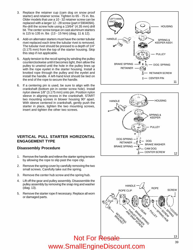
39
3. Replace the retainer cup (cam dog on snow proofstarter) and retainer screw. Tighten to 65 - 75 in. lbs.Older models that use a 10 - 32 retainer screw can bereplaced with a larger 12 - 28 screw (part # 590409A).Re-drill the screw hole using a 13/64" (4.35 mm) drillbit. The center screw torque on cast aluminum startersis 115 to 135 in. lbs (13 - 15 Nm) (diag. 11 & 12).
4. Add-on alternator starters must have the center tubularrivet replaced each time the tubular rivet is removed.The tubular rivet should be pressed to a depth of 1/4"(3.175 mm) from the top of the starter housing. Skipthis step if not applicable.
5. Apply tension to the recoil spring by winding the pulleycounterclockwise until it becomes tight, then allow thepulley to unwind until the hole in the pulley lines upwith the rope eyelet in the starter housing. Install aknotted rope through the pulley and the eyelet andinstall the handle. A left-hand knot should be tied onthe end of the rope to secure the handle.
6. If a centering pin is used, be sure to align with thecrankshaft (bottom pin in center screw hole). Installnylon sleeve 1/8" (3.175 mm) onto pin. Position nylonsleeve in aligning recess in the crankshaft. STARTtwo mounting screws in blower housing 90o apart.With sleeve centered in crankshaft, gently push thestarter in place, tighten the two mounting screws,insert and tighten the other two screws.
VERTICAL PULL STARTER HORIZONTALENGAGEMENT TYPE
Disassembly Procedure
1. Remove the handle and relieve the starter spring tensionby allowing the rope to slip past the rope clip.
2. Remove the spring cover by carefully removing the twosmall screws. Carefully take out the spring.
3. Remove the center hub screw and the spring hub.
4. Lift off the gear and pulley assembly. Disassemble thepulley assembly by removing the snap ring and washer(diag. 13).
5. Remove the starter rope if necessary. Replace all wornor damaged parts.
12
����
�����
�
�����
�����
����
��������
�����
�
��
�����
����
������
� �����
�� ��
����
�������
��������
���
�������
�
����
���
13
����
�������������
������
������
��������
��������
�����������
�����������
�����
�������� ��
��
������������������
������
��������
�������������
���������
��������
�����������
����
11
������
����� ��
����
Not For Resale www.SmallEngineDiscount.com
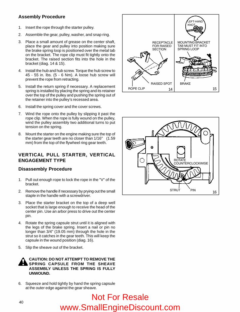
40
Assembly Procedure
1. Insert the rope through the starter pulley.
2. Assemble the gear, pulley, washer, and snap ring.
3. Place a small amount of grease on the center shaft,place the gear and pulley into position making surethe brake spring loop is positioned over the metal tabon the bracket. The rope clip must fit tightly onto thebracket. The raised section fits into the hole in thebracket (diag. 14 & 15).
4. Install the hub and hub screw. Torque the hub screw to45 - 55 in. lbs. (5 - 6 Nm). A loose hub screw willprevent the rope from retracting.
5. Install the return spring if necessary. A replacementspring is installed by placing the spring and its retainerover the top of the pulley and pushing the spring out ofthe retainer into the pulley's recessed area.
6. Install the spring cover and the cover screws.
7. Wind the rope onto the pulley by slipping it past therope clip. When the rope is fully wound on the pulley,wind the pulley assembly two additional turns to puttension on the spring.
8. Mount the starter on the engine making sure the top ofthe starter gear teeth are no closer than 1/16" (1.59mm) from the top of the flywheel ring gear teeth.
VERTICAL PULL STARTER, VERTICALENGAGEMENT TYPE
Disassembly Procedure
1. Pull out enough rope to lock the rope in the "V" of thebracket.
2. Remove the handle if necessary by prying out the smallstaple in the handle with a screwdriver.
3. Place the starter bracket on the top of a deep wellsocket that is large enough to receive the head of thecenter pin. Use an arbor press to drive out the centerpin.
4. Rotate the spring capsule strut until it is aligned withthe legs of the brake spring. Insert a nail or pin nolonger than 3/4" (19.05 mm) through the hole in thestrut so it catches in the gear teeth. This will keep thecapsule in the wound position (diag. 16).
5. Slip the sheave out of the bracket.
CAUTION: DO NOT ATTEMPT TO REMOVE THESPRING CAPSULE FROM THE SHEAVEASSEMBLY UNLESS THE SPRING IS FULLYUNWOUND.
6. Squeeze and hold tightly by hand the spring capsuleat the outer edge against the gear sheave.
���
15
16
14
����������������������
�����
���������
��������
�������������������������
�����
���������������������������������������
����� ��
����
Not For Resale www.SmallEngineDiscount.com

41
7. Remove the retainer pin from the strut and slowly relievethe spring tension by allowing the spring capsule torotate slowly under control, until completely unwound.The spring capsule can now be removed from the gearsheave.
Assembly Procedure
1. Feed the new rope through the hole and tie a left-handed knot on the rope end. Make sure the rope andknot do not protrude from the knot cavity and bind thepulley rotation (diag. 17).
2. Wind the rope on the sheave assembly clockwise,viewing the gear from the gear side of the sheave.
3. Reinstall the brake spring, being careful not to spreadthe spring more than necessary.
4. Install the spring capsule, making sure the starterspring end hooks on the gear hub (diag. 18).
5. Wind the spring four full turns and align the brake springlegs with the strut as shown. Insert the pin in the strut(diag. 19).
6. If the starter is equipped with a locking or delay pawland spring, make sure these are in place beforegrasping the gear and spring capsule assembly andsliding it into the bracket. Make sure the legs of thebrake spring are positioned in the slots of the bracket.
7. Feed the rope end under the rope guide and hook itinto the "V" notch. Remove the pin and the strut willrotate clockwise against the bracket (diag. 21).
8. Insert the new center pin by pressing or driving the pinfirmly in place. Reinstall the starter assembly on theengine (diag. 21).
����������������������� ������
�������������������������� ������
����� ��
����
��������������������������
�������������� �������
17
1918
������������!���������
������ ���������� ��
���������������
���� ��
����"
* USED ON SOME MODELS 20
�����������
�������
��������
���"
����������"
�����
����
���
�����
�����������
�����������"
������� ����
����������
������������� ���� ����
� ����������������������������!#$���������
21
Not For Resale www.SmallEngineDiscount.com

42
CHAPTER 6 ELECTRICAL SYSTEMSGENERAL INFORMATION
The electrical system consists of three main elements: a battery, a starting circuit, and a charging circuit. The battery ispart of both the starting and charging circuit. The battery should be checked before going into any extensive starter orcharging system checks. If a battery has a shorted cell, overcharging can result, and the regulator or rectifier may appearto be at fault. If a cell has an open or high resistance connection, the electric starter operation will be affected.
The power source used to provide the energy to turn an electric starter motor on Tecumseh engines is either 120 volt A.C.current or 12 volt D.C. An A.C. starter circuit utilizes a 120 volt power source instead of a battery. The 12 volt batterymodels require a charging system to maintain proper battery charge.
The starting circuit includes the battery, battery cables, starter or ignition switch, safety switches, and an electric startermotor.
The charging system consists of alternator charge coils, rectifiers or diodes, regulator, ignition switch, flywheel magnets,and a battery. All engines that have a charging system will use a combination of some or all of these features.
OPERATION
1
������������
����
�������
� ������ ��������
���
�����
����
���������
�����
� ��������
������
����������
������� ����
������
����
�������
ROTATION OF FLYWHEEL
2
STARTING CIRCUIT AND ELECTRICSTARTERS
After all of the safety interlock switches have been activated,the starter switch will complete the circuit. A strongmagnetic force is produced by the electrical current runningthrough the armature windings. The armature magnetismrepels the magnetism produced by the permanent fieldmagnets of the electric starter. The repelling magneticforces cause the armature to rotate, moving the drive pinionlaterally on the splined armature shaft, meshing the starterpinion gear with the flywheel ring gear. When the drive pinioncontacts the stop at the end of the armature shaft, thepinion rotates along with the armature shaft to crank theengine. The armature and pinion remain positively engageduntil the engine fires and the flywheel rotates faster thanthe armature. The greater momentum of the flywheel throwsthe starter pinion gear out of mesh and forces the starterpinion back to the disengaged position. After the switch isreleased, the starting circuit is opened and the armaturecoasts to a stop. A small anti-drift spring holds the pinionin the disengaged position (diag. 1).
CHARGING CIRCUIT
When a conductor (alternating coils) cuts the magneticfield generated by the magnets in the flywheel, a currentwill be induced in the alternator coil. The permanentmagnets in the flywheel have a magnetic field in which thelines of magnetic force run from the North Pole to the SouthPole. As the flywheel rotates and the position of themagnets change, the direction of the magnetic fieldchanges or alternates. The alternating coils are wound indifferent directions to allow current to flow as an A.C.waveform (diag. 2).
Not For Resale www.SmallEngineDiscount.com

43
Current flows through a diode when the anode is more positive than the cathode. The cathode end of the diode shouldpoint toward the battery when diode is used between a charging system and a battery.
HALF WAVE RECTIFIER SINGLE DIODE
The single diode allows only the positive half of the A.C. signal through. It does not allow the negative portion through.
���������
�������� ��
FULL WAVE RECTIFIER(BRIDGE RECTIFIER)
������ ��
��������������
������ ��
��������
����������������
��������
������ �� �������� ��
FULL WAVE RECTIFIER (BRIDGERECTIFIER)
The full wave rectifier makes use of the entire A.C. signal,converting it to D.C.
COMPONENTS
BATTERY
The batteries used in conjunction with Tecumseh enginesare 12 volt lead acid or “maintenance free” style. Thechemical energy produced by the dissimilar metals of thebattery plates provides a electrical potential that is used topower the electric starter or unit accessories. Consult theoriginal equipment manufacturer’s service manual for batterysize, capacities, and testing procedure.
WIRING
The wires used in Tecumseh electrical systems are copper stranded with an insulated coating around the copper strands.
CONDITION: All wiring must be fully insulated between connection points, securely fastened and free of foreign material(such as rust and corrosion) at the connection points. This is especially important in the use of batteries where much ofthe potential may be lost due to loose connections or corrosion. Remember to check the insulation on the wire. All ittakes is a pin hole to "ground out" on the engine or frame. This is of special concern when moisture or water is present.This may cause the engine to run erratically or be impossible to start.
��������
��������
3
���������������������������������
4
����������������������������
5
��������
��������
CONVERTING ALTERNATING CURRENT TODIRECT CURRENT
In order to charge a battery, it is necessary to convertalternating current (A.C.) to direct current (D.C.). This isaccomplished by using a diode or rectifier (diag. 3). A singlediode makes use of only one half of the A.C. signal and isknown as HALF WAVE RECTIFICATION (diag. 4). This isacceptable in certain applications. In certain situations itis necessary to make use of the entire A.C. signal. Toaccomplish this, multiple diodes in a bridge configurationare used to produce FULL WAVE RECTIFICATION (diag.5).
������������������������
�
Not For Resale www.SmallEngineDiscount.com

44
WIRE GAUGE: The proper thickness of wire is necessaryin all electrical circuits. Wire diameter is measured inincrements of gauge numbers. As the gauge number ofthe wire increases, the wire diameter decreases in size(diag.6).
1. The starter circuit wiring must be rated at #6 or lowergauge number.
2. The charging circuit wiring must be rated at #16 orlower gauge number (20 amp system requires #14 orlower gauge number).
# 18
# 6
3. The magneto circuit wiring (ground circuit) must be rated at #18 or lower gauge number.
Tecumseh's standard engine wiring color codes, effective August, 1992 are as follows:
Code Product
Yellow - Alternator A.C. Leads
Red - Alternator D.C. + Leads
Brown - Alternator D.C. - Leads
Black - Alternator Ground Leads, Battery Ground Leads
Orange - 12 Volt Starter B + Leads
Dark Green - Ignition Shut-Off Leads
NOTE: PRIOR TO AUGUST 1992, WIRE CODES CHANGED ACCORDING TO MODEL AND SPECIFICATIONNUMBERS.
6
7
8
9
10
THE LARGER THE NUMBER THE SMALLER THE WIRE
ELECTRICAL TERMS
ALTERNATOR - An alternator consists of coils of wirewound around a metal lamination stack. When a magnetis moved past the coils, a current is induced in the coils. Ingeneral, the greater the number of coils, the greater theoutput of the alternator (diag. 7).
IGNITION COIL - The ignition coil is used to fire the sparkplug. It is completely independent from the alternator coils.
RECTIFIERS and DIODES - Charging a battery requiresthat the alternating current produced by the alternator bechanged to direct current. This is accomplished by usinga diode or rectifier.
REGULATOR/RECTIFIERS - This combines a regulatorwith a rectifier. The regulator prevents overcharging of thebattery and the rectifier changes the alternating current todirect current (diag.8, 9, 10).
CONDUCTORS - A conductor is a material that allows anelectric current to pass through it. All metals are conductorsof electricity, but some are better conductors than others.Silver, copper and gold are some of the better knownconductors. As the temperature of the conductor increases,the resistance increases.
INSULATORS - An insulator is a material that will not allowan electric current to pass through it. Some of the morecommon materials that are insulators are glass, plastic,rubber, ceramics and porcelain.
Not For Resale www.SmallEngineDiscount.com

45
BASIC CHECKS
Before going into extensive checks, be sure to perform the more basic checks first, such as:
1. Battery defective or not charged.
2. Corroded or loose terminals and connections, or wrong connections.
3. Cracked insulation or broken wires.
4. A wire "grounding out" in the system.
5. Defective switch.
6. Operator presence system functioning properly.*
*NOTE: ALL LAWN AND GARDEN TRACTORS BUILT AFTER JULY OF 1987 ARE REQUIRED TO HAVE AN OPERATORPRESENCE SYSTEM AND MANY CAME EQUIPPED WITH SUCH A SYSTEM PRIOR TO THIS DATE. IF THE TRACTORIS "CUTTING OUT" OR WILL NOT START, THIS IS AN AREA THAT SHOULD BE CHECKED OUT.
Not For Resale www.SmallEngineDiscount.com

46
Starter will notturn
Starter turns atlow rpms or
stalls under load
Is there powerat the power
source?
Check wiring,connections,
safety switches,starter switch
Check starter forbinding brushes,worn brushes,
dirty or oilycommutator
NO
NO YES
YES
Repair or replacepower source
Is power supplied to thestarter terminal?
Internal enginefailure, repair orreplace engine
NO YESIsolate engine
from theequipment, doesengine turn over?
Repair or replaceequipment
causing excessiveloading
Remove sparkplug, does engineturn over freely?
YESNO
Internal enginefailure or flywheel
interference
Reinstall sparkplug, does
engine bind oncompression
stroke?
YESNO
Check valve lash.Adjust if
necessary. Doesthe engine turn
over withoutbinding now?
YES
NO
Repair or replaceelectric starter
TROUBLESHOOTING ELECTRICAL STARTER CIRCUIT FLOW CHART
Intermittentstarter operation
Not For Resale www.SmallEngineDiscount.com

47
Check diodes,replace if no
continuity exists orif continuity existsreversing test leads
Check fuses,replace asnecessary
Check switches,wiring, or lights for
shorts
Identify the charging systemused by model and specificationnumber or visually check theelectrical plug
Consult the Quick ReferenceService Guide for testprocedures on the differentcharging systems available.
Test for either AC or DC voltageas directed at the proper engineRPM
Is the voltage greater than orequal to the minimum value?
Alternator coilfailure, replacecoil assy.
NO
NO
YES
YES Check wiring, switches, orammeter for breaks, shorts
Is AC voltage before diode orrectifier greater than the minimumvalue?
TROUBLESHOOTING ELECTRICAL CHARGING CIRCUIT FLOW CHART
Not For Resale www.SmallEngineDiscount.com

48
TESTING PROCEDURE
STARTING CIRCUIT
1. Check the power source using an electrical tester and follow the testers recommended procedure. Make sure thebattery meets the minimum battery voltage requirements found in the original equipment manufacturer's servicemanual.
2. Check the electric starter terminal for the required voltage (12v D.C. or 120 v A.C.) using a voltmeter.
CAUTION: FOLLOW ALL SAFETY PRECAUTIONS WHEN TESTING FOR A.C. VOLTAGE, ELECTRIC SHOCKCAN KILL.
3. Check wiring, connections, fuses, ignition or starter switch, safety switches, or solenoid for continuity using aohmmeter or a continuity light. Repair or replace as necessary.
4. Remove all equipment loads from the engine. Take off all drive belts, chains, and couplers to isolate the engine fromthe equipment it is powering.
5. Try to turn the engine over using the recoil assembly if equipped. If the engine doesn’t turn over, a mechanical bindingmay be the cause. Check for proper lubrication (oil level and viscosity), starter gear and flywheel ring gear interference.If no problem is discovered, the problem is an internal failure.
6. If the engine binds only on the compression stroke, check the engine valve clearance per the specification table inChapter 10. If the valve clearance is within the specifications, the camshaft (compression release) may requirereplacement. Valve clearance not within the listed specifications will require either resetting or grinding the valvestems to obtain the proper clearance.
7. If the engine turns over freely, the electric starter should be disassembled and checked. If the preceding steps fail tocorrect the problem, the engine will require disassembly to find the mechanical failure. See Chapter 9 under"Disassembly Procedure".
CHARGING CIRCUIT
The following pages will show wiring diagrams of several Tecumseh charging systems. The charging system used on theengine is best identified by obtaining the engine model number and the specification number on the engine. Consult aTecumseh dealer or a parts manual to identify the charging system. To make many of the tests it is necessary to run theengine and measure alternator output with a voltmeter. When making voltage tests with the engine running, it is notnecessary to take readings at all the listed R.P.M.s. Checking at one of the speeds is sufficient.
In some cases an open circuit D.C. check cannot be made. An SCR (Silicon Controlled Rectifier) is located in the circuitwhich requires a minimum “turn on” voltage to allow it to conduct. Without the battery in the circuit this “turn on” voltageis not present. The SCR “senses” this and there will be no D.C. output from the regulator or rectifier.
Each charging system has its own testing procedure. Test the charging system using the applicable procedure on thefollowing pages.
11��
�������������������
�����
�������� ����������
����������������
���������������
������������
���� ����������350 Milliamp Charging SystemModels: Rotary Mower Engines Equippedwith Electric Start
CHECKING THE SYSTEM: The battery must be in thecircuit to perform the test properly. Connect a voltmeteracross the battery. The voltmeter should read the batteryvoltage. Start the engine. With the engine running, thereshould be an increase in the voltage reading. If there is nochange in the voltage reading, the alternator is defectiveand should be replaced. See Chapter 9 for "DisassemblyProcedure" (diag. 11).
NOTE: SET THE VOLTMETER TO THE 0-20 VOLT D.C.SCALE FOR THE TEST.
Not For Resale www.SmallEngineDiscount.com

49
18 Watt A.C. Lighting AlternatorModels: H35, HS & HSSK 40-50, HM &HMSK 70-80-100
CHECKING THE SYSTEM: To check the system,disconnect the plug from the rest of the lighting system.Connect a wire lead from the single pin connector comingout of the engine to one terminal of a No. 4414, 18 wattbulb. Connect another wire lead to the other terminal of thebulb and run to a good ground on the engine. Start theengine and test the circuit using the A.C. voltmeter asshown (diag. 12).
With the engine running, minimum A.C. voltage acrossthe bulb should be:
2000 R.P.M. - 6.0 Volts A.C.
3000 R.P.M. - 8.5 Volts A.C.
3600 R.P.M. - 10.0 Volts A.C.
If minimum values are noted, the alternator is okay. If lessthan the minimum values, the alternator is defective. SeeChapter 9 for "Disassembly Procedure".
1 Amp (18 Watt) Add-on Alternator
CHECKING THE SYSTEM: To check the system,disconnect the plug from the rest of the lighting system.Connect a No. 4414, 18 watt bulb in line with each terminalin the plug. Start the engine and test the circuit using avoltmeter as shown (diag. 13).
With the engine running, minimum A.C. voltage valuesacross the bulb should be:
2000 R.P.M. - 8.0 Volts A.C.
3000 R.P.M. - 10.5 Volts A.C.
3600 R.P.M. - 12.0 Volts A.C.
If minimum values are noted, the alternator is okay. If theminimum values are not noted, the alternator or A.C.connector is defective. See Chapter 9 for "DisassemblyProcedure".
D.C. Charging Adaptor
Rectifier Bridge Check With Ohmmeter for D.C.Adaptor
The following tests should be performed without the enginerunning to determine the condition of the D.C. adaptor.
Continuity should exist during one of the two following tests.No continuity should exist while performing the oppositetest.
If continuity exists during both tests, or if no continuityexists during both tests, the D.C. adaptor is defective.
TEST NO. 1 - Connect negative probe of meter to red outputlead. Connect positive probe of meter to both A.C. terminalsand black output lead (diag. 14).
����������
12
�����
��
����������
13
�����
�����
���������
14
��� ������������
��
��
�����
������������
(continued on top of next page)Not For Resale
www.SmallEngineDiscount.com

50
TEST NO. 2 - Connect the positive probe of meter to red output lead. Connect the negative probe of meter to both A.C.terminals and black output lead.
Connect the negative probe of meter to black output lead. Connect the positive probe of meter to both A.C. terminals andred output lead.
If the D.C. adaptor is not defective and a known good battery fails to hold a charge, then perform an A.C. output voltagetest.
NOTE: PRIOR TO AUGUST 1992, THE BLACK WIRE WAS BROWN.
CHECKING THE SYSTEM: To check the system, disconnect the D.C. adaptor from the add-on alternator. Connect a No.4414, 18 watt bulb in line with each terminal in the alternator. Start engine and test circuit using an A.C. voltmeter asshown (diag 14).
With the engine running, minimum A.C. voltage values across the bulb should be:
2000 R.P.M. - 8.0 Volts A.C.
3000 R.P.M. - 10.5 Volts A.C.
3600 R.P.M. - 12.0 Volts A.C.
If the minimum values are noted, alternator is okay. If the minimum values are not noted, the alternator or A.C. connectoris defective.
���������������� �����������
To check this system follow the meter hook ups at theright, checking the D.C. negative and D.C. positive first. Ifoutput is below standard listed, pull back protective coatingin front of the diode and check A.C. output. If A.C. is goodcheck each diode it services as requested see parts list.(diag. 15)
D.C. value (+) or (-) check. A.C. outputs both sides.
R.P.M. D.C. Volts R.P.M. Volts A.C.2500 - 8.0 Volts D.C. 2500 - 18 Volts A.C.3000 - 9.5 Volts D.C. 3000 - 22 Volts A.C.3300 - 10.5 Volts D.C. 3600 - 26 Volts A.C.3600 - 11.5 Volts D.C.
NOTE: These minimum numbers should be obtained byyour meter and will often be higher.
3 Amp A.C. Lighting AlternatorModels: H & HSK 30- 35, HS & HSSK 40, H &HSK 50-60, HH50-60, HM & HMSK 70-80-100,HHM80
Before making any exterior tests, check for an inoperativeswitch, shorted wires and burned out headlight and/or stoptail light. To check out the alternator, check the A.C. leadto ground (diag. 16).
With engine running, minimum values should read:
2500 R.P.M. - 8.0 Volts A.C.3000 R.P.M. - 9.5 Volts A.C.3300 R.P.M. - 10.5 Volts A.C.3600 R.P.M. - 11.5 Volts A.C.
If the above minimum readings are noted, the alternator isokay. Check for defective lights, wiring or switches. If lessthan the above readings, the alternator is defective. SeeChapter 9 for "Disassembly Procedure". 16
�����
��
��������� �����������
������������
��� ������
15
��
D.C. NEGATIVEOUTPUT LEAD(BROWN D.C.)
D.C. POSITIVEOUTPUT LEAD(RED D.C.)
��������� D.C.
D.C.A.C.
TO POSITIVESIDE OFBATTERY
Not For Resale www.SmallEngineDiscount.com

51
NOTE: ON OLDER POINT IGNITION SYSTEMS, THE A.C.OUTPUT LEADS ARE BLACK AND RED.
3 Amp D.C. Alternator System - RectifierPanel
This 3 amp system is readily identified by the rectifier panelin the circuit. The panel includes two diodes and a fuse foroverload protection. The rectifier panel does not regulatethe output of this system.
CHECKING THE SYSTEM: Check the fuse to determine ifit is good. A continuity light or ohmmeter can detect afaulty fuse. Replace with a six (6) amp fuse if necessary.Determine if the diodes are functioning properly. A continuitylight may be used to check diodes. (diag. 17).
When replacing the diode in the rectifier panel, locate theundercut on one end of the diode and match it to the detenton terminal clip of the rectifier panel.
Test the D.C. output of the rectifier panel as follows:
Disconnect the battery lead from the terminal of rectifierpanel. Use D.C. voltage meter probe on + battery terminalas shown in the diagram (diag. 18). Connect negative leadto engine ground.
Minimum values should read:
2500 R.P.M. - 12.0 Volts D.C.
3000 R.P.M. - 14.0 Volts D.C.
3300 R.P.M. - 16.0 Volts D.C.
3600 R.P.M. - 18.0 Volts D.C.
If these minimum readings are noted, the system is okay.Check for bad battery, ammeter, wiring, etc.
If less than above reading, proceed to make an A.C. outputcheck. With the battery lead disconnected from rectifierpanel, probe the A.C. terminals with the voltmeter on theA.C. scale (diag. 19).
Minimum values should read:
2500 R.P.M. - 24.0 Volts A.C.
3000 R.P.M. - 29.0 Volts A.C.
3300 R.P.M. - 32.0 Volts A.C.
3600 R.P.M. - 35.0 Volts A.C.
If less than above output, generating coil assembly isdefective. See Chapter 9 for "Disassembly Procedure".
NOTE: There is no regulator in this system. The total outputof the two diodes is three (3) AMPS. If the battery isovercharging (boiling and bubbling), reduce the D.C. inputby one-half by removing one of the diodes.
� �
17
18
����������
���
���
�����
��������������
�����
�������� ������������
�����������
19
���
��
Not For Resale www.SmallEngineDiscount.com

52
3 Amp DC Alternator System - Diode inHarness SleeveModels: H30-35, HS40, H50-60, HH50-60,HM70-80-100, HHM80
This system has a diode included in the red wire whichconverts the alternating current (A.C.) to direct current.The direct current (D.C.) is used to provide a trickle chargefor the battery. The leads from the alternator and the typeof connector may vary, but the output readings will be thesame.
CHECKING THE SYSTEM: Remove the fuse from the fuseholder and check the fuse to make certain it is good. Iffaulty, replace with a six (6) AMP fuse.
To check D.C. output, separate the connectors at theengine. Place the probe (+) in the red wire lead connector.Ground the other probe to the engine (diag. 20).
With the engine running minimum values should read:
2500 R.P.M. - 8.0 Volts D.C.
3000 R.P.M. - 9.5 Volts D.C.
3300 R.P.M. -10.5 Volts D.C.
3600 R.P.M. -11.5 Volts D.C.
If these minimum readings are noted, the system is okay.Check for bad battery, ammeter, wiring, etc.
If less than the above readings, proceed to make an A.C.output check by pulling back the protective coating fromthe fuse holder and diode. Using an A.C. voltmeter, checkvoltage from a point between the engine and the diode asshown in the diagram (diag. 21).
With the engine running, minimum values should read:
2500 R.P.M. - 18.0 Volts A.C.
3000 R.P.M. - 22.0 Volts A.C.
3300 R.P.M. - 24.0 Volts A.C.
3600 R.P.M. - 26.0 Volts A.C.
If low or no voltage is experienced, replace the alternator. Ifthe alternator puts out the minimum A.C. voltage, replacethe diode.
To replace the diode, disconnect at plug (spade terminal)and cut the wire on the opposite end of the diode at thesolderless (crimped) connector. Remove 1/4" (6.35 mm) ofinsulation from the cut end of the wire and twist the strandstogether. Place the solderless connector from the new diodeonto the exposed 1/4" (6.35 mm) wire and crimp theconnector with a standard electricians pliers. Reconnectplug end (or spade connector (diag. 22).
RED
GREEN
GROUNDPROBE (+)
20
22
21RED
GREEN
DIODE
GROUND
PROBE (+)
FUSE HOLDER
SOLDERLESSCONNECTOR
SPADECONNECTOR
�
Not For Resale www.SmallEngineDiscount.com

53
23
5 Amp Alternator System Regulator-RectifierUnder Blower Housing
CHECKING THE SYSTEM: An open circuit D.C. voltagecheck cannot be made with this system. If a known goodbattery fails to maintain a charge, proceed to make anA.C. voltage test.
To do this, the blower housing must be removed, and theregulator-rectifier must be brought outside of the blowerhousing.
Disconnect the red D.C. output connector at the wiringharness and connect the probes from an A.C. voltmeter tothe wire terminals at the regulator-rectifier (diag. 23).
CAUTION: AT NO TIME SHOULD THE ENGINEBE STARTED WITH THE BLOWER HOUSINGREMOVED.
With the engine running, the minimum values should read:
2500 R.P.M. - 19.0 Volts A.C.
3000 R.P.M. - 23.0 Volts A.C.
3300 R.P.M. - 26.0 Volts A.C.
3600 R.P.M. - 28.0 Volts A.C.
If the minimum values are noted, the alternator is okay; the regulator-rectifier is defective. If less than above readings, thealternator is defective. See Chapter 9 for "Disassembly Procedure".
3 Amp D.C. 5 Amp A.C. Alternator
Models: H & HSK 50-60, HH50-60, HM & HMSK 70-80-90-100, TVM125-140-170-195-220,TVXL195-220
����
24
D.C.
�����
��
This unit combines a 3 Amp D.C. system used to chargea battery with a 5 Amp A.C. system used for lighting.Located in the red wire of the harness is a diode whichconverts the alternating current to direct current for chargingthe battery. The yellow wire provides the A.C. voltage forthe lighting circuit.
(continued on top of next page)
A.C. VOLTMETER
INSERT PROBES INTOCONNECTOR SLOTS.DO NOT REMOVECONNECTOR WIRES.
CAUTION: BLOWER HOUSING MUST BEINSTALLED WHEN RUNNING ENGINE
Not For Resale www.SmallEngineDiscount.com

54
CHECKING THE SYSTEM: To check the system,disconnect the plug and measure the D.C. voltage at thered wire terminal (diag. 24). Measure the A.C. voltage atthe yellow wire terminal. With the engine running, theminimum values should be:
3 Amp D.C.
2500 R.P.M. - 8.0 Volts D.C.3000 R.P.M. - 11.0 Volts D.C.3600 R.P.M. - 13.0 Volts D.C.
5 Amp A.C.
2500 R.P.M. - 8.0 Volts A.C.3000 R.P.M. - 11.0 Volts A.C.3600 R.P.M. - 13.0 Volts A.C.
If the above minimum values are noted, system is okay.Check for defective lights, wiring or switches. If less thanabove values are noted, pull back the protective shrink tubingfrom the diode. Using an A.C. voltmeter, check the voltagegoing into the diode from alternator, at the lead on thealternator side of the diode (diag.25).
All Models
With the engine running, the minimum values should read:2500 R.P.M. - 20.0 Volts A.C.3000 R.P.M. - 25.0 Volts A.C.3300 R.P.M. - 26.5 Volts A.C.3600 R.P.M. - 29.0 Volts A.C.If low or no voltage is experienced, replace the alternator. Ifthe alternator puts out the minimum A.C. voltage, replacethe diode.
7 Amp Alternator System Regulator-RectifierExternal to Engine
CHECKING THE SYSTEM: To check the system,disconnect the D.C. or B+ wire at the switch end andmeasure D.C. voltage between the lead and ground (diag.26).
With the engine running, minimum values should read:2500 R.P.M. - 9.0 Volts D.C.3000 R.P.M. - 11.0 Volts D.C.3600 R.P.M. - 14.0 Volts D.C.
If the minimum readings are noted, system is okay. Checkfor defective ammeter, wiring, etc. If less than the abovereadings, disconnect the plug from the regulator-rectifier,and insert the A.C. voltmeter probes in the two outsideterminals (diag. 27).
With the engine running, minimum values should read:2500 R.P.M. - 12.0 Volts A.C.3000 R.P.M. - 14.0 Volts A.C.3600 R.P.M. - 18.0 Volts A.C.
If the minimum readings are noted, the alternator is okay;the regulator-rectifier is defective. If less than the abovereadings, the alternator is defective. See Chapter 9 for"Disassembly Procedure".
��
A.C.
25
�����
��������!��������������������
������������
26
A.C.
27
��������������
Not For Resale www.SmallEngineDiscount.com

55
7 Amp Alternator System Regulator-Rectifier Under Engine Block HousingModels: H50-60, HH50-60, HM70-80-100,HHM80, TVM125-140-170-195-220
In this system, the regulator and rectifier are combined inone solid state unit mounted under the blower housing ofthe engine.
Various types of regulator-rectifiers have been used ondifferent applications. Test procedures for all types are thesame. However, regulator styles are not interchangeable(diag. 28).
CHECKING THE SYSTEM: An open circuit D.C. voltagecheck cannot be made with this system. If a known goodbattery fails to maintain a charge, proceed to make anA.C. voltage test.
To do this, the blower housing must be removed, and theregulator-rectifier must be brought outside of the blowerhousing.Keep the A.C. leads attached to the regulator-rectifier. Installthe blower housing with the regulator-rectifier outside thehousing. With an A.C. voltmeter probe the regulator asshown (diag. 29)
CAUTION: AT NO TIME SHOULD THE ENGINEBE STARTED WITH THE BLOWER HOUSINGREMOVED.
With engine running, minimum A.C. voltage from lead tolead should be:
2500 R.P.M. - 16.0 Volts A.C.3000 R.P.M. - 19.0 Volts A.C.3300 R.P.M. - 21.0 Volts A.C.3600 R.P.M. - 23.0 Volts A.C.
If the minimum readings are noted, the alternator is okay.If the system fails to charge a known good battery, theregulator-rectifier must be defective.
10 Amp Alternator System - Regulator-Rectifier-External to Engine
In this system, the regulator and rectifier are combined inone solid state unit.
CHECKING THE SYSTEM: To check the system,disconnect the D.C. or B+ wire at the switch end andmeasure D.C. voltage between the lead and ground (diag.30).
With the engine running, minimum values should read:
2500 R.P.M. - 13.0 Volts D.C.3000 R.P.M. - 16.0 Volts D.C.3600 R.P.M. - 20.0 Volts D.C.
If the minimum values are noted, the system is okay. Checkfor defective ammeter, wiring, etc. If less than the abovereadings, disconnect the plug from the regulator-rectifier,and insert the A.C. voltmeter probes in the two outsideterminals (diag. 31).
�������� ���������
����������������
28
29
������"������������������������������������
������������
�����
��
����� �����������������������������������������
��������!��������������������
�������������
�����
��
30
31
(continued on top of next page)
�������� �������� ��������
Not For Resale www.SmallEngineDiscount.com

56
With the engine running, minimum values should read:
2500 R.P.M. - 16.0 Volts A.C.
3000 R.P.M. - 19.0 Volts A.C.
3600 R.P.M. - 24.0 Volts A.C.
If the minimum readings are noted, the alternator is okay;the regulator-rectifier is defective. If less than abovereadings, the alternator is defective. See Chapter 9 for"Disassembly Procedure".
�������� �������
32
A.C.
10 Amp AlternatorModels: H & HSK 50-60, HH50-60, HM & HMSK 70-80-100, HHM80,TVM125-140-170-195-220
CHECKING THE SYSTEM: Unplug the connector at the wiring harness supplied by the OEM. Proceed to make an A.C.output check. Place one lead of the A.C. voltmeter on the center plug of the connector. Place the other lead to engineground (diag. 32).
With the engine running, minimum values should read:
2500 R.P.M. - 16.0 Volts A.C.
3000 R.P.M. - 20.0 Volts A.C.
3300 R.P.M. - 22.0 Volts A.C.
12 Amp D.C. Regulated AlternatorModels: HM80-100, OHM90-110, OHV110-130, TVM220
CHECKING THE SYSTEM: Unplug the connector at the wiring harness supplied by the OEM. Proceed to make an A.C.output check. Place one lead of the A.C. voltmeter on the center plug of the connector. Place the other lead to engineground.
With the engine running, minimum values should read:
2500 R.P.M. - 16.0 Volts A.C.
3000 R.P.M. - 20.0 Volts A.C.
3600 R.P.M. - 25.0 Volts A.C.
������������������
If a known good or load tested battery fails to maintain a charge, the charging system and the regulator can be checkedusing a voltmeter. Set the voltmeter on the 0-20 Volt D.C. scale and connect the probes across the battery terminals asshown. Note the battery voltage. Start the engine, the voltage reading should increase from the noted battery voltage butnot exceed 15 Volts D.C. If no voltage increase is noted, proceed to make an A.C. voltage check using the applicableprocedure. If the battery voltage exceeds 15 Volts D.C., or the proper minimum A.C. voltage is noted during the check,replace the regulator.
������������������������
Check the LOS switch while it is in the engine. The enginemust be level, and the oil level at the full mark. Place thespeed control in the run position. Remove the spark plugwire from the spark plug. Install a gap type tester connectedto the spark plug wire and a good engine ground. Spin theengine over using the electric or recoil starter. A brightblue spark should be seen at the tester. If not, remove theblower housing and disconnect the LOS lead from theignition module. Reinstall the blower housing and spin theengine over. If spark occurs now, replace the LOS switch.If no spark is seen, replace the ignition module.
33
�#$��%&��'()*#$+���,#$+��%,-�
�,#(+*���&./0��%,-�
��1+%)%#+��#%&���,--+��%,-�
ON/OFF LIGHTED ROCKER SWITCH WITHLOW OIL SHUTDOWN (LOS)
If less than above output, the alternator assembly isdefective. See Chapter 9 for "Disassembly Procedure".
If less than above output, the alternator assembly isdefective. See Chapter 9 for "Disassembly Procedure".
Not For Resale www.SmallEngineDiscount.com

57
34
� �������� �� ������
35
��������
� ������
�������
�������
SERVICE
This section covers the service procedures for the 12 and 120 volt electric starters. For diagnosis of the starting circuitsee “Electrical Starter Troubleshooting” in this chapter. Illustrations may not be identical in configuration to the starterbeing serviced, but procedures and tests apply unless otherwise stated.
(continued on top of next page)
12 VOLT OR 120 VOLT ELECTRICSTARTERS WITH EXPOSED SHAFT
1. Remove the plastic dust cover on the armature end(diag. 34).
2. Push down the spring retainer and remove the retainerring.
3. Slide off the spring retainer, anti-drift spring, gear, anddrive nut.
4. If internal service is necessary, scribe a line acrossthe cap assemblies and armature housing to aid inreassembly.
5. Remove the two or four retaining nuts from the throughbolts holding the cap assembly.
6. Slide off the cap assembly. The terminal insulator slidesout of the commutator cap.
7. Remove the armature.
8. Inspect and replace as necessary.
9. Use the reverse procedure for reassembly.
10. Inspect flywheel ring gear for damage beforeinstallation.
12 VOLT D.C. OR 120 VOLT A.C. ELECTRICSTARTERS WITH CAP ASSEMBLY
1. Remove the retainer ring from the armature shaft(diag.35).
2. Remove the two nuts from the through bolts holdingthe cap assembly on.
3. Slide off the cap assembly. The engaging nut, gear,spring, and spring retainer will remain in the capassembly.
4. If complete disassembly is required, refer to step # 4in the previous section for additional steps.
5. Inspect and replace as necessary. Use reverseprocedure for assembly. ( For ease of assembly, placethe armature into the brush end frame first.)
6. Inspect flywheel ring gear for damage beforeinstallation.
Not For Resale www.SmallEngineDiscount.com
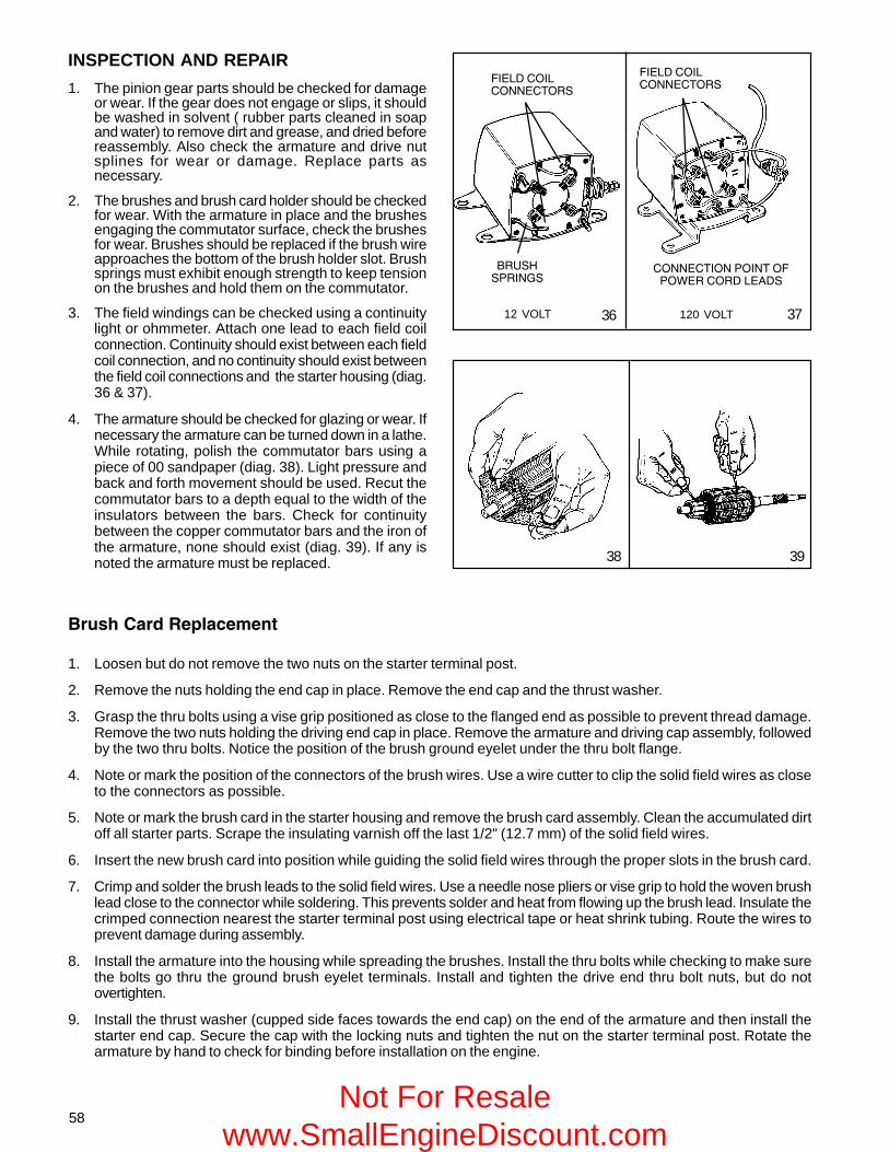
58
INSPECTION AND REPAIR
1. The pinion gear parts should be checked for damageor wear. If the gear does not engage or slips, it shouldbe washed in solvent ( rubber parts cleaned in soapand water) to remove dirt and grease, and dried beforereassembly. Also check the armature and drive nutsplines for wear or damage. Replace parts asnecessary.
2. The brushes and brush card holder should be checkedfor wear. With the armature in place and the brushesengaging the commutator surface, check the brushesfor wear. Brushes should be replaced if the brush wireapproaches the bottom of the brush holder slot. Brushsprings must exhibit enough strength to keep tensionon the brushes and hold them on the commutator.
3. The field windings can be checked using a continuitylight or ohmmeter. Attach one lead to each field coilconnection. Continuity should exist between each fieldcoil connection, and no continuity should exist betweenthe field coil connections and the starter housing (diag.36 & 37).
4. The armature should be checked for glazing or wear. Ifnecessary the armature can be turned down in a lathe.While rotating, polish the commutator bars using apiece of 00 sandpaper (diag. 38). Light pressure andback and forth movement should be used. Recut thecommutator bars to a depth equal to the width of theinsulators between the bars. Check for continuitybetween the copper commutator bars and the iron ofthe armature, none should exist (diag. 39). If any isnoted the armature must be replaced. 38 39
� !"�� #��$�% &$�$��
1. Loosen but do not remove the two nuts on the starter terminal post.
2. Remove the nuts holding the end cap in place. Remove the end cap and the thrust washer.
3. Grasp the thru bolts using a vise grip positioned as close to the flanged end as possible to prevent thread damage.Remove the two nuts holding the driving end cap in place. Remove the armature and driving cap assembly, followedby the two thru bolts. Notice the position of the brush ground eyelet under the thru bolt flange.
4. Note or mark the position of the connectors of the brush wires. Use a wire cutter to clip the solid field wires as closeto the connectors as possible.
5. Note or mark the brush card in the starter housing and remove the brush card assembly. Clean the accumulated dirtoff all starter parts. Scrape the insulating varnish off the last 1/2" (12.7 mm) of the solid field wires.
6. Insert the new brush card into position while guiding the solid field wires through the proper slots in the brush card.
7. Crimp and solder the brush leads to the solid field wires. Use a needle nose pliers or vise grip to hold the woven brushlead close to the connector while soldering. This prevents solder and heat from flowing up the brush lead. Insulate thecrimped connection nearest the starter terminal post using electrical tape or heat shrink tubing. Route the wires toprevent damage during assembly.
8. Install the armature into the housing while spreading the brushes. Install the thru bolts while checking to make surethe bolts go thru the ground brush eyelet terminals. Install and tighten the drive end thru bolt nuts, but do notovertighten.
9. Install the thrust washer (cupped side faces towards the end cap) on the end of the armature and then install thestarter end cap. Secure the cap with the locking nuts and tighten the nut on the starter terminal post. Rotate thearmature by hand to check for binding before installation on the engine.
12 VOLT 120 VOLT
������� ������ �������������
3736
����������������
����������������
������ ����
Not For Resale www.SmallEngineDiscount.com

59
CHAPTER 7 FLYWHEEL BRAKE SYSTEMSGENERAL INFORMATION
Tecumseh’s brake systems provide two methods of meeting compliance standards which has become a federal lawas of June 30, 1982. There are two additional methods used by equipment manufacturers that also meet compliancestandards and they are as follows:
1. Use of the blade brake clutch in conjunction with either a top or side mounted recoil starter or 12 volt electricstarter. The blade stops within three seconds after the operator lets go of the blade control bail at the operatorposition and the engine continues to run. Starter rope handle is either on the engine or on the equipment handle.
2. Use of a recoil starter (top or side mounted) with the rope handle on the engine as opposed to within 24 inches(60.9 cm) of the operator position. This method is acceptable if the mower deck passes the 360 degree foot probetest. A specified foot probe must not contact the blade when applied completely around the entire blade housing.This alternative can be used with engine mounted brake systems and typical bail controls. The blade stops withinthree seconds after the operator lets go of the engine/blade control bail at the operator position.
Tecumseh’s Flywheel Brake system provides consumer safety by stopping the engine and blade within three secondsafter the operator releases the engine/blade control bail at the handle of the lawnmower. These systems are availableon both recoil and electric start models. The engine stopping time is affected by the engine R.P.M. Consult microfichecard #30, the Plus 1 or Parts Smart Look-Up system, or Service Bulletin #107 to determine the correct engine RPMor blade tip speed.
OPERATION
BOTTOM SURFACE SYSTEM
In the stop position with the handle mounted engine / blade control released, the torsion spring rotates the brake leverforcing the brake pad against the underside of the flywheel, actuates the ignition kill switch and on electric startmodels, opens the starter interlock switch (diag. 1).
In order to restart the engine, the handle mounted engine / blade control must be applied. This action pulls the brakepad away from the flywheel, opens the ignition kill switch and on electric start models, closes the starter interlockswitch. This will allow the engine to be started by energizing the starter with a starter switch (diag. 2).
�������������
���������
21
���� �������������
������������ �����
���
���� ����������������
Not For Resale www.SmallEngineDiscount.com

60
OPERATION (CONTINUED)
INSIDE EDGE SYSTEM
In the stop position the brake pad is applied to the inside edge of the flywheel, at the same time the ignition systemis grounded (diag. 3).
In order to restart the engine, the brake control must be applied. This action pulls the brake pad away from the insideedge of the flywheel and opens the ignition kill switch. On electric start systems the starter is energized by anignition switch or a two motion control. On non-electric start systems, the recoil starter rope must be pulled to startengine (diag. 4).
3 4
5
�����������������������
COMPONENTS
Both the Bottom Surface and the Inside Edge systemsuse the following components:
The brake lever and pad assembly consists of a steellever with a brake pad bonded to the lever (diag. 5).
The ignition kill switch is a plastic block with a wireextending out of it. The wire is attached to a terminalwhich is connected to the ignition kill wire. The brakelever contacts and grounds the wire of the switch whenthe engine / blade control is released, and the ignitionmodule is grounded. This in turn kills the ignition (diag.5).
The interlock switch is a push button switch that isactivated by the brake lever when the engine / blade controlis actuated. If there is a starter switch used to start theengine, the interlock switch acts as a safety switch andwill not allow the starter to crank unless theengine / blade control is depressed.
Where a two motion control is used the interlock switchis utilized as the starter switch.
The Torsion Spring supplies the pressure to the brakelever and brake pad to stop the flywheel.
The Control Cable transfers the motion of theengine / blade control to the brake system.
�����������������������
�������������
�������������
���������������
����������
�����������������
Not For Resale www.SmallEngineDiscount.com

61
������������������
6
7
�����������������
�����
����� ������
����������
�����������
8
9
������
�����������������
������
��������
SERVICE
If the brake system fails to kill the ignition and stop the blade within 3 seconds the following service proceduresshould be followed.
FLYWHEEL REMOVAL
NOTE: BEFORE THE FLYWHEEL IS REMOVED OR REPLACED, THE BRAKE PRESSURE ON THE FLYWHEELMUST BE RELIEVED AS OUTLINED BELOW UNDER "BRAKE LEVER AND PAD".
Remove the flywheel as outlined in Chapter 9 under "Disassembly".
BRAKE LEVER AND PAD
Bottom Surface
To relieve the brake pressure on the flywheel, remove thetorsion spring by firmly grasping the short end of thespring with a pliers and unhook the spring from the bracketthen remove the flywheel (diag. 6).
Remove the brake lever and pad assembly. Inspect thebrake pad for dirt, oil or grease contamination. If the padis contaminated, or if there is less than .060" (1.524 mm)of brake pad material at the pad's thinnest point,replacement is necessary. The brake pad is bonded tothe brake lever and must be replaced as an assembly.Install the brake lever and pad assembly and continue toreassemble the brake system in the reverse order ofdisassembly.
NOTE: WHEN REMOVING THE BRAKE BRACKET THETORSION SPRING MUST BE RELEASED BEFORE THETOP STARTER BOLT IS REMOVED OR THE THREADSIN THE CYLINDER BLOCK WILL BE DAMAGED.
Inside Edge
To relieve the brake pressure on the flywheel, compressthe spring by moving the lever toward the spark plug,when the hole in the lever aligns with the hole in thebracket, secure the lever with alignment tool 670298 thenremove the flywheel (diag. 7). Remove the alignment tool.Release the spring tension by unhooking the short endof the spring from bracket with a pliers. Remove the “E”clip from the brake pad shaft. Slide the pad lever fromthe shaft and unhook the link. Inspect the brake pad fordirt, oil or grease contamination. If the pad is contaminated,or if there is less than .060" (1.524 mm) of brake padmaterial at the pad's thinnest point, replacement isnecessary. The brake pad is bonded to the brake leverand must be replaced as an assembly. Rehook the link,install the brake lever and pad assembly, install the "E"clip, rehook the short end of the spring and continue toreassemble the brake system in the reverse order ofdisassembly.
IGNITION GROUNDOUT TERMINALInspect the ignition kill switch grounding clip for properalignment and contact with the brake arm. Insure that allelectrical connections are clean and secure (diag. 8 &9). Not For Resale
www.SmallEngineDiscount.com
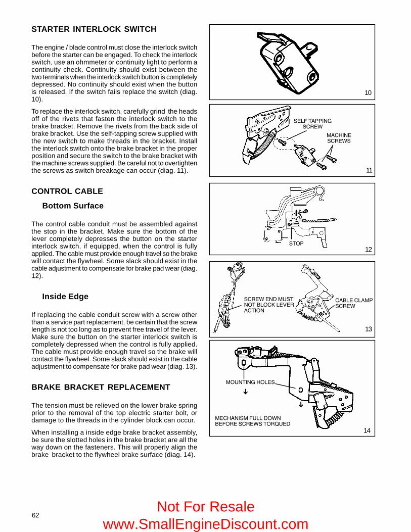
62
�������������
����������������������������������
13
11
10
�
�
���������������
���
���������������������������������������
������������
��������������
14
12
STARTER INTERLOCK SWITCH
The engine / blade control must close the interlock switchbefore the starter can be engaged. To check the interlockswitch, use an ohmmeter or continuity light to perform acontinuity check. Continuity should exist between thetwo terminals when the interlock switch button is completelydepressed. No continuity should exist when the buttonis released. If the switch fails replace the switch (diag.10).
To replace the interlock switch, carefully grind the headsoff of the rivets that fasten the interlock switch to thebrake bracket. Remove the rivets from the back side ofbrake bracket. Use the self-tapping screw supplied withthe new switch to make threads in the bracket. Installthe interlock switch onto the brake bracket in the properposition and secure the switch to the brake bracket withthe machine screws supplied. Be careful not to overtightenthe screws as switch breakage can occur (diag. 11).
CONTROL CABLE
Bottom Surface
The control cable conduit must be assembled againstthe stop in the bracket. Make sure the bottom of thelever completely depresses the button on the starterinterlock switch, if equipped, when the control is fullyapplied. The cable must provide enough travel so the brakewill contact the flywheel. Some slack should exist in thecable adjustment to compensate for brake pad wear (diag.12).
Inside Edge
If replacing the cable conduit screw with a screw otherthan a service part replacement, be certain that the screwlength is not too long as to prevent free travel of the lever.Make sure the button on the starter interlock switch iscompletely depressed when the control is fully applied.The cable must provide enough travel so the brake willcontact the flywheel. Some slack should exist in the cableadjustment to compensate for brake pad wear (diag. 13).
BRAKE BRACKET REPLACEMENT
The tension must be relieved on the lower brake springprior to the removal of the top electric starter bolt, ordamage to the threads in the cylinder block can occur.
When installing a inside edge brake bracket assembly,be sure the slotted holes in the brake bracket are all theway down on the fasteners. This will properly align thebrake bracket to the flywheel brake surface (diag. 14).
Not For Resale www.SmallEngineDiscount.com

63
CHAPTER 8 IGNITIONGENERAL INFORMATION
The ignition systems used on Tecumseh engines are either solid state capacitor discharge modules or magneto ignitionsystems. The basic functional difference is that the solid state modules are triggered by an electronic switch (SCR).Magneto ignition systems rely on the mechanical action of opening and closing a set of moveable contact points totrigger when the spark will occur.
The solid state ignition system consists of a flywheel magnet and key, charge coil, capacitor, a silicon controlled rectifier,pulse transformer, trigger coil, high tension lead, and a spark plug. Everything except the flywheel magnet, key and thespark plug are located in a encapsulated ignition module. This solid state (CDI - Capacitive Discharge Ignition) module isprotected by epoxy filler from exposure to dirt and moisture. This system requires no maintenance other than checks ofthe high tension lead and spark plug.
The Tecumseh magneto ignition consists of a stator assembly made of laminations, a coil, contact points, condenser, apermanent magnet mounted in the flywheel, high tension lead, and a spark plug. The coil is sealed by epoxy filler, and thepoints and condenser are sealed from dirt and moisture by a crankshaft seal and cover gasket.
POINTS OPEN
PATH OF MAGNETICLINES OF FORCE
FLYWHEELROTATION
POINTSCLOSED
MAGNET
OPERATION
SOLID STATE IGNITION SYSTEM (CDI)
As the magnets in the flywheel rotate past the charge coil,electrical energy is produced in the module. The energy isstored in the capacitor ( approx. 200 volts) until it is releasedby an electrical switch (SCR). As the magnet continues torotate, it travels past a trigger coil where a low voltagesignal is produced. This low voltage signal closes the SCRswitch, allowing the energy stored in the capacitor to flowto a transformer where the voltage is increased from 200volts at 200 RPM to 22,000 volts at 3000 RPM. This voltageflows through the high tension lead to the spark plug whereit arcs across the electrodes and ignites the air-fuel mixture(diag. 1).
MAGNETO IGNITION SYSTEM (POINTS)
As the flywheel turns, the magnets that are mounted inthe wheel, pass the coil mounted on the stator. As themagnet's North Pole enters the area of the center leg ofthe stator, a magnetic field is concentrated through thelaminations to the magnet's South Pole. This causes ageneration of current flow in the coil's primary winding. Theignition points are closed (diag. 2).
As the flywheel continues to rotate, the North Poleapproaches the last leg of the lamination stack. Themagnetic field through the center leg reverses, producinga large change in the magnetic field, and a high current inthe primary side of the coil (diag. 3).
At this time, the contacts open and the primary currentstops flowing. This change in current causes a voltage inthe primary, which induces a high voltage in the secondarywinding of the coil. The voltage travels through the sparkplug wire, to the spark plug and jumps the gap of the plugto ignite the air/fuel mixture.
1
2
3Not For Resale www.SmallEngineDiscount.com

64
IDENTIFICATION OF TECUMSEH IGNITION SYSTEMS
COMPONENTS OF A TECUMSEH MAGNETOIGNITION SYSTEM (DIAG. 7)
A. Flywheel with magnets
B. Coil
C. Condenser
D. Spark plug
E. Contact points
F. Ignition cam
G. Stator plate (dust cover, cam wiper, and laminations.)
H. Flywheel key
The flywheel with magnets provide the magnetic flux(or field) which is necessary to induce the low voltage inthe primary circuit. A horseshoe magnet is a good exampleof how the magnets function in the flywheel. The magnetsare either cast in or glued onto the flywheel, and are not areplaceable item (diag. 8).
The ignition coil is used to increase the low voltage inthe primary to high voltage in the secondary, capable ofjumping the spark plug gap. The coil consists of a primaryand a secondary winding of wire. The primary is the lowvoltage (200 - 300 volts) winding, consisting ofapproximately 150 turns of heavy gauge wire next to thecore. The secondary winding consists of approximately10,000 turns of very fine wire wrapped over the primary.When induced by the primary, the secondary windinggenerates a voltage of between 10,000 - 20,000 volts, whichcan arc the spark plug gap (diag. 9).
�������������
�������� �����
���� ��� ���
��������������������������
��������� ���
���������������
����������
4 5
7
8
9
�����������������������������������
���������
��������������������������
6
������
�������������
��������������
����������������
����������
Not For Resale www.SmallEngineDiscount.com

65
The condenser acts as an electrical shock absorber toprevent arcing between the contact points as they open.Arcing will lower the voltage at the spark plug, as well asburn and pit the contact points. The condenser is areplaceable item (diag. 10).
The spark plug is made up of two electrodes. The outsideelectrode is grounded and secured to the threaded sleeve.The center electrode is insulated with porcelain. The twoare separated by an air gap which creates a resistance. Alarge voltage from the secondary arcs the air gap whichcauses a spark and ignites the air-fuel mixture in the cylinder(diag. 11).
The contact points consist of an insulated, movable pointthat connects to the coil primary lead, and a stationarypoint that is grounded to the stator body. Spring tensionholds the points together making a complete path for theprimary circuit, and are opened by the action of the pointarm which rests on the ignition cam. The contact pointsare a replaceable item (diag. 12).
The ignition cam is an oblong device which rotates withthe crankshaft, and opens the points for firing the ignitionsystem. It is important to check the ignition cam forroughness, if rough replace the cam. When inserting theignition cam onto the crankshaft make sure that the sidestamped "TOP", or the side that has an arrow on it facesthe mechanic (diag. 13).
NOTE: SOME IGNITION CAMS ARE MACHINEDDIRECTLY ONTO THE CRANKSHAFT AND ARE NOTREPLACEABLE.
The stator plate is an aluminum fixture which houses thepoints, cam wiper, condenser, and has the laminationsriveted to it. The laminations are strips of iron rivetedtogether to form an iron core. Rust or debris in betweenthe laminations will hamper the performance of the ignitionsystem. If corrosion on the laminations is severe, the statorplate should be replaced (diag. 14).
The flywheel key locates the flywheel to the crankshaftin the proper position. If a flywheel key is sheared, or partiallysheared, the engine will not start or be difficult to start(diag. 15).
12
13
14
15
10
11
Not For Resale www.SmallEngineDiscount.com

66
Check flywheel fordamaged or sheared key
Set proper air gap onexternal coil
Set proper point gap, checkcondensor and timing
Testcoil for intermittent or
weak spark
Check electric starter andbattery if applicable
Equipment problem,check switches, wiringand equipment controls
Parasitic load
Engine problem, check forshorts or grounds in wiring
Disconnect ignitioncut-off wire
at the ignition coil &repeat test
Oil shutdown oron/off rocker switch
Check for proper air gapon external
coil and repeat test
Check flywheel magnetsfor strength
Test ignition module
Spark
Replace spark plug
Isolate engine and repeattest
No Spark
Spark
Engine runserratically or shuts
off, restarts
IGNITION TROUBLESHOOTING
Check for spark
Engine WillNot Start
No Spark
Not For Resale www.SmallEngineDiscount.com

67
TESTING PROCEDURE
1. Check for spark using a commercially available sparktester and following the tester's recommendedprocedure.
2. Check for the correct spark plug and for cracks in theporcelain, pitted or burned electrodes, excessivecarbon buildup, and proper air gap setting. Replace ifquestionable.
3. Remove the blower housing, disconnect the ignitionground lead at the ignition coil (solid state only).Reinstall the blower housing and crank the engine over.If spark occurs, check the ignition switch, safetyinterlock switches, electrical wiring for shorting toground, or oil shutdown switch.
NOTE: STANDARD POINT IGNITION MAY HAVE TO BEDISCONNECTED AT THE IGNITION SHUTOFF (AT THESPEED CONTROL).
4. Check the air gap between the flywheel magnets andthe laminations of an externally mounted coil or module.It should be .0125 (.317 mm) or use gauge part #670297.
5. Check the flywheel magnets for the proper strengthusing this rough test. Hold a screwdriver at the extremeend of the handle with the blade down, move the bladeto within 3/4 inch (19.05 mm) of the magnets. If thescrewdriver blade is attracted to the magnets, themagnetic strength is satisfactory (diag. 16).
6. Examine the stator components (diag. 17).
A. Check the ignition cam for roughness.
B. Check the movable point arm that rests on theignition cam for wear.
C. Check the spring steel on the point assembly forevidence of excessive heat.
D. Check contact points for wear. If they are pitted orburned, this is an indication that the condenser isnot functioning properly. If any of the above are faulty,replace accordingly.
E. When replacing the points, also replace thecondenser.
F. After the points are replaced and engine is re-timed,be sure to clean the points with lint free paper. Anengine will not run smoothly if the points areimproperly set or coated with even a small quantityof oil, etc.
7. Examine the coil and lamination assembly (either
16
17
�������� �!"�##�
������
18
internal or external) for cracks in the insulation or other damage which would cause shorts or leakage of current.Make sure the electrical leads are intact, especially where they enter the coil (diag. 18).
8. Check the operation of the coil using an approved tester. Follow the instructions furnished with the test unit orbooklets offered by the Tecumseh Products Co. Engine and Transmission Group Service Division. If the coil orlamination assembly is defective, replace as necessary.
NOTE: IF LAMINATIONS ARE BAD ON AN INTERNAL COIL ASSEMBLY, THE ENTIRE STATOR BODY MUST BEREPLACED SINCE THE LAMINATIONS ARE PERMANENTLY RIVETED TO THE STATOR.
External coils are permanently attached to the lamination and must be serviced as an assembly.
Not For Resale www.SmallEngineDiscount.com

68
When reinstalling the plug make sure it is clean of all foreign material.
NOTE: DO NOT USE A SAND BLASTER TO CLEAN PLUGS, MICROSCOPIC PARTICLES LEFT IN THE PLUG CANSCORE THE ENGINE CYLINDER DURING OPERATION. USE A SOLVENT AND A WIRE BRUSH TO CLEAN, ANDBLOW OUT THOROUGHLY WITH COMPRESSED AIR.
Replace the spark plug with the proper spark plug. Consult the proper parts breakdown for the spark plug to be used inthe engine being serviced.
Set the spark plug gap at .030" (.762 mm).
Install the spark plug and tighten to 250 inch pounds torque (28.5 Nm). If a torque wrench is not available, screw sparkplug in as far as possible, by hand, and use a spark plug wrench to turn spark plug 1/8 to 1/4 of a turn further if using theold spark plug or 1/2 of a turn further if using a new spark plug.
CONDITIONS CAUSING FREQUENT SPARK PLUG FOULING
1. Carburetor setting too rich or air cleaner restricted.
2. Partially closed choke shutter.
3. Poor grade of gasoline.
4. Improper fuel.
5. Restricted exhaust system.
6. Incorrect spark plug.
7. Incorrect spark plug gap.
8. Oil level too high, or breather is restricted.
9. Faulty piston rings.
10. Weak ignition system.
IGNITION TIMING PROCEDURE
In order for an engine to run effectively and efficiently, the spark must ignite the compressed air-fuel mixture when thepiston is in a specific position to deliver maximum power. This position is known as Before Top Dead Center (BTDC). If themixture is ignited too soon, kickback can be experienced due to preignition. If the mixture is ignited too late, loss ofpower can be experienced due to retarded spark.
The Standard Point System
Internal coils are used on small and medium frame 4 cycle engines. First check the specification charts in the back ofthis manual or the quick reference chart for the correct ignition dimensions, (point gap setting and timing specification)depending on the model of engine.
SERVICE
To remove ignition components from the engine, seeChapter 9 under "Disassembly".
SPARK PLUG SERVICE
Spark plugs should be removed, cleaned, and adjustedperiodically.
Check the air gap with a spark plug gap gauge and adjustaccordingly. Set the spark plug gap at .030" (.762 mm)(diag. 19).
Replace the plug if the center and ground electrodes arepitted or burned, or if the porcelain is cracked or discolored.
19
������� ���������
���� ������ ����20
Not For Resale www.SmallEngineDiscount.com

69
Begin the procedure by replacing the points if necessary.To do this remove the nut that secure the movable portionof the breaker points. Remove the screw from the stationaryportion of the breaker points and the worn breaker pointassembly. Install a new breaker point assembly and adjustthe point gap. This is done by rotating the crankshaft untilthe point arm is resting on the high side of the ignitioncam. Set the point gap by loosening the screw on themovable point set and insert a feeler gauge perspecification. Adjust the point gap so that a light drag isfelt on the feeler gauge. Tighten the screw and recheck thegap. Leave the leads unattached for the timing procedure.Use this procedure on all standard point ignition systemswhen point replacement is necessary (diag. 21).
Install a dial indicator (Part # 670241), equipped with thecorrect tip on the extender leg. Use the small tip for engineswith timing dimensions of between top dead center (T.D.C.)and .050" (1.27 mm) before top dead center (B.T.D.C.).Use the large tip for engines with timing dimensions ofbetween .051" (1.295 mm) B.T.D.C. to .150" (3.81 mm)B.T.D.C. Make sure to secure the extender leg in positionto locate the tip directly over the piston head. Loosen thescrew on the side of the adaptor sleeve to allow the sleeveto be turned into the threads of the spark plug hole, not theentire dial indicator. This will ensure the proper location ofthe tip. Once the adapter sleeve is secured in the hole,tighten screw on sleeve adaptor to prevent the dial frommoving up or down, which would give a false reading (diag.22).
Find T.D.C. with both valves closed by rotating thecrankshaft clockwise when looking at the magneto end ofthe crank, until the needle on the dial stops and reversesdirection. Where the needle stops is T.D.C. Loosen thescrew on the dial, and rotate the dial so that zero is linedup with the needle at T.D.C. Tighten the screw on the dialto secure it in place (diag. 23).
While watching the needle on the dial indicator, rotate thecrankshaft counterclockwise when looking at the magnetoend of the crank, .010" (.254 mm) past the B.T.D.C.dimension. Then rotate the crankshaft clockwise to theproper B.T.D.C. dimension, this will take out any slackbetween the connecting rod and crankshaft assembly.
Example: If the specification of .080" (2.032 mm) is theB.T.D.C. dimension, rotate the crankshaft counter-clockwise so that the needle on the dial indicator travels to.090" (2.286 mm) B.T.D.C. (diag. 24), then rotate thecrankshaft clockwise so that the needle travels to thespecified dimension of .080" (2.032 mm) B.T.D.C. (diag.25).
Next, if the original breaker points are being used,disconnect the leads from the point terminal. Reinstall thenut & tighten. Connect one lead of a continuity light, orohmmeter to the point terminal and the other lead to agood ground. Loosen the two bolts holding down the statorand rotate the stator until the continuity light or ohmmeterindicates a break in the circuit. Torque down the statorbolts while maintaining the stator plate position and thetiming procedure is completed. Reconnect the leads onthe point terminal and tighten the nut making sure that theleads do not touch the flywheel (diag. 26).
2524
23
22
21
������! !��$�$%&�##�
�������!%!��$�!�$�##�
������!�
����'�����
����'�
��������
����� �'��
��
���������
�������
(continued on top of next page)
26
Not For Resale www.SmallEngineDiscount.com

70
30
Before putting the dust cover back on the points box, cleanthe points by sliding lint free paper back and forth betweenthe contacts. Manually, open the points when removingthe paper to eliminate paper fibers from remaining betweenthe contact points (diag. 27).
Fixed Timed System (External coil)
This system has the contact points and condenser mountedunder the flywheel with the laminations and coil mountedoutside the flywheel. This system is identified by the squarehole in the stator, the round configuration of the coil, andon older coils, the word "Grey Key" is stamped on the coilto identify the proper flywheel key to be used. Whenordering an external coil for replacement from TecumsehProducts, a solid state module will be received as areplacement. The new module will be supplied with theproper flywheel key (diag. 28).
Torque down the stator bolts to secure the stator in place.Next, rotate the crankshaft until the point arm is resting onthe high side of the ignition cam. Set the point gap at .020"(.508 mm), by loosening the screw on the movable point,and insert a .020" (.508 mm) feeler gauge between thecontact points (diag. 29). Tighten the screw on the movablepoint and then recheck the point gap. Be sure to cleancontact points with lint free paper (diag. 27).
NOTE: The flywheel key used on engines with an externalcoil and points looks similar to the solid state key, however,timing will be effected if the wrong key is used.
Reinstall the proper flywheel key, flywheel, washer andtorque down the flywheel nut to specification. Reinstall theexternal coil and set the proper air gap to .0125" (.3175mm) using air gap gauge, part # 670297 between themagnets and laminations and torque the mounting screwsto specification. Remove the air gap gauge and rotate theflywheel to check for any possible striking points. If noneare found, the air gap is set correctly and the timingprocedure is completed (diag. 30).
Solid State Ignition Timing
Timing is set using a .0125" (.3175 mm) air gap gauge(Part No. 670297). Loosen the two hold-down screws, insertthe .0125" (.3175 mm) remove semi-color gauge betweenthe laminations and the magnet on the flywheel. Slide thesolid state ignition assembly against the air gap gaugeand the flywheel magnet. Torque the two hold down screwsto the correct specification and remove the air gap gauge.Rotate the flywheel one full revolution to check for anypossible striking points. If none are found, the air gap isset correctly and the timing procedure is completed (diag.30).
28
29
27
���������� ��
�!�$"����("�##�
Not For Resale www.SmallEngineDiscount.com

71
32
31
33
Other Solid State Systems
The following systems are located under the flywheel. Allcomponents are encapsulated into one module. No timingis necessary with this type (diag. 31, 32, 33).
Check the system by checking for a spark or use acommercially available test equipment.
SERVICE TIPS
DO NOT:
Interchange flywheels, flywheel keys, spark plugs,condensers, or points. (Some systems do not usestandard points and condensers.)
Use flywheels with cooling fins that are broken off.
Reglue ceramic magnets back onto the inside of theflywheel.
Re-oil the cam wiper in a magneto system.
Use a standard business card as an air gap gauge.
File the contact points.
Attempt to reglue the spark plug lead back into a coilor a solid state module.
Store a solid state module within 20 feet (6.1 meters)of an unshielded welder.
PLEASE DO:
Follow directions carefully.
Lookup the correct ignition dimensions in the propermechanic's manual or quick reference chart, for theengine being repaired.
Clean points with lint free paper after setting gap.
Reinstall the point terminal nut and tighten afterremoving leads, before timing procedure.
Remember to correctly TIME a Tecumseh engine, evenwhen just changing points on a magneto system.
Remember to use correct air gap gauge.
Check for correct flywheel key which effects timing.
Not For Resale www.SmallEngineDiscount.com

72
CHAPTER 9 INTERNAL ENGINE AND CYLINDER
GENERAL INFORMATION
This chapter covers the cylinder block, piston and rod assemblies, cylinder head, crankshaft, camshaft, valve train,breather, cylinder cover, flywheel, counterbalance systems, and lubrication systems. The governors and the governorsystems are covered in Chapter 4.
All Tecumseh engines covered in this manual are four cycle engines with the valves in the engine block. The crankshaftposition is designated as either horizontal or vertical as the engine rests on its base. The engines identified by decals ormodel as XL (Extra Life) or XL/C (Extra Life / Commercial ) are made using aluminum alloy diecast around a cast ironcylinder liner. However, not all engines with cast iron cylinder liners are identified as XL or XL/C. Engine blocks of theheavy frame series (HH, VH) are made of cast iron. All other engines use aluminum alloy for the cylinder block along withpistons that are chromium plated.
OPERATION
4-CYCLE ENGINE THEORY
All 4-cycle engines require four piston strokes to completeone power cycle. The flywheel on one end of the crankshaftprovides the inertia to keep the engine running smoothlybetween power strokes.
The camshaft gear is twice as large as the mating gear onthe crankshaft so as to allow proper engine valve timing foreach cycle. The crankshaft makes two revolutions for everycamshaft revolution.
1. INTAKE. The intake valve is open and the exhaust valveis closed. The piston is traveling downward creating alow pressure area, drawing the air-fuel mixture fromthe carburetor into the cylinder area above the piston(diag. 1).
2. COMPRESSION. As the piston reaches Bottom DeadCenter (BDC) the intake valve closes. The piston thenrises, compressing the air-fuel mixture trapped in thecombustion chamber (diag. 2).
3. POWER. During this piston stroke both valves remainclosed. As the piston reaches the Before Top DeadCenter (BTDC) ignition point, the spark plug fires,igniting the air-fuel mixture. In the time it takes to igniteall the available fuel, the piston has moved to Top DeadCenter (TDC) ready to take the full combustive force ofthe fuel for maximum power during downward pistontravel. The expanding gases force the piston down(diag. 3).
4. EXHAUST. The exhaust valve opens. As the pistonstarts to the top of the cylinder, the exhaust gases areforced out (diag. 4).
After the piston reaches Top Dead Center (TDC), the fourstroke process will begin again as the piston movesdownward and the intake valve opens.
3 4
1 2������������� �
����� �������
Not For Resale www.SmallEngineDiscount.com

73
LUBRICATION SYSTEMS
The lubrication system used with all Tecumseh horizontalcrankshaft engines covered in this manual utilize a splashtype system. An oil dipper on the connecting rod splashesoil in the crankcase to lubricate all internal moving parts.Some engines have the dipper as an integral part of theconnecting rod assembly, while others have a dipper thatis bolted on with one of the rod bolts (diag. 5).
All vertical shaft engines use a positive displacementplunger oil pump or rotary type oil pump. Oil is pumpedfrom the bottom of the crankcase, up through the camshaftand over to the top main bearing. Oil under pressurelubricates the top crankshaft main bearing and camshaftupper bearing (diag. 6).
On all Tecumseh vertical shaft 4-cycle engines, the oil issprayed out under pressure through a small hole betweenthe top camshaft and crankshaft bearing to lubricate thepiston, connecting rod, and other internal parts (diag. 7).
The plunger style oil pump is located on an eccentric onthe camshaft. As the camshaft rotates, the eccentric movesthe barrel back and forth on the plunger forcing oil throughthe hole in the center of the camshaft. The ball on the endof the plunger is anchored in a recess in the cylinder cover(diag. 8).
������������������������
5
6
7 8
COUNTERBALANCE SYSTEMS
Some Tecumseh engines may be equipped with an Ultra-Balance® counterbalance system. This system uses asingle weighted shaft that is driven off the crankshaft. Theshaft's function is to counteract the imbalance caused bythe counterweights on the crankshaft and the combustionforces (diag. 9).
9
�������������
�����������
����������������������������������
������������������
���������������������
�����
�������
�����
��������
������
��������
����������������������
����
��� ������������
������������� ������������
������
��� ���������������
�����������������
Not For Resale www.SmallEngineDiscount.com

74
COMPONENTS
The cylinder block houses the piston, valves and along with the cylinder cover all the internal components. The block isa one piece diecast aluminum alloy or cast iron cylinder casting (diag. 10).
The piston transmits the force of the burning and expanding gases through the connecting rod to the crankshaft.
The piston rings provide the seal between the cylinder wall and the piston. The rings keep the combustion pressuresfrom entering the crankcase and also wipe the oil off the cylinder wall and return it to the sump.
The connecting rod assembly is the link between the piston (piston pin) and the crankshaft.
The cylinder head is a one piece aluminum alloy or cast iron casting that is bolted to the top of the cylinder block. Themany fins provide cooling for the engine.
The crankshaft converts the up and down piston movement to the rotational force (torque) by an offset crankpin or rodjournal.
The camshaft lobes raise and lower the lifters at the proper time to allow air and fuel in and exhaust out of the cylinder.Teeth on the camshaft gear time the camshaft to the crankshaft.
The valves allow air-fuel mixture to enter the cylinder and exhaust gases to exit. The valves provide a positive seal whenclosed.
The valve springs return the valves to the closed position and must be strong enough to maintain valve lifter and camlobe contact. The valve retainers lock the spring to the valve stem.
The valve lifters maintain contact on the camshaft and push the valves open.
The crankcase breather is a one way check valve that allows air out and prevents air from coming in. It allows the engineto develop a partial vacuum in the crankcase during operation.
The cylinder cover (or flange on verticals) provides the bearing surface for the power take off (P.T.O.) end of the crankshaftand camshaft. This bolted on cover is removed to provide access to all internal components.
The oil pump (vertical shaft only) consists of a steel plunger and a nylon housing that rides on the camshaft eccentric.
The flywheel provides the mass to smooth the effects of one power stroke every other crankshaft revolution. Flywheelsare made of aluminum alloy or cast iron. The flywheel fins act as a fan to cool the engine.
10
������
��������
�����������
��������
�����������
��� ������������
�����������
������������
���������
�����
����������
��� �����
������������
Not For Resale www.SmallEngineDiscount.com

75
ENGINE OPERATION PROBLEMS
OVERHEATS
Excessive engine loading
Low oil level or wrong viscosity oil
Cooling air flow, obstructed orclogged cooling fins
Carburetor improperly adjusted orimproper RPM setting
Incorrect spark plugor Ignition timing
Carbon in the combustion chamber
Incorrect or damaged flywheel key
ENGINE KNOCKS
Associated equipment loose orimproperly adjusted
Check for excessive carbon incombustion chamber
Loose flywheel, examine key,keyway, and proper flywheel nut
torque
Incorrect spark plug or Ignitiontiming
Loose or worn connecting rod
Worn cylinder
SURGES OR RUNS UNEVENLY
Fuel cap vent obstructed
Dirty carburetor or air filter
Carburetor improperly adjusted
Governor sticking, binding orimproper RPM setting
Carburetor linkage, shafts orshutters sticking or binding
Incorrect spark plug or Intermittentspark, check ignition
EXCESSIVE OIL CONSUMPTION
Oil level above full
Wrong viscosity oil
Excessive engine speed
Engine cooling fins dirty causingoverheating
Breather damaged, dirty orimproperly installed
Damaged gaskets, seals or"O" rings
Lean carb setting causingoverheating (adjustable carb)
Piston rings worn
Worn or glazed cylinder
Valve guides worn excessively
Valve guides worn excessively
Not For Resale www.SmallEngineDiscount.com

76
ENGINE MISFIRES
Wrong or fouled spark plug
Carburetor improperly adjusted
Valves sticking or not seating properly
Incorrect spark plug orIgnition timing
Excessive carbon build up
Improper Valve Lash orWeak valve springs
ENGINE OPERATION PROBLEMS
BREATHER PASSING OIL
Oil level too high
Excessive RPM or improper governorsetting
Damaged gaskets, seals or "O" rings
Breather damaged, dirty or improperlyinstalled
Piston rings not properly seated or ringend gaps are aligned
Angle of operation too severe
ENGINE VIBRATES EXCESSIVELY
Bent crankshaft
Attached equipment out of balance
Loose mounting bolts
If applicable counter balance notproperly aligned
LACKS POWER
Air intake obstructed
Lack of lubrication or improperlubrication
Carburetor improperly adjusted
Exhaust Obstructed
Improper valve lash
Loss of compression (worn rings,blown head gasket)
Not For Resale www.SmallEngineDiscount.com

77
TESTING
ENGINE KNOCKS
1. Check the blade hub, blade adapter, or crankshaft coupler for loose fit, loose bolts, or crankshaft key damage.Remove, inspect, replace if necessary. Reinstall and re-torque the bolts to the proper torque.
2. Check the flywheel key and the flywheel and crankshaft keyway for wear or partial shearing. Replace if any damageis evident. Tighten the flywheel nut to the proper torque.
3. Check for the correct ignition module air gap or the correct timing (point ignition). Replace the points and condenserif the points show any wear, oil, or pitting.
4. Remove the cylinder head and check for excessive carbon in the combustion chamber. Also check for the correcthead gasket used, and check the spark plug for proper reach and heat range (correct spark plug for the engine).
5. Check for the proper valve lash using a feeler gauge, and check the internal components (piston, cylinder, connectingrod, crankshaft journal) for excessive clearance.
ENGINE OVERHEATS
1. Make sure the engine is not being overloaded. Remove excess load (sharpen blades, limit operation speed, processless material).
2. Check the oil level and viscosity. Add or replace as necessary.
3. Check for clogged cooling fins or obstructions to the air flow. Remove the blower housing, clean and reinstall.
4. Check the carburetor for correct adjustment or remove and clean the carburetor using tag wire and compressed air.See Chapter 3 under "Service."
5. Check the engine R.P.M. setting using a vibratach or other tachometer and compare it to the R.P.M. settings foundon microfiche card #30 according to the engine model and specification number. Adjust as necessary.
6. Make sure the correct spark plug is being used. Check the ignition timing. See Chapter 8 "Ignition - Service." Correctflywheel key or partially sheared key.
7. Remove the cylinder head to check for excessive carbon buildup. Clean as necessary.
SURGES OR RUNS UNEVENLY
1. Check the fuel cap to make sure it is venting. Loosen the cap and retry engine operation.
2. Replace or clean the air filter.
3. Check the carburetor adjustment or clean the carburetor. See Chapter 3 under "Service."
4. Check the engine R.P.M. setting using a vibratach or other tachometer and compare it to the R.P.M. settings foundon microfiche card #30 according to the engine model and specification number. Adjust as necessary.
5. Visually check all linkages. Check the governor shaft, throttle shaft, or pivot points for binding.
6. Check the ignition module operation using a gap type tester inserted in the high tension lead. Check for intermittentspark, incorrect spark plug, or a fouled condition.
ENGINE MISFIRES
1. Check the spark plug for the proper application or a fouled condition. Replace if questionable.
2. Reset the carburetor following the adjustment procedure or clean the carburetor. See Chapter 3 under "Service."
3. Check the ignition timing. See Chapter 8 under "Service."
4. Check for carbon buildup in the combustion chamber.
5. Inspect the valves and valve seats for leakage. Check for scoring or discoloration on the valve stem in the valve guidearea. Recut the valves and seats if questionable. See "Valve Service" in this chapter.
(continued on top of next page)Not For Resale www.SmallEngineDiscount.com

78
ENGINE VIBRATES EXCESSIVELY
1. Check the engine crankshaft on the PTO end for bends using a straight edge, square or a dial indicator. Blades oradapters must be removed. Any deflection will cause a vibration problem.
2. Check the engine mounting bolts, make sure they are tight.
3. Remove and check the attached equipment for an out of balance condition.
4. If the engine is equipped with a counterbalance shaft, check the gear timing to determine if the counterbalance is outof time.
BREATHER PASSING OIL
1. Check the oil level, make sure the engine is not overfilled. Also verify that the viscosity rating on the container of theoil being used is to specification.
2. Check the angle of operation. Avoid prolonged use at a severe angle.
3. Check the engine R.P.M. setting for excessive R.P.M. using a vibratach or other tachometer and compare it to theR.P.M. settings found on microfiche card # 30 according to the engine model and specification number. Adjust thehigh and low R.P.M. as necessary.
4. Check for leaking or damaged gaskets, seals, or "O"-rings. External leaks may not be evident; however, the leakmay prevent the engine from achieving a partial crankcase vacuum.
5. Check the breather for damage, dirty condition, or improper installation. The oil return hole(s) must face down.
6. Check the engine compression using a compression tester. If the engine has weak compression, determine thecause of weak compression: worn rings, leaking head gasket, or leaking valves. Follow the compression tester'sprocedure.
EXCESSIVE OIL CONSUMPTION
1. Check the oil level, oil viscosity on the container of the oil being used, and oil condition. Replace and fill to the properlevel.
2. Check the angle of operation. Avoid prolonged use at a severe angle.
3. Check for leaking or damaged gaskets, seals, or "O"-rings. External leaks may not be evident, however, the leakmay prevent the engine from achieving a partial crankcase vacuum.
4. Check the engine R.P.M. setting using a vibratach or other tachometer and compare it to the R.P.M. settings foundon microfiche card #30 according to the engine model and specification number. Adjust as necessary.
5. Check the breather for damage, dirty condition, or improper installation. The oil return hole(s) must face down.
6. Clean the cooling fins to prevent overheating.
7. Check the carburetor setting causing a lean running condition, overheating the engine.
8. Check the engine compression using a compression tester. If the engine has weak compression, determine thecause of weak compression: worn rings, leaking head gasket, or leaking valves. Follow the compression tester'sprocedure.
9. Check the valve guide clearance for excessive wear.
LACKS POWER
1. Check the air intake for an obstruction (dirty filter, oil saturated filter, other debris).
2. Check the oil level, oil viscosity on the container of the oil being used and oil condition. Replace and fill to the properlevel.
3. Readjust the carburetor or remove the carburetor for cleaning. See Chapter 3 under "Service."
4. Check the exhaust for a restriction preventing proper exhaust flow.
(continued on top of next page)Not For Resale www.SmallEngineDiscount.com

79
5. Check the engine valve lash. Reset the valves at the proper lash.
6. Check the valves for proper seating and valve guide lash. Recondition the valves and seats. Replace the valves ifnecessary.
7. Check the ignition timing. Check the flywheel key for partial shearing.
14
13
��������������������������
�� �������
�����������
12
��� �������
��������
������������
11
�������!��
������ ���
���� �����
�� ��
����������� ����
���������������
SERVICE
DISASSEMBLY PROCEDURE
The following procedures apply to most engine models.Actual procedure may vary.
1. Disconnect the high tension lead from the spark plug.Remove the spark plug.
2. Drain the oil from the crankcase. Drain or shut off thefuel supply.
3. Remove the air cleaner assembly.
4. Remove the fuel tank if it is attached to the engine.Fuel tanks may be held on with bolts, screws, or somemodels require taps upward with a soft face hammerloosening the plastic tank wedged in the blower housingslots.
On some LEV engine models, removal of the bezelcover is necessary to view the engine identificationor to provide access to the recoil assembly screws.Push in toward the spark plug end (as shown), lift upto clear the recoil, then pull the cover away from thespark plug to remove. (diag. 11)
5. Remove the blower housing by first unscrewing thescrew holding the dipstick tube to the blower housingor unscrewing the dipstick tube and removing theremaining bolts on the blower housing.
6. Unplug the ignition kill wire from the terminal on top ofthe ignition module and unbolt the ignition module.
7. Remove the flywheel nut, washer, and starter cup. Usea strap wrench (part # 670305) to hold the flywheelfrom turning (diag. 12). Thread the appropriate flywheelknock-off tool part # 670103, (7/16") or part # 670169(1/2") on the crankshaft until it bottoms out, then back-off one complete turn. Using a large screwdriver, liftupward under the flywheel and tap sharply and squarelyon the knock-off tool to break the flywheel loose. Ifnecessary, rotate the flywheel a half turn and repeatuntil it loosens (diag. 13). A flywheel puller (part #670306) may be used on engines with cored holesand also on flywheels with holes drilled and tapped(diag. 14).
NOTE: DO NOT USE A JAW TYPE PULLER.
8. Remove the flywheel key, stator, and baffle plate.
9. Remove the muffler.
10. Remove the intake pipe and the carburetor. Be carefulnot to bend or damage the linkage when removing.Mark the hookup points or diagram the linkagearrangement to aid in reassembly.
11. Remove the cylinder head.
12. Remove the crankcase breather.
(continued on top of next page)
������������������������������
Not For Resale www.SmallEngineDiscount.com

80
14. Remove the internal components. Align the timingmarks on all engines except VM70, 80, 100, HHM80,HM70, 80, 100, TVM170, 195, 220 to relieve valve lifterpressure. On these engines it is necessary to rotatethe camshaft clockwise three (3) teeth past the alignedposition to allow the compression release mechanismto clear the exhaust valve lifter and to allow thecamshaft to be removed (diag. 19 & 20).
��������
19
20
�������������
�����������
�������
������
��������������
13. Remove the cylinder cover or mounting flange using a seal protector positioned in the seal to prevent seal damage.The crankshaft must be free of rust or scale to slide the cover off the crankshaft. H30-HS50 horizontal crankshaftengines with ball bearings on the crankshaft require the oil seal and the snap ring to be removed prior to the cylindercover removal. On engines equipped with 8 1/2:1 gear reduction, turn the crankshaft to roll the reduction shaft gear offthe crankshaft worm gear when removing the cylinder cover (diag. 15, 16, 17, 18).
��������
15
17
16 18
������������
��������������� �����
����
15. Remove the lifters, rod cap, and balance shaft or gearsif applicable.
16. Before removing the piston, remove any carbon fromthe top of the cylinder bore to prevent ring breakage.Push the piston out the top of the cylinder bore.
17. Remove the valves by using a valve spring compressorto compress the valve spring and rotate the valve springretainer to allow the valve stem to pass through. Liftthe valves out of the cylinder block. Remove the springassemblies being careful to note the differences, theoriginal placement of the springs and the presence ofseals. Reinstall the spring assemblies on the samevalve in the reverse order as they are removed.
����������
������
�������
�����
��� ����
�������������������������
�"����#$%&
�"�#'(�$)#*+
,"�*$+-"�$(.�$)#*+
�"�#'/0�$)#*+
1"�*&$'(*+
Not For Resale www.SmallEngineDiscount.com

81
CYLINDERS
Visually check the cylinder for broken or cracked fins or a scored cylinder bore. Check the main bearings for wear orscoring. If the main bearings are worn or scored they can be replaced on some models. See "Crankshaft Bearing Service"in this chapter.
Use a dial bore gauge or telescoping gauge with a micrometer to accurately measure the cylinder bore. Measure in thepiston travel area approximately 1/2 to 3/4 of an inch (12.7 to 19.05 mm) from the top and the bottom . Measure at 90degrees to the piston pin, 45 degrees to the piston pin, and even with the piston pin as the piston would appear whenassembled. A rigid hone is recommended to "true" any cylinder irregularities. If the cylinder bore is worn more than .005"(.127 mm) oversize, out of round or scored, it should be replaced or re-sized to .010 or .020 oversize (.254 mm or .508mm). In some cases engines are built with oversize cylinders. If the cylinder is oversize, the oversize value will beimprinted in the top of the cylinder (diag. 23).
To re-size a cylinder, use a commercially available hone of the proper size. Chuck the hone in a drill press with a spindlespeed of about 600 R.P.M.
Start with coarse stones and center the cylinder under the drill press spindle. Lower the hone so the lower end of thestones contacts the lowest point in the cylinder bore.
Rotate the adjusting nut so that the stones touch the cylinder wall and begin honing at the bottom of the cylinder. A lighthoning oil should be used to lubricate and cool while honing. Move the hone up and down at a rate of 50 strokes perminute to avoid putting ridges in the cylinder wall. Every fourth or fifth stroke, move the hone far enough to extend the
������������������������������� 22����
����
�������
��������"���������!�
�������
23
stones one inch beyond the top and bottom of the cylinderbore.
Check the bore diameter every twenty or thirty strokes forsize and a 35o - 45o crosshatch pattern. If the stones collectmetal, clean the stones with a wire brush when the hone isremoved. (diag. 21).
Hone with the coarse stones until the cylinder bore is within.002 inch (.051 mm) of the desired finish size. Replace thecoarse stones with finishing stones and continue honingthe cylinder to the final size. Tecumseh recommends usinga 390 grit hone for finishing.
Clean the cylinder and crankcase with soap and water anddry thoroughly.
Replace the piston and the piston rings with the correctoversize parts as indicated in the parts manual.
Trenching has been incorporated in the cylinders of theH50, H60, HHM80, and HM100 series of engines, as wellas the TVM125,140, and 220 models. Trenching improvesair/fuel flow and results in increased horsepower in theseengines. When reinstalling the piston, rings, and rodassembly in these engines, stagger the ring end gaps andplace the ring end gaps out of the trenched area. This willprevent the rings from possibly catching the trenched areaand breaking during assembly (diag. 22).
21
Not For Resale www.SmallEngineDiscount.com

82
2
�
3�
�
,
1-
24
��
3
�
2-
1
�
,
�����������������������������������
����������
����3������������4������������ 25
�������������������������3���������
CYLINDER HEADS
Check the cylinder head for warpage by placing the headon a precision flat surface. If warped in excess of .005"(.13 mm) replace the head. Slight warpage can be correctedby placing a sheet of #400 wet /dry sandpaper on a precisionflat surface and rubbing the head gasket surface in a circularpattern until the entire gasket surface shows evidence ofsanding. A small amount of honing oil on the sandpaperwill make it easier to slide the head. Always replace thehead gasket and torque the head bolts in 50 inch poundincrements in the numbered sequence to 200 inch pounds(22.5 Nm) (diag. 24 & 25).
Engine models V50, H50, H60, H70, VH50, VH60, VH70require a flat and a belleville washer on bolts numbered 1,3, and 7. Current production HM80 and HM100 use flatwashers only on bolts numbered 2 and 3 in conjunctionwith the gas tank mounting bolts. All other head bolts onHM80 and HM100 use a flat and a belleville washer oneach bolt.
Engine models V60, V70, TVM125, 140, 195, 220 requirea flat washer and a belleville washer on all head bolts.
PISTONS, RINGS, AND CONNECTING RODS
Piston
The piston should be checked for wear by measuring atthe bottom of the skirt 90 degrees from the piston pin holewith a micrometer. Check the ring side clearance using afeeler gauge with new ring. Clean all carbon from the pistontop and the ring grooves before measuring. Visually inspectthe piston skirt area for scoring or scratches from dirtingestion. If scoring or deep scratches are evident, replacethe piston.
If the cylinder bore needs re-sizing, an oversize piston willbe necessary. Oversize pistons are identified by theimprinted decimal oversize value imprinted on the top ofthe piston (diag. 26).
Rings
After the cylinder bore diameter has been checked and isacceptable to rebuild, the ring end gap should be checkedusing new rings. Place a new compression ring squarelyin the center of the ring travel area. Use the piston upsidedown to push the ring down (diag. 28) and measure thegap with a feeler gauge. The ring end gap must be withinthe specification to have adequate oil control (diag. 29).This procedure will assure correct piston ring end gapmeasurement. Ring side clearance should also be checkedwith a feeler gauge when using new rings with an old piston(diag. 27).
Replace the rings in sets and install the piston, rings, androd assembly in the cylinder bore with the ring end gapsstaggered. When installing new rings in a used cylinder,the cylinder wall should be de-glazed using a commerciallyavailable de-glazing tool or hone.
26
27
��������"���
������!������
��������������������� ������������ ���������������������
����������������
������������
���
,��������������
������������
(continued on top of next page)
�����
28
29
�������
��������
Not For Resale www.SmallEngineDiscount.com

83
Use a ring expander to remove and replace the rings. Donot spread the rings too wide or breakage will result.
If the top compression ring has an inside chamfer, thischamfer must face UP. The second compression ring willhave either an inside chamfer or an outside notch. The ruleto follow is an inside chamfer always faces up. An outsidenotch (diag. 31) will face down or towards the skirt of thepiston.
The oil control ring can be installed with either side up. Theexpander (if equipped) end gap and the ring end gap shouldbe staggered.
Emission Rings
Used on TVS, LEV, H35, VLV, HM80 and TVXL195engines that comply with emission standards. These ringshave a narrower width and a different profile (barrel faced).Barrel faced rings may be installed in either direction. Theunderside of the oil control ring utilizes a coil type expander.
These rings conform better to the cylinder allowing for betteroil control by wiping the cylinder wall cleaner. The coiledexpander ring helps create a more uniform load on thecylinder wall which gives a more consistent distribution ofoil. NOTE: The use of these rings on a standard non-emission piston will cause ring breakage due to its widerring grooves.
Connecting Rods
Some engine models have offset piston pins (not centered)to centralize the combustion force on the piston. Enginemodels LAV50, HM70, HM80, HHM80, HM100,TVM170,195, 220, have offset pistons. When installing theconnecting rod to the piston it is imperative that the rod beinstalled correctly. The piston used on these models willhave either an arrow stamped above the piston pin hole, anumber cast on the inside of the piston skirt or an arrowstamped on the top of the piston (diag. 32 & 33). All otherengine models use a centered piston pin. If the piston doesnot have an arrow or number cast inside, the piston can beinstalled in either direction on the connecting rod. On allengine models, the match marks on the connectingrod must align and face out when installing theassembly in the engine (diag. 34 & 35).
The arrow on the top of the piston must point toward thevalves when installing it in the cylinder (diag. 33). The insidecasting number (if present) must face toward the long sideof the connecting rod. If there is an arrow on the side of thepiston, the arrow must point toward the short side of theconnecting rod. (diag. 32).
On horizontal shaft engines, oil dippers are attached tothe bottom connecting rod bolt. Some engines have the oildipper cast in the rod cap. Consult the specification chartfor the proper rod bolt torque when installing the cap. Therod bolts should be torqued in 50 inch pound (5.5 Nm)increments until the specified torque is achieved.
30
���������������
����������������
,��������������
31
�����������
,��������������
����������������
���������������
�������������������������
33����������������
�������
�������� �
��3����������3�5�����2���2�����2����������������������������������������
������������
�����������
�������������
��������������
32
3534
�������� �
�������
�������� ��*'&#*+67/$&'7(
Not For Resale www.SmallEngineDiscount.com

84
36
37
CRANKSHAFTS AND CAMSHAFTS
Inspect the crankshaft visually and with a micrometer forwear, scratching, scoring, or out of round condition. Checkfor bends on the P.T.O. end using a straight edge, squareor a dial indicator.
CAUTION: NEVER TRY TO STRAIGHTEN ABENT CRANKSHAFT.
The timing marks on the camshaft and the crankshaft gearsmust be aligned for proper valve timing. (diag. 36 & 37).
Camshafts
Check the camshaft bearing surfaces for wear using amicrometer. Inspect the cam lobes for scoring or excessivewear. If a damaged camshaft is replaced, the matingcrankshaft and governor gear should also be replaced. Ifthe crankshaft gear is pressed on it is not serviceable andthe crankshaft must also be replaced.
Clean the camshaft with solvent and blow all parts andpassages dry with compressed air, making sure that thepins and counterweights are operating freely and smoothlyon mechanical compression relief types.
Camshafts used in rotary mower engines utilize a compositegear (glass filled nylon) for the purpose of reducing internalgear noise.
Mechanical Compression Release (MCR) camshafts havea pin located in the camshaft, that extends over the exhaustcam lobe, to lift the valve and relieve the engine compressionfor easier cranking. When the engine starts, centrifugalforce moves the weight outward and the pin will drop backdown. The engine will now run at full compression (diag.38).
Some engines are equipped with Bump CompressionRelease (BCR) camshafts that have a small bump groundon the exhaust lobe of the camshaft to relieve compression(diag. 39).
Newer camshafts are designated as Ramp CompressionRelease (RCR) and utilize a less aggressive ramp thanwhat is used on the BCR camshaft.
LEV Exhaust Mechanical CompressionRelease (MCR) Cam Bushing Service(Used in production October 1999)
Removal1. Place an LEV cylinder in a soft jawed vice and using a
nonmetallic mallet, tap a #6 easy-out into the bushingso the easy-out makes a solid contact with the cambushing.
2. Turn counterclockwise until the easy-out goes into thebushing a sufficient amount so that the bushing can beremoved without the easy-out releasing. Spin thebushing counterclockwise with the easy-out while pullingfor removal. CAUTION: Cam bushings should never bereused.
3. Blow compressed air down the top main bearing oilgalley to the top cam bearing. This will clean any plasticparticles that might have entered into the passage fromthe cam bushing removal procedure. Rinse cylinder ina parts tank, then lubricate the cam bearing pocketwith oil.
���� �����
������������
���������������
�������
��� ���������
�����������������
���
������������
�����
���������������
��� �����
38
39��� �
�������
�����������������
��������
��
������
���������
40
���� ����
���� ����
�������
���� ������
�
Not For Resale www.SmallEngineDiscount.com

85
Installation
1. Lube the small end of the LEV/VSK camshaft and anew cam bushing liberally with oil. (Never reuse cambushings once removed).
2. With the strength of your hand, place a new cambushing on the corresponding end of the camshaft andpress the bushing into the cam until flush with thecasting.
VALVES
The valves should be checked for proper clearance, sealing,and wear. Valve condition is critical for proper engineperformance. Valve clearance should be checked beforeremoval from the engine block if a valve problem issuspected or when the valves or seats are recut.
Valve clearance (between the valve stem and valve lifter)should be set or checked when the engine is cold. Thepiston should be at T.D.C. on the compression stroke (bothvalves closed).
Use a valve grinder or "V" block to hold the valve squarewhen grinding the valve stem to obtain the proper clearance(diag. 43).
When servicing the valves, all carbon should be removedfrom the valve head and stem. If the valves are in a usablecondition, the valve face should be ground using a valvegrinder to a 45 degree angle. If after grinding the valve facethe margin is less than 1/32 of an inch (.793 mm), thevalve should be replaced (diag. 43).
Valves are not identical. Valves marked "EX" or "X" areinstalled in the exhaust valve location. Valves marked "I"are installed in the intake valve location. If the valves areunmarked, the nonmagnetic valve (head) is installed in theexhaust valve location.
To reinstall the valves, position the valve caps and springsin the valve compartment. If the spring has dampening coils,the valve spring should be installed with the dampeningcoils away from the valve cap and retainer (diag. 44).
Install the valves into the guides making sure the correctvalve is in the proper port. The valve stem must pass throughthe upper valve cap and spring. Hook the valve springretainer on the groove in the valve stem and release thespring tension to lock the cap in place. Early models mayhave a pin through the valve stem. Compress the springand cap and use a needle nose pliers to insert the pin inthe valve stem hole. Release the spring and check thatthe pin is locked under the cap.
Emissionized engines have a valve stem seal on the intakevalve which prevents excess oil vapor from entering thecombustion chamber. This vapor would produce anunsatisfactory exhaust emission and fail today's CARBand EPA emission standards.
Tecumseh's position on emissionized engines is thatoversized valves are not necessary. The emissionized valvewith the valve stem seal should last the life of the engine.Therefore, seals for oversized valves do not exist for oursmall frame engines. Replacement of this seal is necessaryif valves have been removed for service.
NOTE: If the spring has dampening coils, they always gotoward the stationary surface.
�������������������������
��������
42
43
44
������������8����
����
����
�����
��� �����������������������!�������
41
45
���9�� ��������
��������������
-���9,�:
�"3�,;;
����
�������������
�����
����
����5���
���9�� ��������
��������������
���������
����
�����������
Not For Resale www.SmallEngineDiscount.com

86
Valve Seats
Valve seats are not replaceable. If they are burned, pitted, or distorted they can be reground using a grinding stone or avalve seat cutting tool. Valve seats are ground to an angle of 46 degrees. Check the specifications section for properwidth.
The recommended procedure to properly cut a valve seat is to use the Neway Valve Cutting System, which consists ofthree different cutters. LEV engines have a small combustion chamber and require the use of a special Neway cutter#103 for the 46 and 31 degree combination cutter. The 60 degree cutter is Neway cutter #101. The tapered pilots requiredare; Neway #100-1/4-1 for the .249 (6.325 mm) exhaust guide, and Neway #100-1/4 for the .250 (6.35 mm) intake guide.Consult the cutter's complete procedure guide for additional information.
NOTE: The valve seats are cast into the engine block at a slight angle on the LEV engines. When reconditioning valveseats on the LEV engine, the seat cutter will make simultaneous contact with the seat and the aluminum portion of theengine block. There is no detrimental effect to performance or life of the valve seat or block from the procedure if donecorrectly.
First, use the 60 degree cutter to cut the bottom narrowing/angle. The more of bottom narrowing that is removed thehigher the contact surface will be on the valve face (closer to the margin diagram 46).
Second, use the 31 degree cutter to cut the top narrowing/angle. The more of top narrowing that is removed the lower thecontact surface will be on the valve face (away from the margin diagram 47).
Lastly, use the 46 degree cutter to cut the middle angle which is where the valve will contact the valve seat (diagram 48).Consult the specifications pages for specific valve seat width dimensions by engine model.
49
4746 48
���� �����
�������������������
������
������
����
������������� ����
150
600
�������������
������
����
����������
������,�0
460
FINALCUT����������
Valve LiftersThe valve lifters on some engines are different lengths. The shorter lifter is installed in the intake position and the longerlifter is installed in the exhaust position. When removing, mark the lifters to install the lifter in the same position as it wasremoved from.
Oversize Valve Guides (Pre-emmisionized Engines)
The valve guides are permanently installed in the cylinder block. If they get worn excessively, they can be reamedoversize to accommodate a 1/32" (.793 mm) oversize valve stem.
The guides should be reamed oversize with a straight shanked hand reamer or low speed drill press. Refer to the "Tableof Specifications" (Chapter 10) to determine the correct oversize dimension. Reamers are available through your localTecumseh parts supplier. Consult the tool section in Chapter 11 for the correct part numbers.
The upper and lower valve spring caps must be redrilled to accommodate the oversize valve stems.
After oversizing the valve guides, the valve seats must be recut to align the valve seat to the valve guide.
CRANKCASE BREATHERS
The breather element and case can be cleaned usingcleaning solvent. Make sure the small drain hole or holesare clean and installed facing down, so as to allow oil toreturn back into the crankcase.
Top Mounted Breather
This type of breather is mounted in the top and rear of thecylinder block in vertical shaft engines. The check valveallows positive pressure to be vented through the elementand out the tube. Some engines have the breather tubeconnected to the air cleaner assembly (diag. 49).Not For Resale
www.SmallEngineDiscount.com

87
CYLINDER COVER, OIL SEAL, AND BEARING SERVICE
Cylinder Cover
The following procedures, except oil seal replacement, require engine disassembly. See "Disassembly Procedure" inthis chapter.
Clean and inspect the cover, look for wear and scoring of the bearing surfaces. Measure the bearing surface diametersusing a micrometer and check the specifications for worn or damaged parts. Replace as necessary.
When reinstalling the cover, apply a drop of Loctite 242 to the cover screw threads and re-torque to the recommendedspecification. Always use new oil seals and gaskets after disassembly.
50
Late production top mounted breathers use the rubber bootand breather tube as a push in design. Mark or note thelocation of the breather tube. Use a large flat bladescrewdriver to pry the boot up and lift the breather assemblyout. Be careful not to drop the breather body out of therubber boot when removing (diag. 50).
A new breather tube boot is recommended for replacementto assure proper crankcase seal. Apply engine oil to thebreather tube boot and push the breather in until the topshoulder of the boot contacts the crankcase.
Side Mounted Breather
This type of breather mounts over the valve compartmentand uses a reed style check valve. Most horizontal shaftengines use this style of breather. The filter element isheld in place by a small barb in the cover. To remove thefilter, insert a knife blade between the filter element andthe barb, and depress the filter element (diag. 51).
Some engine models have two gaskets installed next tothe cylinder block. If two gaskets were originally installed,replace them using two gaskets (diag. 52).
Integral Breather
Some ECV engines are equipped with breathers that arepart of the cylinder block. Venting is accomplished throughpassages drilled in the block to route the air flow to theoutside (diag. 53).
���������
������
����� ��� ��
����
����
��������
����
������
��� ��
����� ����
53
��������������
����������������� �����
����
��� ��
��������������
����������
�����
��� ��������
���������
51 52
��� ��
Not For Resale www.SmallEngineDiscount.com

88
58
57
55
54
�������������13��3�
�������
������������������<����������������������������
��������������������
���������
��������������
����������
������
Oil Seal Service
NOTE: BEFORE REMOVING THE OIL SEAL, CHECK TOSEE IF THE SEAL IS RAISED OR RECESSED. WHENINSTALLING A NEW OIL SEAL, TAP IT INTO POSITIONGENTLY UNTIL IT IS SEATED INTO ITS BOSS. SOMESEALS ARE NOT POSITIONED FLUSH TO THECYLINDER COVER. ATTEMPTING TO INSTALL THE SEALTOO FAR IN CAN CAUSE DAMAGE TO THE OIL SEALAND ENGINE.
If the crankshaft is removed from the engine, remove theold oil seals by tapping them out with a screwdriver or punchfrom the inside. If the crankshaft is in place, remove theseal by using the proper oil seal puller (diag. 54).
Select the proper seal protector and driver from the tool listin Chapter 11 to install a new oil seal. Place the oil sealover the protector (spring side of seal faces inward) andplace it over the crankshaft. Drive the seal into positionusing the universal driver part no. 670272. The seal protectorwill insure that the seal is driven in to the proper depth(diag. 55).
CRANKSHAFT BEARING SERVICE
Ball Bearing Service (H40-HM100 engines)
To remove the ball bearing from the cylinder cover, thebearing locks will have to be rotated out of the way. Firstloosen the locking nuts with a socket. Turn the retainerbolts counterclockwise to the unlocked position with aneedle nose pliers (diag. 56). The flat side of the retainerwill face away from the bearing in the unlocked position(diag. 57).
When reinstalling the locks, the flat side must face thebearing while the locking nuts should be torqued to15-22 inch pounds (1.695 - 2.486 Nm).
To remove a ball bearing from the crankshaft, use a bearingsplitter and a puller (diag. 58).
When installing the ball bearing to the crankshaft, thebearing must be heated by either using a hot oil bath orheat lamp to expand the bearing. This will allow the bearingto slide on the crankshaft with no interference fit. Be carefulto use adequate protection handling the hot ball bearing.The bearing and the thrust washer must seat tightly againstthe crankshaft gear.
������� ���������
��������
���������5���� ���������� ���������������
56
���� ��
��� ���"�"�"����������
��������������
Not For Resale www.SmallEngineDiscount.com

89
59
60
61
COUNTERBALANCE SERVICE
To correctly align the Ultra-Balance® system, rotate thepiston to top dead center (TDC) and insert thecounterbalance shaft into its boss in the cylinder blockwith the arrow on the gear pointing toward the crankshaft.
Slide the drive gear on the crankshaft, making sure thedrive gear is located on the crankshaft key and that thearrow on the drive gear is aligned with the arrow on thegear on the counterbalance shaft (diag. 59 & 60).
FLYWHEEL SERVICE
Some Tecumseh engines have polypropylene fans that arereplaceable. A damaged fan can be replaced by tappingon the outside portion of the fan until it separates from theiron portion of the flywheel (diag. 61).
A new fan may be installed by heating the polypropylenefan in a pan of boiling water. Suspend the fan off the bottomof the pan while heating. Using adequate protection, installthe hot fan to the flywheel. Make sure the fan locators fitinto the hub area of the flywheel.
Flywheel magnets are factory installed and permanentlybonded to the flywheel. If the magnets are damaged orlose their magnetic strength, the flywheel must be replaced.
������������
�����
���������
�����
��������
���������
�������
�����
����������������������������
��������
Not For Resale www.SmallEngineDiscount.com

��
CHAPTER 10
ENGINE SPECIFICATIONS
����������������� �������� ������ ������������
������������ ��������� �� ��������������
�� ����� ��������������������������� ����
����������������������� ������ ��� �������������
������ ���� ������������������������ ��� ��
Not For Resale www.SmallEngineDiscount.com

��
FOUR CYCLE TORQUE SPECIFICATIONS��������� ����������� ��� ���������� ��������������� ��������������������� �������� � �������������������������� ��������������������������������������������������� ��� ������������������ ����������������������������� ������������� ���������������� ������������������! ����� ������������������������� � ��������"������ �������� ���
noitacoL .sbl.ni .sbl.tf mN
LLALXVT
SVTLLATNT
LLAVCE
LLAVAL
,V,H,HH
HV04-03
KSSHSH
MVT,521
041
KSH-05H
06
05V06V07V
KSH07H
MV&MVTLXVT,071022,591
KSMHLXMH
MH
,HHHV
07-05VELKSV
stloBdaeH.lyC 002 5.61 5.22 X X X X X X X X X X X X X X
stloBdoR.nnoC 501 5.8 5.11 X X X X X X X X
stloBdoR.nnoC 071 41 91 X X
stloBdoR.nnoC 012 5.71 42 X X X X
rorevoC.lyCegnalF 511 5.9 31 X X X X X X X X X X X
rorevoC.lyC)kolrewoP(egnalF 521 5.01 41 X X X X
tuNleehwylF)munimulA( 054 5.73 15 X X X X X X X
tuNleehwylF 574 04 45 X X X X
tuNleehwylF)noritsaC( 055 64 26 X X X X X X
tuNleehwylF 036 5.25 17 X
tuNleehwylF.ngI.txE 007 85 97 X X X
gulPkrapS 052 12 5.82 X X X X X X X X X X X X X X
gnitnuoM.ngI)rednilyCottceriD( 54 4 5 X X X X X
gnitnuoM.ngI)rednilyCottceriD( 09 5.7 01 X
gnitnuoM.ngI)rednilyCotdutS( 53 3 4 X X
gnitnuoM.ngI)dutSot( 54 4 5 X X X X X X X X
otepiPekatnIrednilyC 59 8 11 X X X X X X X
otepiPekatnIrednilyC 011 9 5.11 X X X X
otepiPekatnIrednilyC 021 01 5.31 X X X
otroterubraCepiPekatnI 07 6 8 X X X X X X X X X X X X X X
retpadA.braCrednilyCot 58 7 5.9 X X
Not For Resale www.SmallEngineDiscount.com
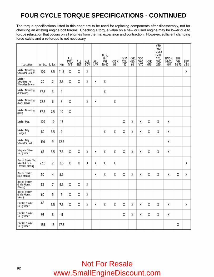
�#
FOUR CYCLE TORQUE SPECIFICATIONS - CONTINUED
��������� ����������� ��� ���������� ��������������� ��������������������� �������� � �������������������������� ��������������������������������������������������� ��� ������������������ ����������������������������� ������������� ���������������� ������������������! ����� ������������������������� � ��������"������ �������� ���
noitacoL .sbl.ni .sbl.tf mN
LLALXVT
SVTLLATNT
LLAVCE
LLAVAL
,V,H,HH
HV04-03
KSSHSH
MVT,521
041
,KSH-05H
06
05V06V07V
KSH07H
08VMV
&MVTLXVT,071,591
022
KSMHLXMH
MH
,HHHV
07-05VELKSV
gnitnuoMrelffuMwercSredluohS 001 5.8 5.11 X X X X
relffuMoNgnitnuoM
wercSredluohS02 2 5.2 X X X X X
gnitnuoMrelffuM)ekacnaP( 5.73 3 4 X
gnitnuoMrelffuM)sbaTkcoL( 5.27 6 8 X X X X
gnitnuoMrelffuM)LTH( 5.78 5.7 01 X
.gtMrelffuM 021 01 31 X X X X X X
.gtMrelffuMdegnalF 08 5.6 9 X X X X X X X X
.gtMrelffuMtloBredluohS 011 9 5.21 X
rotatSotengaMrednilyCoT 56 5.5 5.7 X X X X X X X X X X X X
poTretratSlioceR23-8&tnuoM
gnimroFdaerhT5.22 2 5.2 X X X X X X X
retratSlioceR)tnuoMpoT( 05 4 5.5 X X X X X X X X X X X
retratSlioceRtnuoMediS(
)citsalP58 7 5.9 X X X
retratSlioceRtnuoMediS(
)lateM06 5 7 X X X
retratScirtcelErednilyCoT
56 5.5 5.7 X X X X X X X X X X X X X
retratScirtcelErednilyCoT 59 8 11 X X X X X X
retratScirtcelErednilyCoT 551 31 5.71 X
Not For Resale www.SmallEngineDiscount.com
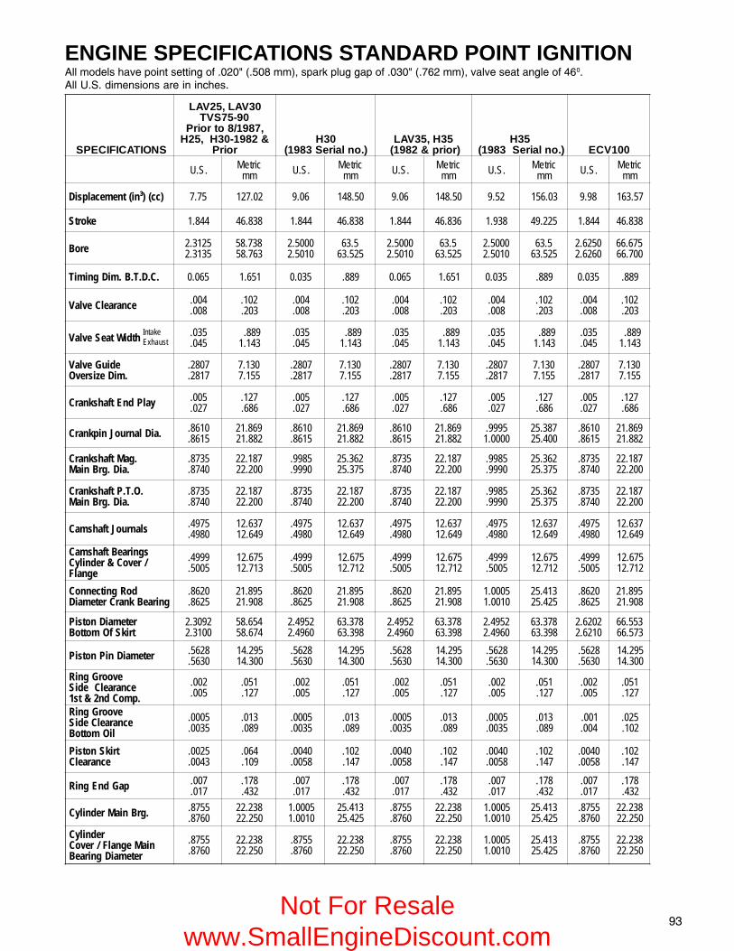
�$
ENGINE SPECIFICATIONS STANDARD POINT IGNITION%������� ����������� �����������#�&�'�(�)���*�� �����������������$�&�'�+,#���*�������� ������������-,��%���.�/������� �� ������������ �
IntakeExhaust
SNOITACIFICEPS
03VAL,52VAL09-57SVT
,7891/8otroirP&2891-03H,52H
roirP03H
).onlaireS3891(53H,53VAL
)roirp&2891(53H
).onlaireS3891( 001VCE
.S.U cirteMmm .S.U cirteM
mm .S.U cirteMmm .S.U cirteM
mm .S.U cirteMmm
)cc()³ni(tnemecalpsiD 57.7 20.721 60.9 05.841 60.9 05.841 25.9 30.651 89.9 75.361
ekortS 448.1 838.64 448.1 838.64 448.1 638.64 839.1 522.94 448.1 838.64
eroB 5213.25313.2
837.85367.85
0005.20105.2
5.36525.36
0005.20105.2
5.36525.36
0005.20105.2
5.36525.36
0526.20626.2
576.66007.66
.C.D.T.B.miDgnimiT 560.0 156.1 530.0 988. 560.0 156.1 530.0 988. 530.0 988.
ecnaraelCevlaV 400.800.
201.302.
400.800.
201.302.
400.800.
201.302.
400.800.
201.302.
400.800.
201.302.
htdiWtaeSevlaV 530.540.
988.341.1
530.540.
988.341.1
530.540.
988.341.1
530.540.
988.341.1
530.540.
988.341.1
ediuGevlaV.miDezisrevO
7082.7182.
031.7551.7
7082.7182.
031.7551.7
7082.7182.
031.7551.7
7082.7182.
031.7551.7
7082.7182.
031.7551.7
yalPdnEtfahsknarC 500.720.
721.686.
500.720.
721.686.
500.720.
721.686.
500.720.
721.686.
500.720.
721.686.
.aiDlanruoJnipknarC 0168.5168.
968.12288.12
0168.5168.
968.12288.12
0168.5168.
968.12288.12
5999.0000.1
783.52004.52
0168.5168.
968.12288.12
.gaMtfahsknarC.aiD.grBniaM
5378.0478.
781.22002.22
5899.0999.
263.52573.52
5378.0478.
781.22002.22
5899.0999.
263.52573.52
5378.0478.
781.22002.22
.O.T.PtfahsknarC.aiD.grBniaM
5378.0478.
781.22002.22
5378.0478.
781.22002.22
5378.0478.
781.22002.22
5899.0999.
263.52573.52
5378.0478.
781.22002.22
slanruoJtfahsmaC 5794.0894.
736.21946.21
5794.0894.
736.21946.21
5794.0894.
736.21946.21
5794.0894.
736.21946.21
5794.0894.
736.21946.21
sgniraeBtfahsmaC/revoC&rednilyC
egnalF
9994.5005.
576.21317.21
9994.5005.
576.21217.21
9994.5005.
576.21217.21
9994.5005.
576.21217.21
9994.5005.
576.21217.21
doRgnitcennoCgniraeBknarCretemaiD
0268.5268.
598.12809.12
0268.5268.
598.12809.12
0268.5268.
598.12809.12
5000.10100.1
314.52524.52
0268.5268.
598.12809.12
retemaiDnotsiPtrikSfOmottoB
2903.20013.2
456.85476.85
2594.20694.2
873.36893.36
2594.20694.2
873.36893.36
2594.20694.2
873.36893.36
2026.20126.2
355.66375.66
retemaiDniPnotsiP 8265.0365.
592.41003.41
8265.0365.
592.41003.41
8265.0365.
592.41003.41
8265.0365.
592.41003.41
8265.0365.
592.41003.41
evoorGgniRecnaraelCediS
.pmoCdn2&ts1
200.500.
150.721.
200.500.
150.721.
200.500.
150.721.
200.500.
150.721.
200.500.
150.721.
evoorGgniRecnaraelCediS
liOmottoB
5000.5300.
310.980.
5000.5300.
310.980.
5000.5300.
310.980.
5000.5300.
310.980.
100.400.
520.201.
trikSnotsiPecnaraelC
5200.3400.
460.901.
0400.8500.
201.741.
0400.8500.
201.741.
0400.8500.
201.741.
0400.8500.
201.741.
paGdnEgniR 700.710.
871.234.
700.710.
871.234.
700.710.
871.234.
700.710.
871.234.
700.710.
871.234.
.grBniaMrednilyC 5578.0678.
832.22052.22
5000.10100.1
314.52524.52
5578.0678.
832.22052.22
5000.10100.1
314.52524.52
5578.0678.
832.22052.22
rednilyCniaMegnalF/revoC
retemaiDgniraeB
5578.0678.
832.22052.22
5578.0678.
832.22052.22
5578.0678.
832.22052.22
5000.10100.1
314.52524.52
5578.0678.
832.22052.22
Not For Resale www.SmallEngineDiscount.com

�-
ENGINE SPECIFICATIONS STANDARD POINT IGNITION (CONT.)%������� ����������� �����������#�&�'�(�)���*�� �����������������$�&�'�+,#���*�������� ������������-,��%���.�/������� �� ������������ �
IntakeExhaust
SNOITACIFICEPS 001TNT
,B04V-04V,04H,04HV
04HH,501SVT,04VAL
501LXVT,04SH 501VCE 011VCE
.S.U cirteMmm .S.U cirteM
mm .S.U cirteMmm .S.U cirteM
mm .S.U cirteMmm
)cc()³ni(tnemecalpsiD 89.9 75.361 40.11 59.081 94.01 39.171 5.01 01.271 5.11 94.881
ekortS 448.1 838.64 052.2 51.75 839.1 32.94 839.1 32.94 839.1 32.94
eroB 0526.20626.2
576.66007.66
0005.20105.2
005.36525.36
0526.20626.2
576.66007.66
0526.20626.2
576.66007.66
0057.20157.2
58.9688.96
.C.D.T.B.miDgnimiT 530.0 988. 050.0 72.1 530.0 988. 530.0 988. 530.0 988.
ecnaraelCevlaV 400.800.
201.302.
400.800.
201.302.
400.800.
201.302.
400.800.
201.302.
400.800.
201.302.
htdiWtaeSevlaV 530.540.
988.341.1
240.250.
760.1123.1
530.540.
988.341.1
530.540.
988.341.1
530.540.
988.341.1
ediuGevlaV.miDezisrevO
7082.7182.
031.7551.7
2343.2443.
717.8347.8
7082.7182.
031.7551.7
7082.7182.
031.7551.7
7082.7182.
031.7551.7
yalPdnEtfahsknarC 500.720.
721.686.
500.720.
721.686.
500.720.
721.686.
500.720.
721.686.
500.720.
721.686.
.aiDlanruoJnipknarC 0168.5168.
968.12288.12
5160.10260.1
269.62579.62
5999.0000.1
783.52004.52
5999.0000.1
783.52004.52
5999.0000.1
783.52004.52
.gaMtfahsknarC.aiD.grBniaM
5899.0999.
263.52573.52
5899.0999.
263.52573.52
5899.0999.
263.52573.52
5899.0999.
263.52573.52
0999.5999.
573.52783.52
.O.T.PtfahsknarC.aiD.grBniaM
5378.0478.
781.22002.22
5899.0999.
263.52573.52
5899.0999.
263.52573.52
5899.0999.
263.52573.52
5899.0999.
263.52573.52
slanruoJtfahsmaC 5794.0894.
736.21946.21
0326.5326.
428.51738.51
5794.0894.
736.21946.21
5794.0894.
314.52524.52
5794.0894.
314.52524.52
sgniraeBtfahsmaC/revoC&rednilyC
egnalF
9994.5005.
576.21317.21
5426.5526.
268.51888.51
9994.5005.
576.21217.21
9994.5005.
576.21217.21
9994.5005.
576.21217.21
doRgnitcennoCgniraeBknarCretemaiD
0268.5268.
598.12809.12
0360.15360.1
000.72310.72
5000.10100.1
314.52524.52
5000.10100.1
736.21946.21
5000.10100.1
736.21946.21
retemaiDnotsiPtrikSfOmottoB
2026.20126.2
355.66375.66
5494.20594.2
063.36373.36
2026.20126.2
355.66375.66
2026.20126.2
355.66375.66
0547.25547.2
327.96637.96
retemaiDniPnotsiP 8265.0365.
592.41003.41
8265.0365.
592.41003.41
8265.0365.
592.41003.41
8265.0365.
592.41003.41
8265.0365.
592.41003.41
evoorGgniRecnaraelCediS
.pmoCdn2&ts1
200.500.
150.721.
200.500.
150.721.
200.500.
150.721.
200.500.
150.721.
200.500.
150.721.
evoorGgniRecnaraelCediS
liOmottoB
100.400.
520.201.
100.400.
520.201.
100.400.
520.201.
100.400.
520.201.
100.400.
520.201.
trikSnotsiPecnaraelC
0400.8500.
201.741.
5500.0700.
041.871.
0400.8500.
201.741.
0400.8500.
201.741.
5400.0600.
411.251.
paGdnEgniR 700.710.
871.234.
700.710.
871.234.
700.710.
871.234.
700.710.
871.234.
700.710.
871.234.
.grBniaMrednilyC 5000.10100.1
314.52524.52
5000.10100.1
314.52524.52
5000.10100.1
314.52524.52
5000.10100.1
314.52524.52
5000.10100.1
314.52524.52
rednilyCniaMegnalF/revoC
retemaiDgniraeB
5578.0678.
832.22052.22
5000.10100.1
314.52524.52
5000.10100.1
314.52524.52
5000.10100.1
314.52524.52
5000.10100.1
314.52524.52
Not For Resale www.SmallEngineDiscount.com

�(
ENGINE SPECIFICATIONS STANDARD POINT IGNITION
0�1�� 2�'%*�3!(���,������(4���((�'��$)4��-���*��'5*�3!+�����$)4���+$�'���+4��)(���*�'�*�3!��!!(�"+��6��� ����$4��$��'�+,#4�+)+���*
%������� ����������� �����������#�&�'�(�)���*�� �����������������$�&�'�+,#���*�������� ������������-,��%���.�/������� �� ������������ �
SNOITACIFICEPS,021SVT,05VAL
05SH021TNT021VCE
,05V521MVT,*05HV
*05HH,05H
,06V041MVT,*06HV
*06HH,06H
,*07HV,07V07MV
*07HH,07H
.S.U cirteMmm .S.U cirteM
mm .S.U cirteMmm .S.U cirteM
mm .S.U cirteMmm
)cc()³ni(tnemecalpsiD 40.21 43.791 40.21 43.791 81.21 36.991 35.31 67.122 40.51 15.642
ekortS 839.1 32.94 839.1 32.94 52.2 51.75 5.2 5.36 235.2 13.46
eroB 0218.20318.2
524.17054.17
0218.20318.2
524.17054.17
0526.20626.2
576.66007.66
0526.20626.2
576.66007.66
0057.20157.2
58.9688.96
.C.D.T.B.miDgnimiT 530.0 988. 530.0 988. 080.0 230.2 080.0 230.2 080.0 230.2
ecnaraelCevlaV 400.010.
201.452.
400.010.
201.452.
800.210.
302.503.
800.210.
302.503.
800.210.
302.503.
htdiWtaeSevlaV 530.540.
988.341.1
530.540.
988.341.1
240.250.
760.1123.1
240.250.
760.1123.1
240.250.
760.1123.1
ediuGevlaV.miDezisrevO
7082.7182.
031.7551.7
7082.7182.
031.7551.7
2343.2443.
717.8347.8
2343.2443.
717.8347.8
2343.2443.
717.8347.8
yalPdnEtfahsknarC500.720.
721.686.
500.720.
721.720.
500.720.
Ceton
721.720.
500.720.
Ceton
721.720.
500.720.
Ceton
721.720.
.aiDlanruoJnipknarC 5999.0000.1
783.52004.52
5999.0000.1
783.52004.52
5160.10260.1
269.62579.62
5160.10260.1
269.62579.62
0681.15681.1
421.03731.03
.gaMtfahsknarC.aiD.grBniaM
5899.0999.
263.52573.52
5899.0999.
263.52573.52
5899.0999.
263.52573.52
5899.0999.
263.52573.52
5899.0999.
263.52573.52
.O.T.PtfahsknarC.aiD.grBniaM
5899.0999.
263.52573.52
5899.0999.
263.52573.52
5899.0999.
263.52573.52
5899.0999.
263.52573.52
5899.0999.
263.52573.52
slanruoJtfahsmaC 5794.0894.
736.21946.21
5794.0894.
736.21946.21
0326.5326.
428.51738.51
0326.5326.
428.51738.51
0326.5326.
428.51738.51
sgniraeBtfahsmaCegnalF/revoC&rednilyC
9994.5005.
576.21317.21
9994.5005.
576.21217.21
5426.5526.
268.51888.51
5426.5526.
268.51888.51
5426.5526.
268.51888.51
doRgnitcennoCgniraeBknarCretemaiD
5000.10100.1
314.52524.52
5000.10100.1
314.52524.52
0360.15360.1
000.72310.72
0360.15360.1
000.72310.72
0881.15881.1
571.03881.03
retemaiDnotsiPtrikSfOmottoB
2708.20808.2
303.17323.17
2708.20808.2
303.17323.17
0126.25126.2
375.66685.66
0126.25126.2
375.665126.2
0547.25547.2
327.96637.96
retemaiDniPnotsiP 8265.0365.
592.41003.41
8265.0365.
592.41003.41
7426.9426.
768.51278.51
7426.9426.
768.51278.51
7426.9426.
768.51278.51
evoorGgniRecnaraelCediS
.pmoCdn2&ts1
200.500.
150.721.
200.500.
150.721.
200.400.
150.201.
200.400.
150.201.
200.300.
150.670.
evoorGgniRecnaraelCediS
liOmottoB
100.400.
520.201.
100.400.
520.201.
200.400.
150.201.
200.400.
150.201.
100.300.
520.670.
trikSnotsiPecnaraelC
0400.8500.
201.741.
0400.8500.
201.741.
5300.0500.Aeton
980.721.
5300.0500.Aeton
980.721.
5400.0600.Beton
411.251.
paGdnEgniR 700.710.
871.234.
700.710.
871.234.
010.020.
452.805.
010.020.
452.805.
010.020.
452.805.
.grBniaMrednilyC 5000.10100.1
314.52524.52
5000.10100.1
314.52524.52
5000.10100.1
314.52524.52
5000.10100.1
314.52524.52
5000.10100.1
314.52524.52
rednilyCniaMegnalF/revoC
retemaiDgniraeB
5000.10100.1
314.52524.52
5000.10100.1
314.52524.52
5000.10100.1
314.52524.52
5000.10100.1
314.52524.52
5000.10100.1
314.52524.52
IntakeExhaust
Not For Resale www.SmallEngineDiscount.com

�,
ENGINE SPECIFICATIONS STANDARD POINT IGNITION (Cont.)%������� ����������� �����������#�&�'�(�)���*�� �����������������$�&�'�+,#���*�������� ������������-,��%���.�/������� �� ������������ �
0��������������������� �7�
1�� 2�'%*�36�8�!6)��"�9� �������������-��'$�)���*��'5*�!+��:���� ��3�����/����;�������(#&
IntakeExhaust
SNOITACIFICEPS 07MH,071MVT,*08MV,08V*08MH,*07H
,591MVT,*08MV08MHH,*08MH 001MH,001MV 001MH,022MVT
.S.U cirteMmm .S.U cirteM
mm .S.U cirteMmm .S.U cirteM
mm .S.U cirteMmm
)cc()³ni(tnemecalpsiD 71.71 24.182 56.81 76.503 34.91Aeton
64.813 2.02 80.333 28.12 36.753
ekortS 235.2 13.46 235.2 13.46 235.2 13.46 235.2 13.46 235.2 13.46
eroB 5739.25839.2
316.47836.47
0260.30360.3
577.77008.77
0521.30621.3
573.97004.97
0781.30881.3
059.08579.08
0213.30313.3
521.48051.48
.C.D.T.B.miDgnimiT 090.0 682.2 090.0 682.2 090.0 682.2 090.0 682.2 090.0 682.2
ecnaraelCevlaV 800.210.
302.503.
800.210.
302.503.
800.210.
302.503.
800.210.
302.503.
800.210.
302.503.
htdiWtaeSevlaV240.8390.
760.1383.2
240.8390.Beton
760.1383.2
240.8390.
760.1383.2
240.8390.
760.1383.2
240.8390.
760.1383.2
ediuGevlaV.miDezisrevO
2343.2443.
717.8347.8
2343.2443.
717.8347.8
2343.2443.
717.8347.8
2343.2443.
717.8347.8
2343.2443.
717.8347.8
yalPdnEtfahsknarC 500.720.
721.686.
500.720.
721.686.
500.720.
721.686.
500.720.
721.686.
500.720.
721.686.
.aiDlanruoJnipknarC 0681.15681.1
421.03731.03
0681.15681.1
421.03731.03
0681.15681.1
421.03731.03
0681.15681.1
421.03731.03
0681.15681.1
421.03731.03
.gaMtfahsknarC.aiD.grBniaM
5899.0999.
263.52573.52
5899.0999.
263.52573.52
5899.0999.
263.52573.52
5899.0999.
263.52573.52
5899.0999.
263.52573.52
.O.T.PtfahsknarC.aiD.grBniaM
0781.15781.1
051.03361.03
0781.15781.1
051.03361.03
0781.15781.1
051.03361.03
0781.15781.1
051.03361.03
0781.15781.1
051.03361.03
slanruoJtfahsmaC 0326.5326.
428.51738.51
0326.5326.
428.51738.51
0326.5326.
428.51738.51
0326.5326.
428.51738.51
0326.5326.
428.51738.51
sgniraeBtfahsmaC/revoC&rednilyC
egnalF
5426.5526.
268.51888.51
5426.5526.
268.51888.51
5426.5526.
268.51888.51
5426.5526.
268.51888.51
5426.5526.
268.51888.51
doRgnitcennoCgniraeBknarCretemaiD
0881.15881.1
571.03881.03
0881.15881.1
571.03881.03
0881.15881.1
571.03881.03
0881.15881.1
571.03881.03
0881.15881.1
571.03881.03
retemaiDnotsiPtrikSfOmottoB
5239.25339.2
684.47115.47
5750.35850.3
166.77686.77
5911.35021.3
532.97162.97
5181.35281.3
018.08638.08
0903.35013.3
940.48780.48
retemaiDniPnotsiP 7426.9426.
768.51278.51
7426.9426.
768.51278.51
7426.9426.
768.51278.51
3786.5786.
754.71364.71
3786.5786.
754.71364.71
evoorGgniRecnaraelCediS
.pmoCdn2&ts1
200.500.
150.721.
200.500.
150.721.
200.500.
150.721.
200.500.
150.721.
200.500.
150.721.
evoorGgniRecnaraelCediS
liOmottoB
100.400.
520.201.
100.400.
520.201.
100.400.
520.201.
100.400.
520.201.
100.400.
520.201.
trikSnotsiPecnaraelC
400.600.
201.251.
5300.5500.
980.041.
5400.5600.
411.571.
5400.5600.
411.571.
5100.0400.
830.201.
paGdnEgniR 010.020.
452.805.
010.020.
452.805.
010.020.
452.805.
010.020.
452.805.
010.020.
452.805.
.grBniaMrednilyC 5000.10100.1
314.52524.52
5000.10100.1
314.52524.52
5000.10100.1
314.52524.52
5000.10100.1
314.52524.52
5000.10100.1
314.52524.52
rednilyCniaMegnalF/revoC
retemaiDgniraeB
0981.15981.1
102.03312.03
0981.15981.1
102.03312.03
0981.15981.1
102.03312.03
0981.15981.1
102.03312.03
0981.15981.1
102.03312.03
Not For Resale www.SmallEngineDiscount.com

�+
SOLID STATE AND EXTERNAL IGNITION%��� ���� ��������� ������������� ������ ������#(&�'�$�+(���*�� �����������������$�&�'�+,#���*�������� ������������-,��%���.�/������� �� ������������ �
IntakeExhaust
SNOITACIFICEPS57SVT
78/8otroirP 09SVT 53H,501SVT,04V
04SH,001VCE,001SVT
001TNT
.S.U cirteMmm .S.U cirteM
mm .S.U cirteMmm .S.U cirteM
mm .S.U cirteMmm
)cc()³ni(tnemecalpsiD 57.7 20.721 60.9 05.841 25.9 30.651 94.01 39.171 89.9 75.361
ekortS 448.1 838.64 448.1 838.64 839.1 522.94 839.1 522.94 448.1 838.64
eroB 5213.25313.2
837.85367.85
005.2105.2
005.36525.36
005.2105.2
005.36525.36
526.2626.2
576.66007.66
526.2626.2
576.66007.66
ecnaraelCevlaV 400.800.
201.302.
400.800.
201.302.
400.800.
201.302.
400.800.
201.302.
400.800.
201.302.
htdiWtaeSevlaV 530.540.
988.341.1
530.540.
988.341.1
530.540.
988.341.1
530.540.
988.341.1
530.540.
988.341.1
ediuGevlaV.miDezisrevO
7082.7182.
031.7551.7
7082.7182.
031.7551.7
7082.7182.
031.7551.7
7082.7182.
031.7551.7
7082.7182.
031.7551.7
yalPdnEtfahsknarC 500.720.
721.686.
500.720.
721.686.
500.720.
721.686.
500.720.
721.686.
500.720.
721.686.
.aiDlanruoJnipknarC 0168.5168.
968.12288.12
0168.5168.
968.12288.12
5999.0000.1
783.52004.52
5999.0000.1
783.52004.52
0168.5168.
968.12288.12
.gaMtfahsknarC.aiD.grBniaM
5899.0999.
263.52573.52
5899.0999.
263.52573.52
5899.0999.
263.52573.52
5899.0999.
263.52573.52
5899.0999.
263.52573.52
.O.T.PtfahsknarC.aiD.grBniaM
5378.0478.
781.22002.22
5378.0478.
781.22002.22
5899.0999.
263.52573.52
5899.0999.
263.52573.52
5378.0478.
781.22002.22
slanruoJtfahsmaC 5794.0894.
736.21946.21
5794.0894.
736.21946.21
5794.0894.
736.21946.21
5794.0894.
736.21946.21
5794.0894.
736.21946.21
sgniraeBtfahsmaC/revoC&rednilyC
egnalF
9994.5005.
576.21317.21
9994.5005.
576.21317.21
9994.5005.
576.21317.21
9994.5005.
576.21317.21
9994.5005.
576.21317.21
doRgnitcennoCgniraeBknarCretemaiD
0268.5268.
598.12809.12
0268.5268.
598.12809.12
5000.10100.1
314.52524.52
5000.10100.1
314.52524.52
0268.5268.
598.12809.12
retemaiDnotsiPtrikSfOmottoB
2903.20013.2
456.85476.85
2594.20694.2
837.36893.36
2594.20694.2
837.36893.36
2026.20126.2
355.66375.66
2026.20126.2
355.66375.66
retemaiDniPnotsiP 8265.0365.
592.41003.41
8265.0365.
592.41003.41
8265.0365.
592.41003.41
8265.0365.
592.41003.41
8265.0365.
592.41003.41
evoorGgniRecnaraelCediS
.pmoCdn2&ts1
200.500.
150.721.
200.500.
150.721.
200.500.
150.721.
200.500.
150.721.
200.500.
150.721.
evoorGgniRecnaraelCediS
liOmottoB
5000.5300.
310.980.
5000.5300.
310.980.
5000.5300.
310.980.
100.400.
520.201.
100.400.
520.201.
trikSnotsiPecnaraelC
5200.3400.
460.901.
0400.8500.
201.741.
0400.8500.
201.741.
0400.8500.
201.741.
0400.8500.
201.741.
paGdnEgniR 010.020.
452.805.
010.020.
452.805.
010.020.
452.805.
010.020.
452.805.
010.020.
452.805.
.grBniaMrednilyC 5000.10100.1
314.52524.52
5000.10100.1
314.52524.52
5000.10100.1
314.52524.52
5000.10100.1
314.52524.52
5000.10100.1
314.52524.52
rednilyCniaMegnalF/revoC
retemaiDgniraeB
5578.0678.
832.22052.22
5578.0678.
832.22052.22
5000.10100.1
314.52524.52
5000.10100.1
314.52524.52
5578.0678.
832.22052.22
Not For Resale www.SmallEngineDiscount.com

�)
SOLID STATE AND EXTERNAL IGNITION%��� ���� ��������� ������������� ������ ������#(&�'�$�+(���*�� �����������������$�&�'�+,#���*�������� ������������-,��%���.�/������� �� ������������ �
IntakeExhaust
SNOITACIFICEPS
511LXVT/SVTseireS00075
YLNO
501SVTseireS00065511LXVT/SVTretal&A00075
021SVTretal&J
retal&H05SH&N55-05KSSH
retal
021SVT,05VALreilrae&G05SH
reilrae&M05KSSH521MVT,05HV
05HH,05H
.S.U cirteMmm .S.U cirteM
mm .S.U cirteMmm .S.U cirteM
mm .S.U cirteMmm
)cc()³ni(tnemecalpsiD 44.11 05.781 23.11 35.581 9.11 40.591 40.21 43.791 81.21 36.991
ekortS 448.1 838.64 448.1 838.64 839.1 32.94 839.1 32.94 052.2 51.75
eroB 218.2318.2
524.17054.17
597.2697.2
399.07810.17
597.2697.2
399.07810.17
218.2318.2
524.17054.17
526.2626.2
576.66007.66
ecnaraelCevlaV 400.800.
201.302.
400.800.
201.302.
400.800.
201.302.
400.800.
201.302.
800.210.
302.503.
htdiWtaeSevlaV 530.540.
988.341.1
530.540.
988.341.1
530.540.
988.341.1
530.540.
988.341.1
240.250.
760.1123.1
ediuGevlaV.miDezisrevO
7082.7182.
031.7551.7
7082.7182.
031.7551.7
7082.7182.
031.7551.7
7082.7182.
031.7551.7
2343.2443.
717.8347.8
yalPdnEtfahsknarC 500.720.
721.686.
500.720.
721.686.
500.720.
721.686.
500.720.
721.686.
500.720.
721.686.
.aiDlanruoJnipknarC 0168.5168.
968.12288.12
0168.5168.
968.12288.12
5999.000.1
783.52004.52
5999.000.1
783.52004.52
5160.10260.1
269.62579.62
.gaMtfahsknarC.aiD.grBniaM
5899.0999.
263.52573.52
5899.0999.
263.52573.52
5899.0999.
263.52573.52
5899.0999.
263.52573.52
5899.0999.
263.52573.52
.O.T.PtfahsknarC.aiD.grBniaM
5378.0478.
781.22002.22
5899.0999.
263.52573.52
5899.0999.
263.52573.52
5899.0999.
263.52573.52
5899.0999.
263.52573.52
slanruoJtfahsmaC 5794.0894.
736.21946.21
5794.0894.
736.21946.21
5794.0894.
736.21946.21
5794.0894.
736.21946.21
0326.5326.
428.51738.51
sgniraeBtfahsmaC/revoC&rednilyC
egnalF
9994.5005.
576.21317.21
9994.5005.
576.21317.21
9994.5005.
576.21317.21
9994.5005.
576.21317.21
5426.5526.
268.51888.51
doRgnitcennoCgniraeBknarCretemaiD
0268.5268.
598.12809.12
0268.5268.
598.12809.12
5000.10100.1
314.52524.52
5000.10100.1
314.52524.52
0360.15360.1
000.72310.72
retemaiDnotsiPtrikSfOmottoB
2708.20808.2
303.17323.17
097.2197.2
668.07198.07
097.2197.2
668.07198.07
2708.20808.2
303.17323.17
2126.20226.2
875.66995.66
retemaiDniPnotsiP 8265.0365.
592.41003.41
8265.0365.
592.41003.41
8265.0365.
592.41003.41
8265.0365.
592.41003.41
7426.9426.
768.51278.51
evoorGgniRecnaraelCediS
.pmoCdn2&ts1
200.500.
150.721.
200.500.
150.721.
200.500.
150.721.
200.500.
150.721.
200.500.
150.721.
evoorGgniRecnaraelCediS
liOmottoB
100.400.
520.201.
100.400.
520.201.
100.400.
520.201.
100.400.
520.201.
100.400.
520.201.
trikSnotsiPecnaraelC
0400.8500.
201.741.
0400.8500.
201.741.
0400.8500.
201.741.
0400.8500.
201.741.
0300.8400.
670.221.
paGdnEgniR 010.020.
452.805.
010.020.
452.805.
010.020.
452.805.
010.020.
452.805.
010.020.
452.805.
.grBniaMrednilyC 5000.10100.1
314.52524.52
5000.10100.1
314.52524.52
5000.10100.1
314.52524.52
5000.10100.1
314.52524.52
5000.10100.1
314.52524.52
rednilyCniaMegnalF/revoC
retemaiDgniraeB
5000.10100.1
314.52524.52
5000.10100.1
314.52524.52
5000.10100.1
314.52524.52
5000.10100.1
314.52524.52
5000.10100.1
314.52524.52
Not For Resale www.SmallEngineDiscount.com

��
SOLID STATE AND EXTERNAL IGNITION%��� ���� ��������� ������������� ������ ������#(&�'�$�+(���*�� �����������������$�&�'�+,#���*�������� ������������-,��%���.�/������� �� ������������ �
1���%�"�<:3= ��������������"�������������� �:���� ��6�>���� ����� ����������������� �����1���5�"�3/?����"�����������>��9�������� �����������<:3����� �
IntakeExhaust
SNOITACIFICEPS 08VEL 001VEL 001KSV 511VEL 021VEL
.S.U cirteMmm .S.U cirteM
mm .S.U cirteMmm .S.U cirteM
mm .S.U cirteMmm
)cc()³ni(tnemecalpsiD 57.7 20.721 89.9 75.361 89.9 75.361 23.11 35.581 09.11 40.591
ekortS 448.1 838.64 448.1 838.64 448.1 838.64 448.1 838.64 839.1 32.94
eroB 113.2213.2
057.85 526.2626.2
576.66007.66
526.2626.2
576.66007.66
597.2697.2
399.07810.17
597.2697.2
399.07810.17
ecnaraelCevlaV 400.800.
201.302.
400.800.
201.302.
400.800.
201.302.
400.800.
201.302.
400.800.
201.302.
htdiWtaeSevlaV 530.540.
988.341.1
660.680.
676.1481.2
660.680.
676.1481.2
660.680.
676.1481.2
660.680.
676.1481.2
ediuGevlaV.miDezisrevO
5052.A/N
363.6A/N
5052.A/N
363.6A/N
5052.A/N
363.6A/N
5052.A/N
363.6A/N
5052.A/N
363.6A/N
yalPdnEtfahsknarC 500.720.
721.686.
500.720.
721.686.
500.720.
721.686.
500.720.
721.686.
500.720.
721.686.
.aiDlanruoJnipknarC 0168.5168.
968.12288.12
5999.000.1
738.52004.52
5999.000.1
738.52004.52
5999.000.1
738.52004.52
5999.000.1
738.52004.52
.gaMtfahsknarC.aiD.grBniaM
5899.0999.
263.52573.52
5899.0999.
263.52573.52
5899.0999.
263.52573.52
5899.0999.
263.52573.52
5899.0999.
263.52573.52
.O.T.PtfahsknarC.aiD.grBniaM
5378.0478.
781.22002.22
5899.0999.
263.52573.52
5899.0999.
263.52573.52
5899.0999.
263.52573.52
5899.0999.
263.52573.52
slanruoJtfahsmaC 5794.0894.
736.21946.21
5794.0894.
736.21946.21
5794.0894.
736.21946.21
5794.0894.
736.21946.21
5794.0894.
736.21946.21
sgniraeBtfahsmaC/revoC&rednilyC
egnalF
9994.5005.
576.21317.21
9994.5005.
576.21317.21
9994.5005.
576.21317.21
9994.5005.
576.21317.21
9994.5005.
576.21317.21
lanruoJmaCdnEgnihsuB
5273.0373.Aeton
264.9474.9
5273.0373.Aeton
264.9474.9 A/N A/N
5273.0373.Aeton
264.9474.9
5273.0373.Aeton
264.9474.9
gnihsuBmaCretemaiDedisnI
673.873.Aeton
055.9106.9
673.873.Aeton
055.9106.9 A/N A/N
673.873.Aeton
055.9106.9
673.873.Aeton
055.9106.9
doRgnitcennoCgniraeBknarCretemaiD
0268.5268.
598.12809.12
5000.10100.1
314.52524.52
0200.15200.1Beton
154.52464.52
5000.10100.1
314.52524.52
5000.10100.1
314.52524.52
retemaiDnotsiPtrikSfOmottoB
903.2013.2
946.85476.85
026.2226.2
845.66995.66
026.2226.2
845.66995.66
097.2297.2
668.07719.07
097.2297.2
668.07719.07
retemaiDniPnotsiP 8265.0365.
592.41003.41
8265.0365.
592.41003.41
8265.0365.
592.41003.41
8265.0365.
592.41003.41
8265.0365.
592.41003.41
evoorGgniRecnaraelCediS
.pmoCdn2&ts1
1100.3400.
820.901.
500..xaM
721. 500..xaM
721. 500..xaM
721. 500..xaM
721.
evoorGgniRecnaraelCediS
liOmottoB
100.400.
520.201.
5300..xaM
980. 5300..xaM
980. 5300..xaM
980. 5300..xaM
980.
trikSnotsiPecnaraelC
5200.5400.
460.411.
300.600.
670.251.
300.600.
670.251.
300.600.
670.251.
300.600.
670.251.
paGdnEgniR 500.310.
721.033.
500.420.
721.016.
500.420.
721.016.
500.420.
721.016.
500.420.
721.016.
.grBniaMrednilyC 5000.10100.1
314.52524.52
5000.10100.1
314.52524.52
5000.10100.1
314.52524.52
5000.10100.1
314.52524.52
5000.10100.1
314.52524.52
rednilyCniaMegnalF/revoC
retemaiDgniraeB
5578.0678.
832.22052.22
5000.10100.1
314.52524.52
5000.10100.1
314.52524.52
5000.10100.1
314.52524.52
5000.10100.1
314.52524.52
Not For Resale www.SmallEngineDiscount.com

���
1�� 2�'%*�3!��!!(�"+������ ����$4��$���'�+,#4�+)+���*�'5*�3!��!!(�",������(4���(��'��$)4��-����*�'�*�3!��!!+�����$)4���+$�'���+4��)(��*�'9*�3!��!!(�",��#�,#$(4#�,#�(�',,�,$+4,,�(,����*�':*�3!��!!+��#�+-,#4#�+-$+�',��+(-4,��,����*��'@*�%����/�����1������#+-��$++(4��$+)�� '$-��)�4$(�������*
SOLID STATE AND EXTERNAL IGNITION%��� ���� ��������� ������������� ������ ������#(&�'�$�+(���*�� �����������������$�&�'�+,#���*�������� ������������-,��%���.�/������� �� ������������ �
IntakeExhaust
SNOITACIFICEPS
06KSH,041MVT,06HV
06HH,06H
,07H,07HV,07V,07KSH
)E(071MVT,07HHLEDOM
07MHgnidnesledoM(
)Cni
07MHgnidnesledoM(
)Dni
sledoM071MVT07MH,)PU&F
sledoM)pu&E(
.S.U cirteMmm .S.U cirteM
mm .S.U cirteMmm .S.U cirteM
mm .S.U cirteMmm
)cc()³ni(tnemecalpsiD 35.31 67.122 40.51 15.642 71.71 24.182 71.71 24.182 34.91 64.813
ekotS 005.2 5.36 235.2 13.46 235.2 13.46 235.2 13.46 235.2 13.46
eroB 526.2626.2
576.66007.66
057.2157.2
58.9688.96
5739.25839.2
316.47836.47
5739.25839.2
316.47836.47
521.3621.3
473.97004.97
ecnaraelCevlaV 800.210.
302.503.
800.210.
302.503.
800.210.
302.503.
800.210.
302.503.
800.210.
302.503.
htdiWtaeSevlaV 240.250.
760.1123.1
240.250.
760.1123.1
240.250.
760.1123.1
240.250.
760.1123.1
240.250.
760.1123.1
ediuGevlaV.miDezisrevO
2343.2443.
717.8347.8
2343.2443.
717.8347.8
2343.2443.
717.8347.8
2343.2443.
717.8347.8
2343.2443.
717.8347.8
yalPdnEtfahsknarC500.720.
)A(etoN
721.686.
500.720.
)A(etoN
721.686.
500.720.
721.686.
700.920.
871.737.
700.920.
871.737.
.aiDlanruoJnipknarC 5160.10260.1
269.62579.62
2681.15681.1
921.03731.03
0681.15681.1
421.03731.03
0473.15473.1
009.43219.43
0473.15473.1
009.43219.43
.gaMtfahsknarC.aiD.grBniaM
5899.0999.
263.52573.52
5899.0999.
263.52573.52
5899.0999.
263.52573.52
5473.10573.1
219.43529.43
5473.10573.1
219.43529.43
.O.T.PtfahsknarC.aiD.grBniaM
5899.0999.
263.52573.52
5899.0999.
263.52573.52
0781.15781.1
051.03361.03
5473.10573.1
219.43529.43
5473.10573.1
219.43529.43
slanruoJtfahsmaC 0326.5326.
428.51738.51
0326.5326.
428.51738.51
0326.5326.
428.51738.51
0326.5326.
428.51738.51
0326.5326.
428.51738.51
sgniraeBtfahsmaC/revoC&rednilyC
egnalF
5426.5526.
268.51888.51
5426.5526.
268.51888.51
5426.5526.
268.51888.51
5426.5526.
268.51888.51
5426.5526.
268.51888.51
doRgnitcennoCgniraeBknarCretemaiD
0360.15360.1
000.72310.72
0360.15360.1
000.72310.72
0881.15881.1
571.03881.03
0673.15673.1
)F(etoN
059.43369.43
0673.15673.1
)F(etoN
059.43369.43
retemaiDnotsiPtrikSfOmottoB
2126.20226.2
)D(etoN
875.66995.66
2126.20226.2
)E(etoN
875.66995.66
5239.25339.2
684.47115.47
5239.25339.2
684.47115.47
5911.35021.3
532.97162.97
retemaiDniPnotsiP 7426.9426.
768.51278.51
7426.9426.
768.51278.51
7426.9426.
768.51278.51
7426.9426.
768.51278.51
7426.9426.
768.51278.51
evoorGgniRecnaraelCediS
.pmoCdn2&ts1
200.500.
150.721.
200.500.
150.721.
200.500.
150.721.
200.500.
150.721.
200.500.
150.721.
evoorGgniRecnaraelCediS
liOmottoB
100.400.
520.201.
100.400.
520.201.
100.400.
520.201.
100.400.
520.201.
100.400.
520.201.
trikSnotsiPecnaraelC
0300.8400.
)B(etoN
670.221.
0300.8400.
)C(etoN
670.221.
400.600.
201.251.
400.600.
201.251.
5400.5600.
411.561.
paGdnEgniR 010.020.
452.805.
010.020.
452.805.
010.020.
452.805.
010.020.
452.805.
010.020.
452.805.
.grBniaMrednilyC 5000.10100.1
314.52524.52
5000.10100.1
314.52524.52
5000.10100.1
314.52524.52
5673.10773.1
369.43679.43
5673.10773.1
369.43679.43
rednilyCniaMegnalF/revoC
retemaiDgniraeB
5000.10100.1
314.52524.52
5000.10100.1
314.52524.52
0981.15981.1
002.03312.03
5673.10773.1
369.43679.43
5673.10773.1
369.43679.43
Not For Resale www.SmallEngineDiscount.com

���
SOLID STATE AND EXTERNAL IGNITION (Cont.)
0��������������������� �7�
1�� 2�'%*�%����/�����1������#+-����$++(4��$+)��'$-��)�4$(�������*�'5*��36�##��.����5����������#4��-#�'��($4#��)-���*00������� ��������������� �������������������
%��� ���� ��������� ������������� ������ ������#(&�'�$�+(���*�� �����������������$�&�'�+,#���*�������� ������������-,��%���.�/������� �� ������������ �
IntakeExhaust
SNOITACIFICEPS
08KSMH591MVT,*08MV**08MH,)K-A(
,09MH,**08MH591MVT,09-08KSMH
591LXVT,)pu&L(,)F-A(022MVT
**001MH
011KSMH,001KSMH,)pu&G(022MVT**001MH,022LXVT
.S.U cirteMmm .S.U cirteM
mm .S.U cirteMmm .S.U cirteM
mm
)cc()³ni(tnemecalpsiD 34.91 64.813 34.91 64.813 28.12 36.753 28.12 36.753
ekortS 235.2 13.46 235.2 13.46 235.2 13.46 235.2 13.46
eroB 521.3621.3
573.97004.97
521.3621.3
573.97004.97
213.3313.3
521.48051.48
213.3313.3
521.48051.48
ecnaraelCevlaV 800.210.
302.503.
800.210.
302.503.
800.210.
302.503.
800.210.
302.503.
htdiWtaeSevlaV 240.8390.
760.1383.2
240.8390.
760.1383.2
240.8390.
760.1383.2
240.8390.
760.1383.2
ediuGevlaV.miDezisrevO
2343.2443.
717.8347.8
2343.2443.
717.8347.8
2343.2443.
717.8347.8
2343.2443.
717.8347.8
yalPdnEtfahsknarC700.920.
871.737.
700.920.
871.737.
700.920.
871.737.
700.920.
)B(etoN
871.737.
.aiDlanruoJnipknarC 0681.15681.1
421.03731.03
0473.15473.1
009.43219.43
0681.15681.1
421.03731.03
0473.15473.1
009.43219.43
.gaMtfahsknarC.aiD.grBniaM
5899.0999.
263.52573.52
5473.10573.1
219.43529.43
5899.0999.
263.52573.52
5473.10573.1
219.43529.43
.O.T.PtfahsknarC.aiD.grBniaM
0781.15781.1
051.03361.03
5473.10573.1
219.43529.43
0781.15781.1
051.03361.03
5473.10573.1
219.43529.43
slanruoJtfahsmaC 0326.5326.
428.51738.51
0326.5326.
428.51738.51
0326.5326.
428.51738.51
0326.5326.
428.51738.51
sgniraeBtfahsmaC/revoC&rednilyC
egnalF
5426.5526.
268.51888.51
5426.5526.
268.51888.51
5426.5526.
268.51888.51
5426.5526.
268.51888.51
doRgnitcennoCgniraeBknarCretemaiD
0881.15881.1
571.03881.03
0673.15673.1
)A(etoN
059.43369.43
0881.15881.1
571.03881.03
0673.15673.1
)A(etoN
059.43369.43
retemaiDnotsiPtrikSfOmottoB
5911.35021.3
532.97162.97
5911.35021.3
532.97162.97
0903.35013.3
940.48780.48
8903.38013.3
960.48490.48
retemaiDniPnotsiP 7426.9426.
768.51278.51
7426.9426.
768.51278.51
3786.5786.
754.71364.71
3786.5786.
754.71364.71
evoorGgniRecnaraelCediS
.pmoCdn2&ts1
200.500.
150.721.
200.500.
150.721.
5100.5300.
830.930.
5100.5300.
830.930.
evoorGgniRecnaraelCediS
liOmottoB
100.400.
520.201.
100.400.
520.201.
100.400.
520.201.
100.400.
520.201.
trikSnotsiPecnaraelC
5400.5600.
441.561.
5400.5600.
441.561.
5100.0400.
830.201.
2100.2300.
030.180.
paGdnEgniR 010.020.
452.805.
010.020.
452.805.
010.020.
452.805.
010.020.
452.805.
.grBniaMrednilyC 5000.10100.1
314.52524.52
5673.10773.1
369.43679.43
5000.10100.1
314.52524.52
5673.10773.1
369.43679.43
rednilyCniaMegnalF/revoC
retemaiDgniraeB
0981.15981.1
002.03312.03
5673.10773.1
369.43679.43
0981.15981.1
002.03312.03
5673.10773.1
369.43679.43
Not For Resale www.SmallEngineDiscount.com

102
������������������ �������� ������������� ����� ��������� ������� �������������������� ��������������������� ������������ ������������������� ���������������������������������������� �!�������������� ������������������� ����� ��������� ������� ��������������������� ���������� �����������Covers the diagnosis and repair of Peerless® power traincomponents.������Contains technical information for the repair of the TC series,2-cycle engines.������Contains diagnosis and technical information for the repairof TVS840, HSK/HXL845/850, 2-cycle engines.695244A������������ ����������������������"�#$!"�$!"%$!"%������������������������� �����������Covers the diagnosis and repair of the Vector Series, 4-cycle engines.
�������������������������� ��������
������� �� !"#��������������������������&�� ������'�%� (��%) (�%%� (�%%) (�%%)� (�"%)� �)� $�������*����������������������� ���������������� �� !"#������������ ���������������������������������������� �!�������������� �������������$%&� ������������ ���������������������������������������� �!�������������� �������������%$ '#������������ ���������������������������������������� �!�������������� �����
VIDEO PROGRAMS695015Carburetor Troubleshooting. Covers identification ofcarburetors used on Tecumseh engines and how totroubleshoot and repair them. VHS only.695059Understanding Tecumseh Ignition Systems. A basicprogram designed to give the small engine technician firsthand knowledge of Tecumseh ignition systems so thetechnician can understand the system and perform repairsto it. VHS only.695148Teardown and reassembly of the 900 series transaxles.This video will show a complete step-by-step procedure forteardown and reassembly of the 900, 910 and 920 seriestransaxles.
CHAPTER 11EDUCATIONAL MATERIALS AND TOOLS
695185Electrical Troubleshooting. This video training program willassist the small engine technician in the proper proceduresfor troubleshooting electrical systems on outdoor powerequipment.695285An in-depth look at the 800 series transaxles. Detailingthe teardown and reassembly procedures for the 800, 801and 820 transaxles.
SPECIAL BOOKLETS
INSTRUCTIONAL GUIDE692738Assists in the use and understanding of the TecumsehMaster Parts Manual. Illustrates time saving featuresincorporated into the manual. Explains new carburetor partsbreakdown format.
4-CYCLE ENGINE FAILURE ANALYSIS695590This booklet is designed as a tool for the average technicianto correctly assess the cause of failure.
CARBURETOR TROUBLESHOOTING BOOKLET695907This booklet is designed as a quick reference to carburetionproblems and related repair procedures.
IGNITION SYSTEMS TROUBLESHOOTING BOOKLET694903This booklet contains information on the identification,possible problems and related repair procedures ofTecumseh Ignition Systems.
SPECIAL TOOLS BOOKLET694862This booklet depicts all specialty tools offered by Tecumsehwhich can be used on 2 and 4 cycle engines and Peerlessunits.
QUICK REFERENCE CHART BOOKLET695933This booklet contains the quick reference information foundon Tecumseh wall charts.This booklet is designed to be used as a work bench quickreference guide when servicing Tecumseh engines andmotion drive systems.
TESTER BOOKLETS694529Test procedures for Tecumseh electrical components usingGraham-Lee Tester 31-SM or 31-SMX-H.694530Test procedures for Tecumseh electrical components usingMerco-O-Tronic Tester 9800. (Tests are similar for 98, 98Aand 79.)
Not For Resale www.SmallEngineDiscount.com

103
OIL SEAL DRIVER FLYWHEEL KNOCK-OFF TOOL
No. 670103 - Knock-off tool (right hand) (7/16").
No. 670169 - Knock-off tool (right hand) (1/2").
No. 670314 - Knock-off tool (right hand) (5/8").
No. 670329 - Knock-off tool (right hand) (3/4").
OIL SEAL REMOVER
Consult the specification chart or measure the shaftdiameter to determine the correct tool.
NOTE: Due to variations in oil seal dimensions, theseremovers may not pull all oil seals.
USE WITH:
No. 670287. 7/8" Crankshaft bearing diameters
No. 670288. 3/4" Crankshaft bearing diameters
No. 670289. 13/16" Crankshaft bearing diameters
No. 670290. 1" Crankshaft bearing diameters
No. 670312. 1-3/8" Crankshaft bearing diameters
No. 670331. 1-1/2" Crankshaft bearing diameters
No. 670272 - Oil Seal Driver. Used with all oil sealprotector-drivers to drive the seal into position.
OIL SEAL PROTECTOR / INSTALLERConsult the specification chart or measure the shaftdiameter to determine the correct tool.670260 - Seal ProtectorPTO & Magneto w/dia. of 1.187”-1.875”HH80-120, VH80-120, OH120-180, VM70-100, HM70-100670261 - Seal ProtectorPTO & Magneto w/dia. of .811”-.815”External ignition lightweight engines670262 - Seal ProtectorPTO & Magneto w/dia. of .749”-.750”Standard ignition lightweight engines670308 - Seal AdaptorPTO & Magneto on HM70-100, TVM170-220, OVM120,TVXL195-220, HMSK100, w/shaft dia. of 1.3745"-1.3750"670309 - Seal ProtectorPTO & Magneto on HM70-100, TVM170-220, OVM120,TVXL195-220, HMSK100, w/shaft dia. of 1.3745"-1.3750"670310 - Seal Protector / InstallerPTO & Magneto on HM70-100, TVM170-220, OVM120,TVXL195-220, HMSK100, w/shaft dia. of 1.3745"-1.3750"670263 - Seal Protector DriverOil seal on extended camshaft medium frame enginesw/dia. of .6248”-.6253”Extended 5/8" camshaft medium frame engines670264 - Seal Protector DriverOil seal on 1/2" extended camshaft small frame enginesw/dia. of .4998”-.5001”670272 - Seal DriverUsed with all oil seal installers670277 - Seal ProtectorOil seal on 8-1/2:1 1/2” shaft on light weight verticalcrankshaft engines670292 - Seal Protector and Installer Assy.Includes 670265, 670266, & 670267(I.D. 1.002", 1.052" and 1.050") for V70, VM70-100, H70,HM70-100, V50-70, H50-70, HS40-50, LAV40-50,TVS105-120, TNT120670293 - Seal Protector and Installer Assy.Includes 670268 & 670269(I.D. .875" and .935") H30-35, LAV30-35, TNT100,TVS75-90, ECV90-100670294 - Seal Protector and Installer Assy.Includes 670273 & 670274(I.D. .680" and 1.005") AH520 & AH600 with one pieceoil seal670330 - Seal Protector / InstallerOHV13.5-17 w/ 1-1/2” extended camshaft670335 - Seal Protector / InstallerHM70-100 PTO & Magneto w/dia. of 1.1870”-1.1875”670336 - Seal Installer - AdpatorHM70-100 w/ 1-1/8” crankshaft670337 - Seal Installer for Ball Bearing PTOOHH engines, use w/ tool 670265Use tool 670266
VIBRATION TACHOMETER
No. 670156 Vibration tachometer.
TAPER GAP GAUGE
No. 670256 Taper Gap Gauge
Not For Resale www.SmallEngineDiscount.com

104
VALVE LAPPING TOOL
No. 670154 Valve lapping tool.
REBUSHING DRIVERS
ToolNumber Description Use with:A. 670158 Bearing Driver 7/8'’ (22.225 mm)
Main Bearings where bushings areavailable.
B. 670159 Bushing Driver
A. 670162 Bearing Driver 1'’ (25.4 mm) MainBearings where bushings are available
B. 670163 Bushing Driver
A. NONEB. 670311 Bushing Driver 1-3/8'’ (41.275 mm)
HM70 100, TVM170 220 and OVM120.670317 Bushing Driver 1-3/16'’ (20.6375 mm)
HM70, HM80 and HM100 Cylinder cover
No. 670298 Alignment Tool.
1/32" (.794 mm) OVERSIZE VALVE GUIDE REAMER
No. 670283. Used on small frame 4 cycle engines onIntake and Exhaust valve guides. Oversize diameter .2807.2817
No. 670284. Used on medium and large frame 4 cycleengines on Intake and Exhaust. Oversize diameter .3432.3442
OVRM and OHV11-17 ADJUSTMENT TOOL
No. 670326
FLYWHEEL PULLER
No. 670306
Not For Resale www.SmallEngineDiscount.com

105
.016 = 1/64
.031 = 1/32
.047 = 3/64
.063 = 1/16
.078 = 5/64
.094 = 3/32
.109 = 7/64
.125 = 1/8
.141 = 9/64
.156 = 5/32
.172 = 11/64
.188 = 3/16
.203 = 13/64
.219 = 7/32
.234 = 15/64
.25 = 1/4
.266 = 17/64
.281 = 9/32
.297 = 19/64
.312 = 5/16
.328 = 21/64
.344 = 11/32
.359 = 23/64
.375 = 3/8
.391 = 25/64
.406 = 13/32
.422 = 27/64
.438 = 7/16
.453 = 29/64
.469 = 15/32
.484 = 31/64
.50 = 1/2
DECIMAL/FRACTION CONVERSIONS
.516 = 33/64
.531 = 17/32
.547 = 35/64
.563 = 9/16
.578 = 37/64
.594 = 19/32
.609 = 39/64
.625 = 5/8
.641 = 41/64
.656 = 21/32
.672 = 43/64
.688 = 11/16
.703 = 45/64
.719 = 23/32
.734 = 47/64
.75 = 3/4
.766 = 49/64
.781 = 25/32
.797 = 51/64
.813 = 13/16
.828 = 53/64
.844 = 27/32
.859 = 55/64
.875 = 7/8
.891 = 57/64
.906 = 29/32
.922 = 59/64
.938 = 15/16
.953 = 61/64
.969 = 31/32
.984 = 63/64
Not For Resale www.SmallEngineDiscount.com

�
�����������������������������������
� ���������������� � ���������������� � ���������������� � ����������������
143.001000 TVM220-157285G
143.001001 HM100-159411R
143.001002 TVM220-157286G
143.001101 HMSK110-159960A
143.001103 HMSK110-159961A
143.001105 HMSK110-159963A
143.003001 H30-35517Y
143.003500 LEV100-335023D
143.003501 H35-45767Z
143.003502 LEV100-335010D
143.003504 LEV115-350144E
143.003504 LEV115-350144E
143.003506 TVS90-43775R
143.003508 LEV100-335011D
143.003800 VSK100-338501A
143.003802 LEV100-338012D
143.003804 TVS90-46129F
143.004000 LEV100-340048D
143.004001 H40-55704A
143.004002 LEV100-340037D
143.004004 LEV100-340024D
143.004006 TVS90-48048D
143.004008 LEV115-350159E
143.004010 LEV100-340031D
143.004012 LEV100-340033D
143.004014 LEV100-340015D
143.004016 LEV100-340016D
143.004018 LEV115-350168E
143.004500 LEV120-361069C
143.004502 LEV100-345014D
143.004504 LEV100-345006D
143.004506 TVS115-57065G
143.005001 HSSK50-67399S
143.005003 HSSK50-67400S
143.005004 LEV115-350128E
143.005006 LEV115-350090E
143.005008 LEV115-350060E
143.005504 LEV115-355021E
143.005506 TVS115-62124D
143.005508 LEV120-361504A
143.005510 LEV115-355022E
143.005512 LEV120-361075C
143.006000 LEV115-360021D
143.006002 TVS120-66021C
143.006004 LEV115-360025D
143.006006 LEV115-360024D
143.006200 LEV115-360026D
143.006202 TVS120-66020C
143.006204 LEV120-361505A
143.006206 LEV115-360030D
143.006502 LEV120-361044C
143.006504 LEV120-361013C
143.006506 LEV120-361054C
143.006508 LEV120-361047C
143.006510 LEV120-361045C
143.006512 LEV120-361037C
143.006700 LEV120-361501A
143.006702 LEV120-361502A
143.006712 LEV120-361503A
143.006714 LEV120-361509A
143.006716 LEV120-361510A
143.008001 HM80-155658T
143.008003 HM80-155680T
143.008501 HM85-155851B
143.009001 HMSK90-156530D
143.009003 HMSK90-156531D
143.009005 HM90-156017E
143.009007 HM90-156018E
143.009009 HM90-156019E
143.011000 TVM220-157220H
143.011002 TVM220-157286H
143.011004 TVM220-157285H
143.011101 HMSK110-159964A
143.011103 HMSK110-159965A
143.013500 LEV100-335011E
143.013501 H35-45768Z
143.013502 LEV100-335010E
143.013503 H35-45777Z
143.013802 LEV100-338022E
143.014000 LEV100-340031E
143.014001 H40-55705A
143.014002 LEV100-340032E
143.014004 LEV100-340033E
143.014006 LEV100-340015E
143.014008 LEV100-340016E
143.014010 LEV100-340017E
143.014012 LEV100-340021E
143.014014 LEV100-340024E
143.014016 LEV100-340052E
143.014500 LEV120-361082C
143.014502 LEV100-345006E
143.014504 LEV100-345021E
143.014506 LEV120-361105C
143.015000 LEV115-350121E
143.015001 HSSK50-67405S
143.015002 LEV115-350189E
143.015003 HSSK50-67406S
143.015004 LEV115-350192E
143.015005 HSSK50-67407S
143.015007 HSSK50-67408S
143.015500 LEV115-355026E
143.015502 LEV120-361096C
143.015504 LEV120-361097C
143.016000 LEV115-360033D
143.016002 LEV115-360034D
143.016004 LEV115-360035D
143.016200 LEV115-360031D
143.016202 LEV120-361519A
143.016502 LEV120-361093C
143.016504 LEV120-361537A
143.016700 LEV120-361515A
143.016702 LEV120-361517A
143.016704 LEV120-361518A
143.016706 LEV120-361520A
143.016708 LEV120-361521A
143.016710 LEV120-361522A
143.016712 LEV120-361523A
143.016714 LEV120-361524A
143.016718 LEV120-361526A
143.016720 LEV120-361527A
143.016722 LEV120-361528A
143.016724 LEV120-361529A
143.016726 LEV120-361530A
143.016728 LEV120-361531A
143.016730 LEV120-361532A
143.016732 LEV120-361533A
143.016734 LEV120-361534A
143.016736 LEV120-361535A
143.016738 LEV120-361536A
143.018001 HM80-155680U
143.018501 HM85-155853C
143.019001 HMSK90-156534D
143.019003 HMSK90-156536D
143.019005 HMSK90-156537D
143.019007 HM90-156021F
143.019009 HM90-156018F
143.019011 HM90-156019F
143.021101 HMSK110-159964B
143.021103 HMSK110-159965B
143.025001 HSSK50-67410S
143.025003 HSSK50-67411S
143.025005 HSSK50-67412S
143.029001 HMSK90-156534E
143.029003 HMSK90-156536E
143.029005 HMSK90-156537E
143.207012 LAV40-50254B
143.207022 LAV40-50205B
143.207032 LAV40-50207B
143.207042 LAV40-50254B
143.207052 LAV40-50201B
143.207072 LAV40-50270B
143.217042 LAV40-50254C
143.217062 LAV40-50207C
143.217072 LAV40-50201C
143.217102 LAV40-50217C
143.235032 LAV50-62002
143.235072 LAV50-62010
143.237042 LAV40-50336C
143.245012 LAV50-62012
143.245012 LAV50-62012
143.245092 LAV50-62015
143.245142 LAV50-62018
143.245152 LAV50-62019
143.245172 LAV50-62023
143.245182 LAV50-62024
143.255012 LAV50-62027
143.255022 LAV50-62029
143.255042 LAV50-62037
143.255052 LAV50-62039A
143.255062 LAV50-62043
143.255072 LAV50-62043A
143.255082 LAV50-62015A
143.255092 LAV50-62037A
143.255102 LAV50-62029A
143.255112 LAV50-62039A
143.257012 LAV40-50358D
143.257022 LAV40-50358C
143.257032 LAV40-50366D
143.257042 LAV40-50201D
143.257052 LAV40-50369D
143.257062 LAV40-50369E
143.257072 LAV40-50366E
143.265012 LAV50-62015A
143.265032 LAV50-62047A
143.265042 LAV50-62030A
143.265052 LAV50-62049A
143.265062 LAV50-62039B
143.265072 LAV50-62047B
143.265082 LAV50-62015B
143.265092 LAV50-62029B
143.265112 LAV50-62037B
143.265122 LAV50-62043B
143.265132 LAV50-62050B
143.265142 LAV50-62051B
143.265152 LAV50-62052B
143.265162 LAV50-62053B
143.265172 LAV50-62024B
143.265192 LAV50-62049B
143.267012 LAV40-50368E
143.267022 LAV40-50368F
143.267042 LAV40-50369F
143.274092 LAV35-40938L
143.274102 LAV35-40939L
143.274112 LAV35-40940L
143.274122 LAV35-40941L
143.274132 LAV35-40942L
143.274162 LAV35-40899L
143.274172 LAV35-40943L
143.274182 LAV35-40944L
143.274252 LAV35-40751L
143.274272 LAV35-40948L
143.274282 LAV35-40949L
143.274292 LAV35-40950L
143.274302 LAV35-40951L
143.274312 LAV35-40952L
143.274322 LAV35-40953L
143.274332 LAV35-40954L
143.274352 LAV35-40955L
143.274372 LAV35-40956L
143.274472 LAV35-40957L
Not For Resale www.SmallEngineDiscount.com

��
�����������������������������������
� ���������������� � ���������������� � ���������������� � ����������������
143.274492 LAV35-40858L
143.274552 LAV35-40961L
143.274592 LAV35-40962L
143.274642 LAV35-40626L
143.274662 LAV35-40967L
143.274682 LAV35-40882L
143.274702 LAV35-40926L
143.274772 LAV35-40924L
143.274792 LAV35-40774L
143.275012 LAV50-62059B
143.275012 LAV50-62059B
143.275022 LAV50-62060B
143.275042 LAV50-62018B
143.275052 LAV50-62063B
143.275062 LAV50-62065B
143.275072 LAV50-62019B
143.275082 LAV50-62066B
143.277012 LAV40-50387D
143.277022 LAV40-50382D
143.284012 LAV35-40969M
143.284022 LAV35-40970M
143.284032 LAV35-40971M
143.284052 LAV35-40972M
143.284062 LAV35-40973M
143.284082 LAV35-40974M
143.284092 LAV35-40975M
143.284112 LAV35-40977M
143.284142 LAV35-40980M
143.284152 LAV35-40981M
143.284162 LAV35-40982M
143.284182 LAV35-40986M
143.284222 LAV30-30538M
143.284242 LAV35-40990M
143.284252 LAV35-40991M
143.284282 LAV35-40992M
143.284292 LAV35-40993M
143.284302 LAV35-40994M
143.284312 LAV35-40882M
143.284322 LAV35-40858M
143.284392 LAV35-40751M
143.284402 LAV35-40995M
143.284412 LAV35-40996M
143.284422 LAV35-40962M
143.284442 LAV30-30539M
143.284482 LAV35-40961M
143.284512 LAV35-40997M
143.284522 LAV35-40998M
143.284542 LAV35-40999M
143.284552 LAV35-41000M
143.284562 LAV35-41001M
143.284572 LAV35-41002M
143.284592 LAV35-41003M
143.284632 LAV35-41006M
143.284652 LAV35-40923M
143.284662 LAV35-40938M
143.284712 LAV35-40926M
143.284722 LAV35-40917M
143.284732 LAV35-40859M
143.284762 LAV35-40463M
143.285012 LAV50-62050C
143.285022 LAV50-62024C
143.285032 LAV50-62066C
143.285042 LAV50-62049C
143.285052 LAV50-62067C
143.285062 LAV50-62065C
143.285072 LAV50-62037C
143.285082 LAV50-62063C
143.285092 LAV50-62068C
143.285102 LAV50-62043C
143.287012 LAV40-50389E
143.287022 LAV40-50391D
143.287032 LAV40-50392E
143.294552 TVS105-53012A
143.294562 TVS105-53013A
143.294622 TVS105-53017A
143.294632 TVS105-53018A
143.294642 TVS105-53016A
143.294702 TVS105-53025A
143.295012 LAV50-62071C
143.295022 LAV50-62072C
143.295032 LAV50-62053C
143.297012 TVS105-53006A
143.304362 LAV35-40906M
143.305042 LAV50-62073C
143.305062 LAV50-62074C
143.313012 TVS75-33010B
143.313022 TVS75-33012B
143.314032 TVS90-43020B
143.314042 TVS90-43022B
143.314052 TVS90-43023B
143.314062 TVS90-43025B
143.314072 TVS90-43032B
143.314082 TVS90-43033B
143.314092 TVS90-43094B
143.314102 TVS90-43095B
143.314112 TVS90-43096B
143.314182 TVS90-43121B
143.314262 TVS90-43059B
143.314272 TVS90-43061B
143.314282 TVS90-43107B
143.314292 TVS90-43019B
143.314302 TVS90-43134B
143.314322 TVS90-43040B
143.314332 TVS90-43112B
143.314342 TVS90-43111B
143.314362 TVS90-43145B
143.314382 TVS90-43044B
143.314402 TVS90-43068B
143.314412 TVS90-43108B
143.314432 LAV35-40917N
143.314482 TVS90-43150B
143.314542 TVS90-43066B
143.314552 TVS90-43088B
143.314562 TVS90-43116B
143.314702 LAV35-40906N
143.314722 TVS90-43139B
143.314732 TVS90-43140B
143.314742 TVS90-43141B
143.314752 TVS90-43142B
143.314762 TVS90-43143B
143.314772 TVS90-43144B
143.315022 LAV50-62071D
143.315032 TVS105-53018B
143.315042 TVS105-53025B
143.315062 LAV50-62065D
143.315072 TVS105-53006B
143.315092 LAV50-62037D
143.315102 LAV50-62053D
143.315112 LAV50-62050D
143.315122 LAV50-62067D
143.321012 TVS75-33010C
143.321022 TVS75-33012C
143.324052 TVS90-43020C
143.324112 TVS90-43116C
143.324142 TVS90-43139C
143.324152 TVS90-43121C
143.324162 TVS90-43025C
143.324172 TVS90-43142C
143.324182 TVXL105-54009A
143.324192 TVS90-43144C
143.326012 TVM195-150016H
143.326022 TVM195-150062H
143.326032 TVM195-150063H
143.326042 TVM195-150114H
143.326052 TVM195-150122H
143.326062 TVM195-150017H
143.326072 TVM195-150065H
143.326082 TVM195-150071H
143.326092 TVM195-150039H
143.326102 TVM195-150080H
143.326112 TVM195-150064H
143.326122 TVM220-157028D
143.326132 TVM220-157035D
143.326142 TVM220-157014D
143.326152 TVM220-157026D
143.326162 TVM220-157047D
143.326172 TVM220-157027D
143.326182 TVM220-157025D
143.326282 TVM140-70281K
143.326292 TVM140-70259K
143.326302 TVM140-70304K
143.326322 TVM170-127008C
143.326332 TVM195-150116H
143.326342 TVM195-150134H
143.326372 TVM170-127009C
143.331012 TVS75-33025D
143.331022 TVS75-33012D
143.334022 TVS90-43173D
143.334032 TVS90-43174D
143.334052 TVXL105-54012B
143.334062 TVS90-43175D
143.334072 TVS90-43176D
143.334112 TVS90-43177D
143.334122 TVS90-43178D
143.334142 TVS90-43068D
143.334152 TVS90-43019D
143.334162 TVS90-43145D
143.334192 LAV35-40917P
143.334202 TVS90-43116D
143.334262 TVS90-43139D
143.334272 TVS90-43140D
143.334282 TVS90-43141D
143.334292 TVS90-43142D
143.334302 TVS90-43143D
143.334312 TVS90-43144D
143.334332 TVS90-43201D
143.334352 TVS90-43121D
143.334362 TVS90-43215D
143.334372 TVS90-43220D
143.334382 TVS90-43226D
143.335032 LAV50-62037E
143.335042 LAV50-62067E
143.335052 TVS120-63209A
143.335062 LAV50-62065E
143.335072 TVS120-63210A
143.336012 TVM140-70371K
143.336022 TVM220-157058D
143.336032 TVM220-157062D
143.336042 TVM220-157069D
143.341012 TVS75-33039D
143.344022 TVS90-43213D
143.344032 TVS90-43214D
143.344042 TVS90-43221D
143.344072 TVS90-43219D
143.344102 TVS90-43222D
143.344112 TVXL105-54017B
143.344142 TVS90-43230D
143.344162 TVS90-43250D
143.344182 TVS90-43252D
143.344192 TVS90-43253D
143.344202 TVS90-43254D
143.344212 TVS90-43255D
143.344222 TVS90-43256D
143.344402 TVXL105-54020B
143.344412 TVXL105-54021B
143.344422 TVS90-43268D
143.344432 TVS90-43269D
143.344442 TVS105-53059D
143.344462 TVS105-53067D
143.345032 TVS120-63211A
Not For Resale www.SmallEngineDiscount.com

���
�����������������������������������
� ���������������� � ���������������� � ���������������� � ����������������
143.345042 LAV50-62082E
143.346012 TVM220-157058E
143.346022 TVM220-157062E
143.346032 TVM170-127008D
143.346042 TVM195-150116J
143.346052 TVM195-150134J
143.346062 TVM220-157069E
143.346072 TVM220-157035E
143.346082 TVM170-127009D
143.346092 TVM195-150016J
143.346102 TVM195-150114J
143.346112 TVM195-150122J
143.346122 TVM195-150039J
143.346132 TVM195-150080J
143.346142 TVM220-157028E
143.346152 TVM220-157014E
143.346162 TVM220-157026E
143.346172 TVM220-157047E
143.346182 TVM220-157027E
143.346192 TVM220-157025E
143.346202 TVM125-60249K
143.351012 TVS75-33046D
143.351022 TVS75-33052D
143.354012 TVS90-43290D
143.354062 TVS90-43291D
143.354092 TVS90-43292D
143.354102 TVS90-43293D
143.354122 TVS90-43294D
143.354132 TVXL105-54024B
143.354142 TVS90-43295D
143.354162 TVS90-43289D
143.354172 TVS90-43288D
143.354182 TVS90-43296D
143.354192 TVS90-43297D
143.354202 TVS90-43298D
143.354212 TVS90-43299D
143.354232 TVS90-43300D
143.354282 LAV35-40917R
143.354292 TVS90-43307D
143.354312 TVS90-43312D
143.354322 TVS90-43315D
143.354332 TVS90-43316D
143.354342 TVS90-43321D
143.354352 TVS90-43322D
143.354482 TVS105-53077D
143.354492 TVS105-53083D
143.354502 TVS105-53084D
143.355032 LAV50-62050F
143.356012 TVM220-157081F
143.356022 TVM125-60249L
143.356032 TVM195-150134K
143.356042 TVM220-157069F
143.356052 TVM195-150151K
143.356062 TVM125-60251L
143.356072 TVM195-150152K
143.356082 TVM220-157083F
143.356092 TVM220-157084F
143.356102 TVM170-127013E
143.356122 TVM195-150154K
143.356132 TVM195-150155K
143.356142 TVM195-150156K
143.356152 TVM195-150157K
143.356162 TVM220-157085F
143.356172 TVM220-157086F
143.356182 TVM220-157087F
143.356192 TVM220-157088F
143.356202 TVM220-157089F
143.356212 TVM220-157090F
143.356222 TVM220-157091F
143.356232 TVM220-157093F
143.356252 TVM220-157097F
143.356362 TVM125-60251L
143.361012 TVS75-33054D
143.364012 TVS90-43333D
143.364082 TVS90-43334D
143.364102 TVS90-43335D
143.364112 TVS90-43336D
143.364122 TVS90-43337D
143.364132 TVS90-43338D
143.364142 TVS90-43339D
143.364202 TVS90-43341D
143.364222 TVS90-43342D
143.364262 TVS105-53087D
143.364352 TVS90-43346E
143.364362 TVS90-43347E
143.364372 TVS90-43348E
143.364392 TVS90-43351D
143.364402 TVS105-53090D
143.366022 TVM195-150134L
143.366032 TVM220-157069G
143.366042 TVM195-150151L
143.366052 TVM220-157093G
143.366062 TVM220-157081G
143.366082 TVM125-60252L
143.366102 TVM195-150152L
143.366112 TVM220-157083G
143.366122 TVM220-157084G
143.366132 TVM220-157097G
143.366152 TVM195-150163L
143.366172 TVM220-157108G
143.366182 TVM125-60254L
143.366192 TVM220-157106G
143.366222 TVM220-157110G
143.371012 TVS75-33056E
143.371022 TVS75-33057E
143.371032 TVS75-33059E
143.374012 TVS90-43352E
143.374022 TVS90-43353E
143.374032 TVS90-43354E
143.374052 TVS90-43356E
143.374072 TVS90-43358E
143.374082 TVS90-43359E
143.374212 TVS90-43360E
143.374222 TVS90-43361E
143.374232 TVS90-43362E
143.374292 TVS105-53601E
143.374302 TVS90-43371E
143.374312 TVS105-53101E
143.374322 TVS90-43342E
143.374332 TVS90-43375E
143.374362 TVS90-43307E
143.374372 TVS105-53602E
143.374382 TVS90-43215E
143.374422 TVS105-53102E
143.374432 TVS90-43389E
143.375042 LAV50-62037F
143.376022 TVM220-157106H
143.376042 TVM195-150164M
143.376052 TVM220-157115H
143.376062 TVM195-150151M
143.376092 TVM220-157083H
143.381012 TVS75-33061F
143.381022 TVS75-33059F
143.384012 TVS90-43379F
143.384022 TVS90-43380F
143.384032 TVS90-43381F
143.384042 TVS90-43382F
143.384052 TVS90-43383F
143.384062 TVS90-43384F
143.384072 TVS90-43385F
143.384082 TVS90-43386F
143.384092 ECV100-145313G
143.384102 ECV100-145314G
143.384112 ECV100-145315G
143.384122 ECV100-145316G
143.384172 ECV100-145317G
143.384202 ECV100-145318G
143.384212 ECV100-145319G
143.384222 ECV100-145258G
143.384232 ECV100-145295G
143.384242 ECV100-145296G
143.384252 ECV100-145286G
143.384262 ECV100-145287G
143.384272 TVS90-43342F
143.384282 TVS90-43347F
143.384292 TVS90-43346F
143.384302 TVS90-43215F
143.384312 TVS90-43396F
143.384322 ECV100-145321G
143.384332 ECV100-145322G
143.384342 TVS90-43348F
143.384352 ECV100-145285G
143.384362 ECV100-145294G
143.384372 ECV100-145293G
143.384382 TVS90-43402F
143.384392 TVS90-43403F
143.384402 TVS105-53107F
143.384412 TVS105-53602F
143.384422 TVS105-53607F
143.384432 TVS100-44604B
143.384442 TVS90-43405F
143.384452 TVS90-43375F
143.384462 ECV100-145273G
143.384472 ECV100-145291G
143.384482 ECV100-145292G
143.384492 ECV100-145266G
143.384502 ECV100-145290G
143.384512 ECV100-145288G
143.384522 ECV100-145297G
143.384532 ECV100-145289G
143.384542 ECV100-145310G
143.384552 TVS90-43389F
143.384562 ECV100-145320G
143.384572 TVS90-43415F
143.385042 LAV50-62037G
143.385052 LAV50-62082G
143.386022 TVM220-157120J
143.386042 TVM220-157122J
143.386052 TVM195-150152N
143.386062 TVM220-157083J
143.386072 TVM220-157084J
143.386082 TVM220-157097J
143.386122 TVM195-150151N
143.386132 TVM195-150164N
143.386142 TVM220-157115J
143.386172 TVM220-157126H
143.386182 TVM220-157128J
143.391012 TVS75-33066F
143.394012 ECV100-145323G
143.394022 TVS90-43420F
143.394032 TVS90-43422F
143.394042 TVS90-43423F
143.394052 TVS90-43424F
143.394062 TVS90-43425F
143.394072 TVS90-43426F
143.394082 ECV100-145324G
143.394122 TVS90-43438F
143.394132 TVS90-43421F
143.394142 TVS90-43428F
143.394152 TVS90-43443F
143.394162 ECV100-145333G
143.394172 ECV100-145327G
143.394222 ECV100-145326G
143.394232 ECV100-145325G
143.394242 TVS90-43451F
143.394252 ECV100-145330G
143.394262 ECV100-145332G
143.394272 ECV100-145331G
143.394282 ECV100-145329G
143.394302 TVS90-43454F
Not For Resale www.SmallEngineDiscount.com

��
�����������������������������������
� ���������������� � ���������������� � ���������������� � ����������������
143.394312 TVS90-43455F
143.394322 TVS90-43456F
143.394332 TVS90-43457F
143.394342 ECV100-145334G
143.394352 ECV100-145335G
143.394362 ECV100-145336G
143.394372 ECV100-145337G
143.394382 ECV100-145338G
143.394392 ECV100-145339G
143.394402 ECV100-145340G
143.394412 ECV100-145341G
143.394422 ECV100-145342G
143.394442 ECV100-145344G
143.394452 ECV100-145345G
143.394462 ECV100-145346G
143.394472 ECV100-145347G
143.394482 ECV100-145348G
143.394492 TVS90-43458F
143.394502 LAV35-40917S
143.394512 ECV100-145349G
143.394522 TVS100-44605B
143.395012 ECV120-152044D
143.395022 ECV120-152045D
143.396022 TVXL220-157213
143.396042 TVXL220-157206
143.396052 TVXL220-157205
143.396082 TVXL220-157215
143.396102 TVM125-60258L
143.396122 TVXL220-157220
143.404022 TVS90-43490F
143.404032 TVS90-43491F
143.404042 TVS105-53123G
143.404082 TVS105-53901G
143.404092 TVS105-53902G
143.404122 TVS120-63114F
143.404132 TVS105-53130G
143.404142 TVS105-53903G
143.404152 TVS120-63115F
143.404162 TVS105-53132G
143.404172 TVS105-53131G
143.404182 TVS120-63901F
143.404202 TVS105-53136G
143.404222 TVS105-53137G
143.404232 TVS105-53138G
143.404242 TVS105-53133G
143.404252 TVS105-53134G
143.404282 TVS105-53139G
143.404292 TVS120-63117F
143.404312 TVS105-53140G
143.404322 TVS105-53153G
143.404332 TVS105-53904G
143.404342 TVS90-43498F
143.404352 TVS90-43499F
143.404362 TVS105-53143G
143.404372 TVS105-53905G
143.404382 TVS105-53906G
143.404392 TVS105-53907G
143.404402 TVS120-63902F
143.404412 TVS105-53147G
143.404422 TVS105-53148G
143.404432 TVS105-53149G
143.404442 TVS105-53150G
143.404452 TVS105-53151G
143.404462 TVS105-53152G
143.404472 TVS120-63120F
143.404482 TVS120-63903F
143.404502 TVS90-43504F
143.404532 TVS90-43497F
143.406022 TVXL220-157205A
143.406032 TVXL220-157215A
143.406042 TVXL220-157220A
143.406082 TVM125-60261L
143.406092 TVXL195-150233
143.406102 TVXL220-157230A
143.406122 TVXL220-157206A
143.406172 TVXL195-150238
143.414012 TVS90-43512G
143.414022 TVS105-53162H
143.414032 TVS90-43513G
143.414042 TVS90-43514G
143.414052 TVS90-43515G
143.414062 TVS105-53163H
143.414072 TVS105-53165H
143.414082 TVS90-43497G
143.414092 ECV100-145334H
143.414102 ECV100-145335H
143.414112 ECV100-145339H
143.414122 ECV100-145340H
143.414132 ECV100-145341H
143.414142 ECV100-145342H
143.414152 ECV100-145344H
143.414162 ECV100-145345H
143.414182 TVS90-43299G
143.414192 ECV100-145337H
143.414202 ECV100-145338H
143.414212 TVS90-43389G
143.414222 TVS105-53167H
143.414222 TVS105-53167H
143.414232 TVS90-43526G
143.414242 TVS90-43375G
143.414252 TVS90-43215G
143.414262 ECV100-145346H
143.414272 ECV100-145347H
143.414282 TVS90-43528G
143.414292 TVS105-53153H
143.414292 TVS105-53153H
143.414302 TVS120-63124G
143.414312 TVS105-53130H
143.414322 TVS105-53901H
143.414332 TVS90-43504G
143.414342 TVS105-53903H
143.414362 TVS105-53911H
143.414372 TVS105-53169H
143.414382 TVS105-53151H
143.414402 TVS105-53902H
143.414412 TVS105-53168H
143.414422 TVS120-63115G
143.414482 TVS105-53139H
143.414492 TVS120-63120G
143.414502 TVS90-43534G
143.414522 TVS90-43901G
143.414542 TVS105-53907H
143.414572 TVS120-63902G
143.414582 TVS105-53910H
143.414592 TVS105-53912H
143.414602 TVS105-53913H
143.414612 TVS90-43537G
143.414622 TVS120-63127G
143.414632 TVS105-53914H
143.414642 TVS120-63907G
143.414652 TVS105-53175H
143.414662 TVS105-53176H
143.414672 TVS105-53177H
143.414682 ECV100-145349H
143.416032 TVXL220-157240A
143.416052 TVM125-60254M
143.416072 TVXL220-157241A
143.424012 TVS90-43504H
143.424022 TVS105-56001
143.424032 TVS90-43497H
143.424042 TVS105-53153J
143.424052 TVS90-43526H
143.424062 TVS120-63129H
143.424072 TVS100-44026D
143.424082 TVS105-56904
143.424102 TVS120-63910H
143.424112 TVS100-44029D
143.424122 TVS100-44030D
143.424132 TVS100-44031D
143.424142 TVS105-56905
143.424152 TVS120-63911H
143.424162 TVS105-56906
143.424172 TVS120-63130H
143.424182 TVS100-44032D
143.424192 TVS100-44033D
143.424202 TVS90-43215H
143.424212 TVS90-43514H
143.424222 TVS90-43513H
143.424232 TVS90-43375H
143.424242 TVS90-43553H
143.424252 TVS90-43528H
143.424262 TVS105-53163J
143.424282 TVS105-53912J
143.424292 TVS105-53913J
143.424312 TVS105-56005
143.424322 TVS105-56006
143.424332 TVS120-63134H
143.424342 TVS120-63135H
143.424352 TVS105-53180J
143.424362 TVS90-43555H
143.424372 TVS90-43556H
143.424382 TVS105-56007
143.424392 TVS105-56907
143.424402 TVS120-63902H
143.424412 TVS90-43558H
143.424462 TVS100-44038D
143.424472 TVS90-43515H
143.424482 TVS120-63137H
143.424492 TVS105-53920J
143.424502 TVS120-63915H
143.424512 TVS90-43298H
143.424532 TVS100-44043D
143.424542 TVS100-44045D
143.424552 TVS100-44046D
143.424562 TVS90-43389H
143.424572 TVS90-43299H
143.424582 TVS120-63916H
143.426012 TVM125-60261M
143.426032 TVXL195-150238A
143.426042 TVXL220-157205B
143.426052 TVXL220-157206B
143.426062 TVXL220-157220B
143.426072 TVXL220-157245B
143.426132 TVXL220-157215B
143.434012 TVS90-43504J
143.434022 TVS90-43526J
143.434032 TVS115-61902
143.434042 TVS115-56007A
143.434052 TVS115-56012A
143.434062 TVS115-57902A
143.434072 TVS90-43572J
143.434082 TVS115-56011A
143.434092 TVS90-46005
143.434102 TVS115-61002
143.434122 TVS115-56010A
143.434132 TVS115-61901
143.434142 TVS90-43497J
143.434152 TVS115-56906A
143.434162 TVS115-56001A
143.434182 TVS115-56017A
143.434192 TVS90-46003
143.434202 TVS115-57012A
143.434212 TVS90-43576J
143.434222 TVS90-46012
143.434232 TVS115-56016A
143.434242 TVS90-46013
143.434262 TVS90-46007
143.434272 TVS90-46015
143.434282 TVS120-63917J
143.434292 TVS90-46017
Not For Resale www.SmallEngineDiscount.com

�
�����������������������������������
� ���������������� � ���������������� � ���������������� � ����������������
143.434302 TVS90-46018
143.434312 TVS90-46019
143.434332 TVS120-63918J
143.434342 TVS100-44037E
143.434352 TVS90-43375J
143.434362 TVS100-44033E
143.434372 TVS90-43513J
143.434382 TVS100-44031E
143.434392 TVS90-43515J
143.434402 TVS90-43553J
143.434412 TVS90-43298J
143.434422 TVS100-44043E
143.434432 TVS90-43215J
143.434442 TVS100-44030E
143.434452 TVS100-44038E
143.434462 TVS100-44032E
143.434472 TVS100-44036E
143.434482 TVS90-43528J
143.434492 TVS105-53913K
143.434502 TVS105-53163K
143.434512 TVS115-61016
143.434522 TVS115-61906
143.434532 TVS90-43514J
143.434542 TVS100-44029E
143.434552 TVS100-44045E
143.434562 TVS90-43299J
143.434572 TVS90-43512J
143.434582 TVS100-44048E
143.434592 TVS115-56911A
143.434602 TVS115-56031A
143.436012 TVXL220-157245C
143.436052 TVM125-60267N
143.436062 TVXL195-150246B
143.436072 TVXL220-157220C
143.436082 TVXL220-157215C
143.436112 TVXL220-157206C
143.436122 TVXL220-157205C
143.436162 TVM125-60254N
143.436172 TVXL195-150238B
143.586112 H70-130006
143.606012 H70-130070
143.606022 H70-130071
143.606032 H70-130072
143.606042 H70-130069
143.606052 H70-130081
143.606102 H70-130097
143.616012 H70-130099
143.616122 H70-130108
143.626012 H70-130138A
143.626032 H70-130135A
143.626052 H70-130029A
143.626062 H70-130097A
143.626082 H70-130037A
143.626092 H70-130108A
143.626102 H70-130013A
143.626122 H70-130036A
143.626142 H70-130006A
143.626152 H70-130070A
143.626172 H70-130081A
143.626192 H70-130017A
143.626212 H70-130057A
143.626292 H70-130168A
143.626312 H70-130069A
143.626322 H70-130015A
143.636032 H70-130172A
143.636062 H70-130173A
143.64152 TVXL105-54029B
143.646012 H70-130182A
143.646022 H70-130181A
143.646032 H70-130183A
143.646062 H70-130013B
143.646072 H70-130006B
143.646082 H70-130181B
143.646092 H70-130182B
143.646102 H70-130173B
143.646122 H70-130057B
143.646132 H70-130108B
143.646152 H70-130081B
143.646172 H70-130185B
143.646182 H70-130183B
143.646192 H60-75365K
143.646202 H70-130186B
143.656032 H60-75403K
143.656062 H70-130172B
143.656102 H70-130193B
143.656122 H70-130196B
143.656132 H70-130197B
143.656152 H70-130200B
143.656192 H70-130069B
143.656232 H70-130202B
143.656262 H70-130203C
143.656272 H70-130205C
143.665032 HS50-67062C
143.665042 HS50-67037C
143.665052 HS50-67128C
143.665072 HS50-67135C
143.666012 H70-130097C
143.666022 H70-130206C
143.666042 H70-130207C
143.666052 H70-130193C
143.666062 H70-130197C
143.666072 H70-130202C
143.666102 H60-75420K
143.666112 H60-75426K
143.666122 H60-75411K
143.666132 H60-75404K
143.666142 H60-75398K
143.666172 H60-75403L
143.666182 H60-75437K
143.666192 H60-75438K
143.666192 H60-75438K
143.666202 H60-75439K
143.666222 H70-130200C
143.666242 HH60-105096F
143.666252 H70-130172C
143.666272 H60-75416K
143.666282 H70-130211C
143.666292 H60-75442M
143.666302 H70-130212D
143.666312 H70-130213D
143.666332 HM100-159008B
143.666342 H70-130006C
143.666362 HM100-159011B
143.666372 H60-75445K
143.666382 H70-130205D
143.667052 HS40-55482G
143.667062 HS40-55477G
143.667072 HS40-55212G
143.667082 HS40-55495G
143.675012 HS50-67146C
143.675022 HS50-67149C
143.675032 H50-65398L
143.676032 H70-130219C
143.676062 HM100-159014A
143.676072 HM100-159015A
143.676082 HM100-159016A
143.676092 HM100-159017A
143.676102 H70-130221C
143.676112 H60-75452K
143.676112 H60-75452K
143.676122 H70-130211D
143.676132 H60-75403M
143.676152 HM100-159019A
143.676162 HM100-159020A
143.676172 H70-130172D
143.676192 H70-130224C
143.676212 HM100-159011C
143.676242 H60-75457M
143.676262 HM100-159008C
143.677022 HS40-55363G
143.685022 HS50-67163C
143.685032 HS50-67177C
143.686012 HM70 132007A
143.686022 HM70 132008A
143.686032 HM80-155122E
143.686042 HM80-155121E
143.686052 HM80-155146E
143.686062 H70-130206D
143.686082 HM80-155164E
143.686092 HM80-155170E
143.686102 HM100-159034C
143.686122 H60-75461M
143.686122 H60-75461M
143.686132 H70-130232D
143.686132 H70-130232D
143.686142 HM80-155171E
143.686142 HM80-155171E
143.686152 HM100-159036C
143.686152 HM100-159036C
143.686162 H60-75462M
143.686172 HM100-159040C
143.686182 H60-75464K
143.687012 HS40-55502G
143.687042 HS40-55514G
143.696012 H60-75465K
143.696032 HM80-155145E
143.696042 H60-75461N
143.696052 H70-130232E
143.696062 HM80-155171F
143.696072 HM100-159036D
143.696082 HS50-67181C
143.696092 HM80-155170F
143.696102 H70-130205E
143.696112 HM100-159034D
143.696122 H60-75462N
143.696132 HM80-155131F
143.696142 H50-65413L
143.696152 H60-75403N
143.697022 HS50-67170C
143.697042 HS50-67117C
143.697052 HS50-67178C
143.706012 H60-75467K
143.706022 H60-75468K
143.706032 HM80-155190E
143.706042 HM80-155189E
143.706052 HM80-155189E
143.706062 H60-75469K
143.706072 HM80-155194E
143.706082 HM80-155193E
143.706092 H70-130172E
143.706102 H60-75470P
143.706112 H70-130240F
143.706122 HM80-155195G
143.706132 HM100-159055E
143.706142 H60-75471P
143.706152 HM100-159034E
143.706162 HM80-155170G
143.706172 H70-130205F
143.706182 H70-130172F
143.706192 H70-130206F
143.706212 H50-65447M
143.706222 HM80-155204G
143.706232 HM100-159062E
143.707012 HS50-67188C
143.707042 HS40-55524G
143.707052 HS50-67190C
143.707072 HS50-67191C
143.707082 HS50-67192C
143.707092 HS50-67193D
143.707102 HS40-55526G
Not For Resale www.SmallEngineDiscount.com

��
�����������������������������������
� ���������������� � ���������������� � ���������������� � ����������������
143.707112 HS50-67195D
143.707122 HS40-55534G
143.707132 HS50-67200D
143.716012 HM70-132014B
143.716022 HM80-155208F
143.716032 H60-75465L
143.716042 H60-75445L
143.716052 HM70-132007B
143.716062 HM70-132008B
143.716072 HM80-155189F
143.716082 HM80-155190F
143.716092 HM100-159014B
143.716102 HM100-159015B
143.716112 H70-130221D
143.716122 H70-130207D
143.716132 H70-130193D
143.716142 H70-130197D
143.716152 HM80-155194F
143.716162 H50-65398M
143.716172 HM80-155122F
143.716182 HM80-155145F
143.716192 HM80-155146F
143.716202 H70-130232F
143.716212 HM100-159066B
143.716222 HM80-155211F
143.716232 H60-75469L
143.716242 H50-65413M
143.716252 H70-130224D
143.716282 H60-75439L
143.716292 H60-75437L
143.716302 HH60-105096G
143.716312 H70-130006D
143.716322 H70-130196D
143.716332 HM100-159019B
143.716342 HM70-132015B
143.716352 H60-75438L
143.716362 H70-130205G
143.716372 HM100-159034F
143.716382 HM100-159055F
143.716392 HM80-155204H
143.716412 H60-75404L
143.716422 H50-65447N
143.716432 HM100-159062F
143.717012 HS40-55482H
143.717022 HS40-55502H
143.717032 HS40-55524H
143.717042 HS50-67190D
143.717052 HS40-55363H
143.717062 HS50-67128D
143.717072 HS50-67163D
143.717082 HS50-67192D
143.717092 HS50-67195E
143.717102 HS40-55537H
143.717112 HS50-67206E
143.724052 HS40-55526H
143.725012 HS50-67210E
143.726012 H60-75480M
143.726022 HM100-159019C
143.726032 HM80-155228F
143.726042 H70-130207E
143.726052 H70-130224E
143.726082 H60-75445M
143.726092 H50-65461P
143.726102 HM100-159066C
143.726132 H60-75416M
143.726142 HH60-105096H
143.726152 HM80-155229H
143.726182 H70-130193E
143.726192 H70-130197E
143.726202 H70-130006E
143.726212 H70-130196E
143.726222 H60-75465M
143.726232 HM100-159014C
143.726242 H60-75469M
143.726252 H70-130206G
143.726262 H60-75439M
143.726272 HM80-155231F
143.726282 H70-130205H
143.726292 HM100-159034G
143.726302 H50-65413P
143.726312 HM100-159072G
143.726322 HM100-159020C
143.734042 HS40-55542H
143.735012 HS50-67220E
143.735022 HS50-67224D
143.736032 H60-75484M
143.736042 HM80-155235F
143.736052 H60-75486M
143.736062 H60-75487M
143.736072 H50-65447P
143.736082 HM80-155238F
143.736092 H70-130252H
143.736102 HM100-159079H
143.736112 H50-65473P
143.736122 HM80-155246J
143.736132 HM80-155247J
143.736142 HM100-159086H
143.742032 HM80-155256F
143.742042 H50-65479N
143.742052 H50-65480N
143.744092 HS50-67238E
143.744102 HS40-55546H
143.744112 HS50-67247E
143.746012 H60-75489M
143.746022 HM80-155250F
143.746062 H70-130256J
143.746072 HM100-159095J
143.746082 HM80-155279J
143.746092 HM80-155280J
143.746102 HM100-159101J
143.751012 H30-35342R
143.751022 H30-35333R
143.751032 H30-35362R
143.751042 H30-35363R
143.751052 H30-35350R
143.751062 H30-35351R
143.754012 H35-45581R
143.754022 H35-45379R
143.754032 H35-45575R
143.754042 H35-45592R
143.754052 H35-45576R
143.754062 HS50-67224E
143.754072 H35-45595R
143.754082 HS50-67163E
143.754092 HS50-67192E
143.754102 H35-45587R
143.754112 HS50-67238F
143.754122 HS40-55546J
143.754132 HS50-67247F
143.754142 HS50-67200F
143.754152 H35-45554R
143.756012 H60-75487N
143.756022 H60-75489N
143.756042 H70-130207F
143.756052 H70-130006F
143.756062 HM100-159020D
143.756072 H60-75469N
143.756082 HM80-155228G
143.756092 H60-75465N
143.756102 HM80-155146G
143.756112 HM100-159014D
143.756122 HM80-155256G
143.756132 H70-130224F
143.756142 H50-65479P
143.756152 HM100-159019D
143.756162 H70-130256K
143.756172 HM100-159095K
143.756182 HM80-155279K
143.756192 HM80-155280K
143.756202 HM100-159101K
143.756212 HM80-155299G
143.756222 H70-130260K
143.764012 HS50-67178F
143.764022 HS50-67265F
143.764032 HS40-55556J
143.764042 HS50-67268F
143.764052 H35-45604R
143.764062 HS50-67273F
143.764072 HS50-67274F
143.766012 HM80-155302H
143.766072 HM80-155306H
143.766082 HM80-155299H
143.766092 HM100-159111L
143.766102 HM80-155308L
143.766112 HM80-155309L
143.766122 HM100-159115L
143.766132 H70-130263K
143.766142 HM100-159125L
143.766152 HM80-155321L
143.774012 H35-45605R
143.774102 H30-35374R
143.774122 H35-45612R
143.774132 HS50-67280E
143.776012 HM80-155299J
143.776022 H70-130264F
143.776042 HM80-155327J
143.776052 HM100-159134F
143.776062 HM100-159135F
143.784012 HS40-55556K
143.784022 HS50-67268G
143.784032 HS50-67274G
143.784042 HS40-55562K
143.784062 H30-35382S
143.784072 HS50-67192F
143.784082 H30-35333S
143.784092 H30-35362S
143.784102 H30-35374S
143.784102 H30-35374S
143.784112 H35-45592S
143.784112 H35-45592S
143.784122 H35-45612S
143.784132 HS50-67280F
143.784142 H35-45379S
143.784152 HS50-67163F
143.784162 H30-35350S
143.784172 H30-35393S
143.784182 H35-45595S
143.784192 HSK35-45554T
143.786012 HM80-155308M
143.786022 HM80-155309M
143.786032 HM80-155321M
143.786042 HM100-159115M
143.786052 HM80-155338M
143.786062 HM100-159140M
143.786072 HM100-159141M
143.786092 HM80-155340L
143.786112 HM80-155346K
143.786122 HM100-159135G
143.786132 H70-130006G
143.786142 H70-130269G
143.786152 H70-130264G
143.786162 H60-75469P
143.786172 HM80-155327K
143.786182 HM100-159111N
143.786192 HM100-159134G
143.786202 HM100-159158G
143.794042 HS50-67268H
143.794052 HS40-55572L
143.794053 HS50-67291H
143.794072 HS40-55573L
Not For Resale www.SmallEngineDiscount.com

���
�����������������������������������
� ���������������� � ���������������� � ���������������� � ����������������
143.794082 HS50-67300H
143.796012 HM80-155308N
143.796022 HM80-155309N
143.796032 HM80-155321N
143.796042 HM80-155338N
143.796052 HM100-159115N
143.796062 HM100-159140N
143.796072 HM100-159141N
143.796082 HM80-155365N
143.796092 HM80-155366N
143.796102 HM100-159162N
143.796132 HM80-155370N
143.796142 HSK70-130267M
143.796152 HM80-155346L
143.796162 HM100-159169H
143.796172 HM100-159135H
143.796182 H70-130006H
143.796192 HM80-155327L
143.796202 HM80-155384L
143.804062 HS40-55586M
143.804072 HS50-67309J
143.804082 H30-35419S
143.804092 H30-35420S
143.804102 H35-45629S
143.804112 H30-35424S
143.806012 HM80-155370P
143.806022 HM80-155309P
143.806032 HM80-155389P
143.806042 HM100-159115P
143.806052 HM100-159180P
143.806072 HM80-155308P
143.806082 HM80-155394P
143.806092 HM100-159183P
143.806092 HM100-159183P
143.806102 HM80-155400L
143.806112 H70-130264H
143.806122 H70-130267N
143.806132 HM100-159192J
143.806142 H70-130268H
143.806152 HM80-155411L
143.806162 HM100-159135J
143.806172 HM100-159169J
143.806182 HM80-155424L
143.814012 HS40-55586N
143.814022 HS50-67309K
143.814032 H30-35426S
143.814042 H30-35427S
143.814072 H30-35431S
143.816012 HMSK100-159183R
143.816022 HM80-155416P
143.816032 HM100-159199R
143.816052 HM80-155433L
143.816062 H60-75469S
143.824012 H30-35427T
143.824022 H30-35426T
143.824022 H30-35426T
143.824042 H30-35431T
143.826012 HM80-155445P
143.826022 HM100-159209R
143.826032 HM80-155433M
143.826042 HM80-155454M
143.826052 HM100-159135K
143.826062 H60-75537S
143.826072 HM80-155424M
143.826092 H60-75538S
143.826102 HM80-155462M
143.826112 H60-75539S
143.826122 HM80-155400M
143.834012 HSSK50-67338L
143.834022 H30-35426U
143.834042 H35-45595T
143.836012 HMSK80-155478R
143.836022 HMSK80-155416R
143.836032 HMSK100-159199S
143.836042 HMSK100-159244S
143.836082 HM80-155487M
143.836092 H60-75537T
143.836102 H60-75538T
143.836112 H60-75469T
143.836122 H60-75539T
143.836132 H60-75554T
143.941000 TVXL220-157245D
143.941001 HMSK100-159244T
143.941001 HMSK100-159244T
143.941002 TVXL220-157205D
143.941003 HMSK100-159261T
143.941004 TVXL220-157215D
143.941005 HM100-159262K
143.941006 TVXL220-157206D
143.941007 HM100-159135L
143.941008 TVXL220-157220D
143.941009 HM100-159262L
143.943001 H30-35426V
143.943003 H30-35431V
143.943005 H30-35450V
143.943009 H30-35453V
143.943009 H30-35453V
143.943501 H35-45655V
143.943502 TVS90-43515K
143.943503 H35-45654V
143.943504 TVS90-43513K
143.943505 H35-45595U
143.943506 TVS90-43215K
143.943507 H35-45657U
143.943508 TVS90-43572K
143.943508 TVS90-43572K
143.943509 H35-45661V
143.943510 TVS90-43298K
143.943512 TVS90-43375K
143.943514 TVS90-43576K
143.943526 TVS90-43512K
143.943528 TVS90-43299K
143.943530 TVS90-43514K
143.943532 TVS90-43700K
143.943800 TVS100-44048F
143.943802 TVS100-44036F
143.943804 TVS90-46030A
143.943806 TVS90-46031A
143.943808 TVS90-46032A
143.943810 TVS100-44043F
143.943812 TVS90-46035A
143.943814 TVS90-46036A
143.943816 TVS90-46037A
143.943818 TVS100-44038F
143.943820 TVS100-44029F
143.943830 TVS100-44046F
143.943832 TVS100-44030F
143.943834 TVS100-44031F
143.943838 TVS100-44033F
143.943842 TVS100-44045F
143.943844 TVS100-44032F
143.944000 TVS105-53163L
143.944002 TVS115-56032B
143.944004 TVS115-56031B
143.944006 TVS115-56033B
143.944008 TVS105-53912L
143.944010 TVS115-56012B
143.944012 TVS115-56010B
143.944014 TVS115-56036B
143.944016 TVS115-56037B
143.944018 TVS115-56016B
143.944022 TVS115-56043B
143.944024 TVS115-56042B
143.944026 TVS105-53913L
143.944028 TVS115-56044B
143.944030 TVS115-56046B
143.944032 TVS115-56912B
143.944034 TVS115-56047B
143.944036 TVS115-56048B
143.944500 TVS115-57020B
143.944502 TVS115-57023B
143.944504 TVS115-57028B
143.944506 TVS115-57030B
143.945000 TVM125-60254P
143.945001 HSSK50-67338M
143.945002 TVS115-61901A
143.945003 HS50-67163H
143.945004 TVS115-61021A
143.945006 TVS115-61022A
143.945010 TVS115-61906A
143.945012 TVS115-61016A
143.945014 TVS115-61002A
143.945016 TVS115-61024A
143.945016 TVS115-61024A
143.945018 TVS115-61026A
143.945020 TVS115-61027A
143.945300 TVS120-63918K
143.945300 TVS120-63918K
143.945302 TVS120-63919K
143.945502 TVS120-63921K
143.945502 TVS120-63921K
143.945504 TVS120-63920K
143.945506 TVS120-63922K
143.945508 TVS120-63923K
143.945510 TVS120-63924K
143.946001 H60-75539U
143.946003 H60-75469U
143.946005 H60-75537U
143.946007 H60-75554U
143.948000 TVXL195-150238C
143.948001 HMSK80-155478S
143.948001 HMSK80-155478S
143.948003 HMSK80-155502S
143.948005 HM80-155487N
143.948007 HM80-155433N
143.948009 HM80-155424N
143.951000 TVM220-157245E
143.951001 HMSK100-159282T
143.951002 TVM220-157206E
143.951003 HM100-159262M
143.951004 TVM220-157215E
143.951005 HM100-159135M
143.951006 TVM220-157205E
143.951008 TVM220-157220E
143.951010 TVM220-157255E
143.953001 H30-35431W
143.953003 H30-35453W
143.953005 H30-35450W
143.953007 H30-35459W
143.953500 TVS90-43576L
143.953501 HT35-45595V
143.953502 TVS90-43513L
143.953503 H35-45654W
143.953504 TVS90-43215L
143.953505 H35-45655W
143.953506 TVS90-43515L
143.953507 H35-45671W
143.953508 TVS90-43700L
143.953509 H35-45657V
143.953510 TVS90-43375L
143.953511 H35-45675W
143.953512 TVS90-43512L
143.953513 H35-45674W
143.953514 TVS90-43514L
143.953515 H35-45661W
143.953516 TVS90-43298L
143.953800 TVS90-46036B
143.953802 TVS100-44029G
143.953804 TVS100-44031G
143.953806 TVS100-44036G
Not For Resale www.SmallEngineDiscount.com

����
�����������������������������������
� ���������������� � ���������������� � ���������������� � ����������������
143.953808 TVS100-44037G
143.953810 TVS100-44046G
143.953812 TVS100-44038G
143.953814 TVS90-46035B
143.953818 TVS100-44030G
143.953820 TVS100-44033G
143.953822 TVS100-44045G
143.953824 TVS100-44032G
143.954000 TVS115-56033C
143.954001 HSSK40-55585S
143.954002 TVS115-56036C
143.954004 TVS105-53163M
143.954006 TVS105-53913M
143.954008 TVS115-56037C
143.954010 TVS115-56051C
143.954018 TVS115-56044C
143.954020 TVS115-56912C
143.954022 TVS115-56047C
143.954024 TVS115-56048C
143.954026 TVS115-56046C
143.954500 TVS115-57031C
143.954502 TVS115-57023C
143.954504 TVS115-57032C
143.954506 TVS115-57030C
143.954508 TVS115-57033C
143.954516 TVS115-57028C
143.955000 TVS115-61907B
143.955001 HSSK50-67338N
143.955001 HSSK50-67338N
143.955002 TVS115-61024B
143.955004 TVS115-61032B
143.955005 HS50-67163J
143.955006 TVS115-61906B
143.955008 TVS115-61016B
143.955010 TVS115-61021B
143.955016 TVS115-61037B
143.955018 TVS115-61039B
143.955020 TVS115-61027B
143.955022 TVS115-61026B
143.955024 TVS115-61041B
143.955300 TVS120-63924L
143.955500 TVS120-63920L
143.955502 TVS120-63925L
143.955506 TVS120-63921L
143.958000 TVM195-150238D
143.958001 HMSK80-155535S
143.958003 HM80-155424P
143.958005 HM80-155487P
143.958007 HM80-155544P
143.959001 HM90-156004B
143.959003 HM90-156005B
143.959005 HM90-156006B
143.961000 TVM220-157259E
143.961001 HMSK100-159244U
143.961003 HMSK100-159305U
143.961005 HM100-159309M
143.961007 HM100-159294M
143.963001 H30-35453X
143.963500 TVS90-43515M
143.963501 H35-45657W
143.963502 TVS90-43215M
143.963503 H35-45687W
143.963504 TVS90-43576M
143.963505 H35-45671X
143.963506 LEV115-350009A
143.963507 H35-45674X
143.963508 TVS90-43729M
143.963509 H35-45675X
143.963511 H35-45661X
143.963513 H35-45697X
143.963515 H35-45698X
143.963517 H35-45595W
143.963800 TVS100-44031H
143.963802 TVS100-44029H
143.963804 TVS90-46068C
143.963806 TVS100-44033H
143.963808 TVS90-46035C
143.963810 TVS100-44030H
143.963812 TVS90-46081C
143.964000 TVS115-56047D
143.964001 HSSK40-55585T
143.964002 TVS115-56036D
143.964004 TVS115-56048D
143.964006 TVS90-48001A
143.964008 TVS90-48005A
143.964010 LEV115-350002A
143.964012 LEV115-350008A
143.964014 TVS115-56071D
143.964016 TVS115-56072D
143.964018 TVS115-56073D
143.964020 TVS115-56074D
143.964022 TVS115-56078D
143.964024 TVS115-56077D
143.964026 TVS115-56076D
143.964028 TVS115-56082D
143.964500 TVS115-57023D
143.964502 TVS115-57031D
143.964504 TVS115-57030D
143.964506 TVS115-57032D
143.964510 LEV115-350005A
143.964512 LEV115-350003A
143.965000 TVM125-60254R
143.965001 HSSK50-67365P
143.965002 TVS115-61049C
143.965003 HSSK50-67338P
143.965004 TVS115-61021C
143.965005 HSSK50-67374P
143.965006 TVS115-61050C
143.965008 TVS115-61016C
143.965010 TVS115-61051C
143.965012 TVS115-61026C
143.965014 TVS115-61037C
143.965016 LEV115-350004A
143.965018 LEV115-350006A
143.965020 TVS115-61027C
143.965022 TVS115-61056C
143.965024 LEV115-350015B
143.965502 TVS120-63920M
143.965504 TVS115-62901A
143.965506 LEV115-355002A
143.965508 TVS115-62902A
143.966001 H60-75469V
143.966003 H60-75539V
143.966004 TVS120-63929M
143.966005 H60-75554V
143.966010 TVS120-63930M
143.966012 TVS120-63924M
143.968000 TVM195-150238E
143.968001 HMSK80-155547T
143.968003 HMSK80-155478T
143.968005 HMSK80-155555T
143.969001 HM90-156007B
143.969003 HM90-156008B
143.969005 HM90-156004B
143.969007 HM90-156005B
143.971000 TVM220-157205F
143.971001 HMSK100-159244V
143.971002 TVM220-157215F
143.971003 HMSK100-159339V
143.971004 TVM220-157206F
143.971005 HM100-159309N
143.971007 HM100-159352M
143.971009 HM100-159135N
143.971011 HM100-159374N
143.973500 TVS90-43576N
143.973501 H35-45657X
143.973502 TVS90-43729N
143.973503 H35-45698Y
143.973504 LEV115-350009B
143.973505 H35-45675Y
143.973507 H35-45697Y
143.973508 TVS90-43515N
143.973509 H35-45674Y
143.973510 TVS90-43746N
143.973511 H35-45661Y
143.973512 LEV115-350043B
143.973513 H35-45657Y
143.973800 TVS90-46083D
143.973802 TVS90-46081D
143.973804 LEV115-350040B
143.974002 TVS115-56089E
143.974004 TVS115-56048E
143.974006 TVS90-48014B
143.974008 TVS90-48013B
143.974010 TVS115-56090E
143.974012 TVS115-56047E
143.974014 TVS115-56094E
143.974016 TVS115-56095E
143.974018 TVS115-56073E
143.974020 LEV115-350044B
143.974022 LEV100-340002A
143.974024 TVS115-56071E
143.974026 TVS115-56074E
143.974030 LEV115-350045B
143.974032 TVS90-48023B
143.974034 TVS115-56077E
143.974036 TVS90-48029B
143.974500 TVS115-57048E
143.974502 TVS115-57049E
143.974504 LEV115-350029B
143.974506 LEV115-350030B
143.974508 TVS115-57054E
143.975000 TVS115-61037D
143.975001 HSSK50-67338R
143.975002 LEV115-350012B
143.975004 TVS115-61051D
143.975006 TVS115-61027D
143.975007 HSSK50-67374R
143.975008 TVS115-61026D
143.975010 TVS115-61056D
143.975012 TVS115-61063D
143.975014 TVS115-61064D
143.975016 TVS115-61065D
143.975024 LEV115-350031B
143.975026 LEV115-350032B
143.975028 TVS115-61072D
143.975030 TVS115-61071D
143.975032 TVS115-61016D
143.975034 LEV115-350047B
143.975036 TVS115-61081D
143.975038 TVS115-61082D
143.975500 TVS115-62106B
143.975502 TVS115-62107B
143.975504 TVS115-62108B
143.975506 TVS115-62110B
143.975508 LEV115-355005B
143.975510 LEV115-355006B
143.975516 TVS115-62114B
143.976002 TVS120-66901A
143.976003 H60-75469W
143.976005 H60-75539W
143.976007 H60-75554W
143.976250 TVS120-66101A
143.976252 TVS120-66102A
143.976254 LEV115-360005A
143.976256 LEV115-360007A
143.976258 LEV115-360008A
143.976260 TVS120-66103A
143.977001 HSK70-130299T
143.978000 TVM195-150238F
Not For Resale www.SmallEngineDiscount.com
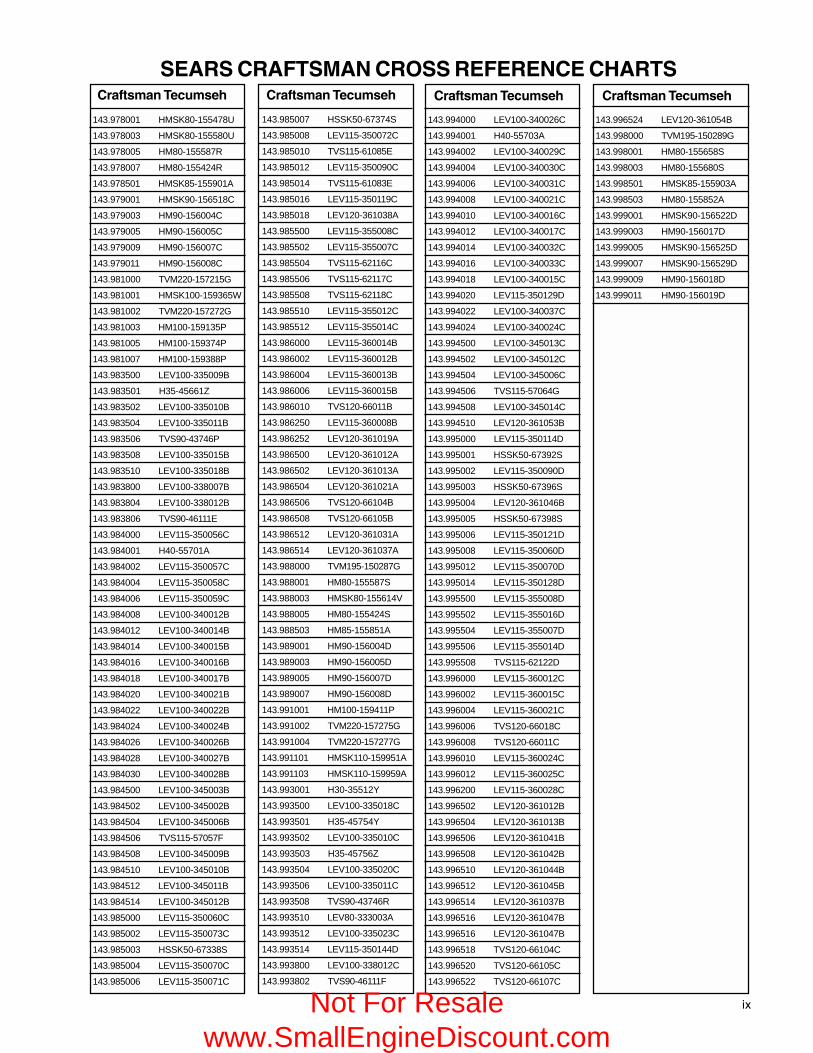
��
�����������������������������������
� ���������������� � ���������������� � ���������������� � ����������������
143.978001 HMSK80-155478U
143.978003 HMSK80-155580U
143.978005 HM80-155587R
143.978007 HM80-155424R
143.978501 HMSK85-155901A
143.979001 HMSK90-156518C
143.979003 HM90-156004C
143.979005 HM90-156005C
143.979009 HM90-156007C
143.979011 HM90-156008C
143.981000 TVM220-157215G
143.981001 HMSK100-159365W
143.981002 TVM220-157272G
143.981003 HM100-159135P
143.981005 HM100-159374P
143.981007 HM100-159388P
143.983500 LEV100-335009B
143.983501 H35-45661Z
143.983502 LEV100-335010B
143.983504 LEV100-335011B
143.983506 TVS90-43746P
143.983508 LEV100-335015B
143.983510 LEV100-335018B
143.983800 LEV100-338007B
143.983804 LEV100-338012B
143.983806 TVS90-46111E
143.984000 LEV115-350056C
143.984001 H40-55701A
143.984002 LEV115-350057C
143.984004 LEV115-350058C
143.984006 LEV115-350059C
143.984008 LEV100-340012B
143.984012 LEV100-340014B
143.984014 LEV100-340015B
143.984016 LEV100-340016B
143.984018 LEV100-340017B
143.984020 LEV100-340021B
143.984022 LEV100-340022B
143.984024 LEV100-340024B
143.984026 LEV100-340026B
143.984028 LEV100-340027B
143.984030 LEV100-340028B
143.984500 LEV100-345003B
143.984502 LEV100-345002B
143.984504 LEV100-345006B
143.984506 TVS115-57057F
143.984508 LEV100-345009B
143.984510 LEV100-345010B
143.984512 LEV100-345011B
143.984514 LEV100-345012B
143.985000 LEV115-350060C
143.985002 LEV115-350073C
143.985003 HSSK50-67338S
143.985004 LEV115-350070C
143.985006 LEV115-350071C
143.985007 HSSK50-67374S
143.985008 LEV115-350072C
143.985010 TVS115-61085E
143.985012 LEV115-350090C
143.985014 TVS115-61083E
143.985016 LEV115-350119C
143.985018 LEV120-361038A
143.985500 LEV115-355008C
143.985502 LEV115-355007C
143.985504 TVS115-62116C
143.985506 TVS115-62117C
143.985508 TVS115-62118C
143.985510 LEV115-355012C
143.985512 LEV115-355014C
143.986000 LEV115-360014B
143.986002 LEV115-360012B
143.986004 LEV115-360013B
143.986006 LEV115-360015B
143.986010 TVS120-66011B
143.986250 LEV115-360008B
143.986252 LEV120-361019A
143.986500 LEV120-361012A
143.986502 LEV120-361013A
143.986504 LEV120-361021A
143.986506 TVS120-66104B
143.986508 TVS120-66105B
143.986512 LEV120-361031A
143.986514 LEV120-361037A
143.988000 TVM195-150287G
143.988001 HM80-155587S
143.988003 HMSK80-155614V
143.988005 HM80-155424S
143.988503 HM85-155851A
143.989001 HM90-156004D
143.989003 HM90-156005D
143.989005 HM90-156007D
143.989007 HM90-156008D
143.991001 HM100-159411P
143.991002 TVM220-157275G
143.991004 TVM220-157277G
143.991101 HMSK110-159951A
143.991103 HMSK110-159959A
143.993001 H30-35512Y
143.993500 LEV100-335018C
143.993501 H35-45754Y
143.993502 LEV100-335010C
143.993503 H35-45756Z
143.993504 LEV100-335020C
143.993506 LEV100-335011C
143.993508 TVS90-43746R
143.993510 LEV80-333003A
143.993512 LEV100-335023C
143.993514 LEV115-350144D
143.993800 LEV100-338012C
143.993802 TVS90-46111F
143.994000 LEV100-340026C
143.994001 H40-55703A
143.994002 LEV100-340029C
143.994004 LEV100-340030C
143.994006 LEV100-340031C
143.994008 LEV100-340021C
143.994010 LEV100-340016C
143.994012 LEV100-340017C
143.994014 LEV100-340032C
143.994016 LEV100-340033C
143.994018 LEV100-340015C
143.994020 LEV115-350129D
143.994022 LEV100-340037C
143.994024 LEV100-340024C
143.994500 LEV100-345013C
143.994502 LEV100-345012C
143.994504 LEV100-345006C
143.994506 TVS115-57064G
143.994508 LEV100-345014C
143.994510 LEV120-361053B
143.995000 LEV115-350114D
143.995001 HSSK50-67392S
143.995002 LEV115-350090D
143.995003 HSSK50-67396S
143.995004 LEV120-361046B
143.995005 HSSK50-67398S
143.995006 LEV115-350121D
143.995008 LEV115-350060D
143.995012 LEV115-350070D
143.995014 LEV115-350128D
143.995500 LEV115-355008D
143.995502 LEV115-355016D
143.995504 LEV115-355007D
143.995506 LEV115-355014D
143.995508 TVS115-62122D
143.996000 LEV115-360012C
143.996002 LEV115-360015C
143.996004 LEV115-360021C
143.996006 TVS120-66018C
143.996008 TVS120-66011C
143.996010 LEV115-360024C
143.996012 LEV115-360025C
143.996200 LEV115-360028C
143.996502 LEV120-361012B
143.996504 LEV120-361013B
143.996506 LEV120-361041B
143.996508 LEV120-361042B
143.996510 LEV120-361044B
143.996512 LEV120-361045B
143.996514 LEV120-361037B
143.996516 LEV120-361047B
143.996516 LEV120-361047B
143.996518 TVS120-66104C
143.996520 TVS120-66105C
143.996522 TVS120-66107C
143.996524 LEV120-361054B
143.998000 TVM195-150289G
143.998001 HM80-155658S
143.998003 HM80-155680S
143.998501 HMSK85-155903A
143.998503 HM80-155852A
143.999001 HMSK90-156522D
143.999003 HM90-156017D
143.999005 HMSK90-156525D
143.999007 HMSK90-156529D
143.999009 HM90-156018D
143.999011 HM90-156019D
Not For Resale www.SmallEngineDiscount.com