technici n / dealworld's largest tv-radi service & sales circulati ...
84
LC ROMIG TECHNICI N / DEAL WORLD'S LARGEST TV-RADI SERVICE & SALES CIRCULATI MAY 1 916S. A HARERACE FUB_ICATICN SIGNAL STRENGTH METERS COLOR SYSTEM TROUBLESHOOTING SOLIQ TATE CURVE TRACER
-
Upload
khangminh22 -
Category
Documents
-
view
0 -
download
0
Transcript of technici n / dealworld's largest tv-radi service & sales circulati ...
LC R
OM
IGT
EC
HN
ICI N
/ DE
AL
WO
RLD
'S LA
RG
ES
T T
V-R
AD
I SE
RV
ICE
& S
ALE
S C
IRC
ULA
TI
MA
Y 1 916S
.A
HA
RE
RA
CE
FU
B_IC
AT
ICN
SIG
NA
L ST
RE
NG
TH
ME
TE
RS
CO
LOR
SY
ST
EM
TR
OU
BLE
SH
OO
TIN
G
SO
LIQT
AT
E C
UR
VE
TR
AC
ER
'or at toiltO
t
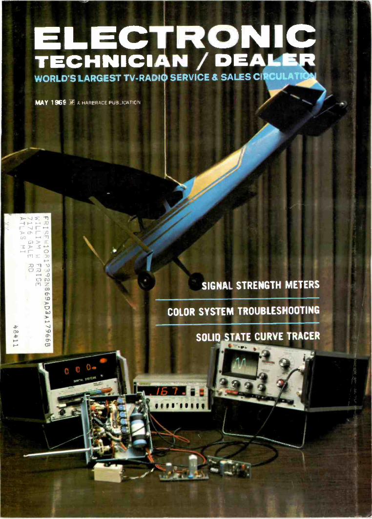
The SevenYear itch.Remember when we introducedyou to our Television Analyst(model 1076)? That was overseven years ago, and she'sstill the only diagnostic tool ofher kind. But now there's anew number. A smart looking,professional model (1077) withdesigns on your heart.
Sure your old model still works.Why not? It was made by B&K.
But, of course, she can't do someof the groovy things the new modelcan do. Like testing TV sets withUHF. And testing transistorized TVsets with complete safety bymatching the impedances oftransistorized circuitry.
The 1077 analyzes every stagein color and black -and -whiteTV sets-without external scopesor wave -form interpretation. And
she does it with a standard testpattern (or special pattern slidetransparencies for color circuity),all of which we supply. She does itall: from antenna input terminalsto the grid of the rocture tube,using the unique B&K signalsubstitution technique.
When you co get together withour Television Analyst, she'l'eliminate those hours you wastedon tough dogs, intermittents andgeneral TV troubleshooting.(Hours for which you often don'tcharge the ustomer.)
Here are some more of hergood points: VHF and all UHF RFchannels; IF; video; sync; chroma;
audio; bias supply; AGC keyingpulse; and signals for completeanalyzing of sweep circuitry,including flyback yoke test,and horizontal and verticaldriving signals.
Got the itch? Contact yourdistributor for complete detailson how to start a new life witha Television Analyst.Or write for Bulletin 1077.
Motel 1077. Net $379.95
A Division of DYNASCAN CORPORATION1801 W. tlelle Plaine Chicago, Illinois 60613
Where electronic innovation is a way of life.
M(puts an end
to test equipment.We've developed
Silent Partners.
. for more details circle 106 on postcard
1223
WF- I
5V P -P
60
WF-5
150V P -P
WF-9
3.2V P -P
7875'L
WF-13
110V P -P
7875
SYMBOL DESCRIPTION
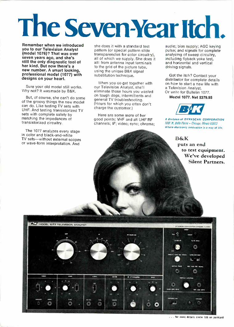
ELECTRONICTECHNICIAN / DEALER
COMPLETE MANUFACTURER S' CIRCUIT DIAGRAMSAND TECHNICAL INFORMATION FOR 6 NEW SETS
SCHEMATIC NO. SCHEMATIC NO.
AIRLINE 1223 PHILCO-FORD 1226TV Model GHJ-14549A TV Chassis 19P22
MAGNAVOX 1224 TRUETONE 1227Color TV Chassis T933 TV Model 3912
MOTOROLA 1225 ZENITH 1228Color TV Chassis TS924B,C TV Chassis 13Z12, 13Z12S
WF -2
80V P -P
60%
WF-6
28V P -P
601,
WF-I0
10 `v P r
7875
WF -3
55V P -P
60
WF-7
450V P -P
7875
WF-11
7875
Balloons WF-1 , WF-2 etc.shown on schematic indicatepoints of observation of thewaveforms.
AIRLINE PART NO
C20A.8,C.D- 40 -200 -250 -IOW 200v elec 034-018800C106 - 330pf 500v 5% mica 045.007200(115- 15pf 4KV 10% disc cm- 825-150016RI I - 12512 439 10% 054.059500R13 - 3.60012 5w 10% WW 053-362510R164 -4 512 10 10% 053-458110RT74 - 9.611 thermstor 057-056500R26A.R -- contr. 100011 (A), vol, 500K
(8) svion-off switch , , , , ............ 055-051600R27A,8 brash, 5M (AI, red hold, I. SM (B) 055-051700R69 - serf lin 5M 055-035000R7I - height SM 055.035100R111 -km: freg o4 50K 055-041700RI23 - lion: hold 75K 055-0320005820 -- diode sel AFC det .. 033-0020005827- rectal** vhcon 10o 900PIV 004-003500A183 - :former audio output 031-008301FC23A- filter choke . .. ...... 032-0023011.1 26A - coil video peok ........ 111.012600L I27A - coil video peak ,,,,,,,,, 111-0127001128A - coil peak ,,,,,,,,,, 111-0128001202 -coil hors: freg 110.0202001203 -:former sound lake -off 6 4 5MHz trap 109-0203001204 - :former IF output 2. video der 109.0204001206A -cod sound quad ,,....109-0206011208 - xformer IF interstoge 109-0208001262- del yoke 027-0262001267- coil choke 2 used 111-0267001388 -coil line filter 111-038800TR788- xformer vert output 033.007802TR94 -'former For,. output ,,,,,, 033-009400
chess's brd ossy 073-041100FI9 - cir brkr 1.75a 099-001900CO206 - couplaie sync take -off . 134.020600
tuner. VHF 066-017300tuner, VHF 006-020500
WF -4
58V P -P
60 '1,
WF-8
42V P -P
7875
7FTA L3021/2 6BL8 SOUND INEERSTAGE
SOUND IF AMP TRANS
CI51 II IOOKR152
47PF
Ri54 ;4 it'10073V ,10
PF3 1
CI52
00151- 916610K
OurANTENNA
TERMINALS
1.2
L
UHFPuT ADJ
---, -I_ 1 _
-,IfIIIT's-
-/-- - ---
...ITI:ai(-4.-E.
ii4-C7:3-4
IL",.., -Cil4 g 1.4 GIMMICK -/- .--.". --OCRV L5 V2A
36115 IF OuTPUT I/2 5148RE AMP COIL MI ER L6
C43 3RF
RI( 0247K VI V2 ix
OURS sue9 4
331 FlUHF IFINPUT
(4) 0 AGCSOCKET INPUT
9
UHF CHANNELSELECTOR STRIP
-,1113irs- vo4F CHANNEL05CADJ
SELECTORCH 2T.R u
STRIP_FORI
R422K
V2B1/2 SUB
osc
R3
:220
0OILIE, (-1, %I, I.C.
INPUTe.FIL
RI, 1010ES
AGC INPUT'1,400 cHass(s)
NOTES
I ALL RESISTORS ARE 1/2 WATT, UNLESS OTHERWISE NOTED
2 CAPACITOR VALUES ARE IN MED, UNLESS OTHERWISE NOTED
5 TUNER IS SHOWN IN UHF CHANNEL POSITION
-riff4D T6
SOUND OE T1 206 A
QUAD COIL
5
0
sv
00v
IC PF
1208
IvC154 R155 CI560015 T 680 .047
1114.
01551 R15600471 j8.20
TP3RI575606
RI58560K
C158. 01
*4 0mg.?'
VOLUk5121
R2613.
0157I00 PF
co,
,CA(1PE
AliOUTPUT
R7, IR
f2);;IF -4, 2IF-1, 0011 fl
TEST° nPOINT "'INePUT
UNE s.OUTPUT
192e P< IF OUTPUT
6 ITO CWSS.SI
RIOijA
NO INPUTIR
(IRON C.ISS.51R. OUTPUT
,TO UR TAM
VHF Tuner Schematic Diagram
VT9 AT 171-378.
1r0 ovAutoIN
10666AUDIO OUTPUT TRANS
AuDIO OUTPUT TO
l SPEAKERS)
77311(- 30V141(V
41,
8159100
12
L
AIRLINETV ModelGM -14549A
MAY 1969
ELECTRONIC TECHNICIAN/DEALER is pub-lished monthly by Harbrace Publications,Inc., Harbrace Building, Duluth, Minnesota55802, a subsidiary of Harcourt, Brace &World, Inc. Subscription rates: One year $5,two years $8, three years $10, in the UnitedStates and Canada. Other countries: Oneyear $9. two years $14, three years $18.Single copies 600. Second class postage paidat Dansville, New York and at additionalmailing offices. Copyright 1969 by HarbracePublications, Inc.POSTMASTER: Send Form 3579 to ELEC-TRONIC TECHNICIAN/DEALER, HarbraceBuilding, Duluth, Minnesota 55802.
NOTESI ALL RESISTORS ARE I/2 WATT, UNLESS OTHERWISE NOTED2 CAPACITOR VALUES ARE IN MFD. UNLESS OTHERWISE NOTED3 VOLTAGE TOLERANCE MAY VARY ± 20%4 VOLTAGES MEASURED FROM POINT INDICATED TO CHASSIS GROUND
WITH 'VTV91-. AT NORMAL SIGNAL INPUT5 WAVEFORMS TAKEN WITH NORMAL SIGNAL INPUT
WF-I2 VT4 208 VT5IF L1N2P01.17T 13 4EH7 IF IN ERSTAGE 4EJ7
SOUND TRAP 1ST IF AMP TRANS 2ND IF AMP42V PP TII- -1 TOP 4.0. 1206
141.25MH,
7
1086K 9
7875'1,IF INPUT INPUT 1
s r-"--)1 icsou rust:, IY
R1,3 3N 1,3 Iv
AGC
TPA
R23FMEG
OUTPUT AGC
0C
111=R2820K
ITO uNER( 4
NAN,
C5, 47R222
C2C9 R4
820TR3
04,.0010I 0015 56 PF 470
-
R22 812 2MEG 158
470TTOF
8+ OUTPUT 08.
,,4,,ITO TuNER I
F49 0160CIRCUIT 001, IKV C206BREAKER
R2047K
0213908
WF 8
001
L204IF OUTPUT TRANS 6
VIDEO DETECTOR
C.. 6.6R65v11° ii PF180
C6560-.- 141
P F 4701211/
L203. SOUND TAKE -OFF4.5MHzTRAP
144.7-147BOT
PF
L__3
47121 VT6TV I , 10666
°' I VIDEO AMP
-71 1.133A Pig
4 7 PF TPI
3PF11213A
41- - -JR9, 1211
701/1rIY
c2122l88A
220TPF
F112110
CI9
1501RI9
Pp 220
CC206SYNC
TAKE -OFFCOUPL ATE
VTIO8(07
SYNC AMP B VERTICAL OSC.
R51
/7I31F7f IOOK,IW 954
(10E-3)
2 2MEG 3vows
330*
'VT781/2 6BL8
KEYED AGC
F.
110-120 V.A C ACFC 23A 142; 4, 200V 470,
26, 126,
40 RI60 WF 9
GO CYCLESIN,,,TERL0c. 45B160,4-ft ,..
' L388 It 11SR2711.1_
200 2501. (20D
10
N 000
(30V 200066UH 200V 2009
'01ARIZEDSW1
ON/OFFSWITCH
ION VOL
CONY MTG TO '13.
BRKT TUNER FIL
R187 ICi7i470K 0I
INV
TVTI4E,1
VTI3 VT12 VIII VTIO VT6 YTSi
210152 48F075
IOCWS BEV 1061(6 REP5 4 5 1 5 4 5 4 I
1
T-C163 HTR
VT -7I
Pix TUBE8 I"
LT-00.
VT8 VT7 VT9 VT440T6 6BL8 10066 4EH7
C173 Ci61 C162
00IT001-1±,
C51.440, 01
imos202.
R528211IW
8530%53,39
851
....(WF
tRL9
686
0015C52
686
"v 600019± +(SSC;
2200
R602706
CSI
T68PFcv
WF-S
AFC
12020
Ri08,121(
220K FRED a( 1-.0056 18"96, 330 piIC105 RICI9IRIO6 HOWL g CI06
DE,
T ,
14104A,1447I-MEG ns,
vCaF751011
'1 LSR20 'NAM i
OVF.ID
........,..,,,,NP:0I°214 7K
3906 3906R103 001
C104- R105
%UT
L(101 C102
82 PF .001
826 R1101.265%
C103, VTI28F07
HORIZ OSC
-24V
R644706
L127A
RI33.6KSW
C8
L126A,000s-1(
R1411301(
IR27A,5MEGBRIGHTNESS
ART
8266,16CONTRAST CONTRAST
0 I-)
I Q
VTI I10CW5 C114_r12119
VERTICAL OUTPUT 686
00 Pro: VERTOUT
R71, SMEGHOT 11E16/4 I°-r
R63
865 6 8MEG
22011
/XV 9
R58130IC, 5%
C 55
R69,.5 MEG
LIN I VERT. LIN.av R2711, i. 5 ME4
HOLD0
VERT MOLD
1301,
8112
56612IV
6 8111, 50KHORIZ
FREQ. ADJ.7
V TO
(WE -12)
0108
001T12107,156
-391
396
1
L7_ J
1--CI74
Ril61.28, IW
ea,VTI32IGY5
HORIZONTALOUTPUT
IICIII, IS
00 NOTIICASURE
giL267
9
F-13
R114330)1
---.0109, 01R124
39068115 CII8470K
HOLD' 0 8120
(115-11
ME .
1722 15 Pi ,4KV-
688 8123, 756HORIZ HOLD
T1
01170
_L100 PF4KV VTI4
17E1E3DAMPER
4
0 L267
7""BOO°
STISOV I0037
LIN 2
1304
130V
RI 5
681(.1W
R5622K
VT323GJP4
PICTURE TUBE
R29,4706 /snnM-
R1639K, 1W
rTR 788
VERTICALOUTPUTTRANS
FOR BEST FOCUS RESULTSCONNECT ORG LEAD TO-.TERMINALS I, 2 OR 3
CII3SOCKET
033
R57SIR
10 I
1262,DEFLECTION YOKE
MORII COILS
RI 1e,1321-'115cvRT 74 C116
I
THERMISTOR
R72560
LPLUG
-1,80
RED
810
DEFLECTION YOKECONNECTOR STRIP
(PIN VIEW)Ma, 2.2
TR94HORIZONTAL OUTPUT
TRANS
/TRY
VTI5163
HIGH VOLTAGERECTIFIER
1223 COPYRIGHT 1969 BY ELECTRONIC TECHNICIAN/DEALER HARBRACE BUILDING. DULUTH. MINNESOTA 55802

1224MAGNAVOXColor TVChassis T933
ELECTRONIC T7/7=Lig ACTECHNICIAN / DEALER
111 nI
'
V V VI
MAY 1969COMPLETE MANUFACTURERS' CIRCUIT DIAGRAMSAND TECHNICAL INFORMATION FOR 6 NEW SETS
11011411.1110 I nI I
110gra
vi V'
0712 10
0797 t 60,002,'713 .000 Sirn I1000
VHFTUNER
VMITUNER
V I Vt
340126 340114 4003 4107340139 340137 6605 6C611
vp, MOTOR
L11311 SwiTCro
J7-1 010042A 6-C J11 - 00010J7-2 040001 ID LL JO - 5 0111011 90-v0J7-3 00101A BO - V a -I 01110111 BO- TT
.1/- 1400 J8- 14011 RIOJ7-6 FC ID -CJT GROOM.11-7 2/00 JI-10 S4012 RED
0-8 FIL 6.3 J -11 1001 BLACKJ7-9 0411011A SD -MM 4111-12 34015 OATJ7-10 IF SD -CCJ7 -4I 0411011A SC.- LJ7-12 CORONA 80-
'151011 0E0910605
L
D61011010
COL_J
LOCpv
CO I
,7147 I1 _ I
*10010HOW. TUNE
DEFEAT SWITCH
3 HOC1700]1_
COrk404
SAC 1 vof PILOT 1.14,T
IMO 9 -
UHF PILOT LIGHT
ENO Vit
ON CHROMA BOARD
S./
000701 00101.20 COLD
TO .01.
1101
GLICKPKTIAM
GIRONABOARD
4AM
040627010%
IC.40vgal
AFCOEFCAT104
stool
AesAirveasdr
rL90
00041711INN
10%
0.04000
C19021005 %
"r"^"r'
Teriell2V r
.461. 4411100."
J'
POT 17320 OM Nal 0002,3
00
V401ISIS
0902400%
010.1000
d0
doss,
TEST POT
COOT *500
000 10.0045% DOOR 20%
11074711/41r10%
01103I
20%
7-5 JT S5)
OF.
$1187
5.1
C920 1.900ttO
1/ TO .43
C110521
5%
C1104680
L
L902 L1107
XTCOOS
0005%
4761 01110
Ave 22010%
4111
0%COU-100
CIO 0000304
-I
A.FC.BOARD
Na22
1402A/C DEFEAT
OUT
a TO CIELUP110190211
TO 1C101. 04102.2. 20410.407
0050I NOV
1400. 210
ti.V703 ciNPle P
U f
x..4002.01VTol v ia,
F
924,10,ARE --F
OV
C70I* 13I
TO 143,
*14,0.,9R3 1.1211 I
ONO 1.10 J ePo Co, MCI
.11
070Mw
PUMA W
ry
0,
C7040702 V701 0707 3300
.p, 004I'je .r, so.
- 111.101ESINSITO/I IT
CONTROL
0
10% *I
C702.0/0.
II/it2211E4
C7.tt
ITO T140)
11143
1134500160
2700
0721033
J5-2 r
01215400
*7225600
1672501
2600
1172010100
[DUOTRAMS
Icc. cool3 .
1.201
040
Rv
11202IM
*703SOO10%
MAICESIEML"
'170702SOTIA
1100.140 041100
2.60
$ toov
1000
1
.-CTOT C70401 0
CT119111F1)
Li, 4D>TO 0410 PULSE
ROSANASA
ABC
v
At
C1011Oi
1001. 4.12B001/0 gihm.
.7-171t, vv_
Ec,. ."1-.C7I30 .1
1.703
1%
C710-- 1001 I
.,..; 0704 L -1102 1
47004400 - -10%
009MC.
*708t011
41.11)21120411-1
4
CHROMA BOARD
0-42'70." I
*7043300
1.0
07275600
110
1470MK C224 2/25
22.30 ISO
11729470K
....
1173040146,
ortstM
a!
0 C403 4.'s7
1
121014SY II .11
04.0].)--- TO 3
0 011-11 TO 400--0_.2121). >P. I
7..
OE DC
-440c lowLI IDE
C.CulT 01 SIKAPIP
A -OPT
0CD -Ka 0.200 Top
4-C.02 '3 ,1-.
yv.
220020a .A ,
-0-) WO3 3 1,40$.11:44 0 00 -OFF -7r .6:,>- ;'-'
1 .111 -10I116-10
TO Ma
ggo"Algt:'gAM
COMO MAO
11L an4
RED
S1[0-000
IL=
$25
101.
,102
5*
Full3422
19 *MC14,
1100-11LK
3- 40 v2115$099
017,w,oc
.1012IL__
_IL J
4148120
VHFTUNER
04105 0030SOURCE SOUR 1,0s
girm
TO.270v
10 f FO1Ili50VD
.IC
T:';Oro
Irp 4,11
0460
50103eW
130
11031200
.C.113 Ion1800--4
TO JUNCTION OF101011 AND 1013
I @ 0201
y CI
POO
T201VOCO
PoPuT TRAMS
.1" 5033v
*201 12.025 11/ 147 01320 IF
IST VIDEO IF 1*4*1TOV
02010K
'071,2"S.Wj:0:711y1/4...eir30'..
COO.000.
*203
C205.0f
*2027005%
C206r--4
COO
02042200
560 t0104477%
17 170v
C207
0010000200
14000 osKm 500
3C204000
22030202 OD 01003 IFISIS TRANS
2910 1.100 IF r.
5I 7CIV 2
315V
315vITOV 2 .3
112.0 C21475 2205% .0500
II
Cl 2 . 100074 0001000 100 100
CVO iC209
4210Goo Lon
.2026'"'"g"
°al:A
2110 BCC
0160.20OW
1050
°au%
SOURCE0000M111)30 NOT 1.412 A0
131 . 9.17m .EG
4
e e -
ROOT100
IVI
C225000
ro 001020 80 Of 0
*2040000
H3--oTO 00103... ID P19 J
r0
1120 -ILK
1013 00011kAL UK
Romon STOICTAKE
ToFFOUTI,
;1:1:" 1 00157:
PS
200
Si NC
1514 0545000 1000
R5SI
C50460
PO
1057130
5701(
ooI
TO MI
C231
111211
00
0/21
07011NINA
11111C UP
TOO
As
800vTO
90017
4.1,4A1100 DOT TEL OCT 2
04042300
1100.013(33
TO OEFL SO Po
.11-12
CO
32335%750"
10.tU11
ww.rwei,00060
:11":50.041, 20_..__3 3.110.0 10.13..
:1=. DOT
rwym'ci.
,
RID 1: TRUSS 11 01 C..'
1 OCT
RPO
.0 . 100114 0217
4/0
IVO56
8300
ISO
C221,E1/.(SOO 7%
00
020 61tw
IP/001D1LZ04 .0500
390
0 02
C5102700
Ti0311 C5 it
'Plt1It 0" ::!:-0$01/. 1141500
;:g0::00.1, ID 0,,
C5t1100010.0 07211
1214
C525.moo ono.. .15
0529
R525 2200 Car3900
C52227
NopC5231
0530520
RCNNIT
VENT 011C
TO MO- 5COKI
IWITCOTO 05
09/11 0520470 820
iC5.4ISO
ammv-.010
10$
V0450
1000033
4"CM
NOMC$07; 4:101:1 ;
Fag
-ova 2A I
160
1124
Lite Lt r.7.5..:
VIDEO If BOARD
0%LT.&
TO 200v
411939
Cl!?= 02041 010410260 KW H225
SYNC AMP 00(0 AMP 00000 1100
0222
Iv
3300,
O
07-10-0
m353.30Olt
1110037
131/
TO 145
1-S05 a5.104 zs, err.
ISO
R134
1-...404.0100
047
C5100042 var °'`gr
VDT OUNVT
41001000
0521
05 2
013322007.-4=
MOO 750A.01.0
ROTAITO?
0 DC COATetv
3
TO ADCO CONTROL050_ BOARD PSI 11
21150
017:7
2 0030c.,!:
407 Ljr,,s*042 020 7/
0\01 CSZ8 130;
a
11754:052:11:f15.
4°eV
1C"O% COLM
5805%
4.%
OM
OPEC WC
Or 1 1Ca
270I I
119301100
07 317K 1531 9102
4 RIOT mostem 54
00012014TAL MOLD
TO 7-381,TO
.13
TO .0VIONCI
A NOW OUTPUT
3000
200
DEFLECTION BOARD
101406606 OS*
V504ItAX7 4000 V
MOAK Or
";,1:1 7:1 ...cor37 Id('
2200 L
11305coo 100
115670041. 2 2002
45411330
.C1014290
icses
925 000
a
AOC AAA1914
T --.17-"C".C1n°74'eairumE Cos
NCO "Il 1 4 ov owICUS
02.10 ROI /
0,13* CO
0106
FOCA ONT. 2001
*5061
711.2"
15K?IV
:C0.1111 .20v PULSED
000 *AMID --O-
CII366 *00vU I I.0 NAPO 22
M11500 9
5%00 5
FC
111;5-
Worcm*0487%C1170409%
1103
1305
102 00,
SAM 41,
LiO410112IOC
g"1w
151111111,170E0
IONINUNT-1.0
WHIM°macs
360V
0-4750.03so... 0121
GAP 000
TO40%,
B
CD
- To 803 P..0 (C0002114411C4 110 .90. 7.4. 8.
CITO RIPS000 24E6IKV 5%
50107
7 71924
5 %TO 2700
20 803 PIN 9 1CO CCCCCCC CC SD AO. IN 7I
0
1224 COPYRIGHT 1969 BY ELECTRONIC TECHNiCIAN/DEALER HARBRACE BUILDING. DULUTH. MINNESOTA 55802
B
C
D
10.1 $60.1
710524100
00777007015
ma/511. RI 5105 To C.30/ no).10110 000 000 COLO.
LLa
CiS5C5101
TO 01400
t0440000012
1.21.11
571210 105
TO J.1PP
C751470
0700
14
O 735400
.716
11060IKE
03517 AIM 2 401
,P3 0100
...MO
0717
5%
C." 405410
CT.
C 1St
^PAAAlli
014.1 OPE in
1700
.,0,..0014 (i) 5,4,
111.10.0,13,."
ft...4,...1.--=_. 7)Hm...
. 1400
TIP E .011 . --7 C;14
I 7 01TO 000ON.
1:21,0140
1C'11
SS 003
07420.1 330
07050000
C737
3 NA 5
708WOO
CAW
C744
I 5%330
0400
T 10101000. 1551.Al ,
C7370
1%
7ram e05.leo iooss
Lp
H550 1IMO 1
InsO 00.
1%.51$10
1112.
C
070011414747
WOO OUTPUT
TOO.' 11"3
/100
00
TOT
mo Go- im.L111
TOO 2 u.Dry
75 ,p000.11,Adt6 470 C045
3,34'0100
2701%WIT TOMS
5751000
WS510
4, %
.1 MOO
C,4,3300%
5000
01770.
'71310
38 4
C 7311
310 r D>
G
H
ate1040
004
0111000
5754.21.15
6 1.... AT.4....., ...,
1.....,tee 400NOS :LA,CONT
1000,11.00 c0{
7 MY
-C,49- IMO
.C70705
3
POI
. 4
0 150 51102440COM 00.
*C7/3
.44.
*0 01 TO 51
0700100
Tort 070
100,01.MY WOK10. 0(7102011
57500.1016
i404r.
035V
071051106
011100
MVOWISP
01.5101000010 T
01102511WWI
OCT1C10. 20
T
470 710NH
MOOMe TWA SWOP 2701
A OIPOP ..NYC r --Rk **0.0_DATNE re* 41) 010,.. IN" r ,
^. v 05
1 Or a w 210 \.. IDS -102L;
Tr i 117570754 4 T.
5110 "5164 r -SU"
-7154
100TO
5701
S
114PM
O 71711 I
mom4024
510 OMr. 210.
11-1, OUP eo1
5-T
071115
C14 ill, 2 *341 10,1
0.: :1 41 R770On
7*
7711I WS
O 701t7 On
C787
1501
N TO)500
7v
TV
vTIRC0100
11-, Mel
n/00ETN2* 0183
O 012
A
O /93MOO
10
0.10
0
11701MAWSAP
014701[1
10340401.1200
011-021
1100010
1500
111.43111
SON
400
,11 14C7 70
CP
-000
0704 0710
.q.
.00026
TV
10/02/0111
NOY
TOTS
CC 08
41 TO TO
4100
1771 7010%
Ctw 4,--0 % 0.;
071t[715 1754.
eLsi TO 4000
44 .1404
TOMOP PM. 02
0111 I.. 3.622500311
1500
ow OW
Oi
0704275t
-,mmTC11,
TO TO.4050 .4050
1.4
.
54115
TO 0100
50117 50 v
0015500
KT 'Oar -MORO COLS
I1 Pm10012
T101PC TRANI
C4/052
0010(0 CONE
SO 5545
's
5.11i0
VERT00171144
TO050
10.1 ,000
- - CD
' FP .. :40" .
055SO
TOP Of04 TILT
CASE
"4 " TOOTS TOb 10 TILT
.S,11
4 102.<4
,CONVERGENCE
C41417
..750`.4 2 (4 3 2 010
..3 0(4 03 3 A .., ,1 2I°^ 0 i 0 . 'jog.)
1 0. 17 :. f ....- :.1.-L:: Or ',,
'
4
,_-_-_-_-_; .. ,.
,.. MIN.10T C17
.111.10
,..,1,4,-r" .. ';'...-'7.1.7.
....et" . .
0,)LA,r 4:,;: : 1.. 111,(.,_,.
.05 ,
....
'Ft'c f.-c"1-:4 . '''6.÷'rrVLJ''' . Ku l(('*I. .1-1° 4, ica* i- - - - - -t i.r. r -
C11
Rao 1,10
I I
IvOtTICAL COLS I 507
15100
7 1E05
1.910510
2.4
4111
33
I0.150000011 740111
/N./N.",
BOARD LETT 102.4
T4TI81104
40
ISo1.
005.. 3 OLL.1 0 1.104
C.00. 1
140410 0 .02-I. C.
01111_LLOON 1
V. L Kamm, c06.
rl.: r Inc -I.:.
2FIC
500015
F .--,7 et:"ftna11..C4.0
0341
00.
is
M..20OT11.1
AWL
*SOS50
5701105
1.1710
006
1141T
0
PC.
,
RIM 7
1500
ONO* t1000
801150001
3344005 00
RLL
14011
SWLAK GAOWIWI CPT SOW T OrALL WM3 (ICE,wow N Mt MIMI.WW1,
O00)1000
1,72,TO
110011710500001001 5
P m I0171
O D
RICO3 3 0 0
$0
Tem"-Cup.
C .1054 -I ITV
RIOSNEGBOXSC.
KW,111411
VOITCI5 504
01 0 f .00044
MS57100
TO T
TO *Deo II
TO Poo N
Oft °pa CTOO MO
122
WONT
CO02coo
104oi100GREEN
SCR
R141000
0011000 .2405000
0,5PAD
4
RE, CtMsu coo
VIDEO CONTROL BOARD
v5.010 TUNES
100 C..11.1.00 .1400 0:10.1105 PAWL
500 02,L1C1CA500 1010500 00.344Cu 03111051.101.4
00 *00
VIO625.722
OP 01.111
2 5072 2OR (0010224722
OR (0010PICT ORETvilt
ro 100.4IRV
TO otv/my
31. Po .11140TMESS
21001140011/5 101410117411 WOAD Wm. 2%
5 WOAD OKCC4 1[0[110[ Of IC .0100014011 0011I Ca0ac1001211 W11111 an OCR 0.0.4
A52 IS wccIallabioF I 090 Lei.
114 0C.00..0117 ALL vOLTAKS 111.0.010 1101 NO
11004.111/2111 75051 40111114100111 45 ASTPPi011P1.
s SOLACE r 111150010 WITH SWIM.E 10010 P1000C7004Iv 0 USE 0 TOR uTO OFF .00 111011 OSLOII 100110 TO MI CLowti) 000 001 SOME UNITS
iStr tAID WITH 3-.1.21 0111011 000.1
D2. mg. 01(0 4.75 5100 o T05Uf
011051 11111011 0114.0
CONTROL ACT 0.1000 011,
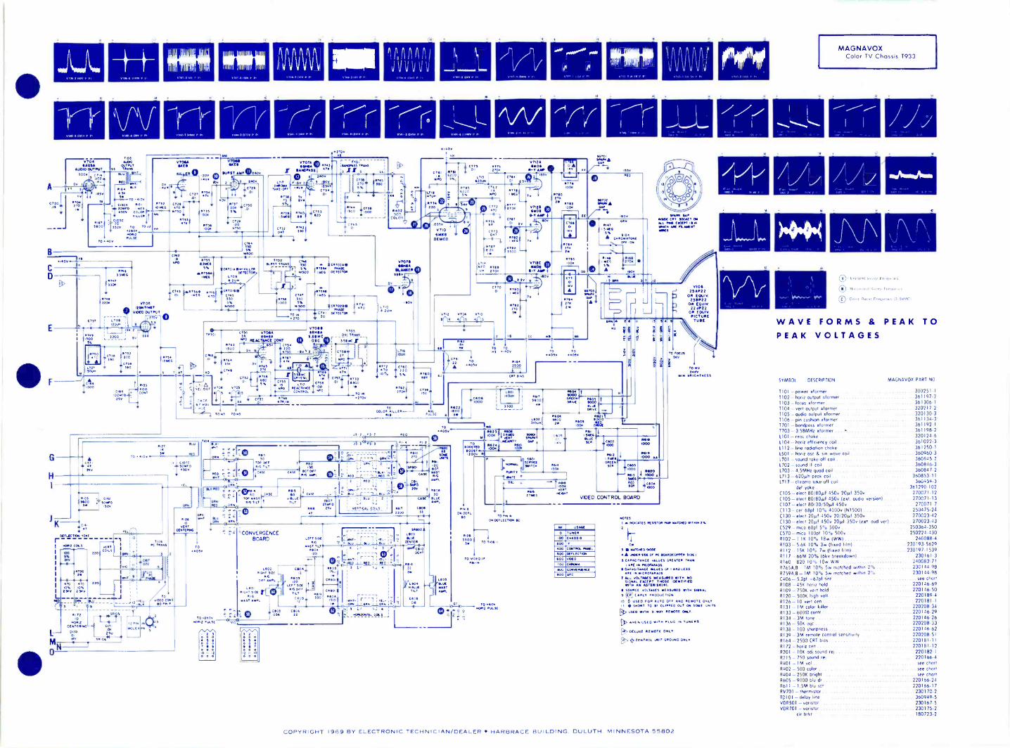
MAGNAVOXColor TV Chassis T933
1.00%,,*
1/( O-
At/ millromArn
0' Vet Ot +1 Nyco FrolooTto
C) v
0,1,1 Fo .
WAVE FORMS & PEAK TOPEAK VOLTAGES
SYMBOL DESCRIPTION MAGNAVOX PART NO
1101 - power 'dormer 300251.1TI02 - honz output 'dormer 361197.2T103 focus oformer 361306.11104 - vent Output xformer 320217-21105 - oudio output xformer 320130.31106 - pin cushion xformer 361134-3T701 - bandpass xformer. .361192.11703 - 3.58MHz xformer 0 361198.2L101 - reac choke 320124.6L104- horiz efficiency coil 5555 361022-31112 line rodiation choke 361250-11501 honz osc 6 fin wove coil 360960-31.101 - sound take -off coil 360845.21.702 - sound IF coil 360846-31.703-4.5MHz quad coil 360847-21713 620gh peak coil 360853.11LTIT -draw, iuke-ufl toil 360959.3
def yoke 361290-102(105 -elect 80100 450v 20etf 350v 270071-12C105 - elect 80/80pf 450v (ext. audio versals) 270071.13C107 elect 80 30 50(.0 450v 270071-7C113- cer 68pf 10% 4000v (N15001 250475.24C130 -elect 20o1 450. 20/20µf 350v 270023.42C130 elect 20W 450v 20pf 350v (ext. aud ver) 270023-43C529 -mica 68pf 50, 500v 250364-350C570 -mica 100pf 10% 500v 250224.4308102-1.11 10% 18w (WWI 240088.4R103 5.61 10% 3w (fixed film) 230193-5629R112-151 10°. 7w (fixed filml 230197-1539RI 17 -66M 20% (6kv breakdown) 230161.3R160 820 10% lOw WW 240082.71R7651,0 1M 10% So matched within 2% 230144.98R759A.B- 1M 10% 5w matched within 2% 230144-98C406 5.20 =67pf tint . see chatR108 -45K horiz hold 220146-69R109 - 750K vert hold 220146.50R120 -500K high volt 220189.4R126-10 vent cen 220181-17I31 IM color killer 220208.34R133 - 60011 contr 220146-29R134 - 3M tone .. 220146.26R136 - 501 ogc 220208-33R138 -100 shonthess 220146.62R139 - 3M remote control sensitivity 220208.51R164-2500 CRT bias 220181-11R172 - hate cen 220181-12R201 - 10K od1 sound rei 220182-1R215-750 sound rei 220166-4R401 - IM vol see chartR402-500 color see chartR404-25011 bright see chart8605-9000 blu dr 220166.24R611 - 1.5M blu scr 220166-17RV701 - thermistor 230170.2TD101 -delay line 360949.5VOR501 - vonstor 230167.5VDR701 - varistor 230175-2
cir brkr 180723.2
COPYRIGHT 1969 BY ELECTRONIC TECHNICIAN/DEALER HARBRACE BUILDING DULUTH. MINNESOTA 55802

1225MOTOROLAColor TV ChassisTS924B,C
ELECTRONIC 7- rrwac=TECHNICIAN / DEALER
MAY 1969COMPLETE MANUFACTURERS' CIRCUIT DIAGRAMSAND TECHNICAL INFORMATION FOR 6 NEW SETS
VIDEO AND AUDIOPANEL "B"
VHF UNIT 148 118
.....--9 0 i C 80
,RIIP
IP 46812r -
CIS
C
TO
R621.1504,TO T501
5
17F
016F
T501
C40112
2w
Ni.
r
V3 T28 TRAP41256012 V4
3BZ6 iST lir
TIB
3E3 Z6iST VIDEO IF 'CM, 2ND VID
1 1 4' 5
1 47 25MHZ 9281
TRAP22K
397514112 TRAPIC
640222K 2W
TO 6910
94# C78005
138
668
121
R101 3 9K 5WM
C08005
V 5 ,41 RAPM25HZ
3E J 7 3160 lF360 VIDEO IF
71 lity2N0 if
T313
t24. Tre
.
R11827K
Fl ,.
10P. . w R319
3
i_fiL413,34
4'21'1 2 TOR
XSOB
1'111215
CI413
-- C4413 04 '-
005 406806T
IR.311 , MN. IC22; ;-er CI ill me.",2. IV '
v'--
con SOUND RE JT 4 SIMI4 ---IC,511 TRAP
1005ill
148 L38 SR1se -C45- 8 I2BY7A
T SBi8 1ST VIDEO A D CO LDC2
42V2WR.
WOOC,713 LSI3.10P C199
V 6
L6,.47
ilv wAr _fly\T
8(29
47 16198 196SR .50PN
3 Lio8
0238v. 3350 V
2-
0yN
82x172 9
73:8
,2pH
NW*8216 822815011 18K
2W
L128 0.1
L14
C 246-
00
010,8
K/
C258m220F^IF
V7
12BY7Aa *K.4 VA -IFS WITH
ONTROL r.ETTINO
1 1129,VN,13
2743
#309 J C27122K 22
1C1268T0021
68 6788.sOK
17979
1176
A T 0C34656F
L11313
0101 SO
I CONTRAST
_L.,
:iirac_WA,-#
03--214 BRIGNINEST6
K
#102 ,
AGC
R37F1006
IF
AND SYNC VIIA
PANEL 621 45GH8AIM KEYED AGC.
NM
47-
C323V
0211 C22F357 687
C2Y001
1127F000K 1,1,
jtrO,
_. I
R5FIN
R7F C6F470KT 005
-12
sOlY"Iv.'issV
RAFF56K ?;. ^roti23P
.26,4o266
V13
6F0 7HOR IZ OSC
850622K 6327
180K
629F R31FS8K 54K
IRK
R 13F391
C 27F470P TP
T IF
EAF
1636F10K
23FVI I 8
1/2 5GH 8ASYNC. SEP
RIOF C OF2701 0,
-.71-TR.C 7F
271
C29F700P
.2F
giv iDW301 65023911 50K
- HOLD
VOLTAGE190V195V205V
ue
01
ANT
VHF TUNER
C2 C
VI V2 a.
- - -062S
La
6.#6,vrVI 2HA5
'-I
10F
VI213vi2A ci9r' /4 10GF 7A ./210GF 7A 01
vE R T osc C2F # #F 820K cf R2 4F
.O3CF
_ As.0005 226 VERT OUT.- 21K
-IF-It 1 -WAY At t -
-1.C.ST -16 c,5E #25,6
680P
1680P IOOK
7 igV21%.__
AIM-- - -1- - -6,6F C 8226 7 Ev470K. .4 7.2t. s
-4/CIIF
= 005
9F
.18
RIO' 3
1V- HOLD./
il4 84071=R50
5602W V 14 ww
2
21 JS6AHOW OUT.
IrsoeR514SKIW
I'5130I5 350V
V2 5KZI3 °
TP, Fmow
was
41/tIr 1.
1
0Iv P0.05 1701101 1R010.4,56,445 0,
-t1-40100 0."700, So00.
04.4 13 010,01
27M376
SICRIE-0
C,4105R2IF
270K
.8F
R60362M
7F
IF,0
i2OV
.
+Clef
SO100v
R6043 56oK a R607 12011
# 3605 3 166063301 V L IN. 100K
v 163AT 2N.V. RECT.
65o a
R5L50126.1 :011.1-1
REMOVE JUMPER TO PEDucE *10TH
FACTORY SELECTION TO MAINTAIN
MAX Hy 23KV AT I2L/V LIVE.
14
0601.2
SF
RED'P
1-0ia
C1S26816
ZOlys
COLOR 152
0152 PANEL"S2"_L 2SC454C 2ND cOlAR
LIS222001
jr111MB
R 329.00R
C 35920P
4SMHZ
V83AU6
SOUND IF.
5 v C478qP
-96.""
c368 67
V95HZ6
SOUND IF SOUND DET
TABO :18Z1256 SA
te
1198Ray
C300 R358 1.
2711
5
C42801
tr3e
201
-6wrs3c
R652 63s2560 C252
-146
62528K
WhyoI.U0
S7016
3
C355210 2
9196-627
RSS2I1
T501
R9011012W
220R5151
-t
02N3#151470
1651
R908 27512701 w
T5013 39K
R52012K
w46A--e. a. 1910iV15
19CG3DAMPER.
R519 - -
IS FC5011SOP
UHF TUNER 07.P9
0 A30,0)HOUSING
0. j 1C1e
I
ATM
EF F .C,ENLCoo .
C50922
1502
00i
(503 3110545
BOOM80057
8406
C5I2047
Lcsi,T 04?
002 "I.
FOCUS
ADJ.
-116 41/01-C902 T R916
.01 "r 26 266
VI7ACOLOR 5GH8APANEL"Sl" COLOR IF. gm270V
Cal C T 0 16115I2"TPIS1 LIS! 2 3 2
--0-P52S1
C 25i !21.00
RSS182K
R1051820
1
C7S1.01
ins II- t D
Rol VISA MI -E. Ri2S -r `or0051 ,K -64
15" )4 5GH8A Tist ',_..COLOR SYNC pile- - - -,C1;1;
451 6
501$14- 2.96ftviS 4.1_,1
I E6S1
SIS
-146 C12S1'-law L
.1
ligpS1.111gS1
1-* Riss.1K
3.9PCOLOR SYNC
TRANS
R608560 2*
T. C804860350 v
13 BOOST
1111
VOLTAGE SYMBOL LEGEND
0 AB1 B2 B3 B4 B5 B6
290V 265V 220V 190V 135V 100 V
290V 270V 220V 195V 135V 205V
295V 265V 220V 205V 135V 225V
L601
01251
TOTALlin
. VERT.'C510 C516
OP 130PTOTAL750,
1225 COPYRIGHT 1969 BY ELECTRONIC TECHNICIAN/DEALER HARBRACE BUILDING. DULUTH. MINNESOTA 55802

TYPE OF SIGNAL AND ORDER OF LISTING.VOLTAGE ZERO SIGNAL (TUNER SET BETWEEN CHANNELS).NORMAL SIGNAL (AIR COLOR PROGRAM).STANDARD COLOR BAR GENERATOR.
#379390
3E1
B
C
TP4B
VOLUME
v lo5AQ 5
AUDIO OUT PUT. AUDIO OUTPUT rRANS.
T301
#302 8303270 68
t;o1
c Boo
sTTY 32°5o v
HUE
COLOR IF
5251
1
COSI15P
a A
2S1
71751
VI9A"i5GH8
L2SICO4
R LIMITER6
IF.5.1 -'CI SI
05
-/ILEIS)12
R1951100 1E4S1
C245COLOR
iL10/7C w
TRANS _
H
(30
VI501180 190 636 3*
NOTE :CONDITIONS OF NORMAL AIR SIGNAL . -5 VOLTS PEAK TOPEAK MEASURED FROM GRIDTO CATHODE OF FIRST VIDEOAMP AND APPROX. -0.5 VOLTS RF AGC BIAS.CONDITIONS OF COLOR BAR GENERATOR -1 VOLT PEAK TOPEAK MEASURED FROM GRID TO CATHODE OF FIRST VIDEOAMP AND APPROX. -0.2 VOLTS RF AGC BIAS.
61 R-1' OUT PUT 120V SETTING;52 COLOR 25VP-P
3 'ST VIDEO 01110 COLOR SIGNAL 0 78P- P
vi4 F./1-21 vio fVT-vR V9 A-7/5- 774- V3121 JS641100F 74 SAO s1285 7A 3AUe 5H26 128'176 3E.J7 3826 3826
4! 4LISB 4) LIBc,22 4
I
4 3 4 33 4 4
C408
C2627267CA- 13i
ICO2 .002.2 002.2 .002.2 00217.
037
C 901 01
-114I VI7B
Z-DEMOD. 5GH8A846si 2.741 8 - Y AMP
R2ISI '0 Iin:13.28 war
L5S I
L4SI BALANCE 9 R3561
I C2251 82431 Ia i43
P 13 2KI
_ 8475, 548ti10-
2
92 262,,R63370500
/423S1 8233ICOP 390
1C25S1110P
1E3SI
4253118K
R4231108 9
X- DEMOD
R2951
846627,48.21BALANCE.R 1..31
L9SI ..I
R49515.6M
L6S1 77'551
R3151 I
828 I
- J RSIt
R3251228Re3S
5
VI9B1/25GH8A
R -`r AMP
9
.50v
Itsr.500
92111W
433512208
C2751.03
R34514701
VI8B1i5GH8AG -Y AMP.
R 65 220K
$
105
C2 SI R 'S.03 4708R405133K R26512W 3.38
E5SI6S
vi3 17-116F07 56H , 211 A5 5ifF8 ir"9562A-171125Gmea -Vinsaisa,
-5
117
N
C3151 C 3231 CS005 7 .DOS 7.009T
-AMAr saF#914 89155008 560K
.5..$015v
TPTS
TOT501
L 20122 Oen
8215113K
R20256 3W
1120558
L202 8203 820433.104 5283* 4382%,
#208220102.
-MM 8210100K
SCREEN 6 -SCREEN.
8209 R211
Mczol
__ 5.00154 OV
El H
A
RIK8:10 2*
1,3 R314
_, 2.00
1.1144DI1 2 .1
TIMc
CONVER PANEL `11"rt E2H ES/4 17,
C4N77:71
C16-3
0E12 °
054 Pa' L 3H Cr
RG-2 3''
GS 65,
C6/4 L2H 17R
.047 116-1
ASH,00
RIM501
RG- Al
Ri6ji RIZ1
8-At
11,
RG-A2 ,27j1"
E431
17110'158
85021S11232
33V
Sw. LOCRE R OFCLOSEDONLY
ICE102
.01
E0 IN
HF TUNERN LAO DONN
8504-
SWIC00113
350 v20
R131.60
RG-TI8141460
PG -T2
RI 0
Rats
8 0518
5*
47
8508250IOW
COO 4A60
I3508
N
-120V Rill5.98 I W
CS21Lil.
20100V + 200VC807 .01
Le0i -111,
820741324ST
2 ?IC
8 -DRIVE
1.42065i<
24002350
14
11.11 II
r
r
-
111001
1 5SP22PICTURETUBE
SKY NORMAL 11 IC TUNE17 2288 VARIES WITHBRIT C ON T
DEGAUSSINGCOIL
MOUNTED BELOWUHF TUNER.
TuLAMENT7H
L_0621 85057 .01 4 20W
(810
500C8011
E 601
-"- 250C 605
.I"'' 250, ,
550V - 350,1
I
008
(805:
c a ogV2 0
E8021
GI
IMP
SCREEN KT 3 -HOME OUT PUT
E1305 E606 ER 07 NOT ON AU. MOODS.
E803,C1111
1,7.7.>' SO200V
ROOSIM Ism A
)AD
Cie 1) 051:37,
0'
4
E804 0 v
7
EOM
ON -
SWITCHON -R301
EOM
5 120P I ICA
- LA04 2
120WAC 111TERLOOt
AC 12JV 60H0
MOTOROLAColor TV Chassis TS924B,C
°NV. p
V
0 IT V (-. 50vp , 0 7V 15-I50Ve P
V
° i8VR.
H
C.7) 440V, r 0 40V, r
l
-------
V V
(9'40V I.
ElH
@ 46 Ve P 413Vit 90V-
MMV
C4140 Ve.
V
® 8.5v. 0. 600W. p
LIMV
0 48Vr . I.
. INV
e
H V H
I 70V. P (3160Ve - ' I 60 VP ,
1 I I
---. --- ----
®35 V, r
IIIIH
l--1) 24 Ve . r °) 60V, p
WWILAmmil.
°I 1 Vi. "PI
.7.71:1111A:a;
H
1 68 V -P..H
MgH
......HH HH
°210Ve e
MH
1 VP- P13
EMH
" 160VP. I. '17" 31 Ve.e ® 13 VIT-1.
CO61 38Vr . r (0 10V, 0 120V,r
MEH
oposki pirlipiiiiErmHH HH H
° 25Ve*. if
gliH
° 105Ve-P 0.7 VA.. SP
limr
H
® 02 VP. A
W Vv
MrH
13
VIIP TUNER
IfaI OSC. If AMP
111
31126 245
I
7201 544444
Zr11".".(9.47.51a04.T1161
(7) '.)21!.4oLon man`-' '1 I r LAWN
1251
0-9zzeco LIU"'
SYMBOL DESCRIPTION
COLOR AMP
(1013226C 46110
Tube Location
OUTPUT
3110
417.1)3E27
(238
0112
31126
131
3826
5)01
ARNj31
C6,-L0-,
5105
IT421 toilRED-Scs. .LuE - SCR
MOTOROLA PART NO
C273 - 47091 10% 500v silver mica 215100524385508- 5091 10% Sky 21D90161A08C514 - 500pf 10% 3kv 21090161413C515- 500pf 10% 3ky 21D90161A13C516-5691 10% Sky NISOO 215180A73C801-C8014/20µ108018/20µf C801C/20µf
(8010/20111 350v lytic 21D90161A35C804 C8044/6091 C80411/60µf 350v lytic 21D90161A36EIS- crystal diode 1N60 48C65837A02EFo68 - dual diode 48D90066A01E43 - voristor . 6890069401E809 -- circuit breaker 80066390A I 5
rert pincushion phase 241765171A45vert pincushion corrector 24365171 A46
5811 - compensating 21.th 2489008340151211- delay line 24890094A011.15B - choke. Rf 24890128A011188 - oudio take off 24590093A01L198 - guod incls. (418 24590163A01Ll S1 -peaking inch. #5251 24590216401L3S1 - filter 248901544011252 - compensating 330ph 24890129A011503 -Boric efficiency 246900134A011.801 -filter choke 25(90097A01L802 -deg coil: CRT 241590130A010151 -color killer 2N3638 4813901654010152 -2nd color amp 25C45AC 48C90172A01RIB -IF trop SK 181190056A02R1413- sound reject 50031 161190056A03
SYNC
VII
HOPIPKILSE D1ODE
NOR EGC.
0.0
n -v Hag (7\FRIO 41:45.:27
1120
PICTURE TUNE.35Pt2
VERT OUT Pu'rTRANS
7601
atUT CIONPER
OWOO ourPuT ETPICIENCT
VI4
I 0,0351 15-4171., 7.1102 COIL 2143s4 ITICloe OCAS
113ANS
*01174
VERT. OPANATNEVERT OUTPuT
OR -SCR *GC V -UN v -SIZE H -v
18890062A01FIR62H11 2
11
18890160401011
11019018060?18E190160401
R11- Al 12011R14H- T2 6011....82251 balance 21 18890056A01R140 - bright 270k 18890123401R105 - conk 50011
1188(C01559820011R205 -B -drive 51R211 -0-screen IM 18C90060A01R301 - vol SOOK inds on/o11 switch (808 18490051601R403- ogc SOOK 18590057A02R502 - horiz hold 50K 18A90050A01R509 -HV odj SOOK 18890049A01R601 -vert hold 1M 18890053401R602 -vert size 5M 181190061A01
18A90057A01R606 vent lin 100KR910 color killer 50012 18890122401
18A90052A01R911 - intensity 50008912 hue 5K 18890055401
8
video dellstlF interstage 24590074A01TT411124890081A01
TSB 4.5MHz trop incls C218, R168 6 R318 2409022401TIE -horiz oxincls (283 24890082401T1S -burst alorrner inch (5151 24890218A01T2S -cola IF incls C951 1 111751 24890072401T35 -phase incls C1951 IL C2351
complete in T5924( 8. later
24(90219401T30
Nouvdi.ofc..ou,netpu;T5025(9022040124P65171A49
T -conyT6070wefi yokeoutput
25(9009940124(90092A01
180 - filament CRT (1455924 25C690100401
COPYRIGHT 1969 BY ELECTRONIC TECHNICIAN/DEALER HARBRACE BUILDING. DULUTH. MINNESOTA 55802

120VAC
60 'N.,
R23
6806 15 560K
N5 - phase comp 30-6035-2N6 -CRT isolation 30-6058-28154-6.8K 3w video plate 33-1363-461240- voristor vert yoke 33-1373-651 -on -oft w/cb (port of VR7)407 -audio output 32-10013-2PC -filter choke 32-10010-3HOT - horiz output 32-10008-7VOT- wart output 32-10012-6VRI -500k vert size 2M v line 60KH hole 33-5595.8VIM -100K bright I5K contr 33-5618-17VR5 3K width 33-5620-IVR6- 150K vert hold 33-5619-9VR7 - 1M vol on -oft w/cb 33-5625-1
VIP del assy w/comp (module "5") 38-19392
LII M3SA18 10001t-1-
IN6OC L17I L9 M28
--.6-IIiir0c.373.0320111
.±1-4--
IF TM
ST %IS , 4.5 1.5:1.VIO4E17
2ND IF
6 50VR48
HST 5ToC38130351 a54
DoGMm
laK
VIIW p55
530
ter 1,3 680,I
1051.1_
C4I-C4IA
1.0015R56 -1-
20%ICH333.0022
0029
RIT
2.2M
2
R a 367:1CK
R631.57W
1E2 6G0184 CIISYNC SEP C22 750
680 5Aio3AI R3/3
--t Sr ISOK CI3kR36 .0082sum T smv
4
3
Ito,
20
VI1/2 10JY151
GATE
2N
156
+150V
R2 R24
33K 22KRi6390(
+150V
P14
1.21
VOLTAGE AND RESISTANCE CHART
TUBE USEPIN NUMBERS
2 3 4 5 1 67 8 9 10 11 12
V I101Y8
Aud.& GateOut. I21(5-1 361(11-1.3314n FIL FIL 211180n 2600 11M 11Z-1
V24C56
SoundDetector
ovlosoy. FIL
SoyFIL
i 20011112i
75v_ OV1211S I j3.50
V310KR8
Video Out.& N.I. AY) 9113-
7.5 681FIL 1FIL
FIL
INF
3-122,&1.
FIL
'1155V.
INF
'11100 !Nic-) IgiiV417E1E3
DamperFIL INF INF
150V126,.INF
1145V126..
OVND
AL
,1911) INF INF iln/ INF FIL
V56GH8
Snd. IF & Sync.
Vert. Osc.& Output
58V121(0
AL
0
21V3.8/40
Ely1211.0 4,FIL
INF
53y_12Kll
-27VI.BM.
1220KV
41250KV.
GND
I 15'2705:t-17V1.8M
11;14f,
-9951(111C
GND
145V126.
11,01/2
.520V..
-1.3V1.9M..
-21VGNI) 2001d2 GND FIL
FIL
-
_Sep.V617JZ8
V7 Noriz.21GY5 Output FIL INF 13(1)(Y. 3-Clhti
GND
GND
GND
TIN D
If
113ClitY2
V8 Hera.8FQ7 .Osc.
1001 1V2.2E0
3.21/,7501/
V9 1st Vid.4EH7 IF 2457
OV420110
.5V240 FIL
!FIL
-11-7150V12110
-50V20111.
VIO4E17
2nd Vid.1IF6V600 g
isy ,iomi FIL FIL GND 15°12K12a) 1 .
V51/2 643.003A
SIF
1041
I .....z.,
-6.-T.71 (
p531-
1
1 .ix La 3j4.5 SND.
I ty
MC TAKE - R!TRAP OFF
- 270
V31/2 IOKR8
N.1 R304
3.96
2
-15r
R451.21 Cl2 R30
T`GCMt2 1'5K%TO HORIZ.OUT. GRID =
+ 150V
W
2.001
CITA0082GMV
MIS
R29
Bev M22AR
iR204.7K
CIO
.00821GMV
=
MI2A
FOCUS 5%M2IA R22
C48C%Le
200VI
R28 R15A5131( 6.81( VR4
3W i5KCONT 200V
Hu R9 27011,100 L2 -vv.
24A 330K20% 330 220 OA
20% 221111v
= ei.M17
RIB RIO+150V
3.3K 150620% C C3
0015 .0033 v,12
10084
1008
4Ate. OUT.
MEGVO
VR7R4
612 220% 2GIA
Illl
M14
GRN
BLKAO!1K
R7100 +150V
Ct4 I IN MODELS
G 82MV
I
WITH PRIVATE1ILISTENG 47.00
JACK
6119 BLK WHT/BLK _1
1.56 &R511 "hi TO
C5 leome MI3 1= R3
GRN GRN/WHT
651 8
ov 7
V31/2 IOKRBVIDEO OUT. 047CI9 39
100VI15
.
SYNC TO +150v ON VHF TUNERTP
v--1SW. ON REAR OF
R60 VHF TUNER CLOSED
68068
+145V ON CHa
ELECTRONIC J-7 Ri=t7diaTECHNICIAN /
C51
SILICONRECT.
LATER PRODUCTION ONLY
C43 WILL BE WIRED AS SHOWNC4IA WILL BE ADDEDC3A, CIA, RIOA B RICA WILL REPLACE NI
1226PHILCO-
FORDTV Chassis 19P22
MAY 1969
SYMBOL DESCRIPTION
C48- 160/240/240/5 @ 200v elec filC49- 150pf 5kv, gate cplgDl -dual phose comp ........... ..D2 -1N60C, 2nd det1.5- 60MHz damper cash16 -noise no colh 32-4762-817 - quod sod det 32-4876-11.8 -4.5MHz trap & sod take -of 32-4688-14112- horiz stabilizer 32-4754-3NI -retrace supp 30-6024-914- veil integrator 30-6030-12N4- horiz osc 30-6057-1
COMPLETE MANUFACTURERS' CIRCUIT DIAGRAMSAND TECHNICAL INFORMATION FOR 6 NEW SETS
PHILCO-FORD PART NO.
M33
1.F.LINK
G5A=1-47.2c42
.471 C6=4
113=1
C4699
110I
L5
Llt j100
TO CtiTVHF .66
Tsu,N,E4Rovi
V94E117IV IF
6
5%
TOcI7T .418A
TUNERA.G.C.
I. F.A. G. C.
C 30
.00151GMV
A.G C.M12T.P
R47
220209.
3.7 _L_C2a.1561*"
ItOOVS
PART OF VR7
leo
I C722
1.100v
I SII ON -OFF CIRCUIT I
SW BREAKER
C50
00V.224
30-1293-43. 30-1246-31
34-8037-134-8022-6
32-4112-62
C48824
V =0TC413D -r C411A
j_240LIF-= 200V = 200Ve -
U1 1 Z3
M3I
12 1 12 1 5 4 4 5 3 5 4 12 1 4 6 5 4 I 4 4IM 8 V4 V7 V3 VS V2 V1 V6 V9/. V40 ,VI3 Cu I
C401 -L C43J9C43-L470 LIT -164A win.0033= .0015 =0015= OMV.0022r
T -I52 U1M
+150V
111}14
111I.1
4VH,
I
I
:0471.200T6e:It(
R65 I
1562W
6-018 220
L
0291106'/8.
1001
2
_C34T0039 R49
=
VPIC 1.it°60K R57 -III 7
681(6F07HOLD PPP1007
VS 073 HOR. OSC.
we M381211
+145vw eC27 '.0039i LI2100V Tvv.
I13:3%
132122K
C33 IICTOSC. 'laI
.0033
33011
1
r143
T'5°pK
L____2::82
2
.08.2K05
r--5
1111.00I Di
0/ 10
I.2M 6
7
M274. 300v IFOCUS
I- ,-
N4 V7
I 10K I21126/210T5
3 1 .J.2, HOR OUTPUT
1
I-
-BM
13.9K
C34A330 T
, NO SERT.86-1INVEER= BIAS
7 11
4,10
R664701W
VR53K
WIDTH
VR1B2.5MVERT. LIN.
50213145V
1200C15
V
R41
R34330
w
272620%
0BRIGHT CONT
"B+150V
R6100(
RIA100K
+1SOV
VR4"4 10011BR GHT
476TO
HORIZ. OUTPUTSCREEN
CI5 M24
R32 .0- 338 2K 400V
C32 +150v
AOT
Mr
MI
IFFH3A;r"-.76.132i
- - --1
I 476 --C4
22KP11:t
R:2.61
5 1K 7
1330
396I
= G4AI
MI3
RII.5K
1W
.047400/.2/ R33
100
V6 C2I- CI1/2 17J28
.034100g"VERT.05C 200v GMVi
R5027Mtw
C 49
TISOSKY5%
TOGATETIE
0.0.T.
7
3
52
KOSV04261;:V"VR6 50v 1/217J18150K VERT OUT.VERT.HOLD
VRIA.-500K R27
11.561
IWVERT SIZE 600K
R58
21
to
VII163
Hy RECTIFIER
LesIA 20%
2 R62 4H.V.
4.7620%
M23 15121
HOP. CO
mr3"E 1:101
I
M7 600V1711 IERi3
V417823/170E3
DAMPER
10
L3
145
CRTI7EMP4
JI I
LSI
1H V.
lijeoo 1.7e61,
T 314.:FOCUSL
M21A M27 =1
4100v 300V
0521 01_±EL__,
i616 400V 4-
IMIO OLK
M30 V.O.T.
047_ Wp4084W3.931600V
gi M25 d1451
R35a}680112I
1W
+145V
!VERT.
ITOKE
OSCILLOSCOPE WAVEFORMSThese waveforms were taken with the receiver adjusted
for an approximate output of 2.5V p/p at the video detector.Voltage readings taken with raster just filling screen and allcontrols set for normal picture viewing except for photos 1, 2and 3 where contrast was at maximum. The voltages givenare approximate peak -to -peak values. The frequencies shownare those of the waveforms...not the sweep rate of the os-cilloscope. All readings taken with Model 1450 B&K Osc-illoscope.
14..1 -44-41. 41111,..
w.
215.57V5ntp/p,(max contrast)
7 1,0 \;;(it;if/P'
dik 50 Volts p/p," 15,750 Hz
ak 40 Volts p/p,w 60 Hz
O 8 Volts p/p,15,750 Hz
9 Volts p; p,15,750 Hz
rr7100 Volts p15,750 Hz
aMla 011.111111.41141.4114,
flo 620.5HVzo(lmtsaxp/p,
contrast)
Pf,9 -V ov I ril
di 110 Volts p/p,w 15,750 Hz
(max contrast)
761.0) VHzolts p/p,
((:)) Hzzltsp/p,
di 40 Volts p p,"' 60 Hz
(/iQ 80 Volts p/p,"" 60 Hz
1300 Volts p/p, "" 60 Volts p p60 Hz 60 Hz
7Vu11 Volts p, p, 15 Volts p/p,15,750 Hz 15,750 Hz
Q 34 Volts p,'p,15,750 Hz
29 Volts p, p,15,750 Hz
p. 400 Volts p/p, 70 Volts p/p,15,750 Hz 15,750 Hz10%, 2 2M
1226 COPYRIGHT 1969 BY ELECTRONIC TECHNICIAN/DEALER HARBRACE BUILDING DULUTH. MINNESOTA 5 5 802
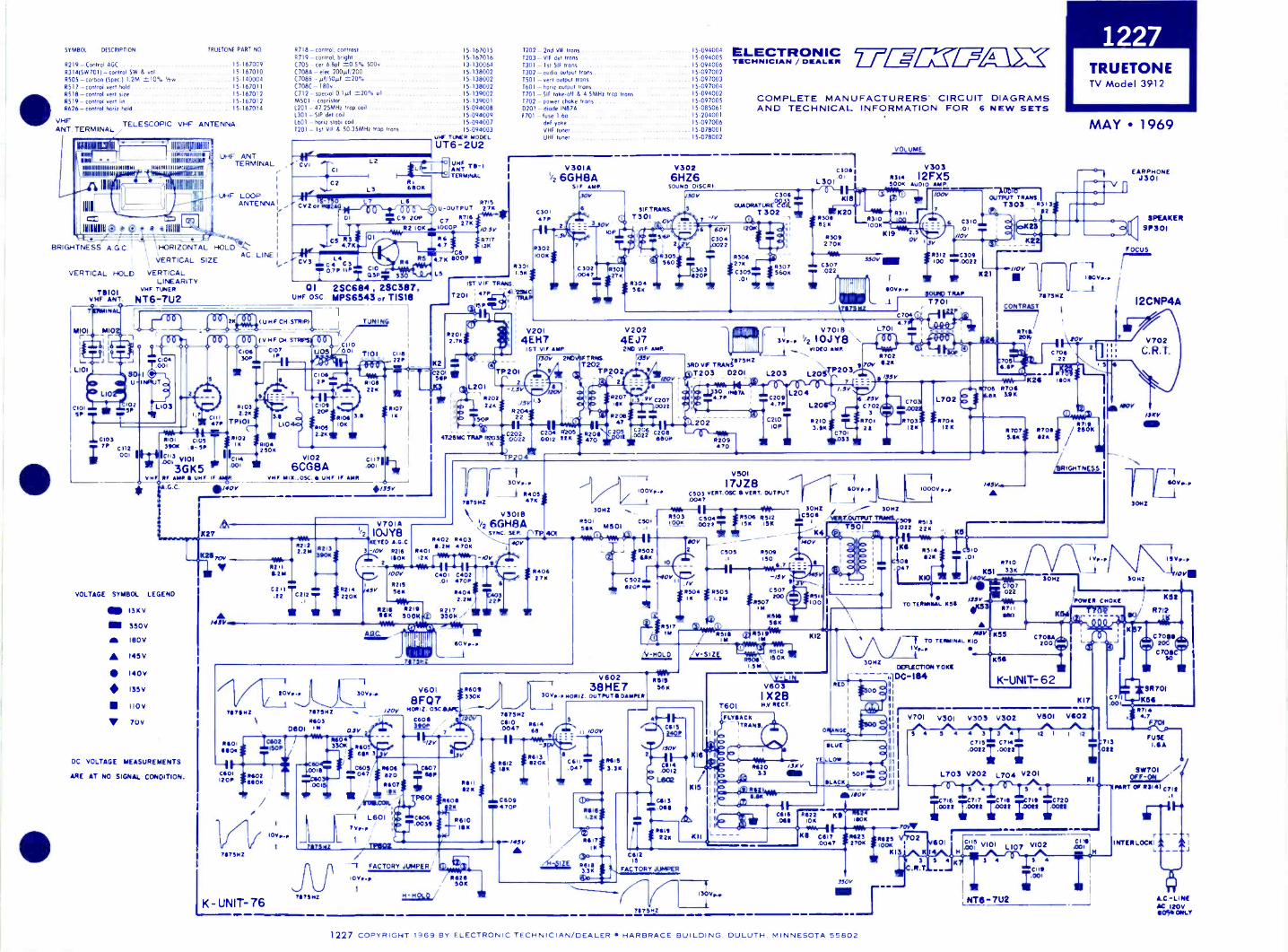
1227
4110 VHFANT. TERMINAL
SYM801. DESCRIPTION TRUETONE PART NO R718 - control, contrast 15.167015
R219 -Control AGC 15167009R314(SW701 - control SW & vol 15-167010R505- carbon (Spec) 1.2M =10% '2W 15.140004R517 -control vert hold 15-167011R518 - control wed size 15-167012R519 - control vert .... 15-167012R626 - control horn hold 15-167014
TELESCOPIC VHF ANTENNA
1011111
61111111111111111111q111111111111111115
1111111111151111611111111 11511111111111511114511
1121:111
III
BRIGHTNESS A G C
VERTICAL HOLD
711101VHF ANT
MOM
UHF ANTTERMINAL
41. -UHF LOOPr ANTENNA
HORIZONTAL HOLD
VERTICAL SIZEAC
VERTICALLINEARITY
VHF TUNER
NT6-7U2
LINE
8719 - control, bright 15-167016C705 cer 6.8pf 20.5% 500w 13-13006407084 - elec 200H1.200 . .. 15-13800207088 - µf/50µI =20% ....... 15-138002C708C - 180v 15-138002C712 - special 0.141 =20% ul 15-139002M501 - capristor 15-1390011201 - 47.25MHz trap coil 15-0940081301 - SIP det coil .. 15-0940091601 - hord stabi coilT201 - 1st VIF L 50 35MHz trap trans
15-09400715-094003
cv,CI
C2
1.2
13
U.F TUNER MOOEL
UT6-2U2
; UHF
t LI 1ANT
-... TERMINAL
66011
7 LeCV2 or "I2A911-j-00 \-Zr.0-0 0
DI op C9 201R2 10K
C 3 LC C5_100.79ccmlnr31 3
U -OUTPUT
C7 8716
1000027K
01 =166
(PAN 474 6009
4.7CS
t.
01 2 S C6 04 28C387,UHF OSC MPS6843 or TIS18
747_11:34L (UHF CH.STRIP/1 _iTUNING
, __4. /./Imm.15111.- ear.
4 -X0,1'7 -sue(v,..c...STRPSCII0
C104 13010:::ci3O.7 Tioi ci isU05/001
.001
L103
0103
;7PC112
001
VHF
1101 Con390K
I4,CII31 1/101
3GK5
51032.2K
9,;g. TP101
C114.001
IF AMR S UHF IF AMR
0140V
8104250K
71026CG8A 001
VHF MIX.. 050. S UHF IF AMR
221
8107
K27
2 7 K
/0 575717128
T202 2nd VII trans 15.094004T203 - VIF det trons 15-0940051301 1st Slf trans 15.094006T302 - oudio output trans 15.097002T501 - vert output trans 15-097003T601 horiz output trans . 15.097004T701 -SIF take -off 4 4 5MHz trap trans 15-094002T702 -- power choke trans 15.0970050201 diode 1N874 15-085061F701 - fuse 1.6a 15-204001
del yoke .. . 15-097006VHF tuner 15.078001UHF tuner 15-078002
ELECTRONICTECHNICIAN / 2_/-7-W=L7,4131C
COMPLETE MANUFACTURERS' CIRCUIT DIAGRAMSAND TECHNICAL INFORMATION FOR 6 NEW SETS
R301Ler J 1.51
1ST VIF TRANS.
T201r
47P 41TRAP
15P
47.26MC TRAP 5203IK
VOLTAGE SYMBOL LEGEND
13KV
350v
IBOV
A 145V
140VI35V
110V
V PUY
DC VOLTAGE MEASUREMENTS
ARE AT NO SIGNAL CONDITION.
5401ROOK ISOP
C601 140212°P 66011
K - UNIT -76
K211707
-_.6; V 821111-21i
112122.214
1213390K
NW
1
C211.22 c 2 la
4n.
1 ; 1
5214 II45V22011
20Y r -o,
?MHZ 7675i4Z1140)
D601 M as r7-
HY*
I
V70IA1,2 10.1Y8
YE0 A.O.0 5402 54033 -/OV 5216 5401
11.211 47011
'sok 'sr -tor2 .9
/00V C401 0402.01 47011.
5215 9
56K924.042: 2 23V1114
RI I 8219 8Ilk 300K 01) 3VO; 111
9M040* Vik--411111
1507
31106 secs6S11 3 V
711175112
130Y -p
71173112
V601
8FQ7H0912. 03C LAPC
0606 /20v
04305 8106 10607047 620 601' Aso?
/ssisosplill-1 L601
7 VP -1
/ 77602
P601 $9604525
0506.0039
ON -
151162K
861018 K
V3026HZ6
SOUND DISCR I
SIFTRANS.T301
V2024E J72110 VIF AMP
IFTRNS.1202
TP202
8501
V30IA1/2 6GH8A
S1F AMP
0301
1302100K
V2014EM7
1ST VIF AMP
C202
P204*
/30V
9
II 30Vp..
7117514Z 1111105/47K
V30166GH8A
NsYNC. 'ATP 401107
54062711
2
/ 1
3011Z
M501
1557
9V C2070022
&Li c2.19-sew
C3061
L301.01
C306osw 1-.-rlr \-118
OUADRATURE COIL -T302 K20
120A eit $ 55 rK1
53042741
C305
.0i ;
3RD VF TRANPIMMZ
5307560K
5309270e
3501/on 307
; 0022
7675112
--T v70113
3o, 1/2 10./Y8VIDEO AMR
T203 D201 L203 L20 P203
30 Imo.%4.7P
4)7) 202 --
- Pf1 -VA.-R209470
V501--T17,1Z8
100Vp. C503 VERT.09C 8 VERT. OUTPUT.0047
C2094.71
C21010P
L204
1501 101.51 0022 ; 15K5503 CI50.1
155011
ISK
1072
16542
11-C5026209
8517IM
V
CSOS
5504 8505II 1.211
8516 41,1
8512
5506ISO
V*"-/SV
C507
1150?200
IM114111
56K
RS11111VkIM
MOLD
540933011
V60238HE7
30 VP -P14011112. OUT IICIAINKR
711175112
CI110 16140047 "
115V
1 FACTORY JUMPER
10 Vo-p141
5626, 50K
86121551
C6094701
9
ISIS96K
S
_ II /00V
WIN
Cill R619.047 I 3.3K
1.2K
/45°5171I
'SOY
C614.0012
L602
0613.065
2211
K
1(15
KI I
T801
L
52103.511
30HZ
K4
5510ascii ,
15"
1.5M---- - 7-V603
I X213NV RECT.
;FLYBACKII
PPo
S.3
551100
KI2
C701033
15171115
0
VOLUME
V3035314 I2FX550011 AUDIO AMP
to
R311
IDDK
KIS
00V r-
L70i
1,511
C7023
970121
.5ov
1007
C31001
-ADDOUTPUT TRANS.
T303 1313
5312 C309100 .0022
11042m) TRAP
T701
C704 04.7
30112
OUTPUT TROMS.
901 022
C70
5703I2K
NED
1000V p -p
55132211
.01
TRUETONETV Model 3912
MAY 1969
Ns I
=me mcilNov
1C211111
1557
4151
Ic55* TO TERMINAL 1410
30111
CONTRAsT
06 5706o 3.9K
1457
5710
101 33r
C707022
OLLIEI
YELLOW
111E2, )4 C.0.11161
FA6C5110R2Y JUMPERis
767151.201111.Mir
R622 ''.711t) -17,17-I WA scnIV
BS C617051123 56211 Vq7".V6010047 27011 to"
K13 K
3 5
.R.T
To ToniaL 2159
DEFLECTION YOKE
111 D0104
1(511
C706.22
K2;-
1110K
;WIC17011elk
C7064200
K -UNIT- 6 2
V701 V301 V303 V302
5 4 5 3
C7I5 C7I4
.0022; .002;
I .1
EARPHONEJ301
SPEAKERSP301
FOCUS
NOV
I2CNP4A
"NV
30.12
3011Z
11113V.L.
111Vp..p
-11/0V111
'POWER CHOKE
K17
V501 V602
12 1 I 12
713082
SR701
K8411
57144.7
FUSE
L703 V202 V201K
PART OPF;1311
BETOI
C711s
L704
s 4
17C0071t61 r717i :C70111 r7111 ;C720
1107 V1025,;,;7 viol
3
NT6-7U2
CI !Ilr.001
5 4
CII9
;001
INTERLOCK'
A.C-LI NEAC 120v6096 ONLY
1227 COPYRIGHT 1969 BY ELECTRONIC TEcHNiciAN/DEALER HARBRACE BUILDING. DULUTH. MINNESOTA 55802

1228Z
EN
ITH
TV
Chassis 13Z
12,13Z
12S
MA
Y 1969
CH
AS
SIS
13Z12
13Z12S
LIS
ELE
CT
RO
NIC
2T-V
E=
All
AC
TE
CH
NIC
IAN
/i
CO
MP
LET
E M
AN
UF
AC
TU
RE
RS
' CIR
CU
IT D
IAG
RA
MS
AN
D T
EC
HN
ICA
L INF
OR
MA
TIO
N F
OR
6 NE
W S
ET
S
SP
EC
IFIC
AT
ION
SP
OW
ER
US
ED
AT
OV
ER
LOA
D P
RO
-120V
60 CY
CLE
ST
EC
TIO
N (A
C LIN
E)
120 Watts
Pigtail F
use (1.8A)
120 Watts
Pigtail F
use (1.8A)
V3
V4
48Z6
4BZ
61 S
T I.F
.2 N
D I.F
.
/14YR
E C
US
LU
47.15411i,6111.
C3
L-461_
_ J
A G
.C.
2.211E6
-220K
13+130V
= icy_D
S680K
_IC6
1470PF
0
T3
#
SO
UN
D P
OW
ER
OU
TP
UT
1 Watt
1 Watt
VS
48263R
D I.F
.
114Vsuer
7037.-
S -- R
ED
veNT
CS
Re
290220
ri
R3
1.5V1.3K
C9
470PF
14VIL_
OR
N
100 4,-4
Li
001
+130V
12 Cl.0(.11
_C12
1.001
Rii
220
T4
SY
MB
OL
DE
SC
RIP
TIO
NZ
EN
ITH
PA
RT
NO
C18A
-300µ1 elec cap 175v22-5506
C188 - 200m
f elec cop 150v22-5506
C18C
-200µf elec cop 150v22-5506
C180- 10µ1 elec cap 150v
22-5506R
6 - 4K contr cont
63-6463R
7- 250K M
ight cont63.5419
R8 -22011 5%
./7 ........AN
NA
63-7236R
9 - 1M vol cont ..
63.7458R
IO - 51( A
GC
cont AN
NA
..........63-7082
R13- 7M
vet", size cont ............. 63-6433R
14- 1M vert hold cent ....................
63-6915R
15 - 300K yen lin cont
63-7522L3 - det series peaking curl
............ 20-2013L4
choke coil20-2004
LS -det shunt peaking cod
20-2520L6 - sound toke-off coil w
inding assyP
ort of 15
SIO
RN
CIJ
C14
CIS
I
S.S
PF
4.717i 4 ?Pi
pi5
J
2.70
320
39KC
l7011
1.9 - good coil winding ossy
Part of T
7LIO
- line filter coil20-1424
1.12 -filter choke95.2567
1.13- horit osc coil ossy5-56875
T2 - 2nd IF
xformer assy
S-66852
T3 - 3rd If xform
er assyS
-6685315
- sound take -off coil assy5-60558
17 -good coil ossy - wiring
5-79340113- sound output xform
er95-2499
T9- yen output xfonners
95.2518T
IO - yoke
95-2676112 - horn sw
eep xformer 6 w
idth sleeve 5-80850199-491
Al - integrator .................................... 87.4
Fl - 1.80 fuse
136-65S
W1 - on -off sw
itchP
ort of R9
TS
V6 A
-TO
SO
UN
D
V2 IIA
F9
LIMIT
ER
GR
ID
VseV
IDE
OA
MP
.I
,L,64
51v4.230P
fl
cac1441;5147;
LSt
Se
MVOzzK
I
6800V
VN
Pl.
12K27K
!sox
Z3;1001CP
396
1-470PF
,INV
R5
6.11Kw
e.+
or
teeef4PD
1500
CO
NT
RA
ST
R6
04_4(ay
025m
ai
spot
T(1112
Lul
.-4. TO
N.V
. 120 KV
7V
I3F
OC
US
AD
J.I2D
GP
4P
IXT
T I
+ 1306 450V
BO
OS
T
AR
EF
ON
LTC
II.
NO
UN
TE
DO
NT
UN
EM
Y-±
-r4m
oo.1/2 H
AF
9+
130 9
SO
UN
D LIM
.T
O 07 P
i ON
SO
UN
D T
AK
E50V
OF
F C
OIL IT
514
668
4.711E6
T6
TO
TU
NE
RN
EA
TE
NS
C27
00I(V
1
450V
V7A
1/2 IMF
!'6,00
SO
UN
D D
ISC
R.
1K
r02091
30V- - - -
J
V3
34
3
C46
.00i I
C56
001
OK
/20V
Ti--
5 TE
L r-LeTI R
96011
IIME
TV
OL.R
E
1560
OS
1
470KT
2S v
1032T
Oi
-K
C32
5/0-T
20
_1
C35
V713
1/2 178F I I
SO
UN
D O
UT
PU
T
Icso[18
101
10114, out
600.:
IOC
EC
220
+130V
C3'
VIO
A1/2 6LN
8H
OR
Z. C
ON
TR
OL
+130V6110
55V I
101E6
V4
VS
v13V
6010
V7
V9
VB
VII
C47
Ca
14
35
54
C49
5001C
5I
1:001
12I
54
Ii
EQ
UIV
ALE
NT
CIR
CU
IT O
F IN
T E
GN
ET
Al
r-R
OU
T1
61306801
I
1."
T"
MIR
IS 33K
I
L___
V108
1/2 6LN8
HO
RIZ
. OS
C.
a DIS
CH
.#2264,
547C
0P8 i
My
-/PV
EILU
120V A
CIN
TE
RLO
CK
047
4506
ye4HS
8A
.G.C
.S
YN
C. C
L IP
JOY
SP
I
C62I.D
oer
IRIS 82K
C63
iw0047 poi
C61
ooh
33K
S6 (P
AR
T O
F V
OL C
ON
1I
L 10
Obi 1- 1`0s3°60
!kV =
=!KV
6
92V
9
-./V-11
T 0033+
1306
2 20
716:
C38a
2
*--:C
41
1500RIO
SK
AG
C
VII
1/2 38HE
7or 38 H
K7
HO
RIZ
. OU
TP
UT
9ro
4-
GR
N
TI2
101116
1720K
V9A
1/2 I7JZ 8
C39
VE
RT
. OS
C.
5"056
CE
SIC
43
*OK
07
4.250K
BR
1GH
TN
ES
551130V
46,v \040
-S
P02
4406811
690C
42
150202
tonS10
-.-
Al
C40.130v
413V
ER
TT
rileh
VH
OLD
ER
T
13E
V98
1/2 17,a8":+
"
VE
RT
. OU
TP
UT
390+
1309
22K
270
-/63PF
/12V BLu
T9
:II412
11?D
i .11
81 0060,...1
04a.
+I30VVE
RT
iLIN
.
5
1/0V
ALO
t 2K
RE
D/
CO
T
4506B
OO
ST
195-11-02222
/3.520*K
T
C-
1 MAnv1C
IET
kv4N
-IL)liCIS
RE
D 0130v
sw-1`21,608
7027K A
T 913
15011
OK200
V
4V
IIBI
Too
-.1/2 38H
E7
I
or 38HK
7I
/4-4.I
2D
AM
PE
R
L14
C67
.033
TO
18R
ED
LEA
D
BL K
VI2
IAD
2H
.V. R
EC
T.
0 12.0KV
1/2 TIO
.rga>T
EL
17.3r717:17 1711,7E1
HO
RIZ
DE
FT
CO
ILS
I
TO
TO
SE
C_SE
E M
OT
E
RIS
3000
123-3734
EA
RP
HO
NE
JAC
K A
SS
EM
BLY
MODELS)_
''I
II
riuT-1)-V
EN
T()E
FL
CO
ILS
NOTES.
ALL VOLTAGES NEASuREO FRON CHASSIS TO POINTS INOICAT20.
ALL VOLTA621 ARE D.C. UNLESS 021421111SE SPECIFIED.
ALL D.C. VOLTAGES TO Of 01450120 OUT A VACUUM TUSE
10t,INITE1 HATING ti
14260041 INPUT RESISTANCE.
ALL VOLTAGE 142ASullEPIENTS TO OE NAM Alto NO SI6MAL
PRESENT.
NOOKAL SITTING OF COolROLS ANO CHANNEL MEC-
UM SET TO (HAMMEL 2
UNLESS 0 ..... ISE SPECIFIED.
ALL CAPACITOR VALUES IM NICROFARADS UNLESS OT114101St
SPECIFIED.
F04 CAPACITOR CAPACITY TOLENANC( SEE LEG2N5.
rINDICATES 201 RAT NE 0$20.
ALL RESISTORS AIM 4101 TOLERANCE. CARSON. 1/2 OTT
UNLESS OTHERNISE SPECIFIES.
RESISTANCE NEASuRENENTS SNOWS wITN COIL DISCONNECT'S
FOON CIRCUIT.
COIL RESISTANCES NOT GIVEN ATE uNOEO 002 OHN.
AARONS ON POTENTIOMETEITS INDICATE CLOCKNISE NOTATION.
WM'S -17-
0-INDICATES VOLTAGE SOURC2.
PICTURE TORE ENO ANODE VOLTAGE TO OE NEASuRED UITO
ELECTROSTATIC KIL0v001422211 WITH SOIGHTOISS AND
CONTRAST CONTROLS FULL COuNTER-CLOCKWISi.
C14CAPACITOO VALUE SELECTED r011 MINIM. POKE 4106116.
VA4IE5 AIIN A RAISE Of 07 Pr
TO 72 PT
IA K.V..
41051.mi,11
NECESSW. REPLACE 11211 [TACT Mu( (DUNS IN
40.2.
(140.20 LETTERS 1101cATE ALIGNNENT
Aso 112ST POINTS wHEIIE APPLICAOL1
ID --0.
C- °MOON OUTPUT
6-2110 1.F. 6410
D-VIDEO OUTPLI
N-SOUND LINITIR PLATE
2-I.F. AGC
J-SOUNO OUTPUT
F.
611001010 FOIE
I.F. ALIGNNE.
P-sou. DISK GRID
61O
1C0te)-
2C --
14
vs Q. =
garare-
N -
r -
CA
_§2 co -4,
Cc
Z2
-r.*
O. CD
t)Wp
CA
64nN
aTO
O
6ELf-61
E8 ;*totio.
0- Ce
z
t g
8 1
0 <0
,,)- -a,-06044,6,-
Tr,
xc
*O-OCC
(-)5-
p(..)cr0A
NtoV CLCtoto0 -
To
.120
1228 CO
PY
RIG
HT
2969B
YE
LEC
TR
ON
IC T
EC
HN
ICIA
N/D
EA
LER
HA
RB
RA
CE
BU
ILDIN
G. D
ULU
TH
. MIN
NE
SO
TA
55802
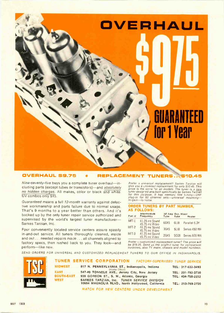
OVERHAUL 69.75 REPLACEMENT TUNERS ... $10.45Nine -seventy-five buys you a complete tuner overhaul-in-cluding parts (except tubes or transistors)-and absolutelyno hidden charges. All makes, color or black and white.UV combos only $15.
Guaranteed means a full 12 -month warranty against defec-tive workmanship and parts failure due to normal usage.That's 9 months to a year better than others. And it'sbacked up by the only tuner repair service authorized andsupervised by the world's largest tuner manufacturer-Sarkes Tarzian, Inc.
Four conveniently located service centers assure speedyin -and -out service. All tuners thoroughly cleaned, insideand out ... needed repairs made ... all channels aligned tofactory specs. then rushed back to you. They look-andperform-like new.
Prefer a universal replacement? Sarkes Tarzian willgive you a Lniversz I replacement for only $10.45. Thisprice is the same 'or all models. The tuner is a newtuner desigr ed ana built specifically by Sarkes Tarzianfor this pu.pose. It has memory fine tuning-UHFplug-in for 82 channel sets-universal mounting-
ORDER TUNERS BY PART NUMBER,AS FOLLOWS:
PartIntermediateFrequency
AF Amp Osc. MixerTube Tube Heater
MFT-1
MFT-2
MFT-3
41.25 mc Sound45.75 mc V deo41.25 mc Sound45.75 mc V- deo41.25 mc Sound45.75 mc Video
6GK5
3GK5
2GK5
61.18
5118
5CG8
Parallel 6.3V
Series 450 MA
Series 600 MA
Prefer a customized replacement tuner? The price willbe S18.25. Send us the original tuner for comparisonpurposes, also TV make, chassis and model numbers.
SEND ORDERS FOR UNIVERSAL AND CUSTOMIZED REPLACEMENT TUNERS TO OUR OFFICE IN INDIANAPOLIS.
TSBTUNER SERVICE CORPORATION FACTORY -SUPERVISED TUNER SERVICE
MIDWEST 817 N. PENNSYLVANIA ST., Indianapolis, IndianaHome Office)
EAST 547-49 TONNELE AVE., Jersey City, New JerseySOUTH-EAST 938 GORDON ST., S. W., Atlanta, GeorgiaWEST SARKES TARZIAN, Inc. TUNER SERVICE DIVISION
10654 MAGNOLIA BLVD., North Hollywood, California
WATCH FOR NEW CENTERS UNDER DEVELOPMENT
TEL: 317-632-3493
TEL: 201-792-3730TEL: 404-758-2232
TEL: 213-769-2720
MAY 1989 19

MALLORY Tips for Technicians af
Versatile Sonalert Signalmakes a great ingenuity tester
Fig. 1-Trapped Sound System
Fig. 2-Mechanical System
Fig. 3-Simple Electronic System
l Fig. 4-High Output Electronic System Ij
Crank up your inventive powers and put them to workwith Sonalert®, the low -drain, solid-state tone signal thatgives a big sound with just a few milliamp drive. Morethan likely you can come up with some great ideas foryour shop, home or car. Ideas for fun, safety-and,perhaps, profit.
Just to give you a few clues, let's take a look at the waywould-be Edisons turned Sonalerts into interesting ideas.We've picked four ways in which others have used thisnew signaller for one application: liquid level alarm.
One of the simplest is a compact system that requires notrigger circuits or complex mechanical devices. All youhave to do is install a glass or plastic tube on the unit'snose cone, and hook the Sonalert to a power source. (Seefigure 1.) Insert the tube into the liquid to the level re-quired for alarm. Since the tube is immersed, no soundcan escape. Once the fluid falls below the critical level,out comes a loud, clear, unmistakable signal. Here's anideal system for use in explosive atmospheres; Sonalertproduces no arcs or sparks.
Figure 2 shows a mechanically actuated system-floatand switch. It's made up by mounting a float ball on alever arm that actuates a plunger switch in series withthe Sonalert and power source. Reliability might be aproblem because of mechanical failures.
For greater reliability, the simple electronic system(figure 3) is hard to beat. Fluid acts as the switch to closethe circuit between Sonalert and the source. Just oneproblem presents itself. The sound level from Sonalert isproportional to current flow. If the liquid is not agood conductor, current flow may be too low.
To overcome this limitation, a high output electronicsignal system was developed (refer to figure 4). Heretransistor Q1 acts as a low resistance switch; and currentflow to the Sonalert is maximum as long as there isenough base current flowing through the fluid to holdQ1 ON.
Here are four variations on one theme. Bet you can comeup with some great ideas on your own. Try. If you can't,we've got more tips for you in booklet No. 9-406 that'syours for the asking at your Mallory Distributor's. It'schock-full of information: how Sonalert works, ratings,specs, mounting instructions and more tips. You canwrite for a copy, if you prefer. Mallory DistributorProducts Company, a division of P. R. Mallory & Co.Inc.. Indianapolis. Indiana 46206.
A OldDON'T FORGET TO ASK 'EM-
A r/ar eke eed4 tie" ff. . . for more details circle 128 on postcard20 ELECTRONIC TECHNICIAN'OEALER

HUGH "SCOTTY"WALLACEPublisher
PAUL DORWEILEREditor
JOSEPH ZAUHARTechnical Editor
MORTON WARNOWField Editor
DONNA BUTLERProduction Editor
BOB ANDRESENArt Editor
LILLIE PEARSONCirculation Manager
JOHN KESSLERManager, Reader Services
JUDI LeMAYAdvertising Production
OFFICES
71 Vanderbilt Ave.New York, N.Y. 10017Phone: (212) 686-2200
Telex: 01-26286
43 East Ohio St.Chicago. III. 60611
Phone: (312) 467-0670Telex: 02-53549
1901 West 8th StreetLos A ngeles, Calif. 90057
213) 483-8530
Harbrace BuildingDuluth. Minn. 55802
Phone: (218) 727-8511Telex: 02-94417
MARKETING REPRESENTATIVES
HUGH ''SCOTTY" WALLACEChicago: (312) 467-0670
ALFRED A. MENEGUSNew York: (212) 686-2200
DONALD D. HOUSTONLos Angeles: 1213) 483-8530
ROBERT UPTONTokyo, Japan
I.P.O., Box 5056
HARBRACE PUBLICATIONS, INC.
JAMES MILHOLLAND, JR.President
DEAN MYHRANExecutive Vice President
RICHARD MOELLERTreasurer
LARS FLADMARKSenior Vice President
HARRY RAMALEYVice President
BEN MARSHVice President
JAMES GHERNAArt Director
WILLIAM SWAINDirector of Marketing Services
DOUG HEDINAd Production Manager
ELECTRONICTECHNICIAN / DEALERWORLDS LARGEST ELECTRONIC TRADE CIRCULATION
MAY 1969 VOL. 89 NO. 5
39 SIGNAL STRENGTH METERSVersatility is the theme of part one in this series which describes thesignal strength meter as well as its importance to the TV service tech-nician and antenna installer
44 LOW COST SOLID-STATE CURVE TRACERHere's an interesting instrument you can build and connect to anyscope for an actual waveform presentation of a transistor's operation
48 COLOR SYSTEM TROUBLESHOOTINGOne of the latest solid-state devices to find its way into a color TV re-ceiver is the "IC chip" for color demodulation explained in this timelyarticle with troubleshooting information
52 CONTRAST NOW-TOMORROW WHAT?The "black screen" filter, which is still relatively new to many techni-cians, is humorously discussed in this Bob and Scoot feature
56 TESTLAB REPORT ON HEATH MODEL IT -18AND EICO MODEL 385This month's testlab discusses the Heath in-circuit/out-of-circuit tran-sistor tester and the EICO battery -powered, transistorized color bargenerator
58 RADIOS FOR RADIOMENThe old saying about the shoemaker's kids is put to the acid test asthis month's dealer explains what two-way radio can mean to a servicebusiness
61 ELECTRONIC LIGHTNING DETECTORThis short, but interesting feature, explains an unusual electronic de-vice designed by a Canadian technician for tracking electrical storms
22 EDITOR'S MEMO24 LETTERS TO THE EDITOR30 TECHNICAL DIGEST34 BOOK REVIEWS64 DEALER SHOWCASE
74 COLORFAX76 NEW PRODUCTS78 NEWS OF THE INDUSTRY86 CATALOGS AND BULLETINS94 AD INDEX
COVERTransistors and digital circuits in everything from model planes to testinstruments is the theme of this month's cover which shows the Hickokdigital test instrument and solid-state scope, the Darcy digital volt-meter, Setchell Carlson's move to transistor plug-in boards for colorTV and the latest Heath digital proportional radio control system formodel enthusiasts.
TEKFAX 16 PAGES OF THE LATEST SCHEMATICS GROUP 201AIRLINE: TV Model GHJ-14549AMAGNAVOX: Color TV Chassis T933MOTOROLA: Color TV Chassis TS924B,CPH I LCO-FORD: TV Chassis 19P22TRUETONE: TV Model 3912ZENITH: TV Chassis 13Z12, 13Z12S
ELECTRONIC TECHNICIAN/DEALER is published monthly by Harbrace Publications, Inc., Har-brace Building, Duluth, Minnesota 55802, a subsidiary of Harcourt, Brace & World, Inc.Subscription rates: One year $5, two years $8, three years $10, in the United States andCanada. Other countries: One year $9, two year:. $14, three years $18. Single copies 75Cin the United States and Canada; all other countries: $2.00. Second class postage paid atDansville, New York, and at additional mailing offices. Copyright 1969 by Harbrace Publi-cations, Inc.
POSTMASTER: Send Form 3579 to ELECTRONIC TECHNICIAN/DEALER, Harbrace Building,Duluth, Minnesota 55802.
MAY 1969 21

The FM -2400C provides anaccurate standard frequencysignal for testing and adjust-ment of mobile transmittersand receivers at predeter-mined frequencies between25 and 500 MHz. Up to 24crystals may be inserted intothe meter. The frequenciescan be those of the radio fre-quency channels of operation,and/or of the intermediatefrequencies of the receiversbetween 5 MHz and 40 MHz.Frequency stability (standard)
.001% from 32 to 122 F.Frequency stability with built-in thermometer, calibratedcrystals and temperature cor-rected charts, .00025% from
+25 F to +125°F. (.000125%special 450 MHz crystals avail-able)
FM 2400C(Meter Only) $445.00
RF CrystalsHi Band $24.00 ea.
Lo Band 15.00 ea.
IF Crystals 8.00 ea.
Write for tree catalog.
INTEFINATIONAL
CRYSTAL MFO. CO., INC.10 NO. LEE OKLA. CITY. OKLA. 73102
meter... Completely Portable Tests Predetermined Frequencies
25 MHz - 500 MHz
EDITOR'S MEMO
TV Helps Sets NBS TimeStandard
The National Bureau of Standardsscientists and engineers have bor-rowed from commercial television inDenver to design a system wherebythe clock that controls the broadcastsfrom station WWV in Fort Collins,Colo., may be kept within a millionth ,
of a second of the atomic clock inBoulder.
The technique uses the televisionsynchronizing pulse on the TV car-rier wave.
This is how it works. A TV tablemodel set is operated at the NBSatomic clock end in Boulder, and an-other at the NBS broadcast station endin Fort Collins. Both TV sets aretuned to the same Denver TV channeland both are connected to sensitiveelectronic equipment which recordsthe arrival of the periodic pulses onthe carrier wave. The sync pulses area known distance apart and are easilyidentified by electronic devices which"tag" them as they arrive at the loca-tion of each recording device. In thepresent case, the distance from crestto crest of succeeding pulses is about11.8 miles.
The equipment records the time ofarrival of these pulses at the "atomiccloCk" in Boulder and at the radio sta-tions in Fort Collins. The time delaybetween the TV transmitter near Den-ver and the Boulder and Fort Collinsreceivers is accurately known to atenth of a millionth of a second. Fromthis information NBS scientists calcu-late the time difference between twoclocki. Once the difference is known,even if it is only a few millionths ofa second, 'corrections may be made tosynchronize the Fort Collins radiostation clock with the atomic clock inBoulder.
The absolute accuracy of the mea-surement is conservatively set at plusor minus a millionth of a second.
Gs Ka.W
22
... for more details circle 125 on postcard
ELECTRONIC TECHNICIAN/DEALER
... for more details circle 126 on postcard

Newreliableprpfitable
JFE1ProgramCenterAmplifiersJFD Program Centers - the result of three years ofresearch and development - are here! Now you canequip any home with a complete entertainment system! Operate up to 4 (or more) TV sets and FM receiversfrom one antenna. Solid state silicon overlay transistors withsilicone sealed printed circuitry provide higher gain,less noise ... ultra -reliable performance. Deliver true-to-life color ... crisp black and whitepictures. Available for 300 ohm or 75 ohm VHF andVHF/UHF/FM installations.The ONLY amplifiers so RELIABLE in performancethat they are backed by an exclusive SIX (6) MONTHINSTANT REPLACEMENT GUARANTEE! With this performance
Outdoor Typefor Fringe and
Weak -Signal Areas
Indoor Typefor City andSuburban Areas
(and insurance), how can you miss?
JFDProgram Cenier an41 Snow Plow
I INSTANT It EPIAI7ENIENTI:Iv:t1t:tNTEE
This unit is guaranteed 100% for a period of six months. If, within a period of six (6) monthsafter it was purchased, it does not operate for any reason whatsoever (including lightning strike,line surgeor static bu ld-up,) or otherwise fail to perform satisfactorily we will replace it witha brand new unit instantly - absolutely FREE! NO QUESTIONS ASKED!
NPArfilty"*LAr1140,4_,sttipt%T.0 IbArAr NZ;
Write today for your Program Center promotional kit and home antenna systems manualJFD ELECTRONICS CORP. 15th Avenue at 62nd Street, Brooklyn, N. Y. 11219
May
.
"See us at the NEW Electronics Show, Booth C100, Suite 4120-4122, Hotel Sahara, Las Vegas, 2 23

ow co 'or 2AUTOMATI
STAPLE GUNSCUT WIRE & CABLE
INSTALLATION COSTS. . without cutting into insulation!
SAFE! Grooved Guide positions wire forproper staple envelopment! Grooved DrivingBlade stops staple at right depth of penetrationto prevent cutting into wire or cable insulation!
No. T-18-Fits wires up to3/16" in diameter.
BELL,TELEPHONE,
THERMOSTAT,INTERCOM,BURGLAR
ALARMand other lowvoltage wiring.
r-, Uses T-18staples with 3/16" round crown
in 3/8" leg length only.
No. T-25-Fits wires up to1/4" in diameter.
Same basic constructionand fastens same 410wires as No. T-18.
Also used forRADIANT
HEAT WIRE
Uses T-25 stapleswith 1/4" round crown in 9/32",3/8", 7/16" and 9/16" leg lengths.,),T-18 and T-25 staples also available in Monel andwith beige, brown and ivory finish at extra cost.
No. T-75-Fits wires and cablesup to 1/2" in diameter.
RADIANT HEATCABLE,
OF CABLE,WIRE CONDUIT
COPPER TUBINGor any non-metallic
sheathed cable.Also used as
DRIVE RINGSin stringing wires.
Uses 1-75 staples with 1/2"flat crown in 9/16", 5/8" and
7/8" leg lengths.
Arrow Automatic Staple Guns save 70% in timeand effort on every type of wire or cable fasten-ing job. Arrow staples are specially designed withdivergent -pointed legs for easier driving androsin -coated for greater holding power! All -steelconstruction and high -carbon hardened steelworking parts are your assurance of maximumlong -life service and trouble -free performance.
Ask your Electrical Supply Dealeror write for further details.
Saddle Brook. New Jorscy
"Pioneers and PacesettersFor Almost A Half Century"
LETTERS
TO THE EDITOR
Readers' Aid
Perhaps one of your readers canhelp me locate a schematic or instruc-tions on a Philco Model 7030 Dynam-ic tester. I think it is used for signaltracing, but the people at Philco saythat manuals are no longer available.If someone can send me a copy I willbe glad to pay the cost.
IRVING KOHNAnchor Electronics300 Valley St.Sausalito, Calif. 94965
I enjoy your magazine very muchand I am writing in hopes that one ofyour readers can help me. I am tryingto obtain the latest roll chart and/oroperating manual for a Simpson Mod-el #330 tube tester. I am willing topay a reasonable price.
JOHN D. TRIPLETT39474 Blue Fin WayFremont, Calif. 94538
I have been a subscriber to ELEC-TRONICS TECHNICIAN/ DEALER formany years and found it very helpful.But now I have a special problem. Ineed a schematic and manual for anEico Model 400 scope. I have triedeverywhere. Maybe one of your read-ers has information on this unit.
R. BERTRAN425 W. 25th St.New York, N.Y. 10011
I have a Test-O-Matic tube checkermade by Shell Electronics Mfg. Corp.of Westbury, N.Y. There are no num-bers on it, but a supplementary chartshowed Model 18. As this corporationis no longer in business, perhaps youor one of your readers can help meget a tube chart for it.
WILLIAM A. GRAUNKE5933 Old Redwood Hwy.Santa Rosa, Calif. 95401
I hope one of your readers canhelp me. I have been looking for aschematic of an old GE AM/FM/SWradio receiver, Model X415 built in1948. I am also looking for a sche-matic of a Japanese AM/FM tran-sistor radio, Royal -Model 300. Anyhelp would be appreciated.
JAMES WAHL414 Superior Ave.Crystal Falls, Mich. 49920
We have a Schaub -Lorenz radio infor repair and cannot obtain parts forit. The manufacturer is located inWest Germany. Possibly you or yourreaders can supply us with informa-tion on this unit. Your assistance isdeeply appreciated.
STANLEY J. PEPERAVideo TV & Appliance717 Gratiot Ave.Saginaw, Mich. 48602
I have a Hi Fi system I would liketo sell and to do so, I need some in-formation on it. It was made by StanWhite, purchased from Leonard Ra-dio in New York and called the Es-quire. It was built in 1957 or 1958. Iwould appreciate any informationyour readers can furnish on this sys-tem.
RICHARD G. RAPP33 Wyoming St.Commack, N.Y. 11725
Perhaps one of your readers canhelp me obtain a schematic for theWeston Model 983 oscilloscope. A re-ply from the company indicates thatit no longer makes scopes and cannotfurnish any data. Also, my compli-ments on a magazine unsurpassed inits field.
THOMAS E. HAMBLINP.O. Box 82King George, Va. 22485
We would like to obtain a schematicof the following TV sets and informa-tion on where we can get parts nearthe Chicago area. The set is a RocketTV, Model No. 8 -HL, EgawadenkiKenkyusho; Tokyo, Japan.
GEORGE KALEC9033 S. Meade Ave.Oak Lawn, Ill. 60453
I have a Webcor Model 152-5 phonoplayer and I need a motor, part# 15X229-5. It was ordered fromWebcor but they said it was no longeravailable. Could one of your readershelp me?
RICHARD WOLFBox 155Wishek, N.D. 58495
I would appreciate any circuit in-formation on a Superior Model TV50. Some tubes are missing and afterwriting several letters, I learned thatSuperior is no longer in business.
W. EVERETT SWIFT160 Maskwonicut St.Sharon, Mass. 02067
. . . for more details circle 104 on postcard
24 ELECTRONIC TECHNICIAN/DEALER

For window -size blow-ups,send 10c to Sprague Products Co.,
65 Marshall St., North Adams, Mass.01247, to cover handling/mailing.Order yours now, so you'll be ableto display it well before July 4th.
EVE
INIEPENDENCEi--- ,
* * ", .:
Iti_R-16;
10'FOR YOU AND YOUR-A IN )EP NDENTTV SERVICE DEALER* * * * * * * * * * * * * * * * * * * * * * * * * * * * * * * *
Your independent TV Service Dealer is in business for himself because he too wants to exercise hisindependence just as you do. You purchased your TV or radio set where you wanted to ... when you
wanted to . . . and at the price you decided was right.Your TV service dealer is also an independent in the things he buys in his day-to-day work. He buys
repair parts where he can get the highest quality and the best service. And, he trained himself in hisown way, on his own time, at his own expense, to be able to do the very best for YOU.
He stands or falls on what you think of him and his work. He has to do good work to keep yourbusiness . . . and he knows it!
We're lucky in these United States that every day is Independence Day. Independent buying, selling,and servicing is the very lifeblood of American business. Let's keep it that way.
SSAGE vvAirt.Reisiimemmemommiew pRooinrrsDISTRIBUTORS' SUPPLY SUBSIDIARY OF SPRAGUE ELECTRIC COMPANY, NORTH ADAMS, MASSACHUSETTS FOR . .
YOUR INDEPENDENT TV -RADIO SERVICE DEALER
MAY 1989

TheComplete
Line
FiA/C0MATVEQUIPMENT
Get all your MATV needs from one reliable
source. Use genuine FINCO MATV
equipment and FINCO Color SpectrumAntennas. Free layout service. Write:
THE FINNEY COMPANY34 W. Interstate Street, Dept. 110-5
Bedford, Ohio 44146
. . . for more details circle 119 on postcard
NEW FROM INJECTORALL
HERE'SPROOF!PROOF that "SUPER100" tuner cleaneris BETTER!
Tested by a leadingindependent laboratoryagainst competitiveproducts!
-.4111,...allglifira. SUPER 100 A B C
CLEANING Excellent Good Fair FairLUBRICATION Good Fair Fair Poor
PLASTIC ATTACK None None None None
FLAMMABILITY None None None Nona
CONDUCTIVITY Nona None Slight SlightANTI -STATIC
PROTECTION Excellent Fair Poor Poor
DRIFT None Slight Yes Yes
SUPER 100 TUNER CLEANER . . . forCOLOR and Black and White TV tuners6 oz. spray can with INJECTORALL steelneedle CAT. NO. 100-6 net $2.10Buy it at your Electronic Dealer.For free catalog on the complete line,write to:
INJECTORALL ELECTRONICS CORP.Great Neck, New York 1 1 0 24
LETTERS
TO THE EDITOR
My problem is obtaining a sche-matic for a Triplett TV -FM signalgenerator/marker Model 3434. Trip-lett was unable to supply it. Possiblyone of your readers has one to loanme which I could have copied.
AVON BAUMAN & SONS3255 Magnum LanesAtlanta, Ga. 30311
I would appreciate any informationyou can give me on finding a sche-matic for a GE Model OFM-1 oscillo-graph.
CHARLES F. BERRY19202 2nd Ave. S.Seattle, Wash.
Public Image
In my opinion the radio and TVtechnician has one of the worst jobs inthe world. I am speaking from expe-rience. My education began in highschool when I took correspondencecourses in communication electronics,communication engineering, black andwhite TV servicing, color servicingand built my own black and white andcolor sets. I have a first class radio-telephone license.
Fortunately I worked for the PostOffice for the required number ofyears to enable me to retire. My pen-sion is ample for my needs. HoweverI love electronics and still do servic-ing, but only sets that are brought tome.
What burns me up is the public'simage of the TV technician. The aver-age person equates us on the samelevel as a grease monkey in a gas sta-tion. The nearest comparison of thetype of work would be that of an elec-trician. However, the comparison inpay is pitiful. The electrician draws awage of $5 to $10 an hour. He has nomoney invested in expensive testingequipment, he does not need sche-matics on every job he does and hedoes not need to keep up with thenewest developments by reading tech-nical magazines and books.
There is hope on the horizon withthe new black and white and colorsets using more and more solid statedevices at the home, service will beconfined to only the simplest troubles.Eventually the day of the half -trainedtube technician will end. He will havethe choice then of either upgradinghimself through further study or findanother job.
MATHEW RUSKOSKI
"Gentlemen...it's timeto bring homethe bacon."Almost any company that'sbeen doing business abroadhas been doing well. That'sgood for you, your companyand world business in gen-eral. But right now, your coun-try needs those profit dollarsto help reduce our balance -of -payments deficit. You canhelp by bringing home asmuch of that income earnedabroad as you possibly can.Why not put the wheels inmotion today? It'll give you agood feeling.
ikePublished as a public service in
co-operation with The Advertising Counciland the Department of Commerce.
. . . for more details circle 124 on postcard
26
Pittsburgh, Pa.
ELECTRONIC TECHNICIAN! DEALER

GE redesigns tubesto satisfy
these tough customersbefore you get them!
Reach for this when you ask,"What else needs fixing?"
Tube designers at General Electric work for areal tough customer. He's our design chief ChrisMcCool -a stickler for longer life and greaterreliability in tubes for replacement use. If a pro-duction type can be made better, he'll see to it.
His GE designers found a way to dissipate plateheat for less operating fatigue . . . resulting inlonger life. They pioneered an improved cathodecoating that resists flaking which used to causeshorts. Microphonics in horizontal output tubeswere eliminated in another design. These are justa few examples of tubes redesigned by GE foryour replacement needs. They're part of the
"service designed" line - dependable tubes youcan stake your reputation on. Stock up now atyour GE distributor. 288-25
GENERAL ELECTRIC
MAY 1969 27

600 BUCKS WORTH OF TVSET AND ANTENNA AND
STILL A LOUSY PICTURE !
HERE'S A GUYWHO NEEDS BELDENANTENNA LEAD-IN
CABLE!
Color or UHF set perfect? Antenna perfect? Then obviouslythere's a missing link. Check that antenna lead-in cable.Old, worn-out, weather-beaten cable, or the ordinary flatribbon kind designed for black and white VHF, causes morefuzzy, distorted pictures than you can count. It's youropportunity to upgrade these customers to a cable matchedto their particular signal reception situations. One ofBelden's Big Four-the link to perfect reception.
FOR CONGESTED AREAS ...
11290 NH1E1.111E11PEIEMIIHM
LOID PER/AOHM POR 2 CHANNEL
In congested, in -city areas, stray electrical interference and noise areat their worst. For perfect, all -82 channel reception-color or B/W-replace old cable with Belden's 8290 Shielded Permohm. Its aluminumBeldfoil® shielding prevents pickup of ghost signals and electrical noiseby the lead-in. Weather-proof and water -proof. You can tape it right tothe mast. Or install it underground, in conduits-even in rain gutters.
Nom. Nom.AWG 0. D. Velocity of
(Stranding) Color (inch) Propagation
N.Capacitance(mmf/ft.)
Nom. Attenuationper 100'
me db22 (7 x 30)
Copperweld.between conductors,shield, stranded
Brown .305 69.8% 7.8
.5152 conductors, orange polyethylene insulation and web
cellular polyethylene oval insulation. Beldfoiltinned drain wire, polyethylene jacket.
5785
177213473671887
1.72.13.23.55.46.67.7
3111162011Package
Lengths in ft.50', 75', 100' coilshave terminalsattached.Available in counterdispenser.250'. 500' spool.
28 ELECTRONIC TECHNICIAN/DEALER

B ELDEN 8285 - PIRMONM
Antenna cable in uncongested or fringe areas picks up littleelectrical interference. But does get a lot of weathering, whichdegrades an already weak signal. These customers needencapsulated cable. Belden 8285 Permohm. Its special poly-ethylene jacket protects the energy field, regardless of weatherconditions. It delivers the strongest signal of any unshieldedtwin lead under adverse conditions. Requires no matchingtransformers and connectors. For all 82 channels, color or B/W.
FOR FRINGE AREAS...
112113 MAMMA%
22 (7 x 30) I Brown I .255 I 73.3%
.468Coppenveld, 2 conductors parallel, orange polyethylene insulation andweb between conductors, cellular polyethylene oval jacket.
5.3
FOR LOCAL BLACK AND WHITE...
8275 CELLIPLINE
. Attenu.
Standska
100 1.4, 50', 75', 100' coils300 2.8 have terminals500 38 attached.700900
4.85.6 Available in counter
dispenser.250', 500' coils and1000' spool.
Cracked, corroded, weathered cable, full of dirt and moisture,loses signal strength; prevents any TV set from delivering aquality picture. Upgrade B/W VHF and local UHF customersto Belden 8275 Celluline. Performance is improved becauseall possible moisture between conductors has been elimi-nated. Abrasion -resistant and weather -resistant for a long,long service life. And, it requires no end sealing.
Nom. Nom. Nom.AWG & O. D. Velocity of Capacitance
(Stranding) Color (inch) Propagation (mmf/ft.)
Nom. Attenuationper 100'
me db
StandardPackage
Lengths in ft.
20 (7 x 28) Brown .300 .1. 0 100 1.05 50', 75', 100' coils200 1.64 in counter dispenser.
.400
Bare copperweld ; 2 conductors parallel, polyethylene with inert
300400500
2.122.52.98
250', 500', 1000'spools..acket
gas filled unicellular polyethylene core. 700 3.62900 4.3
N DUOFOIL
FOR MATV AND CATV...
11228 11110171111; coax
Got an apartment or townhouse complex in your area? Motelsor hotels? Or is CATV coming? Use Belden's new 75 ohmcoaxial cable -8228 Duofoil. Shielding is 100%-sweep tested100%. Spiral wrapped drain wires provide long flex life. Smalldiameter saves space in conduit installations. Use Duofoilfor all coaxial color and B/W VHF, UHF and CATV applications.
Nom. Nom.Velocity of Capacitance
Propagation (mmf/ft.)meNom. At
perenuation Standard100' Package
db I Lengths in ft.,
18 Black .242 50 1.5 100', 500', 1000'Solid, Bare 100 2.1 spools.
200 3.1300 3.8400 4.5500 5.0600 5.5700 6.0800 6.5900 6.9
See your local Belden distributor for fulldetails or to order. For a free copy of therecent reprint article, "Electronic Cable,"write: Belden Corporation, P.O. Box 5070-A,Chicago, Illinois 60680.
BELDEN
MAY 1989
. for more details circle 109 on postcard
29

TECHNICAL DIGEST
ADMIRALPolyester Film Capacitor Identification
Many current Admiral electronic products use a rec-tangular green plastic capacitor with both leads at thebottom. Polyester film such as Du Pont's Mylar is used asthe dielectric.
Some capacitors of this type have the value printed onthe case (.01, 0.02, etc.); others have the value printed incode. The code consists of the first two digits of thepicofarad value plus a digit indicating the number ofzeros that follow. For instance: 223 is 22000pf or .022µf,103 is 10000pf or .01µf, etc.
The letter M or K indicates tolerance: M is 20 percent,K is 10 percent. The working voltage and vendor code alsoappear on many. Most of this type that we have seenhave this information arranged on four separate lines.
Radio Chassis 24A5/24A5A-Overheating Resistors
Increasing the tolerances of components and high linevoltage can cause failure of resistors R48, R100, R106and CR2. If you find these resistors overheating, replaceR106 with a 4711, 1 w, 60B14-470; R100 with a 22011, 1 w,60B14-221; R48 with an 8212, 1/2w, 60B8-820. Check CR2and replace if shorted. All three resistors must be changedat the same time. Kink the leads to hold them off theboard.
Radio Chassis 13H1-Audio Distortion
Audio distortion on the model Y847R radio using the13H1 chassis may be caused by a defective bias control,R101, 2075B89-50. This small control is located on the
BIAS
2SD186A340 AT
011
CM.E1465
156
5.5P
*2S8405A,B,COUTPUT
012
co 6
/111(10(i5104 R43 fr., L7 50
,?,9.2, 2.6.5
R53
SDT-09 '5 C51
5006V
141100
or
654
258405A,B,COUTPUT013
1.1k
--054
THE S3
615
3" 1055".002 .01
CONTROL
153,220
411. 33K01 220R1
1-1142ADJ.
F445.66
R50
250 5030.64
1.60' 41--- 0
65,100 IC53 1057200 -64 1200n
--IC58.01 01_8'
PA SPEAK(M3
011-041 SWITCH(PART OF Riglp,
0
SWI
101111166
11113 III -
41-1C59D4
M2AC
OMERJACK
A
circuit board just to the left of the speaker magnet. If thecontrol is defective, moving it usually causes the distortionto be intermittent. The problem is a poor connection wherethe lug is riveted to the control element-we suggest re-placement of the control. The replacement control mustbe adjusted according to the procedure given in service
manual S1214-if it isn't, you may still have distortion orhigh current drain.
21H15 Horizontal Output Tube Replaced by 2111/6
The 21HJ5 tube used for horizontal output in the mono-chrome TV chassis covered by service manuals S924,S955, S956, S957 and S971 is no longer available. The
<ADD 150f1, 5W
13GB5 tube, which replaced the 21 HJ5 in later runs ofthese chassis, has been suggested as a substitute. However,this substitution required, changing the tube socket andother components. We can now supply the 21JV6 whichwill replace the 21F115 with only slight rewiring of theoriginal socket and the addition of a resistor across theheater.
To replace the 21HJ5 with a 21JV6: (1) Remove leadsfrom pin 3 and connect to pin 11. (2) Remove leads frompins 5 and 9 and connect to pin 3. (3) Add a 61C20-44(15014 5w) resistor between pins 1 and 12. In areas withlow line voltage, this resistance may be increased to 180t1(do not exceed 18002).
The following chassis may have used the 21HJ5:16L3B,C; 16UK3B,C; 16UA4C,D; 16UE4C,D; I6UL3B,-C; 16M3B,C; 16B4C; 16F4U; 16P3B; 16UM3B,C;16UB4C; 16G4U; 16K3B,C; 16A4C,D; 16E4C,D.
The 21JV6 tube is available through an Admiral dis-tributor.
TV Chassis TG2-2/9in. TV-Vertical Hold Problem
If the picture in a 9in. TV set will not roll down withthe vertical hold control and it acts like a linearity con-trol, check for a defective C410, a 5600pf capacitor in late
CHECK rORDEFECTIVE CAPACITOR
1/2 17JZ84(11 0S0v402A
StOt
HEIGHT -1483
831(g
200
141.
0%130% 1/217JZ13)1
14011Soft
1421lull.11*11113101
MS.0014.10%
IMO tinll040 'DOI11r. ig
0111
r: ;NT
fill 'OOP,'vOPP x goo,
III X WUXI
VERT.LIN.
30 ELECTRONIC TECHNICIAN/DEALER

production models, connected to the vertical oscillator grid.The part number of this capacitor is incorrectly listed
in S1044E as 65C80-56; please change it to 65C80-78.We are temporarily substituting the previously used capaci-tor, 65C80-25 (4700pf).
MAGNAVOXTape Model 1V9022-Battery Installation Recorder
Reports indicate the "C" size battery cells have been in-stalled incorrectly in the field as a result of misreading the
battery outline provided on the plastic pull-out tab. Thiswill result in jamming of the tape in the PLAY or RECORD
positions.
RCA VICTORPortable Clock Radio Model RZS-Transistor Clock Circuit
vco portable clock radios in this year's product line,the RZS 43 and RZS 45, employ an interesting transistor
MAGNETS ARE
ATTRACTED BYDRIVE COIL FIELD
CI
0.01
C3
HAIRSPRING
COUNTERWEIGHT
FEEDBACKPULSE
circuit to drive the clock mechanism. The transistor clockcircuit closely resembles a blocking oscillator. In place of
Continued on page 88
MAY 1969
Speedy solutions to servicing problems
from LECTROTECH
ONE YEARWARRANTY
TT -250 Transistor AnalyzerGOOD/BAD TRANSISTOR TESTING IN OR OUT OF CIRCUITNow-positive Good/Bad in -circuit and out -of -circuit testing.Also tests diodes and rectifiers. In -circuit testing measuresdynamic AC gain. No transistor leads to unsolder or disconnect.Out -of -circuit testing measures transistor Beta on 2 scales: 0to 250 and 0 to 500. Automatic biasing . . . no calibration re-quired. PNP or NPN determined immediately. The TT -250 mea-sures transistor leakage (lam) directly in micro -amperes and,for diodes and rectifiers measures reverse leakage and forwardconduction directly to determine front -to -back ratio. SimpleGood/Bad test instantly determines condition of power transis-tors. Panel has Power Transistor Socket. Measures leakage cur-rent of transistor electrolytics at test voltage of s 7 506 volts. Size 101/2" x 7" x 4". Wt. 51/2 lbs. NET s..;
For Color andBlack & White
ONE YEARWARRANTY
CRT -100Picture Tube Analyzer
Features line voltage adjustment to insure all tube voltages arecorrect regardless of line voltage. Critical Grid -to -Cathode Leak-age is read on sersitive meter for greatest accuracy. Leakage inall other elements indicated on neon lamp. Tests all black andwhite and all color tubes for leakage, shorts and emissions andtests each color gun separately to a standard set of test condi-tions. With variable G-2 voltage, each grid is normalized to areference cut-off voltage. This method, used by tube manufac-turers, simulates tube performance in color receiver. Rejuve-nates, removes shorts from picture tubes for increased bright-ness and tube life. Life expectancy test predicts remaininguseful life of all type picture tubes. Complete withPlug-in Type Test Cables and Set-up Chart. NET $8950
ISee your distributor or write DEPT. ET -5
L'ECTROTECH, INC.4529 N. Kedzie Ave., Chicago, Illinois 60625
... for more details circle 127 on postcard31
13&11(puts
anendto
testequipment.
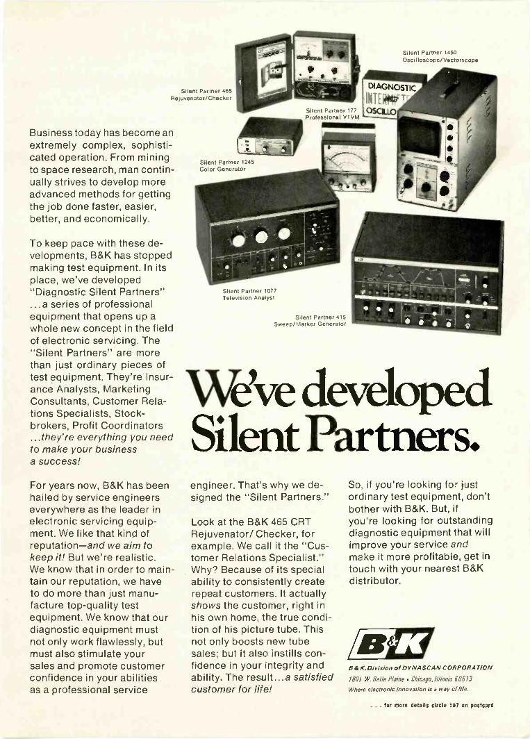
Silent Partner 465Rejuvenator/Checker
Business today has become anextremely complex, sophisti-cated operation. From miningto space research, man contin-ually strives to develop moreadvanced methods for gettingthe job done faster, easier,better, and economically.
To keep pace with these de-velopments, B&K has stoppedmaking test equipment. In itsplace, we've developed"Diagnostic Silent Partners"...a series of professionalequipment that opens up awhole new concept in the fieldof electronic servicing. The"Silent Partners" are morethan just ordinary pieces oftest equipment. They're Insur-ance Analysts, MarketingConsultants, Customer Rela-tions Specialists, Stock-brokers, Profit Coordinators...they're everything you needto make your businessa success!
For years now, B&K has beenhailed by service engineerseverywhere as the leader inelectronic servicing equip-ment. We like that kind ofreputation-and we aim tokeep it! But we're realistic.We know that in order to main-tain our reputation, we haveto do more than just manu-facture top-quality testequipment. We know that ourdiagnostic equipment mustnot only work flawlessly, butmust also stimulate yoursales and promote customerconfidence in your abilitiesas a professional service
Silent Partner 1450Oscilloscope/Vectorscope
Silent Partner 177Profession.11 VTVM
Silent Partner 1245Color Generator
Silent Partner 1077Television Analyst
Silent Partner 415Sweep/Marker Generator
We've developedSilent Partners.engineer. That's why we de-signed the "Silent Partners."
Look at the B&K 465 CRTRejuvenator/ Checker, forexample. We call it the "Cus-tomer Relations Specialist."Why? Because of its specialability to consistently createrepeat customers. It actuallyshows the customer, right inhis own home, the true condi-tion of his picture tube. Thisnot only boosts new tubesales; but it also instills con-fidence in your integrity andability. The result...a satisfiedcustomer for life!
So if you're looking for justordinary test equipment, don'tbother with B&K. But, ifyou're looking for outstandingdiagnostic equipment that willimprove your service andmake it more profitable, get intouch with your nearest B&Kdistributor.
B&K.Division of DYNASCAN CORPORATION
1801 W. Belle Pldine . Chicago. llino4 60613
Where electronic innovation is a way of life.
... for more details circle 107 on postcard

BOOK REVIEWS
99 WAYS TO IMPROVE YOURTV RECEPTION, by Len Buckwal-ter, published by Howard W. Sams &Co. 128 pages, 51/2 x 81/2. $2.95.
This book discusses antennas, lead-ins, boosters, rotators, couplers, inter-ference and improvements. It explainsways of improving on the basic an-tenna installation and covers suchthings as proper grounding, antennaorientation and interference. Thechapter on lead-ins explains the var-
ious types, when they should be used,why and how to install them withsubsequent information detailing in-stallation practices and improvementsto the TV, antenna and lead-in. Thebook covers most of the areas con-cerned with proper TV reception in-cluding some practical hints on coloradjustments. Since the information isaimed toward the customer, the dealermay find it a welcome addition to hisbook sales rack as a customer educa-tion work.
ADVANCED AND EXTRA -CLASSAMATEUR LICENSE HANDBOOKby Howard S. Pyle, W7OE, published
Thanks to color television, you'reworking in a vastly expanded market.It's highly competitive; and you have todo a first-rate job to stay on top of yourcompetition. That's why B&K developedthe 1245 Color Generator. It's the"Silent Partner" that makes a goodimpression. One that sells your cus-tomer on you and builds your image asa top-notch professional technician.
The B&K 1245 Portable Color Generatoris the leader in the service industry. Noother color generator on the market cancompare in quality and performance.
All solid-state, the 1245 offers instantoperation in all service environments.It eliminates waiting, warm-up, oradjustment. And you receive thebrightest, cleanest patterns possible.
Being fully portable, the 1245 has onlytwo front -panel controls for ease ofoperation-AC power/color level and
B&K 1245Station Quality
Color Generatorpattern selector. Station -qualitywaveforms provide complete protectionagainst obsolescence. A well-definedback porch on the horizontal sync pulsemakes it easier to converge the colortube, And the built-in gun killerworks on any picture tube, bothforeign and domestic.
So if you're looking for a portable colorgenerator that can solve color servicingproblems fast, the B&K 1245 is youranswer. It's not just a color generator.It's a "Silent Partner," designed to giveyou more time to create new salesby cutting servicing time to a minimum.
B&K Color Generator.Model 1245. Net: $134.95.
BdK Division of Dynascan Corp.1801 W. Belle PlaineChicago, Illinois 60613
B&K puts an end to test equipment.We've developed Silent Partners.
by Howard W. Sams & Co., Inc. $3.95paperbound.
This timely handbook answers theneeds of amateurs with General, Con-ditional and Technician class licensesfor a study guide to higher class li-censes. The book is written by a manwho knows what amateur radio isabout because he has been at it for60 years. It is divided into 13 chapterscovering all of the necessary subjectssuch as RF oscillators, power supplies,modulation, advanced RF theory andmany others. The later chapters getinto actual study material for the ad-vanced and extra class licenses with asection devoted to typical questionsand answers. Amateurs and techni-cians alike will find this handbook auseful reference for communicationselectronics.
ELECTRONICS REFERENCE DA-TABOOK by Norman H. Crowhurst,published by 7'AB Books, Inc. 232pages, over 100 illustrations, 45 tables.$7.95 hardbound, $4.95 paperbound.
In going through this referencebook, the ten chapters devoted to ev-erything from basic units to transmis-sion lines appear quite thorough. Inmost cases the charts are preceded bya brief explanation of applications,background information and source.It does get deep in one particular areawhere the book discusses the "J" op-erator used in design calculations, andmost likely a technician would findthis portion of no interest. However,for the most part the tables, graphsand formulas are pertinent to elec-tronic technicians. The book also in-cludes tables of line losses, informa-tion on FET's, IC's, vacuum tubes andother material not normally found inone source.
College tuition covers onlyabout 1/3 the cost of a
college education.Help supply the other
GIVE TO THE COLLEGE
OF YOUR CHOICE.Tls
0 *1- advertisingcontributed forthe public good
c'ou NO'
AID TO HIGHER EDUCATION CAMPAIGN
34
... for more details circle 108 on postcard
ELECTRONIC TECHNICIAN/DEALER

More than 5 million two-way trans-mitters have skyrocketed the demandfor service men and field, system, andR & D engineers. Topnotch licensedexperts can earn $12,000 a year ormore.You can be your own boss, buildyour own company. And you don'tneed a college education to break in.
HOW WOULD YOU LIKE to earn $5 to$7 an hour... $200 to $300 a week
... $10,000 to $15,000 a year? One ofyour best chances today, especially ifyou don't have a college education, isin the field of two-way radio.
Two-way radio is booming. Todaythere are more than five million two-way transmitters for police cars, firetrucks, taxis, planes, etc. and Citizen'sBand uses-and the number is grow-ing at the rate of 80,000 per month.
This wildfire boom presents a solidgold opportunity for trained two-wayradio service experts. Most of themare earning between $5,000 and$10,000 a year more than the averageradio -TV repair man.
Why You'll Earn Top PayThe reason is that the U.S. doesn'tpermit anyone to service two-way ra-dio systems unless he is licensed bythe FCC (Federal CommunicationsCommission). And there aren'tenough licensed experts to go around.
This means that the available li-censed expert can "write his ownticket" when it comes to earnings.Some work by the hour and usuallycharge at least $5.00 per hour, $7.50on evenings and Sundays, plus travelexpenses. Others charge each cus-tomer a monthly retainer fee, such as$20 a month for a base station and$7.50 for each mobile station. A sur-vey showed that one man can easily
maintain at least 15 base stations and85 mobiles. This would add up to atleast $12,000 a year.
How to Get StartedHow do you break into the ranks ofthe big -money earners in two-way ra-dio? This is probably the best way:1. Without quitting your present job,learn enough about electronics fun-damentals to pass the GovernmentFCC License. Then get a job in atwo-way radio service shop and"learn the ropes" of the business.2. As soon as you've earned a reputa-tion as an expert, there are severalways you can go. You can move out,and start signing up your own cus-tomers. You might become a fran-chised service representative of a bigmanufacturer and then start gettinginto two-way radio sales, where onesales contract might net you $5,000.Or you may be invited to move upinto a high -prestige salaried job withone of the same manufacturers.
The first step-mastering the funda-mentals of Electronics in your sparetime and getting your FCC License-can be easier than you think.
ENROLLUNDER NEW
G.I. BILLAll CIE coursesare available un-der the new G.I.Bill. If you servedon active dutysince January 31,1955, or are in ser-vice now, checkbox on card forG.I.Bill informa-tion.
r
Cleveland Institute of Electronicshas been successfully teaching Elec-tronics by mail for over thirty years.Right at home, in your spare time,you learn Electronics step by step.Our AUTO-PROGRAMMEDoleSSOTIS andcoaching by expert instructors makeeverything clear and easy, even formen who thought they were "poorlearners."
Your FCC License...or Your Money Back!
By the time you've finished your CIEcourse, you'll be able to pass the FCCLicense Exam with ease. Better thannine out of ten CIE graduates areable to pass the FCC Exam, eventhough two out of three non -CIEmen fail. This startling record ofachievement makes possible our fa-mous FCC License Warranty: you'llpass the FCC Exam upon completionof your course or your tuition will berefunded in full.
Find out more. Mail the bound -inpost-paid card for two FREE books,"How To Succeed In Electronics"and "How To Get A CommercialFCC License." If card has been de-tached, use. coupon below.
CIECleveland Institute of Electronics1776 East 17th Street. Cleveland, Ohio 44114
Please send me without cost or obligation:1. Your 44 -page book "How To Succeed In Electronics"describing the job opportunities in Electronics today, andhow your courses can prepare me for them.2. Your book on "How To Get A Commercial FCC License."
Name Age(PLEASE PRINT)
Address
City State ZipAccredited Member National Home Study Council ET -51
How to get into one of today's hottestmoney -making fields servicing 2-way radios!
He's flying high. Before he got his CIE training and FCC License, Ed Dulaney's onlyprofessional skill was as a commercial pilot engaged in crop dusting. Today he hashis own two-way radio company, with seven lull -time employees. "I am much betteroff financially, and really enjoy my work," he says. "I found my electronics lessonsthorough and easy to understand. The CIE course was the best investment I ever made."
MAY 1989
Business is booming. August Gibbemeyerwas in radio -TV repair work before study-ing with CIE. Now, he says, "we are inthe marine and two-way radio business.Our trade has grown by leaps and bounds."
. . . for more details circle 114 on postcard37
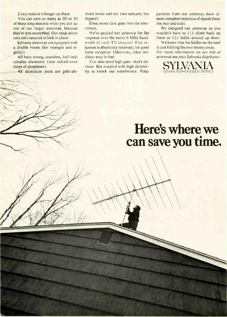
Every minute is longer up there.You can save as many as 20 or 30
of those long minutes when you put upone of our larger antennas, becausethey're pre -assembled. Our snap -jointstake only seconds to lock in place.
Sylvania antennas are equipped witha double boom (for strength and ri-gidity ).
All have strong, seamless, half -inchtubular elements (not rolled -overstrips of aluminum).
All aluminum parts are gold-alo-
dized inside and out (not sprayed, butdipped)
Even more care goes into the elec-tronics.
We've peaked our antennas for flatresponse over the entire 6 MHz band-width of each TV channel. Flat re-sponse is absolutely necessary for goodcolor reception. Otherwise, color ren-dition may be lost.
You also need high gain-that's ob-vious. But coupled with high directiv-ity to knock out interference. Polar
patterns from our antennas show al-most complete rejection of signals fromthe rear and sides.
We designed our antennas so youwouldn't have to (1) climb back upthere or (2) fiddle around up there.
We know that the fiddler on the roofis just fiddling his own money away.For more information on our line ofantennas see your Sylvania distributor.
SYLVANIAGENERAL TELEPHONE & ELECTRONICS
Here's where wecan save you time.

ELECTRONICTECHNICIAN / DEALER
MAY 1969
Signal Strength MetersIf you install antennas, MATV systems
or troubleshoot TV 'front -ends,'
you should consider the use
of a signal strength meter (SSM)as a basic aid to increase
efficiency and profit
The installation of a TV antenna has foryears followed a rather standard pattern --not referring to the nuts and bolts of puttingup towers, guy wires and the like, but in themethod used to aim the antenna for the bestsignal. The technician normally turns theantenna for the best picture and the custom-er is happy. Some technicians use a portableTV on the roof and this system works fine --for a simple home TV installation.
But if you install MATV systems, you needan instrument that will tell you when youhave the antenna set for the best possiblesignal. MATV systems are gaining popular-ity with motel operators, hotels, resorts andnow, home owners. It's a big market and onethat many service -dealers are getting intobecause it is a natural for an existing TV salesand service business.
USES FOR AN SSMHowever, a typical MATV installation can
cost hundreds of dollars. When you sell one,you want to be sure it is installed correctly.That means you will need the proper tools --a portable signal strength meter is one ofthe most useful. Besides using it to set an-tenna for maximum signal direction, it is in-valuable in checking distribution amplifiergain, line losses and other branches of theinstallation critical to an efficient system.
The signal strength meter can also be usedwhen bidding on complex MATV systems,
such as used in motels and apartment build-ings. First use the meter to take an initialsurvey of the signal strengths available inthe area. This can be done by taking a read-ing of the available channels with the meterconnected to an existing antenna or by us-ing a portable antenna of your own. Some ser-vice -dealers have crank -up antennas and tow-ers mounted right on their service vehiclesfor this purpose. With an idea of the localsignals, you can then take the antenna com-bination you propose to install and establishamplifier, tap -off and splitter requirementswith nothing left to guesswork.
In your shop, an SSM can be used to mea-sure hum modulation in TV amplifiers, pre-amplifiers and front -ends. You will be ableto determine noise figures, signal-to-noiseratio and gain. You can also make performanceand frequency response evaluations in otherpassive and active equipment operating inthe VHF, FM and UHF ranges. And since SSMunits are portable, their applications easilyextend to field use.
In the customer's home you will find a sig-nal strength meter invaluable for preciselytuning 30011 twinlead traps for the elimina-
TEKLAB REPORT . . .
The Packard Bell coior tv snt scheduled for coverage in thismonth's Teklab report was not received in time to permit thereport to be included in th,s issue.
te more details circle 138 on postcard
MAY 1989 39

Signal Strength Meters . . .
tion of frequency interference. The meter willalso provide a rapid and positive indicationof whether a problem of signal loss is in the TVset, the antenna, preamplifier or the distributionsystem. This is easily checked by comparingreadings on the meter with the values in dbthat you know should exist at specific locationsin the system.
HOW AN SSM WORKSBasically, an SSM (signal strength meter)
is a sensitive tunable RF microvolt meter.For TV applications it is normally calibrat-ed to indicate microvolts or decibels (dbmv)of average composite signal developed acrossa 300 or 755 load. (Fig. 1) Not all SSM me -
Fig. 1 --Typical signal strength meter face reads dbmvand microvolts.
ters indicate average signal, some read peak.In simplified form, the SSM has a receiv-
ing antenna, a tuning circuit and a diode de-tector in series with a microammeter. (Fig.2)
Capacitor, C2, would be of such value thatthe RC time constant resulting from its dis-
VDI r
Fig. 2 --Simplified schematic diagram of SSM circuit.
charge through the internal resistance ofthe meter would provide an indicated aver-age of the detected composite signal level.However, this simplified circuit alone wouldnot be adequate for accurate measurementsof low signal levels. Amplification is requiredand the non -linearity of the diode would tendto produce erroneous meter readings. Moreelaborate SSM circuits of precision signalstrength meters are shown in Fig. 3 and 4.The UHF and VHF sections have calibrat-ed input attenuators to allow signal measure -
Fig. 3 --Schematic diagram of SSM model 718 (Courtesy Jerrold).
40 ELECTRONIC TECHNICIAN/C*141R

L
r
L
-r
MI
W50000011V
OUT
seen..
BAND SWITCH SIOF AMP
M. 2.4150SR T01
CAR
fs
c
TUN
C.
VW TUNER
L E_
tear1-
smIts
C11
501
OSCILLATOR'Ur
811,
It v
SGR et.
UHF.° LUNE
1ST IF1.014S
VMS
AOC AMP
L
OF,
Fig. 4 --Schematic diagram of SSM Model FS 134 (Courtesy of Sencore).
ments over a greater range. Refer to Fig.3 for the following circuit description.
The VHF input to the base of Q2 is throughan impedance matching bandpass filter com-posed of Ll through L5, Cl through C4, Cxand Cy. Q1 is the oscillator transistor in amodified shunt --Hartley circuit. Oscillatortracking is provided by the ganged capac-itor, Cz. Oscillator injection to the mixer isthrough C6 to the base of Q2. The 30MHzcomponent at the output of Q2 goes to thefirst IF amplifier through a tuned bandpassfilter comprised of C9, C10, L6, L7, C11, C15and C16.
This filter is tuned by C10 and C11 to the30MHz IF and has a passband of 0.5MHz.Following Q3, transistors Q4 and Q5 providethe second and third stage of IF amplification.The output of the RF detector diode, Dl, isconverted to a logarithmic form for the met-er by compression diode, D2. An audio out-put jack is provided for monitoring the TVsound of FM band. A speaker is not used be-
2NOOm
IFassTa
3R0 IF540745
1117
fi_,ftms,
eV
AUDIODRIVER Ifk
S134
14 S S OCT
114
auleTVI
7V
AUDIOiii
OUTPUT
SCHEMATI
OCT.
i sir
045
C50 -*OW
cause the additional stages of amplificationnecessary to drive it would decrease batterylife and would not practically enhance themeter's usefulness.
The UHF front-end is preceded by a fix-ed pad consisting of R40, R41, R42 and R43to reduce spurious signal radiation from theUHF mixer/tuner and improve the input VSWR(voltage standing wave ratio) characteristics.The 30MHz output of the UHF tuner/mix-er section goes to the base of Q6 through aswitchable attenuator comprised of R35 andR44 in the X10 (20db) attenuation positionand through a short in the 0db attenuationposition. Transistor, Q6, operates as a buf-fer amplifier between the UHF section andthe following IF stages.
Calibration is provided by placing the VHF/UHF switch in the center position, thus per-mitting front panel adjustment of the bat-tery current (by turning potentiometer R28)to cause deflection to a meter "CAL" mark-ing. This procedure ensures accurate read -
MAY 1909 41

Signal Strength Meters ...
V54-216 MHz300 OR 75 0SIGNAL SOURCE
V70-890 MHz300 OR 7511SIGNAL SOURCE
VHFAT TEN
UHF
TUNER
VHFTUNER
30MHz
UHF
AT TEN
BUFFERAMP
30 MHz IF STRIP
1ST
IF2INFO 3RD
EARPHONES
DE T
*.)METER
Fig. 5-Block diagram of SSM.
ings of the UHF and VHF average compositesignal strength.
When using an SSM to check gain and lossin a MATV system, coaxial cable or twin leadis normally connected directly to the instru-ment and requires no special accessories. Someunits have built-in matching transformers andinput jacks for connecting either type of lead-in, others provide an external matching device.
However, for other measurements a probeis often necessary and can be easily madeby attaching a standard test probe to oneend of a low -loss shielded 750 cable and ter-minating the other end in a suitable connect-or.
To install the probe, a 1/2 in. section ofshielding should be exposed, unwoven andall but a small group of adjacent strands elim-inated. To these remaining strands of shield-ing solder a length of insulated wire with analligator clip at the other end. This will serveas the ground connection to the chassis beingtested.
The remaining free end of the test cable
II
Fig. 6 --Shows completed probe used for signal tracing.
should be trimmed back and an F59 or equiv-alent connector attached to it as shown inFig. 6. This will permit insertion of the testassembly into the 750 VHF or UHF inputterminal of the SSM. Some signal strengthmeters have a readily accessible detectoroutput jack. After determining what typeof plug it takes, an assembly can be madefor visually monitoring this detector outputwith your oscilloscope. The connector forthe scope end would, of course, depend uponthe type of scope input.
UNDERSTANDING THE DECIBELThe true amplification and gain of RF ampli-
fiers and preamps with 300 or 7511 input andoutput impedances such as used in MATVcan be determined by doing a little figuring.But before you get excited about complicatedformulas, bear in mind that a signal strengthmeter reads in dbmv and microvolts direct-ly, so all of the data required for figuring volt-age amplification, voltage gain and powergain is readily available. All you have to dois plug in the values.
You don't have to be a mathematician tohandle the decibel, but you do have to startthinking with numbers of a different kind.
The most important thing to know aboutthe decibel (db for short) is that it doesn'tsay "how much" or "how many" like the"10"in 10 dollars, it says "so many times." It's some-thing like the word "twice." And, like "twice,"it doesn't have any meaning in terms of quan-tity ("how much") unless you specify "so manytimes" something. For example, 6db alwaysmeans (in voltage) "two times" or "twice asmany."
The funny thing about the db is the non-linear relationship as shown in these examples.
42 ELECTRONIC TECHNICIAN/DEALEfi

6 db=2 x 20 db =10 x10 db.- 3.14 x 30 db .31.4 x12 db,--=4 x 40 db =400 x18 db= 8 x 60 db =1000 x
Notice that while 10db is approximately3 x, 20db =10 x. The gain is about three timesgreater by doubling 10db. But if you double20db to get 40db, you get 100 x, which is 10times greater. All this comes from the waythe db is derived. And because of its behavior,it makes all kinds of systems figuring simple.It's best that you try to follow the reasoningbehind the db. We will start with the follow-ing formula --and don't let it scare you.
db =20 log ElE2
Saying it in English, it goes like this: Thedb is equal to 20 times the common logarithmof the major (larger) voltage divided by theminor (smaller) voltage. Solving it goes likethis. Suppose we have an amplifier and wantto find its voltage gain in db. Being an am-plifier, its output will be larger than its input,so the output voltage is the "major" voltage.Divide the output by the input, the formulasays, so let's assign some values. Say the outputvoltage is 100 and the input 10, then 100 ÷10equals 10. Now the formula is reduced to:
db = 20 log 10
Now we have to find the common logarithmof 10. This is what causes most TV repair-men to gulp --they forgot their logarithmsas soon as possible after leaving high school.But there's no mystery about the commonlog. The common log, or logarithm to the base10, is only that little number that goes aboveand to the right of a number, the exponent,like in 10 2; but when used as the log, it is theexponent required to raise 10 to the numberwe have in mind.
As an example, 2 is the logarithm of 100,since 10 raised to the second power (10 2 )equals 100. Now, every number we knowcan be expressed as a power of 10, andmathematicians have spent years compilinglog tables to the tenth decimal place. Inour particular problem, we have to find theexponent which makes 10 equal to the base ofthe common logarithm, which is also 10. Thisone's easy --it's 101, so that the common logof El equals 1. The formula
E2now looks like this:
db = 20 x 1, and db (gain) = 20
We have found out that the amplifier's gainis 20db. Of course, if we'd found a fraction-al number, like 18.5 when we divided El byE2, we'd need a log table to find the commonlog of 18.5. This you will never need as longas you have a conversion chart handy whichconverts the ratio expressed by El directlyto db. E2
One of the puzzling things about the dbis 0db. 0db isn't "nothing" --it's something. It'sthe same as saying "there is a relationship ofone to one" --in other words no gain --no loss. Itworks out like this, and we can use the am-plifier we had before, but now we find theinput is 10v and the output 10v. The form-ula then looks like ;his:
db = 20 log10 E2
10
10
201og 110
= 20 log
El
since 10 divided by 10 is 1.The question now is what exponent will
raise 1 to 10? This is a funny one, the logicof which has escaped mathematicians -theyonly know it works --look:
10 2 =- 100
101
= - 10
10 = 110-1 =.1
We can see the sense behind the first, sec-ond and fourth expression, but the third onlymakes sense because it fits and works. Let'sput it into the formula: db = 20x0, andtherefore the amplifier's gain is 0db.
This boils down to the fact that when wesay 6db, we mean that we are talking aboutsomething which is twice as great as 0db,since 0db is one times and 6db is two times.The question always comes --"What's 0db?"The answer is--Odb is anything you chooseto make it! In audio, committees of engineershave assigned a value to 0db which they agreedupon. In TV systems you can specify whatyou like. It can be the antenna signal, for in-stance, or you can choose 1000 µ v read across750 impedance. This is a pretty good signalfor a TV set.
The great advantage of using the db is thatContinued on page 90
MAY 199943
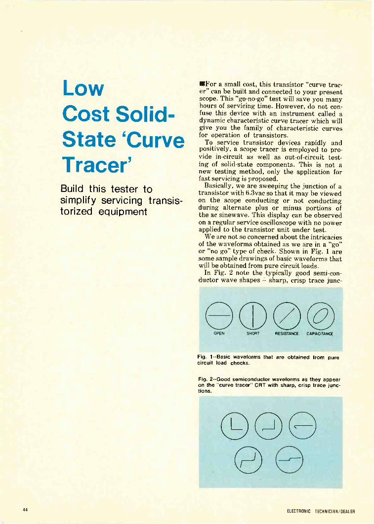
LowCost Solid -
State 'CurveTracer'Build this tester tosimplify servicing transis-torized equipment
For a small cost, this transistor "curve trac-er" can be built and connected to your presentscope. This "go -no-go" test will save you manyhours of servicing time. However, do not con-fuse this device with an instrument called adynamic characteristic curve tracer which willgive you the family of characteristic curvesfor operation of transistors.
To service transistor devices rapidly andpositively, a scope tracer is employed to pro-vide in -circuit as well as out -of -circuit test-ing of solid-state components. This is not anew testing method, only the application forfast servicing is proposed.
Basically, we are sweeping the junction of atransistor with 6.3vac so that it may be viewedon the scope conducting or not conductingduring alternate plus or minus portions ofthe ac sinewave. This display can be observedon a regular service oscilloscope with no powerapplied to the transistor unit under test.
We are not so concerned about the intricaciesof the waveforms obtained as we are in a "go"or "no go" type of check. Shown in Fig. 1 aresome sample drawings of basic waveforms thatwill be obtained from pure circuit loads.
In Fig. 2 note the typically good semi -con-ductor wave shapes sharp, crisp trace junc-
OPEN SHORT RESISTANCE CAPACITANCE
Fig. 1 --Basic waveforms that are obtained from purecircuit load checks.
Fig. 2 --Good semiconductor waveforms as they appearon the "curve tracer" CRT with sharp, crisp trace junc-tions.
44 ELECTRONIC TECHNICIAN/DEALER
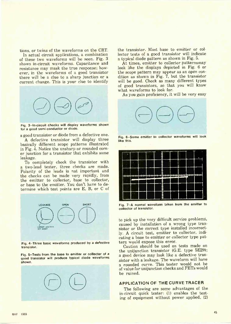
tions, or twins of the waveforms on the CRT.In actual circuit applications, a combination
of these two waveforms will be seen. Fig. 3shows in -circuit waveforms. Capacitance andresistance may mask the true response; how-ever, in the waveforms of a good transistorthere will be a clue to a sharp junction or acurrent change. This is your clue to identify
Fig. 3--In-circuit checks will display waveforms shownfor a good semi -conductor or diode.
a good transistor or diode from a defective one.A defective transistor will display three
basically different scope patterns illustratedin Fig. 4. Notice the unsharp or rounded corn-er junction for a transistor that exhibits someleakage.
To completely check the transistor witha two -lead tester, three checks are made.Polarity of the leads is not important andthe checks can be made very rapidly, fromthe emitter to collector, base to collector,or base to the emitter. You don't have to de-termine which test points are E, B, or C of
LEAKAGE OPEN
CORNER JUNCTIONNOT SHARP
CD
SHORT
Fig. 4 --Three basic waveforms produced by a de'ectivetransistor.
Fig. 5 --Tests from the base to emitter or collector of agood transistor will produce typical diode waveformsshown.
the transistor. Most base to emitter or col-lector tests of a good transistor will indicatea typical diode pattern as shown in Fig. 5.
At times, emitter to collector patternsmaylook like the displays depicted in Fig. 6 orthe scope pattern may appear as an open con-dition as shown in Fig. 7, but the transistorwill be good. Check as many different typesof good transistors, so that you will knowwhat waveforms to look for.
As you gain proficiency, it will be very easy
Fig. 6-Some emitter to collector waveforms will looklike this.
1111M1101111111111111111111E-1111111111-
111M1111111111111111M1Fig. 7--A normal waveform taken from the emitter tocollector of transistor.
to pick up the very difficult service problemA,caused by installation of a wrong type tran-sistor or the correct type installed incorrect-ly. A circuit test, emitter to collector, indi-cating a base to emitter or collector type pat-tern would expose this error.
Caution should be used on tests made onthe unijunction transistor (G.E. type 5E29);a good device may look like a defective tran-sistor with a leakage. The waveform will havea rounded curve. This tester would not beof value for unijunction checks and FETs wouldbe ruined.
APPLICATION OF 7H E CURVE TRACERThe following are some advantages of the
in -circuit quick tester: (1) enables the test-ing of equipment without power applied, (2)
MAY 196945

`Curve Tracer' .. .
rapid accurate servicing by a semi -skilledtechnician, (3) servicing without referenceschematics is possible in many instances, (4)checks and confirms performance (exceptbeta) of all semiconductors with only an ad-ditional equipment cost of less than $8, (5)enables the service technician to repair equip-ment that he may not be familiar with, aswell as equipment without technical infor-
Si
TO TRANSISTORUNDER TEST
Fig. 8 --Schematic of the transistor or diode tester.
Fig. 9 --The complete setup of the oscilloscope and "curvetracer."
LEAKAGE
SCOPE
0 00 0001
Ow---
VO HOIN
OUT
TEST0
TEST UNIT
GOOD SHORT
E B C[ [
TRANSISTORUNDER TEST
OPEN
mation, (6) Diode checks can be made in thecircuit along with the transistors (one defec-tive diode can cause as much equipment mal-function as a defective transistor).
A speed check was made with this testeron a Motorola TS -915 solid-state color chas-sis. It contains more than 60 transistors andover 26 diodes but it took less than 20 minutesto check them all. One defective transistorwas located and replaced, putting the setback into proper operation.
Fig. 8 shows the simple schematic for thein- or out -of -circuit transistor or diode tester.
To calibrate this unit, without a load across
1111111111111111111.1111111111111111111111111111111111
1111111111111111111111111:11=1:4111111111111111111
Fig. 10 --Actual oscilloscope waveform showing a goodtransistor with probes connected from emitter to col-lector.
Issio ttt 0000 44114 111.8,00..
Fig. 11 --Waveform showing a shorted transistor.
Fig. 12 --Waveform showing an open emitter to baseof the in -circuit transistor with a slight loop indicatingcapacitance in the circuit.
46ELECTRONIC TECHNICIAN/DEALER

the test leads, adjust the scope's horizontalamplifier to scan about 3 in. of width. Withthe two test probes shorted, adjust the scope'svertical amplifier gain to scan a line about 3 in.high. Fig. 9 shows the complete setup of theoscilloscope and curve tracer.
The following are actual waveforms of tran-sistors checked in the circuit:
In Fig. 10 a good transistor trace is shownwith probes connected from emitter to col-lector, and a shorted transistor waveformis shown in Fig. 11. In Fig. 12 the waveformdenotes an open emitter to base of the in -cir-cuit transistor with a slight loop indicating
Fig. 13 --Waveform showing transistor with base to col-lector leakage.
.-4344
Fig. 14--A weird looking waveform taken from emitterto collector of a good transistor with inductance andcapacitance in circuit.
Fig. 15 --Waveform showing an intermittently shortedtransistor producing a cross pattern waveform.
some capacitance in the circuit being checked.Leakage is shown in the waveform of Fig.
13 measured from the base to collector ofthis transistor. However, the oscilloscopewaveform in Fig. 14, showing a sharp bend,proved this transistor to be good. This semi-conductor was in a circuit that contained bothinductance and capacitance, but was detect-ed by this tester. An intermittently shortedtransistor is illustrated in Fig. 15 showingcross pattern waveform effect.
SERVICING SOLID-STATE STEREOEQUIPMENT
In most. cases, a stereo amplifier will havetwo relatively identical channels. If the tran-sistors are "even numbered" in the left chan-nel then the same transistor should be foundin the right channel with an even type number.
Troubleshooting this equipment can be doneby comparing each "twin stage" response,enabling even an inexperienced technician tomake a rapid diagnosis of either transistor orcircuit component failure.
All stages of the amplifier can be checkedand repaired before reinstalling the unit. Inmany cases, the repairs will be complete anda limited power test can be made with con-fidence. If the amplifier does not operate,use a scope, preferably with a dual -trace plug-in amplifier and signal trace, by comparingthe left and right channel waveshapes.
MAKING STEREO CHECKS(1) Always make a complete visual check
for burnt parts. (2) Use the touch and smelltechnique for indications of excessive heateven though burnt parts are not evident. (3)Make a complete visual check for indicationsof previous service repairs or damage. (4)Remember, always check transistors beforeinstalling and recheck transistors in -circuitafter installation. Transistors can be dam-aged during installation or removal. (5) Alldiodes can also be checked rapidly along withthe transistors. (6) Check the service tick-ets for other tips and clues as to what thetrouble may be or call your stereo custom-er should more information be needed.
The "curve tracer" can also be used forcontinuity checks of the printed circuit foilfor cracks or defective solder joints. Flexthe board and watch the scope waveformfor your point to point continuity test. Evenshorted or open capacitors and coils can belocated with this test method.
47
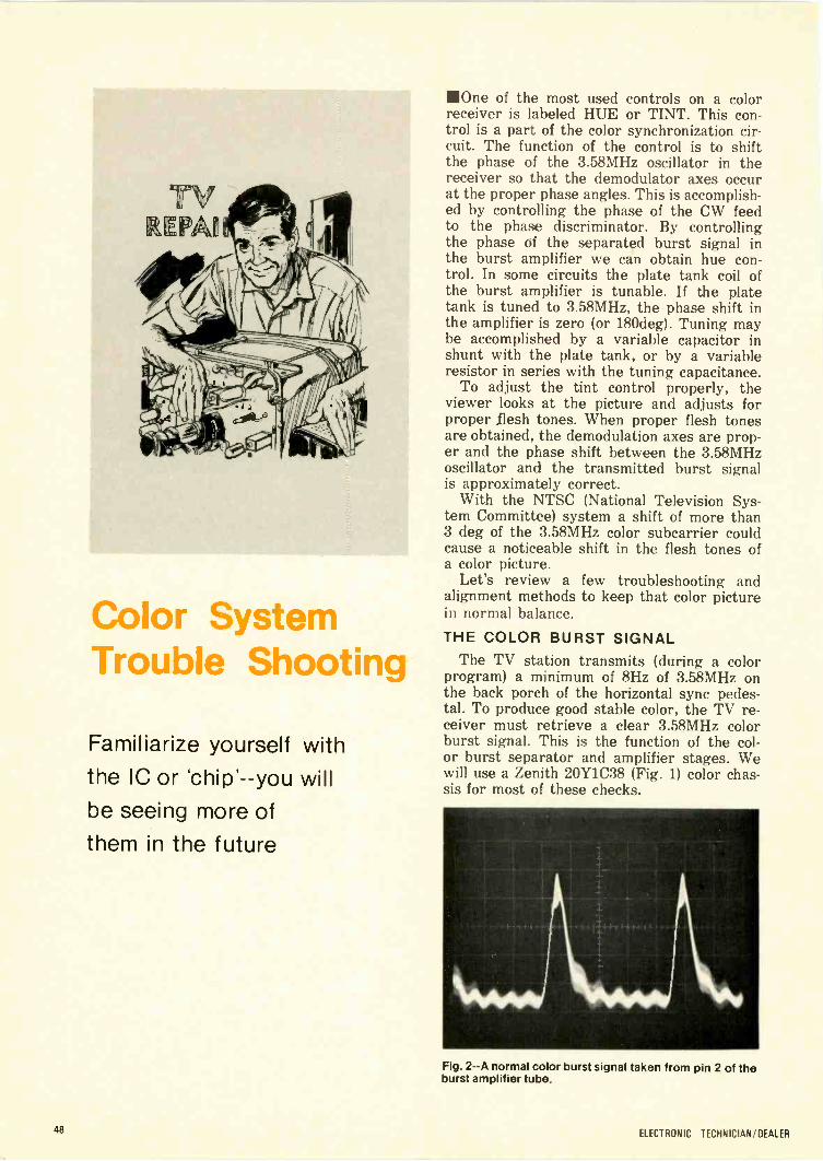
Color SystemTrouble Shooting
Familiarize yourself withthe IC or 'chip' --you will
be seeing more ofthem in the future
One of the most used controls on a colorreceiver is labeled HUE or TINT. This con-trol is a part of the color synchronization cir-cuit. The function of the control is to shiftthe phase of the 3.58MHz oscillator in thereceiver so that the demodulator axes occurat the proper phase angles. This is accomplish-ed by controlling the phase of the CW feedto the phase discriminator. By controllingthe phase of the separated burst signal inthe burst amplifier we can obtain hue con-trol. In some circuits the plate tank coil ofthe burst amplifier is tunable. If the platetank is tuned to 3.58MHz, the phase shift inthe amplifier is zero (or 180deg). Tuning maybe accomplished by a variable capacitor inshunt with the plate tank, or by a variableresistor in series with the tuning capacitance.
To adjust the tint control properly, theviewer looks at the picture and adjusts forproper flesh tones. When proper flesh tonesare obtained, the demodulation axes are prop-er and the phase shift between the 3.58MHzoscillator and the transmitted burst signalis approximately correct.
With the NTSC (National Television Sys-tem Committee) system a shift of more than3 deg of the 3.58MHz color subcarrier couldcause a noticeable shift in the flesh tones ofa color picture.
Let's review a few troubleshooting andalignment methods to keep that color picturein normal balance.
THE COLOR BURST SIGNALThe TV station transmits (during a color
program) a minimum of 8Hz of 3.58MHz onthe back porch of the horizontal sync pedes-tal. To produce good stable color, the TV re-ceiver must retrieve a clear 3.58MHz colorburst signal. This is the function of the col-or burst separator and amplifier stages. Wewill use a Zenith 20Y1C38 (Fig. 1) color chas-sis for most of these checks.
Fig. 2--A normal color burst signal taken from pin 2 of theburst amplifier tube.
48 ELECTRONIC TECHNICIAN/DEALER

The proper color burst signal is shown inFig. 2, riding on the tip of the horizontal key-ing pulse. This waveform was taken at pin2 of V16 burst amplifier tube. An improperscope waveform expanded for detail is illus-trated in Fig. 3. The 3.58MHz burst signal
4 9 I 2. X4-1
Fig. 3 --An improper color burst signal waveform expandedfor detail. The 3.58MHz burst signal is shown riding onthe side of the keying pulse.
is shown riding on the side of the keying pulseand the result would be poor color sync orno color at all. This condition could be caus-ed by a faulty coupling capacitor feeding blank -
Wet ueore KAE,IerO1"5 MO 5.91i
OH 'LACK II 991irtPRO6RAI9, ,norre
V 6B K7L,er Vdtee,:e1/2 6K T8 ma' P'''`"" VIIB
1ST COLOR 1/2 6K T8AMP, 2ND COLOR AMP
90v23r
6 R59
, LtKzSOL
SA., 2 2""I..7016
GP -r
MATCH02*1
L.9 C77.6220,7
COLORLLrR
TMCO
opt
TO Pe
Pm 93 HOE
200 VISA 1-1/2 6JU8A
A.0 C -KILLERPHASE DETECTOR
s.
729PLUG 92
LE 5527!..LS
Ce2
1,9 l'3.9:77.0i 9r
IIIT"
lit15...'; <. 1
I" 01T
- SOC1EET
I LEVEL,L,.. RHO T vie 4o
ri0
Ws L 23
.56MM.20
C"
VI5B1/2 6JU8A
C157 A.F.C.PHASEDETECTOR
ing pulses from the sweep transformer. How-ever, do not overlook circuit trouble in thehorizontal oscillator AFC and sync amplifierstages.
A dual -amplifier triggered scope is veryuseful in checking these color circuits. The
Fig. 4 --The proper timing of the color burst and keyingpulse is shown in the oscillograph waveform. The toptrace is color burst information at V16 burst amp plate,while the bottom trace is simultaneously compared withthe keying pulse at pin 2 of the same tube.
proper timing of the color burst and keyingpulse in this stage is shown in Fig. 4, oscil-
C92T00.5
44
P47
C9/
PUSH-PULL8-1
0 INJECTION
560E
Tc
TP2
.730v
R949. __C_aL"" 22172
491MEG
-2.009P
40V -
V166JC6
BURST AMP
.001
-BURST TARE -OFF
60.9 75 pp,
L5.e:3,e
L
.0.
40e ..5
`Fr /- Cigi:,99s r -4-,».
390vCt60*off LeZ
627973 u,NMI29,
390,'
VI7A1/2 6Gel8A
REACT.CONTROL
77
.T4OP
%1'
Ps?6710516
9059 -PULL-YC T ON
C.67
.749
710T
250V
10981.01
544
641C,69
kOPf
220P
-le 4100.e
T- , I T'
9
1011
IS.79 0,
IMP P -PIII IN,
IIISP MP3.0 PP,
VI7B1/2 6GH8A
3.58MHzOSC
9739K
C 179
Fig. 1 --Partial schematic of the color section in a Zenith20Y1 C38 color chassis.
MAY 196949

lograph wavetrace. The top trace is colorburst information at V16, burst amp platepin 7, while the bottom trace is simulta-neously compared with the keying pulse at pin2 of the same tube.
A balanced 3.58MHz color burst signal willbe taken at the secondary of L40, AFC andACC phase detector transformer. The dual -
trace oscilloscope waveform that should befound at this stage is shown in Fig. 5 and this
Fig. 5 --The dual -trace oscilloscope waveform shows abalanced 3.58MHz color burst signal taken at the secon-dary of the AFC and ACC phase detector transformer.
burst pulse should measure 60v P -P. If thispulse is unbalanced, check the following com-ponents, C158, C159, R95A, R95B and thephase transformer, L40. Check other scopewaveforms (Fig. 1) for proper operation.
TROUBLESHOOTING AND ALIGNMENTOF THE COLOR AFC CIRCUIT
The following "time saving" service tech-niques should be used for alignment of the3.58MHz color oscillator in Zenith color sets.
Voltage measurements should be takenat test point "W" (color AFC circuit) --referto Fig. 1.
If the receiver has AFTC (automatic finetuning control) provisions, turn AFTC switchto the OFF position while making these ad-justments.
A properly operating color set will gen-erally read about zero voltage when measur-ed with a VTVM at test point "W" under nosignal condition (tuner set between channels).Should this voltage exceed lv (positive ornegative), several different symptoms mayappear as follows: (1) complete absence ofcolor information; (2) intermittent loss ofcolor sync; (3) color dropout; (4) critical finetuning range for color and (5) delay in color"lock -in" when changing from one channelto another.
Some of the probable causes for voltagesin excess of lv at test point "W" under no
signal conditions are as follows: (1) a faulty3.58MHz CW oscillator and control tube; (2)a defective AFC phase detector (tube or solid-state diode) --one diode may be conductingconsiderably more than the other; (3) an openor leaky section in one of the two dual .001µfcapacitors in the AFC phase detector circuit;(4) a defective 42 ph choke at test point "W '--this choke is important for stability of theoscillator; (5) component leakage or valuechange in the anti -hunt network (from testpoint "W" to ground); (6) incorrect settingof the 3.58MHz color oscillator frequencyadjustment, L44 and (7) the 2.2M resistorshave changed value (not matched) in the AFCphase detector circuit --these resistors mustbe matched to within 2 percent of each other.
The range of correction voltage at test point"W" to maintain color sync for the 3.58MHzcolor oscillator with color signal should beapproximately 5v (positive or negative) foroptimum pull -in range. The inability to de-velop this range of voltage may result in sev-eral varied troubles as will now be noted.
The following information can be used tocheck the pull -in range (voltage correctionrange) at test point "W": (1) feed a color sig-nal to the tuner antenna terminals, (2) con-nect a VTVM from test point "W" to ground,(3) ground test point "K," killer voltage canbe measured at this point (ground to opencolor channel), (4) adjust the slug of the col-or oscillator frequency coil (L44) by turningit clockwise as viewed from the bottom ofthe chassis. Check the voltage reading onthe VTVM. About 5v negative should be pres-ent with the color pattern remaining in sync.Adjust the slug counter clockwise. The neg-ative voltage should slowly approach zero,then reverse polarity and approach about5v positive with the color pattern remain-ing in sync. Change polarity of your VTVM.This range (approximately ±5v) is consider-ed normal and correct for consistent colorsync.
If this range is considerably less than ±5v, circuit troubleshooting is then necessary.The following service tips are suggested:(1) Check or replace the color oscillator andAFC phase detector tubes; (2) Check all com-ponents from test point "W" to ground. Aprime suspect would be the .1 pf capacitorC163; (3) Check the 42µh choke at test point"W," L43; (4) With the oscilloscope, checkfor presence of burst signal at the phase de-tector coil, L40; (5) Check the dual .0010 ca-pacitors (two are used) in the color AFC phasedetector circuit, and also capacitors or coldsolder joints in the screen grid circuit of theburst amplifier tube; (6) The 3.58MHz cry-stal may also be defective (replace and alignoscillator for zero beat); (7) Oscillator coil,
50 ELECTRONIC TECHNICIAN/DEALER

L44, may be faulty (substitute with new coil).The adjustment of the 3.58MHz oscillator
must be made correctly.The procedure for adjusting the 3.58MHz
CW oscillator to "zero beat" with an "on theair" color program is as follows: (1) Tune ina color program and observe color on the CRT.(2) Ground test points "K" and "W" on thechassis. Should the color be "running" acrossthe screen at a rapid rate, it is an indicationthat the 3.58MHz oscillator requires tuningfor a "zero" beat condition. (3) Adjust thecore of the color oscillator frequency coil,L44, until the color band movement comes toa near standstill. Continue to tune the 3.58MHzoscillator coil while noting colors on thescreen. Tune until the color on the screenbecomes a solid hue. At this point, all colorhas come to a standstill.
Use caution when making this adjustmentas an error can easily be made. It is possibleto adjust the core until two or more "red"and "blue" wide diagonal bars are seen tobe at a standstill. This is not "zero" beat, butcan easily be mistaken for it. Proof of "zero"beat can be made by removing the groundfrom test point "W" and connecting a VTVMfrom this point to ground. A reading of upto ±2.5v may be present. When the 3.58MHzoscillator is correctly set for "zero" beat, thevoltage measured at test point "W" will bevirtually zero (or less than -±-1v). Removethe VTVM and again ground test point "W"if further adjustment is necessary.
Proper alignment of the 3.58MHz coloroscillator will solve many color sync and fadeout complaints.
IC 'CHIP' COLOR DEMODULATORSome new Zenith color chassis employ an
TohVJg
COHT
3.1x
lb GotDIFFERENCE ANA'S.
-(R-r)
, 7.v
se.,
%:, 1
5 2.V
033 0134
dfCro
,-, 30 .1-.05
4° I---iour
L .eA PE 7, .6-___ ?°Cs 330 1. , ..L.1,_...
I
Or IV C'Tg, 4-ro ey;',. -ca .50c -T If% jp, 4..._t'-. T__n__
e.r
C 32
I.C.2221-37DEMOD.
At2.VISPS s
CeteRAm?
RFCTO0 ;
ii541____17 P4
FRcnr
3 58 nlo0 or 0 CFig. 6 --The "chip" IC Demodulator.Courtesy of Fairchild.
IC "chip" (IC 221-37) for the color demodulator.This IC contains two double -balanced syn-
chronous detectors that are coupled to a ma-trix system where the desired color differ-ence signals are developed. Shown in Fig.6, the output of the second color amplifieris coupled to an IC stage or "chip". This "chip"is designed to plug into a conventional 9 -pinminiature socket and is keyed accordingly.
Two chroma signals of opposite polarityare coupled to terminals two and three. Thedual -trace scope waveform (Fig. 7) showsthe color difference signals of -(R-Y), -(B-Y)
i'l\WokovluiN
'll'itityy`f`ILmk
Fig. 7 --The dual -trace waveform shows the color differ-ence signals of -(B-Y) top waveform and -(R-Y) bottom
at terminals eight and nineof the IC demodulator.
chroma signal output which will appear atterminals eight and nine of the "chip." Os-cillator injection reference (3.58MHz-CW)is injected at terminals number four and five.A dual -trace triggered scope signal wave-form of this CW signal is shown in Fig. 8. Pleasenote the 3.58 MHZ CW signal has been sup-erimposed on the scope for an exact phasecheck of the 104deg signal shift.) The oscil-
Fig. 8-- A dual -trace triggered scope waveform of the CWsignal. The 3.58MHz CW signal had been superimposedon the scope for an exact phase check of the 104degsignal shift.
Continued 00 page 92
MAY 196951

Contrast Now--Tomorrow What?
Bob tells Scoot aboutfilters for CRTs --and alittle of what's to come
in this business
111"I've seen some crazy gimmicks foistedon the public, but this 'black -screen' gimmickis the worst yet."
Scoot was talking mostly to himself, butBob took the cue and, in his usual fashion,came to the manufacturer's defense.
"You and a lot of others seem to think thateverything a manufacturer trys to sell thepublic is some kind of gimmick. Scoot, forthe most part, the engineers have to sell themarketing people on new ideas and the ideashave to be sound or they won't budge."
"Oh boy! Me and my big mouth. OK, brightguy--defender-of-the-great-American-manufac-turer--what does a dark glass in front ofa CRT do to the picture besides cut downon the light?"
"Well, as you know, several TV makershave picked up the dark filter idea, Scoot.Now, it should seem reasonable to you thatif it were only a gimmick, the other manu-facturers would say that it was only a gim-mick and go about their business. Right?"
"I'm not convinced.""And I'm not through. To answer your ques-
tion, I'll only say that the dark filter increasesthe contrast."
"How can you say that? I know that theblacks will be 'blacker' but the whites willbe darker, too."
"Not so, Scoot. At least, not quite. Althoughthe blacks will be 'blacker' and the whitesdarker, too, the difference between the twowill be greater. In other words, there willbe more contrast."
"That's double-talk if I ever heard double-talk."
"Then keep quiet and I'll explain. The dark-est object you can have in a picture cannotbe any 'blacker' than the screen itself. Whatmakes it appear black, even though it is re-latively light, is the contrast between thescreen and the lighter picture elements.
"Now, the reason you see the phosphoron the screen when the set is switched off,
Fig. 1 --Reflected light allows you to see the screen whenthere is no light from the set itself.
52ELECTRONIC TECHNICIAN/DEALER

is because the light hitting the phosphor isreflected to your eyes. Look here."
Bob scribbled a picture on the scratch padon Scoot's bench (Fig. 1).
"Light coming from the phosphor whenthe set is on follows the same paths to theeye, but it is not reflected."
Bob drew another sketch (Fig. 2).
Fig. 2 --When the set is turned on, light from the phosphoroverpowers the reflected light and makes theappear black.
screen
"The reflected light is not as strong as thelight emitted by the phosphor so the eye seesa contrast: black and white.
"In a very bright light, like sunlight, stillanother factor is involved. The sunlight notonly reduces the contrast, it overloads theCRT phosphor and reduces the phosphor out-put."
"That all sounds good, Bob. But what aboutthe dark glass, what does it do for the pic-ture?" "Well, for one thing, it can reduceexternal light reaching the CRT and mayprevent 'overloading' the CRT phosphor.But the really big effect is that the externallight must go through the filter twice whilethe light emitted by the tube only goes throughit once."
Bob drew another sketch, adding a filter
FILTER
Fig. 3--A 50 percent transmission filter demonstrateshow only 25 percent of the reflected light is seen but50 percent of the phosphor light is seen.
to the TV set as shown in Fig. 3."I think I'm beginning to see the !it, Bob.""Good, let's make an example just to make
sure. Let's look at a few rays of light and seehow this filter works. Just for the sake ofthis example, let's say that the filter will trans-mit 50 percent of the light that strikes it andabsorbs 50 percent.
"If four rays of light strike the filter, thenonly two go through. OK? And when the CRTreflects these, only one will get through tothe eye. In other words, only 25 percent ofthe light that strikes the filter is reflectedto the eye. That's what makes it look dark.
"On the other hand, two of the four raysemitted from the CRT will pass through thefilter to the eye. So, what would be a four -to -four ratio without a filter --a perfect wash-out --becomes a two -to -one with the filter.Of course, this ignores a few minor pointsand the ratio only holds true for a filter witha 50 percent transmission characteristic."
"I'll be darned. I never thought of it thatway."
"Obviously, jug -head. While we're at it,we may as well get you acquainted with pol-arized filters, too. We're going to be usingthem on that CCTV job at the steel mill.
"We don't have to discuss all the anglesof linearly polarized light. Let's just say thatthere are two kinds: left polarized and rightpolarized. Normal light, like we're workingin, is about 50-50."
Bob pulled a cheater cord from a benchdrawer and tied one end to the handle. Thenhe slid it between the back rungs of an oldchair and with a flick of his wrist produceda wave motion (Fig. 4).
"See, Scoot, the chair doesn't block thecord's motion when I swing it up-and-down.But, when I swing it sideways the rungs hit
Fig. 4--A swinging cheater cord and the rungs of a chaircan be used to demonstrate the function of polarizingfilters.
MAY 196953

it and don't let the waves form. They can passthrough in only one direction or plane.
"If we put a polarized filter in front of or-dinary light, we get only polarized light out --like so."
Bob took a book from the shelf behind hisdesk, brushed off the dust, opened it at a fad-ed yellow marker and pointed to a drawingat the top of the page (Fig. 5).
POLARIZING FILTER POLARIZING FILTER
Fig. 5 --Polarizing filters can be employed to stop virtuallyall light when they are rotated out of phase.
A thin smile appeared on Scoot's face. "I'mreally in for it now."
"As I was saying, Scoot, we assume thathalf the light is left polarized and the otherhalf right polarized. The material in the firstfilter --like the chair rungs --permits only thelight waves polarized in one direction to passthrough --the others are stopped by the fil-ter.
"The second filter is like the first one ex-cept it's Notated 90deg--I'll use a little refer-ence -'X' on the two filters to show it. Nowthe imaginary rungs in this second filter arein a direction that would allow the waves al-ready blocked to pass through --if they werestill around. Instead, these 'rungs' block theremaining light waves."
"Oh, I get it now --it sounds simple, Bob.And, I suppose any smooth surface --like theface of a CRT --will reverse the polarized lighttraveling through this filter --the filter catchingwhat's left --the reflected light --the second
POLARIZING FILTER
Fig. 6 --When light is reflected from a smooth surface, theangle of polarization is not reversed.
time through. You know --if left polarized lightgot through the filter, it would become rightpolarized light when reflected and the fil-ter would block its return."
"It sounds like a good idea, Scoot, but you'rewrong. A single polarized filter --like the oneswe've been talking about --wouldn't do anymore good than the regular filters we justtalked about --the fact that the light becomespolarized wouldn't help much."
"Then why have you been ,talking aboutpolarized filters when I've got TV sets to fix --those polarized filters are just some other'gizmos' to help increase sales."
"You're just getting ahead of me, Scoot ,
we'll see why your idea doesn't work and whatcan be done to make it work. Here, look atthe next page in the book (Fig. 6) --then you'llsee that a smooth surface, or even a mirror,doesn't reverse the polarity of left or rightpolarized light. While you're studying that,I'll set up a simple demonstration of someprinciples youll have to learn before we cango any further."
Bob connected the sinewave output of anaudio signal generator to both the horizon-tal and vertical inputs of a scope (Fig. 7).
Fig. 7 --An audio signal generator and scope are usedto demonstrate the effective components of polarizedlight.
"Now look at the screen, Scoot. When Iturn the scope's phase control so that thelittle green dot moves left -and -right in phasewith its up-and-down motion, then we havea single diagonal line (Fig. 8 phase =0°). Thetwo motions cause the dot to move diagonallyup -and -down --like a wave of right polarizedlight.
"By turning this phase control knob somemore, I can change the horizontal and verti-cal signals so that they are 180deg out of phase.Now the dot --instead of moving to the rightwhen it moves up --is moving to the left whenit moves up. This motion forms another dia-gonal line (Fig. 8 phase =180°) resembling
54 ELECTRONIC TECHNICIAN/DEALER

0 0 9 90
109 180 9 270
Fig. 8 --Patterns formed on the scope are dependent onthe phase relationship between the horizontal and ver-tical sinewaves.
a wave of left polarized light. Although forboth diagonals the dot moves in a straightline, its movement along that line is a com-bination of movements up-and-down and right -and -left. One combination of movements canbe said to exist for right polarized light --adifferent combination can be said to existfor left polarized light.
"You see, Scoot, though the dot appearsto be moving only along one diagonal lineor the other, we can think of it as also beinga combination of horizontal and vertical mo-tions from the two inputs on the scope."
"No comment.""Well, Scoot, it's the phase angle between
the two motions that determines whetherthe dot's motion forms a right or left diag-onal line. When the horizontal and verticalwaves are in phase, they form a right diagon-al line --when the horizontal wave is 180degbehind the vertical wave, a left diagonal lineis formed.
"By adjusting the phase control knob sothat the horizontal motion is 90deg behindthe vertical motion, the dot appears to ro-tate clockwise (Fig. 8 phase = 90°) --turningthe knob further makes the horizontal motion270deg behind the vertical motion --now thedot appears to be rotating counterclockwise(Fig. 8 phase = 270°)."
"So am I.""Turn to the next page marked in the book -
there's a couple of diagrams there that mightclear up what I'm trying to get through yourthick head.
"Let's say that the polarizing filter in thefirst diagram (Fig. 9) permits only right po-larized light to pass through it. But directly
behind this filter is a retarding element.""A what?""A retarding element --its a thin piece of
transparent material that is able to slow upwaves traveling in one plane, while not thosein another plane. The filter shown here slowsup the horizontal component waves of theright polarized light, while allowing the verti-cal component to travel through at the nor-mal rate. This, in effect, alters the phase anglebetween the two component waves."
"You don't say."
Fig. 9 --Circular polarizers contain a linear polarizing fil-ter and a quarter -wave retarding element.
"Look --the right polarized light is like thatright diagonal line that we had on the scope --its horizontal component was in phase withits vertical component. The retarding ele-ment is able to slow down the horizontal com-ponent --once the polarized light has passedthrough the retarding element the horizon-tal componentcomponent --the retarding element havingchanged the right polarized light into circu-lar polarized light --rotating clockwise."
"Oh I get it, Bob, then the light from thelamp travels to the polarizing filter --only rightpolarized light traveling through. The retard-ing element changes this right polarized lightto circular polarized light, which is rotatingclockwise."
"Good for you, Scoot --you may get this yet!""Now, once we get through the next fig-
ure (Fig. 10), we may have you understand-ing these circular polarizers.
I
POLARZING FILTER RETARDING ELEMENT
Fig. 10 --The phase shift of light in the retarding elementpermits the virtual elimination of reflected light in thelinear polarizing filter.
Continued on page 82
MAY 198955

TEST LAB REPORT
HEATH MODEL IT -18A Heath Model IT -18 in-circuit/out-of-circuit transistor tester is assembledand evaluated by our ELECTRONICTECHNICIAN/DEALER lab technicians
The Model IT -18 was assembled in about twohours. The entire circuit wires to the five operat-ing controls and one test socket on the metal chas-sis. A sensitive, easy -to -read microammeter takesup more than half the space of the unit which isrelatively simple to construct.
The tester is a bi-polar device using a single "D"cell for power and weighs only 2 1/4 lb. We triedthe tester on several transistors, some which weknew were good and others defective. The unitprovided practical gain (Beta) values for the goodtransistors which were plugged into the test sock-et. However, as the manufacturer states, in -cir-cuit tests for gain are dependent on the shunt res-istances in the transistor circuit. So if you needaccurate beta values, remove the transistor fromthe circuit and measure it. The IT -18 tester willnot check special purpose devices such as FET's
zener diodes or other high leakage units. Also,do not make in -circuit transistor tests with pow-er on the circuit.
This tester will also tell you whether a transis-tor is an NPN or PNP by using the polarity switchand BETA CAL controls. The meter circuit is design-ed to calibrate only when the polarity switch isin the proper position; if you have the wrong po-larity selected, it will not calibrate. The instruc-tions with the tester are complete to the point ofexplaining how beta and ICBO or ICEO leakage testsare accomplished and works very well for norm-al shop measurements. If you do transistor work,as most technicians do today, it can save you val-uable time by telling you when you have a norm-al or defective transistor before you go to all thetrouble of unsoldering it. The Model IT -18 is pricedat $24.95.
we -
Model IT -18 in-circuit/out-of-circuit trans-istor tester measures gain (beta) and leakage.
The circuit is basically a low impedance,common -emitter amplifier using the trans-istor being tested to complete the circuit.
for more details circle 900 on postcard56 ELECTRONIC TECHNICIAN/DEALER
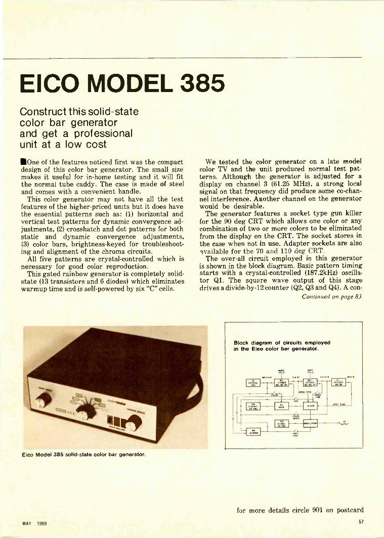
EICO MODEL 385Construct this solid-statecolor bar generatorand get a professionalunit at a low cost
110ne of the features noticed first was the compactdesign of this color bar generator. The small sizemakes it useful for in -home testing and it will fitthe normal tube caddy. The case is made of steeland comes with a convenient handle.
This color generator may not have all the testfeatures of the higher -priced units but it does havethe essential patterns such as: (1) horizontal andvertical test patterns for dynamic convergence ad-justments, (2) crosshatch and dot patterns for bothstatic and dynamic convergence adjustments,(3) color bars, brightness -keyed for troubleshoot-ing and alignment of the chroma circuits.
All five patterns are crystal -controlled which isnecessary for good color reproduction.
This gated rainbow generator is completely solid-state (13 transistors and 6 diodes) which eliminateswarmup time and is self -powered by six "C" cells.
Eico Model 385 solid-state color bar generator.
We tested the color generator on a late modelcolor TV and the unit produced normal test pat-terns. Although the generator is adjusted for adisplay on channel 3 (61.25 MHz), a strong localsignal on that frequency did produce some co -chan-nel interference. Another channel on the generatorwould be desirable.
The generator features a socket type gun killerfor the 90 deg CRT which allows one color or anycombination of two or more colors to be eliminatedfrom the display on the CRT. The socket stores inthe case when not in use. Adapter sockets are alsoavailable for the 70 and 110 deg CRT.
The over-all circuit employed in this generatorshown in the block diagram. Basic pattern timing
starts with a crystal -controlled (187.2kHz) oscilla-tor Ql. The square wave output of this stagedrives a divide -by -12 counter (Q2, Q3 and Q4). A con -
Continued on page 83
Block diagram of circuits employedin the Eico color bar generator.
MO.
MAY 1959
for more details circle 901 on postcard67
DEALERFAXADVERTISING/MERCHANDISING/SALES
Radios forRadiomenUsing two-way radio for field
communication can increase serviceefficiency and sales
"That color TV set of mine went on thefritz right in the middle of a ball game," theunhappy customer said over the phone tohis dealer. "Can you send a repairman overhere right away?"
"Well, it might be a while," the dealer said."The service truck is out on calls."
"How long will it take?""Well, sir, I don't rightly know.""What do you mean, you don't know . . .
get hold of him and find out!""He had a whole list of job orders when
he left the shop," the dealer pointed out. "BynowI don't know where he is."
"Well, call him and ask!" the customer de-manded. "You've got two-way radio commu-nication like everybody else in the servicebusiness, haven't you?"
"W -e -e -l-1, no.""What! And you're in the radio business?"
the customer snorted. "I've heard about theshoemaker whose children have no shoes,but this is ridiculous." He slammed down thephone and dialed a competitor.
Fireside TV Service, whose ad in the Chi-cago classified phone book features the line,"Radio Dispatched," is one of the rapidly grow-ing number of electronics service organiza-tions who are turning to two-way radio asa control tool and service facility.
"We average a couple of dozen calls a daywhich we facilitate by radio," says HowardPerlstein, Fireside's shop manager. "We figurethat seven out of ten 'cold' calls come in asa result of that ad in the phone book aboutour service trucks being radio dispatchedfor faster service. Considering how muchbetter service we can give our customersand how much more efficiently we can make
use of a service man's time, we find that thelimited use of two-way radio by our competi-tion is downright incredible."
Utilization of two-way radio within theelectronics service industry itself is belowthe norm in most other service industries,according to a spokesman for a leading man-ufacturer. "Most of the radio and TV peopleat the consumer level are still missing theboat," he says. "And it's their own boat."
However, many technicians and dealersfeel that this situation is partly attributableto the manufacturers themselves. "They con-fuse us," a Houston shop owner avers. "Sure,I've considered two-way, but you should seeall the literature about it I've got on my desk.Field communications equipment, CitizensBand radio, business band, high band, lowband, UHF band, FM, paging units . . . allclaiming that they've got the best answer."
Although the subject is complicated bythe diversity of equipment available, it be-comes less confusing when it is noted thatbroadcast communication for commercialuse is still a comparatively new field and thatmany of the equipment salesmen have a ten-dency to become over -enthusiastic. Loadingup users with far more equipment than theycan possibly use is common, and much of itis unnecessarily complex, too.
Some of the claims can be pretty wild. Onemanufacturer even claims that two-way radiowill cut down on phone bills, which is exag-gerated when total costs are considered. Theindustry is also fond of proclaiming the factthat there are now more than two millionusers of two-way radio, but often neglectsto add that this figure includes police carsand taxi -cabs.
Two-way radio is a tool that costs moneyand its cost can be justified only by the firmthat needs it -- just as a dealer who special-izes in selling new sets would seldom havemuch need for any elaborate testing equip-ment. Or the shop specializing in hotel andhospital work, where the men go to the samejob every day until quitting time, would havelittle use for a field communications setup.Many electronic technicians and dealers donot need two-way radio. But the ones whodo, need it badly.
Competition is so keen and technology sostandardized in most parts of the countrytoday that two-way radio can often be thecompetitive edge that makes the difference.When a customer calls for service and therepairman rings the door bell before the cus-tomer gets a chance to hang up the phone,as sometimes happens, word of that kind ofservice gets around the neighborhood fast.
Instant communication can also increasethe working productivity of a busy truck,
51 ELECTRONIC TECHNICIAN/DEALER

,/tk,
I
TV SALES and SERVICE dOE- - - sad ser
- -j- - - fir8ALEsi -
ti' 1
especially when new calls come in for stopsin the neighborhood where the truck is al-ready operating. The shop can often "fill theslots" by catching the truck between stopsfor interim job orders in what can be the mostflexible of schedules. When an order is oc-casionally canceled, the shop can notify thetruck accordingly to save an unnecessarytrip.
Accidents happen, too. Trucks or otherequipment can break down. Or the wrongtools or parts may have been taken to a job,which can be run out by a delivery man. Wrongor illegible addresses on work orders are notunknown in the service industry, either.
In residential neighborhoods, in particu-lar, a man in the field may find getting to aphone difficult, or at least time consuming.And how does the shop reach him when he'sneeded?
"The means to keep in constant contactwith our three trucks in the field simplifiesadministration when all the shopman hasto do is 'call up' the man on the job for pro-gress reports," says Jim Lyons, the servicemanager for Fireside TV. "This can even meanthat our operating costs per job ticket arelower than if we didn't have that kind of fieldcontrol. We definitely use two-way radio asa competitive weapon, which is all the moremeaningful because most of the other radioand TV servicemen not only don't have two-way radio of their own for field communica-tion, they don't even know everything aboutit."
The vast majority of electronic techniciansand dealers neither sell nor service two-waycommunications equipment, and a capsulerundown may be in order.
Simplest of all is Citizens Band radio, uni-
- 'A...7
'5 -
tt.
k
versally known as CB. The FCC has set aside23 channels in the AM wave length for theexclusive use of "all ordinary citizens" andno other broadcasting is allowed within theirfrequency range. No license is required forthe purchase or operation of CB radio withan input power of 100 milliwatts or less.
Higher -powered CBs require an FCC li-cense which now costs $9.25 including a bookof regulations, but no tests are required andthe licensing is actually little more than aregistration. The license is good for five yearsand renewable on request. Application blanksare available from any FCC office, or from manymany of the specializing distributors.
The height of a transmitting tower is limitedby law, but the regulations allow the userto install an antenna on his existing TV an-tenna.
All 23 CB channels are shared by otherCB users. This chummy setup makes eachchannel almost like a telephone party line.The CB transceiver can be anything froma walkie-talkie type model to a full-scale three -unit base station.
CB desk -top models, or units designed forinstallation under the dash in a truck or car,are easier to use than walkie-talkies becauseall the operator has to hold is the palm micro-phone. Biggest advantage of desk -top models,though, is the fact that they are higher poweredthan walkie-talkies and can be hooked intoa rooftop antenna. The higher the antenna,the more distance (watt for watt) the signalwill go.
The cheapest mike models, even some at5w with 12 -channel capabilities, cost less thanthe best walkie-talkies. Lower -priced onesmay have crystals for only one -channel opera-tion, but better models include the full 23
MAY 1989 59

Radios...channels. Additional refinements get the pricesup to around $300 for a good set that approach-es amateur equipment in transmission andreception quality.
The biggest trouble with CB is its success.It is relatively new. But in just a few years,it has also become one of the most crowdednetworks. A large city, for example, mighthave 10,000 CB users all looking for an open"party line" at the same time. . .and with only23 channels to select from, CB is all but chok-ing itself to death.
In most of the heavily populated sectionsof the country, about the only hope for a fight-ing chance with CB is in single sideband equip-ment.
Sideband transceivers usually incorpor-ate all the best features available for CB, andmost of them sell in the $275 to $325 bracket.As of now, users of sideband enjoy a relative-ly uncluttered field, but only because the devel-opment is so new. The CB field is just toowide open, and there are not many parts ofthe country left where a businessman canstill operate with relative freedom.
CB compared to FM is like playing golfon a municipal course compared to playingat a private country club. Most "serious" usersof two-way radio prefer FM for five reasons:
1. The choice of operating frequencies iswider.
2. The field itself is not as crowded, andalthough many FM users do share channels,their use and selection of channels is morestrictly regulated by the FCC.
3. Input power can go up to 330w--66 timesmore powerful than CB's maximum allow-able wattage.
4. An FM user can put up higher transmit-ting towers and communicate over distancesfar beyond the capabilities of CB.
5. Frequency modulation itself normallyreduces the noise and interference from ve-hicle ignition systems, roadside power linesand other man-made noise sources which canmake messages on AM (including CB) diffi-cult to understand.
Getting a license to operate an FM stationis tougher than CB and not available to thecasual applicant. Prospective users are con-sidered only after proving their need as wellas their responsibility. They can expect towait several months for an okay and assign-ment of individual channel rights.
Not counting the expense of putting upthe tower, costs for a base station can startin the neighborhood of $500. The average
cost is more likely to be closer to $1000. FMis split into low band, high band and UHFband operations in a range from 25 to 470MHz. High band is the most crowded.
Terrain characteristics, local congestionand the usual interference factors all go intodetermining how expensive a system theuser will need. Lower -watt units cost lessto operate than high-powered stations, andthe more complicated the system, the moremaintenance it is likely to need. Lightly power-ed low -band mobile units start at about $300,while transistorized models for medium rangeare usually around $500 or $600.
Powerful portable units, which a service-man can carry around like an over -sizedlunch pail, are also available at prices all theway up to $685.
Paging units small enough to be worn ina shirt pocket and which do no more thansignal the wearer with a beep tone to get tothe nearest telephone are in wide use becauseof their selective signaling - - only one manhears the beep. Other pagers, which can costup to $190 each, permit the reception of "pri-vate line" voice messages through the useof a special one-way transmitter that cancost from $250 up.
One of the best two-way radio communi-cations is through Mobilephone facilities op-erated by local telephone companies. Theynot only provide the ultimate in transmis-sion equipment and facilities, but also takecare of maintenance. Mobilephones are notcheap, though. The user usually pays a minimumof $40 a month, which entitles him to 100 "unitcalls." This means that each call costs at least40 cents -, - not counting anything against thecost of the handset -equipped transceiver it-self, which runs around $1500 in many partsof the country.
But as one southside service -dealer says,"I couldn't care less about what's going tohappen five years from now, our two-wayradio system paid for itself easily during thefirst six months we had it, not only in extrabusiness but in cutting costs as well. Wehave a $150 walkie-talkie in each of our twotrucks and another in the shop. Nobody isever any further away than the button onthe transceiver. The total investment of lessthan $500 at current bank rates is actually'worth' less than $40 a year - - and we cansave that much in wasted gasoline alone. Sure,we have our troubles with walkie-talkie equip-ment, but it is certainly a lot better than nocommunications at all."10
60 ELECTRONIC TECHNICIAN/DEALER

Cathode ray tube lightning detector (Courtesy British Columbia fc .est Service)
ElectronicLightningDetector
Lightning is a dread enemy of the forest, a factwell known by the people who must depend onforest resources for a living. Lightning accounts forapproximately 35 percent of the forest fires, andposes a difficult situation because hard -to -locate"sleeper" blazes can smolder for some time be-fore suddenly bursting into flame.
But the threat of fire by lightning may be com-ing to its long-lived conclusion. Alex Stewart,a member of the IEEE for about 35 years, hasdeveloped an electronic device which can trace thestriking path of lightning. As a technician with theBritish Columbia Forest Service, he began experi-menting with a cathode ray tube direction finderwhich can track the path of electrical storms.
After two years of development his idea wasput to the test and proven able to show where
MAY 1969 61

Lightning Detector . . .
Lightning causes approximately 35 percent of forest fires (Courtesy BC Forest Service)
lightning was causing a fire. The value of the de-vice naturally lies in the fact that fire fightingcould be rushed to the newly formed blaze-be-fore it had time to build and destroy millions ofacres of valuable timber. The unit has a built-inalarm system which makes it unnecessary for the"look out" men to constantly monitor the scopeface. The lightning detector features a dual tracktape system which is used to tie the observer'sreading of a bearing on the scope to a fixed timescale to coordinate observations from other sta-tions.
The method of operation is to record WWVtime signals on one tape track while recordingthe observer's voice reading bearings from thescope on the other track. Then two tapes fromtwo stations are then played back together andbearings at any fixed point in time are plotted togive a position for the lightning stroke.
A giant fir tree ;truck by liglitriini [cold have
caused widespread fire if not loczted it time.
62 ELECTRONIC TECHNICIAN/DEALER

(0,ft
This little part )sv3f, playsa big role in radio.
This box gives you top revues.
The transistor is no bit playerwhen it comes to radio
performance. That's why Delcotransistors are manufactured
under controlled conditions thatassure high reliability. And
why they're thoroughly testedbefore being placed in the
familiar blue and black box.
Delco Radio engineers areleaders in auto radio design
and transistor technology.
Delco radios are originalequipment on over half
of the cars on the road.
That United Delco box is yourguarantee of genuine OEM
Radio0
1 W DS -501Transistor
quality replacement parts. Andjust 12 Delco transistors replaceover 7,500 other types.
Doesn't it make good sense tostock the best?
Remember these facts when youre -order. And remember, too,that your United Delco supplierhandles the most recognizedname in the parts business.
Next time you think little,think big. Think Delco.
DELCO RADIO, Div. of General Motors, Kokomo. Ind.
United. 0DelcoMARK OF (=MERGE
. . for mere details circle 117 on paiftweIWAY 1969
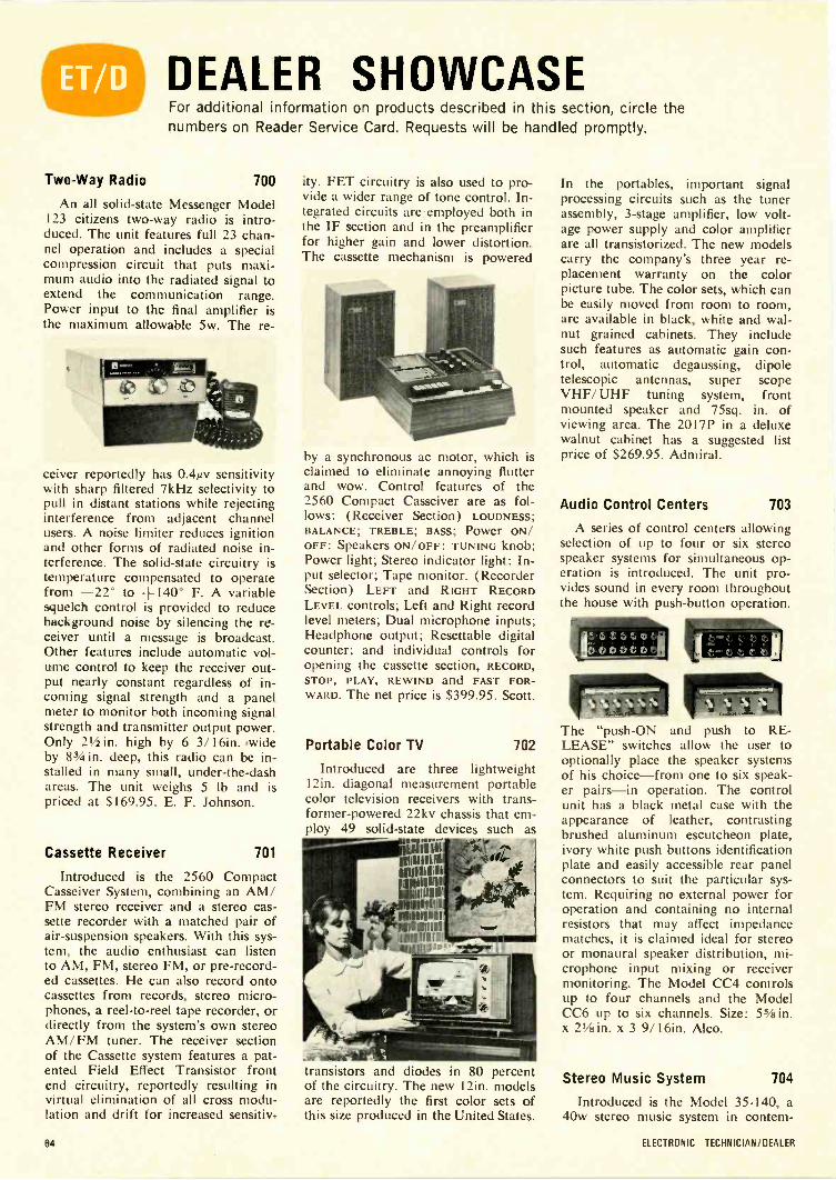
DEALER SHOWCASEFor additional information on products described in this section, circle thenumbers on Reader Service Card. Requests will be handled promptly.
Two -Way Radio 700
An all solid-state Messenger Model123 citizens two-way radio is intro-duced. The unit features full 23 chan-nel operation and includes a specialcompression circuit that puts maxi-mum audio into the radiated signal toextend the communication range.Power input to the final amplifier isthe maximum allowable 5w. The re-
ceiver reportedly has 0.4i4v sensitivitywith sharp filtered 7kHz selectivity topull in distant stations while rejectinginterference from adjacent channelusers. A noise limiter reduces ignitionand other forms of radiated noise in-terference. The solid-state circuitry istemperature compensated to operatefrom -22° to +140° F. A variablesquelch control is provided to reducebackground noise by silencing the re-ceiver until a message is broadcast.Other features include automatic vol-ume control to keep the receiver out-put nearly constant regardless of in-coming signal strength and a panelmeter to monitor both incoming signalstrength and transmitter output power.Only 21/2 in. high by 6 3/16in. 'wideby 83/4 in. deep, this radio can be in-stalled in many small, under -the -dashareas. The unit weighs 5 lb and ispriced at $169.95. E. F. Johnson.
Cassette Receiver 701
Introduced is the 2560 CompactCasseiver System, combining an AM/FM stereo receiver and a stereo cas-sette recorder with a matched pair ofair -suspension speakers. With this sys-tem, the audio enthusiast can listento AM, FM, stereo FM, or pre-record-ed cassettes. He can also record ontocassettes from records, stereo micro-phones, a reel-to-reel tape recorder, ordirectly from the system's own stereoAM/ FM tuner. The receiver sectionof the Cassette system features a pat-ented Field Effect Transistor frontend circuitry, reportedly resulting invirtual elimination of all cross modu-lation and drift for increased sensitiv-
ity. FET circuitry is also used to pro-vide a wider range of tone control. In-tegrated circuits are employed both inthe IF section and in the preamplifierfor higher gain and lower distortion.The cassette mechanism is powered
by a synchronous ac motor, which isclaimed to eliminate annoying flutterand wow. Control features of the2560 Compact Casseiver are as fol-lows: (Receiver Section) LOUDNESS;BALANCE; TREBLE; BASS; Power ON/OFF: Speakers ON/OFF: TUNING knob;Power light; Stereo indicator light: In-put selector; Tape monitor. (RecorderSection) LEFT and RIGHT RECORDLEVEL controls; Left and Right recordlevel meters; Dual microphone inputs;Headphone output; Resettable digitalcounter; and individual controls foropening the cassette section, RECORD,STOP, PLAY, REWIND and FAST FOR-WARD. The net price is $399.95. Scott.
Portable Color TV 702
Introduced are three lightweight12in. diagonal measurement portablecolor television receivers with trans-former -powered 22kv chassis that em-ploy 49 solid-state devices such as
transistors and diodes in 80 percentof the circuitry. The new 12in. modelsare reportedly the first color sets ofthis size produced in the United States.
In the portables, important signalprocessing circuits such as the tunerassembly, 3 -stage amplifier, low volt-age power supply and color amplifierare all transistorized. The new modelscarry the company's three year re-placement warranty on the colorpicture tube. The color sets, which canbe easily moved from room to room,are available in black, white and wal-nut grained cabinets. They includesuch features as automatic gain con-trol, automatic degaussing, dipoletelescopic antennas, super scopeVHF/ UHF tuning system, frontmounted speaker and 75sq. in. ofviewing area. The 2017P in a deluxewalnut cabinet has a suggested listprice of $269.95. Admiral.
Audio Control Centers 703
A series of control centers allowingselection of up to four or six stereospeaker systems for simultaneous op-eration is introduced. The unit pro-vides sound in every room throughoutthe house with push-button operation.
The "push -ON and push to RE-LEASE" switches allow the user tooptionally place the speaker systemsof his choice-from one to six speak-er pairs-in operation. The controlunit has a black metal case with theappearance of leather, contrastingbrushed aluminum escutcheon plate,ivory white push buttons identificationplate and easily accessible rear panelconnectors to suit the particular sys-tem. Requiring no external power foroperation and containing no internalresistors that may affect impedancematches, it is claimed ideal for stereoor monaural speaker distribution, mi-crophone input mixing or receivermonitoring. The Model CC4 controlsup to four channels and the ModelCC6 up to six channels. Size: 55/a in.x 2'/a in. x 3 9/16in. Alco.
Stereo Music System 704
Introduced is the Model 35-140, a40w stereo music system in contem-
04 ELECTRONIC TECHNICIAN/DEALER

The New 1969 Improved Model 257 A REVOLUTIONARY NEW
TUBE TESTING OUTFIT
1
_0 COMPLETE WITH ALL
ADAPTERS AND ACCESSORIES,
NO 'EXTRAS"
STANDARD TUBES:
I/ Tests the new Novars, Nuvistors, 10 Pins, Magnovals,Compactrons and Decals.
V". More than 2,500 tube listings.yor Tests each section of multi -section tubes individually
for shorts, leakage and Cathode emission.V' Ultra sensitive circuit will indicate leakage up to 5
Megohms.I/ Employs new improved 41/2" dual scale meter with a
unique sealed damping chamber to assure accurate,vibration -less readings.
yr Complete set of tube straighteners mounted on frontpanel.
Tests all modern tubes includingNovars, Nuvistors, Compactrons and Decals.
All Picture Tubes, Black and White
and Color
ANNOUNCING... for the first timeA complete TV Tube Testing Outfit designed specifi-cally to test all TV tubes, color as well as standard.Don't confuse the Model 257 picture tube accessorycomponents with mass produced "picture tube adap-ters" designed to work in conjunction with all com-petitive tube testers. The basic Model 257 circuit wasmodified to work compatibly with our picture tube ac-cessories and those components are not sold by us tobe used with other competitive tube testers or eventube testers previously produced by us. They werecustom designed and produced to work specifically inconjunction with the Model 257.
BLACK AND WHITE PICTURE TUBES:
yor Single cable used 'or testing all Black and White PictureTubes with deflection angles 50 to 114 degrees.
Low` The Model 257 tests all Black and White Picture Tubesfor emission, inter -element shorts and leakage.
COLOR PICTURE TUBES:
$4 750The Model 257 is housed in a handsome, sturdy, portable case. Comes complete with all
joir The Red, Green and Blue Color guns are tested individ-ually for cathode emission quality, and each gun istested separately for shorts or leakage between controlgrid, cathode and heate-. Employment of a newly per-fected dual socket cable enables accomplishments of alltests in the shortest possible time.
adapters and accessories, ready to plug in and use. No "extras" to buy. Only
NOTICE
We have been producing radio, TV and electronic test equipment since 1935. which means we were makingTube Testers at a time when there were relatively few tubes on the market, 'way before the advent of TV. Themodel 257 employs every design improvement and every technique we have learned over an uninterrupted pro-duction period of 32 years. Accurate Instrument Co., Inc.
SEND NO MONEY WITH ORDERPAY POSTMAN NOTHING ON DELIVERY
rTry it for 10 days before you buy.If completely satisfied then send$10.00 and pay the balance at therate of $10.00 per month until thetotal price of $47.50 (plus P.P.,handling and budget charge) ispaid. If not completely satisfied,return to us, no explanationnecessary.
ACCURATE INSTRUMENT CO., INC.Dept. 652, 2435 White Plains Road, Bronx, N.Y. 10467
Please rush me one Model 257. If satisfactory I agree to pay $10.00 within 10 daysand balance at rate of $10.00 per month until total price of $47.50 (plus P.P., handlingand budget charge) is paid. If not satisfactory, I may return for cancellation of account.
Name
Address
City 7one StateC] Save Money! Check here and enclose $47.50 with this coupon and we will pay all shipping
charges. You still retain the privilege of returning after 10 day trial for full refund.
... for more details circle 101 on postcard
MAY 196965

DEALER SHOWCASE
porary cabinetry. This unit featuresall of the elements necessary for stereoreproduction in a pre -assembled com-pact design. The receiver -amplifier de-livers sound on AM/FM and stereoFM and through its Garrard auto-matic changer with a magnetic car-tridge to reproduce mono or stereorecords. The unit, featuring two acous-tically suspended speaker systems, isfinished in an oiled walnut cabinetand brushed aluminum control panel.
Speakers measure 177/8 in. x 10in. x51/2in. depth. Specifications: 40w mu-sic power at 862 reportedly less than
1% H.D. at listening levels; 40dbchannel separation. Frequency re-sponse 25-25,000Hz. Separate bass
One company dominatesthe sound column field...
ARGOS.And you reap the profits! Why? Because as an Argos TSSD (TotalSound System Distributor), you have the tools to do the job right,starting with the product itself. Argos "Sound Directors" are notjust boxfuls of speakers. Each is a carefully engineered soundsystem designed to do a specific job, with models for voice rein-forcement, background music, hi -fidelity, big rooms, little rooms,indoors or out. They're also easy to install and aim with Argos'exclusive Speedy Mounting Clips and Focus Gauge.
Fifteen minutes with our booklet, "Sound Solutions to SoundProblems with Sound Columns," will help you solve 95% of thespeaker system problems that come your way. But it takes morethan even this to be the industry's leading sound column people.Let us show you the rest. Write today.
.4
17,-Cc51CM.PRODUCTS COMPANY
600 South Sycamore StreetGenoa, Illinois 60135... for more details circle 103 on postcard
See the "Block Buster" Display Dealat the N.E.W. Show Booth C119
and treble controls. Built-in overloadprotection. Tuner section: 3.5pv for20db S/N on FM. 30062 FM antennaand built-in ferrite loop for AM. Hasstereo headphone jack and tape -intape -out jacks. Turntable: Garrardwith 4 pole shaded "Induction Surge"motor with magnetic cartridge anddiamond stylus. Automatic cutoffturns off all power on last record.Claricon.
Turntable 705
Introduced is the Model 600 top -of -the -line turntable. The base incorpo-rates an illuminated power switch thatpermits the complete receiver systemto be shut off automatically by theturntable after the last record hasbeen played. The turntable comes
complete with a base and dust coverready to plug into a system. The unithas a cast turntable and an adjustablecontrol which applies a continuouslycorrected degree of compensation toneutralize the inward skating forceand eliminate distortion caused by un-equal side wall pressure on the stylus.In addition, the turntable has a MI-CROMETER STYLUS PRESSURE adjust-ment which permits 1/2g settings from0 to 6g; it also has a STEREO MUTINGswitch for complete silence during therecord change cycle. Another featureis the CUEING and PAUSE controllever, which allows the listener toraise or lower the pickup arm at anytime and return it to the same grove.BSR.
Communications Microphone 706
Introduced is the "level -limiter"microphone which is claimed toeliminate overload distortion resultingfrom excessive input while increasingthe average level on normal speech.The Model 500 -PS is readily adaptedto two-way radio and is suited forpublic safety, as land, maritime or air -mobile operation. The microphonecontains a silicon solid-state circuit,which reportedly provides 40db
Continued on page 72
ELECTRONIC TECHNICIAN/DEALER66

How do you"install" confidencewhen you install an RCAcolor picture tube?
The surest way to compliment acustomer is to agree with hisopinion. This is pretty easy to dowhen it comes to deciding whichbrand of replacement color pic-ture tube to install in his set.
Here both set owner andservice technician agree-and by
a wide margin-on RCA! And for one very good reason:RCA's reputation...for experience, quality, and proven per-formance...over the years. More years than anyone else inthe business.
Place your confidence in the company that perfected thecolor TV system in use today. Introduced more technicalinnovations than any other company. Stays on top of thestate-of-the-art not just in technology, but in tube sizes as well.
Whether it's an all -new RCA HI-LITE or the popular pricedquality rebuilt RCA Colorama-when you recommendRCA-you'll not only flatter your customer, you'll also be pro-tecting your own hard-earned service reputation. That'sbecause RCA picture tubes are designed to protect thebiggest reputation in the COLOR TV industry.
RCA Electronic Components, Harrison, N.J.
RCAMAY 1969 67
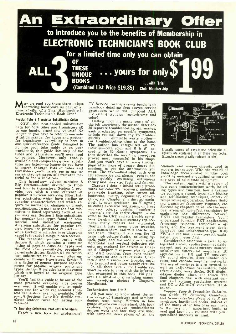
An Extraordinary Offerto introduce you to the benefits of Membership in
ELECTRONIC TECHNICIAN'S BOOK CLUBfor a limited time only you can obtain
OF
ALLUNIQUE " yours for only$THESE
BOOKS ...with Trial(Combined List Price $19.85) Club Membership
May we send you these three uniqueservicing handbooks as part of an
unusual offer of a Trial Membership inElectronic Technician's Book Club?Popular Tube & Transistor Substitution Guide
NOW-the most -needed substitutiondata for both tubes and transistors allin one handy, brand-new volume! Nolonger do you have to refer to one sub"-stitution manual for tubes and anotherfor transistors-everything is here inone quick -reference guide. Designed tofit into your tube caddy or on yourworkbench, this guide lists 99% of thetubes and transistors you'll ever needto replace. Moreover, only readily -available and comparably -priced substi-tutes are listed-no longer do you haveto search through lists of tubes andtransistors you'll rarely see in use, orsearch through pages of irrelevant ma-terial to find a substitute.
This brand-new volume contains 8Big Sections-four devoted to tubesand four to transistors. Section 1 pro-vides you with a cross-reference ofpopular American receiving tubes, list-ing substitutes which have similar orsuperior characteristics and which re-quire no mechanical changes or circuitmodifications. In each case the best sub-stitute is listed separately from othersyou may use. Section 2 lists substitutesfor popular tube types found in com-mercial and industrial equipment.American substitutes for popular for-eign types are presented in Section 3,while Section 4 includes base diagramskeyed to the tube listings in each section.
The transistor portion begins withSection 5, which contains a completelisting of popular American types andthe most readily -available, popularly -priced substitutes. Section 6 lists Amer-ican substitutes for the most often en-countered foreign transistors. Section 7is a listing of general-purpose replace-ments for popular original equipmenttypes. Section 8 includes base diagramswhich are keyed to the original typelistings.
You'll find this guide to be one of themost practical everyday aids you'veever used. It will enable you to repairmany sets for which replacement tubesand transistors are not available. 160pps., 8 Sections. Long -life, flexible sim-ulated leather cover for lasting con-venience.
TV Servicing Guidebook: Problems & SolutionsIleic's it new book for professional
TV Service Technicians-a benchman'shandbook detailing shop -proven serviceprocedures which will pinpoint ALLTV circuit troubles-monochrome andcolor!
Calling upon his many years of on-the-job experience, the author describes30 separate troubleshooting approaches,each predicated on specific symptoms,to help you nail down any TV problemquickly . . . eliminate waste motion-cut troubleshooting time to the bone.The author has categorized all TVtroubles-both color and B & W-ac-cording to 62 classic symptoms. Hethen describes the servicing proceduresproved most successful in his shops.And you won't have to wade throughpage after page of dreary theory dis-cussions to get the information youwant. The text-illustrated with over100 schematics and photos-gets to thepoint quickly, excluding extraneoustheory and unrelated facts and figures.
Chapter 1 details initial setup proce-dures for color TV receivers, includinggray -scale tracking, color screen ad-justments, purity, degaussing, conver-gence, etc. Chapter 2 is devoted exclu-sively to color problems-no Y signal;no color; excessive red, green, or blue;incorrect colors; pastels; "confetti";"worms"; etc. An entire chapter is de-voted to the CRT and its trouble symp-toms. To eliminate unnecessary replace-ment, many repairs are suggested.Chapter 4 lists seven video troubles,what causes them, and tells how to cor-rect them. Chapter 5 analyzes the 13basic high voltage faults, including fly-back, yoke, and the oscillator circuits.Horizontal and vertical deflection cir-cuits are explored for defects in Chap-ter 6. Chapter 7 exposes elusive syncand AGC troubles, from sync takeoffto integrator and AFC circuits. Chap-ters 8 and 9 encompass troubles pecu-liar to sound and power supply circuits.
In all, there isn't a TV trouble youwon't be able to cure with the informa-tion presented in this book. 176 pps.;over 100 illustrations, including numer-ous waveform photos; 9 Chapters.Hardbound.
Semiconductors From A to ZAll you need to know about the en-
tire range of transistors and semicon-ductors used today. Written in lan-guage anyone can understand, this bookexplains how various semiconductordevices work and how they are used,with complete descriptions of all the
LARGECGt/PLING CAP
HF LF ZI.Trjr"ORSHUNTPEAKING COIL
Literally scores of easy -to -use schematic di-agrams are contained in all these new books.(Example shown greatly reduced in size)
common and unique circuits used inmodern technology. With the wealth ofknowledge incorporated in this bookyou'll be eminently qualified to serviceany type of solid-state equipment.
The content begins with a review ofhow basic semiconductors work, includ-ing types and function, how a transis-tor conveys a signal, transistor biasingand self -biasing techniques, effects oftemperature on operation, factors limit-ing transistor frequency response, etc.Succeeding chapters delve into the mys-tical arena of field-effect transistors byexplaining the differences betweenFETs and regular transistors. You'llunderstand junction FET applications,frequency response, temperature ef-fects, and the treatment given deple-tion -type and enhancement -type MOSFETs in the most down-to-earth expla-nation you'll ever find.
Considerable attention is given to in-tegrated circuit applications-variable-current and constant -current sources,unbalanced differential amplifiers, ICapplications in FM and TV receivers,TV sound circuits, discriminator cir-cuits, and cascade amplifier networks.The use of varicaps is also covered, aswell as unijunction transistors, field-effect diodes, zener diodes, SCR diodes,4 -layer diodes, discs, and triacs. Thefinal chapters deal with constant cur-rent and voltage regulating systemsand DC -to -AC -to -DC converters. Hard-bound.
Popular Tube & Transistor Substitu-tion Guide, TV Servicing Guidebook,and Semiconductors From A to Z arehandsome, hardbound books, indicativeof the many other fine offerings madeto Members . . . important books toread and keep . . . volumes with yourspecialized interests in mind.
68ELECTRONIC TECHNICIAN/DEALER

POPULAR
SUBSTITUTION GUIDE
BRAND-NEW & Original Covers BOTH Tubes & Transistors
Long -Life Vinyl CoverLists U.S. & Foreign Types
How You Profit From Club MembershipThis is just a sample of the help and
generous savings the Club offers you.For here is a Club devoted exclusivelyto seeking out only those titles of inter-est to you as an electronic technician(no hobby or "fringe" books are of-fered). Membership in the Club offersyou several advantages:
1. Charter Bonus. Popular Tube &Transistor Substitution Guide, TV Ser-vicing Guidebook, and SemiconductorsFrom A to Z carry a publisher's retailprice of $19.85. But they can be yoursfor only $1.99 with your Trial Mem-bership.
2. Continuous Savings: The Club guar-antees to save you 15% to 75% on thebooks you need.
3. Editorial Advisory Services: TheClub's Editorial Advisory Board se-lects only the important books of directinterest to you.
4. Wide Selection: Members are annu-ally offered over 50 of the authoritativebooks on all phases of electronic servic-ing. The Club makes it a point to offernew books, along with standard classics
. lists books from all publishers-notjust one or two.
5. Prevents You From Missing NewBooks: The Club's FREE monthlyNews gives you advance notice of im-portant new books . . . books vital toyour continued professional advance-ment.
This extraordinary offer is intendedto prove to you, through your own ex-perience, that these very real advan-tages can be yours ... that it is possible
SERVICINGGUIDEBOOK
176 pages over 100 illus. Scores of waveform photos
Covers both B & W and Color Unique step-by-step guide
to keep up with the professional litera-ture published in your specific area ofinterest . . . and to save substantiallywhile so doing.
How the tlub Works
Forthcoming selections are describedin the FREE monthly Club News. Thus,you are among the first to know about,and to own if you desire, significantbooks. You choose only the main or al-ternate selection you want (or adviseif you wish no book at all) by means ofa handy form and return envelope en-closed with the News. As part of yourTrial Membership, you need purchaseas few as four books during the coming12 months. You would probably buy atleast this many anyway ... without thesubstantial savings offered throughClub Membership.
Limited Time Offer!
Here, then, is an interesting opportu-nity to enroll on a trial basis . . . toprove to yourself, in a short time, theadvantages of belonging to the onlyBook Club devoted exclusively to elec-tronic servicing. We urge you, if thisunique offer is appealing, to act prompt-ly, for we've reserved only a limitednumber of Handbooks for new Members.
To start your Membership on theseattractive terms, simply fill out andmail the postage -paid Airmail card to-day. You will receive Popular Tube &Transistor Substitution Guide, TV Ser-vicing Guidebook, and SemiconductorsFrom A to Z for FREE 10 -day inspec-tion. SEND NO MONEY! If you arenot delighted with these quality hard-bound books, return them within 10days and your Trial Membership willbe cancelled without cost or obligation.Electronic Technician's Book Club, BlueRidge Summit, Pa. 17214.
SEMICONDUCTORS
256 pages over 300 illus. Permanent Hardbound Volume
26 Fact -Filled Chapters Practical & down-to-earth
Example of numerous picture trouble pho-tos used as a guide to circuit faults.
Typical SavingsOffered ClubMembers on Recent Selections
RCA Color TY Service ManualList Price $7.95; Club Price $4.95
Electronics Reference Data BookList Price $7.95; Club Price $4.95
Digital Computer AnalysisList Price $10.95; Club Price $7.95
How To Test Almost Everything ElectronicList Price $5.65; Club Price $3.95
How to Use Your YOM. YTYM & ScopeList Price $6.95; Club Price $4.95
Modern Electronic TroubleshootingList Price $7.95; Club Price $4.95
Installing Hi-Fi SystemsList Price $7.95; Club Price $4.95
Electronic Circuit Design HandbookList Price $14.95; Club Price $7.95
Repairing Home Audio SystemsList Price $7.95; Club Price $6.50
FET Applications HandbookList Price $12.95; Club Price $7.95
Handbook of Semiconductor CircuitsList Price $7.95; Club Price $4.95
Pinpoint TY Troubles in 10 MinutesList Price $6.95; Club Price $4.95
Easy Way To Service RadiosList Price $6.95; Club Price $3.95
Practical Color TY Servicing TechniquesList Price $7.95; Club Price $4.95
On the Color TY Service BenchList Price $6.95; Club Price $4.95
Transistor Circuit GuidebookList Price $6.95; Club Price $4.95
Mathematics for ElectronicsList Price $10.95; Club Price $7.95
Transistor ProjectsList Price $5.95; Club Price $2.95
Radio Operating Questions & AnswersList Price $9.25; Club Price $7.95
Electronic Musical InstrumentsList Price $10.00; Club Price $7.95
SEND NO MONEY! Simply fill in and mail postage -paid Airmail card today!
MAY 1989 71
Oaktron
takes thetime tomake it
better!Oaktron provides you with thetop speaker value for your money.People expect a little more fromOaktron, and we're not going todisappoint them. Why settle for less,write today for your FREE catalog.
See you at the NEW Show,Las Vegas, Nevada
AKTRONOaktrdn Industries, Inc.
1000 Thirtieth St., Monroe, Wis. 53566
40 VUES wallet holds116,. all your pictures,
identification andcredit cards, as well as
coins and foldingmoney. Available in a
variety of fashioncolors. You can giveher several, becausethese Briteners areyour fast movers!
. . for more details circle 130 on postcard
LIMITED TIME OFFER!LADIES PHOTO BILLFOLD
YOUR GIFT FROM PERMA-POWERWHEN YOU BUY EITHER OF THESE
BRITENER DEALS
BIGGEST SELLERIN TV HISTORY
Perma- Power Vu-BriteModel C-401. (Parallelwiring, duodecal base.)Buy 12 at themoney -saving $G95package price of ".°
and the billfold is FREE
WORLD'S MOSTUSEFUL BRITENERPerma-Power Tu-BriteModel C-212. (Workson any 110° button baseset.) Buy 5 at themoney -savingpackage price of1095
itand the billfold is FREE
Always rely on Perma-Power Briteners toextend useful picture tube life for months,preserve excellent customer relations for years!
Division of of Charnbe ain Manufacturing Corporation5740 North Tripp Avenue, Chicago, Illinois 60646
. . 8ar more details circle 131 on postcard
DEALER SHOWCASE
Continued from page 66dynamic range low distortion com-pression. Frequency response is auto-matically controlled by voice level toprevent garbling and allow optimum
intelligibility. The standard modeloperates from 10.5 to 18vdc between-30 and +65°C, and has attack timeof 1ms, released time of 0.25s andharmonic distortion of less than 5%over full compression range. VegaElectronics.
Portable TV 707
Announced is the Model 6912 B/WTV with a 75sq in. screen. The set of-fers a tuner which employs frame gridcircuitry for VHF and solid-state cir-cuitry for UHF. This tuner, plus thesignal amplification provided by three
MODEL69,2t
IF stages is said to insure reception infringe areas. The cabinet, two-tonegreen with a recessed aluminum han-dle, contains a 4in. speaker and built-in antennas. Other features include:keyed automatic gain control; ear-phone jack for private listening; 18tubes, 4 diodes and I transistor. Thepicture tuoe operates from a 13 kvsupply and is claimed to eliminatedust buildup. The unit measures 111/2in. high, 161/in. wide and 11-1/8in.deep. List price is $99.95. Broadmoor.
72 ELECTRONIC TECHNICIAN/DEALER

Krylon''' Crystal Clear is standard fading and high voltage lossesequipment for all installation and keeps lead-in connectionsand service work. It prevents tight.It's the repairman'smany of the causes of picture "4""-1ftell5 handiest repaircan.
Borden Chemical, Division of Borden Inc
tkYSTitlyISpL E A 1140
It AY c AllNo 1302
fI t 44.pic), 1 fA t-EcTRoNs-
radio aircan
MAY 1969
. . . for more details circle 110 on postcard
73

COLORFAX
ADMIRALColor TV Chassis K-10-Service Note
Before removing or installing an 8AC 10 or 12AC 10 col-or amplifier tube in the current 12, 14 and 16in. hybridcolor television models, pull the ac cord! If you don't,transistor Q20 or Q21 is almost sure to be ruined. Makea habit of disconnecting power before making or breakingany connections on transistorized equipment. Surges, arcsand transients can instantly ruin transistors. Please notethis information in your S1225 service manual.
Color TV Chassis K-10-Keyed AGC CircuitThe AGC system employs three transistors and one rec-
tifier; two NPN transistors are used for the AGC gate andAGC amplifier, and a PNP for the RF delayed AGC.The chassis has a "keyed forward" type of AGC appliedto the RF amplifier and first IF.
A composite signal is taken from the emitter of the firstvideo amplifier and fed to the base of transistor Q9 through
+25 0 7AGC DELAY
09AGCGATE cme53
AEC RECT99
6656
8854
RHOS
AGC
29
(A-Tcc
C855
8649
+25 IF AGC
08AGC
REMS AMP
#847
C950
R651
RB77
Rm36A
125
11440
+2$V
an RC isolating network. The base emitter junction is re-verse biased but the sync pulses are of sufficient positiveamplitude to drive the base positive and cause the tran-sistor to conduct.
The sync pulses are directly proportional to the strengthof the signal and using them as the source for AGC controlwill give control of the IF and RF sections proportionalto the signal strength at the first video amplifier stage.
The emitter of AGC gate transistor, Q9, is attached tothe 25v B+ by the 2K AGC control. Adjusting this con-trol varies the positive voltage across the emitter resistorwhich in turn controls the conduction of Q9 during synctime and reverse biases it during scan time.
The collector receives a positive -going, horizontal pulsethrough rectifier CRB53. Transistor Q9 conducts in directproportion to the signal blanking pulse on the base. Recti-fier CRB53 conduction builds up on capacitor CC1 andcharging capacitor CB50. A positive voltage is also pres-ent at CB50 through resistor RB48 from a 25v source.The balance is at a voltage lower than the positive 25v,depending on the signal strength. This voltage is applied tothe base of Q8.
IF AGC: Assuming the signal level has increased, thefollowing will occur. As the voltage is decreased on thebase of Q8, it decreases the current flow through the col-lector which reduces the voltage drop across the load re-sistor RB77. This increases the AGC voltage applied to
the base of transistor Q1 causing an increased flow of cur-rent through it. This in turn does two things: (1) It in-creases the voltage drop across the extra high resistorRA17, thus lowering the voltage of the collector of Q1and reducing the amplification. (2) It changes the im-pedance relationship of LA20 and LA2 to Q1 causing animpedance mismatch further reducing the stage gain.
RF AGC: The collector of the AGC delay transistorQ7 is connected to ground through RB45. With no currentflow through Q7, a residual bias supplied through RB46keeps the RF amplifier at maximum gain. The base of theAGC delay transistor Q7 is supplied by a voltage dividernetwork, consisting of RB40 from the 25v positive voltagesupply and RB41 to ground. This holds the base to about6v positive.
The emitter of the AGC transistor Q7 is connected tothe positive power supply through resistor RB77 and thecontrol RH36. As the incoming signal strength increases,the dc amplifier Q8 will conduct less. The collector voltagewill become more positive and this potential will be ap-plied to the emitter of Q7. With very weak signals, theAGC delay control RH36 is adjusted so that the baseemitter junction of Q7 is reverse biased. To make thisstage conduct, increase the voltage drop between the baseand the emitter ' until it reaches its conduction voltage(emitter 6.5v). It will be increasing the emitter voltagein a positive direction. This would be equivalent to mov-ing the base voltage in a more negative direction. Noticethat this is a PNP operating inverted. Once forward biasis established, it will induce collector current flow throughRB45.
The over-all effect will be seen as an increasing positivevoltage at its collector which is the RF AGC source. Thispositive voltage will forward bias the RF transistor Q51and the over-all gain of the system will be reduced. Forweak signals, the RF amplifier is biased to full efficiencythrough RB46.
GENERAL ELECTRICColor TV Chassis KE-Quick Removal of Cabinet Backs
In the near future it will be possible to quickly removethe masonite backs from KE line color television cabinetsby removing only two screws instead of the usual nine. Toaccomplish this, the masonite cabinet backs have been re-designed to use four quick -release fasteners (two at eachside) and three permanently positioned retainers at the
RETAINERS
QUICK -RELEASEFASTENERS
HOR IZ.A.C. CENTER.
INTER -LOCK
CI
SCREW
top rear of the cabinet. One screw is located adjacent tothe ac interlock and the other screw is near the HORIZON-TAL CENTERING control. To remove the back: (1) Removethe two screws. (2) Rotate the quick -release fasteners un-til they are vertical (parallel with opening). (3) Removethe masonite back by pulling out at the bottom to discon-nect the ac interlock and then carefully pull down about'/2 in. to release the top of the cabinet back from the threeretainers. Now pull the back straight out and away from
74 ELECTRONIC TECHNICIAN/DEALER

the cabinet. Precaution: ALWAYS HOLD THE CABI-NET BACK FIRMLY DURING DISASSEMBLY TOPREVENT THE BACK FROM DROPPING AND HIT-TING THE PICTURE TUBE NECK. THIS PRECAU-TION APPLIES TO THE DISASSEMBLY OF ANYCABINET BACK. To replace the back: (1) Push theback under the three retainers at the top of the cabinet.(2) Push in at the bottom and connect the ac interlock.(3) Rotate the four quick -release fasteners to a horizontalposition (across the holes). (4) Replace the two screws.
Color Chassis KE-Service InformationKE Chassis -Power Supply Diode Failures
Whenever a CR109 or CR110 power supply diode fail-ure occurs, you should add .001Af, I kv (ET22X58) ca-pacitors across diodes CR109 and CR 110. A capacitor ispacked with each replacement diode. This provides addedprotection against voltage surges which may damage thediode.
These capacitors were added to production sets startingwith Ser. No. OS4E.
Preset Fine Tuning Adjustment Shirts
Investigation has shown that some complaints of thisnature are caused by interference between the channelselector and fine tuning knobs because of the selector knobbeing pushed on too far.
At present, the production line is adding a thin washerbetween these knobs to prevent interference. In later pro-duction, the knobs will be revised to prevent the conditionand eliminate the washer.
The simplest solution is to pull the selector knob outslightly so that it does not rub on the fine tuning knob.You may be able to eliminate some service calls by in-structing the customer to do this.
In the event that you find cases where the problem re-occurs, contact your General Electric television distribu-tor for washers to be placed between the knobs.
MAGNAVOXColor TV Chassis T931/T933/T938-Defective 61M8 Video/Sync
Amplifier and 6106A 3rd Video IF Amplifier
Low contrast, deterioration of picture quality, lowchroma output and poor sync are all possible symptoms ofa defective 6LM8 tube. The symptoms may be more orless pronounced depending upon the condition of the tube.Check the 6LM8 tube as a possible cause when these symp-
T2032ND VIDEO IF
TRANS3RD
OV
V203 L2036JC6 RED
VIDEO IF DOTis5v
4
3 7 C2241.5
N33001.25PC
245
D201SOUND DE TC23I 1,3
2.2±.25PF V I.5V
NPO C215330
02190,L209
10QUM 5%
NPO
02222200r
1905%
CM390
L204 Nl500(PRINTED)
C-co- - -
A
R214IOK
R213470
C217*1000
L
TO HICHECKRESISTOR
TO +200v
toms are noted. Sometimes the failure of the 6JC6A 3rdvideo IF tube will result in failure of the plate/screen load
resistor, R213. Check the condition of this 47052, 1/2wresistor when replacing a defective 6JC6A tube.
MOTOROLAColor TV Chassis TS-915-No High Voltage
Symptom: No raster and a check reveals there is no high
VERT OUT
Q1 (H)
TO
CONVERGENCE
CIRCUIT
15 NIF 68
TO HORIZ
DRIVER
40V
T1H
J1-8 T1 H
R10J
750
J2-3
R211-1)
VERT
CENT-.41--(:)YOKE
ily;
FUSE
RES
10.11
+ 95V
Continued on page 93
NEW - AUDIO
ili't TII r_q_4111 ;FOR SWITCHING SYSTEM'S INPUT OR OUTPUT
Control up to 4-6 complete stereo speaker systems, located in everyroom in your house. Jr . . use it to switch in or out various inputssuch as tuners, tape recorders, phonos, etc. No impedance worries.Attractive black leatherette finish; employs easy -to -use push -pushswitches. Size: 5%" < 21/4" x 3°W. See your dealer today.
MASS.26.95EA C ELECTRONIC PRODUCTtHs-CHANNEL
RCA JACK 19.95L
ANDOVER,
(S h ow n)
01945
10 Wart Power
INTERCOM& Paging SystemDesigned to offer tie latestin solid state and moreoperational feature!. Masterand remote originate callsby making use o "tone"calling. Indicators continue . -,,to display cells unt 1 contactis completei Sim3lified 2 -wire installat ion.8-t -ansistor,5 -station master. .15 VAC. MASTER
$69.95
AETIOISEIEICLONIC PRODUCTS INC NO ANDOVER MASS 0184',
MAY 1969
for more details circle 144 on postcard
75

NEW PRODUCTSFor additional information on products described in this section, circle thenumbers on Reader Service Card. Requests will be handled promptly.
VHF Broad Band Amplifier 708
Announced are solid-state VHFbroad band distribution amplifiers,Models M-104 and M-105, designedfor color and monochrome installa-tions. The systems are intended forsmall apartment houses and multipleinstallations of approximately 25-30
INPUT
M 10411004 11, YAM. If I.
GANLO GY0 GAIN
MI SAND
FINCci
46
outlets such asThe split band design of the amplifierpresents greatly improved signal abil-ity and a reported 24db gain in thelow -band and 26db in the high -band.Electrical specifications are the samefor both models except that the M-105has separate low -band and high -bandinputs at 750. The M-104 features alow noise input circuit to offer the in-staller a choice of 300 or 750 inputwith separate level controls on eachband for maximum flexibility. Noisefigure on the low -band is 5.5db andon high -band is 6.5db. Finco.
Antennas 709
Introduced is a new series of tele-vision antennas that provide improved
color and monochrome reception onall TV channels-VHF and UHF-as well as radio reception on the FMband. An optional extra UHF element
is available which is claimed to in-crease gain an average of 35 percenton difficult channels. The five antennamodels in the series, available for di-rect 3000 installation and convertibleto 750 operation by means of snap -ontransformers, are designed for use inareas classified from "local" to "deepfringe" in signal strength. The anten-nas are compact, lightweight and fac-tory preassembled for easy mastmounting. List price is from $21.95to $64.95. Jerrold.
MATV Attenu ators 710
A line of fixed and variable attenu-ators has been designed specificallyfor 82 channel cable powered MATVsystems. The Model SL -6801 is vari-
1-7511-1
jFI5 YOOTHLINEIIal III IN
12 Db 6DB 3 DB
'114 114 114MOM 6.01
$4M* ire rt g,, ,..,411111111
able from 0 to 21db in 3db steps. The"F" type connectors are used for in-put and output with attenuation se-lected by heavy-duty slide switches.The Models SL -6803, SL -6806, SL -6812 and SL -6820 are fixed at attenu-ations of 3db, 6db, 12db and 20db,respectively. All attenuators in thenew line pass UHF as well as VHF,providing uniform attenuation acrossthe entire TV -FM spectrum. Theyalso pass ac and dc power for cablepowering applications. The ModelSL -6801 variable lists for $22.50 andthe fixed attenuators list for $5.95each attenuator. JFD.
VOM Kit 711
A new VOM in kit form for tech-nicians features 38 measuring ranges.The meter has 5000 ohms/volt ac -dcsensitivity with input protection on allvoltage, current and db ranges. Pre-cision 1 percent resistors are used
throughout. Operating controls in-clude a ZERO/ OHMS adjust, RANGESwitch and FUNCTION switch to pro-vide full scale readings on a 41/2 in.two-color meter. The VOM has eightscales: ac -dc volts at 0-1, 5, 10, 50,
100, 500 and 5K; ac -dc current at0-1, 10, 100ma, la; ohms at 0-5K,50K, 500K and db readings from-20 to +76db in six ranges. Theunit measures 63/4 in. x 51/4 in. x 23/4 in.and comes with a battery, test leads,carrying strap and operating manual.Price is $19.95. Allied.
VTVM 712
Announced is the Model LV-76AVacuum Tube Voltmeter, a multi-purpose instrument suitable for lab-oratories, service shops and schools.
Its construction makes it particular-ly adaptable for field use. The in-strument has seven dc and seven acranges from 1.5v to 1500v. The re -
76ELECTRONIC TECHNICIAN/DEALER

sistance ranges cover from 10S2 mid -scale to 1Gsz full scale. The inputimpedance is 1M and the frequencyresponse is 20Hz to 4MHz. Accu-racy is ± 5 percent full scale. Onlyone test probe is used for all mea-surements which permits maximumoperating ease. The dc polarity re-versing switch makes it unnecessaryto reverse the test leads when mak-ing transistor circuit tests. Price is$54. Leader.
713Blue Lateral and Purity Assembly
A single unit, blue lateral and pur-ity assembly is introduced as a re-placement for similar assemblies onany size American rectangular colorpicture tube. The 7604 assembly reg-isters blue, red and green beams si-multaneously within .06in. A single
wheel rotates two magnetic rings inopposite directions to provide bluebeam lateral convergence. Purity cor-rection is accomplished by individualadjustment of the two purity rings.The magnets are said to compensatefor misregistration up to .005in. inany direction. Net price $3.96. Miller.
Service Kit 714
Introduced is an attractive, light-weight, durable service kit in an at-taché case. The kit is designed to as-sist you in servicing color television
receivers in the home. It consists ofone complete set of PC boards withtubes (not including convergenceboard assembly) at a price less thanyou would pay for the "boards" alone.The boards provide a quick, effective
Continued on page 84
FARAim
SUPETOANYVTVIV11
ORVOM--andforlessmoney
$69.95
....111-.
C 111/11-151111(5,14P41P11-1111KM4f
IClt/NAI
0 (MO CENTII4 'IC marAgo+)
8 r c 1=t
FIELD EFFECT METER
(.5
F E 14
CI 1
!V
NEW FIELD EFFECT MULTIMETERHere is the revolLtiorary new approach to circuit testing the solidstate Sencore FIELD EFFECT METER. This FE14 combines theadvantages of a VTVM and the portability and versatility of a VOMinto a single low-cost instrument. This is all made possible by theuse of the new space age field effect transistor that is instant inaction but operates like a vacuum tube in loading characteristics.Compare the features of the FIELD EFFECT METER to you- VTVMor VOM.Minimum circuit loading - 15 megohm input impedance on DC is better than aVTVM and up to 750 times better than a 20,000 ohm per volt VOM - 10 megohminput impedance on AC is 20 times better than a standard VTVM_ The FIELDEFFECT METER is constant on all ranges, not like a VOM that charges loadingwith each range.
Seven AC peao-to-peak ranges with frequency response to 10MHz. Seven zerocenter scales down to 0.5 volt. Five ohmeter ranges to 1000 megohms. DC currentmeasurements :o 1 ampere. Full meter and circuit protection. Mirrored scale.Low current drain on batteries - less that 2 milliamps. Built-in battery check.Unbreakable all -steel vinyl clad case. Optional Hi -Voltage probe adds 3KV,10KV and 3)KV ranges with minimum circuit loading for greatest accuracy in theindustry . 5995.
FE16 HI -ACCURACY FIELD EFFECT METER.All of above features, plus unmatchedaccuracy - 1.5% on DC, 3% on AC. High -stylemeter, knobs, and special meter -tiltinghandle. $84.50.
01=1NO. MANUFACTURER OF ELECTRONIC MAINTENANCE EQUIPMENT
426 SOUTH WESTGATE DRIVE. ADDISON. ILLINOIS 60101
. for more details circle 133 on postcard
MAY 1969 77

NEW!AVAILABLE ONLY FROM
HEAVY-DUTY TV FM ANTENNA
7/1ft2TRI-MOUNT
ROOF TOWER
MOUNTSQUICKLYON: FLATROOF-ROOF PEAK-SLOPED SIDE-EAVE ROOFPEAK
IDEAL FOR INSTALLATIONSREQUIRING 2 OR 3 ANTENNASON A SINGLE MAST, OR ROOFSREQUIRING HIGHER MASTS
Completely pre -assembled;shipped folded; opens like anumbrella Self-supporting antenna mast roof mount Single -wing nut secures tri-mount in desired mountingposition Complete with hardware including specialmounting nails and roof -sealing pitch patches Noguying required Made of heavy -gauge, hot -dip galvan-ized, rust -proof steel mast Also available in kits withwire, insulators, etc.
SEND FOR COMPLETE DATA SHEETSOLD THROUGH DISTRIBUTORS
SOUTH RIVER METAL PRODUCTS CO., INC.SOUTH RIVER, NEW JERSEY 08882 (201) 254-5252
CLOSED
HALF -OPEN
711M 71671/2 ft. 1,/a" x 16 ga.
steel mast
NOT O:
GALVANIZED
PATENT PE.JOING
Visit Us at the Sahara Hotel, Las Vegas-Booths E 121-123 May 21-23
. for more details circle 136 on postcard
NEWS
OF THE INDUSTRY
Chemtronics To IntroduceNew Contact Cleaner
Chemtronics Inc., a leading manufacturer of chemicalsfor the electronic industry, plans to celebrate its 12th yearin business by introducing a new contact cleaner. Theproduct is formulated specifically for gold and silver platedcontacts. The cleaner employs a foaming action to cleanand polish precious metal contacts, then leaves a perma-nent lubricant claimed to prolong contact life, reduce fric-tion, and maintain low contact resistance. Based in Brook-lyn, N.Y., Chemtronics' product line includes a variety oftuner cleaners and lubricants, contact cleaners, high volt-age insulators, clear insulating sprays, tape recorder andrecord player cleaners, glass and plastic cleaners, pene-trating and lubricating oils, solders, glues, rubber drivewheel, belt and cord restorers, and component coolers forlocating thermal intermittents.
Clad Metal PartsImprove Color TV Sets
Clad metal parts that bend with temperature change aresaid to be helping RCA television sets provide optimumcolor performance from cold turn -on to full warm-up. Thethermostat metal components, a key part of RCA's "Perma-Chrome" system, allow the picture tube to compensatecontinually and automatically for temperature changes asso-ciated with set warm-up. It is claimed that the viewer getsan optimum picture immediately and consistently insteadof having to wait until the set is fully warmed up, whichgenerally takes over an hour. A picture tube equipped with"Perma-Chrome" reportedly can be accurately adjusted foroptimum color reproduction within minutes. This simplifiesadjustments at the factory and eliminates the possible needfor readjustment in the home.
Thermostat metal is one of the oldest clad metals-twoor more metals bonded together for a combination ofproperties. It is the critical element in home and autotemperature -control systems in which its characteristic ofchanging shape with changing temperature is useful foropening and closing electrical switches.
Texas Instruments Inc., one of the producers of the RCAcomponents, sees a trend toward employing this charac-teristic to compensate for troublesome temperature changesin various instruments and machines.
Objective of the system and its thermostat metal com-ponents is to keep energy particles-electrons-accuratelyaimed at the appropriate red, green and blue phosphor dotsthey excite to produce color images. The electrons emanatefrom one of three electron guns located in the neck of thepicture tube and are orientated in such a manner to exciteone of the three types of phosphor. Colors other than red,green and blue are produced by varying the number ofelectrons that strike each of the phosphor dots in a giventrio. True color reproduction depends on each phosphordot being struck only by electrons from the proper electrongun. This is accomplished by inserting a shadow mask be-tween the electron guns and the face of the tube.
The shadow mask is a thin steel sheet with hundreds ofthousands of tiny holes to permit the passage of electrons.When properly positioned, it will permit the passage onlyof those electrons aimed at the center of the correctphosphor dot. As the tube heats up during normal opera-tion, however, the mask expands. The former resulted in
78 ELECTRONIC TECHNICIAN/DEALER

I'm gladyou askedthat wwstion...
Who offers the most profit in tuner service?
Would you believe PRECISION TUNER
SERVICE does?
If you're one of our thousands of long-
time customers, you've already had it
proven to you DAY AFTER DAY.
But, if you're not, you'll want to know
how we got all those happy customers-
(steady, satisfied customers, that is)
They tested us and learned:
PRECISION TUNER SERVICE is dependable .. . quality work . . . no
complaints . . . just conscientious service!
PRECISION TUNER SERVICE uses only ORIGINAL PARTS . . . nohome-made or make -do inferior merchandise! (This is why we chargeextra for major parts)! You get your tuner back in ORIGINALEQUIPMENT condition.
PRECISION TUNER SERViCE is fastest! Speedy 8 -hour service .. .
every time. No phone calls. No wondering.
PRECISION TUNER SERVICE is more profitable! The cost is less ...up to $5.50 less than other tuner service! Major parts, tubes, tran-sistors charged at net price. UV Combos -$14.95
AND NOW FOR EVEN FASTER SERVICE-A BRANCH PLANT IN TEXAS AND CALIFORNIA, TOO!
Why don't you test us and find out?Don't make it easy on us . . .
don't Ore 11$ a break !
you get...ast g-7.Service!
$8 95
1 Yr. GuaranteeFor finer, faster PRECISION TUNER SERVICE,send faulty tuner with tubes, shields and allbroken parts to:
.4.0- PRECISION TUNER SERVICE
one of the OLDEST and LARGEST tuner service companies in the country
WEST: 2325 WALDORFTURLOCK, CALIF. 95380TEL. 209, 632-2928
HOME OFFICE: 1210 S. WALNUTBLOOMINGTON, IND. 47401TEL. 812, 339-9653
SOUTH: 332 W. TYLERLONGVIEW, -EX. 75601TEL. 214, 753-4334
MAY 1969
for more ('0;111-, circle 132 on postcard

NEWS
OF THE INDUSTRYgood color near the center of the tube and poor color-or "misregister"-around the edges where displaced holesin the shadow mask caused electrons to strike phosphordots improperly.
RCA's solution to this problem in the system is a shadowmask mounted at four points on thermostat metalbrackets supplied by Texas Instruments. Instead ofrestraining the shadow mask at its mounting points, theclad metal brackets themselves change shape and let themask move evenly toward the face of the tube. This keepsthe holes in the mask aligned with the phosphor dots andelectron beams that must coincide.
Proper register and true color reproduction are achievedeverywhere on the tube regardless of elapsed time fromturn -on.
The Thermostat Metals Branch of Texas Instrumentsproduces the mounting brackets from thermostatmetal, a 50-50 combination of low -expansion "Invar"-36 percent nickel and 64 percent iron-and a high-expansion material consisting of 22 percent nickel, 3 per-cent chrome and 75 percent iron.
The clad metal brackets, which measure 1 x 2 x 0.040in.,are spotwelded between the shadow mask frame and alloysteel cantilever springs at four symmetrical mounting pointsat the top, bottom and sides of the tube. The brackets aremade with a longitudinal fold between two flat areas whichare spot-welded to the mask frame and the cantilever springs.The brackets change shape with temperature along thefolds. Cantilever springs attach to the tube by means ofbosses in the glass. Clad metal brackets help provide an
economical solution to the expansion problem.
Finco Mobile Display UnitBegins National Tour
The fully equipped FINCO Mobile Display and Re-search Laboratory from the Finney Co. of Bedford, Ohio,has begun a tour of the country which will eventually takeit to all 50 states. The 30ft. self-contained unit bringsdemonstrations of FINCO MATV systems products anddesign techniques directly to FINCO distributors, staffsand technicians.
In addition to demonstrating the operation of systemcomponents, the mobile unit is equipped to research andsolve individual problems which might arise in the actualinstallation of a MATV system.
In charge of the unit is Roger Priebe, FINCO MATVsystems field representative. As the unit moves from ter-ritory to territory, Priebe will work with each regionalmanager in his respective area. Demonstrations will be at-tended by an estimated 7500 industry persons.
The Finney Co., a nationally recognized leader in theelectronics industry, manufactures FINCO antennas forcolor and black -and -white television, FM, stereo and mon-aural reception and electronic components and accessoriesas well as master antenna systems (MATV).
FOR MORE INFORMATION
ON ADS AND NEW PRODUCTS,
SEE READERS' SERVICE, PAGE 95.
Engineered for outstandingreception-tenith outdoorantennasfor color TV!The best color TV deserves the best antenna. And youcan confidently sell Zenith antennas for optimum recep-tion in any signal area. Zenith quality features include:
Capacitor coupled cap -electronic VHF dipoles. Tapered UHF grid driver. Staggered square UHF directors. Low impedance, triple boom construction. Gold -color alodized coating, for greater corrosion
resistance and electrical conductivity.
For quality -engineered antennas and accessories,see your Zenith Distributor.
Why not sell the best AfilfirliThe quality goes in
before the name goes on
80
... for more details circle 143 on postcard
ELECTRONIC TECHNICIAN DEALER

Lahorafory or General PurposeTriplett meetsthe need
Whatever your testing needs, wherever
you're working, there's a Triplett portable
tester to meet :he requirements - as per -
fectly as the skills of dedicated craftsmen canprecisely
1
23
1
2
3
guarantee. For example, here are four winners
from Triplett's great 630 Series:
MODEL 630-ALABORATORY V -O -M
± 11/2% DC, ± 3% AC accuracy.One selector switch minimizeschance of incorrect settingsand burnouts.Rugged 51/2" suspensionmeter movement with 41/2"mirrored scale.
$7100
MULTI -PURPOSE V -O -MMODEL 630 -PLOne selector switch minimizeschance of incorrect settings andburnouts. Polarity reversing for DC.4.4 Ohms center scale, 0.1 ohmto 100 megohms resistance.Meter movement diode protectedagainst instantaneous overloads.
$6100
1
2
3
MODEL 630 -APLLABORATORY V -O -M
11/2% DC, 3% AC accuracy.One selector switch minimizeschance of incorrect settingsand ournouts. Po arityreversing for DC.Suspension meter movementdiodes protected againstinstantaneous overloads.
12
3
MULTI -PURPOSE V -0-MMODEL 630One selector switch minimizes chanceof incorrect settings and burnouts.4.4 Ohm center scale, reads from0.1 ohm up to 100 megohmsresistance in 4 ranges.20,000 ohms per volt DCsensitivity; 5,C00 AC.
$7100
See your Triplett representative or distributor for free demonstration.
$6100
TRIPLETT ELECTRICAL INSTRUMENT CO. BLUFFTON, OHIO 45817
DON'T FORGET TO ASK 'EM "WHAT ELSE NEEDS FI(ING?"
MAY 1969
. . . for more details circle 139 on postcard
81

CONTRAST NOW ...Continued from page 55
"Only right polarized lightpasses through the polarizing fil-ter. The horizontal wave compo-nent of this light is in phase withthe vertical component. Whenpassing through the quarter -wave retarding element a phaseshift occurs --the horizontal wavecomponent then lagging 90 degbehind the vertical --the lightwave rotating clockwise. Thislight wave is still rotating clock-
wise after it has been reflectedoff the mirror and re-enters theretarding element. After againtraveling through this element,the horizontal component lagsan additional 90 deg behind thevertical component --it is then atotal of 180 deg behind the verti-cal wave component --this beingthe phase angle of left polarizedlight. Left polarized light can'ttravel through this polarizingfilter and so the reflected lightis stopped."
"I get it now, Bob. Only right
For You Who Know Good Tools . . .
And Won't Buy Any Other KindIf you're one of those discriminating hand toolusers who know and demand only the best,chances are you're already a Channellockcustomer. You know the beauty of full -polished, drop -forged steel, the smooth work-ing precision -made working parts, the fine,hand honed cutting edges that distinguish hand
tools by Channellock. What you may not knowis the wide choice of Channellock quality toolsavailable to you. You can treat yourself toan arm -chair visit with the entire Channellockfamily in our color catalog. Let us send you acopy, no charge.
TOOLS BY
CHAN NEL LOCKMEADVILLE, PA
. for more details circle III on postcard
polarized light passes throughthe polarized filter --right polar-ized light has horizontal and ver-tical wave components in phasewith one another. After firsttraveling through the retardingelement the horizontal componentlags 90 deg behind the verticalcomponent, and upon returningit lags an additional 90 deg or atotal of 180 deg behind the verti-cal component --this relationshipof components forms left polar-ized light, which is absorbed bythe filter."
"Good for you, Scoot! By tra-veling twice through the retard-ing element, the right polarizedlight becomes left polarized light --
the polarizing filter being posi-tioned for removing left polarizedlight."
"What's this gray piece of plas-tic doing near the back of thebook?"
"That's a sample of the circu-lar polarizer we've been talkingabout.
"The linear polarizer is on oneside, Scoot, and the quarter -waveretarding element is bonded onthe other side of the filter --that'swhy it looks like only one pieceof plastic."
Scoot removed the polarizerfrom the book and, with the benchlight shining over his shoulder,held it in front of the screen ofa TV set.
"Just as I told you, Bob, anhour's lesson and the 'gizmo'doesn't even work!"
"Turn it over, Scoot. You pro-bably have the retarding elementfacing you instead of between thepolarizer and the CRT. I can justsee it now --you'll have all thecircular polarizers on that CCTVjob facing the wrong side out."
Scoot turned the filter over."Say, it does make the CRT
look black !""Yes, Scoot, and when you get
around to fixing that TV set,you'll see that since the lightfrom the CRT isn't polarized, itcan come out through the polar-izer. The filter may polarizethat light, but it won't removeit as it gets rid of the reflectedlight.
"And speaking of fixing TVsets --that reminds me, Scoot --you've missed another coffeebreak and had better get startedfixing this set."
82ELECTRONIC TECHNICIAN/DEALER

Eico
Continued from page 57
trol in this divider (HORIZ HOLD)determines the frequency of thehorizontal sync pulses and ver-tical lines displayed on the CRT.The output of Q1 also drives clip-per Q12 when the function switchis in the crosshatch or dot position.
The output from the divide -by -12 counter drives a divide -by -26counter (Q5, Q6 and Q7). A con-trol in this circuit (VERTICALHOLD) determines the frequency(number) of the horizontal linesas well as controlling the verticalsync frequency.
The output from the 26:1 counterthen drives a divide -by -10 coun-ter which generates the actualvertical sync.
Transistor Q10 is a crystal -controlled 3.56MHz oscillator thatgenerates a rainbow color sig-nal which is passed to gate Q11.The gate circuit is driven toproduce the color bars.
Transistor Q13 is a crystal -controlled oscillator operatingon TV channel 3 (61.25MHz).The block diagram also shows thevarious interconnections made bythe pattern selector switch tocreate the horizontal lines, ver-tical lines, crosshatch, dot andcolor -bar patterns.
Kit construction is simplifiedby employing printed circuitboards with "reference designa-tion" letters representing thepart stamped on the board. Nextmonth's testlab report will coverthe Darcy DM330 digital multi -meter and the B & K Model 1077Analyst..
Specifications: RF Output: 10,000-winto 30011on TV channel 3. HorizontalLines: 7 visible lines. Vertical Lines:8 visible lines. Crosshatch: 7 horizontalby 8 vertical lines. Dots: 56 medium-sized dots (two scanning lines thick).Color Bars: 8 stable and distinct stan-dard color bars. Master Pattern Os-cillator: 187.2kHz, crystal -controlled.Chroma Oscillator: 3.65MHz, crystal -controlled. RF Oscillator: 61.25MHz(TV channel 3), crystal -controlled.Crystals: All crystals accurate to 0.005%.Size: 8 1/2in. wide, 3in. high, 8 1/2in.deep. Weight: 4 1/2 lb. Power Supply:Six "C" cells (1 1/2v).
CHIM-MOUNT
iHEAVY DUTY SING°STRAP RATCHET
Catalog No. 8010Suggested Net $6.55Catalog No. 8010-LSuggested Net 6.95
EASY, IMMEDIATE INSTALLATION
This rugged, all-weather unit defies the elements. Ofone-piece durable construction with aluminum cor-ner guards that makes application faster, easier,safer and neater. Vertically straight installationis sure.
Always insist on GCyou'll get more for your money, every time!
GC ELECTRONICS DIVISION OF HYDROMETALS, INC.MAIN PLANT: ROCKFORD, ILL. U.S.A.
Giant New FREE Catalog!... Only GC gives you everything in elec-tronics . . . has for almost 40 years. Write for your copy today!
GCELECTRONICS
has everything in
TV HARDWARE
... for more details circle 121 on postcard
MAY 196983

NEW PRODUCTS
Continued from page 77
method of troubleshooting. Boards arecurrently used in the color portablesand will be incorporated into produc-tion of future models. Included in thecover is a convenient pouch to carryyour service data, order blanks, sche-matics, etc. Setchell Carlson.
Knobs Antenna 715
Four different knob styles are in-troduced. Depending on the style, the
series is suitable for commercial prod-uct applications such as stereos, Hi Ficomponents and intercoms or on in-
strument and control panels. In stan-dard form the knob is flat with amolded recess on top. A second stylemay be specified with a metallic ring
introducing the
"third generation" of
the famous A /S
MAGNUM family,
4 dB gain!More true gain than ever before-in-creases effective radiated power to 13watts!
New Power -Tip radials!Power -loaded radials provide lower radi-ation angle, increased range, far morecompact configuration!
CB BASE STATION ANTENNA
Suggested c3695Resale: 4'
New "Stati-Lite Diamond"!Drastically reduces noise, preventsstatic charge accumulation, helpsto lower angle of radiation.
Dual Phasing coil!Optimizes impedance match, for excel-lent bandwidth characteristics, VSWRless than 1.4 to 1.
the antenna specialists co.Division of Allen Electric & Equipment Co. 12435 Euclid Ave., Cleveland, Ohio 44106Export Offices: 2200 Shames Dr., Westbury, N.Y. 11690Also available in Canada.
Write for full color,illustrated technical brochure today!
look to. the Stotpet al Oualily":
around the top. A third version has aspun aluminum inlay inserted in therecess. Another variation is providedwith a spun aluminum cap coveringthe top of the knob. All knobs in theseries have serrated sides. Each of thestyles in the 900 series is available insix new sizes: 1/4, 3A , Vs, 11/2 and 11/4in. Depending on the diameter, knobsvary in height from Vs to 13/16in. Allbut the smallest sizes are furnishedoptionally in two brass insert shaftsizes: 1/4 and 1/4in.; a single set screwis standard. Kurz-Kasch.
Transcription Turntable 716
Introduced is a transcription turn-table, model TD -125. The unit incor-porates an electronic transistotizeddrive system to reduce the motor ro-tation speed which the manufacturerclaims results in reduced audible
rumble. Other features include anelectronic speed selector and pitchcontrol, three speeds -16, 33, 45 rpm-dynamically balanced 12in. diecastturntable and replaceable tonearmboard for mounting your choice oftonearm. Firm
Noise Source Locator 717
Introduced is the model TNL2, alightweight, self -powered noise sourcelocator. With this instrument, it is re-portedly possible to tell without trian-
gulation, the direction from whichnoise impulses are being propagatedalong any given power line. The unitpinpoints sources of interference toTV and communications reception.Price $595. International.
84
. . . for more details circle 102 on postcardELECTRONIC TECHNICIAN/DEALER

THE PROFIT -MAKER!
40"
OVEN-BOMBARDI IT COMBINATION
30"
65"
REBUILDS ANY SIZE ROUND OR RECTANGU-LAR COLOR PICTURE TUBES . . . AVERAGECOST PER TUBE $7.80
REBUILDS ANY SIZE BLACK AND WHITE PIC-TURE TUBE . . . AVERAGE COST PER TUBE$1.80
FREE INSTALLATION AND TRAINING ANY-WHERE IN THE CONTINENTAL U.S.A.
FREE SUPPLIES FOR REBUILDING YOUR FIRST50 PICTURE TUBES
A.7747.12N,
EXTREMELY EASY TO OPERATE INCLUDES LAMINATING AND DELAMINA1-
ING EQUIPMENT FOR REBUILDING BLACKAND WHITE AND COLOR BONDED -FACEPICTURE TUBES.
INCLUDES ALL TOOLS FOR REBUILDINGROUND AND RECTANGULAR COLOR PICTURETUBES
INCLUDES ALL TOOLS FOR REBUILDINGBLACK AND WHITE PICTURE TUBES
CRT COLOR CHAMPION . . . $2,875.00 Mail Coupon Today for FREE CATALOG
C.R.T. Equipment Company, Inc.2740 Old Lebanon RoadNashville, Tennessee 37214
Telephone (615) 883-0215
(Plcase Print)
Name
Firm Na-ne
Address
City
State Zip
MAY 1969
. . . for more details circle 116 on postcard85
1NEW ENDECO
Desolderi ngKits MODEL
300-K
KIT1101ae11
"40_,,..,--:
4
4....
4
SHOWN
- 44 llAorop.
All youyou need to handlealmost any desolderingand resoldering job!
Kit 300K includes the famous Endecopencil desoldering iron Model 300, sixdifferent size tips (.038 to .090) for anyjob, tip cleaning tool, and metal standfor iron ... all in a handy lifetime steelstorage box. $19.90 net. Model 300K-3with a 3 -wire cord $20.90. Also a similarkit for military users. Kit 100K with largeEndeco iron (Model 100A) is $27.40, and3 -wire Kit 100AD-3 $28.40.
SEE YOUR DISTRIBUTOR OR WRITE
ENTERPRISEDEVELOPMENTCORPORATION
513 E. 65th St.. INDIANAPOLIS. IND. 46220
... for more details circle 118 on post
WINEGARD BREAKSPRICE BARRIER ONFRINGE AREA TVPREAMPLIFIERS!
SOLID $1995RD -300
LIST
Perfect for weak signal areas wherethere are no local TV or FM stations.Gain of +15db amplifies VHF and FM,reduces snow, strengthens weak, fadedpictures. Special lightning protected cir-cuit. Mounts on any antenna exceptSuper Colortrons. Includes power sup-ply. A tremendous value!
OCopyright 1969
WinegardANTENNA SYSTEMS
WINEGARD COMPANY 3019-3 KIRKWOOD STREETBURLINGTON, IOWA 52601
... for more details circle 142 on postcard
CATALOGS Et
BULLETINS
Consumer Electronics Annual 400
A 36 -page booklet devoted exclu-sively to consumer electronics is avail-able. It can be used by employees toanswer consumer inquiries. The 1969edition will not be published untilmidyear. However, a limited quantityOf 1968 booklets are still available atreduced prices as follows: 1-10 copies,50 cents each; over 10 copies, 25cents each. EIA.
Instruments 401
A 68 -page catalog describes in-struments for research and develop-ment, in industry as well as for edu-cational purposes. Included are fullspecifications, illustrations and manyschematics for: Malmstadt-Enkespectroscopy system, instrumenta-tion laboratory chart recorders, re-cording pH electrometers, polarog-raphy system, Berkeley PhysicsLaboratory, and Heath oscillo-scopes, power supplies, voltmeters,signal generators, testers, bridges,etc. This catalog also introduces amajor new development, the Heath/Malmstadt-Enke Modular DigitalSystem. Among other new productsis a Log/Linear Current RecordingSystem. It reportedly can resolvecurrents as low as 1 picoampere,such as those used in spectropho-tometry or gas chromatography.
A Heath/Solartron OscilloscopeSystem is also shown for the firsttime, featuring true double beam,DC-15MHz bandwidth and 100AV/cm sensitivity. Heath Co.
Soldering Iron Tips 402
A 28 -page, two-color soldering irontip catalog is available. Featuringdrawings of tips in diameters from 1/8
to 11/2in., the new file folder style cat-alog is designed to enable tip users tospecify diameter, length, point shape,shank style and point tinning require-ments when ordering. A complete se-lection of diamond, cone, chisel,screwdriver, bevel, turned down andtapered tips is illustrated, as well asplug, sleeve and threaded shankstyles. Leading brands and models ofsoldering irons for these tips are alsolisted. The soldering iron tips are ironplated to resist corrosion and pitting.They also feature the patented shank
NO
UNIVERSAL
INVERTERSA. C. Household ElectricalAnywhere ... in your
To car, boat or plane!Operate Tape Recorders TV
Sets Dictating Ma-chines Radios Public Address Systems Elec.tric Shavers Record Players food Mixers andEmergency Lighting. NET12U-RHG (12 V.) 175-200 W. Sh. Wt. 27 lbs. 79.662811-RHG 0 V.) 150-175 W. Sh. Wt. 27 lbs. 96.66
"A" Battery
ELIMINATORFor Demonstrating andTesting Auto Radios-
TRANSISTOR or VIBRATOROPERATED!
Designed for testing D.C.Electrical Apparatus on Reg-ular A.G. Lines.
MAY ALSO BE USED AS A BATTERY CHARGERMODEL 610C-ELIF ... 6 volts at 10 amps, or 12 volts
et 6 amps. Shipping weight 22 lbs.USER NET PRICE $5982
ATRAUTO RADIO andCOMMUNICATION
LONGER -LIFE
VIBRATORS"The Best b Test!"
MEM
"ATR ELECTRONICS, INC.QQuality Products Since 1931
St. Paul. Minnesota 55101-11 S A
. .. for more details circle 105 on postcard
What's one life toa guy who thinks
he has nine.You only have one life to live.Don't treat it lightly. An-nual checkups are the firstline of defense against cancer.It's nice to find out you're ashealthy as you feel. Helpyourself with a checkup. Andothers with a check.
American Cancer Society
86 ELECTRONIC TECHNICIAN/DEALER
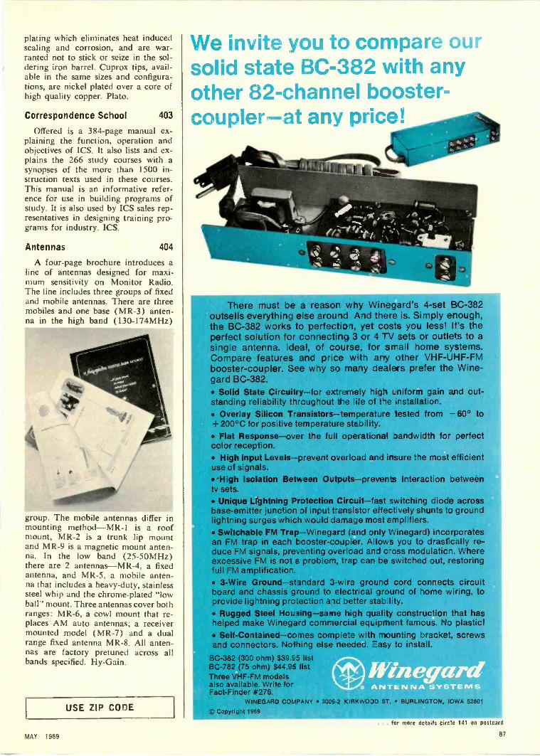
plating which eliminates heat inducedscaling and corrosion, and are war-ranted not to stick or seize in the sol-dering iron barrel. Cuprox tips, avail-able in the same sizes and configura-tions, are nickel plated over a core ofhigh quality copper. Plato.
Correspondence School 403
Offered is a 384 -page manual ex-plaining the function, operation andobjectives of ICS. It also lists and ex-plains the 266 study courses with asynopses of the more than 1500 in-struction texts used in these courses.This manual is an informative refer-ence for use in building programs ofstudy. It is also used by ICS sales rep-resentatives in designing training pro-grams for industry. ICS.
Antennas 404
A four -page brochure introduces aline of antennas designed for maxi-mum sensitivity on Monitor Radio.The line includes three groups of fixedand mobile antennas. There are threemobiles and one base (MR -3) anten-na in the high band (130-174MHz)
group. The mobile antennas differ inmounting method-MR-1 is a roofmount, MR -2 is a trunk lip mountand MR -9 is a magnetic mount anten-na. In the low band (25-50MHz)there are 2 antennas-MR-4, a fixedantenna, and MR -5, a mobile anten-na that includes a heavy-duty, stainlesssteel whip and the chrome -plated "lowball" mount. Three antennas cover bothranges: MR -6, a cowl mount that re-places AM auto antennas; a receivermounted model (MR -7) and a dualrange fixed antenna MR -8. All anten-nas are factory pretuned across allbands specified. Hy -Gain.
USE ZIP CODE
We invite you to compare oursolid state BC -382 with anyother 82 -channel booster-coupler-at any price!
1
There must be a reason why WinDgard's 4 -set BC -382outsells everything else around And there is. Simply erough,the BC -382 works to perfection, yet costs you less! It's theperfect solution for connectirg 3 or 4 -V sets or outlets to asingle antenna. Ideal, of course, for small home systems.Compare features and price with any other VHF -UHF -FMbooster -coupler. See why so many dealers prefer the Wine-gard BC -382. Solid State Circuitry-for extremely high Lniform gain and out-standing reliability thrcughout the life of the installation. Overlay Silicon Transistors-temperature tested from -60° to+ 200°C for positive te -nperature stability. Flat Response-over the full operational bandwidth for perfectcolor reception. High Input Levels-prevent overload and irsure the most efficientuse of signals. 'High Isolation Between Outputs-prevents interaction betweentv sets. Unique Lightning Protection Circuit-fast switching diode acrossbase -emitter junction df input t-Ensistor e'fectively shunts t3 groundlightning surges which would damage most Emplifiers. Switchable FM Trap-Winegard (and or ly Winegard) incorporatesan FM trap in each booster -coupler. Allows you to drastically re-duce FM signals, preventing overload and c-oss modulaticn. Whereexcessive FM is not E. problem, trap can be switched out, restoringfull FM amplification. 3 -Wire Ground-standard 3 -wire ground cord connects circuitboard and chassis g-ound to electrical ground of home wiring, toprovide lightning pro:ection and better stab lity. Rugged Steel Housing-same high quality construction that hashelped make Winegard commercial eqi_ipnent famous. No plastic! Self-Contained-comes complete with mounting bracket, screwsand connectors. Nothing else needed. Easy to install.
BC -382 (300 ohm) $39.E5 listBC -782 (75 ohm) $44.95 listThree VHF -FM modelsalso available. Write forFact -Finder #276.
WINEGAR) COMPANY 300E-2 KIRKWODD ST. BURLINGTON, IOWA 52601
Copyright 1969
MAY 1969
. . for more details circle 141 on postcard
87

NEW Heathkit Solid -StateColor Bar- Dot Generator
I
Kit IG-28Only $79.95*
6
Advanced Integrated CircuitryDelivers 12 Patterns PlusClear Raster ... No DividerChain Adjustment ... NoFlicker, Bounce or Jitter
All solid-state construction using Integrated Cir-cuitry No divider chain adjustments Stablepattern display - no flicker, bounce or jitter Produces 12 patterns plus clear raster Instantswitch selection of all functions Exclusive 3x3display plus standard 9x9 display of all patterns Horizontal lines only one raster thick for addedaccuracy Variable front panel tuning for channels2 through 6 Variable front panel positive andnegative video output Front panel negative goingsync output Two handy AC outlets on front panel Built n gun shorting circuit with lead piercingconne, irs Front panel switchable crystal con-trolled >und carrier Copper -banded transformerto redL-e stray fields Safe three -wire line cord Fast, easy construction with two circuit boards andtwo wiring har
Advanced Design. The new Heathkit IG-28 isone of the most stable, versatile Color and B&WTV service instruments available. In addition tothe exclusive Heath "3 x 3" display of patternsillustrated, it also produces the familiar 9 x 9displays . . . plus a clear raster for adjustingpurity without upsetting the AGC. Fifteen J -KFlip -Flops count down from a crystal controlledoscillator to eliminate divider chain instabilityand adjustment.
Time -Saving Versatility . . . gives you frontpanel tuning for channels 2 thru 6 ... front panelvariable plus and minus video output . . . frontpanel sync output ... two convenient AC outlets. . . built-in gun shorting circuits and grid jacks
. vectorscope capability . . . crystal controlledsound carrier . . . banded transformer to elimi-nate stray fields ... zener-regulated power supply... safe three -wire line cord ... fast circuit board -wiring harness assembly. For the versatility youcouldn't get before . . . put the new IG-28 onyour bench now.
Kit IG-28, 8 lbs $79.95*
L
HEATH COMPANY, Dept. 24-5Benton Harbor, Michigan 49022
Please send my FREE 1969 Heathkit Catalog.
Enclosed is $ plus shipping.
IOW
Standard9x9 Displays
plusExclusive
Heath"3 x 3" Display
r
3,3 Dot
3x3 Cross Hatch
3,3 Shading
3,3 Color Bars
3,3 Vertical
r
3x3 Horizontal
Please send model isi
Name
Address
City State ZipPrices & specifications subject to change without notice.
*Mail order prices; F.O.B. factory. 7E-200 j
TECHNICAL DIGEST
Continued from page 31
the blocking oscillator transformer, the clock drive circuituses two air core coils wound together and positionedin proximity to the balance wheel in the clock.
The transistorized drive circuit provides pulses of mag-netic energy that alternately attract and repel the magnetsmounted in the balance wheel assembly, causing it to os-cillate. The reciprocating motion of the balance wheel canbe compared to its counterpart in an ordinary clock orwrist watch.
When battery voltage (1.5v) is applied to the clockdrive circuit, transistor Q1 is slightly forward biased byresistor R 1 (150K) causing a small collector current. Thiscollector current creates a magnetic field about coil LI.The polarity of the magnetic field produced by LI is suchthat it attracts the magnet in the balance wheel, causing itto rotate in a direction that brings the magnet closer to the
HAIR SPRING
MAGNETICBALANCE WHEEL
ESCAPEMENTPAWL
C.
GEAR TRAIN
coil assembly. The moving magnet induces a pulse of volt-age in coil L2 which is part of a feedback network con-nected to the base of transistor Q 1. The positive feedbackpulse developed by coil L2 tends to increase forward biason transistor Q1, causing magnetic energy and further de-flection of the balance wheel.
As the balance wheel pivots toward the L1 -L2 coil as-sembly, mechanical energy is stored in the hair, spring andthe balance wheel, letting it rotate past the magnetic coilassembly. Further rotation of the balance wheel causes thesouth pole of the magnet to cross the L1-1.2 coil assembly.The polarity of the magnetic field produced by the balancewheel magnets reverses, and the polarity of the voltage in-duced in coil L2 also reverses, creating a voltage pulse ofopposite polarity on the base of transistor Q1. The reversebias afforded by the feedback pulse cuts off transistor Q1and the mechanical energy stored in the balance wheel as-sembly drives the wheel back to its original position-al-lowing the cycle to be repeated at a rate of approximately5 pulses per second. The exact period of balance wheel os-cillation is determined by the mechanical resonance of thehair-spring/balance wheel assembly-not by the electricalcomponents-just as in a conventional clock.
The mechanical energy produced by the oscillation ofthe balance wheel is transmitted by a small pawl locatedon the end of the balance wheel assembly. The back andforth motion of the pawl moves the first gear (in the geartrain) one tooth at a time-as the balance wheel movesback and forth. The illustration details the mechanicalcoupling between the balance wheel and the hands of theclock.
... for more details circle 123 on postcard88 ELECTRONIC TECHNICIAN/DEALER

CATALOGS Et
BULLETINS
Audio Connectors 405
A new catalog describes a line ofaudio connectors, standard micro-phone connectors, adapters, RF con-nectors, Y connectors, AC receptaclesand phone jacks. The catalog includesspecifications, detailed drawings, ap-plication hints and prices for singleand multiple conductor models. Itprovides engineers and designers withan up-to-the-minute guide to the latestin, audio connectors and related com-ponents. Switchcraft.
Automotive Speakers 406
A new automotive loudspeaker re-placement guide is available. Cover-ing model years 1960 through 1969inclusive, the guide lists replacementloudspeakers for all American andforeign automobiles and reportedly isthe most up-to-date reference and re-placement guide now available to elec-tronic distributors and service tech-nicians. Printed in an easy -to -use 81/2x llin. format with "universal"punching, the new guide is availablewithout charge. Jensen.
Tools 407
A 24 -page catalog of hard -to -findtools describes each tool and its appli-cation. The catalog contains a collec-tion of useful tools rarely sold by in-dustrial distributors or stores, such aselectronic pliers, jewelers' tools, sen-sitive drillers, precision tools, flexibleshaft machines, unusual solders, sol-dering jigs, hard -wire cutters, screwand nut starters, glass drills, miniaturefiles, rifflers and reamers. Also shownare soldering machines, endless hack-saws, divider setters, diamond glasscutters and rust remover devices.Brookstone.
Microphones 408
An eight -page microphone and ac-cessory brochure is offered. The bro-chure includes the complete line ofprofessional and entertainer series ofmicrophones, stands, bases, mixersand accessories. Geloso.
MATV Systems 409
An MATV planning manual, a ba-sic text of systems design and plan-ning, is offered. Written for techni-cians who want to educate themselvesin the MATV business, the bookletdescribes MATV systems products, as
well as the fundamentals of system de-sign and design calculations. Also in-cluded in the manual are sample VHFand all -channel systems, a db to volt-age multiplier chart, coax cable andtransmission line guide, TV channelassignments and a glossary of themost used MATV terms. Finney.
Instruments 410
A 12 -page catalog describes thecompany's complete line of advancedelectronic test equipment. The newcatalog, Form No. 458, features fivenew test instruments, including asweep and marker generator, combi-nation oscilloscope/vectorscope, color
generator and two transistor/FETtesters. Other instruments includedare field effect meters, tube testers,CRT testers, field strength meters andspecial purpose instruments, all withperformance data and prices. Sencore.
411Switches and Panel Components
An eight -page catalog features aline of miniature switches and frontpanel components. The catalog listsan expanded line of miniature switch-es, keyboard switches, push-buttonmodules, machined aluminum knobs,ceramic terminal strips, readout indi-cators, pilot light assemblies andminiature lamps. Product descriptions,
ANNOUNCING SPACE AG
nnOAMING ACTION
r7.
- uU 1JCI
IL L
CLEANS, POLISHES,LUBRICATES CONTACTS
EACH TIME CHANNELIS CHANGED
SPACE AGELUBRICANT
N'T DRY OUTFOAMS AWAY
IRT AND CORROSIONTUN -O -FOAM is a new generation of
tuner sprays. I. is not simply a cleanewith a little residue of lubricant It is
space age lubricant that cleans as it lubricateOrdinary lubricants are hydrocarbon compound
which dry out rapidly. TUN -0 -FOAM is a spaceage lubricant in which the carbon has been,
replaced by a rugged, synthetic element. The resultis a long-lasting lubricant capable of withstanding
extremes of temperature and maintaining lubricity overthoisands of channel changes. Thus, no matter how
hit the chassis runs, TUN -a -FOAM will not cake upo dry out. Especially well suited to silver and gold
plated contacts, it is the same type of lubricant used intoday's spacec-aft - the finest ingredients ever put into a can.
Each tine the tuner is rotated, the contacts are cleaned,polish( d and lubricated. Yet TUN -0 -FOAM is non-abrasive
TRY TUN 0 FOAM IT'S GUARANTEED TO BE THE BFST TUNERLUBRICANT CLEANER YOU'VE EVER USED OR YOUR MONEY REFUNDED.
HEMTRONIC1260 RALPH AVENUE BROOKLYN, N.Y. 11236
FOR EXPORT: ROBURN AGENCIES INC., NEW YORK, N.Y. 10013IN CANADA: PERFECT MANUFACTURING LT
MAY 1989
. for more details circle 112 on postcard
89

Signal Strength Meters ...
Continued from page 43
you can add and subtract numbers in db whencomputing a system, and the numbers staysmall. Otherwise, you would have to divideor multiply at each step, and your computa-tions would involve large, complex numbers.
CALCULATING GAIN IN MATV SYSTEMSSince the data for calculating voltage am-
plification, voltage gain and power amplifica-tion is readily available, all you have to do isplug the values into the formulas.
The formulas to determine true amplifica-tion or gain of RF amplifiers and preampswith 300 or 750 input and output impedancesare:
(1) Voltage Amplification (Av)= E out/Ein
(2) Voltage Gain or Power in db =dbmvout - dbmv in
(3) Power Amplification (Av)= Antilog(.1 [dbmv out - dbmv in ).
Remember that stage gain measurementsmade with very small input signals may yieldresults different from those youwith a larger input signal. This is becauseof amplifier efficiency characteristics.
To determine voltage amplification (Av)in a typical MATV installation using the aboveformulas, we will assume that your measuredinput signal (E in) was 1000gv and the outputsignal (E out) was 2000gv. According to theformula, Av=20000,7/1000mv=2.
Voltage gain and power gain are easilycomputed from a reading in db. Going backa little, we indicated that a 2 times amplifica-tion was equal to 6db. From formula (1) wefound that the voltage amplification was 2,or 6db. Therefore, formula (2) tells us thatvoltage or power gain is dbmv out - dbmvin. Plugging in our values, 6db (dbmv out)- 0db (dbmv in) = 6db.
To determine power amplification we willagain assume that the input signal was 0dband the output signal was 6db. From the form-ula Power Amplification (Av) = Antilog (.1
6dbmv - Odbmv )=Antilog = (.1 C6 7 1
= 4. In this formula, .1 times 6 = .6. To findthe Antilog of .6 you will have to consult atable of common logarithms. The table indi-cates that the Antilog of .6 is approximate-ly 3.98 which is rounded off to 4.
If the input impedance (Zin) of the deviceyou are measuring is approximately equalto the output impedance (Zout), but not equalto 75 or 3000, amplification measurements
(either power or voltage) will be reasonablyaccurate, although the actual dbmv or toimeter indications will be in error. When Zoutis not equal to Zin, the presence of a signalcan be detected, but determination of gainwould require a knowledge of the circuit andthe signal strength meter.
A porcelain isolation/coupling capacitormay be used between the probe tip and thetest point to reduce the effects of circuit load-ing by the SSM. A typical low -capacity probeis shown in Fig. 7. A low -capacity probe is
R 9M
TOMETER
3 TO 30pf
PROBE
GRD CLIP
Fig. 7 --Schematic diagram of low capacity probe whichcan be used to reduce circuit loading.
generally designed with a 10 to 1 attenua-tion factor, so if the meter has an input im-pedance of 1M0, a 9M0 resistor will providethe 10 to 1 ratio.
The trimmer capacitor is used to compen-sate for frequency response. As a rule ofthumb, the trimmer is selected so that its re-actance at the test frequency is equal to tentimes the lower of the two impedances (Zout andZin) of the equipment under test. Actual dbmvand psi readings will be off. But with this tech-nique it is generally possible to make rela-tive gain checks without fear of circuit de-
tuning, overloading or upsetting AGC bias.
SIGNAL TRACING TV FRONT ENDSSignal tracing essentially has the same
objective as the stage gain measurementspreviously described. The main differenceis that signal tracing does not normally re-quire specific gain computation but concernsitself with the presence or absence of a signaland its relative gain or loss in a passive de-vice. Fig. 8 shows a block diagram of a typi-cal TV RF section. The troubleshooting pro-cedure should provide you with some helpfultechniques that can be used in the shop orthe customer's home.
First, tune the SSM and TV receiver toa given channel. Then check the signal levelat the tuner input (antenna terminals). Foran accurate reading, connect the downleaddirectly to the SSM. The minimum accept-able reading should be close to 10001/ v or
90 ELECTRONIC TECHNICIAN/DEALER

illustrations and prices are included.Alco.
Semiconductors 412
A 64 -page transistor and diodecatalog lists a complete line of semi-conductor discrete devices. The cata-log presents key parameters and pack-age outline dimensions along with anumerical index that quickly locatesthe device of interest. The listings aregrouped by applications for the read-er's convenience. They include diodes,small signal transistors, dual transis-tors, Field Effect Transistors, powertransistors, communication devices,silicon -controlled rectifiers, specialtydiode products and electro-optical de-vices. Fairchild.
Microphones 413
A 20 -page catalog describes a lineof micrpphones, including several re-cently developed models. Included inthe catalog are professional cardioiddynamic, mobile and transistorizedmobile, base station, paging, publicaddress and tape recording micro-phones, plus microphone cartridges,stands and accessories. The publica-tion includes technical sections andproduct descriptions, specifications,photographs and list prices on eachmicrophone. Turner.
Tape Recorder 414
A new 16 -page illustrated catalogdescribes the portable cassette andreel-to-reel models, cassette, 8 -tractand reel-to-reel tape decks, Radio-corders and stereo tape systems. Ap-plications, features and specificationsof the complete line are included inthe tape recorder catalog. Concord.
Last year, 7,000 peopledied because theyfound excuses for notwearing seat belts.
This year, our ads couldtake away thoseexcuses and savequite a few lives.
Unless the ads don'tfind their wayinto your magazine.
Then, what's your excuse?
Imaginea doctorwithout astethoscope
Imaginean engineerwithout aslide rule
Imaginea professionalservice technic ianwithout a SencoreMighty Mite V.
STANDARD OFA PROFESSION!The Mighty Mite has become the standard of the industry with over50,000 used daily by competent professional servicemen from coastto coast. The Mighty Mite checks them all; tubes large and small . .
and it checks them critically too. 100 megohm grid leakage sensitivity,individual tube element shorts test and cathode emission test at fullrated current make the Mighty Mite really tcugh. It's tough on tubetests, tough in appearance with vinyl case and cover, and mightytough on competition. But, it's not tough on your pocketbook at only
See your Sencore distributor today.He has the TC142 Mighty Mite in stock. $84.50
NO. I MANUFACTURER OF ELECTRONIC MANTENANCE EQUIPMENT
426 SOUTH WESTGATE DRIVE. ADDISON. ILLINOIS 60101
. . for more details circle 134 on postcard
MAY 1969 91

Fig. 8 --Block diagram of typical TV RF section.
Odbmv. If this is satisfactory, reconnect theantenna to the antenna terminals and againcheck the input signal level. This time usethe test probe assembly (impedance mismatchmay result in a lower reading ).
Note the reading across the antenna ter-minals, then move the probe to the grid (orbase) of the RF amplifier. A standard tubet :st-adapter socket will provide access to thetube pins if necessary. The probe readingsat the antenna terminals and the RF gridare normally within 25 percent of each other.The reading at the grid will be lower becauseof circuit detuning by the tube adaptor.
Lack of signal at the RF grid would indicatea problem in the antenna balun (RF trans-former), coupling capacitors or the appro-priate section of the tuning switch assembly.
Next, check the collector or plate (if cascadestage, check output plate) signal. This read-ing should show a higher reading than thatmeasured at the grid. A relatively strongsignal indicates satisfactory interstage coup-ling (via the tuner). The signal should also bedetected at the mixer plate (although a non-linear device, the mixer's component inputfrequencies will be present at the output).
The mixer grid can then be checked forpresence of the oscillator injection signal.This may be done by tuning the SSM approx-imately 41MHz up from the channel centerfrequency. For example, channel six coversfrom 82 to 88MHz. Channel center is 85MHz.Tuning the SSM to about 126MHz shouldbring in the oscillator signal. If alignmentof the tuner is necessary a standard sweep -marker generator and scope should be used.Future articles on the signal strength meterwill cover its use in making receiver sensi-tivity, frequency response, noise figure, signal-to-noise and antenna tests.
Color System ...
Continued from page 51
loscope will tell you if it is the IC or otheicircuit components which are defective. Al-so, if the "chip" is defective, incorrect volt-age readings at the terminals should revealif replacement is necessary.
Although the chroma output of the secondcolor amplifier (at the collector) is approxi-mately 6v P -P, the step-down for impedancematching of L34 (2nd color amplifier trans-former) to the "chip" input results in approxi-mately 0.75v P -P input to terminals two andthree. A power supply input of 24v is appliedacross terminals one and six. Amplificationthrough the "chip" is greater than 10 times.providing adequate signal amplitude to thecolor difference amplifier grids. The opera-tion of the "chip" (similar to the switch -typetube operation) is such that the 2nd harmonic(7.2MHz) of the 3.58MHz must be trappedin the output circuit. (The 3.58MHz fundamen-tal is automatically canceled within the "chip.")This is provided by the coils L39, L45 andL51 in the output circuit which provides ahigh impedance to this frequency (7.2MHz).In addition, these coils also aid in providingthe necessary response of the color -differ-ence signals.
The transmission line which couples thecolor oscillator reference signals to the "chip"is similar to other color chassis.However, the phase of the signals at varioustake -off points is slightly different and com-ponent values also differ. It should be not-ed that the values of components are rath-er critical and although failure of any oneis unlikely, the exact replacement should bemade when necessary. When servicing these"chip" circuits, do not substitute or use com-ponents that are only "close" in value.
The hue control is connected to the trans-mission line so that only the injection signalsto the "chip" are affected. The AFC and ACCreference signal are unaffected.
A small capacitor (.39pf) is connected fromone of the chroma inputs of the demodula-tor to the AFC phase detector. This capaci-tor provides a feedback of the burst signalfrom the AFC phase detector which elimin-ates any tendency toward 3.58MHz radia-tion.
The TV technician must become more pro-ficient in troubleshooting these IC's as wewill be seeing many more "chips" in electron-ic products in the near future.
92ELECTRONIC TECHNICIAN/DEALER

BOOK REVIEWS
SERVICING THE SOLID STATECHASSIS by Homer L. Davidson.Published by TAB Books, Inc., 256pages, 200 illustrations. $7.95 hard-bound, $4.95 paperbound.
This book discusses a number ofsolid state equipments including TV,pocket radios, ac -dc, AM -FM, autoand multi -band receivers. It also cov-ers auto tape players, phonographs,tape recorders and stereo amplifiers.These subjects fill all but two of the12 chapters. A preliminary chapter ongeneral transistor testing and the end-ing chapter on troubleshooting tipsround it out. The chapters are all com-plete in their particular analysis of cir-cuit problems and they are backed upwith appropriate schematics, diagramsand waveforms. In most cases thewriter attempts to provide a generalview of the circuit then plugs in circuitdefects with typical causes and cures.The troubleshooting procedures arefor the most part sound, but in a fewinstances they include some very gen-eral and broad statements. However,the service technician who finds his la-bors divided among a variety of solidstate equipments will appreciate muchof the knowledge and technique thisbook provides.
Colorfax...Continued from page 75
voltage. Possible Cause: Open verticalfuse resistor, R2(H). The fuse is lo-cated on convergence panel door. Pro-cedure: Use voltmeter to check for95v at both terminals of the resistor.Do not jumper fuse terminals. If re-sistor is open, check for a short at theload end. Suspect a shorted verticaltransistor. See illustration for detailson how this open resistor causes lossof high voltage. Analysis: The fuseresistor protects the vertical outputtransformer and associated partsshould the transistor short. A 40v sup-ply (was 26-28v in previous models)is secured from this circuit throughRIOJ at terminal J2 -3. -This 40v sup-plies the horizontal driver stage. Thus,if the fuse opens, there will be no ras-ter because of no high voltage. Thefuse not only protects the vertical out-put transformer, but it avoids a hori-zontal line if the vertical transistorshorts and blows the fuse.
USE ZIP CODE
NOWCHECKTRANSISTORS
IN OR OUT OF CIRCUIT . . .
Flick functionswitch to leftto check allregular tran-sistors.
"11111111fteke, Model TF151
all regular transistors plus the new field effect transistors.You won't be stopped when you run into the new FETs that are wiredinto the latest hi-fi, newest TV receivers and nearly every other new devicecoming on the market. For the very first time, you can check them all,in or out of circuit. The TF151 works every time using tried and provensignal injection techniques. New, improved tests on special RF transistorsand the latest high power transistors, mean that the TF151 is the onlyup-to-date transistor tester on the market. A new, exclusive setup bookin rear compartment guides you to every test for over 12,000 transistorsand FETs. The book is not needed for general service troubleshooting.Regular transistors are checked for beta gain and Icbo leakage. FETsare checked for transconductance and Igss leakage. only $12950
Your distributor just got this new tester in stock.See him, it obsoletes all others.
Flick functionswitch to rightto check anyFET.
ILL
1\1C01=1NO. 1 MANUFACTURER Of ELEC'RONIC MAIN-ENANCE EQUIPMENT
426 SOUTH WESTGATE DRIVE. AODISON. ILLINOIS 60101... for more details circle 135 on postcard
MAY 1969 93
AI4#1,Pt%

MAKEYOUROWN
TUNER TEST!If you're like most professional TV tech-
nicians, you clean the tuner of every chassis youservice.
But how careful are you In choosing your tunerspray? The wrong spray can cost you a lot Inaggravation and callbacks.
That's why we ask you to
MAKE THIS TEST YOURSELF1. Tune in a good color picture on any color set.2. Spray the tuner with anything but a Chem-
tronics Spray.3. You will see the color fade and disappear al-
most immediately, due to the changes ofcapacitance in tuned circuits caused by thespray.
7r1COLOR rN1COLORCARRIER CARRIER
NORMAL RESPONSE RESPONSE DETUNEDBY SPRAY
4. Walt about 10 minutes for the spray to dry.Unfortunately, the color will not come back.
5. Spray the tuner with Chemtronics TUN -0 -WASH.6. Wait about two minutes and color will be re-
stored.
WHAT THIS TEST MEANS TO YOUMost tuner sprays leave a residue of slow dry-
ing, petroleum base lubricant. This saturates thecoils and other components causing a shift Inresponse as shown in illustration.
To compensate for this shift, you often adjustoscillator slugs. Then, when the set has playedin your customer's house for a week or two, theresidue dries out, shifting the oscillator backtoward its original frequency. If the customercan't compensate for this drift with the finetuner, you have a callback on your hands. Evenif the drift is not too severe, the remaining resi-due picks up dirt and eventually "gunks up"the tuner.
TUN -O -WASH IS LIKE NO OTHERSPRAY ON THE MARKET
TUN -0 -WASH is a powerful, high pressure spraydesigned to do just one job superlatively well.It melts away grease, oil, dirt and corrosionquickly and completely. It leaves absolutely noresidue behind. Tests show that TUN.0-WASH isat least 10 times as effective as any other tunerspray in degreasing gunked up tuners.
Use TUN -0 -WASH as your first step in repairing any tuner. It gives you a clean start in muchthe same way as the ultrasonic bath used bytuner specialists - but without harmful vibra-tion. You'll be surprised at howmany tuners you can repair theTUN-0WASH way.
Then, once the tuner is restoredto good working condition, you canlubricate it with a light spray ofChemtronics famous COLOR-LUBE,guaranteed not to detune, attackplastic parts or "gunk up." COLORLUBE uses a unique synthetic lu-bricating formula developed spe.cifically for color TV tuners.
Giant 24 oz. canonly $3.25 dealer net.
1260 RALPH AVENUE BROOKLYN, N.Y. 11236
AD INDEX
Accurate Instruments
Alco Electronics Products, Inc.
Antenna Specialists
Argos Products
Arrow Fastener Co.
A.T.R. Electronics Inc.
65
75
84
66
24
86
B & K Division 2nd Cover, 32, 33, 34
Belden Corporation 28, 29
Borden Chemical Inc. 73
Channellock, Inc.
Chemtronics, Inc.
Cleveland Institute
Cornell-Dubilier
C. R. T. Equipment
Delco Radio Div.
Enterprise Development
Finney Company
G. C. Electronics
G. E. Tubes
Heath Company
Interjectorall Electronics
International Crystal
JFD Electronics
Lampkin Labs
Lectrotech
Mallory Distributor
Multicore Sales
Oaktron
Perma-Power
Precision Tuner
RCA General Purpose
RCA Picture Tubes Division
Sencore
South River Metal
Sprague
Sylvania
Triplett Electrical
Tuner Service Corp.
Winegard
Zenith Sales Corp.
82
89-94
35, 36, 37
3rd Cover
85
63
86
26, 94
83
27
88
26
22
23
94
31
20
94
72
72
79
4th .1:over
67
77, 91, 93
78
25
38
81
19
86, 87
80
Color TVWINDOWANTENNAby FINGL7,Outperforms anyindoor antenna!
FCW-VUVHF -UHF
00:s14.95FCW-VVHF ONLYList $11.95
Unique swivel design zeros -indirectly on stations.
Aluminum construction with gold-corodized, corrosion -proof finishon antenna.
Fits horizontaly or vertically inwindows up to 42" wide or high.
Extension bars available for largerwindows.
FINCO
.,0-462 Dept 110-5
THE FINNEYCOMPANY
34 West Interstate St.. Bedford. Ohio 44146
... for more details circle 120 on postcard
"HOW TO MAKE MONEYin Mobile Radio Maintenance"AUTHORITATIVE GUIDEBOOK
Amour THE NOON IN Tw0.1VT ae6101111.ERACI10. Gives FACTSFIGURES. PAT RATES.WRITE TODAY! FREE
,a%a
II
LAMPK IN LABORATORIES, INC.Div. II - BRADENTON, FLA 33505
WORLD'SFINEST
ritTICORE
ONLY 69cBUY IT AT RADIO -TV PARTS STORES
MULTICORE SALES CORP., WESTBURY. N Y 11591. . . for more details circle 129 on postcard
ELECTRONIC TECHNICIAN DEALER
for more details circle 115 on postcard
. . for more details circle 113 on postcard94

The Wide RangerRides Again.
And you sure need the Ranger back.You see the guys who design the circuits and components
want to keep costs at a minimum. So they specify electrolytics withthe minimum capacity and vcltage to do :he job.
And that's the trouble. That's why the -e are thousands ofdifferent sizes and rating for twist prong capacitors.
Then :here's the label problem. The manufacturers meet thebroad standard tolerances laid down by E LA.. But it's not possibleto build these capacitors to very close tolerances.. So most capacitorsare made to exceed the capacity shown on the La -Del.
For example, a capacitor marked 100 rid. at 300 volts could infact measure from 90 mfd. to 200 mfd. and still be within tolerance.
So we decided to make things a little slipler. We examinedover 20,000 capacitors and put together a new line of 248 WideRange Twist Prongs that can replace 97% of all electrolytic& you'reever going to come across.
And they're all liked in the new Cornell-Dubilier ElectrolyticReplacement Guide. Plus a complete listing of the line by voltageand capacities; a complete reference to major competitors' products;100% reference to all color TV chassis original manufactures'part numbers and a 'cross reference to major black and whileTV chassis. Write today for your free copy.
D CORRELL-CDUBIUER
Dealer Company NameStreet Address, City, StatePhone Number
I (INDIVIDUAL'S NAME) (INDIVIDUAL'S TITLE)
Give her this...Use RCA's attractive new, red and black, die -cut"What Else Needs Fixing?" business calling cardsto increase your business! When you give Mrs.Housewife a card as you arrive at her home, youtrigger her thinking ...remind her of some otherelectronic device or appliance that may needfixing. The Electronic Industries Associationestimates that you'll have a 50°/o chance of gettingan additional job on the spot, measurably increas-
ing your profit -per -call. In effect, it gives you asecond no -cost call. They'll work equally well onin-store customers, too. The cards are availableonly through Authorized RCA Tube Distributors asour way of supporting this important industryprogram. For the name of your nearest Distributoroffering these business -building calling cardswrite Dept. 451, RCA Electronic Components,Harrison, N. J. 07029.
so she'll read this!
LIMO nentD1331
COMPLETE ELECTRONIC SERVICING WITHRCA TUBES, TRANSISTORS, BATTERIES
TV Sets Phonograph What ElseAntennas
Tape
i] Intercom
n Sound
NeedsFixing
Recorder Amplifier
Radios 1; Battery -OperatedTube Transistor Devices Tape Player
.1 What Else?