Technical Sales Catalogue Technical S ales C atalogue
683
Technical Sales Catalogue March 2009
-
Upload
khangminh22 -
Category
Documents
-
view
0 -
download
0
Transcript of Technical Sales Catalogue Technical S ales C atalogue
Technical Sales CatalogueMarch 2009
RIELLO S.p.A.
Via Ing. Pilade Riello, 537045 Legnago (VR) ItalyTel. +39.0442.630111 - Fax +39.0442.21980www.rielloburners.com - [email protected]
Riello Burners is a brand of Riello Group.
Since the Company is constantly engaged in the production improvement, the aesthetic and dimensional features, the technical data, the equipment and the accessories can be changed.This document contains confidential and proprietary information of RIELLO S.p.A. Unless authorised, this information shall not be divulged, nor duplicated in whole or in part.
Tech
nica
l Sal
es C
atal
ogue
03.2
009

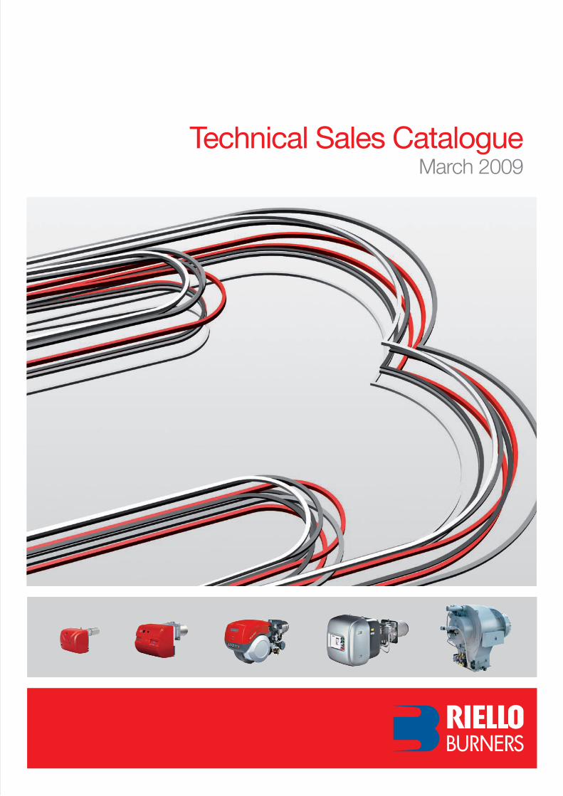
BURNERS PRODUCTION PLANTS. Pietro - Legnago (Verona), Italy
COMBUSTION RESEARCH CENTREAngiari (Verona) - Italy
Our Premises


3
This catalogue contains information to help you in selecting the right burner for any problem of heat production. There are the following sections:
How to use this catalogue
pag. 5
Range of Products
In this section the product can be selected by operation, fuel and series. This index consists of bar charts showing the minimum and maximum output for each series. Low NOx series are green plus fuel colours.
pag. 13
Index
In this section the product can be selected by operation, fuel and series. For each series there are:• a picture• series name• models in the series• output range • technical sheet page number.
pag. 25
Monobloc Burners Data Sheets Section
This section contains the technical sheets of monobloc burners, divided by fuel, series and operation.
pag. 599
Industrial Combustion System Data Sheets Section
This section contains the technical sheet for all components needed to carry out a complete industrial burner system.
pag. 663
Special Burners on Demand
This section contains further burner variants and technical options available upon request.
pag. 667
Request for Information
You can ask information for Riello Burners Technical Offi ce directly using a special form.
pag. 669
Sales and Service Network
In this section you will fi nd the Riello Burners distributors around the world and the references for the contact.

4
In the catalogue each colour represents a different fuel so that a fuel type can be matched to a series of burners. For low NOx burners the green colour is associated with fuel type color.
Fuels and associatedcolour identifi cation
LOW NOx LIGHT OIL BURNERS
LIGHT OIL BURNERS
HEAVY OIL BURNERS
LOW NOx GAS BURNERS
GAS BURNERS
LOW NOx DUAL FUEL BURNERS
DUAL FUEL BURNERS
INDUSTRIAL BURNERS
SYSTEM COMPONENTS
5
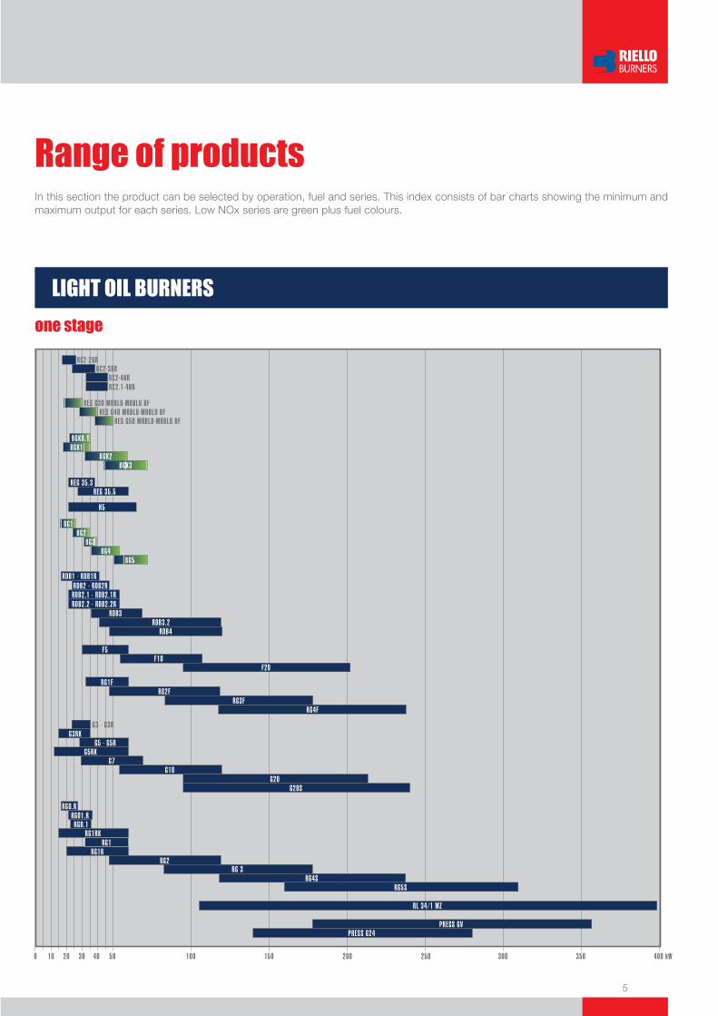
Range of productsIn this section the product can be selected by operation, fuel and series. This index consists of bar charts showing the minimum and maximum output for each series. Low NOx series are green plus fuel colours.
LIGHT OIL BURNERS
one stage
6
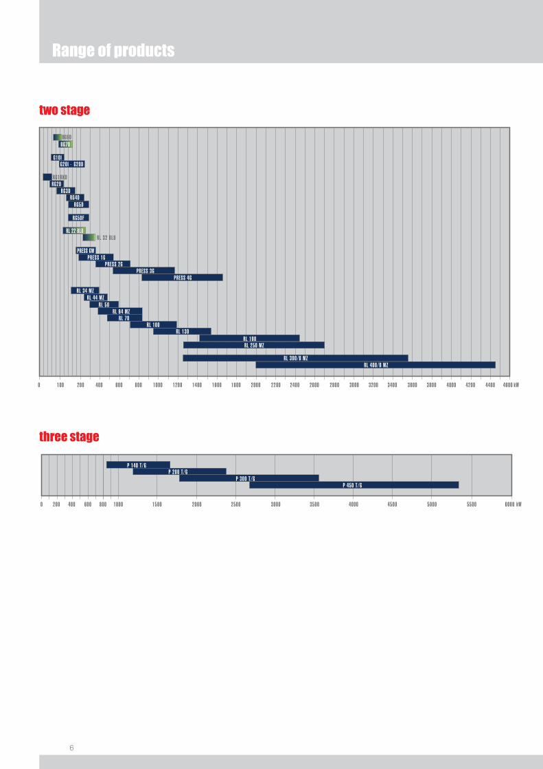
two stage
three stage
Range of products
1000 3500 kW6000800 1500 2000 2500 3000 4000 4500 5000 5500
P 140 T/G
P 450 T/GP 300 T/G
P 200 T/G
6000 400200

7
two stage-progressive/modulating
modulating
70001000 8000 kW6000 100002000 3000 4000 90005000 11000
MB 4 LE
MB 10 LEMB 8 LE
MB 6 LE
Range of products

8
Range of products
two stage-progressive/modulating
6000 1000 3500 kW800200 1500 2000 2500 3000 4000 4500 5000 5500400
P 140 P/N (ECO)
P 450 P/N (ECO)P 300 P/N (ECO)
P 200 P/N (ECO)
P 140 P/NA (ECO)
P 450 P/NA (ECO)P 300 P/NA (ECO)
P 200 P/NA (ECO)
HEAVY OIL BURNERS
one stage
two stage
three stage
6000 1000 3500 kW800200 1500 2000 2500 3000 4000 4500 5000 5500400
P 140 T/N (ECO)
P 450 T/N (ECO)P 300 T/N (ECO)
P 200 T/N (ECO)
100 500200 70030020 60 kW0 1000400 1100600 800 900 1400 15001200 1300
P 45 N
RN 28RN 38
P 30 N
P 60 NP 100 N
RN 50RN 70
RN 100RN 130
P 45 N/ECOP 30 N/ECO
P 60 N/ECOP 100 N/ECO
100 20025 50 kW0 75 125 150 175 250225
N20N10
9
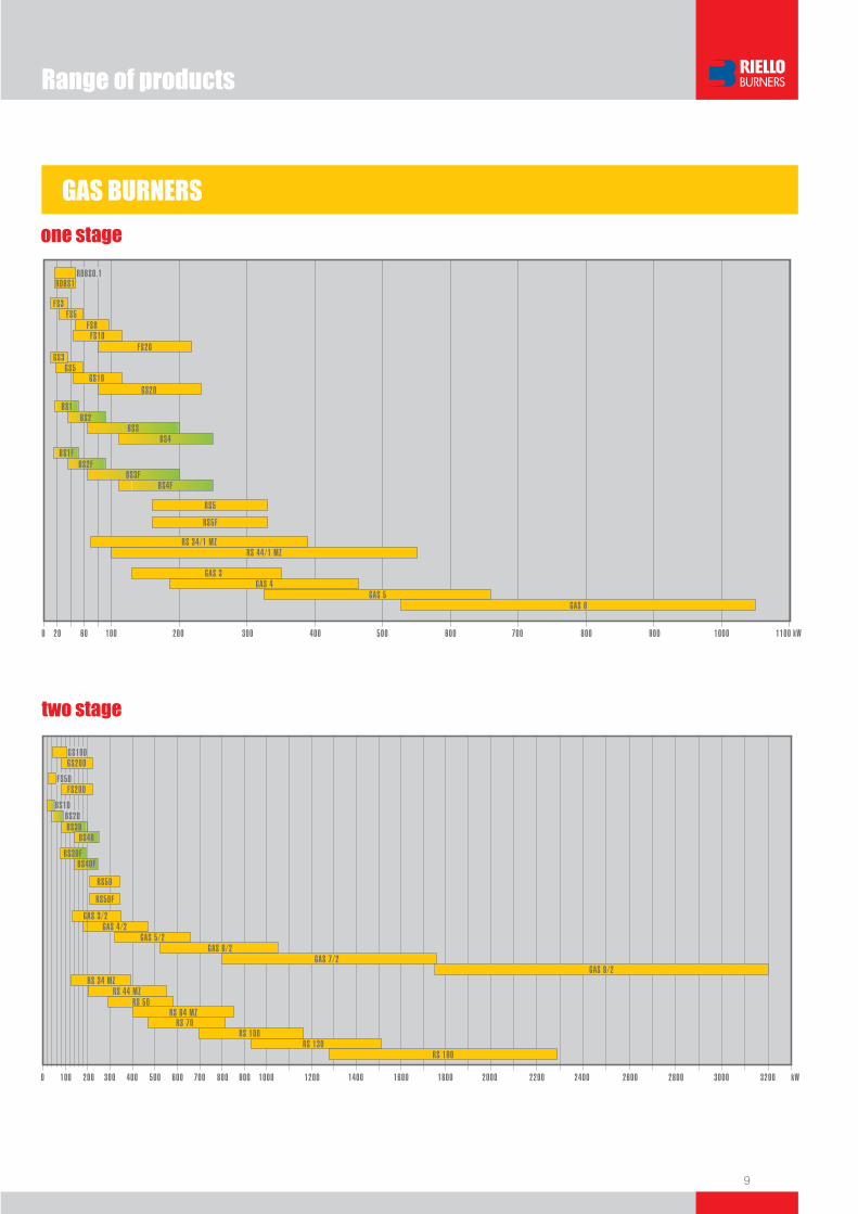
GAS BURNERS
one stage
two stage
Range of products
10
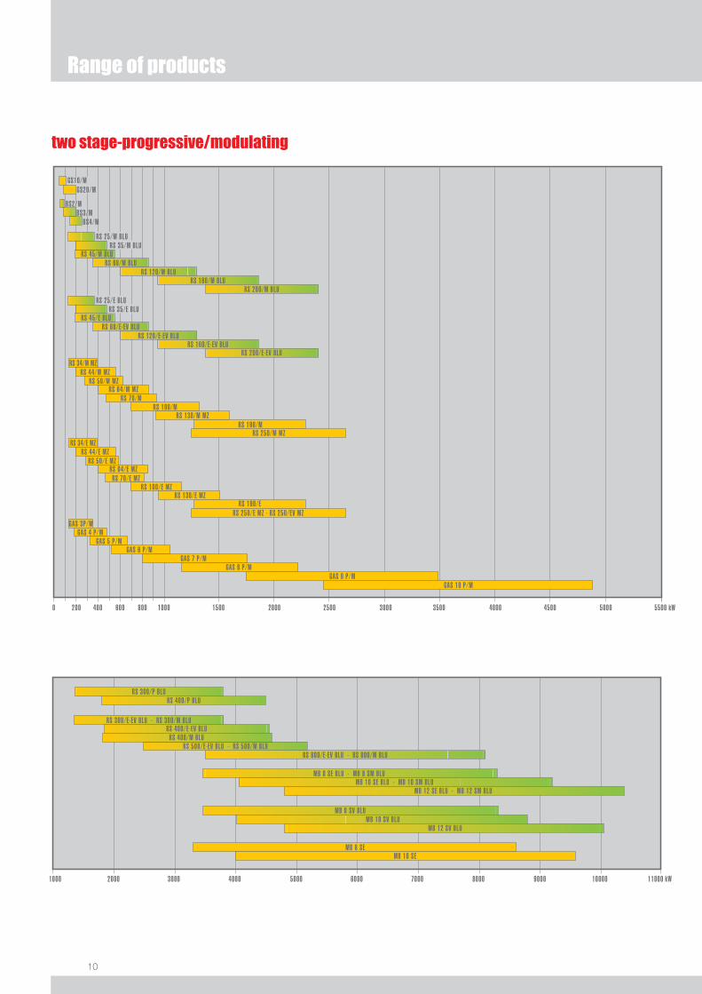
Range of products
two stage-progressive/modulating

11
DUAL FUEL BURNERS
two stage
Range of products
100 500200 70030020 60 kW0 1000400 1100600 800 900 1400 15001200 1300
GI/EMME 400
RLS 28RLS 38
GI/EMME 300
GI/EMME 600GI/EMME 900
RLS 50RLS 70
RLS 100RLS 130
two stage-progressive/modulating
modulating
70001000 8000 kW6000 100002000 3000 4000 90005000 11000
MB 10 LSEMB 8 LSE
MB 6 LSE

12
ER series - all fuels
These data are indicative for all fuels.
OIL, GAS and DUAL FUEL INDUSTRIAL BURNERS
DB series - all fuels
Range of products
8000 kW6000 100002000 4000 12000 1800016000 2000014000
DB 12DB 9
DB 6DB 4
DB 16DB 20
22000 2800026000 3000024000 3400032000 360000
8000 kW6000 100002000 4000 12000 1800016000 2000014000
ER 12ER 9
ER 6ER 4
ER 16ER 20
22000 2800026000 3000024000 3400032000
ER 25ER 32
360000
13
Index
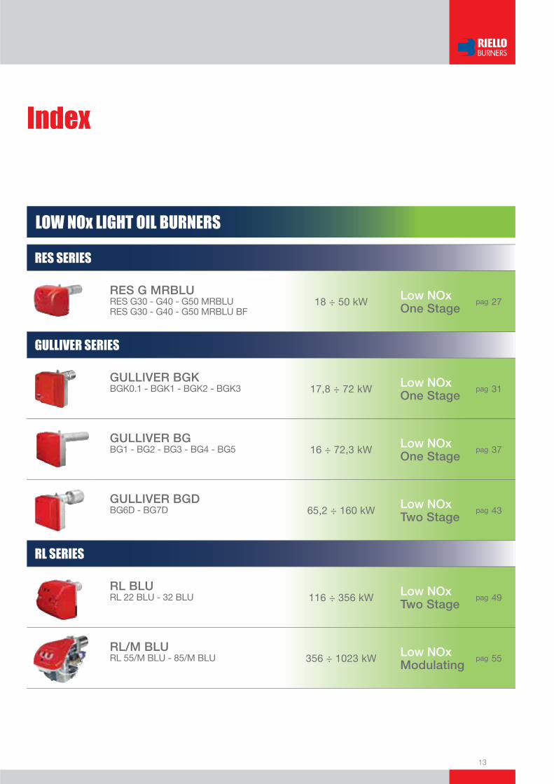
LOW NOx LIGHT OIL BURNERS
RES SERIES
RES G MRBLURES G30 - G40 - G50 MRBLURES G30 - G40 - G50 MRBLU BF
18 ÷ 50 kW Low NOx One Stage
pag 27
GULLIVER SERIES
GULLIVER BGKBGK0.1 - BGK1 - BGK2 - BGK3 17,8 ÷ 72 kW Low NOx
One Stage pag 31
GULLIVER BGBG1 - BG2 - BG3 - BG4 - BG5 16 ÷ 72,3 kW Low NOx
One Stagepag 37
GULLIVER BGD BG6D - BG7D 65,2 ÷ 160 kW Low NOx
Two Stage pag 43
RL SERIES
RL BLURL 22 BLU - 32 BLU 116 ÷ 356 kW Low NOx
Two Stagepag 49
RL/M BLURL 55/M BLU - 85/M BLU 356 ÷ 1023 kW Low NOx
Modulatingpag 55
14
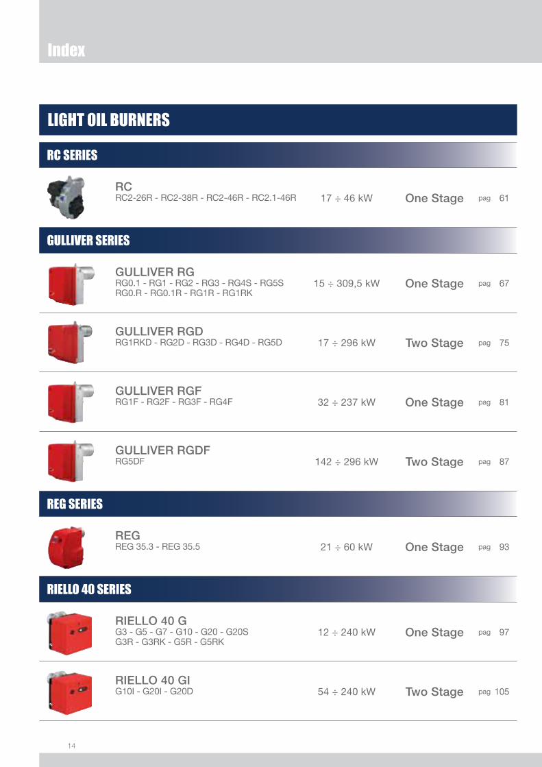
LIGHT OIL BURNERS
RC SERIES
RCRC2-26R - RC2-38R - RC2-46R - RC2.1-46R 17 ÷ 46 kW One Stage pag 61
GULLIVER SERIES
GULLIVER RG RG0.1 - RG1 - RG2 - RG3 - RG4S - RG5S RG0.R - RG0.1R - RG1R - RG1RK
15 ÷ 309,5 kW One Stage pag 67
GULLIVER RGDRG1RKD - RG2D - RG3D - RG4D - RG5D 17 ÷ 296 kW Two Stage pag 75
GULLIVER RGF RG1F - RG2F - RG3F - RG4F 32 ÷ 237 kW One Stage pag 81
GULLIVER RGDFRG5DF 142 ÷ 296 kW Two Stage pag 87
REG SERIES
REGREG 35.3 - REG 35.5 21 ÷ 60 kW One Stage pag 93
RIELLO 40 SERIES
RIELLO 40 GG3 - G5 - G7 - G10 - G20 - G20SG3R - G3RK - G5R - G5RK
12 ÷ 240 kW One Stage pag 97
RIELLO 40 GIG10I - G20I - G20D 54 ÷ 240 kW Two Stage pag 105
Index

15
RIELLO 40 SERIES
RIELLO 40 FF5 - F10 - F20 30 ÷ 202 kW One Stage pag 111
RIELLO 40 HH5 21 ÷ 65 kW One Stage pag 117
RDB SERIES
RDBRDB1 - RDB1R - RDB2 - RDB2R - RDB2.1 - RDB2.1R - RDB2.2 - RDB2.2R - RDB3 - RDB3.2 - RDB4
16,8 ÷ 120 kW One Stage pag 121
PRESS SERIES
PRESS GVPRESS GV - G24 140 ÷ 356 kW One Stage pag 127
PRESS GPRESS GW - 1G - 2G - 3G - 4G 178 ÷ 1660 kW Two Stage pag 133
PRESS T/GP 140T/G - 200T/G - 300T/G - 450T/G 830 ÷ 5340 kW Three Stage pag 141
PRESS P/GP 140P/G - 200P/G - 300P/G - 450P/G 830 ÷ 5340 kW Modulating pag 149
RL SERIES
RL/1RL 34/1 MZ 107 ÷ 398 kW One Stage pag 157
RLRL 34 MZ - 44 MZ - 50 - 64 MZ RL 70 - 100 - 130 - 190 - 250 MZ
154 ÷ 2700 kW Two Stage pag 165
Index
16
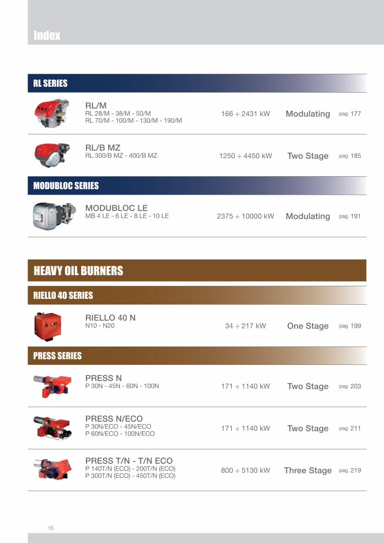
RL SERIES
RL/MRL 28/M - 38/M - 50/MRL 70/M - 100/M - 130/M - 190/M
166 ÷ 2431 kW Modulating pag 177
RL/B MZRL 300/B MZ - 400/B MZ 1250 ÷ 4450 kW Two Stage pag 185
MODUBLOC SERIES
MODUBLOC LEMB 4 LE - 6 LE - 8 LE - 10 LE 2375 ÷ 10000 kW Modulating pag 191
HEAVY OIL BURNERS
RIELLO 40 SERIES
RIELLO 40 NN10 - N20 34 ÷ 217 kW One Stage pag 199
PRESS SERIES
PRESS NP 30N - 45N - 60N - 100N 171 ÷ 1140 kW Two Stage pag 203
PRESS N/ECOP 30N/ECO - 45N/ECOP 60N/ECO - 100N/ECO
171 ÷ 1140 kW Two Stage pag 211
PRESS T/N - T/N ECOP 140T/N (ECO) - 200T/N (ECO) P 300T/N (ECO) - 450T/N (ECO)
800 ÷ 5130 kW Three Stage pag 219
Index

17
PRESS SERIES
PRESS P/N - P/N ECOP 140P/N (ECO) - 200P/N (ECO) P 300P/N (ECO) - 450P/N (ECO)
800 ÷ 5130 kW Modulating pag 227
PRESS P/NA - P/NA ECOP 140P/NA (ECO) - 200P/NA (ECO) P 300P/NA (ECO) - 450P/NA (ECO)
800 ÷ 5130 kW Modulating pag 235
RN SERIES
RNRN 28 - 38 - 50 - 70 - 100 - 130 228 ÷ 1481 kW Two Stage pag 245
LOW NOx GAS BURNERS
GULLIVER SERIES
GULLIVER BSBS1 - BS2 - BS3 - BS4 16 ÷ 250 kW Low NOx
One Stage pag 251
GULLIVER BSDBS1D - BS2D - BS3D - BS4D 19 ÷ 250 kW Low NOx
Two Stagepag 257
GULLIVER BS/M BS2/M - BS3/M - BS4/M 49 ÷ 250 kW Low NOx
Modulating pag 263
GULLIVER BSFBS1F - BS2F - BS3F - BS4F 16 ÷ 250 kW Low NOx
One Stagepag 269
GULLIVER BSDFBS3DF - BS4DF 75 ÷ 246 kW Low NOx
Two Stagepag 275
Index

18
RS SERIES
RS 25÷200/M BLURS 25/M - 35/M - 45/M - 68/M BLURS 120/M - 160/M - 200/M BLU
125 ÷ 2400 kW Low NOxModulating
pag 281
RS 25÷200/E-EV BLURS 25/E - 35/E - 45/E - 68/E-EV BLURS 120/E-EV - 160/E-EV - 200/E-EV BLU
125 ÷ 2400 kW Low NOxModulating
pag 295
RS/P BLURS 300/P - 400/P BLU 1350 ÷ 4500 kW Low NOx
Modulating pag 307
RS 300÷800/M BLURS 300/M - 400/M - 500/M - 800/M BLU 1350 ÷ 8100 kW Low NOx
Modulatingpag 315
RS 300÷800/E-EV BLURS 300/E - 400/E - 500/E - 800/E BLURS 300/EV - 400/EV - 500/EV - 800/EV BLU
1350 ÷ 8100 kW Low NOxModulating
pag 323
MODUBLOC SERIES
MODUBLOC SM BLUMB 8 SM - 10 SM - 12 SM BLU 3450 ÷ 10400 kW Low NOx
Modulatingpag 333
MODUBLOC SE - SV BLUMB 8 SE - 10 SE - 12 SE BLUMB 8 SV - 10 SV - 12 SV BLU
3450 ÷ 10400 kW3450 ÷ 10050 kW
Low NOxModulating
pag 341
Index

19
GAS BURNERS
RDBS SERIES
RDBSRDBS0.1 - RDBS1 16 ÷ 48 kW One Stage pag 351
RIELLO 40 SERIES
RIELLO 40 GSGS3 - GS5 - GS10 - GS20 11 ÷ 220 kW One Stage pag 355
RIELLO 40 GSDGS10D - GS20D 41 ÷ 220 kW Two Stage pag 361
RIELLO 40 GS/MGS10/M - GS20/M 42 ÷ 194 kW Modulating pag 367
RIELLO 40 FSFS3 - FS5 - FS8 - FS10 - FS20 11 ÷ 220 kW One Stage pag 373
RIELLO 40 FSDFS5D - FS20D 23 ÷ 220 kW Two Stage pag 381
GULLIVER SERIES
GULLIVER RSRS5 160 ÷ 330 kW One Stage pag 387
GULLIVER RSDRS5D 208 ÷ 345 kW Two Stage pag 393
GULLIVER RSFRS5F 160 ÷ 330 kW One Stage pag 399
Index

20
GULLIVER SERIES
GULLIVER RSDFRS5DF 208 ÷ 345 kW Two Stage pag 405
GAS SERIES
GASGAS 3 - 4 - 5 - 6 130 ÷ 1050 kW One Stage pag 411
GAS/2GAS 3/2 - 4/2 - 5/2 - 6/2 - 7/2 - 9/2 130 ÷ 3200 kW Two Stage pag 419
GAS P/MGAS 3P/M - 4P/M - 5P/M - 6P/M - 7P/MGAS 8P/M - 9P/M - 10P/M
130 ÷ 4885 kW Modulating pag 429
RS SERIES
RS/1RS 34/1 MZ - 44/1 MZ 70 ÷ 550 kW One Stage pag 441
RSRS 34 MZ - 44 MZ - 50 - 64 MZ RS 70 - 100 - 130 - 190
130 ÷ 2290 kW Two Stage pag 449
RS/MRS 34/M MZ - 44/M MZ - 50/M MZRS 64/M MZ - 70/M - 100/M - 130/M MZ RS 190/M - 250/M MZ
130 ÷ 2650 kW Modulating pag 467
RS/E-EV MZRS 34/E MZ - 44/E MZ - 50/E MZRS 64/E MZ - 70/E MZ - 100/E MZ RS 130/E MZ - 190/E - 250/E-EV MZ
130 ÷ 2650 kW Modulating pag 487
MODUBLOC SERIES
MODUBLOC SEMB 8 SE - 10 SE 3300 ÷ 9580 kW Modulating pag 501
Index

21
LOW NOx DUAL FUEL BURNERS
RLS SERIES
RLS/M MXRLS 68/M MX - 120/M MX - 160/M MX 350 ÷ 1840 kW Low NOx
Modulatingpag 509
RLS/BP MXRLS 300/BP MX - 400/BP MX 1250 ÷ 4500 kW Low NOx
Modulatingpag 519
RLS 500-800/M MXRLS 500/M MX - 800/M MX 2500 ÷ 8000 kW Low NOx
Modulatingpag 527
RLS/E-EV MXRLS 300/E-EV MX - 400/E-EV MXRLS 500/E-EV MX - 800/E-EV MX
1250 ÷ 8000 kW Low NOxModulating
pag 535
DUAL FUEL BURNERS
RLS SERIES
RLSRLS 28 - 38 - 50 - 70 - 100 - 130 163 ÷ 1395 kW Two Stage pag 543
RLS/M MZRLS 190/M MZ - 250/M MZ 1100 ÷ 2460 kW Modulating pag 553
Index

22
ENNE/EMME SERIES
ENNE/EMMEENNE/EMME 1400 - 2000 - 3000 - 4500 814 ÷ 5000 kW Modulating pag 579
MODUBLOC SERIES
MODUBLOC LSEMB 6 LSE - 8 LSE - 10 LSE 3300 ÷ 9580 kW Modulating pag 589
INDUSTRIAL BURNERS
DB SERIES
DBDB 4 - 6 - 9 - 12 - 16 - 20 2500 ÷ 20000 kW pag 601
ER SERIES
ERER 4 - 6 - 9 - 12 - 16 - 20 - 25 - 32 2500 ÷ 32000 kW pag 613
Index
GI/EMME SERIES
GI/EMME 300÷900GI/EMME 300 - 400 - 600 - 900 175 ÷ 922 kW Two Stage pag 561
GI/EMME 1400÷4500GI/EMME 1400 - 2000 - 3000 - 4500 820 ÷ 4650 kW Modulating pag 569
23
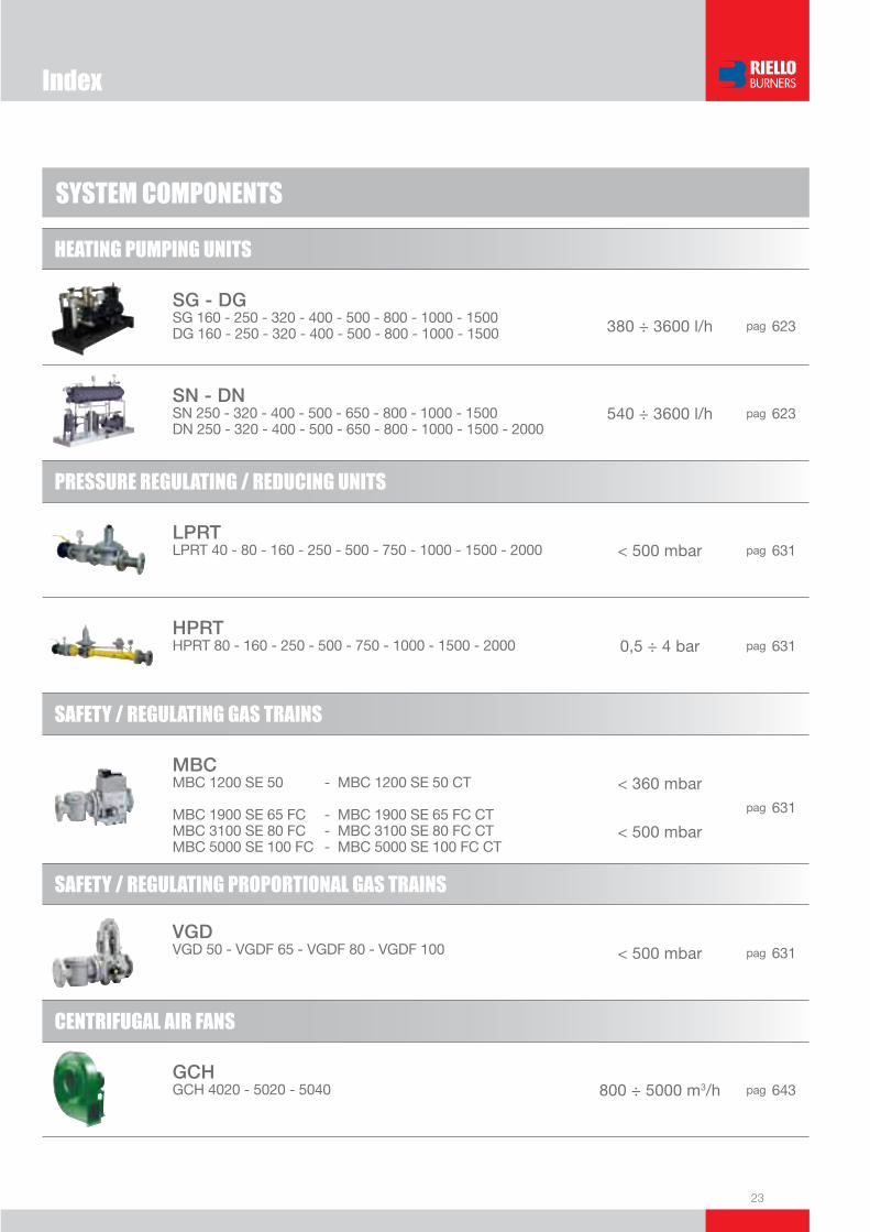
SYSTEM COMPONENTS
HEATING PUMPING UNITS
SG - DGSG 160 - 250 - 320 - 400 - 500 - 800 - 1000 - 1500DG 160 - 250 - 320 - 400 - 500 - 800 - 1000 - 1500 380 ÷ 3600 l/h pag 623
SN - DNSN 250 - 320 - 400 - 500 - 650 - 800 - 1000 - 1500DN 250 - 320 - 400 - 500 - 650 - 800 - 1000 - 1500 - 2000
540 ÷ 3600 l/h pag 623
PRESSURE REGULATING / REDUCING UNITS
LPRTLPRT 40 - 80 - 160 - 250 - 500 - 750 - 1000 - 1500 - 2000 < 500 mbar pag 631
HPRTHPRT 80 - 160 - 250 - 500 - 750 - 1000 - 1500 - 2000 0,5 ÷ 4 bar pag 631
SAFETY / REGULATING GAS TRAINS
MBCMBC 1200 SE 50 - MBC 1200 SE 50 CT
MBC 1900 SE 65 FC - MBC 1900 SE 65 FC CTMBC 3100 SE 80 FC - MBC 3100 SE 80 FC CTMBC 5000 SE 100 FC - MBC 5000 SE 100 FC CT
< 360 mbar
< 500 mbar
pag 631
SAFETY / REGULATING PROPORTIONAL GAS TRAINS
VGDVGD 50 - VGDF 65 - VGDF 80 - VGDF 100 < 500 mbar pag 631
CENTRIFUGAL AIR FANS
GCHGCH 4020 - 5020 - 5040 800 ÷ 5000 m3/h pag 643
Index

24
CENTRIFUGAL AIR FANS
GCMGCM 4540 - 5020 - 5040 4000 ÷ 9500 m3/h pag 643
GBJGBJ H0 5630 - 6320 - 6330 - 6380 - 712 - 717GBJ I0 6310 - 6320 - 6360 - 710 - 712 - 800A
3500 ÷ 20000 m3/h pag 643
BURNER CONTROL PANELS
QAfor TI series - pag 657
Index

25
Monobloc burners data sheets section
LOW NOx LIGHT OIL BURNERS
LIGHT OIL BURNERS
HEAVY OIL BURNERS
LOW NOx GAS BURNERS
GAS BURNERS
LOW NOx DUAL FUEL BURNERS
DUAL FUEL BURNERS
pag 27
pag 61
pag 199
pag 251
pag 351
pag 509
pag 543
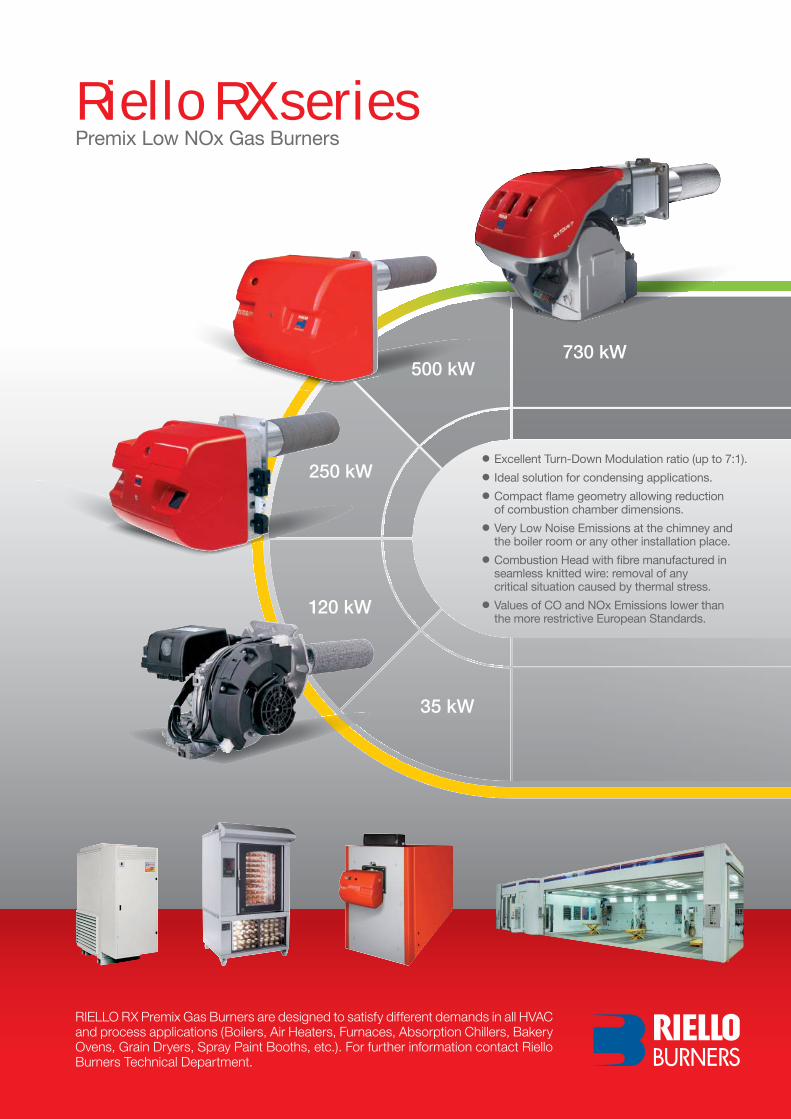
● Excellent Turn-Down Modulation ratio (up to 7:1).● Ideal solution for condensing applications.● Compact fl ame geometry allowing reduction of combustion chamber dimensions.● Very Low Noise Emissions at the chimney and the boiler room or any other installation place.● Combustion Head with fi bre manufactured in seamless knitted wire: removal of any critical situation caused by thermal stress.● Values of CO and NOx Emissions lower than the more restrictive European Standards.
RIELLO RX Premix Gas Burners are designed to satisfy different demands in all HVAC and process applications (Boilers, Air Heaters, Furnaces, Absorption Chillers, Bakery Ovens, Grain Dryers, Spray Paint Booths, etc.). For further information contact Riello Burners Technical Department.
Riello RX seriesPremix Low NOx Gas Burners
250 kW
500 kW730 kW

Low NOx One Stage Light Oil Burners
27
LOW
NOx
LIG
HT O
ILUseful working fi eldfor choosing theburner
Test conditionsconforming to EN267 Temperature: 20°CPressure: 1013,5 mbarAltitude: 0 m a.s.l.
RES (Riello Environment Solution) is the new Low NOx light oil burners series with extremely low emissions to meet the increasingly stringent demands for low environmental impact products.This family consists of 3 models based on the same ventilation device, with an output range from 18 to 50 kW. This series of burners comes in conventional and balanced fl ue versions.The new Riello RES are fi tted with a microprocessor-based control box, with diagnostic functions. The new combustion head and the sealed ventilation system, keep NOx levels extremely low in spite of the small dimensions and very low noise emissions. All the models are approved by the EN 267 European Standard, conform to European Directives, Machinery, EMC, Low Voltage, Boiler Effi ciency. All burners are test fi red before they leave the factory.
FIRING RATES
RES G30 MRBLU 18 ÷ 30 kWRES G30 MRBLU BF 18 ÷ 30 kWRES G40 MRBLU 28 ÷ 40 kWRES G40 MRBLU BF 28 ÷ 40 kWRES G50 MRBLU 38 ÷ 50 kWRES G50 MRBLU BF 38 ÷ 50 kW
RES G MRBLU SERIES
G30 G40 G50

28
BURNER
Overall dimensions (mm)
Low NOx One Stage Light Oil Burners
Z
XY
PACKAGING
MODEL X Y Z kg u RES G30 - 40 MRBLU 700 360 345 15,5
u RES G50 MRBLU 700 360 345 15,5
MODEL X Y Z kg u RES G30 - 40 MRBLU BF 730 460 350 15,5
u RES G50 MRBLU BF 730 460 350 15,5
RES G MRBLU RES G MRBLU BF
MODEL A C C1 C2 D F Q Ru All models 106 166 140 170 106 189 45° 11 NOTE: These dimensions are the same as BF models.
BURNER - BOILER MOUNTING FLANGE
MODEL A D E F(max) H I L R(max)
u RES G30 MRBLU 326 275 272 280 100 208 32 118
u RES G40 MRBLU 326 275 272 307 105 208 32 118
u RES G50 MRBLU 326 275 272 310 105 208 32 118
MODEL A D E F(max) H I L R(max) Ju RES G30 MRBLU BF 383 351 272 280 100 208 32 113 75
u RES G40 MRBLU BF 383 351 272 307 105 208 32 108 75
u RES G50 MRBLU BF 383 351 272 310 105 208 32 129 75
RES G MRBLU SERIES

29
LOW
NOx
LIG
HT O
IL
DESIGNATION OF SERIES
STATE OF SUPPLY
Specifi cation
Low NOx One Stage Light Oil Burners
Completely automatic monobloc light oil burners, with one stage operation fi tted with:- Forward blades fan and airtight fan house for high performance- Sound proofi ng cover - Air damper with inner adjustment for conventional fl ue version- Air damper with external adjustment, with no need to remove the cover, for balanced fl ue version- Single phase electric motor 230 V, 50 Hz- Combustion head fi tted with: - inconel 601 end cone resistant to high temperatures - ignition electrodes - fl ame stability disk- Geared pump for fuel supply, fi tted with: - fi lter - pressure regulator - connectors for installing a pressure gauge and vacuometer - inner by-pass for preparing for single pipe installation- Fuel feed solenoid incorporated in the pump- UV sensor for fl ame detection- Microprocessor-based burner safety control box, with diagnostic and remote control release functions- Protection fi lter against radio interference (included into burner safety control box)- Light oil nozzle- IP X0D (IP 40) protection level- PTC fuel heater.
Standard equipment:- Two fl exible pipes and two connectors- Flange, screen, screws and nuts for fi xing- Grommet - Flame tube - 7-pin plug- Remote control release kit- Instruction handbook for installation, use and maintenance- Spare parts catalogue.
Series : RES
Fuel : G Light-oil
Size
Possible variations : R Light-oil pre-heater
Emission : BLU Class 3 EN267
Version : ... Conventional fl ue BF Balanced fl ue
Electrical supply to the system : 1/230/50 1/230V/50Hz
RES G MRBLU SERIES
RES G 30M R BLU BF 1/230/50

30
Available models
Low nox one Stage Light oil Burners
Code Model Heat output totaleleCtriCal
power
(kw)
CertifiCation note
(kw) (kg/h)
20011492 reS G30 MrBlu 18 ÷ 30 1,5 ÷ 2,5 0,28 -
20011495 reS G40 MrBlu 28 ÷ 40 2,4 ÷ 3,4 0,3 -
20011498 reS G50 MrBlu 38 ÷ 50 3,2 ÷ 4,2 0,3 -
20011500 reS G30 MrBlu Bf 18 ÷ 30 1,5 ÷ 2,5 0,28 -
20011502 reS G40 MrBlu Bf 28 ÷ 40 2,4 ÷ 3,4 0,3 -
20011504 reS G50 MrBlu Bf 38 ÷ 50 3,2 ÷ 4,2 0,3 -
Burner accessories
7-pin plug kitIf necessary a 7-pin plug kit is available (in packaging of n. 5 pieces).
Burner Kit Code
u All models 3000945
Burner filterinG deGree (µm) Kit Code
u All models 100 3000926
To solve problems of air or water in the oil circuit a special filter/degassing unit is available, made up of aluminium cover, plastic tank, stainless steel filtering cartridge, air release cap and water purge valve. It is available singularly.
Light oil filter/degassing unit
Burner Kit Code
u All models 3002731
To connect the control box to a personal computer for the transmission of operation, fault signals and detailed service information, an interface adapter with PC software are available.
PC Interface kit
Net calorific value: 11,8 kWh/kg; 10200 kcal/kg - Viscosity at 20°C: 4÷6 mm2/s (cSt).The burners of RES series are in according to EN 267.
RES G MRBLU SERIES
Low nox one Stage Light oil Burners
31
Low
Nox
LIG
HT O
IL
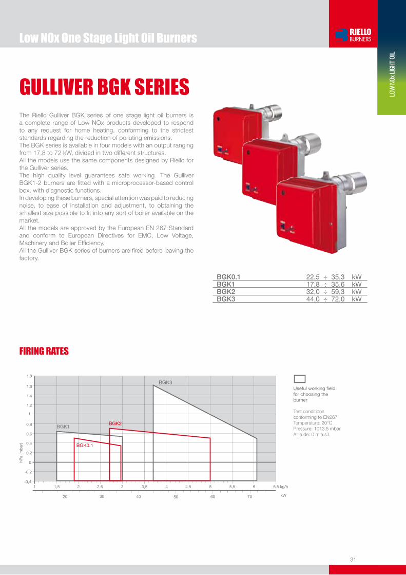
The Riello Gulliver BGK series of one stage light oil burners is a complete range of Low NOx products developed to respond to any request for home heating, conforming to the strictest standards regarding the reduction of polluting emissions.The BGK series is available in four models with an output ranging from 17,8 to 72 kW, divided in two different structures. All the models use the same components designed by Riello for the Gulliver series. The high quality level guarantees safe working. The Gulliver BGK1-2 burners are fitted with a microprocessor-based control box, with diagnostic functions.In developing these burners, special attention was paid to reducing noise, to ease of installation and adjustment, to obtaining the smallest size possible to fit into any sort of boiler available on the market.All the models are approved by the European EN 267 Standard and conform to European Directives for EMC, Low Voltage, Machinery and Boiler Efficiency.All the Gulliver BGK series of burners are fired before leaving the factory.
BGK0.1 22,5 ÷ 35,3 kWBGK1 17,8 ÷ 35,6 kWBGK2 32,0 ÷ 59,3 kWBGK3 44,0 ÷ 72,0 kW
FIRInG RATES
Useful working fieldfor choosing theburner
Test conditionsconforming to EN267 Temperature: 20°CPressure: 1013,5 mbarAltitude: 0 m a.s.l.
GULLIVER BGK SERIES
BGK3

32
BURnER
overall dimensions (mm)
Low nox one Stage Light oil BurnersGULLIVER BGK SERIES
Z
XY
BGK0.1 BGK1 - BGK2 - BGK3
E
H
I
L
Q
FE
H
I
L
Q
FA
D
A
D
IMPORTANT: Boiler door must have a max. thickness of 70 mm for BGK0.1, 80 mm for BGK1 and 90 mm for BGK2 and BGK3, refractory lining included.
Model A d e F H I l Q u BGK0.1 234 254 196 191 87 210 4 84
u BGK1 255 280 202 192 87 230 10 89
u BGK2 255 280 202 197 90 230 10 89
u BGK3 300 345 230 197 90 285 12 89
Model A C C1 C2 d F Q R u BGK0.1 91 144 130 150 91 180 45° 11
u BGK1 106 168 140 166 106 189 45° 11
u BGK2 106 168 140 166 106 189 45° 11
u BGK3 106 168 140 166 106 189 45° 11
Model X Y Z kg u BGK0.1 343 268 310 13
u BGK1 533 288 340 13
u BGK2 533 288 340 13
u BGK3 600 345 430 16,5
BURnER - BoILER MoUnTInG FLAnGE
PACKAGInG
BGK0.1 BGK1 - BGK2 - BGK3
33
Low
Nox
LIG
HT O
IL
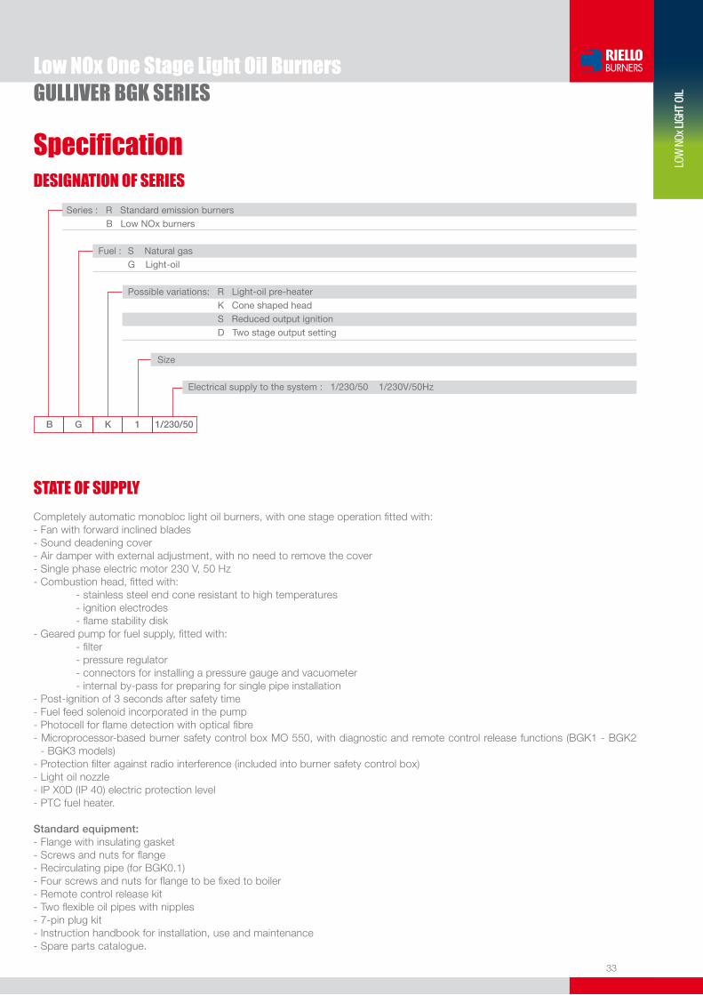
DESIGnATIon oF SERIES
Specification
Low nox one Stage Light oil BurnersGULLIVER BGK SERIES
STATE oF SUPPLY
B G K 1 1/230/50
Series : R Standard emission burners B low Nox burners
Fuel : S Natural gas G light-oil Possible variations: R light-oil pre-heater K Cone shaped head S Reduced output ignition d Two stage output setting
Size
electrical supply to the system : 1/230/50 1/230V/50Hz
Completely automatic monobloc light oil burners, with one stage operation fitted with:- Fan with forward inclined blades- Sound deadening cover- Air damper with external adjustment, with no need to remove the cover- Single phase electric motor 230 V, 50 Hz - Combustion head, fitted with: - stainless steel end cone resistant to high temperatures - ignition electrodes - flame stability disk - Geared pump for fuel supply, fitted with: - filter - pressure regulator - connectors for installing a pressure gauge and vacuometer - internal by-pass for preparing for single pipe installation - Post-ignition of 3 seconds after safety time- Fuel feed solenoid incorporated in the pump- Photocell for flame detection with optical fibre- Microprocessor-based burner safety control box MO 550, with diagnostic and remote control release functions (BGK1 - BGK2
- BGK3 models)- Protection filter against radio interference (included into burner safety control box)- Light oil nozzle- IP X0D (IP 40) electric protection level- PTC fuel heater.
Standard equipment:- Flange with insulating gasket- Screws and nuts for flange- Recirculating pipe (for BGK0.1)- Four screws and nuts for flange to be fixed to boiler- Remote control release kit- Two flexible oil pipes with nipples- 7-pin plug kit- Instruction handbook for installation, use and maintenance- Spare parts catalogue.
34
Available models
Low nox one Stage Light oil BurnersGULLIVER BGK SERIES
Code Model HeAT oUTPUT ToTAleleCTRICAl
PoWeR
(kW)
CeRTIFICATIoN NoTe
(kW) (kg/h)
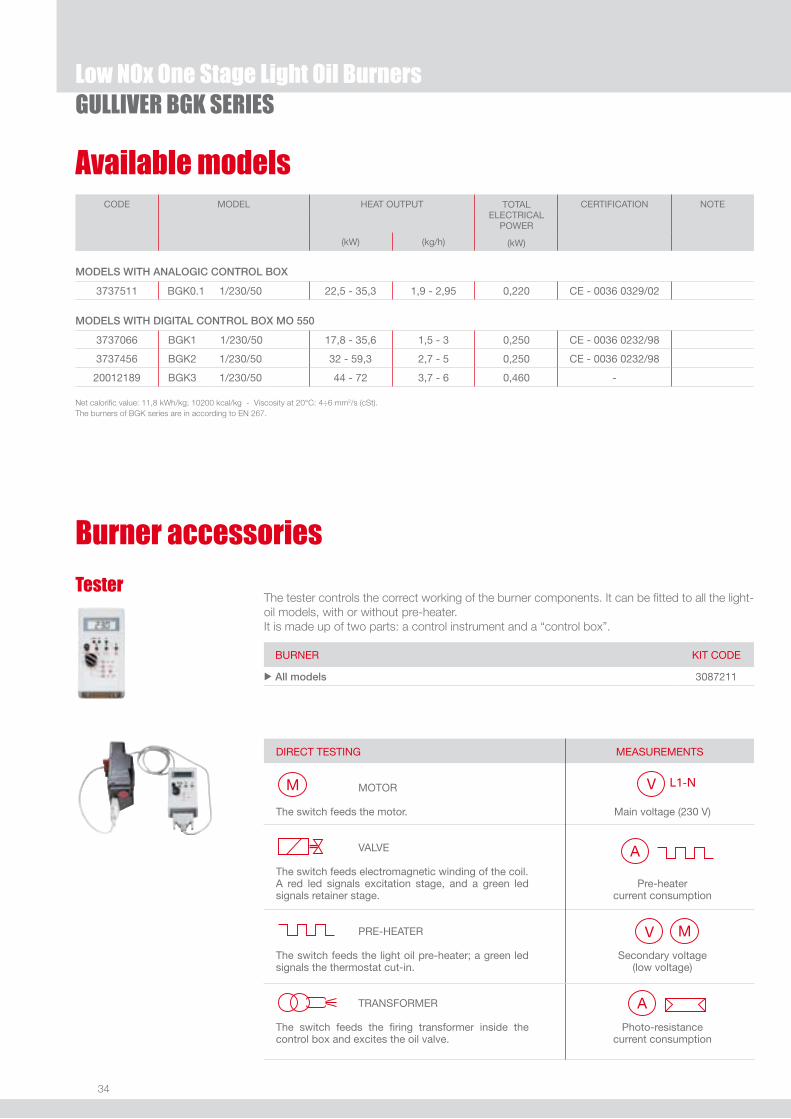
ModelS with ANAloGiC CoNtrol Box
3737511 BGK0.1 1/230/50 22,5 - 35,3 1,9 - 2,95 0,220 Ce - 0036 0329/02
ModelS with diGitAl CoNtrol Box Mo 550
3737066 BGK1 1/230/50 17,8 - 35,6 1,5 - 3 0,250 Ce - 0036 0232/98
3737456 BGK2 1/230/50 32 - 59,3 2,7 - 5 0,250 Ce - 0036 0232/98
20012189 BGK3 1/230/50 44 - 72 3,7 - 6 0,460 -
Net calorific value: 11,8 kWh/kg; 10200 kcal/kg - Viscosity at 20°C: 4÷6 mm2/s (cSt).The burners of BGK series are in according to EN 267.
Burner accessories
BURNeR KIT Code
u All models 3087211
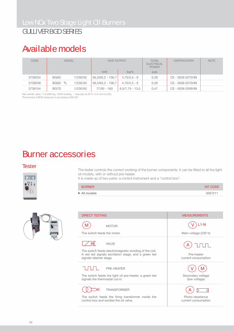
The tester controls the correct working of the burner components. It can be fitted to all the light-oil models, with or without pre-heater. It is made up of two parts: a control instrument and a “control box”.
Tester
dIReCT TeSTING MoToR The switch feeds the motor. VAlVe
The switch feeds electromagnetic winding of the coil. A red led signals excitation stage, and a green led signals retainer stage. PRe-HeATeR The switch feeds the light oil pre-heater; a green led signals the thermostat cut-in. TRANSFoRMeR The switch feeds the firing transformer inside the control box and excites the oil valve.
MeASUReMeNTS
Main voltage (230 V)
Pre-heater current consumption
Secondary voltage (low voltage)
Photo-resistance current consumption

35
Low
Nox
LIG
HT O
IL
Burner accessories
Low nox one Stage Light oil BurnersGULLIVER BGK SERIES
7-pin plug kitIf necessary a 7-pin plug kit is available (in packaging of n. 5 pieces).
BURNeR KIT Code
u All models 3000945
BURNeR FIlTeRING deGRee (µm) KIT Code
u All models 100 3000926
To solve problems of air or water in the oil circuit a special filter/degassing unit is available, made up of aluminium cover, plastic tank, stainless steel filtering cartridge, air release cap and water purge valve. It is available singularly.
Light oil filter/degassing unit
BURNeR KIT Code
u BGK1 - BGK2 - BGK3 3002731
To connect the control box to a personal computer for the transmission of operation, fault signals and detailed service information, an interface adapter with PC software are available.
PC Interface kit
BURNeR FIlTeRING deGRee (µm) KIT Code
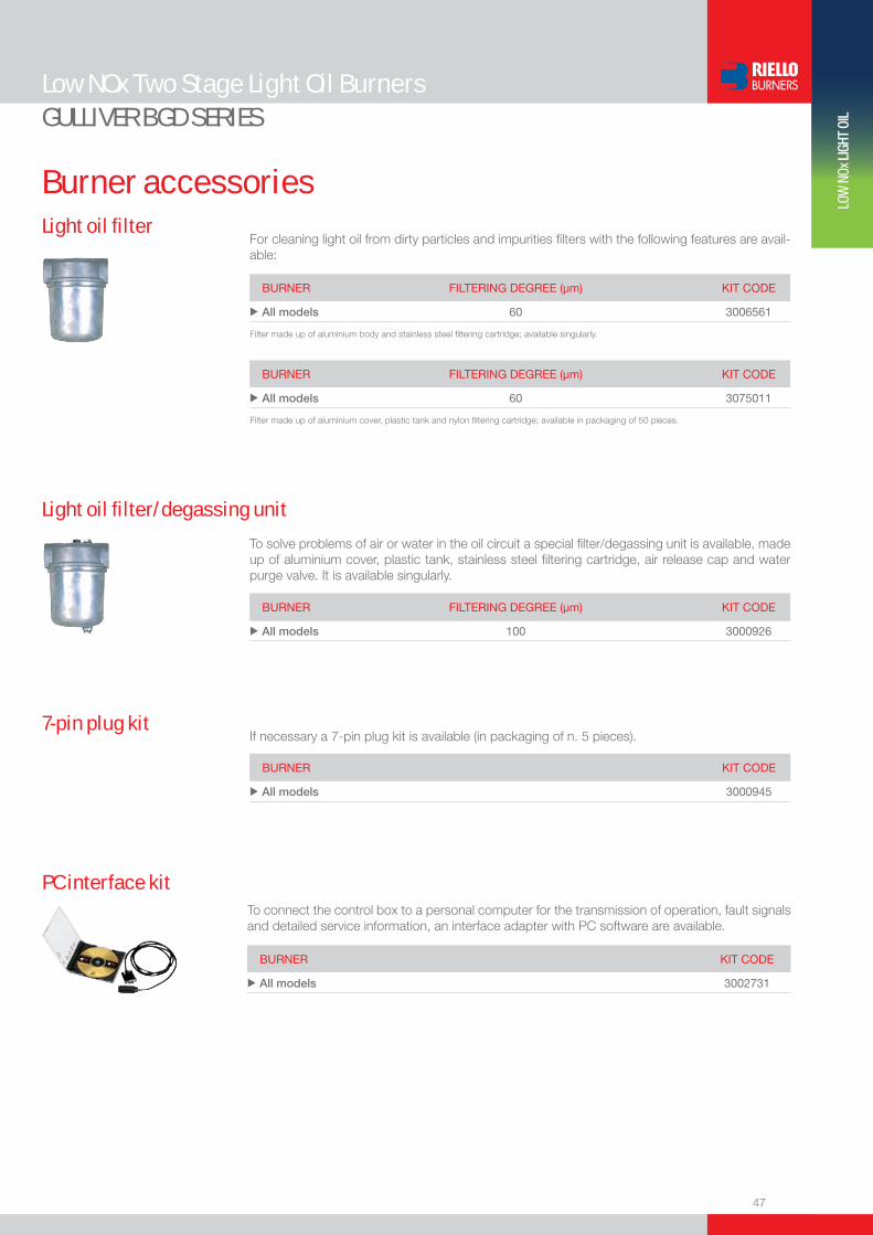
u All models 60 3006561
For cleaning light oil from dirty particles and impurities filters with the following features are avail-able:
Light oil filter
Filter made up of aluminium body and stainless steel filtering cartridge; available singularly.
BURNeR FIlTeRING deGRee (µm) KIT Code
u All models 60 3075011
Filter made up of aluminium cover, plastic tank and nylon filtering cartridge; available in packaging of 50 pieces.
BURNeR KIT Code
u BGK0.1 3001168+3007492
Control box MO 550 and sensor flame
On request, we can supply a more efficient control box with following features:- Digital technology- Post-ignition of 3 seconds after safety time (total ignition time of 8 seconds)- Multi-color LED signalling the various working stage- Visual or PC interface diagnostic functions through multi-color LED device- Remote lock-out reset (the connection is supplied with the MO 550 accessory)- Recycling for 3 attemps if there is flame failure during operation- Programmable post-purge (up to 6 minutes), continuous purge, long pre-purge (2 minutes)- Post-combustion lock-out- Logging of burner operation parameters (for example operating time, number and type of lock-outs)

www.rielloburners.com
We are here providing reliable use of energy for your applications

Low NOx One Stage Light Oil Burners
37
LOW
NOx
LIG
HT O
IL
The Riello Gulliver BG series of one stage light oil burners is a complete range of Low NOx products, developed to respond to any request for home heating, conforming to the strictest standards governing the reduction of polluting emissions. The Gulliver BG series is available in fi ve different models,with an output ranging from 16 to 72,3 kW, divided in two different structures.All the models use the same components designed by Riello for the Gulliver series. The high quality level guarantees safe working. The Gulliver BG burners are fi tted with a microprocessor-based control box, with diagnostic functions.In developing these burners, special attention was paid to reducing noise, to the ease of installation and adjustment, to obtaining the smallest size possible to fi t into any sort of boiler available on the market.All the models are approved by the EN 267 European Standard and conform to European Directives for EMC, Low Voltage, Machinery and Boiler Effi ciency.All the Gulliver BG burners are fi red before leaving the factory.
GULLIVER BG SERIES
FIRING RATES
BG1 16,0 ÷ 26,0 kW BG2 24,0 ÷ 34,5 kW BG3 31,0 ÷ 39,0 kWBG4 35,5 ÷ 54,5 kWBG5 51,0 ÷ 72,3 kW
Useful working fi eldfor choosing theburner
Test conditionsconforming to EN267 Temperature: 20°CPressure: 1013,5 mbarAltitude: 0 m a.s.l.
38
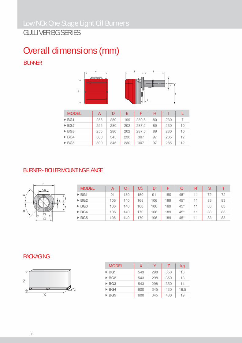
BURNER
BURNER - BOILER MOUNTING FLANGE
Overall dimensions (mm)
Low NOx One Stage Light Oil BurnersGULLIVER BG SERIES
MODEL A D E F H I L u BG1 255 280 199 280,5 80 230 7
u BG2 255 280 202 287,5 89 230 10
u BG3 255 280 202 287,5 89 230 10
u BG4 300 345 230 307 97 285 12
u BG5 300 345 230 307 97 285 12
MODEL A C1 C2 D F Q R S T u BG1 91 130 150 91 180 45° 11 72 72
u BG2 106 140 168 106 189 45° 11 83 83
u BG3 106 140 168 106 189 45° 11 83 83
u BG4 106 140 170 106 189 45° 11 83 83
u BG5 106 140 170 106 189 45° 11 83 83
Z
XY
PACKAGING
MODEL X Y Z kg u BG1 543 298 350 13
u BG2 543 298 350 13
u BG3 543 298 350 14
u BG4 600 345 430 16,5
u BG5 600 345 430 19

39
LOW
NOx
LIG
HT O
IL
DESIGNATION OF SERIES
Specifi cation
Low NOx One Stage Light Oil BurnersGULLIVER BG SERIES
STATE OF SUPPLY
Series : R Standard emission burners B Low NOx burners
Fuel : S Natural gas G Light-oil
Size Possible variations: R Light-oil pre-heater K Cone shaped head S Reduced output ignition D Two stage output setting
Electrical supply to the system : 1/230/50 1/230V/50Hz
B G 1 1/230/50
Completely automatic monobloc light oil burners, one stage operation, made up of:- Fan with forward curve blades- Cover lined with sound-proofi ng material- Air damper, completely closed in stand by, with external adjustment, with no need to remove the cover- Single phase electric motor 230 V, 50 Hz- Combustion head fi tted with: - stainless steel head cone, resistant to high temperatures - ignition electrodes - fl ame stability disk- Geared pump for fuel supply, fi tted with: - fi lter - pressure regulator - attachments for fi tting a pressure gauge and vacuum meter - internal by-pass for preparing for single-pipe installations- Fuel feed solenoid valve incorporated in the pump- IRD for fl ame detection- Microprocessor-based burner safety control box MO 550, with diagnostic and remote control release functions- Protection fi lter against radio interference (included into burner safety control box)- Light oil nozzle- IP X0D (IP 40) protection level- PTC fuel pre-heater.
Standard equipment:- Two fl exible pipes for connection to the light oil supply line- Two nipples for connection to the pump- Flange, screws and nuts for fi xing- Thermal screen- Instruction handbook for installation, use and maintenance- Spare parts catalogue.
40
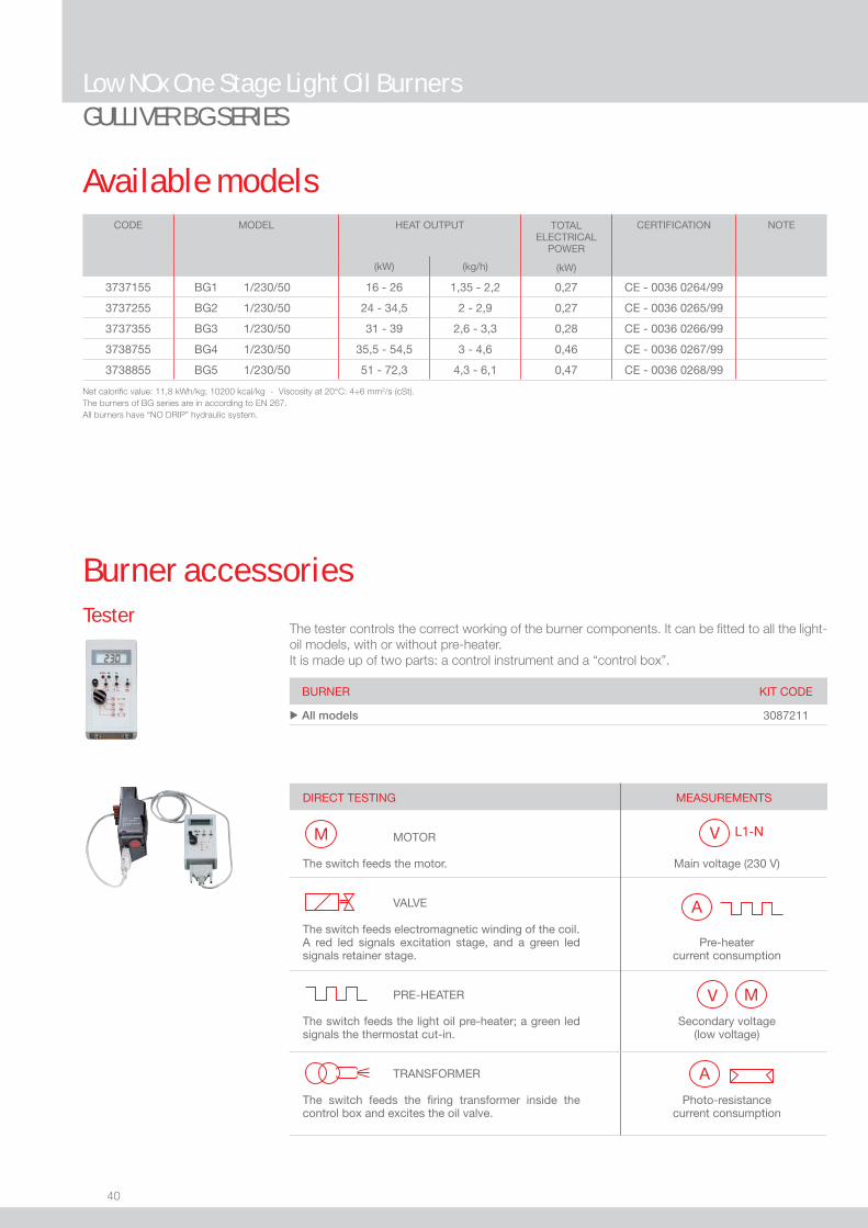
Available models
Low NOx One Stage Light Oil BurnersGULLIVER BG SERIES
CODE MODEL HEAT OUTPUT TOTALELECTRICAL
POWER
(kW)
CERTIFICATION NOTE
(kW) (kg/h)
3737155 BG1 1/230/50 16 - 26 1,35 - 2,2 0,27 CE - 0036 0264/99
3737255 BG2 1/230/50 24 - 34,5 2 - 2,9 0,27 CE - 0036 0265/99
3737355 BG3 1/230/50 31 - 39 2,6 - 3,3 0,28 CE - 0036 0266/99
3738755 BG4 1/230/50 35,5 - 54,5 3 - 4,6 0,46 CE - 0036 0267/99
3738855 BG5 1/230/50 51 - 72,3 4,3 - 6,1 0,47 CE - 0036 0268/99
Net calorifi c value: 11,8 kWh/kg; 10200 kcal/kg - Viscosity at 20°C: 4÷6 mm2/s (cSt).The burners of BG series are in according to EN 267.All burners have “NO DRIP” hydraulic system.
Burner accessories
BURNER KIT CODE
u All models 3087211
The tester controls the correct working of the burner components. It can be fi tted to all the light-oil models, with or without pre-heater. It is made up of two parts: a control instrument and a “control box”.
Tester
DIRECT TESTING MOTOR The switch feeds the motor. VALVE
The switch feeds electromagnetic winding of the coil. A red led signals excitation stage, and a green led signals retainer stage. PRE-HEATER The switch feeds the light oil pre-heater; a green led signals the thermostat cut-in. TRANSFORMER The switch feeds the fi ring transformer inside the control box and excites the oil valve.
MEASUREMENTS
Main voltage (230 V)
Pre-heater current consumption
Secondary voltage (low voltage)
Photo-resistance current consumption

41
LOW
NOx
LIG
HT O
IL
Burner accessories
Low NOx One Stage Light Oil BurnersGULLIVER BG SERIES
7-pin plug kitIf necessary a 7-pin plug kit is available (in packaging of n. 5 pieces).
BURNER KIT CODE
u All models 3000945
BURNER FILTERING DEGREE (µm) KIT CODE
u All models 100 3000926
To solve problems of air or water in the oil circuit a special fi lter/degassing unit is available, made up of aluminium cover, plastic tank, stainless steel fi ltering cartridge, air release cap and water purge valve. It is available singularly.
Light oil fi lter/degassing unit
BURNER FILTERING DEGREE (µm) KIT CODE
u All models 60 3006561
For cleaning light oil from dirty particles and impurities fi lters with the following features are avail-able:
Light oil fi lter
Filter made up of aluminium body and stainless steel fi ltering cartridge; available singularly.
BURNER FILTERING DEGREE (µm) KIT CODE
u All models 60 3075011
Filter made up of aluminium cover, plastic tank and nylon fi ltering cartridge; available in packaging of 50 pieces.
PC interface kitTo connect the control box to a personal computer for the transmission of operation, fault signals and detailed service information, an interface adapter with PC software are available.
BURNER KIT CODE
u All models 3002731


43
LOW
NOx
LIG
HT O
IL
Low NOx Two Stage Light Oil Burners
GULLIVER BGD SERIESThe Riello Gulliver BGD series of two stage light oil burners is a complete range of Low NOx products, developed to respond to any request for home heating, conforming to the strictest standards governing the reduction of polluting emissions. The Gulliver BGD series is available in two different models, with an output ranging from 65,2 to 160 kW, divided in two different structures. All the models use the same components designed by Riello for the Gulliver series. The high quality level guarantees safe working. The Gulliver BGD burners are fi tted with a microprocessor-based control box, with diagnostic functions.In developing these burners, special attention was paid to reducing noise, to the ease of installation and adjustment, to obtaining the smallest size possible to fi t into any sort of boiler available on the market. The two stage operation guarantees high level of thermal unit effi ciency. All the models are approved by the EN 267 European Standard and conform to European Directives for EMC, Low Voltage, Machinery and Boiler Effi ciency.All the Gulliver BGD burners are fi red before leaving the factory.
FIRING RATES
Useful working fi eldfor choosing theburner
1st stage operationrange
Test conditionsconforming to EN267 Temperature: 20°CPressure: 1013,5 mbarAltitude: 0 m a.s.l.
BG6D 56,3/65,2 ÷ 106,7 kW BG7D 77/92 ÷ 160 kW
EN 267
44
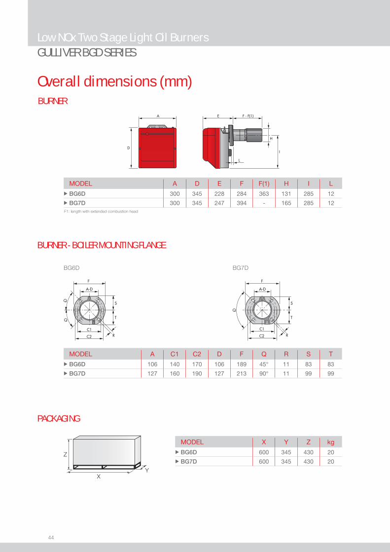
BURNER
Overall dimensions (mm)
GULLIVER BGD SERIESLow NOx Two Stage Light Oil Burners
MODEL A D E F F(1) H I L u BG6D 300 345 228 284 363 131 285 12
u BG7D 300 345 247 394 - 165 285 12
A
D
F - F(1)E
H
I
L
MODEL A C1 C2 D F Q R S T u BG6D 106 140 170 106 189 45° 11 83 83
u BG7D 127 160 190 127 213 90° 11 99 99
BG6D BG7D
MODEL X Y Z kg u BG6D 600 345 430 20
u BG7D 600 345 430 20 Z
XY
PACKAGING
BURNER - BOILER MOUNTING FLANGE
F1: length with extended combustion head
45
LOW
NOx
LIG
HT O
IL
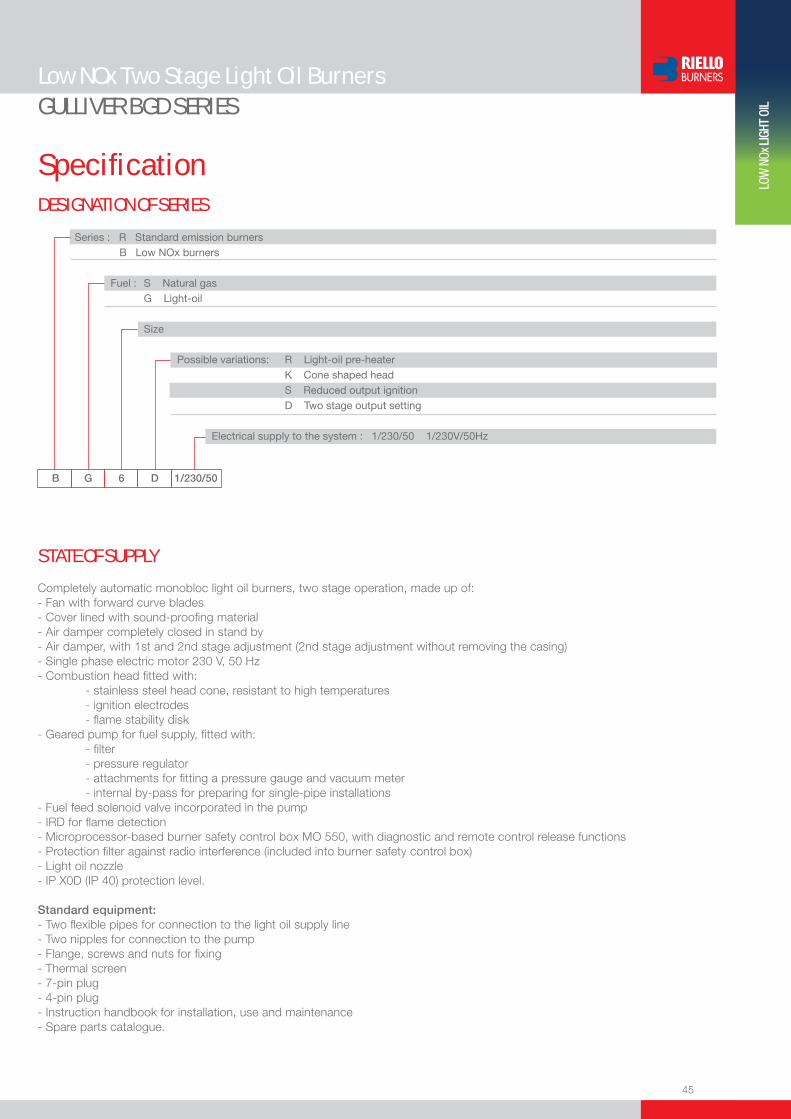
DESIGNATION OF SERIES
Specifi cation
Low NOx Two Stage Light Oil BurnersGULLIVER BGD SERIES
STATE OF SUPPLY
Series : R Standard emission burners B Low NOx burners
Fuel : S Natural gas G Light-oil
Size Possible variations: R Light-oil pre-heater K Cone shaped head S Reduced output ignition D Two stage output setting
Electrical supply to the system : 1/230/50 1/230V/50Hz
B G 6 D 1/230/50
Completely automatic monobloc light oil burners, two stage operation, made up of:- Fan with forward curve blades- Cover lined with sound-proofi ng material- Air damper completely closed in stand by- Air damper, with 1st and 2nd stage adjustment (2nd stage adjustment without removing the casing)- Single phase electric motor 230 V, 50 Hz- Combustion head fi tted with: - stainless steel head cone, resistant to high temperatures - ignition electrodes - fl ame stability disk- Geared pump for fuel supply, fi tted with: - fi lter - pressure regulator - attachments for fi tting a pressure gauge and vacuum meter - internal by-pass for preparing for single-pipe installations- Fuel feed solenoid valve incorporated in the pump- IRD for fl ame detection- Microprocessor-based burner safety control box MO 550, with diagnostic and remote control release functions- Protection fi lter against radio interference (included into burner safety control box)- Light oil nozzle- IP X0D (IP 40) protection level.
Standard equipment:- Two fl exible pipes for connection to the light oil supply line- Two nipples for connection to the pump- Flange, screws and nuts for fi xing- Thermal screen- 7-pin plug- 4-pin plug- Instruction handbook for installation, use and maintenance- Spare parts catalogue.
46
Available models
GULLIVER BGD SERIESLow NOx Two Stage Light Oil Burners
CODE MODEL HEAT OUTPUT TOTALELECTRICAL
POWER
(kW)
CERTIFICATION NOTE
(kW) (kg/h)
3739254 BG6D 1/230/50 56,3/65,2 - 106,7 4,75/5,5 - 9 0,39 CE - 0036 0270/99
3739258 BG6D TL 1/230/50 56,3/65,2 - 106,7 4,75/5,5 - 9 0,39 CE - 0036 0270/99
3739154 BG7D 1/230/50 77/92 - 160 6,5/7,75 - 13,5 0,47 CE - 0036 0269/99
Net calorifi c value: 11,8 kWh/kg; 10200 kcal/kg - Viscosity at 20°C: 4÷6 mm2/s (cSt).The burners of BGD series are in according to EN 267.
Burner accessories
BURNER KIT CODE
u All models 3087211
The tester controls the correct working of the burner components. It can be fi tted to all the light-oil models, with or without pre-heater. It is made up of two parts: a control instrument and a “control box”.
Tester
DIRECT TESTING MOTOR The switch feeds the motor. VALVE
The switch feeds electromagnetic winding of the coil. A red led signals excitation stage, and a green led signals retainer stage. PRE-HEATER The switch feeds the light oil pre-heater; a green led signals the thermostat cut-in. TRANSFORMER The switch feeds the fi ring transformer inside the control box and excites the oil valve.
MEASUREMENTS
Main voltage (230 V)
Pre-heater current consumption
Secondary voltage (low voltage)
Photo-resistance current consumption
47
LOW
NOx
LIG
HT O
IL
Burner accessories
Low NOx Two Stage Light Oil BurnersGULLIVER BGD SERIES
7-pin plug kitIf necessary a 7-pin plug kit is available (in packaging of n. 5 pieces).
BURNER KIT CODE
u All models 3000945
BURNER FILTERING DEGREE (µm) KIT CODE
u All models 100 3000926
To solve problems of air or water in the oil circuit a special fi lter/degassing unit is available, made up of aluminium cover, plastic tank, stainless steel fi ltering cartridge, air release cap and water purge valve. It is available singularly.
Light oil fi lter/degassing unit
BURNER FILTERING DEGREE (µm) KIT CODE
u All models 60 3006561
For cleaning light oil from dirty particles and impurities fi lters with the following features are avail-able:
Light oil fi lter
Filter made up of aluminium body and stainless steel fi ltering cartridge; available singularly.
BURNER FILTERING DEGREE (µm) KIT CODE
u All models 60 3075011
Filter made up of aluminium cover, plastic tank and nylon fi ltering cartridge; available in packaging of 50 pieces.
PC interface kitTo connect the control box to a personal computer for the transmission of operation, fault signals and detailed service information, an interface adapter with PC software are available.
BURNER KIT CODE
u All models 3002731


49
LOW
NOx
LIG
HT O
IL
FIRING RATES
Low NOx Two Stage Light Oil Burners
RL BLU SERIESThe RL BLU series of burners have been designed for use in hot or superheated water boilers, hot air or steam generators, diathermic oil boilers. The series includes two models with output ranging from 116 to 356 kW. A servomotor with three adjustable positions guarantees correct air output and air damper closing when the burner is turned off.The burners are fi tted with an electronic device STATUS PANEL, which supplies complete diagnostic: hour counter, ignition meter, identifi cation of trouble shooting. Special care has been paid to keeping overall dimensions compact, to easy servicing, to design and to noise emissions.The elevated performance of the fans and combustion head, guarantee fl exibility of use and excellent working at all fi ring rates and low NOx emissions.
RL 22 BLU 89/116 ÷ 261 kWRL 32 BLU 166/228 ÷ 356 kW
Useful working fi eldfor choosing theburner
1st stage operationrange
Test conditionsconforming to EN267 Temperature: 20°CPressure: 1013,5 mbarAltitude: 0 m a.s.l.

50
BURNER
BURNER - BOILER MOUNTING FLANGE
Overall dimensions (mm)
Low NOx Two Stage Light Oil BurnersRL BLU SERIES
MODEL A D E F - F (1) H I L O - O (1) u RL 22 BLU 476 474 468 197 - 276 140 352 52 604 - 739
u RL 32 BLU 476 474 468 217 - 293 140 352 52 604 - 739
MODEL D1 D2 Ø u RL 22 BLU 160 224 M8
u RL 32 BLU 160 224 M8
PACKAGING
Z
XY
MODEL X Y Z kg u RL 22 BLU 850 540 550 40
u RL 32 BLU 850 540 550 41

51
LOW
NOx
LIG
HT O
IL
DESIGNATION OF SERIES
Specifi cation
Low NOx Two Stage Light Oil BurnersRL BLU SERIES
R L 22 BLU TC FS1 1/230/50 230/50-60
Series : R
Fuel : S Natural gas L Light oil LS Light oil / Natural gas N Heavy oil
Size
Operation : /1 One stage ... Two stage /M Modulating /E Electronic cam /P Proportioning air/gas valve /EV Electronic cam predisposed for variable speed (with inverter)
Emission : ... Class 1 EN267 - EN676 MZ Class 2 EN267 - EN676 BLU Class 3 EN267 - EN676
MX Class 2 EN267
Class 3 EN676
Head : TC Standard head TL Extended head
Flame control system : FS1 Standard (1 stop every 24 h) FS2 Continuous working (1 stop every 72 h)
Electrical supply to the system : 1/230/50 1/230V/50Hz 3/230/50 3/230V/50Hz 3/400/50 3N/400V/50Hz 3/230-400/50 3/230V/50Hz - 3N/400V/50Hz 3/220/60 3/220V/60Hz 3/380/60 3N/380V/60Hz 3/220-380/60 3/220/60Hz - 3N/380V/60Hz
Auxiliary voltage : 230/50-60 230V/50-60Hz 110/50-60 110V/50-60Hz
ID : Differential switch
BASIC DESIGNATION
EXTENDED DESIGNATION
52
Low NOx Two Stage Light Oil BurnersRL BLU SERIES
Available models
STATE OF SUPPLY
Specifi cation
Monoblock forced draught Low NOx oil burner with completely automatic two stage operation, made up of:- Air suction circuit lined with sound-proofi ng material- Fan with reverse curve blades- Air damper for air setting, driven by the adjustable servomotor- Low emission combustion head, that can be set on the basis of required output - Gears pump for high pressure fuel supply- Two oil valves fi tted directly on to the pump- Photocell for fl ame detection- Burner safety control box- Electronic device to check all burners operational modes (status panel)- Burner on/off switch- Manual high/low fl ame switch- Flame inspection window- Slide bars for easier installation and maintenance- Protection fi lter against radio interference- IP 44 electric protection level.
Standard equipment:- 1 nozzle- 2 fl exible pipes for connection to the oil supply network- 2 gaskets for the fl exible pipes- 2 nipples for connection to the pump- 1 thermal screen- 4 screws for fi xing the burner fl ange to the boiler- Wiring loom fi ttings for electrical connections- Instruction handbook for installation, use and maintenance- Spare parts catalogue.
CODE MODEL HEAT OUTPUT TOTALELECTRICAL
POWER
CERTIFICATION NOTE
(kW) (kg/h) (kW)
3895110 RL 22 BLU TC ST FS1 1/230/50 230/50-60 89/116-261 7,5/9,8-22 0,6 CE 0036 0308/01
3895210 RL 32 BLU TC ST FS1 1/230/50 230/50-60 166/228-356 14/19,2-30 0,6 CE 0036 0308/01
Net calorifi c value: 11,8 kWh/kg - 10200 kcal/kg - Viscosity at 20°C: 4-6 mm2/s (cSt) The burners of RL BLU series are in according to 89/336 (2004/108) - 73/23 (2006/95) - 98/37 - 92/42 EC Directive and EN 267.

53
LOW
NOx
LIG
HT O
IL
Low NOx Two Stage Light Oil BurnersRL BLU SERIES
NozzlesThe nozzles of RL 22 and 32 BLU burners are chosen on the basis of the maximum output re-quired from the application.
NOTE: each burner needs N° 1 nozzle.
GPH
RATED DELIVERY [kg/h] AT 8 bar
RATED DELIVERY [kg/h] AT 20 bar
DELAVAN 60°A CODE
MONARCH 60°PLP CODE
u 2.25 7.4 11.9 3042134 3041132
u 2.50 8.2 13.4 3042144 3041142
u 3.00 9.9 16.1 3042148 3041152
u 3.50 11.5 18.8 3042164 3041162
u 4.00 13.2 21.5 3042174 3041172
u 4.50 14.8 24.0 3042184 3041182
u 5.00 16.5 26.8 3042194 3041192
u 5.50 18.1 29.5 3042204 3041202
u 6.00 19.8 32.2 3042214 3041212
“Standard head” burners can be transformed into “extended head” versions, by using the special kit.
Extended head kit
BURNER
STANDARD HEAD LENGTH (mm)
EXTENDED HEAD LENGTH (mm)
KIT CODE
u RL 22 BLU 197 276 3010204
u RL 32 BLU 217 293 3010205
To solve problem of air in the oil sucked, two versions of degasing unit are available.
Degasing unit
BURNER
FILTER
FILTERING DEGREE (µm)
DEGASING UNIT CODE
u RL 22 BLU - RL 32 BLU With fi lter 50 - 75 3010055
u RL 22 BLU - RL 32 BLU Without fi lter - 3010054
Burner accessories
If noise emission needs reducing even further, sound-proofi ng boxes are available.
Sound proofi ng box
BURNER
BOX TYPE
AVERAGE NOISE REDUCTION [dB(A)] (*)
BOX CODE
u RL 22 BLU - RL 32 BLU C1/3 10 3010403
(*) according to EN 15036-1 standard
54
Low NOx Two Stage Light Oil BurnersRL BLU SERIES
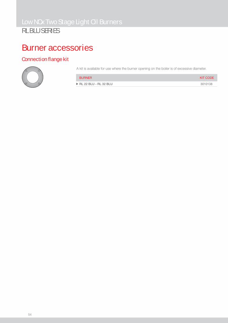
Connection fl ange kit
A kit is available for use where the burner opening on the boiler is of excessive diameter.
Burner accessories
BURNER KIT CODE
u RL 22 BLU - RL 32 BLU 3010138

55
LOW
NOx
LIG
HT O
IL
Low NOx Modulating Light Oil Burners
RL/M BLU SERIESThe RL/M BLU burners series covers a fi ring range from 360 to 1023 kW, and it has been designed for use in hot or superheated water boilers, hot air or steam generators and diathermic oil boilers.Operation can be “two stage progressive” or, alternatively, “modulating” with the installation of a PID logic regulator and respective probes.RL/M BLU burners series guarantees high effi ciency levels in all applications, thus reducing fuel consumption and running costs.Sound emissions optimisation is guaranteed by the use of fans with reverse curve blades and sound deadening material incorporated in the air suction circuit.The exclusive design ensures reduced dimensions, simple use and maintenance. A wide range of accessories guarantees elevated working fl exibility.
RL 55/M BLU 190/356 ÷ 712 kW RL 85/M BLU 223/594 ÷ 1023 kW
NOTE: The RL 55-85/M BLU burners are designed exclusively for combustion chambers with fl ue gas outlet from the bottom, for example three fl ue gas passes (not reverse fl ame boilers) accessible through the door. Maximum thickness of the frontal boiler wall: 250 mm.Exhaust gases ducts must be always and exclusively directed upwards; change in directions must be realized only by bent elements; the angle between the axis of the stroke coming out of the combustion chamber and the axis of the chimney must be smaller than 45°.
Useful working fi eldfor choosing theburner
Modulation range
Test conditionsconforming to EN267 Temperature: 20°CPressure: 1013,5 mbarAltitude: 0 m a.s.l.
FIRING RATES

56
BURNER
Overall dimensions (mm)
Low NOx Modulating Light Oil BurnersRL/M BLU SERIES
MODEL A B C D E F H I O u RL 55/M BLU 663 296 367 555 680 365 189 430 951
u RL 85/M BLU 705 338 367 555 680 365 189 430 951
MODEL D1 D2 Ø u RL 55/M BLU 195 275-325 M12
u RL 85/M BLU 195 275-325 M12
PACKAGING
Z
XY
MODEL X Y Z kg u RL 55/M BLU 1270 745 885 65
u RL 85/M BLU 1270 745 885 70
BURNER - BOILER MOUNTING FLANGE
57
LOW
NOx
LIG
HT O
IL
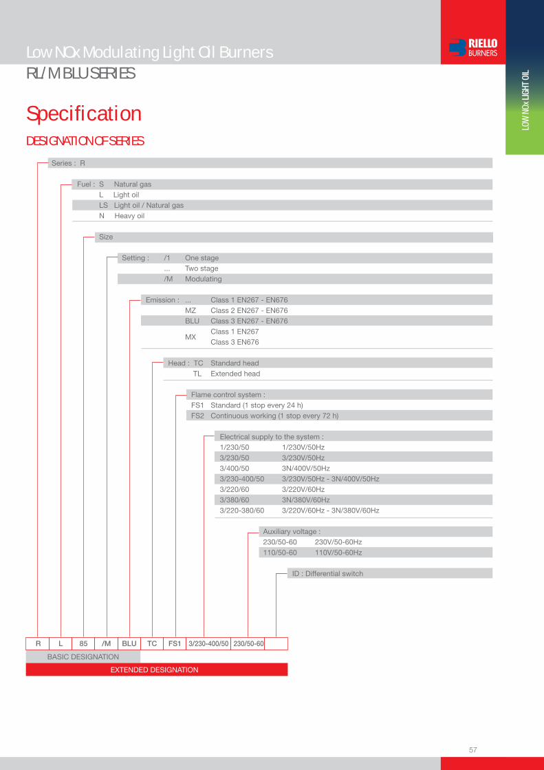
DESIGNATION OF SERIES
Specifi cation
Low NOx Modulating Light Oil BurnersRL/M BLU SERIES
R L 85 /M BLU TC FS1 3/230-400/50 230/50-60
Series : R
Fuel : S Natural gas L Light oil LS Light oil / Natural gas N Heavy oil
Size
Setting : /1 One stage ... Two stage /M Modulating Emission : ... Class 1 EN267 - EN676 MZ Class 2 EN267 - EN676 BLU Class 3 EN267 - EN676
MX Class 1 EN267
Class 3 EN676
Head : TC Standard head TL Extended head
Flame control system : FS1 Standard (1 stop every 24 h) FS2 Continuous working (1 stop every 72 h)
Electrical supply to the system : 1/230/50 1/230V/50Hz 3/230/50 3/230V/50Hz 3/400/50 3N/400V/50Hz 3/230-400/50 3/230V/50Hz - 3N/400V/50Hz 3/220/60 3/220V/60Hz 3/380/60 3N/380V/60Hz 3/220-380/60 3/220V/60Hz - 3N/380V/60Hz
Auxiliary voltage : 230/50-60 230V/50-60Hz 110/50-60 110V/50-60Hz
ID : Differential switch
BASIC DESIGNATION
EXTENDED DESIGNATION
58
Low NOx Modulating Light Oil BurnersRL/M BLU SERIES
Available models
STATE OF SUPPLY
Specifi cation
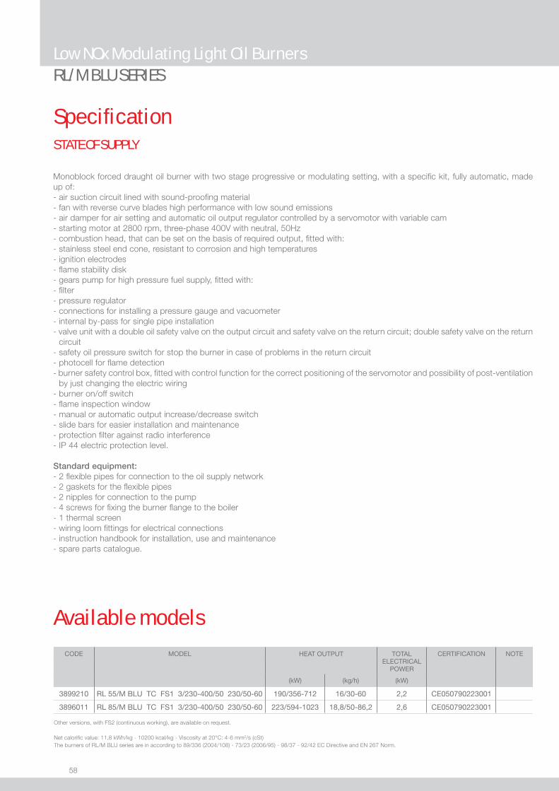
Monoblock forced draught oil burner with two stage progressive or modulating setting, with a specifi c kit, fully automatic, made up of:- air suction circuit lined with sound-proofi ng material- fan with reverse curve blades high performance with low sound emissions- air damper for air setting and automatic oil output regulator controlled by a servomotor with variable cam- starting motor at 2800 rpm, three-phase 400V with neutral, 50Hz- combustion head, that can be set on the basis of required output, fi tted with:- stainless steel end cone, resistant to corrosion and high temperatures- ignition electrodes- fl ame stability disk- gears pump for high pressure fuel supply, fi tted with:- fi lter- pressure regulator- connections for installing a pressure gauge and vacuometer- internal by-pass for single pipe installation- valve unit with a double oil safety valve on the output circuit and safety valve on the return circuit; double safety valve on the return
circuit - safety oil pressure switch for stop the burner in case of problems in the return circuit- photocell for fl ame detection- burner safety control box, fi tted with control function for the correct positioning of the servomotor and possibility of post-ventilation
by just changing the electric wiring- burner on/off switch- fl ame inspection window- manual or automatic output increase/decrease switch- slide bars for easier installation and maintenance- protection fi lter against radio interference- IP 44 electric protection level.
Standard equipment:- 2 fl exible pipes for connection to the oil supply network- 2 gaskets for the fl exible pipes- 2 nipples for connection to the pump- 4 screws for fi xing the burner fl ange to the boiler- 1 thermal screen- wiring loom fi ttings for electrical connections- instruction handbook for installation, use and maintenance- spare parts catalogue.
CODE MODEL HEAT OUTPUT TOTALELECTRICAL
POWER
CERTIFICATION NOTE
(kW) (kg/h) (kW)
3899210 RL 55/M BLU TC FS1 3/230-400/50 230/50-60 190/356-712 16/30-60 2,2 CE050790223001
3896011 RL 85/M BLU TC FS1 3/230-400/50 230/50-60 223/594-1023 18,8/50-86,2 2,6 CE050790223001
Other versions, with FS2 (continuous working), are available on request.
Net calorifi c value: 11,8 kWh/kg - 10200 kcal/kg - Viscosity at 20°C: 4-6 mm2/s (cSt) The burners of RL/M BLU series are in according to 89/336 (2004/108) - 73/23 (2006/95) - 98/37 - 92/42 EC Directive and EN 267 Norm.
59
LOW
NOx
LIG
HT O
IL
Burner accessories
RL/M BLU SERIESLow NOx Modulating Light Oil Burners
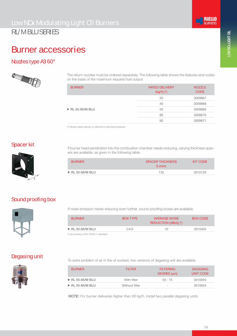
Nozzles type A3 60°
The return nozzles must be ordered separately. The following table shows the features and codes on the basis of the maximum required fuel output.
BURNER
RATED DELIVERY (kg/h) (*)
NOZZLE CODE
30 3009867
40 3009868
u RL 55-85/M BLU 50 3009869
60 3009870
90 3009871
(*) Nozzle rated delivery is referred to atomised pressure
If noise emission needs reducing even further, sound-proofi ng boxes are available.
Sound proofi ng box
BURNER
BOX TYPE
AVERAGE NOISE REDUCTION [dB(A)] (*)
BOX CODE
u RL 55-85/M BLU C4/5 10 3010404
(*) according to EN 15036-1 standard
If burner head penetration into the combustion chamber needs reducing, varying thickness spac-ers are available, as given in the following table:
Spacer kit
BURNER
SPACER THICKNESS S (mm)
KIT CODE
u RL 55-85/M BLU 135 3010129
To solve problem of air in the oil sucked, two versions of degasing unit are available.Degasing unit
BURNER
FILTER
FILTERING DEGREE (µm)
DEGASING UNIT CODE
u RL 55-85/M BLU With fi lter 50 - 75 3010055
u RL 55-85/M BLU Without fi lter - 3010054
NOTE: For burner deliveries higher than 80 kg/h, install two parallel degasing units.

60
Low NOx Modulating Light Oil BurnersRL/M BLU SERIES
Burner accessoriesAccessories for modulating operation
To obtain modulating operation, the RL/M BLU series of burners requires a regulator with three point outlet controls. The following table lists the accessories for modulating operation with their application range.
BURNER
REGULATOR TYPE
REGULATOR CODE
u RL 55-85/M BLU RWF 40 3010212
Depending on the servomotor fi tted to the burner, a three-pole potentiometer (1000 Ω) can be installed to check the position of the servomotor. The KITS available for the various burners are listed below.
BURNER
POTENTIOMETER KIT CODE
u RL 55-85/M BLU 3010021
The relative temperature or pressure probes fi tted to the regulator must be chosen on the basis of the application.
BURNER PROBE TYPE RANGE (°C) (bar) PROBE CODE
u RL/M BLU Temperature PT 100 -100 ÷ 500°C 3010110
u RL/M BLU Pressure 4 ÷ 20 mA 0 ÷ 2,5 bar 3010213
u RL/M BLU Pressure 4 ÷ 20 mA 0 ÷ 16 bar 3010214
One Stage Light Oil Burners
61
LIGH
T OI
L
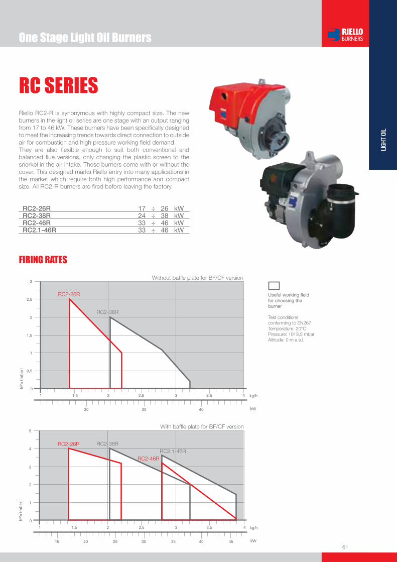
RC SERIESRiello RC2-R is synonymous with highly compact size. The new burners in the light oil series are one stage with an output ranging from 17 to 46 kW. These burners have been specifi cally designed to meet the increasing trends towards direct connection to outside air for combustion and high pressure working fi eld demand.They are also fl exible enough to suit both conventional and balanced fl ue versions, only changing the plastic screen to the snorkel in the air intake. These burners come with or without the cover. This designed marks Riello entry into many applications in the market which require both high performance and compact size. All RC2-R burners are fi red before leaving the factory.
RC2-26R 17 ÷ 26 kWRC2-38R 24 ÷ 38 kWRC2-46R 33 ÷ 46 kWRC2.1-46R 33 ÷ 46 kW
RC2-26R
RC2-38R
RC2-46R
RC2-38RRC2-26RRC2.1-46R
Without baffl e plate for BF/CF version
With baffl e plate for BF/CF version
FIRING RATES
Useful working fi eldfor choosing theburner
Test conditionsconforming to EN267 Temperature: 20°CPressure: 1013,5 mbarAltitude: 0 m a.s.l.

62
RC SERIES
BURNER
BURNER - BOILER MOUNTING FLANGE
Overall dimensions (mm)
One Stage Light Oil Burners
Model A D E F H I Lu RC2-26R 267 256 192 108 85 183 10
u RC2-38R 267 256 192 108 85 183 10
u RC2-46R 267 256 192 108 85 183 10
u RC2.1-46R 267 256 192 108 85 183 10
Z
XY
Model C C1 C2 F Q Ru RC2-26R 144 130 150 180 45° 11
u RC2-38R 144 130 150 180 45° 11
u RC2-46R 144 130 150 180 45° 11
u RC2.1-46R 144 130 150 180 45° 11
Model X Y Z kgu RC2-26R 363 295 310 10
u RC2-38R 363 295 310 10
u RC2-46R 363 295 310 10
u RC2.1-46R 363 295 310 10
PACKAGING

63
LIGH
T OI
L
RC SERIES
DESIGNATION OF SERIES
STATE OF SUPPLY
Specifi cation
One Stage Light Oil Burners
RC 2-46 R 1/230/50
Series : RC
Size
Possible variations : R Light-oil pre-heater
Electrical supply to the system : 1/230/50 1/230V/50Hz
Completely automatic monobloc light oil burners, with single stage operation made up of:- Forward blades fan and airtight fan house for high performance- Air damper with adjustment for conventional fl ue version- Single phase electric motor 230 V, 50 Hz- Combustion head made up of: - stainless steel end cone resistant to high temperatures - ignition electrodes - fl ame stability disk- Geared pump for fuel supply, fi tted with: - fi lter - pressure regulator - connectors for installing a pressure gauge and vacuometer - inner by-pass for preparing for single pipe installation- Fuel feed solenoid incorporated in the pump- Photocell for fl ame detection- Electronic fl ame control equipment- IP X0D (IP 40) protection level.
Standard equipment:- Two fl exible pipes and two connectors- Flange, screen screws and nuts for fi xing- Cable with 6-pole socket- Instruction handbook for installation, use and maintenance- Spare parts catalogue.
64
RC SERIES
Available models
One Stage Light Oil Burners
CODE MODEL
HEAT OUTPUT TOTALELECTRICAL
POWER
CERTIFICATION NOTE
(kW) (kg/h) (kW)
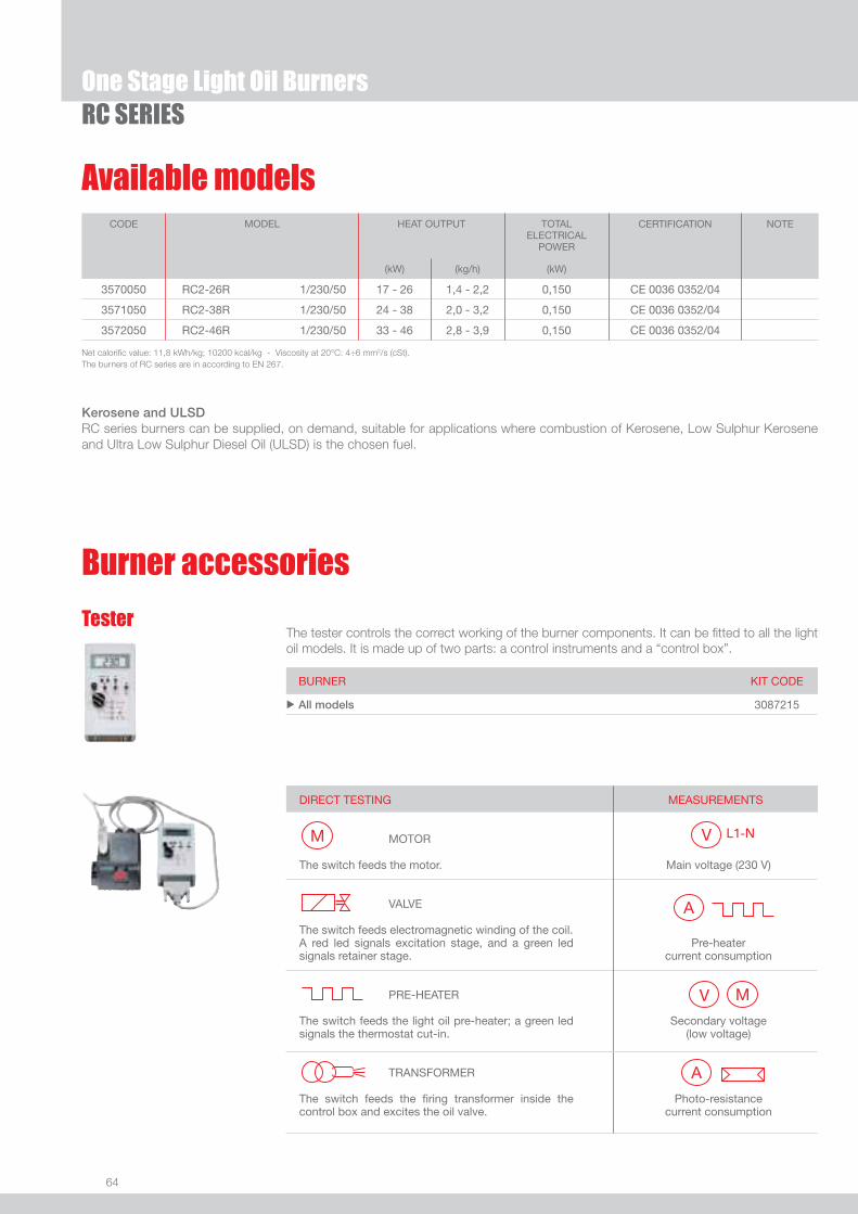
3570050 RC2-26R 1/230/50 17 - 26 1,4 - 2,2 0,150 CE 0036 0352/04
3571050 RC2-38R 1/230/50 24 - 38 2,0 - 3,2 0,150 CE 0036 0352/04
3572050 RC2-46R 1/230/50 33 - 46 2,8 - 3,9 0,150 CE 0036 0352/04
Net calorifi c value: 11,8 kWh/kg; 10200 kcal/kg - Viscosity at 20°C: 4÷6 mm2/s (cSt).The burners of RC series are in according to EN 267.
Burner accessories
BURNER KIT CODE
u All models 3087215
The tester controls the correct working of the burner components. It can be fi tted to all the light oil models. It is made up of two parts: a control instruments and a “control box”.
Tester
DIRECT TESTING MOTOR The switch feeds the motor. VALVE
The switch feeds electromagnetic winding of the coil. A red led signals excitation stage, and a green led signals retainer stage. PRE-HEATER The switch feeds the light oil pre-heater; a green led signals the thermostat cut-in. TRANSFORMER The switch feeds the fi ring transformer inside the control box and excites the oil valve.
MEASUREMENTS
Main voltage (230 V)
Pre-heater current consumption
Secondary voltage (low voltage)
Photo-resistance current consumption
Kerosene and ULSDRC series burners can be supplied, on demand, suitable for applications where combustion of Kerosene, Low Sulphur Kerosene and Ultra Low Sulphur Diesel Oil (ULSD) is the chosen fuel.
65
LIGH
T OI
L
RC SERIES
Burner accessories
One Stage Light Oil Burners
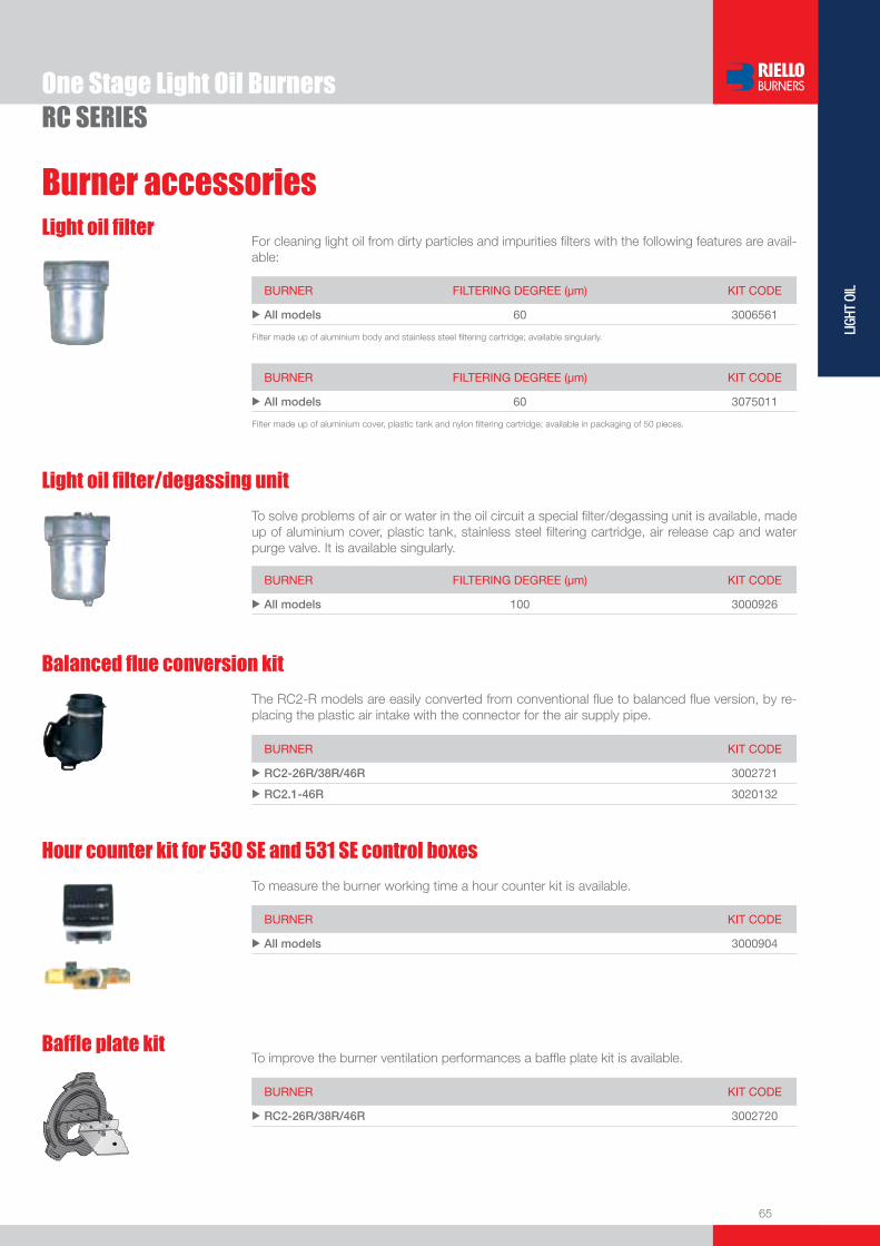
BURNER FILTERING DEGREE (µm) KIT CODE
u All models 100 3000926
To solve problems of air or water in the oil circuit a special fi lter/degassing unit is available, made up of aluminium cover, plastic tank, stainless steel fi ltering cartridge, air release cap and water purge valve. It is available singularly.
Light oil fi lter/degassing unit
BURNER FILTERING DEGREE (µm) KIT CODE
u All models 60 3006561
For cleaning light oil from dirty particles and impurities fi lters with the following features are avail-able:
Light oil fi lter
Filter made up of aluminium body and stainless steel fi ltering cartridge; available singularly.
BURNER FILTERING DEGREE (µm) KIT CODE
u All models 60 3075011
Filter made up of aluminium cover, plastic tank and nylon fi ltering cartridge; available in packaging of 50 pieces.
BURNER KIT CODE
u RC2-26R/38R/46R 3002721
u RC2.1-46R 3020132
The RC2-R models are easily converted from conventional fl ue to balanced fl ue version, by re-placing the plastic air intake with the connector for the air supply pipe.
Balanced fl ue conversion kit
BURNER KIT CODE
u All models 3000904
To measure the burner working time a hour counter kit is available.
Hour counter kit for 530 SE and 531 SE control boxes
BURNER KIT CODE
u RC2-26R/38R/46R 3002720
To improve the burner ventilation performances a baffl e plate kit is available.Baffl e plate kit


One Stage Light Oil Burners
67
LIGH
T OI
L
GULLIVER RG SERIESThe Riello Gulliver RG one stage light oil burners series, is a complete range of products developed to respond to any request for home heating. The Gulliver RG series is available in ten different models, with an output ranging from 16,6 to 309,5 kW, divided in fi ve different structures.All the models use the same components designed by Riello for the Gulliver series. The high quality level guarantees safe working.In developing these burners, special attention was paid to reducing noise, to the easiness of installation and adjustment, to obtaining the smallest size possible to fi t into any sort of boiler available on the market.All the models are approved by the EN 267 European Standard and conform to European Directives for EMC, Low Voltage, Machinery and Boiler Effi ciency.All the Gulliver RG burners are fi red before leaving the factory. RG0.R 16,6 ÷ 27,3 kW
RG0.1 22,5 ÷ 35,6 kWRG0.1R 21,3 ÷ 36,7 kWRG1 32,0 ÷ 60,0 kW RG1R 20,0 ÷ 60,0 kW RG1RK 15,0 ÷ 60,0 kW RG2 47,0 ÷ 119,0 kW RG3 83,0 ÷ 178,0 kWRG4S 118,5 ÷ 237,0 kWRG5S 160,0 ÷ 309,5 kW
FIRING RATES
Useful working fi eldfor choosing theburner
Test conditionsconforming to EN267 Temperature: 20°CPressure: 1013,5 mbarAltitude: 0 m a.s.l.

68
One Stage Light Oil BurnersGULLIVER RG SERIES
FIRING RATES
Useful working fi eldfor choosing theburner
Test conditionsconforming to EN267 Temperature: 20°CPressure: 1013,5 mbarAltitude: 0 m a.s.l.
69
LIGH
T OI
L
One Stage Light Oil Burners
Overall dimensions (mm)BURNER
BURNER - BOILER MOUNTING FLANGE
PACKAGING
Z
XY
GULLIVER RG SERIES
GULLIVER RG0 GULLIVER RG
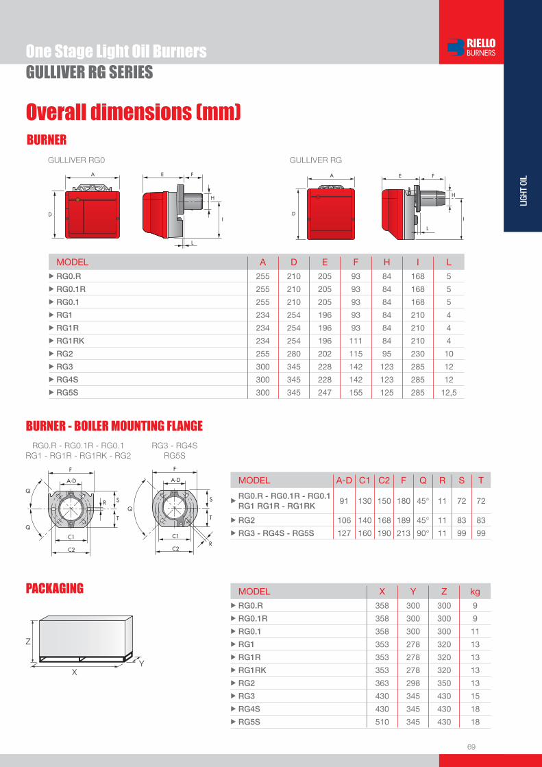
MODEL A D E F H I L u RG0.R 255 210 205 93 84 168 5
u RG0.1R 255 210 205 93 84 168 5
u RG0.1 255 210 205 93 84 168 5
u RG1 234 254 196 93 84 210 4
u RG1R 234 254 196 93 84 210 4
u RG1RK 234 254 196 111 84 210 4
u RG2 255 280 202 115 95 230 10
u RG3 300 345 228 142 123 285 12
u RG4S 300 345 228 142 123 285 12
u RG5S 300 345 247 155 125 285 12,5
RG0.R - RG0.1R - RG0.1 RG1 - RG1R - RG1RK - RG2
RG3 - RG4S RG5S
MODEL A-D C1 C2 F Q R S T
uRG0.R - RG0.1R - RG0.1 RG1 RG1R - RG1RK
91 130 150 180 45° 11 72 72
u RG2 106 140 168 189 45° 11 83 83
u RG3 - RG4S - RG5S 127 160 190 213 90° 11 99 99
MODEL X Y Z kg u RG0.R 358 300 300 9
u RG0.1R 358 300 300 9
u RG0.1 358 300 300 11
u RG1 353 278 320 13
u RG1R 353 278 320 13
u RG1RK 353 278 320 13
u RG2 363 298 350 13
u RG3 430 345 430 15
u RG4S 430 345 430 18
u RG5S 510 345 430 18

70
One Stage Light Oil BurnersGULLIVER RG SERIES
DESIGNATION OF SERIES
STATE OF SUPPLY
Specifi cation
Completely automatic monobloc light oil burners, one stage operation, made up of:- Fan with forward curve blades- Cover lined with sound-proofi ng material- Air damper, completely closed in stand by, with external adjustment, without need to remove the cover- Single phase electric motor 230 V, 50 Hz- Combustion head fi tted with: - stainless steel head cone, resistant to high temperatures - ignition electrodes - fl ame stability disk- Geared pump for fuel supply, fi tted with: - fi lter - pressure regulator - attachments for fi tting a pressure gauge and vacuum meter - internal by-pass for preparing for single-pipe installations- Fuel feed solenoid valve incorporated in the pump- Photocell for fl ame detection- Electronic fl ame control equipment- Light oil nozzle- IP X0D (IP 40) protection level- PTC fuel pre-heater (optional)- Reduced output ignition mechanism (optional).
Standard equipment:- Two fl exible pipes for connection to the light oil supply line- Two nipples for connection to the pump- Flange, screws and nuts for fi xing- Thermal screen- 7-pin plug (not included in models with digital control box MO 550)- Instruction handbook for installation, use and maintenance- Spare parts catalogue.
R G 4 S 1/230/50
Series : R Standard emission burners B Low NOx burners
Fuel : S Natural gas G Light-oil Size
Possible variations: R Light-oil pre-heater K Cone shaped head S Reduced output ignition D Two stage output setting
Electrical supply to the system : 1/230/50 1/230V/50Hz

71
LIGH
T OI
L
One Stage Light Oil Burners
Available models
GULLIVER RG SERIES
Net calorifi c value: 11,8 kWh/kg; 10200 kcal/kg - Viscosity at 20°C: 4÷6 mm2/s (cSt).The burners of RG series are in according to EN 267.On demand all RG burners can be supplied with digital control box MO 550.
CODE MODEL HEAT OUTPUT TOTALELECTRICAL POWER
CERTIFICATION NOTE
(kW) (kg/h) (kW)
MODELS WITH ANALOGIC CONTROL BOX
3736550 RG0.R 1/230/50 16,6 - 27,3 1,4 - 2,3 0,290 CE - 0036 0272/99
3736850 RG0.1 1/230/50 22,5 - 35,6 1,9 - 3,0 0,170 CE - 0036 0294/00
3736750 RG0.1R 1/230/50 21,3 - 36,7 1,8 - 3,1 0,290 CE - 0036 0273/99
3736350 RG1 1/230/50 32 - 60 2,7 - 5 0,170 CE - 0036 0341/03
3736450 RG1R 1/230/50 20 - 60 1,7 - 5 0,290 CE - 0036 0341/03
3736250 RG1RK 1/230/50 15 - 60 1,3 - 5 0,290 CE - 0036 0341/03
3737750 RG2 1/230/50 47 - 119 4 - 10 0,180 CE - 0036 0344/03
3739350 RG3 1/230/50 83 - 178 7 - 15 0,390 CE - 0036 0348/04
3739650 RG4S 1/230/50 118,5 - 237 10 - 20 0,390 CE - 0036 0348/04
3739950 RG5S 1/230/50 160 - 309,5 13,5 - 26,1 0,470 CE - 0036 0310/01
MODELS WITH DIGITAL CONTROL BOX MO 550
3736554 RG0.R 1/230/50 16,6 - 27,3 1,4 - 2,3 0,290 CE - 0036 0272/99
3736254 RG1RK 1/230/50 15 - 60 1,3 - 5 0,290 CE - 0036 0341/03
3737754 RG2 1/230/50 47 - 119 4 - 10 0,180 CE - 0036 0344/03
3739354 RG3 1/230/50 83 - 178 7 - 15 0,390 CE - 0036 0348/04
3739654 RG4S 1/230/50 118.5 - 237 10 - 20 0,390 CE - 0036 0348/04
Bio fuels Riello Burners is able to offer technical variants which allow burners to be used within environmental heating, process or special applications. These applications now include solutions for liquid Bio fuels (I.e. biodiesel and vegetable oil).Our experience in research and development and fi eld applications with organic origin Bio fuels has resulted in Riello being able to offer a wide range of solutions for the combustion of Bio fuels.
Kerosene and ULSDGulliver RG series burners can be supplied, on demand, suitable for applications where combustion of Kerosene, Low Sulphur Kerosene and Ultra Low Sulphur Diesel Oil (ULSD) is the chosen fuel.These burner variants can be provided upon request and after a technical-commercial evaluation; for more information please contact Riello Burners Commercial and Technical Department, our Application Engineers will be pleased to help you.

72
One Stage Light Oil Burners
By using the special accessories, the burner can be with-drawn to reduce head penetration into the combustion chamber.
Spacer kit
BURNER SPACER THICKNESS S (mm)
KIT CODE
u RG0.R - RG0.1R - RG0.1 - RG1 - RG1R - RG1RK 15 3007931
u RG2 25 3000672
u RG3 - RG4S - RG5S 25 3000673
Pre-heater kitThis kit is used only for Gulliver RG1 burner. It can be installed in particular weather conditions and with viscous oil.
BURNER KIT CODE
u RG1 3001083
GULLIVER RG SERIES
Burner accessoriesExtended head kit
Kits of extended heads are available.
BURNER STANDARD HEADLENGTH (mm)
EXTENDED HEADLENGTH (mm)
KIT CODE
u RG1 - RG1R 93 163 3000963
u RG1RK 111 181 3000982
u RG2 115 180 3000964
u RG2 115 300 3000967
u RG3 142 210 3000965
u RG3 142 300 3000968
u RG4S 142 210 3000966
u RG4S 142 300 3000969
u RG5S 155 300 3001068

73
LIGH
T OI
L
Burner accessories
One Stage Light Oil BurnersGULLIVER RG SERIES
BURNER KIT CODE
u RG0.R - RG0.1R - RG0.1 - RG1R - RG1RK 3001168+3007492
u RG1 - RG2 - RG3 - RG4S - RG5S 3001168+3007492+3007792
BURNER KIT CODE
u All models 3087211
The tester controls the correct working of the burner components. It can be fi tted to all the light-oil models, with or without pre-heater. It is made up of two parts: a control instrument and a “control box”.
Tester
DIRECT TESTING MOTOR The switch feeds the motor. VALVE
The switch feeds electromagnetic winding of the coil. A red led signals excitation stage, and a green led signals retainer stage. PRE-HEATER The switch feeds the light oil pre-heater; a green led signals the thermostat cut-in. TRANSFORMER The switch feeds the fi ring transformer inside the control box and excites the oil valve.
MEASUREMENTS
Main voltage (230 V)
Pre-heater current consumption
Secondary voltage (low voltage)
Photo-resistance current consumption
Control box MO 550, sensor fl ame and short circuit plug
On request, we can supply a more effi cient control box with following features:- Digital technology- Post-ignition of 3 seconds after safety time (total ignition time of 8 seconds)- Multi-color LED signalling the various working stage- Visual or PC interface diagnostic functions through multi-color LED device- Remote lock-out reset (the connection is supplied with the MO 550 accessory)- Recycling for 3 attemps if there is fl ame failure during operation- Programmable post-purge (up to 6 minutes), continuous purge, long pre-purge (2 minutes)- Post-combustion lock-out- Logging of burner operation parameters (for example operating time, number and type of lock-outs)
74
One Stage Light Oil BurnersGULLIVER RG SERIES
Burner accessories
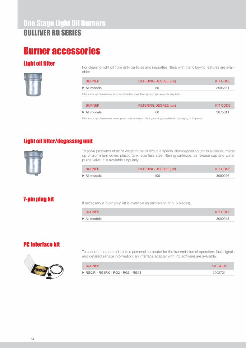
BURNER FILTERING DEGREE (µm) KIT CODE
u All models 100 3000926
To solve problems of air or water in the oil circuit a special fi lter/degassing unit is available, made up of aluminium cover, plastic tank, stainless steel fi ltering cartridge, air release cap and water purge valve. It is available singularly.
Light oil fi lter/degassing unit
BURNER FILTERING DEGREE (µm) KIT CODE
u All models 60 3006561
For cleaning light oil from dirty particles and impurities fi lters with the following features are avail-able:
Light oil fi lter
Filter made up of aluminium body and stainless steel fi ltering cartridge; available singularly.
BURNER FILTERING DEGREE (µm) KIT CODE
u All models 60 3075011
Filter made up of aluminium cover, plastic tank and nylon fi ltering cartridge; available in packaging of 50 pieces.
7-pin plug kitIf necessary a 7-pin plug kit is available (in packaging of n. 5 pieces).
BURNER KIT CODE
u All models 3000945
BURNER KIT CODE
u RG0.R - RG1RK - RG2 - RG3 - RG4S 3002731
To connect the control box to a personal computer for the transmission of operation, fault signals and detailed service information, an interface adapter with PC software are available.
PC Interface kit

75
LIGH
T OI
L
GULLIVER RGD SERIESThe Riello Gulliver RGD series of two stage light oil burners, is a complete range of products developed to respond to any request for home heating. The Gulliver RGD series is available in fi ve different models, with an output ranging from 14 to 296 kW, divided in four different structures.All the models use the same components designed by Riello for the Gulliver series. The high quality level guarantees safe working.In developing these burners, special attention was paid to reducing noise, to the ease of installation and adjustment, to obtaining the smallest size possible to fi t into any sort of boiler available on the market.The two stage operation guarantees high level of thermal unit effi ciency.All the models are approved by the EN 267 European Standard and conform to European Directives for EMC, Low Voltage, Machinery and Boiler Effi ciency.All the Gulliver RGD burners are fi red before leaving the factory.
RG1RKD 14/17 ÷ 60 kW RG2D 42/49 ÷ 118 kW RG3D 65/83 ÷ 178 kWRG4D 106/130 ÷ 237 kWRG5D 95/142 ÷ 296 kW
Two Stage Light Oil Burners
FIRING RATES
Useful working fi eldfor choosing theburner
1st stage operationrange
Test conditionsconforming to EN267 Temperature: 20°CPressure: 1013,5 mbarAltitude: 0 m a.s.l.
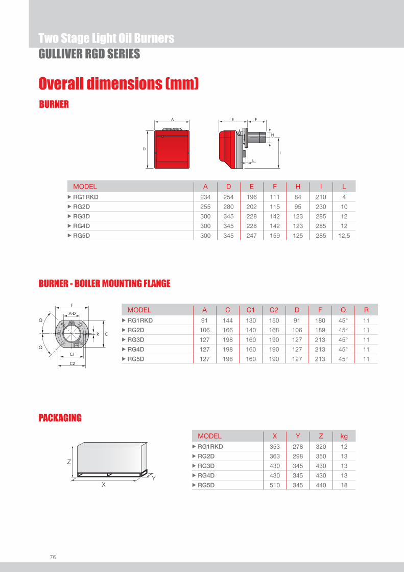
76
BURNER
BURNER - BOILER MOUNTING FLANGE
Overall dimensions (mm)
GULLIVER RGD SERIESTwo Stage Light Oil Burners
MODEL A D E F H I L u RG1RKD 234 254 196 111 84 210 4
u RG2D 255 280 202 115 95 230 10
u RG3D 300 345 228 142 123 285 12
u RG4D 300 345 228 142 123 285 12
u RG5D 300 345 247 159 125 285 12,5
PACKAGING
Z
XY
MODEL A C C1 C2 D F Q R u RG1RKD 91 144 130 150 91 180 45° 11
u RG2D 106 166 140 168 106 189 45° 11
u RG3D 127 198 160 190 127 213 45° 11
u RG4D 127 198 160 190 127 213 45° 11
u RG5D 127 198 160 190 127 213 45° 11
MODEL X Y Z kg u RG1RKD 353 278 320 12
u RG2D 363 298 350 13
u RG3D 430 345 430 13
u RG4D 430 345 430 13
u RG5D 510 345 440 18
77
LIGH
T OI
L
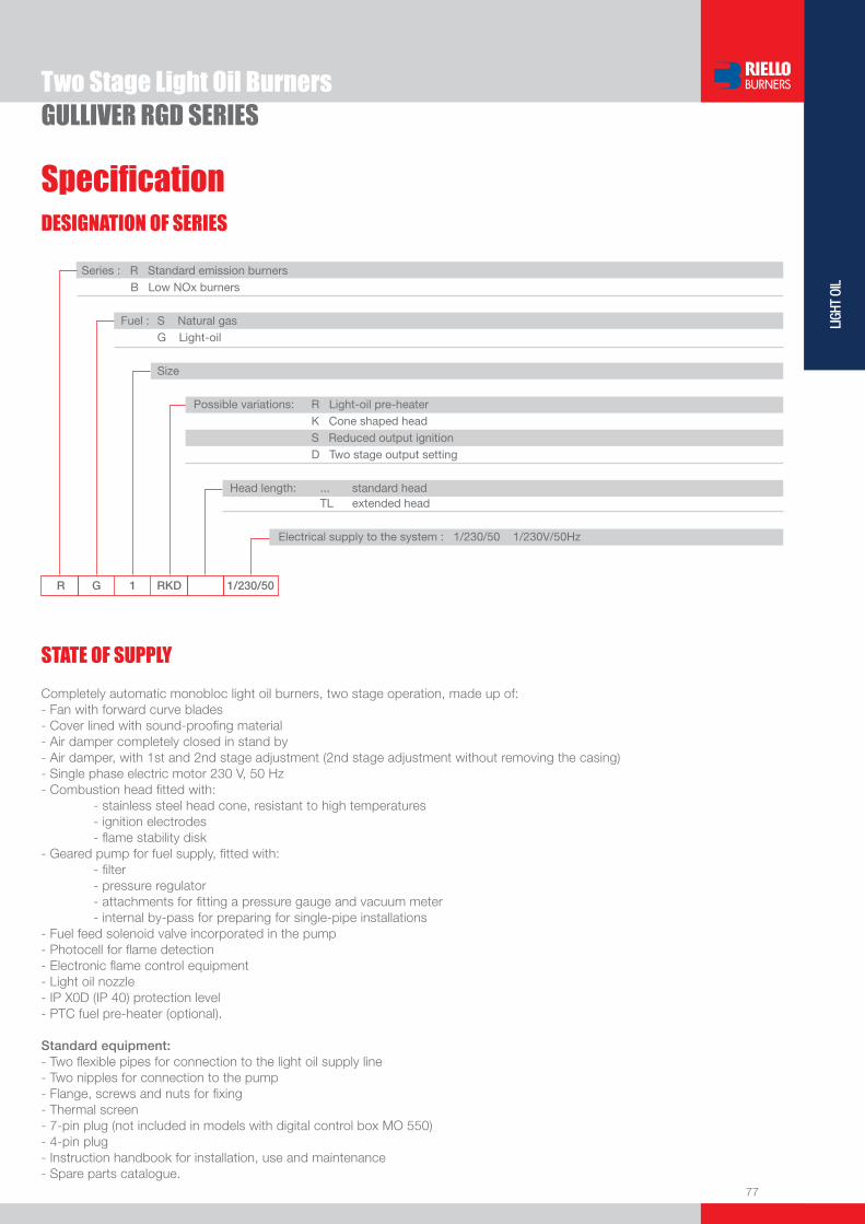
DESIGNATION OF SERIES
Specifi cation
Two Stage Light Oil BurnersGULLIVER RGD SERIES
STATE OF SUPPLY
R G 1 RKD 1/230/50
Series : R Standard emission burners B Low NOx burners
Fuel : S Natural gas G Light-oil Size
Possible variations: R Light-oil pre-heater K Cone shaped head S Reduced output ignition D Two stage output setting
Head length: ... standard head TL extended head Electrical supply to the system : 1/230/50 1/230V/50Hz
Completely automatic monobloc light oil burners, two stage operation, made up of:- Fan with forward curve blades- Cover lined with sound-proofi ng material- Air damper completely closed in stand by- Air damper, with 1st and 2nd stage adjustment (2nd stage adjustment without removing the casing)- Single phase electric motor 230 V, 50 Hz- Combustion head fi tted with: - stainless steel head cone, resistant to high temperatures - ignition electrodes - fl ame stability disk- Geared pump for fuel supply, fi tted with: - fi lter - pressure regulator - attachments for fi tting a pressure gauge and vacuum meter - internal by-pass for preparing for single-pipe installations- Fuel feed solenoid valve incorporated in the pump- Photocell for fl ame detection- Electronic fl ame control equipment- Light oil nozzle- IP X0D (IP 40) protection level- PTC fuel pre-heater (optional).
Standard equipment:- Two fl exible pipes for connection to the light oil supply line- Two nipples for connection to the pump- Flange, screws and nuts for fi xing- Thermal screen- 7-pin plug (not included in models with digital control box MO 550)- 4-pin plug- Instruction handbook for installation, use and maintenance- Spare parts catalogue.
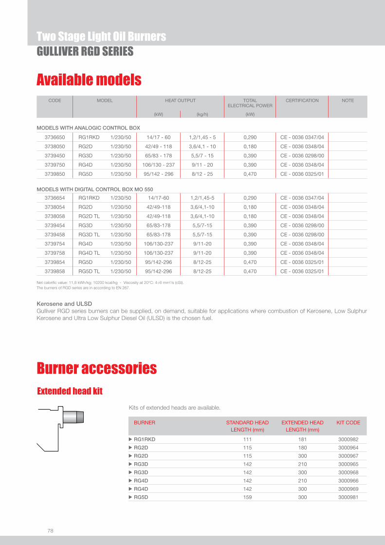
78
Available models
Two Stage Light Oil BurnersGULLIVER RGD SERIES
Net calorifi c value: 11,8 kWh/kg; 10200 kcal/kg - Viscosity at 20°C: 4÷6 mm2/s (cSt).The burners of RGD series are in according to EN 267.
CODE MODEL HEAT OUTPUT TOTALELECTRICAL POWER
CERTIFICATION NOTE
(kW) (kg/h) (kW)
MODELS WITH ANALOGIC CONTROL BOX
3736650 RG1RKD 1/230/50 14/17 - 60 1,2/1,45 - 5 0,290 CE - 0036 0347/04
3738050 RG2D 1/230/50 42/49 - 118 3,6/4,1 - 10 0,180 CE - 0036 0348/04
3739450 RG3D 1/230/50 65/83 - 178 5,5/7 - 15 0,390 CE - 0036 0298/00
3739750 RG4D 1/230/50 106/130 - 237 9/11 - 20 0,390 CE - 0036 0348/04
3739850 RG5D 1/230/50 95/142 - 296 8/12 - 25 0,470 CE - 0036 0325/01
MODELS WITH DIGITAL CONTROL BOX MO 550
3736654 RG1RKD 1/230/50 14/17-60 1,2/1,45-5 0,290 CE - 0036 0347/04
3738054 RG2D 1/230/50 42/49-118 3,6/4,1-10 0,180 CE - 0036 0348/04
3738058 RG2D TL 1/230/50 42/49-118 3,6/4,1-10 0,180 CE - 0036 0348/04
3739454 RG3D 1/230/50 65/83-178 5,5/7-15 0,390 CE - 0036 0298/00
3739458 RG3D TL 1/230/50 65/83-178 5,5/7-15 0,390 CE - 0036 0298/00
3739754 RG4D 1/230/50 106/130-237 9/11-20 0,390 CE - 0036 0348/04
3739758 RG4D TL 1/230/50 106/130-237 9/11-20 0,390 CE - 0036 0348/04
3739854 RG5D 1/230/50 95/142-296 8/12-25 0,470 CE - 0036 0325/01
3739858 RG5D TL 1/230/50 95/142-296 8/12-25 0,470 CE - 0036 0325/01
Extended head kit
Kits of extended heads are available.
BURNER STANDARD HEADLENGTH (mm)
EXTENDED HEADLENGTH (mm)
KIT CODE
u RG1RKD 111 181 3000982
u RG2D 115 180 3000964
u RG2D 115 300 3000967
u RG3D 142 210 3000965
u RG3D 142 300 3000968
u RG4D 142 210 3000966
u RG4D 142 300 3000969
u RG5D 159 300 3000981
Burner accessories
Kerosene and ULSDGulliver RGD series burners can be supplied, on demand, suitable for applications where combustion of Kerosene, Low Sulphur Kerosene and Ultra Low Sulphur Diesel Oil (ULSD) is the chosen fuel.

79
LIGH
T OI
L
Burner accessories
Two Stage Light Oil BurnersGULLIVER RGD SERIES
By using the special accessories, the burner can be with-drawn to reduce head penetration into the combustion chamber.
Spacer kit
BURNER SPACER THICKNESS S (mm)
KIT CODE
u RG1RKD 15 3007931
u RG2D 25 3000672
u RG3D - RG4D - RG5D 25 3000673
BURNER FILTERING DEGREE (µm) KIT CODE
u All models 100 3000926
To solve problems of air or water in the oil circuit a special fi lter/degassing unit is available, made up of aluminium cover, plastic tank, stainless steel fi ltering cartridge, air release cap and water purge valve. It is available singularly.
Light oil fi lter/degassing unit
BURNER FILTERING DEGREE (µm) KIT CODE
u All models 60 3006561
For cleaning light oil from dirty particles and impurities fi lters with the following features are avail-able:
Light oil fi lter
Filter made up of aluminium body and stainless steel fi ltering cartridge; available singularly.
BURNER FILTERING DEGREE (µm) KIT CODE
u All models 60 3075011
Filter made up of aluminium cover, plastic tank and nylon fi ltering cartridge; available in packaging of 50 pieces.
7-pin plug kitIf necessary a 7-pin plug kit is available (in packaging of n. 5 pieces).
BURNER KIT CODE
u All models 3000945
BURNER KIT CODE
u RG1RKD - RG2D - RG3D - RG4D - RG5D 3002731
To connect the control box to a personal computer for the transmission of operation, fault signals and detailed service information, an interface adapter with PC software are available.
PC Interface kit
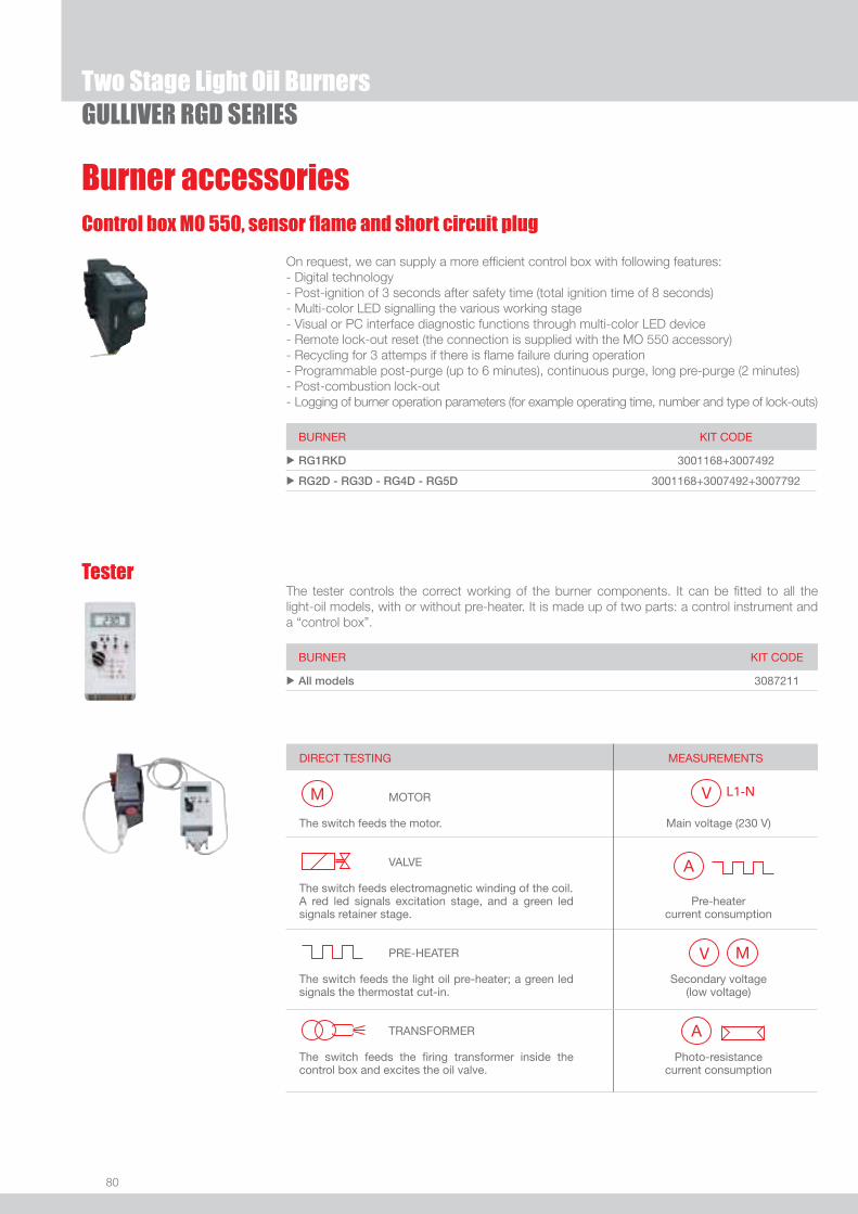
80
Two Stage Light Oil BurnersGULLIVER RGD SERIES
Burner accessories
BURNER KIT CODE
u RG1RKD 3001168+3007492
u RG2D - RG3D - RG4D - RG5D 3001168+3007492+3007792
BURNER KIT CODE
u All models 3087211
The tester controls the correct working of the burner components. It can be fi tted to all the light-oil models, with or without pre-heater. It is made up of two parts: a control instrument and a “control box”.
Tester
DIRECT TESTING MOTOR The switch feeds the motor. VALVE
The switch feeds electromagnetic winding of the coil. A red led signals excitation stage, and a green led signals retainer stage. PRE-HEATER The switch feeds the light oil pre-heater; a green led signals the thermostat cut-in. TRANSFORMER The switch feeds the fi ring transformer inside the control box and excites the oil valve.
MEASUREMENTS
Main voltage (230 V)
Pre-heater current consumption
Secondary voltage (low voltage)
Photo-resistance current consumption
Control box MO 550, sensor fl ame and short circuit plug
On request, we can supply a more effi cient control box with following features:- Digital technology- Post-ignition of 3 seconds after safety time (total ignition time of 8 seconds)- Multi-color LED signalling the various working stage- Visual or PC interface diagnostic functions through multi-color LED device- Remote lock-out reset (the connection is supplied with the MO 550 accessory)- Recycling for 3 attemps if there is fl ame failure during operation- Programmable post-purge (up to 6 minutes), continuous purge, long pre-purge (2 minutes)- Post-combustion lock-out- Logging of burner operation parameters (for example operating time, number and type of lock-outs)

One Stage Light Oil Burners
81
LIGH
T OI
L
GULLIVER RGF SERIESThe Riello Gulliver RGF series of one stage light oil burners, is a complete range of products developed to respond to any request for light industrial processes like bakery ovens, spray painting ovens, small steam or thermal boilers and all applications which require a reliable, user-friendly industrial product with enhanced performance and specifi c functions.The Gulliver RGF series is available in four different models, with an output ranging from 32 to 237 kW, divided in three different structures.All the models use the same components designed by Riello for the Gulliver series and have the same ventilation system and overall dimensions as the previous one stage light oil models.This new series can operates on 50 or 60 Hz and a Voltage 220 - 230 Volt (dual frequency).All these burners are conform to the EN 267 Standard (Forced draught oil burners) and to European Directives for EMC, Low Voltage and Machinery. For depressurised working fi eld see EN 746-2 Standard.All the Gulliver RGF burners are fi red before leaving the factory.
RG1F 32,0 ÷ 60,0 kW RG2F 47,0 ÷ 119,0 kW RG3F 83,0 ÷ 178,0 kWRG4F 118,5 ÷ 237,0 kW
FIRING RATES
Useful working fi eldfor choosing theburner
Test conditionsconforming to EN267 Temperature: 20°CPressure: 1013,5 mbarAltitude: 0 m a.s.l.
IMPORTANT: For the part of the working fi eld that is depressurised, refer to EN 746-2 Standard.

82
BURNER
Overall dimensions (mm)
One Stage Light Oil BurnersGULLIVER RGF SERIES
GULLIVER RG1F GULLIVER RG2F - RG3F - RG4F
MODEL A D E F H I L u RG1F 234 254 196 93 84 210 4
u RG2F 255 280 202 115 95 230 10
u RG3F 300 345 228 142 123 285 12
u RG4F 300 345 228 142 125 285 12
MODEL A C1 C2 D F Q R S T u RG1F 91 130 150 91 180 45° 11 72 72
u RG2F 106 140 168 106 189 45° 11 83 83
u RG3F 127 160 190 127 213 90° 11 99 99
u RG4F 127 160 190 127 213 90° 11 99 99
GULLIVER RG1F - RG2F GULLIVER RG3F - RG4F
Z
XY
MODEL X Y Z kg u RG1F 353 278 320 13
u RG2F 363 298 350 13
u RG3F 430 345 430 15
u RG4F 430 345 430 18
BURNER - BOILER MOUNTING FLANGE
PACKAGING

83
LIGH
T OI
L
DESIGNATION OF SERIES
Specifi cation
One Stage Light Oil BurnersGULLIVER RGF SERIES
STATE OF SUPPLY
Completely automatic monobloc light oil burners, with one stage operation fi tted with:- Fan with forward curve blades- Cover lined with sound - proofi ng material - Air damper, always open in stand by, with external adjustment, without need to remove the cover- Single phase electric motor 220 - 230 V, 50 - 60 Hz- Combustion head fi tted with: - stainless steel head cone, resistant to high temperatures - ignition electrodes - fl ame stability disk- Geared pump for fuel supply, fi tted with: - fi lter - pressure regulator - attachments for fi tting a pressure gauge and vacuum meter - internal by-pass for preparing for single-pipe installations- Fuel feed solenoid valve incorporated in the pump- Photocell for fl ame detection- Electronic fl ame control equipment- Light oil nozzle- IP X0D (IP 40) protection level- PTC fuel pre-heater.
Standard equipment:- Flange with insulating gasket- Screw and nuts for fl ange- 7-pin plug- Screw and nuts for fl ange to be fi xed to the heat generator- Flexible oil pipes with nipples - Instruction handbook for installation, use and maintenance- Spare parts catalogue.
Series : R Standard emission burners B Low NOx burners
Fuel : S Natural gas G Light-oil
Size Possible variations: F Light industrial processes
Electrical supply to the system : 1/220-230/50-60 1/220-230V/50-60Hz
R G 4 F 1/230/50

84
Available models
One Stage Light Oil BurnersGULLIVER RGF SERIES
CODE MODEL HEAT OUTPUT TOTALELECTRICAL POWER
CERTIFICATION NOTE
(kW) (kg/h) (kW)
3736370 RG1F 1/220-230/50-60 32 - 60 2,7 - 5 0,155 (at 50Hz) - 0,200 (at 60 Hz) CE 0036 0341/03
3737770 RG2F 1/220-230/50-60 47 - 119 4 - 10 0,165 (at 50Hz) - 0,220 (at 60 Hz) CE 0036 0344/03
3739370 RG3F 1/220-230/50-60 83 - 178 7 - 15 0,380 (at 50Hz) - 0,520 (at 60 Hz) CE 0036 0348/04
3739670 RG4F 1/220-230/50-60 118,5 - 237 10 - 20 0,370 (at 50Hz) - 0,510 (at 60 Hz) CE 0036 0348/04
Net calorifi c value: 11,8 kWh/kg; 10200 kcal/kg - Viscosity at 20°C: 4÷6 mm2/s (cSt).The burners of RGF series are in according to EN 267 and 746-2.
Burner accessories
Kits of extended heads are available.
Extended head kit
BURNER STANDARD HEAD LENGTH (mm)
EXTENDED HEAD LENGTH (mm)
KIT CODE
u RG1F 93 163 3000963
u RG2F 115 180 3000964
u RG2F 115 300 3000967
u RG3F 142 210 3000965
u RG3F 142 300 3000968
u RG4F 142 210 3000966
u RG4F 142 300 3000969
By using the special accessories, the burner can be with-drawn to reduce head penetration into the combustion chamber.
Spacer kit
BURNER SPACER THICKNESS S (mm)
KIT CODE
u RG1F 15 3007931
u RG2F 25 3000672
u RG3F - RG4F 25 3000673
Pre-heater kitThis kit is used only for Gulliver RG1F burner. It can be installed in special atmospheric conditions (low temperatures), with high diesel oil viscosity and with low deliveries.
BURNER KIT CODE
u RG1F 3001083
Kerosene and ULSDGulliver RGF series burners can be supplied, on demand, suitable for applications where combustion of Kerosene, Low Sulphur Kerosene and Ultra Low Sulphur Diesel Oil (ULSD) is the chosen fuel.

85
LIGH
T OI
L
Burner accessories
One Stage Light Oil BurnersGULLIVER RGF SERIES
Control box MO 550, sensor fl ame and short circuit plug
On request, we can supply a more effi cient control box with following features:- Digital technology- Post-ignition of 3 seconds after safety time (total ignition time of 8 seconds)- Multi-color LED signalling the various working stage- Visual or PC interface diagnostic functions through multi-color LED device- Remote lock-out reset (the connection is supplied with the MO 550 accessory)- Recycling for 3 attemps if there is fl ame failure during operation- Programmable post-purge (up to 6 minutes), continuous purge, long pre-purge (2 minutes)- Post-combustion lock-out- Logging of burner operation parameters (for example operating time, number and type of lock-outs)
BURNER KIT CODE
u All models 3001168+3007492+3007792
BURNER KIT CODE
u All models 3087211
The tester controls the correct working of the burner components. It can be fi tted to all the light-oil models, with or without pre-heater. It is made up of two parts: a control instrument and a “control box”.
Tester
DIRECT TESTING MOTOR The switch feeds the motor. VALVE
The switch feeds electromagnetic winding of the coil. A red led signals excitation stage, and a green led signals retainer stage. PRE-HEATER The switch feeds the light oil pre-heater; a green led signals the thermostat cut-in. TRANSFORMER The switch feeds the fi ring transformer inside the control box and excites the oil valve.
MEASUREMENTS
Main voltage (230 V)
Pre-heater current consumption
Secondary voltage (low voltage)
Photo-resistance current consumption
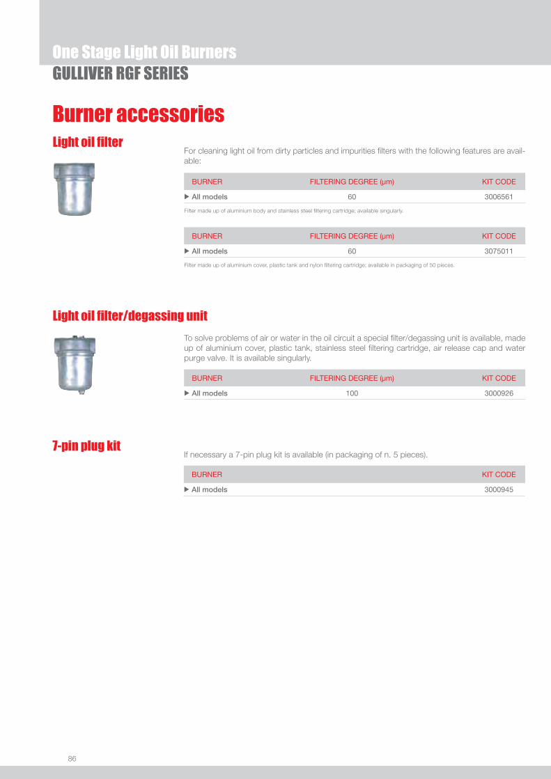
86
One Stage Light Oil BurnersGULLIVER RGF SERIES
Burner accessories
BURNER FILTERING DEGREE (µm) KIT CODE
u All models 100 3000926
To solve problems of air or water in the oil circuit a special fi lter/degassing unit is available, made up of aluminium cover, plastic tank, stainless steel fi ltering cartridge, air release cap and water purge valve. It is available singularly.
Light oil fi lter/degassing unit
BURNER FILTERING DEGREE (µm) KIT CODE
u All models 60 3006561
For cleaning light oil from dirty particles and impurities fi lters with the following features are avail-able:
Light oil fi lter
Filter made up of aluminium body and stainless steel fi ltering cartridge; available singularly.
BURNER FILTERING DEGREE (µm) KIT CODE
u All models 60 3075011
Filter made up of aluminium cover, plastic tank and nylon fi ltering cartridge; available in packaging of 50 pieces.
7-pin plug kitIf necessary a 7-pin plug kit is available (in packaging of n. 5 pieces).
BURNER KIT CODE
u All models 3000945

87
LIGH
T OI
L
Two Stage Light Oil Burners
GULLIVER RGDF SERIESThe Riello Gulliver RG5DF is a new model of one stage light oil burner, developed to respond to any request for light industrial processes like bakery ovens, spray painting ovens, small steam or thermal boilers and all applications which require a reliable, user-friendly industrial product with enhanced performance and specifi c functions.This model uses the same components designed by Riello for the Gulliver series and has the same ventilation system and overall dimensions as the previous two stage light oil model.This new burner can operates on 50 or 60 Hz and a Voltage 220 - 230 Volt (dual frequency). It is conform to the EN 267 Standard (Forced draught oil burners) and to European Directives for EMC, Low Voltage and Machinery. For depressurised working fi eld see EN 746-2 Standard. The Gulliver RG5DF burner is fi red before leaving the factory. RG5DF 95/142 ÷ 296 kW
FIRING RATES
Useful working fi eldfor choosing theburner
1st stage operationrange
Test conditionsconforming to EN267 Temperature: 20°CPressure: 1013,5 mbarAltitude: 0 m a.s.l.
IMPORTANT: For the part of the working fi eld that is depressurised, refer to EN 746-2 Standard.

88
BURNER
Overall dimensions (mm)
Two Stage Light Oil BurnersGULLIVER RGDF SERIES
MODEL A D E F H I L u RG5DF 300 345 247 159 125 285 12,5
MODEL A C C1 C2 D F Q R u RG5DF 127 198 160 190 127 213 45° 11
MODEL X Y Z kg u RG5DF 510 345 440 18
PACKAGING
Z
XY
BURNER - BOILER MOUNTING FLANGE
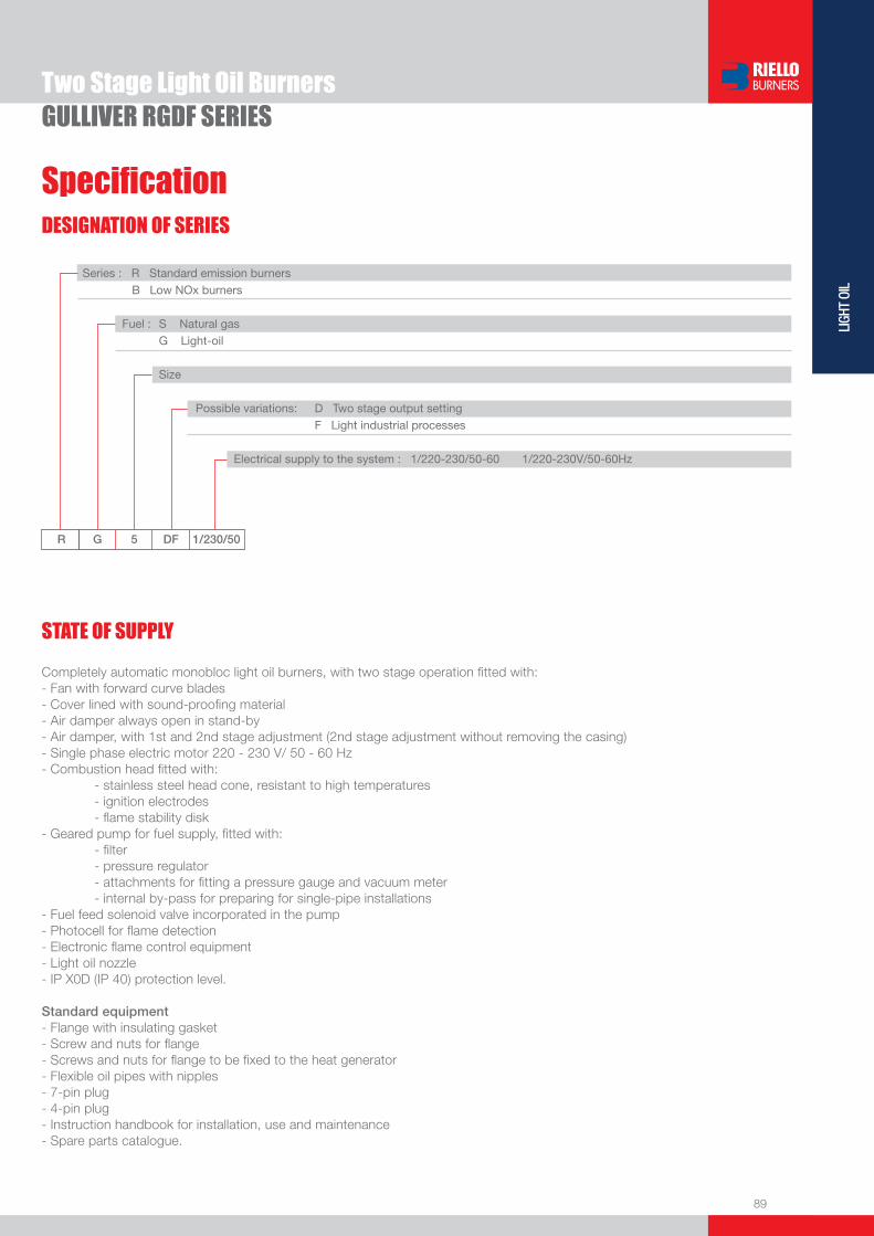
89
LIGH
T OI
L
DESIGNATION OF SERIES
Specifi cation
Two Stage Light Oil BurnersGULLIVER RGDF SERIES
STATE OF SUPPLY
R G 5 DF 1/230/50
Series : R Standard emission burners B Low NOx burners
Fuel : S Natural gas G Light-oil Size
Possible variations: D Two stage output setting F Light industrial processes
Electrical supply to the system : 1/220-230/50-60 1/220-230V/50-60Hz
Completely automatic monobloc light oil burners, with two stage operation fi tted with:- Fan with forward curve blades- Cover lined with sound-proofi ng material- Air damper always open in stand-by- Air damper, with 1st and 2nd stage adjustment (2nd stage adjustment without removing the casing)- Single phase electric motor 220 - 230 V/ 50 - 60 Hz- Combustion head fi tted with: - stainless steel head cone, resistant to high temperatures - ignition electrodes - fl ame stability disk- Geared pump for fuel supply, fi tted with: - fi lter - pressure regulator - attachments for fi tting a pressure gauge and vacuum meter - internal by-pass for preparing for single-pipe installations- Fuel feed solenoid valve incorporated in the pump - Photocell for fl ame detection - Electronic fl ame control equipment - Light oil nozzle- IP X0D (IP 40) protection level.
Standard equipment- Flange with insulating gasket- Screw and nuts for fl ange- Screws and nuts for fl ange to be fi xed to the heat generator- Flexible oil pipes with nipples- 7-pin plug- 4-pin plug- Instruction handbook for installation, use and maintenance- Spare parts catalogue.
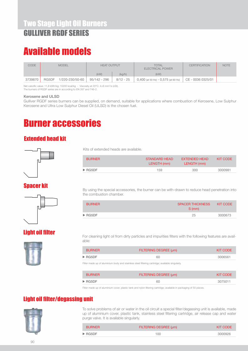
90
Available models
Two Stage Light Oil BurnersGULLIVER RGDF SERIES
Net calorifi c value: 11,8 kWh/kg; 10200 kcal/kg - Viscosity at 20°C: 4÷6 mm2/s (cSt).The burners of RGDF series are in according to EN 267 and 746-2.
CODE MODEL HEAT OUTPUT TOTALELECTRICAL POWER
CERTIFICATION NOTE
(kW) (kg/h) (kW)
3739870 RG5DF 1/220-230/50-60 95/142 - 296 8/12 - 25 0,400 (at 50 Hz) - 0,575 (at 60 Hz) CE - 0036 0325/01
By using the special accessories, the burner can be with-drawn to reduce head penetration into the combustion chamber.
Spacer kit
BURNER SPACER THICKNESS S (mm)
KIT CODE
u RG5DF 25 3000673
Burner accessories
Extended head kit
Kits of extended heads are available.
BURNER STANDARD HEADLENGTH (mm)
EXTENDED HEADLENGTH (mm)
KIT CODE
u RG5DF 159 300 3000981
BURNER FILTERING DEGREE (µm) KIT CODE
u RG5DF 100 3000926
To solve problems of air or water in the oil circuit a special fi lter/degassing unit is available, made up of aluminium cover, plastic tank, stainless steel fi ltering cartridge, air release cap and water purge valve. It is available singularly.
Light oil fi lter/degassing unit
BURNER FILTERING DEGREE (µm) KIT CODE
u RG5DF 60 3006561
For cleaning light oil from dirty particles and impurities fi lters with the following features are avail-able:
Light oil fi lter
Filter made up of aluminium body and stainless steel fi ltering cartridge; available singularly.
BURNER FILTERING DEGREE (µm) KIT CODE
u RG5DF 60 3075011
Filter made up of aluminium cover, plastic tank and nylon fi ltering cartridge; available in packaging of 50 pieces.
Kerosene and ULSDGulliver RGDF series burners can be supplied, on demand, suitable for applications where combustion of Kerosene, Low Sulphur Kerosene and Ultra Low Sulphur Diesel Oil (ULSD) is the chosen fuel.

91
LIGH
T OI
L
Burner accessories
Two Stage Light Oil BurnersGULLIVER RGDF SERIES
BURNER KIT CODE
u RG5DF 3087211
The tester controls the correct working of the burner components. It can be fi tted to all the light-oil models, with or without pre-heater. It is made up of two parts: a control instrument and a “control box”.
Tester
DIRECT TESTING MOTOR The switch feeds the motor. VALVE
The switch feeds electromagnetic winding of the coil. A red led signals excitation stage, and a green led signals retainer stage. PRE-HEATER The switch feeds the light oil pre-heater; a green led signals the thermostat cut-in. TRANSFORMER The switch feeds the fi ring transformer inside the control box and excites the oil valve.
MEASUREMENTS
Main voltage (230 V)
Pre-heater current consumption
Secondary voltage (low voltage)
Photo-resistance current consumption
7-pin plug kitIf necessary a 7-pin plug kit is available (in packaging of n. 5 pieces).
BURNER KIT CODE
u RG5DF 3000945
BURNER KIT CODE
u RG5DF 3001168+3007492+3007792
Control box MO 550, sensor fl ame and short circuit plug
On request, we can supply a more effi cient control box with following features:- Digital technology- Post-ignition of 3 seconds after safety time (total ignition time of 8 seconds)- Multi-color LED signalling the various working stage- Visual or PC interface diagnostic functions through multi-color LED device- Remote lock-out reset (the connection is supplied with the MO 550 accessory)- Recycling for 3 attemps if there is fl ame failure during operation- Programmable post-purge (up to 6 minutes), continuous purge, long pre-purge (2 minutes)- Post-combustion lock-out- Logging of burner operation parameters (for example operating time, number and type of lock-outs)


One Stage Light Oil Burners
93
LIGH
T OI
L
REG SERIESThe REG series of one stage light oil burners, is available in two models with an output ranging from 21 to 60 kW, in a single structure.The models are available with or without casing and with or without pre-heater.These models are distinguished by their compact size. All the models use the same Riello components designed for the REG series. The high quality level guarantees safe working.In developing these burners, special attention was paid to reducing noise, to ease of installation and adjustment, to obtaining the minimum size possible to allow fi tting to any sort of boiler available on the market.All the models are approved by European EN 267 standard and conform to European Directives for EMC, Low Voltage, Machinery and Boiler Effi ciency.All the REG series of burners are fi red before leaving the factory.
REG 35.3 21 ÷ 38 kW REG 35.5 27 ÷ 60 kW
FIRING RATES
Useful working fi eldfor choosing theburner
Test conditionsconforming to EN267 Temperature: 20°CPressure: 1013,5 mbarAltitude: 0 m a.s.l.

94
BURNER
Overall dimensions (mm)
One Stage Light Oil BurnersREG SERIES
(1) Basic version. (2) With cover.* The combustion head is available in 2 different lengths.
BURNER - BOILER MOUNTING FLANGE
MODEL A D E F * H I K u REG 35.3 (1) 215,5 279 211 82 89 211,5 121,5
u REG 35.5 (1) 215,5 279 211 80 89 211,5 121,5
u REG 35.3 (2) 223 282 240,5 82 89 214,5 121,5
u REG 35.5 (2) 223 282 240,5 80 89 214,5 121,5
MODEL A C1 C2 D F Q S T u REG 35.3 95 130 150 95 170 45° 65 65
u REG 35.5 95 130 150 95 170 45° 65 65
MODEL X Y Z kg u REG 35.3 347 310 220 10
u REG 35.5 347 310 220 10
PACKAGING
Z
XY

95
LIGH
T OI
L
DESIGNATION OF SERIES
Specifi cation
One Stage Light Oil BurnersREG SERIES
STATE OF SUPPLY
REG 35.3 R 1/230/50
Series : REG
Size
Possible variations : R Light-oil pre-heater
Electrical supply to the system : 1/230/50 1/230V/50Hz
Monoblock fully automatic light oil burners, one stage operation, made up of:- Fan with forward curve blades- Adjustable air damper- Single phase electric motor 230 V, 50 Hz- Combustion head, fi tted with: - stainless steel end cone, resistant to high temperatures - ignition electrodes - fl ame stability disk - Geared pump for fuel supply, fi tted with: - fi lter - pressure regulator - connectors for installing a pressure gauge and vacuometer - internal by-pass for preparing for single pipe installation - Fuel feed solenoid incorporated in the pump- Photocell for fl ame detection- Electronic fl ame control equipment - Light oil nozzle- IP X0D (IP 40) protection level- Fuel heater (optional).
Standard equipment:- Two fl exible pipes for connecting to the light oil supply line- Two nipples for connecting to the pump- Flange, screws and nuts for fi xing- Thermal screen- Instruction handbook for installation, use and maintenance- Spare parts catalogue.
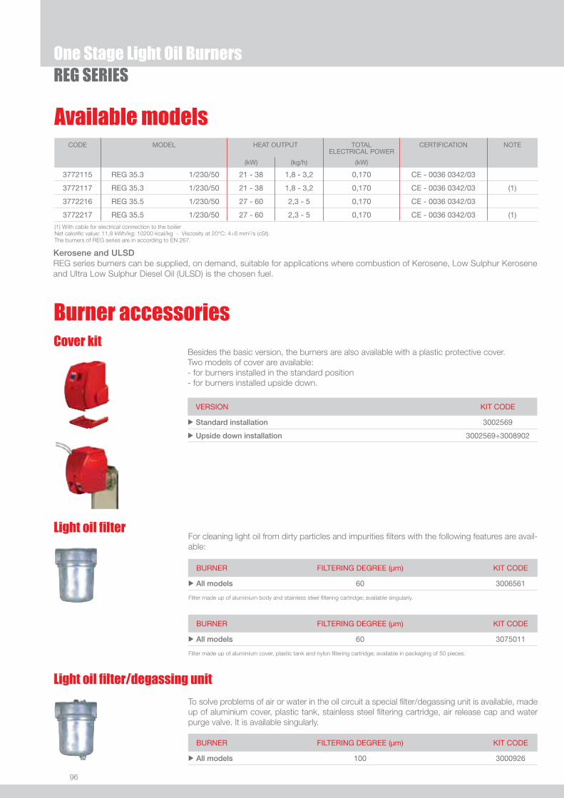
96
One Stage Light Oil BurnersREG SERIES
Burner accessoriesCover kit
Besides the basic version, the burners are also available with a plastic protective cover.Two models of cover are available:- for burners installed in the standard position - for burners installed upside down.
VERSION KIT CODE
u Standard installation 3002569
u Upside down installation 3002569+3008902
BURNER FILTERING DEGREE (µm) KIT CODE
u All models 100 3000926
To solve problems of air or water in the oil circuit a special fi lter/degassing unit is available, made up of aluminium cover, plastic tank, stainless steel fi ltering cartridge, air release cap and water purge valve. It is available singularly.
Light oil fi lter/degassing unit
BURNER FILTERING DEGREE (µm) KIT CODE
u All models 60 3006561
For cleaning light oil from dirty particles and impurities fi lters with the following features are avail-able:
Light oil fi lter
Filter made up of aluminium body and stainless steel fi ltering cartridge; available singularly.
BURNER FILTERING DEGREE (µm) KIT CODE
u All models 60 3075011
Filter made up of aluminium cover, plastic tank and nylon fi ltering cartridge; available in packaging of 50 pieces.
(1) With cable for electrical connection to the boilerNet calorifi c value: 11,8 kWh/kg; 10200 kcal/kg - Viscosity at 20°C: 4÷6 mm2/s (cSt).The burners of REG series are in according to EN 267.
CODE MODEL HEAT OUTPUT TOTAL ELECTRICAL POWER
CERTIFICATION NOTE
(kW) (kg/h) (kW)
3772115 REG 35.3 1/230/50 21 - 38 1,8 - 3,2 0,170 CE - 0036 0342/03
3772117 REG 35.3 1/230/50 21 - 38 1,8 - 3,2 0,170 CE - 0036 0342/03 (1)
3772216 REG 35.5 1/230/50 27 - 60 2,3 - 5 0,170 CE - 0036 0342/03
3772217 REG 35.5 1/230/50 27 - 60 2,3 - 5 0,170 CE - 0036 0342/03 (1)
Available models
Kerosene and ULSDREG series burners can be supplied, on demand, suitable for applications where combustion of Kerosene, Low Sulphur Kerosene and Ultra Low Sulphur Diesel Oil (ULSD) is the chosen fuel.
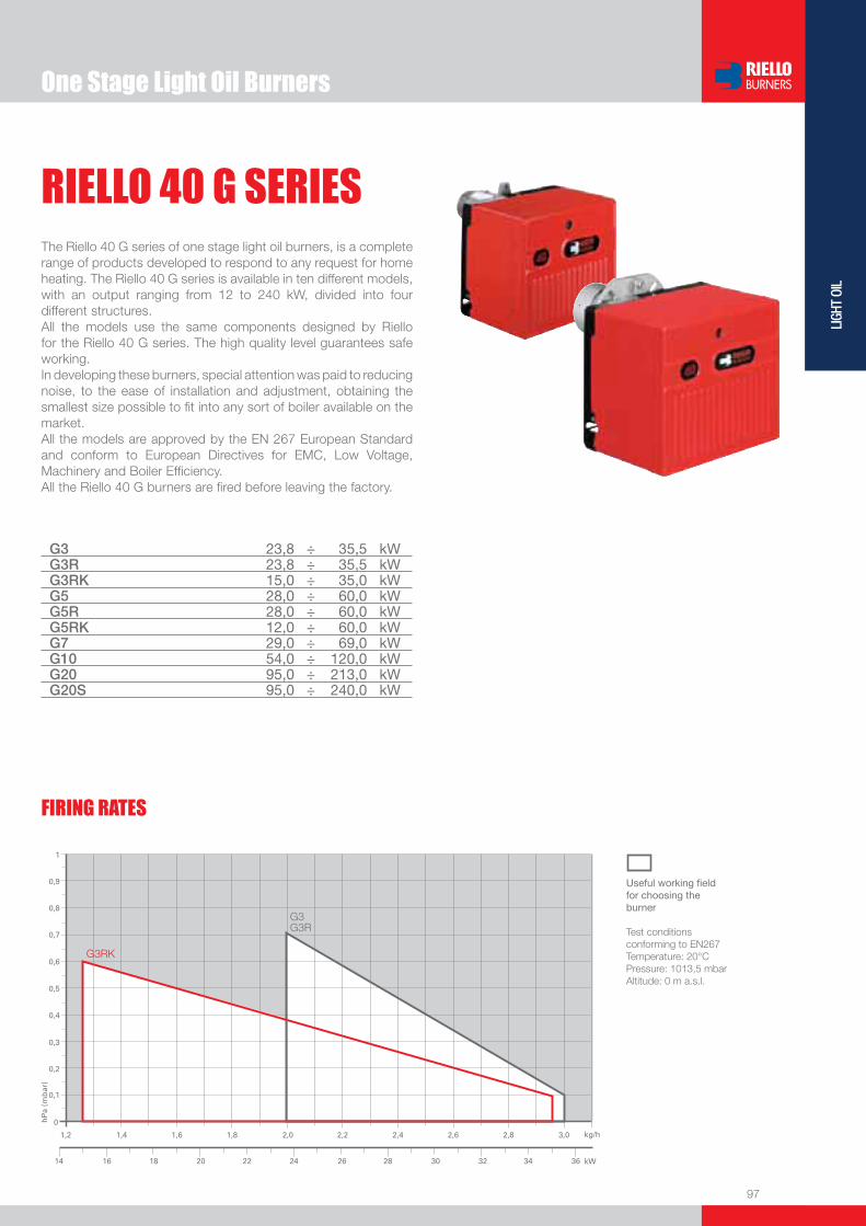
One Stage Light Oil Burners
97
LIGH
T OI
L
RIELLO 40 G SERIESThe Riello 40 G series of one stage light oil burners, is a complete range of products developed to respond to any request for home heating. The Riello 40 G series is available in ten different models, with an output ranging from 12 to 240 kW, divided into four different structures.All the models use the same components designed by Riello for the Riello 40 G series. The high quality level guarantees safe working.In developing these burners, special attention was paid to reducing noise, to the ease of installation and adjustment, obtaining the smallest size possible to fi t into any sort of boiler available on the market.All the models are approved by the EN 267 European Standard and conform to European Directives for EMC, Low Voltage, Machinery and Boiler Effi ciency.All the Riello 40 G burners are fi red before leaving the factory.
G3 23,8 ÷ 35,5 kWG3R 23,8 ÷ 35,5 kWG3RK 15,0 ÷ 35,0 kWG5 28,0 ÷ 60,0 kWG5R 28,0 ÷ 60,0 kWG5RK 12,0 ÷ 60,0 kWG7 29,0 ÷ 69,0 kWG10 54,0 ÷ 120,0 kWG20 95,0 ÷ 213,0 kWG20S 95,0 ÷ 240,0 kW
FIRING RATES
Useful working fi eldfor choosing theburner
Test conditionsconforming to EN267 Temperature: 20°CPressure: 1013,5 mbarAltitude: 0 m a.s.l.

98
One Stage Light Oil BurnersRIELLO 40 G SERIES
FIRING RATES
Useful working fi eldfor choosing theburner
Test conditionsconforming to EN267 Temperature: 20°CPressure: 1013,5 mbarAltitude: 0 m a.s.l.

99
LIGH
T OI
L
One Stage Light Oil BurnersRIELLO 40 G SERIES
Overall dimensions (mm)BURNER
BURNER - BOILER MOUNTING FLANGE
PACKAGING
Z
XY
G3 - G3R - G3RK - G5 - G5R - G5RK - G7 - G10G20 - G20S
MODEL A D E F F2 H I L u G3 252 215 203 86 - 89 164 19 u G3R 252 215 203 86 - 89 164 19 u G3RK 252 215 203 97 115 89 164 19 u G5 272 233 236 107 - 89 180 37 u G5R 272 233 236 107 - 89 180 37 u G5RK 272 233 236 94 112 89 180 37 u G7 305 262 261 73 - 89 204 40 u G10 305 262 261 108 - 105 204 40 u G20 350 298 295 118 - 125 230 41 u G20S 350 298 295 118 - 125 230 41
MODEL X Y Z kg u G3 363 295 310 10 u G3R 363 295 310 10 u G3RK 363 295 310 10,5 u G5 383 315 325 12 u G5R 383 315 325 12 u G5RK 383 315 325 12 u G7 423 348 340 13 u G10 423 348 340 13 u G20 483 393 377 16 u G20S 483 393 377 17,5
MODEL C1 C2 F Q R S T u G3 - G3R - G3RK - G5 - G5R - G5RK 130 150 180 45° 11 72 75u G7 - G10 140 170 189 45° 11 83 83 u G20 - G20S 160 190 213 90° 11 99 99

100
One Stage Light Oil BurnersRIELLO 40 G SERIES
STATE OF SUPPLY
Specifi cationDESIGNATION OF SERIES
G 5 RK 1/230/50
Series : G
Size
Possible variations : R Light-oil pre-heater K Cone shaped head S Reduced output ignition D Two stage output setting
Electrical supply to the system : 1/230/50 1/230V/50Hz 1/220/60 1/220V/60Hz
Completely automatic monobloc light oil burners, one stage operation, made up of:- Fan with forward curve blades- Metallic cover lined with sound-proofi ng material- Air damper, completely closed in stand by, with adjustment- Single phase electric motor 230 V, 50 Hz- Combustion head fi tted with: - stainless steel head cone, resistant to high temperatures - ignition electrodes - fl ame stability disk- Geared pump for fuel supply, fi tted with: - fi lter - pressure regulator - attachments for fi tting a pressure gauge and vacuum meter - internal by-pass for preparing for single-pipe installations- Fuel feed solenoid valve incorporated in the pump- Photocell for fl ame detection- Electronic fl ame control equipment- Light oil nozzle- IP X0D (IP 40) protection level- Fuel pre-heater (optional)- Reduced output ignition mechanism (optional).
Standard equipment:- Two fl exible pipes for connection to the light oil supply line- Two nipples for connection to the pump- Flange, screws and nuts for fi xing- Thermal gasket- 7-pin plug (on request)- Maintenance assembly- Instruction handbook for installation, use and maintenance- Spare parts catalogue.

101
LIGH
T OI
L
One Stage Light Oil BurnersRIELLO 40 G SERIES
Available modelsCODE MODEL HEAT OUTPUT TOTAL ELECTRICAL
POWERCERTIFICATION NOTE
(kW) (kg/h) (kW)
3743125 G3 1/230/50 23,8 - 35,5 2 - 3 0,115 CE – 0036 0315/01
3743831 G3R 1/230/50 23,8 - 35,5 2 - 3 0,165 CE – 0036 0315/01
3743412 G3RK 1/230/50 15 - 35 1,3 - 3 0,170 CE – 0036 0254/99
3744512 G5 1/230/50 28 - 60 2,3 - 5 0,130 -
3744612 G5R 1/230/50 28 - 60 2,3 - 5 0,185 -
3745312 G5RK 1/230/50 12 - 60 1 - 5 0,185 CE – 0036 0256/99
3745959 G7 1/230/50 29 - 69 2,5 - 5,8 0,160 - (1)
3746412 G10 1/230/50 54 - 120 4,5 - 10 0,170 CE – 0036 0257/99
3746464 G10 1/220/60 54 - 120 4,5 - 10 0,200 -
3747412 G20 1/230/50 95 - 213 8 - 18 0,320 -
3747459 G20 1/220/60 95 - 213 8 - 18 0,400 -
3748212 G20S 1/230/50 95 - 240 8 - 20 0,330 -
3748259 G20S 1/220/60 95 - 240 8 - 20 0,410 -
MODELS WITH 24V DC ELECTRICAL SUPPLY
3452030 G7 24V DC 29 - 69 2,45 - 5,8 0,3
20006157 G10 24V DC 54 - 120 4,5 - 10 0,3
3452736 G20 24V DC 95 - 201 8 - 17 0,3
(1) UK versionNet calorifi c value: 11,8 kWh/kg - 10200 kcal/kg - Viscosity at 20°C: 4÷6 mm2/s (cSt)The burners of G series are in according to EN 267.
Bio fuels Riello Burners is able to offer technical variants which allow burners to be used within environmental heating, process or special applications. These applications now include solutions for liquid Bio fuels (I.e. biodiesel and vegetable oil).Our experience in research and development and fi eld applications with organic origin Bio fuels has resulted in Riello being able to offer a wide range of solutions for the combustion of Bio fuels.
Kerosene and ULSDRiello 40 G series burners can be supplied, on demand, suitable for applications where combustion of Kerosene, Low Sulphur Kerosene and Ultra Low Sulphur Diesel Oil (ULSD) is the chosen fuel.These burner variants can be provided upon request and after a technical-commercial evaluation; for more information please contact Riello Burners Commercial and Technical Department, our Application Engineers will be pleased to help you.
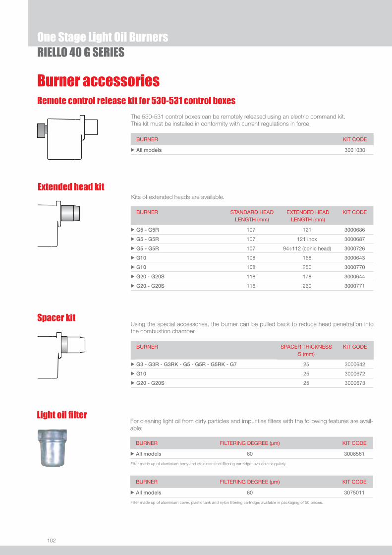
102
One Stage Light Oil Burners
Burner accessoriesRemote control release kit for 530-531 control boxes
The 530-531 control boxes can be remotely released using an electric command kit. This kit must be installed in conformity with current regulations in force.
BURNER KIT CODE
u All models 3001030
RIELLO 40 G SERIES
Using the special accessories, the burner can be pulled back to reduce head penetration into the combustion chamber.
Spacer kit
BURNER SPACER THICKNESS S (mm)
KIT CODE
u G3 - G3R - G3RK - G5 - G5R - G5RK - G7 25 3000642
u G10 25 3000672
u G20 - G20S 25 3000673
Extended head kitKits of extended heads are available.
BURNER STANDARD HEADLENGTH (mm)
EXTENDED HEADLENGTH (mm)
KIT CODE
u G5 - G5R 107 121 3000686
u G5 - G5R 107 121 inox 3000687
u G5 - G5R 107 94÷112 (conic head) 3000726
u G10 108 168 3000643
u G10 108 250 3000770
u G20 - G20S 118 178 3000644
u G20 - G20S 118 260 3000771
BURNER FILTERING DEGREE (µm) KIT CODE
u All models 60 3006561
For cleaning light oil from dirty particles and impurities fi lters with the following features are avail-able:
Light oil fi lter
Filter made up of aluminium body and stainless steel fi ltering cartridge; available singularly.
BURNER FILTERING DEGREE (µm) KIT CODE
u All models 60 3075011
Filter made up of aluminium cover, plastic tank and nylon fi ltering cartridge; available in packaging of 50 pieces.
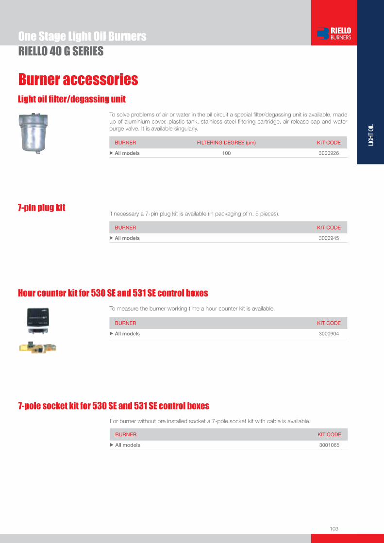
103
LIGH
T OI
L
One Stage Light Oil BurnersRIELLO 40 G SERIES
Burner accessories
BURNER FILTERING DEGREE (µm) KIT CODE
u All models 100 3000926
To solve problems of air or water in the oil circuit a special fi lter/degassing unit is available, made up of aluminium cover, plastic tank, stainless steel fi ltering cartridge, air release cap and water purge valve. It is available singularly.
Light oil fi lter/degassing unit
BURNER KIT CODE
u All models 3000904
To measure the burner working time a hour counter kit is available.
Hour counter kit for 530 SE and 531 SE control boxes
7-pin plug kitIf necessary a 7-pin plug kit is available (in packaging of n. 5 pieces).
BURNER KIT CODE
u All models 3000945
7-pole socket kit for 530 SE and 531 SE control boxes
BURNER KIT CODE
u All models 3001065
For burner without pre installed socket a 7-pole socket kit with cable is available.

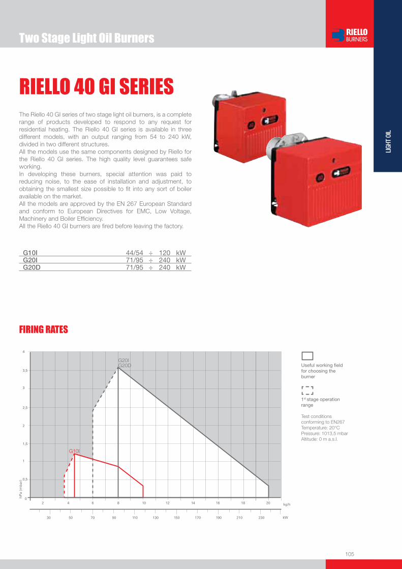
105
LIGH
T OI
L
FIRING RATES
Two Stage Light Oil Burners
RIELLO 40 GI SERIESThe Riello 40 GI series of two stage light oil burners, is a complete range of products developed to respond to any request for residential heating. The Riello 40 GI series is available in three different models, with an output ranging from 54 to 240 kW, divided in two different structures.All the models use the same components designed by Riello for the Riello 40 GI series. The high quality level guarantees safe working.In developing these burners, special attention was paid to reducing noise, to the ease of installation and adjustment, to obtaining the smallest size possible to fi t into any sort of boiler available on the market.All the models are approved by the EN 267 European Standard and conform to European Directives for EMC, Low Voltage, Machinery and Boiler Effi ciency.All the Riello 40 GI burners are fi red before leaving the factory.
G10I 44/54 ÷ 120 kWG20I 71/95 ÷ 240 kWG20D 71/95 ÷ 240 kW
Useful working fi eldfor choosing theburner
1st stage operationrange
Test conditionsconforming to EN267 Temperature: 20°CPressure: 1013,5 mbarAltitude: 0 m a.s.l.

106
BURNER
Overall dimensions (mm)
Two Stage Light Oil BurnersRIELLO 40 GI SERIES
G10I G20I - G20D
MODEL A D E F F2 H I L u G10I 305 262 261 108 - 105 204 40
u G20I - G20D 350 298 295 118 - 125 230 41
MODEL C1 C2 F Q R S T u G10I 140 170 189 45° 11 83 83
u G20I 160 190 213 90° 11 99 99
u G20D 160 190 213 90° 11 99 99
MODEL X Y Z kg u G10I 423 348 340 13
u G20I 483 393 377 15
u G20D 483 393 377 16,3
Z
XY
BURNER - BOILER MOUNTING FLANGE
PACKAGING

107
LIGH
T OI
L
DESIGNATION OF SERIES
Specifi cation
Two Stage Light Oil BurnersRIELLO 40 GI SERIES
STATE OF SUPPLY
G 10 I 1/230/50
Series : G
Size
Possible variations : I Intelligent D Two stage output adjustment R Light-oil pre-heater
Electrical supply to the system : 1/230/50 1/230V/50Hz 1/220/60 1/220V/60Hz
Completely automatic monobloc light oil burners, two stage operation, made up of:- Fan with forward curve blades- Cover lined with sound-proofi ng material- Servomotor to drive the air damper to fully closed position at stand-by, low and high fi re position- Single phase electric motor 230 V, 50 Hz- Combustion head fi tted with: - stainless steel head cone, resistant to high temperatures - ignition electrodes - fl ame stability disk- Geared pump for fuel supply, fi tted with: - fi lter - pressure regulator - attachments for fi tting a pressure gauge and vacuum meter - internal by-pass for preparing for single-pipe installations- Fuel feed solenoid valves incorporated in the pump- Photocell for fl ame detection- Electronic fl ame control equipment- Light oil nozzle- IP X0D (IP 40) protection level- Reduced output ignition mechanism.
Standard equipment:- Two fl exible pipes for connection to the light oil supply line- Two nipples for connection to the pump- Flange, screws and nuts for fi xing- Thermal screen- 7-pin plug- 4-pin plug- External probe (for “I” versions only)- Maintenance assembly- Instruction handbook for installation, use and maintenance- Spare parts catalogue.
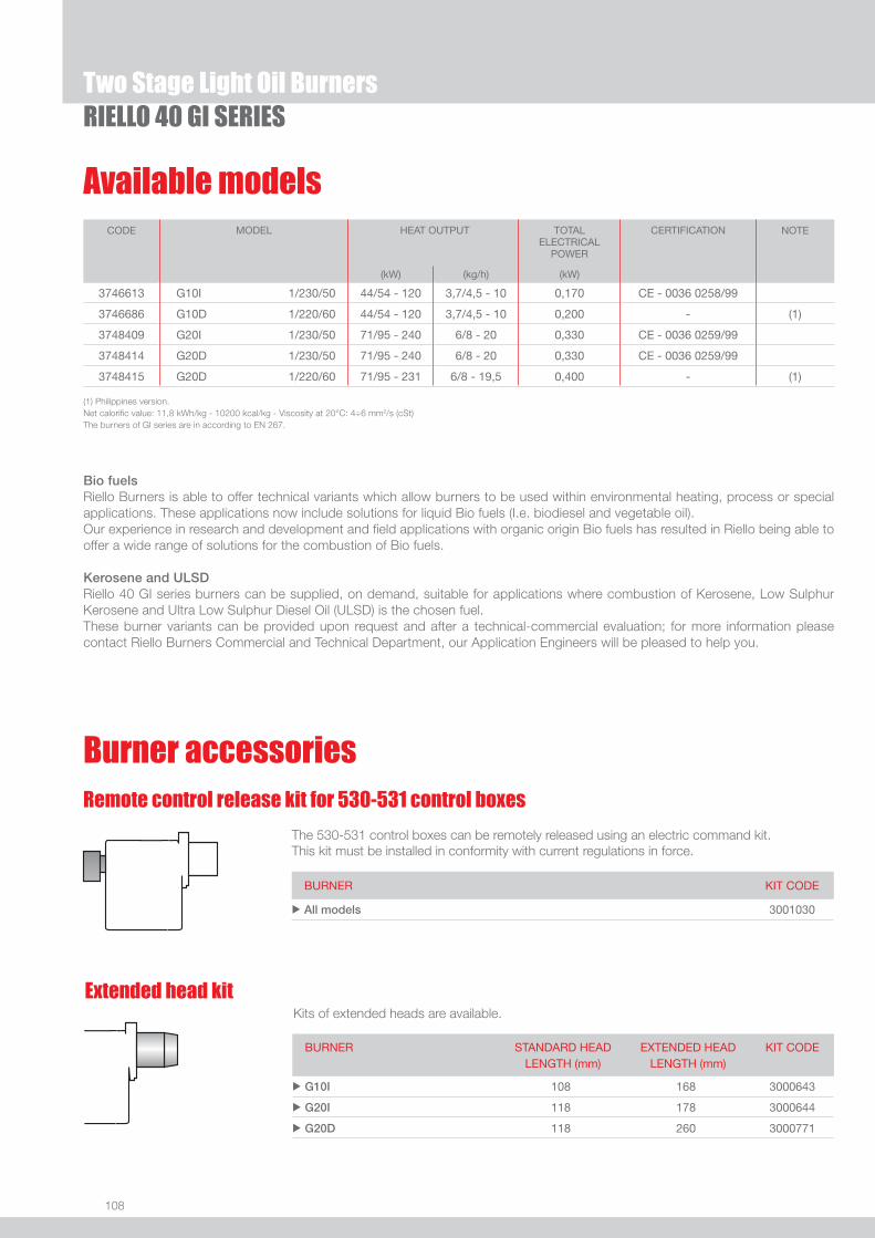
108
Available models
Two Stage Light Oil BurnersRIELLO 40 GI SERIES
CODE MODEL
HEAT OUTPUT TOTALELECTRICAL
POWER
CERTIFICATION NOTE
(kW) (kg/h) (kW)
3746613 G10I 1/230/50 44/54 - 120 3,7/4,5 - 10 0,170 CE - 0036 0258/99
3746686 G10D 1/220/60 44/54 - 120 3,7/4,5 - 10 0,200 - (1)
3748409 G20I 1/230/50 71/95 - 240 6/8 - 20 0,330 CE - 0036 0259/99
3748414 G20D 1/230/50 71/95 - 240 6/8 - 20 0,330 CE - 0036 0259/99
3748415 G20D 1/220/60 71/95 - 231 6/8 - 19,5 0,400 - (1)
(1) Philippines version.Net calorifi c value: 11,8 kWh/kg - 10200 kcal/kg - Viscosity at 20°C: 4÷6 mm2/s (cSt)The burners of GI series are in according to EN 267.
Remote control release kit for 530-531 control boxes
The 530-531 control boxes can be remotely released using an electric command kit. This kit must be installed in conformity with current regulations in force.
BURNER KIT CODE
u All models 3001030
Extended head kitKits of extended heads are available.
BURNER STANDARD HEADLENGTH (mm)
EXTENDED HEADLENGTH (mm)
KIT CODE
u G10I 108 168 3000643
u G20I 118 178 3000644
u G20D 118 260 3000771
Burner accessories
Bio fuels Riello Burners is able to offer technical variants which allow burners to be used within environmental heating, process or special applications. These applications now include solutions for liquid Bio fuels (I.e. biodiesel and vegetable oil).Our experience in research and development and fi eld applications with organic origin Bio fuels has resulted in Riello being able to offer a wide range of solutions for the combustion of Bio fuels.
Kerosene and ULSDRiello 40 GI series burners can be supplied, on demand, suitable for applications where combustion of Kerosene, Low Sulphur Kerosene and Ultra Low Sulphur Diesel Oil (ULSD) is the chosen fuel.These burner variants can be provided upon request and after a technical-commercial evaluation; for more information please contact Riello Burners Commercial and Technical Department, our Application Engineers will be pleased to help you.
109
LIGH
T OI
L
Burner accessories
Using the special accessories, the burner can be pulled back to reduce head penetration into the combustion chamber.
Spacer kit
BURNER SPACER THICKNESS S (mm)
KIT CODE
u G10I 25 3000672
u G20I - G20D 25 3000673
Two Stage Light Oil BurnersRIELLO 40 GI SERIES
BURNER FILTERING DEGREE (µm) KIT CODE
u All models 60 3006561
For cleaning light oil from dirty particles and impurities fi lters with the following features are avail-able:
Light oil fi lter
Filter made up of aluminium body and stainless steel fi ltering cartridge; available singularly.
BURNER FILTERING DEGREE (µm) KIT CODE
u All models 60 3075011
Filter made up of aluminium cover, plastic tank and nylon fi ltering cartridge; available in packaging of 50 pieces.
BURNER FILTERING DEGREE (µm) KIT CODE
u All models 100 3000926
To solve problems of air or water in the oil circuit a special fi lter/degassing unit is available, made up of aluminium cover, plastic tank, stainless steel fi ltering cartridge, air release cap and water purge valve. It is available singularly.
Light oil fi lter/degassing unit
BURNER KIT CODE
u All models 3000904
To measure the burner working time a hour counter kit is available.
Hour counter kit for 530 SE and 531 SE control boxes
7-pin plug kitIf necessary a 7-pin plug kit is available (in packaging of n. 5 pieces).
BURNER KIT CODE
u All models 3000945


One Stage Light Oil Burners
111
LIGH
T OI
L
RIELLO 40 F SERIESThe Riello 40 F series of one stage light oil burners, is a complete range of products developed to respond to any request for light industrial applications. The Riello 40 F series is available in three different models, with an output ranging from 30 to 202 kW, divided in three different structures.All the models use the same components designed by Riello for the Riello 40 F series. The high quality level guarantees safe working.In developing these burners, special attention was paid to reducing noise, to the ease of installation and adjustment, to obtaining the smallest size possible to fi t into any sort of boiler available on the market.All the models are approved by the EN 267 European Standard and conform to European Directives for EMC, Low Voltage, Machinery and Boiler Effi ciency.All the Riello 40 F burners are fi red before leaving the factory.
F5 30 ÷ 60 kWF10 54 ÷ 107 kWF20 95 ÷ 202 kW
FIRING RATES
Useful working fi eldfor choosing theburner
Test conditionsconforming to EN267 Temperature: 20°CPressure: 1013,5 mbarAltitude: 0 m a.s.l.

112
BURNER
Overall dimensions (mm)
One Stage Light Oil BurnersRIELLO 40 F SERIES
MODEL A D E F H I L u F5 272 233 240 72 89 180 41
u F10 305 262 265 104 105 204 44
u F20 350 298 299 118 125 230 45
MODEL C1 C2 F Q R S T u F5 130 150 180 45° 11 72 75
u F10 140 170 189 45° 11 83 83
u F20 160 190 213 90° 11 99 99
MODEL X Y Z kg u F5 383 315 325 12
u F10 423 348 340 13
u F20 483 393 377 16
PACKAGING
Z
XY
BURNER - BOILER MOUNTING FLANGE
F5 - F10 F20

113
LIGH
T OI
L
DESIGNATION OF SERIES
Specifi cation
One Stage Light Oil BurnersRIELLO 40 F SERIES
STATE OF SUPPLY
F 5 1/230/50
Series : F
Size Electrical supply to the system : 1/230/50 1/230V/50Hz 1/220/60 1/220V/60Hz
Completely automatic monobloc light oil burners, one stage operation, made up of:- Fan with forward curve blades- Metallic cover - Fixed air damper with adjustment- Single phase electric motor 230 V, 50 Hz- Combustion head fi tted with: - stainless steel head cone, resistant to high temperatures - ignition electrodes - fl ame stability disk- Geared pump for fuel supply, fi tted with: - fi lter - pressure regulator - attachments for fi tting a pressure gauge and vacuum meter - internal by-pass for preparing for single-pipe installations- Fuel feed solenoid valve incorporated in the pump- Photocell for fl ame detection- Electronic fl ame control equipment- Light oil nozzle- IP X0D (IP 40) protection level.
Standard equipment:- Two fl exible pipes for connection to the light oil supply line- Two nipples for connection to the pump- Flange, screws and nuts for fi xing- Thermal screen- Instruction handbook for installation, use and maintenance- Spare parts catalogue.

114
Available models
One Stage Light Oil BurnersRIELLO 40 F SERIES
Net calorifi c value: 11,8 kWh/kg - 10200 kcal/kg - Viscosity at 20°C: 4÷6 mm2/s (cSt)The burners of F series are in according to EN 267.
CODE MODEL
HEAT OUTPUT
TOTAL ELECTRICALPOWER
CERTIFICATION NOTE
(kW) (kg/h) (kW)
3451083 F5 1/230/50 30 - 60 2,5 - 5 0,130 -
3746159 F5 1/220/60 30 - 60 2,5 - 5 0,180 -
3452083 F10 1/230/50 54 - 107 4,5 - 9 0,170 -
3746260 F10 1/220/60 54 - 107 4,5 - 9 0,200 -
3452783 F20 1/230/50 95 - 202 8 - 17 0,320 -
3747260 F20 1/220/60 95 - 213 8 - 18 0,400 -
Burner accessories
Extended head kitKits of extended heads are available.
BURNER STANDARD HEADLENGTH (mm)
EXTENDED HEADLENGTH (mm)
KIT CODE
u F5 72 90 3006001
u F5 72 90 inox 3000688
u F5 72 107 3000638
u F5 72 121 3000686
u F5 72 121 inox 3000687
u F10 104 168 3000643
u F10 104 250 3000770
u F20 118 178 3000644
u F20 118 260 3000771
Remote control release kit for 530 SE control box
The 530 SE control box can be remotely released using an electric command kit. This kit must be installed in conformity with current regulations in force.
BURNER KIT CODE
u F5 - F10 - F20 3001030
Bio fuels Riello Burners is able to offer technical variants which allow burners to be used within environmental heating, process or special applications. These applications now include solutions for liquid Bio fuels (I.e. biodiesel and vegetable oil).Our experience in research and development and fi eld applications with organic origin Bio fuels has resulted in Riello being able to offer a wide range of solutions for the combustion of Bio fuels.
Kerosene and ULSDRiello 40 F series burners can be supplied, on demand, suitable for applications where combustion of Kerosene, Low Sulphur Kerosene and Ultra Low Sulphur Diesel Oil (ULSD) is the chosen fuel.These burner variants can be provided upon request and after a technical-commercial evaluation; for more information please contact Riello Burners Commercial and Technical Department, our Application Engineers will be pleased to help you.
115
LIGH
T OI
L
Burner accessories
One Stage Light Oil Burners
Using the special accessories, the burner can be pulled back to reduce head penetration into the combustion chamber.
Spacer kit
BURNER SPACER THICKNESS S (mm)
KIT CODE
u F5 25 3000642
u F10 25 3000672
u F10 25 3000673
RIELLO 40 F SERIES
BURNER FILTERING DEGREE (µm) KIT CODE
u All models 100 3000926
To solve problems of air or water in the oil circuit a special fi lter/degassing unit is available, made up of aluminium cover, plastic tank, stainless steel fi ltering cartridge, air release cap and water purge valve. It is available singularly.
Light oil fi lter/degassing unit
BURNER FILTERING DEGREE (µm) KIT CODE
u All models 60 3006561
For cleaning light oil from dirty particles and impurities fi lters with the following features are avail-able:
Light oil fi lter
Filter made up of aluminium body and stainless steel fi ltering cartridge; available singularly.
BURNER FILTERING DEGREE (µm) KIT CODE
u All models 60 3075011
Filter made up of aluminium cover, plastic tank and nylon fi ltering cartridge; available in packaging of 50 pieces.
BURNER KIT CODE
u All models 3000904
To measure the burner working time a hour counter kit is available.
Hour counter kit for 530 SE and 531 SE control boxes
7-pin plug kitIf necessary a 7-pin plug kit is available (in packaging of n. 5 pieces).
BURNER KIT CODE
u All models 3000945
7-pole socket kit for 530 SE and 531 SE control boxes
BURNER KIT CODE
u All models 3001065
For burner without pre installed socket a 7-pole socket kit with cable is available.

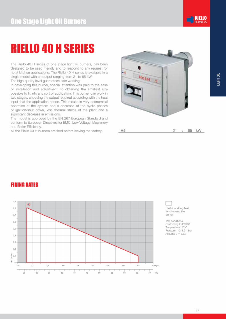
One Stage Light Oil Burners
117
LIGH
T OI
L
FIRING RATES
One Stage Light Oil Burners
RIELLO 40 H SERIESThe Riello 40 H series of one stage light oil burners, has been designed to be used friendly and to respond to any request for hotel kitchen applications. The Riello 40 H series is available in a single model with an output ranging from 21 to 65 kW.The high quality level guarantees safe working.In developing this burner, special attention was paid to the ease of installation and adjustment, to obtaining the smallest size possible to fi t into any sort of application. This burner can work in two stages, choosing the output required according with the heat input that the application needs. This results in very economical operation of the system and a decrease of the cyclic phases of ignition/shut down, less thermal stress of the plant and a signifi cant decrease in emissions.The model is approved by the EN 267 European Standard and conform to European Directives for EMC, Low Voltage, Machinery and Boiler Effi ciency. All the Riello 40 H burners are fi red before leaving the factory. H5 21 ÷ 65 kW
Useful working fi eldfor choosing theburner
Test conditionsconforming to EN267 Temperature: 20°CPressure: 1013,5 mbarAltitude: 0 m a.s.l.
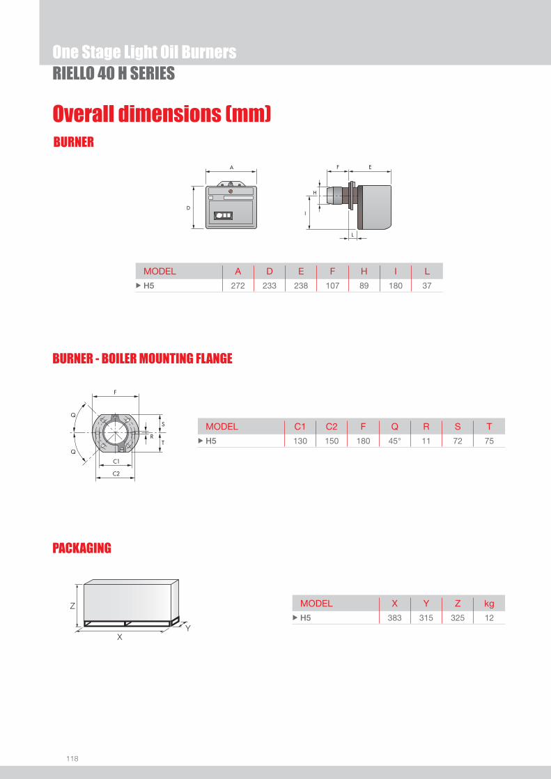
118
BURNER
Overall dimensions (mm)
One Stage Light Oil Burners
MODEL A D E F H I L u H5 272 233 238 107 89 180 37
MODEL C1 C2 F Q R S T u H5 130 150 180 45° 11 72 75
MODEL X Y Z kg u H5 383 315 325 12
PACKAGING
Z
XY
RIELLO 40 H SERIES
BURNER - BOILER MOUNTING FLANGE
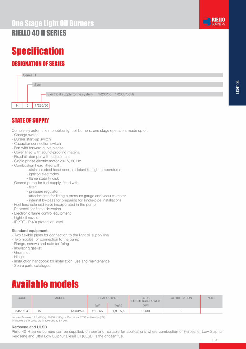
119
LIGH
T OI
L
DESIGNATION OF SERIES
Specifi cation
One Stage Light Oil BurnersRIELLO 40 H SERIES
STATE OF SUPPLY
Series : H
Size Electrical supply to the system : 1/230/50 1/230V/50Hz
Completely automatic monobloc light oil burners, one stage operation, made up of:- Change switch- Burner start-up switch- Capacitor connection switch- Fan with forward curve blades- Cover lined with sound-proofi ng material- Fixed air damper with adjustment- Single phase electric motor 230 V, 50 Hz- Combustion head fi tted with: - stainless steel head cone, resistant to high temperatures - ignition electrodes - fl ame stability disk- Geared pump for fuel supply, fi tted with: - fi lter - pressure regulator - attachments for fi tting a pressure gauge and vacuum meter - internal by-pass for preparing for single-pipe installations- Fuel feed solenoid valve incorporated in the pump- Photocell for fl ame detection- Electronic fl ame control equipment- Light oil nozzle- IP X0D (IP 40) protection level.
Standard equipment:- Two fl exible pipes for connection to the light oil supply line- Two nipples for connection to the pump- Flange, screws and nuts for fi xing- Insulating gasket- Grommet- Hinge- Instruction handbook for installation, use and maintenance- Spare parts catalogue.
Net calorifi c value: 11,8 kWh/kg; 10200 kcal/kg - Viscosity at 20°C: 4÷6 mm2/s (cSt).The burners of H series are in according to EN 267.
CODE MODEL HEAT OUTPUT TOTAL ELECTRICAL POWER
CERTIFICATION NOTE
(kW) (kg/h) (kW)
3451104 H5 1/230/50 21 - 65 1,8 - 5,5 0,130 -
Available models
Kerosene and ULSDRiello 40 H series burners can be supplied, on demand, suitable for applications where combustion of Kerosene, Low Sulphur Kerosene and Ultra Low Sulphur Diesel Oil (ULSD) is the chosen fuel.
H 5 1/230/50

120
One Stage Light Oil BurnersRIELLO 40 H SERIES
Burner accessories
ProtectionBURNER KIT CODE
u H5 3000925
Extended head kit
Kits of extended heads are available.
BURNER STANDARD HEADLENGTH (mm)
EXTENDED HEADLENGTH (mm)
KIT CODE
u H5 107 121 3000686
u H5 107 121 INOX 3000687
Using the special accessories, the burner can be pulled back to reduce head penetration into the combustion chamber.
Spacer kit
BURNER SPACER THICKNESS S (mm)
KIT CODE
u H5 25 3000642
End cone without turbulator ring
BURNER KIT CODE
u H5 3006040
BURNER FILTERING DEGREE (µm) KIT CODE
u H5 100 3000926
To solve problems of air or water in the oil circuit a special fi lter/degassing unit is available, made up of aluminium cover, plastic tank, stainless steel fi ltering cartridge, air release cap and water purge valve. It is available singularly.
Light oil fi lter/degassing unit
BURNER FILTERING DEGREE (µm) KIT CODE
u H5 60 3006561
For cleaning light oil from dirty particles and impurities fi lters with the following features are avail-able:
Light oil fi lter
Filter made up of aluminium body and stainless steel fi ltering cartridge; available singularly.
BURNER FILTERING DEGREE (µm) KIT CODE
u H5 60 3075011
Filter made up of aluminium cover, plastic tank and nylon fi ltering cartridge; available in packaging of 50 pieces.

121
LIGH
T OI
L
One Stage Light Oil and Kerosene Burners
RDB SERIESThe Riello RDB series of one stage light oil and kerosene burners is available in eleven basic models, with an output ranging from 16,8 to 120 kW, in three different structures. The models are available in light oil and kerosene versions, conventional fl ue and balanced fl ue, with or without the fuel pre-heater fi tted.A new model has been specifi cally designed to meet the increasing trends towards high pressure working fi eld demand.These models are distinguished by their compact size. All the models use the same components designed by Riello for the RDB series. The high quality level guarantees safe working. The RDB burners are equipped with a geared pump suitable for Kerosene, Low Sulphur Kerosene and ultra low sulphur diesel oil (ULSD).In developing these burners, special attention was paid to reducing noise, to the ease of installation and adjustment, to obtaining the smallest size possible to fi t into any sort of boiler available on the market. All the models are approved by the EN 267 European Standard and conform to European Directives for EMC, Low Voltage, Machinery and Boiler Effi ciency. All the RDB burners are fi red before leaving the factory.
RDB1-1R 16,8 ÷ 40,6 kW RDB2-2R 24,0 ÷ 46,2 kWRDB2.1-2.1R 21,0 ÷ 54,0 kWRDB2.2-2.2R 21,0 ÷ 54,0 kWRDB3 35,6 ÷ 69,0 kWRDB3.2 41,5 ÷ 119,0 kWRDB4 47,45 ÷ 120,0 kW
FIRING RATES
Useful working fi eldfor choosing theburner
Test conditionsconforming to EN267 Temperature: 20°CPressure: 1013,5 mbarAltitude: 0 m a.s.l.

122
BURNER
Overall dimensions (mm)
Z
XY
One Stage Light Oil and Kerosene BurnersRDB SERIES
L
EF
I
J A
D
EF
I
L
A
D
H H
RDB1-1R - RDB2-2R - RDB2.1-2.1R - RDB2.2-2.2R RDB3 - RDB3.2 - RDB4
MODEL A D H F E L I J u RDB1-1R 276 230 89-90 76-86 202 20 168 75 u RDB2-2R 276 230 89-90 76-86 202 20 168 75 u RDB2.1-2.1R 286 230 85 77 202 20 168 75 u RDB2.2-2.2R 286 230 85 77 202 20 168 75 u RDB3 325 268 88 78 253 30 204 75 u RDB3.2 325 268 95 69,5 253 30 204 75 u RDB4 325 268 105 111 253 30 204 75
BURNER - BOILER MOUNTING FLANGERDB1-1R - RDB2-2R - RDB2.1-2.1R - RDB2.2-2.2R RDB3 - RDB3.2 - RDB4
MODEL X Y Z kg u RDB1-1R 395 305 295 11 u RDB2-2R 395 305 295 11 u RDB2.1-2.1R 395 305 295 11 u RDB2.2-2.2R 395 305 295 11 u RDB3 435 360 355 15 u RDB3.2 435 360 355 15 u RDB4 435 360 355 15
MODEL L M N O P Q u RDB1-1R 130 150 180 91 72 72 u RDB2-2R 130 150 180 91 72 72 u RDB2.1-2.1R 130 150 180 91 72 72 u RDB2.2-2.2R 130 150 180 91 72 72 u RDB3 140 168 189 106 83 83 u RDB3.2 140 168 189 106 83 83 u RDB4 140 168 189 106 83 83
PACKAGING
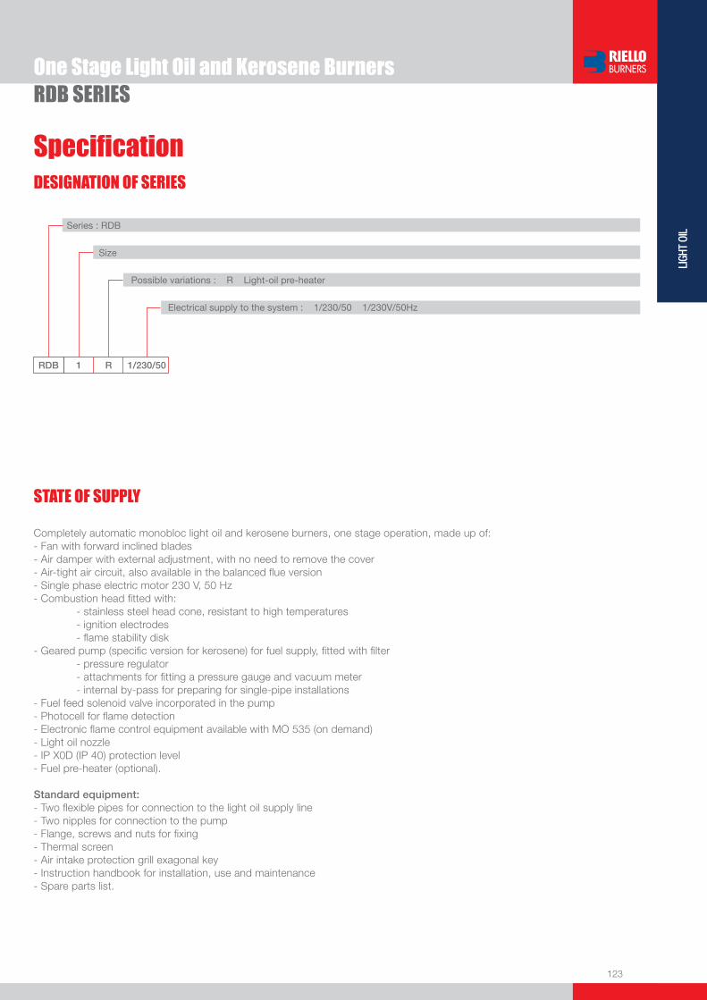
123
LIGH
T OI
L
DESIGNATION OF SERIES
Specifi cation
One Stage Light Oil and Kerosene BurnersRDB SERIES
STATE OF SUPPLY
RDB 1 R 1/230/50
Series : RDB
Size
Possible variations : R Light-oil pre-heater
Electrical supply to the system : 1/230/50 1/230V/50Hz
Completely automatic monobloc light oil and kerosene burners, one stage operation, made up of:- Fan with forward inclined blades- Air damper with external adjustment, with no need to remove the cover- Air-tight air circuit, also available in the balanced fl ue version- Single phase electric motor 230 V, 50 Hz- Combustion head fi tted with: - stainless steel head cone, resistant to high temperatures - ignition electrodes - fl ame stability disk- Geared pump (specifi c version for kerosene) for fuel supply, fi tted with fi lter - pressure regulator - attachments for fi tting a pressure gauge and vacuum meter - internal by-pass for preparing for single-pipe installations- Fuel feed solenoid valve incorporated in the pump- Photocell for fl ame detection- Electronic fl ame control equipment available with MO 535 (on demand)- Light oil nozzle- IP X0D (IP 40) protection level- Fuel pre-heater (optional).
Standard equipment:- Two fl exible pipes for connection to the light oil supply line- Two nipples for connection to the pump- Flange, screws and nuts for fi xing- Thermal screen- Air intake protection grill exagonal key- Instruction handbook for installation, use and maintenance- Spare parts list.

124
Available models
RDB SERIESOne Stage Light Oil and Kerosene Burners
(1) All burner models are OEM’s customized.(2) This code is unprovided with thermal screen.Net calorifi c value: 11,8 kWh/kg; 10200 kcal/kg - Viscosity at 20°C: light oil models 4÷6; kerosene models 1,5÷6 mm2/s (cSt).The burners of RDB series are in according to EN 267.
CODE MODEL HEAT OUTPUT TOTALELECTRICAL
POWER
CERTIFICATION NOTE
(kW) (kg/h) (kW)
on demand RDB1 1/230/50 16,8 - 26,3 1,4 - 2,2 0,115 CE - 0036 0316/01 (1) (2)
on demand RDB1R 1/230/50 21,6 - 40,6 1,8 - 3,4 0,170 CE - 0036 0326/01 (1)
on demand RDB2 1/230/50 24 - 38,3 2 - 3,2 0,125 CE - 0036 0316/01 (1)
on demand RDB2 1/230/50 29,6 - 59,3 2,5 - 5 0,125 CE - 0036 0316/01 (1)
on demand RDB2R 1/230/50 33,2 - 46,2 2,8 - 3,9 0,175 CE - 0036 0316/01 (1)
on demand RDB2.1 1/230/50 21,5 - 42 1,8 - 3,5 0,160 CE - 0036 0316/01 (1)
on demand RDB2.1R 1/230/50 33 - 54 2,8 - 4,5 0,230 CE - 0036 0316/01 (1)
on demand RDB2.2 1/230/50 21 - 41,5 1,8 - 3,5 0,160 CE - 0036 0316/01 (1)
on demand RDB2.2R 1/230/50 33,5 - 51 2,9 - 4,3 0,230 CE - 0036 0316/01 (1)
on demand RDB3 1/230/50 35,6 - 68,7 3 - 5,8 0,160 CE - 0036 0275/99 (1)
on demand RDB3.2 1/230/50 41 - 120 3,5 - 10 0,160 CE - 0036 0332/02 (1)
on demand RDB4 1/230/50 47,45 - 120 4 - 10 0,160 CE - 0036 0332/02 (1)

125
LIGH
T OI
L
Burner accessories
One Stage Light Oil and Kerosene BurnersRDB SERIES
Balanced-conventional fl ue conversion kit
All the RDB series models are easily converted from conventional fl ue to balanced fl ue, by replac-ing the plastic screen on the air intake with the connector for the air supply pipe.
BURNER BALANCED FLUEKIT CODE
CONVENTIONAL FLUEKIT CODE
u RDB1-1R - RDB2-2R - RDB2.1-2.1R - RDB2.2-2.2R 3062774 3062775
u RDB3 - RDB4 3062774 3062876
BURNER KIT CODE
u All models 3087216
The tester controls the correct working of the burner components. It can be fi tted to all the light-oil models, with or without pre-heater.It is made up of two parts: a control instrument and a “control box”.
Tester
DIRECT TESTING MOTOR The switch feeds the motor. VALVE
The switch feeds electromagnetic winding of the coil. A red led signals excitation stage, and a green led signals retainer stage. PRE-HEATER The switch feeds the light oil pre-heater; a green led signals the thermostat cut-in. TRANSFORMER The switch feeds the fi ring transformer inside the control box and excites the oil valve.
MEASUREMENTS
Main voltage (230 V)
Pre-heater current consumption
Secondary voltage (low voltage)
Photo-resistance current consumption

126
One Stage Light Oil and Kerosene BurnersRDB SERIES
Extended head kitKits of extended heads are available.
BURNER STANDARD HEADLENGTH (mm)
EXTENDED HEADLENGTH (mm)
KIT CODE
u RDB4 111 170 3004590
BURNER FILTERING DEGREE (µm) KIT CODE
u All models 60 3006561
For cleaning light oil from dirty particles and impurities fi lters with the following features are avail-able:
Light oil fi lter
Filter made up of aluminium body and stainless steel fi ltering cartridge; available singularly.
BURNER FILTERING DEGREE (µm) KIT CODE
u All models 60 3075011
Filter made up of aluminium cover, plastic tank and nylon fi ltering cartridge; available in packaging of 50 pieces.
BURNER FILTERING DEGREE (µm) KIT CODE
u All models 100 3000926
To solve problems of air or water in the oil circuit a special fi lter/degassing unit is available, made up of aluminium cover, plastic tank, stainless steel fi ltering cartridge, air release cap and water purge valve. It is available singularly.
Light oil fi lter/degassing unit
Burner accessories
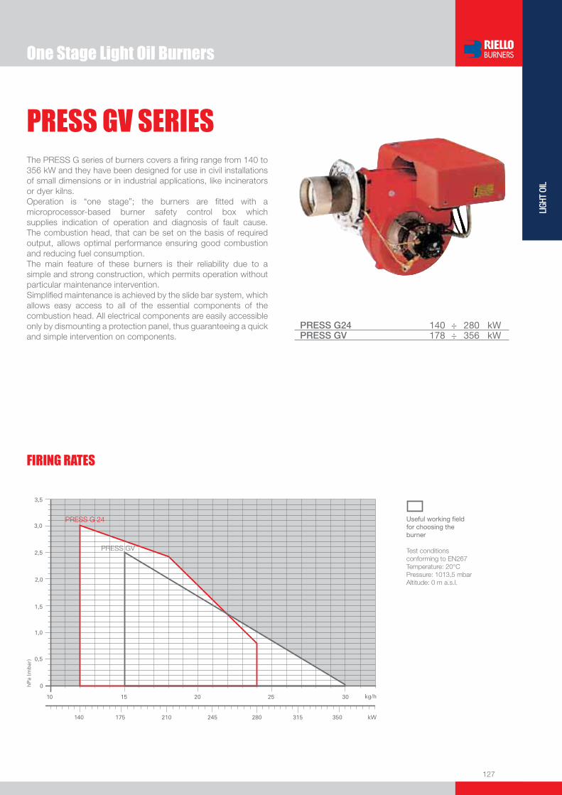
One Stage Light Oil Burners
127
LIGH
T OI
L
FIRING RATES
PRESS GV SERIESThe PRESS G series of burners covers a fi ring range from 140 to 356 kW and they have been designed for use in civil installations of small dimensions or in industrial applications, like incinerators or dyer kilns.Operation is “one stage”; the burners are fi tted with a microprocessor-based burner safety control box which supplies indication of operation and diagnosis of fault cause. The combustion head, that can be set on the basis of required output, allows optimal performance ensuring good combustion and reducing fuel consumption.The main feature of these burners is their reliability due to a simple and strong construction, which permits operation without particular maintenance intervention. Simplifi ed maintenance is achieved by the slide bar system, which allows easy access to all of the essential components of the combustion head. All electrical components are easily accessible only by dismounting a protection panel, thus guaranteeing a quick and simple intervention on components.
PRESS G24 140 ÷ 280 kWPRESS GV 178 ÷ 356 kW
Useful working fi eldfor choosing theburner
Test conditionsconforming to EN267 Temperature: 20°CPressure: 1013,5 mbarAltitude: 0 m a.s.l.

128
BURNER
PACKAGING
Overall dimensions (mm)
One Stage Light Oil BurnersPRESS GV SERIES
PRESS G24 PRESS GV
BURNER - BOILER MOUNTING FLANGE
PRESS G24 PRESS GV
MODEL A B C D E F - F (1) H I L O - O (1)u PRESS G24 425 222 203 397 485 118 - 253 125 290 - - - -
u PRESS GV 439 234 205 397 473 185 - 320 140 292 59 690 - 825
MODEL D1 D2 D3 D4 D5 Ø u PRESS G24 213 198 160 190 11 -
u PRESS GV 160 160 155 - - M10
MODEL X - X (1) Y Z kg u PRESS G24 650 535 450 33
u PRESS GV 680 535 450 33
(1) Length with extended combustion head.
(1) Length with extended combustion head.
Z
X - X (1)Y

129
LIGH
T OI
L
DESIGNATION OF SERIES
Specifi cation
One Stage Light Oil BurnersPRESS GV SERIES
PRESS G24 TC FS1 1/230/50 230/50
Series : PRESS
Operation : GV or G24 One stage GW or 1-2-3-4G Two stage
Emission : ... Class 1 EN267 Head : TC Standard head TL Extended head
Flame control system : FS1 Standard (1 stop every 24 h) FS2 Continuous working (1 stop every 72 h)
Electrical supply to the system : 1/230/50 1/230V/50Hz 1/210/60 1/210V/60Hz 1/220/60 1/220V/60Hz 1/200/50-60 1/200V/50-60Hz 3/230-400/50 3/230V/50Hz - 3N/400V/50Hz 3/210/60 3/210V/60Hz 3/220-380/60 3/220V/60Hz - 3N/380V/60Hz 3/200/50-60 3/200V/50-60Hz Auxiliary voltage : 230/50 230V/50Hz 120/60 120V/60Hz 220/60 220V/60Hz 200/50-60 200V/50-60Hz
BASIC DESIGNATION
EXTENDED DESIGNATION
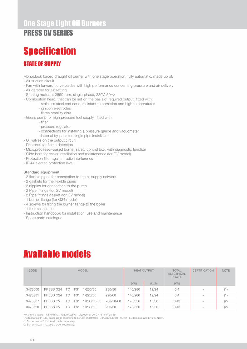
130
One Stage Light Oil BurnersPRESS GV SERIES
Available models
STATE OF SUPPLY
Monoblock forced draught oil burner with one stage operation, fully automatic, made up of:- Air suction circuit- Fan with forward curve blades with high performance concerning pressure and air delivery- Air damper for air setting- Starting motor at 2850 rpm, single-phase, 230V, 50Hz- Combustion head, that can be set on the basis of required output, fi tted with: - stainless steel end cone, resistant to corrosion and high temperatures - ignition electrodes - fl ame stability disk- Gears pump for high pressure fuel supply, fi tted with: - fi lter - pressure regulator - connections for installing a pressure gauge and vacuometer - internal by-pass for single pipe installation- Oil valves on the output circuit- Photocell for fl ame detection- Microprocessor-based burner safety control box, with diagnostic function- Slide bars for easier installation and maintenance (for GV model)- Protection fi lter against radio interference- IP 44 electric protection level.
Standard equipment:- 2 fl exible pipes for connection to the oil supply network- 2 gaskets for the fl exible pipes- 2 nipples for connection to the pump- 2 Pipe fi ttings (for GV model)- 2 Pipe fi ttings gasket (for GV model)- 1 burner fl ange (for G24 model)- 4 screws for fi xing the burner fl ange to the boiler- 1 thermal screen- Instruction handbook for installation, use and maintenance- Spare parts catalogue.
Specifi cation
Net calorifi c value: 11,8 kWh/kg - 10200 kcal/kg - Viscosity at 20°C 4-6 mm2/s (cSt)The burners of PRESS series are in according to 89/336 (2004/108) - 73/23 (2006/95) - 92/42 - EC Directive and EN 267 Norm.(1) Burner needs 2 nozzles (to order separately).(2) Burner needs 1 nozzle (to order separately).
CODE MODEL HEAT OUTPUT TOTALELECTRICAL
POWER
CERTIFICATION NOTE
(kW) (kg/h) (kW)
3473000 PRESS G24 TC FS1 1/230/50 230/50 140/280 12/24 0,4 - (1)
3473081 PRESS G24 TC FS1 1/220/60 220/60 140/280 12/24 0,4 - (1)
3473687 PRESS GV TC FS1 1/200/50-60 200/50-60 178/356 15/30 0,43 - (2)
3473620 PRESS GV TC FS1 1/230/50 230/50 178/356 15/30 0,43 - (2)

131
LIGH
T OI
L
Burner accessories
One Stage Light Oil BurnersPRESS GV SERIES
Nozzles type 60°B
The nozzles must be ordered separately. The following table shows the features and codes on the basis of the maximum required fuel output.
NOTE : for nozzles quantity to order see note in the “Available Burner Models” table.
BURNER RATED DELIVERY [kg/h] at 12 bar
GPH NOZZLE CODE
u PRESS G24 6,3 1,50 3042107
u PRESS G24 7,3 1,75 3042110
u PRESS G24 8,5 2,00 3042126
u PRESS G24 10,6 2,50 3042140
u PRESS G24 12,7 3,00 3042158
u PRESS G24 14,8 3,50 3042162
u PRESS GV 17 4,00 3042172
u PRESS GV 19,1 4,50 3042182
u PRESS GV 21,2 5,00 3042192
u PRESS GV 23,3 5,50 3042202
u PRESS GV 25,5 6,00 3042212
u PRESS GV 27,6 6,50 3042222
u PRESS GV 29,7 7,00 3042232
u PRESS GV 31,8 7,50 3042242
Extended head kit
“Standard head” burners can be transformed into “extended head” versions, by using the special kit.
BURNER STANDARD HEADLENGTH (mm)
EXTENDED HEADLENGTH (mm)
KIT CODE
u PRESS G24 118 253 3010051
u PRESS GV 185 320 3000580
If burner head penetration into the combustion chamber needs reducing, varying thickness spacers are available, as given in the following list.
Spacer kit
BURNER
SPACER THICKNESS S (mm)
KIT CODE
u PRESS GV 142 3000755

132
One Stage Light Oil Burners
If noise emission needs reducing even further, sound-proofi ng boxes are available.
Sound proofi ng box
BURNER
BOX TYPE
AVERAGE NOISE REDUCTION [dB(A)] (*)
BOX CODE
u PRESS GV C1/3 10 3010403
(*) according to EN 15036-1 standard
To solve problem of air in the oil sucked, two versions of degasing unit are available.Degasing unit
BURNER
FILTER
FILTERING DEGREE (µm)
DEGASING UNIT CODE
u PRESS GV With fi lter 50 - 75 3010055
u PRESS GV Without fi lter - 3010054
PRESS GV SERIES
BURNER KIT CODE
u PRESS G24 - GV 3002719
To connect the control box to a personal computer for the transmission of operation, fault signals and detailed service information, an interface adapter with PC software are available.
PC Interface kit
Burner accessories
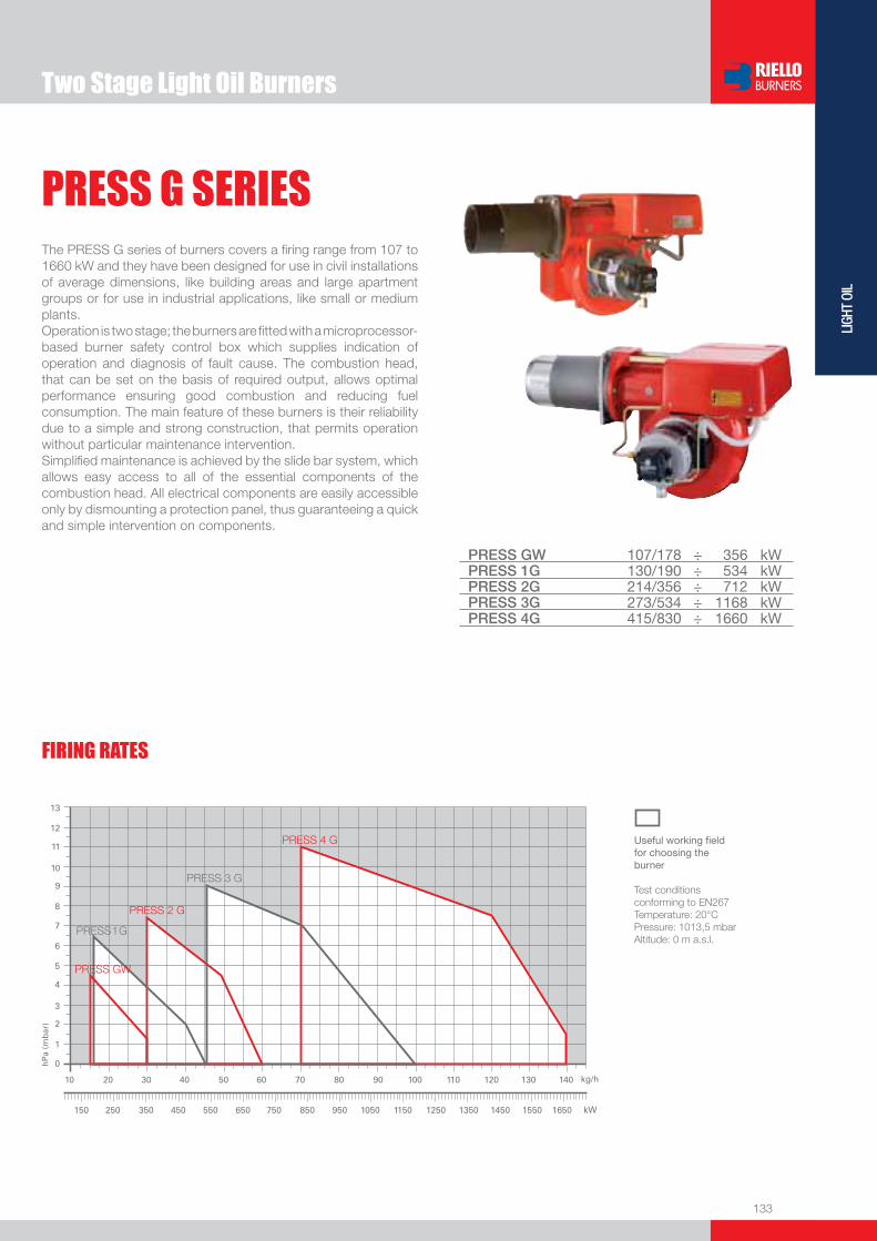
133
LIGH
T OI
L
PRESS G SERIESThe PRESS G series of burners covers a fi ring range from 107 to 1660 kW and they have been designed for use in civil installations of average dimensions, like building areas and large apartment groups or for use in industrial applications, like small or medium plants.Operation is two stage; the burners are fi tted with a microprocessor-based burner safety control box which supplies indication of operation and diagnosis of fault cause. The combustion head, that can be set on the basis of required output, allows optimal performance ensuring good combustion and reducing fuel consumption. The main feature of these burners is their reliability due to a simple and strong construction, that permits operation without particular maintenance intervention. Simplifi ed maintenance is achieved by the slide bar system, which allows easy access to all of the essential components of the combustion head. All electrical components are easily accessible only by dismounting a protection panel, thus guaranteeing a quick and simple intervention on components.
PRESS GW 107/178 ÷ 356 kWPRESS 1G 130/190 ÷ 534 kWPRESS 2G 214/356 ÷ 712 kWPRESS 3G 273/534 ÷ 1168 kWPRESS 4G 415/830 ÷ 1660 kW
Two Stage Light Oil Burners
Useful working fi eldfor choosing theburner
Test conditionsconforming to EN267 Temperature: 20°CPressure: 1013,5 mbarAltitude: 0 m a.s.l.
FIRING RATES

134
BURNER
Overall dimensions (mm)
PRESS G SERIES
(1) Length with extended combustion head.
Two Stage Light Oil Burners
MODEL A B C D E F - F (1) H I L O - O (1) u PRESS GW 439 234 205 397 473 185 - 320 140 292 59 745 - 880
u PRESS 1G 475 270 205 397 473 237 - 370 150 292 59 745 - 880
u PRESS 2G 475 270 205 437 506 245 - 403 155 332 89 785 - 945
u PRESS 3G 611 406 205 485 570 254 - 412 175 370 88 846 - 1006
u PRESS 4G 675 354 316 590 720 266 - 426 205 445 175 999 - 1159
BURNER - BOILER MOUNTING FLANGE
MODEL D1 D2 D3 Ø u PRESS GW 160 160 155 M10
u PRESS 1G 160 160 165 M10
u PRESS 2G 160 160 165 M10
u PRESS 3G 195 195 185 M12
u PRESS 4G 230 230 210 M12
(1) Length with extended combustion head.
Z
X - X (1)Y
PACKAGING
MODEL X - X (1) Y Z kg u PRESS GW 695 542 468 37
u PRESS 1G 745 542 468 44
u PRESS 2G 800 542 515 44
u PRESS 3G 905 680 563 55
u PRESS 4G 1045 727 660 95

135
LIGH
T OI
L
DESIGNATION OF SERIES
Specifi cation
PRESS G SERIES
PRESS 4G TC FS1 3/230-400/50 230/50
Series : PRESS
Operation : GV or G24 One stage GW or 1-2-3-4G Two stage
Emission : ... Class 1 EN267 Head : TC Standard head TL Extended head
Flame control system : FS1 Standard (1 stop every 24 h) FS2 Continuous working (1 stop every 72 h)
Electrical supply to the system : 1/230/50 1/230V/50Hz 1/210/60 1/210V/60Hz 1/220/60 1/220V/60Hz 1/200/50-60 1/200V/50-60Hz 3/230-400/50 3/230V/50Hz - 3N/400V/50Hz 3/210/60 3/210V/60Hz 3/220-380/60 3/220V/60Hz - 3N/380V/60Hz 3/200/50-60 3/200V/50-60Hz Auxiliary voltage : 230/50 230V/50Hz 120/60 120V/60Hz 220/60 220V/60Hz 200/50-60 200V/50-60Hz
BASIC DESIGNATION
EXTENDED DESIGNATION
Two Stage Light Oil Burners

136
PRESS G SERIES
STATE OF SUPPLY
Monoblock forced draught oil burner with two stage operation, fully automatic, made up of:- Air suction circuit lined with sound-proofi ng material- Fan with forward curve blades with high performance concerning pressure and air delivery- Air damper for air setting - Hydraulic ram for air damper control- Starting motor at 2800 rpm, three-phase 400V with neutral, 50Hz (single-phase, 230V and 50Hz for the PRESS GW model)- Combustion head, that can be set on the basis of required output, fi tted with: - stainless steel end cone, resistant to corrosion and high temperatures - ignition electrodes - fl ame stability disk- Fan pressure test point- Gears pump for high pressure fuel supply, fi tted with: - fi lter - pressure regulator - connections for installing a pressure gauge and vacuometer - internal by-pass for single pipe installation- Valve unit with two delivery oil valves on the output circuit- Photocell for fl ame detection- Microprocessor-based burner safety control box, with diagnostic function- Slide bars for easier installation and maintenance- Protection fi lter against radio interference- IP 44 electric protection level.
Standard equipment:- 2 fl exible pipes for connection to the oil supply network- 2 gaskets for the fl exible pipes- 2 nipples for connection to the pump- 4 screws for fi xing the burner fl ange to the boiler- 1 thermal screen- Instruction handbook for installation, use and maintenance- Spare parts catalogue.
Specifi cation
Two Stage Light Oil Burners
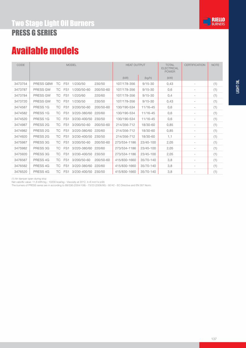
137
LIGH
T OI
L
Available models
(1) Air damper open during stopNet calorifi c value: 11,8 kWh/kg - 10200 kcal/kg - Viscosity at 20°C: 4÷6 mm2/s (cSt) The burners of PRESS series are in according to 89/336 (2004/108) - 73/23 (2006/95) - 92/42 - EC Directive and EN 267 Norm.
CODE MODEL HEAT OUTPUT TOTALELECTRICAL
POWER
CERTIFICATION NOTE
(kW) (kg/h) (kW)
3473754 PRESS GBW TC FS1 1/230/50 230/50 107/178-356 9/15-30 0,43 - (1)
3473787 PRESS GW TC FS1 1/200/50-60 200/50-60 107/178-356 9/15-30 0,6 - (1)
3473784 PRESS GW TC FS1 1/220/60 220/60 107/178-356 9/15-30 0,4 - (1)
3473720 PRESS GW TC FS1 1/230/50 230/50 107/178-356 9/15-30 0,43 - (1)
3474587 PRESS 1G TC FS1 3/200/50-60 200/50-60 130/190-534 11/16-45 0,6 - (1)
3474582 PRESS 1G TC FS1 3/220-380/60 220/60 130/190-534 11/16-45 0,6 - (1)
3474520 PRESS 1G TC FS1 3/230-400/50 230/50 130/190-534 11/16-45 0,6 - (1)
3474987 PRESS 2G TC FS1 3/200/50-60 200/50-60 214/356-712 18/30-60 0,85 - (1)
3474982 PRESS 2G TC FS1 3/220-380/60 220/60 214/356-712 18/30-60 0,85 - (1)
3474920 PRESS 2G TC FS1 3/230-400/50 230/50 214/356-712 18/30-60 1,1 - (1)
3475987 PRESS 3G TC FS1 3/200/50-60 200/50-60 273/534-1186 23/45-100 2,05 - (1)
3475982 PRESS 3G TC FS1 3/220-380/60 220/60 273/534-1186 23/45-100 2,05 - (1)
3475920 PRESS 3G TC FS1 3/230-400/50 230/50 273/534-1186 23/45-100 2,05 - (1)
3476587 PRESS 4G TC FS1 3/200/50-60 200/50-60 415/830-1660 35/70-140 3,8 - (1)
3476582 PRESS 4G TC FS1 3/220-380/60 220/60 415/830-1660 35/70-140 3,8 - (1)
3476520 PRESS 4G TC FS1 3/230-400/50 230/50 415/830-1660 35/70-140 3,8 - (1)
Two Stage Light Oil BurnersPRESS G SERIES

138
PRESS G SERIES
Nozzles type 60°B
The nozzles must be ordered separately. The following table shows the features and codes on the basis of the maximum required fuel output.
NOTE: each burner is equipped with N° 2 nozzles.
Extended head kit
“Standard head” burners can be transformed into “extended head” versions, by using the special kit.
BURNER STANDARD HEADLENGTH (mm)
EXTENDED HEADLENGTH (mm)
KIT CODE
u PRESS GW 185 320 3000581
u PRESS 1G 237 370 3000537
u PRESS 2G 245 403 3000538
u PRESS 3G 254 412 3000851
u PRESS 4G 266 426 3000555
Two Stage Light Oil Burners
Burner accessories
BURNER RATED DELIVERY [kg/h] at 12 bar
GPH NOZZLE CODE
u PRESS GW - 1G 8,5 2,00 3042126
u PRESS GW - 1G 10,6 2,50 3042140
u PRESS GW - 1G 12,7 3,00 3042158
u PRESS GW - 1G 14,8 3,50 3042162
u PRESS GW - 1G - 2G 17 4,00 3042172
u PRESS 1G - 2G 19,1 4,50 3042182
u PRESS 1G - 2G 21,2 5,00 3042192
u PRESS 1G - 2G 23,3 5,50 3042202
u PRESS 2G - 3G 25,5 6,00 3042212
u PRESS 2G - 3G 27,6 6,50 3042222
u PRESS 2G - 3G 29,7 7,00 3042232
u PRESS 3G 31,8 7,50 3042242
u PRESS 3G 33,9 8,00 3042252
u PRESS 3G 36,1 8,50 3042262
u PRESS 3G - 4G 40,3 9,50 3042282
u PRESS 3G - 4G 42,4 10,00 3042292
u PRESS 3G - 4G 46,7 11,00 3042312
u PRESS 3G - 4G 50,9 12,00 3042322
u PRESS 4G 55,1 13,00 3042332
u PRESS 4G 59,4 14,00 3042352
u PRESS 4G 63,6 15,00 3042362
u PRESS 4G 67,9 16,00 3042382
u PRESS 4G 72,1 17,00 3042392
u PRESS 4G 76,4 18,00 3042412

139
LIGH
T OI
L
Burner accessories
If burner head penetration into the combustion chamber needs reducing, varying thickness spacers are available, as given in the following list.
Spacer kit
BURNER
SPACER THICKNESS S (mm)
KIT CODE
u All models 142 3000755
PRESS G SERIESTwo Stage Light Oil Burners
If noise emission needs reducing even further, sound-proofi ng boxes are available.
Sound proofi ng box
BURNER
BOX TYPE
AVERAGE NOISE REDUCTION [dB(A)] (*)
BOX CODE
u PRESS GW - 1G - 2G - 3G C1/3 10 3010403
u PRESS 4G C4/5 10 3010404
(*) according to EN 15036-1 standard
To solve problem of air in the oil sucked, two versions of degasing unit are available.Degasing unit
BURNER
FILTER
FILTERING DEGREE (µm)
DEGASING UNIT CODE
uPRESS GWPRESS 1G - 2G - 3G(*) - 4G(*)
With fi lter 50 - 75 3010055
uPRESS GWPRESS 1G - 2G - 3G(*) - 4G(*)
Without fi lter - 3010054
BURNER KIT CODE
u All models 3002719
To connect the control box to a personal computer for the transmission of operation, fault signals and detailed service information, an interface adapter with PC software are available.
PC Interface kit
Air damper complete closure kit
To minimize thermal dispersion caused by the stack draught sucking air from the fan’s suction opening, an “air damper complete closure kit” is available. This is composed by a hydraulic ram, which closes the air damper completely when the burner shuts down.
BURNER KIT CODE
u PRESS GW 3000853
u PRESS 1G 3000854
u PRESS 2G 3000855
u PRESS 3G 3000856
u PRESS 4G 3000857
(*) For oil fl ow larger than 80 kg/h install two degasing units in parallel in the oil supply line.


141
LIGH
T OI
L
Three Stage Light Oil Burners
PRESS T/G SERIESThe PRESS T/G series of burners covers a fi ring range from 830 to 5340 kW.Available in 4 different models, this burners are particularly well suited for matching with pressurized chamber boilers.For their characteristics, they fi nd application in big civil plants for domestic heating or in industrial applications where thermal load is repetitive and predictable.An hydraulic ram exclusive system, with 3 adjustable positions, regulates dampers opening, allowing air passage in relation to output required: in this way fl ame stability is optimized in every working point, with micro-regulation available.The burners are fi tted with a microprocessor-based burner safety control box which supplies indication of operation and diagnosis of fault cause.
P 140 T/G 380/830 ÷ 1660 kWP 200 T/G 557/1186 ÷ 2372 kWP 300 T/G 712/1779 ÷ 3560 kWP 450 T/G 890/2670 ÷ 5340 kW
FIRING RATES
Useful working fi eldfor choosing theburner
Test conditionsconforming to EN267 Temperature: 20°CPressure: 1013,5 mbarAltitude: 0 m a.s.l.
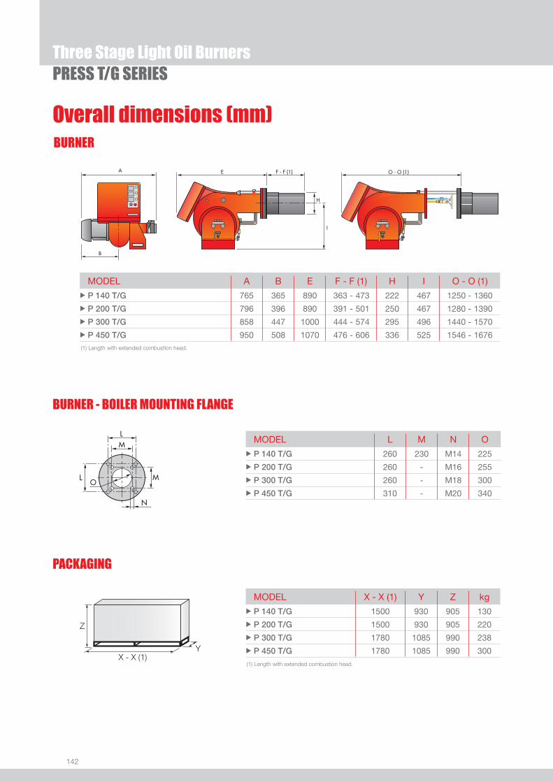
142
BURNER
Overall dimensions (mm)
Three Stage Light Oil BurnersPRESS T/G SERIES
MODEL A B E F - F (1) H I O - O (1) u P 140 T/G 765 365 890 363 - 473 222 467 1250 - 1360
u P 200 T/G 796 396 890 391 - 501 250 467 1280 - 1390
u P 300 T/G 858 447 1000 444 - 574 295 496 1440 - 1570
u P 450 T/G 950 508 1070 476 - 606 336 525 1546 - 1676 (1) Length with extended combustion head.
(1) Length with extended combustion head.
Z
X - X (1)Y
PACKAGING
MODEL X - X (1) Y Z kg u P 140 T/G 1500 930 905 130
u P 200 T/G 1500 930 905 220
u P 300 T/G 1780 1085 990 238
u P 450 T/G 1780 1085 990 300
MODEL L M N O u P 140 T/G 260 230 M14 225
u P 200 T/G 260 - M16 255
u P 300 T/G 260 - M18 300
u P 450 T/G 310 - M20 340
BURNER - BOILER MOUNTING FLANGE

143
LIGH
T OI
L
DESIGNATION OF SERIES
Specifi cation
Three Stage Light Oil BurnersPRESS T/G SERIES
PRESS 140 T/G TC FS1 3/230-400/50 230/50
Series : PRESS
Size : 140 ... 450
Operation : T/G Three stage P/G Modulating
Emission : ... Class 1 EN267 Head : TC Standard head TL Extended head
Flame control system : FS1 Standard (1 stop every 24 h) FS2 Continuous working (1 stop every 72 h)
Electrical supply to the system : 3/230/50 3/230V/50Hz 3/400/50 3N/400V/50Hz 3/230-400/50 3/230V/50Hz - 3N/400V/50Hz 3/220-380/60 3/220V/60Hz - 3N/380V/60Hz 3/200/50-60 3/200V/50-60Hz Auxiliary voltage : 230/50 230V/50Hz 220/60 220V/60Hz 110/50-60 110V/50-60Hz
BASIC DESIGNATION
EXTENDED DESIGNATION
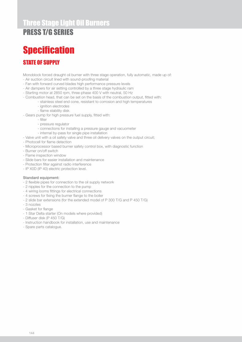
144
PRESS T/G SERIES
STATE OF SUPPLY
Monoblock forced draught oil burner with three stage operation, fully automatic, made up of:- Air suction circuit lined with sound-proofi ng material- Fan with forward curved blades high performance pressure levels- Air dampers for air setting controlled by a three stage hydraulic ram- Starting motor at 2850 rpm, three-phase 400 V with neutral, 50 Hz- Combustion head, that can be set on the basis of the combustion output, fi tted with: - stainless steel end cone, resistant to corrosion and high temperatures - ignition electrodes - fl ame stability disk- Gears pump for high pressure fuel supply, fi tted with: - fi lter - pressure regulator - connections for installing a pressure gauge and vacuometer - internal by-pass for single pipe installation- Valve unit with a oil safety valve and three oil delivery valves on the output circuit;- Photocell for fl ame detection- Microprocessor based burner safety control box, with diagnostic function- Burner on/off switch- Flame inspection window- Slide bars for easier installation and maintenance- Protection fi lter against radio interference- IP X0D (IP 40) electric protection level.
Standard equipment:- 2 fl exible pipes for connection to the oil supply network- 2 nipples for the connection to the pump- 4 wiring looms fi ttings for electrical connections- 4 screws for fi xing the burner fl ange to the boiler- 2 slide bar extensions (for the extended model of P 300 T/G and P 450 T/G)- 3 nozzles- Gasket for fl ange- 1 Star Delta starter (On models where provided)- Diffuser disk (P 450 T/G)- Instruction handbook for installation, use and maintenance- Spare parts catalogue.
Specifi cation
Three Stage Light Oil Burners

145
LIGH
T OI
L
Available models
Three Stage Light Oil BurnersPRESS T/G SERIES
CODE MODEL
HEAT OUTPUT
TOTALELECTRICAL
POWER
CERTIFICATION NOTE
(kW) (kg/h) (kW)
3476823 PRESS 140 T/G TC FS1 3/230-400/50 230/50 380/830÷1660 32/70÷140 4,5 CE060890223002
3476824 PRESS 140 T/G TL FS1 3/230-400/50 230/50 380/830÷1660 32/70÷140 4,5 CE060890223002
3476885 PRESS 140 T/G TC FS1 3/220-380/60 220/60 380/830÷1660 32/70÷140 4,5 -
3476886 PRESS 140 T/G TL FS1 3/220-380/60 220/60 380/830÷1660 32/70÷140 4,5 -
3477723 PRESS 200 T/G TC FS1 3/230-400/50 230/50 557/1186÷2372 47/100÷200 5,5 CE060890223002
3477724 PRESS 200 T/G TL FS1 3/230-400/50 230/50 557/1186÷2372 47/100÷200 5,5 CE060890223002
3477785 PRESS 200 T/G TC FS1 3/220-380/60 220/60 557/1186÷2372 47/100÷200 5,5 -
3477786 PRESS 200 T/G TL FS1 3/220-380/60 220/60 557/1186÷2372 47/100÷200 5,5 -
3478837 PRESS 300 T/G TC FS1 3/230-400/50 230/50 712/1779÷3560 60/150÷300 10 CE060890223002
3478838 PRESS 300 T/G TL FS1 3/230-400/50 230/50 712/1779÷3560 60/150÷300 10 CE060890223002
3478839 PRESS 300 T/G TC FS1 3/230/50 230/50 712/1779÷3560 60/150÷300 10 CE060890223002 (1)
3478840 PRESS 300 T/G TL FS1 3/230/50 230/50 712/1779÷3560 60/150÷300 10 CE060890223002 (1)
3478841 PRESS 300 T/G TC FS1 3/400/50 230/50 712/1779÷3560 60/150÷300 10 CE060890223002 (1)
3478842 PRESS 300 T/G TL FS1 3/400/50 230/50 712/1779÷3560 60/150÷300 10 CE060890223002 (1)
3478985 PRESS 300 T/G TC FS1 3/220-380/60 220/60 712/1779÷3560 60/150÷300 10 -
3478986 PRESS 300 T/G TL FS1 3/220-380/60 220/60 712/1779÷3560 60/150÷300 10 -
3479336 PRESS 450 T/G TC FS1 3/230/50 230/50 890/2670÷5340 75/225÷450 15 CE060890223002 (1)
3479337 PRESS 450 T/G TL FS1 3/230/50 230/50 890/2670÷5340 75/225÷450 15 CE060890223002 (1)
3479338 PRESS 450 T/G TC FS1 3/400/50 230/50 890/2670÷5340 75/225÷450 15 CE060890223002 (1)
3479339 PRESS 450 T/G TL FS1 3/400/50 230/50 890/2670÷5340 75/225÷450 15 CE060890223002 (1)
(1) Star-delta starting, as standard equipmentNet calorifi c value: 11,8 kWh/kg - 10200 kcal/kg - Viscosity at 20°C: 4÷6 mm2/s (cSt) The burners of PRESS series are in according to 89/336 (2004/108) - 73/23 (2006/95) - 92/42 - 89/392 EC Directive and EN 267 Norm.
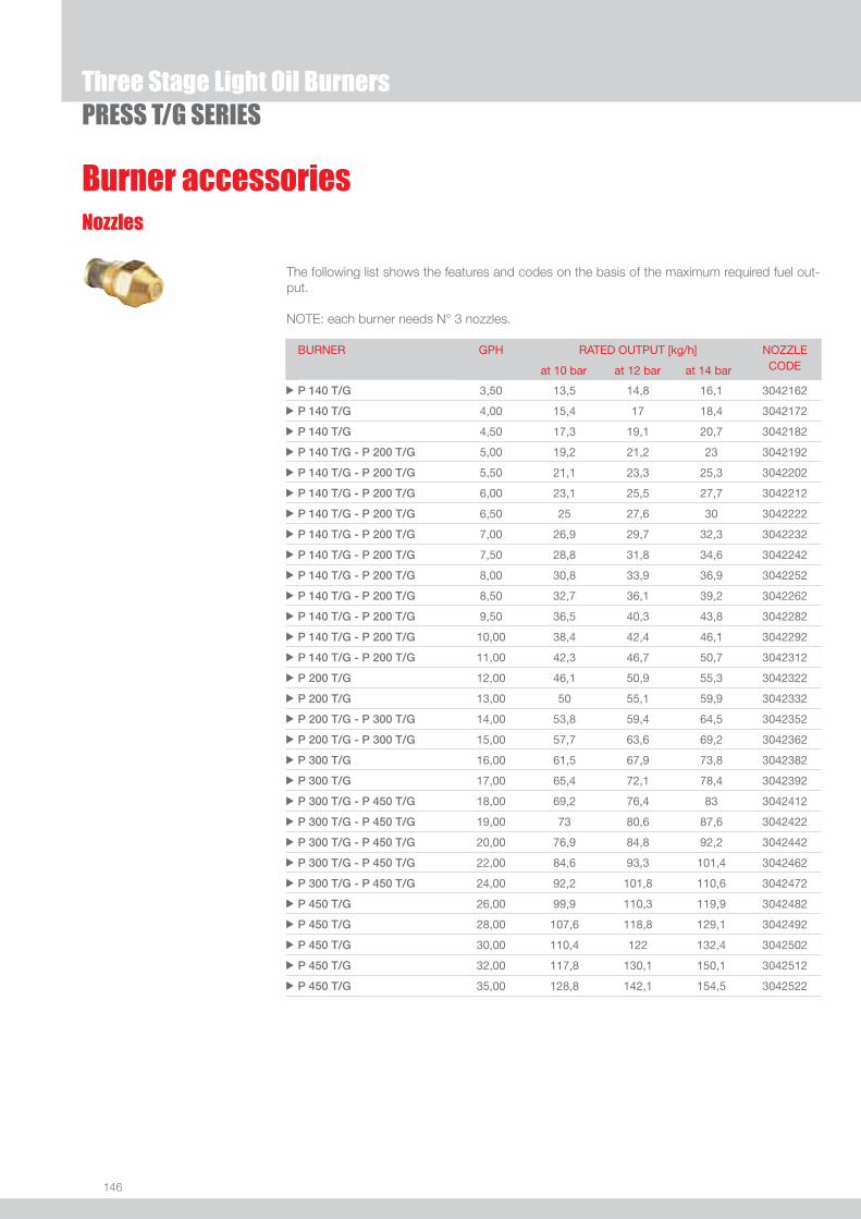
146
PRESS T/G SERIES
Nozzles
The following list shows the features and codes on the basis of the maximum required fuel out-put.
NOTE: each burner needs N° 3 nozzles.
Three Stage Light Oil Burners
Burner accessories
BURNER GPH RATED OUTPUT [kg/h] NOZZLE CODE at 10 bar at 12 bar at 14 bar
u P 140 T/G 3,50 13,5 14,8 16,1 3042162
u P 140 T/G 4,00 15,4 17 18,4 3042172
u P 140 T/G 4,50 17,3 19,1 20,7 3042182
u P 140 T/G - P 200 T/G 5,00 19,2 21,2 23 3042192
u P 140 T/G - P 200 T/G 5,50 21,1 23,3 25,3 3042202
u P 140 T/G - P 200 T/G 6,00 23,1 25,5 27,7 3042212
u P 140 T/G - P 200 T/G 6,50 25 27,6 30 3042222
u P 140 T/G - P 200 T/G 7,00 26,9 29,7 32,3 3042232
u P 140 T/G - P 200 T/G 7,50 28,8 31,8 34,6 3042242
u P 140 T/G - P 200 T/G 8,00 30,8 33,9 36,9 3042252
u P 140 T/G - P 200 T/G 8,50 32,7 36,1 39,2 3042262
u P 140 T/G - P 200 T/G 9,50 36,5 40,3 43,8 3042282
u P 140 T/G - P 200 T/G 10,00 38,4 42,4 46,1 3042292
u P 140 T/G - P 200 T/G 11,00 42,3 46,7 50,7 3042312
u P 200 T/G 12,00 46,1 50,9 55,3 3042322
u P 200 T/G 13,00 50 55,1 59,9 3042332
u P 200 T/G - P 300 T/G 14,00 53,8 59,4 64,5 3042352
u P 200 T/G - P 300 T/G 15,00 57,7 63,6 69,2 3042362
u P 300 T/G 16,00 61,5 67,9 73,8 3042382
u P 300 T/G 17,00 65,4 72,1 78,4 3042392
u P 300 T/G - P 450 T/G 18,00 69,2 76,4 83 3042412
u P 300 T/G - P 450 T/G 19,00 73 80,6 87,6 3042422
u P 300 T/G - P 450 T/G 20,00 76,9 84,8 92,2 3042442
u P 300 T/G - P 450 T/G 22,00 84,6 93,3 101,4 3042462
u P 300 T/G - P 450 T/G 24,00 92,2 101,8 110,6 3042472
u P 450 T/G 26,00 99,9 110,3 119,9 3042482
u P 450 T/G 28,00 107,6 118,8 129,1 3042492
u P 450 T/G 30,00 110,4 122 132,4 3042502
u P 450 T/G 32,00 117,8 130,1 150,1 3042512
u P 450 T/G 35,00 128,8 142,1 154,5 3042522
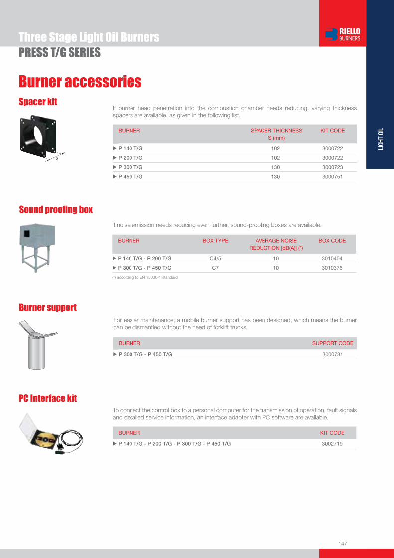
147
LIGH
T OI
L
Burner accessories
If burner head penetration into the combustion chamber needs reducing, varying thickness spacers are available, as given in the following list.
Spacer kit
BURNER
SPACER THICKNESS S (mm)
KIT CODE
u P 140 T/G 102 3000722
u P 200 T/G 102 3000722
u P 300 T/G 130 3000723
u P 450 T/G 130 3000751
PRESS T/G SERIESThree Stage Light Oil Burners
If noise emission needs reducing even further, sound-proofi ng boxes are available.
Sound proofi ng box
BURNER
BOX TYPE
AVERAGE NOISE REDUCTION [dB(A)] (*)
BOX CODE
u P 140 T/G - P 200 T/G C4/5 10 3010404
u P 300 T/G - P 450 T/G C7 10 3010376
(*) according to EN 15036-1 standard
BURNER KIT CODE
u P 140 T/G - P 200 T/G - P 300 T/G - P 450 T/G 3002719
To connect the control box to a personal computer for the transmission of operation, fault signals and detailed service information, an interface adapter with PC software are available.
PC Interface kit
Burner supportFor easier maintenance, a mobile burner support has been designed, which means the burner can be dismantled without the need of forklift trucks.
BURNER SUPPORT CODE
u P 300 T/G - P 450 T/G 3000731


149
LIGH
T OI
L
Modulating Light Oil Burners
PRESS P/G SERIESThe PRESS P/G series of burners covers a fi ring range from 415 to 5340 kW.Setting can be “two stage progressive” or, alternatively, “modulating” with the installation of a PID logic regulator and respective probes, which guarantees a turn down ratio of 3:1.The versatility of this range makes the burner well suited for use on commercial or industrial applications where the load factor is subject to wide variations over a short period of time.Simplifi ed maintenance is achieved by Riello designed slide bar system, which allows easy access to all of the essential components of the combustion head.
P 140 P/G 415/830 ÷ 1660 kWP 200 P/G 590/1185 ÷ 2370 kWP 300 P/G 890/1780 ÷ 3560 kWP 450 P/G 1190/2670 ÷ 5340 kW
FIRING RATES
Useful working fi eldfor choosing theburner
Modulation range
Test conditionsconforming to EN267 Temperature: 20°CPressure: 1013,5 mbarAltitude: 0 m a.s.l.
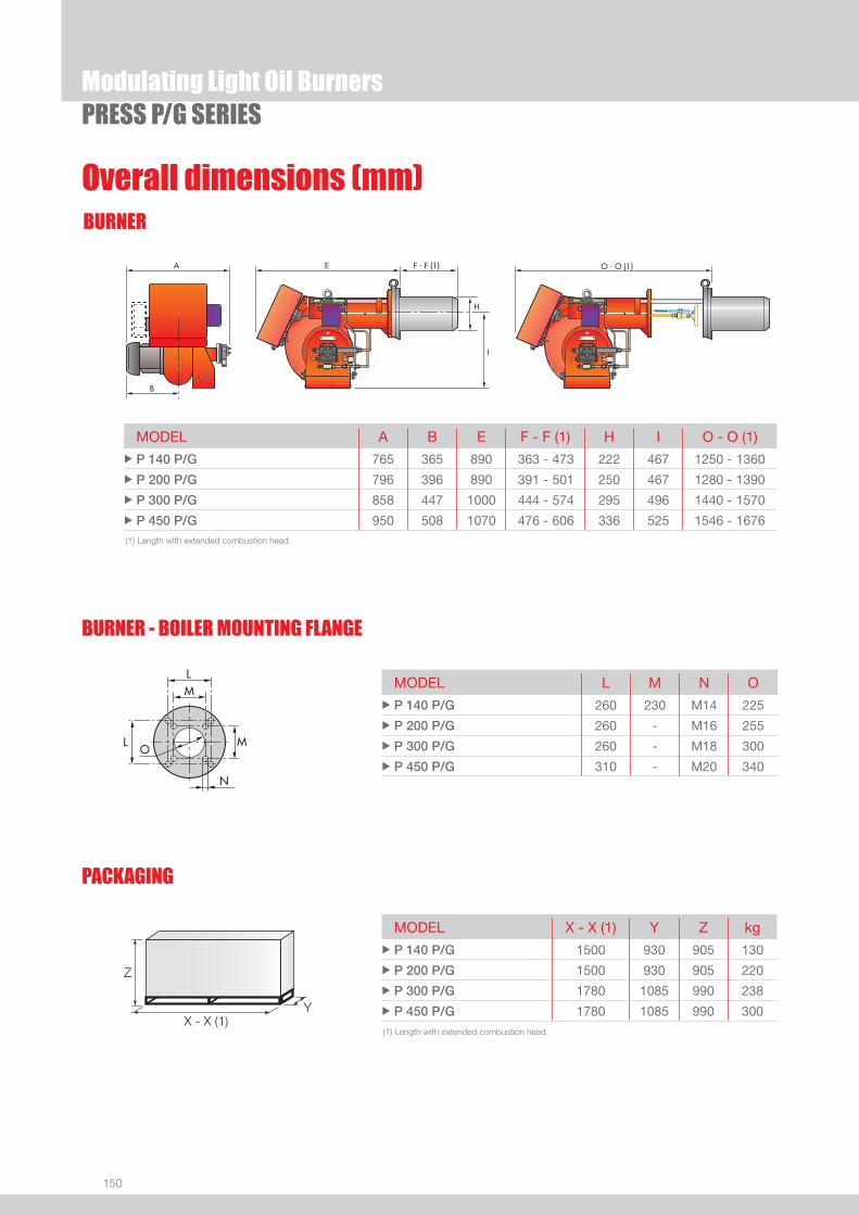
150
BURNER
Overall dimensions (mm)
Modulating Light Oil BurnersPRESS P/G SERIES
MODEL A B E F - F (1) H I O - O (1) u P 140 P/G 765 365 890 363 - 473 222 467 1250 - 1360
u P 200 P/G 796 396 890 391 - 501 250 467 1280 - 1390
u P 300 P/G 858 447 1000 444 - 574 295 496 1440 - 1570
u P 450 P/G 950 508 1070 476 - 606 336 525 1546 - 1676 (1) Length with extended combustion head.
(1) Length with extended combustion head.
Z
X - X (1)Y
PACKAGING
MODEL X - X (1) Y Z kg u P 140 P/G 1500 930 905 130
u P 200 P/G 1500 930 905 220
u P 300 P/G 1780 1085 990 238
u P 450 P/G 1780 1085 990 300
MODEL L M N O u P 140 P/G 260 230 M14 225
u P 200 P/G 260 - M16 255
u P 300 P/G 260 - M18 300
u P 450 P/G 310 - M20 340
BURNER - BOILER MOUNTING FLANGE

151
LIGH
T OI
L
DESIGNATION OF SERIES
Specifi cation
Modulating Light Oil BurnersPRESS P/G SERIES
PRESS 140 P/G TC FS1 3/230-400/50 230/50
Series : PRESS
Size : 140 ... 450
Operation : T/G Three stage P/G Modulating
Emission : ... Class 1 EN267 Head : TC Standard head TL Extended head
Flame control system : FS1 Standard (1 stop every 24 h) FS2 Continuous working (1 stop every 72 h)
Electrical supply to the system : 3/230/50 3/230V/50Hz 3/400/50 3N/400V/50Hz 3/230-400/50 3/230V/50Hz - 3N/400V/50Hz 3/220-380/60 3/220V/60Hz - 3N/380V/60Hz 3/200/50-60 3/200V/50-60Hz Auxiliary voltage : 230/50 230V/50Hz 220/60 220V/60Hz 110/50-60 110V/50-60Hz
BASIC DESIGNATION
EXTENDED DESIGNATION

152
PRESS P/G SERIES
STATE OF SUPPLY
Monoblock forced draught oil burner, two stage progressive or modulating operation, with a kit, fully automatic, made up of:- Air suction circuit- Fan with forward curved blades high performance pressure levels- Air damper for air setting and automatic oil output regulator controlled by a servomotor with variable cam- Starting motor at 2850rpm, three-phase 400V with neutral, 50Hz- Combustion head, that can be set on the basis of the required output, fi tted with: - stainless steel end cone, resistant to corrosion and high temperatures - ignition electrodes - fl ame stability disk- Gears pump for high pressure fuel supply, fi tted with: - fi lter - pressure regulator - connections for installing a pressure gauge and vacuometer - internal by-pass for single pipe installation- Valve unit with a double oil safety valve on the output circuit and double safety valve on the return circuit- Safey oil pressure switch for stop the burner in the case of problems on return circuit- Photocell for fl ame detection- Burner safety control box, fi tted with control functions for the correct positioning of the servomotor and possibility of post-
ventilation by just changing the electric wiring- Flame inspection window- Slide bars for easier installation and maintenance- Protection fi lter against radio interference- IP X0D (IP 40) electric protection level.
Standard equipment:- 2 fl exible pipes for connection to the oil supply network- 2 nipples for the connection to the pump- wiring looms fi ttings for electrcial connections- 4 screws for fi xing the burner fl ange to the boiler- 2 slide bar extensions (for the extended head models of P 300 P/G e P 450 P/G)- 1 star delta starter (on models where provided)- Instruction handbook for installation, use and maintenance- Spare parts catalogue.
Specifi cation
Modulating Light Oil Burners

153
LIGH
T OI
L
Available models
Modulating Light Oil BurnersPRESS P/G SERIES
(1) Star-delta starting, as standard equipmentNet calorifi c value: 11,8 kWh/kg - 10200 kcal/kg - Viscosity at 20°C: 4÷6 mm2/s (cSt) The burners of PRESS series are in according to 89/336 (2004/108) - 73/23 (2006/95) - 92/42 - 89/392 EC Directive and EN 267 Norm.
CODE MODEL
HEAT OUTPUT
TOTAL ELECTRICAL
POWER
CERTIFICATION NOTE
(kW) (kg/h) (kW)
3476867 PRESS 140 P/G TC FS1 3/230-400/50 230/50 415/830÷1660 35/70÷140 4,5 CE060890223002
3476868 PRESS 140 P/G TL FS1 3/230-400/50 230/50 415/830÷1660 35/70÷140 4,5 CE060890223002
3477767 PRESS 200 P/G TC FS1 3/230-400/50 230/50 590/1185÷2370 50/100÷200 5,5 CE060890223002
3477768 PRESS 200 P/G TL FS1 3/230-400/50 230/50 590/1185÷2370 50/100÷200 5,5 CE060890223002
3478941 PRESS 300 P/G TC FS1 3/230-400/50 230/50 890/1780÷3560 75/150÷300 10 CE060890223002
3478942 PRESS 300 P/G TL FS1 3/230-400/50 230/50 890/1780÷3560 75/150÷300 10 CE060890223002
3478943 PRESS 300 P/G TC FS1 3/230/50 230/50 890/1780÷3560 75/150÷300 10 CE060890223002 (1)
3478944 PRESS 300 P/G TL FS1 3/230/50 230/50 890/1780÷3560 75/150÷300 10 CE060890223002 (1)
3478945 PRESS 300 P/G TC FS1 3/400/50 230/50 890/1780÷3560 75/150÷300 10 CE060890223002 (1)
3478946 PRESS 300 P/G TL FS1 3/400/50 230/50 890/1780÷3560 75/150÷300 10 CE060890223002 (1)
3479369 PRESS 450 P/G TC FS1 3/230/50 230/50 1190/2670÷5340 100/225÷450 15 CE060890223002 (1)
3479370 PRESS 450 P/G TL FS1 3/230/50 230/50 1190/2670÷5340 100/225÷450 15 CE060890223002 (1)
3479371 PRESS 450 P/G TC FS1 3/400/50 230/50 1190/2670÷5340 100/225÷450 15 CE060890223002 (1)
3479372 PRESS 450 P/G TL FS1 3/400/50 230/50 1190/2670÷5340 100/225÷450 15 CE060890223002 (1)
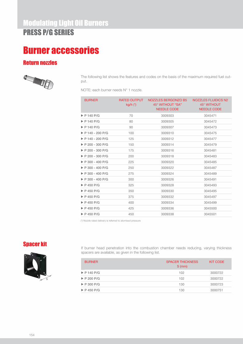
154
PRESS P/G SERIES
Return nozzles
The following list shows the features and codes on the basis of the maximum required fuel out-put.
NOTE: each burner needs N° 1 nozzle.
If burner head penetration into the combustion chamber needs reducing, varying thickness spacers are available, as given in the following list.
Spacer kit
BURNER
SPACER THICKNESS S (mm)
KIT CODE
u P 140 P/G 102 3000722
u P 200 P/G 102 3000722
u P 300 P/G 130 3000723
u P 450 P/G 130 3000751
Modulating Light Oil Burners
Burner accessories
BURNER RATED OUTPUT kg/h (*)
NOZZLES BERGONZO B5 45° WITHOUT “SA”
NEEDLE CODE
NOZZLES FLUIDICS N2 45° WITHOUT
NEEDLE CODE
u P 140 P/G 70 3009303 3045471
u P 140 P/G 80 3009305 3045472
u P 140 P/G 90 3009307 3045473
u P 140 - 200 P/G 100 3009310 3045475
u P 140 - 200 P/G 125 3009312 3045477
u P 200 - 300 P/G 150 3009314 3045479
u P 200 - 300 P/G 175 3009316 3045481
u P 200 - 300 P/G 200 3009318 3045483
u P 300 - 400 P/G 225 3009320 3045485
u P 300 - 400 P/G 250 3009322 3045487
u P 300 - 400 P/G 275 3009324 3045489
u P 300 - 400 P/G 300 3009326 3045491
u P 450 P/G 325 3009328 3045493
u P 450 P/G 350 3009330 3045495
u P 450 P/G 375 3009332 3045497
u P 450 P/G 400 3009334 3045499
u P 450 P/G 425 3009336 3045500
u P 450 P/G 450 3009338 3045501
(*) Nozzle rated delivery is referred to atomised pressure

155
LIGH
T OI
L
Burner accessories
PRESS P/G SERIESModulating Light Oil Burners
If noise emission needs reducing even further, sound-proofi ng boxes are available.
Sound proofi ng box
BURNER
BOX TYPE
AVERAGE NOISE REDUCTION [dB(A)] (*)
BOX CODE
u P 140 P/G - P 200 P/G C4/5 10 3010404
u P 300 P/G - P 450 P/G C7 10 3010376
(*) according to EN 15036-1 standard
Burner supportFor easier maintenance, a mobile burner support has been designed, which means the burner can be dismantled without the need of forklift trucks.
BURNER SUPPORT CODE
u P 300 P/G - P 450 P/G 3000731
Accessories for modulating operation
To obtain modulating operation, the PRESS P/G series of burners requires a regulator.
BURNER
REGULATOR TYPE
REGULATOR CODE
u P 140 - 200 - 300 - 450 P/G RWF 40 3010211
Depending on the servomotor fi tted to the burner, a three-pole potentiometer (1000 Ω) can be installed to check the position of the servomotor.
BURNER
POTENTIOMETER KIT CODE
u P 140 - 200 - 300 - 450 P/G 3010021
The relative temperature or pressure probes fi tted to the regulator, must be chosen on the basis of the application.
BURNER PROBE TYPE RANGE (°C) (bar) PROBE CODE
u P 140 - 200 - 300 - 450 P/G Temperature PT 100 -100 ÷ 500°C 3010110
u P 140 - 200 - 300 - 450 P/G Pressure 4 ÷ 20 mA 0 ÷ 2,5 bar 3010213
u P 140 - 200 - 300 - 450 P/G Pressure 4 ÷ 20 mA 0 ÷ 16 bar 3010214

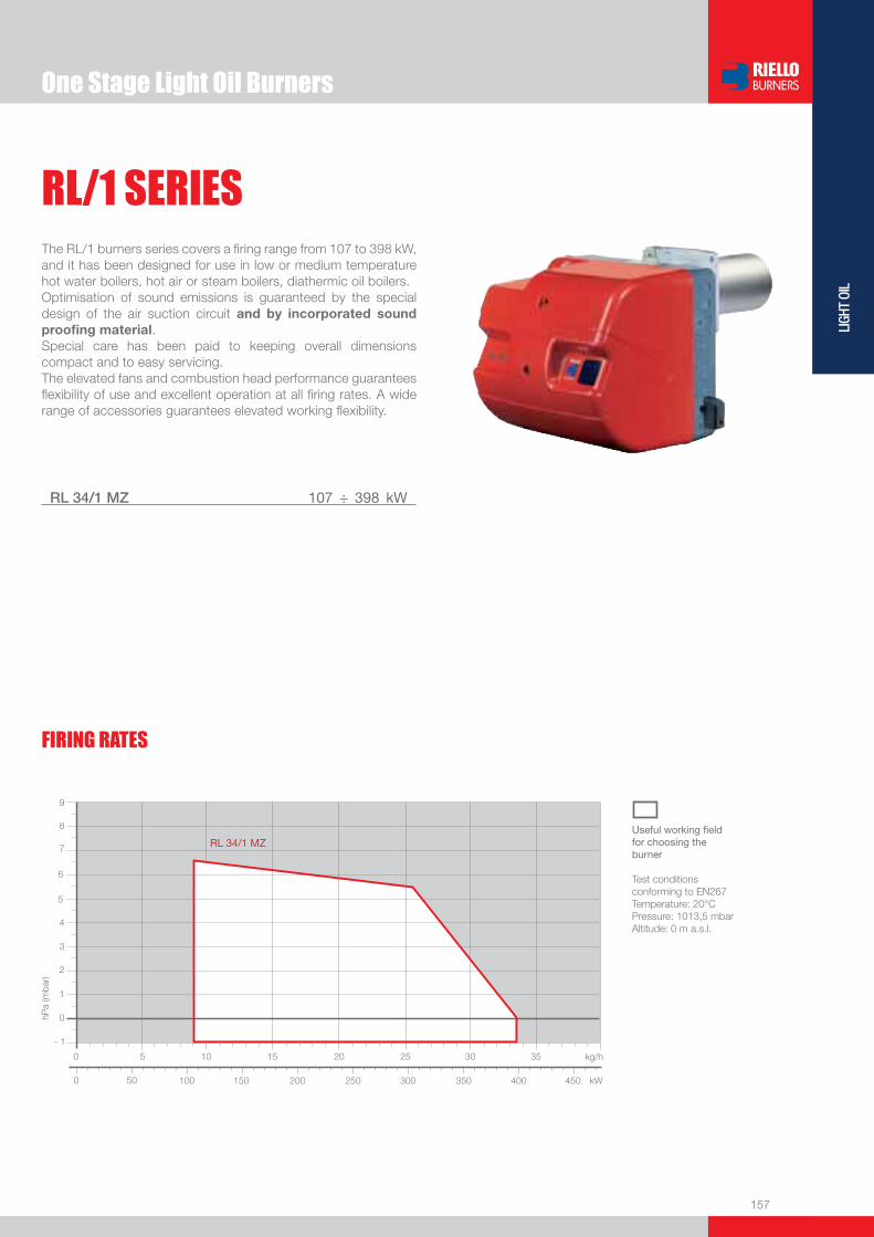
One Stage Light Oil Burners
157
LIGH
T OI
LUseful working fi eldfor choosing theburner
Test conditionsconforming to EN267 Temperature: 20°CPressure: 1013,5 mbarAltitude: 0 m a.s.l.
RL/1 SERIESThe RL/1 burners series covers a fi ring range from 107 to 398 kW, and it has been designed for use in low or medium temperature hot water boilers, hot air or steam boilers, diathermic oil boilers. Optimisation of sound emissions is guaranteed by the special design of the air suction circuit and by incorporated sound proofi ng material.Special care has been paid to keeping overall dimensions compact and to easy servicing.The elevated fans and combustion head performance guarantees fl exibility of use and excellent operation at all fi ring rates. A wide range of accessories guarantees elevated working fl exibility.
RL 34/1 MZ 107 ÷ 398 kW
FIRING RATES

158
BURNER
Overall dimensions (mm)
One Stage Light Oil Burners
(1) dimension with extended head
MODEL D1 D2 Ø u RL 34/1 MZ 160 224 M8
MODEL X (1) Y Z kgu RL 34/1 MZ 1000 485 500 32
(1) Length with short and extended head
�
�
��������
�
�
�������
MODEL A D E F - F(1) H I L O - O(1)u RL 34/1 MZ 442 422 508 216 - 351 140 305 138 780 - 915
BURNER - BOILER MOUNTING FLANGE
PACKAGING
Z
X (1)Y
RL/1 SERIES

159
LIGH
T OI
L
DESIGNATION OF SERIES
Specifi cation
One Stage Light Oil Burners
BASIC DESIGNATION
EXTENDED DESIGNATION
R L 34 /1 MZ TC FS1 1/230/50 230/50-60
Series: R Fuel: S Natural Gas SP LPG L Light oil LS Light oil/Methane N Heavy oil
Size Setting: /1 Single stage ... Two stage /M Modulating Emission: ... Class 1 EN267 - EN676 MZ Class 2 EN267 - EN676 BLU Class 3 EN267 - EN676
MX Class 1 EN267
Class 3 EN676 Head length: TC standard head TL extended head Flame control system: FS1 Standard (1 stop every 24 h) FS2 Continuous working (1 stop every 72 h) Electrical supply to the system: 1/230/50 1/230V/50Hz 1/220-230/50-60 1/220-230V/50-60Hz 3/230/50 3/230V/50Hz 3/400/50 3N/400V/50Hz 3/230-400/50 3/230V/50Hz - 3N/400V/50Hz 3/220/60 3/220V/60Hz 3/380/60 3N/380V/60Hz 3/220-380/60 3/220V/60Hz - 3N/380V/60Hz
3/220-400/50-60 3/220-230V/50-60Hz
3/380-400V/50-60Hz
Auxiliary voltage: 230/50-60 230V/50-60Hz 220-230/50-60 220-230V/50-60Hz 110/50-60 110V/50-60Hz
ID: Differential switch
RL/1 SERIES

160
One Stage Light Oil Burners
Available models
STATE OF SUPPLY
Specifi cation
RL/1 SERIES
Monoblock forced draught oil burner with one stage operation, fully automatic, made up of:- Air suction circuit with sound proofi ng material - High performance fan with forward curve blades - Air damper for air setting- Starting motor at 2800 rpm, single-phase, 220-230V / 50-60Hz - Combustion head, that can be set on the basis of required output, fi tted with: - stainless steel end cone, resistant to corrosion and high temperatures - ignition electrodes - fl ame stability disk- Fan pressure test point- Gears pump for high pressure fuel supply, fi tted with: - fi lter - pressure regulator - connections for installing a pressure gauge and vacuometer - internal by-pass for single pipe installation- Valve unit with a double oil delivery valve on the output circuit- Photocell for fl ame detection- Microprocessor-based burner safety control box, with diagnostic function- Plugs and socket for electrical connections, accessible from the external of the cover- Flame inspection window- Slide bars for easier installation and maintenance- Protection fi lter against radio interference- IP X0D (IP 40) electric protection level.
Standard equipment:- 2 fl exible pipes for connection to the oil supply network- 2 gaskets for the fl exible pipes- 2 nipples for connection to the pump- 1 thermal screen- 2 slide bar extensions (for model with long blast tube)- 4 screws for fi xing the burner fl ange to the boiler- 1 7pin plug for electrical connection- Instruction handbook for installation, use and maintenance- Spare parts catalogue.
CODE MODEL HEAT OUTPUT TOTALELECTRICAL
POWER
CERTIFICATION NOTE
(kW) (kg/h) (kW)
3470110 RL 34/1 MZ TC FS1 1/220-230/50-60 220-230/50-60 107 - 398 9 - 34 0,6 CE-00360383/07
3470111 RL 34/1 MZ TL FS1 1/220-230/50-60 220-230/50-60 107 - 398 9 - 34 0,6 CE-00360383/07
Net calorifi c value: 11,8 kWh/kg - 10200 kcal/kg - Viscosity at 20°C: 4÷6 mm2/s (cSt) The burners of RL/1 series are in according to 89/336 (2004/108) - 73/23 (2006/95) - 92/42 - 89/392 EC Directive and EN 267 Norm.
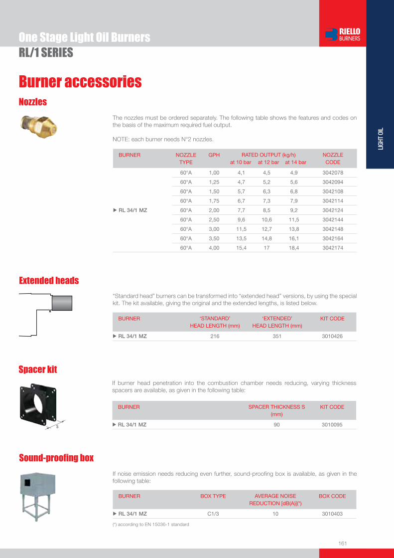
161
LIGH
T OI
L
One Stage Light Oil BurnersRL/1 SERIES
Burner accessories
Extended heads
“Standard head” burners can be transformed into “extended head” versions, by using the special kit. The kit available, giving the original and the extended lengths, is listed below.
BURNER ‘STANDARD’ HEAD LENGTH (mm)
‘EXTENDED’ HEAD LENGTH (mm)
KIT CODE
u RL 34/1 MZ 216 351 3010426
Nozzles
The nozzles must be ordered separately. The following table shows the features and codes on the basis of the maximum required fuel output.
NOTE: each burner needs N°2 nozzles.
Sound-proofi ng box
If noise emission needs reducing even further, sound-proofi ng box is available, as given in the following table:
BURNER BOX TYPE AVERAGE NOISE REDUCTION [dB(A)](*)
BOX CODE
u RL 34/1 MZ C1/3 10 3010403
(*) according to EN 15036-1 standard
Spacer kitIf burner head penetration into the combustion chamber needs reducing, varying thickness spacers are available, as given in the following table:
BURNER SPACER THICKNESS S (mm)
KIT CODE
u RL 34/1 MZ 90 3010095
BURNER NOZZLETYPE
GPH RATED OUTPUT (kg/h)at 10 bar at 12 bar at 14 bar
NOZZLECODE
u RL 34/1 MZ
60°A 1,00 4,1 4,5 4,9 3042078
60°A 1,25 4,7 5,2 5,6 3042094
60°A 1,50 5,7 6,3 6,8 3042108
60°A 1,75 6,7 7,3 7,9 3042114
60°A 2,00 7,7 8,5 9,2 3042124
60°A 2,50 9,6 10,6 11,5 3042144
60°A 3,00 11,5 12,7 13,8 3042148
60°A 3,50 13,5 14,8 16,1 3042164
60°A 4,00 15,4 17 18,4 3042174

162
One Stage Light Oil BurnersRL/1 SERIES
Burner accessories
Connection fl ange kit
Degasing unit
Ground fault interrupter kit
Volt free contact kit
PC interface kitTo connect the control box to a personal computer for the transmission of operation, fault signals and detailed service information, an interface adapter with PC software are available.
BURNER KIT CODE
u RL 34/1 MZ 3002719
A volt free contact kit is available for installation onto the burner. It can be used for a remote interface between burner operating signals. Every burner can be equipped with a single kit to remote the fl ame presence signal and the burner lockout indication.
BURNER KIT CODE
u RL 34/1 MZ 3010419
A “Ground fault interrupter kit” is available as a safety device for electrical system fault.
BURNER KIT CODE
u RL 34/1 MZ 3010448
With single pipe systems, you can fi nd air in the oil sucked by the pump that comes from the oil itself due to negative pressure or to a faulty seal.To solve this problem, we recommend fi tting a degasing unit near the burner. Two versions are available with or without fi lter:
BURNER FILTER KIT CODE
u RL 34/1 MZ With fi lter 3010055
u RL 34/1 MZ Without fi lter 3010054
BURNER KIT CODE
u RL 34/1 MZ 3010138
A kit is available for use where the burner opening on the boiler is of excessive diameter.
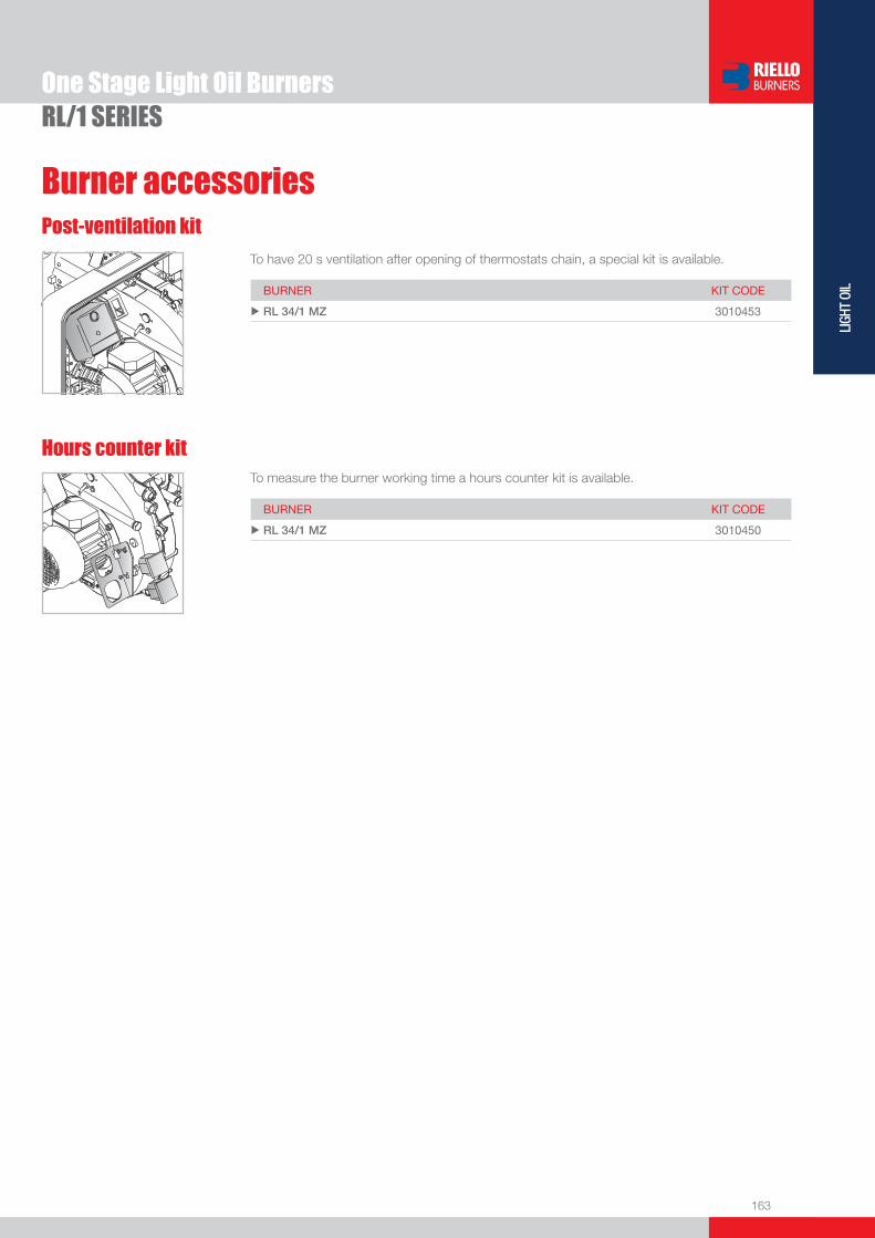
163
LIGH
T OI
L
Burner accessories
One Stage Light Oil BurnersRL/1 SERIES
Post-ventilation kit
Hours counter kitTo measure the burner working time a hours counter kit is available.
BURNER KIT CODE
u RL 34/1 MZ 3010450
To have 20 s ventilation after opening of thermostats chain, a special kit is available.
BURNER KIT CODE
u RL 34/1 MZ 3010453

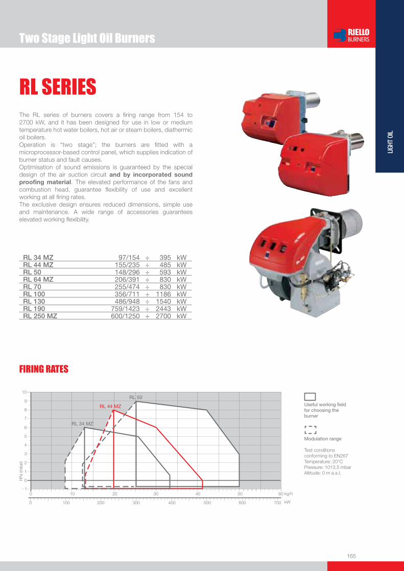
165
LIGH
T OI
L
RL SERIES
Two Stage Light Oil Burners
The RL series of burners covers a fi ring range from 154 to 2700 kW, and it has been designed for use in low or medium temperature hot water boilers, hot air or steam boilers, diathermic oil boilers.Operation is “two stage”; the burners are fi tted with a microprocessor-based control panel, which supplies indication of burner status and fault causes.Optimisation of sound emissions is guaranteed by the special design of the air suction circuit and by incorporated sound proofi ng material. The elevated performance of the fans and combustion head, guarantee fl exibility of use and excellent working at all fi ring rates.The exclusive design ensures reduced dimensions, simple use and maintenance. A wide range of accessories guarantees elevated working fl exibility.
RL 34 MZ 97/154 ÷ 395 kWRL 44 MZ 155/235 ÷ 485 kWRL 50 148/296 ÷ 593 kWRL 64 MZ 206/391 ÷ 830 kWRL 70 255/474 ÷ 830 kWRL 100 356/711 ÷ 1186 kWRL 130 486/948 ÷ 1540 kWRL 190 759/1423 ÷ 2443 kWRL 250 MZ 600/1250 ÷ 2700 kW
FIRING RATES
Useful working fi eldfor choosing theburner
Modulation range
Test conditionsconforming to EN267 Temperature: 20°CPressure: 1013,5 mbarAltitude: 0 m a.s.l.
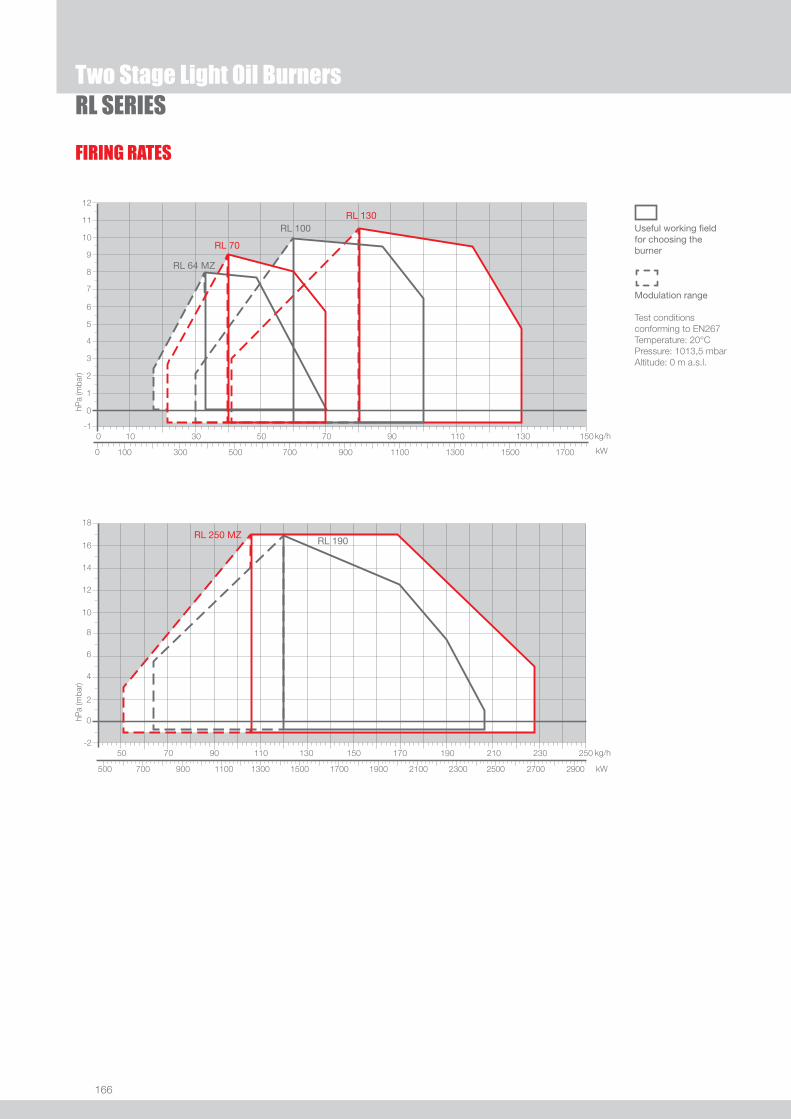
166
RL SERIES
FIRING RATES
Useful working fi eldfor choosing theburner
Modulation range
Test conditionsconforming to EN267 Temperature: 20°CPressure: 1013,5 mbarAltitude: 0 m a.s.l.
Two Stage Light Oil Burners

167
LIGH
T OI
L
RL SERIES
Overall dimensions (mm)BURNER
Two Stage Light Oil Burners
RL 34 - 44 MZ RL 50
(1) dimension with extended head
RL 64 MZ RL 70 - 100 - 130 - 190 - 250 MZ
(1) dimension with extended head
�
�
�������
��������
�
�
�
�
��������
�
�
�������
�������
�
� �
� �
��������
�
�
�������
�
�
�
�
�
��������
MODEL A D E F - F(1) H I L O - O(1)u RL 34 MZ 442 422 508 216 - 351 140 305 138 780 - 915
u RL 44 MZ 442 422 508 216 - 351 152 305 138 780 - 915
u RL 50 476 474 468 216 - 351 152 352 52 672 - 807
MODEL A B C D E F - F(1) H I L O - O(1)u RL 64 MZ 538 300 238 490 477 250 - 385 179 335 60 680 - 815
u RL 70 580 296 284 555 680 250 - 385 179 430 - 951 - 1086
u RL 100 599 312 287 555 680 250 - 385 179 430 - 951 - 1086
u RL 130 625 338 287 555 680 250 - 385 189 430 - 951 - 1086
u RL 190 756 366 390 555 712 370 - - 222 430 - 1166 - -
u RL 250 MZ 910 432 478 596 705 378 - - 222 436 - 1163 - -
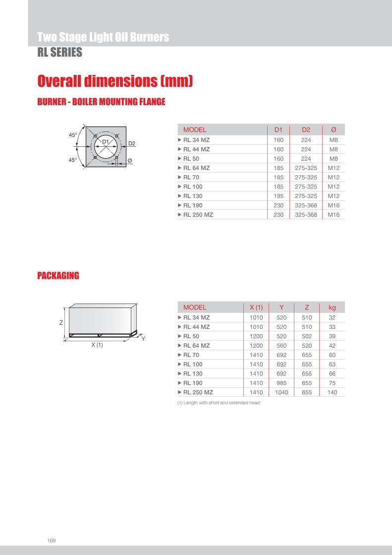
168
Overall dimensions (mm)BURNER - BOILER MOUNTING FLANGE
PACKAGING
Z
X (1)Y
RL SERIESTwo Stage Light Oil Burners
MODEL D1 D2 Ø u RL 34 MZ 160 224 M8
u RL 44 MZ 160 224 M8
u RL 50 160 224 M8
u RL 64 MZ 185 275-325 M12
u RL 70 185 275-325 M12
u RL 100 185 275-325 M12
u RL 130 195 275-325 M12
u RL 190 230 325-368 M16
u RL 250 MZ 230 325-368 M16
MODEL X (1) Y Z kgu RL 34 MZ 1010 520 510 32
u RL 44 MZ 1010 520 510 33
u RL 50 1200 520 502 39
u RL 64 MZ 1200 560 520 42
u RL 70 1410 692 655 60
u RL 100 1410 692 655 63
u RL 130 1410 692 655 66
u RL 190 1410 985 655 75
u RL 250 MZ 1410 1040 655 140
(1) Length with short and extended head
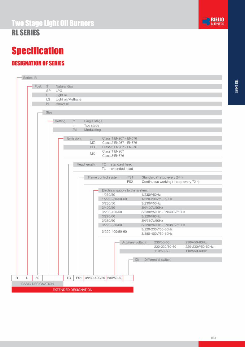
169
LIGH
T OI
L
DESIGNATION OF SERIES
Specifi cation
RL SERIESTwo Stage Light Oil Burners
BASIC DESIGNATION
EXTENDED DESIGNATION
R L 50 TC FS1 3/230-400/50 230/50-60
Series: R Fuel: S Natural Gas SP LPG L Light oil LS Light oil/Methane N Heavy oil
Size Setting: /1 Single stage ... Two stage /M Modulating Emission: ... Class 1 EN267 - EN676 MZ Class 2 EN267 - EN676 BLU Class 3 EN267 - EN676
MX Class 1 EN267
Class 3 EN676 Head length: TC standard head TL extended head Flame control system: FS1 Standard (1 stop every 24 h) FS2 Continuous working (1 stop every 72 h) Electrical supply to the system: 1/230/50 1/230V/50Hz 1/220-230/50-60 1/220-230V/50-60Hz 3/230/50 3/230V/50Hz 3/400/50 3N/400V/50Hz 3/230-400/50 3/230V/50Hz - 3N/400V/50Hz 3/220/60 3/220V/60Hz 3/380/60 3N/380V/60Hz 3/220-380/60 3/220V/60Hz - 3N/380V/60Hz
3/220-400/50-60 3/220-230V/50-60Hz
3/380-400V/50-60Hz
Auxiliary voltage: 230/50-60 230V/50-60Hz 220-230/50-60 220-230V/50-60Hz 110/50-60 110V/50-60Hz
ID: Differential switch
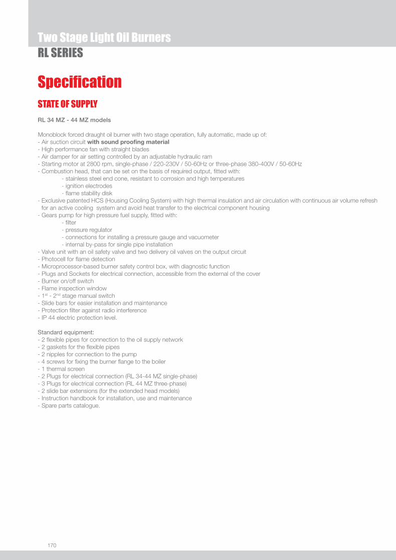
170
RL SERIESTwo Stage Light Oil Burners
STATE OF SUPPLY
Specifi cation
RL 34 MZ - 44 MZ models
Monoblock forced draught oil burner with two stage operation, fully automatic, made up of:- Air suction circuit with sound proofi ng material- High performance fan with straight blades- Air damper for air setting controlled by an adjustable hydraulic ram - Starting motor at 2800 rpm, single-phase / 220-230V / 50-60Hz or three-phase 380-400V / 50-60Hz- Combustion head, that can be set on the basis of required output, fi tted with: - stainless steel end cone, resistant to corrosion and high temperatures - ignition electrodes - fl ame stability disk- Exclusive patented HCS (Housing Cooling System) with high thermal insulation and air circulation with continuous air volume refresh
for an active cooling system and avoid heat transfer to the electrical component housing- Gears pump for high pressure fuel supply, fi tted with: - fi lter - pressure regulator - connections for installing a pressure gauge and vacuometer - internal by-pass for single pipe installation- Valve unit with an oil safety valve and two delivery oil valves on the output circuit- Photocell for fl ame detection- Microprocessor-based burner safety control box, with diagnostic function- Plugs and Sockets for electrical connection, accessible from the external of the cover- Burner on/off switch- Flame inspection window- 1st - 2nd stage manual switch- Slide bars for easier installation and maintenance- Protection fi lter against radio interference- IP 44 electric protection level.
Standard equipment:- 2 fl exible pipes for connection to the oil supply network- 2 gaskets for the fl exible pipes- 2 nipples for connection to the pump- 4 screws for fi xing the burner fl ange to the boiler- 1 thermal screen- 2 Plugs for electrical connection (RL 34-44 MZ single-phase)- 3 Plugs for electrical connection (RL 44 MZ three-phase)- 2 slide bar extensions (for the extended head models)- Instruction handbook for installation, use and maintenance- Spare parts catalogue.

171
LIGH
T OI
L
Two Stage Light Oil BurnersRL SERIES
RL 50 - 64 MZ - 70 - 100 - 130 - 190 - 250 MZ models
Monoblock forced draught oil burner with two stage operation, fully automatic, made up of:- Air suction circuit lined with sound-proofi ng material- Fan with reverse curve blades (RL 50 - 70 - 100 - 130 models) or straight blades (RL 64 MZ - 190 - 250 MZ models)- Air damper for air setting controlled by an adjustable hydraulic ram (or by a servomotor for the RL 250 MZ)- Starting motor at 2800 rpm, three-phase 400V with neutral, 50Hz- Combustion head, that can be set on the basis of required output, fi tted with: - stainless steel end cone, resistant to corrosion and high temperatures - ignition electrodes - fl ame stability disk- Gears pump for high pressure fuel supply, fi tted with: - fi lter - pressure regulator - connections for installing a pressure gauge and vacuometer - internal by-pass for single pipe installation- Valve unit with an oil safety valve and two delivery oil valves on the output circuit- Photocell for fl ame detection- Microprocessor-based burner safety control box, with diagnostic function- Burner on/off switch- Flame inspection window- 1st - 2nd stage manual switch- Slide bars for easier installation and maintenance- Protection fi lter against radio interference- IP 44 electric protection level.
Standard equipment:- 2 fl exible pipes for connection to the oil supply network- 2 gaskets for the fl exible pipes- 2 nipples for connection to the pump- 4 screws for fi xing the burner fl ange to the boiler- 1 thermal screen- Fairleads for electrical connections (RL 50 models)- 2 slide bar extensions (for the extended head models and the RL 190 - 250 MZ models)- Instruction handbook for installation, use and maintenance- Spare parts catalogue.
STATE OF SUPPLY
Specifi cation

172
Available models
RL SERIESTwo Stage Light Oil Burners
(1) with plug and socket (2) with terminal boardNet calorifi c value: 11,8 kWh/kg - 10200 kcal/kg - Viscosity at 20°C: 4-6 mm2/s (cSt). The burners of RL series are in according to 89/336 (2004/108) - 73/23 (2006/95) - 92/42 - 89/392 EC Directive and EN 267 Norm.
WARNING: nozzles are supplied as accessories that must be ordered separately; please refer to the “Burner Accessories” section.
Bio fuelsRiello Burners is able to offer technical variants which allow burners to be used within environmental heating, process or special applications. These applications now include solutions for liquid Bio fuels (I.e. biodiesel and vegetable oil).Our experience in research and development and fi eld applications with organic origin Bio fuels has resulted in Riello being able to offer a wide range of solutions for the combustion of Bio fuels.These burner variants can be provided upon request and after a technical-commercial evaluation; for more information please contact Riello Burners Commercial and Technical Department, our Application Engineers will be pleased to help you.
CODE MODEL HEAT OUTPUT TOTALELECTRICAL
POWER
CERTIFICATION NOTE
(kW) (kg/h) (kW)
3470210 RL 34 MZ TC FS1 1/220-230/50-60 220-230/50-60 97/154-395 8,3/13-33,6 0,6 CE-0036 0383/07 (1)
3470211 RL 34 MZ TL FS1 1/220-230/50-60 220-230/50-60 97/154-395 8,3/13-33,6 0,6 CE-0036 0383/07 (1)
3470310 RL 44 MZ TC FS1 1/220-230/50-60 220-230/50-60 155/235-485 13/20-41 0,7 CE-0036 0383/07 (1)
3470311 RL 44 MZ TL FS1 1/220-230/50-60 220-230/50-60 155/235-485 13/20-41 0,7 CE-0036 0383/07 (1)
3470340 RL 44 MZ TC FS1 3/220-400/50-60 220-230/50-60 155/235-485 13/20-41 0,75 CE-0036 0383/07 (1)
3470341 RL 44 MZ TL FS1 3/220-400/50-60 220-230/50-60 155/235-485 13/20-41 0,75 CE-0036 0383/07 (1)
3474632 RL 50 TC FS1 3/230-400/50 230/50-60 148/296-593 12,5/25-50 0,75 DIN BN 5G226/03 (1)
3474633 RL 50 TL FS1 3/230-400/50 230/50-60 148/296-593 12,5/25-50 0,75 DIN BN 5G226/03 (1)
3474680 RL 50 TC FS1 3/208-230/380-460/60 230/50-60 148/296-593 12,5/25-50 0,75 -- (1)
3474681 RL 50 TL FS1 3/208-230/380-460/60 230/50-60 148/296-593 12,5/25-50 0,75 -- (1)
3470410 RL 64 MZ TC FS1 3/230-400/50 230/50-60 206/391-830 17,4/33-70 1,4 CE-0036 0382/07 (1)
3470411 RL 64 MZ TL FS1 3/230-400/50 230/50-60 206/391-830 17,4/33-70 1,4 CE-0036 0382/07 (1)
3475032 RL 70 TC FS1 3/230-400/50 230/50-60 255/474-830 21,5/40-70 1,4 05 07 90223 001 (2)
3475033 RL 70 TL FS1 3/230-400/50 230/50-60 255/474-830 21,5/40-70 1,4 05 07 90223 001 (2)
3475034 RL 70 TC FS1 3/230-400/50 230/50-60 255/474-830 21,5/40-70 1,4 05 07 90223 001 (1) (2)
3475035 RL 70 TL FS1 3/230-400/50 230/50-60 255/474-830 21,5/40-70 1,4 05 07 90223 001 (1) (2)
3475080 RL 70 TC FS1 3/208-230/380-460/60 230/50-60 255/474-830 21,5/40-70 1,4 -- (2)
3475081 RL 70 TL FS1 3/208-230/380-460/60 230/50-60 255/474-830 21,5/40-70 1,4 -- (2)
3475232 RL 100 TC FS1 3/230-400/50 230/50-60 356/711-1186 30/60-100 1,8 05 07 90223 001 (2)
3475233 RL 100 TL FS1 3/230-400/50 230/50-60 356/711-1186 30/60-100 1,8 05 07 90223 001 (2)
3475234 RL 100 TC FS1 3/230-400/50 230/50-60 356/711-1186 30/60-100 1,8 05 07 90223 001 (1) (2)
3475235 RL 100 TL FS1 3/230-400/50 230/50-60 356/711-1186 30/60-100 1,8 05 07 90223 001 (1) (2)
3475280 RL 100 TC FS1 3/208-230/380-460/60 230/50-60 356/711-1186 30/60-100 1,8 -- (2)
3475281 RL 100 TL FS1 3/208-230/380-460/60 230/50-60 356/711-1186 30/60-100 1,8 -- (2)
3475432 RL 130 TC FS1 3/230-400/50 230/50-60 486/948-1540 41/80-130 2,6 05 07 90223 001 (2)
3475433 RL 130 TL FS1 3/230-400/50 230/50-60 486/948-1540 41/80-130 2,6 05 07 90223 001 (2)
3475434 RL 130 TC FS1 3/230-400/50 230/50-60 486/948-1540 41/80-130 2,6 05 07 90223 001 (1) (2)
3475435 RL 130 TL FS1 3/230-400/50 230/50-60 486/948-1540 41/80-130 2,6 05 07 90223 001 (1) (2)
3475480 RL 130 TC FS1 3/208-230/380-460/60 230/50-60 486/948-1540 41/80-130 2,6 -- (2)
3475481 RL 130 TL FS1 3/208-230/380-460/60 230/50-60 486/948-1540 41/80-130 2,6 -- (2)
3475613 RL 190 TC FS1 3/400/50 230/50-60 759/1423-2443 64/120-206 5,87 DIN BN 5G861/03 (2)
20011008 RL 190 TC FS1 3/230/50 230/50-60 759/1423-2443 64/120-206 5,87 DIN BN 5G861/03 (2)
3475614 RL 190 TC FS1 3/400/50 230/50-60 759/1423-2443 64/120-206 5,87 -- (1) (2)
20011018 RL 190 TC FS1 3/230/50 230/50-60 759/1423-2443 64/120-206 5,87 -- (1) (2)
3475680 RL 190 TC FS1 3/460/60 220/60 759/1423-2443 64/120-206 5,87 -- (2)
20011009 RL 190 TC FS1 3/220/60 220/60 759/1423-2443 64/120-206 5,87 -- (2)
3470010 RL 250 MZ TC FS1 3/400/50 230/50-60 600/1250-2700 51/106-228 7,2 in progress (2)

173
LIGH
T OI
L
Burner accessories
Two Stage Light Oil BurnersRL SERIES
NozzlesThe nozzles must be ordered separately. The following table shows the features and codes on the basis of the maximum required fuel output.
NOTE: each burner needs N°2 nozzles.
BURNER NOZZLETYPE
GPH RATED OUTPUT (kg/h)at 10 bar at 12 bar at 14 bar
NOZZLECODE
u RL 34 MZ 60°A 1,00 4,1 4,5 4,9 3042078
u RL 34 MZ 60°A 1,25 4,7 5,2 5,6 3042094
u RL 34 MZ 60°A 1,50 5,7 6,3 6,8 3042108
u RL 34 MZ 60°A 1,75 6,7 7,3 7,9 3042114
u RL 34 MZ 60°A 2,00 7,7 8,5 9,2 3042124
u RL 34 MZ 60°A 2,50 9,6 10,6 11,5 3042144
u RL 34 MZ 60°A 3,00 11,5 12,7 13,8 3042148
u RL 34 MZ 60°A 3,50 13,5 14,8 16,1 3042164
u RL 34 MZ 60°A 4,00 15,4 17 18,4 3042174
u RL 34 MZ 60°A 4,50 17,3 19,1 20,7 3042184
u RL 44 MZ 45°A 1,50 5,7 6,3 6,8 20011655
u RL 44 MZ 45°A 1,75 6,7 7,3 7,9 20011658
u RL 44 MZ 45°A 2,00 7,7 8,5 9,2 20011662
u RL 44 MZ 45°A 2,50 9,6 10,6 11,5 20011666
u RL 44 MZ 45°A 3,00 11,5 12,7 13,8 20011669
u RL 44 MZ 45°A 3,50 13,5 14,8 16,1 20011672
u RL 44 MZ 45°A 4,00 15,4 17 18,4 20011674
u RL 44 MZ 45°A 4,50 17,3 19,1 20,7 20009760
u RL 44 MZ 45°A 5,00 19,2 21,2 23 20011677
u RL 44 MZ 45°A 5,50 21,1 23,3 25,3 20011678
u RL 44 MZ 45°A 6,00 23,1 25,5 27,7 20011679
u RL 50 60°B 3,00 11,5 12,7 13,8 3042158
u RL 50 60°B 3,50 13,5 14,8 16,1 3042162
u RL 50 - 64 MZ 60°B 4,00 15,4 17 18,4 3042172
u RL 50 - 64 MZ 60°B 4,50 17,3 19,1 20,7 3042182
u RL 50 - 64 MZ - 70 60°B 5,00 19,2 21,2 23 3042192
u RL 50 - 64 MZ - 70 60°B 5,50 21,1 23,3 25,3 3042202
u RL 50 - 64 MZ - 70 60°B 6,00 23,1 25,5 27,7 3042212
u RL 50 - 64 MZ - 70 60°B 6,50 25 27,6 30 3042222
u RL 64 MZ - 70 - 100 60°B 7,00 26,9 29,7 32,3 3042232
u RL 64 MZ - 70 - 100 60°B 7,50 28,8 31,8 34,6 3042242
u RL 64 MZ - 70 - 100 60°B 8,00 30,8 33,9 36,9 3042252
u RL 64 MZ - 70 - 100 60°B 8,50 32,7 36,1 39,2 3042262
u RL 64 MZ - 70 - 100 - 130 60°B 9,50 36,5 40,3 43,8 3042282
u RL 64 MZ - 70 - 100 - 130 - 190 60°B 10,00 38,4 42,4 46,1 3042292
u RL 64 MZ - 70 - 100 - 130 - 190 60°B 11,00 42,3 46,7 50,7 3042312
u RL 64 MZ - 100 - 130 - 190 - 250 MZ 60°B 12,00 46,1 50,9 55,3 3042322
u RL 64 MZ - 100 - 130 - 190 - 250 MZ 60°B 13,00 50 55,1 59,9 3042332
To be continued in the following page
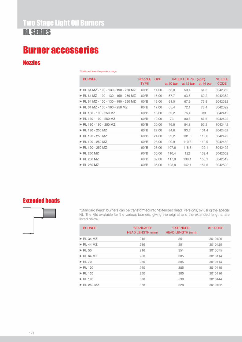
174
RL SERIESTwo Stage Light Oil Burners
Burner accessories
Extended heads
“Standard head” burners can be transformed into “extended head” versions, by using the special kit. The kits available for the various burners, giving the original and the extended lengths, are listed below.
BURNER ‘STANDARD’ HEAD LENGTH (mm)
‘EXTENDED’ HEAD LENGTH (mm)
KIT CODE
u RL 34 MZ 216 351 3010426
u RL 44 MZ 216 351 3010425
u RL 50 216 351 3010075
u RL 64 MZ 250 385 3010114
u RL 70 250 385 3010114
u RL 100 250 385 3010115
u RL 130 250 385 3010116
u RL 190 370 530 3010444
u RL 250 MZ 378 528 3010422
Nozzles
BURNER NOZZLETYPE
GPH RATED OUTPUT (kg/h)at 10 bar at 12 bar at 14 bar
NOZZLECODE
u RL 64 MZ - 100 - 130 - 190 - 250 MZ 60°B 14,00 53,8 59,4 64,5 3042352
u RL 64 MZ - 100 - 130 - 190 - 250 MZ 60°B 15,00 57,7 63,6 69,2 3042362
u RL 64 MZ - 100 - 130 - 190 - 250 MZ 60°B 16,00 61,5 67,9 73,8 3042382
u RL 64 MZ - 130 - 190 - 250 MZ 60°B 17,00 65,4 72,1 78,4 3042392
u RL 130 - 190 - 250 MZ 60°B 18,00 69,2 76,4 83 3042412
u RL 130 - 190 - 250 MZ 60°B 19,00 73 80,6 87,6 3042422
u RL 130 - 190 - 250 MZ 60°B 20,00 76,9 84,8 92,2 3042442
u RL 190 - 250 MZ 60°B 22,00 84,6 93,3 101,4 3042462
u RL 190 - 250 MZ 60°B 24,00 92,2 101,8 110,6 3042472
u RL 190 - 250 MZ 60°B 26,00 99,9 110,3 119,9 3042482
u RL 190 - 250 MZ 60°B 28,00 107,6 118,8 129,1 3042492
u RL 250 MZ 60°B 30,00 110,4 122 132,4 3042502
u RL 250 MZ 60°B 32,00 117,8 130,1 150,1 3042512
u RL 250 MZ 60°B 35,00 128,8 142,1 154,5 3042522
Continued from the previous page
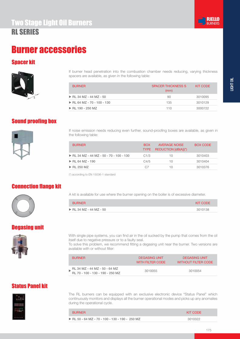
175
LIGH
T OI
L
Burner accessories
Two Stage Light Oil BurnersRL SERIES
Status Panel kitThe RL burners can be equipped with an exclusive electronic device “Status Panel” which continuously monitors and displays all the burner operational modes and picks up any anomalies during the operational cycle.
BURNER KIT CODE
u RL 50 - 64 MZ - 70 - 100 - 130 - 190 - 250 MZ 3010322
Degasing unitWith single pipe systems, you can fi nd air in the oil sucked by the pump that comes from the oil itself due to negative pressure or to a faulty seal.To solve this problem, we recommend fi tting a degasing unit near the burner. Two versions are available with or without fi lter:
BURNER DEGASING UNIT WITH FILTER CODE
DEGASING UNIT WITHOUT FILTER CODE
uRL 34 MZ - 44 MZ - 50 - 64 MZ RL 70 - 100 - 130 - 190 - 250 MZ
3010055 3010054
Connection fl ange kit
BURNER KIT CODE
u RL 34 MZ - 44 MZ - 50 3010138
A kit is available for use where the burner opening on the boiler is of excessive diameter.
Sound proofi ng box
If noise emission needs reducing even further, sound-proofi ng boxes are available, as given in the following table:
BURNER BOX TYPE
AVERAGE NOISE REDUCTION [dB(A)](*)
BOX CODE
u RL 34 MZ - 44 MZ - 50 - 70 - 100 - 130 C1/3 10 3010403
u RL 64 MZ - 190 C4/5 10 3010404
u RL 250 MZ C7 10 3010376
(*) according to EN 15036-1 standard
Spacer kit
If burner head penetration into the combustion chamber needs reducing, varying thickness spacers are available, as given in the following table:
BURNER SPACER THICKNESS S (mm)
KIT CODE
u RL 34 MZ - 44 MZ - 50 90 3010095
u RL 64 MZ - 70 - 100 - 130 135 3010129
u RL 190 - 250 MZ 110 3000722

176
RL SERIESTwo Stage Light Oil Burners
Burner accessories
Ground fault interrupter kit
A “Ground fault interrupter kit” is available as a safety device for electrical system fault.
BURNER KIT CODE
u RL 34 MZ - 44 MZ 3010448
Post-ventilation kitTo have 20 s ventilation after opening of thermostats chain, a special kit is available.
BURNER KIT CODE
u RL 34 MZ - 44 MZ 3010453
Hours counter kitTo measure the burner working time a hours counter kit is available.
BURNER KIT CODE
u RL 34 MZ - 44 MZ 3010450
PC interface kitTo connect the control box to a personal computer for the transmission of operation, fault signals and detailed service information, an interface adapter with PC software are available.
BURNER KIT CODE
u RL 34 MZ - 44 MZ - 50 - 64 MZ - 70 - 100 - 130 - 190 - 250 MZ 3002719
Volt free contact kitA volt free contact kit is available for installation onto the burner. It can be used for a remote interface between burner operating signals. Every burner can be equipped with a single kit to remote the fl ame presence signal and the burner lockout indication.
BURNER KIT CODE
u RL 34 MZ - 44 MZ - 64 MZ 3010419
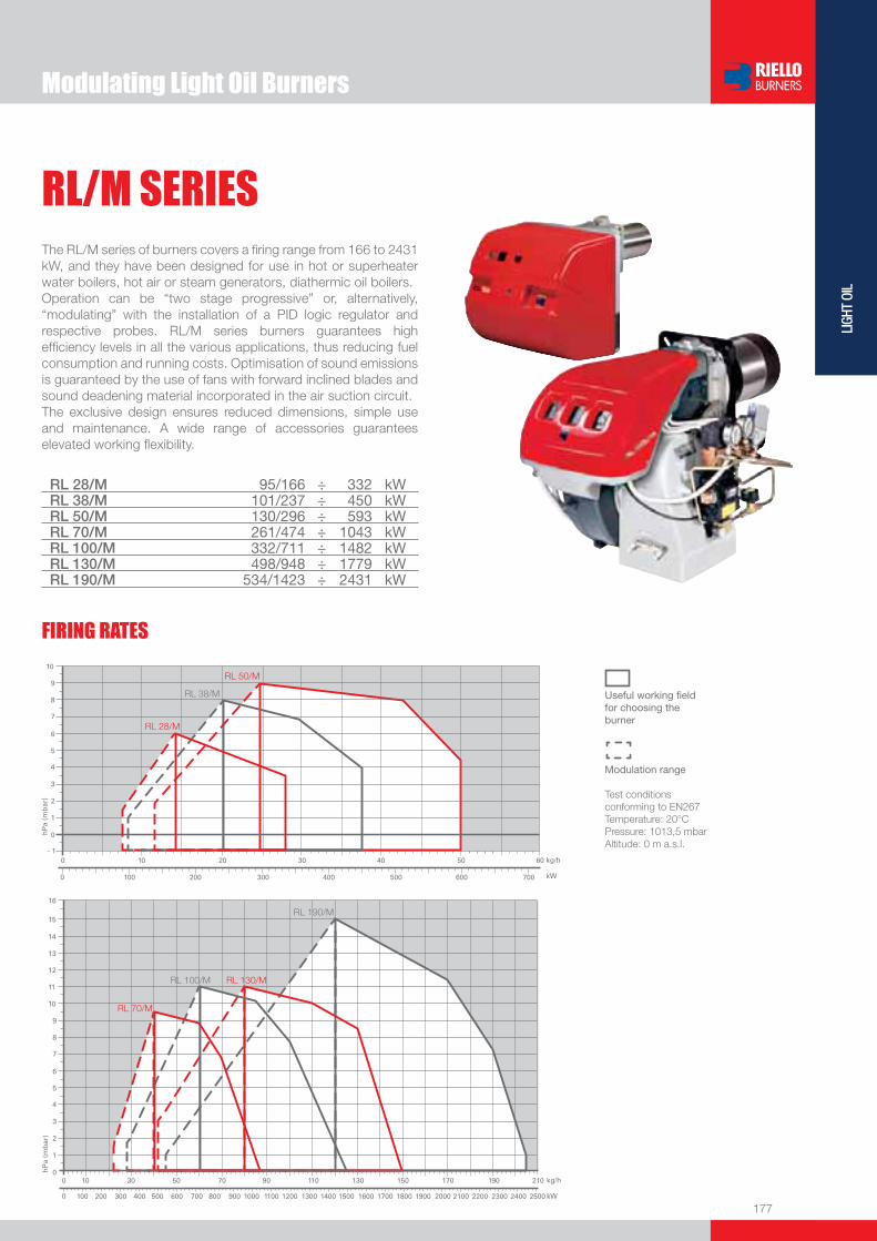
177
LIGH
T OI
L
Modulating Light Oil Burners
RL/M SERIESThe RL/M series of burners covers a fi ring range from 166 to 2431 kW, and they have been designed for use in hot or superheater water boilers, hot air or steam generators, diathermic oil boilers.Operation can be “two stage progressive” or, alternatively, “modulating” with the installation of a PID logic regulator and respective probes. RL/M series burners guarantees high effi ciency levels in all the various applications, thus reducing fuel consumption and running costs. Optimisation of sound emissions is guaranteed by the use of fans with forward inclined blades and sound deadening material incorporated in the air suction circuit.The exclusive design ensures reduced dimensions, simple use and maintenance. A wide range of accessories guarantees elevated working fl exibility.
RL 28/M 95/166 ÷ 332 kWRL 38/M 101/237 ÷ 450 kWRL 50/M 130/296 ÷ 593 kWRL 70/M 261/474 ÷ 1043 kWRL 100/M 332/711 ÷ 1482 kWRL 130/M 498/948 ÷ 1779 kWRL 190/M 534/1423 ÷ 2431 kW
FIRING RATES
Useful working fi eldfor choosing theburner
Modulation range
Test conditionsconforming to EN267 Temperature: 20°CPressure: 1013,5 mbarAltitude: 0 m a.s.l.

178
BURNER
PACKAGING
Overall dimensions (mm)
Modulating Light Oil BurnersRL/M SERIES
RL 28/M - 38/M - 50/M RL 70/M - 100/M - 130/M - 190/M
(1) Length with extended combustion head.
(1) Length with extended combustion head.
BURNER - BOILER MOUNTING FLANGE
MODEL A B C D E F - F (1) H I O - O (1)u RL 28/M 476 - - 474 468 241 - 351 140 352 672 - 807u RL 38/M 476 - - 474 468 241 - 351 140 352 672 - 807u RL 50/M 476 - - 474 468 241 - 351 152 352 672 - 807u RL 70/M 663 296 367 555 680 272 - 385 179 430 951 - 1086u RL 100/M 679 312 367 555 680 272 - 385 179 430 951 - 1086u RL 130/M 705 338 367 555 680 272 - 385 189 430 951 - 1086u RL 190/M 813 366 447 555 712 370 222 430 1166
MODEL D1 D2 Ø u RL 28/M 160 224 M8 u RL 38/M 160 224 M8 u RL 50/M 160 224 M8 u RL 70/M 185 275 - 325 M12 u RL 100/M 185 275 - 325 M12 u RL 130/M 195 275 - 325 M12 u RL 190/M 230 325 - 368 M16
MODEL X - X (1) Y Z kg u RL 28/M 872 540 550 39 u RL 38/M 872 540 550 41 u RL 50/M 872 540 550 42 u RL 70/M 1150 792 600 65 u RL 100/M 1150 792 600 68 u RL 130/M 1150 792 600 71 u RL 190/M 1200 800 850 95
Z
X - X (1)Y

179
LIGH
T OI
L
DESIGNATION OF SERIES
Specifi cation
EXTENDED DESIGNATION
Modulating Light Oil BurnersRL/M SERIES
R L 50 /M TC FS1 3/230-400/50 230/50-60
Series : R
Fuel : S Natural gas L Light oil LS Light oil / Natural gas N Heavy oil
Size
Operation : /1 One stage ... Two stage /M Modulating /E Electronic cam /P Proportioning air/gas valve /EV Electronic cam predisposed for variable speed (with inverter) Emission : ... Class 1 EN267 - EN676 MZ Class 2 EN267 - EN676 BLU Class 3 EN267 - EN676
MX Class 2 EN267
Class 3 EN676
Head : TC Standard head TL Extended head
Flame control system : FS1 Standard (1 stop every 24 h) FS2 Continuous working (1 stop every 72 h)
Electrical supply to the system : 1/230/50 1/230V/50Hz 3/230/50 3/230V/50Hz 3/400/50 3N/400V/50Hz 3/230-400/50 3/230V/50Hz - 3N/400V/50Hz 3/220/60 3/220V/60Hz 3/380/60 3N/380V/60Hz 3/220-380/60 3/220V/60Hz - 3N/380V/60Hz
Auxiliary voltage : 230/50-60 230V/50-60Hz 110/50-60 110V/50-60Hz
ID : Differential switch
BASIC DESIGNATION

180
RL/M SERIES
STATE OF SUPPLY
Monoblock forced draught oil burners, two stage progressive or modulating operation with a kit, made up of:- Air suction circuit lined with sound-proofi ng material- Fan with reverse curve blades (forward curve blades on the 190/M model)- Air damper for air setting and automatic oil output regulator controlled by a servomotor with variable cam- Combustion head, that can be set on the basis of required output- Gears pump for high pressure fuel supply - Valve unit with a double oil safety valve on the output circuit and safety valve on the return circuit; double safety valve on the return circuit for models RL 100/M, RL 130/M, RL 190/M and for all models in the TRD-72, NBN version
- Safety oil pressure switch- Minimum oil pressure switch in the output circuit for the TRD-72, NBN versions- Photocell for fl ame detection- Burner safety control box - Burner on/off switch- Flame inspection window- Manual or automatic output increase/decrease switch- Slide bars for easier installation and maintenance- Protection fi lter against radio interference- IP 44 electric protection level.
Standard equipment:- 2 fl exible pipes for connection to the oil supply network- 2 gaskets for the fl exible pipes- 2 nipples for connection to the pump- 4 screws for fi xing the burner fl ange to the boiler- 1 thermal screen- Wiring loom fi ttings for electrical connections- 2 slide bar extensions (for the extended head models and the RL 190/M model)- Instruction handbook for installation, use and maintenance- Spare parts catalogue.
Specifi cation
Modulating Light Oil Burners

181
LIGH
T OI
L
Available models
Modulating Light Oil BurnersRL/M SERIES
CODE MODEL HEAT OUTPUT TOTAL ELECTRICAL
POWER
CERTIFICATION NOTE
(kW) (kg/h) (kW)
3471002 RL 28/M TC FS1 1/230/50 230/50-60 90/166-332 7,5/14-28 0,4 -
3471003 RL 28/M TL FS1 1/230/50 230/50-60 90/166-332 7,5/14-28 0,4 -
3471080 RL 28/M TC FS1 1/220-230/60 230/50-60 90/166-332 7,5/14-28 0,4 -
3471081 RL 28/M TL FS1 1/220-230/60 230/50-60 90/166-332 7,5/14-28 0,4 -
3471402 RL 38/M TC FS1 3/230-400/50 230/50-60 101/237-450 8,5/20-38 0,6 -
3471403 RL 38/M TL FS1 3/230-400/50 230/50-60 101/237-450 8,5/20-38 0,6 -
3471480 RL 38/M TC FS1 3/208-230/380-460/60 230/50-60 101/237-450 8,5/20-38 0,66 -
3471481 RL 38/M TL FS1 3/208-230/380-460/60 230/50-60 101/237-450 8,5/20-38 0,66 -
3471602 RL 50/M TC FS1 3/230-400/50 230/50-60 130/296-593 11/25-50 0,8 -
3471603 RL 50/M TL FS1 3/230-400/50 230/50-60 130/296-593 11/25-50 0,8 -
3471680 RL 50/M TC FS1 3/208-230/380-460/60 230/50-60 130/296-593 11/25-50 0,66 -
3471681 RL 50/M TL FS1 3/208-230/380-460/60 230/50-60 130/296-593 11/25-50 0,66 -
3477012 RL 70/M TC FS1 3/230-400/50 230/50-60 261/474-1043 22/40-88 1,4 CE-050790223001
3477013 RL 70/M TL FS1 3/230-400/50 230/50-60 261/474-1043 22/40-88 1,4 CE-050790223001
3477080 RL 70/M TC FS1 3/208-230/380-460/60 230/50-60 261/474-1043 22/40-88 1,4 CE-050790223001
3477081 RL 70/M TL FS1 3/208-230/380-460/60 230/50-60 261/474-1043 22/40-88 1,4 CE-050790223001
3477022 RL 70/M TC FS2 3/230-400/50 230/50-60 261/474-1043 22/40-88 1,4 CE-050790223001
3477023 RL 70/M TL FS2 3/230-400/50 230/50-60 261/474-1043 22/40-88 1,4 CE-050790223001
3477212 RL 100/M TC FS1 3/230-400/50 230/50-60 332/711-1482 28/60-125 2,1 CE-050790223001
3477213 RL 100/M TL FS1 3/230-400/50 230/50-60 332/711-1482 28/60-125 2,1 CE-050790223001
3477280 RL 100/M TC FS1 3/208-230/380-460/60 230/50-60 332/711-1482 28/60-125 2,1 CE-050790223001
3477281 RL 100/M TL FS1 3/208-230/380-460/60 230/50-60 332/711-1482 28/60-125 2,1 CE-050790223001
3477222 RL 100/M TC FS2 3/230-400/50 230/50-60 332/711-1482 28/60-125 2,1 CE-050790223001
3477223 RL 100/M TL FS2 3/230-400/50 230/50-60 332/711-1482 28/60-125 2,1 CE-050790223001
3477412 RL 130/M TC FS1 3/230-400/50 230/50-60 498/948-1779 42/80-150 2,6 CE-050790223001
3477413 RL 130/M TL FS1 3/230-400/50 230/50-60 498/948-1779 42/80-150 2,6 CE-050790223001
3477480 RL 130/M TC FS1 3/208-230/380-460/60 230/50-60 498/948-1779 42/80-150 2,6 CE-050790223001
3477481 RL 130/M TL FS1 3/208-230/380-460/60 230/50-60 498/948-1779 42/80-150 2,6 CE-050790223001
3477422 RL 130/M TC FS2 3/230-400/50 230/50-60 498/948-1779 42/80-150 2,6 CE-050790223001
3477423 RL 130/M TL FS2 3/230-400/50 230/50-60 498/948-1779 42/80-150 2,6 CE-050790223001
3477811 RL 190/M TC FS1 3/400/50 230/50-60 534/1423-2431 45/120-205 5,5 CE-050790223001
20011022 RL 190/M TC FS1 3/230/50 230/50-60 534/1423-2431 45/120-205 5,5 CE-050790223001
3477880 RL 190/M TC FS1 3/460/60 220/60 534/1423-2431 45/120-205 5,5 CE-050790223001
20011029 RL 190/M TC FS1 3/220/60 220/60 534/1423-2431 45/120-205 5,5 CE-050790223001
3477822 RL 190/M TC FS2 3/400/50 230/50-60 534/1423-2431 45/120-205 5,5 CE-050790223001
20011025 RL 190/M TC FS2 3/230/50 230/50-60 534/1423-2431 45/120-205 5,5 CE-050790223001
Net calorifi c value: 11,8 kWh/kg - 10200 kcal/kg - Viscosity at 20°C: 4-6 mm2/s (cSt).The burners of RL/M series are in according to 89/336 (2004/108) - 73/23 (2006/95) - 98/37 - 92/42 EC Directive and EN 267 Norm.

182
RL/M SERIES
Return nozzles type A3 45°
The following list shows the features and codes on the basis of the maximum required fuel out-put.
NOTE: each burner needs N° 1 nozzle.
If burner head penetration into the combustion chamber needs reducing, varying thickness spacers are available, as given in the following list.
Spacer kit
BURNER
SPACER THICKNESS S (mm)
KIT CODE
u RL 28/M - 38/M - 50/M 90 3010095
u RL 70/M - 100/M - 130/M 135 3010129
u RL 190/M 102 3000722
Modulating Light Oil Burners
Burner accessories
BURNER RATED OUTPUT kg/h NOZZLE CODE
u RL 28/M 15 3009850
u RL 28/M - 38/M 20 3009851
u RL 28/M - 38/M - 50/M 30 3009852
u RL 38/M - 50/M - 70/M 40 3009853
u RL 50/M - 70/M 50 3009854
u RL 70/M - 100/M 60 3009855
u RL 70/M - 100/M 70 3009856
u RL 100/M - 130/M 80 3009857
u RL 100/M - 130/M 90 3009858
u RL 100/M - 130/M 100 3009859
u RL 130/M 110 3009860
u RL 130/M - 190/M 120 3009861
u RL 130/M - 190/M 130 3009862
u RL 190/M 140 3009863
u RL 190/M 160 3009864
u RL 190/M 180 3009865
u RL 190/M 200 3009866
“Standard head” burners can be transformed into “extended head” versions, by using the special kit.
Extended head kit
BURNER
STANDARD HEAD LENGTH (mm)
EXTENDED HEAD LENGTH (mm)
KIT CODE
u RL 28/M 241 351 3010120
u RL 38/M 241 351 3010121
u RL 50/M 241 351 3010122
u RL 70/M 272 385 3010159
u RL 100/M 272 385 3010160
u RL 130/M 272 385 3010161
u RL 190/M 370 - -
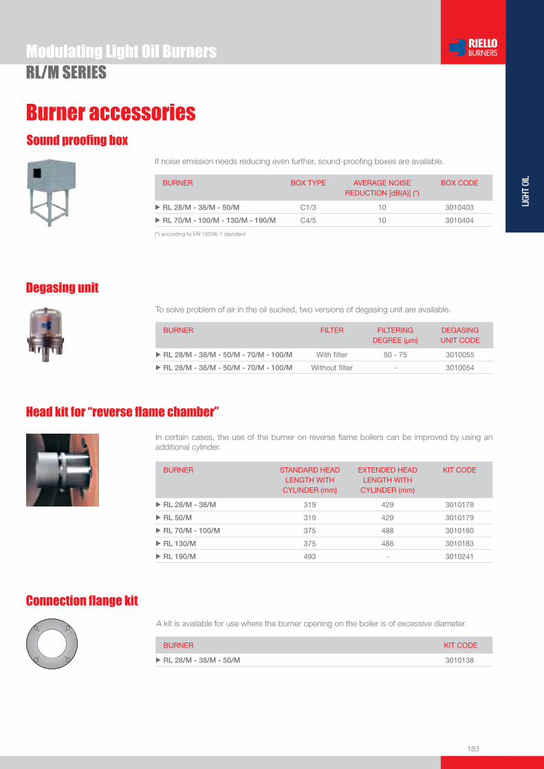
183
LIGH
T OI
L
Burner accessories
RL/M SERIESModulating Light Oil Burners
If noise emission needs reducing even further, sound-proofi ng boxes are available.
Sound proofi ng box
BURNER
BOX TYPE
AVERAGE NOISE REDUCTION [dB(A)] (*)
BOX CODE
u RL 28/M - 38/M - 50/M C1/3 10 3010403
u RL 70/M - 100/M - 130/M - 190/M C4/5 10 3010404
(*) according to EN 15036-1 standard
Connection fl ange kit
A kit is available for use where the burner opening on the boiler is of excessive diameter.
BURNER KIT CODE
u RL 28/M - 38/M - 50/M 3010138
To solve problem of air in the oil sucked, two versions of degasing unit are available.
Degasing unit
BURNER
FILTER
FILTERING DEGREE (µm)
DEGASING UNIT CODE
u RL 28/M - 38/M - 50/M - 70/M - 100/M With fi lter 50 - 75 3010055
u RL 28/M - 38/M - 50/M - 70/M - 100/M Without fi lter - 3010054
Head kit for “reverse fl ame chamber”
In certain cases, the use of the burner on reverse fl ame boilers can be improved by using an additional cylinder.
BURNER STANDARD HEAD LENGTH WITH
CYLINDER (mm)
EXTENDED HEADLENGTH WITH
CYLINDER (mm)
KIT CODE
u RL 28/M - 38/M 319 429 3010178
u RL 50/M 319 429 3010179
u RL 70/M - 100/M 375 488 3010180
u RL 130/M 375 488 3010183
u RL 190/M 493 - 3010241
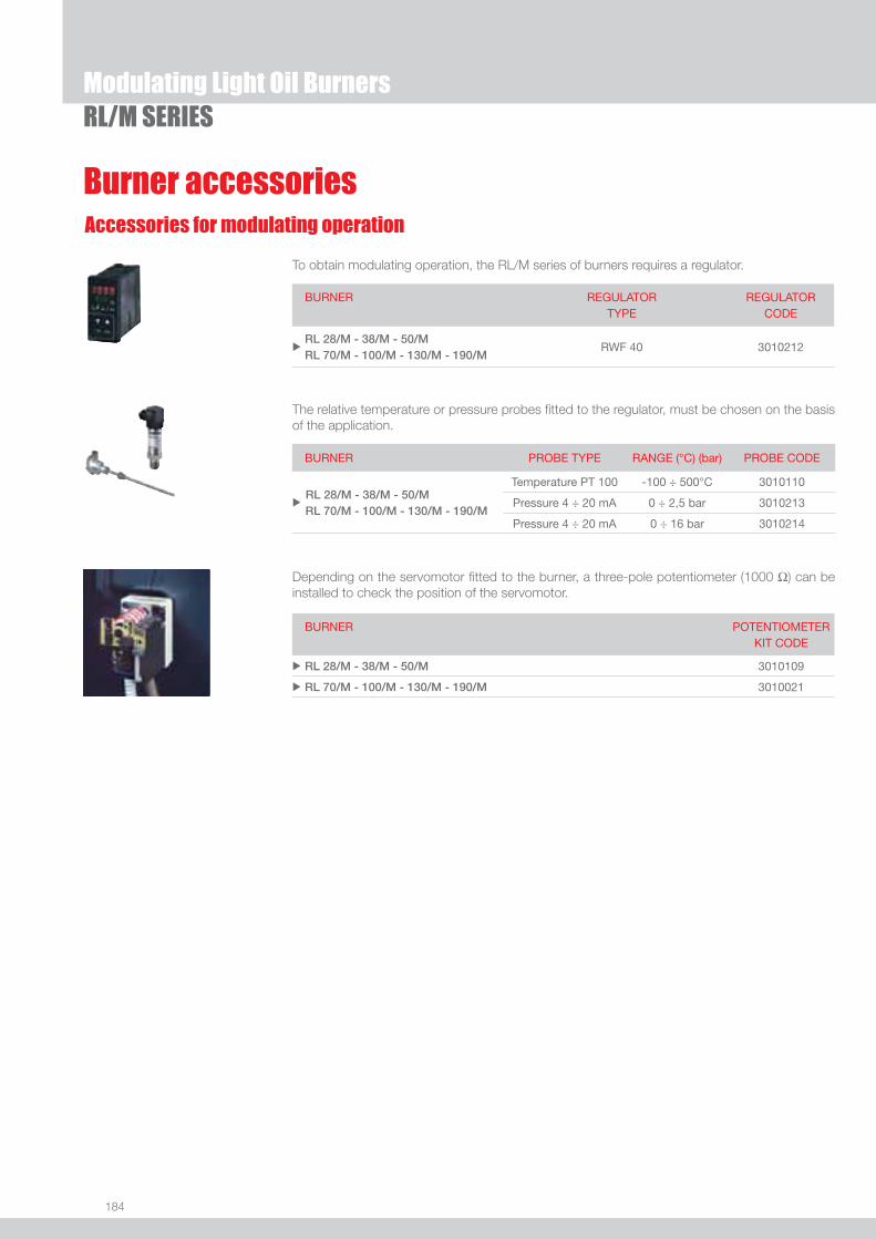
184
Modulating Light Oil BurnersRL/M SERIES
Burner accessoriesAccessories for modulating operation
To obtain modulating operation, the RL/M series of burners requires a regulator.
BURNER
REGULATOR TYPE
REGULATOR CODE
uRL 28/M - 38/M - 50/M RL 70/M - 100/M - 130/M - 190/M
RWF 40 3010212
Depending on the servomotor fi tted to the burner, a three-pole potentiometer (1000 Ω) can be installed to check the position of the servomotor.
BURNER
POTENTIOMETER KIT CODE
u RL 28/M - 38/M - 50/M 3010109
u RL 70/M - 100/M - 130/M - 190/M 3010021
The relative temperature or pressure probes fi tted to the regulator, must be chosen on the basis of the application.
BURNER PROBE TYPE RANGE (°C) (bar) PROBE CODE
u RL 28/M - 38/M - 50/M
RL 70/M - 100/M - 130/M - 190/M
Temperature PT 100 -100 ÷ 500°C 3010110
Pressure 4 ÷ 20 mA 0 ÷ 2,5 bar 3010213
Pressure 4 ÷ 20 mA 0 ÷ 16 bar 3010214
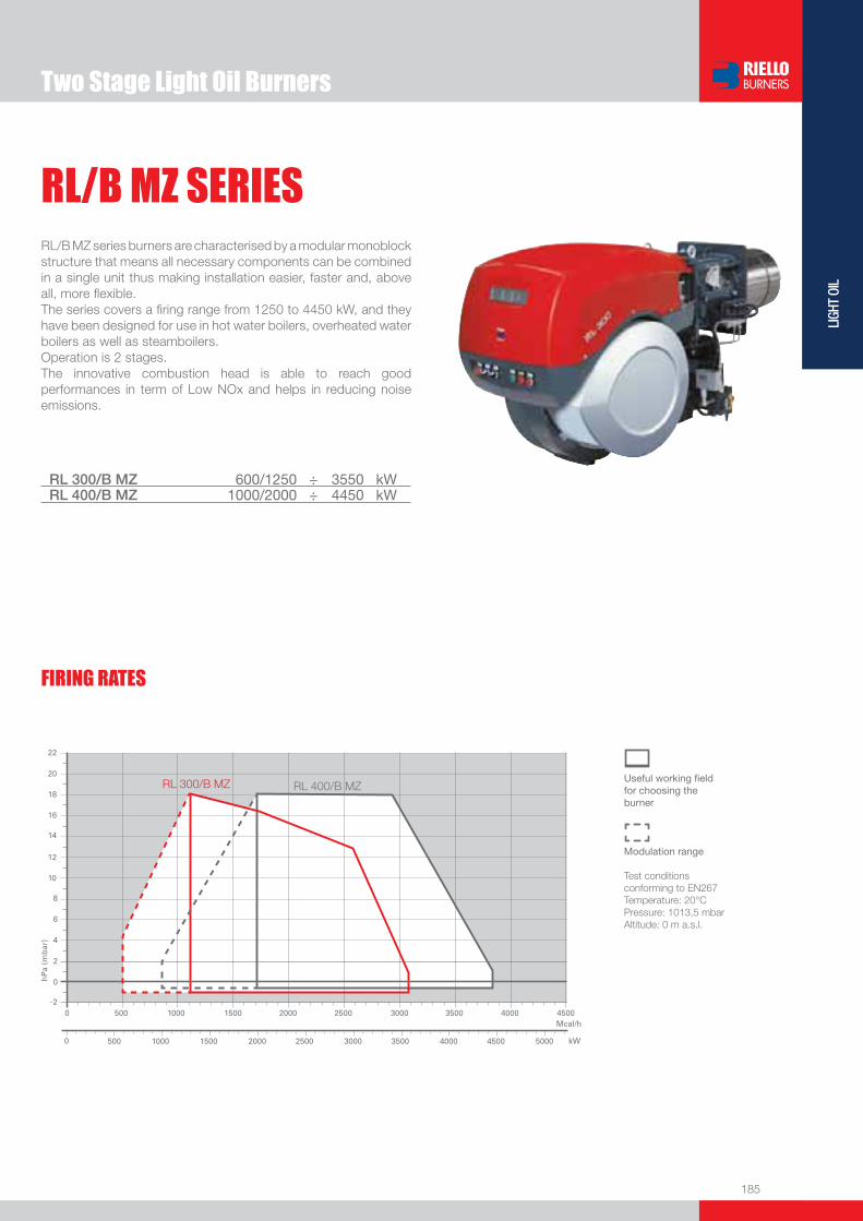
185
LIGH
T OI
L
RL/B MZ series burners are characterised by a modular monoblock structure that means all necessary components can be combined in a single unit thus making installation easier, faster and, above all, more fl exible.The series covers a fi ring range from 1250 to 4450 kW, and they have been designed for use in hot water boilers, overheated water boilers as well as steamboilers. Operation is 2 stages.The innovative combustion head is able to reach good performances in term of Low NOx and helps in reducing noise emissions.
RL/B MZ SERIES
RL 300/B MZ 600/1250 ÷ 3550 kW RL 400/B MZ 1000/2000 ÷ 4450 kW
Useful working fi eldfor choosing theburner
Modulation range
Test conditionsconforming to EN267 Temperature: 20°CPressure: 1013,5 mbarAltitude: 0 m a.s.l.
Two Stage Light Oil Burners
FIRING RATES

186
RL/B MZ SERIESTwo Stage Light Oil Burners
BURNER - BOILER MOUNTING FLANGE
Z
XY
MODEL A D E F H I O S u RL 300/B MZ 720 890 1325 510 313 605 1055 1175
u RL 400/B MZ 775 890 1325 510 313 605 1055 1175
MODEL D1 D2 Ø u RL 300/B MZ 350 452 M18
u RL 400/B MZ 350 452 M18
MODEL X Y Z kg u RL 300/B MZ 1960 970 940 230
u RL 400/B MZ 1960 970 940 240
PACKAGING
BURNER
Overall dimensions (mm)
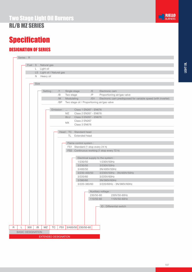
187
LIGH
T OI
L
Two Stage Light Oil BurnersRL/B MZ SERIES
R L 300 /B MZ TC FS1 3/400/50 230/50-60
Series : R
Fuel : S Natural gas L Light oil LS Light oil / Natural gas N Heavy oil
Size
Setting : /1 Single stage /E Electronic cam /B Two stage /P Proportioning air/gas valve /M Modulating /EV Electronic cam predisposed for variable speed (with inverter) /BP Two stage oil / Proportioning air/gas valve Emission : ... Class 1 EN267 - EN676 MZ Class 2 EN267 - EN676 BLU Class 3 EN267 - EN676
MX Class 2 EN267
Class 3 EN676
Head : TC Standard head TL Extended head
Flame control system : FS1 Standard (1 stop every 24 h) FS2 Continuous working (1 stop every 72 h)
Electrical supply to the system : 1/230/50 1/230V/50Hz 3/230/50 3/230V/50Hz 3/400/50 3N/400V/50Hz 3/230-400/50 3/230V/50Hz - 3N/400V/50Hz 3/220/60 3/220V/60Hz 3/380/60 3N/380V/60Hz 3/220-380/60 3/220/60Hz - 3N/380V/60Hz
Auxiliary voltage : 230/50-60 230V/50-60Hz 110/50-60 110V/50-60Hz
ID : Differential switch
BASIC DESIGNATION
EXTENDED DESIGNATION
DESIGNATION OF SERIES
Specifi cation

188
RL/B MZ SERIES - STATE OF SUPPLY
Specifi cation
Monoblock forced draught gas burner with “two stage progressive” operation, fully automatic, made up of:- Fan with reverse curve blades high performance with low sound emissions- Air suction circuit lined with sound-proofi ng material- Air damper for air setting controlled by a high precision servomotor- Air pressure switch- Fan starting motor at 2800 rpm, three-phase 230/400 - 400/690 V with neutral, 50Hz - Low emission combustion head, that can be set on the basis of required output, fi tted with: - stainless steel end cone, resistant to corrosion and high temperatures - ignition electrodes - fl ame stability disk- Burner safety control box for controlling the system safety- Star/triangle starter for the fan motor (only for RL 400/B MZ model)- Main electrical supply terminal board- Burner on/off switch - Auxiliary voltage led signal- Burner working led signal- Contacts motor and thermal relay with release button- Motor internal thermal protection- Motor failure led signal - Burner failure led signal and lighted release button- Emergency button- Coded connection plugs-sockets- Burner opening hinge- Lifting rings- IP 54 electric protection level- Gears pump for high pressure fuel supply - Pump starting motor- Oil safety valves- Three oil valves (1st and 2nd stage 3nd safety valve)- Photocell for fl ame detection- Flame inspection window.
Standard equipment:- 1 fl ange gasket- 4 screws for fi xing the fl ange- 1 thermal screen- 4 screws for fi xing the burner fl ange to the boiler- 2 fl exible pipes for connection to the oil supply network- 2 nipples for connection to the pump with gaskets.- Instruction handbook for installation, use and maintenance- Spare parts catalogue.
Two Stage Light Oil BurnersRL/B MZ SERIES

189
LIGH
T OI
L
Available modelsRL/B MZ SERIES - Burners
CODE MODEL HEAT OUTPUT TOTALELECTRICAL
POWER
CERTIFICATION NOTE
(kW) (kg/h) (kW)
3478410 RL 300/B MZ TC FS1 3/230-400/50 230/50-60 600/1250-3550 50/105-301 6 050790223001
3478512 RL 400/B MZ TC FS1 3/400/50 230/50-60 1000/2000-4450 84/169-378 9 050790223001
Net calorifi c value: 11,8 kWh/kg - 10200 kcal/kg - Viscosity at 20°C: 4-6 mm2/s (cSt) The burners of RL/B MZ series are in according to 89/336 (2004/108) - 73/23 (2006/95) - 98/37 - 92/42 EC Directive and EN 267 Norm.
Two Stage Light Oil BurnersRL/B MZ SERIES
Nozzles type 60° BThe nozzles must be ordered separately. The following table shows the features and codes on the basis of the maximum required fuel output.
NOTE: each burner needs N° 2 nozzles.
Burner accessories
BURNER
GPH
RATED OUTPUT (kg/h) NOZZLE CODEat 10 bar at 12 bar at 14 bar
u RL/B MZ 12,00 44,2 48,7 53,0 3009950
u RL/B MZ 13,00 47,8 52,8 57,4 3009951
u RL/B MZ 14,00 51,5 56,9 61,8 3009952
u RL/B MZ 15,00 55,2 60,9 66,2 3009953
u RL/B MZ 16,00 58,9 65,0 70,6 3009954
u RL/B MZ 17,00 62,6 69,0 75,0 3009955
u RL/B MZ 18,00 66,2 73,1 79,4 3009956
u RL/B MZ 19,00 69,9 77,2 83,5 3009957
u RL/B MZ 20,00 73,6 81,2 88,3 3009958
u RL/B MZ 22,00 81,0 89,3 97,1 3009959
u RL/B MZ 24,00 88,3 97,5 105,9 3009960
u RL/B MZ 26,00 95,7 105,6 114,7 3009961
u RL/B MZ 28,00 103,1 113,7 123,6 3009962
u RL/B MZ 30,00 110,4 121,8 132,4 3009963
u RL/B MZ 35,00 128,8 142,1 154,5 3009964
u RL/B MZ 40,00 147,2 162,4 176,5 3009965
u RL/B MZ 45,00 165,6 182,7 198,6 3009966
u RL/B MZ 50,00 184,0 203,0 220,7 3009967
u RL/B MZ 55,00 202,4 223,4 242,7 3009968
u RL/B MZ 60,00 220,8 243,7 264,8 3009969
u RL/B MZ 65,00 239,2 264,0 286,9 3009970
u RL/B MZ 70,00 257,6 284,3 309,0 3009971
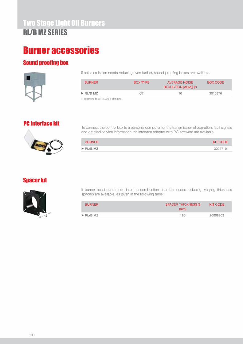
190
If noise emission needs reducing even further, sound-proofi ng boxes are available.
Sound proofi ng box
BURNER
BOX TYPE
AVERAGE NOISE REDUCTION [dB(A)] (*)
BOX CODE
u RL/B MZ C7 10 3010376
Burner accessories
Two Stage Light Oil BurnersRL/B MZ SERIES
(*) according to EN 15036-1 standard
BURNER KIT CODE
u RL/B MZ 3002719
To connect the control box to a personal computer for the transmission of operation, fault signals and detailed service information, an interface adapter with PC software are available.
PC Interface kit
Spacer kit
If burner head penetration into the combustion chamber needs reducing, varying thickness spacers are available, as given in the following table:
BURNER SPACER THICKNESS S (mm)
KIT CODE
u RL/B MZ 180 20008903
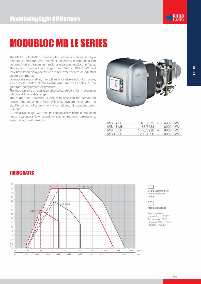
191
LIGH
T OI
L
Modulating Light Oil Burners
MODUBLOC MB LE SERIESThe MODUBLOC MB LE series of burners are characterised by a monoblock structure that means all necessary components can be combined in a single unit, making installation easier and faster. The series covers a fi ring range from 1070 to 10000 kW, and they have been designed for use in hot water boilers or industrial steam generators.Operation is modulating, through an innovative electronic module, which gives control of the air/fuel ratio and PID control of the generator temperature or pressure.The mechanisms of regulation allow to catch up a high modulation ratio on all fi ring rates range.The burner can, therefore, supply with precision the demanded power, guaranteeing a high effi ciency system level and the stability setting, obtaining fuel consumption and operating costs reduction. An exclusive design, with fan unit fi tted on line with the combustion head, guarantees low sound emissions, reduced dimensions, easy use and maintenance.
MB 4 LE 1070/2375 ÷ 4092 kWMB 6 LE 1186/3558 ÷ 6000 kWMB 8 LE 1450/3290 ÷ 9000 kWMB 10 LE 1200/4000 ÷ 10000 kW
FIRING RATES
Useful working fi eldfor choosing theburner
Modulation range
Test conditionsconforming to EN267 Temperature: 20°CPressure: 1013,5 mbarAltitude: 0 m a.s.l.

192
BURNER
PACKAGING
Overall dimensions (mm)
Z
XY
Modulating Light Oil BurnersMODUBLOC MB LE SERIES
BURNER - BOILER MOUNTING FLANGE
MODEL A D E F H I N O S uMB 4 LE 840 910 1470 511 336 490 183 1205 1330
uMB 6 LE 840 910 1470 511 336 490 183 1205 1330
uMB 8 LE 1007 1079 1900 530 413 575 208 1570 1740
uMB 10 LE 1007 1079 1900 530 413 575 208 1570 1740
MODEL D1 D2 Ø uMB 4 LE 350 496 M20
uMB 6 LE 350 496 M20
uMB 8 LE 418 608 M20
uMB 10 LE 418 608 M20
MODEL X Y Z kg uMB 4 LE 2120 1005 1175 300
uMB 6 LE 2120 1005 1175 300
uMB 8 LE 2690 1170 1350 450
uMB 10 LE 2690 1170 1350 450

193
LIGH
T OI
L
DESIGNATION OF SERIES
Specifi cation
Modulating Light Oil BurnersMODUBLOC MB LE SERIES
EXTENDED DESIGNATION
MB 4 L E TC FR FS1 3/400/50 230/50-60
Series : MB
Size
Fuel : S Natural gas L Light oil LS Light oil / Natural gas
Operation : E Electronic cam V Electronic cam and variable speed (with Inverter) P Proportioning air/gas valve Emission : ... Class 1 EN267 - EN676 MZ Class 2 EN267 - EN676 BLU Class 3 EN267 - EN676
MX Class 2 EN267
Class 3 EN676
Head : TC Standard head TL Extended head
Fuel supply : FR from the right FL from the left
Flame control system : FS1 Standard (1 stop every 24 h) FS2 Continuous working (1 stop every 72 h)
Electrical supply to the system : 3/400/50 3N/400V/50Hz 3/230/50 3/230V/50Hz Auxiliary voltage : 230/50-60 230V/50-60Hz 110/50-60 110V/50-60Hz
BASIC DESIGNATION

194
MODUBLOC MB LE SERIES
STATE OF SUPPLY
Monoblock forced draught oil burners modulanting operation, made up of:- Fan with reverse curve blades- Air suction circuit lined with sound-proofi ng material- Air damper for air setting controlled by a high precision servomotor- Air pressure switch- Fan starting motor- Pump starting motor- Mobile combustion head, that can be set on the basis of required output - Gears pump for high pressure fuel supply - Valve unit- Automatic setting for light oil delivery, controlled by a high precision servomotor- Safety oil pressure switch- Pressure gauge for delivery pressure- Pressure gauge for return pressure- Minimum oil pressure switch- Module for air/fuel setting and output modulation- Burner safety control box- Photocell for fl ame detection- Star/triangle starter for the fan motor- Main electrical supply terminal board- Pump motor starter- Burner on/off switch- Auxiliary voltage led signal- Manual or automatic output increase/decrease switch- Burner working led signal- Contacts motor and thermal relay with release button- Thermal protector PTO for the fan motor- Motor failure led signal- Burner failure led signal and lighted release button- Led signal for correct rotation direction of fan and pump motor- Emergency button- Coded connection plugs-sockets- Burner opening hinge- Lifting rings- IP X0D (IP 40) protection level.
Standard equipment:- 2 fl exible pipes- 2 gaskets for the fl exible pipes- 2 nipples for connection to the pump- 4 screws for fi xing the burner fl ange to the boiler- 1 thermal screen- Instruction handbook for installation, use and maintenance- Spare parts catalogue.
Specifi cation
Modulating Light Oil Burners

195
LIGH
T OI
L
Available models
Modulating Light Oil BurnersMODUBLOC MB LE SERIES
Net calorifi c value: 11,8 kWh/kg - 10200 kcal/kg - Viscosity at 20°C: 4÷6 mm2/s (cSt).The burners of MB LE series are in according to 73/23 (2006/95) - 89/336 (2004/108) - 98/37 EC Directive and EN 267 Norm.
CODE MODEL HEAT OUTPUT TOTAL ELECTRICAL
POWER
CERTIFICATION NOTE
(kW) (kg/h) (kW)
3478000 MB4LE TC FR FS1 3/400/50 230/50-60 1070/2375÷4092 90/200÷345 16 DIN 5G 932/99 M
3478005 MB4LE TC FL FS1 3/400/50 230/50-60 1070/2375÷4092 90/200÷345 16 DIN 5G 932/99 M
3478100 MB6LE TC FR FS1 3/400/50 230/50-60 1186/3558÷6000 100/300÷506 18 DIN 5G 932/99 M
3478105 MB6LE TC FL FS1 3/400/50 230/50-60 1186/3558÷6000 100/300÷506 18 DIN 5G 932/99 M
3478200 MB8LE TC FR FS1 3/400/50 230/50-60 1450/3290÷9000 122/276÷762 22 DIN 5G 997/03
3478210 MB8LE TC FR FS2 3/400/50 230/50-60 1450/3290÷9000 122/276÷762 22 DIN 5G 997/03
3478205 MB8LE TC FL FS1 3/400/50 230/50-60 1450/3290÷9000 122/276÷762 22 DIN 5G 997/03
3478215 MB8LE TC FL FS2 3/400/50 230/50-60 1450/3290÷9000 122/276÷762 22 DIN 5G 997/03
3478300 MB10LE TC FR FS1 3/400/50 230/50-60 1200/4000÷10000 101/339÷837 27 DIN 5G 998/03
3478310 MB10LE TC FR FS2 3/400/50 230/50-60 1200/4000÷10000 101/339÷837 27 DIN 5G 998/03
3478305 MB10LE TC FL FS1 3/400/50 230/50-60 1200/4000÷10000 101/339÷837 27 DIN 5G 998/03
3478315 MB10LE TC FL FS2 3/400/50 230/50-60 1200/4000÷10000 101/339÷837 27 DIN 5G 998/03
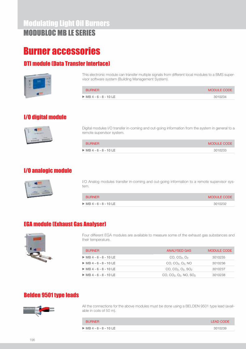
196
Modulating Light Oil BurnersMODUBLOC MB LE SERIES
Burner accessoriesDTI module (Data Transfer Interface)
This electronic module can transfer multiple signals from different local modules to a BMS super-visor software system (Building Management System).
BURNER MODULE CODE
u MB 4 - 6 - 8 - 10 LE 3010234
I/O digital module
Digital modules I/O transfer in-coming and out-going information from the system in general to a remote supervisor system.
BURNER MODULE CODE
u MB 4 - 6 - 8 - 10 LE 3010233
I/O analogic module
I/O Analog modules transfer in-coming and out-going information to a remote supervisor sys-tem.
BURNER MODULE CODE
u MB 4 - 6 - 8 - 10 LE 3010232
EGA module (Exhaust Gas Analyser)
Four different EGA modules are available to measure some of the exhaust gas substances and their temperature.
BURNER ANALYSED GAS MODULE CODE
u MB 4 - 6 - 8 - 10 LE CO, CO2, O2 3010235
u MB 4 - 6 - 8 - 10 LE CO, CO2, O2, NO 3010236
u MB 4 - 6 - 8 - 10 LE CO, CO2, O2, SO2 3010237
u MB 4 - 6 - 8 - 10 LE CO, CO2, O2, NO, SO2 3010238
Belden 9501 type leads
All the connections for the above modules must be done using a BELDEN 9501 type lead (avail-able in coils of 50 m).
BURNER LEAD CODE
u MB 4 - 6 - 8 - 10 LE 3010239

197
LIGH
T OI
L
Burner accessories
Modulating Light Oil BurnersMODUBLOC MB LE SERIES
Accessories for modulating operation
Main management module allows a modulating operation with use of probes chosen on the basis of the application.
BURNER PROBE TYPE RANGE (°C) (bar) PROBE CODE
u MB 4 - 6 - 8 - 10 LE Temperature 0 ÷ 400°C 3010187
u MB 4 - 6 - 8 - 10 LE Pressure 0 ÷ 3 bar 3010246
u MB 4 - 6 - 8 - 10 LE Pressure 0 ÷ 18 bar 3010186
u MB 4 - 6 - 8 - 10 LE Pressure 0 ÷ 30 bar 3010188
Return nozzlesThe following list shows the features and codes on the basis of the maximum required fuel out-put.
NOTE: each burner needs N° 1 nozzle.
BURNER RATED
DELIVERY (kg/h)
NOZZLE CODE
(1)
NOZZLE CODE
(2)
uMB 8 LE
525 3009813 3045459
550 3009814 3045460
575 3009815 3045461
600 3009816 3045462
650 3009817 3045463
700 3009818 3045464
uMB 10 LE
400 3009808 3045454
425 3009809 3045455
450 3009810 3045456
475 3009811 3045457
500 3009812 3045458
525 3009813 3045459
550 3009814 3045460
575 3009815 3045461
600 3009816 3045462
650 3009817 3045463
700 3009818 3045464
750 3009819 3045465
800 3009820 -
850 3009821 -
900 3009822 -
BURNER RATED
DELIVERY (kg/h)
NOZZLE CODE
(1)
NOZZLE CODE
(2)
u MB 4 LE
200 3009800 3045438
225 3009801 3045440
250 3009802 3045442
275 3009803 3045444
300 3009804 3045446
325 3009805 3045448
u MB 6 LE
350 3009806 3045450
375 3009807 3045452
400 3009808 3045454
425 3009809 3045455
450 3009810 3045456
475 3009811 3045457
500 3009812 3045458
u MB 8 LE
300 3009804 3045446
325 3009805 3045448
350 3009806 3045450
375 3009807 3045452
400 3009808 3045454
425 3009809 3045455
450 3009810 3045456
475 3009811 3045457
500 3009812 3045458
(1) Nozzles Bergonzo B5 45° - with “AA” needle code. (2) Nozzles Fluidics W2 45° - with “AA” needle code.

198
Modulating Light Oil BurnersMODUBLOC MB LE SERIES
Burner accessoriesBurner support
For easier maintenance, a mobile burner support has been designed, which means the burner can be dismantled without the need for forklift trucks.
BURNER SUPPORT CODE
u MB 4 - 6 - 8 - 10 LE 3010385
If noise emission needs reducing even further, sound-proofi ng boxes are available.
Sound proofi ng box
BURNER
AVERAGE NOISE REDUCTION [dB(A)] (*)
BOX CODE
u MB 4 - 6 - 8 - 10 LE 10 3010401
(*) according to EN 15036-1 standard

One Stage Heavy Oil Burners
199
HEAV
Y OI
L
RIELLO 40 N SERIESThe Riello 40 N series of one stage heavy oil burners, is a complete range of products developed to respond to any request for the use of heavy oil in heating systems and light industrial processes. The Riello 40 N series is available in two different models, with an output ranging from 34 to 217 kW, divided into two basic structures.All the models use many components designed by Riello for the Riello 40 series but are fi tted with special components for heavy oil combustion. The high quality level guarantees safe working.In developing these burners, special attention has been paid to reducing noise, to the ease of installation and adjustment, to reducing the size in order to facilitate installation in any kind of boiler on the market.All the models are conform to EMC European Directives, for Low Voltage and Machinery.All the Riello 40 N burners are tested before leaving the factory.
N 10 34 ÷ 102 kWN 20 102 ÷ 217 kW
FIRING RATES
Useful working fi eldfor choosing theburner
Test conditions Temperature: 20°CPressure: 1013,5 mbarAltitude: 0 m a.s.l.
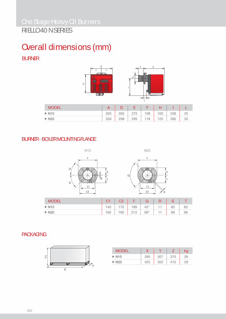
200
RIELLO 40 N SERIES
BURNER
Overall dimensions (mm)
One Stage Heavy Oil Burners
MODEL C1 C2 F Q R S T u N10 140 170 189 45° 11 83 83
u N20 160 190 213 90° 11 99 99
N10 N20
BURNER - BOILER MOUNTING FLANGE
MODEL A D E F H I L u N10 305 262 275 108 105 258 25
u N20 350 298 295 118 125 280 35
MODEL X Y Z kg u N10 395 307 375 26
u N20 425 352 410 29
PACKAGING
Z
XY
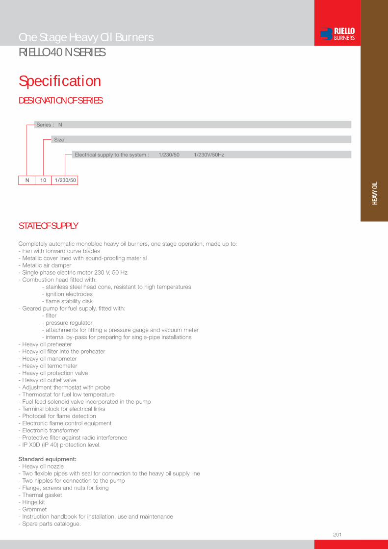
201
HEAV
Y OI
L
RIELLO 40 N SERIES
DESIGNATION OF SERIES
Specifi cation
One Stage Heavy Oil Burners
N 10 1/230/50
Series : N
Size Electrical supply to the system : 1/230/50 1/230V/50Hz
Completely automatic monobloc heavy oil burners, one stage operation, made up to:- Fan with forward curve blades- Metallic cover lined with sound-proofi ng material - Metallic air damper- Single phase electric motor 230 V, 50 Hz- Combustion head fi tted with: - stainless steel head cone, resistant to high temperatures - ignition electrodes - fl ame stability disk- Geared pump for fuel supply, fi tted with: - fi lter - pressure regulator - attachments for fi tting a pressure gauge and vacuum meter - internal by-pass for preparing for single-pipe installations- Heavy oil preheater- Heavy oil fi lter into the preheater- Heavy oil manometer- Heavy oil termometer- Heavy oil protection valve- Heavy oil outlet valve- Adjustment thermostat with probe- Thermostat for fuel low temperature - Fuel feed solenoid valve incorporated in the pump- Terminal block for electrical links- Photocell for fl ame detection- Electronic fl ame control equipment- Electronic transformer- Protective fi lter against radio interference- IP X0D (IP 40) protection level.
Standard equipment:- Heavy oil nozzle- Two fl exible pipes with seal for connection to the heavy oil supply line- Two nipples for connection to the pump- Flange, screws and nuts for fi xing- Thermal gasket- Hinge kit- Grommet- Instruction handbook for installation, use and maintenance- Spare parts catalogue.
STATE OF SUPPLY
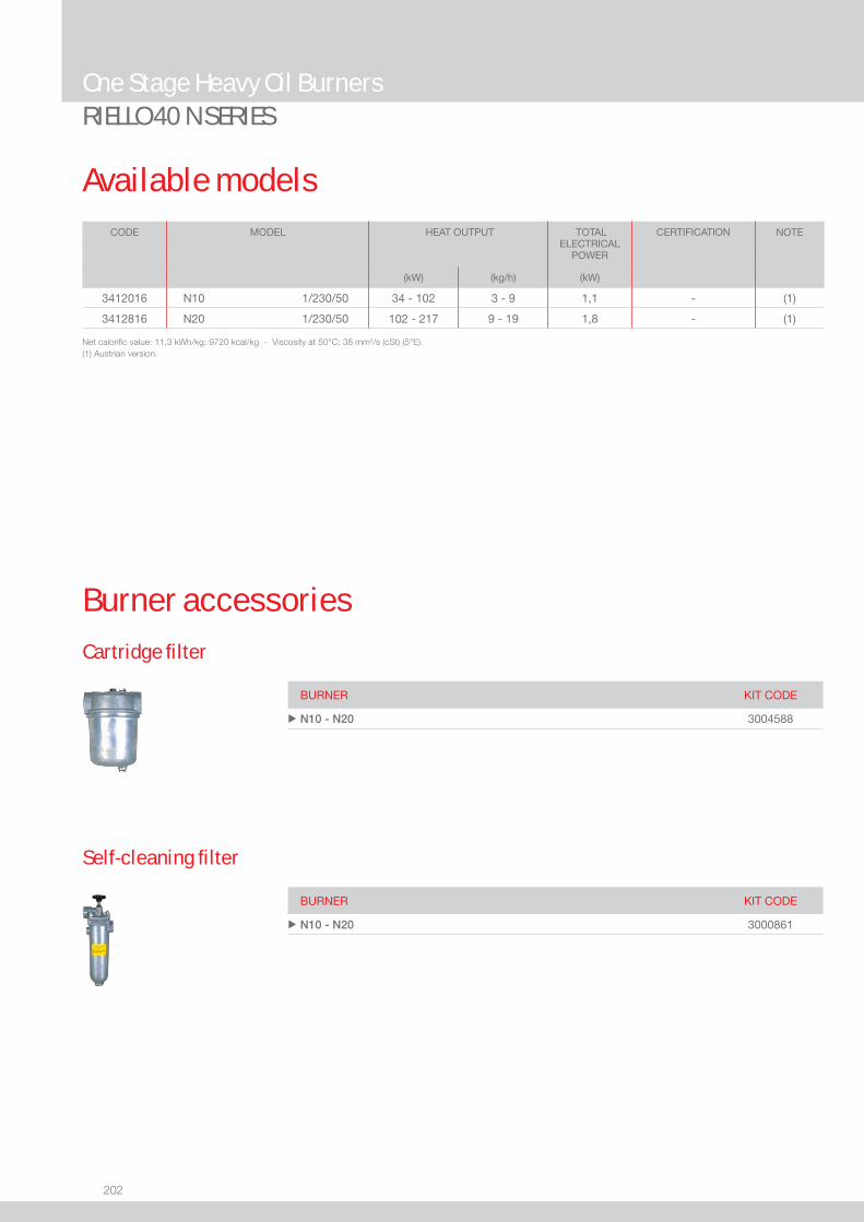
202
RIELLO 40 N SERIES
Available models
One Stage Heavy Oil Burners
CODE MODEL
HEAT OUTPUT TOTALELECTRICAL
POWER
CERTIFICATION NOTE
(kW) (kg/h) (kW)
3412016 N10 1/230/50 34 - 102 3 - 9 1,1 - (1)
3412816 N20 1/230/50 102 - 217 9 - 19 1,8 - (1)
Net calorifi c value: 11,3 kWh/kg; 9720 kcal/kg - Viscosity at 50°C: 38 mm2/s (cSt) (5°E).(1) Austrian version.
Burner accessoriesCartridge fi lter
Self-cleaning fi lter
BURNER KIT CODE
u N10 - N20 3004588
BURNER KIT CODE
u N10 - N20 3000861
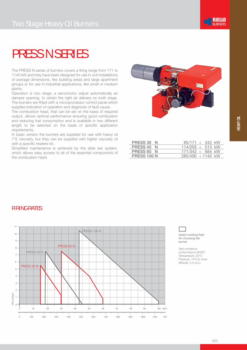
203
HEAV
Y OI
L
Two Stage Heavy Oil Burners
PRESS N SERIESThe PRESS N series of burners covers a fi ring range from 171 to 1140 kW and they have been designed for use in civil installations of average dimensions, like building areas and large apartment groups or for use in industrial applications, like small or medium plants.Operation is two stage; a servomotor adjust automatically air damper opening, to obtain the right air delivery on both stage. The burners are fi tted with a microprocessor control panel which supplies indication of operation and diagnosis of fault cause. The combustion head, that can be set on the basis of required output, allows optimal performance ensuring good combustion and reducing fuel consumption and is available in two different length to be selected on the basis of specifi c application requirements.In basic version the burners are supplied for use with heavy oil 7°E viscosity, but they can be supplied with higher viscosity oil with a specifi c heaters kit.Simplifi ed maintenance is achieved by the slide bar system, which allows easy access to all of the essential components of the combustion head.
PRESS 30 N 85/171 ÷ 342 kWPRESS 45 N 114/205 ÷ 513 kWPRESS 60 N 171/342 ÷ 684 kWPRESS 100 N 285/490 ÷ 1140 kW
FIRING RATES
Useful working fi eldfor choosing theburner
Test conditionsconforming to EN267 Temperature: 20°CPressure: 1013,5 mbarAltitude: 0 m a.s.l.

204
BURNER
PACKAGING
Overall dimensions (mm)
Two Stage Heavy Oil BurnersPRESS N SERIES
BURNER - BOILER MOUNTING FLANGE
Z
X - X(1)Y
MODEL A B C E F - F(1) H I O - O(1)u PRESS 30 N 625 335 290 625 185 - 320 161 305 905 - 1080
u PRESS 45 N 625 335 290 625 235 - 370 161 305 925 - 1100
u PRESS 60 N 625 335 290 660 245 - 400 172 335 940 - 1115
u PRESS 100 N 625 335 290 710 250 - 410 195 370 1010 - 1195
MODEL P R S u PRESS 30 N 160 170 M 10
u PRESS 45 N 160 170 M 10
u PRESS 60 N 160 180 M 10
u PRESS 100 N 195 205 M 12
(1) Length with extended combustion head
(1) Length with extended combustion head
MODEL X - X(1) Y Z kg u PRESS 30 N 880 - 1015 690 622 84
u PRESS 45 N 880 - 1015 690 622 84
u PRESS 60 N 925 - 1095 760 652 87
u PRESS 100 N 985 - 1145 790 652 104

205
HEAV
Y OI
L
DESIGNATION OF SERIES
Specifi cation
Two Stage Heavy Oil BurnersPRESS N SERIES
PRESS 60 N TC FS1 3/230-400/50 230/50
Series : PRESS
Size
Operation : N Two stage T/N Three stage P/N Modulating
Emission : ... Class 1 EN267 Head : TC Standard head TL Extended head
Flame control system : FS1 Standard (1 stop every 24 h) FS2 Continuous working (1 stop every 72 h)
Electrical supply to the system : 1/230/50 1/230V/50Hz 3/230/50 3/230V/50Hz 3/400/50 3N/400V/50Hz 3/230-400/50 3/230V/50Hz - 3N/400V/50Hz 3/220-380/60 3/220V/60Hz - 3N/380V/60Hz Auxiliary voltage : 230/50 230V/50Hz 220/60 220V/60Hz
BASIC DESIGNATION
EXTENDED DESIGNATION
206
Specifi cationSTATE OF SUPPLY
Monoblock forced draught heavy oil burner, two stage operation, made up of:- Air suction circuit- Fan with forward curved blades - Air dampers for air setting controlled by a servomotor- Starting motor at 2850 rpm- Combustion head, fi tted with: - stainless steel end cone, resistant to corrosion and high temperatures - ignition electrodes - fl ame stability disk- Gears pump for high pressure fuel supply, fi tted with: - fi lter - pressure regulator - connections for installing a pressure gauge and vacuometer - internal by-pass for single pipe installation- Valve unit with a double oil safety valve on the output circuit;- Oil preheater provided with chance of a thermometer application for temperature control;- Servomotor for air damper regulation;- Photocell for fl ame detection;- Microprocessor-based burner safety control box, with diagnostic function - Flame inspection window- Slide bars for easier installation and maintenance- Protection fi lter against radio interference- IP X0D (IP 40) protection level.
Standard equipment:- 2 fl exible hoses for pipe connection- 2 gaskets for fl exible hoses- 2 nipples for fl exible hoses- 1 thermal insulation screen- 4 screws for fi xing the burner fl ange to the boiler- 2 nozzles (see table of available burner model)- 2 extensions for bars (for long head version)- Instruction handbook for installation, use and maintenance- Spare parts catalogue.
Two Stage Heavy Oil BurnersPRESS N SERIES
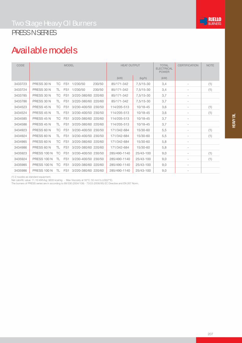
207
HEAV
Y OI
L
Available models
Two Stage Heavy Oil BurnersPRESS N SERIES
(1) 2 nozzles as standard equipment.Net calorifi c value: 11,16 kWh/kg; 9600 kcal/kg - Max Viscosity at 50°C: 50 mm2/s (cSt)(7°E).The burners of PRESS series are in according to 89/336 (2004/108) - 73/23 (2006/95) EC Directive and EN 267 Norm.
CODE MODEL
HEAT OUTPUT TOTAL ELECTRICAL
POWER
CERTIFICATION NOTE
(kW) (kg/h) (kW)
3433723 PRESS 30 N TC FS1 1/230/50 230/50 85/171-342 7,5/15-30 3,4 - (1)
3433724 PRESS 30 N TL FS1 1/230/50 230/50 85/171-342 7,5/15-30 3,4 - (1)
3433785 PRESS 30 N TC FS1 3/220-380/60 220/60 85/171-342 7,5/15-30 3,7 -
3433786 PRESS 30 N TL FS1 3/220-380/60 220/60 85/171-342 7,5/15-30 3,7 -
3434523 PRESS 45 N TC FS1 3/230-400/50 230/50 114/205-513 10/18-45 3,6 - (1)
3434524 PRESS 45 N TL FS1 3/230-400/50 230/50 114/205-513 10/18-45 3,6 - (1)
3434585 PRESS 45 N TC FS1 3/220-380/60 220/60 114/205-513 10/18-45 3,7 -
3434586 PRESS 45 N TL FS1 3/220-380/60 220/60 114/205-513 10/18-45 3,7 -
3434923 PRESS 60 N TC FS1 3/230-400/50 230/50 171/342-684 15/30-60 5,5 - (1)
3434924 PRESS 60 N TL FS1 3/230-400/50 230/50 171/342-684 15/30-60 5,5 - (1)
3434985 PRESS 60 N TC FS1 3/220-380/60 220/60 171/342-684 15/30-60 5,8 -
3434986 PRESS 60 N TL FS1 3/220-380/60 220/60 171/342-684 15/30-60 5,8 -
3435923 PRESS 100 N TC FS1 3/230-400/50 230/50 285/490-1140 25/43-100 9,0 - (1)
3435924 PRESS 100 N TL FS1 3/230-400/50 230/50 285/490-1140 25/43-100 9,0 - (1)
3435985 PRESS 100 N TC FS1 3/220-380/60 220/60 285/490-1140 25/43-100 9,0 -
3435986 PRESS 100 N TL FS1 3/220-380/60 220/60 285/490-1140 25/43-100 9,0 -
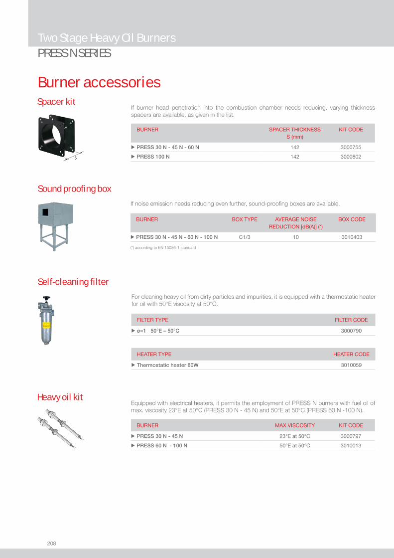
208
Two Stage Heavy Oil BurnersPRESS N SERIES
Burner accessories
If burner head penetration into the combustion chamber needs reducing, varying thickness spacers are available, as given in the list.
Spacer kit
BURNER
SPACER THICKNESS S (mm)
KIT CODE
u PRESS 30 N - 45 N - 60 N 142 3000755
u PRESS 100 N 142 3000802
If noise emission needs reducing even further, sound-proofi ng boxes are available.
Sound proofi ng box
BURNER
BOX TYPE
AVERAGE NOISE REDUCTION [dB(A)] (*)
BOX CODE
u PRESS 30 N - 45 N - 60 N - 100 N C1/3 10 3010403
(*) according to EN 15036-1 standard
Self-cleaning fi lter
FILTER TYPE FILTER CODE
u ø=1 50°E – 50°C 3000790
For cleaning heavy oil from dirty particles and impurities, it is equipped with a thermostatic heater for oil with 50°E viscosity at 50°C.
HEATER TYPE HEATER CODE
u Thermostatic heater 80W 3010059
Equipped with electrical heaters, it permits the employment of PRESS N burners with fuel oil of max. viscosity 23°E at 50°C (PRESS 30 N - 45 N) and 50°E at 50°C (PRESS 60 N -100 N).
Heavy oil kit
BURNER MAX VISCOSITY KIT CODE
u PRESS 30 N - 45 N 23°E at 50°C 3000797
u PRESS 60 N - 100 N 50°E at 50°C 3010013

209
HEAV
Y OI
L
Burner accessories
Two Stage Heavy Oil BurnersPRESS N SERIES
BURNER KIT CODE
u PRESS 30 N - 45 N - 60 N - 100 N 3002719
To connect the control box to a personal computer for the transmission of operation, fault signals and detailed service information, an interface adapter with PC software are available.
PC Interface kit
Cartridge fi lter
For cleaning heavy oil from dirty particles and impurities, it is equipped with a cartridge system for oil with 7°E viscosity at 50°C.
FILTER TYPE FILTER CODE
u Cartridge 7°E – 50°C 3005209
HEATER TYPE HEATER CODE
u Thermo - resistance up to 30°E - 50° 3010050
Thermostats allow heavy oil temperature control and regulation during burner operation. They are available in electronic and maximum versions.
Thermostats
BURNER THERMOSTAT TYPE
THERMOSTAT CODE
u PRESS 30 N - 45 N - 60 N - 100 N Electronic 3000799
u PRESS 30 N - 45 N - 60 N - 100 N Maximum 3000800
u PRESS 30 N - 45 N - 60 N - 100 N Kit electronic 3010173
TD - PE
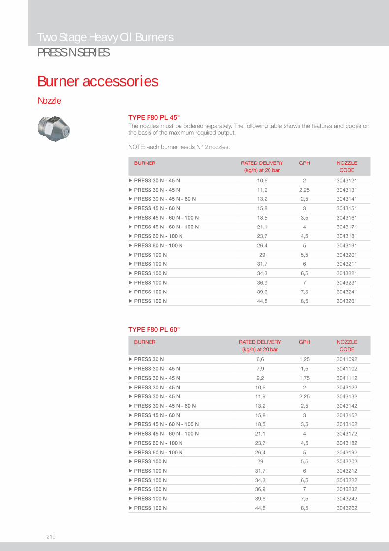
210
Two Stage Heavy Oil BurnersPRESS N SERIES
Burner accessoriesNozzle
The nozzles must be ordered separately. The following table shows the features and codes on the basis of the maximum required output.
NOTE: each burner needs N° 2 nozzles.
BURNER RATED DELIVERY(kg/h) at 20 bar
GPH NOZZLECODE
u PRESS 30 N - 45 N 10,6 2 3043121
u PRESS 30 N - 45 N 11,9 2,25 3043131
u PRESS 30 N - 45 N - 60 N 13,2 2,5 3043141
u PRESS 45 N - 60 N 15,8 3 3043151
u PRESS 45 N - 60 N - 100 N 18,5 3,5 3043161
u PRESS 45 N - 60 N - 100 N 21,1 4 3043171
u PRESS 60 N - 100 N 23,7 4,5 3043181
u PRESS 60 N - 100 N 26,4 5 3043191
u PRESS 100 N 29 5,5 3043201
u PRESS 100 N 31,7 6 3043211
u PRESS 100 N 34,3 6,5 3043221
u PRESS 100 N 36,9 7 3043231
u PRESS 100 N 39,6 7,5 3043241
u PRESS 100 N 44,8 8,5 3043261
TYPE F80 PL 60°
BURNER RATED DELIVERY (kg/h) at 20 bar
GPH NOZZLE CODE
u PRESS 30 N 6,6 1,25 3041092
u PRESS 30 N - 45 N 7,9 1,5 3041102
u PRESS 30 N - 45 N 9,2 1,75 3041112
u PRESS 30 N - 45 N 10,6 2 3043122
u PRESS 30 N - 45 N 11,9 2,25 3043132
u PRESS 30 N - 45 N - 60 N 13,2 2,5 3043142
u PRESS 45 N - 60 N 15,8 3 3043152
u PRESS 45 N - 60 N - 100 N 18,5 3,5 3043162
u PRESS 45 N - 60 N - 100 N 21,1 4 3043172
u PRESS 60 N - 100 N 23,7 4,5 3043182
u PRESS 60 N - 100 N 26,4 5 3043192
u PRESS 100 N 29 5,5 3043202
u PRESS 100 N 31,7 6 3043212
u PRESS 100 N 34,3 6,5 3043222
u PRESS 100 N 36,9 7 3043232
u PRESS 100 N 39,6 7,5 3043242
u PRESS 100 N 44,8 8,5 3043262
TYPE F80 PL 45°

211
HEAV
Y OI
L
Two Stage Heavy Oil Burners
PRESS N/ECO SERIESPRESS N/ECO burner series covers a fi ring range from 171 to 1140 kW and it has been designed for operation with low sulphur fuels. The burners are equipped with a separate low speed pump.They have been designed for use in civil installations of average dimensions, like building areas and large apartment groups or for use in industrial applications, like small or medium plants.Operation is two stage; a servomotor adjust automatically air damper opening, to obtain the right air delivery on both stage. The burners are fi tted with a microprocessor control panel which supplies indication of operation and diagnosis of fault cause.The combustion head, that can be set on the basis of required output, allows optimal performance ensuring good combustion and reducing fuel consumption and is available in two different length to be selected on the basis of specifi c application requirements.As standard the burners are supplied with electrical heaters installed on crucial parts of hydraulics circuit, for use with heavy oil viscosity up to 15°E.Simplifi ed maintenance is achieved by the slide bar system, which allows easy access to all of the essential components of the combustion head.
PRESS 30 N/ECO 85/171 ÷ 342 kWPRESS 45 N/ECO 114/205 ÷ 513 kWPRESS 60 N/ECO 171/342 ÷ 684 kWPRESS 100 N/ECO 285/490 ÷ 1140 kW
FIRING RATES
Useful working fi eldfor choosing theburner
Test conditionsconforming to EN267 Temperature: 20°CPressure: 1013,5 mbarAltitude: 0 m a.s.l.
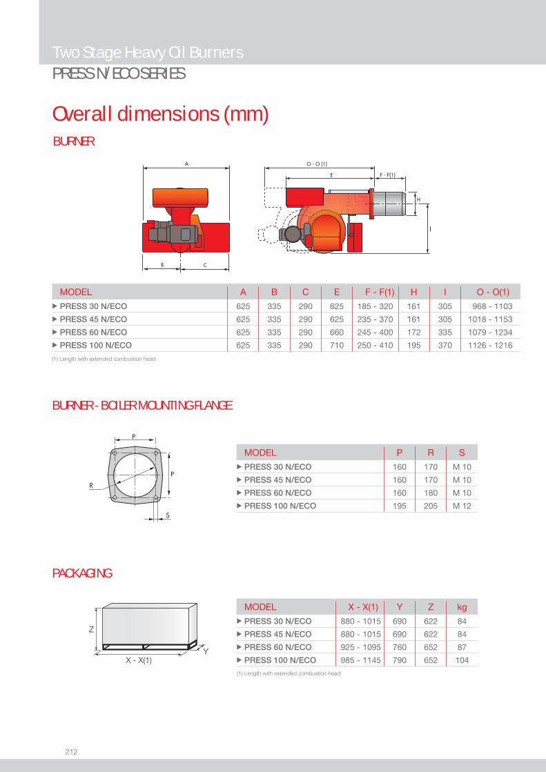
212
BURNER
Overall dimensions (mm)
Two Stage Heavy Oil BurnersPRESS N/ECO SERIES
Z
X - X(1)Y
MODEL P R S u PRESS 30 N/ECO 160 170 M 10
u PRESS 45 N/ECO 160 170 M 10
u PRESS 60 N/ECO 160 180 M 10
u PRESS 100 N/ECO 195 205 M 12
(1) Length with extended combustion head
(1) Length with extended combustion head
MODEL A B C E F - F(1) H I O - O(1)u PRESS 30 N/ECO 625 335 290 625 185 - 320 161 305 968 - 1103
u PRESS 45 N/ECO 625 335 290 625 235 - 370 161 305 1018 - 1153
u PRESS 60 N/ECO 625 335 290 660 245 - 400 172 335 1079 - 1234
u PRESS 100 N/ECO 625 335 290 710 250 - 410 195 370 1126 - 1216
BURNER - BOILER MOUNTING FLANGE
PACKAGING
MODEL X - X(1) Y Z kg u PRESS 30 N/ECO 880 - 1015 690 622 84
u PRESS 45 N/ECO 880 - 1015 690 622 84
u PRESS 60 N/ECO 925 - 1095 760 652 87
u PRESS 100 N/ECO 985 - 1145 790 652 104
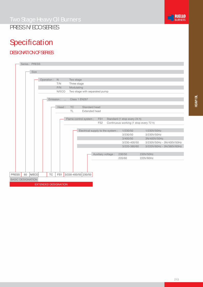
213
HEAV
Y OI
L
DESIGNATION OF SERIES
Specifi cation
Two Stage Heavy Oil BurnersPRESS N/ECO SERIES
PRESS 60 N/ECO TC FS1 3/230-400/50 230/50
Series : PRESS
Size
Operation : N Two stage T/N Three stage P/N Modulating N/ECO Two stage with separated pump
Emission : ... Class 1 EN267 Head : TC Standard head TL Extended head
Flame control system : FS1 Standard (1 stop every 24 h) FS2 Continuous working (1 stop every 72 h)
Electrical supply to the system : 1/230/50 1/230V/50Hz 3/230/50 3/230V/50Hz 3/400/50 3N/400V/50Hz 3/230-400/50 3/230V/50Hz - 3N/400V/50Hz 3/220-380/60 3/220V/60Hz - 3N/380V/60Hz Auxiliary voltage : 230/50 230V/50Hz 220/60 220V/60Hz
BASIC DESIGNATION
EXTENDED DESIGNATION

214
Specifi cationSTATE OF SUPPLY
Monoblock forced draught heavy oil burner, two stage operation, made up of:- Air suction circuit- Fan with forward curved blades - Air dampers for air setting controlled by a servomotor- Fan motor at 2850 rpm- Oil pump motor at 1400 rpm- Combustion head, fi tted with: - stainless steel end cone, resistant to corrosion and high temperatures - ignition electrodes - fl ame stability disk- Gears pump for high pressure fuel supply, fi tted with: - fi lter - pressure regulator - connections for installing a pressure gauge and vacuometer - internal by-pass for single pipe installation- Valve unit with a double oil safety valve on the output circuit- Double fi lter between pump and nozzle- Oil preheater provided with chance of a thermometer application for temperature control- Installed electrical heaters on pump, nozzle holder, valves assembly- Servomotor for air damper regulation- Air pressure switch- Photocell for fl ame detection- Microprocessor-based burner safety control box, with diagnostic function - Flame inspection window- Slide bars for easier installation and maintenance- Protection fi lter against radio interference- IP X0D (IP 40) protection level.
Standard equipment:- 2 fl exible hoses for pipe connection- 2 gaskets for fl exible hoses- 2 nipples for fl exible hoses- 1 thermal insulation screen- 4 screws for fi xing the burner fl ange to the boiler- 2 nozzles (see table of available burner model)- 2 extensions for bars (for long head version)- Instruction handbook for installation, use and maintenance- Spare parts catalogue.
Two Stage Heavy Oil BurnersPRESS N/ECO SERIES

215
HEAV
Y OI
L
Available models
Two Stage Heavy Oil BurnersPRESS N/ECO SERIES
(1) 2 nozzles as standard equipment.(2) Installed electrical heaters on pump, nozzle holder, valves assemblyNet calorifi c value: 11,16 kWh/kg; 9600 kcal/kg - Max Viscosity at 50°C: 115 mm2/s (cSt)(15°E).The burners of PRESS series are in according to 89/336 (2004/108) - 73/23 (2006/95) EC Directive and EN 267 Norm.
CODE MODEL
HEAT OUTPUT TOTAL ELECTRICAL
POWER
CERTIFICATION NOTE
(kW) (kg/h) (kW)
3433823 PRESS 30 N/ECO TC FS1 1/230/50 230/50 85/171-342 7,5/15-30 3,9 - (1) (2)
3433824 PRESS 30 N/ECO TL FS1 1/230/50 230/50 85/171-342 7,5/15-30 3,9 - (1) (2)
3433881 PRESS 30 N/ECO TC FS1 3/220-380/60 220/60 85/171-342 7,5/15-30 4,2 - (2)
3433882 PRESS 30 N/ECO TL FS1 3/220-380/60 220/60 85/171-342 7,5/15-30 4,2 - (2)
3434623 PRESS 45 N/ECO TC FS1 3/230-400/50 230/50 114/205-513 10/18-45 4,1 - (1) (2)
3434624 PRESS 45 N/ECO TL FS1 3/230-400/50 230/50 114/205-513 10/18-45 4,1 - (1) (2)
3434681 PRESS 45 N/ECO TC FS1 3/220-380/60 220/60 114/205-513 10/18-45 4,2 - (2)
3434682 PRESS 45 N/ECO TL FS1 3/220-380/60 220/60 114/205-513 10/18-45 4,2 - (2)
3435023 PRESS 60 N/ECO TC FS1 3/230-400/50 230/50 171/342-684 15/30-60 6,0 - (1) (2)
3435024 PRESS 60 N/ECO TL FS1 3/230-400/50 230/50 171/342-684 15/30-60 6,0 - (1) (2)
3435081 PRESS 60 N/ECO TC FS1 3/220-380/60 220/60 171/342-684 15/30-60 6,3 - (2)
3435082 PRESS 60 N/ECO TL FS1 3/220-380/60 220/60 171/342-684 15/30-60 6,3 - (2)
3436023 PRESS 100 N/ECO TC FS1 3/230-400/50 230/50 285/490-1140 25/43-100 9,5 - (1) (2)
3436024 PRESS 100 N/ECO TL FS1 3/230-400/50 230/50 285/490-1140 25/43-100 9,5 - (1) (2)
3436081 PRESS 100 N/ECO TC FS1 3/220-380/60 220/60 285/490-1140 25/43-100 9,5 - (2)
3436082 PRESS 100 N/ECO TL FS1 3/220-380/60 220/60 285/490-1140 25/43-100 9,5 - (2)
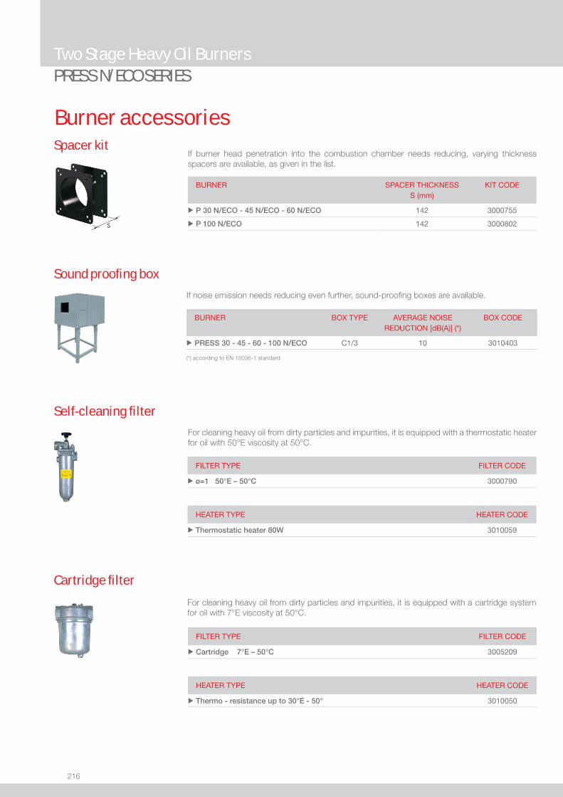
216
Two Stage Heavy Oil BurnersPRESS N/ECO SERIES
Burner accessories
If burner head penetration into the combustion chamber needs reducing, varying thickness spacers are available, as given in the list.
Spacer kit
BURNER
SPACER THICKNESS S (mm)
KIT CODE
u P 30 N/ECO - 45 N/ECO - 60 N/ECO 142 3000755
u P 100 N/ECO 142 3000802
If noise emission needs reducing even further, sound-proofi ng boxes are available.
Sound proofi ng box
BURNER
BOX TYPE
AVERAGE NOISE REDUCTION [dB(A)] (*)
BOX CODE
u PRESS 30 - 45 - 60 - 100 N/ECO C1/3 10 3010403
(*) according to EN 15036-1 standard
Self-cleaning fi lter
FILTER TYPE FILTER CODE
u ø=1 50°E – 50°C 3000790
For cleaning heavy oil from dirty particles and impurities, it is equipped with a thermostatic heater for oil with 50°E viscosity at 50°C.
HEATER TYPE HEATER CODE
u Thermostatic heater 80W 3010059
Cartridge fi lter
For cleaning heavy oil from dirty particles and impurities, it is equipped with a cartridge system for oil with 7°E viscosity at 50°C.
FILTER TYPE FILTER CODE
u Cartridge 7°E – 50°C 3005209
HEATER TYPE HEATER CODE
u Thermo - resistance up to 30°E - 50° 3010050

217
HEAV
Y OI
L
Burner accessories
Two Stage Heavy Oil BurnersPRESS N/ECO SERIES
BURNER KIT CODE
u P 30 N/ECO - 45 N/ECO - 60 N/ECO - 100 N/ECO 3002719
To connect the control box to a personal computer for the transmission of operation, fault signals and detailed service information, an interface adapter with PC software are available.
PC Interface kit
Thermostats allow heavy oil temperature control and regulation during burner operation. They are available in electronic and maximum versions.
Thermostats
BURNER THERMOSTAT TYPE
THERMOSTAT CODE
u P 30 N/ECO - 45 N/ECO - 60 N/ECO - 100 N/ECO Electronic 3000799 TD - PE

218
Two Stage Heavy Oil BurnersPRESS N/ECO SERIES
Burner accessoriesNozzle
The nozzles must be ordered separately. The following table shows the features and codes on the basis of the maximum required output.
NOTE: each burner needs N° 2 nozzles.
BURNER RATED DELIVERY(kg/h) at 20 bar
GPH NOZZLECODE
u P 30 N/ECO - 45 N/ECO 10,6 2 3043121
u P 30 N/ECO - 45 N/ECO 11,9 2,25 3043131
u P 30 N/ECO - 45 N/ECO - 60 N/ECO 13,2 2,5 3043141
u P 45 N/ECO - 60 N/ECO 15,8 3 3043151
u P 45 N/ECO - 60 N/ECO - 100 N/ECO 18,5 3,5 3043161
u P 45 N/ECO - 60 N/ECO - 100 N/ECO 21,1 4 3043171
u P 60 N/ECO - 100 N/ECO 23,7 4,5 3043181
u P 60 N/ECO - 100 N/ECO 26,4 5 3043191
u P 100 N/ECO 29 5,5 3043201
u P 100 N/ECO 31,7 6 3043211
u P 100 N/ECO 34,3 6,5 3043221
u P 100 N/ECO 36,9 7 3043231
u P 100 N/ECO 39,6 7,5 3043241
u P 100 N/ECO 44,8 8,5 3043261
BURNER RATED DELIVERY (kg/h) at 20 bar
GPH NOZZLE CODE
u P 30 N/ECO 6,6 1,25 3041092
u P 30 N/ECO - 45 N/ECO 7,9 1,5 3041102
u P 30 N/ECO - 45 N/ECO 9,2 1,75 3041112
u P 30 N/ECO - 45 N/ECO 10,6 2 3043122
u P 30 N/ECO - 45 N/ECO 11,9 2,25 3043132
u P 30 N/ECO - 45 N/ECO - 60 N/ECO 13,2 2,5 3043142
u P 45 N/ECO - 60 N/ECO 15,8 3 3043152
u P 45 N/ECO - 60 N/ECO - 100 N/ECO 18,5 3,5 3043162
u P 45 N/ECO - 60 N/ECO - 100 N/ECO 21,1 4 3043172
u P 60 N/ECO - 100 N/ECO 23,7 4,5 3043182
u P 60 N/ECO - 100 N/ECO 26,4 5 3043192
u P 100 N/ECO 29 5,5 3043202
u P 100 N/ECO 31,7 6 3043212
u P 100 N/ECO 34,3 6,5 3043222
u P 100 N/ECO 36,9 7 3043232
u P 100 N/ECO 39,6 7,5 3043242
u P 100 N/ECO 44,8 8,5 3043262
TYPE F80 PL 60°
TYPE F80 PL 45°

219
HEAV
Y OI
L
Three Stage Heavy Oil Burners
PRESS T/N - T/N ECO SERIESThe PRESS T/N series of burners covers a fi ring range from 800 to 5130 kW. They have been designed in three versions for use in commercial and industrial installations, to burn different oil viscosity from 7 up to 60 °E @ 50°C. Operation is three-stage, thus making these burners suitable for installations that have variable but predictable heating requirments. A servomotor adjusts automatically air damper to the opening value, determined to obtain always the necessary fuel consumption. Every model of PRESS T/N series is available in two different combustion head lenght (short or long head) to be selected on the basis of specifi c application requirments. An electric preheater has been fi tted to maintain the oil at the correct atomising temperature at maximum ouput and special heaters kits are separately supplied for burning high viscosity oil.Simplifi ed maintenance is achieved by the Riello designed slide bar system, which allows easy access to all of the essential components of the combustion head.
FIRING RATES
Useful working fi eldfor choosing theburner
Test conditionsconforming to EN267 Temperature: 20°CPressure: 1013,5 mbarAltitude: 0 m a.s.l.
P 140 T/N 320/800 ÷ 1600 kWP 200 T/N 515/1140 ÷ 2280 kWP 300 T/N 626/1710 ÷ 3420 kWP 450 T/N 855/2560 ÷ 5130 kWP 140 T/N ECO 320/800 ÷ 1600 kWP 200 T/N ECO 515/1140 ÷ 2280 kWP 300 T/N ECO 626/1710 ÷ 3420 kWP 450 T/N ECO 855/2560 ÷ 5130 kW

220
BURNER
Overall dimensions (mm)
Three Stage Heavy Oil BurnersPRESS T/N - T/N ECO SERIES
BURNER - BOILER MOUNTING FLANGE
PRESS T/N ECO
PRESS T/N
MODEL L M N P u P 140 T/N (ECO) 260 230 M 14 225
u P 200 T/N (ECO) 260 - M 16 255
u P 300 T/N (ECO) 260 - M 18 300
u P 450 T/N (ECO) 310 - M 20 350
MODEL A B C E G - G(1) H I O - O(1)u P 140 T/N 796 396 400 890 323 - 433 222 467 1370 - 1370
u P 200 T/N 796 396 400 890 352 - 462 250 467 1370 - 1370
u P 300 T/N 858 447 411 1000 376 - 506 295 496 1515 - 1665
u P 450 T/N 950 508 442 1090 435 - 565 336 525 1665 - 1820
u P 140 T/N ECO 900 396 504 890 323 - 433 222 467 1370 - 1370
u P 200 T/N ECO 900 396 504 890 352 - 462 250 467 1370 - 1370
u P 300 T/N ECO 984 447 537 1000 376 - 506 295 496 1515 - 1665
u P 450 T/N ECO 1100 508 592 1090 435 - 565 336 525 1665 - 1820
MODEL X Y Z kg u P 140 T/N (ECO) 1500 930 900 180
u P 200 T/N (ECO) 1500 930 900 190
u P 300 T/N (ECO) 1780 1085 990 260
u P 450 T/N (ECO) 1780 1085 990 350
Z
XY
PACKAGING
(1) Length with extended combustion head

221
HEAV
Y OI
L
DESIGNATION OF SERIES
Specifi cation
Three Stage Heavy Oil BurnersPRESS T/N - T/N ECO SERIES
PRESS 140 T/N TC FS1 3/230-400/50 230/50
Series : PRESS
Size
Operation : N Two stage N/ECO Two stage with separated oil pump T/N Three stage T/N ECO Three stage with separate oil pump P/N Modulating P/N ECO Modulating with separate oil pump
Emission : ... Class 1 EN267 Head : TC Standard head TL Extended head
Flame control system : FS1 Standard (1 stop every 24 h) FS2 Continuous working (1 stop every 72 h)
Electrical supply to the system : 1/230/50 1/230V/50Hz 3/230/50 3/230V/50Hz 3/400/50 3N/400V/50Hz 3/230-400/50 3/230V/50Hz - 3N/400V/50Hz 3/220-380/60 3/220V/60Hz - 3N/380V/60Hz Auxiliary voltage : 230/50 230V/50Hz 220/60 220V/60Hz
BASIC DESIGNATION
EXTENDED DESIGNATION

222
Specifi cationSTATE OF SUPPLY
Monoblock forced draught heavy oil burner, three stage operation, made up of:- Air suction circuit- Fan with forward curved blades - Air dampers for air setting controlled by a servomotor- Fan motor at 2850 rpm- Combustion head, fi tted with: - stainless steel end cone, resistant to corrosion and high temperatures - ignition electrodes - fl ame stability disk- Gears pump for high pressure fuel supply, fi tted with: - fi lter - pressure regulator - connections for installing a pressure gauge and vacuometer - internal by-pass for single pipe installation- Valve unit with a oil safety shut-off valve fi tted in series with three valves controlling three-stage on the output circuit- Heavy oil heating cartridges (T/N ECO version)- Oil pump motor at 1400 rpm (T/N ECO version)- Oil preheater- Servomotor for air damper regulation- Photocell for fl ame detection- Burner safety control box - Flame inspection window- Slide bars for easier installation and maintenance- Protection fi lter against radio interference- IP X0D (IP 40) electric protection level.
Standard equipment:- 2 fl exible hoses for pipe connection- 2 nipples for fl exible hoses- 1 thermal insulation screen- 4 screws for fi xing the burner fl ange to the boiler- 3 nozzles- 2 extensions for bars (for long head version of P 300 T/N and P 450 T/N)- 5 wiring looms for electrical connections (7 for P 450 T/N version)- 1 star delta starter (only for P 450 T/N version)- Instruction handbook for installation, use and maintenance- Spare parts catalogue.
Three Stage Heavy Oil BurnersPRESS T/N - T/N ECO SERIES
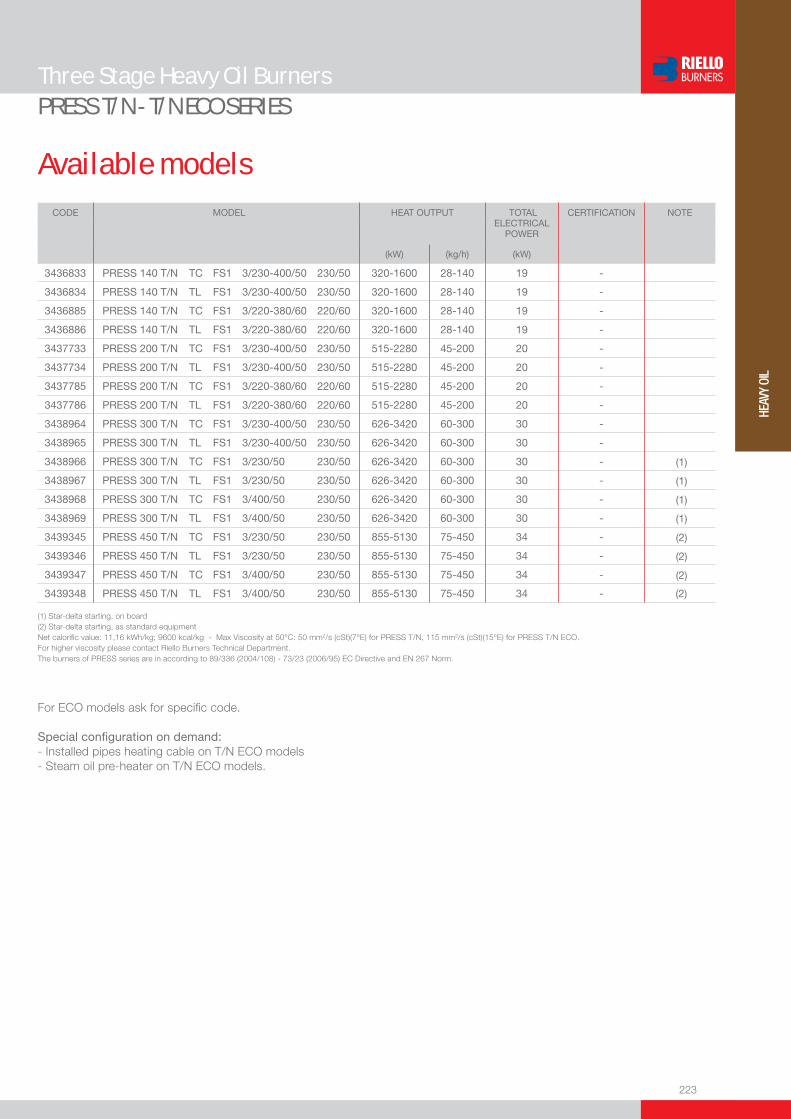
223
HEAV
Y OI
L
Available models
Three Stage Heavy Oil BurnersPRESS T/N - T/N ECO SERIES
(1) Star-delta starting, on board(2) Star-delta starting, as standard equipmentNet calorifi c value: 11,16 kWh/kg; 9600 kcal/kg - Max Viscosity at 50°C: 50 mm2/s (cSt)(7°E) for PRESS T/N, 115 mm2/s (cSt)(15°E) for PRESS T/N ECO.For higher viscosity please contact Riello Burners Technical Department.The burners of PRESS series are in according to 89/336 (2004/108) - 73/23 (2006/95) EC Directive and EN 267 Norm.
CODE MODEL
HEAT OUTPUT
TOTAL ELECTRICAL
POWER
CERTIFICATION NOTE
(kW) (kg/h) (kW)
3436833 PRESS 140 T/N TC FS1 3/230-400/50 230/50 320-1600 28-140 19 -
3436834 PRESS 140 T/N TL FS1 3/230-400/50 230/50 320-1600 28-140 19 -
3436885 PRESS 140 T/N TC FS1 3/220-380/60 220/60 320-1600 28-140 19 -
3436886 PRESS 140 T/N TL FS1 3/220-380/60 220/60 320-1600 28-140 19 -
3437733 PRESS 200 T/N TC FS1 3/230-400/50 230/50 515-2280 45-200 20 -
3437734 PRESS 200 T/N TL FS1 3/230-400/50 230/50 515-2280 45-200 20 -
3437785 PRESS 200 T/N TC FS1 3/220-380/60 220/60 515-2280 45-200 20 -
3437786 PRESS 200 T/N TL FS1 3/220-380/60 220/60 515-2280 45-200 20 -
3438964 PRESS 300 T/N TC FS1 3/230-400/50 230/50 626-3420 60-300 30 -
3438965 PRESS 300 T/N TL FS1 3/230-400/50 230/50 626-3420 60-300 30 -
3438966 PRESS 300 T/N TC FS1 3/230/50 230/50 626-3420 60-300 30 - (1)
3438967 PRESS 300 T/N TL FS1 3/230/50 230/50 626-3420 60-300 30 - (1)
3438968 PRESS 300 T/N TC FS1 3/400/50 230/50 626-3420 60-300 30 - (1)
3438969 PRESS 300 T/N TL FS1 3/400/50 230/50 626-3420 60-300 30 - (1)
3439345 PRESS 450 T/N TC FS1 3/230/50 230/50 855-5130 75-450 34 - (2)
3439346 PRESS 450 T/N TL FS1 3/230/50 230/50 855-5130 75-450 34 - (2)
3439347 PRESS 450 T/N TC FS1 3/400/50 230/50 855-5130 75-450 34 - (2)
3439348 PRESS 450 T/N TL FS1 3/400/50 230/50 855-5130 75-450 34 - (2)
For ECO models ask for specifi c code.
Special confi guration on demand:- Installed pipes heating cable on T/N ECO models- Steam oil pre-heater on T/N ECO models.

224
Three Stage Heavy Oil BurnersPRESS T/N - T/N ECO SERIES
Burner accessories
If burner head penetration into the combustion chamber needs reducing, varying thickness spacers are available, as given in the list.
Spacer kit
BURNER
SPACER THICKNESS S (mm)
KIT CODE
u P 140 T/N - P 200 T/N 102 3000722
u P 300 T/N 110 3000723
u P 450 T/N 130 3000751
Nozzle type F80 PL 60°
The nozzles must be ordered separately. The following table shows the features and codes on the basis of the maximum required output.
NOTE: each burner needs N° 3 nozzles.
BURNER RATED DELIVERY(kg/h) at 25 bar
GPH NOZZLECODE
u P 140 T/N 20,8 3,5 3043162
u P 140 T/N 23,8 4 3043172
u P 140 T/N 26,8 4,5 3043182
u P 140 T/N - P 200 T/N 29,8 5 3043192
u P 140 T/N - P 200 T/N 32,7 5,5 3043202
u P 140 T/N - P 200 T/N 35,7 6 3043212
u P 140 T/N - P 200 T/N 38,7 6,5 3043222
u P 140 T/N - P 200 T/N 41,7 7 3043232
u P 140 T/N - P 200 T/N 44,6 7,5 3043242
u P 200 T/N - P 300 T/N 50,6 8,5 3043262
u P 200 T/N - P 300 T/N 56,5 9,5 3043272
u P 200 T/N - P 300 T/N - P 450 T/N 62,5 10,5 3043302
u P 300 T/N - P 450 T/N 71,4 12 3043322
u P 300 T/N - P 450 T/N 80,4 13,5 3043342
u P 300 T/N - P 450 T/N 92,3 15,5 3043372
u P 450 T/N 104,2 17,5 3043402
u P 450 T/N 116,1 19,5 3043432
u P 450 T/N 128 21,5 3043452
u P 450 T/N 142,8 24 3043472
Available for T/N and T/N ECO versions

225
HEAV
Y OI
L
Burner accessories
Three Stage Heavy Oil BurnersPRESS T/N - T/N ECO SERIES
If noise emission needs reducing even further, sound-proofi ng boxes are available.
Sound proofi ng box
BURNER
BOX TYPE
AVERAGE NOISE REDUCTION [dB(A)] (*)
BOX CODE
u P 140 T/N - P 200 T/N C4/5 10 3010404
u P 300 T/N - P 450 T/N C7 10 3010376
(*) according to EN 15036-1 standard
Self-cleaning fi lter
FILTER TYPE FILTERING DEGREE (µm)
FILTER CODE
u Ø = 1”1/2 (60°E at 50°C) 300 3010022
For cleaning heavy oil from dirty particles and impurities, it is equipped with a thermostatic heater for oil with 60°E viscosity at 50°C.
HEATER / THERMOSTAT TYPE HEATER / THERMOSTAT CODE
u Thermostatic heater with LED 3010060
u Heater 3010061
u Thermostat (two-stage / regulable) 3010062
Gas separator bottle connects the burner oil circuit to the main ring circuit. It allows to recover heat in excess and discharge return circuit gas.
Gas separator bottle
BURNER CODE
u P 140 T/N - P 200 T/N 3000748
u P 300 T/N - P 450 T/N 3010012
Equipped with electrical heaters, it permits the employment of PRESS T/N burners with fuel oil of max. viscosity 25°E at 50°C.
Heavy oil kit
BURNER KIT CODE
u P 140 T/N - P 200 T/N - P 300 T/N - P 450 T/N 3000721
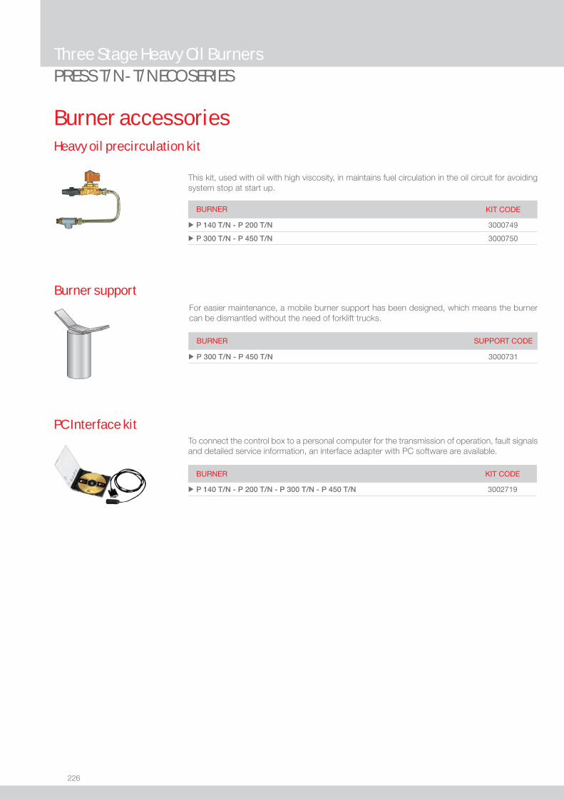
226
BURNER KIT CODE
u P 140 T/N - P 200 T/N - P 300 T/N - P 450 T/N 3002719
To connect the control box to a personal computer for the transmission of operation, fault signals and detailed service information, an interface adapter with PC software are available.
PC Interface kit
Burner accessories
PRESS T/N - T/N ECO SERIESThree Stage Heavy Oil Burners
This kit, used with oil with high viscosity, in maintains fuel circulation in the oil circuit for avoiding system stop at start up.
Heavy oil precirculation kit
BURNER KIT CODE
u P 140 T/N - P 200 T/N 3000749
u P 300 T/N - P 450 T/N 3000750
Burner supportFor easier maintenance, a mobile burner support has been designed, which means the burner can be dismantled without the need of forklift trucks.
BURNER SUPPORT CODE
u P 300 T/N - P 450 T/N 3000731

227
HEAV
Y OI
L
Modulating Heavy Oil Burners
PRESS P/N - P/N ECO SERIESThe PRESS P/N series of burners covers a fi ring range from 800 to 5130 kW. They have been designed in three versions for use in commercial and industrial installation, to burn different oil viscosity from 7 up to 60°E @ 50°C.Operation can be “two stage progressive” or, alternatively, “modulating” with the installation of a PID logic regulator and respective probes, which guarantees a turn down ratio of 3:1.The versatility of this range makes the burner well suited for use on steam boilers where the load factor is subject to wide variations, on thermal oil boilers and on boilers for particular heating plants, as hospitals or similar.Simplifi ed maintenance is achieved by the Riello designed slide bar system, which allows easy access to all of the essential components of the combustion head.
P 140 P/N 400/800 ÷ 1600 kWP 200 P/N 570/1140 ÷ 2280 kWP 300 P/N 683/1710 ÷ 3420 kWP 450 P/N 1140/2615 ÷ 5130 kWP 140 P/N ECO 400/800 ÷ 1600 kWP 200 P/N ECO 570/1140 ÷ 2280 kWP 300 P/N ECO 683/1710 ÷ 3420 kWP 450 P/N ECO 1140/2615 ÷ 5130 kW
FIRING RATES
Useful working fi eldfor choosing theburner
Modulation range
Test conditionsconforming to EN267 Temperature: 20°CPressure: 1013,5 mbarAltitude: 0 m a.s.l.
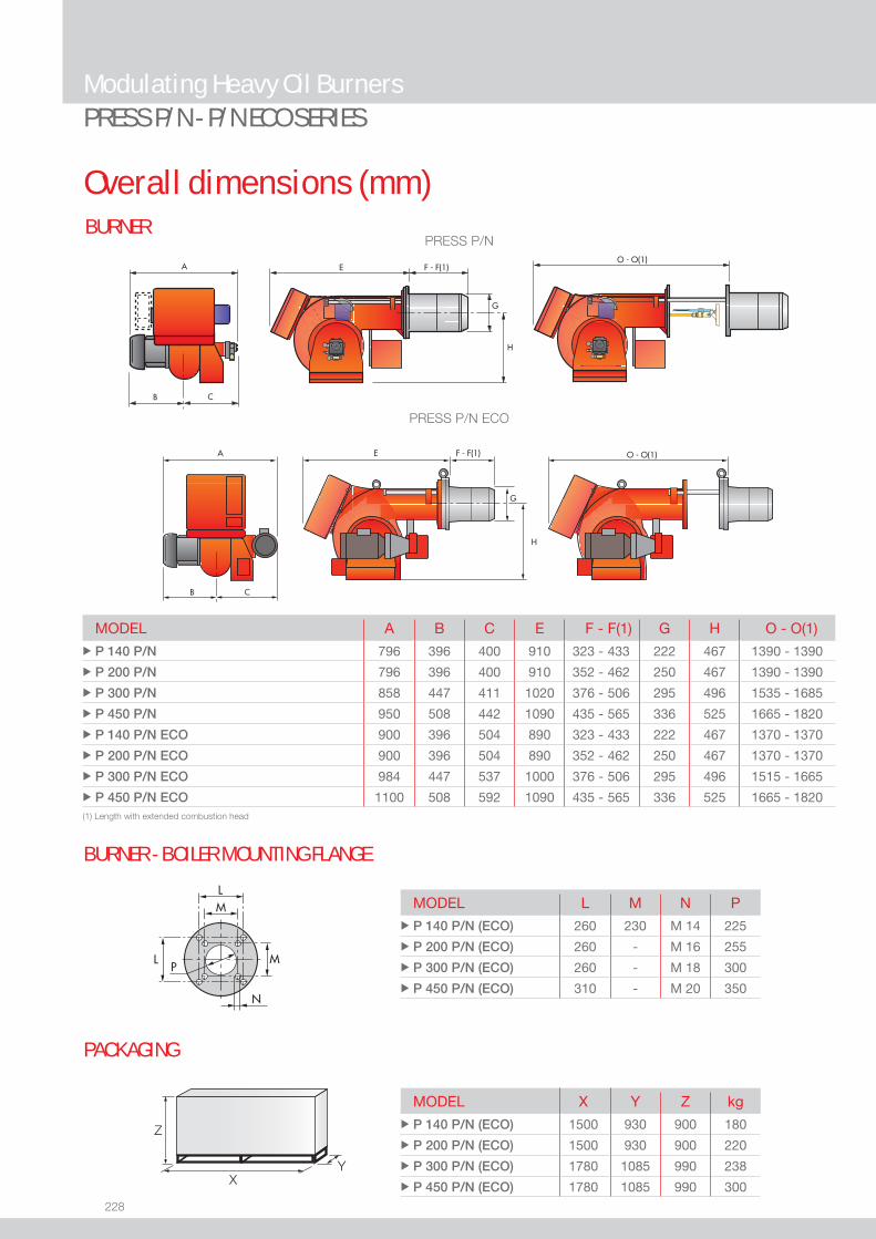
228
BURNER
Overall dimensions (mm)
Modulating Heavy Oil BurnersPRESS P/N - P/N ECO SERIES
BURNER - BOILER MOUNTING FLANGE
PRESS P/N ECO
PRESS P/N
MODEL L M N P u P 140 P/N (ECO) 260 230 M 14 225
u P 200 P/N (ECO) 260 - M 16 255
u P 300 P/N (ECO) 260 - M 18 300
u P 450 P/N (ECO) 310 - M 20 350
MODEL A B C E F - F(1) G H O - O(1)u P 140 P/N 796 396 400 910 323 - 433 222 467 1390 - 1390
u P 200 P/N 796 396 400 910 352 - 462 250 467 1390 - 1390
u P 300 P/N 858 447 411 1020 376 - 506 295 496 1535 - 1685
u P 450 P/N 950 508 442 1090 435 - 565 336 525 1665 - 1820
u P 140 P/N ECO 900 396 504 890 323 - 433 222 467 1370 - 1370
u P 200 P/N ECO 900 396 504 890 352 - 462 250 467 1370 - 1370
u P 300 P/N ECO 984 447 537 1000 376 - 506 295 496 1515 - 1665
u P 450 P/N ECO 1100 508 592 1090 435 - 565 336 525 1665 - 1820
MODEL X Y Z kg u P 140 P/N (ECO) 1500 930 900 180
u P 200 P/N (ECO) 1500 930 900 220
u P 300 P/N (ECO) 1780 1085 990 238
u P 450 P/N (ECO) 1780 1085 990 300
Z
XY
PACKAGING
(1) Length with extended combustion head

229
HEAV
Y OI
L
DESIGNATION OF SERIES
Specifi cation
Modulating Heavy Oil BurnersPRESS P/N - P/N ECO SERIES
PRESS 140 P/N TC FS1 3/230-400/50 230/50
Series : PRESS
Size
Operation : N Two stage N/ECO Two stage with separated oil pump T/N Three stage T/N ECO Three stage with separate oil pump P/N Modulating P/N ECO Modulating with separate oil pump
Emission : ... Class 1 EN267 Head : TC Standard head TL Extended head
Flame control system : FS1 Standard (1 stop every 24 h) FS2 Continuous working (1 stop every 72 h)
Electrical supply to the system : 1/230/50 1/230V/50Hz 3/230/50 3/230V/50Hz 3/400/50 3N/400V/50Hz 3/230-400/50 3/230V/50Hz - 3N/400V/50Hz 3/220-380/60 3/220V/60Hz - 3N/380V/60Hz Auxiliary voltage : 230/50 230V/50Hz 220/60 220V/60Hz
BASIC DESIGNATION
EXTENDED DESIGNATION
230
Specifi cationSTATE OF SUPPLY
Monoblock forced draught oil burner with two-stage progressive or modulating operation, with a specifi c kit, fully automatic, made up of:- Air suction circuit lined with sound-proofi ng material- Fan with forward curved blades high performance pressure levels- Air damper for air setting and automatic oil output regulator controlled by a servomotor with variable cam- Fan motor at 2850 rpm, three-phase 400V with neutral, 50Hz- Combustion head, that can be set on the basis of the combustion output, fi tted with: - stainless steel end cone, resistant to corrosion and high temperatures - ignition electrodes - fl ame stability disk- Gears pump for high pressure fuel supply, fi tted with: - fi lter - pressure regulator - connections for installing a pressure gauge and vacuometer - internal by-pass for single pipe installation- Heavy oil heating cartridges (P/N ECO version)- Pipes heating cable (P/N ECO version)- Oil pump motor at 1400 rpm (P/N ECO version) - Valve unit with a double oil safety valve on the output circuit- Electrical preheater for heavy oil - Safey oil pressure switch- Photocell for fl ame detection- Burner safety control box, fi tted with control function for the correct positioning of the servomotor and possibility of post-ventilaton
by just changing the electric wiring- Flame inspection window- Slide bars for easier installation and maintenance- Protection fi lter against radio interference- IP X0D (IP 40) electric protection level.
Standard equipment:- 2 fl exible pipes for connection to the oil supply network- 2 nipples for the connection to the pump- Wiring looms fi ttings for electrcial connections- 4 screws for fi xing the burner fl ange to the boiler- 2 slide bar extensions (for the extended head models of P 300 P/N and P 450 P/N)- Gasket for fl ange- Starter*- Instruction handbook for installation, use and maintenance- Spare parts catalogue.
* for versions with star-delta starting
Modulating Heavy Oil BurnersPRESS P/N - P/N ECO SERIES

231
HEAV
Y OI
L
Available models
Modulating Heavy Oil BurnersPRESS P/N - P/N ECO SERIES
Net calorifi c value: 11,16 kWh/kg; 9600 kcal/kgThe burners of PRESS series are in according to 89/336 (2004/108) - 73/23 (2006/95) EC Directive and EN 267 Norm.(1) Star-delta starting
CODE MODEL HEAT OUTPUT TOTALELECTRICAL
POWER
CERTIFICATION NOTE
(kW) (kg/h) (kW)
3436876 P 140 P/N TC FS1 3/230-400/50 230/50 400/800÷1600 35/70÷140 19 -
3436877 P 140 P/N TL FS1 3/230-400/50 230/50 400/800÷1600 35/70÷140 19 -
3437776 P 200 P/N TC FS1 3/230-400/50 230/50 570/1140÷2280 50/100÷200 20 -
3437777 P 200 P/N TL FS1 3/230-400/50 230/50 570/1140÷2280 50/100÷200 20 -
3438989 P 300 P/N TC FS1 3/230/50 230/50 683/1710÷3420 60/150÷300 30 - (1)
3438987 P 300 P/N TC FS1 3/230-400/50 230/50 683/1710÷3420 60/150÷300 30 -
3438991 P 300 P/N TC FS1 3/400/50 230/50 683/1710÷3420 60/150÷300 30 - (1)
3438990 P 300 P/N TL FS1 3/230/50 230/50 683/1710÷3420 60/150÷300 30 - (1)
3438988 P 300 P/N TL FS1 3/230-400/50 230/50 683/1710÷3420 60/150÷300 30 -
3438992 P 300 P/N TL FS1 3/400/50 230/50 683/1710÷3420 60/150÷300 30 - (1)
3439385 P 450 P/N TC FS1 3/230/50 230/50 1140/2615÷5130 100/225÷450 34 - (1)
3439387 P 450 P/N TC FS1 3/400/50 230/50 1140/2615÷5130 100/225÷450 34 - (1)
3439386 P 450 P/N TL FS1 3/230/50 230/50 1140/2615÷5130 100/225÷450 34 - (1)
3439388 P 450 P/N TL FS1 3/400/50 230/50 1140/2615÷5130 100/225÷450 34 - (1)
ViscosityThe modulating burner P/N series can burn different heavy oil types from 50 up to 450 cSt @ 50°C (7 up to 60°E @ 50°C).For different viscosity levels Riello recommends 3 different confi gurations:1) PRESS P/N version for viscosity up to 50 cSt (7°E) @ 50°C: basic version with 2800 rmp oil pump installed directly on fan motor shaft (see available codes in the table above)2) PRESS P/N version for viscosity up to 200 cSt (25°E) @ 50°C: as basic version + heavy oil heating cartridges factory installed on nozzle, pump and valves group (please ask for specifi c code)3) PRESS P/N ECO version for viscosity up to 450 cSt (60°E) @ 50°C: - with separate 1400 rpm low speed pump - heavy oil heating cartridges factory installed on nozzle, pump and valves group - pipes heating cable factory installed (please ask for specifi c code)
Special confi guration on demand:- Steam oil pre-heater on P/N ECO models.
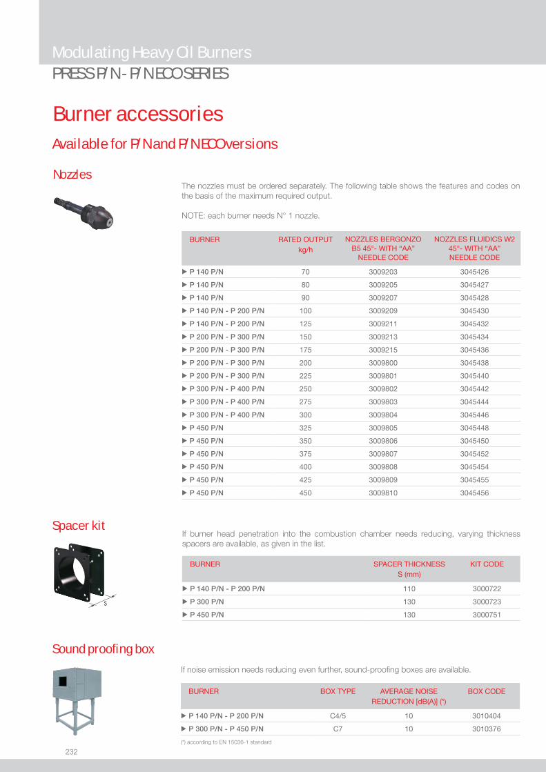
232
Modulating Heavy Oil BurnersPRESS P/N - P/N ECO SERIES
Burner accessories
If burner head penetration into the combustion chamber needs reducing, varying thickness spacers are available, as given in the list.
Spacer kit
BURNER
SPACER THICKNESS S (mm)
KIT CODE
u P 140 P/N - P 200 P/N 110 3000722
u P 300 P/N 130 3000723
u P 450 P/N 130 3000751
If noise emission needs reducing even further, sound-proofi ng boxes are available.
Sound proofi ng box
BURNER
BOX TYPE
AVERAGE NOISE REDUCTION [dB(A)] (*)
BOX CODE
u P 140 P/N - P 200 P/N C4/5 10 3010404
u P 300 P/N - P 450 P/N C7 10 3010376
(*) according to EN 15036-1 standard
NozzlesThe nozzles must be ordered separately. The following table shows the features and codes on the basis of the maximum required output.
NOTE: each burner needs N° 1 nozzle.
Available for P/N and P/N ECO versions
BURNER RATED OUTPUT kg/h
NOZZLES BERGONZO B5 45°- WITH “AA”
NEEDLE CODE
NOZZLES FLUIDICS W2 45°- WITH “AA” NEEDLE CODE
u P 140 P/N 70 3009203 3045426
u P 140 P/N 80 3009205 3045427
u P 140 P/N 90 3009207 3045428
u P 140 P/N - P 200 P/N 100 3009209 3045430
u P 140 P/N - P 200 P/N 125 3009211 3045432
u P 200 P/N - P 300 P/N 150 3009213 3045434
u P 200 P/N - P 300 P/N 175 3009215 3045436
u P 200 P/N - P 300 P/N 200 3009800 3045438
u P 200 P/N - P 300 P/N 225 3009801 3045440
u P 300 P/N - P 400 P/N 250 3009802 3045442
u P 300 P/N - P 400 P/N 275 3009803 3045444
u P 300 P/N - P 400 P/N 300 3009804 3045446
u P 450 P/N 325 3009805 3045448
u P 450 P/N 350 3009806 3045450
u P 450 P/N 375 3009807 3045452
u P 450 P/N 400 3009808 3045454
u P 450 P/N 425 3009809 3045455
u P 450 P/N 450 3009810 3045456
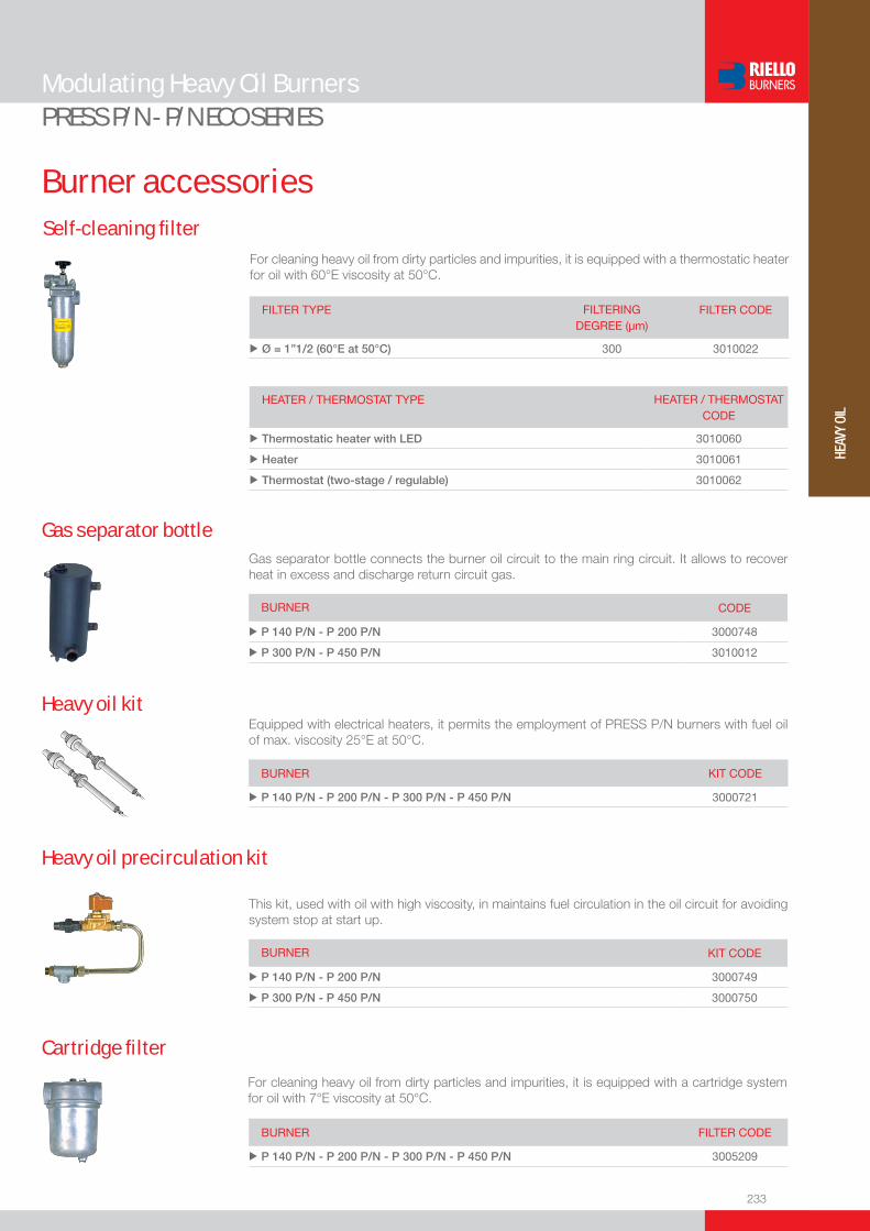
233
HEAV
Y OI
L
Burner accessories
Modulating Heavy Oil BurnersPRESS P/N - P/N ECO SERIES
Self-cleaning fi lter
FILTER TYPE FILTERING DEGREE (µm)
FILTER CODE
u Ø = 1”1/2 (60°E at 50°C) 300 3010022
For cleaning heavy oil from dirty particles and impurities, it is equipped with a thermostatic heater for oil with 60°E viscosity at 50°C.
HEATER / THERMOSTAT TYPE HEATER / THERMOSTAT CODE
u Thermostatic heater with LED 3010060
u Heater 3010061
u Thermostat (two-stage / regulable) 3010062
Gas separator bottle connects the burner oil circuit to the main ring circuit. It allows to recover heat in excess and discharge return circuit gas.
Gas separator bottle
BURNER CODE
u P 140 P/N - P 200 P/N 3000748
u P 300 P/N - P 450 P/N 3010012
Equipped with electrical heaters, it permits the employment of PRESS P/N burners with fuel oil of max. viscosity 25°E at 50°C.
Heavy oil kit
BURNER KIT CODE
u P 140 P/N - P 200 P/N - P 300 P/N - P 450 P/N 3000721
This kit, used with oil with high viscosity, in maintains fuel circulation in the oil circuit for avoiding system stop at start up.
Heavy oil precirculation kit
BURNER KIT CODE
u P 140 P/N - P 200 P/N 3000749
u P 300 P/N - P 450 P/N 3000750
Cartridge fi lter
For cleaning heavy oil from dirty particles and impurities, it is equipped with a cartridge system for oil with 7°E viscosity at 50°C.
BURNER FILTER CODE
u P 140 P/N - P 200 P/N - P 300 P/N - P 450 P/N 3005209
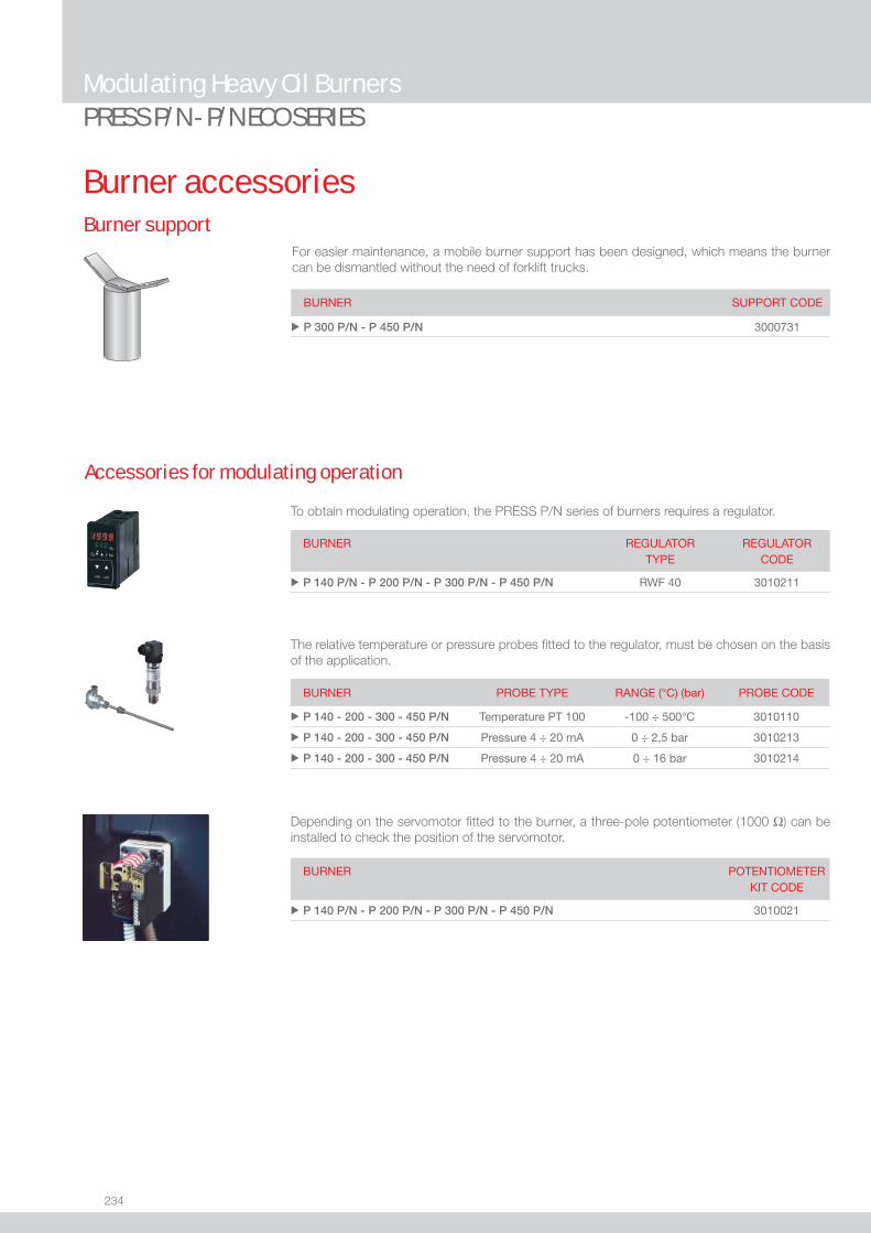
234
Burner accessories
PRESS P/N - P/N ECO SERIESModulating Heavy Oil Burners
Burner supportFor easier maintenance, a mobile burner support has been designed, which means the burner can be dismantled without the need of forklift trucks.
BURNER SUPPORT CODE
u P 300 P/N - P 450 P/N 3000731
Accessories for modulating operation
To obtain modulating operation, the PRESS P/N series of burners requires a regulator.
BURNER
REGULATOR TYPE
REGULATOR CODE
u P 140 P/N - P 200 P/N - P 300 P/N - P 450 P/N RWF 40 3010211
Depending on the servomotor fi tted to the burner, a three-pole potentiometer (1000 Ω) can be installed to check the position of the servomotor.
BURNER
POTENTIOMETER KIT CODE
u P 140 P/N - P 200 P/N - P 300 P/N - P 450 P/N 3010021
The relative temperature or pressure probes fi tted to the regulator, must be chosen on the basis of the application.
BURNER PROBE TYPE RANGE (°C) (bar) PROBE CODE
u P 140 - 200 - 300 - 450 P/N Temperature PT 100 -100 ÷ 500°C 3010110
u P 140 - 200 - 300 - 450 P/N Pressure 4 ÷ 20 mA 0 ÷ 2,5 bar 3010213
u P 140 - 200 - 300 - 450 P/N Pressure 4 ÷ 20 mA 0 ÷ 16 bar 3010214

235
HEAV
Y OI
L
Modulating Heavy Oil Burners with Air/Steam Atomizing
PRESS P/NA - P/NA ECO SERIESHeavy oil burner series P/NA is an evolution of the traditional heavy oil modulating burners P/N series.The new range applies a different technology to replace the usual mechanical atomising (high pressure) by “assisted” air/steam atomising (feed pressure 5-8 bar) and taking the related advantages when burning heavy fuels (even vegetal oil).The upgraded design has been introduced to meet even the worst fuel qualities and to reach anyway the best achievable combustion performance (lower particulate and NOx emissions).The capacity range is suited to cover applications on steam generators designed for production from 1 to 6 tons/hr of steam or an equivalent capacity in case of other kind of boiler.Reliable and smooth ignition is achieved by LPG pilot burner installed into the combustion head.The control system includes all safety and operation interlocks, making possible the confi guration compliance to the latest design norms on world-wide base (i.e. EN 267 – UL 296 – others), by the available options on request.
P 140 P/NA 400/800 ÷ 1600 kWP 200 P/NA 570/1140 ÷ 2280 kWP 300 P/NA 683/1710 ÷ 3420 kWP 450 P/NA 1140/2615 ÷ 5130 kWP 140 P/NA ECO 400/800 ÷ 1600 kWP 200 P/NA ECO 570/1140 ÷ 2280 kWP 300 P/NA ECO 683/1710 ÷ 3420 kWP 450 P/NA ECO 1140/2615 ÷ 5130 kW
FIRING RATES
Useful working fi eldfor choosing theburner
Modulation range
Test conditionsconforming to EN267 Temperature: 20°CPressure: 1013,5 mbarAltitude: 0 m a.s.l.
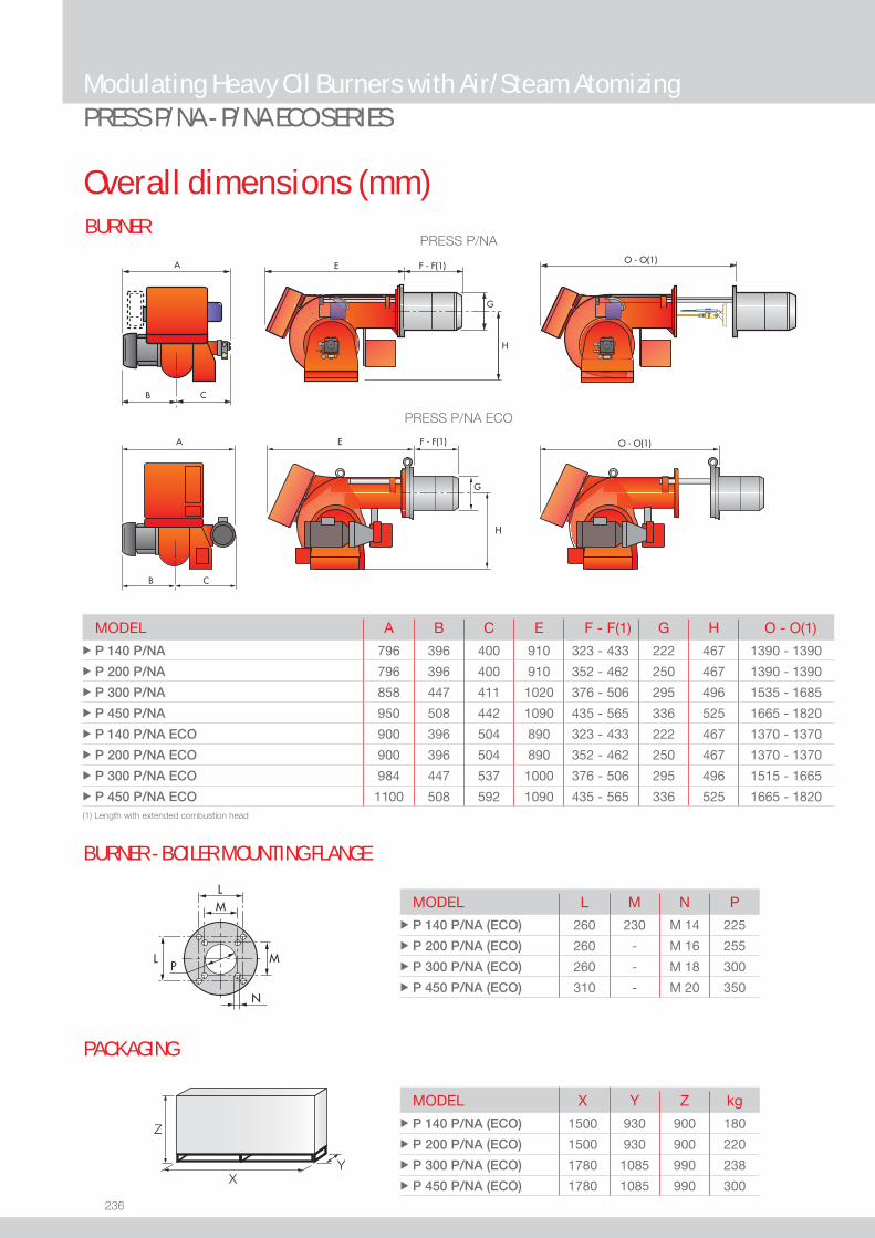
236
BURNER
Overall dimensions (mm)
Modulating Heavy Oil Burners with Air/Steam AtomizingPRESS P/NA - P/NA ECO SERIES
BURNER - BOILER MOUNTING FLANGE
PRESS P/NA ECO
PRESS P/NA
MODEL L M N P u P 140 P/NA (ECO) 260 230 M 14 225
u P 200 P/NA (ECO) 260 - M 16 255
u P 300 P/NA (ECO) 260 - M 18 300
u P 450 P/NA (ECO) 310 - M 20 350
MODEL A B C E F - F(1) G H O - O(1)u P 140 P/NA 796 396 400 910 323 - 433 222 467 1390 - 1390
u P 200 P/NA 796 396 400 910 352 - 462 250 467 1390 - 1390
u P 300 P/NA 858 447 411 1020 376 - 506 295 496 1535 - 1685
u P 450 P/NA 950 508 442 1090 435 - 565 336 525 1665 - 1820
u P 140 P/NA ECO 900 396 504 890 323 - 433 222 467 1370 - 1370
u P 200 P/NA ECO 900 396 504 890 352 - 462 250 467 1370 - 1370
u P 300 P/NA ECO 984 447 537 1000 376 - 506 295 496 1515 - 1665
u P 450 P/NA ECO 1100 508 592 1090 435 - 565 336 525 1665 - 1820
MODEL X Y Z kg u P 140 P/NA (ECO) 1500 930 900 180
u P 200 P/NA (ECO) 1500 930 900 220
u P 300 P/NA (ECO) 1780 1085 990 238
u P 450 P/NA (ECO) 1780 1085 990 300
Z
XY
PACKAGING
(1) Length with extended combustion head

237
HEAV
Y OI
L
DESIGNATION OF SERIES
Specifi cation
Modulating Heavy Oil Burners with Air/Steam AtomizingPRESS P/NA - P/NA ECO SERIES
PRESS 140 P/NA TC FS1 3/230-400/50 230/50
Series : PRESS
Size
Operation : N Two stage N/ECO Two stage with separated oil pump T/N Three stage T/N ECO Three stage with separate oil pump P/N Modulating P/N ECO Modulating with separate oil pump P/NA Modulating with air/steam atomizing
Emission : ... Class 1 EN267 Head : TC Standard head TL Extended head
Flame control system : FS1 Standard (1 stop every 24 h) FS2 Continuous working (1 stop every 72 h)
Electrical supply to the system : 1/230/50 1/230V/50Hz 3/230/50 3/230V/50Hz 3/400/50 3N/400V/50Hz 3/230-400/50 3/230V/50Hz - 3N/400V/50Hz 3/220-380/60 3/220V/60Hz - 3N/380V/60Hz Auxiliary voltage : 230/50 230V/50Hz 220/60 220V/60Hz
BASIC DESIGNATION
EXTENDED DESIGNATION

238
Specifi cationSTATE OF SUPPLY
Monoblock forced draught oil burner with two-stage progressive or modulating operation, with a specifi c kit, fully automatic, made up of:- Air suction circuit lined with sound-proofi ng material- Fan with forward curved blades high performance pressure levels- Air damper for air setting and automatic oil output regulator controlled by a servomotor with variable cam- Fan motor at 2850 rpm, three-phase 400V with neutral, 50Hz- Combustion head, that can be set on the basis of the combustion output, fi tted with: - stainless steel end cone, resistant to corrosion and high temperatures - ignition electrodes - fl ame stability disk- Gears pump for high pressure fuel supply, fi tted with: - fi lter - pressure regulator - connections for installing a pressure gauge and vacuometer - internal by-pass for single pipe installation- Heavy oil kit cartridges- Pipes heating cable (P/NA ECO version)- Oil pump motor at 1400 rpm (P/NA ECO version) - Valve unit with a double oil safety valve on the output circuit- LPG pilot burner ignition- Electrical preheater for heavy oil - Safety oil pressure switch- Photocell for fl ame detection- Burner safety control box, fi tted with control function for the correct positioning of the servomotor and possibility of post-ventilaton
by just changing the electric wiring- Flame inspection window- Slide bars for easier installation and maintenance- Protection fi lter against radio interference- IP X0D (IP 40) electric protection level.
Standard equipment:- 2 fl exible pipes for connection to the oil supply network- 2 nipples for the connection to the pump- Wiring looms fi ttings for electrcial connections- 4 screws for fi xing the burner fl ange to the boiler- 2 slide bar extensions (for the extended head models of P 300 P/NA and P 450 P/NA)- Gasket for fl ange- Starter*- Instruction handbook for installation, use and maintenance- Spare parts catalogue.
* for versions with star-delta starting
Modulating Heavy Oil Burners with Air/Steam AtomizingPRESS P/NA - P/NA ECO SERIES
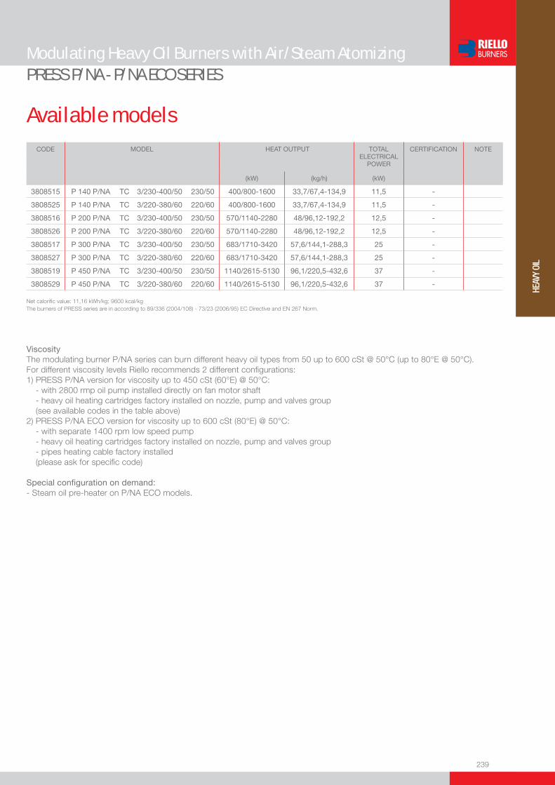
239
HEAV
Y OI
L
Available models
Modulating Heavy Oil Burners with Air/Steam AtomizingPRESS P/NA - P/NA ECO SERIES
CODE MODEL
HEAT OUTPUT TOTALELECTRICAL
POWER
CERTIFICATION NOTE
(kW) (kg/h) (kW)
3808515 P 140 P/NA TC 3/230-400/50 230/50 400/800-1600 33,7/67,4-134,9 11,5 -
3808525 P 140 P/NA TC 3/220-380/60 220/60 400/800-1600 33,7/67,4-134,9 11,5 -
3808516 P 200 P/NA TC 3/230-400/50 230/50 570/1140-2280 48/96,12-192,2 12,5 -
3808526 P 200 P/NA TC 3/220-380/60 220/60 570/1140-2280 48/96,12-192,2 12,5 -
3808517 P 300 P/NA TC 3/230-400/50 230/50 683/1710-3420 57,6/144,1-288,3 25 -
3808527 P 300 P/NA TC 3/220-380/60 220/60 683/1710-3420 57,6/144,1-288,3 25 -
3808519 P 450 P/NA TC 3/230-400/50 230/50 1140/2615-5130 96,1/220,5-432,6 37 -
3808529 P 450 P/NA TC 3/220-380/60 220/60 1140/2615-5130 96,1/220,5-432,6 37 -
Net calorifi c value: 11,16 kWh/kg; 9600 kcal/kgThe burners of PRESS series are in according to 89/336 (2004/108) - 73/23 (2006/95) EC Directive and EN 267 Norm.
ViscosityThe modulating burner P/NA series can burn different heavy oil types from 50 up to 600 cSt @ 50°C (up to 80°E @ 50°C).For different viscosity levels Riello recommends 2 different confi gurations:1) PRESS P/NA version for viscosity up to 450 cSt (60°E) @ 50°C: - with 2800 rmp oil pump installed directly on fan motor shaft - heavy oil heating cartridges factory installed on nozzle, pump and valves group (see available codes in the table above)2) PRESS P/NA ECO version for viscosity up to 600 cSt (80°E) @ 50°C: - with separate 1400 rpm low speed pump - heavy oil heating cartridges factory installed on nozzle, pump and valves group - pipes heating cable factory installed (please ask for specifi c code)
Special confi guration on demand:- Steam oil pre-heater on P/NA ECO models.

240
Modulating Heavy Oil Burners with Air/Steam AtomizingPRESS P/NA - P/NA ECO SERIES
Burner accessories
Y-jet air/steam atomising nozzles - type 15 AG 45°
Effective nozzle delivery depends from many factors. Particular small variations of air/steam at-omising pressure or viscosity at the nozzle, cause big oil delivery variations. Therefore, to choose the right nozzle it is so necessary to consider all parameters listed in the table below.
Available for P/NA and P/NA ECO versions
NO
ZZLE
15
AG
45°
VIS
CO
SIT
Y @
N
OZZ
LE
OIL
DEN
SIT
YOIL DELIVERY
(kg/h)
AIR CONSUMPTIONAT 4 bar
(kg/h)
SUGG
ESTE
D AI
R/ST
EAM
PRE
SSUR
E
CODE
cSt kg/m3 6 bar 5 bar 4 bar 3 bar 2 bar HIGH FIRE LOW FIRE bar
u 60
5 850 112 94 75 60 32 2,5 8,4 2
304500010 875 95 80 60 41 20 5,9 13,9 3
20 900 75 60 42 25 n.a.* 10 20 4
30 925 68 55 36 20 n.a.* 11,3 21,7 4
u 70
5 850 130 110 90 70 36 2,9 9,9 2
304500110 875 111 95 78 48 25 6,8 16 3
20 900 88 70 50 30 n.a.* 11,9 23 4
30 925 80 64 44 24 n.a.* 13,2 25,4 4
u 80
5 850 150 130 105 80 40 3,3 11,3 2
304500210 875 127 108 85 55 30 7,8 18,3 3
20 900 100 80 55 35 n.a.* 13,6 26,2 4
30 925 91 73 51 30 n.a.* 15 28,9 4
u 100
5 850 187 158 130 100 50 4,2 14 2
304500310 875 158 135 100 70 35 9,8 22,8 3
20 900 126 105 70 40 n.a.* 17 32,7 4
30 925 114 91 65 35 n.a.* 18,8 34,2 4
u 130
5 850 243 200 170 130 60 5,4 18,3 2
304500410 875 206 173 130 95 40 12,7 29,7 3
20 900 163 131 90 55 n.a.* 22 42,6 4
30 925 148 118 82 45 n.a.* 24,4 47 4
u 160
5 850 299 260 210 160 80 6,7 22,5 2
304500510 875 253 215 170 115 50 15,7 36,5 3
20 900 201 161 115 65 n.a.* 27,1 52,4 4
30 925 182 145 102 58 n.a.* 30 57,9 4
u 200
5 850 374 330 260 215 105 8,3 28,1 2
304500610 875 317 270 215 145 60 19,6 45,7 3
20 900 252 203 140 85 n.a.* 33,9 65,5 4
30 925 228 182 120 70 n.a.* 37,5 72,4 4
u 225
5 850 421 365 285 220 110 9,4 31,7 2
304500710 875 357 311 240 160 70 22,1 51,4 3
20 900 280 225 156 100 n.a.* 38,2 73,7 4
30 925 256 205 141 60 n.a.* 42,2 81,4 4
u 250
5 850 468 410 340 250 120 10,4 35,2 2
304500810 875 396 340 270 180 80 24,5 57,1 3
20 900 315 252 175 110 n.a.* 42,4 81,9 4
30 925 285 228 150 85 n.a.* 46,8 90,5 4
u 275
5 850 514 430 360 270 130 11,5 38,6 2
304500910 875 436 365 300 190 85 27 62,8 3
20 900 346 277 193 120 n.a.* 46,7 90 4
30 925 313 250 175 95 n.a.* 51,6 99,5 4
u 300
5 850 560 470 400 300 150 11,5 38,6 2
304501010 875 476 410 340 200 90 29,3 68,5 3
20 900 378 302 210 130 n.a.* 51 98,2 4
30 925 342 273 190 100 n.a.* 56,3 108,6 4* This matching is not available.

241
HEAV
Y OI
L
Burner accessories
Modulating Heavy Oil Burners with Air/Steam AtomizingPRESS P/NA - P/NA ECO SERIES
If burner head penetration into the combustion chamber needs reducing, varying thickness spacers are available, as given in the list.
Spacer kit
BURNER
SPACER THICKNESS S (mm)
KIT CODE
u P 140 P/NA - P 200 P/NA 110 3000722
u P 300 P/NA 130 3000723
u P 450 P/NA 130 3000751
If noise emission needs reducing even further, sound-proofi ng boxes are available.
Sound proofi ng box
BURNER
BOX TYPE
AVERAGE NOISE REDUCTION [dB(A)] (*)
BOX CODE
u P 140 P/NA - P 200 P/NA C4/5 10 3010404
u P 300 P/NA - P 450 P/NA C7 10 3010376
(*) according to EN 15036-1 standard
Self-cleaning fi lter
FILTER TYPE FILTERING DEGREE (µm)
FILTER CODE
u Ø = 1”1/2 (60°E at 50°C) 300 3010022
For cleaning heavy oil from dirty particles and impurities, it is equipped with a thermostatic heater for oil with 60°E viscosity at 50°C.
HEATER / THERMOSTAT TYPE HEATER / THERMOSTAT CODE
u Thermostatic heater with LED 3010060
u Heater 3010061
u Thermostat (two-stage / regulable) 3010062
Cartridge fi lter
For cleaning heavy oil from dirty particles and impurities, it is equipped with a cartridge system for oil with 7°E viscosity at 50°C.
BURNER FILTER CODE
u P 140 P/NA - P 200 P/NA - P 300 P/NA - P 450 P/NA 3005209

242
Modulating Heavy Oil Burners with Air/Steam AtomizingPRESS P/NA - P/NA ECO SERIES
Burner accessories
Burner supportFor easier maintenance, a mobile burner support has been designed, which means the burner can be dismantled without the need of forklift trucks.
BURNER SUPPORT CODE
u P 300 P/NA - P 450 P/NA 3000731
Accessories for modulating operation
To obtain modulating operation, the PRESS P/NA series of burners requires a regulator.
BURNER
REGULATOR TYPE
REGULATOR CODE
u P 140 P/NA - P 200 P/NA - P 300 P/NA - P 450 P/NA RWF 40 3010211
Depending on the servomotor fi tted to the burner, a three-pole potentiometer (1000 Ω) can be installed to check the position of the servomotor.
BURNER
POTENTIOMETER KIT CODE
u P 140 P/NA - P 200 P/NA - P 300 P/NA - P 450 P/NA 3010021
The relative temperature or pressure probes fi tted to the regulator, must be chosen on the basis of the application.
BURNER PROBE TYPE RANGE (°C) (bar) PROBE CODE
u P 140 - 200 - 300 - 450 P/NA Temperature PT 100 -100 ÷ 500°C 3010110
u P 140 - 200 - 300 - 450 P/NA Pressure 4 ÷ 20 mA 0 ÷ 2,5 bar 3010213
u P 140 - 200 - 300 - 450 P/NA Pressure 4 ÷ 20 mA 0 ÷ 16 bar 3010214
Gas separator bottle connects the burner oil circuit to the main ring circuit. It allows to recover heat in excess and discharge return circuit gas.
Gas separator bottle
BURNER CODE
u P 140 P/NA - P 200 P/NA 3000748
u P 300 P/NA - P 450 P/NA 3010012
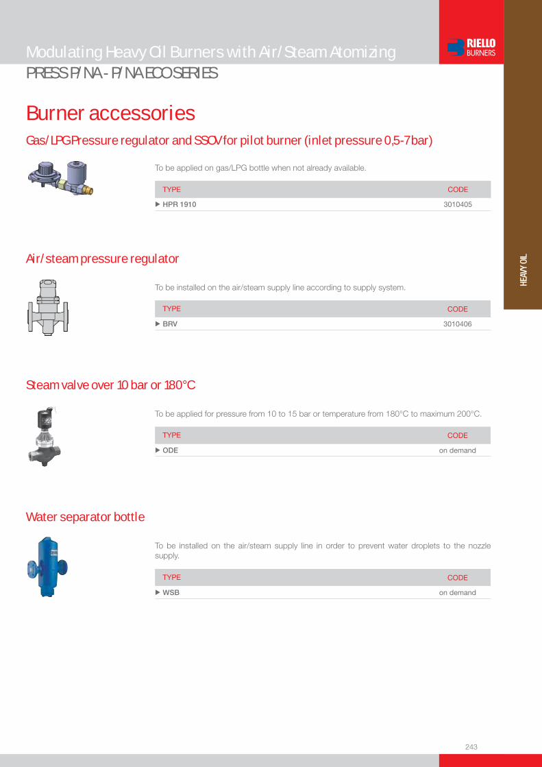
243
HEAV
Y OI
L
Burner accessories
Modulating Heavy Oil Burners with Air/Steam AtomizingPRESS P/NA - P/NA ECO SERIES
To be applied on gas/LPG bottle when not already available.
Gas/LPG Pressure regulator and SSOV for pilot burner (inlet pressure 0,5-7 bar)
TYPE CODE
u HPR 1910 3010405
To be installed on the air/steam supply line according to supply system.
Air/steam pressure regulator
TYPE CODE
u BRV 3010406
To be applied for pressure from 10 to 15 bar or temperature from 180°C to maximum 200°C.
Steam valve over 10 bar or 180°C
TYPE CODE
u ODE on demand
To be installed on the air/steam supply line in order to prevent water droplets to the nozzle supply.
Water separator bottle
TYPE CODE
u WSB on demand


245
HEAV
Y OI
L
Two Stage Heavy Oil Burners
RN SERIESThe RN series of burners covers a fi ring range from 228 to 1481 kW, and has been designed for use in hot or superheater water boilers, hot air or steam generators, diathermic oil boilers.Operation is “two stage”; the burners are fi tted with an electronic device LED PANEL, which supplies Information about burner working.All necessary components of hydraulic heavy-oil circuit are assembled in a separate structure, called BAG, for easy and fast installation.Optimisation of sound emissions is guaranteed by the use of fans with forward curved blades and sound deadening material incorporated in the air suction circuit.The elevated performance of the fans and combustion head, guarantee fl exibility of use and excellent working at all fi ring rates.The exclusive design ensures reduced dimensions, simple use and maintenance. A wide range of accessories guarantees elevated working fl exibility.
RN 28 114/228 ÷ 342 kWRN 38 136/273 ÷ 456 kWRN 50 171/342 ÷ 570 kWRN 70 228/456 ÷ 798 kWRN 100 342/684 ÷ 1140 kWRN 130 456/912 ÷ 1481 kW
FIRING RATES
Useful working fi eldfor choosing theburner
1st stage operation range
Test conditionsconforming to EN267 Temperature: 20°CPressure: 1013,5 mbarAltitude: 0 m a.s.l.

246
BURNER
Overall dimensions (mm)
Two Stage Heavy Oil BurnersRN SERIES
BURNER - BOILER MOUNTING FLANGE
MODEL A B C D E F H I L Ou RN 28 476 - - 474 468 265 166 352 52 730u RN 38 476 - - 474 468 265 166 352 52 730u RN 50 476 - - 474 468 265 166 352 52 730u RN 70 511 296 215 555 680 310 189 430 - 951u RN 100 527 312 215 555 680 330 200 430 - 951u RN 130 553 338 215 555 680 330 220 430 - 951u BAG 40 - 50 - 60 680 763 780 276 324 650 - - - -
Z
XY
PACKAGING
MODEL D1 D2 Ø u RN 28 - 38 - 50 170 224 M8 u RN 70 200 275-325 M12 u RN 100 210 275-325 M12u RN 130 230 275-325 M12
RN 28 - 38 - 50 RN 70 - 100 - 130
BAG 40 - 50 -130
MODEL X Y Z kg u RN 28 1015 630 500 52u RN 38 - 50 1015 630 500 57 u RN 70 1054 614 666 59u RN 100 1054 614 666 62 u RN 130 1054 614 666 65 u BAG 40 824 859 394 62u BAG 50 824 859 394 67 u BAG 130 824 859 394 69
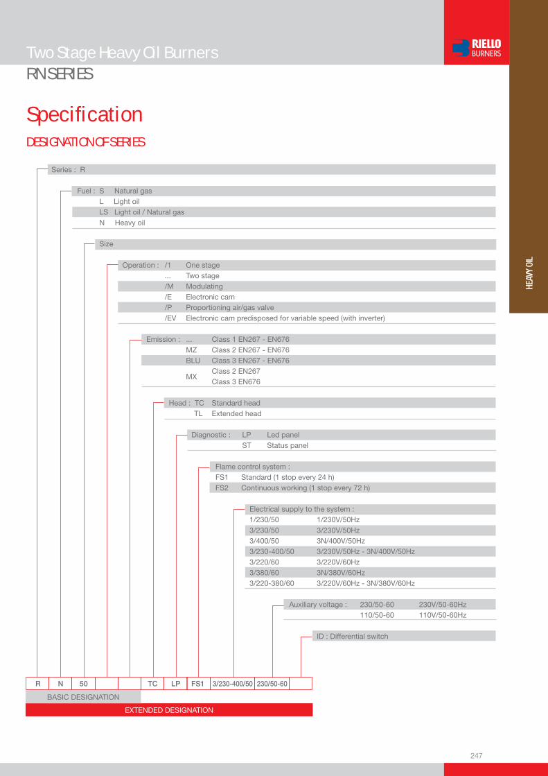
247
HEAV
Y OI
L
DESIGNATION OF SERIES
Specifi cation
Two Stage Heavy Oil BurnersRN SERIES
EXTENDED DESIGNATION
R N 50 TC LP FS1 3/230-400/50 230/50-60
BASIC DESIGNATION
Series : R
Fuel : S Natural gas L Light oil LS Light oil / Natural gas N Heavy oil
Size
Operation : /1 One stage ... Two stage /M Modulating /E Electronic cam /P Proportioning air/gas valve /EV Electronic cam predisposed for variable speed (with inverter) Emission : ... Class 1 EN267 - EN676 MZ Class 2 EN267 - EN676 BLU Class 3 EN267 - EN676
MX Class 2 EN267
Class 3 EN676
Head : TC Standard head TL Extended head
Diagnostic : LP Led panel ST Status panel
Flame control system : FS1 Standard (1 stop every 24 h) FS2 Continuous working (1 stop every 72 h)
Electrical supply to the system : 1/230/50 1/230V/50Hz 3/230/50 3/230V/50Hz 3/400/50 3N/400V/50Hz 3/230-400/50 3/230V/50Hz - 3N/400V/50Hz 3/220/60 3/220V/60Hz 3/380/60 3N/380V/60Hz 3/220-380/60 3/220V/60Hz - 3N/380V/60Hz
Auxiliary voltage : 230/50-60 230V/50-60Hz 110/50-60 110V/50-60Hz
ID : Differential switch
248
STATE OF SUPPLY
Two Stage Heavy Oil BurnersRN SERIES
Monobloc forced draught heavy oil burner, two stage operation, made up of: - Air suction circuit lined with sound-proofi ng material- Fan with reverse curve blades- Air damper for air setting controlled by a servomotor- Combustion head, that can be set on the basis of required output - Photocell for fl ame detection- Burner safety control box- Electronic device to check all burners operational modes (Led Panel)- Burner on/off switch- Manual 1st and 2nd stage switch- Plugs for electrical connections (RN 28-38-50)- Flame inspection window- Slide bars for easier installation and maintenance- Protection fi lter against radio interference- IP 44 electric protection level.
BAG- Pressure gauge for fuel supply loop- Atomising pressure gauge- Self-controlling resistances for warming suction fi lter, delivery fi lter, valve and pump- High and Low point thermostat- High point thermostat with reset push-button- Loop pressure control switch with burner operation enable (set at 1 bar)- Pump- Pump motor- Pre-purge valve- Degasing unit- Valve for gas release from degasing unit- Comb-fi lter at delivery- Terminal strip- Wiring looms- Bag/Burner electrical connection socket- Electronic thermostat- Heating element Pt100- Back pressure valve- Comb-fi lter at pump suction- Pre-heater.
Standard equipment:- 2 fl exible hoses for burner/bag connection (L = 1.3 m)- 1 insulation for fl exible hoses - 2 nipples for fl exible hoses- 1 insulating screen- 4 screws for fi xing the burner fl ange to the boiler- Wiring looms for electrical connections (for RN 28-38-50 model)- 1 tube for installing BAG on left (for RN 28-38-50 model)- 2 nozzles- Instruction handbook for installation, use and maintenance- Spare parts catalogue.
Specifi cation

249
HEAV
Y OI
L
Two Stage Heavy Oil BurnersRN SERIES
Available models
(1) For RN 28 burner.(2) For RN 38-50 burners.(3) For RN 70-100-130 burners.Net calorifi c value: 11,16 kWh/kg; 9.600 kcal/kg - Viscosity at 50°C: 150 mm2/s (cSt)(20°E).The burners of RN series are in according to 89/336 (2004/108) - 73/23 (2006/95) EC Directive and EN 267 Norm.
CODE MODEL HEAT OUTPUT TOTAL ELECTRICAL
POWER
CERTIFICATION NOTE
(kW) (kg/h) (kW)
3433201 RN 28 TC LP FS1 3/230-400/50 230/50-60 114/228-342 10/20-30 4 -
3433301 RN 38 TC LP FS1 3/230-400/50 230/50-60 136/273-456 12/24-40 5 -
3433401 RN 50 TC LP FS1 3/230-400/50 230/50-60 171/342-570 15/30-50 6 -
3434101 RN 70 TC LP FS1 3/230-400/50 230/50-60 228/456-798 20/40-70 10 -
3434201 RN 100 TC LP FS1 3/230-400/50 230/50-60 342/684-1140 30/60-100 10 -
3434301 RN 130 TC LP FS1 3/230-400/50 230/50-60 456/912-1481 40/80-130 11 -
3891510 BAG 40 3 - (1)
3891511 BAG 50 4 - (2)
3891512 BAG 130 8 - (3)
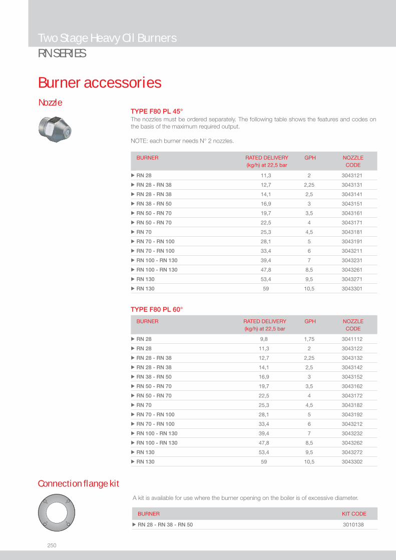
250
Two Stage Heavy Oil BurnersRN SERIES
Burner accessoriesNozzle
The nozzles must be ordered separately. The following table shows the features and codes on the basis of the maximum required output.
NOTE: each burner needs N° 2 nozzles.
BURNER RATED DELIVERY(kg/h) at 22,5 bar
GPH NOZZLECODE
u RN 28 11,3 2 3043121
u RN 28 - RN 38 12,7 2,25 3043131
u RN 28 - RN 38 14,1 2,5 3043141
u RN 38 - RN 50 16,9 3 3043151
u RN 50 - RN 70 19,7 3,5 3043161
u RN 50 - RN 70 22,5 4 3043171
u RN 70 25,3 4,5 3043181
u RN 70 - RN 100 28,1 5 3043191
u RN 70 - RN 100 33,4 6 3043211
u RN 100 - RN 130 39,4 7 3043231
u RN 100 - RN 130 47,8 8,5 3043261
u RN 130 53,4 9,5 3043271
u RN 130 59 10,5 3043301
BURNER RATED DELIVERY (kg/h) at 22,5 bar
GPH NOZZLE CODE
u RN 28 9,8 1,75 3041112
u RN 28 11,3 2 3043122
u RN 28 - RN 38 12,7 2,25 3043132
u RN 28 - RN 38 14,1 2,5 3043142
u RN 38 - RN 50 16,9 3 3043152
u RN 50 - RN 70 19,7 3,5 3043162
u RN 50 - RN 70 22,5 4 3043172
u RN 70 25,3 4,5 3043182
u RN 70 - RN 100 28,1 5 3043192
u RN 70 - RN 100 33,4 6 3043212
u RN 100 - RN 130 39,4 7 3043232
u RN 100 - RN 130 47,8 8,5 3043262
u RN 130 53,4 9,5 3043272
u RN 130 59 10,5 3043302
Connection fl ange kit
A kit is available for use where the burner opening on the boiler is of excessive diameter.
BURNER KIT CODE
u RN 28 - RN 38 - RN 50 3010138
TYPE F80 PL 60°
TYPE F80 PL 45°

Low NOx One Stage Gas Burners
251
LOW
NOx
GAS
GULLIVER BS SERIESThe Riello Gulliver BS series of one stage gas burners, is a complete range of Low NOx emission products, developed to respond to any request for home heating, conforming to the most severe standards regarding the reduction of polluting emissions.This series of burners is available in four different models with an output ranging from 16 to 250 kW, divided in four different structures. All the models use the same components designed by Riello for the Gulliver series. The high quality level guarantees safe working. The burners are fi tted with a microprocessor-based burner safety control box which supplies indication of operation and diagnosis of fault cause. In developing these burners, special attention was paid to reducing noise, the ease of installation and adjustment, to obtaining the smallest size possible to fi t into any sort of boiler available on the market.All the models are approved by the EN 676 European Standard and conform to European Directives, Gas Appliance, EMC, Low Voltage, Boiler Effi ciency.All the Gulliver BS burners are tested before leaving the factory.
BS1 16 ÷ 52 kWBS2 35 ÷ 91 kW BS3 65 ÷ 200 kW BS4 110 ÷ 250 kW
FIRING RATES
Useful working fi eldfor choosing theburner
Test conditions conforming to EN676Temperature: 20°CPressure: 1013,5 mbarAltitude: 0 m a.s.l.
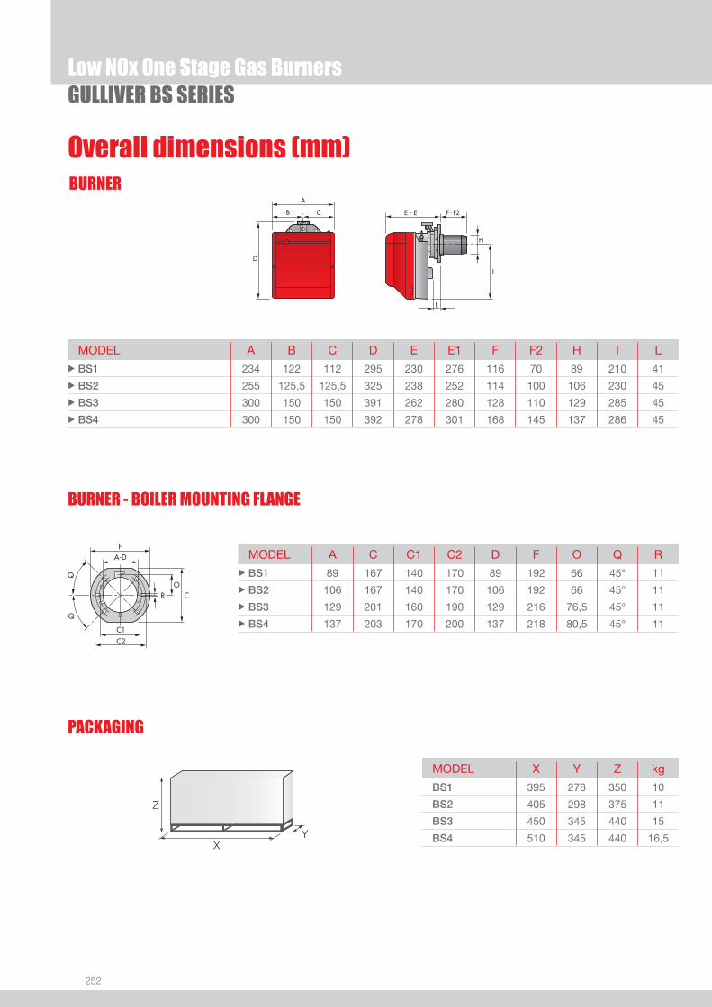
252
GULLIVER BS SERIES
BURNER
BURNER - BOILER MOUNTING FLANGE
Overall dimensions (mm)
Low NOx One Stage Gas Burners
MODEL A C C1 C2 D F O Q R u BS1 89 167 140 170 89 192 66 45° 11
u BS2 106 167 140 170 106 192 66 45° 11
u BS3 129 201 160 190 129 216 76,5 45° 11
u BS4 137 203 170 200 137 218 80,5 45° 11
MODEL A B C D E E1 F F2 H I L u BS1 234 122 112 295 230 276 116 70 89 210 41
u BS2 255 125,5 125,5 325 238 252 114 100 106 230 45
u BS3 300 150 150 391 262 280 128 110 129 285 45
u BS4 300 150 150 392 278 301 168 145 137 286 45
PACKAGING
Z
XY
MODEL X Y Z kg
BS1 395 278 350 10
BS2 405 298 375 11
BS3 450 345 440 15
BS4 510 345 440 16,5

253
GULLIVER BS SERIES
DESIGNATION OF SERIES
Specifi cation
Low NOx One Stage Gas Burners
LOW
NOx
GAS
B S 3 1/230/50
STATE OF SUPPLY
Series: R Standard emission burner B Low NOx burners
Fuel: S Natural gas SP LPG G Light oil
Size
Optional variations: R Light oil pre-heater K Cone shaped head S Reduced output ignition D Two stage output operation
Electrical supply to the system: 1/230/50 1/230V/50Hz
Monoblock, gas burners, completely automatic, one stage operation, made up of:- Fan with forward curve blades- Cover lined with sound-proofi ng material- Air damper, completely closed in stand by, with external adjustment, with no need to remove the cover- Single phase electric motor 230 V, 50 Hz- Combustion head fi tted with: - stainless steel head cone, resistant to high temperatures - ignition electrodes - ionisation probe - gas distributor - fl ame stability disk- Flame inspection window- Adjustable air pressure switch, with graduated selector, to guarantee burner lock out in the case of insuffi cient combustible air- Microprocessor-based burner safety control box, with diagnostic and remote reset functions- Protection fi lter against radio interference (included into burner safety control box)- IP X0D (IP 40) electric protection level.
Standard equipment:- Sliding fl ange- Flange insulation screen- Screws and nuts for fi xing the fl ange to the boiler- 7-pin plug- Remote control release kit- Instruction handbook for installation, use and maintenance- Spare parts catalogue.

254
GULLIVER BS SERIES
Burners
Available models
Low NOx One Stage Gas Burners
CODE MODEL HEAT OUTPUT TOTALELECTRICAL
POWER(kW)
CERTIFICATION NOTE
(kW)NATURAL GAS
(Nm3/h)
3761158 BS1 1/230/50 16 - 52 1,6 - 5,2 0,150 CE - 0085 AQ0409 (1)
3761258 BS2 1/230/50 35 - 91 3,5 - 9,1 0,180 CE - 0085 AQ0409 (1)
3761358 BS3 1/230/50 65 - 200 6,5 - 20 0,350 CE - 0085 AQ0409 (1)
3761458 BS4 1/230/50 110 - 250 11 - 25 0,530 CE - 0085 AQ0409 (1)
Net calorifi c value G20: 10 kWh/Nm3 - Density: 0,71 kg/Nm3.The burners of BS series are in according to EN 676.(1) With plug and socket.
GAS TRAIN GAS TRAIN NATURAL GAS LPG NOTE
CODE * MODEL BURNER ADAPTER BURNER ADAPTER
(type) (code) (type) (code)
MU
LTIB
LOC 3970570 MBC 65 DLE BS1 BS1 (1)
3970546 MBDLE 405 BS1 BS1 (1)
3970547 MBDLE 405 BS2 BS2 (1)
3970544 MBDLE 407 BS2 BS2 (1)
3970548 MBDLE 407 BS3 - BS4 BS3 - BS4 (1) (2)
3970549 MBDLE 410 BS3 - BS4 BS3 - BS4 (1)
3970550 MBDLE 412 BS3 - BS4 BS3 - BS4 (1)
* Gas trains are 230V/50Hz - 220V/60Hz electrical supply.(1) With installed plug.(2) BS3 and BS4 ≤ 150 kW with natural gas.
To select the gas train please refer to the technical data leafl et and/or instruction manual.
Gas Trains

255
GULLIVER BS SERIES
Burner accessories
Low NOx One Stage Gas Burners
LOW
NOx
GAS
Extended head kit
Burners standard head can be transformed into “extended head” versions by using the special kit. Here the KITS available for the various burners are listed, showing the original and the extended lengths.
BURNER STANDARD HEAD LENGTH (mm)
EXTENDED HEAD LENGTH (mm)
KIT CODE
u BS2 (long) 100 ÷ 114 170 ÷ 180 3001007
u BS2 (extra long) 100 ÷ 114 270 ÷ 280 3001008
u BS3 110 ÷ 128 267 ÷ 282 3001009
u BS4 145 ÷ 168 302 ÷ 317 3001016
LPG kitFor burning LPG gas, a special kit is available to be fi tted to the combustion head on the burner, as shown in the following table.
BURNER KIT CODE FOR STANDARD HEAD
KIT CODE FOR EXTENDED HEAD
u BS1 3001003 -
u BS2 3001004 3001004
u BS3 3001005 3001005
u BS4 3001011 3001011
Alternative combustion head kit
This kit can be used to prevent combustion instability which could arise with particular heat generators.
BURNER KIT CODE
u BS1 3001059
u BS2 3001064
u BS3 3001060
u BS4 3001070
Town Gas kitFor burning Town Gas, a special kit is available to be fi tted to the combustion head on the burner, as shown in the following table.
BURNER KIT CODE FOR STANDARD HEAD (*)
KIT CODE FOR EXTENDED HEAD (*)
u BS1 3002727 -
u BS2 3002728 3002728
u BS3 3002729 3002729
(*) Without CE certifi cation
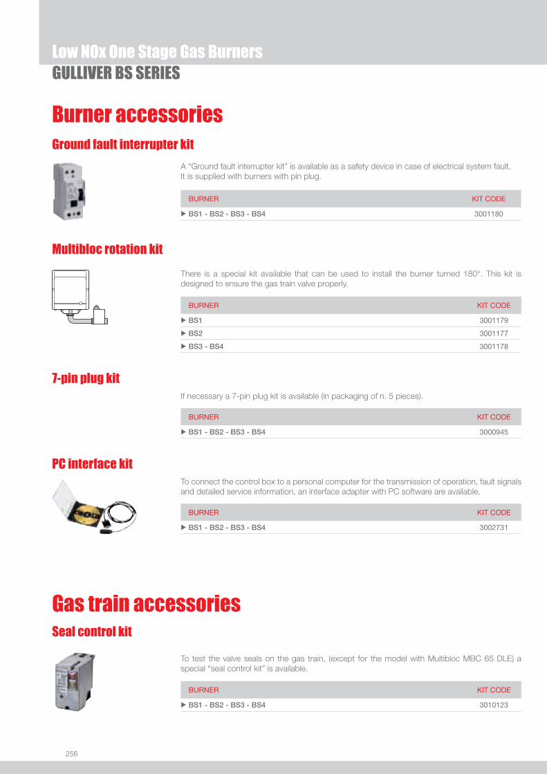
256
GULLIVER BS SERIESLow NOx One Stage Gas Burners
Burner accessories
There is a special kit available that can be used to install the burner turned 180°. This kit is designed to ensure the gas train valve properly.
Multibloc rotation kit
BURNER KIT CODE
u BS1 3001179
u BS2 3001177
u BS3 - BS4 3001178
7-pin plug kitIf necessary a 7-pin plug kit is available (in packaging of n. 5 pieces).
BURNER KIT CODE
u BS1 - BS2 - BS3 - BS4 3000945
PC interface kitTo connect the control box to a personal computer for the transmission of operation, fault signals and detailed service information, an interface adapter with PC software are available.
BURNER KIT CODE
u BS1 - BS2 - BS3 - BS4 3002731
To test the valve seals on the gas train, (except for the model with Multibloc MBC 65 DLE) a special “seal control kit” is available.
Seal control kit
Gas train accessories
BURNER KIT CODE
u BS1 - BS2 - BS3 - BS4 3010123
Ground fault interrupter kit
A “Ground fault interrupter kit” is available as a safety device in case of electrical system fault. It is supplied with burners with pin plug.
BURNER KIT CODE
u BS1 - BS2 - BS3 - BS4 3001180

257
LOW
NOx
GAS
Low NOx Two Stage Gas Burners
GULLIVER BSD SERIESThe Riello Gulliver BSD series of two stage gas burners, is a complete range of Low NOx emission products, developed to respond to any request for home heating, conforming to the most severe standards regarding the reduction of polluting emissions.This series of burners is available in four different models with an output ranging from 16 to 250 kW, divided in four different structures. All the models use the same components designed by Riello for the Gulliver series. The high quality level guarantees safe working. The burners are fi tted with a microprocessor-based burner safety control box which supplies indication of operation and diagnosis of fault cause. In developing these burners, special attention was paid to reducing noise, the ease of installation and adjustment, to obtaining the smallest size possible to fi t into any sort of boiler available on the market. Two stage working guarantees high level performance from the thermal unit. All the models are approved by the EN 676 European Standard and conform to European Directives, Gas Appliance, EMC, Low Voltage, Boiler Effi ciency.All the Gulliver BSD burners are tested before leaving the factory.
BS1D 16/19 ÷ 52 kWBS2D 35/40 ÷ 91 kW BS3D 65/80 ÷ 200 kW BS4D 110/140 ÷ 250 kW
FIRING RATES
Useful working fi eldfor choosing theburner
1st stage operationrange
Test conditionsconforming to EN676 Temperature: 20°CPressure: 1013,5 mbarAltitude: 0 m a.s.l.
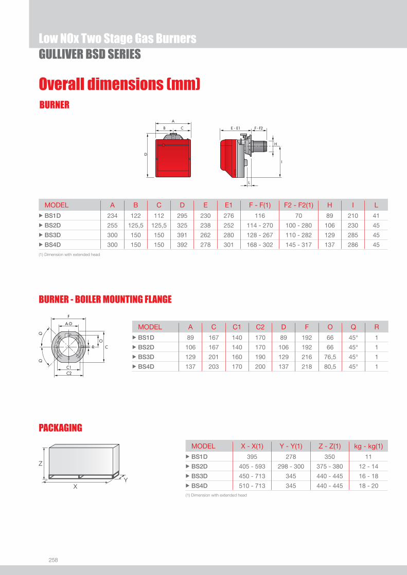
258
BURNER
GULLIVER BSD SERIESLow NOx Two Stage Gas Burners
Overall dimensions (mm)
MODEL A B C D E E1 F - F(1) F2 - F2(1) H I L u BS1D 234 122 112 295 230 276 116 70 89 210 41
u BS2D 255 125,5 125,5 325 238 252 114 - 270 100 - 280 106 230 45
u BS3D 300 150 150 391 262 280 128 - 267 110 - 282 129 285 45
u BS4D 300 150 150 392 278 301 168 - 302 145 - 317 137 286 45
MODEL A C C1 C2 D F O Q R u BS1D 89 167 140 170 89 192 66 45° 1
u BS2D 106 167 140 170 106 192 66 45° 1
u BS3D 129 201 160 190 129 216 76,5 45° 1
u BS4D 137 203 170 200 137 218 80,5 45° 1
PACKAGING
Z
XY
MODEL X - X(1) Y - Y(1) Z - Z(1) kg - kg(1) u BS1D 395 278 350 11
u BS2D 405 - 593 298 - 300 375 - 380 12 - 14
u BS3D 450 - 713 345 440 - 445 16 - 18
u BS4D 510 - 713 345 440 - 445 18 - 20
BURNER - BOILER MOUNTING FLANGE
(1) Dimension with extended head
(1) Dimension with extended head

259
DESIGNATION OF SERIES
Specifi cation
LOW
NOx
GAS
Low NOx Two Stage Gas BurnersGULLIVER BSD SERIES
Monoblock, gas burners, completely automatic, two stage operation, made up of:- Fan with forward curve blades- Cover lined with sound-proofi ng material- Air damper, completely closed in stand by, driven by an electric servomotor- Air damper with 1st and 2nd stage adjustment (2nd stage external adjustment, with no need to remove the cover)- Single phase electric motor 230 V, 50 Hz- Combustion head fi tted with: - stainless steel head cone, resistant to high temperatures - ignition electrodes - ionisation probe - gas distributor - fl ame stability disk- Flame inspection window - Adjustable air pressure switch, with graduated selector, to guarantee burner lock out in the case of insuffi cient combustible air- Microprocessor-based burner safety control box, with diagnostic and remote reset functions- Protection fi lter against radio interference (included into burner safety control box)- IP X0D (IP 40) electric protection level.
Standard equipment:- Sliding fl ange- Flange insulation screen- Screws and nuts for fi xing the fl ange to the boiler- 7-pin plug- 4-pin plug- Remote control release kit- Instruction handbook for installation, use and maintenance- Spare parts catalogue.
B S 3 D 1/230/50
Series: R Standard emission burner B Low NOx burners
Fuel: S Natural gas SP LPG G Light oil
Size
Optional variations: R Light oil pre-heater K Cone shaped head S Reduced output ignition D Two stage output operation
Head : TC Standard head TL Extended head
Electrical supply to the system: 1/230/50 1/230V/50Hz
STATE OF SUPPLY

260
Available models
Low NOx Two Stage Gas BurnersGULLIVER BSD SERIES
CODE MODEL HEAT OUTPUT TOTALELECTRICAL
POWER(kW)
CERTIFICATION NOTE
(kW)NATURAL GAS
(Nm3/h)
3761558 BS1D 1/230/50 16/19 - 52 1,6/1,9 - 5,2 0,150 CE - 0085 AQ0409 (1)
3761658 BS2D 1/230/50 35/40 - 91 3,5/4 - 9 0,180 CE - 0085 AQ0409 (1)
3761618 BS2D TL 1/230/50 35/40 - 91 3,5/4 - 9 0,180 CE - 0085 AQ0409 (1)
3761758 BS3D 1/230/50 65/80 - 200 6,5/8 - 20 0,350 CE - 0085 AQ0409 (1)
3761718 BS3D TL 1/230/50 65/80 - 200 6,5/8 - 20 0,350 CE - 0085 AQ0409 (1)
3761858 BS4D 1/230/50 110/140 - 250 11/14 - 25 0,530 CE - 0085 AQ0409 (1)
3761818 BS4D TL 1/230/50 110/140 - 250 11/14 - 25 0,530 CE - 0085 AQ0409 (1)
3761559 BSP1D 1/230/50 16/19 - 52 -- 0,150 CE - 0085 AQ0409 (1)
3761659 BSP2D 1/230/50 35/40 - 91 -- 0,180 CE - 0085 AQ0409 (1)
3761759 BSP3D 1/230/50 65/80 - 200 -- 0,350 CE - 0085 AQ0409 (1)
3761859 BSP4D 1/230/50 110/140 - 250 -- 0,530 CE - 0085 AQ0409 (1)
Net calorifi c value G20: 10 kWh/Nm3 - Density: 0,71 kg/Nm3.Net calorifi c value LPG: 25,8 kWh/Nm3 - Density: 2,02 kg/Nm3.The burners of BS series are in according to EN 676.(1) With plug and socket.
Burners
Gas Trains
GAS TRAIN GAS TRAIN NATURAL GAS LPG NOTE
CODE * MODEL BURNER ADAPTER BURNER ADAPTER
(type) (code) (type) (code)
MU
LTIB
LOC 3970539 MBZRDLE 405 BS1D BS1D (1)
3970540 MBZRDLE 405 BS2D BS2D (1)
3970538 MBZRDLE 407 BS2D BS2D (1)
3970541 MBZRDLE 407 BS3D - BS4D BS3D - BS4D (1) (2)
3970542 MBZRDLE 410 BS3D - BS4D BS3D - BS4D
3970543 MBZRDLE 412 BS3D - BS4D BS3D - BS4D
* Gas trains are 230V/50Hz - 220V/60Hz electrical supply.(1) With installed plug.(2) BS3D and BS4D ≤ 150 kW with natural gas.
To select the gas train please refer to the technical data leafl et and/or instruction manual.

261
Burner accessories
LOW
NOx
GAS
Low NOx Two Stage Gas BurnersGULLIVER BSD SERIES
Extended head kit
Burners standard head can be transformed into “extended head” versions by using the special kit. Here the KITS available for the various burners are listed, showing the original and the extended lengths.
BURNER STANDARD HEAD LENGTH (mm)
EXTENDED HEAD LENGTH (mm)
KIT CODE
u BS2D (long) 100 ÷ 114 170 ÷ 180 3001007
u BS2D (extra long) 100 ÷ 114 270 ÷ 280 3001008
u BS3D 110 ÷ 128 267 ÷ 282 3001009
u BS4D 145 ÷ 168 302 ÷ 317 3001016
LPG kitFor burning LPG gas, a special kit is available to be fi tted to the combustion head on the burner, as shown in the following table.
BURNER KIT CODE FOR STANDARD HEAD
KIT CODE FOR EXTENDED HEAD
u BS1D 3001003 -
u BS2D 3001004 3001004
u BS3D 3001005 3001005
u BS4D 3001011 3001011
Alternative combustion head kit
This kit can be used to prevent combustion instability which could arise with particular heat generators.
BURNER KIT CODE
u BS1D 3001059
u BS2D 3001064
u BS3D 3001060
u BS4D 3001070
Town Gas kitFor burning Town Gas, a special kit is available to be fi tted to the combustion head on the burner, as shown in the following table.
BURNER KIT CODE FOR STANDARD HEAD (*)
KIT CODE FOR EXTENDED HEAD (*)
u BS1D 3002727 -
u BS2D 3002728 3002728
u BS3D 3002729 3002729
(*) Without CE certifi cation

262
Burner accessories
There is a special kit available that can be used to install the burner turned 180°. This kit is designed to ensure the gas train valve properly.
Multibloc rotation kit
BURNER KIT CODE
u BS1D 3001179
u BS2D 3001177
u BS3D - BS4D 3001178
7-pin plug kitIf necessary a 7-pin plug kit is available (in packaging of n. 5 pieces).
BURNER KIT CODE
u BS1D - BS2D - BS3D - BS4D 3000945
PC interface kitTo connect the control box to a personal computer for the transmission of operation, fault signals and detailed service information, an interface adapter with PC software are available.
BURNER KIT CODE
u BS1D - BS2D - BS3D - BS4D 3002731
To test the valve seals on the gas train a special “seal control kit” is available.
Seal control kit
Gas train accessories
BURNER KIT CODE
u BS1D - BS2D - BS3D - BS4D 3010123
GULLIVER BSD SERIESLow NOx Two Stage Gas Burners
Ground fault interrupter kit
A “Ground fault interrupter kit” is available as a safety device in case of electrical system fault. It is supplied with burners with pin plug.
BURNER KIT CODE
u BS1D - BS2D - BS3D - BS4D 3001180
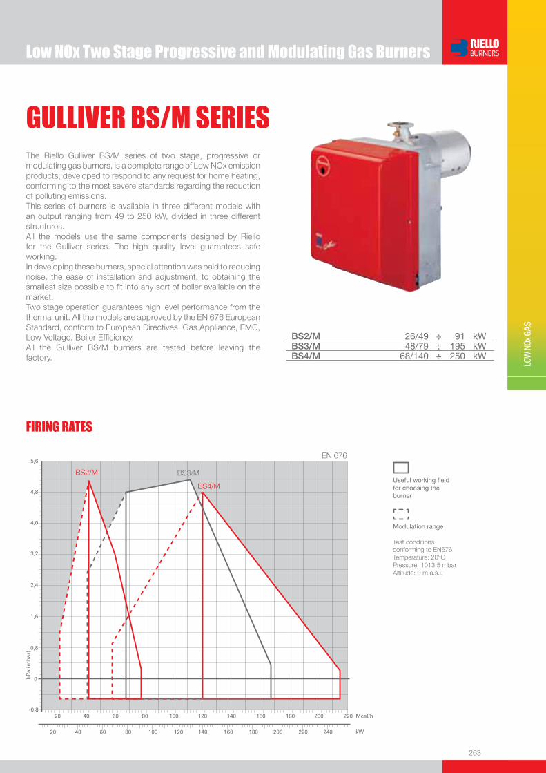
263
LOW
NOx
GAS
Low NOx Two Stage Progressive and Modulating Gas Burners
GULLIVER BS/M SERIESThe Riello Gulliver BS/M series of two stage, progressive or modulating gas burners, is a complete range of Low NOx emission products, developed to respond to any request for home heating, conforming to the most severe standards regarding the reduction of polluting emissions.This series of burners is available in three different models with an output ranging from 49 to 250 kW, divided in three different structures.All the models use the same components designed by Riello for the Gulliver series. The high quality level guarantees safe working.In developing these burners, special attention was paid to reducing noise, the ease of installation and adjustment, to obtaining the smallest size possible to fi t into any sort of boiler available on the market.Two stage operation guarantees high level performance from the thermal unit. All the models are approved by the EN 676 European Standard, conform to European Directives, Gas Appliance, EMC, Low Voltage, Boiler Effi ciency.All the Gulliver BS/M burners are tested before leaving the factory.
BS2/M 26/49 ÷ 91 kWBS3/M 48/79 ÷ 195 kW BS4/M 68/140 ÷ 250 kW
FIRING RATES
Useful working fi eldfor choosing theburner
Modulation range
Test conditionsconforming to EN676 Temperature: 20°CPressure: 1013,5 mbarAltitude: 0 m a.s.l.

264
BURNER
BURNER - BOILER MOUNTING FLANGE
Overall dimensions (mm)
Low NOx Two Stage Progressive and Modulating Gas BurnersGULLIVER BS/M SERIES
MODEL A B C D E E1 F F2 H I L u BS2/M 285 125,5 125,5 325 238 252 114 100 106 230 46
u BS3/M 330 150 150 391 262 280 128 110 129 285 46
u BS3/M TL 330 150 150 391 262 270 185 170 129 285 45
u BS4/M 330 150 150 392 278 301 168 145 137 286 46
MODEL A C C1 C2 F O Q R u BS2/M 106 167 140 170 192 66 45° 11
u BS3/M 129 201 160 190 216 76,5 45° 11
u BS3/M TL 129 201 160 190 216 76,5 45° 11
u BS4/M 137 203 170 200 218 80,5 45° 11
MODEL X Y Z kg u BS2/M 405 328 375 12
u BS3/M 450 375 440 16
u BS3/M TL 510 375 440 18
u BS4/M 510 375 440 18
PACKAGING
Z
XY

265
DESIGNATION OF SERIES
Specification
Low
Nox
GAS
Low NOx Two Stage Progressive and Modulating Gas BurnersGULLIVER BS/M SERIES
STATE OF SUPPLY
Monobloc, gas burners, completely automatic, high/low progressive operation mode or fully modulating by using a regulator:- Fan with forward curve blades- Cover lined with sound proofing material - Microprocessor-based burner safety control box, with diagnostic and remote reset functions- Servomotor to drive the air damper to fully closed position at stand by, low and high fire position- Single phase electric motor 230 V, 50 Hz- Combustion head fitted with: - stainless steel head cone, resistant to high temperatures - ignition electrodes - ionisation probe - gas distributor - flame stability disk- Flame inspection window- Adjustable air pressure switch, with graduated selector, to guarantee burner lock out in the case of insufficient combustible air- Protection filter against radio interference- IP X0D (IP 40) electric protection level.
Standard equipment:- Flange with insulating gasket- Screws and nuts for flange to be fixed to boiler- Screw and nut for flange- Blue plastic tube- G 1/8 union elbow- 4-pin plug- 7-pin plug- Instruction handbook for installation, use and maintenance- Spare parts catalogue.
Series: R Standard emission burner B Low NOx burners
Fuel: S Natural gas SP LPG
Size
Optional variations: /M Two stage progressive of fully modulating
Head : TC Standard head TL Extended head
Electrical supply to the system: 1/230/50 1/230V/50Hz
B S 3 /M 1/230/50

266
Available models
Low NOx Two Stage Progressive and Modulating Gas BurnersGULLIVER BS/M SERIES
CODE MODEL HEAT OUTPUT TOTALELECTRICAL
POWER(kW)
CERTIFICATION NOTE
(kW)NATURAL GAS
(Nm3/h)
3762250 BS2/M 1/230/50 26/49 - 91 2,6/4,9 - 9,1 0,180 CE - 0085 BN0609 (1)
3762350 BS3/M 1/230/50 48/79 - 195 4,8/7,9 - 19,5 0,350 CE - 0085 BN0609 (1)
3762370 BS3/M TL 1/230/50 48/79 - 195 4,8/7,9 - 19,5 0,350 CE - 0085 BN0609 (1)
3762450 BS4/M 1/230/50 68/140 - 250 6,8/14 - 25 0,530 CE - 0085 BN0609 (1)
Net calorifi c value G20: 10 kWh/Nm3 - Density: 0,71 kg/Nm3.The burners of BS/M series are in according to EN 676.(1) With plug and socket.
Burners
Gas Trains
GAS TRAIN GAS TRAIN NATURAL GAS LPG NOTE
CODE * MODEL BURNER ADAPTER BURNER ADAPTER
(type) (code) (type) (code)
MU
LTIB
LOC
3970587 CG 120 BS2/M BS2/M (1)
3970588 CG 220 BS3/M - BS4/M BS3/M - BS4/M (1)
* Gas trains are 230V/50Hz - 220V/60Hz electrical supply.(1) With installed plug.
To select the gas train please refer to the technical data leafl et and/or instruction manual.
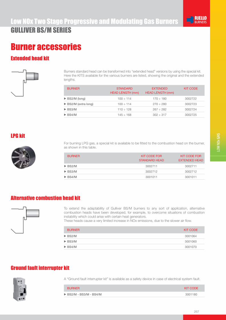
267
Burner accessories
LOW
NOx
GAS
Low NOx Two Stage Progressive and Modulating Gas BurnersGULLIVER BS/M SERIES
Extended head kit
Burners standard head can be transformed into “extended head” versions by using the special kit. Here the KITS available for the various burners are listed, showing the original and the extended lengths.
BURNER STANDARD HEAD LENGTH (mm)
EXTENDED HEAD LENGTH (mm)
KIT CODE
u BS2/M (long) 100 ÷ 114 170 ÷ 180 3002722
u BS2/M (extra long) 100 ÷ 114 270 ÷ 280 3002723
u BS3/M 110 ÷ 128 267 ÷ 282 3002724
u BS4/M 145 ÷ 168 302 ÷ 317 3002725
LPG kitFor burning LPG gas, a special kit is available to be fi tted to the combustion head on the burner, as shown in this table.
BURNER KIT CODE FOR STANDARD HEAD
KIT CODE FOR EXTENDED HEAD
u BS2/M 3002711 3002711
u BS3/M 3002712 3002712
u BS4/M 3001011 3001011
Alternative combustion head kit
To extend the adaptability of Gulliver BS/M burners to any sort of application, alternative combustion heads have been developed, for example, to overcome situations of combustion instability which could arise with certain heat generators.These heads cause a very limited increase in NOx emissions, due to the slower air fl ow.
BURNER KIT CODE
u BS2/M 3001064
u BS3/M 3001060
u BS4/M 3001070
Ground fault interrupter kit
A “Ground fault interrupter kit” is available as a safety device in case of electrical system fault.
BURNER KIT CODE
u BS2/M - BS3/M - BS4/M 3001180
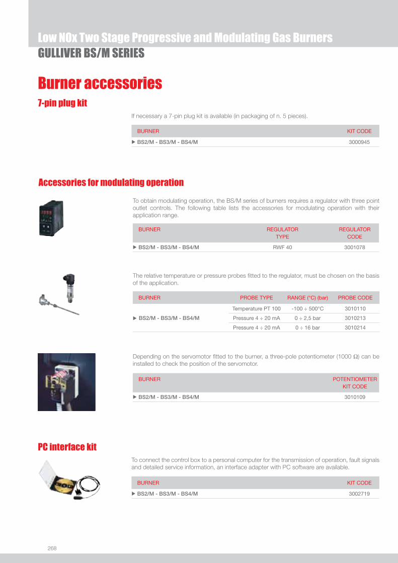
268
7-pin plug kitIf necessary a 7-pin plug kit is available (in packaging of n. 5 pieces).
Burner accessories
BURNER KIT CODE
u BS2/M - BS3/M - BS4/M 3000945
GULLIVER BS/M SERIESLow NOx Two Stage Progressive and Modulating Gas Burners
Accessories for modulating operation
To obtain modulating operation, the BS/M series of burners requires a regulator with three point outlet controls. The following table lists the accessories for modulating operation with their application range.
BURNER
REGULATOR TYPE
REGULATOR CODE
u BS2/M - BS3/M - BS4/M RWF 40 3001078
Depending on the servomotor fi tted to the burner, a three-pole potentiometer (1000 Ω) can be installed to check the position of the servomotor.
BURNER
POTENTIOMETER KIT CODE
u BS2/M - BS3/M - BS4/M 3010109
The relative temperature or pressure probes fi tted to the regulator, must be chosen on the basis of the application.
BURNER PROBE TYPE RANGE (°C) (bar) PROBE CODE
u BS2/M - BS3/M - BS4/M
Temperature PT 100 -100 ÷ 500°C 3010110
Pressure 4 ÷ 20 mA 0 ÷ 2,5 bar 3010213
Pressure 4 ÷ 20 mA 0 ÷ 16 bar 3010214
PC interface kitTo connect the control box to a personal computer for the transmission of operation, fault signals and detailed service information, an interface adapter with PC software are available.
BURNER KIT CODE
u BS2/M - BS3/M - BS4/M 3002719
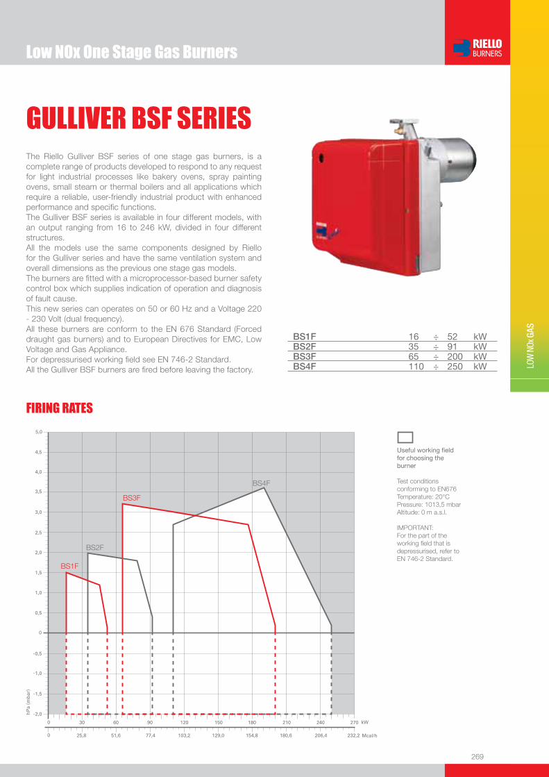
Low NOx One Stage Gas Burners
269
LOW
NOx
GAS
GULLIVER BSF SERIESThe Riello Gulliver BSF series of one stage gas burners, is a complete range of products developed to respond to any request for light industrial processes like bakery ovens, spray painting ovens, small steam or thermal boilers and all applications which require a reliable, user-friendly industrial product with enhanced performance and specifi c functions.The Gulliver BSF series is available in four different models, with an output ranging from 16 to 246 kW, divided in four different structures.All the models use the same components designed by Riello for the Gulliver series and have the same ventilation system and overall dimensions as the previous one stage gas models.The burners are fi tted with a microprocessor-based burner safety control box which supplies indication of operation and diagnosis of fault cause.This new series can operates on 50 or 60 Hz and a Voltage 220 - 230 Volt (dual frequency).All these burners are conform to the EN 676 Standard (Forced draught gas burners) and to European Directives for EMC, Low Voltage and Gas Appliance. For depressurised working fi eld see EN 746-2 Standard.All the Gulliver BSF burners are fi red before leaving the factory.
BS1F 16 ÷ 52 kWBS2F 35 ÷ 91 kW BS3F 65 ÷ 200 kW BS4F 110 ÷ 250 kW
FIRING RATES
Useful working fi eldfor choosing theburner
Test conditionsconforming to EN676 Temperature: 20°CPressure: 1013,5 mbarAltitude: 0 m a.s.l.
IMPORTANT: For the part of the working fi eld that is depressurised, refer to EN 746-2 Standard.
-
-
-
-
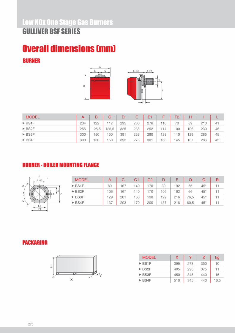
270
BURNER
BURNER - BOILER MOUNTING FLANGE
Low NOx One Stage Gas BurnersGULLIVER BSF SERIES
Overall dimensions (mm)
MODEL A B C D E E1 F F2 H I L u BS1F 234 122 112 295 230 276 116 70 89 210 41
u BS2F 255 125,5 125,5 325 238 252 114 100 106 230 45
u BS3F 300 150 150 391 262 280 128 110 129 285 45
u BS4F 300 150 150 392 278 301 168 145 137 286 45
MODEL A C C1 C2 D F O Q R u BS1F 89 167 140 170 89 192 66 45° 11
u BS2F 106 167 140 170 106 192 66 45° 11
u BS3F 129 201 160 190 129 216 76,5 45° 11
u BS4F 137 203 170 200 137 218 80,5 45° 11
MODEL X Y Z kg u BS1F 395 278 350 10
u BS2F 405 298 375 11
u BS3F 450 345 440 15
u BS4F 510 345 440 16,5
Z
XY
PACKAGING
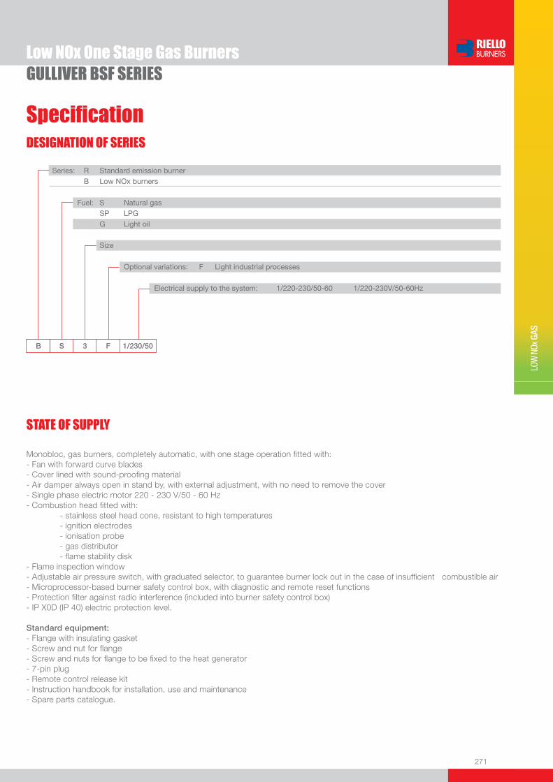
271
DESIGNATION OF SERIES
Specifi cation
Low NOx One Stage Gas Burners
LOW
NOx
GAS
GULLIVER BSF SERIES
B S 3 F 1/230/50
Series: R Standard emission burner B Low NOx burners
Fuel: S Natural gas SP LPG G Light oil
Size
Optional variations: F Light industrial processes
Electrical supply to the system: 1/220-230/50-60 1/220-230V/50-60Hz
Monobloc, gas burners, completely automatic, with one stage operation fi tted with:- Fan with forward curve blades- Cover lined with sound-proofi ng material- Air damper always open in stand by, with external adjustment, with no need to remove the cover- Single phase electric motor 220 - 230 V/50 - 60 Hz- Combustion head fi tted with: - stainless steel head cone, resistant to high temperatures - ignition electrodes - ionisation probe - gas distributor - fl ame stability disk- Flame inspection window- Adjustable air pressure switch, with graduated selector, to guarantee burner lock out in the case of insuffi cient combustible air- Microprocessor-based burner safety control box, with diagnostic and remote reset functions- Protection fi lter against radio interference (included into burner safety control box)- IP X0D (IP 40) electric protection level.
Standard equipment:- Flange with insulating gasket- Screw and nut for fl ange- Screw and nuts for fl ange to be fi xed to the heat generator- 7-pin plug- Remote control release kit- Instruction handbook for installation, use and maintenance- Spare parts catalogue.
STATE OF SUPPLY
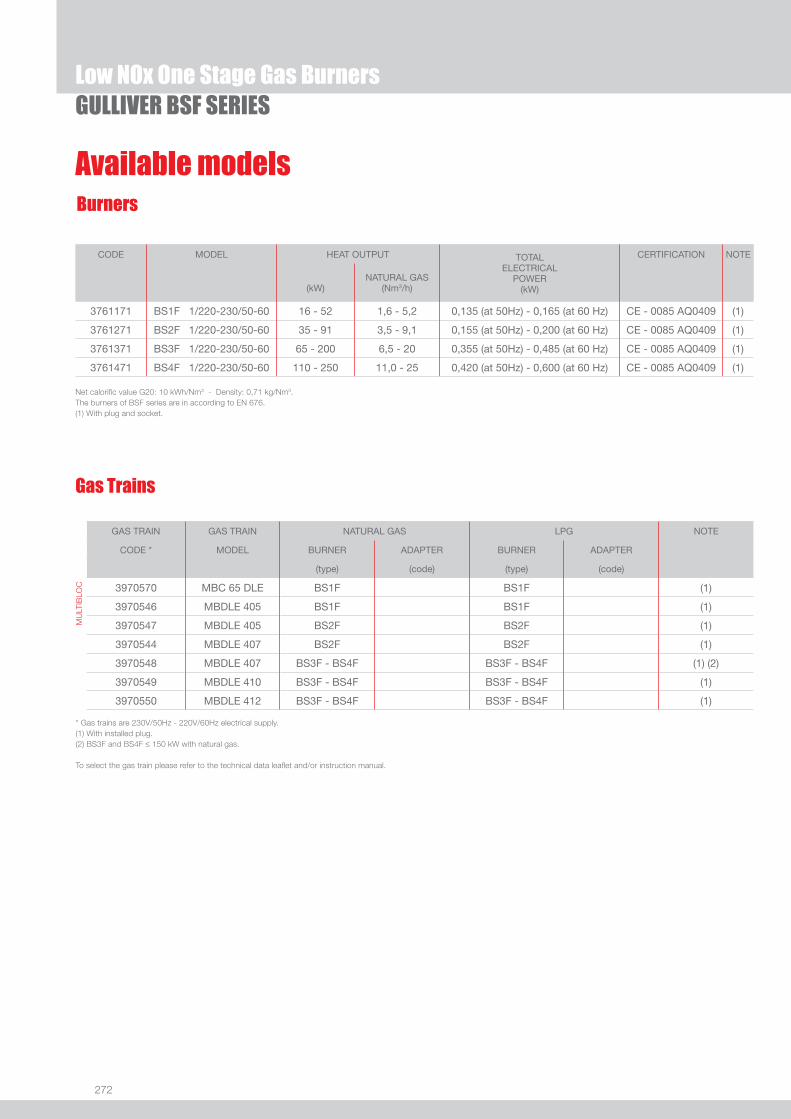
272
Available models
Low NOx One Stage Gas BurnersGULLIVER BSF SERIES
Burners
CODE MODEL HEAT OUTPUT TOTALELECTRICAL
POWER(kW)
CERTIFICATION NOTE
(kW)NATURAL GAS
(Nm3/h)
3761171 BS1F 1/220-230/50-60 16 - 52 1,6 - 5,2 0,135 (at 50Hz) - 0,165 (at 60 Hz) CE - 0085 AQ0409 (1)
3761271 BS2F 1/220-230/50-60 35 - 91 3,5 - 9,1 0,155 (at 50Hz) - 0,200 (at 60 Hz) CE - 0085 AQ0409 (1)
3761371 BS3F 1/220-230/50-60 65 - 200 6,5 - 20 0,355 (at 50Hz) - 0,485 (at 60 Hz) CE - 0085 AQ0409 (1)
3761471 BS4F 1/220-230/50-60 110 - 250 11,0 - 25 0,420 (at 50Hz) - 0,600 (at 60 Hz) CE - 0085 AQ0409 (1)
Net calorifi c value G20: 10 kWh/Nm3 - Density: 0,71 kg/Nm3.The burners of BSF series are in according to EN 676.(1) With plug and socket.
Gas Trains
GAS TRAIN GAS TRAIN NATURAL GAS LPG NOTE
CODE * MODEL BURNER ADAPTER BURNER ADAPTER
(type) (code) (type) (code)
MU
LTIB
LOC 3970570 MBC 65 DLE BS1F BS1F (1)
3970546 MBDLE 405 BS1F BS1F (1)
3970547 MBDLE 405 BS2F BS2F (1)
3970544 MBDLE 407 BS2F BS2F (1)
3970548 MBDLE 407 BS3F - BS4F BS3F - BS4F (1) (2)
3970549 MBDLE 410 BS3F - BS4F BS3F - BS4F (1)
3970550 MBDLE 412 BS3F - BS4F BS3F - BS4F (1)
* Gas trains are 230V/50Hz - 220V/60Hz electrical supply.(1) With installed plug.(2) BS3F and BS4F ≤ 150 kW with natural gas.
To select the gas train please refer to the technical data leafl et and/or instruction manual.

273
Burner accessories
Low NOx One Stage Gas Burners
LOW
NOx
GAS
GULLIVER BSF SERIES
Extended head kit
Burners standard head can be transformed into “extended head” versions by using the special kit. Here the kits available for the various burners are listed, showing the original and the extended lengths.
BURNER STANDARD HEAD LENGTH (mm)
EXTENDED HEAD LENGTH (mm)
KIT CODE
u BS2F (long) 100 ÷ 114 170 ÷ 180 3001007
u BS2F (extra long) 100 ÷ 114 270 ÷ 280 3001008
u BS3F 110 ÷ 128 267 ÷ 282 3001009
u BS4F 145 ÷ 168 302 ÷ 317 3001016
LPG kitFor burning LPG gas, a special kit is available to be fi tted to the combustion head on the burner, as shown in the following table.
BURNER KIT CODE FOR STANDARD HEAD
KIT CODE FOR EXTENDED HEAD
u BS1F 3001003 -
u BS2F 3001004 3001004
u BS3F 3001005 3001005
u BS4F 3001011 3001011
Alternative combustion head kit
This kit can be used to prevent combustion instability which could arise with particular heat generators.
BURNER KIT CODE
u BS1F 3001059
u BS2F 3001064
u BS3F 3001060
u BS4F 3001070
Town Gas kitFor burning Town Gas, a special kit is available to be fi tted to the combustion head on the burner, as shown in the following table.
BURNER KIT CODE FOR STANDARD HEAD (*)
KIT CODE FOR EXTENDED HEAD (*)
u BS1F 3002727 -
u BS2F 3002728 3002728
u BS3F 3002729 3002729
(*) Without CE certifi cation
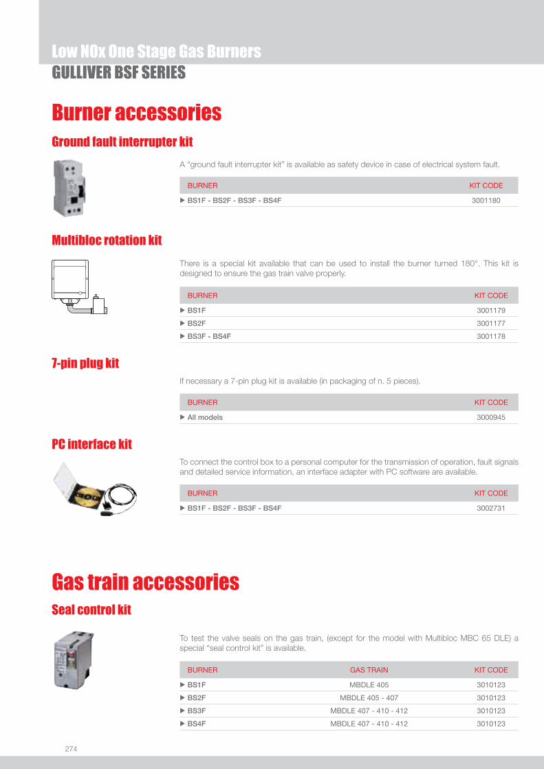
274
Low NOx One Stage Gas BurnersGULLIVER BSF SERIES
Burner accessories
There is a special kit available that can be used to install the burner turned 180°. This kit is designed to ensure the gas train valve properly.
Multibloc rotation kit
BURNER KIT CODE
u BS1F 3001179
u BS2F 3001177
u BS3F - BS4F 3001178
7-pin plug kitIf necessary a 7-pin plug kit is available (in packaging of n. 5 pieces).
BURNER KIT CODE
u All models 3000945
PC interface kitTo connect the control box to a personal computer for the transmission of operation, fault signals and detailed service information, an interface adapter with PC software are available.
BURNER KIT CODE
u BS1F - BS2F - BS3F - BS4F 3002731
To test the valve seals on the gas train, (except for the model with Multibloc MBC 65 DLE) a special “seal control kit” is available.
Seal control kit
Gas train accessories
BURNER GAS TRAIN KIT CODE
u BS1F MBDLE 405 3010123
u BS2F MBDLE 405 - 407 3010123
u BS3F MBDLE 407 - 410 - 412 3010123
u BS4F MBDLE 407 - 410 - 412 3010123
Ground fault interrupter kit
A “ground fault interrupter kit” is available as safety device in case of electrical system fault.
BURNER KIT CODE
u BS1F - BS2F - BS3F - BS4F 3001180

275
LOW
NOx
GAS
GULLIVER BSDF SERIES
Low NOx Two Stage Gas Burners
The Riello Gulliver BSDF series of two stage gas burners, is a complete range of Low NOx emission products, developed to respond to any request for light industrial processes like bakery ovens, spray painting ovens, small steam or thermal boilers and all applications which require a reliable, user-friendly industrial product with enhanced performance and specifi c functions.This series of burners is available in two different models with an output ranging from 75 to 246 kW, divided in two different structures. All the models use the same components designed by Riello for the Gulliver series. The high quality level guarantees safe working. The burners are fi tted with a microprocessor-based burner safety control box which supplies indication of operation and diagnosis of fault cause. This new series can operates on 50 or 60 Hz and a Voltage 220 - 230 Volt (dual frequency).For depressurised working fi eld see EN 746-2 Standard.All the Gulliver BSD burners are tested before leaving the factory.
BS3DF 65/75 ÷ 189 kW BS4DF 110/140 ÷ 246 kW
Useful working fi eldfor choosing theburner
1st stage operationrange
Test conditionsconforming to EN676 Temperature: 20°CPressure: 1013,5 mbarAltitude: 0 m a.s.l.
FIRING RATES
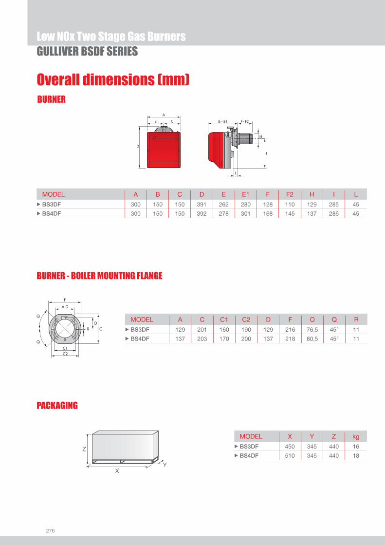
276
BURNER
GULLIVER BSDF SERIESLow NOx Two Stage Gas Burners
Overall dimensions (mm)
MODEL A B C D E E1 F F2 H I L u BS3DF 300 150 150 391 262 280 128 110 129 285 45
u BS4DF 300 150 150 392 278 301 168 145 137 286 45
MODEL A C C1 C2 D F O Q R u BS3DF 129 201 160 190 129 216 76,5 45° 11
u BS4DF 137 203 170 200 137 218 80,5 45° 11
PACKAGING
Z
XY
MODEL X Y Z kg u BS3DF 450 345 440 16
u BS4DF 510 345 440 18
BURNER - BOILER MOUNTING FLANGE

277
DESIGNATION OF SERIES
Specifi cation
LOW
NOx
GAS
Low NOx Two Stage Gas BurnersGULLIVER BSDF SERIES
Monoblock, gas burners, completely automatic, two stage operation, made up of:- Fan with forward curve blades- Cover lined with sound-proofi ng material- Air damper with 1st and 2nd stage adjustment (2nd stage external adjustment, with no need to remove the cover)- Driven by an electric servomotor- Single phase electric motor 220-230 V / 50-60 Hz- Combustion head fi tted with: - stainless steel head cone, resistant to high temperatures - ignition electrodes - ionisation probe - gas distributor - fl ame stability disk- Flame inspection window - Adjustable air pressure switch, with graduated selector, to guarantee burner lock out in the case of insuffi cient combustible air- Microprocessor-based burner safety control box, with diagnostic and remote reset functions- Protection fi lter against radio interference (included into burner safety control box)- IP X0D (IP 40) electric protection level.
Standard equipment:- Sliding fl ange- Flange insulation screen- Screws and nuts for fi xing the fl ange to the boiler- 7-pin plug- 4-pin plug- Remote control release kit- Instruction handbook for installation, use and maintenance- Spare parts catalogue.
Series: R Standard emission burner B Low NOx burners
Fuel: S Natural gas SP LPG G Light oil
Size
Optional variations: R Light oil pre-heater K Cone shaped head S Reduced output ignition D Two stage output operation F Light Industrial Processes
Electrical supply to the system: 1/220-230/50-60 1/220-230V/50-60Hz
STATE OF SUPPLY
B S 3 DF 1/230/50
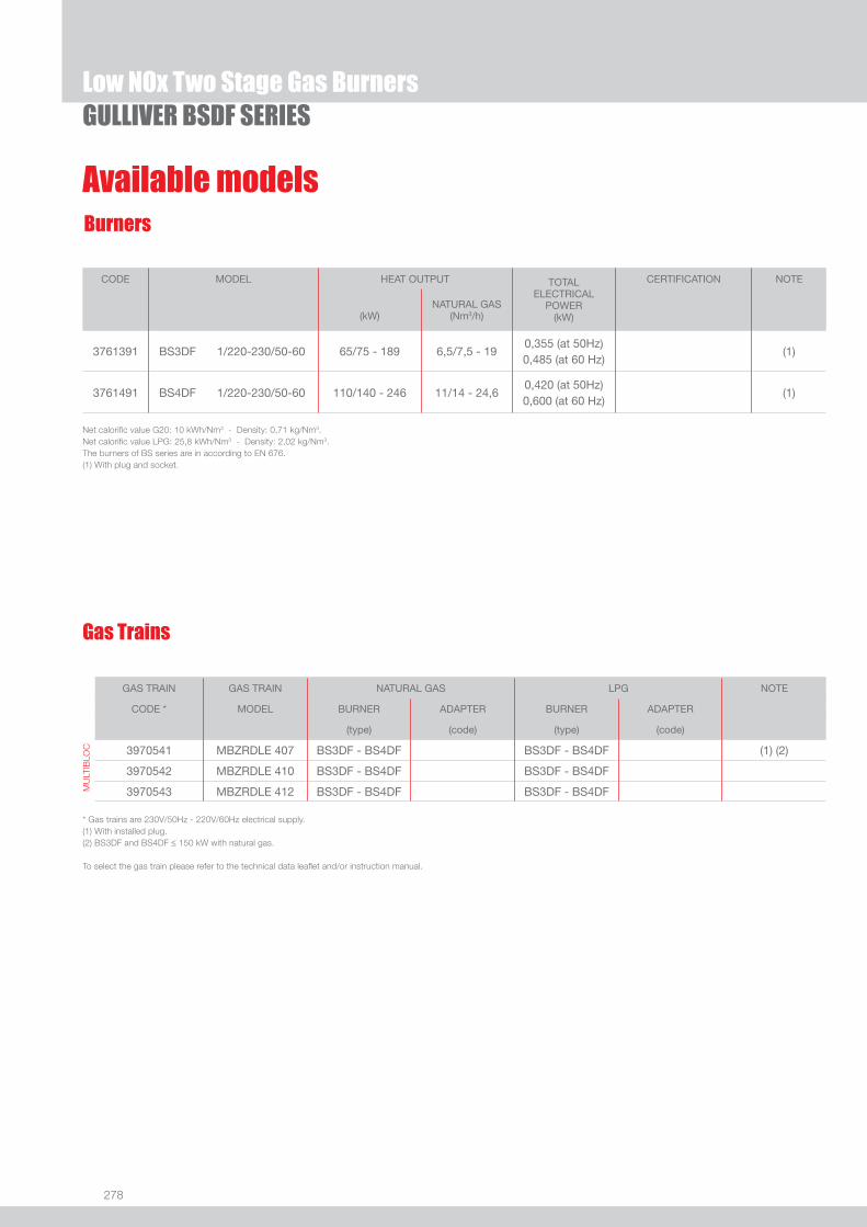
278
Available models
Low NOx Two Stage Gas BurnersGULLIVER BSDF SERIES
CODE MODEL HEAT OUTPUT TOTALELECTRICAL
POWER(kW)
CERTIFICATION NOTE
(kW)NATURAL GAS
(Nm3/h)
3761391 BS3DF 1/220-230/50-60 65/75 - 189 6,5/7,5 - 190,355 (at 50Hz)0,485 (at 60 Hz)
(1)
3761491 BS4DF 1/220-230/50-60 110/140 - 246 11/14 - 24,60,420 (at 50Hz)0,600 (at 60 Hz)
(1)
Net calorifi c value G20: 10 kWh/Nm3 - Density: 0,71 kg/Nm3.Net calorifi c value LPG: 25,8 kWh/Nm3 - Density: 2,02 kg/Nm3.The burners of BS series are in according to EN 676.(1) With plug and socket.
Burners
Gas Trains
GAS TRAIN GAS TRAIN NATURAL GAS LPG NOTE
CODE * MODEL BURNER ADAPTER BURNER ADAPTER
(type) (code) (type) (code)
MU
LTIB
LOC 3970541 MBZRDLE 407 BS3DF - BS4DF BS3DF - BS4DF (1) (2)
3970542 MBZRDLE 410 BS3DF - BS4DF BS3DF - BS4DF
3970543 MBZRDLE 412 BS3DF - BS4DF BS3DF - BS4DF
* Gas trains are 230V/50Hz - 220V/60Hz electrical supply.(1) With installed plug.(2) BS3DF and BS4DF ≤ 150 kW with natural gas.
To select the gas train please refer to the technical data leafl et and/or instruction manual.
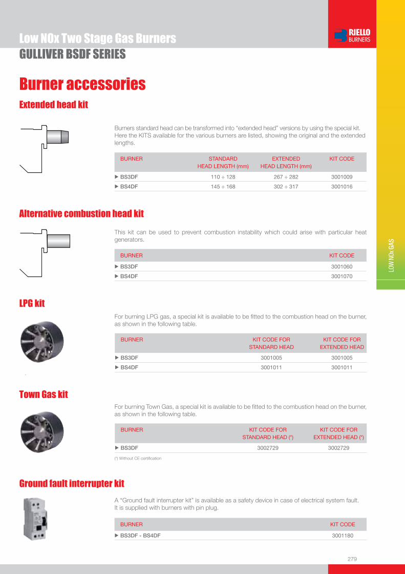
279
Burner accessories
LOW
NOx
GAS
Low NOx Two Stage Gas BurnersGULLIVER BSDF SERIES
Extended head kit
Burners standard head can be transformed into “extended head” versions by using the special kit. Here the KITS available for the various burners are listed, showing the original and the extended lengths.
BURNER STANDARD HEAD LENGTH (mm)
EXTENDED HEAD LENGTH (mm)
KIT CODE
u BS3DF 110 ÷ 128 267 ÷ 282 3001009
u BS4DF 145 ÷ 168 302 ÷ 317 3001016
LPG kitFor burning LPG gas, a special kit is available to be fi tted to the combustion head on the burner, as shown in the following table.
BURNER KIT CODE FOR STANDARD HEAD
KIT CODE FOR EXTENDED HEAD
u BS3DF 3001005 3001005
u BS4DF 3001011 3001011
Alternative combustion head kit
This kit can be used to prevent combustion instability which could arise with particular heat generators.
BURNER KIT CODE
u BS3DF 3001060
u BS4DF 3001070
Ground fault interrupter kit
A “Ground fault interrupter kit” is available as a safety device in case of electrical system fault. It is supplied with burners with pin plug.
BURNER KIT CODE
u BS3DF - BS4DF 3001180
Town Gas kitFor burning Town Gas, a special kit is available to be fi tted to the combustion head on the burner, as shown in the following table.
BURNER KIT CODE FOR STANDARD HEAD (*)
KIT CODE FOR EXTENDED HEAD (*)
u BS3DF 3002729 3002729
(*) Without CE certifi cation
280
There is a special kit available that can be used to install the burner turned 180°. This kit is designed to ensure the gas train valve properly.
7-pin plug kitIf necessary a 7-pin plug kit is available (in packaging of n. 5 pieces).
PC interface kitTo connect the control box to a personal computer for the transmission of operation, fault signals and detailed service information, an interface adapter with PC software are available.
Multibloc rotation kit
Burner accessories
BURNER KIT CODE
u BS3DF - BS4DF 3001178
BURNER KIT CODE
u BS3DF - BS4DF 3000945
BURNER KIT CODE
u BS3DF - BS4DF 3002731
To test the valve seals on the gas train a special “seal control kit” is available.
Seal control kit
Gas train accessories
BURNER KIT CODE
u BS3DF - BS4DF 3010123
GULLIVER BSDF SERIESLow NOx Two Stage Gas Burners

281
LOW
NOx
GAS
RS 25/M BLU 44/125 ÷ 370 kWRS 35/M BLU 70/200 ÷ 480 kWRS 45/M BLU 90/190 ÷ 550 kWRS 68/M BLU 150/350 ÷ 860 kWRS 120/M BLU 300/600 ÷ 1300 kWRS 160/M BLU 300/930 ÷ 1860 kWRS 200/M BLU 570/1375 ÷ 2400 kW
RS 25÷200/M BLU SERIES
Low NOx Modulating Gas Burners
The RS/M BLU burners series covers a fi ring range from 44 to 2400 kW, and it has been designed for use in low or medium temperature hot water boilers, hot air or steam boilers, diathermic oil boilers. Operation can be “two stage progressive” or, alternatively, “modulating” with the installation of a PID logic regulator and respective probes. RS/M BLU burners series guarantees high effi ciency levels in all the various applications, thus reducing fuel consumption and running costs. The exclusive design ensures reduced dimensions, simple use and maintenance. Optimisation of sound emissions is guaranteed by the special design of the air suction circuit and by incorporated sound proofi ng material.A wide range of accessories guarantees elevated working fl exibility.
FIRING RATES
Useful working fi eldfor choosing theburner
Modulation range
Test conditionsconforming to EN676 Temperature: 20°CPressure: 1013,5 mbarAltitude: 0 m a.s.l.

282
BURNER
Overall dimensions (mm)
RS 25÷200/M BLU SERIESLow NOx Modulating Gas Burners
RS 25/M - 35/M BLU RS 45/M BLU
RS 68/M - 120/M - 160/M - 200/M BLU
MODEL A B C D E F - F (1) H I L M N O - O(1) S V u RS 25/M BLU 442 - - 422 508 230 - 365 140 305 138 1”1/2 84 780 - - - 177 u RS 35/M BLU 442 - - 422 508 230 - 365 152 305 138 1”1/2 84 780 - - - 177 u RS 45/M BLU 476 - - 474 580 229 - 354 160 352 164 1”1/2 108 810 - 810 367 168 u RS 68/M BLU 527 312 215 555 840 255 - 390 189 430 214 2” 134 1161 - 1296 - 221 u RS 120/M BLU 553 338 215 555 840 255 - 390 189 430 214 2” 134 1161 - 1296 - 221 u RS 160/M BLU 671 366 305 555 863 373 - 503 221 436 237 2” 141 1442 - 1587 - 264 u RS 200/M BLU 737 432 305 555 863 373 - 503 221 436 237 2” 141 1442 - 1587 - 264
BURNER - BOILER MOUNTING FLANGE MODEL D1 D2 Ø u RS 25/M BLU 160 224 M8 u RS 35/M BLU 160 224 M8 u RS 45/M BLU 165 224 M8 u RS 68/M BLU 195 275-325 M12 u RS 120/M BLU 195 275-325 M12 u RS 160/M BLU 230 325-368 M16 u RS 200/M BLU 230 325-368 M16
Z
X(1)Y
PACKAGING MODEL X(1) Y Z kg u RS 25/M BLU 1000 485 500 39 u RS 35/M BLU 1000 485 500 40 u RS 45/M BLU 1015 500 630 48 u RS 68/M BLU 1405 700 660 78 u RS 120/M BLU 1405 700 660 84 u RS 160/M BLU 1405-1420 1000 660 89 u RS 200/M BLU 1405-1420 1000 660 125
(1) Length with extended combustion head
(1) dimension with standard and extended head

283
DESIGNATION OF SERIES
Specifi cation
LOW
NOx
GAS
Low NOx Modulating Gas BurnersRS 25÷200/M BLU SERIES
EXTENDED DESIGNATION
R S 120 /M BLU TC FS1 3/230-400/50 230/50-60
Series : R
Fuel : S Natural gas SP LPG L Light oil LS Light oil / Natural gas N Heavy oil
Size
Operation : /1 One stage ... Two stage /M Modulating mechanical cam /E Electronic cam /P Proportioning air/gas valve /EV Electronic cam predisposed for variable speed (with inverter) Emission : ... Class 1 EN267 - EN676 MZ Class 2 EN267 - EN676 BLU Class 3 EN267 - EN676
MX Class 2 EN267
Class 3 EN676
Head : TC Standard head TL Extended head
Diagnostic : LP Led panel ST Status panel
Flame control system : FS1 Standard (1 stop every 24 h) FS2 Continuous working (1 stop every 72 h)
Electrical supply to the system : 1/230/50 1/230V/50Hz 1/220-230/50-60 1/220-230V/50-60Hz 3/230/50 3/230V/50Hz 3/400/50 3N/400V/50Hz 3/230-400/50 3/230V/50Hz - 3N/400V/50Hz 3/220/60 3/220V/60Hz 3/380/60 3N/380V/60Hz 3/220-380/60 3/220V/60Hz - 3N/380V/60Hz
3/220-400/50-60 3/220-230V/50-60Hz
3/380-400V/50-60Hz
Auxiliary voltage : 230/50-60 230V/50-60Hz 110/50-60 110V/50-60Hz
ID : Differential switch
BASIC DESIGNATION

284
STATE OF SUPPLY
Specifi cation
Monoblock forced draught Low NOx gas burner, two stage progressive or modulating operation with a kit, made up of:- Air suction circuit with sound proofi ng material- Air damper for air fl ow setting and butterfl y valve for regulating fuel output controlled by a servomotor with variable cam- Low emissions combustion head, that can be set on the basis of required output, fi tted with: - stainless steel end cone, resistant to corrosion and high temperatures - ignition electrodes - ionisation probe - gas distributor - fl ame stability disk- Minimum air pressure switch stops the burner in case of insuffi cient air quantity at the combustion head- Burner on/off selection switch- Manual or automatic output increase/decrease switch- Microprocessor-based burner safety control box, with diagnostic functions- Flame inspection window- Slide bars for easier installation and maintenance- Protection fi lter against radio interference
RS 25-35/M BLU models- High performance fan with forward curve blades- Starting motor at 2800 rpm, single-phase / 220-230V / 50-60Hz or three-phase / 380-400V / 50-60Hz- Exclusive patented HCS (Housing Cooling System) with high thermal insulation and air circulation with continuous air volume
refresh for an active cooling system and avoid heat transfer to the electrical component housing- Plug and socket for electrical connections accessible from the external of the cover- IP 40 electric protection level.
RS 45-68-120-160-200/M BLU models- Fan with reverse curve blades (RS 45-68-120/M BLU models) or forward curve blades (RS 160-200/M BLU models)- Sound-proofi ng material on air suction circuit- Starting motor at 2800 rpm, three-phase 400V with neutral, 50Hz (single-phase, 230V, 50Hz for the RS 45/M BLU model)- Maximum gas pressure switch- IP 44 electric protection level.
Standard equipment- 1 gas train fl ange- 1 fl ange gasket- 4 screws for fi xing the fl ange- 1 thermal screen- 4 screws for fi xing the burner fl ange to the boiler- Fairleads for the electrical connection (RS 45/M BLU)- 3 plugs for electrical connection (RS 25-35/M BLU single-phase)- 4 plugs for electrical connection (RS 35/M BLU three-phase)- 2 slide bar extensions (for extended head models and RS 160-200/M BLU models)- Instruction handbook for installation, use and maintenance- Spare parts catalogue.
RS 25÷200/M BLU SERIESLow NOx Modulating Gas Burners

285
LOW
NOx
GAS
Available modelsBurners
Natural gas, net calorifi c value: 10 kWh/Nm3 - Density: 0,71 kg/Nm3
The burners of RS/M BLU series are in according to 90/396 - 89/336 (2004/108) - 73/23 (2006/95) - 92/42 EC Directive and EN 676 - LRV 92 Norm.(1) With plug and socket.(2) With terminal board.
Low NOx Modulating Gas BurnersRS 25÷200/M BLU SERIES
CODE MODEL HEAT OUTPUT TOTAL ELECTRICAL
POWER
CERTIFICATION NOTE
NATURAL GAS
(kW) (Nm3/h) (kW)
3910510 RS 25/M BLU TC FS1 1/220-230/50-60 220-230/50-60 44/125÷370 4,5/13÷37 0,6 CE-0085BR0379 (1)
3910511 RS 25/M BLU TL FS1 1/220-230/50-60 220-230/50-60 44/125÷370 4,5/13÷37 0,6 CE-0085BR0379 (1)
3910610 RS 35/M BLU TC FS1 1/220-230/50-60 220-230/50-60 70/200÷480 7/20÷48 0,7 CE-0085BR0379 (1)
3910611 RS 35/M BLU TL FS1 1/220-230/50-60 220-230/50-60 70/200÷480 7/20÷48 0,7 CE-0085BR0379 (1)
3910640 RS 35/M BLU TC FS1 3/220-400/50-60 220-230/50-60 70/200÷480 7/20÷48 0,75 CE-0085BR0379 (1)
3910641 RS 35/M BLU TL FS1 3/220-400/50-60 220-230/50-60 70/200÷480 7/20÷48 0,75 CE-0085BR0379 (1)
3910520 RS 25/M BLU TC FS2 1/220-230/50-60 220-230/50-60 44/125÷370 4,5/13÷37 0,6 CE-0085BR0379 (1)
3910521 RS 25/M BLU TL FS2 1/220-230/50-60 220-230/50-60 44/125÷370 4,5/13÷37 0,6 CE-0085BR0379 (1)
3910620 RS 35/M BLU TC FS2 1/220-230/50-60 220-230/50-60 70/200÷480 7/20÷48 0,7 CE-0085BR0379 (1)
3910621 RS 35/M BLU TL FS2 1/220-230/50-60 220-230/50-60 70/200÷480 7/20÷48 0,7 CE-0085BR0379 (1)
3910650 RS 35/M BLU TC FS2 3/220-400/50-60 220-230/50-60 70/200÷480 7/20÷48 0,75 CE-0085BR0379 (1)
3910651 RS 35/M BLU TL FS2 3/220-400/50-60 220-230/50-60 70/200÷480 7/20÷48 0,75 CE-0085BR0379 (1)
3897306 RS 45/M BLU TC FS1 1/230/50 230/50-60 90/190-550 9/19-55 0,6 CE 0085 BM0104 (1)
3897307 RS 45/M BLU TL FS1 1/230/50 230/50-60 90/190-550 9/19-55 0,6 CE 0085 BM0104 (1)
3897312 RS 45/M BLU TC FS2 1/230/50 230/50-60 90/190-550 9/19-55 0,6 CE 0085 BM0104 (1)
3897313 RS 45/M BLU TL FS2 1/230/50 230/50-60 90/190-550 9/19-55 0,6 CE 0085 BM0104 (1)
3897406 RS 68/M BLU TC FS1 3/230-400/50 230/50-60 150/350-860 15/35-86 1,8 CE 0085 BM0452 (2)
3897407 RS 68/M BLU TL FS1 3/230-400/50 230/50-60 150/350-860 15/35-86 1,8 CE 0085 BM0452 (2)
3897420 RS 68/M BLU TC FS2 3/230-400/50 230/50-60 150/350-860 15/35-86 1,8 CE 0085 BM0452 (2)
3897421 RS 68/M BLU TL FS2 3/230-400/50 230/50-60 150/350-860 15/35-86 1,8 CE 0085 BM0452 (2)
3866211 RS 68/M BLU TC FS1 3/230-400/50 230/50-60 150/350-860 15/35-86 1,8 CE 0085 BM0452 (1)
3866212 RS 68/M BLU TL FS1 3/230-400/50 230/50-60 150/350-860 15/35-86 1,8 CE 0085 BM0452 (1)
3897606 RS 120/M BLU TC FS1 3/230-400/50 230/50-60 300/600-1300 30/60-130 2,6 CE 0085 BM0452 (2)
3897607 RS 120/M BLU TL FS1 3/230-400/50 230/50-60 300/600-1300 30/60-130 2,6 CE 0085 BM0452 (2)
3897620 RS 120/M BLU TC FS2 3/230-400/50 230/50-60 300/600-1300 30/60-130 2,6 CE 0085 BM0452 (2)
3897621 RS 120/M BLU TL FS2 3/230-400/50 230/50-60 300/600-1300 30/60-130 2,6 CE 0085 BM0452 (2)
3866213 RS 120/M BLU TC FS1 3/230-400/50 230/50-60 300/600-1300 30/60-130 2,6 CE 0085 BM0452 (1)
20009506 RS 120/M BLU TL FS1 3/220-380/60 230/50-60 300/600-1300 30/60-130 2,6 - (2)
3788006 RS 160/M BLU TC FS1 3/400/50 230/50-60 300/930-1860 30/93-186 4,8 CE 0085 BM0452 (2)
on demand RS 160/M BLU TC FS1 3/230/50 230/50-60 300/930-1860 30/93-186 4,8 CE 0085 BM0452 (2)
3788007 RS 160/M BLU TL FS1 3/400/50 230/50-60 300/930-1860 30/93-186 4,8 CE 0085 BM0452 (2)
on demand RS 160/M BLU TL FS1 3/230/50 230/50-60 300/930-1860 30/93-186 4,8 CE 0085 BM0452 (2)
3788011 RS 160/M BLU TC FS2 3/400/50 230/50-60 300/930-1860 30/93-186 4,8 CE 0085 BM0452 (2)
on demand RS 160/M BLU TC FS2 3/230/50 230/50-60 300/930-1860 30/93-186 4,8 CE 0085 BM0452 (2)
3788012 RS 160/M BLU TL FS2 3/400/50 230/50-60 300/930-1860 30/93-186 4,8 CE 0085 BM0452 (2)
on demand RS 160/M BLU TL FS2 3/230/50 230/50-60 300/930-1860 30/93-186 4,8 CE 0085 BM0452 (2)
3866214 RS 160/M BLU TC FS1 3/400/50 230/50-60 300/930-1860 30/93-186 4,8 CE 0085 BM0452 (1)
on demand RS 160/M BLU TC FS1 3/230/50 230/50-60 300/930-1860 30/93-186 4,8 CE 0085 BM0452 (1)
20006048 RS 160/M BLU TC FS1 3/380/60 230/50-60 300/930-1860 30/93-186 4,8 - (2)

286
Gas Trains
RS 25÷200/M BLU SERIESLow NOx Modulating Gas Burners
* Gas trains are 230V/50Hz - 220V/60Hz electrical supply.(1) Gas Train with 6-pin plug to install for connection to the burner. (2) Gas Train with 6-pin plug installed for connection to the burner.(3) Gas Train S52 type for application with high combustion head pressure drop. (4) Seal control accessory.(5) Seal control incorporated.To select the gas train please refer to the technical data leafl et and/or instruction manual.
GAS TRAIN GAS TRAIN NATURAL GAS LPG NOTE
CODE* MODEL BURNER ADAPTER BURNER ADAPTER
(type) (code) (type) (code)
MU
LTIB
LOC
GA
S T
RA
INS 3970500
MBD 405
RS 25/M BLU 3000824 RS 25/M BLU 3000824 (1) (4) - - RS 35/M BLU 3000824
RS 25/M BLU 3000824 RS 25/M BLU 3000824
3970553 MBD 407 RS 35/M BLU 3000824 RS 35/M BLU 3000824 (1) (4)
RS 45/M BLU 3000824 - -
RS 25/M BLU 3000824 RS 25/M BLU 3000824
3970229 MBD 407 RS 35/M BLU 3000824 RS 35/M BLU 3000824 (2) (4)
RS 45/M BLU 3000824 - -
RS 25/M BLU 3000824 RS 25/M BLU 3000824
3970554 MBD 410 RS 35/M BLU 3000824 RS 35/M BLU 3000824 (1) (4)
RS 45/M BLU 3000824 - -
RS 25/M BLU 3000824 RS 25/M BLU 3000824
3970230 MBD 410 RS 35/M BLU 3000824 RS 35/M BLU 3000824 (2) (4)
RS 45/M BLU 3000824 - -
Available modelsBurners
CODE MODEL HEAT OUTPUT TOTAL ELECTRICAL
POWER
CERTIFICATION NOTE
NATURAL GAS
(kW) (Nm3/h) (kW)
20006049 RS 160/M BLU TL FS1 3/380/60 230/50-60 300/930-1860 30/93-186 4,8 - (2)
3899710 RS 200/M BLU TC FS1 3/400/50 230/50-60 570/1375-2400 57/138-240 8,2 in progress (2)
3899711 RS 200/M BLU TL FS1 3/400/50 230/50-60 570/1375-2400 57/138-240 8,2 in progress (2)
3899740 RS 200/M BLU TC FS1 3/230/50 230/50-60 570/1375-2400 57/138-240 8,2 in progress (2)
3899741 RS 200/M BLU TL FS1 3/230/50 230/50-60 570/1375-2400 57/138-240 8,2 in progress (2)
3899720 RS 200/M BLU TC FS2 3/400/50 230/50-60 570/1375-2400 57/138-240 8,2 in progress (2)
3899721 RS 200/M BLU TL FS2 3/400/50 230/50-60 570/1375-2400 57/138-240 8,2 in progress (2)
3899750 RS 200/M BLU TC FS2 3/230/50 230/50-60 570/1375-2400 57/138-240 8,2 in progress (2)
3899751 RS 200/M BLU TL FS2 3/230/50 230/50-60 570/1375-2400 57/138-240 8,2 in progress (2)
3897344 RS 45/M BLU TC FS1 1/230/50 230/50-60 ID 90/190-550 9/19-55 0,6 CE 0085 BM0104 (2)
3897345 RS 45/M BLU TL FS1 1/230/50 230/50-60 ID 90/190-550 9/19-55 0,6 CE 0085 BM0104 (2)
3897342 RS 45/M BLU TC FS2 1/230/50 230/50-60 ID 90/190-550 9/19-55 0,6 CE 0085 BM0104 (2)
3897343 RS 45/M BLU TL FS2 1/230/50 230/50-60 ID 90/190-550 9/19-55 0,6 CE 0085 BM0104 (2)
Natural gas, net calorifi c value: 10 kWh/Nm3 - Density: 0,71 kg/Nm3
The burners of RS/M BLU series are in according to 90/396 - 89/336 (2004/108) - 73/23 (2006/95) - 92/42 EC Directive and EN 676 - LRV 92 Norm.(1) With plug and socket.(2) With terminal board.
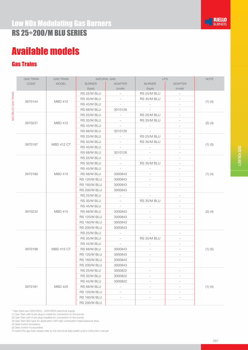
287
LOW
NOx
GAS
Low NOx Modulating Gas BurnersRS 25÷200/M BLU SERIES
Gas Trains
Available models
GAS TRAIN GAS TRAIN NATURAL GAS LPG NOTE
CODE* MODEL BURNER ADAPTER BURNER ADAPTER
(type) (code) (type) (code)
MU
LTIB
LOC
GA
S T
RA
INS
3970144
MBD 412
RS 25/M BLU - RS 25/M BLU -
(1) (4)
RS 35/M BLU - RS 35/M BLU -
RS 45/M BLU - - -
RS 68/M BLU 3010126 - -
3970231
MBD 412
RS 25/M BLU - RS 25/M BLU -
(2) (4)
RS 35/M BLU - RS 35/M BLU -
RS 45/M BLU - - -
RS 68/M BLU 3010126 - -
3970197
MBD 412 CT
RS 25/M BLU - RS 25/M BLU -
(1) (5)
RS 35/M BLU - RS 35/M BLU -
RS 45/M BLU - - -
RS 68/M BLU 3010126 - -
3970180
MBD 415
RS 25/M BLU - - -
(1) (4)
RS 35/M BLU - RS 35/M BLU -
RS 45/M BLU - - -
RS 68/M BLU 3000843 - -
RS 120/M BLU 3000843 - -
RS 160/M BLU 3000843 - -
RS 200/M BLU 3000843
3970232
MBD 415
RS 25/M BLU - - -
(2) (4)
RS 35/M BLU - RS 35/M BLU -
RS 45/M BLU - - -
RS 68/M BLU 3000843 - -
RS 120/M BLU 3000843 - -
RS 160/M BLU 3000843 - -
RS 200/M BLU 3000843
3970198
MBD 415 CT
RS 25/M BLU - - -
(1) (5)
RS 35/M BLU - RS 35/M BLU -
RS 45/M BLU - - -
RS 68/M BLU 3000843 - -
RS 120/M BLU 3000843 - -
RS 160/M BLU 3000843 - -
RS 200/M BLU 3000843
3970181
MBD 420
RS 25/M BLU 3000822 - -
(1) (4)
RS 35/M BLU 3000822 - -
RS 45/M BLU 3000822 - -
RS 68/M BLU - - -
RS 120/M BLU - - -
RS 160/M BLU - - -
RS 200/M BLU
* Gas trains are 230V/50Hz - 220V/60Hz electrical supply.(1) Gas Train with 6-pin plug to install for connection to the burner. (2) Gas Train with 6-pin plug installed for connection to the burner.(3) Gas Train S52 type for application with high combustion head pressure drop. (4) Seal control accessory.(5) Seal control incorporated.To select the gas train please refer to the technical data leafl et and/or instruction manual.
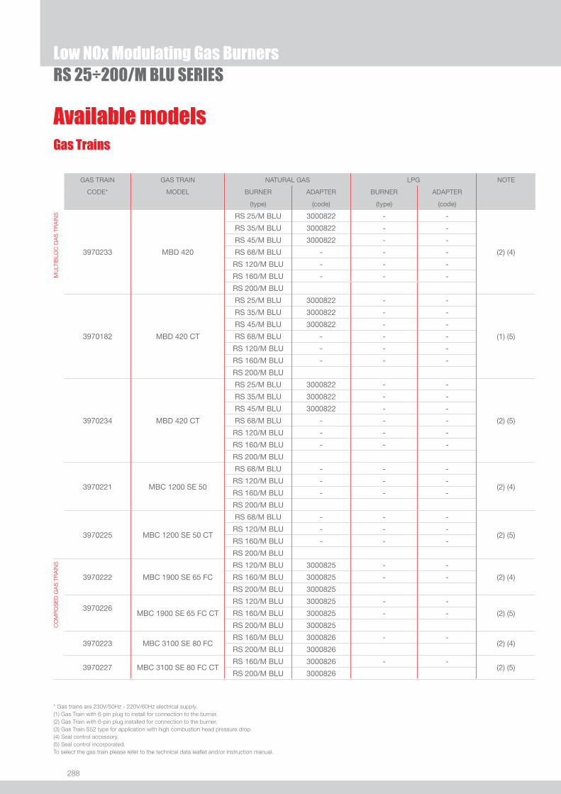
288
Available modelsGas Trains
RS 25÷200/M BLU SERIESLow NOx Modulating Gas Burners
GAS TRAIN GAS TRAIN NATURAL GAS LPG NOTE
CODE* MODEL BURNER ADAPTER BURNER ADAPTER
(type) (code) (type) (code)
MU
LTIB
LOC
GA
S T
RA
INS
RS 25/M BLU 3000822 - -
RS 35/M BLU 3000822 - -
RS 45/M BLU 3000822 - -
3970233 MBD 420 RS 68/M BLU - - - (2) (4)
RS 120/M BLU - - -
RS 160/M BLU - - -
RS 200/M BLU
RS 25/M BLU 3000822 - -
RS 35/M BLU 3000822 - -
RS 45/M BLU 3000822 - -
3970182 MBD 420 CT RS 68/M BLU - - - (1) (5)
RS 120/M BLU - - -
RS 160/M BLU - - -
RS 200/M BLU
RS 25/M BLU 3000822 - -
RS 35/M BLU 3000822 - -
RS 45/M BLU 3000822 - -
3970234 MBD 420 CT RS 68/M BLU - - - (2) (5)
RS 120/M BLU - - -
RS 160/M BLU - - -
RS 200/M BLU
3970221
MBC 1200 SE 50
RS 68/M BLU - - -
(2) (4)
RS 120/M BLU - - -
RS 160/M BLU - - -
RS 200/M BLU
3970225
MBC 1200 SE 50 CT
RS 68/M BLU - - -
(2) (5)
RS 120/M BLU - - -
RS 160/M BLU - - -
RS 200/M BLU
CO
MP
OS
ED
GA
S T
RA
INS
3970222 MBC 1900 SE 65 FC
RS 120/M BLU 3000825 - -
(2) (4) RS 160/M BLU 3000825 - -
RS 200/M BLU 3000825
3970226
MBC 1900 SE 65 FC CT
RS 120/M BLU 3000825 - -
(2) (5) RS 160/M BLU 3000825 - -
RS 200/M BLU 3000825
3970223 MBC 3100 SE 80 FC RS 160/M BLU 3000826 - -
(2) (4)RS 200/M BLU 3000826
3970227 MBC 3100 SE 80 FC CTRS 160/M BLU 3000826 - -
(2) (5)RS 200/M BLU 3000826
* Gas trains are 230V/50Hz - 220V/60Hz electrical supply.(1) Gas Train with 6-pin plug to install for connection to the burner. (2) Gas Train with 6-pin plug installed for connection to the burner.(3) Gas Train S52 type for application with high combustion head pressure drop. (4) Seal control accessory.(5) Seal control incorporated.To select the gas train please refer to the technical data leafl et and/or instruction manual.

289
Burner accessories
LOW
NOx
GAS
Low NOx Modulating Gas BurnersRS 25÷200/M BLU SERIES
If burner head penetration into the combustion chamber needs reducing, varying thickness spacers are available, as given in the following list.
Spacer kit
BURNER
SPACER THICKNESS S (mm)
KIT CODE
u RS 25/M - 35/M - 45/M BLU 90 3010095
u RS 68/M - 120/M BLU 135 3010129
u RS 160/M - 200/M BLU 110 3000722
“Standard head” burners can be transformed into “extended head” versions, by using the special kit. The KITS available for the various burners, giving the original and the extended lengths, are listed below.
Extended head kit
BURNER
STANDARD HEAD LENGTH (mm)
EXTENDED HEAD LENGTH (mm)
KIT CODE
u RS 25/M BLU 230 365 3010430
u RS 35/M BLU 230 365 3010431
u RS 45/M BLU 229 354 3010240
u RS 68/M - 120/M BLU 255 390 3010177
u RS 160/M BLU 373 503 3010442
u RS 200/M BLU 373 503 3010474
Continuous ventilation kit
BURNER KIT CODE
u RS 25/M - 35/M BLU 3010449
u RS 45/M - 68/M - 120/M - 160/M - 200/M BLU 3010094
If the burner requires continuous ventilation in the stages without fl ame, a special kit is available as given in the following table.
If noise emission needs reducing even further, sound-proofi ng boxes are available.
Sound proofi ng box
BURNER
BOX TYPE
AVERAGE NOISE REDUCTION [dB(A)] (*)
BOX CODE
u RS 25/M - 35/M - 45/M BLU C1/3 10 3010403
u RS 68/M - 120/M - 160/M - 200/M BLU C4/5 10 3010404
(*) according to EN 15036-1 standard

290
Burner accessoriesAccessories for modulating operation
To obtain modulating operation, the RS/M BLU series of burners requires a regulator with three point outlet controls. On RS 25/M - 35/M BLU the regulator is connected to the burner electrical wiring by plug-in system in order to make the connection easier and faster. The following table lists the accessories for modulating operation with their application range.
BURNER
REGULATOR TYPE
REGULATOR CODE
u RS 25/M - 35/M - 45/M BLU RWF 40 3010417
u RS 68/M - 120/M - 160/M BLU RWF 40 3010212
u RS 200/M BLU RWF 40 3010414
Depending on the servomotor fi tted to the burner, a three-pole potentiometer (1000 Ω) can be installed to check the position of the servomotor. The KITS available for the various burners are listed below.
BURNER
POTENTIOMETER KIT CODE
u RS 25/M - 35/M BLU 3010420
u RS 45/M BLU 3010109
u RS 68/M - 120/M - 160/M BLU 3010021
u RS 200/M BLU 3010416
The relative temperature or pressure probes fi tted to the regulator, must be chosen on the basis of the application.
BURNER PROBE TYPE RANGE (°C) (bar) PROBE CODE
u RS 25/M - 35/M - 45/M - 68/M BLU
RS 120/M - 160/M - 200/M BLU
Temperature PT 100 -100 ÷ 500°C 3010110
Pressure 4 ÷ 20 mA 0 ÷ 2,5 bar 3010213
Pressure 4 ÷ 20 mA 0 ÷ 16 bar 3010214
RS 25÷200/M BLU SERIESLow NOx Modulating Gas Burners
BURNER TYPE (INPUT SIGNAL) CODE
u RS 25/M - 35/M BLU0/2 - 10 V (impedance 200 KΩ)0/4 - 20 mA (impedance 250 Ω)
3010410
uRS 45/M - 68/M BLU RS 120/M - 160/M BLU
0/2 - 10 V (impedance 200 KΩ)0/4 - 20 mA (impedance 250 Ω)
on demand
u RS 200/M BLU0/2 - 10 V (impedance 200 KΩ)0/4 - 20 mA (impedance 250 Ω)
3010415
Modulating operation can also be obtained with an analog control signal converter and a feedback three-pole potentiometer.Alternatively, the potentiometer can be used to check the servomotor position.

291
Burner accessories
LOW
NOx
GAS
Low NOx Modulating Gas BurnersRS 25÷200/M BLU SERIES
Head kit for “reverse fl ame chamber”
In certain cases, the use of the burner on reverse fl ame boilers can be improved by using an additional Pipes Kit.
BURNER KIT CODE
u RS 68/M BLU 3010247
u RS 120/M BLU 3010248
u RS 160/M BLU 3010249
Ground fault interrupter kit
A “Ground fault interrupter kit” is available as a safety device in case of electrical system fault.
BURNER KIT CODE
u RS 25/M - 35/M BLU 3010448
Gas max pressure switch
If necessary a Gas max pressure Switch kit is available and connectable to the burner electrical wiring trough Plugs & Sockets system.
BURNER CODE
u RS 25/M - 35/M BLU 3010418
�� ��
��
�
����
����
��
��
���
Volt free contact kitA volt free contact kit is available for installation onto the burner. It can be used for a remote interface between burner operating signals. Every burner can be equipped with a single kit for a remote check of the fl ame presence signal and the burner lockout indication.
BURNER KIT CODE
u RS 25/M - 35/M BLU 3010419
BURNER KIT CODE
u RS 25/M - 35/M - 45/M - 68/M - 120/M - 160/M - 200/M BLU 3002719
To connect the control box to a personal computer for the transmission of operation, fault signals and detailed service information, an interface adapter with PC software are available.
PC Interface kit
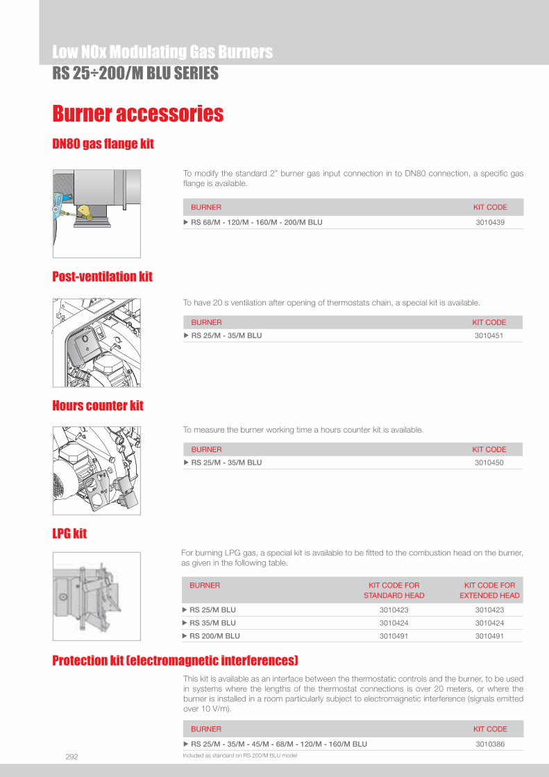
292
Burner accessories
RS 25÷200/M BLU SERIESLow NOx Modulating Gas Burners
DN80 gas fl ange kit
To modify the standard 2” burner gas input connection in to DN80 connection, a specifi c gas fl ange is available.
Hours counter kit
To measure the burner working time a hours counter kit is available.
BURNER KIT CODE
u RS 25/M - 35/M BLU 3010450
Post-ventilation kit
To have 20 s ventilation after opening of thermostats chain, a special kit is available.
BURNER KIT CODE
u RS 25/M - 35/M BLU 3010451
BURNER KIT CODE
u RS 68/M - 120/M - 160/M - 200/M BLU 3010439
LPG kitFor burning LPG gas, a special kit is available to be fi tted to the combustion head on the burner, as given in the following table.
BURNER KIT CODE FOR STANDARD HEAD
KIT CODE FOR EXTENDED HEAD
u RS 25/M BLU 3010423 3010423
u RS 35/M BLU 3010424 3010424
u RS 200/M BLU 3010491 3010491
This kit is available as an interface between the thermostatic controls and the burner, to be used in systems where the lengths of the thermostat connections is over 20 meters, or where the burner is installed in a room particularly subject to electromagnetic interference (signals emitted over 10 V/m).
BURNER KIT CODE
u RS 25/M - 35/M - 45/M - 68/M - 120/M - 160/M BLU 3010386
Protection kit (electromagnetic interferences)
Included as standard on RS 200/M BLU model

293
LOW
NOx
GAS
Low NOx Modulating Gas BurnersRS 25÷200/M BLU SERIES
Gas train accessoriesAdapters
When the diameter of the gas train is different from the set diameter of the burners, an adapter must be fi tted between the gas train and the burner.
BURNER GAS TRAIN DIMENSIONS ADAPTER CODE
u RS 25/M BLU MBD 405 - 407 - 410 1” 1/23/4” 3000824
MBD 420 1” 1/22” 3000822
u RS 35/M BLU MBD 405 - 407 - 410 1” 1/23/4” 3000824
MBD 420 1” 1/22” 3000822
u RS 120/M BLU
MBD 415 2”1” 1/2 3000843
MBC 1900 2” 1/2DN 65
1” 1/2
2”
3000825
u RS 160/M BLU
MBD 415 2”1” 1/2 3000843
MBC 1900 2” 1/2DN 65
1” 1/2
2”
3000825
MBC 3100 2” 1/2DN 80 2” 3000826
u RS 45/M BLU MBD 407 - 410 1” 1/23/4” 3000824
MBD 420 1” 1/22” 3000822
u RS 200/M BLU
MBD 415 2”1” 1/2 3000843
MBC 1900 2” 1/2DN 65
1” 1/2
2”
3000825
MBC 3100 2” 1/2DN 80 2” 3000826
u RS 68/M BLU MBD 412 2”1” 1/4 3010126
MBD 415 2”1” 1/2 3000843
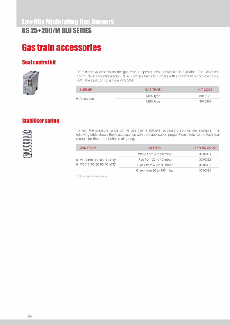
294
Gas train accessories
Seal control kit
To test the valve seals on the gas train, a special “seal control kit” is available. The valve seal control device is compulsory (EN 676) on gas trains to burners with a maximum output over 1200 kW. The seal control is type VPS 504.
BURNER GAS TRAIN KIT CODE
u All modelsMBD type 3010123
MBC type 3010367
Stabiliser spring
To vary the pressure range of the gas train stabilisers, accessory springs are available. The following table shows these accessories with their application range. Please refer to the technical manual for the correct choice of spring.
GAS TRAIN SPRING SPRING CODE
u
u
MBC 1900 SE 65 FC (CT)*MBC 3100 SE 80 FC (CT)*
White from 4 to 20 mbar 3010381
Red from 20 to 40 mbar 3010382
Black from 40 to 80 mbar 3010383
Green from 80 to 150 mbar 3010384
RS 25÷200/M BLU SERIESLow NOx Modulating Gas Burners
* with and without seal control.

295
LOW
NOx
GAS
Low NOx Modulating Gas Burners
RS 25÷200/E-EV BLU SERIESThe RS/E BLU and RS/EV BLU burners series covers a fi ring range from 44 to 2400 kW, and it is based on a new Digital Burner Management System, Riello REC27-37, which is able to manage the air-fuel ratio by independent servomotors in order to obtain a perfect output control and to assure a correct combustion and safe operation on all modulation range. Operation can be “two stage progressive” or, alternatively, “modulating” with the installation of a PID logic regulator and respective probes. RS/E BLU burners series guarantees high effi ciency levels in all the various applications, thus reducing fuel consumption and running costs; specifi cs versions are available to operate with Variable Speed Drive technology base on the control of a Frequency Inverter that modifi es the air fl ow through the motor speed variation. Optimisation of sound emissions is guaranteed by the special design of the air suction circuit and by incorporated sound proofi ng material.
RS 25/E BLU 44/125 ÷ 370 kWRS 35/E BLU 70/200 ÷ 480 kWRS 45/E BLU 90/190 ÷ 550 kWRS 68/E BLU-RS 68/EV BLU 150/350 ÷ 860 kWRS 120/E BLU-RS 120/EV BLU 300/600 ÷ 1300 kWRS 160/E BLU-RS 160/EV BLU 300/930 ÷ 1860 kWRS 200/E BLU-RS 200/EV BLU 570/1375 ÷ 2400 kW
FIRING RATES
Useful working fi eldfor choosing theburner
Modulation range
Test conditionsconforming to EN676 Temperature: 20°CPressure: 1013,5 mbarAltitude: 0 m a.s.l.
RS 25/E BLU
RS 35/E BLU
RS 45/E BLU
RS 68/E-EV BLU
RS 120/E-EV BLU
RS 200/E-EV BLU
RS 160/E-EV BLU

296
BURNER
Overall dimensions (mm)
RS 25÷200/E-EV BLU SERIESLow NOx Modulating Gas Burners
A
D
B C
V
O - O (1)E
I
F - F (1)L
N
M
H
RS 25/E - 35/E BLU RS 45/E BLU
RS 68/E-EV - 120/E-EV - 160/E-EV - 200/E-EV BLU
(1) dimension with extended head
MODEL A B C D E F - F (1) H I L M N O - O(1) S V u RS 25/E BLU 442 - - 422 508 230 - 365 140 305 138 1”1/2 84 780 - - - 177 u RS 35/E BLU 442 - - 422 508 230 - 365 152 305 138 1”1/2 84 780 - - - 177 u RS 45/E BLU 476 - - 474 580 229 - 354 160 352 164 1”1/2 108 810 - 810 367 168 u RS 68/E-EV BLU 527 312 215 555 840 255 - 390 189 430 214 2” 134 1161 - 1296 - 221 u RS 120/E-EV BLU 553 338 215 555 840 255 - 390 189 430 214 2” 134 1161 - 1296 - 221 u RS 160/E-EV BLU 671 366 305 555 863 373 - 503 221 436 221 2” 141 1442 - 1587 - 264 u RS 200/E-EV BLU 737 432 305 555 863 373 - 503 221 436 221 2” 141 1442 - 1587 - 264
MODEL D1 D2 Ø u RS 25/E BLU 160 224 M8 u RS 35/E BLU 160 224 M8 u RS 45/E BLU 165 224 M8 u RS 68/E-EV BLU 195 275-325 M12 u RS 120/E-EV BLU 195 275-325 M12 u RS 160/E-EV BLU 230 325-368 M16 u RS 200/E-EV BLU 230 325-368 M16
(1) dimension with standard and extended head
MODEL X(1) Y Z kg u RS 25/E BLU 1000 485 500 39 u RS 35/E BLU 1000 485 500 40 u RS 45/E BLU 1015 500 630 48 u RS 68/E-EV BLU 1405 700 660 78 u RS 120/E-EV BLU 1405 700 660 84 u RS 160/E-EV BLU 1405-1420 1000 660 89 u RS 200/E-EV BLU 1405-1420 1000 660 125
BURNER - BOILER MOUNTING FLANGE
Z
X(1)Y
PACKAGING
A
D
E
FF (1)
I
N
V
O - O (1)
S
H
M
A
D
O
FF (1)
E
H
I
N
VM
LL
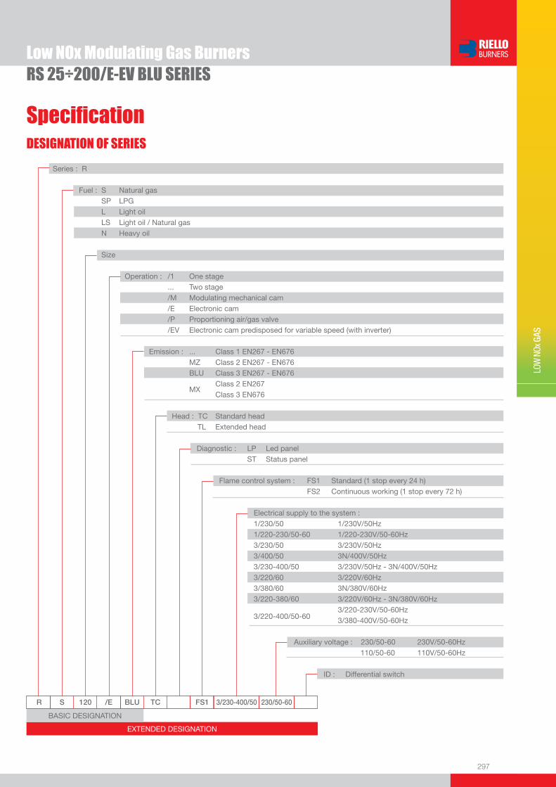
297
DESIGNATION OF SERIES
Specifi cation
LOW
NOx
GAS
Low NOx Modulating Gas BurnersRS 25÷200/E-EV BLU SERIES
EXTENDED DESIGNATION
R S 120 /E BLU TC FS1 3/230-400/50 230/50-60
Series : R
Fuel : S Natural gas SP LPG L Light oil LS Light oil / Natural gas N Heavy oil
Size
Operation : /1 One stage ... Two stage /M Modulating mechanical cam /E Electronic cam /P Proportioning air/gas valve /EV Electronic cam predisposed for variable speed (with inverter) Emission : ... Class 1 EN267 - EN676 MZ Class 2 EN267 - EN676 BLU Class 3 EN267 - EN676
MX Class 2 EN267
Class 3 EN676
Head : TC Standard head TL Extended head
Diagnostic : LP Led panel ST Status panel
Flame control system : FS1 Standard (1 stop every 24 h) FS2 Continuous working (1 stop every 72 h)
Electrical supply to the system : 1/230/50 1/230V/50Hz 1/220-230/50-60 1/220-230V/50-60Hz 3/230/50 3/230V/50Hz 3/400/50 3N/400V/50Hz 3/230-400/50 3/230V/50Hz - 3N/400V/50Hz 3/220/60 3/220V/60Hz 3/380/60 3N/380V/60Hz 3/220-380/60 3/220V/60Hz - 3N/380V/60Hz
3/220-400/50-60 3/220-230V/50-60Hz
3/380-400V/50-60Hz
Auxiliary voltage : 230/50-60 230V/50-60Hz 110/50-60 110V/50-60Hz
ID : Differential switch
BASIC DESIGNATION
298
RS 25÷200/E-EV BLU SERIESLow NOx Modulating Gas Burners
STATE OF SUPPLY
Specifi cation
RS 25/E - 35/E BLU modelsMonoblock forced draught Low NOx gas burner with two stage progressive or modulating operation, with a specifi c kit, fully automatic, made up of:- Microprocessor-based Digital Burner Management System (RS/E models) - Display Interface operating unit to adjust the system- Air suction circuit with sound proofi ng material- High performance fan with straight blades- Air damper for air fl ow setting and butterfl y valve for regulating fuel output controlled by independent stepper motor actuators - Starting motor at 2800 rpm, single-phase/220-230V/50-60Hz or three-phase/380-400V/50-60Hz- low emission combustion head, that can be set on the basis of required output, fi tted with: - stainless steel end cone, resistant to corrosion and high temperatures - ignition electrodes - ionisation probe - gas distributor - fl ame stability disk- Exclusive patented HCS (Housing Cooling System) with high thermal insulation and air circulation with continuous air volume refresh
for an active cooling system and avoid heat transfer to the electrical component housing- Minimum air pressure switch stops the burner in case of insuffi cient air quantity at the combustion head- Plugs and sockets for electrical connection, accessible from the external of the cover- Burner on/off selection switch- Flame inspection window- Slide bars for easier installation and maintenance- Protection fi lter against radio interference- IP X0D (IP 40) electric protection level.
Standard equipment:- 1 gas train fl ange- 1 fl ange gasket- 4 screws for fi xing the fl ange- 1 thermal screen- 4 screws for fi xing the burner fl ange to the boiler- 3 plugs for electrical connection (RS 25-35/E BLU single-phase)- 4 plugs for electrical connection (RS 35/E BLU three-phase)- Instruction handbook for installation, use and maintenance- Spare parts catalogue.
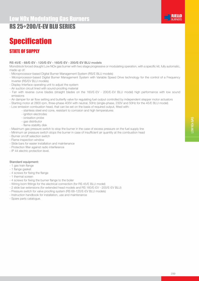
299
LOW
NOx
GAS
Low NOx Modulating Gas BurnersRS 25÷200/E-EV BLU SERIES
RS 45/E - 68/E-EV - 120/E-EV - 160/E-EV - 200/E-EV BLU modelsMonoblock forced draught Low NOx gas burner with two stage progressive or modulating operation, with a specifi c kit, fully automatic, made up of:- Microprocessor-based Digital Burner Management System (RS/E BLU models)- Microprocessor-based Digital Burner Management System with Variable Speed Drive technology for the control of a Frequency
Inverter (RS/EV BLU models)- Display Interface operating unit to adjust the system- Air suction circuit lined with sound-proofi ng material- Fan with reverse curve blades (straight blades on the 160/E-EV - 200/E-EV BLU model) high performance with low sound
emissions- Air damper for air fl ow setting and butterfl y valve for regulating fuel output controlled by independent stepper motor actuators - Starting motor at 2800 rpm, three-phase 400V with neutral, 50Hz (single-phase, 230V and 50Hz for the 45/E BLU model)- Low emission combustion head, that can be set on the basis of required output, fi tted with: - stainless steel end cone, resistant to corrosion and high temperatures - ignition electrodes - ionisation probe - gas distributor - fl ame stability disk- Maximum gas pressure switch to stop the burner in the case of excess pressure on the fuel supply line- Minimum air pressure switch stops the burner in case of insuffi cient air quantity at the combustion head- Burner on/off selection switch- Flame inspection window- Slide bars for easier installation and maintenance- Protection fi lter against radio interference- IP 44 electric protection level.
Standard equipment:- 1 gas train fl ange- 1 fl ange gasket- 4 screws for fi xing the fl ange- 1 thermal screen- 4 screws for fi xing the burner fl ange to the boiler- Wiring loom fi ttings for the electrical connection (for RS 45/E BLU model)- 2 slide bar extensions (for extended head models and RS 160/E-EV - 200/E-EV BLU)- Pressure switch for valve proofi ng system (RS 68-120/E-EV BLU models) - Instruction handbook for installation, use and maintenance- Spare parts catalogue.
STATE OF SUPPLY
Specifi cation

300
Available models
RS 25÷200/E-EV BLU SERIESLow NOx Modulating Gas Burners
Natural gas, net calorifi c value: 10 kWh/Nm3 - Density: 0,71 kg/Nm3
The burners of RS/E BLU series are in according to 90/396 - 89/336 (2004/108) - 73/23 (2006/95) - 92/42 EC Directive and EN 676.(1) With plug and socket.(2) With terminal board.(3) Seal control function is included on Burner Digital Management System; it is necessary to add the PVP kit on the gas train as Accessory (see Gas Train Accessories paragraph).(4) Seal control function is included on Burner Digital Management System; it is necessary to add the PVP kit (included as burner standard equipment) on the gas train.(5) Frequency Inverter installed on burner motor. (6) Frequency Inverter to be ordered as separated accessory; please refer to “Burner Accessories” paragraph. (7) Please ask for specifi c code.
CODE MODEL HEAT OUTPUT TOTAL ELECTRICAL
POWER
CERTIFICATION NOTE
NATURAL GAS
(kW) (Nm3/h) (kW)
3910710 RS 25/E BLU TC FS1 1/220-230/50-60 220-230/50-60 44/125÷370 4,5/13÷37 0,6 EC 0085BS0379 (1)(3)
3910711 RS 25/E BLU TL FS1 1/220-230/50-60 220-230/50-60 44/125÷370 4,5/13÷37 0,6 EC 0085BS0379 (1)(3)
3910810 RS 35/E BLU TC FS1 1/220-230/50-60 220-230/50-60 70/200÷480 7/20÷48 0,7 EC 0085BS0379 (1)(3)
3910811 RS 35/E BLU TL FS1 1/220-230/50-60 220-230/50-60 70/200÷480 7/20÷48 0,7 EC 0085BS0379 (1)(3)
3910840 RS 35/E BLU TC FS1 3/220-400/50-60 220-230/50-60 70/200÷480 7/20÷48 0,75 EC 0085BS0379 (1)(3)
3910841 RS 35/E BLU TL FS1 3/220-400/50-60 220-230/50-60 70/200÷480 7/20÷48 0,75 EC 0085BS0379 (1)(3)
3897332 RS 45/E BLU TC FS1 1/230/50 230/50-60 90/190-550 9/19-55 0,7 EC 0085BS0380 (1)(3)
3897333 RS 45/E BLU TL FS1 1/230/50 230/50-60 90/190-550 9/19-55 0,7 EC 0085BS0380 (1)(3)
3897432 RS 68/E BLU TC FS1 3/230-400/50 230/50-60 150/350-860 15/35-86 2,0 EC 0085BS0267 (2)(3)
3897433 RS 68/E BLU TL FS1 3/230-400/50 230/50-60 150/350-860 15/35-86 2,0 EC 0085BS0267 (2)(3)
3897632 RS 120/E BLU TC FS1 3/230-400/50 230/50-60 300/600-1300 30/60-130 2,8 EC 0085BS0268 (2)(4)
3897633 RS 120/E BLU TL FS1 3/230-400/50 230/50-60 300/600-1300 30/60-130 2,8 EC 0085BS0268 (2)(4)
3788032 RS 160/E BLU TC FS1 3/400/50 230/50-60 300/930-1860 30/93-186 5,3 EC 0085BS0266 (2)(4)
3788033 RS 160/E BLU TL FS1 3/400/50 230/50-60 300/930-1860 30/93-186 5,3 EC 0085BS0266 (2)(4)
3899810 RS 200/E BLU TC FS1 3/400/50 230/50-60 570/1375-2400 57/138-240 6,5 in progress (2)(4)
3899811 RS 200/E BLU TL FS1 3/400/50 230/50-60 570/1375-2400 57/138-240 6,5 in progress (2)(4)
3899840 RS 200/E BLU TC FS1 3/230/50 230/50-60 570/1375-2400 57/138-240 6,5 in progress (2)(4)
3899841 RS 200/E BLU TL FS1 3/230/50 230/50-60 570/1375-2400 57/138-240 6,5 in progress (2)(4)
(7) RS 68/EV BLU TC FS1 3/230-400/50 230/50-60 150/350-860 15/35-86 2,0 in progress (2)(3)(5)
(7) RS 68/EV BLU TL FS1 3/230-400/50 230/50-60 150/350-860 15/35-86 2,0 in progress (2)(3)(5)
(7) RS 120/EV BLU TC FS1 3/230-400/50 230/50-60 300/600-1300 30/60-130 2,8 in progress (2)(4)(5)
(7) RS 120/EV BLU TL FS1 3/230-400/50 230/50-60 300/600-1300 30/60-130 2,8 in progress (2)(4)(5)
20010976 RS 120/EV BLU TC FS1 3/230-400/50 230/50-60 300/600-1300 30/60-130 2,8 in progress (2)(4)(6)
(7) RS 160/EV BLU TC FS1 3/400/50 230/50-60 300/930-1860 30/93-186 5,3 in progress (2)(4)(5)
(7) RS 160/EV BLU TL FS1 3/400/50 230/50-60 300/930-1860 30/93-186 5,3 in progress (2)(4)(5)
20010988 RS 160/EV BLU TC FS1 3/400/50 230/50-60 300/930-1860 30/93-186 5,3 in progress (2)(4)(6)
(7) RS 200/EV BLU TC FS1 3/400/50 230/50-60 570/1375-2400 57/138-240 6,5 in progress (2)(4)(5)
(7) RS 200/EV BLU TL FS1 3/400/50 230/50-60 570/1375-2400 57/138-240 6,5 in progress (2)(4)(5)
20006982 RS 200/EV BLU TC FS1 3/400/50 230/50-60 570/1375-2400 57/138-240 6,5 in progress (2)(4)(6)
Burners

301
LOW
NOx
GAS
Low NOx Modulating Gas BurnersRS 25÷200/E-EV BLU SERIES
Gas Trains
* Gas trains are 230V/50Hz - 220V/60Hz electrical supply.(1) Gas Train with 6-pin plug to install for connection to the burner. (2) Gas Train with 6-pin plug installed for connection to the burner.(3) Integrated seal control is not available with this gas train. To select the gas train please refer to the technical data leafl et and/or instruction manual.
GAS TRAIN GAS TRAIN NATURAL GAS LPG NOTE
CODE* MODEL BURNER ADAPTER BURNER ADAPTER
(type) (code) (type) (code)
MU
LTIB
LOC
GA
S T
RA
INS
3970602 MBC 120
RS 25/E BLU 3000824 RS 25/E BLU 3000824
(1) (3) RS 35/E BLU 3000824 RS 35/E BLU 3000824
RS 45/E BLU 3000824 - -
RS 25/E BLU 3000824 RS 25/E BLU 3000824
3970599 MBD 407 RS 35/E BLU 3000824 RS 35/E BLU 3000824 (1)
RS 45/E BLU 3000824 - -
RS 25/E BLU - RS 25/E BLU -
3970258 MBD 410 RS 35/E BLU - RS 35/E BLU - (1)
RS 45/E BLU - - -
3970256
MBD 412
RS 25/E BLU - RS 25/E BLU -
(1)
RS 35/E BLU - RS 35/E BLU -
RS 45/E BLU - - -
RS 68/E-EV BLU 3010126 - -
RS 120/E-EV BLU 3010126 - -
3970250
MBD 415
RS 25/E BLU - - -
(1)
RS 35/E BLU - RS 35/E BLU -
RS 45/E BLU - - -
RS 68/E-EV BLU 3000843 - -
RS 120/E-EV BLU 3000843 - -
RS 160/E-EV BLU 3000843 - -
RS 200/E-EV BLU 3000843 - -
3970257 MBD 420
RS 25/E BLU 3000822 - -
(1)
RS 35/E BLU 3000822 - -
RS 45/E BLU 3000822 - -
RS 68/E-EV BLU - - -
RS 120/E-EV BLU - - -
RS 160/E-EV BLU - - -
RS 200/E-EV BLU - - -
3970221 MBC 1200 SE 50
RS 68/E-EV BLU - - -
(2)RS 120/E-EV BLU - - -
RS 160/E-EV BLU - - -
RS 200/E-EV BLU - - -
CO
MP
OS
ED
GA
S T
RA
INS
3970222 MBC 1900 SE 65 FC
RS 68/E-EV BLU 3000825 - -
(2)RS 120/E-EV BLU 3000825 - -
RS 160/E-EV BLU 3000825 - -
RS 200/E-EV BLU 3000825 - -
3970223 MBC 3100 SE 80 FCRS 160/E-EV BLU 3000826 - -
(2)RS 200/E-EV BLU 3000826 - -
Available models

302
RS 25÷200/E-EV BLU SERIESLow NOx Modulating Gas Burners
Burner accessories
If burner head penetration into the combustion chamber needs reducing, varying thickness spacers are available, as given in the following list.
Spacer kit
“Standard head” burners can be transformed into “extended head” versions, by using the special kit. The KITS available for the various burners, giving the original and the extended lengths, are listed below.
Extended head kit
Continuous ventilation kit
If the burner requires continuous ventilation in the stages without fl ame, a special kit is available as given in the following table.
Sound proofi ng box
If noise emission needs reducing even further, sound-proofi ng boxes are available, as given in the following table:
BURNER BOX TYPE
AVERAGE NOISE REDUCTION [dB(A)](*)
BOX CODE
u RS 25/E - 35/E - 45/E BLU C1/3 10 3010403
u RS 68/E-EV - 120/E-EV - 160/E-EV - 200/E-EV BLU C4/5 10 3010404
BURNER SPACER THICKNESS S (mm)
KIT CODE
u RS 25/E - 35/E - 45/E BLU 90 3010095
u RS 68/E-EV - 120/E-EV BLU 135 3010129
u RS 160/E-EV - 200/E-EV BLU 110 3000722
(*) according to EN 15036-1 standard
BURNER KIT CODE
u RS 25/E - 35/E BLU 3010449
u RS 45/E - 68/E-EV - 120/E-EV - 160/E-EV - 200/E-EV BLU 3010094
Note: the Post-ventilation function is obtainable by modifi cation of the Digital Burner Management System parameters (see burner instruction manual).
BURNER STANDARD HEAD LENGTH (mm)
EXTENDED HEAD LENGTH (mm)
KIT CODE
u RS 25/E BLU 230 365 3010430
u RS 35/E BLU 230 365 3010431
u RS 45/E BLU 229 354 20006586
u RS 68/E-EV - 120/E-EV BLU 255 390 3010177
u RS 160/E-EV BLU 373 503 3010442
u RS 200/E-EV BLU 373 503 3010474

303
Burner accessories
LOW
NOx
GAS
Low NOx Modulating Gas BurnersRS 25÷200/E-EV BLU SERIES
To obtain modulating operation, the RS/E BLU series of burners requires a regulator with three point outlet controls. On RS 25/E - 35/E BLU the regulator is connected to the burner electrical wiring by plug-in system in order to make the connection easier and faster. The following table lists the accessories for modulating operation with their application range.
Accessories for modulating operation
BURNER
REGULATOR TYPE
REGULATOR CODE
u RS 25/E - 35/E - 45/E BLU RWF 40 3010417
u RS 68/E-EV - 120/E-EV - 160/E-EV - 200/E-EV BLU RWF 40 3010414
The relative temperature or pressure probes fi tted to the regulator, must be chosen on the basis of the application.
BURNER PROBE TYPE RANGE (°C) (bar) PROBE CODE
u
RS 25/E - 35/E - 45/E BLU RS 68/E-EV - 120/E-EV BLU RS 160/E-EV - 200/E-EV BLU
Temperature PT 100 -100 ÷ 500°C 3010110
Pressure 4 ÷ 20 mA 0 ÷ 2,5 bar 3010213
Pressure 4 ÷ 20 mA 0 ÷ 16 bar 3010214
Head kit for “reverse fl ame chamber”
In certain cases, the use of the burner on reverse fl ame boilers can be improved by using an additional Pipes Kit.
BURNER KIT CODE
u RS 68/E-EV BLU 3010247
u RS 120/E-EV BLU 3010248
u RS 160/E-EV BLU 3010249
Ground fault interrupter kit
A “Ground fault interrupter kit” is available as a safety device in case of electrical system fault.
BURNER KIT CODE
u RS 25/E - 35/E BLU 3010448
Gas max pressure switch
If necessary a Gas max pressure Switch kit is available and connectable to the burner electrical wiring trough Plugs & Sockets system.
BURNER CODE
u RS 25/E - 35/E BLU 3010418
�� ��
��
�
����
����
��
��
���

304
RS 25÷200/E-EV BLU SERIESLow NOx Modulating Gas Burners
Burner accessoriesVolt free contact kit
A volt free contact kit is available for installation onto the burner. It can be used for a remote interface between burner operating signals. Every burner can be equipped with a single kit for a remote check of the fl ame presence signal and the burner lockout indication.
BURNER KIT CODE
u RS 25/E - 35/E BLU 3010419
OCI412 interface kitInterface kit between the REC27.100A2 and a Modbus system, such as a building automation and control system (BACS).The Modbus interface is based on the RS-485 standard.
BURNER KIT CODE
u RS 25/E - 35/E - 45/E - 68/E-EV - 120/E-EV - 160/E-EV - 200/E-EV BLU 3010437
OCI410 interface for ACS410 software kit
Interface kit between burner management system and PC. It facilitates viewing, handling and recording setting parameters on site.
BURNER KIT CODE
u RS 25/E - 35/E - 45/E - 68/E-EV - 120/E-EV - 160/E-EV - 200/E-EV BLU 3010436
LPG kitFor burning LPG gas, a special kit is available to be fi tted to the combustion head on the burner, as given in the following table:
BURNER KIT CODE FOR‘STANDARD HEAD’
KIT CODE FOR‘EXTENDED HEAD’
u RS 25/E BLU 3010423 3010423
u RS 35/E BLU 3010424 3010424
u RS 200/E-EV BLU 3010491 3010491
DN80 gas fl ange kit
To modify the standard 2” burner gas input connection in to DN80 connection, a specifi c gas fl ange is available.
BURNER KIT CODE
u RS 68/E-EV - 120/E-EV - 160/E-EV - 200/E-EV BLU 3010439
Variable Speed Drive (VSD) for RS/EV series onlyThe motor speed variation for the RS/EV BLU burners series is obtained thanks to a frequency converter: variable speed drive (VSD).
BURNER KIT CODE
u RS 68/EV - 120/EV BLU 20008555
u RS 160/EV BLU 20011040
u RS 200/EV BLU 3010379
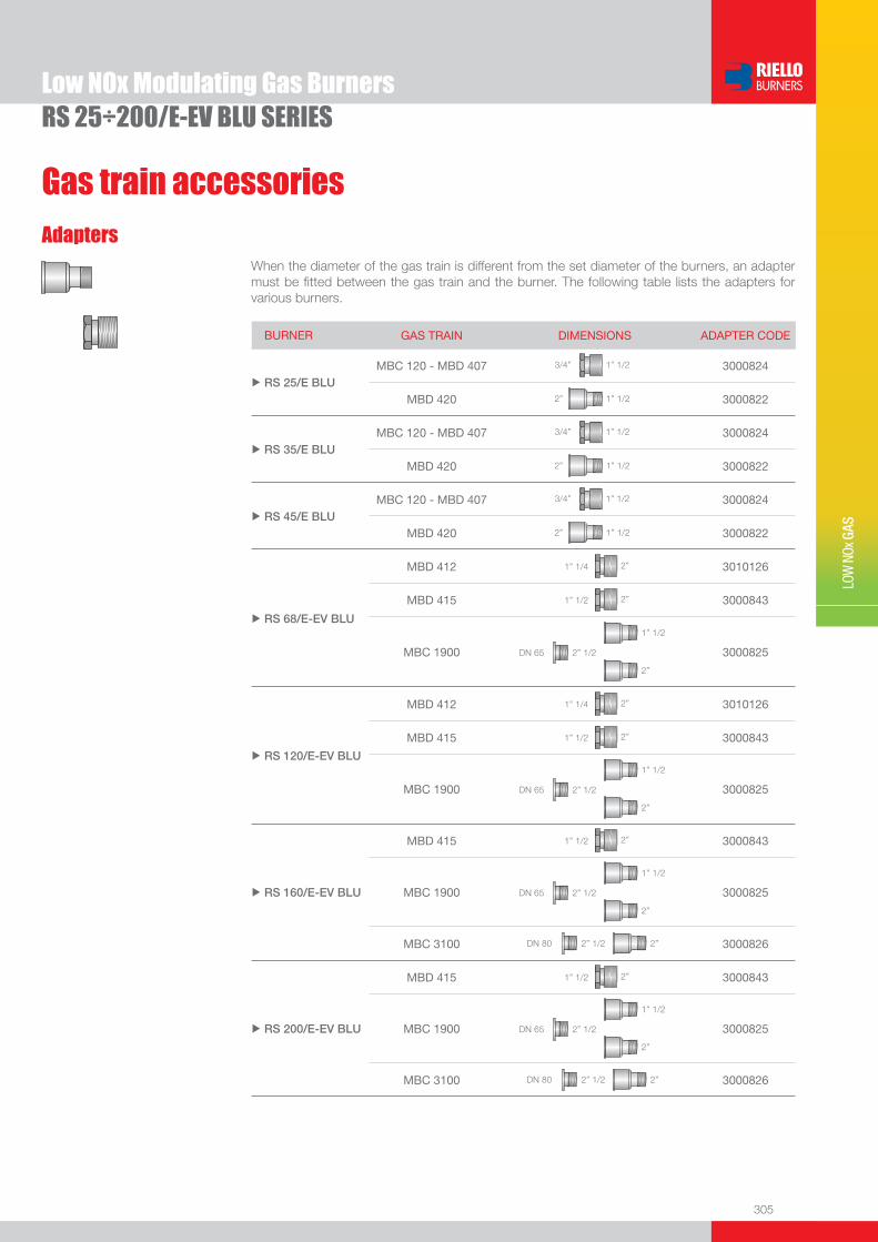
305
LOW
NOx
GAS
Low NOx Modulating Gas BurnersRS 25÷200/E-EV BLU SERIES
AdaptersWhen the diameter of the gas train is different from the set diameter of the burners, an adapter must be fi tted between the gas train and the burner. The following table lists the adapters for various burners.
BURNER GAS TRAIN DIMENSIONS ADAPTER CODE
u RS 25/E BLUMBC 120 - MBD 407 1” 1/23/4” 3000824
MBD 420 1” 1/22” 3000822
u RS 35/E BLUMBC 120 - MBD 407 1” 1/23/4” 3000824
MBD 420 1” 1/22” 3000822
u RS 45/E BLUMBC 120 - MBD 407 1” 1/23/4” 3000824
MBD 420 1” 1/22” 3000822
u RS 68/E-EV BLU
MBD 412 2”1” 1/4 3010126
MBD 415 2”1” 1/2 3000843
MBC 1900 2” 1/2DN 65
1” 1/2
2”
3000825
u RS 120/E-EV BLU
MBD 412 2”1” 1/4 3010126
MBD 415 2”1” 1/2 3000843
MBC 1900 2” 1/2DN 65
1” 1/2
2”
3000825
u RS 160/E-EV BLU
MBD 415 2”1” 1/2 3000843
MBC 1900 2” 1/2DN 65
1” 1/2
2”
3000825
MBC 3100 2” 1/2DN 80 2” 3000826
u RS 200/E-EV BLU
MBD 415 2”1” 1/2 3000843
MBC 1900 2” 1/2DN 65
1” 1/2
2”
3000825
MBC 3100 2” 1/2DN 80 2” 3000826
Gas train accessories

306
Gas train accessories
RS 25÷200/E-EV BLU SERIESLow NOx Modulating Gas Burners
Stabiliser springAccessory springs are available to vary the pressure range of the gas train composed. The following table shows these accessories with their application range. Please refer to the technical manual for the correct choice of spring.
GAS TRAIN SPRING SPRING CODE
uMBC 1900 SE 65 FC (CT)* MBC 3100 SE 80 FC (CT)*
White from 4 to 20 mbar 3010381
Red from 20 to 40 mbar 3010382
Black from 40 to 80 mbar 3010383
Green from 80 to 150 mbar 3010384
* with and without seal control
PVP (Pressure Valve Proving) kit *The seal control function is included on Burner Digital Management System, it is only necessary to add the PVP kit on the gas train.The PVP is included as standard equipment on RS 120/E-EV-160/E-EV-200/E-EV BLU models.
BURNER KIT CODE
u MBD type - MBC type ** 3010344
* not necessary for the RS 120/E-EV - 160/E-EV - 200/E-EV BLU models where is included as a standard.** MBC 120 model excluded (integrated seal control is not available with this gas train).

307
LOW
NOx
GAS
FIRING RATES
Low NOx Modulating Gas Burners
RS/P BLU SERIESRS/P series burners are characterised by a modular monoblock structure which means that all necessary components can be combined in a single unit thus making installation easier, faster and, above all, more fl exible.The series covers a fi ring range from 1350 to 4500 kW, and they have been designed for use in hot water boilers or industrial steam generators.Operation can be “two stage progressive” or alternative “modulating” with the installation of a PID logic regulator.Using a particular proportioning valve the burner keeps desired air to gas ratio in every working condition.The burner can, also, supply with precision the demanded power, guaranteeing an high effi ciency system level and the stability setting, obtaining fuel consumption and operating costs reduction.The innovative combustion head ensures reducing noise and pollutants.
RS 300/P BLU 500/1350 ÷ 3800 kWRS 400/P BLU 800/1800 ÷ 4500 kW
Useful working fi eldfor choosing theburner
Modulation range
Test conditionsconforming to EN676 Temperature: 20°CPressure: 1013,5 mbarAltitude: 0 m a.s.l.
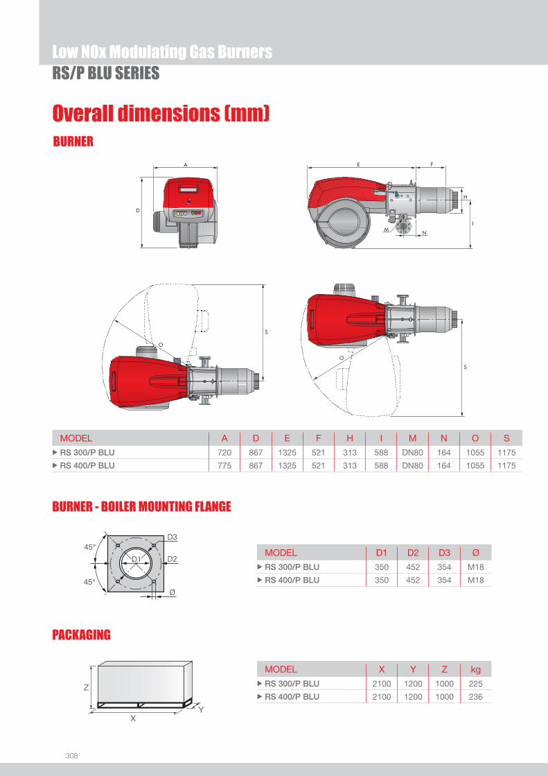
308
BURNER
Overall dimensions (mm)
Low NOx Modulating Gas BurnersRS/P BLU SERIES
BURNER - BOILER MOUNTING FLANGE
MODEL A D E F H I M N O S u RS 300/P BLU 720 867 1325 521 313 588 DN80 164 1055 1175
u RS 400/P BLU 775 867 1325 521 313 588 DN80 164 1055 1175
MODEL D1 D2 D3 Ø u RS 300/P BLU 350 452 354 M18
u RS 400/P BLU 350 452 354 M18
MODEL X Y Z kg u RS 300/P BLU 2100 1200 1000 225
u RS 400/P BLU 2100 1200 1000 236 Z
XY
PACKAGING
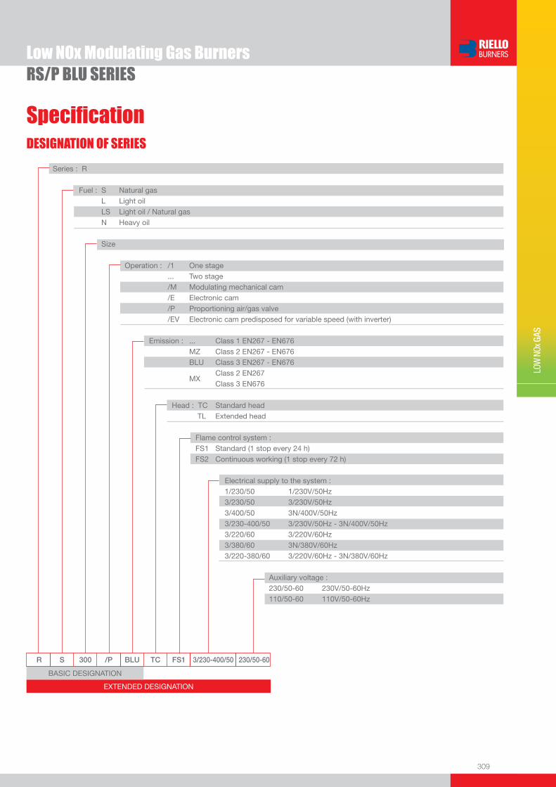
309
DESIGNATION OF SERIES
Specifi cation
LOW
NOx
GAS
Low NOx Modulating Gas BurnersRS/P BLU SERIES
EXTENDED DESIGNATION
R S 300 /P BLU TC FS1 3/230-400/50 230/50-60
Series : R
Fuel : S Natural gas L Light oil LS Light oil / Natural gas N Heavy oil
Size
Operation : /1 One stage ... Two stage /M Modulating mechanical cam /E Electronic cam /P Proportioning air/gas valve /EV Electronic cam predisposed for variable speed (with inverter) Emission : ... Class 1 EN267 - EN676 MZ Class 2 EN267 - EN676 BLU Class 3 EN267 - EN676
MX Class 2 EN267
Class 3 EN676
Head : TC Standard head TL Extended head
Flame control system : FS1 Standard (1 stop every 24 h) FS2 Continuous working (1 stop every 72 h)
Electrical supply to the system : 1/230/50 1/230V/50Hz 3/230/50 3/230V/50Hz 3/400/50 3N/400V/50Hz 3/230-400/50 3/230V/50Hz - 3N/400V/50Hz 3/220/60 3/220V/60Hz 3/380/60 3N/380V/60Hz 3/220-380/60 3/220V/60Hz - 3N/380V/60Hz
Auxiliary voltage : 230/50-60 230V/50-60Hz 110/50-60 110V/50-60Hz
BASIC DESIGNATION
310
Low NOx Modulating Gas BurnersRS/P BLU SERIES
STATE OF SUPPLY
Specifi cation
Monoblock forced draught gas burner with two stage operation, fully automatic, made up of:- Fan with reverse curve blades high performance with low sound emissions- Air suction circuit lined with sound-proofi ng material- Air damper for air setting controlled by a high precision servomotor- Air pressure switch- Fan starting motor at 2900 rpm, three-phase 230/400 - 400/690 V with neutral, 50Hz - Low emission combustion head, that can be set on the basis of required output, fi tted with: - stainless steel end cone, resistant to corrosion and high temperatures - ignition electrodes - fl ame stability disk- Proportional air/gas valve- Maximum gas pressure switch, with pressure test point, for halting the burner in the case of over pressure on the fuel supply
line- Module for air/fuel setting and output modulation with separated PID control of temperature or pressure- Microprocessor-based burner safety control box, with diagnostic functions- Ionization probe for fl ame detector- Star/triangle starter for the fan motor (version with motor electrical power 7,5 kW)- Main electrical supply terminal board- Burner on/off switch - Auxiliary voltage led signal- Manual or automatic output increase/decrease switch- Burner working led signal- Contacts motor and thermal relay with release button- Motor internal thermal protection- Motor failure led signal - Burner failure led signal and lighted release button- Emergency button- Coded connection plugs-sockets- Burner opening hinge- Lifting rings- IP 54 electric protection level.
Standard equipment:- 1 fl ange gasket- 4 screws for fi xing the fl ange- 1 thermal screen- 4 screws for fi xing the burner fl ange to the boiler- Instruction handbook for installation, use and maintenance- Spare parts catalogue.

311
LOW
NOx
GAS
Low NOx Modulating Gas BurnersRS/P BLU SERIES
Available modelsBurners
Gas Trains
Natural gas, net calorifi c value: 10 kWh/Nm3 - Density: 0,71 kg/Nm3
The burners of RS/P BLU series are in according to 90/396 - 89/336 (2004/108) - 73/23 (2006/95) EC Directives.
CODE MODEL
HEAT OUTPUT TOTAL ELECTRICAL
POWER
CERTIFICATION NOTE
NATURAL GAS
(kW) (Nm3/h) (kW)
3898310 RS 300/P BLU TC FS1 3/230-400/50 230/50-60 700/1350-3800 70/135-380 6 CE 0085B00341
20006127 RS 300/P BLU TC FS1 3/220-380/60 220/50-60 700/1350-3800 70/135-380 6 -
3898412 RS 400/P BLU TC FS1 3/400/50 230/50-60 1000/1800-4500 100/180-450 9 CE 0085B00341
20006130 RS 400/P BLU TC FS1 3/380/60 220/50-60 1000/1800-4500 100/180-450 9 -
* Gas trains are 230V/50Hz - 220V/60Hz electrical supply.** See adapter length on “Gas trains accessories” paragraph.(1) Seal control to be ordered separately - see “Gas trains accessories” section.(2) Adapter is necessary when the gas train has to be installed to the left of the burner to allow maintenance, or if is necessary to space out the gas train from burner. To select the gas train please refer to the technical data leafl et and/or instruction manual.
GAS TRAIN
CODE *
GAS TRAIN
MODEL
NATURAL GAS SEAL CONTROL NOTE
BURNER ADAPTER
(type) (code)
CO
MP
OS
ED
GA
S T
RA
IN
3970215 VGD 50 RS 300/P RS 400/P
3000826 3010367 (1) (2)
3970212 VGDF 65 RS 300/P RS 400/P
3010221 or
3010369** 3010367 (1) (2)
3970213 VGDF 80 RS 300/P RS 400/P
3010222 3010367 (1) (2)
3970214 VGDF 100 RS 300/P RS 400/P
3010223 or
3010370** 3010367 (1) (2)
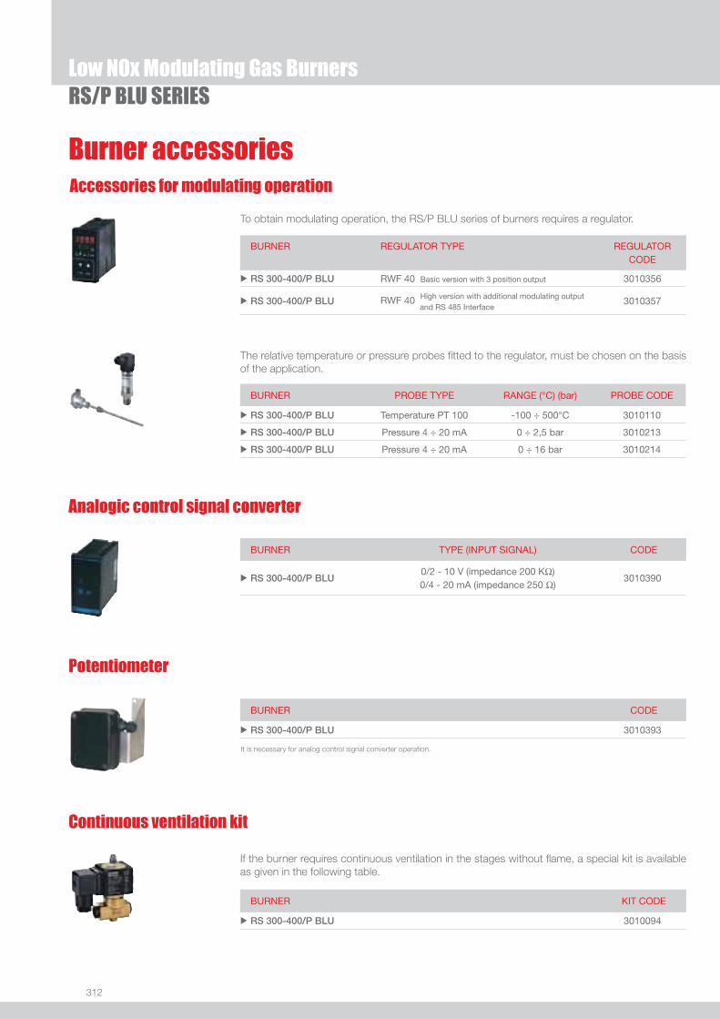
312
Burner accessories
RS/P BLU SERIESLow NOx Modulating Gas Burners
Accessories for modulating operation
To obtain modulating operation, the RS/P BLU series of burners requires a regulator.
BURNER
REGULATOR TYPE REGULATOR CODE
u RS 300-400/P BLU RWF 40 Basic version with 3 position output 3010356
u RS 300-400/P BLU RWF 40 High version with additional modulating output and RS 485 Interface
3010357
The relative temperature or pressure probes fi tted to the regulator, must be chosen on the basis of the application.
BURNER PROBE TYPE RANGE (°C) (bar) PROBE CODE
u RS 300-400/P BLU Temperature PT 100 -100 ÷ 500°C 3010110
u RS 300-400/P BLU Pressure 4 ÷ 20 mA 0 ÷ 2,5 bar 3010213
u RS 300-400/P BLU Pressure 4 ÷ 20 mA 0 ÷ 16 bar 3010214
Analogic control signal converter
BURNER TYPE (INPUT SIGNAL) CODE
u RS 300-400/P BLU0/2 - 10 V (impedance 200 KΩ)0/4 - 20 mA (impedance 250 Ω)
3010390
Potentiometer
BURNER CODE
u RS 300-400/P BLU 3010393
It is necessary for analog control signal converter operation.
Continuous ventilation kit
BURNER KIT CODE
u RS 300-400/P BLU 3010094
If the burner requires continuous ventilation in the stages without fl ame, a special kit is available as given in the following table.
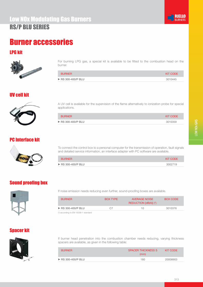
313
Burner accessories
LOW
NOx
GAS
Low NOx Modulating Gas BurnersRS/P BLU SERIES
LPG kit
For burning LPG gas, a special kit is available to be fi tted to the combustion head on the burner.
BURNER KIT CODE
u RS 300-400/P BLU 3010445
UV cell kit
A UV cell is avaliable for the supervision of the fl ame alternatively to ionization probe for special applications.
BURNER KIT CODE
u RS 300-400/P BLU 3010359
If noise emission needs reducing even further, sound-proofi ng boxes are available.
Sound proofi ng box
BURNER
BOX TYPE
AVERAGE NOISE REDUCTION [dB(A)] (*)
BOX CODE
u RS 300-400/P BLU C7 10 3010376
(*) according to EN 15036-1 standard
BURNER KIT CODE
u RS 300-400/P BLU 3002719
To connect the control box to a personal computer for the transmission of operation, fault signals and detailed service information, an interface adapter with PC software are available.
PC Interface kit
BURNER SPACER THICKNESS S (mm)
KIT CODE
u RS 300-400/P BLU 180 20008903
Spacer kit
If burner head penetration into the combustion chamber needs reducing, varying thickness spacers are available, as given in the following table:
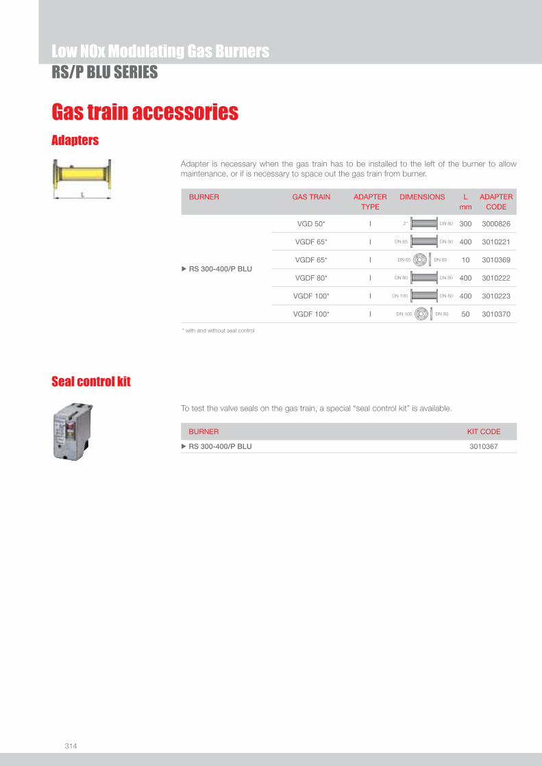
314
Gas train accessoriesAdapters
Adapter is necessary when the gas train has to be installed to the left of the burner to allow maintenance, or if is necessary to space out the gas train from burner.
RS/P BLU SERIESLow NOx Modulating Gas Burners
To test the valve seals on the gas train, a special “seal control kit” is available.
Seal control kit
BURNER KIT CODE
u RS 300-400/P BLU 3010367
BURNER GAS TRAIN ADAPTER TYPE
DIMENSIONS L mm
ADAPTER CODE
u RS 300-400/P BLU
VGD 50* I 2” DN 80 300 3000826
VGDF 65* I DN 65 DN 80 400 3010221
VGDF 65* I DN 65 DN 80 10 3010369
VGDF 80* I DN 80 DN 80 400 3010222
VGDF 100* I DN 100 DN 80 400 3010223
VGDF 100* I DN 100 DN 80 50 3010370
* with and without seal control

315
LOW
NOx
GAS
Low NOx Modulating Gas Burners
RS 300÷800/M BLU SERIES
RS 300/M BLU 500/1350 ÷ 3800 kWRS 400/M BLU 950/1830 ÷ 4590 kWRS 500/M BLU 1000/2500 ÷ 5170 kWRS 800/M BLU 1200/3500 ÷ 8100 kW
The RS 300-400-500-800/M BLU burners are characterised by a monoblock structure which means that all necessary components are combined in a single unit, making installation easier and faster.The burners cover a fi ring range from 1350 to 8100 kW, and it have been designed for use in hot water boilers or industrial steam generators.Operation can be “two stage progressive” or alternatively “modulating” with the installation of a PID logic regulator or by external 4-20 mA/0-10 V signal.The mechanical cam device of regulation allows to catch up a high modulation ratio on all fi ring rates range. The burners can, therefore, supply with precision the demanded power, guaranteeing a high effi ciency system level and the stability setting, obtaining fuel consumption and operating costs reduction.The combustion head, engineered with advanced simulation devices, guarantees reduced polluting emissions (NOx < 80 mg/kWh). FS1 and FS2 versions are available for intermittent and continuous operation applications. An exclusive design, with reverse blade fan, guarantees low sound emissions, low electrical consumption, easy use and maintenance.
FIRING RATES
Useful working fi eldfor choosing theburner
Modulation range
Test conditionsconforming to EN676 Temperature: 20°CPressure: 1013,5 mbarAltitude: 0 m a.s.l.
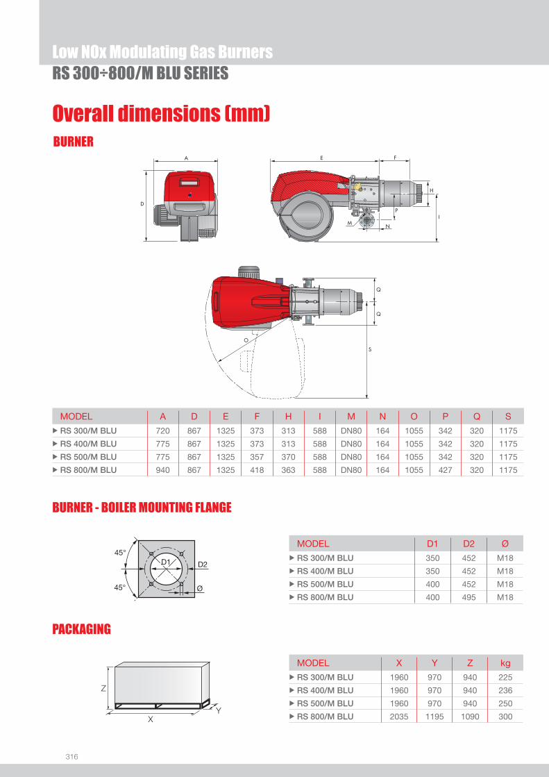
316
BURNER
PACKAGING
Overall dimensions (mm)
RS 300÷800/M BLU SERIESLow NOx Modulating Gas Burners
MODEL A D E F H I M N O P Q S u RS 300/M BLU 720 867 1325 373 313 588 DN80 164 1055 342 320 1175
u RS 400/M BLU 775 867 1325 373 313 588 DN80 164 1055 342 320 1175
u RS 500/M BLU 775 867 1325 357 370 588 DN80 164 1055 342 320 1175
u RS 800/M BLU 940 867 1325 418 363 588 DN80 164 1055 427 320 1175
MODEL D1 D2 Ø u RS 300/M BLU 350 452 M18
u RS 400/M BLU 350 452 M18
u RS 500/M BLU 400 452 M18
u RS 800/M BLU 400 495 M18
MODEL X Y Z kgu RS 300/M BLU 1960 970 940 225
u RS 400/M BLU 1960 970 940 236
u RS 500/M BLU 1960 970 940 250
u RS 800/M BLU 2035 1195 1090 300
BURNER - BOILER MOUNTING FLANGE
Z
XY

317
DESIGNATION OF SERIES
Specifi cation
LOW
NOx
GAS
Low NOx Modulating Gas BurnersRS 300÷800/M BLU SERIES
BASIC DESIGNATION
EXTENDED DESIGNATION
R S 500 /M BLU TC FS1 3/230-400/50 230/50-60
Series: R Fuel: S Natural Gas L Light oil LS Light oil/Natural Gas N Heavy oil
Size Setting : /1 Single stage /B Two stage /M Modulating - Mechanical cam /P Proportioning air/gas valve /E Electronic cam /EV Electronic cam predisposed for variable speed (with inverter) Emission : ... Class 1 EN267 - EN676 MZ Class 2 EN267 - EN676 BLU Class 3 EN267 - EN676
MX Class 2 EN267
Class 3 EN676 Head length: TC standard head TL extended head Flame control system: FS1 Standard (1 stop every 24 h) FS2 Continuous working (1 stop every 72 h) Electrical supply to the system: 1/230/50 1/230V/50Hz 3/230/50 3/230V/50Hz 3/400/50 3N/400V/50Hz 3/230-400/50 3/230V/50Hz - 3N/400V/50Hz 3/220/60 3/220V/60Hz 3/380/60 3N/380V/60Hz 3/220-380/60 3/220/60Hz - 3N/380V/60Hz
Auxiliary voltage: 230/50-60 230V/50-60Hz 110/50-60 110V/50-60Hz

318
STATE OF SUPPLY
Specifi cation
RS 300÷800/M BLU SERIESLow NOx Modulating Gas Burners
Monoblock forced draught gas burner with modulating operation, fully automatic, made up of:- Fan with reverse curve blades high performance with low sound emissions- Air suction circuit lined with sound-proofi ng material- Air damper for air setting controlled by a high precision servomotor- Air pressure switch- Fan starting motor at 2900 rpm, three-phase 230/400 - 400/690 V with neutral, 50 Hz - Low emission combustion head, that can be set on the basis of required output, fi tted with: - stainless steel end cone, resistant to corrosion and high temperatures - ignition electrodes - fl ame stability disk- Maximum gas pressure switch, with pressure test point, for halting the burner in the case of over pressure on the fuel supply
line- Burner safety control box for controlling the system safety (RMG/M for FS1 intermittent operation - LGK16 for FS2 continuous
operation)- Ionisation probe for fl ame detection- Star/triangle starter for the fan motor (burners with motor electrical power ≥ 7,5 kW)- Main electrical supply terminal board- Burner on/off switch - Auxiliary voltage led signal- Manual or automatic output increase/decrease switch- Burner working led signal- Contacts motor and thermal relay with release button- Motor internal thermal protection- Motor failure led signal - Burner failure led signal and lighted release button- Led signal for correct rotation direction of fan motor- Emergency button- Coded connection plugs-sockets- Burner opening hinge- Lifting rings- IP 54 electric protection level- Tee gas supply connector DN 80 for gas train connection (RS 300-400-500 models).
Standard equipment:- 1 fl ange gasket- 8 screws for fi xing the fl ange- 1 thermal screen- 4 screws for fi xing the burner fl ange to the boiler- Curve DN 80 for gas train connection (RS 800 model)- Instruction handbook for installation, use and maintenance- Spare parts catalogue.

319
LOW
NOx
GAS
Available modelsBurners
Low NOx Modulating Gas BurnersRS 300÷800/M BLU SERIES
CODE MODEL HEAT OUTPUT TOTAL ELECTRICAL
POWER
CERTIFICATION NOTE
NATURAL GAS
(kW) (Nm3/h) (kW)
3899410 RS 300/M BLU TC FS1 3/230-400/50 230/50-60 500/1350-3800 50/135-380 6 CE 0085BR0480
20008428 RS 300/M BLU TC FS1 3/220-380/60 220/50-60 500/1350-3800 50/135-380 6 -
3899510 RS 400/M BLU TC FS1 3/400/50 230/50-60 950/1830-4590 95/183-459 9 CE 0085BR0481
20008404 RS 400/M BLU TC FS1 3/380/60 220/50-60 950/1830-4590 95/183-459 9 -
3899110 RS 500/M BLU TC FS1 3/400/50 230/50-60 1000/2500-5170 100/250-517 11 CE 0085BO0341
3899115 RS 500/M BLU TC FS2 3/400/50 230/50-60 1000/2500-5170 100/250-517 11 CE 0085BO0341
20006131 RS 500/M BLU TC FS1 3/380/60 220/50-60 1000/2500-5170 100/250-517 11 -
3911010 RS 800/M BLU TC FS1 3/400/50 230/50-60 1200/3500-8100 120/350-810 24 CE 0085BT0337
3911050 RS 800/M BLU TC FS2 3/400/50 230/50-60 1200/3500-8100 120/350-810 24 CE 0085BT0337
20008894 RS 800/M BLU TC FS1 3/380/60 220/50-60 1200/3500-8100 120/350-810 26 -
Natural gas, net calorifi c value: 10 kWh/Nm3 - Density: 0,71 kg/Nm3
The burners of RS/M BLU series are in according to 90/396 - 89/336 (2004/108) - 73/23 (2006/95) EC Directives.
Gas Trains
* gas train are 230V/50Hz - 220V/60Hz electrical supply(1) without seal control (2) seal control includedTo select the gas train please refer to the technical data leafl et and/or instruction manual.
GAS TRAIN GAS TRAIN NATURAL GAS NOTE
CODE* MODEL BURNER ADAPTER
(type) (code)
MU
LTIB
LOC
3970221 MBC 1200 SE 50 RS 300-400/M BLU 3000826 (1)
3970225 MBC 1200 SE 50 CT RS 300-400/M BLU 3000826 (2)
CO
MP
OS
ED
GA
S T
RA
INS 3970222 MBC 1900 SE 65 FC RS 300-400-500-800/M BLU 3010221 (1)
3970226 MBC 1900 SE 65 FC CT RS 300-400-500-800/M BLU 3010221 (2)
3970223 MBC 3100 SE 80 FC RS 300-400-500-800/M BLU 3010222 (1)
3970227 MBC 3100 SE 80 FC CT RS 300-400-500-800/M BLU 3010222 (2)
3970224 MBC 5000 SE 100 FC RS 300-400-500-800/M BLU 3010223 (1)
3970228 MBC 5000 SE 100 FC CT RS 300-400-500-800/M BLU 3010223 (2)
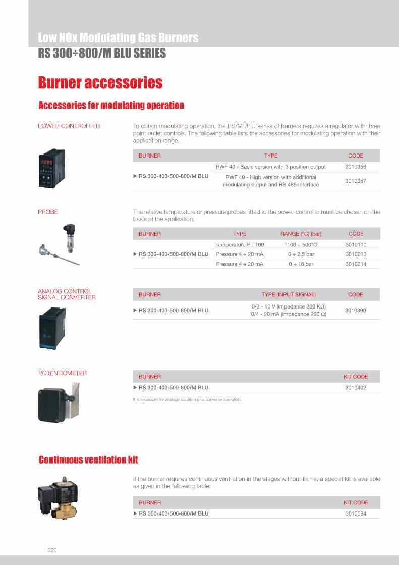
320
Burner accessoriesAccessories for modulating operation
RS 300÷800/M BLU SERIESLow NOx Modulating Gas Burners
Continuous ventilation kit
If the burner requires continuous ventilation in the stages without fl ame, a special kit is available as given in the following table:
BURNER KIT CODE
u RS 300-400-500-800/M BLU 3010094
To obtain modulating operation, the RS/M BLU series of burners requires a regulator with three point outlet controls. The following table lists the accessories for modulating operation with their application range.
BURNER TYPE CODE
u RS 300-400-500-800/M BLU
RWF 40 - Basic version with 3 position output 3010356
RWF 40 - High version with additional modulating output and RS 485 Interface
3010357
POWER CONTROLLER
BURNER TYPE RANGE (°C) (bar) CODE
u RS 300-400-500-800/M BLU
Temperature PT 100 -100 ÷ 500°C 3010110
Pressure 4 ÷ 20 mA 0 ÷ 2,5 bar 3010213
Pressure 4 ÷ 20 mA 0 ÷ 16 bar 3010214
The relative temperature or pressure probes fi tted to the power controller must be chosen on the basis of the application.
PROBE
BURNER TYPE (INPUT SIGNAL) CODE
u RS 300-400-500-800/M BLU0/2 - 10 V (impedance 200 KΩ) 0/4 - 20 mA (impedance 250 Ω)
3010390
ANALOG CONTROL SIGNAL CONVERTER
BURNER KIT CODE
u RS 300-400-500-800/M BLU 3010402
POTENTIOMETER
It is necessary for analogic control signal converter operation.

321
Burner accessories
LOW
NOx
GAS
Low NOx Modulating Gas BurnersRS 300÷800/M BLU SERIES
Sound proofi ng boxIf noise emission needs reducing even further, sound-proofi ng boxes are available, as given in the following table:
BURNER BOX TYPE AVERAGE NOISE REDUCTION [dB(A)](*)
BOX CODE
u RS 300-400-500-800/M BLU C7 10 3010376
(*) according to EN 15036-1 standard
UV cell kitA UV cell is available for the supervision of the fl ame alternatively to ionisation probe for special applications.
BURNER KIT CODE
u RS 300-400-500-800/M BLU 3010359
PC interface kitTo connect the control box to a personal computer for the transmission of operation, fault signals and detailed service information, an interface adapter with PC software are available.
BURNER KIT CODE
u RS 300-400-500-800/M BLU 3002719
LPG kitFor burning LPG gas, a special kit is available to be fi tted to the combustion head of the burner.
BURNER CODE
u RS 300-400-500/M BLU 3010445 (*)
u RS 800/M BLU 20007822
(*) approval in progress.
BURNER SPACER THICKNESS S (mm)
KIT CODE
u RS 300-400-500-800/M BLU 180 20008903
Spacer kit
If burner head penetration into the combustion chamber needs reducing, varying thickness spacers are available, as given in the following table:

322
Gas train accessories
RS 300÷800/M BLU SERIES Low NOx Modulating Gas Burners
Seal control
BURNER CODE
u RS 300-400-500-800/M BLU 3010125
Adapters
In certain cases, an adapter must be fi tted between the gas train and the burner, when the diameter of the gas train is different from the set diameter of the burner.Below are given the adapters than can be fi tted on the various burners:
BURNER GAS TRAIN ADAPTER TYPE
DIMENSIONS L mm
ADAPTER CODE
u RS 300-400-500-800/M BLU
MBC 1200 SE 50* I 2” DN 80 300 3000826
MBC 1900 SE 65 FC* I DN 65 DN 80 400 3010221
MBC 1900 SE 65 FC* I DN 65 DN 80 10 3010369
MBC 3100 SE 80 FC* I DN 80 DN 80 400 3010222
MBC 5000 SE 100 FC* I DN 100 DN 80 400 3010223
MBC 5000 SE 100 FC* I DN 100 DN 80 50 3010370
* with and without seal control
Stabiliser spring
To vary the pressure range of the gas train stabilisers, accessory springs are available. The following table shows these accessories with their application range. Please refer to the technical manual for the correct choice of spring.
GAS TRAIN SPRING SPRING CODE
u
MBC 1900 SE 65 FC (CT)* MBC 3100 SE 80 FC (CT)* MBC 5000 SE 100 FC (CT)*
White from 4 to 20 mbar 3010381
Red from 20 to 40 mbar 3010382
Black from 40 to 80 mbar 3010383
Green from 80 to 150 mbar 3010384
* with and without seal control

323
LOW
NOx
GAS
Low NOx Modulating Gas Burners
RS 300÷800/E-EV BLU SERIESThe RS/E and RS/EV series burners are characterised by a modular monoblock structure that means all necessary components can be combined in a single unit thus making installation easier, faster and, above all, more fl exible.The series covers a fi ring range from 1350 to 8100 kW, and they have been designed for use in hot water boilers or industrial steam generators.Operation can be “two stage progressive” or alternatively “modulating” with the installation of a PID logic regulator on the RS/E series burners while RS/EV series is fully “modulating”.The mechanisms of regulation allow to catch up a high modulation ratio on all fi ring rates range.The burner can, therefore, supply with precision the demanded power, guaranteeing an high effi ciency system level and the stability setting, obtaining fuel consumption and operating costs reduction.The burner operation can be intermittent or continuous by menu setting.The innovative combustion head, adjustment system ensures perfect movement during modulation as well as reducing noise and pollutants.
RS 300/E BLU 500/1350 ÷ 3800 kWRS 400/E BLU 800/1840 ÷ 4550 kWRS 500/E BLU 1000/2500 ÷ 5170 kWRS 800/E BLU 1200/3500 ÷ 8100 kWRS 300/EV BLU 500/1350 ÷ 3800 kWRS 400/EV BLU 800/1840 ÷ 4550 kWRS 500/EV BLU 1000/2500 ÷ 5170 kWRS 800/EV BLU 1200/3500 ÷ 8100 kW
FIRING RATES
RS 300/E-EV BLU
RS 400/E-EV BLU
RS 500/E-EV BLU
RS 800/E-EV BLU
Useful working fi eldfor choosing theburner
Modulation range
Test conditionsconforming to EN676 Temperature: 20°CPressure: 1013,5 mbarAltitude: 0 m a.s.l.
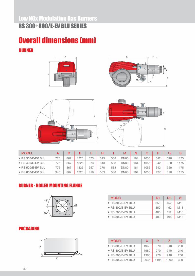
324
BURNER
Overall dimensions (mm)
RS 300÷800/E-EV BLU SERIESLow NOx Modulating Gas Burners
MODEL A D E F H I M N O P Q S u RS 300/E-EV BLU 720 867 1325 373 313 588 DN80 164 1055 342 320 1175
u RS 400/E-EV BLU 775 867 1325 373 313 588 DN80 164 1055 342 320 1175
u RS 500/E-EV BLU 775 867 1325 357 370 588 DN80 164 1055 342 320 1175
u RS 800/E-EV BLU 940 867 1325 418 363 588 DN80 164 1055 427 320 1175
MODEL D1 D2 Ø u RS 300/E-EV BLU 350 452 M18
u RS 400/E-EV BLU 350 452 M18
u RS 500/E-EV BLU 400 452 M18
u RS 800/E-EV BLU 400 495 M18
MODEL X Y Z kgu RS 300/E-EV BLU 1960 970 940 230
u RS 400/E-EV BLU 1960 970 940 240
u RS 500/E-EV BLU 1960 970 940 250
u RS 800/E-EV BLU 2035 1195 1090 300
A
D
E
I
F
M
H
N
S
O
O
S
P
Q
Q
BURNER - BOILER MOUNTING FLANGE
Z
XY
PACKAGING

325
DESIGNATION OF SERIES
Specifi cation
LOW
NOx
GAS
Low NOx Modulating Gas BurnersRS 300÷800/E-EV BLU SERIES
BASIC DESIGNATION
EXTENDED DESIGNATION
R S 300 /E BLU TC FS2 3/230-400/50 230/50-60
Series: R Fuel: S Natural Gas L Light oil LS Light oil/Natural Gas N Heavy oil
Size Setting : /1 Single stage /B Two stage /M Modulating - Mechanical cam
/E Electronic cam /P Proportioning air/gas valve /EV Electronic cam predisposed for variable speed (with inverter)
Emission : ... Class 1 EN267 - EN676 MZ Class 2 EN267 - EN676 BLU Class 3 EN267 - EN676
MX Class 2 EN267
Class 3 EN676 Head length: TC standard head TL extended head Flame control system: FS1 Standard (1 stop every 24 h) FS2 Continuous working (1 stop every 72 h) Electrical supply to the system: 1/230/50 1/230V/50Hz 3/230/50 3/230V/50Hz 3/400/50 3N/400V/50Hz 3/230-400/50 3/230V/50Hz - 3N/400V/50Hz 3/220/60 3/220V/60Hz 3/380/60 3N/380V/60Hz 3/220-380/60 3/220/60Hz - 3N/380V/60Hz
Auxiliary voltage: 230/50-60 230V/50-60Hz 110/50-60 110V/50-60Hz
326
RS 300÷800/E-EV BLU SERIESLow NOx Modulating Gas Burners
STATE OF SUPPLY
Specifi cation
Monoblock forced draught gas burner with modulating operation, fully automatic, made up of:- Fan with reverse curve blades high performance with low sound emissions- Air suction circuit lined with sound-proofi ng material- Air damper for air setting controlled by a high precision servomotor- Air pressure switch- Fan starting motor at 2900 rpm, three-phase 230/400 - 400/690 V with neutral, 50Hz - Low emission mobile combustion head, that can be set on the basis of required output, fi tted with: - stainless steel end cone, resistant to corrosion and high temperatures - ignition electrodes - fl ame stability disk- Automatic regulator for gas delivery, controlled by a high precision servomotor- Maximum gas pressure switch, with pressure test point, for halting the burner in the case of over pressure on the fuel supply line- Module for air/fuel setting and output modulation with separated PID control of temperature or pressure, available as accessory for
RS/E BLU model - Module for air/fuel setting and output modulation with incorporated PID control of temperature or pressure of the heat generator
(RS/EV BLU)- Burner safety control box for controlling the system safety- Ionization probe for fl ame detector- Star/triangle starter for the fan motor (burners with motor electrical power > = 7,5 kW, RS/E)- Main electrical supply terminal board- Burner on/off switch - Auxiliary voltage led signal- Manual or automatic output increase/decrease switch- Burner working led signal- Contacts motor and thermal relay with release button- Motor internal thermal protection- Motor failure led signal - Burner failure led signal and lighted release button- Emergency button- Coded connection plugs-sockets- Burner opening hinge- Lifting rings- IP 54 electric protection level- Tee gas supply connector DN 80 for gas train connection (RS 300-400-500 models)
Standard equipment:- 1 fl ange gasket- 4 screws for fi xing the fl ange- 1 thermal screen- 4 screws for fi xing the burner fl ange to the boiler- Seal control- Seal control pressure switch (for installation on gas train)- Curve DN 80 for gas train connection (RS 800 model)- Instruction handbook for installation, use and maintenance- Spare parts catalogue.
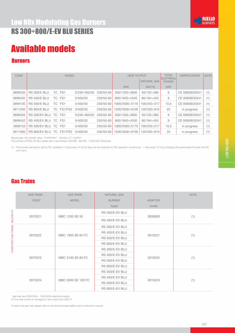
327
LOW
NOx
GAS
Gas Trains
Low NOx Modulating Gas BurnersRS 300÷800/E-EV BLU SERIES
Available modelsBurners
CODE MODEL HEAT OUTPUT TOTAL ELECTRICAL
POWER
CERTIFICATION NOTE
NATURAL GAS
(kW) (Nm3/h) (kW)
3898330 RS 300/E BLU TC FS1 3/230-400/50 230/50-60 500/1350÷3800 50/135÷380 6 CE 0085BO0341 (1)
3898432 RS 400/E BLU TC FS1 3/400/50 230/50-60 800/1840÷4550 80/184÷455 9 CE 0085BO0341 (1)
3899130 RS 500/E BLU TC FS1 3/400/50 230/50-60 1000/2500÷5170 100/250÷517 10,5 CE 0085BO0341 (1)
3911030 RS 800/E BLU TC FS1/FS2 3/400/50 230/50-60 1200/3500÷8100 120/350÷810 25 in progress (1)
3898350 RS 300/EV BLU TC FS1 3/230-400/50 230/50-60 500/1350÷3800 50/135÷380 6 CE 0085BO0341 (1)
3898452 RS 400/EV BLU TC FS1 3/400/50 230/50-60 800/1840÷4550 80/184÷455 9 CE 0085BO0341 (1)
3899152 RS 500/EV BLU TC FS1 3/400/50 230/50-60 1000/2500÷5170 100/250÷517 10,5 in progress (1)
3911090 RS 800/EV BLU TC FS1/FS2 3/400/50 230/50-60 1200/3500÷8100 120/350÷810 25 in progress (1)
Natural gas, net calorifi c value: 10 kWh/Nm3 - Density: 0,71 kg/Nm3
The burners of RS/E-EV BLU series are in according to 90/396 - 89/336 - 73/23 EEC Directives.
(1) - The burners are factory set for FS1 operation (1 stop every 24 h) but they can be switched to FS2 operation (continuous - 1 stop every 72 h) by changing the parameters through the AZL unit menu.
GAS TRAIN GAS TRAIN NATURAL GAS NOTE
CODE* MODEL BURNER ADAPTER
(type) (code)
MU
LTIB
LOC
3970221 MBC 1200 SE 50RS 300/E-EV BLU
3000826 (1)RS 400/E-EV BLU
CO
MP
OS
ED
GA
S T
RA
INS
3970222 MBC 1900 SE 65 FC
RS 300/E-EV BLU
3010221 (1)RS 400/E-EV BLU
RS 500/E-EV BLU
RS 800/E-EV BLU
3970223 MBC 3100 SE 80 FC
RS 300/E-EV BLU
3010222 (1)RS 400/E-EV BLU
RS 500/E-EV BLU
RS 800/E-EV BLU
3970224 MBC 5000 SE 100 FC
RS 300/E-EV BLU
3010223 (1)RS 400/E-EV BLU
RS 500/E-EV BLU
RS 800/E-EV BLU
* gas train are 230V/50Hz - 220V/60Hz electrical supply(1) The seal control is managed by the control box LMV 51.
To select the gas train please refer to the technical data leafl et and/or instruction manual.
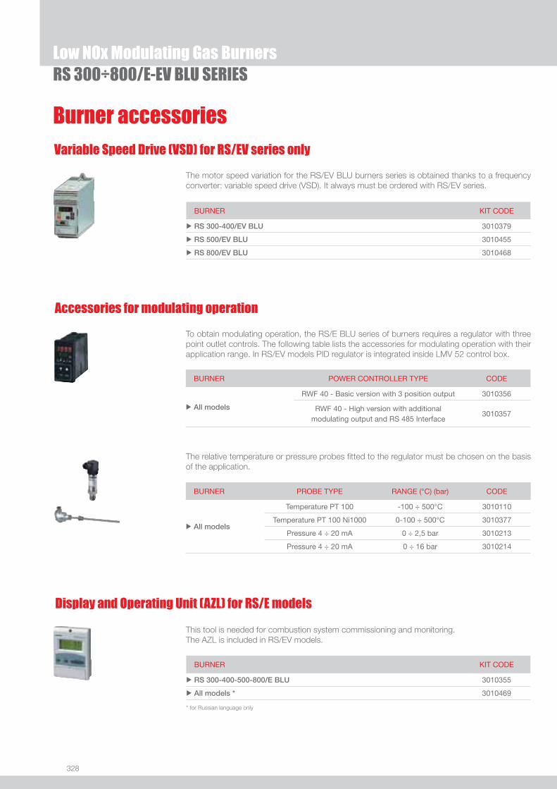
328
RS 300÷800/E-EV BLU SERIESLow NOx Modulating Gas Burners
Burner accessories
Accessories for modulating operation
To obtain modulating operation, the RS/E BLU series of burners requires a regulator with three point outlet controls. The following table lists the accessories for modulating operation with their application range. In RS/EV models PID regulator is integrated inside LMV 52 control box.
BURNER POWER CONTROLLER TYPE CODE
u All models
RWF 40 - Basic version with 3 position output 3010356
RWF 40 - High version with additional modulating output and RS 485 Interface
3010357
BURNER PROBE TYPE RANGE (°C) (bar) CODE
u All models
Temperature PT 100 -100 ÷ 500°C 3010110
Temperature PT 100 Ni1000 0-100 ÷ 500°C 3010377
Pressure 4 ÷ 20 mA 0 ÷ 2,5 bar 3010213
Pressure 4 ÷ 20 mA 0 ÷ 16 bar 3010214
The relative temperature or pressure probes fi tted to the regulator must be chosen on the basis of the application.
Variable Speed Drive (VSD) for RS/EV series only
The motor speed variation for the RS/EV BLU burners series is obtained thanks to a frequency converter: variable speed drive (VSD). It always must be ordered with RS/EV series.
BURNER KIT CODE
u RS 300-400/EV BLU 3010379
u RS 500/EV BLU 3010455
u RS 800/EV BLU 3010468
Display and Operating Unit (AZL) for RS/E models
This tool is needed for combustion system commissioning and monitoring.The AZL is included in RS/EV models.
BURNER KIT CODE
u RS 300-400-500-800/E BLU 3010355
u All models * 3010469
* for Russian language only
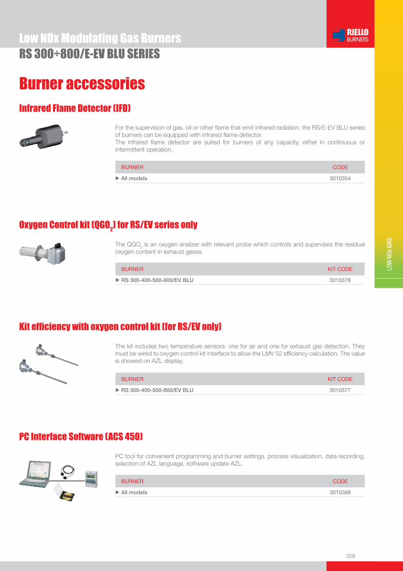
329
Burner accessories
LOW
NOx
GAS
Low NOx Modulating Gas BurnersRS 300÷800/E-EV BLU SERIES
Infrared Flame Detector (IFD)
For the supervision of gas, oil or other fl ame that emit infrared radiation, the RS/E-EV BLU series of burners can be equipped with infrared fl ame detector.The infrared fl ame detector are suited for burners of any capacity, either in continuous or intermittent operation.
BURNER CODE
u All models 3010354
Oxygen Control kit (QGO2) for RS/EV series only
The QGO2 is an oxygen analizer with relevant probe which controls and supervises the residual oxygen content in exhaust gases.
BURNER KIT CODE
u RS 300-400-500-800/EV BLU 3010378
Kit effi ciency with oxygen control kit (for RS/EV only)
The kit includes two temperature sensors: one for air and one for exhaust gas detection. They must be wired to oxygen control kit interface to allow the LMV 52 effi ciency calculation. The value is showed on AZL display.
BURNER KIT CODE
u RS 300-400-500-800/EV BLU 3010377
PC Interface Software (ACS 450)
PC tool for convenient programming and burner settings, process visualization, data recording, selection of AZL language, software update AZL.
BURNER CODE
u All models 3010388
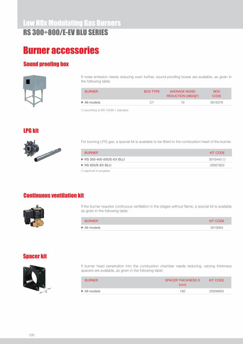
330
RS 300÷800/E-EV BLU SERIESLow NOx Modulating Gas Burners
Burner accessories
Continuous ventilation kit
LPG kit
Sound proofi ng box
If noise emission needs reducing even further, sound-proofi ng boxes are available, as given in the following table:
BURNER BOX TYPE AVERAGE NOISE REDUCTION [dB(A)](*)
BOX CODE
u All models C7 10 3010376
(*) according to EN 15036-1 standard
For burning LPG gas, a special kit is available to be fi tted to the combustion head of the burner.
BURNER KIT CODE
u RS 300-400-500/E-EV BLU 3010445 (*)
u RS 800/E-EV BLU 20007822
(*) approval in progress.
If the burner requires continuous ventilation in the stages without fl ame, a special kit is available as given in the following table:
BURNER KIT CODE
u All models 3010094
BURNER SPACER THICKNESS S (mm)
KIT CODE
u All models 180 20008903
Spacer kit
If burner head penetration into the combustion chamber needs reducing, varying thickness spacers are available, as given in the following table:

331
LOW
NOx
GAS
Low NOx Modulating Gas BurnersRS 300÷800/E-EV BLU SERIES
Adapters
Stabiliser spring
To vary the pressure range of the gas train stabilisers, accessory springs are available. The following table shows these accessories with their application range. Please refer to the technical manual for the correct choice of spring.
GAS TRAIN SPRING SPRING CODE
u
MBC 1900 SE 65 FC MBC 3100 SE 80 FC MBC 5000 SE 100 FC
White from 4 to 20 mbar 3010381
Red from 20 to 40 mbar 3010382
Black from 40 to 80 mbar 3010383
Green from 80 to 150 mbar 3010384
Gas train accessories
BURNER GAS TRAIN ADAPTER TYPE
DIMENSIONS L mm
ADAPTER CODE
u All models
MBC 1200 SE 50* I 2” DN 80 300 3000826
MBC 1900 SE 65 FC* I DN 65 DN 80 400 3010221
MBC 1900 SE 65 FC* I DN 65 DN 80 10 3010369
MBC 3100 SE 80 FC* I DN 80 DN 80 400 3010222
MBC 5000 SE 100 FC* I DN 100 DN 80 400 3010223
MBC 5000 SE 100 FC* I DN 100 DN 80 50 3010370
* with and without seal control
In certain cases, an adapter must be fi tted between the gas train and the burner, when the diameter of the gas train is different from the set diameter of the burner.Below are given the adapters than can be fi tted on the various burners:


333
LOW
NOx
GAS
The MODUBLOC MB SM BLU series is characterised by a monoblock structure which means that all necessary components are combined in a single unit, making installation easier and faster. The series covers a fi ring range from 3450 to 10400 kW, and it has been designed for use in hot water boilers or industrial steam generators.Operation can be “two stage progressive” o alternatively “modulating” with the installation of a PID logic regulator or by external 4-20 mA/0-10 V signal.The mechanical cam device of regulation allows to catch up a high modulation ratio on all fi ring rates range.The burner can, therefore, supply with precision the demanded power, guaranteeing a high effi ciency system level and the stability setting, obtaining fuel consumption and operating costs reduction. The combustion head, engineered with advanced simulation devices, guarantees reduced polluting emissions. An exclusive design, with fan unit fi tted in axis with the combustion head, guarantees low sound emissions, easy use and maintenance.
MB 8 SM BLU 1300/3450 ÷ 8300 kWMB 10 SM BLU 1100/4068 ÷ 9200 kWMB 12 SM BLU 1500/4800 ÷ 10400 kW
Low NOx Modulating Gas Burners
MODUBLOC MB SM BLU SERIES
FIRING RATES
Useful working fi eldfor choosing theburner
Modulation range
Test conditionsconforming to EN676 Temperature: 20°CPressure: 1013,5 mbarAltitude: 0 m a.s.l.

334
BURNER
Overall dimensions (mm)
Low NOx Modulating Gas BurnersMODUBLOC MB SM BLU SERIES
O
O
E
H
F
N
I
A
D
S
M
S
T
BURNER - BOILER MOUNTING FLANGE
MODEL A D E F H I M N O S TuMB 8 SM BLU 1007 1079 1900 475 413 575 DN80 208 1570 1740 221
uMB 10 SM BLU 1007 1079 1900 475 413 575 DN80 208 1570 1740 221
uMB 12 SM BLU 1007 1079 1900 454 456 575 DN80 208 1570 1740 221
MODEL D1 D2 Ø uMB 8 SM BLU 418 608 M20
uMB 10 SM BLU 418 608 M20
uMB 12 SM BLU 470 608 M20
MODEL X Y Z kg uMB 8 SM BLU 2690 1170 1350 450
uMB 10 SM BLU 2690 1170 1350 450
uMB 12 SM BLU 2690 1170 1350 460
PACKAGING
Z
XY

335
DESIGNATION OF SERIES
Specifi cation
LOW
NOx
GAS
Low NOx Modulating Gas BurnersMODUBLOC MB SM BLU SERIES
EXTENDED DESIGNATION
MB 8 S M BLU TC FS1 3/400/50 230/50-60
Series : MB
Size
Fuel : S Natural gas L Light oil LS Light oil / Methane
Operation : M Mechanic cam E Electronic cam V Variable speed (with Inverter) P Proportioning gas valve with air/gas ratio controller Emission : ... Class 1 EN267 - EN676 MZ Class 2 EN267 - EN676 BLU Class 3 EN267 - EN676
MX Class 2 EN267
Class 3 EN676
Head : TC Standard head TL Extended head
Flame control system : FS1 Standard (1 stop every 24 h)
Electrical supply to the system : 3/400/50 3N/400V/50Hz 3/230/50 3/230V/50Hz Auxiliary voltage : 230/50-60 230V/50-60Hz 110/50-60 110V/50-60Hz
BASIC DESIGNATION

336
STATE OF SUPPLY
Specifi cation
Low NOx Modulating Gas BurnersMODUBLOC MB SM BLU SERIES
Monoblock forced draught gas burner with modulating operation, fully automatic, made up of:- Fan with reverse curve blades high performance with low sound emissions- Air suction circuit lined with sound-proofi ng material- Air damper for air setting controlled by a high precision servomotor- Air pressure switch- Fan starting motor at 2900 rpm, three-phase 230/400 - 400/690 V with neutral, 50Hz - Low emission combustion head, that can be set on the basis of required output, fi tted with: - stainless steel end cone, resistant to corrosion and high temperatures - ignition electrodes - fl ame stability disk- Maximum gas pressure switch, with pressure test point, for halting the burner in the case of over pressure on the fuel supply
line- Module for air/fuel setting and output modulation with incorporated PID control of temperature or pressure of the heat generator- Burner safety control box for controlling the system safety- Photocell for fl ame detection- Star/triangle starter for the fan motor- Main electrical supply terminal board- Burner on/off switch - Auxiliary voltage led signal- Manual or automatic output increase/decrease switch- Burner working led signal- Contacts motor and thermal relay with release button- Motor internal thermal protection- Motor failure led signal - Burner failure led signal and lighted release button- Led signal for correct rotation direction of fan motor- Emergency button- Coded connection plugs-sockets- Burner opening hinge- Lifting rings- IP X0D (IP 40) electric protection level.
Standard equipment:- 1 fl ange gasket- 8 screws for fi xing the fl ange- 1 thermal screen- 4 screws for fi xing the burner fl ange to the boiler- Instruction handbook for installation, use and maintenance- Spare parts catalogue.

337
LOW
NOx
GAS
Available modelsBurners
Gas Trains
Low NOx Modulating Gas BurnersMODUBLOC MB SM BLU SERIES
G20 net calorifi c value: 10 kWh/Nm3 - Density: 0,71 kg/Nm3
The burners of MB SM BLU series are produced according to 90/396 - 89/336 (2004/108) - 73/23 (2006/95) EC Directive and EN 676 Norm.
GAS TRAIN GAS TRAIN NATURAL GAS NOTE
CODE * MODEL BURNER ADAPTER (type) (code)
MU
LTIB
LOC
3970221 MBC 1200 SE 50 MB 8-10-12 SM BLU 3000826 (I) (2)
3970225 MBC 1200 SE 50 CT MB 8-10-12 SM BLU 3000826 (I) (1)
CO
MP
OS
ED
GA
S T
RA
INS 3970222 MBC 1900 SE 65 FC MB 8-10-12 SM BLU 3010221 (I) - 3010225 (Z) (2)
3970226 MBC 1900 SE 65 FC CT MB 8-10-12 SM BLU 3010221 (I) - 3010225 (Z) (1)
3970223 MBC 3100 SE 80 FC MB 8-10-12 SM BLU 3010222 (I) - 3010226 (Z) (2)
3970227 MBC 3100 SE 80 FC CT MB 8-10-12 SM BLU 3010222 (I) - 3010226 (Z) (1)
3970224 MBC 5000 SE 100 FC MB 10-12 SM BLU 3010223 (I) - 3010227 (Z) (2)
3970228 MBC 5000 SE 100 FC CT MB 10-12 SM BLU 3010223 (I) - 3010227 (Z) (1)
* gas train are 230V/50Hz - 220V/60Hz electrical supply (1) seal control incorporated (2) seal control to be ordered as accessory
To select the gas train please refer to the technical data leafl et and/or instruction manual.
CODE MODEL
HEAT OUTPUT
TOTAL ELECTRICAL
POWER
CERTIFICATION NOTE
(kW) (kg/H) (kW)
3897960 MB 8SM BLU TC FS1 3/400/50 1300/3450-8300 110/291-700 19 CE 0085 BR0215
3897965 MB 8SM BLU TC FS2 3/400/50 1300/3450-8300 110/291-700 19 CE 0085 BR0215
3896660 MB10SM BLU TC FS1 3/400/50 1100/4068-9200 93/343-776 22 CE 0085 BR0216
3896665 MB10SM BLU TC FS2 3/400/50 1100/4068-9200 93/343-776 22 CE 0085 BR0216
3896760 MB12SM BLU TC FS1 3/400/50 1500/4800-10400 126/405-877 27 CE 0085 BR0217
3896765 MB12SM BLU TC FS2 3/400/50 1500/4800-10400 126/405-877 27 CE 0085 BR0217
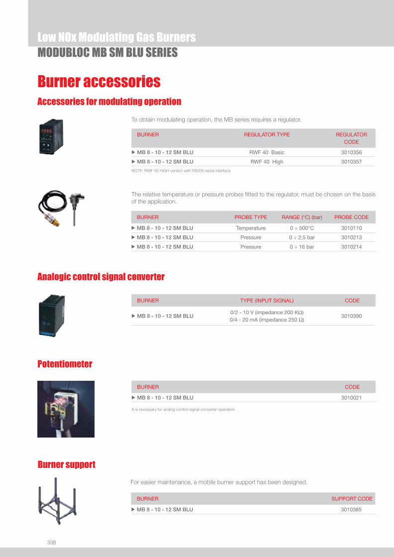
338
Burner accessories
MODUBLOC MB SM BLU SERIESLow NOx Modulating Gas Burners
Accessories for modulating operation
To obtain modulating operation, the MB series requires a regulator.
BURNER
REGULATOR TYPE REGULATOR CODE
u MB 8 - 10 - 12 SM BLU RWF 40 Basic 3010356
u MB 8 - 10 - 12 SM BLU RWF 40 High 3010357
The relative temperature or pressure probes fi tted to the regulator, must be chosen on the basis of the application.
Analogic control signal converter
BURNER TYPE (INPUT SIGNAL) CODE
u MB 8 - 10 - 12 SM BLU0/2 - 10 V (impedance 200 KΩ)0/4 - 20 mA (impedance 250 Ω)
3010390
BURNER PROBE TYPE RANGE (°C) (bar) PROBE CODE
u MB 8 - 10 - 12 SM BLU Temperature 0 ÷ 500°C 3010110
u MB 8 - 10 - 12 SM BLU Pressure 0 ÷ 2,5 bar 3010213
u MB 8 - 10 - 12 SM BLU Pressure 0 ÷ 16 bar 3010214
Burner support
For easier maintenance, a mobile burner support has been designed.
BURNER SUPPORT CODE
u MB 8 - 10 - 12 SM BLU 3010385
Potentiometer
BURNER CODE
u MB 8 - 10 - 12 SM BLU 3010021
It is necessary for analog control signal converter operation.
NOTE: RWF 40 HIGH version with RS435 serial interface.
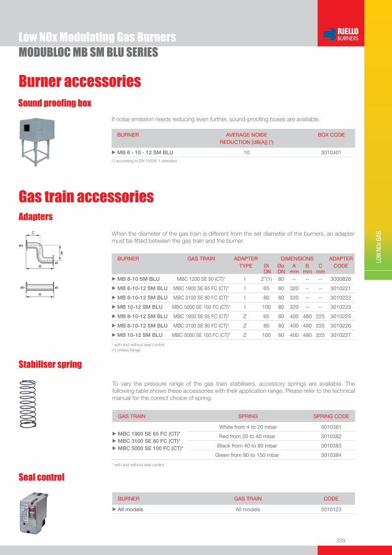
339
LOW
NOx
GAS
Low NOx Modulating Gas BurnersMODUBLOC MB SM BLU SERIES
Seal control
BURNER GAS TRAIN CODE
u All models All models 3010123
Gas train accessoriesAdapters
When the diameter of the gas train is different from the set diameter of the burners, an adapter must be fi tted between the gas train and the burner.
BURNER GAS TRAIN ADAPTER TYPE
DIMENSIONS Øi Øo A B C
ADAPTER CODE
DN DN mm mm mmu MB 8-10 SM BLU MBC 1200 SE 50 (CT)* I 2”(1) 80 -- -- -- 3000826
u MB 8-10-12 SM BLU MBC 1900 SE 65 FC (CT)* I 65 80 320 -- -- 3010221
u MB 8-10-12 SM BLU MBC 3100 SE 80 FC (CT)* I 80 80 320 -- -- 3010222
u MB 10-12 SM BLU MBC 5000 SE 100 FC (CT)* I 100 80 320 -- -- 3010223
u MB 8-10-12 SM BLU MBC 1900 SE 65 FC (CT)* Z 65 80 400 480 225 3010225
u MB 8-10-12 SM BLU MBC 3100 SE 80 FC (CT)* Z 80 80 400 480 225 3010226
u MB 10-12 SM BLU MBC 5000 SE 100 FC (CT)* Z 100 80 400 480 225 3010227
* with and without seal control(1) Unless fl ange
To vary the pressure range of the gas train stabilisers, accessory springs are available. The following table shows these accessories with their application range. Please refer to the technical manual for the correct choice of spring.
Stabiliser spring
GAS TRAIN SPRING SPRING CODE
u
u
u
MBC 1900 SE 65 FC (CT)* MBC 3100 SE 80 FC (CT)* MBC 5000 SE 100 FC (CT)*
White from 4 to 20 mbar 3010381
Red from 20 to 40 mbar 3010382
Black from 40 to 80 mbar 3010383
Green from 80 to 150 mbar 3010384
* with and without seal control
Burner accessories
If noise emission needs reducing even further, sound-proofi ng boxes are available.
Sound proofi ng box
BURNER
AVERAGE NOISE REDUCTION [dB(A)] (*)
BOX CODE
u MB 8 - 10 - 12 SM BLU 10 3010401
(*) according to EN 15036-1 standard

In addition to the solutions already available as standard, Riello Burners is able to supply on demand other burners, in the commercial and industrial range, equipped with continuous control of O2, CO and smoke temperature.These devices, integrated into the burners, guarantee an excellent operation with a very low air excess, granting remarkable fuel savings and less waste gases production, all within total safety during the operation.
Combustion control systems
l Easy installation l Small overall dimensionsl Indipendence from external air thanks to CO controll Easy setting of lowest air excess with constant value on all firing rates thanks to the exhaust gas analyserl Energy savingl Noise reductionl Polluting emissions reductionl Total safety during operation
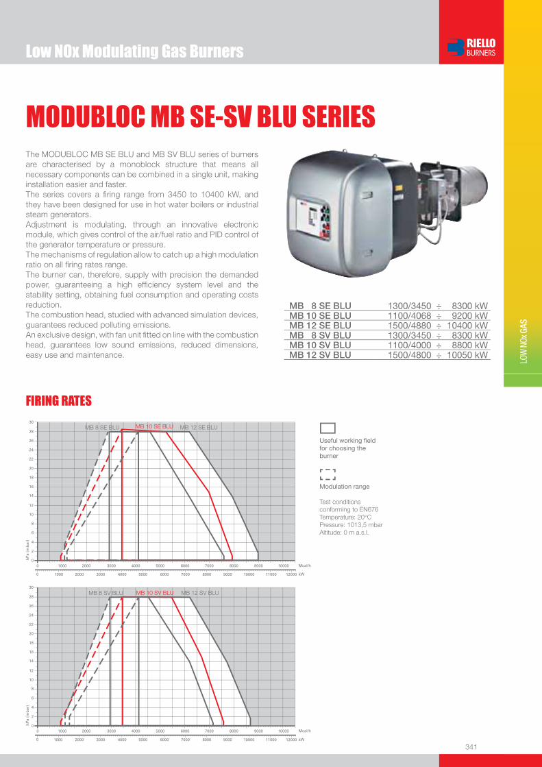
341
LOW
NOx
GAS
Low NOx Modulating Gas Burners
MODUBLOC MB SE-SV BLU SERIESThe MODUBLOC MB SE BLU and MB SV BLU series of burners are characterised by a monoblock structure that means all necessary components can be combined in a single unit, making installation easier and faster. The series covers a fi ring range from 3450 to 10400 kW, and they have been designed for use in hot water boilers or industrial steam generators.Adjustment is modulating, through an innovative electronic module, which gives control of the air/fuel ratio and PID control of the generator temperature or pressure.The mechanisms of regulation allow to catch up a high modulation ratio on all fi ring rates range.The burner can, therefore, supply with precision the demanded power, guaranteeing a high effi ciency system level and the stability setting, obtaining fuel consumption and operating costs reduction. The combustion head, studied with advanced simulation devices, guarantees reduced polluting emissions. An exclusive design, with fan unit fi tted on line with the combustion head, guarantees low sound emissions, reduced dimensions, easy use and maintenance.
MB 8 SE BLU 1300/3450 ÷ 8300 kWMB 10 SE BLU 1100/4068 ÷ 9200 kWMB 12 SE BLU 1500/4880 ÷ 10400 kWMB 8 SV BLU 1300/3450 ÷ 8300 kWMB 10 SV BLU 1100/4000 ÷ 8800 kWMB 12 SV BLU 1500/4800 ÷ 10050 kW
FIRING RATES
Useful working fi eldfor choosing theburner
Modulation range
Test conditionsconforming to EN676 Temperature: 20°CPressure: 1013,5 mbarAltitude: 0 m a.s.l.

342
BURNER
Overall dimensions (mm)
Low NOx Modulating Gas BurnersMODUBLOC MB SE-SV BLU SERIES
E
H
F
N
I
A
D
S
M
SO
O
BURNER - BOILER MOUNTING FLANGE
MODEL A D E F H I M N O S uMB 8 SE-SV BLU 1007 1079 1900 475 413 575 DN80 208 1570 1740
uMB 10 SE-SV BLU 1007 1079 1900 475 413 575 DN80 208 1570 1740
uMB 12 SE-SV BLU 1007 1079 1900 454 456 575 DN80 208 1570 1740
MODEL D1 D2 Ø uMB 8 SE-SV BLU 418 608 M20
uMB 10 SE-SV BLU 418 608 M20
uMB 12 SE-SV BLU 470 608 M20
MODEL X Y Z kg uMB 8 SE-SV BLU 2690 1170 1350 450
uMB 10 SE-SV BLU 2700 1170 1350 450
uMB 12 SE-SV BLU 2700 1170 1390 450
PACKAGING
Z
XY
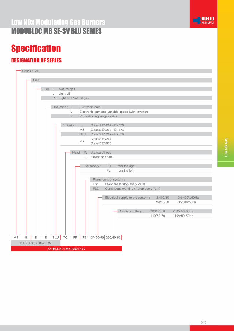
343
DESIGNATION OF SERIES
Specifi cation
LOW
NOx
GAS
Low NOx Modulating Gas BurnersMODUBLOC MB SE-SV BLU SERIES
EXTENDED DESIGNATION
MB 8 S E BLU TC FR FS1 3/400/50 230/50-60
Series : MB
Size
Fuel : S Natural gas L Light oil LS Light oil / Natural gas
Operation : E Electronic cam V Electronic cam and variable speed (with Inverter) P Proportioning air/gas valve Emission : ... Class 1 EN267 - EN676 MZ Class 2 EN267 - EN676 BLU Class 3 EN267 - EN676
MX Class 2 EN267
Class 3 EN676
Head : TC Standard head TL Extended head
Fuel supply : FR from the right FL from the left
Flame control system : FS1 Standard (1 stop every 24 h) FS2 Continuous working (1 stop every 72 h)
Electrical supply to the system : 3/400/50 3N/400V/50Hz 3/230/50 3/230V/50Hz Auxiliary voltage : 230/50-60 230V/50-60Hz 110/50-60 110V/50-60Hz
BASIC DESIGNATION
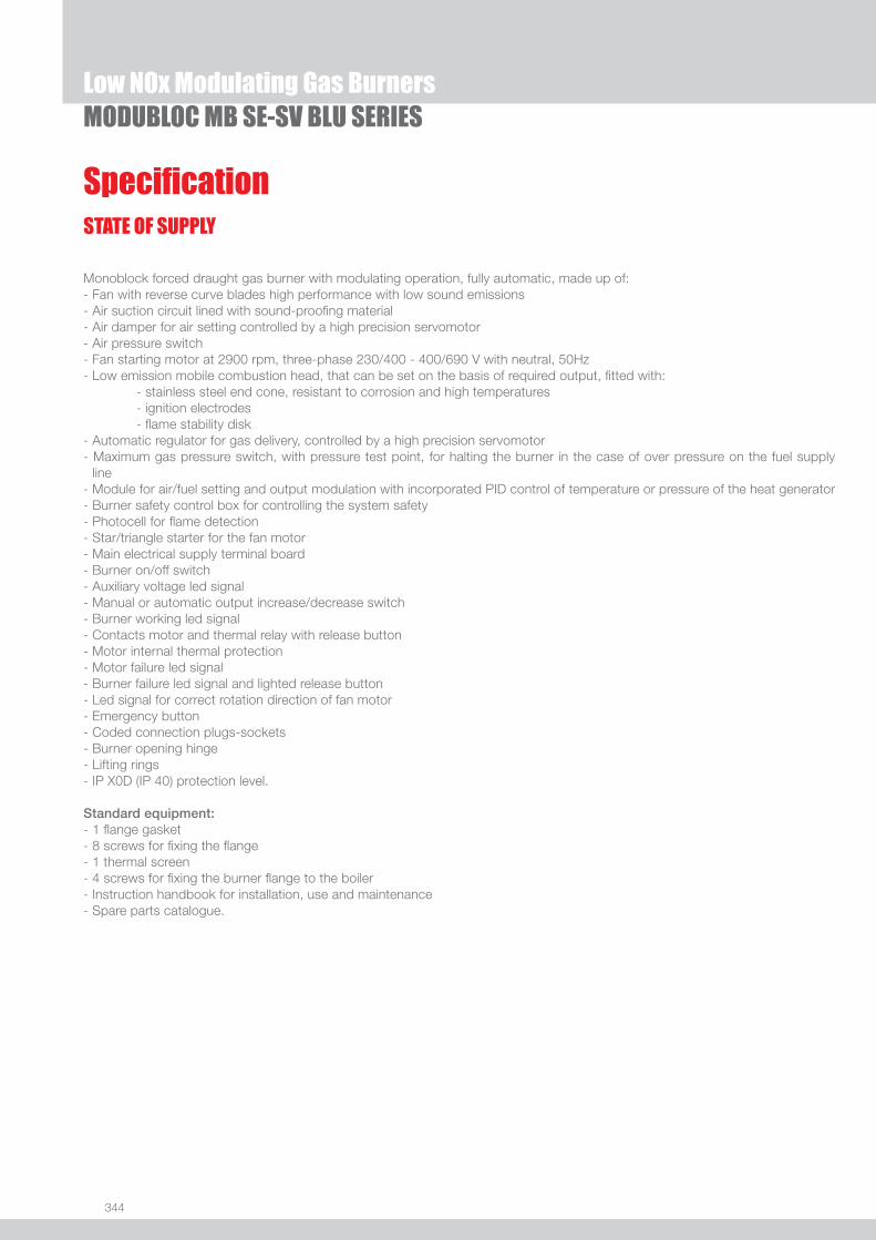
344
STATE OF SUPPLY
Specifi cation
Low NOx Modulating Gas BurnersMODUBLOC MB SE-SV BLU SERIES
Monoblock forced draught gas burner with modulating operation, fully automatic, made up of:- Fan with reverse curve blades high performance with low sound emissions- Air suction circuit lined with sound-proofi ng material- Air damper for air setting controlled by a high precision servomotor- Air pressure switch- Fan starting motor at 2900 rpm, three-phase 230/400 - 400/690 V with neutral, 50Hz - Low emission mobile combustion head, that can be set on the basis of required output, fi tted with: - stainless steel end cone, resistant to corrosion and high temperatures - ignition electrodes - fl ame stability disk- Automatic regulator for gas delivery, controlled by a high precision servomotor- Maximum gas pressure switch, with pressure test point, for halting the burner in the case of over pressure on the fuel supply
line- Module for air/fuel setting and output modulation with incorporated PID control of temperature or pressure of the heat generator- Burner safety control box for controlling the system safety- Photocell for fl ame detection- Star/triangle starter for the fan motor- Main electrical supply terminal board- Burner on/off switch - Auxiliary voltage led signal- Manual or automatic output increase/decrease switch- Burner working led signal- Contacts motor and thermal relay with release button- Motor internal thermal protection- Motor failure led signal - Burner failure led signal and lighted release button- Led signal for correct rotation direction of fan motor- Emergency button- Coded connection plugs-sockets- Burner opening hinge- Lifting rings- IP X0D (IP 40) protection level.
Standard equipment:- 1 fl ange gasket- 8 screws for fi xing the fl ange- 1 thermal screen- 4 screws for fi xing the burner fl ange to the boiler- Instruction handbook for installation, use and maintenance- Spare parts catalogue.
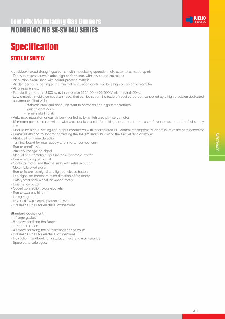
345
LOW
NOx
GAS
STATE OF SUPPLY
Specifi cation
Low NOx Modulating Gas BurnersMODUBLOC MB SE-SV BLU SERIES
Monoblock forced draught gas burner with modulating operation, fully automatic, made up of:- Fan with reverse curve blades high performance with low sound emissions- Air suction circuit lined with sound-proofi ng material- Air damper for air setting at the minimal modulation controlled by a high precision servomotor- Air pressure switch- Fan starting motor at 2900 rpm, three-phase 230/400 - 400/690 V with neutral, 50Hz - Low emission mobile combustion head, that can be set on the basis of required output, controlled by a high precision dedicated
servomotor, fi tted with: - stainless steel end cone, resistant to corrosion and high temperatures - ignition electrodes - fl ame stability disk- Automatic regulator for gas delivery, controlled by a high precision servomotor- Maximum gas pressure switch, with pressure test point, for halting the burner in the case of over pressure on the fuel supply
line- Module for air/fuel setting and output modulation with incorporated PID control of temperature or pressure of the heat generator- Burner safety control box for controlling the system safety built-in to the air-fuel ratio controller- Photocell for fl ame detection- Terminal board for main supply and inverter connections- Burner on/off switch - Auxiliary voltage led signal- Manual or automatic output increase/decrease switch- Burner working led signal- Contacts motor and thermal relay with release button- Motor failure led signal - Burner failure led signal and lighted release button- Led signal for correct rotation direction of fan motor- Safety feed back signal fan speed motor- Emergency button- Coded connection plugs-sockets- Burner opening hinge- Lifting rings- IP X0D (IP 40) electric protection level- 6 fairleads Pg11 for electrical connections.
Standard equipment:- 1 fl ange gasket- 8 screws for fi xing the fl ange- 1 thermal screen- 4 screws for fi xing the burner fl ange to the boiler- 6 fairleads Pg11 for electrical connections- Instruction handbook for installation, use and maintenance- Spare parts catalogue.
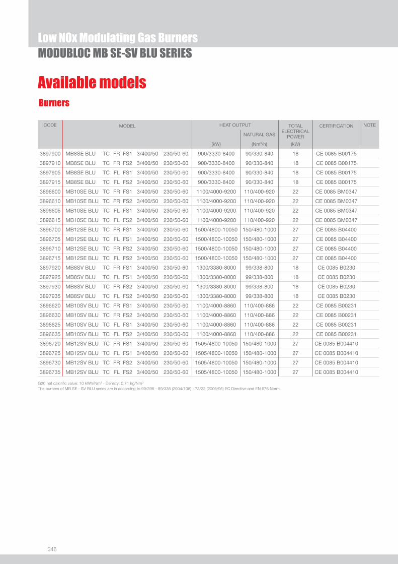
346
Low NOx Modulating Gas BurnersMODUBLOC MB SE-SV BLU SERIES
Available modelsBurners
CODE MODEL HEAT OUTPUT TOTAL ELECTRICAL
POWER
CERTIFICATION NOTE
NATURAL GAS
(kW) (Nm3/h) (kW)
3897900 MB8SE BLU TC FR FS1 3/400/50 230/50-60 900/3330-8400 90/330-840 18 CE 0085 B00175
3897910 MB8SE BLU TC FR FS2 3/400/50 230/50-60 900/3330-8400 90/330-840 18 CE 0085 B00175
3897905 MB8SE BLU TC FL FS1 3/400/50 230/50-60 900/3330-8400 90/330-840 18 CE 0085 B00175
3897915 MB8SE BLU TC FL FS2 3/400/50 230/50-60 900/3330-8400 90/330-840 18 CE 0085 B00175
3896600 MB10SE BLU TC FR FS1 3/400/50 230/50-60 1100/4000-9200 110/400-920 22 CE 0085 BM0347
3896610 MB10SE BLU TC FR FS2 3/400/50 230/50-60 1100/4000-9200 110/400-920 22 CE 0085 BM0347
3896605 MB10SE BLU TC FL FS1 3/400/50 230/50-60 1100/4000-9200 110/400-920 22 CE 0085 BM0347
3896615 MB10SE BLU TC FL FS2 3/400/50 230/50-60 1100/4000-9200 110/400-920 22 CE 0085 BM0347
3896700 MB12SE BLU TC FR FS1 3/400/50 230/50-60 1500/4800-10050 150/480-1000 27 CE 0085 B04400
3896705 MB12SE BLU TC FL FS1 3/400/50 230/50-60 1500/4800-10050 150/480-1000 27 CE 0085 B04400
3896710 MB12SE BLU TC FR FS2 3/400/50 230/50-60 1500/4800-10050 150/480-1000 27 CE 0085 B04400
3896715 MB12SE BLU TC FL FS2 3/400/50 230/50-60 1500/4800-10050 150/480-1000 27 CE 0085 B04400
3897920 MB8SV BLU TC FR FS1 3/400/50 230/50-60 1300/3380-8000 99/338-800 18 CE 0085 B0230
3897925 MB8SV BLU TC FL FS1 3/400/50 230/50-60 1300/3380-8000 99/338-800 18 CE 0085 B0230
3897930 MB8SV BLU TC FR FS2 3/400/50 230/50-60 1300/3380-8000 99/338-800 18 CE 0085 B0230
3897935 MB8SV BLU TC FL FS2 3/400/50 230/50-60 1300/3380-8000 99/338-800 18 CE 0085 B0230
3896620 MB10SV BLU TC FR FS1 3/400/50 230/50-60 1100/4000-8860 110/400-886 22 CE 0085 B00231
3896630 MB10SV BLU TC FR FS2 3/400/50 230/50-60 1100/4000-8860 110/400-886 22 CE 0085 B00231
3896625 MB10SV BLU TC FL FS1 3/400/50 230/50-60 1100/4000-8860 110/400-886 22 CE 0085 B00231
3896635 MB10SV BLU TC FL FS2 3/400/50 230/50-60 1100/4000-8860 110/400-886 22 CE 0085 B00231
3896720 MB12SV BLU TC FR FS1 3/400/50 230/50-60 1505/4800-10050 150/480-1000 27 CE 0085 B004410
3896725 MB12SV BLU TC FL FS1 3/400/50 230/50-60 1505/4800-10050 150/480-1000 27 CE 0085 B004410
3896730 MB12SV BLU TC FR FS2 3/400/50 230/50-60 1505/4800-10050 150/480-1000 27 CE 0085 B004410
3896735 MB12SV BLU TC FL FS2 3/400/50 230/50-60 1505/4800-10050 150/480-1000 27 CE 0085 B004410
G20 net calorifi c value: 10 kWh/Nm3 - Density: 0,71 kg/Nm3
The burners of MB SE - SV BLU series are in according to 90/396 - 89/336 (2004/108) - 73/23 (2006/95) EC Directive and EN 676 Norm.

347
LOW
NOx
GAS
Available models
Low NOx Modulating Gas BurnersMODUBLOC MB SE-SV BLU SERIES
Gas Trains
* gas trains are 230V/50Hz - 220V/60Hz electrical supply(1) Seal control incorporated
To select the gas train please refer to the technical data leafl et and/or instruction manual.
GAS TRAIN GAS TRAIN NATURAL GAS LPG NOTE
CODE * MODEL BURNER (type)
ADAPTER (code)
BURNER (type)
ADAPTER (code)
MU
LTIB
LOC
3970225
MBC 1200 SE 50 CT
MB 8 SE-SV BLU 3000826 (“I”) type (1)
MB 10 SE-SV BLU
CO
MP
OS
ED
3970226
MBC 1900 SE 65 FC CT
MB 8 SE-SV BLU3010221 (“I”) type 3010225 (“Z”) type
MB 10 SE-SV BLU (1)
MB 12 SE-SV BLU
3970227
MBC 3100 SE 80 FC CT
MB 8 SE-SV BLU3010222 (“I”) type 3010226 (“Z”) type
(1) MB 10 SE-SV BLU
MB 12 SE-SV BLU
3970228
MBC 5000 SE 100 FC CT
MB 8 SE-SV BLU3010223 (“I”) type 3010227 (“Z”) type
(1) MB 10 SE-SV BLU
MB 12 SE-SV BLU

348
Low NOx Modulating Gas BurnersMODUBLOC MB SE-SV BLU SERIES
Burner accessoriesDTI module (Data Transfer Interface)
This electronic module can transfer multiple signals from different local modules to a BMS supervisor software system (Building Management System).
BURNER MODULE CODE
u MB 8 - 10 - 12 SE - SV BLU 3010234
I/O digital module
Digital modules I/O transfer in-coming and out-going information from the boiler room or from the system in general to a remote supervisor system.
BURNER MODULE CODE
u MB 8 - 10 - 12 SE - SV BLU 3010233
I/O analogic module
I/O Analog modules transfer in-coming and out-going information to a remote supervisor system.
BURNER MODULE CODE
u MB 8 - 10 - 12 SE - SV BLU 3010232
EGA module (Exhaust Gas Analyser)
Four different EGA modules are available to measure some of the exhaust gas substances and their temperature.
BURNER ANALYSED GAS MODULE CODE
u MB 8 - 10 - 12 SE - SV BLU CO, CO2, O2 3010235
u MB 8 - 10 - 12 SE - SV BLU CO, CO2, O2, NO 3010236
u MB 8 - 10 - 12 SE - SV BLU CO, CO2, O2, SO2 3010237
u MB 8 - 10 - 12 SE - SV BLU CO, CO2, O2, NO, SO2 3010238
Belden 9501 type leads
All the connections for the above modules must be done using a BELDEN 9501 type lead (available in coils of 50 m).
BURNER LEAD CODE
u MB 8 - 10 - 12 SE - SV BLU 3010239

349
Burner accessories
LOW
NOx
GAS
Low NOx Modulating Gas BurnersMODUBLOC MB SE-SV BLU SERIES
Accessories for modulating operation
Main management module allows a modulating operation with use of probes chosen on the basis of the application.
BURNER PROBE TYPE RANGE (°C) (bar) PROBE CODE
u MB 8 - 10 - 12 SE - SV BLU Temperature 0 ÷ 400°C 3010187
u MB 8 - 10 - 12 SE - SV BLU Pressure 0 ÷ 3 bar 3010246
u MB 8 - 10 - 12 SE - SV BLU Pressure 0 ÷ 18 bar 3010186
u MB 8 - 10 - 12 SE - SV BLU Pressure 0 ÷ 30 bar 3010188
Burner support
For easier maintenance, a mobile burner support has been designed, which means the burner can be dismantled without the need for forklift trucks.
BURNER SUPPORT CODE
u MB 8 - 10 - 12 SE - SV BLU 3010385
Inverter module
The inverter allows the variation of the amount of combustion air through a variable speed action of the fan motor.
BURNER CODE
u MB 8 SV BLU 3010446
u MB 10 - 12 SV BLU 3010447
If noise emission needs reducing even further, sound-proofi ng boxes are available.
Sound proofi ng box
BURNER
AVERAGE NOISE REDUCTION [dB(A)] (*)
BOX CODE
u MB 8 - 10 - 12 SE - SV BLU 10 3010401
(*) according to EN 15036-1 standard
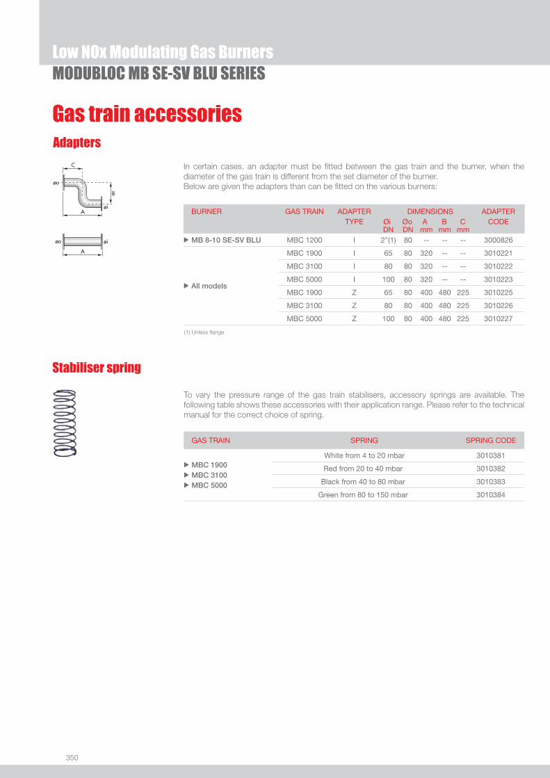
350
Gas train accessoriesAdapters
In certain cases, an adapter must be fi tted between the gas train and the burner, when the diameter of the gas train is different from the set diameter of the burner.Below are given the adapters than can be fi tted on the various burners:
MODUBLOC MB SE-SV BLU SERIESLow NOx Modulating Gas Burners
To vary the pressure range of the gas train stabilisers, accessory springs are available. The following table shows these accessories with their application range. Please refer to the technical manual for the correct choice of spring.
Stabiliser spring
GAS TRAIN SPRING SPRING CODE
u
u
u
MBC 1900 MBC 3100 MBC 5000
White from 4 to 20 mbar 3010381
Red from 20 to 40 mbar 3010382
Black from 40 to 80 mbar 3010383
Green from 80 to 150 mbar 3010384
BURNER GAS TRAIN ADAPTER TYPE
DIMENSIONS Øi Øo A B C
ADAPTER CODE
DN DN mm mm mmu MB 8-10 SE-SV BLU MBC 1200 I 2”(1) 80 -- -- -- 3000826
u All models
MBC 1900 I 65 80 320 -- -- 3010221
MBC 3100 I 80 80 320 -- -- 3010222
MBC 5000 I 100 80 320 -- -- 3010223
MBC 1900 Z 65 80 400 480 225 3010225
MBC 3100 Z 80 80 400 480 225 3010226
MBC 5000 Z 100 80 400 480 225 3010227
(1) Unless fl ange

One Stage Gas Burners
351
GAS
RDBS SERIES
Useful working fi eldfor choosing theburner
Test conditionsconforming to EN676 Temperature: 20°CPressure: 1013,5 mbarAltitude: 0 m a.s.l.
The Riello RDBS is a new series of one stage gas burners with integrated gas train, characterised by its small dimensions in spite of its high combustion performance. It is available in conventional fl ue and balanced fl ue versions. It has been developed to respond to any request for home heating, conforming to current regulations in force. The RDBS series is available in two models with an output range from 16 to 48 kW; the difference between the two models are the gas train and the combustion head.The RDBS1 model is made up of a class A gas train and a standard fl ame combustion head, the RDBS0.1 model is made up of a class B gas train and a short fl ame combustion head.The RDBS burners are fi tted with a microprocessor based control box with diagnostic functions. These models use the same components designed by Riello for RDB series. The high quality level guarantees safe working.In developing these burners, special attention was paid to reducing noise, the ease of installation and adjustment, to obtaining the smallest size possible to fi t into any sort of boiler available on the market.These models are approved by the EN 676 European Standard and European Directives, Gas Appliance, EMC, Low Voltage, Boiler Effi ciency.The RDBS burners are tested before leaving the factory.
RDBS1 16 ÷ 47 kWRDBS0.1 16 ÷ 48 kW
FIRING RATES

352
RDBS SERIES
BURNER
Overall dimensions (mm)
One Stage Gas Burners
B
D
C
L
EF
I
H
MODEL B C D E F H I L u RDBS1 195 141 222 207 115 89 168 20
u RDBS0.1 195 141 222 207 94 89 168 20
MODEL A C1 C2 D F Q R S T u RDBS1 91 130 150 91 180 45° 11 72 72
u RDBS0.1 91 130 150 91 180 45° 11 72 72
PACKAGING
Z
XY
BURNER - BOILER MOUNTING FLANGE
MODEL X Y Z kg u RDBS1 405 360 350 12
u RDBS0.1 405 360 350 12

353
GAS
RDBS SERIES
DESIGNATION OF SERIES
Specifi cation
One Stage Gas Burners
RDB S 1 1/230/50
Series : RDB
Fuel : S Natural gas
Size
Electrical supply to the system : 1/230/50 1/230V/50Hz
Monoblock, gas burner, completely automatic, with one stage operation made up of:- Fan with forward curve blades- Cover lined- Air damper with external adjustment, with no need to remove the cover- Single phase electric motor 230 V, 50 Hz- Combustion head fi tted with: - stainless steel head cone, resistant to high temperatures - ignition electrodes - ionisation probe - gas distributor - fl ame stability disk- Incorporated gas train- Adjustable air pressure switch, with graduated selector, to guarantee burner lock out in the case of insuffi cient combustible air- Microprocessor-based fl ame control box, with diagnostic functions- Protection fi lter against radio interference- IP X0D (IP 40) electric protection level.
Standard equipment:RDBS1- Flange with insulating gasket- 4-pin plug- Screws and nuts for fl ange to be fi xed to boiler- Protection grill for CF application - 90° manual gate valve- Tube 1/2”- Flange 90° - Instruction handbook for installation, use and maintenance- Spare parts catalogue.
RDBS0.1- Flange with insulating gasket- Screws and nuts for fl ange to be fi xed to boiler- Flange 90° - Instruction handbook for installation, use and maintenance- Spare parts catalogue.
STATE OF SUPPLY
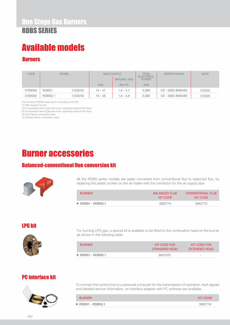
354
RDBS SERIES
Burners
Available models
One Stage Gas Burners
The burners of RDBS series are in according to EN 676. (1) With plug and socket.(2) Incorporated class A gas train (max. operating pressure 65 mbar).(3) Incorporated class B gas train (max. operating pressure 65 mbar).(4) Short fl ame combustion head.(5) Standard fl ame combustion head.
CODE
MODEL
HEAT OUTPUT TOTAL
ELECTRICALPOWER
CERTIFICATION NOTE
NATURAL GAS
(kW) (Nm3/h) (kW)
3768000 RDBS1 1/230/50 16 - 47 1,6 - 4,7 0,090 CE - 0085 BM0490 (1)(2)(5)
3769000 RDBS0.1 1/230/50 16 - 48 1,6 - 4,8 0,090 CE - 0085 BM0490 (1)(3)(4)
Burner accessoriesBalanced-conventional fl ue conversion kit
All the RDBS series models are easily converted from conventional fl ue to balanced fl ue, by replacing the plastic screen on the air intake with the connector for the air supply pipe.
BURNER BALANCED FLUEKIT CODE
CONVENTIONAL FLUEKIT CODE
u RDBS1 - RDBS0.1 3062774 3062775
LPG kitFor burning LPG gas, a special kit is available to be fi tted to the combustion head on the burner as shown in the following table.
BURNER KIT CODE FORSTANDARD HEAD
KIT CODE FOREXTENDED HEAD
u RDBS1 - RDBS0.1 3001076 -
PC interface kitTo connect the control box to a personal computer for the transmission of operation, fault signals and detailed service information, an interface adapter with PC software are available.
BURNER KIT CODE
u RDBS1 - RDBS0.1 3002719
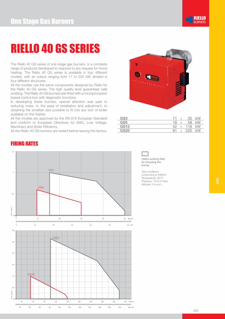
One Stage Gas Burners
355
GAS
RIELLO 40 GS SERIESThe Riello 40 GS series of one stage gas burners, is a complete range of products developed to respond to any request for home heating. The Riello 40 GS series is available in four different models, with an output ranging from 11 to 220 kW, divided in four different structures.All the models use the same components designed by Riello for the Riello 40 GS series. The high quality level guarantees safe working. The Riello 40 GS burners are fi tted with a microprocessor based control box with diagnostic functions.In developing these burners, special attention was paid to reducing noise, to the ease of installation and adjustment, to obtaining the smallest size possible to fi t into any sort of boiler available on the market.All the models are approved by the EN 676 European Standard and conform to European Directives for EMC, Low Voltage, Machinery and Boiler Effi ciency.All the Riello 40 GS burners are tested before leaving the factory.
GS3 11 ÷ 35 kWGS5 18 ÷ 58 kWGS10 42 ÷ 116 kWGS20 81 ÷ 220 kW
FIRING RATES
Useful working fi eldfor choosing theburner
Test conditionsconforming to EN676 Temperature: 20°CPressure: 1013,5 mbarAltitude: 0 m a.s.l.

356
BURNER
Overall dimensions (mm)
One Stage Gas BurnersRIELLO 40 GS SERIES
A1
D
C
Reduction nipple **
Rp 1/2” - Rp 3/8”
F E
IV
M
N
A
H
Z
MODEL A A1 C D E F H I M N V Z u GS3 - 252 - 215 230 100 91 165 Rp 3/8”* 37 132 25
u GS5 - 272 - 233 295 100 91 180 Rp 1/2” 48 138 28
u GS10 341 - 188,5 262 346 110 105 204 Rp 3/4” 61 142 33
u GS10 *** - 305 - 262 346 110 105 204 Rp 3/4” 61 142 33
u GS20 387 - 212 298 389 120 125 230 Rp 3/4” 67 152 33
u GS20 *** - 350 - 298 389 120 125 230 Rp 3/4” 67 152 33
GS3 - GS5 - GS10 GS20
MODEL A1 A2 B1 B2 C C1 F Q R u GS3 - - - - 140 130 170 45° 10
u GS5 - - - - 140 130 170 45° 10
u GS10 - - - - 160 130 185 45° 11
u GS20 155 200 155 200 170 - 170 90° 11
MODEL X Y Z kg u GS3 375 335 310 12
u GS5 445 355 325 12
u GS10 483 423 330 17
u GS20 535 463 375 22
BURNER - BOILER MOUNTING FLANGE
* With reduction nipple** Standard equipment on R40 GS3
*** Versions with air damper opening motor inside the cover
Z
XY
PACKAGING

357
GAS
DESIGNATION OF SERIES
Specifi cation
One Stage Gas BurnersRIELLO 40 GS SERIES
G S 3 1/230/50
Series : G
Fuel : S Natural gas
Size
Electrical supply to the system : 1/230/50 1/230V/50Hz 1/220/60 1/220V/60Hz
Monoblock, gas burners, completely automatic, with one stage settings fi tted with:- Fan with forward curve blades- Cover lined with sound-proofi ng material- Air damper, completely closed in stand by, with adjustment inside the cover- Single phase electric motor 230 V, 50 Hz- Combustion head fi tted with: - stainless steel head cone, resistant to high temperatures - ignition electrodes - ionisation probe - gas distributor - fl ame stability disk- Adjustable air pressure switch, with graduated selector, to guarantee burner lock out in the case of insuffi cient combustible air- Microprocessor-based burner safety control box MG 557 (with diagnostic, remote reset, continuous purge integrated, recycle, post-purge)
- IP X0D (IP 40) electric protection level.
Standard equipment:- Flange insulation screen- Screws and nuts for fi xing the fl ange to the boiler- 7-pole socket - Hinge- Reduction nipple Rp 1/2” - Rp 3/8” (for R40 GS3 only)- Grommet- Instruction handbook for installation, use and maintenance- Spare parts catalogue.
STATE OF SUPPLY

358
Available models
One Stage Gas BurnersRIELLO 40 GS SERIES
Burners
Gas Trains
CODE
MODEL
HEAT OUTPUT TOTAL
ELECTRICALPOWER
CERTIFICATION NOTE
NATURAL GAS
(kW) (Nm3/h) (kW)
3755119 GS3 1/230/50 11 - 35 1,1 - 3,5 0,100 CE – 0063 AP6680 (1) (5)
3755219 GS5 1/230/50 18 - 58 1,8 - 5,8 0,110 CE – 0063 AP6680 (1) (5)
3755281 GS5 1/220/60 23 - 65 2,3 - 6,5 0,180 - (2) (4) (5)
3755426 GS10 1/230/50 42 - 116 4,2 - 11,6 0,130 CE – 0063 AP6680 (1)
3755444 GS10 1/230/50 42 - 116 4,2 - 11,6 0,130 CE – 0063 AP6680 (2) (3)
3755483 GS10 1/220/60 42 - 116 4,2 - 11,6 0,200 - (2) (4) (5)
20007527 GS10 1/220/60 42 - 116 4,2 - 11,6 0,200 - (1) (4) (5)
3755616 GS20 1/230/50 81 - 220 8,1 - 22 0,250 CE – 0063 AP6680 (1)
3755644 GS20 1/230/50 81 - 220 8,1 - 22 0,250 CE – 0063 AP6680 (2) (3)
3755683 GS20 1/220/60 81 - 220 8,1 - 22 0,430 - (2) (4) (5)
* Gas train are 230V/50Hz - 220V/60Hz electrical supply (1) With installed plug (if the plug is not necessary, remove it in accordance with gas train instruction manual indication)(2) GS10 ≤ 80 kW with natural gas(3) GS20 ≤ 180 kW with natural gas
To select the gas train please refer to the technical data leafl et and/or instruction manual.
GAS TRAIN GAS TRAIN NATURAL GAS LPG NOTE
CODE * MODEL BURNER ADAPTER BURNER ADAPTER
(type) (code) (type) (code)
MU
LTIB
LOC
GA
S T
RA
IN 3970569 MBC 65 DLE GS3 - GS5 GS3 - GS5 (1)
3970530 MBDLE 405 GS5 - GS10 GS5 - GS10 (1)
3970500 MBDLE 405 GS10 GS10 (1) (2)
3970531 MBDLE 407 GS5 - GS10 - GS20 GS5 - GS10 - GS20 (1) (3)
3970532 MBDLE 410 GS10 - GS20 GS10 - GS20 (1)
Net calorifi c value G20: 10 kWh/Nm3 - Density: 0,71 kg/Nm3
The burners of GS series are in according to EN 676(1) With plug and socket(2) With terminal block(3) Belgium version(4) Korea version(5) With air damper opening motor inside the cover

359
GAS
Burner accessories
One Stage Gas BurnersRIELLO 40 GS SERIES
Remote reset control kit for MG 557/3/5 control box
The MG 557 control box can be remotely released using an electric command kit. This kit must be installed in conformity with current regulations in force.
BURNER KIT CODE
u GS3 - GS5 3002750
Extended head kit“Standard head” burners can be transformed into “extended head” versions by using the special kit. Below the KITS available for the various burners are listed, showing the original and the extended lengths.
BURNER STANDARD HEADLENGTH (mm)
EXTENDED HEADLENGTH (mm)
KIT CODE
u GS3 - GS5 100 125 3000820
u GS10 110 170 3001064
u GS20 120 280 3000873
LPG kitFor burning LPG gas, a special kit is available to be fi tted to the combustion head on the burner as shown in the following table.
BURNER KIT CODE FORSTANDARD HEAD
KIT CODE FOREXTENDED HEAD
u GS3 3000881 3000881
u GS5 3000882 3000882
u GS10 3000884 3000884
u GS20 3000886 3000886
End cone with turbulator disk
BURNER PROJECTION (mm) KIT CODE
u GS5 +15 3000916
u GS10 +18 3000918
u GS20 +23 3000919
Town gas kit
BURNER KIT CODE
u GS3 3000888
u GS5 3000889
u GS10 3000891
u GS20 3000893
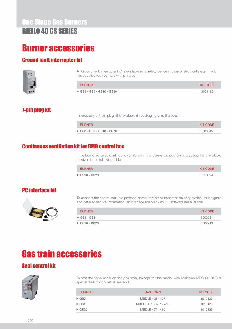
360
One Stage Gas BurnersRIELLO 40 GS SERIES
Burner accessoriesGround fault interrupter kit
A “Ground fault interrupter kit” is available as a safety device in case of electrical system fault. It is supplied with burners with pin plug.
BURNER KIT CODE
u GS3 - GS5 - GS10 - GS20 3001180
7-pin plug kitIf necessary a 7-pin plug kit is available (in packaging of n. 5 pieces).
BURNER KIT CODE
u GS3 - GS5 - GS10 - GS20 3000945
PC interface kitTo connect the control box to a personal computer for the transmission of operation, fault signals and detailed service information, an interface adapter with PC software are available.
BURNER KIT CODE
u GS3 - GS5 3002731
u GS10 - GS20 3002719
Continuous ventilation kit for RMG control box
If the burner requires continuous ventilation in the stages without fl ame, a special kit is available as given in the following table.
BURNER KIT CODE
u GS10 - GS20 3010094
To test the valve seals on the gas train, (except for the model with Multibloc MBC 65 DLE) a special “seal control kit” is available.
Seal control kit
Gas train accessories
BURNER GAS TRAIN KIT CODE
u GS5 MBDLE 405 - 407 3010123
u GS10 MBDLE 405 - 407 - 410 3010123
u GS20 MBDLE 407 - 410 3010123
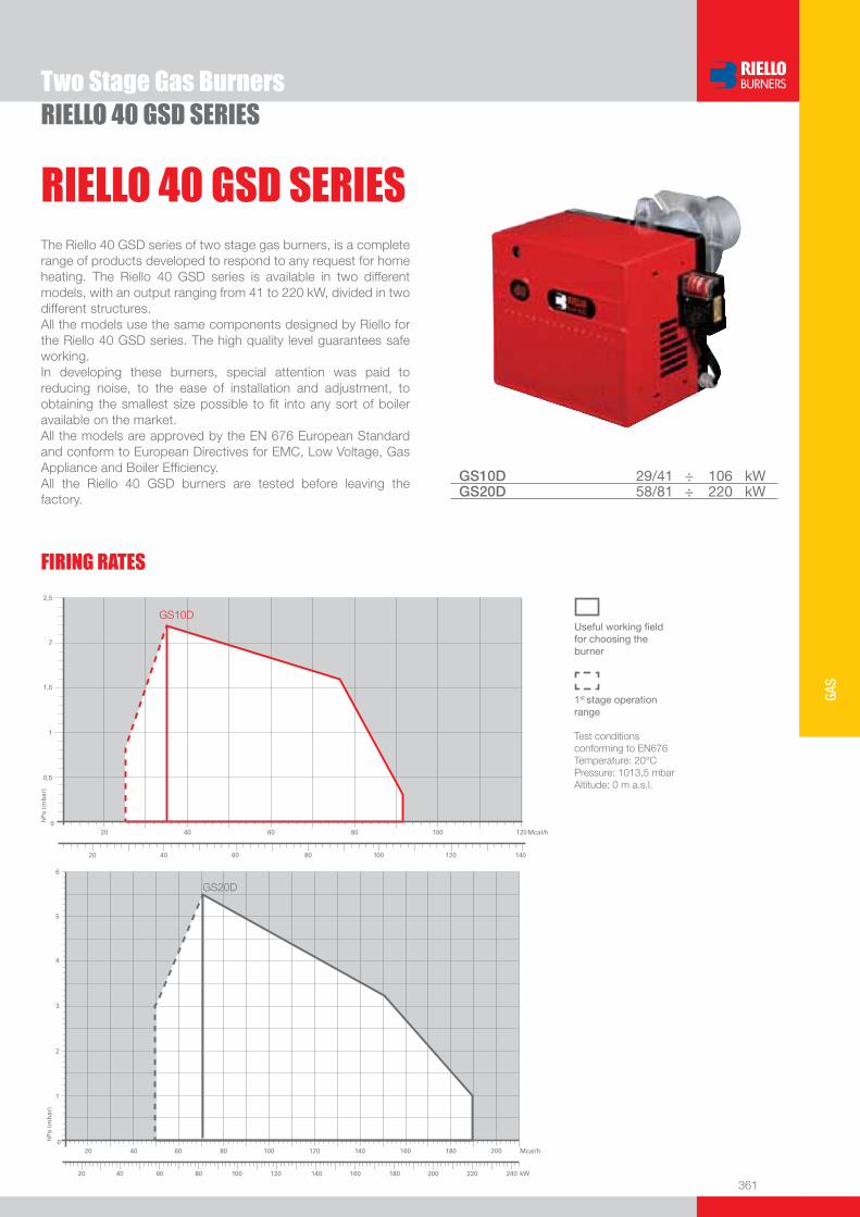
361
GAS
RIELLO 40 GSD SERIESTwo Stage Gas Burners
The Riello 40 GSD series of two stage gas burners, is a complete range of products developed to respond to any request for home heating. The Riello 40 GSD series is available in two different models, with an output ranging from 41 to 220 kW, divided in two different structures.All the models use the same components designed by Riello for the Riello 40 GSD series. The high quality level guarantees safe working.In developing these burners, special attention was paid to reducing noise, to the ease of installation and adjustment, to obtaining the smallest size possible to fi t into any sort of boiler available on the market.All the models are approved by the EN 676 European Standard and conform to European Directives for EMC, Low Voltage, Gas Appliance and Boiler Effi ciency.All the Riello 40 GSD burners are tested before leaving the factory.
GS10D 29/41 ÷ 106 kWGS20D 58/81 ÷ 220 kW
RIELLO 40 GSD SERIES
FIRING RATES
Useful working fi eldfor choosing theburner
1st stage operationrange
Test conditionsconforming to EN676 Temperature: 20°CPressure: 1013,5 mbarAltitude: 0 m a.s.l.

362
BURNER
Overall dimensions (mm)
RIELLO 40 GSD SERIES
MODEL A D E F H I M N V Z u GS10D 368 262 346 110 105 204 Rp 3/4” 61 142 33
u GS20D 413 298 389 120 125 230 Rp 3/4” 67 152 33
GS10D GS20D
MODEL A1 A2 B1 B2 C C1 F Q R u GS10D - - - - 160 130 185 45° 11
u GS20D 155 200 155 200 170 - 170 90° 11
MODEL X Y Z kg u GS10D 495 483 330 17
u GS20D 535 535 375 22
BURNER - BOILER MOUNTING FLANGE
Two Stage Gas Burners
PACKAGING
Z
XY
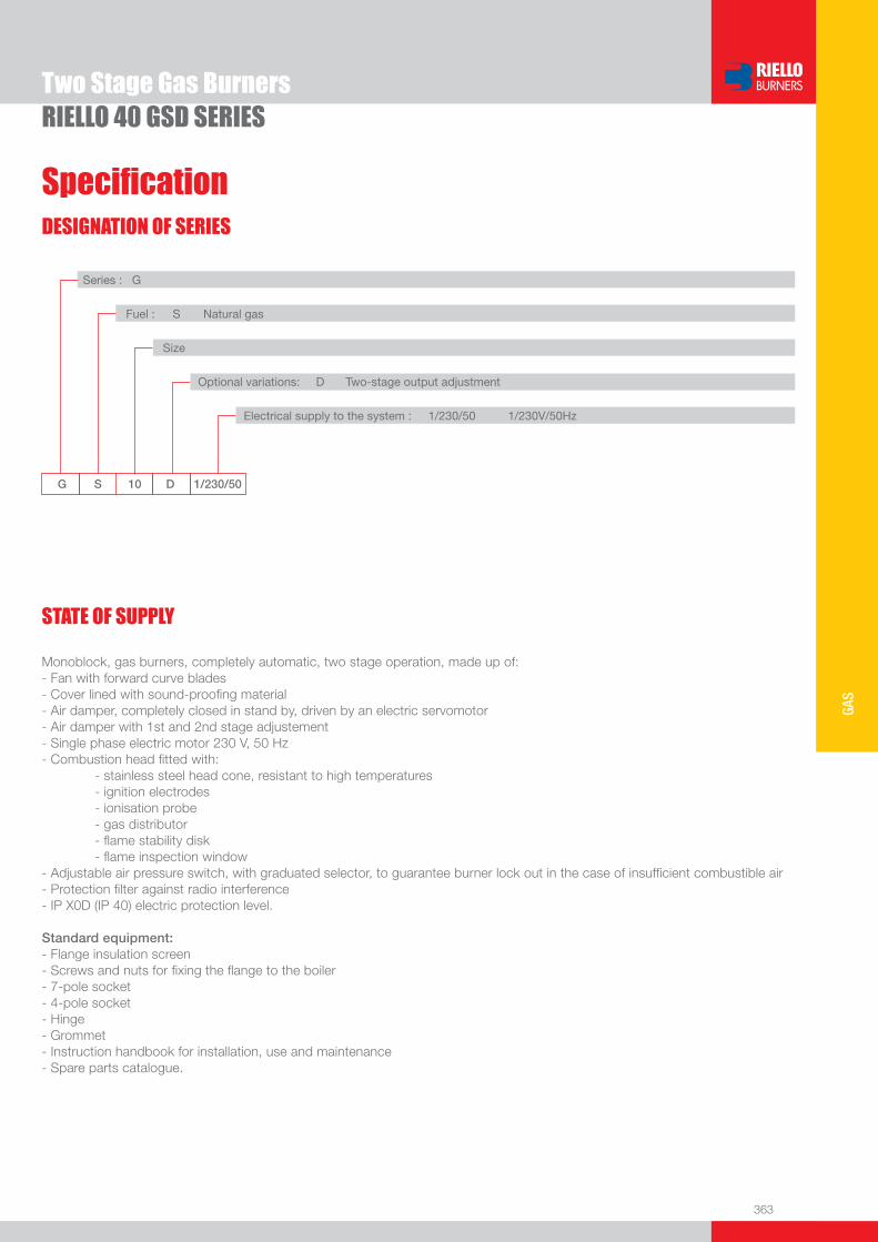
363
GAS
DESIGNATION OF SERIES
Specifi cation
RIELLO 40 GSD SERIES
G S 10 D 1/230/50
Series : G
Fuel : S Natural gas
Size
Optional variations: D Two-stage output adjustment
Electrical supply to the system : 1/230/50 1/230V/50Hz
Monoblock, gas burners, completely automatic, two stage operation, made up of:- Fan with forward curve blades- Cover lined with sound-proofi ng material- Air damper, completely closed in stand by, driven by an electric servomotor- Air damper with 1st and 2nd stage adjustement- Single phase electric motor 230 V, 50 Hz- Combustion head fi tted with: - stainless steel head cone, resistant to high temperatures - ignition electrodes - ionisation probe - gas distributor - fl ame stability disk - fl ame inspection window - Adjustable air pressure switch, with graduated selector, to guarantee burner lock out in the case of insuffi cient combustible air- Protection fi lter against radio interference- IP X0D (IP 40) electric protection level.
Standard equipment:- Flange insulation screen- Screws and nuts for fi xing the fl ange to the boiler- 7-pole socket- 4-pole socket - Hinge- Grommet- Instruction handbook for installation, use and maintenance- Spare parts catalogue.
STATE OF SUPPLY
Two Stage Gas Burners

364
Available models
RIELLO 40 GSD SERIES
Burners
Gas Trains
CODE
MODEL
HEAT OUTPUT TOTAL
ELECTRICALPOWER
CERTIFICATION NOTE
NATURAL GAS
(kW) (Nm3/h) (kW)
3757615 GS10D 1/230/50 29/41 - 106 2,9/4,1 - 10,6 0,130 CE – 0063 AP6680 (1)
3757714 GS20D 1/230/50 58/81 - 220 5,8/8,1 - 22 0,250 CE – 0063 AP6680 (1)
* Gas train are 230V/50Hz - 220V/60Hz electrical supply (1) With installed plug(2) GS10D ≤ 80 kW with natural gas(3) GS20D ≤ 180 kW with natural gas
To select the gas train please refer to the technical data leafl et and/or instruction manual.
GAS TRAIN GAS TRAIN NATURAL GAS LPG NOTE
CODE * MODEL BURNER ADAPTER BURNER ADAPTER
(type) (code) (type) (code)
MULT
IBLOC
GAS
TRAIN
S
3970084 MBZRDLE 405 GS10D GS10D (1) (2)
3970537 MBZRDLE 407 GS10D - GS20D GS10D - GS20D (1) (3)
3970534 MBZRDLE 410 GS20D GS20D (1)
Net calorifi c value G20: 10 kWh/Nm3 - Density: 0,71 kg/Nm3
The burners of GSD series are in according to EN 676(1) With plug and socket.
Two Stage Gas Burners

365
GAS
Burner accessories
RIELLO 40 GSD SERIES
Extended head kitBurners “standard head” can be transformed into “extended head” versions by using the special kit. Here the KITS available for the various burners are listed, showing the original and the extended lengths.
BURNER STANDARD HEADLENGTH (mm)
EXTENDED HEADLENGTH (mm)
KIT CODE
u GS10D 100 170 3000864
u GS20D 120 280 3000873
LPG kitFor burning LPG gas, a special kit is available to be fi tted to the combustion head on the burner as shown in the following table.
BURNER KIT CODE FORSTANDARD HEAD
KIT CODE FOREXTENDED HEAD
u GS10D 3000884 3000884
u GS20D 3000886 3000886
End cone with turbulator disk
BURNER PROJECTION (mm) KIT CODE
u GS10D +18 3000918
u GS20D +23 3000919
Town gas kit
BURNER KIT CODE
u GS10D 3000891
u GS20D 3000893
Two Stage Gas Burners
Ground fault interrupter kit
A “Ground fault interrupter kit” is available as a safety device in case of electrical system fault. It is supplied with burners with pin plug.
BURNER KIT CODE
u GS10D - GS20D 3001180

366
RIELLO 40 GSD SERIES
Burner accessories7-pin plug kit
If necessary a 7-pin plug kit is available (in packaging of n. 5 pieces).
BURNER KIT CODE
u GS10D - GS20D 3000945
PC interface kitTo connect the control box to a personal computer for the transmission of operation, fault signals and detailed service information, an interface adapter with PC software are available.
BURNER KIT CODE
u GS10D - GS20D 3002719
Continuous ventilation kit for RMG control box
If the burner requires continuous ventilation in the stages without fl ame, a special kit is available as given in the following table.
BURNER KIT CODE
u GS10D - GS20D 3010094
To test the valve seals on the gas train a special “seal control kit” is available.
Seal control kit
Gas train accessories
BURNER KIT CODE
u GS10D - GS20D 3010123
Two Stage Gas Burners
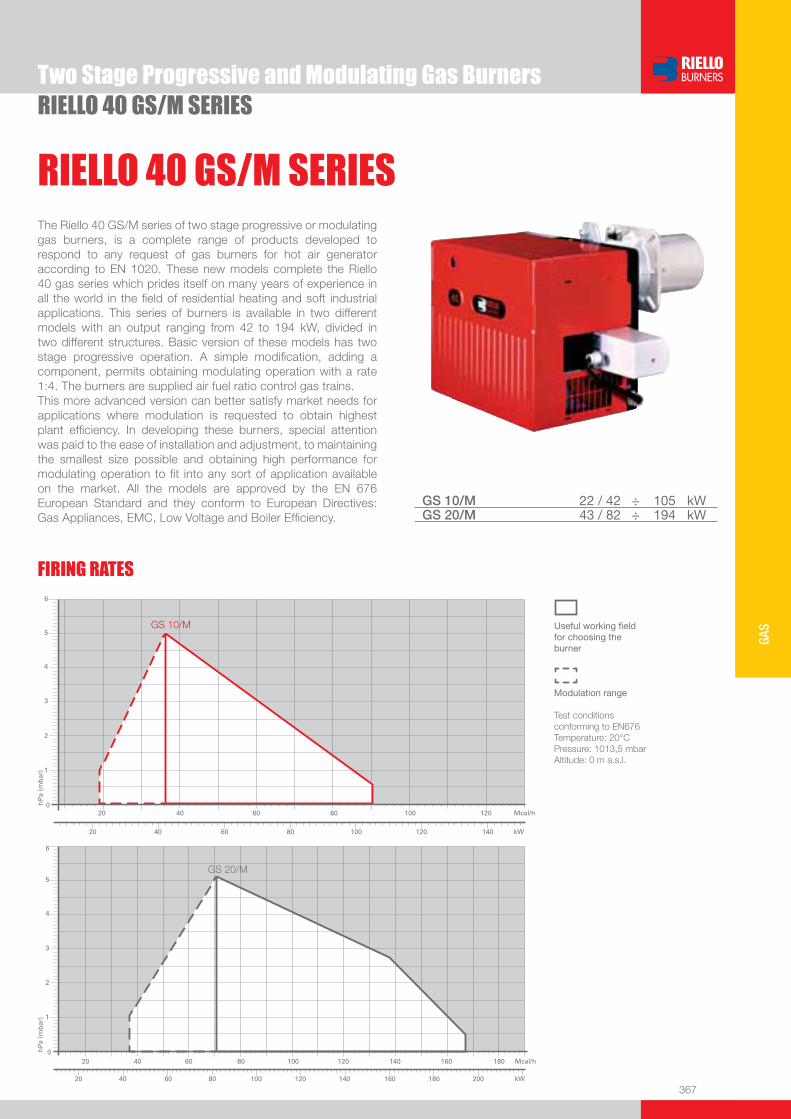
367
GAS
RIELLO 40 GS/M SERIESTwo Stage Progressive and Modulating Gas Burners
The Riello 40 GS/M series of two stage progressive or modulating gas burners, is a complete range of products developed to respond to any request of gas burners for hot air generator according to EN 1020. These new models complete the Riello 40 gas series which prides itself on many years of experience in all the world in the fi eld of residential heating and soft industrial applications. This series of burners is available in two different models with an output ranging from 42 to 194 kW, divided in two different structures. Basic version of these models has two stage progressive operation. A simple modifi cation, adding a component, permits obtaining modulating operation with a rate 1:4. The burners are supplied air fuel ratio control gas trains.This more advanced version can better satisfy market needs for applications where modulation is requested to obtain highest plant effi ciency. In developing these burners, special attention was paid to the ease of installation and adjustment, to maintaining the smallest size possible and obtaining high performance for modulating operation to fi t into any sort of application available on the market. All the models are approved by the EN 676 European Standard and they conform to European Directives: Gas Appliances, EMC, Low Voltage and Boiler Effi ciency.
RIELLO 40 GS/M SERIES
FIRING RATES
Useful working fi eldfor choosing theburner
Modulation range
Test conditionsconforming to EN676 Temperature: 20°CPressure: 1013,5 mbarAltitude: 0 m a.s.l.
GS 10/M 22 / 42 ÷ 105 kWGS 20/M 43 / 82 ÷ 194 kW

368
BURNER
Overall dimensions (mm)
RIELLO 40 GS/M SERIES
GS10/M GS20/M
BURNER - BOILER MOUNTING FLANGE
Two Stage Progressive and Modulating Gas Burners
PACKAGING
Z
XY
MODEL A D E F H I M N V Z u GS10/M 425 262 347 110 105 204 Rp 3/4” 61 142 33
u GS20/M 488 298 389 120 125 230 Rp 3/4” 67 152 33
MODEL A1 A2 B1 B2 C C1 F Q R u GS10/M - - - - 160 130 185 45° 11
u GS20/M 155 200 155 200 170 - 170 90° 11
MODEL X Y Z kg u GS10/M 505 490 330 17
u GS20/M 560 535 375 17
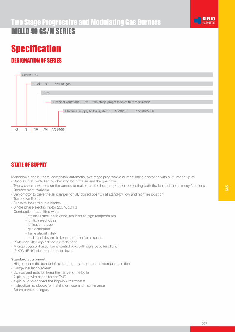
369
GAS
DESIGNATION OF SERIES
Specifi cation
RIELLO 40 GS/M SERIES
G S 10 /M 1/230/50
Series : G
Fuel : S Natural gas
Size
Optional variations: /M two stage progressive of fully modulating
Electrical supply to the system : 1/230/50 1/230V/50Hz
Monoblock, gas burners, completely automatic, two stage progressive or modulating operation with a kit, made up of:- Ratio air/fuel controlled by checking both the air and the gas fl ows- Two pressure switches on the burner, to make sure the burner operation, detecting both the fan and the chimney functions- Remote reset available- Servomotor to drive the air damper to fully closed position at stand-by, low and high fi re position- Turn down fi re 1:4- Fan with forward curve blades- Single phase electric motor 230 V, 50 Hz- Combustion head fi tted with: - stainless steel head cone, resistant to high temperatures - ignition electrodes - ionisation probe - gas distributor - fl ame stability disk - additional device, to keep short the fl ame shape - Protection fi lter against radio interference- Microprocessor-based fl ame control box, with diagnostic functions- IP X0D (IP 40) electric protection level.
Standard equipment:- Hinge to turn the burner left-side or right-side for the maintenance position- Flange insulation screen- Screws and nuts for fi xing the fl ange to the boiler- 7-pin plug with capacitor for EMC- 4-pin plug to connect the high-low thermostat- Instruction handbook for installation, use and maintenance- Spare parts catalogue.
STATE OF SUPPLY
Two Stage Progressive and Modulating Gas Burners

370
Available models
RIELLO 40 GS/M SERIES
Burners
Gas Trains
CODE
MODEL
HEAT OUTPUT TOTAL
ELECTRICALPOWER
CERTIFICATION NOTE
NATURAL GAS
(kW) (Nm3/h) (kW)
3755556 GS10/M 1/230/50 22/42 - 105 2,2/4,2 - 10,5 0,130 CE – 0085 BM0453 (1)
3755756 GS20/M 1/230/50 43/82 - 194 4,3/8,2 - 19,4 0,250 CE – 0085 BM0453 (1)
* Gas train are 230V/50Hz - 220V/60Hz electrical supply (1) With plug and socket. (2) ≥120 kW. To select the gas train please refer to the technical data leafl et and/or instruction manual.
GAS TRAIN GAS TRAIN NATURAL GAS LPG NOTE
CODE * MODEL BURNER ADAPTER BURNER ADAPTER
(type) (code) (type) (code)
MULT
IBLOC
GAS
TRAIN
S
3970535 MB-VEF 407GS10/M GS10/M
(1)GS20/M GS20/M
3970536 MB-VEF 412 GS20/M GS20/M (1) (2)
(1) With installed plug.Net calorifi c value G20 gas: 10 kWh/Nm3; 8600 kcal/Nm3 - Density: 0,71 kg/Nm3.
Two Stage Progressive and Modulating Gas Burners
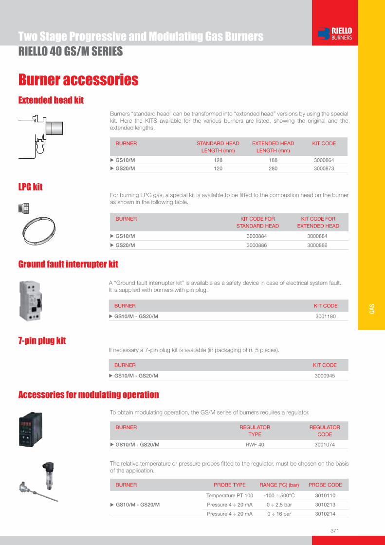
371
GAS
Burner accessories
RIELLO 40 GS/M SERIES
Extended head kitBurners “standard head” can be transformed into “extended head” versions by using the special kit. Here the KITS available for the various burners are listed, showing the original and the extended lengths.
BURNER STANDARD HEADLENGTH (mm)
EXTENDED HEADLENGTH (mm)
KIT CODE
u GS10/M 128 188 3000864
u GS20/M 120 280 3000873
LPG kitFor burning LPG gas, a special kit is available to be fi tted to the combustion head on the burner as shown in the following table.
BURNER KIT CODE FORSTANDARD HEAD
KIT CODE FOREXTENDED HEAD
u GS10/M 3000884 3000884
u GS20/M 3000886 3000886
Two Stage Progressive and Modulating Gas Burners
7-pin plug kitIf necessary a 7-pin plug kit is available (in packaging of n. 5 pieces).
BURNER KIT CODE
u GS10/M - GS20/M 3000945
Ground fault interrupter kit
A “Ground fault interrupter kit” is available as a safety device in case of electrical system fault. It is supplied with burners with pin plug.
BURNER KIT CODE
u GS10/M - GS20/M 3001180
Accessories for modulating operation
To obtain modulating operation, the GS/M series of burners requires a regulator.
BURNER
REGULATOR TYPE
REGULATOR CODE
u GS10/M - GS20/M RWF 40 3001074
The relative temperature or pressure probes fi tted to the regulator, must be chosen on the basis of the application.
BURNER PROBE TYPE RANGE (°C) (bar) PROBE CODE
u GS10/M - GS20/M
Temperature PT 100 -100 ÷ 500°C 3010110
Pressure 4 ÷ 20 mA 0 ÷ 2,5 bar 3010213
Pressure 4 ÷ 20 mA 0 ÷ 16 bar 3010214

372
Burner accessories
RIELLO 40 GS/M SERIESTwo Stage Progressive and Modulating Gas Burners
PC interface kitTo connect the control box to a personal computer for the transmission of operation, fault signals and detailed service information, an interface adapter with PC software are available.
BURNER KIT CODE
u GS10/M - GS20/M 3002719

One Stage Gas Burners
373
GAS
RIELLO 40 FS SERIESThe Riello 40 FS series of one stage gas burners, is a complete range of products developed to respond to any request for light industrial application. The Riello 40 FS series is available in fi ve different models, with an output ranging from 11 to 220 kW, divided in four different structures.All the models use the same components designed by Riello for the Riello 40 FS series. The high quality level guarantees safe working.The Riello 40 FS burners are fi tted with a microprocessor - based control box, with diagnostic functions.In developing these burners, special attention was paid to reducing noise, to the ease of installation and adjustment, to obtaining the smallest size possible to fi t into any sort of boiler available on the market.All the models are approved by the EN 676 European Standard and conform to European Directives for EMC, Low Voltage, Machinery and Boiler Effi ciency.All the Riello 40 FS burners are tested before leaving the factory.
FS3 11 ÷ 35 kWFS5 23 ÷ 58 kWFS8 46 ÷ 93 kWFS10 42 ÷ 116 kWFS20 81 ÷ 220 kW
FIRING RATES
Useful working fi eldfor choosing theburner
Test conditionsconforming to EN676 Temperature: 20°CPressure: 1013,5 mbarAltitude: 0 m a.s.l.

374
BURNER
Overall dimensions (mm)
One Stage Gas BurnersRIELLO 40 FS SERIES
FS3 - FS5 - FS8 - FS10 FS20
MODEL A D E F H I M N V Z u FS3 252 215 230 100 91 165 Rp 3/8”* 37 132 25
u FS5 272 233 295 100 91 180 Rp 1/2” 48 138 28
u FS8 305 262 347 110 105 204 Rp 3/4” 61 142 33
u FS10 305 262 346 110 105 204 Rp 3/4” 61 142 33
u FS20 350 298 389 120 125 230 Rp 3/4” 67 152 33
* With reduction nipple** Standard equipment on R40 FS3
MODEL A1 A2 B1 B2 C C1 F Q R u FS3 - - - - 140 130 170 45° 10
u FS5 - - - - 140 130 170 45° 10
u FS8 - - - - 160 130 185 45° 11
u FS10 - - - - 160 130 185 45° 11
u FS20 155 200 155 200 170 - 170 90° 11
MODEL X Y Z kg u FS3 375 335 310 9,5
u FS5 445 355 335 11
u FS8 483 495 330 13,6
u FS10 483 495 330 17
u FS20 535 535 375 20
BURNER - BOILER MOUNTING FLANGE
PACKAGING
Z
XY
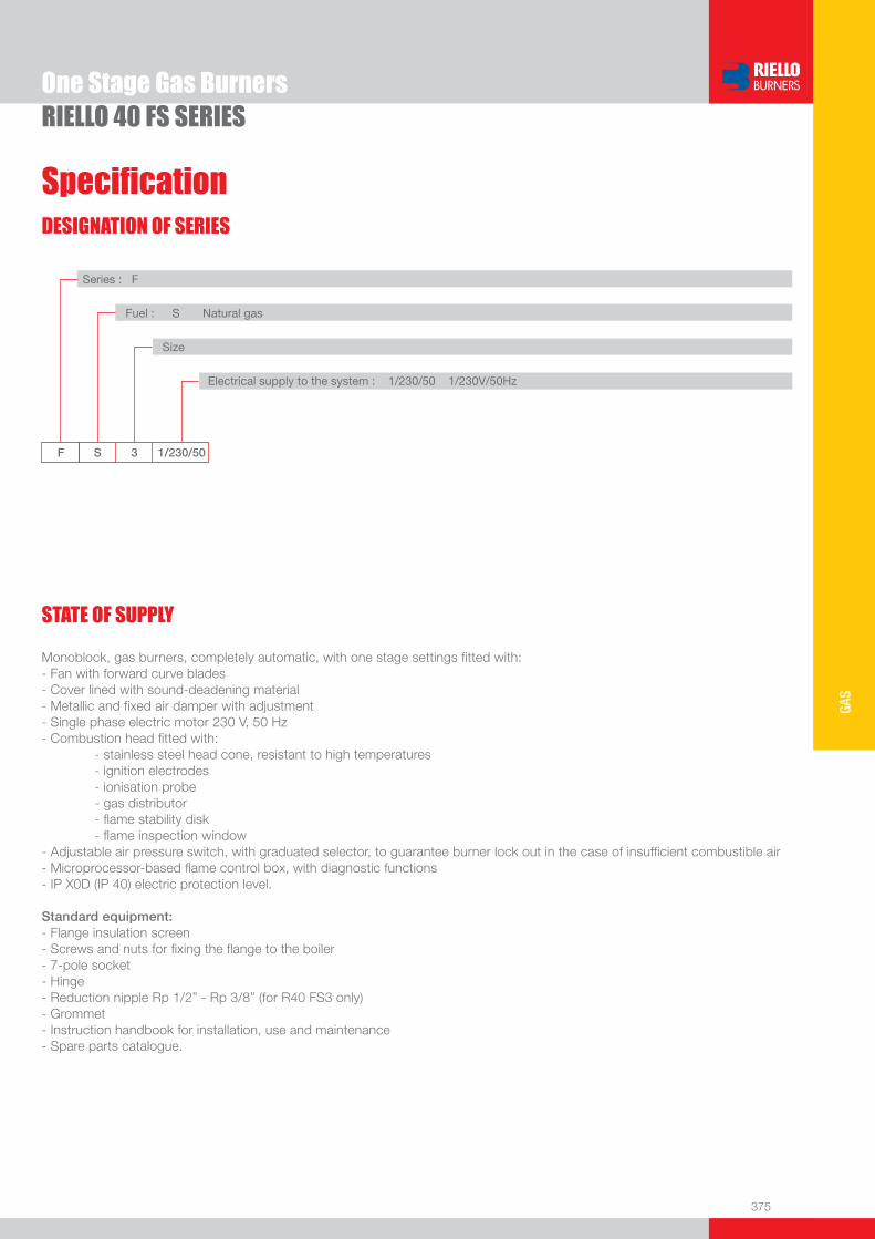
375
GAS
DESIGNATION OF SERIES
Specifi cation
One Stage Gas BurnersRIELLO 40 FS SERIES
STATE OF SUPPLY
F S 3 1/230/50
Series : F
Fuel : S Natural gas
Size
Electrical supply to the system : 1/230/50 1/230V/50Hz
Monoblock, gas burners, completely automatic, with one stage settings fi tted with:- Fan with forward curve blades- Cover lined with sound-deadening material- Metallic and fi xed air damper with adjustment- Single phase electric motor 230 V, 50 Hz- Combustion head fi tted with: - stainless steel head cone, resistant to high temperatures - ignition electrodes - ionisation probe - gas distributor - fl ame stability disk - fl ame inspection window- Adjustable air pressure switch, with graduated selector, to guarantee burner lock out in the case of insuffi cient combustible air- Microprocessor-based fl ame control box, with diagnostic functions- IP X0D (IP 40) electric protection level.
Standard equipment:- Flange insulation screen- Screws and nuts for fi xing the fl ange to the boiler- 7-pole socket - Hinge- Reduction nipple Rp 1/2” - Rp 3/8” (for R40 FS3 only)- Grommet- Instruction handbook for installation, use and maintenance- Spare parts catalogue.

376
Available models
One Stage Gas BurnersRIELLO 40 FS SERIES
Burners
Gas Trains
CODE
MODEL
HEAT OUTPUT TOTAL
ELECTRICALPOWER
CERTIFICATION NOTE
NATURAL GAS
(kW) (Nm3/h) (kW)
3756506 FS3 1/230/50 11 - 35 1,1 - 3,5 0,150 CE – 0063 AP6680
3756606 FS5 1/230/50 23 - 58 2,3 - 5,8 0,150 CE – 0063 AP6680 (1)
3756706 FS8 1/230/50 46 - 93 4,6 - 9,3 0,150 CE – 0063 AP6680 (1)
3756435 FS10 1/230/50 42 - 116 4,2 - 11,6 0,130 CE – 0063 AP6680 (1) (2)
3756935 FS20 1/230/50 81 - 220 8,1 - 22 0,250 CE – 0063 AP6680 (1) (2)
CODE
MODEL
HEAT OUTPUT TOTAL
ELECTRICALPOWER
CERTIFICATION NOTE
LPG
(kW) (Nm3/h) (kW)
3756439 FSP10 1/230/50 42 - 116 1,6 - 4,4 0,130 CE – 0063AP6680 (1) (2)
3756939 FSP20 1/230/50 81 - 220 3,1 - 8,5 0,250 CE – 0063AP6680 (1) (2)
Net calorifi c value G20: 10 kWh/Nm3 - Density: 0,71 kg/Nm3
Net calorifi c value G31 (LPG): 25,8 kWh/Nm3 - Density: 2,02 kg/Nm3
The burners of FS series are in according to EN 676(1) With plug and socket(2) French version
Models for LPG applications
* Gas train are 230V/50Hz - 220V/60Hz electrical supply (1) With installed plug (if the plug is not necessary, remove it in accordance with gas train instruction manual indication)(2) FS8 ≤ 80 kW with natural gas(3) FS10 ≤ 80 kW with natural gas(4) FS20 ≤ 180 kW with natural gas
To select the gas train please refer to the technical data leafl et and/or instruction manual.
GAS TRAIN GAS TRAIN NATURAL GAS LPG NOTE
CODE * MODEL BURNER ADAPTER BURNER ADAPTER
(type) (code) (type) (code)
MU
LTIB
LOC
GA
S T
RA
IN 3970569 MBC 65 DLE FS3 - FS5 FS3 - FS5 (1)
3970530 MBDLE 405 FS5 - FS8 - FS20 FS5 - FS8 - FS20 (1) (2)
3970500 MBDLE 405 FS10 FS10 (1) (3)
3970531 MBDLE 407 FS5 - FS8 - FS10 - FS20 FS5 - FS8 - FS10 - FS20 (1) (4)
3970532 MBDLE 410 FS10 - FS20 FS10 - FS20 (1)

377
GAS
Burner accessories
One Stage Gas BurnersRIELLO 40 FS SERIES
Remote reset control kit for MG 557/3/5 control box
The MG 557 control box can be remotely released using an electric command kit. This kit must be installed in conformity with the local authority.
BURNER KIT CODE
u FS3 - FS5 - FS8 3002750
Extended head kitBurners “standard head” can be transformed into “extended head” versions by using the special kit. Here the KITS available for the various burners are listed, showing the original and the extended lengths.
BURNER STANDARD HEADLENGTH (mm)
EXTENDED HEADLENGTH (mm)
KIT CODE
u FS3 - FS5 100 125 3000820
u FS8 - FS10 110 170 3000864
u FS8 110 278 3000920
u FS20 120 280 3000873
LPG kitFor burning LPG gas, a special kit is available to be fi tted to the combustion head on the burner as shown in the following table.
BURNER KIT CODE FORSTANDARD HEAD
KIT CODE FOREXTENDED HEAD
u FS3 3000881 3000881
u FS5 3000882 3000882
u FS8 3000927 3000927
u FS10 3000884 3000884
u FS20 3000886 3000886
End cone with turbulator disk
BURNER PROJECTION (mm) KIT CODE
u FS5 +15 3000916
u FS8 +18 3000917
u FS10 +18 3000918
u FS20 +23 3000919

378
One Stage Gas BurnersRIELLO 40 FS SERIES
Burner accessoriesTown gas kit
BURNER KIT CODE
u FS3 3000888
u FS5 3000889
u FS8 3000890
u FS10 3000891
u FS20 3000893
Ground fault interrupter kit
A “Ground fault interrupter kit” is available as a safety device in case of electrical system fault. It is supplied with burners with pin plug.
BURNER KIT CODE
u FS5 - FS8 - FS10 - FS20 3001180
7-pin plug kitIf necessary a 7-pin plug kit is available (in packaging of n. 5 pieces).
BURNER KIT CODE
u All models 3000945
PC interface kitTo connect the control box to a personal computer for the transmission of operation, fault signals and detailed service information, an interface adapter with PC software are available.
BURNER KIT CODE
u FS3 - FS5 - FS8 3002731
u FS10 - FS20 3002719
Continuous ventilation kit for RMG control box
If the burner requires continuous ventilation in the stages without fl ame, a special kit is available as given in the following table.
BURNER KIT CODE
u FS10 - FS20 3010094
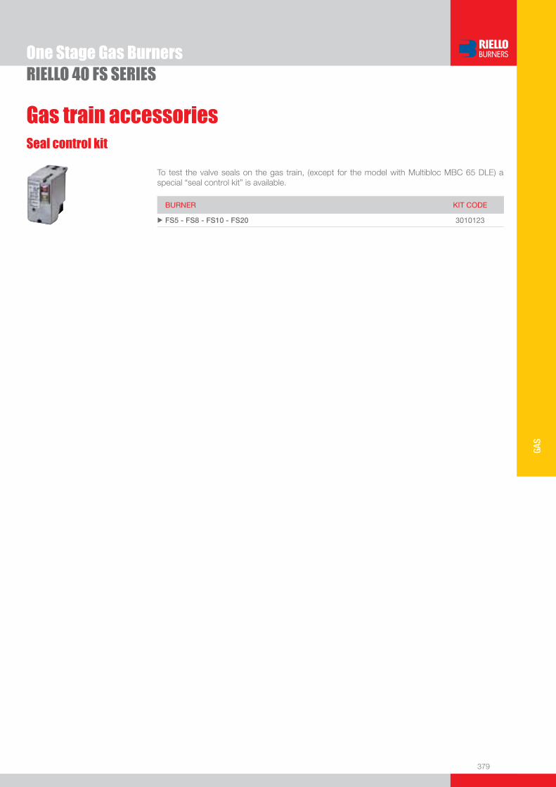
379
GAS
One Stage Gas BurnersRIELLO 40 FS SERIES
To test the valve seals on the gas train, (except for the model with Multibloc MBC 65 DLE) a special “seal control kit” is available.
Seal control kit
Gas train accessories
BURNER KIT CODE
u FS5 - FS8 - FS10 - FS20 3010123

www.rielloburners.com
We are here bringing warmth in your life
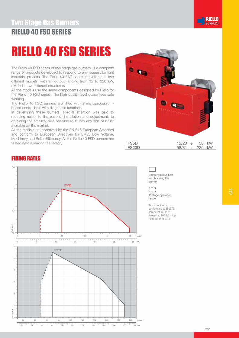
381
GAS
RIELLO 40 FSD SERIESTwo Stage Gas Burners
The Riello 40 FSD series of two stage gas burners, is a complete range of products developed to respond to any request for light industrial process. The Riello 40 FSD series is available in two different models, with an output ranging from 12 to 220 kW, divided in two different structures.All the models use the same components designed by Riello for the Riello 40 FSD series. The high quality level guarantees safe working.The Riello 40 FSD burners are fi tted with a microprocessor - based control box, with diagnostic functions.In developing these burners, special attention was paid to reducing noise, to the ease of installation and adjustment, to obtaining the smallest size possible to fi t into any sort of boiler available on the market.All the models are approved by the EN 676 European Standard and conform to European Directives for EMC, Low Voltage, Machinery and Boiler Effi ciency. All the Riello 40 FSD burners are tested before leaving the factory. FS5D 12/23 ÷ 58 kW
FS20D 58/81 ÷ 220 kW
RIELLO 40 FSD SERIES
FIRING RATES
Useful working fi eldfor choosing theburner
1st stage operationrange
Test conditionsconforming to EN676 Temperature: 20°CPressure: 1013,5 mbarAltitude: 0 m a.s.l.
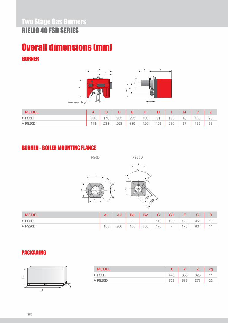
382
BURNER
Overall dimensions (mm)
RIELLO 40 FSD SERIES
MODEL A C D E F H I N V Z u FS5D 306 170 233 295 100 91 180 48 138 28
u FS20D 413 238 298 389 120 125 230 67 152 33
FS5D FS20D
MODEL A1 A2 B1 B2 C C1 F Q R u FS5D - - - - 140 130 170 45° 10
u FS20D 155 200 155 200 170 - 170 90° 11
MODEL X Y Z kg u FS5D 445 355 325 11
u FS20D 535 535 375 22
BURNER - BOILER MOUNTING FLANGE
Two Stage Gas Burners
PACKAGING
Z
XY

383
GAS
DESIGNATION OF SERIES
Specifi cation
RIELLO 40 FSD SERIES
F S 5 D 1/230/50
Series : F
Fuel : S Natural gas
Size
Optional variations: D Two-stage output adjustment
Electrical supply to the system : 1/230/50 1/230V/50Hz
Monoblock, gas burners, completely automatic, with two stage settings fi tted with:- Fan with forward curve blades- Metallic cover- Air damper, completely closed in stand by, driven by an electric servomotor- Air damper with 1st and 2nd stage adjustement- Single phase electric motor 230 V, 50 Hz- Combustion head fi tted with: - stainless steel head cone, resistant to high temperatures - ignition electrodes - ionisation probe - gas distributor - fl ame stability disk- Adjustable air pressure switch, with graduated selector, to guarantee burner lock out in the case of insuffi cient combustible air- Microprocessor-based burner safety control box MG 557 (with diagnostic, remote reset, continuous purge integrated, recycle,
post-purge)- IP X0D (IP 40) electric protection level.
Standard equipment:- Insulating gasket- Screws and nuts for fi xing the fl ange to the boiler- Hinge- Cable grommet- Instruction handbook for installation, use and maintenance- Spare parts catalogue.
STATE OF SUPPLY
Two Stage Gas Burners

384
Available models
RIELLO 40 FSD SERIES
Burners
Gas Trains
CODE
MODEL
HEAT OUTPUT TOTAL
ELECTRICALPOWER
CERTIFICATION NOTE
NATURAL GAS
(kW) (Nm3/h) (kW)
3758705 FS5D 1/230/50 12/23 - 58 1,2/2,3 - 5,8 0,110 CE – 0063 AP6680 (1)
3759105 FS20D 1/230/50 58/81 - 220 5,8/8,1 - 22 0,250 CE – 0063 AP6680 (1)
* Gas train are 230V/50Hz - 220V/60Hz electrical supply (1) With installed plug (if the plug is not necessary, remove it in accordance with gas train instruction manual indication)(2) FS20D ≤ 180 kW with natural gas
To select the gas train please refer to the technical data leafl et and/or instruction manual.
GAS TRAIN GAS TRAIN NATURAL GAS LPG NOTE
CODE * MODEL BURNER ADAPTER BURNER ADAPTER
(type) (code) (type) (code)
MULT
IBLOC
GAS
TRAIN
S
3970555 MBZRDLE 405 FS5D FS5D (1)
3970537 MBZRDLE 407 FS20D FS20D (1) (2)
3970534 MBZRDLE 410 FS20D FS20D (1)
Net calorifi c value G20: 10 kWh/Nm3 - Density: 0,71 kg/Nm3
The burners of FSD series are in according to EN 676(1) With terminal block.
Two Stage Gas Burners
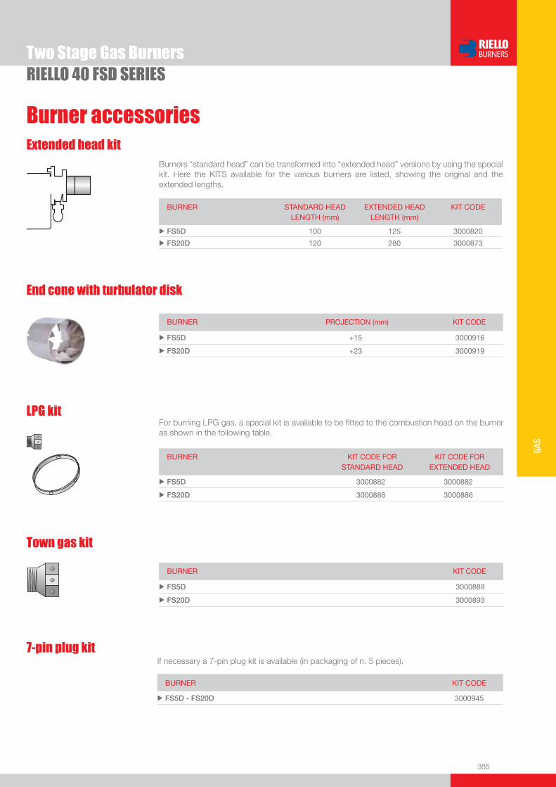
385
GAS
Burner accessories
RIELLO 40 FSD SERIES
Extended head kitBurners “standard head” can be transformed into “extended head” versions by using the special kit. Here the KITS available for the various burners are listed, showing the original and the extended lengths.
BURNER STANDARD HEADLENGTH (mm)
EXTENDED HEADLENGTH (mm)
KIT CODE
u FS5D 100 125 3000820
u FS20D 120 280 3000873
LPG kitFor burning LPG gas, a special kit is available to be fi tted to the combustion head on the burner as shown in the following table.
BURNER KIT CODE FORSTANDARD HEAD
KIT CODE FOREXTENDED HEAD
u FS5D 3000882 3000882
u FS20D 3000886 3000886
End cone with turbulator disk
BURNER PROJECTION (mm) KIT CODE
u FS5D +15 3000916
u FS20D +23 3000919
Town gas kit
BURNER KIT CODE
u FS5D 3000889
u FS20D 3000893
Two Stage Gas Burners
7-pin plug kitIf necessary a 7-pin plug kit is available (in packaging of n. 5 pieces).
BURNER KIT CODE
u FS5D - FS20D 3000945

386
RIELLO 40 FSD SERIES
Burner accessories
PC interface kitTo connect the control box to a personal computer for the transmission of operation, fault signals and detailed service information, an interface adapter with PC software are available.
BURNER KIT CODE
u FS5D 3002731
u FS20D 3002719
Continuous ventilation kit for RMG control box
If the burner requires continuous ventilation in the stages without fl ame, a special kit is available as given in the following table.
BURNER KIT CODE
u FS20D 3010094
To test the valve seals on the gas train a special “seal control kit” is available.
Seal control kit
Gas train accessories
BURNER KIT CODE
u FS5D - FS20D 3010123
Two Stage Gas Burners
Remote reset control kit for MG 557/3 control box
The MG 557 control box can be remotely released using an electric command kit. This kit must be installed in conformity with the local authority.
BURNER KIT CODE
u FS5D 3002750
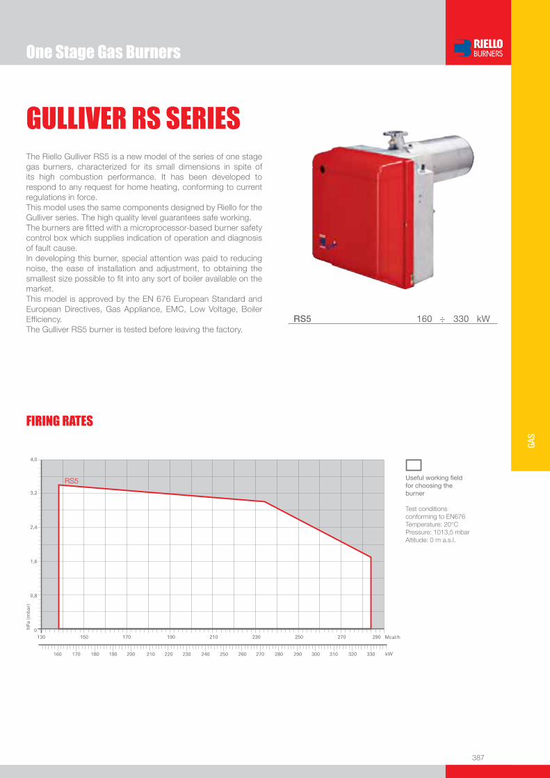
One Stage Gas Burners
387
GAS
FIRING RATES
GULLIVER RS SERIESThe Riello Gulliver RS5 is a new model of the series of one stage gas burners, characterized for its small dimensions in spite of its high combustion performance. It has been developed to respond to any request for home heating, conforming to current regulations in force.This model uses the same components designed by Riello for the Gulliver series. The high quality level guarantees safe working.The burners are fi tted with a microprocessor-based burner safety control box which supplies indication of operation and diagnosis of fault cause.In developing this burner, special attention was paid to reducing noise, the ease of installation and adjustment, to obtaining the smallest size possible to fi t into any sort of boiler available on the market.This model is approved by the EN 676 European Standard and European Directives, Gas Appliance, EMC, Low Voltage, Boiler Effi ciency.The Gulliver RS5 burner is tested before leaving the factory.
RS5 160 ÷ 330 kW
Useful working fi eldfor choosing theburner
Test conditionsconforming to EN676 Temperature: 20°CPressure: 1013,5 mbarAltitude: 0 m a.s.l.
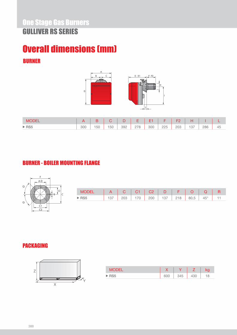
388
BURNER
Overall dimensions (mm)
One Stage Gas BurnersGULLIVER RS SERIES
MODEL A B C D E E1 F F2 H I L u RS5 300 150 150 392 278 300 225 203 137 286 45
MODEL A C C1 C2 D F O Q R u RS5 137 203 170 200 137 218 80,5 45° 11
MODEL X Y Z kg u RS5 600 345 430 18
Z
XY
PACKAGING
BURNER - BOILER MOUNTING FLANGE
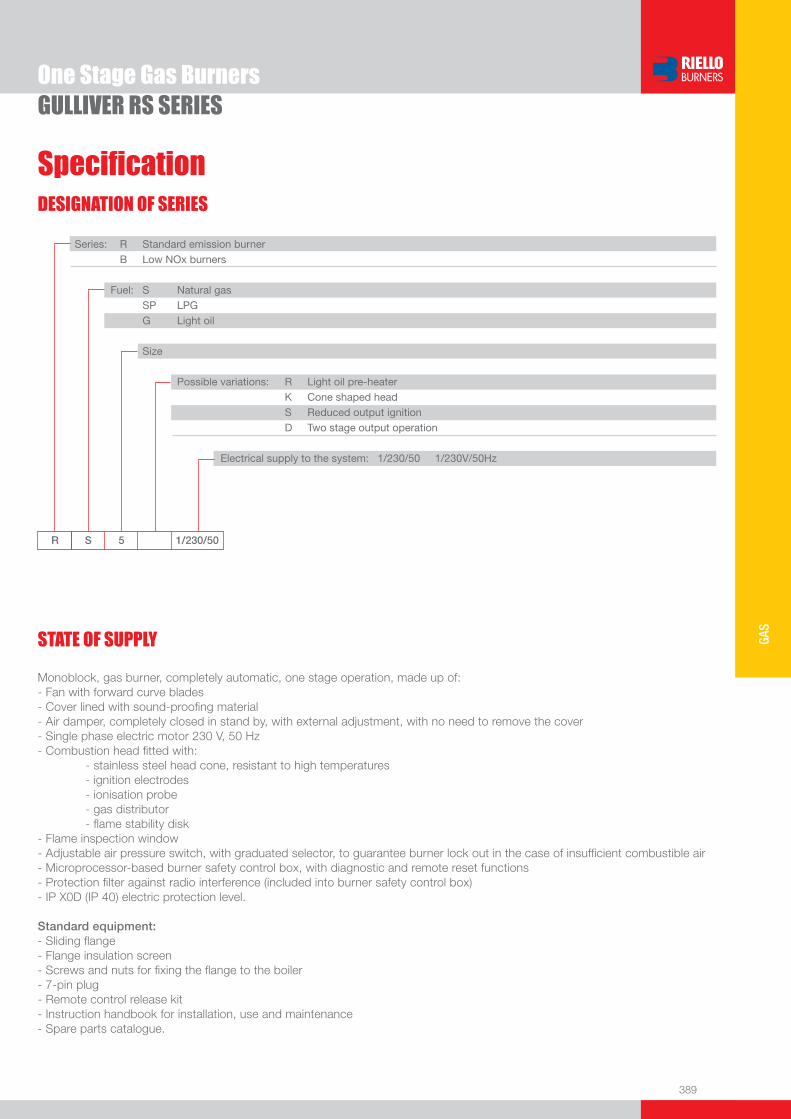
389
GAS
DESIGNATION OF SERIES
Specifi cation
One Stage Gas BurnersGULLIVER RS SERIES
STATE OF SUPPLY
R S 5 1/230/50
Series: R Standard emission burner B Low NOx burners
Fuel: S Natural gas SP LPG G Light oil
Size
Possible variations: R Light oil pre-heater K Cone shaped head S Reduced output ignition D Two stage output operation
Electrical supply to the system: 1/230/50 1/230V/50Hz
Monoblock, gas burner, completely automatic, one stage operation, made up of:- Fan with forward curve blades- Cover lined with sound-proofi ng material- Air damper, completely closed in stand by, with external adjustment, with no need to remove the cover- Single phase electric motor 230 V, 50 Hz- Combustion head fi tted with: - stainless steel head cone, resistant to high temperatures - ignition electrodes - ionisation probe - gas distributor - fl ame stability disk- Flame inspection window - Adjustable air pressure switch, with graduated selector, to guarantee burner lock out in the case of insuffi cient combustible air- Microprocessor-based burner safety control box, with diagnostic and remote reset functions- Protection fi lter against radio interference (included into burner safety control box)- IP X0D (IP 40) electric protection level.
Standard equipment:- Sliding fl ange- Flange insulation screen- Screws and nuts for fi xing the fl ange to the boiler- 7-pin plug- Remote control release kit- Instruction handbook for installation, use and maintenance- Spare parts catalogue.
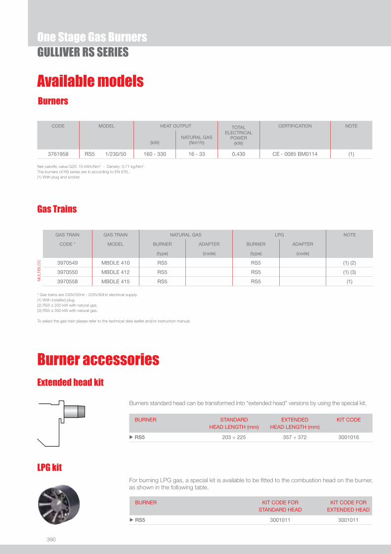
390
Available models
One Stage Gas BurnersGULLIVER RS SERIES
Burners
CODE MODEL HEAT OUTPUT TOTALELECTRICAL
POWER(kW)
CERTIFICATION NOTE
(kW)NATURAL GAS
(Nm3/h)
3761958 RS5 1/230/50 160 - 330 16 - 33 0,430 CE - 0085 BM0114 (1)
Net calorifi c value G20: 10 kWh/Nm3 - Density: 0,71 kg/Nm3.The burners of RS series are in according to EN 676.(1) With plug and socket.
Gas Trains
GAS TRAIN GAS TRAIN NATURAL GAS LPG NOTE
CODE * MODEL BURNER ADAPTER BURNER ADAPTER
(type) (code) (type) (code)
MU
LTIB
LOC 3970549 MBDLE 410 RS5 RS5 (1) (2)
3970550 MBDLE 412 RS5 RS5 (1) (3)
3970558 MBDLE 415 RS5 RS5 (1)
* Gas trains are 230V/50Hz - 220V/60Hz electrical supply.(1) With installed plug.(2) RS5 ≤ 200 kW with natural gas.(3) RS5 ≤ 300 kW with natural gas.
To select the gas train please refer to the technical data leafl et and/or instruction manual.
Extended head kit
Burners standard head can be transformed into “extended head” versions by using the special kit.
BURNER STANDARD HEAD LENGTH (mm)
EXTENDED HEAD LENGTH (mm)
KIT CODE
u RS5 203 ÷ 225 357 ÷ 372 3001016
LPG kitFor burning LPG gas, a special kit is available to be fi tted to the combustion head on the burner, as shown in the following table.
BURNER KIT CODE FOR STANDARD HEAD
KIT CODE FOR EXTENDED HEAD
u RS5 3001011 3001011
Burner accessories

391
GAS
Burner accessories
One Stage Gas BurnersGULLIVER RS SERIES
There is a special kit available that can be used to install the burner turned 180°. This kit is designed to ensure the gas train valve properly.
Multibloc rotation kit
BURNER KIT CODE
u RS5 3001178
7-pin plug kitIf necessary a 7-pin plug kit is available (in packaging of n. 5 pieces).
BURNER KIT CODE
u RS5 3000945
PC interface kitTo connect the control box to a personal computer for the transmission of operation, fault signals and detailed service information, an interface adapter with PC software are available.
BURNER KIT CODE
u RS5 3002731
To test the valve seals on the gas train, a special “seal control kit” is available.
Seal control kit
Gas train accessories
BURNER KIT CODE
u RS5 3010123
Ground fault interrupter kit
A “Ground fault interrupter kit” is available as a safety device in case of electrical system fault. It is supplied with burners with pin plug.
BURNER KIT CODE
u RS5 3001180


393
GAS
FIRING RATES
GULLIVER RSD SERIESThe Riello Gulliver RS5D is a new model of the series of two stage gas burners, characterized for its small dimensions in spite of its high combustion performance. It has been developed to respond to any request for home heating, conforming to current regulations in force. This models uses the same components designed by Riello for the Gulliver series. The high quality level guarantees safe working.The burners are fi tted with a microprocessor-based burner safety control box which supplies indication of operation and diagnosis of fault cause.In developing this burner, special attention was paid to reducing noise, the ease of installation and adjustment, to obtaining the smallest size possible to fi t into any sort of boiler available on the market.This model is approved by the EN 676 European Standard and European Directives, Gas Appliance, EMC, Low Voltage, Boiler Effi ciency.The Gulliver RS5D burner is tested before leaving the factory. RS5D 160/208 ÷ 345 kW
Two Stage Gas Burners
Useful working fi eldfor choosing theburner
1st stage operationrange
Test conditionsconforming to EN676 Temperature: 20°CPressure: 1013,5 mbarAltitude: 0 m a.s.l.
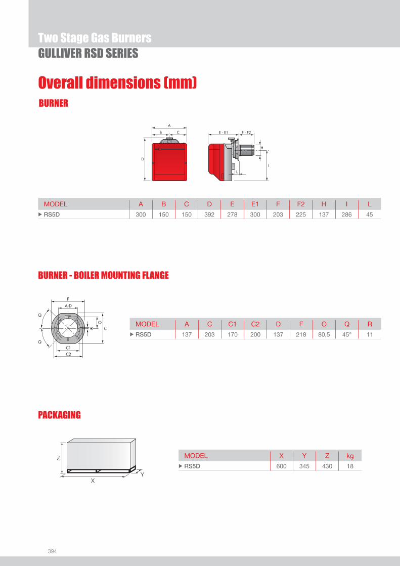
394
BURNER
Overall dimensions (mm)
GULLIVER RSD SERIES
MODEL A B C D E E1 F F2 H I L u RS5D 300 150 150 392 278 300 203 225 137 286 45
MODEL A C C1 C2 D F O Q R u RS5D 137 203 170 200 137 218 80,5 45° 11
MODEL X Y Z kg u RS5D 600 345 430 18
Z
XY
PACKAGING
BURNER - BOILER MOUNTING FLANGE
Two Stage Gas Burners

395
GAS
DESIGNATION OF SERIES
Specifi cation
GULLIVER RSD SERIES
STATE OF SUPPLY
Series: R Standard emission burner B Low NOx burners
Fuel: S Natural gas SP LPG G Light oil
Size
Possible variations: R Light oil pre-heater K Cone shaped head S Reduced output ignition D Two stage output operation
Electrical supply to the system: 1/230/50 1/230V/50Hz
Monoblock, gas burner, completely automatic, with two stage settings fi tted with:- Fan with forward curve blades- Cover lined with sound - proofi ng material- Air damper, with 1st and 2nd stage adjustment, driven by an electric servomotor - Single phase electric motor 230 V, 50 Hz- Combustion head fi tted with: - stainless steel head cone, resistant to high temperatures - ignition electrodes - ionisation probe - gas distributor - fl ame stability disk- Flame inspection window- Adjustable air pressure switch, with graduated selector, to guarantee burner lock out in the case of insuffi cient combustible air- Microprocessor-based burner safety control box, with diagnostic and remote reset functions- Protection fi lter against radio interference (included into burner safety control box)- IP X0D (IP 40) electric protection level.
Standard equipment:- Sliding fl ange- Flange insulation screen- Screws and nuts for fi xing the fl ange to the boiler - 7-pin plug- 4-pin plug- Remote control release kit- Instruction handbook for installation, use and maintenance- Spare parts catalogue.
Two Stage Gas Burners
R S 5 D 1/230/50

396
Available models
GULLIVER RSD SERIES
Burners
CODE MODEL HEAT OUTPUT TOTALELECTRICAL
POWER(kW)
CERTIFICATION NOTE
(kW)NATURAL GAS
(Nm3/h)
3762058 RS5D 1/230/50 160/208 - 345 16/20,8 - 34,5 0,450 CE - 0085 BN0325 (1)
Net calorifi c value G20: 10 kWh/Nm3 - Density: 0,71 kg/Nm3.The burners of RSD series are in according to EN 676.(1) With plug and socket.
Gas Trains
GAS TRAIN GAS TRAIN NATURAL GAS LPG NOTE
CODE * MODEL BURNER ADAPTER BURNER ADAPTER
(type) (code) (type) (code)
MU
LTIB
LOC 3970542 MBZRDLE 410 RS5D RS5D (1) (2)
3970543 MBZRDLE 412 RS5D RS5D (1) (3)
3970582 MBZRDLE 415 RS5D RS5D (1)
* Gas trains are 230V/50Hz - 220V/60Hz electrical supply.(1) With installed plug.(2) RS5D ≤ 200 kW with natural gas.(3) RS5D ≤ 300 kW with natural gas.
To select the gas train please refer to the technical data leafl et and/or instruction manual.
Extended head kit
Burners standard head can be transformed into “extended head” versions by using the special kit.
BURNER STANDARD HEAD LENGTH (mm)
EXTENDED HEAD LENGTH (mm)
KIT CODE
u RS5D 203 ÷ 225 357 ÷ 372 3001016
LPG kitFor burning LPG gas, a special kit is available to be fi tted to the combustion head on the burner, as shown in the following table.
BURNER KIT CODE FOR STANDARD HEAD
KIT CODE FOR EXTENDED HEAD
u RS5D 3001011 3001011
Burner accessories
Two Stage Gas Burners

397
GAS
Burner accessories
GULLIVER RSD SERIES
There is a special kit available that can be used to install the burner turned 180°. This kit is designed to ensure the gas train valve properly.
Multibloc rotation kit
BURNER KIT CODE
u RS5D 3001178
7-pin plug kitIf necessary a 7-pin plug kit is available (in packaging of n. 5 pieces).
BURNER KIT CODE
u RS5D 3000945
PC interface kitTo connect the control box to a personal computer for the transmission of operation, fault signals and detailed service information, an interface adapter with PC software are available.
BURNER KIT CODE
u RS5D 3002731
To test the valve seals on the gas train, a special “seal control kit” is available.
Seal control kit
Gas train accessories
BURNER KIT CODE
u RS5D 3010123
Ground fault interrupter kit
A “Ground fault interrupter kit” is available as a safety device in case of electrical system fault. It is supplied with burners with pin plug.
BURNER KIT CODE
u RS5D 3001180
Two Stage Gas Burners


One Stage Gas Burners
399
GAS
FIRING RATES
GULLIVER RSF SERIESThe Riello Gulliver RS5F, is a new model of the series of one stage gas burners, developed to respond to any request for light industrial processes like bakery ovens, spray painting ovens, small steam or thermal boilers and all applications which require a reliable, user-friendly industrial product with enhanced performance and specifi c functions.The Gulliver RS5F series has an output ranging from 160 to 330 kW, uses the same components designed by Riello for the Gulliver series and have the same ventilation system and overall dimensions as the previous one stage gas model.The burners are fi tted with a microprocessor-based burner safety control box which supplies indication of operation and diagnosis of fault cause.This new burner can operate on 50 or 60 Hz and a Voltage 220 - 230 Volt (dual frequency) and it is conform to the EN 676 Standard (Forced draught gas burners) and to European Directives for EMC, Low Voltage and Machinery. For depressurised working fi eld see EN 746-2 Standard.All the Gulliver RS5F burners are fi red before leaving the factory. RS5F 160 ÷ 330 kW
Useful working fi eldfor choosing theburner
Test conditionsconforming to EN676 Temperature: 20°CPressure: 1013,5 mbarAltitude: 0 m a.s.l.
IMPORTANT: For the part of the working fi eld that is depressurised, refer to EN 746-2 Standard.

400
BURNER
Overall dimensions (mm)
One Stage Gas BurnersGULLIVER RSF SERIES
MODEL A B C D E E1 F F2 H I L u RS5F 300 150 150 392 278 300 225 203 137 286 45
MODEL A C C1 C2 D F O Q R u RS5F 137 203 170 200 137 218 80,5 45° 11
MODEL X Y Z kg u RS5F 600 345 430 18
Z
XY
PACKAGING
BURNER - BOILER MOUNTING FLANGE

401
GAS
DESIGNATION OF SERIES
Specifi cation
One Stage Gas BurnersGULLIVER RSF SERIES
STATE OF SUPPLY
R S 5 F 1/230/50
Series: R Standard emission burner B Low NOx burners
Fuel: S Natural gas SP LPG G Light oil
Size
Possible variations: F Light industrial processes Electrical supply to the system: 1/220-230/50-60 1/220-230V/50-60Hz
Monobloc, gas burner, completely automatic, one stage operation, made up of:- Fan with forward curve blades- Cover lined with sound-proofi ng material- Air damper, always open in stand by, with external adjustment, with no need to remove the cover- Single phase electric motor 220-230 V, 50-60 Hz- Combustion head fi tted with: - stainless steel head cone, resistant to high temperatures - ignition electrodes - ionisation probe - gas distributor - fl ame stability disk- Flame inspection window - Adjustable air pressure switch, with graduated selector, to guarantee burner lock out in the case of insuffi cient combustible air- Microprocessor-based burner safety control box, with diagnostic and remote reset functions- Protection fi lter against radio interference (included into burner safety control box)- IP X0D (IP 40) electric protection level.
Standard equipment:- Flange with insulating gasket- Screw and nut for fl ange- Screws and nuts for fl ange to be fi xed to the heat generator- 7-pin plug- Remote control release kit- Instruction handbook for installation, use and maintenance- Spare parts catalogue.

402
Available models
One Stage Gas BurnersGULLIVER RSF SERIES
Burners
CODE MODEL HEAT OUTPUT TOTALELECTRICAL
POWER(kW)
CERTIFICATION NOTE
(kW)NATURAL GAS
(Nm3/h)
3761971 RS5F 1/220-230/50-60 160 - 330 16,0 - 33,0 0,430 (at 50 Hz) - 0,600 (at 60 Hz) CE - 0085 BM0114 (1)
Net calorifi c value G20: 10 kWh/Nm3 - Density: 0,71 kg/Nm3.The burners of RSF series are in according to EN 676.(1) With plug and socket.
Gas Trains
GAS TRAIN GAS TRAIN NATURAL GAS LPG NOTE
CODE * MODEL BURNER ADAPTER BURNER ADAPTER
(type) (code) (type) (code)
MU
LTIB
LOC 3970549 MBDLE 410 RS5F RS5F (1) (2)
3970550 MBDLE 412 RS5F RS5F (1) (3)
3970558 MBDLE 415 RS5F RS5F (1)
* Gas trains are 230V/50Hz - 220V/60Hz electrical supply.(1) With installed plug.(2) RS5F ≤ 200 kW with natural gas.(3) RS5F ≤ 300 kW with natural gas.
To select the gas train please refer to the technical data leafl et and/or instruction manual.
Extended head kit
Burners standard head can be transformed into “extended head” versions by using the special kit.
BURNER STANDARD HEAD LENGTH (mm)
EXTENDED HEAD LENGTH (mm)
KIT CODE
u RS5F 203 ÷ 225 302 ÷ 317 3001016
LPG kitFor burning LPG gas, a special kit is available to be fi tted to the combustion head on the burner, as shown in the following table.
BURNER KIT CODE FOR STANDARD HEAD
KIT CODE FOR EXTENDED HEAD
u RS5F 3001011 3001011
Burner accessories

403
GAS
Burner accessories
One Stage Gas BurnersGULLIVER RSF SERIES
There is a special kit available that can be used to install the burner turned 180°. This kit is designed to ensure the gas train valve properly.
Multibloc rotation kit
BURNER KIT CODE
u RS5F 3001178
7-pin plug kitIf necessary a 7-pin plug kit is available (in packaging of n. 5 pieces).
BURNER KIT CODE
u RS5F 3000945
PC interface kitTo connect the control box to a personal computer for the transmission of operation, fault signals and detailed service information, an interface adapter with PC software are available.
BURNER KIT CODE
u RS5F 3002731
To test the valve seals on the gas train, a special “seal control kit” is available.
Seal control kit
Gas train accessories
BURNER GAS TRAIN KIT CODE
u RS5F MBDLE 410 - 412 - 415 3010123
Ground fault interrupter kit
A “Ground fault interrupter kit” is available as a safety device in case of electrical system fault. It is supplied with burners with pin plug.
BURNER KIT CODE
u RS5F 3001180

The new Riello Burners RS VA series of duct burners has been designed for the installation in direct heating systems with medium-low temperature levels, as the ones adopted in spray booths.This burner is particularly suitable for situation of elevated re-circulation and high air delivery variability, thanks to the dedicated fan. Moreover, the protection of the combustion head from the primary air fl ow avoids the settlement of impurities on the combustion module, guaranteeing long-lasting operation effi ciency.
Riello RS VA seriesAir Duct BurnersDirect heating applications with low temperature
RS 28 VA 225 30/180-270 kWRS 38 VA 300 30/270-360 kWRS 50 VA 450 90/360-530 kWRS 70 VA 600 120/530-700 kW
● Complete combustion at every output level thanks to a pre-adjusted air delivery system● Excellent fl ame stability and uniform combustion● Simple use● Reduced fl ame length● Operation with natural gas and LPG without installing accessory kits● “Ready-to-install” package● Thermal exchange effi ciency near to 100%● 8:1 modulation ratio (optional version)● “Package” confi guration “L” or “T” shape to suit to different types of applications● Suitable for 50-60 Hz

405
GAS
FIRING RATES
Two Stage Gas Burners
GULLIVER RSDF SERIESThe Riello Gulliver RS5DF is a new model of the series of two stage gas burners, characterized for its small dimensions in spite of its high combustion performance. It has been developed to respond to any request for light industrial processes like bakery ovens, spray painting ovens, small steam or thermal boilers and all applications which require a reliable, user-friendly industrial product with enhanced performance and specifi c functions. This model uses the same components designed by Riello for the Gulliver series. The high quality level guarantees safe working.The burners are fi tted with a microprocessor-based burner safety control box which supplies indication of operation and diagnosis of fault cause.This new burner can operate on 50 or 60 Hz and a Voltage 220 - 230 Volt (dual frequency) and it is conform to the EN 676 Standard (Forced draught gas burners) and to European Directives for EMC, Low Voltage and Machinery. For depressurised working fi eld see EN 746-2 Standard. The Gulliver RS5DF burner is tested before leaving the factory. RS5DF 160/208 ÷ 345 kW
Useful working fi eldfor choosing theburner
1st stage operationrange
Test conditionsconforming to EN676 Temperature: 20°CPressure: 1013,5 mbarAltitude: 0 m a.s.l.

406
BURNER
Overall dimensions (mm)
GULLIVER RSDF SERIES
MODEL A B C D E E1 F F2 H I L u RS5DF 300 150 150 392 278 300 203 225 137 286 45
MODEL A C C1 C2 D F O Q R u RS5DF 137 203 170 200 137 218 80,5 45° 11
MODEL X Y Z kg u RS5DF 600 345 430 18
Z
XY
PACKAGING
BURNER - BOILER MOUNTING FLANGE
Two Stage Gas Burners

407
GAS
DESIGNATION OF SERIES
Specifi cation
GULLIVER RSDF SERIES
STATE OF SUPPLY
Series: R Standard emission burner B Low NOx burners
Fuel: S Natural gas SP LPG G Light oil
Size
Possible variations: R Light oil pre-heater K Cone shaped head S Reduced output ignition D Two stage output operation F Light Industrial Processes
Electrical supply to the system: 1/220-230/50-60 1/220-230V/50-60Hz
Monoblock, gas burner, completely automatic, with two stage settings fi tted with:- Fan with forward curve blades- Cover lined with sound - proofi ng material- Air damper, with 1st and 2nd stage adjustment, driven by an electric servomotor - Single phase electric motor 220-230 V / 50-60 Hz- Combustion head fi tted with: - stainless steel head cone, resistant to high temperatures - ignition electrodes - ionisation probe - gas distributor - fl ame stability disk- Flame inspection window- Adjustable air pressure switch, with graduated selector, to guarantee burner lock out in the case of insuffi cient combustible air- Microprocessor-based burner safety control box, with diagnostic and remote reset functions- Protection fi lter against radio interference (included into burner safety control box)- IP X0D (IP 40) electric protection level.
Standard equipment:- Sliding fl ange- Flange insulation screen- Screws and nuts for fi xing the fl ange to the boiler - 7-pin plug- 4-pin plug- Remote control release kit- Instruction handbook for installation, use and maintenance- Spare parts catalogue.
Two Stage Gas Burners
R S 5 DF 1/230/50
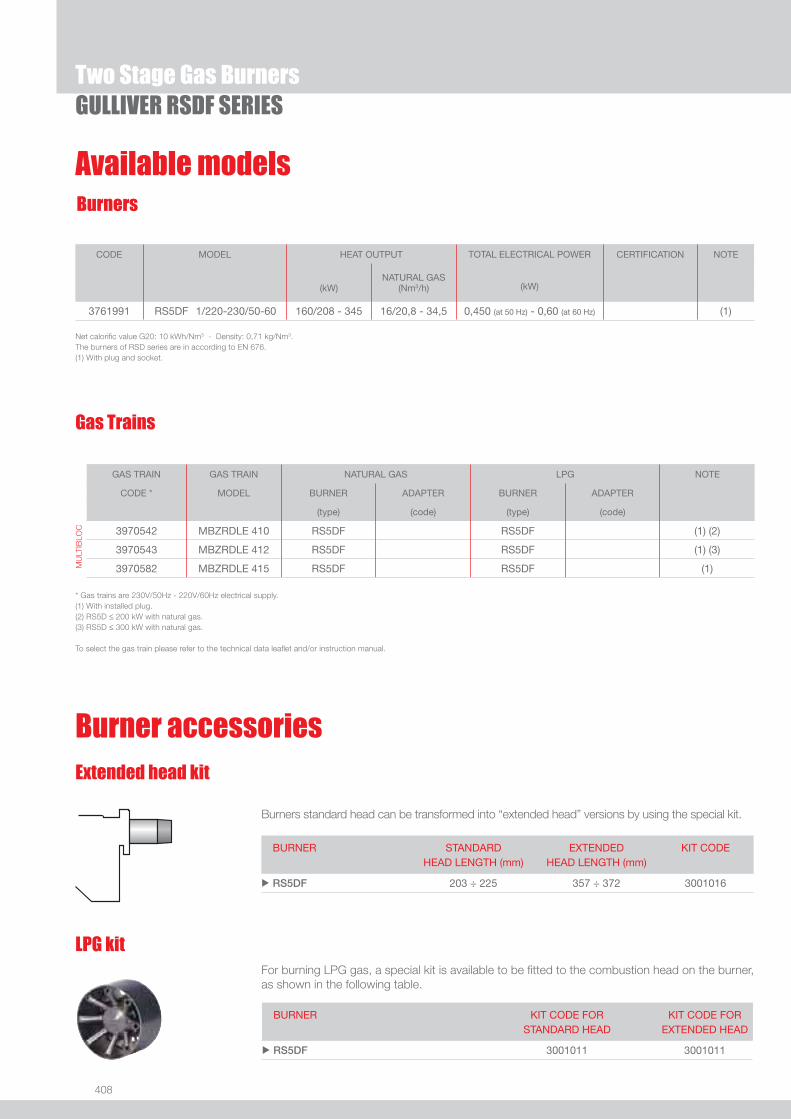
408
Available models
GULLIVER RSDF SERIES
Burners
CODE MODEL HEAT OUTPUT TOTAL ELECTRICAL POWER
(kW)
CERTIFICATION NOTE
(kW)NATURAL GAS
(Nm3/h)
3761991 RS5DF 1/220-230/50-60 160/208 - 345 16/20,8 - 34,5 0,450 (at 50 Hz) - 0,60 (at 60 Hz) (1)
Net calorifi c value G20: 10 kWh/Nm3 - Density: 0,71 kg/Nm3.The burners of RSD series are in according to EN 676.(1) With plug and socket.
Gas Trains
GAS TRAIN GAS TRAIN NATURAL GAS LPG NOTE
CODE * MODEL BURNER ADAPTER BURNER ADAPTER
(type) (code) (type) (code)
MU
LTIB
LOC 3970542 MBZRDLE 410 RS5DF RS5DF (1) (2)
3970543 MBZRDLE 412 RS5DF RS5DF (1) (3)
3970582 MBZRDLE 415 RS5DF RS5DF (1)
* Gas trains are 230V/50Hz - 220V/60Hz electrical supply.(1) With installed plug.(2) RS5D ≤ 200 kW with natural gas.(3) RS5D ≤ 300 kW with natural gas.
To select the gas train please refer to the technical data leafl et and/or instruction manual.
Extended head kit
Burners standard head can be transformed into “extended head” versions by using the special kit.
BURNER STANDARD HEAD LENGTH (mm)
EXTENDED HEAD LENGTH (mm)
KIT CODE
u RS5DF 203 ÷ 225 357 ÷ 372 3001016
LPG kitFor burning LPG gas, a special kit is available to be fi tted to the combustion head on the burner, as shown in the following table.
BURNER KIT CODE FOR STANDARD HEAD
KIT CODE FOR EXTENDED HEAD
u RS5DF 3001011 3001011
Burner accessories
Two Stage Gas Burners
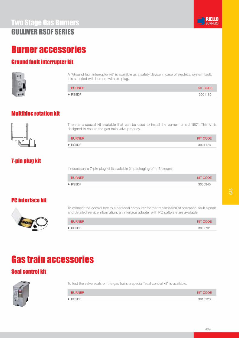
409
GAS
Burner accessories
GULLIVER RSDF SERIES
There is a special kit available that can be used to install the burner turned 180°. This kit is designed to ensure the gas train valve properly.
Multibloc rotation kit
BURNER KIT CODE
u RS5DF 3001178
7-pin plug kitIf necessary a 7-pin plug kit is available (in packaging of n. 5 pieces).
BURNER KIT CODE
u RS5DF 3000945
PC interface kitTo connect the control box to a personal computer for the transmission of operation, fault signals and detailed service information, an interface adapter with PC software are available.
BURNER KIT CODE
u RS5DF 3002731
To test the valve seals on the gas train, a special “seal control kit” is available.
Seal control kit
Gas train accessories
BURNER KIT CODE
u RS5DF 3010123
Ground fault interrupter kit
A “Ground fault interrupter kit” is available as a safety device in case of electrical system fault. It is supplied with burners with pin plug.
BURNER KIT CODE
u RS5DF 3001180
Two Stage Gas Burners

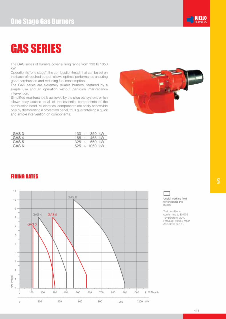
One Stage Gas Burners
411
GAS
GAS SERIESThe GAS series of burners cover a fi ring range from 130 to 1050 kW.Operation is “one stage”; the combustion head, that can be set on the basis of required output, allows optimal performance ensuring good combustion and reducing fuel consumption.The GAS series are extremely reliable burners, featured by a simple use and an operation without particular maintenance intervention. Simplifi ed maintenance is achieved by the slide bar system, which allows easy access to all of the essential components of the combustion head. All electrical components are easily accessible only by dismounting a protection panel, thus guaranteeing a quick and simple intervention on components.
GAS 3 130 ÷ 350 kWGAS 4 185 ÷ 465 kWGAS 5 325 ÷ 660 kWGAS 6 525 ÷ 1050 kW
FIRING RATES
Useful working fi eldfor choosing theburner
Test conditionsconforming to EN676 Temperature: 20°CPressure: 1013,5 mbarAltitude: 0 m a.s.l.

412
BURNER
Overall dimensions (mm)
One Stage Gas BurnersGAS SERIES
MODEL A B C D E F - F (1) H I M N O V u GAS 3 410 205 205 397 610 185 - 320 140 292 1”1/2 97 775 165
u GAS 4 410 205 205 397 610 187 - 320 150 292 1”1/2 97 775 165
u GAS 5 431 226 205 437 645 207 - 365 155 332 1”1/2 97 810 165
u GAS 6 463 258 205 485 770 227 - 360 175 370 2” 131 966 195
(1) Length with extended combustion head
Z
X - X (1)Y
PACKAGING
MODEL D1 D2 Ø u GAS 3 155 226 M10
u GAS 4 165 226 M10
u GAS 5 165 226 M10
u GAS 6 185 276 M12
MODEL X - X (1) Y Z kg u GAS 3 850 545 473 32
u GAS 4 850 545 473 38
u GAS 5 895 543 520 41
u GAS 6 1045 543 555 58
BURNER - BOILER MOUNTING FLANGE
(1) Length with extended combustion head
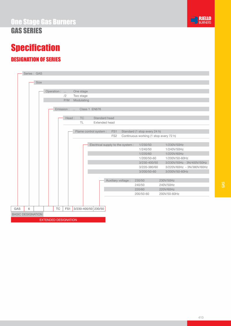
413
GAS
DESIGNATION OF SERIES
Specifi cation
One Stage Gas BurnersGAS SERIES
GAS 6 TC FS1 3/230-400/50 230/50
Series : GAS
Size
Operation : ... One stage /2 Two stage P/M Modulating
Emission : ... Class 1 EN676 Head : TC Standard head TL Extended head
Flame control system : FS1 Standard (1 stop every 24 h) FS2 Continuous working (1 stop every 72 h)
Electrical supply to the system : 1/230/50 1/230V/50Hz 1/240/50 1/240V/50Hz 1/220/60 1/220V/60Hz 1/200/50-60 1/200V/50-60Hz 3/230-400/50 3/230V/50Hz - 3N/400V/50Hz 3/220-380/60 3/220V/60Hz - 3N/380V/60Hz 3/200/50-60 3/200V/50-60Hz Auxiliary voltage : 230/50 230V/50Hz 240/50 240V/50Hz 220/60 220V/60Hz 200/50-60 200V/50-60Hz
BASIC DESIGNATION
EXTENDED DESIGNATION
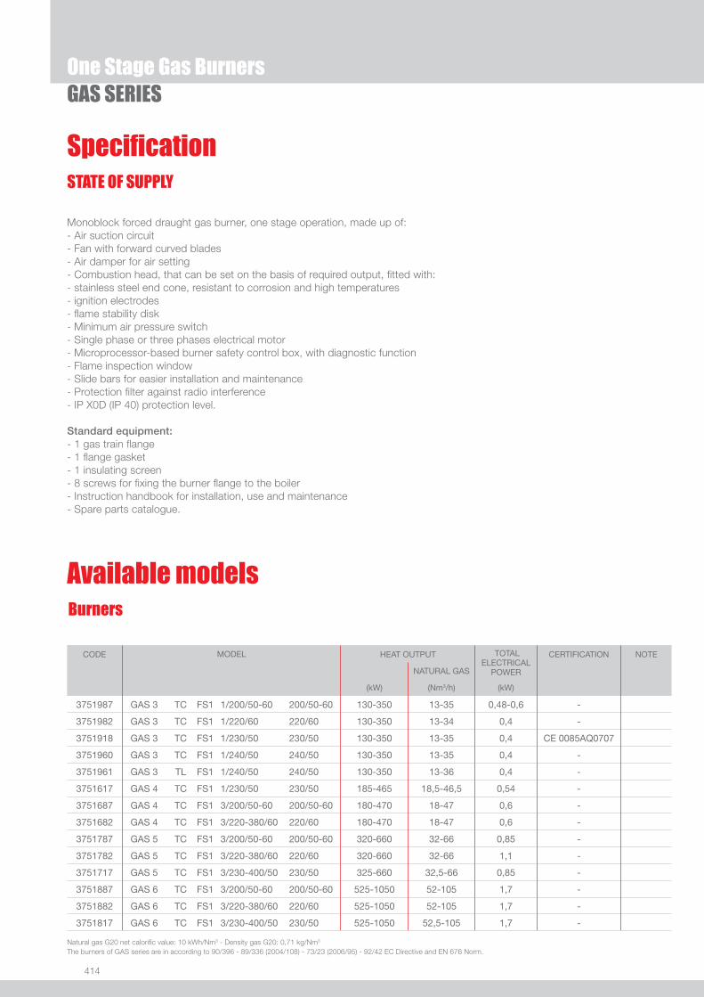
414
One Stage Gas BurnersGAS SERIES
Burners
STATE OF SUPPLY
Monoblock forced draught gas burner, one stage operation, made up of:- Air suction circuit- Fan with forward curved blades- Air damper for air setting - Combustion head, that can be set on the basis of required output, fi tted with:- stainless steel end cone, resistant to corrosion and high temperatures- ignition electrodes- fl ame stability disk- Minimum air pressure switch- Single phase or three phases electrical motor- Microprocessor-based burner safety control box, with diagnostic function- Flame inspection window- Slide bars for easier installation and maintenance- Protection fi lter against radio interference- IP X0D (IP 40) protection level.
Standard equipment:- 1 gas train fl ange- 1 fl ange gasket- 1 insulating screen- 8 screws for fi xing the burner fl ange to the boiler- Instruction handbook for installation, use and maintenance- Spare parts catalogue.
Specifi cation
Natural gas G20 net calorifi c value: 10 kWh/Nm3 - Density gas G20: 0,71 kg/Nm3 The burners of GAS series are in according to 90/396 - 89/336 (2004/108) - 73/23 (2006/95) - 92/42 EC Directive and EN 676 Norm.
CODE MODEL
HEAT OUTPUT TOTAL
ELECTRICALPOWER
CERTIFICATION NOTE
NATURAL GAS
(kW) (Nm3/h) (kW)
3751987 GAS 3 TC FS1 1/200/50-60 200/50-60 130-350 13-35 0,48-0,6 -
3751982 GAS 3 TC FS1 1/220/60 220/60 130-350 13-34 0,4 -
3751918 GAS 3 TC FS1 1/230/50 230/50 130-350 13-35 0,4 CE 0085AQ0707
3751960 GAS 3 TC FS1 1/240/50 240/50 130-350 13-35 0,4 -
3751961 GAS 3 TL FS1 1/240/50 240/50 130-350 13-36 0,4 -
3751617 GAS 4 TC FS1 1/230/50 230/50 185-465 18,5-46,5 0,54 -
3751687 GAS 4 TC FS1 3/200/50-60 200/50-60 180-470 18-47 0,6 -
3751682 GAS 4 TC FS1 3/220-380/60 220/60 180-470 18-47 0,6 -
3751787 GAS 5 TC FS1 3/200/50-60 200/50-60 320-660 32-66 0,85 -
3751782 GAS 5 TC FS1 3/220-380/60 220/60 320-660 32-66 1,1 -
3751717 GAS 5 TC FS1 3/230-400/50 230/50 325-660 32,5-66 0,85 -
3751887 GAS 6 TC FS1 3/200/50-60 200/50-60 525-1050 52-105 1,7 -
3751882 GAS 6 TC FS1 3/220-380/60 220/60 525-1050 52-105 1,7 -
3751817 GAS 6 TC FS1 3/230-400/50 230/50 525-1050 52,5-105 1,7 -
Available models
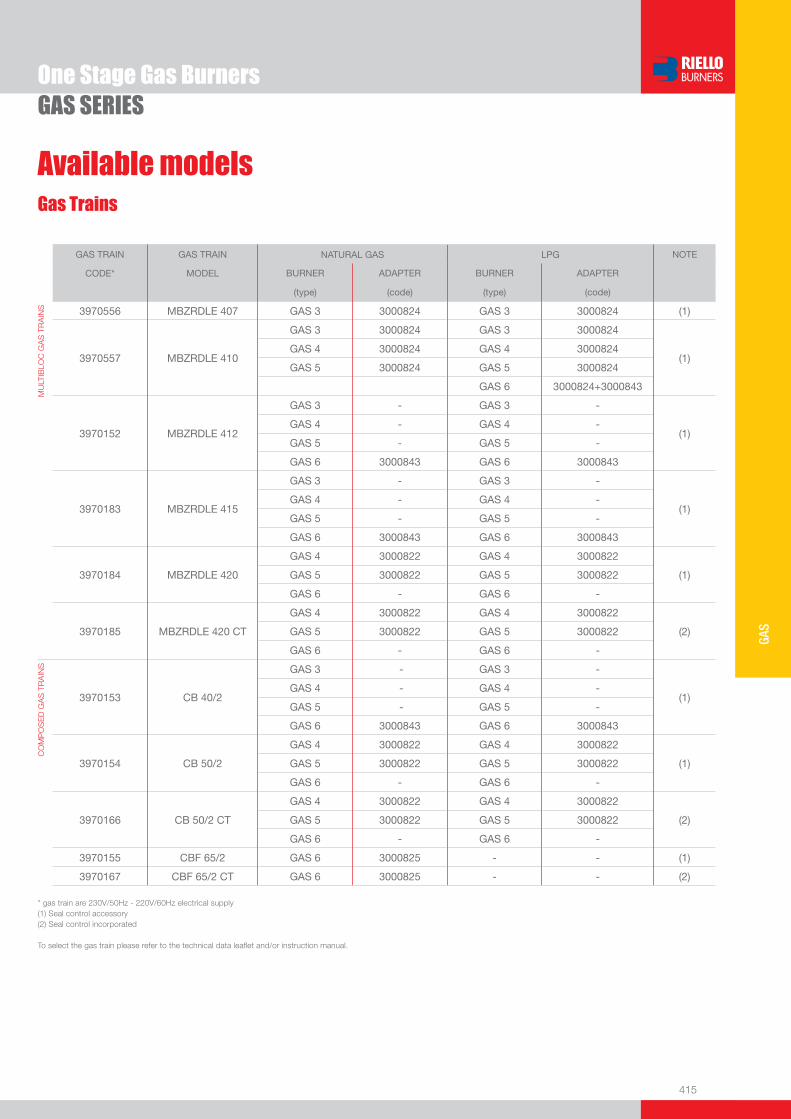
415
GAS
One Stage Gas BurnersGAS SERIES
Available modelsGas Trains
GAS TRAIN GAS TRAIN NATURAL GAS LPG NOTE
CODE* MODEL BURNER ADAPTER BURNER ADAPTER
(type) (code) (type) (code)
MU
LTIB
LOC
GA
S T
RA
INS 3970556 MBZRDLE 407 GAS 3 3000824 GAS 3 3000824 (1)
3970557 MBZRDLE 410
GAS 3 3000824 GAS 3 3000824
(1)GAS 4 3000824 GAS 4 3000824
GAS 5 3000824 GAS 5 3000824
GAS 6 3000824+3000843
3970152 MBZRDLE 412
GAS 3 - GAS 3 -
(1)GAS 4 - GAS 4 -
GAS 5 - GAS 5 -
GAS 6 3000843 GAS 6 3000843
3970183 MBZRDLE 415
GAS 3 - GAS 3 -
(1)GAS 4 - GAS 4 -
GAS 5 - GAS 5 -
GAS 6 3000843 GAS 6 3000843
3970184 MBZRDLE 420
GAS 4 3000822 GAS 4 3000822
(1)GAS 5 3000822 GAS 5 3000822
GAS 6 - GAS 6 -
3970185 MBZRDLE 420 CT
GAS 4 3000822 GAS 4 3000822
(2)GAS 5 3000822 GAS 5 3000822
GAS 6 - GAS 6 -
CO
MP
OS
ED
GA
S T
RA
INS
3970153 CB 40/2
GAS 3 - GAS 3 -
(1)GAS 4 - GAS 4 -
GAS 5 - GAS 5 -
GAS 6 3000843 GAS 6 3000843
3970154 CB 50/2
GAS 4 3000822 GAS 4 3000822
(1)GAS 5 3000822 GAS 5 3000822
GAS 6 - GAS 6 -
3970166 CB 50/2 CT
GAS 4 3000822 GAS 4 3000822
(2)GAS 5 3000822 GAS 5 3000822
GAS 6 - GAS 6 -
3970155 CBF 65/2 GAS 6 3000825 - - (1)
3970167 CBF 65/2 CT GAS 6 3000825 - - (2)
* gas train are 230V/50Hz - 220V/60Hz electrical supply(1) Seal control accessory(2) Seal control incorporated
To select the gas train please refer to the technical data leafl et and/or instruction manual.
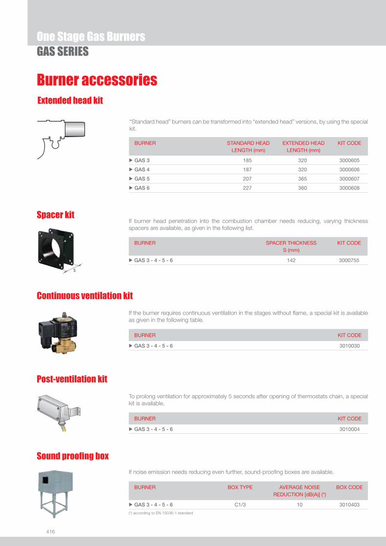
416
One Stage Gas BurnersGAS SERIES
Burner accessoriesExtended head kit
“Standard head” burners can be transformed into “extended head” versions, by using the special kit.
BURNER STANDARD HEADLENGTH (mm)
EXTENDED HEADLENGTH (mm)
KIT CODE
u GAS 3 185 320 3000605
u GAS 4 187 320 3000606
u GAS 5 207 365 3000607
u GAS 6 227 360 3000608
If burner head penetration into the combustion chamber needs reducing, varying thickness spacers are available, as given in the following list.
Spacer kit
BURNER
SPACER THICKNESS S (mm)
KIT CODE
u GAS 3 - 4 - 5 - 6 142 3000755
If the burner requires continuous ventilation in the stages without fl ame, a special kit is available as given in the following table.
Continuous ventilation kit
BURNER KIT CODE
u GAS 3 - 4 - 5 - 6 3010030
To prolong ventilation for approximately 5 seconds after opening of thermostats chain, a special kit is available.
Post-ventilation kit
BURNER KIT CODE
u GAS 3 - 4 - 5 - 6 3010004
If noise emission needs reducing even further, sound-proofi ng boxes are available.
Sound proofi ng box
BURNER
BOX TYPE
AVERAGE NOISE REDUCTION [dB(A)] (*)
BOX CODE
u GAS 3 - 4 - 5 - 6 C1/3 10 3010403
(*) according to EN 15036-1 standard
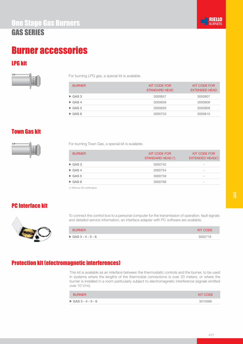
417
GAS
Burner accessories
One Stage Gas BurnersGAS SERIES
LPG kit
For burning LPG gas, a special kit is available.
BURNER KIT CODE FOR STANDARD HEAD
KIT CODE FOR EXTENDED HEAD
u GAS 3 3000657 3000807
u GAS 4 3000658 3000808
u GAS 5 3000659 3000809
u GAS 6 3000753 3000810
Town Gas kit
For burning Town Gas, a special kit is available.
BURNER KIT CODE FOR STANDARD HEAD (*)
KIT CODE FOR EXTENDED HEAD(*)
u GAS 3 3000742 -
u GAS 4 3000754 -
u GAS 5 3000759 -
u GAS 6 3000768 -
(*) Without CE certifi cation
BURNER KIT CODE
u GAS 3 - 4 - 5 - 6 3002719
To connect the control box to a personal computer for the transmission of operation, fault signals and detailed service information, an interface adapter with PC software are available.
PC Interface kit
This kit is available as an interface between the thermostatic controls and the burner, to be used in systems where the lengths of the thermostat connections is over 20 meters, or where the burner is installed in a room particularly subject to electromagnetic interference (signals emitted over 10 V/m).
BURNER KIT CODE
u GAS 3 - 4 - 5 - 6 3010386
Protection kit (electromagnetic interferences)

418
One Stage Gas Burners
Gas train accessories
GAS SERIES
Adapters
When the diameter of the gas train is different from the set diameter of the burners, an adapter must be fi tted between the gas train and the burner.
BURNER GAS TRAIN DIMENSIONS ADAPTER CODE
u GAS 3 MBZRDLE 407 - 410 1” 1/23/4” 3000824
u GAS 4 MBZRDLE 410 1” 1/23/4” 3000824
MBZRDLE 420 - CB 50/2 1” 1/22” 3000822
u GAS 5 MBZRDLE 410 1” 1/23/4” 3000824
MBZRDLE 420 - CB 50/2 1” 1/22” 3000822
u GAS 6
MBZRDLE 410
1” 1/23/4”
2”1” 1/2
3000824
3000843
MBZRDLE 412-415 - CB 40/2 2”1” 1/2 3000843
CBF 65/2 2” 1/2DN 65
1” 1/2
2”
3000825
Seal control kit
To test the valve seals on the gas train, a special “seal control kit” is available.
BURNER GAS TRAIN KIT CODE
u GAS 3 MBZRDLE 407 - 410 - 412 - 415 3010123
CB 40/2 3010125
u GAS 4 MBZRDLE 410 - 412 - 415 - 420 3010123
CB 40/2 - 50/2 3010125
u GAS 5 MBZRDLE 410 - 412 - 415 - 420 3010123
CB 40/2 - 50/2 3010125
u GAS 6 MBZRDLE 410 - 412 - 415 - 420 3010123
CB 40/2 - 50/2 - 65/2 3010125
Stabiliser spring
Accessory springs are available to vary the pressure range of the gas train stabilisers.
GAS TRAIN SPRING CODE
u CBF 65/2 Red from 25 to 55 mbar 3010133
u CBF 65/2 Black from 60 to 110 mbar 3010135
u CBF 65/2 Pink from 100 to 150 mbar 3090456
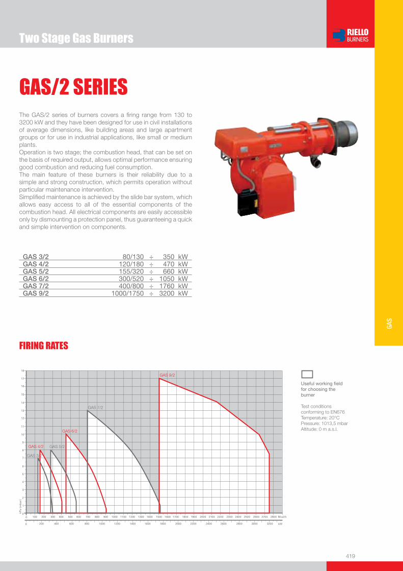
419
GAS
Two Stage Gas Burners
GAS/2 SERIESThe GAS/2 series of burners covers a fi ring range from 130 to 3200 kW and they have been designed for use in civil installations of average dimensions, like building areas and large apartment groups or for use in industrial applications, like small or medium plants.Operation is two stage; the combustion head, that can be set on the basis of required output, allows optimal performance ensuring good combustion and reducing fuel consumption.The main feature of these burners is their reliability due to a simple and strong construction, which permits operation without particular maintenance intervention. Simplifi ed maintenance is achieved by the slide bar system, which allows easy access to all of the essential components of the combustion head. All electrical components are easily accessible only by dismounting a protection panel, thus guaranteeing a quick and simple intervention on components.
GAS 3/2 80/130 ÷ 350 kWGAS 4/2 120/180 ÷ 470 kWGAS 5/2 155/320 ÷ 660 kWGAS 6/2 300/520 ÷ 1050 kWGAS 7/2 400/800 ÷ 1760 kWGAS 9/2 1000/1750 ÷ 3200 kW
FIRING RATES
Useful working fi eldfor choosing theburner
Test conditionsconforming to EN676 Temperature: 20°CPressure: 1013,5 mbarAltitude: 0 m a.s.l.

420
BURNER
Overall dimensions (mm)
Two Stage Gas BurnersGAS/2 SERIES
GAS 3/2 - 4/2 - 5/2 - 6/2 - 7/2
GAS 9/2
Z
X - X (1)Y
BURNER - BOILER MOUNTING FLANGE
MODEL D1 D2 Ø u GAS 3/2 155 226 M10
u GAS 4/2 165 226 M10
u GAS 5/2 165 226 M10
u GAS 6/2 185 276 M12
u GAS 7/2 230 325 M12
u GAS 9/2 300 368 M18
MODEL X - X (1) Y Z kg u GAS 3/2 850 545 473 34
u GAS 4/2 850 545 473 40
u GAS 5/2 895 543 520 43
u GAS 6/2 1045 543 555 60
u GAS 7/2 1245 727 665 98
u GAS 9/2 1870 920 910 240
(1) Length with extended combustion head
PACKAGING
(1) Length with extended combustion head
MODEL A B C D E F - F (1) H I M N O V u GAS 3/2 410 205 205 397 610 185 - 320 140 292 1”1/2 97 775 165
u GAS 4/2 410 205 205 397 610 187 - 320 150 292 1”1/2 97 775 165
u GAS 5/2 431 226 205 437 645 207 - 365 155 332 1”1/2 97 810 165
u GAS 6/2 463 258 205 485 770 227 - 360 175 370 2” 131 966 195
u GAS 7/2 606 358 248 590 920 240 - 400 220 445 2” 140 1142 245
u GAS 9/2 780 445 335 680 1200 444 - 574 295 495 2” 168 1627 210

421
GAS
DESIGNATION OF SERIES
Specifi cation
Two Stage Gas BurnersGAS/2 SERIES
Series : GAS
Size
Operation : ... One stage /2 Two stage P/M Modulating
Emission : ... Class 1 EN267 - EN676 Head : TC Standard head TL Extended head
Flame control system : FS1 Standard (1 stop every 24 h) FS2 Continuous working (1 stop every 72 h)
Electrical supply to the system : 1/230/50 1/230V/50Hz 1/220/60 1/220V/60Hz 3/230-400/50 3/230V/50Hz - 3N/400V/50Hz 3/220-380/60 3/220V/60Hz - 3N/380V/60Hz 3/254-440/60 3/254V/60Hz - 3N/440V/60Hz 3/265-460/60 3/265V/60Hz - 3N/460V/60Hz Auxiliary voltage : 230/50-60 230V/50-60Hz 110/50-60 110V/50-60Hz
BASIC DESIGNATION
EXTENDED DESIGNATION
GAS 7 /2 TC FS1 3/230-400/50 230/50

422
GAS/2 SERIES
Burners
STATE OF SUPPLY
Monoblock forced draught gas burner, two stage operation, made up of:- Air suction circuit- Fan with forward curved blades- Air damper for air setting - Combustion head, that can be set on the basis of required output, fi tted with:- stainless steel end cone, resistant to corrosion and high temperatures- ignition electrodes- fl ame stability disk- Minimum air pressure switch- Single phase or three phases electrical motor- Microprocessor-based burner safety control box, with diagnostic function- Flame inspection window- Slide bars for easier installation and maintenance- Protection fi lter against radio interference- IP X0D (IP 40) protection level.
Standard equipment:- 1 gas train fl ange- 1 fl ange gasket- 1 insulating screen- 8 screws for fi xing the burner fl ange to the boiler- Instruction handbook for installation, use and maintenance- Spare parts catalogue.
Specifi cation
Natural gas G20 net calorifi c value: 10 kWh/Nm3 - Density gas G20: 0,71 kg/Nm3 The burners of GAS/2 series are in according to 90/396 - 89/336 (2004/108) - 73/23 (2006/95) - 92/42 EC Directive and EN 676 Norm.
Available models
Two Stage Gas Burners
CODE MODEL
HEAT OUTPUT TOTAL
ELECTRICALPOWER
CERTIFICATION NOTE
NATURAL GAS
(kW) (Nm3/h) (kW)
3752182 GAS 3/2 TC FS1 1/220/60 220/60 80/130-340 8/13-34 0,4 -
3752118 GAS 3/2 TC FS1 1/230/50 230/50 80/130-350 8/13-35 0,4 CE 0085AQ0707
3752218 GAS 4/2 TC FS1 1/230/50 230/50 120/180-470 12/18-47 0,54 CE 0085AQ0707
3752282 GAS 4/2 TC FS1 3/220-380/60 220/60 115/180-470 11,5/18-47 0,6 -
3752382 GAS 5/2 TC FS1 3/220-380/60 220/60 155/320-660 15,5/32-66 1,1 -
3752318 GAS 5/2 TC FS1 3/230-400/50 230/50 155/320-660 15,5/32-66 0,85 CE 0085AQ0707
3752482 GAS 6/2 TC FS1 3/220-380/60 220/60 300/520-1050 30/52-105 1,9 -
3752418 GAS 6/2 TC FS1 3/230-400/50 230/50 300/520-1050 30/52-105 1,7 CE 0085AQ0707
3752582 GAS 7/2 TC FS1 3/220-380/60 220/60 400/800-1760 40/80-176 3,8 -
3752518 GAS 7/2 TC FS1 3/230-400/50 230/50 400/800-1760 40/80-176 3,4 CE 0085AQ0707
3788300 GAS 9/2 TC FS1 3/230-400/50 1000/1750-3200 100/175-320 9 -
3788301 GAS 9/2 TL FS1 3/230-400/50 1000/1750-3200 100/175-320 9 -
3788302 GAS 9/2 TC FS1 3/254-440/60 1000/1750-3200 100/175-320 9 -
3788303 GAS 9/2 TL FS1 3/254-440/60 1000/1750-3200 100/175-320 9 -

423
GAS
GAS/2 SERIES
Available modelsGas Trains
Two Stage Gas Burners
GAS TRAIN GAS TRAIN NATURAL GAS LPG NOTE
CODE* MODEL BURNER ADAPTER BURNER ADAPTER
(type) (code) (type) (code)
MU
LTIB
LOC
GA
S T
RA
INS 3970046 MBZRDLE 407 GAS 3/2 3000824 GAS 3/2 3000824 (1)
3970079 MBZRDLE 410
GAS 3/2 3000824 GAS 3/2 3000824
(1)GAS 4/2 3000824 GAS 4/2 3000824
GAS 5/2 3000824 GAS 5/2 3000824
GAS 6/2 3000824 + 3000843
3970152 MBZRDLE 412
GAS 3/2 - GAS 3/2 -
(1)GAS 4/2 - GAS 4/2 -
GAS 5/2 - GAS 5/2 -
GAS 6/2 3010125 GAS 6/2 3010125
3970183 MBZRDLE 415
GAS 3/2 - GAS 3/2 -
(1)
GAS 4/2 - GAS 4/2 -
GAS 5/2 - GAS 5/2 -
GAS 6/2 3000843 GAS 6/2 3000843
GAS 7/2 3000843 GAS 7/2 3000843
3970184 MBZRDLE 420
GAS 4/2 3000822 GAS 4/2 3000822
(1)
GAS 5/2 3000822 GAS 5/2 3000822
GAS 6/2 - GAS 6/2 -
GAS 7/2 - GAS 7/2 -
GAS 9/2 - GAS 9/2 -
3970185 MBZRDLE 420 CT
GAS 4/2 3000822 GAS 4/2 3000822
(2)GAS 5/2 3000822 GAS 5/2 3000822
GAS 6/2 - GAS 6/2 -
GAS 7/2 - GAS 7/2 -
CO
MP
OS
ED
GA
S T
RA
INS
3970153 CB 40/2
GAS 3/2 - GAS 3/2 -
(1)
GAS 4/2 - GAS 4/2 -
GAS 5/2 - GAS 5/2 -
GAS 6/2 3000843 GAS 6/2 3000843
GAS 7/2 3000843 GAS 7/2 3000843
3970154 CB 50/2
GAS 4/2 3000822 GAS 4/2 3000822
(1)
GAS 5/2 3000822 GAS 5/2 3000822
GAS 6/2 - GAS 6/2 -
GAS 7/2 - GAS 7/2 -
GAS 9/2 - GAS 9/2 -
3809901 CBF 65/2 GAS 9/2 3000825 GAS 9/2 3000825 (1)
3970155 CBF 65/2GAS 6/2 3000825 - -
(1)GAS 7/2 3000825 GAS 7/2 3000825
3970167 CBF 65/2 CTGAS 6/2 3000825 - -
(2)GAS 7/2 3000825 GAS 7/2 3000825
3809902 CBF 80/2 GAS 9/2 3000826 GAS 9/2 3000826 (1)
3970156 CBF 80/2 GAS 7/2 3000826 - - (1)
3970168 CBF 80/2 CT GAS 7/2 3000826 - - (2)
* gas train are 230V/50Hz - 220V/60Hz electrical supply(1) Seal control accessory(2) Seal control incorporated
To select the gas train please refer to the technical data leafl et and/or instruction manual.
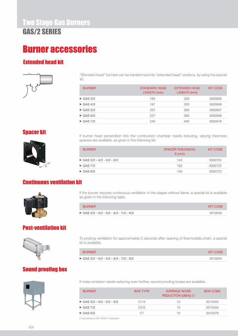
424
If noise emission needs reducing even further, sound-proofi ng boxes are available.
Sound proofi ng box
BURNER
BOX TYPE
AVERAGE NOISE REDUCTION [dB(A)] (*)
BOX CODE
u GAS 3/2 - 4/2 - 5/2 - 6/2 C1/3 10 3010403
u GAS 7/2 C4/5 10 3010404
u GAS 9/2 C7 10 3010376
(*) according to EN 15036-1 standard
GAS/2 SERIES
Burner accessoriesExtended head kit
“Standard head” burners can be transformed into “extended head” versions, by using the special kit.
BURNER STANDARD HEADLENGTH (mm)
EXTENDED HEADLENGTH (mm)
KIT CODE
u GAS 3/2 185 320 3000605
u GAS 4/2 187 320 3000606
u GAS 5/2 207 365 3000607
u GAS 6/2 227 360 3000608
u GAS 7/2 240 400 3000678
If burner head penetration into the combustion chamber needs reducing, varying thickness spacers are available, as given in the following list.
Spacer kit
BURNER
SPACER THICKNESS S (mm)
KIT CODE
u GAS 3/2 - 4/2 - 5/2 - 6/2 142 3000755
u GAS 7/2 102 3000722
u GAS 9/2 130 3000723
If the burner requires continuous ventilation in the stages without fl ame, a special kit is available as given in the following table.
Continuous ventilation kit
BURNER KIT CODE
u GAS 3/2 - 4/2 - 5/2 - 6/2 - 7/2 - 9/2 3010030
To prolong ventilation for approximately 5 seconds after opening of thermostats chain, a special kit is available.
Post-ventilation kit
BURNER KIT CODE
u GAS 3/2 - 4/2 - 5/2 - 6/2 - 7/2 - 9/2 3010004
Two Stage Gas Burners

425
GAS
Burner accessories
GAS/2 SERIES
LPG kit
For burning LPG gas, a special kit is available.
BURNER KIT CODE FOR STANDARD HEAD
KIT CODE FOR EXTENDED HEAD
u GAS 3/2 3000657 3000807
u GAS 4/2 3000658 3000808
u GAS 5/2 3000659 3000809
u GAS 6/2 3000753 3000810
u GAS 7/2 3000806 3000811
u GAS 9/2 3000876 3010028
Town Gas kit
For burning Town Gas, a special kit is available.
BURNER KIT CODE FOR STANDARD HEAD (*)
KIT CODE FOR EXTENDED HEAD (*)
u GAS 3/2 3000742 -
u GAS 4/2 3000754 -
u GAS 5/2 3000759 -
u GAS 6/2 3000768 -
u GAS 7/2 3000769 -
u GAS 9/2 3010298 -
(*) Without CE certifi cation
BURNER KIT CODE
u GAS 3/2 - 4/2 - 5/2 - 6/2 - 7/2 - 9/2 3002719
To connect the control box to a personal computer for the transmission of operation, fault signals and detailed service information, an interface adapter with PC software are available.
PC Interface kit
This kit is available as an interface between the thermostatic controls and the burner, to be used in systems where the lengths of the thermostat connections is over 20 meters, or where the burner is installed in a room particularly subject to electromagnetic interference (signals emitted over 10 V/m).
BURNER KIT CODE
u GAS 3/2 - 4/2 - 5/2 - 6/2 - 7/2 - 9/2 3010386
Protection kit (electromagnetic interferences)

426
Gas train accessories
Two Stage Gas BurnersGAS/2 SERIES
Adapters
When the diameter of the gas train is different from the set diameter of the burners, an adapter must be fi tted between the gas train and the burner.
BURNER GAS TRAIN DIMENSIONS ADAPTER CODE
u GAS 3/2 MBZRDLE 407 - 410 1” 1/23/4” 3000824
u GAS 4/2 MBZRDLE 410 1” 1/23/4” 3000824
MBZRDLE 420 - CB 50/2 1” 1/22” 3000822
u GAS 5/2 MBZRDLE 410 1” 1/23/4” 3000824
MBZRDLE 420 - CB 50/2 1” 1/22” 3000822
u GAS 6/2
MBZRDLE 410
1” 1/23/4”
2”1” 1/2
3000824
3000843
MBZRDLE 412-415 - CB 40/2 2”1” 1/2 3000843
CBF 65/2 2” 1/2DN 65
1” 1/2
2”
3000825
u GAS 7/2
MBZRDLE 415 - CB 40/2 2”1” 1/2 3000843
CBF 65/2 2” 1/2DN 65
1” 1/2
2”
3000825
CBF 80/2 2” 1/2DN 80 2” 3000826
u GAS 9/2 CBF 65/2 2” 1/2DN 65
1” 1/2
2”
300825
CBF 80/2 2” 1/2DN 80 2” 3000826
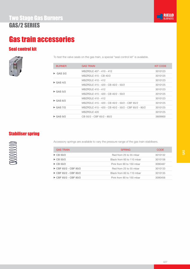
427
GAS
Two Stage Gas BurnersGAS/2 SERIES
Gas train accessoriesSeal control kit
To test the valve seals on the gas train, a special “seal control kit” is available.
Stabiliser spring
Accessory springs are available to vary the pressure range of the gas train stabilisers.
GAS TRAIN SPRING CODE
u CB 50/2 Red from 25 to 55 mbar 3010132
u CB 50/2 Black from 60 to 110 mbar 3010158
u CB 50/2 Pink from 90 to 150 mbar 3090487
u CBF 65/2 - CBF 80/2 Red from 25 to 55 mbar 3010133
u CBF 65/2 - CBF 80/2 Black from 60 to 110 mbar 3010135
u CBF 65/2 - CBF 80/2 Pink from 90 to 150 mbar 3090456
BURNER GAS TRAIN KIT CODE
u GAS 3/2 MBZRDLE 407 - 410 - 412 3010123
MBZRDLE 415 - CB 40/2 3010125
u GAS 4/2 MBZRDLE 410 - 412 3010123
MBZRDLE 415 - 420 - CB 40/2 - 50/2 3010125
u GAS 5/2 MBZRDLE 410 - 412 3010123
MBZRDLE 415 - 420 - CB 40/2 - 50/2 3010125
u GAS 6/2 MBZRDLE 410 - 412 3010123
MBZRDLE 415 - 420 - CB 40/2 - 50/2 - CBF 65/2 3010125
u GAS 7/2 MBZRDLE 415 - 420 - CB 40/2 - 50/2 - CBF 65/2 - 80/2 3010125
MBZRDLE 420 3010125
u GAS 9/2 CB 50/2 - CBF 65/2 - 80/2 3809900
www.rielloburners.com
We are here setting the standard as your specialist energy-partner

429
GAS
Modulating Gas Burners
GAS P/M SERIESThe GAS P/M series covers a fi ring range from 130 to 4885 kW.Operation is featured by progressive two stage operation or full modulation, with an advanced modulating control system and probes. The burners of GAS P/M series are well suited for applications requiring versatility of control (process, steam, refrigerating absorption) where a variable output is needed.Due to their metal sheet structures, they are specifi cally suitable for process applications where plastic materials could be easily damaged or deformed. Simplifi ed maintenance is achieved by sliding bars which permit the access to the combustion head without need of removing the burner from the boiler.
GAS 3 P/M 80/130 ÷ 350 kWGAS 4 P/M 120/180 ÷ 470 kWGAS 5 P/M 155/320 ÷ 660 kWGAS 6 P/M 300/520 ÷ 1050 kWGAS 7 P/M 400/800 ÷ 1760 kWGAS 8 P/M 640/1163 ÷ 2210 kWGAS 9 P/M 870/1744 ÷ 3488 kWGAS 10 P/M 1140/2441 ÷ 4885 kW
FIRING RATES
Useful working fi eldfor choosing theburner
Modulation range
Test conditionsconforming to EN676 Temperature: 20°CPressure: 1013,5 mbarAltitude: 0 m a.s.l.
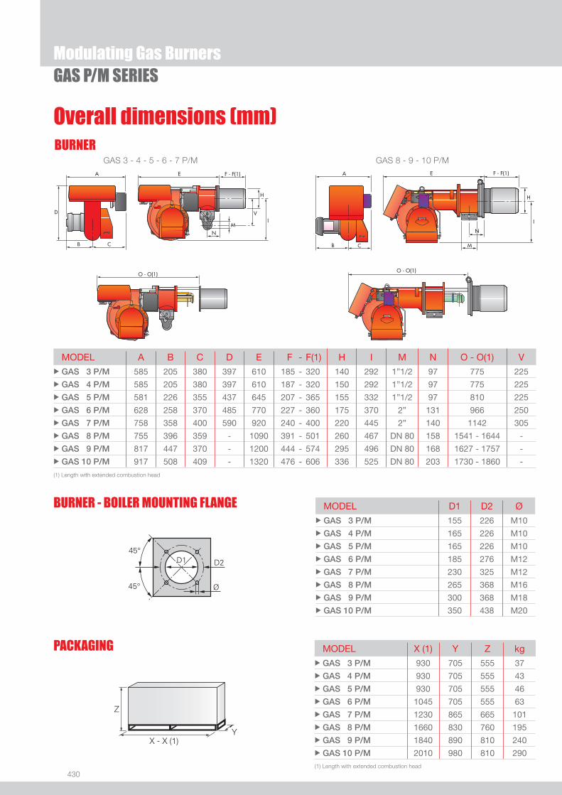
430
BURNER
Overall dimensions (mm)
Modulating Gas BurnersGAS P/M SERIES
Z
X - X (1)Y
BURNER - BOILER MOUNTING FLANGE MODEL D1 D2 Ø u GAS 3 P/M 155 226 M10 u GAS 4 P/M 165 226 M10 u GAS 5 P/M 165 226 M10 u GAS 6 P/M 185 276 M12 u GAS 7 P/M 230 325 M12u GAS 8 P/M 265 368 M16u GAS 9 P/M 300 368 M18u GAS 10 P/M 350 438 M20
(1) Length with extended combustion head
(1) Length with extended combustion head
MODEL X (1) Y Z kg u GAS 3 P/M 930 705 555 37u GAS 4 P/M 930 705 555 43u GAS 5 P/M 930 705 555 46u GAS 6 P/M 1045 705 555 63u GAS 7 P/M 1230 865 665 101u GAS 8 P/M 1660 830 760 195u GAS 9 P/M 1840 890 810 240u GAS 10 P/M 2010 980 810 290
PACKAGING
MODEL A B C D E F - F(1) H I M N O - O(1) Vu GAS 3 P/M 585 205 380 397 610 185 - 320 140 292 1”1/2 97 775 225u GAS 4 P/M 585 205 380 397 610 187 - 320 150 292 1”1/2 97 775 225u GAS 5 P/M 581 226 355 437 645 207 - 365 155 332 1”1/2 97 810 225u GAS 6 P/M 628 258 370 485 770 227 - 360 175 370 2” 131 966 250u GAS 7 P/M 758 358 400 590 920 240 - 400 220 445 2” 140 1142 305u GAS 8 P/M 755 396 359 - 1090 391 - 501 260 467 DN 80 158 1541 - 1644 -u GAS 9 P/M 817 447 370 - 1200 444 - 574 295 496 DN 80 168 1627 - 1757 -u GAS 10 P/M 917 508 409 - 1320 476 - 606 336 525 DN 80 203 1730 - 1860 -
GAS 3 - 4 - 5 - 6 - 7 P/M GAS 8 - 9 - 10 P/M

431
GAS
DESIGNATION OF SERIES
Specifi cation
Modulating Gas BurnersGAS P/M SERIES
GAS 9 P/M TC FS1 3/230-400/50 230/50-60
Series : GAS
Size
Operation : ... One stage /2 Two stage P/M Modulating
Emission : ... Class 1 EN267 - EN676 Head : TC Standard head TL Extended head
Flame control system : FS1 Standard (1 stop every 24 h) FS2 Continuous working (1 stop every 72 h)
Electrical supply to the system : 1/230/50 1/230V/50Hz 1/210/60 1/210V/60Hz 3/230/50 3/230V/50Hz 3/400/50 3N/400V/50Hz 3/230-400/50 3/230V/50Hz - 3N/400V/50Hz 3/210/60 3/210V/60Hz 3/220/60 3/220V/60Hz 3/380/60 3/380V/60Hz 3/220-380/60 3/220V/60Hz - 3N/380V/60Hz Auxiliary voltage : 230/50 230V/50Hz 220/60 220V/60Hz 120/50-60 120V/50-60Hz 230/50-60 230V/50-60Hz
BASIC DESIGNATION
EXTENDED DESIGNATION

432
GAS P/M SERIES
STATE OF SUPPLY
Monoblock forced draught gas burner, two stage progressive operation or modulating with a kit, made up of:- Air suction circuit- Fan with forward curved blades- Air damper for air setting controlled by a servomotor;- Combustion head, that can be set on the basis of required output, fi tted with:- stainless steel end cone, resistant to corrosion and high temperatures- ignition electrodes- fl ame stability disk- Servomotor for air and gas delivery regulation- Maximum gas pressure switch (except for GAS 3 P/M model)- Minimum air pressure switch- Single phase or three phases electrical motor- Ionisation probe- Flame inspection window- Slide bars for easier installation and maintenance- Protection fi lter against radio interference- IP X0D (IP 40) protection level.
Standard equipment:- 1 gas train fl ange- 1 fl ange gasket- 1 insulating screen- 8 screws for fi xing the burner fl ange to the boiler (12 for GAS 8 P/M - GAS 9 P/M and GAS 10 P/M)- 4 wiring looms for electrical connections- 1 star delta starter (for GAS 8 P/M - GAS 9 P/M and GAS 10 P/M)- 2 wiring looms for electrical connections to the star delta starter (for GAS 8 P/M - GAS 9 P/M and GAS 10 P/M)- 8 washers (for GAS 8 P/M - GAS 9 P/M and GAS 10 P/M)- 2 bar extensions (only for extended head versions of GAS 8 P/M - GAS 9 P/M and GAS 10 P/M)- Instruction handbook for installation, use and maintenance- Spare parts catalogue.
Specifi cation
Modulating Gas Burners
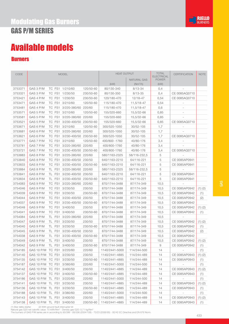
433
GAS
GAS P/M SERIES
Available modelsBurners
(1) Star delta starter (2) With ground fault interrupter kitNatural gas G20 net calorifi c value: 10 kWh/Nm3 - Density gas G20: 0,71 kg/Nm3 The burners of GAS P/M series are in according to 90/396 - 89/336 (2004/108) - 73/23 (2006/95) - 92/42 EC Directive and EN 676 Norm.
Modulating Gas Burners
CODE MODEL HEAT OUTPUT TOTAL ELECTRICAL
POWER
CERTIFICATION NOTE
NATURAL GAS
(kW) (Nm3/h) (kW)
3753371 GAS 3 P/M TC FS1 1/210/60 120/50-60 80/130-340 8/13-34 0,4 -
3753321 GAS 3 P/M TC FS1 1/230/50 230/50-60 80/130-350 8/13-35 0,4 CE 0085AQ0710
3753421 GAS 4 P/M TC FS1 1/230/50 230/50-60 120/180-470 12/18-47 0,54 CE 0085AQ0710
3753471 GAS 4 P/M TC FS1 3/210/60 120/50-60 115/180-470 11,5/18-47 0,54 -
3753481 GAS 4 P/M TC FS1 3/220-380/60 220/60 115/180-470 11,5/18-47 0,6 -
3753571 GAS 5 P/M TC FS1 3/210/60 120/50-60 155/320-660 15,5/32-66 0,85 -
3753581 GAS 5 P/M TC FS1 3/220-380/60 220/60 155/320-660 15,5/32-66 0,85 -
3753521 GAS 5 P/M TC FS1 3/230-400/50 230/50-60 155/320-660 15,5/32-66 0,85 CE 0085AQ0710
3753671 GAS 6 P/M TC FS1 3/210/60 120/50-60 300/520-1050 30/52-105 1,7 -
3753681 GAS 6 P/M TC FS1 3/220-380/60 220/60 300/520-1050 30/52-105 1,7 -
3753621 GAS 6 P/M TC FS1 3/230-400/50 230/50-60 300/520-1050 30/52-105 1,7 CE 0085AQ0710
3753771 GAS 7 P/M TC FS1 3/210/60 120/50-60 400/800 -1760 40/80-176 3,4 -
3753781 GAS 7 P/M TC FS1 3/220-380/60 220/60 400/800-1760 40/80-176 3,4 -
3753721 GAS 7 P/M TC FS1 3/230-400/50 230/50-60 400/800-1760 40/80-176 3,4 CE 0085AQ0710
3753883 GAS 8 P/M TC FS1 3/220-380/60 220/60 580/1163-2325 58/116-232,5 5 -
3753840 GAS 8 P/M TC FS1 3/230-400/50 230/50 640/1163-2210 64/116-221 5 CE 0085AP0941
3753833 GAS 8 P/M TC FS1 3/230-400/50 230/50-60 640/1163-2210 64/116-221 5 CE 0085AP0941
3753884 GAS 8 P/M TL FS1 3/220-380/60 220/60 580/1163-2325 58/116-232,5 5 -
3753841 GAS 8 P/M TL FS1 3/230-400/50 230/50 640/1163-2210 64/116-221 5 CE 0085AP0941
3753834 GAS 8 P/M TL FS1 3/230-400/50 230/50-60 640/1163-2210 64/116-221 5 CE 0085AP0941
3754083 GAS 9 P/M TC FS1 3/220-380/60 220/60 870/1744-3488 87/174-349 10,5 -
3754046 GAS 9 P/M TC FS1 3/230/50 230/50 870/1744-3488 87/174-349 10,5 CE 0085AP0942 (1) (2)
3754039 GAS 9 P/M TC FS1 3/230/50 230/50-60 870/1744-3488 87/174-349 10,5 CE 0085AP0942 (1)
3754044 GAS 9 P/M TC FS1 3/230-400/50 230/50 870/1744-3488 87/174-349 10,5 CE 0085AP0942 (2)
3754037 GAS 9 P/M TC FS1 3/230-400/50 230/50-60 870/1744-3488 87/174-349 10,5 CE 0085AP0942
3754048 GAS 9 P/M TC FS1 3/400/50 230/50 870/1744-3488 87/174-349 10,5 CE 0085AP0942 (1) (2)
3754041 GAS 9 P/M TC FS1 3/400/50 230/50-60 870/1744-3488 87/174-349 10,5 CE 0085AP0942 (1)
3754084 GAS 9 P/M TL FS1 3/220-380/60 220/60 870/1744-3488 87/174-349 10,5 -
3754047 GAS 9 P/M TL FS1 3/230/50 230/50 870/1744-3488 87/174-349 10,5 CE 0085AP0942 (1) (2)
3754040 GAS 9 P/M TL FS1 3/230/50 230/50-60 870/1744-3488 87/174-349 10,5 CE 0085AP0942 (1)
3754045 GAS 9 P/M TL FS1 3/230-400/50 230/50 870/1744-3488 87/174-349 10,5 CE 0085AP0942 (2)
3754038 GAS 9 P/M TL FS1 3/230-400/50 230/50-60 870/1744-3488 87/174-349 10,5 CE 0085AP0942
3754049 GAS 9 P/M TL FS1 3/400/50 230/50 870/1744-3488 87/174-349 10,5 CE 0085AP0942 (1) (2)
3754042 GAS 9 P/M TL FS1 3/400/50 230/50-60 870/1744-3488 87/174-349 9 CE 0085AP0942 (1)
3754185 GAS 10 P/M TC FS1 3/220/60 220/60 1140/2441-5000 114/244-500 14 - (1)
3754140 GAS 10 P/M TC FS1 3/230/50 230/50 1140/2441-4885 114/244-489 14 CE 0085AP0943 (1) (2)
3754135 GAS 10 P/M TC FS1 3/230/50 230/50-60 1140/2441-4885 114/244-489 14 CE 0085AP0943 (1)
3754187 GAS 10 P/M TC FS1 3/380/60 220/60 1140/2441-5000 114/244-500 14 - (1)
3754142 GAS 10 P/M TC FS1 3/400/50 230/50 1140/2441-4885 114/244-489 14 CE 0085AP0943 (1) (2)
3754137 GAS 10 P/M TC FS1 3/400/50 230/50-60 1140/2441-4885 114/244-489 14 CE 0085AP0943 (1)
3754186 GAS 10 P/M TL FS1 3/220/60 220/60 1140/2441-5000 114/244-500 14 - (1)
3754141 GAS 10 P/M TL FS1 3/230/50 230/50 1140/2441-4885 114/244-489 14 CE 0085AP0943 (1) (2)
3754136 GAS 10 P/M TL FS1 3/230/50 230/50-60 1140/2441-4885 114/244-489 14 CE 0085AP0943 (1)
3754188 GAS 10 P/M TL FS1 3/380/60 220/60 1140/2441-5000 114/244-500 14 - (1)
3754143 GAS 10 P/M TL FS1 3/400/50 230/50 1140/2441-4885 114/244-489 14 CE 0085AP0943 (1) (2)
3754138 GAS 10 P/M TL FS1 3/400/50 230/50-60 1140/2441-4885 114/244-489 14 CE 0085AP0943 (1)
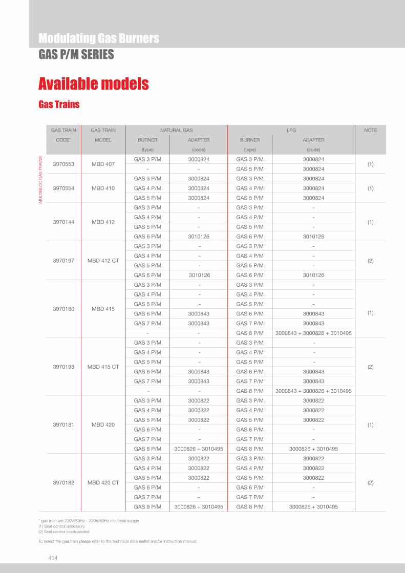
434
Available modelsGas Trains
* gas train are 230V/50Hz - 220V/60Hz electrical supply(1) Seal control accessory(2) Seal control incorporated
To select the gas train please refer to the technical data leafl et and/or instruction manual.
Modulating Gas BurnersGAS P/M SERIES
GAS TRAIN GAS TRAIN NATURAL GAS LPG NOTE
CODE* MODEL BURNER ADAPTER BURNER ADAPTER
(type) (code) (type) (code)
MU
LTIB
LOC
GA
S T
RA
INS
3970553 MBD 407GAS 3 P/M 3000824 GAS 3 P/M 3000824
(1)- - GAS 5 P/M 3000824
3970554 MBD 410
GAS 3 P/M 3000824 GAS 3 P/M 3000824
(1)GAS 4 P/M 3000824 GAS 4 P/M 3000824
GAS 5 P/M 3000824 GAS 5 P/M 3000824
3970144 MBD 412
GAS 3 P/M - GAS 3 P/M -
(1)GAS 4 P/M - GAS 4 P/M -
GAS 5 P/M - GAS 5 P/M -
GAS 6 P/M 3010126 GAS 6 P/M 3010126
3970197 MBD 412 CT
GAS 3 P/M - GAS 3 P/M -
(2)GAS 4 P/M - GAS 4 P/M -
GAS 5 P/M - GAS 5 P/M -
GAS 6 P/M 3010126 GAS 6 P/M 3010126
3970180 MBD 415
GAS 3 P/M - GAS 3 P/M -
(1)
GAS 4 P/M - GAS 4 P/M -
GAS 5 P/M - GAS 5 P/M -
GAS 6 P/M 3000843 GAS 6 P/M 3000843
GAS 7 P/M 3000843 GAS 7 P/M 3000843
- - GAS 8 P/M 3000843 + 3000826 + 3010495
3970198 MBD 415 CT
GAS 3 P/M - GAS 3 P/M -
(2)
GAS 4 P/M - GAS 4 P/M -
GAS 5 P/M - GAS 5 P/M -
GAS 6 P/M 3000843 GAS 6 P/M 3000843
GAS 7 P/M 3000843 GAS 7 P/M 3000843
- - GAS 8 P/M 3000843 + 3000826 + 3010495
3970181 MBD 420
GAS 3 P/M 3000822 GAS 3 P/M 3000822
(1)
GAS 4 P/M 3000822 GAS 4 P/M 3000822
GAS 5 P/M 3000822 GAS 5 P/M 3000822
GAS 6 P/M - GAS 6 P/M -
GAS 7 P/M - GAS 7 P/M -
GAS 8 P/M 3000826 + 3010495 GAS 8 P/M 3000826 + 3010495
3970182 MBD 420 CT
GAS 3 P/M 3000822 GAS 3 P/M 3000822
(2)
GAS 4 P/M 3000822 GAS 4 P/M 3000822
GAS 5 P/M 3000822 GAS 5 P/M 3000822
GAS 6 P/M - GAS 6 P/M -
GAS 7 P/M - GAS 7 P/M -
GAS 8 P/M 3000826 + 3010495 GAS 8 P/M 3000826 + 3010495
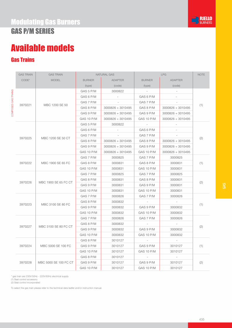
435
GAS
Modulating Gas BurnersGAS P/M SERIES
Available modelsGas Trains
GAS TRAIN GAS TRAIN NATURAL GAS LPG NOTE
CODE* MODEL BURNER ADAPTER BURNER ADAPTER
(type) (code) (type) (code)
CO
MP
OS
ED
GA
S T
RA
INS
3970221 MBC 1200 SE 50
GAS 5 P/M 3000822 - -
(1)
GAS 6 P/M - GAS 6 P/M -
GAS 7 P/M - GAS 7 P/M -
GAS 8 P/M 3000826 + 3010495 GAS 8 P/M 3000826 + 3010495
GAS 9 P/M 3000826 + 3010495 GAS 9 P/M 3000826 + 3010495
GAS 10 P/M 3000826 + 3010495 GAS 10 P/M 3000826 + 3010495
3970225 MBC 1200 SE 50 CT
GAS 5 P/M 3000822 - -
(2)
GAS 6 P/M - GAS 6 P/M -
GAS 7 P/M - GAS 7 P/M -
GAS 8 P/M 3000826 + 3010495 GAS 8 P/M 3000826 + 3010495
GAS 9 P/M 3000826 + 3010495 GAS 9 P/M 3000826 + 3010495
GAS 10 P/M 3000826 + 3010495 GAS 10 P/M 3000826 + 3010495
3970222 MBC 1900 SE 65 FC
GAS 7 P/M 3000825 GAS 7 P/M 3000825 (1)
GAS 8 P/M 3000831 GAS 8 P/M 3000831
GAS 10 P/M 3000831 GAS 10 P/M 3000831
3970226 MBC 1900 SE 65 FC CT
GAS 7 P/M 3000825 GAS 7 P/M 3000825
(2)
GAS 8 P/M 3000831 GAS 8 P/M 3000831
GAS 9 P/M 3000831 GAS 9 P/M 3000831
GAS 10 P/M 3000831 GAS 10 P/M 3000831
3970223 MBC 3100 SE 80 FC
GAS 7 P/M 3000826 GAS 7 P/M 3000826
(1)GAS 8 P/M 3000832 - -
GAS 9 P/M 3000832 GAS 9 P/M 3000832
GAS 10 P/M 3000832 GAS 10 P/M 3000832
3970227 MBC 3100 SE 80 FC CT
GAS 7 P/M 3000826 GAS 7 P/M 3000826
(2)GAS 8 P/M 3000832 - -
GAS 9 P/M 3000832 GAS 9 P/M 3000832
GAS 10 P/M 3000832 GAS 10 P/M 3000832
3970224 MBC 5000 SE 100 FC
GAS 8 P/M 3010127 - -
(1)GAS 9 P/M 3010127 GAS 9 P/M 3010127
GAS 10 P/M 3010127 GAS 10 P/M 3010127
3970228 MBC 5000 SE 100 FC CT
GAS 8 P/M 3010127 - -
(2)GAS 9 P/M 3010127 GAS 9 P/M 3010127
GAS 10 P/M 3010127 GAS 10 P/M 3010127
* gas train are 230V/50Hz - 220V/60Hz electrical supply(1) Seal control accessory(2) Seal control incorporated
To select the gas train please refer to the technical data leafl et and/or instruction manual.
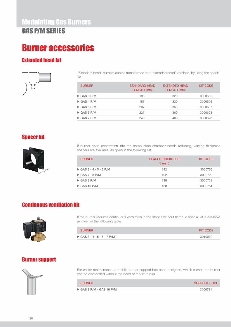
436
GAS P/M SERIES
Burner accessoriesExtended head kit
“Standard head” burners can be transformed into “extended head” versions, by using the special kit.
BURNER STANDARD HEADLENGTH (mm)
EXTENDED HEADLENGTH (mm)
KIT CODE
u GAS 3 P/M 185 320 3000605
u GAS 4 P/M 187 320 3000606
u GAS 5 P/M 207 365 3000607
u GAS 6 P/M 227 360 3000608
u GAS 7 P/M 240 400 3000678
If burner head penetration into the combustion chamber needs reducing, varying thickness spacers are available, as given in the following list.
Spacer kit
BURNER
SPACER THICKNESS S (mm)
KIT CODE
u GAS 3 - 4 - 5 - 6 P/M 142 3000755
u GAS 7 - 8 P/M 102 3000722
u GAS 9 P/M 130 3000723
u GAS 10 P/M 130 3000751
If the burner requires continuous ventilation in the stages without fl ame, a special kit is available as given in the following table.
Continuous ventilation kit
BURNER KIT CODE
u GAS 3 - 4 - 5 - 6 - 7 P/M 3010030
For easier maintenance, a mobile burner support has been designed, which means the burner can be dismantled without the need of forklift trucks.
Burner support
BURNER SUPPORT CODE
u GAS 8 P/M - GAS 10 P/M 3000731
Modulating Gas Burners

437
GAS
Burner accessories
GAS P/M SERIES
If noise emission needs reducing even further, sound-proofi ng boxes are available.
Sound proofi ng box
BURNER
BOX TYPE
AVERAGE NOISE REDUCTION [dB(A)] (*)
BOX CODE
u GAS 3 - 4 - 5 - 6 P/M C1/3 10 3010403
u GAS 7 - 8 P/M C4/5 10 3010404
u GAS 9 - 10 P/M C7 10 3010376
(*) according to EN 15036-1 standard
LPG kit
For burning LPG gas, a special kit is available.
BURNER KIT CODE FOR STANDARD HEAD
KIT CODE FOR EXTENDED HEAD
u GAS 3 P/M 3000657 3000807
u GAS 4 P/M 3000658 3000808
u GAS 5 P/M 3000659 3000809
u GAS 6 P/M 3000753 3000810
u GAS 7 P/M 3000806 3000811
u GAS 8 P/M 3000875 3010029
u GAS 9 P/M 3000876 3010028
u GAS 10 P/M 3010152 3010153
Town Gas kit
For burning Town Gas, a special kit is available.
BURNER KIT CODE FOR STANDARD HEAD (*)
KIT CODE FOR EXTENDED HEAD (*)
u GAS 3 P/M 3000742 -
u GAS 4 P/M 3000754 -
u GAS 5 P/M 3000759 -
u GAS 6 P/M 3000768 -
u GAS 7 P/M 3000769 -
u GAS 8 P/M - -
u GAS 9 P/M 3010298 3010298
u GAS 10 P/M 3010300 3010300
(*) Without CE certifi cation
Modulating Gas Burners

438
Burner accessories
GAS P/M SERIESModulating Gas Burners
Accessories for modulating operation
To obtain modulating operation, the GAS P/M series of burners requires a regulator.
BURNER
REGULATOR TYPE
REGULATOR CODE
u GAS 3 - 4 - 5 - 6 - 7 P/M RWF 40 3010210
u GAS 8 - 9 - 10 P/M RWF 40 3010211
Depending on the servomotor fi tted to the burner, a three-pole potentiometer (1000 Ω) can be installed to check the position of the servomotor.
BURNER
POTENTIOMETER KIT CODE
uGAS 3 - 4 - 5 - 6 - 7 P/MGAS 8 - 9 - 10 P/M
3010021
The relative temperature or pressure probes fi tted to the regulator, must be chosen on the basis of the application.
BURNER PROBE TYPE RANGE (°C) (bar) PROBE CODE
uGAS 3 - 4 - 5 - 6 - 7 P/MGAS 8 - 9 - 10 P/M
Temperature PT 100 -100 ÷ 500°C 3010110
Pressure 4 ÷ 20 mA 0 ÷ 2,5 bar 3010213
Pressure 4 ÷ 20 mA 0 ÷ 16 bar 3010214

439
GAS
Modulating Gas BurnersGAS P/M SERIES
Gas train accessoriesAdapters
When the diameter of the gas train is different from the set diameter of the burners, an adapter must be fi tted between the gas train and the burner.
BURNER GAS TRAIN DIMENSIONS ADAPTER CODE
u GAS 3 P/M MBD 407 - 410 1” 1/23/4” 3000824
MBD 420 1” 1/22” 3000822
u GAS 4 - 5 P/M
MBD 407 1” 1/23/4” 3000824
MBD 410 1” 1/23/4” 3000824
MBD 420 1” 1/22” 3000822
MBC 1200 1” 1/22” 3000822
u GAS 6 - 7 P/M
MBD 412 2” 1” 1/4 3010126
MBD 415 2”1” 1/2 3000843
MBC 1900 2” 1/2DN 65
1” 1/2
2”
3000825
MBC 3100 2” 1/2DN 80 2” 3000826
u GAS 8 P/M
MBD 415 2” 1/2DN 80 2” 2” 1” 1/2
3000826 +
3010495 +
3000843
MBD 420 2” 1/2DN 80 2” 2”3000826
+3010495
MBC 1200 2” 1/2DN 80 2” 2”3000826
+3010495
MBC 1900 DN 65
DN 80
3000831
MBC 3100 DN 80
DN 80
3000832
MBC 5000 DN 100
DN 80
3010127
u GAS 9 - 10 P/M
MBC 1200 2” 1/2DN 80 2” 2”3000826
+3010495
MBC 1900 DN 65
DN 80
3000831
MBC 3100 DN 80
DN 80 3000832
MBC 5000 DN 100
DN 80
3010127

440
Gas train accessoriesSeal control kit
To test the valve seals on the gas train, a special “seal control kit” is available.
BURNER GAS TRAIN KIT CODE
u All models All models 3010123
Stabiliser spring
To vary the pressure range of the gas train stabilisers, accessory springs are available. The following table shows these accessories with their application range. Please refer to the technical manual for the correct choice of spring.
GAS TRAIN SPRING SPRING CODE
u
u
u
MBC 1900MBC 3100MBC 5000
White from 4 to 20 mbar 3010381
Red from 20 to 40 mbar 3010382
Black from 40 to 80 mbar 3010383
Green from 80 to 150 mbar 3010384
GAS P/M SERIESModulating Gas Burners

One Stage Gas Burners
441
GAS
FIRING RATES
RS/1 SERIESThe RS/1 series of burners covers a fi ring range from 70 to 550 kW, and they have been designed for use in low or medium temperature hot water boilers, hot air or steam boilers, diathermic oil boilers.Operation is “one stage”; the burners are fi tted with a microprocessor-based burner safety control box which supplies indication of operation and diagnosis of fault cause. Optimisation of sound emissions is guaranteed by the special design of the air suction circuit.The elevated performance of the fans and combustion head, guarantee fl exibility of use and excellent working at all fi ring rates.The exclusive design ensures reduced dimensions, simple use and maintenance. Optimisation of sound emissions is guaranteed by the special design of the air suction circuit and by incorporated sound proofi ng material. A wide range of accessories guarantees elevated working fl exibility.
RS 34/1 MZ 70 ÷ 390 kWRS 44/1 MZ 100 ÷ 550 kW
Useful working fi eldfor choosing theburner
Test conditionsconforming to EN676 Temperature: 20°CPressure: 1013,5 mbarAltitude: 0 m a.s.l.

442
BURNER
Overall dimensions (mm)
One Stage Gas BurnersRS/1 SERIES
�
�
�
�
�
��
� � � ����
(1) dimension with extended head
MODEL A D E F - F(1) H I L M N O S Vu RS 34/1 MZ 442 422 508 216 - 351 140 305 138 1”1/2 84 780 - 177
u RS 44/1 MZ 442 422 508 216 - 351 152 305 138 1”1/2 84 780 - 177
MODEL D1 D2 Ø u RS 34/1 MZ 160 224 M8
u RS 44/1 MZ 160 224 M8
MODEL X (1) Y Z kgu RS 34/1 MZ 1000 485 500 32
u RS 44/1 MZ 1000 485 500 33(1) dimension with standard and extended head
Z
X(1)Y
BURNER - BOILER MOUNTING FLANGE
PACKAGING
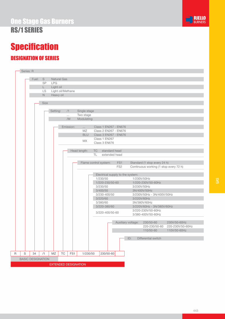
443
GAS
DESIGNATION OF SERIES
Specifi cation
One Stage Gas BurnersRS/1 SERIES
BASIC DESIGNATION
EXTENDED DESIGNATION
R S 34 /1 MZ TC FS1 1/230/50 230/50-60
Series: R Fuel: S Natural Gas SP LPG L Light oil LS Light oil/Methane N Heavy oil
Size Setting: /1 Single stage ... Two stage /M Modulating Emission: ... Class 1 EN267 - EN676 MZ Class 2 EN267 - EN676 BLU Class 3 EN267 - EN676
MX Class 1 EN267
Class 3 EN676 Head length: TC standard head TL extended head Flame control system: FS1 Standard (1 stop every 24 h) FS2 Continuous working (1 stop every 72 h) Electrical supply to the system: 1/230/50 1/230V/50Hz 1/220-230/50-60 1/220-230V/50-60Hz 3/230/50 3/230V/50Hz 3/400/50 3N/400V/50Hz 3/230-400/50 3/230V/50Hz - 3N/400V/50Hz 3/220/60 3/220V/60Hz 3/380/60 3N/380V/60Hz 3/220-380/60 3/220V/60Hz - 3N/380V/60Hz
3/220-400/50-60 3/220-230V/50-60Hz
3/380-400V/50-60Hz
Auxiliary voltage: 230/50-60 230V/50-60Hz 220-230/50-60 220-230V/50-60Hz 110/50-60 110V/50-60Hz
ID: Differential switch
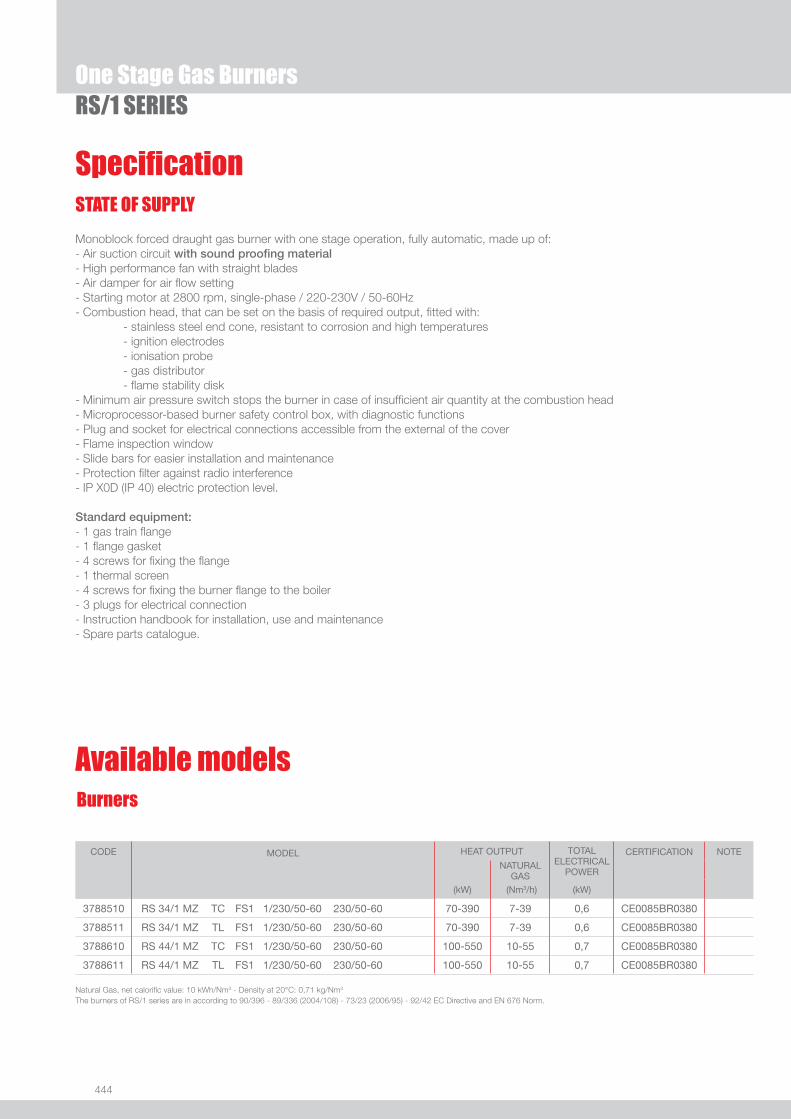
444
One Stage Gas BurnersRS/1 SERIES
Specifi cationSTATE OF SUPPLY
Monoblock forced draught gas burner with one stage operation, fully automatic, made up of:- Air suction circuit with sound proofi ng material- High performance fan with straight blades- Air damper for air fl ow setting- Starting motor at 2800 rpm, single-phase / 220-230V / 50-60Hz- Combustion head, that can be set on the basis of required output, fi tted with: - stainless steel end cone, resistant to corrosion and high temperatures - ignition electrodes - ionisation probe - gas distributor - fl ame stability disk- Minimum air pressure switch stops the burner in case of insuffi cient air quantity at the combustion head- Microprocessor-based burner safety control box, with diagnostic functions- Plug and socket for electrical connections accessible from the external of the cover- Flame inspection window- Slide bars for easier installation and maintenance- Protection fi lter against radio interference- IP X0D (IP 40) electric protection level.
Standard equipment:- 1 gas train fl ange - 1 fl ange gasket- 4 screws for fi xing the fl ange- 1 thermal screen- 4 screws for fi xing the burner fl ange to the boiler- 3 plugs for electrical connection- Instruction handbook for installation, use and maintenance- Spare parts catalogue.
CODE MODEL HEAT OUTPUT TOTAL ELECTRICAL
POWER
CERTIFICATION NOTE
NATURAL GAS
(kW) (Nm3/h) (kW)
3788510 RS 34/1 MZ TC FS1 1/230/50-60 230/50-60 70-390 7-39 0,6 CE0085BR0380
3788511 RS 34/1 MZ TL FS1 1/230/50-60 230/50-60 70-390 7-39 0,6 CE0085BR0380
3788610 RS 44/1 MZ TC FS1 1/230/50-60 230/50-60 100-550 10-55 0,7 CE0085BR0380
3788611 RS 44/1 MZ TL FS1 1/230/50-60 230/50-60 100-550 10-55 0,7 CE0085BR0380
Natural Gas, net calorifi c value: 10 kWh/Nm3 - Density at 20°C: 0,71 kg/Nm3
The burners of RS/1 series are in according to 90/396 - 89/336 (2004/108) - 73/23 (2006/95) - 92/42 EC Directive and EN 676 Norm.
Burners
Available models

445
GAS
One Stage Gas BurnersRS/1 SERIES
Available modelsGas Trains
* Gas trains are 230V/50Hz - 220V/60Hz electrical supply.** Conforming to EN676 Standard the one stage gas train can be used on RS 34/1 - 44/1 up to a capacity of 350 kW.(1) Gas Train with 6-pin plug to install for connection to the burner. (2) Gas Train with 6-pin plug installed for connection to the burner.(3) Gas Train S52 type for application with high combustion head pressure drop. (4) Seal control accessory.(5) Seal control incorporated.To select the gas train please refer to the technical data leafl et and/or instruction manual.
GAS TRAIN GAS TRAIN NATURAL GAS LPG NOTE
CODE* MODEL** BURNER ADAPTER BURNER ADAPTER
(type) (code) (type) (code)
MU
LTIB
LOC
GA
S T
RA
INS
3970500 MBD 405RS 34/1 MZ 3000824 -- --
(1) (4)RS 44/1 MZ 3000824 RS 44/1 MZ 3000824
39705533970229
MBD 407RS 34/1 MZ 3000824 RS 34/1 MZ 3000824 (1) (4)
(2) (4)RS 44/1 MZ 3000824 RS 44/1 MZ 3000824
3970599 MBD 407-- -- RS 34/1 MZ 3000824
(1) (3) (4)-- -- RS 44/1 MZ 3000824
3970046 MBZRDLE 407RS 34/1 MZ 3000824 RS 34/1 MZ 3000824
(1) (4)RS 44/1 MZ 3000824 RS 44/1 MZ 3000824
39705543970230
MBD 410RS 34/1 MZ 3000824 RS 34/1 MZ 3000824 (1) (4)
(2) (4)RS 44/1 MZ 3000824 RS 44/1 MZ 3000824
3970600 MBD 410-- -- RS 34/1 MZ 3000824
(1) (3) (4)-- -- RS 44/1 MZ 3000824
3970079 MBZRDLE 410RS 34/1 MZ 3000824 RS 34/1 MZ 3000824
(1) (4)RS 44/1 MZ 3000824 RS 44/1 MZ 3000824
39701443970231
MBD 412RS 34/1 MZ -- RS 34/1 MZ -- (1) (4)
(2) (4)RS 44/1 MZ -- RS 44/1 MZ --
3970197 MBD 412 CTRS 34/1 MZ -- RS 34/1 MZ --
(1) (5)RS 44/1 MZ -- RS 44/1 MZ --
3970152 MBZRDLE 412RS 34/1 MZ -- RS 34/1 MZ --
(1) (4)RS 44/1 MZ -- RS 44/1 MZ --
39701803970232
MBD 415RS 34/1 MZ -- RS 34/1 MZ -- (1) (4)
(2) (4)RS 44/1 MZ -- RS 44/1 MZ --
3970250 MBD 415 CT-- -- -- --
(1) (3) (5)-- -- RS 44/1 MZ --
3970198 MBD 415 CTRS 34/1 MZ -- RS 34/1 MZ --
(1) (5)RS 44/1 MZ -- RS 44/1 MZ --
3970253 MBD 415 CT-- -- -- --
(1) (3) (5)-- -- RS 44/1 MZ --
3970183 MBZRDLE 415RS 34/1 MZ -- RS 34/1 MZ --
(1) (4)RS 44/1 MZ -- RS 44/1 MZ --
39701813970233
MBD 420RS 34/1 MZ 3000822 -- -- (1) (4)
(2) (4)RS 44/1 MZ 3000822 -- --
39701823970234
MBD 420 CTRS 34/1 MZ 3000822 -- -- (1) (5)
(2) (5)RS 44/1 MZ 3000822 -- --
3970184 MBZRDLE 420RS 34/1 MZ 3000822 -- --
(1) (4)RS 44/1 MZ 3000822 -- --
3970185 MBZRDLE 420 CTRS 34/1 MZ 3000822 -- --
(1) (5)RS 44/1 MZ 3000822 -- --
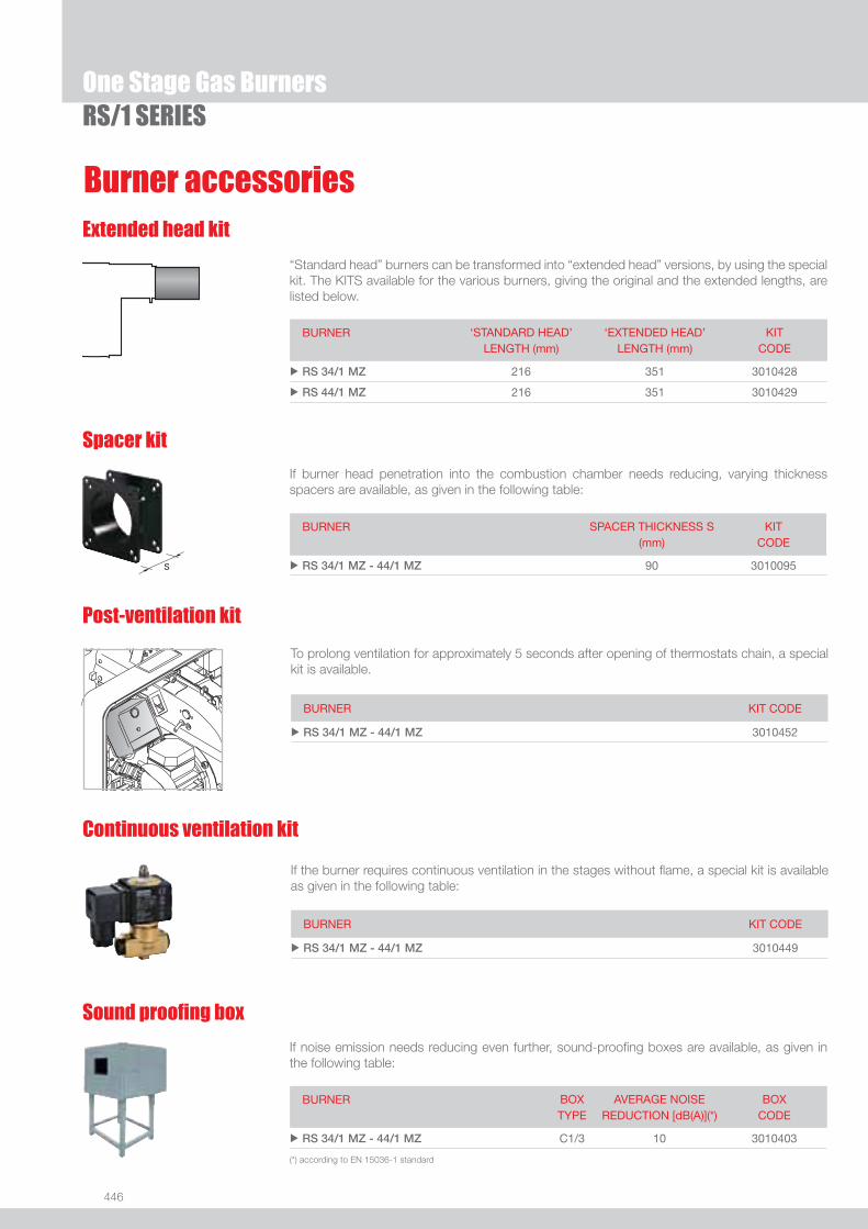
446
One Stage Gas BurnersRS/1 SERIES
Burner accessories
Spacer kit
If burner head penetration into the combustion chamber needs reducing, varying thickness spacers are available, as given in the following table:
BURNER SPACER THICKNESS S (mm)
KIT CODE
u RS 34/1 MZ - 44/1 MZ 90 3010095
Continuous ventilation kit
If the burner requires continuous ventilation in the stages without fl ame, a special kit is available as given in the following table:
BURNER KIT CODE
u RS 34/1 MZ - 44/1 MZ 3010449
Extended head kit
“Standard head” burners can be transformed into “extended head” versions, by using the special kit. The KITS available for the various burners, giving the original and the extended lengths, are listed below.
BURNER ‘STANDARD HEAD’ LENGTH (mm)
‘EXTENDED HEAD’ LENGTH (mm)
KIT CODE
u RS 34/1 MZ 216 351 3010428
u RS 44/1 MZ 216 351 3010429
Sound proofi ng box
If noise emission needs reducing even further, sound-proofi ng boxes are available, as given in the following table:
BURNER BOX TYPE
AVERAGE NOISE REDUCTION [dB(A)](*)
BOX CODE
u RS 34/1 MZ - 44/1 MZ C1/3 10 3010403
(*) according to EN 15036-1 standard
Post-ventilation kit
To prolong ventilation for approximately 5 seconds after opening of thermostats chain, a special kit is available.
BURNER KIT CODE
u RS 34/1 MZ - 44/1 MZ 3010452
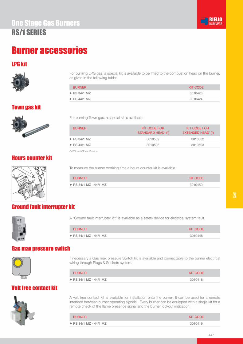
447
GAS
Burner accessories
One Stage Gas BurnersRS/1 SERIES
LPG kit
Hours counter kit
To measure the burner working time a hours counter kit is available.
BURNER KIT CODE
u RS 34/1 MZ - 44/1 MZ 3010450
Gas max pressure switch
If necessary a Gas max pressure Switch kit is available and connectable to the burner electrical wiring through Plugs & Sockets system.
BURNER KIT CODE
u RS 34/1 MZ - 44/1 MZ 3010418
�� ��
��
�
����
����
��
��
���
Ground fault interrupter kit
A “Ground fault interrupter kit” is available as a safety device for electrical system fault.
BURNER KIT CODE
u RS 34/1 MZ - 44/1 MZ 3010448
For burning LPG gas, a special kit is available to be fi tted to the combustion head on the burner, as given in the following table:
BURNER KIT CODE
u RS 34/1 MZ 3010423
u RS 44/1 MZ 3010424
Town gas kit
For burning Town gas, a special kit is available:
BURNER KIT CODE FOR‘STANDARD HEAD’ (*)
KIT CODE FOR‘EXTENDED HEAD’ (*)
u RS 34/1 MZ 3010502 3010502
u RS 44/1 MZ 3010503 3010503
(*) Without CE certifi cation
Volt free contact kit
A volt free contact kit is available for installation onto the burner. It can be used for a remote interface between burner operating signals. Every burner can be equipped with a single kit for a remote check of the fl ame presence signal and the burner lockout indication.
BURNER KIT CODE
u RS 34/1 MZ - 44/1 MZ 3010419

448
One Stage Gas Burners
PC interface kitTo connect the control box to a personal computer for the transmission of operation, fault signals and detailed service information, an interface adapter with PC software are available.
BURNER KIT CODE
u RS 34/1 MZ - 44/1 MZ 3002719
Seal control kit
To test the valve seals on the gas train, a special “seal control kit” is available. The valve seal control device is compulsory (EN 676) on gas trains to burners with a maximum output over 1200 kW. The sealing control is type VPS 504.
GAS TRAIN KIT CODE
uMBD 405 - MBD 407 - MBZRDLE 407 - MBD 410 - MBZRDLE 410 MBD 412 - MBZRDLE 412 - MBD 415 - CB 40/1
3010123
u MBZRDLE 415 - CB 40/2 - MBZRDLE 420 - CB 50/2 3010125
Adapters
When the diameter of the gas train is different from the set diameter of the burners, an adapter must be fi tted between the gas train and the burner. The following table lists the adapters for various burners.
BURNER GAS TRAIN DIMENSIONS ADAPTER CODE
u RS 34/1 MZ
MBD 405 - 407 - 410 1” 1/23/4” 3000824
MBZRDLE 407 - 410 1” 1/23/4” 3000824
MBD 420 - 420 CT 1” 1/22” 3000822
MBZRDLE 420 - 420 CT 1” 1/22” 3000822
u RS 44/1 MZ
MBD 407 - 410 1” 1/23/4” 3000824
MBZRDLE 407 - 410 1” 1/23/4” 3000824
MBD 420 - 420 CT 1” 1/22” 3000822
MBZRDLE 420 - 420 CT 1” 1/22” 3000822
Gas train accessories
Burner accessories
RS/1 SERIES
This kit is available as an interface between the thermostatic controls and the burner, to be used in systems where the lengths of the thermostat connections is over 20 meters, or where the burner is installed in a room particularly subject to electromagnetic interference (signals emitted over 10 V/m).
BURNER KIT CODE
u RS 34/1 MZ - 44/1 MZ 3010386
Protection kit (electromagnetic interferences)
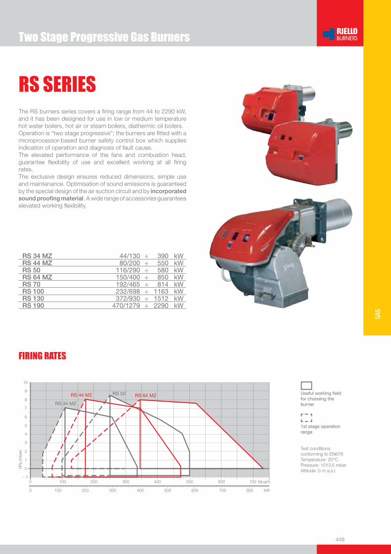
449
GAS
Two Stage Progressive Gas Burners
RS SERIESThe RS burners series covers a fi ring range from 44 to 2290 kW, and it has been designed for use in low or medium temperature hot water boilers, hot air or steam boilers, diathermic oil boilers.Operation is “two stage progressive”; the burners are fi tted with a microprocessor-based burner safety control box which supplies indication of operation and diagnosis of fault cause.The elevated performance of the fans and combustion head, guarantee fl exibility of use and excellent working at all fi ring rates.The exclusive design ensures reduced dimensions, simple use and maintenance. Optimisation of sound emissions is guaranteed by the special design of the air suction circuit and by incorporated sound proofi ng material. A wide range of accessories guarantees elevated working fl exibility.
RS 34 MZ 44/130 ÷ 390 kWRS 44 MZ 80/200 ÷ 550 kWRS 50 116/290 ÷ 580 kWRS 64 MZ 150/400 ÷ 850 kWRS 70 192/465 ÷ 814 kWRS 100 232/698 ÷ 1163 kWRS 130 372/930 ÷ 1512 kWRS 190 470/1279 ÷ 2290 kW
FIRING RATES
Useful working fi eldfor choosing theburner
1st stage operation range
Test conditionsconforming to EN676 Temperature: 20°CPressure: 1013,5 mbarAltitude: 0 m a.s.l.
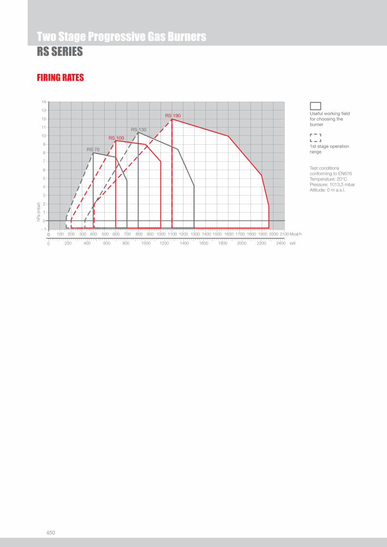
450
FIRING RATES
Two Stage Progressive Gas BurnersRS SERIES
Useful working fi eldfor choosing theburner
1st stage operation range
Test conditionsconforming to EN676 Temperature: 20°CPressure: 1013,5 mbarAltitude: 0 m a.s.l.

451
GAS
Overall dimensions (mm)BURNER
Two Stage Progressive Gas BurnersRS SERIES
MODEL A D E F G - G(1) H I L M N O S u RS 34 MZ 442 422 508 138 216 - 351 140 305 177 1”1/2 84 780 -
u RS 44 MZ 442 422 508 138 216 - 351 152 305 177 1”1/2 84 780 -
u RS 50 476 474 580 164 216 - 351 152 352 168 1”1/2 108 810 367
RS 34 MZ - 44 MZ RS 50
(1) dimension with extended head
RS 64 MZ RS 70 - 100 - 130 - 190
MODEL A B C D E F G - G(1) H I L M N O - O(1)u RS 64 MZ 533 300 - 490 640 222 250 - 385 179 352 221 2” 134 810 - -
u RS 70 511 296 215 555 840 214 250 - 385 179 430 221 2” 134 1161 - 1296
u RS 100 527 312 215 555 840 214 250 - 385 179 430 221 2” 134 1161 - 1296
u RS 130 553 338 215 555 840 214 280 - 415 189 430 221 2” 134 1161 - 1296
u RS 190 681 366 315 555 872 246 372 - 530 222 430 221 2” 150 1328 - -
(1) dimension with extended head
�
�
�
�����
�
�
��
�
�
�
�
�
�����
�
�
�
�
�
�
�
��������
�
�
� �
�
�
���������
�
�
�����
�
�
�
�
�
�
�
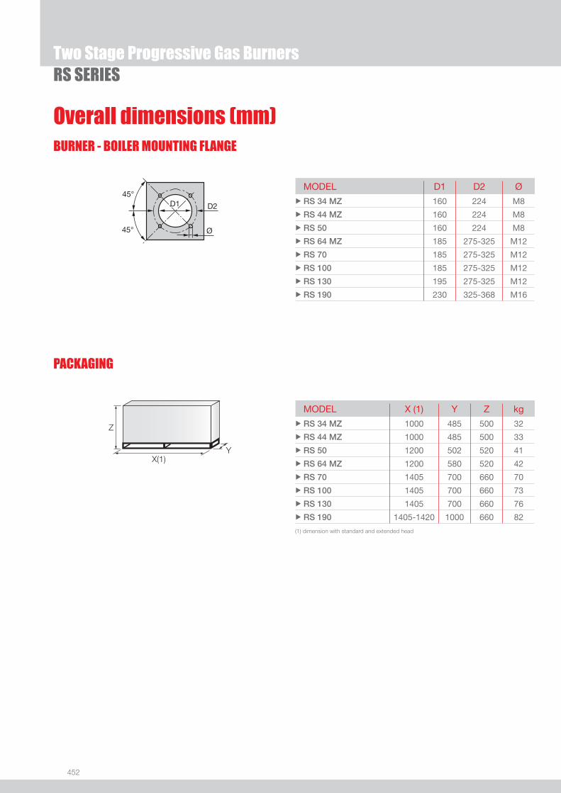
452
Overall dimensions (mm)BURNER - BOILER MOUNTING FLANGE
PACKAGING
Z
X(1)Y
Two Stage Progressive Gas BurnersRS SERIES
MODEL D1 D2 Ø u RS 34 MZ 160 224 M8
u RS 44 MZ 160 224 M8
u RS 50 160 224 M8
u RS 64 MZ 185 275-325 M12
u RS 70 185 275-325 M12
u RS 100 185 275-325 M12
u RS 130 195 275-325 M12
u RS 190 230 325-368 M16
MODEL X (1) Y Z kgu RS 34 MZ 1000 485 500 32
u RS 44 MZ 1000 485 500 33
u RS 50 1200 502 520 41
u RS 64 MZ 1200 580 520 42
u RS 70 1405 700 660 70
u RS 100 1405 700 660 73
u RS 130 1405 700 660 76
u RS 190 1405-1420 1000 660 82
(1) dimension with standard and extended head

453
GAS
DESIGNATION OF SERIES
Specifi cation
Two Stage Progressive Gas BurnersRS SERIES
BASIC DESIGNATION
EXTENDED DESIGNATION
R S 130 TC FS1 3/230-400/50 230/50-60
Series: R Fuel: S Natural Gas SP LPG L Light oil LS Light oil/Methane N Heavy oil
Size Setting: /1 Single stage ... Two stage /M Modulating Emission: ... Class 1 EN267 - EN676 MZ Class 2 EN267 - EN676 BLU Class 3 EN267 - EN676
MX Class 1 EN267
Class 3 EN676 Head length: TC standard head TL extended head Flame control system: FS1 Standard (1 stop every 24 h) FS2 Continuous working (1 stop every 72 h) Electrical supply to the system: 1/230/50 1/230V/50Hz 1/220-230/50-60 1/220-230V/50-60Hz 3/230/50 3/230V/50Hz 3/400/50 3N/400V/50Hz 3/230-400/50 3/230V/50Hz - 3N/400V/50Hz 3/220/60 3/220V/60Hz 3/380/60 3N/380V/60Hz 3/220-380/60 3/220V/60Hz - 3N/380V/60Hz
3/220-400/50-60 3/220-230V/50-60Hz
3/380-400V/50-60Hz
Auxiliary voltage: 230/50-60 230V/50-60Hz 220-230/50-60 220-230V/50-60Hz 110/50-60 110V/50-60Hz
ID: Differential switch
454
Two Stage Progressive Gas BurnersRS SERIES
STATE OF SUPPLY
Specifi cation
RS 34 MZ - 44 MZ modelsMonoblock forced draught gas burner with two stage operation, fully automatic, made up of:- Air suction circuit with sound proofi ng material- High performance fan with straight blades - Air damper for air fl ow setting and butterfl y valve for regulating fuel output on 1st and 2nd stage controlled by a servomotor with
variable cam- Starting motor at 2800 rpm, single-phase / 220-230V / 50-60Hz or three-phase / 380-400V / 50-60Hz- Combustion head, that can be set on the basis of required output, fi tted with: - stainless steel end cone, resistant to corrosion and high temperatures - ignition electrodes - ionisation probe - gas distributor - fl ame stability disk- Exclusive patented HCS (Housing Cooling System) with high thermal insulation and air circulation with continuous air volume refresh
for an active cooling system and avoid heat transfer to the electrical component housing- Minimum air pressure switch stops the burner in case of insuffi cient air quantity at the combustion head- Microprocessor-based burner safety control box, with diagnostic functions- Plug and socket for electrical connections accessible from the external of the cover- Burner on/off selection switch- 1st - 2nd stage manual switch- Flame inspection window- Slide bars for easier installation and maintenance- Protection fi lter against radio interference- IP X0D (IP 40) electric protection level.
Standard equipment- 1 gas train fl ange - 1 fl ange gasket- 4 screws for fi xing the fl ange- 1 thermal screen- 4 screws for fi xing the burner fl ange to the boiler- 3 plugs for electrical connection (RS 34 - 44 MZ single-phase)- 4 plugs for electrical connection (RS 44 MZ three-phase)- Instruction handbook for installation, use and maintenance- Spare parts catalogue.

455
GAS
Two Stage Progressive Gas BurnersRS SERIES
STATE OF SUPPLY
Specifi cation
RS 50 - 64 MZ - 70 - 100 - 130 - 190 modelsMonoblock forced draught gas burner with two stage operation, fully automatic, made up of:- Air suction circuit lined with sound-proofi ng material- Fan with reverse curve blades (RS 50 - 70 - 100 - 130 models) or straight blades (RS 64 MZ - 190 models)- Air damper for air fl ow setting and butterfl y valve for regulating fuel output on 1st and 2nd stage controlled by a servomotor with
variable cam- Starting motor at 2800 rpm, three-phase 400V with neutral, 50Hz- Combustion head, that can be set on the basis of required output, fi tted with: - stainless steel end cone, resistant to corrosion and high temperatures - ignition electrodes - ionisation probe - gas distributor - fl ame stability disk- Minimum air pressure switch stops the burner in case of insuffi cient air quantity at the combustion head- Microprocessor-based burner safety control box, with diagnostic functions- Plug and socket for electrical connections (RS 50 models)- Burner on/off selection switch- 1st - 2nd stage manual switch- Flame inspection window- Slide bars for easier installation and maintenance- Protection fi lter against radio interference- IP 44 electric protection level.
Standard equipment- 1 gas train fl ange - 1 fl ange gasket- 4 screws for fi xing the fl ange- 1 thermal screen- 4 screws for fi xing the burner fl ange to the boiler- Wiring loom fi ttings for the electrical connection (RS 50)- 2 slide bar extensions (for extended head models and RS 190 model)- Instruction handbook for installation, use and maintenance- Spare parts catalogue.

456
Burners
Available models
Two Stage Progressive Gas BurnersRS SERIES
CODE MODEL
HEAT OUTPUT TOTAL ELECTRICAL
POWER
CERTIFICATION NOTE
NATURAL GAS
(kW) (Nm3/h) (kW)
3789010 RS 34 MZ TC FS1 1/230/50-60 230/50-60 44/130-390 4,5/13-39 0,6 CE 0085BR0381 (1)
3789011 RS 34 MZ TL FS1 1/230/50-60 230/50-60 44/130-390 4,5/13-39 0,6 CE 0085BR0381 (1)
20008266 RSP 34 TC FS1 1/230/50-60 230/50-60 44/130-390 4,5/13-39 0,6 CE 0085BR0381 (1)
3789110 RS 44 MZ TC FS1 1/230/50-60 230/50-60 80/200-550 8/20-55 0,7 CE 0085BR0381 (1)
3789111 RS 44 MZ TL FS1 1/230/50-60 230/50-60 80/200-550 8/20-55 0,7 CE 0085BR0381 (1)
3789140 RS 44 MZ TC FS1 3/230-400/50-60 230/50-60 80/200-550 8/20-55 0,8 CE 0085BR0381 (1)
3789141 RS 44 MZ TL FS1 3/230-400/50-60 230/50-60 80/200-550 8/20-55 0,8 CE 0085BR0381 (1)
3784702 RS 50 TC FS1 3/230-400/50 230/50-60 116/290-581 12/29-58 0,75 CE 0085AP0735 (1)
3784703 RS 50 TL FS1 3/230-400/50 230/50-60 116/290-581 12/29-58 0,75 CE 0085AP0735 (1)
3784720 RS 50 TC FS1 3/230-460/60 230/50-60 116/290-581 12/29-58 0,75 - (1)
3784721 RS 50 TL FS1 3/230-460/60 230/50-60 116/290-581 12/29-58 0,75 - (1)
3789310 RS 64 MZ TC FS1 3/230-400/50 230/50-60 150/400-850 15/40-85 1,5 in progress (1)
3789311 RS 64 MZ TL FS1 3/230-400/50 230/50-60 150/400-850 15/40-85 1,5 in progress (1)
3785102 RS 70 TC FS1 3/230-400/50 230/50-60 192/465-814 19/46,5-81 1,4 CE 0085AP0944 (2)
3785103 RS 70 TL FS1 3/230-400/50 230/50-60 192/465-814 19/46,5-81 1,4 CE 0085AP0944 (2)
3785104 RS 70 TC FS1 3/230-400/50 230/50-60 192/465-814 19/46,5-81 1,4 CE 0085AP0944 (1) (2)
3785105 RS 70 TL FS1 3/230-400/50 230/50-60 192/465-814 19/46,5-81 1,4 CE 0085AP0944 (1) (2)
3785120 RS 70 TC FS1 3/230-460/60 230/50-60 192/465-814 19/46,5-81 1,4 - (2)
3785121 RS 70 TL FS1 3/230-460/60 230/50-60 192/465-814 19/46,5-81 1,4 - (2)
3785302 RS 100 TC FS1 3/230-400/50 230/50-60 232/698-1163 23/70-116 1,8 CE 0085AP0945 (2)
3785303 RS 100 TL FS1 3/230-400/50 230/50-60 232/698-1163 23/70-116 1,8 CE 0085AP0945 (2)
3785304 RS 100 TC FS1 3/230-400/50 230/50-60 232/698-1163 23/70-116 1,8 CE 0085AP0945 (1) (2)
3785305 RS 100 TL FS1 3/230-400/50 230/50-60 232/698-1163 23/70-116 1,8 CE 0085AP0945 (1) (2)
3785320 RS 100 TC FS1 3/230-460/60 230/50-60 232/698-1163 23/70-116 1,8 - (2)
3785321 RS 100 TL FS1 3/230-460/60 230/50-60 232/698-1163 23/70-116 1,8 - (2)
3785502 RS 130 TC FS1 3/230-400/50 230/50-60 372/930-1512 37/93-151 2,6 CE 0085AP0946 (2)
3785503 RS 130 TL FS1 3/230-400/50 230/50-60 372/930-1512 37/93-151 2,6 CE 0085AP0946 (2)
3785504 RS 130 TC FS1 3/230-400/50 230/50-60 372/930-1512 37/93-151 2,6 CE 0085AP0946 (1) (2)
3785505 RS 130 TL FS1 3/230-400/50 230/50-60 372/930-1512 37/93-151 2,6 CE 0085AP0946 (1) (2)
3785520 RS 130 TC FS1 3/230-460/60 230/50-60 372/930-1512 37/93-151 2,6 - (2)
3785521 RS 130 TL FS1 3/230-460/60 230/50-60 372/930-1512 37/93-151 2,6 - (2)
3785813 RS 190 TC FS1 3/400/50 230/50-60 470/1279-2290 47/128-229 5,5 CE 0085AT0042 (2)
on demand RS 190 TC FS1 3/230/50 230/50-60 470/1279-2290 47/128-229 5,5 CE 0085AT0042 (2)
3785814 RS 190 TC FS1 3/400/50 230/50-60 470/1279-2290 47/128-229 5,5 CE 0085AT0042 (1) (2)
on demand RS 190 TC FS1 3/230/50 230/50-60 470/1279-2290 47/128-229 5,5 CE 0085AT0042 (1) (2)
3785820 RS 190 TC FS1 3/460/60 230/50-60 470/1279-2290 47/128-229 5,5 - (2)
on demand RS 190 TC FS1 3/220/60 220/60 470/1279-2290 47/128-229 5,5 - (2)
Natural Gas, net calorifi c value: 10 kWh/Nm3 - Density at 20°C: 0,71 kg/Nm3
The burners of RS series are in according to 90/396 - 89/336 (2004/108) - 73/23 (2006/95) - 92/42 EC Directive and EN 676 Norm.(1) With plug and socket. (2) With terminal board.
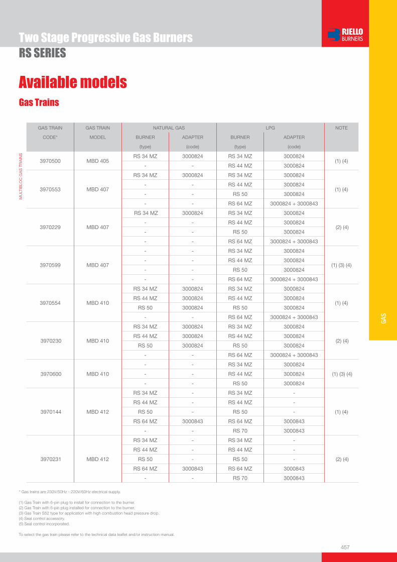
457
GAS
Two Stage Progressive Gas BurnersRS SERIES
Gas Trains
Available models
GAS TRAIN GAS TRAIN NATURAL GAS LPG NOTE
CODE* MODEL BURNER ADAPTER BURNER ADAPTER
(type) (code) (type) (code)
MU
LTIB
LOC
GA
S T
RA
INS
3970500 MBD 405RS 34 MZ 3000824 RS 34 MZ 3000824
(1) (4) - - RS 44 MZ 3000824
3970553
MBD 407
RS 34 MZ 3000824 RS 34 MZ 3000824
(1) (4)
- - RS 44 MZ 3000824
- - RS 50 3000824
- - RS 64 MZ 3000824 + 3000843
3970229 MBD 407
RS 34 MZ 3000824 RS 34 MZ 3000824
(2) (4)
- - RS 44 MZ 3000824
- - RS 50 3000824
- - RS 64 MZ 3000824 + 3000843
3970599
MBD 407
- - RS 34 MZ 3000824
(1) (3) (4)
- - RS 44 MZ 3000824
- - RS 50 3000824
- - RS 64 MZ 3000824 + 3000843
3970554
MBD 410
RS 34 MZ 3000824 RS 34 MZ 3000824
(1) (4)
RS 44 MZ 3000824 RS 44 MZ 3000824
RS 50 3000824 RS 50 3000824
- - RS 64 MZ 3000824 + 3000843
3970230 MBD 410
RS 34 MZ 3000824 RS 34 MZ 3000824
(2) (4) RS 44 MZ 3000824 RS 44 MZ 3000824
RS 50 3000824 RS 50 3000824
- - RS 64 MZ 3000824 + 3000843
3970600 MBD 410
- - RS 34 MZ 3000824
(1) (3) (4) - - RS 44 MZ 3000824
- - RS 50 3000824
3970144 MBD 412
RS 34 MZ - RS 34 MZ -
(1) (4)
RS 44 MZ - RS 44 MZ -
RS 50 - RS 50 -
RS 64 MZ 3000843 RS 64 MZ 3000843
- - RS 70 3000843
3970231 MBD 412
RS 34 MZ - RS 34 MZ -
(2) (4)
RS 44 MZ - RS 44 MZ -
RS 50 - RS 50 -
RS 64 MZ 3000843 RS 64 MZ 3000843
- - RS 70 3000843
* Gas trains are 230V/50Hz - 220V/60Hz electrical supply.
(1) Gas Train with 6-pin plug to install for connection to the burner. (2) Gas Train with 6-pin plug installed for connection to the burner.(3) Gas Train S52 type for application with high combustion head pressure drop. (4) Seal control accessory.(5) Seal control incorporated.
To select the gas train please refer to the technical data leafl et and/or instruction manual.

458
Available modelsGas Trains
Two Stage Progressive Gas BurnersRS SERIES
GAS TRAIN GAS TRAIN NATURAL GAS LPG NOTE
CODE* MODEL BURNER ADAPTER BURNER ADAPTER
(type) (code) (type) (code)
MU
LTIB
LOC
GA
S T
RA
INS
3970197
MBD 412 CT
RS 34 MZ - RS 34 MZ -
(1) (5)
RS 44 MZ - RS 44 MZ -
RS 50 - RS 50 -
RS 64 MZ 3000843 RS 64 MZ 3000843
- - RS 70 3000843
3970180
MBD 415
RS 34 MZ - RS 34 MZ -
(1) (4)
RS 44 MZ - RS 44 MZ -
RS 50 - RS 50 -
RS 64 MZ 3000843 RS 64 MZ 3000843
RS 70 3000843 RS 70 3000843
RS 100 3000843 RS 100 3000843
RS 130 3000843 RS 130 3000843
- - RS 190 3000843
3970232
MBD 415
RS 34 MZ - RS 34 MZ -
(2) (4)
RS 44 MZ - RS 44 MZ -
RS 50 - RS 50 -
RS 64 MZ 3000843 RS 64 MZ 3000843
RS 70 3000843 RS 70 3000843
RS 100 3000843 RS 100 3000843
RS 130 3000843 RS 130 3000843
- - RS 190 3000843
3970250 MBD 415 RS 50 - RS 50 - (1) (3) (4)
3970198
MBD 415 CT
RS 34 MZ - RS 34 MZ -
(1) (5)
RS 44 MZ - RS 44 MZ -
RS 50 - RS 50 -
RS 64 MZ 3000843 RS 64 MZ 3000843
RS 70 3000843 RS 70 3000843
RS 100 3000843 RS 100 3000843
RS 130 3000843 RS 130 3000843
- - RS 190 3000843
3970253 MBD 415 CT RS 50 - RS 50 - (1) (3) (5)
* Gas trains are 230V/50Hz - 220V/60Hz electrical supply.
(1) Gas Train with 6-pin plug to install for connection to the burner. (2) Gas Train with 6-pin plug installed for connection to the burner.(3) Gas Train S52 type for application with high combustion head pressure drop. (4) Seal control accessory.(5) Seal control incorporated.
To select the gas train please refer to the technical data leafl et and/or instruction manual.
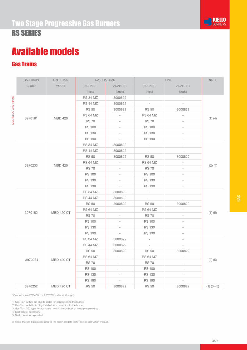
459
GAS
Two Stage Progressive Gas BurnersRS SERIES
Gas Trains
Available models
GAS TRAIN GAS TRAIN NATURAL GAS LPG NOTE
CODE* MODEL BURNER ADAPTER BURNER ADAPTER
(type) (code) (type) (code)
MU
LTIB
LOC
GA
S T
RA
INS
3970181
MBD 420
RS 34 MZ 3000822 - -
(1) (4)
RS 44 MZ 3000822 - -
RS 50 3000822 RS 50 3000822
RS 64 MZ - RS 64 MZ -
RS 70 - RS 70 -
RS 100 - RS 100 -
RS 130 - RS 130 -
RS 190 - RS 190 -
3970233
MBD 420
RS 34 MZ 3000822 - -
(2) (4)
RS 44 MZ 3000822 - -
RS 50 3000822 RS 50 3000822
RS 64 MZ - RS 64 MZ -
RS 70 - RS 70 -
RS 100 - RS 100 -
RS 130 - RS 130 -
RS 190 - RS 190 -
3970182
MBD 420 CT
RS 34 MZ 3000822 - -
(1) (5)
RS 44 MZ 3000822 - -
RS 50 3000822 RS 50 3000822
RS 64 MZ - RS 64 MZ -
RS 70 - RS 70 -
RS 100 - RS 100 -
RS 130 - RS 130 -
RS 190 - RS 190 -
3970234
MBD 420 CT
RS 34 MZ 3000822 - -
(2) (5)
RS 44 MZ 3000822 - -
RS 50 3000822 RS 50 3000822
RS 64 MZ - RS 64 MZ -
RS 70 - RS 70 -
RS 100 - RS 100 -
RS 130 - RS 130 -
RS 190 - RS 190 -
3970252 MBD 420 CT RS 50 3000822 RS 50 3000822 (1) (3) (5)
* Gas trains are 230V/50Hz - 220V/60Hz electrical supply.
(1) Gas Train with 6-pin plug to install for connection to the burner. (2) Gas Train with 6-pin plug installed for connection to the burner.(3) Gas Train S52 type for application with high combustion head pressure drop. (4) Seal control accessory.(5) Seal control incorporated.
To select the gas train please refer to the technical data leafl et and/or instruction manual.
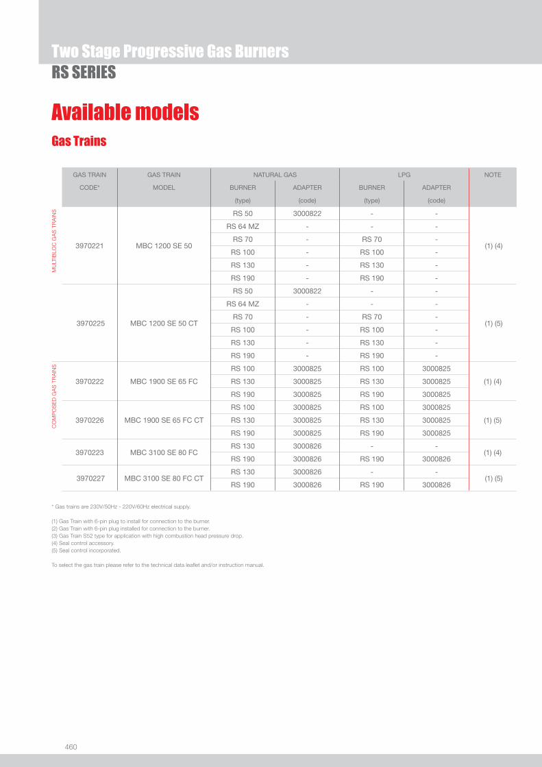
460
Available modelsGas Trains
Two Stage Progressive Gas BurnersRS SERIES
GAS TRAIN GAS TRAIN NATURAL GAS LPG NOTE
CODE* MODEL BURNER ADAPTER BURNER ADAPTER
(type) (code) (type) (code)
MU
LTIB
LOC
GA
S T
RA
INS
3970221
MBC 1200 SE 50
RS 50 3000822 - -
(1) (4)
RS 64 MZ - - -
RS 70 - RS 70 -
RS 100 - RS 100 -
RS 130 - RS 130 -
RS 190 - RS 190 -
3970225
MBC 1200 SE 50 CT
RS 50 3000822 - -
(1) (5)
RS 64 MZ - - -
RS 70 - RS 70 -
RS 100 - RS 100 -
RS 130 - RS 130 -
RS 190 - RS 190 -
CO
MP
OS
ED
GA
S T
RA
INS
3970222 MBC 1900 SE 65 FC
RS 100 3000825 RS 100 3000825
(1) (4) RS 130 3000825 RS 130 3000825
RS 190 3000825 RS 190 3000825
3970226
MBC 1900 SE 65 FC CT
RS 100 3000825 RS 100 3000825 (1) (5)
RS 130 3000825 RS 130 3000825
RS 190 3000825 RS 190 3000825
3970223 MBC 3100 SE 80 FCRS 130 3000826 - -
(1) (4) RS 190 3000826 RS 190 3000826
3970227 MBC 3100 SE 80 FC CTRS 130 3000826 - -
(1) (5) RS 190 3000826 RS 190 3000826
* Gas trains are 230V/50Hz - 220V/60Hz electrical supply.
(1) Gas Train with 6-pin plug to install for connection to the burner. (2) Gas Train with 6-pin plug installed for connection to the burner.(3) Gas Train S52 type for application with high combustion head pressure drop. (4) Seal control accessory.(5) Seal control incorporated.
To select the gas train please refer to the technical data leafl et and/or instruction manual.

461
GAS
Burner accessories
Two Stage Progressive Gas BurnersRS SERIES
Spacer kit
If burner head penetration into the combustion chamber needs reducing, varying thickness spacers are available, as given in the following table:
BURNER SPACER THICKNESS S (mm)
KIT CODE
u RS 34 MZ - 44 MZ - 50 90 3010095
u RS 64 MZ - 70 - 100 - 130 135 3010129
u RS 190 102 3000722
Continuous ventilation kit
If the burner requires continuous ventilation in the stages without fl ame, a special kit is available as given in the following table:
BURNER KIT CODE
u RS 34 MZ - 44 MZ 3010449
u RS 50 - 70 - 100 - 130 - 190 3010094
Extended head kit
“Standard head” burners can be transformed into “extended head” versions, by using the special kit. The KITS available for the various burners, giving the original and the extended lengths, are listed below.
BURNER ‘STANDARD HEAD’ LENGTH (mm)
‘EXTENDED HEAD’ LENGTH (mm)
KIT CODE
u RS 34 MZ 216 351 3010428
u RS 44 MZ 216 351 3010429
u RS 50 216 351 3010078
u RS 64 MZ 250 385 3010427
u RS 70 250 385 3010117
u RS 100 250 385 3010118
u RS 130 280 415 3010119
u RS 190 372 530 3010443
Post-ventilation kit
To prolong ventilation after opening of thermostats chain, a special kit is available.
BURNER POST-VENTILATION TIME (s)
KIT CODE
u RS 34 MZ - 44 MZ 5 3010004
u RS 50 - 70 - 100 - 130 - 190 20 3010452
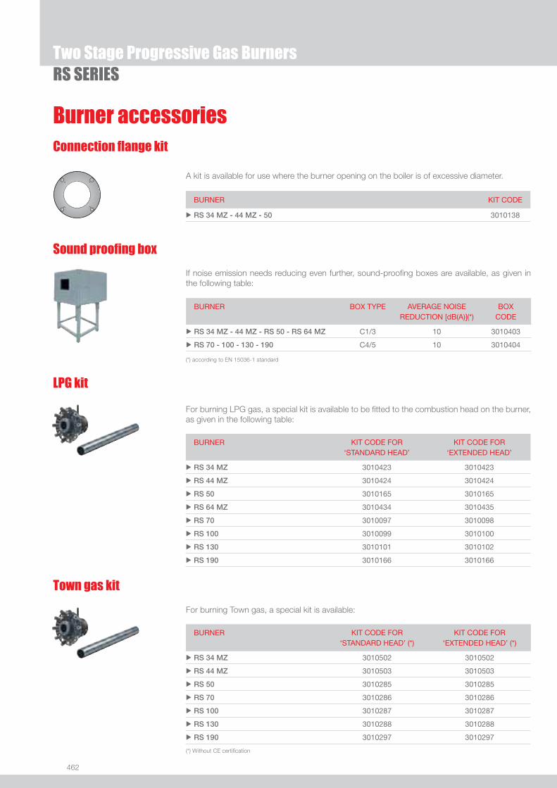
462
Two Stage Progressive Gas BurnersRS SERIES
Burner accessories
LPG kit
For burning LPG gas, a special kit is available to be fi tted to the combustion head on the burner, as given in the following table:
BURNER KIT CODE FOR‘STANDARD HEAD’
KIT CODE FOR‘EXTENDED HEAD’
u RS 34 MZ 3010423 3010423
u RS 44 MZ 3010424 3010424
u RS 50 3010165 3010165
u RS 64 MZ 3010434 3010435
u RS 70 3010097 3010098
u RS 100 3010099 3010100
u RS 130 3010101 3010102
u RS 190 3010166 3010166
Town gas kit
For burning Town gas, a special kit is available:
BURNER KIT CODE FOR‘STANDARD HEAD’ (*)
KIT CODE FOR‘EXTENDED HEAD’ (*)
u RS 34 MZ 3010502 3010502
u RS 44 MZ 3010503 3010503
u RS 50 3010285 3010285
u RS 70 3010286 3010286
u RS 100 3010287 3010287
u RS 130 3010288 3010288
u RS 190 3010297 3010297
(*) Without CE certifi cation
Connection fl ange kit
BURNER KIT CODE
u RS 34 MZ - 44 MZ - 50 3010138
A kit is available for use where the burner opening on the boiler is of excessive diameter.
Sound proofi ng box
If noise emission needs reducing even further, sound-proofi ng boxes are available, as given in the following table:
BURNER BOX TYPE AVERAGE NOISE REDUCTION [dB(A)](*)
BOX CODE
u RS 34 MZ - 44 MZ - RS 50 - RS 64 MZ C1/3 10 3010403
u RS 70 - 100 - 130 - 190 C4/5 10 3010404
(*) according to EN 15036-1 standard
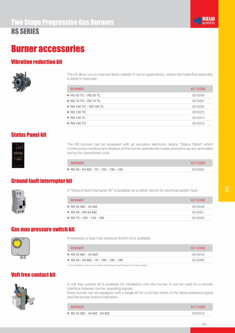
463
GAS
Burner accessories
Two Stage Progressive Gas BurnersRS SERIES
Vibration reduction kit
The kit allow you to improve fl ame stability in some applications, where the boiler/fl ue assembly is liable to resonate.
BURNER KIT CODE
u RS 50 TC - RS 50 TL 3010200
u RS 70 TC - RS 70 TL 3010201
u RS 100 TC - RS 100 TL 3010202
u RS 130 TC 3010373
u RS 130 TL 3010374
u RS 190 TC 3010375
Status Panel kit
The RS burners can be equipped with an exclusive electronic device “Status Panel” which continuously monitors and displays all the burner operational modes and picks up any anomalies during the operational cycle.
BURNER KIT CODE
u RS 50 - 64 MZ - 70 - 100 - 130 - 190 3010322
Ground fault interrupter kit
A “Ground fault interrupter kit” is available as a safety device for electrical system fault.
BURNER KIT CODE
u RS 34 MZ - 44 MZ 3010448
u RS 50 - RS 64 MZ 3010321
u RS 70 - 100 - 130 - 190 3010329
Volt free contact kit
A volt free contact kit is available for installation onto the burner. It can be used for a remote interface between burner operating signals. Every burner can be equipped with a single kit for a remote check of the fl ame presence signal and the burner lockout indication.
BURNER KIT CODE
u RS 34 MZ - 44 MZ - 64 MZ 3010419
Gas max pressure switch kit
If necessary a Gas max pressure Switch kit is available.
BURNER KIT CODE
u RS 34 MZ - 44 MZ* 3010418
u RS 50 - 64 MZ - 70 - 100 - 130 - 190 3010493
�� ��
��
�
����
����
��
��
���
* Connectable to the burner electrical wiring through Plugs & Sockets system

464
Two Stage Progressive Gas BurnersRS SERIES
Burner accessories
PC interface kit
To connect the control box to a personal computer for the transmission of operation, fault signals and detailed service information, an interface adapter with PC software are available.
BURNER KIT CODE
u RS 34 MZ - 44 MZ - 50 - 64 MZ - 70 - 100 - 130 - 190 3002719
Hours counter kit
To measure the burner working time a hours counter kit is available.
BURNER KIT CODE
u RS 34 MZ - 44 MZ 3010450
DN80 gas fl ange kit
To modify the standard 2” burner gas input connection in to DN80 connection, a specifi c gas fl ange is available.
BURNER KIT CODE
u RS 64 MZ - 70 - 100 - 130 - 190 3010439
This kit is available as an interface between the thermostatic controls and the burner, to be used in systems where the lengths of the thermostat connections is over 20 meters, or where the burner is installed in a room particularly subject to electromagnetic interference (signals emitted over 10 V/m).
BURNER KIT CODE
u RS 34 MZ - 44 MZ - 50 - 64 MZ - 70 - 100 - 130 3010386
Protection kit (electromagnetic interferences)
Included as standard on RS 190 model.
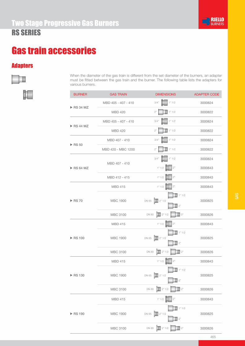
465
GAS
Two Stage Progressive Gas BurnersRS SERIES
Gas train accessories
Adapters
When the diameter of the gas train is different from the set diameter of the burners, an adapter must be fi tted between the gas train and the burner. The following table lists the adapters for various burners.
BURNER GAS TRAIN DIMENSIONS ADAPTER CODE
u RS 34 MZ MBD 405 - 407 - 410 1” 1/23/4” 3000824
MBD 420 1” 1/22” 3000822
u RS 44 MZMBD 405 - 407 - 410 1” 1/23/4” 3000824
MBD 420 1” 1/22” 3000822
u RS 50MBD 407 - 410 1” 1/23/4” 3000824
MBD 420 - MBC 1200 1” 1/22” 3000822
u RS 64 MZMBD 407 - 410
1” 1/23/4”
2”1” 1/2
3000824
3000843
MBD 412 - 415 2”1” 1/2 3000843
u RS 70
MBD 415 2”1” 1/2 3000843
MBC 1900 2” 1/2DN 65
1” 1/2
2”
3000825
MBC 3100 2” 1/2DN 80 2” 3000826
u RS 100
MBD 415 2”1” 1/2 3000843
MBC 1900 2” 1/2DN 65
1” 1/2
2”
3000825
MBC 3100 2” 1/2DN 80 2” 3000826
u RS 130
MBD 415 2”1” 1/2 3000843
MBC 1900 2” 1/2DN 65
1” 1/2
2”
3000825
MBC 3100 2” 1/2DN 80 2” 3000826
u RS 190
MBD 415 2”1” 1/2 3000843
MBC 1900 2” 1/2DN 65
1” 1/2
2”
3000825
MBC 3100 2” 1/2DN 80 2” 3000826
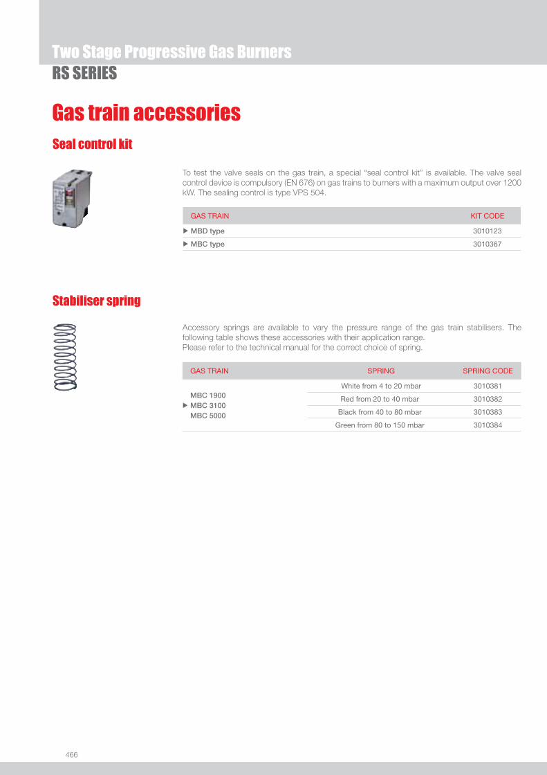
466
Gas train accessories
Two Stage Progressive Gas BurnersRS SERIES
Stabiliser spring
Accessory springs are available to vary the pressure range of the gas train stabilisers. The following table shows these accessories with their application range.Please refer to the technical manual for the correct choice of spring.
GAS TRAIN SPRING SPRING CODE
u
MBC 1900 MBC 3100 MBC 5000
White from 4 to 20 mbar 3010381
Red from 20 to 40 mbar 3010382
Black from 40 to 80 mbar 3010383
Green from 80 to 150 mbar 3010384
Seal control kit
To test the valve seals on the gas train, a special “seal control kit” is available. The valve seal control device is compulsory (EN 676) on gas trains to burners with a maximum output over 1200 kW. The sealing control is type VPS 504.
GAS TRAIN KIT CODE
u MBD type 3010123
u MBC type 3010367

467
GAS
RS/M SERIES
Modulating Gas Burners
The RS/M burners series covers a fi ring range from 44 to 2650 kW, and it has been designed for use in low or medium temperature hot water boilers, hot air or steam boilers, diathermic oil boilers.Operation can be “two stage progressive” or, alternatively, “modulating” with the installation of a PID logic regulator and respective probes.RS/M burners series guarantees high effi ciency levels in all the various applications, thus reducing fuel consumption and running costs.The exclusive design ensures reduced dimensions, simple use and maintenance. Optimisation of sound emissions is guaranteed by the special design of the air suction circuit and by incorporated sound proofi ng material.A wide range of accessories guarantees elevated working fl exibility.
RS 34/M MZ 44/130 ÷ 390 kWRS 44/M MZ 80/200 ÷ 550 kWRS 50/M MZ 80/285 ÷ 630 kWRS 64/M MZ 150/400 ÷ 850 kWRS 70/M 150/470 ÷ 930 kWRS 100/M 150/700 ÷ 1340 kWRS 130/M MZ 240/920 ÷ 1600 kWRS 190/M 470/1279 ÷ 2290 kWRS 250/M MZ 600/1250 ÷ 2650 kW
FIRING RATES
Useful working fi eldfor choosing theburner
Modulation range
Test conditionsconforming to EN676 Temperature: 20°CPressure: 1013,5 mbarAltitude: 0 m a.s.l.
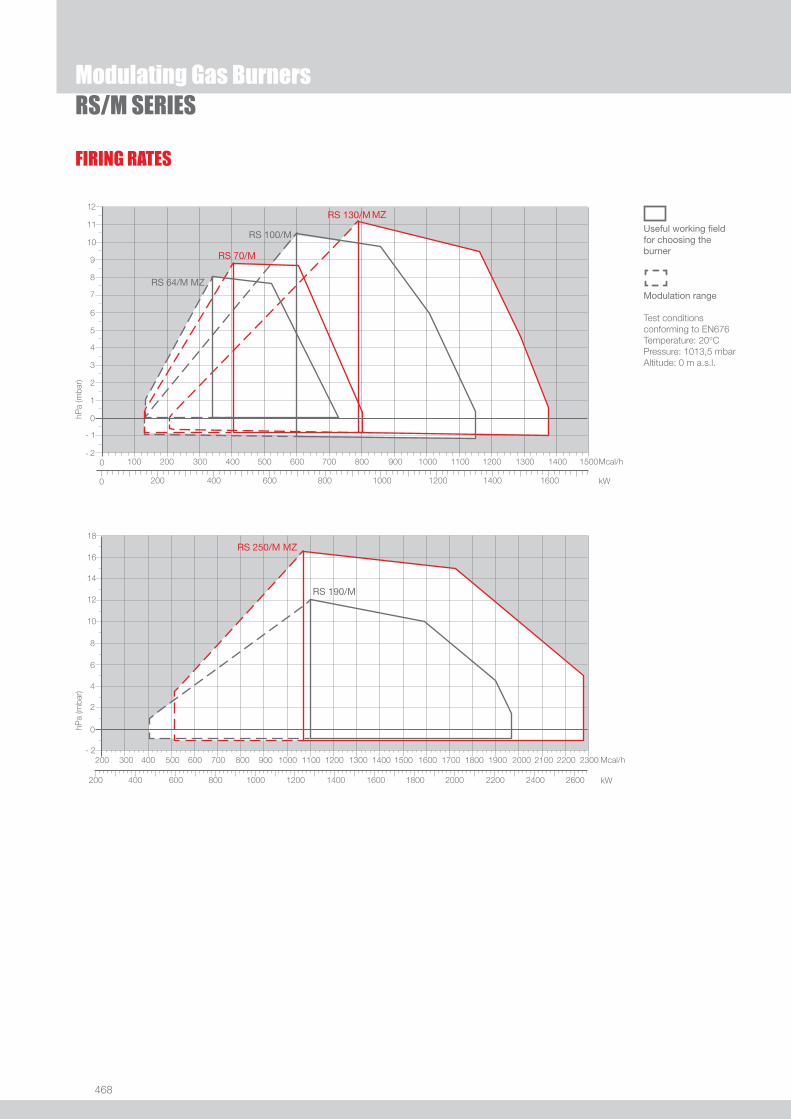
468
FIRING RATES
Useful working fi eldfor choosing theburner
Modulation range
Test conditionsconforming to EN676 Temperature: 20°CPressure: 1013,5 mbarAltitude: 0 m a.s.l.
Modulating Gas BurnersRS/M SERIES

469
GAS
Overall dimensions (mm)BURNER
Modulating Gas BurnersRS/M SERIES
MODEL A D E F G - G(1) H I L M N O P u RS 34/M MZ 442 422 508 138 216 - 351 140 305 177 1”1/2 84 780 -
u RS 44/M MZ 442 422 508 138 216 - 351 152 305 177 1”1/2 84 780 -
u RS 50/M 476 474 580 164 216 - 351 152 352 168 1”1/2 108 810 719
RS 34/M MZ - 44/M MZ RS 50/M
(1) dimension with extended head
�
�
�
�����
�
�
��
�
�
�
�
�
�����
�
�
�
�
�
RS 64/M MZ RS 70/M - 100/M - 130/M - 190/M - 250/M MZ
�
�
�� ���
�
�
�
�
�
�
� � � ���
�
�
� �
�
�
�
� � � ����
�
�
MODEL A B C D E F G - G(1) H I L M N O - O(1)u RS 64/M MZ 533 300 - 490 640 222 250 - 385 179 352 221 2” 134 810 - -
u RS 70/M 511 296 215 555 840 214 250 - 385 179 430 221 2” 134 1161 - 1296
u RS 100/M 527 312 215 555 840 214 250 - 385 179 430 221 2” 134 1161 - 1296
u RS 130/M 553 338 215 555 840 214 280 - 415 189 430 221 2” 134 1161 - 1296
u RS 190/M 681 366 315 555 856 230 372 - 530 222 430 221 2” 150 1328 - -
u RS 250/M MZ 732 427 305 555 872 230 370 - 520 222 430 221 2” 150 1322 - -
(1) dimension with extended head

470
Overall dimensions (mm)
Modulating Gas BurnersRS/M SERIES
BURNER - BOILER MOUNTING FLANGE
PACKAGING
Z
X(1)Y
MODEL D1 D2 Ø u RS 34/M MZ 160 224 M8
u RS 44/M MZ 160 224 M8
u RS 50/M 160 224 M8
u RS 64/M MZ 185 275-325 M12
u RS 70/M 185 275-325 M12
u RS 100/M 185 275-325 M12
u RS 130/M 195 275-325 M12
u RS 190/M 230 325-368 M16
u RS 250/M MZ 230 325-368 M16
MODEL X (1) Y Z kgu RS 34/M MZ 1000 485 500 32
u RS 44/M MZ 1000 485 500 33
u RS 50/M 1200 502 520 41
u RS 64/M MZ 1200 580 520 42
u RS 70/M 1405 700 660 70
u RS 100/M 1405 700 660 73
u RS 130/M 1405 700 660 76
u RS 190/M 1405-1420 1000 660 82
u RS 250/M MZ 1405-1420 1000 660 117
(1) dimension with standard and extended head

471
GAS
DESIGNATION OF SERIES
Specifi cation
Modulating Gas BurnersRS/M SERIES
BASIC DESIGNATION
EXTENDED DESIGNATION
R S 50 /M TC FS1 3/230-400/50 230/50-60
Series: R Fuel: S Natural Gas SP LPG L Light oil LS Light oil/Methane N Heavy oil
Size Setting: /1 Single stage ... Two stage /M Modulating Emission: ... Class 1 EN267 - EN676 MZ Class 2 EN267 - EN676 BLU Class 3 EN267 - EN676
MX Class 1 EN267
Class 3 EN676 Head length: TC standard head TL extended head Flame control system: FS1 Standard (1 stop every 24 h) FS2 Continuous working (1 stop every 72 h) Electrical supply to the system: 1/230/50 1/230V/50Hz 1/220-230/50-60 1/220-230V/50-60Hz 3/230/50 3/230V/50Hz 3/400/50 3N/400V/50Hz 3/230-400/50 3/230V/50Hz - 3N/400V/50Hz 3/220/60 3/220V/60Hz 3/380/60 3N/380V/60Hz 3/220-380/60 3/220V/60Hz - 3N/380V/60Hz
3/220-400/50-60 3/220-230V/50-60Hz
3/380-400V/50-60Hz
Auxiliary voltage: 230/50-60 230V/50-60Hz 220-230/50-60 220-230V/50-60Hz 110/50-60 110V/50-60Hz
ID: Differential switch
472
STATE OF SUPPLY
Specifi cation
Modulating Gas BurnersRS/M SERIES
RS 34/M MZ - 44/M MZ modelsMonoblock forced draught gas burner with two stage progressive or modulating operation, with a specifi c kit, fully automatic, made up of:- Air suction circuit with sound proofi ng material- High performance fan with straight blades - Air damper for air fl ow setting and butterfl y valve for regulating fuel output controlled by a servomotor with variable cam- Starting motor at 2800 rpm, single-phase / 220-230V / 50-60Hz or three-phase / 380-400V / 50-60Hz- Combustion head, that can be set on the basis of required output, fi tted with: - stainless steel end cone, resistant to corrosion and high temperatures - ignition electrodes - ionisation probe - gas distributor - fl ame stability disk- Exclusive patented HCS (Housing Cooling System) with high thermal insulation and air circulation with continuous air volume
refresh for an active cooling system and avoid heat transfer to the electrical component housing- Minimum air pressure switch stops the burner in case of insuffi cient air quantity at the combustion head- Microprocessor-based burner safety control box, with diagnostic functions- Plugs and Sockets for electrical connection, accessible from the external of the cover- Burner on/off selection switch- Manual or automatic output increase/decrease selection switch- Flame inspection window- Slide bars for easier installation and maintenance- Protection fi lter against radio interference- IP 40 electric protection level.
Standard equipment:- 1 gas train fl ange - 1 fl ange gasket- 4 screws for fi xing the fl ange- 1 thermal screen- 4 screws for fi xing the burner fl ange to the boiler- 3 plugs for electrical connection (RS 34-44/M MZ single-phase)- 4 plugs for electrical connection (RS 44/M MZ three-phase)- Instruction handbook for installation, use and maintenance- Spare parts catalogue.
473
GAS
Modulating Gas BurnersRS/M SERIES
RS 50/M - 64/M MZ - 70/M - 100/M - 130/M - 190/M - 250/M MZ modelsMonoblock forced draught gas burner with two stage progressive or modulating operation, with a specifi c kit, fully automatic, made up of:- Air suction circuit lined with sound-proofi ng material- Fan with reverse curve blades (RS 50 - 70 - 100 - 130/M models) or straight blades (RS 64/M MZ - 190/M - 250/M MZ models) - Air damper for air fl ow setting and butterfl y valve for regulating fuel output controlled by a servomotor with variable cam- Starting motor at 2800 rpm, three-phase 400V with neutral, 50Hz- Combustion head, that can be set on the basis of required output, fi tted with: - stainless steel end cone, resistant to corrosion and high temperatures - ignition electrodes - ionisation probe - gas distributor - fl ame stability disk- Maximum gas pressure switch to stop the burner in the case of excess pressure on the fuel supply line- Minimum air pressure switch stops the burner in case of insuffi cient air quantity at the combustion head- Microprocessor-based burner safety control box, with diagnostic functions- Burner on/off selection switch- Manual or automatic output increase/decrease selection switch- Flame inspection window- Slide bars for easier installation and maintenance- Protection fi lter against radio interference- IP 44 electric protection level.
Standard equipment:- 1 gas train fl ange - 1 fl ange gasket- 4 screws for fi xing the fl ange- 1 thermal screen- 4 screws for fi xing the burner fl ange to the boiler- Wiring loom fi ttings for the electrical connection (RS 50/M)- 2 slide bar extensions (for extended head models and RS 190/M model)- Instruction handbook for installation, use and maintenance- Spare parts catalogue.
STATE OF SUPPLY
Specifi cation

474
Burners
Available models
CODE MODEL
HEAT OUTPUT TOTAL ELECTRICAL
POWER
CERTIFICATION NOTE
NATURAL GAS
(kW) (Nm3/h) (kW)
3788710 RS 34/M MZ TC FS1 1/230/50-60 230/50-60 44/130÷390 4,5/13÷39 0,6 CE 0085BR0378 (1)
3788711 RS 34/M MZ TL FS1 1/230/50-60 230/50-60 44/130÷390 4,5/13÷39 0,6 CE 0085BR0378 (1)
3788810 RS 44/M MZ TC FS1 1/230/50-60 230/50-60 80/200÷550 8/20÷55 0,7 CE 0085BR0378 (1)
3788811 RS 44/M MZ TL FS1 1/230/50-60 230/50-60 80/200÷550 8/20÷55 0,7 CE 0085BR0378 (1)
3788840 RS 44/M MZ TC FS1 3/230-400/50-60 230/50-60 80/200÷550 8/20÷55 0,75 CE 0085BR0378 (1)
3788841 RS 44/M MZ TL FS1 3/230-400/50-60 230/50-60 80/200÷550 8/20÷55 0,75 CE 0085BR0378 (1)
3781622 RS 50/M MZ TC FS1 3/230-400/50 230/50-60 80/285÷630 8/29÷63 0,75 CE 0085AQ0709 (2)
3781623 RS 50/M MZ TL FS1 3/230-400/50 230/50-60 80/285÷630 8/29÷63 0,75 CE 0085AQ0709 (2)
3866202 RS 50/M MZ TC FS1 3/230-400/50 230/50-60 80/285÷630 8/29÷63 0,75 CE 0085AQ0709 (1)
3781682 RS 50/M MZ TC FS1 3/230-460/60 230/50-60 80/285÷630 8/29÷63 0,66 - (2)
3781683 RS 50/M MZ TL FS1 3/230-460/60 230/50-60 80/285÷630 8/29÷63 0,66 - (2)
3788910 RS 64/M MZ TC FS1 3/230-400/50 230/50-60 150/400÷850 15/40÷85 1,5 CE 0085BR0558 (1)
3788911 RS 64/M MZ TL FS1 3/230-400/50 230/50-60 150/400÷850 15/40÷85 1,5 CE 0085BR0558 (1)
3788920 RS 64/M MZ TC FS2 3/230-400/50 230/50-60 150/400÷850 15/40÷85 1,5 CE 0085BR0558 (1)
3788921 RS 64/M MZ TL FS2 3/230-400/50 230/50-60 150/400÷850 15/40÷85 1,5 CE 0085BR0558 (1)
3789610 RS 70/M TC FS1 3/230-400/50 230/50-60 150/470÷930 15/47÷93 1,4 CE 0085AQ0708 (2)
3787040 RS 70/M TC FS1 3/230-400/50 230/50-60 ID 150/470÷930 15/47÷93 1,4 CE 0085AQ0708 (2)
3789611 RS 70/M TL FS1 3/230-400/50 230/50-60 150/470÷930 15/47÷93 1,4 CE 0085AQ0708 (2)
3787041 RS 70/M TL FS1 3/230-400/50 230/50-60 ID 150/470÷930 15/47÷93 1,4 CE 0085AQ0708 (2)
3866203 RS 70/M TC FS1 3/230-400/50 230/50-60 150/470÷930 15/47÷93 1,4 CE 0085AQ0708 (1)
3787082 RS 70/M TC FS1 3/230-460/60 230/50-60 150/470÷930 15/47÷93 1,4 - (2)
3787083 RS 70/M TL FS1 3/230-460/60 230/50-60 150/470÷930 15/47÷93 1,4 - (2)
3789710 RS 100/M TC FS1 3/230-400/50 230/50-60 150/700÷1340 15/70÷134 1,8 CE 0085AQ0708 (2)
3787240 RS 100/M TC FS1 3/230-400/50 230/50-60 ID 150/700÷1340 15/70÷134 1,8 CE 0085AQ0708 (2)
3789711 RS 100/M TL FS1 3/230-400/50 230/50-60 150/700÷1340 15/70÷134 1,8 CE 0085AQ0708 (2)
3787241 RS 100/M TL FS1 3/230-400/50 230/50-60 ID 150/700÷1340 15/70÷134 1,8 CE 0085AQ0708 (2)
3866204 RS 100/M TC FS1 3/230-400/50 230/50-60 150/700÷1340 15/70÷134 1,8 CE 0085AQ0708 (1)
3787282 RS 100/M TC FS1 3/230-460/60 230/50-60 150/700÷1340 15/70÷134 2,1 - (2)
3787283 RS 100/M TL FS1 3/230-460/60 230/50-60 150/700÷1340 15/70÷134 2,1 - (2)
3789810 RS 130/M MZ TC FS1 3/230-400/50 230/50-60 240/920÷1600 24/92÷160 2,6 CE 0085AQ0708 (2)
3787440 RS 130/M MZ TC FS1 3/230-400/50 230/50-60 ID 240/920÷1600 24/92÷160 2,6 CE 0085AQ0708 (2)
3789811 RS 130/M MZ TL FS1 3/230-400/50 230/50-60 240/920÷1600 24/92÷160 2,6 CE 0085AQ0708 (2)
3787441 RS 130/M MZ TL FS1 3/230-400/50 230/50-60 ID 240/920÷1600 24/92÷160 2,6 CE 0085AQ0708 (2)
3866205 RS 130/M MZ TC FS1 3/230-400/50 230/50-60 240/920÷1600 24/92÷160 2,6 CE 0085AQ0708 (1)
3787482 RS 130/M MZ TC FS1 3/230-460/60 230/50-60 240/920÷1600 24/92÷160 2,6 - (2)
3787483 RS 130/M MZ TL FS1 3/230-460/60 230/50-60 240/920÷1600 24/92÷160 2,6 - (2)
Modulating Gas BurnersRS/M SERIES
Natural Gas, net calorifi c value: 10 kWh/Nm3 - Density at 20°C: 0,71 kg/Nm3
The burners of RS/M series are in according to 90/396 - 89/336 (2004/108) - 73/23 (2006/95) - 92/42 EC Directive and EN 676 Norm.(1) With plug and socket. (2) With terminal board.
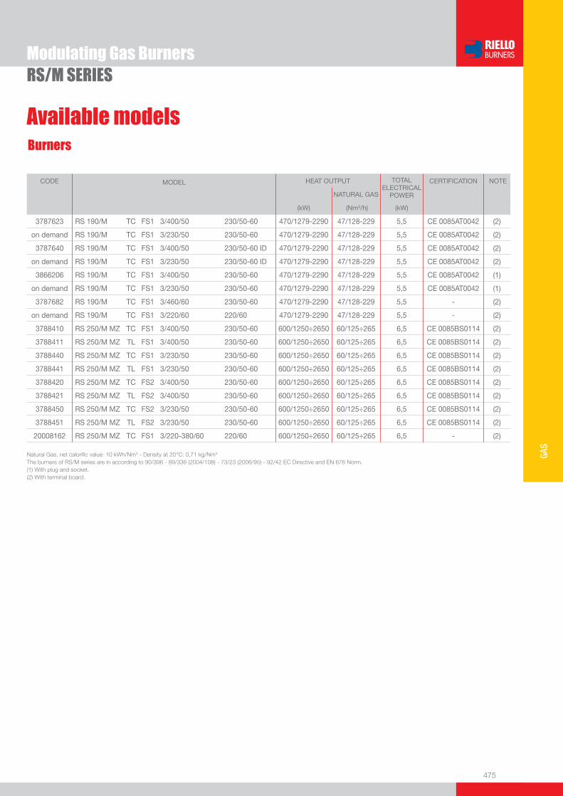
475
GAS
Modulating Gas BurnersRS/M SERIES
CODE MODEL
HEAT OUTPUT TOTAL ELECTRICAL
POWER
CERTIFICATION NOTE
NATURAL GAS
(kW) (Nm3/h) (kW)
3787623 RS 190/M TC FS1 3/400/50 230/50-60 470/1279-2290 47/128-229 5,5 CE 0085AT0042 (2)
on demand RS 190/M TC FS1 3/230/50 230/50-60 470/1279-2290 47/128-229 5,5 CE 0085AT0042 (2)
3787640 RS 190/M TC FS1 3/400/50 230/50-60 ID 470/1279-2290 47/128-229 5,5 CE 0085AT0042 (2)
on demand RS 190/M TC FS1 3/230/50 230/50-60 ID 470/1279-2290 47/128-229 5,5 CE 0085AT0042 (2)
3866206 RS 190/M TC FS1 3/400/50 230/50-60 470/1279-2290 47/128-229 5,5 CE 0085AT0042 (1)
on demand RS 190/M TC FS1 3/230/50 230/50-60 470/1279-2290 47/128-229 5,5 CE 0085AT0042 (1)
3787682 RS 190/M TC FS1 3/460/60 230/50-60 470/1279-2290 47/128-229 5,5 - (2)
on demand RS 190/M TC FS1 3/220/60 220/60 470/1279-2290 47/128-229 5,5 - (2)
3788410 RS 250/M MZ TC FS1 3/400/50 230/50-60 600/1250÷2650 60/125÷265 6,5 CE 0085BS0114 (2)
3788411 RS 250/M MZ TL FS1 3/400/50 230/50-60 600/1250÷2650 60/125÷265 6,5 CE 0085BS0114 (2)
3788440 RS 250/M MZ TC FS1 3/230/50 230/50-60 600/1250÷2650 60/125÷265 6,5 CE 0085BS0114 (2)
3788441 RS 250/M MZ TL FS1 3/230/50 230/50-60 600/1250÷2650 60/125÷265 6,5 CE 0085BS0114 (2)
3788420 RS 250/M MZ TC FS2 3/400/50 230/50-60 600/1250÷2650 60/125÷265 6,5 CE 0085BS0114 (2)
3788421 RS 250/M MZ TL FS2 3/400/50 230/50-60 600/1250÷2650 60/125÷265 6,5 CE 0085BS0114 (2)
3788450 RS 250/M MZ TC FS2 3/230/50 230/50-60 600/1250÷2650 60/125÷265 6,5 CE 0085BS0114 (2)
3788451 RS 250/M MZ TL FS2 3/230/50 230/50-60 600/1250÷2650 60/125÷265 6,5 CE 0085BS0114 (2)
20008162 RS 250/M MZ TC FS1 3/220-380/60 220/60 600/1250÷2650 60/125÷265 6,5 - (2)
Natural Gas, net calorifi c value: 10 kWh/Nm3 - Density at 20°C: 0,71 kg/Nm3
The burners of RS/M series are in according to 90/396 - 89/336 (2004/108) - 73/23 (2006/95) - 92/42 EC Directive and EN 676 Norm.(1) With plug and socket. (2) With terminal board.
Burners
Available models
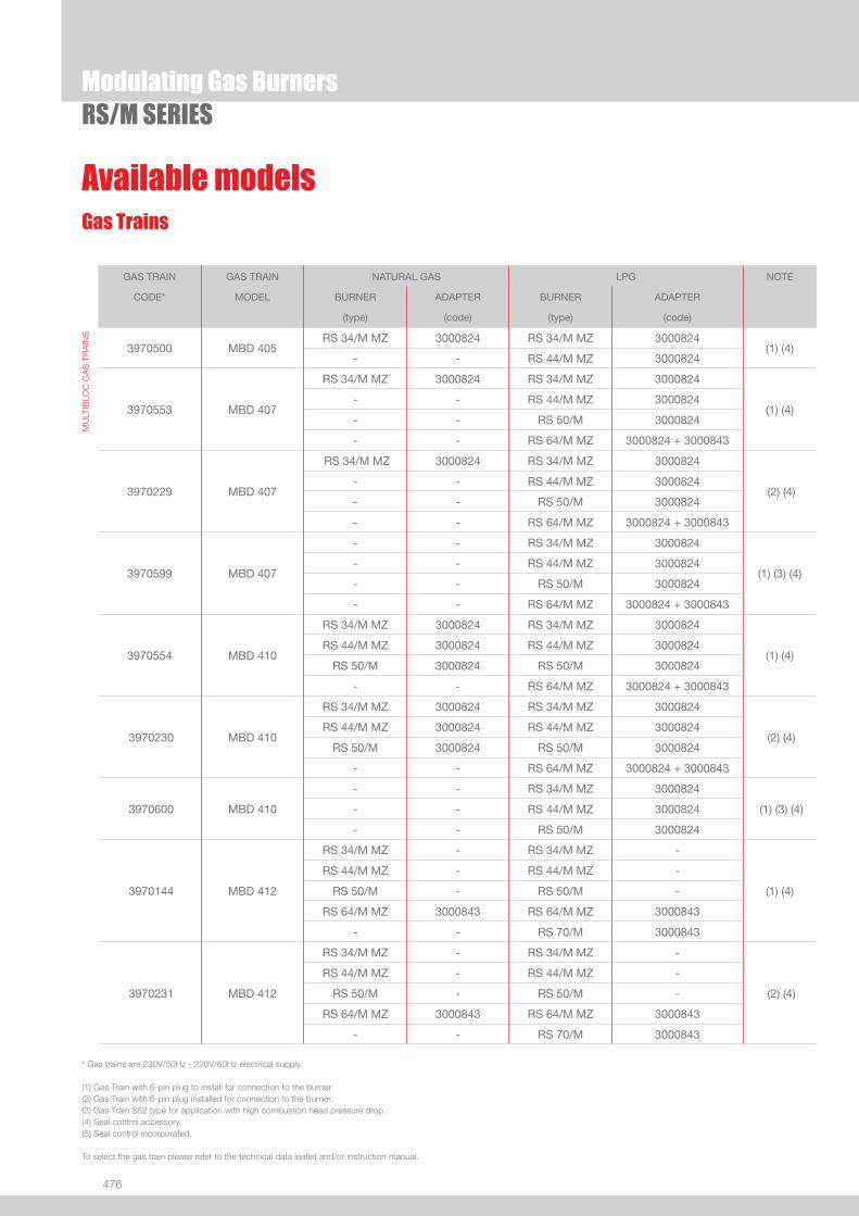
476
Gas Trains
Modulating Gas BurnersRS/M SERIES
GAS TRAIN GAS TRAIN NATURAL GAS LPG NOTE
CODE* MODEL BURNER ADAPTER BURNER ADAPTER
(type) (code) (type) (code)
MU
LTIB
LOC
GA
S T
RA
INS
3970500 MBD 405RS 34/M MZ 3000824 RS 34/M MZ 3000824
(1) (4) - - RS 44/M MZ 3000824
3970553
MBD 407
RS 34/M MZ 3000824 RS 34/M MZ 3000824
(1) (4)
- - RS 44/M MZ 3000824
- - RS 50/M 3000824
- - RS 64/M MZ 3000824 + 3000843
3970229 MBD 407
RS 34/M MZ 3000824 RS 34/M MZ 3000824
(2) (4)
- - RS 44/M MZ 3000824
- - RS 50/M 3000824
- - RS 64/M MZ 3000824 + 3000843
3970599
MBD 407
- - RS 34/M MZ 3000824
(1) (3) (4)
- - RS 44/M MZ 3000824
- - RS 50/M 3000824
- - RS 64/M MZ 3000824 + 3000843
3970554
MBD 410
RS 34/M MZ 3000824 RS 34/M MZ 3000824
(1) (4)
RS 44/M MZ 3000824 RS 44/M MZ 3000824
RS 50/M 3000824 RS 50/M 3000824
- - RS 64/M MZ 3000824 + 3000843
3970230 MBD 410
RS 34/M MZ 3000824 RS 34/M MZ 3000824
(2) (4) RS 44/M MZ 3000824 RS 44/M MZ 3000824
RS 50/M 3000824 RS 50/M 3000824
- - RS 64/M MZ 3000824 + 3000843
3970600 MBD 410
- - RS 34/M MZ 3000824
(1) (3) (4) - - RS 44/M MZ 3000824
- - RS 50/M 3000824
3970144 MBD 412
RS 34/M MZ - RS 34/M MZ -
(1) (4)
RS 44/M MZ - RS 44/M MZ -
RS 50/M - RS 50/M -
RS 64/M MZ 3000843 RS 64/M MZ 3000843
- - RS 70/M 3000843
3970231 MBD 412
RS 34/M MZ - RS 34/M MZ -
(2) (4)
RS 44/M MZ - RS 44/M MZ -
RS 50/M - RS 50/M -
RS 64/M MZ 3000843 RS 64/M MZ 3000843
- - RS 70/M 3000843
* Gas trains are 230V/50Hz - 220V/60Hz electrical supply.
(1) Gas Train with 6-pin plug to install for connection to the burner. (2) Gas Train with 6-pin plug installed for connection to the burner.(3) Gas Train S52 type for application with high combustion head pressure drop. (4) Seal control accessory.(5) Seal control incorporated.
To select the gas train please refer to the technical data leafl et and/or instruction manual.
Available models

477
GAS
Modulating Gas BurnersRS/M SERIES
Gas Trains
Available models
GAS TRAIN GAS TRAIN NATURAL GAS LPG NOTE
CODE* MODEL BURNER ADAPTER BURNER ADAPTER
(type) (code) (type) (code)
MU
LTIB
LOC
GA
S T
RA
INS
3970197
MBD 412 CT
RS 34/M MZ - RS 34/M MZ -
(1) (5)
RS 44/M MZ - RS 44/M MZ -
RS 50/M - RS 50/M -
RS 64/M MZ 3000843 RS 64/M MZ 3000843
- - RS 70/M 3000843
3970180
MBD 415
RS 34/M MZ - RS 34/M MZ -
(1) (4)
RS 44/M MZ - RS 44/M MZ -
RS 50/M - RS 50/M -
RS 64/M MZ 3000843 RS 64/M MZ 3000843
RS 70/M 3000843 RS 70/M 3000843
RS 100/M 3000843 RS 100/M 3000843
RS 130/M 3000843 RS 130/M 3000843
- - RS 190/M 3000843
3970232
MBD 415
RS 34/M MZ - RS 34/M MZ -
(2) (4)
RS 44/M MZ - RS 44/M MZ -
RS 50/M - RS 50/M -
RS 64/M MZ 3000843 RS 64/M MZ 3000843
RS 70/M 3000843 RS 70/M 3000843
RS 100/M 3000843 RS 100/M 3000843
RS 130/M 3000843 RS 130/M 3000843
- - RS 190/M 3000843
3970250 MBD 415 RS 50/M - RS 50/M - (1) (3) (4)
3970198
MBD 415 CT
RS 34/M MZ - RS 34/M MZ -
(1) (5)
RS 44/M MZ - RS 44/M MZ -
RS 50/M - RS 50/M -
RS 64/M MZ 3000843 RS 64/M MZ 3000843
RS 70/M 3000843 RS 70/M 3000843
RS 100/M 3000843 RS 100/M 3000843
RS 130/M 3000843 RS 130/M 3000843
- - RS 190/M 3000843
3970253 MBD 415 CT RS 50/M - RS 50/M - (1) (3) (5)
* Gas trains are 230V/50Hz - 220V/60Hz electrical supply.
(1) Gas Train with 6-pin plug to install for connection to the burner. (2) Gas Train with 6-pin plug installed for connection to the burner.(3) Gas Train S52 type for application with high combustion head pressure drop. (4) Seal control accessory.(5) Seal control incorporated.
To select the gas train please refer to the technical data leafl et and/or instruction manual.
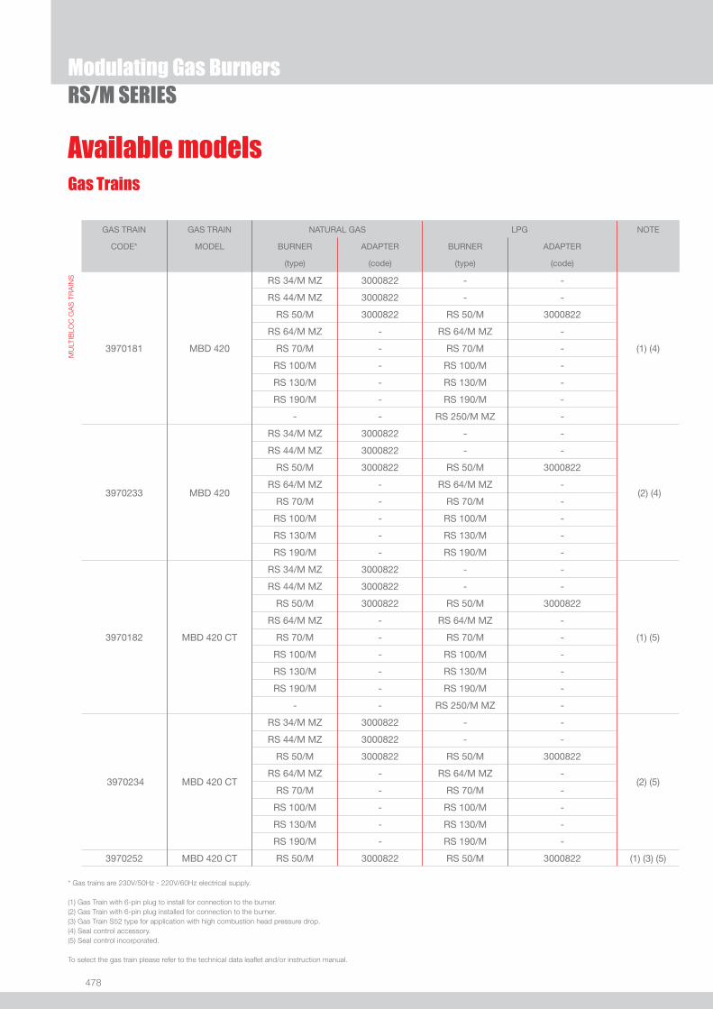
478
Available modelsGas Trains
Modulating Gas BurnersRS/M SERIES
GAS TRAIN GAS TRAIN NATURAL GAS LPG NOTE
CODE* MODEL BURNER ADAPTER BURNER ADAPTER
(type) (code) (type) (code)
MU
LTIB
LOC
GA
S T
RA
INS
3970181
MBD 420
RS 34/M MZ 3000822 - -
(1) (4)
RS 44/M MZ 3000822 - -
RS 50/M 3000822 RS 50/M 3000822
RS 64/M MZ - RS 64/M MZ -
RS 70/M - RS 70/M -
RS 100/M - RS 100/M -
RS 130/M - RS 130/M -
RS 190/M - RS 190/M -
- - RS 250/M MZ -
3970233
MBD 420
RS 34/M MZ 3000822 - -
(2) (4)
RS 44/M MZ 3000822 - -
RS 50/M 3000822 RS 50/M 3000822
RS 64/M MZ - RS 64/M MZ -
RS 70/M - RS 70/M -
RS 100/M - RS 100/M -
RS 130/M - RS 130/M -
RS 190/M - RS 190/M -
3970182
MBD 420 CT
RS 34/M MZ 3000822 - -
(1) (5)
RS 44/M MZ 3000822 - -
RS 50/M 3000822 RS 50/M 3000822
RS 64/M MZ - RS 64/M MZ -
RS 70/M - RS 70/M -
RS 100/M - RS 100/M -
RS 130/M - RS 130/M -
RS 190/M - RS 190/M -
- - RS 250/M MZ -
3970234
MBD 420 CT
RS 34/M MZ 3000822 - -
(2) (5)
RS 44/M MZ 3000822 - -
RS 50/M 3000822 RS 50/M 3000822
RS 64/M MZ - RS 64/M MZ -
RS 70/M - RS 70/M -
RS 100/M - RS 100/M -
RS 130/M - RS 130/M -
RS 190/M - RS 190/M -
3970252 MBD 420 CT RS 50/M 3000822 RS 50/M 3000822 (1) (3) (5)
* Gas trains are 230V/50Hz - 220V/60Hz electrical supply.
(1) Gas Train with 6-pin plug to install for connection to the burner. (2) Gas Train with 6-pin plug installed for connection to the burner.(3) Gas Train S52 type for application with high combustion head pressure drop. (4) Seal control accessory.(5) Seal control incorporated.
To select the gas train please refer to the technical data leafl et and/or instruction manual.
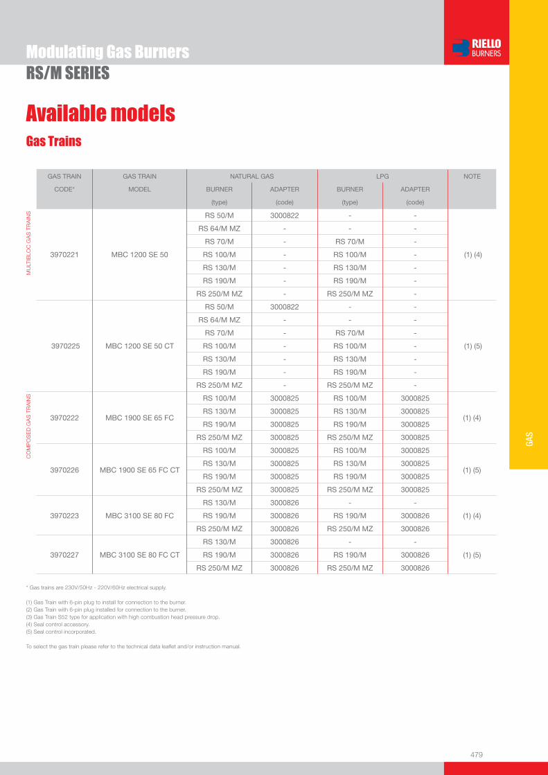
479
GAS
Gas Trains
Modulating Gas BurnersRS/M SERIES
Available models
GAS TRAIN GAS TRAIN NATURAL GAS LPG NOTE
CODE* MODEL BURNER ADAPTER BURNER ADAPTER
(type) (code) (type) (code)
MU
LTIB
LOC
GA
S T
RA
INS
3970221
MBC 1200 SE 50
RS 50/M 3000822 - -
(1) (4)
RS 64/M MZ - - -
RS 70/M - RS 70/M -
RS 100/M - RS 100/M -
RS 130/M - RS 130/M -
RS 190/M - RS 190/M -
RS 250/M MZ - RS 250/M MZ -
3970225
MBC 1200 SE 50 CT
RS 50/M 3000822 - -
(1) (5)
RS 64/M MZ - - -
RS 70/M - RS 70/M -
RS 100/M - RS 100/M -
RS 130/M - RS 130/M -
RS 190/M - RS 190/M -
RS 250/M MZ - RS 250/M MZ -
CO
MP
OS
ED
GA
S T
RA
INS
3970222 MBC 1900 SE 65 FC
RS 100/M 3000825 RS 100/M 3000825
(1) (4) RS 130/M 3000825 RS 130/M 3000825
RS 190/M 3000825 RS 190/M 3000825
RS 250/M MZ 3000825 RS 250/M MZ 3000825
3970226
MBC 1900 SE 65 FC CT
RS 100/M 3000825 RS 100/M 3000825
(1) (5)
RS 130/M 3000825 RS 130/M 3000825
RS 190/M 3000825 RS 190/M 3000825
RS 250/M MZ 3000825 RS 250/M MZ 3000825
3970223
MBC 3100 SE 80 FC
RS 130/M 3000826 - - (1) (4)
RS 190/M 3000826 RS 190/M 3000826
RS 250/M MZ 3000826 RS 250/M MZ 3000826
3970227
MBC 3100 SE 80 FC CT
RS 130/M 3000826 - - (1) (5)
RS 190/M 3000826 RS 190/M 3000826
RS 250/M MZ 3000826 RS 250/M MZ 3000826
* Gas trains are 230V/50Hz - 220V/60Hz electrical supply.
(1) Gas Train with 6-pin plug to install for connection to the burner. (2) Gas Train with 6-pin plug installed for connection to the burner.(3) Gas Train S52 type for application with high combustion head pressure drop. (4) Seal control accessory.(5) Seal control incorporated.
To select the gas train please refer to the technical data leafl et and/or instruction manual.

480
Modulating Gas BurnersRS/M SERIES
Burner accessories
Extended heads
“Standard head” burners can be transformed into “extended head” versions, by using the special kit. The KITS available for the various burners, giving the original and the extended lengths, are listed below.
BURNER ‘STANDARD HEAD’ LENGTH (mm)
‘EXTENDED HEAD’ LENGTH (mm)
KIT CODE
u RS 34/M MZ 216 351 3010428
u RS 44/M MZ 216 351 3010429
u RS 50/M 216 351 3010078
u RS 64/M MZ 250 385 3010427
u RS 70/M 250 385 3010117
u RS 100/M 250 385 3010118
u RS 130/M 280 415 3010119
u RS 190/M 372 530 3010443
u RS 250/M MZ 370 520 3010412
Spacer kit
If burner head penetration into the combustion chamber needs reducing, varying thickness spacers are available, as given in the following table:
BURNER SPACER THICKNESS S (mm)
KIT CODE
u RS 34/M MZ - 44/M MZ - RS 50/M 90 3010095
u RS 64/M MZ - RS 70/M - 100/M - 130/M 135 3010129
u RS 190/M - 250/M MZ 110 3000722
Sound proofi ng box
If noise emission needs reducing even further, sound-proofi ng boxes are available, as given in the following table:
BURNER BOX TYPE
AVERAGE NOISE REDUCTION [dB(A)](*)
BOX CODE
u RS 34/M MZ - 44/M MZ - RS 50/M - RS 64/M MZ C1/3 10 3010403
u RS 70/M - 100/M - 130/M - 190/M - RS 250/M MZ C4/5 10 3010404
Continuous ventilation kit
If the burner requires continuous ventilation in the stages without fl ame, a special kit is available as given in the following table:
BURNER KIT CODE
u RS 34/M MZ - 44/M MZ 3010449
u RS 50/M - 70/M - 100/M - 130/M - 190/M - 250/M 3010094
(*) according to EN 15036-1 standard
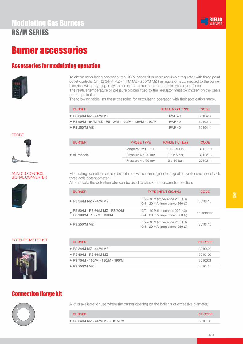
481
GAS
Burner accessories
Modulating Gas BurnersRS/M SERIES
Accessories for modulating operation
To obtain modulating operation, the RS/M series of burners requires a regulator with three point outlet controls. On RS 34/M MZ - 44/M MZ - 250/M MZ the regulator is connected to the burner electrical wiring by plug-in system in order to make the connection easier and faster. The relative temperature or pressure probes fi tted to the regulator must be chosen on the basis of the application. The following table lists the accessories for modulating operation with their application range.
BURNER REGULATOR TYPE CODE
u RS 34/M MZ - 44/M MZ RWF 40 3010417
u RS 50/M - 64/M MZ - RS 70/M - 100/M - 130/M - 190/M RWF 40 3010212
u RS 250/M MZ RWF 40 3010414
BURNER PROBE TYPE RANGE (°C) (bar) CODE
u All models
Temperature PT 100 -100 ÷ 500°C 3010110
Pressure 4 ÷ 20 mA 0 ÷ 2,5 bar 3010213
Pressure 4 ÷ 20 mA 0 ÷ 16 bar 3010214
BURNER KIT CODE
u RS 34/M MZ - 44/M MZ 3010420
u RS 50/M - RS 64/M MZ 3010109
u RS 70/M - 100/M - 130/M - 190/M 3010021
u RS 250/M MZ 3010416
POTENTIOMETER KIT
Connection fl ange kit
BURNER KIT CODE
u RS 34/M MZ - 44/M MZ - RS 50/M 3010138
A kit is available for use where the burner opening on the boiler is of excessive diameter.
PROBE
Modulating operation can also be obtained with an analog control signal converter and a feedback three-pole potentiometer.Alternatively, the potentiometer can be used to check the servomotor position.
BURNER TYPE (INPUT SIGNAL) CODE
u RS 34/M MZ - 44/M MZ 0/2 - 10 V (impedance 200 KΩ) 0/4 - 20 mA (impedance 250 Ω)
3010410
uRS 50/M - RS 64/M MZ - RS 70/MRS 100/M - 130/M - 190/M
0/2 - 10 V (impedance 200 KΩ) 0/4 - 20 mA (impedance 250 Ω)
on demand
u RS 250/M MZ 0/2 - 10 V (impedance 200 KΩ) 0/4 - 20 mA (impedance 250 Ω)
3010415
ANALOG CONTROL SIGNAL CONVERTER
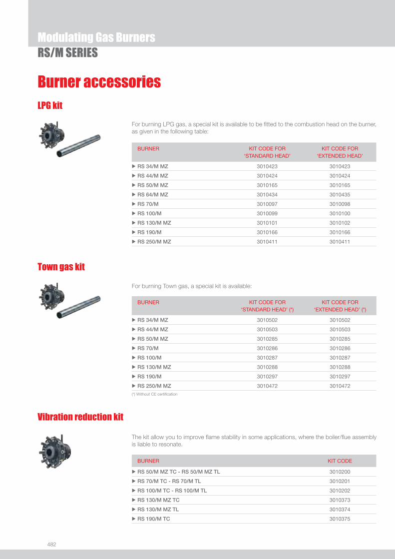
482
Modulating Gas BurnersRS/M SERIES
Burner accessoriesLPG kit
For burning LPG gas, a special kit is available to be fi tted to the combustion head on the burner, as given in the following table:
BURNER KIT CODE FOR‘STANDARD HEAD’
KIT CODE FOR‘EXTENDED HEAD’
u RS 34/M MZ 3010423 3010423
u RS 44/M MZ 3010424 3010424
u RS 50/M MZ 3010165 3010165
u RS 64/M MZ 3010434 3010435
u RS 70/M 3010097 3010098
u RS 100/M 3010099 3010100
u RS 130/M MZ 3010101 3010102
u RS 190/M 3010166 3010166
u RS 250/M MZ 3010411 3010411
Town gas kit
For burning Town gas, a special kit is available:
BURNER KIT CODE FOR‘STANDARD HEAD’ (*)
KIT CODE FOR‘EXTENDED HEAD’ (*)
u RS 34/M MZ 3010502 3010502
u RS 44/M MZ 3010503 3010503
u RS 50/M MZ 3010285 3010285
u RS 70/M 3010286 3010286
u RS 100/M 3010287 3010287
u RS 130/M MZ 3010288 3010288
u RS 190/M 3010297 3010297
u RS 250/M MZ 3010472 3010472
(*) Without CE certifi cation
Vibration reduction kit
The kit allow you to improve fl ame stability in some applications, where the boiler/fl ue assembly is liable to resonate.
BURNER KIT CODE
u RS 50/M MZ TC - RS 50/M MZ TL 3010200
u RS 70/M TC - RS 70/M TL 3010201
u RS 100/M TC - RS 100/M TL 3010202
u RS 130/M MZ TC 3010373
u RS 130/M MZ TL 3010374
u RS 190/M TC 3010375

483
GAS
Burner accessories
Modulating Gas BurnersRS/M SERIES
Ground fault interrupter kit
A “Ground fault interrupter kit” is available as a safety device for electrical system fault.
BURNER KIT CODE
u RS 34/M MZ - 44/M MZ 3010448
u RS 50/M - RS 64/M MZ 3010321
u RS 70/M - 100/M - 130/M - 190/M - RS 250/M MZ 3010329
Gas max pressure switch kit
If necessary a Gas max pressure Switch kit is available and connectable to the burner electrical wiring through Plugs & Sockets system.
BURNER (*) KIT CODE
u RS 34/M MZ - 44/M MZ 3010418
�� ��
��
�
����
����
��
��
���
Volt free contact kit
A volt free contact kit is available for installation onto the burner. It can be used for a remote interface between burner operating signals. Every burner can be equipped with a single kit for a remote check of the fl ame presence signal or the burner lockout indication.
BURNER KIT CODE
u RS 34/M MZ - 44/M MZ - 64/M MZ 3010419
PC interface kit
To connect the control box to a personal computer for the transmission of operation, fault signals and detailed service information, an interface adapter with PC software are available.
BURNER KIT CODE
u RS 34/M MZ - 44/M MZ - 64/M MZ - 250/M MZ 3002719
DN80 gas fl ange kit
To modify the standard 2” burner gas input connection in to DN80 connection, a specifi c gas fl ange is available.
BURNER KIT CODE
u RS 64/M MZ - 70/M - 100/M - 130/M - 190/M - 250/M MZ 3010439
(*) Gas max pressure switch is installed as a standard on RS 50/M MZ - 64/M MZ - 70/M - 100/M - 130/M MZ - 190/M - 250/M MZ
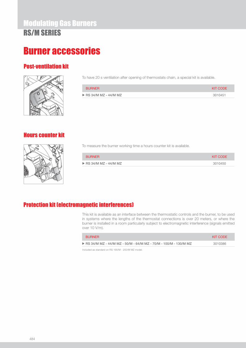
484
Modulating Gas BurnersRS/M SERIES
Burner accessories
Hours counter kit
To measure the burner working time a hours counter kit is available.
BURNER KIT CODE
u RS 34/M MZ - 44/M MZ 3010450
Gas Train Accessories
Post-ventilation kit
To have 20 s ventilation after opening of thermostats chain, a special kit is available.
BURNER KIT CODE
u RS 34/M MZ - 44/M MZ 3010451
This kit is available as an interface between the thermostatic controls and the burner, to be used in systems where the lengths of the thermostat connections is over 20 meters, or where the burner is installed in a room particularly subject to electromagnetic interference (signals emitted over 10 V/m).
BURNER KIT CODE
u RS 34/M MZ - 44/M MZ - 50/M - 64/M MZ - 70/M - 100/M - 130/M MZ 3010386
Protection kit (electromagnetic interferences)
Included as standard on RS 190/M - 250/M MZ model.

485
GAS
Modulating Gas BurnersRS/M SERIES
Gas train accessories
Adapters
When the diameter of the gas train is different from the set diameter of the burners, an adapter must be fi tted between the gas train and the burner. The following table lists the adapters for various burners.
BURNER GAS TRAIN DIMENSIONS ADAPTER CODE
u RS 34/M MZ MBD 405 - 407 - 410 1” 1/23/4” 3000824
MBD 420 1” 1/22” 3000822
u RS 44/M MZMBD 405 - 407 - 410 1” 1/23/4” 3000824
MBD 420 1” 1/22” 3000822
u RS 50/MMBD 407 - 410 1” 1/23/4” 3000824
MBD 420 - MBC 1200 1” 1/22” 3000822
u RS 64/M MZMBD 407 - 410
1” 1/23/4”
2”1” 1/2
3000824+
3000843
MBD 412 - 415 2”1” 1/2 3000843
u RS 70/M
MBD 415 2”1” 1/2 3000843
MBC 1900 2” 1/2DN 65
1” 1/2
2”
3000825
MBC 3100 2” 1/2DN 80 2” 3000826
u RS 100/M
MBD 415 2”1” 1/2 3000843
MBC 1900 2” 1/2DN 65
1” 1/2
2”
3000825
MBC 3100 2” 1/2DN 80 2” 3000826
u RS 130/M
MBD 415 2”1” 1/2 3000843
MBC 1900 2” 1/2DN 65
1” 1/2
2”
3000825
MBC 3100 2” 1/2DN 80 2” 3000826
To be continued in the following page

486
Gas train accessories
BURNER GAS TRAIN DIMENSIONS ADAPTER CODE
u RS 190/M
MBD 415 2”1” 1/2 3000843
MBC 1900 2” 1/2DN 65
1” 1/2
2”
3000825
MBC 3100 2” 1/2DN 80 2” 3000826
u RS 250/M MZ
MBC 1900 2” 1/2DN 65
1” 1/2
2”
3000825
MBC 3100 2” 1/2DN 80 2” 3000826
Adapters
Modulating Gas BurnersRS/M SERIES
Stabiliser spring
Accessory springs are available to vary the pressure range of the gas train stabilisers. The following table shows these accessories with their application range.Please refer to the technical manual for the correct choice of spring.
GAS TRAIN SPRING SPRING CODE
u
MBC 1900 MBC 3100 MBC 5000
White from 4 to 20 mbar 3010381
Red from 20 to 40 mbar 3010382
Black from 40 to 80 mbar 3010383
Green from 80 to 150 mbar 3010384
Seal control kit
To test the valve seals on the gas train, a special “seal control kit” is available. The valve seal control device is compulsory (EN 676) on gas trains to burners with a maximum output over 1200 kW. The sealing control is type VPS 504.
GAS TRAIN KIT CODE
u MBD type 3010123
u MBC type 3010367
Continued from the previous page

487
GAS
RS/E-EV MZ SERIES
Modulating Gas Burners
The RS/E-EV MZ burners series covers a fi ring range from 44 to 2650 kW, and it is based on a new Digital Burner Management System, Riello REC27, which is able to manage the air-fuel ratio by independent servomotors in order to obtain a perfect output control and to assure a correct combustion and safe operation on all modulation range. Operation can be “two stage progressive” or, alternatively, “modulating” with the installation of a PID logic regulator and respective probes. RS/E MZ burners series guarantees high effi ciency levels in all the various applications, thus reducing fuel consumption and running costs. The RS 250/EV MZ model, equipped with REC37, is available to operate with Variable Speed Drive technology base on the control of a Frequency Inverter that modifi es the air fl ow through the motor speed variation.Optimisation of sound emissions is guaranteed by the special design of the air suction circuit and by incorporated sound proofi ng material.
RS 34/E MZ 44/130 ÷ 390 kWRS 44/E MZ 80/200 ÷ 550 kWRS 50/E MZ 85/290 ÷ 580 kWRS 64/E MZ 150/400 ÷ 850 kWRS 70/E MZ 135/465 ÷ 814 kWRS 100/E MZ 150/698 ÷ 1163 kWRS 130/E MZ 160/930 ÷ 1512 kWRS 190/E 470/1279 ÷ 2290 kWRS 250/E MZ 600/1250 ÷ 2650 kWRS 250/EV MZ 600/1250 ÷ 2650 kW
RS 34/E MZ
RS 44/E MZ RS 50/E MZ
FIRING RATES
Useful working fi eldfor choosing theburner
Modulation range
Test conditionsconforming to EN676 Temperature: 20°CPressure: 1013,5 mbarAltitude: 0 m a.s.l.
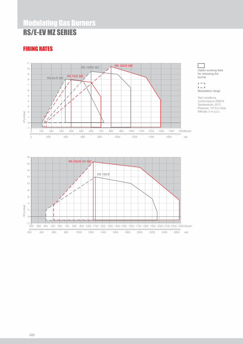
488
RS 64/E MZRS 70/E MZ
RS 100/E MZ RS 130/E MZ
RS 190/E
RS 250/E-EV MZ
FIRING RATES
Useful working fi eldfor choosing theburner
Modulation range
Test conditionsconforming to EN676 Temperature: 20°CPressure: 1013,5 mbarAltitude: 0 m a.s.l.
Modulating Gas BurnersRS/E-EV MZ SERIES
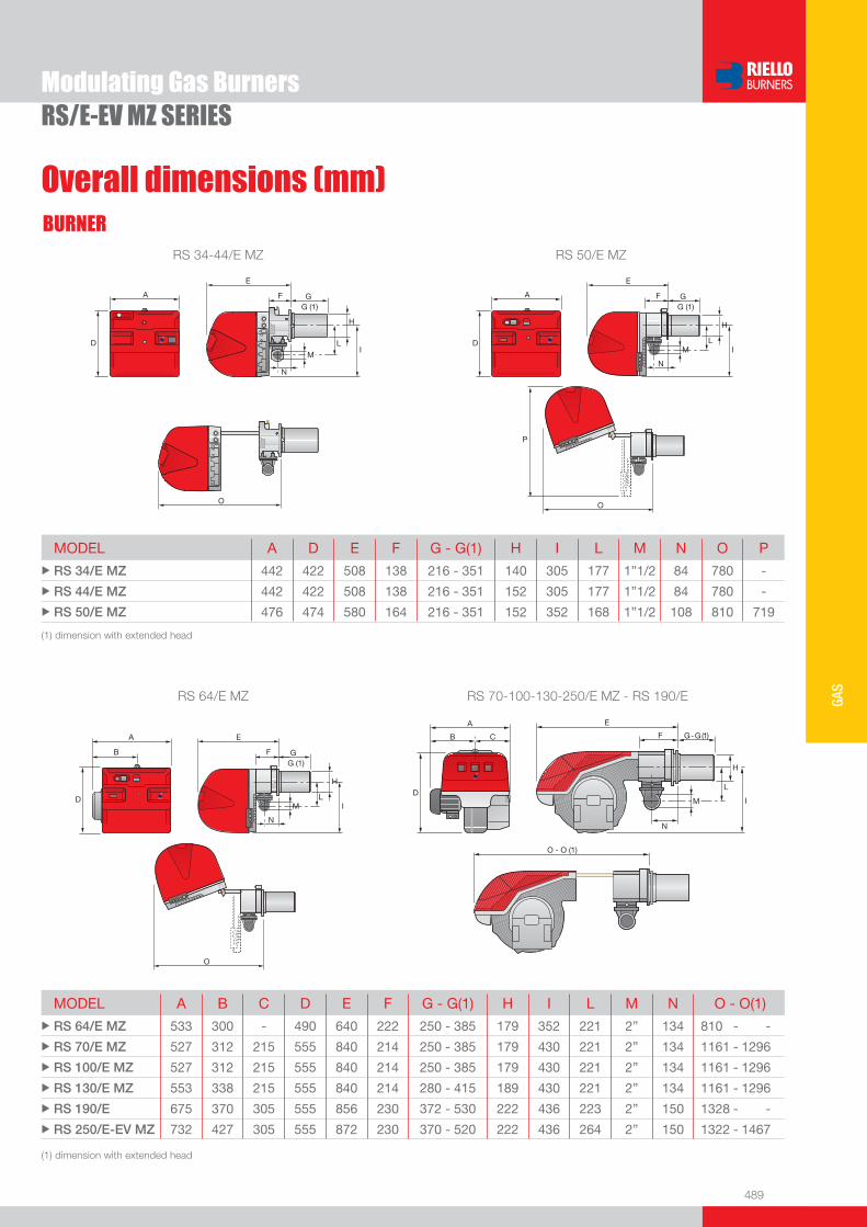
489
GAS
Overall dimensions (mm)BURNER
Modulating Gas BurnersRS/E-EV MZ SERIES
RS 34-44/E MZ RS 50/E MZ
(1) dimension with extended head
RS 64/E MZ RS 70-100-130-250/E MZ - RS 190/E
MODEL A B C D E F G - G(1) H I L M N O - O(1)u RS 64/E MZ 533 300 - 490 640 222 250 - 385 179 352 221 2” 134 810 - -
u RS 70/E MZ 527 312 215 555 840 214 250 - 385 179 430 221 2” 134 1161 - 1296
u RS 100/E MZ 527 312 215 555 840 214 250 - 385 179 430 221 2” 134 1161 - 1296
u RS 130/E MZ 553 338 215 555 840 214 280 - 415 189 430 221 2” 134 1161 - 1296
u RS 190/E 675 370 305 555 856 230 372 - 530 222 436 223 2” 150 1328 - -
u RS 250/E-EV MZ 732 427 305 555 872 230 370 - 520 222 436 264 2” 150 1322 - 1467
(1) dimension with extended head
A
D
O
GG (1)
E
H
I
N
LM
F
P
O
A
D
GG (1)
E
H
I
N
ML
F
A
D
B CA
D
L
O - O (1)
E
I
G - G (1)F
N
M
H
GG (1)
E
H
I
N
ML
F
O
B
MODEL A D E F G - G(1) H I L M N O P u RS 34/E MZ 442 422 508 138 216 - 351 140 305 177 1”1/2 84 780 -
u RS 44/E MZ 442 422 508 138 216 - 351 152 305 177 1”1/2 84 780 -
u RS 50/E MZ 476 474 580 164 216 - 351 152 352 168 1”1/2 108 810 719

490
Overall dimensions (mm)
Modulating Gas BurnersRS/E-EV MZ SERIES
BURNER - BOILER MOUNTING FLANGE
MODEL D1 D2 Ø u RS 34/E MZ 160 224 M8
u RS 44/E MZ 160 224 M8
u RS 50/E MZ 160 224 M8
u RS 64/E MZ 185 275-325 M12
u RS 70/E MZ 185 275-325 M12
u RS 100/E MZ 185 275-325 M12
u RS 130/E MZ 195 275-325 M12
u RS 190/E 230 325-368 M16
u RS 250/E-EV MZ 230 325-368 M16
MODEL X (1) Y Z kgu RS 34/E MZ 1000 485 500 39
u RS 44/E MZ 1000 485 500 40
u RS 50/E MZ 1200 502 630 48
u RS 64/E MZ 1200 580 630 50
u RS 70/E MZ 1405 700 660 78
u RS 100/E MZ 1405 700 660 81
u RS 130/E MZ 1405 700 660 84
u RS 190/E 1405 1000 660 89
u RS 250/E-EV MZ 1405-1420 1000 660 125
(1) dimension with standard and extended head
PACKAGING
Z
X(1)Y
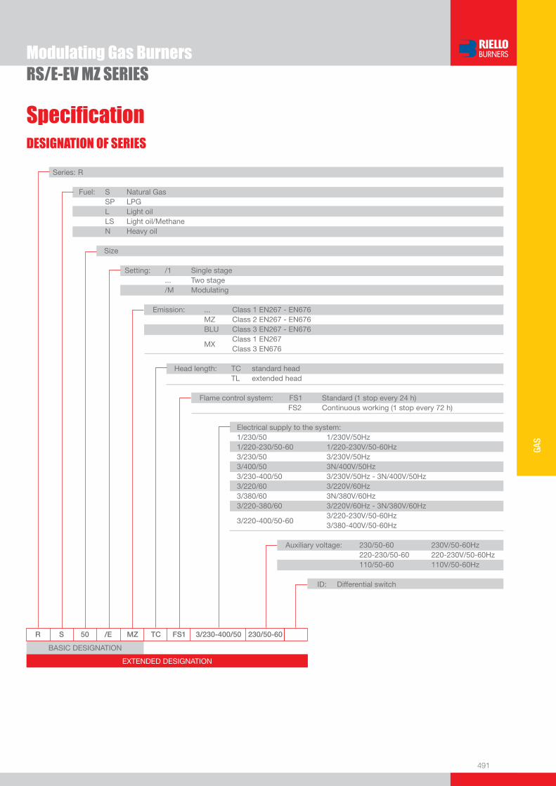
491
GAS
DESIGNATION OF SERIES
Specifi cation
Modulating Gas BurnersRS/E-EV MZ SERIES
BASIC DESIGNATION
EXTENDED DESIGNATION
R S 50 /E MZ TC FS1 3/230-400/50 230/50-60
Series: R Fuel: S Natural Gas SP LPG L Light oil LS Light oil/Methane N Heavy oil
Size Setting: /1 Single stage ... Two stage /M Modulating Emission: ... Class 1 EN267 - EN676 MZ Class 2 EN267 - EN676 BLU Class 3 EN267 - EN676
MX Class 1 EN267
Class 3 EN676 Head length: TC standard head TL extended head Flame control system: FS1 Standard (1 stop every 24 h) FS2 Continuous working (1 stop every 72 h) Electrical supply to the system: 1/230/50 1/230V/50Hz 1/220-230/50-60 1/220-230V/50-60Hz 3/230/50 3/230V/50Hz 3/400/50 3N/400V/50Hz 3/230-400/50 3/230V/50Hz - 3N/400V/50Hz 3/220/60 3/220V/60Hz 3/380/60 3N/380V/60Hz 3/220-380/60 3/220V/60Hz - 3N/380V/60Hz
3/220-400/50-60 3/220-230V/50-60Hz
3/380-400V/50-60Hz
Auxiliary voltage: 230/50-60 230V/50-60Hz 220-230/50-60 220-230V/50-60Hz 110/50-60 110V/50-60Hz
ID: Differential switch
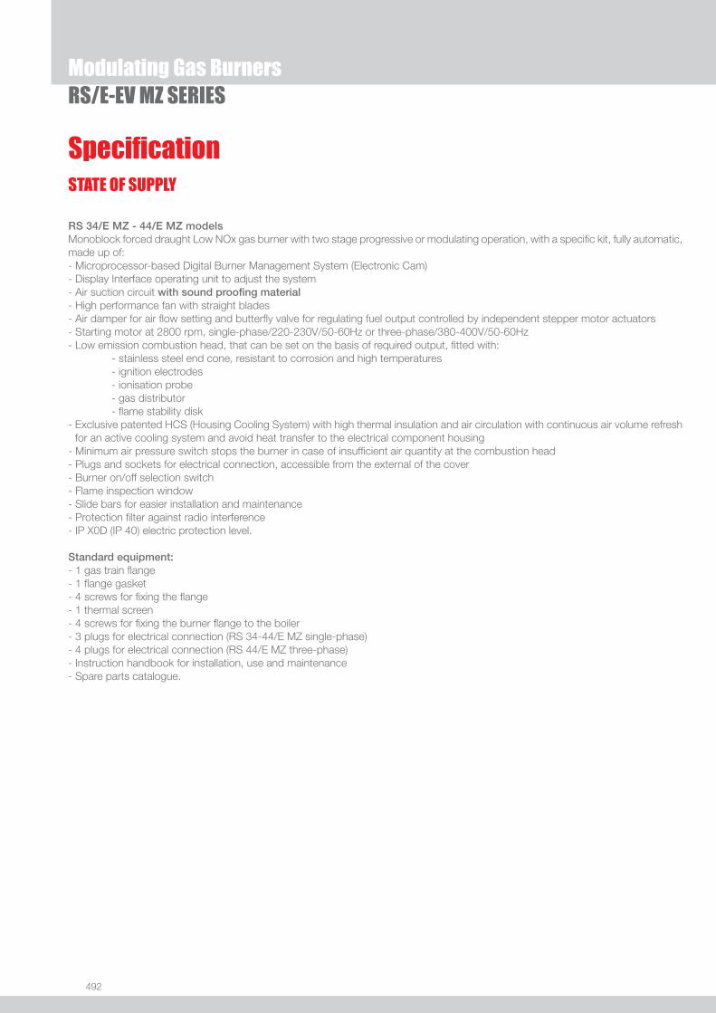
492
Modulating Gas BurnersRS/E-EV MZ SERIES
STATE OF SUPPLY
Specifi cation
RS 34/E MZ - 44/E MZ modelsMonoblock forced draught Low NOx gas burner with two stage progressive or modulating operation, with a specifi c kit, fully automatic, made up of:- Microprocessor-based Digital Burner Management System (Electronic Cam) - Display Interface operating unit to adjust the system- Air suction circuit with sound proofi ng material- High performance fan with straight blades- Air damper for air fl ow setting and butterfl y valve for regulating fuel output controlled by independent stepper motor actuators - Starting motor at 2800 rpm, single-phase/220-230V/50-60Hz or three-phase/380-400V/50-60Hz- Low emission combustion head, that can be set on the basis of required output, fi tted with: - stainless steel end cone, resistant to corrosion and high temperatures - ignition electrodes - ionisation probe - gas distributor - fl ame stability disk- Exclusive patented HCS (Housing Cooling System) with high thermal insulation and air circulation with continuous air volume refresh
for an active cooling system and avoid heat transfer to the electrical component housing- Minimum air pressure switch stops the burner in case of insuffi cient air quantity at the combustion head- Plugs and sockets for electrical connection, accessible from the external of the cover- Burner on/off selection switch- Flame inspection window- Slide bars for easier installation and maintenance- Protection fi lter against radio interference- IP X0D (IP 40) electric protection level.
Standard equipment:- 1 gas train fl ange- 1 fl ange gasket- 4 screws for fi xing the fl ange- 1 thermal screen- 4 screws for fi xing the burner fl ange to the boiler- 3 plugs for electrical connection (RS 34-44/E MZ single-phase)- 4 plugs for electrical connection (RS 44/E MZ three-phase)- Instruction handbook for installation, use and maintenance- Spare parts catalogue.
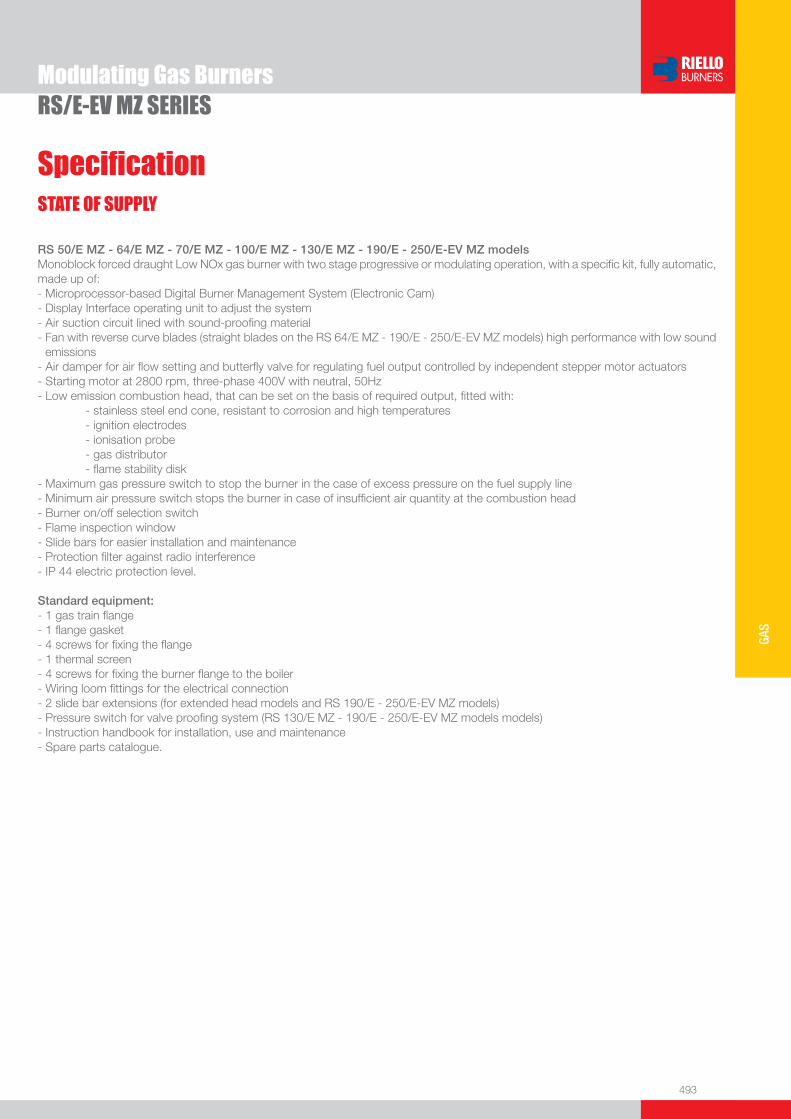
493
GAS
Modulating Gas BurnersRS/E-EV MZ SERIES
STATE OF SUPPLY
Specifi cation
RS 50/E MZ - 64/E MZ - 70/E MZ - 100/E MZ - 130/E MZ - 190/E - 250/E-EV MZ modelsMonoblock forced draught Low NOx gas burner with two stage progressive or modulating operation, with a specifi c kit, fully automatic, made up of:- Microprocessor-based Digital Burner Management System (Electronic Cam) - Display Interface operating unit to adjust the system- Air suction circuit lined with sound-proofi ng material- Fan with reverse curve blades (straight blades on the RS 64/E MZ - 190/E - 250/E-EV MZ models) high performance with low sound
emissions- Air damper for air fl ow setting and butterfl y valve for regulating fuel output controlled by independent stepper motor actuators - Starting motor at 2800 rpm, three-phase 400V with neutral, 50Hz - Low emission combustion head, that can be set on the basis of required output, fi tted with: - stainless steel end cone, resistant to corrosion and high temperatures - ignition electrodes - ionisation probe - gas distributor - fl ame stability disk- Maximum gas pressure switch to stop the burner in the case of excess pressure on the fuel supply line- Minimum air pressure switch stops the burner in case of insuffi cient air quantity at the combustion head- Burner on/off selection switch- Flame inspection window- Slide bars for easier installation and maintenance- Protection fi lter against radio interference- IP 44 electric protection level.
Standard equipment:- 1 gas train fl ange- 1 fl ange gasket- 4 screws for fi xing the fl ange- 1 thermal screen- 4 screws for fi xing the burner fl ange to the boiler- Wiring loom fi ttings for the electrical connection - 2 slide bar extensions (for extended head models and RS 190/E - 250/E-EV MZ models)- Pressure switch for valve proofi ng system (RS 130/E MZ - 190/E - 250/E-EV MZ models models) - Instruction handbook for installation, use and maintenance- Spare parts catalogue.

494
Burners
Available models
Modulating Gas BurnersRS/E-EV MZ SERIES
CODE MODEL
HEAT OUTPUT TOTAL ELECTRICAL
POWER
CERTIFICATION NOTE
NATURAL GAS
(kW) (Nm3/h) (kW)
3789410 RS 34/E MZ TC FS1 1/220-230/50-60 220-230/50-60 44/130÷ 390 4,5/13÷39 0,6 CE 0085BS0378 (1)(3)
3789411 RS 34/E MZ TL FS1 1/220-230/50-60 220-230/50-60 44/130÷ 390 4,5/13÷39 0,6 CE 0085BS0378 (1)(3)
3789510 RS 44/E MZ TC FS1 1/220-230/50-60 220-230/50-60 80/200÷550 8/20÷55 0,7 CE 0085BS0378 (1)(3)
3789511 RS 44/E MZ TL FS1 1/220-230/50-60 220-230/50-60 80/200÷550 8/20÷55 0,7 CE 0085BS0378 (1)(3)
3789540 RS 44/E MZ TC FS1 3/220-400/50-60 220-230/50-60 80/200÷550 8/20÷55 0,75 CE 0085BS0378 (1)(3)
3789541 RS 44/E MZ TL FS1 3/220-400/50-60 220-230/50-60 80/200÷550 8/20÷55 0,75 CE 0085BS0378 (1)(3)
3781622 RS 50/E MZ TC FS1 3/230-400/50 230/50-60 85/290-580 8,5/29-58 0,75 in progress (1)(3)
3781623 RS 50/E MZ TL FS1 3/230-400/50 230/50-60 85/290-580 8,5/29-58 0,75 in progress (1)(3)
3789910 RS 64/E MZ TC FS1 3/230-400/50 230/50-60 150/400÷850 15/40÷85 1,2 in progress (1)(3)
3789911 RS 64/E MZ TL FS1 3/230-400/50 230/50-60 150/400÷850 15/40÷85 1,2 in progress (1)(3)
3787032 RS 70/E MZ TC FS1 3/230-400/50 230/50-60 135/465-814 13,5/46,5-81 1,6 in progress (2)(3)
3787033 RS 70/E MZ TL FS1 3/230-400/50 230/50-60 135/465-814 13,5/46,5-81 1,6 in progress (2)(3)
3787232 RS 100/E MZ TC FS1 3/230-400/50 230/50-60 150/698-1163 15/70-116 2,0 in progress (2)(3)
3787233 RS 100/E MZ TL FS1 3/230-400/50 230/50-60 150/698-1163 15/70-116 2,0 in progress (2)(3)
3787432 RS 130/E MZ TC FS1 3/230-400/50 230/50-60 160/930-1512 16/93-151 2,8 in progress (2)(4)
3787433 RS 130/E MZ TL FS1 3/230-400/50 230/50-60 160/930-1512 16/93-151 2,8 in progress (2)(4)
3787632 RS 190/E MZ TC FS1 3/400/50 230/50-60 470/1279-2290 47/128-229 5,3 in progress (2)(4)
on demand RS 190/E MZ TC FS1 3/230/50 230/50-60 470/1279-2290 47/128-229 5,3 in progress (2)(4)
3789210 RS 250/E MZ TC FS1 3/400/50 230/50-60 600/1250÷2650 60/125÷265 6,5 CE 0085BT0061 (2)(4)
3789211 RS 250/E MZ TL FS1 3/400/50 230/50-60 600/1250÷2650 60/125÷265 6,5 CE 0085BT0061 (2)(4)
3789240 RS 250/E MZ TC FS1 3/230/50 230/50-60 600/1250÷2650 60/125÷265 6,5 CE 0085BT0061 (2)(4)
3789241 RS 250/E MZ TL FS1 3/230/50 230/50-60 600/1250÷2650 60/125÷265 6,5 CE 0085BT0061 (2)(4)
on demand RS 250/EV MZ TC FS1 3/400/50 230/50-60 600/1250÷2650 60/125÷265 6,5 in progress (2)(4)
Natural Gas, net calorifi c value: 10 kWh/Nm3 - Density at 20°C: 0,71 kg/Nm3
The burners of RS/E MZ series are in according to 90/396 - 89/336 (2004/108) - 73/23 (2006/95) - 92/42 EC Directive and EN 676 Norm.(1) With plug and socket. (2) With terminal board.(3) Seal control function is included on Burner Digital Management System; it is necessary to add the PVP kit on the gas train as Accessory (see Gas Train Accessories paragraph).(4) Seal control function is included on Burner Digital Management System; it is necessary to add the PVP kit (included as burner standard equipment) on the gas train.
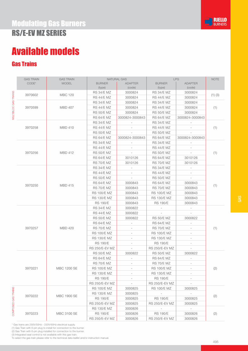
495
GAS
Gas Trains
Available models
Modulating Gas BurnersRS/E-EV MZ SERIES
GAS TRAIN GAS TRAIN NATURAL GAS LPG NOTECODE* MODEL BURNER ADAPTER BURNER ADAPTER
(type) (code) (type) (code)
MU
LTIB
LOC
GA
S T
RA
INS
3970602 MBC 120RS 34/E MZ 3000824 RS 34/E MZ 3000824
(1) (3) RS 44/E MZ 3000824 RS 44/E MZ 3000824
RS 34/E MZ 3000824 RS 34/E MZ 3000824
3970599 MBD 407 RS 44/E MZ 3000824 RS 44/E MZ 3000824 (1)
RS 50/E MZ 3000824 RS 50/E MZ 3000824
RS 64/E MZ 3000824-3000843 RS 64/E MZ 3000824-3000843
RS 34/E MZ - RS 34/E MZ -
3970258 MBD 410 RS 44/E MZ - RS 44/E MZ - (1)
RS 50/E MZ - RS 50/E MZ -
RS 64/E MZ 3000824-3000843 RS 64/E MZ 3000824-3000843
3970256
MBD 412
RS 34/E MZ - RS 34/E MZ -
(1)
RS 44/E MZ - RS 44/E MZ -
RS 50/E MZ - RS 50/E MZ -
RS 64/E MZ 3010126 RS 64/E MZ 3010126
RS 70/E MZ 3010126 RS 70/E MZ 3010126
3970250
MBD 415
RS 34/E MZ - RS 34/E MZ -
(1)
RS 44/E MZ - RS 44/E MZ -
RS 50/E MZ - RS 50/E MZ -
RS 64/E MZ 3000843 RS 64/E MZ 3000843
RS 70/E MZ 3000843 RS 70/E MZ 3000843
RS 100/E MZ 3000843 RS 100/E MZ 3000843
RS 130/E MZ 3000843 RS 130/E MZ 3000843
RS 190/E 3000843 RS 190/E 3000843
3970257 MBD 420
RS 34/E MZ 3000822 - -
(1)
RS 44/E MZ 3000822 - -
RS 50/E MZ 3000822 RS 50/E MZ 3000822
RS 64/E MZ - RS 64/E MZ -
RS 70/E MZ - RS 70/E MZ -
RS 100/E MZ - RS 100/E MZ -
RS 130/E MZ - RS 130/E MZ -
RS 190/E - RS 190/E -
RS 250/E-EV MZ - RS 250/E-EV MZ -
3970221 MBC 1200 SE
RS 50/E MZ 3000822 RS 50/E MZ 3000822
(2)
RS 64/E MZ - RS 64/E MZ -
RS 70/E MZ - RS 70/E MZ -
RS 100/E MZ - RS 100/E MZ -
RS 130/E MZ - RS 130/E MZ -
RS 190/E - RS 190/E -
RS 250/E-EV MZ - RS 250/E-EV MZ -
CO
MP
OS
ED
GA
S T
RA
INS
3970222 MBC 1900 SE
RS 100/E MZ 3000825 RS 100/E MZ 3000825
(2)RS 130/E MZ 3000825 - -
RS 190/E 3000825 RS 190/E 3000825
RS 250/E-EV MZ 3000825 RS 250/E-EV MZ 3000825
3970223 MBC 3100 SE
RS 130/E MZ 3000826 - -
(2)RS 190/E 3000826 RS 190/E 3000826
RS 250/E-EV MZ 3000826 RS 250/E-EV MZ 3000826
* Gas trains are 230V/50Hz - 220V/60Hz electrical supply.(1) Gas Train with 6-pin plug to install for connection to the burner. (2) Gas Train with 6-pin plug installed for connection to the burner.(3) Integrated seal control is not available with this gas train. To select the gas train please refer to the technical data leafl et and/or instruction manual.
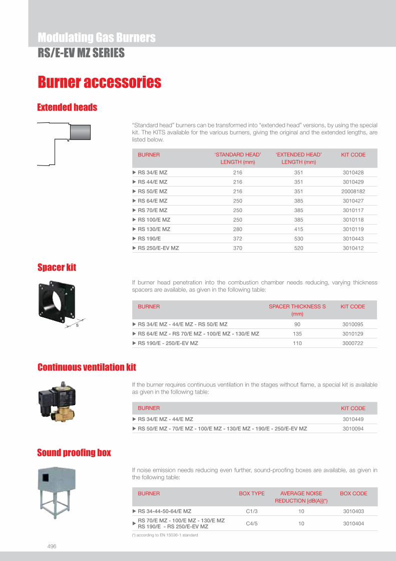
496
Modulating Gas BurnersRS/E-EV MZ SERIES
Burner accessories
Extended heads
“Standard head” burners can be transformed into “extended head” versions, by using the special kit. The KITS available for the various burners, giving the original and the extended lengths, are listed below.
BURNER ‘STANDARD HEAD’ LENGTH (mm)
‘EXTENDED HEAD’ LENGTH (mm)
KIT CODE
u RS 34/E MZ 216 351 3010428
u RS 44/E MZ 216 351 3010429
u RS 50/E MZ 216 351 20008182
u RS 64/E MZ 250 385 3010427
u RS 70/E MZ 250 385 3010117
u RS 100/E MZ 250 385 3010118
u RS 130/E MZ 280 415 3010119
u RS 190/E 372 530 3010443
u RS 250/E-EV MZ 370 520 3010412
Spacer kit
If burner head penetration into the combustion chamber needs reducing, varying thickness spacers are available, as given in the following table:
BURNER SPACER THICKNESS S (mm)
KIT CODE
u RS 34/E MZ - 44/E MZ - RS 50/E MZ 90 3010095
u RS 64/E MZ - RS 70/E MZ - 100/E MZ - 130/E MZ 135 3010129
u RS 190/E - 250/E-EV MZ 110 3000722
Continuous ventilation kit
If the burner requires continuous ventilation in the stages without fl ame, a special kit is available as given in the following table:
BURNER KIT CODE
u RS 34/E MZ - 44/E MZ 3010449
u RS 50/E MZ - 70/E MZ - 100/E MZ - 130/E MZ - 190/E - 250/E-EV MZ 3010094
Sound proofi ng box
If noise emission needs reducing even further, sound-proofi ng boxes are available, as given in the following table:
BURNER BOX TYPE AVERAGE NOISE REDUCTION [dB(A)](*)
BOX CODE
u RS 34-44-50-64/E MZ C1/3 10 3010403
uRS 70/E MZ - 100/E MZ - 130/E MZ RS 190/E - RS 250/E-EV MZ C4/5 10 3010404
(*) according to EN 15036-1 standard
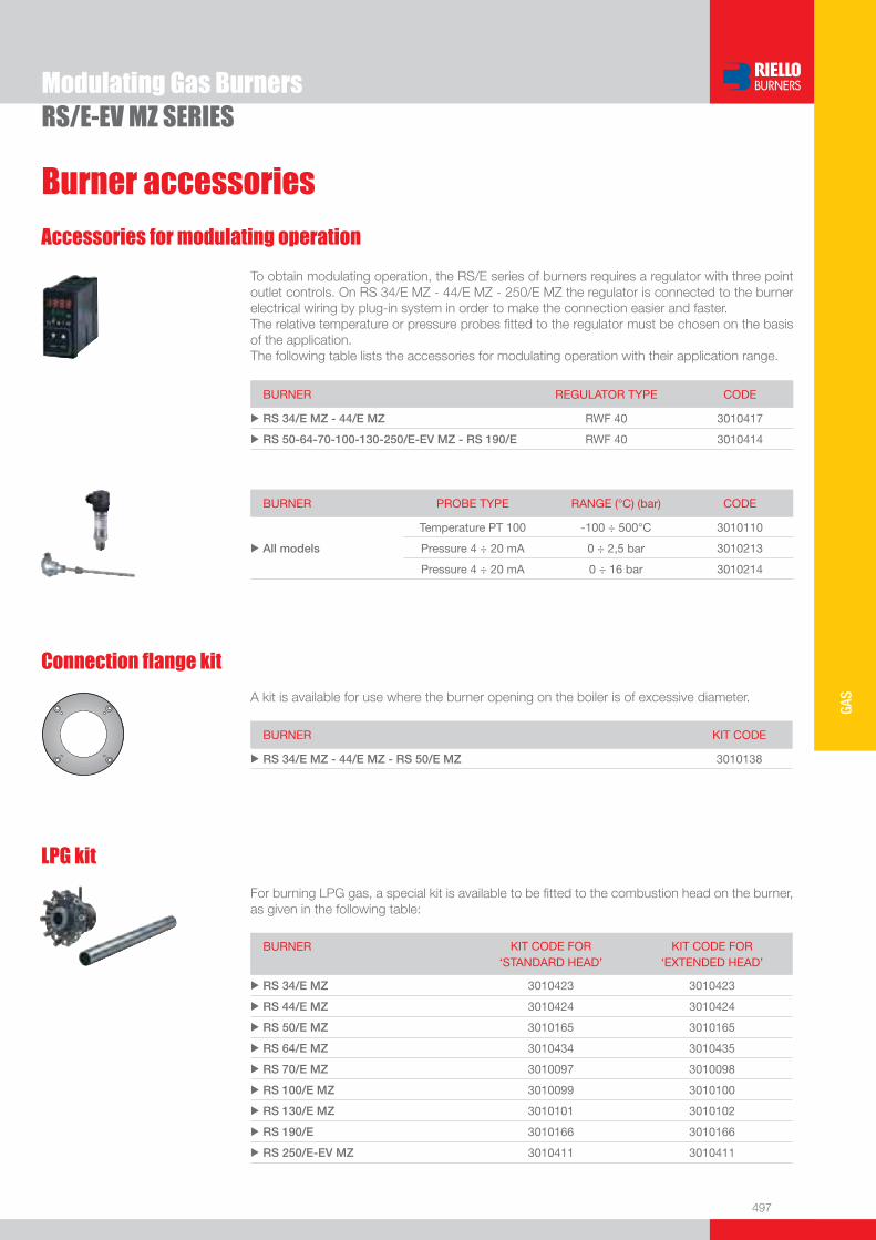
497
GAS
Burner accessories
Modulating Gas BurnersRS/E-EV MZ SERIES
Accessories for modulating operation
To obtain modulating operation, the RS/E series of burners requires a regulator with three point outlet controls. On RS 34/E MZ - 44/E MZ - 250/E MZ the regulator is connected to the burner electrical wiring by plug-in system in order to make the connection easier and faster. The relative temperature or pressure probes fi tted to the regulator must be chosen on the basis of the application. The following table lists the accessories for modulating operation with their application range.
BURNER REGULATOR TYPE CODE
u RS 34/E MZ - 44/E MZ RWF 40 3010417
u RS 50-64-70-100-130-250/E-EV MZ - RS 190/E RWF 40 3010414
BURNER PROBE TYPE RANGE (°C) (bar) CODE
Temperature PT 100 -100 ÷ 500°C 3010110
u All models Pressure 4 ÷ 20 mA 0 ÷ 2,5 bar 3010213
Pressure 4 ÷ 20 mA 0 ÷ 16 bar 3010214
Connection fl ange kit
BURNER KIT CODE
u RS 34/E MZ - 44/E MZ - RS 50/E MZ 3010138
A kit is available for use where the burner opening on the boiler is of excessive diameter.
LPG kit
For burning LPG gas, a special kit is available to be fi tted to the combustion head on the burner, as given in the following table:
BURNER KIT CODE FOR‘STANDARD HEAD’
KIT CODE FOR‘EXTENDED HEAD’
u RS 34/E MZ 3010423 3010423
u RS 44/E MZ 3010424 3010424
u RS 50/E MZ 3010165 3010165
u RS 64/E MZ 3010434 3010435
u RS 70/E MZ 3010097 3010098
u RS 100/E MZ 3010099 3010100
u RS 130/E MZ 3010101 3010102
u RS 190/E 3010166 3010166
u RS 250/E-EV MZ 3010411 3010411

498
Modulating Gas BurnersRS/E-EV MZ SERIES
Burner accessories
Town gas kit
For burning Town gas, a special kit is available:
BURNER KIT CODE FOR‘STANDARD HEAD’ (*)
KIT CODE FOR‘EXTENDED HEAD’ (*)
u RS 34/E MZ 3010502 3010502
u RS 44/E MZ 3010503 3010503
u RS 50/E MZ 3010285 3010285
u RS 70/E MZ 3010286 3010286
u RS 100/E MZ 3010287 3010287
u RS 130/E MZ 3010288 3010288
u RS 190/E 3010297 3010297 (*) Without CE certifi cation
Gas max pressure switch
If necessary a Gas max pressure Switch kit is available and connectable to the burner electrical wiring through Plugs & Sockets system.
BURNER KIT CODE
u RS 34/E MZ - 44/E MZ 3010418
�� ��
��
�
����
����
��
��
���
Volt free contact kitA volt free contact kit is available for installation onto the burner. It can be used for a remote interface between burner operating signals. Every burner can be equipped with a single kit for a remote check of the fl ame presence signal and the burner lockout indication.
BURNER KIT CODE
u RS 34/E MZ - 44/E MZ 3010419
DN80 gas fl ange kit
To modify the standard 2” burner gas input connection in to DN80 connection, a specifi c gas fl ange is available.
BURNER KIT CODE
u RS 64-70-100-130-250/E EV MZ - RS 190/E 3010439
Ground fault interrupter kit
A “Ground fault interrupter kit” is available as a safety device for electrical system fault.
BURNER KIT CODE
u RS 34/E MZ - 44/E MZ 3010448
u RS 50/E MZ - RS 64/E MZ 3010321
u RS 70-100-130-250/E-EV MZ - RS 190/E 3010329

499
GAS
Burner accessories
Modulating Gas BurnersRS/E-EV MZ SERIES
Stabiliser springAccessory springs are available to vary the pressure range of the gas train stabilisers. The following table shows these accessories with their application range. Please refer to the technical manual for the correct choice of spring.
GAS TRAIN SPRING SPRING CODE
u
MBC 1900 MBC 3100 MBC 5000
White from 4 to 20 mbar 3010381
Red from 20 to 40 mbar 3010382
Black from 40 to 80 mbar 3010383
Green from 80 to 150 mbar 3010384
OCI410 interface for ACS410 software kit
Interface kit between burner management system and PC. It facilitates viewing, handling and recording setting parameters on site.
BURNER KIT CODE
u RS 34-44-64-70-100-130-250/E-EV MZ - RS 190/E 3010436
OCI412 interface kitInterface kit between the REC27.100A2 and a Modbus system, such as a building automation and control system (BACS). The Modbus interface is based on the RS-485 standard.
BURNER KIT CODE
u RS 34-44-64-70-100-130-250/E-EV MZ - RS 190/E 3010437
PVP (Pressure Valve Proving) kit *
The seal control function is included on Burner Digital Management System, it is only necessary to add the PVP kit on the gas train.The PVP is included as standard equipment on RS 130/E-250/E-EV MZ and RS 190/E models.
BURNER KIT CODE
u MBD type - MBC type ** 3010344
* not necessary for the RS 130/E-250/E MZ and RS 190/E models where is included as a standard.** MBC 120 model excluded (integrated seal control is not available with this gas train).
Gas train accessories
Variable Speed Drive (VSD) for RS/EV series only
The motor speed variation for the RS/EV MZ burners series is obtained thanks to a frequency converter: variable speed drive (VSD). It always must be ordered with RS/EV series.
BURNER KIT CODE
u RS 250/EV MZ 3010379

500
Gas train accessories
Modulating Gas BurnersRS/E-EV MZ SERIES
Adapters
When the diameter of the gas train is different from the set diameter of the burners, an adapter must be fi tted between the gas train and the burner. The following table lists the adapters for various burners.
BURNER GAS TRAIN DIMENSIONS ADAPTER CODE
u RS 34/E MZ MBC 120 - MBD 407 1” 1/23/4” 3000824
MBD 420 1” 1/22” 3000822
u RS 44/E MZMBC 120 - MBD 407 1” 1/23/4” 3000824
MBD 420 1” 1/22” 3000822
u RS 50/E MZMBC 120 - MBD 407 1” 1/23/4” 3000824
MBD 420 - MBC 1200 1” 1/22” 3000822
u RS 64/E MZMBD 407
1” 1/23/4”
2”1” 1/2
3000824+
3000843
MBD 415 2”1” 1/2 3000843
u RS 70/E MZMBD 412 2”1” 1/4 3010126
MBD 415 2”1” 1/2 3000843
u RS 100/E MZ
MBD 415 2”1” 1/2 3000843
MBC 1900 2” 1/2DN 65
1” 1/2
2”
3000825
u RS 130/E MZ
MBD 415 2”1” 1/2 3000843
MBC 1900 2” 1/2DN 65
1” 1/2
2”
3000825
MBC 3100 2” 1/2DN 80 2” 3000826
u RS 190/E
MBD 415 2”1” 1/2 3000843
MBC 1900 2” 1/2DN 65
1” 1/2
2”
3000825
MBC 3100 2” 1/2DN 80 2” 3000826
u RS 250/E-EV MZMBC 1900 2” 1/2DN 65
1” 1/2
2”
3000825
MBC 3100 2” 1/2DN 80 2” 3000826

501
GAS
Modulating Gas Burners
MODUBLOC MB SE SERIESThe MODUBLOC MB SE series of burners are characterised by a monoblock structure that means all necessary components can be combined in a single unit, making installation easier and faster. The series covers a fi ring range from 3300 to 9580 kW, and they have been designed for use in hot water boilers or industrial steam generators.Adjustment is modulating, through an innovative electronic module, which gives control of the air/fuel ratio and PID control of the generator temperature or pressure.The mechanisms of regulation allow to catch up a high modulation ratio on all fi ring rates range.The burner can, therefore, supply with precision the demanded power, guaranteeing a high effi ciency system level and the stability setting, obtaining fuel consumption and operating costs reduction. An exclusive design, with fan unit fi tted on line with the combustion head, guarantees low sound emissions, reduced dimensions, easy use and maintenance.
MB 8 SE 1300/3300 ÷ 8600 kWMB 10 SE 1185/4000 ÷ 9580 kW
FIRING RATES
Useful working fi eldfor choosing theburner
Modulation range
Test conditionsconforming to EN676 Temperature: 20°CPressure: 1013,5 mbarAltitude: 0 m a.s.l.

502
BURNER
Overall dimensions (mm)
Z
XY
Modulating Gas BurnersMODUBLOC MB SE SERIES
BURNER - BOILER MOUNTING FLANGE
MODEL A D E F H I M N O S uMB 8 SE 1007 1079 1900 530 413 575 DN80 208 1570 1740
uMB 10 SE 1007 1079 1900 530 413 575 DN80 208 1570 1740
MODEL D1 D2 Ø uMB 8 SE 418 608 M20
uMB 10 SE 418 608 M20
MODEL X Y Z kg uMB 8 SE 2700 1170 1350 450
uMB 10 SE 2700 1170 1350 450
PACKAGING
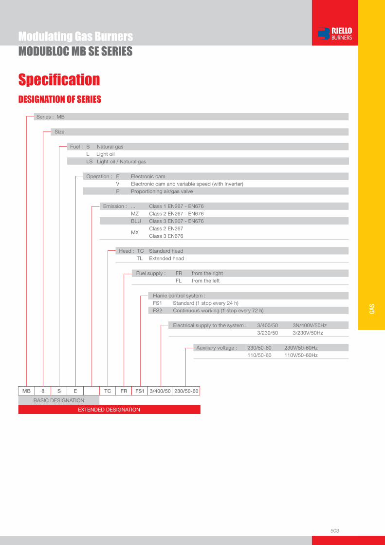
503
GAS
DESIGNATION OF SERIES
Specifi cation
Modulating Gas BurnersMODUBLOC MB SE SERIES
EXTENDED DESIGNATION
MB 8 S E TC FR FS1 3/400/50 230/50-60
Series : MB
Size
Fuel : S Natural gas L Light oil LS Light oil / Natural gas
Operation : E Electronic cam V Electronic cam and variable speed (with Inverter) P Proportioning air/gas valve Emission : ... Class 1 EN267 - EN676 MZ Class 2 EN267 - EN676 BLU Class 3 EN267 - EN676
MX Class 2 EN267
Class 3 EN676
Head : TC Standard head TL Extended head
Fuel supply : FR from the right FL from the left
Flame control system : FS1 Standard (1 stop every 24 h) FS2 Continuous working (1 stop every 72 h)
Electrical supply to the system : 3/400/50 3N/400V/50Hz 3/230/50 3/230V/50Hz Auxiliary voltage : 230/50-60 230V/50-60Hz 110/50-60 110V/50-60Hz
BASIC DESIGNATION

504
Modulating Gas BurnersMODUBLOC MB SE SERIES
STATE OF SUPPLY
Specifi cation
Monoblock forced draught gas burner with modulating operation, fully automatic, made up of:- Fan with reverse curve blades high performance with low sound emissions- Air suction circuit lined with sound-proofi ng material- Air damper for air setting controlled by a high precision servomotor- Air pressure switch- Fan starting motor at 2900 rpm, three-phase 230/400 - 400/690 V with neutral, 50Hz - Mobile combustion head, that can be set on the basis of required output, fi tted with: - stainless steel end cone, resistant to corrosion and high temperatures - ignition electrodes - fl ame stability disk- Automatic regulator for gas delivery, controlled by a high precision servomotor- Maximum gas pressure switch, with pressure test point, for halting the burner in the case of over pressure on the fuel supply
line- Module for air/fuel setting and output modulation with incorporated PID control of temperature or pressure of the heat generator- Burner safety control box for controlling the system safety- Photocell for fl ame detection- Star/triangle starter for the fan motor- Main electrical supply terminal board- Burner on/off switch - Auxiliary voltage led signal- Manual or automatic output increase/decrease switch- Burner working led signal- Contacts motor and thermal relay with release button- Motor internal thermal protection- Motor failure led signal - Burner failure led signal and lighted release button- Led signal for correct rotation direction of fan motor- Emergency button- Coded connection plugs-sockets- Burner opening hinge- Lifting rings- IP X0D (IP 40) protection level.
Standard equipment:- 1 fl ange gasket- 8 screws for fi xing the fl ange- 1 thermal screen- 4 screws for fi xing the burner fl ange to the boiler- Instruction handbook for installation, use and maintenance- Spare parts catalogue.

505
GAS
Available modelsBurners
Modulating Gas BurnersMODUBLOC MB SE SERIES
Gas Trains
CODE MODEL HEAT OUTPUT TOTAL ELECTRICAL
POWER
CERTIFICATION NOTE
NATURAL GAS
(kW) (Nm3/h) (kW)
3786200 MB8SE TC FR FS1 3/400/50 230/50-60 1300/3300-8600 130/330-860 18 CE 0085BO0169
3786210 MB8SE TC FR FS2 3/400/50 230/50-60 1300/3300-8600 130/330-860 18 CE 0085BO0169
3786205 MB8SE TC FL FS1 3/400/50 230/50-60 1300/3300-8600 130/330-860 18 CE 0085BO0169
3786215 MB8SE TC FL FS2 3/400/50 230/50-60 1300/3300-8600 130/330-860 18 CE 0085BO0169
3786300 MB10SE TC FR FS1 3/400/50 230/50-60 1185/4000-9580 119/400-958 22 CE 0085BO0162
3786310 MB10SE TC FR FS2 3/400/50 230/50-60 1185/4000-9580 119/400-958 22 CE 0085BO0162
3786305 MB10SE TC FL FS1 3/400/50 230/50-60 1185/4000-9580 119/400-958 22 CE 0085BO0162
3786315 MB10SE TC FL FS2 3/400/50 230/50-60 1185/4000-9580 119/400-958 22 CE 0085BO0162
G20 net calorifi c value 10 kWh/Nm3 - Density 0,71 kg/Nm3
The burners of MB SE series are in according to 90/396 - 89/336 (2004/108) - 73/23 (2006/95) EC Directive and EN 676 Norm.
* gas trains are 230V/50Hz - 220V/60Hz electrical supply(1) Seal control incorporated
To select the gas train please refer to the technical data leafl et and/or instruction manual.
GAS TRAIN GAS TRAIN NATURAL GAS LPG NOTE
CODE * MODEL BURNER (type)
ADAPTER (code)
BURNER (type)
ADAPTER (code)
MU
LTIB
LOC
3970225 MBC 1200 SE 50 CT MB 8 SE
3000826 (“I”) type MB 8 SE
3000826 (“I”) type (1) MB 10 SE MB 10 SE
CO
MP
OS
ED
GA
S T
RA
IN
3970226 MBC 1900 SE 65 FC CTMB 8 SE 3010221 (“I”) type
3010225 (“Z”) type
MB 8 SE 3010221 (“I”) type 3010225 (“Z”) type
(1)MB 10 SE MB 10 SE
3970227 MBC 3100 SE 80 FC CTMB 8 SE 3010222 (“I”) type
3010226 (“Z”) type
MB 8 SE 3010222 (“I”) type 3010226 (“Z”) type
(1)MB 10 SE MB 10 SE
3970228 MBC 5000 SE 100 FC CTMB 8 SE 3010223 (“I”) type
3010227 (“Z”) type
MB 8 SE 3010223 (“I”) type 3010227 (“Z”) type
(1)MB 10 SE MB 10 SE
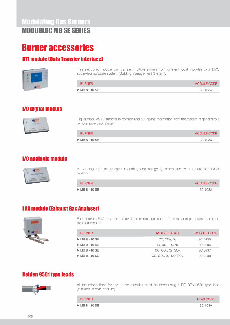
506
Burner accessories
MODUBLOC MB SE SERIESModulating Gas Burners
DTI module (Data Transfer Interface)
This electronic module can transfer multiple signals from different local modules to a BMS supervisor software system (Building Management System).
BURNER MODULE CODE
u MB 8 - 10 SE 3010234
I/O digital module
Digital modules I/O transfer in-coming and out-going information from the system in general to a remote supervisor system.
BURNER MODULE CODE
u MB 8 - 10 SE 3010233
I/O analogic module
I/O Analog modules transfer in-coming and out-going information to a remote supervisor system.
BURNER MODULE CODE
u MB 8 - 10 SE 3010232
EGA module (Exhaust Gas Analyser)
Four different EGA modules are available to measure some of the exhaust gas substances and their temperature.
BURNER ANALYSED GAS MODULE CODE
u MB 8 - 10 SE CO, CO2, O2 3010235
u MB 8 - 10 SE CO, CO2, O2, NO 3010236
u MB 8 - 10 SE CO, CO2, O2, SO2 3010237
u MB 8 - 10 SE CO, CO2, O2, NO, SO2 3010238
Belden 9501 type leads
All the connections for the above modules must be done using a BELDEN 9501 type lead (available in coils of 50 m).
BURNER LEAD CODE
u MB 8 - 10 SE 3010239

507
GAS
Burner accessories
MODUBLOC MB SE SERIESModulating Gas Burners
Accessories for modulating operation
Main management module allows a modulating operation with use of probes chosen on the basis of the application.
BURNER PROBE TYPE RANGE (°C) (bar) PROBE CODE
u MB 8 - 10 SE Temperature 0 ÷ 400°C 3010187
u MB 8 - 10 SE Pressure 0 ÷ 3 bar 3010246
u MB 8 - 10 SE Pressure 0 ÷ 18 bar 3010186
u MB 8 - 10 SE Pressure 0 ÷ 30 bar 3010188
Burner support
For easier maintenance, a mobile burner support has been designed.
BURNER SUPPORT CODE
u MB 8 - 10 SE 3010385
LPG kit
For burning LPG gas, a special kit is available.
BURNER KIT CODE
u MB 8 - 10 SE 3010296
If noise emission needs reducing even further, sound-proofi ng boxes are available.
Sound proofi ng box
BURNER
AVERAGE NOISE REDUCTION [dB(A)] (*)
BOX CODE
u MB 8 - 10 SE 10 3010401
(*) according to EN 15036-1 standard
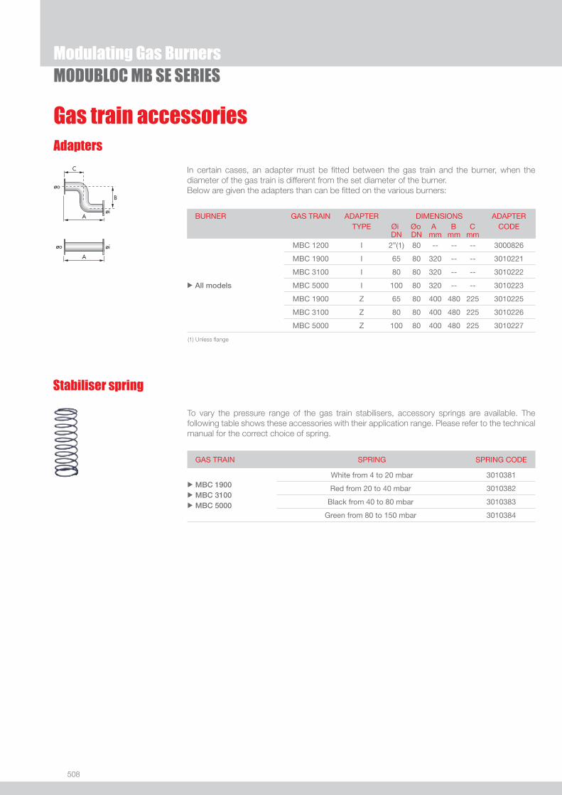
508
Gas train accessories
Modulating Gas BurnersMODUBLOC MB SE SERIES
Adapters
In certain cases, an adapter must be fi tted between the gas train and the burner, when the diameter of the gas train is different from the set diameter of the burner.Below are given the adapters than can be fi tted on the various burners:
To vary the pressure range of the gas train stabilisers, accessory springs are available. The following table shows these accessories with their application range. Please refer to the technical manual for the correct choice of spring.
Stabiliser spring
GAS TRAIN SPRING SPRING CODE
u
u
u
MBC 1900 MBC 3100 MBC 5000
White from 4 to 20 mbar 3010381
Red from 20 to 40 mbar 3010382
Black from 40 to 80 mbar 3010383
Green from 80 to 150 mbar 3010384
BURNER GAS TRAIN ADAPTER TYPE
DIMENSIONS Øi Øo A B C
ADAPTER CODE
DN DN mm mm mm
u All models
MBC 1200 I 2”(1) 80 -- -- -- 3000826
MBC 1900 I 65 80 320 -- -- 3010221
MBC 3100 I 80 80 320 -- -- 3010222
MBC 5000 I 100 80 320 -- -- 3010223
MBC 1900 Z 65 80 400 480 225 3010225
MBC 3100 Z 80 80 400 480 225 3010226
MBC 5000 Z 100 80 400 480 225 3010227
(1) Unless fl ange

Low NOx Modulating Dual Fuel Burners
509
LOW
NOx
DUA
L FU
EL
RLS/M MX SERIES
Useful working fi eldfor choosing theburner
Modulation range
Test conditionsconforming to EN267- EN676 Temperature: 20°CPressure: 1013,5 mbarAltitude: 0 m a.s.l.
The RLS/M MX series of burners covers a fi ring range from 350 to 1840 kW, and they have been designed for use in low or medium temperature hot water boilers, hot air or steam boilers, diathermic oil boilers.Operation is “two stage” at the oil side and “modulating” at the gas side with the installation of a PID logic regulator and respective probes.RLS/M MX series burners guarantees high effi ciency levels in all the various applications, thus reducing fuel consumption and running costs.Optimisation of sound emissions is guaranteed by the special design of air suction circuit and the use of sound proofi ng material.The exclusive design ensures reduced dimensions, simple use and maintenance. A wide range of accessories guarantees elevated working fl exibility.
RLS 68/M MX 200/350 ÷ 860 kWRLS 120/M MX 300/600 ÷ 1200 kWRLS 160/M MX 300/930 ÷ 1840 kW
FIRING RATES

510
RLS/M MX SERIES
BURNER
Overall dimensions (mm)
Low NOx Modulating Dual Fuel Burners
(1) Length with extended combustion head.
BURNER - BOILER MOUNTING FLANGE
MODEL A B C D E F - F (1) H I L M N O - O (1) V u RLS 68/M MX 691 296 395 555 840 260 - 395 214 430 214 2” 134 1161 - 1300 221
u RLS 120/M MX 733 338 395 555 840 260 - 395 214 430 214 2” 134 1161 - 1300 221
u RLS 160/M MX 843 366 477 555 863 373 - 503 221 430 237 2” 141 1442 - 1589 186
MODEL D1 D2 Ø u RLS 68-120/M MX 195 275 - 325 M12
u RLS 160/M MX 230 325 - 368 M16
(1) Length with standard and extended combustion head.
MODEL X (1) Y Z kg u RLS 68/M MX 1400 975 645 70
u RLS 120/M MX 1400 975 645 76
u RLS 160/M MX 1400 975 645 95
PACKAGING
Z
XY
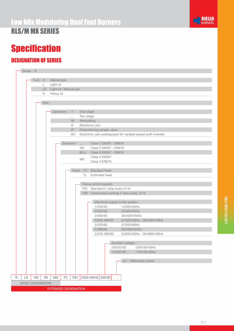
511
RLS/M MX SERIES
DESIGNATION OF SERIES
Specifi cation
Low NOx Modulating Dual Fuel Burners
LOW
NOx
DUA
L FU
EL
EXTENDED DESIGNATION
R LS 160 /M MX TC FS1 3/230-400/50 230/50
Series : R
Fuel : S Natural gas L Light oil LS Light oil / Natural gas N Heavy oil
Size
Operation : /1 One stage ... Two stage /M Modulating /E Electronic cam /P Proportioning air/gas valve /EV Electronic cam predisposed for variable speed (with inverter) Emission : ... Class 1 EN267 - EN676 MZ Class 2 EN267 - EN676 BLU Class 3 EN267 - EN676
MX Class 2 EN267
Class 3 EN676
Head : TC Standard head TL Extended head
Flame control system : FS1 Standard (1 stop every 24 h) FS2 Continuous working (1 stop every 72 h)
Electrical supply to the system : 1/230/50 1/230V/50Hz 3/230/50 3/230V/50Hz 3/400/50 3N/400V/50Hz 3/230-400/50 3/230V/50Hz - 3N/400V/50Hz 3/220/60 3/220V/60Hz 3/380/60 3N/380V/60Hz 3/220-380/60 3/220V/60Hz - 3N/380V/60Hz
Auxiliary voltage : 230/50-60 230V/50-60Hz 110/50-60 110V/50-60Hz
ID : Differential switch
BASIC DESIGNATION

512
RLS/M MX SERIESLow NOx Modulating Dual Fuel Burners
STATE OF SUPPLY
Specifi cation
Monoblock forced draught Low NOx dual fuel burner with two stage operation at the oil side and two stage progressive or modulating operation at the gas side, with a specifi c kit, fully automatic, made up of:- air suction circuit lined with sound-proofi ng material- centrifugal fan with high performance and low sound emissions- air damper for air fl ow setting and butterfl y valve for regulating gas output controlled by a servomotor with variable cam- starting motor at 2800 rpm, three-phase 400V with neutral, 50Hz - low emission combustion head, that can be set on the basis of required output, fi tted with: - stainless steel end cone, resistant to corrosion and high temperatures - ignition electrodes - gas distributor - fl ame stability disk- maximum gas pressure switch to stop the burner in the case of excess pressure on the fuel supply line- minimum air pressure switch stops the burner in case of insuffi cient air quantity at the combustion head- gears pump for high pressure fuel supply - pump starting motor- oil safety valves- two oil valves (1st and 2nd stage)- burner safety control box- UV photocell for fl ame detection- burner on/off selection switch- manual or automatic output increase/decrease selection switch- Oil/Gas selector- fl ame inspection window- slide bars for easier installation and maintenance- protection fi lter against radio interference- IP 44 electric protection level.
Standard equipment:- 1 gas train fl ange- 1 fl ange gasket- 4 screws for fi xing the fl ange- 1 thermal screen- 4 screws for fi xing the burner fl ange to the boiler- 2 fl exible pipes for connection to the oil supply network- 2 nipples for connection to the pump with gaskets- Instruction handbook for installation, use and maintenance- Spare parts catalogue.
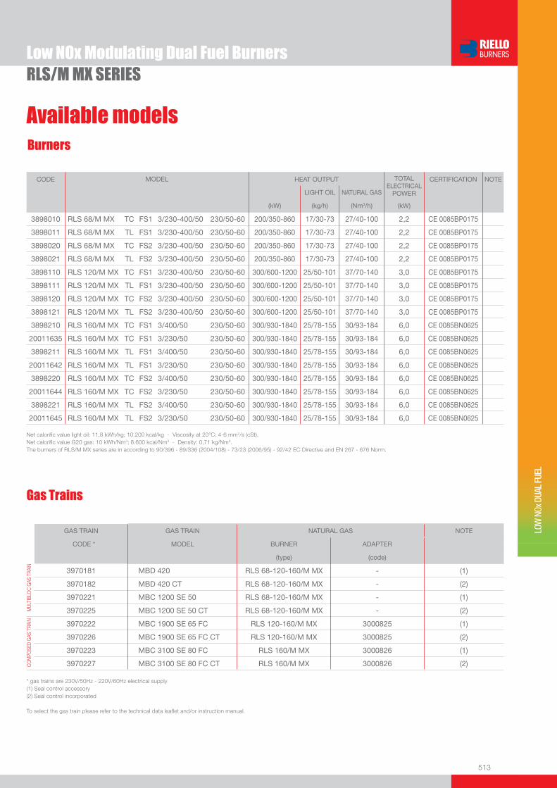
513
RLS/M MX SERIESLow NOx Modulating Dual Fuel Burners
LOW
NOx
DUA
L FU
EL
Gas Trains
Burners
Available models
Net calorifi c value light oil: 11,8 kWh/kg; 10.200 kcal/kg - Viscosity at 20°C: 4-6 mm2/s (cSt).Net calorifi c value G20 gas: 10 kWh/Nm3; 8.600 kcal/Nm3 - Density: 0,71 kg/Nm3.The burners of RLS/M MX series are in according to 90/396 - 89/336 (2004/108) - 73/23 (2006/95) - 92/42 EC Directive and EN 267 - 676 Norm.
CODE MODEL HEAT OUTPUT TOTALELECTRICAL
POWER
CERTIFICATION NOTE
LIGHT OIL NATURAL GAS
(kW) (kg/h) (Nm3/h) (kW)
3898010 RLS 68/M MX TC FS1 3/230-400/50 230/50-60 200/350-860 17/30-73 27/40-100 2,2 CE 0085BP0175
3898011 RLS 68/M MX TL FS1 3/230-400/50 230/50-60 200/350-860 17/30-73 27/40-100 2,2 CE 0085BP0175
3898020 RLS 68/M MX TC FS2 3/230-400/50 230/50-60 200/350-860 17/30-73 27/40-100 2,2 CE 0085BP0175
3898021 RLS 68/M MX TL FS2 3/230-400/50 230/50-60 200/350-860 17/30-73 27/40-100 2,2 CE 0085BP0175
3898110 RLS 120/M MX TC FS1 3/230-400/50 230/50-60 300/600-1200 25/50-101 37/70-140 3,0 CE 0085BP0175
3898111 RLS 120/M MX TL FS1 3/230-400/50 230/50-60 300/600-1200 25/50-101 37/70-140 3,0 CE 0085BP0175
3898120 RLS 120/M MX TC FS2 3/230-400/50 230/50-60 300/600-1200 25/50-101 37/70-140 3,0 CE 0085BP0175
3898121 RLS 120/M MX TL FS2 3/230-400/50 230/50-60 300/600-1200 25/50-101 37/70-140 3,0 CE 0085BP0175
3898210 RLS 160/M MX TC FS1 3/400/50 230/50-60 300/930-1840 25/78-155 30/93-184 6,0 CE 0085BN0625
20011635 RLS 160/M MX TC FS1 3/230/50 230/50-60 300/930-1840 25/78-155 30/93-184 6,0 CE 0085BN0625
3898211 RLS 160/M MX TL FS1 3/400/50 230/50-60 300/930-1840 25/78-155 30/93-184 6,0 CE 0085BN0625
20011642 RLS 160/M MX TL FS1 3/230/50 230/50-60 300/930-1840 25/78-155 30/93-184 6,0 CE 0085BN0625
3898220 RLS 160/M MX TC FS2 3/400/50 230/50-60 300/930-1840 25/78-155 30/93-184 6,0 CE 0085BN0625
20011644 RLS 160/M MX TC FS2 3/230/50 230/50-60 300/930-1840 25/78-155 30/93-184 6,0 CE 0085BN0625
3898221 RLS 160/M MX TL FS2 3/400/50 230/50-60 300/930-1840 25/78-155 30/93-184 6,0 CE 0085BN0625
20011645 RLS 160/M MX TL FS2 3/230/50 230/50-60 300/930-1840 25/78-155 30/93-184 6,0 CE 0085BN0625
GAS TRAIN GAS TRAIN NATURAL GAS NOTE
CODE * MODEL BURNER ADAPTER
(type) (code)
MUL
TIBL
OC G
AS T
RAIN
3970181 MBD 420 RLS 68-120-160/M MX - (1)
3970182 MBD 420 CT RLS 68-120-160/M MX - (2)
3970221 MBC 1200 SE 50 RLS 68-120-160/M MX - (1)
3970225 MBC 1200 SE 50 CT RLS 68-120-160/M MX - (2)
COM
POSE
D GA
S TR
AIN
3970222 MBC 1900 SE 65 FC RLS 120-160/M MX 3000825 (1)
3970226 MBC 1900 SE 65 FC CT RLS 120-160/M MX 3000825 (2)
3970223 MBC 3100 SE 80 FC RLS 160/M MX 3000826 (1)
3970227 MBC 3100 SE 80 FC CT RLS 160/M MX 3000826 (2)
* gas trains are 230V/50Hz - 220V/60Hz electrical supply(1) Seal control accessory(2) Seal control incorporated
To select the gas train please refer to the technical data leafl et and/or instruction manual.

514
RLS/M MX SERIESLow NOx Modulating Dual Fuel Burners
Nozzles type 60° B
The nozzles must be ordered separately. The following table shows the features and codes on the basis of the maximum required fuel output.
NOTE: each burner needs N° 2 nozzles.
Burner accessories
(*) Nozzle rated delivery is reffered to atomized pressure
BURNER RATED DELIVERY kg/h (*) GPH NOZZLE
u RLS 68-120/M MX
21,2 5,00 3042582
23,3 5,50 3042202
25,5 6,00 3042583
27,6 6,50 3042222
29,7 7,00 3042584
31,8 7,50 3042242
33,9 8,00 3042585
36,1 8,50 3042262
38,2 9,00 3042586
40,3 9,50 3042282
u RLS/M MX
42,4 10,00 3042292
46,7 11,00 3042312
50,9 12,00 3042322
55,1 13,00 3042332
59,4 14,00 3042352
63,6 15,00 3042362
67,9 16,00 3042382
72,1 17,00 3042392
76,4 18,00 3042412
80,6 19,00 3042422
84,8 20,00 3042442
93,3 22,00 3042462
101,8 24,00 3042472
u RLS 160/M MX 110,3 26,00 3042482
118,8 28,00 3042492
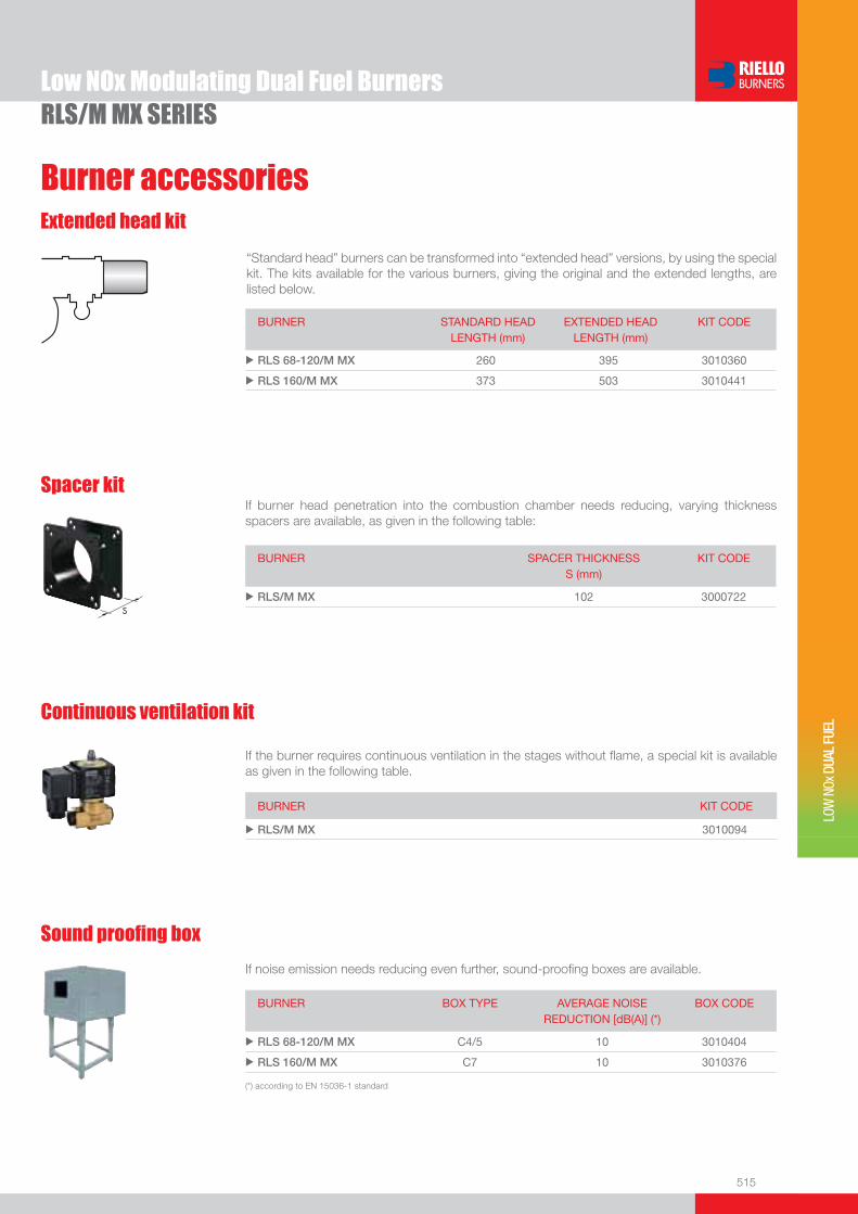
515
RLS/M MX SERIES
Burner accessories
Low NOx Modulating Dual Fuel Burners
LOW
NOx
DUA
L FU
EL
If noise emission needs reducing even further, sound-proofi ng boxes are available.
Sound proofi ng box
BURNER
BOX TYPE
AVERAGE NOISE REDUCTION [dB(A)] (*)
BOX CODE
u RLS 68-120/M MX C4/5 10 3010404
u RLS 160/M MX C7 10 3010376
(*) according to EN 15036-1 standard
If burner head penetration into the combustion chamber needs reducing, varying thickness spacers are available, as given in the following table:
Spacer kit
BURNER
SPACER THICKNESS S (mm)
KIT CODE
u RLS/M MX 102 3000722
Continuous ventilation kit
BURNER KIT CODE
u RLS/M MX 3010094
If the burner requires continuous ventilation in the stages without fl ame, a special kit is available as given in the following table.
Extended head kit
“Standard head” burners can be transformed into “extended head” versions, by using the special kit. The kits available for the various burners, giving the original and the extended lengths, are listed below.
BURNER STANDARD HEADLENGTH (mm)
EXTENDED HEADLENGTH (mm)
KIT CODE
u RLS 68-120/M MX 260 395 3010360
u RLS 160/M MX 373 503 3010441
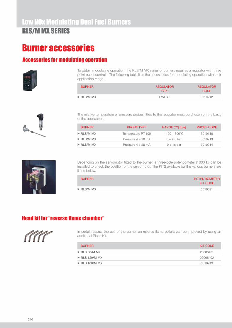
516
RLS/M MX SERIESLow NOx Modulating Dual Fuel Burners
Burner accessoriesAccessories for modulating operation
To obtain modulating operation, the RLS/M MX series of burners requires a regulator with three point outlet controls. The following table lists the accessories for modulating operation with their application range.
BURNER
REGULATOR TYPE
REGULATOR CODE
u RLS/M MX RWF 40 3010212
Depending on the servomotor fi tted to the burner, a three-pole potentiometer (1000 Ω) can be installed to check the position of the servomotor. The KITS available for the various burners are listed below.
BURNER
POTENTIOMETER KIT CODE
u RLS/M MX 3010021
The relative temperature or pressure probes fi tted to the regulator must be chosen on the basis of the application.
BURNER PROBE TYPE RANGE (°C) (bar) PROBE CODE
u RLS/M MX Temperature PT 100 -100 ÷ 500°C 3010110
u RLS/M MX Pressure 4 ÷ 20 mA 0 ÷ 2,5 bar 3010213
u RLS/M MX Pressure 4 ÷ 20 mA 0 ÷ 16 bar 3010214
Head kit for “reverse fl ame chamber”
In certain cases, the use of the burner on reverse fl ame boilers can be improved by using an additional Pipes Kit.
BURNER KIT CODE
u RLS 68/M MX 20006401
u RLS 120/M MX 20006402
u RLS 160/M MX 3010249
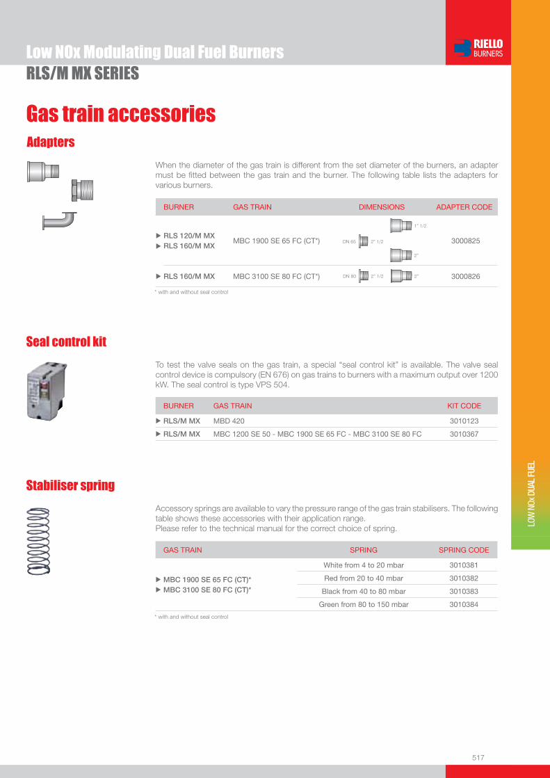
517
RLS/M MX SERIESLow NOx Modulating Dual Fuel Burners
LOW
NOx
DUA
L FU
EL
Gas train accessoriesAdapters
When the diameter of the gas train is different from the set diameter of the burners, an adapter must be fi tted between the gas train and the burner. The following table lists the adapters for various burners.
BURNER GAS TRAIN DIMENSIONS ADAPTER CODE
RLS 120/M MXRLS 160/M MX
MBC 1900 SE 65 FC (CT*) 2” 1/2DN 65
1” 1/2
2”
3000825
RLS 160/M MX MBC 3100 SE 80 FC (CT*) 2” 1/2DN 80 2” 3000826
u
u
u
* with and without seal control
Seal control kit
To test the valve seals on the gas train, a special “seal control kit” is available. The valve seal control device is compulsory (EN 676) on gas trains to burners with a maximum output over 1200 kW. The seal control is type VPS 504.
BURNER GAS TRAIN KIT CODE
u RLS/M MX MBD 420 3010123
u RLS/M MX MBC 1200 SE 50 - MBC 1900 SE 65 FC - MBC 3100 SE 80 FC 3010367
Stabiliser spring
Accessory springs are available to vary the pressure range of the gas train stabilisers. The following table shows these accessories with their application range.Please refer to the technical manual for the correct choice of spring.
GAS TRAIN SPRING SPRING CODE
u
u
MBC 1900 SE 65 FC (CT)* MBC 3100 SE 80 FC (CT)*
White from 4 to 20 mbar 3010381
Red from 20 to 40 mbar 3010382
Black from 40 to 80 mbar 3010383
Green from 80 to 150 mbar 3010384
* with and without seal control

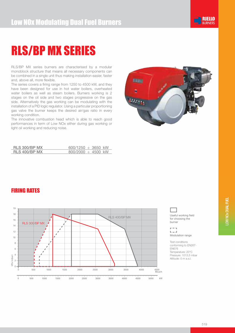
519
LOW
NOx
DUA
L FU
EL
Useful working fi eldfor choosing theburner
Modulation range
Test conditionsconforming to EN267- EN676 Temperature: 20°CPressure: 1013,5 mbarAltitude: 0 m a.s.l.
RLS/BP MX SERIESRLS/BP MX series burners are characterised by a modular monoblock structure that means all necessary components can be combined in a single unit thus making installation easier, faster and, above all, more fl exible.The series covers a fi ring range from 1250 to 4500 kW, and they have been designed for use in hot water boilers, overheated water boilers as well as steam boilers. Burners working is 2 stages on the oil side and two stages progressive on the gas side. Alternatively the gas working can be modulating with the installation of a PID logic regulator. Using a particular proportioning gas valve the burner keeps the desired air/gas ratio in every working condition.The innovative combustion head which is able to reach good performances in term of Low NOx either during gas working or light oil working and reducing noise.
RLS 300/BP MX 600/1250 ÷ 3650 kWRLS 400/BP MX 800/2000 ÷ 4500 kW
FIRING RATES
Low NOx Modulating Dual Fuel Burners
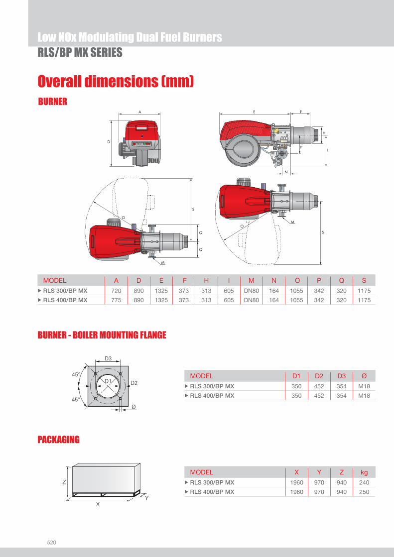
520
BURNER
Overall dimensions (mm)
BURNER - BOILER MOUNTING FLANGE
MODEL A D E F H I M N O P Q S u RLS 300/BP MX 720 890 1325 373 313 605 DN80 164 1055 342 320 1175
u RLS 400/BP MX 775 890 1325 373 313 605 DN80 164 1055 342 320 1175
MODEL D1 D2 D3 Ø u RLS 300/BP MX 350 452 354 M18
u RLS 400/BP MX 350 452 354 M18
MODEL X Y Z kg u RLS 300/BP MX 1960 970 940 240
u RLS 400/BP MX 1960 970 940 250
PACKAGING
Z
XY
RLS/BP MX SERIES
M
S
O
M
O
S
Q
Q
A
D
E
I
F
H
N
P
Low NOx Modulating Dual Fuel Burners
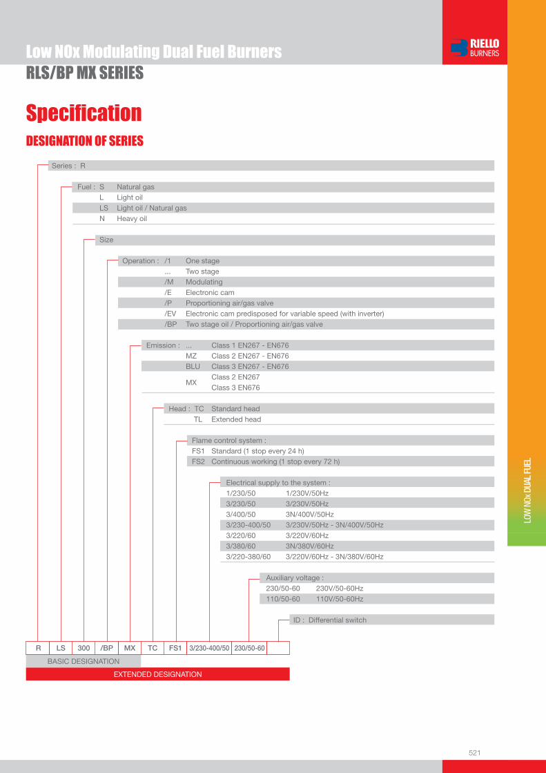
521
DESIGNATION OF SERIES
Specifi cation
LOW
NOx
DUA
L FU
EL
EXTENDED DESIGNATION
R LS 300 /BP MX TC FS1 3/230-400/50 230/50-60
Series : R
Fuel : S Natural gas L Light oil LS Light oil / Natural gas N Heavy oil
Size
Operation : /1 One stage ... Two stage /M Modulating /E Electronic cam /P Proportioning air/gas valve /EV Electronic cam predisposed for variable speed (with inverter) /BP Two stage oil / Proportioning air/gas valve Emission : ... Class 1 EN267 - EN676 MZ Class 2 EN267 - EN676 BLU Class 3 EN267 - EN676
MX Class 2 EN267
Class 3 EN676
Head : TC Standard head TL Extended head
Flame control system : FS1 Standard (1 stop every 24 h) FS2 Continuous working (1 stop every 72 h)
Electrical supply to the system : 1/230/50 1/230V/50Hz 3/230/50 3/230V/50Hz 3/400/50 3N/400V/50Hz 3/230-400/50 3/230V/50Hz - 3N/400V/50Hz 3/220/60 3/220V/60Hz 3/380/60 3N/380V/60Hz 3/220-380/60 3/220V/60Hz - 3N/380V/60Hz
Auxiliary voltage : 230/50-60 230V/50-60Hz 110/50-60 110V/50-60Hz
ID : Differential switch
BASIC DESIGNATION
RLS/BP MX SERIESLow NOx Modulating Dual Fuel Burners
522
STATE OF SUPPLY
Specifi cation
Monoblock forced draught gas burner with “two stage progressive” or “modulating” operation, fully automatic, made up of:- Fan with reverse curve blades high performance with low sound emissions- Air suction circuit lined with sound-proofi ng material- Air damper for air setting controlled by a high precision servomotor- Air pressure switch- Fan starting motor at 2800 rpm, three-phase 230/400 - 400/690 V with neutral, 50Hz - Low emission combustion head, that can be set on the basis of required output, fi tted with: - stainless steel end cone, resistant to corrosion and high temperatures - ignition electrodes - fl ame stability disk- Maximum gas pressure switch, with pressure test point, for halting the burner in the case of over pressure on the fuel supply
line- Module for air/fuel setting and output modulation with separated PID control of temperature or pressure, available as accessory
for RLS/BP MX model - Burner safety control box for controlling the system safety- Ionization probe for fl ame detector- Star/triangle starter for the fan motor (only for RLS 400/BP MX model)- Main electrical supply terminal board- Burner on/off switch - Auxiliary voltage led signal- Burner working led signal- Contacts motor and thermal relay with release button- Motor internal thermal protection- Motor failure led signal - Burner failure led signal and lighted release button- Emergency button- Coded connection plugs-sockets- Lifting rings- IP 54 electric protection level- Gears pump for high pressure fuel supply - Pump starting motor- Oil safety valves- Three oil valves (1st and 2nd stage 3nd safety valve)- UV photocell for fl ame detection- Oil/Gas selector- Flame inspection window- Burner opening hinge.
Standard equipment:- 1 fl ange gasket- 4 screws for fi xing the fl ange- 1 thermal screen- 4 screws for fi xing the burner fl ange to the boiler- 2 fl exible pipes for connection to the oil supply network- 2 nipples for connection to the pump with gaskets.- Instruction handbook for installation, use and maintenance- Spare parts catalogue.
RLS/BP MX SERIESLow NOx Modulating Dual Fuel Burners

523
LOW
NOx
DUA
L FU
EL
Gas Trains
Burners
Available models
Net calorifi c value light oil: 11,8 kWh/kg; 10.200 kcal/kg - Viscosity at 20°C: 4-6 mm2/s (cSt).Net calorifi c value G20 gas: 10 kWh/Nm3; 8.600 kcal/Nm3 - Density: 0,71 kg/Nm3.The burners of RLS/BP MX series are in according to 90/396 - 89/336 (2004/108) - 73/23 (2006/95) - 92/42 EC Directive and EN 267 - 676 Norm.
CODE MODEL HEAT OUTPUT TOTALELECTRICAL
POWER
CERTIFICATION NOTE
LIGHT OIL NATURAL GAS
(kW) (kg/h) (Nm3/h) (kW)
3898510 RLS 300/BP MX TC FS1 3/230-400/50 230/50-60 600/1250-3650 50/105-308 60/125-365 7,5 CE 0085 BP5534
20006452 RLS 300/BP MX TC FS1 3/220-380/60 220/60 600/1250-3650 50/105-308 60/125-365 7,5 -
3898612 RLS 400/BP MX TC FS1 3/400/50 230/50-60 800/2000-4500 68/169-380 80/200-450 11 CE 0085 BP5535
RLS/BP MX SERIESLow NOx Modulating Dual Fuel Burners
* Gas trains are 230V/50Hz - 220V/60Hz electrical supply.** See adapter length on “Gas trains accessories” paragraph.(1) Seal control to be ordered separately - see “Gas trains accessories” section.(2) Adapter is necessary when the gas train has to be installed to the left of the burner to allow maintenance, or if is necessary to space out the gas train from burner. To select the gas train please refer to the technical data leafl et and/or instruction manual.
GAS TRAIN
CODE *
GAS TRAIN
MODEL
NATURAL GAS SEAL CONTROL NOTE
BURNER ADAPTER
(type) (code)
CO
MP
OS
ED
GA
S T
RA
IN
3970215 VGD 50 RLS 300/BP MX RLS 400/BP MX
3000826 3010367 (1) (2)
3970212 VGDF 65 RLS 300/BP MX RLS 400/BP MX
3010221 or
3010369** 3010367 (1) (2)
3970213 VGDF 80 RLS 300/BP MX RLS 400/BP MX
3010222 3010367 (1) (2)
3970214 VGDF 100 RLS 300/BP MX RLS 400/BP MX
3010223 or
3010370** 3010367 (1) (2)

524
Nozzles type 60° B
The nozzles must be ordered separately. The following table shows the features and codes on the basis of the maximum required fuel output.
NOTE: each burner needs N° 2 nozzles.
Burner accessories
RLS/BP MX SERIES
BURNER
GPH
RATED OUTPUT (kg/h) NOZZLE CODEat 10 bar at 12 bar at 14 bar
u RLS/BP MX 12,00 44,2 48,7 53,0 3009950
u RLS/BP MX 13,00 47,8 52,8 57,4 3009951
u RLS/BP MX 14,00 51,5 56,9 61,8 3009952
u RLS/BP MX 15,00 55,2 60,9 66,2 3009953
u RLS/BP MX 16,00 58,9 65,0 70,6 3009954
u RLS/BP MX 17,00 62,6 69,0 75,0 3009955
u RLS/BP MX 18,00 66,2 73,1 79,4 3009956
u RLS/BP MX 19,00 69,9 77,2 83,5 3009957
u RLS/BP MX 20,00 73,6 81,2 88,3 3009958
u RLS/BP MX 22,00 81,0 89,3 97,1 3009959
u RLS/BP MX 24,00 88,3 97,5 105,9 3009960
u RLS/BP MX 26,00 95,7 105,6 114,7 3009961
u RLS/BP MX 28,00 103,1 113,7 123,6 3009962
u RLS/BP MX 30,00 110,4 121,8 132,4 3009963
u RLS/BP MX 35,00 128,8 142,1 154,5 3009964
u RLS/BP MX 40,00 147,2 162,4 176,5 3009965
u RLS/BP MX 45,00 165,6 182,7 198,6 3009966
u RLS/BP MX 50,00 184,0 203,0 220,7 3009967
u RLS/BP MX 55,00 202,4 223,4 242,7 3009968
u RLS/BP MX 60,00 220,8 243,7 264,8 3009969
u RLS/BP MX 65,00 239,2 264,0 286,9 3009970
u RLS/BP MX 70,00 257,6 284,3 309,0 3009971
Fuel remote selection kit
BURNER KIT CODE
u RLS 300-400/BP MX 3010372
Low NOx Modulating Dual Fuel Burners
BURNER SPACER THICKNESS S (mm)
KIT CODE
u RLS 300-400/BP MX 180 20008903
Spacer kit
If burner head penetration into the combustion chamber needs reducing, varying thickness spacers are available, as given in the following table:

525
Burner accessories
LOW
NOx
DUA
L FU
EL
If noise emission needs reducing even further, sound-proofi ng boxes are available.
Sound proofi ng box
BURNER
BOX TYPE
AVERAGE NOISE REDUCTION [dB(A)] (*)
BOX CODE
u RLS 300-400/BP MX C7 10 3010376
(*) according to EN 15036-1 standard
Continuous ventilation kit
BURNER KIT CODE
u RLS 300-400/BP MX 3010030
If the burner requires continuous ventilation in the stages without fl ame, a special kit is available as given in the following table.
RLS/BP MX SERIES
Accessories for modulating operation
To obtain modulating operation, the RLS/BP MX series of burners requires a regulator with three point outlet controls. The following table lists the accessories for modulating operation with their application range.
BURNER
REGULATOR TYPE REGULATOR CODE
u RLS 300-400/BP MX RWF 40 Basic version with 3 position output 3010356
u RLS 300-400/BP MX RWF 40 High version with additional modulating output and RS 485 Interface
3010357
The relative temperature or pressure probes fi tted to the regulator, must be chosen on the basis of the application.
BURNER PROBE TYPE RANGE (°C) (bar) PROBE CODE
u RLS 300-400/BP MX Temperature PT 100 -100 ÷ 500°C 3010110
u RLS 300-400/BP MX Pressure 4 ÷ 20 mA 0 ÷ 2,5 bar 3010213
u RLS 300-400/BP MX Pressure 4 ÷ 20 mA 0 ÷ 16 bar 3010214
Depending on the servomotor fi tted to the burner, a three-pole potentiometer (1000 Ω) can be installed to check the position of the servomotor. The KITS available for the various burners are listed below.
BURNER
POTENTIOMETER KIT CODE
u RLS 300-400/BP MX 3010021
Low NOx Modulating Dual Fuel Burners

526
Gas train accessories
RLS/BP MX SERIES
Adapters
To test the valve seals on the gas train, a special “seal control kit” is available. The valve seal control device is compulsory (EN 676) on gas trains to burners with a maximum output over 1200 kW. The seal control is type VPS 504.
Seal control kit
BURNER GAS TRAIN KIT CODE
u RLS 300-400/BP MX VGD 50 - VGDF 65 - VGDF 80 - VGDF 100 3010367
Low NOx Modulating Dual Fuel Burners
Adapter is necessary when the gas train has to be installed to the left of the burner to allow maintenance, or if is necessary to space out the gas train from burner.
BURNER GAS TRAIN ADAPTER TYPE
DIMENSIONS L mm
ADAPTER CODE
u RLS 300-400/BP MX
VGD 50* I 2” DN 80 300 3000826
VGDF 65* I DN 65 DN 80 400 3010221
VGDF 65* I DN 65 DN 80 10 3010369
VGDF 80* I DN 80 DN 80 400 3010222
VGDF 100* I DN 100 DN 80 400 3010223
VGDF 100* I DN 100 DN 80 50 3010370
* with and without seal control

Low NOx Modulating Dual Fuel Burners
527
LOW
NOx
DUA
L FU
EL
Useful working fi eldfor choosing theburner
Modulation range
Test conditionsconforming to EN267- EN676 Temperature: 20°CPressure: 1013,5 mbarAltitude: 0 m a.s.l.
RLS 500-800/M MX SERIESRLS/M MX burners are characterised by a modular monoblock structure that means all necessary components can be combined in a single unit thus making installation easier, faster and, above all, more fl exible.The series covers a fi ring range from 1120 to 8000 kW, and it has been designed for use in hot water boilers, overheated water boilers as well as steam boilers. Operation can be “two stage progressive” or alternatively “modulating”, for both fuels, light oil and gas, with the installation of a PID logic regulator .The mechanical cam device of regulation allows to catch up a high modulation ratio on all fi ring rates range. The burners can, therefore, supply with precision the demanded power, guaranteeing a high effi ciency system level and the stability setting, obtaining fuel consumption and operating costs reduction.The combustion head guarantees reduced polluting emissions (NOx < 80 mg/kWh on gas operation). An exclusive design guarantees low sound emissions, low electrical consumption, easy use and maintenance.
RLS 500/M MX 1120/2500 ÷ 5050 kWRLS 800/M MX 1750/3500 ÷ 8000 kW
RLS 500/M MX
RLS 800/M MX
FIRING RATES

528
BURNER
Overall dimensions (mm)
Low NOx Modulating Dual Fuel BurnersRLS 500-800/M MX SERIES
BURNER - BOILER MOUNTING FLANGE
Model A d e F H I M N o Q S u RLS 500/M MX 900 890 1325 395 370 605 dN80 164 1055 320 1175
u RLS 800/M MX 940 937 1325 405 428 630 dN80 164 1055 320 1190
Model d1 d2 Ø u RLS 500/M MX 400 452 M18
u RLS 800/M MX 450 495 M18
Model X Y Z kg u RLS 500/M MX 1960 970 1100 280
u RLS 800/M MX 1960 970 1100 320
PACKAGING
Z
XY

529
DESIGNATION OF SERIES
Specifi cation
Low NOx Modulating Dual Fuel Burners
LOW
NOx
DUA
L FU
EL
RLS 500-800/M MX SERIES
EXTENDED DESIGNATION
R LS 300 /M MX TC FS1 3/400/50 230/50-60
Series : R
Fuel : S Natural gas L Light oil LS Light oil / Natural gas N Heavy oil
Size
Operation : /1 One stage /B Two stage /M Modulating - Mechanical cam /E Electronic cam /P Proportioning air/gas valve /EV Electronic cam predisposed for variable speed (with inverter) Emission : ... Class 1 EN267 - EN676 MZ Class 2 EN267 - EN676 BLU Class 3 EN267 - EN676
MX Class 2 EN267
Class 3 EN676
Head : TC Standard head TL Extended head
Flame control system : FS1 Standard (1 stop every 24 h) FS2 Continuous working (1 stop every 72 h)
Electrical supply to the system : 1/230/50 1/230V/50Hz 3/230/50 3/230V/50Hz 3/400/50 3N/400V/50Hz 3/230-400/50 3/230V/50Hz - 3N/400V/50Hz 3/220/60 3/220V/60Hz 3/380/60 3N/380V/60Hz 3/220-380/60 3/220V/60Hz - 3N/380V/60Hz
Auxiliary voltage : 230/50-60 230V/50-60Hz 110/50-60 110V/50-60Hz
BASIC DESIGNATION

530
Low NOx Modulating Dual Fuel BurnersRLS 500-800/M MX SERIES
Specifi cationSTATE OF SUPPLY
Monoblock forced draught gas burner with modulating operation, fully automatic, made up of:- High performance fan with forward curve blades - Air suction circuit lined with sound-proofi ng material- Air damper for air setting controlled by a high precision servomotor- Air pressure switch- Fan starting motor at 2800 rpm, three-phase, 400V, 50Hz- Low emission combustion head, that can be set on the basis of required output, fi tted with: - stainless steel end cone, resistant to corrosion and high temperatures - ignition electrodes - fl ame stability disk- Mechanical cam with gas and oil modulator - Maximum gas pressure switch, with pressure test point, to stop the burner in the case of over pressure on the fuel supply line- Flame control panel for controlling the system safety - Infrared fl ame detector- Star/triangle starter for the fan motor - Main electrical supply terminal board- Burner on/off switch- Auxiliary voltage led signal- Burner working led signal- Contacts motor and thermal relay with release button- Motor internal thermal protection- Motor failure led signal- Burner failure led signal and lighted release button- Emergency button- Coded connection plugs-sockets- Burner opening hinge- Lifting rings- IP 54 electric protection level- Light oil gears pump for high pressure fuel supply- Dedicated pump starting motor- Valve unit with double oil safety valve on the output circuit and double safety valve on the return circuit- Maximum an minimum oil pressure switches - Oil pressure gauges on supply and return oil lines - Oil/Gas selector- Flame inspection window.
Standard equipment:- 1 fl ange gasket- 4 screws for fi xing the fl ange- 1 thermal screen- 4 screws for fi xing the burner fl ange to the boiler- 2 fl exible pipes for connection to the oil supply network- 2 nipples for connection to the pump with gaskets- Seal control pressure switch (for installation on gas train)- Instruction handbook for installation, use and maintenance- Spare parts catalogue.

531
Low NOx Modulating Dual Fuel Burners
LOW
NOx
DUA
L FU
EL
RLS 500-800/M MX SERIES
Available modelsBurners
Gas Trains
Net calorifi c value light oil: 11,8 kWh/kg; 10.200 kcal/kg - Viscosity at 20°C: 4-6 mm2/s (cSt).Net calorifi c value G20 gas: 10 kWh/Nm3; 8.600 kcal/Nm3 - Density: 0,71 kg/Nm3.The burners of RLS/M MX series are in according to 90/396 - 89/336 (2004/108) - 73/23 (2006/95) - 92/42 EC Directive and EN 267 - 676 Norm.
CODE MODEL HEAT OUTPUT TOTALELECTRICAL
POWER
CERTIFICATION NOTE
LIGHT OIL NATURAL GAS
(kW) (kg/h) (Nm3/h) (kW)
3899612 RLS 500/M MX TC FS1 3/400/50 230/50-60 1120/2500-5050 95/211-426 112/250-505 15 (oil)13 (gas)
in progress
3911112 RLS 800/M MX TC FS1 3/400/50 230/50-60 1750/3500-8000 148/295-675 175/350-800 26 (oil)24 (gas)
in progress
GAS TRAIN GAS TRAIN NATURAL GAS NOTE
CODE* MODEL BURNER ADAPTER
(type) (code)
CO
MP
OS
ED
GA
S T
RA
INS
3970222 MBC 1900 SE 65 FCRLS 500/M MX
3010221 (1)RLS 800/M MX
3970223 MBC 3100 SE 80 FCRLS 500/M MX
3010222 (1)RLS 800/M MX
3970224 MBC 5000 SE 100 FCRLS 500/M MX
3010223 (1)RLS 800/M MX
* gas train are 230V/50Hz - 220V/60Hz electrical supply(1) The seal control is managed by the control box LMV 51.
To select the gas train please refer to the technical data leafl et and/or instruction manual.
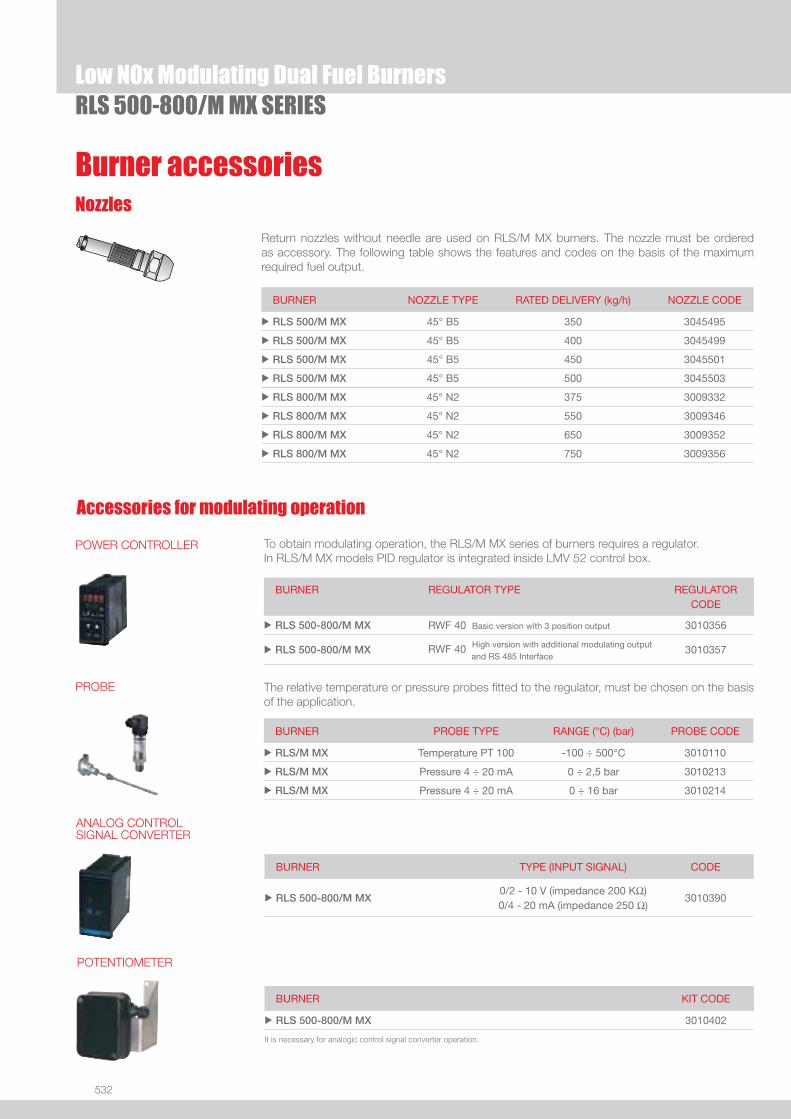
532
Low NOx Modulating Dual Fuel Burners
Burner accessories
Accessories for modulating operation
Nozzles
Return nozzles without needle are used on RLS/M MX burners. The nozzle must be ordered as accessory. The following table shows the features and codes on the basis of the maximum required fuel output.
BURNER NOZZLE TYPE RATED DELIVERY (kg/h) NOZZLE CODE
u RLS 500/M MX 45° B5 350 3045495
u RLS 500/M MX 45° B5 400 3045499
u RLS 500/M MX 45° B5 450 3045501
u RLS 500/M MX 45° B5 500 3045503
u RLS 800/M MX 45° N2 375 3009332
u RLS 800/M MX 45° N2 550 3009346
u RLS 800/M MX 45° N2 650 3009352
u RLS 800/M MX 45° N2 750 3009356
RLS 500-800/M MX SERIES
BURNER KIT CODE
u RLS 500-800/M MX 3010402
POTENTIOMETER
It is necessary for analogic control signal converter operation.
BURNER TYPE (INPUT SIGNAL) CODE
u RLS 500-800/M MX0/2 - 10 V (impedance 200 KΩ) 0/4 - 20 mA (impedance 250 Ω)
3010390
ANALOG CONTROL SIGNAL CONVERTER
To obtain modulating operation, the RLS/M MX series of burners requires a regulator.In RLS/M MX models PID regulator is integrated inside LMV 52 control box.
BURNER
REGULATOR TYPE REGULATOR CODE
u RLS 500-800/M MX RWF 40 Basic version with 3 position output 3010356
u RLS 500-800/M MX RWF 40 High version with additional modulating output and RS 485 Interface
3010357
POWER CONTROLLER
The relative temperature or pressure probes fi tted to the regulator, must be chosen on the basis of the application.
BURNER PROBE TYPE RANGE (°C) (bar) PROBE CODE
u RLS/M MX Temperature PT 100 -100 ÷ 500°C 3010110
u RLS/M MX Pressure 4 ÷ 20 mA 0 ÷ 2,5 bar 3010213
u RLS/M MX Pressure 4 ÷ 20 mA 0 ÷ 16 bar 3010214
PROBE
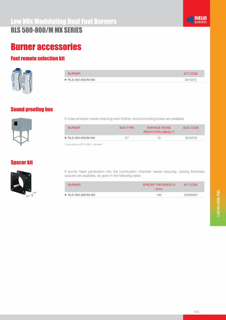
533
Burner accessories
Low NOx Modulating Dual Fuel Burners
LOW
NOx
DUA
L FU
EL
Fuel remote selection kit
BURNER KIT CODE
u RLS 500-800/M MX 3010372
RLS 500-800/M MX SERIES
If noise emission needs reducing even further, sound-proofi ng boxes are available.
Sound proofi ng box
BURNER
BOX TYPE
AVERAGE NOISE REDUCTION [dB(A)] (*)
BOX CODE
u RLS 500-800/M MX C7 10 3010376
(*) according to EN 15036-1 standard
BURNER SPACER THICKNESS S (mm)
KIT CODE
u RLS 500-800/M MX 180 20008903
Spacer kit
If burner head penetration into the combustion chamber needs reducing, varying thickness spacers are available, as given in the following table:
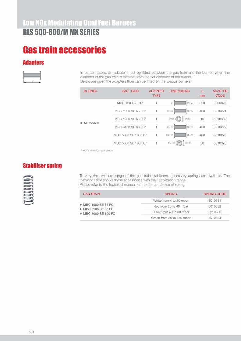
534
Low NOx Modulating Dual Fuel Burners
Gas train accessoriesAdapters
Stabiliser spring
To vary the pressure range of the gas train stabilisers, accessory springs are available. The following table shows these accessories with their application range. Please refer to the technical manual for the correct choice of spring.
GAS TRAIN SPRING SPRING CODE
u
u
u
MBC 1900 SE 65 FC MBC 3100 SE 80 FCMBC 5000 SE 100 FC
White from 4 to 20 mbar 3010381
Red from 20 to 40 mbar 3010382
Black from 40 to 80 mbar 3010383
Green from 80 to 150 mbar 3010384
BURNER GAS TRAIN ADAPTER TYPE
DIMENSIONS L mm
ADAPTER CODE
u All models
MBC 1200 SE 50* I 2” DN 80 300 3000826
MBC 1900 SE 65 FC* I DN 65 DN 80 400 3010221
MBC 1900 SE 65 FC* I DN 65 DN 80 10 3010369
MBC 3100 SE 80 FC* I DN 80 DN 80 400 3010222
MBC 5000 SE 100 FC* I DN 100 DN 80 400 3010223
MBC 5000 SE 100 FC* I DN 100 DN 80 50 3010370
* with and without seal control
In certain cases, an adapter must be fi tted between the gas train and the burner, when the diameter of the gas train is different from the set diameter of the burner.Below are given the adapters than can be fi tted on the various burners:
RLS 500-800/M MX SERIES

535
LOW
NOx
DUA
L FU
EL
RLS/E-EV MX SERIESRLS/E-EV MX series burners are characterised by a modular monoblock structure that means all necessary components can be combined in a single unit thus making installation easier, faster and, above all, more fl exible.The series covers a fi ring range from 1250 to 8000 kW, and they have been designed for use in hot water boilers, overheated water boilers as well as steam boilers. Operation can be “two stage progressive” or alternatively “modulating” for both fuels, ligth oil and gas, with the installation of a PID logic regulator on the RLS/E series burners while RLS/EV series is fully “modulating”. The burner can, therefore, supply with precision the demanded power, guaranteeing an high effi ciency system level and the stability setting, obtaining fuel consumption and operating costs reduction.The innovative combustion head, adjustment system ensures perfect movement during modulation as well as reducing noise and pollutants.
RLS 300/E MX 600/1250 ÷ 3550 kWRLS 400/E MX 800/1800 ÷ 4300 kWRLS 500/E MX 1120/2500 ÷ 5050 kWRLS 800/E MX 1750/3500 ÷ 8000 kWRLS 300/EV MX 600/1250 ÷ 3550 kWRLS 400/EV MX 800/1800 ÷ 4300 kWRLS 500/EV MX 1120/2500 ÷ 5050 kWRLS 800/EV MX 1750/3500 ÷ 8000 kW
FIRING RATES
Low NOx Modulating Dual Fuel Burners
Useful working fi eldfor choosing theburner
Modulation range
Test conditionsconforming to EN267- EN676 Temperature: 20°CPressure: 1013,5 mbarAltitude: 0 m a.s.l.
RLS 500/E-EV MX
RLS 800/E-EV MX

536
BURNER
Overall dimensions (mm)
BURNER - BOILER MOUNTING FLANGE
MODEL A D E F H I M N O P Q S u RLS 300/E-EV MX 720 890 1325 373 313 605 DN80 164 1055 342 320 1175
u RLS 400/E-EV MX 775 890 1325 373 313 605 DN80 164 1055 342 320 1175
u RLS 500/E-EV MX 815 890 1325 395 370 605 DN80 164 1055 342 320 1175
u RLS 800/E-EV MX 940 937 1325 405 428 630 DN80 164 1055 427 320 1190
MODEL D1 D2 Ø u RLS 300/E-EV MX 350 452 M18
u RLS 400/E-EV MX 350 452 M18
u RLS 500/E-EV MX 400 452 M18
u RLS 800/E-EV MX 450 495 M18
MODEL X Y Z kg u RLS 300/E-EV MX 1960 970 1100 240
u RLS 400/E-EV MX 1960 970 1100 250
u RLS 500/E-EV MX 1960 970 1100 280
u RLS 800/E-EV MX 1960 970 1100 320
PACKAGING
Z
XY
RLS/E-EV MX SERIESLow NOx Modulating Dual Fuel Burners

537
DESIGNATION OF SERIES
Specifi cation
LOW
NOx
DUA
L FU
EL
EXTENDED DESIGNATION
R LS 300 /E MX TC FS1 3/400/50 230/50-60
Series : R
Fuel : S Natural gas L Light oil LS Light oil / Natural gas N Heavy oil
Size
Operation : /1 One stage /B Two stage /M Modulating - Mechanical cam /E Electronic cam /P Proportioning air/gas valve /EV Electronic cam predisposed for variable speed (with inverter) Emission : ... Class 1 EN267 - EN676 MZ Class 2 EN267 - EN676 BLU Class 3 EN267 - EN676
MX Class 2 EN267
Class 3 EN676
Head : TC Standard head TL Extended head
Flame control system : FS1 Standard (1 stop every 24 h) FS2 Continuous working (1 stop every 72 h)
Electrical supply to the system : 1/230/50 1/230V/50Hz 3/230/50 3/230V/50Hz 3/400/50 3N/400V/50Hz 3/230-400/50 3/230V/50Hz - 3N/400V/50Hz 3/220/60 3/220V/60Hz 3/380/60 3N/380V/60Hz 3/220-380/60 3/220V/60Hz - 3N/380V/60Hz
Auxiliary voltage : 230/50-60 230V/50-60Hz 110/50-60 110V/50-60Hz
BASIC DESIGNATION
RLS/E-EV MX SERIESLow NOx Modulating Dual Fuel Burners

538
STATE OF SUPPLY
Specifi cation
Monoblock forced draught gas burner with modulating operation, fully automatic, made up of:- High performance fan with low sound emissions, reverse curve blades for RLS 300-400/E-EV MX, forward curve blades for RLS 500-800/E-EV MX- Air suction circuit lined with sound-proofi ng material- Air damper for air setting controlled by a high precision servomotor- Air pressure switch- Fan starting motor at 2800 rpm, three-phase 230/400 - 400/690 V with neutral, 50Hz- Separate light oil pump - Low emission combustion head, that can be set on the basis of required output, fi tted with: - stainless steel end cone, resistant to corrosion and high temperatures - ignition electrodes - fl ame stability disk- Ignition pilot burner with gas train- Maximum gas pressure switch, with pressure test point, for halting the burner in the case of over pressure on the fuel supply
line- Digital Burner management system for air/fuel setting; with output PID modulation control included on RLS/EV MX models, as
accessory on RLS/EV MX- Electronic cam for controlling the system safety- Infrared fl ame detector- Star/triangle starter for the fan motor (burners with motor electrical power ≥ 7,5 kW - RLS/E versions)- Main electrical supply terminal board- Burner on/off switch - Auxiliary voltage led signal- Burner working led signal- Contacts motor and thermal relay with release button- Motor internal thermal protection- Motor failure led signal - Burner failure led signal and lighted release button- Emergency button- Coded connection plugs-sockets- Burner opening hinge- Lifting rings- IP 54 electric protection level- Gears pump for high pressure fuel supply - Pump starting motor- Oil safety valves- Valve unit with double oil safety valve on the output circuit and double safety valve on the return circuit- Oil/Gas selector- Flame inspection window.
Standard equipment:- 1 fl ange gasket- 4 screws for fi xing the fl ange- 1 thermal screen- 4 screws for fi xing the burner fl ange to the boiler- 2 fl exible pipes for connection to the oil supply network- 2 nipples for connection to the pump with gaskets- Seal control pressure switch (for installation on gas train)- Instruction handbook for installation, use and maintenance- Spare parts catalogue.
RLS/E-EV MX SERIESLow NOx Modulating Dual Fuel Burners

539
LOW
NOx
DUA
L FU
EL
Gas Trains
Burners
Available models
Net calorifi c value light oil: 11,8 kWh/kg; 10.200 kcal/kg - Viscosity at 20°C: 4-6 mm2/s (cSt).Net calorifi c value G20 gas: 10 kWh/Nm3; 8.600 kcal/Nm3 - Density: 0,71 kg/Nm3.The burners of RLS/E-EV MX series are in according to 90/396 - 89/336 (2004/108) - 73/23 (2006/95) - 92/42 EC Directive and EN 267 - 676 Norm.(1) - The burners are factory set for FS1 operation (1 stop every 24 h) but they can be switched to FS2 operation (continuous - 1 stop every 72 h) by changing the parameters through the AZL
unit menu.
CODE MODEL HEAT OUTPUT TOTALELECTRICAL
POWER
CERTIFICATION NOTE
LIGHT OIL NATURAL GAS
(kW) (kg/h) (Nm3/h) (kW)
3898530 RLS 300/E MX TC FS1 3/400/50 230/50-60 600/1250-3550 50/105-300 60/125-355 7,5 CE 0085BR0471 (1)
20005681 RLS 300/E MX TC FS1 3/380/60 220/60 600/1250-3550 50/105-300 60/125-355 7,5 - (1)
3898632 RLS 400/E MX TC FS1 3/400/50 230/50-60 800/1800-4300 67/152-363 80/180-430 11,5 CE 0085BR0472 (1)
3899632 RLS 500/E MX TC FS1 3/400/50 230/50-60 1120/2500-5050 95/211-426 112/250-505 15 (oil)13 (gas)
in progress (1)
3911132 RLS 800/E MX TC FS1 3/400/50 230/50-60 1750/3500-8000 148/295-675 175/350-800 26 (oil)24 (gas)
in progress (1)
on demand RLS 300/EV MX TC FS1 3/400/50 230/50-60 600/1250-3550 50/105-300 60/125-355 7,5 in progress (1)
on demand RLS 400/EV MX TC FS1 3/400/50 230/50-60 800/1800-4300 67/152-363 80/180-430 11,5 in progress (1)
20005681 RLS 500/EV MX TC FS1 3/400/50 230/50-60 1120/2500-5050 95/211-426 112/250-505 15 (oil)13 (gas)
in progress (1)
20011319 RLS 800/EV MX TC FS1 3/400/50 230/50-60 1750/3500-8000 148/295-675 175/350-800 26 (oil)24 (gas)
in progress (1)
RLS/E-EV MX SERIESLow NOx Modulating Dual Fuel Burners
GAS TRAIN GAS TRAIN NATURAL GAS NOTE
CODE* MODEL BURNER ADAPTER
(type) (code)
MU
LTIB
LOC
3970221 MBC 1200 SE 50RLS 300/E-EV MX
3000826 (1)RLS 400/E-EV MX
CO
MP
OS
ED
GA
S T
RA
INS
3970222 MBC 1900 SE 65 FC
RLS 300/E-EV MX
3010221 (1)RLS 400/E-EV MX
RLS 500/E-EV MX
RLS 800/E-EV MX
3970223 MBC 3100 SE 80 FC
RLS 300/E-EV MX
3010222 (1)RLS 400/E-EV MX
RLS 500/E-EV MX
RLS 800/E-EV MX
3970224 MBC 5000 SE 100 FC
RLS 300/E-EV MX
3010223 (1)RLS 400/E-EV MX
RLS 500/E-EV MX
RLS 800/E-EV MX
* gas train are 230V/50Hz - 220V/60Hz electrical supply(1) The seal control is managed by the control box LMV 51.
To select the gas train please refer to the technical data leafl et and/or instruction manual.

540
Nozzles
The nozzles must be ordered separately. The following table shows the features and codes on the basis of the maximum required fuel output.
Burner accessories
RLS/E-EV MX SERIES
Accessories for modulating operation
To obtain modulating operation, the RLS/E MX series of burners requires a regulator.In RLS/EV models PID regulator is integrated inside LMV 52 control box.
BURNER
REGULATOR TYPE REGULATOR CODE
u RLS 300-400-500-800/E MX RWF 40 Basic version with 3 position output 3010356
u RLS 300-400-500-800/E MX RWF 40 High version with additional modulating output and RS 485 Interface
3010357
The relative temperature or pressure probes fi tted to the regulator, must be chosen on the basis of the application.
BURNER PROBE TYPE RANGE (°C) (bar) PROBE CODE
u RLS/E-EV MX Temperature PT 100 -100 ÷ 500°C 3010110
u RLS/E-EV MX Pressure 4 ÷ 20 mA 0 ÷ 2,5 bar 3010213
u RLS/E-EV MX Pressure 4 ÷ 20 mA 0 ÷ 16 bar 3010214
BURNER (*) RATED DELIVERY (kg/h) NOZZLE CODE
u RLS 300-400/E-EV MX 150 3009363
u RLS 300-400/E-EV MX 200 3009364
u RLS 300-400/E-EV MX 225 3009365
u RLS 300-400/E-EV MX 250 3009366
u RLS 300-400/E-EV MX 275 3009367
u RLS 300-400/E-EV MX 300 3009368
u RLS 400/E-EV MX 325 3009369
u RLS 400/E-EV MX 350 3009370
u RLS 400/E-EV MX 375 3009371
u RLS 400/E-EV MX 400 3009372
u RLS 400/E-EV MX 425 3009373
This tool is needed for combustion system commissioning and monitoring. The AZL is included in RLS/EV models.
Display and Operating Unit (AZL)
BURNER KIT CODE
u RLS 300-400-500-800/E MX 3010355
u All models * 3010469
* for Russian language only
Low NOx Modulating Dual Fuel Burners
(*) for RLS 500-800/E-EV MX models please contact Riello Burners Technical Department
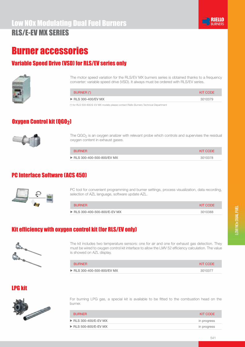
541
Burner accessories
LOW
NOx
DUA
L FU
EL
RLS/E-EV MX SERIES
The QGO2 is an oxygen analizer with relevant probe which controls and supervises the residual oxygen content in exhaust gases.
Oxygen Control kit (QGO2)
BURNER KIT CODE
u RLS 300-400-500-800/EV MX 3010378
PC tool for convenient programming and burner settings, process visualization, data recording, selection of AZL language, software update AZL.
PC Interface Software (ACS 450)
BURNER KIT CODE
u RLS 300-400-500-800/E-EV MX 3010388
Kit effi ciency with oxygen control kit (for RLS/EV only)
The kit includes two temperature sensors: one for air and one for exhaust gas detection. They must be wired to oxygen control kit interface to allow the LMV 52 effi ciency calculation. The value is showed on AZL display.
BURNER KIT CODE
u RLS 300-400-500-800/EV MX 3010377
LPG kit
For burning LPG gas, a special kit is available to be fi tted to the combustion head on the burner.
BURNER KIT CODE
u RLS 300-400/E-EV MX in progress
u RLS 500-800/E-EV MX in progress
Low NOx Modulating Dual Fuel Burners
Variable Speed Drive (VSD) for RLS/EV series only
The motor speed variation for the RLS/EV MX burners series is obtained thanks to a frequency converter: variable speed drive (VSD). It always must be ordered with RLS/EV series.
BURNER (*) KIT CODE
u RLS 300-400/EV MX 3010379
(*) for RLS 500-800/E-EV MX models please contact Riello Burners Technical Department

542
Burner accessories
Gas train accessoriesAdapters
If noise emission needs reducing even further, sound-proofi ng boxes are available.
Sound proofi ng box
BURNER
BOX TYPE
AVERAGE NOISE REDUCTION [dB(A)] (*)
BOX CODE
u RLS 300-400-500-800/E-EV MX C7 10 3010376
(*) according to EN 15036-1 standard
RLS/E-EV MX SERIES
Stabiliser spring
To vary the pressure range of the gas train stabilisers, accessory springs are available. The following table shows these accessories with their application range. Please refer to the technical manual for the correct choice of spring.
GAS TRAIN SPRING SPRING CODE
u
u
u
MBC 1900 SE 65 FC MBC 3100 SE 80 FCMBC 5000 SE 100 FC
White from 4 to 20 mbar 3010381
Red from 20 to 40 mbar 3010382
Black from 40 to 80 mbar 3010383
Green from 80 to 150 mbar 3010384
Low NOx Modulating Dual Fuel Burners
BURNER SPACER THICKNESS S (mm)
KIT CODE
u RLS 300-400-500-800/E-EV MX 180 20008903
Spacer kit
If burner head penetration into the combustion chamber needs reducing, varying thickness spacers are available, as given in the following table:
BURNER GAS TRAIN ADAPTER TYPE
DIMENSIONS L mm
ADAPTER CODE
u All models
MBC 1200 SE 50* I 2” DN 80 300 3000826
MBC 1900 SE 65 FC* I DN 65 DN 80 400 3010221
MBC 1900 SE 65 FC* I DN 65 DN 80 10 3010369
MBC 3100 SE 80 FC* I DN 80 DN 80 400 3010222
MBC 5000 SE 100 FC* I DN 100 DN 80 400 3010223
MBC 5000 SE 100 FC* I DN 100 DN 80 50 3010370
* with and without seal control
In certain cases, an adapter must be fi tted between the gas train and the burner, when the diameter of the gas train is different from the set diameter of the burner.Below are given the adapters than can be fi tted on the various burners:
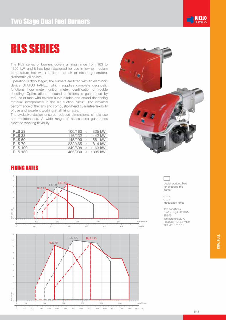
Two Stage Dual Fuel Burners
543
DUAL
FUE
L
RLS SERIES
RLS 28 100/163 ÷ 325 kWRLS 38 116/232 ÷ 442 kWRLS 50 145/290 ÷ 581 kWRLS 70 232/465 ÷ 814 kWRLS 100 349/698 ÷ 1163 kWRLS 130 465/930 ÷ 1395 kW
The RLS series of burners covers a fi ring range from 163 to 1395 kW, and it has been designed for use in low or medium temperature hot water boilers, hot air or steam generators, diathermic oil boilers.Operation is “two stage”; the burners are fi tted with an electronic device STATUS PANEL, which supplies complete diagnostic functions: hour meter, ignition meter, identifi cation of trouble shooting. Optimisation of sound emissions is guaranteed by the use of fans with reverse curve blades and sound deadening material incorporated in the air suction circuit. The elevated performance of the fans and combustion head guarantee fl exibility of use and excellent working at all fi ring rates.The exclusive design ensures reduced dimensions, simple use and maintenance. A wide range of accessories guarantees elevated working fl exibility.
FIRING RATES
Useful working fi eldfor choosing theburner
Modulation range
Test conditionsconforming to EN267- EN676 Temperature: 20°CPressure: 1013,5 mbarAltitude: 0 m a.s.l.
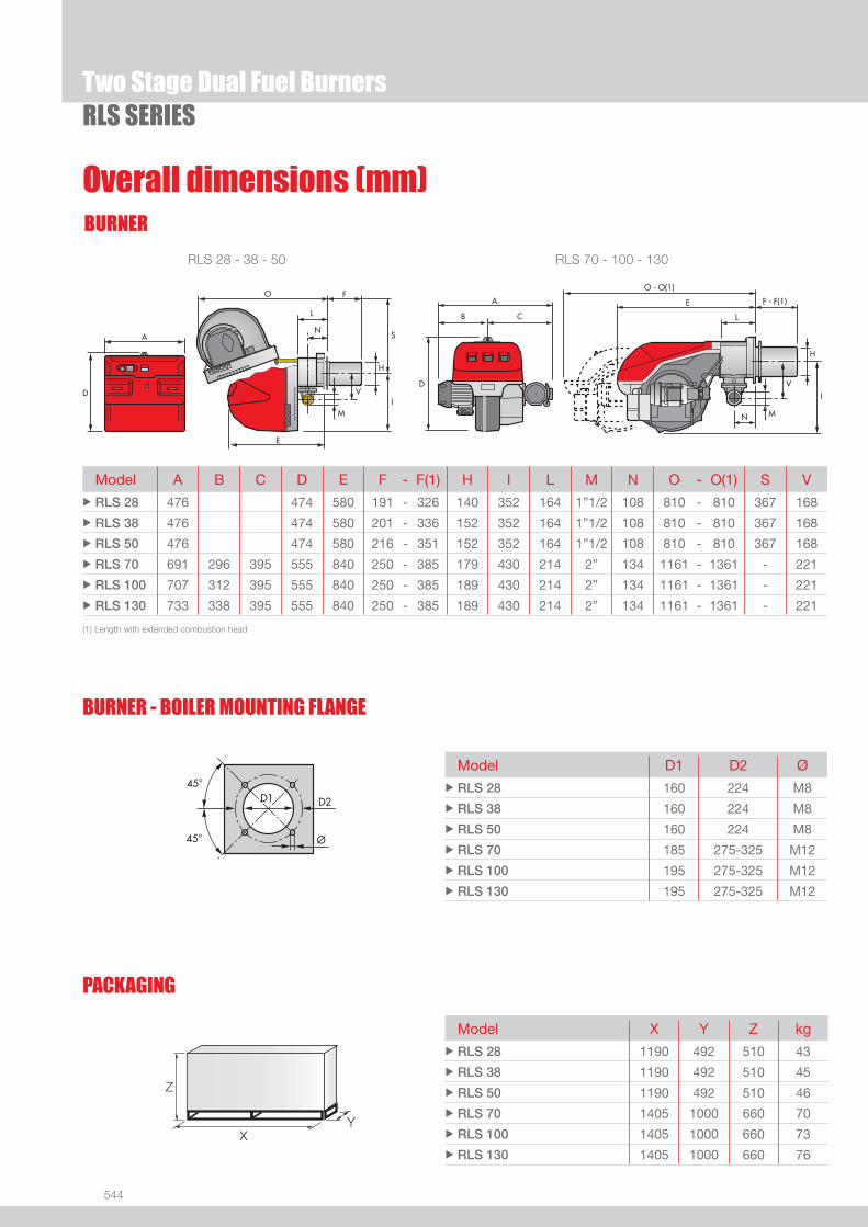
544
RLS SERIES
BURNER
Overall dimensions (mm)
Two Stage Dual Fuel Burners
RLS 28 - 38 - 50 RLS 70 - 100 - 130
Model X Y Z kgu RLS 28 1190 492 510 43
u RLS 38 1190 492 510 45
u RLS 50 1190 492 510 46
u RLS 70 1405 1000 660 70
u RLS 100 1405 1000 660 73
u RLS 130 1405 1000 660 76
Model D1 D2 Øu RLS 28 160 224 M8
u RLS 38 160 224 M8
u RLS 50 160 224 M8
u RLS 70 185 275-325 M12
u RLS 100 195 275-325 M12
u RLS 130 195 275-325 M12
BURNER - BOILER MOUNTING FLANGE
Z
XY
Model A B C D E F - F(1) H I L M N O - O(1) S Vu RLS 28 476 474 580 191 - 326 140 352 164 1”1/2 108 810 - 810 367 168
u RLS 38 476 474 580 201 - 336 152 352 164 1”1/2 108 810 - 810 367 168
u RLS 50 476 474 580 216 - 351 152 352 164 1”1/2 108 810 - 810 367 168
u RLS 70 691 296 395 555 840 250 - 385 179 430 214 2” 134 1161 - 1361 - 221
u RLS 100 707 312 395 555 840 250 - 385 189 430 214 2” 134 1161 - 1361 - 221
u RLS 130 733 338 395 555 840 250 - 385 189 430 214 2” 134 1161 - 1361 - 221
(1) Length with extended combustion head
PACKAGING

545
DUAL
FUE
L
RLS SERIES
DESIGNATION OF SERIES
Specifi cation
Two Stage Dual Fuel Burners
EXTENDED DESIGNATION
R LS 28 TC FS1 3/230-400/50 230/50
Series : R
Fuel : S Natural gas L Light oil LS Light oil / Natural gas N Heavy oil
Size
Operation : /1 One stage ... Two stage /M Modulating /E Electronic cam /P Proportioning air/gas valve /EV Electronic cam predisposed for variable speed (with inverter) Emission : ... Class 1 EN267 - EN676 MZ Class 2 EN267 - EN676 BLU Class 3 EN267 - EN676
MX Class 2 EN267
Class 3 EN676
Head : TC Standard head TL Extended head
Diagnostic : LP Led panel ST Status panel
Flame control system : FS1 Standard (1 stop every 24 h) FS2 Continuous working (1 stop every 72 h)
Electrical supply to the system : 1/230/50 1/230V/50Hz 3/230/50 3/230V/50Hz 3/400/50 3N/400V/50Hz 3/230-400/50 3/230V/50Hz - 3N/400V/50Hz 3/220/60 3/220V/60Hz 3/380/60 3N/380V/60Hz 3/220-380/60 3/220V/60Hz - 3N/380V/60Hz
Auxiliary voltage : 230/50-60 230V/50-60Hz 110/50-60 110V/50-60Hz
ID : Differential switch
BASIC DESIGNATION

546
RLS SERIESTwo Stage Dual Fuel Burners
Specifi cationSTATE OF SUPPLY
Monobloc forced draught dual fuel burner, two stage operation, made up of:- Air suction circuit lined with sound-proofi ng material- Fan with reverse curve blades- Fan starting motor- Air damper for air setting controlled by a servomotor- Minimum air pressure switch- Combustion head, that can be set on the basis of required output - Gears pump for high pressure fuel supply - Pump starting motor- Oil safety valves- Two oil valves (1st and 2nd stage)- Burner safety control box - Electronic device to check all burners operational modes (Led Panel)- UV photocell for fl ame detection- Burner on/off switch- Oil/Gas selector- Manual 1st and 2nd stage switch- Plugs for electrical connections (RLS 28-38-50)- Flame inspection window- Slide bars for easier installation and maintenance- Protection fi lter against radio interference- IP 44 electric protection level.
Standard equipment:- 1 gas train fl ange- 1 fl ange gasket- 4 screws for fi xing the fl ange- 1 thermal screen- 4 screws for fi xing the burner fl ange to the boiler- 2 fl exible pipes for connection to the oil supply network- 2 nipples for connection to the pump with gaskets- Kit for transformation to LPG- Fairleads for electrical connections (for RLS 28-38-50 model)- Instruction handbook for installation, use and maintenance- Spare parts catalogue.

547
DUAL
FUE
L
RLS SERIESTwo Stage Dual Fuel Burners
Burners
Available models
CODE MODEL
HEAT OUTPUT TOTAL ELECTRICAL
POWER
CERTIFICATION NOTE
LIGHT OIL NATURAL GAS
(kW) (kg/h) (Nm3/h) (kW)
3483201 RLS 28 TC LP FS1 1/230/50 230/50 100/163-325 8,5/13,7-27,4 10/16-33 0,53 (1)
20008836 RLS 28 TC LP FS1 1/220/60 220/60 100/163-325 8,5/13,7-27,4 10/16-33 0,53 -
3484101 RLS 38 TC LP FS1 1/230/50 230/50 116/232-442 9,8/19,6-37,3 12/23-44 0,76 (1)
3484601 RLS 50 TC LP FS1 3/230-400/50 230/50 145/290-581 12,3/24,5-49 15/29-58 0,91 (1)
20008911 RLS 50 TC LP FS1 3/220-380/60 220/60 145/290-581 12,3/24,5-49 15/29-58 0,91 -
3485001 RLS 70 TC LP FS1 3/230-400/50 230/50 232/465-814 19/39-69 23/47-81 2,0 (2)
3485201 RLS 100 TC LP FS1 3/230-400/50 230/50 349/698-1163 29,5/59-98 35/70-116 2,4 (2)
3485401 RLS 130 TC LP FS1 3/230-400/50 230/50 465/930-1395 39/78-118 47/93-140 3,2 (2)
(1) CE 0063AR4637(2) CE 0063AS4863Net calorifi c value light oil: 11,8 kWh/kg; 10.200 kcal/kg - Viscosity at 20°C: 4-6 mm2/s (cSt).Net calorifi c value G20 gas: 10 kWh/Nm3; 8.600 kcal/Nm3 - Density: 0,71 kg/Nm3.The burners of RLS series are in according to 90/396 - 89/336 (2004/108) - 73/23 (2006/95) - 92/42 EC Directive and EN 267 - 676 Norm.
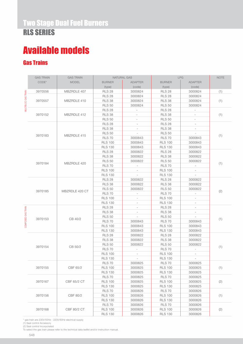
548
RLS SERIES
Available models
Two Stage Dual Fuel Burners
Gas Trains
GAS TRAIN GAS TRAIN NATURAL GAS LPG NOTE
CODE* MODEL BURNER ADAPTER BURNER ADAPTER
(type) (code) (type) (code)
MUL
TIBL
OC
GAS
TRA
IN 3970556 MBZRDLE 407 RLS 28 3000824 RLS 28 3000824 (1)
3970557 MBZRDLE 410RLS 28 3000824 RLS 28 3000824
(1)RLS 38 3000824 RLS 38 3000824RLS 50 3000824 RLS 50 3000824
3970152 MBZRDLE 412RLS 28 - RLS 28 -
(1)RLS 38 - RLS 38 -RLS 50 - RLS 50 -
3970183 MBZRDLE 415
RLS 28 - RLS 28 -
(1)
RLS 38 - RLS 38 - RLS 50 - RLS 50 - RLS 70 3000843 RLS 70 3000843RLS 100 3000843 RLS 100 3000843RLS 130 3000843 RLS 130 3000843
3970184 MBZRDLE 420
RLS 28 3000822 RLS 28 3000822
(1)
RLS 38 3000822 RLS 38 3000822RLS 50 3000822 RLS 50 3000822RLS 70 - RLS 70 -RLS 100 - RLS 100 -RLS 130 - RLS 130 -
3970185 MBZRDLE 420 CT
RLS 28 3000822 RLS 28 3000822
(2)
RLS 38 3000822 RLS 38 3000822RLS 50 3000822 RLS 50 3000822RLS 70 - RLS 70 -RLS 100 - RLS 100 -RLS 130 - RLS 130 -
COM
POSE
D G
AS T
RAIN
3970153 CB 40/2
RLS 28 - RLS 28 -
(1)
RLS 38 - RLS 38 -RLS 50 - RLS 50 -RLS 70 3000843 RLS 70 3000843RLS 100 3000843 RLS 100 3000843RLS 130 3000843 RLS 130 3000843
3970154 CB 50/2
RLS 28 3000822 RLS 28 3000822
(1)
RLS 38 3000822 RLS 38 3000822RLS 50 3000822 RLS 50 3000822RLS 70 - RLS 70 -RLS 100 - RLS 100 -RLS 130 - RLS 130 -
3970155 CBF 65/2RLS 70 3000825 RLS 70 3000825
(1)RLS 100 3000825 RLS 100 3000825RLS 130 3000825 RLS 130 3000825
3970167 CBF 65/2 CTRLS 70 3000825 RLS 70 3000825
(2)RLS 100 3000825 RLS 100 3000825RLS 130 3000825 RLS 130 3000825
3970156 CBF 80/2RLS 70 3000826 RLS 70 3000826
(1)RLS 100 3000826 RLS 100 3000826RLS 130 3000826 RLS 130 3000826
3970168 CBF 80/2 CTRLS 70 3000826 RLS 70 3000826
(2)RLS 100 3000826 RLS 100 3000826RLS 130 3000826 RLS 130 3000826
* gas train are 230V/50Hz - 220V/60Hz electrical supply(1) Seal control Accessory(2) Seal control IncorporatedTo select the gas train please refer to the technical data leafl et and/or instruction manual.
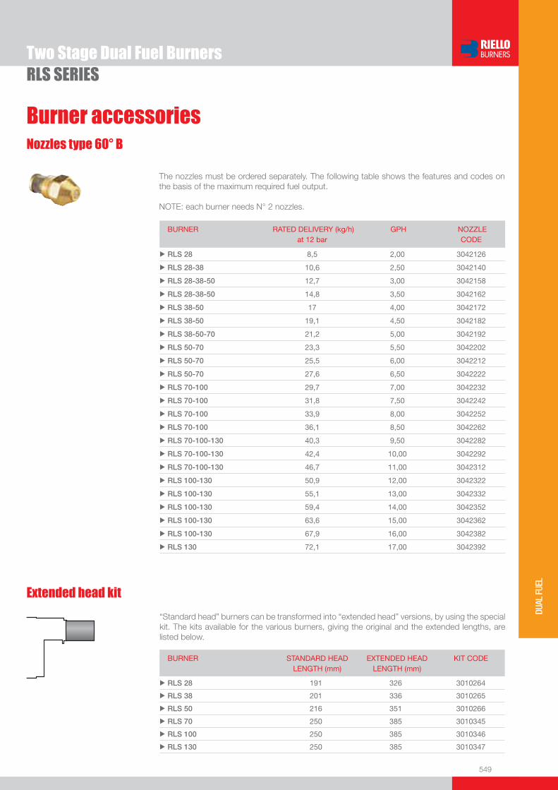
549
DUAL
FUE
L
RLS SERIES
Burner accessories
Two Stage Dual Fuel Burners
BURNER RATED DELIVERY (kg/h)at 12 bar
GPH NOZZLECODE
u RLS 28 8,5 2,00 3042126
u RLS 28-38 10,6 2,50 3042140
u RLS 28-38-50 12,7 3,00 3042158
u RLS 28-38-50 14,8 3,50 3042162
u RLS 38-50 17 4,00 3042172
u RLS 38-50 19,1 4,50 3042182
u RLS 38-50-70 21,2 5,00 3042192
u RLS 50-70 23,3 5,50 3042202
u RLS 50-70 25,5 6,00 3042212
u RLS 50-70 27,6 6,50 3042222
u RLS 70-100 29,7 7,00 3042232
u RLS 70-100 31,8 7,50 3042242
u RLS 70-100 33,9 8,00 3042252
u RLS 70-100 36,1 8,50 3042262
u RLS 70-100-130 40,3 9,50 3042282
u RLS 70-100-130 42,4 10,00 3042292
u RLS 70-100-130 46,7 11,00 3042312
u RLS 100-130 50,9 12,00 3042322
u RLS 100-130 55,1 13,00 3042332
u RLS 100-130 59,4 14,00 3042352
u RLS 100-130 63,6 15,00 3042362
u RLS 100-130 67,9 16,00 3042382
u RLS 130 72,1 17,00 3042392
The nozzles must be ordered separately. The following table shows the features and codes on the basis of the maximum required fuel output.
NOTE: each burner needs N° 2 nozzles.
Nozzles type 60° B
Extended head kit
“Standard head” burners can be transformed into “extended head” versions, by using the special kit. The kits available for the various burners, giving the original and the extended lengths, are listed below.
BURNER STANDARD HEADLENGTH (mm)
EXTENDED HEADLENGTH (mm)
KIT CODE
u RLS 28 191 326 3010264
u RLS 38 201 336 3010265
u RLS 50 216 351 3010266
u RLS 70 250 385 3010345
u RLS 100 250 385 3010346
u RLS 130 250 385 3010347
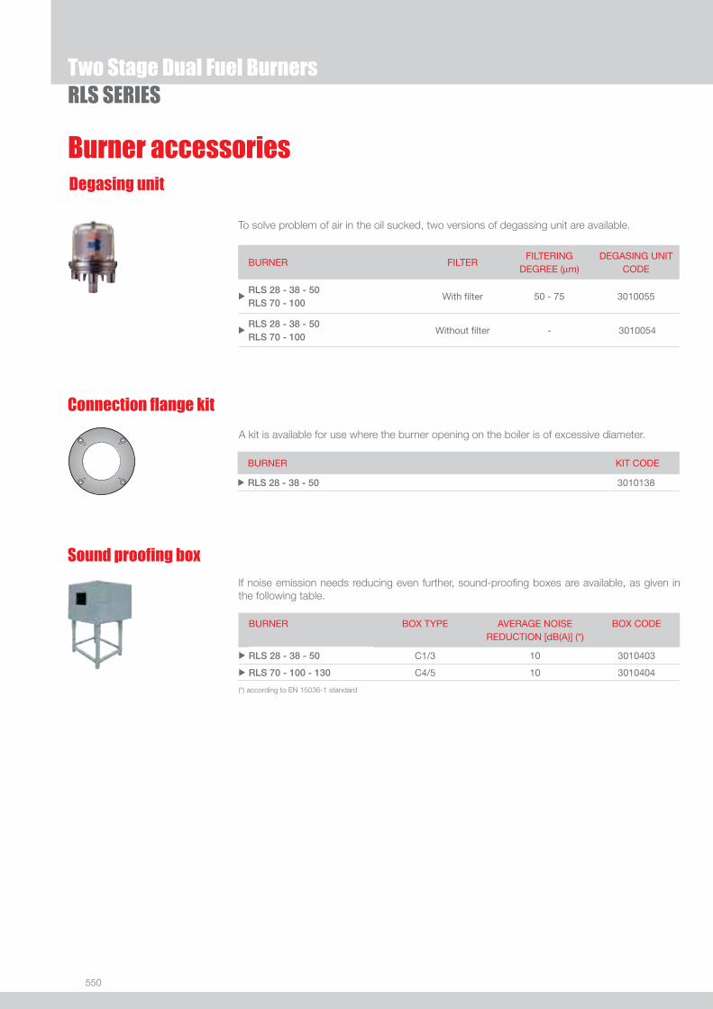
550
RLS SERIESTwo Stage Dual Fuel Burners
Burner accessoriesDegasing unit
To solve problem of air in the oil sucked, two versions of degassing unit are available.
BURNER FILTER FILTERING
DEGREE (μm) DEGASING UNIT
CODE
uRLS 28 - 38 - 50 RLS 70 - 100
With fi lter 50 - 75 3010055
uRLS 28 - 38 - 50RLS 70 - 100
Without fi lter - 3010054
If noise emission needs reducing even further, sound-proofi ng boxes are available, as given in the following table.
Sound proofi ng box
BURNER
BOX TYPE
AVERAGE NOISE REDUCTION [dB(A)] (*)
BOX CODE
u RLS 28 - 38 - 50 C1/3 10 3010403
u RLS 70 - 100 - 130 C4/5 10 3010404
(*) according to EN 15036-1 standard
Connection fl ange kit
A kit is available for use where the burner opening on the boiler is of excessive diameter.
BURNER KIT CODE
u RLS 28 - 38 - 50 3010138
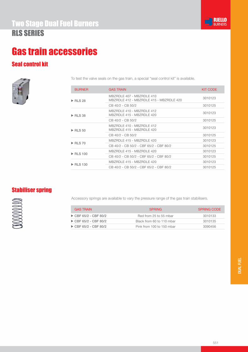
551
DUAL
FUE
L
RLS SERIESTwo Stage Dual Fuel Burners
Gas train accessories
BURNER GAS TRAIN KIT CODE
u RLS 28 MBZRDLE 407 - MBZRDLE 410 MBZRDLE 412 - MBZRDLE 415 - MBZRDLE 420
3010123
CB 40/2 - CB 50/2 3010125
u RLS 38 MBZRDLE 410 - MBZRDLE 412 MBZRDLE 415 - MBZRDLE 420
3010123
CB 40/2 - CB 50/2 3010125
u RLS 50 MBZRDLE 410 - MBZRDLE 412 MBZRDLE 415 - MBZRDLE 420
3010123
CB 40/2 - CB 50/2 3010125
u RLS 70 MBZRDLE 415 - MBZRDLE 420 3010123
CB 40/2 - CB 50/2 - CBF 65/2 - CBF 80/2 3010125
u RLS 100MBZRDLE 415 - MBZRDLE 420 3010123
CB 40/2 - CB 50/2 - CBF 65/2 - CBF 80/2 3010125
u RLS 130MBZRDLE 415 - MBZRDLE 420 3010123
CB 40/2 - CB 50/2 - CBF 65/2 - CBF 80/2 3010125
Seal control kit
To test the valve seals on the gas train, a special “seal control kit” is available.
Stabiliser springAccessory springs are available to vary the pressure range of the gas train stabilisers.
GAS TRAIN SPRING SPRING CODE
u CBF 65/2 - CBF 80/2 Red from 25 to 55 mbar 3010133
u CBF 65/2 - CBF 80/2 Black from 60 to 110 mbar 3010135
u CBF 65/2 - CBF 80/2 Pink from 100 to 150 mbar 3090456
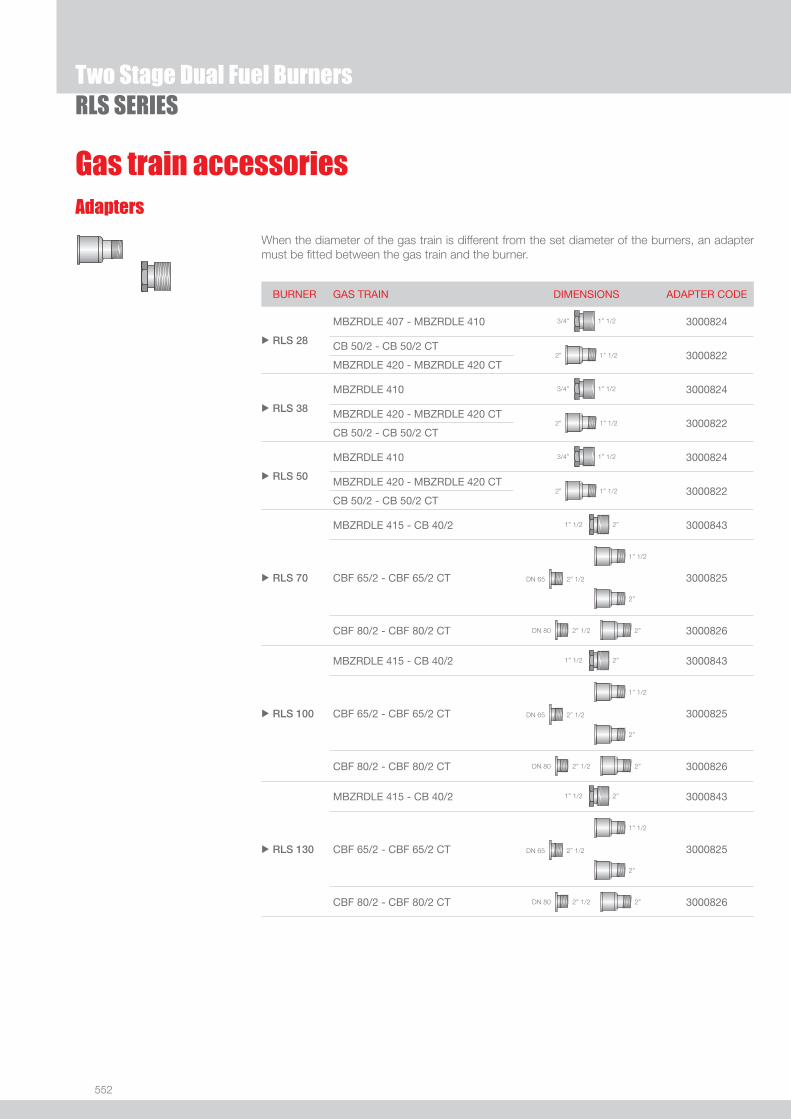
552
RLS SERIESTwo Stage Dual Fuel Burners
Gas train accessoriesAdapters
When the diameter of the gas train is different from the set diameter of the burners, an adapter must be fi tted between the gas train and the burner.
BURNER GAS TRAIN DIMENSIONS ADAPTER CODE
u RLS 28
MBZRDLE 407 - MBZRDLE 410 1” 1/23/4” 3000824
CB 50/2 - CB 50/2 CT1” 1/22” 3000822
MBZRDLE 420 - MBZRDLE 420 CT
u RLS 38
MBZRDLE 410 1” 1/23/4” 3000824
MBZRDLE 420 - MBZRDLE 420 CT 1” 1/22” 3000822
CB 50/2 - CB 50/2 CT
u RLS 50
MBZRDLE 410 1” 1/23/4” 3000824
MBZRDLE 420 - MBZRDLE 420 CT 1” 1/22” 3000822
CB 50/2 - CB 50/2 CT
u RLS 70
MBZRDLE 415 - CB 40/2 2”1” 1/2 3000843
CBF 65/2 - CBF 65/2 CT 2” 1/2DN 65
1” 1/2
2”
3000825
CBF 80/2 - CBF 80/2 CT 2” 1/2DN 80 2” 3000826
u RLS 100
MBZRDLE 415 - CB 40/2 2”1” 1/2 3000843
CBF 65/2 - CBF 65/2 CT 2” 1/2DN 65
1” 1/2
2”
3000825
CBF 80/2 - CBF 80/2 CT 2” 1/2DN 80 2” 3000826
u RLS 130
MBZRDLE 415 - CB 40/2 2”1” 1/2 3000843
CBF 65/2 - CBF 65/2 CT 2” 1/2DN 65
1” 1/2
2”
3000825
CBF 80/2 - CBF 80/2 CT 2” 1/2DN 80 2” 3000826

553
DUAL
FUE
L
Modulating Dual Fuel Burners
RLS/M MZ SERIESThe RLS/M MZ series of burners covers a fi ring range from 550 to 2460 kW, and they have been designed for use in hot or superheated water boilers, hot air or steam generators, diathermic oil boilers.Operation is “two stage” at the oil side and “modulating” at the gas side with the installation of a PID logic regulator and respective probes.RLS/M MZ series burners guarantees high effi ciency levels in all the various applications, thus reducing fuel consumption and running costs.Optimisation of sound emissions is guaranteed by the special design of air suction circuit and the use of sound proofi ng material.The exclusive design ensures reduced dimensions, simple use and maintenance. A wide range of accessories guarantees elevated working fl exibility.
RLS 190/M MZ 550/1100 ÷ 2150 kWRLS 250/M MZ 550/1230 ÷ 2460 kW
FIRING RATES
Useful working fi eldfor choosing theburner
Modulation range
Test conditionsconforming to EN267- EN676 Temperature: 20°CPressure: 1013,5 mbarAltitude: 0 m a.s.l.

554
BURNER
BURNER - BOILER MOUNTING FLANGE
Overall dimensions (mm)
RLS/M MZ SERIESModulating Dual Fuel Burners
PACKAGING
Z
XY
MODEL A B C D E F - F (1) H I L M N O - O (1) Vu RLS 190/M MZ 843 366 477 555 863 412 - 542 222 430 237 Rp2 141 1442 - 1587 186
u RLS 250/M MZ 904 427 477 555 863 412 - 542 222 435 237 Rp2 141 1442 - 1587 186
(1) Length with extended combustion head.
Model D1 D2 Øu RLS 190/M MZ 230 325 - 368 M16
u RLS 250/M MZ 230 325 - 368 M16
Model X Y Z kgu RLS 190/M MZ 1400 975 645 95
u RLS 250/M MZ 1400 1000 765 100

555
DUAL
FUE
L
DESIGNATION OF SERIES
Specifi cation
Modulating Dual Fuel BurnersRLS/M MZ SERIES
EXTENDED DESIGNATION
R LS 190 /M MZ TC FS1 3/230-400/50 230/50
Series : R
Fuel : S Natural gas L Light oil LS Light oil / Natural gas N Heavy oil
Size
Operation : /1 One stage ... Two stage /M Modulating /E Electronic cam /P Proportioning air/gas valve /EV Electronic cam predisposed for variable speed (with inverter) Emission : ... Class 1 EN267 - EN676 MZ Class 2 EN267 - EN676 BLU Class 3 EN267 - EN676
MX Class 2 EN267
Class 3 EN676
Head : TC Standard head TL Extended head
Flame control system : FS1 Standard (1 stop every 24 h) FS2 Continuous working (1 stop every 72 h)
Electrical supply to the system : 1/230/50 1/230V/50Hz 3/230/50 3/230V/50Hz 3/400/50 3N/400V/50Hz 3/230-400/50 3/230V/50Hz - 3N/400V/50Hz 3/220/60 3/220V/60Hz 3/380/60 3N/380V/60Hz 3/220-380/60 3/220V/60Hz - 3N/380V/60Hz
Auxiliary voltage : 230/50-60 230V/50-60Hz 110/50-60 110V/50-60Hz
ID : Differential switch
BASIC DESIGNATION

556
RLS/M MZ SERIESModulating Dual Fuel Burners
Specifi cationSTATE OF SUPPLY
Monoblock forced draught dual fuel burner with two stage operation at the oil side and two stage progressive or modulating operation at the gas side, with a specifi c kit, fully automatic, made up of:- air suction circuit lined with sound-proofi ng material- centrifugal fan with high performance and low sound emissions- air damper for air fl ow setting and butterfl y valve for regulating gas output controlled by a servomotor with variable cam- starting motor at 2800 rpm, three-phase 400V with neutral, 50Hz - low emission combustion head, that can be set on the basis of required output, fi tted with: - stainless steel end cone, resistant to corrosion and high temperatures - ignition electrodes - gas distributor - fl ame stability disk- maximum gas pressure switch to stop the burner in the case of excess pressure on the fuel supply line- minimum air pressure switch stops the burner in case of insuffi cient air quantity at the combustion head- gears pump for high pressure fuel supply - pump starting motor- oil safety valves- two oil valves (1st and 2nd stage)- burner safety control box- UV photocell for fl ame detection- burner on/off selection switch- manual or automatic output increase/decrease selection switch- Oil/Gas selector- fl ame inspection window- slide bars for easier installation and maintenance- protection fi lter against radio interference- IP 44 electric protection level.
Standard equipment:- 1 gas train fl ange- 1 fl ange gasket- 4 screws for fi xing the fl ange- 1 thermal screen- 4 screws for fi xing the burner fl ange to the boiler- 2 fl exible pipes for connection to the oil supply network- 2 nipples for connection to the pump with gaskets- Instruction handbook for installation, use and maintenance- Spare parts catalogue.
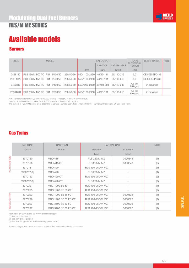
557
DUAL
FUE
L
Modulating Dual Fuel BurnersRLS/M MZ SERIES
Burners
Available models
CODE MODEL
HEAT OUTPUT TOTAL ELECTRICAL
POWER
CERTIFICATION NOTE
LIGHT OIL NATURAL GAS
(kW) (kg/h) (Nm3/h) (kW)
3488110 RLS 190/M MZ TC FS1 3/400/50 230/50-60 550/1100-2150 46/93-181 55/110-215 6,0 CE 0085BP0439
20011625 RLS 190/M MZ TC FS1 3/230/50 230/50-60 550/1100-2150 46/93-181 55/110-215 6,0 CE 0085BP0439
3482810 RLS 250/M MZ TC FS1 3/400/50 230/50-60 550/1230-2460 46/104-208 55/123-246 7,5 (oil)6,0 (gas) in progress
20004704 RLS 250/M MZ TC FS1 3/230/50 230/50-60 550/1100-2150 46/93-181 55/110-215 7,5 (oil)6,0 (gas) in progress
Net calorifi c value light oil: 11,8 kWh/kg; 10.200 kcal/kg - Viscosity at 20°C: 4-6 mm2/s (cSt).Net calorifi c value G20 gas: 10 kWh/Nm3; 8.600 kcal/Nm3 - Density: 0,71 kg/Nm3.The burners of RLS/M MZ series are in according to 90/396 - 89/336 (2004/108) - 73/23 (2006/95) - 92/42 EC Directive and EN 267 - 676 Norm.
Gas Trains
GAS TRAIN GAS TRAIN NATURAL GAS NOTE
CODE * MODEL BURNER ADAPTER
(type) (code)
MUL
TIBL
OC G
AS T
RAIN
3970180 MBD 415 RLS 250/M MZ 3000843 (1)
3970198 MBD 415 CT RLS 250/M MZ 3000843 (2)
3970181 MBD 420 RLS 190-250/M MZ - (1)
3970257 (3) MBD 420 RLS 250/M MZ - (1)
3970182 MBD 420 CT RLS 190-250/M MZ - (2)
3970252 (3) MBD 420 CT RLS 250/M MZ - (2)
3970221 MBC 1200 SE 50 RLS 190-250/M MZ - (1)
3970225 MBC 1200 SE 50 CT RLS 190-250/M MZ - (2)
COM
POSE
D GA
S TR
AIN
3970222 MBC 1900 SE 65 FC RLS 190-250/M MZ 3000825 (1)
3970226 MBC 1900 SE 65 FC CT RLS 190-250/M MZ 3000825 (2)
3970223 MBC 3100 SE 80 FC RLS 190-250/M MZ 3000826 (1)
3970227 MBC 3100 SE 80 FC CT RLS 190-250/M MZ 3000826 (2)
* gas trains are 230V/50Hz - 220V/60Hz electrical supply(1) Seal control accessory(2) Seal control incorporated(3) Gas Train S5 type for application with high pressure drop
To select the gas train please refer to the technical data leafl et and/or instruction manual.
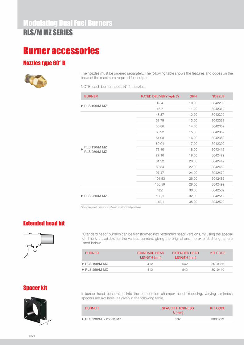
558
RLS/M MZ SERIESModulating Dual Fuel Burners
Nozzles type 60° B
Burner accessories
If burner head penetration into the combustion chamber needs reducing, varying thickness spacers are available, as given in the following table.
Spacer kit
Extended head kit
“Standard head” burners can be transformed into “extended head” versions, by using the special kit. The kits available for the various burners, giving the original and the extended lengths, are listed below.
The nozzles must be ordered separately. The following table shows the features and codes on the basis of the maximum required fuel output.
NOTE: each burner needs N° 2 nozzles.
(*) Nozzle rated delivery is reffered to atomized pressure
BURNER RATED DELIVERY kg/h (*) GPH NOZZLE
u RLS 190/M MZ 42,4 10,00 3042292
46,7 11,00 3042312
uRLS 190/M MZRLS 250/M MZ
48,37 12,00 3042322
52,79 13,00 3042332
56,86 14,00 3042352
60,92 15,00 3042362
64,98 16,00 3042382
69,04 17,00 3042392
73,10 18,00 3042412
77,16 19,00 3042422
81,22 20,00 3042442
89,34 22,00 3042462
97,47 24,00 3042472
101,53 26,00 3042482
105,59 28,00 3042492
u RLS 250/M MZ
122 30,00 3042502
130,1 32,00 3042512
142,1 35,00 3042522
BURNER
SPACER THICKNESS S (mm)
KIT CODE
u RLS 190/M - 250/M MZ 102 3000722
BURNER STANDARD HEADLENGTH (mm)
EXTENDED HEADLENGTH (mm)
KIT CODE
u RLS 190/M MZ 412 542 3010366
u RLS 250/M MZ 412 542 3010440

559
DUAL
FUE
L
Burner accessories
Modulating Dual Fuel BurnersRLS/M MZ SERIES
If noise emission needs reducing even further, sound-proofi ng boxes are available.
Sound proofi ng box
BURNER
BOX TYPE
AVERAGE NOISE REDUCTION [dB(A)] (*)
BOX CODE
u RLS 190/M MZ C4/5 10 3010404
u RLS 250/M MZ C7 10 3010376(*) according to EN 15036-1 standard
Continuous ventilation kit
BURNER KIT CODE
u RLS 190/M - 250/M MZ 3010094
If the burner requires continuous ventilation in the stages without fl ame, a special kit is available as given in the following table.
Accessories for modulating operation
To obtain modulating operation, the RLS/M MZ series of burners requires a regulator with three point outlet controls. The following table lists the accessories for modulating operation with their application range.
BURNER TYPE CODE
u RLS 190/M MZ RWF 40 3010212
u RLS 250/M MZ RWF 40 3010414
TYPE RANGE (°C) (bar) CODE
Temperature PT 100 -100 ÷ 500°C 3010110
Pressure 4 ÷ 20 mA 0 ÷ 2,5 bar 3010213
Pressure 4 ÷ 20 mA 0 ÷ 16 bar 3010214
The relative temperature or pressure probes fi tted to the regulator must be chosen on the basis of the application.
REGULATOR
PROBE
BURNER TYPE (INPUT SIGNAL) CODE
u RLS 250/M MZ 0/2 - 10 V (impedance 200 KΩ) 0/4 - 20 mA (impedance 250 Ω)
3010415
ANALOG CONTROL SIGNAL CONVERTER
BURNER KIT CODE
u RLS 190/M MZ 3010021
u RLS 250/M MZ 3010416
POTENTIOMETER KIT Depending on the servomotor fi tted to the burner, a three-pole potentiometer (1000 Ω) can be installed to check the position of the servomotor. The KITS available for the various burners are listed below.

560
Gas train accessories
RLS/M MZ SERIESModulating Dual Fuel Burners
Adapters
Seal control kit
Stabiliser spring
Accessory springs are available to vary the pressure range of the gas train stabilisers. The following table shows these accessories with their application range.Please refer to the technical manual for the correct choice of spring.
GAS TRAIN SPRING SPRING CODE
u
u
MBC 1900 SE 65 FC (CT)* MBC 3100 SE 80 FC (CT)*
White from 4 to 20 mbar 3010381
Red from 20 to 40 mbar 3010382
Black from 40 to 80 mbar 3010383
Green from 80 to 150 mbar 3010384
* with and without seal control
When the diameter of the gas train is different from the set diameter of the burners, an adapter must be fi tted between the gas train and the burner. The following table lists the adapters for various burners.
To test the valve seals on the gas train, a special “seal control kit” is available. The valve seal control device is compulsory (EN 676) on gas trains to burners with a maximum output over 1200 kW. The seal control is type VPS 504.
BURNER GAS TRAIN KIT CODE
u RLS 190/M - 250/M MZ MBC without CT 3010367
u RLS 190/M - 250/M MZ MBD without CT 3010123
u RLS 250/M MZMBC 1900 SE 65 FCMBC 1900 SE 65 FC CT
2” 1/2DN 65
1” 1/2
2”
3000825
MBC 3100 SE 80 FCMBC 3100 SE 80 FC CT
2” 1/2DN 80 2” 3000826
MBD 415 2”1” 1/2 3000843
u RLS 190/M MZ
MBC 1900 SE 65 FCMBC 1900 SE 65 FC CT
2” 1/2DN 65
1” 1/2
2”
3000825
MBC 3100 SE 80 FCMBC 3100 SE 80 FC CT
2” 1/2DN 80 2” 3000826
BURNER GAS TRAIN DIMENSIONS ADAPTER CODE

Two Stage Dual Fuel Burners
561
DUAL
FUE
L
FIRING RATES
GI/EMME 300÷900 SERIESThe GI/EMME 300-900 series of burners covers a fi ring range from 175 to 922 kW.They have been designed for middle and high output users and they are in particular suitable for matching with pressurized boilers.Their use allow to have an high safety in operation, guaranteed from the double fuel supply. Two options of operation are available: only gas and only light oil, thus settable by a selector and a terminal board. Light oil circuit is fi tted with his own electric motor: this permits pump stop during gas operation preventing danger of pumping seizure. A wide range of accessories and gas trains suitable to the burners guarantee an elevated working fl exibility.
GI/EMME 300 107/175 ÷ 332 kWGI/EMME 400 116/232 ÷ 465 kWGI/EMME 600 174/348 ÷ 665 kWGI/EMME 900 250/525 ÷ 922 kW
Useful working fi eldfor choosing theburner
Test conditionsconforming to EN267- EN676 Temperature: 20°CPressure: 1013,5 mbarAltitude: 0 m a.s.l.

562
BURNER
Overall dimensions (mm)
Two Stage Dual Fuel BurnersGI/EMME 300÷900 SERIES
MODEL A D E F - F(1) H I M N O Vu GI/EMME 300 410 397 610 185 - 320 140 292 1”1/2 97 978 165
u GI/EMME 400 410 397 610 187 - 320 150 292 1”1/2 97 1018 165
u GI/EMME 600 410 437 645 187 - 320 155 332 1”1/2 97 1063 165
u GI/EMME 900 410 485 770 227 - 360 175 370 2” 131 1260 195
(1) Length with extended combustion head
MODEL X Y Z kg u GI/EMME 300 835 530 453 42
u GI/EMME 400 835 530 453 49
u GI/EMME 600 880 530 500 64
u GI/EMME 900 1030 530 435 88
MODEL L M N u GI/EMME 300 160 155 M10
u GI/EMME 400 160 165 M10
u GI/EMME 600 160 165 M10
u GI/EMME 900 195 185 M12
BURNER - BOILER MOUNTING FLANGE
PACKAGING
Z
XY
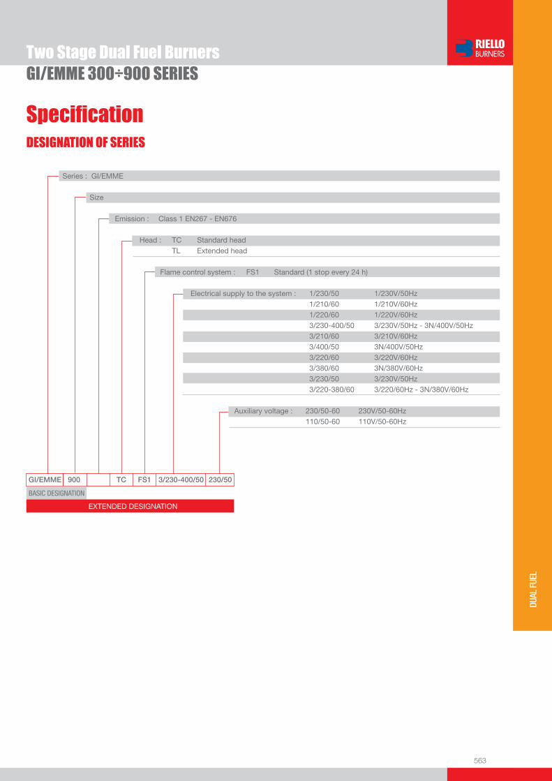
563
DUAL
FUE
L
DESIGNATION OF SERIES
Specifi cation
Two Stage Dual Fuel BurnersGI/EMME 300÷900 SERIES
GI/EMME 900 TC FS1 3/230-400/50 230/50
BASIC DESIGNATION
EXTENDED DESIGNATION
Series : GI/EMME
Size Emission : Class 1 EN267 - EN676 Head : TC Standard head TL Extended head
Flame control system : FS1 Standard (1 stop every 24 h)
Electrical supply to the system : 1/230/50 1/230V/50Hz 1/210/60 1/210V/60Hz 1/220/60 1/220V/60Hz 3/230-400/50 3/230V/50Hz - 3N/400V/50Hz 3/210/60 3/210V/60Hz 3/400/50 3N/400V/50Hz 3/220/60 3/220V/60Hz 3/380/60 3N/380V/60Hz 3/230/50 3/230V/50Hz 3/220-380/60 3/220/60Hz - 3N/380V/60Hz Auxiliary voltage : 230/50-60 230V/50-60Hz 110/50-60 110V/50-60Hz

564
Two Stage Dual Fuel Burners
Specifi cationSTATE OF SUPPLY
Monoblock forced draught dual fuel burner, two stage operation, made up of:- Air suction circuit- Fan with forward curved blades- Air damper for setting controlled by a servomotor- Combustion head, that can be set on the basis of required output- Minimum air pressure switch- Fan electrical motor- Pump electrical motor- Gears pump for high pressure fuel supply, fi tted with: - fi lter - pressure regulator - connections for installing a pressure gauge and a a vacuometer - internal by-pass for single pipe installation- Valve unit with a double oil safety valve on the output circuit- UV photocell for fl ame detection- Flame inspection window- Slide bars for easier installation and maintenance- Protection fi lter against radio interference- IP X0D (IP 40) protection level.
Standard equipment:- 1 gas train fl ange- 1 fl ange gasket- 1 insulating screen- 2 fl exible hoses for connection to the oil supply circuit- 2 nipples for connection to the pump- 3 wiring looms fi ttings for electrical connections- 8 screws for fi xing the burner fl ange to the boiler- 1 LPG kit- Instruction manual for installation, use and maintenance- Spare parts catalogue.
GI/EMME 300÷900 SERIES

565
DUAL
FUE
L
Two Stage Dual Fuel Burners
Available models
GI/EMME 300÷900 SERIES
Burners
CODE MODEL HEAT OUTPUT TOTALELECTRICAL
POWER
CERTIFICATION NOTE
LIGHT OIL NATURAL GAS
(kW) (kg/h) (Nm3/h) (kW)
3483681 GI/EMME 300 TC FS1 1/220/60 220/60 107/175-340 9/15-29 11/17,5-34 0,5 -
3483621 GI/EMME 300 TC FS1 1/230/50 230/50 107/175-332 9/15-28 11/17,5-33 0,5 -
3484271 GI/EMME 400 TC FS1 1/210/60 120/60 116/232-465 10/20-39 12/23-46,5 0,62 -
3484221 GI/EMME 400 TC FS1 1/230/50 230/50 116/232-465 10/20-39 12/23-46,5 0,62 -
3484281 GI/EMME 400 TC FS1 3/220-380/60 220/60 116/232-465 10/20-39 12/23-46,5 0,62 -
3484871 GI/EMME 600 TC FS1 3/210/60 120/60 174/348-697 15/30-60 17/35-70 1,1 -
3484881 GI/EMME 600 TC FS1 3/220-380/60 220/60 174/348-697 15/30-60 17/35-70 1,1 -
3484821 GI/EMME 600 TC FS1 3/230-400/50 230/50 174/348-665 15/30-56 17/35-66,5 1,1 -
3485971 GI/EMME 900 TC FS1 3/210/60 120/60 262/523-1045 22/44-88 26/52-105 2 -
3485981 GI/EMME 900 TC FS1 3/220-380/60 220/60 262/523-1045 22/44-88 26/52-105 2 -
3485921 GI/EMME 900 TC FS1 3/230-400/50 230/50 250/525-922 21/44-78 25/52,5-92 2 -
Net calorifi c value light oil: 11,8 kWh/kg; 10.200 kcal/kg - Viscosity at 20°C: 4-6 mm2/s (cSt).Net calorifi c value G20 gas: 10 kWh/Nm3; 8.600 kcal/Nm3 - Density: 0,71 kg/Nm3.The burners of GI/EMME series are in according to 89/336 (2004/108), 73/23 (2006/95) Directive and EN 267, EN 676 Norm.

566
Available models
Two Stage Dual Fuel Burners
Gas Trains
* Gas trains are 230V/50Hz - 220V/60Hz electrical supply.(1) Seal control accessory.(2) Seal control incorporated.
To select the gas train please refer to the technical data leafl et and/or instruction manual.
GAS TRAIN GAS TRAIN NATURAL GAS LPG NOTE
CODE* MODEL BURNER ADAPTER BURNER ADAPTER
(type) (code) (type) (code)
MU
LTIB
LOC
GA
S T
RA
IN 3970556 MBZRDLE 407 GI/EMME 300 3000824 GI/EMME 300 3000824 (1)
3970557 MBZRDLE 410
GI/EMME 300 3000824 3000824
(1) GI/EMME 400 3000824 GI/EMME 300 3000824
GI/EMME 600 3000824 GI/EMME 400 3000824
3970152
MBZRDLE 412
GI/EMME 300 3010124
(1) GI/EMME 400 3010124 GI/EMME 300 3000824
GI/EMME 600 3010124 GI/EMME 400 3000824
GI/EMME 900 3010126 GI/EMME 600 3000824
3970183 MBZRDLE 415
GI/EMME 300 - GI/EMME 300 -
(1) GI/EMME 400 - GI/EMME 400 -
GI/EMME 600 - GI/EMME 600 -
GI/EMME 900 3000843 GI/EMME 900 3000843
3970184 MBZRDLE 420
GI/EMME 400 3000822 GI/EMME 400 3000822
(1) GI/EMME 600 3000822 GI/EMME 600 3000822
GI/EMME 900 - GI/EMME 900 -
3970185 MBZRDLE 420 CT
GI/EMME 400 3000822 GI/EMME 400 3000822
(2) GI/EMME 600 3000822 GI/EMME 600 3000822
GI/EMME 900 - GI/EMME 900 -
CO
MP
OS
ED
GA
S T
RA
IN
3970153 CB 40/2
GI/EMME 300 - GI/EMME 300 -
(1) GI/EMME 400 - GI/EMME 400 -
GI/EMME 600 - GI/EMME 600 -
GI/EMME 900 3000843 GI/EMME 900 3000843
3970154 CB 50/2
GI/EMME 400 - GI/EMME 400 -
(1) GI/EMME 600 - GI/EMME 600 -
GI/EMME 900 - GI/EMME 900 -
3970155 CB 65/2 GI/EMME 900 3000825 GI/EMME 900 3000825 (1)
3970167 CB 65/2 CT GI/EMME 900 3000825 GI/EMME 900 3000825 (2)
GI/EMME 300÷900 SERIES

567
DUAL
FUE
L
Burner accessories
Two Stage Dual Fuel BurnersGI/EMME 300÷900 SERIES
Nozzles type 60° B
The nozzles must be ordered separately. The following table shows the features and codes on the basis of the maximum required fuel output.
NOTE: each burner needs N° 2 nozzles.
BURNER RATED DELIVERY (kg/h)AT 12 bar
GPH NOZZLECODE
u GI/EMME 300 6,8 1,75 3042110
u GI/EMME 300 7,8 2,00 3042126
u GI/EMME 300 8,7 2,25 3042127
u GI/EMME 300 - 400 9,7 2,50 3042140
u GI/EMME 300 - 400 11,6 3,00 3042158
u GI/EMME 300 - 400 13,6 3,50 3042162
u GI/EMME 300 - 400 - 600 15,6 4,00 3042172
u GI/EMME 400 - 600 17,5 4,50 3042182
u GI/EMME 400 - 600 19,4 5,00 3042192
u GI/EMME 400 - 600 21,3 5,50 3042202
u GI/EMME 600 - 900 23,3 6,00 3042212
u GI/EMME 600 - 900 27,1 7,00 3042232
u GI/EMME 600 - 900 29,1 7,50 3042242
u GI/EMME 900 33 8,50 3042262
u GI/EMME 900 36,8 9,50 3042282
u GI/EMME 900 38,8 10,00 3042292
u GI/EMME 900 42,3 11,00 3042312
u GI/EMME 900 46,5 12,00 3042322
If noise emission needs reducing even further, sound-proofi ng boxes are available.
Sound proofi ng box
BURNER
BOX TYPE
AVERAGE NOISE REDUCTION [dB(A)] (*)
BOX CODE
u GI/EMME 300 - 400 - 600 - 900 C1/3 10 3010403
(*) according to EN 15036-1 standard
Extended head kit
“Standard head” burners can be transformed into “extended head” versions, by using the special kit. The kits available for the various burners, giving the original and the extended lengths, are listed below.
BURNER STANDARD HEADLENGTH (mm)
EXTENDED HEADLENGTH (mm)
KIT CODE
u GI/EMME 300 185 320 3000836
u GI/EMME 400 187 320 3010001
u GI/EMME 600 187 320 3010002
u GI/EMME 900 227 360 3010003
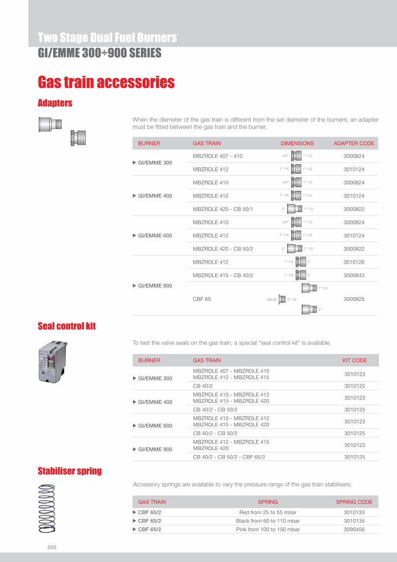
568
Two Stage Dual Fuel Burners
Gas train accessoriesAdapters
When the diameter of the gas train is different from the set diameter of the burners, an adapter must be fi tted between the gas train and the burner.
BURNER GAS TRAIN KIT CODE
u GI/EMME 300 MBZRDLE 407 - MBZRDLE 410 MBZRDLE 412 - MBZRDLE 415
3010123
CB 40/2 3010125
u GI/EMME 400 MBZRDLE 410 - MBZRDLE 412 MBZRDLE 415 - MBZRDLE 420
3010123
CB 40/2 - CB 50/2 3010125
u GI/EMME 600 MBZRDLE 410 - MBZRDLE 412 MBZRDLE 415 - MBZRDLE 420
3010123
CB 40/2 - CB 50/2 3010125
u GI/EMME 900 MBZRDLE 412 - MBZRDLE 415 MBZRDLE 420
3010123
CB 40/2 - CB 50/2 - CBF 65/2 3010125
Seal control kit
To test the valve seals on the gas train, a special “seal control kit” is available.
GI/EMME 300÷900 SERIES
Stabiliser springAccessory springs are available to vary the pressure range of the gas train stabilisers.
GAS TRAIN SPRING SPRING CODE
u CBF 65/2 Red from 25 to 55 mbar 3010133
u CBF 65/2 Black from 60 to 110 mbar 3010135
u CBF 65/2 Pink from 100 to 150 mbar 3090456
BURNER GAS TRAIN DIMENSIONS ADAPTER CODE
u GI/EMME 300MBZRDLE 407 - 410 1” 1/23/4” 3000824
MBZRDLE 412 1” 1/21” 1/4 3010124
u GI/EMME 400
MBZRDLE 410 1” 1/23/4” 3000824
MBZRDLE 412 1” 1/21” 1/4 3010124
MBZRDLE 420 - CB 50/1 1” 1/22” 3000822
u GI/EMME 600
MBZRDLE 410 1” 1/23/4” 3000824
MBZRDLE 412 1” 1/21” 1/4 3010124
MBZRDLE 420 - CB 50/2 1” 1/22” 3000822
u GI/EMME 900
MBZRDLE 412 2”1” 1/4 3010126
MBZRDLE 415 - CB 40/2 2”1” 1/2 3000843
CBF 65 2” 1/2DN 65
1” 1/2
2”
3000825

569
DUAL
FUE
L
Useful working fi eldfor choosing theburner
Modulation range
Test conditionsconforming to EN267- EN676 Temperature: 20°CPressure: 1013,5 mbarAltitude: 0 m a.s.l.
Modulating Dual Fuel Burners
GI/EMME 1400÷4500 SERIESThe GI/EMME 1400-4500 series of burners covers a fi ring range from 820 to 4650 kW. They ave been designed for high output users and they are suitable for matching with every kind of boilers, with normal or pressurized combustion chamber.Operation can be “two stage progressive” or, alternatively, “modulating” with the installation of a PID logic regulator and respective probes. Two options of operation are available: only gas and only light oil, thus settable by a manual switch. Light oil circuit is fi tted with his own electric motor: this permits pump stop during gas operation preventing danger of pumping seizure and avoiding oil circulation. A wide range of accessories and gas trains suitable to the burners guarantee an elevated working fl exibility.
GI/EMME 1400 407/820 ÷ 1540 kWGI/EMME 2000 581/1163 ÷ 2325 kWGI/EMME 3000 872/1744 ÷ 3488 kWGI/EMME 4500 1163/2350 ÷ 4650 kW
FIRING RATES
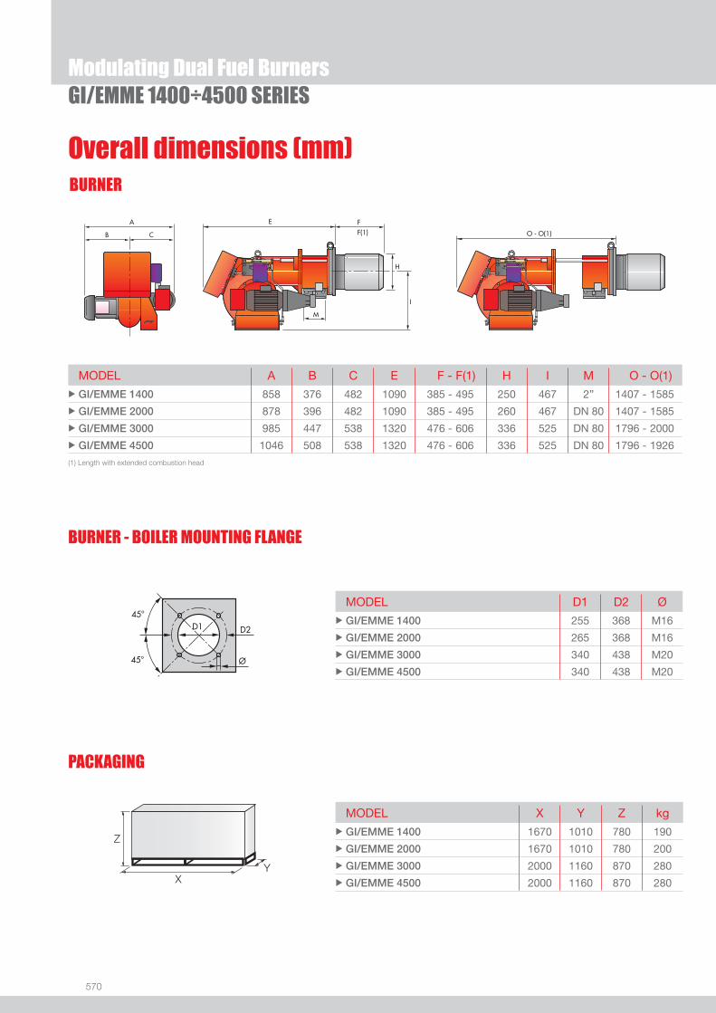
570
BURNER
Overall dimensions (mm)
GI/EMME 1400÷4500 SERIES
(1) Length with extended combustion head
MODEL A B C E F - F(1) H I M O - O(1) u GI/EMME 1400 858 376 482 1090 385 - 495 250 467 2” 1407 - 1585
u GI/EMME 2000 878 396 482 1090 385 - 495 260 467 DN 80 1407 - 1585
u GI/EMME 3000 985 447 538 1320 476 - 606 336 525 DN 80 1796 - 2000
u GI/EMME 4500 1046 508 538 1320 476 - 606 336 525 DN 80 1796 - 1926
MODEL X Y Z kg u GI/EMME 1400 1670 1010 780 190
u GI/EMME 2000 1670 1010 780 200
u GI/EMME 3000 2000 1160 870 280
u GI/EMME 4500 2000 1160 870 280
MODEL D1 D2 Ø u GI/EMME 1400 255 368 M16
u GI/EMME 2000 265 368 M16
u GI/EMME 3000 340 438 M20
u GI/EMME 4500 340 438 M20
BURNER - BOILER MOUNTING FLANGE
PACKAGING
Z
XY
Modulating Dual Fuel Burners

571
DUAL
FUE
L
DESIGNATION OF SERIES
Specifi cation
GI/EMME 1400÷4500 SERIES
BASIC DESIGNATION
EXTENDED DESIGNATION
Series : GI/EMME
Size Emission : Class 1 EN267 - EN676 Head : TC Standard head TL Extended head
Flame control system : FS1 Standard (1 stop every 24 h)
Electrical supply to the system : 1/230/50 1/230V/50Hz 1/210/60 1/210V/60Hz 1/220/60 1/220V/60Hz 3/230-400/50 3/230V/50Hz - 3N/400V/50Hz 3/210/60 3/210V/60Hz 3/400/50 3N/400V/50Hz 3/220/60 3/220V/60Hz 3/380/60 3N/380V/60Hz 3/230/50 3/230V/50Hz 3/220-380/60 3/220/60Hz - 3N/380V/60Hz Auxiliary voltage : 230/50 230V/50Hz 120/60 120V/60Hz 220/60 220V/60Hz
Modulating Dual Fuel Burners
GI/EMME 1400 TC FS1 3/230-400/50 230/50
572
Specifi cationSTATE OF SUPPLY
Monoblock forced draught dual fuel burner, two stage progressive or modulating operation with a kit, made up of:- Air suction circuit- Fan with forward curved blades- Air damper for setting and butterfl y valve for regulating fuel output controlled by a servomotor- Combustion head, that can be set on the basis of required output- Maximum gas pressure switch- Minimum air pressure switch- Fan electrical motor- Pump electrical motor- Gears pump for high pressure fuel supply, fi tted with: - fi lter - pressure regulator - connections for installing a pressure gauge and a a vacuometer - internal by-pass for single pipe installation- Valve unit with a double oil safety valve on the output circuit and safety valve on the return circuit- UV photocell for fl ame detection- Flame inspection window- Slide bars for easier installation and maintenance- Protection fi lter against radio interference- IP X0D (IP 40) protection level.
Standard equipment:- 1 fl ange (for GI/EMME 1400)- 1 gas train fl ange- 8 screws for fi xing the burner fl ange to the boiler (for GI/EMME 1400)- 12 screws for fi xing the burner fl ange to the boiler- 1 insulating screen- 2 fl exible hoses for connection to the oil supply circuit- 2 nipples for connection to the pump- 4 wiring looms fi ttings for electrical connections- 2 pin extensions- 8 washers (for GI/EMME 1400)- 12 washers- Instruction handbook for installation, use and maintenance- Spare parts catalogue.
GI/EMME 1400÷4500 SERIESModulating Dual Fuel Burners

573
DUAL
FUE
L
Available models
GI/EMME 1400÷4500 SERIES
Burners
(1) CE 0085AQ0712 - DIN 5G830/97 M.(2) CE 0085AQ0712 - DIN 5G831/97 M.(3) CE 0085AQ0712 - DIN 5G832/97 M.(4) CE 0085AQ0712 - DIN 5G833/97 M.* Star delta starter.Net calorifi c value light oil: 11,8 kWh/kg; 10.200 kcal/kg - Viscosity at 20°C: 4-6 mm2/s (cSt).Net calorifi c value G20 gas: 10 kWh/Nm3; 8.600 kcal/Nm3 - Density: 0,71 kg/Nm3.The burners of GI/EMME series are in according to 90/396 - 89/336 (2004/108) - 73/23 (2006/95) EC Directive and EN 267-676 Norm.
Modulating Dual Fuel Burners
CODE MODEL HEAT OUTPUT TOTALELECTRICAL
POWER
CERTIFICATION NOTE
LIGHT OIL NATURAL GAS
(kW) (kg/h) (Nm3/h) (kW)
3486683 GI/EMME 1400 TC FS1 3/220-380/60 220/60 415/814-1660 35/69-140 41/81-166 3 + 1,1 -
3486655 GI/EMME 1400 TC FS1 3/230-400/50 230/50 407/820-1540 34/69-130 41/82-154 3 + 1,1 (1)
3486684 GI/EMME 1400 TL FS1 3/220-380/60 220/60 415/814-1660 35/69-140 41/81-166 3 + 1,1 -
3486656 GI/EMME 1400 TL FS1 3/230-400/50 230/50 407/820-1540 34/69-130 41/82-154 3 + 1,1 (1)
3487683 GI/EMME 2000 TC FS1 3/220-380/60 220/60 590/1163-2370 50/98-200 59/116-237 4 + 1,1 -
3487657 GI/EMME 2000 TC FS1 3/230-400/50 230/50 581/1163-2325 49/98-196 58/116-233 4 + 1,1 (2)
3487659 GI/EMME 2000 TC FS1 3/400/50 230/50 581/1163-2325 49/98-196 58/116-233 4 + 1,1 (2) *
3487684 GI/EMME 2000 TL FS1 3/220-380/60 220/60 590/1163-2370 50/98-200 59/116-237 4 + 1,1 -
3487658 GI/EMME 2000 TL FS1 3/230-400/50 230/50 581/1163-2325 49/98-196 58/116-233 4 + 1,1 (2)
3487660 GI/EMME 2000 TL FS1 3/400/50 230/50 581/1163-2325 49/98-196 58/116-233 4 + 1,1 (2) *
3488783 GI/EMME 3000 TC FS1 3/220-380/60 220/60 890/1744-3560 75/147-300 89/174-356 9 + 1,5 -
3488757 GI/EMME 3000 TC FS1 3/230-400/50 230/50 872/1744-3488 74/147-294 87/174-349 9 + 1,5 (3)
3488759 GI/EMME 3000 TC FS1 3/400/50 230/50 872/1744-3488 74/147-294 87/174-349 9 + 1,5 (3) *
3488784 GI/EMME 3000 TL FS1 3/220-380/60 220/60 890/1744-3560 75/147-300 89/174-356 9 + 1,5 -
3488758 GI/EMME 3000 TL FS1 3/230-400/50 230/50 872/1744-3488 74/147-294 87/174-349 9 + 1,5 (3)
3488760 GI/EMME 3000 TL FS1 3/400/50 230/50 872/1744-3488 74/147-294 87/174-349 9 + 1,5 (3) *
3489085 GI/EMME 4500 TC FS1 3/220/60 220/60 1190/2325-5100 100/196-430 119/233-510 12 + 1,5 - *
3489063 GI/EMME 4500 TC FS1 3/230/50 230/50 1163/2350-4650 98/198-392 116/235-465 12 + 1,5 (4) *
3489087 GI/EMME 4500 TC FS1 3/380/60 220/60 1190/2325-5100 100/196-430 119/233-510 12 + 1,5 - *
3489065 GI/EMME 4500 TC FS1 3/400/50 230/50 1163/2350-4650 98/198-392 116/235-465 12 + 1,5 (4) *
3489086 GI/EMME 4500 TL FS1 3/220/60 220/60 1190/2325-5100 100/196-430 119/233-510 12 + 1,5 - *
3489064 GI/EMME 4500 TL FS1 3/230/50 230/50 1163/2350-4650 98/198-392 116/235-465 12 + 1,5 (4) *
3489088 GI/EMME 4500 TL FS1 3/380/60 220/60 1190/2325-5100 100/196-430 119/233-510 12 + 1,5 - *
3489066 GI/EMME 4500 TL FS1 3/400/50 230/50 1163/2350-4650 98/198-392 116/235-465 12 + 1,5 (4) *
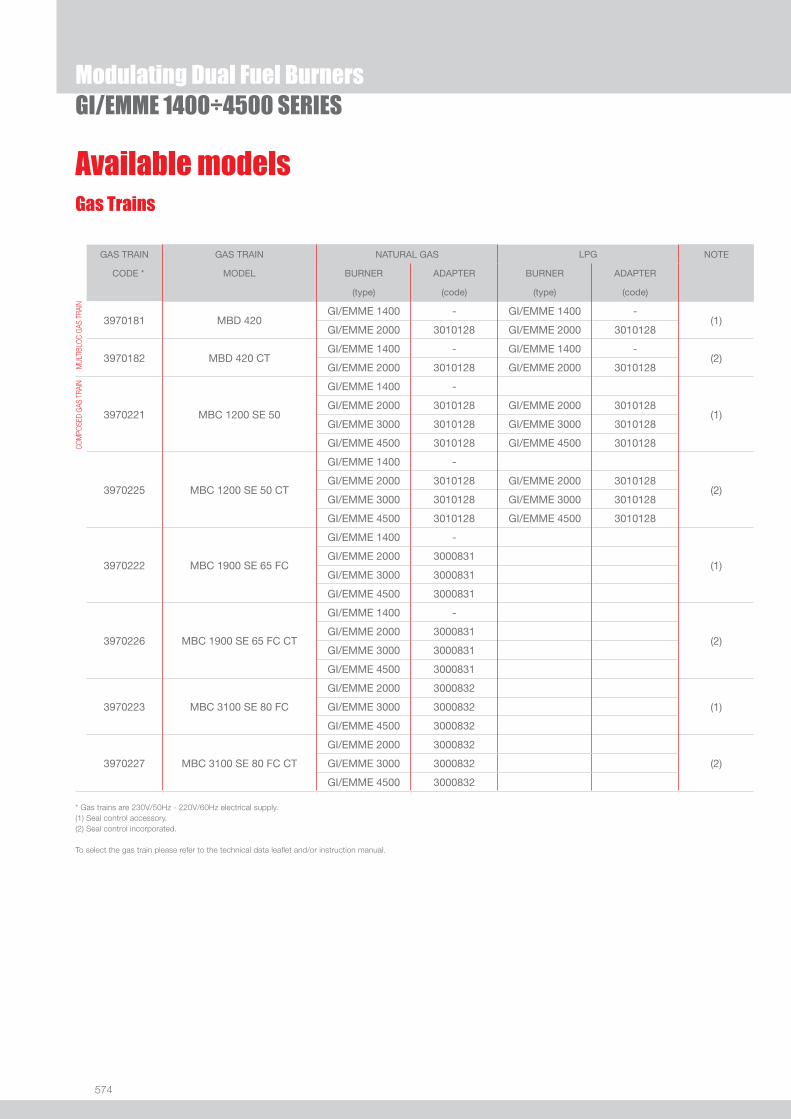
574
Available modelsGas Trains
* Gas trains are 230V/50Hz - 220V/60Hz electrical supply.(1) Seal control accessory.(2) Seal control incorporated.
To select the gas train please refer to the technical data leafl et and/or instruction manual.
GI/EMME 1400÷4500 SERIESModulating Dual Fuel Burners
GAS TRAIN GAS TRAIN NATURAL GAS LPG NOTE
CODE * MODEL BURNER ADAPTER BURNER ADAPTER
(type) (code) (type) (code)
MUL
TIBL
OC G
AS T
RAIN
3970181 MBD 420GI/EMME 1400 - GI/EMME 1400 -
(1)GI/EMME 2000 3010128 GI/EMME 2000 3010128
3970182 MBD 420 CTGI/EMME 1400 - GI/EMME 1400 -
(2)GI/EMME 2000 3010128 GI/EMME 2000 3010128
COM
POSE
D GA
S TR
AIN
3970221 MBC 1200 SE 50
GI/EMME 1400 -
(1)GI/EMME 2000 3010128 GI/EMME 2000 3010128
GI/EMME 3000 3010128 GI/EMME 3000 3010128
GI/EMME 4500 3010128 GI/EMME 4500 3010128
3970225 MBC 1200 SE 50 CT
GI/EMME 1400 -
(2)GI/EMME 2000 3010128 GI/EMME 2000 3010128
GI/EMME 3000 3010128 GI/EMME 3000 3010128
GI/EMME 4500 3010128 GI/EMME 4500 3010128
3970222 MBC 1900 SE 65 FC
GI/EMME 1400 -
(1)GI/EMME 2000 3000831
GI/EMME 3000 3000831
GI/EMME 4500 3000831
3970226 MBC 1900 SE 65 FC CT
GI/EMME 1400 -
(2)GI/EMME 2000 3000831
GI/EMME 3000 3000831
GI/EMME 4500 3000831
3970223 MBC 3100 SE 80 FC
GI/EMME 2000 3000832
(1)GI/EMME 3000 3000832
GI/EMME 4500 3000832
3970227 MBC 3100 SE 80 FC CT
GI/EMME 2000 3000832
(2)GI/EMME 3000 3000832
GI/EMME 4500 3000832

575
DUAL
FUE
L
Burner accessories
GI/EMME 1400÷4500 SERIES
Nozzles type B5-SA 45°
The nozzles must be ordered separately. The following table shows the features and codes on the basis of the maximum required fuel output.
NOTE: each burner needs N° 1 nozzle.
If noise emission needs reducing even further, sound-proofi ng boxes are available.
Sound proofi ng box
BURNER
BOX TYPE
AVERAGE NOISE REDUCTION [dB(A)] (*)
BOX CODE
u GI/EMME 1400 - 2000 - 3000 - 4500 C7 10 3010376
(*) according to EN 15036-1 standard
Modulating Dual Fuel Burners
BURNER RATED DELIVERY (kg/h)
NOZZLECODE (1)
NOZZLECODE (2)
u GI/EMME 1400 70 3009303 3045471
u GI/EMME 1400 80 3009305 3045472
u GI/EMME 1400 90 3009307 3045473
u GI/EMME 1400 - 2000 100 3009310 3045475
u GI/EMME 1400 - 2000 125 3009312 3045477
u GI/EMME 2000 - 3000 150 3009314 3045479
u GI/EMME 2000 - 3000 175 3009316 3045481
u GI/EMME 2000 - 3000 - 4500 200 3009318 3045483
u GI/EMME 3000 - 4500 225 3009320 3045485
u GI/EMME 3000 - 4500 250 3009322 3045487
u GI/EMME 3000 - 4500 275 3009324 3045489
u GI/EMME 3000 - 4500 300 3009326 3045491
u GI/EMME 4500 325 3009328 3045493
u GI/EMME 4500 350 3009330 3045495
u GI/EMME 4500 375 3009332 3045497
u GI/EMME 4500 400 3009334 3045499
(1) Nozzles Bergonzo B5 45° - without “SA” needle code. (2) Nozzles Fluidics N2 45° - without needle code.
If burner head penetration into the combustion chamber needs reducing, varying thickness spacers are available, as given in the following list.
Spacer kit
BURNER
SPACER THICKNESS S (mm)
KIT CODE
u GI/EMME 1400 - 2000 102 3000722
u GI/EMME 3000 - 4500 130 3000751

576
Modulating Dual Fuel BurnersGI/EMME 1400÷4500 SERIES
Burner accessoriesAccessories for modulating operation
To obtain modulating operation, the GI/EMME series of burners requires a regulator.
BURNER
REGULATOR TYPE
REGULATOR CODE
u GI/EMME 1400 - 2000 - 3000 - 4500 RWF 40 3010211
Depending on the servomotor fi tted to the burner, a three-pole potentiometer (1000 Ω) can be installed to check the position of the servomotor.
BURNER
POTENTIOMETER KIT CODE
u GI/EMME 1400 - 2000 - 3000 - 4500 3010021
The relative temperature or pressure probes fi tted to the regulator, must be chosen on the basis of the application.
BURNER PROBE TYPE RANGE (°C) (bar) PROBE CODE
uGI/EMME 1400 - 2000GI/EMME 3000 - 4500
Temperature PT 100 -100 ÷ 500°C 3010110
Pressure 4 ÷ 20 mA 0 ÷ 2,5 bar 3010213
Pressure 4 ÷ 20 mA 0 ÷ 16 bar 3010214
For easier maintenance, a mobile burner support has been designed, which means the burner can be dismantled without the need of forklift trucks.
Burner support
BURNER SUPPORT CODE
u GI/EMME 1400 - 2000 - 3000 - 4500 3000731
LPG kit
For burning LPG gas, a special kit is available to be fi tted to the combustion head on the burner, as given in the following table.
BURNER KIT CODE FOR STANDARD HEAD
KIT CODE FOR EXTENDED HEAD
u GI/EMME 1400 - 2000 3010063 3010063

577
DUAL
FUE
L
Modulating Dual Fuel BurnersGI/EMME 1400÷4500 SERIES
Gas train accessories
Seal control kit
To test the valve seals on the gas train, a special “seal control kit” is available.
BURNER GAS TRAIN KIT CODE
u All models All models 3010123
Stabiliser spring
To vary the pressure range of the gas train stabilisers, accessory springs are available. The following table shows these accessories with their application range. Please refer to the technical manual for the correct choice of spring.
GAS TRAIN SPRING SPRING CODE
u
u
u
MBC 1900MBC 3100MBC 5000
White from 4 to 20 mbar 3010381
Red from 20 to 40 mbar 3010382
Black from 40 to 80 mbar 3010383
Green from 80 to 150 mbar 3010384
BURNER GAS TRAIN DIMENSIONS ADAPTER CODE
u GI/EMME 1400 MBC 1900 2” 1/2DN 65 2” 3000825
u GI/EMME 2000
MBD 420
2” 1/2 2”
DN 80
DN 65 3010128
MBC 1200
2” 1/2 2”
DN 80
DN 65 3010128
MBC 1900 DN 65
DN 80
3000831
MBC 3100 DN 80
DN 80
3000832
u GI/EMME 3000
MBC 1200
2” 1/2 2”
DN 80
DN 65 3010128
MBC 1900 DN 65
DN 80
3000831
MBC 3100 DN 80
DN 80
3000832
u GI/EMME 4500
MBC 1200
2” 1/2 2”
DN 80
DN 65 3010128
MBC 1900 DN 65
DN 80
3000831
MBC 3100 DN 80
DN 80
3000832
Adapters
When the diameter of the gas train is different from the set diameter of the burners, an adapter must be fi tted between the gas train and the burner.


579
DUAL
FUE
L
Useful working fi eldfor choosing theburner
Modulation range
Test conditionsconforming to EN267- EN676 Temperature: 20°CPressure: 1013,5 mbarAltitude: 0 m a.s.l.
ENNE/EMME SERIESThe ENNE/EMME 1400-4500 series of burners covers a fi ring range from 814 to 5000 kW. They They have been designed for high output users and they are suitable for matching with every kind of boilers, with normal or pressurized combustion chamber.Operation can be “two stage progressive” or, alternatively, “modulating” with the installation of a PID logic regulator and respective probes. Two fuel options are available: only gas and only heavy oil, thus settable by a manual switch. Heavy oil circuit is fi tted with his own electric motor: this permits pump stop during gas operation preventing danger of pumping seizure and avoiding oil circulation. A wide range of accessories and gas trains suitable to the burners guarantee an elevated working fl exibility.
ENNE/EMME 1400 407/814 ÷ 1628 kWENNE/EMME 2000 581/1163 ÷ 2325 kWENNE/EMME 3000 872/1744 ÷ 3488 kWENNE/EMME 4500 1163/2325 ÷ 5000 kW
Modulating Dual Fuel Burners
FIRING RATES

580
BURNER
Overall dimensions (mm)
ENNE/EMME SERIES
(1) Length with extended combustion head
PACKAGING
Z
X - X(1)Y
MODEL D1 D2 Ø u ENNE/EMME 1400 255 368 M16
u ENNE/EMME 2000 265 368 M16
u ENNE/EMME 3000 340 438 M20
u ENNE/EMME 4500 340 438 M20
BURNER - BOILER MOUNTING FLANGE
Modulating Dual Fuel Burners
MODEL A B C E F - F(1) H I M O - O(1) u ENNE/EMME 1400 892 376 516 1090 385 - 495 250 467 2” 1475 - 1585
u ENNE/EMME 2000 912 396 516 1090 385 - 495 260 467 DN80 1475 - 1585
u ENNE/EMME 3000 1000 447 553 1320 476 - 606 336 525 DN80 1796 - 1926
u ENNE/EMME 4500 1061 508 553 1320 476 - 606 336 525 DN80 1796 - 1926
MODEL X - X(1) Y Z Kg u ENNE/EMME 1400 1670 - 1670 1010 780 265
u ENNE/EMME 2000 1670 - 1670 1010 780 265
u ENNE/EMME 3000 2000 - 2000 1160 870 280
u ENNE/EMME 4500 2000 - 2000 1160 870 290
(1) Length with extended combustion head

581
DUAL
FUE
L
DESIGNATION OF SERIES
Specifi cation
ENNE/EMME SERIES
BASIC DESIGNATION
EXTENDED DESIGNATION
Series : ENNE/EMME
Size Emission : Class 1 EN267 - EN676 Head : TC Standard head TL Extended head
Flame control system : FS1 Standard (1 stop every 24 h)
Electrical supply to the system : 3/220/50 3/220V/50Hz 3/380/50 3N/380V/50Hz 3/220-380/50 3/220/50Hz - 3N/380V/50Hz Auxiliary voltage : 220/50 220V/50Hz
Modulating Dual Fuel Burners
ENNE/EMME 1400 TC FS1 3/220-380/50 220/50

582
Specifi cationSTATE OF SUPPLY
Monoblock forced draught dual fuel burner, two stage progressive or modulating operation with a kit, made up of:- Air suction circuit- Fan with forward curved blades- Air damper for setting and butterfl y valve for regulating fuel output controlled by a servomotor- Combustion head, that can be set on the basis of required output- Maximum gas pressure switch- Minimum air pressure switch- Fan electrical motor- Pump electrical motor- Gears pump for high pressure fuel supply, fi tted with: -fi lter -pressure regulator -connections for installing a pressure gauge and a a vacuometer -internal by-pass for single pipe installation- Preheater unit- Valve unit with a double oil safety valve on the output circuit and safety valve on the return circuit- UV photocell for fl ame detection- Flame inspection window- Slide bars for easier installation and maintenance- Protection fi lter against radio interference- IP X0D (IP 40) protection level.
Standard equipment:- 1 gas train fl ange- 12 screws for fi xing the burner fl ange to the boiler- 1 insulating screen- 2 fl exible hoses for connection to the oil supply circuit- 2 nipples for connection to the pump- 4 wiring looms fi ttings for electrical connections- 2 pin extensions- 8 washers- Instruction handbook for installation, use and maintenance- Spare parts catalogue.
Modulating Dual Fuel BurnersENNE/EMME SERIES
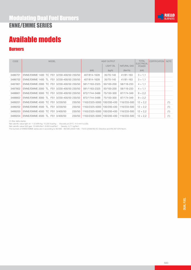
583
DUAL
FUE
L
Available modelsBurners
(1) Star delta starter.Net calorifi c value light oil: 11,8 kWh/kg; 10.200 kcal/kg - Viscosity at 20°C: 4-6 mm2/s (cSt).Net calorifi c value G20 gas: 10 kWh/Nm3; 8.600 kcal/Nm3 - Density: 0,71 kg/Nm3.The burners of ENNE/EMME series are in according to 90/396 - 89/336 (2004/108) - 73/23 (2006/95) EC Directive and EN 267-676 Norm.
Modulating Dual Fuel BurnersENNE/EMME SERIES
CODE MODEL HEAT OUTPUT TOTALELECTRICAL
POWER
CERTIFICATION NOTE
LIGHT OIL NATURAL GAS
(kW) (kg/h) (Nm3/h) (kW)
3486701 ENNE/EMME 1400 TC FS1 3/230-400/50 230/50 407/814-1628 35/70-140 41/81-163 3 + 1,1
3486702 ENNE/EMME 1400 TL FS1 3/230-400/50 230/50 407/814-1628 35/70-140 41/81-163 3 + 1,1
3487801 ENNE/EMME 2000 TC FS1 3/230-400/50 230/50 581/1163-2325 50/100-200 58/116-233 4 + 1,1
3487802 ENNE/EMME 2000 TL FS1 3/230-400/50 230/50 581/1163-2325 50/100-200 58/116-233 4 + 1,1
3488801 ENNE/EMME 3000 TC FS1 3/230-400/50 230/50 872/1744-3488 75/150-300 87/174-349 9 + 2,2
3488802 ENNE/EMME 3000 TL FS1 3/230-400/50 230/50 872/1744-3488 75/150-300 87/174-349 9 + 2,2
3489201 ENNE/EMME 4500 TC FS1 3/230/50 230/50 1163/2325-5000 100/200-430 116/233-500 12 + 2,2 (1)
3489202 ENNE/EMME 4500 TL FS1 3/230/50 230/50 1163/2325-5000 100/200-430 116/233-500 12 + 2,2 (1)
3489203 ENNE/EMME 4500 TC FS1 3/400/50 230/50 1163/2325-5000 100/200-430 116/233-500 12 + 2,2 (1)
3489204 ENNE/EMME 4500 TL FS1 3/400/50 230/50 1163/2325-5000 100/200-430 116/233-500 12 + 2,2 (1)

584
Available modelsGas Trains
* Gas trains are 230V/50Hz - 220V/60Hz electrical supply.(1) Seal control accessory.(2) Seal control incorporated.
To select the gas train please refer to the technical data leafl et and/or instruction manual.
Modulating Dual Fuel Burners
GAS TRAIN GAS TRAIN NATURAL GAS LPG NOTE
CODE * MODEL BURNER ADAPTER BURNER ADAPTER
(type) (code) (type) (code)
MUL
TIBL
OC G
AS T
RAIN
3970181 MBD 420ENNE/EMME 1400 - ENNE/EMME 1400 -
(1)ENNE/EMME 2000 3010128 ENNE/EMME 2000 3010128
3970182 MBD 420 CTENNE/EMME 1400 - ENNE/EMME 1400 -
(2)ENNE/EMME 2000 3010128 ENNE/EMME 2000 3010128
COM
POSE
D GA
S TR
AIN
3970221 MBC 1200 SE 50
ENNE/EMME 1400 -
(1)ENNE/EMME 2000 3010128 ENNE/EMME 2000 3010128
ENNE/EMME 3000 3010128 ENNE/EMME 3000 3010128
ENNE/EMME 4500 3010128 ENNE/EMME 4500 3010128
3970225 MBC 1200 SE 50 CT
ENNE/EMME 1400 -
(2)ENNE/EMME 2000 3010128 ENNE/EMME 2000 3010128
ENNE/EMME 3000 3010128 ENNE/EMME 3000 3010128
ENNE/EMME 4500 3010128 ENNE/EMME 4500 3010128
3970222 MBC 1900 SE 65 FC
ENNE/EMME 1400 3000825
(1)ENNE/EMME 2000 3000831
ENNE/EMME 3000 3000831
ENNE/EMME 4500 3000831
3970226 MBC 1900 SE 65 FC CT
ENNE/EMME 1400 -
(2)ENNE/EMME 2000 3000831
ENNE/EMME 3000 3000831
ENNE/EMME 4500 3000831
3970223 MBC 3100 SE 80 FC
ENNE/EMME 2000 3000832
(1)ENNE/EMME 3000 3000832
ENNE/EMME 4500 3000832
3970227 MBC 3100 SE 80 FC CT
ENNE/EMME 2000 3000832
(2)ENNE/EMME 3000 3000832
ENNE/EMME 4500 3000832
ENNE/EMME SERIES

585
DUAL
FUE
L
Burner accessoriesNozzles type B5-AA 45°
The nozzles must be ordered separately. The following table shows the features and codes on the basis of the maximum required fuel output.
NOTE: each burner needs N° 1 nozzle.
If noise emission needs reducing even further, sound-proofi ng boxes are available.
Sound proofi ng box
BURNER
BOX TYPE
AVERAGE NOISE REDUCTION [dB(A)] (*)
BOX CODE
u ENNE/EMME 1400-2000-3000-4500 C7 10 3010376
(*) according to EN 15036-1 standard
Modulating Dual Fuel Burners
BURNER RATED DELIVERY (kg/h)
NOZZLECODE (1)
NOZZLECODE (2)
u ENNE/EMME 1400 70 3009203 3045426
u ENNE/EMME 1400 80 3009205 3045427
u ENNE/EMME 1400 90 3009207 3045428
u ENNE/EMME 1400 - 2000 100 3009209 3045430
u ENNE/EMME 1400 - 2000 125 3009211 3045432
u ENNE/EMME 1400 - 2000 - 3000 150 3009213 3045434
u ENNE/EMME 2000 - 3000 175 3009215 3045436
u ENNE/EMME 2000 - 3000 - 4500 200 3009800 3045438
u ENNE/EMME 3000 - 4500 225 3009801 3045440
u ENNE/EMME 3000 - 4500 250 3009802 3045442
u ENNE/EMME 3000 - 4500 275 3009803 3045444
u ENNE/EMME 3000 - 4500 300 3009804 3045446
u ENNE/EMME 4500 325 3009805 3045448
u ENNE/EMME 4500 350 3009806 3045450
u ENNE/EMME 4500 375 3009807 3045452
u ENNE/EMME 4500 400 3009808 3045454
u ENNE/EMME 4500 425 3009809 3045455
u ENNE/EMME 4500 450 3009810 3045456
(1) Nozzles Bergonzo B5 45° - with “AA” needle code. (2) Nozzles Fluidics W2 45° - with “AA” needle code.
If burner head penetration into the combustion chamber needs reducing, varying thickness spacers are available, as given in the following list.
Spacer kit
BURNER
SPACER THICKNESS S (mm)
KIT CODE
u ENNE/EMME 1400 - 2000 102 3000722
u ENNE/EMME 3000 - 4500 130 3000751
ENNE/EMME SERIES

586
Modulating Dual Fuel Burners
Burner accessoriesAccessories for modulating operation
To obtain modulating operation, the ENNE/EMME series of burners requires a regulator.
BURNER
REGULATOR TYPE
REGULATOR CODE
u ENNE/EMME 1400 - 2000 - 3000 - 4500 RWF 40 3010211
Depending on the servomotor fi tted to the burner, a three-pole potentiometer (1000 Ω) can be installed to check the position of the servomotor.
BURNER
POTENTIOMETER KIT CODE
u ENNE/EMME 1400 - 2000 - 3000 - 4500 3010021
The relative temperature or pressure probes fi tted to the regulator, must be chosen on the basis of the application.
BURNER PROBE TYPE RANGE (°C) (bar) PROBE CODE
uENNE/EMME 1400 - 2000ENNE/EMME 3000 - 4500
Temperature PT 100 -100 ÷ 500°C 3010110
Pressure 4 ÷ 20 mA 0 ÷ 2,5 bar 3010213
Pressure 4 ÷ 20 mA 0 ÷ 16 bar 3010214
LPG kit
For burning LPG gas, a special kit is available to be fi tted to the combustion head on the burner, as given in the following table.
BURNER KIT CODE FOR STANDARD HEAD
KIT CODE FOR EXTENDED HEAD
u ENNE/EMME 1400 - 2000 3010063 3010063
u ENNE/EMME 3000 in progress in progress
u ENNE/EMME 4500 3090937 3090937
ENNE/EMME SERIES

587
DUAL
FUE
L
Modulating Dual Fuel Burners
Burner accessories
ENNE/EMME SERIES
Self-cleaning fi lter
FILTER TYPE FILTERING DEGREE (µm)
FILTER CODE
u Ø = 1”1/2 (60°E at 50°C) 300 3010022
For cleaning heavy oil from dirty particles and impurities, it is equipped with a thermostatic heater for oil with 60°E viscosity at 50°C.
HEATER / THERMOSTAT TYPE HEATER / THERMOSTAT CODE
u Thermostatic heater with LED 3010060
u Heater 3010061
u Thermostat (two-stage / regulable) 3010062
In modulating burner, gas separator bottle connects the burner circuit to the main ring circuit. It allows to recover heat in excess by discharge of the gas from the return circuit.
Degasing unit
BURNER DEGASING UNIT CODE
u ENNE/EMME 1400 - 2000 3000748
u ENNE/EMME 3000 - 4500 3010012

588
Gas train accessories
Modulating Dual Fuel BurnersENNE/EMME SERIES
Seal control kit
To test the valve seals on the gas train, a special “seal control kit” is available.
BURNER GAS TRAIN KIT CODE
u All models All models 3010123
Stabiliser spring
To vary the pressure range of the gas train stabilisers, accessory springs are available. The following table shows these accessories with their application range. Please refer to the technical manual for the correct choice of spring.
GAS TRAIN SPRING SPRING CODE
u
u
u
MBC 1900MBC 3100MBC 5000
White from 4 to 20 mbar 3010381
Red from 20 to 40 mbar 3010382
Black from 40 to 80 mbar 3010383
Green from 80 to 150 mbar 3010384
BURNER GAS TRAIN DIMENSIONS ADAPTER CODE
u ENNE/EMME 1400 MBC 1900 2” 1/2DN 65 2” 3000825
u ENNE/EMME 2000
MBD 420
2” 1/2 2”
DN 80
DN 65 3010128
MBC 1200
2” 1/2 2”
DN 80
DN 65 3010128
MBC 1900 DN 65
DN 80
3000831
MBC 3100 DN 80
DN 80
3000832
u ENNE/EMME 3000
MBC 1200
2” 1/2 2”
DN 80
DN 65 3010128
MBC 1900 DN 65
DN 80
3000831
MBC 3100 DN 80
DN 80
3000832
u ENNE/EMME 4500
MBC 1200
2” 1/2 2”
DN 80
DN 65 3010128
MBC 1900 DN 65
DN 80
3000831
MBC 3100 DN 80
DN 80
3000832
Adapters
When the diameter of the gas train is different from the set diameter of the burners, an adapter must be fi tted between the gas train and the burner.
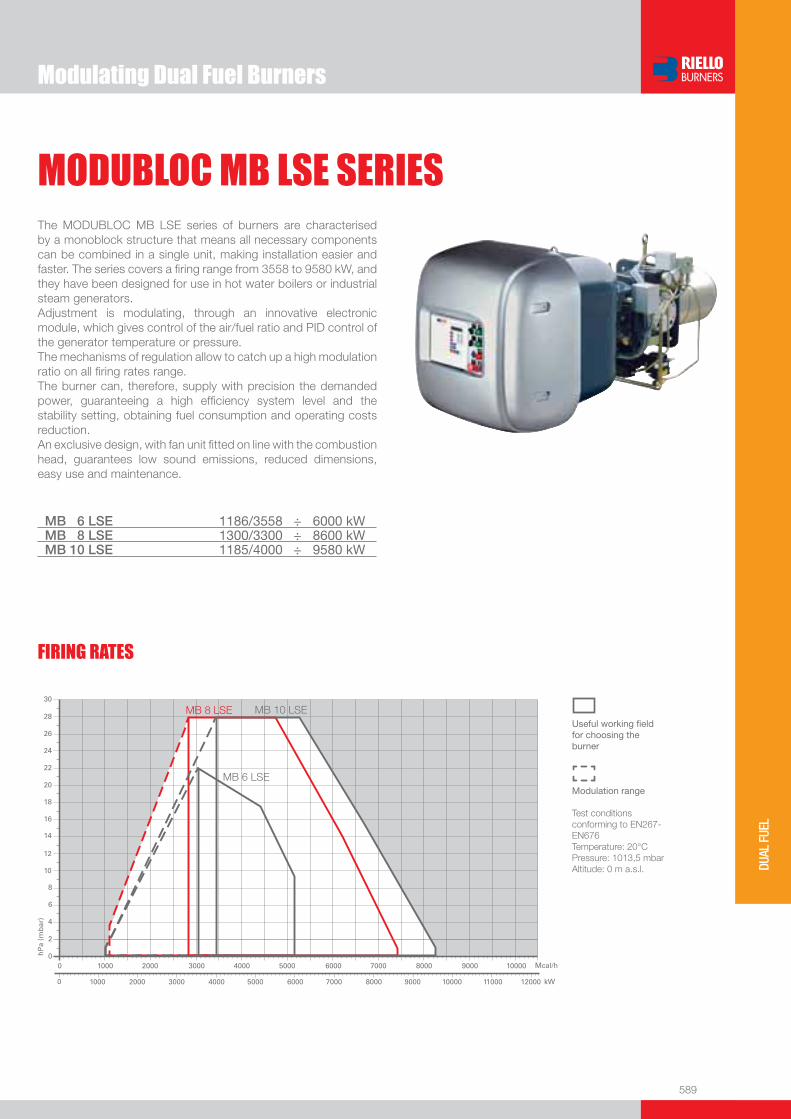
589
DUAL
FUE
L
Useful working fi eldfor choosing theburner
Modulation range
Test conditionsconforming to EN267- EN676 Temperature: 20°CPressure: 1013,5 mbarAltitude: 0 m a.s.l.
Modulating Dual Fuel Burners
MODUBLOC MB LSE SERIESThe MODUBLOC MB LSE series of burners are characterised by a monoblock structure that means all necessary components can be combined in a single unit, making installation easier and faster. The series covers a fi ring range from 3558 to 9580 kW, and they have been designed for use in hot water boilers or industrial steam generators.Adjustment is modulating, through an innovative electronic module, which gives control of the air/fuel ratio and PID control of the generator temperature or pressure.The mechanisms of regulation allow to catch up a high modulation ratio on all fi ring rates range.The burner can, therefore, supply with precision the demanded power, guaranteeing a high effi ciency system level and the stability setting, obtaining fuel consumption and operating costs reduction. An exclusive design, with fan unit fi tted on line with the combustion head, guarantees low sound emissions, reduced dimensions, easy use and maintenance.
MB 6 LSE 1186/3558 ÷ 6000 kWMB 8 LSE 1300/3300 ÷ 8600 kWMB 10 LSE 1185/4000 ÷ 9580 kW
FIRING RATES
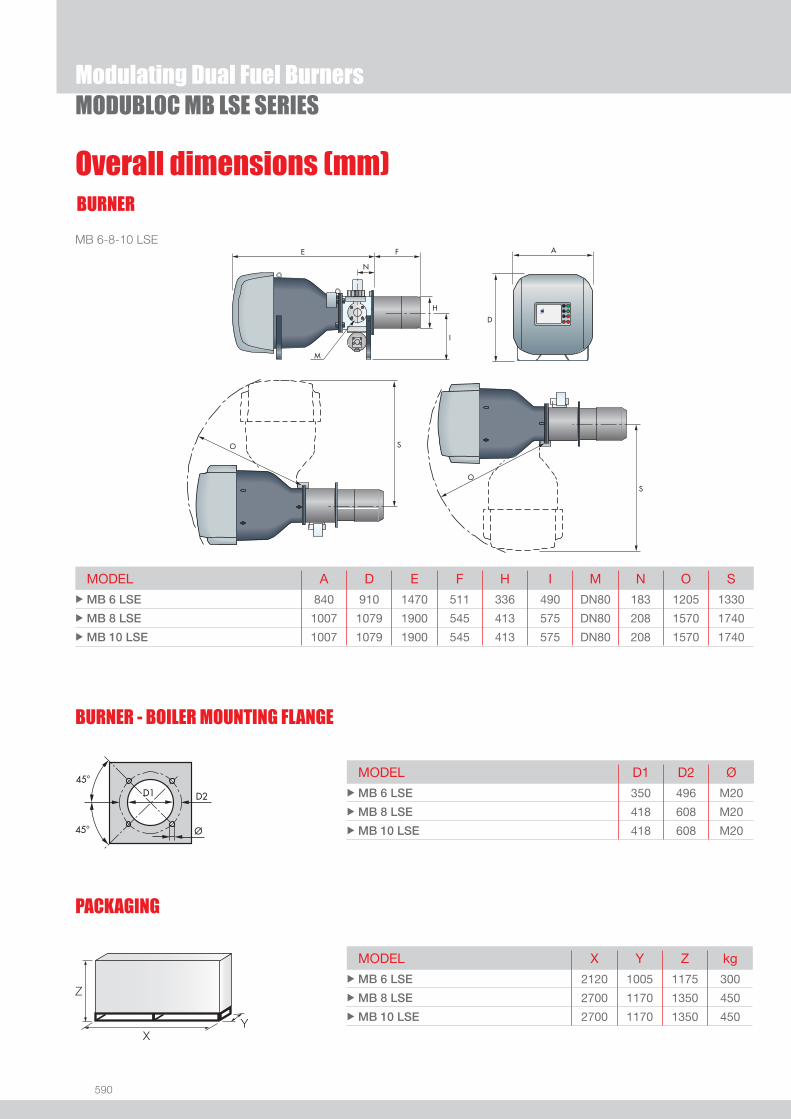
590
BURNER
PACKAGING
Overall dimensions (mm)
Z
XY
MB 6-8-10 LSE
MODEL A D E F H I M N O S uMB 6 LSE 840 910 1470 511 336 490 DN80 183 1205 1330
uMB 8 LSE 1007 1079 1900 545 413 575 DN80 208 1570 1740
uMB 10 LSE 1007 1079 1900 545 413 575 DN80 208 1570 1740
MODEL D1 D2 Ø uMB 6 LSE 350 496 M20
uMB 8 LSE 418 608 M20
uMB 10 LSE 418 608 M20
MODEL X Y Z kg uMB 6 LSE 2120 1005 1175 300
uMB 8 LSE 2700 1170 1350 450
uMB 10 LSE 2700 1170 1350 450
Modulating Dual Fuel Burners
BURNER - BOILER MOUNTING FLANGE
MODUBLOC MB LSE SERIES
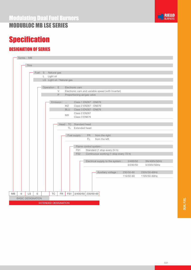
591
DUAL
FUE
L
DESIGNATION OF SERIES
Specifi cation
Modulating Dual Fuel BurnersMODUBLOC MB LSE SERIES
EXTENDED DESIGNATION
MB 6 LS E TC FR FS1 3/400/50 230/50-60
Series : MB
Size
Fuel : S Natural gas L Light oil LS Light oil / Natural gas
Operation : E Electronic cam V Electronic cam and variable speed (with Inverter) P Proportioning air/gas valve Emission : ... Class 1 EN267 - EN676 MZ Class 2 EN267 - EN676 BLU Class 3 EN267 - EN676
MX Class 2 EN267
Class 3 EN676
Head : TC Standard head TL Extended head
Fuel supply : FR from the right FL from the left
Flame control system : FS1 Standard (1 stop every 24 h) FS2 Continuous working (1 stop every 72 h)
Electrical supply to the system : 3/400/50 3N/400V/50Hz 3/230/50 3/230V/50Hz Auxiliary voltage : 230/50-60 230V/50-60Hz 110/50-60 110V/50-60Hz
BASIC DESIGNATION

592
Specifi cationSTATE OF SUPPLY
Modulating Dual Fuel BurnersMODUBLOC MB LSE SERIES
Monoblock forced draught dual-fuel burner modulating operation, made up of:- Fan with reverse curve blades- Air suction circuit lined with sound-proofi ng material- Air damper for air setting controlled by a high precision servomotor- Air pressure switch- Fan starting motor- Pump starting motor- Mobile combustion head, that can be set on the basis of required output - Gears pump for high pressure fuel supply - Valve unit- Automatic setting for light oil and gas delivery, controlled by a high precision servomotor- Safety oil pressure switch- Pressure gauge for delivery pressure- Pressure gauge for return pressure- Minimum oil pressure switch- Maximum gas pressure switch - Module for air/fuel setting and output modulation- Burner safety control box- Photocell for fl ame detection- Star/triangle starter for the fan motor- Main electrical supply terminal board- Pump motor starter- Burner on/off switch- Auxiliary voltage led signal- Manual or automatic output increase/decrease switch- Burner working led signal- Contacts motor and thermal relay with release button- Motor internal thermal protection- Motor failure led signal- Burner failure led signal and lighted release button- Led signal for correct rotation direction of fan and pump motor- Emergency button- Coded connection plugs-sockets- Burner opening hinge- Lifting rings- IP X0D (IP 40) protection level.
Standard equipment:- 2 fl exible pipes- 2 gaskets for the fl exible pipes- 2 nipples for connection to the pump- 1 fl ange gasket- 8 screws for fi xing the fl ange- 4 screws for fi xing the burner fl ange to the boiler- 1 thermal screen- Instruction handbook for installation, use and maintenance- Spare parts catalogue.
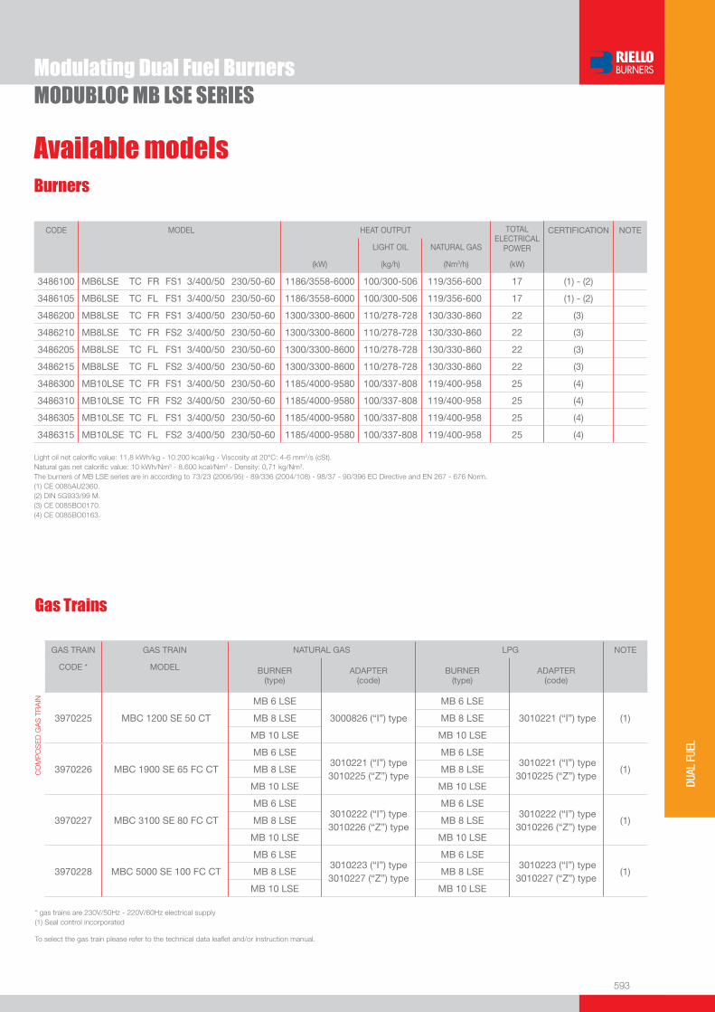
593
DUAL
FUE
L
Available modelsBurners
Light oil net calorifi c value: 11,8 kWh/kg - 10.200 kcal/kg - Viscosity at 20°C: 4-6 mm2/s (cSt).Natural gas net calorifi c value: 10 kWh/Nm3 - 8.600 kcal/Nm3 - Density: 0,71 kg/Nm3.The burners of MB LSE series are in according to 73/23 (2006/95) - 89/336 (2004/108) - 98/37 - 90/396 EC Directive and EN 267 - 676 Norm.(1) CE 0085AU2360. (2) DIN 5G933/99 M.(3) CE 0085BO0170.(4) CE 0085BO0163.
Modulating Dual Fuel BurnersMODUBLOC MB LSE SERIES
CODE MODEL HEAT OUTPUT TOTALELECTRICAL
POWER
CERTIFICATION NOTE
LIGHT OIL NATURAL GAS
(kW) (kg/h) (Nm3/h) (kW)
3486100 MB6LSE TC FR FS1 3/400/50 230/50-60 1186/3558-6000 100/300-506 119/356-600 17 (1) - (2)
3486105 MB6LSE TC FL FS1 3/400/50 230/50-60 1186/3558-6000 100/300-506 119/356-600 17 (1) - (2)
3486200 MB8LSE TC FR FS1 3/400/50 230/50-60 1300/3300-8600 110/278-728 130/330-860 22 (3)
3486210 MB8LSE TC FR FS2 3/400/50 230/50-60 1300/3300-8600 110/278-728 130/330-860 22 (3)
3486205 MB8LSE TC FL FS1 3/400/50 230/50-60 1300/3300-8600 110/278-728 130/330-860 22 (3)
3486215 MB8LSE TC FL FS2 3/400/50 230/50-60 1300/3300-8600 110/278-728 130/330-860 22 (3)
3486300 MB10LSE TC FR FS1 3/400/50 230/50-60 1185/4000-9580 100/337-808 119/400-958 25 (4)
3486310 MB10LSE TC FR FS2 3/400/50 230/50-60 1185/4000-9580 100/337-808 119/400-958 25 (4)
3486305 MB10LSE TC FL FS1 3/400/50 230/50-60 1185/4000-9580 100/337-808 119/400-958 25 (4)
3486315 MB10LSE TC FL FS2 3/400/50 230/50-60 1185/4000-9580 100/337-808 119/400-958 25 (4)
Gas Trains
* gas trains are 230V/50Hz - 220V/60Hz electrical supply(1) Seal control incorporated
To select the gas train please refer to the technical data leafl et and/or instruction manual.
GAS TRAIN GAS TRAIN NATURAL GAS LPG NOTE
CODE * MODEL BURNER (type)
ADAPTER (code)
BURNER (type)
ADAPTER (code)
CO
MP
OS
ED
GA
S T
RA
IN
3970225
MBC 1200 SE 50 CT
MB 6 LSE
3000826 (“I”) type
MB 6 LSE
3010221 (“I”) type (1) MB 8 LSE MB 8 LSE
MB 10 LSE MB 10 LSE
3970226
MBC 1900 SE 65 FC CT
MB 6 LSE 3010221 (“I”) type 3010225 (“Z”) type
MB 6 LSE 3010221 (“I”) type 3010225 (“Z”) type
(1) MB 8 LSE MB 8 LSE
MB 10 LSE MB 10 LSE
3970227
MBC 3100 SE 80 FC CT
MB 6 LSE 3010222 (“I”) type 3010226 (“Z”) type
MB 6 LSE 3010222 (“I”) type 3010226 (“Z”) type
(1) MB 8 LSE MB 8 LSE
MB 10 LSE MB 10 LSE
3970228
MBC 5000 SE 100 FC CT
MB 6 LSE 3010223 (“I”) type 3010227 (“Z”) type
MB 6 LSE 3010223 (“I”) type 3010227 (“Z”) type
(1) MB 8 LSE MB 8 LSE
MB 10 LSE MB 10 LSE

594
Modulating Dual Fuel BurnersMODUBLOC MB LSE SERIES
DTI module (Data Transfer Interface)
This electronic module can transfer multiple signals from different local modules to a BMS supervisor software system (Building Management System).
BURNER MODULE CODE
u MB 6 - 8 - 10 LSE 3010234
I/O digital module
Digital modules I/O transfer in-coming and out-going information from the system in general to a remote supervisor system.
BURNER MODULE CODE
u MB 6 - 8 - 10 LSE 3010233
I/O analogic module
I/O Analog modules transfer in-coming and out-going information to a remote supervisor system.
BURNER MODULE CODE
u MB 6 - 8 - 10 LSE 3010232
EGA module (Exhaust Gas Analyser)
Four different EGA modules are available to measure some of the exhaust gas substances and their temperature.
BURNER ANALYSED GAS MODULE CODE
u MB 6 - 8 - 10 LSE CO, CO2, O2 3010235
u MB 6 - 8 - 10 LSE CO, CO2, O2, NO 3010236
u MB 6 - 8 - 10 LSE CO, CO2, O2, SO2 3010237
u MB 6 - 8 - 10 LSE CO, CO2, O2, NO, SO2 3010238
Belden 9501 type leads
All the connections for the above modules must be done using a BELDEN 9501 type lead (available in coils of 50 m).
BURNER LEAD CODE
u MB 6 - 8 - 10 LSE 3010239
Burner accessories

595
DUAL
FUE
L
Burner accessories
Modulating Dual Fuel Burners
Accessories for modulating operation
MODUBLOC MB LSE SERIES
Main management module allows a modulating operation with use of probes chosen on the basis of the application.
BURNER PROBE TYPE RANGE (°C) (bar) PROBE CODE
u MB 6 - 8 - 10 LSE Temperature 0 ÷ 400°C 3010187
u MB 6 - 8 - 10 LSE Pressure 0 ÷ 3 bar 3010246
u MB 6 - 8 - 10 LSE Pressure 0 ÷ 18 bar 3010186
u MB 6 - 8 - 10 LSE Pressure 0 ÷ 30 bar 3010188
Return nozzles
The following list shows the features and codes on the basis of the maximum required fuel output.
NOTE: each burner needs N° 1 nozzle.
(1) Nozzles Bergonzo B5 45° - with “AA” needle code. (2) Nozzles Fluidics W2 45° - with “AA” needle code.
BURNER RATED DELIVERY
(kg/h)
NOZZLE CODE
(1)
NOZZLE CODE
(2)
uMB 10 LSE
400 3009808 3045454
425 3009809 3045455
450 3009810 3045456
475 3009811 3045457
500 3009812 3045458
525 3009813 3045459
550 3009814 3045460
575 3009815 3045461
600 3009816 3045462
650 3009817 3045463
700 3009818 3045464
750 3009819 3045465
800 3009820 -
850 3009821 -
900 3009822 -
BURNER RATED DELIVERY
(kg/h)
NOZZLE CODE
(1)
NOZZLE CODE
(2)
u MB 6 LSE
350 3009806 3045450
375 3009807 3045452
400 3009808 3045454
425 3009809 3045455
450 3009810 3045456
475 3009811 3045457
500 3009812 3045458
u MB 8 LSE
300 3009804 3045446
325 3009805 3045448
350 3009806 3045450
375 3009807 3045452
400 3009808 3045454
425 3009809 3045455
450 3009810 3045456
475 3009811 3045457
500 3009812 3045458
525 3009813 3045459
550 3009814 3045460
575 3009815 3045461
600 3009816 3045462
650 3009817 3045463
700 3009818 3045464
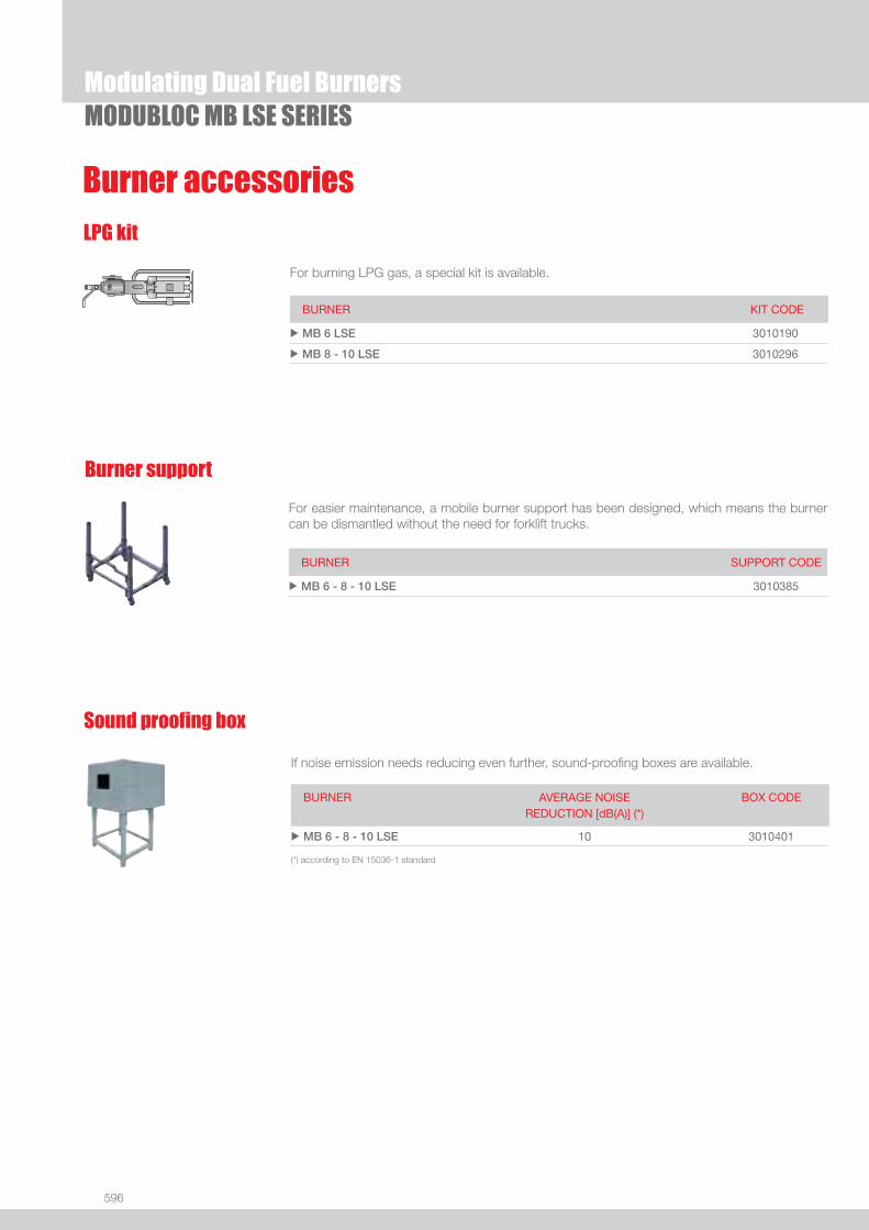
596
Burner support
For easier maintenance, a mobile burner support has been designed, which means the burner can be dismantled without the need for forklift trucks.
BURNER SUPPORT CODE
u MB 6 - 8 - 10 LSE 3010385
LPG kit
For burning LPG gas, a special kit is available.
BURNER KIT CODE
u MB 6 LSE 3010190
u MB 8 - 10 LSE 3010296
Modulating Dual Fuel BurnersMODUBLOC MB LSE SERIES
Burner accessories
If noise emission needs reducing even further, sound-proofi ng boxes are available.
Sound proofi ng box
BURNER
AVERAGE NOISE REDUCTION [dB(A)] (*)
BOX CODE
u MB 6 - 8 - 10 LSE 10 3010401
(*) according to EN 15036-1 standard
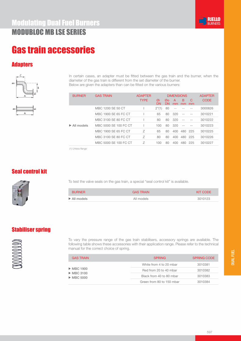
597
DUAL
FUE
L
Gas train accessories
Modulating Dual Fuel Burners
Seal control kit
To test the valve seals on the gas train, a special “seal control kit” is available.
BURNER GAS TRAIN KIT CODE
u All models All models 3010123
Stabiliser spring
To vary the pressure range of the gas train stabilisers, accessory springs are available. The following table shows these accessories with their application range. Please refer to the technical manual for the correct choice of spring.
GAS TRAIN SPRING SPRING CODE
u
u
u
MBC 1900MBC 3100MBC 5000
White from 4 to 20 mbar 3010381
Red from 20 to 40 mbar 3010382
Black from 40 to 80 mbar 3010383
Green from 80 to 150 mbar 3010384
MODUBLOC MB LSE SERIES
Adapters
In certain cases, an adapter must be fi tted between the gas train and the burner, when the diameter of the gas train is different from the set diameter of the burner.Below are given the adapters than can be fi tted on the various burners:
BURNER GAS TRAIN ADAPTER TYPE
DIMENSIONS Øi Øo A B C
ADAPTER CODE
DN DN mm mm mm
u All models
MBC 1200 SE 50 CT I 2”(1) 80 -- -- -- 3000826
MBC 1900 SE 65 FC CT I 65 80 320 -- -- 3010221
MBC 3100 SE 80 FC CT I 80 80 320 -- -- 3010222
MBC 5000 SE 100 FC CT I 100 80 320 -- -- 3010223
MBC 1900 SE 65 FC CT Z 65 80 400 480 225 3010225
MBC 3100 SE 80 FC CT Z 80 80 400 480 225 3010226
MBC 5000 SE 100 FC CT Z 100 80 400 480 225 3010227
(1) Unless fl ange

599
INDU
STRI
AL
INDUSTRIAL BURNERS
SYSTEM COMPONENTS
Industrial combustion system data sheets section
HEATING PUMPING UNITS
PRESSURE REGULATING / REDUCING UNITS
SAFETY / REGULATING GAS TRAINS
SAFETY / REGULATING PROPORTIONAL GAS TRAINS
CENTRIFUGAL AIR FANS
BURNER CONTROL PANELS
pag 601
pag 623
pag 623
pag 631
pag 643
pag 657

www.rielloburners.com
We are here energizing your working environment and processes

601
INDU
STRI
AL
DB SERIES
Industrial Dual Block Oil, Gas and Dual Fuel Burners
The new DB burners platform represents the evolution in Riello Burners industrial product range.They are dual block burners for application in big plants (district heating, hospitals) as well as in food, chemicals, textile industry for matching with hot water boilers, steam and thermal oil generators.DB series burners can be supplied with electronic or mechanical air-fuel ratio control according to customer specifi cation.DB 9-12-16-20 are equipped with pilot ignition, while for DB 4-6 models it can be supplied on demand. DB series can work with pre-heated air up to 150°C as standard, up to 250°C with special construction. New variable geometry combustion head allows to reach < 80 mg/kWh NOx emission on natural gas operations.An hinge system for easier combustion head maintenance is available on all models.As part of the offer, various accessories (air fan, control panels, high pressure gas train, etc) are available.
DB 4 1000/2500 ÷ 5000 kWDB 6 1400/4000 ÷ 7800 kWDB 9 1500/5000 ÷ 9500 kWDB 12 1700/7000 ÷ 12500 kWDB 16 2500/8000 ÷ 16000 kWDB 20 3000/10000 ÷ 20000 kW

602
Industrial Dual Block Oil, Gas and Dual Fuel BurnersDB SERIES
FIRING RATES
Modulation range Working fi eld
Test conditions conforming to EN 267- EN676 Temperature: 20°CPressure: 1013.5 mbarAltitude: 100 m a.s.l.

603
INDU
STRI
AL
Industrial Dual Block Oil, Gas and Dual Fuel BurnersDB SERIES
Overall dimensions (mm)
BURNER
A
L
P
O B C (*)
D
N
F E
M
b2 a2
GAS CONNECTIONS
All dimensions are approximate and mentioned just as an indication. Please refer to Riello Burners Technical Department for further detailed information.
MODEL A B C D E F L (L*) M N O P u DB 4 1577 700 536 313 385 375 1033 (1217) 450 760 341 183
u DB 6 1577 700 536 363 385 375 1033 (1217) 450 760 341 183
u DB 9 1857 851 662 413 420 333 1195 (1539) 550 753 344 208
u DB 12 1857 851 662 456 420 333 1195 (1539) 550 753 344 208
u DB 16 2080 852 797 544 486 448 1283 (1600) 761 934 431 258
u DB 20 2080 852 797 590 486 448 1283 (1600) 761 934 431 258
L = gas versionL* = oil and dual fuel versionsa2 - b2 = see “Burner-boiler mounting fl ange” dimensions table(*) Instructions about how to realize the fettling are reported in the manual of the burner in the chapter “Fixing to the boiler”.
DN 65 gas connection from belowElbow adapter DN 65 requiredDN 80 gas connection from below (for gas versions). Elbow adapter DN 80 required.
DB 9 - 12 DB 16 - 20
DN 80 gas connection from the sideStraight adapter DN 80 required.
DN 100 gas connection from the sideElbow 100/100 adapter already included as standard equipment
DB 4: DN 65DB 6: DN 80

604
Overall dimensions (mm)
Industrial Dual Block Oil, Gas and Dual Fuel BurnersDB SERIES
BURNER - BOILER MOUNTING FLANGE
PACKAGING
Z
XY
AIR DUCT CONNECTION FIXING TO THE BOILER GAS SUPPLY
DB 4 - 6 - 9 - 12 DB 16 - 20
Ø2
D3b1
b2
t
b
a1a2 at
t1 t1
Ø3
D2
Ø1
D1
45°
45°
D2
Ø1
D1
45°
22,5°
Overall dimensions and weights to estimate the delivery.
MODEL X Y Z kgu DB 4 2100 1000 1200 200
u DB 6 2100 1000 1200 200
u DB 9 2100 1000 1200 250
u DB 12 2100 1000 1200 250
u DB 16 2200 1000 1300 300
u DB 20 2200 1000 1300 300
MODEL a a1 a2 b b1 b2 D1 D2 D3 t t1 Ø1 Ø2 Ø3 u DB 4 329 370 400 308 370 409 350 452 145 - DN 65 130 130 M18 4x45°M16 13
u DB 6 329 370 400 308 370 409 380 495 160 - DN80 130 130 M18 M16 13
u DB 9 436 476 506 400 440 470 420 608 160 - DN 80 200 180 M20 M18 11
u DB 12 436 476 506 400 440 470 465 608 160 - DN 80 200 180 M20 18 11
u DB 16 562 620 652 452 510 542 560 700 180 - DN 100 260 205 M16 18 11
u DB 20 562 620 652 452 510 542 600 700 160 - DN 100 260 205 M16 18 11

605
INDU
STRI
AL
DESIGNATION OF SERIES
Specifi cation
Industrial Dual Block Oil, Gas and Dual Fuel BurnersDB SERIES
BASIC DESIGNATION
EXTENDED DESIGNATION
DB 4 S E C03 TC FS1 FR A0 T50 230/50-60
Series: DB Size: 4 - 6 - 9 - 12 - 16 - 20 Fuel: S = natural gas NS = heavy oil/natural gas L = light oil NAS = heavy oil assisted atomizing/natural gas N = heavy oil LS = light oil/natural gas NA = heavy oil assisted atomizing LP = light oil/LPG P = LPG NAP = heavy oil assisted atomizing/LPG
Operation: M = mechanical cam EV = electronic cam predisposed for variable speed E = electronic cam Emissions*: C11 = class 1 oil - class 1 gas C23 = class 2 oil - class 3 gas C03 = No oil - class 3 gas C01 = No oil - class 1 gas C10 = class 1 oil - No gas C20 = class 2 oil - No gas Head length: TC = standard head TL = extended head Flame safeguard: FS1 = standard checking (1 stop/24 h) FS2 = continuous self checking Fuel supply: FR = from right FL = from left Air supply: A0 = from the bottom A180 = from the top Air max temperature: T50 = 50°C T150 = 150°C T250 = 250°C Auxiliary voltage: 230V/50-60Hz 110V/50-60Hz
* Estimated, emissions values, considering a hot water boiler with thermal load of 1,1 MW/m3 Guaranteed values to be confi rmed after the verifi cation of the combustion chamber charachteristics
606
Industrial Dual Block Oil, Gas and Dual Fuel BurnersDB SERIES
Specifi cationDB SERIES - STATE OF SUPPLY
All burnersDual block forced draught burner, two stages progressive or modulating operation (with a kit), separate supply, fully automatic, made up of:- Air damper for air setting with variable profi le cam controlled by a servomotor (version /M – mechanical cam)- Air damper for air setting with air servomotor managed by microprocessor (version /E – electronic cam)- Variable geometry combustion head that can be set according the required output- Combustion head servomotor managed by microprocessor (version /E – electronic cam DB16-20 only)- Pilot burner with two gas valves and pressure regulator (as standard on DB9-12-16-20 only)- Minimum air pressure switch- Flame inspection window- Electrical interface box with ignition transformer inside- Opening hinge to have easier combustion head inspection and maintenance- IP54 protection level.
Oil Burner- Phototcell for fl ame detection- Nozzle pipe- Safety nozzle valve- Oil lance without nozzle (nozzle must be ordered separately) - Valves group with safety oil valves- Oil capacity regulator controlled by air servomotor linkage (version /M – mechanical cam)- Oil capacity regulator with servomotor managed by microprocessor (version /E – electronic cam)- Maximum oil pressure switch on the return circuit- Pressure gauge on delivery and return circuit.
Standard equipment: - screws for fi xing the burner fl ange to the boiler- thermal screen- instruction handbook for installation, use and maintenance- spare parts catalogue.
Gas Burner- Photocell for fl ame detection- Maximum gas pressure switch- Butterfl y gas valve controlled by air servomotor linkage (version /M – mechanical cam)- Butterfl y gas valve with servomotor managed by microprocessor (version /E – electronic cam)- Gas pressure test point to the combustion head.
Standard equipment:- screws for fi xing the burner fl ange to the boiler - thermal screen- screws for fi xing the gas train fl ange to the burner- gas train gasket- high voltage burner ignition for DB 4÷6- pilot burner ignition for DB 9÷20 (for DB 4÷6 on demand)- instruction handbook for installation, use and maintenance- spare parts catalogue.

607
INDU
STRI
AL
Industrial Dual Block Oil, Gas and Dual Fuel BurnersDB SERIES
Dual fuel Burner (Oil/Gas)- Phototcell for fl ame detection- Nozzle pipe- Safety nozzle valve- Oil lance without nozzle (nozzle must be ordered separately) - Valves group with safety oil valves- Oil capacity regulator controlled by air servomotor linkage (version /M – mechanical cam)- Oil capacity regulator with servomotor managed by microprocessor (version /E – electronic cam)- Maximum oil pressure switch on the return circuit- Pressure gauge on delivery and return circuit- Maximum gas pressure switch- Butterfl y gas valve controlled by air servomotor linkage (version /M – mechanical cam)- Gas/oil servomotor managed by microprocessor (version /E – electronic cam) for butterfl y gas valve / oil capacity regulator
control- Gas pressure test point to the combustion head.
Standard equipment: - screws for fi xing the burner fl ange to the boiler- thermal screen- screws for fi xing the gas train fl ange to the burner - gas train gasket- high voltage burner ignition for DB 4÷6- pilot burner ignition for DB 9÷20 (for DB 4÷6 on demand)- instruction handbook for installation, use and maintenance- spare parts catalogue.
Specifi cationDB SERIES - STATE OF SUPPLY
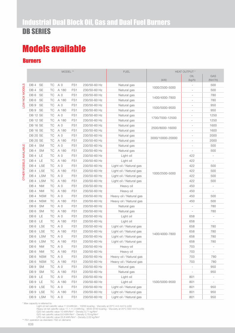
608
Industrial Dual Block Oil, Gas and Dual Fuel BurnersDB SERIES
Burners
Models available
* Max capacity is referred to: Light oil net calorifi c value 11,8 kWh/kh - 10200 kcal/kg - Viscosity at 20°C 4-6 mm2/s (cSt) Heavy oil net calorifi c value 11,1-11,3 kWh/kg - 9545-9720 kcal/kg - Viscosity at 20°C 500 mm2/s (cSt) G20 net calorifi c value 10 kWh/Nm3 - Density 0,71 kg/Nm3
G25 net calorifi c value 8,6 kWh/Nm3 - Density 0,78 kg/Nm3
LPG net calorifi c value 25,8 kWh/Nm3 - Density 2,02 kg/Nm3
** FS1 operation as standard. FS2 on demand.
MODEL ** FUEL HEAT OUTPUT *
OIL GAS(kW) (kg/h) (Nm3/h)
LOW
NO
X M
OD
ELS DB 4 SE TC A 0 FS1 230/50-60 Hz Natural gas
1000/2500-5000 - 500
DB 4 SE TC A 180 FS1 230/50-60 Hz Natural gas - 500
DB 6 SE TC A 0 FS1 230/50-60 Hz Natural gas1400/4000-7800
- 780
DB 6 SE TC A 180 FS1 230/50-60 Hz Natural gas - 780
DB 9 SE TC A 0 FS1 230/50-60 Hz Natural gas1500/5000-9500
- 950
DB 9 SE TC A 180 FS1 230/50-60 Hz Natural gas - 950
DB 12 SE TC A 0 FS1 230/50-60 Hz Natural gas1700/7000-12500
- 1250
DB 12 SE TC A 180 FS1 230/50-60 Hz Natural gas - 1250
DB 16 SE TC A 0 FS1 230/50-60 Hz Natural gas2500/8000-16000
- 1600
DB 16 SE TC A 180 FS1 230/50-60 Hz Natural gas - 1600
DB 20 SE TC A 0 FS1 230/50-60 Hz Natural gas3000/10000-20000
- 2000
DB 20 SE TC A 180 FS1 230/50-60 Hz Natural gas - 2000
OTH
ER
MO
DE
LS A
VAIL
AB
LE DB 4 SM TC A 0 FS1 230/50-60 Hz Natural gas
1000/2500-5000
- 500
DB 4 SM TC A 180 FS1 230/50-60 Hz Natural gas - 500
DB 4 LE TC A 0 FS1 230/50-60 Hz Light oil 422 -
DB 4 LE TC A 180 FS1 230/50-60 Hz Light oil 422 -
DB 4 LSE TC A 0 FS1 230/50-60 Hz Light oil / Natural gas 422 500
DB 4 LSE TC A 180 FS1 230/50-60 Hz Light oil / Natural gas 422 500
DB 4 LSM TC A 0 FS1 230/50-60 Hz Light oil / Natural gas 422 500
DB 4 LSM TC A 180 FS1 230/50-60 Hz Light oil / Natural gas 422 500
DB 4 NM TC A 0 FS1 230/50-60 Hz Heavy oil 450 -
DB 4 NM TC A 180 FS1 230/50-60 Hz Heavy oil 450 -
DB 4 NSM TC A 0 FS1 230/50-60 Hz Heavy oil / Natural gas 450 500
DB 4 NSM TC A 180 FS1 230/50-60 Hz Heavy oil / Natural gas 450 500
DB 6 SM TC A 0 FS1 230/50-60 Hz Natural gas
1400/4000-7800
- 780
DB 6 SM TC A 180 FS1 230/50-60 Hz Natural gas - 780
DB 6 LE TC A 0 FS1 230/50-60 Hz Light oil 658 -
DB 6 LE TC A 180 FS1 230/50-60 Hz Light oil 658 -
DB 6 LSE TC A 0 FS1 230/50-60 Hz Light oil / Natural gas 658 780
DB 6 LSE TC A 180 FS1 230/50-60 Hz Light oil / Natural gas 658 780
DB 6 LSM TC A 0 FS1 230/50-60 Hz Light oil / Natural gas 658 780
DB 6 LSM TC A 180 FS1 230/50-60 Hz Light oil / Natural gas 658 780
DB 6 NM TC A 0 FS1 230/50-60 Hz Heavy oil 703 -
DB 6 NM TC A 180 FS1 230/50-60 Hz Heavy oil 703 -
DB 6 NSM TC A 0 FS1 230/50-60 Hz Heavy oil / Natural gas 703 780
DB 6 NSM TC A 180 FS1 230/50-60 Hz Heavy oil / Natural gas 703 780
DB 9 SM TC A 0 FS1 230/50-60 Hz Natural gas
1500/5000-9500
- 950
DB 9 SM TC A 180 FS1 230/50-60 Hz Natural gas - 950
DB 9 LE TC A 0 FS1 230/50-60 Hz Light oil 801 -
DB 9 LE TC A 180 FS1 230/50-60 Hz Light oil 801 -
DB 9 LSE TC A 0 FS1 230/50-60 Hz Light oil / Natural gas 801 950
DB 9 LSE TC A 180 FS1 230/50-60 Hz Light oil / Natural gas 801 950
DB 9 LSM TC A 0 FS1 230/50-60 Hz Light oil / Natural gas 801 950

609
INDU
STRI
AL
Industrial Dual Block Oil, Gas and Dual Fuel BurnersDB SERIES
Other versions are available on request.
Burners
Models available
MODEL ** FUEL HEAT OUTPUT *
OIL GAS
(kW) (kg/h) (Nm3/h)
OTH
ER
MO
DE
LS A
VAIL
AB
LE DB 9 LSM TC A 180 FS1 230/50-60 Hz Light oil / Natural gas
1500/5000-9500
801 950
DB 9 NM TC A 0 FS1 230/50-60 Hz Heavy oil 856 -
DB 9 NM TC A 180 FS1 230/50-60 Hz Heavy oil 856 -
DB 9 NSM TC A 0 FS1 230/50-60 Hz Heavy oil / Natural gas 856 950
DB 9 NSM TC A 180 FS1 230/50-60 Hz Heavy oil / Natural gas 856 950
DB 12 SM TC A 0 FS1 230/50-60 Hz Natural gas
1700/7000-12500
- 1250
DB 12 SM TC A 180 FS1 230/50-60 Hz Natural gas - 1250
DB 12 LE TC A 0 FS1 230/50-60 Hz Light oil 1054 -
DB 12 LE TC A 180 FS1 230/50-60 Hz Light oil 1054 -
DB 12 LSE TC A 0 FS1 230/50-60 Hz Light oil / Natural gas 1054 1250
DB 12 LSE TC A 180 FS1 230/50-60 Hz Light oil / Natural gas 1054 1250
DB 12 LSM TC A 0 FS1 230/50-60 Hz Light oil / Natural gas 1054 1250
DB 12 LSM TC A 180 FS1 230/50-60 Hz Light oil / Natural gas 1054 1250
DB 12 NM TC A 0 FS1 230/50-60 Hz Heavy oil 1126 -
DB 12 NM TC A 180 FS1 230/50-60 Hz Heavy oil 1126 -
DB 12 NSM TC A 0 FS1 230/50-60 Hz Heavy oil / Natural gas 1126 1250
DB 12 NSM TC A 180 FS1 230/50-60 Hz Heavy oil / Natural gas 1126 1250
DB 16 SM TC A 0 FS1 230/50-60 Hz Natural gas
2500/8000-16000
- 1600
DB 16 SM TC A 180 FS1 230/50-60 Hz Natural gas - 1600
DB 16 LE TC A 0 FS1 230/50-60 Hz Light oil 1349 -
DB 16 LE TC A 180 FS1 230/50-60 Hz Light oil 1349 -
DB 16 LSE TC A 0 FS1 230/50-60 Hz Light oil / Natural gas 1349 1600
DB 16 LSE TC A 180 FS1 230/50-60 Hz Light oil / Natural gas 1349 1600
DB 16 LSM TC A 0 FS1 230/50-60 Hz Light oil / Natural gas 1349 1600
DB 16 LSM TC A 180 FS1 230/50-60 Hz Light oil / Natural gas 1349 1600
DB 16 NM TC A 0 FS1 230/50-60 Hz Heavy oil 1441 -
DB 16 NM TC A 180 FS1 230/50-60 Hz Heavy oil 1441 -
DB 16 NSM TC A 0 FS1 230/50-60 Hz Heavy oil / Natural gas 1441 1600
DB 16 NSM TC A 180 FS1 230/50-60 Hz Heavy oil / Natural gas 1441 1600
DB 20 SM TC A 0 FS1 230/50-60 Hz Natural gas
3000/10000-20000
- 2000
DB 20 SM TC A 180 FS1 230/50-60 Hz Natural gas - 2000
DB 20 LE TC A 0 FS1 230/50-60 Hz Light oil 1686 -
DB 20 LE TC A 180 FS1 230/50-60 Hz Light oil 1686 -
DB 20 LSE TC A 0 FS1 230/50-60 Hz Light oil / Natural gas 1686 2000
DB 20 LSE TC A 180 FS1 230/50-60 Hz Light oil / Natural gas 1686 2000
DB 20 LSM TC A 0 FS1 230/50-60 Hz Light oil / Natural gas 1686 2000
DB 20 LSM TC A 180 FS1 230/50-60 Hz Light oil / Natural gas 1686 2000
DB 20 NM TC A 0 FS1 230/50-60 Hz Heavy oil 1802 -
DB 20 NM TC A 180 FS1 230/50-60 Hz Heavy oil 1802 -
DB 20 NSM TC A 0 FS1 230/50-60 Hz Heavy oil / Natural gas 1802 2000
DB 20 NSM TC A 180 FS1 230/50-60 Hz Heavy oil / Natural gas 1802 2000
* Max capacity is referred to: Light oil net calorifi c value 11,8 kWh/kh - 10200 kcal/kg - Viscosity at 20°C 4-6 mm2/s (cSt) Heavy oil net calorifi c value 11,1-11,3 kWh/kg - 9545-9720 kcal/kg - Viscosity at 20°C 500 mm2/s (cSt) G20 net calorifi c value 10 kWh/Nm3 - Density 0,71 kg/Nm3
G25 net calorifi c value 8,6 kWh/Nm3 - Density 0,78 kg/Nm3
LPG net calorifi c value 25,8 kWh/Nm3 - Density 2,02 kg/Nm3
** FS1 operation as standard. FS2 on demand.

610
Burner accessories
Industrial Dual Block Oil, Gas and Dual Fuel BurnersDB SERIES
Nozzles for DB 4 - 6 - 9 - 12 - 16 - 20
The nozzles must be ordered separately. The following table shows the features and codes on the basis of the maximum required fuel output. One nozzle required for each burner, able to guarantee the calculated oil delivery.
Nozzles:W2 maximum modulating ratio 1:4 (interchangeable with B5)B5 maximum modulating ratio 1:5 (interchangeable with W2)CT5 maximum modulating ratio 1:5 bigger shape
*steam boiler size according to: N.C.V. heavy oil = 11,16 kWh/kg combustion air = 50°C 1 ton/h = 775 kW (eff = 90%)
For steam/air assisted atomizing, special nozzles available on demand.
BURNER
ton/h*
RATED DELIVERY
kg/h
NOZZLES TYPEW2 - 45°
CODE
RATED DELIVERY
kg/h
NOZZLES TYPEB5 - 45° - AA
CODE
RATED DELIVERY
kg/h
NOZZLES TYPECT5 - 45°
CODE
u DB 4 - 6 - 9
3 200 3045438 200 3009800
225 3045440 225 3009801
250 3045442 250 3009802
4 275 3045444 275 3009803
300 3045446 300 3009804
325 3045448 325 3009805
5 350 3045450 350 3009806
375 3045452 375 3009807
6 400 3045454 400 3009808
425 3045455 425 3009809
450 3045456 450 3009810
u DB 6 - 9 - 12
475 3045457 475 3009811
500 3045458 500 3009812
525 3045459 525 3009813
8 550 3045460 550 3009814
575 3045461 575 3009815
600 3045462 600 3009816
650 3045463 650 3009817
10 700 3045464 700 3009818 700 20006462
u DB 9 - 12 - 16
750 3045465 750 3009819
800 3009820 800 20006465
12 850 3009821
u DB 12 - 16 - 20
900 20006468
15 1000 20006469
16 1100 20006470
u DB 16 - 20
1200 20006471
18 1300 20006472
20 1400 20006473
1500 20006474
u DB 20
22 1600 20006475
1700 20006476
25 1800 20006477
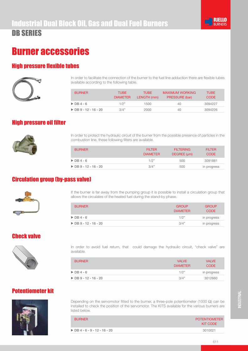
611
INDU
STRI
AL
Burner accessories
Industrial Dual Block Oil, Gas and Dual Fuel BurnersDB SERIES
High pressure fl exible tubes
In order to facilitate the connection of the burner to the fuel line adduction there are fl exible tubes available according to the following table.
BURNER TUBE DIAMETER
TUBE LENGTH (mm)
MAXIMUM WORKING PRESSURE (bar)
TUBE CODE
u DB 4 - 6 1/2” 1500 40 3094227
u DB 9 - 12 - 16 - 20 3/4” 2000 40 3094226
Depending on the servomotor fi tted to the burner, a three-pole potentiometer (1000 Ω) can be installed to check the position of the servomotor. The KITS available for the various burners are listed below.
BURNER
POTENTIOMETER KIT CODE
u DB 4 - 6 - 9 - 12 - 16 - 20 3010021
Potentiometer kit
Check valve
In order to avoid fuel return, that could damage the hydraulic circuit, “check valve” are available.
BURNER VALVE DIAMETER
VALVE CODE
u DB 4 - 6 1/2” in progress
u DB 9 - 12 - 16 - 20 3/4” 3012660
Circulation group (by-pass valve)
If the burner is far away from the pumping group it is possible to install a circulation group that allows the circulates of the heated fuel during the stand-by phase.
BURNER GROUP DIAMETER
GROUP CODE
u DB 4 - 6 1/2” in progress
u DB 9 - 12 - 16 - 20 3/4” in progress
High pressure oil fi lter
In order to protect the hydraulic circuit of the burner from the possible presence of particles in the combustion line, these following fi lters are available.
BURNER FILTER DIAMETER
FILTERING DEGREE (µm)
FILTER CODE
u DB 4 - 6 1/2” 500 3091881
u DB 9 - 12 - 16 - 20 3/4” 500 in progress

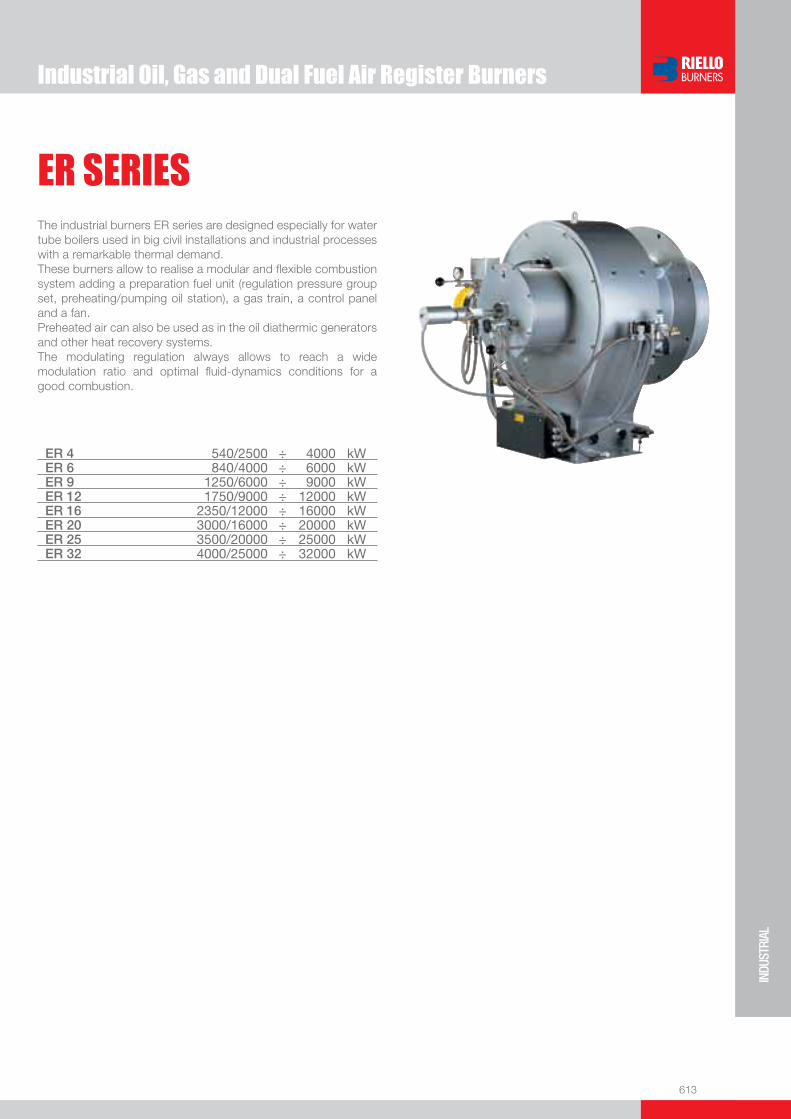
Industrial Oil, Gas and Dual Fuel Air Register Burners
613
INDU
STRI
AL
ER SERIESThe industrial burners ER series are designed especially for water tube boilers used in big civil installations and industrial processes with a remarkable thermal demand.These burners allow to realise a modular and fl exible combustion system adding a preparation fuel unit (regulation pressure group set, preheating/pumping oil station), a gas train, a control panel and a fan.Preheated air can also be used as in the oil diathermic generators and other heat recovery systems.The modulating regulation always allows to reach a wide modulation ratio and optimal fl uid-dynamics conditions for a good combustion.
ER 4 540/2500 ÷ 4000 kWER 6 840/4000 ÷ 6000 kWER 9 1250/6000 ÷ 9000 kWER 12 1750/9000 ÷ 12000 kWER 16 2350/12000 ÷ 16000 kWER 20 3000/16000 ÷ 20000 kWER 25 3500/20000 ÷ 25000 kWER 32 4000/25000 ÷ 32000 kW

614
ER SERIESIndustrial Oil, Gas and Dual Fuel Air Register Burners
FIRING RATES
Test conditions conforming to EN 267 - EN 676:Temperature: 20°C - Pressure: 1013,5 mbar - Altitude: 0 m a.s.l.
Modulation range Working fi eld
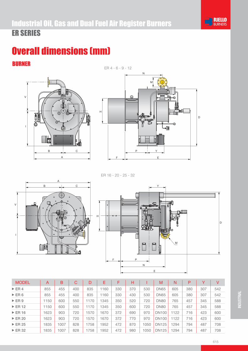
615
INDU
STRI
AL
ER SERIESIndustrial Oil, Gas and Dual Fuel Air Register Burners
BURNER
Overall dimensions (mm)
ER 4 - 6 - 9 - 12
ER 16 - 20 - 25 - 32
MODEL A B C D E F H I M N P Y V u ER 4 855 455 400 835 1160 330 370 530 DN65 605 380 307 542
u ER 6 855 455 400 835 1160 330 430 530 DN65 605 380 307 542
u ER 9 1150 600 550 1170 1345 350 520 720 DN80 765 457 345 588
u ER 12 1150 600 550 1170 1345 350 600 720 DN80 765 457 345 588
u ER 16 1623 903 720 1570 1670 372 690 970 DN100 1122 716 423 600
u ER 20 1623 903 720 1570 1670 372 770 970 DN100 1122 716 423 600
u ER 25 1835 1007 828 1758 1952 472 870 1050 DN125 1294 794 487 708
u ER 32 1835 1007 828 1758 1952 472 980 1050 DN125 1294 794 487 708
A
CB
I
V
E
Y
F
P
H
N
D
M
I
V
A
CB
H
F P
N
E
M
Y
D

616
ER SERIES
Overall dimensions (mm)
Industrial Oil, Gas and Dual Fuel Air Register Burners
Z
XY
BURNER - BOILER MOUNTING FLANGE
PACKAGING
MODEL X Y Z kgu ER 4 2090 1460 1680 200
u ER 6 2090 1460 1680 200
u ER 9 2300 1750 1900 300
u ER 12 2300 1750 1900 300
u ER 16 2750 2100 2150 500
u ER 20 2750 2100 2150 500
u ER 25 3000 2500 2300 800
u ER 32 3000 2500 2300 800
MODEL a a1 a2 b b1 b2 D1 D2 D3 t Ø1 Ø2 u ER 4 400 444 480 324 280 360 380 552 145 148 M18 18
u ER 6 400 444 480 324 280 360 440 552 145 148 M18 18
u ER 9 500 551 580 405 355 435 530 800 160 125 M18 18
u ER 12 500 551 580 405 355 435 620 800 160 125 M18 18
u ER 16 710 775 810 567 500 600 710 970 180 160 M20 18
u ER 20 710 775 810 567 500 600 790 970 180 160 M20 18
u ER 25 900 968 1018 708 640 758 930 1200 210 200 M20 18
u ER 32 900 968 1018 708 640 758 1050 1200 210 200 M20 18
ER 9÷32ER 4-6
AIR DUCT CONNECTION
b
t
b2
t
t
t
t
b1
a1a2 a
FIXING TO THE BOILER
D2
45°
D1
Ø1
22,5
GAS SUPPLY
Ø2
D3DN
Ø2
D3
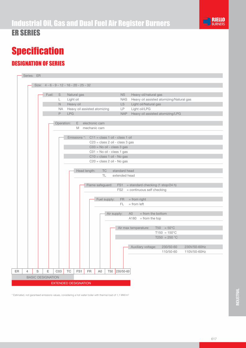
617
INDU
STRI
AL
ER SERIES
Specifi cation
Industrial Oil, Gas and Dual Fuel Air Register Burners
DESIGNATION OF SERIES
BASIC DESIGNATION
EXTENDED DESIGNATION
ER 4 S E C03 TC FS1 FR A0 T50 230/50-60
Series: ER Size: 4 - 6 - 9 - 12 - 16 - 20 - 25 - 32 Fuel: S Natural gas NS Heavy oil/natural gas L Light oil NAS Heavy oil assisted atomizing/Natural gas N Heavy oil LS Light oil/Natural gas NA Heavy oil assisted atomizing LP Light oil/LPG P LPG NAP Heavy oil assisted atomizing/LPG Operation: E electronic cam M mechanic cam Emissions *: C11 = class 1 oil - class 1 oil C23 = class 2 oil - class 3 gas C03 = No oil - class 3 gas C01 = No oil - class 1 gas C10 = class 1 oil - No gas C20 = class 2 oil - No gas Head length: TC standard head TL extended head
Flame safeguard: FS1 = standard checking (1 stop/24 h) FS2 = continuous self checking
Fuel supply: FR = from right FL = from left
Air supply: A0 = from the bottom A180 = from the top
Air max temperature: T50 = 50°C T150 = 150°C T250 = 250 °C
Auxiliary voltage: 230/50-60 230V/50-60Hz 110/50-60 110V/50-60Hz
* Estimated, not garanteed emissions values, considering a hot water boiler with thermal load of 1,1 MW/m3

618
ER SERIESIndustrial Oil, Gas and Dual Fuel Air Register Burners
Specifi cationSTATE OF SUPPLY
Oil burnerForced draught oil burner with modulating operation and separate supplies, fully automatic, made up of:- Sheet-steel airlock painted with a front cover for access to the internal elements- Air dampers for air setting controlled by two indipendent high precision servomotors - Combustion head fi tted with:
- stainless steel end cone, resistant to corrosion and high temperatures- pilot burner with gas train and ignition electrodes- fl ame stability disk made up of axial swirlers
- Flame shape regulation device- Photocell for fl ame detection- Minimum air pressure switch- Nozzle pipe- Safety nozzle valve- Valves group with safety oil valves- Automatic regulator of oil delivery controlled by a high precision servomotor- Maximum oil pressure switch on the return circuit- Pressure gauge on the delivery circuit- Pressure gauge on the return circuit- Electrical box with ignition transformer- IP 54 electric protection level.
Standard equipment: - Screws for fi xing the burner fl ange to the boiler- Thermal screen- Instruction handbook for installation, use and maintenance- Spare parts catalogue.
Gas burnerForced draught gas burner with modulating operation and separate supplies, fully automatic, made up of:- Sheet-steel airlock painted with a front cover for access to the internal elements- Air dampers for air setting controlled by two indipendent high precision servomotors - Combustion head fi tted with:
- stainless steel end cone, resistant to corrosion and high temperatures- gas distributor with multiple pipes- pilot burner with gas train and ignition electrodes- uv photocell- fl ame stability disk made up of axial swirler
- Flame shape regulation device- Minimum air pressure switch- Maximum gas pressure switch- Automatic regulator for gas delivery, controlled by a high precision servomotor- Gas pressure test point to the combustion head- Electrical box with ignition transformer- IP 54 electric protection level.
Standard equipment:- Screws for fi xing the burner fl ange to the boiler - Thermal screen- Screws for fi xing the gas train fl ange to the burner- Gas train gasket- Instruction handbook for installation, use and maintenance- Spare parts catalogue.

619
INDU
STRI
AL
ER SERIESIndustrial Oil, Gas and Dual Fuel Air Register Burners
Specifi cationSTATE OF SUPPLY
Dual fuel burner (oil/gas)Forced draught dual fuel burner with modulating operation and separate supplies, fully automatic, made up of:- Sheet-steel airlock painted with a front cover for access to the internal elements- Air dampers for air setting controlled by two indipendent high precision servomotors- Combustion head fi tted with:
- stainless steel end cone, resistant to corrosion and high temperatures- gas distributor with multiple pipes- pilot burner with gas train and ignition electrodes- fl ame stability disk made up of axial swirler
- Flame shape regulation device- UV photocell for fl ame detection- Nozzle pipe - Safety nozzle valve- Valves group with safety oil valves- Automatic regulator of oil and gas delivery controlled by a high precision servomotor- Maximum oil pressure switch on the return circuit- Pressure gauge on the delivery circuit- Pressure gauge on the return circuit- Minimum air pressure switch- Maximum gas pressure switch- Gas pressure test point to the combustion head- Electrical box with ignition transformer- IP 54 electric protection level.
Standard equipment: - Screws for fi xing the burner fl ange to the boiler- Thermal screen- Screws for fi xing the gas train fl ange to the burner - Gas train gasket- Instruction handbook for installation, use and maintenance- Spare parts catalogue.
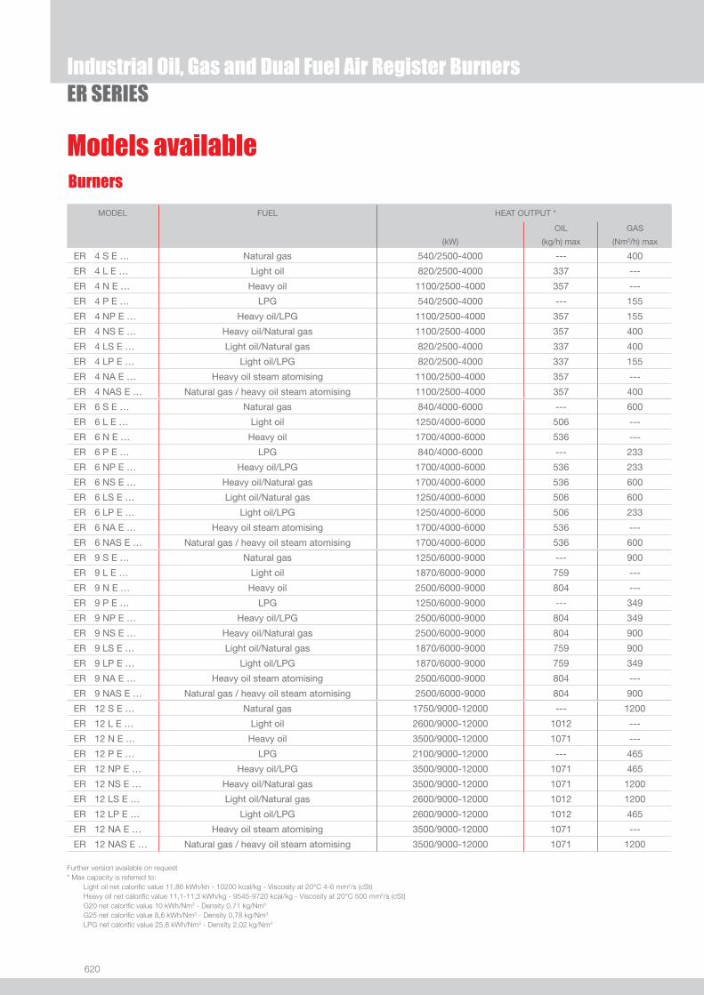
620
ER SERIES
Models available
Industrial Oil, Gas and Dual Fuel Air Register Burners
Further version available on request* Max capacity is referred to: Light oil net calorifi c value 11,86 kWh/kh - 10200 kcal/kg - Viscosity at 20°C 4-6 mm2/s (cSt) Heavy oil net calorifi c value 11,1-11,3 kWh/kg - 9545-9720 kcal/kg - Viscosity at 20°C 500 mm2/s (cSt) G20 net calorifi c value 10 kWh/Nm3 - Density 0,71 kg/Nm3
G25 net calorifi c value 8,6 kWh/Nm3 - Density 0,78 kg/Nm3
LPG net calorifi c value 25,8 kWh/Nm3 - Density 2,02 kg/Nm3
MODEL
FUEL HEAT OUTPUT *
OIL GAS
(kW) (kg/h) max (Nm3/h) max
ER 4 S E … Natural gas 540/2500-4000 --- 400
ER 4 L E … Light oil 820/2500-4000 337 ---
ER 4 N E … Heavy oil 1100/2500-4000 357 ---
ER 4 P E … LPG 540/2500-4000 --- 155
ER 4 NP E … Heavy oil/LPG 1100/2500-4000 357 155
ER 4 NS E … Heavy oil/Natural gas 1100/2500-4000 357 400
ER 4 LS E … Light oil/Natural gas 820/2500-4000 337 400
ER 4 LP E … Light oil/LPG 820/2500-4000 337 155
ER 4 NA E … Heavy oil steam atomising 1100/2500-4000 357 ---
ER 4 NAS E … Natural gas / heavy oil steam atomising 1100/2500-4000 357 400
ER 6 S E … Natural gas 840/4000-6000 --- 600
ER 6 L E … Light oil 1250/4000-6000 506 ---
ER 6 N E … Heavy oil 1700/4000-6000 536 ---
ER 6 P E … LPG 840/4000-6000 --- 233
ER 6 NP E … Heavy oil/LPG 1700/4000-6000 536 233
ER 6 NS E … Heavy oil/Natural gas 1700/4000-6000 536 600
ER 6 LS E … Light oil/Natural gas 1250/4000-6000 506 600
ER 6 LP E … Light oil/LPG 1250/4000-6000 506 233
ER 6 NA E … Heavy oil steam atomising 1700/4000-6000 536 ---
ER 6 NAS E … Natural gas / heavy oil steam atomising 1700/4000-6000 536 600
ER 9 S E … Natural gas 1250/6000-9000 --- 900
ER 9 L E … Light oil 1870/6000-9000 759 ---
ER 9 N E … Heavy oil 2500/6000-9000 804 ---
ER 9 P E … LPG 1250/6000-9000 --- 349
ER 9 NP E … Heavy oil/LPG 2500/6000-9000 804 349
ER 9 NS E … Heavy oil/Natural gas 2500/6000-9000 804 900
ER 9 LS E … Light oil/Natural gas 1870/6000-9000 759 900
ER 9 LP E … Light oil/LPG 1870/6000-9000 759 349
ER 9 NA E … Heavy oil steam atomising 2500/6000-9000 804 ---
ER 9 NAS E … Natural gas / heavy oil steam atomising 2500/6000-9000 804 900
ER 12 S E … Natural gas 1750/9000-12000 --- 1200
ER 12 L E … Light oil 2600/9000-12000 1012 ---
ER 12 N E … Heavy oil 3500/9000-12000 1071 ---
ER 12 P E … LPG 2100/9000-12000 --- 465
ER 12 NP E … Heavy oil/LPG 3500/9000-12000 1071 465
ER 12 NS E … Heavy oil/Natural gas 3500/9000-12000 1071 1200
ER 12 LS E … Light oil/Natural gas 2600/9000-12000 1012 1200
ER 12 LP E … Light oil/LPG 2600/9000-12000 1012 465
ER 12 NA E … Heavy oil steam atomising 3500/9000-12000 1071 ---
ER 12 NAS E … Natural gas / heavy oil steam atomising 3500/9000-12000 1071 1200
Burners
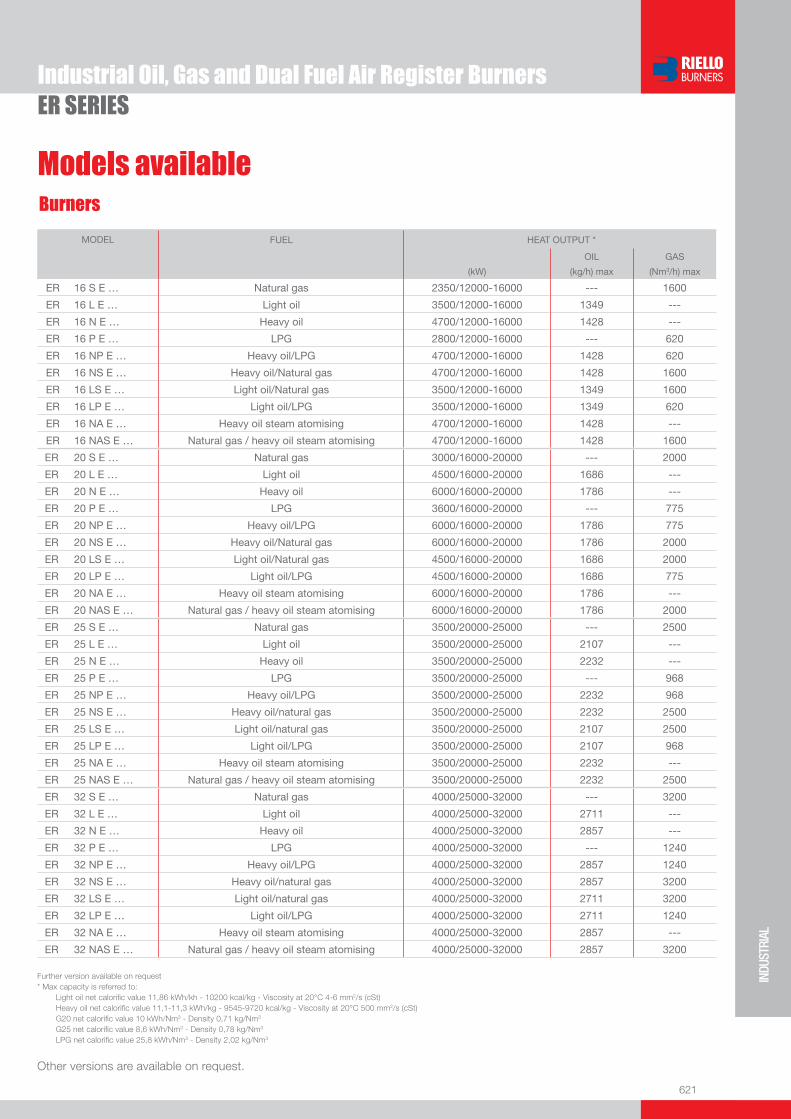
621
INDU
STRI
AL
ER SERIESIndustrial Oil, Gas and Dual Fuel Air Register Burners
Other versions are available on request.
MODEL
FUEL HEAT OUTPUT *
OIL GAS
(kW) (kg/h) max (Nm3/h) max
ER 16 S E … Natural gas 2350/12000-16000 --- 1600
ER 16 L E … Light oil 3500/12000-16000 1349 ---
ER 16 N E … Heavy oil 4700/12000-16000 1428 ---
ER 16 P E … LPG 2800/12000-16000 --- 620
ER 16 NP E … Heavy oil/LPG 4700/12000-16000 1428 620
ER 16 NS E … Heavy oil/Natural gas 4700/12000-16000 1428 1600
ER 16 LS E … Light oil/Natural gas 3500/12000-16000 1349 1600
ER 16 LP E … Light oil/LPG 3500/12000-16000 1349 620
ER 16 NA E … Heavy oil steam atomising 4700/12000-16000 1428 ---
ER 16 NAS E … Natural gas / heavy oil steam atomising 4700/12000-16000 1428 1600
ER 20 S E … Natural gas 3000/16000-20000 --- 2000
ER 20 L E … Light oil 4500/16000-20000 1686 ---
ER 20 N E … Heavy oil 6000/16000-20000 1786 ---
ER 20 P E … LPG 3600/16000-20000 --- 775
ER 20 NP E … Heavy oil/LPG 6000/16000-20000 1786 775
ER 20 NS E … Heavy oil/Natural gas 6000/16000-20000 1786 2000
ER 20 LS E … Light oil/Natural gas 4500/16000-20000 1686 2000
ER 20 LP E … Light oil/LPG 4500/16000-20000 1686 775
ER 20 NA E … Heavy oil steam atomising 6000/16000-20000 1786 ---
ER 20 NAS E … Natural gas / heavy oil steam atomising 6000/16000-20000 1786 2000
ER 25 S E … Natural gas 3500/20000-25000 --- 2500
ER 25 L E … Light oil 3500/20000-25000 2107 ---
ER 25 N E … Heavy oil 3500/20000-25000 2232 ---
ER 25 P E … LPG 3500/20000-25000 --- 968
ER 25 NP E … Heavy oil/LPG 3500/20000-25000 2232 968
ER 25 NS E … Heavy oil/natural gas 3500/20000-25000 2232 2500
ER 25 LS E … Light oil/natural gas 3500/20000-25000 2107 2500
ER 25 LP E … Light oil/LPG 3500/20000-25000 2107 968
ER 25 NA E … Heavy oil steam atomising 3500/20000-25000 2232 ---
ER 25 NAS E … Natural gas / heavy oil steam atomising 3500/20000-25000 2232 2500
ER 32 S E … Natural gas 4000/25000-32000 --- 3200
ER 32 L E … Light oil 4000/25000-32000 2711 ---
ER 32 N E … Heavy oil 4000/25000-32000 2857 ---
ER 32 P E … LPG 4000/25000-32000 --- 1240
ER 32 NP E … Heavy oil/LPG 4000/25000-32000 2857 1240
ER 32 NS E … Heavy oil/natural gas 4000/25000-32000 2857 3200
ER 32 LS E … Light oil/natural gas 4000/25000-32000 2711 3200
ER 32 LP E … Light oil/LPG 4000/25000-32000 2711 1240
ER 32 NA E … Heavy oil steam atomising 4000/25000-32000 2857 ---
ER 32 NAS E … Natural gas / heavy oil steam atomising 4000/25000-32000 2857 3200
Further version available on request* Max capacity is referred to: Light oil net calorifi c value 11,86 kWh/kh - 10200 kcal/kg - Viscosity at 20°C 4-6 mm2/s (cSt) Heavy oil net calorifi c value 11,1-11,3 kWh/kg - 9545-9720 kcal/kg - Viscosity at 20°C 500 mm2/s (cSt) G20 net calorifi c value 10 kWh/Nm3 - Density 0,71 kg/Nm3
G25 net calorifi c value 8,6 kWh/Nm3 - Density 0,78 kg/Nm3
LPG net calorifi c value 25,8 kWh/Nm3 - Density 2,02 kg/Nm3
Burners
Models available


623
SYST
EM C
OMPO
NENT
S
The unit skids of SG, DG, SN and DN series to treat and prepare fuel are an integral part of the industrial burners. The system, designed for oil fuel with max viscosity 65°E at 50°C, consists mainly of a fi lter, a heater, a pump and a vent valve. Electric or steam/electric heaters may be used and a double system with backup fi lter and pump is also available.The unit skids come ready assembled and tested for fast installation and the wide range of models available makes the system suitable for many different application.
SG and DG series 380 ÷ 3600 l/h pre-set at 28 barSN and DN series 540 ÷ 3600 l/h pre-set at 30 bar
Light Oil Pumping Unit Skids - Heavy Oil Heating and Pumping Unit Skids for Industrial Burners
SG and DG SERIESSN and DN SERIES
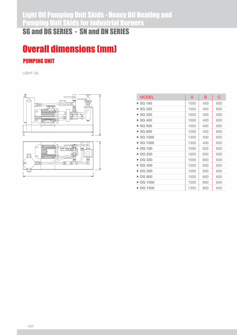
624
SG and DG SERIES - SN and DN SERIES
PUMPING UNIT
LIGHT OIL
Overall dimensions (mm)
MODEL A B C u SG 160 1000 400 600
u SG 250 1000 400 600
u SG 320 1000 400 600
u SG 400 1000 400 600
u SG 500 1000 400 600
u SG 800 1000 400 600
u SG 1000 1300 400 650
u SG 1500 1300 400 650
u DG 160 1000 600 600
u DG 250 1000 600 600
u DG 320 1000 600 600
u DG 400 1000 600 600
u DG 500 1000 600 600
u DG 800 1000 600 600
u DG 1000 1300 800 650
u DG 1500 1300 800 650
Light Oil Pumping Unit Skids - Heavy Oil Heating and Pumping Unit Skids for Industrial Burners

625
SYST
EM C
OMPO
NENT
S
HEAVY OIL
Electrical heater
PUMPING UNIT
Overall dimensions (mm)
Electrical/steam heater
MODEL A B Cu SN 250 EP 1400 400 985
u SN 320 EP 1400 400 985
u SN 400 EP 1500 400 1100
u SN 650 EP 1500 400 1100
u SN 800 EP 1500 400 1100
u SN 1000 EP 1500 600 1100
u SN 1500 EP 1500 600 1100
u DN 250 EP 1400 700 985
u DN 320 EP 1400 700 985
u DN 400 EP 1500 700 1100
u DN 650 EP 1500 700 1100
u DN 800 EP 1500 700 1100
u DN 1000 EP 1500 900 1100
u DN 1500 EP 1500 900 1100
MODEL A B Cu SN 250 EV 1700 400 1105
u SN 320 EV 1700 400 1200
u SN 400 EV 1700 400 1200
u SN 500 EV 1700 400 1200
u SN 650 EV 1700 400 1200
u SN 800 EV 1700 400 1200
u SN 1000 EV 1900 600 1300
u SN 1500 EV 1900 600 1300
u SN 2000 EV 1900 600 1300
u DN 250 EV 1700 700 1105
u DN 320 EV 1700 700 1200
u DN 400 EV 1700 700 1200
u DN 500 EV 1700 700 1200
u DN 650 EV 1700 700 1200
u DN 800 EV 1700 700 1200
u DN 1000 EV 1900 900 1300
u DN 1500 EV 1900 900 1300
u DN 2000 EV 1900 900 1300
Light Oil Pumping Unit Skids - Heavy Oil Heating and Pumping Unit Skids for Industrial BurnersSG and DG SERIES - SN and DN SERIES
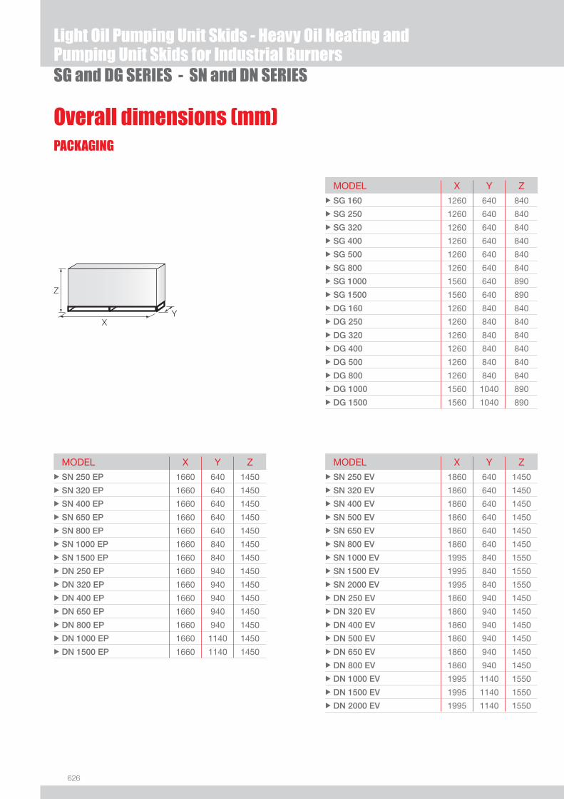
626
Overall dimensions (mm)PACKAGING
SG and DG SERIES - SN and DN SERIES
Z
XY
MODEL X Y Zu SG 160 1260 640 840
u SG 250 1260 640 840
u SG 320 1260 640 840
u SG 400 1260 640 840
u SG 500 1260 640 840
u SG 800 1260 640 840
u SG 1000 1560 640 890
u SG 1500 1560 640 890
u DG 160 1260 840 840
u DG 250 1260 840 840
u DG 320 1260 840 840
u DG 400 1260 840 840
u DG 500 1260 840 840
u DG 800 1260 840 840
u DG 1000 1560 1040 890
u DG 1500 1560 1040 890
MODEL X Y Zu SN 250 EP 1660 640 1450
u SN 320 EP 1660 640 1450
u SN 400 EP 1660 640 1450
u SN 650 EP 1660 640 1450
u SN 800 EP 1660 640 1450
u SN 1000 EP 1660 840 1450
u SN 1500 EP 1660 840 1450
u DN 250 EP 1660 940 1450
u DN 320 EP 1660 940 1450
u DN 400 EP 1660 940 1450
u DN 650 EP 1660 940 1450
u DN 800 EP 1660 940 1450
u DN 1000 EP 1660 1140 1450
u DN 1500 EP 1660 1140 1450
MODEL X Y Zu SN 250 EV 1860 640 1450
u SN 320 EV 1860 640 1450
u SN 400 EV 1860 640 1450
u SN 500 EV 1860 640 1450
u SN 650 EV 1860 640 1450
u SN 800 EV 1860 640 1450
u SN 1000 EV 1995 840 1550
u SN 1500 EV 1995 840 1550
u SN 2000 EV 1995 840 1550
u DN 250 EV 1860 940 1450
u DN 320 EV 1860 940 1450
u DN 400 EV 1860 940 1450
u DN 500 EV 1860 940 1450
u DN 650 EV 1860 940 1450
u DN 800 EV 1860 940 1450
u DN 1000 EV 1995 1140 1550
u DN 1500 EV 1995 1140 1550
u DN 2000 EV 1995 1140 1550
Light Oil Pumping Unit Skids - Heavy Oil Heating and Pumping Unit Skids for Industrial Burners
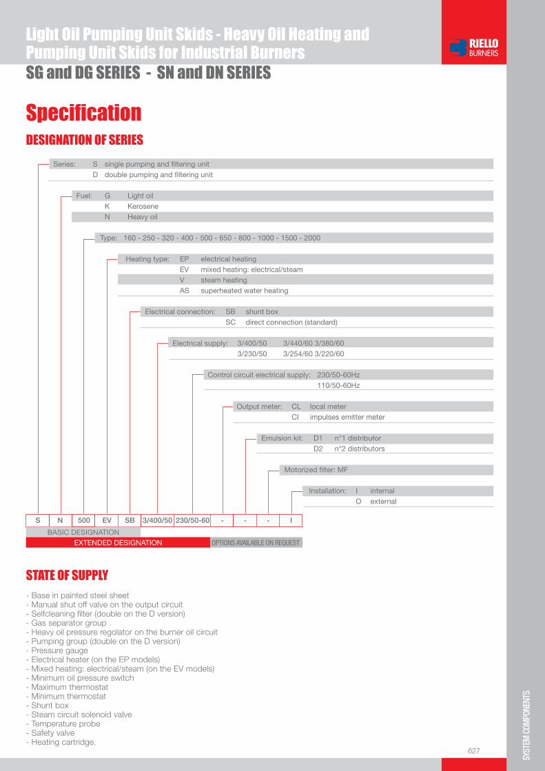
627
SYST
EM C
OMPO
NENT
S
BASIC DESIGNATIONEXTENDED DESIGNATION
S N 500 EV SB 3/400/50 230/50-60 - - - I
OPTIONS AVAILABLE ON REQUEST
Series: S single pumping and fi ltering unit D double pumping and fi ltering unit
Fuel: G Light oil K Kerosene N Heavy oil
Type: 160 - 250 - 320 - 400 - 500 - 650 - 800 - 1000 - 1500 - 2000
Heating type: EP electrical heating EV mixed heating: electrical/steam V steam heating AS superheated water heating
Electrical connection: SB shunt box SC direct connection (standard)
Electrical supply: 3/400/50 3/440/60 3/380/60 3/230/50 3/254/60 3/220/60
Control circuit electrical supply: 230/50-60Hz 110/50-60Hz
Output meter: CL local meter CI impulses emitter meter
Emulsion kit: D1 n°1 distributor D2 n°2 distributors
Motorized fi lter: MF
Installation: I internal O external
Specifi cationDESIGNATION OF SERIES
SG and DG SERIES - SN and DN SERIES
- Base in painted steel sheet- Manual shut off valve on the output circuit- Selfcleaning fi lter (double on the D version)- Gas separator group- Heavy oil pressure regolator on the burner oil circuit- Pumping group (double on the D version)- Pressure gauge- Electrical heater (on the EP models)- Mixed heating: electrical/steam (on the EV models)- Minimum oil pressure switch- Maximum thermostat- Minimum thermostat- Shunt box- Steam circuit solenoid valve- Temperature probe- Safety valve- Heating cartridge.
STATE OF SUPPLY
Light Oil Pumping Unit Skids - Heavy Oil Heating and Pumping Unit Skids for Industrial Burners

628
SG and DG SERIES - SN and DN SERIES
Other models are available on request.
Available models
CODE MODELS FUEL PORT DELIVERY DELIVERY MOTOR
SIZE at 15 bar at 28 bar POWER
(l/h) (l/h) (kW)
on demand SG 250 SC 3/380/60 230/50-60 I Light oil 1/2” 900 780 1,5
3090820 SG 320 SC 3/400/50-3/440/60 230/50-60 I Light oil 1/2” 910* 810* 1,1*
3090545 SG 400 SC 3/400/50-3/440/60 230/50-60 I Light oil 1/2” 1270* 1140* 2,2*
3090549 SG 800 SC 3/400/50-3/440/60 230/50-60 I Light oil 3/4” 1960* 1700* 3,0*
3090657 SG 1000 SC 3/400/50-3/440/60 230/50-60 I Light oil 1” 2800* 2200* 4,0*
* these data are referred to 50 Hz supply
* these data are referred to 50 Hz supply - oil viscosity max 65°E at 50°C
* these data are referred to 50 Hz supply - oil viscosity max 65°E at 50°C ** percentage of output with electrical heater only
CODE MODELS FUEL PORT DELIVERY DELIVERY MOTOR HEATING ELECTRICAL
POWER
MAX
SIZE at 15 bar at 30 bar POWER DELIVERY
(l/h) (l/h) (kW) (kW) (kg/h)
on demand SN 250 EP SC 3/400/50-3/440/60 230/50-60 I Heavy oil 1/2” 580* 540* 1,1* 14* 265*
on demand SN 320 EP SC 3/400/50-3/440/60 230/50-60 I Heavy oil 3/4” 950* 700* 1,5* 20* 350*
on demand SN 650 EP SC 3/400/50-3/440/60 230/50-60 I Heavy oil 3/4” 1400* 1200* 2,2* 40* 590*
on demand SN 800 EP SC 3/400/50-3/440/60 230/50-60 I Heavy oil 3/4” 1900* 1700* 3* 30* 800*
on demand DN 800 EP SC 3/400/50-3/440/60 230/50-60 I Heavy oil 3/4” 1900* 1700* 3+3* 40* 775*
CODE MODELS FUEL PORT DELIVERY DELIVERY MOTOR ELECTRICAL HEATED
OUTPUT **
MAX
SIZE at 15 bar at 30 bar POWER DELIVERY
(l/h) (l/h) (kW) (%) (kg/h)
on demand SN 250 EV SC 3/400/50-3/440/60 230/50-60 I Heavy oil 1/2” 580* 540* 1,1* 100 265*
on demand SN 400 EV SC 3/400/50-3/440/60 230/50-60 I Heavy oil 3/4” 1400* 1200* 2,2* 70 415*
on demand SN 400 EV SC 3/380/60 230/50-60 I Heavy oil 3/4” 1680 1440 2,2 70 415
on demand SN 500 EV SC 3/400/50-3/440/60 230/50-60 I Heavy oil 3/4” 1400* 1200* 2,2* 65 590*
on demand SN 650 EV SC 3/400/50-3/440/60 230/50-60 I Heavy oil 3/4” 1900* 1700* 3,0* 70 700*
on demand SN 800 EV SC 3/400/50-3/440/60 230/50-60 I Heavy oil 3/4” 1900* 1700* 3,0* 70 800*
on demand SN 1000 EV SC 3/400/50-3/440/60 230/50-60 I Heavy oil 1” 2700* 2200* 5,5* 70 1083*
Light Oil Pumping Unit Skids - Heavy Oil Heating and Pumping Unit Skids for Industrial Burners

629
SYST
EM C
OMPO
NENT
S
SG and DG SERIES - SN and DN SERIES
Available accessoriesPumping unit for main ring
MODEL ELECTRICAL SUPPLY Ph/V/Hz
CONNECTION IN/OUT
DELIVERY at 9 bar [l/h]
ELECTRIC MOTOR POWER [kW]
MOTOR SPEED [rpm]
CODE
Max viscosity 12°E at 50°C
u RG 600 3/400/50 3/440/60
Rp 1/2 600 720
0,37 0,43
1400 1700
3093220
u RG 1000 3/400/50 3/440/60
Rp 3/4 1000 1200
0,55 0,65
1400 1700
3093221
u RG 1500 3/400/50 3/440/60
Rp 3/4 1500 1800
0,75 0,88
1400 1700
3093222
u RG 2000 3/400/50 3/440/60
Rp 3/4 2000 2400
1,1 1,27
1400 1700
3093223
u RG 3000 3/400/50 3/440/60
Rp 1 3000 3600
1,5 1,8
1400 1700
3093224
u RG 4500 3/400/50 3/440/60
Rp 1 4500 5400
2,2 2,5
1400 1700
on demand
u RG 6000 3/400/50 3/440/60
Rp 1 6000 7200
3 3,5
1400 1700
3093226
Max viscosity 65°E at 50°C
u RGS 670 3/400/50 3/440/60
Rp 1 670 800
0,75 0,88
950 1100
3093232
u RGS 1000 3/400/50 3/440/60
Rp 1 1000 1200
1,1 1,27
950 1100
3093227
u RGS 1330 3/400/50 3/440/60
Rp 1 1330 1600
1,5 1,8
950 1100
3093228
u RGS 2000 3/400/50 3/440/60
Rp 1 1/4 2000 2400
2,2 2,5
950 1100
on demand
u RGS 3000 3/400/50 3/440/60
Rp 1 1/4 3000 3600
3 3,5
950 1100
on demand
u RGS 4000 3/400/50 3/440/60
Rp 1 1/4 4000 4800
4 4,8
950 1100
3093231
Pumping group with pressure regulator
MODEL ELECTRICAL SUPPLY Ph/V/Hz
CONNECTION IN/OUT
DELIVERY at 28 bar [l/h]
ELECTRIC MOTOR POWER [kW]
MOTOR SPEED [rpm]
CODE
Max viscosity 65°E at 50°C
u GP 700 3/400/50 3/440/60
Rp 3/4 700 840
1,5 1400 1700
3093211
u GP 1200 3/400/50 3/440/60
Rp 3/4 1200 1440
2,2 1400 1700
3093212
u GP 1700 3/400/50 3/440/60
Rp 3/4 1700 2040
3,0 1400 1700
3093213
u GP 2200 3/400/50 3/440/60
Rp 1 2200 2640
4,0 1400 1700
3093217
Light Oil Pumping Unit Skids - Heavy Oil Heating and Pumping Unit Skids for Industrial Burners

630
SG and DG SERIES - SN and DN SERIES
Available accessoriesAutomatic gas separator
TYPE CONNECTION IN/OUT MAX WORKING DELIVERY [l/h] CODE
u GS 150 1”1/2 - 1” 1000 3000748
u GS 250 1”1/2 - 1”1/2 2000 3010012
Heating cartridge
TYPE ELECTRICAL POWER [W] CODE
u HC 100 100 on demand
u HC 160 160 3090621
u HC 280 280 3090622
Line fi lter
TYPE ELECTRICAL POWER [W] CONNECTION IN/OUT MAX DELIVERY [l/h] CODE
Cartridge fi lter 100 μm (light oil)
u LOCF 3800 - Rp 1 3800 3090236
Selfcleaning fi lter 300 μm
u SCOF 2000 80 Rp 1 1/2 2000 3000790
u SCOF 4000 80 - 300 Rp 1 1/2 4000 3010022
Pressure regolator
TYPE SETTING RANGE [bar] CONNECTION IN/OUT MAX DELIVERY [l/h] CODE
u BGH 3/4 1 - 4 Rp 3/4 2000 3090569
u BGHG 1 1 - 4 Rp 1 6000 3090316
u BGHG 1 1/4 1 - 4 Rp 1 1/4 10000 on demand
Light Oil Pumping Unit Skids - Heavy Oil Heating and Pumping Unit Skids for Industrial Burners

631
SYST
EM C
OMPO
NENT
S
Pressure Regulating-Reducing Units / Safety-RegulatingGas Trains / Safety-Regulating Proportional Gas Trains
HPRT SERIESLPRT SERIESMBC SERIESVGD SERIESPressure reduction and regulation units allow to bring gas pressure available in the line to values suited to the specifi c application.Gas trains include a series of safety and control devices for gas feeding to the burner.They are constructed and supplied with two different selection options (separated or assembled units). The selection has to be made on the specifi c application (available pressure, installation chances,…).This permits to reach the best fl exibilty using pre-assembled units, which are also tested in the factory according with existing norms and designed for a easy installation.
HPRT Pin = 0,5 ÷ 4 barLPRT Pin <= 0,5 barMBC Pin <= 0,5 bar (<= 0,36 threaded) VGD Pin <= 0,5 bar
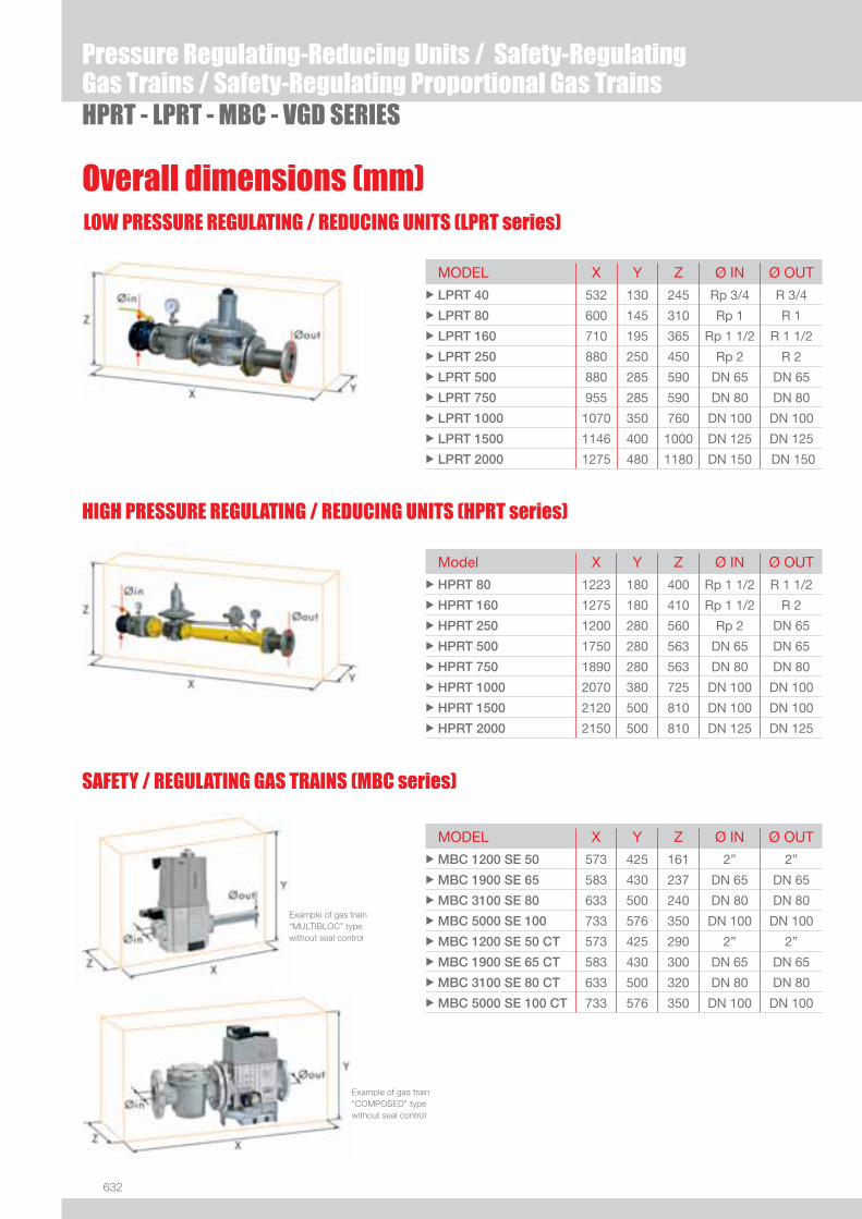
632
Overall dimensions (mm)
HPRT - LPRT - MBC - VGD SERIES
Pressure Regulating-Reducing Units / Safety-RegulatingGas Trains / Safety-Regulating Proportional Gas Trains
SAFETY / REGULATING GAS TRAINS (MBC series)
HIGH PRESSURE REGULATING / REDUCING UNITS (HPRT series)
LOW PRESSURE REGULATING / REDUCING UNITS (LPRT series)
MODEL X Y Z Ø IN Ø OUTu LPRT 40 532 130 245 Rp 3/4 R 3/4
u LPRT 80 600 145 310 Rp 1 R 1
u LPRT 160 710 195 365 Rp 1 1/2 R 1 1/2
u LPRT 250 880 250 450 Rp 2 R 2
u LPRT 500 880 285 590 DN 65 DN 65
u LPRT 750 955 285 590 DN 80 DN 80
u LPRT 1000 1070 350 760 DN 100 DN 100
u LPRT 1500 1146 400 1000 DN 125 DN 125
u LPRT 2000 1275 480 1180 DN 150 DN 150
Model X Y Z Ø IN Ø OUTu HPRT 80 1223 180 400 Rp 1 1/2 R 1 1/2
u HPRT 160 1275 180 410 Rp 1 1/2 R 2
u HPRT 250 1200 280 560 Rp 2 DN 65
u HPRT 500 1750 280 563 DN 65 DN 65
u HPRT 750 1890 280 563 DN 80 DN 80
u HPRT 1000 2070 380 725 DN 100 DN 100
u HPRT 1500 2120 500 810 DN 100 DN 100
u HPRT 2000 2150 500 810 DN 125 DN 125
MODEL X Y Z Ø IN Ø OUTu MBC 1200 SE 50 573 425 161 2” 2”
u MBC 1900 SE 65 583 430 237 DN 65 DN 65
u MBC 3100 SE 80 633 500 240 DN 80 DN 80
u MBC 5000 SE 100 733 576 350 DN 100 DN 100
u MBC 1200 SE 50 CT 573 425 290 2” 2”
u MBC 1900 SE 65 CT 583 430 300 DN 65 DN 65
u MBC 3100 SE 80 CT 633 500 320 DN 80 DN 80
u MBC 5000 SE 100 CT 733 576 350 DN 100 DN 100
Example of gas train “MULTIBLOC” type without seal control
Example of gas train “COMPOSED” type without seal control
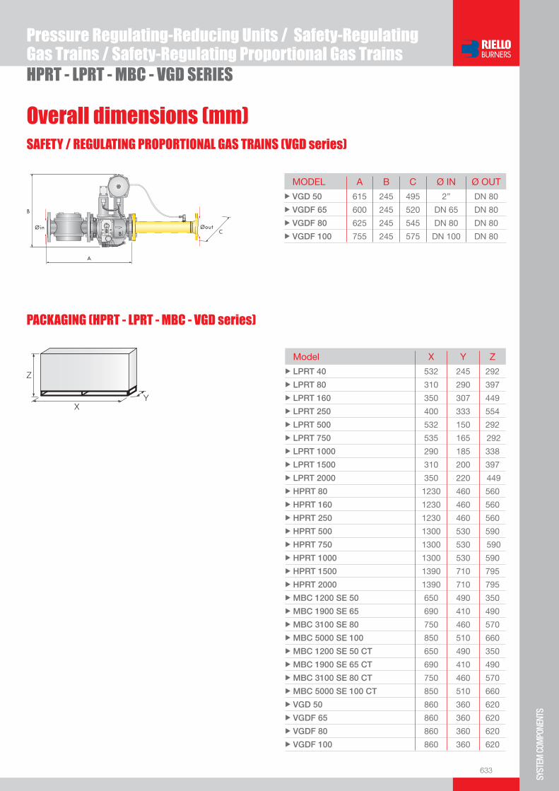
633
SYST
EM C
OMPO
NENT
S
HPRT - LPRT - MBC - VGD SERIES
Pressure Regulating-Reducing Units / Safety-RegulatingGas Trains / Safety-Regulating Proportional Gas Trains
Overall dimensions (mm)SAFETY / REGULATING PROPORTIONAL GAS TRAINS (VGD series)
PACKAGING (HPRT - LPRT - MBC - VGD series)
Z
XY
MODEL A B C Ø IN Ø OUTu VGD 50 615 245 495 2” DN 80
u VGDF 65 600 245 520 DN 65 DN 80
u VGDF 80 625 245 545 DN 80 DN 80
u VGDF 100 755 245 575 DN 100 DN 80
Model X Y Zu LPRT 40 532 245 292
u LPRT 80 310 290 397
u LPRT 160 350 307 449
u LPRT 250 400 333 554
u LPRT 500 532 150 292
u LPRT 750 535 165 292
u LPRT 1000 290 185 338
u LPRT 1500 310 200 397
u LPRT 2000 350 220 449
u HPRT 80 1230 460 560
u HPRT 160 1230 460 560
u HPRT 250 1230 460 560
u HPRT 500 1300 530 590
u HPRT 750 1300 530 590
u HPRT 1000 1300 530 590
u HPRT 1500 1390 710 795
u HPRT 2000 1390 710 795
u MBC 1200 SE 50 650 490 350
u MBC 1900 SE 65 690 410 490
u MBC 3100 SE 80 750 460 570
u MBC 5000 SE 100 850 510 660
u MBC 1200 SE 50 CT 650 490 350
u MBC 1900 SE 65 CT 690 410 490
u MBC 3100 SE 80 CT 750 460 570
u MBC 5000 SE 100 CT 850 510 660
u VGD 50 860 360 620
u VGDF 65 860 360 620
u VGDF 80 860 360 620
u VGDF 100 860 360 620
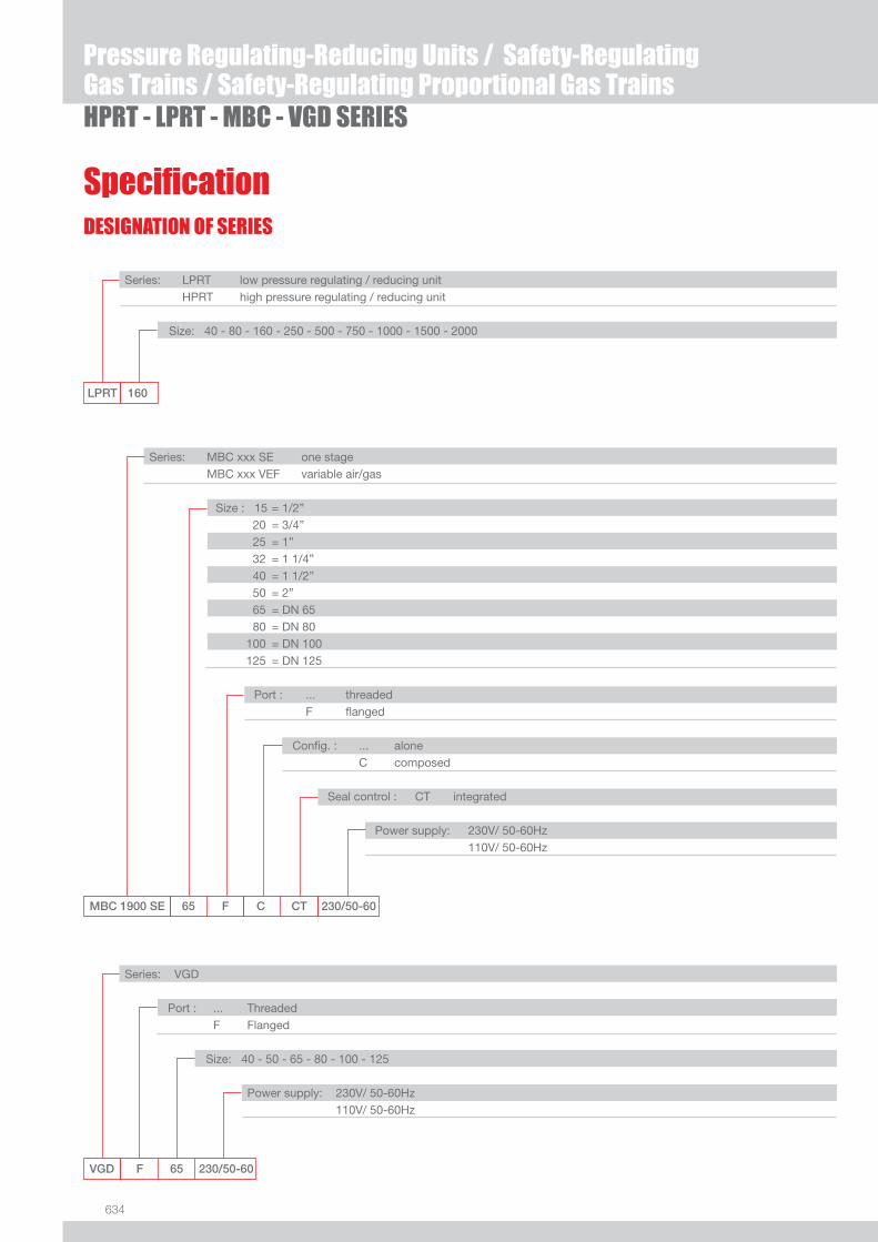
634
DESIGNATION OF SERIES
Specifi cation
HPRT - LPRT - MBC - VGD SERIES
Pressure Regulating-Reducing Units / Safety-RegulatingGas Trains / Safety-Regulating Proportional Gas Trains
LPRT 160
Series: LPRT low pressure regulating / reducing unit HPRT high pressure regulating / reducing unit
Size: 40 - 80 - 160 - 250 - 500 - 750 - 1000 - 1500 - 2000
VGD F 65 230/50-60
Series: VGD
Port : ... Threaded F Flanged
Size: 40 - 50 - 65 - 80 - 100 - 125
Power supply: 230V/ 50-60Hz 110V/ 50-60Hz
MBC 1900 SE 65 F C CT 230/50-60
Series: MBC xxx SE one stage MBC xxx VEF variable air/gas
Size : 15 = 1/2” 20 = 3/4” 25 = 1” 32 = 1 1/4” 40 = 1 1/2” 50 = 2” 65 = DN 65 80 = DN 80 100 = DN 100 125 = DN 125
Port : ... threaded F fl anged
Confi g. : ... alone C composed
Seal control : CT integrated Power supply: 230V/ 50-60Hz 110V/ 50-60Hz
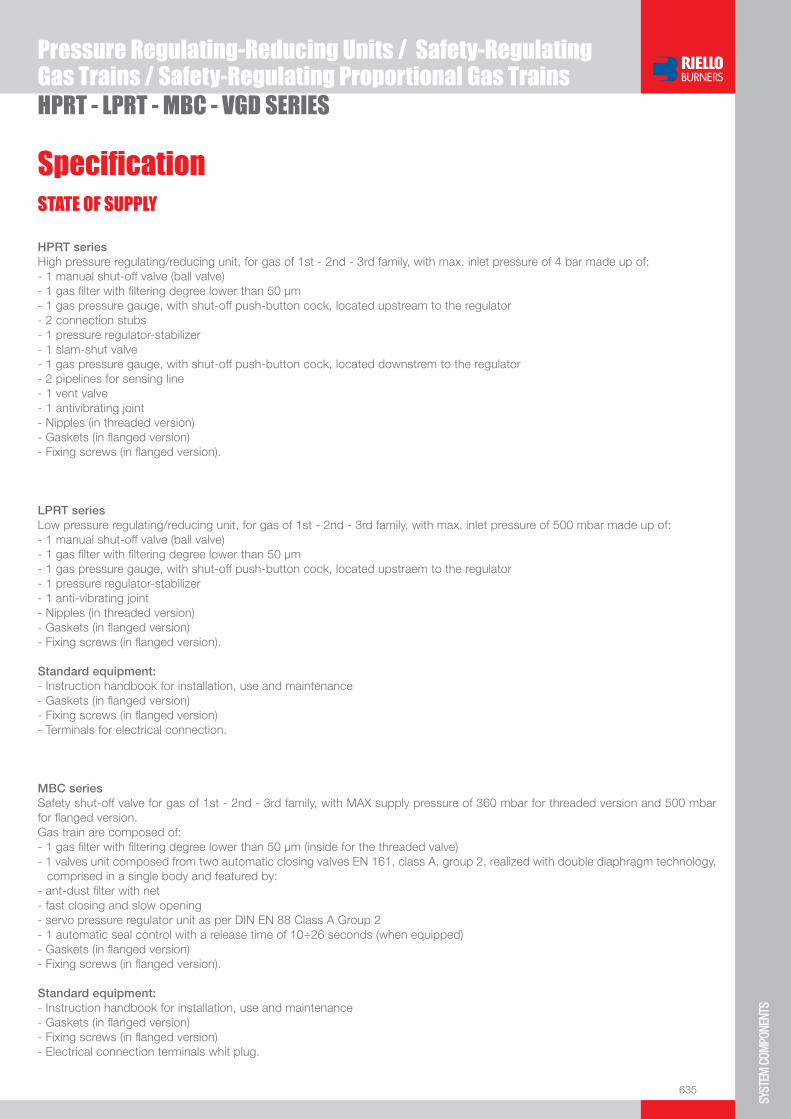
635
SYST
EM C
OMPO
NENT
S
Specifi cation
HPRT - LPRT - MBC - VGD SERIES
Pressure Regulating-Reducing Units / Safety-RegulatingGas Trains / Safety-Regulating Proportional Gas Trains
STATE OF SUPPLY
HPRT seriesHigh pressure regulating/reducing unit, for gas of 1st - 2nd - 3rd family, with max. inlet pressure of 4 bar made up of:- 1 manual shut-off valve (ball valve)- 1 gas fi lter with fi ltering degree lower than 50 µm- 1 gas pressure gauge, with shut-off push-button cock, located upstream to the regulator- 2 connection stubs- 1 pressure regulator-stabilizer- 1 slam-shut valve- 1 gas pressure gauge, with shut-off push-button cock, located downstrem to the regulator- 2 pipelines for sensing line- 1 vent valve- 1 antivibrating joint- Nipples (in threaded version)- Gaskets (in fl anged version)- Fixing screws (in fl anged version).
LPRT seriesLow pressure regulating/reducing unit, for gas of 1st - 2nd - 3rd family, with max. inlet pressure of 500 mbar made up of:- 1 manual shut-off valve (ball valve)- 1 gas fi lter with fi ltering degree lower than 50 µm- 1 gas pressure gauge, with shut-off push-button cock, located upstraem to the regulator- 1 pressure regulator-stabilizer- 1 anti-vibrating joint- Nipples (in threaded version)- Gaskets (in fl anged version)- Fixing screws (in fl anged version).
Standard equipment:- Instruction handbook for installation, use and maintenance- Gaskets (in fl anged version)- Fixing screws (in fl anged version)- Terminals for electrical connection.
MBC seriesSafety shut-off valve for gas of 1st - 2nd - 3rd family, with MAX supply pressure of 360 mbar for threaded version and 500 mbar for fl anged version.Gas train are composed of:- 1 gas fi lter with fi ltering degree lower than 50 µm (inside for the threaded valve)- 1 valves unit composed from two automatic closing valves EN 161, class A, group 2, realized with double diaphragm technology,
comprised in a single body and featured by:- ant-dust fi lter with net- fast closing and slow opening- servo pressure regulator unit as per DIN EN 88 Class A Group 2- 1 automatic seal control with a release time of 10÷26 seconds (when equipped)- Gaskets (in fl anged version)- Fixing screws (in fl anged version).
Standard equipment:- Instruction handbook for installation, use and maintenance- Gaskets (in fl anged version)- Fixing screws (in fl anged version)- Electrical connection terminals whit plug.

636
STATE OF SUPPLY
Specifi cation
VGD seriesSafety shut-off valve for gas of 1st - 2nd - 3rd family, with MAX supply pressure of 500 mbar composed from:- 1 valves unit composed from two automatic closing valves EN 161, class A, group 2, realized with double diaphragm technology,
comprised in a single body and featured by: - fast closing and slow opening with adjustable fast stroke for initial gas volume - adjustable main delivery and proportional regulation - ant-dust fi lter with net- 1 automatic seal control with a release time of 10÷26 seconds (when equipped)- nipples (in threaded version)- gaskets (in fl anged version)- fi xing screws (in fl anged version).
Standard equipment:- instruction handbook for installation, use and maintenance- gaskets (in fl anged version)- fi xing screws (in fl anged version)- electrical connection terminals.
HPRT - LPRT - MBC - VGD SERIES
Pressure Regulating-Reducing Units / Safety-RegulatingGas Trains / Safety-Regulating Proportional Gas Trains
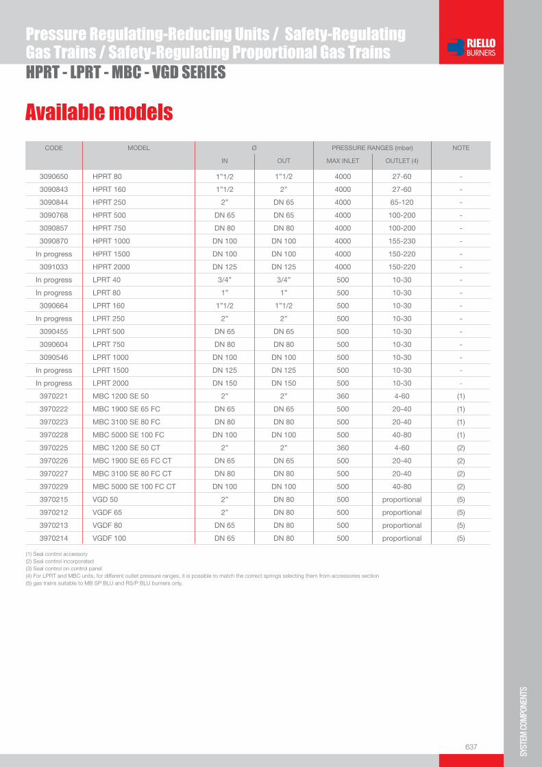
637
SYST
EM C
OMPO
NENT
S
Available models
HPRT - LPRT - MBC - VGD SERIES
Pressure Regulating-Reducing Units / Safety-RegulatingGas Trains / Safety-Regulating Proportional Gas Trains
CODE MODEL Ø PRESSURE RANGES (mbar) NOTE
IN OUT MAX INLET OUTLET (4)
3090650 HPRT 80 1”1/2 1”1/2 4000 27-60 -
3090843 HPRT 160 1”1/2 2” 4000 27-60 -
3090844 HPRT 250 2” DN 65 4000 65-120 -
3090768 HPRT 500 DN 65 DN 65 4000 100-200 -
3090857 HPRT 750 DN 80 DN 80 4000 100-200 -
3090870 HPRT 1000 DN 100 DN 100 4000 155-230 -
In progress HPRT 1500 DN 100 DN 100 4000 150-220 -
3091033 HPRT 2000 DN 125 DN 125 4000 150-220 -
In progress LPRT 40 3/4” 3/4” 500 10-30 -
In progress LPRT 80 1” 1” 500 10-30 -
3090664 LPRT 160 1”1/2 1”1/2 500 10-30 -
In progress LPRT 250 2” 2” 500 10-30 -
3090455 LPRT 500 DN 65 DN 65 500 10-30 -
3090604 LPRT 750 DN 80 DN 80 500 10-30 -
3090546 LPRT 1000 DN 100 DN 100 500 10-30 -
In progress LPRT 1500 DN 125 DN 125 500 10-30 -
In progress LPRT 2000 DN 150 DN 150 500 10-30 -
3970221 MBC 1200 SE 50 2” 2” 360 4-60 (1)
3970222 MBC 1900 SE 65 FC DN 65 DN 65 500 20-40 (1)
3970223 MBC 3100 SE 80 FC DN 80 DN 80 500 20-40 (1)
3970228 MBC 5000 SE 100 FC DN 100 DN 100 500 40-80 (1)
3970225 MBC 1200 SE 50 CT 2” 2” 360 4-60 (2)
3970226 MBC 1900 SE 65 FC CT DN 65 DN 65 500 20-40 (2)
3970227 MBC 3100 SE 80 FC CT DN 80 DN 80 500 20-40 (2)
3970229 MBC 5000 SE 100 FC CT DN 100 DN 100 500 40-80 (2)
3970215 VGD 50 2” DN 80 500 proportional (5)
3970212 VGDF 65 2” DN 80 500 proportional (5)
3970213 VGDF 80 DN 65 DN 80 500 proportional (5)
3970214 VGDF 100 DN 65 DN 80 500 proportional (5)
(1) Seal control accessory(2) Seal control incorporated (3) Seal control on control panel(4) For LPRT and MBC units, for different outlet pressure ranges, it is possible to match the correct springs selecting them from accessories section(5) gas trains suitable to MB SP BLU and RS/P BLU burners only.
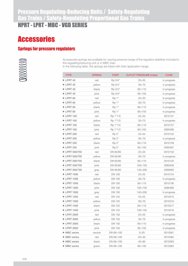
638
HPRT - LPRT - MBC - VGD SERIES
Pressure Regulating-Reducing Units / Safety-RegulatingGas Trains / Safety-Regulating Proportional Gas Trains
AccessoriesSprings for pressure regulators
Accessories springs are available for varying pressure range of the regulator-stabilizer included in the regulating/reducing unit or in MBC train.In the following table, the springs are listed with their application range.
TYPE SPRING PORT OUTLET PRESSURE (mbar) CODE
u LPRT 40 red Rp 3/4” 25÷55 in progress
u LPRT 40 yellow Rp 3/4” 30÷70 in progress
u LPRT 40 black Rp 3/4” 60÷110 in progress
u LPRT 40 pink Rp 3/4” 90÷150 in progress
u LPRT 80 red Rp 1” 25÷55 in progress
u LPRT 80 yellow Rp 1” 30÷70 in progress
u LPRT 80 black Rp 1” 60÷110 in progress
u LPRT 80 pink Rp 1” 90÷150 in progress
u LPRT 160 red Rp 1”1/2 25÷55 3010131
u LPRT 160 yellow Rp 1”1/2 30÷70 in progress
u LPRT 160 black Rp 1”1/2 60÷110 3010157
u LPRT 160 pink Rp 1”1/2 90÷150 3090486
u LPRT 250 red Rp 2” 25÷55 3010132
u LPRT 250 yellow Rp 2” 30÷70 in progress
u LPRT 250 black Rp 2” 60÷110 3010158
u LPRT 250 pink Rp 2” 90÷150 3090487
u LPRT 500/750 red DN 65/80 25÷55 3010133
u LPRT 500/750 yellow DN 65/80 30÷70 in progress
u LPRT 500/750 black DN 65/80 60÷110 3010135
u LPRT 500/750 pink DN 65/80 100÷150 3090456
u LPRT 500/750 grey DN 65/80 140÷200 3090992
u LPRT 1000 red DN 100 25÷55 3010134
u LPRT 1000 yellow DN 100 30÷70 in progress
u LPRT 1000 black DN 100 60÷110 3010136
u LPRT 1000 pink DN 100 100÷150 3090489
u LPRT 1000 grey DN 100 140÷200 in progress
u LPRT 1500 red DN 125 25÷55 3010315
u LPRT 1500 yellow DN 125 30÷70 3010316
u LPRT 1500 black DN 125 60÷110 3010317
u LPRT 1500 pink DN 125 100÷150 3010318
u LPRT 2000 red DN 150 25÷55 in progress
u LPRT 2000 yellow DN 150 30÷70 in progress
u LPRT 2000 black DN 150 60÷110 in progress
u LPRT 2000 pink DN 150 90÷150 in progress
u MBC series neutral DN 68÷100 0÷20 3010381
u MBC series red DN 68÷100 20÷40 3010382
u MBC series black DN 68÷100 40÷80 3010383
u MBC series green DN 68÷100 80÷150 3010384
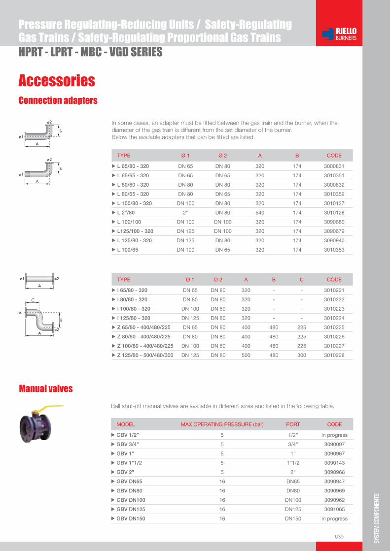
639
SYST
EM C
OMPO
NENT
S
HPRT - LPRT - MBC - VGD SERIES
Pressure Regulating-Reducing Units / Safety-RegulatingGas Trains / Safety-Regulating Proportional Gas Trains
AccessoriesConnection adapters
In some cases, an adapter must be fi tted between the gas train and the burner, when the diameter of the gas train is different from the set diameter of the burner.Below the available adapters that can be fi tted are listed.
TYPE Ø 1 Ø 2 A B CODE
u L 65/80 - 320 DN 65 DN 80 320 174 3000831
u L 65/65 - 320 DN 65 DN 65 320 174 3010351
u L 80/80 - 320 DN 80 DN 80 320 174 3000832
u L 80/65 - 320 DN 80 DN 65 320 174 3010352
u L 100/80 - 320 DN 100 DN 80 320 174 3010127
u L 2”/80 2” DN 80 540 174 3010128
u L 100/100 DN 100 DN 100 320 174 3090680
u L125/100 - 320 DN 125 DN 100 320 174 3090679
u L 125/80 - 320 DN 125 DN 80 320 174 3090940
u L 100/65 DN 100 DN 65 320 174 3010353
TYPE Ø 1 Ø 2 A B C CODE
u I 65/80 - 320 DN 65 DN 80 320 - - 3010221
u I 80/80 - 320 DN 80 DN 80 320 - - 3010222
u I 100/80 - 320 DN 100 DN 80 320 - - 3010223
u I 125/80 - 320 DN 125 DN 80 320 - - 3010224
u Z 65/80 - 400/480/225 DN 65 DN 80 400 480 225 3010225
u Z 80/80 - 400/480/225 DN 80 DN 80 400 480 225 3010226
u Z 100/80 - 400/480/225 DN 100 DN 80 400 480 225 3010227
u Z 125/80 - 500/480/300 DN 125 DN 80 500 480 300 3010228
Manual valves
Ball shut-off manual valves are available in different sizes and listed in the following table.
MODEL MAX OPERATING PRESSURE (bar) PORT CODE
u GBV 1/2” 5 1/2” in progress
u GBV 3/4” 5 3/4” 3090097
u GBV 1” 5 1” 3090967
u GBV 1”1/2 5 1”1/2 3090143
u GBV 2” 5 2” 3090968
u GBV DN65 16 DN65 3090947
u GBV DN80 16 DN80 3090969
u GBV DN100 16 DN100 3090962
u GBV DN125 16 DN125 3091065
u GBV DN150 16 DN150 in progress

640
HPRT - LPRT - MBC - VGD SERIES
Pressure Regulating-Reducing Units / Safety-RegulatingGas Trains / Safety-Regulating Proportional Gas Trains
AccessoriesAnti-vibrating joints
Anti-vibrating joints to damp vibrations and facilitate application of the gas train to the gas distri-bution line are available in different sizes listed in the table below.
Type porT size inleT max pressure (bar) Code
u GA 20 3/4” 6 3891033
u GA 25 1” 6 3891034
u GA 40 1”1/2 6 3891043
u GA 50 2” 6 3891053
u GAF 65 dn65 6 3891013
u GAF 80 dn80 6 3891003
u GAF 100 dn100 6 3891023
u GAF 125 dn125 6 3091092
Filters
A series of gas filters of different sizes are avilable and listed in the following table.
Type porT in/ouT inleT max pressure (bar) Code
u GF515/1 1”1/2 0,5 3012198
u GF520/1 2” 0,5 3012199
u GF40065/3 dn 65 4 3012200
u GF40080/3 dn 80 4 3012201
u GF40100/3 dn 100 4 3012202
u GF40125 dn 125 4 3013141
Pressure regulators
A series of pressure regulators of different sizes are avilable and listed in the following table.
Type porT in/ouT inleT max pressure (bar) Code
u FRS 515 1”1/2 0,5 3012203
u FRS 520 2” 0,5 3012204
u FRS 5065 dn 65 0,5 3012205
u FRS 5080 dn 80 0,5 3012206
u FRS 5100 dn 100 0,5 3012207
u FRS 5125 dn 125 0,5 on demand
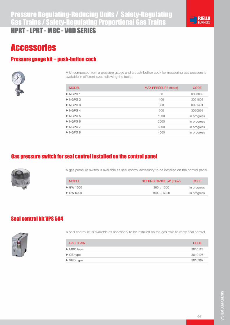
641
SYST
EM C
OMPO
NENT
S
HPRT - LPRT - MBC - VGD SERIES
Pressure Regulating-Reducing Units / Safety-RegulatingGas Trains / Safety-Regulating Proportional Gas Trains
AccessoriesPressure gauge kit + push-button cock
A kit composed from a pressure gauge and a push-button cock for measuring gas pressure is available in different sizes following the table.
MODEL MAX PRESSURE (mbar) CODE
u NGPG 1 60 3090062
u NGPG 2 100 3091805
u NGPG 3 300 3091491
u NGPG 4 500 3090099
u NGPG 5 1000 in progress
u NGPG 6 2000 in progress
u NGPG 7 3000 in progress
u NGPG 8 4000 in progress
Gas pressure switch for seal control installed on the control panel
A gas pressure switch is available as seal control accessory to be installed on the control panel.
MODEL SETTING RANGE ΔP (mbar) CODE
u GW 1500 300 ÷ 1500 in progress
u GW 6000 1000 ÷ 6000 in progress
Seal control kit VPS 504
A seal control kit is available as accessory to be installed on the gas train to verify seal control.
GAS TRAIN CODE
u MBC type 3010123
u CB type 3010125
u VGD type 3010367


643
SYST
EM C
OMPO
NENT
S
Centrifugal Air Fans for Industrial Burners
GCH SERIESGCM SERIESGBJ SERIESAir supply fans allow to bring comburent air through the adduction channel to the combustion head in pressure and delivery conditions required from the application.The air delivery processed from the fan is in a correct proportion to the fuel to guarantee the required burner output with a safe combustion. Performance tables help the fan selection among the available models.All the models are pre-assembled and tested in factory in the respect of existing normatives so to permit the maximum installation facility.
GCH SERIES 800 ÷ 5000 m3/h 1800 ÷ 4800 PaGCM SERIES 4000 ÷ 9500 m3/h 1800 ÷ 4400 PaGBJ SERIES 3500 ÷ 20000 m3/h 2800 ÷ 10000 Pa

644
Overall dimensions (mm)
Centrifugal Air Fans for Industrial BurnersGCH - GCM - GBJ SERIES
GCH SERIES
OUTLET FLANGE
Fan and basement
MODEL A B C D E F G H I L M N O Pu GCH 04020 660 580 400 230 280 80 375 67 215 270 245 137 60 18
u GCH 05020 800 735 570 290 355 100 450 85 320 392 360 250 45 25
u GCH 05040 800 735 570 290 355 100 450 85 320 392 360 250 45 25
MODEL a b c d e f gu GCH 04020 180 219 250 125 167 195 112
u GCH 05020 224 265 294 160 200 230 112
u GCH 05040 224 265 294 160 200 230 112

645
SYST
EM C
OMPO
NENT
S
Centrifugal Air Fans for Industrial BurnersGCH - GCM - GBJ SERIES
GCM SERIES
OUTLET FLANGE
Fan and basement
Overall dimensions (mm)
MODEL A B C D E F G H I L M N O Pu GCM 04540 930 750 720 328 335 140 560 132 320 392 360 250 45 25
u GCM 05020 1010 840 750 365 355 160 630 148 320 392 360 250 45 25
u GCM 05040 1010 840 820 365 355 160 630 148 425 440 400 340 55 30
MODEL a b c d e f gu GCM 04540 355 405 435 250 300 330 125
u GCM 05020 400 448 480 280 332 360 125
u GCM 05040 400 448 480 280 332 360 125
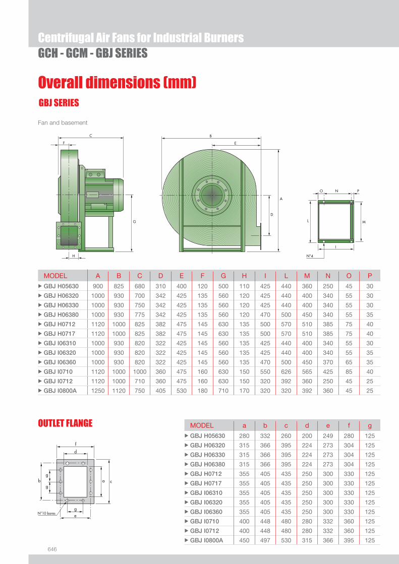
646
Overall dimensions (mm)
Centrifugal Air Fans for Industrial BurnersGCH - GCM - GBJ SERIES
GBJ SERIES
OUTLET FLANGE
Fan and basement
MODEL A B C D E F G H I L M N O Pu GBJ H05630 900 825 680 310 400 120 500 110 425 440 360 250 45 30
u GBJ H06320 1000 930 700 342 425 135 560 120 425 440 400 340 55 30
u GBJ H06330 1000 930 750 342 425 135 560 120 425 440 400 340 55 30
u GBJ H06380 1000 930 775 342 425 135 560 120 470 500 450 340 55 35
u GBJ H0712 1120 1000 825 382 475 145 630 135 500 570 510 385 75 40
u GBJ H0717 1120 1000 825 382 475 145 630 135 500 570 510 385 75 40
u GBJ I06310 1000 930 820 322 425 145 560 135 425 440 400 340 55 30
u GBJ I06320 1000 930 820 322 425 145 560 135 425 440 400 340 55 35
u GBJ I06360 1000 930 820 322 425 145 560 135 470 500 450 370 65 35
u GBJ I0710 1120 1000 1000 360 475 160 630 150 550 626 565 425 85 40
u GBJ I0712 1120 1000 710 360 475 160 630 150 320 392 360 250 45 25
u GBJ I0800A 1250 1120 750 405 530 180 710 170 320 320 392 360 45 25
MODEL a b c d e f gu GBJ H05630 280 332 260 200 249 280 125
u GBJ H06320 315 366 395 224 273 304 125
u GBJ H06330 315 366 395 224 273 304 125
u GBJ H06380 315 366 395 224 273 304 125
u GBJ H0712 355 405 435 250 300 330 125
u GBJ H0717 355 405 435 250 300 330 125
u GBJ I06310 355 405 435 250 300 330 125
u GBJ I06320 355 405 435 250 300 330 125
u GBJ I06360 355 405 435 250 300 330 125
u GBJ I0710 400 448 480 280 332 360 125
u GBJ I0712 400 448 480 280 332 360 125
u GBJ I0800A 450 497 530 315 366 395 125

647
SYST
EM C
OMPO
NENT
S
DESIGNATION OF SERIES
Specifi cation
Centrifugal Air Fans for Industrial BurnersGCH - GCM - GBJ SERIES
STATE OF SUPPLY
Air fan models of GBJ, GCM and GCH series are provided, already assembled and tested in the factory, packaged on pallets with protective plastic fi lms.The issue includes:- centrifugal fan made up of a spiral-box which contains the fan wheel fi tted on drive shaft- three phases electrical motor- intake protection grid- vibration damping coupling outfl ow-end- terminals for electrical connection- handbook for installation, use and maintenance.
EXTENDED DESIGNATION
GBJ H05630 LG 0 3/380VΔ/50Hz I CE
Series: GCH, GCM, GBJ
Model: 04020 ........................................................................ I0800A Discharge position: RD 0 45 90 135 180 225 270 315 (clockwise rotation) LG 0 45 90 135 180 225 270 315 (counterclockwise rotation)
Electrical supply: 3 / 380 VΔ / 60 Hz 3 / 400 VΔ / 50 Hz 3 / 440 VΔ / 60 Hz 3 / 220 VΔ / 60 Hz 3 / 230 VΔ / 50 Hz
Installation: I Indoor O Outdoor
Motor certifi cation: CE EEX PROOF RINA (Naval approval) ...
BASIC DESIGNATION

648
Technical data delivery and static pressure
Centrifugal Air Fans for Industrial BurnersGCH - GCM - GBJ SERIES
The features listed are referred to air at the temperature of +15°C and at the barometrical pressure of 760 mmHg with specifi c gravity 1,226 kg/m3
Capacity tolerance: ± 5 %

649
SYST
EM C
OMPO
NENT
S
Available models
Centrifugal Air Fans for Industrial BurnersGCH - GCM - GBJ SERIES
CODE MODELS TOTAL ELECTRICAL POWER SOUND PRESSURE NOTE
INSTALLED ABSORBED
(kW) (kW) dB(A)
In progress GCH 04020 RD 270 3/400 VΔ/50 Hz 1,5 1,4 72
In progress GCH 04020 LG 270 3/400 VΔ/50 Hz 1,5 1,4 72
In progress GCH 04020 RD 0 3/400 VΔ/50 Hz 1,5 1,4 72
In progress GCH 04020 LG 0 3/400 VΔ/50 Hz 1,5 1,4 72
In progress GCH 04020 RD 270 3/380 VΔ/60 Hz 1,5 1,4 72
In progress GCH 04020 LG 270 3/380 VΔ/60 Hz 1,5 1,4 72
In progress GCH 04020 RD 0 3/380 VΔ/60 Hz 1,5 1,4 72
In progress GCH 04020 LG 0 3/380 VΔ/60 Hz 1,5 1,4 72
In progress GCH 05020 RD 270 3/400 VΔ/50 Hz 5,5 5,2 78
In progress GCH 05020 LG 270 3/400 VΔ/50 Hz 5,5 5,2 78
In progress GCH 05020 RD 0 3/400 VΔ/50 Hz 5,5 5,2 78
In progress GCH 05020 LG 0 3/400 VΔ/50 Hz 5,5 5,2 78
In progress GCH 05020 RD 270 3/380 VΔ/60 Hz 5,5 5,2 78
In progress GCH 05020 LG 270 3/380 VΔ/60 Hz 5,5 5,2 78
In progress GCH 05020 RD 0 3/380 VΔ/60 Hz 5,5 5,2 78
In progress GCH 05020 LG 0 3/380 VΔ/60 Hz 5,5 5,2 78
In progress GCH 05040 RD 270 3/400 VΔ/50 Hz 7,5 7 80
In progress GCH 05040 LG 270 3/400 VΔ/50 Hz 7,5 7 80
In progress GCH 05040 RD 0 3/400 VΔ/50 Hz 7,5 7 80
In progress GCH 05040 LG 0 3/400 VΔ/50 Hz 7,5 7 80
In progress GCH 05040 RD 270 3/380 VΔ/60 Hz 7,5 7 80
In progress GCH 05040 LG 270 3/380 VΔ/60 Hz 7,5 7 80
In progress GCH 05040 RD 0 3/380 VΔ/60 Hz 7,5 7 80
In progress GCH 05040 LG 0 3/380 VΔ/60 Hz 7,5 7 80
3891100 GCM 04540 RD 270 3/400 VΔ/50 Hz 7,5 7,1 82
3891101 GCM 04540 LG 270 3/400 VΔ/50 Hz 7,5 7,1 82
3891102 GCM 04540 RD 0 3/400 VΔ/50 Hz 7,5 7,1 82
3891103 GCM 04540 LG 0 3/400 VΔ/50 Hz 7,5 7,1 82
3891104 GCM 04540 RD 270 3/440 VΔ/60 Hz 7,5 7,1 82
3891105 GCM 04540 LG 270 3/440 VΔ/60 Hz 7,5 7,1 82
3891106 GCM 04540 RD 0 3/440 VΔ/60 Hz 7,5 7,1 82
3891107 GCM 04540 LG 0 3/440 VΔ/60 Hz 7,5 7,1 82
3891108 GCM 04540 RD 270 3/380 VΔ/60 Hz 7,5 7,1 82
3891109 GCM 04540 LG 270 3/380 VΔ/60 Hz 7,5 7,1 82
3891110 GCM 04540 RD 0 3/380 VΔ/60 Hz 7,5 7,1 82
3891111 GCM 04540 LG 0 3/380 VΔ/60 Hz 7,5 7,1 82
3891112 GCM 05020 RD 270 3/400 VΔ/50 Hz 9 8,7 83
3891113 GCM 05020 LG 270 3/400 VΔ/50 Hz 9 8,7 83
3891114 GCM 05020 RD 0 3/400 VΔ/50 Hz 9 8,7 83
3891115 GCM 05020 LG 0 3/400 VΔ/50 Hz 9 8,7 83
3891116 GCM 05020 RD 270 3/440 VΔ/60 Hz 9 8,7 83
3891117 GCM 05020 LG 270 3/440 VΔ/60 Hz 9 8,7 83

650
Available models
Centrifugal Air Fans for Industrial BurnersGCH - GCM - GBJ SERIES
CODE MODELS TOTAL ELECTRICAL POWER SOUND PRESSURE NOTE
INSTALLED ABSORBED
(kW) (kW) dB(A)
3891118 GCM 05020 RD 0 3/440 VΔ/60 Hz 9 8,7 83
3891119 GCM 05020 LG 0 3/440 VΔ/60 Hz 9 8,7 83
3891120 GCM 05020 RD 270 3/380 VΔ/60 Hz 9 8,7 83
3891121 GCM 05020 LG 270 3/380 VΔ/60 Hz 9 8,7 83
3891122 GCM 05020 RD 0 3/380 VΔ/60 Hz 9 8,7 83
3891123 GCM 05020 LG 0 3/380 VΔ/60 Hz 9 8,7 83
3891124 GCM 05040 RD 270 3/400 VΔ/50 Hz 11 10,5 84
3891125 GCM 05040 LG 270 3/400 VΔ/ 50 Hz 11 10,5 84
3891126 GCM 05040 RD 0 3/400 VΔ/ 50 Hz 11 10,5 84
3891127 GCM 05040 LG 0 3/400 VΔ/ 50 Hz 11 10,5 84
3891128 GCM 05040 RD 270 3/440 VΔ/ 60 Hz 11 10,5 84
3891129 GCM 05040 LG 270 3/440 VΔ/ 60 Hz 11 10,5 84
3891130 GCM 05040 RD 0 3/440 VΔ/ 60 Hz 11 10,5 84
3891131 GCM 05040 LG 0 3/440 VΔ/ 60 Hz 11 10,5 84
3891132 GCM 05040 RD 270 3/380 VΔ/ 60 Hz 11 10,5 84
3891133 GCM 05040 LG 270 3/380 VΔ/ 60 Hz 11 10,5 84
3891134 GCM 05040 RD 0 3/380 VΔ/ 60 Hz 11 10,5 84
3891135 GCM 05040 LG 0 3/380 VΔ/ 60 Hz 11 10,5 84
3891136 GBJ H05630 RD 270 3/400 VΔ/ 50 Hz 11 10,5 88
3891137 GBJ H05630 LG 270 3/400 VΔ/ 50 Hz 11 10,5 88
3891138 GBJ H05630 RD 0 3/400 VΔ/ 50 Hz 11 10,5 88
3891139 GBJ H05630 LG 0 3/400 VΔ/ 50 Hz 11 10,5 88
3891140 GBJ H05630 RD 270 3/440 VΔ/ 60 Hz 11 10,5 88
3891141 GBJ H05630 LG 270 3/440 VΔ/ 60 Hz 11 10,5 88
3891142 GBJ H05630 RD 0 3/440 VΔ/ 60 Hz 11 10,5 88
3891143 GBJ H05630 LG 0 3/440 VΔ/ 60 Hz 11 10,5 88
3891144 GBJ H05630 RD 270 3/380 VΔ/ 60 Hz 11 10,5 88
3891145 GBJ H05630 LG 270 3/380 VΔ/ 60 Hz 11 10,5 88
3891146 GBJ H05630 RD 0 3/380 VΔ/ 60 Hz 11 10,5 88
3891147 GBJ H05630 LG 0 3/380 VΔ/ 60 Hz 11 10,5 88
3891148 GBJ H06320 RD 270 3/400 VΔ/ 50 Hz 15 14,5 91
3891149 GBJ H06320 LG 270 3/400 VΔ/ 50 Hz 15 14,5 91
3891150 GBJ H06320 RD 0 3/400 VΔ/ 50 Hz 15 14,5 91
3891151 GBJ H06320 LG 0 3/400 VΔ/ 50 Hz 15 14,5 91
3891152 GBJ H06320 RD 270 3/440 VΔ/ 60 Hz 15 14,5 91
3891153 GBJ H06320 LG 270 3/440 VΔ/ 60 Hz 15 14,5 91
3891154 GBJ H06320 RD 0 3/440 VΔ/ 60 Hz 15 14,5 91
3891155 GBJ H06320 LG 0 3/440 VΔ/ 60 Hz 15 14,5 91
3891156 GBJ H06320 RD 270 3/380 VΔ/ 60 Hz 15 14,5 91
3891157 GBJ H06320 LG 270 3/380 VΔ/ 60 Hz 15 14,5 91
3891158 GBJ H06320 RD 0 3/380 VΔ/ 60 Hz 15 14,5 91
3891159 GBJ H06320 LG 0 3/380 VΔ/ 60 Hz 15 14,5 91

651
SYST
EM C
OMPO
NENT
S
Centrifugal Air Fans for Industrial BurnersGCH - GCM - GBJ SERIES
CODE MODELS TOTAL ELECTRICAL POWER SOUND PRESSURE NOTE
INSTALLED ABSORBED
(kW) (kW) dB(A)
3891160 GBJ I06310 RD 270 3/400 VΔ/ 50 Hz 15 14,5 90
3891161 GBJ I06310 LG 270 3/400 VΔ/ 50 Hz 15 14,5 90
3891162 GBJ I06310 RD 0 3/400 VΔ/ 50 Hz 15 14,5 90
3891163 GBJ I06310 LG 0 3/400 VΔ/ 50 Hz 15 14,5 90
3891164 GBJ I06310 RD 270 3/440 VΔ/ 60 Hz 15 14,5 90
3891165 GBJ I06310 LG 270 3/440 VΔ/ 60 Hz 15 14,5 90
3891166 GBJ I06310 RD 0 3/440 VΔ/ 60 Hz 15 14,5 90
3891167 GBJ I06310 LG 0 3/440 VΔ/ 60 Hz 15 14,5 90
3891168 GBJ I06310 RD 270 3/380 VΔ/ 60 Hz 15 14,5 90
3891169 GBJ I06310 LG 270 3/380 VΔ/ 60 Hz 15 14,5 90
3891170 GBJ I06310 RD 0 3/380 VΔ/ 60 Hz 15 14,5 90
3891171 GBJ I06310 LG 0 3/380 VΔ/ 60 Hz 15 14,5 90
3891172 GBJ H06330 RD 270 3/400 VΔ/ 50 Hz 18,5 18 92
3891173 GBJ H06330 LG 270 3/400 VΔ/ 50 Hz 18,5 18 92
3891174 GBJ H06330 RD 0 3/400 VΔ/ 50 Hz 18,5 18 92
3891175 GBJ H06330 LG 0 3/400 VΔ/ 50 Hz 18,5 18 92
3891176 GBJ H06330 RD 270 3/440 VΔ/ 60 Hz 18,5 18 92
3891177 GBJ H06330 LG 270 3/440 VΔ/ 60 Hz 18,5 18 92
3891178 GBJ H06330 RD 0 3/440 VΔ/ 60 Hz 18,5 18 92
3891179 GBJ H06330 LG 0 3/440 VΔ/ 60 Hz 18,5 18 92
3891180 GBJ H06330 RD 270 3/380 VΔ/ 60 Hz 18,5 18 92
3891181 GBJ H06330 LG 270 3/380 VΔ/ 60 Hz 18,5 18 92
3891182 GBJ H06330RD 0 3/380 VΔ/ 60 Hz 18,5 18 92
3891183 GBJ H06330 LG 0 3/380 VΔ/ 60 Hz 18,5 18 92
3891184 GBJ I06320 RD 270 3/400 VΔ/ 50 Hz 18,5 18 90
3891185 GBJ I06320 LG 270 3/400 VΔ/ 50 Hz 18,5 18 90
3891186 GBJ I06320 RD 0 3/400 VΔ/ 50 Hz 18,5 18 90
3891187 GBJ I06320 LG 0 3/400 VΔ/ 50 Hz 18,5 18 90
3891188 GBJ I06320 RD 270 3/440 VΔ/ 60 Hz 18,5 18 90
3891189 GBJ I06320 LG 270 3/440 VΔ/ 60 Hz 18,5 18 90
3891190 GBJ I06320 RD 0 3/440 VΔ/ 60 Hz 18,5 18 90
3891191 GBJ I06320 LG 0 3/440 VΔ/ 60 Hz 18,5 18 90
3891192 GBJ I06320 RD 270 3/380 VΔ/ 60 Hz 18,5 18 90
3891193 GBJ I06320 LG 270 3/380 VΔ/ 60 Hz 18,5 18 90
3891194 GBJ I06320 RD 0 3/380 VΔ/ 60 Hz 18,5 18 90
3891195 GBJ I06320 LG 0 3/380 VΔ/ 60 Hz 18,5 18 90
3891196 GBJ I06360 RD 270 3/400 VΔ/ 50 Hz 22 21 92
3891197 GBJ I06360 LG 270 3/400 VΔ/ 50 Hz 22 21 92
3891198 GBJ I06360 RD 0 3/400 VΔ/ 50 Hz 22 21 92
3891199 GBJ I06360 LG 0 3/400 VΔ/ 50 Hz 22 21 92
3891200 GBJ I06360 RD 270 3/440 VΔ/ 60 Hz 22 21 92
3891201 GBJ I06360 LG 270 3/440 VΔ/ 60 Hz 22 21 92
Available models
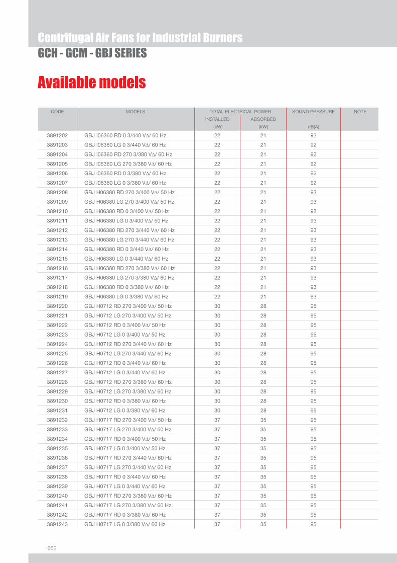
652
Available models
Centrifugal Air Fans for Industrial BurnersGCH - GCM - GBJ SERIES
CODE MODELS TOTAL ELECTRICAL POWER SOUND PRESSURE NOTE
INSTALLED ABSORBED
(kW) (kW) dB(A)
3891202 GBJ I06360 RD 0 3/440 VΔ/ 60 Hz 22 21 92
3891203 GBJ I06360 LG 0 3/440 VΔ/ 60 Hz 22 21 92
3891204 GBJ I06360 RD 270 3/380 VΔ/ 60 Hz 22 21 92
3891205 GBJ I06360 LG 270 3/380 VΔ/ 60 Hz 22 21 92
3891206 GBJ I06360 RD 0 3/380 VΔ/ 60 Hz 22 21 92
3891207 GBJ I06360 LG 0 3/380 VΔ/ 60 Hz 22 21 92
3891208 GBJ H06380 RD 270 3/400 VΔ/ 50 Hz 22 21 93
3891209 GBJ H06380 LG 270 3/400 VΔ/ 50 Hz 22 21 93
3891210 GBJ H06380 RD 0 3/400 VΔ/ 50 Hz 22 21 93
3891211 GBJ H06380 LG 0 3/400 VΔ/ 50 Hz 22 21 93
3891212 GBJ H06380 RD 270 3/440 VΔ/ 60 Hz 22 21 93
3891213 GBJ H06380 LG 270 3/440 VΔ/ 60 Hz 22 21 93
3891214 GBJ H06380 RD 0 3/440 VΔ/ 60 Hz 22 21 93
3891215 GBJ H06380 LG 0 3/440 VΔ/ 60 Hz 22 21 93
3891216 GBJ H06380 RD 270 3/380 VΔ/ 60 Hz 22 21 93
3891217 GBJ H06380 LG 270 3/380 VΔ/ 60 Hz 22 21 93
3891218 GBJ H06380 RD 0 3/380 VΔ/ 60 Hz 22 21 93
3891219 GBJ H06380 LG 0 3/380 VΔ/ 60 Hz 22 21 93
3891220 GBJ H0712 RD 270 3/400 VΔ/ 50 Hz 30 28 95
3891221 GBJ H0712 LG 270 3/400 VΔ/ 50 Hz 30 28 95
3891222 GBJ H0712 RD 0 3/400 VΔ/ 50 Hz 30 28 95
3891223 GBJ H0712 LG 0 3/400 VΔ/ 50 Hz 30 28 95
3891224 GBJ H0712 RD 270 3/440 VΔ/ 60 Hz 30 28 95
3891225 GBJ H0712 LG 270 3/440 VΔ/ 60 Hz 30 28 95
3891226 GBJ H0712 RD 0 3/440 VΔ/ 60 Hz 30 28 95
3891227 GBJ H0712 LG 0 3/440 VΔ/ 60 Hz 30 28 95
3891228 GBJ H0712 RD 270 3/380 VΔ/ 60 Hz 30 28 95
3891229 GBJ H0712 LG 270 3/380 VΔ/ 60 Hz 30 28 95
3891230 GBJ H0712 RD 0 3/380 VΔ/ 60 Hz 30 28 95
3891231 GBJ H0712 LG 0 3/380 VΔ/ 60 Hz 30 28 95
3891232 GBJ H0717 RD 270 3/400 VΔ/ 50 Hz 37 35 95
3891233 GBJ H0717 LG 270 3/400 VΔ/ 50 Hz 37 35 95
3891234 GBJ H0717 RD 0 3/400 VΔ/ 50 Hz 37 35 95
3891235 GBJ H0717 LG 0 3/400 VΔ/ 50 Hz 37 35 95
3891236 GBJ H0717 RD 270 3/440 VΔ/ 60 Hz 37 35 95
3891237 GBJ H0717 LG 270 3/440 VΔ/ 60 Hz 37 35 95
3891238 GBJ H0717 RD 0 3/440 VΔ/ 60 Hz 37 35 95
3891239 GBJ H0717 LG 0 3/440 VΔ/ 60 Hz 37 35 95
3891240 GBJ H0717 RD 270 3/380 VΔ/ 60 Hz 37 35 95
3891241 GBJ H0717 LG 270 3/380 VΔ/ 60 Hz 37 35 95
3891242 GBJ H0717 RD 0 3/380 VΔ/ 60 Hz 37 35 95
3891243 GBJ H0717 LG 0 3/380 VΔ/ 60 Hz 37 35 95

653
SYST
EM C
OMPO
NENT
S
Centrifugal Air Fans for Industrial BurnersGCH - GCM - GBJ SERIES
CODE MODELS TOTAL ELECTRICAL POWER SOUND PRESSURE NOTE
INSTALLED ABSORBED
(kW) (kW) dB(A)
3891244 GBJ I0710 RD 270 3/400 VΔ/ 50 Hz 37 35 94
3891245 GBJ I0710 LG 270 3/400 VΔ/ 50 Hz 37 35 94
3891246 GBJ I0710 RD 0 3/400 VΔ/ 50 Hz 37 35 94
3891247 GBJ I0710 LG 0 3/400 VΔ/ 50 Hz 37 35 94
3891248 GBJ I0710 RD 270 3/440 VΔ/ 60 Hz 37 35 94
3891249 GBJ I0710 LG 270 3/440 VΔ/ 60 Hz 37 35 94
3891250 GBJ I0710 RD 0 3/440 VΔ/ 60 Hz 37 35 94
3891251 GBJ I0710 LG 0 3/440 VΔ/ 60 Hz 37 35 94
3891252 GBJ I0710 RD 270 3/380 VΔ/ 60 Hz 37 35 94
3891253 GBJ I0710 LG 270 3/380 VΔ/ 60 Hz 37 35 94
3891254 GBJ I0710 RD 0 3/380 VΔ/ 60 Hz 37 35 94
3891255 GBJ I0710 LG 0 3/380 VΔ/ 60 Hz 37 35 94
3891256 GBJ I0712 RD 270 3/400 VΔ/ 50 Hz 45 42 94
3891257 GBJ I0712 LG 270 3/400 VΔ/ 50 Hz 45 42 94
3891258 GBJ I0712 RD 0 3/400 VΔ/ 50 Hz 45 42 94
3891259 GBJ I0712 LG 0 3/400 VΔ/ 50 Hz 45 42 94
3891260 GBJ I0712 RD 270 3/440 VΔ/ 60 Hz 45 42 94
3891261 GBJ I0712 LG 270 3/440 VΔ/ 60 Hz 45 42 94
3891262 GBJ I0712 RD 0 3/440 VΔ/ 60 Hz 45 42 94
3891263 GBJ I0712 LG 0 3/440 VΔ/ 60 Hz 45 42 94
3891264 GBJ I0712* RD 270 3/380 VΔ/ 60 Hz 45 42 94
3891265 GBJ I0712* LG 270 3/380 VΔ/ 60 Hz 45 42 94
3891266 GBJ I0712* RD 0 3/380 VΔ/ 60 Hz 45 42 94
3891267 GBJ I0712* LG 0 3/380 VΔ/ 60 Hz 45 42 94
3891268 GBJ I0800A RD 270 3/400 VΔ/ 50 Hz 55 50 95
3891269 GBJ I0800A LG 270 3/400 VΔ/ 50 Hz 55 50 95
3891270 GBJ I0800A RD 0 3/400 VΔ/ 50 Hz 55 50 95
3891271 GBJ I0800A LG 0 3/400 VΔ/ 50 Hz 55 50 95
3891272 GBJ I0800A RD 270 3/440 VΔ/ 60 Hz 55 50 95
3891273 GBJ I0800A LG 270 3/440 VΔ/ 60 Hz 55 50 95
3891274 GBJ I0800A RD 0 3/440 VΔ/ 60 Hz 55 50 95
3891275 GBJ I0800A LG 0 3/440 VΔ/ 60 Hz 55 50 95
3891276 GBJ I0800A* RD 270 3/380 VΔ/ 60 Hz 55 50 95
3891277 GBJ I0800A* LG 270 3/380 VΔ/ 60 Hz 55 50 95
3891278 GBJ I0800A* RD 0 3/380 VΔ/ 60 Hz 55 50 95
3891279 GBJ I0800A* LG 0 3/380 VΔ/ 60 Hz 55 50 95
Available models
* Motor size 45-55 kW voltage supply 3/380 V/60 Hz are rewinded. Other electrical supply are available on request.
Noise level tolerance: + 3 dB

654
Fan accessoriesFan silencers for GCM and GBJ models
Cylindrical/rectangular silencers in zinc sheet full of circular fl ange for mounting on the fans as-piration mouths.
Centrifugal Air Fans for Industrial BurnersGCH - GCM - GBJ SERIES
Fan silencers for GCM models
SILENCER SUCTION FLANGE
OUTLET FLANGE
FAN MODELS
LENGHT
(m)
NOISE REDUCTION
(dBA)
CODE
u GXS A 1032 GXS B32 GWA 0321L GCM 04540 1 3-4 In progress
u GXS A 1035 GXS B35 GWA 0361L GCM 05020 1 3-4 In progress
u GXS A 1035 GXS B35 GWA 0361L GCM 05040 1 3-4 In progress
Fan silencers for GBJ models
SILENCER SUCTION FLANGE
(mm)
OUTLET FLANGE
(mm)
FAN MODELS
LENGHT
(m)
NOISE REDUCTION
(dBA)
CODE
u GXS J1 400x800 350 GBJ H06320 GBJ I06310
2 3-4 In progress
u GXS J2 800x600 350 GBJ H05630 GBJ H06330
2 3-4 In progress
u
GXS J3
800x750 400
GBJ H06380GBJ I06320 GBJ I0710 GBJ I07120
2 3-4 In progress
u GXS J4 800x900 400 GBJ I06360 GBJ H07120
2 3-4 In progress
u GXS J5 800x1050 500 GBJ H07170 2 3-4 In progress
u GXS J6 1200x800 560 GBJ I0800A 2 3-4 In progress

655
SYST
EM C
OMPO
NENT
S
Fan accessoriesCircular DAPO’ fl ow regulators for GCM and GBJ models
Flow rate regulators are used to vary the fan fl ow rate, so as to keep the effi ciency high even during the operation. Available with manual and motor-driven operation.
Centrifugal Air Fans for Industrial BurnersGCH - GCM - GBJ SERIES
Circular DAPO’ fl ow regulators for GCM models
TYPE BORES (n°) WEIGHT (kg) FAN MODELS CODE
u GXH _0315 8 19 GCM 04540 In progress
u GXH _0355 8 21 GCM 05020 In progress
u GXH _0355 8 21 GCM 05040 In progress
Circular DAPO’ fl ow regulators for GBJ models
TYPE BORES (n°) WEIGHT (kg) FAN MODELS CODE
u GXH _0280 8 17 GBJ H05630 In progress
u GXH _0315 8 19 GBJ H06320 In progress
u GXH _0315 8 19 GBJ H06330 In progress
u GXH _0315 8 19 GBJ H06380 In progress
u GXH _0355 8 21 GBJ H0712 In progress
u GXH _0355 8 21 GBJ H0717 In progress
u GXH _0355 8 21 GBJ I06310 In progress
u GXH _0355 8 21 GBJ I06320 In progress
u GXH _0355 8 21 GBJ I06360 In progress
u GXH _0400 12 23 GBJ I0710 In progress
u GXH _0400 12 23 GBJ I0712 In progress
u GXH _0450 12 26 GBJ I0800A In progress
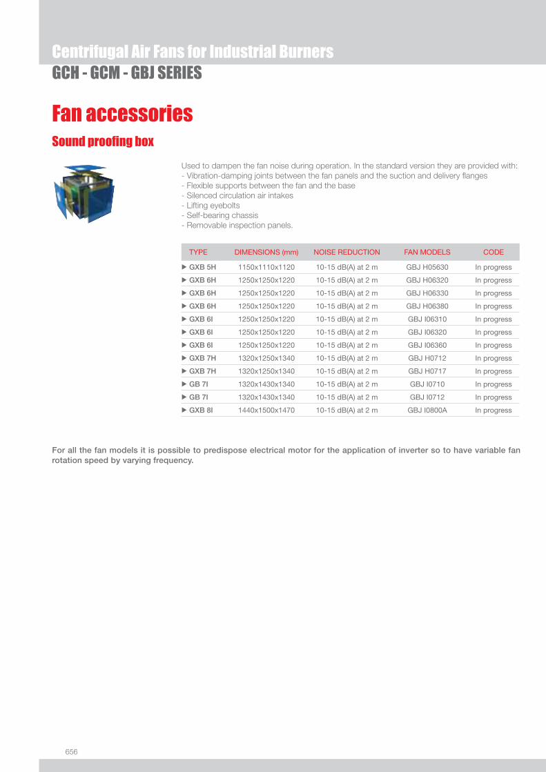
656
Fan accessories
Centrifugal Air Fans for Industrial BurnersGCH - GCM - GBJ SERIES
Sound proofi ng box
Used to dampen the fan noise during operation. In the standard version they are provided with: - Vibration-damping joints between the fan panels and the suction and delivery fl anges - Flexible supports between the fan and the base - Silenced circulation air intakes - Lifting eyebolts - Self-bearing chassis - Removable inspection panels.
For all the fan models it is possible to predispose electrical motor for the application of inverter so to have variable fan rotation speed by varying frequency.
TYPE DIMENSIONS (mm) NOISE REDUCTION FAN MODELS CODE
u GXB 5H 1150x1110x1120 10-15 dB(A) at 2 m GBJ H05630 In progress
u GXB 6H 1250x1250x1220 10-15 dB(A) at 2 m GBJ H06320 In progress
u GXB 6H 1250x1250x1220 10-15 dB(A) at 2 m GBJ H06330 In progress
u GXB 6H 1250x1250x1220 10-15 dB(A) at 2 m GBJ H06380 In progress
u GXB 6I 1250x1250x1220 10-15 dB(A) at 2 m GBJ I06310 In progress
u GXB 6I 1250x1250x1220 10-15 dB(A) at 2 m GBJ I06320 In progress
u GXB 6I 1250x1250x1220 10-15 dB(A) at 2 m GBJ I06360 In progress
u GXB 7H 1320x1250x1340 10-15 dB(A) at 2 m GBJ H0712 In progress
u GXB 7H 1320x1250x1340 10-15 dB(A) at 2 m GBJ H0717 In progress
u GB 7I 1320x1430x1340 10-15 dB(A) at 2 m GBJ I0710 In progress
u GB 7I 1320x1430x1340 10-15 dB(A) at 2 m GBJ I0712 In progress
u GXB 8I 1440x1500x1470 10-15 dB(A) at 2 m GBJ I0800A In progress

657
SYST
EM C
OMPO
NENT
S
Control Panels for Industrial Burners
QA SERIESBurner control panels are available in different structural versions, such as wall-mounted and desk tpye (on request).The automatic control system makes the logical integration of whole combustion system.The customisation of this logic is carried out with the different type of combustion process and in compliance with the main safety norms.Basic operation can be increased by the addition of more sophisticated control systems such as continuos regulation of combustion (oxygene trim), fan speed control (with inverter), electronic cam and others.The standard control panels are designed and realized according to the norm EN 60439-1. They are suitable for indoor application (IP 54), on request, suitable for outdoor applications.
QA…PM Natural GasQA…PG Light OilQA…PN Heavy OilQA…PGM Natural Gas and Light OilQA…PNM Natural Gas and heavy Oil
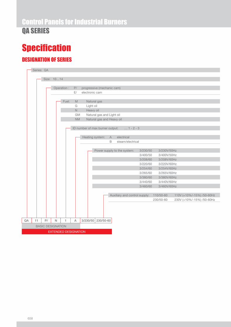
658
Control Panels for Industrial Burners QA SERIES
DESIGNATION OF SERIES
Specifi cation
EXTENDED DESIGNATION
QA 11 P/ N 1 A 3/230/50 230/50-60
Series: QA
Size: 10…14
Operation : P/ progressive (mechanic cam) E/ electronic cam
Fuel: M Natural gas G Light oil N Heavy oil GM Natural gas and Light oil NM Natural gas and Heavy oil
ID number of max burner output: … 1 - 2 - 3
Heating system: A electrical B steam/electrical
Power supply to the system: 3/230/50 3/230V/50Hz 3/400/50 3/400V/50Hz 3/208/60 3/208V/60Hz 3/220/60 3/220V/60Hz 3/254/60 3/254V/60Hz 3/265/60 3/265V/60Hz 3/380/60 3/380V/60Hz 3/440/60 3/440V/60Hz 3/460/60 3/460V/60Hz
Auxiliary and control supply: 110/50-60 110V (+10%/-15%) /50-60Hz 230/50-60 230V (+10%/-15%) /50-60Hz
BASIC DESIGNATION

659
SYST
EM C
OMPO
NENT
S
Specifi cation
QA SERIESControl Panels for Industrial Burners
STATE OF SUPPLY
Wall-mounted burner control panels for logical integration of a whole combustion system, made up of some basic components and different devices depending on applications requirments following the list and the table below.
- General switch with door interlock- Control box for ingition cycle and fl ame safeguard- Power controller (RWF 40) for modulating operation- Terminal strip with bearings- Carpentery metal structure for support and assembly of all components- Fuse block- Thermal relay- Auxilary relay and socket- Lamps.
(1) Only electrical heating type(2) Steam/electrical heating type(*) Only for burners with micromodulation system

660
Available models
QA SERIESControl Panels for Industrial Burners
MODEL MAX. BURNER POWER (kW)
QA 10 PM - 1A 3/230/50 3900
QA 10 PM - 2A 3/230/50 4600
QA 11 PM - 1A 3/230/50 5400
QA 11 PM - 2A 3/230/50 6200
QA 11 PM - 3A 3/230/50 7000
QA 12 PM - 1A 3/230/50 7700
QA 12 PM - 2A 3/230/50 8500
QA 13 PM - 1A 3/230/50 9500
QA 13 PM - 2A 3/230/50 10800
QA 14 PM - 1A 3/230/50 11600
QA 14 PM - 2A 3/230/50 12400
QA 10 PG - 1A 3/230/50 3900
QA 10 PG - 2A 3/230/50 4600
QA 11 PG - 1A 3/230/50 5400
QA 11 PG - 2A 3/230/50 6200
QA 11 PG - 3A 3/230/50 7000
QA 12 PG - 1A 3/230/50 7700
QA 12 PG - 2A 3/230/50 8500
QA 13 PG - 1A 3/230/50 9300
QA 13 PG - 2A 3/230/50 10800
QA 14 PG - 1A 3/230/50 11600
QA 14 PG - 2A 3/230/50 12400
QA 10 PN - 1A 3/230/50 3900
QA 10 PN - 2A 3/230/50 4600
QA 11 PN - 1A 3/230/50 5400
QA 11 PN - 2A 3/230/50 6200
QA 11 PN - 3A 3/230/50 7000
QA 12 PN - 1A 3/230/50 7700
QA 12 PN - 2A 3/230/50 8500
QA 13 PN - 1A 3/230/50 9300
QA 13 PN - 2A 3/230/50 10800
QA 14 PN - 1A 3/230/50 11600
QA 14 PN - 2A 3/230/50 12400
QA 10 PN - 1B 3/230/50 3900
QA 10 PN - 2B 3/230/50 5000
QA 11 PN - 1B 3/230/50 5400
QA 11 PN - 2B 3/230/50 6200
QA 11 PN - 3B 3/230/50 7000
QA 12 PN - 1B 3/230/50 7700
QA 12 PN - 2B 3/230/50 8500
QA 13 PN - 1B 3/230/50 9300
QA 13 PN - 2B 3/230/50 10800
QA 14 PN - 1B 3/230/50 11600
QA 14 PN - 2B 3/230/50 12400
MODEL MAX. BURNER POWER (kW)
QA 10 PGM - 1A 3/230/50 3900
QA 10 PGM - 2A 3/230/50 4600
QA 11 PGM - 1A 3/230/50 5400
QA 11 PGM - 2A 3/230/50 6200
QA 11 PGM - 3A 3/230/50 7000
QA 12 PGM - 1A 3/230/50 7700
QA 12 PGM - 2A 3/230/50 8500
QA 13 PGM - 1A 3/230/50 9300
QA 13 PGM - 2A 3/230/50 10800
QA 14 PGM - 1A 3/230/50 11600
QA 14 PGM - 2A 3/230/50 12400
QA 10 PNM - 1A 3/230/50 3900
QA 10 PNM - 2A 3/230/50 4600
QA 11 PNM - 1A 3/230/50 5400
QA 11 PNM - 2A 3/230/50 6200
QA 11 PNM - 3A 3/230/50 7000
QA 12 PNM - 1A 3/230/50 7700
QA 12 PNM - 2A 3/230/50 8500
QA 13 PNM - 1A 3/230/50 9300
QA 13 PNM - 2A 3/230/50 10800
QA 14 PNM - 1A 3/230/50 11600
QA 14 PNM - 2A 3/230/50 12400
QA 10 PNM - 1B 3/230/50 3900
QA 10 PNM - 2B 3/230/50 5000
QA 11 PNM - 1B 3/230/50 5400
QA 11 PNM - 2B 3/230/50 6200
QA 11 PNM - 3B 3/230/50 7000
QA 12 PNM - 1B 3/230/50 7700
QA 12 PNM - 2B 3/230/50 8500
QA 13 PNM - 1B 3/230/50 9300
QA 13 PNM - 2B 3/230/50 10800
QA 14 PNM - 1B 3/230/50 11600
QA 14 PNM - 2B 3/230/50 12400
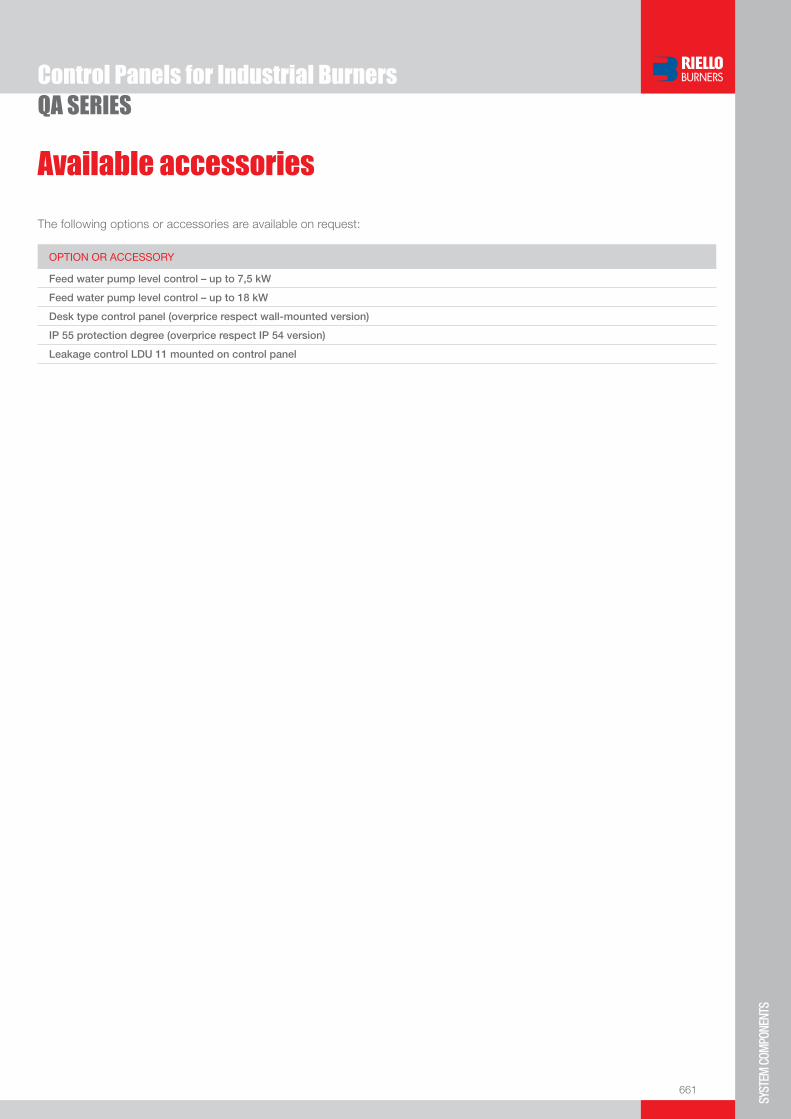
661
SYST
EM C
OMPO
NENT
S
TESTO primo accessorio
QA SERIESControl Panels for Industrial Burners
Available accessories
The following options or accessories are available on request:
OPTION OR ACCESSORY
Feed water pump level control – up to 7,5 kW
Feed water pump level control – up to 18 kW
Desk type control panel (overprice respect wall-mounted version)
IP 55 protection degree (overprice respect IP 54 version)
Leakage control LDU 11 mounted on control panel

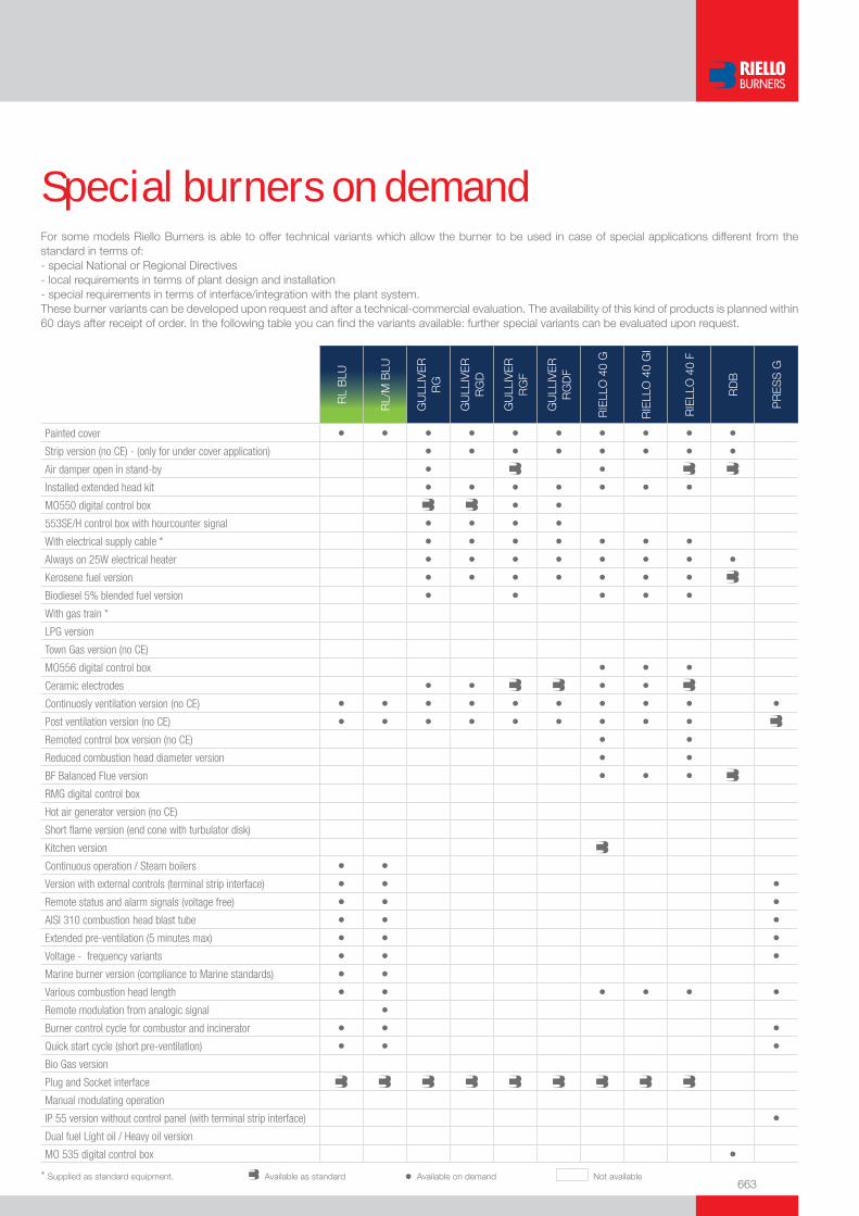
663
Special burners on demandFor some models Riello Burners is able to offer technical variants which allow the burner to be used in case of special applications different from the standard in terms of:- special National or Regional Directives- local requirements in terms of plant design and installation- special requirements in terms of interface/integration with the plant system.These burner variants can be developed upon request and after a technical-commercial evaluation. The availability of this kind of products is planned within 60 days after receipt of order. In the following table you can fi nd the variants available: further special variants can be evaluated upon request.
RL
BLU
RL/
M B
LU
GU
LLIV
ER
R
G
GU
LLIV
ER
R
GD
GU
LLIV
ER
R
GF
GU
LLIV
ER
R
GD
F
RIE
LLO
40
G
RIE
LLO
40
GI
RIE
LLO
40
F
RD
B
PR
ES
S G
Painted cover • • • • • • • • • •Strip version (no CE) - (only for under cover application) • • • • • • • •Air damper open in stand-by • •Installed extended head kit • • • • • • •MO550 digital control box • •553SE/H control box with hourcounter signal • • • •With electrical supply cable * • • • • • • •Always on 25W electrical heater • • • • • • • •Kerosene fuel version • • • • • • •Biodiesel 5% blended fuel version • • • • •With gas train *
LPG version
Town Gas version (no CE)
MO556 digital control box • • •Ceramic electrodes • • • •Continuosly ventilation version (no CE) • • • • • • • • • •Post ventilation version (no CE) • • • • • • • • •Remoted control box version (no CE) • •Reduced combustion head diameter version • •BF Balanced Flue version • • •RMG digital control box
Hot air generator version (no CE)
Short fl ame version (end cone with turbulator disk)
Kitchen version
Continuous operation / Steam boilers • •Version with external controls (terminal strip interface) • • •Remote status and alarm signals (voltage free) • • •AISI 310 combustion head blast tube • • •Extended pre-ventilation (5 minutes max) • • •Voltage - frequency variants • • •Marine burner version (compliance to Marine standards) • •Various combustion head length • • • • • •Remote modulation from analogic signal •Burner control cycle for combustor and incinerator • • •Quick start cycle (short pre-ventilation) • • •Bio Gas version
Plug and Socket interface
Manual modulating operation
IP 55 version without control panel (with terminal strip interface) •Dual fuel Light oil / Heavy oil version
MO 535 digital control box •* Supplied as standard equipment. Available as standard • Available on demand Not available
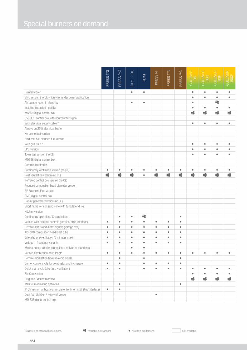
664664
PR
ES
S T
/G
PR
ES
S P
/G
RL/
1 -
RL
RL/
M
PR
ES
S N
PR
ES
S T
/N
PR
ES
S P
/N
GU
LLIV
ER
B
S
GU
LLIV
ER
B
SD
GU
LLIV
ER
B
SF
GU
LLIV
ER
B
SD
F
Painted cover • • • • • •Strip version (no CE) - (only for under cover application) • • • •Air damper open in stand-by • • •Installed extended head kit • • • •MG569 digital control box
553SE/H control box with hourcounter signal
With electrical supply cable * • • • •Always on 25W electrical heater
Kerosene fuel version
Biodiesel 5% blended fuel version
With gas train * • • • •LPG version • • • •Town Gas version (no CE) • • • •MO556 digital control box
Ceramic electrodes
Continuosly ventilation version (no CE) • • • • • • • • • • •Post ventilation version (no CE) •Remoted control box version (no CE)
Reduced combustion head diameter version
BF Balanced Flue version
RMG digital control box
Hot air generator version (no CE)
Short fl ame version (end cone with turbulator disk)
Kitchen version
Continuous operation / Steam boilers • • •Version with external controls (terminal strip interface) • • • • • • •Remote status and alarm signals (voltage free) • • • • • • •AISI 310 combustion head blast tube • • • • • • •Extended pre-ventilation (5 minutes max) • • • • • • •Voltage - frequency variants • • • • • • •Marine burner version (compliance to Marine standards) • •Various combustion head length • • • • • • • • • • •Remote modulation from analogic signal • • •Burner control cycle for combustor and incinerator • • • • • •Quick start cycle (short pre-ventilation) • • • • • • • • • •Bio Gas version • • • •Plug and Socket interface
Manual modulating operation • •IP 55 version without control panel (with terminal strip interface) • •Dual fuel Light oil / Heavy oil version •MO 535 digital control box
* Supplied as standard equipment. Available as standard • Available on demand Not available
Special burners on demand

665
RS
/M B
LU
RS
/E B
LU
RIE
LLO
40
GS
RIE
LLO
40
GS
D
RIE
LLO
40
FS
RIE
LLO
40
FSD
GU
LLIV
ER
R
S
GU
LLIV
ER
R
SD
GU
LLIV
ER
R
SF
GU
LLIV
ER
R
SD
F
GA
S
Painted cover • • • • • • • • • •Strip version (no CE) - (only for under cover application) • • • • • • • •Air damper open in stand-by • •Installed extended head kit • • • • • • • •MG569 digital control box
553SE/H control box with hourcounter signal
With electrical supply cable * • • • • • • • •Always on 25W electrical heater
Kerosene fuel version
Biodiesel 5% blended fuel version
With gas train * • • • • • • • •LPG version • • • • • • • • • • •Town Gas version (no CE) • • • • • • • • •MG557 digital control box
Ceramic electrodes
Continuosly ventilation version (no CE) • • • • • • • • • •Post ventilation version (no CE) • • • • • •Remoted control box version (no CE)
Reduced combustion head diameter version
BF Balanced Flue version • •RMG digital control box • • • •Hot air generator version (no CE) • •Short fl ame version (end cone with turbulator disk) • • •Kitchen version •Continuous operation / Steam boilers • •Version with external controls (terminal strip interface) • • •Remote status and alarm signals (voltage free) • • •AISI 310 combustion head blast tube • • •Extended pre-ventilation (5 minutes max) • • •Voltage - frequency variants • • •Marine burner version (compliance to Marine standards)
Various combustion head length • • • • • • • • • • •Remote modulation from analogic signal • •Burner control cycle for combustor and incinerator • •Quick start cycle (short pre-ventilation) • • • • • • •Bio Gas version • • • • • • • • •Plug and Socket interface
Manual modulating operation
IP 55 version without control panel (with terminal strip interface)
Dual fuel Light oil / Heavy oil version
MO 535 digital control box
* Supplied as standard equipment. Available as standard • Available on demand Not available
Special burners on demand

666666
GA
S/2
GA
S P
/M
RS
/1 -
RS
RS
/M
RS
/E M
Z
RLS
/M M
X
RLS
RLS
/M M
Z
GI/E
MM
ETw
o S
tage
GI/E
MM
EM
odul
atin
g
EN
NE
/EM
ME
Painted cover • • • • • •Strip version (no CE) - (only for under cover application)
Air damper open in stand-by
Installed extended head kit • • • • •MO550 digital control box
553SE/H control box with hourcounter signal
With electrical supply cable *
Always on 25W electrical heater
Kerosene fuel version
Biodiesel 5% blended fuel version
With gas train *
LPG version • • • • • • • • • • •Town Gas version (no CE) • • • • •MO556 digital control box
Ceramic electrodes
Continuosly ventilation version (no CE) • • • • • • • • • • •Post ventilation version (no CE) • • • • • • • •Remoted control box version (no CE)
Reduced combustion head diameter version
BF Balanced Flue version
RMG digital control box
Hot air generator version (no CE)
Short fl ame version (end cone with turbulator disk)
Kitchen version
Continuous operation / Steam boilers • • • • • • • • •Version with external controls (terminal strip interface) • • • • • • • • • • •Remote status and alarm signals (voltage free) • • • • • • • • • • •AISI 310 combustion head blast tube • • • • • •Extended pre-ventilation (5 minutes max) • • • • • • • • • • •Voltage - frequency variants • • • • • • • • • • •Marine burner version (compliance to Marine standards)
Various combustion head length • • • • • • • • • • •Remote modulation from analogic signal • • • • • • •Burner control cycle for combustor and incinerator • • • • • • • • • •Quick start cycle (short pre-ventilation) • • • • • • • • • • •Bio Gas version • • • • • • • • • • •Plug and Socket interface • •Manual modulating operation • •IP 55 version without control panel (with terminal strip interface)
Dual fuel Light oil / Heavy oil version
MO 535 digital control box
* Supplied as standard equipment. Available as standard • Available on demand Not available
Special burners on demand

667
Request for informationIf you did not fi nd the product for your application in this catalogue, please fi ll in the following form and send it to RIELLO BURNERS APPLICATION ENGINEERING DEPT. (fax +39 0442 630 375 - [email protected])
������� ����� ������� ����������� ������
����������� ���������� ���
������������� ����
������
����������� ������������������� ��
������������������
����������� ����������
������������������������ ��� �����
���
!��������� ���������������� ������� ��������
��������� ����� ��� ��
���������������������� ������ ����
����� �������������
����������������� "����������
!�������
!"����
#��$�����
���������� ��������� �����
��
%����&�'�������
()�*��'�����������
�����$��������+,%-.�������������
#���$��% ������� ������
"�����&��������
%�/����-��
0���1��
0�/�����������
%�����$�1��
2�1����������
*��������
%�����$�����
��3�1����/������ � � � � � ���� ��3�1����/�������� � � � � ��� 4� %���� � � � � ��� �����
0������ *1���������*1������
%��/��������*1������
'������� ����������������5������
������
2�/�� ��
-���� ��
0�/� ��
��$�� ��
�������
����������$���6����� ��
�������/��
2�/������
27�
0�� ����
*�1��/��
8���
"��������� ,������� �
2�1� ��������� �����
#/������/�/������� %��� �/������� 2���/�������
'������%���$�$��'��)9:;�'��9:9 �����<������%���$�$��=2�)>9;�=2�:>?
%��/������
-��������� -���������
%��/������ '�������
()���� �<��� ���
'�� �� ������� +7�1������/���������������/����@��� .
ABB�)!B�?B !CB�))B�9B )DB�D)B�9B AAB�))B�9B )!B�)!B�?B ������������������
<�����$ �������� *����� 4�E�$�� (��$��
9��%�����)B4� !4'����?B4� )B4'����?B4� ?B4'����?B4� C?4'����?B4�
��� ������/�����/


669
Sales & Service Network
WEST EUROPE RESIDENTIALBURNERS
COMMERCIALBURNERS
INDUSTRIALBURNERS
COUNTRY COMPANY REFERENCES FOR CONTACT
ALBANIA Name: Ergeda VulcanoAddress: Brigada 8 str. 8/1 Build.City: Tirana
Office Phone:355 4 237273Office Fax:355 4 237273e-mail: [email protected]
BELGIUM Name: Riello S.A./N.V.Address: Waverstraat 3City: B-9310 Aalst-Moorsel
Office Phone: 0032 53 769030Office Fax: 0032 53 789440e-mail: [email protected]
Name: Geveke Climate TechnologyAddress: Leuvenseweg 250 ACity: B-1800 Vilvoorde
Office Phone: +32 2 257 10 03Office Fax: +32 2 257 10 08e-mail: [email protected]
CYPRUS Name: Royal Engineering Co. Ltd.Address: 1, Prodicou Str. P.O. Box 20689City: 1662 Nicosia
Office Phone: +357-2-344985 / 347782Office Fax: +357 - 2 - 348436Mobile Phone: +35-09-657192e-mail: [email protected]
DENMARK Name: Milton A/SAddress: Kornmarksvej 8-10City: D.K. 2605 Brøndby
Office Phone: +45 46970000Office Fax: +45 46970001e-mail: [email protected]
FINLAND Name: Oy Callidus AbAddress: Hiekkakiventie 1City: 00710 Helsinki
Office Phone: 09 3747 51Office Fax: 09 3747 5505e-mail: [email protected]:www.callidus.fi
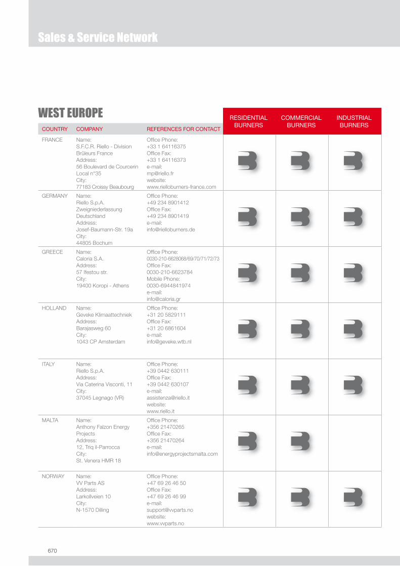
670670
WEST EUROPE RESIDENTIALBURNERS
COMMERCIALBURNERS
INDUSTRIALBURNERS
COUNTRY COMPANY REFERENCES FOR CONTACT
FRANCE Name: S.F.C.R. Riello - Division Brûleurs FranceAddress: 56 Boulevard de CourcerinLocal n°35City: 77183 Croissy Beaubourg
Office Phone: +33 1 64116375Office Fax: +33 1 64116373e-mail: [email protected]:www.rielloburners-france.com
GERMANY Name: Riello S.p.A. Zweigniederlassung DeutschlandAddress: Josef-Baumann-Str. 19aCity: 44805 Bochum
Office Phone: +49 234 8901412Office Fax: +49 234 8901419e-mail: [email protected]
GREECE Name: Caloria S.A.Address: 57 Ifestou str.City: 19400 Koropi - Athens
Office Phone: 0030-210-6628068/69/70/71/72/73Office Fax: 0030-210-6623784Mobile Phone:0030-6944841974e-mail: [email protected]
HOLLAND Name: Geveke KlimaattechniekAddress: Barajasweg 60City: 1043 CP Amsterdam
Office Phone: +31 20 5829111Office Fax: +31 20 6861604e-mail: [email protected]
ITALY Name: Riello S.p.A.Address: Via Caterina Visconti, 11City: 37045 Legnago (VR)
Office Phone: +39 0442 630111Office Fax: +39 0442 630107e-mail: [email protected]:www.riello.it
MALTA Name: Anthony Falzon Energy ProjectsAddress: 12, Triq il-ParroccaCity: St. Venera HMR 18
Office Phone: +356 21470265Office Fax: +356 21470264e-mail: [email protected]
NORWAY Name: VV Parts ASAddress: Larkollveien 10City: N-1570 Dilling
Office Phone: +47 69 26 46 50Office Fax: +47 69 26 46 99e-mail: [email protected]: www.vvparts.no
Sales & Service Network

671
WEST EUROPE RESIDENTIALBURNERS
COMMERCIALBURNERS
INDUSTRIALBURNERS
COUNTRY COMPANY REFERENCES FOR CONTACT
PORTUGAL Name: Eclipse Combustion S.A.Address: Santander, 71City: 08020 Barcelona
Office Phone: +34 93 4980400Office Fax: +34 93 4980410website:www.eclipsenet.com
Name:GaleciaAddress:Rua dos Combatentes, 681City:4485 - 093 FajozesVila Do Conde
Office Phone:+351 252 660500Office Fax: +351 252 660501e-mail: [email protected]
SPAIN Name: Eclipse Combustion S.A.Address: Santander, 71City: 08020 Barcelona
Office Phone: +34 93 4980400Office Fax: +34 93 4980410website:www.eclipsenet.com
SWITZERLAND Name: Riello Suisse S.A.Address: Via IndustriaCity: CH-6814 Lamone
Office Phone: +41/91/6045022Office Fax: +41/91/6045024Mobile Phone:+41/79/2070551e-mail: [email protected]
SWEDEN Name: Milton Sverige ABAddress: Lastgatan 13City: 254 64 Helsingborg
Office Phone: +46 042252840Office Fax: +46 042158621e-mail: [email protected]:www.milton.se
UK Name: Riello Ltd.Address: The Ermine Centre Ermine Business ParkCity: Huntingdon Cambridgeshire PE29 6WX
Office Phone: +44 1480432144Office Fax: +44 1480432191e-mail: [email protected]
Sales & Service Network
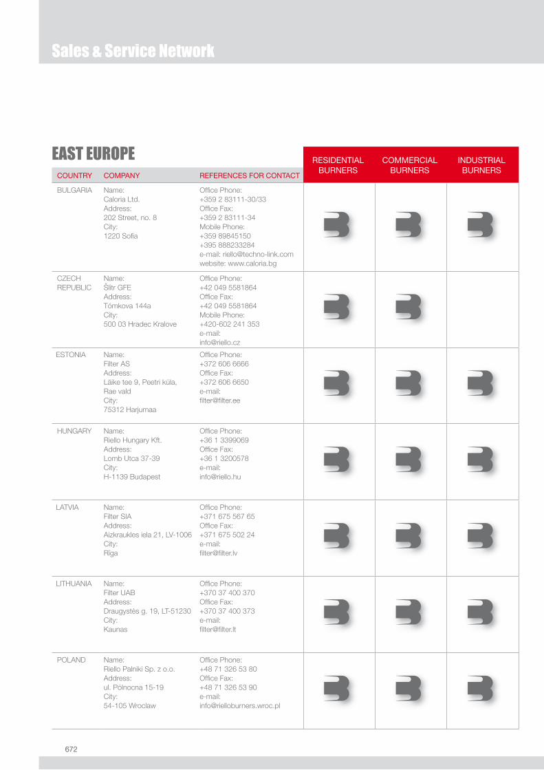
672672
Sales & Service Network
EAST EUROPE RESIDENTIALBURNERS
COMMERCIALBURNERS
INDUSTRIALBURNERS
COUNTRY COMPANY REFERENCES FOR CONTACT
BULGARIA Name: Caloria Ltd.Address: 202 Street, no. 8City: 1220 Sofia
Office Phone: +359 2 83111-30/33Office Fax: +359 2 83111-34Mobile Phone: +359 89845150 +395 888233284e-mail: [email protected]: www.caloria.bg
CZECHREPUBLIC
Name: Slitr GFEAddress: Tómkova 144aCity: 500 03 Hradec Kralove
Office Phone: +42 049 5581864Office Fax: +42 049 5581864Mobile Phone: +420-602 241 353e-mail: [email protected]
ESTONIA Name:Filter ASAddress: Läike tee 9, Peetri küla, Rae valdCity: 75312 Harjumaa
Office Phone: +372 606 6666Office Fax: +372 606 6650e-mail: [email protected]
HUNGARY Name: Riello Hungary Kft.Address: Lomb Utca 37-39City: H-1139 Budapest
Office Phone: +36 1 3399069Office Fax: +36 1 3200578e-mail: [email protected]
LATVIA Name:Filter SIAAddress: Aizkraukles iela 21, LV-1006 City:Riga
Office Phone: +371 675 567 65Office Fax: +371 675 502 24e-mail: [email protected]
LITHUANIA Name:Filter UABAddress: Draugystes g. 19, LT-51230City: Kaunas
Office Phone: +370 37 400 370Office Fax: +370 37 400 373e-mail: [email protected]
POLAND Name: Riello Palniki Sp. z o.o.Address: ul. Pólnocna 15-19City: 54-105 Wroclaw
Office Phone: +48 71 326 53 80Office Fax: +48 71 326 53 90e-mail: [email protected]
.

673
EAST EUROPE RESIDENTIALBURNERS
COMMERCIALBURNERS
INDUSTRIALBURNERS
COUNTRY COMPANY REFERENCES FOR CONTACT
ROMANIA Name:SC Riello RO S.r.l.Address:Str. Siret nr.95, sect.1City:012152 Bucuresti
Office Phone: +40 21 2246648 Office Fax: +40 21 2029287e-mail: [email protected]
RUSSIA Name: Riello S.p.A.Representative Office in CISAddress: Malaya Kaluzhskaya StreetCity: 117927 Moscow
Office Phone: +7-495-7851485Office Fax: +7-495-7851486e-mail: [email protected]
SLOVAKREPUBLIC
Name: Iseng-Mont s.r.o.Address: Cervenej Arnady, 18City: 93401 Levice
Office Phone: +421-36-6313240/6313042Office Fax: +421-36-6319248e-mail: [email protected]
UKRAINE Name: Riello S.p.A.Representative Office in CISAddress: Otto Shmidta str. 26bCity: 04107 Kiev
Office Phone: +38 (044) 239-97-31Office Fax: +38 (044) 239-97-31e-mail:[email protected]
Sales & Service Network
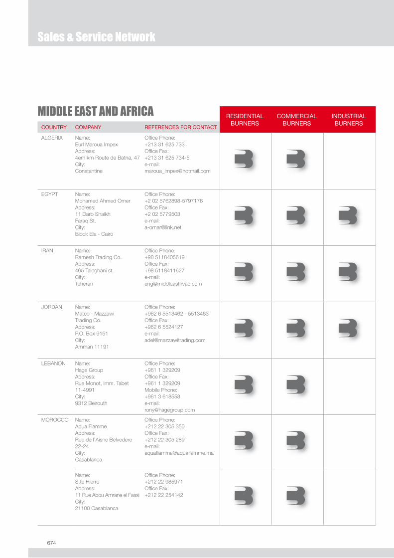
674674
MIDDLE EAST AND AFRICA RESIDENTIALBURNERS
COMMERCIALBURNERS
INDUSTRIALBURNERS
COUNTRY COMPANY REFERENCES FOR CONTACT
ALGERIA Name: Eurl Maroua ImpexAddress: 4em km Route de Batna, 47City: Constantine
Office Phone: +213 31 625 733Office Fax: +213 31 625 734-5e-mail:[email protected]
EGYPT Name: Mohamed Ahmed OmerAddress: 11 Darb ShaikhFaraq St.City: Block Ela - Cairo
Office Phone: +2 02 5762898-5797176Office Fax: +2 02 5779503e-mail:[email protected]
IRAN Name: Ramesh Trading Co.Address: 465 Taleghani st.City: Teheran
Office Phone: +98 5118405619Office Fax: +98 5118411627e-mail:[email protected]
JORDAN Name: Matco - Mazzawi Trading Co.Address: P.O. Box 9151City: Amman 11191
Office Phone: +962 6 5513462 - 5513463Office Fax: +962 6 5524127e-mail: [email protected]
LEBANON Name: Hage GroupAddress: Rue Monot, Imm. Tabet11-4991City: 9312 Beirouth
Office Phone: +961 1 329209Office Fax: +961 1 329209Mobile Phone: +961 3 618558e-mail: [email protected]
MOROCCO Name: Aqua FlammeAddress: Rue de l’Aisne Belvedere 22-24City: Casablanca
Office Phone: +212 22 305 350Office Fax: +212 22 305 289e-mail: [email protected]
Name: S.te HierroAddress: 11 Rue Abou Amrane el FassiCity: 21100 Casablanca
Office Phone: +212 22 985971Office Fax: +212 22 254142
Sales & Service Network
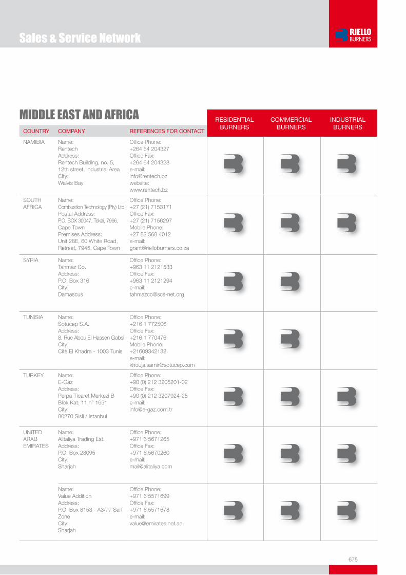
675
MIDDLE EAST AND AFRICA RESIDENTIALBURNERS
COMMERCIALBURNERS
INDUSTRIALBURNERS
COUNTRY COMPANY REFERENCES FOR CONTACT
NAMIBIA Name: RentechAddress:Rentech Building, no. 5, 12th street, Industrial AreaCity: Walvis Bay
Office Phone: +264 64 204327Office Fax: +264 64 204328e-mail:[email protected]:www.rentech.bz
SOUTHAFRICA
Name: Combustion Technology (Pty) Ltd.Postal Address: P.O. BOX 30047, Tokai, 7966, Cape TownPremises Address:Unit 28E, 60 White Road, Retreat, 7945, Cape Town
Office Phone: +27 (21) 7153171Office Fax: +27 (21) 7156297Mobile Phone:+27 82 568 4012e-mail:[email protected]
SYRIA Name: Tahmaz Co.Address: P.O. Box 316City: Damascus
Office Phone: +963 11 2121533Office Fax: +963 11 2121294e-mail:[email protected]
TUNISIA Name: Sotucep S.A.Address: 8, Rue Abou El Hassen GabsiCity: Citè El Khadra - 1003 Tunis
Office Phone: +216 1 772506Office Fax: +216 1 770476Mobile Phone: +21609342132e-mail:[email protected]
TURKEY Name:E-GazAddress:Perpa Ticaret Merkezi B Blok Kat: 11 n° 1651City:80270 Sisli / Istanbul
Office Phone: +90 (0) 212 3205201-02Office Fax: +90 (0) 212 3207924-25e-mail:[email protected]
UNITED ARAB EMIRATES
Name: Alitaliya Trading Est.Address: P.O. Box 28095City: Sharjah
Office Phone: +971 6 5671265Office Fax: +971 6 5670260e-mail:[email protected]
Name: Value AdditionAddress: P.O. Box 8153 - A3/77 Saif ZoneCity: Sharjah
Office Phone: +971 6 5571699Office Fax: +971 6 5571678e-mail:[email protected]
Sales & Service Network

676676
Sales & Service Network
FAR EAST AND OCEANIA RESIDENTIALBURNERS
COMMERCIALBURNERS
INDUSTRIALBURNERS
COUNTRY COMPANY REFERENCES FOR CONTACT
AUSTRALIA Name: AccuthermAddress: Unit 1/5 Samantha CourtCity: Knoxfield 3180 Victoria
Office Phone: +61 3 97636335Office Fax: +61 3 97638003e-mail:[email protected]
Name: System Control Engineering PTY. LTD.Address: 5 Alfred Street, Blackburn, Victoria 3130 City: Melbourne
Office Phone: +61 3 9877 3211 Office Fax: +61 3 9878 5337 e-mails: [email protected] [email protected]: www.systemcontrol.com.au
CHINA Name: Riello Beijing Representative OfficeAddress: Rm. 1915, Gemdale Plaza Tower B, No. 91 Jianguo Road Chaoyang DistrictCity: 100022 Beijing
Office Phone: +86 10 6563 0131Office Fax: +86 10 6566 2772e-mail:[email protected]
INDIA Name: Suntec Energy SystemsAddress: “Sambhaav House”Bodakdev, VastrapurCity: 380015 Ahmedabad
Office Phone: +91 79 26871911Office Fax: +91 79 26871990e-mail: [email protected]
INDONESIA Name: Pt. Unitek StandarindoAddress: Jl. Pangeran Jayakarta 44/29,Complex Hotel MercureCity: 10730 Jakarta
Office Phone: +62 21 6289456 - 6264806Office Fax: +62 21 6264807 e-mail:[email protected]
JAPAN Name: Riello Japan Inc.Address: c/o NFK 1-53,2-Chome, ShitteTsurumi-ku, P.O. Box 280 City: Yokohama
Office Phone: +81 455758097Office Fax: +81 455758099e-mail:[email protected]
KOREA Name: Chungwoo Gnt. Co. Ltd.Address: 1Ma – 715Ho 1695, Jeongwang-dong, Kyunggi-do, 429-915City: Shihung-city
Office Phone: +82 31 4972041Office Fax: +82 31 4972048Website: http://cwgnt.co.kr
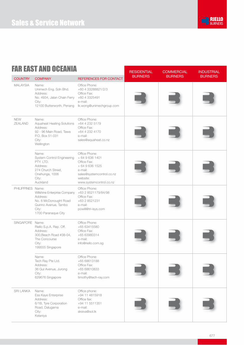
677
FAR EAST AND OCEANIA RESIDENTIALBURNERS
COMMERCIALBURNERS
INDUSTRIALBURNERS
COUNTRY COMPANY REFERENCES FOR CONTACT
MALAYSIA Name: Unimech Eng. Sdn Bhd.Address: No. 4934, Jalan Chain FerryCity: 12100 Butterworth, Penang
Office Phone: +60 4 33288821/2/3Office Fax: +60 4 3325491e-mail: [email protected]
NEWZEALAND
Name: Aquaheat Heating SolutionsAddress: 92 - 96 Main Road, TawaP.O. Box 51-031City: Wellington
Office Phone: +64 4 232 5179Office Fax: +64 4 232 4170e-mail: [email protected]
Name: System Control Engineering PTY. LTD.Address: 274 Church Street, Onehunga, 1006City: Auckland
Office Phone: + 64 9 636 1401Office Fax: + 64 9 636 1525e-mail: [email protected]: www.systemcontrol.co.nz
PHILIPPINES Name: Willshine Enterprise CompanyAddress: No. 6 McDonought RoadQuirino Avenue, TamboCity: 1700 Paranaque City
Office Phone: +63 2 8521179/84/98Office Fax: +63 2 8521231e-mail:[email protected]
SINGAPORE Name: Riello S.p.A. Rep. Off.Address: 300,Beach Road #38-04, The ConcourseCity: 199555 Singapore
Office Phone: +65 63415580Office Fax: +65 63980314e-mail: [email protected]
Name: Tech Ray Pte Ltd.Address: 36 Gul Avenue, JurongCity: 629676 Singapore
Office Phone: +65 68613188Office Fax: +65 68610833e-mail: [email protected]
SRI LANKA Name: Ess Kaye EnterpriseAddress: 6/1B, Tyre Corporation Road, Dalugama City:Kelaniya
Office phone: +94 11 4815918 Office fax: +94 11 5511351 e-mail:[email protected]
Sales & Service Network
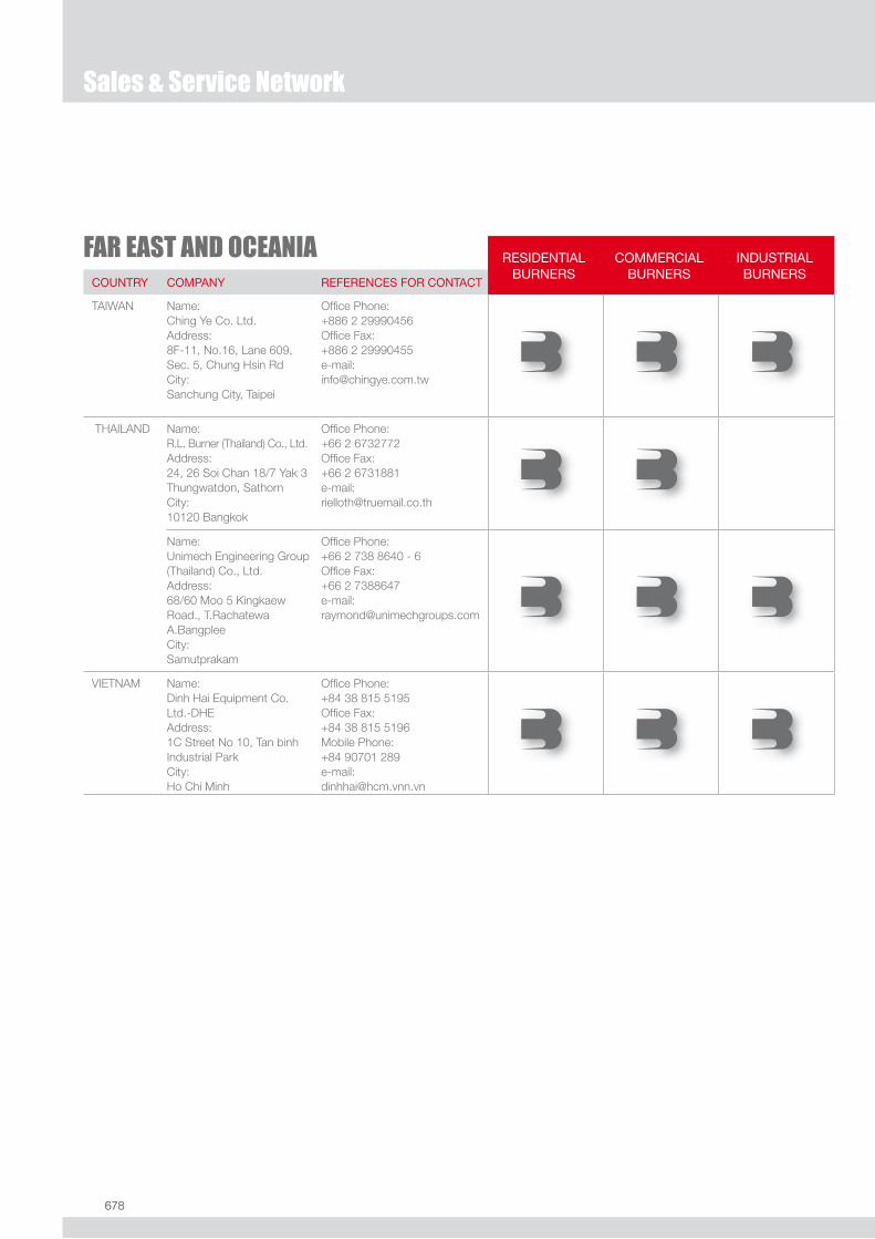
678678
Sales & Service Network
FAR EAST AND OCEANIA RESIDENTIALBURNERS
COMMERCIALBURNERS
INDUSTRIALBURNERS
COUNTRY COMPANY REFERENCES FOR CONTACT
TAIWAN Name: Ching Ye Co. Ltd.Address: 8F-11, No.16, Lane 609, Sec. 5, Chung Hsin RdCity: Sanchung City, Taipei
Office Phone: +886 2 29990456Office Fax: +886 2 29990455e-mail: [email protected]
THAILAND Name: R.L. Burner (Thailand) Co., Ltd.Address: 24, 26 Soi Chan 18/7 Yak 3Thungwatdon, SathornCity: 10120 Bangkok
Office Phone: +66 2 6732772Office Fax: +66 2 6731881e-mail: [email protected]
Name:Unimech Engineering Group (Thailand) Co., Ltd.Address:68/60 Moo 5 Kingkaew Road., T.Rachatewa A.Bangplee City: Samutprakam
Office Phone:+66 2 738 8640 - 6Office Fax: +66 2 7388647e-mail:[email protected]
VIETNAM Name: Dinh Hai Equipment Co. Ltd.-DHEAddress: 1C Street No 10, Tan binh Industrial ParkCity: Ho Chi Minh
Office Phone: +84 38 815 5195Office Fax: +84 38 815 5196Mobile Phone: +84 90701 289e-mail: [email protected]

679
AMERICA RESIDENTIALBURNERS
COMMERCIALBURNERS
INDUSTRIALBURNERS
COUNTRY COMPANY REFERENCES FOR CONTACT
BRAZIL Name: Auto-Ferr Ind. e Com. de Queimadores Ltda.Address: Av. Álvaro Guimarães, 322 09890-001 Bairro Planalto City: São Bernardo do Campo
Office Phone: +55 11 4341-4894Office Fax: +55 11 4341-6501e-mail:[email protected]:www.riello.com.br
CANADA Name: Riello Burners North AmericaAddress: 2165 Meadowpine Blvd.City: L5N 6H6 Mississauga (Ontario)
Office Phone: +1-800-4-RIELLO+1-800-474-3556Office Fax: +1-866-2-RIELLOe-mail:[email protected]
CHILE Name: Anwo S.A.Address: Los Orfebres 380Parque Ind. La ReinaCity: Santiago de Chile
Office Phone: +56 2 7310000Office Fax: +56 2 2730404Mobile Phone: 096791004e-mail: [email protected]:www.anwo.cl
COLOMBIA Name:Indisa S.A.Address: Cra. 75 no. 48A-27City: 55812 Medellin
Office Phone: +57 4 2605533Office Fax: +57 4 2308388e-mail: [email protected]:www.indisa.com.co
CUBA Name: Air Tecnia S.A. de C.V.Address: Calle 24 105 apto. Entra 1ra y 3ra MiramarCity: Playa
Office Phone: +537240064Office Fax: +537249660e-mail: [email protected]
MEXICO Name: Controles y Quemadores de Mexico, S.A. de C.V.Address: Blvd. Hermanos Serdan, 41 Col. AmorCity: Puebla
Office Phone: 0052 22 480817Office Fax: 0052 22 480817e-mail: [email protected]:www.cqmexico.com.mx
PANAMA Name: Servipan S.A.Address: Calle Principal Altos de Bethania 3C - Apartado 6 City: 2680 El Dorado Panama
Office Phone: +507 2600748Office Fax: +507 2606342e-mail: [email protected]
Sales & Service Network
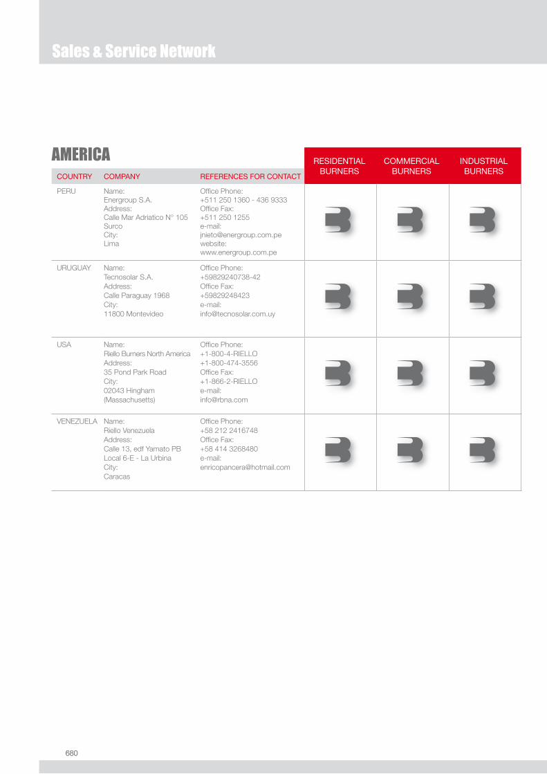
680680
Sales & Service Network
AMERICA RESIDENTIALBURNERS
COMMERCIALBURNERS
INDUSTRIALBURNERS
COUNTRY COMPANY REFERENCES FOR CONTACT
PERU Name: Energroup S.A.Address: Calle Mar Adriatico N° 105Surco City: Lima
Office Phone: +511 250 1360 - 436 9333Office Fax: +511 250 1255e-mail: [email protected]:www.energroup.com.pe
URUGUAY Name: Tecnosolar S.A.Address: Calle Paraguay 1968City: 11800 Montevideo
Office Phone: +59829240738-42Office Fax: +59829248423e-mail: [email protected]
USA Name: Riello Burners North AmericaAddress: 35 Pond Park RoadCity: 02043 Hingham (Massachusetts)
Office Phone: +1-800-4-RIELLO+1-800-474-3556Office Fax: +1-866-2-RIELLOe-mail:[email protected]
VENEZUELA Name: Riello VenezuelaAddress: Calle 13, edf Yamato PB Local 6-E - La Urbina City: Caracas
Office Phone: +58 212 2416748Office Fax: +58 414 3268480e-mail:[email protected]

BURNERS PRODUCTION PLANTS. Pietro - Legnago (Verona), Italy
COMBUSTION RESEARCH CENTREAngiari (Verona) - Italy
Technical Sales CatalogueMarch 2008
RIELLO S.p.A.
Via Ing. Pilade Riello, 537045 Legnago (VR) ItalyTel. +39.0442.630111 - Fax +39.0442.21980www.rielloburners.com - [email protected]
Riello Burners is a brand of Riello Group.
Since the Company is constantly engaged in the production improvement, the aesthetic and dimensional features, the technical data, the equipment and the accessories can be changed.This document contains confi dential and proprietary information of RIELLO S.p.A. Unless authorised, this information shall not be divulged, nor duplicated in whole or in part.
DO
RS
O