Technical Report II - Electrical Systems
11
-
Upload
khangminh22 -
Category
Documents
-
view
0 -
download
0
Transcript of Technical Report II - Electrical Systems

Michael P. Gardner
Eastern united states
Technical Report IInovember 4, 2008
a mixed-use project in the
lighting/electrical
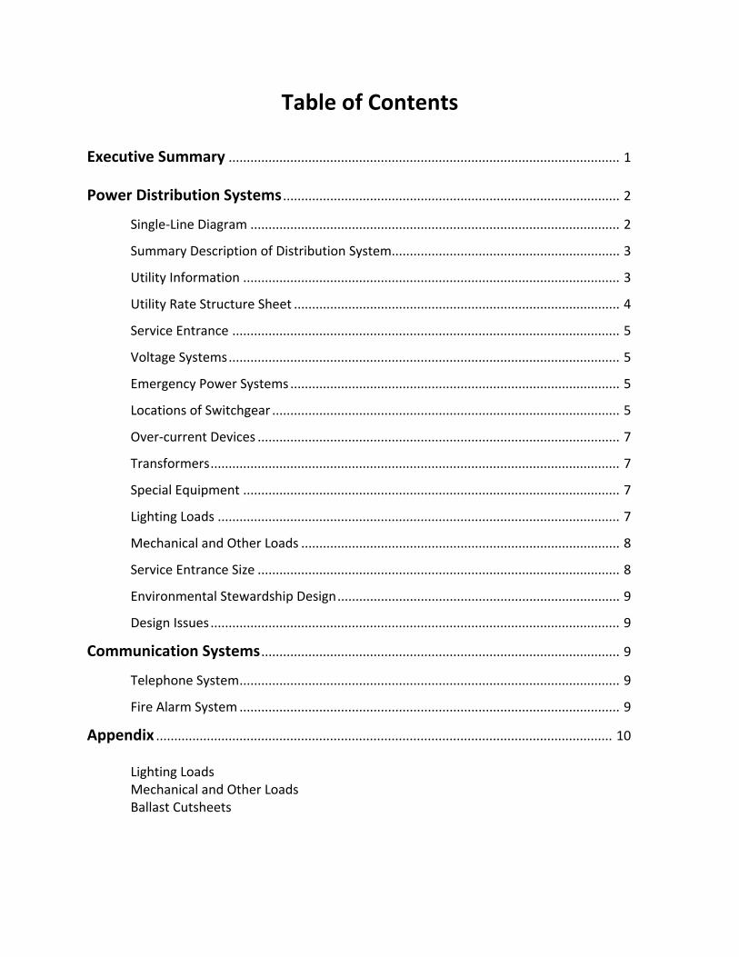
Table of Contents Executive Summary ............................................................................................................ 1 Power Distribution Systems ............................................................................................. 2
Single‐Line Diagram ...................................................................................................... 2
Summary Description of Distribution System............................................................... 3
Utility Information ........................................................................................................ 3
Utility Rate Structure Sheet .......................................................................................... 4
Service Entrance ........................................................................................................... 5
Voltage Systems ............................................................................................................ 5
Emergency Power Systems ........................................................................................... 5
Locations of Switchgear ................................................................................................ 5
Over‐current Devices .................................................................................................... 7
Transformers ................................................................................................................. 7
Special Equipment ........................................................................................................ 7
Lighting Loads ............................................................................................................... 7
Mechanical and Other Loads ........................................................................................ 8
Service Entrance Size .................................................................................................... 8
Environmental Stewardship Design .............................................................................. 9
Design Issues ................................................................................................................. 9
Communication Systems ................................................................................................... 9
Telephone System ......................................................................................................... 9
Fire Alarm System ......................................................................................................... 9
Appendix .............................................................................................................................. 10 Lighting Loads Mechanical and Other Loads Ballast Cutsheets
Michael P. Gardner Lighting/Electrical Professor Ted Dannerth Mixed‐Use Project Metropolitan Eastern United States November 4, 2008 Technical Report 2
Executive Summary This building is a mixed‐use project currently being constructed in a metropolitan area in the eastern United States. It has nine stories above grade and four levels underground. On the ground floor is primarily retail space with the floors above housing residential apartment units and some office space.
The electrical service is supplied by PEPCO and uses three transformers to step down the building’s voltage to 208Y/120. The system uses a 230 kW generator to back‐up the fire alarm, sprinklers, emergency lighting, and crucial communication systems. A significant percentage of the building’s lighting load comes from the 185 residential apartments which use various luminaires containing incandescent, halogen, and compact fluorescent sources.
The total load contributed by mechanical and other equipment was calculated to be
approximately 600 kW. The sizing of the service entrance in the Construction Document phase was found to be 3,000 A which seems to be too small for a 280,000 square‐foot building.
Information necessary to perform calculations and create the single‐line diagram was obtained from the project’s construction documents.

Michael P. Gardner
Technical Report 2
[2]
Power Distribution Systems
Below is a listing of the documents used in creating the single‐line diagram. Single‐Line Diagram Drawing List E5.1 – Main Electric Room G1 Level E5.2 – Electrical Service, 250v Service E5.3 – Electrical House Service, 250v Service E5.4 – Electrical Risers for Dwelling Units
Single‐Line Diagram Drawing
See the attached Single‐Line Drawing and Feeder Schedule for an aid in understanding power distribution throughout the building.
Michael P. Gardner
Technical Report 2
[3]
Summary Description of Distribution System
The utility provider (PEPCO) supplies three transformers in the transformer vault rooms
located on the ground floor. They step down the voltage to either 208Y/120V or to 480Y/277V. From there, power flows to the electrical room where it splits and travels to five fused disconnect switches (designated as Main #1‐#5). From Main #1 and #2, power is distributed to meter stacks #1 and #2. Feeders are then routed to various electrical panels in apartment units. From Main #3, power is distributed in two separate directions. One direction is to the gym floor, and the other is to the penthouse level electrical room. From the penthouse level, feeders are routed to various electrical panels in apartment units on the upper floors of the building. Main #4 protects panelboards in the lower ground floors, while power flows through Main #5 to the penthouse mechanical equipment (cooling towers, roof‐top units, and panelboards). Elevators are powered through the main line tapped at the PEPCO C/T Cabinet and backed up by an emergency system. If power failure from the utility occurs, an emergency generator continues to power them.
Utility Company Information
Name and Location: PEPCO 701 Ninth Street, N.W. Washington, DC www.pepco.com
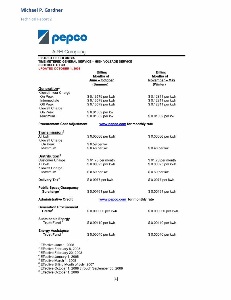
Rate Structure: See attached utility rate structure sheet.
Michael P. Gardner
Technical Report 2
[4]
Michael P. Gardner
Technical Report 2
[5]
Service Entrance
The point where the electric utility company’s service and responsibility ends and the owner’s begins is located in the three transformer vaults on the outer northern edge of the building close to the street. The lines from the PEPCO‐owned transformers run to a buss vault and enter the building (directly into the main electrical room on floor G1). From the buss vault, the conduit enters openings made of PVC pipe directly into an area where they are completely encased in concrete. They are then routed through service troughs to their respective main distribution panels. The use of electricity is metered at the service entrance after the PEPCO equipment. There are also three meter stations throughout the building that house individual meters for each apartment unit.
Voltage Systems
There are two voltage systems throughout the building. 480Y/277 is listed as powering
common areas and other non‐residential spaces like outdoor fixtures, retail space, offices, and lobbies, although actual equipment could not be found that is listed at this voltage. 208/120 single phase, 3‐wire systems power apartment units and equipment located in them (kitchen, lighting, receptacles). 208/120 3‐phase, 4‐wire systems power various mechanical equipment (AC units, cooling towers).
Emergency Power Systems
A 230 kW generator is responsible for providing power to all emergency equipment in
the building if the utility experiences a failure. Transfer switches sense when the utility fails and thus connect the generator to power the loads. Panel EL1 houses connections to emergency equipment on the G1 garage level of the building. This includes elevator lobby receptacles, a jockey pump, telephone equipment, generator equipment, and other mechanical equipment. Panel EL2 supplies power to garage lighting and lighting for the ground floor. Located on Panel EL3 is emergency corridor lighting for all floors. Panel EL4 provides power for elevator cab lighting and stairwell air pressurization equipment. The fire alarm control panel is also powered by this system.
The connections between the emergency equipment can be described as follows. When power is lost from the utility service, two automatic transfer switches are triggered to allow the generator to power the system. Power flows from the generator through three disconnect switches back through the ATS’s and then to emergency panels. The fire pump, however, receives power through its own separate ATS. The fire pump is rated at 75 hp, operating on three phases of 208V.
Locations of Switchgear
Main electrical gear is located in the main electrical room on the 1st floor garage level.
This room is adjacent to the transformer vaults on the exterior of the building. Other electrical rooms are located on the gym floor level, ground floor electrical room, the 1st floor electrical
Michael P. Gardner
Technical Report 2
[6]
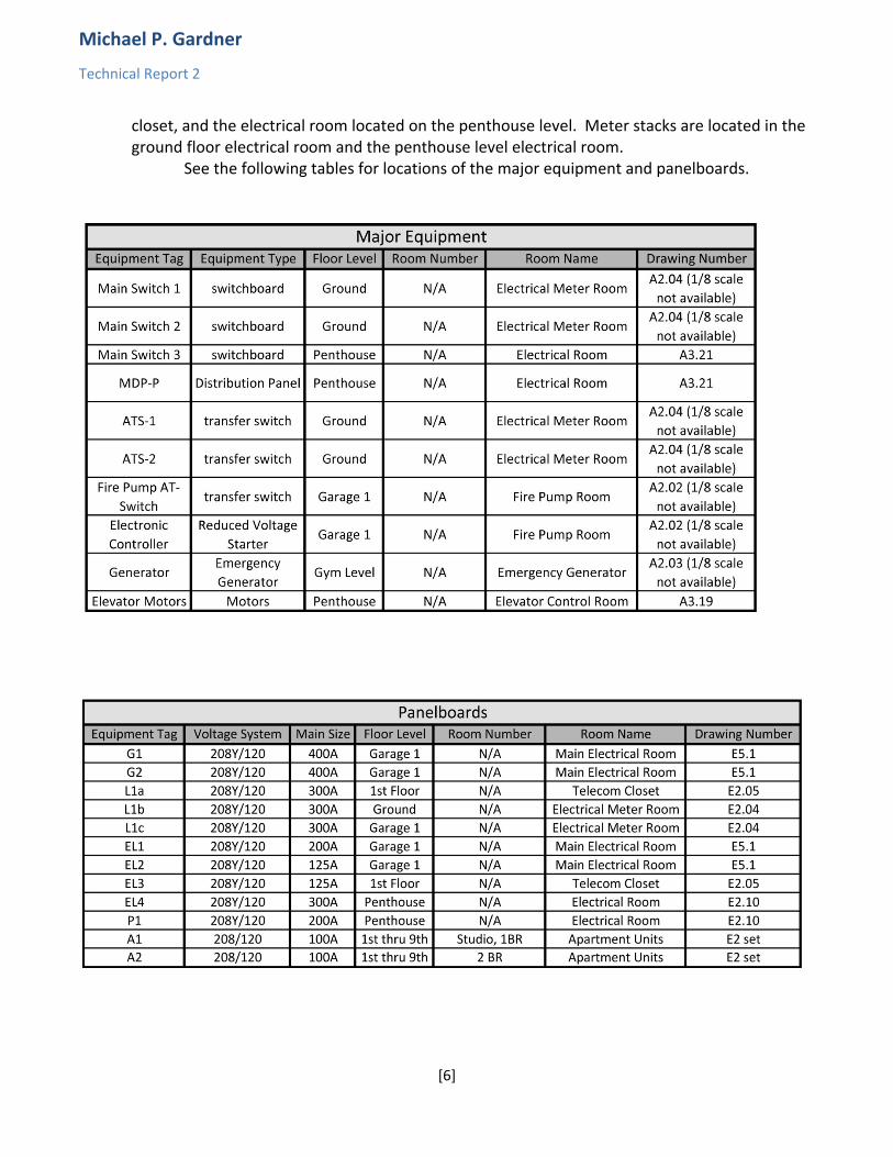
closet, and the electrical room located on the penthouse level. Meter stacks are located in the ground floor electrical room and the penthouse level electrical room.
See the following tables for locations of the major equipment and panelboards.
Michael P. Gardner
Technical Report 2
[7]
Over‐current Devices
The main over‐current devices in the main service entrance switchboards #1, 2, 3, and 5 are class L fuses rated at 1200 amperes. In Main #4, the fuse is class L rated at 800 amperes. Each station has 3 fuses of the respective class and rating.
The branch over‐current devices in the main service entrance switchboards are located downstream in the form of disconnect switches with fuses with varying ratings. One is a class RK5 fuse and has a rating of 300A.
In a typical distribution panel, the circuit breaker is rated at 50K AIC. The over‐current device in a typical lighting and appliance panelboard is a 20A circuit
breaker with a 10K AIC rating. Transformers
Transformers are not shown on drawings nor located in available specifications. There are three transformer vaults, indicating that there are three separate transformers providing service from the utility. Further information regarding primary and secondary voltages could not be obtained in a timely manner and will be added later with permission.
Special Equipment
A generator is used for providing emergency power as discussed in Emergency Power System. It is a 230 kW generator operating at 208Y/120V 3‐phase, 4‐wires.
Meter stacks are used to measure power supplied to individual apartment units. There are a total of three stacks in the building. Stacks #1 and #2 are located in the Electrical Meter Room on the ground floor. Stack #3 is located in the electrical room on the penthouse level. Stacks 1 through 3 contain meters for 60, 80, and 45 apartment units, respectively. From these stacks, feeders are routed directly to an individual apartment’s panelboard.
Lighting Loads
The majority of the lighting loads in the building come from the systems in the apartment units. Mostly, they are comprised of incandescent, halogen, and compact fluorescent luminaires. Linear fluorescent fixtures provide illumination to the garage levels. The building also contains some exterior lighting systems for the outdoor courtyard and rooftop terrace levels. Metal halide lamps are the sources in these luminaires. See the luminaire schedule in the appendix for more information.
ASHRAE/IESNA 90.1 requires a building’s lighting systems to be automatically shut‐off if the building is over 5,000 square feet in area. Exceptions to this rule are lighting intended for twenty‐four hour use and lighting where automatic shut‐off would endanger the safety or security of the building and/or its occupants. Since this project is primarily for residential use, the hallways will most likely be illuminated at all times. Automatic control devices will not be used for the individual apartment units or the garage levels. Retail spaces, outdoor spaces, and the lighting on the fitness level will most likely be the systems affected by this automatic shut‐off requirement to save energy.
Michael P. Gardner
Technical Report 2
[8]
Mechanical and Other Loads
The loads of the building are divided up between mechanical systems, plumbing systems, and architectural equipment. The building contains a number of heaters, fans, pumps, and also three elevators. These pieces of equipment, as well as their respective loads, are listed in the appendix.
Service Entrance Size
Three different methods were used in estimating the size of the service entrance during various phases of the project design. For the Conceptual/Schematic phase, general values of VA/square foot were used based on the type of occupancy. These were then multiplied by the respective areas of those occupancies. Since the building is a mixed‐use project, multiple types of occupancy were used.
For the Design Development stage, load values based on equipment were used from the NEC to obtain the estimated service entrance size.
In the Construction Document phase, lighting load densities were used based on the type of occupancy. All other equipment loads were taken from mechanical schedules and other electrical information.
Typically, these methods would significantly overestimate in the beginning stages and fine‐tune the size in the Construction Document stage. The final stage, however, showed a radically smaller size for the service entrance. This may be due to loads not being listed in documents or specifications.
The sizes and methods are shown in the following tables.
Michael P. Gardner
Technical Report 2
[9]
Environmental Stewardship Design Although the building has many “green” features. The electrical system does not seem
to include any. Energy efficient lighting equipment is not prevalent throughout the building. Efficient
fluorescent fixtures are used where it is fitting, but they seem to be today’s standard. Many incandescent sources are used throughout the apartment units.
Design Issues
A buss duct does not seem to appear in the drawings and this could be an issue if it does not exist. If it does not exist, efficient routing of wiring may not take place which could lead to voltage drop problems and cost increases.
Communication Systems Telephone System
From the telephone riser diagram on sheet E5.4, the telephone system branches out
from the gym level, in the Main Telephone Room. This source is called the Main Telephone Terminal Board. Telephone cable runs directly from this to the ground floor connecting to office spaces, front door entry, commercial spaces, and the fire alarm room. Each residential floor has a telecom closet in the corridor. From these junctions, telephone cable is run to each individual apartment unit. Telephone cable is also run to the three elevator cars accessed through the penthouse/roof level. Fire Alarm System
The fire alarm system in this building is there to alert occupants when there is a fire
present in the building and an evacuation is necessary. The system is comprised of various detectors such as smoke detectors in apartment units, box‐type smoke detectors in corridors, heat detectors, and detectors located in ductwork. There are pull stations throughout the building so that occupants can alert the system of a fire. Strobes and speakers are also located throughout the building to commence and maintain an evacuation order. The control for the fire alarm system is located in the control room on the ground floor. Most of the apartment units have two speakers, one in the living area, and one in the bedroom. There are also speakers in every general room throughout the building.