Technical Reference Using the EP Plus Control
61
-
Upload
khangminh22 -
Category
Documents
-
view
0 -
download
0
Transcript of Technical Reference Using the EP Plus Control

�������� �� ��� ������� ��������
� �������� ��� ��������
� ����� ��� ��������
� ������ ��� ��������
� ���� �����
� ������������� ��� ��� ��� ��� �� !���� �� !"��"#�� !"��"#$� %���"#"�
� &����'� (����
�����������������
����������������������
)*++*,�- ��+-&, �&,)&,� �&- ���� ����� �� � � ����� ��������� � �� � � � ������

����������������.����������������������
30022F8J 36030F8J 42032F7J 48040F7J 30015S5J 30022S4J 30022S5J30015M4J 30015M6J 30022M5J 36021Q4J 36021Q6J 36026Q4J 36026Q6J42026Q4J 42026Q6J 48040F7B 48040F7N 30022T5J 36026V5J 36026V7J42026V6J

�������
�������� ����� �������
�������
Document ............. BIRHUK02Spec Date ................ 20000905� ���������������As-of Date ............... 20000905
�� �� !����This manual provides commissioning, programming, operating, and troubleshooting
instructions for Milnor® washer extractors equipped with the Milnor® E-P Plus® microprocessorcontrol. See the installation manual for information on machine installation procedures andmechanical requirements. See the service manual for preventive maintenance, service procedures,and mechanical parts identification. See the schematic manual for electrical parts identificationand electrical troubleshooting instructions.
�� �� ���"�����#��������!�������The start-up display sequence for models using the E-P Plus® controller is described in the
document BICJHO01, entitled “Running a Formula.” Use the table of contents for this manual tolocate this document.
�� �� $�%��&��������������������&��&�������#�������� ���� ��
���������
A complete identification of this manual or any document in this manual must include allspecifications shown on the front cover, as defined below:
Published manual number—Primary identification number for the manual or any variation of it.
Specified date—The approximate date of introduction of the product or product change thismanual covers.
As-of date—When a manual for an old product is generated, any new information about the oldproduct developed up to this date will be included in the manual.
Access date—The date the manual was generated (assembled and formatted).
Applicability—Code(s) that represent a group of machines this manual applies to and/or actualmodel numbers of applicable machines. The complete list of applicable models is providedinside the front cover.
When referring to any document used in this manual (as identified by an eight-characterdocument number such as BIUUUD13 at the start of the document), a complete identification ofthe document must include all specifications shown on the front cover, except substituting thedocument number for the published manual number.
�� �� ��������'���������������������������� ���� �� ���������
The following, some of which may be used in this publication, are trademarks of PellerinMilnor Corporation:

�������
�������� ����� �������
Table 1: Trademarks
Ampsaver® CBW® Gear Guardian® Milnet® Staph-Guard®
Autolint® Dye-Extractor® Hands-Off® Milnor® System 4®
Auto-Purge® Dyextractor® Hydro-Cushion® Miltrac System 7®
Autovac E-P Plus® Mildata® Miltron Totaltrol
— End of BIRHUK02 —

���� �� �� �� ��
�������� ����� �������
��������
Sections Figures, Tables, and Supplements
�������
i. About This Manual (Document BIRHUK02)
i.1. Scopei.2. The Normal Display at Start-upi.3. How To Identify This Manual and Its Included Documents
(Document BIUUUD13)
i.4. Trademarks of Pellerin Milnor Corporation (Document
BIUUUD14)Table 1: Trademarks
���������������
�������( �������������
1.1. Important Owner/User Information (Document BIRHUK01)
1.1.1. Ensure Safety of All Laundry Personnel1.1.2. Customize Data1.1.2.1. When to Customize Data1.1.2.2. What Customizing Requires1.1.2.3. Data Accessibility Table 2: Data Use and Alteration1.1.2.4. If Data Becomes Corrupted
1.2. Determining Load Size (Document BIWUUO01)
1.3. Important Instructions for Pumped Chemical Inlets(Document BIWUUI01)
1.3.1. How Pumped Chemical Systems Can Internally Damagethe Washer-extractor
Supplement 1: Preventing Dribbling byPurging Chemical Lines
1.3.2. Locating Chemical System Components to Reduce theRisk of Internal Damage
Figure 1: Proper Routing of ChemicalTubing
1.3.3. Preventing Leaks Which Can Injure Personnel and CauseExternal Damage
Figure 2: Proper Chemical TubingConnection Locations
1.4. Connecting Chemical Systems (Document BICJFI01) Supplement 2: Maximizing ChemicalInjection Precision
1.4.1. Available Chemical Injection Methods1.4.1.1. Chemical Injection Output Signals1.4.1.2. Optional Five-Compartment Flushing Chemical
Injector1.4.1.3. Liquid Chemical Tube Barbed Connectors1.4.2. Considerations for Pumped Chemical Systems1.4.3. Connecting Devices to Receive Injection Signals

���� �� �� �� ��
�������� ����� �������
Sections Figures, Tables, and Supplements
1.4.4. Connecting Chemicals to FxJ Models Table 3: Chemical Injection Signals forFxJ Models
Figure 3: Terminal Blocks (Typical) forFxJ Models
1.4.5. Connecting Chemicals to 42-inch Q4x, and 36-inch and42-inch Q6x and VxJ Models
Table 4: Chemical Injection Signals forSpecific Qxx and Vxx Models
Figure 4: Terminal Blocks (Typical) forQxx Models
1.4.6. Connecting Chemicals to 30-inch Mxx, T5J, and VxJModels
Figure 5: Terminal Strip TBS in M-styleMachine
�������) �����������
2.1. Controls on E-P Plus Washer-extractors (Document
BICJHC01)
Figure 6: E-P Plus Control Panels
2.1.1. Control Functions During Normal Operation2.1.2. Control Functions During Manual Operation2.1.3. Control Functions During Programming
2.2. Selecting an Industry Formula Set (Document BICJHC02) Figure 7: Location of DIP SwitchesTable 5: DIP Switch Settings for Industry
ConfigurationsSupplement 3: How to Set DIP Switch
Position S5
2.3. Programming the E-P Plus Controller (Document BICJHP01)
2.3.1. How to Avoid Data Loss2.3.2. Return to Run Mode (Option 0)2.3.3. Add or Change a Formula (Option 1)2.3.3.1. About the Programming Help Screens2.3.3.2. Moving Forward and Backward through Steps and
Decisions2.3.3.2.1. Actions when the Cursor is at the Step Number2.3.3.2.2. Actions when the Cursor is at a Decision within a
Step2.3.3.3. Create a New Formula2.3.3.4. Delete an Existing Formula2.3.3.5. Change an Existing Formula2.3.3.5.1. How to Insert or Delete a Step in an Existing
Formula2.3.3.5.2. The Step Decisions2.3.3.5.3. How to Modulate Water Valves to Regulate
Incoming Water Temperature2.3.3.5.4. How to Use Cooldown2.3.3.5.5. How to Select the Bath Level2.3.3.5.6. How to Select the Steam Code

���� �� �� �� ��
�������� ����� �������
Sections Figures, Tables, and Supplements
2.3.3.5.7. Injecting Chemicals Table 6: Codes for Inject Times of 100Seconds and Longer
2.3.3.5.8. How to Save or Discard Changes2.3.4. Configure the Control (Option 2)2.3.4.1. Moving Forward and Backward in Configure2.3.4.2. The Configure Decisions2.3.5. Restoring Standard E-P Plus Formulas (Document BICJUP01)
�������* +��������
3.1. Running a Formula (Document BICJHO01)
3.1.1. Applying Power3.1.2. Selecting and Starting the Formula3.1.2.1. Load Machine and Close Door3.1.2.2. Using the Optional Power-Operated Door3.1.2.3. Using the Optional Tilt Controls3.1.2.4. Jogging the Cylinder (Optional)3.1.2.5. Selecting a Formula3.1.3. Unloading the Machine Table 7: Coast Times at Program End or
Termination3.1.4. The Display during Automatic Operation3.1.5. How to Shorten, Terminate, or Suspend a Running
Formula3.1.6. How to Restart after Power Loss3.1.7. How the Flush Valve Works3.1.8. How Cooldown Works
3.2. Viewing and Clearing the Formula Count Accumulator(Document BICJUD01)
�������, ���������������
4.1. The EP-Plus Manual Menu (Document BICJHT02)
4.1.1. The Manual Menu4.1.1.1. Components4.1.1.2. How to Access the Manual Menu4.1.1.3. How to Return to the Run Mode from the Manual
Menu4.1.2. Determining the Software Version4.1.3. Viewing Microprocessor Inputs Table 8: E-P Plus Inputs4.1.4. Actuating Microprocessor Outputs Table 9: E-P Plus Outputs
4.2. Error Messages (Document BICJHT01)
4.2.1. Error Messages at Power Up4.2.2. Error Messages during Normal Operation

���� �� �� �� ��
�������� ����� �������
Sections Figures, Tables, and Supplements
�������- !�����������&����������
5.1. The E-P Plus Hardware (Document BICJUF01)
5.1.1. Keyswitches5.1.1.1. Run/Program Keyswitch5.1.1.2. Automatic/Test Keyswitch5.1.2. Display5.1.3. Power Supply5.1.4. CPU Processor Board5.1.5. Outputs5.1.6. Option Outputs5.1.7. Analog to Digital Convertor5.1.8. Temperature Probe5.1.9. Pressure Sensor
5.2. How to Set Water Levels (Document BICJFD01) Table 10: Adjustable Water Levels5.2.1. Factory Settings Table 11: Factory Water Level Settings5.2.2. How the Pressure Switch Works Table 12: Function of Level Switches
Figure 8: Pressure Switch Identification5.2.3. Adjusting Water Levels

������� �� ��������� � �
�������� ����� �������
�������(
�������������
Document ............. BIRHUK01Spec Date ................ 20000905( ( &��������+%���.����&����������As-of Date ............... 20000905
The following two procedures must be completed before this machine is placed in service:
1. Ensure the safety of all laundry personnel.
2. Customize the data contained in the memory of the machine (configuration, formulas, andproductivity/formula accumulator data).
������ ������!����������/���������������Ensure that all personnel who will operate or maintain this machine read the safety manual
before permitting them to access the machine. Ensure that all user manuals are available to theappropriate personnel and that all precautions explained in all applicable manuals are observed.
������ �������0�#���Customizing the data includes verifying that the controller is configured for the particular
application, modifying certain wash programs if necessary for optimum productivity, andverifying that the formula count accumulator is cleared so the formula count will be accurate.
�������� 1������������0�#���
• When commissioning the machine
• When required by error message
• After replacing the microprocessor board
• After upgrading the software
• After adding or removing optional equipment

������� �� ��������� � �
�������� ����� �������
�������� 1����������0����2�����—Verify configuration. Program formulas and clearproductivity data, if applicable. See the programming and operating sections in this manual forinstructions.
�������� #����������������—Configuration and formula data can only be altered while the keyswitchis in the Program position (data is protected by the keyswitch). Productivity data, because it isaccumulated in the Run mode, cannot be protected by the keyswitch and is accessible to anyone.Data is accessible to the extent described in Table 2.
Table 2: Data Use and Alteration
Data Type How Data can be Used and Altered
Configuration Data Data can be read and written over
Formula Data Data can be read, written over (added to/changed) and cleared
Productivity Data Data can be read and cleared
�������� &�#���3���������������—If the microprocessor senses that data is unusable orunreliable, an error message will appear—usually at power-up—possibly preventing machineoperation. The consequences and appropriate actions for each error message are explained in thetroubleshooting instructions. Follow these instructions exactly to ensure that corrupt data iscompletely eliminated and replaced with valid data. Failure to do so may result in unsafeoperation or machine damage.
— End of BIRHUK01 —
Document ............BIWUUO01Spec Date ................ 20000905( ) #����������/���!�0�As-of Date ............... 20000905
Putting too much linen into a properly designed laundry washer-extractor will not overloadthe machine to its mechanical or electrical detriment if these guidelines are followed:
1. The goods consist of typical cotton and/or synthetic fabrics normally encountered incommercial laundering operations.
2. The load is not so bulky as to prevent a reasonably balanced distribution prior to the onset ofextraction.
3. The extract speed has not been increased above the designed maximum.
4. The total number of intermediate and final extractions do not exceed the designed maximumfor the extract motor.
Thus, the maximum soiled linen capacity for any properly designed washer-extractor isessentially limited by the amount of soiled goods that can actually be placed in the cylinder.
The maximum weight of soiled goods that a washer-extractor cylinder will accept dependson the following factors:
• the internal volume of the cylinder (the space into which the goods can be placed), and
• the density (weight and bulkiness) of the specific goods
For example, many polyester-cotton fabrics have relatively low weights for their bulk so oneshould rarely expect to be able to put in a published maximum capacity load of such fabrics. Infact, published maximum capacities of machines based on the now generally accepted industrystandards will usually be achieved only with the highest density, closely woven fabrics and areasonable soil content.

������� �� ��������� � �
�������� ����� �������
The best load size depends on the size of the machine—plus the type of goods, soil content,and wash quality desired. Since the latter factors vary considerably, prior experience and/orexperimentation generally yield the best results. Use these guidelines:
1. Overloading a washer-extractor will not increase production because longer wash formulasand more rewash will be required.
2. Avoid underloads because the inevitable greater extraction imbalance will cause more extractre-cycles and may stress the machine unnecessarily.
3. Load divided cylinder machines so that the weight in each compartment is approximatelyequal at the onset of extraction. Do not put goods with grossly dissimilar water absorptioncharacteristics in the different compartments. Do not attempt to balance loads of wet goods inone compartment against dry goods in the other.
— End of BIWUUO01 —
Document ..............BIWUUI01Spec Date ................ 20000905( * &��������&��������������������
��������&����� As-of Date ............... 20000905
������ $�%��������������!���������&���������#��������1�������4�������
Many pumped liquid chemical systems dribble concentrated chemicals out of the injectiontubes when the system is not used for relatively long periods of time—as after working hours andduring weekends. This puts highly concentrated corrosive chemicals in direct contact with drystainless steel surfaces, and often directly on any textiles left in the machine. Chemicaldeterioration (rusting) of the stainless steel and damage to the textiles is the inevitableresult.
Pellerin Milnor Corporation accepts absolutely no responsibility whatsoever for damage toits equipment or to any textiles therein when concentrated chemicals dribble out of theinjection tubes onto any part of the machine or its contents.
����� � ���� ��� �
���������� �������� � ������� �������� �����
Although the injection site is flushed by washer agitation on some models and after eachinjection on other models to aid the injection process, this flushing provides absolutely noprotection against harmful dribble which occurs later—when the machine is no longer in use.
One foolproof solution for “dribbling” is to completely purge the appropriate chemicalinjection tube with fresh water after every injection, so that only fresh water (which cannotcause a problem) can dribble out.
Obviously, it is the sole responsibility of the pump and/or chemical supplier (not themachine manufacturer) to furnish such a flushing device. (We understand that such flushingtype chemical injection systems—both for retrofit to existing systems and for newinstallations—are now offered by others.)
������ /���������������!���������������������������'��&�������#�����
If the tubes, pumps, and chemical tanks are kept well below the injection point, thelikelihood of “after-hours dribbling” is reduced, but not totally eliminated.
We therefore urge that tubes from any non-flushing pumped chemical system be connectedas shown in Figure 1. Although fresh-water flushing the just-used tubes after each injection

������� �� ��������� � �
�������� ����� �������
would be better, we believe routing the tubes as indicated will probably minimize the dribblingeffect about as much as possible without flushing. Never permit tanks, pumps, or any portion ofthe tubes to be higher than the injection point. If loops in the injection tubes are employed, makesure the entire loop is well below the injection point.
Figure 1: Proper Routing of Chemical Tubing
�� �� As shown in Figure 1, all tanks, pumps, and tubing must be lower than the injection point on themachine and must not dribble chemicals into the machine, nor leak chemicals externally onto any portionof the machine or its surroundings.
������ ���5������/��'�1�������&�6���������������������4������#�����
All ports on the inlet are plugged at the Milnor® factory. When replacing plugs with fittingsor when reinstalling plugs, always use the sealant furnished (LocTite RTV Silicone Adhesive orequivalent). Use properly sized hose barbs, always use clamps, and check for leaks. Use the hosebarbs furnished with your machine only if they provide the proper fit for the tubes employed.Ensure that excessive pressures cannot build up that might burst or disconnect tubing. Instruct theoperator to monitor for leaks and report any occurences.
When calibrating injections, it is permissible to remove tubes from barbed fittings to takesamples. However, always check for leaks after installing tubes and clamps. A preferable methodis to install a three-way or two two-way valves onto each injection tube for sampling.
������� � � ����� �������� ����� ��� ���������—Concentrated liquidchemicals leaking from a chemical system can burn skin and eyes, cause other types ofinjury or illness, and corrode machine components.• Ensure that excessive pressures cannot build up which might burst or disconnect a
chemical delivery tube.• Ensure that there are no external chemical leaks when the system is installed or
calibrated.• Periodically check the system for leaks during operation.
�� !�"� # � ����� ��������� ��� ��$���� ������—Chemicals dribbling intothe machine when it is idle will corrode machine components and damage any textilesleft in the machine.• If possible, use a system that flushes the entire chemical delivery tube after each
injection.• If a non-flushing system is used, install tanks, pumps, and tubing below the injection
point on the machine, such that chemicals travel to the machine at an upward angle.
�� !�"� % � ����� �$&�������—Certain chemicals will react when combined.• Connect chemical inlets as shown in Figure 2.

������� �� ��������� � �
�������� ����� �������
Figure 2: Proper Chemical Tubing Connection Locations
Front View of Chemical Injection Points Legend
1. Soap2. Softener3. Bleach4. Starch5. Sour
�"!��' ( � Pellerin Milnor Corporation accepts absolutely no responsibility fordamage to its equipment or to any textiles therein when concentrated chemicalsdribble out of the injection tubes onto any part of the machine or its contents.
— End of BIWUUI01 —
Document .................BICJFI01Spec Date ................ 20000905( , ������������������!������As-of Date ............... 20000905
Multiple methods are available on System 7® and E-P Plus® washer-extractors toaccommodate chemical systems. Use this section to help determine the best method of chemicalinjection and how to connect the chemical system. Always consult the schematic manual for thismachine before connecting chemical systems to the machine.
���'� ) � '������� *���+ ,�-���—Contact with high voltage electricity willkill or seriously injure you. Even with the Master Switch off and/or any EmergencyStop switches off, three-phase power and control circuit power are still present atseveral locations within electric boxes and electrical components.
���'� . � ��/�� ��� ����� ,�-����—Improper wiring can cause themachine to malfunction, risking injury to personnel, damage to machine components,and damage to goods.• Electrical and piping connections described in this section must be made only by
qualified, authorized personnel.• Lock off and tag out power at the external disconnect switches for the washer-
extractor and for any chemical devices that provide power to the interpret relay box(if furnished) before proceeding.
• Do not rely merely on the information in this section when wiring. Consult allapplicable electrical schematics.
• Do not reroute or rearrange any wires not specifically permitted by this instruction.• Do not connect a common wire to ground. Use the common terminal furnished.
�� !�"� 0 � ���+ �1 ���� �� ������������ ���� 2����� —Injection times ofless than 10 seconds are discouraged because fine adjustments are not possible andfactors such as pump lag time may cause significant variations in the amount ofchemical delivered.• Size pumps or valves small enough for adequate control (i.e., for longer injection
times).• Use two pumps or valves to inject a small or large quantity of the same chemical, if
required.

������� �� ��������� � �
�������� ����� �������
����� � ���� ��� �
3�$���-��� �������� ��/������ ���������
Injection of a consistent amount of chemical is important in controlling wash quality andusing chemicals economically. When chemicals are injected by units of time, as is done withmost washer-extractors, injections of short duration can be imprecise because of two reasons:
• Fine adjustments to the delivered quantity are not possible. For example, if an injection ofthree seconds is extended by one second, the quantity delivered is theoretically increasedby more than 30 percent. However, if an injection of 20 seconds is increased by onesecond, the theoretical quantity is increased by only five percent.
• Variations in the time between the start of the chemical signal and the start of the chemicaldelivery into the machine can cause significant differences in the quantity of chemicalinjected. In this case, if a pump starts more slowly some times than others, or if thedelivery tubes are partially empty at the start of the inject period, the quantity of chemicaldelivered may vary significantly. As an example, assume a peristaltic pump moveschemical along the delivery tube at a rate of three feet per second. If the delivery tube isempty for three feet along its length, then one second of the injection time is spent injectingair rather than chemical. If the programmed injection time is only three seconds, then onethird of the desired chemical is not being delivered. However, if the programmed injectiontime is 20 seconds, the chemical delivery is only five percent less than desired.
Increasing the programmed injection time makes any variation less significant. Usepumps and/or valves sized to allow inject times of at least 10 seconds. If injection times fora specific chemical vary widely from one formula to another, consider using two pumps orvalves for the same chemical. Actuate one pump for injecting small quantities, and useboth pumps or valves for larger quantities.
������ �5���������������&�6�������������
�������� ��������&�6������+�����!������—Five discrete signals (for chemicals 1 through 5)are furnished standard on all washer extractors. These signals are available at a terminal strip onSystem 7® and E-P Plus® machines. Check the nameplate on the machine to verify the model.
�������� +�������7�5�������������7���������������&�6�����—A five-compartmentdry supply injector mounted externally on the washer-extractors is offered optionally. The fiveelectrically operated flush valves are wired to chemical injection output signals at terminal stripTBA.
�������� /�2���������������3���������������—A six port inlet is standard on all models.Use these valveless inlets to connect tubes from remote chemical supply injection systems thatare not continuously pressurized and that deliver chemicals only when an injection iscommanded.
������ �������������������������������!������Pumped chemical systems deliver chemicals to the machine intermittently usually via
peristaltic pumps. Inlets on the machine must be unrestricted at all times (valveless). The five portpumped chemical inlets meet this requirement.
An inherent risk of this method of chemical injection is that concentrated chemicals candribble into the machine after it is shut down for the evening, causing machine and/or linendamage. Because Milnor® has no control over the design or installation of pumped chemicalsystems, Pellerin Milnor Corporation accepts absolutely no responsibility for damage to its

������� �� ��������� � �
�������� ����� �������
equipment or textiles therein caused in this way. Much more information on this subject isprovided in document BIWUUI01, “Important Instructions for Pumped Chemical Inlets” (seetable of contents). Consult this document before connecting a pumped chemical system.
������ ����������#�5����������5�&�6������!������Injection signals provide a 110VAC/50Hz or 120VAC/60Hz potential. Each signal can
accomodate one apparatus not exceeding 37 milliamperes. Inject signals cannot be madepotential-free.
�� !�"� 4 � ����� ���&����� �����—Board components will burn out andrequire board replacement if devices driven by inject signals do not meet the electricalspecifications. Pumps generally draw a higher current and will burn out boardcomponents.
������ ���������������������748������Acquire signals at terminal strip TBA in the high voltage control box. Chemicals 1 through 5
are represented by terminals as shown in Table 3 and Figure 3.
Table 3: Chemical Injection Signals for FxJ Models
Signal ComponentTBA Terminal
Number
Chemical 1 95
Chemical 2 85
Chemical 3 75
Chemical 4 91
Chemical 5 93
Flush 97
Common 6
Figure 3: Terminal Blocks (Typical) for FxJ Models
������ ���������������������,)�����9,4:���*;��������,)�����9;4���<48������
Acquire signals at terminal strip TBA in the high voltage control box (see Figure 4).Chemicals 1 through 5 are represented by points 40 through 44, point 38 is flush, and point 6 is

������� �� ��������� � �
�������� ����� �������
common. The specified voltage is enabled between the appropriate point and common wheneveran injection is called for.
Table 4: Chemical Injection Signals for SpecificQxx and Vxx Models
Signal ComponentTBA Terminal
Number
Chemical 1 40
Chemical 2 41
Chemical 3 42
Chemical 4 43
Chemical 5 44
Flush 38
Common 6
Figure 4: Terminal Blocks (Typical) for Qxx Models
������ ���������������������*=������44:�-8:���<48������Acquire signals at terminal strip TBS in the incoming power box (see Figure 5). Pins 1
through 5 are for chemicals 1 through 5 respectively, and pin 8 is common. The specified voltageis enabled between the appropriate pin and common whenever an injection is commanded.
Figure 5: Terminal Strip TBS in M-style Machine
— End of BICJFI01 —

������� �� ��������� �
�������� ����� �������
�������)
�����������
Document ...............BICJHC01Spec Date ................ 20000905) ( �����������������51�������4��������As-of Date ............... 20000905
The controls on Milnor® E-P Plus® washer-extractors are primarily mechanical push-buttonsand indicator lights. Other controls include a keyswitch, a standard emergency stop button, and atwo-position rotary switch for main machine power. Some of these controls serve differentfunctions in the three operational modes of the machine. The function of each control in thenormal, manual, and programming modes of this machine is described in detail in this document.
Figure 6: E-P Plus Control Panels
Cylinder-mounted Control Panel Legend
��������
��
����������
��
�
��
�
�
��� � ����
1. Start button2. Run/Program keyswitch3. Pictorial Instructions4. Display5. Scroll button6. Select Program button7. Next/Signal Cancel button8. Terminate button9. Manual/Automatic
keyswitch10. Operator Signal light11. Master switch (FxJ/QxJ
only)12. Emergency Stop button
(FxJ/QxJ only)
Console-mounted Control Panel
��������
��
1
0 0 10 0 20 0 30 0 4
��
��
� � �
�� �
�

������� �� ��������� �
�������� ����� �������
������ �������7��������#�����"�����+��������Normal operation is the state of the machine when the machine control circuit is energized
and the Run/Program keyswitch is in the Run position. The machine may be either idle (waitingto run a formula) or running. If the machine is idle, the message on the display will begin with“Run Formula” and include a formula number on the second line.
1. Press the Start button (�) to initiate the selected wash formula. The formula begins if poweris available at the machine and the loading door is closed.
2. The Run/Program keyswitch must be in the Run position (�) unless the machine is beingconfigured or programmed. All control descriptions listed under section 2.1.1 ControlFunctions During Normal Operation are based on the keyswitch being in the Run position.Refer to section 2.1.3 for descriptions of how the controls operate with the keyswitch in theProgram position (�).
3. Pictorial instructions briefly describe the steps required for normal machine operation.
1. Load the machine to the rated capacity.
2. Securely close the loading door.
3. Select the appropriate formula for the goods in the machine.
4. Add chemicals if the machine is not connected to an automatic chemical delivery system.
5. Press the Start button.
4. The display on these machines is a liquid crystal or vacuum fluorescent display showing twolines of twenty characters each. Liquid crystal displays present black characters on a lightgray background, while vacuum fluorescent displays are bright green characters against ablack background.
5. When selecting a specific formula to run, press the Scroll button (�) to display the nextlower numbered formula in memory. Press this button when the lowest formula is displayed(Formula 01) to select the highest numbered available formula (maximum of 30 formulas).
6. The Select Program button (�) functions in much the same manner as the Scroll buttondescribed above. Press this button to display the next higher numbered formula in memory.
7. In normal operation, pressing the Next/Signal Cancel button (�) silences the operator signalbuzzer. If a signal is programmed with a chemical injection in any formula, this button mustbe pressed to confirm that the chemical has been added before operation resumes.
8. The Terminate button (�) cancels all remaining steps in any running formula and initiatesthe shutdown procedure for the machine. Formulas ended in this manner cannot be resumed.
9. The Manual/Automatic keyswitch (���) has no effect while a formula is running.Switching this key to the Manual position (�) when the display says “Run Formula xx”initiates manual mode, where the controls function as described in section 2.1.2 ControlFunctions During Manual Operation.
10. The Operator Signal light is a visual indicator that operator attention is required. This light isilluminated simultaneously with the sounding of the operator signal buzzer.
11. The Master switch, if present, controls power to the control circuit of the machine. Changingthis switch from the on position (�) to the off position (�) in any manual mode selectionturns off the machine control circuit.
12. Press the Emergency Stop button to stop the machine by removing power from the machinecontrols. Formulas ended in this manner can be resumed at the beginning of the interruptedstep by following the prompts on the display.

������� �� ��������� �
�������� ����� �������
������ �������7��������#�����������+��������Manual operation is used primarily for troubleshooting the machine by activating outputs
and viewing inputs.
1. Press the Start button (�) to initiate the selected wash formula. The formula begins if poweris available at the machine and the loading door is closed.
2. The Run/Program keyswitch must be in the Run position (�) unless the machine is beingconfigured or programmed. All control descriptions listed under section 2.1.1 ControlFunctions During Normal Operation are based on the keyswitch being in the Run position.Refer to section 2.1.3 for descriptions of how the controls operate with the keyswitch in theProgram position (�).
3. Pictorial instructions briefly describe the steps required for normal machine operation.
1. Load the machine to the rated capacity.
2. Securely close the loading door.
3. Select the appropriate formula for the goods in the machine.
4. Add chemicals if the machine is not connected to an automatic chemical delivery system.
5. Press the Start button.
4. The display on these machines is a liquid crystal or vacuum fluorescent display showing twolines of twenty characters each.
5. When selecting a specific formula to run, press the Scroll button (�) to display the nextlower numbered formula in memory. Press this button when the lowest formula is displayed(Formula 01) to select the highest numbered available formula (maximum of 30 formulas).
6. The Select Program button (�) functions in much the same manner as the Scroll buttondescribed above. Press this button to display the next higher numbered formula in memory.
7. In normal operation, pressing the Next/Signal Cancel button (�) silences the operator signalbuzzer. If a signal is programmed with a chemical injection in any formula, this button mustbe pressed to confirm that the chemical has been added before operation resumes.
8. The Terminate button (�) cancels all remaining steps in any running formula and initiatesthe shutdown procedure for the machine. Formulas ended in this manner cannot be resumed.
9. The Manual/Automatic keyswitch (���) has no effect while a formula is running.Switching this key to the Manual position (�) when the display says “Run Formula xx”initiates manual mode, where the controls function as described in section 2.1.2 ControlFunctions During Manual Operation.
10. The Operator Signal light is a visual indicator that operator attention is required. This light isilluminated simultaneously with the sounding of the operator signal buzzer.
11. On certain models, the Master switch controls power to the control circuit of the machine.Changing this switch from the on position (�) to the off position (�) in any manual modeselection turns off the machine control circuit.
12. Press the Emergency Stop button to stop the machine by removing power from the machinecontrols. Formulas ended in this manner can be resumed at the beginning of the interruptedstep by following the prompts on the display.
������ �������7��������#����������������The programming mode is used to modify the actions performed in a wash formula, or to
create new wash formulas.
1. When in the programming mode and with the cursor blinking at the step number, press theStart button (�) for instructions on inserting or deleting a step. Press the Start button and the
������� �� ��������� �
�������� ����� �������
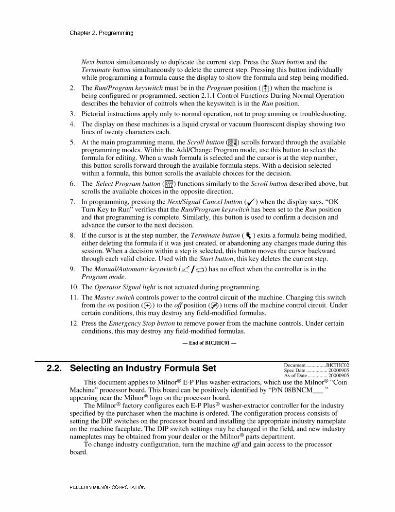
Next button simultaneously to duplicate the current step. Press the Start button and theTerminate button simultaneously to delete the current step. Pressing this button individuallywhile programming a formula cause the display to show the formula and step being modified.
2. The Run/Program keyswitch must be in the Program position (�) when the machine isbeing configured or programmed. section 2.1.1 Control Functions During Normal Operationdescribes the behavior of controls when the keyswitch is in the Run position.
3. Pictorial instructions apply only to normal operation, not to programming or troubleshooting.
4. The display on these machines is a liquid crystal or vacuum fluorescent display showing twolines of twenty characters each.
5. At the main programming menu, the Scroll button (�) scrolls forward through the availableprogramming modes. Within the Add/Change Program mode, use this button to select theformula for editing. When a wash formula is selected and the cursor is at the step number,this button scrolls forward through the available formula steps. With a decision selectedwithin a formula, this button scrolls the available choices for the decision.
6. The Select Program button (�) functions similarly to the Scroll button described above, butscrolls the available choices in the opposite direction.
7. In programming, pressing the Next/Signal Cancel button (�) when the display says, “OKTurn Key to Run” verifies that the Run/Program keyswitch has been set to the Run positionand that programming is complete. Similarly, this button is used to confirm a decision andadvance the cursor to the next decision.
8. If the cursor is at the step number, the Terminate button (�) exits a formula being modified,either deleting the formula if it was just created, or abandoning any changes made during thissession. When a decision within a step is selected, this button moves the cursor backwardthrough each valid choice. Used with the Start button, this key deletes the current step.
9. The Manual/Automatic keyswitch (���) has no effect when the controller is in theProgram mode.
10. The Operator Signal light is not actuated during programming.
11. The Master switch controls power to the control circuit of the machine. Changing this switchfrom the on position (�) to the off position (�) turns off the machine control circuit. Undercertain conditions, this may destroy any field-modified formulas.
12. Press the Emergency Stop button to remove power from the machine controls. Under certainconditions, this may destroy any field-modified formulas.
— End of BICJHC01 —
Document ...............BICJHC02Spec Date ................ 20000905) ) !����������&�������7������!��As-of Date ............... 20000905
This document applies to Milnor® E-P Plus washer-extractors, which use the Milnor® “CoinMachine” processor board. This board can be positively identified by “P/N 08BNCM___ ”appearing near the Milnor® logo on the processor board.
The Milnor® factory configures each E-P Plus® washer-extractor controller for the industryspecified by the purchaser when the machine is ordered. The configuration process consists ofsetting the DIP switches on the processor board and installing the appropriate industry nameplateon the machine faceplate. The DIP switch settings may be changed in the field, and new industrynameplates may be obtained from your dealer or the Milnor® parts department.
To change industry configuration, turn the machine off and gain access to the processorboard.

������� �� ��������� �
�������� ����� �������
���'� 6 � '������������ ��-���—Do not open the door to any electric boxwithout first turning the power off. These controls use 120VAC power or higher, whichis extremely dangerous.
The location of the DIP switches on the microprocessor board are shown in Figure 7, as areexamples of the on and off positions. Set the switches to the desired configuration according toTable 5. Turn the machine on; the display will show the current configuration.
Figure 7: Location of DIP Switches
Processor Board Legend
A. DIP switchB. Board identification area1. OFF2. ON3. ON4. OFF
DIP Switch (Partial View)
Table 5: DIP Switch Settings for Industry Configurations
Switch Settings
Industry Configuration S1 S2 S3 S4 S5 S6 S7 S8
Correctional Facilities OFF OFF OFF OFF
Hotels and Motels ON OFF OFF OFF
Athletic Laundries OFF ON OFF OFF
Healthcare Facilities ON ON OFF OFF
Restaurants OFF OFF ON OFF
Commercial Laundries ON OFF ON OFF
Shirt Laundries OFF ON ON OFF
Offshore Laundries ON ON ON OFF
Fire-Fighter OFF OFF OFF ON
Driveselection—see
explanationbelow.
Offprevents/On
allowsskippingsteps.*
These switchesare not used inthese models.
* Setting S6 on enables the operator to cancel any step in progress except a drain before an extract.

������� �� ��������� �
�������� ����� �������
����� � ���� ��� �
,�7 �� *�� �� *7���� �������� *)
For 36021/36026Q6J and 42026QxJ models—set switch S5 to ON. Otherwise, these modelswill skip drain speed and attempt to enter extract from wash speed. This action willoverload the extract motor, possibly causing it to stall.
For 36021/36026Q4J models—set switch S5 to OFF. Otherwise, these models will skip E1(low extract speed) and attempt to enter E2 (high extract speed) from distribution speed.This action will overload the extract motor, possibly causing it to stall.
For all MxJ, SxJ, FxJ, and 36026/42026VxJ models—switch S5 has no effect.
— End of BICJHC02 —
Document ...............BICJHP01Spec Date ................ 20000905) * ���������������������5����������As-of Date ............... 20000905
The microprocessor controller used in this washer extractor operates in two modes,depending on whether the machine is being used to process goods (the Run mode or Formulamenu) or is being programmed with operating characteristics to be used when a wash formula isstarted (the Program mode). This document describes the available operator actions and displayfeedback in the Program mode.
The Program mode is accessible only when the Run/Program keyswitch is set to theProgram position (�), as described below. From the Program menu, there are four optionsavailable:
• Option 0: OK TURN KEY TO RUN (detailed in section 2.3.2 )
• Option 1: ADD/CHANGE FORMULA (detailed in section 2.3.3 )
• Option 2: CONFIGURE (detailed in section 2.3.4 )
• Option 3: STANDARD FORMULAS
Each of these options is described in detail in this document. For information on how to startthe machine and run a formula, see the appropriate section listed in the table of contents of thismanual.
������ $�%���5���#���/���
�� !�"� �8 � ����� �����&���� 9������ ���—Never turn the Run/Programkeyswitch from the Program position to the Run position unless the display says OKTurn Key to Run.• Failure to follow this direction will result in the loss of all formula modifications
entered during the current programming session. Formulas not modified during thissession will not be affected.
�� !�"� �� � ����� �����&���� ���1��������� ���—Never shut off machinepower, turn off the Master switch, or press the Emergency Stop button to exit theProgram mode.• Once the Configure menu has been accessed, all configure decisions must be
confirmed by pressing the Next button (�) before another action can be taken.• Failure to follow this direction will result in corruption of machine memory.
Use the following procedures to clear corrupted formula and configuration memory andrestore valid data.

������� �� ��������� �
�������� ����� �������
Display or Action Explanation
CHECKSUM ERROR,TURN KEY TO PROGRAM
This display indicates that all memory will be cleared. Themachine controller must be reconfigured and any newformulas or modifications to standard formulas must be re-programmed.
� Accesses the first configuration decision.
TEMP CONTROL?0=NO 1=YES 0
First configure decision.
������ �������������>+�����=?Option 0 allows for a safe return from the Program mode to the Formula menu, preserving
any changes that were made during the programming session and maintaining the integrity ofprogramming and configuration data.
Display or Action Explanation
PROGRAM 0 MENU OK TURN KEY TO RUN
This is Option 0 of the Program menu. From this display, returnto the Formula menu or select another available menu option.
� Returns to Run mode (Formula menu)
or
�/� Scrolls the available choices in the Program menu.
������ ������������7������>+�����(?Washer extractors with the Milnor® E-P Plus® control system have the capacity for up to 30
unique wash formulas. The space for these formulas is allocated in memory whether or not theformulas are actually used.
The user interface employs similar procedures for creating a new formula and for changingan existing formula. Both procedures are detailed below, in section 2.3.3.3 Create a New Formulaand section 2.3.3.5 Change an Existing Formula. The control system will inform the personprogramming the machine whether the selected formula has already been programmed.
�������� �������������������$���!������
Display or Action Explanation
03 TMMQFFFHC LSCWSS*01 0000----- -------
This is Page A of the programming menu. The cursor is at thefirst decision (T=Type of Step). Each decision has an associatedhelp screen.
03 T TYPE OF STEP01 0 END FORMULA
This is a typical programming help screen. Help screens appearautomatically if no valid entry is made within four seconds ofaccessing the decision.

������� �� ��������� �
�������� ����� �������
Display or Action Explanation
� Accepts the selected value for the current decision and advancesthe cursor to the next decision, regardless of the status of thehelp screen.
� At either Page A or B, displays formula and step name forselected step if the help screen has not appeared.
MODIFYINGFORMULA 03 - STEP 01
This is a typical display of the formula and step name.
�������� ��5���7��%������3��'%����������!�������#��������—Each step hastwo displays: Page A and Page B.
Display or Action Explanation
03 TMMQFFFHC SCWSS*01
This is Page A. In this example, the “03” at the left end of thedisplay represents the formula number. The “01” below itrepresents the step number within that formula. The CWSS*decisions shown in bold repeat for each chemical programmed inthis step.
03 SPD D E01
This is Page B. When the cursor is advanced past the lastdecision on Page A, Page B appears for the remaining decisionsin this step. The decisions required on both pages vary accordingto machine model and options.
���������� ��������������� �������������������� ����
Display or Action Explanation
� / � Indexes forward/backward through the step numbers in thisformula.
� Accesses the selected step and positions the cursor at decision T,or saves all changes and exits this formula if this is the last stepof an existing formula.
� Exits this formula, clearing the formula if it has not been saved,or discarding any changes to a previously existing formula.

������� �� ��������� �
�������� ����� �������
���������� ��������������� ���������������������������������
Display or Action Explanation
� Moves the cursor forward among Pages A and B through eachvalid decision in a specific step. This accepts the standard ordefault decision if another choice was not previously made.
� Moves the cursor backward among the two pages, through eachvalid decision within a specific step, except in the followingcases:
• If the cursor is at decision T on Page A, it will move to thestep number.
• If the cursor is at the first decision on Page B, it will back upto the first decision (C) for the first chemical commanded inthis bath.
� Displays the name of the formula and step being modified.
�������� �������"�%7������—Creating a new formula with the E-P Plus® controller entailsadding and defining steps in one of the existing but blank formulas.
Display or Action Explanation
PROGRAM 1 MENU ADD/CHANGE FORMULA
This is Option 1 of the Program menu. From this display, eitheraccess a formula by number to change or create, or selectanother available menu option.
� Accesses the formula list for selection of a formula number tochange or create.
ADD/CHANGE FORMULA00 RETURN TO MENU
This is the Add/Change Formula display. From this display,either back up to the Program menu, or begin creating orchanging a formula.
� / � Scrolls the available formula numbers. If the selected formulanumber hasn't already been programmed, it is selected for add. Ifthe number has already been programmed, it is selected forchange, as shown in the following two displays.
ADD/CHANGE FORMULA23 FORMULA NUMBER 23
Formula 23 is available for adding because it does not currentlyexist.
ADD/CHANGE FORMULA07 FORMULA NUMBER 07
Formula 07 is available for changing because it already exists.
� Accesses the selected formula for programming. Valid formulanumbers are 01 through 30.
07 TMMQFFFHC LSCWSS*01 205012523 200----
Formula 07, Step 01 selected for programming.

������� �� ��������� �
�������� ����� �������
�������� #��������4������7������
Display or Action Explanation
03 TMMQFFFHC LSCWSS*01 0000------ ------
Delete an existing formula by making step 01 an End step.Accomplish this by setting the T value for step 01 of the formulato 0.
�������� ���������4������7������
���������� ������������������������������������������������� ��
Display or Action Explanation
03 TMMQFFFHC LSCWSS*01 112217513 2121250
Cursor blinking on step number indicates that adding or deletinga step is allowed.
� Provides a help screen for inserting and deleting steps, as shownbelow.
START+NEXT/TERM TOINS/DELETE THIS STEP
This is the help screen for inserting and deleting steps.
� Advances the cursor without deleting or duplicating the selectedstep. This key accesses the next step and allows for modificationof the values there.
� Scrolls through the available choices for the decision indicatedby the cursor.
����������������
Display or Action Explanation
� + � Duplicates the selected step to the next numerical position. Ifthis is Step 01, the duplicated step becomes the new Step 01 andall the following steps move to the next higher numericalposition.
Duplication of End Formula or Extract steps is prevented by thecontroller.
03 TMMQFFFHC LSCWSS*01 NEW STEP01 DUPED
This display indicates that the new step has been created as acopy of the previous step.
���������������
Display or Action Explanation
� + � Deletes the selected step. The next step becomes the current stepby assuming the number of the step that was just deleted. Allfollowing steps move one number lower.
Deletion of End Formula is prevented in all cases. A Bath stepcan not be deleted if it falls between two Extract steps.
03 TMMQFFFHC LSCWSS*01 STEP DELETED
This display indicates that the selected step has been deletedfrom the wash formula.

������� �� ��������� �
�������� ����� �������
���������� �����������������—A maximum of 30 formulas may be programmed, with a maximumcombined total of 225 steps in all formulas.
Display or Action Explanation
03 TMMQFFFHC LSCWSS*01
This is the Type of Step decision display.

������� �� ��������� �
�������� ����� �������
Display or Action Explanation
0 End formula: The last step of each formula must be of type 0.This step is automatically added as a last step if the previous stepis type 6 (final extract). A formula may be ended without a finalextract by setting the last step to type 0. If the last step before theEnd Formula step is a type other than final extract, the controllerwill ask “End Formula #xx?”.
Setting the first step of an existing formula to type 0 deletes theformula, as described in section 2.3.3.4 Delete an ExistingFormula.
1 One-way wash: Washing routine for increased mechanical actionand minimum energy consumption. Use for smaller pieces wheretangling and “roping” is not a consideration.
2 Two-way wash: Washing routine for use with bedsheets andother large items which tend to rope and tangle unless reversed.
3 Soak wash: The cylinder does not turn when this step type isprogrammed. Use this step type only when no mechanical actionis required, as for especially delicate fabrics. Consider chemicalconcentrations, bath time, and liquor temperature when usingthis type of step.
4 Intermediate extract 1 (E1): This is the lowest extract speed forHxJ, FxJ, and 36-inch and 42-inch VxJ models. For othermodels, this is low extract speed, used for extractions betweenbaths or for final extract at low speed if machine has two-speedextract.
5 This selection differs with machine model. For FxJ, HxJ, and 36-inch and 42-inch VxJ models, this causes an intermediate extract(E2). For other models, this is the final extract sequence. In finalextract the machine runs at intermediate extract speed for aduration determined by machine model and configuration, theruns at high extract speed for the remainder of the programmedextract time. The formula ends when the commanded extracttime expires.
SxJ models enter final extract (E2) speed immediately when a final extract step begins. MxJmodels run at E1 for 100 seconds before accelerating to E2. QxJ models run at E1 for 60 secondsif DIP switch S5 is set to off, but enter E2 immediately if this switch position is set to on.
6 Final extract (E3): For certain models only, this is the sequenceleading to the highest extract speed. The machine executes anintermediate extract 1 (E1) for a duration of 100 seconds. After100 seconds at E1, the machine accelerates to E3 (high extractspeed) for the remainder of the programmed extract time. Whenthe programmed extract time ends, the cylinder stops and theformula ends.
03 TMMQFFFHC LSCWSS*01 1
Duration of step in minutes, minutes, and quarter minutes.

������� �� ��������� �
�������� ����� �������
Display or Action Explanation
000 Invalid entry. Controller defaults this entry to 001 (15 seconds).
001 00.25 minutes; 00:15 seconds is minumum programmable timefor a bath step.
013 01.75 minutes; 01:45 seconds is the minimum valid time for anextract step. Programming an extract step shorter than this maycause the timer to stop counting down.
113 11.75 minutes; 11:45
633 63.75 minutes; 63:45 is the maximum programmable time forany single step. To achieve a bath time longer than 63:45,program two consecutive bath steps with the first ending with aNo Drain. This effectively doubles the maximum allowable bathtime.
The total time required for a formula to run to completion includes factors other than thetotal of the times of each step in the formula. For MxJ and FxJ machines, add 1:00 distributiontime each time the machine enters an extract step from a bath step. Also, add 1:00 for eachstandard drain (drain speed), or 1:20 for each two-way wash drain. For QxJ models, add 1:08 foreach distribution or drain (either standard or 2-way wash drains). For SxJ models, distributionbegins when bath time expires and lasts until five seconds after the high level input is lost or twoseconds after the low level input is lost, depending on which level is lost first.
03 TMMQFFFHC LSCWSS*01 xxx
Temperature decision appears only if the machine is suppliedwith and configured for temperature control (Temp Control =Yes), as described in section 2.3.4 .
FFF or CCC Degrees Fahrenheit or Celsius in this bath. Units are selected inthe Configuration menu.
--- Display if no temperature is commanded
050°F/010°C Minimum temperature in any bath
205°F/095°C Maximum temperature in any bath
03 TMMQFFFHC LSCWSS*01 x
Control of hot water valve
0 Hot water valve off
1 Hot water valve on
2 Raises temperature of filling water. See section 2.3.3.5.3 formore information.
3 invalid response—not allowed
03 TMMQFFFHC LSCWSS*01 x
Control of cold water valve

������� �� ��������� �
�������� ����� �������
Display or Action Explanation
0 Cold water valve off
1 Cold water valve on
2 invalid response—not allowed
3 Lowers temperature of filling water. See section 2.3.3.5.4 formore information.
03 TMMQFFFHC3LSCWSS*01 x
Third water only appears if machine is supplied with andconfigured for this option.
0 Third water valve off
1 Third water valve on
2 Raises temperature of filling water if connected to a hot watersource
3 Lowers temperature of filling water if connected to a cold watersource
If a temperature is programmed in a step, the control requires either modulated water (H=2and C=1 or 3, or C=3 and H=1 or 2) or steam injection, otherwise the cursor returns to thetemperature decision for correction. See section 2.3.3.5.3 for details on how to regulate thetemperature of incoming water.
���������� ��������� ����� �����!��"������#�� �������������� ������������� ��—Whenprogramming a thermo-modulated temperature for a bath using both hot and cold water valves,the relationship between the desired temperature and the temperature of a split fill (hot and coldvalves open simultaneously) is important.
If the desired temperature is hotter than the normal split temperature, a faster, more accuratefill with a more constant temperature is achieved by programming the hot water valve open (H=1)and the cold water valve to open only to lower the fill temperature (C=3).
If the desired temperature is colder than the normal split temperature, similar results can beachieved by programming the hot water valve to open only to raise the fill temperature (H=2) andthe cold water valve to remain open constantly (C=1).
���������� ������$����������—A cooldown is programmed as a separate bath step following thebath in which the cooldown is desired. In the cooldown step, command a desired cooldowntemperature with all water valves programmed off (0). The E-P Plus® control automaticallyinserts a no drain in the previous bath and 010 in MMQ, for a step time of 1:00.
The commanded cooldown temperature must always be at least 15 degrees Fahrenheit (8degrees Celsius) hotter than the hottest ambient temperature or the hottest cold water temperaturethat will be encountered. If this rule is not followed, achieving the desired cooler temperaturemay take a long time, or even be impossible.
After the desired cooldown temperature has been achieved for 15 seconds, the cooldownprocess will continue for one minute. Upon completion of the cooldown process, the machine willdrain unless a no drain was programmed to prolong the cooldown bath. Prolonging of thecooldown bath is useful especially in cases where chemicals are to be added to the cooler bathliquor.
Display or Action Explanation
ILLEGAL COOLDOWNSTEP. PRESS START
This display results from commanding all water valves off (0) ina bath following an extract step.

������� �� ��������� �
�������� ����� �������
Display or Action Explanation
� If the machine is configured for cooldown, this keystroke returnsthe cursor to the time field (MMQ).
If the machine is not configured for cooldown, but is configuredfor temperature control, this keystroke returns the cursor to thetemperature field (FFF).
If temperature control is not configured, this keystroke returnsthe cursor to the first water valve field.
���������� ����������������%���&�"��
Display or Action Explanation
03 TMMQFFFHC LSCWSS*01 x
The values of high and low bath levels are determined byhardware settings on the level switches.
1 Low bath level
2 High bath level
���������� ��������������������������
Display or Action Explanation
03 TMMQFFFHC LSCWSS*01 x
Appears only if the machine is supplied with and configured fortemperature control (Temp control=yes) and steam (Steam errorgreater than 0).
0 no steam in this bath
The six available steam codes are combinations of three yes/no decisions, as describedbelow.
• Early refers to whether steaming should begin at the lowest safe level, or if steaming shouldonly begin after the commanded level is achieved. Usually, a “Start Steaming Early” code (4,5, or 6) is used when the machine receives only cold water or when the hot water in the planthas a relatively low temperature. Use a No response if the machine has both hot and coldwater valves and the commanded temperature is lower than the hot water temperature.
• After refers to whether steam is allowed in this bath after temperature has been achieved onceand subsequently fallen below the commanded temperature. A No response prevents a secondsteaming after temperature is first achieved. Use No if chemicals or goods may be damagedby steam after a chemical injection (as in bleach baths).
• Timer refers to whether the timer runs or stops while steaming up to temperature. Stopscauses the timer to stop counting until the commanded temperature is first achieved. Runs isfor use when some temperature fluctuations are acceptable or when it is certain that thecommanded temperature will be nearly achieved while filling. Use Stops if temperature mustbe achieved before adding chemicals, otherwise software will suppress this chemical-addchoice.

������� �� ��������� �
�������� ����� �������
Display or Action Explanation
1 Early=No; After=Yes; Timer=Runs. Control does not startsteaming until commanded liquor level is achieved; if necessary,steam is allowed after temperature is first achieved; timer runswhile steaming up to temperature.
2 Early=No; After=No; Timer=Stops. Control does not startsteaming until commanded liquor level is achieved; steam is notallowed after temperature is first achieved; timer stops whilesteaming up to temperature.
3 Early=No; After=Yes; Timer=Stops. Control does not startsteaming until commanded liquor level is achieved; if necessary,steam is allowed after temperature is first achieved; timer stopswhile steaming up to temperature.
4 Early=Yes; After=Yes; Timer=Runs. Control starts steaming atlowest safe level; if necessary, steam is allowed aftertemperature is first achieved; timer runs while steaming up totemperature.
5 Early=Yes; After=No; Timer=Stops. Control starts steaming atlowest safe level; steam is not allowed after temperature is firstachieved; timer stops while steaming up to temperature.
6 Early=Yes; After=Yes; Timer=Stops. Control starts steaming atlowest safe level; if necessary, steam is allowed aftertemperature is first achieved; timer stops while steaming up totemperature.
���������� ��'���������������
Display or Action Explanation
03 TMMQFFFHC LSCWSS*01 x
Chemicals can be added to any bath other than a cooldown bath.A standard chemical injection can be prevented by commandingC = 0 (no chemical in this bath) or by commanding SS = 00(zero seconds of chemical inject time). Up to five chemicalinjections per bath step are allowed.
0 No chemical in this bath
2 Inject chemical number 2
5 Inject chemical number 5 (Five is maximum number ofchemicals.)
03 TMMQFFFHC LSCWSS*01 1
Select the option determining the point in the step at which thischemical will be injected.

������� �� ��������� �
�������� ����� �������
Display or Action Explanation
0 with fill. The chemical will be injected simultaneously with theopening of the water valves.
1 at level satisfied. The chemical injection begins only after thecommanded bath level has been achieved.
2 at level and temperature satisfied. This option is only available ifa steam code of 2, 3, 5, or 6 is used (see section 2.3.3.5.6 ) toachieve a specified temperature with Timer Stops commanded(also described in section 2.3.3.5.6 ).
03 TMMQFFFHC LSCWSS*01 xx
Program the duration of the chemical injection, in seconds.
00 Zero seconds, prohibits this chemical injection.
40 40 seconds. If no specific time is entered, the controlautomatically inserts a value of 40. Any other value between 00and 255 (entered as “Q5”) may be specified and will override the40-second default duration
B9 119 seconds (example)
Q5 255 seconds (maximum duration)
Inject times longer than 99 seconds are programmed in the two-digit inject time field byusing alphabetic characters to represent values greater than 99 in the first position. The letters Athrough Q are used, but not the letter O. The second position is always a number between 0 and9. Values of the alphabetic characters are defined in Table 6 below:
Table 6: Codes for Inject Times of 100 Seconds and Longer
AlphabeticCode Value
AlphabeticCode Value
AlphabeticCode Value
AlphabeticCode Value
A 100 E 140 I 180 M 220
B 110 F 150 J 190 N 230
C 120 G 160 K 200 P 240
D 130 H 170 L 210 Q 250
�� !�"� �# � ���+ �1 ���� �� ������������ ���� 2����� —Chemicalinjections should always have a duration of at least 10 seconds. With shorter injectiontimes, fine adjustments are not possible, and variations in response times have anexaggerated effect on the quantity delivered.• Select pumps or valves of the appropriate size to provide for longer injection times.• If quantities of one chemical must vary greatly among formulas, use two pumps or
valves for that chemical.
Display or Action Explanation
03 TMMQFFFHC LSCWSS*01 0
Is a signal required when the chemical is desired? The signalwill not occur until the When to start chemical injection decisionis satisfied. The commanded chemical injection will not beginuntil the signal is cancelled.
������� �� ��������� �
�������� ����� �������
Display or Action Explanation
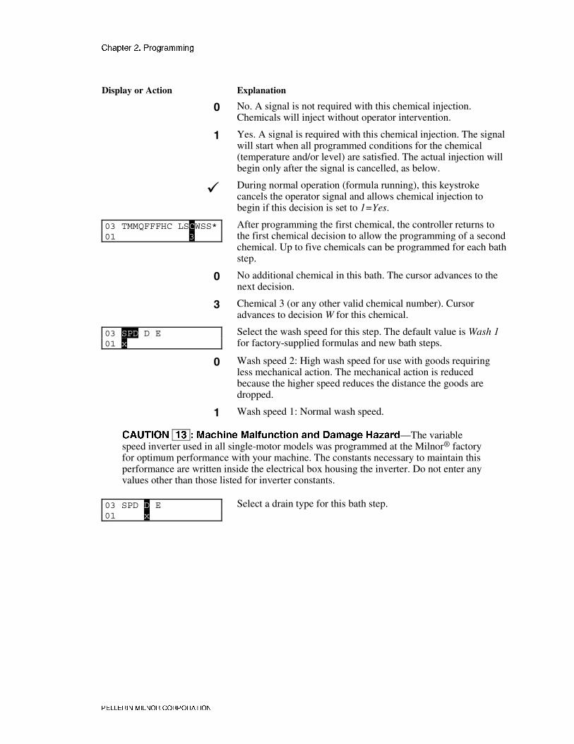
0 No. A signal is not required with this chemical injection.Chemicals will inject without operator intervention.
1 Yes. A signal is required with this chemical injection. The signalwill start when all programmed conditions for the chemical(temperature and/or level) are satisfied. The actual injection willbegin only after the signal is cancelled, as below.
� During normal operation (formula running), this keystrokecancels the operator signal and allows chemical injection tobegin if this decision is set to 1=Yes.
03 TMMQFFFHC LSCWSS*01 3
After programming the first chemical, the controller returns tothe first chemical decision to allow the programming of a secondchemical. Up to five chemicals can be programmed for each bathstep.
0 No additional chemical in this bath. The cursor advances to thenext decision.
3 Chemical 3 (or any other valid chemical number). Cursoradvances to decision W for this chemical.
03 SPD D E01 x
Select the wash speed for this step. The default value is Wash 1for factory-supplied formulas and new bath steps.
0 Wash speed 2: High wash speed for use with goods requiringless mechanical action. The mechanical action is reducedbecause the higher speed reduces the distance the goods aredropped.
1 Wash speed 1: Normal wash speed.
�� !�"� �% � 3������ 3��1������� ��� ����� ,�-���—The variablespeed inverter used in all single-motor models was programmed at the Milnor® factoryfor optimum performance with your machine. The constants necessary to maintain thisperformance are written inside the electrical box housing the inverter. Do not enter anyvalues other than those listed for inverter constants.
03 SPD D E01 x
Select a drain type for this bath step.

������� �� ��������� �
�������� ����� �������
Display or Action Explanation
0 Standard drain speed—basket turns clockwise at drain(distribution) speed.
1 Two-way wash speed—basket reverses at wash speed to providemore mechanical action on the goods as the bath liquor isdraining away.
2 Do not drain—bath liquor is retained for later operations in thissame bath. Chemicals may be added, and temperature or levelmay be raised without draining.
3 Stop with fill—the basket is kept stationary during the fillprevious to this drain, but rotates at drain speed for this drain.
4 Stop with drain—the basket is kept stationary during the drain,allowing no mechanical action.
5 Stop with fill and drain—a combination of drain types 3 and 4,the basket is held stationary during the previous fill and thecurrent drain.
03 SPD DRE01 x
If machine is equipped and configured for a second drain, selectthe drain destination for this step.
0 Drain to sewer
1 Drain to reuse
03 TMMQFFFHC LSCWSS*02 x
The cursor returns to this display to program the next step unlessthe step just programmed is the last step of a formula or if thenumber of steps exceeds 50, in which case the cursor advancesto decision E.
END FORMULA #030 NO
Appears if T=0 in previous display and this is not the lastavailable step in this formula.
0 No. Aborts the previous T=0 selection. Display returns to the T(type of step) decision.
1 Yes. Accepts that the formula ends here.
03 SPD D E02 x
Determine how this formula is to end.

������� �� ��������� �
�������� ����� �������
Display or Action Explanation
0 Stopped. Operator must press � to silence the signal.
1 Reversing at wash speed. Operator must press � to end theformula.
2 Drain speed. Operator must press � to end the formula.
3 Tumble at wash speed. Signal sounds after two minutes.Operator must press � to end the formula.
4 Stop. The operator signal sounds for two minutes, then themachine shuts off. The operator can end the formula before thistime expires by pressing �. This option is available only on FxJand 36-inch or 42-inch VxJ machine models running softwareversion 9B005 and later.
5 Reversing. The basket reverses at wash speed and the operatorsignal sounds for two minutes, then the machine and signal bothshut off. The operator can end the formula before this timeexpires by pressing �. This option is available only on FxJ and36-inch or 42-inch VxJ machine models running softwareversion 9B005 and later.
6 Drain speed. The basket turns at drain speed and the operatorsignal sounds for two minutes, then the machine and signal bothshut off. The operator can end the formula before this timeexpires by pressing �. This option is available only on FxJ and36-inch or 42-inch VxJ machine models running softwareversion 9B005 and later.
7 Tumble. The basket rotates for two minutes, then the signalsounds while the basket rotates for another two minutes, then themachine and signal both shut off. The operator can end theformula before this time expires by pressing �. This option isavailable only on FxJ and 36-inch or 42-inch VxJ machinemodels running software version 9B005 and later.
ADD/CHANGE FORMULA00 RETURN TO MENU
Appears if step just previously programmed is the last step of theformula. The controller is prepared for adding or editing anotherformula, or returning to the Programming menu.
� Returns to the Program menu.
PROGRAM 0 MENU 0K TURN KEY TO RUN
This is the Program menu.
� Saves changes and new formulas, then returns to the Run mode.
�� !�"� �( � '����� &���������� ������� ��� �����—If the program keyis turned to � at this point, all programming changes will be lost when power to themachine is turned off. Later software versions allow the person programming themachine to correct the error, as described below.
RUN KEY TURNED EARLYALL NEW CHANGES LOST
This message appears on later software versions only. Itindicates that the key was turned to � before � was pressed.

������� �� ��������� �
�������� ����� �������
Display or Action Explanation
� Returns the controller to the Program menu.
PROGRAM 0 MENU OK TURN KEY TO RUN
This is the Program menu, from which the operator can correctlysave the modified formulas.
�, � Saves all formula modifications and returns the controller to theRun mode.
PLEASE WAIT This display indicates that the formula modifications are beingsaved in permanent memory.
RUN FORMULA00 OK TO POWER OFF
This is the Run Formula display.
���������� ��������"�������������������—Use the procedures detailed above to navigate in aformula and make changes. The following procedures should be used to return to the formulamenu and either save or discard the changes made.
Display or Action Explanation
� Saves all changes if the cursor is on the Step Number. This keymay need to be pressed more than one time to exit the formula.
� Exits the formula and discards all changes made during thisprogramming session.
������ �������������������>+�����)?Because the microprocessor control system used in this machine is capable of controlling
several different models with a wide variety of options, each unit must be configured to match itsspecific model and type of washer-extractor. This configuration informs the microprocessor ofthe characteristics of this machine, such as the number of water valves, the presence oftemperature control, cooldown, etc. Such decisions are discrete to the specific machine and mustnever be changed unless options are later added or removed. In addition to these hardware-specific decisions, certain configuration choices, such as the display of English or metric units,are left to the discretion of the owner/operator.
�� !�"� �) � ���1����� ��� �� �� ����—If the controller loses power eitheraccidentally or intentionally while in the Configure mode, all configuration data may becorrupted. Reconfigure the controller at installation and any time a memory error isdetected. Although certain codes are discretionary and are so marked below, mostconfigure codes must match those shown on the metal configuration nameplate unlessoptional equipment has been added to or removed from the machine.
�������� ��5���7��%������3��'%�������������
Display or Action Explanation
PROGRAM 2 MENU CONFIGURE
This display indicates that the controller is in Program modewith the Configure menu selected for access.
� Access the Configure menu and displays the first configurationdecision.
TEMP CONTROL?0=NO 1=YES 0
The value that appears here may vary according to how thecontroller was last configured.

������� �� ��������� �
�������� ����� �������
Display or Action Explanation
� Accepts the displayed selection and automatically advances tothe next configure decision.
� Accepts the displayed selection and reverts to the previousconfigure decision. In certain cases earlier decisions will affectlater ones.
�������� ������������#��������
Display or Action Explanation
� Accepts the selected value for the current decision and advancesthe cursor to the next decision, regardless of the status of thehelp screen. This action is required for each configurationdecision.
TEMP CONTROL0=NO 1=YES 1
Select 0=No if this machine is not equipped with steam,cooldown, or the equipment required to provide or control theseoptional functions. If 0=No is selected, the next availabledecision will be Extra Water.
Select 1=Yes if this machine is equipped with the necessaryvalves and supply piping to perform steaming and/or cooldown,as well as any necessary electronic boards to control theseoptions.
TEMP UNITS0=°F 1=°C 0
Select 0=°F to use Fahrenheit as the temperature scale.
Select 1=°C to use Celsius as the temperature scale.
�� �� This decision appears only if the machine is configuredfor temperature control (the value for the Temp Control decision,above, must be 1).
STEAM ERROR0 = NO STEAM 0
This decision appears only if the machine is configured fortemperature control (described above).
Select 0=No Steam if the machine is not equipped for steaming,as in the case of a machine with temperature control usedexclusively for cooldown.
Select from options 1 through 3 if steam is available. Thenumber of minutes selected is the maximum time that themachine will steam in an attempt to achieve the desiredtemperature before a steam error is displayed. This self-clearingerror does not stop machine operation. However, for formulasteps where the timer is commanded to stop while steaming untilthe desired temperature is achieved, production may be severlyrestricted by steam errors.
������� �� ��������� �
�������� ����� �������
Display or Action Explanation
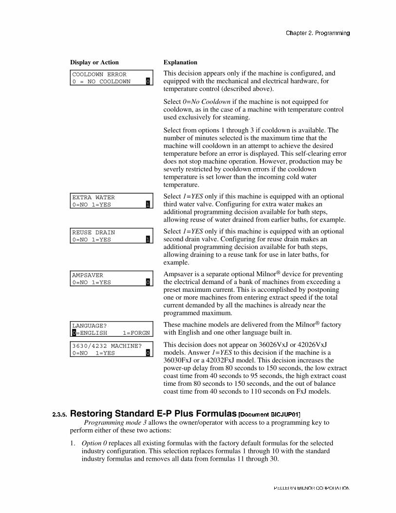
COOLDOWN ERROR0 = NO COOLDOWN 0
This decision appears only if the machine is configured, andequipped with the mechanical and electrical hardware, fortemperature control (described above).
Select 0=No Cooldown if the machine is not equipped forcooldown, as in the case of a machine with temperature controlused exclusively for steaming.
Select from options 1 through 3 if cooldown is available. Thenumber of minutes selected is the maximum time that themachine will cooldown in an attempt to achieve the desiredtemperature before an error is displayed. This self-clearing errordoes not stop machine operation. However, production may beseverly restricted by cooldown errors if the cooldowntemperature is set lower than the incoming cold watertemperature.
EXTRA WATER0=NO 1=YES 1
Select 1=YES only if this machine is equipped with an optionalthird water valve. Configuring for extra water makes anadditional programming decision available for bath steps,allowing reuse of water drained from earlier baths, for example.
REUSE DRAIN0=NO 1=YES 1
Select 1=YES only if this machine is equipped with an optionalsecond drain valve. Configuring for reuse drain makes anadditional programming decision available for bath steps,allowing draining to a reuse tank for use in later baths, forexample.
AMPSAVER0=NO 1=YES 0
Ampsaver is a separate optional Milnor® device for preventingthe electrical demand of a bank of machines from exceeding apreset maximum current. This is accomplished by postponingone or more machines from entering extract speed if the totalcurrent demanded by all the machines is already near theprogrammed maximum.
LANGUAGE?0=ENGLISH 1=FORGN
These machine models are delivered from the Milnor® factorywith English and one other language built in.
3630/4232 MACHINE?0=NO 1=YES 0
This decision does not appear on 36026VxJ or 42026VxJmodels. Answer 1=YES to this decision if the machine is a36030FxJ or a 42032FxJ model. This decision increases thepower-up delay from 80 seconds to 150 seconds, the low extractcoast time from 40 seconds to 95 seconds, the high extract coasttime from 80 seconds to 150 seconds, and the out of balancecoast time from 40 seconds to 110 seconds on FxJ models.
������ ��������!��������������7������� ���� �� ����� !��
Programming mode 3 allows the owner/operator with access to a programming key toperform either of these two actions:
1. Option 0 replaces all existing formulas with the factory default formulas for the selectedindustry configuration. This selection replaces formulas 1 through 10 with the standardindustry formulas and removes all data from formulas 11 through 30.

������� �� ��������� �
�������� ����� �������
2. Option 1 replaces only formulas 1 through 10 with the standard industry formulas. Thisleaves any user-programmed data in formulas 11 through 30 intact.
�� !�"� �. � ����� ��� ����—Other than the two methods described above, itis not possible to selectively delete field-modified or field-programmed formulas withthis programming mode. This mode erases all field-programmed formulas 1 through 10or 1 through 30 as specified. For selective deletions and modifications, use Programmode 1 (Add/Change Formula).
The remainder of this document details the procedure for restoring the industry standardformulas on models employing the Milnor® E-P Plus® controller.
Display or Action Explanation
PROGRAM 0 MENU OK TURN KEY TO RUN
This is Option 0 of the Program menu. From this display, eitherreturn to Run mode or select another menu item.
� / � Scrolls available choices (0 through 3) in the Program menu.
PROGRAM 3 MENU STANDARD FORMULAS
This is Option 3 of the Program menu.
� Accesses the Standard Formulas option of the Program menu.
CORRECTIONAL LAUNDRY0 DEFAULT 30 FORMULA
Option 0 (Default 30 Formulas) of the Standard Formula menueffectively deletes all 30 formulas, then replaces formulas 1through 10 with the factory-supplied standard formulas for theselected industry. Formulas 11 through 30 are replaced withblank formulas.
CORRECTIONAL LAUNDRY1 DEFAULT 10 FORMULA
Option 1 (Default 10 Formulas) deletes only formulas 1 through10 and replaces them with the factory-supplied standardformulas for the selected industry. Formulas 11 through 30 arenot modifed with this selection.
� / � Scrolls the available choices (0 Default 30 Formulas or 1Default 10 Formulas).
� Cancels this procedure without changing or deleting anyformulas.
PROGRAM 3 MENU STANDARD FORMULAS
If the procedure is cancelled, the display returns to Option 3 ofthe Program menu.
� Defaults the selected set of formulas, either 1 through 30, or 1through 10.
CORRECTIONAL LAUNDRY ** PLEASE WAIT **
Appears for approximately five seconds as the standard formulasare written.
PROGRAM 3 MENU STANDARD FORMULAS
Replaces the previous display when the process is completed.
� / � Scroll to Program menu item 0 before exiting Program mode.
PROGRAM 0 MENU OK TURN KEY TO RUN
This is Program menu item 0. It's now safe to turn theRun/Program keyswitch to the Run position.

������� �� ��������� �
�������� ����� �������
Display or Action Explanation
� � Returns to Formula menu.
RUN FORMULA00 OK TO POWER OFF
Formula menu; run a formula or shut down the machine.
— End of BICJHP01 —

������� �� ������� �
�������� ����� �������
�������*
+��������
Document .............. BICJHO01Spec Date ................ 20000905* ( �������7������As-of Date ............... 20000905
������ ����������%��
Display or Action Explanation
� The Run/Program keyswitch must be set to the Run positionbefore the main wall disconnect (fuse or circuit breaker) isclosed to provide power to the machine.
When power is first applied to the machine, the display shows the software copyrightinformation, machine name, and the checksum number. The checksum number changes with anyprogramming change. To detect unauthorized programming, record the checksum at the end ofeach authorized programming session and compare it to the checksum displayed at each powerup.
Some Milnor® washer extractors with E-P Plus® controls do not use a speed sensing deviceto verify that the basket has stopped rotating. Therefore, when power is first applied to themachine, at least 80 seconds must elapse before any further operations can be attempted. Thisprovides sufficient time for the basket to coast to a complete stop if power was lost while themachine was in a high speed extract and restored before the basket stopped.
���'� �0 � '����������� ,�-���—The linen inside or hanging partiallyoutside a turning cylinder can suddenly wrap around your hand, arm, or body. Theinertia of the spinning cylinder can cause the entangled linen to twist off or sever bodyparts. You can be killed or seriously injured.• Never put any part of your body inside this machine or touch the linen while the
machine is turning.
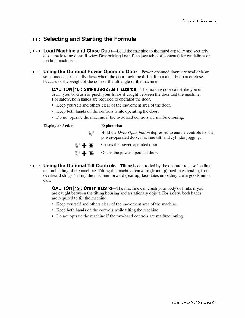
������� �� ������� �
�������� ����� �������
������ !�����������!����������7������
�������� /������������������#���—Load the machine to the rated capacity and securelyclose the loading door. Review Determining Load Size (see table of contents) for guidelines onloading machines.
�������� ��������+���������%���+�������#���—Power-operated doors are available onsome models, especially those where the door might be difficult to manually open or closebecause of the weight of the door or the tilt angle of the machine.
�� !�"� �4 � *���+� ��� ����� ��-����—The moving door can strike you orcrush you, or crush or pinch your limbs if caught between the door and the machine.For safety, both hands are required to operated the door.• Keep yourself and others clear of the movement area of the door.• Keep both hands on the controls while operating the door.• Do not operate the machine if the two-hand controls are malfunctioning.
Display or Action Explanation
Hold the Door Open button depressed to enable controls for thepower-operated door, machine tilt, and cylinder jogging.
� Closes the power-operated door.
� � Opens the power-operated door.
�������� ��������+�������������������—Tilting is controlled by the operator to ease loadingand unloading of the machine. Tilting the machine rearward (front up) facilitates loading fromoverheard slings. Tilting the machine forward (rear up) facilitates unloading clean goods into acart.
�� !�"� �6 � ����� ��-���—The machine can crush your body or limbs if youare caught between the tilting housing and a stationary object. For safety, both handsare required to tilt the machine.• Keep yourself and others clear of the movement area of the machine.• Keep both hands on the controls while tilting the machine.• Do not operate the machine if the two-hand controls are malfunctioning.

������� �� ������� �
�������� ����� �������
Display or Action Explanation
Hold the Door Open button depressed to enable controls for thepower-operated door, machine tilt, and cylinder jogging.
� Set the Front/Rear Tilt switch to the Rear Up position to tilt themachine forward for unloading or to return it to the normaloperating position after unloading.
Set the Front/Rear Tilt switch to the Front Up position to tilt themachine rearward for loading or to return it to the normaloperating position before starting a formula.
� � � � Hold the Door Open button depressed and turn and hold the TiltUp/Down switch to tilt the machine to the desired position.Release the Tilt Up/Down switch when the desired tilt angle isreached. Tilting will stop automatically when the tilt limit isreached.
�������� 8�����������������>+�������?—When the machine is idle (a formula is not running),the cylinder can be manually jogged while tilted rearward to help draw in goods during loading.Similarly, the cylinder can be manually jogged when tilted forward to help discharge goods fromthe machine.
�� !�"� #8 � ����� ��-���—Contact with the rotating cylinder can crush yourlimbs. For safety, both hands are required to jog the cylinder.• Keep yourself and others clear of the cylinder and goods during jogging operations.• Keep both hands on the controls while jogging the cylinder.• Do not operate the machine if the two-hand controls are malfunctioning.
Display or Action Explanation
Hold the Door Open button depressed to enable controls for thepower-operated door, machine tilt, and cylinder jogging.
� � Jogs the cylinder clockwise.
� � Jogs the cylinder counter-clockwise.
�������� !���������7������
Display or Action Explanation
RUN FORMULA00 OK TO POWER OFF
This is the Run Formula display. From this display, the operatorcan disconnect power from the machine without risking damageto electronic parts, or he can select a formula to run, as describedbelow.
� indexes forward through the 30 formulas.
� indexes backward through the 30 formulas.
RUN FORMULA07 FORMULA NUMBER 07
Example display: Formula 07 selected for running.

������� �� ������� �
�������� ����� �������
Display or Action Explanation
� starts the machine with the selected formula.
RUN FORMULADOES NOT EXIST
indicates that the formula selected for running has not beenprogrammed or is not available. This display appears for threeseconds.
������ �������������������How a formula ends depends on the machine type, how the last step of the formula was
programmed, and whether the formula finishes without interruption or is terminated manually.
���'� #� � '����������� ,�-���—The linen inside or hanging partiallyoutside a turning cylinder can suddenly wrap around your hand, arm, or body. Theinertia of the spinning cylinder can cause the entangled linen to twist off or sever bodyparts. You can be killed or seriously injured.• Never put any part of your body inside this machine or touch the linen while the
machine is turning.
When a formula ends normally or is terminated, the door remains locked while the cylindercoasts to a stop. The delay times between the end of the formula and when the door unlocks aregiven in Table 7.
Table 7: Coast Times at Program End or Termination
Machine Model
Step Type MxJ SxJ36026 &
42026VxJ Standard FxJ 42032 F8J
Bath 15 sec. 15 sec. 15 sec. 15 sec. 15 sec.
Low Extract 45 sec. 65 sec. 45 sec. 60 sec. 114 sec.
High Extract 95 sec. 95 sec. 80 sec. 95 sec. 135 sec.
QxJ models are equipped with a speed switch and braking system, allowing the door tounlock when the basket has slowed to a safe speed and when the water level is below the bottomof the door.
If the formula runs to completion, all coast time is included in the overall time. Thus, duringcoast, the normal automatic display (shown in section 3.1.4 ) continues.
�� �� Depending on the How to End code, the controller will describe how the cycle is ending andinstruct the operator to press � to escape this step in the cycle.
Display or Action Explanation
UNLOCKING THE DOORPLEASE WAIT
display during the last 15 seconds of coast, or during the entirecoast time if the formula was manually terminated.
WAITING TO UNLOAD U
At the end of the coast time, the operator alarm sounds.
� Silences the operator alarm. The door unlocks, and the machinemay be unloaded.

������� �� ������� �
�������� ����� �������
������ ���#���������������������+��������
Display or Action Explanation
23:04 F02S01 02:37dF=A168/D170 LEV 1
23:04 STEP 01 02:37dF=A168/D170 SPD 0
These two displays alternate during normal operation.
23:04 F02S01 02:37 23:04 is the time remaining in the formula.
F02S01 indicates that the current formula is 02 (F02) and thecurrent step is 01 (S01).
02:37 is the time remaining in this step.
23:04 STEP01 02:37 STEP01 is the current step
EXTRACT indicates that the machine is currently executing anextract.
TIMEHALT indicates that the timer is stopped while a chemicalis being injected. The chemical supplier must connect equipmentfor this option.
dF=A168/D170 LEV 2Temperature in this machine is measured in degrees Fahrenheitor Celsius, according to machine configuration.
dF indicates that temperature is shown in degrees Fahrenheit; dCindicates degrees Celsius.
A168 indicates that the current achieved temperature is 168degrees. Temperature is displayed only if the machine isequipped with and configured for temperature control.
D170 indicates that the desired temperature for this step is 170degrees. Temperature displays only if machine is equipped withand configured for temperature control.
LEV 2 indicates that the bath level achieved is Level 2.
SPD 0 LEV 2SPD 0 indicates the bath speed (either 0 or 1) for this step.
WAIT FOR LEVEL 2 H indicates that Level 2 is programmedfor this step, but is not yet achieved. The H indicates that the hotwater valve is open; C indicates cold water, and 3 indicates extrawater.
CHEM 03 is displayed when Chemical 03 is being injected. Thenumber for each chemical (up to five may be connected) isdisplayed as the chemical is injected. See also section 3.1.7 forinformation about the chemical flush valve.
FINAL EXTRACT indicates that the step in progress is the finalstep of the wash formula.

������� �� ������� �
�������� ����� �������
������ $�%��!������:���������:��!�������������7������
Display or Action Explanation
� + � Cancels a step. Advances the step timer to zero for any bath, adrain not followed by an extract, or any extract in progress. Thenext step begins automatically.
This operation is possible only if DIP switch 6 on the processorboard is in the on position, allowing the cancelling of steps.
� On QxJ models only, this keystroke suspends a formula inprogress. The drain opens, the machine stops, and the operatoralarm sounds. � resumes the suspended formula.
� Cancels the current formula and returns the machine to the RunFormula display.
RUN FORMULA00 OK TO POWER OFF
This is the Run Formula display. The door interlock, describedin section 3.1.3 , must expire before the door can be opened.
������ $�%���������������%��/���The E-P Plus® control remembers the formula and step it was executing if power fails or if
the wall disconnect or master switch is turned off while the machine is operating in automaticmode.
Display or Action Explanation
PRESS START TO RUNSTEP xx - FORMULA yy
On most machine models, this display appears when power isrestored. The formula and step which were in progress whenpower was interrupted are shown.
ENABLE 3-WIRE TO RUNSTEP xx - FORMULA yy
On QxJ models, this display appears when power is restored.The formula and step which were in progress when power wasinterrupted are shown.
� Resumes the formula at the displayed formula and step. If theoutage occured in a bath step, level and temperature (ifcommanded) must again be satisfied, even if these were alreadysatisfied before power was lost. Any commanded chemicals willbe injected again.
If the outage occured during a drain, that step will be repeated,then followed by the next commanded step.
If the outage occured during an extract step, the previous bathwill be repeated before the extract step begins.
� Terminates the formula in progress.
����"� $�%���7����<��5�1��'�The E-P Plus® controller includes an output signal that activates the flush valve for 30
seconds after the last chemical has been injected into each bath. If a bath is shortened orterminated before of while this valve is energized, the flush valve will be turned off. Shorteningor terminating a bath may prevent the flush valve from activating.

������� �� ������� �
�������� ����� �������
����#� $�%������%�1��'�Goods must be cool enough to handle immediately after a wash cycle is finished. However, a
drastic temperature change may set wrinkles in goods of certain fabrics. Therefore, many Milnor®
washer extractors employ a feature called cooldown to gradually lower the water temperature andthus provide cool goods at the end of the wash cycle without setting wrinkles.
For SxJ and MxJ models, the cooldown valve is turned on until the cooldown step iscompleted (desired temperature is reached), regardless of level.
For FxJ, QxJ, and VxJ models, the cooldown valve is turned on until high (cooldown) levelis reached. This causes the drain to open and the cooldown valve to close until high level is lost.When high level is lost, the drain closes and the cooldown valve opens. This process continuesuntil the cooldown step is complete.
— End of BICJHO01 —
Document .............. BICJUD01Spec Date ................ 20000905* ) <��%�����������������7�����������
����������� As-of Date ............... 20000905
The microprocessor controller increments a discrete counter for each formula near the end ofthe formula. This count is maintained until the counter is cleared. The maximum number of timesa formula can be counted before resetting the accumulator is 999, after which the count willremain at 999 until cleared. The count for each formula can only be viewed and/or cleared whilethe machine is in the Run mode but not running a formula (machine is idle).
�� !�"� ## � ����� �����&��� ����������� ���—The accumulated data canbe corrupted or become inaccurate if power is lost for an extended period of time, themaximum count of 999 is reached, or the memory is corrupted by electricalinterference.• Apply power to the machine for at least 15 seconds every 48 hours to retain the
formula count. See “Important Owner/User Information” for more detailedinformation.
• To help ensure an accurate count, record the value and clear each accumulator beforeit reaches 999 counts.
• If the display shows “Accumulator Error,” the count for all formulas must be cleared.See the document on error messages for more information.
Display or Action Explanation
RUN FORMULA00 OK TO POWER OFF
This is the normal display at power-up.
�/ � Selects a formula by indexing forward/backward through theformula numbers (01-30).
With any formula selected,
� Displays the count in the upper right corner of the display.
RUN FORMULA 03805 FORMULA NUMBER 05
This example shows that 38 loads were processed with formula05 since the counter was reset.
� + � Clears the count for the selected formula.
— End of BICJUD01 —

������� �� ������������ �
�������� ����� �������
�������,
���������������
Document ...............BICJHT02Spec Date ................ 20000905, ( ��������������������As-of Date ............... 20000905
������ �������� ��
�������� ����������—The Manual menu is made up of these selections:
1. Software Date Code—a display of the software type and date code, both of which are fixed inthe software; and the industry type, which is determined by setting the DIP switches on theprocessor board.
2. Test Inputs—allows viewing of microprocessor inputs for testing when a formula is notrunning. Devices, including the door latch and the level transducer, provide signals to themicroprocessor by grounding certain inputs. The status of these inputs can be monitored inthis mode, and changes to the input status will appear instantaneously.
3. Test Outputs—allows the actuation of outputs for testing when a formula is not running.Outputs are signals from the microprocessor to other devices, such as chemical pumps andmotor contactors.
�������� $�%���������������� ��
Display or Action Explanation
RUN FORMULA00 OK TO POWER OFF
The machine must be idle (power on, but not running a formula)before the Manual menu can be accessed. Also, theRun/Program keyswitch must be at the Run position (�).
� Accesses the Manual menu.
MANUAL MENU1 SOFTWARE DATE CODE
Reverse type indicates blinking cursor position. Select one of theManual menu modes or return to the Run mode, as describedbelow.
� / � Scrolls forward/backward through the available modes of theManual menu.
� Returns to the Run mode.
RUN FORMULA00 OK TO POWER OFF
Run mode selected; control is awaiting selection of a validformula number. The formula number that was selected whenthe Manual menu was accessed appears on the display.

������� �� ������������ �
�������� ����� �������
�������� $�%��������������� �������������� ��
Display or Action Explanation
� Enters the Manual menu from Run mode.
MANUAL MENU1 SOFTWARE DATE CODE
This is the Manual menu display.
� Exits the Manual menu to the Run mode.
RUN FORMULA00 OK TO POWER OFF
This is the Run mode display. Select a formula to run, or turn offmachine power.
������ #�������������!���%���<������
Display or Action Explanation
� Accesses the Manual menu.
MANUAL MENU1 SOFTWARE DATE CODE
Manual menu accessed and Software date code mode selected.
� Depress the Start button to view the software date code andmachine configuration information, as shown below.
EP-PLUS/M 8A008CORRECTIONAL LAUNDRY
Machine style (/M = MxJ), software date code (8A008), andconfiguration (Correctional Laundry).
� Returns to the Manual menu from the Software Date Codedisplay.
MANUAL MENU1 SOFTWARE DATE CODE
From the Manual menu, select another manual function with �/ � or return to Run mode by turning the key to �.
������ <��%�����������������&�����The on/off state of each input to the microprocessor can be displayed by using the Test
Inputs selection of the Manual menu. The machine must be idle (not running a formula).
Display or Action Explanation
� Accesses the Manual menu.
MANUAL MENU2 TEST INPUTS
Manual menu accessed and Test Inputs mode selected.
� Accesses the Test Inputs mode.
ABCDEFGHIJKLMNOP (-)+--++----+----+- OFF
The input display code on the top row corresponds to a displaycode in Table 8. The status of the input is displayed beneath eachcode. If the input is energized, a “+” appears. Non-energizedinputs are represented by “–”.
� Restores the controller to the Manual menu.
MANUAL MENU2 TEST INPUTS
From the Manual menu, select another manual function with �/ � or return to Run mode by turning the key to �.

������� �� ������������ �
�������� ����� �������
Table 8: E-P Plus Inputs
Display Code Input Name Model Connector-Pin
A Select Program button all MTA4-6
B Door is Closed all MTA4-5
C Next/Signal Cancel button all MTA4-4
D Terminate button all MTA4-3
E Low Level switch all MTA4-2
F Start button all MTA4-1
G Auto/Manual switch all MTA5-6
Scroll button allH (see note)
Cooldown Level (if so equipped) QxJMTA5-5
Three-wire QxJI
Vibration switch SxJ, FxJMTA5-4
Speed switch QxJJ
Inverter Fault FxJ, VxJMTA5-3
K High Level switch all MTA5-2
L Run/Program keyswitch all MTA5-1
M not used — MTA8-4
N AmpSaver Acknowledge all MTA8-3
O External Fault all MTA8-2
P Halt Bath Time all MTA8-1
�� �� Input H is shared by the Scroll button (�) and cooldown level on QxJ models only.
������ �����������������������+������Machine functions may be tested individually or in groups by using the Test Outputs
component of the Manual menu. The machine must be idle (not running a formula).
���'� #% � �������� ��� '����������� ,�-���—Bare manual outputsactuate washer-extractor mechanisms. Keep all personnel clear.
Display or Action Explanation
� Accesses the Manual menu.
MANUAL MENU3 TEST OUTPUTS
This is the Manual menu display with the Test Outputscomponent selected.
� Accesses the output testing selection.
TEST OUTPUTS01 INJECT CHEMICAL 5
This is the Output testing display.
� / � Indexes forward and backward through the output names, asshown in Table 9.
TEST OUTPUTS07 COLD WATER VALVE
Example display with output in place to be selected andsubsequently actuated.

������� �� ������������ �
�������� ����� �������
Display or Action Explanation
� Accesses the selected output for actuation. All outputs areinitially disabled when accessed.
COLD WATER VALVE0=OFF 1=ON 0
Example display with output accessed and disabled.
� Enables the output (turns the output on).
COLD WATER VALVE0=OFF 1=ON 1
Example display with output enabled. The cold water valve isopen.
� If the output was already on, this keystroke turns it off.
COLD WATER VALVE0=OFF 1=ON 0
Example display with output disabled. The cold water valve isclosed.
� Disables (turns off) the output if it was previously enabled, andadvances to the next output.
HOT WATER VALVE0=OFF 1=ON 0
Display after pressing � to advance to the next output.
� Disables the output if it was enabled, then returns to the Manualmenu.
MANUAL MENU3 TEST OUTPUTS
Display of Manual menu.
� Turns off the output if it was on, then returns to the Run mode.
RUN FORMULA00 OK TO POWER OFF
Display of Run mode.

������� �� ������������ �
�������� ����� �������
Table 9: E-P Plus Outputs
OutputNumber Models Description
OutputDevice Consequences of Actuation
MxJ, Q4J Wash clutch 0=extract clutch energized; 1=washclutch energized1
all others Logic outputK0
operates logic output
2 all Cold water valve K1 Opens valve
3 all Hot water valve K2 Opens valve
4 all Inject chemical 5 K3 Operates chemical inject device
5 all Inject chemical 1 K4 Operates chemical inject device
6 all Inject chemical 4 K5 Operates chemical inject device
7 all Inject chemical 3 K6 Operates chemical inject device
8 all Inject chemical 2 K7 Operates chemical inject device
FxJ, MxJ,VxJ, SxJ Extract speed (use only with
empty basket)
Prevents door from opening, releasesbrake (if any), and turns basket at drainspeed9
QxJ Not used—see Output 24 test
K8
10all Distribution speed (door must
be closed) K9Prevents door from opening, releasesbrake (if any), and turns basket at drainspeed
11all Clockwise wash speed (door
must be closed) K10Prevents door from opening, releasesbrake (if any), and turns basket CW atwash speed
12all Counterclockwise wash speed
(door must be closed) K11Prevents door from opening, releasesbrake (if any), and turns basket CCWat wash speed
FxJ, MxJ,VxJ, SxJ Buzz signal Sounds operator alarm
13QxJ Brake
K12Releases brake
FxJ, MxJ,VxJ, SxJ Flush valve Opens flush valve
14QxJ Buzz signal
K13Sounds operator alarm
15 all Drain solenoid K14 Closes drain
FxJ, MxJ,VxJ, SxJ Door interlock Energizes door lock
16QxJ Flush valve
K15Opens flush valve
17 all Reuse drain (optional) K16 Operates reuse drain if present
18 all Extra water (optional) K17 Operates extra water if present
19 all Cooldown (optional) K18 Operates cooldown if present
20 all Steam (optional) K19 Operates steam if present
21 all Ampsaver (optional) K20 Operates Ampsaver if present
22 all not used K21 Operates output

������� �� ������������ �
�������� ����� �������
OutputNumber Models Description
OutputDevice Consequences of Actuation
23 all Reversing wash speed (doormust be closed) Test Lock door, release brake (if any) and
turn basket reversing at wash speed
FxJ, MxJ,VxJ Test
Lock door, CW wash for 0:20, drainfor 0:20, E1 for 0:60, E2 (E3 for FxJand VxJ)24
QxJ
High speed extract (use onlywith empty basket; door mustbe closed)
Test Lock door, CW wash for 0:04, drainfor 0:08 (except SxJ), E2
25 all Fill to low level (level 1);(door must be closed) Test Lock door, close drain, cold water to
level 1, cold water off
26 all Fill to high level (level 2);door must be closed) Test Lock door, close drain, cold water to
level 2, cold water off
— End of BICJHT02 —
Document ...............BICJHT01Spec Date ................ 20000905, ) �������������As-of Date ............... 20000905
������ �����������������%����If an error message appears during power up, the error must be cleared before the machine
can be run or programmed.
Display or Action Explanation
ACCUMULATOR ERRORTERMINATE TO CLEAR
The microprocessor performs a memory check each time themachine is turned on. This error message appears if themicroprocessor detects that the accumulator data is corrupt, inwhich case all accumulators must be reset to zero.
� Resets all accumulators and clears the error message. See“Viewing and Clearing the Formula Count Accumulator” (seeTable of Contents) for more information.
CHECKSUM ERROR,TURN KEY TO PROGRAM
Appears if there is illegal data in the configuration, formula, orindustry memory areas. Use the following procedure to clear thiserror.
1. Reconfigure the machine according to the configuration information in “Programming the E-P Plus® Control” (see Table of Contents).
2. Reinstall the standard (default) formulas according to the default formula loading procedurein “Programming the E-P Plus® Control”.
3. Reprogram any lost wash formulas according to “Programming the E-P Plus® Control”.
MEMORY: EEPROMIS NOT TALKING
This message appears when the microprocessor cannot read fromthe EEPROM (memory chip).

������� �� ������������ �
�������� ����� �������
Display or Action Explanation
1. Lock off and tag out power to the machine.
2. Replace flash memory. Contact the Milnor® factory to ensure that the replacement memory isthe most current version for your machine.
3. Restore power to machine.
4. Reconfigure the machine according to the configuration information in “Programming the E-P Plus® Control” (see Table of Contents).
5. Reinstall the standard (default) formulas according to the default formula loading procedurein “Programming the E-P Plus® Control”.
6. Reprogram lost wash formulas according to “Programming the E-P Plus® Control”.
A/D BOARD IS NOTTALKING
This error message indicates that the analog to digital board isnot communicating with the microprocessor.
1. Lock off and tag out power to the machine.
2. Check the connections at both ends of the ribbon cable between the processor board and theanalog to digital board.
3. Restore power.
4. If the error persists, lock off and tag out power to the machine. Have a qualified servicetechnician replace the the suspect board.
������ �������������������"�����+��������If an error message appears on the bottom line of the display while the machine is running,
the timer shown on the top line will stop counting. When the error is corrected, the timer resumescounting down. To troubleshoot most errors, suspend the formula in progress and turn power off.Do not terminate the formula if it is to be resumed after the error is corrected. See "Running aFormula" for more information.
Display or Action Explanation
DOOR NOT CLOSEDThis error message indicates that the door input is not madewhile the machine is running. Verify that the door is closed, thencheck the door switch and its connection to the microprocessor.Press � if necessary to resume operation after the error iscorrected. Never operate this machine while this message ispresent.
CHECK LEVEL SWITCHThe level switch may be faulty, perhaps reporting that level 2was achieved before level 1. Check the level switch and its inputconnection to the microprocessor.
LEVELS STILL MADEThe microprocessor is still receiving information that a level ismade just before or during an extract step, or immediately beforethe fill for a bath step. This error is self-clearing when level islost.
TOO LONG TO FILLTime to fill to level exceeded 10 minutes. Check the watervalves, strainers, supply lines, and water pressure. The machinewill continue to fill until level is reached, at which time the errorwill automatically clear and normal operation will resume.

������� �� ������������ �
�������� ����� �������
Display or Action Explanation
TOO LONG TO STEAMThe configured maximum time to steam up to the desiredtemperature has been exceeded. Check the steam valve, strainer,main steam header and pressure, etc. Steaming will continueuntil temperature is achieved, when the error will automaticallyclear and normal operation will resume.
TOO LONG TO COOLThe configured maximum time to cool down to the desiredtemperature has been exceeded. Check the cooldown valve andstrainer if equipped, cold water pressure, and position of verniervalve on cooldown inlet. Cooldown will continue until thedesired temperature is achieved, when the error willautomatically clear.
TOO LONG TO DRAINThe machine did not drain properly in the allotted drain time.This self-correcting error will clear when the water level in thebasket is low enough to begin the next operation.
CHECK PROBEThis error message indicates that the resistance of thetemperature probe is outside the specified range. Test the probeby disconnecting the probe leads from the processor board andchecking the resistance with an accurate digital ohmmeter.Resistance between the two leads must be between 2K and 35KOhms. Resistance between each lead and ground must beinfinite.
EXTERNAL FAULTThe programmed chemical injection failed, usually because thechemical supply system is empty. When chemicals are addedand can be injected, this error will clear automatically, allowingoperation to resume.
THREE WIRE DISABLEDThe three-wire relay de-energized. This relay provides controlcircuit power to the machine. Once energized by momentarilydepressing the start button (�), it is held energized by its ownnormally open contacts, along with motor overloads, doorinterlocks, etc. Should any of these contacts open evenmomentarily, the machine stops and this display appears. Thiserror can only be cleared by depressing the start button (�), andonly then if the error has been cleared.
INVERTER FAULTThis error message appears if the microprocessor does notreceive an input from the inverter within 14 seconds of thebeginning of the formula. After 14 seconds without an inverterinput, the timer stops, the basket is stationary, and the drainvalve opens. To recover, press the Next key (�).
VIBRATION SW TRIPPED RECOVERY SEQUENCE
When the vibration switch closes, the timer stops. After 80seconds (120 seconds on 42032F7J models), the basket reversesat wash speed as the cylinder fills with water. When low level isachieved, the cylinder reverses for one additional minute at washspeed, then accelerates to extract speed.
— End of BICJHT01 —

������� �� ������ �� ! ��������
�������� ����� �������
�������-
!�����������&����������
Document ............... BICJUF01Spec Date ................ 20000905- ( ����������$���%���As-of Date ............... 20000905
The Milnor® E-P Plus® microprocessor control is designed specifically for Milnor® washer-extractors. Along with certain external electromechanical relay logic and sensing devices, itcontrols all machine and system functions. Not every microprocessor system includes all thefollowing components.
������ @���%������
�������� ��.�������@���%����—This keyswitch allows controlling who has the necessary accessto modify wash formulas. Formulas can be modified only when this switch is turned from the Runposition (�) to the Program position (�). To safeguard wash formulas, keep this key in asecure place with restricted personnel access.
�������� ���������.����@���%����—This keyswitch allows controlling who has the necessaryaccess to operate the machine in Test mode for troubleshooting. Test mode can only be accessedwhen this switch is turned from the Automatic position (�) to the Test position (�). To reducethe risk of personal injury and machine damage, keep this key in a secure place with restrictedpersonnel access.
������ #������Machines in the FxJ and HxJ model lines, as well as the 30015 and 30022VxJ models, use a
vacuum fluorescent display consisting of two lines of 20 characters each. This type of display iseasily identified by green characters on a black background when operating, or a nearly blackbackground when not operating.
Machines in the QxJ, MxJ, and SxJ model lines, as well as the 36026 and 42026VxJ models,use a liquid crystal display consisting of two lines of 20 characters each. This display can beidentified by dark gray characters on a lighter background when operating, or a light graybackground when not operating.
������ ��%��!�����The power supply serves to provide a regulated specific voltage to the processor board and
certain auxiliary boards and devices. It converts control circuit alternating current voltage to +12volts direct current, –12 volts direct current, and +5 volts direct current. The power supply isswitchable between 120 volts and 240 volts alternating current input voltage.
Although the +12VDC and –12VDC are not adjustable, the +5VDC is rather sensitive andthe power supply must be adjusted so the actual voltage at the processor board is between

������� �� ������ �� ! ��������
�������� ����� �������
5.04VDC and 5.06VDC as measured by an accurate digital voltmeter. If this voltage is notwithin the stated range, the machine is likely to malfunction.
������ ������������3����The central processing unit (CPU) processes data received from the various inputs, stores
information, and responds to each pushbutton entry with the appropriate action. Data is stored inone or more of the following types of memory chips on the CPU board, depending on themachine model.
EPROM—Erasable Programmable Read Only Memory contains fixed instructions programmedby Milnor® (software) that determine how the machine functions. The standard industryformulas are also stored here.
EEPROM—Electrically Erasable Programmable Read Only Memory stores all protectedmemory (30 formulas and configure data) for machines using the 788 processor board. Theseare machine models other than the HxJ, TxJ, and 30015 and 30022VxJ. EEPROMs do notrequire a constant source of power to retain memory.
SRAM—Static Random Access Memory stores the accumulator (formula count) data as long asthe machine has power, or via a capacitor for approximately 24 hours with power off. Thistype of component is also used to retain the last formula and step in progress when power isturned off at the machine while a formula is running. SRAM is used in all E-P Plus®
controllers.
������ +������Depending on the processor board, output relays may be either socket-mounted to a separate
output board, or permanently soldered to the processor board. E-P Plus® machines other thanHxJ, TxJ, and 30015 and 30022VxJ models employ the 788 processor board and a separate boardhousing the output relays.
For models other than the HxJ, TxJ, and 30015 and 30022VxJ, the 16 output relays aresocket-mounted SPDT electromechanical relays with contacts capable of faithfully conducting amaximum of 25VA (0.1 ampere (100 millliamperes) at 220/240VAC, or 0.2 amperes (200milliamperes) at a maximum of 110/120VAC). The output voltage will be either 220/240VAC or110/120VAC, depending on machine model and type.
These outputs and their power source are intended only to drive another relay with highercontact ratings that may, in turn, drive a pump, valve, solenoid, etc. from a separate power source.Never use these outputs to directly drive a pump, valve, or solenoid unless the maximum currentrequired never exceeds the above values. Higher ampere or VA loads will burn out traces on theprinted circuit board or possibly overload and damage the control circuit transformer.
������ +�����+������These six output relays are mounted on an optional additional board for machines using the
788 E-P Plus® processor board (models other than HxJ, TxJ, and 30015 and 30022VxJ). Theoption output relays have the same specifications and limitations as those used for the standardoutputs.
����"� ��������#���������5�����This component converts analog signals, such as from the temperature probe, to a digital
signal that can be used by the microprocessor. Up to two analog to digital channels can beprovided on the A/D convertor board used in models other than the HxJ, TxJ, and 30015 and30022VxJ. The A/D convertor also provides a fixed voltage which is used as a reference forsensing temperature.

������� �� ������ �� ! ��������
�������� ����� �������
����#� ����������������A thermistor temperature probe is provided in the machine sump if the machine is equiped
for optional temperature control. This probe is a resistor that changes value according totemperature.
����$� ��������!�����Machine models other than HxJ, TxJ, and 30015 and 30022VxJ use electro-mechanical
pressure switches to detect the water level in the cylinder.
— End of BICJUF01 —
Document ............... BICJFD01Spec Date ................ 20000905- ) $�%��!��1����/�5���As-of Date ............... 20000905
These washer-extractors have the following adjustable water levels:
Table 10: Adjustable Water Levels
Level Suggested Uses
Level 1 (low) Wash, distribution, wetdown
Level 2 (high) Wash, distribution, wetdown
Level 3 (optional) Cooldown
These levels should not normally be altered. If absolutely necessary, however, levels 1 and 2may be reliably adjusted up or down about two inches (5 cm), as explained in this document. Thelevel 3 switch is supplied with optional cooldown and is normally set three inches (7.6 cm) abovelevel 2. On machines manufactured after 1 April 1990, an additional level switch (SPLLS) isprovided to keep the door locked until the bath drops below a certain level. The SPLLS switchsetting must not be altered from the factory setting.
������ 7������!�������Factory settings shown below specify the depth of the bath inside an empty, stationary
cylinder. The levels in open-pocket cylinders (which slope down to the rear) are at the rear(deepest part) of the cylinder. The goods in a loaded, rotating cylinder both absorb water andoccupy space. Thus, depending on load size, type of goods, etc., it is likely that either more orless water will be needed to achieve any level compared to filling an empty, stationary cylinder.
�� !�"� #( � ����� �����:���� ������� �1 �����—Inadequate wetting ofgoods can cause a reduction in wash quality and improper distribution of the goods inthe cylinder prior to extraction.• Do not set Level 1 lower than the factory setting.
Table 11: Factory Water Level Settings
Cylinder Dimensions Level 1 Level 2 Level 3 (optional)
30015 7 inches (17.8 cm) 9 inches (22.9 cm) 14 inches (35.6 cm)
30020/30022 7 inches (17.8 cm) 9 inches (22.9 cm) 14 inches (35.6 cm)
36021 8 inches (20.3 cm) 13 inches (33.0 cm) 15 inches (38.1 cm)
36026 8 inches (20.3 cm) 13 inches (33.0 cm) 15 inches (38.1 cm)
42026 10 inches (25.4 cm) 13 inches (33.0 cm) 15 inches (38.1 cm)

������� �� ������ �� ! ��������
�������� ����� �������
������ $�%�����������!%����1��'�As the water level in the shell of a washer-extractor rises, it exerts a force downward. The
pressure switch is connected by a length of plastic tubing to a point near the bottom of the shell.As the water level in the machine rises, it slightly compresses the air trapped in this plastictubing. It is the pressure of this compressed air that closes the switch, indicating that a certainlevel is achieved.
The function of the various pressure switches found on this machine may be identified by theitem numbers in Table 12 below. The part numbers can be found in the component list, includedin the electrical schematic manual.
Table 12: Function of Level Switches
Switch Item Number Switch Function
SPLL Level 1
SPLH Level 2
SPCD Cooldown
SPLLS OK to Open Door
Each pressure switch has one trip point adjusting screw, as shown in Figure 8. The switchmanufacturer calibrates these switches to achieve the specified level. When the switch isinstalled, the washer is tested for proper water levels and when these are satisfied, the trip pointadjusting screw on each pressure switch is painted with wax to hold its adjustment.
Figure 8: Pressure Switch Identification
Legend
A. Common terminal (1)B. Normally closed terminal (2)C. Normally open terminal (3)D. Trip point adjusting screwE. Air tube connection (not visible)
�� !�"� #) � ������� "���1��7—A crimped, cut, or loosely connected air tubewill prevent the air pressure from tripping the level switch, causing the machine tooverflow.• Inspect all air tubes on a regular basis for even the smallest leak.

������� �� ������ �� ! ��������
�������� ����� �������
������ ��6������1����/�5���It is normally not necessary to adjust water levels. However, if this is desired, always
measure the level with the cylinder at rest and without goods. It is not possible to determine awater level by observation while the machine is rotating or with goods in the cylinder.
1. With the cylinder empty, measure from the bottom inside of the cylinder. Place clearly visiblemarks on the rear wall at each of the desired levels.
������� #. � ����� '��������� *���+—The adjusting screw may becomeelectrically energized when machine power is on.• Make adjustments only with an insulated screwdriver.
2. Fill the machine to each level, adjusting the level setting if necessary, then drain and refill.Repeat this process until the desired level is achieved.
���� If manual outputs 19 and 20 exist in your software, use these to fill to Level 1 and Level 2. Ifmanual outputs 19 and 20 are not available, temporarily modify a formula to fill each levelwith the basket stationary.
���� To move the level, turn the trip point adjusting screw with an insulated screwdriver aboutone half turn each time. Turn clockwise to raise the level, or counter-clockwise to lower thelevel.
— End of BICJFD01 —