Technical Bulletins: Br-C1 (D179/D180/D181), Pro 8100EX ...
422
Technical Bulletin PAGE: 1/1 Model: BR-C1 (D179) Date: 20-Aug-13 No.: RD179001 Subject: FSM Correction (Notes on main power switch status check / ITB unit removal procedure) Prepared by: Kazuya Tsutsui From: 1st PP Tech Service Sec., PP Tech Service Dept., Troubleshooting Mechanical Paper path Part information Electrical Transmit/receive Action required Service manual revision Retrofit information Classification: Product Safety Other ( ) Tier 2 Please make the following two corrections in your field service manual. Correction 1 Installation > Installation Requirements > Main Power and Operation Power Switch > Operation Switch Replace the above description with the following. Correction 2 Replacement and Adjustment > ITB Unit > ITB Unit Removal > ITB Unit The following description was added in step 5. When pulling out the unit, release the lock on the left side of the rail.
-
Upload
khangminh22 -
Category
Documents
-
view
1 -
download
0
Transcript of Technical Bulletins: Br-C1 (D179/D180/D181), Pro 8100EX ...
Technical Bulletin PAGE: 1/1
Model: BR-C1 (D179) Date: 20-Aug-13 No.: RD179001
Subject: FSM Correction (Notes on main power switch status check / ITB unit removal procedure)
Prepared by: Kazuya Tsutsui
From: 1st PP Tech Service Sec., PP Tech Service Dept.,
Troubleshooting
Mechanical
Paper path
Part information
Electrical
Transmit/receive
Action required
Service manual revision
Retrofit information
Classification:
Product Safety Other ( ) Tier 2
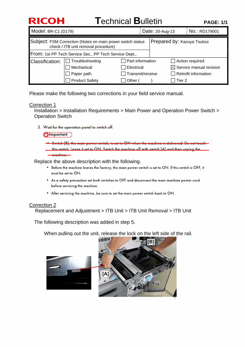
Please make the following two corrections in your field service manual.
Correction 1 Installation > Installation Requirements > Main Power and Operation Power Switch > Operation Switch
Replace the above description with the following.
Correction 2 Replacement and Adjustment > ITB Unit > ITB Unit Removal > ITB Unit
The following description was added in step 5.
When pulling out the unit, release the lock on the left side of the rail.
Technical Bulletin PAGE: 1/1
Reissued: 13-May-15
Model: BR-C1 Date: 23-Aug-13 No.: RD179004c
RTB Reissue The items in bold italics have been corrected or added.
Subject: Firmware Release Note: NetworkDocBox Prepared by: J.Ohno
From: 1st PP Tech Service Sect., PP Tech Service Dept.
Classification: Troubleshooting
Mechanical
Paper path
Part information
Electrical
Transmit/receive
Action required
Service manual revision
Retrofit information
Product Safety Other (Firmware) Tier 2
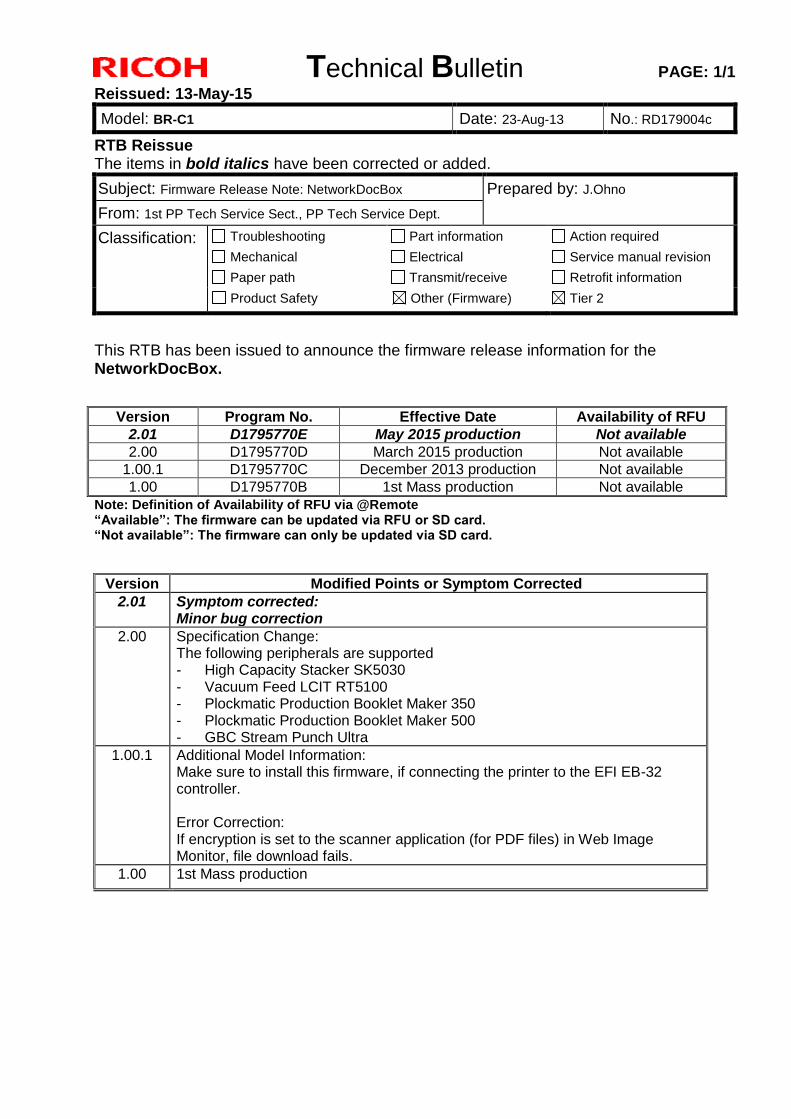
This RTB has been issued to announce the firmware release information for the NetworkDocBox.
Version Program No. Effective Date Availability of RFU
2.01 D1795770E May 2015 production Not available
2.00 D1795770D March 2015 production Not available
1.00.1 D1795770C December 2013 production Not available
1.00 D1795770B 1st Mass production Not available
Note: Definition of Availability of RFU via @Remote “Available”: The firmware can be updated via RFU or SD card. “Not available”: The firmware can only be updated via SD card.
Version Modified Points or Symptom Corrected
2.01 Symptom corrected: Minor bug correction
2.00 Specification Change: The following peripherals are supported - High Capacity Stacker SK5030 - Vacuum Feed LCIT RT5100 - Plockmatic Production Booklet Maker 350 - Plockmatic Production Booklet Maker 500 - GBC Stream Punch Ultra
1.00.1 Additional Model Information: Make sure to install this firmware, if connecting the printer to the EFI EB-32 controller. Error Correction: If encryption is set to the scanner application (for PDF files) in Web Image Monitor, file download fails.
1.00 1st Mass production
Technical Bulletin PAGE: 1/1
Reissued: 21-May-15
Model: BR-C1 Date: 23-Aug-13 No.: RD179007b
RTB Reissue The items in bold italics have been corrected or added.
Subject: Firmware Release Note: Web Uapl Prepared by: J.Ohno
From: 1st PP Tech Service Sect., PP Tech Service Dept.
Classification: Troubleshooting
Mechanical
Paper path
Part information
Electrical
Transmit/receive
Action required
Service manual revision
Retrofit information
Product Safety Other (Firmware) Tier 2
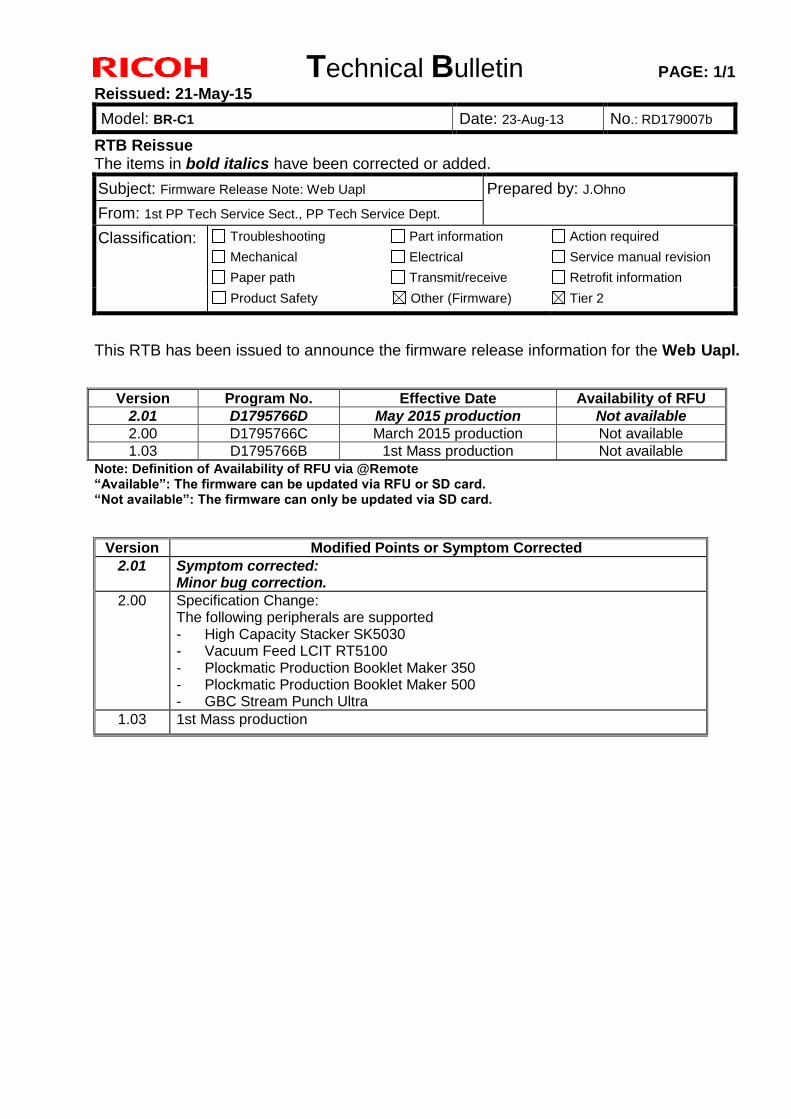
This RTB has been issued to announce the firmware release information for the Web Uapl.
Version Program No. Effective Date Availability of RFU
2.01 D1795766D May 2015 production Not available
2.00 D1795766C March 2015 production Not available
1.03 D1795766B 1st Mass production Not available
Note: Definition of Availability of RFU via @Remote “Available”: The firmware can be updated via RFU or SD card. “Not available”: The firmware can only be updated via SD card.
Version Modified Points or Symptom Corrected
2.01 Symptom corrected: Minor bug correction.
2.00 Specification Change: The following peripherals are supported - High Capacity Stacker SK5030 - Vacuum Feed LCIT RT5100 - Plockmatic Production Booklet Maker 350 - Plockmatic Production Booklet Maker 500 - GBC Stream Punch Ultra
1.03 1st Mass production
Technical Bulletin PAGE: 1/1
Reissued: 30-Mar-15
Model: BR-C1 Date: 23-Aug-13 No.: RD179010a
RTB Reissue The items in bold italics have been corrected or added.
Subject: Firmware Release Note: PowerSaving Sys Prepared by: Y.Tanimoto
From: 3rd PP Tech Service Sect., PP Tech Service Dept.
Classification: Troubleshooting
Mechanical
Paper path
Part information
Electrical
Transmit/receive
Action required
Service manual revision
Retrofit information
Product Safety Other (Firmware) Tier 2
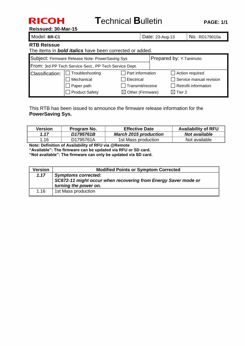
This RTB has been issued to announce the firmware release information for the PowerSaving Sys.
Version Program No. Effective Date Availability of RFU
1.17 D1795761B March 2015 production Not available
1.16 D1795761A 1st Mass production Not available
Note: Definition of Availability of RFU via @Remote “Available”: The firmware can be updated via RFU or SD card. “Not available”: The firmware can only be updated via SD card.
Version Modified Points or Symptom Corrected
1.17 Symptoms corrected: SC672-11 might occur when recovering from Energy Saver mode or turning the power on.
1.16 1st Mass production
Technical Bulletin PAGE: 1/1
Model: BR-C1 Date: 23-Aug-13 No.: RD179011
Subject: Firmware Release Note: PS3 Prepared by: J.Ohno
From: 1st PP Tech Service Sect., PP Tech Service Dept.
Classification: Troubleshooting
Mechanical
Paper path
Part information
Electrical
Transmit/receive
Action required
Service manual revision
Retrofit information
Product Safety Other (Firmware) Tier 2
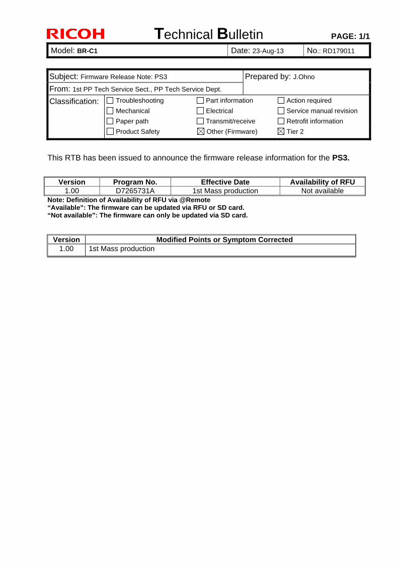
This RTB has been issued to announce the firmware release information for the PS3.
Version Program No. Effective Date Availability of RFU 1.00 D7265731A 1st Mass production Not available
Note: Definition of Availability of RFU via @Remote “Available”: The firmware can be updated via RFU or SD card. “Not available”: The firmware can only be updated via SD card.
Version Modified Points or Symptom Corrected 1.00 1st Mass production
Technical Bulletin PAGE: 1/1
Reissued: 23-Mar-15
Model: BR-C1 Date: 23-Aug-13 No.: RD179012a
RTB Reissue The items in bold italics have been added.
Subject: Firmware Release Note: RPCS Prepared by: J.Ohno
From: 1st PP Tech Service Sect., PP Tech Service Dept.
Classification: Troubleshooting
Mechanical
Paper path
Part information
Electrical
Transmit/receive
Action required
Service manual revision
Retrofit information
Product Safety Other (Firmware) Tier 2
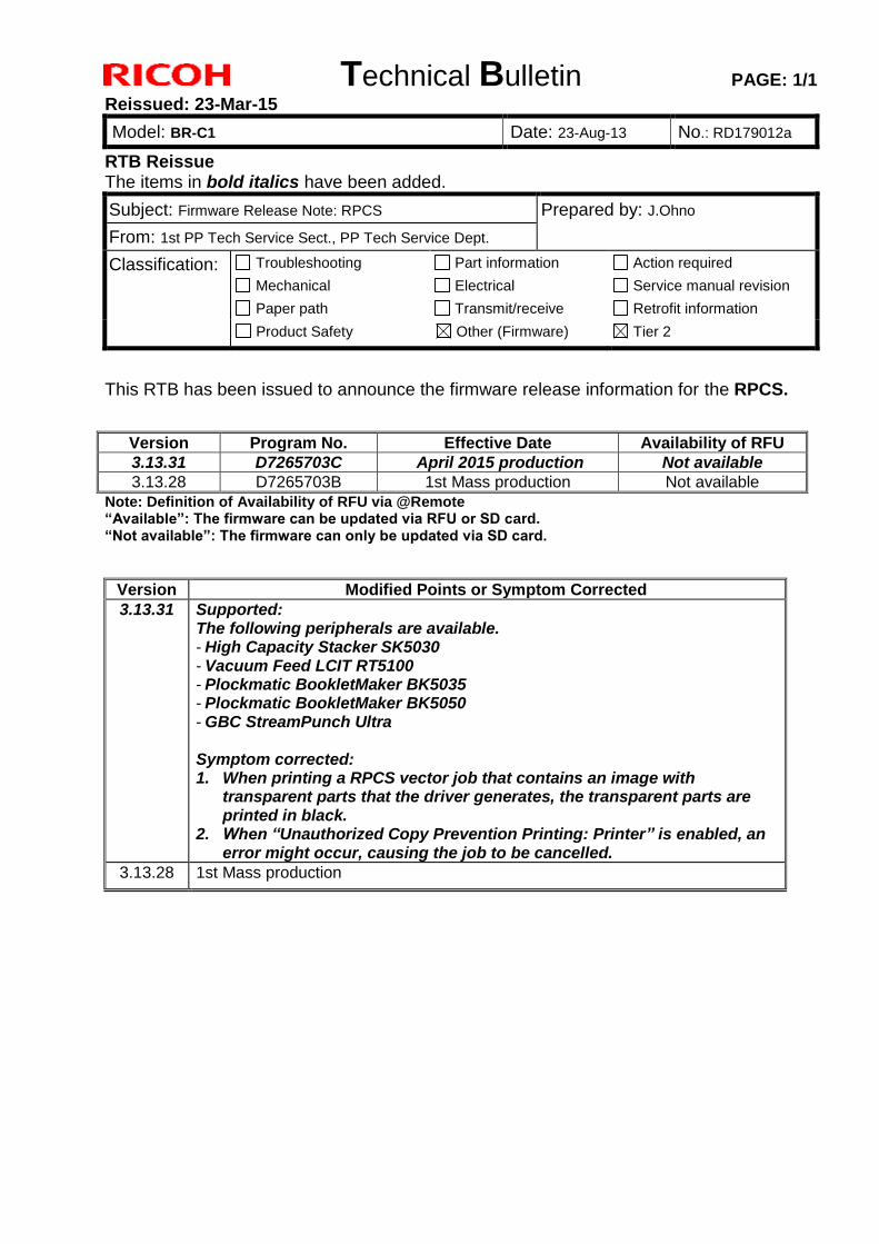
This RTB has been issued to announce the firmware release information for the RPCS.
Version Program No. Effective Date Availability of RFU
3.13.31 D7265703C April 2015 production Not available
3.13.28 D7265703B 1st Mass production Not available
Note: Definition of Availability of RFU via @Remote “Available”: The firmware can be updated via RFU or SD card. “Not available”: The firmware can only be updated via SD card.
Version Modified Points or Symptom Corrected
3.13.31 Supported: The following peripherals are available. - High Capacity Stacker SK5030 - Vacuum Feed LCIT RT5100 - Plockmatic BookletMaker BK5035 - Plockmatic BookletMaker BK5050 - GBC StreamPunch Ultra Symptom corrected: 1. When printing a RPCS vector job that contains an image with
transparent parts that the driver generates, the transparent parts are printed in black.
2. When “Unauthorized Copy Prevention Printing: Printer” is enabled, an error might occur, causing the job to be cancelled.
3.13.28 1st Mass production
Technical Bulletin PAGE: 1/1
Reissued: 30-Mar-15
Model: BR-C1 Date: 23-Aug-13 No.: RD179014c
RTB Reissue The items in bold italics have been corrected or added.
Subject: Firmware Release Note: EXJS Prepared by: Y.Tanimoto
From: 3rd PP Tech Service Sect., PP Tech Service Dept.
Classification: Troubleshooting
Mechanical
Paper path
Part information
Electrical
Transmit/receive
Action required
Service manual revision
Retrofit information
Product Safety Other (Firmware) Tier 2
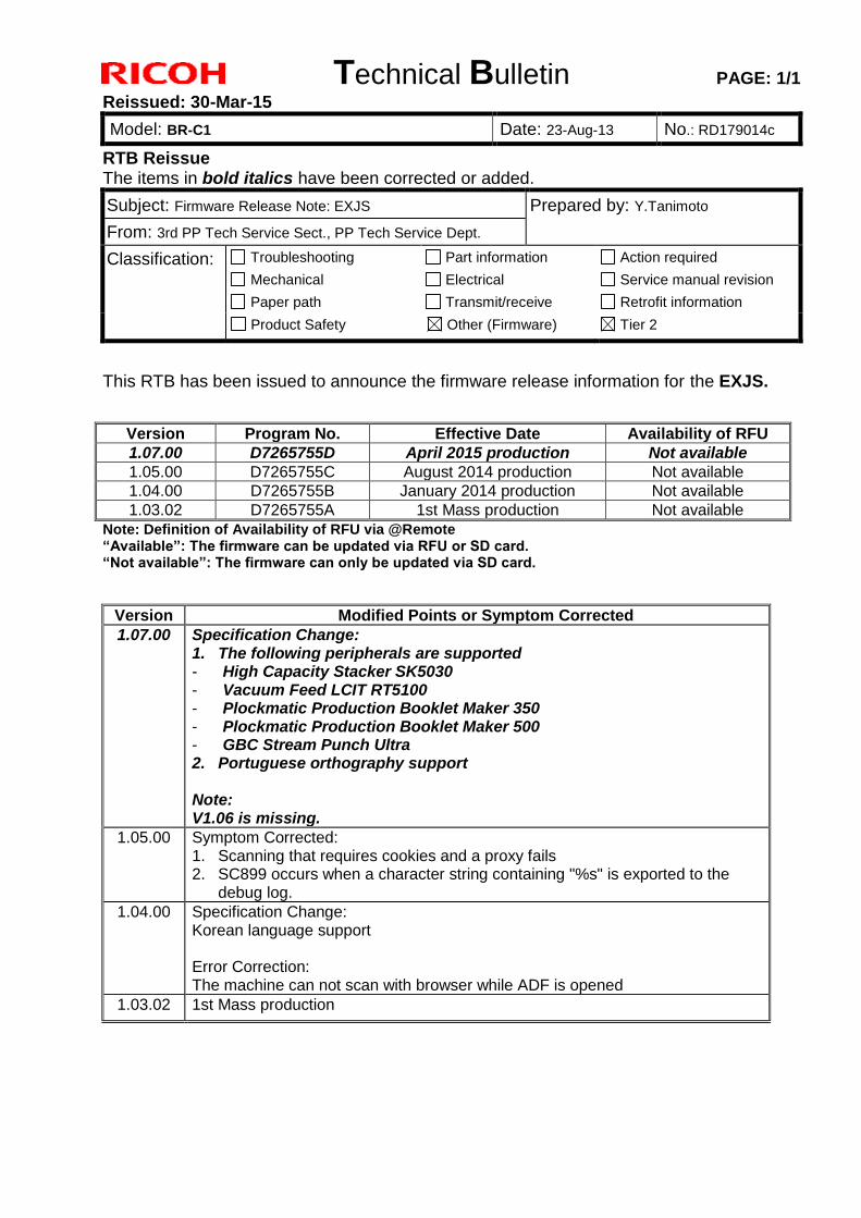
This RTB has been issued to announce the firmware release information for the EXJS.
Version Program No. Effective Date Availability of RFU
1.07.00 D7265755D April 2015 production Not available
1.05.00 D7265755C August 2014 production Not available
1.04.00 D7265755B January 2014 production Not available
1.03.02 D7265755A 1st Mass production Not available
Note: Definition of Availability of RFU via @Remote “Available”: The firmware can be updated via RFU or SD card. “Not available”: The firmware can only be updated via SD card.
Version Modified Points or Symptom Corrected
1.07.00 Specification Change: 1. The following peripherals are supported - High Capacity Stacker SK5030 - Vacuum Feed LCIT RT5100 - Plockmatic Production Booklet Maker 350 - Plockmatic Production Booklet Maker 500 - GBC Stream Punch Ultra 2. Portuguese orthography support Note: V1.06 is missing.
1.05.00 Symptom Corrected: 1. Scanning that requires cookies and a proxy fails 2. SC899 occurs when a character string containing "%s" is exported to the
debug log.
1.04.00 Specification Change: Korean language support Error Correction: The machine can not scan with browser while ADF is opened
1.03.02 1st Mass production
Technical Bulletin PAGE: 1/1
Model: BR-C1 Date: 23-Aug-13 No.: RD179015
Subject: Firmware Release Note: Option Netware Prepared by: J.Ohno
From: 1st PP Tech Service Sect., PP Tech Service Dept.
Classification: Troubleshooting
Mechanical
Paper path
Part information
Electrical
Transmit/receive
Action required
Service manual revision
Retrofit information
Product Safety Other (Firmware) Tier 2
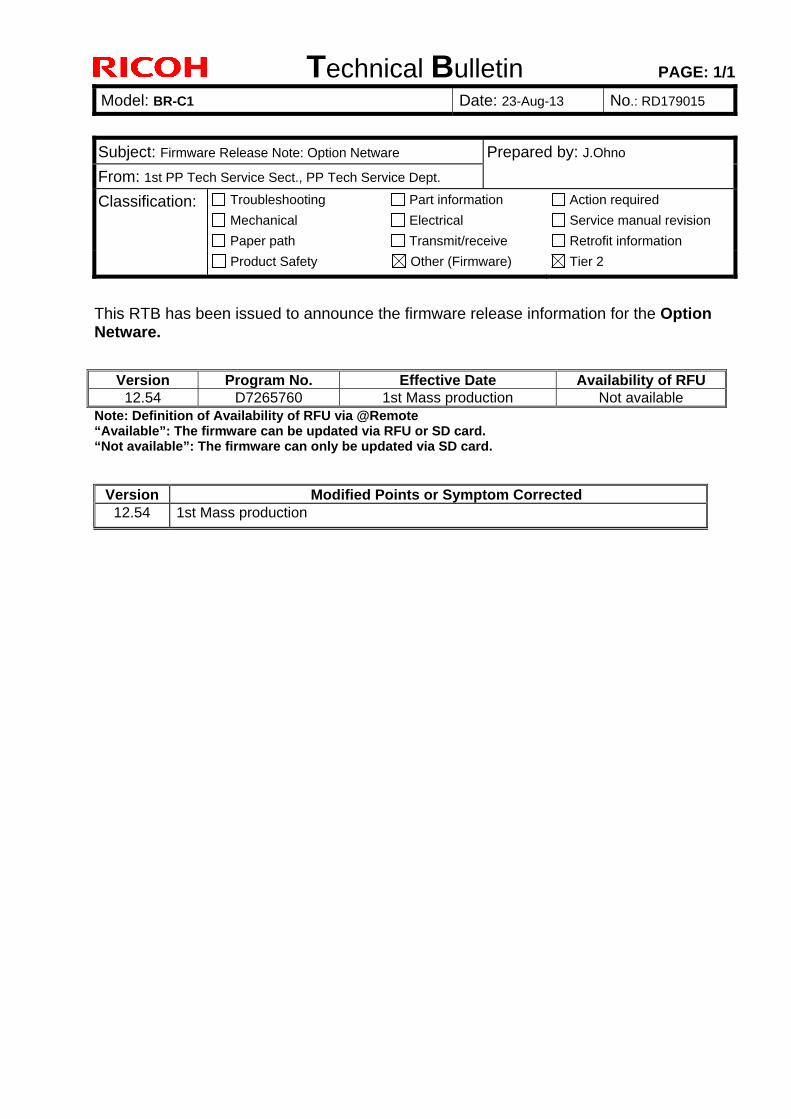
This RTB has been issued to announce the firmware release information for the Option Netware.
Version Program No. Effective Date Availability of RFU 12.54 D7265760 1st Mass production Not available
Note: Definition of Availability of RFU via @Remote “Available”: The firmware can be updated via RFU or SD card. “Not available”: The firmware can only be updated via SD card.
Version Modified Points or Symptom Corrected 12.54 1st Mass production
Technical Bulletin PAGE: 1/1
Reissued: 03-Oct-16
Model: BR-C1/Leo-C1/BR-C2 Date: 23-Aug-13 No.: RD179016e
RTB Reissue The items in bold italics have been added.
Subject: Firmware Release Note: ADF_SINAI_B Prepared by: J. Ohno
From: 3rd PP Tech Service Sect., PP Tech Service Dept.
Classification: Troubleshooting
Mechanical
Paper path
Part information
Electrical
Transmit/receive
Action required
Service manual revision
Retrofit information
Product Safety Other (Firmware) Tier 2
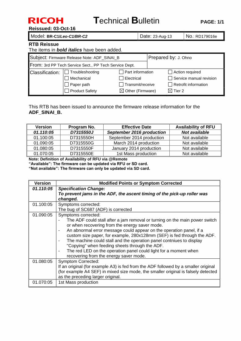
This RTB has been issued to announce the firmware release information for the ADF_SINAI_B.
Version Program No. Effective Date Availability of RFU
01.110:05 D7315550J September 2016 production Not available
01.100:05 D7315550H September 2014 production Not available
01.090:05 D7315550G March 2014 production Not available
01.080:05 D7315550F January 2014 production Not available
01.070:05 D7315550E 1st Mass production Not available
Note: Definition of Availability of RFU via @Remote “Available”: The firmware can be updated via RFU or SD card. “Not available”: The firmware can only be updated via SD card.
Version Modified Points or Symptom Corrected
01.110:05 Specification Change: To prevent jams in the ADF, the ascent timing of the pick-up roller was changed.
01.100:05 Symptoms corrected: The bug of SC687 (ADF) is corrected
01.090:05 Symptoms corrected: - The ADF could stall after a jam removal or turning on the main power switch
or when recovering from the energy saver mode. - An abnormal error message could appear on the operation panel, if a
custom size paper, for example, 280x128mm (SEF) is fed through the ADF. - The machine could stall and the operation panel contniues to display
"Copying" when feeding sheets through the ADF. - The red LED on the operation panel could light for a moment when
recovering from the energy saver mode.
01.080:05 Symptom Corrected: If an original (for example A3) is fed from the ADF followed by a smaller original (for example A4 SEF) in mixed size mode, the smaller original is falsely detected as the preceding larger original.
01.070:05 1st Mass production
Technical Bulletin PAGE: 1/3
Reissued: 02-Jun-15
Model: BR-C1/Leo-C1/Leo-P1/Andromeda-P1/BR-P1 Date: 23-Aug-13 No.: RD179017k
RTB Reissue The items in bold italics have been corrected or added.
Subject: Firmware Release Note: BookletFinisher_SR5060 Prepared by: J.Ohno
From: 1st PP Tech Service Sect., PP Tech Service Dept.
Classification: Troubleshooting
Mechanical
Paper path
Part information
Electrical
Transmit/receive
Action required
Service manual revision
Retrofit information
Product Safety Other (Firmware) Tier 2
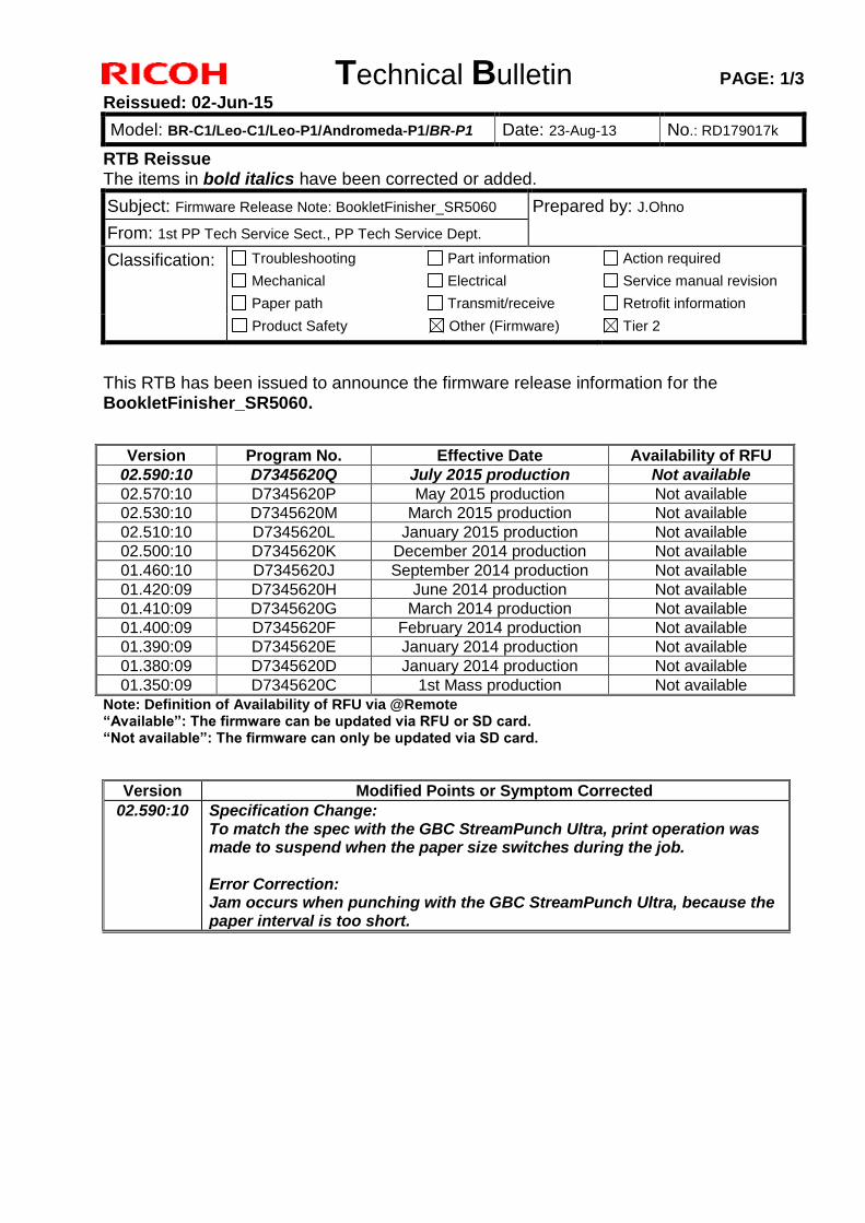
This RTB has been issued to announce the firmware release information for the BookletFinisher_SR5060.
Version Program No. Effective Date Availability of RFU
02.590:10 D7345620Q July 2015 production Not available
02.570:10 D7345620P May 2015 production Not available
02.530:10 D7345620M March 2015 production Not available
02.510:10 D7345620L January 2015 production Not available
02.500:10 D7345620K December 2014 production Not available
01.460:10 D7345620J September 2014 production Not available
01.420:09 D7345620H June 2014 production Not available
01.410:09 D7345620G March 2014 production Not available
01.400:09 D7345620F February 2014 production Not available
01.390:09 D7345620E January 2014 production Not available
01.380:09 D7345620D January 2014 production Not available
01.350:09 D7345620C 1st Mass production Not available
Note: Definition of Availability of RFU via @Remote “Available”: The firmware can be updated via RFU or SD card. “Not available”: The firmware can only be updated via SD card.
Version Modified Points or Symptom Corrected
02.590:10 Specification Change: To match the spec with the GBC StreamPunch Ultra, print operation was made to suspend when the paper size switches during the job. Error Correction: Jam occurs when punching with the GBC StreamPunch Ultra, because the paper interval is too short.
Technical Bulletin PAGE: 2/3
Reissued: 02-Jun-15
Model: BR-C1/Leo-C1/Leo-P1/Andromeda-P1/BR-P1 Date: 23-Aug-13 No.: RD179017k
Version Modified Points or Symptom Corrected
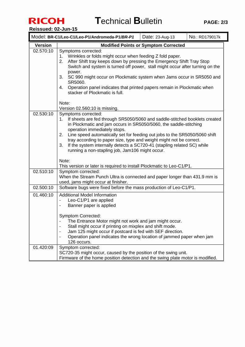
02.570:10 Symptoms corrected: 1. Wrinkles or folds might occur when feeding Z fold paper. 2. After Shift tray keeps down by pressing the Emergency Shift Tray Stop
Switch and system is turned off power, stall might occur after turning on the power.
3. SC 990 might occur on Plockmatic system when Jams occur in SR5050 and SR5060.
4. Operation panel indicates that printed papers remain in Plockmatic when stacker of Plockmatic is full.
Note: Version 02.560:10 is missing.
02.530:10 Symptoms corrected: 1. If sheets are fed through SR5050/5060 and saddle-stitched booklets created
in Plockmatic and jam occurs in SR5050/5060, the saddle-stitching operation immediately stops.
2. Line speed automatically set for feeding out jobs to the SR5050/5060 shift tray according to paper size, type and weight might not be correct.
3. If the system internally detects a SC720-41 (stapling related SC) while running a non-stapling job, Jam106 might occur.
Note: This version or later is required to install Plockmatic to Leo-C1/P1.
02.510:10 Symptom corrected: When the Stream Punch Ultra is connected and paper longer than 431.9 mm is used, jams might occur at finisher.
02.500:10 Software bugs were fixed before the mass production of Leo-C1/P1.
01.460:10 Additional Model Information - Leo-C1/P1 are applied - Banner paper is applied Symptom Corrected: - The Entrance Motor might not work and jam might occur. - Stall might occur if printing on mixplex and shift mode. - Jam 125 might occur if postcard is fed with SEF direction. - Operation panel indicates the wrong location of jammed paper when jam
126 occurs.
01.420:09 Symptom corrected: SC720-35 might occur, caused by the position of the swing unit. Firmware of the home position detection and the swing plate motor is modified.
Technical Bulletin PAGE: 3/3
Reissued: 02-Jun-15
Model: BR-C1/Leo-C1/Leo-P1/Andromeda-P1/BR-P1 Date: 23-Aug-13 No.: RD179017k
Version Modified Points or Symptom Corrected
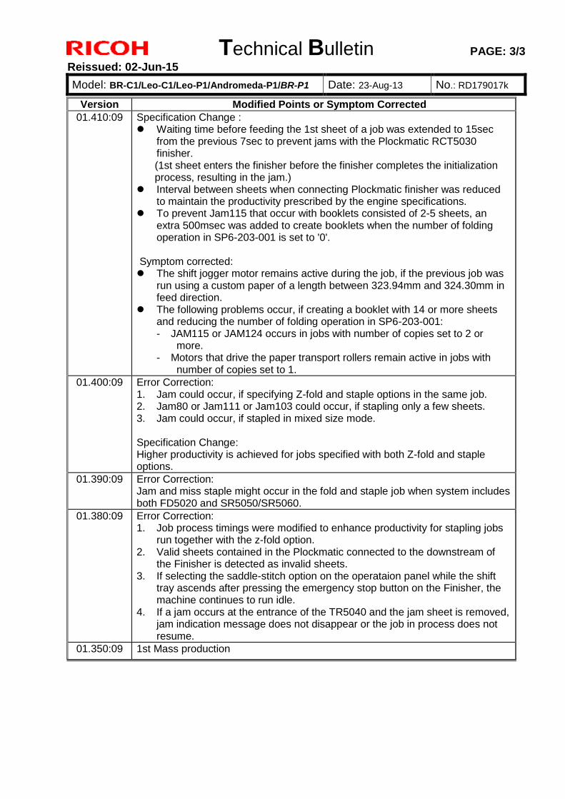
01.410:09 Specification Change : Waiting time before feeding the 1st sheet of a job was extended to 15sec
from the previous 7sec to prevent jams with the Plockmatic RCT5030 finisher. (1st sheet enters the finisher before the finisher completes the initialization process, resulting in the jam.)
Interval between sheets when connecting Plockmatic finisher was reduced to maintain the productivity prescribed by the engine specifications.
To prevent Jam115 that occur with booklets consisted of 2-5 sheets, an extra 500msec was added to create booklets when the number of folding operation in SP6-203-001 is set to '0'.
Symptom corrected: The shift jogger motor remains active during the job, if the previous job was
run using a custom paper of a length between 323.94mm and 324.30mm in feed direction.
The following problems occur, if creating a booklet with 14 or more sheets and reducing the number of folding operation in SP6-203-001: - JAM115 or JAM124 occurs in jobs with number of copies set to 2 or
more. - Motors that drive the paper transport rollers remain active in jobs with
number of copies set to 1.
01.400:09 Error Correction: 1. Jam could occur, if specifying Z-fold and staple options in the same job. 2. Jam80 or Jam111 or Jam103 could occur, if stapling only a few sheets. 3. Jam could occur, if stapled in mixed size mode. Specification Change: Higher productivity is achieved for jobs specified with both Z-fold and staple options.
01.390:09 Error Correction: Jam and miss staple might occur in the fold and staple job when system includes both FD5020 and SR5050/SR5060.
01.380:09 Error Correction: 1. Job process timings were modified to enhance productivity for stapling jobs
run together with the z-fold option. 2. Valid sheets contained in the Plockmatic connected to the downstream of
the Finisher is detected as invalid sheets. 3. If selecting the saddle-stitch option on the operataion panel while the shift
tray ascends after pressing the emergency stop button on the Finisher, the machine continues to run idle.
4. If a jam occurs at the entrance of the TR5040 and the jam sheet is removed, jam indication message does not disappear or the job in process does not resume.
01.350:09 1st Mass production
Technical Bulletin PAGE: 1/1 Reissued: 04-Aug-16
Model: BR-C1/Leo-C1/Leo-P1/BR-P1/Andromeda-P1 Date: 23-Aug-13 No.: RD179018d
RTB Reissue The items in bold italics have been corrected.
Subject: Firmware Release Note: Folder_FD5020 Prepared by: J. Ohno
From: 1st PP Tech Service Sect., PP Tech Service Dept.
Classification: Troubleshooting
Mechanical
Paper path
Part information
Electrical
Transmit/receive
Action required
Service manual revision
Retrofit information
Product Safety Other (Firmware) Tier 2
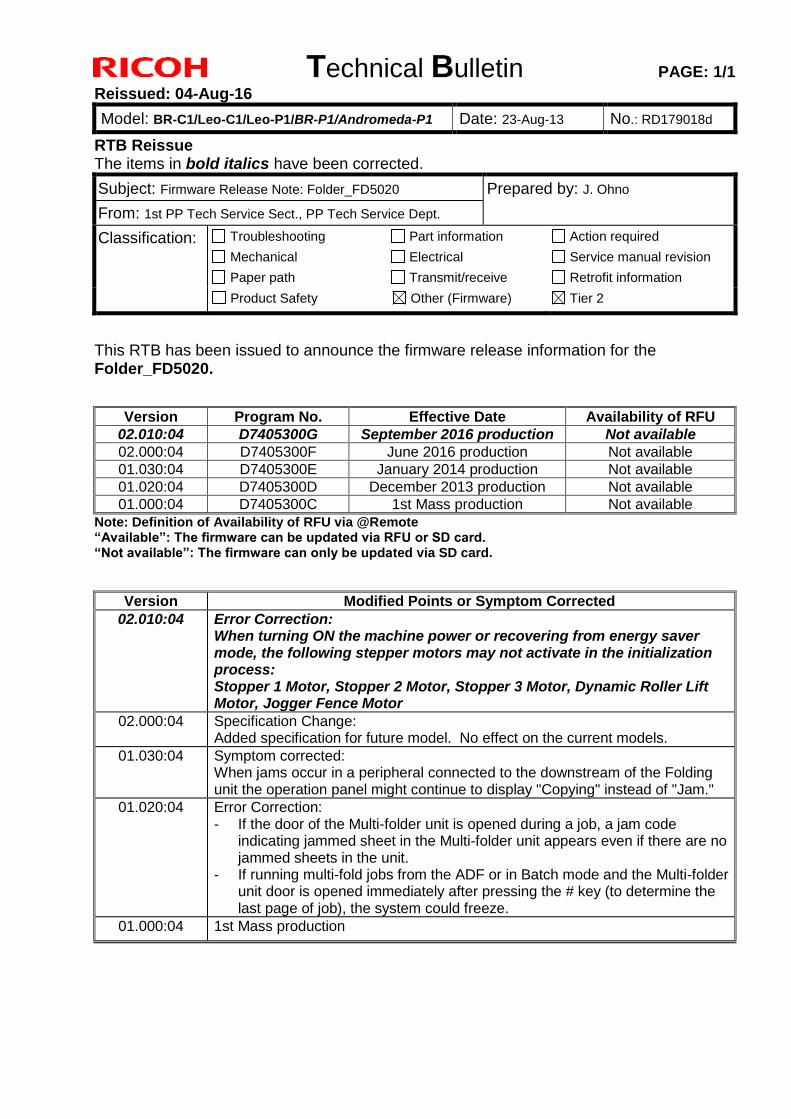
This RTB has been issued to announce the firmware release information for the Folder_FD5020.
Version Program No. Effective Date Availability of RFU 02.010:04 D7405300G September 2016 production Not available
02.000:04 D7405300F June 2016 production Not available 01.030:04 D7405300E January 2014 production Not available 01.020:04 D7405300D December 2013 production Not available 01.000:04 D7405300C 1st Mass production Not available
Note: Definition of Availability of RFU via @Remote “Available”: The firmware can be updated via RFU or SD card. “Not available”: The firmware can only be updated via SD card.
Version Modified Points or Symptom Corrected 02.010:04 Error Correction:
When turning ON the machine power or recovering from energy saver mode, the following stepper motors may not activate in the initialization process: Stopper 1 Motor, Stopper 2 Motor, Stopper 3 Motor, Dynamic Roller Lift Motor, Jogger Fence Motor
02.000:04 Specification Change: Added specification for future model. No effect on the current models.
01.030:04 Symptom corrected: When jams occur in a peripheral connected to the downstream of the Folding unit the operation panel might continue to display "Copying" instead of "Jam."
01.020:04 Error Correction: - If the door of the Multi-folder unit is opened during a job, a jam code
indicating jammed sheet in the Multi-folder unit appears even if there are no jammed sheets in the unit.
- If running multi-fold jobs from the ADF or in Batch mode and the Multi-folder unit door is opened immediately after pressing the # key (to determine the last page of job), the system could freeze.
01.000:04 1st Mass production
Technical Bulletin PAGE: 1/1
Reissued: 30-Mar-16
Model: BR-C1/Leo-C1/Leo-P1/BR-P1/Andromeda-P1 Date: 23-Aug-13 No.: RD179019b
RTB Reissue The items in bold italics have been corrected or added.
Subject: Firmware Release Note: Inserter_INSERTER Prepared by: J.Ohno
From: 1st PP Tech Service Sect., PP Tech Service Dept.
Classification: Troubleshooting
Mechanical
Paper path
Part information
Electrical
Transmit/receive
Action required
Service manual revision
Retrofit information
Product Safety Other (Firmware) Tier 2
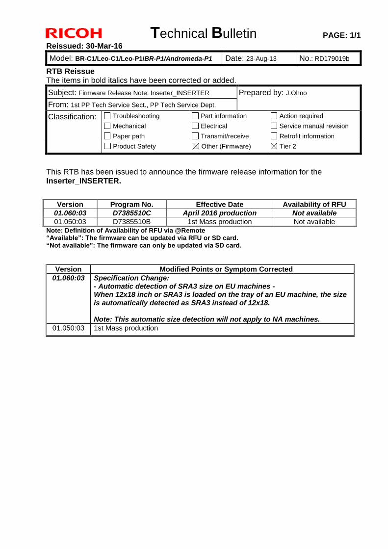
This RTB has been issued to announce the firmware release information for the Inserter_INSERTER.
Version Program No. Effective Date Availability of RFU
01.060:03 D7385510C April 2016 production Not available
01.050:03 D7385510B 1st Mass production Not available
Note: Definition of Availability of RFU via @Remote “Available”: The firmware can be updated via RFU or SD card. “Not available”: The firmware can only be updated via SD card.
Version Modified Points or Symptom Corrected
01.060:03 Specification Change: - Automatic detection of SRA3 size on EU machines - When 12x18 inch or SRA3 is loaded on the tray of an EU machine, the size is automatically detected as SRA3 instead of 12x18. Note: This automatic size detection will not apply to NA machines.
01.050:03 1st Mass production
Technical Bulletin PAGE: 1/1
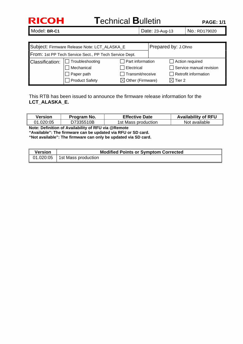
Model: BR-C1 Date: 23-Aug-13 No.: RD179020
Subject: Firmware Release Note: LCT_ALASKA_E Prepared by: J.Ohno
From: 1st PP Tech Service Sect., PP Tech Service Dept.
Classification: Troubleshooting
Mechanical
Paper path
Part information
Electrical
Transmit/receive
Action required
Service manual revision
Retrofit information
Product Safety Other (Firmware) Tier 2
This RTB has been issued to announce the firmware release information for the LCT_ALASKA_E.
Version Program No. Effective Date Availability of RFU 01.020:05 D7335510B 1st Mass production Not available
Note: Definition of Availability of RFU via @Remote “Available”: The firmware can be updated via RFU or SD card. “Not available”: The firmware can only be updated via SD card.
Version Modified Points or Symptom Corrected 01.020:05 1st Mass production
Technical Bulletin PAGE: 1/1 Reissued: 09-May-16
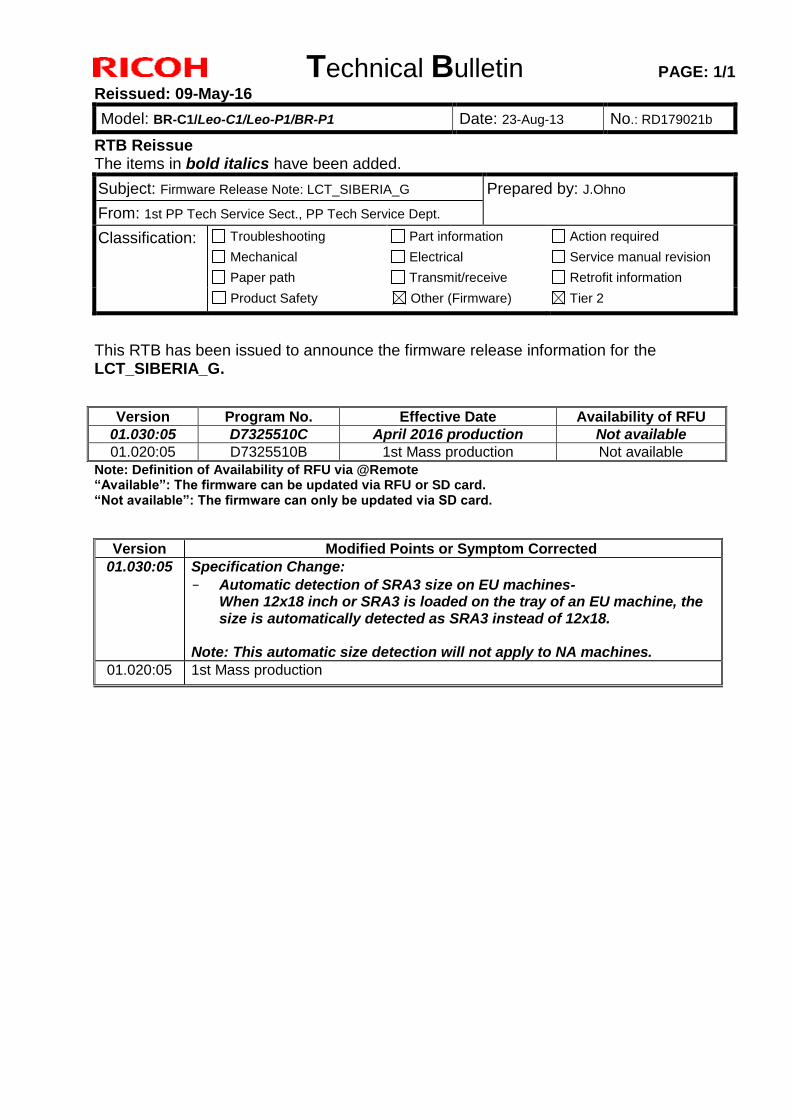
Model: BR-C1/Leo-C1/Leo-P1/BR-P1 Date: 23-Aug-13 No.: RD179021b
RTB Reissue The items in bold italics have been added.
Subject: Firmware Release Note: LCT_SIBERIA_G Prepared by: J.Ohno
From: 1st PP Tech Service Sect., PP Tech Service Dept.
Classification: Troubleshooting
Mechanical
Paper path
Part information
Electrical
Transmit/receive
Action required
Service manual revision
Retrofit information
Product Safety Other (Firmware) Tier 2
This RTB has been issued to announce the firmware release information for the LCT_SIBERIA_G.
Version Program No. Effective Date Availability of RFU 01.030:05 D7325510C April 2016 production Not available
01.020:05 D7325510B 1st Mass production Not available Note: Definition of Availability of RFU via @Remote “Available”: The firmware can be updated via RFU or SD card. “Not available”: The firmware can only be updated via SD card.
Version Modified Points or Symptom Corrected 01.030:05 Specification Change:
- Automatic detection of SRA3 size on EU machines- When 12x18 inch or SRA3 is loaded on the tray of an EU machine, the size is automatically detected as SRA3 instead of 12x18.
Note: This automatic size detection will not apply to NA machines.
01.020:05 1st Mass production
Technical Bulletin PAGE: 1/3
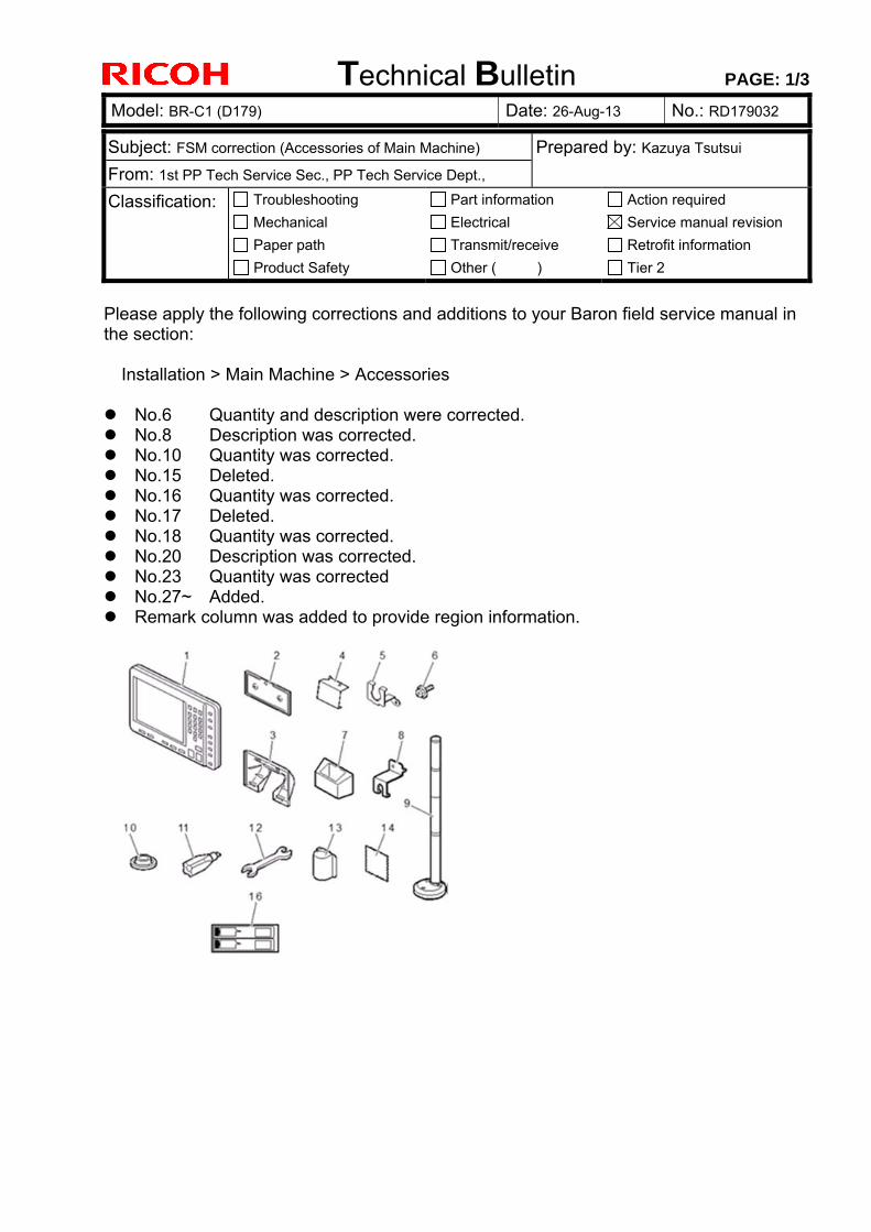
Model: BR-C1 (D179) Date: 26-Aug-13 No.: RD179032
Subject: FSM correction (Accessories of Main Machine) Prepared by: Kazuya Tsutsui
From: 1st PP Tech Service Sec., PP Tech Service Dept.,
Classification: Troubleshooting
Mechanical
Paper path
Product Safety
Part information
Electrical
Transmit/receive
Other ( )
Action required
Service manual revision
Retrofit information
Tier 2
Please apply the following corrections and additions to your Baron field service manual in the section:
Installation > Main Machine > Accessories
No.6 Quantity and description were corrected. No.8 Description was corrected. No.10 Quantity was corrected. No.15 Deleted. No.16 Quantity was corrected. No.17 Deleted. No.18 Quantity was corrected. No.20 Description was corrected. No.23 Quantity was corrected No.27~ Added. Remark column was added to provide region information.
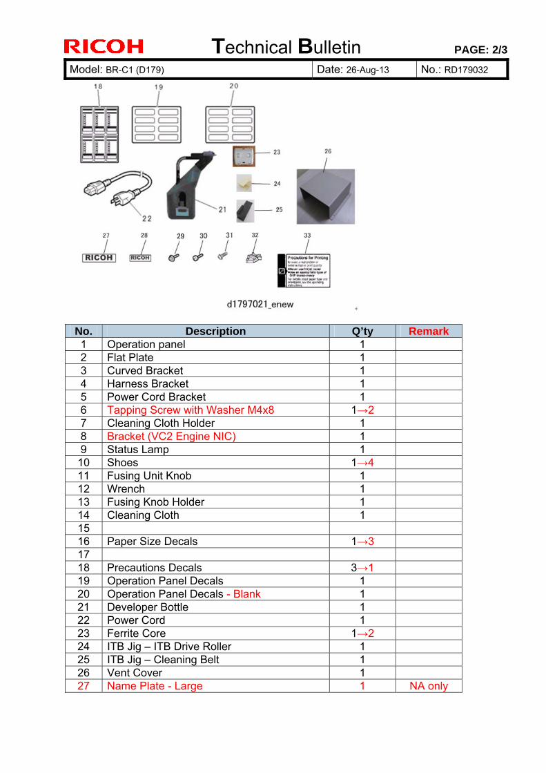
Technical Bulletin PAGE: 2/3
Model: BR-C1 (D179) Date: 26-Aug-13 No.: RD179032
No. Description Q’ty Remark 1 Operation panel 1 2 Flat Plate 1 3 Curved Bracket 1 4 Harness Bracket 1 5 Power Cord Bracket 1 6 Tapping Screw with Washer M4x8 1→2 7 Cleaning Cloth Holder 1 8 Bracket (VC2 Engine NIC) 1 9 Status Lamp 1
10 Shoes 1→4 11 Fusing Unit Knob 1 12 Wrench 1 13 Fusing Knob Holder 1 14 Cleaning Cloth 1 15 16 Paper Size Decals 1→3 17 18 Precautions Decals 3→1 19 Operation Panel Decals 1 20 Operation Panel Decals - Blank 1 21 Developer Bottle 1 22 Power Cord 1 23 Ferrite Core 1→2 24 ITB Jig – ITB Drive Roller 1 25 ITB Jig – Cleaning Belt 1 26 Vent Cover 1 27 Name Plate - Large 1 NA only
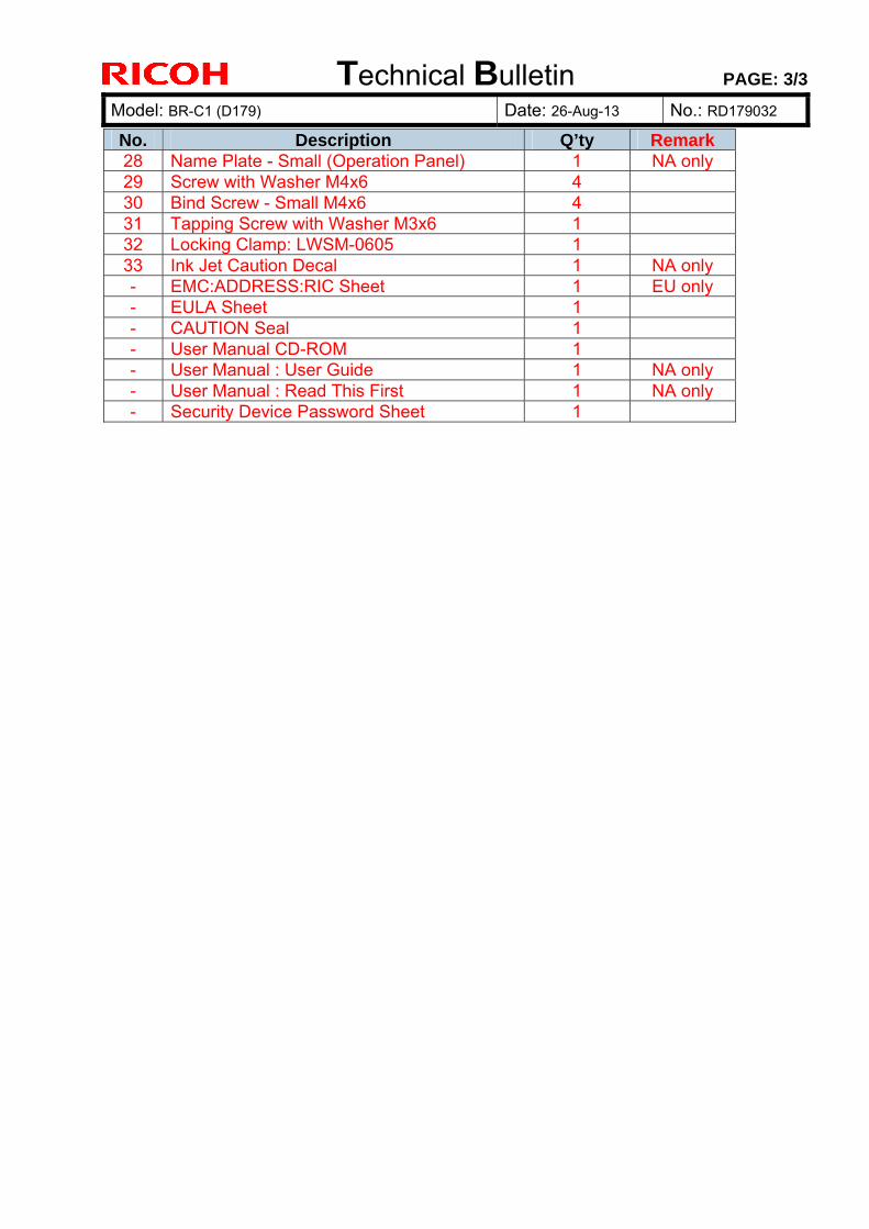
Technical Bulletin PAGE: 3/3
Model: BR-C1 (D179) Date: 26-Aug-13 No.: RD179032
No. Description Q’ty Remark 28 Name Plate - Small (Operation Panel) 1 NA only 29 Screw with Washer M4x6 4 30 Bind Screw - Small M4x6 4 31 Tapping Screw with Washer M3x6 1 32 Locking Clamp: LWSM-0605 1 33 Ink Jet Caution Decal 1 NA only - EMC:ADDRESS:RIC Sheet 1 EU only - EULA Sheet 1 - CAUTION Seal 1 - User Manual CD-ROM 1 - User Manual : User Guide 1 NA only - User Manual : Read This First 1 NA only - Security Device Password Sheet 1
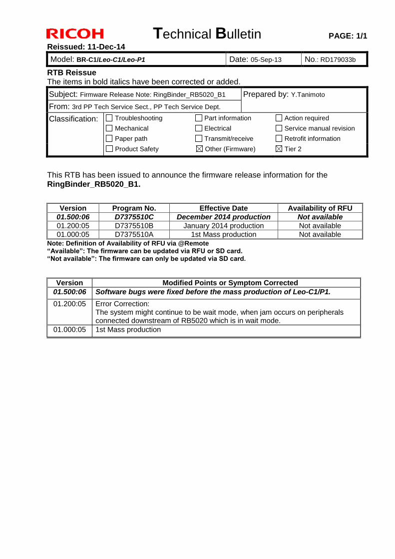
Technical Bulletin PAGE: 1/1
Reissued: 11-Dec-14
Model: BR-C1/Leo-C1/Leo-P1 Date: 05-Sep-13 No.: RD179033b
RTB Reissue The items in bold italics have been corrected or added.
Subject: Firmware Release Note: RingBinder_RB5020_B1 Prepared by: Y.Tanimoto
From: 3rd PP Tech Service Sect., PP Tech Service Dept.
Classification: Troubleshooting
Mechanical
Paper path
Part information
Electrical
Transmit/receive
Action required
Service manual revision
Retrofit information
Product Safety Other (Firmware) Tier 2
This RTB has been issued to announce the firmware release information for the RingBinder_RB5020_B1.
Version Program No. Effective Date Availability of RFU
01.500:06 D7375510C December 2014 production Not available
01.200:05 D7375510B January 2014 production Not available
01.000:05 D7375510A 1st Mass production Not available
Note: Definition of Availability of RFU via @Remote “Available”: The firmware can be updated via RFU or SD card. “Not available”: The firmware can only be updated via SD card.
Version Modified Points or Symptom Corrected
01.500:06 Software bugs were fixed before the mass production of Leo-C1/P1.
01.200:05 Error Correction: The system might continue to be wait mode, when jam occurs on peripherals connected downstream of RB5020 which is in wait mode.
01.000:05 1st Mass production
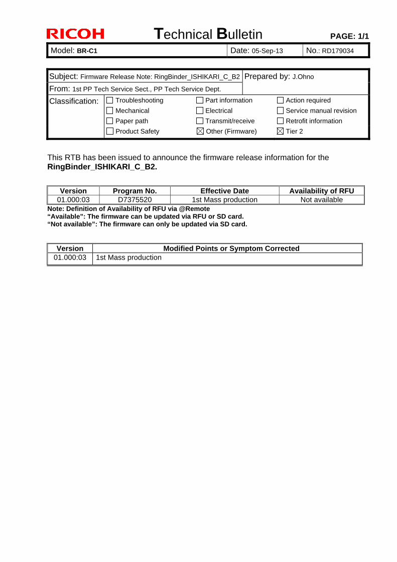
Technical Bulletin PAGE: 1/1
Model: BR-C1 Date: 05-Sep-13 No.: RD179034
Subject: Firmware Release Note: RingBinder_ISHIKARI_C_B2 Prepared by: J.Ohno
From: 1st PP Tech Service Sect., PP Tech Service Dept.
Classification: Troubleshooting
Mechanical
Paper path
Part information
Electrical
Transmit/receive
Action required
Service manual revision
Retrofit information
Product Safety Other (Firmware) Tier 2
This RTB has been issued to announce the firmware release information for the RingBinder_ISHIKARI_C_B2.
Version Program No. Effective Date Availability of RFU 01.000:03 D7375520 1st Mass production Not available
Note: Definition of Availability of RFU via @Remote “Available”: The firmware can be updated via RFU or SD card. “Not available”: The firmware can only be updated via SD card.
Version Modified Points or Symptom Corrected 01.000:03 1st Mass production
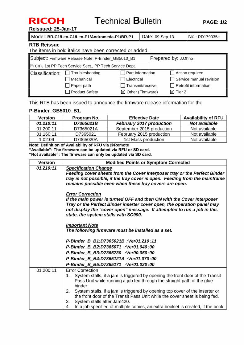
Technical Bulletin PAGE: 1/2
Reissued: 25-Jan-17
Model: BR-C1/Leo-C1/Leo-P1/Andromeda-P1/BR-P1 Date: 09-Sep-13 No.: RD179035c
RTB Reissue The items in bold italics have been corrected or added.
Subject: Firmware Release Note: P-Binder_GB5010_B1 Prepared by: J.Ohno
From: 1st PP Tech Service Sect., PP Tech Service Dept.
Classification: Troubleshooting
Mechanical
Paper path
Part information
Electrical
Transmit/receive
Action required
Service manual revision
Retrofit information
Product Safety Other (Firmware) Tier 2
This RTB has been issued to announce the firmware release information for the
P-Binder_GB5010_B1.
Version Program No. Effective Date Availability of RFU
01.210:11 D7365021B February 2017 production Not available
01.200:11 D7365021A September 2015 production Not available
01.160:11 D7365021 February 2015 production Not available
1.02:09 D7365020A 1st Mass production Not available
Note: Definition of Availability of RFU via @Remote “Available”: The firmware can be updated via RFU or SD card. “Not available”: The firmware can only be updated via SD card.
Version Modified Points or Symptom Corrected
01.210:11 Specification Change Feeding cover sheets from the Cover Interposer tray or the Perfect Binder tray is not possible, if the tray cover is open. Feeding from the mainframe remains possible even when these tray covers are open. Error Correction If the main power is turned OFF and then ON with the Cover Interposer Tray or the Perfect Binder inserter cover open, the operation panel may not display the "cover open" message. If attempted to run a job in this state, the system stalls with SC990. Important Note The following firmware must be installed as a set.
P-Binder_B_B1:D7365021B :Ver01.210:11
P-Binder_B_B2:D7365071 :Ver01.040:00
P-Binder_B_B3:D7365730 :Ver00.050:00
P-Binder_B_B4:D7365121A :Ver01.070:00
P-Binder_B_B5:D7365171 :Ver01.020:00
01.200:11 Error Correction 1. System stalls, if a jam is triggered by opening the front door of the Transit
Pass Unit while running a job fed through the straight path of the glue binder.
2. System stalls, if a jam is triggered by opening top cover of the inserter or the front door of the Transit Pass Unit while the cover sheet is being fed.
3. System stalls after Jam420. 4. In a job specified of multiple copies, an extra booklet is created, if the book
Technical Bulletin PAGE: 2/2
Reissued: 25-Jan-17
Model: BR-C1/Leo-C1/Leo-P1/Andromeda-P1/BR-P1 Date: 09-Sep-13 No.: RD179035c
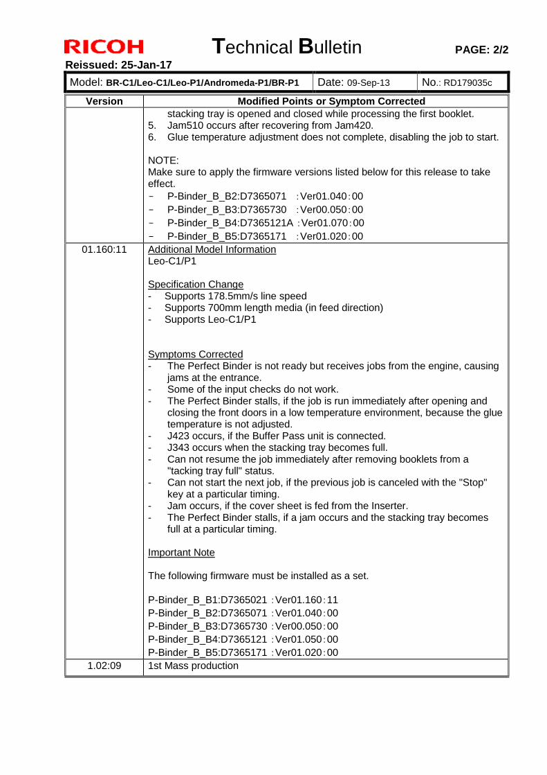
Version Modified Points or Symptom Corrected
stacking tray is opened and closed while processing the first booklet. 5. Jam510 occurs after recovering from Jam420. 6. Glue temperature adjustment does not complete, disabling the job to start.
NOTE: Make sure to apply the firmware versions listed below for this release to take effect.
- P-Binder_B_B2:D7365071 :Ver01.040:00
- P-Binder_B_B3:D7365730 :Ver00.050:00
- P-Binder_B_B4:D7365121A :Ver01.070:00
- P-Binder_B_B5:D7365171 :Ver01.020:00
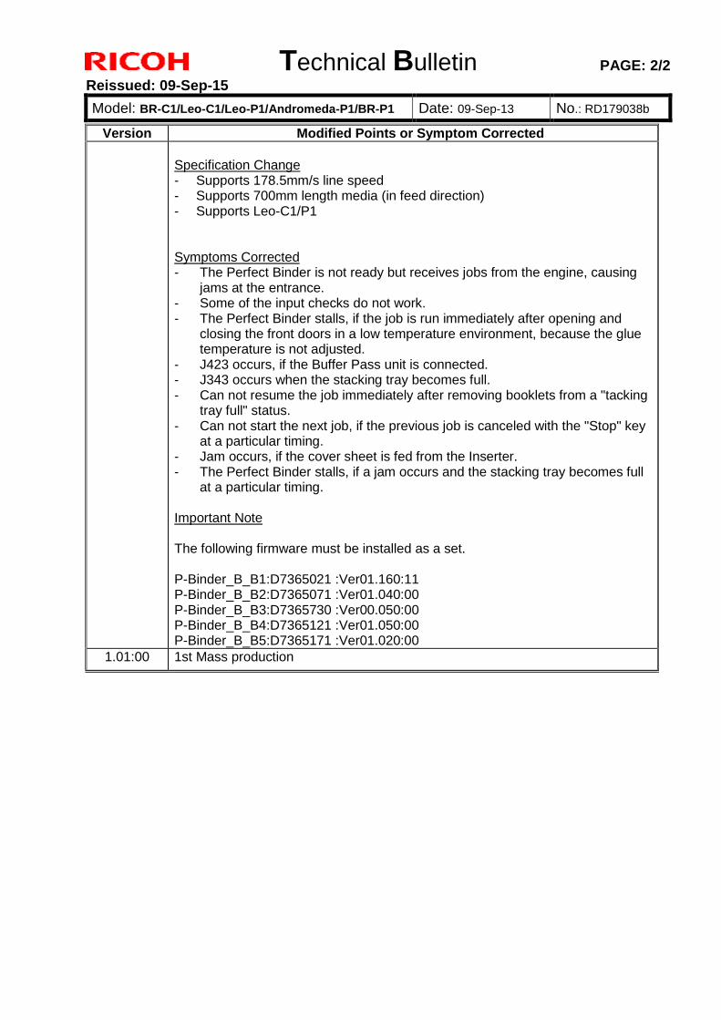
01.160:11 Additional Model Information Leo-C1/P1 Specification Change - Supports 178.5mm/s line speed - Supports 700mm length media (in feed direction) - Supports Leo-C1/P1 Symptoms Corrected - The Perfect Binder is not ready but receives jobs from the engine, causing
jams at the entrance. - Some of the input checks do not work. - The Perfect Binder stalls, if the job is run immediately after opening and
closing the front doors in a low temperature environment, because the glue temperature is not adjusted.
- J423 occurs, if the Buffer Pass unit is connected. - J343 occurs when the stacking tray becomes full. - Can not resume the job immediately after removing booklets from a
"tacking tray full" status. - Can not start the next job, if the previous job is canceled with the "Stop"
key at a particular timing. - Jam occurs, if the cover sheet is fed from the Inserter. - The Perfect Binder stalls, if a jam occurs and the stacking tray becomes
full at a particular timing. Important Note The following firmware must be installed as a set.
P-Binder_B_B1:D7365021 :Ver01.160:11
P-Binder_B_B2:D7365071 :Ver01.040:00
P-Binder_B_B3:D7365730 :Ver00.050:00
P-Binder_B_B4:D7365121 :Ver01.050:00
P-Binder_B_B5:D7365171 :Ver01.020:00
1.02:09 1st Mass production
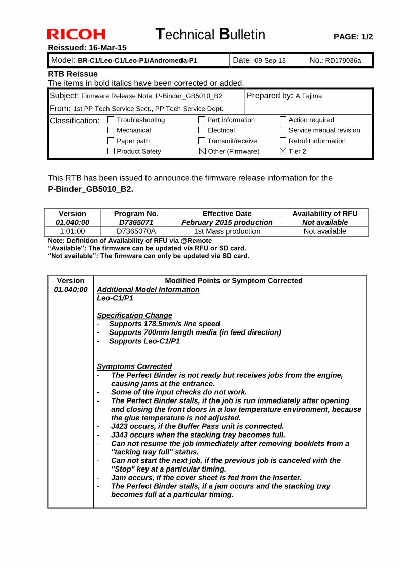
Technical Bulletin PAGE: 1/2
Reissued: 16-Mar-15
Model: BR-C1/Leo-C1/Leo-P1/Andromeda-P1 Date: 09-Sep-13 No.: RD179036a
RTB Reissue The items in bold italics have been corrected or added.
Subject: Firmware Release Note: P-Binder_GB5010_B2 Prepared by: A.Tajima
From: 1st PP Tech Service Sect., PP Tech Service Dept.
Classification: Troubleshooting
Mechanical
Paper path
Part information
Electrical
Transmit/receive
Action required
Service manual revision
Retrofit information
Product Safety Other (Firmware) Tier 2
This RTB has been issued to announce the firmware release information for the
P-Binder_GB5010_B2.
Version Program No. Effective Date Availability of RFU
01.040:00 D7365071 February 2015 production Not available
1.01:00 D7365070A 1st Mass production Not available
Note: Definition of Availability of RFU via @Remote “Available”: The firmware can be updated via RFU or SD card. “Not available”: The firmware can only be updated via SD card.
Version Modified Points or Symptom Corrected
01.040:00 Additional Model Information Leo-C1/P1 Specification Change - Supports 178.5mm/s line speed - Supports 700mm length media (in feed direction) - Supports Leo-C1/P1 Symptoms Corrected - The Perfect Binder is not ready but receives jobs from the engine,
causing jams at the entrance. - Some of the input checks do not work. - The Perfect Binder stalls, if the job is run immediately after opening
and closing the front doors in a low temperature environment, because the glue temperature is not adjusted.
- J423 occurs, if the Buffer Pass unit is connected. - J343 occurs when the stacking tray becomes full. - Can not resume the job immediately after removing booklets from a
"tacking tray full" status. - Can not start the next job, if the previous job is canceled with the
"Stop" key at a particular timing. - Jam occurs, if the cover sheet is fed from the Inserter. - The Perfect Binder stalls, if a jam occurs and the stacking tray
becomes full at a particular timing.

Technical Bulletin PAGE: 2/2
Reissued: 16-Mar-15
Model: BR-C1/Leo-C1/Leo-P1/Andromeda-P1 Date: 09-Sep-13 No.: RD179036a
Version Modified Points or Symptom Corrected
Important Note The following firmware must be installed as a set. P-Binder_B_B1:D7365021 :Ver01.160:11 P-Binder_B_B2:D7365071 :Ver01.040:00 P-Binder_B_B3:D7365730 :Ver00.050:00 P-Binder_B_B4:D7365121 :Ver01.050:00 P-Binder_B_B5:D7365171 :Ver01.020:00
1.01:00 1st Mass production
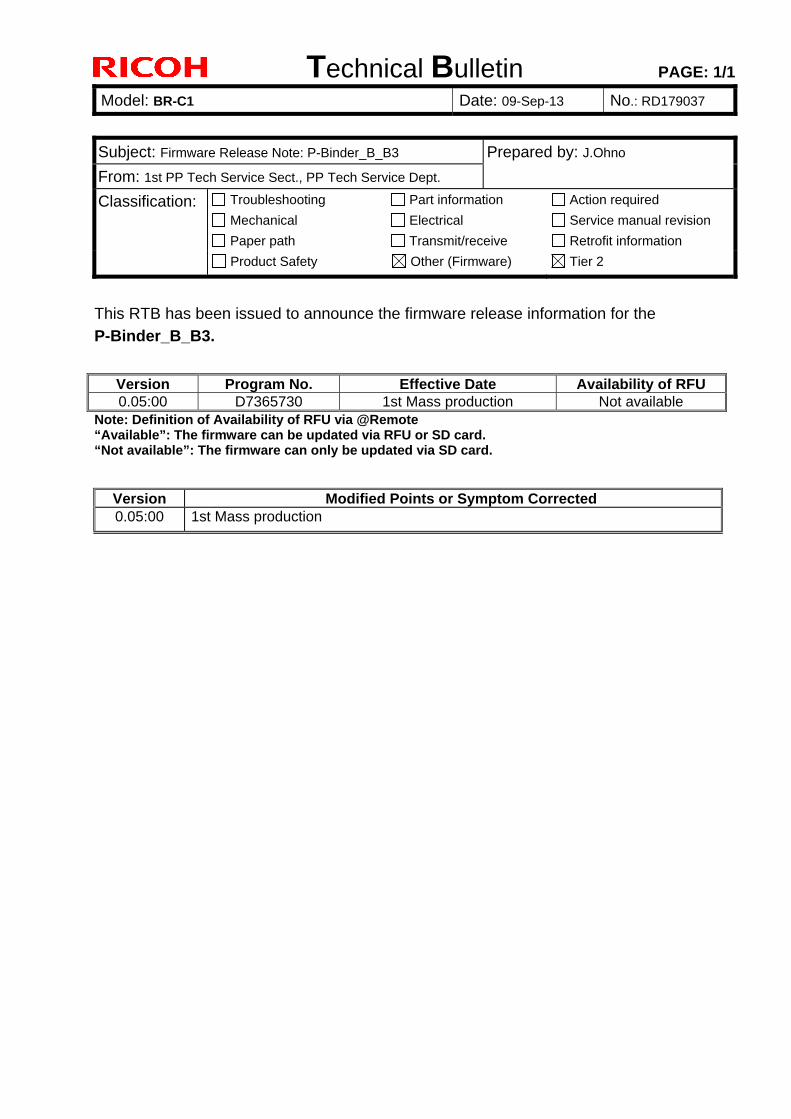
Technical Bulletin PAGE: 1/1
Model: BR-C1 Date: 09-Sep-13 No.: RD179037
Subject: Firmware Release Note: P-Binder_B_B3 Prepared by: J.Ohno
From: 1st PP Tech Service Sect., PP Tech Service Dept.
Classification: Troubleshooting
Mechanical
Paper path
Part information
Electrical
Transmit/receive
Action required
Service manual revision
Retrofit information
Product Safety Other (Firmware) Tier 2
This RTB has been issued to announce the firmware release information for the
P-Binder_B_B3.
Version Program No. Effective Date Availability of RFU 0.05:00 D7365730 1st Mass production Not available
Note: Definition of Availability of RFU via @Remote “Available”: The firmware can be updated via RFU or SD card. “Not available”: The firmware can only be updated via SD card.
Version Modified Points or Symptom Corrected 0.05:00 1st Mass production
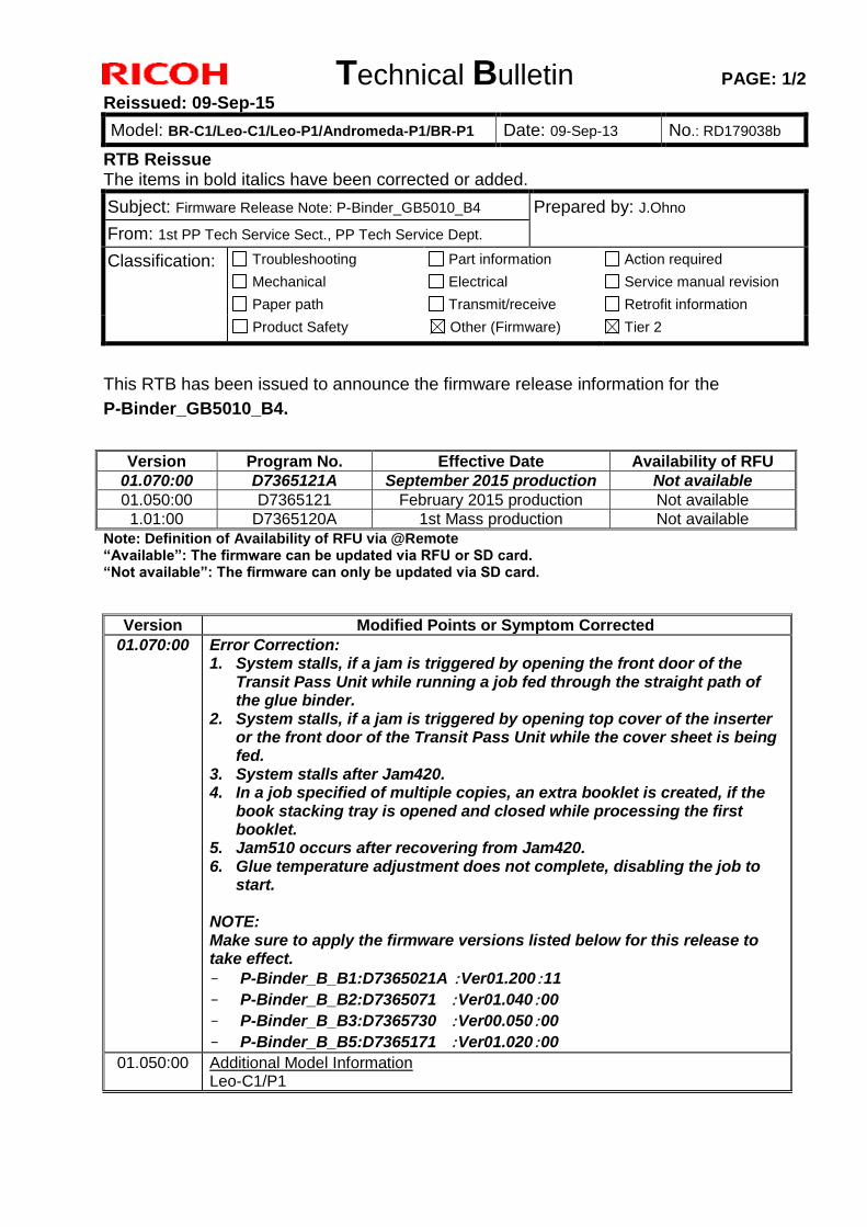
Technical Bulletin PAGE: 1/2
Reissued: 09-Sep-15
Model: BR-C1/Leo-C1/Leo-P1/Andromeda-P1/BR-P1 Date: 09-Sep-13 No.: RD179038b
RTB Reissue The items in bold italics have been corrected or added.
Subject: Firmware Release Note: P-Binder_GB5010_B4 Prepared by: J.Ohno
From: 1st PP Tech Service Sect., PP Tech Service Dept.
Classification: Troubleshooting
Mechanical
Paper path
Part information
Electrical
Transmit/receive
Action required
Service manual revision
Retrofit information
Product Safety Other (Firmware) Tier 2
This RTB has been issued to announce the firmware release information for the
P-Binder_GB5010_B4.
Version Program No. Effective Date Availability of RFU
01.070:00 D7365121A September 2015 production Not available
01.050:00 D7365121 February 2015 production Not available
1.01:00 D7365120A 1st Mass production Not available
Note: Definition of Availability of RFU via @Remote “Available”: The firmware can be updated via RFU or SD card. “Not available”: The firmware can only be updated via SD card.
Version Modified Points or Symptom Corrected
01.070:00 Error Correction: 1. System stalls, if a jam is triggered by opening the front door of the
Transit Pass Unit while running a job fed through the straight path of the glue binder.
2. System stalls, if a jam is triggered by opening top cover of the inserter or the front door of the Transit Pass Unit while the cover sheet is being fed.
3. System stalls after Jam420. 4. In a job specified of multiple copies, an extra booklet is created, if the
book stacking tray is opened and closed while processing the first booklet.
5. Jam510 occurs after recovering from Jam420. 6. Glue temperature adjustment does not complete, disabling the job to
start. NOTE: Make sure to apply the firmware versions listed below for this release to take effect.
- P-Binder_B_B1:D7365021A :Ver01.200:11
- P-Binder_B_B2:D7365071 :Ver01.040:00
- P-Binder_B_B3:D7365730 :Ver00.050:00
- P-Binder_B_B5:D7365171 :Ver01.020:00
01.050:00 Additional Model Information Leo-C1/P1
Technical Bulletin PAGE: 2/2
Reissued: 09-Sep-15
Model: BR-C1/Leo-C1/Leo-P1/Andromeda-P1/BR-P1 Date: 09-Sep-13 No.: RD179038b
Version Modified Points or Symptom Corrected
Specification Change - Supports 178.5mm/s line speed - Supports 700mm length media (in feed direction) - Supports Leo-C1/P1 Symptoms Corrected - The Perfect Binder is not ready but receives jobs from the engine, causing
jams at the entrance. - Some of the input checks do not work. - The Perfect Binder stalls, if the job is run immediately after opening and
closing the front doors in a low temperature environment, because the glue temperature is not adjusted.
- J423 occurs, if the Buffer Pass unit is connected. - J343 occurs when the stacking tray becomes full. - Can not resume the job immediately after removing booklets from a "tacking
tray full" status. - Can not start the next job, if the previous job is canceled with the "Stop" key
at a particular timing. - Jam occurs, if the cover sheet is fed from the Inserter. - The Perfect Binder stalls, if a jam occurs and the stacking tray becomes full
at a particular timing. Important Note The following firmware must be installed as a set. P-Binder_B_B1:D7365021 :Ver01.160:11 P-Binder_B_B2:D7365071 :Ver01.040:00 P-Binder_B_B3:D7365730 :Ver00.050:00 P-Binder_B_B4:D7365121 :Ver01.050:00 P-Binder_B_B5:D7365171 :Ver01.020:00
1.01:00 1st Mass production
Technical Bulletin PAGE: 1/1
Reissued: 16-Mar-15
Model: BR-C1/Leo-C1/Leo-P1/Andromeda-P1 Date: 09-Sep-13 No.: RD179039a
RTB Reissue The items in bold italics have been corrected or added.
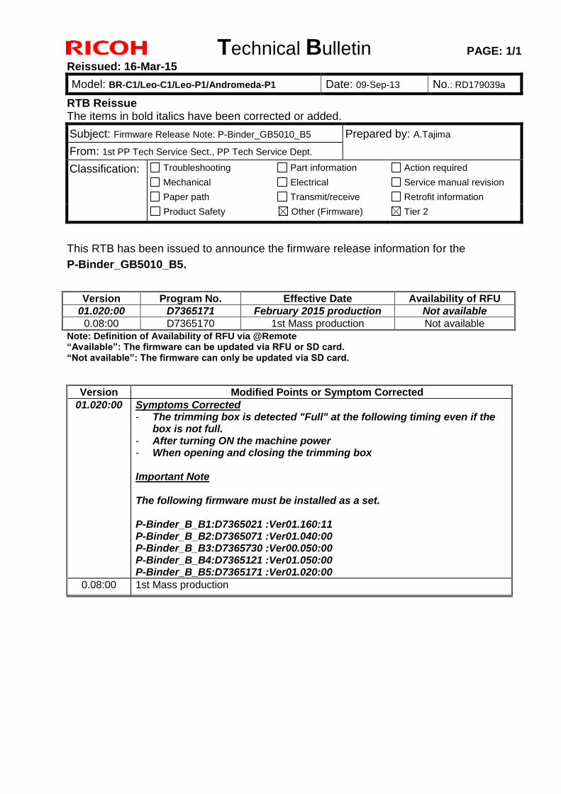
Subject: Firmware Release Note: P-Binder_GB5010_B5 Prepared by: A.Tajima
From: 1st PP Tech Service Sect., PP Tech Service Dept.
Classification: Troubleshooting
Mechanical
Paper path
Part information
Electrical
Transmit/receive
Action required
Service manual revision
Retrofit information
Product Safety Other (Firmware) Tier 2
This RTB has been issued to announce the firmware release information for the
P-Binder_GB5010_B5.
Version Program No. Effective Date Availability of RFU
01.020:00 D7365171 February 2015 production Not available
0.08:00 D7365170 1st Mass production Not available
Note: Definition of Availability of RFU via @Remote “Available”: The firmware can be updated via RFU or SD card. “Not available”: The firmware can only be updated via SD card.
Version Modified Points or Symptom Corrected
01.020:00 Symptoms Corrected - The trimming box is detected "Full" at the following timing even if the
box is not full. - After turning ON the machine power - When opening and closing the trimming box Important Note The following firmware must be installed as a set. P-Binder_B_B1:D7365021 :Ver01.160:11 P-Binder_B_B2:D7365071 :Ver01.040:00 P-Binder_B_B3:D7365730 :Ver00.050:00 P-Binder_B_B4:D7365121 :Ver01.050:00 P-Binder_B_B5:D7365171 :Ver01.020:00
0.08:00 1st Mass production
Technical Bulletin PAGE: 1/1
Model: BR-C1 (D179) Date: 09-Sep-13 No.: RD179040
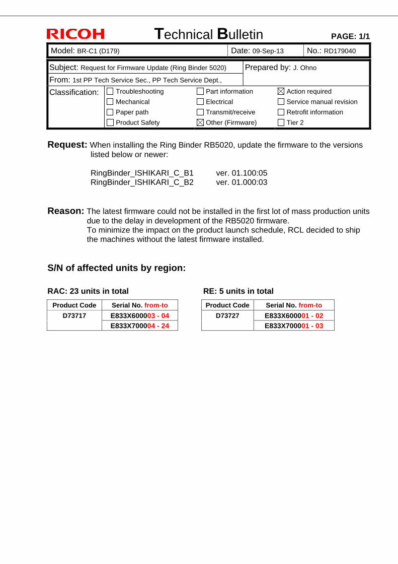
Subject: Request for Firmware Update (Ring Binder 5020) Prepared by: J. Ohno
From: 1st PP Tech Service Sec., PP Tech Service Dept.,
Classification: Troubleshooting
Mechanical
Paper path
Product Safety
Part information
Electrical
Transmit/receive
Other (Firmware)
Action required
Service manual revision
Retrofit information
Tier 2
Request: When installing the Ring Binder RB5020, update the firmware to the versions
listed below or newer:
RingBinder_ISHIKARI_C_B1 ver. 01.100:05 RingBinder_ISHIKARI_C_B2 ver. 01.000:03
Reason: The latest firmware could not be installed in the first lot of mass production units
due to the delay in development of the RB5020 firmware. To minimize the impact on the product launch schedule, RCL decided to ship the machines without the latest firmware installed.
S/N of affected units by region:
RAC: 23 units in total RE: 5 units in total
Product Code Serial No. from-to Product Code Serial No. from-to
D73717 E833X600003 - 04 D73727 E833X600001 - 02 E833X700004 - 24 E833X700001 - 03
Technical Bulletin PAGE: 1/1
Model: BR-C1 (D179) Date: 17-Sep-13 No.: RD179041
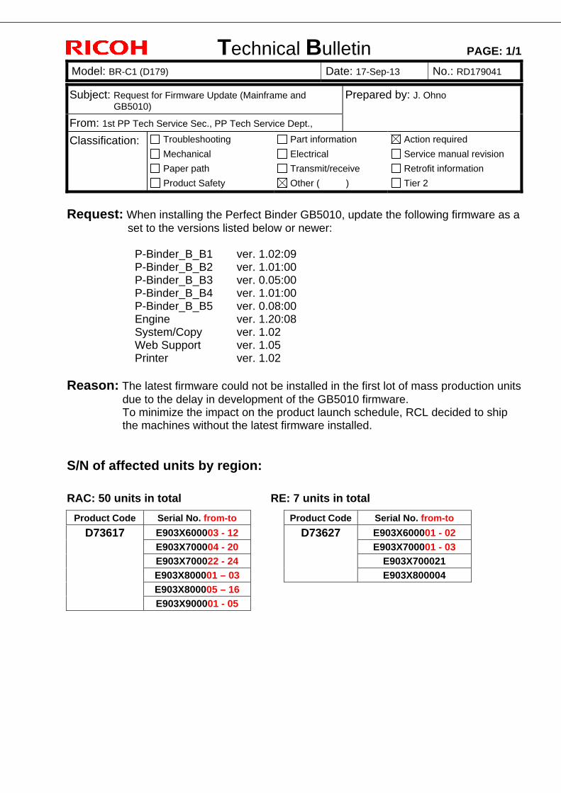
Subject: Request for Firmware Update (Mainframe and GB5010)
Prepared by: J. Ohno
From: 1st PP Tech Service Sec., PP Tech Service Dept.,
Classification: Troubleshooting
Mechanical
Paper path
Product Safety
Part information
Electrical
Transmit/receive
Other ( )
Action required
Service manual revision
Retrofit information
Tier 2
Request: When installing the Perfect Binder GB5010, update the following firmware as a
set to the versions listed below or newer:
P-Binder_B_B1 ver. 1.02:09 P-Binder_B_B2 ver. 1.01:00 P-Binder_B_B3 ver. 0.05:00 P-Binder_B_B4 ver. 1.01:00 P-Binder_B_B5 ver. 0.08:00 Engine ver. 1.20:08 System/Copy ver. 1.02 Web Support ver. 1.05 Printer ver. 1.02
Reason: The latest firmware could not be installed in the first lot of mass production units
due to the delay in development of the GB5010 firmware. To minimize the impact on the product launch schedule, RCL decided to ship the machines without the latest firmware installed.
S/N of affected units by region:
RAC: 50 units in total RE: 7 units in total
Product Code Serial No. from-to Product Code Serial No. from-to
D73617 E903X600003 - 12 D73627 E903X600001 - 02 E903X700004 - 20 E903X700001 - 03 E903X700022 - 24 E903X700021
E903X800001 – 03 E903X800004
E903X800005 – 16
E903X900001 - 05
Technical Bulletin PAGE: 1/1
Reissued: 09-Mar-17
Model: BR-C1 Date: 20-Jun-13 No.: RD179042d
RTB Reissue The items in bold italics have been corrected or added.
Subject: Firmware Release Note: browser Prepared by: H. Morishima
From: 2nd Tech Service Sect., MFP/Printer Tech Service Dept.
Classification: Troubleshooting
Mechanical
Paper path
Product Safety
Part information
Electrical
Transmit/receive
Other (Firmware)
Action required
Service manual revision
Retrofit information
Tier 2
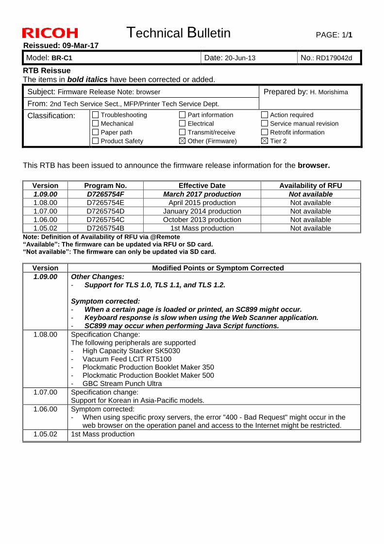
This RTB has been issued to announce the firmware release information for the browser.
Version Program No. Effective Date Availability of RFU
1.09.00 D7265754F March 2017 production Not available
1.08.00 D7265754E April 2015 production Not available
1.07.00 D7265754D January 2014 production Not available
1.06.00 D7265754C October 2013 production Not available
1.05.02 D7265754B 1st Mass production Not available
Note: Definition of Availability of RFU via @Remote “Available”: The firmware can be updated via RFU or SD card. “Not available”: The firmware can only be updated via SD card.
Version Modified Points or Symptom Corrected
1.09.00 Other Changes: - Support for TLS 1.0, TLS 1.1, and TLS 1.2. Symptom corrected: - When a certain page is loaded or printed, an SC899 might occur. - Keyboard response is slow when using the Web Scanner application. - SC899 may occur when performing Java Script functions.
1.08.00 Specification Change: The following peripherals are supported - High Capacity Stacker SK5030 - Vacuum Feed LCIT RT5100 - Plockmatic Production Booklet Maker 350 - Plockmatic Production Booklet Maker 500 - GBC Stream Punch Ultra
1.07.00 Specification change: Support for Korean in Asia-Pacific models.
1.06.00 Symptom corrected: - When using specific proxy servers, the error "400 - Bad Request" might occur in the
web browser on the operation panel and access to the Internet might be restricted.
1.05.02 1st Mass production
Technical Bulletin PAGE: 1/1
Model: BR-C1 (D179) Date: 6-Nov-31 No.: RD179043
Subject: FSM correction -ITB cleaning unit replacement procedure-
Prepared by: Kazuya Tsutsui
From: 1st PP Tech Service Sec., PP Tech Service Dept.,
Classification: Troubleshooting
Mechanical
Paper path
Product Safety
Part information
Electrical
Transmit/receive
Other ( )
Action required
Service manual revision
Retrofit information
Tier 2
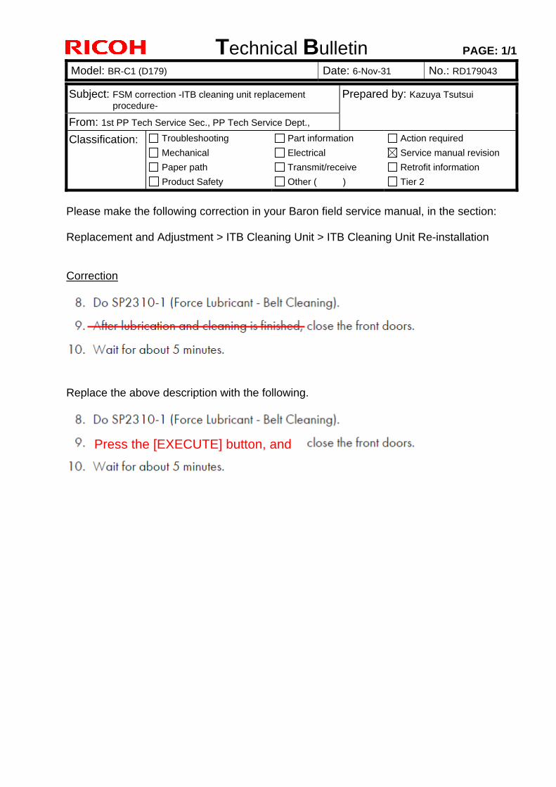
Please make the following correction in your Baron field service manual, in the section: Replacement and Adjustment > ITB Cleaning Unit > ITB Cleaning Unit Re-installation Correction
Replace the above description with the following.
Press the [EXECUTE] button, and
Technical Bulletin PAGE: 1/2
Model: BR-C1 (D179) Date: 18-Nov-13 No.: RD179044
Subject: FSM correction Prepared by: J Ohno
From: 1st PP Tech Service Sec., PP Tech Service Dept
Classification: Troubleshooting Mechanical Paper path Product Safety
Part information Electrical Transmit/receive Other ( )
Action required Service manual revision Retrofit information Tier 2
Please apply the following 3 corrections to your field service manual.
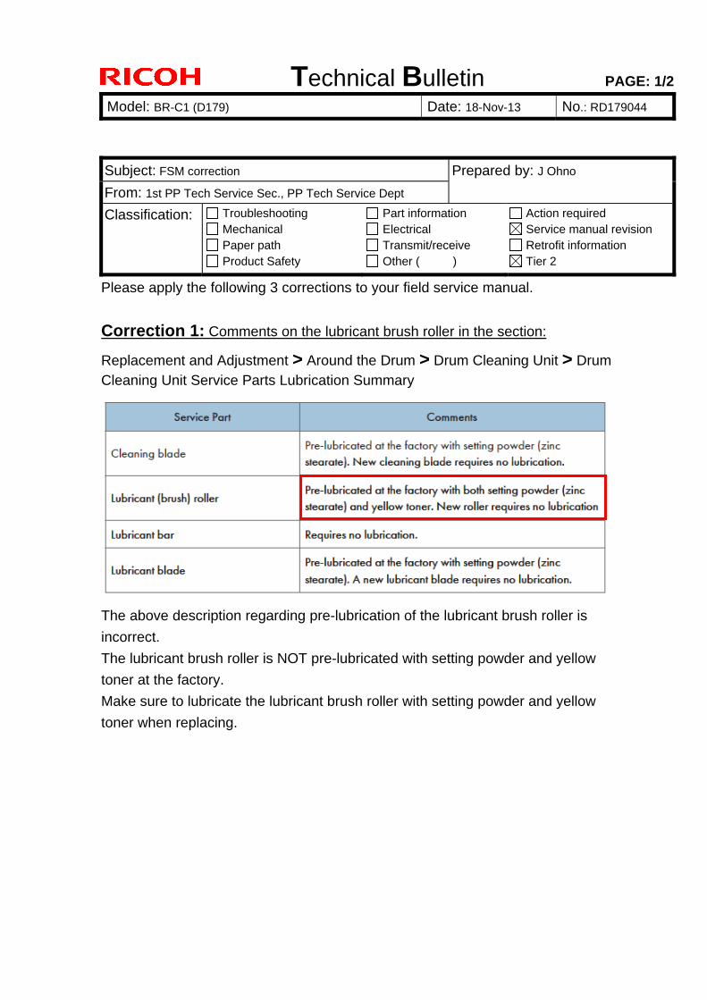
Correction 1: Comments on the lubricant brush roller in the section:
Replacement and Adjustment > Around the Drum > Drum Cleaning Unit > Drum Cleaning Unit Service Parts Lubrication Summary
The above description regarding pre-lubrication of the lubricant brush roller is
incorrect.
The lubricant brush roller is NOT pre-lubricated with setting powder and yellow
toner at the factory.
Make sure to lubricate the lubricant brush roller with setting powder and yellow
toner when replacing.
Technical Bulletin PAGE: 2/2
Model: BR-C1 (D179) Date: 18-Nov-13 No.: RD179044
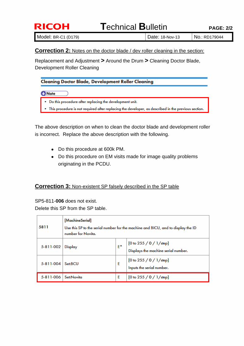
Correction 2: Notes on the doctor blade / dev roller cleaning in the section:
Replacement and Adjustment > Around the Drum > Cleaning Doctor Blade, Development Roller Cleaning
The above description on when to clean the doctor blade and development roller
is incorrect. Replace the above description with the following.
Do this procedure at 600k PM.
Do this procedure on EM visits made for image quality problems
originating in the PCDU.
Correction 3: Non-existent SP falsely described in the SP table
SP5-811-006 does not exist.
Delete this SP from the SP table.

Technical Bulletin PAGE: 1/1
Model: BR-C1 (D179) Date: 13-Dec-13 No.: RD179045
Subject: FSM correction – SC issued when the Used Toner Path is blocked
Prepared by: Kazuya Tsutsui
From: 1st PP Tech Service Sec., PP Tech Service Dept.,
Classification: Troubleshooting
Mechanical
Paper path
Product Safety
Part information
Electrical
Transmit/receive
Other ( )
Action required
Service manual revision
Retrofit information
Tier 2
Please make the following correction in your Baron field service manual in the section:
Replacement and Adjustment > Used Toner Path > Used Toner Path, Used Toner
Transport Motor Correction The SC number was incorrect. The correct SC number is SC488.
SC488
Technical Bulletin PAGE: 1/5
Model: BR-C1 (D179) Date: 25-Dec-24 No.: RD179046
Subject: Harness position check to prevent Jam122 on SR5050/5060
Prepared by: Kazuya Tsutsui
From: 1st PP Tech Service Sec., PP Tech Service Dept.,
Classification: Troubleshooting
Mechanical
Paper path
Product Safety
Part information
Electrical
Transmit/receive
Other ( )
Action required
Service manual revision
Retrofit information
Tier 2
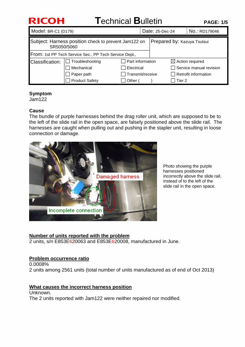
Symptom Jam122 Cause The bundle of purple harnesses behind the drag roller unit, which are supposed to be to the left of the slide rail in the open space, are falsely positioned above the slide rail. The harnesses are caught when pulling out and pushing in the stapler unit, resulting in loose connection or damage.
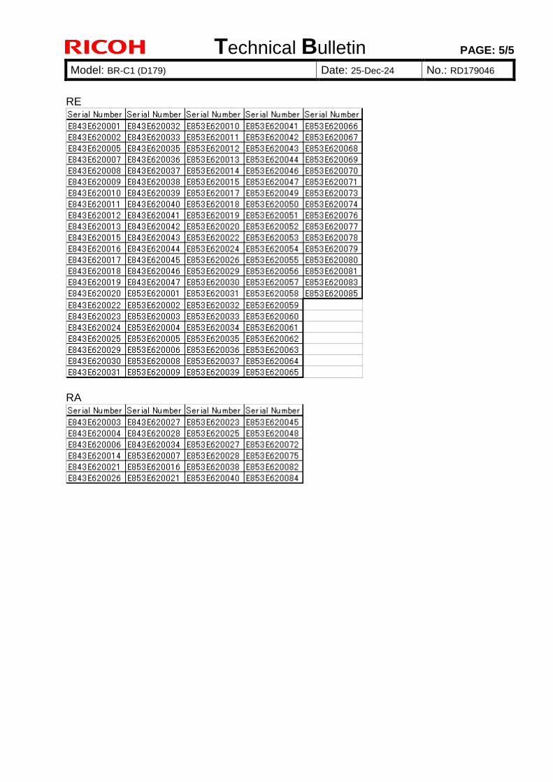
Number of units reported with the problem 2 units, s/n E853E620063 and E853E620008, manufactured in June. Problem occurrence ratio 0.0008% 2 units among 2561 units (total number of units manufactured as of end of Oct 2013) What causes the incorrect harness position Unknown. The 2 units reported with Jam122 were neither repaired nor modified.
Photo showing the purple harnesses positioned incorrectly above the slide rail, instead of to the left of the slide rail in the open space.
Technical Bulletin PAGE: 2/5
Model: BR-C1 (D179) Date: 25-Dec-24 No.: RD179046
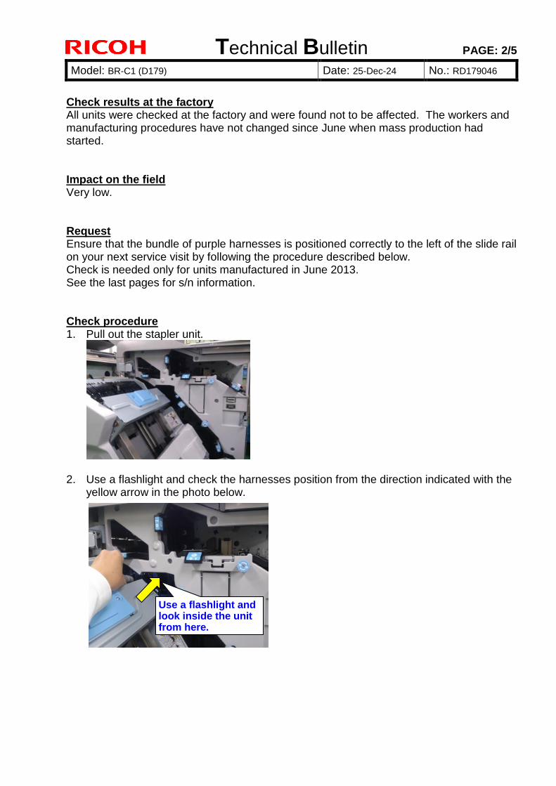
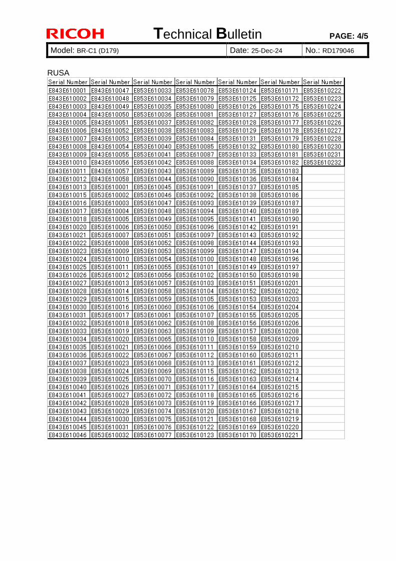
Check results at the factory All units were checked at the factory and were found not to be affected. The workers and manufacturing procedures have not changed since June when mass production had started. Impact on the field Very low. Request Ensure that the bundle of purple harnesses is positioned correctly to the left of the slide rail on your next service visit by following the procedure described below. Check is needed only for units manufactured in June 2013. See the last pages for s/n information. Check procedure 1. Pull out the stapler unit.
2. Use a flashlight and check the harnesses position from the direction indicated with the yellow arrow in the photo below.
Use a flashlight and look inside the unit from here.
Technical Bulletin PAGE: 3/5
Model: BR-C1 (D179) Date: 25-Dec-24 No.: RD179046
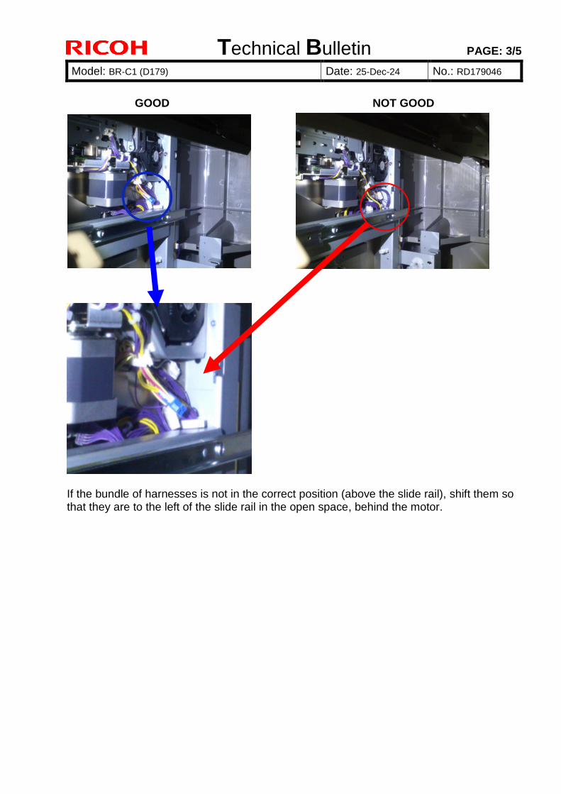
GOOD NOT GOOD
If the bundle of harnesses is not in the correct position (above the slide rail), shift them so that they are to the left of the slide rail in the open space, behind the motor.
Technical Bulletin PAGE: 4/5
Model: BR-C1 (D179) Date: 25-Dec-24 No.: RD179046
RUSA
Technical Bulletin PAGE: 5/5
Model: BR-C1 (D179) Date: 25-Dec-24 No.: RD179046
RE
RA
Technical Bulletin PAGE: 1/12
Model: BR-C1 (D179) Date: 26-Dec-13 No.: RD179047
Please apply the following 2 corrections to your field service manual.
The operation panel installation procedure was changed for better harness routing.
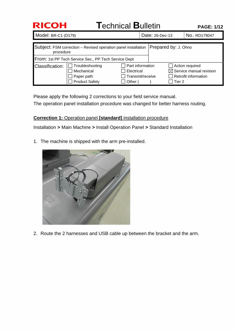
Correction 1: Operation panel [standard] installation procedure
Installation > Main Machine > Install Operation Panel > Standard Installation
1. The machine is shipped with the arm pre-installed.
2. Route the 2 harnesses and USB cable up between the bracket and the arm.
Subject: FSM correction – Revised operation panel installation procedure
Prepared by: J. Ohno
From: 1st PP Tech Service Sec., PP Tech Service Dept
Classification: Troubleshooting Mechanical Paper path Product Safety
Part information Electrical Transmit/receive Other ( )
Action required Service manual revision Retrofit information Tier 2
Technical Bulletin PAGE: 2/12
Model: BR-C1 (D179) Date: 26-Dec-13 No.: RD179047
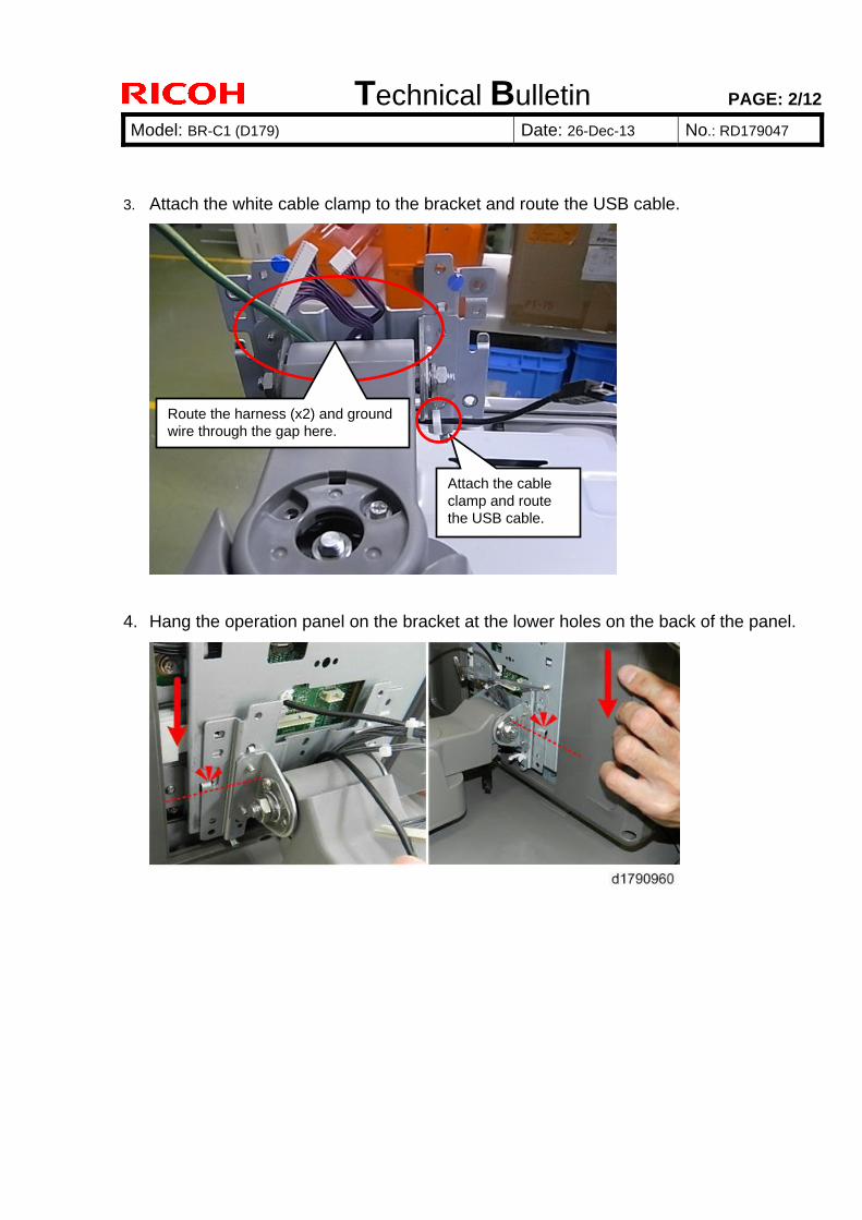
3. Attach the white cable clamp to the bracket and route the USB cable.
4. Hang the operation panel on the bracket at the lower holes on the back of the panel.
Attach the cable clamp and route the USB cable.
Route the harness (x2) and ground wire through the gap here.
Technical Bulletin PAGE: 3/12
Model: BR-C1 (D179) Date: 26-Dec-13 No.: RD179047
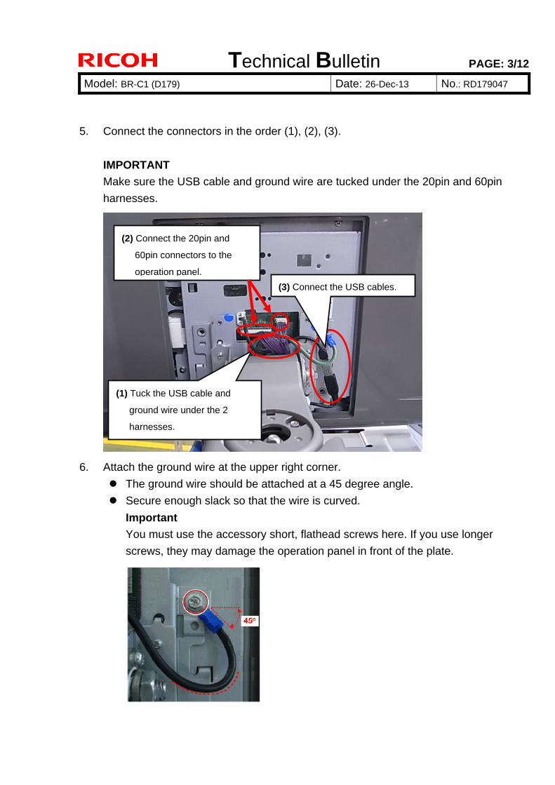
5. Connect the connectors in the order (1), (2), (3).
IMPORTANT
Make sure the USB cable and ground wire are tucked under the 20pin and 60pin
harnesses.
6. Attach the ground wire at the upper right corner.
The ground wire should be attached at a 45 degree angle.
Secure enough slack so that the wire is curved.
Important
You must use the accessory short, flathead screws here. If you use longer
screws, they may damage the operation panel in front of the plate.
(2) Connect the 20pin and
60pin connectors to the
operation panel.
(1) Tuck the USB cable and
ground wire under the 2
harnesses.
(3) Connect the USB cables.
Technical Bulletin PAGE: 4/12
Model: BR-C1 (D179) Date: 26-Dec-13 No.: RD179047
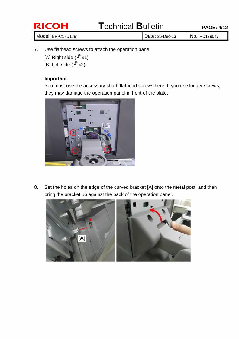
7. Use flathead screws to attach the operation panel.
[A] Right side ( x1)
[B] Left side ( x2)
Important
You must use the accessory short, flathead screws here. If you use longer screws,
they may damage the operation panel in front of the plate.
8. Set the holes on the edge of the curved bracket [A] onto the metal post, and then
bring the bracket up against the back of the operation panel.
Technical Bulletin PAGE: 5/12
Model: BR-C1 (D179) Date: 26-Dec-13 No.: RD179047
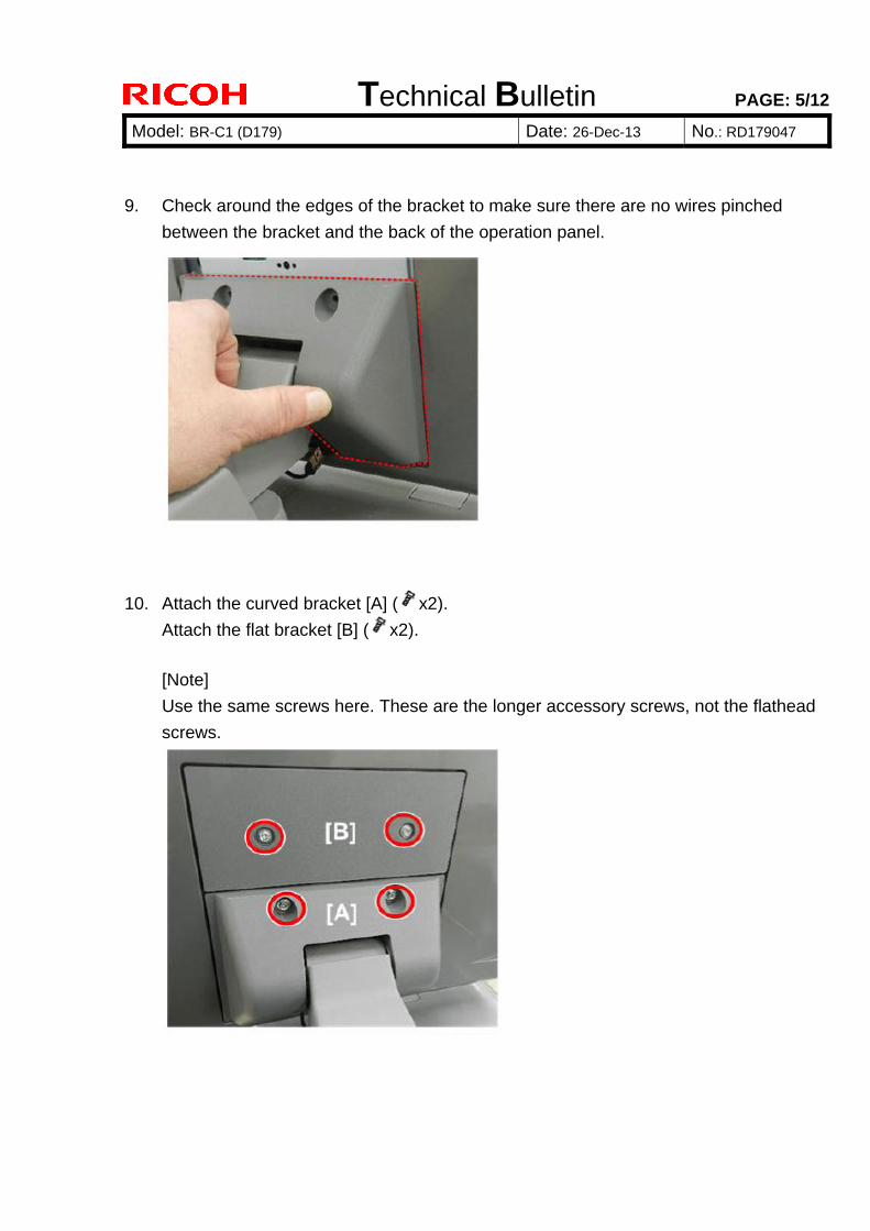
9. Check around the edges of the bracket to make sure there are no wires pinched
between the bracket and the back of the operation panel.
10. Attach the curved bracket [A] ( x2).
Attach the flat bracket [B] ( x2).
[Note]
Use the same screws here. These are the longer accessory screws, not the flathead
screws.
Technical Bulletin PAGE: 6/12
Model: BR-C1 (D179) Date: 26-Dec-13 No.: RD179047
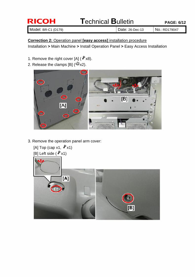
Correction 2: Operation panel [easy access] installation procedure
Installation > Main Machine > Install Operation Panel > Easy Access Installation
1. Remove the right cover [A] ( x8).
2. Release the clamps [B] ( x2).
3. Remove the operation panel arm cover:
[A] Top (cap x1, x1)
[B] Left side ( x1)
Technical Bulletin PAGE: 7/12
Model: BR-C1 (D179) Date: 26-Dec-13 No.: RD179047
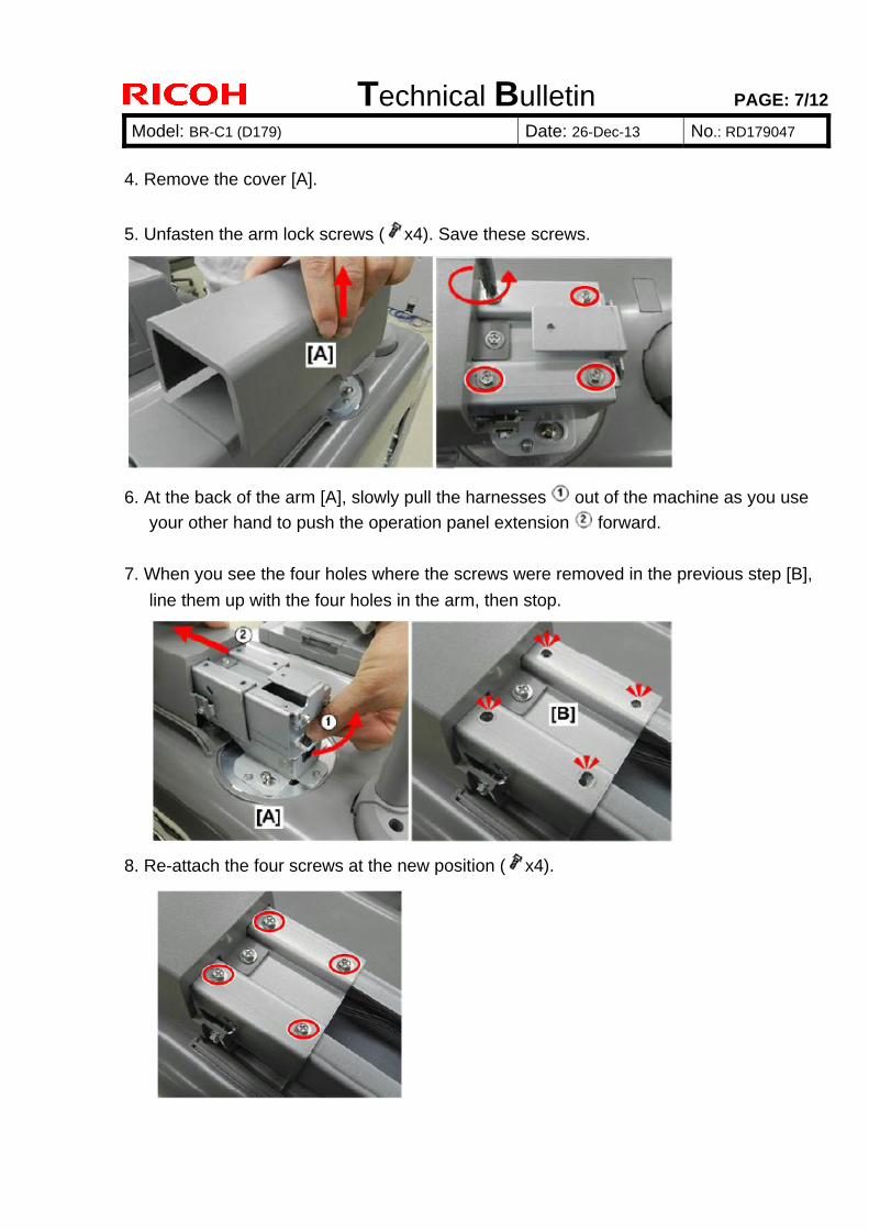
4. Remove the cover [A].
5. Unfasten the arm lock screws ( x4). Save these screws.
6. At the back of the arm [A], slowly pull the harnesses out of the machine as you use
your other hand to push the operation panel extension forward.
7. When you see the four holes where the screws were removed in the previous step [B],
line them up with the four holes in the arm, then stop.
8. Re-attach the four screws at the new position ( x4).
Technical Bulletin PAGE: 8/12
Model: BR-C1 (D179) Date: 26-Dec-13 No.: RD179047
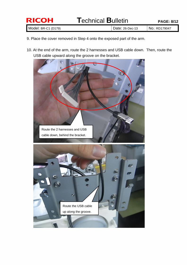
9. Place the cover removed in Step 4 onto the exposed part of the arm.
10. At the end of the arm, route the 2 harnesses and USB cable down. Then, route the
USB cable upward along the groove on the bracket.
Route the 2 harnesses and USB
cable down, behind the bracket.
Route the USB cable
up along the groove.
Technical Bulletin PAGE: 9/12
Model: BR-C1 (D179) Date: 26-Dec-13 No.: RD179047
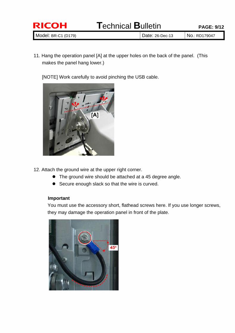
11. Hang the operation panel [A] at the upper holes on the back of the panel. (This
makes the panel hang lower.)
[NOTE] Work carefully to avoid pinching the USB cable.
12. Attach the ground wire at the upper right corner.
The ground wire should be attached at a 45 degree angle.
Secure enough slack so that the wire is curved.
Important
You must use the accessory short, flathead screws here. If you use longer screws,
they may damage the operation panel in front of the plate.
Technical Bulletin PAGE: 10/12
Model: BR-C1 (D179) Date: 26-Dec-13 No.: RD179047
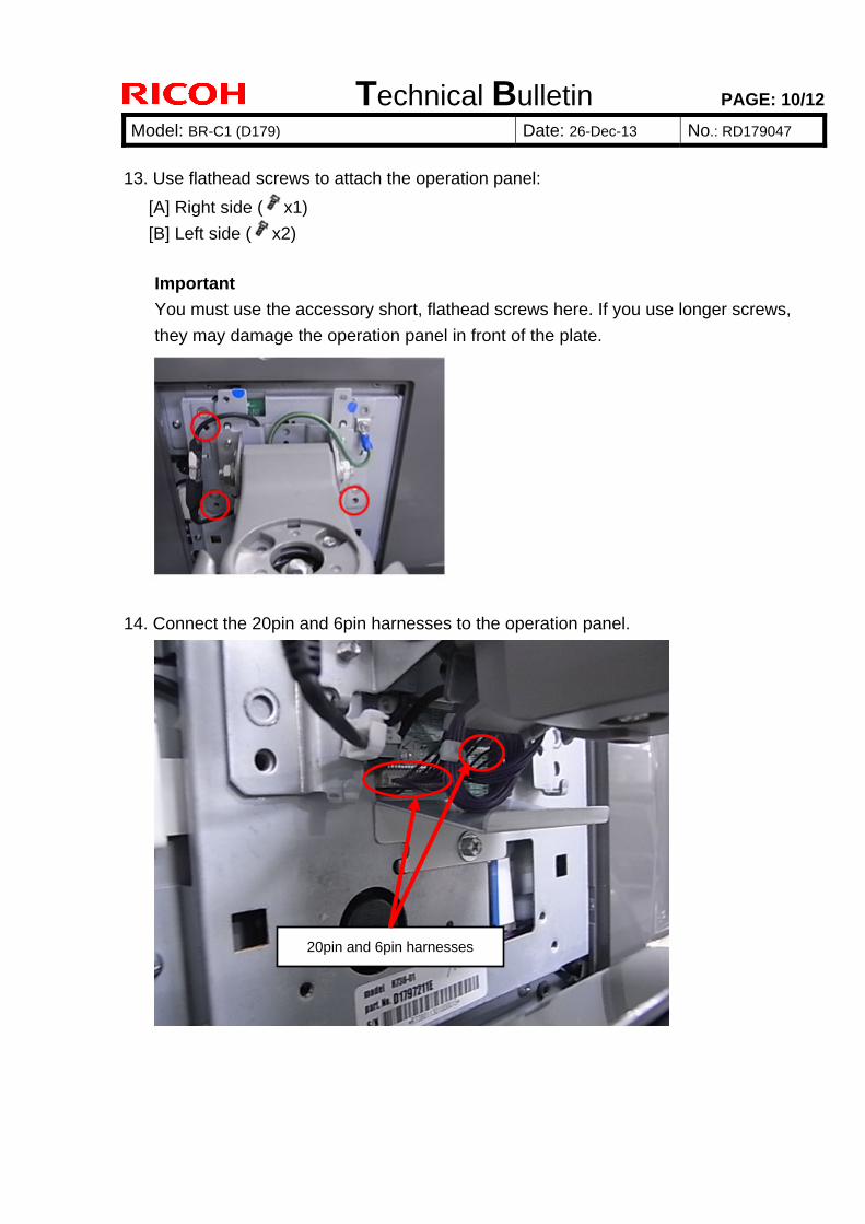
13. Use flathead screws to attach the operation panel:
[A] Right side ( x1)
[B] Left side ( x2)
Important
You must use the accessory short, flathead screws here. If you use longer screws,
they may damage the operation panel in front of the plate.
14. Connect the 20pin and 6pin harnesses to the operation panel.
20pin and 6pin harnesses
Technical Bulletin PAGE: 11/12
Model: BR-C1 (D179) Date: 26-Dec-13 No.: RD179047
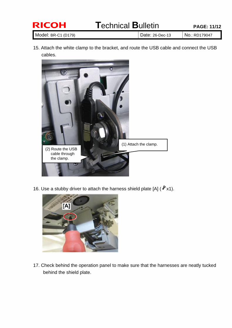
15. Attach the white clamp to the bracket, and route the USB cable and connect the USB
cables.
16. Use a stubby driver to attach the harness shield plate [A] ( x1).
17. Check behind the operation panel to make sure that the harnesses are neatly tucked
behind the shield plate.
(1) Attach the clamp. (2) Route the USB
cable through the clamp.
Technical Bulletin PAGE: 12/12
Model: BR-C1 (D179) Date: 26-Dec-13 No.: RD179047
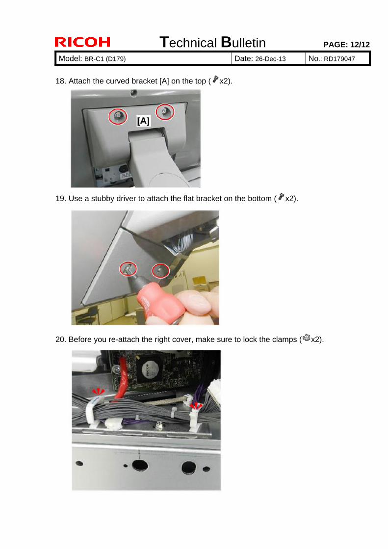
18. Attach the curved bracket [A] on the top ( x2).
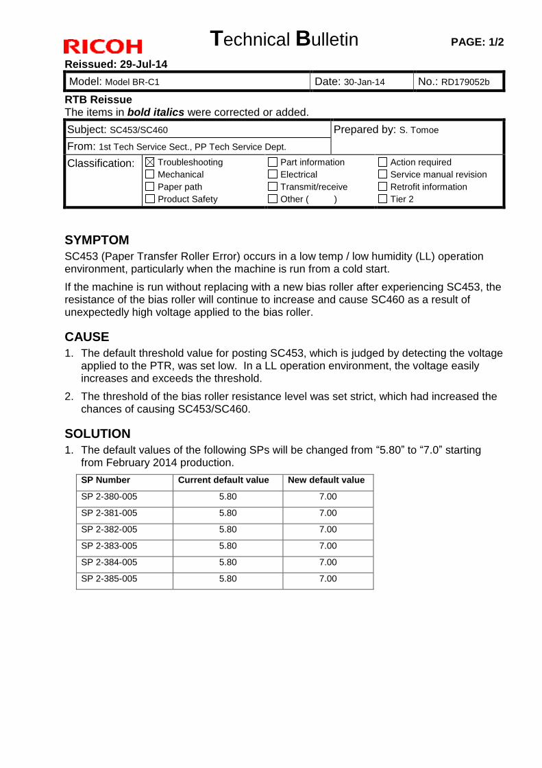
19. Use a stubby driver to attach the flat bracket on the bottom ( x2).
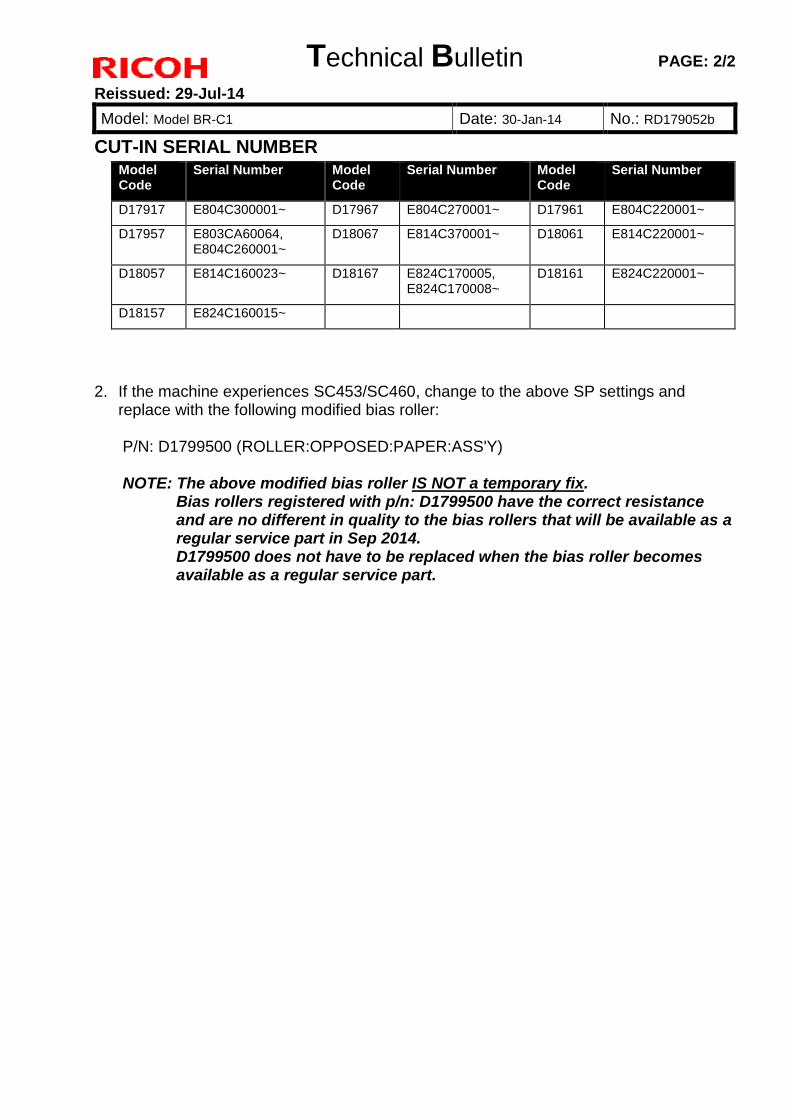
20. Before you re-attach the right cover, make sure to lock the clamps ( x2).
Technical Bulletin PAGE: 1/2
Reissued: 29-Jul-14
Model: Model BR-C1 Date: 30-Jan-14 No.: RD179052b
RTB Reissue The items in bold italics were corrected or added.
Subject: SC453/SC460 Prepared by: S. Tomoe
From: 1st Tech Service Sect., PP Tech Service Dept.
Classification: Troubleshooting
Mechanical
Paper path
Product Safety
Part information
Electrical
Transmit/receive
Other ( )
Action required
Service manual revision
Retrofit information
Tier 2
SYMPTOM
SC453 (Paper Transfer Roller Error) occurs in a low temp / low humidity (LL) operation environment, particularly when the machine is run from a cold start.
If the machine is run without replacing with a new bias roller after experiencing SC453, the resistance of the bias roller will continue to increase and cause SC460 as a result of unexpectedly high voltage applied to the bias roller.
CAUSE
1. The default threshold value for posting SC453, which is judged by detecting the voltage applied to the PTR, was set low. In a LL operation environment, the voltage easily increases and exceeds the threshold.
2. The threshold of the bias roller resistance level was set strict, which had increased the chances of causing SC453/SC460.
SOLUTION
1. The default values of the following SPs will be changed from “5.80” to “7.0” starting from February 2014 production.
SP Number Current default value New default value
SP 2-380-005 5.80 7.00
SP 2-381-005 5.80 7.00
SP 2-382-005 5.80 7.00
SP 2-383-005 5.80 7.00
SP 2-384-005 5.80 7.00
SP 2-385-005 5.80 7.00
Technical Bulletin PAGE: 2/2
Reissued: 29-Jul-14
Model: Model BR-C1 Date: 30-Jan-14 No.: RD179052b
CUT-IN SERIAL NUMBER Model Code
Serial Number Model Code
Serial Number Model Code
Serial Number
D17917 E804C300001~ D17967 E804C270001~ D17961 E804C220001~
D17957 E803CA60064, E804C260001~
D18067 E814C370001~ D18061 E814C220001~
D18057 E814C160023~ D18167 E824C170005, E824C170008~
D18161 E824C220001~
D18157 E824C160015~
2. If the machine experiences SC453/SC460, change to the above SP settings and replace with the following modified bias roller: P/N: D1799500 (ROLLER:OPPOSED:PAPER:ASS'Y) NOTE: The above modified bias roller IS NOT a temporary fix.
Bias rollers registered with p/n: D1799500 have the correct resistance and are no different in quality to the bias rollers that will be available as a regular service part in Sep 2014. D1799500 does not have to be replaced when the bias roller becomes available as a regular service part.
Technical Bulletin PAGE: 1/6
Model: BR-C1 (D179) Date: 31-Jan-14 No.: RD179053
Subject: Field Modification for SC720-75 Prepared by: J. Ohno
From: 1st PP Tech Service Sec., PP Tech Service Dept.,
Classification: Troubleshooting
Mechanical
Paper path
Product Safety
Part information
Electrical
Transmit/receive
Other ( )
Action required
Service manual revision
Retrofit information
Tier 2
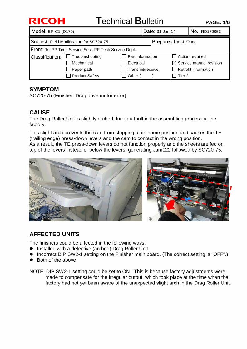
SYMPTOM SC720-75 (Finisher: Drag drive motor error)
CAUSE The Drag Roller Unit is slightly arched due to a fault in the assembling process at the factory.
This slight arch prevents the cam from stopping at its home position and causes the TE (trailing edge) press-down levers and the cam to contact in the wrong position. As a result, the TE press-down levers do not function properly and the sheets are fed on top of the levers instead of below the levers, generating Jam122 followed by SC720-75.
AFFECTED UNITS
The finishers could be affected in the following ways: Installed with a defective (arched) Drag Roller Unit Incorrect DIP SW2-1 setting on the Finisher main board. (The correct setting is "OFF".) Both of the above NOTE: DIP SW2-1 setting could be set to ON. This is because factory adjustments were
made to compensate for the irregular output, which took place at the time when the factory had not yet been aware of the unexpected slight arch in the Drag Roller Unit.
Technical Bulletin PAGE: 2/6
Model: BR-C1 (D179) Date: 31-Jan-14 No.: RD179053
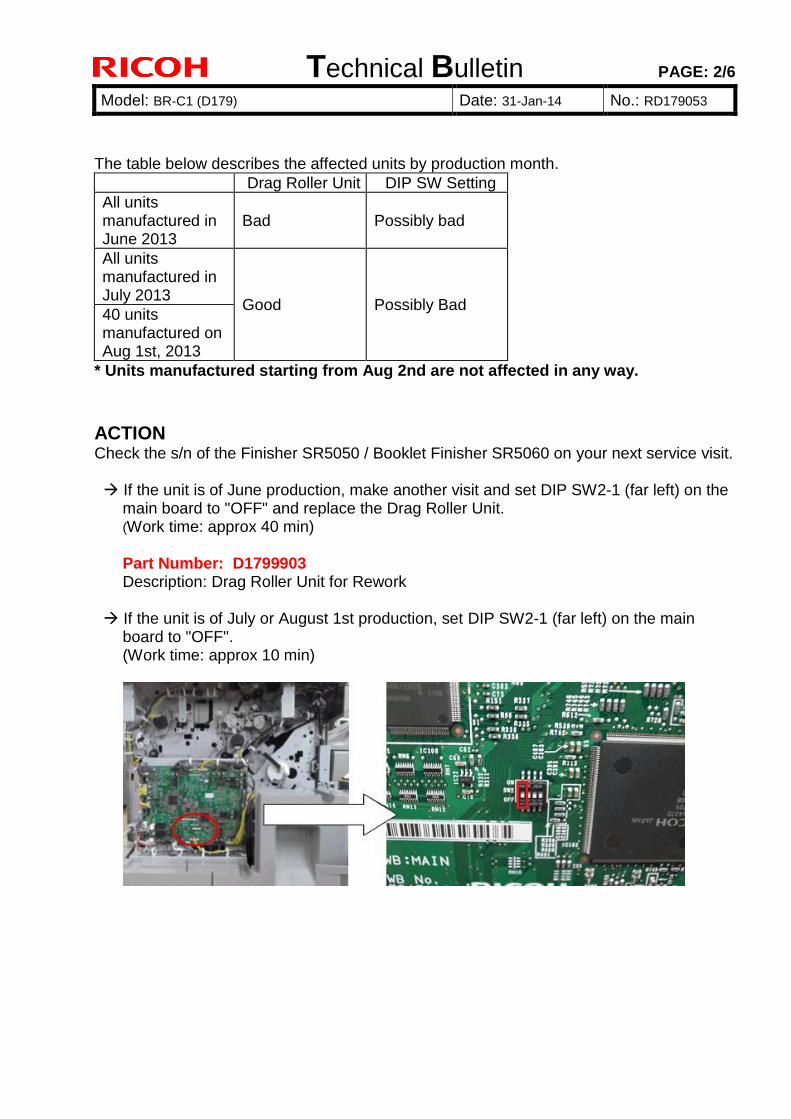
The table below describes the affected units by production month.
Drag Roller Unit DIP SW Setting
All units manufactured in June 2013
Bad Possibly bad
All units manufactured in July 2013
Good Possibly Bad 40 units manufactured on Aug 1st, 2013
* Units manufactured starting from Aug 2nd are not affected in any way.
ACTION Check the s/n of the Finisher SR5050 / Booklet Finisher SR5060 on your next service visit. If the unit is of June production, make another visit and set DIP SW2-1 (far left) on the
main board to "OFF" and replace the Drag Roller Unit. (Work time: approx 40 min)
Part Number: D1799903 Description: Drag Roller Unit for Rework
If the unit is of July or August 1st production, set DIP SW2-1 (far left) on the main
board to "OFF". (Work time: approx 10 min)
Technical Bulletin PAGE: 3/6
Model: BR-C1 (D179) Date: 31-Jan-14 No.: RD179053
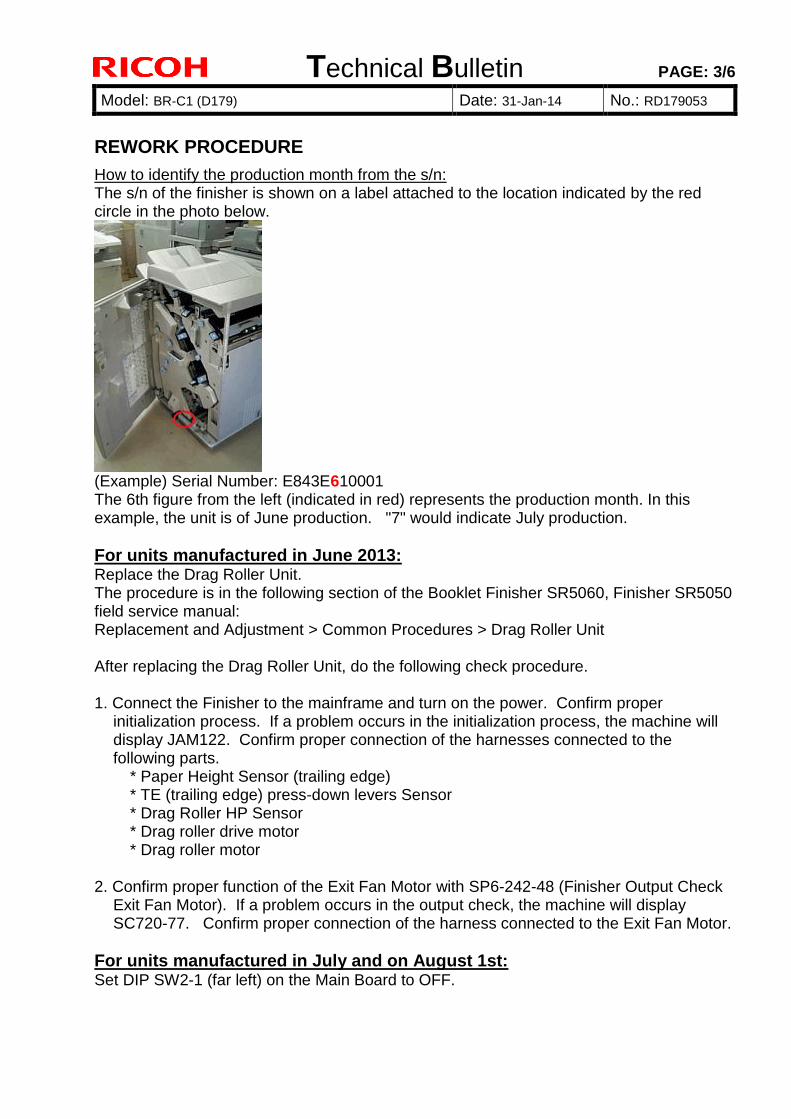
REWORK PROCEDURE
How to identify the production month from the s/n: The s/n of the finisher is shown on a label attached to the location indicated by the red circle in the photo below.
(Example) Serial Number: E843E610001 The 6th figure from the left (indicated in red) represents the production month. In this example, the unit is of June production. "7" would indicate July production.
For units manufactured in June 2013: Replace the Drag Roller Unit. The procedure is in the following section of the Booklet Finisher SR5060, Finisher SR5050 field service manual: Replacement and Adjustment > Common Procedures > Drag Roller Unit After replacing the Drag Roller Unit, do the following check procedure. 1. Connect the Finisher to the mainframe and turn on the power. Confirm proper
initialization process. If a problem occurs in the initialization process, the machine will display JAM122. Confirm proper connection of the harnesses connected to the following parts.
* Paper Height Sensor (trailing edge) * TE (trailing edge) press-down levers Sensor * Drag Roller HP Sensor * Drag roller drive motor * Drag roller motor 2. Confirm proper function of the Exit Fan Motor with SP6-242-48 (Finisher Output Check
Exit Fan Motor). If a problem occurs in the output check, the machine will display SC720-77. Confirm proper connection of the harness connected to the Exit Fan Motor.
For units manufactured in July and on August 1st: Set DIP SW2-1 (far left) on the Main Board to OFF.
Technical Bulletin PAGE: 4/6
Model: BR-C1 (D179) Date: 31-Jan-14 No.: RD179053
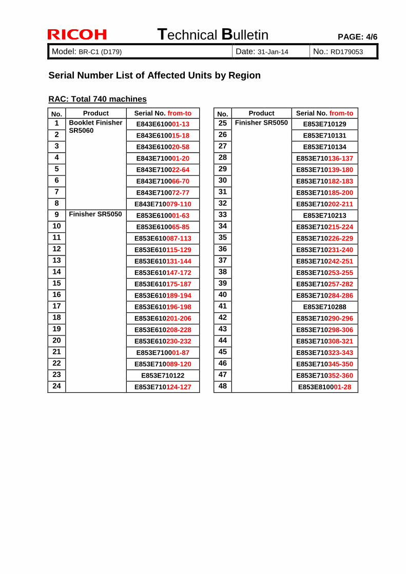
Serial Number List of Affected Units by Region
RAC: Total 740 machines
No. Product Serial No. from-to
No. Product Serial No. from-to
1 Booklet Finisher SR5060
E843E610001-13 25 Finisher SR5050 E853E710129
2 E843E610015-18 26 E853E710131
3 E843E610020-58 27 E853E710134
4 E843E710001-20 28 E853E710136-137
5 E843E710022-64 29 E853E710139-180
6 E843E710066-70 30 E853E710182-183
7 E843E710072-77 31 E853E710185-200
8 E843E710079-110 32 E853E710202-211
9 Finisher SR5050 E853E610001-63 33 E853E710213
10 E853E610065-85 34 E853E710215-224
11 E853E610087-113 35 E853E710226-229
12 E853E610115-129 36 E853E710231-240
13 E853E610131-144 37 E853E710242-251
14 E853E610147-172 38 E853E710253-255
15 E853E610175-187 39 E853E710257-282
16 E853E610189-194 40 E853E710284-286
17 E853E610196-198 41 E853E710288
18 E853E610201-206 42 E853E710290-296
19 E853E610208-228 43 E853E710298-306
20 E853E610230-232 44 E853E710308-321
21 E853E710001-87 45 E853E710323-343
22 E853E710089-120 46 E853E710345-350
23 E853E710122 47 E853E710352-360
24 E853E710124-127 48 E853E810001-28
Technical Bulletin PAGE: 5/6
Model: BR-C1 (D179) Date: 31-Jan-14 No.: RD179053
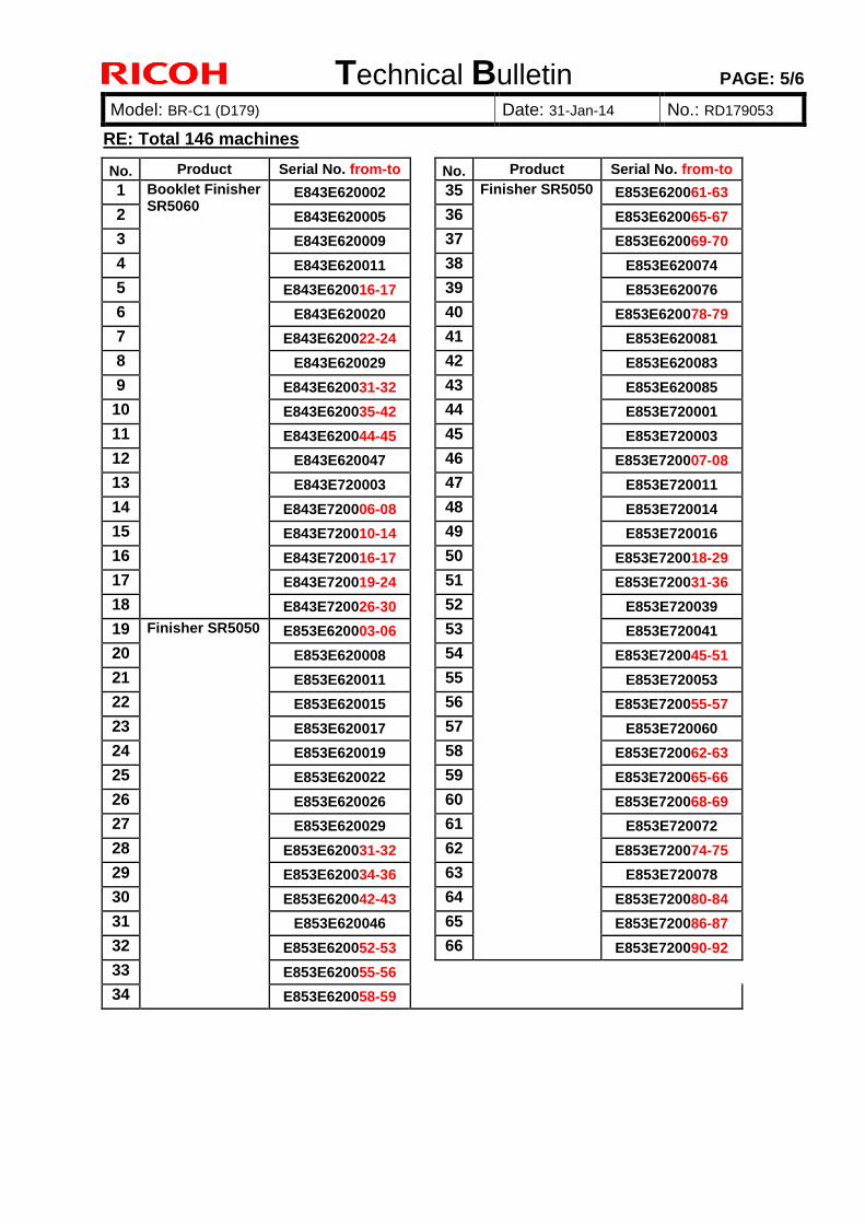
RE: Total 146 machines
No. Product Serial No. from-to
No. Product Serial No. from-to
1 Booklet Finisher SR5060
E843E620002 35 Finisher SR5050 E853E620061-63
2 E843E620005 36 E853E620065-67
3 E843E620009 37 E853E620069-70
4 E843E620011 38 E853E620074
5 E843E620016-17 39 E853E620076
6 E843E620020 40 E853E620078-79
7 E843E620022-24 41 E853E620081
8 E843E620029 42 E853E620083
9 E843E620031-32 43 E853E620085
10 E843E620035-42 44 E853E720001
11 E843E620044-45 45 E853E720003
12 E843E620047 46 E853E720007-08
13 E843E720003 47 E853E720011
14 E843E720006-08 48 E853E720014
15 E843E720010-14 49 E853E720016
16 E843E720016-17 50 E853E720018-29
17 E843E720019-24 51 E853E720031-36
18 E843E720026-30 52 E853E720039
19 Finisher SR5050 E853E620003-06 53 E853E720041
20 E853E620008 54 E853E720045-51
21 E853E620011 55 E853E720053
22 E853E620015 56 E853E720055-57
23 E853E620017 57 E853E720060
24 E853E620019 58 E853E720062-63
25 E853E620022 59 E853E720065-66
26 E853E620026 60 E853E720068-69
27 E853E620029 61 E853E720072
28 E853E620031-32 62 E853E720074-75
29 E853E620034-36 63 E853E720078
30 E853E620042-43 64 E853E720080-84
31 E853E620046 65 E853E720086-87
32 E853E620052-53 66 E853E720090-92
33 E853E620055-56
34 E853E620058-59
Technical Bulletin PAGE: 6/6
Model: BR-C1 (D179) Date: 31-Jan-14 No.: RD179053
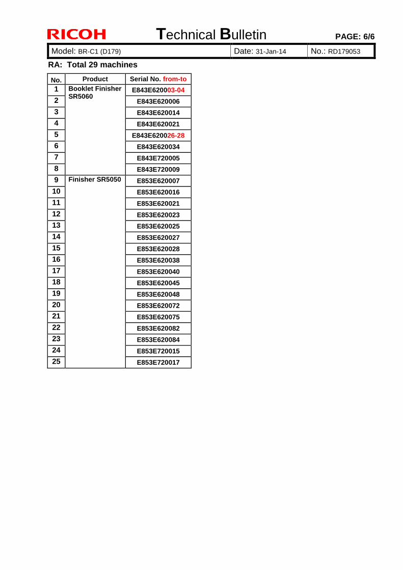
RA: Total 29 machines
No. Product Serial No. from-to
1 Booklet Finisher SR5060
E843E620003-04
2 E843E620006
3 E843E620014
4 E843E620021
5 E843E620026-28
6 E843E620034
7 E843E720005
8 E843E720009
9 Finisher SR5050 E853E620007
10 E853E620016
11 E853E620021
12 E853E620023
13 E853E620025
14 E853E620027
15 E853E620028
16 E853E620038
17 E853E620040
18 E853E620045
19 E853E620048
20 E853E620072
21 E853E620075
22 E853E620082
23 E853E620084
24 E853E720015
25 E853E720017

Technical Bulletin PAGE: 1/2
Model: Model BR-C1 Date: 04-Feb-14 No.: RD179054
Subject: Service Manual Correction Prepared by: S. Tomoe
From: 1st Tech Service Sect., PP Tech Service Dept.
Classification: Troubleshooting
Mechanical
Paper path
Product Safety
Part information
Electrical
Transmit/receive
Other ( )
Action required
Service manual revision
Retrofit information
Tier 2
Please apply the following to your service manual.
Installation > Main Machine> Check and Adjust Image Areas after Installing or Moving> Main Scan/Sub Scan Registration Adjustment
Page 124:
[Current]
7. Use the averaged value calculated in Step 7 to adjust the setting of SP1502-001. The calculated value is added to the current setting of SP1501-001. For example, if the current value of SP1501-001 is “1.0” mm, and the calculated
value is “0.2”, then you should enter “1.2” (mm).
[Correct]
7. Use the averaged value calculated in Step 6 to adjust the setting of SP1502-001. The calculated value is added to the current setting of SP1502-001. For example, if the current value of SP1502-001 is “1.0” mm, and the calculated
value is “0.2”, then you should enter “1.2” (mm).
Page 126:
[Current]
1. After completing the adjustments, do SP2109-003 Pattern #14, and then print 5 Trimming Area patterns on both sides of each A3 sheet. Measure and for the front side, just as you did above, and then measure
and for the back side as shown in the diagram above. The measurements for , should be 4±0.3 mm. If the each value for , is 2.0±0.1 and the averaged value 2.0±0.3, this is ideal
and no further adjustment is required. Go to Step 15. If , are not within these ranges, repeat this procedure from Step 2 If 3,6 are not within range, go to Step 10

Technical Bulletin PAGE: 2/2
Model: Model BR-C1 Date: 04-Feb-14 No.: RD179054
[Correct]
1. After completing the adjustments, do SP2109-003 Pattern #14, and then print 5 Trimming Area patterns on both sides of each A3 sheet.
Measure and for the front side, just as you did above, and then measure and for the back side as shown in the diagram above.
The measurements for , should be 4±0.3 mm. If the each value for , is 2.0±0.1 and the averaged value 2.0±0.3, this is ideal
and no further adjustment is required. Go to Step 15. If , are not within these ranges, repeat this procedure from Step 2 on page 123. If , are not within range, go to next step.
Technical Bulletin PAGE: 1/3
Model: BR-C1 (D179) Date: 12-Feb-14 No.: RD179055
Subject: Part Information- DRUM Knob fastening tool Prepared by: J.Ohno
From: PP Service Planning Department 1G
Classification: Troubleshooting
Mechanical
Paper path
Product Safety
Part information
Electrical
Transmit/receive
Other ( )
Action required
Service manual revision
Retrofit information
Tier 2
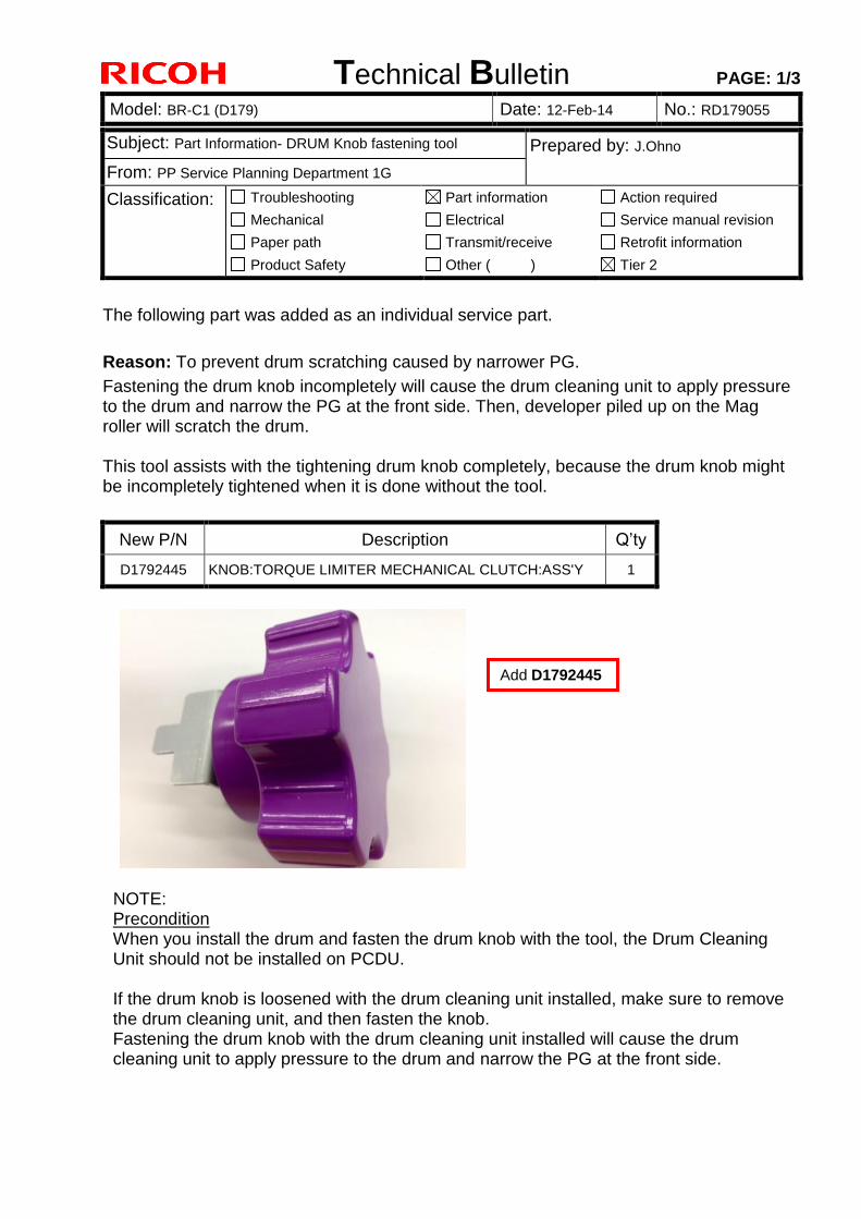
The following part was added as an individual service part.
Reason: To prevent drum scratching caused by narrower PG.
Fastening the drum knob incompletely will cause the drum cleaning unit to apply pressure to the drum and narrow the PG at the front side. Then, developer piled up on the Mag roller will scratch the drum. This tool assists with the tightening drum knob completely, because the drum knob might be incompletely tightened when it is done without the tool.
New P/N Description Q’ty
D1792445 KNOB:TORQUE LIMITER MECHANICAL CLUTCH:ASS'Y 1
NOTE: Precondition When you install the drum and fasten the drum knob with the tool, the Drum Cleaning Unit should not be installed on PCDU. If the drum knob is loosened with the drum cleaning unit installed, make sure to remove the drum cleaning unit, and then fasten the knob. Fastening the drum knob with the drum cleaning unit installed will cause the drum cleaning unit to apply pressure to the drum and narrow the PG at the front side.
Add D1792445
Technical Bulletin PAGE: 2/3
Model: BR-C1 (D179) Date: 12-Feb-14 No.: RD179055
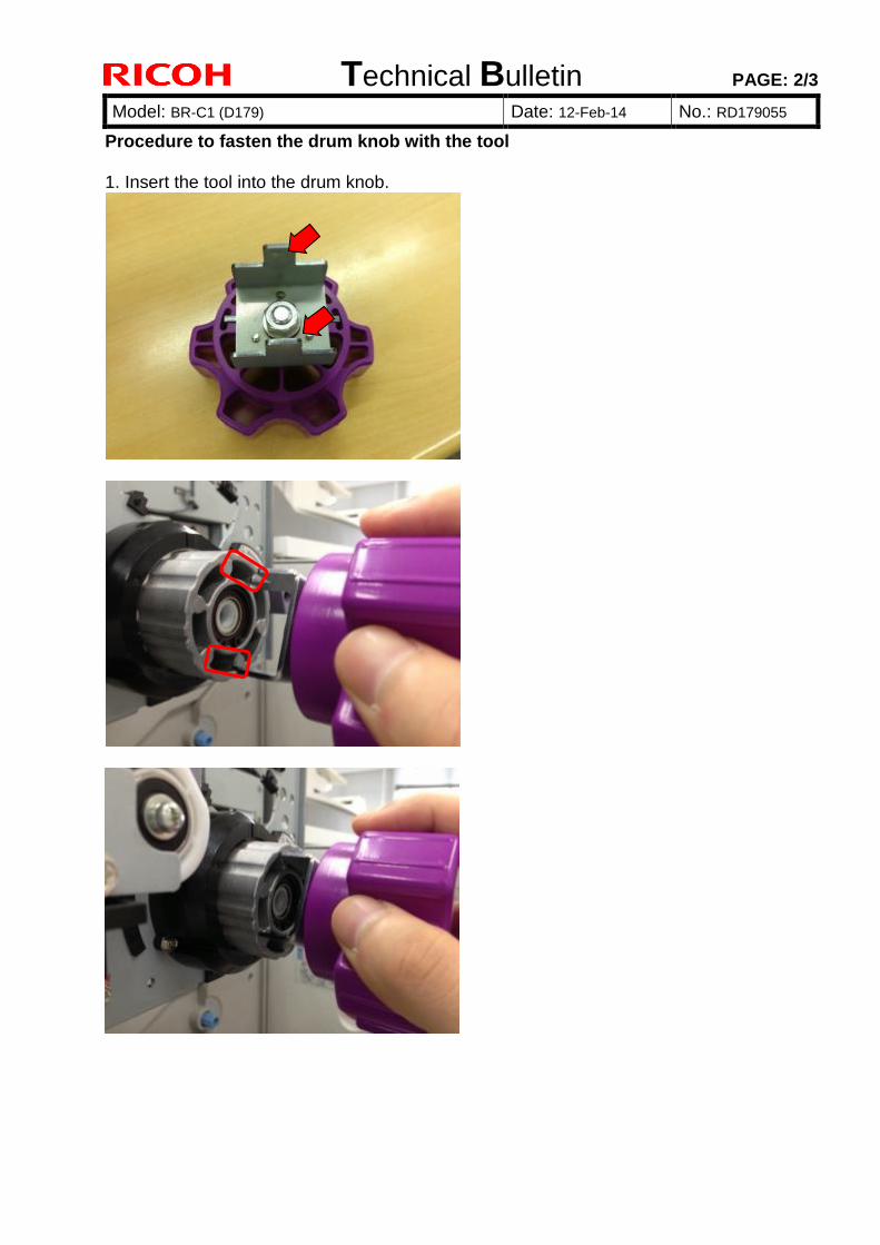
Procedure to fasten the drum knob with the tool 1. Insert the tool into the drum knob.
Technical Bulletin PAGE: 3/3
Model: BR-C1 (D179) Date: 12-Feb-14 No.: RD179055
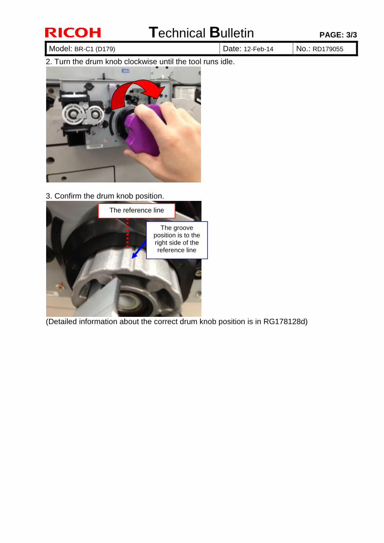
2. Turn the drum knob clockwise until the tool runs idle.
3. Confirm the drum knob position.
(Detailed information about the correct drum knob position is in RG178128d)
The groove position is to the right side of the reference line
The reference line
Technical Bulletin PAGE: 1/9 Reissued: 23rd-Apr-13 Model: AG-P1/C1, AGL-P1/C1, Aries-P1.5/C1.5 Date: 06-Dec-10 No.: RG178128d
RTB Reissue The items in bold italics were corrected or added.
This RTB has been issued to announce the correct handling procedure of the PCDU* to prevent scratches on the drum, which occurs when the PG* is narrower at the front side of the drum than the rear side.
NOTE * PCDU includes the photoconductive drums and the development units. * PG is the gap between the drum and the development rollers
1. Primary Considerations When Handling the PCDU Take note of the information in the following section to avoid the problems listed below.
1) Different density between left and right sides on a page 2) Toner adhesion to the development rollers 3) Scratches on the drums resulting from toner adhesion to the development rollers 4) Toner clumps caused by narrowed PG
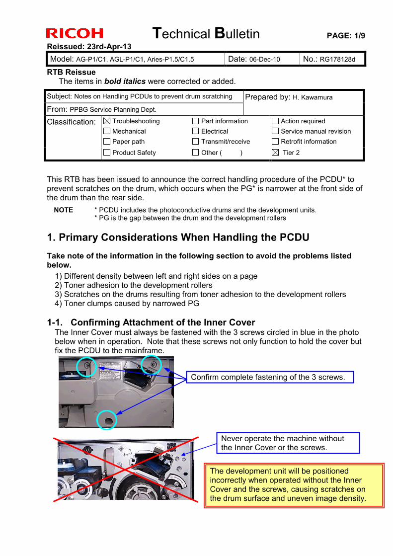
1-1. Confirming Attachment of the Inner Cover The Inner Cover must always be fastened with the 3 screws circled in blue in the photo below when in operation. Note that these screws not only function to hold the cover but fix the PCDU to the mainframe.
Subject: Notes on Handling PCDUs to prevent drum scratching Prepared by: H. Kawamura From: PPBG Service Planning Dept. Classification: Troubleshooting
Mechanical Paper path
Part information Electrical Transmit/receive
Action required Service manual revision Retrofit information
Product Safety Other ( ) Tier 2
Confirm complete fastening of the 3 screws.
Never operate the machine without the Inner Cover or the screws.
The development unit will be positioned incorrectly when operated without the Inner Cover and the screws, causing scratches on the drum surface and uneven image density.
Technical Bulletin PAGE: 2/9 Reissued: 23rd-Apr-13 Model: AG-P1/C1, AGL-P1/C1, Aries-P1.5/C1.5 Date: 06-Dec-10 No.: RG178128d
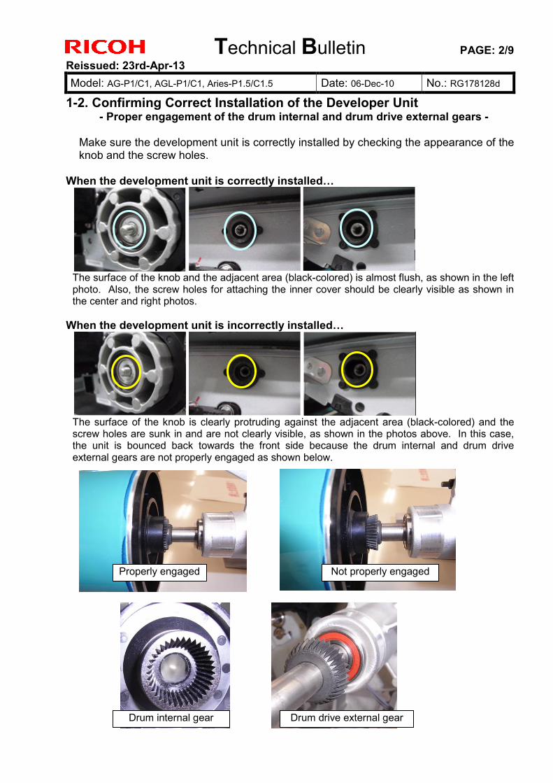
1-2. Confirming Correct Installation of the Developer Unit - Proper engagement of the drum internal and drum drive external gears -
Make sure the development unit is correctly installed by checking the appearance of the knob and the screw holes.
When the development unit is correctly installed…
The surface of the knob and the adjacent area (black-colored) is almost flush, as shown in the left photo. Also, the screw holes for attaching the inner cover should be clearly visible as shown in the center and right photos.
When the development unit is incorrectly installed…
The surface of the knob is clearly protruding against the adjacent area (black-colored) and the screw holes are sunk in and are not clearly visible, as shown in the photos above. In this case, the unit is bounced back towards the front side because the drum internal and drum drive external gears are not properly engaged as shown below.
Properly engaged Not properly engaged
Drum internal gear Drum drive external gear
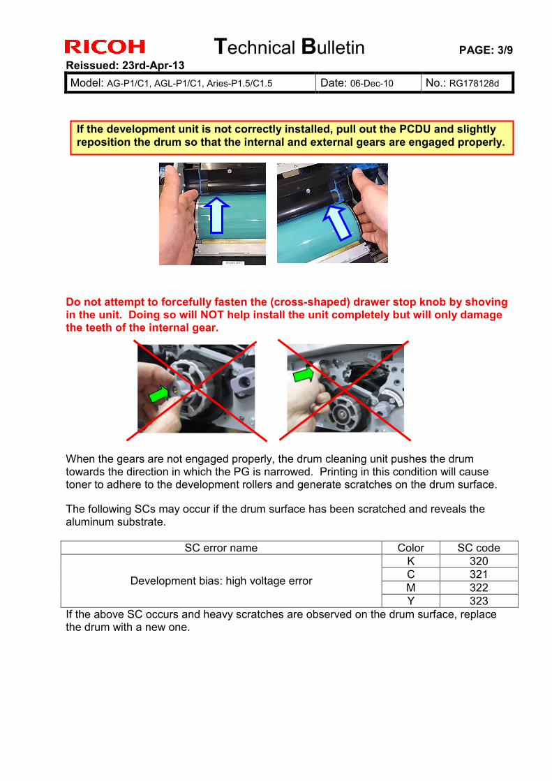
Technical Bulletin PAGE: 3/9 Reissued: 23rd-Apr-13 Model: AG-P1/C1, AGL-P1/C1, Aries-P1.5/C1.5 Date: 06-Dec-10 No.: RG178128d
Do not attempt to forcefully fasten the (cross-shaped) drawer stop knob by shoving in the unit. Doing so will NOT help install the unit completely but will only damage the teeth of the internal gear. When the gears are not engaged properly, the drum cleaning unit pushes the drum towards the direction in which the PG is narrowed. Printing in this condition will cause toner to adhere to the development rollers and generate scratches on the drum surface. The following SCs may occur if the drum surface has been scratched and reveals the aluminum substrate.
SC error name Color SC code K 320 C 321 M 322 Development bias: high voltage error
Y 323 If the above SC occurs and heavy scratches are observed on the drum surface, replace the drum with a new one.
If the development unit is not correctly installed, pull out the PCDU and slightly reposition the drum so that the internal and external gears are engaged properly.
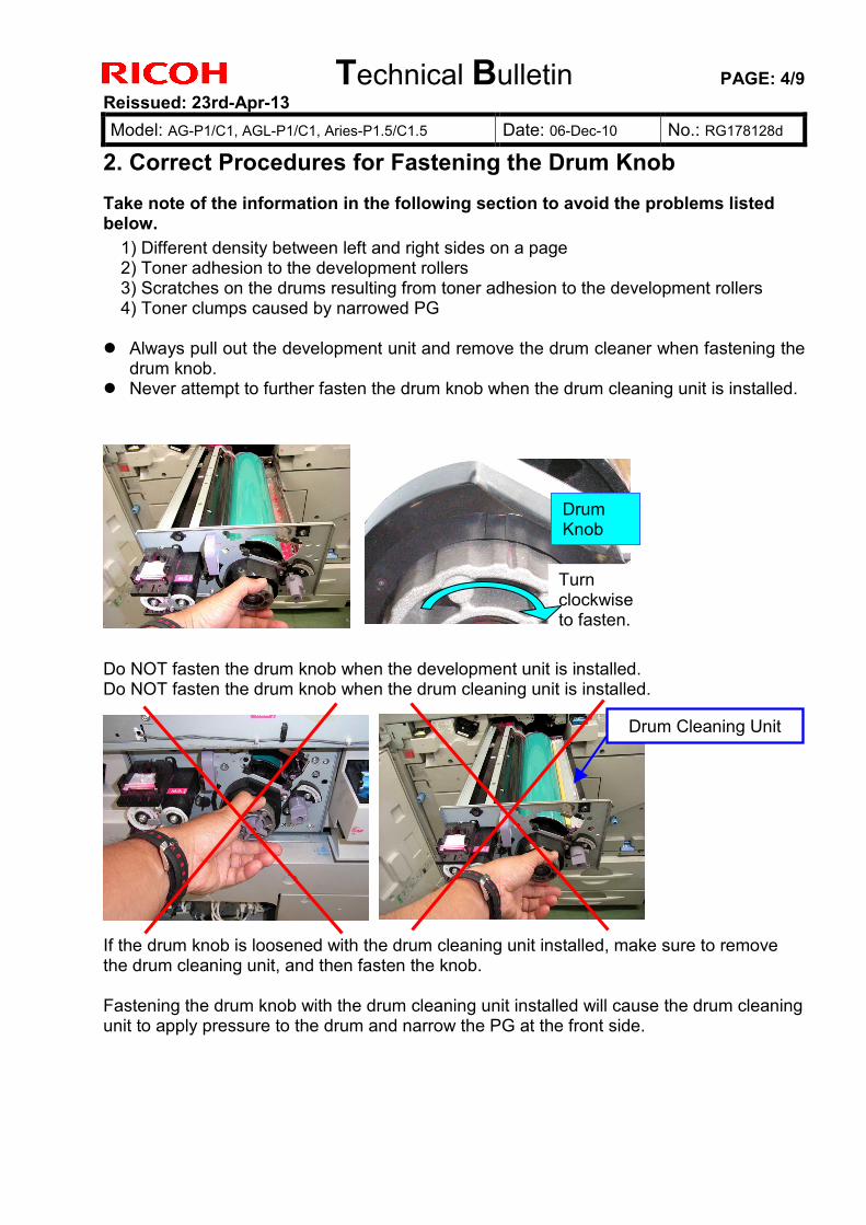
Technical Bulletin PAGE: 4/9 Reissued: 23rd-Apr-13 Model: AG-P1/C1, AGL-P1/C1, Aries-P1.5/C1.5 Date: 06-Dec-10 No.: RG178128d
2. Correct Procedures for Fastening the Drum Knob Take note of the information in the following section to avoid the problems listed below.
1) Different density between left and right sides on a page 2) Toner adhesion to the development rollers 3) Scratches on the drums resulting from toner adhesion to the development rollers 4) Toner clumps caused by narrowed PG Always pull out the development unit and remove the drum cleaner when fastening the
drum knob. Never attempt to further fasten the drum knob when the drum cleaning unit is installed.
Do NOT fasten the drum knob when the development unit is installed. Do NOT fasten the drum knob when the drum cleaning unit is installed.
If the drum knob is loosened with the drum cleaning unit installed, make sure to remove the drum cleaning unit, and then fasten the knob. Fastening the drum knob with the drum cleaning unit installed will cause the drum cleaning unit to apply pressure to the drum and narrow the PG at the front side.
Drum Knob
Turn clockwise to fasten.
Drum Cleaning Unit
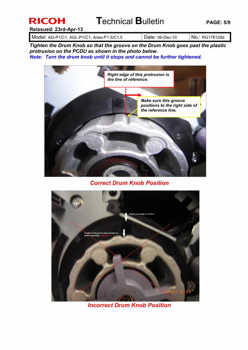
Technical Bulletin PAGE: 5/9 Reissued: 23rd-Apr-13 Model: AG-P1/C1, AGL-P1/C1, Aries-P1.5/C1.5 Date: 06-Dec-10 No.: RG178128d
Tighten the Drum Knob so that the groove on the Drum Knob goes past the plastic protrusion on the PCDU as shown in the photo below. Note: Turn the drum knob until it stops and cannot be further tightened.
Right edge of this protrusion is the line of reference.
Make sure this groove positions to the right side of the reference line.
Correct Drum Knob Position
Incorrect Drum Knob Position
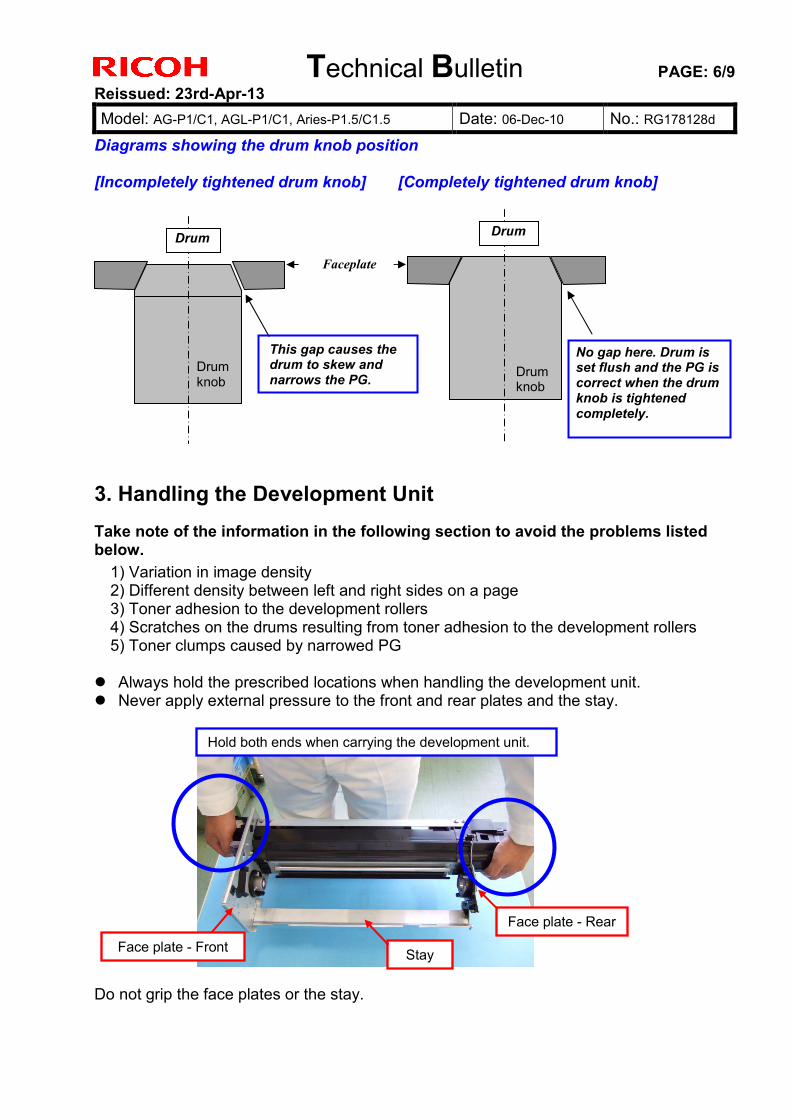
Technical Bulletin PAGE: 6/9 Reissued: 23rd-Apr-13 Model: AG-P1/C1, AGL-P1/C1, Aries-P1.5/C1.5 Date: 06-Dec-10 No.: RG178128d
Diagrams showing the drum knob position [Incompletely tightened drum knob] [Completely tightened drum knob]
3. Handling the Development Unit Take note of the information in the following section to avoid the problems listed below.
1) Variation in image density 2) Different density between left and right sides on a page 3) Toner adhesion to the development rollers 4) Scratches on the drums resulting from toner adhesion to the development rollers 5) Toner clumps caused by narrowed PG Always hold the prescribed locations when handling the development unit. Never apply external pressure to the front and rear plates and the stay.
Do not grip the face plates or the stay.
Faceplate
Drum
Drum knob
Drum knob
No gap here. Drum is set flush and the PG is correct when the drum knob is tightened completely.
Drum
Stay
Face plate - Rear
Hold both ends when carrying the development unit.
Face plate - Front
This gap causes the drum to skew and narrows the PG.
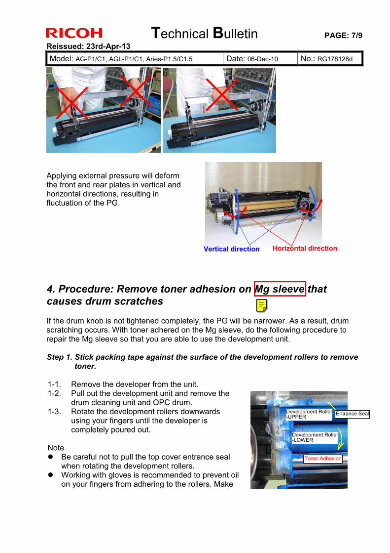
Technical Bulletin PAGE: 7/9 Reissued: 23rd-Apr-13 Model: AG-P1/C1, AGL-P1/C1, Aries-P1.5/C1.5 Date: 06-Dec-10 No.: RG178128d
Applying external pressure will deform the front and rear plates in vertical and horizontal directions, resulting in fluctuation of the PG. 4. Procedure: Remove toner adhesion on Mg sleeve that causes drum scratches If the drum knob is not tightened completely, the PG will be narrower. As a result, drum scratching occurs. With toner adhered on the Mg sleeve, do the following procedure to repair the Mg sleeve so that you are able to use the development unit. Step 1. Stick packing tape against the surface of the development rollers to remove
toner. 1-1. Remove the developer from the unit. 1-2. Pull out the development unit and remove the
drum cleaning unit and OPC drum. 1-3. Rotate the development rollers downwards
using your fingers until the developer is completely poured out.
Note
Be careful not to pull the top cover entrance seal when rotating the development rollers.
Working with gloves is recommended to prevent oil on your fingers from adhering to the rollers. Make
Horizontal directionVertical direction
Development Roller-LOWER
Development Roller-UPPER Entrance Seal
Toner Adhesion
Ed O'Brien
Mg sleeve - means development roller, not magenta
Ed O'Brien

Technical Bulletin PAGE: 8/9 Reissued: 23rd-Apr-13 Model: AG-P1/C1, AGL-P1/C1, Aries-P1.5/C1.5 Date: 06-Dec-10 No.: RG178128d
sure to thoroughly wash your hands in advance if gloves are not available.
1-4. Stick the packing tape against the surface of the development rollers and peel off the
toner. Repeat this procedure. (Vacuuming the toner in advance will make this process easier.)
NOTE
Make sure the packing tape adhesives do not adhere to the development rollers. NEVER apply solvent to remove toner from the development rollers. Solvent will
dissolve the toner, which will then adhere to the development rollers even more strongly.
Make sure to completely remove toner adhered to the development rollers. Toner will build up on any toner particles remaining on the development roller.
Step 2. Set the drum and the drum cleaning unit, and install the development unit in the mainframe. Scratches on the drum surface may be observed in areas corresponding to the toner adhesion on the development rollers. Replace with a new drum if scratches are confirmed. Notes on Fastening the Drum Knob. (Reference P.4 “2. Correct Procedures for
Fastening the Drum Knob”) Make sure the drum cleaning unit is not installed when setting the drum and fastening
the knob. Turn the drum knob clockwise and check that fastening is complete. DO NOT ‘loosen fasten’ the drum knob after installing the cleaning unit. Doing so
will reduce the PG at the front side. Step 3. Pour in the developer, and execute Process Control (SP 3-820-002)))). Step 4. Print out 2 full-bleed solid images (on A4/LT-Portrait) for the required color.
Toner adhered to the dev roller
Stick packing tape against the dev roller to remove adhered toner.
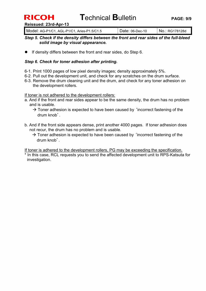
Technical Bulletin PAGE: 9/9 Reissued: 23rd-Apr-13 Model: AG-P1/C1, AGL-P1/C1, Aries-P1.5/C1.5 Date: 06-Dec-10 No.: RG178128d
Step 5. Check if the density differs between the front and rear sides of the full-bleed solid image by visual appearance.
If density differs between the front and rear sides, do Step 6.
Step 6. Check for toner adhesion after printing. 6-1. Print 1000 pages of low pixel density images; density approximately 5%. 6-2. Pull out the development unit, and check for any scratches on the drum surface. 6-3. Remove the drum cleaning unit and the drum, and check for any toner adhesion on
the development rollers. If toner is not adhered to the development rollers: a. And if the front and rear sides appear to be the same density, the drum has no problem
and is usable. Toner adhesion is expected to have been caused by ‘incorrect fastening of the drum knob’.
b. And if the front side appears dense, print another 4000 pages. If toner adhesion does
not recur, the drum has no problem and is usable. Toner adhesion is expected to have been caused by ‘incorrect fastening of the drum knob’.
If toner is adhered to the development rollers, PG may be exceeding the specification. * In this case, RCL requests you to send the affected development unit to RPS-Katsuta for
investigation.
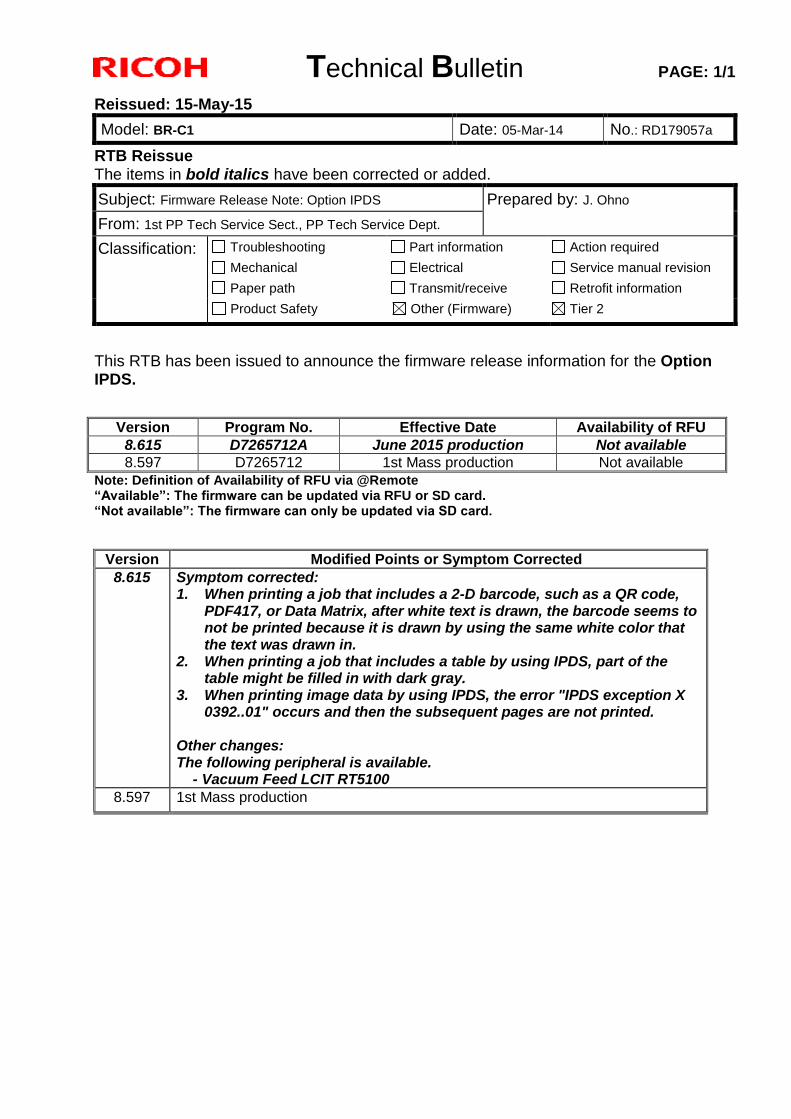
Technical Bulletin PAGE: 1/1
Reissued: 15-May-15
Model: BR-C1 Date: 05-Mar-14 No.: RD179057a
RTB Reissue The items in bold italics have been corrected or added.
Subject: Firmware Release Note: Option IPDS Prepared by: J. Ohno
From: 1st PP Tech Service Sect., PP Tech Service Dept.
Classification: Troubleshooting
Mechanical
Paper path
Part information
Electrical
Transmit/receive
Action required
Service manual revision
Retrofit information
Product Safety Other (Firmware) Tier 2
This RTB has been issued to announce the firmware release information for the Option IPDS.
Version Program No. Effective Date Availability of RFU
8.615 D7265712A June 2015 production Not available
8.597 D7265712 1st Mass production Not available
Note: Definition of Availability of RFU via @Remote “Available”: The firmware can be updated via RFU or SD card. “Not available”: The firmware can only be updated via SD card.
Version Modified Points or Symptom Corrected
8.615 Symptom corrected: 1. When printing a job that includes a 2-D barcode, such as a QR code,
PDF417, or Data Matrix, after white text is drawn, the barcode seems to not be printed because it is drawn by using the same white color that the text was drawn in.
2. When printing a job that includes a table by using IPDS, part of the table might be filled in with dark gray.
3. When printing image data by using IPDS, the error "IPDS exception X 0392..01" occurs and then the subsequent pages are not printed.
Other changes: The following peripheral is available. - Vacuum Feed LCIT RT5100
8.597 1st Mass production
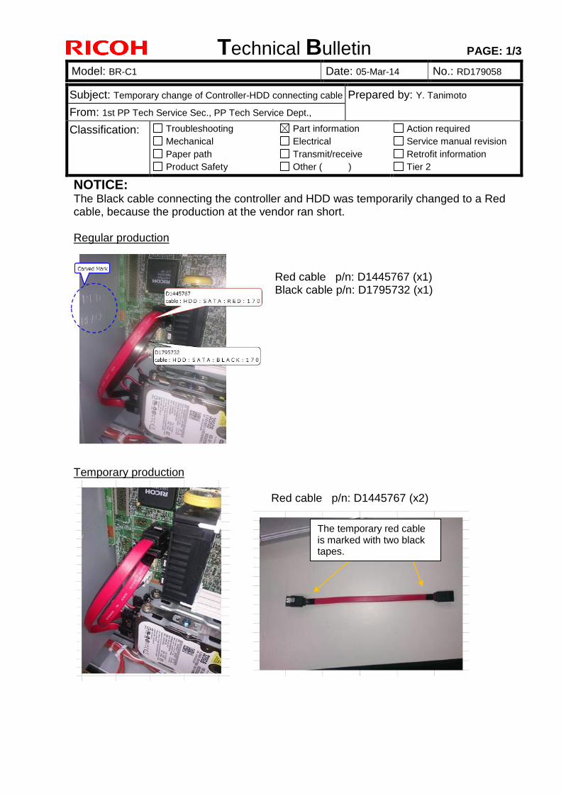
Technical Bulletin PAGE: 1/3
Model: BR-C1 Date: 05-Mar-14 No.: RD179058
Subject: Temporary change of Controller-HDD connecting cable Prepared by: Y. Tanimoto
From: 1st PP Tech Service Sec., PP Tech Service Dept.,
Classification: Troubleshooting
Mechanical
Paper path
Product Safety
Part information
Electrical
Transmit/receive
Other ( )
Action required
Service manual revision
Retrofit information
Tier 2
NOTICE: The Black cable connecting the controller and HDD was temporarily changed to a Red cable, because the production at the vendor ran short.
Regular production
Red cable p/n: D1445767 (x1) Black cable p/n: D1795732 (x1)
Temporary production
The temporary red cable is marked with two black tapes.
Red cable p/n: D1445767 (x2)
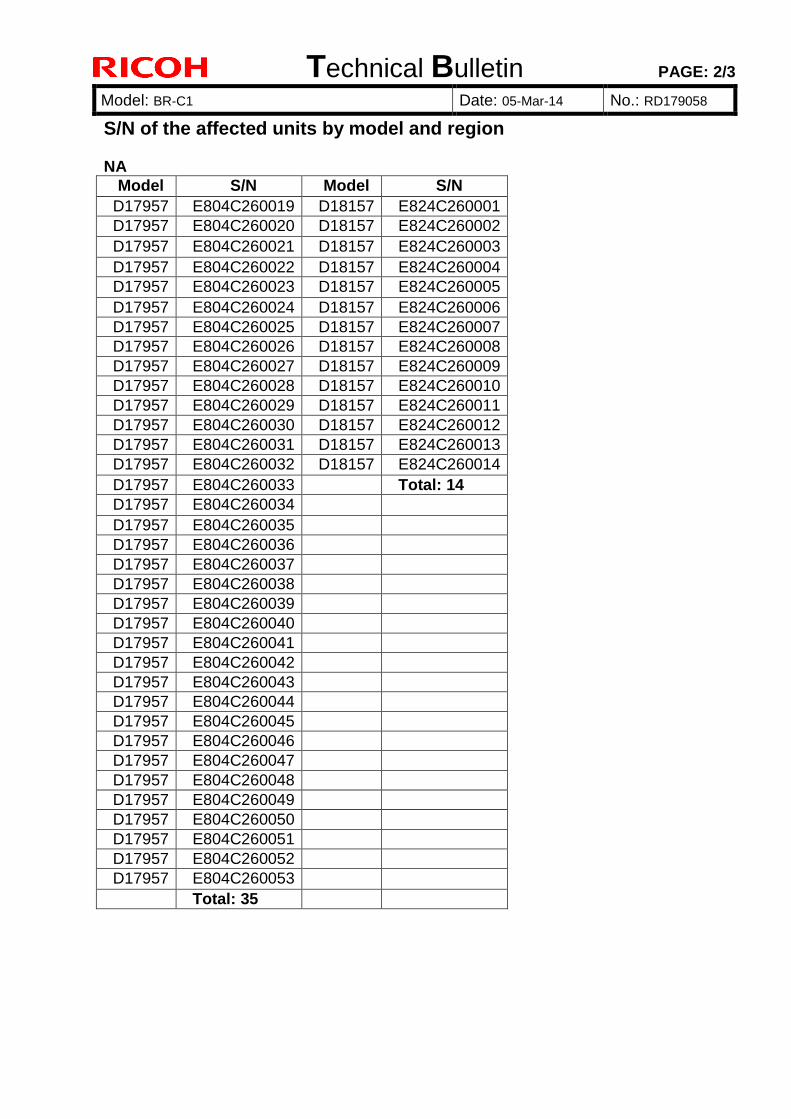
Technical Bulletin PAGE: 2/3
Model: BR-C1 Date: 05-Mar-14 No.: RD179058
S/N of the affected units by model and region NA
Model S/N Model S/N
D17957 E804C260019 D18157 E824C260001
D17957 E804C260020 D18157 E824C260002
D17957 E804C260021 D18157 E824C260003
D17957 E804C260022 D18157 E824C260004
D17957 E804C260023 D18157 E824C260005
D17957 E804C260024 D18157 E824C260006
D17957 E804C260025 D18157 E824C260007
D17957 E804C260026 D18157 E824C260008
D17957 E804C260027 D18157 E824C260009
D17957 E804C260028 D18157 E824C260010
D17957 E804C260029 D18157 E824C260011
D17957 E804C260030 D18157 E824C260012
D17957 E804C260031 D18157 E824C260013
D17957 E804C260032 D18157 E824C260014
D17957 E804C260033 Total: 14
D17957 E804C260034
D17957 E804C260035
D17957 E804C260036
D17957 E804C260037
D17957 E804C260038
D17957 E804C260039
D17957 E804C260040
D17957 E804C260041
D17957 E804C260042
D17957 E804C260043
D17957 E804C260044
D17957 E804C260045
D17957 E804C260046
D17957 E804C260047
D17957 E804C260048
D17957 E804C260049
D17957 E804C260050
D17957 E804C260051
D17957 E804C260052
D17957 E804C260053
Total: 35
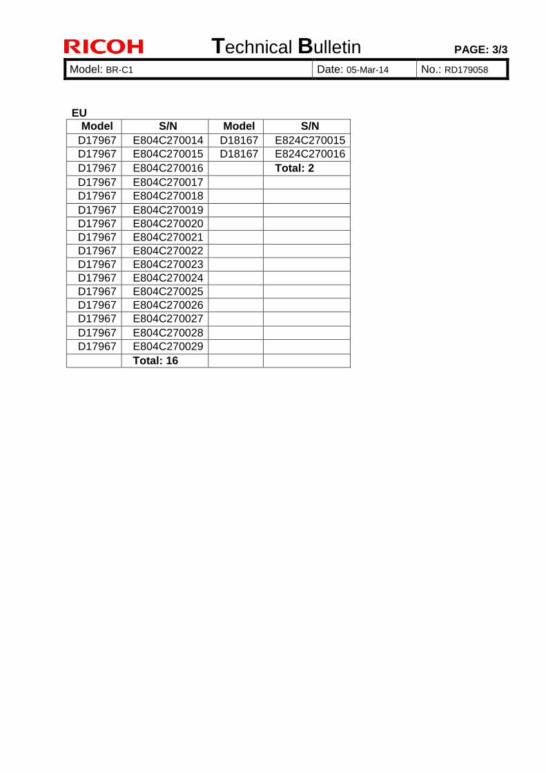
Technical Bulletin PAGE: 3/3
Model: BR-C1 Date: 05-Mar-14 No.: RD179058
EU
Model S/N Model S/N
D17967 E804C270014 D18167 E824C270015
D17967 E804C270015 D18167 E824C270016
D17967 E804C270016 Total: 2
D17967 E804C270017
D17967 E804C270018
D17967 E804C270019
D17967 E804C270020
D17967 E804C270021
D17967 E804C270022
D17967 E804C270023
D17967 E804C270024
D17967 E804C270025
D17967 E804C270026
D17967 E804C270027
D17967 E804C270028
D17967 E804C270029
Total: 16
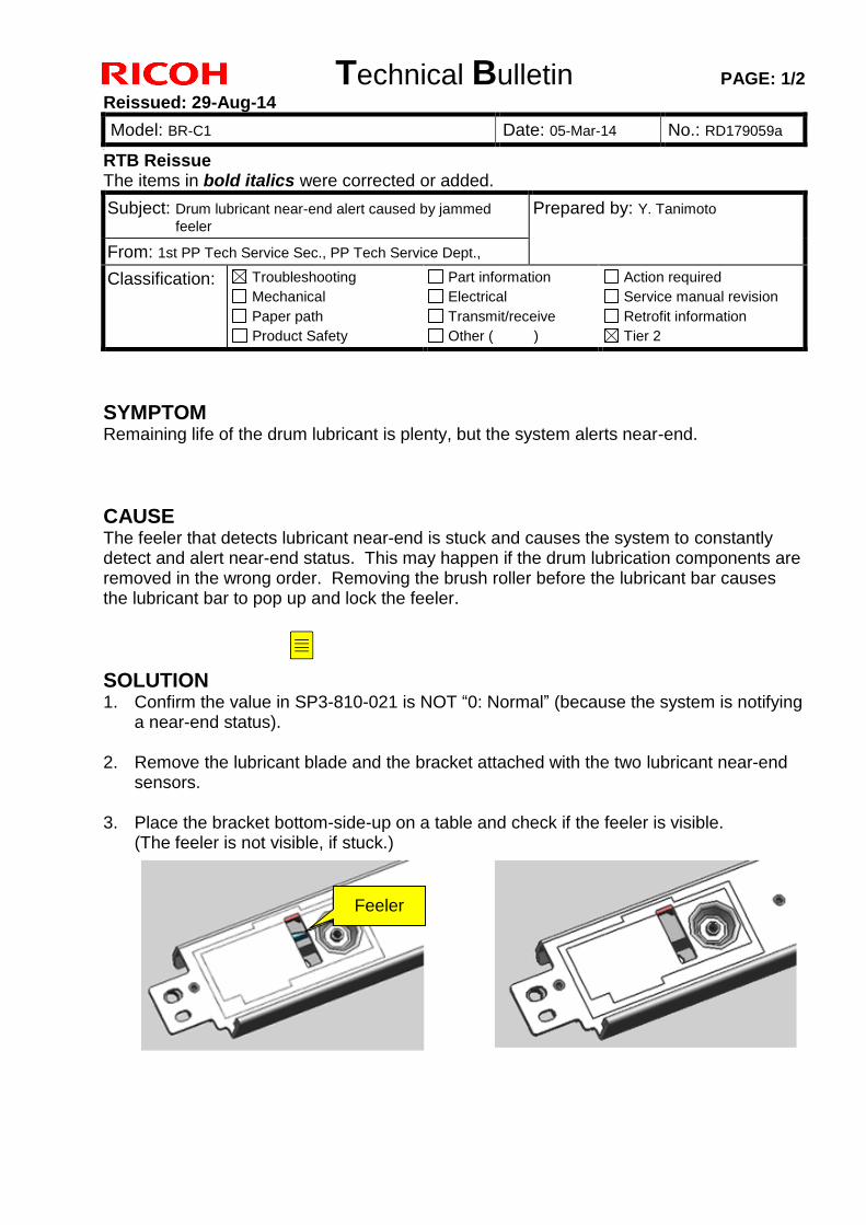
Technical Bulletin PAGE: 1/2
Reissued: 29-Aug-14
Model: BR-C1 Date: 05-Mar-14 No.: RD179059a
R
RTB Reissue The items in bold italics were corrected or added.
Subject: Drum lubricant near-end alert caused by jammed
feeler Prepared by: Y. Tanimoto
From: 1st PP Tech Service Sec., PP Tech Service Dept.,
Classification: Troubleshooting
Mechanical
Paper path
Product Safety
Part information
Electrical
Transmit/receive
Other ( )
Action required
Service manual revision
Retrofit information
Tier 2
SYMPTOM Remaining life of the drum lubricant is plenty, but the system alerts near-end.
CAUSE The feeler that detects lubricant near-end is stuck and causes the system to constantly detect and alert near-end status. This may happen if the drum lubrication components are removed in the wrong order. Removing the brush roller before the lubricant bar causes the lubricant bar to pop up and lock the feeler.
SOLUTION 1. Confirm the value in SP3-810-021 is NOT “0: Normal” (because the system is notifying
a near-end status).
2. Remove the lubricant blade and the bracket attached with the two lubricant near-end sensors.
3. Place the bracket bottom-side-up on a table and check if the feeler is visible. (The feeler is not visible, if stuck.)
Feeler
Ed
Sticky Note
If the value is 0, do nothing. If the value is 1, 2, or 3, go on to step 2.
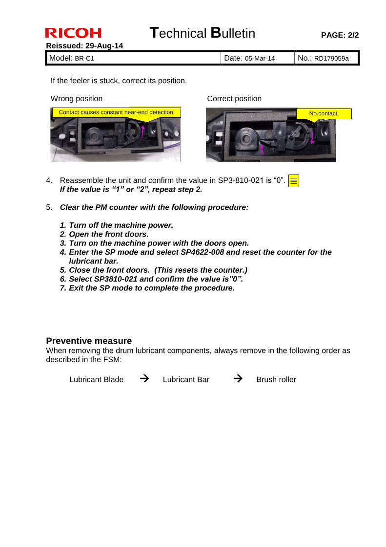
Technical Bulletin PAGE: 2/2
Reissued: 29-Aug-14
Model: BR-C1 Date: 05-Mar-14 No.: RD179059a
R
If the feeler is stuck, correct its position.
Wrong position Correct position
4. Reassemble the unit and confirm the value in SP3-810-021 is “0”. If the value is “1” or “2”, repeat step 2.
5. Clear the PM counter with the following procedure:
1. Turn off the machine power. 2. Open the front doors. 3. Turn on the machine power with the doors open. 4. Enter the SP mode and select SP4622-008 and reset the counter for the
lubricant bar. 5. Close the front doors. (This resets the counter.) 6. Select SP3810-021 and confirm the value is”0”. 7. Exit the SP mode to complete the procedure.
Preventive measure When removing the drum lubricant components, always remove in the following order as described in the FSM:
Lubricant Blade Lubricant Bar Brush roller
Contact causes constant near-end detection. No contact.
Ed
Sticky Note
If the value is not 0, check that the feeler and sensor are installed correctly.
Technical Bulletin PAGE: 1/1
Reissued: 11-Dec-14
Model: MET-C1cde/MET-C1cde_SOP
CH-C1/CH-C1 Pro/BR-C1/Z-C2/Z-C2_SOP/Leo-C1/Leo-P1
Date: 01-Jul-13 No.: RD149014b
RTB Reissue The items in bold italics have been changed or added.
Subject: Firmware Release Note: Font EXP Prepared by: N. Yoshida
From: 1st Tech Service Sect., MFP/Printer Tech Service Dept.
Classification: Troubleshooting
Mechanical
Paper path
Product Safety
Part information
Electrical
Transmit/receive
Other (Firmware)
Action required
Service manual revision
Retrofit information
Tier 2
Important Information about Normal/Smart Panel Firmware Updates
When updating machine firmware, make sure NOT to install Smart Panel supported firmware on a machine with a normal operation panel (and vice-versa). If you do, the machine may not function as designed and product warranty may not apply.
To avoid this, when updating the firmware, make sure that the numbers next to "NEW" and "ROM" are the same on the operation panel.
If you install the wrong firmware, repeat the update procedure and check the numbers mentioned above.
This RTB has been issued to announce the firmware release information for the Font EXP.
Version Program No. Effective Date Availability of RFU
1.00 D1495581 1st Mass production Available
Note: Definition of Availability of RFU via @Remote “Available”: The firmware can be updated via RFU or SD card. “Not available”: The firmware can only be updated via SD card.
Version Modified Points or Symptom Corrected
1.00 1st Mass production

Technical Bulletin PAGE: 1/1
Reissued: 11-Dec-14
Model: MET-C1cde/MET-C1cde_SOP
CH-C1 Office/CH-C1 Pro/BR-C1/Z-C2/Z-C2_SOP/Leo-C1/Leo-P1
Date: 01-Jul-13 No.: RD149026b
RTB Reissue The items in bold italics have been changed or added.
Subject: Firmware Release Note: PS3 Font Prepared by: N. Yoshida
From: 1st Tech Service Sect., MFP/Printer Tech Service Dept.
Classification: Troubleshooting
Mechanical
Paper path
Product Safety
Part information
Electrical
Transmit/receive
Other (Firmware)
Action required
Service manual revision
Retrofit information
Tier 2
Important Information about Normal/Smart Panel Firmware Updates
When updating machine firmware, make sure NOT to install Smart Panel supported firmware on a machine with a normal operation panel (and vice-versa). If you do, the machine may not function as designed and product warranty may not apply.
To avoid this, when updating the firmware, make sure that the numbers next to "NEW" and "ROM" are the same on the operation panel.
If you install the wrong firmware, repeat the update procedure and check the numbers mentioned above.
This RTB has been issued to announce the firmware release information for the PS3 Font.
Version Program No. Effective Date Availability of RFU
1.12 D6205681 1st Mass production Available
Note: Definition of Availability of RFU via @Remote “Available”: The firmware can be updated via RFU or SD card. “Not available”: The firmware can only be updated via SD card.
Version Modified Points or Symptom Corrected
1.12 1st Mass production

Technical Bulletin PAGE: 1/8
Model: BR-C1 Date: 12-Mar-14 No.: RD179060
Subject: Procedures for Installing the GBC StreamPunch Prepared by: Y. Tanimoto
From: 1st PP Tech Service Sec., PP Tech Service Dept.,
Classification: Troubleshooting
Mechanical
Paper path
Product Safety
Part information
Electrical
Transmit/receive
Other ( )
Action required
Service manual revision
Retrofit information
Tier 2
Procedures for installing the StreamPunch directly downstream of the D179/D180/D181
1. Overview
If you wish to install the GBC StreamPunch directly downstream of the D179/D180/D181, do the following:
1. Order the special parts described in the next section “2. Required Parts”.
2. Install the special parts according to the procedure described in section “3. Installation”.
3. This procedure is the same as the D074/D075/M044 copier/printer.
IMPORTANT
Never install the punch unit directly downstream of the main machine without using the special parts described in section 2 for the following reasons:
1. Possible jams
2. Possible injuries to your hands if the D741 Decurler Unit (Decurl Unit DU5030) is installed and the door or the punch unit is open
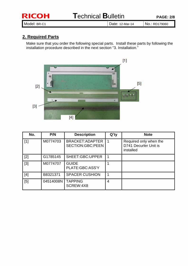
Technical Bulletin PAGE: 2/8
Model: BR-C1 Date: 12-Mar-14 No.: RD179060
2. Required Parts
Make sure that you order the following special parts. Install these parts by following the installation procedure described in the next section “3. Installation.”
No. P/N Description Q’ty Note
[1] M0774703 BRACKET:ADAPTER SECTION:GBC:PEEN
1 Required only when the D741 Decurler Unit is installed
[2] G1785145 SHEET:GBC:UPPER 1
[3] M0774707 GUIDE PLATE:GBC:ASS'Y
1
[4] B8321371 SPACER CUSHION 1
[5] 04514008N TAPPING SCREW:4X8
4
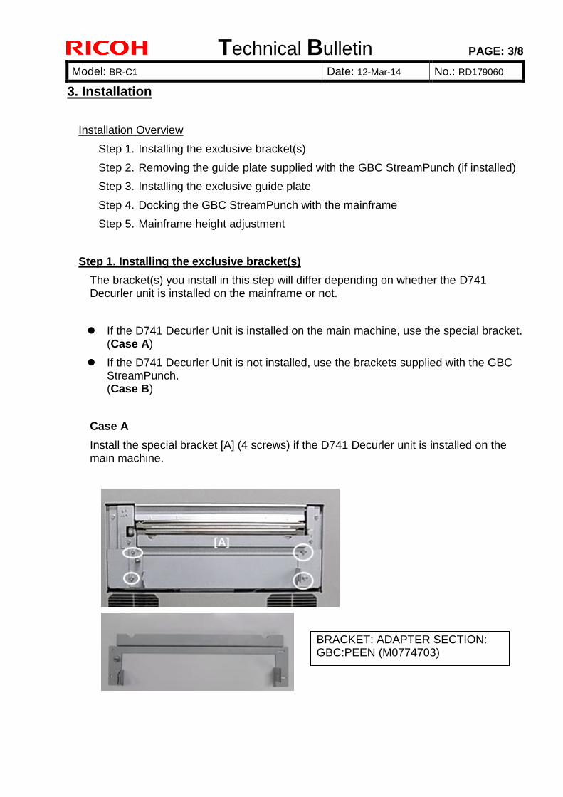
Technical Bulletin PAGE: 3/8
Model: BR-C1 Date: 12-Mar-14 No.: RD179060
3. Installation
Installation Overview
Step 1. Installing the exclusive bracket(s)
Step 2. Removing the guide plate supplied with the GBC StreamPunch (if installed)
Step 3. Installing the exclusive guide plate
Step 4. Docking the GBC StreamPunch with the mainframe
Step 5. Mainframe height adjustment
Step 1. Installing the exclusive bracket(s)
The bracket(s) you install in this step will differ depending on whether the D741 Decurler unit is installed on the mainframe or not.
If the D741 Decurler Unit is installed on the main machine, use the special bracket. (Case A)
If the D741 Decurler Unit is not installed, use the brackets supplied with the GBC StreamPunch. (Case B)
Case A
Install the special bracket [A] (4 screws) if the D741 Decurler unit is installed on the main machine.
[A]
BRACKET: ADAPTER SECTION: GBC:PEEN (M0774703)
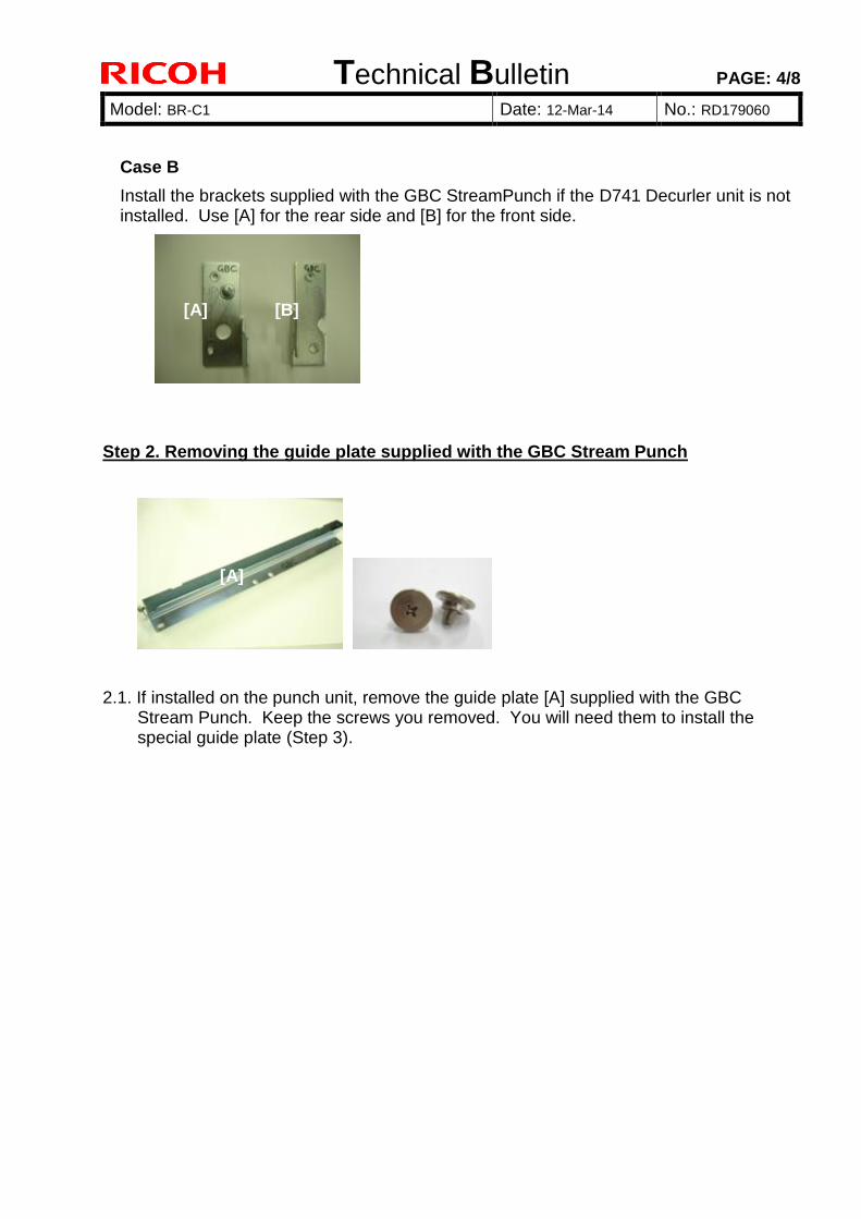
Technical Bulletin PAGE: 4/8
Model: BR-C1 Date: 12-Mar-14 No.: RD179060
Case B
Install the brackets supplied with the GBC StreamPunch if the D741 Decurler unit is not installed. Use [A] for the rear side and [B] for the front side.
Step 2. Removing the guide plate supplied with the GBC Stream Punch
2.1. If installed on the punch unit, remove the guide plate [A] supplied with the GBC Stream Punch. Keep the screws you removed. You will need them to install the special guide plate (Step 3).
[A] [B]
[A]
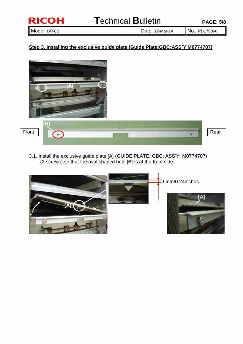
Technical Bulletin PAGE: 5/8
Model: BR-C1 Date: 12-Mar-14 No.: RD179060
Step 3. Installing the exclusive guide plate (Guide Plate:GBC:ASS’Y M0774707)
3.1. Install the exclusive guide plate [A] (GUIDE PLATE: GBC: ASS’Y: M0774707)
(2 screws) so that the oval shaped hole [B] is at the front side.
6m
m
[A]
[A]
6mm/0.24inches
[A] [A]
Front Rear
[B]
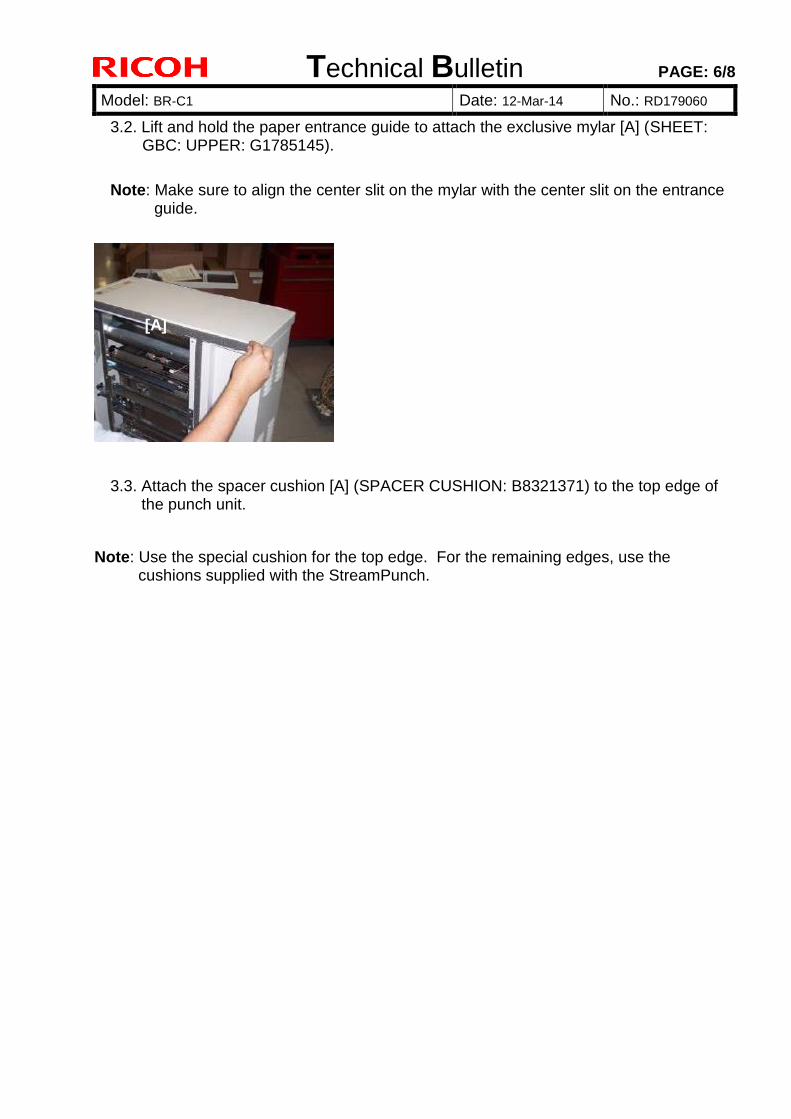
Technical Bulletin PAGE: 6/8
Model: BR-C1 Date: 12-Mar-14 No.: RD179060
3.2. Lift and hold the paper entrance guide to attach the exclusive mylar [A] (SHEET: GBC: UPPER: G1785145).
Note: Make sure to align the center slit on the mylar with the center slit on the entrance
guide.
3.3. Attach the spacer cushion [A] (SPACER CUSHION: B8321371) to the top edge of the punch unit.
Note: Use the special cushion for the top edge. For the remaining edges, use the cushions supplied with the StreamPunch.
[A]
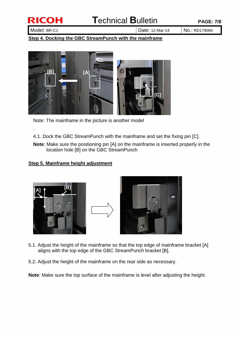
Technical Bulletin PAGE: 7/8
Model: BR-C1 Date: 12-Mar-14 No.: RD179060
Step 4. Docking the GBC StreamPunch with the mainframe
Note: The mainframe in the picture is another model
.
4.1. Dock the GBC StreamPunch with the mainframe and set the fixing pin [C].
Note: Make sure the positioning pin [A] on the mainframe is inserted properly in the location hole [B] on the GBC StreamPunch
Step 5. Mainframe height adjustment
5.1. Adjust the height of the mainframe so that the top edge of mainframe bracket [A]
aligns with the top edge of the GBC StreamPunch bracket [B]. 5.2. Adjust the height of the mainframe on the rear side as necessary.
Note: Make sure the top surface of the mainframe is level after adjusting the height.
[A] [B]
[C]
[B] [A]
[A] [A]
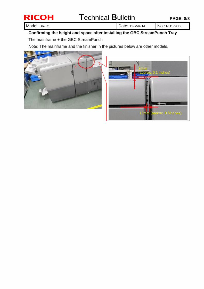
Technical Bulletin PAGE: 8/8
Model: BR-C1 Date: 12-Mar-14 No.: RD179060
Confirming the height and space after installing the GBC StreamPunch Tray
The mainframe + the GBC StreamPunch
Note: The mainframe and the finisher in the pictures below are other models.
2mm (approx. 0.1 inches)
13mm (approx. 0.5inches)
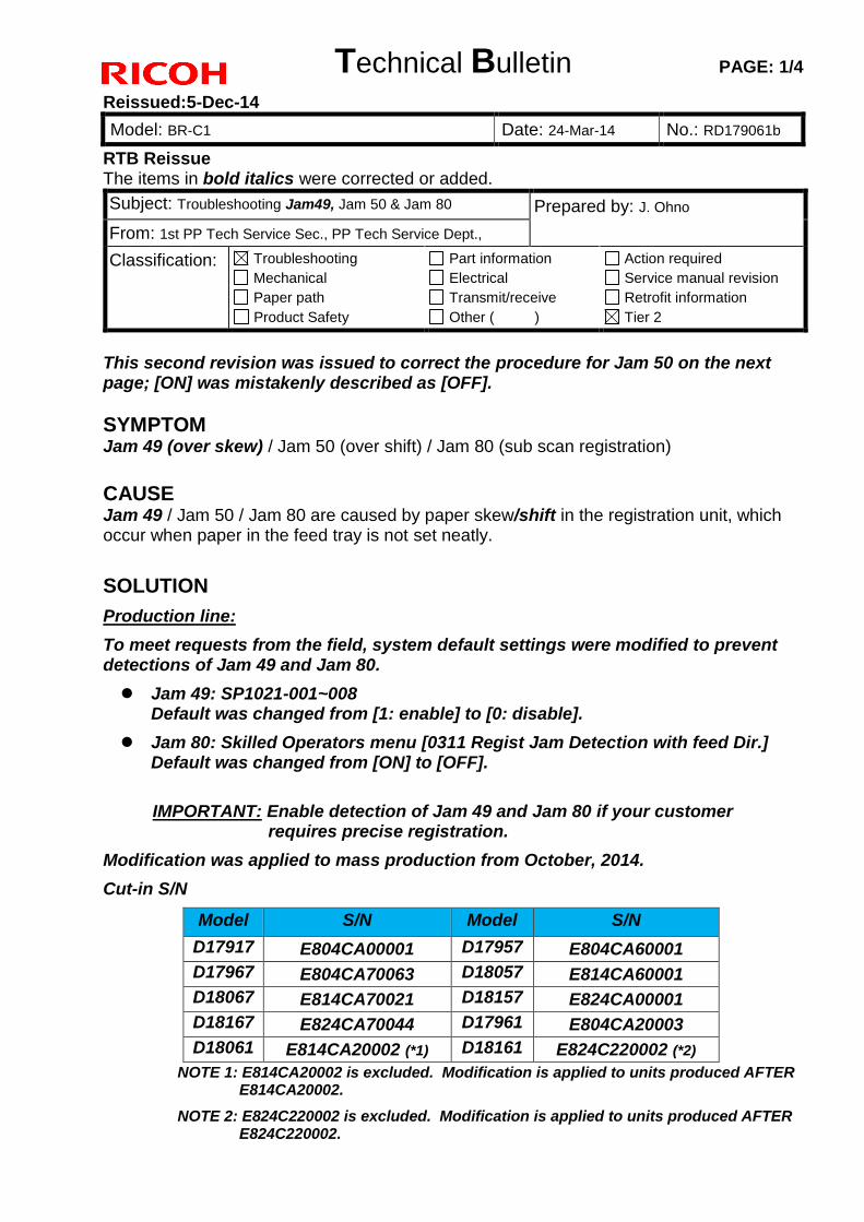
Technical Bulletin PAGE: 1/4
Reissued:5-Dec-14
Model: BR-C1 Date: 24-Mar-14 No.: RD179061b
RTB Reissue The items in bold italics were corrected or added.
This second revision was issued to correct the procedure for Jam 50 on the next page; [ON] was mistakenly described as [OFF].
SYMPTOM Jam 49 (over skew) / Jam 50 (over shift) / Jam 80 (sub scan registration)
CAUSE Jam 49 / Jam 50 / Jam 80 are caused by paper skew/shift in the registration unit, which occur when paper in the feed tray is not set neatly.
SOLUTION
Production line:
To meet requests from the field, system default settings were modified to prevent detections of Jam 49 and Jam 80.
Jam 49: SP1021-001~008Default was changed from [1: enable] to [0: disable].
Jam 80: Skilled Operators menu [0311 Regist Jam Detection with feed Dir.]Default was changed from [ON] to [OFF].
IMPORTANT: Enable detection of Jam 49 and Jam 80 if your customer requires precise registration.
Modification was applied to mass production from October, 2014.
Cut-in S/N
Model S/N Model S/N
D17917 E804CA00001 D17957 E804CA60001
D17967 E804CA70063 D18057 E814CA60001
D18067 E814CA70021 D18157 E824CA00001
D18167 E824CA70044 D17961 E804CA20003
D18061 E814CA20002 (*1) D18161 E824C220002 (*2)
Subject: Troubleshooting Jam49, Jam 50 & Jam 80 Prepared by: J. Ohno
From: 1st PP Tech Service Sec., PP Tech Service Dept.,
Classification: Troubleshooting
Mechanical
Paper path
Product Safety
Part information
Electrical
Transmit/receive
Other ( )
Action required
Service manual revision
Retrofit information
Tier 2
NOTE 1: E814CA20002 is excluded. Modification is applied to units produced AFTER E814CA20002.
NOTE 2: E824C220002 is excluded. Modification is applied to units produced AFTER E824C220002.
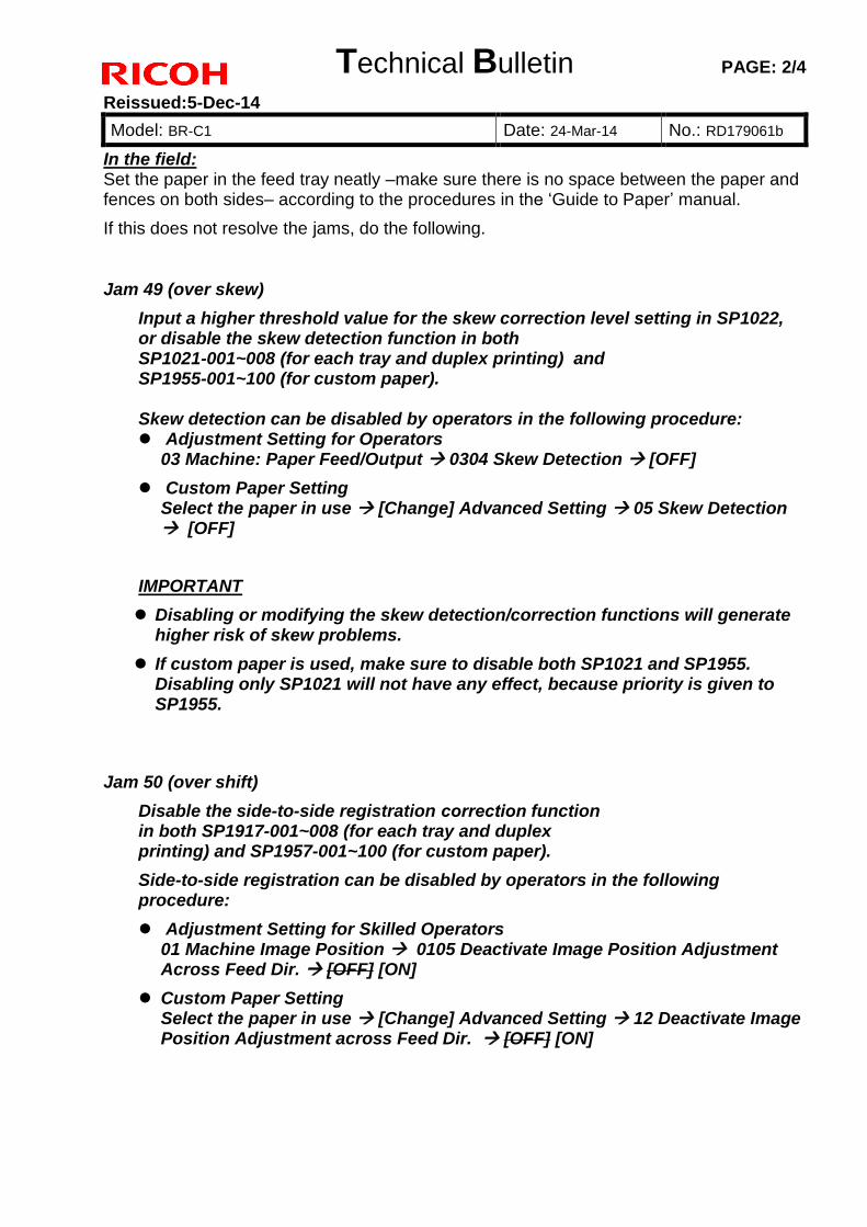
Technical Bulletin PAGE: 2/4
Reissued:5-Dec-14
Model: BR-C1 Date: 24-Mar-14 No.: RD179061b
In the field: Set the paper in the feed tray neatly –make sure there is no space between the paper and fences on both sides– according to the procedures in the ‘Guide to Paper’ manual.
If this does not resolve the jams, do the following.
Jam 49 (over skew)
Input a higher threshold value for the skew correction level setting in SP1022, or disable the skew detection function in both SP1021-001~008 (for each tray and duplex printing) and SP1955-001~100 (for custom paper).
Skew detection can be disabled by operators in the following procedure: Adjustment Setting for Operators
03 Machine: Paper Feed/Output 0304 Skew Detection [OFF]
Custom Paper SettingSelect the paper in use [Change] Advanced Setting 05 Skew Detection [OFF]
IMPORTANT
Disabling or modifying the skew detection/correction functions will generatehigher risk of skew problems.
If custom paper is used, make sure to disable both SP1021 and SP1955.Disabling only SP1021 will not have any effect, because priority is given toSP1955.
Jam 50 (over shift)
Disable the side-to-side registration correction function in both SP1917-001~008 (for each tray and duplex printing) and SP1957-001~100 (for custom paper).
Side-to-side registration can be disabled by operators in the following procedure:
Adjustment Setting for Skilled Operators01 Machine Image Position 0105 Deactivate Image Position Adjustment Across Feed Dir. [OFF] [ON]
Custom Paper SettingSelect the paper in use [Change] Advanced Setting 12 Deactivate ImagePosition Adjustment across Feed Dir. [OFF] [ON]
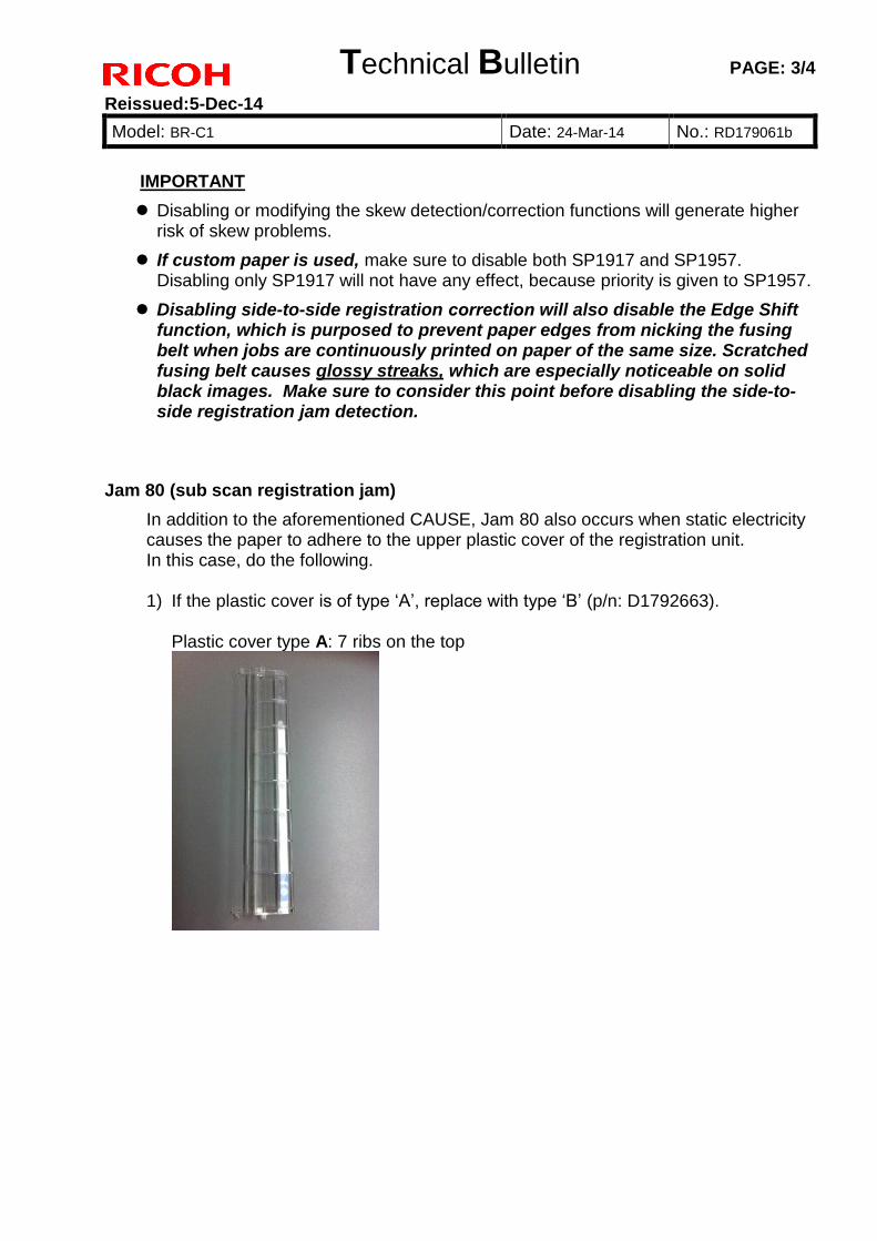
Technical Bulletin PAGE: 3/4
Reissued:5-Dec-14
Model: BR-C1 Date: 24-Mar-14 No.: RD179061b
IMPORTANT
Disabling or modifying the skew detection/correction functions will generate higherrisk of skew problems.
If custom paper is used, make sure to disable both SP1917 and SP1957.Disabling only SP1917 will not have any effect, because priority is given to SP1957.
Disabling side-to-side registration correction will also disable the Edge Shift function, which is purposed to prevent paper edges from nicking the fusing belt when jobs are continuously printed on paper of the same size. Scratched fusing belt causes glossy streaks, which are especially noticeable on solid black images. Make sure to consider this point before disabling the side-to-side registration jam detection.
Jam 80 (sub scan registration jam)
In addition to the aforementioned CAUSE, Jam 80 also occurs when static electricity causes the paper to adhere to the upper plastic cover of the registration unit. In this case, do the following.
1) If the plastic cover is of type ‘A’, replace with type ‘B’ (p/n: D1792663).
Plastic cover type A: 7 ribs on the top
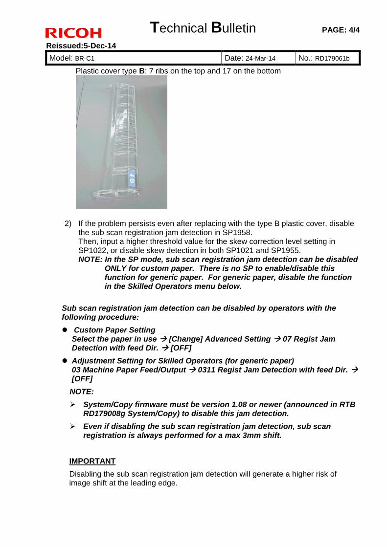
Technical Bulletin PAGE: 4/4
Reissued:5-Dec-14
Model: BR-C1 Date: 24-Mar-14 No.: RD179061b
Plastic cover type B: 7 ribs on the top and 17 on the bottom
2) If the problem persists even after replacing with the type B plastic cover, disablethe sub scan registration jam detection in SP1958.Then, input a higher threshold value for the skew correction level setting inSP1022, or disable skew detection in both SP1021 and SP1955.NOTE: In the SP mode, sub scan registration jam detection can be disabled
ONLY for custom paper. There is no SP to enable/disable this function for generic paper. For generic paper, disable the function in the Skilled Operators menu below.
Sub scan registration jam detection can be disabled by operators with the following procedure:
Custom Paper SettingSelect the paper in use [Change] Advanced Setting 07 Regist Jam Detection with feed Dir. [OFF]
Adjustment Setting for Skilled Operators (for generic paper)03 Machine Paper Feed/Output 0311 Regist Jam Detection with feed Dir. [OFF]
NOTE:
System/Copy firmware must be version 1.08 or newer (announced in RTBRD179008g System/Copy) to disable this jam detection.
Even if disabling the sub scan registration jam detection, sub scanregistration is always performed for a max 3mm shift.
IMPORTANT
Disabling the sub scan registration jam detection will generate a higher risk of image shift at the leading edge.
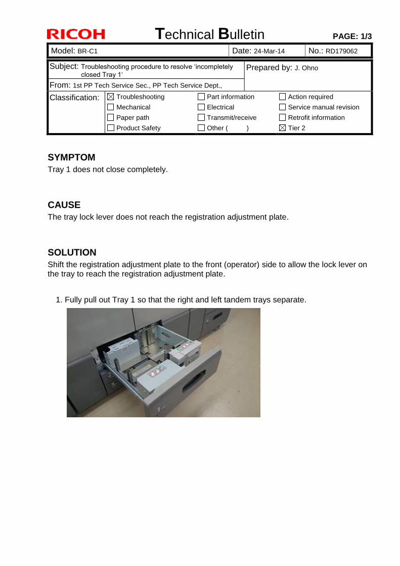
Technical Bulletin PAGE: 1/3
Model: BR-C1 Date: 24-Mar-14 No.: RD179062
Subject: Troubleshooting procedure to resolve ‘incompletely
closed Tray 1‘ Prepared by: J. Ohno
From: 1st PP Tech Service Sec., PP Tech Service Dept.,
Classification: Troubleshooting
Mechanical
Paper path
Product Safety
Part information
Electrical
Transmit/receive
Other ( )
Action required
Service manual revision
Retrofit information
Tier 2
SYMPTOM
Tray 1 does not close completely.
CAUSE
The tray lock lever does not reach the registration adjustment plate.
SOLUTION
Shift the registration adjustment plate to the front (operator) side to allow the lock lever on the tray to reach the registration adjustment plate.
1. Fully pull out Tray 1 so that the right and left tandem trays separate.
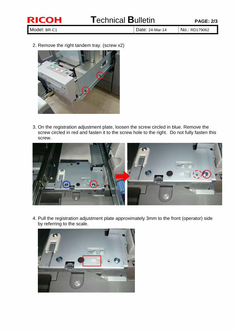
Technical Bulletin PAGE: 2/3
Model: BR-C1 Date: 24-Mar-14 No.: RD179062
2. Remove the right tandem tray. (screw x2)
3. On the registration adjustment plate, loosen the screw circled in blue. Remove the screw circled in red and fasten it to the screw hole to the right. Do not fully fasten this screw.
4. Pull the registration adjustment plate approximately 3mm to the front (operator) side by referring to the scale.

Technical Bulletin PAGE: 3/3
Model: BR-C1 Date: 24-Mar-14 No.: RD179062
5. Retrieve the original screw position for the screw removed in step 3.
6. Set the right tandem tray. (screw x2)
7. To compensate for the 3mm-shift to the front, do both of the following steps.
a. Disable the registration adjustment in the main scan direction in either Adjustment Settings for Operators 1-105-01 ~ 08 or in SP1-917-001 ~ 008 [Side-to-Side Reg Disable] 0 1.
b. Adjust the registration in SP1-002-001 [Main Scan Regist (Shift: Off): Tray 1].
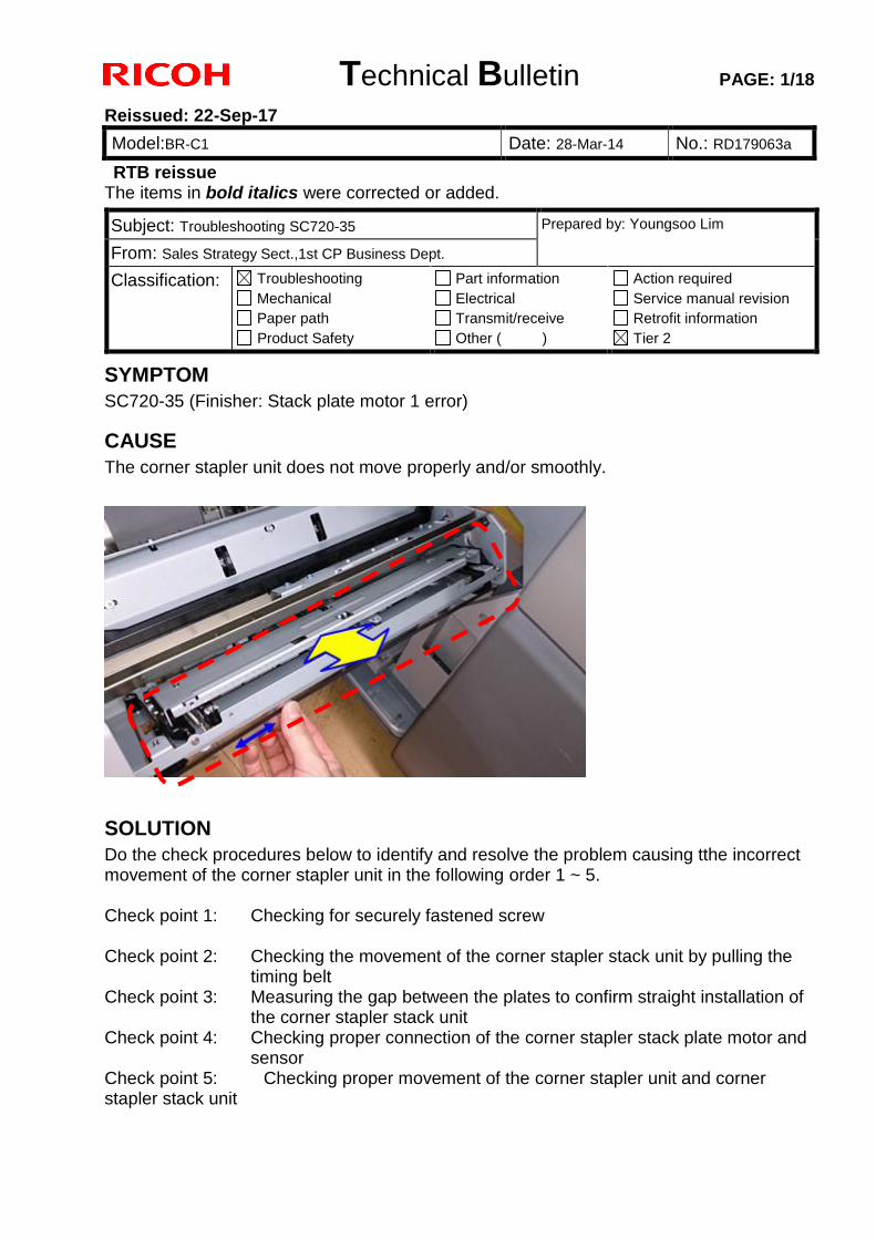
Technical Bulletin PAGE: 1/18
Reissued: 22-Sep-17
Model:BR-C1 Date: 28-Mar-14 No.: RD179063a
RTB reissue The items in bold italics were corrected or added.
SYMPTOM
SC720-35 (Finisher: Stack plate motor 1 error)
CAUSE
The corner stapler unit does not move properly and/or smoothly.
SOLUTION
Do the check procedures below to identify and resolve the problem causing tthe incorrect movement of the corner stapler unit in the following order 1 ~ 5. Check point 1: Checking for securely fastened screw Check point 2: Checking the movement of the corner stapler stack unit by pulling the
timing belt Check point 3: Measuring the gap between the plates to confirm straight installation of
the corner stapler stack unit Check point 4: Checking proper connection of the corner stapler stack plate motor and
sensor Check point 5: Checking proper movement of the corner stapler unit and corner stapler stack unit
Subject: Troubleshooting SC720-35 Prepared by: Youngsoo Lim
From: Sales Strategy Sect.,1st CP Business Dept.
Classification: Troubleshooting
Mechanical
Paper path
Product Safety
Part information
Electrical
Transmit/receive
Other ( )
Action required
Service manual revision
Retrofit information
Tier 2
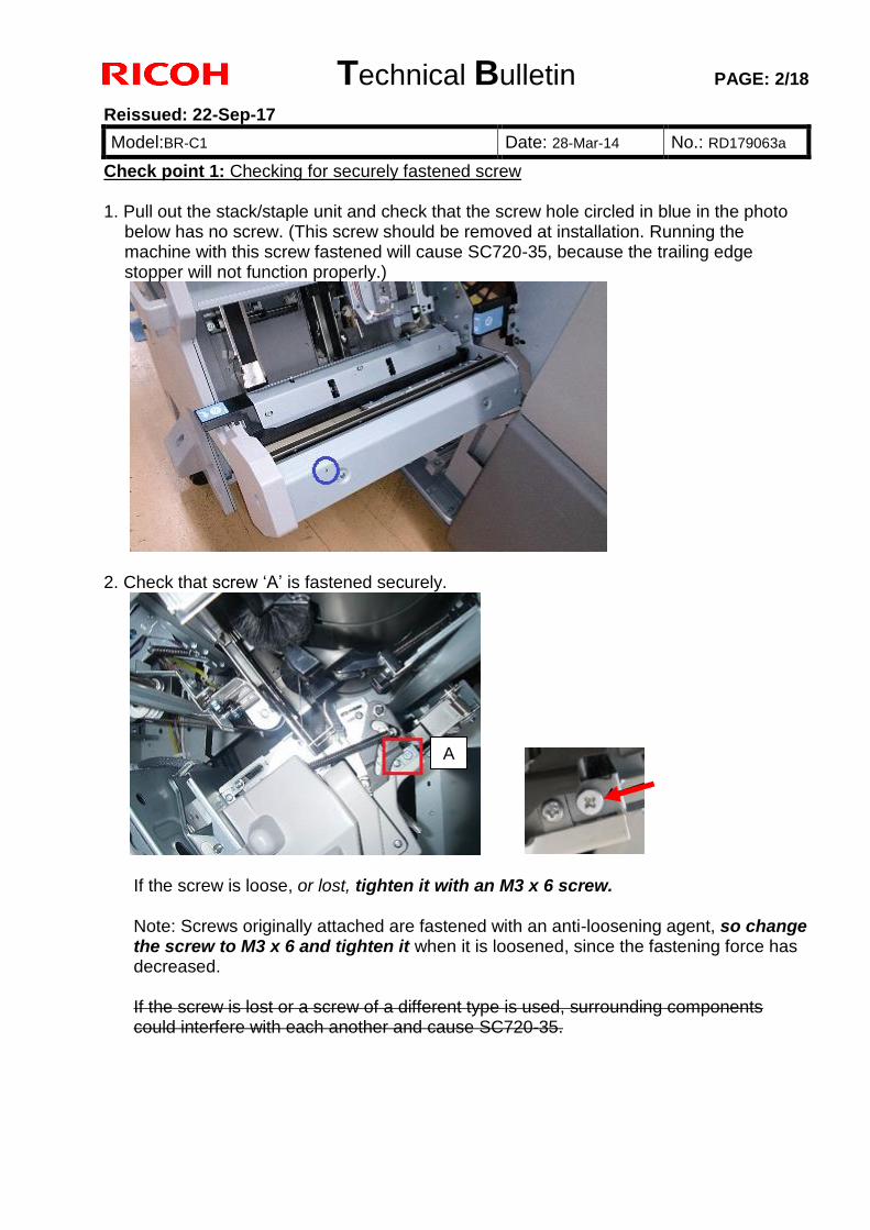
Technical Bulletin PAGE: 2/18
Reissued: 22-Sep-17
Model:BR-C1 Date: 28-Mar-14 No.: RD179063a
Check point 1: Checking for securely fastened screw 1. Pull out the stack/staple unit and check that the screw hole circled in blue in the photo
below has no screw. (This screw should be removed at installation. Running the machine with this screw fastened will cause SC720-35, because the trailing edge stopper will not function properly.)
2. Check that screw ‘A’ is fastened securely.
If the screw is loose, or lost, tighten it with an M3 x 6 screw. Note: Screws originally attached are fastened with an anti-loosening agent, so change the screw to M3 x 6 and tighten it when it is loosened, since the fastening force has decreased. If the screw is lost or a screw of a different type is used, surrounding components could interfere with each another and cause SC720-35.
A
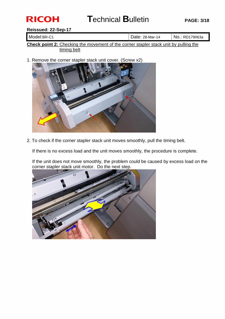
Technical Bulletin PAGE: 3/18
Reissued: 22-Sep-17
Model:BR-C1 Date: 28-Mar-14 No.: RD179063a
Check point 2: Checking the movement of the corner stapler stack unit by pulling the timing belt
1. Remove the corner stapler stack unit cover. (Screw x2)
2. To check if the corner stapler stack unit moves smoothly, pull the timing belt.
If there is no excess load and the unit moves smoothly, the procedure is complete. If the unit does not move smoothly, the problem could be caused by excess load on the corner stapler stack unit motor. Do the next step.
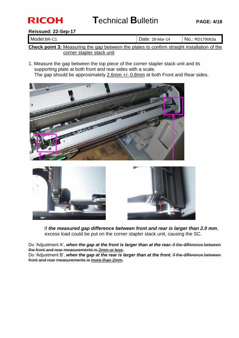
Technical Bulletin PAGE: 4/18
Reissued: 22-Sep-17
Model:BR-C1 Date: 28-Mar-14 No.: RD179063a
Check point 3: Measuring the gap between the plates to confirm straight installation of the corner stapler stack unit
1. Measure the gap between the top piece of the corner stapler stack unit and its
supporting plate at both front and rear sides with a scale. The gap should be approximately 2.6mm +/- 0.8mm at both Front and Rear sides.
If the measured gap difference between front and rear is larger than 2.0 mm, excess load could be put on the corner stapler stack unit, causing the SC.
Do ‘Adjustment A’, when the gap at the front is larger than at the rear. if the difference between the front and rear measurements is 2mm or less. Do ‘Adjustment B’, when the gap at the rear is larger than at the front. if the difference between front and rear measurements is more than 2mm.
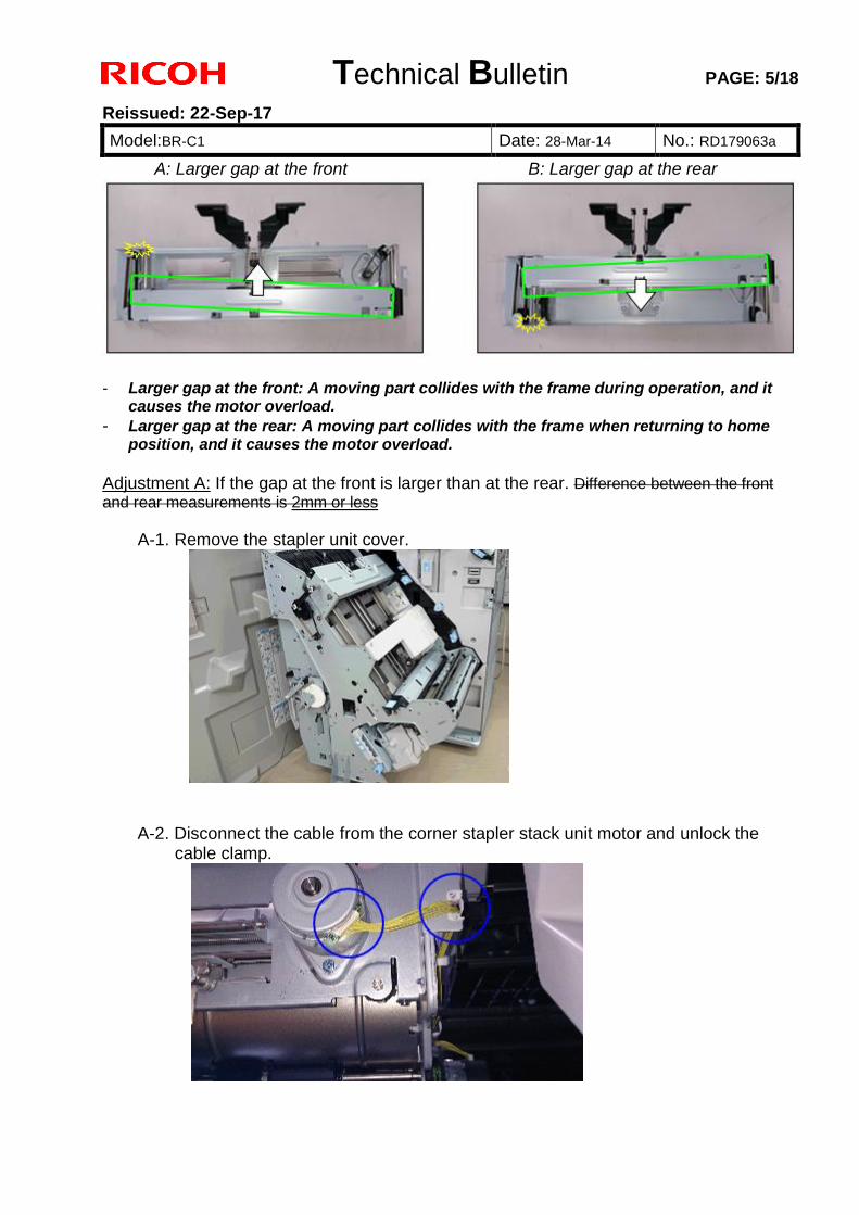
Technical Bulletin PAGE: 5/18
Reissued: 22-Sep-17
Model:BR-C1 Date: 28-Mar-14 No.: RD179063a
A: Larger gap at the front B: Larger gap at the rear
- Larger gap at the front: A moving part collides with the frame during operation, and it
causes the motor overload.
- Larger gap at the rear: A moving part collides with the frame when returning to home position, and it causes the motor overload.
Adjustment A: If the gap at the front is larger than at the rear. Difference between the front
and rear measurements is 2mm or less
A-1. Remove the stapler unit cover.
A-2. Disconnect the cable from the corner stapler stack unit motor and unlock the
cable clamp.
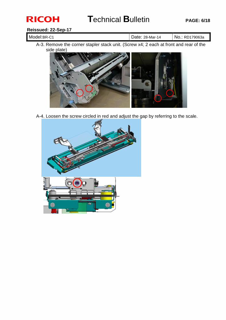
Technical Bulletin PAGE: 6/18
Reissued: 22-Sep-17
Model:BR-C1 Date: 28-Mar-14 No.: RD179063a
A-3. Remove the corner stapler stack unit. (Screw x4; 2 each at front and rear of the side plate)
A-4. Loosen the screw circled in red and adjust the gap by referring to the scale.
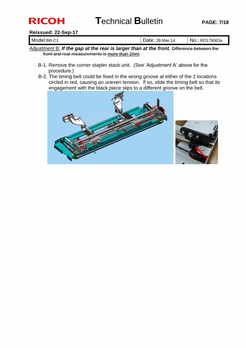
Technical Bulletin PAGE: 7/18
Reissued: 22-Sep-17
Model:BR-C1 Date: 28-Mar-14 No.: RD179063a
Adjustment B: If the gap at the rear is larger than at the front. Difference between the
front and rear measurements is more than 2mm B-1. Remove the corner stapler stack unit. (See ‘Adjustment A’ above for the
procedure.) B-2. The timing belt could be fixed in the wrong groove at either of the 2 locations
circled in red, causing an uneven tension. If so, slide the timing belt so that its engagement with the black piece slips to a different groove on the belt.
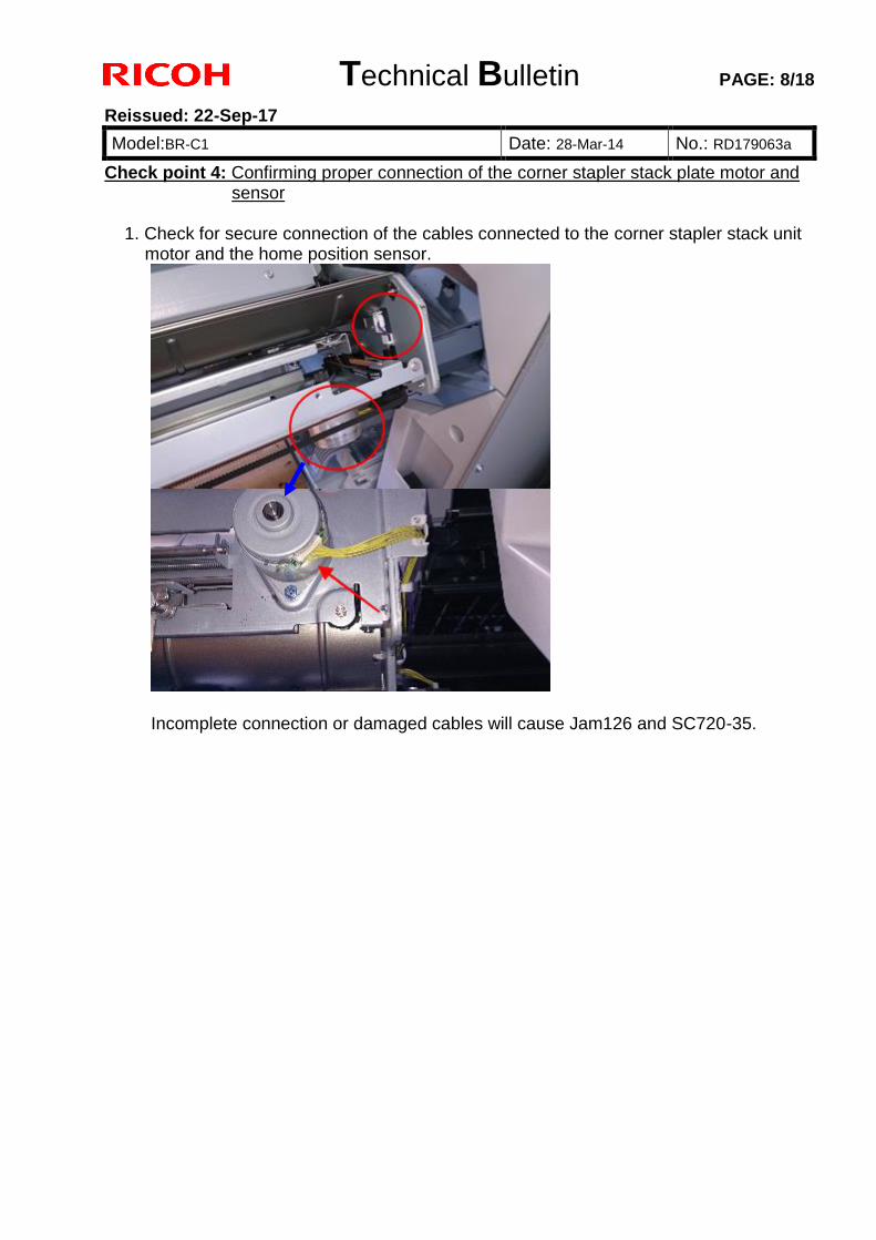
Technical Bulletin PAGE: 8/18
Reissued: 22-Sep-17
Model:BR-C1 Date: 28-Mar-14 No.: RD179063a
Check point 4: Confirming proper connection of the corner stapler stack plate motor and sensor
1. Check for secure connection of the cables connected to the corner stapler stack unit
motor and the home position sensor.
Incomplete connection or damaged cables will cause Jam126 and SC720-35.
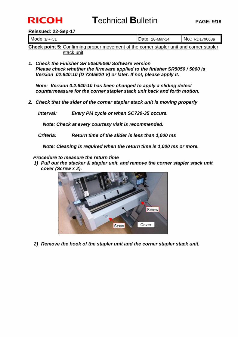
Technical Bulletin PAGE: 9/18
Reissued: 22-Sep-17
Model:BR-C1 Date: 28-Mar-14 No.: RD179063a
Check point 5: Confirming proper movement of the corner stapler unit and corner stapler stack unit
1. Check the Finisher SR 5050/5060 Software version
Please check whether the firmware applied to the finisher SR5050 / 5060 is Version 02.640:10 (D 7345620 V) or later. If not, please apply it. Note: Version 0.2.640:10 has been changed to apply a sliding defect countermeasure for the corner stapler stack unit back and forth motion.
2. Check that the sider of the corner stapler stack unit is moving properly
Interval: Every PM cycle or when SC720-35 occurs.
Note: Check at every courtesy visit is recommended.
Criteria: Return time of the slider is less than 1,000 ms
Note: Cleaning is required when the return time is 1,000 ms or more.
Procedure to measure the return time 1) Pull out the stacker & stapler unit, and remove the corner stapler stack unit
cover (Screw x 2).
2) Remove the hook of the stapler unit and the corner stapler stack unit.
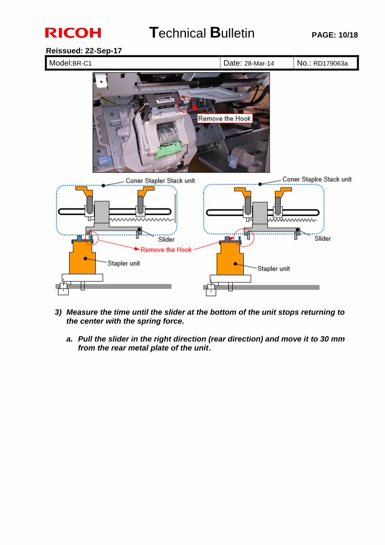
Technical Bulletin PAGE: 10/18
Reissued: 22-Sep-17
Model:BR-C1 Date: 28-Mar-14 No.: RD179063a
3) Measure the time until the slider at the bottom of the unit stops returning to the center with the spring force. a. Pull the slider in the right direction (rear direction) and move it to 30 mm
from the rear metal plate of the unit .
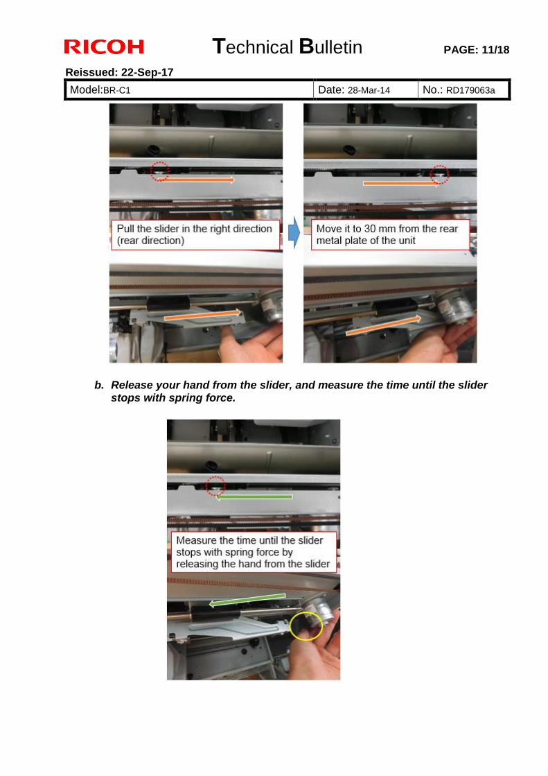
Technical Bulletin PAGE: 11/18
Reissued: 22-Sep-17
Model:BR-C1 Date: 28-Mar-14 No.: RD179063a
b. Release your hand from the slider, and measure the time until the slider stops with spring force.
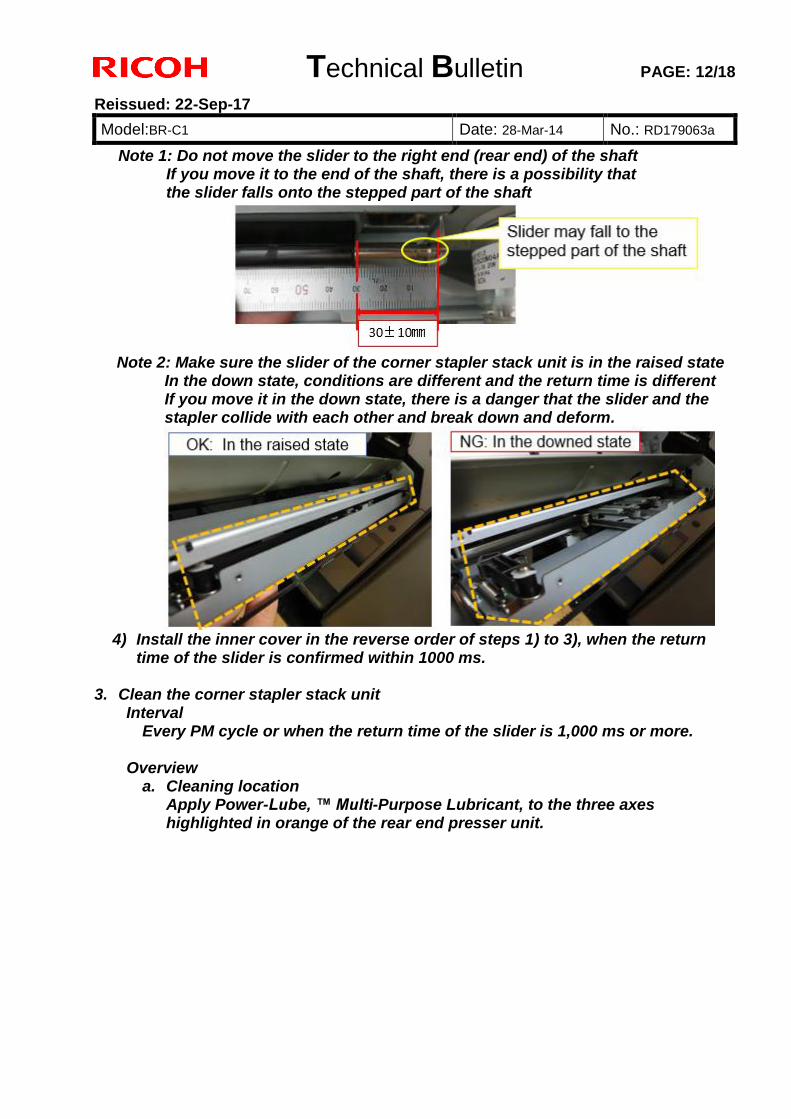
Technical Bulletin PAGE: 12/18
Reissued: 22-Sep-17
Model:BR-C1 Date: 28-Mar-14 No.: RD179063a
Note 1: Do not move the slider to the right end (rear end) of the shaft If you move it to the end of the shaft, there is a possibility that the slider falls onto the stepped part of the shaft
Note 2: Make sure the slider of the corner stapler stack unit is in the raised state In the down state, conditions are different and the return time is different If you move it in the down state, there is a danger that the slider and the stapler collide with each other and break down and deform.
4) Install the inner cover in the reverse order of steps 1) to 3), when the return
time of the slider is confirmed within 1000 ms. 3. Clean the corner stapler stack unit
Interval Every PM cycle or when the return time of the slider is 1,000 ms or more.
Overview
a. Cleaning location Apply Power-Lube, ™ Multi-Purpose Lubricant, to the three axes highlighted in orange of the rear end presser unit.
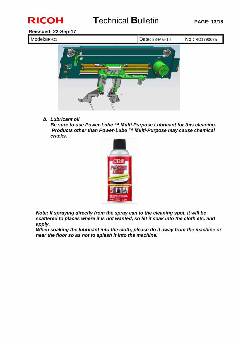
Technical Bulletin PAGE: 13/18
Reissued: 22-Sep-17
Model:BR-C1 Date: 28-Mar-14 No.: RD179063a
b. Lubricant oil Be sure to use Power-Lube ™ Multi-Purpose Lubricant for this cleaning. Products other than Power-Lube ™ Multi-Purpose may cause chemical cracks.
Note: If spraying directly from the spray can to the cleaning spot, it will be scattered to places where it is not wanted, so let it soak into the cloth etc. and apply. When soaking the lubricant into the cloth, please do it away from the machine or near the floor so as not to splash it into the machine.
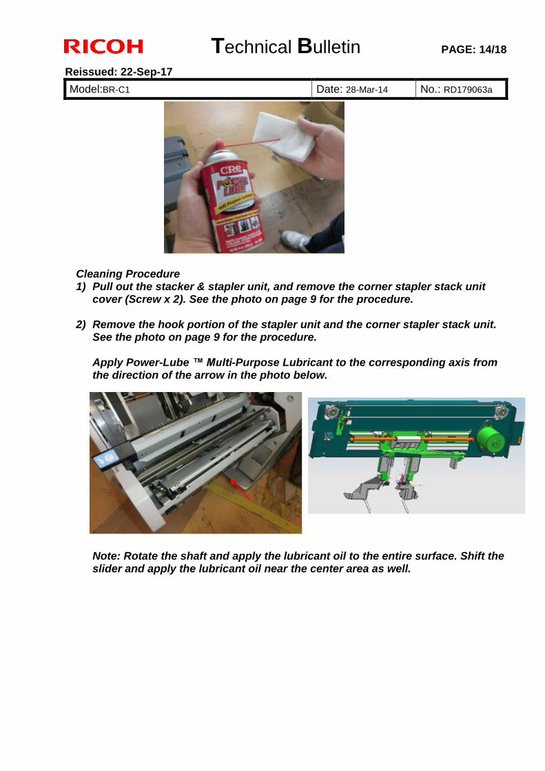
Technical Bulletin PAGE: 14/18
Reissued: 22-Sep-17
Model:BR-C1 Date: 28-Mar-14 No.: RD179063a
Cleaning Procedure 1) Pull out the stacker & stapler unit, and remove the corner stapler stack unit
cover (Screw x 2). See the photo on page 9 for the procedure.
2) Remove the hook portion of the stapler unit and the corner stapler stack unit. See the photo on page 9 for the procedure.
Apply Power-Lube ™ Multi-Purpose Lubricant to the corresponding axis from the direction of the arrow in the photo below.
Note: Rotate the shaft and apply the lubricant oil to the entire surface. Shift the slider and apply the lubricant oil near the center area as well.
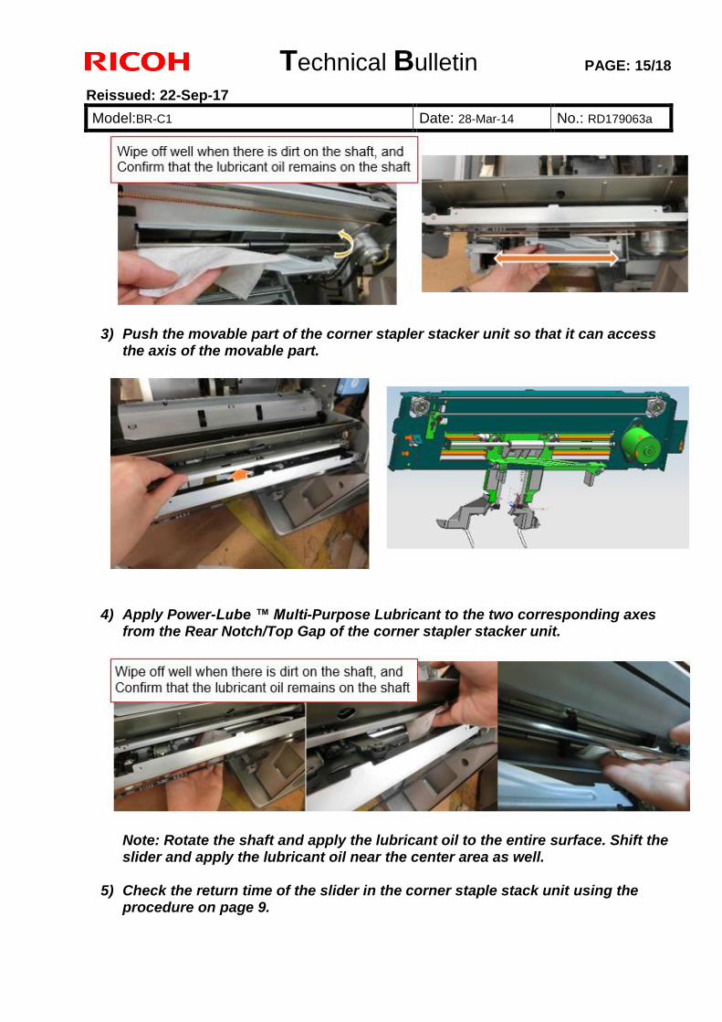
Technical Bulletin PAGE: 15/18
Reissued: 22-Sep-17
Model:BR-C1 Date: 28-Mar-14 No.: RD179063a
3) Push the movable part of the corner stapler stacker unit so that it can access the axis of the movable part.
4) Apply Power-Lube ™ Multi-Purpose Lubricant to the two corresponding axes
from the Rear Notch/Top Gap of the corner stapler stacker unit.
Note: Rotate the shaft and apply the lubricant oil to the entire surface. Shift the slider and apply the lubricant oil near the center area as well.
5) Check the return time of the slider in the corner staple stack unit using the
procedure on page 9.
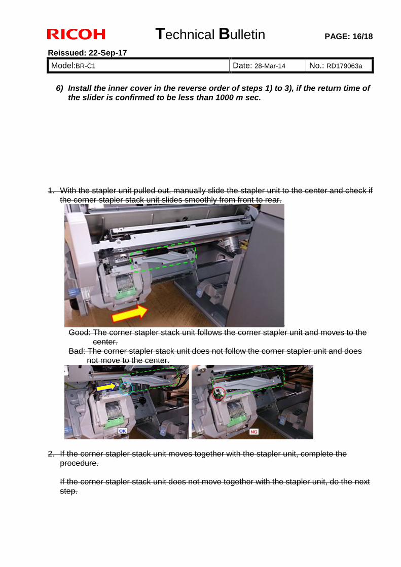
Technical Bulletin PAGE: 16/18
Reissued: 22-Sep-17
Model:BR-C1 Date: 28-Mar-14 No.: RD179063a
6) Install the inner cover in the reverse order of steps 1) to 3), if the return time of
the slider is confirmed to be less than 1000 m sec. 1. With the stapler unit pulled out, manually slide the stapler unit to the center and check if
the corner stapler stack unit slides smoothly from front to rear.
Good: The corner stapler stack unit follows the corner stapler unit and moves to the
center. Bad: The corner stapler stack unit does not follow the corner stapler unit and does
not move to the center.
2. If the corner stapler stack unit moves together with the stapler unit, complete the procedure. If the corner stapler stack unit does not move together with the stapler unit, do the next step.
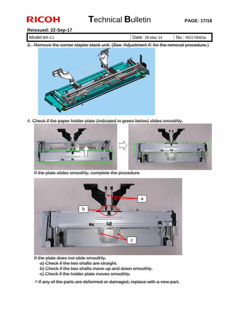
Technical Bulletin PAGE: 17/18
Reissued: 22-Sep-17
Model:BR-C1 Date: 28-Mar-14 No.: RD179063a
3. Remove the corner stapler stack unit. (See ‘Adjustment A’ for the removal procedure.)
4. Check if the paper holder plate (indicated in green below) slides smoothly.
If the plate slides smoothly, complete the procedure.
If the plate does not slide smoothly,
a) Check if the two shafts are straight. b) Check if the two shafts move up and down smoothly. c) Check if the holder plate moves smoothly.
* If any of the parts are deformed or damaged, replace with a new part.
a
b
c
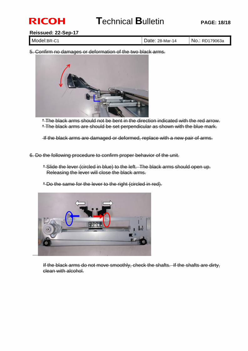
Technical Bulletin PAGE: 18/18
Reissued: 22-Sep-17
Model:BR-C1 Date: 28-Mar-14 No.: RD179063a
5. Confirm no damages or deformation of the two black arms.
* The black arms should not be bent in the direction indicated with the red arrow. * The black arms are should be set perpendicular as shown with the blue mark. If the black arms are damaged or deformed, replace with a new pair of arms.
6. Do the following procedure to confirm proper behavior of the unit.
* Slide the lever (circled in blue) to the left. The black arms should open up. Releasing the lever will close the black arms.
* Do the same for the lever to the right (circled in red).
If the black arms do not move smoothly, check the shafts. If the shafts are dirty, clean with alcohol.
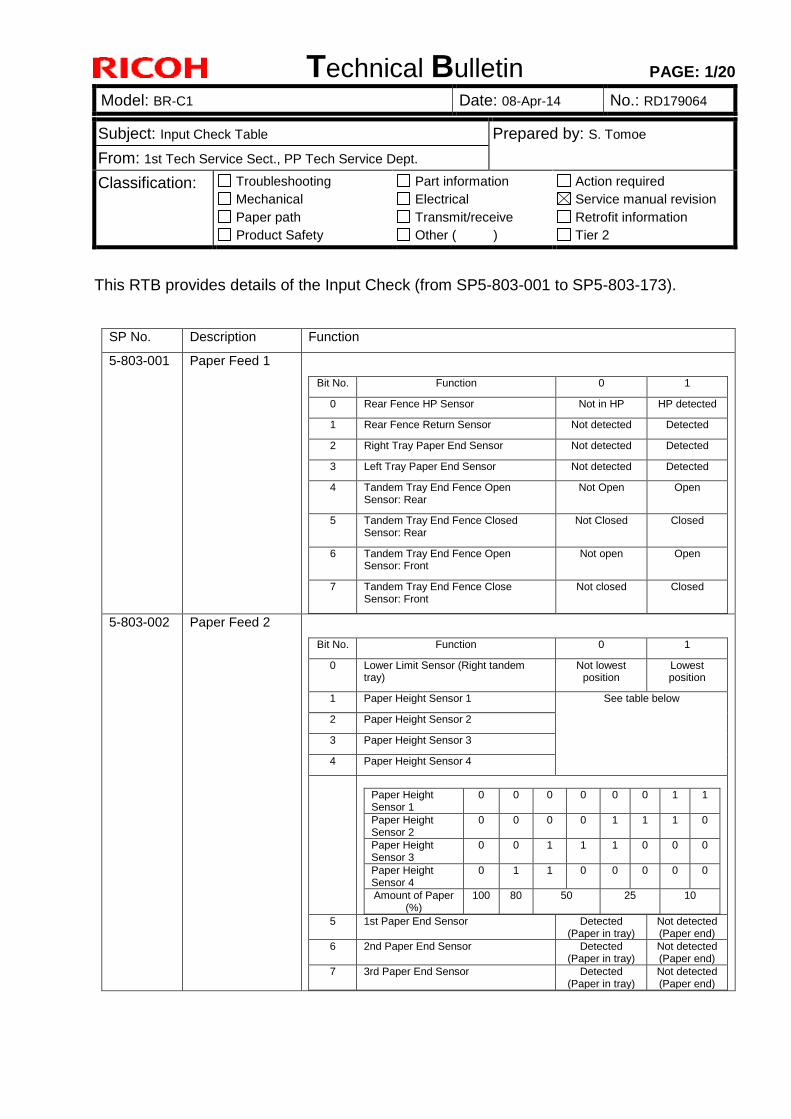
Technical Bulletin PAGE: 1/20
Model: BR-C1 Date: 08-Apr-14 No.: RD179064
Subject: Input Check Table Prepared by: S. Tomoe
From: 1st Tech Service Sect., PP Tech Service Dept.
Classification: Troubleshooting
Mechanical
Paper path
Product Safety
Part information
Electrical
Transmit/receive
Other ( )
Action required
Service manual revision
Retrofit information
Tier 2
This RTB provides details of the Input Check (from SP5-803-001 to SP5-803-173).
SP No. Description Function
5-803-001 Paper Feed 1
Bit No. Function 0 1
0 Rear Fence HP Sensor Not in HP HP detected
1 Rear Fence Return Sensor Not detected Detected
2 Right Tray Paper End Sensor Not detected Detected
3 Left Tray Paper End Sensor Not detected Detected
4 Tandem Tray End Fence Open Sensor: Rear
Not Open Open
5 Tandem Tray End Fence Closed Sensor: Rear
Not Closed Closed
6 Tandem Tray End Fence Open Sensor: Front
Not open Open
7 Tandem Tray End Fence Close Sensor: Front
Not closed Closed
5-803-002 Paper Feed 2
Bit No. Function 0 1
0 Lower Limit Sensor (Right tandem tray)
Not lowest position
Lowest position
1 Paper Height Sensor 1 See table below
2 Paper Height Sensor 2
3 Paper Height Sensor 3
4 Paper Height Sensor 4
Paper Height Sensor 1
0 0 0 0 0 0 1 1
Paper Height Sensor 2
0 0 0 0 1 1 1 0
Paper Height Sensor 3
0 0 1 1 1 0 0 0
Paper Height Sensor 4
0 1 1 0 0 0 0 0
Amount of Paper (%)
100 80 50 25 10
5 1st Paper End Sensor Detected (Paper in tray)
Not detected (Paper end)
6 2nd Paper End Sensor Detected (Paper in tray)
Not detected (Paper end)
7 3rd Paper End Sensor Detected (Paper in tray)
Not detected (Paper end)
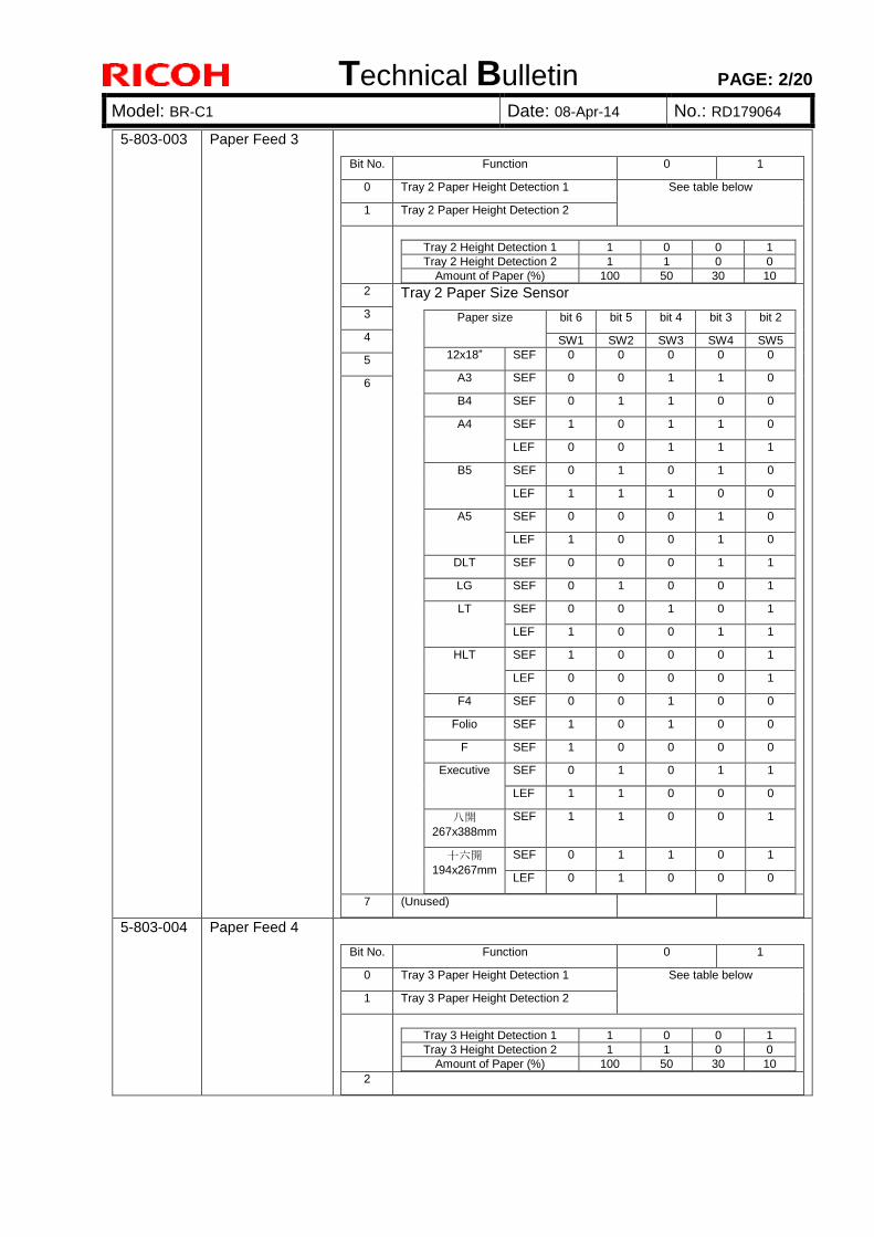
Technical Bulletin PAGE: 2/20
Model: BR-C1 Date: 08-Apr-14 No.: RD179064
5-803-003 Paper Feed 3
Bit No. Function 0 1
0 Tray 2 Paper Height Detection 1 See table below
1 Tray 2 Paper Height Detection 2
Tray 2 Height Detection 1 1 0 0 1
Tray 2 Height Detection 2 1 1 0 0
Amount of Paper (%) 100 50 30 10
2 Tray 2 Paper Size Sensor
Paper size bit 6 bit 5 bit 4 bit 3 bit 2
SW1 SW2 SW3 SW4 SW5
12x18” SEF 0 0 0 0 0
A3 SEF 0 0 1 1 0
B4 SEF 0 1 1 0 0
A4 SEF 1 0 1 1 0
LEF 0 0 1 1 1
B5 SEF 0 1 0 1 0
LEF 1 1 1 0 0
A5 SEF 0 0 0 1 0
LEF 1 0 0 1 0
DLT SEF 0 0 0 1 1
LG SEF 0 1 0 0 1
LT SEF 0 0 1 0 1
LEF 1 0 0 1 1
HLT SEF 1 0 0 0 1
LEF 0 0 0 0 1
F4 SEF 0 0 1 0 0
Folio SEF 1 0 1 0 0
F SEF 1 0 0 0 0
Executive SEF 0 1 0 1 1
LEF 1 1 0 0 0
八開
267x388mm
SEF 1 1 0 0 1
十六開
194x267mm
SEF 0 1 1 0 1
LEF 0 1 0 0 0
3
4
5
6
7 (Unused)
5-803-004 Paper Feed 4
Bit No. Function 0 1
0 Tray 3 Paper Height Detection 1 See table below
1 Tray 3 Paper Height Detection 2
Tray 3 Height Detection 1 1 0 0 1
Tray 3 Height Detection 2 1 1 0 0
Amount of Paper (%) 100 50 30 10
2
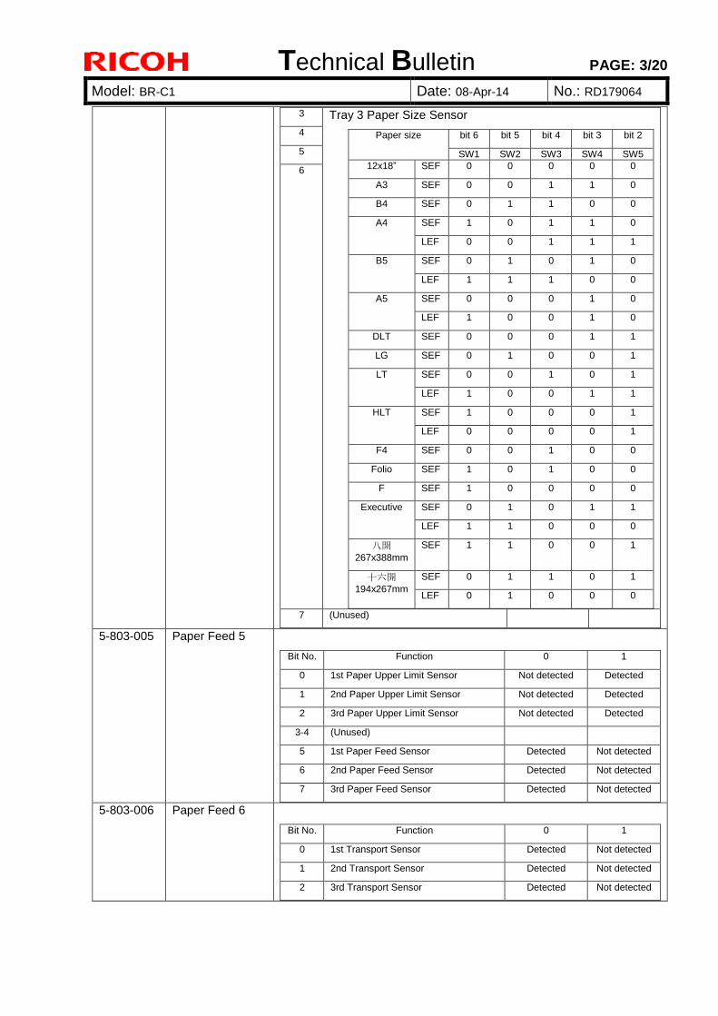
Technical Bulletin PAGE: 3/20
Model: BR-C1 Date: 08-Apr-14 No.: RD179064
3 Tray 3 Paper Size Sensor
Paper size bit 6 bit 5 bit 4 bit 3 bit 2
SW1 SW2 SW3 SW4 SW5
12x18” SEF 0 0 0 0 0
A3 SEF 0 0 1 1 0
B4 SEF 0 1 1 0 0
A4 SEF 1 0 1 1 0
LEF 0 0 1 1 1
B5 SEF 0 1 0 1 0
LEF 1 1 1 0 0
A5 SEF 0 0 0 1 0
LEF 1 0 0 1 0
DLT SEF 0 0 0 1 1
LG SEF 0 1 0 0 1
LT SEF 0 0 1 0 1
LEF 1 0 0 1 1
HLT SEF 1 0 0 0 1
LEF 0 0 0 0 1
F4 SEF 0 0 1 0 0
Folio SEF 1 0 1 0 0
F SEF 1 0 0 0 0
Executive SEF 0 1 0 1 1
LEF 1 1 0 0 0
八開
267x388mm
SEF 1 1 0 0 1
十六開
194x267mm
SEF 0 1 1 0 1
LEF 0 1 0 0 0
4
5
6
7 (Unused)
5-803-005 Paper Feed 5
Bit No. Function 0 1
0 1st Paper Upper Limit Sensor Not detected Detected
1 2nd Paper Upper Limit Sensor Not detected Detected
2 3rd Paper Upper Limit Sensor Not detected Detected
3-4 (Unused)
5 1st Paper Feed Sensor Detected Not detected
6 2nd Paper Feed Sensor Detected Not detected
7 3rd Paper Feed Sensor Detected Not detected
5-803-006 Paper Feed 6
Bit No. Function 0 1
0 1st Transport Sensor Detected Not detected
1 2nd Transport Sensor Detected Not detected
2 3rd Transport Sensor Detected Not detected

Technical Bulletin PAGE: 4/20
Model: BR-C1 Date: 08-Apr-14 No.: RD179064
3 Vertical Transport Sensor Detected Not detected
4 Main Relay Sensor Detected Not detected
5 Registration Entrance Sensor Detected Not detected
6 LCT Relay Sensor Detected Not detected
7 Registration Timing Sensor Detected Not detected
5-803-007 Paper Feed 7
Bit No. Function 0 1
0 Transfer Timing Sensor Detected Not detected
1 Transport Roller Separation Sensor Detected Not detected
2 Fusing Exit Sensor: Center Detected Not detected
3 Pressure Roller Paper Sensor Not detected Detected
4 Fusing Belt Sensor Not detected Detected
5 Exit Junction Sensor Detected Not detected
6 Exit Sensor Detected Not detected
7 Exit Invert Sensor Detected Not detected
5-803-008 Paper Feed 8
Bit No. Function 0 1
0 Duplex Invert Sensor Detected Not detected
1 Duplex Transport Sensor 1 Detected Not detected
2 Duplex Transport Sensor 2 Detected Not detected
3 Duplex Transport Sensor 3 Detected Not detected
4 Duplex Transport Sensor 4 Detected Not detected
5 Duplex Transport Sensor 5 Detected Not detected
6 Duplex Transport Sensor 6 Detected Not detected
7 Duplex Unit Exit Sensor Detected Not detected
5-803-009 Paper Feed 9
Bit No. Function 0 1
0 Purge Relay Sensor Detected Not detected
1 Purged Paper Sensor Not detected Detected
2-4 (Unused)
5 Registration Gate Roller HP Sensor Not in HP HP detected
6 LE Shift Unit HP Sensor Not in HP HP detected
7 TE Shift Unit HP Sensor Not in HP HP detected
5-803-010 Paper Feed 10
Bit No. Function 0 1
0 Main Relay HP Sensor Not in HP (Roller
separated)
HP detected (Roller in contact)
1 LCT Relay HP Sensor Not in HP (Roller
separated)
HP detected (Roller in contact)
2 Exit Junction Gate HP Sensor Invert path Straight path
3 Invert Exit HP Sensor HP detected (Roller in contact)
Not in HP (Roller
separated)
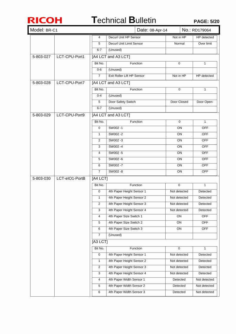
Technical Bulletin PAGE: 5/20
Model: BR-C1 Date: 08-Apr-14 No.: RD179064
4 Decurl Unit HP Sensor Not in HP HP detected
5 Decurl Unit Limit Sensor Normal Over limit
6-7 (Unused)
5-803-027 LCT-CPU-Port1 [A4 LCT and A3 LCT]
Bit No. Function 0 1
0-6 (Unused)
7 Exit Roller Lift HP Sensor Not in HP HP detected
5-803-028 LCT-CPU-Port7 [A4 LCT and A3 LCT]
Bit No. Function 0 1
0-4 (Unused)
5 Door Safety Switch Door Closed Door Open-
6-7 (Unused)
5-803-029 LCT-CPU-Port9 [A4 LCT and A3 LCT]
Bit No. Function 0 1
0 SW002 -1 ON OFF
1 SW002 -2 ON OFF
2 SW002 -3 ON OFF
3 SW002 -4 ON OFF
4 SW002 -5 ON OFF
5 SW002 -6 ON OFF
6 SW002 -7 ON OFF
7 SW002 -8 ON OFF
5-803-030 LCT-eIO1-PortB [A4 LCT]
Bit No. Function 0 1
0 4th Paper Height Sensor 1 Not detected Detected
1 4th Paper Height Sensor 2 Not detected Detected
2 4th Paper Height Sensor 3 Not detected Detected
3 4th Paper Height Sensor 4 Not detected Detected
4 4th Paper Size Switch 1 ON OFF
5 4th Paper Size Switch 2 ON OFF
6 4th Paper Size Switch 3 ON OFF
7 (Unused)
[A3 LCT]
Bit No. Function 0 1
0 4th Paper Height Sensor 1 Not detected Detected
1 4th Paper Height Sensor 2 Not detected Detected
2 4th Paper Height Sensor 3 Not detected Detected
3 4th Paper Height Sensor 4 Not detected Detected
4 4th Paper Width Sensor 1 Detected Not detected
5 4th Paper Width Sensor 2 Detected Not detected
6 4th Paper Width Sensor 3 Detected Not detected
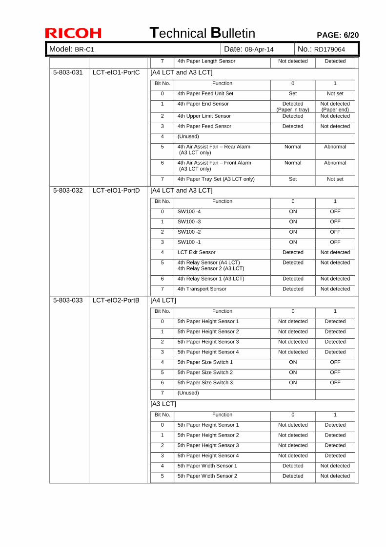
Technical Bulletin PAGE: 6/20
Model: BR-C1 Date: 08-Apr-14 No.: RD179064
7 4th Paper Length Sensor Not detected Detected
5-803-031 LCT-eIO1-PortC [A4 LCT and A3 LCT]
Bit No. Function 0 1
0 4th Paper Feed Unit Set Set Not set
1 4th Paper End Sensor Detected (Paper in tray)
Not detected (Paper end)
2 4th Upper Limit Sensor Detected Not detected
3 4th Paper Feed Sensor Detected Not detected
4 (Unused)
5 4th Air Assist Fan – Rear Alarm (A3 LCT only)
Normal Abnormal
6 4th Air Assist Fan – Front Alarm (A3 LCT only)
Normal Abnormal
7 4th Paper Tray Set (A3 LCT only) Set Not set
5-803-032 LCT-eIO1-PortD [A4 LCT and A3 LCT]
Bit No. Function 0 1
0 SW100 -4 ON OFF
1 SW100 -3 ON OFF
2 SW100 -2 ON OFF
3 SW100 -1 ON OFF
4 LCT Exit Sensor Detected Not detected
5 4th Relay Sensor (A4 LCT) 4th Relay Sensor 2 (A3 LCT)
Detected Not detected
6 4th Relay Sensor 1 (A3 LCT) Detected Not detected
7 4th Transport Sensor Detected Not detected
5-803-033 LCT-eIO2-PortB [A4 LCT]
Bit No. Function 0 1
0 5th Paper Height Sensor 1 Not detected Detected
1 5th Paper Height Sensor 2 Not detected Detected
2 5th Paper Height Sensor 3 Not detected Detected
3 5th Paper Height Sensor 4 Not detected Detected
4 5th Paper Size Switch 1 ON OFF
5 5th Paper Size Switch 2 ON OFF
6 5th Paper Size Switch 3 ON OFF
7 (Unused)
[A3 LCT]
Bit No. Function 0 1
0 5th Paper Height Sensor 1 Not detected Detected
1 5th Paper Height Sensor 2 Not detected Detected
2 5th Paper Height Sensor 3 Not detected Detected
3 5th Paper Height Sensor 4 Not detected Detected
4 5th Paper Width Sensor 1 Detected Not detected
5 5th Paper Width Sensor 2 Detected Not detected
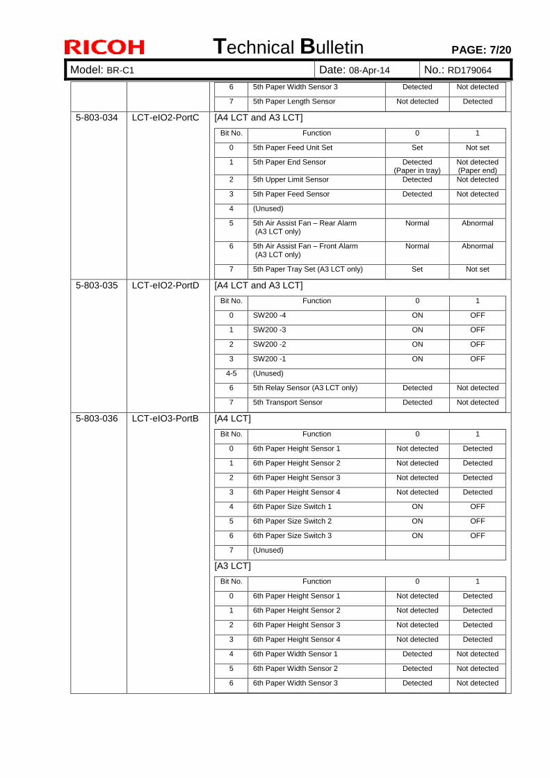
Technical Bulletin PAGE: 7/20
Model: BR-C1 Date: 08-Apr-14 No.: RD179064
6 5th Paper Width Sensor 3 Detected Not detected
7 5th Paper Length Sensor Not detected Detected
5-803-034 LCT-eIO2-PortC [A4 LCT and A3 LCT]
Bit No. Function 0 1
0 5th Paper Feed Unit Set Set Not set
1 5th Paper End Sensor Detected (Paper in tray)
Not detected (Paper end)
2 5th Upper Limit Sensor Detected Not detected
3 5th Paper Feed Sensor Detected Not detected
4 (Unused)
5 5th Air Assist Fan – Rear Alarm (A3 LCT only)
Normal Abnormal
6 5th Air Assist Fan – Front Alarm (A3 LCT only)
Normal Abnormal
7 5th Paper Tray Set (A3 LCT only) Set Not set
5-803-035 LCT-eIO2-PortD [A4 LCT and A3 LCT]
Bit No. Function 0 1
0 SW200 -4 ON OFF
1 SW200 -3 ON OFF
2 SW200 -2 ON OFF
3 SW200 -1 ON OFF
4-5 (Unused)
6 5th Relay Sensor (A3 LCT only) Detected Not detected
7 5th Transport Sensor Detected Not detected
5-803-036 LCT-eIO3-PortB [A4 LCT]
Bit No. Function 0 1
0 6th Paper Height Sensor 1 Not detected Detected
1 6th Paper Height Sensor 2 Not detected Detected
2 6th Paper Height Sensor 3 Not detected Detected
3 6th Paper Height Sensor 4 Not detected Detected
4 6th Paper Size Switch 1 ON OFF
5 6th Paper Size Switch 2 ON OFF
6 6th Paper Size Switch 3 ON OFF
7 (Unused)
[A3 LCT]
Bit No. Function 0 1
0 6th Paper Height Sensor 1 Not detected Detected
1 6th Paper Height Sensor 2 Not detected Detected
2 6th Paper Height Sensor 3 Not detected Detected
3 6th Paper Height Sensor 4 Not detected Detected
4 6th Paper Width Sensor 1 Detected Not detected
5 6th Paper Width Sensor 2 Detected Not detected
6 6th Paper Width Sensor 3 Detected Not detected
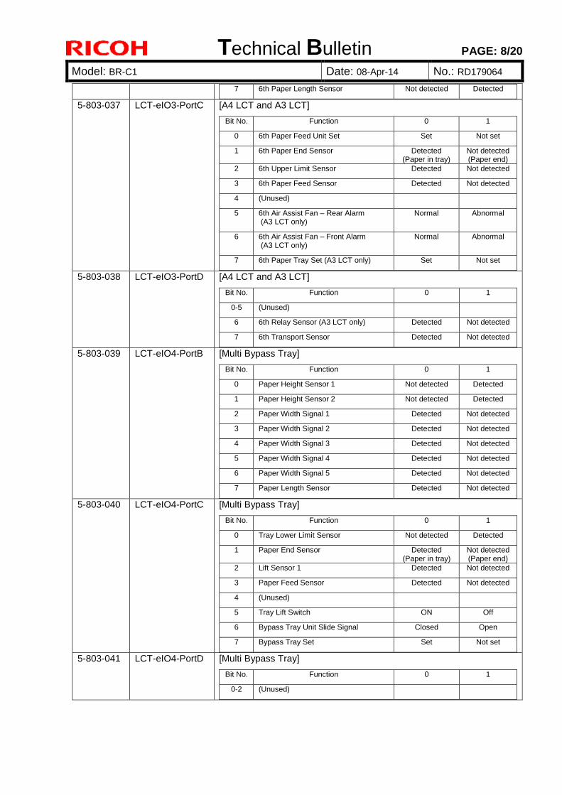
Technical Bulletin PAGE: 8/20
Model: BR-C1 Date: 08-Apr-14 No.: RD179064
7 6th Paper Length Sensor Not detected Detected
5-803-037 LCT-eIO3-PortC [A4 LCT and A3 LCT]
Bit No. Function 0 1
0 6th Paper Feed Unit Set Set Not set
1 6th Paper End Sensor Detected (Paper in tray)
Not detected (Paper end)
2 6th Upper Limit Sensor Detected Not detected
3 6th Paper Feed Sensor Detected Not detected
4 (Unused)
5 6th Air Assist Fan – Rear Alarm (A3 LCT only)
Normal Abnormal
6 6th Air Assist Fan – Front Alarm (A3 LCT only)
Normal Abnormal
7 6th Paper Tray Set (A3 LCT only) Set Not set
5-803-038 LCT-eIO3-PortD [A4 LCT and A3 LCT]
Bit No. Function 0 1
0-5 (Unused)
6 6th Relay Sensor (A3 LCT only) Detected Not detected
7 6th Transport Sensor Detected Not detected
5-803-039 LCT-eIO4-PortB [Multi Bypass Tray]
Bit No. Function 0 1
0 Paper Height Sensor 1 Not detected Detected
1 Paper Height Sensor 2 Not detected Detected
2 Paper Width Signal 1 Detected Not detected
3 Paper Width Signal 2 Detected Not detected
4 Paper Width Signal 3 Detected Not detected
5 Paper Width Signal 4 Detected Not detected
6 Paper Width Signal 5 Detected Not detected
7 Paper Length Sensor Detected Not detected
5-803-040 LCT-eIO4-PortC [Multi Bypass Tray]
Bit No. Function 0 1
0 Tray Lower Limit Sensor Not detected Detected
1 Paper End Sensor Detected (Paper in tray)
Not detected (Paper end)
2 Lift Sensor 1 Detected Not detected
3 Paper Feed Sensor Detected Not detected
4 (Unused) 5 Tray Lift Switch ON Off
6 Bypass Tray Unit Slide Signal Closed Open
7 Bypass Tray Set Set Not set
5-803-041 LCT-eIO4-PortD [Multi Bypass Tray]
Bit No. Function 0 1
0-2 (Unused)
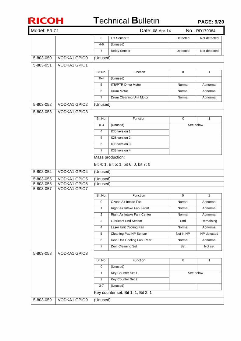
Technical Bulletin PAGE: 9/20
Model: BR-C1 Date: 08-Apr-14 No.: RD179064
3 Lift Sensor 2 Detected Not detected
4-6 (Unused) 7 Relay Sensor Detected Not detected
5-803-050 VODKA1 GPIO0 (Unused)
5-803-051 VODKA1 GPIO1
Bit No. Function 0 1
0-4 (Unused)
5 ITB/PTR Drive Motor Normal Abnormal
6 Drum Motor Normal Abnormal
7 Drum Cleaning Unit Motor Normal Abnormal
5-803-052 VODKA1 GPIO2 (Unused)
5-803-053 VODKA1 GPIO3
Bit No. Function 0 1
0-3 (Unused) See below
4 IOB version 1
5 IOB version 2
6 IOB version 3
7 IOB version 4
Mass production:
Bit 4: 1, Bit 5: 1, bit 6: 0, bit 7: 0
5-803-054 VODKA1 GPIO4 (Unused)
5-803-055 VODKA1 GPIO5 (Unused) 5-803-056 VODKA1 GPIO6 (Unused) 5-803-057 VODKA1 GPIO7
Bit No. Function 0 1
0 Ozone Air Intake Fan Normal Abnormal
1 Right Air Intake Fan: Front Normal Abnormal
2 Right Air Intake Fan: Center Normal Abnormal
3 Lubricant End Sensor End Remaining
4 Laser Unit Cooling Fan Normal Abnormal
5 Cleaning Pad HP Sensor Not in HP HP detected
6 Dev. Unit Cooling Fan :Rear Normal Abnormal
7 Dev. Cleaning Set Set Not set
5-803-058 VODKA1 GPIO8
Bit No. Function 0 1
0 (Unused)
1 Key Counter Set 1 See below
2 Key Counter Set 2
3-7 (Unused)
Key counter set: Bit 1: 1, Bit 2: 1
5-803-059 VODKA1 GPIO9 (Unused)
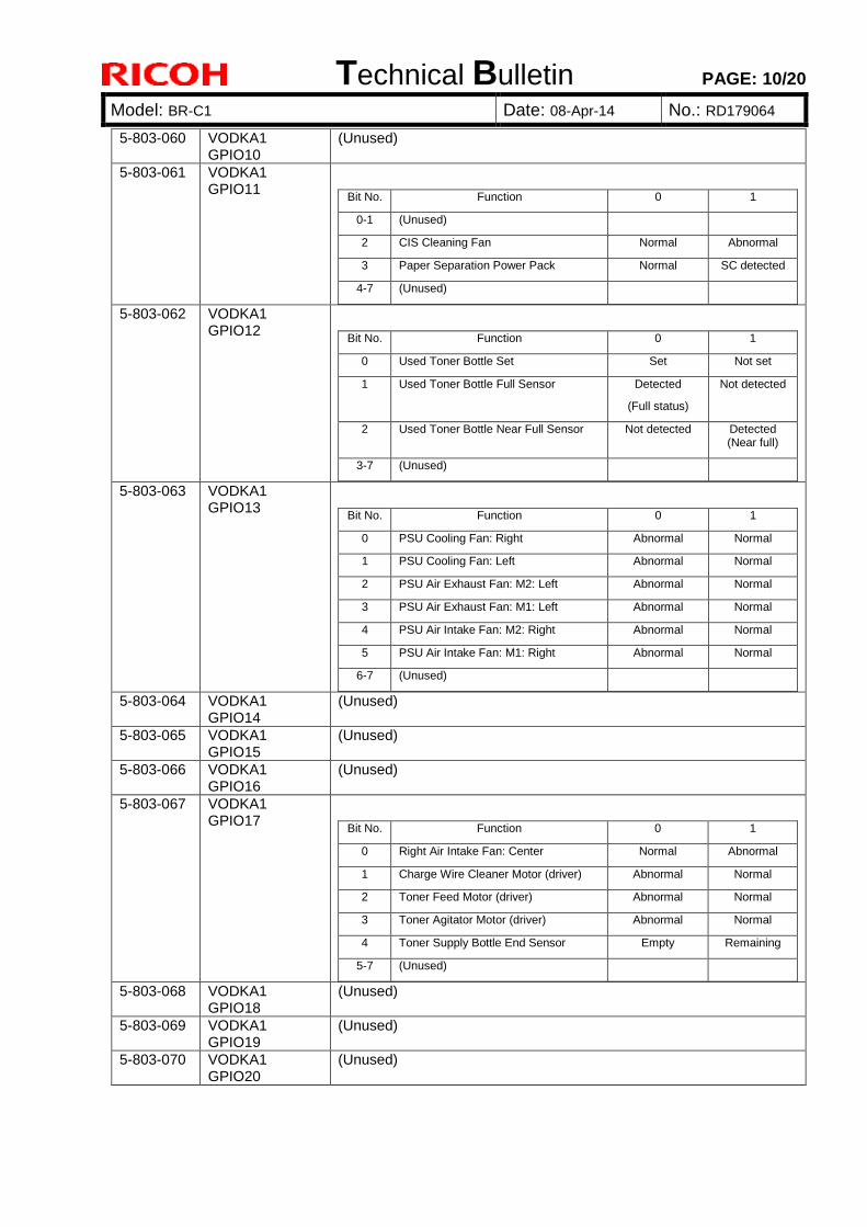
Technical Bulletin PAGE: 10/20
Model: BR-C1 Date: 08-Apr-14 No.: RD179064
5-803-060 VODKA1 GPIO10
(Unused)
5-803-061 VODKA1 GPIO11
Bit No. Function 0 1
0-1 (Unused)
2 CIS Cleaning Fan Normal Abnormal
3 Paper Separation Power Pack Normal SC detected
4-7 (Unused)
5-803-062 VODKA1 GPIO12
Bit No. Function 0 1
0 Used Toner Bottle Set Set Not set
1 Used Toner Bottle Full Sensor Detected
(Full status)
Not detected
2 Used Toner Bottle Near Full Sensor Not detected Detected (Near full)
3-7 (Unused)
5-803-063 VODKA1 GPIO13
Bit No. Function 0 1
0 PSU Cooling Fan: Right Abnormal Normal
1 PSU Cooling Fan: Left Abnormal Normal
2 PSU Air Exhaust Fan: M2: Left Abnormal Normal
3 PSU Air Exhaust Fan: M1: Left Abnormal Normal
4 PSU Air Intake Fan: M2: Right Abnormal Normal
5 PSU Air Intake Fan: M1: Right Abnormal Normal
6-7 (Unused)
5-803-064 VODKA1 GPIO14
(Unused)
5-803-065 VODKA1 GPIO15
(Unused)
5-803-066 VODKA1 GPIO16
(Unused)
5-803-067 VODKA1 GPIO17
Bit No. Function 0 1
0 Right Air Intake Fan: Center Normal Abnormal
1 Charge Wire Cleaner Motor (driver) Abnormal Normal
2 Toner Feed Motor (driver) Abnormal Normal
3 Toner Agitator Motor (driver) Abnormal Normal
4 Toner Supply Bottle End Sensor Empty Remaining
5-7 (Unused)
5-803-068 VODKA1 GPIO18
(Unused)
5-803-069 VODKA1 GPIO19
(Unused)
5-803-070 VODKA1 GPIO20
(Unused)
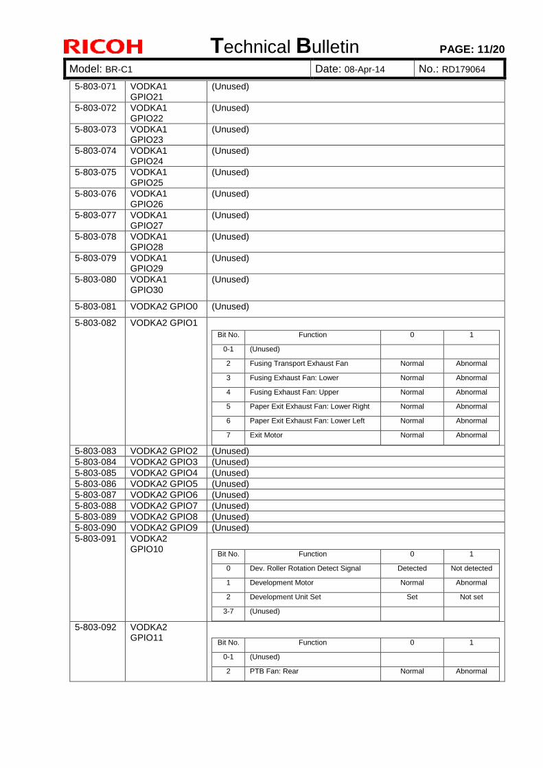
Technical Bulletin PAGE: 11/20
Model: BR-C1 Date: 08-Apr-14 No.: RD179064
5-803-071 VODKA1 GPIO21
(Unused)
5-803-072 VODKA1 GPIO22
(Unused)
5-803-073 VODKA1 GPIO23
(Unused)
5-803-074 VODKA1 GPIO24
(Unused)
5-803-075 VODKA1 GPIO25
(Unused)
5-803-076 VODKA1 GPIO26
(Unused)
5-803-077 VODKA1 GPIO27
(Unused)
5-803-078 VODKA1 GPIO28
(Unused)
5-803-079 VODKA1 GPIO29
(Unused)
5-803-080 VODKA1 GPIO30
(Unused)
5-803-081 VODKA2 GPIO0 (Unused)
5-803-082 VODKA2 GPIO1 Bit No. Function 0 1
0-1 (Unused)
2 Fusing Transport Exhaust Fan Normal Abnormal
3 Fusing Exhaust Fan: Lower Normal Abnormal
4 Fusing Exhaust Fan: Upper Normal Abnormal
5 Paper Exit Exhaust Fan: Lower Right Normal Abnormal
6 Paper Exit Exhaust Fan: Lower Left Normal Abnormal
7 Exit Motor Normal Abnormal
5-803-083 VODKA2 GPIO2 (Unused) 5-803-084 VODKA2 GPIO3 (Unused) 5-803-085 VODKA2 GPIO4 (Unused) 5-803-086 VODKA2 GPIO5 (Unused) 5-803-087 VODKA2 GPIO6 (Unused) 5-803-088 VODKA2 GPIO7 (Unused) 5-803-089 VODKA2 GPIO8 (Unused) 5-803-090 VODKA2 GPIO9 (Unused) 5-803-091 VODKA2
GPIO10
Bit No. Function 0 1
0 Dev. Roller Rotation Detect Signal Detected Not detected
1 Development Motor Normal Abnormal
2 Development Unit Set Set Not set
3-7 (Unused)
5-803-092 VODKA2 GPIO11
Bit No. Function 0 1
0-1 (Unused)
2 PTB Fan: Rear Normal Abnormal
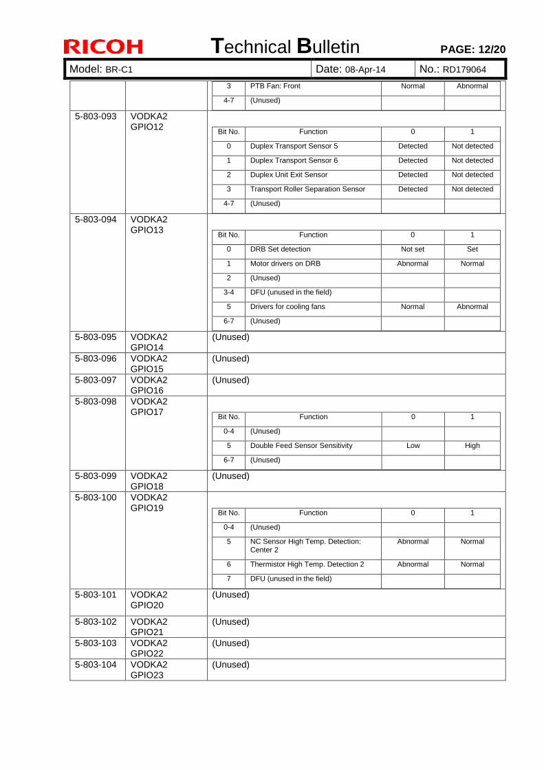
Technical Bulletin PAGE: 12/20
Model: BR-C1 Date: 08-Apr-14 No.: RD179064
3 PTB Fan: Front Normal Abnormal
4-7 (Unused)
5-803-093 VODKA2 GPIO12
Bit No. Function 0 1
0 Duplex Transport Sensor 5 Detected Not detected
1 Duplex Transport Sensor 6 Detected Not detected
2 Duplex Unit Exit Sensor Detected Not detected
3 Transport Roller Separation Sensor Detected Not detected
4-7 (Unused)
5-803-094 VODKA2 GPIO13
Bit No. Function 0 1
0 DRB Set detection Not set Set
1 Motor drivers on DRB Abnormal Normal
2 (Unused)
3-4 DFU (unused in the field)
5 Drivers for cooling fans Normal Abnormal
6-7 (Unused)
5-803-095 VODKA2 GPIO14
(Unused)
5-803-096 VODKA2 GPIO15
(Unused)
5-803-097 VODKA2 GPIO16
(Unused)
5-803-098 VODKA2 GPIO17
Bit No. Function 0 1
0-4 (Unused)
5 Double Feed Sensor Sensitivity Low High
6-7 (Unused)
5-803-099 VODKA2 GPIO18
(Unused)
5-803-100 VODKA2 GPIO19
Bit No. Function 0 1
0-4 (Unused)
5 NC Sensor High Temp. Detection: Center 2
Abnormal Normal
6 Thermistor High Temp. Detection 2 Abnormal Normal
7 DFU (unused in the field)
5-803-101 VODKA2 GPIO20
(Unused)
5-803-102 VODKA2 GPIO21
(Unused)
5-803-103 VODKA2 GPIO22
(Unused)
5-803-104 VODKA2 GPIO23
(Unused)
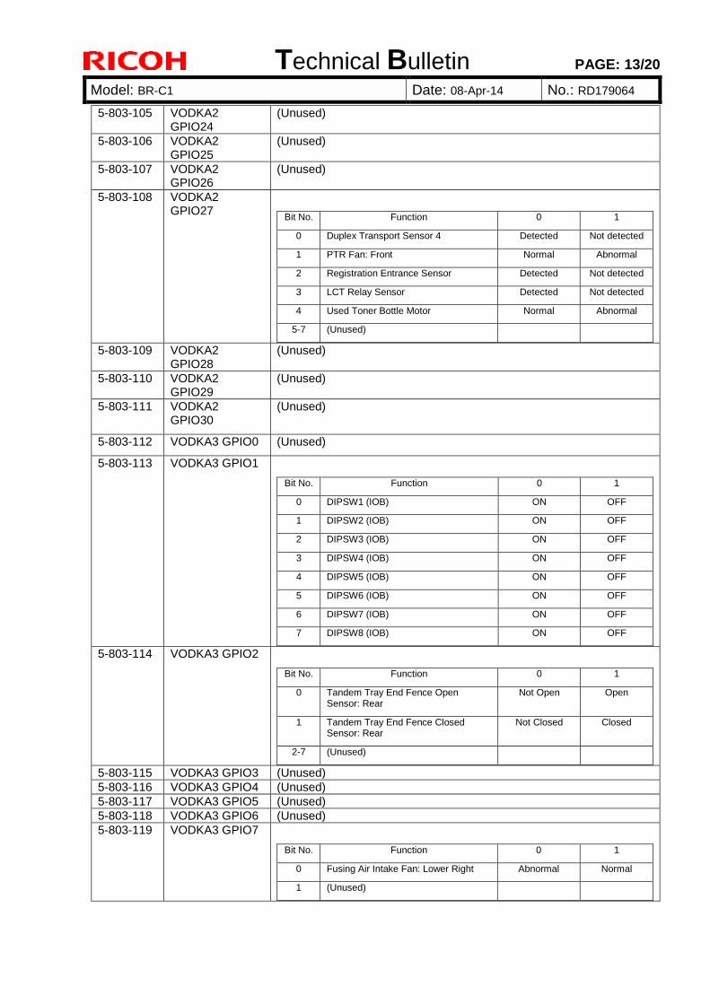
Technical Bulletin PAGE: 13/20
Model: BR-C1 Date: 08-Apr-14 No.: RD179064
5-803-105 VODKA2 GPIO24
(Unused)
5-803-106 VODKA2 GPIO25
(Unused)
5-803-107 VODKA2 GPIO26
(Unused)
5-803-108 VODKA2 GPIO27
Bit No. Function 0 1
0 Duplex Transport Sensor 4 Detected Not detected
1 PTR Fan: Front Normal Abnormal
2 Registration Entrance Sensor Detected Not detected
3 LCT Relay Sensor Detected Not detected
4 Used Toner Bottle Motor Normal Abnormal
5-7 (Unused)
5-803-109 VODKA2 GPIO28
(Unused)
5-803-110 VODKA2 GPIO29
(Unused)
5-803-111 VODKA2 GPIO30
(Unused)
5-803-112 VODKA3 GPIO0 (Unused)
5-803-113 VODKA3 GPIO1
Bit No. Function 0 1
0 DIPSW1 (IOB) ON OFF
1 DIPSW2 (IOB) ON OFF
2 DIPSW3 (IOB) ON OFF
3 DIPSW4 (IOB) ON OFF
4 DIPSW5 (IOB) ON OFF
5 DIPSW6 (IOB) ON OFF
6 DIPSW7 (IOB) ON OFF
7 DIPSW8 (IOB) ON OFF
5-803-114 VODKA3 GPIO2
Bit No. Function 0 1
0 Tandem Tray End Fence Open Sensor: Rear
Not Open Open
1 Tandem Tray End Fence Closed Sensor: Rear
Not Closed Closed
2-7 (Unused)
5-803-115 VODKA3 GPIO3 (Unused) 5-803-116 VODKA3 GPIO4 (Unused) 5-803-117 VODKA3 GPIO5 (Unused) 5-803-118 VODKA3 GPIO6 (Unused) 5-803-119 VODKA3 GPIO7
Bit No. Function 0 1
0 Fusing Air Intake Fan: Lower Right Abnormal Normal
1 (Unused)
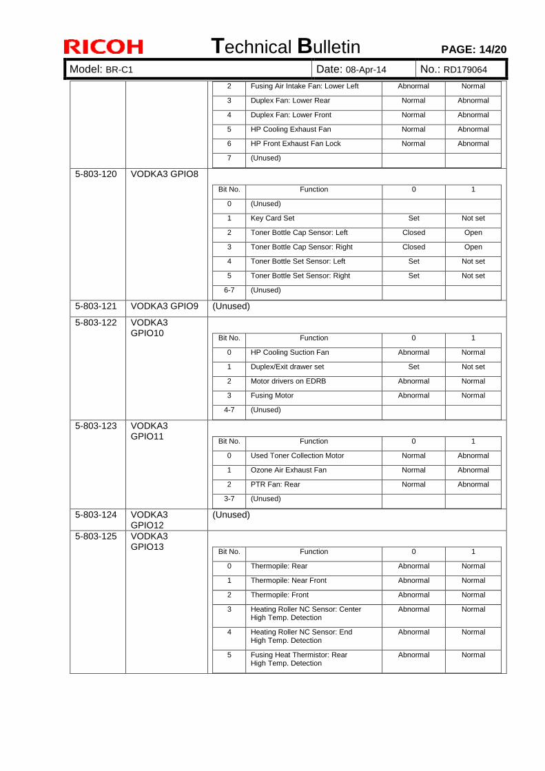
Technical Bulletin PAGE: 14/20
Model: BR-C1 Date: 08-Apr-14 No.: RD179064
2 Fusing Air Intake Fan: Lower Left Abnormal Normal
3 Duplex Fan: Lower Rear Normal Abnormal
4 Duplex Fan: Lower Front Normal Abnormal
5 HP Cooling Exhaust Fan Normal Abnormal
6 HP Front Exhaust Fan Lock Normal Abnormal
7 (Unused)
5-803-120 VODKA3 GPIO8
Bit No. Function 0 1
0 (Unused)
1 Key Card Set Set Not set
2 Toner Bottle Cap Sensor: Left Closed Open
3 Toner Bottle Cap Sensor: Right Closed Open
4 Toner Bottle Set Sensor: Left Set Not set
5 Toner Bottle Set Sensor: Right Set Not set
6-7 (Unused)
5-803-121 VODKA3 GPIO9 (Unused)
5-803-122 VODKA3 GPIO10
Bit No. Function 0 1
0 HP Cooling Suction Fan Abnormal Normal
1 Duplex/Exit drawer set Set Not set
2 Motor drivers on EDRB Abnormal Normal
3 Fusing Motor Abnormal Normal
4-7 (Unused)
5-803-123 VODKA3 GPIO11
Bit No. Function 0 1
0 Used Toner Collection Motor Normal Abnormal
1 Ozone Air Exhaust Fan Normal Abnormal
2 PTR Fan: Rear Normal Abnormal
3-7 (Unused)
5-803-124 VODKA3 GPIO12
(Unused)
5-803-125 VODKA3 GPIO13
Bit No. Function 0 1
0 Thermopile: Rear Abnormal Normal
1 Thermopile: Near Front Abnormal Normal
2 Thermopile: Front Abnormal Normal
3 Heating Roller NC Sensor: Center High Temp. Detection
Abnormal Normal
4 Heating Roller NC Sensor: End High Temp. Detection
Abnormal Normal
5 Fusing Heat Thermistor: Rear High Temp. Detection
Abnormal Normal
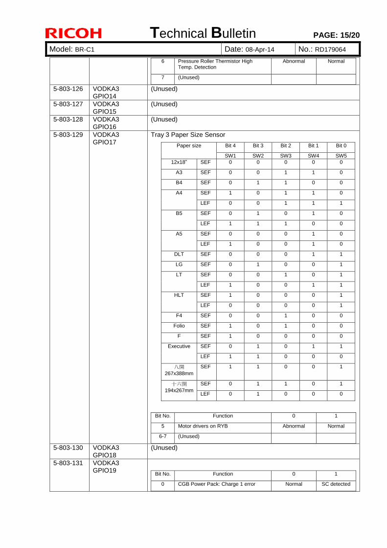
Technical Bulletin PAGE: 15/20
Model: BR-C1 Date: 08-Apr-14 No.: RD179064
6 Pressure Roller Thermistor High Temp. Detection
Abnormal Normal
7 (Unused)
5-803-126 VODKA3 GPIO14
(Unused)
5-803-127 VODKA3 GPIO15
(Unused)
5-803-128 VODKA3 GPIO16
(Unused)
5-803-129 VODKA3 GPIO17
Tray 3 Paper Size Sensor
Paper size Bit 4 Bit 3 Bit 2 Bit 1 Bit 0
SW1 SW2 SW3 SW4 SW5
12x18” SEF 0 0 0 0 0
A3 SEF 0 0 1 1 0
B4 SEF 0 1 1 0 0
A4 SEF 1 0 1 1 0
LEF 0 0 1 1 1
B5 SEF 0 1 0 1 0
LEF 1 1 1 0 0
A5 SEF 0 0 0 1 0
LEF 1 0 0 1 0
DLT SEF 0 0 0 1 1
LG SEF 0 1 0 0 1
LT SEF 0 0 1 0 1
LEF 1 0 0 1 1
HLT SEF 1 0 0 0 1
LEF 0 0 0 0 1
F4 SEF 0 0 1 0 0
Folio SEF 1 0 1 0 0
F SEF 1 0 0 0 0
Executive SEF 0 1 0 1 1
LEF 1 1 0 0 0
八開
267x388mm
SEF 1 1 0 0 1
十六開
194x267mm
SEF 0 1 1 0 1
LEF 0 1 0 0 0
Bit No. Function 0 1
5 Motor drivers on RYB Abnormal Normal
6-7 (Unused)
5-803-130 VODKA3 GPIO18
(Unused)
5-803-131 VODKA3 GPIO19
Bit No. Function 0 1
0 CGB Power Pack: Charge 1 error Normal SC detected
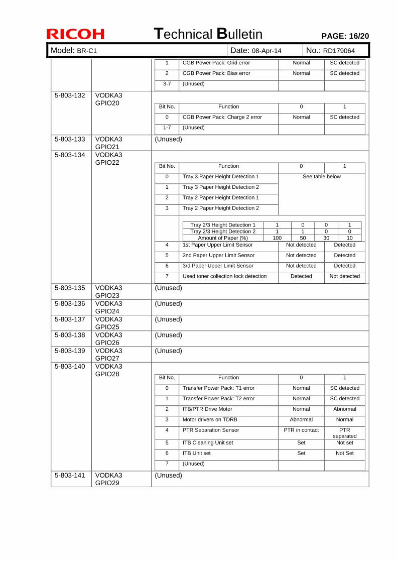
Technical Bulletin PAGE: 16/20
Model: BR-C1 Date: 08-Apr-14 No.: RD179064
1 CGB Power Pack: Grid error Normal SC detected
2 CGB Power Pack: Bias error Normal SC detected
3-7 (Unused)
5-803-132 VODKA3 GPIO20
Bit No. Function 0 1
0 CGB Power Pack: Charge 2 error Normal SC detected
1-7 (Unused)
5-803-133 VODKA3 GPIO21
(Unused)
5-803-134 VODKA3 GPIO22
Bit No. Function 0 1
0 Tray 3 Paper Height Detection 1 See table below
1 Tray 3 Paper Height Detection 2
2 Tray 2 Paper Height Detection 1
3 Tray 2 Paper Height Detection 2
Tray 2/3 Height Detection 1 1 0 0 1
Tray 2/3 Height Detection 2 1 1 0 0
Amount of Paper (%) 100 50 30 10
4 1st Paper Upper Limit Sensor Not detected Detected
5 2nd Paper Upper Limit Sensor Not detected Detected
6 3rd Paper Upper Limit Sensor Not detected Detected
7 Used toner collection lock detection Detected Not detected
5-803-135 VODKA3 GPIO23
(Unused)
5-803-136 VODKA3 GPIO24
(Unused)
5-803-137 VODKA3 GPIO25
(Unused)
5-803-138 VODKA3 GPIO26
(Unused)
5-803-139 VODKA3 GPIO27
(Unused)
5-803-140 VODKA3 GPIO28
Bit No. Function 0 1
0 Transfer Power Pack: T1 error Normal SC detected
1 Transfer Power Pack: T2 error Normal SC detected
2 ITB/PTR Drive Motor Normal Abnormal
3 Motor drivers on TDRB Abnormal Normal
4 PTR Separation Sensor PTR in contact PTR separated
5 ITB Cleaning Unit set Set Not set
6 ITB Unit set Set Not Set
7 (Unused)
5-803-141 VODKA3 GPIO29
(Unused)
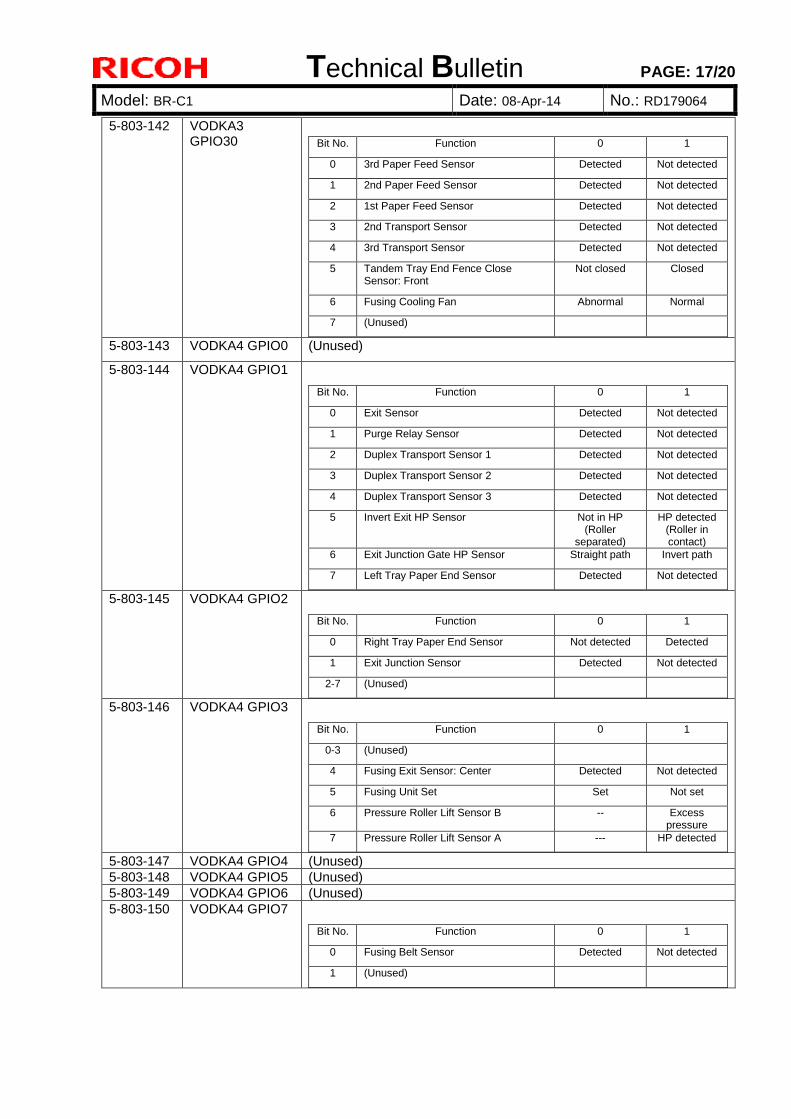
Technical Bulletin PAGE: 17/20
Model: BR-C1 Date: 08-Apr-14 No.: RD179064
5-803-142 VODKA3 GPIO30
Bit No. Function 0 1
0 3rd Paper Feed Sensor Detected Not detected
1 2nd Paper Feed Sensor Detected Not detected
2 1st Paper Feed Sensor Detected Not detected
3 2nd Transport Sensor Detected Not detected
4 3rd Transport Sensor Detected Not detected
5 Tandem Tray End Fence Close Sensor: Front
Not closed Closed
6 Fusing Cooling Fan Abnormal Normal
7 (Unused)
5-803-143 VODKA4 GPIO0 (Unused)
5-803-144 VODKA4 GPIO1
Bit No. Function 0 1
0 Exit Sensor Detected Not detected
1 Purge Relay Sensor Detected Not detected
2 Duplex Transport Sensor 1 Detected Not detected
3 Duplex Transport Sensor 2 Detected Not detected
4 Duplex Transport Sensor 3 Detected Not detected
5 Invert Exit HP Sensor Not in HP (Roller
separated)
HP detected (Roller in contact)
6 Exit Junction Gate HP Sensor Straight path Invert path
7 Left Tray Paper End Sensor Detected Not detected
5-803-145 VODKA4 GPIO2
Bit No. Function 0 1
0 Right Tray Paper End Sensor Not detected Detected
1 Exit Junction Sensor Detected Not detected
2-7 (Unused)
5-803-146 VODKA4 GPIO3
Bit No. Function 0 1
0-3 (Unused)
4 Fusing Exit Sensor: Center Detected Not detected
5 Fusing Unit Set Set Not set
6 Pressure Roller Lift Sensor B -- Excess pressure
7 Pressure Roller Lift Sensor A --- HP detected
5-803-147 VODKA4 GPIO4 (Unused) 5-803-148 VODKA4 GPIO5 (Unused) 5-803-149 VODKA4 GPIO6 (Unused) 5-803-150 VODKA4 GPIO7
Bit No. Function 0 1
0 Fusing Belt Sensor Detected Not detected
1 (Unused)
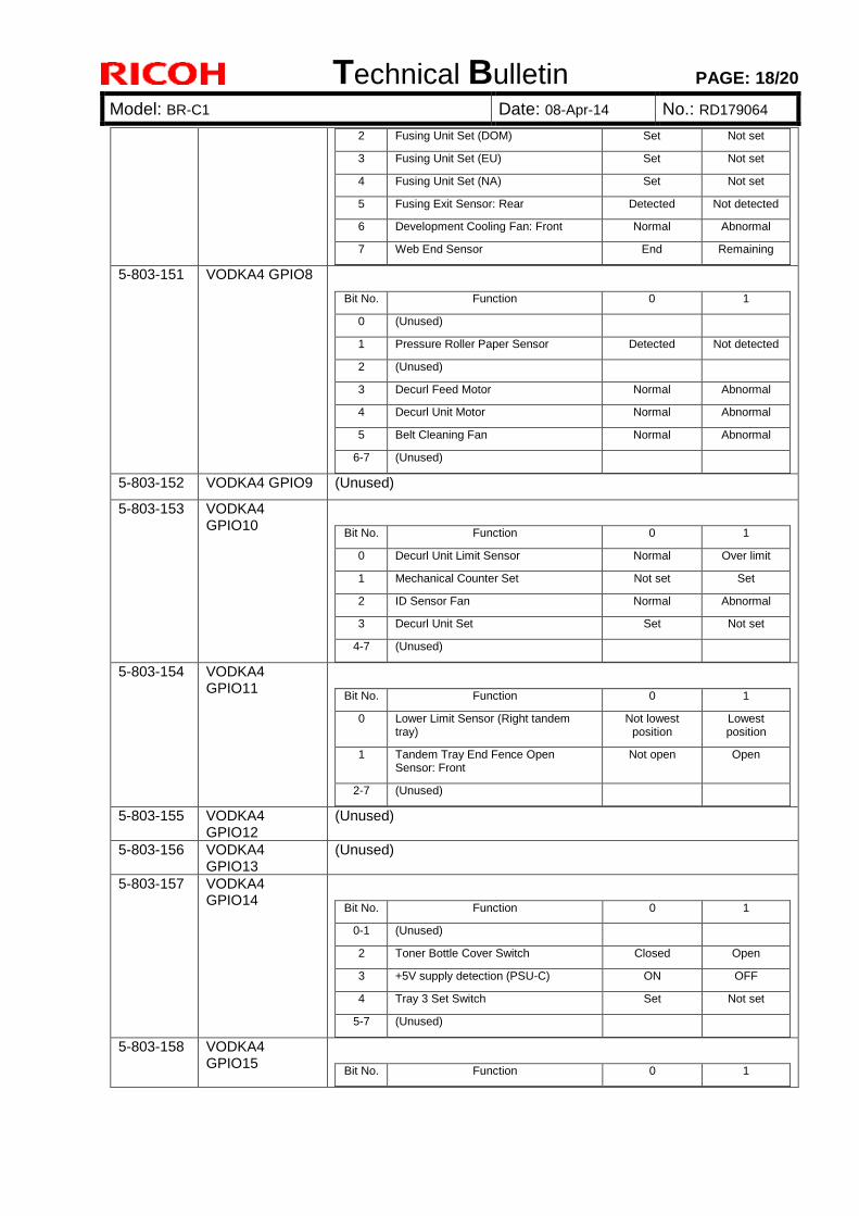
Technical Bulletin PAGE: 18/20
Model: BR-C1 Date: 08-Apr-14 No.: RD179064
2 Fusing Unit Set (DOM) Set Not set
3 Fusing Unit Set (EU) Set Not set
4 Fusing Unit Set (NA) Set Not set
5 Fusing Exit Sensor: Rear Detected Not detected
6 Development Cooling Fan: Front Normal Abnormal
7 Web End Sensor End Remaining
5-803-151 VODKA4 GPIO8
Bit No. Function 0 1
0 (Unused)
1 Pressure Roller Paper Sensor Detected Not detected
2 (Unused)
3 Decurl Feed Motor Normal Abnormal
4 Decurl Unit Motor Normal Abnormal
5 Belt Cleaning Fan Normal Abnormal
6-7 (Unused)
5-803-152 VODKA4 GPIO9 (Unused)
5-803-153 VODKA4 GPIO10
Bit No. Function 0 1
0 Decurl Unit Limit Sensor Normal Over limit
1 Mechanical Counter Set Not set Set
2 ID Sensor Fan Normal Abnormal
3 Decurl Unit Set Set Not set
4-7 (Unused)
5-803-154 VODKA4 GPIO11
Bit No. Function 0 1
0 Lower Limit Sensor (Right tandem tray)
Not lowest position
Lowest position
1 Tandem Tray End Fence Open Sensor: Front
Not open Open
2-7 (Unused)
5-803-155 VODKA4 GPIO12
(Unused)
5-803-156 VODKA4 GPIO13
(Unused)
5-803-157 VODKA4 GPIO14
Bit No. Function 0 1
0-1 (Unused)
2 Toner Bottle Cover Switch Closed Open
3 +5V supply detection (PSU-C) ON OFF
4 Tray 3 Set Switch Set Not set
5-7 (Unused)
5-803-158 VODKA4 GPIO15
Bit No. Function 0 1
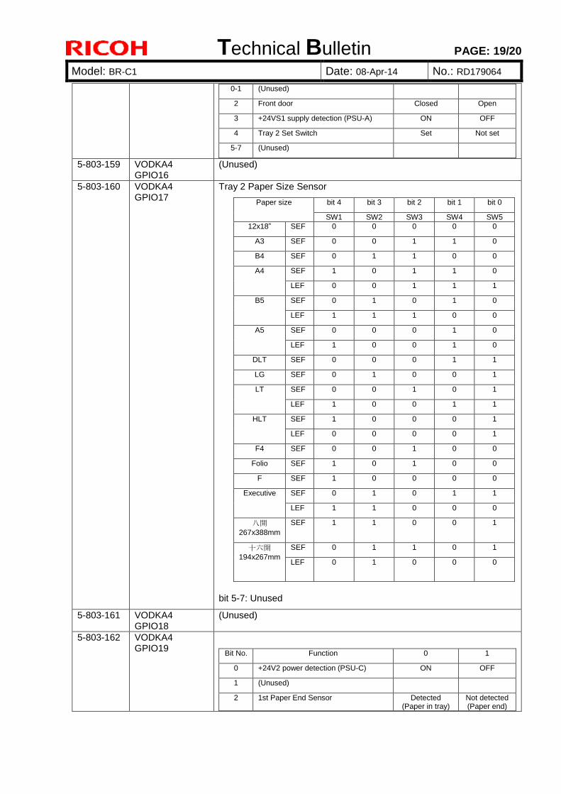
Technical Bulletin PAGE: 19/20
Model: BR-C1 Date: 08-Apr-14 No.: RD179064
0-1 (Unused)
2 Front door Closed Open
3 +24VS1 supply detection (PSU-A) ON OFF
4 Tray 2 Set Switch Set Not set
5-7 (Unused)
5-803-159 VODKA4 GPIO16
(Unused)
5-803-160 VODKA4 GPIO17
Tray 2 Paper Size Sensor
Paper size bit 4 bit 3 bit 2 bit 1 bit 0
SW1 SW2 SW3 SW4 SW5
12x18” SEF 0 0 0 0 0
A3 SEF 0 0 1 1 0
B4 SEF 0 1 1 0 0
A4 SEF 1 0 1 1 0
LEF 0 0 1 1 1
B5 SEF 0 1 0 1 0
LEF 1 1 1 0 0
A5 SEF 0 0 0 1 0
LEF 1 0 0 1 0
DLT SEF 0 0 0 1 1
LG SEF 0 1 0 0 1
LT SEF 0 0 1 0 1
LEF 1 0 0 1 1
HLT SEF 1 0 0 0 1
LEF 0 0 0 0 1
F4 SEF 0 0 1 0 0
Folio SEF 1 0 1 0 0
F SEF 1 0 0 0 0
Executive SEF 0 1 0 1 1
LEF 1 1 0 0 0
八開
267x388mm
SEF 1 1 0 0 1
十六開
194x267mm
SEF 0 1 1 0 1
LEF 0 1 0 0 0
bit 5-7: Unused
5-803-161 VODKA4 GPIO18
(Unused)
5-803-162 VODKA4 GPIO19
Bit No. Function 0 1
0 +24V2 power detection (PSU-C) ON OFF
1 (Unused)
2 1st Paper End Sensor Detected (Paper in tray)
Not detected (Paper end)
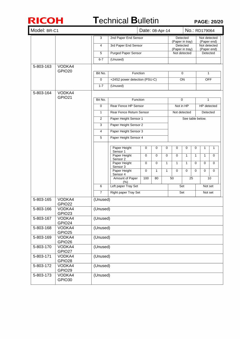
Technical Bulletin PAGE: 20/20
Model: BR-C1 Date: 08-Apr-14 No.: RD179064
3 2nd Paper End Sensor Detected (Paper in tray)
Not detected (Paper end)
4 3rd Paper End Sensor Detected (Paper in tray)
Not detected (Paper end)
5 Purged Paper Sensor Not detected Detected
6-7 (Unused)
5-803-163 VODKA4 GPIO20
Bit No. Function 0 1
0 +24S2 power detection (PSU-C) ON OFF
1-7 (Unused)
5-803-164 VODKA4 GPIO21
Bit No. Function 0 1
0 Rear Fence HP Sensor Not in HP HP detected
1 Rear Fence Return Sensor Not detected Detected
2 Paper Height Sensor 1 See table below.
3 Paper Height Sensor 2
4 Paper Height Sensor 3
5 Paper Height Sensor 4
Paper Height Sensor 1
0 0 0 0 0 0 1 1
Paper Height Sensor 2
0 0 0 0 1 1 1 0
Paper Height Sensor 3
0 0 1 1 1 0 0 0
Paper Height Sensor 4
0 1 1 0 0 0 0 0
Amount of Paper (%)
100 80 50 25 10
6 Left paper Tray Set Set Not set
7 Right paper Tray Set Set Not set
5-803-165 VODKA4 GPIO22
(Unused)
5-803-166 VODKA4 GPIO23
(Unused)
5-803-167 VODKA4 GPIO24
(Unused)
5-803-168 VODKA4 GPIO25
(Unused)
5-803-169 VODKA4 GPIO26
(Unused)
5-803-170 VODKA4 GPIO27
(Unused)
5-803-171 VODKA4 GPIO28
(Unused)
5-803-172 VODKA4 GPIO29
(Unused)
5-803-173 VODKA4 GPIO30
(Unused)
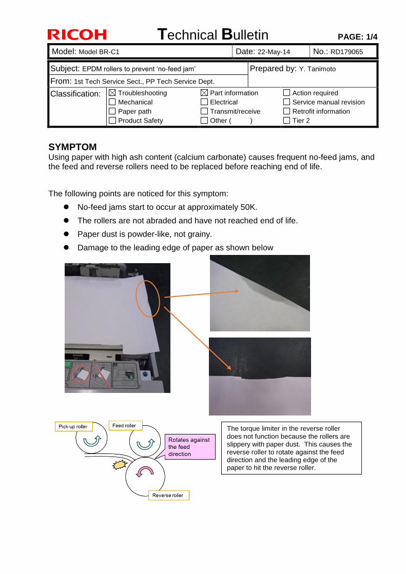
Technical Bulletin PAGE: 1/4
Model: Model BR-C1 Date: 22-May-14 No.: RD179065
Subject: EPDM rollers to prevent ‘no-feed jam’ Prepared by: Y. Tanimoto
From: 1st Tech Service Sect., PP Tech Service Dept.
Classification: Troubleshooting
Mechanical
Paper path
Product Safety
Part information
Electrical
Transmit/receive
Other ( )
Action required
Service manual revision
Retrofit information
Tier 2
SYMPTOM Using paper with high ash content (calcium carbonate) causes frequent no-feed jams, and the feed and reverse rollers need to be replaced before reaching end of life.
The following points are noticed for this symptom:
No-feed jams start to occur at approximately 50K.
The rollers are not abraded and have not reached end of life.
Paper dust is powder-like, not grainy.
Damage to the leading edge of paper as shown below
The torque limiter in the reverse roller does not function because the rollers are slippery with paper dust. This causes the reverse roller to rotate against the feed direction and the leading edge of the paper to hit the reverse roller.
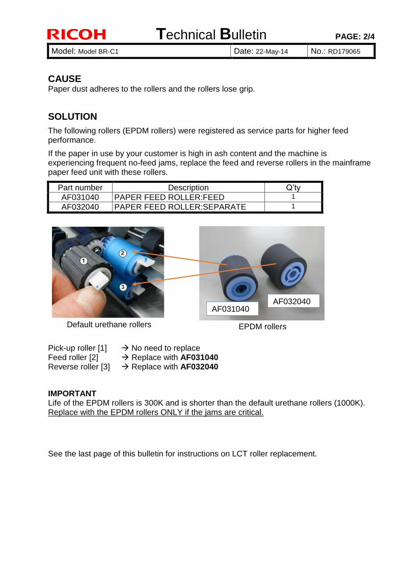
Technical Bulletin PAGE: 2/4
Model: Model BR-C1 Date: 22-May-14 No.: RD179065
CAUSE Paper dust adheres to the rollers and the rollers lose grip.
SOLUTION
The following rollers (EPDM rollers) were registered as service parts for higher feed performance.
If the paper in use by your customer is high in ash content and the machine is experiencing frequent no-feed jams, replace the feed and reverse rollers in the mainframe paper feed unit with these rollers.
Part number Description Q’ty
AF031040 PAPER FEED ROLLER:FEED 1
AF032040 PAPER FEED ROLLER:SEPARATE 1
Pick-up roller [1] No need to replace Feed roller [2] Replace with AF031040 Reverse roller [3] Replace with AF032040
IMPORTANT Life of the EPDM rollers is 300K and is shorter than the default urethane rollers (1000K). Replace with the EPDM rollers ONLY if the jams are critical.
See the last page of this bulletin for instructions on LCT roller replacement.
AF031040 AF032040
Default urethane rollers EPDM rollers
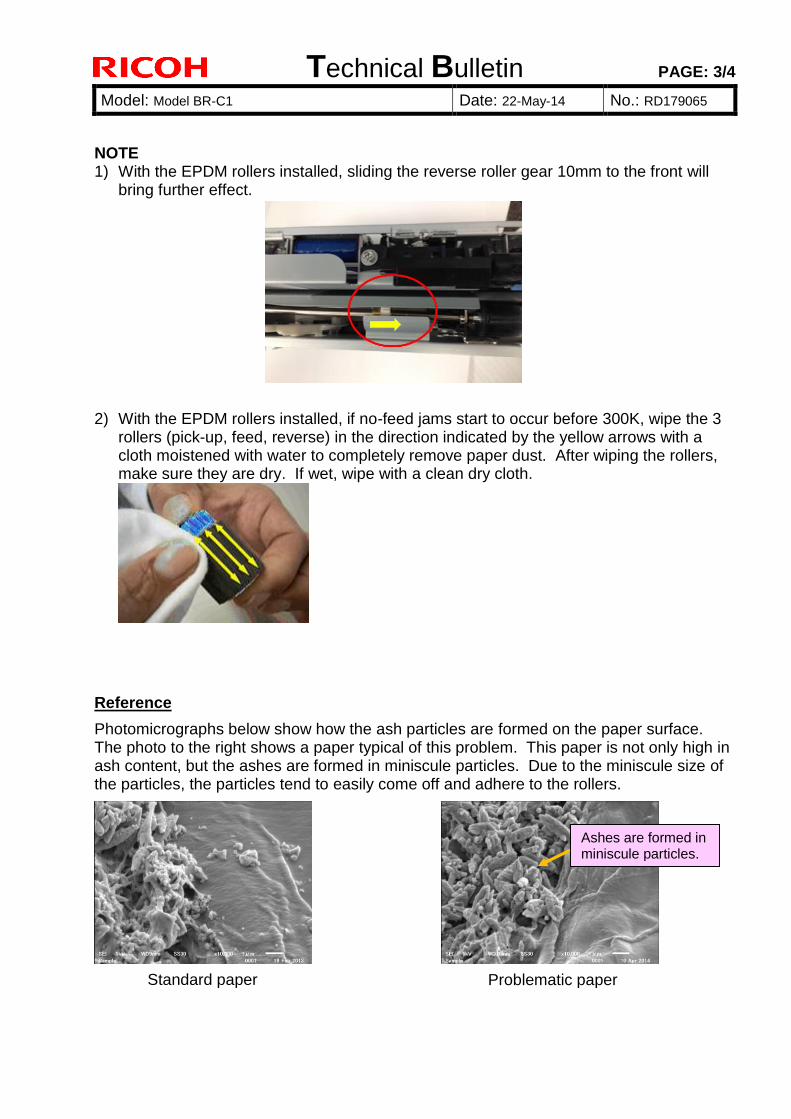
Technical Bulletin PAGE: 3/4
Model: Model BR-C1 Date: 22-May-14 No.: RD179065
NOTE 1) With the EPDM rollers installed, sliding the reverse roller gear 10mm to the front will
bring further effect.
2) With the EPDM rollers installed, if no-feed jams start to occur before 300K, wipe the 3 rollers (pick-up, feed, reverse) in the direction indicated by the yellow arrows with a cloth moistened with water to completely remove paper dust. After wiping the rollers, make sure they are dry. If wet, wipe with a clean dry cloth.
Reference
Photomicrographs below show how the ash particles are formed on the paper surface. The photo to the right shows a paper typical of this problem. This paper is not only high in ash content, but the ashes are formed in miniscule particles. Due to the miniscule size of the particles, the particles tend to easily come off and adhere to the rollers.
Ashes are formed in miniscule particles.
Standard paper Problematic paper
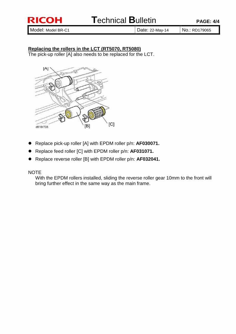
Technical Bulletin PAGE: 4/4
Model: Model BR-C1 Date: 22-May-14 No.: RD179065
Replacing the rollers in the LCT (RT5070, RT5080) The pick-up roller [A] also needs to be replaced for the LCT.
Replace pick-up roller [A] with EPDM roller p/n: AF030071.
Replace feed roller [C] with EPDM roller p/n: AF031071.
Replace reverse roller [B] with EPDM roller p/n: AF032041.
NOTE
With the EPDM rollers installed, sliding the reverse roller gear 10mm to the front will bring further effect in the same way as the main frame.
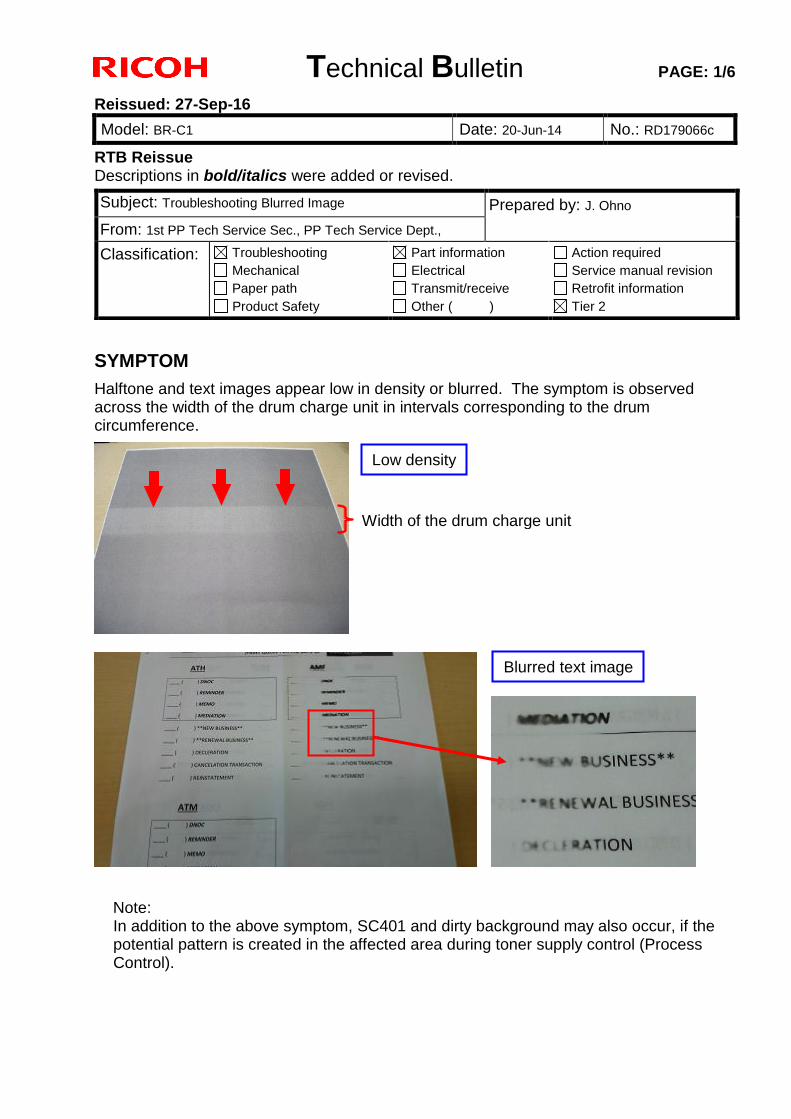
Technical Bulletin PAGE: 1/6
Reissued: 27-Sep-16
Model: BR-C1 Date: 20-Jun-14 No.: RD179066c
RTB Reissue Descriptions in bold/italics were added or revised.
SYMPTOM
Halftone and text images appear low in density or blurred. The symptom is observed across the width of the drum charge unit in intervals corresponding to the drum circumference.
Note: In addition to the above symptom, SC401 and dirty background may also occur, if the potential pattern is created in the affected area during toner supply control (Process Control).
Subject: Troubleshooting Blurred Image Prepared by: J. Ohno
From: 1st PP Tech Service Sec., PP Tech Service Dept.,
Classification: Troubleshooting Mechanical Paper path Product Safety
Part information Electrical Transmit/receive Other ( )
Action required Service manual revision Retrofit information Tier 2
Width of the drum charge unit
Low density
Blurred text image
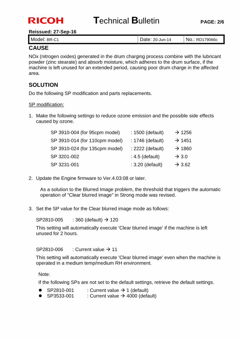
Technical Bulletin PAGE: 2/6
Reissued: 27-Sep-16
Model: BR-C1 Date: 20-Jun-14 No.: RD179066c
CAUSE
NOx (nitrogen oxides) generated in the drum charging process combine with the lubricant powder (zinc stearate) and absorb moisture, which adheres to the drum surface, if the machine is left unused for an extended period, causing poor drum charge in the affected area. SOLUTION
Do the following SP modification and parts replacements. SP modification: 1. Make the following settings to reduce ozone emission and the possible side effects
caused by ozone.
SP 3910-004 (for 95cpm model) : 1500 (default) 1256
SP 3910-014 (for 110cpm model) : 1746 (default) 1451
SP 3910-024 (for 135cpm model) : 2222 (default) 1860
SP 3201-002 : 4.5 (default) 3.0
SP 3231-001 : 3.20 (default) 3.62
2. Update the Engine firmware to Ver.4.03:08 or later.
As a solution to the Blurred Image problem, the threshold that triggers the automatic operation of "Clear blurred image" in Strong mode was revised.
3. Set the SP value for the Clear blurred image mode as follows:
SP2810-005 : 360 (default) 120
This setting will automatically execute 'Clear blurred image' if the machine is left unused for 2 hours.
SP2810-006 : Current value 11
This setting will automatically execute 'Clear blurred image' even when the machine is operated in a medium temp/medium RH environment. Note:
If the following SPs are not set to the default settings, retrieve the default settings.
SP2810-001 : Current value 1 (default) SP3533-001 : Current value 4000 (default)
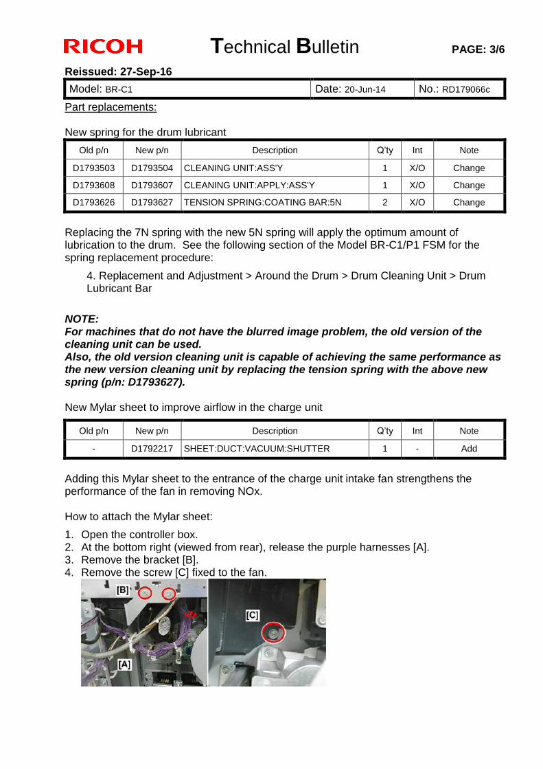
Technical Bulletin PAGE: 3/6
Reissued: 27-Sep-16
Model: BR-C1 Date: 20-Jun-14 No.: RD179066c
Part replacements: New spring for the drum lubricant
Old p/n New p/n Description Q’ty Int Note
D1793503 D1793504 CLEANING UNIT:ASS'Y 1 X/O Change
D1793608 D1793607 CLEANING UNIT:APPLY:ASS'Y 1 X/O Change
D1793626 D1793627 TENSION SPRING:COATING BAR:5N 2 X/O Change
Replacing the 7N spring with the new 5N spring will apply the optimum amount of lubrication to the drum. See the following section of the Model BR-C1/P1 FSM for the spring replacement procedure:
4. Replacement and Adjustment > Around the Drum > Drum Cleaning Unit > Drum Lubricant Bar
NOTE: For machines that do not have the blurred image problem, the old version of the cleaning unit can be used. Also, the old version cleaning unit is capable of achieving the same performance as the new version cleaning unit by replacing the tension spring with the above new spring (p/n: D1793627). New Mylar sheet to improve airflow in the charge unit
Old p/n New p/n Description Q’ty Int Note
- D1792217 SHEET:DUCT:VACUUM:SHUTTER 1 - Add
Adding this Mylar sheet to the entrance of the charge unit intake fan strengthens the performance of the fan in removing NOx. How to attach the Mylar sheet:
1. Open the controller box. 2. At the bottom right (viewed from rear), release the purple harnesses [A]. 3. Remove the bracket [B]. 4. Remove the screw [C] fixed to the fan.
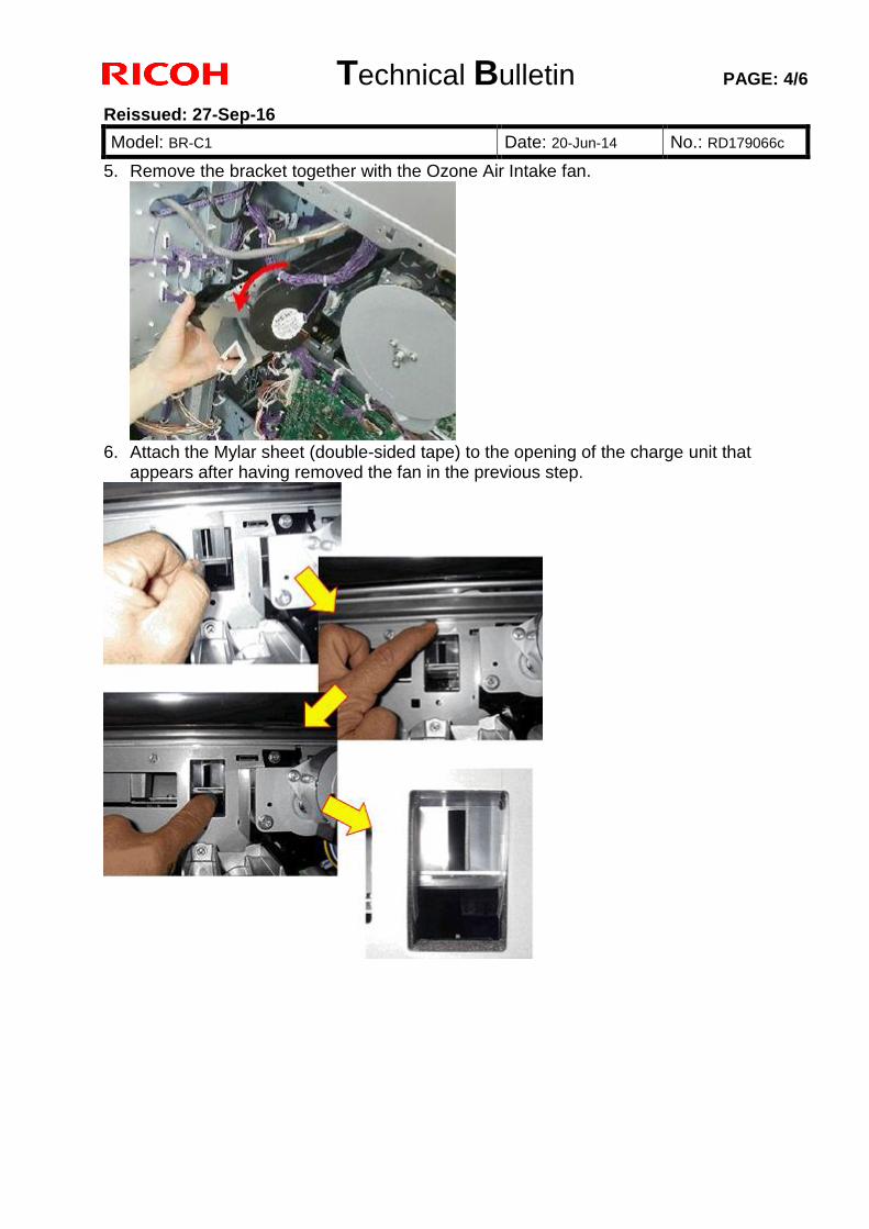
Technical Bulletin PAGE: 4/6
Reissued: 27-Sep-16
Model: BR-C1 Date: 20-Jun-14 No.: RD179066c
5. Remove the bracket together with the Ozone Air Intake fan.
6. Attach the Mylar sheet (double-sided tape) to the opening of the charge unit that
appears after having removed the fan in the previous step.
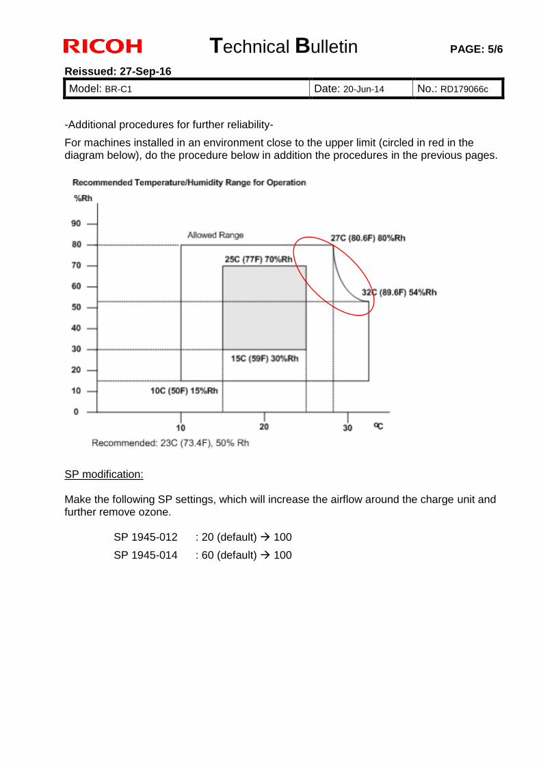
Technical Bulletin PAGE: 5/6
Reissued: 27-Sep-16
Model: BR-C1 Date: 20-Jun-14 No.: RD179066c
-Additional procedures for further reliability-
For machines installed in an environment close to the upper limit (circled in red in the diagram below), do the procedure below in addition the procedures in the previous pages.
SP modification: Make the following SP settings, which will increase the airflow around the charge unit and further remove ozone.
SP 1945-012 : 20 (default) 100
SP 1945-014 : 60 (default) 100
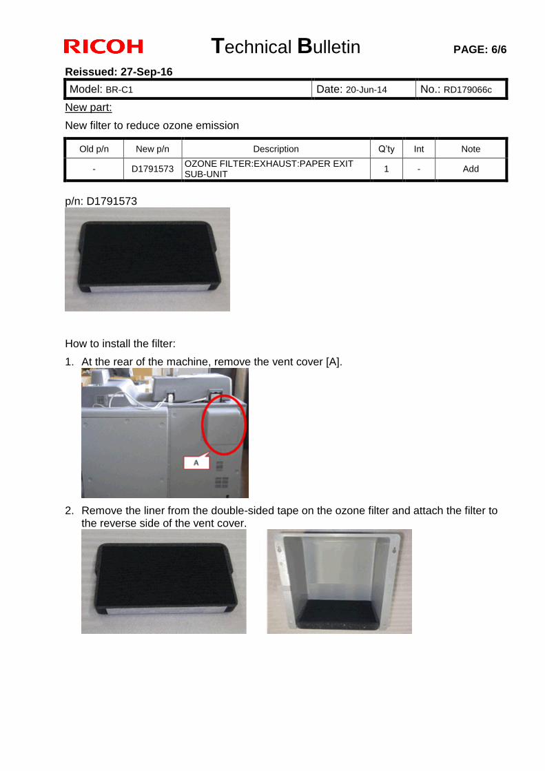
Technical Bulletin PAGE: 6/6
Reissued: 27-Sep-16
Model: BR-C1 Date: 20-Jun-14 No.: RD179066c
New part:
New filter to reduce ozone emission
Old p/n New p/n Description Q’ty Int Note
- D1791573 OZONE FILTER:EXHAUST:PAPER EXIT SUB-UNIT
1 - Add
p/n: D1791573
How to install the filter:
1. At the rear of the machine, remove the vent cover [A].
2. Remove the liner from the double-sided tape on the ozone filter and attach the filter to the reverse side of the vent cover.
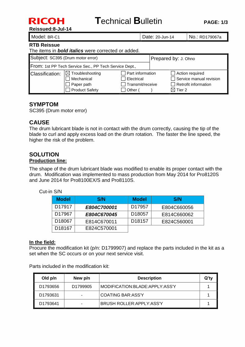
Technical Bulletin PAGE: 1/3
Reissued:8-Jul-14
Model: BR-C1 Date: 20-Jun-14 No.: RD179067a
RTB Reissue The items in bold italics were corrected or added.
Subject: SC395 (Drum motor error) Prepared by: J. Ohno
From: 1st PP Tech Service Sec., PP Tech Service Dept.,
Classification: Troubleshooting
Mechanical
Paper path
Product Safety
Part information
Electrical
Transmit/receive
Other ( )
Action required
Service manual revision
Retrofit information
Tier 2
SYMPTOM SC395 (Drum motor error)
CAUSE The drum lubricant blade is not in contact with the drum correctly, causing the tip of the blade to curl and apply excess load on the drum rotation. The faster the line speed, the higher the risk of the problem.
SOLUTION Production line:
The shape of the drum lubricant blade was modified to enable its proper contact with the drum. Modification was implemented to mass production from May 2014 for Pro8120S and June 2014 for Pro8100EX/S and Pro8110S.
Cut-in S/N
Model S/N Model S/N
D17917 E804C700001 D17957 E804C660056
D17967 E804C670045 D18057 E814C660062
D18067 E814C670011 D18157 E824C560001
D18167 E824C570001
In the field: Procure the modification kit (p/n: D1799907) and replace the parts included in the kit as a set when the SC occurs or on your next service visit.
Parts included in the modification kit:
Old p/n New p/n Description Q’ty
D1793656 D1799905 MODIFICATION:BLADE:APPLY:ASS'Y 1
D1793631 - COATING BAR:ASS'Y 1
D1793641 - BRUSH ROLLER:APPLY:ASS'Y 1
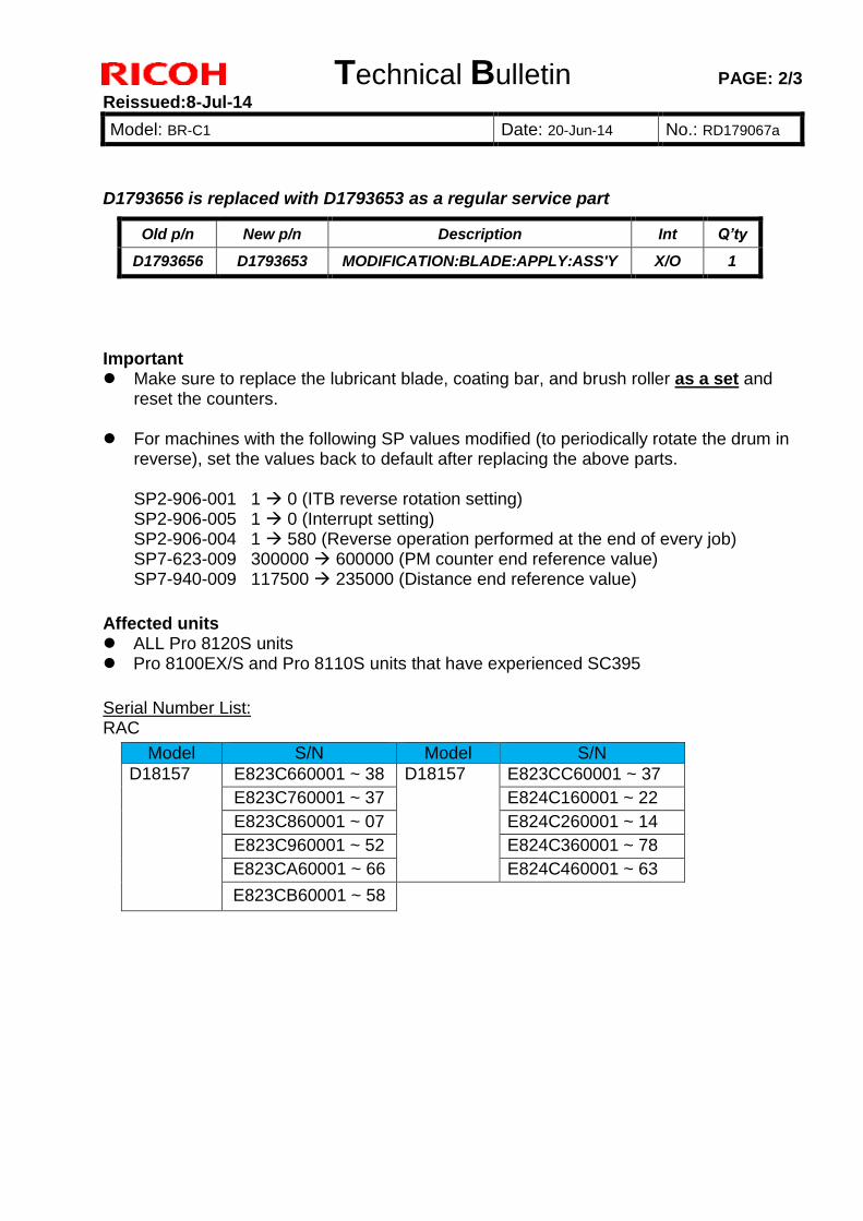
Technical Bulletin PAGE: 2/3
Reissued:8-Jul-14
Model: BR-C1 Date: 20-Jun-14 No.: RD179067a
D1793656 is replaced with D1793653 as a regular service part
Important Make sure to replace the lubricant blade, coating bar, and brush roller as a set and
reset the counters. For machines with the following SP values modified (to periodically rotate the drum in
reverse), set the values back to default after replacing the above parts.
SP2-906-001 1 0 (ITB reverse rotation setting) SP2-906-005 1 0 (Interrupt setting) SP2-906-004 1 580 (Reverse operation performed at the end of every job) SP7-623-009 300000 600000 (PM counter end reference value) SP7-940-009 117500 235000 (Distance end reference value)
Affected units ALL Pro 8120S units Pro 8100EX/S and Pro 8110S units that have experienced SC395
Serial Number List: RAC
Model S/N Model S/N
D18157 E823C660001 ~ 38 D18157 E823CC60001 ~ 37
E823C760001 ~ 37 E824C160001 ~ 22
E823C860001 ~ 07 E824C260001 ~ 14
E823C960001 ~ 52 E824C360001 ~ 78
E823CA60001 ~ 66 E824C460001 ~ 63
E823CB60001 ~ 58
Old p/n New p/n Description Int Q’ty
D1793656 D1793653 MODIFICATION:BLADE:APPLY:ASS'Y X/O 1
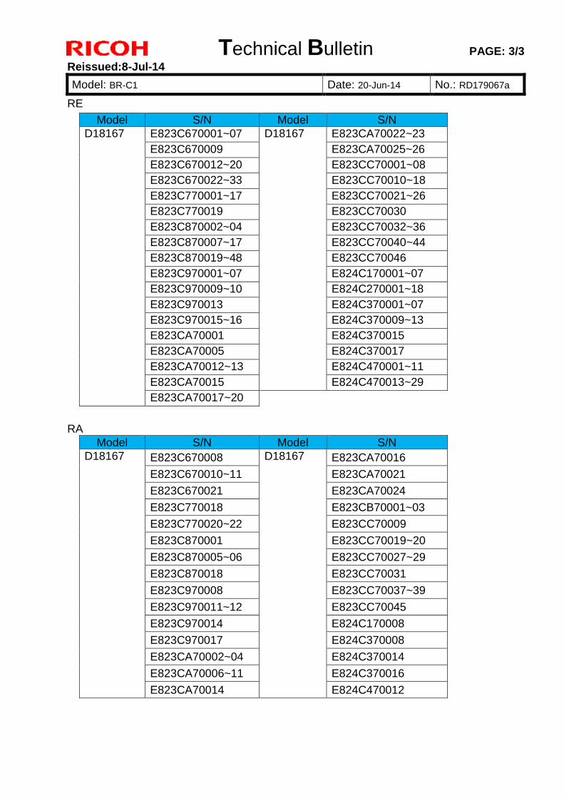
Technical Bulletin PAGE: 3/3
Reissued:8-Jul-14
Model: BR-C1 Date: 20-Jun-14 No.: RD179067a
RE
Model S/N Model S/N
D18167 E823C670001~07 D18167 E823CA70022~23
E823C670009 E823CA70025~26
E823C670012~20 E823CC70001~08
E823C670022~33 E823CC70010~18
E823C770001~17 E823CC70021~26
E823C770019 E823CC70030
E823C870002~04 E823CC70032~36
E823C870007~17 E823CC70040~44
E823C870019~48 E823CC70046
E823C970001~07 E824C170001~07
E823C970009~10 E824C270001~18
E823C970013 E824C370001~07
E823C970015~16 E824C370009~13
E823CA70001 E824C370015
E823CA70005 E824C370017
E823CA70012~13 E824C470001~11
E823CA70015 E824C470013~29
E823CA70017~20
RA
Model S/N Model S/N
D18167 E823C670008 D18167 E823CA70016
E823C670010~11 E823CA70021
E823C670021 E823CA70024
E823C770018 E823CB70001~03
E823C770020~22 E823CC70009
E823C870001 E823CC70019~20
E823C870005~06 E823CC70027~29
E823C870018 E823CC70031
E823C970008 E823CC70037~39
E823C970011~12 E823CC70045
E823C970014 E824C170008
E823C970017 E824C370008
E823CA70002~04 E824C370014
E823CA70006~11 E824C370016
E823CA70014 E824C470012
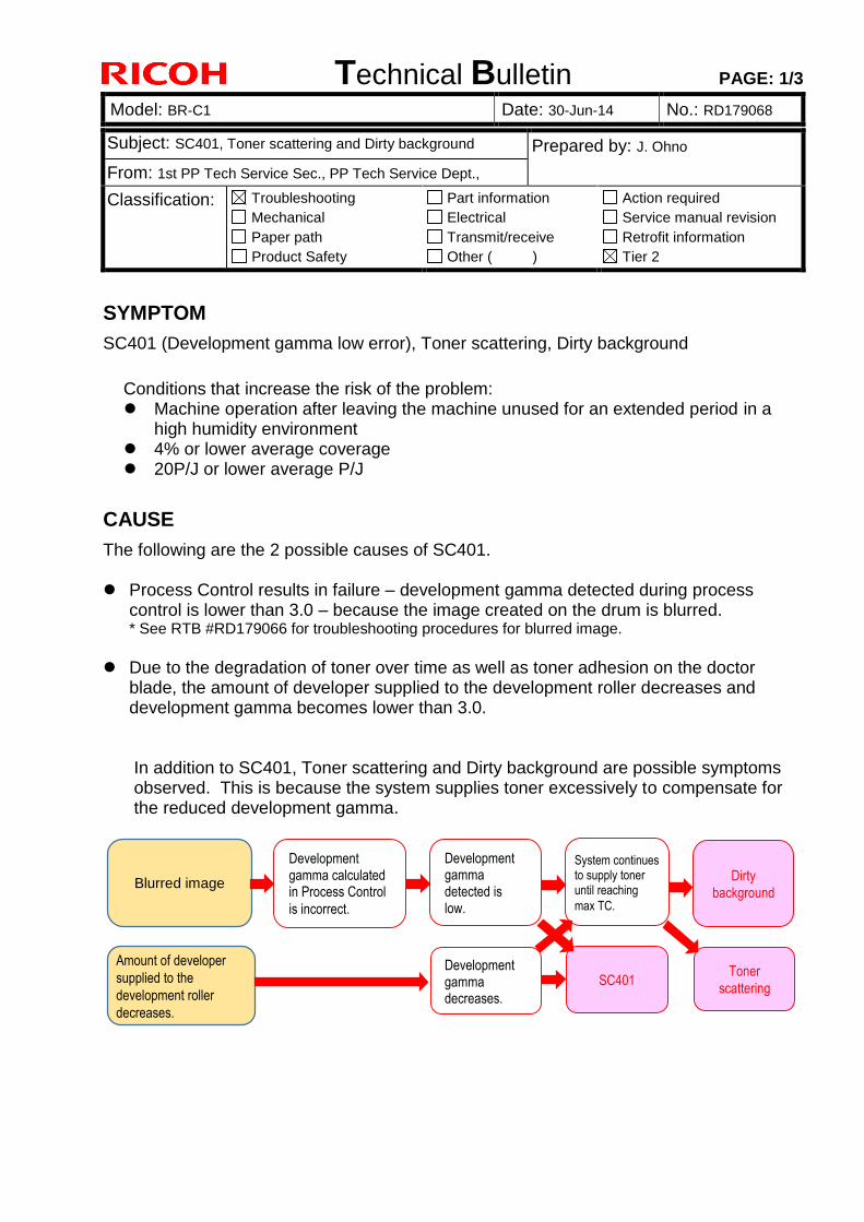
Technical Bulletin PAGE: 1/3
Model: BR-C1 Date: 30-Jun-14 No.: RD179068
Subject: SC401, Toner scattering and Dirty background Prepared by: J. Ohno
From: 1st PP Tech Service Sec., PP Tech Service Dept.,
Classification: Troubleshooting
Mechanical
Paper path
Product Safety
Part information
Electrical
Transmit/receive
Other ( )
Action required
Service manual revision
Retrofit information
Tier 2
SYMPTOM
SC401 (Development gamma low error), Toner scattering, Dirty background
Conditions that increase the risk of the problem: Machine operation after leaving the machine unused for an extended period in a
high humidity environment 4% or lower average coverage 20P/J or lower average P/J
CAUSE
The following are the 2 possible causes of SC401. Process Control results in failure – development gamma detected during process
control is lower than 3.0 – because the image created on the drum is blurred. * See RTB #RD179066 for troubleshooting procedures for blurred image.
Due to the degradation of toner over time as well as toner adhesion on the doctor
blade, the amount of developer supplied to the development roller decreases and development gamma becomes lower than 3.0.
In addition to SC401, Toner scattering and Dirty background are possible symptoms observed. This is because the system supplies toner excessively to compensate for the reduced development gamma.
Blurred image
Amount of developer
supplied to the
development roller
decreases.
Development gamma calculated in Process Control
is incorrect.
Development gamma detected is low.
System continues to supply toner until reaching
max TC.
Dirty
background
Development gamma decreases.
SC401 Toner
scattering
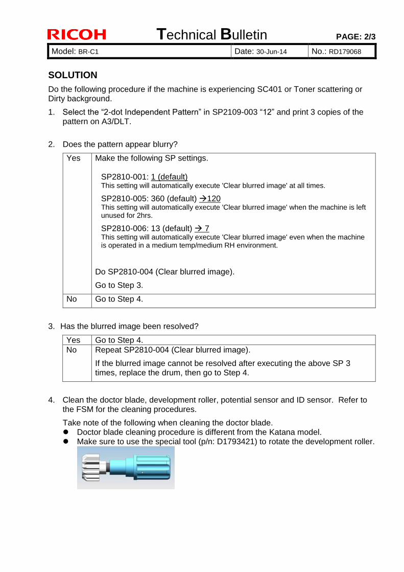
Technical Bulletin PAGE: 2/3
Model: BR-C1 Date: 30-Jun-14 No.: RD179068
SOLUTION
Do the following procedure if the machine is experiencing SC401 or Toner scattering or Dirty background.
1. Select the “2-dot Independent Pattern” in SP2109-003 “12” and print 3 copies of the pattern on A3/DLT.
2. Does the pattern appear blurry?
Yes Make the following SP settings.
SP2810-001: 1 (default) This setting will automatically execute 'Clear blurred image' at all times.
SP2810-005: 360 (default) 120 This setting will automatically execute 'Clear blurred image' when the machine is left unused for 2hrs.
SP2810-006: 13 (default) 7 This setting will automatically execute 'Clear blurred image' even when the machine is operated in a medium temp/medium RH environment.
Do SP2810-004 (Clear blurred image).
Go to Step 3.
No Go to Step 4.
3. Has the blurred image been resolved?
Yes Go to Step 4.
No Repeat SP2810-004 (Clear blurred image).
If the blurred image cannot be resolved after executing the above SP 3 times, replace the drum, then go to Step 4.
4. Clean the doctor blade, development roller, potential sensor and ID sensor. Refer to the FSM for the cleaning procedures.
Take note of the following when cleaning the doctor blade. Doctor blade cleaning procedure is different from the Katana model. Make sure to use the special tool (p/n: D1793421) to rotate the development roller.
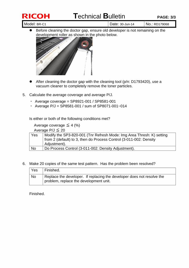
Technical Bulletin PAGE: 3/3
Model: BR-C1 Date: 30-Jun-14 No.: RD179068
Before cleaning the doctor gap, ensure old developer is not remaining on the development roller as shown in the photo below.
After cleaning the doctor gap with the cleaning tool (p/n: D1793420), use a vacuum cleaner to completely remove the toner particles.
5. Calculate the average coverage and average P/J.
・ Average coverage = SP8921-001 / SP8581-001
・ Average P/J = SP8581-001 / sum of SP8071-001~014
Is either or both of the following conditions met?
Average coverage ≦ 4 (%)
Average P/J ≦ 20
Yes Modify the SP3-820-001 (Tnr Refresh Mode: Img Area Thresh: K) setting from 2 (default) to 3, then do Process Control (3-011-002: Density Adjustment).
No Do Process Control (3-011-002: Density Adjustment).
6. Make 20 copies of the same test pattern. Has the problem been resolved?
Yes Finished.
No Replace the developer. If replacing the developer does not resolve the problem, replace the development unit.
Finished.
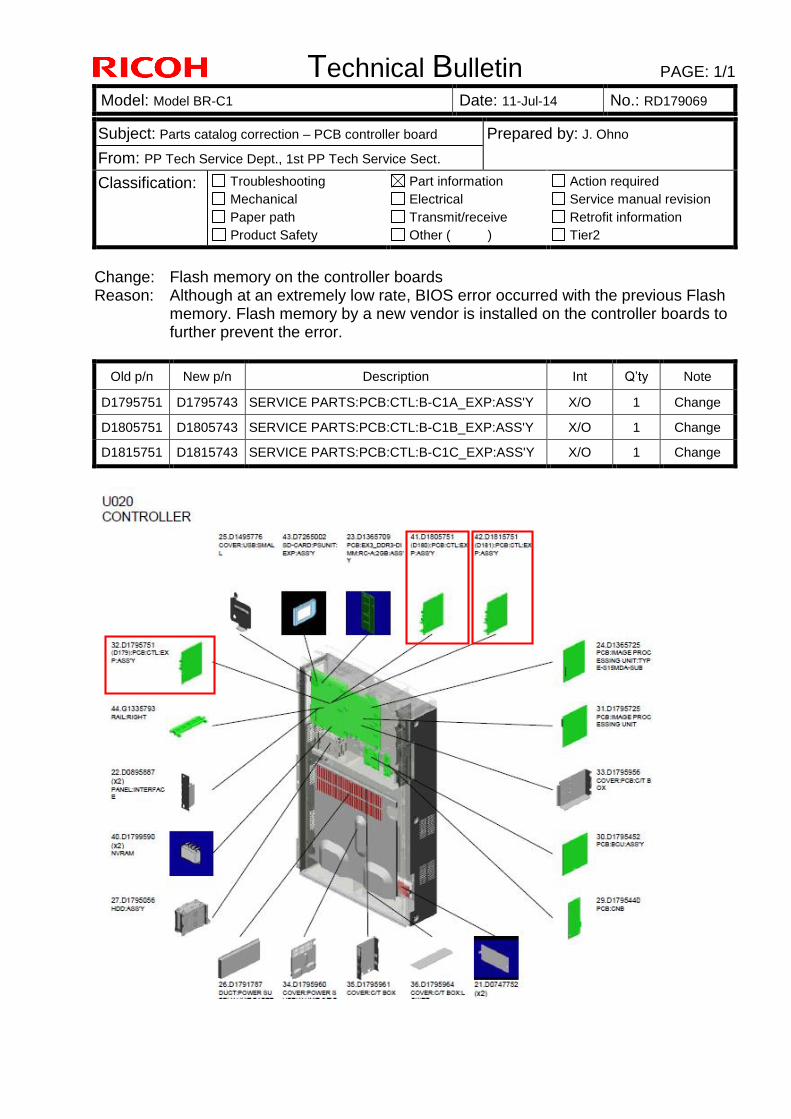
Technical Bulletin PAGE: 1/1
Model: Model BR-C1 Date: 11-Jul-14 No.: RD179069
Subject: Parts catalog correction – PCB controller board Prepared by: J. Ohno
From: PP Tech Service Dept., 1st PP Tech Service Sect.
Classification: Troubleshooting
Mechanical
Paper path
Product Safety
Part information
Electrical
Transmit/receive
Other ( )
Action required
Service manual revision
Retrofit information
Tier2
Change: Flash memory on the controller boards Reason: Although at an extremely low rate, BIOS error occurred with the previous Flash
memory. Flash memory by a new vendor is installed on the controller boards to further prevent the error.
Old p/n New p/n Description Int Q’ty Note
D1795751 D1795743 SERVICE PARTS:PCB:CTL:B-C1A_EXP:ASS'Y X/O 1 Change
D1805751 D1805743 SERVICE PARTS:PCB:CTL:B-C1B_EXP:ASS'Y X/O 1 Change
D1815751 D1815743 SERVICE PARTS:PCB:CTL:B-C1C_EXP:ASS'Y X/O 1 Change
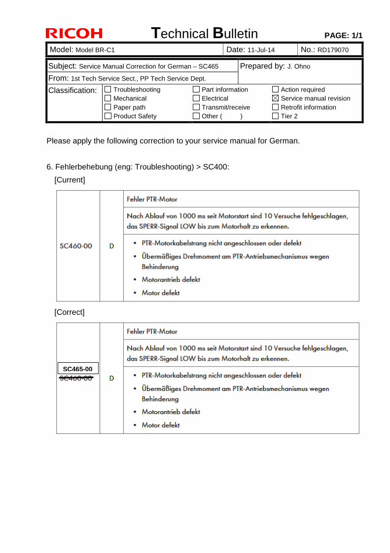
Technical Bulletin PAGE: 1/1
Model: Model BR-C1 Date: 11-Jul-14 No.: RD179070
Subject: Service Manual Correction for German – SC465 Prepared by: J. Ohno
From: 1st Tech Service Sect., PP Tech Service Dept.
Classification: Troubleshooting
Mechanical
Paper path
Product Safety
Part information
Electrical
Transmit/receive
Other ( )
Action required
Service manual revision
Retrofit information
Tier 2
Please apply the following correction to your service manual for German.
6. Fehlerbehebung (eng: Troubleshooting) > SC400:
[Current]
[Correct]
SC465-00
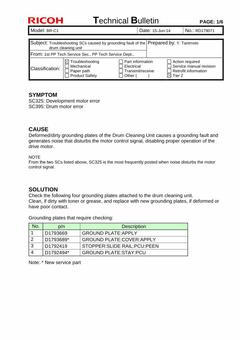
Technical Bulletin PAGE: 1/6
Model: BR-C1 Date: 15-Jun-14 No.: RD179071
SYMPTOM SC325: Development motor error SC395: Drum motor error
CAUSE Deformed/dirty grounding plates of the Drum Cleaning Unit causes a grounding fault and generates noise that disturbs the motor control signal, disabling proper operation of the drive motor.
NOTE From the two SCs listed above, SC325 is the most frequently posted when noise disturbs the motor control signal.
SOLUTION Check the following four grounding plates attached to the drum cleaning unit. Clean, if dirty with toner or grease, and replace with new grounding plates, if deformed or have poor contact.
Grounding plates that require checking:
Note: * New service part
Subject: Troubleshooting SCs caused by grounding fault of the
drum cleaning unit Prepared by: Y. Tanimoto
From: 1st PP Tech Service Sec., PP Tech Service Dept.,
Classification:
Troubleshooting Mechanical Paper path Product Safety
Part information Electrical Transmit/receive Other ( )
Action required Service manual revision Retrofit information Tier 2
No. p/n Description
1 D1793669 GROUND PLATE:APPLY
2 D1793689* GROUND PLATE:COVER:APPLY
3 D1792419 STOPPER:SLIDE RAIL:PCU:PEEN
4 D1792494* GROUND PLATE:STAY:PCU
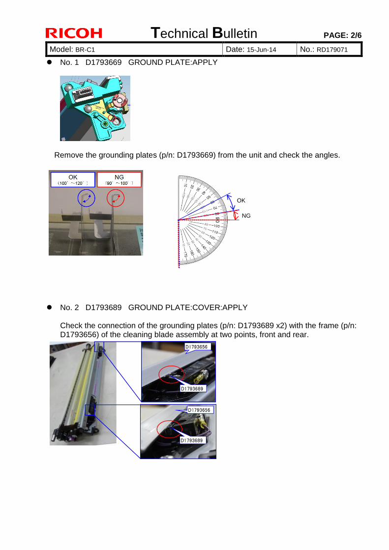
Technical Bulletin PAGE: 2/6
Model: BR-C1 Date: 15-Jun-14 No.: RD179071
No. 1 D1793669 GROUND PLATE:APPLY
Remove the grounding plates (p/n: D1793669) from the unit and check the angles.
No. 2 D1793689 GROUND PLATE:COVER:APPLY
Check the connection of the grounding plates (p/n: D1793689 x2) with the frame (p/n: D1793656) of the cleaning blade assembly at two points, front and rear.
OK
NG
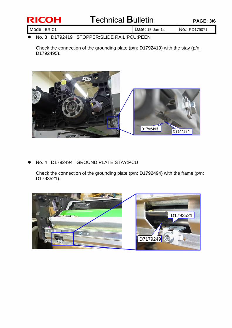
Technical Bulletin PAGE: 3/6
Model: BR-C1 Date: 15-Jun-14 No.: RD179071
No. 3 D1792419 STOPPER:SLIDE RAIL:PCU:PEEN Check the connection of the grounding plate (p/n: D1792419) with the stay (p/n: D1792495).
No. 4 D1792494 GROUND PLATE:STAY:PCU
Check the connection of the grounding plate (p/n: D1792494) with the frame (p/n: D1793521).
D71792494
D1793521
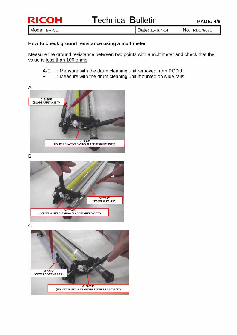
Technical Bulletin PAGE: 4/6
Model: BR-C1 Date: 15-Jun-14 No.: RD179071
How to check ground resistance using a multimeter Measure the ground resistance between two points with a multimeter and check that the value is less than 100 ohms.
A-E : Measure with the drum cleaning unit removed from PCDU. F : Measure with the drum cleaning unit mounted on slide rails.
A
B
C
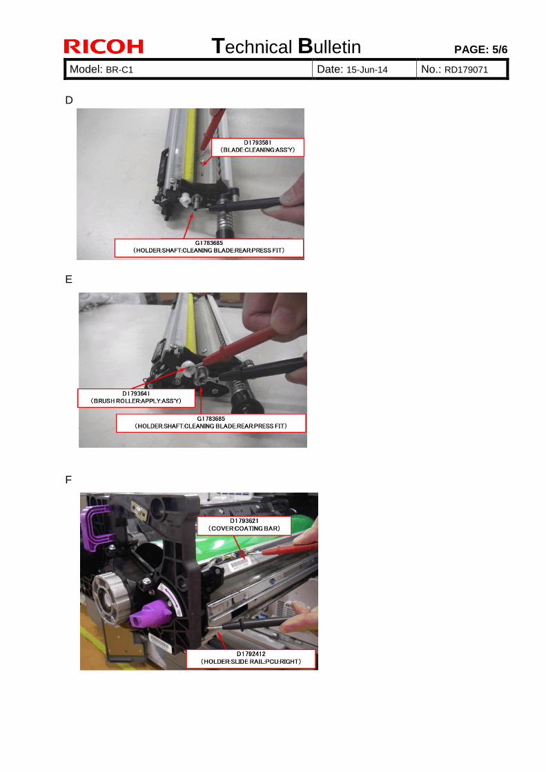
Technical Bulletin PAGE: 5/6
Model: BR-C1 Date: 15-Jun-14 No.: RD179071
D
E
F
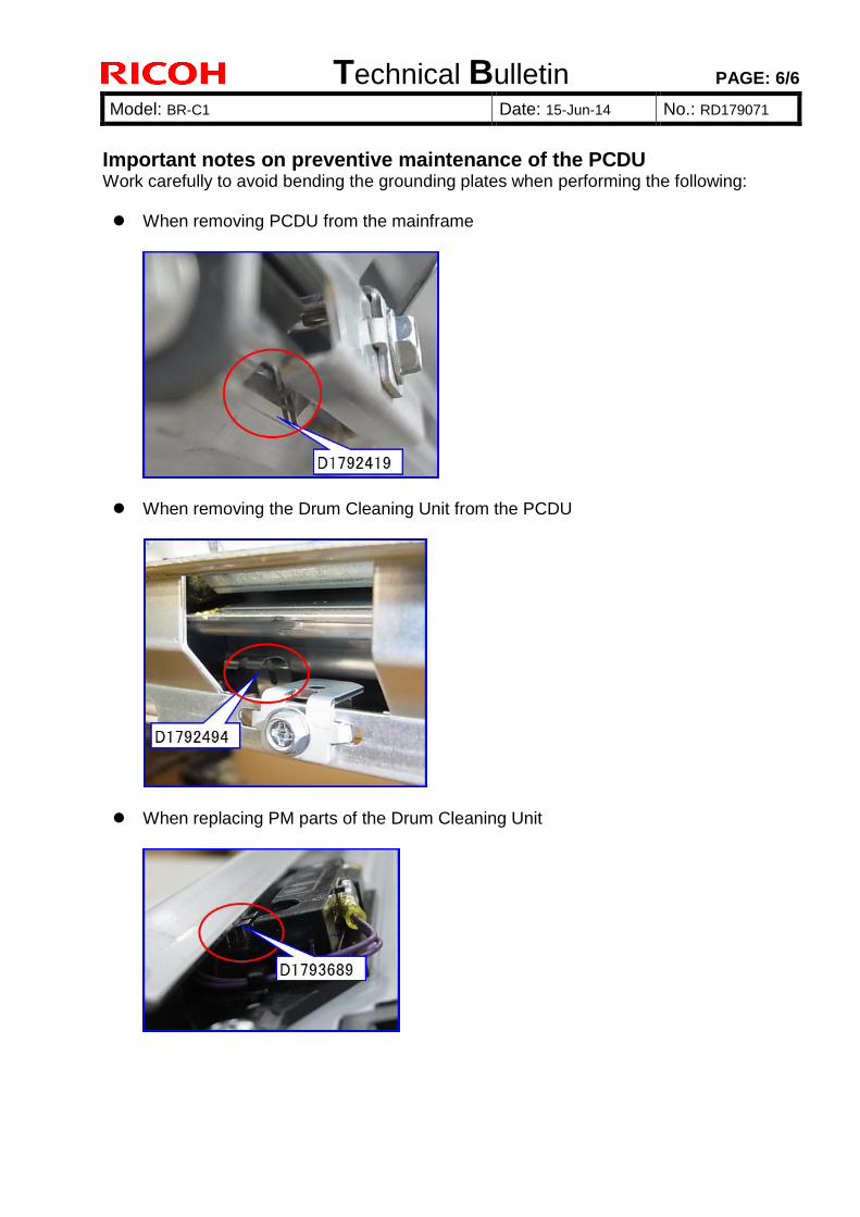
Technical Bulletin PAGE: 6/6
Model: BR-C1 Date: 15-Jun-14 No.: RD179071
Important notes on preventive maintenance of the PCDU Work carefully to avoid bending the grounding plates when performing the following: When removing PCDU from the mainframe
When removing the Drum Cleaning Unit from the PCDU
When replacing PM parts of the Drum Cleaning Unit
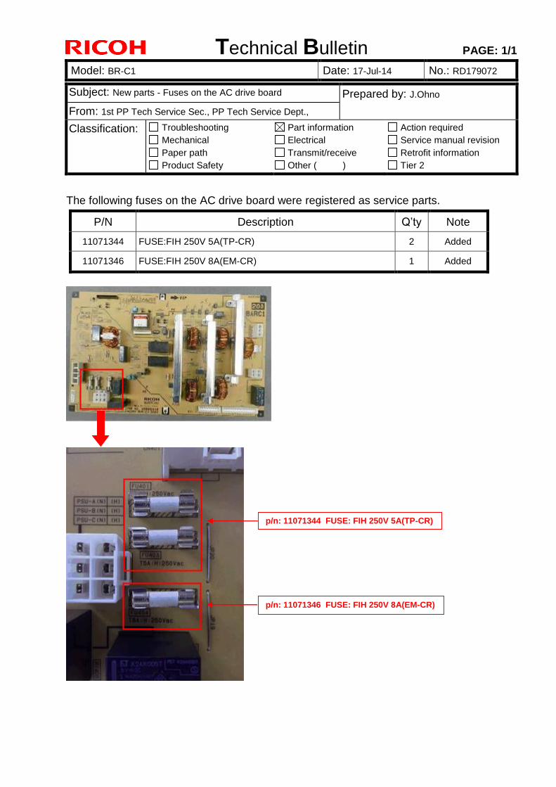
Technical Bulletin PAGE: 1/1
Model: BR-C1 Date: 17-Jul-14 No.: RD179072
Subject: New parts - Fuses on the AC drive board Prepared by: J.Ohno
From: 1st PP Tech Service Sec., PP Tech Service Dept.,
Classification: Troubleshooting
Mechanical
Paper path
Product Safety
Part information
Electrical
Transmit/receive
Other ( )
Action required
Service manual revision
Retrofit information
Tier 2
The following fuses on the AC drive board were registered as service parts.
P/N Description Q’ty Note
11071344 FUSE:FIH 250V 5A(TP-CR) 2 Added
11071346 FUSE:FIH 250V 8A(EM-CR) 1 Added
p/n: 11071344 FUSE: FIH 250V 5A(TP-CR)
p/n: 11071346 FUSE: FIH 250V 8A(EM-CR)
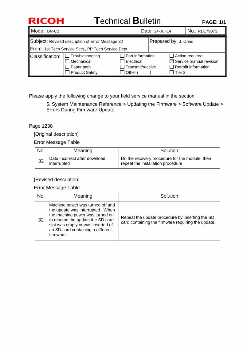
Technical Bulletin PAGE: 1/1
Model: BR-C1 Date: 24-Jul-14 No.: RD179073
Subject: Revised description of Error Message 32 Prepared by: J. Ohno
From: 1st Tech Service Sect., PP Tech Service Dept.
Classification: Troubleshooting
Mechanical
Paper path
Product Safety
Part information
Electrical
Transmit/receive
Other ( )
Action required
Service manual revision
Retrofit information
Tier 2
Please apply the following change to your field service manual in the section:
5. System Maintenance Reference > Updating the Firmware > Software Update > Errors During Firmware Update
Page 1238
[Original description]
Error Message Table
No. Meaning Solution
32 Data incorrect after download interrupted
Do the recovery procedure for the module, then repeat the installation procedure
[Revised description]
Error Message Table
No. Meaning Solution
32
Machine power was turned off and the update was interrupted. When the machine power was turned on to resume the update the SD card slot was empty or was inserted of an SD card containing a different firmware.
Repeat the update procedure by inserting the SD card containing the firmware requiring the update.
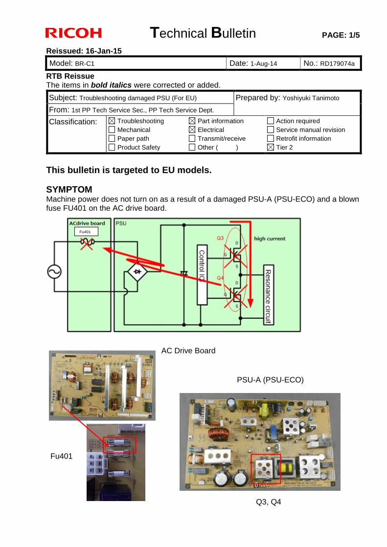
Technical Bulletin PAGE: 1/5
Reissued: 16-Jan-15
Model: BR-C1 Date: 1-Aug-14 No.: RD179074a
RTB Reissue The items in bold italics were corrected or added.
This bulletin is targeted to EU models.
SYMPTOM Machine power does not turn on as a result of a damaged PSU-A (PSU-ECO) and a blown fuse FU401 on the AC drive board.
Subject: Troubleshooting damaged PSU (For EU) Prepared by: Yoshiyuki Tanimoto
From: 1st PP Tech Service Sec., PP Tech Service Dept.
Classification: Troubleshooting
Mechanical
Paper path
Product Safety
Part information
Electrical
Transmit/receive
Other ( )
Action required
Service manual revision
Retrofit information
Tier 2
Fu401
AC Drive Board
PSU-A (PSU-ECO)
Fu401
Q3, Q4
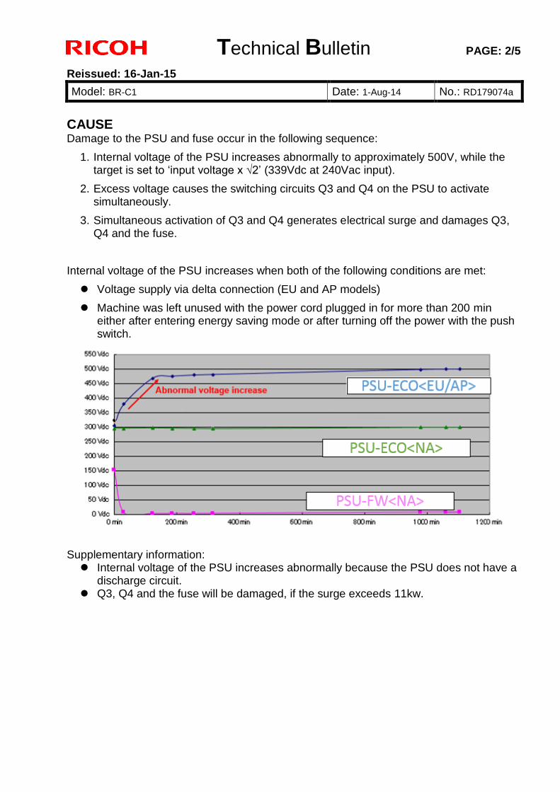
Technical Bulletin PAGE: 2/5
Reissued: 16-Jan-15
Model: BR-C1 Date: 1-Aug-14 No.: RD179074a
CAUSE Damage to the PSU and fuse occur in the following sequence:
1. Internal voltage of the PSU increases abnormally to approximately 500V, while the target is set to ‘input voltage x √2’ (339Vdc at 240Vac input).
2. Excess voltage causes the switching circuits Q3 and Q4 on the PSU to activate simultaneously.
3. Simultaneous activation of Q3 and Q4 generates electrical surge and damages Q3, Q4 and the fuse.
Internal voltage of the PSU increases when both of the following conditions are met:
Voltage supply via delta connection (EU and AP models)
Machine was left unused with the power cord plugged in for more than 200 min either after entering energy saving mode or after turning off the power with the push switch.
Supplementary information: Internal voltage of the PSU increases abnormally because the PSU does not have a
discharge circuit. Q3, Q4 and the fuse will be damaged, if the surge exceeds 11kw.
Technical Bulletin PAGE: 3/5
Reissued: 16-Jan-15
Model: BR-C1 Date: 1-Aug-14 No.: RD179074a
SOLUTION Production line:
Modification was implemented twice, both in order to prevent the internal voltage of the PSU from increasing.
1st Modification: A varistor was added to modify the resistance between the Gate and Source.
2nd Modification: Added a resistance of 2.2 M ohm.
Note that the estimated failure rate of the PSU is different between the 1st and 2nd modifications.
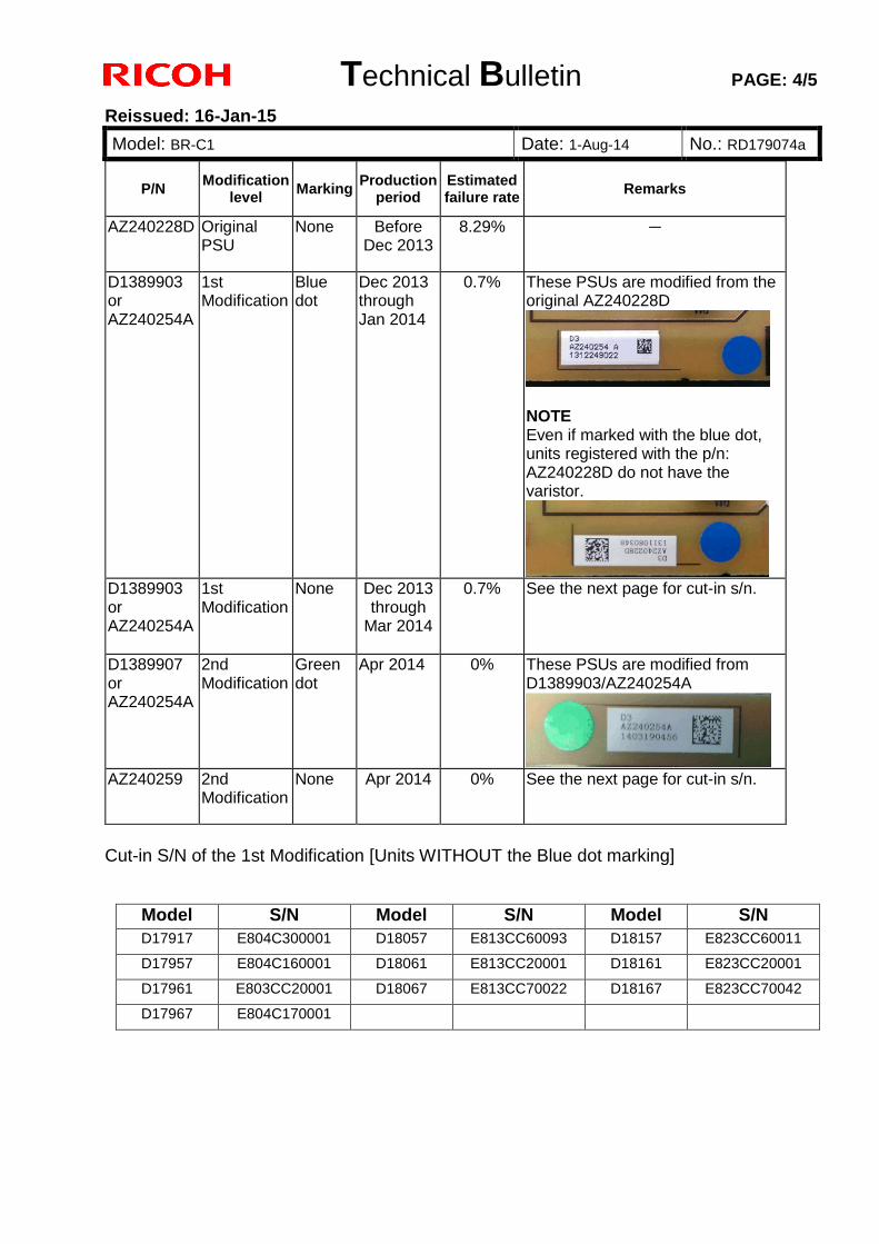
Technical Bulletin PAGE: 4/5
Reissued: 16-Jan-15
Model: BR-C1 Date: 1-Aug-14 No.: RD179074a
Cut-in S/N of the 1st Modification [Units WITHOUT the Blue dot marking]
Model S/N Model S/N Model S/N
D17917 E804C300001
D18057 E813CC60093
D18157 E823CC60011
D17957 E804C160001
D18061 E813CC20001
D18161 E823CC20001
D17961 E803CC20001
D18067 E813CC70022
D18167 E823CC70042
D17967 E804C170001
P/N Modification
level Marking
Production period
Estimated failure rate
Remarks
AZ240228D Original PSU
None Before Dec 2013
8.29% -
D1389903 or AZ240254A
1st Modification
Blue dot
Dec 2013 through Jan 2014
0.7% These PSUs are modified from the original AZ240228D
NOTE Even if marked with the blue dot, units registered with the p/n: AZ240228D do not have the varistor.
D1389903 or AZ240254A
1st Modification
None Dec 2013 through
Mar 2014
0.7% See the next page for cut-in s/n.
D1389907 or AZ240254A
2nd Modification
Green dot
Apr 2014 0% These PSUs are modified from D1389903/AZ240254A
AZ240259 2nd
Modification None Apr 2014 0% See the next page for cut-in s/n.
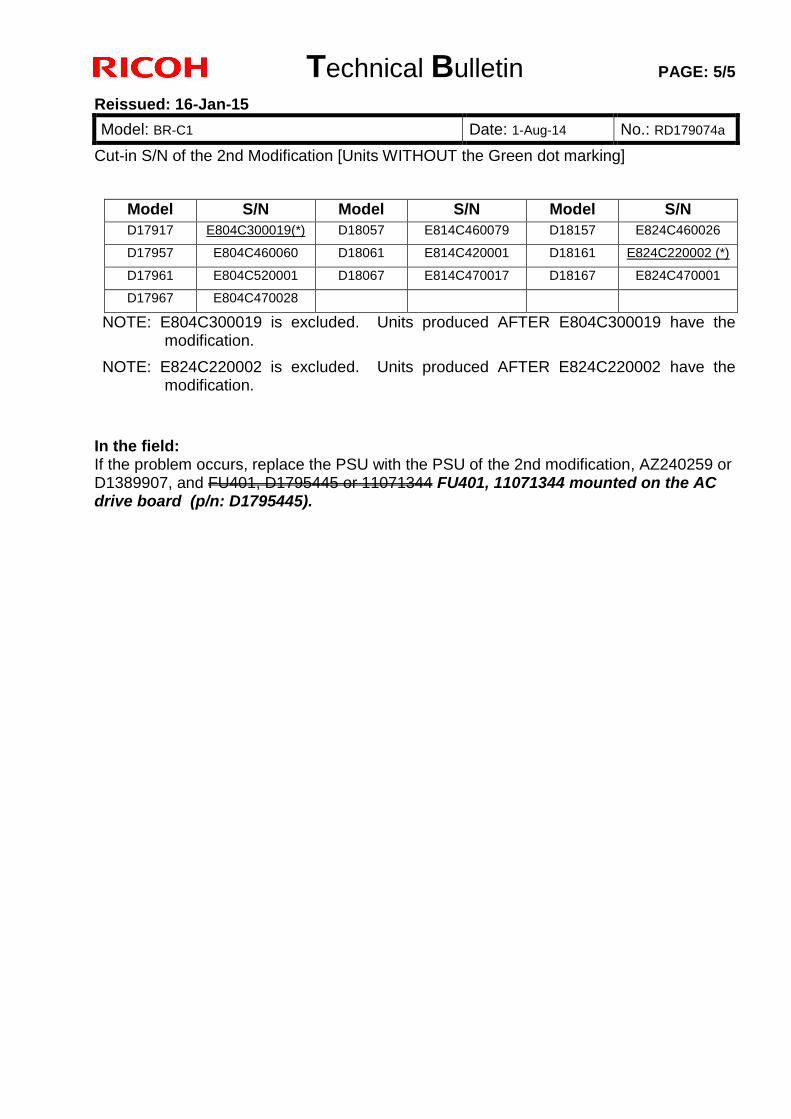
Technical Bulletin PAGE: 5/5
Reissued: 16-Jan-15
Model: BR-C1 Date: 1-Aug-14 No.: RD179074a
Cut-in S/N of the 2nd Modification [Units WITHOUT the Green dot marking]
Model S/N Model S/N Model S/N
D17917 E804C300019(*)
D18057 E814C460079
D18157 E824C460026
D17957 E804C460060
D18061 E814C420001
D18161 E824C220002 (*)
D17961 E804C520001
D18067 E814C470017
D18167 E824C470001
D17967 E804C470028
NOTE: E804C300019 is excluded. Units produced AFTER E804C300019 have the modification.
NOTE: E824C220002 is excluded. Units produced AFTER E824C220002 have the modification.
In the field: If the problem occurs, replace the PSU with the PSU of the 2nd modification, AZ240259 or D1389907, and FU401, D1795445 or 11071344 FU401, 11071344 mounted on the AC drive board (p/n: D1795445).
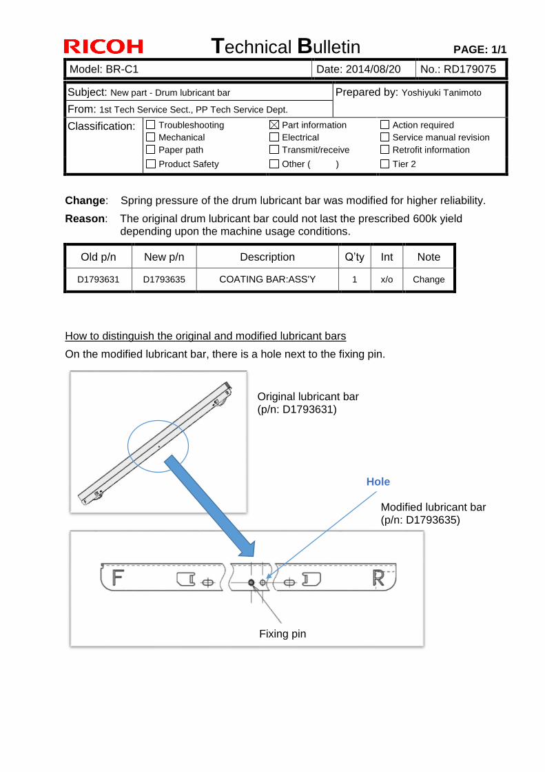
Technical Bulletin PAGE: 1/1
Model: BR-C1 Date: 2014/08/20 No.: RD179075
Subject: New part - Drum lubricant bar Prepared by: Yoshiyuki Tanimoto
From: 1st Tech Service Sect., PP Tech Service Dept.
Classification: Troubleshooting
Mechanical
Paper path
Part information
Electrical
Transmit/receive
Action required
Service manual revision
Retrofit information
Product Safety Other ( ) Tier 2
Change: Spring pressure of the drum lubricant bar was modified for higher reliability.
Reason: The original drum lubricant bar could not last the prescribed 600k yield depending upon the machine usage conditions.
Old p/n New p/n Description Q’ty Int Note
D1793631 D1793635 COATING BAR:ASS'Y 1 x/o Change
How to distinguish the original and modified lubricant bars
On the modified lubricant bar, there is a hole next to the fixing pin.
Fixing pin
Hole
Original lubricant bar (p/n: D1793631)
Modified lubricant bar (p/n: D1793635)

Technical Bulletin PAGE: 1/2
Model: BR-C1 Date: 2014/08/20 No.: RD179076
Subject: New part – ADF guide ass’y Prepared by: Yoshiyuki Tanimoto
From: 1st Tech Service Sect., PP Tech Service Dept.
Classification: Troubleshooting
Mechanical
Paper path
Part information
Electrical
Transmit/receive
Action required
Service manual revision
Retrofit information
Product Safety Other ( ) Tier 2
Change: Upper guide plate of the ADF
Reason: To prevent originals from jamming in the ADF
Old part number
New part number
Description Q’ty Int Note
- D7314310 GUIDE:PAPER FEED:UPPER: SUB-ASS'Y
1 X/O Add
Note: D7314310 is attached with 4 mylar sheets (p/n: D5433314).
Detail of the modification Originals fed through the ADF may interfere with the projection (circled in red) located on the edge of the guide plate and result in jams, especially when the side fence is stretched to the maximum width. To prevent this, the projection was shifted (2.7mm) toward the outside, allowing wider path for the original.
D7314310
D5433314 SHEET:SCANNING:ENTRANCE:MIDDLE
SUB-ASS’Y
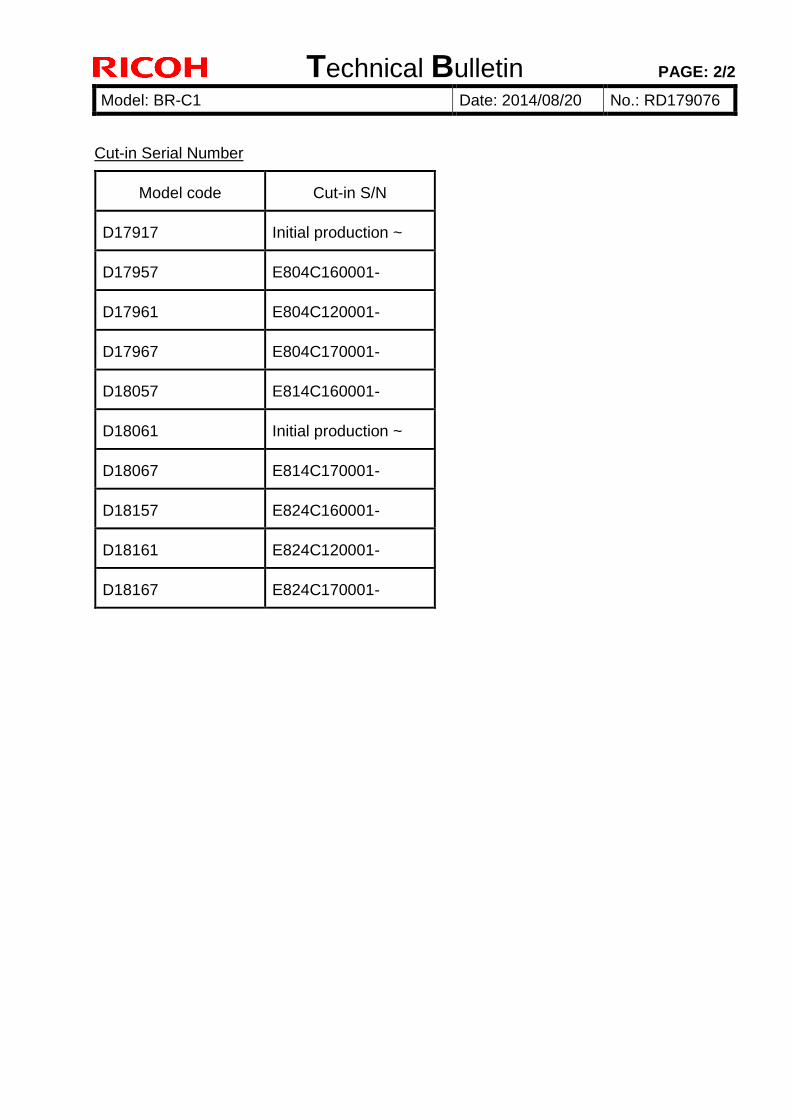
Technical Bulletin PAGE: 2/2
Model: BR-C1 Date: 2014/08/20 No.: RD179076
Cut-in Serial Number
Model code Cut-in S/N
D17917 Initial production ~
D17957 E804C160001-
D17961 E804C120001-
D17967 E804C170001-
D18057 E814C160001-
D18061 Initial production ~
D18067 E814C170001-
D18157 E824C160001-
D18161 E824C120001-
D18167 E824C170001-
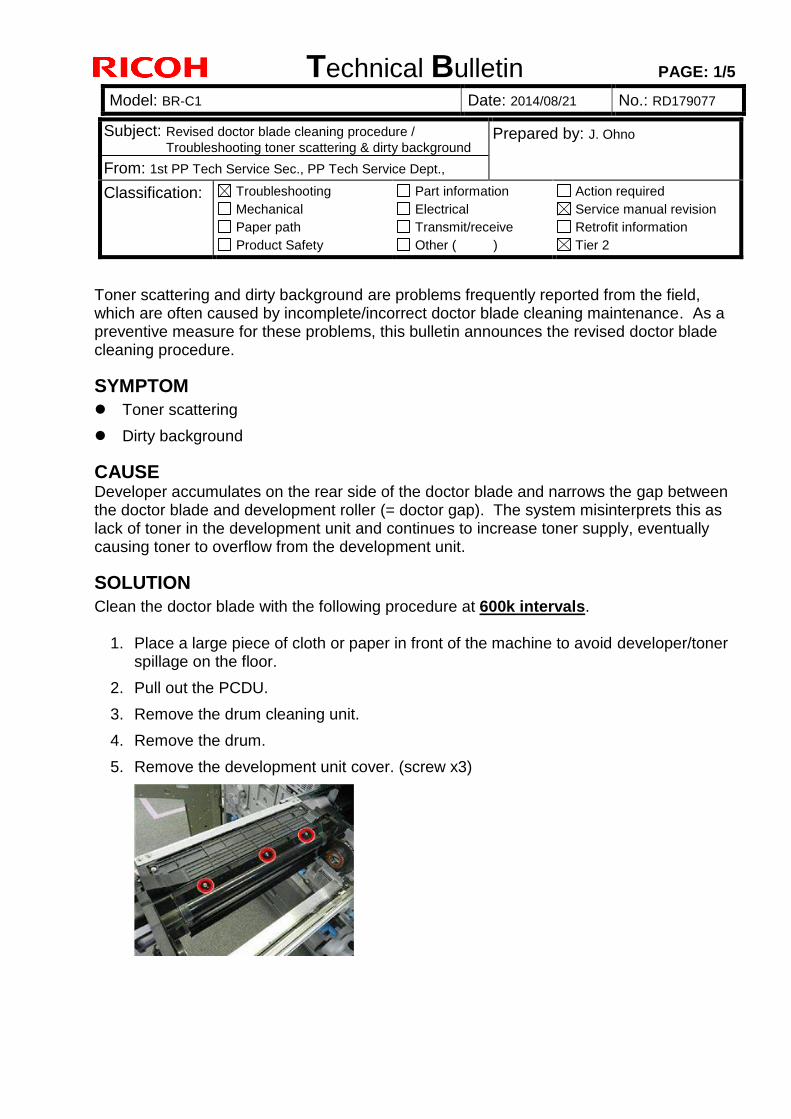
Technical Bulletin PAGE: 1/5
Model: BR-C1 Date: 2014/08/21 No.: RD179077
Subject: Revised doctor blade cleaning procedure /
Troubleshooting toner scattering & dirty background Prepared by: J. Ohno
From: 1st PP Tech Service Sec., PP Tech Service Dept.,
Classification: Troubleshooting
Mechanical
Paper path
Product Safety
Part information
Electrical
Transmit/receive
Other ( )
Action required
Service manual revision
Retrofit information
Tier 2
Toner scattering and dirty background are problems frequently reported from the field, which are often caused by incomplete/incorrect doctor blade cleaning maintenance. As a preventive measure for these problems, this bulletin announces the revised doctor blade cleaning procedure.
SYMPTOM
Toner scattering
Dirty background
CAUSE Developer accumulates on the rear side of the doctor blade and narrows the gap between the doctor blade and development roller (= doctor gap). The system misinterprets this as lack of toner in the development unit and continues to increase toner supply, eventually causing toner to overflow from the development unit.
SOLUTION
Clean the doctor blade with the following procedure at 600k intervals.
1. Place a large piece of cloth or paper in front of the machine to avoid developer/toner spillage on the floor.
2. Pull out the PCDU.
3. Remove the drum cleaning unit.
4. Remove the drum.
5. Remove the development unit cover. (screw x3)
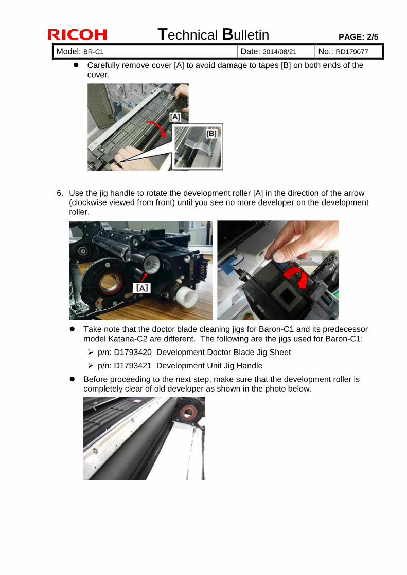
Technical Bulletin PAGE: 2/5
Model: BR-C1 Date: 2014/08/21 No.: RD179077
Carefully remove cover [A] to avoid damage to tapes [B] on both ends of the cover.
6. Use the jig handle to rotate the development roller [A] in the direction of the arrow (clockwise viewed from front) until you see no more developer on the development roller.
Take note that the doctor blade cleaning jigs for Baron-C1 and its predecessor model Katana-C2 are different. The following are the jigs used for Baron-C1:
p/n: D1793420 Development Doctor Blade Jig Sheet
p/n: D1793421 Development Unit Jig Handle
Before proceeding to the next step, make sure that the development roller is completely clear of old developer as shown in the photo below.
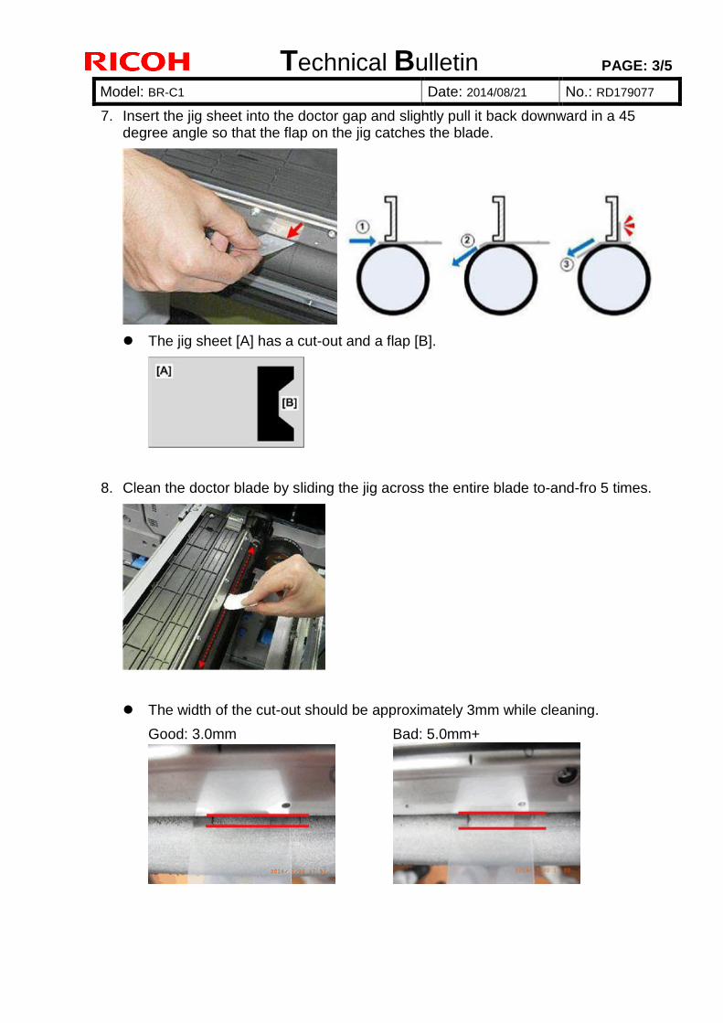
Technical Bulletin PAGE: 3/5
Model: BR-C1 Date: 2014/08/21 No.: RD179077
7. Insert the jig sheet into the doctor gap and slightly pull it back downward in a 45 degree angle so that the flap on the jig catches the blade.
The jig sheet [A] has a cut-out and a flap [B].
8. Clean the doctor blade by sliding the jig across the entire blade to-and-fro 5 times.
The width of the cut-out should be approximately 3mm while cleaning.
Good: 3.0mm Bad: 5.0mm+
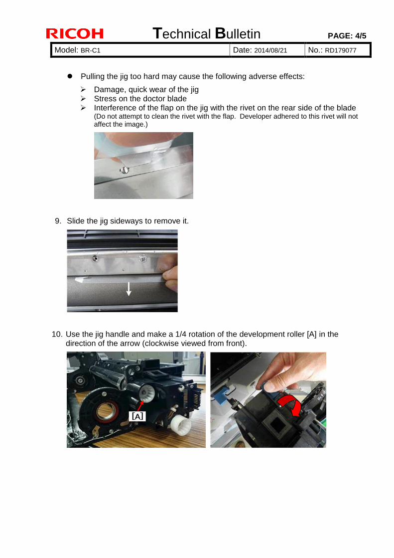
Technical Bulletin PAGE: 4/5
Model: BR-C1 Date: 2014/08/21 No.: RD179077
Pulling the jig too hard may cause the following adverse effects:
Damage, quick wear of the jig Stress on the doctor blade Interference of the flap on the jig with the rivet on the rear side of the blade
(Do not attempt to clean the rivet with the flap. Developer adhered to this rivet will not affect the image.)
9. Slide the jig sideways to remove it.
10. Use the jig handle and make a 1/4 rotation of the development roller [A] in the direction of the arrow (clockwise viewed from front).
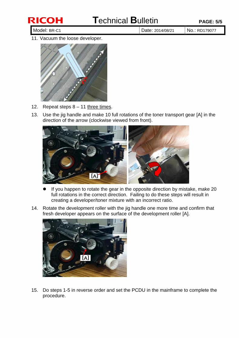
Technical Bulletin PAGE: 5/5
Model: BR-C1 Date: 2014/08/21 No.: RD179077
11. Vacuum the loose developer.
12. Repeat steps 8 – 11 three times.
13. Use the jig handle and make 10 full rotations of the toner transport gear [A] in the direction of the arrow (clockwise viewed from front).
If you happen to rotate the gear in the opposite direction by mistake, make 20 full rotations in the correct direction. Failing to do these steps will result in creating a developer/toner mixture with an incorrect ratio.
14. Rotate the development roller with the jig handle one more time and confirm that fresh developer appears on the surface of the development roller [A].
15. Do steps 1-5 in reverse order and set the PCDU in the mainframe to complete the procedure.
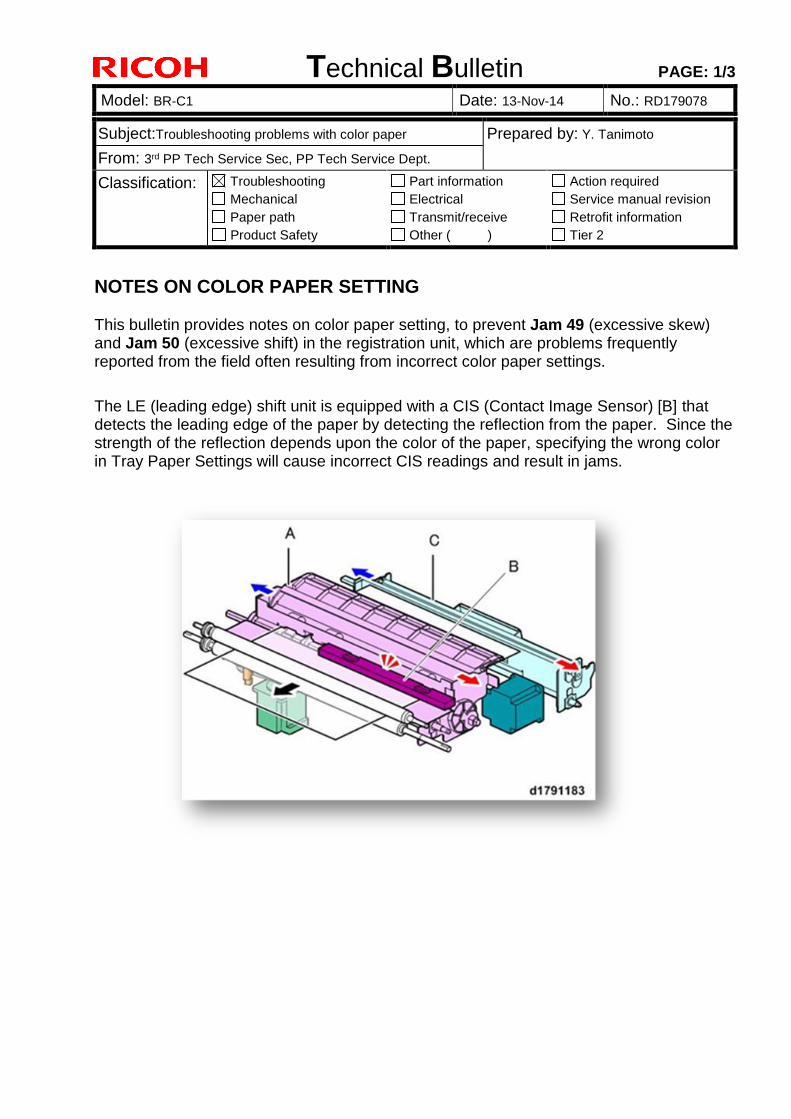
Technical Bulletin PAGE: 1/3
Model: BR-C1 Date: 13-Nov-14 No.: RD179078
Subject:Troubleshooting problems with color paper Prepared by: Y. Tanimoto
From: 3rd PP Tech Service Sec, PP Tech Service Dept.
Classification: Troubleshooting
Mechanical
Paper path
Product Safety
Part information
Electrical
Transmit/receive
Other ( )
Action required
Service manual revision
Retrofit information
Tier 2
NOTES ON COLOR PAPER SETTING This bulletin provides notes on color paper setting, to prevent Jam 49 (excessive skew) and Jam 50 (excessive shift) in the registration unit, which are problems frequently reported from the field often resulting from incorrect color paper settings.
The LE (leading edge) shift unit is equipped with a CIS (Contact Image Sensor) [B] that detects the leading edge of the paper by detecting the reflection from the paper. Since the strength of the reflection depends upon the color of the paper, specifying the wrong color in Tray Paper Settings will cause incorrect CIS readings and result in jams.
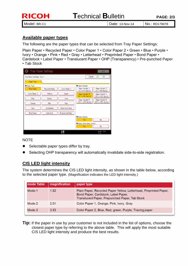
Technical Bulletin PAGE: 2/3
Model: BR-C1 Date: 13-Nov-14 No.: RD179078
Available paper types
The following are the paper types that can be selected from Tray Paper Settings:
Plain Paper • Recycled Paper • Color Paper 1 • Color Paper 2 • Green • Blue • Purple • Ivory • Orange • Pink • Red • Gray • Letterhead • Preprinted Paper • Bond Paper • Cardstock • Label Paper • Translucent Paper • OHP (Transparency) • Pre-punched Paper • Tab Stock
NOTE
Selectable paper types differ by tray.
Selecting OHP transparency will automatically invalidate side-to-side registration.
CIS LED light intensity
The system determines the CIS LED light intensity, as shown in the table below, according to the selected paper type. (Magnification indicates the LED light intensity.)
Tip: If the paper in use by your customer is not included in the list of options, choose the
closest paper type by referring to the above table. This will apply the most suitable CIS LED light intensity and produce the best results.
Technical Bulletin PAGE: 3/3
Model: BR-C1 Date: 13-Nov-14 No.: RD179078
How to prevent/resolve the problem
Specify a darker paper color, for example, change to Color Paper 1 or to Color Paper 2.
If the job is printed on paper of a variety of colors, specify the darkest color.
If the problem occurs even with the mode set to 3 (Color Paper 2), increase the CIS LED light intensity with the following procedure. SP mode: SP1-916-003 variable magnification mode 3 1.00~ 5.00 / 3.53 (default) / 0.001 step Advanced Settings: Login [Paper Setting] [Edit Custom Paper] Select the paper in use [Change] under “Advanced Settings” Select 06 [Color Paper Edge Detection Adjustment]. NOTE: Do not apply a value that is too high. Doing so may cause jams because
the CIS detects diffused refection from the surrounding components, for example, the guide plates, and will also shorten the CIS life.
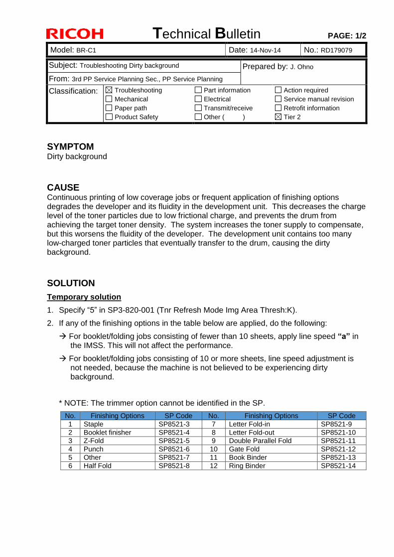
Technical Bulletin PAGE: 1/2
Model: BR-C1 Date: 14-Nov-14 No.: RD179079
Subject: Troubleshooting Dirty background Prepared by: J. Ohno
From: 3rd PP Service Planning Sec., PP Service Planning
Classification: Troubleshooting
Mechanical
Paper path
Product Safety
Part information
Electrical
Transmit/receive
Other ( )
Action required
Service manual revision
Retrofit information
Tier 2
SYMPTOM Dirty background
CAUSE Continuous printing of low coverage jobs or frequent application of finishing options degrades the developer and its fluidity in the development unit. This decreases the charge level of the toner particles due to low frictional charge, and prevents the drum from achieving the target toner density. The system increases the toner supply to compensate, but this worsens the fluidity of the developer. The development unit contains too many low-charged toner particles that eventually transfer to the drum, causing the dirty background.
SOLUTION
Temporary solution
1. Specify “5” in SP3-820-001 (Tnr Refresh Mode Img Area Thresh:K).
2. If any of the finishing options in the table below are applied, do the following:
For booklet/folding jobs consisting of fewer than 10 sheets, apply line speed “a” in the IMSS. This will not affect the performance.
For booklet/folding jobs consisting of 10 or more sheets, line speed adjustment is not needed, because the machine is not believed to be experiencing dirty background.
* NOTE: The trimmer option cannot be identified in the SP.
No. Finishing Options SP Code No. Finishing Options SP Code
1 Staple SP8521-3 7 Letter Fold-in SP8521-9
2 Booklet finisher SP8521-4 8 Letter Fold-out SP8521-10
3 Z-Fold SP8521-5 9 Double Parallel Fold SP8521-11
4 Punch SP8521-6 10 Gate Fold SP8521-12
5 Other SP8521-7 11 Book Binder SP8521-13
6 Half Fold SP8521-8 12 Ring Binder SP8521-14

Technical Bulletin PAGE: 2/2
Model: BR-C1 Date: 14-Nov-14 No.: RD179079
Permanent solution
Firmware modification
The current spec enables disposal of toner only between sheets and after job completion. The modified spec will also dispose of toner while the mainframe engine runs idle, such as during finishing operations.
<Modified firmware release schedule>
Jan 2015 Pre-release
Apr 2015 Application to mass production
This bulletin will be re-issued to announce the details of the modified firmware as soon as the release date is determined.
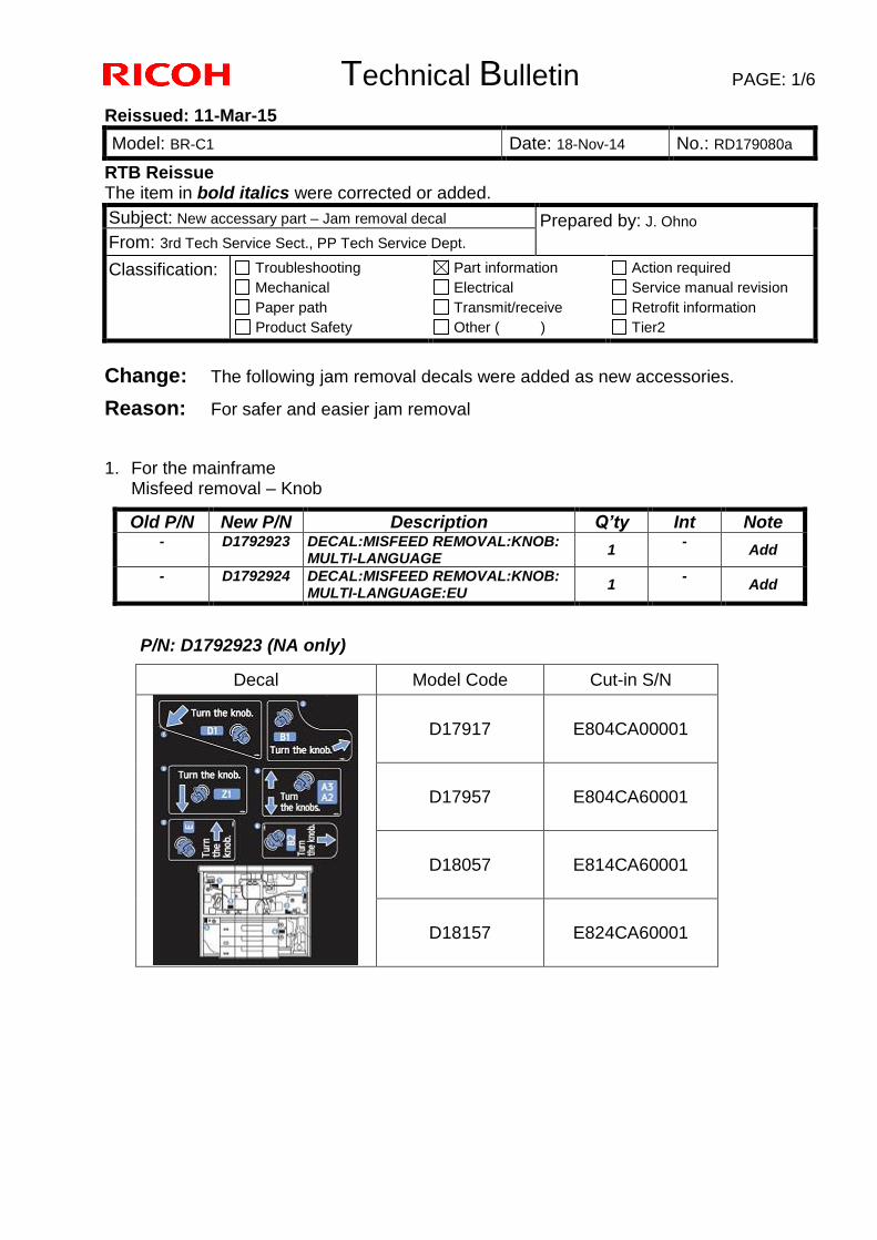
Technical Bulletin PAGE: 1/6
Reissued: 11-Mar-15
Model: BR-C1 Date: 18-Nov-14 No.: RD179080a
RTB Reissue The item in bold italics were corrected or added.
Subject: New accessary part – Jam removal decal Prepared by: J. Ohno
From: 3rd Tech Service Sect., PP Tech Service Dept.
Classification: Troubleshooting
Mechanical
Paper path
Product Safety
Part information
Electrical
Transmit/receive
Other ( )
Action required
Service manual revision
Retrofit information
Tier2
Change: The following jam removal decals were added as new accessories.
Reason: For safer and easier jam removal
1. For the mainframe Misfeed removal – Knob
Old P/N New P/N Description Q’ty Int Note - D1792923 DECAL:MISFEED REMOVAL:KNOB:
MULTI-LANGUAGE 1
- Add
- D1792924 DECAL:MISFEED REMOVAL:KNOB: MULTI-LANGUAGE:EU
1 -
Add
P/N: D1792923 (NA only)
Decal Model Code Cut-in S/N
D17917 E804CA00001
D17957 E804CA60001
D18057 E814CA60001
D18157 E824CA60001

Technical Bulletin PAGE: 2/6
Reissued: 11-Mar-15
Model: BR-C1 Date: 18-Nov-14 No.: RD179080a
P/N: D1792924 (EU, AP)
Decal Model Code Cut-in S/N
D17967 E804CC70001
D18067 E814CC70001
D18167 E824CC70001
2. For the Decurl Unit DU5030 Misfeed removal - Paper exit sub unit
Old P/N New P/N Description Q’ty Int Note - D7414595 DECAL:PAPER EXIT SUB-UNIT:
MISFEED REMOVAL 1
- Add
P/N: D7414595
Decal Model Code Cut-in S/N
D74117 G034CB00001
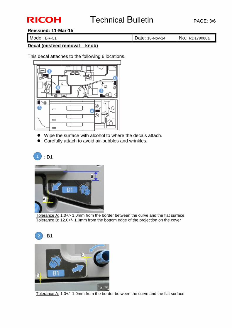
Technical Bulletin PAGE: 3/6
Reissued: 11-Mar-15
Model: BR-C1 Date: 18-Nov-14 No.: RD179080a
Decal (misfeed removal – knob) This decal attaches to the following 6 locations.
Wipe the surface with alcohol to where the decals attach. Carefully attach to avoid air-bubbles and wrinkles.
: D1
Tolerance A: 1.0+/- 1.0mm from the border between the curve and the flat surface Tolerance B: 12.0+/- 1.0mm from the bottom edge of the projection on the cover
: B1
Tolerance A: 1.0+/- 1.0mm from the border between the curve and the flat surface
1
2
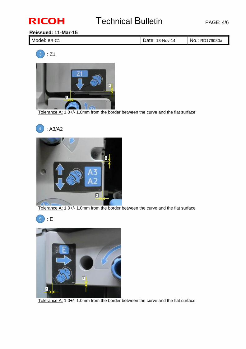
Technical Bulletin PAGE: 4/6
Reissued: 11-Mar-15
Model: BR-C1 Date: 18-Nov-14 No.: RD179080a
: Z1
Tolerance A: 1.0+/- 1.0mm from the border between the curve and the flat surface
: A3/A2
Tolerance A: 1.0+/- 1.0mm from the border between the curve and the flat surface
: E
Tolerance A: 1.0+/- 1.0mm from the border between the curve and the flat surface
3
4
5
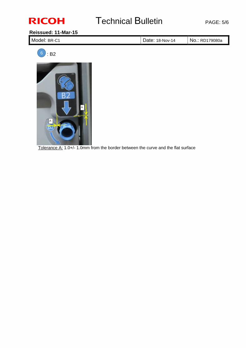
Technical Bulletin PAGE: 5/6
Reissued: 11-Mar-15
Model: BR-C1 Date: 18-Nov-14 No.: RD179080a
: B2
Tolerance A: 1.0+/- 1.0mm from the border between the curve and the flat surface
6
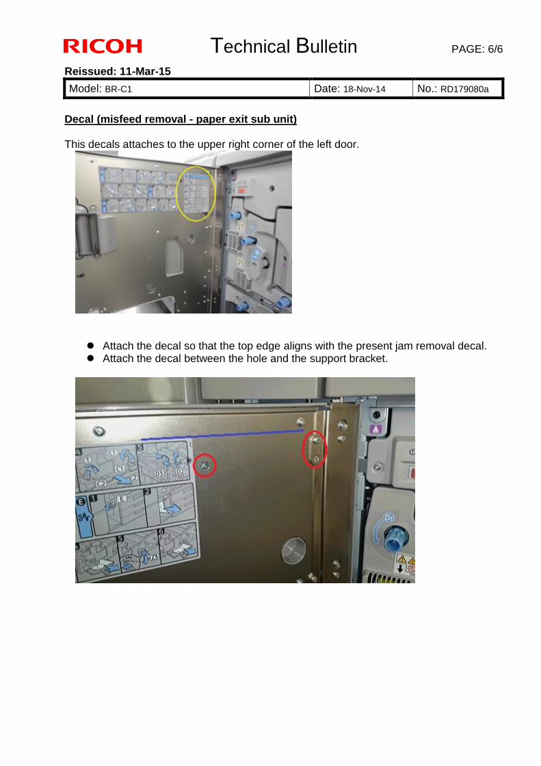
Technical Bulletin PAGE: 6/6
Reissued: 11-Mar-15
Model: BR-C1 Date: 18-Nov-14 No.: RD179080a
Decal (misfeed removal - paper exit sub unit) This decals attaches to the upper right corner of the left door.
Attach the decal so that the top edge aligns with the present jam removal decal. Attach the decal between the hole and the support bracket.
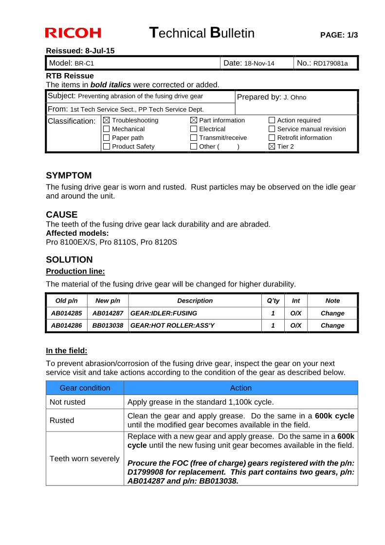
Technical Bulletin PAGE: 1/3
Reissued: 8-Jul-15
Model: BR-C1 Date: 18-Nov-14 No.: RD179081a
RTB Reissue The items in bold italics were corrected or added.
Subject: Preventing abrasion of the fusing drive gear Prepared by: J. Ohno
From: 1st Tech Service Sect., PP Tech Service Dept.
Classification: Troubleshooting
Mechanical
Paper path
Product Safety
Part information
Electrical
Transmit/receive
Other ( )
Action required
Service manual revision
Retrofit information
Tier 2
SYMPTOM
The fusing drive gear is worn and rusted. Rust particles may be observed on the idle gear and around the unit.
CAUSE
The teeth of the fusing drive gear lack durability and are abraded. Affected models: Pro 8100EX/S, Pro 8110S, Pro 8120S
SOLUTION
Production line:
The material of the fusing drive gear will be changed for higher durability.
Old p/n New p/n Description Q’ty Int Note
AB014285 AB014287 GEAR:IDLER:FUSING 1 O/X Change
AB014286 BB013038 GEAR:HOT ROLLER:ASS'Y 1 O/X Change
In the field:
To prevent abrasion/corrosion of the fusing drive gear, inspect the gear on your next service visit and take actions according to the condition of the gear as described below.
Gear condition Action
Not rusted Apply grease in the standard 1,100k cycle.
Rusted Clean the gear and apply grease. Do the same in a 600k cycle until the modified gear becomes available in the field.
Teeth worn severely
Replace with a new gear and apply grease. Do the same in a 600k cycle until the new fusing unit gear becomes available in the field. Procure the FOC (free of charge) gears registered with the p/n: D1799908 for replacement. This part contains two gears, p/n: AB014287 and p/n: BB013038.
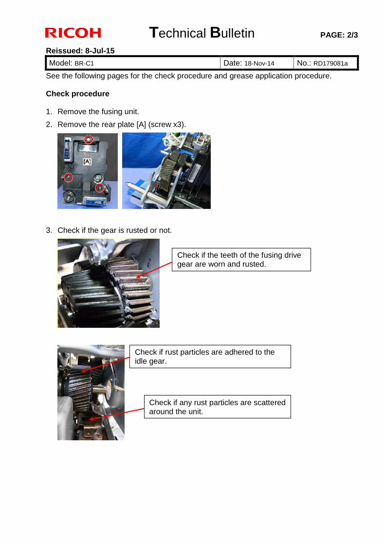
Technical Bulletin PAGE: 2/3
Reissued: 8-Jul-15
Model: BR-C1 Date: 18-Nov-14 No.: RD179081a
See the following pages for the check procedure and grease application procedure. Check procedure 1. Remove the fusing unit.
2. Remove the rear plate [A] (screw x3).
3. Check if the gear is rusted or not.
Check if rust particles are adhered to the idle gear.
Check if any rust particles are scattered around the unit.
Check if the teeth of the fusing drive gear are worn and rusted.
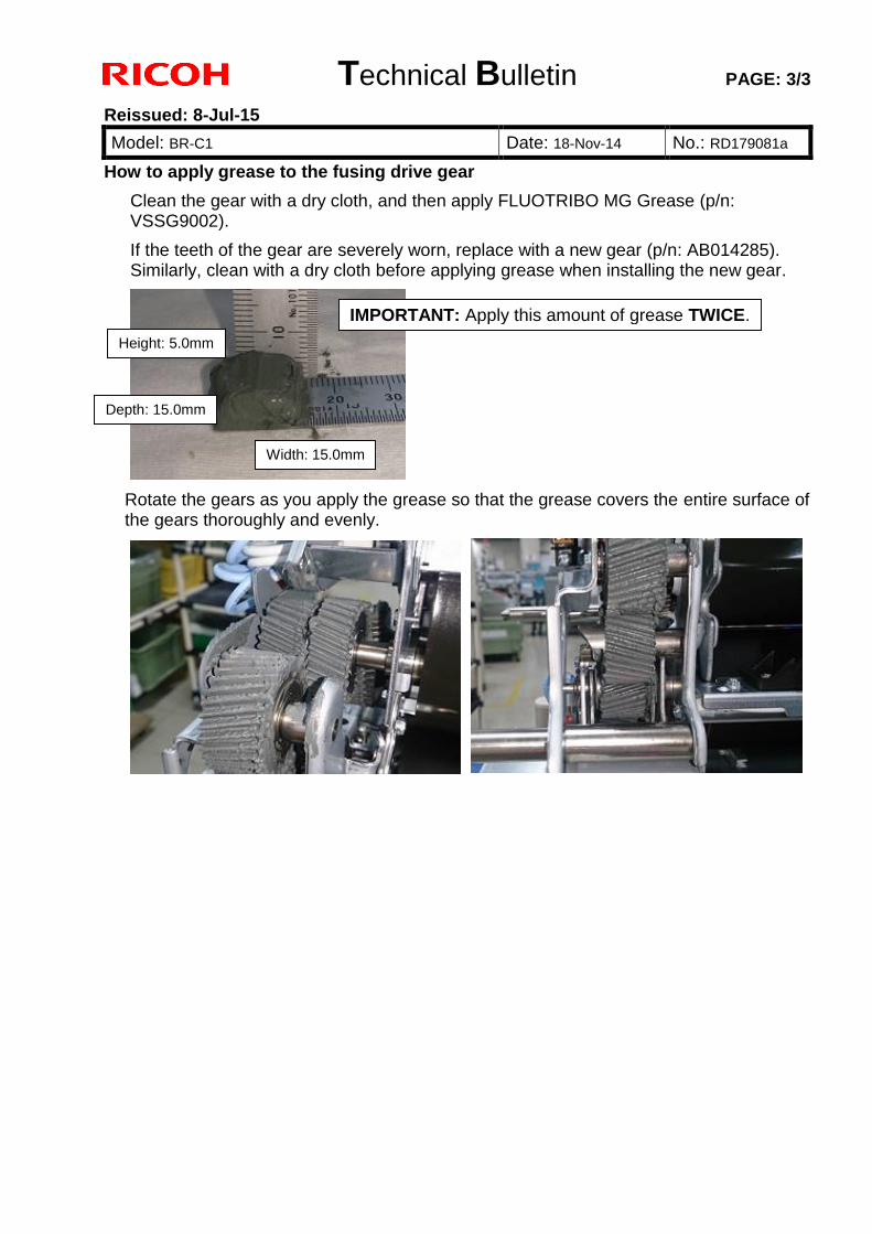
Technical Bulletin PAGE: 3/3
Reissued: 8-Jul-15
Model: BR-C1 Date: 18-Nov-14 No.: RD179081a
How to apply grease to the fusing drive gear
Clean the gear with a dry cloth, and then apply FLUOTRIBO MG Grease (p/n: VSSG9002).
If the teeth of the gear are severely worn, replace with a new gear (p/n: AB014285). Similarly, clean with a dry cloth before applying grease when installing the new gear.
Rotate the gears as you apply the grease so that the grease covers the entire surface of the gears thoroughly and evenly.
IMPORTANT: Apply this amount of grease TWICE.
Height: 5.0mm
Depth: 15.0mm
Width: 15.0mm
Technical Bulletin PAGE: 1/2
Model: BR-C1 Date: 28-Nov-14 No.: RD179082
Subject: Corrections in FSM and Troubleshooting Manual Prepared by: T. Suzuki
From: PP Tech Service Dept., 3rd PP Tech Service Sect.
Classification: Troubleshooting
Mechanical
Paper path
Product Safety
Part information
Electrical
Transmit/receive
Other ( )
Action required
Service manual revision
Retrofit information
Tier2
Please apply the following corrections to your field service manual and troubleshooting manual.
Correction 1: Field Service Manual
Appendices > 3. Appendices: SP Mode Tables > Main SP Tables-2 >SP2 –XXX (Drum)
Delete the following SP.
2-920-001 Initialize Belt Position E
[- / - / -]
[Execute]
Executes it during exchange image transfer
belt, and initializes belt position.
Correction 2: Troubleshooting Manual
Other Problems > ITB Centering: SC Codes: SC471-04, -05, -06 > Make Sure the Machine is Level
Page 149; Lines 1, 9, and 17
Incorrect : SP2-920-001
Correct : SP2-920-002
See next page.
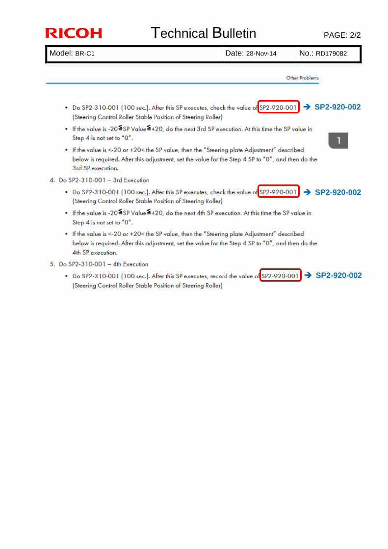
Technical Bulletin PAGE: 2/2
Model: BR-C1 Date: 28-Nov-14 No.: RD179082
SP2-920-002
SP2-920-002
SP2-920-002

Technical Bulletin PAGE: 1/1
Reissued: 11-Dec-14
Model: MET-C1cde/MET-C1cde_SOP
CH-C1 Office/CH-C1 Pro/Z-C2/Z-C2_SOP/Leo-C1/Leo-P1
Date: 18-Jun-13 No.: RD149025b
RTB Reissue The items in bold italics have been changed or added.
Subject: Firmware Release Note: PCL Font Prepared by: N. Yoshida
From: 1st Tech Service Sect., MFP/Printer Tech Service Dept.
Classification: Troubleshooting
Mechanical
Paper path
Product Safety
Part information
Electrical
Transmit/receive
Other (Firmware)
Action required
Service manual revision
Retrofit information
Tier 2
Important Information about Normal/Smart Panel Firmware Updates
When updating machine firmware, make sure NOT to install Smart Panel supported firmware on a machine with a normal operation panel (and vice-versa). If you do, the machine may not function as designed and product warranty may not apply.
To avoid this, when updating the firmware, make sure that the numbers next to "NEW" and "ROM" are the same on the operation panel.
If you install the wrong firmware, repeat the update procedure and check the numbers mentioned above.
This RTB has been issued to announce the firmware release information for the PCL Font.
Version Program No. Effective Date Availability of RFU
1.06 D1315586A 1st Mass production Available
Note: Definition of Availability of RFU via @Remote “Available”: The firmware can be updated via RFU or SD card. “Not available”: The firmware can only be updated via SD card.
Version Modified Points or Symptom Corrected
1.06 1st Mass production
Technical Bulletin PAGE: 1/7
Model: Model BR-C1 Date: 15-Dec-14 No.: RD179056
Important Information on Installing the BR-C1 models as a CC-CERTIFIED Machine compliant with IEEE Std 2600.1TM-2009 Do the following five steps if you want to install the BR-C1 models as a CC-CERTIFIED MACHINE compliant with IEEE Std 2600.1TM-2009. Note: Machines in production are CC-certified beginning in January 2014. Important: If the customer requests maintenance on the machine, please perform the maintenance without accessing SP mode. 1. Make sure the customer has received the English language Operating Instructions (O/I) shown in the page 6 - 7 Important:
・For installations in the EU market, make sure this is the Ricoh-genuine O/I.
・Tell the customer to download the online documents (the information about the
authentication based on the CC certification system) from the URLs provided in "Manuals for This Machine" in "Manuals Provided with This Machine" in "Read This First". 2. Tell the customer to read the “Notes for Administrators: Using This Machine in a Network Environment Compliant with IEEE Std 2600.1TM-2009”. See the following pages for Step 3 to Step 5.
Subject: CC-CERTIFIED IN 2013 Machine Prepared by: Y. Urushihara
From: 1st Tech Service Sect., MFP/P Tech Service Dept.
Classification: Troubleshooting
Mechanical
Paper path
Product Safety
Part information
Electrical
Transmit/receive
Other ( )
Action required
Service manual revision
Retrofit information
Tier 2
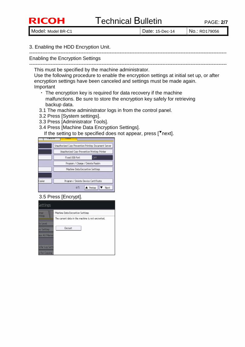
Technical Bulletin PAGE: 2/7
Model: Model BR-C1 Date: 15-Dec-14 No.: RD179056
3. Enabling the HDD Encryption Unit. ------------------------------------------------------------------------------------------------------------------------ Enabling the Encryption Settings ------------------------------------------------------------------------------------------------------------------------ This must be specified by the machine administrator. Use the following procedure to enable the encryption settings at initial set up, or after encryption settings have been canceled and settings must be made again. Important
・ The encryption key is required for data recovery if the machine
malfunctions. Be sure to store the encryption key safely for retrieving backup data. 3.1 The machine administrator logs in from the control panel. 3.2 Press [System settings]. 3.3 Press [Administrator Tools]. 3.4 Press [Machine Data Encryption Settings].
If the setting to be specified does not appear, press [▼next].
3.5 Press [Encrypt].

Technical Bulletin PAGE: 3/7
Model: Model BR-C1 Date: 15-Dec-14 No.: RD179056
3.6 Select the [Format All Data] to reset all of the data. Note: It takes about five minutes to complete this operation. 3.7 Press the [Print on Paper]. 3.8 Hand the customer the printout of the encryption key. 3.9 Press [OK]. 3.10 Press [Exit]. 3.11 Press [Exit]. 3.12 Log out. 3.13 Turn off the main power switch, and then turn the main power switch back on.

Technical Bulletin PAGE: 4/7
Model: Model BR-C1 Date: 15-Dec-14 No.: RD179056
4. Prohibit a use of JavaTM Platform. Disable the functions of "JavaTM Platform setting (SP5-730-001)". 5. Make sure the machine contains the correct firmware.
● If the customer wants to install the machine in the same condition as when CC
Certification was first attained (same as the January 2014 machines), install the exact versions shown in the table below.
● If the customer wants to install the machine as an equivalent of the January 2014
machines, install the versions shown in the table below or later. If you are not sure which one the customer is requesting, contact your sales department.
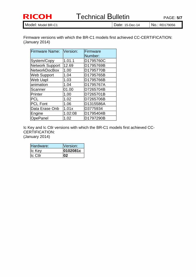
Technical Bulletin PAGE: 5/7
Model: Model BR-C1 Date: 15-Dec-14 No.: RD179056
Firmware versions with which the BR-C1 models first achieved CC-CERTIFICATION: (January 2014)
Firmware Name: Version: Firmware Number:
System/Copy 1.01.1 D1795760C
Network Support 12.69 D1795769B
NetworkDocBox 1.00 D1795770B
Web Support 1.04 D1795765B
Web Uapl 1.03 D1795766B
animation 1.04 D1795767A
Scanner 01.00 D7265704B
Printer 1.00 D7265701B
PCL 1.02 D7265706B
PCL Font 1.06 D1315586A
Data Erase Onb 1.01x D3775934
Engine 1.02:08 D1795404B
OpePanel 1.02 D1797290B
Ic Key and Ic Ctlr versions with which the BR-C1 models first achieved CC-CERTIFICATION: (January 2014)
Hardware: Version:
Ic Key 0102081c
Ic Ctlr 02
Technical Bulletin PAGE: 6/7
Model: Model BR-C1 Date: 15-Dec-14 No.: RD179056
The list of Operating Instructions (O/I) <For NA> Paper Documents
・D181-2512A Pro 8100S/8110S/8120S
Read This First
・D143-7350 Notes for Security Guide
・D181-2502A Pro 8100S/8110S/8120S
User Guide
・D181-2599 Notes for Users
・D181-2546 Notes for Users
CD-ROMs
・D181-7706 Manuals
Pro 8100S/8110S/8120S series A
・D726-7810 Printer/Scanner Drivers and Utilities
RICOH Pro 8100S/8110S/8120S series LANIER Pro 8100S/8110S/8120S series
SAVIN Pro 8100S/8110S/8120S series Online Documents
・D181-2583 Notes on Security Functions
・D181-2581 Notes for Administrators:
Using This Machine in a Network Environment Compliant with IEEE Std 2600.1TM-2009 <For EU and Asia> Paper Documents
・D181-2511 Pro 8100S/8110S/8120S
Read This First
・D143-7350 Notes for Security Guide
・D181-2596 Notes for Users
・D181-2546 Notes for Users
・D181-2590 Notes for Users
CD-ROMs
・D181-7706 Manuals
Pro 8100S/8110S/8120S series A
・D726-7813 Printer/Scanner Drivers and Utilities
RICOH Pro 8100S/8110S/8120S series Pro 8100S/8110S/8120S series infotec Pro 8100S/8110S/8120S series

Technical Bulletin PAGE: 7/7
Model: Model BR-C1 Date: 15-Dec-14 No.: RD179056
LANIER Pro 8100S/8110S/8120S series Online Documents
・D181-2583 Notes on Security Functions
・D181-2581 Notes for Administrators:
Using This Machine in a Network Environment Compliant with IEEE Std 2600.1TM-2009
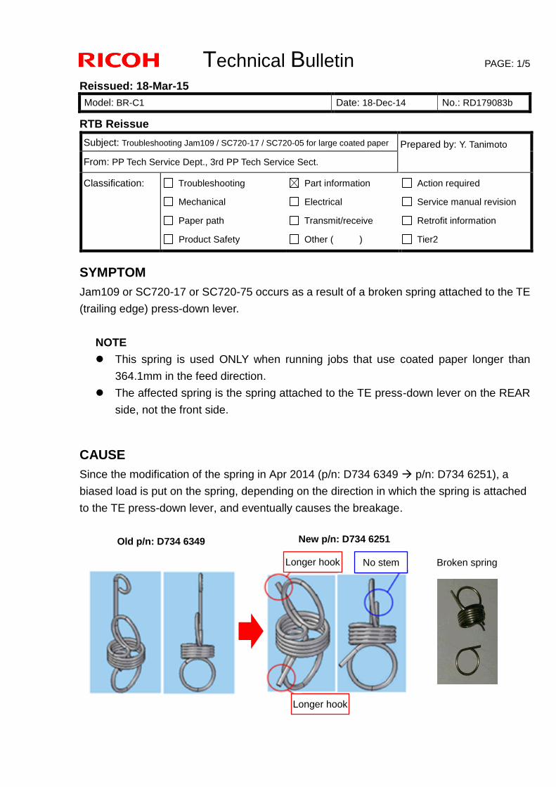
Technical Bulletin PAGE: 1/5
Reissued: 18-Mar-15
Model: BR-C1 Date: 18-Dec-14 No.: RD179083b
RTB Reissue
SYMPTOM
Jam109 or SC720-17 or SC720-75 occurs as a result of a broken spring attached to the TE
(trailing edge) press-down lever.
NOTE
This spring is used ONLY when running jobs that use coated paper longer than
364.1mm in the feed direction.
The affected spring is the spring attached to the TE press-down lever on the REAR
side, not the front side.
CAUSE
Since the modification of the spring in Apr 2014 (p/n: D734 6349 p/n: D734 6251), a
biased load is put on the spring, depending on the direction in which the spring is attached
to the TE press-down lever, and eventually causes the breakage.
Subject: Troubleshooting Jam109 / SC720-17 / SC720-05 for large coated paper Prepared by: Y. Tanimoto
From: PP Tech Service Dept., 3rd PP Tech Service Sect.
Classification: Troubleshooting
Mechanical
Paper path
Product Safety
Part information
Electrical
Transmit/receive
Other ( )
Action required
Service manual revision
Retrofit information
Tier2
Old p/n: D734 6349 New p/n: D734 6251
Longer hook
Longer hook No stem Broken spring
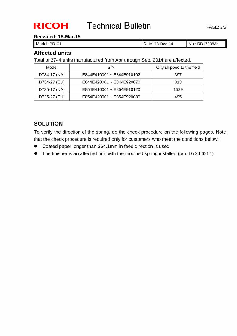
Technical Bulletin PAGE: 2/5
Reissued: 18-Mar-15
Model: BR-C1 Date: 18-Dec-14 No.: RD179083b
Affected units
Total of 2744 units manufactured from Apr through Sep, 2014 are affected.
Model S/N Q’ty shipped to the field
D734-17 (NA) E844E410001 ~ E844E910102 397
D734-27 (EU) E844E420001 ~ E844E920070 313
D735-17 (NA) E854E410001 ~ E854E910120 1539
D735-27 (EU) E854E420001 ~ E854E920080 495
SOLUTION
To verify the direction of the spring, do the check procedure on the following pages. Note
that the check procedure is required only for customers who meet the conditions below:
Coated paper longer than 364.1mm in feed direction is used
The finisher is an affected unit with the modified spring installed (p/n: D734 6251)
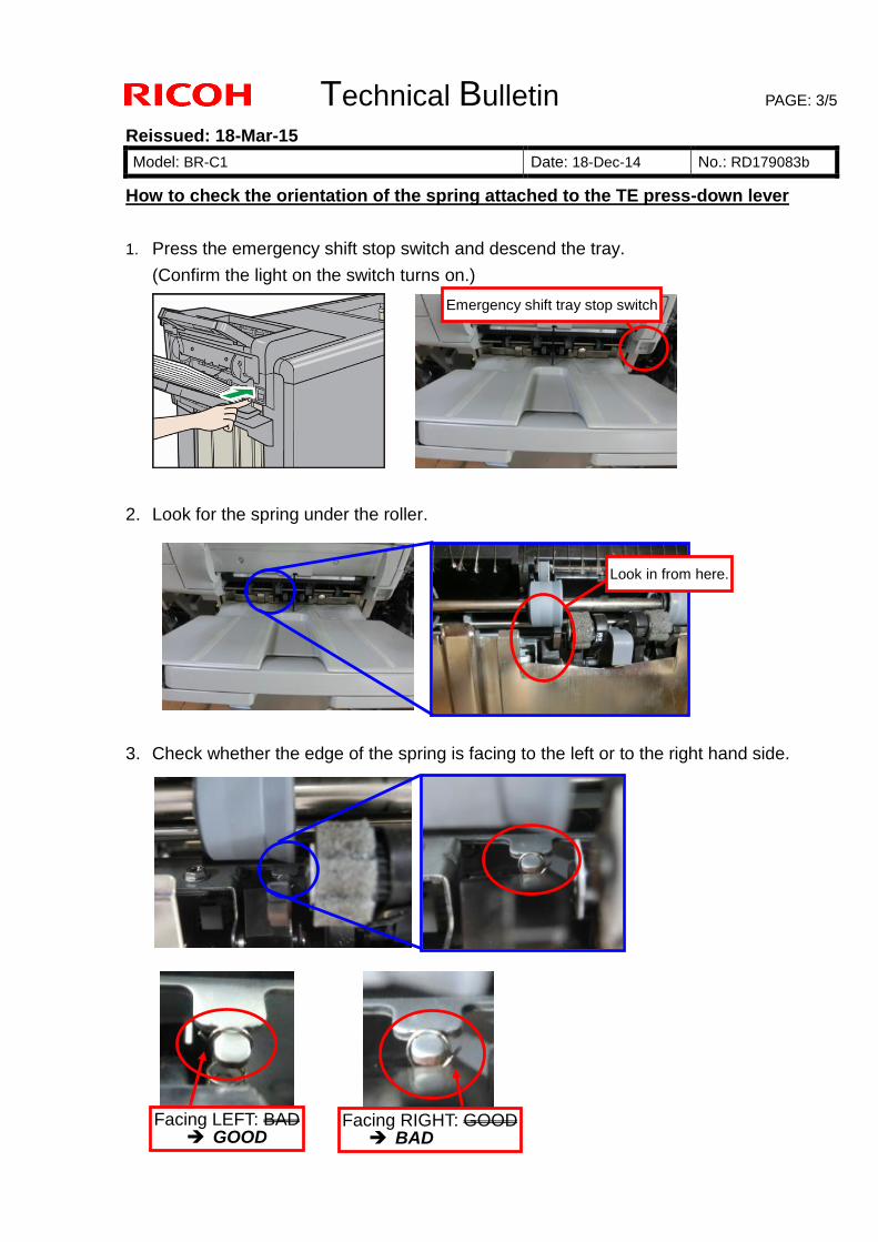
Technical Bulletin PAGE: 3/5
Reissued: 18-Mar-15
Model: BR-C1 Date: 18-Dec-14 No.: RD179083b
How to check the orientation of the spring attached to the TE press-down lever
1. Press the emergency shift stop switch and descend the tray.
(Confirm the light on the switch turns on.)
2. Look for the spring under the roller.
3. Check whether the edge of the spring is facing to the left or to the right hand side.
Emergency shift tray stop switch
Look in from here.
Facing LEFT: BAD GOOD
Facing RIGHT: GOOD BAD
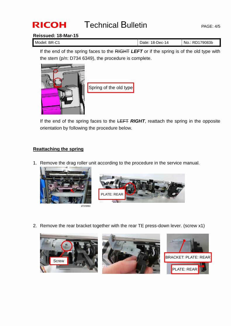
Technical Bulletin PAGE: 4/5
Reissued: 18-Mar-15
Model: BR-C1 Date: 18-Dec-14 No.: RD179083b
If the end of the spring faces to the RIGHT LEFT or if the spring is of the old type with
the stem (p/n: D734 6349), the procedure is complete.
If the end of the spring faces to the LEFT RIGHT, reattach the spring in the opposite
orientation by following the procedure below.
Reattaching the spring
1. Remove the drag roller unit according to the procedure in the service manual.
2. Remove the rear bracket together with the rear TE press-down lever. (screw x1)
PLATE: REAR
Screw BRACKET: PLATE: REAR
PLATE: REAR
Spring of the old type
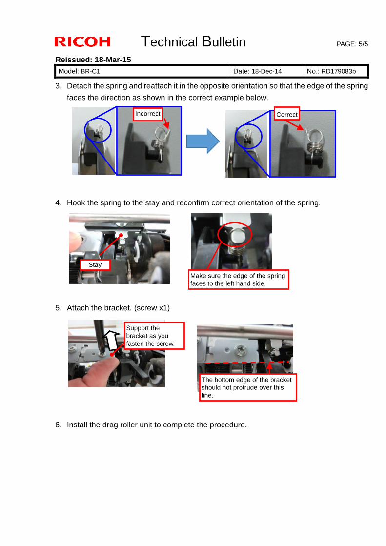
Technical Bulletin PAGE: 5/5
Reissued: 18-Mar-15
Model: BR-C1 Date: 18-Dec-14 No.: RD179083b
3. Detach the spring and reattach it in the opposite orientation so that the edge of the spring
faces the direction as shown in the correct example below.
4. Hook the spring to the stay and reconfirm correct orientation of the spring.
5. Attach the bracket. (screw x1)
6. Install the drag roller unit to complete the procedure.
Incorrect
Correct
Stay
Make sure the edge of the spring
faces to the left hand side.
Support the
bracket as you
fasten the screw.
The bottom edge of the bracket
should not protrude over this
line.
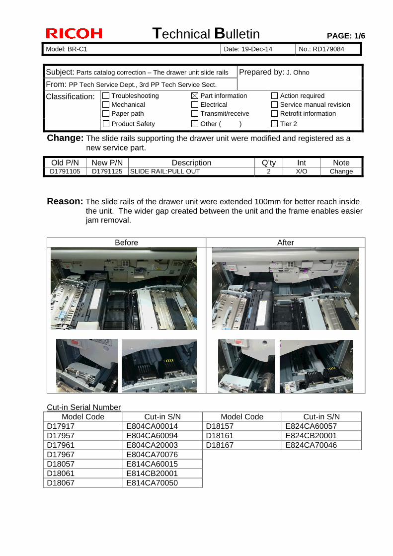
Technical Bulletin PAGE: 1/6
Model: BR-C1 Date: 19-Dec-14 No.: RD179084
Subject: Parts catalog correction – The drawer unit slide rails Prepared by: J. Ohno
From: PP Tech Service Dept., 3rd PP Tech Service Sect.
Classification: Troubleshooting Mechanical Paper path
Part information Electrical Transmit/receive
Action required Service manual revision Retrofit information
Product Safety Other ( ) Tier 2
Change: The slide rails supporting the drawer unit were modified and registered as a new service part.
Old P/N New P/N Description Q’ty Int Note D1791105 D1791125 SLIDE RAIL:PULL OUT 2 X/O Change
Reason: The slide rails of the drawer unit were extended 100mm for better reach inside the unit. The wider gap created between the unit and the frame enables easier jam removal.
Before After
Cut-in Serial Number
Model Code Cut-in S/N Model Code Cut-in S/N D17917 E804CA00014 D18157 E824CA60057 D17957 E804CA60094 D18161 E824CB20001 D17961 E804CA20003 D18167 E824CA70046 D17967 E804CA70076 D18057 E814CA60015 D18061 E814CB20001 D18067 E814CA70050
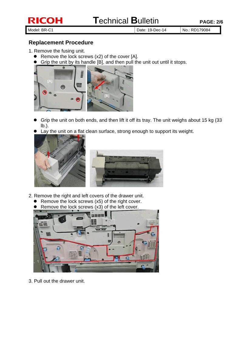
Technical Bulletin PAGE: 2/6
Model: BR-C1 Date: 19-Dec-14 No.: RD179084
Replacement Procedure
1. Remove the fusing unit. Remove the lock screws (x2) of the cover [A]. Grip the unit by its handle [B], and then pull the unit out until it stops.
Grip the unit on both ends, and then lift it off its tray. The unit weighs about 15 kg (33
lb.). Lay the unit on a flat clean surface, strong enough to support its weight.
2. Remove the right and left covers of the drawer unit. Remove the lock screws (x5) of the right cover. Remove the lock screws (x3) of the left cover.
3. Pull out the drawer unit.
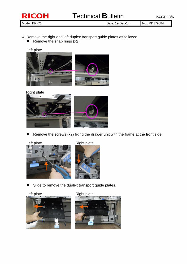
Technical Bulletin PAGE: 3/6
Model: BR-C1 Date: 19-Dec-14 No.: RD179084
4. Remove the right and left duplex transport guide plates as follows: Remove the snap rings (x2).
Left plate
Right plate
Remove the screws (x2) fixing the drawer unit with the frame at the front side.
Left plate Right plate
Slide to remove the duplex transport guide plates.
Left plate Right plate
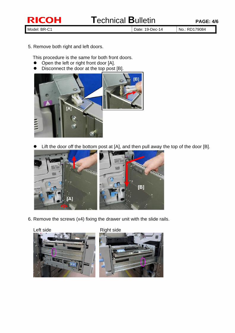
Technical Bulletin PAGE: 4/6
Model: BR-C1 Date: 19-Dec-14 No.: RD179084
5. Remove both right and left doors.
This procedure is the same for both front doors. Open the left or right front door [A]. Disconnect the door at the top post [B].
Lift the door off the bottom post at [A], and then pull away the top of the door [B].
6. Remove the screws (x4) fixing the drawer unit with the slide rails. Left side Right side
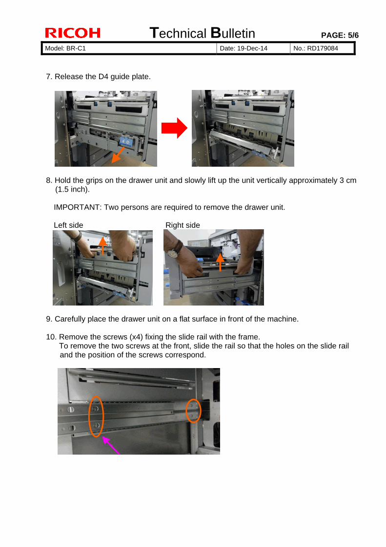
Technical Bulletin PAGE: 5/6
Model: BR-C1 Date: 19-Dec-14 No.: RD179084
7. Release the D4 guide plate.
8. Hold the grips on the drawer unit and slowly lift up the unit vertically approximately 3 cm
(1.5 inch).
IMPORTANT: Two persons are required to remove the drawer unit.
Left side Right side
9. Carefully place the drawer unit on a flat surface in front of the machine. 10. Remove the screws (x4) fixing the slide rail with the frame. To remove the two screws at the front, slide the rail so that the holes on the slide rail
and the position of the screws correspond.
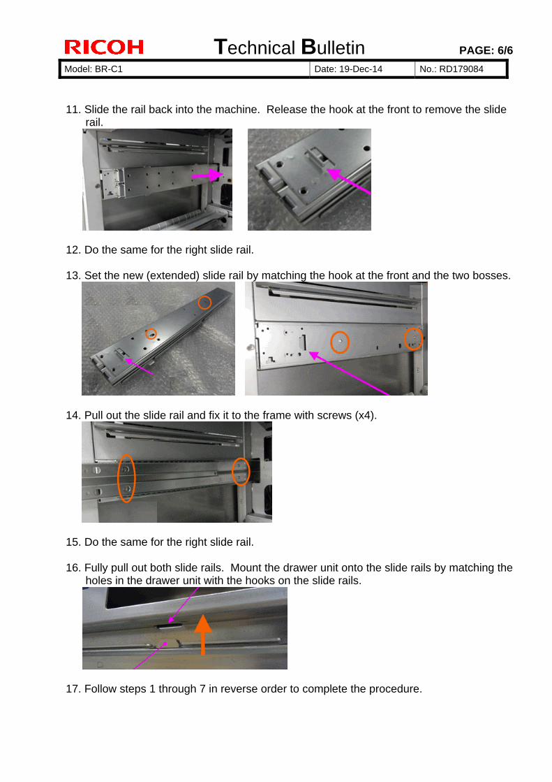
Technical Bulletin PAGE: 6/6
Model: BR-C1 Date: 19-Dec-14 No.: RD179084
11. Slide the rail back into the machine. Release the hook at the front to remove the slide
rail.
12. Do the same for the right slide rail. 13. Set the new (extended) slide rail by matching the hook at the front and the two bosses.
14. Pull out the slide rail and fix it to the frame with screws (x4).
15. Do the same for the right slide rail. 16. Fully pull out both slide rails. Mount the drawer unit onto the slide rails by matching the
holes in the drawer unit with the hooks on the slide rails.
17. Follow steps 1 through 7 in reverse order to complete the procedure.
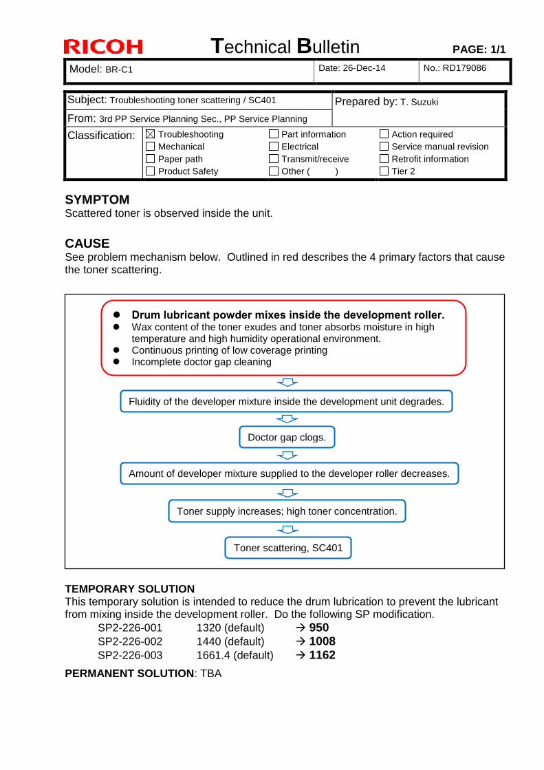
Technical Bulletin PAGE: 1/1
Model: BR-C1 Date: 26-Dec-14 No.: RD179086
SYMPTOM Scattered toner is observed inside the unit.
CAUSE See problem mechanism below. Outlined in red describes the 4 primary factors that cause the toner scattering.
TEMPORARY SOLUTION This temporary solution is intended to reduce the drum lubrication to prevent the lubricant from mixing inside the development roller. Do the following SP modification.
SP2-226-001 1320 (default) 950
SP2-226-002 1440 (default) 1008
SP2-226-003 1661.4 (default) 1162
PERMANENT SOLUTION: TBA
Subject: Troubleshooting toner scattering / SC401 Prepared by: T. Suzuki
From: 3rd PP Service Planning Sec., PP Service Planning
Classification: Troubleshooting
Mechanical
Paper path
Product Safety
Part information
Electrical
Transmit/receive
Other ( )
Action required
Service manual revision
Retrofit information
Tier 2
Fluidity of the developer mixture inside the development unit degrades.
Amount of developer mixture supplied to the developer roller decreases.
Toner supply increases; high toner concentration.
Drum lubricant powder mixes inside the development roller. Wax content of the toner exudes and toner absorbs moisture in high
temperature and high humidity operational environment. Continuous printing of low coverage printing Incomplete doctor gap cleaning
Toner scattering, SC401
Doctor gap clogs.
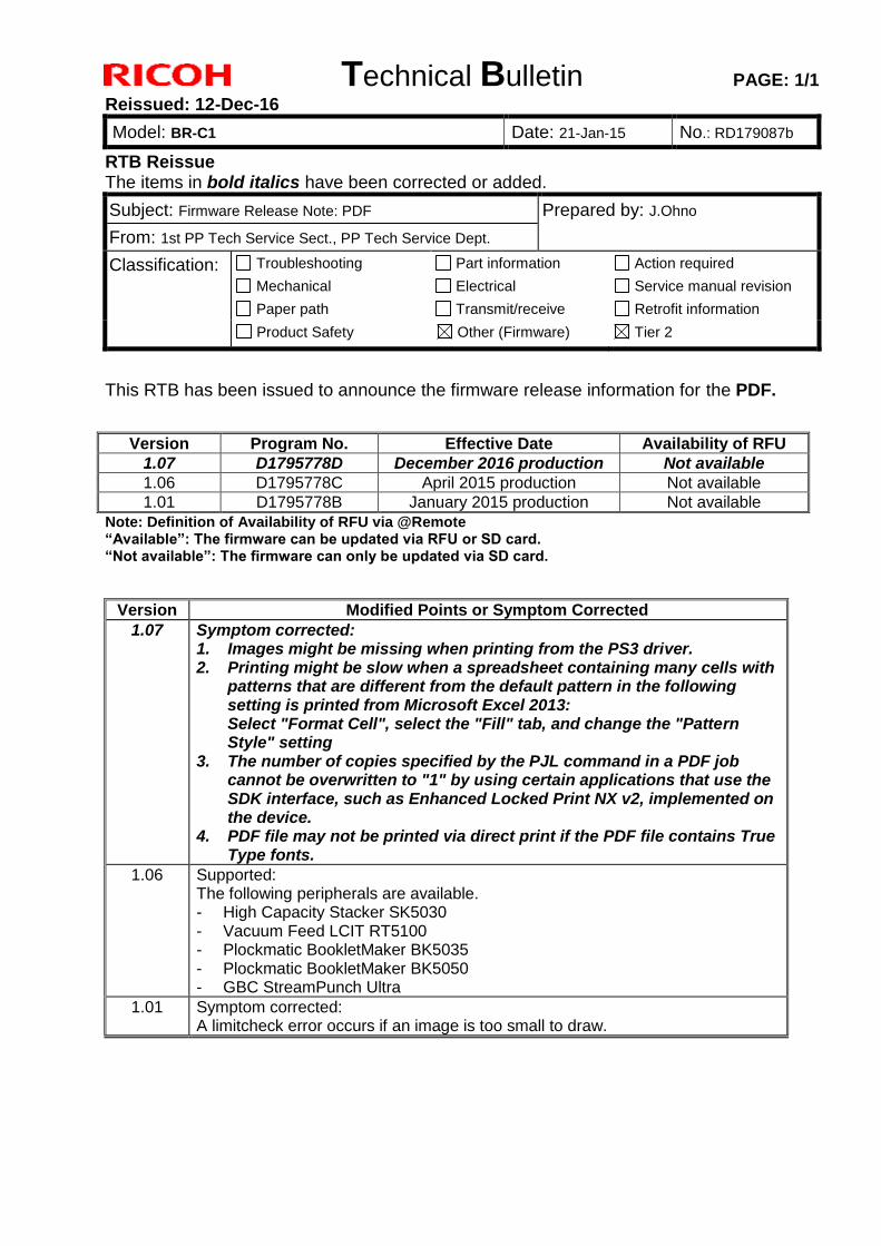
Technical Bulletin PAGE: 1/1
Reissued: 12-Dec-16
Model: BR-C1 Date: 21-Jan-15 No.: RD179087b
RTB Reissue The items in bold italics have been corrected or added.
Subject: Firmware Release Note: PDF Prepared by: J.Ohno
From: 1st PP Tech Service Sect., PP Tech Service Dept.
Classification: Troubleshooting
Mechanical
Paper path
Part information
Electrical
Transmit/receive
Action required
Service manual revision
Retrofit information
Product Safety Other (Firmware) Tier 2
This RTB has been issued to announce the firmware release information for the PDF.
Version Program No. Effective Date Availability of RFU
1.07 D1795778D December 2016 production Not available
1.06 D1795778C April 2015 production Not available
1.01 D1795778B January 2015 production Not available
Note: Definition of Availability of RFU via @Remote “Available”: The firmware can be updated via RFU or SD card. “Not available”: The firmware can only be updated via SD card.
Version Modified Points or Symptom Corrected
1.07 Symptom corrected: 1. Images might be missing when printing from the PS3 driver. 2. Printing might be slow when a spreadsheet containing many cells with
patterns that are different from the default pattern in the following setting is printed from Microsoft Excel 2013: Select "Format Cell", select the "Fill" tab, and change the "Pattern Style" setting
3. The number of copies specified by the PJL command in a PDF job cannot be overwritten to "1" by using certain applications that use the SDK interface, such as Enhanced Locked Print NX v2, implemented on the device.
4. PDF file may not be printed via direct print if the PDF file contains True Type fonts.
1.06 Supported: The following peripherals are available. - High Capacity Stacker SK5030 - Vacuum Feed LCIT RT5100 - Plockmatic BookletMaker BK5035 - Plockmatic BookletMaker BK5050 - GBC StreamPunch Ultra
1.01 Symptom corrected: A limitcheck error occurs if an image is too small to draw.
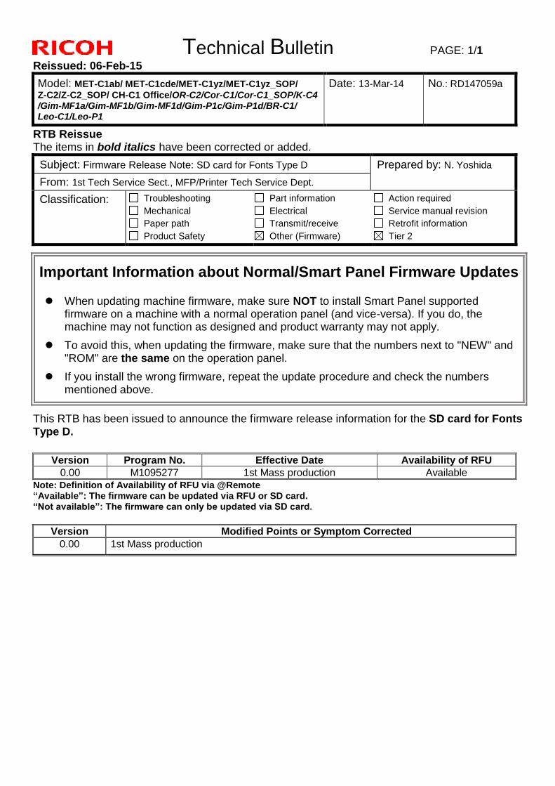
Technical Bulletin PAGE: 1/1
Reissued: 06-Feb-15
Model: MET-C1ab/ MET-C1cde/MET-C1yz/MET-C1yz_SOP/
Z-C2/Z-C2_SOP/ CH-C1 Office/OR-C2/Cor-C1/Cor-C1_SOP/K-C4 /Gim-MF1a/Gim-MF1b/Gim-MF1d/Gim-P1c/Gim-P1d/BR-C1/ Leo-C1/Leo-P1
Date: 13-Mar-14 No.: RD147059a
RTB Reissue The items in bold italics have been corrected or added.
Subject: Firmware Release Note: SD card for Fonts Type D Prepared by: N. Yoshida
From: 1st Tech Service Sect., MFP/Printer Tech Service Dept.
Classification: Troubleshooting
Mechanical
Paper path
Product Safety
Part information
Electrical
Transmit/receive
Other (Firmware)
Action required
Service manual revision
Retrofit information
Tier 2
Important Information about Normal/Smart Panel Firmware Updates
When updating machine firmware, make sure NOT to install Smart Panel supported firmware on a machine with a normal operation panel (and vice-versa). If you do, the machine may not function as designed and product warranty may not apply.
To avoid this, when updating the firmware, make sure that the numbers next to "NEW" and "ROM" are the same on the operation panel.
If you install the wrong firmware, repeat the update procedure and check the numbers mentioned above.
This RTB has been issued to announce the firmware release information for the SD card for Fonts Type D.
Version Program No. Effective Date Availability of RFU
0.00 M1095277 1st Mass production Available
Note: Definition of Availability of RFU via @Remote “Available”: The firmware can be updated via RFU or SD card. “Not available”: The firmware can only be updated via SD card.
Version Modified Points or Symptom Corrected
0.00 1st Mass production
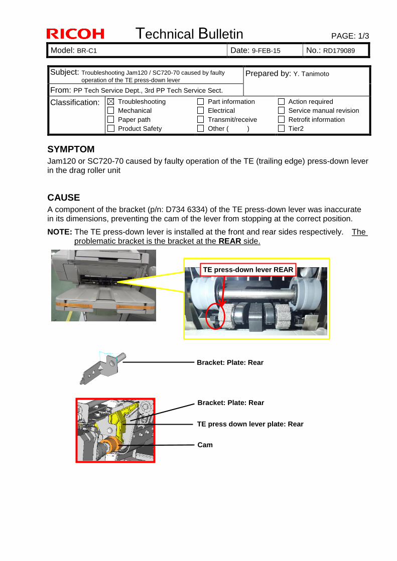
Technical Bulletin PAGE: 1/3
Model: BR-C1 Date: 9-FEB-15 No.: RD179089
SYMPTOM
Jam120 or SC720-70 caused by faulty operation of the TE (trailing edge) press-down lever in the drag roller unit
CAUSE
A component of the bracket (p/n: D734 6334) of the TE press-down lever was inaccurate in its dimensions, preventing the cam of the lever from stopping at the correct position.
NOTE: The TE press-down lever is installed at the front and rear sides respectively. The problematic bracket is the bracket at the REAR side.
Subject: Troubleshooting Jam120 / SC720-70 caused by faulty
operation of the TE press-down lever Prepared by: Y. Tanimoto
From: PP Tech Service Dept., 3rd PP Tech Service Sect.
Classification: Troubleshooting
Mechanical
Paper path
Product Safety
Part information
Electrical
Transmit/receive
Other ( )
Action required
Service manual revision
Retrofit information
Tier2
TE press-down lever REAR
Bracket: Plate: Rear
Bracket: Plate: Rear
TE press down lever plate: Rear
Cam
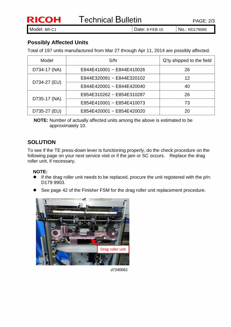
Technical Bulletin PAGE: 2/3
Model: BR-C1 Date: 9-FEB-15 No.: RD179089
Possibly Affected Units
Total of 197 units manufactured from Mar 27 through Apr 11, 2014 are possibly affected.
Model S/N Q’ty shipped to the field
D734-17 (NA) E844E410001 ~ E844E410026 26
D734-27 (EU) E844E320091 ~ E844E320102 12
E844E420001 ~ E844E420040 40
D735-17 (NA) E854E310262 ~ E854E310287 26
E854E410001 ~ E854E410073 73
D735-27 (EU) E854E420001 ~ E854E420020 20
NOTE: Number of actually affected units among the above is estimated to be approximately 10.
SOLUTION
To see if the TE press-down lever is functioning properly, do the check procedure on the following page on your next service visit or if the jam or SC occurs. Replace the drag roller unit, if necessary.
NOTE: If the drag roller unit needs to be replaced, procure the unit registered with the p/n:
D179 9903.
See page 42 of the Finisher FSM for the drag roller unit replacement procedure.
Drag roller unit
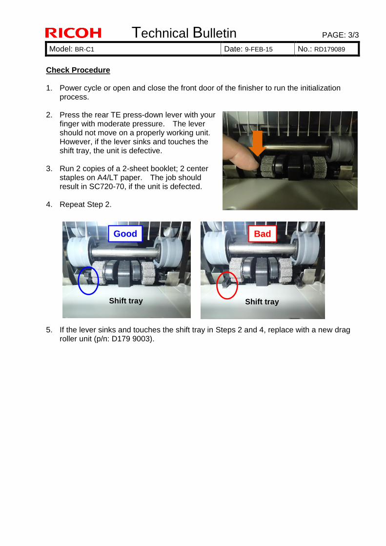
Technical Bulletin PAGE: 3/3
Model: BR-C1 Date: 9-FEB-15 No.: RD179089
Check Procedure 1. Power cycle or open and close the front door of the finisher to run the initialization
process.
2. Press the rear TE press-down lever with your finger with moderate pressure. The lever should not move on a properly working unit. However, if the lever sinks and touches the shift tray, the unit is defective.
3. Run 2 copies of a 2-sheet booklet; 2 center staples on A4/LT paper. The job should result in SC720-70, if the unit is defected.
4. Repeat Step 2.
5. If the lever sinks and touches the shift tray in Steps 2 and 4, replace with a new drag
roller unit (p/n: D179 9003).
Good
Shift tray
Bad
Shift tray
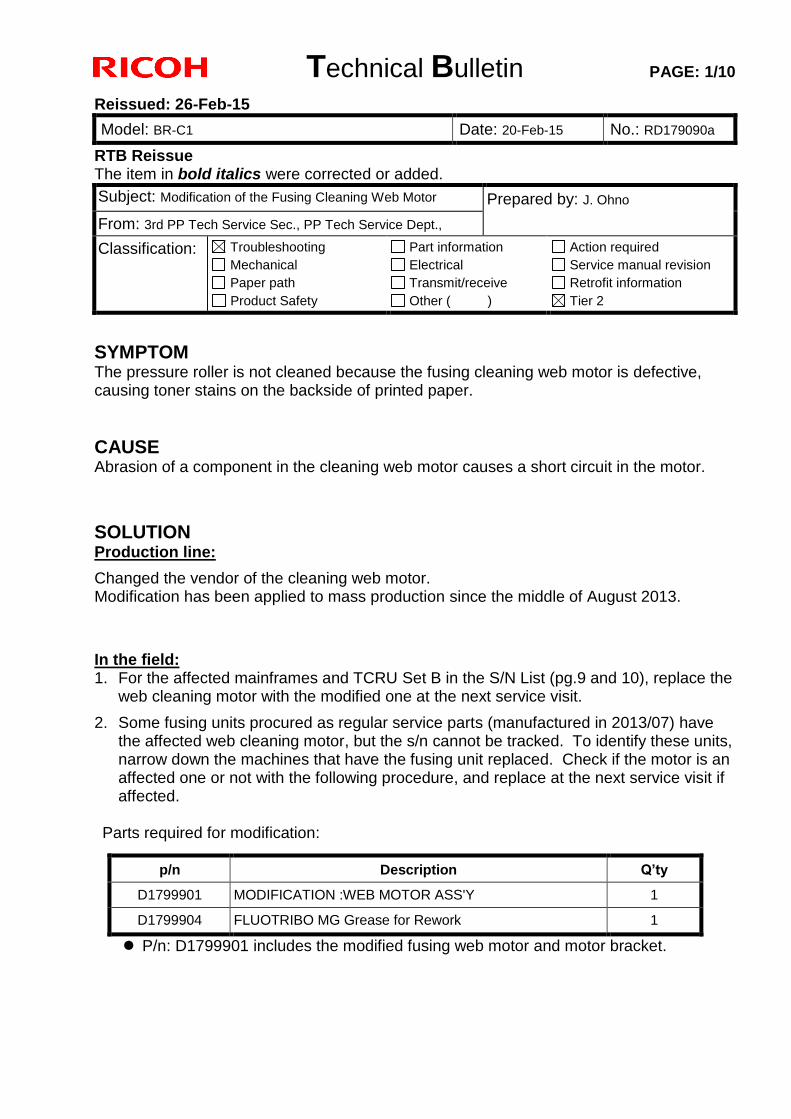
Technical Bulletin PAGE: 1/10
Reissued: 26-Feb-15
Model: BR-C1 Date: 20-Feb-15 No.: RD179090a
RTB Reissue The item in bold italics were corrected or added.
Subject: Modification of the Fusing Cleaning Web Motor Prepared by: J. Ohno
From: 3rd PP Tech Service Sec., PP Tech Service Dept.,
Classification: Troubleshooting
Mechanical
Paper path
Product Safety
Part information
Electrical
Transmit/receive
Other ( )
Action required
Service manual revision
Retrofit information
Tier 2
SYMPTOM The pressure roller is not cleaned because the fusing cleaning web motor is defective, causing toner stains on the backside of printed paper.
CAUSE Abrasion of a component in the cleaning web motor causes a short circuit in the motor.
SOLUTION Production line:
Changed the vendor of the cleaning web motor. Modification has been applied to mass production since the middle of August 2013.
In the field: 1. For the affected mainframes and TCRU Set B in the S/N List (pg.9 and 10), replace the
web cleaning motor with the modified one at the next service visit.
2. Some fusing units procured as regular service parts (manufactured in 2013/07) have the affected web cleaning motor, but the s/n cannot be tracked. To identify these units, narrow down the machines that have the fusing unit replaced. Check if the motor is an affected one or not with the following procedure, and replace at the next service visit if affected.
Parts required for modification:
P/n: D1799901 includes the modified fusing web motor and motor bracket.
p/n Description Q’ty
D1799901 MODIFICATION :WEB MOTOR ASS'Y 1
D1799904 FLUOTRIBO MG Grease for Rework 1
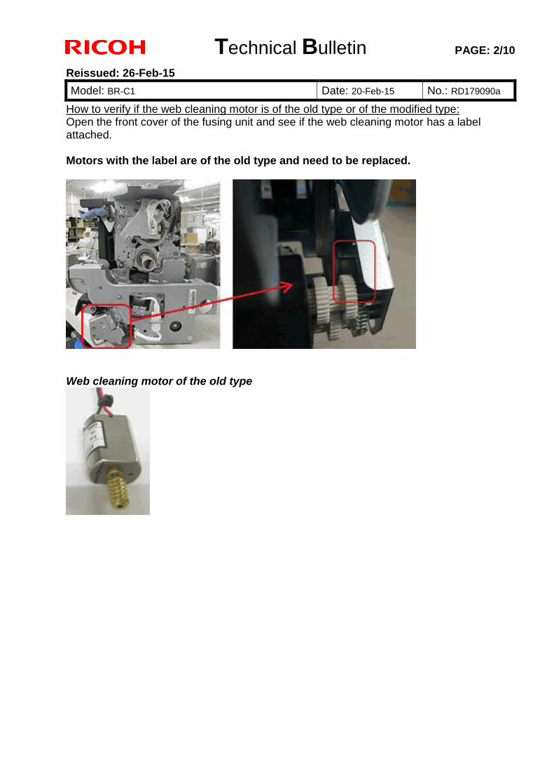
Technical Bulletin PAGE: 2/10
Reissued: 26-Feb-15
Model: BR-C1 Date: 20-Feb-15 No.: RD179090a
How to verify if the web cleaning motor is of the old type or of the modified type: Open the front cover of the fusing unit and see if the web cleaning motor has a label attached. Motors with the label are of the old type and need to be replaced.
Web cleaning motor of the old type
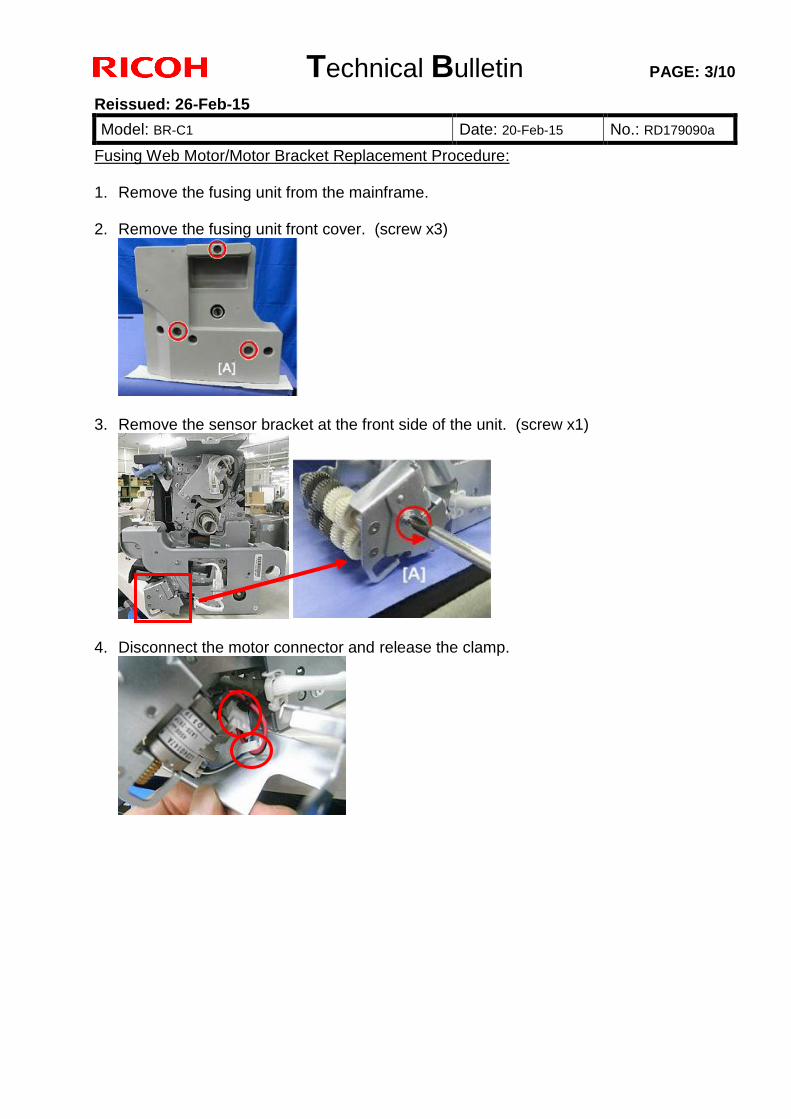
Technical Bulletin PAGE: 3/10
Reissued: 26-Feb-15
Model: BR-C1 Date: 20-Feb-15 No.: RD179090a
Fusing Web Motor/Motor Bracket Replacement Procedure: 1. Remove the fusing unit from the mainframe.
2. Remove the fusing unit front cover. (screw x3)
3. Remove the sensor bracket at the front side of the unit. (screw x1)
4. Disconnect the motor connector and release the clamp.
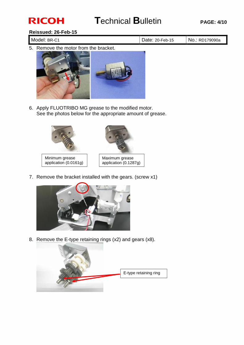
Technical Bulletin PAGE: 4/10
Reissued: 26-Feb-15
Model: BR-C1 Date: 20-Feb-15 No.: RD179090a
5. Remove the motor from the bracket.
6. Apply FLUOTRIBO MG grease to the modified motor. See the photos below for the appropriate amount of grease.
7. Remove the bracket installed with the gears. (screw x1)
8. Remove the E-type retaining rings (x2) and gears (x8).
Minimum grease application (0.0161g)
Maximum grease application (0.1287g)
E-type retaining ring
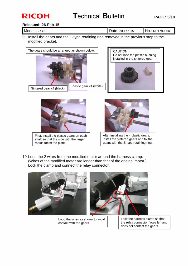
Technical Bulletin PAGE: 5/10
Reissued: 26-Feb-15
Model: BR-C1 Date: 20-Feb-15 No.: RD179090a
9. Install the gears and the E-type retaining ring removed in the previous step to the modified bracket.
10. Loop the 2 wires from the modified motor around the harness clamp. (Wires of the modified motor are longer than that of the original motor.) Lock the clamp and connect the relay connector.
The gears should be arranged as shown below.
Sintered gear x4 (black) Plastic gear x4 (white)
CAUTION Do not lose the plastic bushing installed in the sintered gear.
First, install the plastic gears on each shaft so that the side with the larger radius faces the plate.
After installing the 4 plastic gears, install the sintered gears and fix the gears with the E-type retaining ring.
Loop the wires as shown to avoid contact with the gears.
Lock the harness clamp so that the relay connector faces left and does not contact the gears.
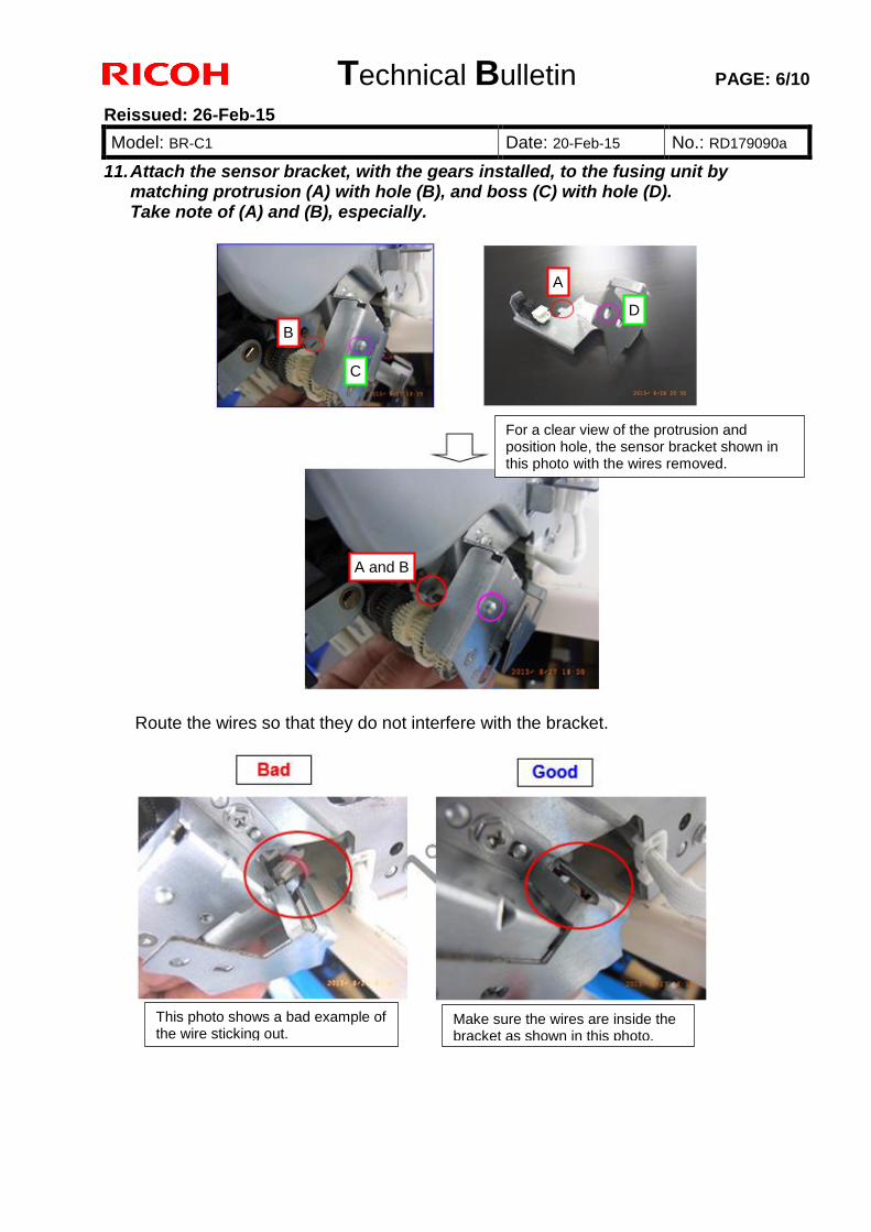
Technical Bulletin PAGE: 6/10
Reissued: 26-Feb-15
Model: BR-C1 Date: 20-Feb-15 No.: RD179090a
11. Attach the sensor bracket, with the gears installed, to the fusing unit by matching protrusion (A) with hole (B), and boss (C) with hole (D). Take note of (A) and (B), especially.
Route the wires so that they do not interfere with the bracket.
For a clear view of the protrusion and position hole, the sensor bracket shown in this photo with the wires removed.
This photo shows a bad example of the wire sticking out.
Make sure the wires are inside the bracket as shown in this photo.
A
B
C
D
A and B
Technical Bulletin PAGE: 7/10
Reissued: 26-Feb-15
Model: BR-C1 Date: 20-Feb-15 No.: RD179090a
12. Attach the fusing unit front cover and put back the fusing unit, and do the SP modification below. SP Modification The modified cleaning web motor has a different rotation speed. (Web life will end faster compared to the original motor.)
To compensate for this difference, the web motor operation time and the near end alert timing need to be modified with the following SPs:
SP-1-902-002 Fusing Web Motor Operation Time SP-1-902-004 Web Near End Setting
SP1-902-002 Fusing Web Motor Operation Time For NA and AP Type-a (95ppm) 17.2 (default) 21.3 (modified value) Type-b (110ppm) 14.7 (default) 18.2 (modified value) Type-c (135ppm) 12.2 (default) 15.0 (modified value) For EU Type-a 11.5 (default) 21.3 (modified value) Type-b 9.8 (default) 18.2 (modified value) Type-c 8.2 (default) 15.0 (modified value) SP1-902-004 Web Near End Setting 81 (default) 71 (modified value) This applies to all models regardless of the region.
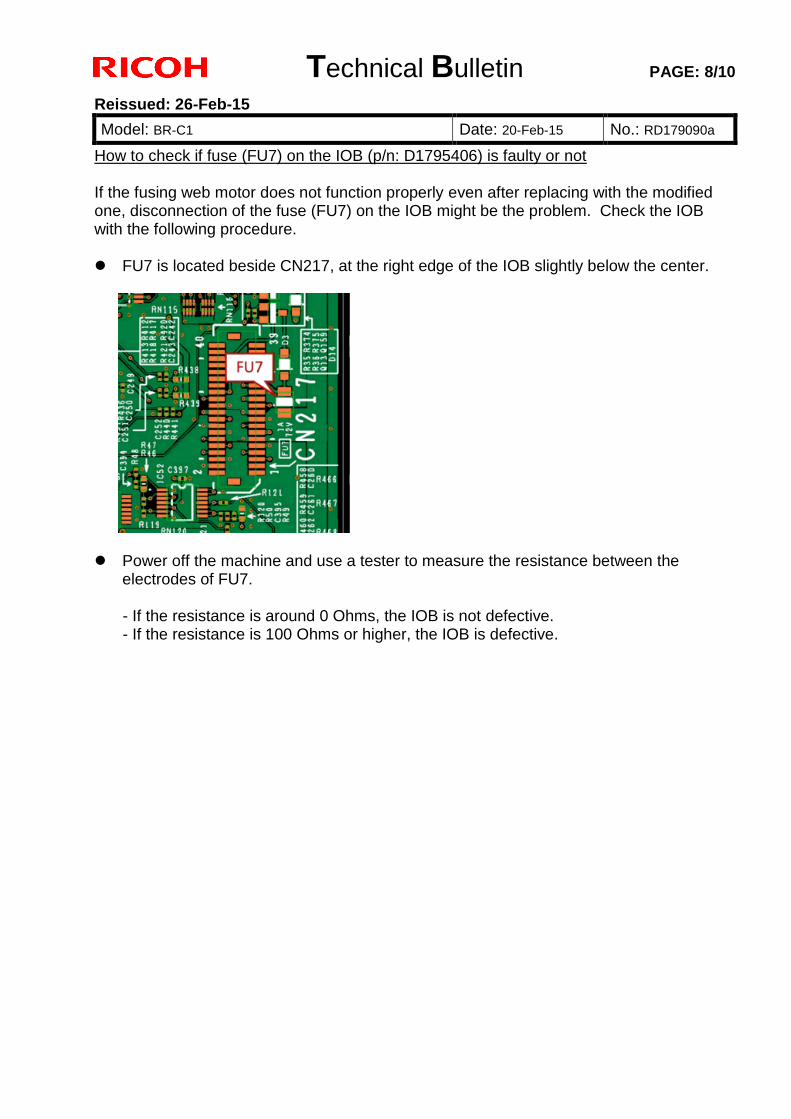
Technical Bulletin PAGE: 8/10
Reissued: 26-Feb-15
Model: BR-C1 Date: 20-Feb-15 No.: RD179090a
How to check if fuse (FU7) on the IOB (p/n: D1795406) is faulty or not If the fusing web motor does not function properly even after replacing with the modified one, disconnection of the fuse (FU7) on the IOB might be the problem. Check the IOB with the following procedure. FU7 is located beside CN217, at the right edge of the IOB slightly below the center.
Power off the machine and use a tester to measure the resistance between the
electrodes of FU7. - If the resistance is around 0 Ohms, the IOB is not defective. - If the resistance is 100 Ohms or higher, the IOB is defective.
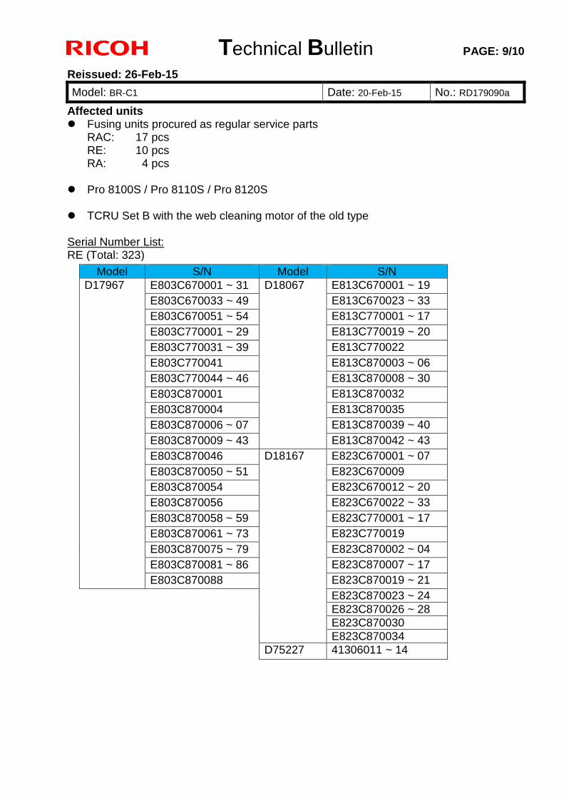
Technical Bulletin PAGE: 9/10
Reissued: 26-Feb-15
Model: BR-C1 Date: 20-Feb-15 No.: RD179090a
Affected units Fusing units procured as regular service parts
RAC: 17 pcs RE: 10 pcs RA: 4 pcs
Pro 8100S / Pro 8110S / Pro 8120S TCRU Set B with the web cleaning motor of the old type Serial Number List: RE (Total: 323)
Model S/N Model S/N
D17967 E803C670001 ~ 31 D18067 E813C670001 ~ 19
E803C670033 ~ 49 E813C670023 ~ 33
E803C670051 ~ 54 E813C770001 ~ 17
E803C770001 ~ 29 E813C770019 ~ 20
E803C770031 ~ 39 E813C770022
E803C770041 E813C870003 ~ 06
E803C770044 ~ 46 E813C870008 ~ 30
E803C870001 E813C870032
E803C870004 E813C870035
E803C870006 ~ 07 E813C870039 ~ 40
E803C870009 ~ 43 E813C870042 ~ 43
E803C870046 D18167 E823C670001 ~ 07
E803C870050 ~ 51 E823C670009
E803C870054 E823C670012 ~ 20
E803C870056 E823C670022 ~ 33
E803C870058 ~ 59 E823C770001 ~ 17
E803C870061 ~ 73 E823C770019
E803C870075 ~ 79 E823C870002 ~ 04
E803C870081 ~ 86 E823C870007 ~ 17
E803C870088 E823C870019 ~ 21
E823C870023 ~ 24
E823C870026 ~ 28
E823C870030
E823C870034
D75227 41306011 ~ 14
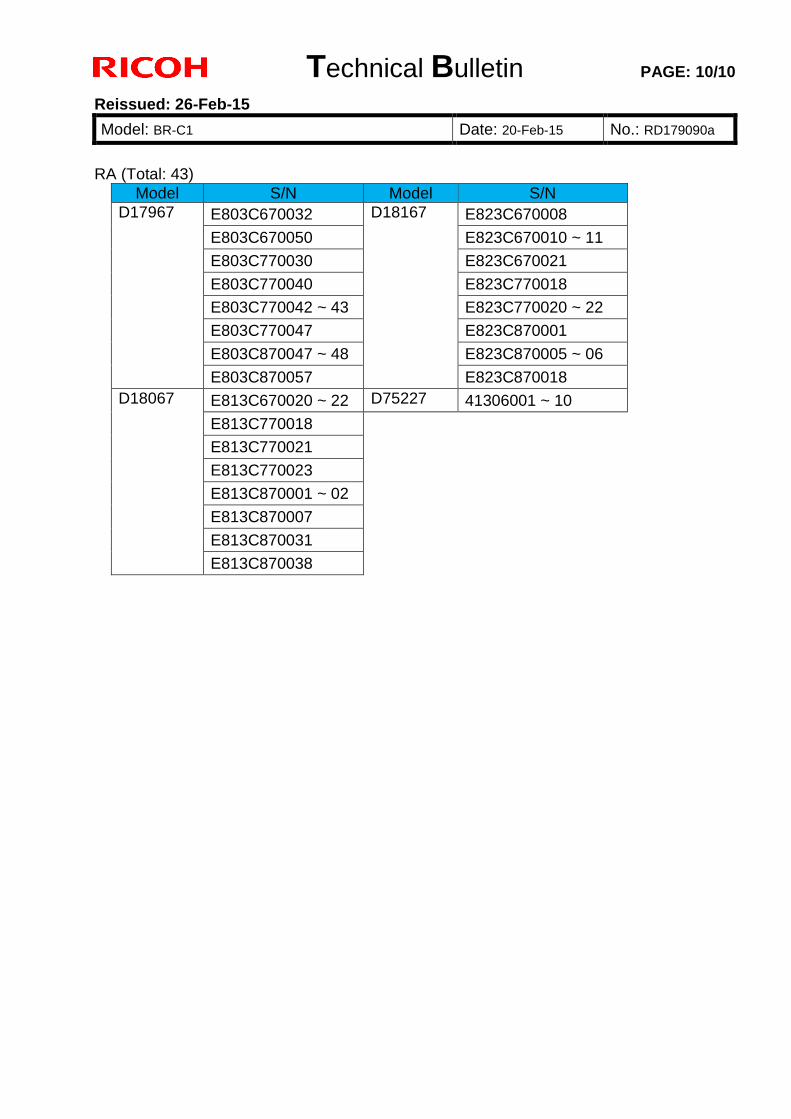
Technical Bulletin PAGE: 10/10
Reissued: 26-Feb-15
Model: BR-C1 Date: 20-Feb-15 No.: RD179090a
RA (Total: 43)
Model S/N Model S/N
D17967 E803C670032 D18167 E823C670008
E803C670050 E823C670010 ~ 11
E803C770030 E823C670021
E803C770040 E823C770018
E803C770042 ~ 43 E823C770020 ~ 22
E803C770047 E823C870001
E803C870047 ~ 48 E823C870005 ~ 06
E803C870057 E823C870018
D18067 E813C670020 ~ 22 D75227 41306001 ~ 10
E813C770018
E813C770021
E813C770023
E813C870001 ~ 02
E813C870007
E813C870031
E813C870038
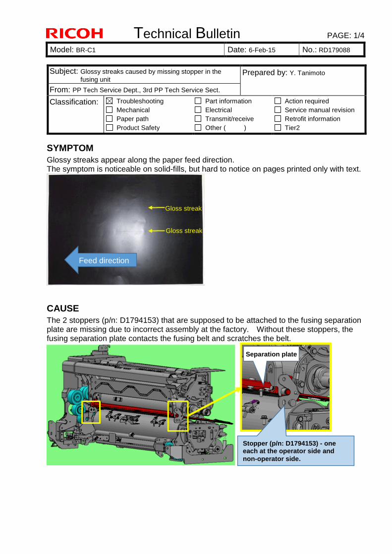
Technical Bulletin PAGE: 1/4
Model: BR-C1 Date: 6-Feb-15 No.: RD179088
SYMPTOM
Glossy streaks appear along the paper feed direction. The symptom is noticeable on solid-fills, but hard to notice on pages printed only with text.
CAUSE
The 2 stoppers (p/n: D1794153) that are supposed to be attached to the fusing separation plate are missing due to incorrect assembly at the factory. Without these stoppers, the fusing separation plate contacts the fusing belt and scratches the belt.
Subject: Glossy streaks caused by missing stopper in the
fusing unit Prepared by: Y. Tanimoto
From: PP Tech Service Dept., 3rd PP Tech Service Sect.
Classification: Troubleshooting
Mechanical
Paper path
Product Safety
Part information
Electrical
Transmit/receive
Other ( )
Action required
Service manual revision
Retrofit information
Tier2
Gloss streak
Separation plate
Stopper (p/n: D1794153) - one each at the operator side and
non-operator side.
Feed direction
Gloss streak
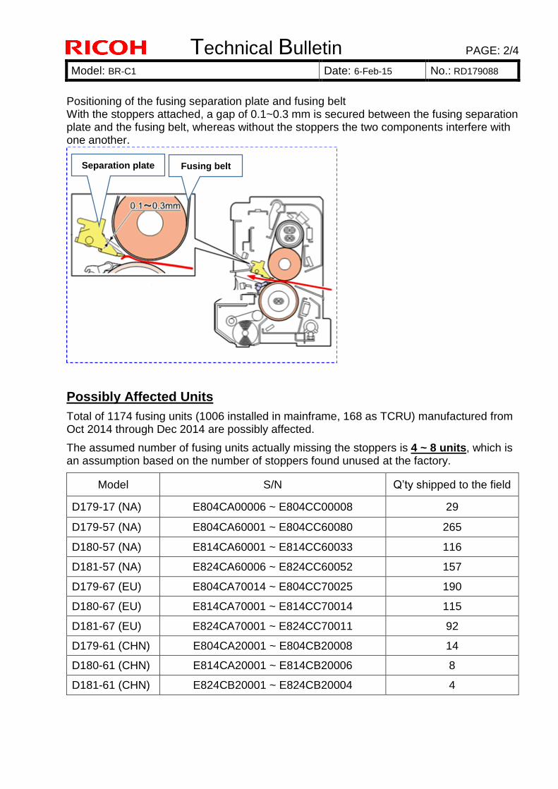
Technical Bulletin PAGE: 2/4
Model: BR-C1 Date: 6-Feb-15 No.: RD179088
Positioning of the fusing separation plate and fusing belt With the stoppers attached, a gap of 0.1~0.3 mm is secured between the fusing separation plate and the fusing belt, whereas without the stoppers the two components interfere with one another.
Possibly Affected Units
Total of 1174 fusing units (1006 installed in mainframe, 168 as TCRU) manufactured from Oct 2014 through Dec 2014 are possibly affected.
The assumed number of fusing units actually missing the stoppers is 4 ~ 8 units, which is an assumption based on the number of stoppers found unused at the factory.
Model S/N Q’ty shipped to the field
D179-17 (NA) E804CA00006 ~ E804CC00008 29
D179-57 (NA) E804CA60001 ~ E804CC60080 265
D180-57 (NA) E814CA60001 ~ E814CC60033 116
D181-57 (NA) E824CA60006 ~ E824CC60052 157
D179-67 (EU) E804CA70014 ~ E804CC70025 190
D180-67 (EU) E814CA70001 ~ E814CC70014 115
D181-67 (EU) E824CA70001 ~ E824CC70011 92
D179-61 (CHN) E804CA20001 ~ E804CB20008 14
D180-61 (CHN) E814CA20001 ~ E814CB20006 8
D181-61 (CHN) E824CB20001 ~ E824CB20004 4
Separation plate Fusing belt
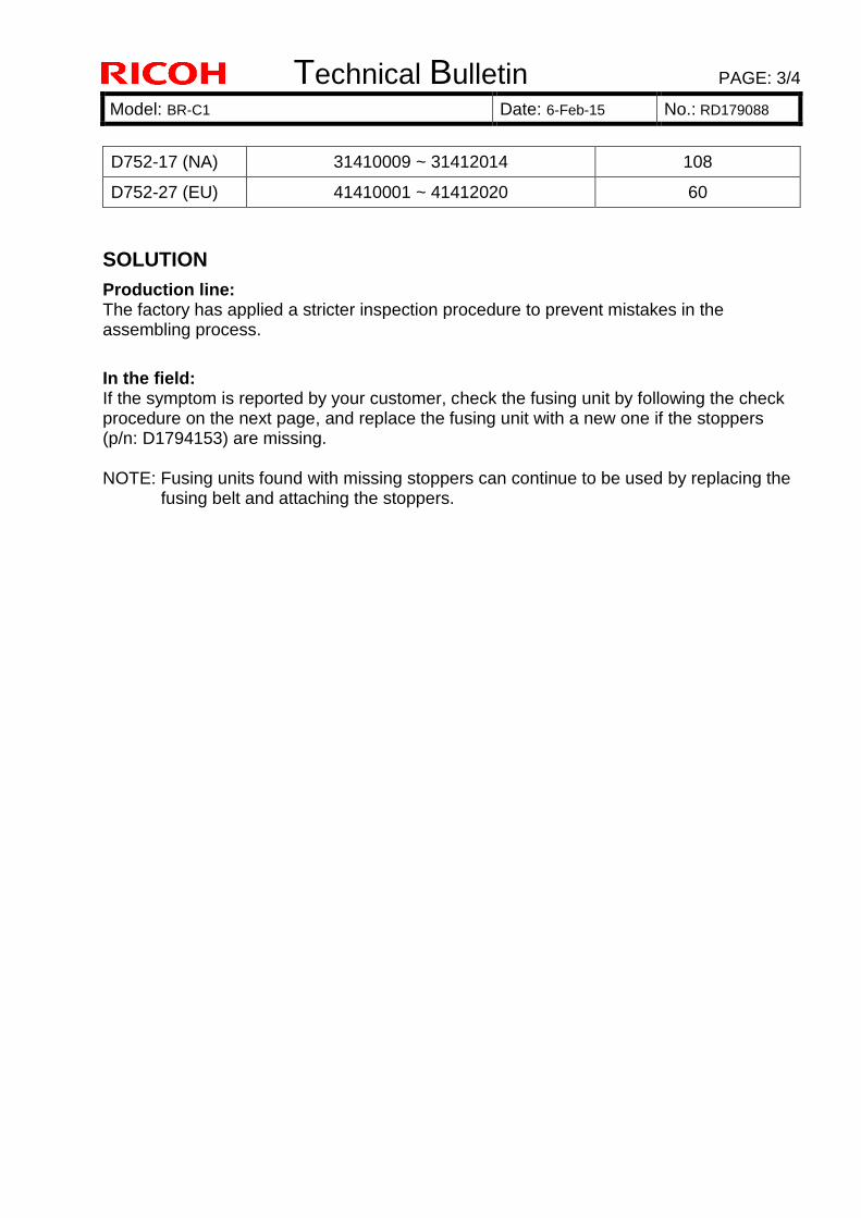
Technical Bulletin PAGE: 3/4
Model: BR-C1 Date: 6-Feb-15 No.: RD179088
D752-17 (NA) 31410009 ~ 31412014 108
D752-27 (EU) 41410001 ~ 41412020 60
SOLUTION
Production line: The factory has applied a stricter inspection procedure to prevent mistakes in the assembling process.
In the field: If the symptom is reported by your customer, check the fusing unit by following the check procedure on the next page, and replace the fusing unit with a new one if the stoppers (p/n: D1794153) are missing. NOTE: Fusing units found with missing stoppers can continue to be used by replacing the
fusing belt and attaching the stoppers.
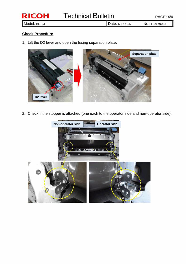
Technical Bulletin PAGE: 4/4
Model: BR-C1 Date: 6-Feb-15 No.: RD179088
Check Procedure 1. Lift the D2 lever and open the fusing separation plate.
2. Check if the stopper is attached (one each to the operator side and non-operator side).
D2 lever
Separation plate
Non-operator side Operator side
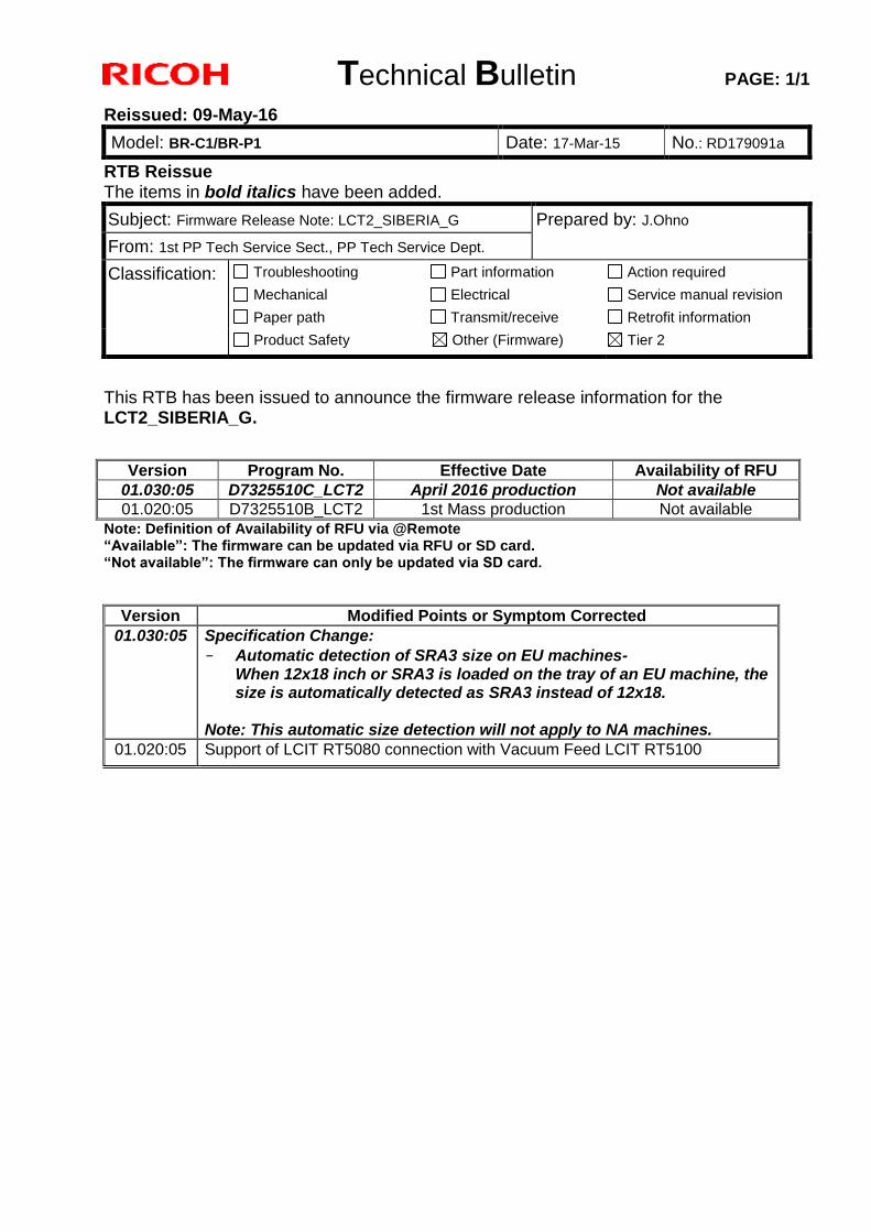
Technical Bulletin PAGE: 1/1
Reissued: 09-May-16
Model: BR-C1/BR-P1 Date: 17-Mar-15 No.: RD179091a
RTB Reissue The items in bold italics have been added.
Subject: Firmware Release Note: LCT2_SIBERIA_G Prepared by: J.Ohno
From: 1st PP Tech Service Sect., PP Tech Service Dept.
Classification: Troubleshooting
Mechanical
Paper path
Part information
Electrical
Transmit/receive
Action required
Service manual revision
Retrofit information
Product Safety Other (Firmware) Tier 2
This RTB has been issued to announce the firmware release information for the LCT2_SIBERIA_G.
Version Program No. Effective Date Availability of RFU 01.030:05 D7325510C_LCT2 April 2016 production Not available
01.020:05 D7325510B_LCT2 1st Mass production Not available Note: Definition of Availability of RFU via @Remote “Available”: The firmware can be updated via RFU or SD card. “Not available”: The firmware can only be updated via SD card.
Version Modified Points or Symptom Corrected 01.030:05 Specification Change:
- Automatic detection of SRA3 size on EU machines- When 12x18 inch or SRA3 is loaded on the tray of an EU machine, the size is automatically detected as SRA3 instead of 12x18.
Note: This automatic size detection will not apply to NA machines.
01.020:05 Support of LCIT RT5080 connection with Vacuum Feed LCIT RT5100
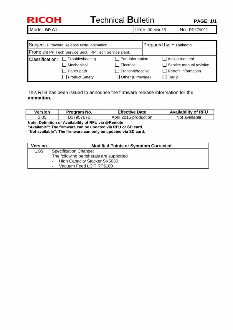
Technical Bulletin PAGE: 1/1
Model: BR-C1 Date: 30-Mar-15 No.: RD179092
Subject: Firmware Release Note: animation Prepared by: Y.Tanimoto
From: 3rd PP Tech Service Sect., PP Tech Service Dept.
Classification: Troubleshooting
Mechanical
Paper path
Part information
Electrical
Transmit/receive
Action required
Service manual revision
Retrofit information
Product Safety Other (Firmware) Tier 2
This RTB has been issued to announce the firmware release information for the animation.
Version Program No. Effective Date Availability of RFU
1.05 D1795767B April 2015 production Not available
Note: Definition of Availability of RFU via @Remote “Available”: The firmware can be updated via RFU or SD card. “Not available”: The firmware can only be updated via SD card.
Version Modified Points or Symptom Corrected
1.05 Specification Change: The following peripherals are supported - High Capacity Stacker SK5030 - Vacuum Feed LCIT RT5100
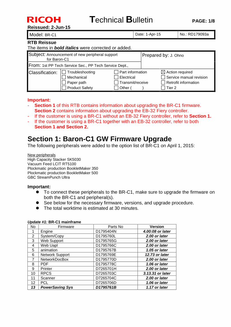
Technical Bulletin PAGE: 1/8
Reissued: 2-Jun-15
Model: BR-C1 Date: 1-Apr-15 No.: RD179093a
RTB Reissue The items in bold italics were corrected or added.
Subject: Announcement of new peripheral support
for Baron-C1 Prepared by: J. Ohno
From: 1st PP Tech Service Sec., PP Tech Service Dept.,
Classification: Troubleshooting
Mechanical
Paper path
Product Safety
Part information
Electrical
Transmit/receive
Other ( )
Action required
Service manual revision
Retrofit information
Tier 2
Important: - Section 1 of this RTB contains information about upgrading the BR-C1 firmware.
Section 2 contains information about upgrading the EB-32 Fiery controller. - If the customer is using a BR-C1 without an EB-32 Fiery controller, refer to Section 1. - If the customer is using a BR-C1 together with an EB-32 controller, refer to both
Section 1 and Section 2.
Section 1: Baron-C1 GW Firmware Upgrade The following peripherals were added to the option list of BR-C1 on April 1, 2015: New peripherals High Capacity Stacker SK5030 Vacuum Feed LCIT RT5100 Plockmatic production BookletMaker 350 Plockmatic production BookletMaker 500 GBC StreamPunch Ultra
Important: To connect these peripherals to the BR-C1, make sure to upgrade the firmware on
both the BR-C1 and peripheral(s). See below for the necessary firmware, versions, and upgrade procedure. The total worktime is estimated at 30 minutes.
Update #1: BR-C1 mainframe
No Firmware Parts No Version
1 Engine D1795404N 4.00:08 or later
2 System/Copy D1795760L 2.00 or later
3 Web Support D1795765G 2.00 or later
4 Web Uapl D1795766C 2.00 or later
5 animation D1795767B 1.05 or later
6 Network Support D1795769E 12.73 or later
7 NetworkDocBox D1795770D 2.00 or later
8 PDF D1795778C 1.06 or later
9 Printer D7265701H 2.00 or later
10 RPCS D7265703C 3.13.31 or later
11 Scanner D7265704C 2.00 or later
12 PCL D7265706D 1.06 or later
13 PowerSaving Sys D1795761B 1.17 or later
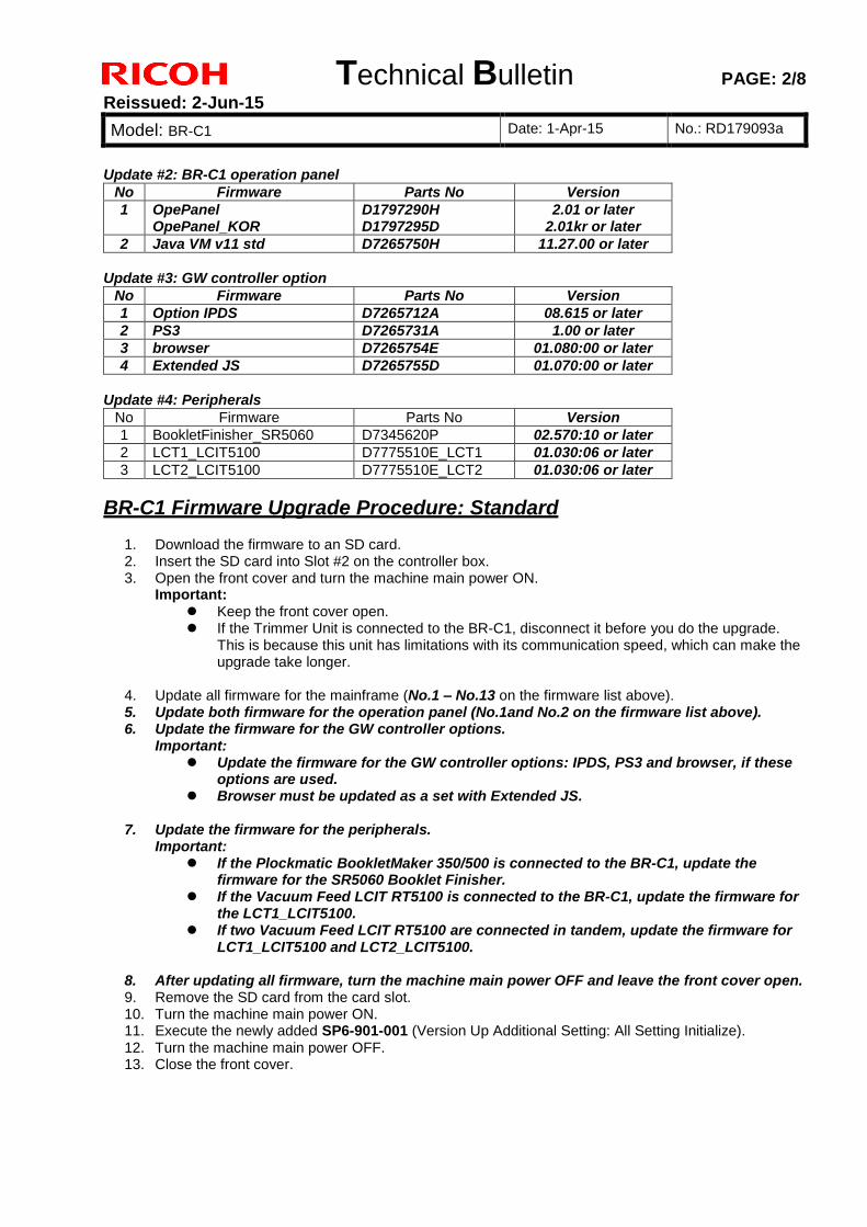
Technical Bulletin PAGE: 2/8
Reissued: 2-Jun-15
Model: BR-C1 Date: 1-Apr-15 No.: RD179093a
Update #2: BR-C1 operation panel
No Firmware Parts No Version
1 OpePanel OpePanel_KOR
D1797290H D1797295D
2.01 or later 2.01kr or later
2 Java VM v11 std D7265750H 11.27.00 or later
Update #3: GW controller option
No Firmware Parts No Version
1 Option IPDS D7265712A 08.615 or later
2 PS3 D7265731A 1.00 or later
3 browser D7265754E 01.080:00 or later
4 Extended JS D7265755D 01.070:00 or later
Update #4: Peripherals
No Firmware Parts No Version
1 BookletFinisher_SR5060 D7345620P 02.570:10 or later
2 LCT1_LCIT5100 D7775510E_LCT1 01.030:06 or later
3 LCT2_LCIT5100 D7775510E_LCT2 01.030:06 or later
BR-C1 Firmware Upgrade Procedure: Standard
1. Download the firmware to an SD card. 2. Insert the SD card into Slot #2 on the controller box. 3. Open the front cover and turn the machine main power ON.
Important: Keep the front cover open. If the Trimmer Unit is connected to the BR-C1, disconnect it before you do the upgrade.
This is because this unit has limitations with its communication speed, which can make the upgrade take longer.
4. Update all firmware for the mainframe (No.1 – No.13 on the firmware list above). 5. Update both firmware for the operation panel (No.1and No.2 on the firmware list above). 6. Update the firmware for the GW controller options.
Important: Update the firmware for the GW controller options: IPDS, PS3 and browser, if these
options are used. Browser must be updated as a set with Extended JS.
7. Update the firmware for the peripherals.
Important: If the Plockmatic BookletMaker 350/500 is connected to the BR-C1, update the
firmware for the SR5060 Booklet Finisher. If the Vacuum Feed LCIT RT5100 is connected to the BR-C1, update the firmware for
the LCT1_LCIT5100. If two Vacuum Feed LCIT RT5100 are connected in tandem, update the firmware for
LCT1_LCIT5100 and LCT2_LCIT5100.
8. After updating all firmware, turn the machine main power OFF and leave the front cover open. 9. Remove the SD card from the card slot. 10. Turn the machine main power ON. 11. Execute the newly added SP6-901-001 (Version Up Additional Setting: All Setting Initialize). 12. Turn the machine main power OFF. 13. Close the front cover.
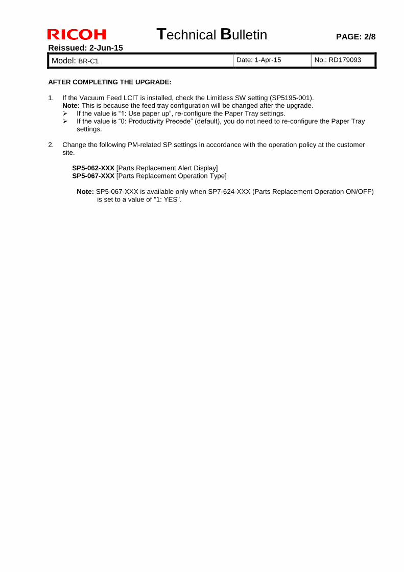
Technical Bulletin PAGE: 2/8
Reissued: 2-Jun-15
Model: BR-C1 Date: 1-Apr-15 No.: RD179093
AFTER COMPLETING THE UPGRADE: 1. If the Vacuum Feed LCIT is installed, check the Limitless SW setting (SP5195-001).
Note: This is because the feed tray configuration will be changed after the upgrade. If the value is “1: Use paper up”, re-configure the Paper Tray settings. If the value is “0: Productivity Precede” (default), you do not need to re-configure the Paper Tray
settings.
2. Change the following PM-related SP settings in accordance with the operation policy at the customer site.
SP5-062-XXX [Parts Replacement Alert Display] SP5-067-XXX [Parts Replacement Operation Type]
Note: SP5-067-XXX is available only when SP7-624-XXX (Parts Replacement Operation ON/OFF)
is set to a value of "1: YES".
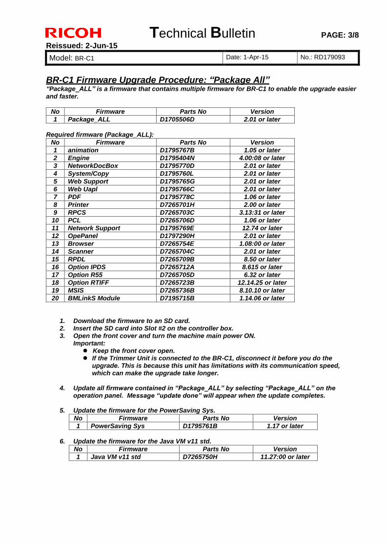
Technical Bulletin PAGE: 3/8
Reissued: 2-Jun-15
Model: BR-C1 Date: 1-Apr-15 No.: RD179093
BR-C1 Firmware Upgrade Procedure: “Package All”“Package_ALL” is a firmware that contains multiple firmware for BR-C1 to enable the upgrade easier and faster.
No Firmware Parts No Version
1 Package_ALL D1705506D 2.01 or later
Required firmware (Package_ALL):
No Firmware Parts No Version
1 animation D1795767B 1.05 or later
2 Engine D1795404N 4.00:08 or later
3 NetworkDocBox D1795770D 2.01 or later
4 System/Copy D1795760L 2.01 or later
5 Web Support D1795765G 2.01 or later
6 Web Uapl D1795766C 2.01 or later
7 PDF D1795778C 1.06 or later
8 Printer D7265701H 2.00 or later
9 RPCS D7265703C 3.13:31 or later
10 PCL D7265706D 1.06 or later
11 Network Support D1795769E 12.74 or later
12 OpePanel D1797290H 2.01 or later
13 Browser D7265754E 1.08:00 or later
14 Scanner D7265704C 2.01 or later
15 RPDL D7265709B 8.50 or later
16 Option IPDS D7265712A 8.615 or later
17 Option R55 D7265705D 6.32 or later
18 Option RTIFF D7265723B 12.14.25 or later
19 MSIS D7265736B 8.10.10 or later
20 BMLinkS Module D7195715B 1.14.06 or later
1. Download the firmware to an SD card. 2. Insert the SD card into Slot #2 on the controller box. 3. Open the front cover and turn the machine main power ON.
Important: Keep the front cover open. If the Trimmer Unit is connected to the BR-C1, disconnect it before you do the
upgrade. This is because this unit has limitations with its communication speed, which can make the upgrade take longer.
4. Update all firmware contained in “Package_ALL” by selecting “Package_ALL” on the
operation panel. Message “update done” will appear when the update completes.
5. Update the firmware for the PowerSaving Sys.
No Firmware Parts No Version
1 PowerSaving Sys D1795761B 1.17 or later
6. Update the firmware for the Java VM v11 std.
No Firmware Parts No Version
1 Java VM v11 std D7265750H 11.27:00 or later
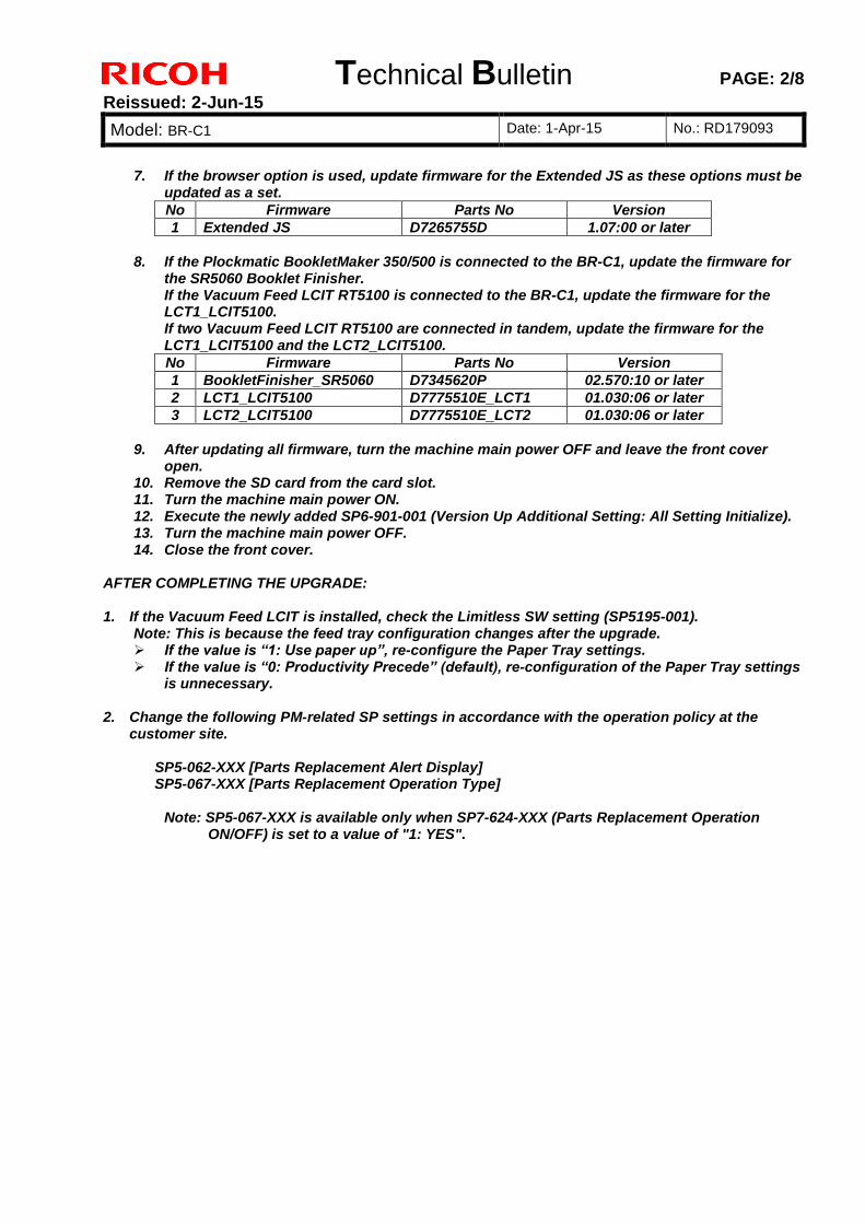
Technical Bulletin PAGE: 2/8
Reissued: 2-Jun-15
Model: BR-C1 Date: 1-Apr-15 No.: RD179093
7. If the browser option is used, update firmware for the Extended JS as these options must be updated as a set.
No Firmware Parts No Version
1 Extended JS D7265755D 1.07:00 or later
8. If the Plockmatic BookletMaker 350/500 is connected to the BR-C1, update the firmware for
the SR5060 Booklet Finisher. If the Vacuum Feed LCIT RT5100 is connected to the BR-C1, update the firmware for the LCT1_LCIT5100. If two Vacuum Feed LCIT RT5100 are connected in tandem, update the firmware for the LCT1_LCIT5100 and the LCT2_LCIT5100.
No Firmware Parts No Version
1 BookletFinisher_SR5060 D7345620P 02.570:10 or later
2 LCT1_LCIT5100 D7775510E_LCT1 01.030:06 or later
3 LCT2_LCIT5100 D7775510E_LCT2 01.030:06 or later
9. After updating all firmware, turn the machine main power OFF and leave the front cover
open. 10. Remove the SD card from the card slot. 11. Turn the machine main power ON. 12. Execute the newly added SP6-901-001 (Version Up Additional Setting: All Setting Initialize). 13. Turn the machine main power OFF. 14. Close the front cover.
AFTER COMPLETING THE UPGRADE: 1. If the Vacuum Feed LCIT is installed, check the Limitless SW setting (SP5195-001).
Note: This is because the feed tray configuration changes after the upgrade. If the value is “1: Use paper up”, re-configure the Paper Tray settings. If the value is “0: Productivity Precede” (default), re-configuration of the Paper Tray settings
is unnecessary. 2. Change the following PM-related SP settings in accordance with the operation policy at the
customer site. SP5-062-XXX [Parts Replacement Alert Display] SP5-067-XXX [Parts Replacement Operation Type]
Note: SP5-067-XXX is available only when SP7-624-XXX (Parts Replacement Operation
ON/OFF) is set to a value of "1: YES".
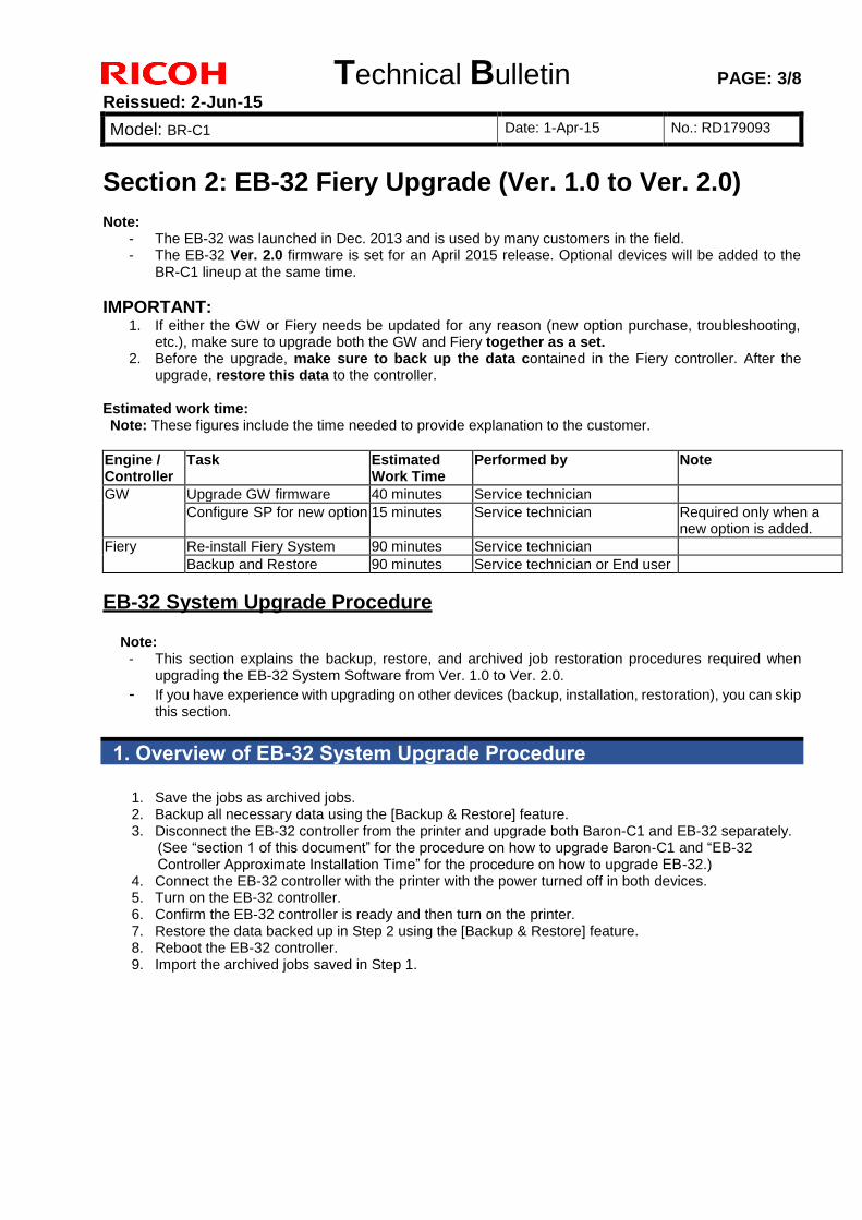
Technical Bulletin PAGE: 3/8
Reissued: 2-Jun-15
Model: BR-C1 Date: 1-Apr-15 No.: RD179093
Section 2: EB-32 Fiery Upgrade (Ver. 1.0 to Ver. 2.0) Note:
- The EB-32 was launched in Dec. 2013 and is used by many customers in the field. - The EB-32 Ver. 2.0 firmware is set for an April 2015 release. Optional devices will be added to the
BR-C1 lineup at the same time.
IMPORTANT: 1. If either the GW or Fiery needs be updated for any reason (new option purchase, troubleshooting,
etc.), make sure to upgrade both the GW and Fiery together as a set. 2. Before the upgrade, make sure to back up the data contained in the Fiery controller. After the
upgrade, restore this data to the controller. Estimated work time: Note: These figures include the time needed to provide explanation to the customer.
Engine / Controller
Task Estimated Work Time
Performed by Note
GW Upgrade GW firmware 40 minutes Service technician
Configure SP for new option 15 minutes Service technician Required only when a new option is added.
Fiery Re-install Fiery System 90 minutes Service technician
Backup and Restore 90 minutes Service technician or End user
EB-32 System Upgrade Procedure
Note: - This section explains the backup, restore, and archived job restoration procedures required when
upgrading the EB-32 System Software from Ver. 1.0 to Ver. 2.0.
- If you have experience with upgrading on other devices (backup, installation, restoration), you can skip this section.
1. Overview of EB-32 System Upgrade Procedure
1. Save the jobs as archived jobs. 2. Backup all necessary data using the [Backup & Restore] feature. 3. Disconnect the EB-32 controller from the printer and upgrade both Baron-C1 and EB-32 separately.
(See “section 1 of this document” for the procedure on how to upgrade Baron-C1 and “EB-32 Controller Approximate Installation Time” for the procedure on how to upgrade EB-32.)
4. Connect the EB-32 controller with the printer with the power turned off in both devices. 5. Turn on the EB-32 controller. 6. Confirm the EB-32 controller is ready and then turn on the printer. 7. Restore the data backed up in Step 2 using the [Backup & Restore] feature. 8. Reboot the EB-32 controller. 9. Import the archived jobs saved in Step 1.
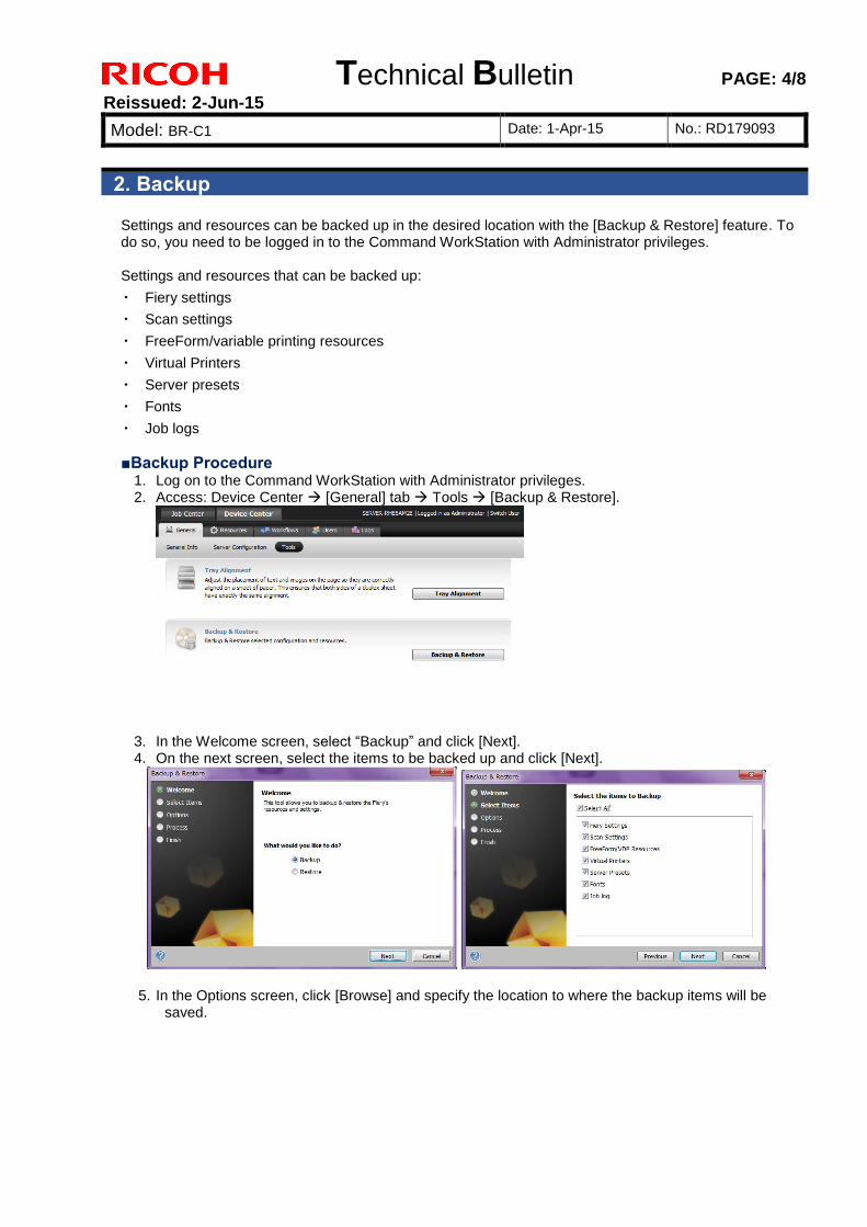
Technical Bulletin PAGE: 4/8
Reissued: 2-Jun-15
Model: BR-C1 Date: 1-Apr-15 No.: RD179093
2. Backup
Settings and resources can be backed up in the desired location with the [Backup & Restore] feature. To do so, you need to be logged in to the Command WorkStation with Administrator privileges. Settings and resources that can be backed up:
・ Fiery settings
・ Scan settings
・ FreeForm/variable printing resources
・ Virtual Printers
・ Server presets
・ Fonts
・ Job logs
■Backup Procedure 1. Log on to the Command WorkStation with Administrator privileges. 2. Access: Device Center [General] tab Tools [Backup & Restore].
3. In the Welcome screen, select “Backup” and click [Next]. 4. On the next screen, select the items to be backed up and click [Next].
5. In the Options screen, click [Browse] and specify the location to where the backup items will be
saved.
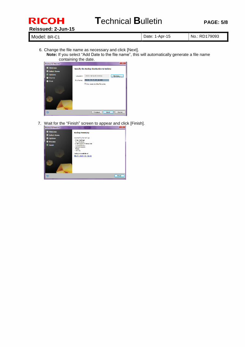
Technical Bulletin PAGE: 5/8
Reissued: 2-Jun-15
Model: BR-C1 Date: 1-Apr-15 No.: RD179093
6. Change the file name as necessary and click [Next]. Note: If you select “Add Date to the file name”, this will automatically generate a file name
containing the date.
7. Wait for the “Finish” screen to appear and click [Finish].
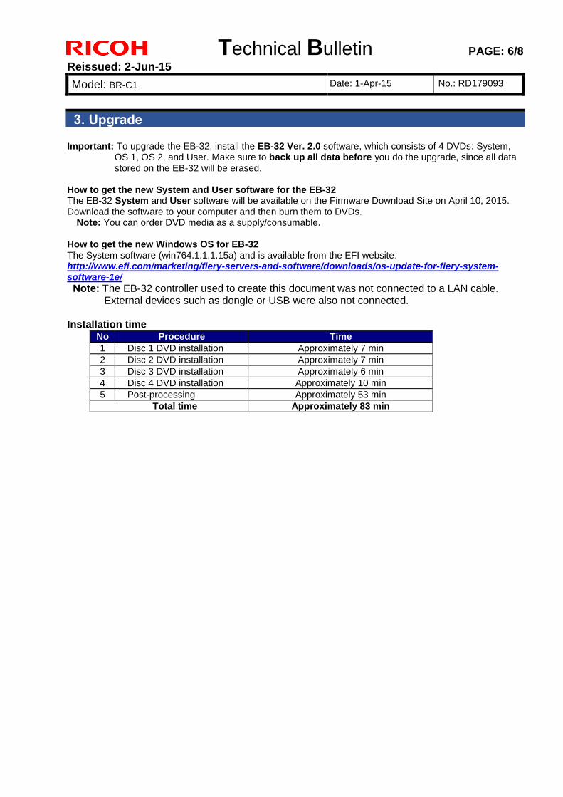
Technical Bulletin PAGE: 6/8
Reissued: 2-Jun-15
Model: BR-C1 Date: 1-Apr-15 No.: RD179093
3. Upgrade Important: To upgrade the EB-32, install the EB-32 Ver. 2.0 software, which consists of 4 DVDs: System,
OS 1, OS 2, and User. Make sure to back up all data before you do the upgrade, since all data stored on the EB-32 will be erased.
How to get the new System and User software for the EB-32 The EB-32 System and User software will be available on the Firmware Download Site on April 10, 2015. Download the software to your computer and then burn them to DVDs.
Note: You can order DVD media as a supply/consumable. How to get the new Windows OS for EB-32 The System software (win764.1.1.1.15a) and is available from the EFI website: http://www.efi.com/marketing/fiery-servers-and-software/downloads/os-update-for-fiery-system-software-1e/
Note: The EB-32 controller used to create this document was not connected to a LAN cable. External devices such as dongle or USB were also not connected.
Installation time
No Procedure Time
1 Disc 1 DVD installation Approximately 7 min
2 Disc 2 DVD installation Approximately 7 min
3 Disc 3 DVD installation Approximately 6 min
4 Disc 4 DVD installation Approximately 10 min
5 Post-processing Approximately 53 min
Total time Approximately 83 min
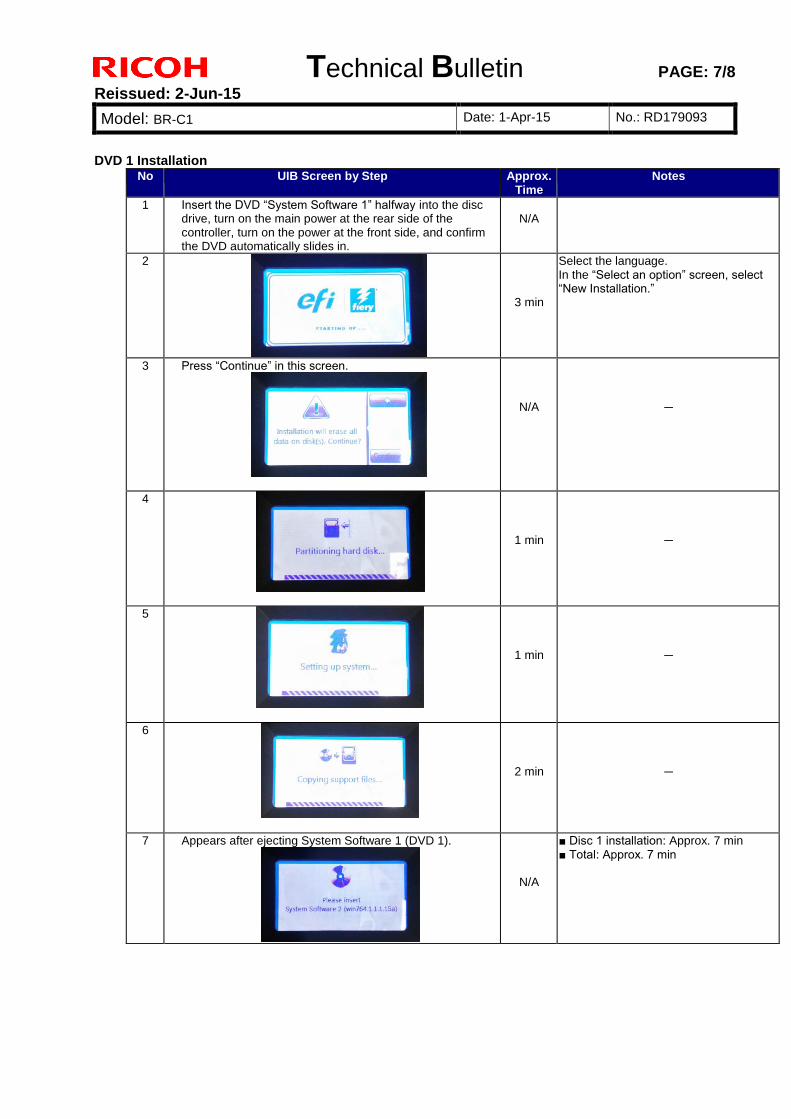
Technical Bulletin PAGE: 7/8
Reissued: 2-Jun-15
Model: BR-C1 Date: 1-Apr-15 No.: RD179093
DVD 1 Installation No UIB Screen by Step Approx.
Time Notes
1 Insert the DVD “System Software 1” halfway into the disc drive, turn on the main power at the rear side of the controller, turn on the power at the front side, and confirm the DVD automatically slides in.
N/A
2
3 min
Select the language. In the “Select an option” screen, select “New Installation.”
3 Press “Continue” in this screen.
N/A
-
4
1 min
-
5
1 min
-
6
2 min
-
7 Appears after ejecting System Software 1 (DVD 1).
N/A
■ Disc 1 installation: Approx. 7 min ■ Total: Approx. 7 min
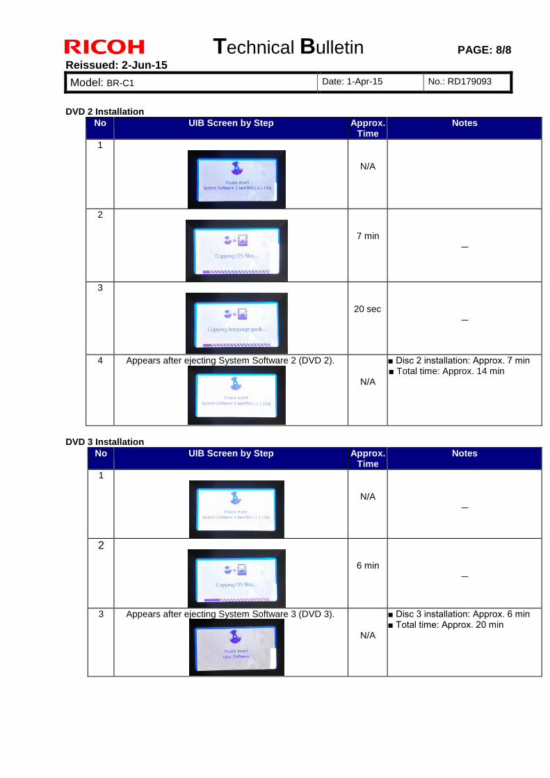
Technical Bulletin PAGE: 8/8
Reissued: 2-Jun-15
Model: BR-C1 Date: 1-Apr-15 No.: RD179093
DVD 2 Installation
No UIB Screen by Step Approx. Time
Notes
1
N/A
2
7 min
-
3
20 sec
-
4 Appears after ejecting System Software 2 (DVD 2).
N/A
■ Disc 2 installation: Approx. 7 min ■ Total time: Approx. 14 min
DVD 3 Installation
No UIB Screen by Step Approx. Time
Notes
1
N/A
-
2
6 min
-
3 Appears after ejecting System Software 3 (DVD 3).
N/A
■ Disc 3 installation: Approx. 6 min ■ Total time: Approx. 20 min
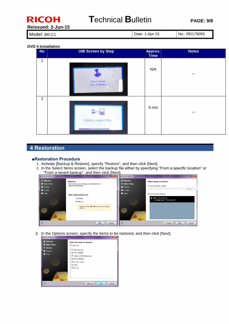
Technical Bulletin PAGE: 9/8
Reissued: 2-Jun-15
Model: BR-C1 Date: 1-Apr-15 No.: RD179093
DVD 4 Installation
No UIB Screen by Step Approx. Time
Notes
1
N/A
-
2
9 min
-
4 Restoration
■Restoration Procedure 1. Activate [Backup & Restore], specify “Restore”, and then click [Next]. 2. In the Select Items screen, select the backup file either by specifying “From a specific location“ or
“From a recent backup”, and then click [Next].
3. In the Options screen, specify the items to be restored, and then click [Next].

Technical Bulletin PAGE: 10/8
Reissued: 2-Jun-15
Model: BR-C1 Date: 1-Apr-15 No.: RD179093
4. Wait for the “Finish” screen to appear, and then click [Finish].
5. Reboot the EB-32 controller to complete the procedure.
5 Restoring Archived Jobs
Archived jobs saved in EB-32 System Version 1.0 can be restored to Version 2.0. Note: Raster data might be removed after the restoration, if the archived job had been RIPped.
■Archived Job Restoration Procedure
1. Save the jobs as Archived Jobs before upgrading the System Software to Version 2.0. 2. Disconnect the EB-32 controller from the printer and upgrade both devices separately. 3. Make sure that the main power on both devices is turned OFF. 4. Connect the EB-32 controller to the printer. 5. Turn the EB-32 controller ON. 6. Make sure that the EB-32 controller is ready, and then turn the printer ON. 7. From the Command WorkStation, import the Archived Jobs that you saved in Step 1.
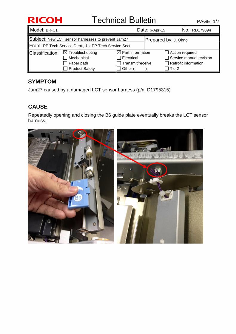
Technical Bulletin PAGE: 1/7
Model: BR-C1 Date: 6-Apr-15 No.: RD179094
Subject: New LCT sensor harnesses to prevent Jam27 Prepared by: J. Ohno
From: PP Tech Service Dept., 1st PP Tech Service Sect.
Classification: Troubleshooting
Mechanical
Paper path
Product Safety
Part information
Electrical
Transmit/receive
Other ( )
Action required
Service manual revision
Retrofit information
Tier2
SYMPTOM
Jam27 caused by a damaged LCT sensor harness (p/n: D1795315)
CAUSE
Repeatedly opening and closing the B6 guide plate eventually breaks the LCT sensor harness.
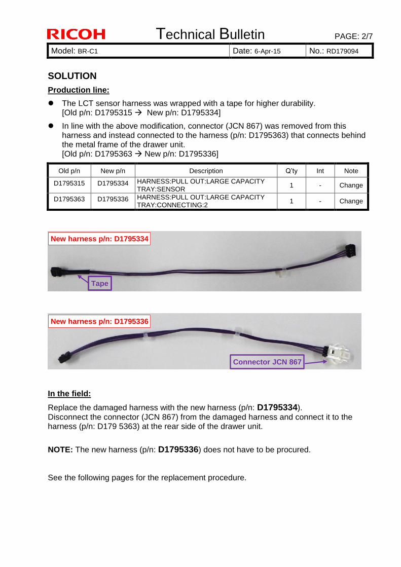
Technical Bulletin PAGE: 2/7
Model: BR-C1 Date: 6-Apr-15 No.: RD179094
SOLUTION
Production line:
The LCT sensor harness was wrapped with a tape for higher durability. [Old p/n: D1795315 New p/n: D1795334]
In line with the above modification, connector (JCN 867) was removed from this harness and instead connected to the harness (p/n: D1795363) that connects behind the metal frame of the drawer unit. [Old p/n: D1795363 New p/n: D1795336]
Old p/n New p/n Description Q’ty Int Note
D1795315 D1795334 HARNESS:PULL OUT:LARGE CAPACITY TRAY:SENSOR
1 - Change
D1795363 D1795336 HARNESS:PULL OUT:LARGE CAPACITY TRAY:CONNECTING:2
1 - Change
In the field:
Replace the damaged harness with the new harness (p/n: D1795334). Disconnect the connector (JCN 867) from the damaged harness and connect it to the harness (p/n: D179 5363) at the rear side of the drawer unit.
NOTE: The new harness (p/n: D1795336) does not have to be procured. See the following pages for the replacement procedure.
New harness p/n: D1795334
Tape
New harness p/n: D1795336
Connector JCN 867
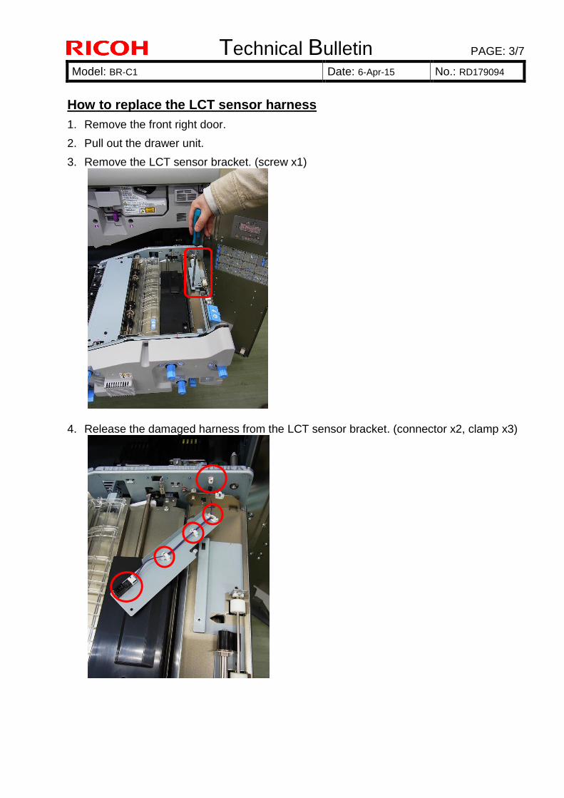
Technical Bulletin PAGE: 3/7
Model: BR-C1 Date: 6-Apr-15 No.: RD179094
How to replace the LCT sensor harness
1. Remove the front right door.
2. Pull out the drawer unit.
3. Remove the LCT sensor bracket. (screw x1)
4. Release the damaged harness from the LCT sensor bracket. (connector x2, clamp x3)
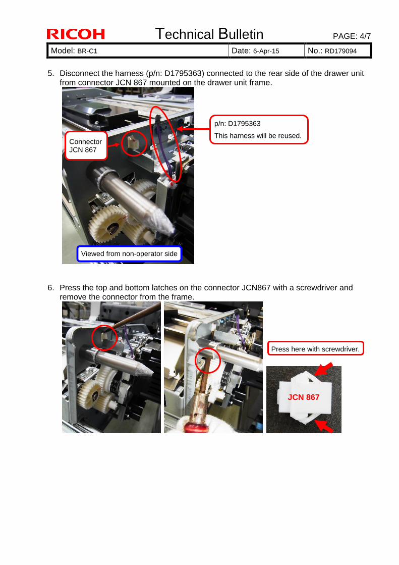
Technical Bulletin PAGE: 4/7
Model: BR-C1 Date: 6-Apr-15 No.: RD179094
5. Disconnect the harness (p/n: D1795363) connected to the rear side of the drawer unit
from connector JCN 867 mounted on the drawer unit frame.
6. Press the top and bottom latches on the connector JCN867 with a screwdriver and
remove the connector from the frame.
Press here with screwdriver.
JCN 867
Connector JCN 867
p/n: D1795363
This harness will be reused.
Viewed from non-operator side
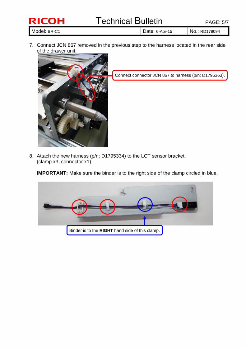
Technical Bulletin PAGE: 5/7
Model: BR-C1 Date: 6-Apr-15 No.: RD179094
7. Connect JCN 867 removed in the previous step to the harness located in the rear side
of the drawer unit.
8. Attach the new harness (p/n: D1795334) to the LCT sensor bracket.
(clamp x3, connector x1) IMPORTANT: Make sure the binder is to the right side of the clamp circled in blue.
Connect connector JCN 867 to harness (p/n: D1795363).
Binder is to the RIGHT hand side of this clamp.
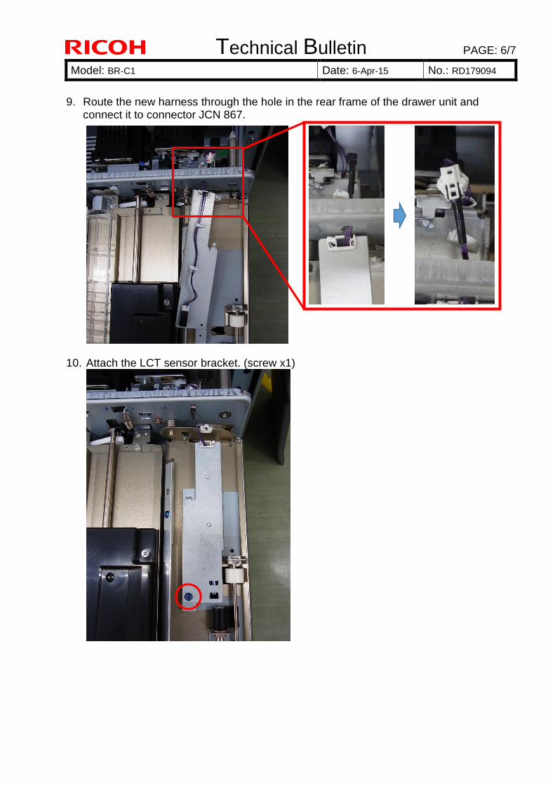
Technical Bulletin PAGE: 6/7
Model: BR-C1 Date: 6-Apr-15 No.: RD179094
9. Route the new harness through the hole in the rear frame of the drawer unit and
connect it to connector JCN 867.
10. Attach the LCT sensor bracket. (screw x1)
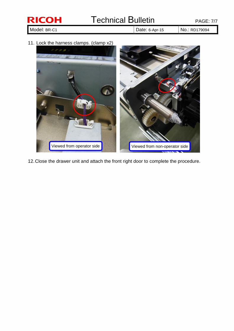
Technical Bulletin PAGE: 7/7
Model: BR-C1 Date: 6-Apr-15 No.: RD179094
11. Lock the harness clamps. (clamp x2)
12. Close the drawer unit and attach the front right door to complete the procedure.
Viewed from operator side Viewed from non-operator side
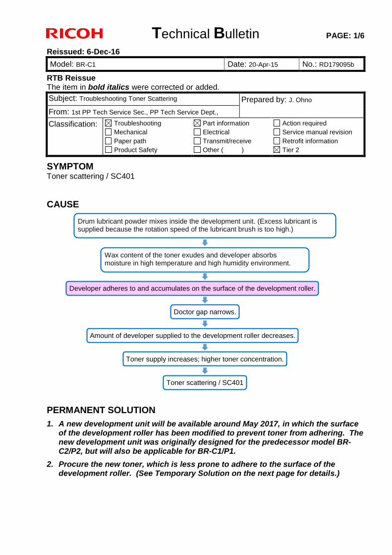
Technical Bulletin PAGE: 1/6
Reissued: 6-Dec-16
Model: BR-C1 Date: 20-Apr-15 No.: RD179095b
RTB Reissue The item in bold italics were corrected or added.
Subject: Troubleshooting Toner Scattering Prepared by: J. Ohno
From: 1st PP Tech Service Sec., PP Tech Service Dept.,
Classification: Troubleshooting
Mechanical
Paper path
Product Safety
Part information
Electrical
Transmit/receive
Other ( )
Action required
Service manual revision
Retrofit information
Tier 2
SYMPTOM Toner scattering / SC401
CAUSE
PERMANENT SOLUTION
1. A new development unit will be available around May 2017, in which the surface of the development roller has been modified to prevent toner from adhering. The new development unit was originally designed for the predecessor model BR-C2/P2, but will also be applicable for BR-C1/P1.
2. Procure the new toner, which is less prone to adhere to the surface of the development roller. (See Temporary Solution on the next page for details.)
Drum lubricant powder mixes inside the development unit. (Excess lubricant is supplied because the rotation speed of the lubricant brush is too high.)
Developer adheres to and accumulates on the surface of the development roller.
Doctor gap narrows.
Amount of developer supplied to the development roller decreases.
Toner supply increases; higher toner concentration.
Toner scattering / SC401
Wax content of the toner exudes and developer absorbs moisture in high temperature and high humidity environment.
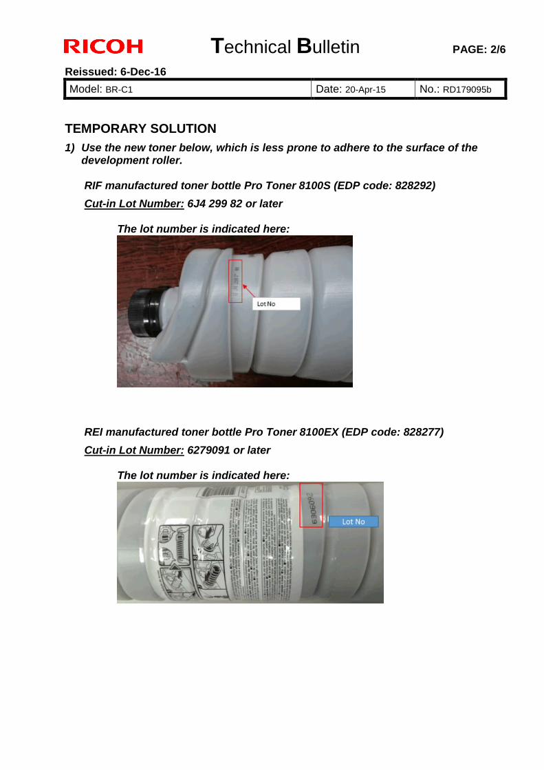
Technical Bulletin PAGE: 2/6
Reissued: 6-Dec-16
Model: BR-C1 Date: 20-Apr-15 No.: RD179095b
TEMPORARY SOLUTION
1) Use the new toner below, which is less prone to adhere to the surface of the development roller. RIF manufactured toner bottle Pro Toner 8100S (EDP code: 828292)
Cut-in Lot Number: 6J4 299 82 or later
The lot number is indicated here:
REI manufactured toner bottle Pro Toner 8100EX (EDP code: 828277)
Cut-in Lot Number: 6279091 or later
The lot number is indicated here:
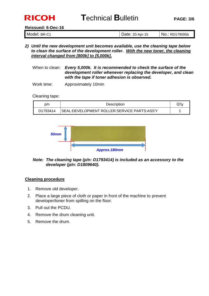
Technical Bulletin PAGE: 3/6
Reissued: 6-Dec-16
Model: BR-C1 Date: 20-Apr-15 No.: RD179095b
2) Until the new development unit becomes available, use the cleaning tape below
to clean the surface of the development roller. With the new toner, the cleaning interval changed from [800k] to [5,000k].
When to clean: Every 5,000k. It is recommended to check the surface of the development roller whenever replacing the developer, and clean with the tape if toner adhesion is observed.
Work time: Approximately 10min
Cleaning tape:
Note: The cleaning tape (p/n: D1793414) is included as an accessory to the developer (p/n: D1809640).
Cleaning procedure
1. Remove old developer.
2. Place a large piece of cloth or paper in front of the machine to prevent developer/toner from spilling on the floor.
3. Pull out the PCDU.
4. Remove the drum cleaning unit.
5. Remove the drum.
p/n Description Q’ty
D1793414 SEAL:DEVELOPMENT ROLLER:SERVICE PARTS:ASS'Y 1
Approx.180mm
50mm
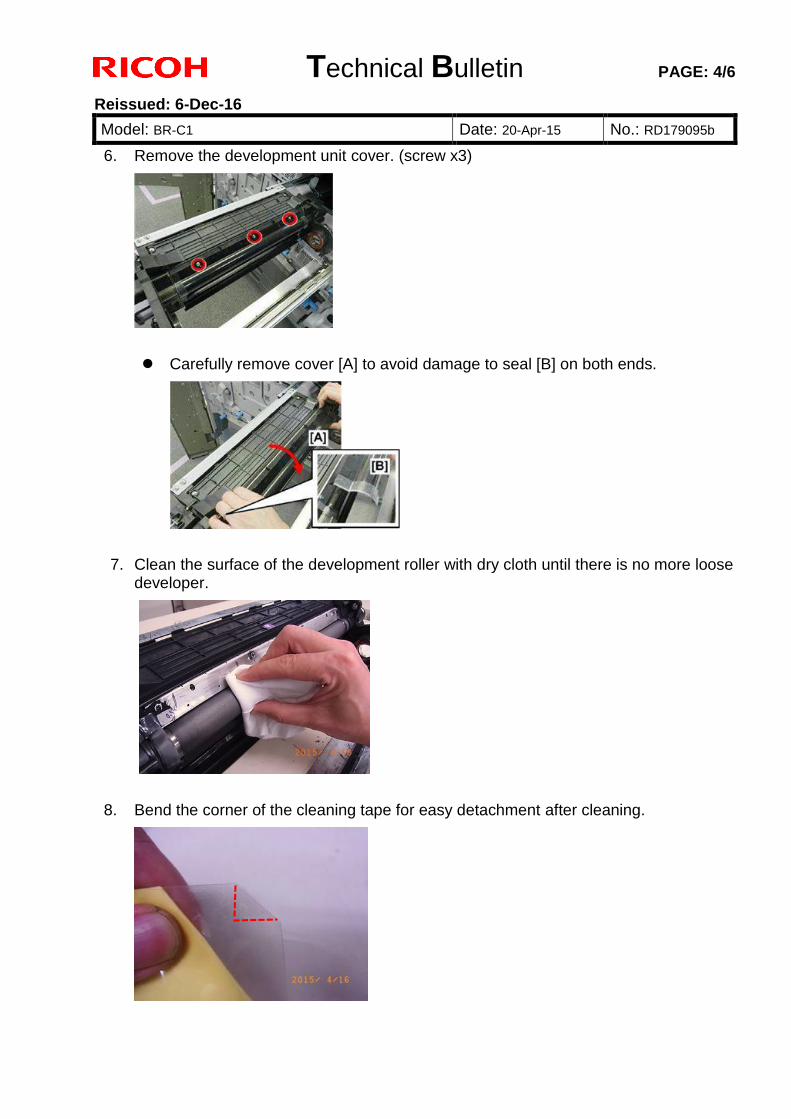
Technical Bulletin PAGE: 4/6
Reissued: 6-Dec-16
Model: BR-C1 Date: 20-Apr-15 No.: RD179095b
6. Remove the development unit cover. (screw x3)
Carefully remove cover [A] to avoid damage to seal [B] on both ends.
7. Clean the surface of the development roller with dry cloth until there is no more loose
developer.
8. Bend the corner of the cleaning tape for easy detachment after cleaning.
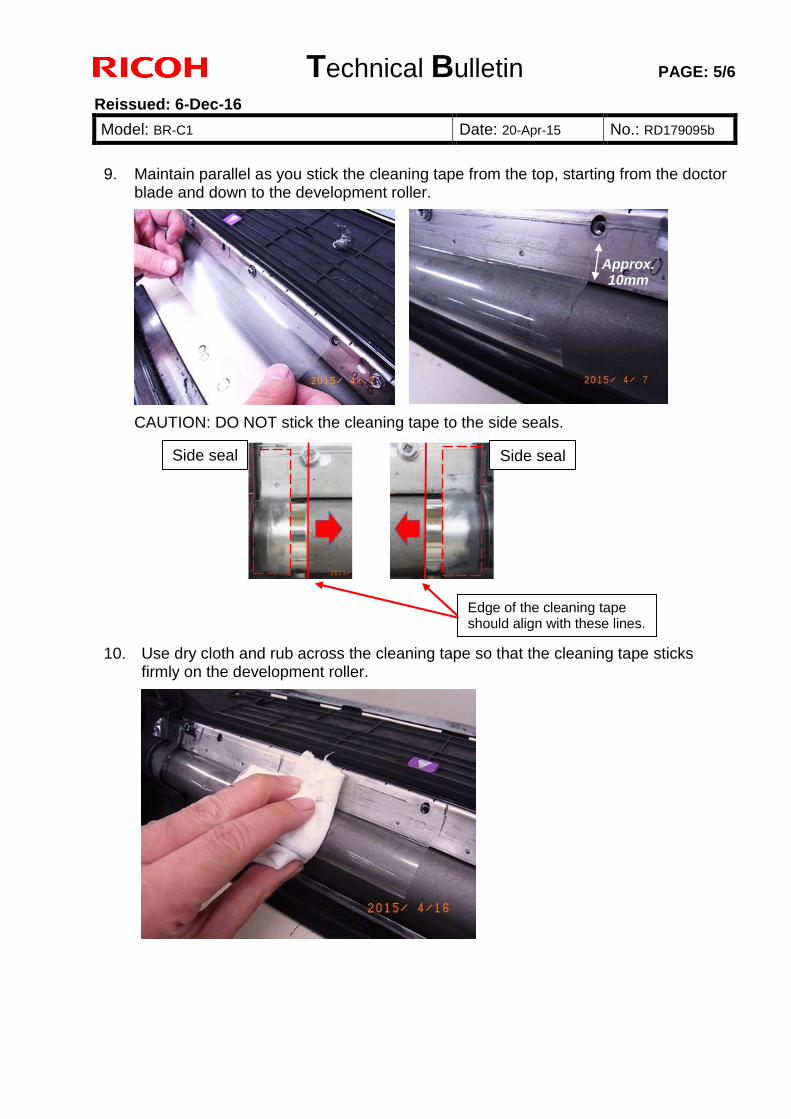
Technical Bulletin PAGE: 5/6
Reissued: 6-Dec-16
Model: BR-C1 Date: 20-Apr-15 No.: RD179095b
9. Maintain parallel as you stick the cleaning tape from the top, starting from the doctor
blade and down to the development roller.
CAUTION: DO NOT stick the cleaning tape to the side seals.
10. Use dry cloth and rub across the cleaning tape so that the cleaning tape sticks firmly on the development roller.
Side seal Side seal
Edge of the cleaning tape should align with these lines.
Approx. 10mm
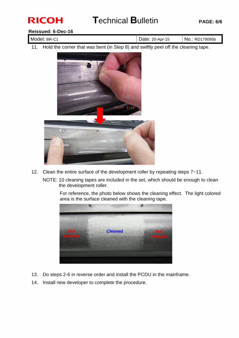
Technical Bulletin PAGE: 6/6
Reissued: 6-Dec-16
Model: BR-C1 Date: 20-Apr-15 No.: RD179095b
11. Hold the corner that was bent (in Step 8) and swiftly peel off the cleaning tape.
12. Clean the entire surface of the development roller by repeating steps 7~11.
NOTE: 10 cleaning tapes are included in the set, which should be enough to clean the development roller.
For reference, the photo below shows the cleaning effect. The light colored area is the surface cleaned with the cleaning tape.
13. Do steps 2-6 in reverse order and install the PCDU in the mainframe.
14. Install new developer to complete the procedure.
Cleaned Not cleaned
Not cleaned
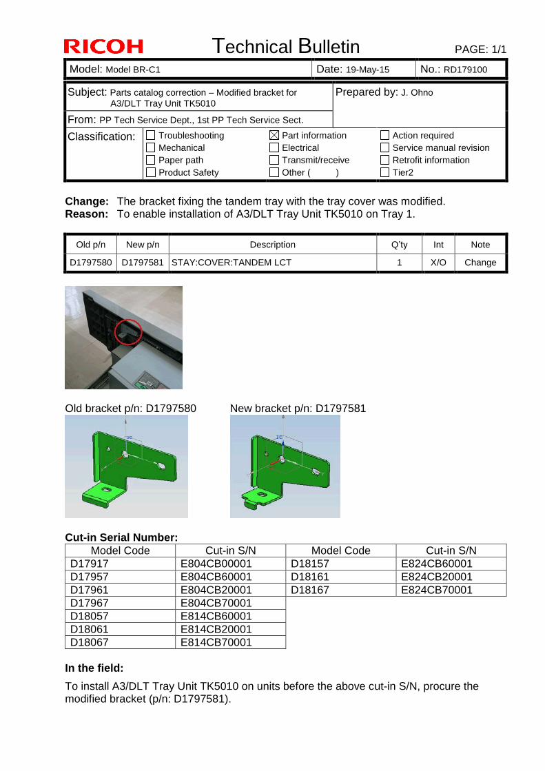
Technical Bulletin PAGE: 1/1
Model: Model BR-C1 Date: 19-May-15 No.: RD179100
Subject: Parts catalog correction – Modified bracket for
A3/DLT Tray Unit TK5010
Prepared by: J. Ohno
From: PP Tech Service Dept., 1st PP Tech Service Sect.
Classification: Troubleshooting
Mechanical
Paper path
Product Safety
Part information
Electrical
Transmit/receive
Other ( )
Action required
Service manual revision
Retrofit information
Tier2
Change: The bracket fixing the tandem tray with the tray cover was modified. Reason: To enable installation of A3/DLT Tray Unit TK5010 on Tray 1.
Old p/n New p/n Description Q’ty Int Note
D1797580 D1797581 STAY:COVER:TANDEM LCT 1 X/O Change
Old bracket p/n: D1797580 New bracket p/n: D1797581
Cut-in Serial Number:
Model Code Cut-in S/N Model Code Cut-in S/N
D17917 E804CB00001 D18157 E824CB60001
D17957 E804CB60001 D18161 E824CB20001
D17961 E804CB20001 D18167 E824CB70001
D17967 E804CB70001
D18057 E814CB60001
D18061 E814CB20001
D18067 E814CB70001
In the field:
To install A3/DLT Tray Unit TK5010 on units before the above cut-in S/N, procure the modified bracket (p/n: D1797581).
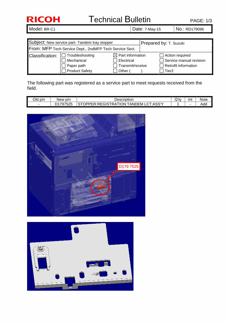
Technical Bulletin PAGE: 1/3
Model: BR-C1 Date: 7-May-15 No.: RD179096
The following part was registered as a service part to meet requests received from the field.
Old p/n New p/n Description Q’ty Int Note
- D1797525 STOPPER:REGISTRATION:TANDEM LCT:ASS'Y 1 - Add
Subject: New service part- Tandem tray stopper Prepared by: T. Suzuki
From: MFP Tech Service Dept., 2ndMFP Tech Service Sect.
Classification: Troubleshooting
Mechanical
Paper path
Product Safety
Part information
Electrical
Transmit/receive
Other ( )
Action required
Service manual revision
Retrofit information
Tier2
D179 7525
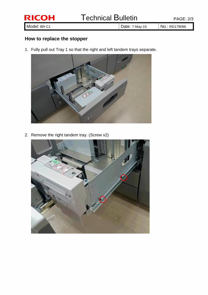
Technical Bulletin PAGE: 2/3
Model: BR-C1 Date: 7-May-15 No.: RD179096
How to replace the stopper 1. Fully pull out Tray 1 so that the right and left tandem trays separate.
2. Remove the right tandem tray. (Screw x2)
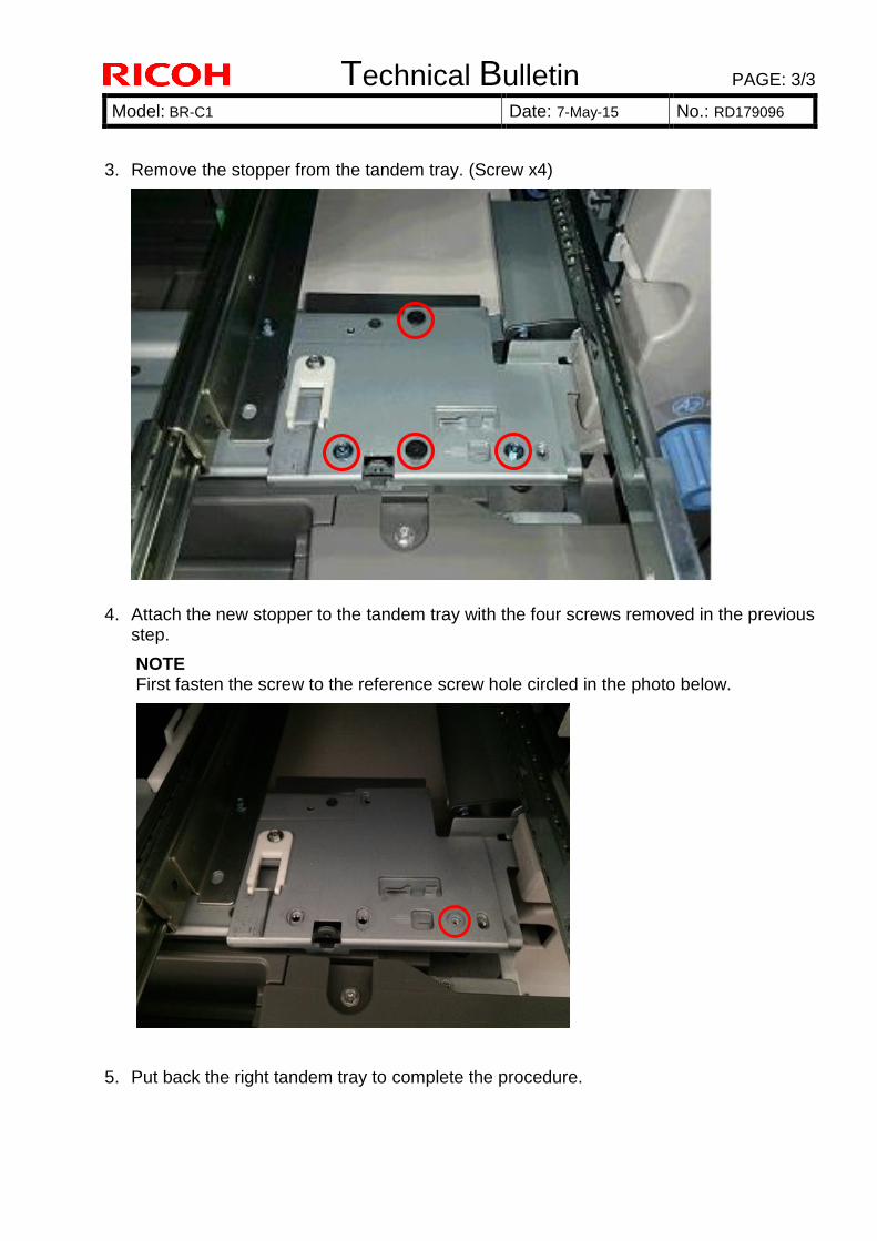
Technical Bulletin PAGE: 3/3
Model: BR-C1 Date: 7-May-15 No.: RD179096
3. Remove the stopper from the tandem tray. (Screw x4)
4. Attach the new stopper to the tandem tray with the four screws removed in the previous
step.
NOTE First fasten the screw to the reference screw hole circled in the photo below.
5. Put back the right tandem tray to complete the procedure.
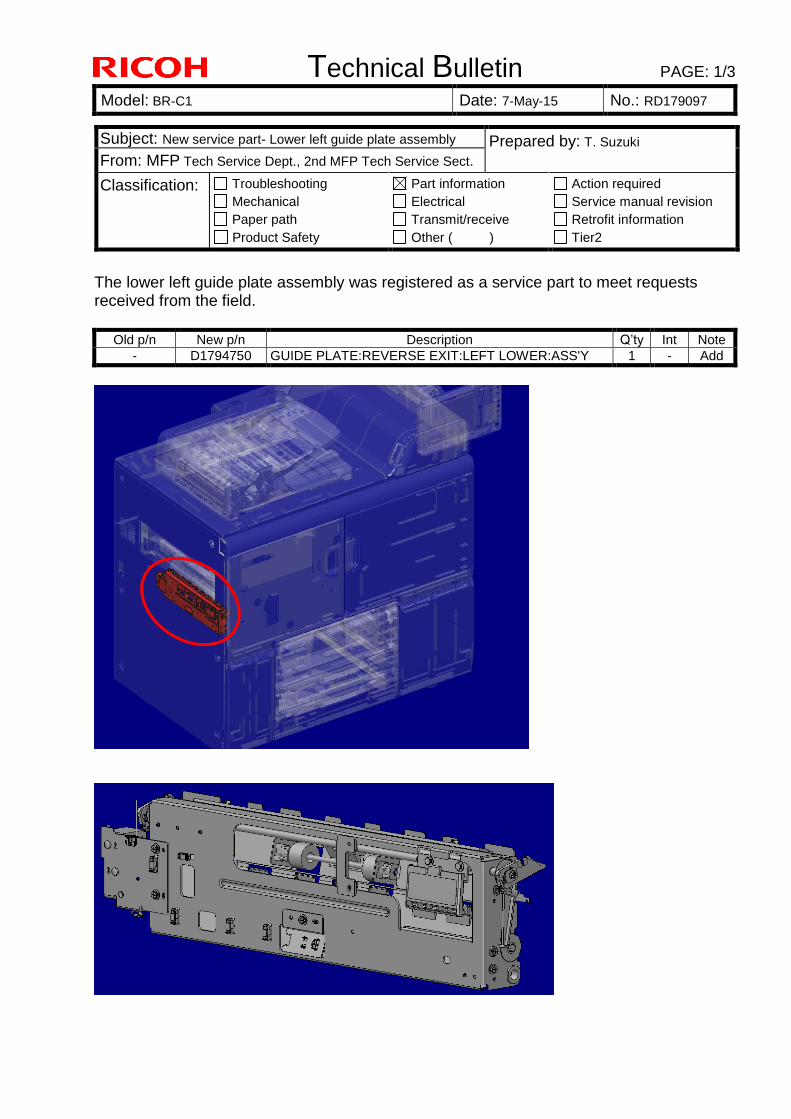
Technical Bulletin PAGE: 1/3
Model: BR-C1 Date: 7-May-15 No.: RD179097
The lower left guide plate assembly was registered as a service part to meet requests received from the field.
Old p/n New p/n Description Q’ty Int Note
- D1794750 GUIDE PLATE:REVERSE EXIT:LEFT LOWER:ASS'Y 1 - Add
Subject: New service part- Lower left guide plate assembly Prepared by: T. Suzuki
From: MFP Tech Service Dept., 2nd MFP Tech Service Sect.
Classification: Troubleshooting
Mechanical
Paper path
Product Safety
Part information
Electrical
Transmit/receive
Other ( )
Action required
Service manual revision
Retrofit information
Tier2
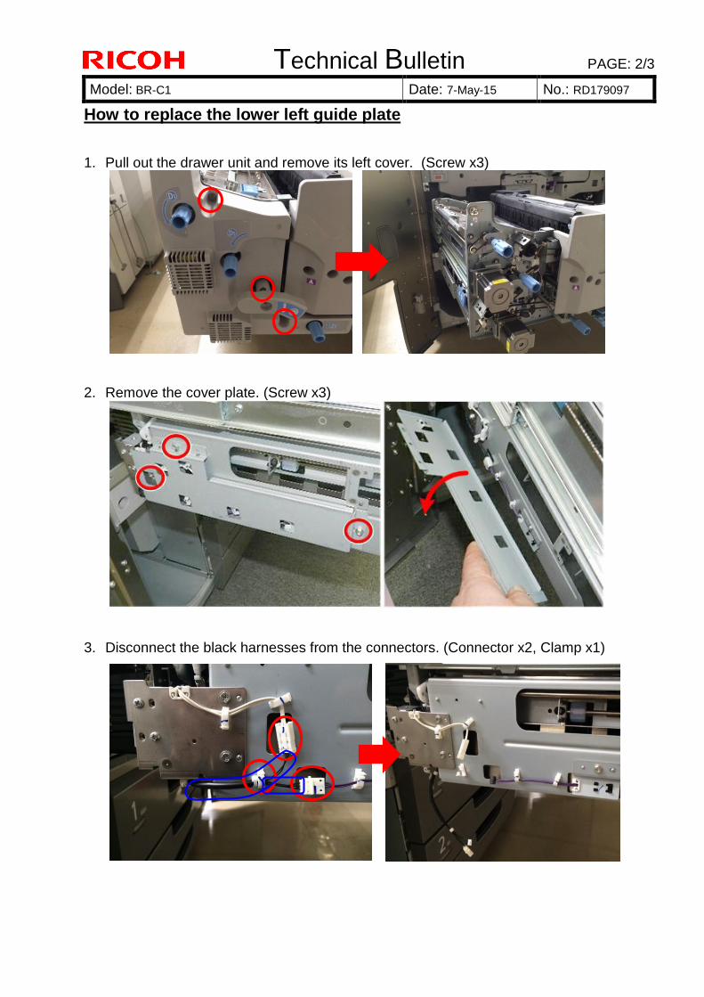
Technical Bulletin PAGE: 2/3
Model: BR-C1 Date: 7-May-15 No.: RD179097
How to replace the lower left guide plate
1. Pull out the drawer unit and remove its left cover. (Screw x3)
2. Remove the cover plate. (Screw x3)
3. Disconnect the black harnesses from the connectors. (Connector x2, Clamp x1)
v
v
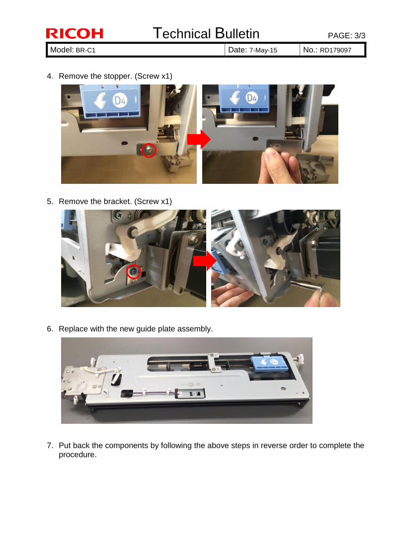
Technical Bulletin PAGE: 3/3
Model: BR-C1 Date: 7-May-15 No.: RD179097
4. Remove the stopper. (Screw x1)
R
5. Remove the bracket. (Screw x1)
6. Replace with the new guide plate assembly.
7. Put back the components by following the above steps in reverse order to complete the procedure.
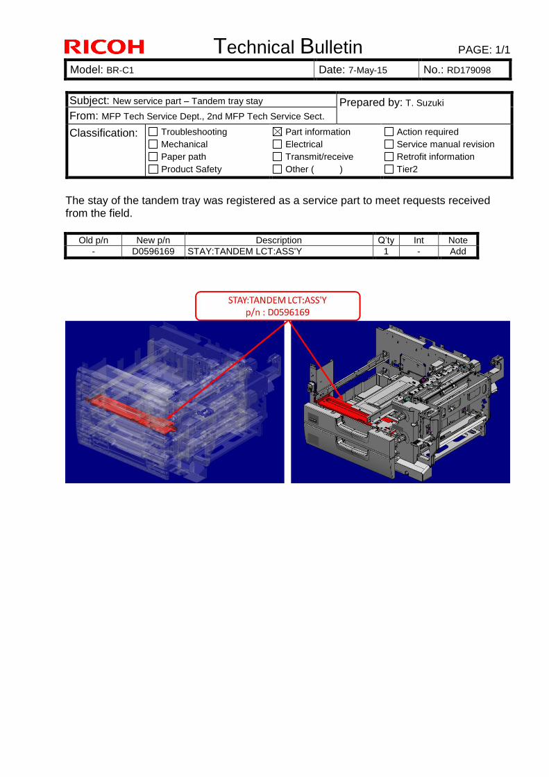
Technical Bulletin PAGE: 1/1
Model: BR-C1 Date: 7-May-15 No.: RD179098
The stay of the tandem tray was registered as a service part to meet requests received from the field.
Old p/n New p/n Description Q’ty Int Note
- D0596169 STAY:TANDEM LCT:ASS'Y 1 - Add
Subject: New service part – Tandem tray stay Prepared by: T. Suzuki
From: MFP Tech Service Dept., 2nd MFP Tech Service Sect.
Classification: Troubleshooting
Mechanical
Paper path
Product Safety
Part information
Electrical
Transmit/receive
Other ( )
Action required
Service manual revision
Retrofit information
Tier2
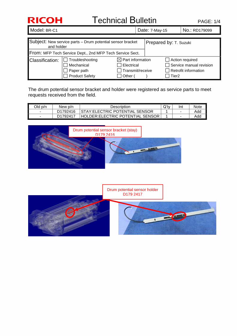
Technical Bulletin PAGE: 1/4
Model: BR-C1 Date: 7-May-15 No.: RD179099
The drum potential sensor bracket and holder were registered as service parts to meet requests received from the field.
Old p/n New p/n Description Q’ty Int Note
- D1792416 STAY:ELECTRIC POTENTIAL SENSOR 1 - Add
- D1792417 HOLDER:ELECTRIC POTENTIAL SENSOR 1 - Add
Subject: New service parts – Drum potential sensor bracket
and holder Prepared by: T. Suzuki
From: MFP Tech Service Dept., 2nd MFP Tech Service Sect.
Classification: Troubleshooting
Mechanical
Paper path
Product Safety
Part information
Electrical
Transmit/receive
Other ( )
Action required
Service manual revision
Retrofit information
Tier2
Drum potential sensor bracket (stay) D179 2416
Drum potential sensor holder D179 2417
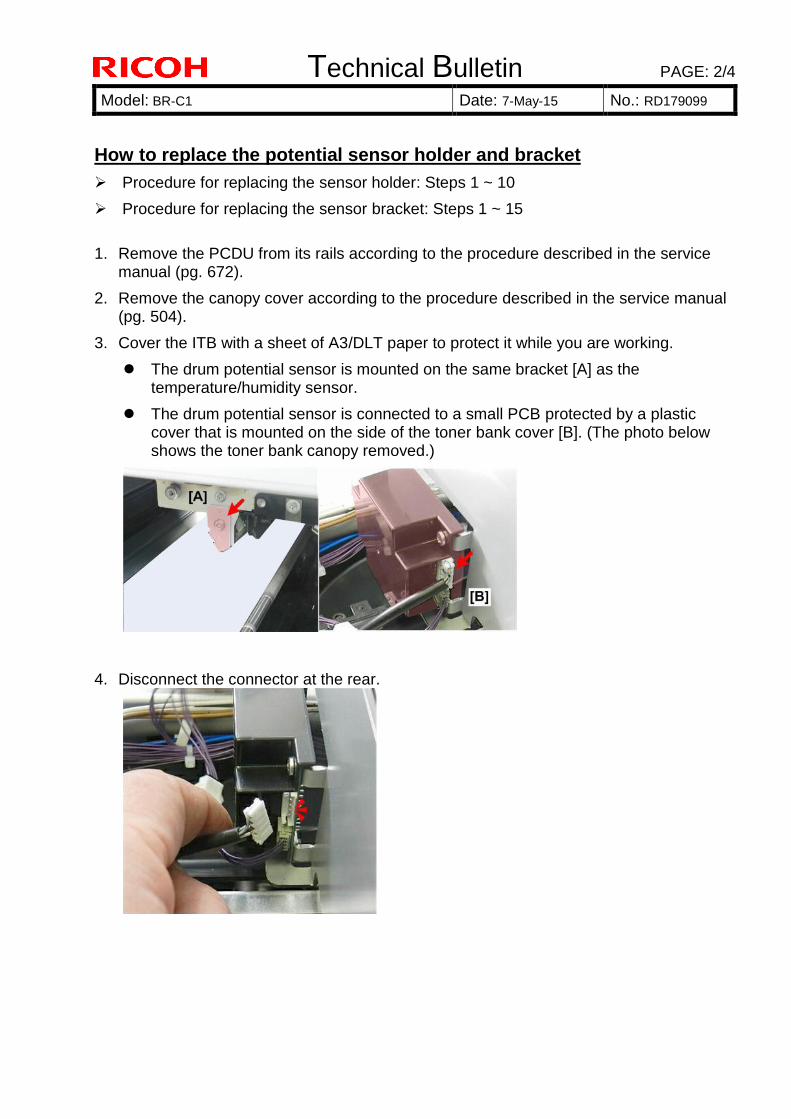
Technical Bulletin PAGE: 2/4
Model: BR-C1 Date: 7-May-15 No.: RD179099
How to replace the potential sensor holder and bracket
Procedure for replacing the sensor holder: Steps 1 ~ 10
Procedure for replacing the sensor bracket: Steps 1 ~ 15
1. Remove the PCDU from its rails according to the procedure described in the service manual (pg. 672).
2. Remove the canopy cover according to the procedure described in the service manual (pg. 504).
3. Cover the ITB with a sheet of A3/DLT paper to protect it while you are working.
The drum potential sensor is mounted on the same bracket [A] as the temperature/humidity sensor.
The drum potential sensor is connected to a small PCB protected by a plastic cover that is mounted on the side of the toner bank cover [B]. (The photo below shows the toner bank canopy removed.)
4. Disconnect the connector at the rear.
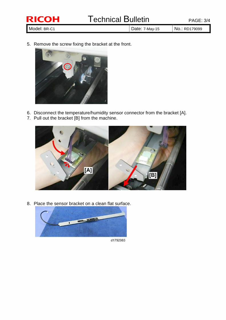
Technical Bulletin PAGE: 3/4
Model: BR-C1 Date: 7-May-15 No.: RD179099
5. Remove the screw fixing the bracket at the front.
6. Disconnect the temperature/humidity sensor connector from the bracket [A]. 7. Pull out the bracket [B] from the machine.
8. Place the sensor bracket on a clean flat surface.
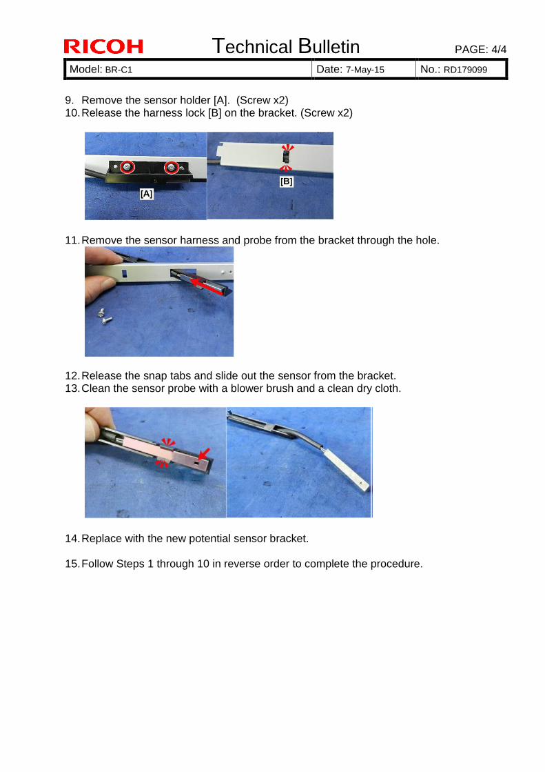
Technical Bulletin PAGE: 4/4
Model: BR-C1 Date: 7-May-15 No.: RD179099
9. Remove the sensor holder [A]. (Screw x2) 10. Release the harness lock [B] on the bracket. (Screw x2)
11. Remove the sensor harness and probe from the bracket through the hole.
12. Release the snap tabs and slide out the sensor from the bracket. 13. Clean the sensor probe with a blower brush and a clean dry cloth.
14. Replace with the new potential sensor bracket.
15. Follow Steps 1 through 10 in reverse order to complete the procedure.
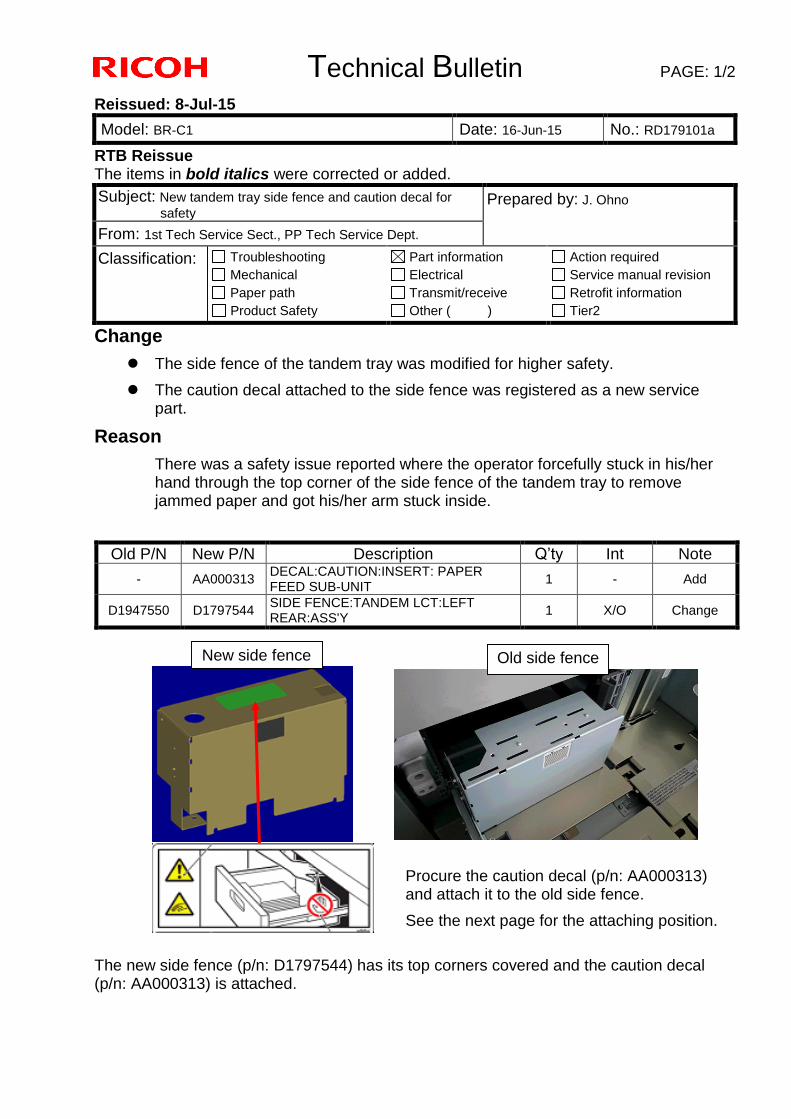
Technical Bulletin PAGE: 1/2
Reissued: 8-Jul-15
Model: BR-C1 Date: 16-Jun-15 No.: RD179101a
RTB Reissue The items in bold italics were corrected or added.
Subject: New tandem tray side fence and caution decal for
safety Prepared by: J. Ohno
From: 1st Tech Service Sect., PP Tech Service Dept.
Classification: Troubleshooting
Mechanical
Paper path
Product Safety
Part information
Electrical
Transmit/receive
Other ( )
Action required
Service manual revision
Retrofit information
Tier2
Change
The side fence of the tandem tray was modified for higher safety.
The caution decal attached to the side fence was registered as a new service part.
Reason
There was a safety issue reported where the operator forcefully stuck in his/her hand through the top corner of the side fence of the tandem tray to remove jammed paper and got his/her arm stuck inside.
Procure the caution decal (p/n: AA000313) and attach it to the old side fence.
See the next page for the attaching position.
The new side fence (p/n: D1797544) has its top corners covered and the caution decal (p/n: AA000313) is attached.
Old P/N New P/N Description Q’ty Int Note
- AA000313 DECAL:CAUTION:INSERT: PAPER FEED SUB-UNIT
1 - Add
D1947550 D1797544 SIDE FENCE:TANDEM LCT:LEFT REAR:ASS'Y
1 X/O Change
Old side fence
New side fence
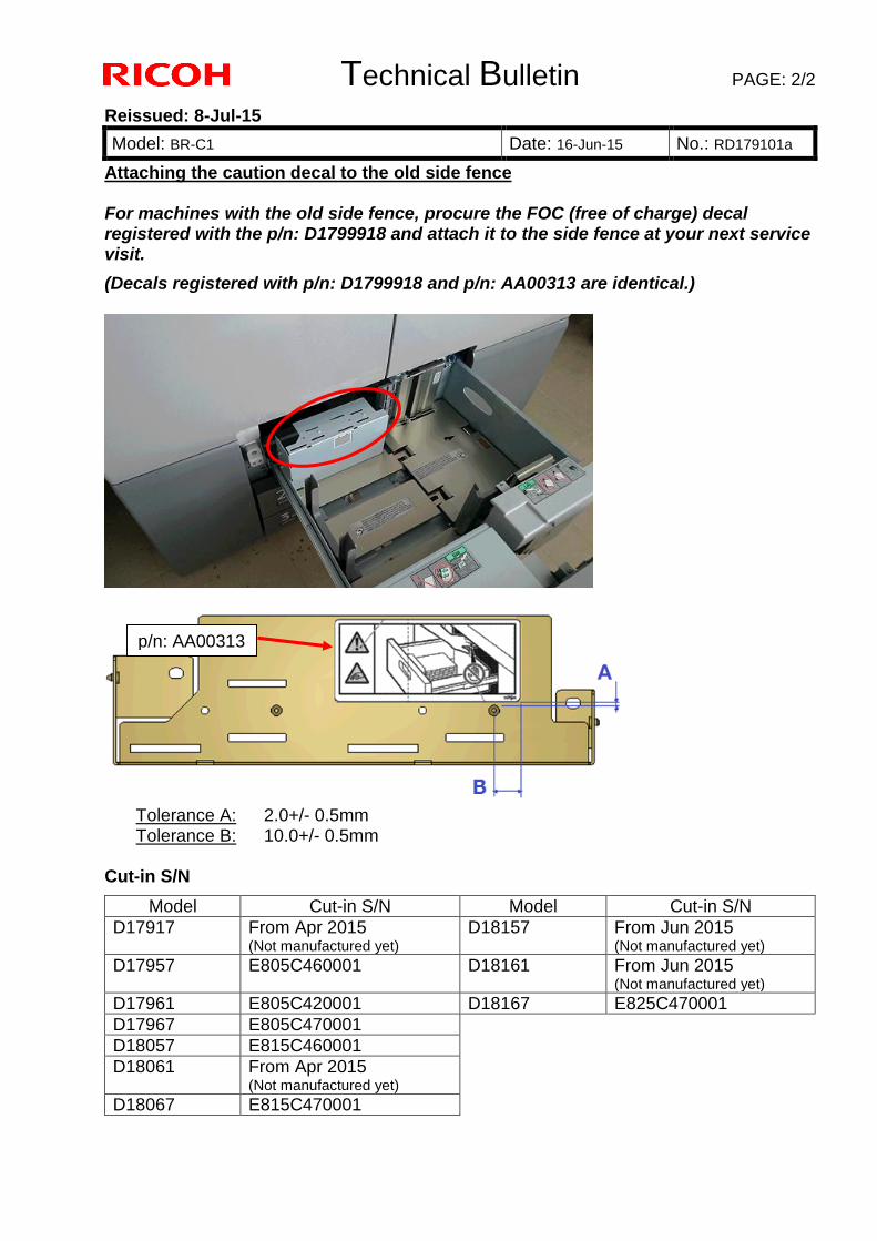
Technical Bulletin PAGE: 2/2
Reissued: 8-Jul-15
Model: BR-C1 Date: 16-Jun-15 No.: RD179101a
Attaching the caution decal to the old side fence For machines with the old side fence, procure the FOC (free of charge) decal registered with the p/n: D1799918 and attach it to the side fence at your next service visit.
(Decals registered with p/n: D1799918 and p/n: AA00313 are identical.)
Tolerance A: 2.0+/- 0.5mm Tolerance B: 10.0+/- 0.5mm
Cut-in S/N
Model Cut-in S/N Model Cut-in S/N
D17917 From Apr 2015 (Not manufactured yet)
D18157 From Jun 2015 (Not manufactured yet)
D17957 E805C460001 D18161 From Jun 2015 (Not manufactured yet)
D17961 E805C420001 D18167 E825C470001
D17967 E805C470001
D18057 E815C460001
D18061 From Apr 2015 (Not manufactured yet)
D18067 E815C470001
p/n: AA00313
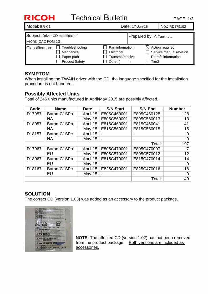
Technical Bulletin PAGE: 1/2
Model: BR-C1 Date: 17-Jun-15 No.: RD179102
SYMPTOM When installing the TWAIN driver with the CD, the language specified for the installation procedure is not honored.
Possibly Affected Units
Total of 246 units manufactured in April/May 2015 are possibly affected.
Code Name Date S/N Start S/N End Number
D17957 Baron-C1SPa NA
April-15 E805C460001 E805C460128 128
May-15 E805C560001 E805C560013 13
D18057 Baron-C1SPb NA
April-15 E815C460001 E815C460041 41
May-15 E815C560001 E815C560015 15
D18157 Baron-C1SPc NA
April-15 - - 0
May-15 - - 0
Total: 197
D17967 Baron-C1SPa EU
April-15 E805C470001 E805C470007 7
May-15 E805C570001 E805C570012 12
D18067 Baron-C1SPb EU
April-15 E815C470001 E815C470014 14
May-15 - - 0
D18167 Baron-C1SPc EU
April-15 E825C470001 E825C470016 16
May-15 - - 0
Total: 49
SOLUTION
The correct CD (version 1.03) was added as an accessory to the product package.
NOTE: The affected CD (version 1.02) has not been removed from the product package. Both versions are included as accessories.
Subject: Driver CD modification Prepared by: Y. Tanimoto
From: QAC FQM 2G.
Classification: Troubleshooting
Mechanical
Paper path
Product Safety
Part information
Electrical
Transmit/receive
Other ( )
Action required
Service manual revision
Retrofit information
Tier2
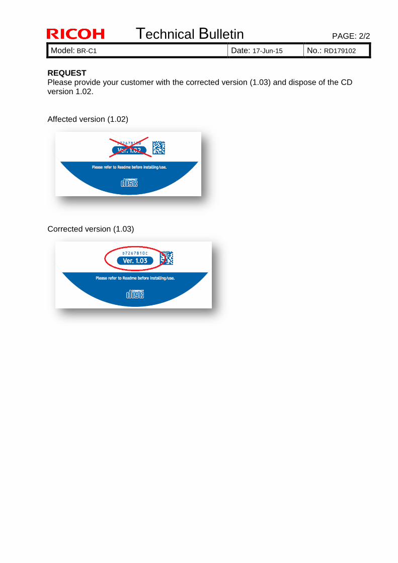
Technical Bulletin PAGE: 2/2
Model: BR-C1 Date: 17-Jun-15 No.: RD179102
REQUEST Please provide your customer with the corrected version (1.03) and dispose of the CD version 1.02. Affected version (1.02)
Corrected version (1.03)
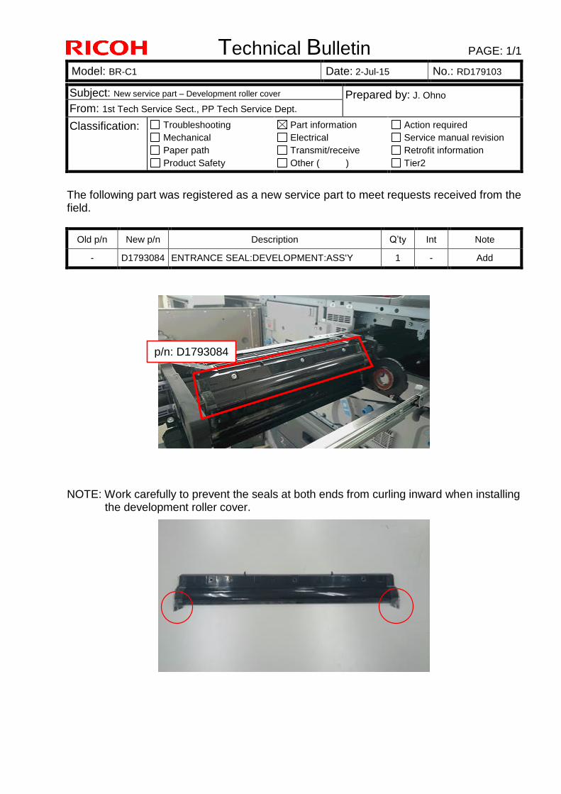
Technical Bulletin PAGE: 1/1
Model: BR-C1 Date: 2-Jul-15 No.: RD179103
Subject: New service part – Development roller cover Prepared by: J. Ohno
From: 1st Tech Service Sect., PP Tech Service Dept.
Classification: Troubleshooting
Mechanical
Paper path
Product Safety
Part information
Electrical
Transmit/receive
Other ( )
Action required
Service manual revision
Retrofit information
Tier2
The following part was registered as a new service part to meet requests received from the field.
Old p/n New p/n Description Q’ty Int Note
- D1793084 ENTRANCE SEAL:DEVELOPMENT:ASS'Y 1 - Add
NOTE: Work carefully to prevent the seals at both ends from curling inward when installing
the development roller cover.
p/n: D1793084
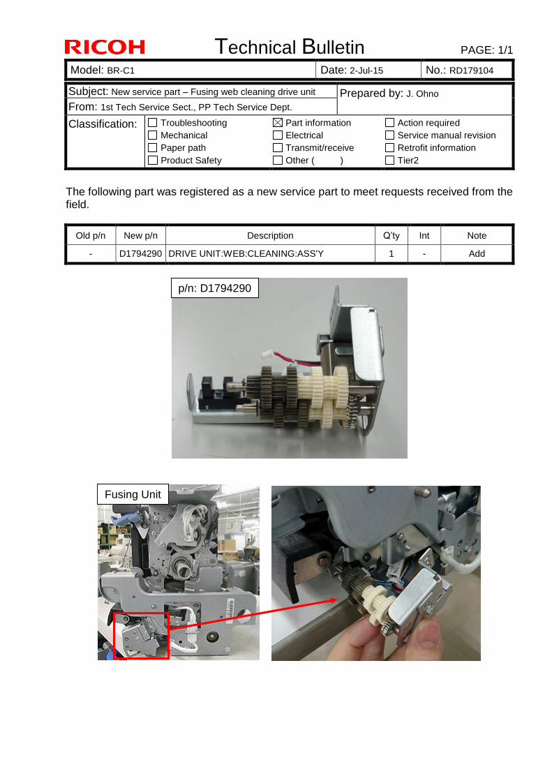
Technical Bulletin PAGE: 1/1
Model: BR-C1 Date: 2-Jul-15 No.: RD179104
Subject: New service part – Fusing web cleaning drive unit Prepared by: J. Ohno
From: 1st Tech Service Sect., PP Tech Service Dept.
Classification: Troubleshooting
Mechanical
Paper path
Product Safety
Part information
Electrical
Transmit/receive
Other ( )
Action required
Service manual revision
Retrofit information
Tier2
The following part was registered as a new service part to meet requests received from the field.
Old p/n New p/n Description Q’ty Int Note
- D1794290 DRIVE UNIT:WEB:CLEANING:ASS'Y 1 - Add
Fusing Unit
p/n: D1794290
Technical Bulletin PAGE: 1/12
Model: BR-C1 Date: 27-Jul-15 No.: RD179105
SYMPTOM
SC581-00 (Decurl Unit: Decurl Home Position sensor error) is indicated on the operation panel.
CAUSE
The lift motor locks, because the nut is unable to spin smoothly on the feed screw due to the following two reasons: The two springs are too strong. The feed screw is not applied with enough grease.
Possibly Affected Units
Total of 699 units manufactured from July 2013 through May 2015 are possibly affected.
Model S/N (*) Q’ty shipped to the field
D74117 To NA 416
To EU 254
To AP 29
(*)NOTE: Refer to P8 ~ P12 for the details of S/N.
Subject: Troubleshooting SC581-00 Prepared by: Y, Tanimoto
From: FQM Group2, Field Quality Management Dept.
Classification: Troubleshooting
Mechanical
Paper path
Product Safety
Part information
Electrical
Transmit/receive
Other ( )
Action required
Service manual revision
Retrofit information
Tier2
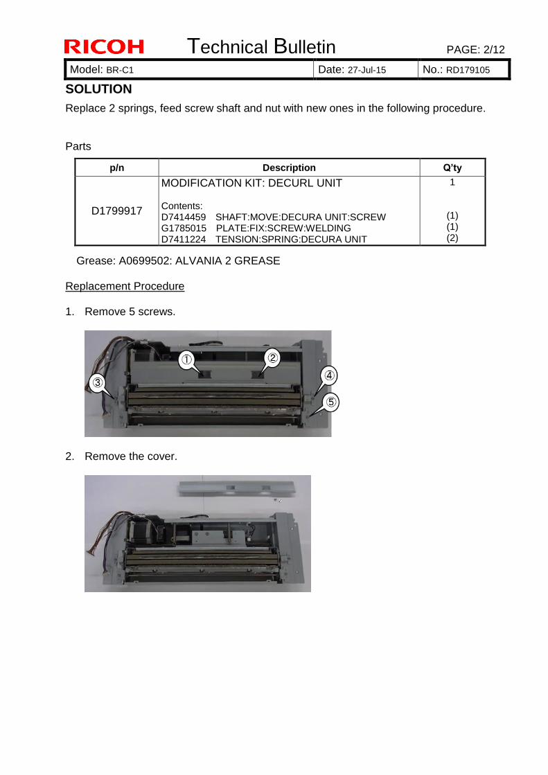
Technical Bulletin PAGE: 2/12
Model: BR-C1 Date: 27-Jul-15 No.: RD179105
SOLUTION
Replace 2 springs, feed screw shaft and nut with new ones in the following procedure. Parts
Grease: A0699502: ALVANIA 2 GREASE Replacement Procedure 1. Remove 5 screws.
2. Remove the cover.
p/n Description Q’ty
D1799917
MODIFICATION KIT: DECURL UNIT Contents: D7414459 SHAFT:MOVE:DECURA UNIT:SCREW G1785015 PLATE:FIX:SCREW:WELDING D7411224 TENSION:SPRING:DECURA UNIT
1
(1) (1) (2)
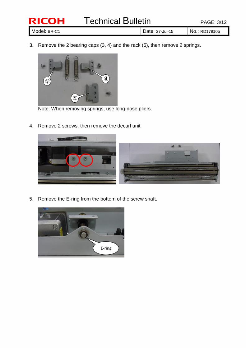
Technical Bulletin PAGE: 3/12
Model: BR-C1 Date: 27-Jul-15 No.: RD179105
3. Remove the 2 bearing caps (3, 4) and the rack (5), then remove 2 springs.
Note: When removing springs, use long-nose pliers.
4. Remove 2 screws, then remove the decurl unit
5. Remove the E-ring from the bottom of the screw shaft.
③ ④
⑤
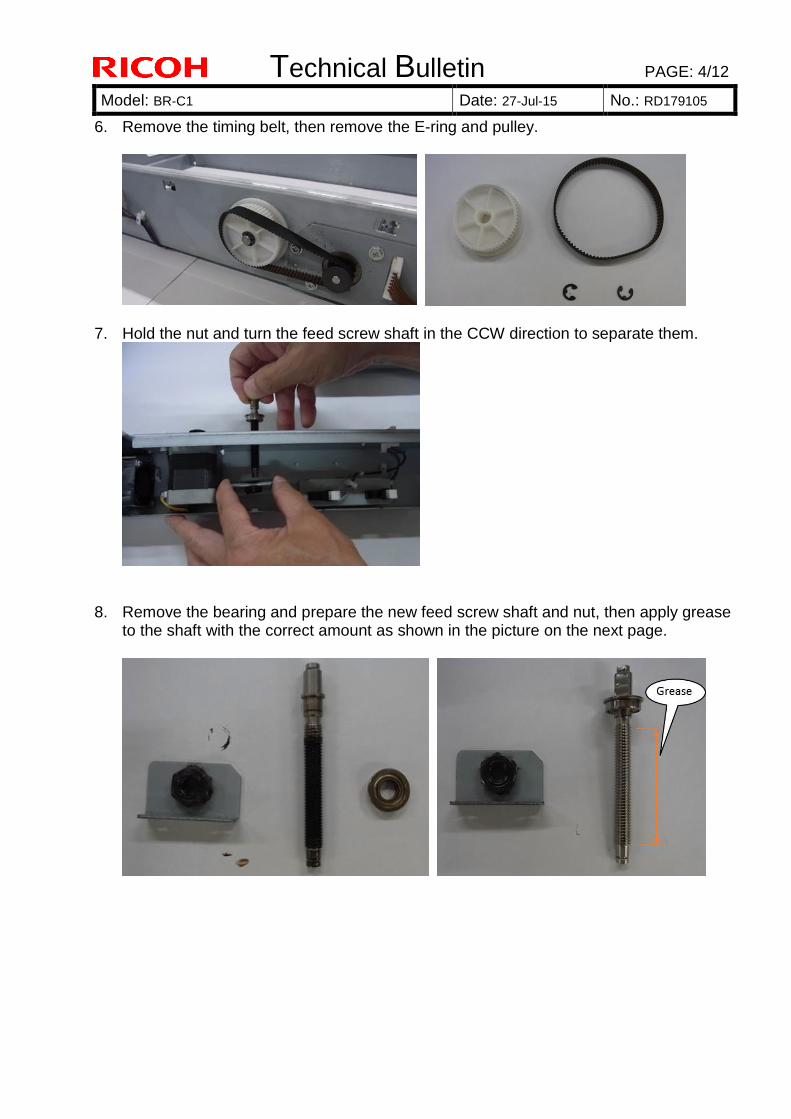
Technical Bulletin PAGE: 4/12
Model: BR-C1 Date: 27-Jul-15 No.: RD179105
6. Remove the timing belt, then remove the E-ring and pulley.
7. Hold the nut and turn the feed screw shaft in the CCW direction to separate them.
8. Remove the bearing and prepare the new feed screw shaft and nut, then apply grease to the shaft with the correct amount as shown in the picture on the next page.
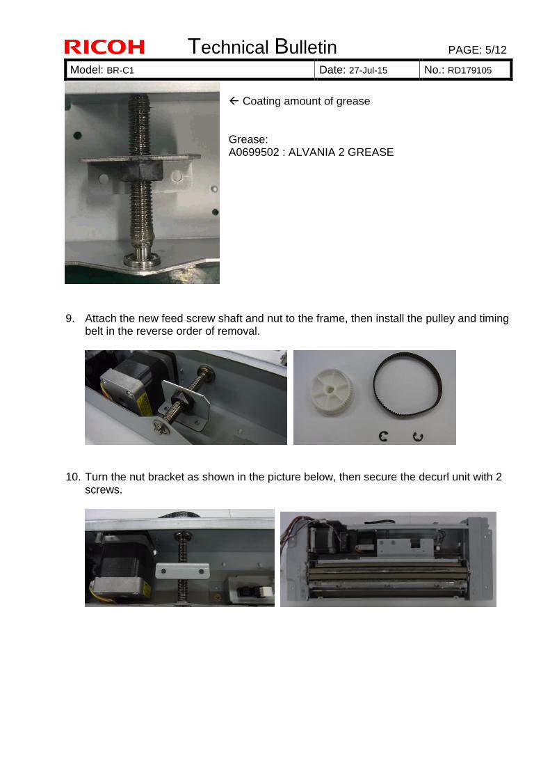
Technical Bulletin PAGE: 5/12
Model: BR-C1 Date: 27-Jul-15 No.: RD179105
Coating amount of grease Grease: A0699502 : ALVANIA 2 GREASE
9. Attach the new feed screw shaft and nut to the frame, then install the pulley and timing belt in the reverse order of removal.
10. Turn the nut bracket as shown in the picture below, then secure the decurl unit with 2 screws.
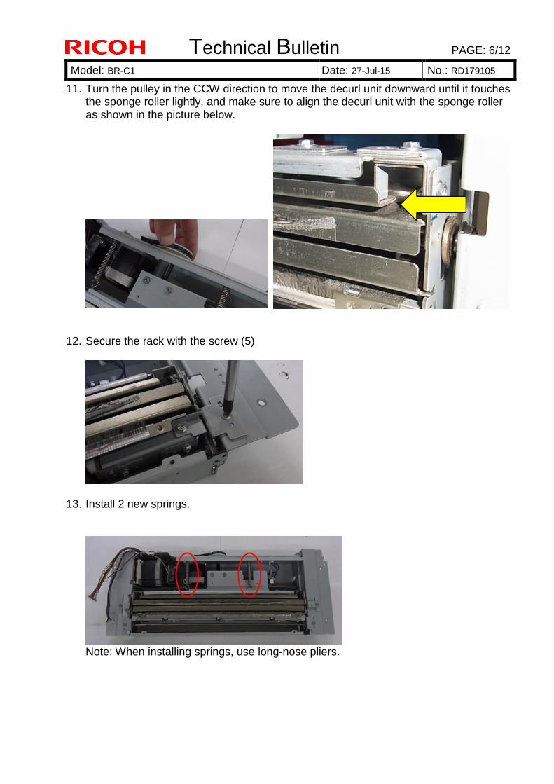
Technical Bulletin PAGE: 6/12
Model: BR-C1 Date: 27-Jul-15 No.: RD179105
11. Turn the pulley in the CCW direction to move the decurl unit downward until it touches the sponge roller lightly, and make sure to align the decurl unit with the sponge roller as shown in the picture below.
12. Secure the rack with the screw (5)
13. Install 2 new springs.
Note: When installing springs, use long-nose pliers.
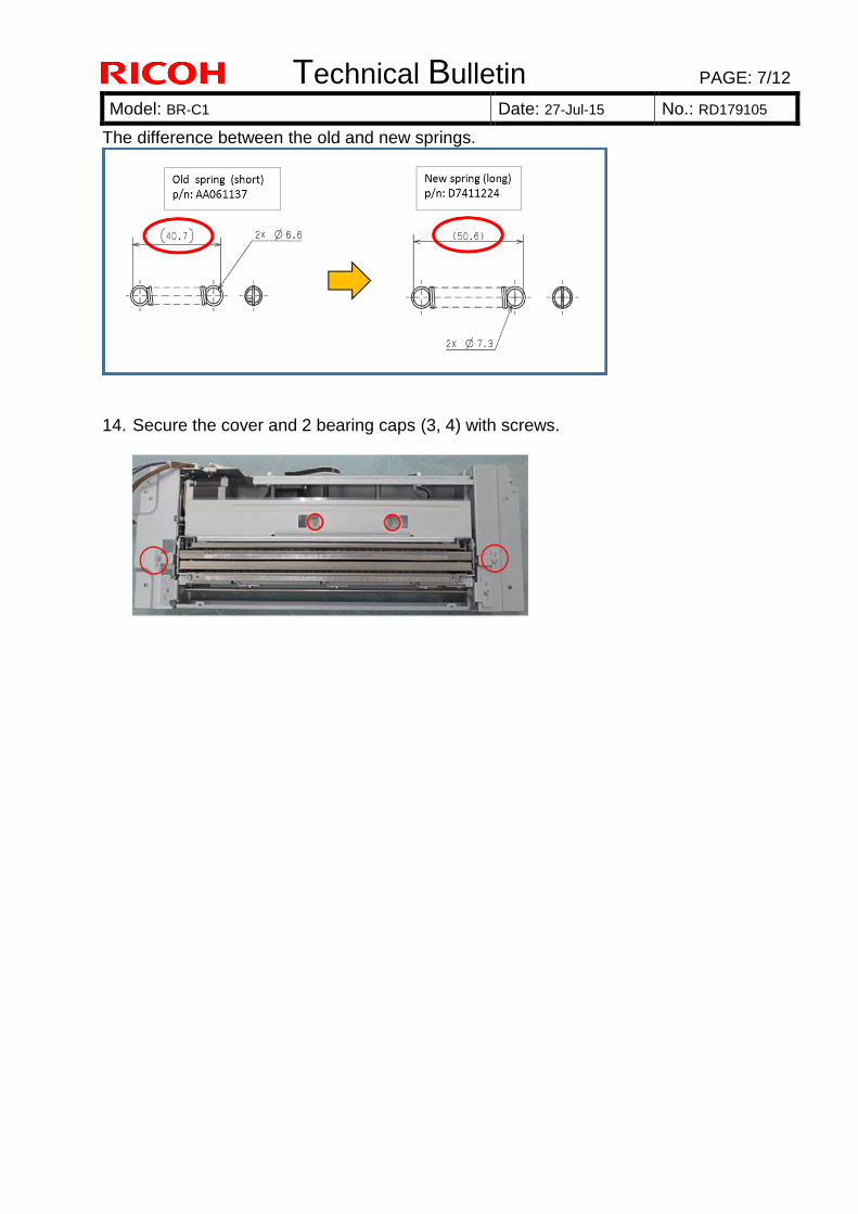
Technical Bulletin PAGE: 7/12
Model: BR-C1 Date: 27-Jul-15 No.: RD179105
The difference between the old and new springs.
14. Secure the cover and 2 bearing caps (3, 4) with screws.
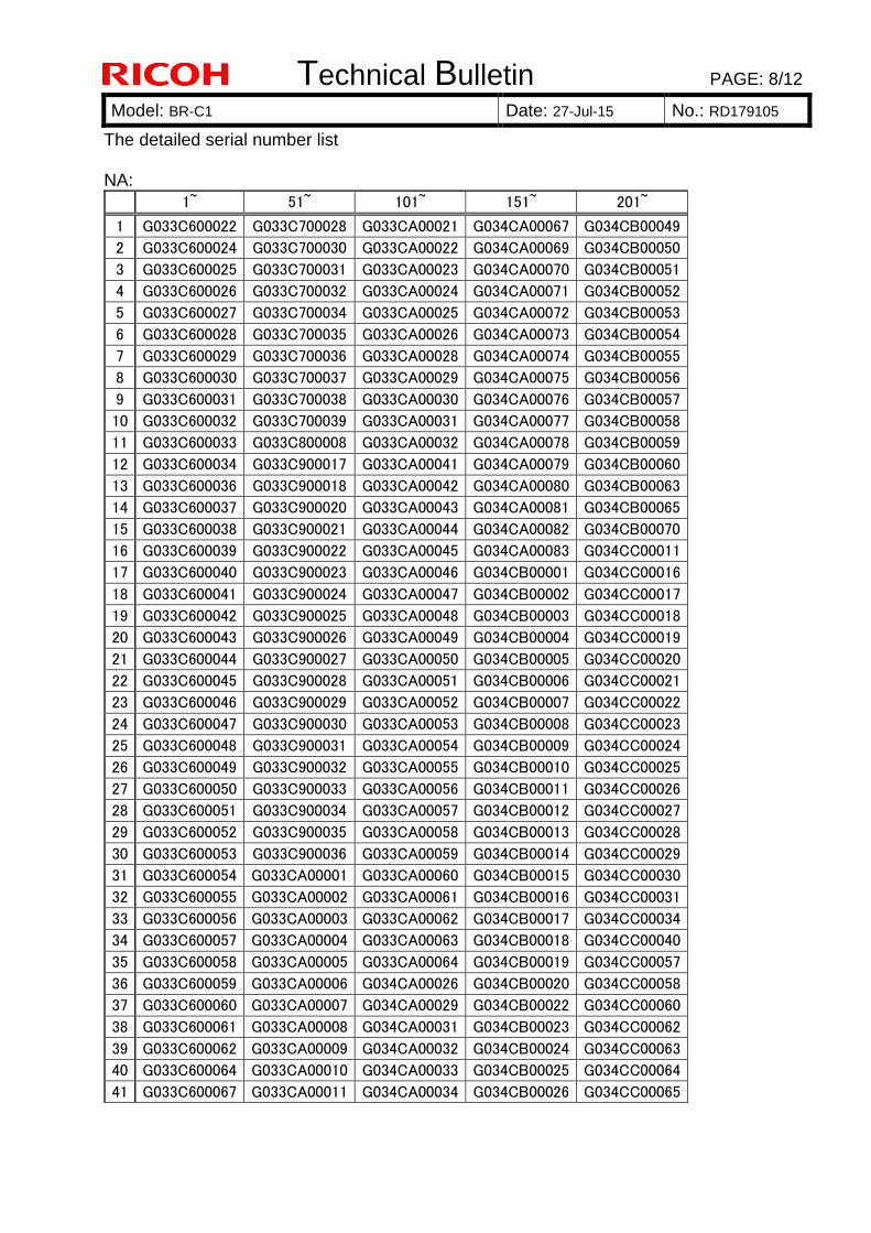
Technical Bulletin PAGE: 8/12
Model: BR-C1 Date: 27-Jul-15 No.: RD179105
The detailed serial number list NA:
1~ 51~ 101~ 151~ 201~
1 G033C600022 G033C700028 G033CA00021 G034CA00067 G034CB00049
2 G033C600024 G033C700030 G033CA00022 G034CA00069 G034CB00050
3 G033C600025 G033C700031 G033CA00023 G034CA00070 G034CB00051
4 G033C600026 G033C700032 G033CA00024 G034CA00071 G034CB00052
5 G033C600027 G033C700034 G033CA00025 G034CA00072 G034CB00053
6 G033C600028 G033C700035 G033CA00026 G034CA00073 G034CB00054
7 G033C600029 G033C700036 G033CA00028 G034CA00074 G034CB00055
8 G033C600030 G033C700037 G033CA00029 G034CA00075 G034CB00056
9 G033C600031 G033C700038 G033CA00030 G034CA00076 G034CB00057
10 G033C600032 G033C700039 G033CA00031 G034CA00077 G034CB00058
11 G033C600033 G033C800008 G033CA00032 G034CA00078 G034CB00059
12 G033C600034 G033C900017 G033CA00041 G034CA00079 G034CB00060
13 G033C600036 G033C900018 G033CA00042 G034CA00080 G034CB00063
14 G033C600037 G033C900020 G033CA00043 G034CA00081 G034CB00065
15 G033C600038 G033C900021 G033CA00044 G034CA00082 G034CB00070
16 G033C600039 G033C900022 G033CA00045 G034CA00083 G034CC00011
17 G033C600040 G033C900023 G033CA00046 G034CB00001 G034CC00016
18 G033C600041 G033C900024 G033CA00047 G034CB00002 G034CC00017
19 G033C600042 G033C900025 G033CA00048 G034CB00003 G034CC00018
20 G033C600043 G033C900026 G033CA00049 G034CB00004 G034CC00019
21 G033C600044 G033C900027 G033CA00050 G034CB00005 G034CC00020
22 G033C600045 G033C900028 G033CA00051 G034CB00006 G034CC00021
23 G033C600046 G033C900029 G033CA00052 G034CB00007 G034CC00022
24 G033C600047 G033C900030 G033CA00053 G034CB00008 G034CC00023
25 G033C600048 G033C900031 G033CA00054 G034CB00009 G034CC00024
26 G033C600049 G033C900032 G033CA00055 G034CB00010 G034CC00025
27 G033C600050 G033C900033 G033CA00056 G034CB00011 G034CC00026
28 G033C600051 G033C900034 G033CA00057 G034CB00012 G034CC00027
29 G033C600052 G033C900035 G033CA00058 G034CB00013 G034CC00028
30 G033C600053 G033C900036 G033CA00059 G034CB00014 G034CC00029
31 G033C600054 G033CA00001 G033CA00060 G034CB00015 G034CC00030
32 G033C600055 G033CA00002 G033CA00061 G034CB00016 G034CC00031
33 G033C600056 G033CA00003 G033CA00062 G034CB00017 G034CC00034
34 G033C600057 G033CA00004 G033CA00063 G034CB00018 G034CC00040
35 G033C600058 G033CA00005 G033CA00064 G034CB00019 G034CC00057
36 G033C600059 G033CA00006 G034CA00026 G034CB00020 G034CC00058
37 G033C600060 G033CA00007 G034CA00029 G034CB00022 G034CC00060
38 G033C600061 G033CA00008 G034CA00031 G034CB00023 G034CC00062
39 G033C600062 G033CA00009 G034CA00032 G034CB00024 G034CC00063
40 G033C600064 G033CA00010 G034CA00033 G034CB00025 G034CC00064
41 G033C600067 G033CA00011 G034CA00034 G034CB00026 G034CC00065
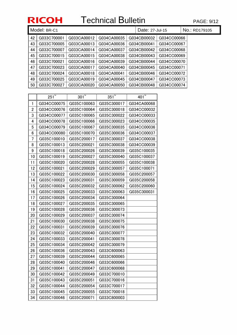
Technical Bulletin PAGE: 9/12
Model: BR-C1 Date: 27-Jul-15 No.: RD179105
42 G033C700001 G033CA00012 G034CA00035 G034CB00032 G034CC00066
43 G033C700005 G033CA00013 G034CA00036 G034CB00041 G034CC00067
44 G033C700007 G033CA00014 G034CA00037 G034CB00042 G034CC00068
45 G033C700015 G033CA00015 G034CA00038 G034CB00043 G034CC00069
46 G033C700021 G033CA00016 G034CA00039 G034CB00044 G034CC00070
47 G033C700023 G033CA00017 G034CA00040 G034CB00045 G034CC00071
48 G033C700024 G033CA00018 G034CA00041 G034CB00046 G034CC00072
49 G033C700025 G033CA00019 G034CA00045 G034CB00047 G034CC00073
50 G033C700027 G033CA00020 G034CA00050 G034CB00048 G034CC00074
251~ 301~ 351~ 401~
1 G034CC00075 G035C100063 G035C300017 G034CA00068
2 G034CC00076 G035C100064 G035C300018 G034CC00032
3 G034CC00077 G035C100065 G035C300022 G034CC00033
4 G034CC00078 G035C100066 G035C300023 G034CC00035
5 G034CC00079 G035C100067 G035C300035 G034CC00036
6 G034CC00080 G035C100070 G035C300036 G034CC00037
7 G035C100010 G035C200017 G035C300037 G034CC00038
8 G035C100013 G035C200021 G035C300038 G034CC00039
9 G035C100018 G035C200026 G035C300039 G035C100035
10 G035C100019 G035C200027 G035C300040 G035C100037
11 G035C100020 G035C200028 G035C300055 G035C100038
12 G035C100021 G035C200029 G035C300057 G035C100071
13 G035C100022 G035C200030 G035C300058 G035C200057
14 G035C100023 G035C200031 G035C300059 G035C200058
15 G035C100024 G035C200032 G035C300062 G035C200060
16 G035C100025 G035C200033 G035C300063 G035C300031
17 G035C100026 G035C200034 G035C300064
18 G035C100027 G035C200035 G035C300065
19 G035C100028 G035C200036 G035C300073
20 G035C100029 G035C200037 G035C300074
21 G035C100030 G035C200038 G035C300075
22 G035C100031 G035C200039 G035C300076
23 G035C100032 G035C200040 G035C300077
24 G035C100033 G035C200041 G035C300078
25 G035C100034 G035C200042 G035C300079
26 G035C100036 G035C200043 G033C600063
27 G035C100039 G035C200044 G033C600065
28 G035C100040 G035C200046 G033C600066
29 G035C100041 G035C200047 G033C600068
30 G035C100042 G035C200049 G033C700010
31 G035C100043 G035C200051 G033C700016
32 G035C100044 G035C200054 G033C700017
33 G035C100045 G035C200055 G033C700018
34 G035C100046 G035C200071 G033C800003
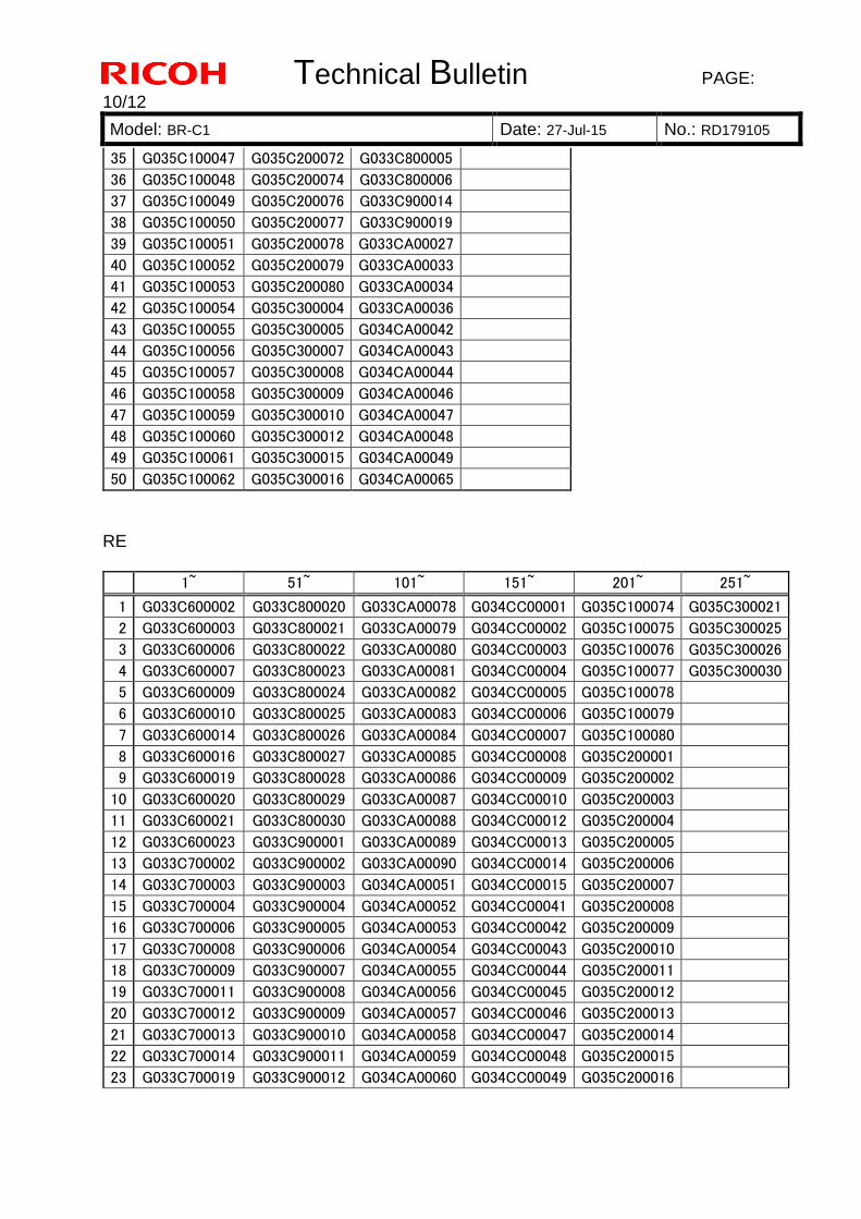
Technical Bulletin PAGE:
10/12
Model: BR-C1 Date: 27-Jul-15 No.: RD179105
35 G035C100047 G035C200072 G033C800005
36 G035C100048 G035C200074 G033C800006
37 G035C100049 G035C200076 G033C900014
38 G035C100050 G035C200077 G033C900019
39 G035C100051 G035C200078 G033CA00027
40 G035C100052 G035C200079 G033CA00033
41 G035C100053 G035C200080 G033CA00034
42 G035C100054 G035C300004 G033CA00036
43 G035C100055 G035C300005 G034CA00042
44 G035C100056 G035C300007 G034CA00043
45 G035C100057 G035C300008 G034CA00044
46 G035C100058 G035C300009 G034CA00046
47 G035C100059 G035C300010 G034CA00047
48 G035C100060 G035C300012 G034CA00048
49 G035C100061 G035C300015 G034CA00049
50 G035C100062 G035C300016 G034CA00065
RE
1~ 51~ 101~ 151~ 201~ 251~
1 G033C600002 G033C800020 G033CA00078 G034CC00001 G035C100074 G035C300021
2 G033C600003 G033C800021 G033CA00079 G034CC00002 G035C100075 G035C300025
3 G033C600006 G033C800022 G033CA00080 G034CC00003 G035C100076 G035C300026
4 G033C600007 G033C800023 G033CA00081 G034CC00004 G035C100077 G035C300030
5 G033C600009 G033C800024 G033CA00082 G034CC00005 G035C100078
6 G033C600010 G033C800025 G033CA00083 G034CC00006 G035C100079
7 G033C600014 G033C800026 G033CA00084 G034CC00007 G035C100080
8 G033C600016 G033C800027 G033CA00085 G034CC00008 G035C200001
9 G033C600019 G033C800028 G033CA00086 G034CC00009 G035C200002
10 G033C600020 G033C800029 G033CA00087 G034CC00010 G035C200003
11 G033C600021 G033C800030 G033CA00088 G034CC00012 G035C200004
12 G033C600023 G033C900001 G033CA00089 G034CC00013 G035C200005
13 G033C700002 G033C900002 G033CA00090 G034CC00014 G035C200006
14 G033C700003 G033C900003 G034CA00051 G034CC00015 G035C200007
15 G033C700004 G033C900004 G034CA00052 G034CC00041 G035C200008
16 G033C700006 G033C900005 G034CA00053 G034CC00042 G035C200009
17 G033C700008 G033C900006 G034CA00054 G034CC00043 G035C200010
18 G033C700009 G033C900007 G034CA00055 G034CC00044 G035C200011
19 G033C700011 G033C900008 G034CA00056 G034CC00045 G035C200012
20 G033C700012 G033C900009 G034CA00057 G034CC00046 G035C200013
21 G033C700013 G033C900010 G034CA00058 G034CC00047 G035C200014
22 G033C700014 G033C900011 G034CA00059 G034CC00048 G035C200015
23 G033C700019 G033C900012 G034CA00060 G034CC00049 G035C200016
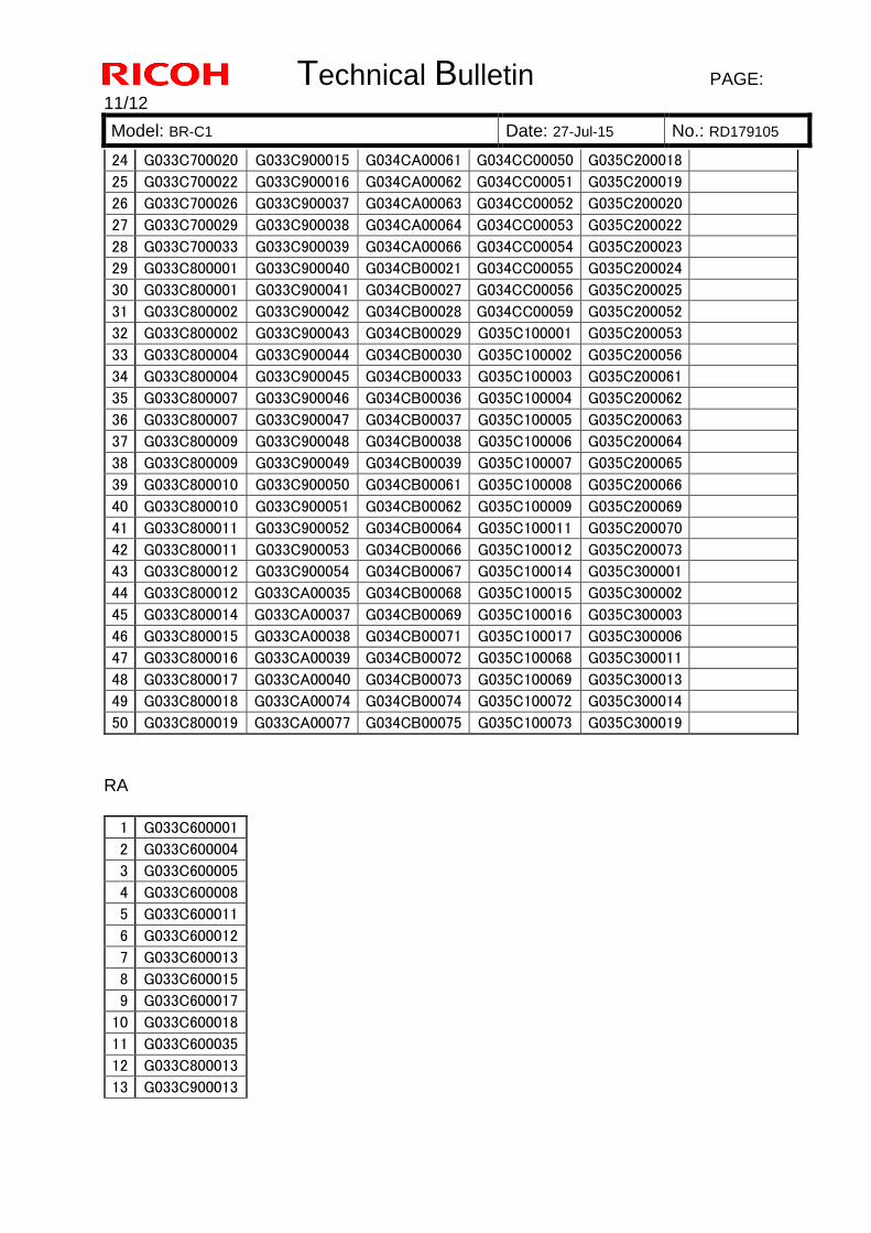
Technical Bulletin PAGE:
11/12
Model: BR-C1 Date: 27-Jul-15 No.: RD179105
24 G033C700020 G033C900015 G034CA00061 G034CC00050 G035C200018
25 G033C700022 G033C900016 G034CA00062 G034CC00051 G035C200019
26 G033C700026 G033C900037 G034CA00063 G034CC00052 G035C200020
27 G033C700029 G033C900038 G034CA00064 G034CC00053 G035C200022
28 G033C700033 G033C900039 G034CA00066 G034CC00054 G035C200023
29 G033C800001 G033C900040 G034CB00021 G034CC00055 G035C200024
30 G033C800001 G033C900041 G034CB00027 G034CC00056 G035C200025
31 G033C800002 G033C900042 G034CB00028 G034CC00059 G035C200052
32 G033C800002 G033C900043 G034CB00029 G035C100001 G035C200053
33 G033C800004 G033C900044 G034CB00030 G035C100002 G035C200056
34 G033C800004 G033C900045 G034CB00033 G035C100003 G035C200061
35 G033C800007 G033C900046 G034CB00036 G035C100004 G035C200062
36 G033C800007 G033C900047 G034CB00037 G035C100005 G035C200063
37 G033C800009 G033C900048 G034CB00038 G035C100006 G035C200064
38 G033C800009 G033C900049 G034CB00039 G035C100007 G035C200065
39 G033C800010 G033C900050 G034CB00061 G035C100008 G035C200066
40 G033C800010 G033C900051 G034CB00062 G035C100009 G035C200069
41 G033C800011 G033C900052 G034CB00064 G035C100011 G035C200070
42 G033C800011 G033C900053 G034CB00066 G035C100012 G035C200073
43 G033C800012 G033C900054 G034CB00067 G035C100014 G035C300001
44 G033C800012 G033CA00035 G034CB00068 G035C100015 G035C300002
45 G033C800014 G033CA00037 G034CB00069 G035C100016 G035C300003
46 G033C800015 G033CA00038 G034CB00071 G035C100017 G035C300006
47 G033C800016 G033CA00039 G034CB00072 G035C100068 G035C300011
48 G033C800017 G033CA00040 G034CB00073 G035C100069 G035C300013
49 G033C800018 G033CA00074 G034CB00074 G035C100072 G035C300014
50 G033C800019 G033CA00077 G034CB00075 G035C100073 G035C300019
RA
1 G033C600001
2 G033C600004
3 G033C600005
4 G033C600008
5 G033C600011
6 G033C600012
7 G033C600013
8 G033C600015
9 G033C600017
10 G033C600018
11 G033C600035
12 G033C800013
13 G033C900013
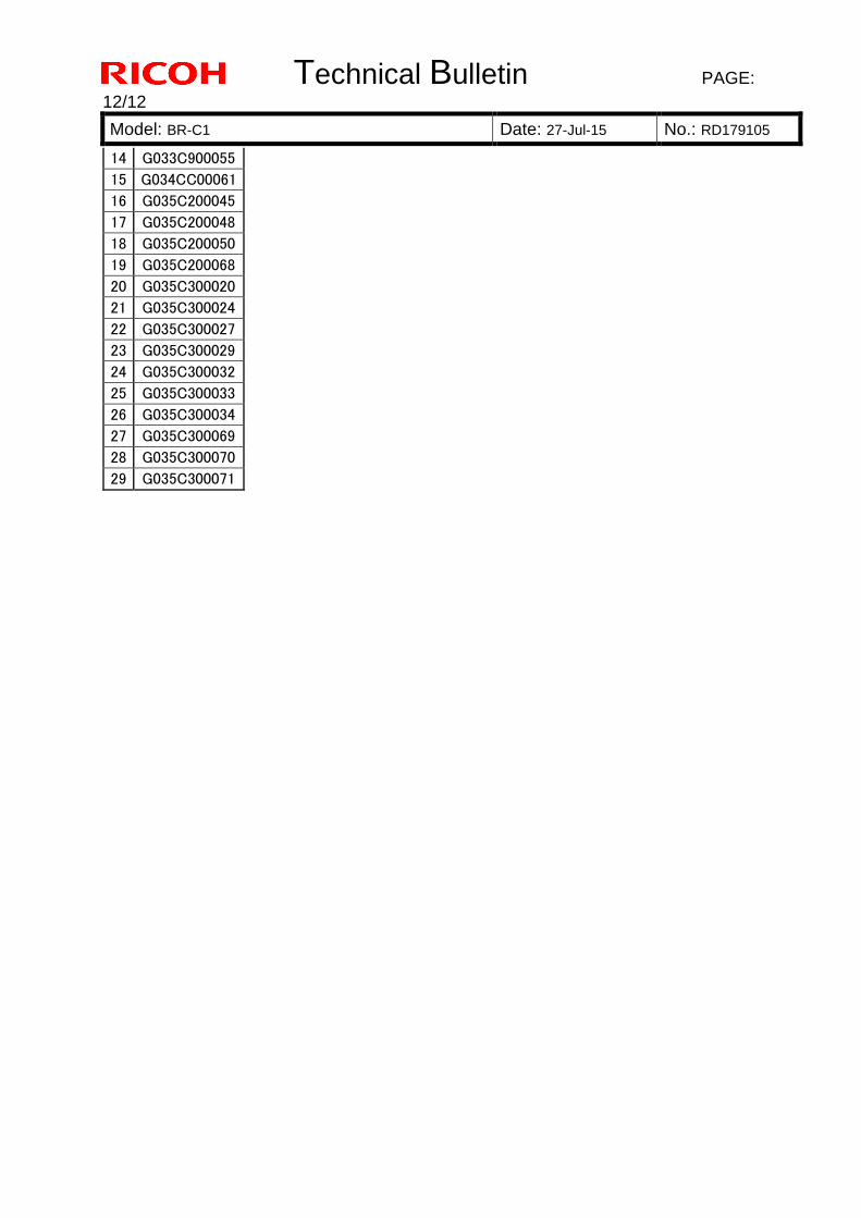
Technical Bulletin PAGE:
12/12
Model: BR-C1 Date: 27-Jul-15 No.: RD179105
14 G033C900055
15 G034CC00061
16 G035C200045
17 G035C200048
18 G035C200050
19 G035C200068
20 G035C300020
21 G035C300024
22 G035C300027
23 G035C300029
24 G035C300032
25 G035C300033
26 G035C300034
27 G035C300069
28 G035C300070
29 G035C300071
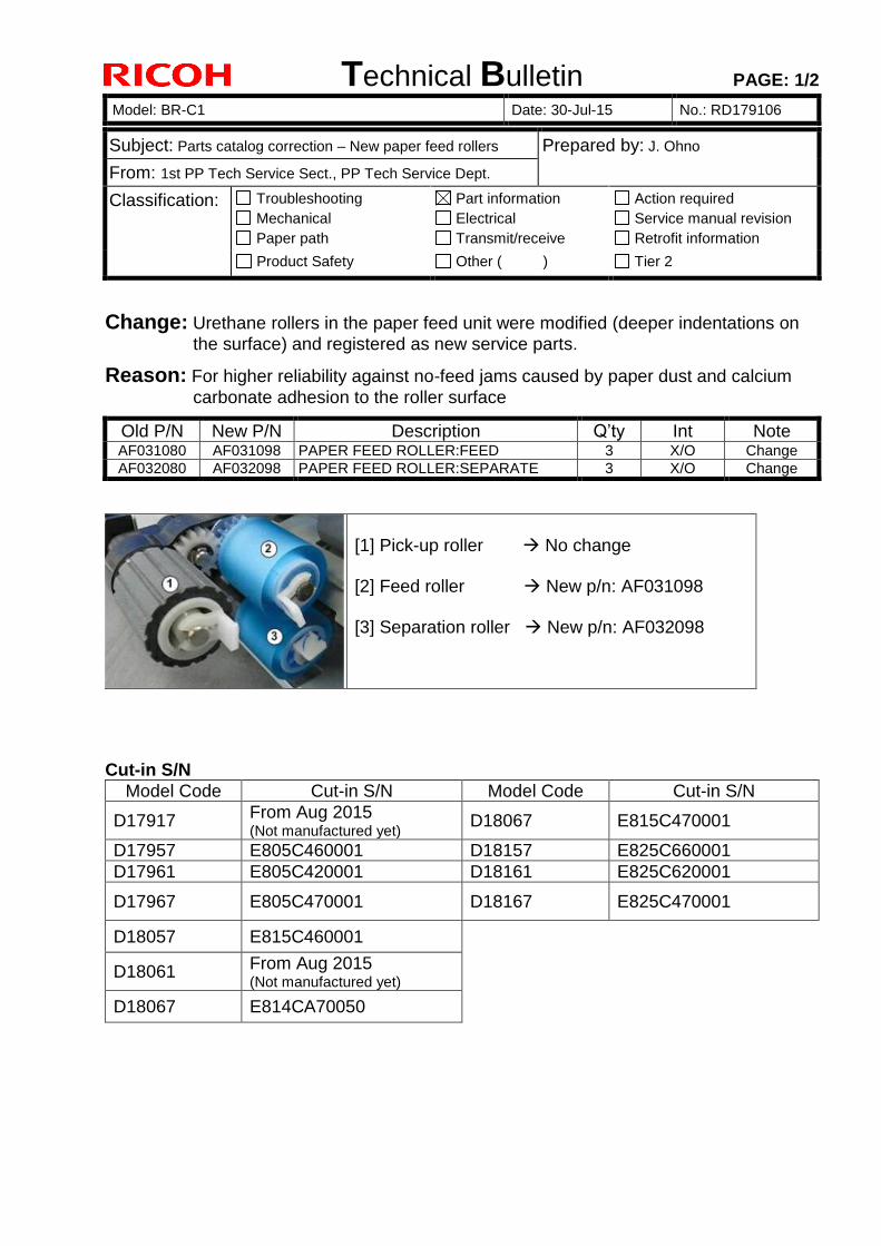
Technical Bulletin PAGE: 1/2
Model: BR-C1 Date: 30-Jul-15 No.: RD179106
Subject: Parts catalog correction – New paper feed rollers Prepared by: J. Ohno
From: 1st PP Tech Service Sect., PP Tech Service Dept.
Classification: Troubleshooting
Mechanical
Paper path
Part information
Electrical
Transmit/receive
Action required
Service manual revision
Retrofit information
Product Safety Other ( ) Tier 2
Change: Urethane rollers in the paper feed unit were modified (deeper indentations on
the surface) and registered as new service parts.
Reason: For higher reliability against no-feed jams caused by paper dust and calcium
carbonate adhesion to the roller surface
Old P/N New P/N Description Q’ty Int Note AF031080 AF031098 PAPER FEED ROLLER:FEED 3 X/O Change
AF032080 AF032098 PAPER FEED ROLLER:SEPARATE 3 X/O Change
[1] Pick-up roller No change [2] Feed roller New p/n: AF031098 [3] Separation roller New p/n: AF032098
Cut-in S/N
Model Code Cut-in S/N Model Code Cut-in S/N
D17917 From Aug 2015 (Not manufactured yet)
D18067 E815C470001
D17957 E805C460001 D18157 E825C660001
D17961 E805C420001 D18161 E825C620001
D17967 E805C470001 D18167 E825C470001
D18057 E815C460001
D18061 From Aug 2015 (Not manufactured yet)
D18067 E814CA70050
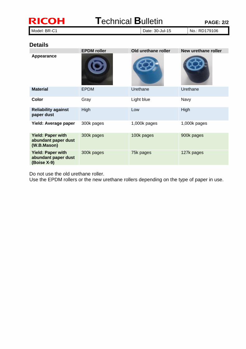
Technical Bulletin PAGE: 2/2
Model: BR-C1 Date: 30-Jul-15 No.: RD179106
Details EPDM roller Old urethane roller New urethane roller
Appearance
Material
EPDM Urethane Urethane
Color
Gray Light blue Navy
Reliability against paper dust
High Low High
Yield: Average paper 300k pages 1,000k pages 1,000k pages
Yield: Paper with abundant paper dust (W.B.Mason)
300k pages 100k pages 900k pages
Yield: Paper with abundant paper dust (Boise X-9)
300k pages 75k pages 127k pages
Do not use the old urethane roller. Use the EPDM rollers or the new urethane rollers depending on the type of paper in use.
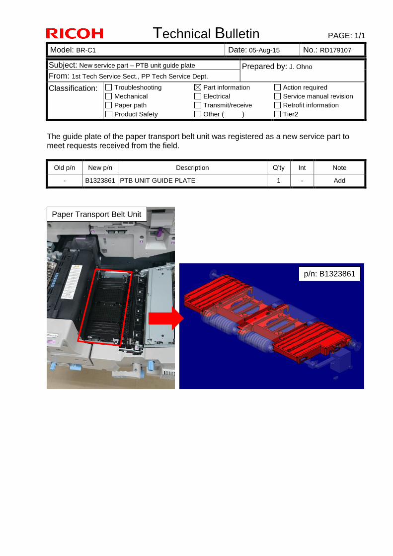
Technical Bulletin PAGE: 1/1
Model: BR-C1 Date: 05-Aug-15 No.: RD179107
Subject: New service part – PTB unit guide plate Prepared by: J. Ohno
From: 1st Tech Service Sect., PP Tech Service Dept.
Classification: Troubleshooting
Mechanical
Paper path
Product Safety
Part information
Electrical
Transmit/receive
Other ( )
Action required
Service manual revision
Retrofit information
Tier2
The guide plate of the paper transport belt unit was registered as a new service part to meet requests received from the field.
Old p/n New p/n Description Q’ty Int Note
- B1323861 PTB UNIT GUIDE PLATE 1 - Add
p/n: B1323861
Paper Transport Belt Unit
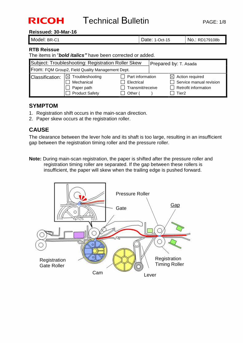
Technical Bulletin PAGE: 1/8
Reissued: 30-Mar-16
Model: BR-C1 Date: 1-Oct-15 No.: RD179108b
RTB Reissue The items in “bold italics” have been corrected or added.
SYMPTOM
1. Registration shift occurs in the main-scan direction. 2. Paper skew occurs at the registration roller.
CAUSE
The clearance between the lever hole and its shaft is too large, resulting in an insufficient gap between the registration timing roller and the pressure roller.
Note: During main-scan registration, the paper is shifted after the pressure roller and registration timing roller are separated. If the gap between these rollers is insufficient, the paper will skew when the trailing edge is pushed forward.
Subject: Troubleshooting: Registration Roller Skew Prepared by: T. Asada
From: FQM Group2, Field Quality Management Dept.
Classification: Troubleshooting
Mechanical
Paper path
Product Safety
Part information
Electrical
Transmit/receive
Other ( )
Action required
Service manual revision
Retrofit information
Tier2
Gate
Registration Gate Roller
Registration Timing Roller
Lever
Pressure Roller
Gap
Cam
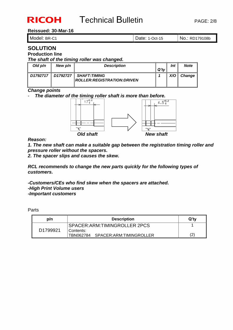
Technical Bulletin PAGE: 2/8
Reissued: 30-Mar-16
Model: BR-C1 Date: 1-Oct-15 No.: RD179108b
SOLUTION
Production line The shaft of the timing roller was changed.
Old p/n New p/n Description
Q’ty Int Note
D1792717 D1792727 SHAFT:TIMING ROLLER:REGISTRATION:DRIVEN
1 X/O Change
Change points - The diameter of the timing roller shaft is more than before.
Old shaft New shaft Reason: 1. The new shaft can make a suitable gap between the registration timing roller and pressure roller without the spacers. 2. The spacer slips and causes the skew. RCL recommends to change the new parts quickly for the following types of customers. -Customers/CEs who find skew when the spacers are attached. -High Print Volume users -Important customers Parts
p/n Description Q’ty
D1799921 SPACER:ARM:TIMINGROLLER 2PCS Contents: TBN062784 SPACER:ARM:TIMINGROLLER
1
(2)
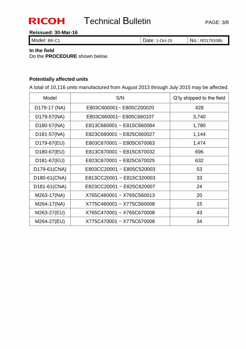
Technical Bulletin PAGE: 3/8
Reissued: 30-Mar-16
Model: BR-C1 Date: 1-Oct-15 No.: RD179108b
In the field Do the PROCEDURE shown below. Potentially affected units
A total of 10,116 units manufactured from August 2013 through July 2015 may be affected.
Model S/N Q’ty shipped to the field
D179-17 (NA) E803C600001~ E805C200020 428
D179-57(NA) E803C660001~ E805C660107 3,740
D180-57(NA) E813C660001 ~ E815C660084 1,780
D181-57(NA) E823C660001 ~ E825C660027 1,144
D179-67(EU) E803C670001 ~ E805C670063 1,474
D180-67(EU) E813C670001 ~ E815C670032 696
D181-67(EU) E823C670001 ~ E825C670025 632
D179-61(CNA) E803CC20001 ~ E805C520003 53
D180-61(CNA) E813CC20001 ~ E815C320003 33
D181-61(CNA) E823CC20001 ~ E825C620007 24
M263-17(NA) X765C460001 ~ X765C560013 20
M264-17(NA) X775C460001 ~ X775C560008 15
M263-27(EU) X765C470001 ~ X765C670008 43
M264-27(EU) X775C470001 ~ X775C670008 34
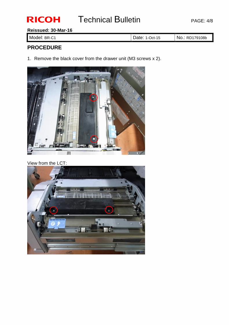
Technical Bulletin PAGE: 4/8
Reissued: 30-Mar-16
Model: BR-C1 Date: 1-Oct-15 No.: RD179108b
PROCEDURE 1. Remove the black cover from the drawer unit (M3 screws x 2).
View from the LCT:
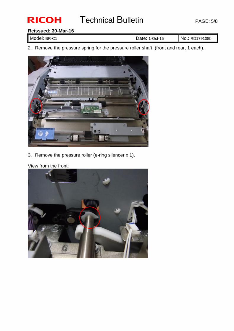
Technical Bulletin PAGE: 5/8
Reissued: 30-Mar-16
Model: BR-C1 Date: 1-Oct-15 No.: RD179108b
2. Remove the pressure spring for the pressure roller shaft. (front and rear, 1 each).
3. Remove the pressure roller (e-ring silencer x 1). View from the front:
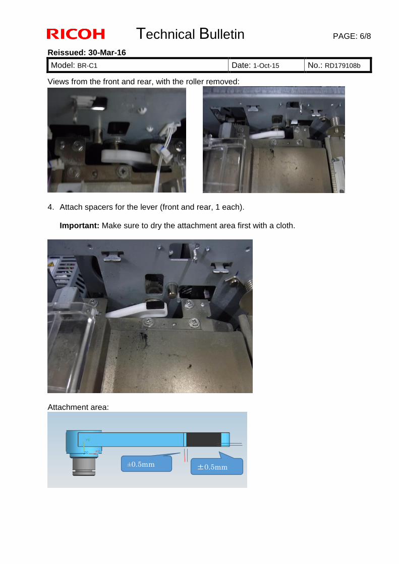
Technical Bulletin PAGE: 6/8
Reissued: 30-Mar-16
Model: BR-C1 Date: 1-Oct-15 No.: RD179108b
Views from the front and rear, with the roller removed:
4. Attach spacers for the lever (front and rear, 1 each).
Important: Make sure to dry the attachment area first with a cloth.
Attachment area:
±0.5mm ±0.5mm
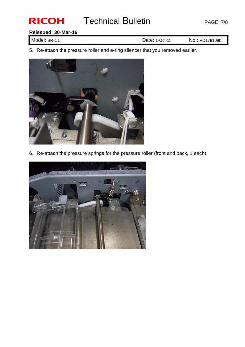
Technical Bulletin PAGE: 7/8
Reissued: 30-Mar-16
Model: BR-C1 Date: 1-Oct-15 No.: RD179108b
5. Re-attach the pressure roller and e-ring silencer that you removed earlier.
6. Re-attach the pressure springs for the pressure roller (front and back, 1 each).
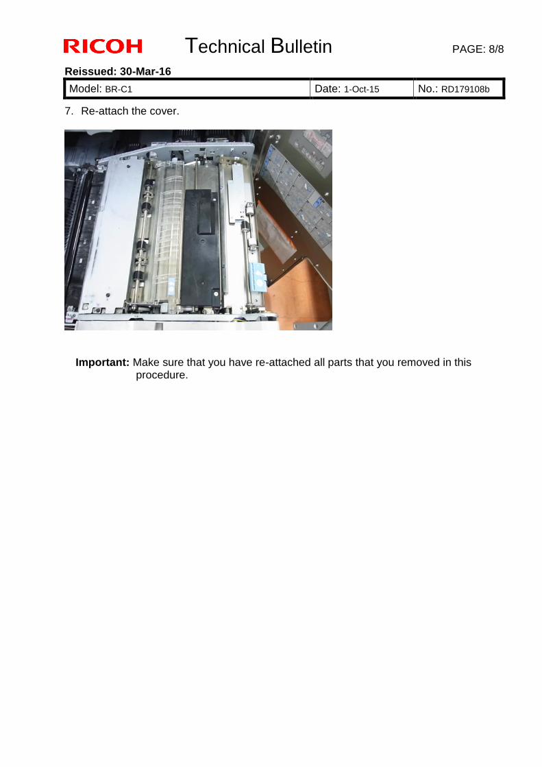
Technical Bulletin PAGE: 8/8
Reissued: 30-Mar-16
Model: BR-C1 Date: 1-Oct-15 No.: RD179108b
7. Re-attach the cover.
Important: Make sure that you have re-attached all parts that you removed in this procedure.
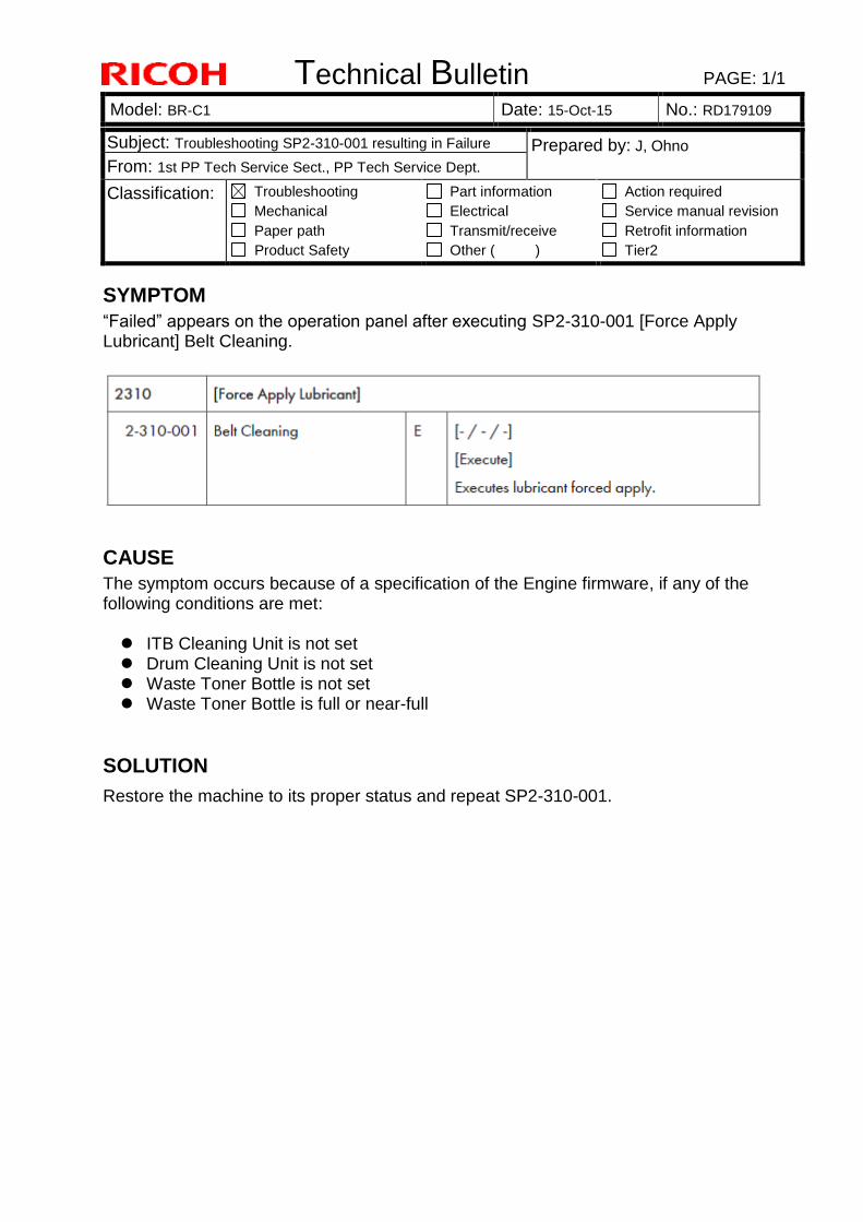
Technical Bulletin PAGE: 1/1
Model: BR-C1 Date: 15-Oct-15 No.: RD179109
SYMPTOM
“Failed” appears on the operation panel after executing SP2-310-001 [Force Apply Lubricant] Belt Cleaning.
CAUSE
The symptom occurs because of a specification of the Engine firmware, if any of the following conditions are met: ITB Cleaning Unit is not set Drum Cleaning Unit is not set Waste Toner Bottle is not set Waste Toner Bottle is full or near-full
SOLUTION
Restore the machine to its proper status and repeat SP2-310-001.
Subject: Troubleshooting SP2-310-001 resulting in Failure Prepared by: J, Ohno
From: 1st PP Tech Service Sect., PP Tech Service Dept.
Classification: Troubleshooting
Mechanical
Paper path
Product Safety
Part information
Electrical
Transmit/receive
Other ( )
Action required
Service manual revision
Retrofit information
Tier2
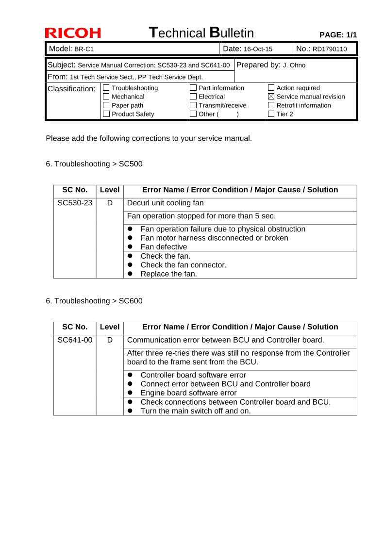
Technical Bulletin PAGE: 1/1
Model: BR-C1 Date: 16-Oct-15 No.: RD1790110
Subject: Service Manual Correction: SC530-23 and SC641-00 Prepared by: J. Ohno
From: 1st Tech Service Sect., PP Tech Service Dept.
Classification: Troubleshooting
Mechanical
Paper path
Product Safety
Part information
Electrical
Transmit/receive
Other ( )
Action required
Service manual revision
Retrofit information
Tier 2
Please add the following corrections to your service manual.
6. Troubleshooting > SC500
SC No. Level Error Name / Error Condition / Major Cause / Solution
SC530-23 D Decurl unit cooling fan
Fan operation stopped for more than 5 sec.
Fan operation failure due to physical obstruction Fan motor harness disconnected or broken Fan defective
Check the fan. Check the fan connector. Replace the fan.
6. Troubleshooting > SC600
SC No. Level Error Name / Error Condition / Major Cause / Solution
SC641-00 D Communication error between BCU and Controller board.
After three re-tries there was still no response from the Controller board to the frame sent from the BCU.
Controller board software error Connect error between BCU and Controller board Engine board software error
Check connections between Controller board and BCU. Turn the main switch off and on.
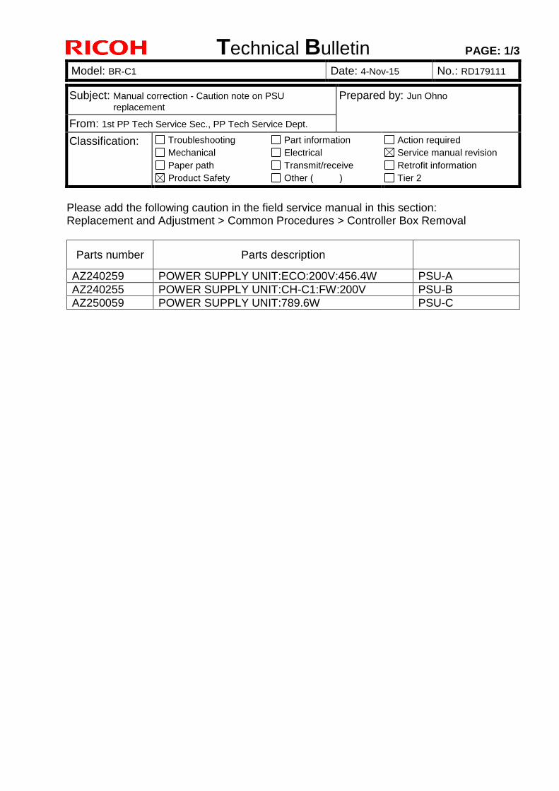
Technical Bulletin PAGE: 1/3
Model: BR-C1 Date: 4-Nov-15 No.: RD179111
Please add the following caution in the field service manual in this section: Replacement and Adjustment > Common Procedures > Controller Box Removal
Parts number Parts description
AZ240259 POWER SUPPLY UNIT:ECO:200V:456.4W PSU-A
AZ240255 POWER SUPPLY UNIT:CH-C1:FW:200V PSU-B
AZ250059 POWER SUPPLY UNIT:789.6W PSU-C
Subject: Manual correction - Caution note on PSU
replacement Prepared by: Jun Ohno
From: 1st PP Tech Service Sec., PP Tech Service Dept.
Classification: Troubleshooting
Mechanical
Paper path
Product Safety
Part information
Electrical
Transmit/receive
Other ( )
Action required
Service manual revision
Retrofit information
Tier 2
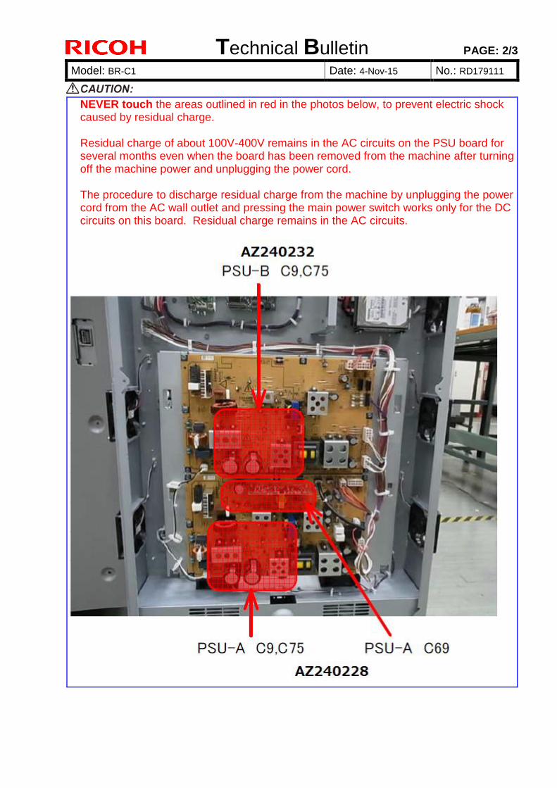
Technical Bulletin PAGE: 2/3
Model: BR-C1 Date: 4-Nov-15 No.: RD179111
NEVER touch the areas outlined in red in the photos below, to prevent electric shock caused by residual charge. Residual charge of about 100V-400V remains in the AC circuits on the PSU board for several months even when the board has been removed from the machine after turning off the machine power and unplugging the power cord. The procedure to discharge residual charge from the machine by unplugging the power cord from the AC wall outlet and pressing the main power switch works only for the DC circuits on this board. Residual charge remains in the AC circuits.
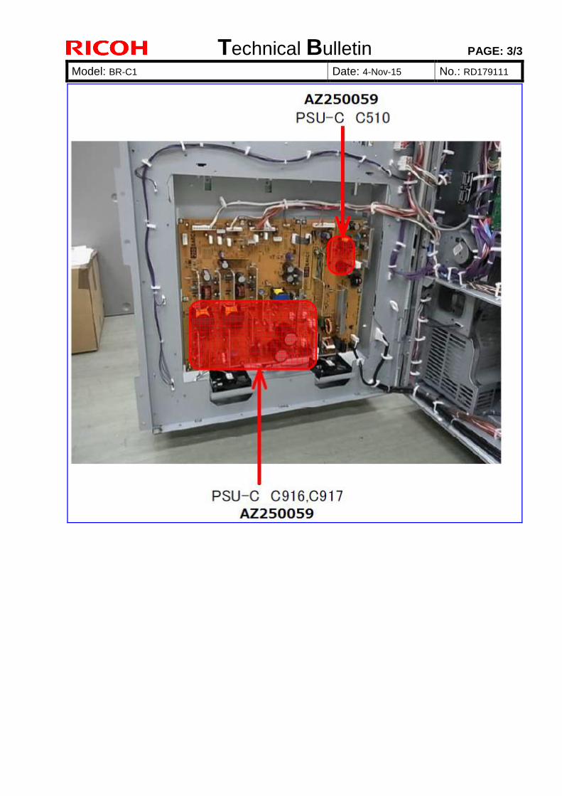
Technical Bulletin PAGE: 3/3
Model: BR-C1 Date: 4-Nov-15 No.: RD179111
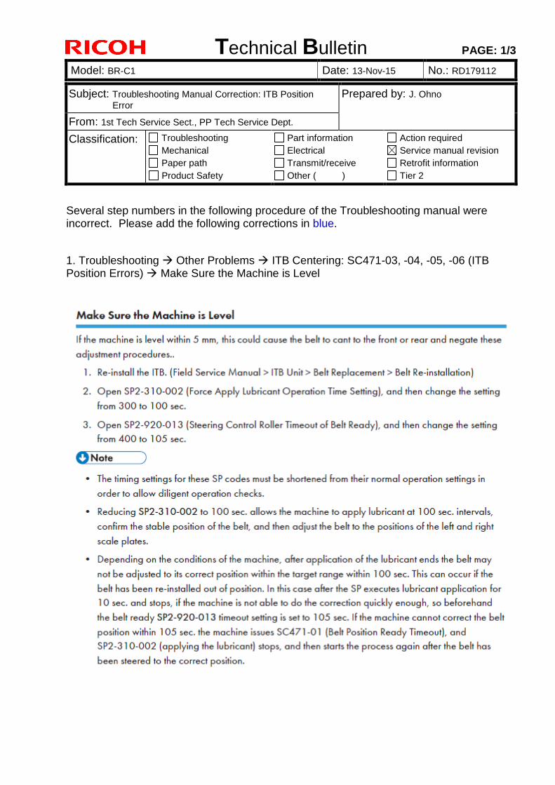
Technical Bulletin PAGE: 1/3
Model: BR-C1 Date: 13-Nov-15 No.: RD179112
Subject: Troubleshooting Manual Correction: ITB Position
Error Prepared by: J. Ohno
From: 1st Tech Service Sect., PP Tech Service Dept.
Classification: Troubleshooting
Mechanical
Paper path
Product Safety
Part information
Electrical
Transmit/receive
Other ( )
Action required
Service manual revision
Retrofit information
Tier 2
Several step numbers in the following procedure of the Troubleshooting manual were incorrect. Please add the following corrections in blue.
1. Troubleshooting Other Problems ITB Centering: SC471-03, -04, -05, -06 (ITB Position Errors) Make Sure the Machine is Level
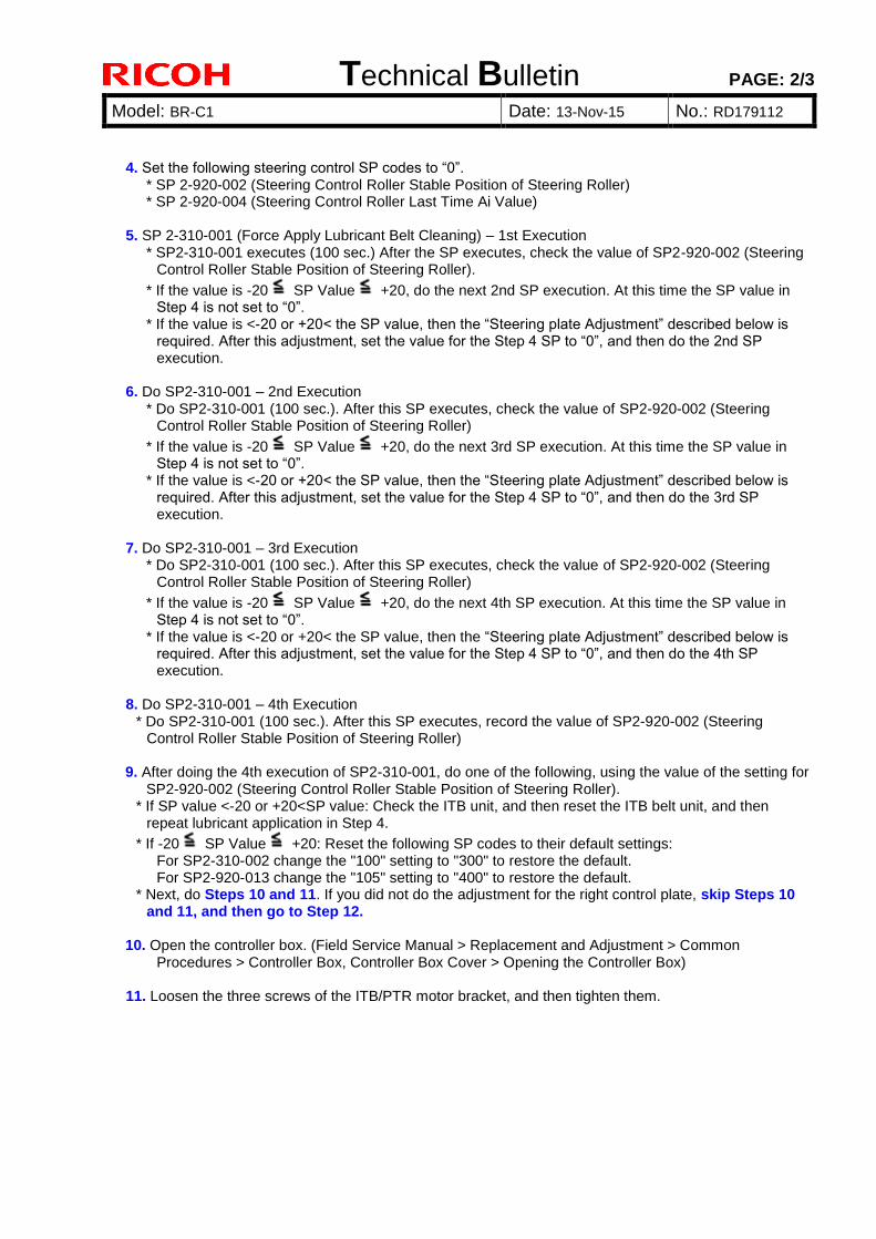
Technical Bulletin PAGE: 2/3
Model: BR-C1 Date: 13-Nov-15 No.: RD179112
4. Set the following steering control SP codes to “0”. * SP 2-920-002 (Steering Control Roller Stable Position of Steering Roller) * SP 2-920-004 (Steering Control Roller Last Time Ai Value)
5. SP 2-310-001 (Force Apply Lubricant Belt Cleaning) – 1st Execution
* SP2-310-001 executes (100 sec.) After the SP executes, check the value of SP2-920-002 (Steering Control Roller Stable Position of Steering Roller).
* If the value is -20 SP Value +20, do the next 2nd SP execution. At this time the SP value in Step 4 is not set to “0”.
* If the value is <-20 or +20< the SP value, then the “Steering plate Adjustment” described below is required. After this adjustment, set the value for the Step 4 SP to “0”, and then do the 2nd SP execution.
6. Do SP2-310-001 – 2nd Execution
* Do SP2-310-001 (100 sec.). After this SP executes, check the value of SP2-920-002 (Steering Control Roller Stable Position of Steering Roller)
* If the value is -20 SP Value +20, do the next 3rd SP execution. At this time the SP value in Step 4 is not set to “0”.
* If the value is <-20 or +20< the SP value, then the “Steering plate Adjustment” described below is required. After this adjustment, set the value for the Step 4 SP to “0”, and then do the 3rd SP execution.
7. Do SP2-310-001 – 3rd Execution
* Do SP2-310-001 (100 sec.). After this SP executes, check the value of SP2-920-002 (Steering Control Roller Stable Position of Steering Roller)
* If the value is -20 SP Value +20, do the next 4th SP execution. At this time the SP value in Step 4 is not set to “0”.
* If the value is <-20 or +20< the SP value, then the “Steering plate Adjustment” described below is required. After this adjustment, set the value for the Step 4 SP to “0”, and then do the 4th SP execution.
8. Do SP2-310-001 – 4th Execution
* Do SP2-310-001 (100 sec.). After this SP executes, record the value of SP2-920-002 (Steering Control Roller Stable Position of Steering Roller)
9. After doing the 4th execution of SP2-310-001, do one of the following, using the value of the setting for
SP2-920-002 (Steering Control Roller Stable Position of Steering Roller). * If SP value <-20 or +20<SP value: Check the ITB unit, and then reset the ITB belt unit, and then
repeat lubricant application in Step 4.
* If -20 SP Value +20: Reset the following SP codes to their default settings: For SP2-310-002 change the "100" setting to "300" to restore the default. For SP2-920-013 change the "105" setting to "400" to restore the default.
* Next, do Steps 10 and 11. If you did not do the adjustment for the right control plate, skip Steps 10 and 11, and then go to Step 12.
10. Open the controller box. (Field Service Manual > Replacement and Adjustment > Common
Procedures > Controller Box, Controller Box Cover > Opening the Controller Box) 11. Loosen the three screws of the ITB/PTR motor bracket, and then tighten them.
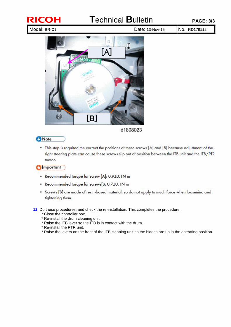
Technical Bulletin PAGE: 3/3
Model: BR-C1 Date: 13-Nov-15 No.: RD179112
12. Do these procedures, and check the re-installation. This completes the procedure. * Close the controller box. * Re-install the drum cleaning unit. * Raise the ITB lever so the ITB is in contact with the drum. * Re-install the PTR unit.
* Raise the levers on the front of the ITB cleaning unit so the blades are up in the operating position.
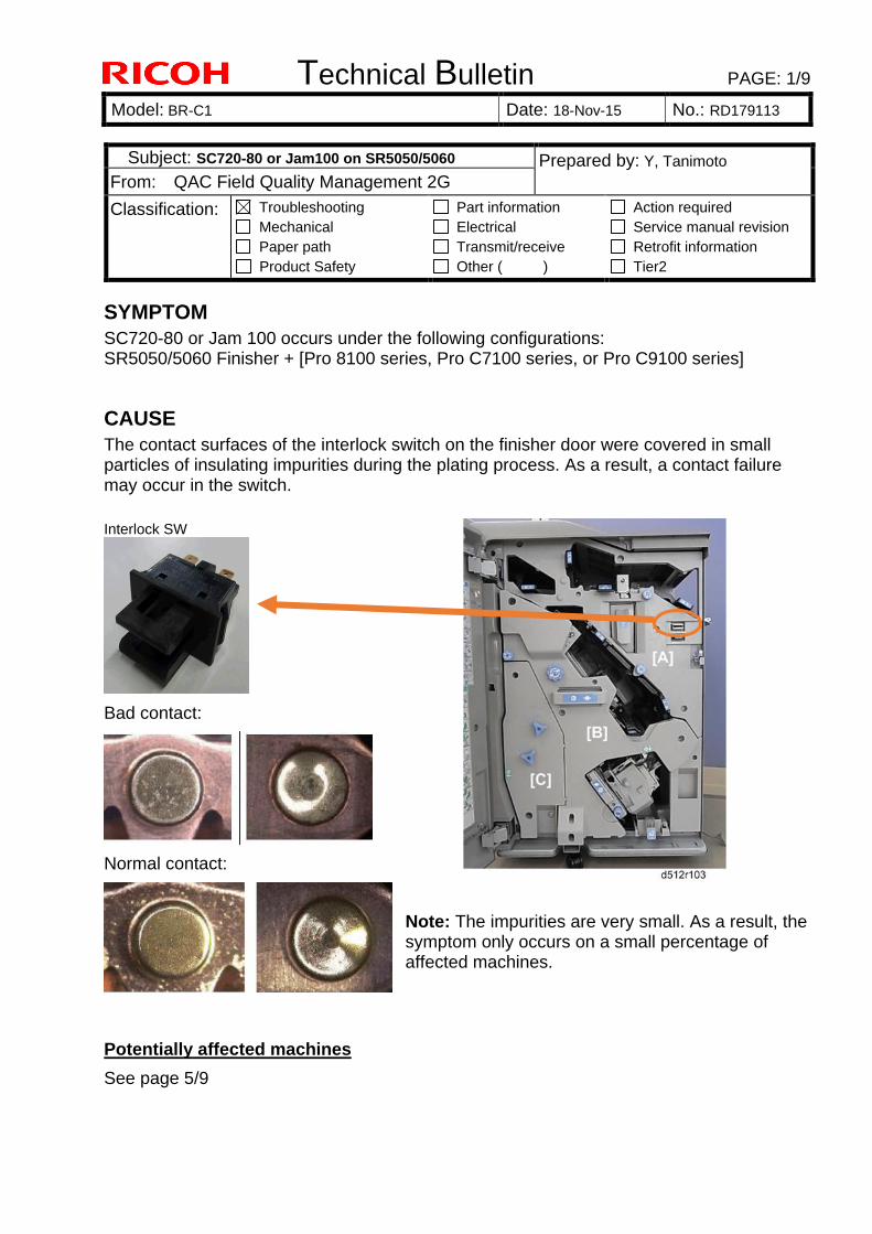
Technical Bulletin PAGE: 1/9
Model: BR-C1 Date: 18-Nov-15 No.: RD179113
SYMPTOM
SC720-80 or Jam 100 occurs under the following configurations: SR5050/5060 Finisher + [Pro 8100 series, Pro C7100 series, or Pro C9100 series]
CAUSE
The contact surfaces of the interlock switch on the finisher door were covered in small particles of insulating impurities during the plating process. As a result, a contact failure may occur in the switch.
Interlock SW
Bad contact:
Normal contact:
Note: The impurities are very small. As a result, the symptom only occurs on a small percentage of affected machines.
Potentially affected machines
See page 5/9
Subject: SC720-80 or Jam100 on SR5050/5060 Prepared by: Y, Tanimoto
From: QAC Field Quality Management 2G
Classification: Troubleshooting
Mechanical
Paper path
Product Safety
Part information
Electrical
Transmit/receive
Other ( )
Action required
Service manual revision
Retrofit information
Tier2
Technical Bulletin PAGE: 2/9
Model: BR-C1 Date: 18-Nov-15 No.: RD179113
SOLUTION
Production line:
- All affected parts will be switched out with normal ones. - Reworks will be performed on affected finishers in field inventory.
In the field:
Replace the interlock switch using the PROCEDURE on the next page, if: 1. You are dispatched to deal with SC720-80 or Jam 100, AND 2. You can confirm in the SMC report that SC720-80 or Jam 100 has occurred at least
2 times.
IMPORTANT: If this SC or Jam has not occurred recently, you do not need to replace the switch. This is because the insulating impurities may be forced off the contact surface during the normal opening and closing of the door.
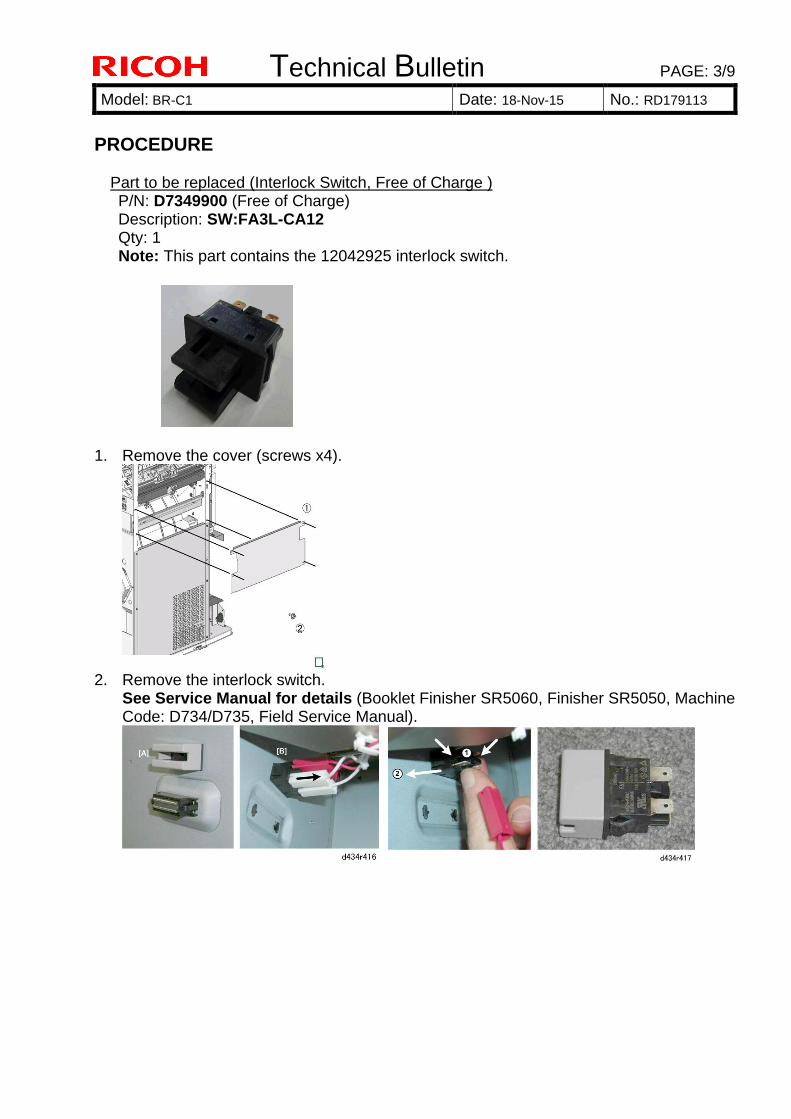
Technical Bulletin PAGE: 3/9
Model: BR-C1 Date: 18-Nov-15 No.: RD179113
PROCEDURE
Part to be replaced (Interlock Switch, Free of Charge ) P/N: D7349900 (Free of Charge) Description: SW:FA3L-CA12 Qty: 1 Note: This part contains the 12042925 interlock switch.
1. Remove the cover (screws x4).
2. Remove the interlock switch.
See Service Manual for details (Booklet Finisher SR5060, Finisher SR5050, Machine Code: D734/D735, Field Service Manual).
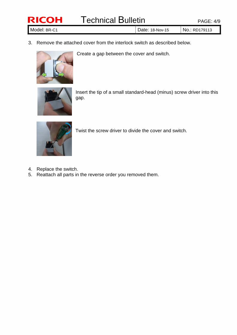
Technical Bulletin PAGE: 4/9
Model: BR-C1 Date: 18-Nov-15 No.: RD179113
3. Remove the attached cover from the interlock switch as described below.
Create a gap between the cover and switch. Insert the tip of a small standard-head (minus) screw driver into this gap. Twist the screw driver to divide the cover and switch.
4. Replace the switch. 5. Reattach all parts in the reverse order you removed them.
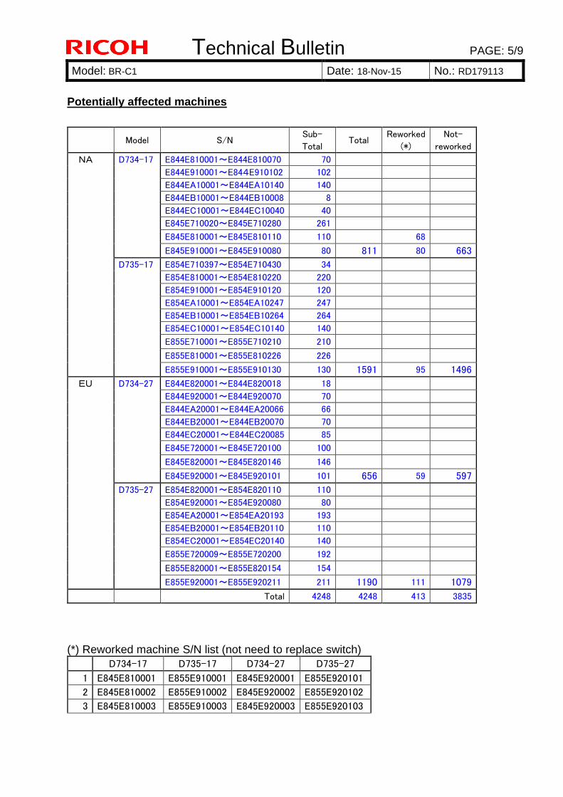
Technical Bulletin PAGE: 5/9
Model: BR-C1 Date: 18-Nov-15 No.: RD179113
Potentially affected machines
Model S/N Sub-
Total Total
Reworked
(*)
Not-
reworked
NA D734-17 E844E810001~E844E810070 70
E844E910001~E844E910102 102
E844EA10001~E844EA10140 140
E844EB10001~E844EB10008 8
E844EC10001~E844EC10040 40
E845E710020~E845E710280 261
E845E810001~E845E810110 110 68
E845E910001~E845E910080 80 811 80 663
D735-17 E854E710397~E854E710430 34
E854E810001~E854E810220 220
E854E910001~E854E910120 120
E854EA10001~E854EA10247 247
E854EB10001~E854EB10264 264
E854EC10001~E854EC10140 140
E855E710001~E855E710210 210
E855E810001~E855E810226 226
E855E910001~E855E910130 130 1591 95 1496
EU D734-27 E844E820001~E844E820018 18
E844E920001~E844E920070 70
E844EA20001~E844EA20066 66
E844EB20001~E844EB20070 70
E844EC20001~E844EC20085 85
E845E720001~E845E720100 100
E845E820001~E845E820146 146
E845E920001~E845E920101 101 656 59 597
D735-27 E854E820001~E854E820110 110
E854E920001~E854E920080 80
E854EA20001~E854EA20193 193
E854EB20001~E854EB20110 110
E854EC20001~E854EC20140 140
E855E720009~E855E720200 192
E855E820001~E855E820154 154
E855E920001~E855E920211 211 1190 111 1079
Total 4248 4248 413 3835
(*) Reworked machine S/N list (not need to replace switch)
D734-17 D735-17 D734-27 D735-27
1 E845E810001 E855E910001 E845E920001 E855E920101
2 E845E810002 E855E910002 E845E920002 E855E920102
3 E845E810003 E855E910003 E845E920003 E855E920103
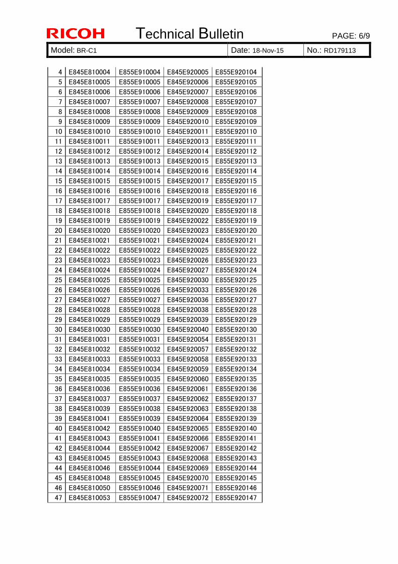
Technical Bulletin PAGE: 6/9
Model: BR-C1 Date: 18-Nov-15 No.: RD179113
4 E845E810004 E855E910004 E845E920005 E855E920104
5 E845E810005 E855E910005 E845E920006 E855E920105
6 E845E810006 E855E910006 E845E920007 E855E920106
7 E845E810007 E855E910007 E845E920008 E855E920107
8 E845E810008 E855E910008 E845E920009 E855E920108
9 E845E810009 E855E910009 E845E920010 E855E920109
10 E845E810010 E855E910010 E845E920011 E855E920110
11 E845E810011 E855E910011 E845E920013 E855E920111
12 E845E810012 E855E910012 E845E920014 E855E920112
13 E845E810013 E855E910013 E845E920015 E855E920113
14 E845E810014 E855E910014 E845E920016 E855E920114
15 E845E810015 E855E910015 E845E920017 E855E920115
16 E845E810016 E855E910016 E845E920018 E855E920116
17 E845E810017 E855E910017 E845E920019 E855E920117
18 E845E810018 E855E910018 E845E920020 E855E920118
19 E845E810019 E855E910019 E845E920022 E855E920119
20 E845E810020 E855E910020 E845E920023 E855E920120
21 E845E810021 E855E910021 E845E920024 E855E920121
22 E845E810022 E855E910022 E845E920025 E855E920122
23 E845E810023 E855E910023 E845E920026 E855E920123
24 E845E810024 E855E910024 E845E920027 E855E920124
25 E845E810025 E855E910025 E845E920030 E855E920125
26 E845E810026 E855E910026 E845E920033 E855E920126
27 E845E810027 E855E910027 E845E920036 E855E920127
28 E845E810028 E855E910028 E845E920038 E855E920128
29 E845E810029 E855E910029 E845E920039 E855E920129
30 E845E810030 E855E910030 E845E920040 E855E920130
31 E845E810031 E855E910031 E845E920054 E855E920131
32 E845E810032 E855E910032 E845E920057 E855E920132
33 E845E810033 E855E910033 E845E920058 E855E920133
34 E845E810034 E855E910034 E845E920059 E855E920134
35 E845E810035 E855E910035 E845E920060 E855E920135
36 E845E810036 E855E910036 E845E920061 E855E920136
37 E845E810037 E855E910037 E845E920062 E855E920137
38 E845E810039 E855E910038 E845E920063 E855E920138
39 E845E810041 E855E910039 E845E920064 E855E920139
40 E845E810042 E855E910040 E845E920065 E855E920140
41 E845E810043 E855E910041 E845E920066 E855E920141
42 E845E810044 E855E910042 E845E920067 E855E920142
43 E845E810045 E855E910043 E845E920068 E855E920143
44 E845E810046 E855E910044 E845E920069 E855E920144
45 E845E810048 E855E910045 E845E920070 E855E920145
46 E845E810050 E855E910046 E845E920071 E855E920146
47 E845E810053 E855E910047 E845E920072 E855E920147
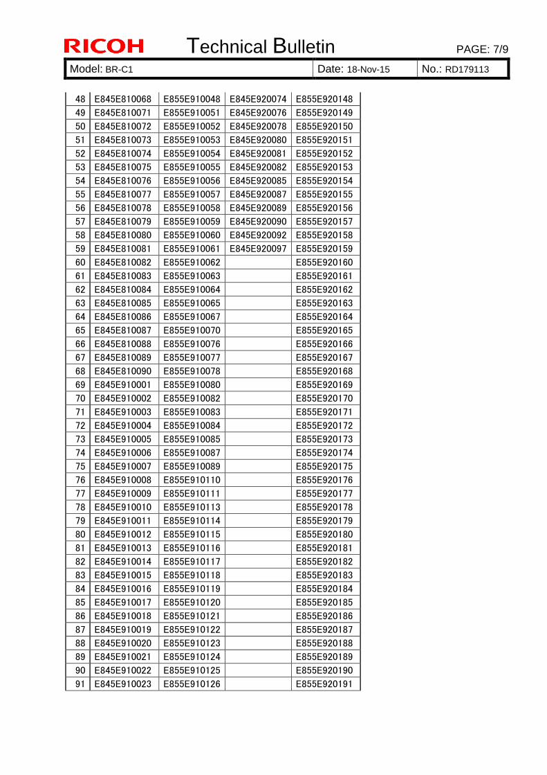
Technical Bulletin PAGE: 7/9
Model: BR-C1 Date: 18-Nov-15 No.: RD179113
48 E845E810068 E855E910048 E845E920074 E855E920148
49 E845E810071 E855E910051 E845E920076 E855E920149
50 E845E810072 E855E910052 E845E920078 E855E920150
51 E845E810073 E855E910053 E845E920080 E855E920151
52 E845E810074 E855E910054 E845E920081 E855E920152
53 E845E810075 E855E910055 E845E920082 E855E920153
54 E845E810076 E855E910056 E845E920085 E855E920154
55 E845E810077 E855E910057 E845E920087 E855E920155
56 E845E810078 E855E910058 E845E920089 E855E920156
57 E845E810079 E855E910059 E845E920090 E855E920157
58 E845E810080 E855E910060 E845E920092 E855E920158
59 E845E810081 E855E910061 E845E920097 E855E920159
60 E845E810082 E855E910062 E855E920160
61 E845E810083 E855E910063 E855E920161
62 E845E810084 E855E910064 E855E920162
63 E845E810085 E855E910065 E855E920163
64 E845E810086 E855E910067 E855E920164
65 E845E810087 E855E910070 E855E920165
66 E845E810088 E855E910076 E855E920166
67 E845E810089 E855E910077 E855E920167
68 E845E810090 E855E910078 E855E920168
69 E845E910001 E855E910080 E855E920169
70 E845E910002 E855E910082 E855E920170
71 E845E910003 E855E910083 E855E920171
72 E845E910004 E855E910084 E855E920172
73 E845E910005 E855E910085 E855E920173
74 E845E910006 E855E910087 E855E920174
75 E845E910007 E855E910089 E855E920175
76 E845E910008 E855E910110 E855E920176
77 E845E910009 E855E910111 E855E920177
78 E845E910010 E855E910113 E855E920178
79 E845E910011 E855E910114 E855E920179
80 E845E910012 E855E910115 E855E920180
81 E845E910013 E855E910116 E855E920181
82 E845E910014 E855E910117 E855E920182
83 E845E910015 E855E910118 E855E920183
84 E845E910016 E855E910119 E855E920184
85 E845E910017 E855E910120 E855E920185
86 E845E910018 E855E910121 E855E920186
87 E845E910019 E855E910122 E855E920187
88 E845E910020 E855E910123 E855E920188
89 E845E910021 E855E910124 E855E920189
90 E845E910022 E855E910125 E855E920190
91 E845E910023 E855E910126 E855E920191
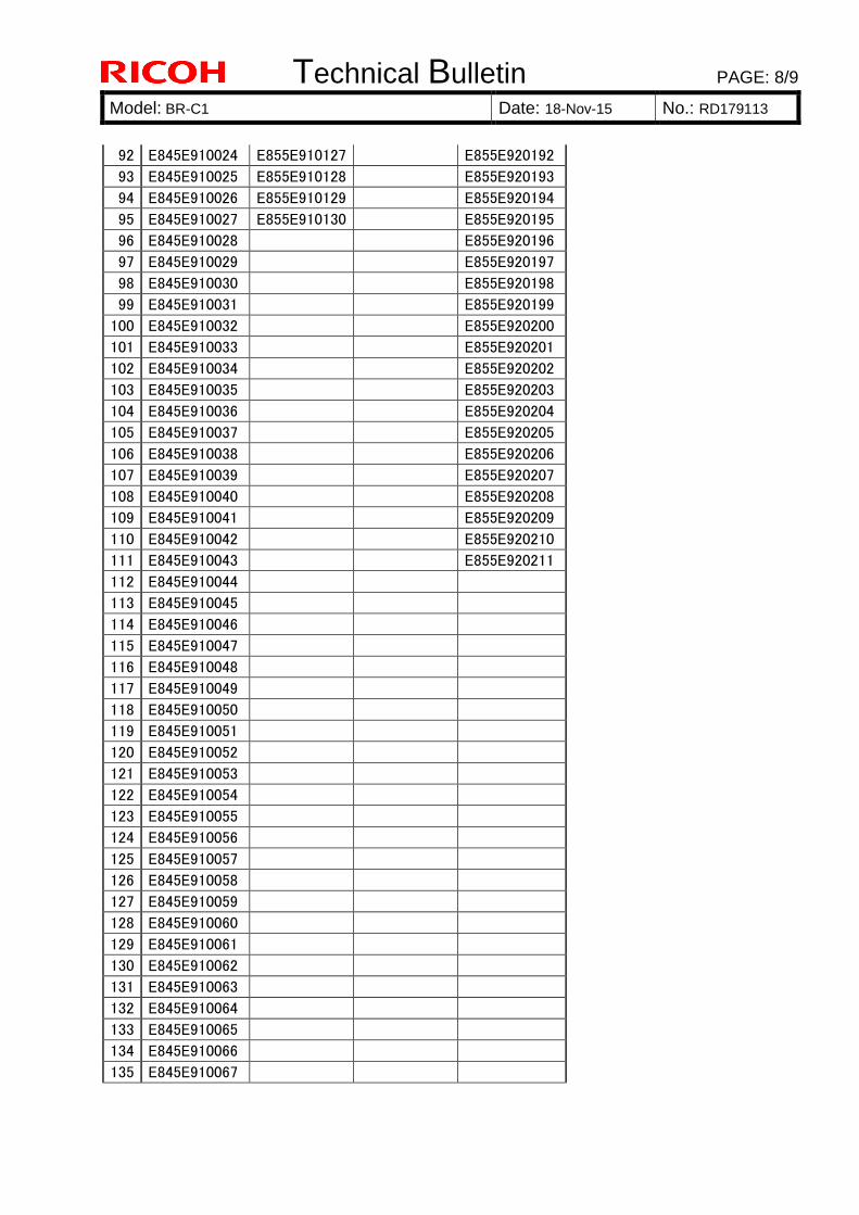
Technical Bulletin PAGE: 8/9
Model: BR-C1 Date: 18-Nov-15 No.: RD179113
92 E845E910024 E855E910127 E855E920192
93 E845E910025 E855E910128 E855E920193
94 E845E910026 E855E910129 E855E920194
95 E845E910027 E855E910130 E855E920195
96 E845E910028 E855E920196
97 E845E910029 E855E920197
98 E845E910030 E855E920198
99 E845E910031 E855E920199
100 E845E910032 E855E920200
101 E845E910033 E855E920201
102 E845E910034 E855E920202
103 E845E910035 E855E920203
104 E845E910036 E855E920204
105 E845E910037 E855E920205
106 E845E910038 E855E920206
107 E845E910039 E855E920207
108 E845E910040 E855E920208
109 E845E910041 E855E920209
110 E845E910042 E855E920210
111 E845E910043 E855E920211
112 E845E910044
113 E845E910045
114 E845E910046
115 E845E910047
116 E845E910048
117 E845E910049
118 E845E910050
119 E845E910051
120 E845E910052
121 E845E910053
122 E845E910054
123 E845E910055
124 E845E910056
125 E845E910057
126 E845E910058
127 E845E910059
128 E845E910060
129 E845E910061
130 E845E910062
131 E845E910063
132 E845E910064
133 E845E910065
134 E845E910066
135 E845E910067
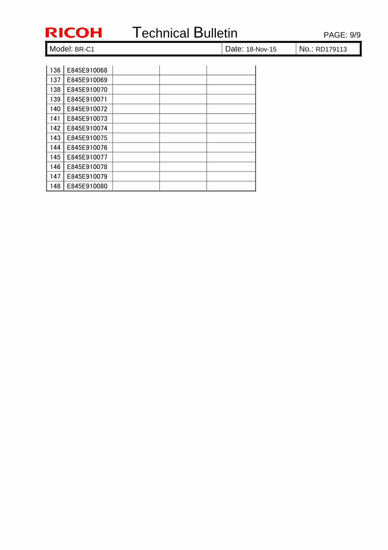
Technical Bulletin PAGE: 9/9
Model: BR-C1 Date: 18-Nov-15 No.: RD179113
136 E845E910068
137 E845E910069
138 E845E910070
139 E845E910071
140 E845E910072
141 E845E910073
142 E845E910074
143 E845E910075
144 E845E910076
145 E845E910077
146 E845E910078
147 E845E910079
148 E845E910080
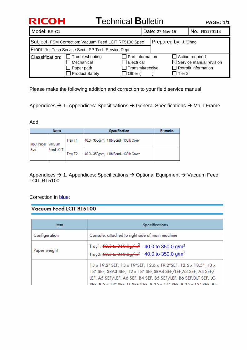
Technical Bulletin PAGE: 1/1
Model: BR-C1 Date: 27-Nov-15 No.: RD179114
Subject: FSM Correction: Vacuum Feed LCIT RT5100 Spec Prepared by: J. Ohno
From: 1st Tech Service Sect., PP Tech Service Dept.
Classification: Troubleshooting
Mechanical
Paper path
Product Safety
Part information
Electrical
Transmit/receive
Other ( )
Action required
Service manual revision
Retrofit information
Tier 2
Please make the following addition and correction to your field service manual.
Appendices 1. Appendices: Specifications General Specifications Main Frame
Add:
Appendices 1. Appendices: Specifications Optional Equipment Vacuum Feed LCIT RT5100
Correction in blue:
40.0 to 350.0 g/m2
40.0 to 350.0 g/m2
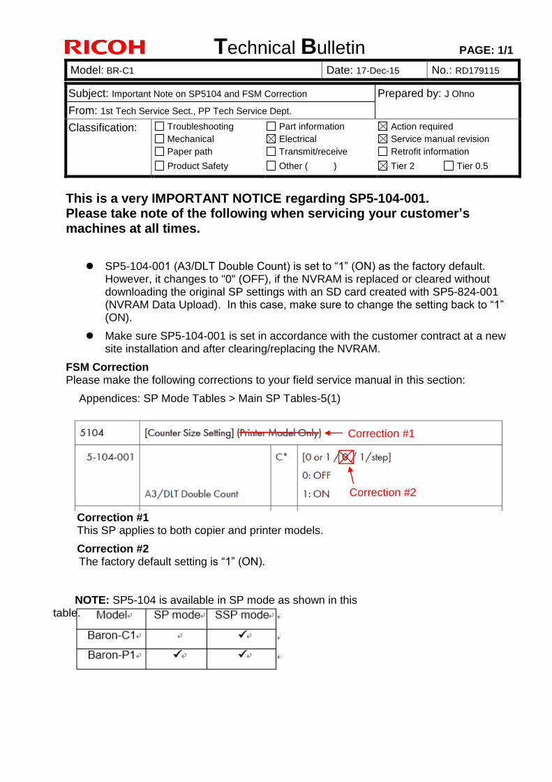
Technical Bulletin PAGE: 1/1
Model: BR-C1 Date: 17-Dec-15 No.: RD179115
Subject: Important Note on SP5104 and FSM Correction Prepared by: J Ohno
From: 1st Tech Service Sect., PP Tech Service Dept.
Classification: Troubleshooting
Mechanical
Paper path
Part information
Electrical
Transmit/receive
Action required
Service manual revision
Retrofit information
Product Safety Other ( ) Tier 2 Tier 0.5
This is a very IMPORTANT NOTICE regarding SP5-104-001. Please take note of the following when servicing your customer’s machines at all times.
SP5-104-001 (A3/DLT Double Count) is set to “1” (ON) as the factory default. However, it changes to "0" (OFF), if the NVRAM is replaced or cleared without downloading the original SP settings with an SD card created with SP5-824-001 (NVRAM Data Upload). In this case, make sure to change the setting back to “1” (ON).
Make sure SP5-104-001 is set in accordance with the customer contract at a new site installation and after clearing/replacing the NVRAM.
FSM Correction Please make the following corrections to your field service manual in this section:
Appendices: SP Mode Tables > Main SP Tables-5(1)
Correction #1 This SP applies to both copier and printer models.
Correction #2 The factory default setting is “1” (ON).
Correction #1
Correction #2
NOTE: SP5-104 is available in SP mode as shown in this table.
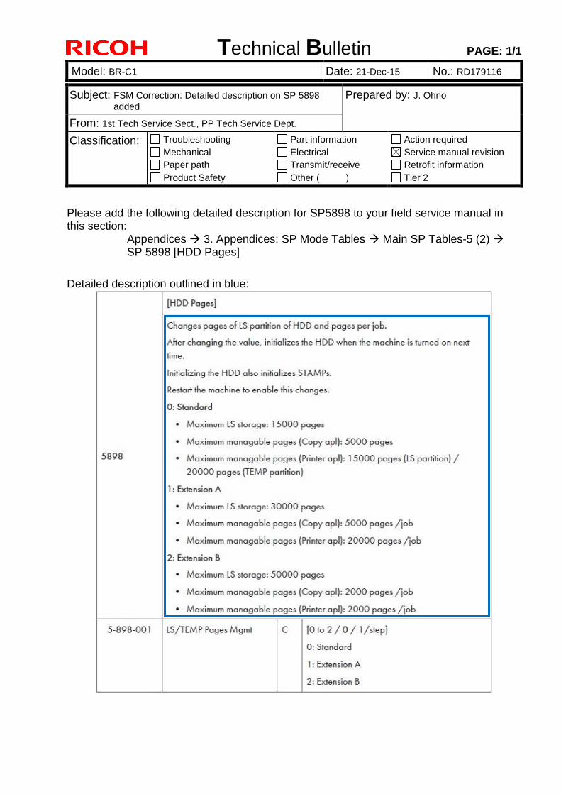
Technical Bulletin PAGE: 1/1
Model: BR-C1 Date: 21-Dec-15 No.: RD179116
Subject: FSM Correction: Detailed description on SP 5898
added Prepared by: J. Ohno
From: 1st Tech Service Sect., PP Tech Service Dept.
Classification: Troubleshooting
Mechanical
Paper path
Product Safety
Part information
Electrical
Transmit/receive
Other ( )
Action required
Service manual revision
Retrofit information
Tier 2
Please add the following detailed description for SP5898 to your field service manual in this section:
Appendices 3. Appendices: SP Mode Tables Main SP Tables-5 (2) SP 5898 [HDD Pages]
Detailed description outlined in blue:
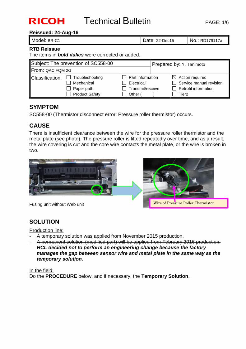
Technical Bulletin PAGE: 1/6
Reissued: 24-Aug-16
Model: BR-C1 Date: 22-Dec15 No.: RD179117a
RTB Reissue The items in bold italics were corrected or added.
SYMPTOM SC558-00 (Thermistor disconnect error: Pressure roller thermistor) occurs.
CAUSE There is insufficient clearance between the wire for the pressure roller thermistor and the metal plate (see photo). The pressure roller is lifted repeatedly over time, and as a result, the wire covering is cut and the core wire contacts the metal plate, or the wire is broken in two.
Fusing unit without Web unit SOLUTION
Production line: - A temporary solution was applied from November 2015 production. - A permanent solution (modified part) will be applied from February 2016 production.
RCL decided not to perform an engineering change because the factory manages the gap between sensor wire and metal plate in the same way as the temporary solution.
In the field: Do the PROCEDURE below, and if necessary, the Temporary Solution.
Subject: The prevention of SC558-00 Prepared by: Y. Tanimoto From: QAC FQM 2G
Classification: Troubleshooting Mechanical Paper path Product Safety
Part information Electrical Transmit/receive Other ( )
Action required Service manual revision Retrofit information Tier2
Wire of Pressure Roller Thermistor
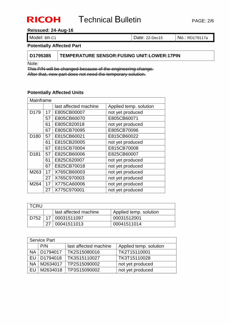
Technical Bulletin PAGE: 2/6
Reissued: 24-Aug-16
Model: BR-C1 Date: 22-Dec15 No.: RD179117a
Potentially Affected Part
D1795385 TEMPERATURE SENSOR:FUSING UNIT:LOWER:17PIN
Note: This P/N will be changed because of the engineering change. After that, new part does not need the temporary solution.
Potentially Affected Units
Mainframe last affected machine Applied temp. solution D179 17 E805CB00007 not yet produced
57 E805CB60070 E805CB60071 61 E805C820018 not yet produced 67 E805CB70095 E805CB70096
D180 57 E815CB60021 E815CB60022 61 E815CB20005 not yet produced 67 E815CB70004 E815CB70008
D181 57 E825CB60006 E825CB60007 61 E825C620007 not yet produced 67 E825CB70018 not yet produced
M263 17 X765CB60003 not yet produced 27 X765C970003 not yet produced
M264 17 X775CA60006 not yet produced 27 X775C970001 not yet produced
TCRU last affected machine Applied temp. solution D752 17 00031511097 00031512001
27 00041511013 00041511014 Service Part P/N last affected machine Applied temp. solution NA D1794017 TK2S15080016 TK2T15110001 EU D1794018 TK3S15110027 TK3T15110028 NA M2634017 TP2S15090002 not yet produced EU M2634018 TP3S15090002 not yet produced
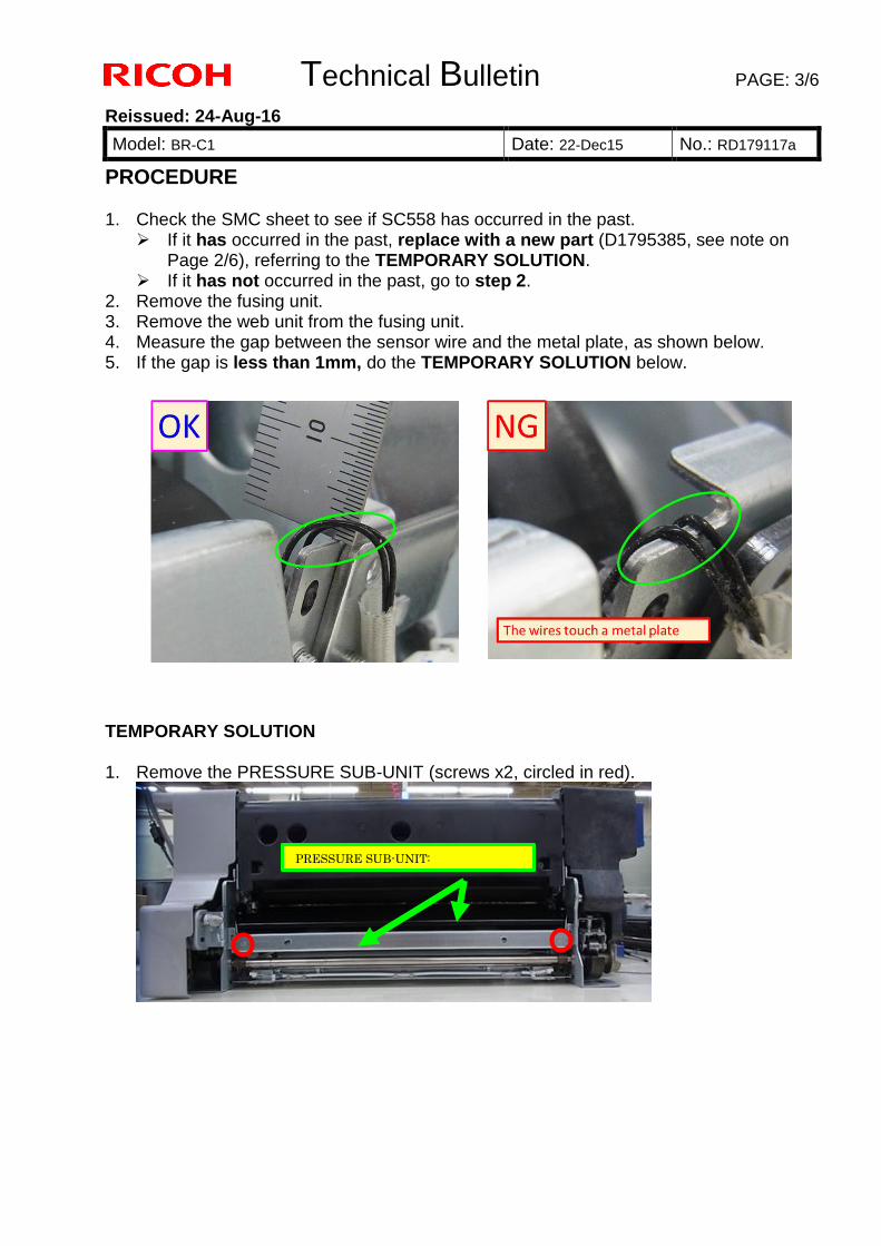
Technical Bulletin PAGE: 3/6
Reissued: 24-Aug-16
Model: BR-C1 Date: 22-Dec15 No.: RD179117a
PROCEDURE 1. Check the SMC sheet to see if SC558 has occurred in the past.
If it has occurred in the past, replace with a new part (D1795385, see note on Page 2/6), referring to the TEMPORARY SOLUTION.
If it has not occurred in the past, go to step 2. 2. Remove the fusing unit. 3. Remove the web unit from the fusing unit. 4. Measure the gap between the sensor wire and the metal plate, as shown below. 5. If the gap is less than 1mm, do the TEMPORARY SOLUTION below.
TEMPORARY SOLUTION 1. Remove the PRESSURE SUB-UNIT (screws x2, circled in red).
PRESSURE SUB-UNIT:
ENTRANCE:ASS’Y
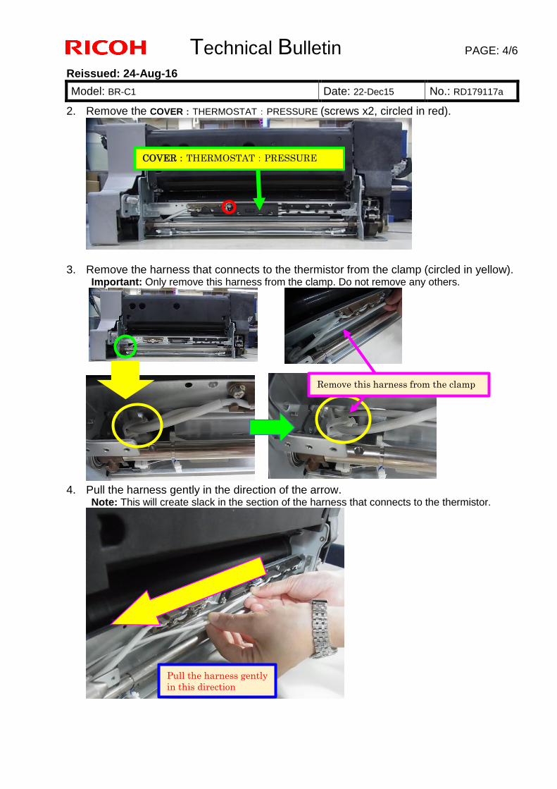
Technical Bulletin PAGE: 4/6
Reissued: 24-Aug-16
Model: BR-C1 Date: 22-Dec15 No.: RD179117a
2. Remove the COVER:THERMOSTAT:PRESSURE (screws x2, circled in red).
3. Remove the harness that connects to the thermistor from the clamp (circled in yellow). Important: Only remove this harness from the clamp. Do not remove any others.
4. Pull the harness gently in the direction of the arrow. Note: This will create slack in the section of the harness that connects to the thermistor.
COVER:THERMOSTAT:PRESSURE
Remove this harness from the clamp
Pull the harness gently in this direction
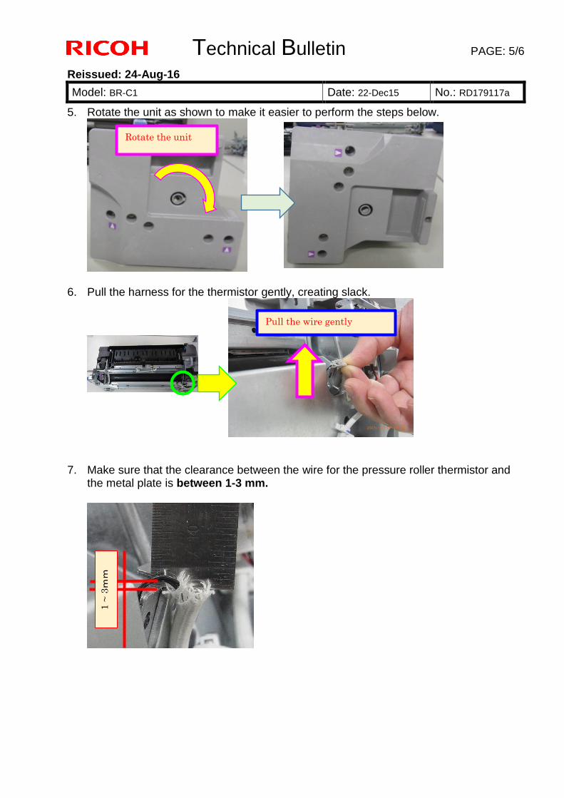
Technical Bulletin PAGE: 5/6
Reissued: 24-Aug-16
Model: BR-C1 Date: 22-Dec15 No.: RD179117a
5. Rotate the unit as shown to make it easier to perform the steps below.
6. Pull the harness for the thermistor gently, creating slack.
7. Make sure that the clearance between the wire for the pressure roller thermistor and the metal plate is between 1-3 mm.
Rotate the unit
Pull the wire gently
1 ~
3mm
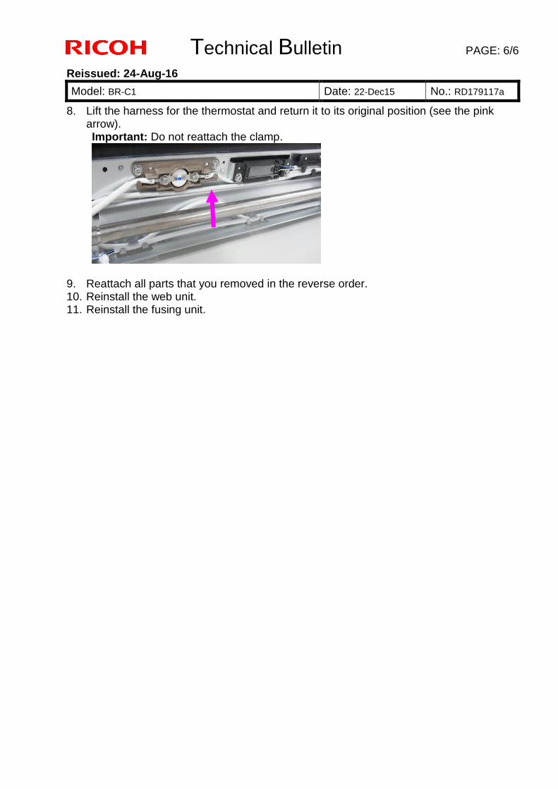
Technical Bulletin PAGE: 6/6
Reissued: 24-Aug-16
Model: BR-C1 Date: 22-Dec15 No.: RD179117a
8. Lift the harness for the thermostat and return it to its original position (see the pink arrow). Important: Do not reattach the clamp.
9. Reattach all parts that you removed in the reverse order. 10. Reinstall the web unit. 11. Reinstall the fusing unit.
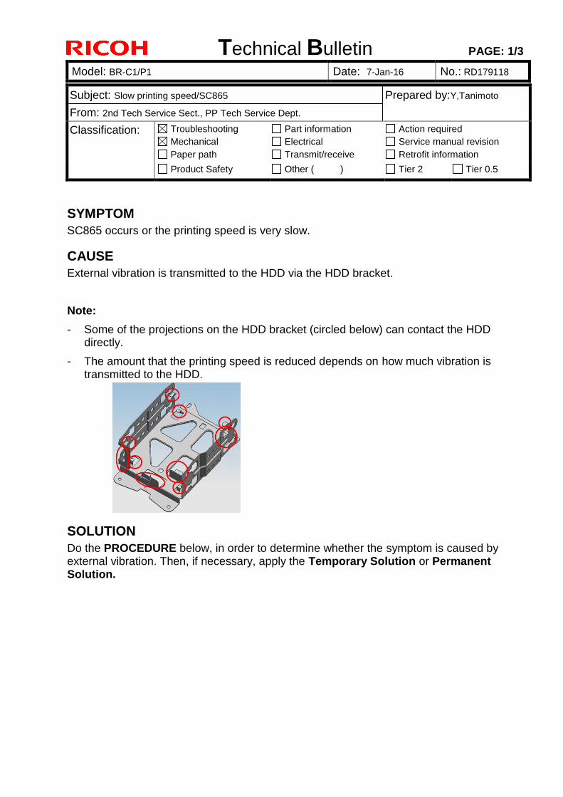
Technical Bulletin PAGE: 1/3
Model: BR-C1/P1 Date: 7-Jan-16 No.: RD179118
Subject: Slow printing speed/SC865 Prepared by:Y,Tanimoto
From: 2nd Tech Service Sect., PP Tech Service Dept.
Classification: Troubleshooting
Mechanical
Paper path
Part information
Electrical
Transmit/receive
Action required
Service manual revision
Retrofit information
Product Safety Other ( ) Tier 2 Tier 0.5
SYMPTOM
SC865 occurs or the printing speed is very slow.
CAUSE
External vibration is transmitted to the HDD via the HDD bracket.
Note:
- Some of the projections on the HDD bracket (circled below) can contact the HDD directly.
- The amount that the printing speed is reduced depends on how much vibration is transmitted to the HDD.
SOLUTION
Do the PROCEDURE below, in order to determine whether the symptom is caused by external vibration. Then, if necessary, apply the Temporary Solution or Permanent Solution.
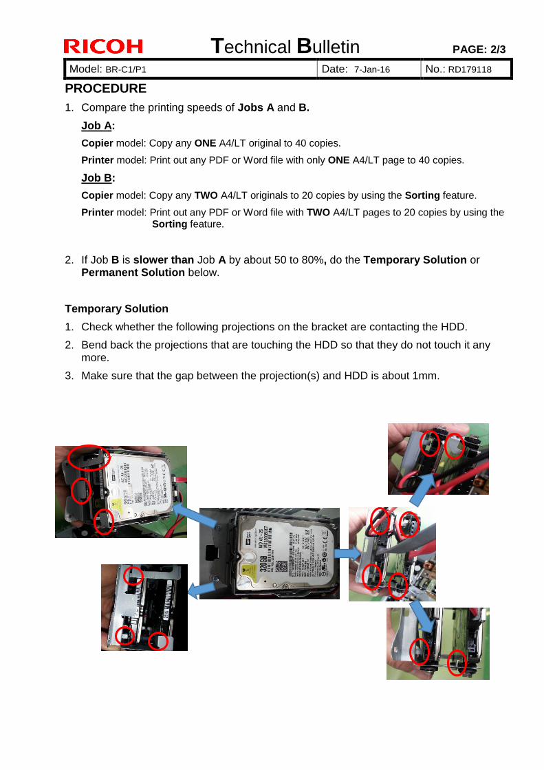
Technical Bulletin PAGE: 2/3
Model: BR-C1/P1 Date: 7-Jan-16 No.: RD179118
PROCEDURE
1. Compare the printing speeds of Jobs A and B.
Job A:
Copier model: Copy any ONE A4/LT original to 40 copies.
Printer model: Print out any PDF or Word file with only ONE A4/LT page to 40 copies.
Job B:
Copier model: Copy any TWO A4/LT originals to 20 copies by using the Sorting feature.
Printer model: Print out any PDF or Word file with TWO A4/LT pages to 20 copies by using the Sorting feature.
2. If Job B is slower than Job A by about 50 to 80%, do the Temporary Solution or Permanent Solution below.
Temporary Solution
1. Check whether the following projections on the bracket are contacting the HDD.
2. Bend back the projections that are touching the HDD so that they do not touch it any more.
3. Make sure that the gap between the projection(s) and HDD is about 1mm.
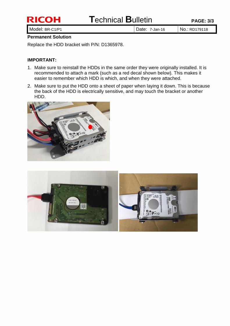
Technical Bulletin PAGE: 3/3
Model: BR-C1/P1 Date: 7-Jan-16 No.: RD179118
Permanent Solution
Replace the HDD bracket with P/N: D1365978.
IMPORTANT:
1. Make sure to reinstall the HDDs in the same order they were originally installed. It is recommended to attach a mark (such as a red decal shown below). This makes it easier to remember which HDD is which, and when they were attached.
2. Make sure to put the HDD onto a sheet of paper when laying it down. This is because the back of the HDD is electrically sensitive, and may touch the bracket or another HDD.
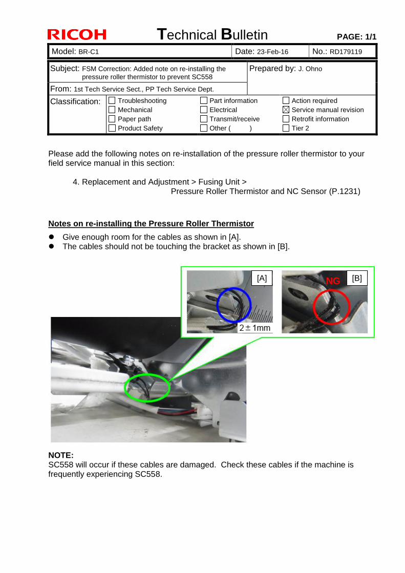
Technical Bulletin PAGE: 1/1
Model: BR-C1 Date: 23-Feb-16 No.: RD179119
Subject: FSM Correction: Added note on re-installing the
pressure roller thermistor to prevent SC558 Prepared by: J. Ohno
From: 1st Tech Service Sect., PP Tech Service Dept.
Classification: Troubleshooting
Mechanical
Paper path
Product Safety
Part information
Electrical
Transmit/receive
Other ( )
Action required
Service manual revision
Retrofit information
Tier 2
Please add the following notes on re-installation of the pressure roller thermistor to your field service manual in this section:
4. Replacement and Adjustment > Fusing Unit > Pressure Roller Thermistor and NC Sensor (P.1231)
Notes on re-installing the Pressure Roller Thermistor
Give enough room for the cables as shown in [A]. The cables should not be touching the bracket as shown in [B].
NOTE: SC558 will occur if these cables are damaged. Check these cables if the machine is frequently experiencing SC558.
[A] [B] NG

Technical Bulletin PAGE: 1/1
Model: BR-C1 Date: 09-Mar-16 No.: RD179120
Subject: Parts catalog correction – Developer Prepared by: J. Ohno
From: 1st PP Tech Service Sect., PP Tech Service Dept.
Classification: Troubleshooting
Mechanical
Paper path
Part information
Electrical
Transmit/receive
Action required
Service manual revision
Retrofit information
Product Safety Other ( ) Tier 2
Change: Cleaning tape (p/n: D1793414) to prevent toner scattering was included as an
accessory to the developer (p/n: D1799640).
Reason: By including the cleaning tape in the developer as a set, the tape does not have
to be procured separately, as it used when replacing the developer.
Old P/N New P/N Description Q’ty Int Note D1799640 D1809640 DEVELOPER BLACK 1 X/O Change
NOTE
The new developer and old developer are no different in their components and quantity. The new developer simply contains the cleaning tape as an accessory.
When replacing the developer, clean the development roller with the cleaning tape by
following the instructions provided in RTB #RD179095a.
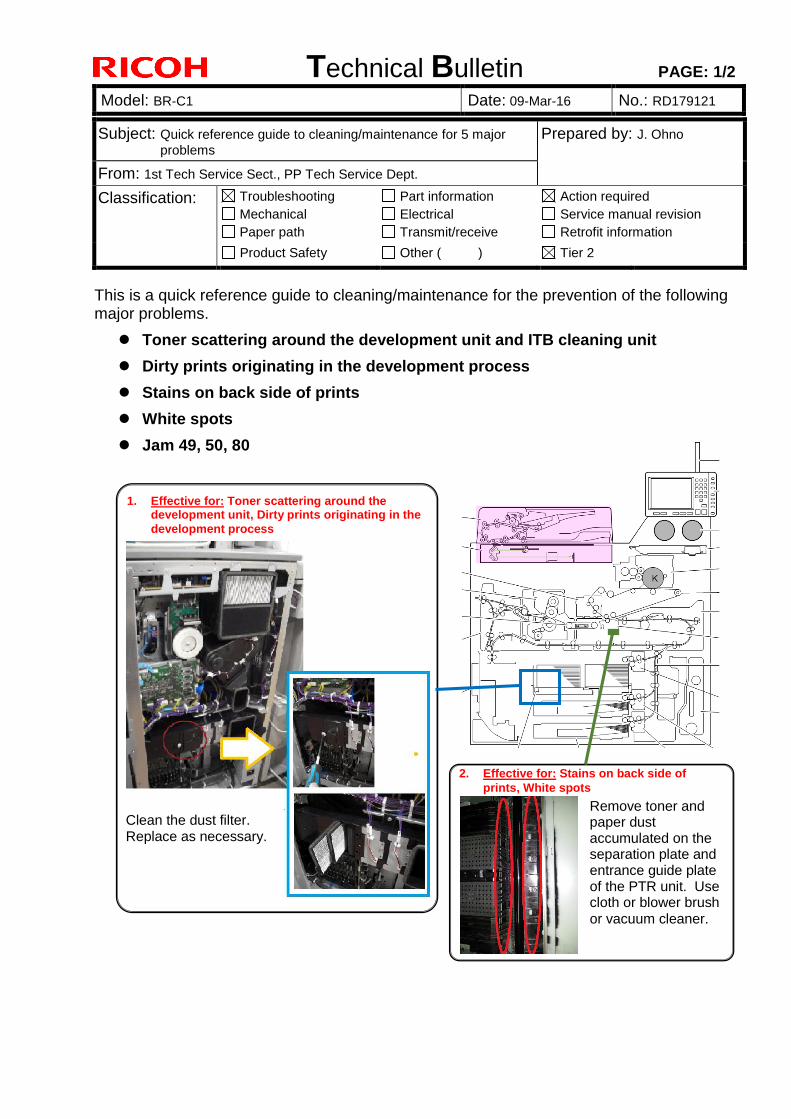
Technical Bulletin PAGE: 1/2
Model: BR-C1 Date: 09-Mar-16 No.: RD179121
Subject: Quick reference guide to cleaning/maintenance for 5 major
problems Prepared by: J. Ohno
From: 1st Tech Service Sect., PP Tech Service Dept.
Classification: Troubleshooting
Mechanical
Paper path
Part information
Electrical
Transmit/receive
Action required
Service manual revision
Retrofit information
Product Safety Other ( ) Tier 2
This is a quick reference guide to cleaning/maintenance for the prevention of the following major problems.
Toner scattering around the development unit and ITB cleaning unit
Dirty prints originating in the development process
Stains on back side of prints
White spots
Jam 49, 50, 80
1. Effective for: Toner scattering around the development unit, Dirty prints originating in the
development process
Clean the dust filter. Replace as necessary.
2. Effective for: Stains on back side of
prints, White spots
Remove toner and paper dust accumulated on the separation plate and entrance guide plate of the PTR unit. Use cloth or blower brush or vacuum cleaner.
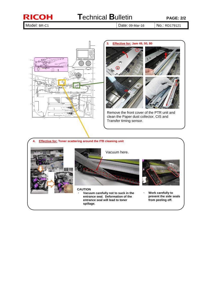
Technical Bulletin PAGE: 2/2
Model: BR-C1 Date: 09-Mar-16 No.: RD179121
3. Effective for: Jam 49, 50, 80
Remove the front cover of the PTR unit and clean the Paper dust collector, CIS and Transfer timing sensor.
4. Effective for: Toner scattering around the ITB cleaning unit
CAUTION ・ Vacuum carefully not to suck in the
entrance seal. Deformation of the entrance seal will lead to toner
spillage.
・ Work carefully to prevent the side seals
from peeling off.
Vacuum here.
Technical Bulletin PAGE: 1/1 Reissued: 09-May-16
Model: Leo-C1/Leo-P1/BR-C1/BR-P1/Andromeda-P1 Date: 11-Dec-14 No.: RD194028b
RTB Reissue The items in bold italics have been corrected or added.
Subject: Firmware Release Note: LCT1_LCIT5100 Prepared by: H. Matsui
From: 1st PP Tech Service Sect., PP Tech Service Dept.
Classification: Troubleshooting
Mechanical
Paper path
Part information
Electrical
Transmit/receive
Action required
Service manual revision
Retrofit information
Product Safety Other (Firmware) Tier 2
This RTB has been issued to announce the firmware release information for the LCT1_LCIT5100.
Version Program No. Effective Date Availability of RFU 01.040:06 D7775510F_LCT1 April 2016 production Not available
01.030:06 D7775510E_LCT1 February 2015 production Not available 01.020:06 D7775510D_LCT1 1st Mass production Not available
Note: Definition of Availability of RFU via @Remote “Available”: The firmware can be updated via RFU or SD card. “Not available”: The firmware can only be updated via SD card.
Version Modified Points or Symptom Corrected 01.040:06 Specification Change:
- Automatic detection of SRA3 size on EU machines - When 12x18 inch or SRA3 is loaded on the tray of an EU machine, the size is automatically detected as SRA3 instead of 12x18. Note: 1. This automatic size detection will not apply to NA machines. 2. For Pro 8100EX/8100S/8110S/8120S, Engine F/W should be upgraded
to Ver 4.05:08 or newer as a set. 3. For Pro 8110/8120, Engine F/W should be upgraded to Ver 1.05:00 or
newer as a set. 4. For Pro C9100/C9110, this automatic size detection will not be
activated for Multi Bypass Tray BY5010.
01.030:06 Error Correction: Minor bug fix
01.020:06 1st Mass production

Technical Bulletin PAGE: 1/1 Reissued: 09-May-16
Model: Leo-C1/Leo-P1/BR-C1/BR-P1/Andromeda-P1 Date: 11-Dec-14 No.: RD194029b
RTB Reissue The items in bold italics have been corrected or added.
Subject: Firmware Release Note: LCT2_LCIT5100 Prepared by: H. Matsui
From: 1st PP Tech Service Sect., PP Tech Service Dept.
Classification: Troubleshooting
Mechanical
Paper path
Part information
Electrical
Transmit/receive
Action required
Service manual revision
Retrofit information
Product Safety Other (Firmware) Tier 2
This RTB has been issued to announce the firmware release information for the LCT2_LCIT5100.
Version Program No. Effective Date Availability of RFU 01.040:06 D7775510F_LCT2 April 2016 production Not available
01.030:06 D7775510E_LCT2 February 2015 production Not available 01.020:06 D7775510D_LCT2 1st Mass production Not available
Note: Definition of Availability of RFU via @Remote “Available”: The firmware can be updated via RFU or SD card. “Not available”: The firmware can only be updated via SD card.
Version Modified Points or Symptom Corrected 01.040:06 Specification Change:
- Automatic detection of SRA3 size on EU machines - When 12x18 inch or SRA3 is loaded on the tray of an EU machine, the size is automatically detected as SRA3 instead of 12x18. Note: 1. This automatic size detection will not apply to NA machines. 2. For Pro 8100EX/8100S/8110S/8120S, Engine F/W should be upgraded
to Ver 4.05:08 or newer as a set. 3. For Pro 8110/8120, Engine F/W should be upgraded to Ver 1.05:00 or
newer as a set. 4. For Pro C9100/C9110, this automatic size detection will not be
activated for Multi Bypass Tray BY5010.
01.030:06 Error Correction: Minor bug fix
01.020:06 1st Mass production
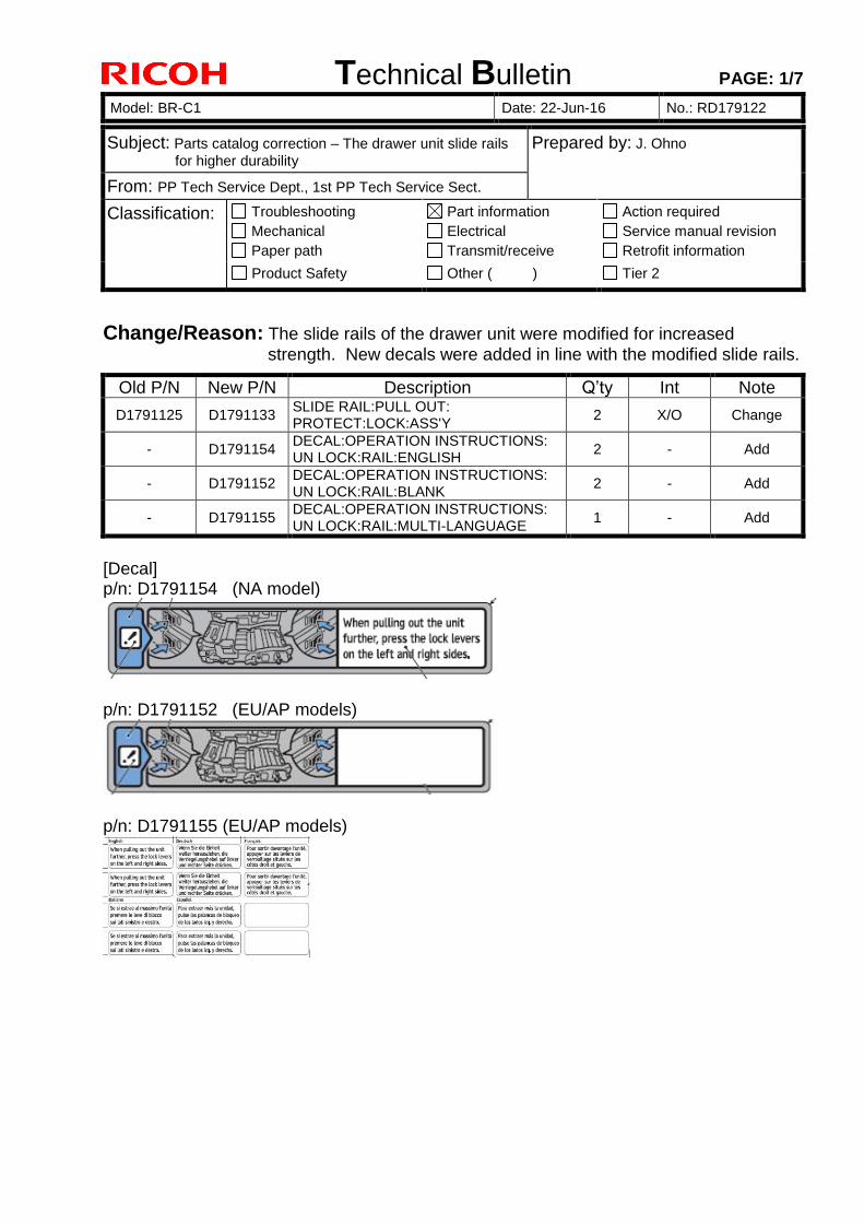
Technical Bulletin PAGE: 1/7
Model: BR-C1 Date: 22-Jun-16 No.: RD179122
Subject: Parts catalog correction – The drawer unit slide rails for higher durability
Prepared by: J. Ohno
From: PP Tech Service Dept., 1st PP Tech Service Sect.
Classification: Troubleshooting Mechanical Paper path
Part information Electrical Transmit/receive
Action required Service manual revision Retrofit information
Product Safety Other ( ) Tier 2
Change/Reason: The slide rails of the drawer unit were modified for increased strength. New decals were added in line with the modified slide rails.
Old P/N New P/N Description Q’ty Int Note
D1791125 D1791133 SLIDE RAIL:PULL OUT: PROTECT:LOCK:ASS'Y
2 X/O Change
- D1791154 DECAL:OPERATION INSTRUCTIONS: UN LOCK:RAIL:ENGLISH
2 - Add
- D1791152 DECAL:OPERATION INSTRUCTIONS: UN LOCK:RAIL:BLANK
2 - Add
- D1791155 DECAL:OPERATION INSTRUCTIONS: UN LOCK:RAIL:MULTI-LANGUAGE
1 - Add
[Decal] p/n: D1791154 (NA model)
p/n: D1791152 (EU/AP models)
p/n: D1791155 (EU/AP models)
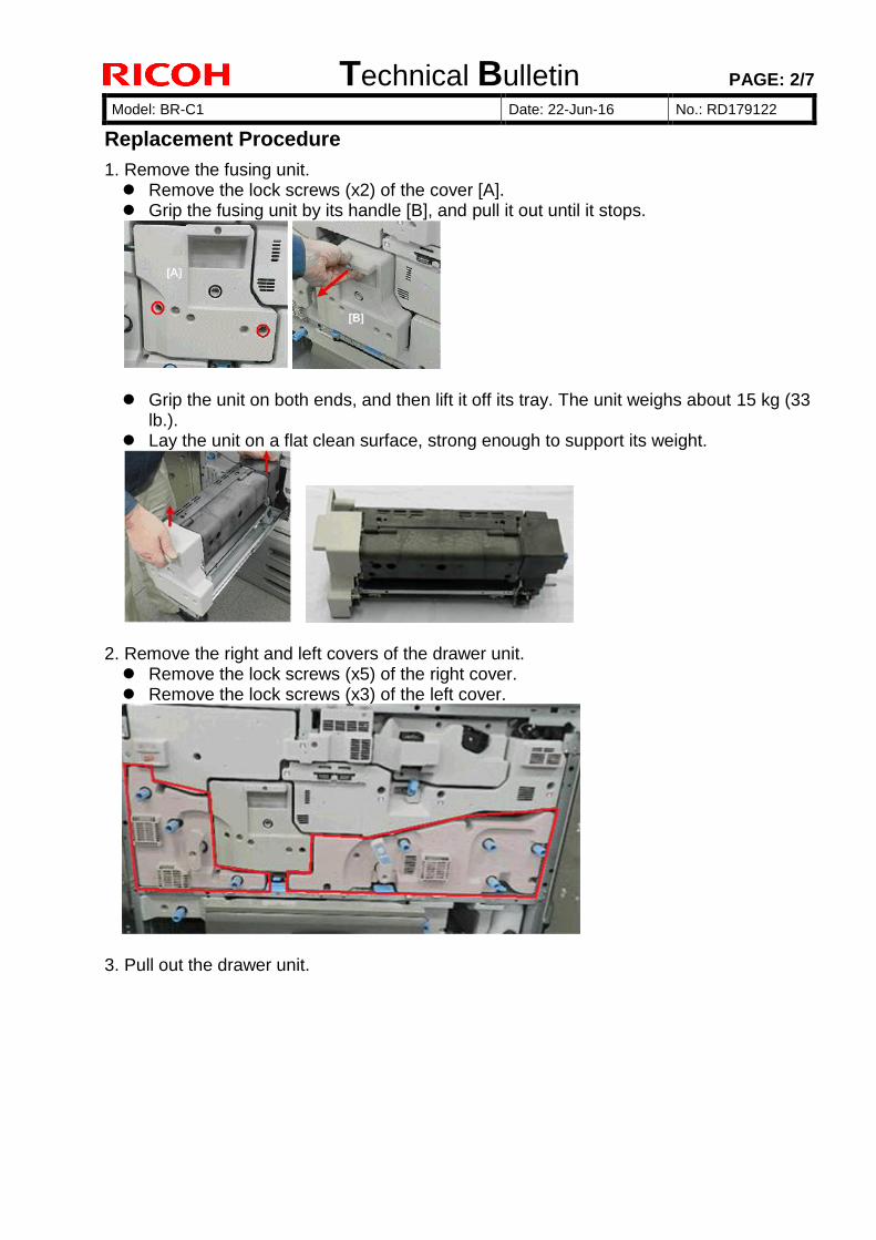
Technical Bulletin PAGE: 2/7
Model: BR-C1 Date: 22-Jun-16 No.: RD179122
Replacement Procedure
1. Remove the fusing unit. Remove the lock screws (x2) of the cover [A]. Grip the fusing unit by its handle [B], and pull it out until it stops.
Grip the unit on both ends, and then lift it off its tray. The unit weighs about 15 kg (33
lb.). Lay the unit on a flat clean surface, strong enough to support its weight.
2. Remove the right and left covers of the drawer unit. Remove the lock screws (x5) of the right cover. Remove the lock screws (x3) of the left cover.
3. Pull out the drawer unit.

Technical Bulletin PAGE: 3/7
Model: BR-C1 Date: 22-Jun-16 No.: RD179122
4. Remove the right and left duplex transport guide plates in the following procedure: Remove the snap rings (x2).
Left plate
Right plate
Remove the screws (x2) fixing the drawer unit with the frame at the front side.
Left plate Right plate
Slide to remove the duplex transport guide plates.
Left plate Right plate
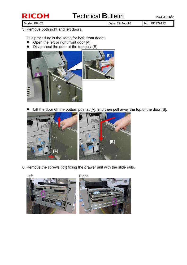
Technical Bulletin PAGE: 4/7
Model: BR-C1 Date: 22-Jun-16 No.: RD179122
5. Remove both right and left doors.
This procedure is the same for both front doors. Open the left or right front door [A]. Disconnect the door at the top post [B].
Lift the door off the bottom post at [A], and then pull away the top of the door [B].
6. Remove the screws (x4) fixing the drawer unit with the slide rails. Left Right
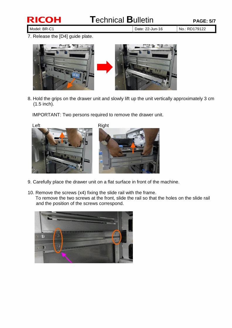
Technical Bulletin PAGE: 5/7
Model: BR-C1 Date: 22-Jun-16 No.: RD179122
7. Release the [D4] guide plate.
8. Hold the grips on the drawer unit and slowly lift up the unit vertically approximately 3 cm
(1.5 inch).
IMPORTANT: Two persons required to remove the drawer unit.
Left Right
9. Carefully place the drawer unit on a flat surface in front of the machine. 10. Remove the screws (x4) fixing the slide rail with the frame. To remove the two screws at the front, slide the rail so that the holes on the slide rail
and the position of the screws correspond.
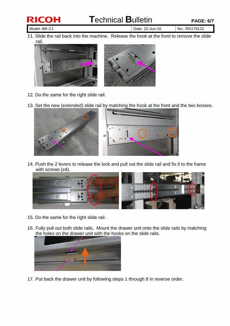
Technical Bulletin PAGE: 6/7
Model: BR-C1 Date: 22-Jun-16 No.: RD179122
11. Slide the rail back into the machine. Release the hook at the front to remove the slide rail.
12. Do the same for the right slide rail. 13. Set the new (extended) slide rail by matching the hook at the front and the two bosses.
14. Push the 2 levers to release the lock and pull out the slide rail and fix it to the frame
with screws (x4).
15. Do the same for the right slide rail. 16. Fully pull out both slide rails. Mount the drawer unit onto the slide rails by matching
the holes on the drawer unit with the hooks on the slide rails.
17. Put back the drawer unit by following steps 1 through 8 in reverse order.
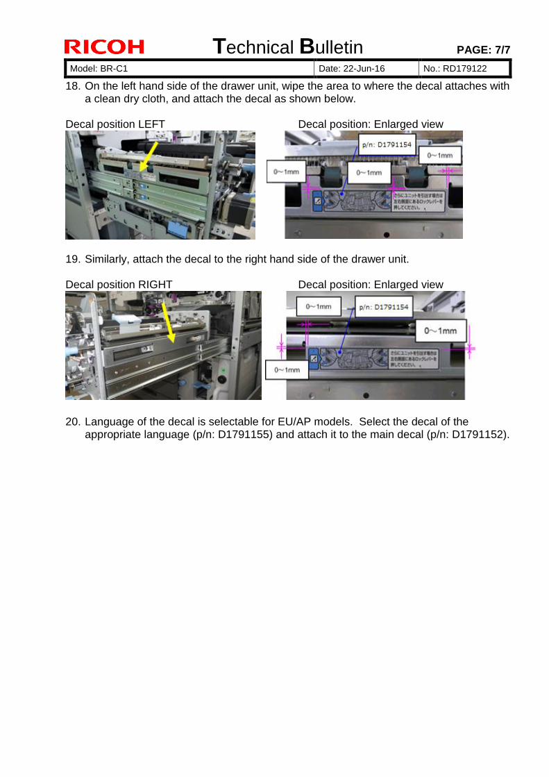
Technical Bulletin PAGE: 7/7
Model: BR-C1 Date: 22-Jun-16 No.: RD179122
18. On the left hand side of the drawer unit, wipe the area to where the decal attaches with a clean dry cloth, and attach the decal as shown below.
Decal position LEFT Decal position: Enlarged view
19. Similarly, attach the decal to the right hand side of the drawer unit. Decal position RIGHT Decal position: Enlarged view
20. Language of the decal is selectable for EU/AP models. Select the decal of the
appropriate language (p/n: D1791155) and attach it to the main decal (p/n: D1791152).
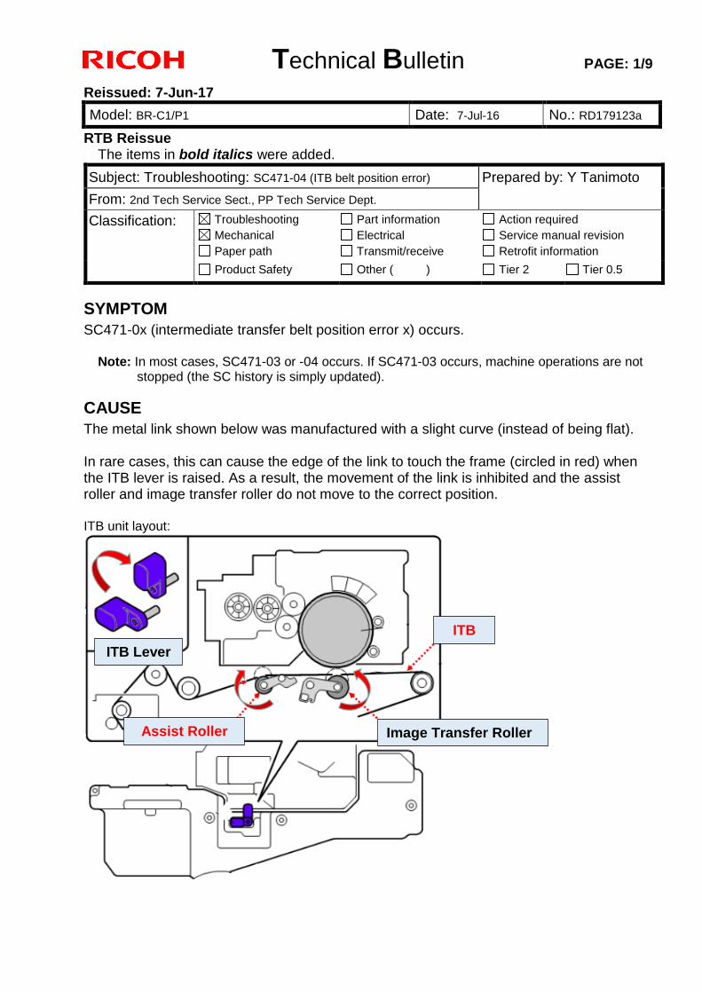
Technical Bulletin PAGE: 1/9
Reissued: 7-Jun-17
Model: BR-C1/P1 Date: 7-Jul-16 No.: RD179123a
RTB Reissue The items in bold italics were added.
SYMPTOM
SC471-0x (intermediate transfer belt position error x) occurs.
Note: In most cases, SC471-03 or -04 occurs. If SC471-03 occurs, machine operations are not stopped (the SC history is simply updated).
CAUSE
The metal link shown below was manufactured with a slight curve (instead of being flat). In rare cases, this can cause the edge of the link to touch the frame (circled in red) when the ITB lever is raised. As a result, the movement of the link is inhibited and the assist roller and image transfer roller do not move to the correct position. ITB unit layout:
Subject: Troubleshooting: SC471-04 (ITB belt position error) Prepared by: Y Tanimoto
From: 2nd Tech Service Sect., PP Tech Service Dept.
Classification: Troubleshooting
Mechanical
Paper path
Part information
Electrical
Transmit/receive
Action required
Service manual revision
Retrofit information
Product Safety Other ( ) Tier 2 Tier 0.5
Image Transfer Roller Assist Roller
ITB
ITB Lever
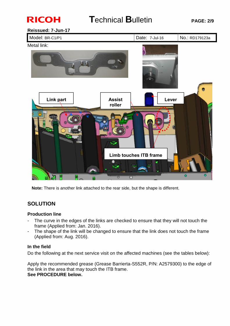
Technical Bulletin PAGE: 2/9
Reissued: 7-Jun-17
Model: BR-C1/P1 Date: 7-Jul-16 No.: RD179123a
Metal link:
Note: There is another link attached to the rear side, but the shape is different.
SOLUTION
Production line
- The curve in the edges of the links are checked to ensure that they will not touch the frame (Applied from: Jan. 2016).
- The shape of the link will be changed to ensure that the link does not touch the frame (Applied from: Aug. 2016).
In the field
Do the following at the next service visit on the affected machines (see the tables below): Apply the recommended grease (Grease Barrierta-S552R, P/N: A2579300) to the edge of the link in the area that may touch the ITB frame. See PROCEDURE below.
Assist roller
Lever Link part
Limb touches ITB frame
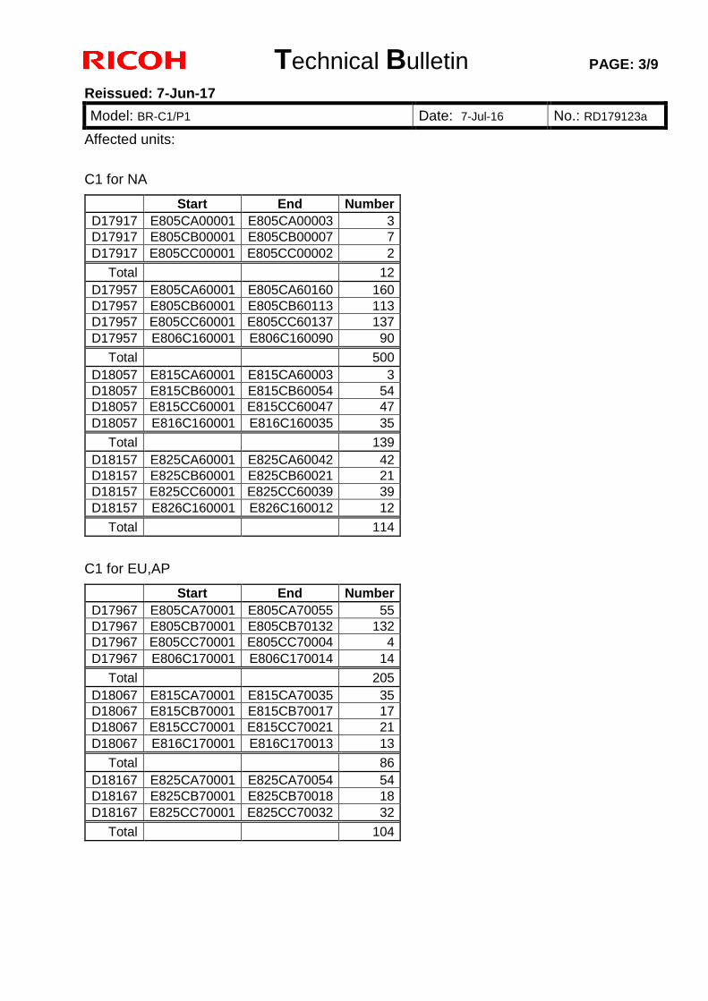
Technical Bulletin PAGE: 3/9
Reissued: 7-Jun-17
Model: BR-C1/P1 Date: 7-Jul-16 No.: RD179123a
Affected units:
C1 for NA
Start End Number
D17917 E805CA00001 E805CA00003 3
D17917 E805CB00001 E805CB00007 7
D17917 E805CC00001 E805CC00002 2
Total 12
D17957 E805CA60001 E805CA60160 160
D17957 E805CB60001 E805CB60113 113
D17957 E805CC60001 E805CC60137 137
D17957 E806C160001 E806C160090 90
Total 500
D18057 E815CA60001 E815CA60003 3
D18057 E815CB60001 E815CB60054 54
D18057 E815CC60001 E815CC60047 47
D18057 E816C160001 E816C160035 35
Total 139
D18157 E825CA60001 E825CA60042 42
D18157 E825CB60001 E825CB60021 21
D18157 E825CC60001 E825CC60039 39
D18157 E826C160001 E826C160012 12
Total 114
C1 for EU,AP
Start End Number
D17967 E805CA70001 E805CA70055 55
D17967 E805CB70001 E805CB70132 132
D17967 E805CC70001 E805CC70004 4
D17967 E806C170001 E806C170014 14
Total 205
D18067 E815CA70001 E815CA70035 35
D18067 E815CB70001 E815CB70017 17
D18067 E815CC70001 E815CC70021 21
D18067 E816C170001 E816C170013 13
Total 86
D18167 E825CA70001 E825CA70054 54
D18167 E825CB70001 E825CB70018 18
D18167 E825CC70001 E825CC70032 32
Total 104
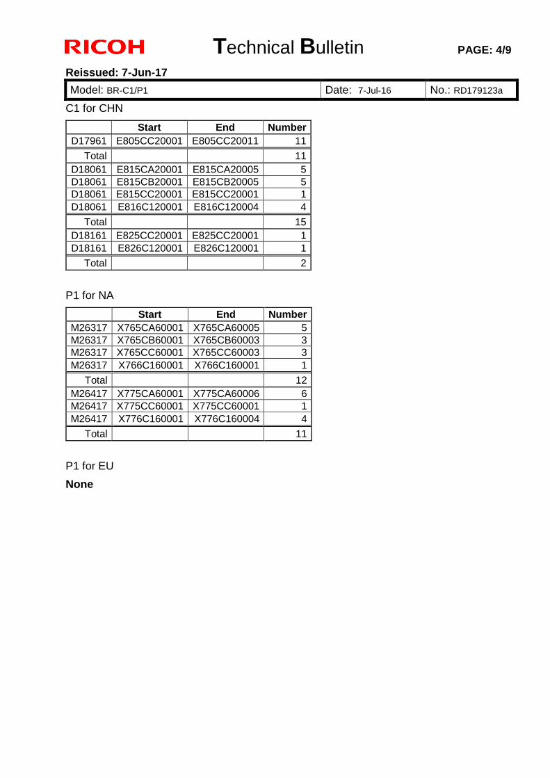
Technical Bulletin PAGE: 4/9
Reissued: 7-Jun-17
Model: BR-C1/P1 Date: 7-Jul-16 No.: RD179123a
C1 for CHN
Start End Number
D17961 E805CC20001 E805CC20011 11
Total 11
D18061 E815CA20001 E815CA20005 5
D18061 E815CB20001 E815CB20005 5
D18061 E815CC20001 E815CC20001 1
D18061 E816C120001 E816C120004 4
Total 15
D18161 E825CC20001 E825CC20001 1
D18161 E826C120001 E826C120001 1
Total 2
P1 for NA
Start End Number
M26317 X765CA60001 X765CA60005 5
M26317 X765CB60001 X765CB60003 3
M26317 X765CC60001 X765CC60003 3
M26317 X766C160001 X766C160001 1
Total 12
M26417 X775CA60001 X775CA60006 6
M26417 X775CC60001 X775CC60001 1
M26417 X776C160001 X776C160004 4
Total 11
P1 for EU
None
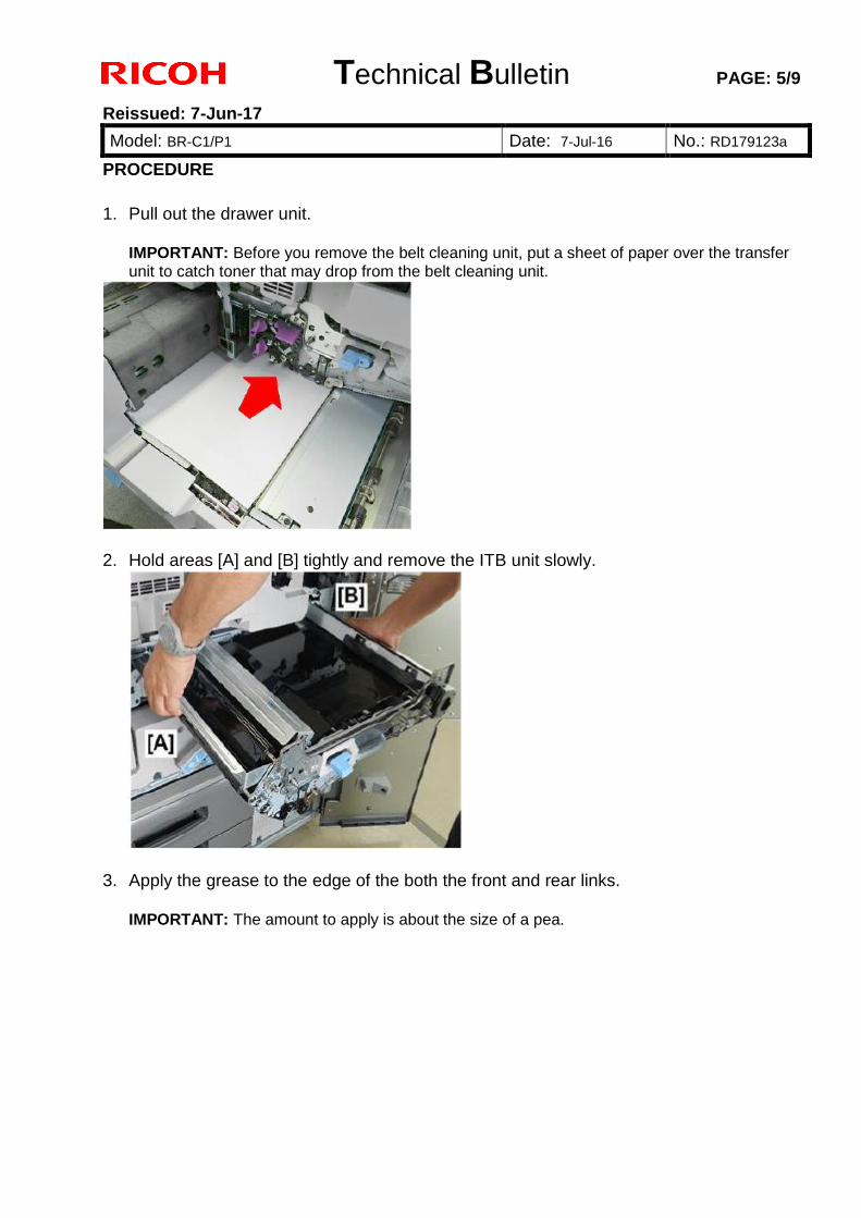
Technical Bulletin PAGE: 5/9
Reissued: 7-Jun-17
Model: BR-C1/P1 Date: 7-Jul-16 No.: RD179123a
PROCEDURE
1. Pull out the drawer unit.
IMPORTANT: Before you remove the belt cleaning unit, put a sheet of paper over the transfer unit to catch toner that may drop from the belt cleaning unit.
2. Hold areas [A] and [B] tightly and remove the ITB unit slowly.
3. Apply the grease to the edge of the both the front and rear links.
IMPORTANT: The amount to apply is about the size of a pea.
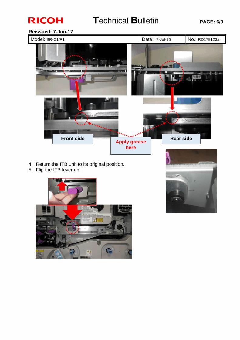
Technical Bulletin PAGE: 6/9
Reissued: 7-Jun-17
Model: BR-C1/P1 Date: 7-Jul-16 No.: RD179123a
4. Return the ITB unit to its original position. 5. Flip the ITB lever up.
Apply grease
here
Front side Rear side
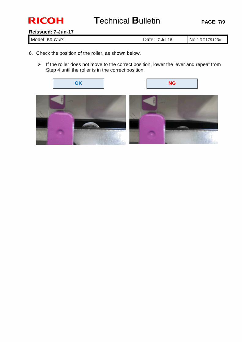
Technical Bulletin PAGE: 7/9
Reissued: 7-Jun-17
Model: BR-C1/P1 Date: 7-Jul-16 No.: RD179123a
6. Check the position of the roller, as shown below.
If the roller does not move to the correct position, lower the lever and repeat from
Step 4 until the roller is in the correct position.
OK NG
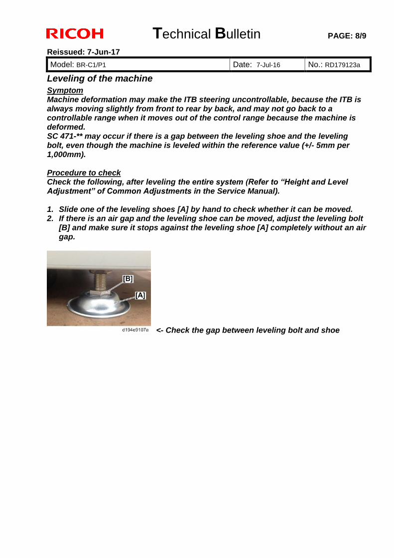
Technical Bulletin PAGE: 8/9
Reissued: 7-Jun-17
Model: BR-C1/P1 Date: 7-Jul-16 No.: RD179123a
Leveling of the machine
Symptom Machine deformation may make the ITB steering uncontrollable, because the ITB is always moving slightly from front to rear by back, and may not go back to a controllable range when it moves out of the control range because the machine is deformed. SC 471-** may occur if there is a gap between the leveling shoe and the leveling bolt, even though the machine is leveled within the reference value (+/- 5mm per 1,000mm). Procedure to check Check the following, after leveling the entire system (Refer to “Height and Level Adjustment” of Common Adjustments in the Service Manual). 1. Slide one of the leveling shoes [A] by hand to check whether it can be moved. 2. If there is an air gap and the leveling shoe can be moved, adjust the leveling bolt
[B] and make sure it stops against the leveling shoe [A] completely without an air gap.
<- Check the gap between leveling bolt and shoe
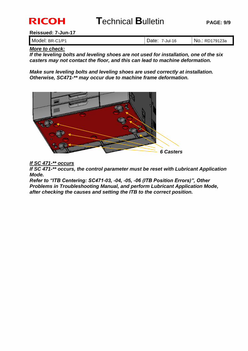
Technical Bulletin PAGE: 9/9
Reissued: 7-Jun-17
Model: BR-C1/P1 Date: 7-Jul-16 No.: RD179123a
More to check: If the leveling bolts and leveling shoes are not used for installation, one of the six casters may not contact the floor, and this can lead to machine deformation. Make sure leveling bolts and leveling shoes are used correctly at installation. Otherwise, SC471-** may occur due to machine frame deformation.
6 Casters If SC 471-** occurs If SC 471-** occurs, the control parameter must be reset with Lubricant Application Mode. Refer to “ITB Centering: SC471-03, -04, -05, -06 (ITB Position Errors)”, Other Problems in Troubleshooting Manual, and perform Lubricant Application Mode, after checking the causes and setting the ITB to the correct position.
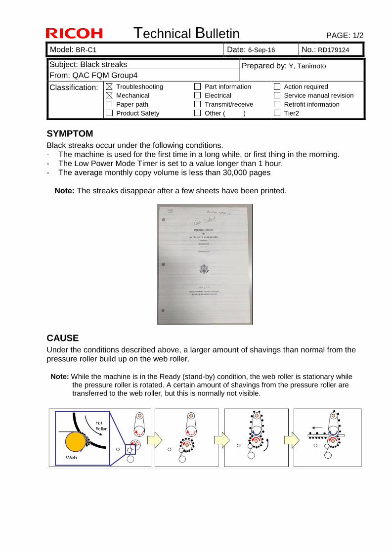
Technical Bulletin PAGE: 1/2
Model: BR-C1 Date: 6-Sep-16 No.: RD179124
SYMPTOM Black streaks occur under the following conditions. - The machine is used for the first time in a long while, or first thing in the morning. - The Low Power Mode Timer is set to a value longer than 1 hour. - The average monthly copy volume is less than 30,000 pages
Note: The streaks disappear after a few sheets have been printed.
CAUSE Under the conditions described above, a larger amount of shavings than normal from the pressure roller build up on the web roller. Note: While the machine is in the Ready (stand-by) condition, the web roller is stationary while
the pressure roller is rotated. A certain amount of shavings from the pressure roller are transferred to the web roller, but this is normally not visible.
Subject: Black streaks Prepared by: Y, Tanimoto From: QAC FQM Group4
Classification: Troubleshooting Mechanical Paper path Product Safety
Part information Electrical Transmit/receive Other ( )
Action required Service manual revision Retrofit information Tier2
Web
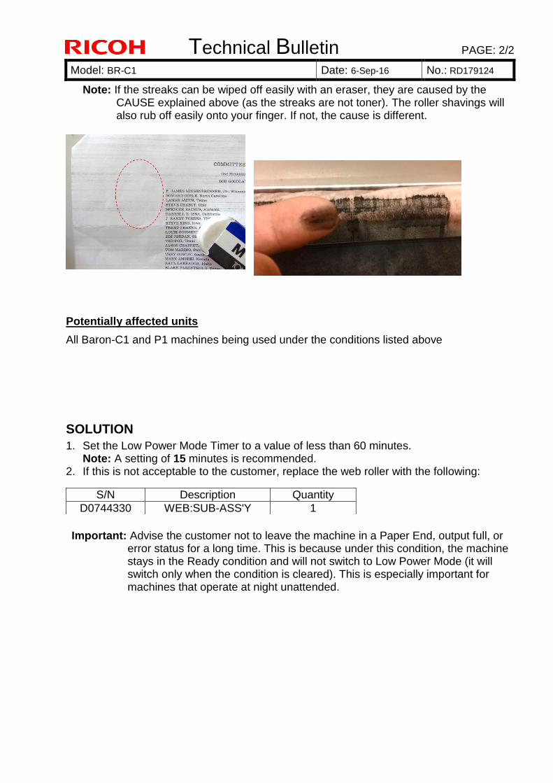
Technical Bulletin PAGE: 2/2
Model: BR-C1 Date: 6-Sep-16 No.: RD179124
Note: If the streaks can be wiped off easily with an eraser, they are caused by the CAUSE explained above (as the streaks are not toner). The roller shavings will also rub off easily onto your finger. If not, the cause is different.
Potentially affected units
All Baron-C1 and P1 machines being used under the conditions listed above
SOLUTION 1. Set the Low Power Mode Timer to a value of less than 60 minutes.
Note: A setting of 15 minutes is recommended. 2. If this is not acceptable to the customer, replace the web roller with the following:
Important: Advise the customer not to leave the machine in a Paper End, output full, or
error status for a long time. This is because under this condition, the machine stays in the Ready condition and will not switch to Low Power Mode (it will switch only when the condition is cleared). This is especially important for machines that operate at night unattended.
S/N Description Quantity D0744330 WEB:SUB-ASS'Y 1
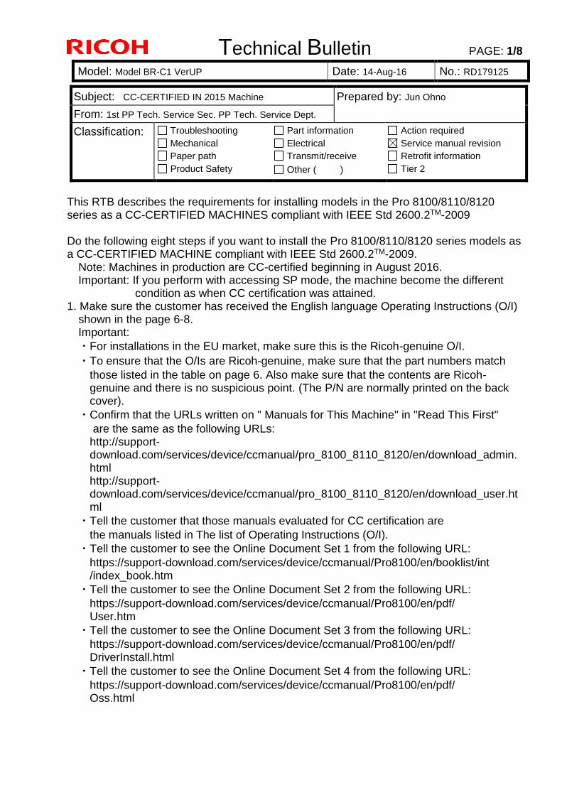
Technical Bulletin PAGE: 1/8
Model: Model BR-C1 VerUP Date: 14-Aug-16 No.: RD179125
0
This RTB describes the requirements for installing models in the Pro 8100/8110/8120 series as a CC-CERTIFIED MACHINES compliant with IEEE Std 2600.2TM-2009 Do the following eight steps if you want to install the Pro 8100/8110/8120 series models as a CC-CERTIFIED MACHINE compliant with IEEE Std 2600.2TM-2009. Note: Machines in production are CC-certified beginning in August 2016. Important: If you perform with accessing SP mode, the machine become the different condition as when CC certification was attained. 1. Make sure the customer has received the English language Operating Instructions (O/I) shown in the page 6-8. Important:
・For installations in the EU market, make sure this is the Ricoh-genuine O/I.
・To ensure that the O/Is are Ricoh-genuine, make sure that the part numbers match
those listed in the table on page 6. Also make sure that the contents are Ricoh-genuine and there is no suspicious point. (The P/N are normally printed on the back cover).
・Confirm that the URLs written on " Manuals for This Machine" in "Read This First"
are the same as the following URLs: http://support-download.com/services/device/ccmanual/pro_8100_8110_8120/en/download_admin.html
http://support-download.com/services/device/ccmanual/pro_8100_8110_8120/en/download_user.html
・Tell the customer that those manuals evaluated for CC certification are
the manuals listed in The list of Operating Instructions (O/I).
・Tell the customer to see the Online Document Set 1 from the following URL:
https://support-download.com/services/device/ccmanual/Pro8100/en/booklist/int /index_book.htm
・Tell the customer to see the Online Document Set 2 from the following URL:
https://support-download.com/services/device/ccmanual/Pro8100/en/pdf/ User.htm
・Tell the customer to see the Online Document Set 3 from the following URL:
https://support-download.com/services/device/ccmanual/Pro8100/en/pdf/ DriverInstall.html
・Tell the customer to see the Online Document Set 4 from the following URL:
https://support-download.com/services/device/ccmanual/Pro8100/en/pdf/ Oss.html
Subject: CC-CERTIFIED IN 2015 Machine Prepared by: Jun Ohno
From: 1st PP Tech. Service Sec. PP Tech. Service Dept.
Classification: Troubleshooting
Mechanical
Paper path
Product Safety
Part information
Electrical
Transmit/receive
Other ( )
Action required
Service manual revision
Retrofit information
Tier 2

Technical Bulletin PAGE: 2/8
Model: Model BR-C1 VerUP Date: 14-Aug-16 No.: RD179125
0
・Tell the customer to see the Online Document Set 5 from the following URL:
https://support-download.com/services/device/ccmanual/Pro8100/en/pdf/ Security.html
・Tell the customer to download the Online Document Set 6 (the information about the
authentication based on the CC certification system) from the URLs provided in "Manuals for This Machine" in "Read This First". 2. Tell the customer to read the “Notes for Administrators: Using This Machine in a Network Environment Compliant with IEEE Std 2600.2TM-2009”. See the following pages for Step 3 to Step 8.
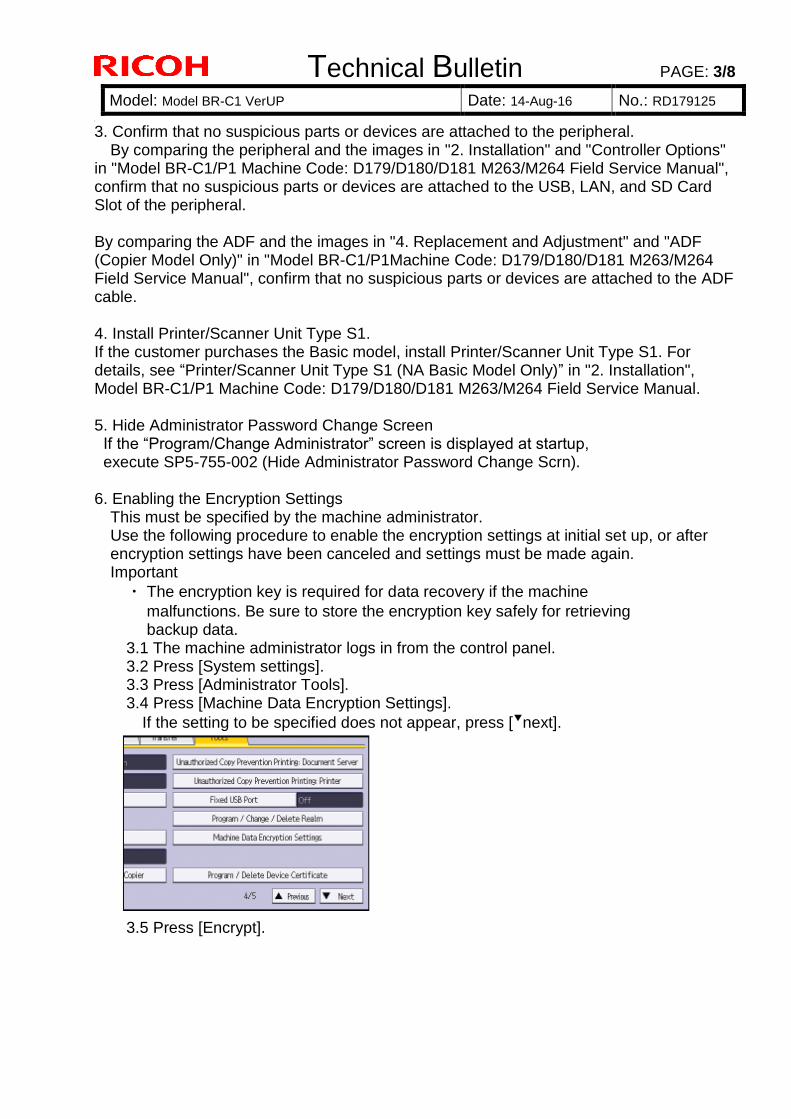
Technical Bulletin PAGE: 3/8
Model: Model BR-C1 VerUP Date: 14-Aug-16 No.: RD179125
0
3. Confirm that no suspicious parts or devices are attached to the peripheral. By comparing the peripheral and the images in "2. Installation" and "Controller Options"
in "Model BR-C1/P1 Machine Code: D179/D180/D181 M263/M264 Field Service Manual", confirm that no suspicious parts or devices are attached to the USB, LAN, and SD Card Slot of the peripheral. By comparing the ADF and the images in "4. Replacement and Adjustment" and "ADF (Copier Model Only)" in "Model BR-C1/P1Machine Code: D179/D180/D181 M263/M264 Field Service Manual", confirm that no suspicious parts or devices are attached to the ADF cable. 4. Install Printer/Scanner Unit Type S1. If the customer purchases the Basic model, install Printer/Scanner Unit Type S1. For details, see “Printer/Scanner Unit Type S1 (NA Basic Model Only)” in "2. Installation", Model BR-C1/P1 Machine Code: D179/D180/D181 M263/M264 Field Service Manual. 5. Hide Administrator Password Change Screen If the “Program/Change Administrator” screen is displayed at startup, execute SP5-755-002 (Hide Administrator Password Change Scrn). 6. Enabling the Encryption Settings This must be specified by the machine administrator. Use the following procedure to enable the encryption settings at initial set up, or after encryption settings have been canceled and settings must be made again. Important
・ The encryption key is required for data recovery if the machine
malfunctions. Be sure to store the encryption key safely for retrieving backup data. 3.1 The machine administrator logs in from the control panel. 3.2 Press [System settings]. 3.3 Press [Administrator Tools]. 3.4 Press [Machine Data Encryption Settings].
If the setting to be specified does not appear, press [▼next].
3.5 Press [Encrypt].
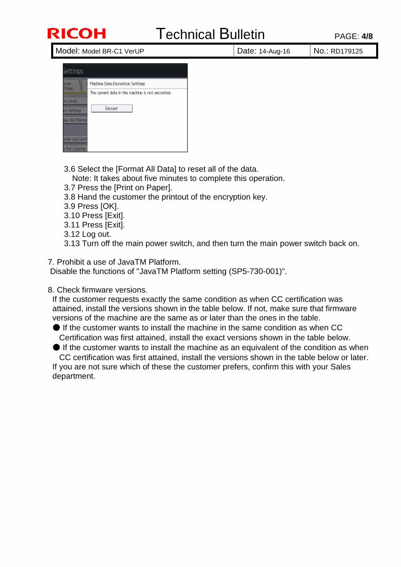
Technical Bulletin PAGE: 4/8
Model: Model BR-C1 VerUP Date: 14-Aug-16 No.: RD179125
0
3.6 Select the [Format All Data] to reset all of the data. Note: It takes about five minutes to complete this operation. 3.7 Press the [Print on Paper]. 3.8 Hand the customer the printout of the encryption key. 3.9 Press [OK]. 3.10 Press [Exit]. 3.11 Press [Exit]. 3.12 Log out. 3.13 Turn off the main power switch, and then turn the main power switch back on. 7. Prohibit a use of JavaTM Platform. Disable the functions of "JavaTM Platform setting (SP5-730-001)". 8. Check firmware versions. If the customer requests exactly the same condition as when CC certification was attained, install the versions shown in the table below. If not, make sure that firmware versions of the machine are the same as or later than the ones in the table.
● If the customer wants to install the machine in the same condition as when CC
Certification was first attained, install the exact versions shown in the table below.
● If the customer wants to install the machine as an equivalent of the condition as when
CC certification was first attained, install the versions shown in the table below or later. If you are not sure which of these the customer prefers, confirm this with your Sales department.
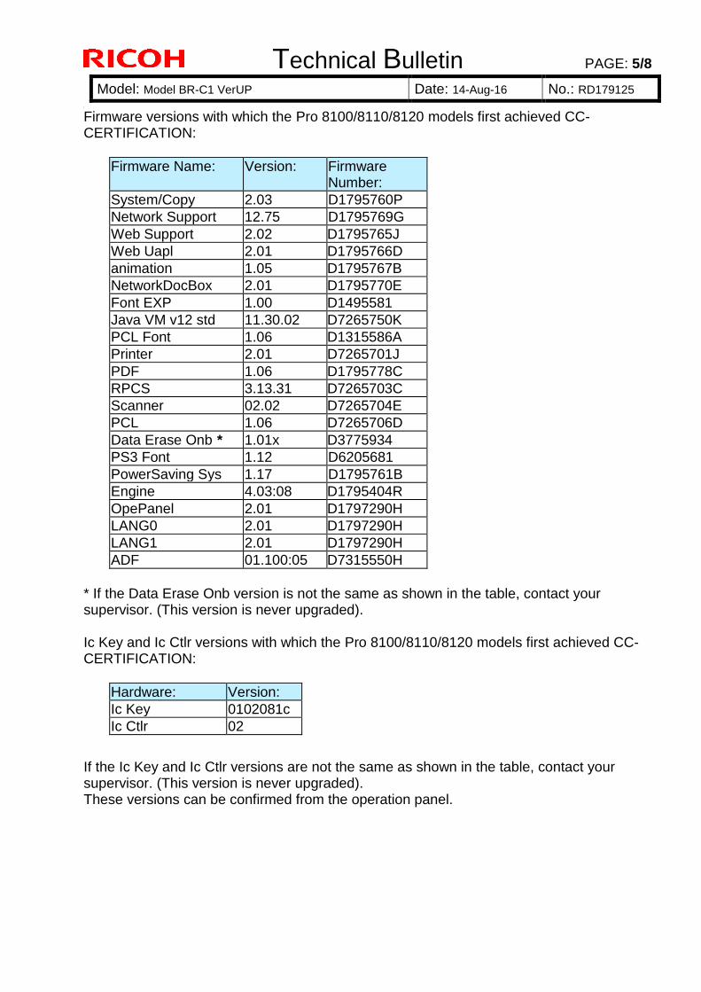
Technical Bulletin PAGE: 5/8
Model: Model BR-C1 VerUP Date: 14-Aug-16 No.: RD179125
0
Firmware versions with which the Pro 8100/8110/8120 models first achieved CC-CERTIFICATION:
Firmware Name: Version: Firmware Number:
System/Copy 2.03 D1795760P
Network Support 12.75 D1795769G
Web Support 2.02 D1795765J
Web Uapl 2.01 D1795766D
animation 1.05 D1795767B
NetworkDocBox 2.01 D1795770E
Font EXP 1.00 D1495581
Java VM v12 std 11.30.02 D7265750K
PCL Font 1.06 D1315586A
Printer 2.01 D7265701J
PDF 1.06 D1795778C
RPCS 3.13.31 D7265703C
Scanner 02.02 D7265704E
PCL 1.06 D7265706D
Data Erase Onb * 1.01x D3775934
PS3 Font 1.12 D6205681
PowerSaving Sys 1.17 D1795761B
Engine 4.03:08 D1795404R
OpePanel 2.01 D1797290H
LANG0 2.01 D1797290H
LANG1 2.01 D1797290H
ADF 01.100:05 D7315550H
* If the Data Erase Onb version is not the same as shown in the table, contact your supervisor. (This version is never upgraded). Ic Key and Ic Ctlr versions with which the Pro 8100/8110/8120 models first achieved CC-CERTIFICATION:
Hardware: Version:
Ic Key 0102081c
Ic Ctlr 02
If the Ic Key and Ic Ctlr versions are not the same as shown in the table, contact your supervisor. (This version is never upgraded). These versions can be confirmed from the operation panel.
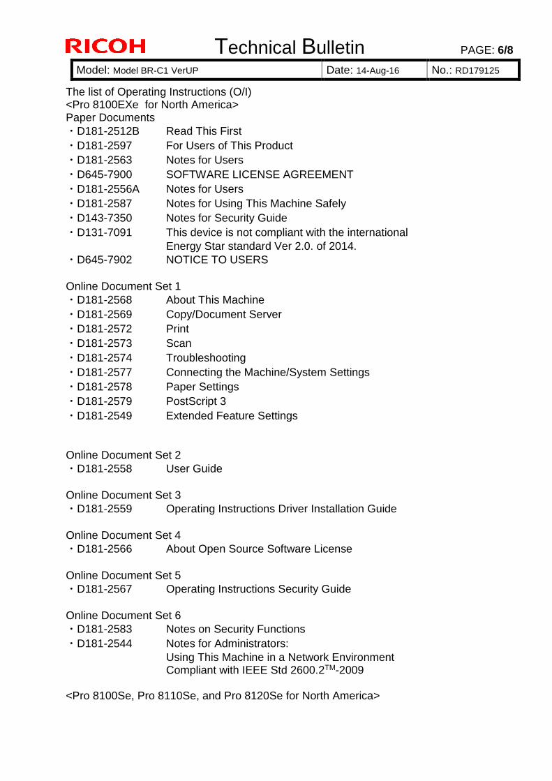
Technical Bulletin PAGE: 6/8
Model: Model BR-C1 VerUP Date: 14-Aug-16 No.: RD179125
0
The list of Operating Instructions (O/I) <Pro 8100EXe for North America> Paper Documents
・D181-2512B Read This First
・D181-2597 For Users of This Product
・D181-2563 Notes for Users
・D645-7900 SOFTWARE LICENSE AGREEMENT
・D181-2556A Notes for Users
・D181-2587 Notes for Using This Machine Safely
・D143-7350 Notes for Security Guide
・D131-7091 This device is not compliant with the international
Energy Star standard Ver 2.0. of 2014.
・D645-7902 NOTICE TO USERS
Online Document Set 1
・D181-2568 About This Machine
・D181-2569 Copy/Document Server
・D181-2572 Print
・D181-2573 Scan
・D181-2574 Troubleshooting
・D181-2577 Connecting the Machine/System Settings
・D181-2578 Paper Settings
・D181-2579 PostScript 3
・D181-2549 Extended Feature Settings
Online Document Set 2
・D181-2558 User Guide
Online Document Set 3
・D181-2559 Operating Instructions Driver Installation Guide
Online Document Set 4
・D181-2566 About Open Source Software License
Online Document Set 5
・D181-2567 Operating Instructions Security Guide
Online Document Set 6
・D181-2583 Notes on Security Functions
・D181-2544 Notes for Administrators:
Using This Machine in a Network Environment Compliant with IEEE Std 2600.2TM-2009 <Pro 8100Se, Pro 8110Se, and Pro 8120Se for North America>
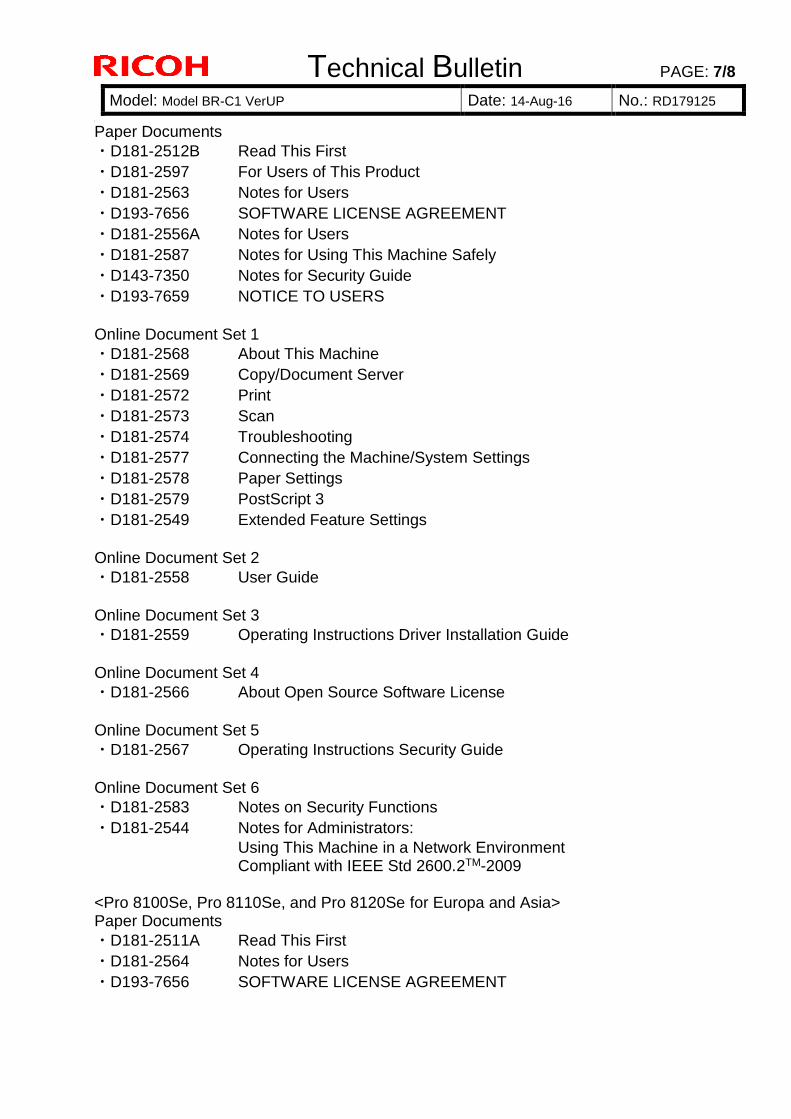
Technical Bulletin PAGE: 7/8
Model: Model BR-C1 VerUP Date: 14-Aug-16 No.: RD179125
0
Paper Documents
・D181-2512B Read This First
・D181-2597 For Users of This Product
・D181-2563 Notes for Users
・D193-7656 SOFTWARE LICENSE AGREEMENT
・D181-2556A Notes for Users
・D181-2587 Notes for Using This Machine Safely
・D143-7350 Notes for Security Guide
・D193-7659 NOTICE TO USERS
Online Document Set 1
・D181-2568 About This Machine
・D181-2569 Copy/Document Server
・D181-2572 Print
・D181-2573 Scan
・D181-2574 Troubleshooting
・D181-2577 Connecting the Machine/System Settings
・D181-2578 Paper Settings
・D181-2579 PostScript 3
・D181-2549 Extended Feature Settings
Online Document Set 2
・D181-2558 User Guide
Online Document Set 3
・D181-2559 Operating Instructions Driver Installation Guide
Online Document Set 4
・D181-2566 About Open Source Software License
Online Document Set 5
・D181-2567 Operating Instructions Security Guide
Online Document Set 6
・D181-2583 Notes on Security Functions
・D181-2544 Notes for Administrators:
Using This Machine in a Network Environment Compliant with IEEE Std 2600.2TM-2009 <Pro 8100Se, Pro 8110Se, and Pro 8120Se for Europa and Asia> Paper Documents
・D181-2511A Read This First
・D181-2564 Notes for Users
・D193-7656 SOFTWARE LICENSE AGREEMENT
Technical Bulletin PAGE: 8/8
Model: Model BR-C1 VerUP Date: 14-Aug-16 No.: RD179125
0
・D202-7097 Notes on Laser Safety Information
・D181-2556A Notes for Users
・D181-2588 Notes for Using This Machine Safely
・D181-2587 Notes for Using This Machine Safely
・D202-7094 Safety Symbols for This Machine
・D143-7350 Notes for Security Guide
・D159-7820 Notes for Security Guide
・D193-7659 NOTICE TO USERS
Online Document Set 1
・D181-2568 About This Machine
・D181-2569 Copy/Document Server
・D181-2572 Print
・D181-2573 Scan
・D181-2574 Troubleshooting
・D181-2577 Connecting the Machine/System Settings
・D181-2578 Paper Settings
・D181-2579 PostScript 3
・D181-2549 Extended Feature Settings
Online Document Set 2
・D181-2558 User Guide
Online Document Set 3
・D181-2559 Operating Instructions Driver Installation Guide
Online Document Set 4
・D181-2566 About Open Source Software License
Online Document Set 5
・D181-2567 Operating Instructions Security Guide
Online Document Set 6
・D181-2583 Notes on Security Functions
・D181-2544 Notes for Administrators:
Using This Machine in a Network Environment Compliant with IEEE Std 2600.2TM-2009
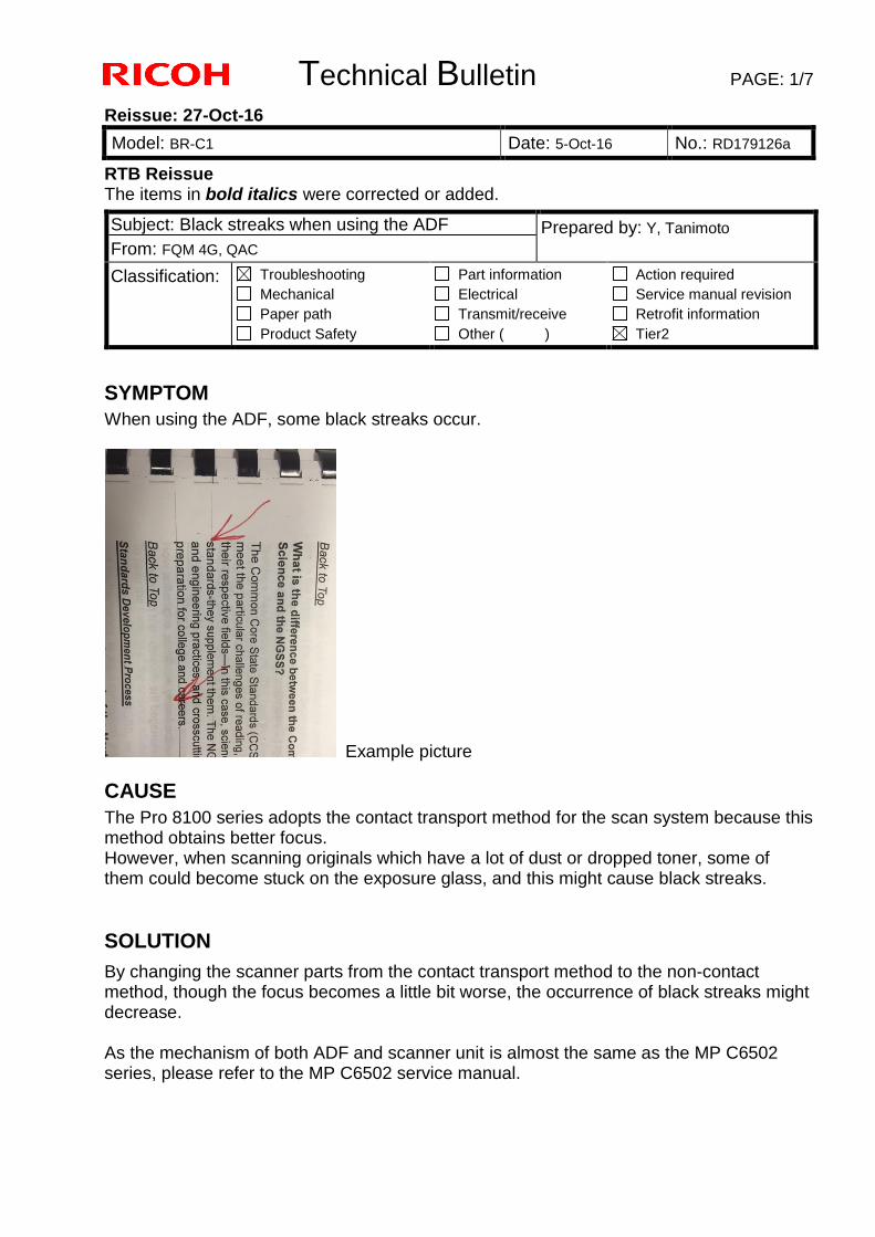
Technical Bulletin PAGE: 1/7
Reissue: 27-Oct-16
Model: BR-C1 Date: 5-Oct-16 No.: RD179126a
RTB Reissue The items in bold italics were corrected or added.
SYMPTOM
When using the ADF, some black streaks occur.
Example picture
CAUSE
The Pro 8100 series adopts the contact transport method for the scan system because this method obtains better focus. However, when scanning originals which have a lot of dust or dropped toner, some of them could become stuck on the exposure glass, and this might cause black streaks.
SOLUTION
By changing the scanner parts from the contact transport method to the non-contact method, though the focus becomes a little bit worse, the occurrence of black streaks might decrease. As the mechanism of both ADF and scanner unit is almost the same as the MP C6502 series, please refer to the MP C6502 service manual.
Subject: Black streaks when using the ADF Prepared by: Y, Tanimoto
From: FQM 4G, QAC
Classification: Troubleshooting
Mechanical
Paper path
Product Safety
Part information
Electrical
Transmit/receive
Other ( )
Action required
Service manual revision
Retrofit information
Tier2

Technical Bulletin PAGE: 2/7
Reissue: 27-Oct-16
Model: BR-C1 Date: 5-Oct-16 No.: RD179126a
Comparison table of replacement parts
Replacement Procedure Contact Type => Non-contact Type Note: This procedure starts after removing top covers around the ADF Exposure Glass How to Attach the ADF Exposure Glass/Gap Sheet
1. Clean the place to attach the exposure glass seal on the exposure glass bracket with alcohol.
2. Attach the exposure glass seal* [C] along the marking [B] on the exposure glass bracket [A].
* The tip of the seal is cut at an angle.
D6833411 D6833461
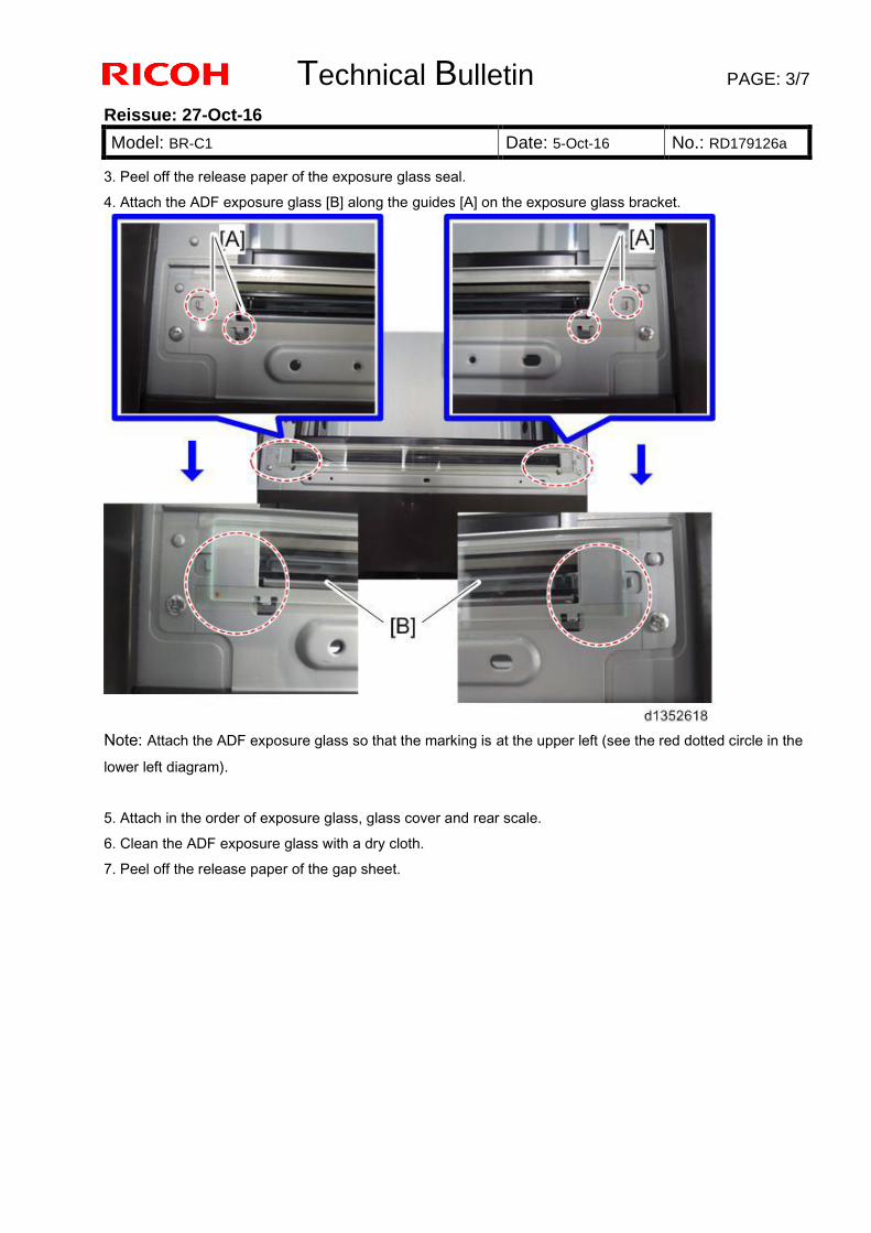
Technical Bulletin PAGE: 3/7
Reissue: 27-Oct-16
Model: BR-C1 Date: 5-Oct-16 No.: RD179126a
3. Peel off the release paper of the exposure glass seal.
4. Attach the ADF exposure glass [B] along the guides [A] on the exposure glass bracket.
Note: Attach the ADF exposure glass so that the marking is at the upper left (see the red dotted circle in the
lower left diagram).
5. Attach in the order of exposure glass, glass cover and rear scale.
6. Clean the ADF exposure glass with a dry cloth.
7. Peel off the release paper of the gap sheet.
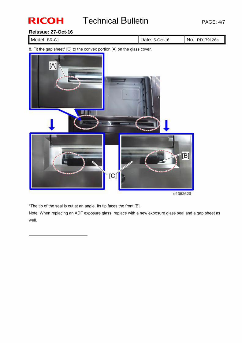
Technical Bulletin PAGE: 4/7
Reissue: 27-Oct-16
Model: BR-C1 Date: 5-Oct-16 No.: RD179126a
8. Fit the gap sheet* [C] to the convex portion [A] on the glass cover.
*The tip of the seal is cut at an angle. Its tip faces the front [B].
Note: When replacing an ADF exposure glass, replace with a new exposure glass seal and a gap sheet as
well.
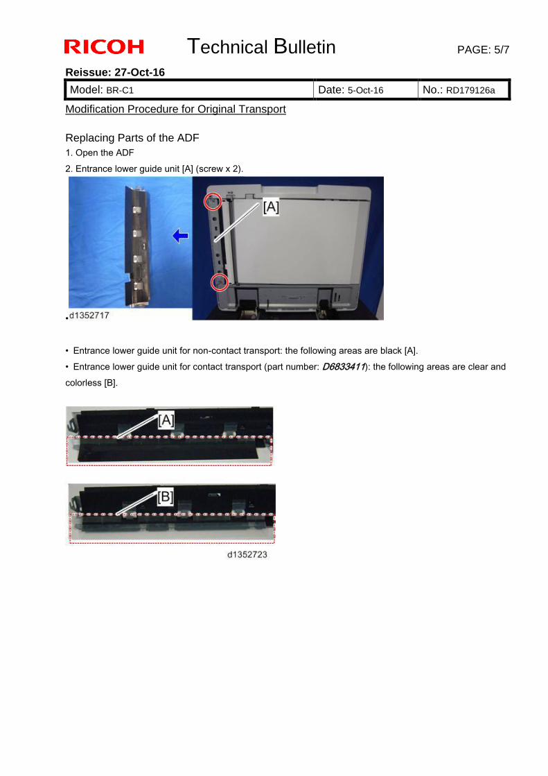
Technical Bulletin PAGE: 5/7
Reissue: 27-Oct-16
Model: BR-C1 Date: 5-Oct-16 No.: RD179126a
Modification Procedure for Original Transport
Replacing Parts of the ADF
1. Open the ADF
2. Entrance lower guide unit [A] (screw x 2).
•
• Entrance lower guide unit for non-contact transport: the following areas are black [A].
• Entrance lower guide unit for contact transport (part number: D6833411): the following areas are clear and
colorless [B].
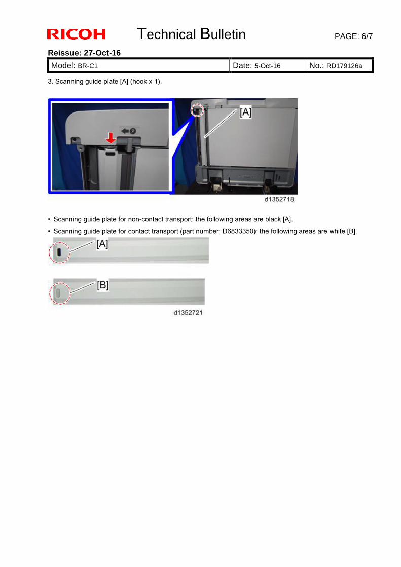
Technical Bulletin PAGE: 6/7
Reissue: 27-Oct-16
Model: BR-C1 Date: 5-Oct-16 No.: RD179126a
3. Scanning guide plate [A] (hook x 1).
• Scanning guide plate for non-contact transport: the following areas are black [A].
• Scanning guide plate for contact transport (part number: D6833350): the following areas are white [B].
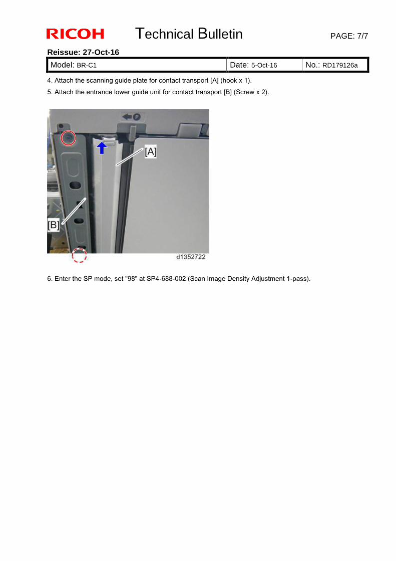
Technical Bulletin PAGE: 7/7
Reissue: 27-Oct-16
Model: BR-C1 Date: 5-Oct-16 No.: RD179126a
4. Attach the scanning guide plate for contact transport [A] (hook x 1).
5. Attach the entrance lower guide unit for contact transport [B] (Screw x 2).
6. Enter the SP mode, set "98" at SP4-688-002 (Scan Image Density Adjustment 1-pass).
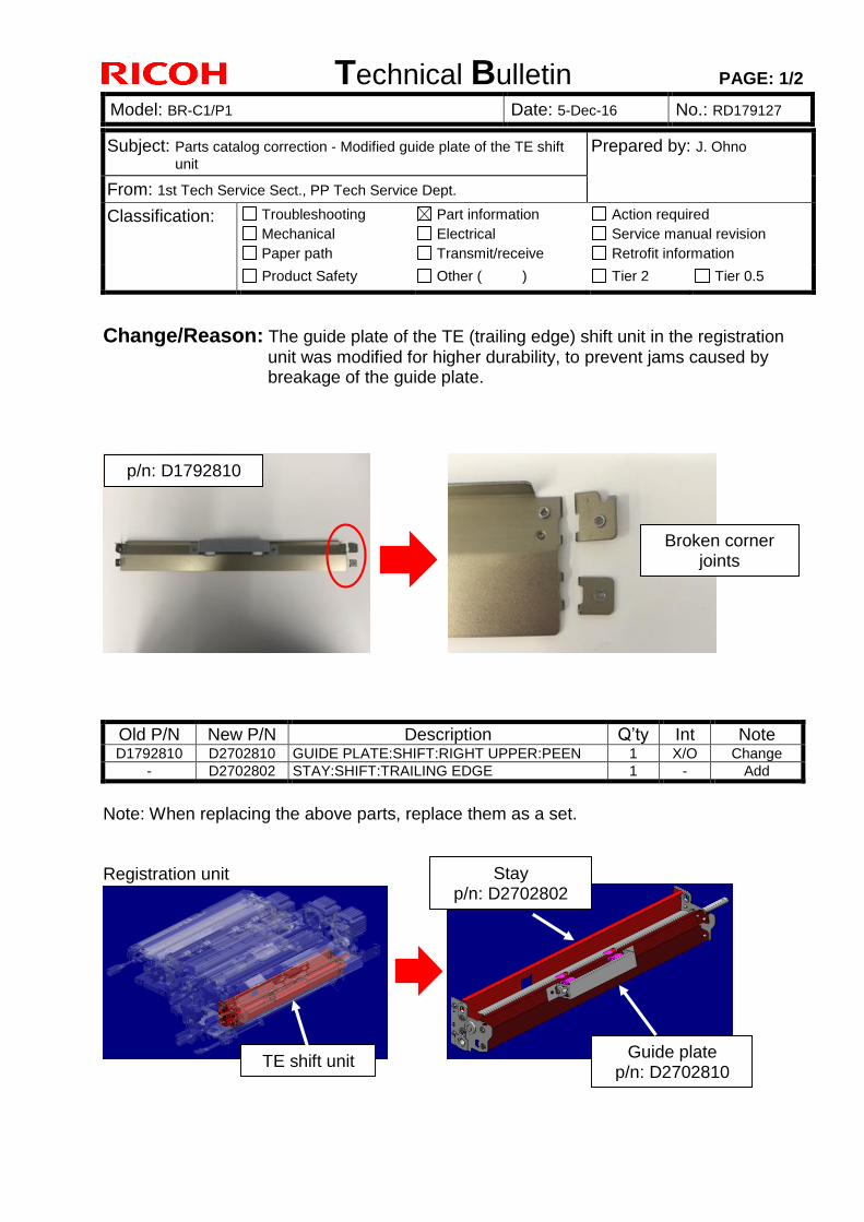
Technical Bulletin PAGE: 1/2
Model: BR-C1/P1 Date: 5-Dec-16 No.: RD179127
Subject: Parts catalog correction - Modified guide plate of the TE shift
unit Prepared by: J. Ohno
From: 1st Tech Service Sect., PP Tech Service Dept.
Classification: Troubleshooting
Mechanical
Paper path
Part information
Electrical
Transmit/receive
Action required
Service manual revision
Retrofit information
Product Safety Other ( ) Tier 2 Tier 0.5
Change/Reason: The guide plate of the TE (trailing edge) shift unit in the registration
unit was modified for higher durability, to prevent jams caused by breakage of the guide plate.
Old P/N New P/N Description Q’ty Int Note D1792810 D2702810 GUIDE PLATE:SHIFT:RIGHT UPPER:PEEN 1 X/O Change
- D2702802 STAY:SHIFT:TRAILING EDGE 1 - Add
Note: When replacing the above parts, replace them as a set. Registration unit
p/n: D1792810
Stay p/n: D2702802
Guide plate p/n: D2702810
TE shift unit
Broken corner joints
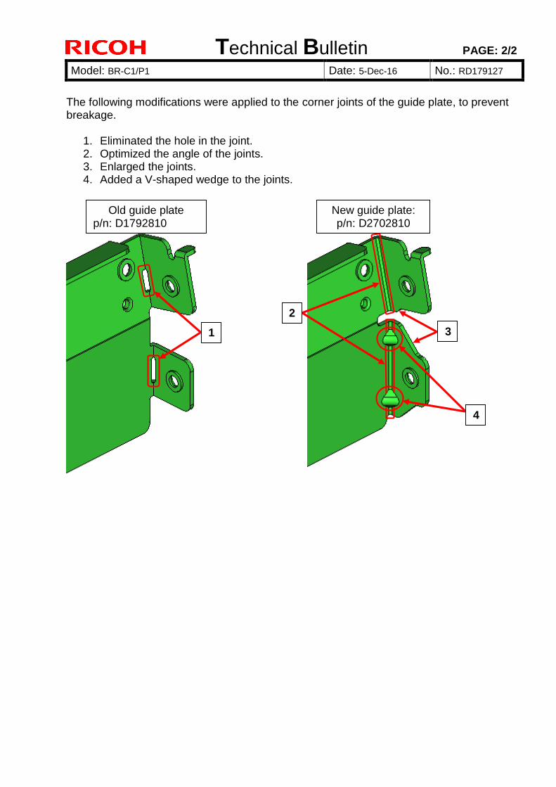
Technical Bulletin PAGE: 2/2
Model: BR-C1/P1 Date: 5-Dec-16 No.: RD179127
The following modifications were applied to the corner joints of the guide plate, to prevent breakage.
1. Eliminated the hole in the joint. 2. Optimized the angle of the joints. 3. Enlarged the joints. 4. Added a V-shaped wedge to the joints.
New guide plate: p/n: D2702810
Old guide plate p/n: D1792810
1
2
3
4
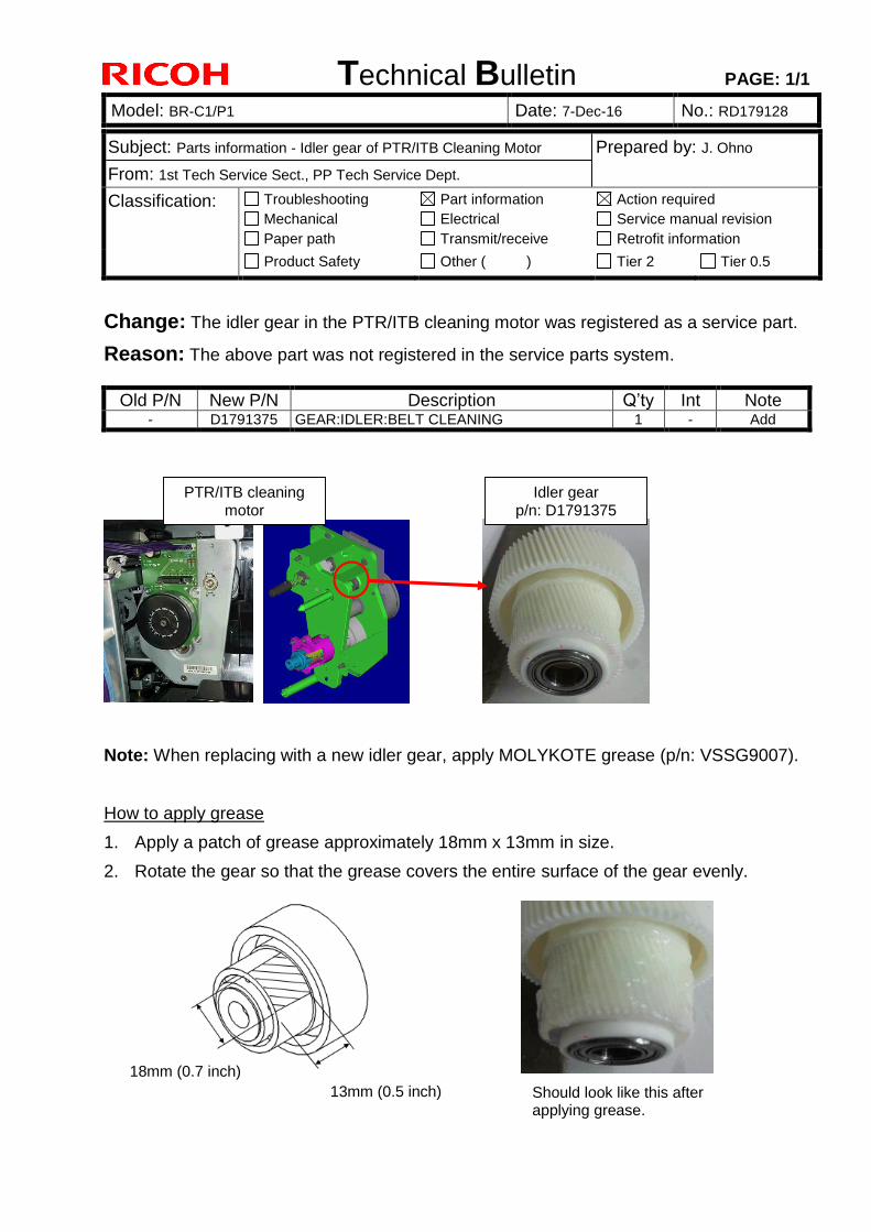
Technical Bulletin PAGE: 1/1
Model: BR-C1/P1 Date: 7-Dec-16 No.: RD179128
Subject: Parts information - Idler gear of PTR/ITB Cleaning Motor Prepared by: J. Ohno
From: 1st Tech Service Sect., PP Tech Service Dept.
Classification: Troubleshooting
Mechanical
Paper path
Part information
Electrical
Transmit/receive
Action required
Service manual revision
Retrofit information
Product Safety Other ( ) Tier 2 Tier 0.5
Change: The idler gear in the PTR/ITB cleaning motor was registered as a service part.
Reason: The above part was not registered in the service parts system.
Old P/N New P/N Description Q’ty Int Note - D1791375 GEAR:IDLER:BELT CLEANING 1 - Add
Note: When replacing with a new idler gear, apply MOLYKOTE grease (p/n: VSSG9007).
How to apply grease
1. Apply a patch of grease approximately 18mm x 13mm in size.
2. Rotate the gear so that the grease covers the entire surface of the gear evenly.
Idler gear p/n: D1791375
18mm (0.7 inch)
13mm (0.5 inch) Should look like this after applying grease.
PTR/ITB cleaning motor
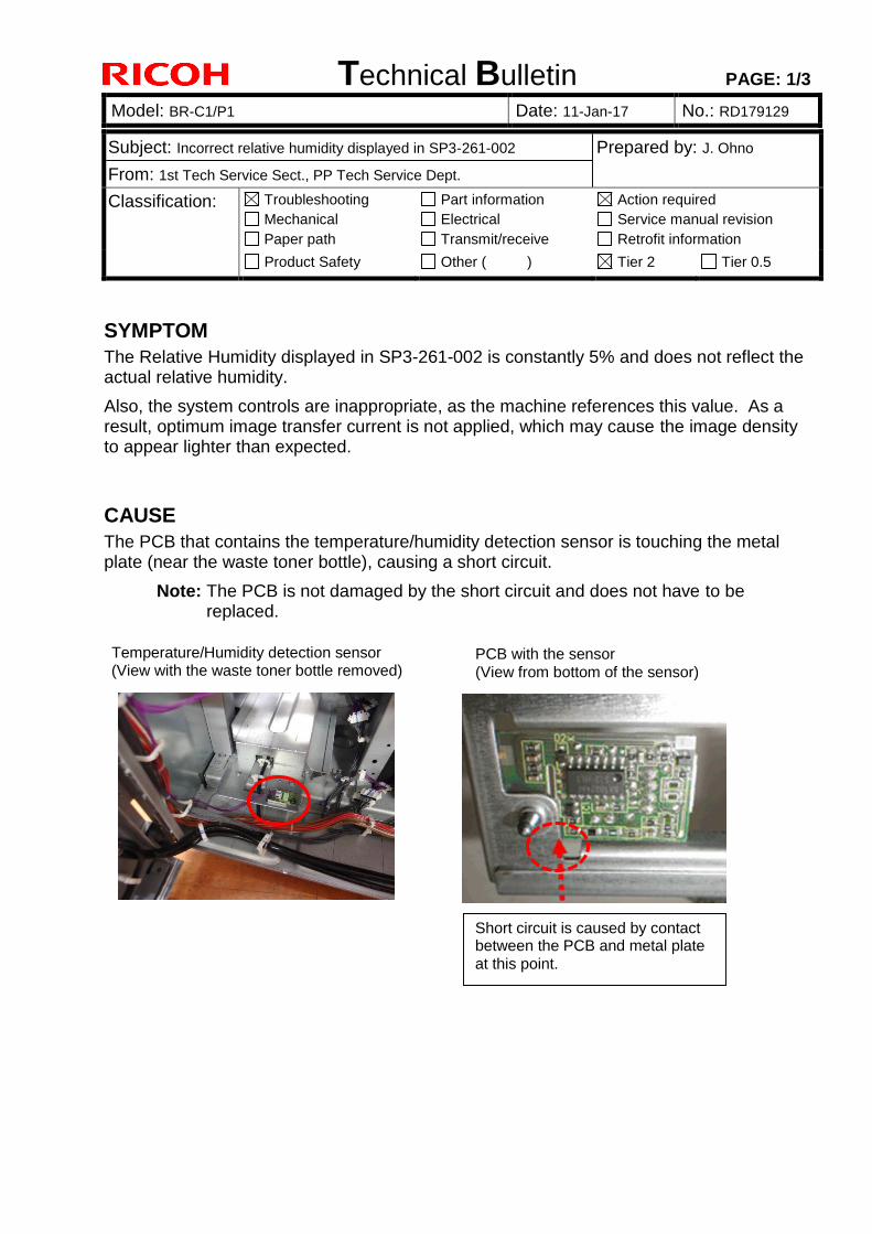
Technical Bulletin PAGE: 1/3
Model: BR-C1/P1 Date: 11-Jan-17 No.: RD179129
Subject: Incorrect relative humidity displayed in SP3-261-002 Prepared by: J. Ohno
From: 1st Tech Service Sect., PP Tech Service Dept.
Classification: Troubleshooting
Mechanical
Paper path
Part information
Electrical
Transmit/receive
Action required
Service manual revision
Retrofit information
Product Safety Other ( ) Tier 2 Tier 0.5
SYMPTOM
The Relative Humidity displayed in SP3-261-002 is constantly 5% and does not reflect the actual relative humidity.
Also, the system controls are inappropriate, as the machine references this value. As a result, optimum image transfer current is not applied, which may cause the image density to appear lighter than expected.
CAUSE
The PCB that contains the temperature/humidity detection sensor is touching the metal plate (near the waste toner bottle), causing a short circuit.
Note: The PCB is not damaged by the short circuit and does not have to be replaced.
Short circuit is caused by contact between the PCB and metal plate at this point.
Temperature/Humidity detection sensor (View with the waste toner bottle removed)
PCB with the sensor (View from bottom of the sensor)
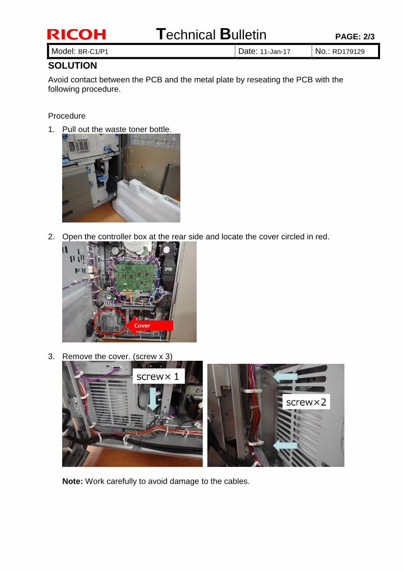
Technical Bulletin PAGE: 2/3
Model: BR-C1/P1 Date: 11-Jan-17 No.: RD179129
SOLUTION
Avoid contact between the PCB and the metal plate by reseating the PCB with the following procedure.
Procedure
1. Pull out the waste toner bottle.
2. Open the controller box at the rear side and locate the cover circled in red.
3. Remove the cover. (screw x 3)
Note: Work carefully to avoid damage to the cables.
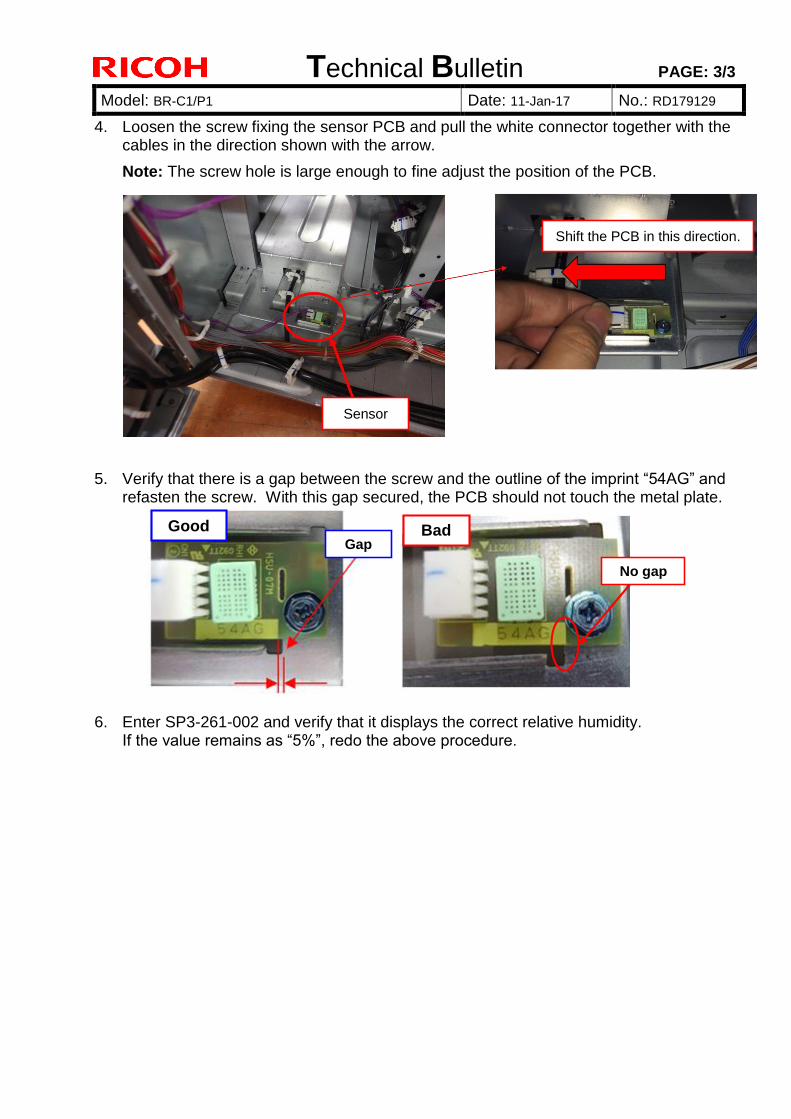
Technical Bulletin PAGE: 3/3
Model: BR-C1/P1 Date: 11-Jan-17 No.: RD179129
4. Loosen the screw fixing the sensor PCB and pull the white connector together with the cables in the direction shown with the arrow.
Note: The screw hole is large enough to fine adjust the position of the PCB.
5. Verify that there is a gap between the screw and the outline of the imprint “54AG” and refasten the screw. With this gap secured, the PCB should not touch the metal plate.
6. Enter SP3-261-002 and verify that it displays the correct relative humidity. If the value remains as “5%”, redo the above procedure.
Good Bad
Shift the PCB in this direction.
Sensor
Gap
No gap
Technical Bulletin PAGE: 1/2
Model: BR-C1/P1 Date: 25-Jan-17 No.: RD179130
Subject: Troubleshooting SC402-51 for High Coverage / Heavy Duty
Jobs Prepared by: J. Ohno
From: 1st Tech Service Sect., PP Tech Service Dept.
Classification: Troubleshooting
Mechanical
Paper path
Part information
Electrical
Transmit/receive
Action required
Service manual revision
Retrofit information
Product Safety Other ( ) Tier 2 Tier 0.5
SYMPTOM
SC402-51 (Development gamma calculation error 1: Insufficient data) tends to occur under any of the following conditions:
Average image coverage ratio is 20% or higher.
[Average coverage ratio (%)] = [SP 8921-001] / [SP 8921-011] SP 8921-001: Coverage (%) Bk SP 8921-011: Coverage /P: Bk
Average 1000 P/J jobs are run continuously, adding up to 70k pages.
[Average P/J] = [SP 8999-001] / [Sum of SP 8071-001 ~ 014] SP 8999-001: Admin. Counter List Total SP 8071-001: T:Jobs/PGS 1 Page SP 8071-002: T:Jobs/PGS 2 Page SP 8071-003: T:Jobs/PGS 3 Page SP 8071-004: T:Jobs/PGS 4 Page SP 8071-005: T:Jobs/PGS 5 Page SP 8071-006: T:Jobs/PGS 6~10 Page SP 8071-007: T:Jobs/PGS 11~20 Page SP 8071-008: T:Jobs/PGS 21~50 Page SP 8071-009: T:Jobs/PGS 51~100 Page SP 8071-010: T:Jobs/PGS 101~300 Page SP 8071-011: T:Jobs/PGS 301~500 Page SP 8071-012: T:Jobs/PGS 501~700 Page SP 8071-013: T:Jobs/PGS 701~1000 Page SP 8071-014: T:Jobs/PGS 1001~ Page
SP 7621-003 (developer counter) is 400k or higher.
Technical Bulletin PAGE: 2/2
Model: BR-C1/P1 Date: 25-Jan-17 No.: RD179130
CAUSE
The development capacity (gamma) cannot be properly calculated due to a vicious cycle:
1. Continuously printing high coverage or heavy duty jobs decreases the toner density in the development unit, which in turn increases the development gamma.
2. The development potential calculated based on the development gamma falls below the lower limit (SP 3622-061) of 200V (default).
3. To compensate for the above, the system automatically increases the toner adhesion amount.
4. However, this again decreases toner density and increases development gamma, and the cycle repeats…..
SOLUTION
Make the following SP modifications:
SP 3201-002: [TnrDensity] Lower TC 4.5 3.0 [wt%]
SP 3231-001: [Vtref Limits :Set] Upper:K 3.22 3.62 [V]
SP 3622-061: [Dev Pot :Set] LowerLimit:K 200 100 [-V]
Also, as a preventive measure for machines that run high coverage / heavy duty jobs, check the following SP values. If the values are deviating from the default values as below, do the above SP modification.
SP 3622-001: [Dev Pot :Set] Current: K 230 [-V] or lower (def: 300)
SP 3630-001: [Dev gamma :Disp/S] Current: K 1.80 [mg/cm2/-kV] or higher (def: 1.2)
Technical Bulletin PAGE: 1/1
Model: BR-C1/P1 Date: 24-May-17 No.: RD179131
Subject: FSM Revision: Added description on SC682-** Prepared by: J. Ohno
From: Sales Strategy Sect., 1st CP Business Dept.
Classification: Troubleshooting
Mechanical
Paper path
Part information
Electrical
Transmit/receive
Action required
Service manual revision
Retrofit information
Product Safety Other ( ) Tier 2 Tier 0.5
Please add the following description on SC682-** to your field service manual in section:
6. Troubleshooting SC600
SC code Level Details (Symptom, Possible cause, Troubleshooting procedure)
SC682-01 D PCU: ID chip communication error (Invalid Device ID)
SC682-06 PCU: ID chip communication error (Channel error)
SC682-11 PCU: ID chip communication error (Device error)
SC682-16 PCU: ID chip communication error (Communication aborted)
SC682-21 PCU: ID chip communication error (Timeout error)
SC682-26 PCU: ID chip communication error (Device shut-down)
SC682-31 PCU: ID chip communication error (Buffer full)
SC682-36 PCU: ID chip communication error (No error code)
Description:
I2C (Inter-Integrated Circuit) communication between the BCU and TD sensor is not established. If rebooting the system does not resolve the SC, check for the following parts and connection.
Possible causes:
* PCU poorly set * TD sensor defective * Poor harness connection between the BCU and TD sensor * BCU defective * IOB defective
Solution:
* Confirm PCU is set properly. * Replace the development unit. * Correct the harness connection between the BCU and TD sensor. * Replace the BCU. * Replace the IOB.
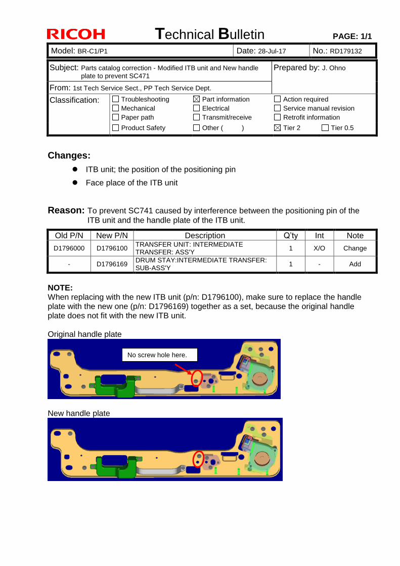
Technical Bulletin PAGE: 1/1
Model: BR-C1/P1 Date: 28-Jul-17 No.: RD179132
Subject: Parts catalog correction - Modified ITB unit and New handle
plate to prevent SC471 Prepared by: J. Ohno
From: 1st Tech Service Sect., PP Tech Service Dept.
Classification: Troubleshooting
Mechanical
Paper path
Part information
Electrical
Transmit/receive
Action required
Service manual revision
Retrofit information
Product Safety Other ( ) Tier 2 Tier 0.5
Changes:
ITB unit; the position of the positioning pin
Face place of the ITB unit
Reason: To prevent SC741 caused by interference between the positioning pin of the
ITB unit and the handle plate of the ITB unit.
Old P/N New P/N Description Q’ty Int Note
D1796000 D1796100 TRANSFER UNIT: INTERMEDIATE TRANSFER: ASS'Y
1 X/O Change
- D1796169 DRUM STAY:INTERMEDIATE TRANSFER: SUB-ASS'Y
1 - Add
NOTE: When replacing with the new ITB unit (p/n: D1796100), make sure to replace the handle plate with the new one (p/n: D1796169) together as a set, because the original handle plate does not fit with the new ITB unit. Original handle plate
New handle plate
No screw hole here.
Technical Bulletin PAGE: 1/6
Model: BR-C1/P1 Date: 25-Aug-17 No.: RD179133
SYMPTOM
Jammed sheets are being processed in a state where they are difficult to handle, and it may be not possible to handle the jammed sheets well, since the withdrawing state of the drawer unit remains bad.
CAUSE
There is a mechanism to lock out the drawer unit at two places, but work is being done at the wrong withdrawal position because we do not explain how to use each locked position.
SOLUTION
1. Add three decals to indicate the unlocking operation of drawer unit 2. Apply the modified firmware to show both jam location and jam removal animation
simultaneously on the operation panel display NOTE: This modification is not mandatory in the field. However, implementation is strongly recommended on the next visit to the customers who do not have dedicated operators, such as schools and school district offices. Part number of Decals For NA
Part number Description Q’ty
D2709902 DECAL:JAM:NA 1
(D2701191) PICK-UP PAPER JAM:OPERATION PANEL:ENGLISH
(1)
(D2701193) DECAL:PULL OUT:LEFT AND RIGHT:ENGLISH (1)
For EU and China
Part number Description Q’ty
D2709903 DECAL:JAM:EU 1
(D2701191) PICK-UP PAPER JAM:OPERATION PANEL:ENGLISH
(1)
(D2701193) DECAL:PULL OUT:LEFT AND RIGHT:ENGLISH (1)
(D2701195) DECAL:PICK-UP PAPER JAM:OPERATION PANEL:MANY LANGUAGES
(1)
(D2701196) DECAL:PULL OUT:LEFT AND RIGHT:MANY LANGUAGES
(1)
Subject: Addition of jam paper removal procedure decal
Prepared by: Y. Tanimoto
From: QAC PPCSG
Classification: Troubleshooting
Mechanical
Paper path
Product Safety
Part information
Electrical
Transmit/receive
Other ( )
Action required
Service manual revision
Retrofit information
Tier2
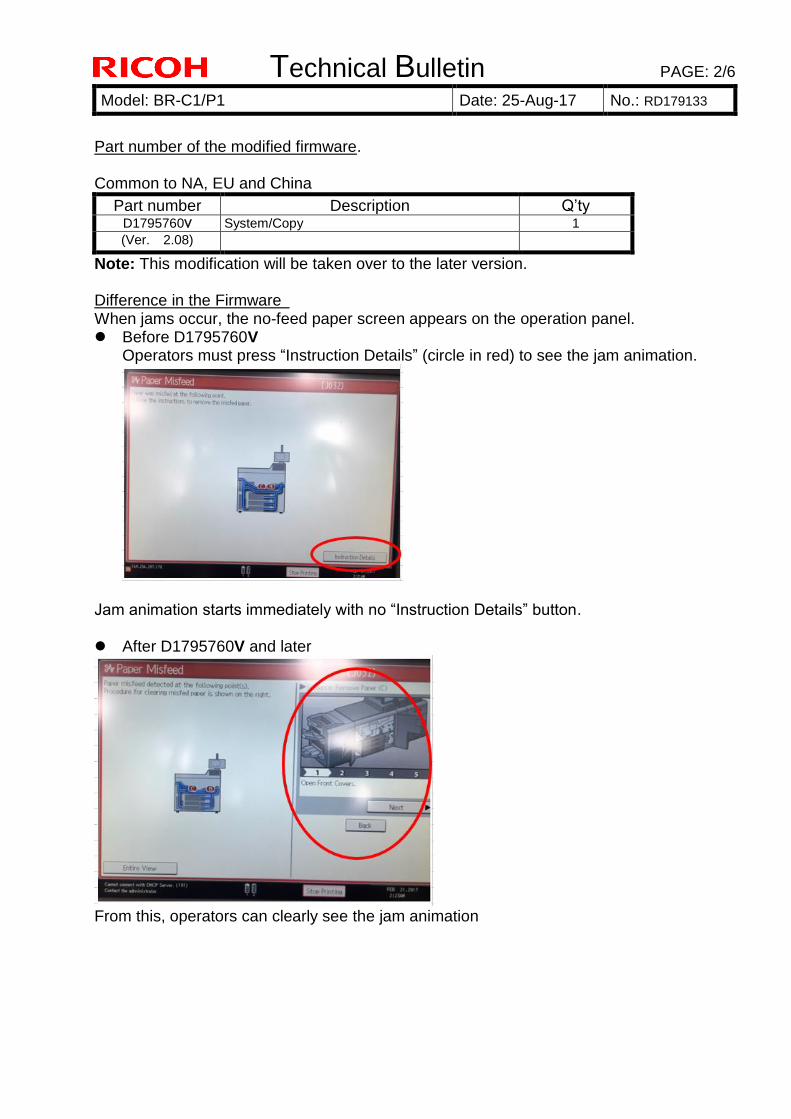
Technical Bulletin PAGE: 2/6
Model: BR-C1/P1 Date: 25-Aug-17 No.: RD179133
Part number of the modified firmware. Common to NA, EU and China
Part number Description Q’ty D1795760V System/Copy 1
(Ver. 2.08)
Note: This modification will be taken over to the later version. Difference in the Firmware When jams occur, the no-feed paper screen appears on the operation panel. Before D1795760V
Operators must press “Instruction Details” (circle in red) to see the jam animation.
Jam animation starts immediately with no “Instruction Details” button.
After D1795760V and later
From this, operators can clearly see the jam animation
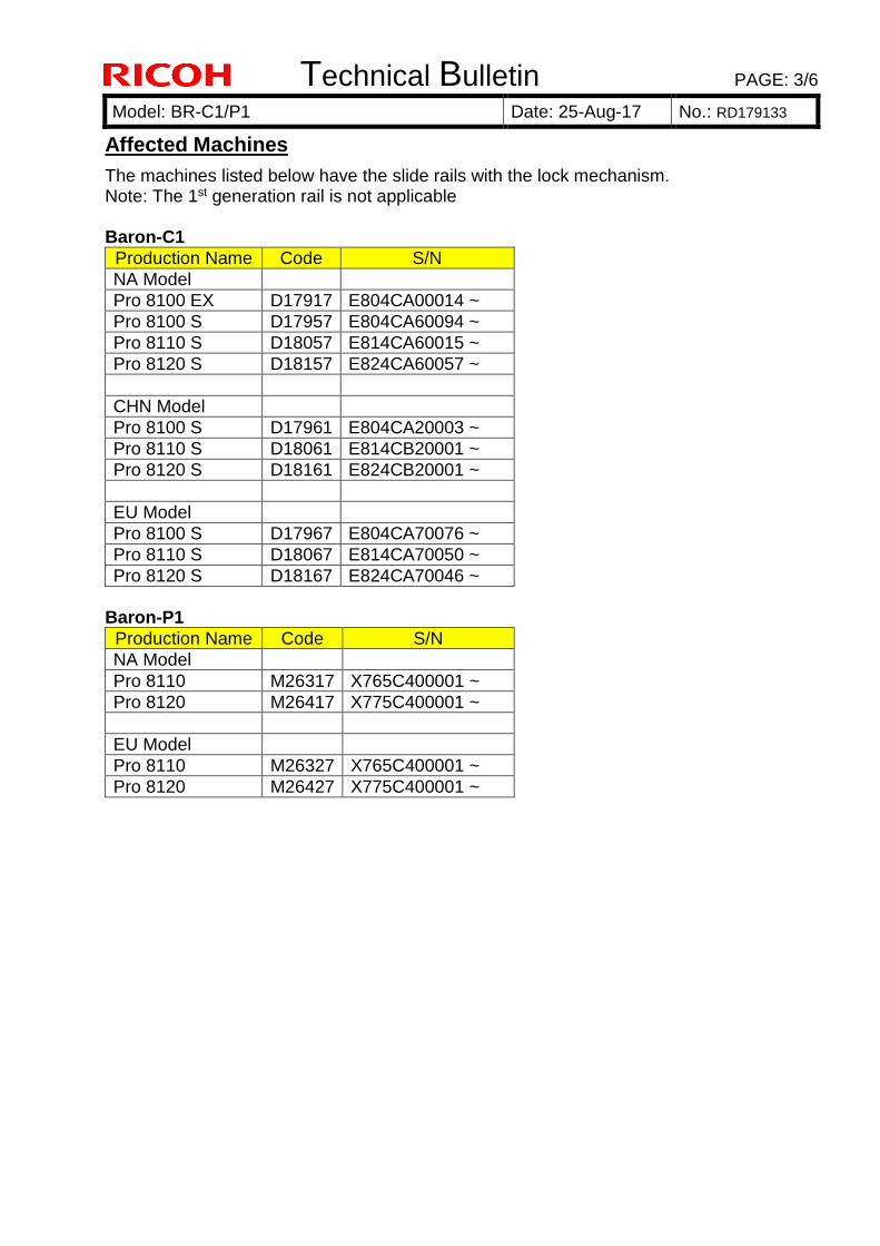
Technical Bulletin PAGE: 3/6
Model: BR-C1/P1 Date: 25-Aug-17 No.: RD179133
Affected Machines
The machines listed below have the slide rails with the lock mechanism. Note: The 1st generation rail is not applicable Baron-C1
Production Name Code S/N
NA Model
Pro 8100 EX D17917 E804CA00014 ~
Pro 8100 S D17957 E804CA60094 ~
Pro 8110 S D18057 E814CA60015 ~
Pro 8120 S D18157 E824CA60057 ~
CHN Model
Pro 8100 S D17961 E804CA20003 ~
Pro 8110 S D18061 E814CB20001 ~
Pro 8120 S D18161 E824CB20001 ~
EU Model
Pro 8100 S D17967 E804CA70076 ~
Pro 8110 S D18067 E814CA70050 ~
Pro 8120 S D18167 E824CA70046 ~
Baron-P1
Production Name Code S/N
NA Model
Pro 8110 M26317 X765C400001 ~
Pro 8120 M26417 X775C400001 ~
EU Model
Pro 8110 M26327 X765C400001 ~
Pro 8120 M26427 X775C400001 ~
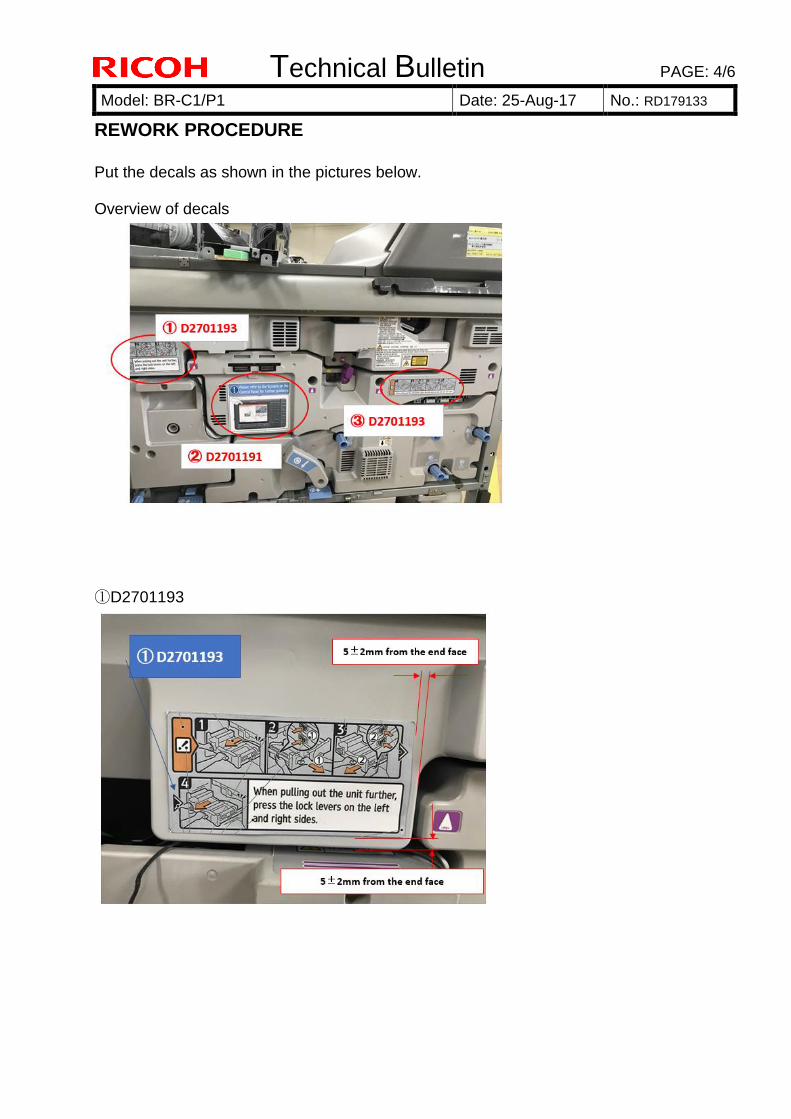
Technical Bulletin PAGE: 4/6
Model: BR-C1/P1 Date: 25-Aug-17 No.: RD179133
REWORK PROCEDURE
Put the decals as shown in the pictures below. Overview of decals
①D2701193
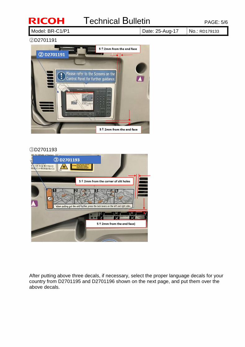
Technical Bulletin PAGE: 5/6
Model: BR-C1/P1 Date: 25-Aug-17 No.: RD179133
②D2701191
③D2701193
After putting above three decals, if necessary, select the proper language decals for your country from D2701195 and D2701196 shown on the next page, and put them over the above decals.

Technical Bulletin PAGE: 6/6
Model: BR-C1/P1 Date: 25-Aug-17 No.: RD179133
D2701195
D2701196
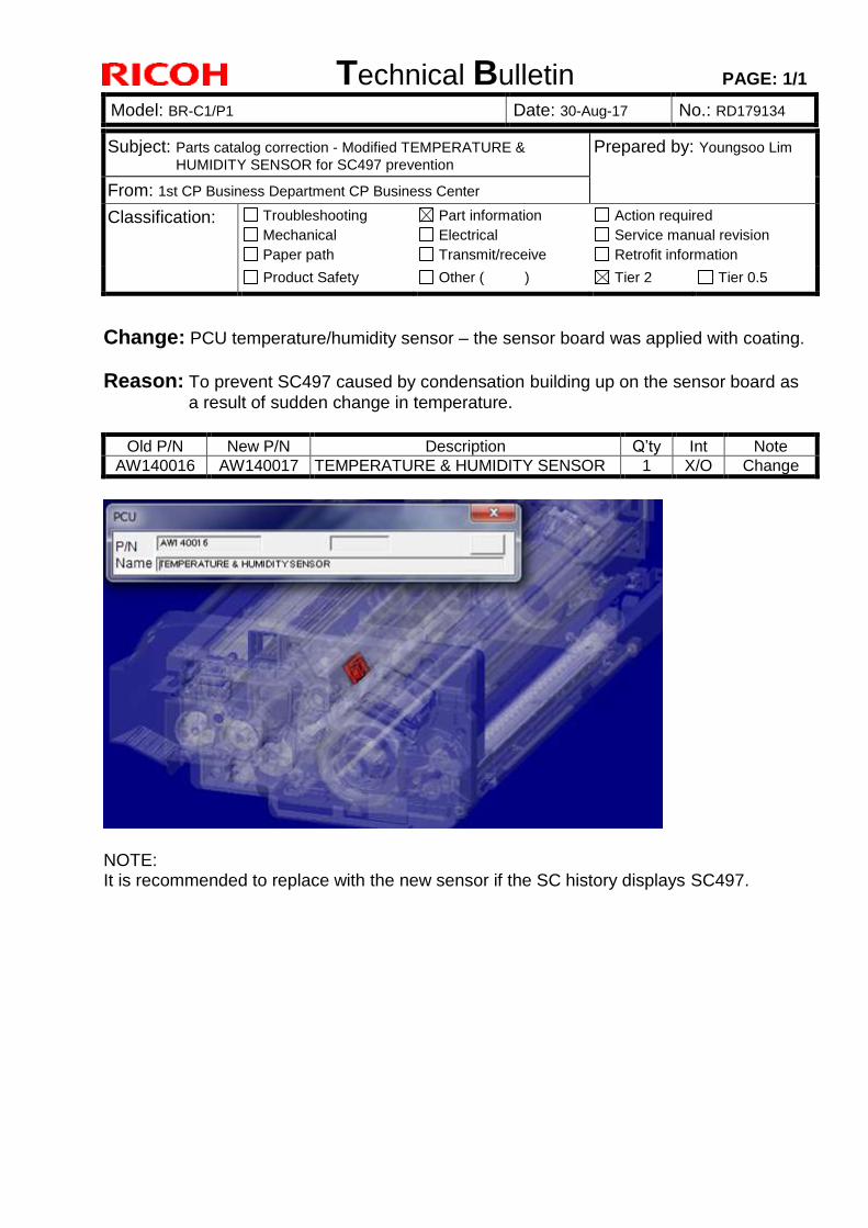
Technical Bulletin PAGE: 1/1
Model: BR-C1/P1 Date: 30-Aug-17 No.: RD179134
Subject: Parts catalog correction - Modified TEMPERATURE &
HUMIDITY SENSOR for SC497 prevention Prepared by: Youngsoo Lim
From: 1st CP Business Department CP Business Center
Classification: Troubleshooting
Mechanical
Paper path
Part information
Electrical
Transmit/receive
Action required
Service manual revision
Retrofit information
Product Safety Other ( ) Tier 2 Tier 0.5
Change: PCU temperature/humidity sensor – the sensor board was applied with coating.
Reason: To prevent SC497 caused by condensation building up on the sensor board as
a result of sudden change in temperature.
Old P/N New P/N Description Q’ty Int Note
AW140016 AW140017 TEMPERATURE & HUMIDITY SENSOR 1 X/O Change
NOTE: It is recommended to replace with the new sensor if the SC history displays SC497.
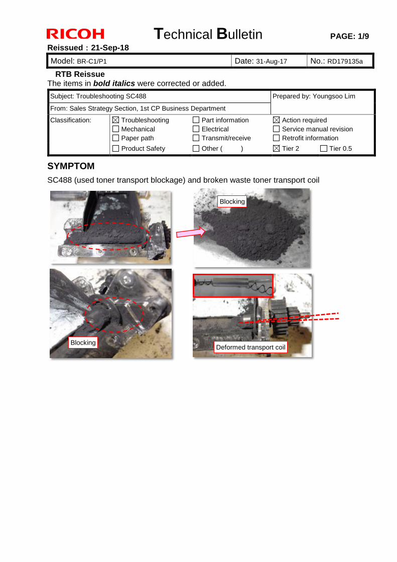
Technical Bulletin PAGE: 1/9
Reissued:21-Sep-18
Model: BR-C1/P1 Date: 31-Aug-17 No.: RD179135a
RTB Reissue The items in bold italics were corrected or added.
SYMPTOM
SC488 (used toner transport blockage) and broken waste toner transport coil
Subject: Troubleshooting SC488 Prepared by: Youngsoo Lim
From: Sales Strategy Section, 1st CP Business Department
Classification: Troubleshooting Mechanical Paper path
Part information Electrical Transmit/receive
Action required Service manual revision Retrofit information
Product Safety Other ( ) Tier 2 Tier 0.5
Blocking
Blocking Deformed coil
Deformed transport coil
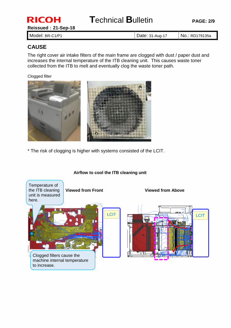
Technical Bulletin PAGE: 2/9
Reissued:21-Sep-18
Model: BR-C1/P1 Date: 31-Aug-17 No.: RD179135a
CAUSE
The right cover air intake filters of the main frame are clogged with dust / paper dust and increases the internal temperature of the ITB cleaning unit. This causes waste toner collected from the ITB to melt and eventually clog the waste toner path. Clogged filter
* The risk of clogging is higher with systems consisted of the LCIT.
Temperature of the ITB cleaning unit is measured here.
Clogged filters cause the machine internal temperature to increase.
LCIT
Viewed from Front
LCIT
Viewed from Above
Airflow to cool the ITB cleaning unit
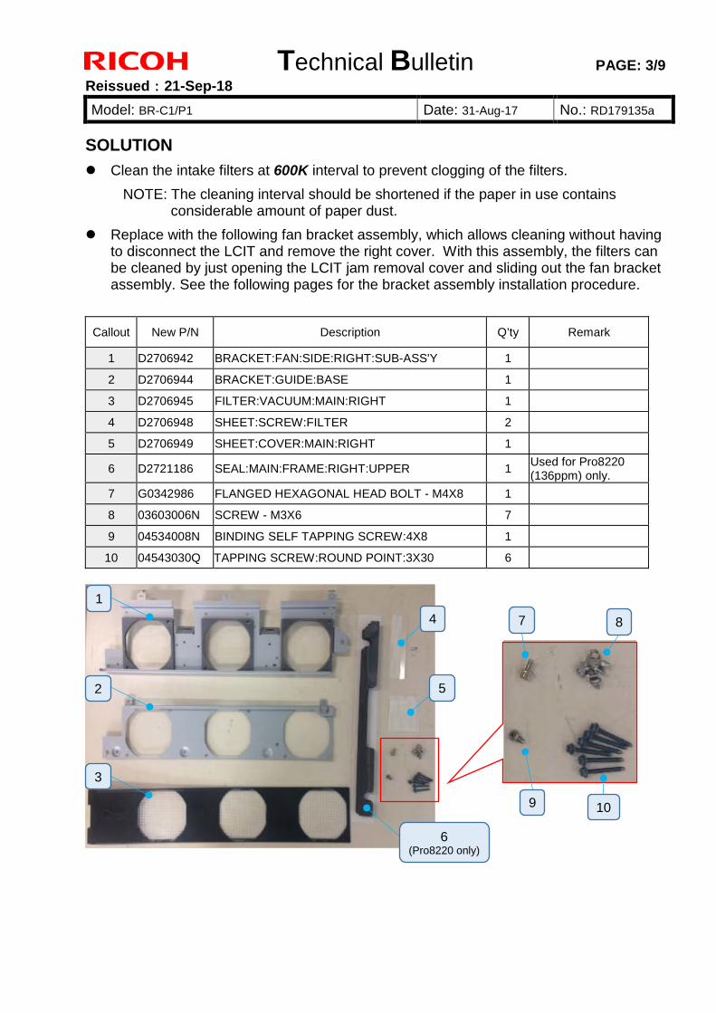
Technical Bulletin PAGE: 3/9
Reissued:21-Sep-18
Model: BR-C1/P1 Date: 31-Aug-17 No.: RD179135a
SOLUTION
Clean the intake filters at 600K interval to prevent clogging of the filters.
NOTE: The cleaning interval should be shortened if the paper in use contains considerable amount of paper dust.
Replace with the following fan bracket assembly, which allows cleaning without having to disconnect the LCIT and remove the right cover. With this assembly, the filters can be cleaned by just opening the LCIT jam removal cover and sliding out the fan bracket assembly. See the following pages for the bracket assembly installation procedure.
Callout New P/N Description Q’ty Remark
1 D2706942 BRACKET:FAN:SIDE:RIGHT:SUB-ASS'Y 1
2 D2706944 BRACKET:GUIDE:BASE 1
3 D2706945 FILTER:VACUUM:MAIN:RIGHT 1
4 D2706948 SHEET:SCREW:FILTER 2
5 D2706949 SHEET:COVER:MAIN:RIGHT 1
6 D2721186 SEAL:MAIN:FRAME:RIGHT:UPPER 1 Used for Pro8220 (136ppm) only.
7 G0342986 FLANGED HEXAGONAL HEAD BOLT - M4X8 1
8 03603006N SCREW - M3X6 7
9 04534008N BINDING SELF TAPPING SCREW:4X8 1
10 04543030Q TAPPING SCREW:ROUND POINT:3X30 6
1
2
3
4
5
6 (Pro8220 only)
7
9
8
10
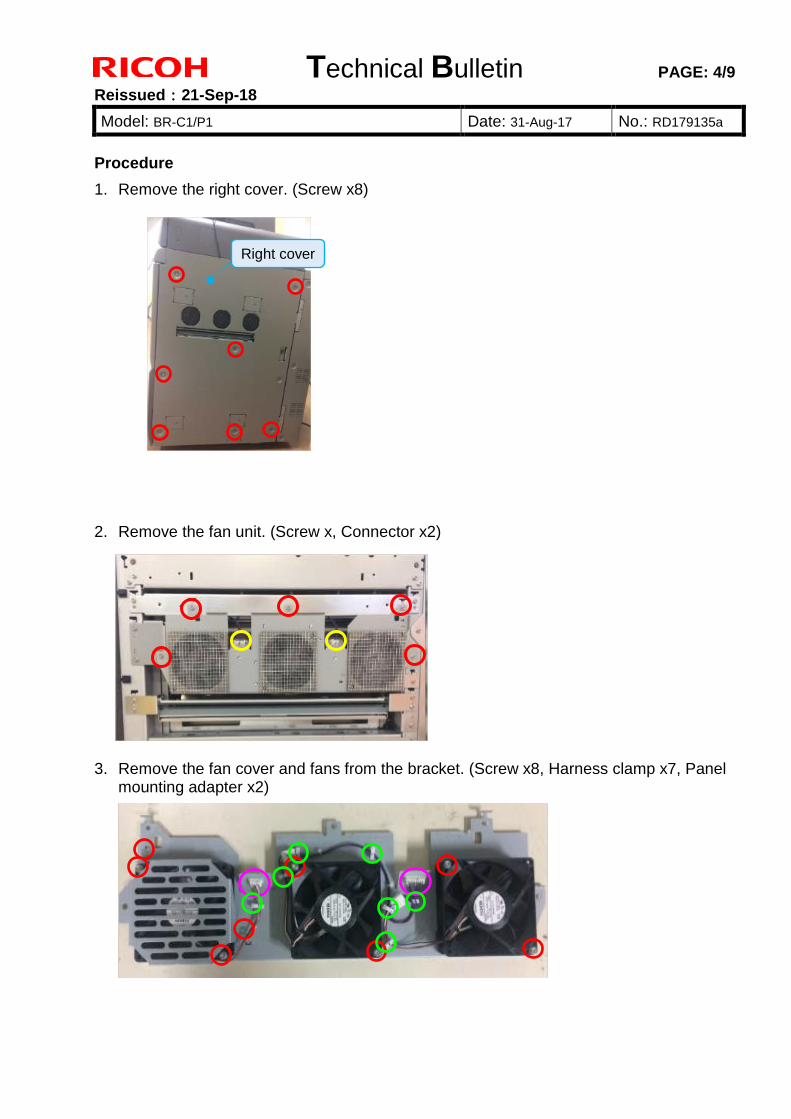
Technical Bulletin PAGE: 4/9
Reissued:21-Sep-18
Model: BR-C1/P1 Date: 31-Aug-17 No.: RD179135a
Procedure
1. Remove the right cover. (Screw x8)
2. Remove the fan unit. (Screw x, Connector x2)
3. Remove the fan cover and fans from the bracket. (Screw x8, Harness clamp x7, Panel mounting adapter x2)
Right cover
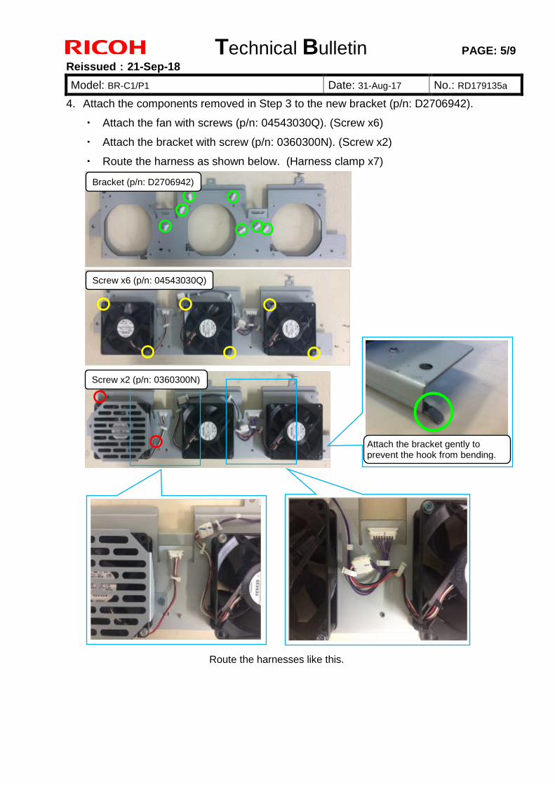
Technical Bulletin PAGE: 5/9
Reissued:21-Sep-18
Model: BR-C1/P1 Date: 31-Aug-17 No.: RD179135a
4. Attach the components removed in Step 3 to the new bracket (p/n: D2706942).
・ Attach the fan with screws (p/n: 04543030Q). (Screw x6)
・ Attach the bracket with screw (p/n: 0360300N). (Screw x2)
・ Route the harness as shown below. (Harness clamp x7)
Bracket (p/n: D2706942)
Screw x6 (p/n: 04543030Q)
Screw x2 (p/n: 0360300N)
Attach the bracket gently to prevent the hook from bending.
Route the harnesses like this.
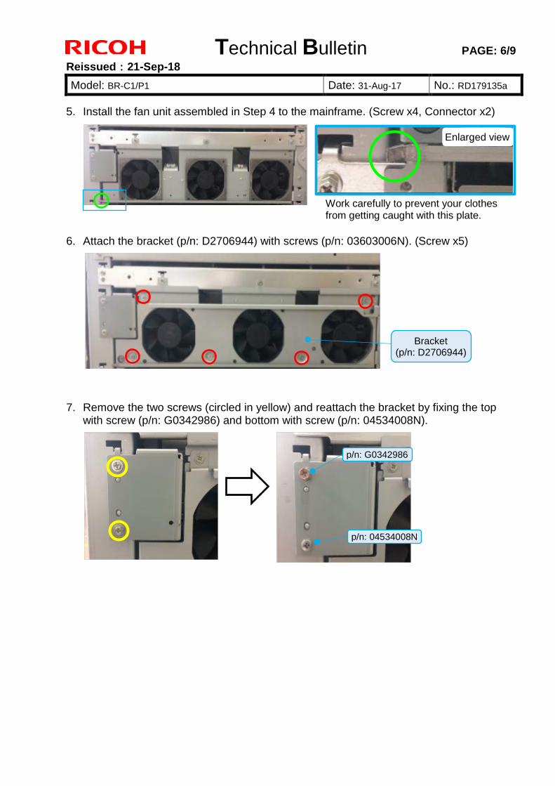
Technical Bulletin PAGE: 6/9
Reissued:21-Sep-18
Model: BR-C1/P1 Date: 31-Aug-17 No.: RD179135a
5. Install the fan unit assembled in Step 4 to the mainframe. (Screw x4, Connector x2)
6. Attach the bracket (p/n: D2706944) with screws (p/n: 03603006N). (Screw x5)
7. Remove the two screws (circled in yellow) and reattach the bracket by fixing the top with screw (p/n: G0342986) and bottom with screw (p/n: 04534008N).
Enlarged view
Work carefully to prevent your clothes from getting caught with this plate.
Bracket (p/n: D2706944)
p/n: G0342986
p/n: 04534008N
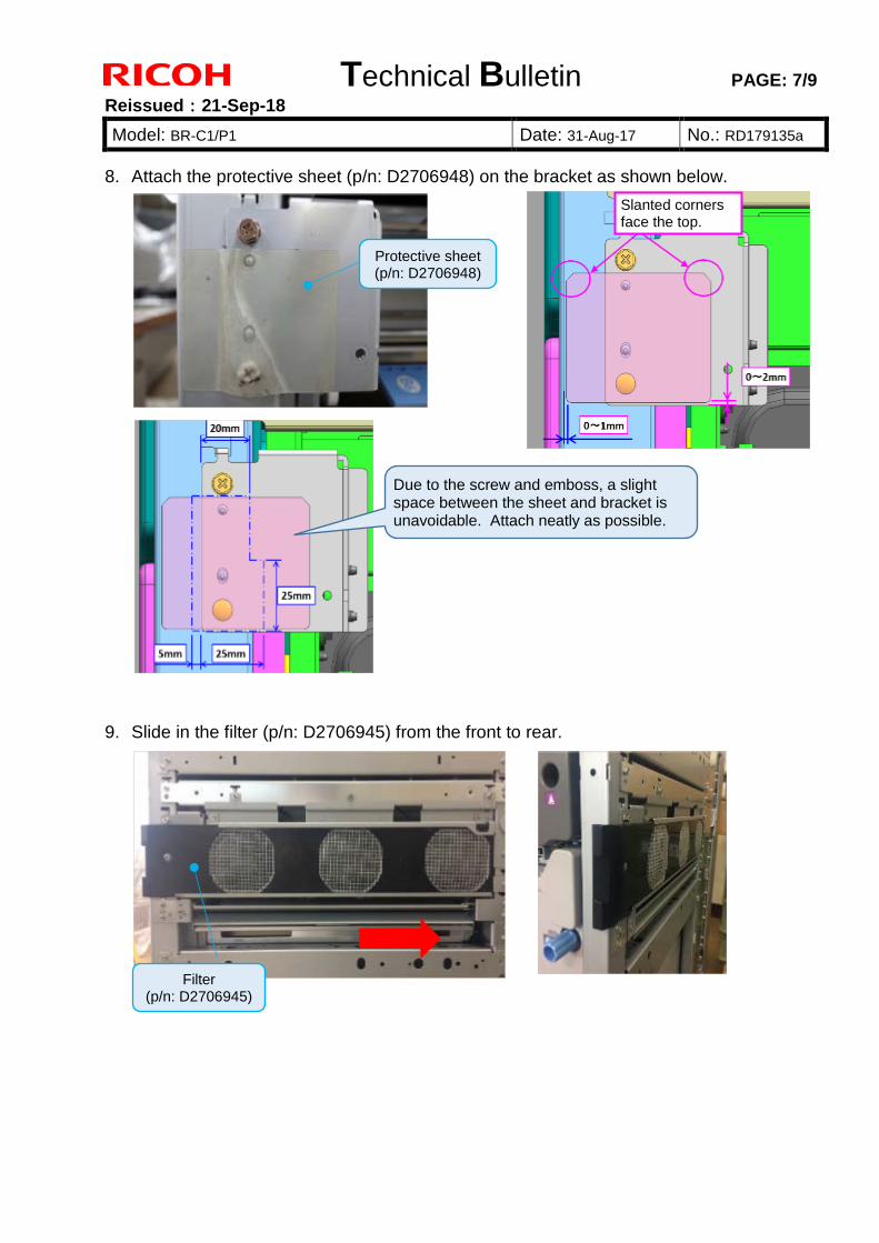
Technical Bulletin PAGE: 7/9
Reissued:21-Sep-18
Model: BR-C1/P1 Date: 31-Aug-17 No.: RD179135a
8. Attach the protective sheet (p/n: D2706948) on the bracket as shown below.
9. Slide in the filter (p/n: D2706945) from the front to rear.
Protective sheet (p/n: D2706948)
Slanted corners face the top.
Due to the screw and emboss, a slight space between the sheet and bracket is unavoidable. Attach neatly as possible.
Filter (p/n: D2706945)
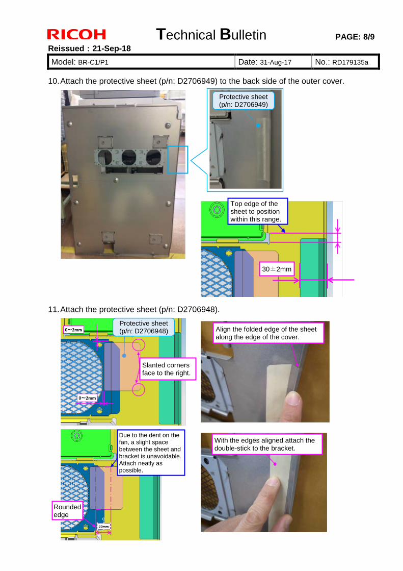
Technical Bulletin PAGE: 8/9
Reissued:21-Sep-18
Model: BR-C1/P1 Date: 31-Aug-17 No.: RD179135a
10. Attach the protective sheet (p/n: D2706949) to the back side of the outer cover.
11. Attach the protective sheet (p/n: D2706948).
Protective sheet (p/n: D2706949)
Top edge of the sheet to position within this range.
30±2mm
Align the folded edge of the sheet along the edge of the cover.
With the edges aligned attach the double-stick to the bracket.
Slanted corners face to the right.
Protective sheet (p/n: D2706948)
Rounded edge
Due to the dent on the fan, a slight space between the sheet and bracket is unavoidable. Attach neatly as possible.
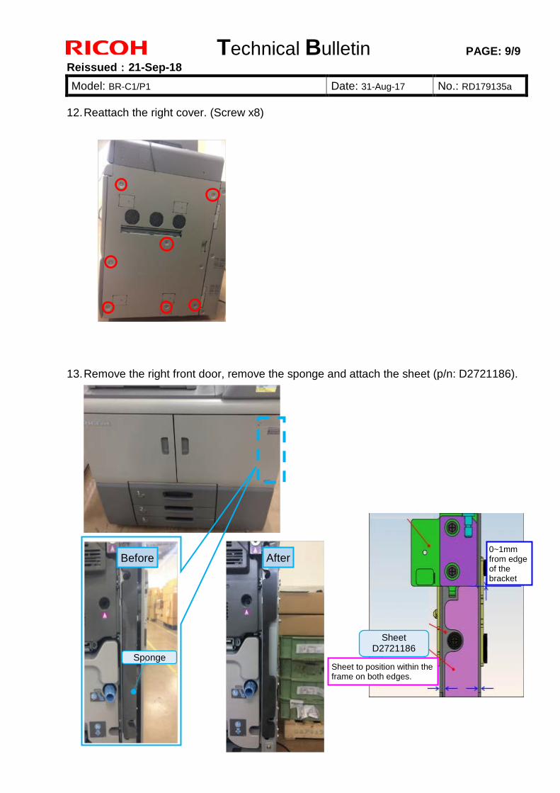
Technical Bulletin PAGE: 9/9
Reissued:21-Sep-18
Model: BR-C1/P1 Date: 31-Aug-17 No.: RD179135a
12. Reattach the right cover. (Screw x8)
13. Remove the right front door, remove the sponge and attach the sheet (p/n: D2721186).
After
Sponge
Before
Sheet D2721186
Sheet to position within the frame on both edges.
0~1mm from edge of the bracket
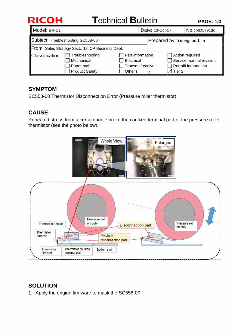
Technical Bulletin PAGE: 1/3
Model: BR-C1 Date: 10-Oct-17 No.: RD179136
Subject: Troubleshooting SC558-00 Prepared by: Youngsoo Lim
From: Sales Strategy Sect., 1st CP Business Dept.
Classification: Troubleshooting
Mechanical
Paper path
Product Safety
Part information
Electrical
Transmit/receive
Other ( )
Action required
Service manual revision
Retrofit information
Tier 2
SYMPTOM
SC558-00 Thermistor Disconnection Error (Pressure roller thermistor)
CAUSE
Repeated stress from a certain angle broke the caulked terminal part of the pressure roller thermistor (see the photo below).
SOLUTION
1. Apply the engine firmware to mask the SC558-00.
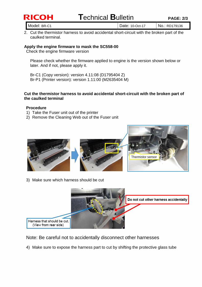
Technical Bulletin PAGE: 2/3
Model: BR-C1 Date: 10-Oct-17 No.: RD179136
2. Cut the thermistor harness to avoid accidental short-circuit with the broken part of the caulked terminal.
Apply the engine firmware to mask the SC558-00 Check the engine firmware version
Please check whether the firmware applied to engine is the version shown below or later. And if not, please apply it. Br-C1 (Copy version): version 4.11:08 (D1795404 Z) Br-P1 (Printer version): version 1.11:00 (M2635404 M)
Cut the thermistor harness to avoid accidental short-circuit with the broken part of the caulked terminal Procedure 1) Take the Fuser unit out of the printer 2) Remove the Cleaning Web out of the Fuser unit
3) Make sure which harness should be cut
Note: Be careful not to accidentally disconnect other harnesses 4) Make sure to expose the harness part to cut by shifting the protective glass tube
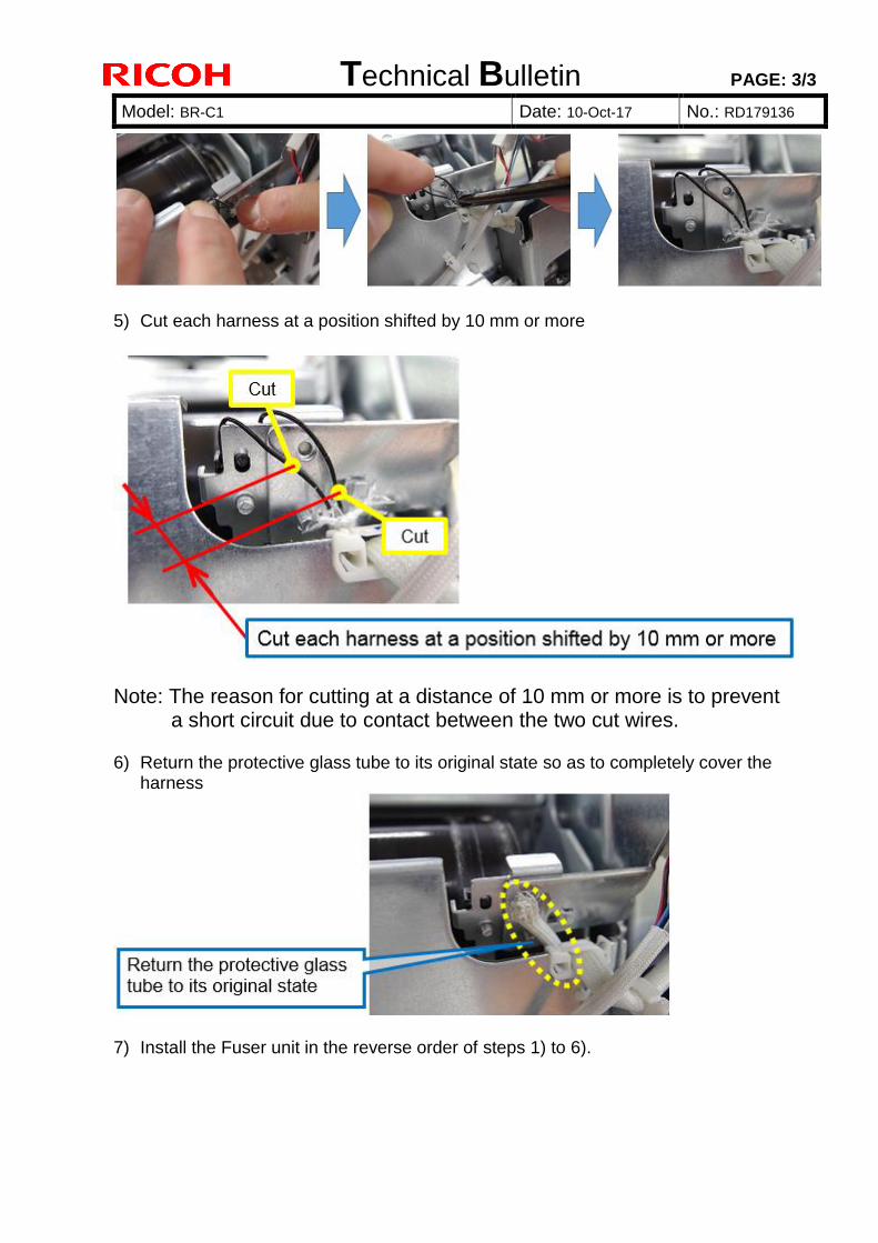
Technical Bulletin PAGE: 3/3
Model: BR-C1 Date: 10-Oct-17 No.: RD179136
5) Cut each harness at a position shifted by 10 mm or more
Note: The reason for cutting at a distance of 10 mm or more is to prevent a short circuit due to contact between the two cut wires.
6) Return the protective glass tube to its original state so as to completely cover the
harness
7) Install the Fuser unit in the reverse order of steps 1) to 6).
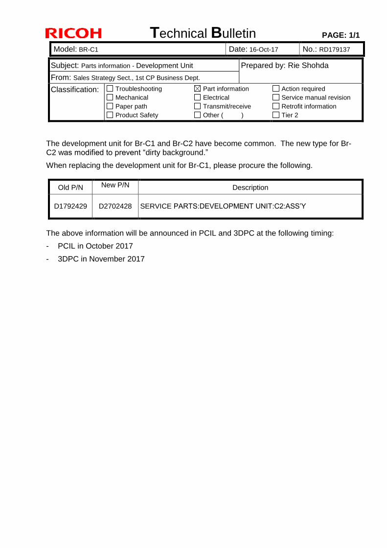
Technical Bulletin PAGE: 1/1
Model: BR-C1 Date: 16-Oct-17 No.: RD179137
Subject: Parts information - Development Unit Prepared by: Rie Shohda
From: Sales Strategy Sect., 1st CP Business Dept.
Classification: Troubleshooting
Mechanical
Paper path
Product Safety
Part information
Electrical
Transmit/receive
Other ( )
Action required
Service manual revision
Retrofit information
Tier 2
The development unit for Br-C1 and Br-C2 have become common. The new type for Br-C2 was modified to prevent “dirty background.”
When replacing the development unit for Br-C1, please procure the following.
Old P/N New P/N Description
D1792429 D2702428 SERVICE PARTS:DEVELOPMENT UNIT:C2:ASS’Y
The above information will be announced in PCIL and 3DPC at the following timing:
- PCIL in October 2017
- 3DPC in November 2017
Technical Bulletin PAGE: 1/1
Model: BR-C1 Date: 26-Mar-18 No.: RD179138
Subject: PM parts replacement alert message spec Prepared by: R. Shohda From: 1st Tech Service Sect., PP Tech Service Dept. Classification: Troubleshooting
Mechanical Paper path Product Safety
Part information Electrical Transmit/receive Other ( )
Action required Service manual revision Retrofit information Tier 2
Notice Regarding PM Alert Banner Message Specification of the PM parts replacement alert banner message that appears on the operation panel for the following parts is not explained in the FSM and has caused confusion in the field. This bulletin clarifies on this point.
- Coating Bar - #Fuser Cleaning Unit - Toner Corrector Bottle - Trimming Unit
SP5062 provides the option to choose whether or not to display the PM parts replacement alert (0: Not display, 1: Display). However, by spec, the alert message will appear for the above parts regardless of the SP5062 setting, because these are critical components to maintain machine operation. Note that the machine will automatically stop if they are not replaced at the appropriate timing.
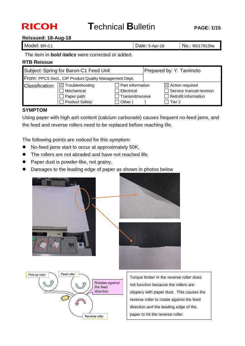
Technical Bulletin PAGE: 1/15
Reissued: 18-Aug-18
Model: BR-C1 Date: 5-Apr-18 No.: RD179139a
The item in bold italics were corrected or added.
RTB Reissue
SYMPTOM
Using paper with high ash content (calcium carbonate) causes frequent no-feed jams, and
the feed and reverse rollers need to be replaced before reaching life.
The following points are noticed for this symptom:
No-feed jams start to occur at approximately 50K.
The rollers are not abraded and have not reached life.
Paper dust is powder-like, not grainy.
Damages to the leading edge of paper as shown in photos below
Subject: Spring for Baron-C1 Feed Unit Prepared by: Y. Tanimoto
From: PPCS Sect., CIP Product Quality Management Dept.
Classification: Troubleshooting Mechanical Paper path Product Safety
Part information Electrical Transmit/receive Other ( )
Action required Service manual revision Retrofit information Tier 2
Torque limiter in the reverse roller does
not function because the rollers are
slippery with paper dust. This causes the
reverse roller to rotate against the feed
direction and the leading edge of the
paper to hit the reverse roller.
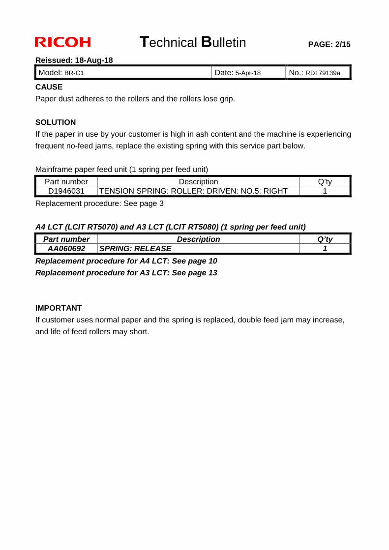
Technical Bulletin PAGE: 2/15
Reissued: 18-Aug-18
Model: BR-C1 Date: 5-Apr-18 No.: RD179139a
CAUSE
Paper dust adheres to the rollers and the rollers lose grip.
SOLUTION
If the paper in use by your customer is high in ash content and the machine is experiencing
frequent no-feed jams, replace the existing spring with this service part below.
Mainframe paper feed unit (1 spring per feed unit)
Part number Description Q’ty D1946031 TENSION SPRING: ROLLER: DRIVEN: NO.5: RIGHT 1
Replacement procedure: See page 3
A4 LCT (LCIT RT5070) and A3 LCT (LCIT RT5080) (1 spring per feed unit) Part number Description Q’ty AA060692 SPRING: RELEASE 1
Replacement procedure for A4 LCT: See page 10 Replacement procedure for A3 LCT: See page 13
IMPORTANT
If customer uses normal paper and the spring is replaced, double feed jam may increase,
and life of feed rollers may short.
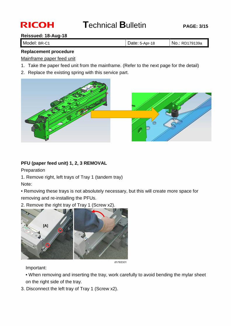
Technical Bulletin PAGE: 3/15
Reissued: 18-Aug-18
Model: BR-C1 Date: 5-Apr-18 No.: RD179139a
Replacement procedure
Mainframe paper feed unit
1. Take the paper feed unit from the mainframe. (Refer to the next page for the detail)
2. Replace the existing spring with this service part.
PFU (paper feed unit) 1, 2, 3 REMOVAL
Preparation
1. Remove right, left trays of Tray 1 (tandem tray)
Note:
• Removing these trays is not absolutely necessary, but this will create more space for
removing and re-installing the PFUs.
2. Remove the right tray of Tray 1 (Screw x2).
Important:
• When removing and inserting the tray, work carefully to avoid bending the mylar sheet
on the right side of the tray.
3. Disconnect the left tray of Tray 1 (Screw x2).
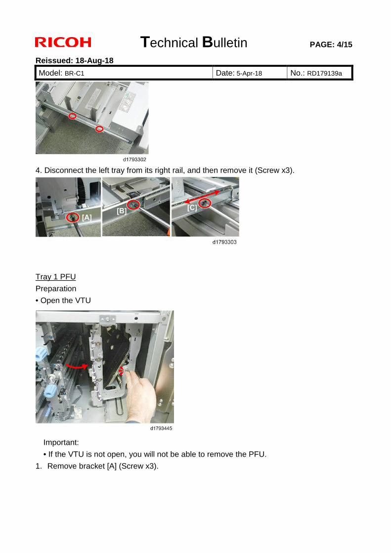
Technical Bulletin PAGE: 4/15
Reissued: 18-Aug-18
Model: BR-C1 Date: 5-Apr-18 No.: RD179139a
4. Disconnect the left tray from its right rail, and then remove it (Screw x3).
Tray 1 PFU
Preparation
• Open the VTU
Important:
• If the VTU is not open, you will not be able to remove the PFU.
1. Remove bracket [A] (Screw x3).
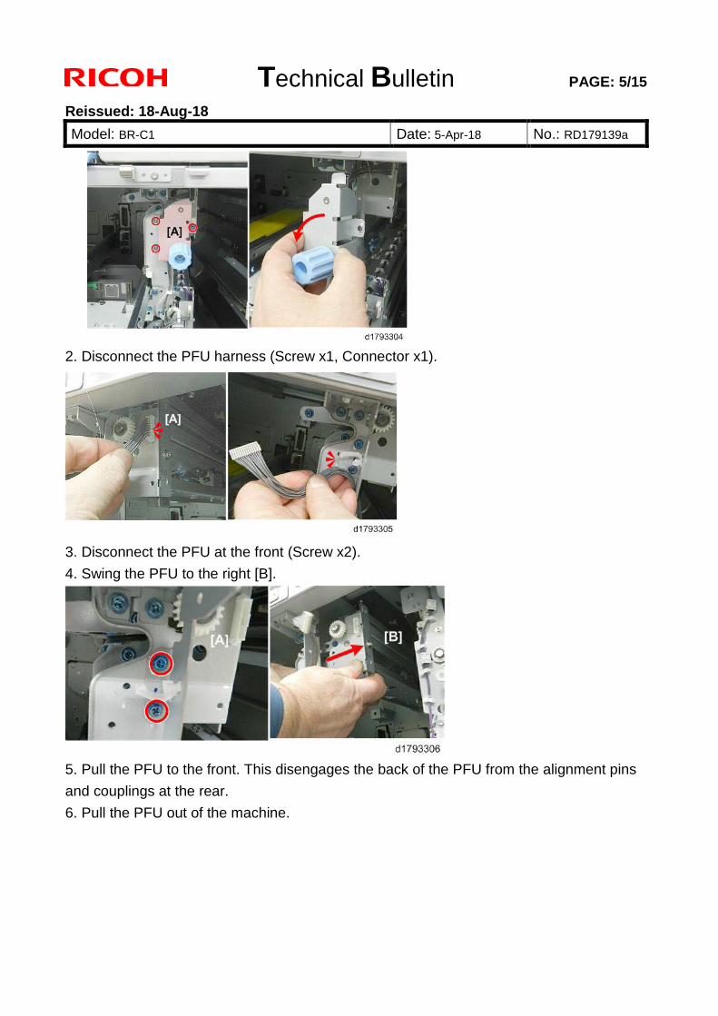
Technical Bulletin PAGE: 5/15
Reissued: 18-Aug-18
Model: BR-C1 Date: 5-Apr-18 No.: RD179139a
2. Disconnect the PFU harness (Screw x1, Connector x1).
3. Disconnect the PFU at the front (Screw x2).
4. Swing the PFU to the right [B].
5. Pull the PFU to the front. This disengages the back of the PFU from the alignment pins
and couplings at the rear.
6. Pull the PFU out of the machine.
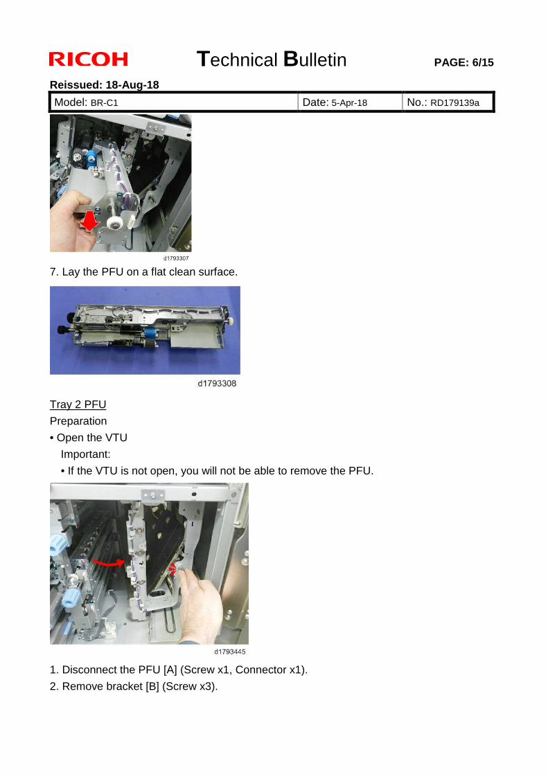
Technical Bulletin PAGE: 6/15
Reissued: 18-Aug-18
Model: BR-C1 Date: 5-Apr-18 No.: RD179139a
7. Lay the PFU on a flat clean surface.
Tray 2 PFU
Preparation
• Open the VTU
Important:
• If the VTU is not open, you will not be able to remove the PFU.
1. Disconnect the PFU [A] (Screw x1, Connector x1).
2. Remove bracket [B] (Screw x3).
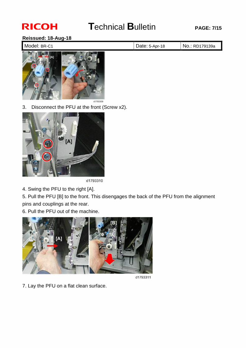
Technical Bulletin PAGE: 7/15
Reissued: 18-Aug-18
Model: BR-C1 Date: 5-Apr-18 No.: RD179139a
3. Disconnect the PFU at the front (Screw x2).
4. Swing the PFU to the right [A].
5. Pull the PFU [B] to the front. This disengages the back of the PFU from the alignment
pins and couplings at the rear.
6. Pull the PFU out of the machine.
7. Lay the PFU on a flat clean surface.
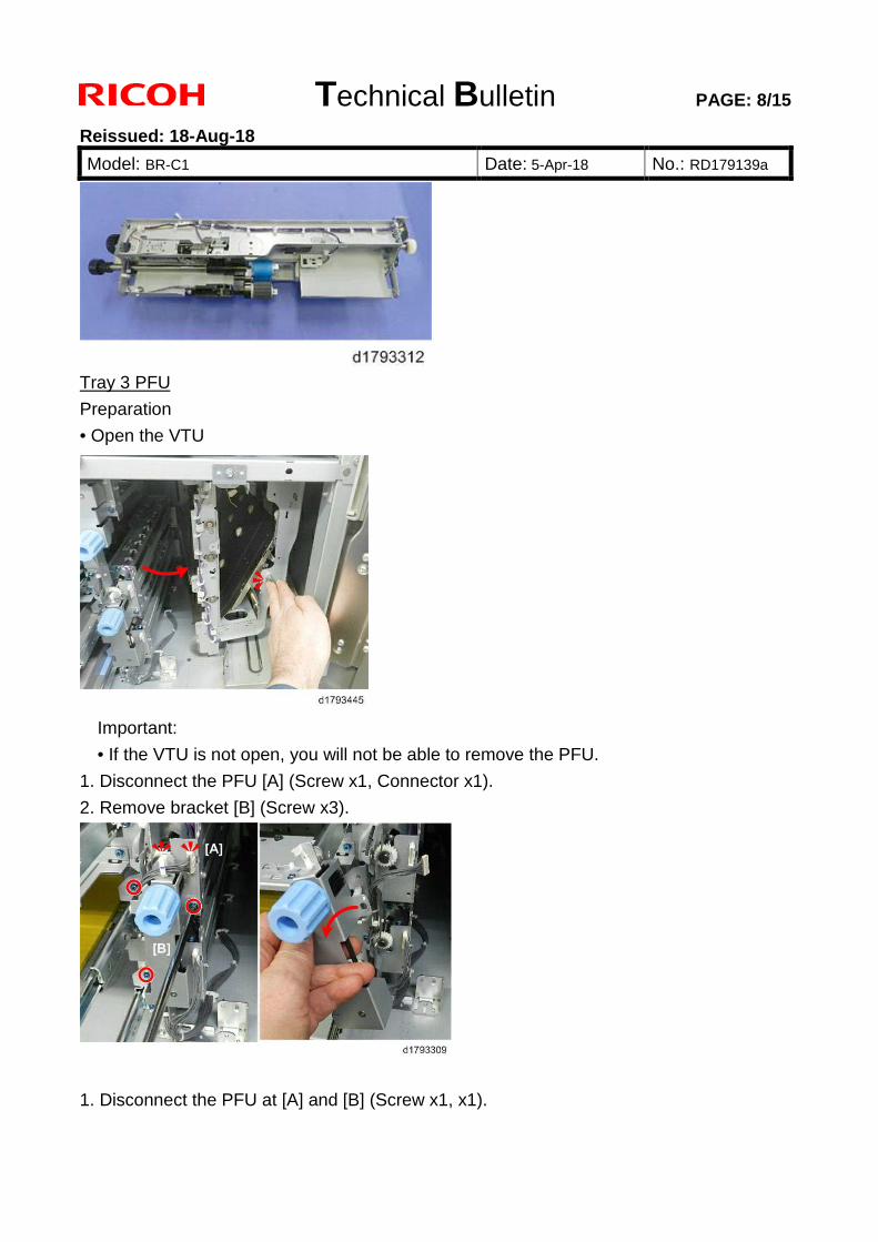
Technical Bulletin PAGE: 8/15
Reissued: 18-Aug-18
Model: BR-C1 Date: 5-Apr-18 No.: RD179139a
Tray 3 PFU
Preparation
• Open the VTU
Important:
• If the VTU is not open, you will not be able to remove the PFU.
1. Disconnect the PFU [A] (Screw x1, Connector x1).
2. Remove bracket [B] (Screw x3).
1. Disconnect the PFU at [A] and [B] (Screw x1, x1).
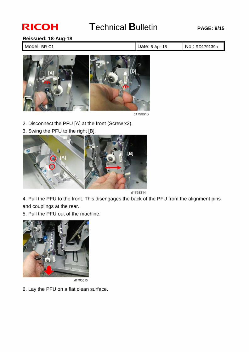
Technical Bulletin PAGE: 9/15
Reissued: 18-Aug-18
Model: BR-C1 Date: 5-Apr-18 No.: RD179139a
2. Disconnect the PFU [A] at the front (Screw x2).
3. Swing the PFU to the right [B].
4. Pull the PFU to the front. This disengages the back of the PFU from the alignment pins
and couplings at the rear.
5. Pull the PFU out of the machine.
6. Lay the PFU on a flat clean surface.
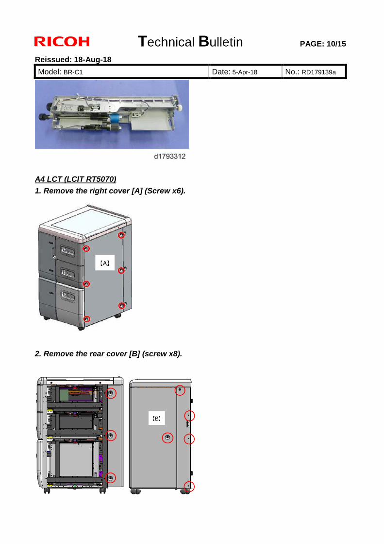
Technical Bulletin PAGE: 10/15
Reissued: 18-Aug-18
Model: BR-C1 Date: 5-Apr-18 No.: RD179139a
A4 LCT (LCIT RT5070) 1. Remove the right cover [A] (Screw x6).
2. Remove the rear cover [B] (screw x8).
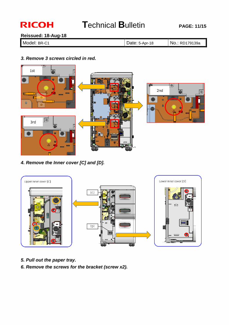
Technical Bulletin PAGE: 11/15
Reissued: 18-Aug-18
Model: BR-C1 Date: 5-Apr-18 No.: RD179139a
3. Remove 3 screws circled in red.
4. Remove the Inner cover [C] and [D].
5. Pull out the paper tray. 6. Remove the screws for the bracket (screw x2).
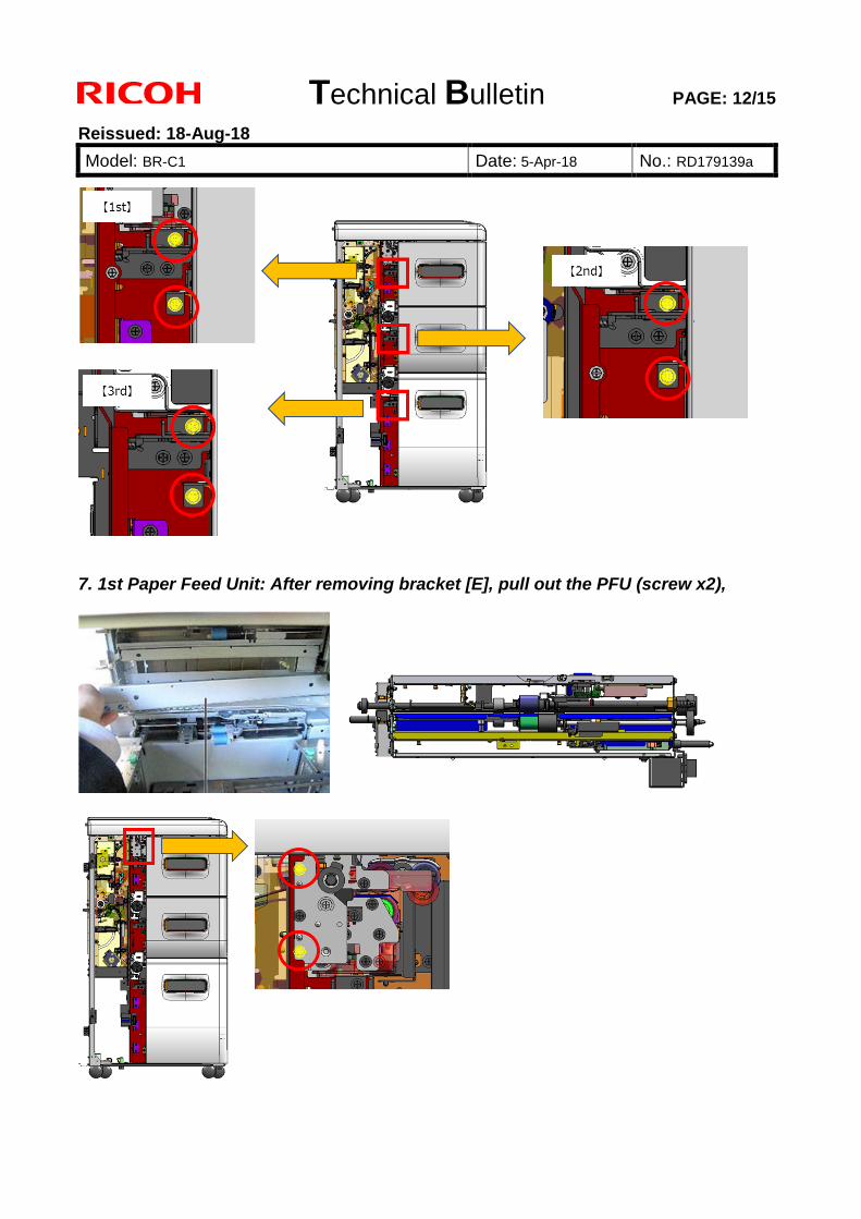
Technical Bulletin PAGE: 12/15
Reissued: 18-Aug-18
Model: BR-C1 Date: 5-Apr-18 No.: RD179139a
7. 1st Paper Feed Unit: After removing bracket [E], pull out the PFU (screw x2),
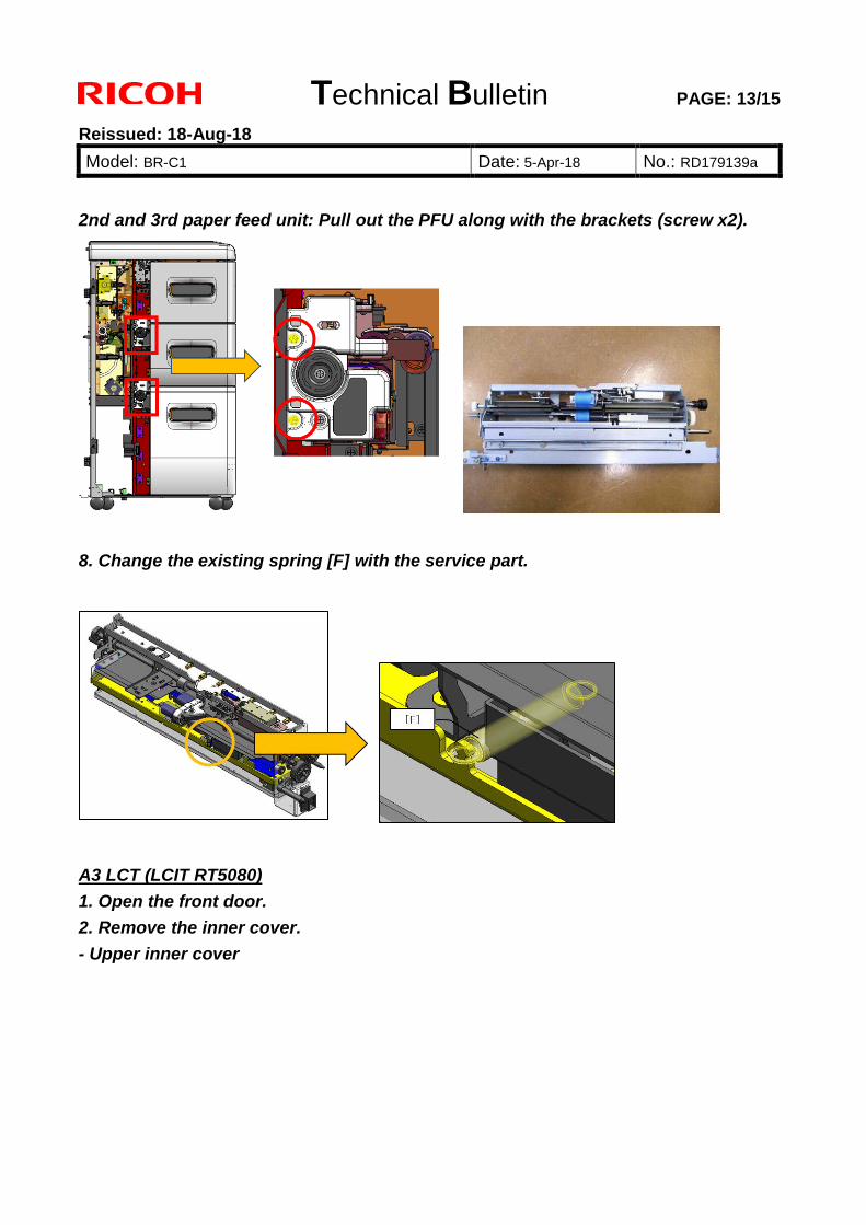
Technical Bulletin PAGE: 13/15
Reissued: 18-Aug-18
Model: BR-C1 Date: 5-Apr-18 No.: RD179139a
2nd and 3rd paper feed unit: Pull out the PFU along with the brackets (screw x2).
8. Change the existing spring [F] with the service part.
A3 LCT (LCIT RT5080) 1. Open the front door. 2. Remove the inner cover. - Upper inner cover
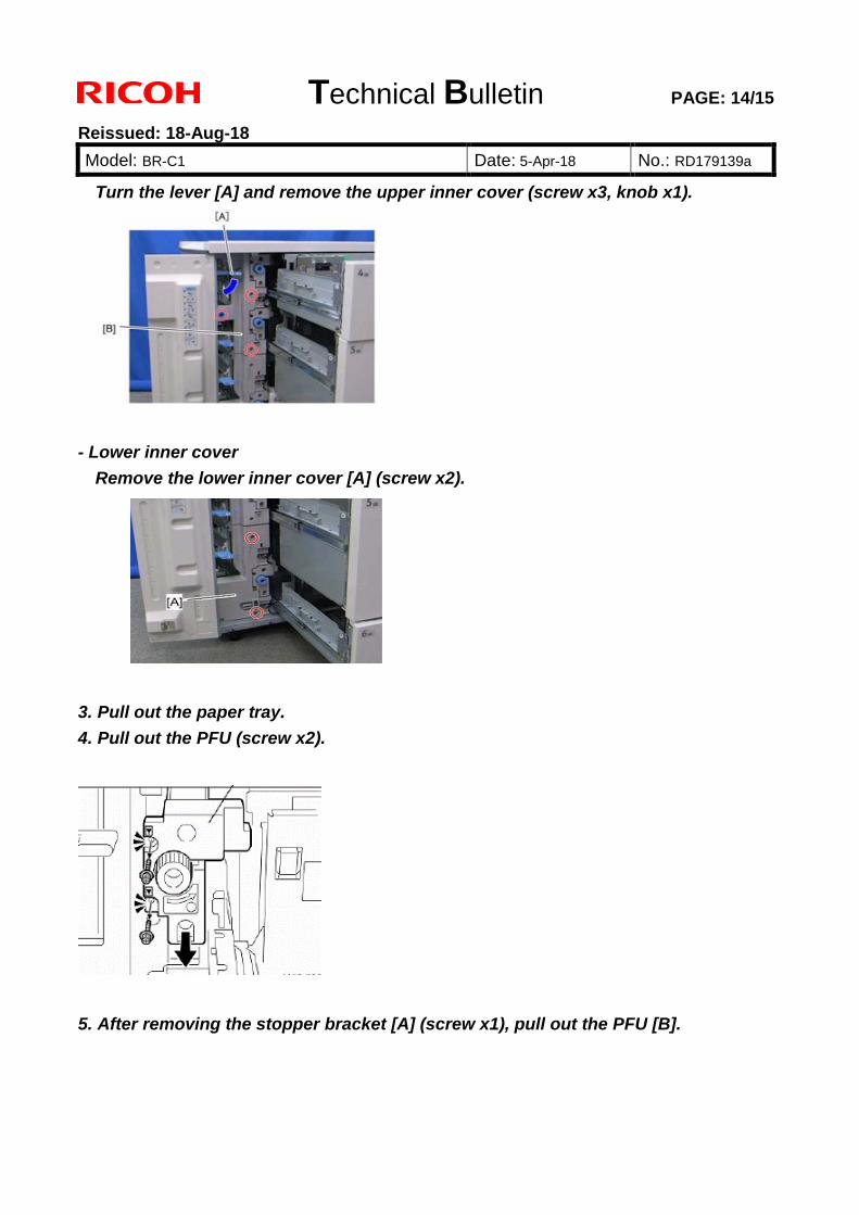
Technical Bulletin PAGE: 14/15
Reissued: 18-Aug-18
Model: BR-C1 Date: 5-Apr-18 No.: RD179139a
Turn the lever [A] and remove the upper inner cover (screw x3, knob x1).
- Lower inner cover
Remove the lower inner cover [A] (screw x2).
3. Pull out the paper tray. 4. Pull out the PFU (screw x2).
5. After removing the stopper bracket [A] (screw x1), pull out the PFU [B].
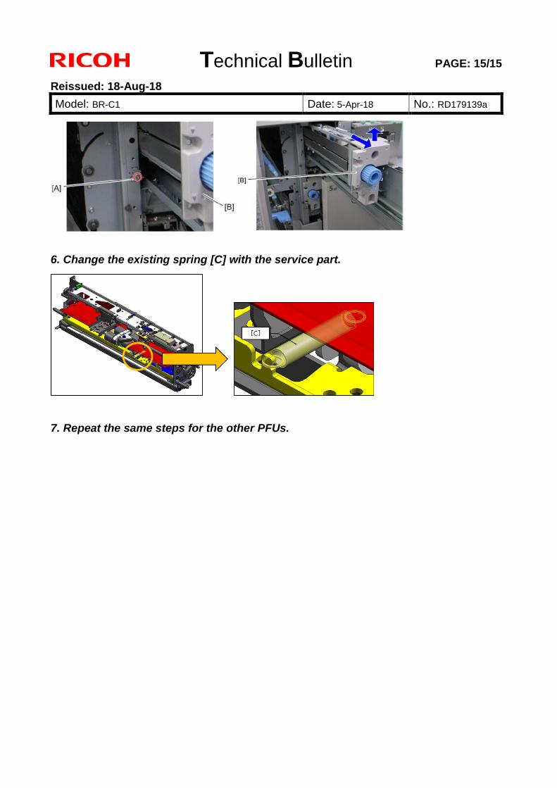
Technical Bulletin PAGE: 15/15
Reissued: 18-Aug-18
Model: BR-C1 Date: 5-Apr-18 No.: RD179139a
6. Change the existing spring [C] with the service part.
7. Repeat the same steps for the other PFUs.
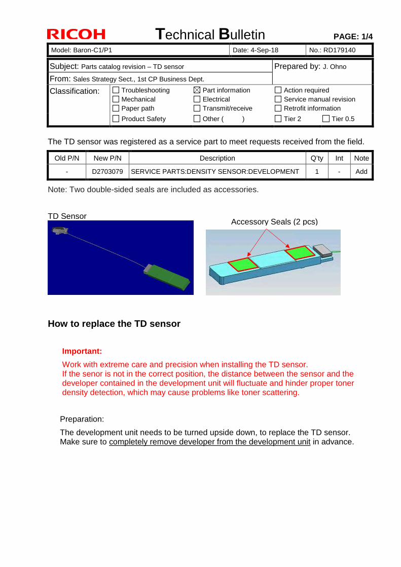
Technical Bulletin PAGE: 1/4
Model: Baron-C1/P1 Date: 4-Sep-18 No.: RD179140
Subject: Parts catalog revision – TD sensor Prepared by: J. Ohno
From: Sales Strategy Sect., 1st CP Business Dept.
Classification: Troubleshooting Mechanical Paper path
Part information Electrical Transmit/receive
Action required Service manual revision Retrofit information
Product Safety Other ( ) Tier 2 Tier 0.5
The TD sensor was registered as a service part to meet requests received from the field.
Old P/N New P/N Description Q’ty Int Note
- D2703079 SERVICE PARTS:DENSITY SENSOR:DEVELOPMENT 1 - Add
Note: Two double-sided seals are included as accessories.
TD Sensor
How to replace the TD sensor
Important:
Work with extreme care and precision when installing the TD sensor. If the senor is not in the correct position, the distance between the sensor and the developer contained in the development unit will fluctuate and hinder proper toner density detection, which may cause problems like toner scattering.
Preparation:
The development unit needs to be turned upside down, to replace the TD sensor. Make sure to completely remove developer from the development unit in advance.
Accessory Seals (2 pcs)
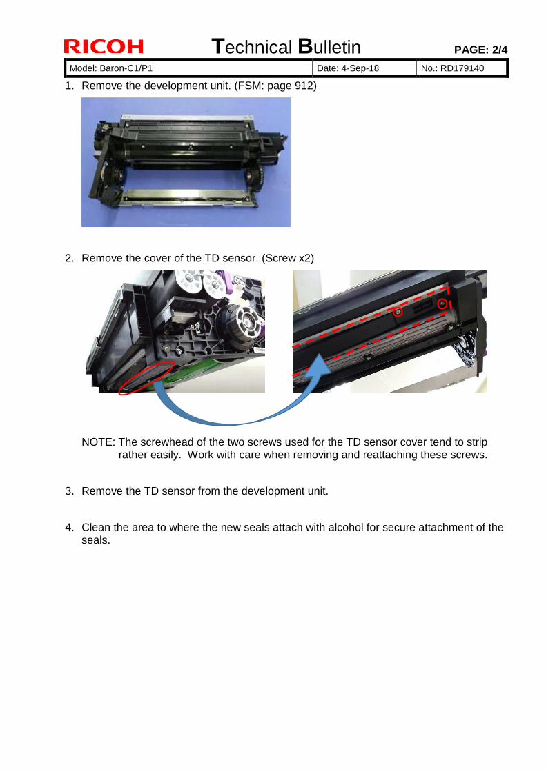
Technical Bulletin PAGE: 2/4
Model: Baron-C1/P1 Date: 4-Sep-18 No.: RD179140
1. Remove the development unit. (FSM: page 912)
2. Remove the cover of the TD sensor. (Screw x2)
NOTE: The screwhead of the two screws used for the TD sensor cover tend to strip rather easily. Work with care when removing and reattaching these screws.
3. Remove the TD sensor from the development unit.
4. Clean the area to where the new seals attach with alcohol for secure attachment of the seals.
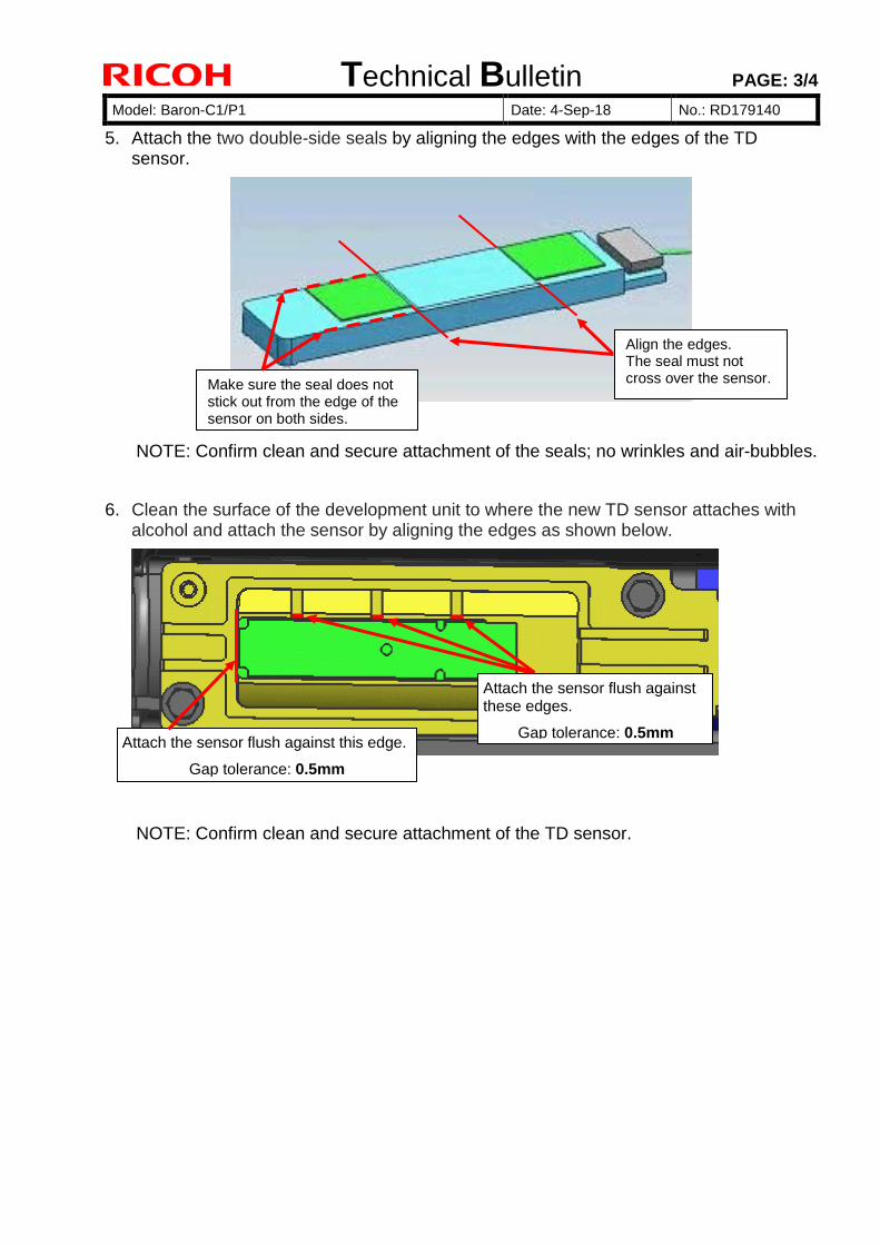
Technical Bulletin PAGE: 3/4
Model: Baron-C1/P1 Date: 4-Sep-18 No.: RD179140
5. Attach the two double-side seals by aligning the edges with the edges of the TD sensor.
NOTE: Confirm clean and secure attachment of the seals; no wrinkles and air-bubbles.
6. Clean the surface of the development unit to where the new TD sensor attaches with alcohol and attach the sensor by aligning the edges as shown below.
NOTE: Confirm clean and secure attachment of the TD sensor.
Attach the sensor flush against this edge.
Gap tolerance: 0.5mm
Align the edges. The seal must not cross over the sensor. Make sure the seal does not
stick out from the edge of the sensor on both sides.
Attach the sensor flush against these edges.
Gap tolerance: 0.5mm
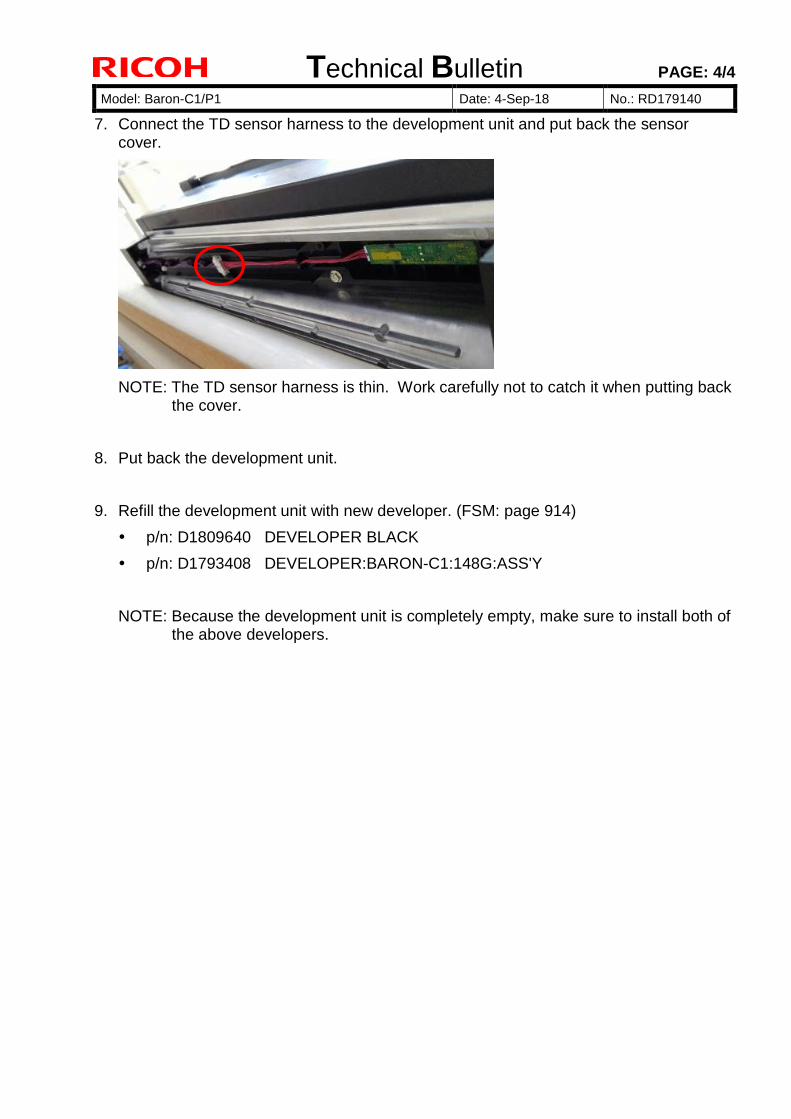
Technical Bulletin PAGE: 4/4
Model: Baron-C1/P1 Date: 4-Sep-18 No.: RD179140
7. Connect the TD sensor harness to the development unit and put back the sensorcover.
NOTE: The TD sensor harness is thin. Work carefully not to catch it when putting back the cover.
8. Put back the development unit.
9. Refill the development unit with new developer. (FSM: page 914)
p/n: D1809640 DEVELOPER BLACK
p/n: D1793408 DEVELOPER:BARON-C1:148G:ASS'Y
NOTE: Because the development unit is completely empty, make sure to install both of the above developers.
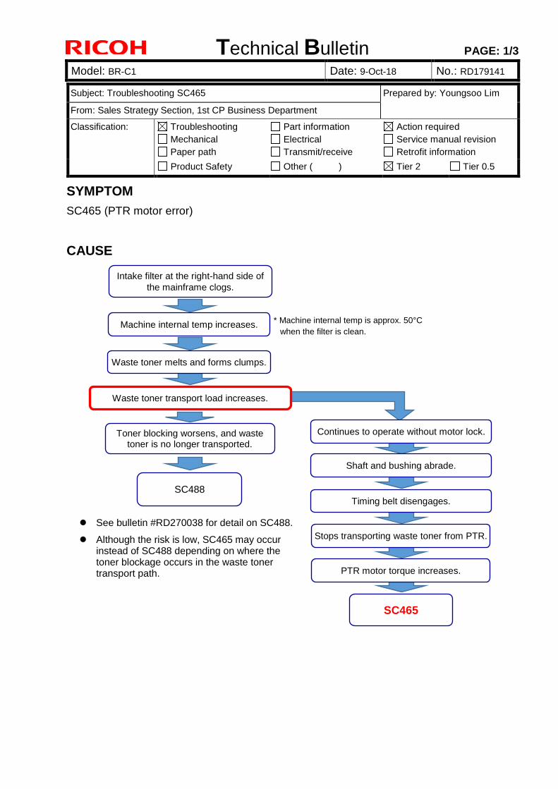
Technical Bulletin PAGE: 1/3
Model: BR-C1 Date: 9-Oct-18 No.: RD179141 2
SYMPTOM
SC465 (PTR motor error)
CAUSE
Subject: Troubleshooting SC465 Prepared by: Youngsoo Lim
From: Sales Strategy Section, 1st CP Business Department
Classification: Troubleshooting Mechanical Paper path
Part information Electrical Transmit/receive
Action required Service manual revision Retrofit information
Product Safety Other ( ) Tier 2 Tier 0.5
* Machine internal temp is approx. 50°Cwhen the filter is clean.
Intake filter at the right-hand side of the mainframe clogs.
Machine internal temp increases.
Waste toner melts and forms clumps.
Waste toner transport load increases.
Toner blocking worsens, and waste toner is no longer transported.
SC488
SC465
Timing belt disengages.
Continues to operate without motor lock.
Shaft and bushing abrade.
Stops transporting waste toner from PTR.
PTR motor torque increases.
See bulletin #RD270038 for detail on SC488.
Although the risk is low, SC465 may occurinstead of SC488 depending on where thetoner blockage occurs in the waste tonertransport path.
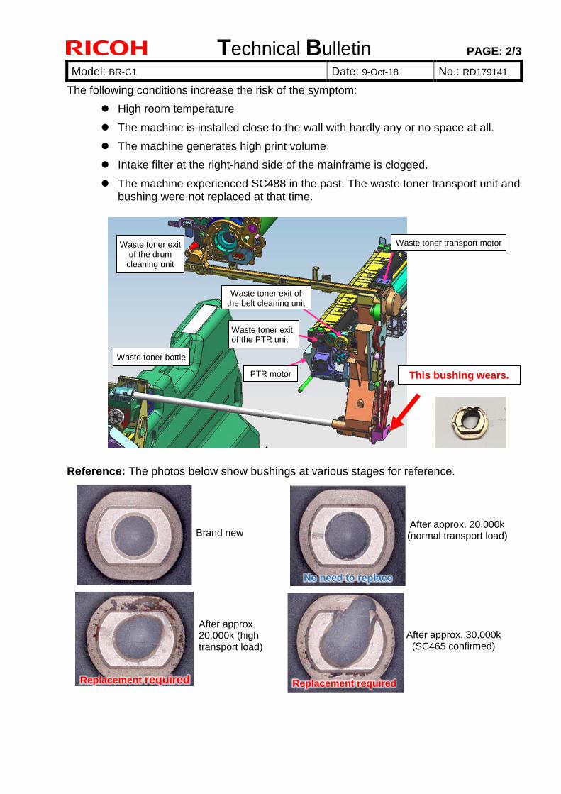
Technical Bulletin PAGE: 2/3
Model: BR-C1 Date: 9-Oct-18 No.: RD179141 2
The following conditions increase the risk of the symptom:
High room temperature
The machine is installed close to the wall with hardly any or no space at all.
The machine generates high print volume.
Intake filter at the right-hand side of the mainframe is clogged.
The machine experienced SC488 in the past. The waste toner transport unit andbushing were not replaced at that time.
Reference: The photos below show bushings at various stages for reference.
Waste toner exit of the drum
cleaning unit
Waste toner bottle
Waste toner exit of the belt cleaning unit
Waste toner exit of the PTR unit
PTR motor
Waste toner transport motor
This bushing wears.
After approx. 20,000k (high transport load)
Replacement required
After approx. 30,000k (SC465 confirmed)
Replacement required
Brand new After approx. 20,000k (normal transport load)
No need to replace
Technical Bulletin PAGE: 3/3
Model: BR-C1 Date: 9-Oct-18 No.: RD179141 2
SOLUTION
Check the above bushing (p/n: B1202063). If it is abraded and requires replacement,replace it together with the waste toner unit (p/n: D1796528).
Request
Please monitor all machines regardless of whether the bushing was found abraded ornot, until you confirm that the machine does not generate the SC.
Affected units:
The above solution and request applies to all Baron-1 and Baron-2 units that have exceeded a total print volume of 20,000k.
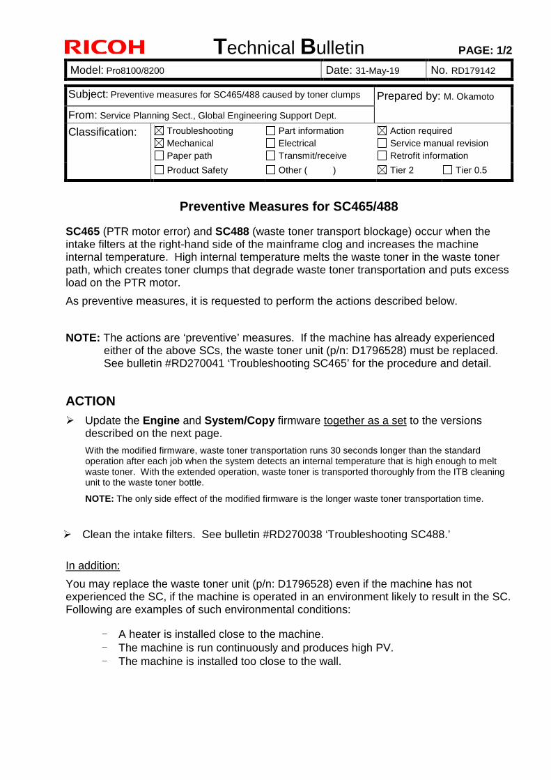
Technical Bulletin PAGE: 1/2
Model: Pro8100/8200 Date: 31-May-19 No. RD179142
Preventive Measures for SC465/488
SC465 (PTR motor error) and SC488 (waste toner transport blockage) occur when the intake filters at the right-hand side of the mainframe clog and increases the machine internal temperature. High internal temperature melts the waste toner in the waste toner path, which creates toner clumps that degrade waste toner transportation and puts excess load on the PTR motor.
As preventive measures, it is requested to perform the actions described below.
NOTE: The actions are ‘preventive’ measures. If the machine has already experienced either of the above SCs, the waste toner unit (p/n: D1796528) must be replaced. See bulletin #RD270041 ‘Troubleshooting SC465’ for the procedure and detail.
ACTION
Update the Engine and System/Copy firmware together as a set to the versions described on the next page.
With the modified firmware, waste toner transportation runs 30 seconds longer than the standard operation after each job when the system detects an internal temperature that is high enough to melt waste toner. With the extended operation, waste toner is transported thoroughly from the ITB cleaning unit to the waste toner bottle.
NOTE: The only side effect of the modified firmware is the longer waste toner transportation time.
Clean the intake filters. See bulletin #RD270038 ‘Troubleshooting SC488.’
In addition:
You may replace the waste toner unit (p/n: D1796528) even if the machine has not experienced the SC, if the machine is operated in an environment likely to result in the SC. Following are examples of such environmental conditions:
‒ A heater is installed close to the machine. ‒ The machine is run continuously and produces high PV. ‒ The machine is installed too close to the wall.
Subject: Preventive measures for SC465/488 caused by toner clumps Prepared by: M. Okamoto
From: Service Planning Sect., Global Engineering Support Dept.
Classification: Troubleshooting Mechanical Paper path
Part information Electrical Transmit/receive
Action required Service manual revision Retrofit information
Product Safety Other ( ) Tier 2 Tier 0.5
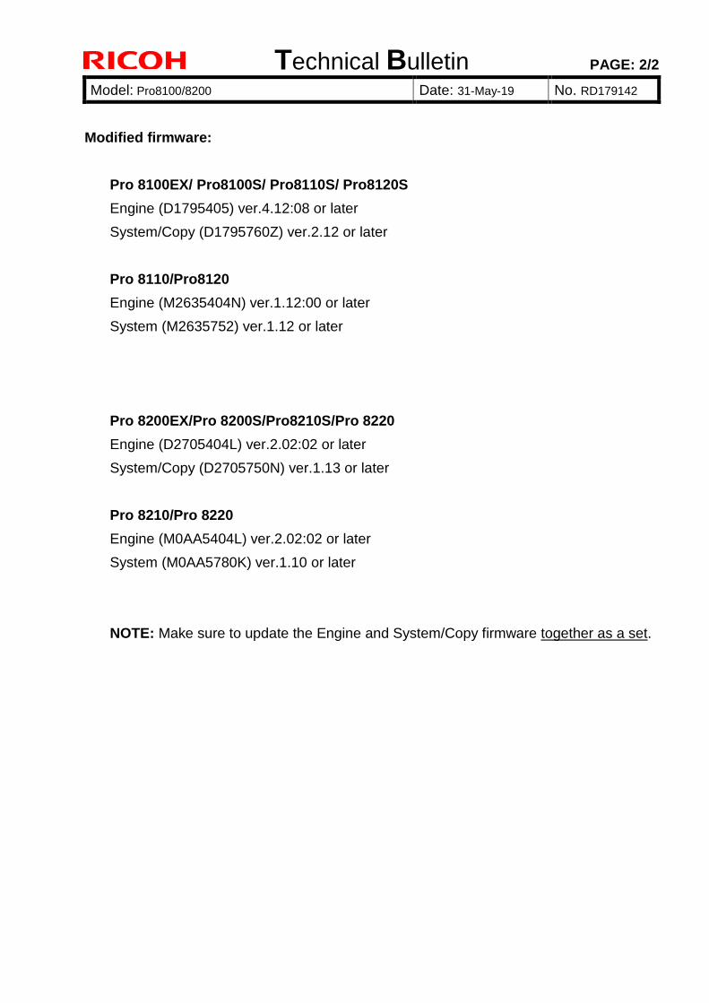
Technical Bulletin PAGE: 2/2
Model: Pro8100/8200 Date: 31-May-19 No. RD179142
Modified firmware:
Pro 8100EX/ Pro8100S/ Pro8110S/ Pro8120S
Engine (D1795405) ver.4.12:08 or later
System/Copy (D1795760Z) ver.2.12 or later
Pro 8110/Pro8120
Engine (M2635404N) ver.1.12:00 or later
System (M2635752) ver.1.12 or later
Pro 8200EX/Pro 8200S/Pro8210S/Pro 8220
Engine (D2705404L) ver.2.02:02 or later
System/Copy (D2705750N) ver.1.13 or later
Pro 8210/Pro 8220
Engine (M0AA5404L) ver.2.02:02 or later
System (M0AA5780K) ver.1.10 or later
NOTE: Make sure to update the Engine and System/Copy firmware together as a set.