Technical Bulletins: Jupiter-C1, J-C1 (B146/B147/B148/B149 ...
135
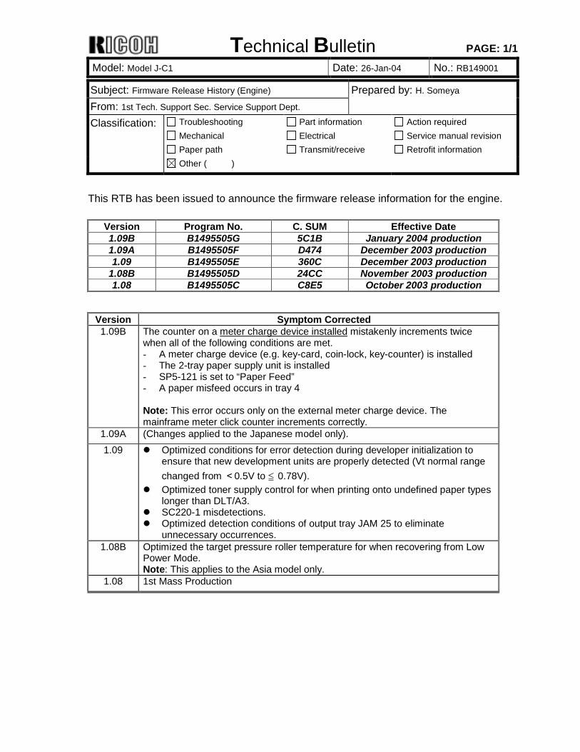
Technical Bulletin PAGE: 1/1 Model: Model J-C1 Date: 26-Jan-04 No.: RB149001 Subject: Firmware Release History (Engine) Prepared by: H. Someya From: 1st Tech. Support Sec. Service Support Dept. Classification: Troubleshooting Mechanical Paper path Part information Electrical Transmit/receive Action required Service manual revision Retrofit information Other ( ) This RTB has been issued to announce the firmware release information for the engine. Version Program No. C. SUM Effective Date 1.09B B1495505G 5C1B January 2004 production 1.09A B1495505F D474 December 2003 production 1.09 B1495505E 360C December 2003 production 1.08B B1495505D 24CC November 2003 production 1.08 B1495505C C8E5 October 2003 production Version Symptom Corrected 1.09B The counter on a meter charge device installed mistakenly increments twice when all of the following conditions are met. - A meter charge device (e.g. key-card, coin-lock, key-counter) is installed - The 2-tray paper supply unit is installed - SP5-121 is set to “Paper Feed” - A paper misfeed occurs in tray 4 Note: This error occurs only on the external meter charge device. The mainframe meter click counter increments correctly. 1.09A (Changes applied to the Japanese model only). 1.09 ! Optimized conditions for error detection during developer initialization to ensure that new development units are properly detected (Vt normal range changed from <0.5V to ≦ 0.78V). ! Optimized toner supply control for when printing onto undefined paper types longer than DLT/A3. ! SC220-1 misdetections. ! Optimized detection conditions of output tray JAM 25 to eliminate unnecessary occurrences. 1.08B Optimized the target pressure roller temperature for when recovering from Low Power Mode. Note: This applies to the Asia model only. 1.08 1st Mass Production
-
Upload
khangminh22 -
Category
Documents
-
view
1 -
download
0
Transcript of Technical Bulletins: Jupiter-C1, J-C1 (B146/B147/B148/B149 ...
Technical Bulletin PAGE: 1/1
Model: Model J-C1 Date: 26-Jan-04 No.: RB149001
Subject: Firmware Release History (Engine) Prepared by: H. Someya From: 1st Tech. Support Sec. Service Support Dept. Classification: Troubleshooting
Mechanical Paper path
Part information Electrical Transmit/receive
Action required Service manual revision Retrofit information
Other ( )
This RTB has been issued to announce the firmware release information for the engine.
Version Program No. C. SUM Effective Date 1.09B B1495505G 5C1B January 2004 production 1.09A B1495505F D474 December 2003 production 1.09 B1495505E 360C December 2003 production
1.08B B1495505D 24CC November 2003 production 1.08 B1495505C C8E5 October 2003 production
Version Symptom Corrected 1.09B The counter on a meter charge device installed mistakenly increments twice
when all of the following conditions are met. - A meter charge device (e.g. key-card, coin-lock, key-counter) is installed - The 2-tray paper supply unit is installed - SP5-121 is set to “Paper Feed” - A paper misfeed occurs in tray 4 Note: This error occurs only on the external meter charge device. The mainframe meter click counter increments correctly.
1.09A (Changes applied to the Japanese model only). 1.09 ! Optimized conditions for error detection during developer initialization to
ensure that new development units are properly detected (Vt normal range changed from <0.5V to ≦ 0.78V).
! Optimized toner supply control for when printing onto undefined paper types longer than DLT/A3.
! SC220-1 misdetections. ! Optimized detection conditions of output tray JAM 25 to eliminate
unnecessary occurrences. 1.08B Optimized the target pressure roller temperature for when recovering from Low
Power Mode. Note: This applies to the Asia model only.
1.08 1st Mass Production
Technical Bulletin PAGE: 1/1
Model: Model J-C1 Date: 26-Jan-04 No.: RB149002
Subject: Service Manual Correction Prepared by: H. Someya From: 1st Tech. Support Sec. Service Support Dept. Classification: Troubleshooting
Mechanical Paper path
Part information Electrical Transmit/receive
Action required Service manual revision Retrofit information
Other ( )
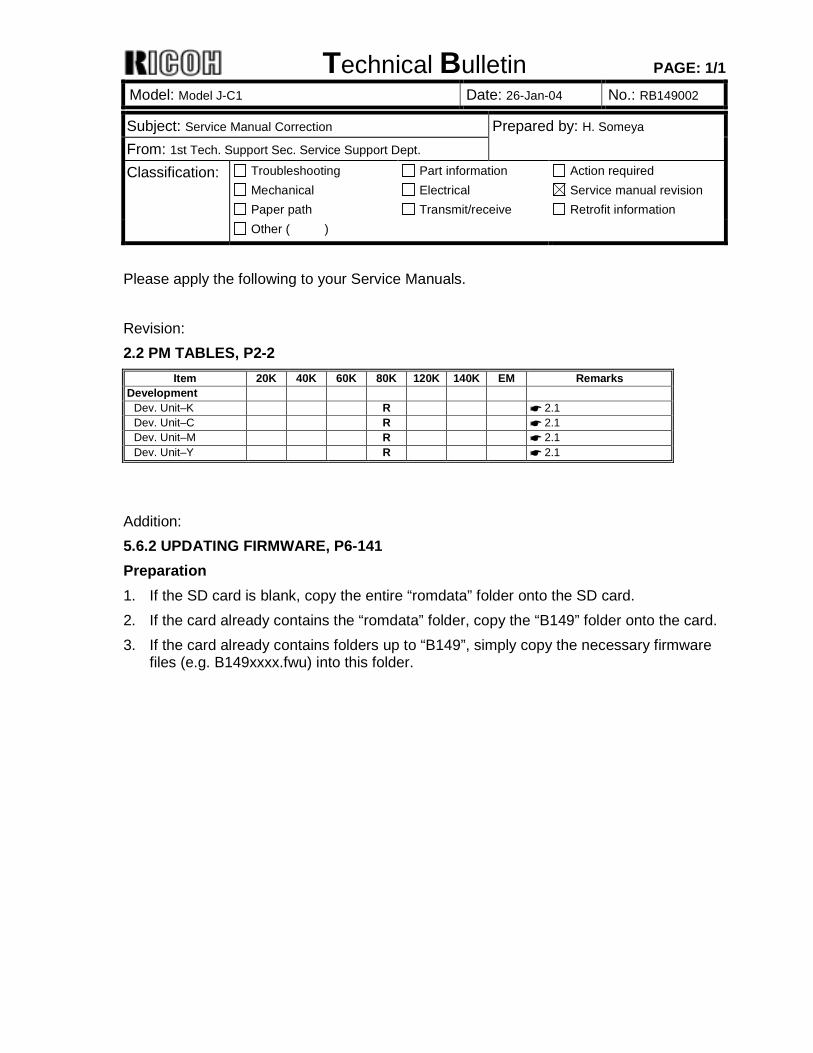
Please apply the following to your Service Manuals. Revision: 2.2 PM TABLES, P2-2
Item 20K 40K 60K 80K 120K 140K EM Remarks Development
Dev. Unit–K R ☛ 2.1 Dev. Unit–C R ☛ 2.1 Dev. Unit–M R ☛ 2.1 Dev. Unit–Y R ☛ 2.1
Addition: 5.6.2 UPDATING FIRMWARE, P6-141 Preparation 1. If the SD card is blank, copy the entire “romdata” folder onto the SD card. 2. If the card already contains the “romdata” folder, copy the “B149” folder onto the card. 3. If the card already contains folders up to “B149”, simply copy the necessary firmware
files (e.g. B149xxxx.fwu) into this folder.
Technical Bulletin PAGE: 1/1
Model: Model J-C1 Date: 26-Jan-04 No.: RB149003
Subject: Firmware Release History (System) Prepared by: H. Someya From: 1st Tech. Support Sec. Service Support Dept. Classification: Troubleshooting
Mechanical Paper path
Part information Electrical Transmit/receive
Action required Service manual revision Retrofit information
Other ( )
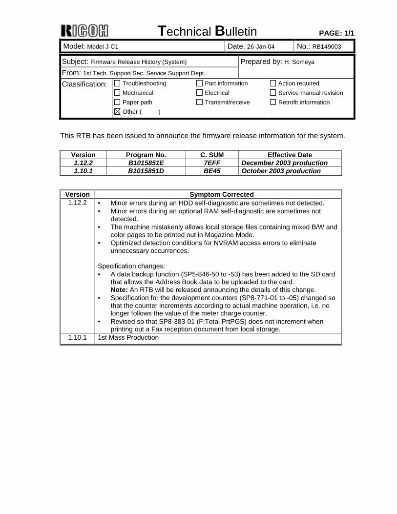
This RTB has been issued to announce the firmware release information for the system.
Version Program No. C. SUM Effective Date 1.12.2 B1015851E 7EFF December 2003 production 1.10.1 B1015851D BE45 October 2003 production
Version Symptom Corrected 1.12.2 • Minor errors during an HDD self-diagnostic are sometimes not detected.
• Minor errors during an optional RAM self-diagnostic are sometimes not detected.
• The machine mistakenly allows local storage files containing mixed B/W and color pages to be printed out in Magazine Mode.
• Optimized detection conditions for NVRAM access errors to eliminate unnecessary occurrences.
Specification changes: • A data backup function (SP5-846-50 to -53) has been added to the SD card
that allows the Address Book data to be uploaded to the card. Note: An RTB will be released announcing the details of this change.
• Specification for the development counters (SP8-771-01 to -05) changed so that the counter increments according to actual machine operation, i.e. no longer follows the value of the meter charge counter.
• Revised so that SP8-383-01 (F:Total PrtPGS) does not increment when printing out a Fax reception document from local storage.
1.10.1 1st Mass Production
Technical Bulletin PAGE: 1/1
Model: Model J-C1 Date: 26-Jan-04 No.: RB149004
Subject: Specification change for the development counter Prepared by: H. Someya From: 1st Tech. Support Sec. Service Support Dept. Classification: Troubleshooting
Mechanical Paper path
Part information Electrical Transmit/receive
Action required Service manual revision Retrofit information
Other ( )
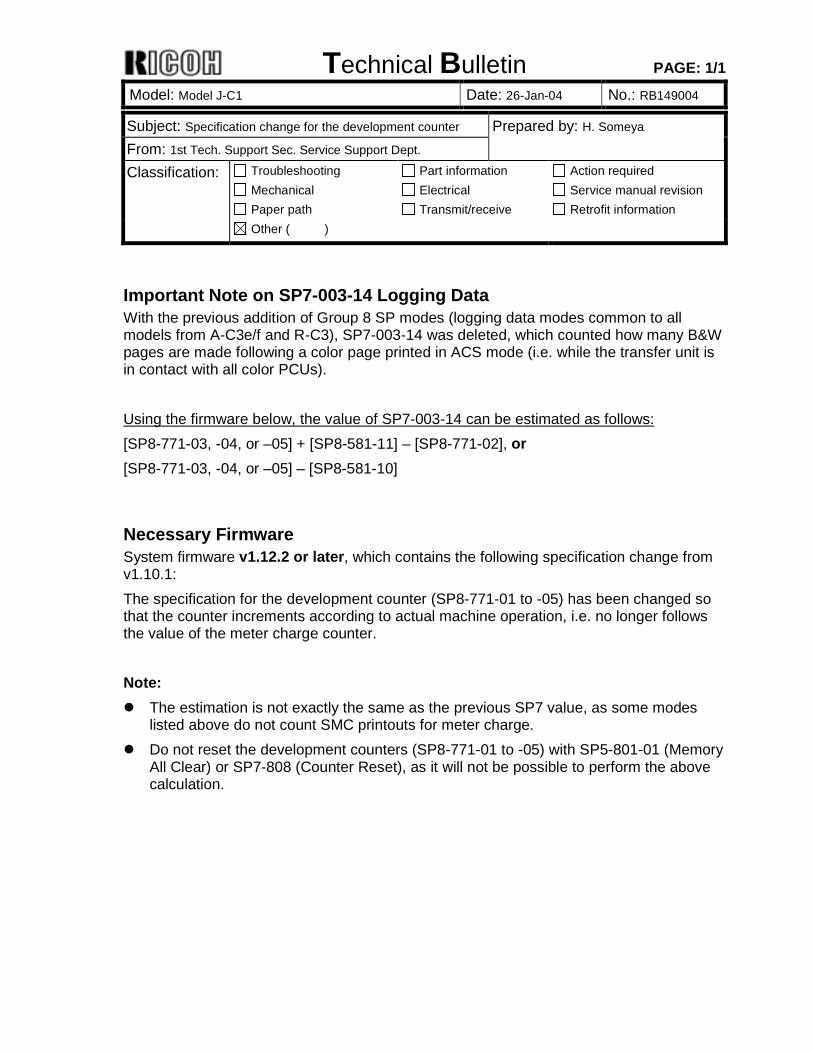
Important Note on SP7-003-14 Logging Data With the previous addition of Group 8 SP modes (logging data modes common to all models from A-C3e/f and R-C3), SP7-003-14 was deleted, which counted how many B&W pages are made following a color page printed in ACS mode (i.e. while the transfer unit is in contact with all color PCUs). Using the firmware below, the value of SP7-003-14 can be estimated as follows: [SP8-771-03, -04, or –05] + [SP8-581-11] – [SP8-771-02], or [SP8-771-03, -04, or –05] – [SP8-581-10]
Necessary Firmware System firmware v1.12.2 or later, which contains the following specification change from v1.10.1: The specification for the development counter (SP8-771-01 to -05) has been changed so that the counter increments according to actual machine operation, i.e. no longer follows the value of the meter charge counter. Note: ! The estimation is not exactly the same as the previous SP7 value, as some modes
listed above do not count SMC printouts for meter charge. ! Do not reset the development counters (SP8-771-01 to -05) with SP5-801-01 (Memory
All Clear) or SP7-808 (Counter Reset), as it will not be possible to perform the above calculation.
Technical Bulletin PAGE: 1/2
Model: Model J-C1 Date: 26-Jan-04 No.: RB149005
Subject: HDD initialization when turing on the main switch Prepared by: H. Someya From: 1st Tech. Support Sec. Service Support Dept. Classification: Troubleshooting
Mechanical Paper path
Part information Electrical Transmit/receive
Action required Service manual revision Retrofit information
Other ( )
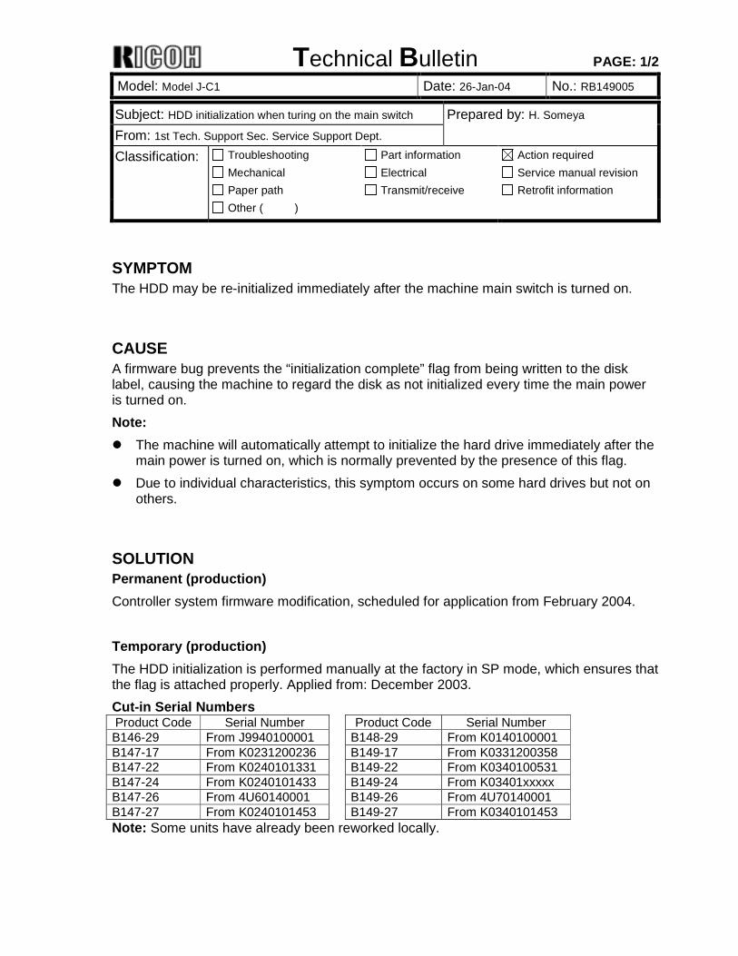
SYMPTOM The HDD may be re-initialized immediately after the machine main switch is turned on.
CAUSE A firmware bug prevents the “initialization complete” flag from being written to the disk label, causing the machine to regard the disk as not initialized every time the main power is turned on. Note: ! The machine will automatically attempt to initialize the hard drive immediately after the
main power is turned on, which is normally prevented by the presence of this flag. ! Due to individual characteristics, this symptom occurs on some hard drives but not on
others.
SOLUTION Permanent (production) Controller system firmware modification, scheduled for application from February 2004. Temporary (production) The HDD initialization is performed manually at the factory in SP mode, which ensures that the flag is attached properly. Applied from: December 2003. Cut-in Serial Numbers Product Code Serial Number Product Code Serial Number B146-29 From J9940100001 B148-29 From K0140100001 B147-17 From K0231200236 B149-17 From K0331200358 B147-22 From K0240101331 B149-22 From K0340100531 B147-24 From K0240101433 B149-24 From K03401xxxxx B147-26 From 4U60140001 B149-26 From 4U70140001 B147-27 From K0240101453 B149-27 From K0340101453 Note: Some units have already been reworked locally.
Technical Bulletin PAGE: 2/2
Model: Model J-C1 Date: 26-Jan-04 No.: RB149005
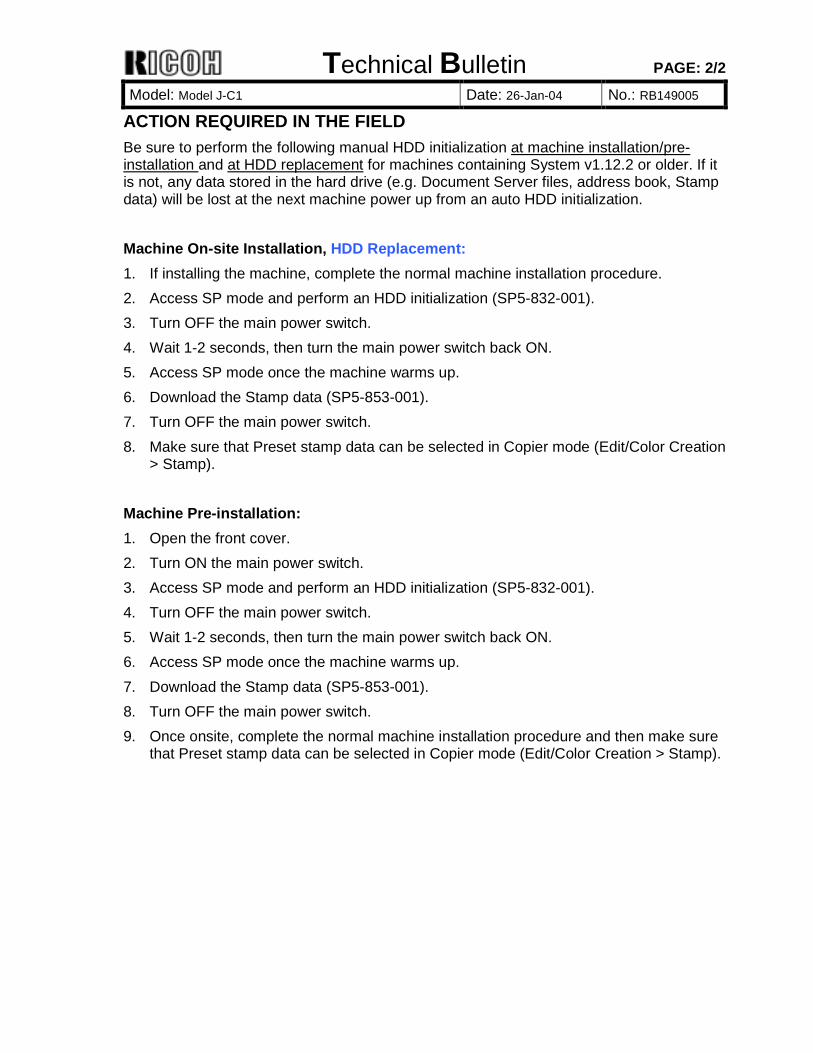
ACTION REQUIRED IN THE FIELD Be sure to perform the following manual HDD initialization at machine installation/pre-installation and at HDD replacement for machines containing System v1.12.2 or older. If it is not, any data stored in the hard drive (e.g. Document Server files, address book, Stamp data) will be lost at the next machine power up from an auto HDD initialization. Machine On-site Installation, HDD Replacement: 1. If installing the machine, complete the normal machine installation procedure. 2. Access SP mode and perform an HDD initialization (SP5-832-001). 3. Turn OFF the main power switch. 4. Wait 1-2 seconds, then turn the main power switch back ON. 5. Access SP mode once the machine warms up. 6. Download the Stamp data (SP5-853-001). 7. Turn OFF the main power switch. 8. Make sure that Preset stamp data can be selected in Copier mode (Edit/Color Creation
> Stamp). Machine Pre-installation: 1. Open the front cover. 2. Turn ON the main power switch. 3. Access SP mode and perform an HDD initialization (SP5-832-001). 4. Turn OFF the main power switch. 5. Wait 1-2 seconds, then turn the main power switch back ON. 6. Access SP mode once the machine warms up. 7. Download the Stamp data (SP5-853-001). 8. Turn OFF the main power switch. 9. Once onsite, complete the normal machine installation procedure and then make sure
that Preset stamp data can be selected in Copier mode (Edit/Color Creation > Stamp).
Technical Bulletin PAGE: 1/1
Model: Model J-C1 Date: 30-Jan-04 No.: RB149006
Subject: Meter-click function error on external meter charge devices Prepared by: H. Someya From: 1st Tech. Support Sec. Service Support Dept. Classification: Troubleshooting
Mechanical Paper path
Part information Electrical Transmit/receive
Action required Service manual revision Retrofit information
Other ( )
SYMPTOM The counter on a meter charge device installed mistakenly increments twice when all of the following conditions are met. - A meter charge device (e.g. key-card, coin-lock, key-counter) is installed - The 2-tray paper supply unit is installed - SP5-121 is set to “Paper Feed” - A paper misfeed occurs in tray 4 Note: This error occurs only on the external meter charge device. The mainframe meter
click counter increments correctly.
CAUSE A software bug causes the counter to increment twice under the above conditions.
SOLUTION I. PRODUCTION Engine main firmware modification (applied from v1.09b) Cut-in Serial Numbers Product Code Serial Number Product Code Serial Number B146-29 From J9940100001 B148-29 From K0140100001 B147-17 From K0240100471 B149-17 From K0340100331 B147-22 From K0240101331 B149-22 From K0340100531 B147-24 From K0240101433 B149-24 From K0340200522 B147-26 From 4U60140001 B149-26 From 4U70140001 B147-27 From K0240101453 B149-27 From K0340101453 II. ACTION IN THE FIELD 1. Upgrade the engine-main firmware to v1.09b, OR 2. Change SP5-121 to "1: Paper Exit".
Technical Bulletin PAGE: 1/1
Model: Model J-C1 Date: 4-Feb-04 No.: RB149007
Subject: Cold offset at power on in cold conditions Prepared by: H.Someya From: 1st Tech. Support Sec. Service Support Dept. Classification: Troubleshooting
Mechanical Paper path
Part information Electrical Transmit/receive
Action required Service manual revision Retrofit information
Other ( )
Symptom Cold offset (poor fusing) may occur when all of the following conditions are met: 1. The machine is turned on under low-temperature conditions 2. The weight of the paper loaded in the tray is near the upper limit for plain paper (e.g.
100g/28lb) 3. Copies are taken in B&W mode (185 mm/sec).
Note: ! The offset normally occurs between the second and fifth copy, gradually improving
and disappearing within a total of approximately 15 copies. ! This does not occur in Color mode or with paper weights of 80g/24lb or less.
Cause The heat distribution across the fusing belt is not uniform while the initial copies are made onto thicker plain paper in B&W mode (highest processing speed).
Action Required 1. SP1-912-2: Change the threshold for enabling low temperature correction from 17oC to
22oC. 2. SP1-916-1: Enable idling mode (set to a value of 1).
SP Mode Default Change to SP1-912-2 17oC 22oC SP1-916-1 0: OFF 1: ON See Note below.
Note: ! It is not required to change the idling time (default: 30 sec) for SP1-916-2. Please
maintain this setting of 30sec, since a software bug will cause the machine to continue running if the setting is changed to 40sec or more (the firmware correcting this will be released soon).
! Enabling Idling Mode causes the warm-up time to increase by 30sec, therefore please advise customers of this point.
Permanent: This firmware will be modified to ensure cold offset does not occur without changing the warm-up time. This RTB will be reissued when the released date had been fixed.
Technical Bulletin PAGE: 1/4
Model: Model J-C1 Date: 4-Feb-04 No.: RB149008
Subject: Faulty images Prepared by: H. Someya From: 1st Tech. Support Sec. Service Support Dept. Classification: Troubleshooting
Mechanical Paper path
Part information Electrical Transmit/receive
Action required Service manual revision Retrofit information
Other ( )
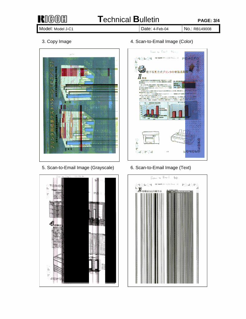
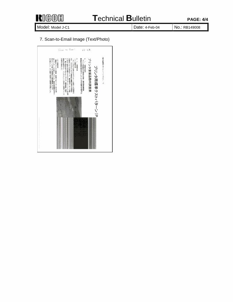
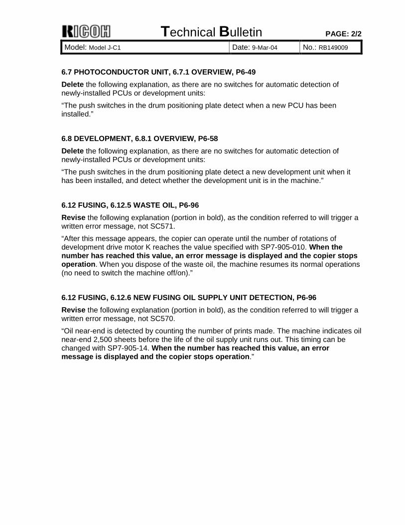
SYMPTOM A RAM access error sometimes occurs when the controller attempts to access the SDRAM DIMM, resulting in one of the faulty images shown below (band shifting along the main scan direction, solid banding, stretched banding). Note: ! Occurrence is limited to when SDRAM DIMM memory is inserted in all 3 slots, and
shows a factory rate of approximately 0.56%. ! Even if this occurs on a fax image, the machine will not send the data.
CAUSE The response time that the controller requires is sometimes too short for the SDRAM DIMM, preventing the image from being read out of memory correctly.
SOLUTION Production (temporary): SDRAMM DIMM parts are tested so that only those that are able to respond in time are selected for use. Product Code Serial Number Product Code Serial Number B146-29 From J9931200001 B148-29 From K0131200001 B147-17 From K0231200001 B149-17 From K0331200001 B147-22 From K0231200721 B149-22 From K0331200816 B147-24 From K0231200851 B149-24 From K0331200926 B147-26 From 4U61230001 B149-26 From 4U71230001 B147-27 From K0231200931 B149-27 From K0331200956
Technical Bulletin PAGE: 2/4
Model: Model J-C1 Date: 4-Feb-04 No.: RB149008
Production (permanent): The following resistors and filter on the controller board have been changed to ensure proper communication between the controller and SDRAM DIMM.
Old Part Number
New Part Number
Description Symbol Number
B1475730 B1475733 Controller for J-C1y (B146/147) * B1495730 B1495733 Controller for J-C1z (B148/149) * 16017879 16017757 Resistor - 0OHM RN15, 32, 106, 107 16090026 16090011 Resistor - 22OHM:+-5%:1/16W RN16, 17, 19, 20, 23, 24, 27, 28 16504470 16071520 Filter - BLM18BA470SN1B R601, 602, 603 16340000 16504470 Resistor - 47OHM+-5%1/10W JP56, 59, 62
Product Code Serial Number Product Code Serial Number B146-29 From J9940100001 B148-29 From K0140100001 B147-17 From K0231200236 B149-17 From K0331200201 B147-22 From K0240101331 B149-22 From K0340100531 B147-24 From K0240101433 B149-24 From K0340200522 B147-26 From 4U60140001 B149-26 From 4U70140001 B147-27 From K0240101453 B149-27 From K0340100573
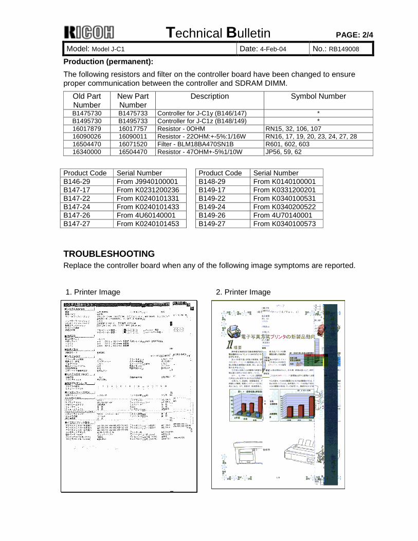
TROUBLESHOOTING Replace the controller board when any of the following image symptoms are reported. 1. Printer Image 2. Printer Image
Technical Bulletin PAGE: 3/4
Model: Model J-C1 Date: 4-Feb-04 No.: RB149008
3. Copy Image 4. Scan-to-Email Image (Color)
5. Scan-to-Email Image (Grayscale) 6. Scan-to-Email Image (Text)
Technical Bulletin PAGE: 4/4
Model: Model J-C1 Date: 4-Feb-04 No.: RB149008
7. Scan-to-Email Image (Text/Photo)

Technical Bulletin PAGE: 1/2
Model: Model J-C1 Date: 9-Mar-04 No.: RB149009
Subject: Service Manual Correction Prepared by: H. Someya From: 1st Tech. Support Sec. Service Support Dept. Classification: Troubleshooting
Mechanical Paper path
Part information Electrical Transmit/receive
Action required Service manual revision Retrofit information
Other ( )
Please apply the following revisions to your Service Manuals. 2.1 SETTINGS, P2-1 • Development Unit–Y (SP5-999-006) • Development Unit–C (SP5-999-008) 4.4 SC TABLES, P4-29 Delete the explanations for SC570 and SC571, as these conditions actually trigger written error messages and not SC code displays. 5.2 COPY SERVICE MODE, 5.2.1 SERVICE MODE TABLES, P5-63 Revise the description for the following.
5999 New Unit Set *BCU #
[0: Disable/1: Enable]
5999 1 PCU: Bk 5999 2 PCU: Y 5999 3 PCU: M 5999 4 PCU: C 5999 5 Dev. U: Bk 5999 6 Dev. U: Y 5999 7 Dev. U: M 5999 8 Dev. U: C 5999 9 Fuser
This program makes the machine to start the initialization processing for a newly installed unit. You set 1: Enable before installing a new unit.
5.2 COPY SERVICE MODE, 5.2.1 SERVICE MODE TABLES, P5-73 Revise the description for SP7804 (sentence in bold), as there are no switches for automatic detection of newly-installed PCUs or development units. 7804 [PM Counter Reset] PM Counter Clear (Unit, [Color])
Dev.: Development Unit, PF: Paper Feed Rollers, Transfer: Transfer Unit Clears the PM counter.
Press the Enter key after the machine asks “Execute?,” which will store the PM counter value in SP7-906-1 to 25 (PM Counter – Previous), and reset the value of the current PM counter to 0. NOTE: The LCT is counted as the 3rd feed station.
Technical Bulletin PAGE: 2/2
Model: Model J-C1 Date: 9-Mar-04 No.: RB149009
6.7 PHOTOCONDUCTOR UNIT, 6.7.1 OVERVIEW, P6-49 Delete the following explanation, as there are no switches for automatic detection of newly-installed PCUs or development units: “The push switches in the drum positioning plate detect when a new PCU has been installed.” 6.8 DEVELOPMENT, 6.8.1 OVERVIEW, P6-58 Delete the following explanation, as there are no switches for automatic detection of newly-installed PCUs or development units: “The push switches in the drum positioning plate detect a new development unit when it has been installed, and detect whether the development unit is in the machine.” 6.12 FUSING, 6.12.5 WASTE OIL, P6-96 Revise the following explanation (portion in bold), as the condition referred to will trigger a written error message, not SC571. “After this message appears, the copier can operate until the number of rotations of development drive motor K reaches the value specified with SP7-905-010. When the number has reached this value, an error message is displayed and the copier stops operation. When you dispose of the waste oil, the machine resumes its normal operations (no need to switch the machine off/on).” 6.12 FUSING, 6.12.6 NEW FUSING OIL SUPPLY UNIT DETECTION, P6-96 Revise the following explanation (portion in bold), as the condition referred to will trigger a written error message, not SC570. “Oil near-end is detected by counting the number of prints made. The machine indicates oil near-end 2,500 sheets before the life of the oil supply unit runs out. This timing can be changed with SP7-905-14. When the number has reached this value, an error message is displayed and the copier stops operation.”
Technical Bulletin PAGE: 1/2
Model: Model J-C1 Date: 17-Mar-04 No.: RB149010
Subject: Firmware Release History (Language) Prepared by: H. Someya From: 1st Tech. Support Sec. Service Support Dept. Classification: Troubleshooting
Mechanical Paper path
Part information Electrical Transmit/receive
Action required Service manual revision Retrofit information
Other ( )
This RTB has been issued to announce the firmware release information for the language kit.
Version Program No. C. SUM Effective Date 3.28 B1015238 5F95 October 2003 production
Version Symptom Corrected
3.28 1st Mass Production
Using the Language Kit. 1. Insert the SD card containing the firmware into the controller SD card slot. 2. Turn ON the main power. Then, chose either the First or Second display language for
the update. Note: It is also possible to write to both the First and Second languages.
3. Start the update. 4. Select the appropriate display language in User Tools. As shown in the table below, there are some cases where certain languages cannot be displayed, depending on the type of operation panel software:
Technical Bulletin PAGE: 2/2
Model: Model J-C1 Date: 17-Mar-04 No.: RB149010
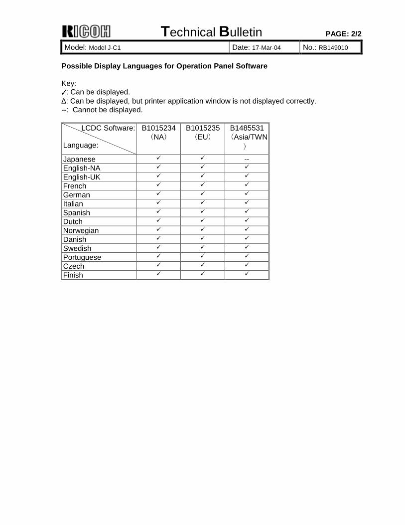
Possible Display Languages for Operation Panel Software Key: !: Can be displayed. ∆: Can be displayed, but printer application window is not displayed correctly. --: Cannot be displayed.
LCDC Software: Language:
B1015234 (NA)
B1015235 (EU)
B1485531 (Asia/TWN
)
Japanese ! ! -- English-NA ! ! ! English-UK ! ! ! French ! ! ! German ! ! ! Italian ! ! ! Spanish ! ! ! Dutch ! ! ! Norwegian ! ! ! Danish ! ! ! Swedish ! ! ! Portuguese ! ! ! Czech ! ! ! Finish ! ! !

Technical Bulletin PAGE: 1/1
Model: Model J-C1 Date: 17-Mar-04 No.: RB149011
Subject: Firmware Release History (MUSIC) Prepared by: H. Someya From: 1st Tech. Support Sec. Service Support Dept. Classification: Troubleshooting
Mechanical Paper path
Part information Electrical Transmit/receive
Action required Service manual revision Retrofit information
Other ( )
This RTB has been issued to announce the firmware release information for MUSIC.
Version Program No. C. SUM Effective Date 1.00 B1015660 A108 October 2003 production
Version Symptom Corrected
1.00 1st Mass Production
Technical Bulletin PAGE: 1/1 Reissued: 27-Jul-04 Model: Model J-C1 Date: 17-Mar-04 No.: RB149012a
RTB Correction The items in bold italics have been corrected or added. Subject: Firmware Release History (Fax) Prepared by: H. Someya From: 1st Tech. Support Sec. Service Support Dept. Classification: Troubleshooting
Mechanical Paper path
Part information Electrical Transmit/receive
Action required Service manual revision Retrofit information
Other ( )
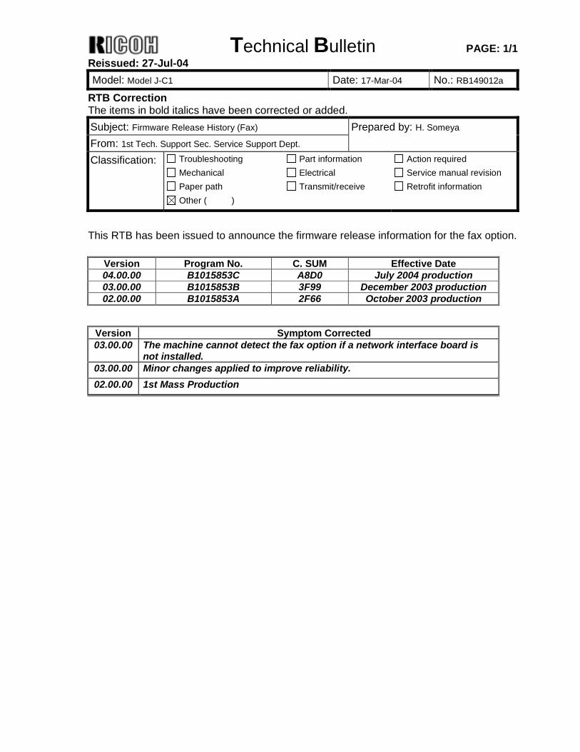
This RTB has been issued to announce the firmware release information for the fax option.
Version Program No. C. SUM Effective Date 04.00.00 B1015853C A8D0 July 2004 production 03.00.00 B1015853B 3F99 December 2003 production 02.00.00 B1015853A 2F66 October 2003 production
Version Symptom Corrected 03.00.00 The machine cannot detect the fax option if a network interface board is
not installed. 03.00.00 Minor changes applied to improve reliability. 02.00.00 1st Mass Production
Technical Bulletin PAGE: 1/1 Reissued: 30-Mar-05 Model: Model J-C1 Date: 17-Mar-04 No.: RB149013a
RTB Correction The items in bold italics have been corrected or added. Subject: Firmware Release History (Netfile) Prepared by: H. Someya From: 1st Tech. Support Sec. Service Support Dept. Classification: Troubleshooting
Mechanical Paper path
Part information Electrical Transmit/receive
Action required Service manual revision Retrofit information
Other ( )
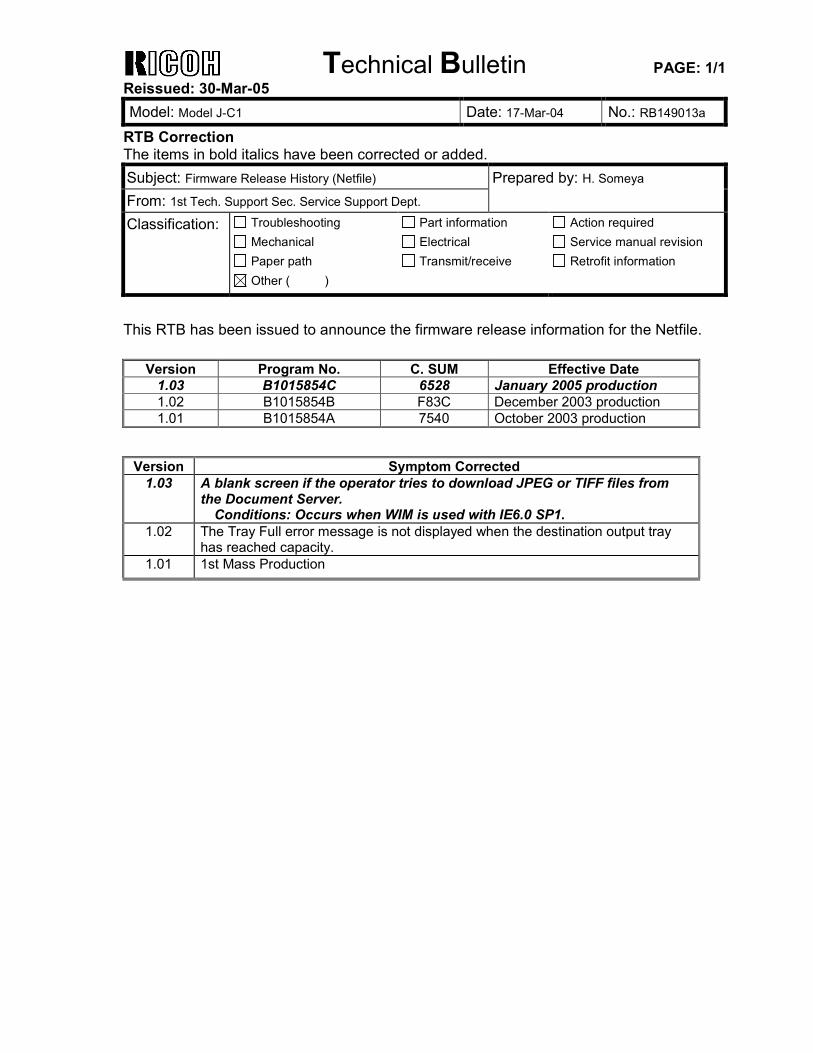
This RTB has been issued to announce the firmware release information for the Netfile.
Version Program No. C. SUM Effective Date 1.03 B1015854C 6528 January 2005 production 1.02 B1015854B F83C December 2003 production 1.01 B1015854A 7540 October 2003 production
Version Symptom Corrected
1.03 A blank screen if the operator tries to download JPEG or TIFF files from the Document Server.
Conditions: Occurs when WIM is used with IE6.0 SP1. 1.02 The Tray Full error message is not displayed when the destination output tray
has reached capacity. 1.01 1st Mass Production

Technical Bulletin PAGE: 1/1 Reissued: 30-Mar-05 Model: Model J-C1 Date: 17-Mar-04 No.: RB149014a
RTB Correction The items in bold italics have been corrected or added. Subject: Firmware Release History (NIB) Prepared by: H. Someya From: 1st Tech. Support Sec. Service Support Dept. Classification: Troubleshooting
Mechanical Paper path
Part information Electrical Transmit/receive
Action required Service manual revision Retrofit information
Other ( )
This RTB has been issued to announce the firmware release information for the NIB.
Version Program No. C. SUM Effective Date 4.13.1 B1015852C 0CD3 (Not applied to production) 4.13 B1015852C 7DB9 December 2003 production 4.11 B1015852B 1EF8 October 2003 production
Version Symptom Corrected 4.13.1 If a host name with over 15 characters is entered, only the first 14
characters is sent to the DHCP server when the client requests an IP address (GFPR#RE04100004).
4.13 Printing slows when jobs of more than 1Mb are sent through a Windows 2000 Standard TCP/IP port (Raw protocol) only.
4.11 1st Mass Production

Technical Bulletin PAGE: 1/1
Model: Model J-C1 Date: 17-Mar-04 No.: RB149015
Subject: Firmware Release History (WebSystem) Prepared by: H. Someya From: 1st Tech. Support Sec. Service Support Dept. Classification: Troubleshooting
Mechanical Paper path
Part information Electrical Transmit/receive
Action required Service manual revision Retrofit information
Other ( )
This RTB has been issued to announce the firmware release information for WebSystem.
Version Program No. C. SUM Effective Date 1.03 B1015855B 5A7E October 2003 production
Version Symptom Corrected
1.03 1st Mass Production
Technical Bulletin PAGE: 1/1
Model: Model J-C1 Date: 17-Mar-04 No.: RB149016
Subject: Firmware Release History (WebDocBox) Prepared by: H. Someya From: 1st Tech. Support Sec. Service Support Dept. Classification: Troubleshooting
Mechanical Paper path
Part information Electrical Transmit/receive
Action required Service manual revision Retrofit information
Other ( )
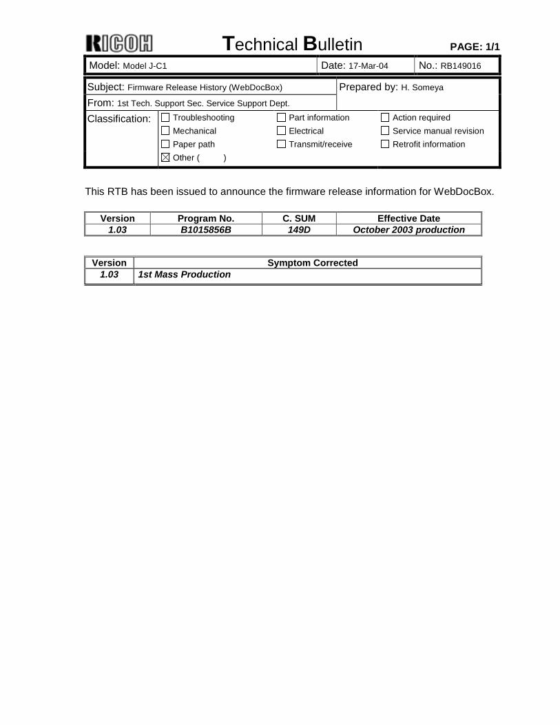
This RTB has been issued to announce the firmware release information for WebDocBox.
Version Program No. C. SUM Effective Date 1.03 B1015856B 149D October 2003 production
Version Symptom Corrected
1.03 1st Mass Production
Technical Bulletin PAGE: 1/1
Model: Model J-C1 Date: 17-Mar-04 No.: RB149017
Subject: Firmware Release History (LCDC) Prepared by: H. Someya From: 1st Tech. Support Sec. Service Support Dept. Classification: Troubleshooting
Mechanical Paper path
Part information Electrical Transmit/receive
Action required Service manual revision Retrofit information
Other ( )
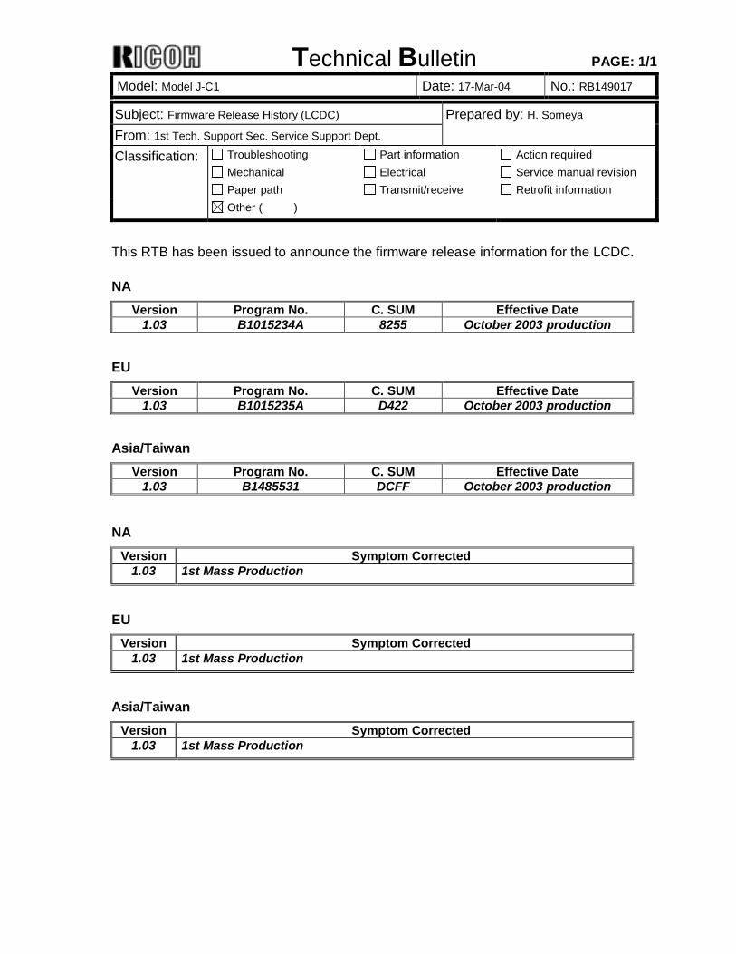
This RTB has been issued to announce the firmware release information for the LCDC. NA
Version Program No. C. SUM Effective Date 1.03 B1015234A 8255 October 2003 production
EU
Version Program No. C. SUM Effective Date 1.03 B1015235A D422 October 2003 production
Asia/Taiwan
Version Program No. C. SUM Effective Date 1.03 B1485531 DCFF October 2003 production
NA Version Symptom Corrected
1.03 1st Mass Production
EU Version Symptom Corrected
1.03 1st Mass Production
Asia/Taiwan Version Symptom Corrected
1.03 1st Mass Production
Technical Bulletin PAGE: 1/1
Model: Model J-C1 Date: 17-Mar-04 No.: RB149018
Subject: Firmware Release History (FCU) Prepared by: H. Someya From: 1st Tech. Support Sec. Service Support Dept. Classification: Troubleshooting
Mechanical Paper path
Part information Electrical Transmit/receive
Action required Service manual revision Retrofit information
Other ( )
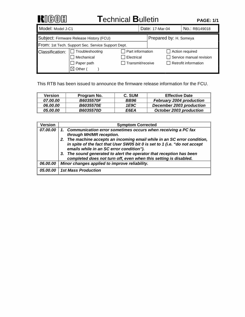
This RTB has been issued to announce the firmware release information for the FCU.
Version Program No. C. SUM Effective Date 07.00.00 B6035570F BB96 February 2004 production 06.00.00 B6035570E 1E9C December 2003 production 05.00.00 B6035570D E6EA October 2003 production
Version Symptom Corrected 07.00.00 1. Communication error sometimes occurs when receiving a PC fax
through MH/MR reception. 2. The machine accepts an incoming email while in an SC error condition,
in spite of the fact that User SW05 bit 0 is set to 1 (i.e. “do not accept emails while in an SC error condition”).
3. The sound generated to alert the operator that reception has been completed does not turn off, even when this setting is disabled.
06.00.00 Minor changes applied to improve reliability. 05.00.00 1st Mass Production
Technical Bulletin PAGE: 1/1
Model: Model J-C1 Date: 18-Mar-04 No.: RB149019
Subject: Firmware Release History (Scanner) Prepared by: H. Someya From: 1st Tech. Support Sec. Service Support Dept. Classification: Troubleshooting
Mechanical Paper path
Part information Electrical Transmit/receive
Action required Service manual revision Retrofit information
Other ( )
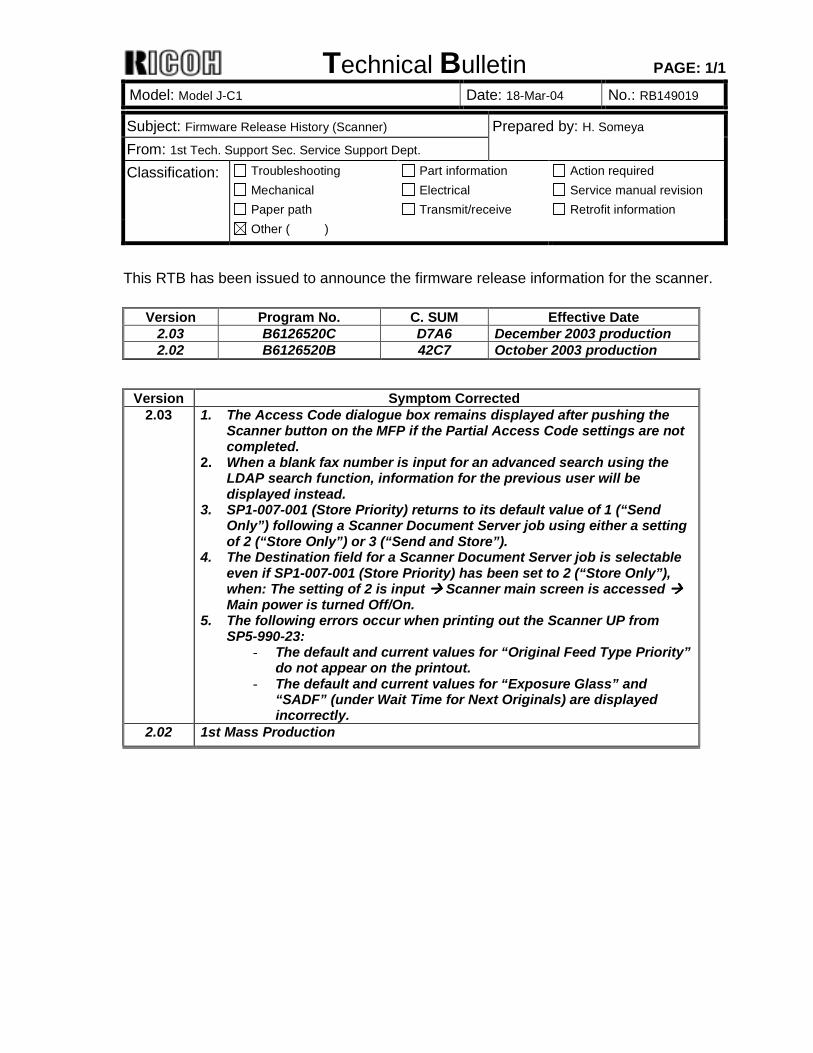
This RTB has been issued to announce the firmware release information for the scanner.
Version Program No. C. SUM Effective Date 2.03 B6126520C D7A6 December 2003 production 2.02 B6126520B 42C7 October 2003 production
Version Symptom Corrected
2.03 1. The Access Code dialogue box remains displayed after pushing the Scanner button on the MFP if the Partial Access Code settings are not completed.
2. When a blank fax number is input for an advanced search using the LDAP search function, information for the previous user will be displayed instead.
3. SP1-007-001 (Store Priority) returns to its default value of 1 (“Send Only”) following a Scanner Document Server job using either a setting of 2 (“Store Only”) or 3 (“Send and Store”).
4. The Destination field for a Scanner Document Server job is selectable even if SP1-007-001 (Store Priority) has been set to 2 (“Store Only”), when: The setting of 2 is input !!!! Scanner main screen is accessed !!!! Main power is turned Off/On.
5. The following errors occur when printing out the Scanner UP from SP5-990-23:
- The default and current values for “Original Feed Type Priority” do not appear on the printout.
- The default and current values for “Exposure Glass” and “SADF” (under Wait Time for Next Originals) are displayed incorrectly.
2.02 1st Mass Production
Technical Bulletin PAGE: 1/1
Model: Model J-C1 Date: 25-Mar-04 No.: RB149020
Subject: Firmware Release History (Scanner IPU) Prepared by: H. Someya From: 1st Tech. Support Sec. Service Support Dept. Classification: Troubleshooting
Mechanical Paper path
Part information Electrical Transmit/receive
Action required Service manual revision Retrofit information
Other ( )
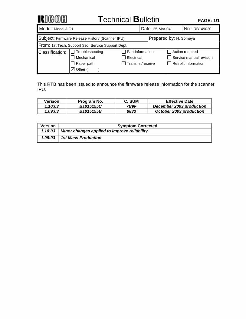
This RTB has been issued to announce the firmware release information for the scanner IPU.
Version Program No. C. SUM Effective Date 1.10:03 B1015155C 7B9F December 2003 production 1.09:03 B1015155B 8833 October 2003 production
Version Symptom Corrected 1.10:03 Minor changes applied to improve reliability. 1.09:03 1st Mass Production
Technical Bulletin PAGE: 1/1
Model: Model J-C1 Date: 30-Mar-04 No.: RB149021
Subject: Firmware Release History (Printer) Prepared by: H. Someya From: 1st Tech. Support Sec. Service Support Dept. Classification: Troubleshooting
Mechanical Paper path
Part information Electrical Transmit/receive
Action required Service manual revision Retrofit information
Other ( )
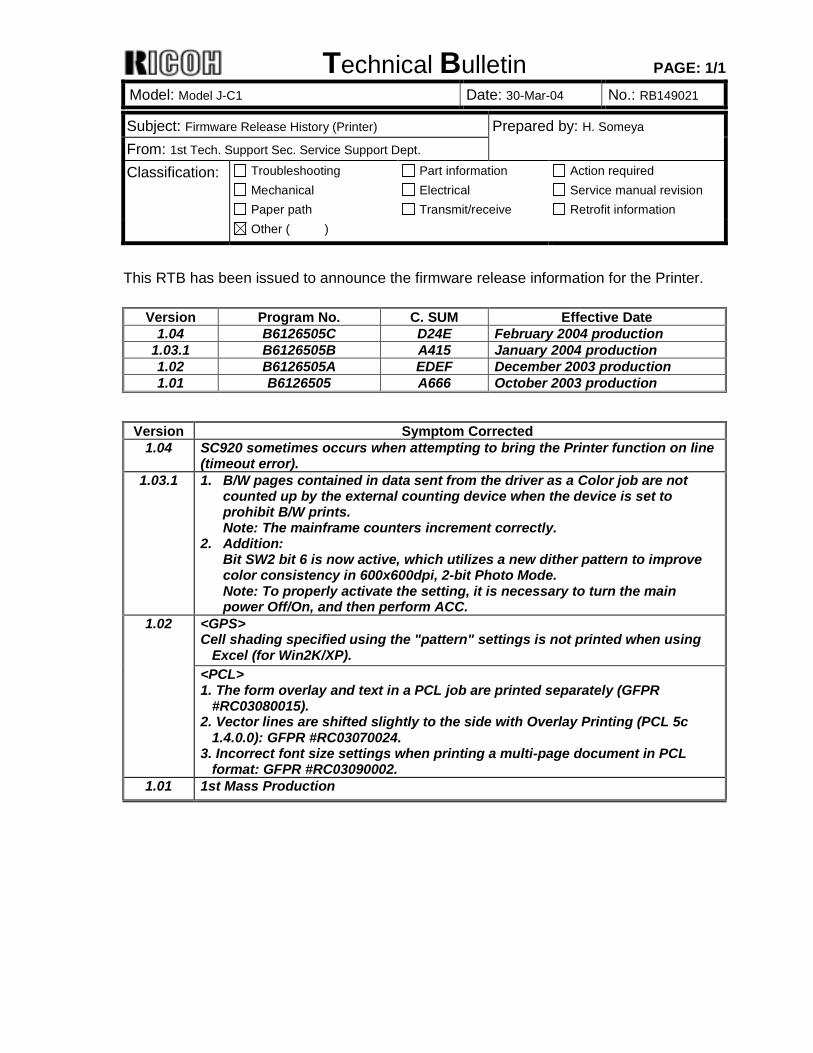
This RTB has been issued to announce the firmware release information for the Printer.
Version Program No. C. SUM Effective Date 1.04 B6126505C D24E February 2004 production
1.03.1 B6126505B A415 January 2004 production 1.02 B6126505A EDEF December 2003 production 1.01 B6126505 A666 October 2003 production
Version Symptom Corrected
1.04 SC920 sometimes occurs when attempting to bring the Printer function on line (timeout error).
1.03.1 1. B/W pages contained in data sent from the driver as a Color job are not counted up by the external counting device when the device is set to prohibit B/W prints. Note: The mainframe counters increment correctly.
2. Addition: Bit SW2 bit 6 is now active, which utilizes a new dither pattern to improve color consistency in 600x600dpi, 2-bit Photo Mode. Note: To properly activate the setting, it is necessary to turn the main power Off/On, and then perform ACC.
<GPS> Cell shading specified using the "pattern" settings is not printed when using
Excel (for Win2K/XP).
1.02
<PCL> 1. The form overlay and text in a PCL job are printed separately (GFPR
#RC03080015). 2. Vector lines are shifted slightly to the side with Overlay Printing (PCL 5c
1.4.0.0): GFPR #RC03070024. 3. Incorrect font size settings when printing a multi-page document in PCL
format: GFPR #RC03090002. 1.01 1st Mass Production
Technical Bulletin PAGE: 1/2 Reissued: 21-Apr-04 Model: Model J-C1 Date: 26-Jan-04 No.: RB149001a
RTB Correction The items in bold italics have been corrected or added. Subject: Firmware Release History (Engine) Prepared by: H. Someya From: 1st Tech. Support Sec. Service Support Dept. Classification: Troubleshooting
Mechanical Paper path
Part information Electrical Transmit/receive
Action required Service manual revision Retrofit information
Other ( )
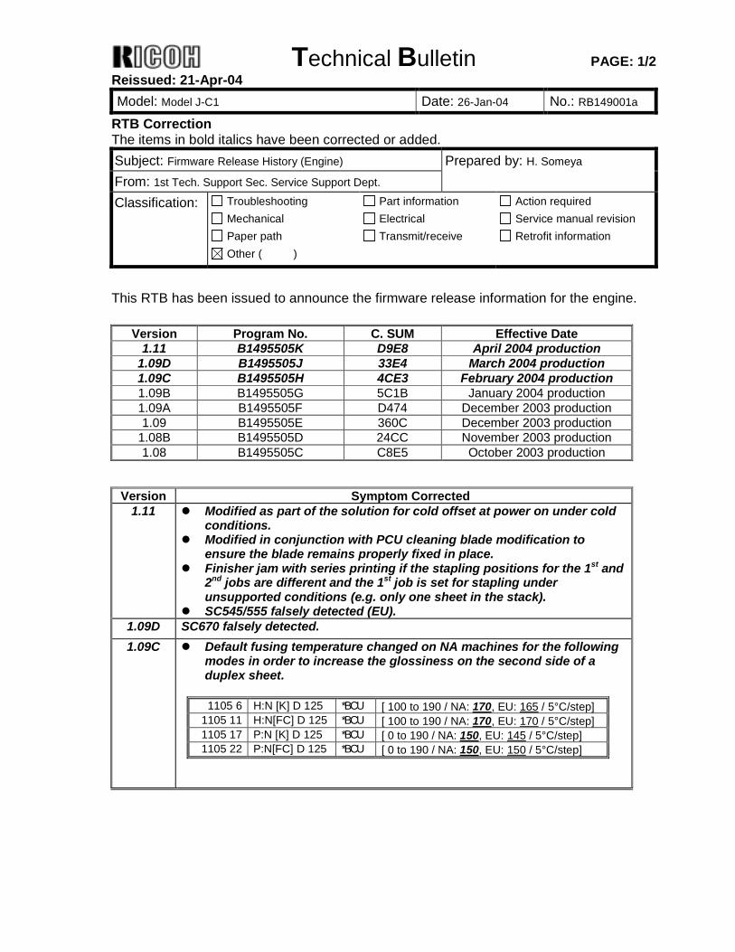
This RTB has been issued to announce the firmware release information for the engine.
Version Program No. C. SUM Effective Date 1.11 B1495505K D9E8 April 2004 production
1.09D B1495505J 33E4 March 2004 production 1.09C B1495505H 4CE3 February 2004 production 1.09B B1495505G 5C1B January 2004 production 1.09A B1495505F D474 December 2003 production 1.09 B1495505E 360C December 2003 production
1.08B B1495505D 24CC November 2003 production 1.08 B1495505C C8E5 October 2003 production
Version Symptom Corrected
1.11 ! Modified as part of the solution for cold offset at power on under cold conditions.
! Modified in conjunction with PCU cleaning blade modification to ensure the blade remains properly fixed in place.
! Finisher jam with series printing if the stapling positions for the 1st and 2nd jobs are different and the 1st job is set for stapling under unsupported conditions (e.g. only one sheet in the stack).
! SC545/555 falsely detected (EU). 1.09D SC670 falsely detected. 1.09C ! Default fusing temperature changed on NA machines for the following
modes in order to increase the glossiness on the second side of a duplex sheet.
1105 6 H:N [K] D 125 *BCU [ 100 to 190 / NA: 170, EU: 165 / 5°C/step]
1105 11 H:N[FC] D 125 *BCU [ 100 to 190 / NA: 170, EU: 170 / 5°C/step] 1105 17 P:N [K] D 125 *BCU [ 0 to 190 / NA: 150, EU: 145 / 5°C/step] 1105 22 P:N[FC] D 125 *BCU [ 0 to 190 / NA: 150, EU: 150 / 5°C/step]
Technical Bulletin PAGE: 2/2 Reissued: 21-Apr-04 Model: Model J-C1 Date: 26-Jan-04 No.: RB149001a
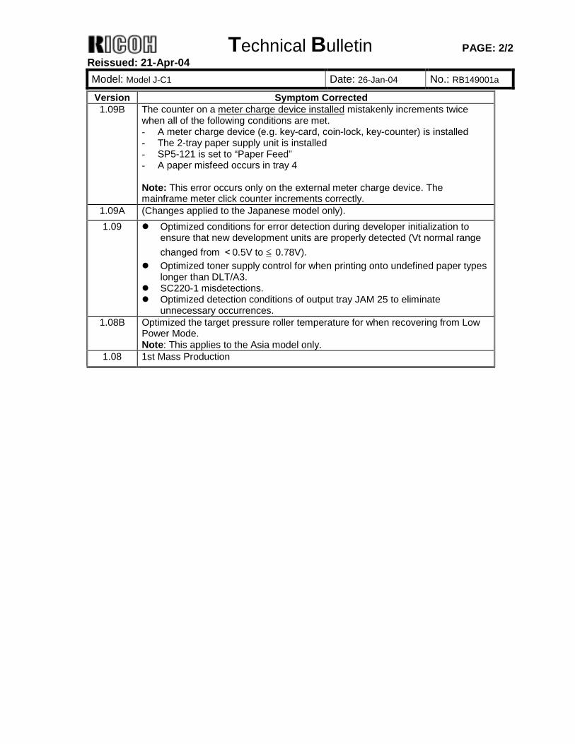
Version Symptom Corrected 1.09B The counter on a meter charge device installed mistakenly increments twice
when all of the following conditions are met. - A meter charge device (e.g. key-card, coin-lock, key-counter) is installed - The 2-tray paper supply unit is installed - SP5-121 is set to “Paper Feed” - A paper misfeed occurs in tray 4 Note: This error occurs only on the external meter charge device. The mainframe meter click counter increments correctly.
1.09A (Changes applied to the Japanese model only). 1.09 ! Optimized conditions for error detection during developer initialization to
ensure that new development units are properly detected (Vt normal range changed from <0.5V to ≦ 0.78V).
! Optimized toner supply control for when printing onto undefined paper types longer than DLT/A3.
! SC220-1 misdetections. ! Optimized detection conditions of output tray JAM 25 to eliminate
unnecessary occurrences. 1.08B Optimized the target pressure roller temperature for when recovering from Low
Power Mode. Note: This applies to the Asia model only.
1.08 1st Mass Production
Technical Bulletin PAGE: 1/2 Reissued: 21-Apr-04 Model: Model J-C1 Date: 26-Jan-04 No.: RB149003a
RTB Correction The items in bold italics have been corrected or added. Subject: Firmware Release History (System) Prepared by: H. Someya From: 1st Tech. Support Sec. Service Support Dept. Classification: Troubleshooting
Mechanical Paper path
Part information Electrical Transmit/receive
Action required Service manual revision Retrofit information
Other ( )
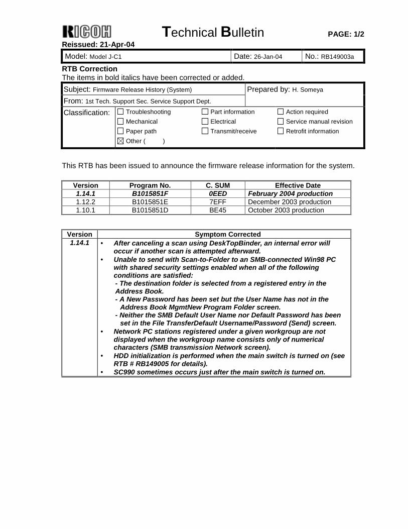
This RTB has been issued to announce the firmware release information for the system.
Version Program No. C. SUM Effective Date 1.14.1 B1015851F 0EED February 2004 production 1.12.2 B1015851E 7EFF December 2003 production 1.10.1 B1015851D BE45 October 2003 production
Version Symptom Corrected 1.14.1 • After canceling a scan using DeskTopBinder, an internal error will
occur if another scan is attempted afterward. • Unable to send with Scan-to-Folder to an SMB-connected Win98 PC
with shared security settings enabled when all of the following conditions are satisfied: - The destination folder is selected from a registered entry in the Address Book. - A New Password has been set but the User Name has not in the
Address Book MgmtNew Program Folder screen. - Neither the SMB Default User Name nor Default Password has been
set in the File TransferDefault Username/Password (Send) screen. • Network PC stations registered under a given workgroup are not
displayed when the workgroup name consists only of numerical characters (SMB transmission Network screen).
• HDD initialization is performed when the main switch is turned on (see RTB # RB149005 for details).
• SC990 sometimes occurs just after the main switch is turned on.
Technical Bulletin PAGE: 2/2 Reissued: 21-Apr-04 Model: Model J-C1 Date: 26-Jan-04 No.: RB149003a
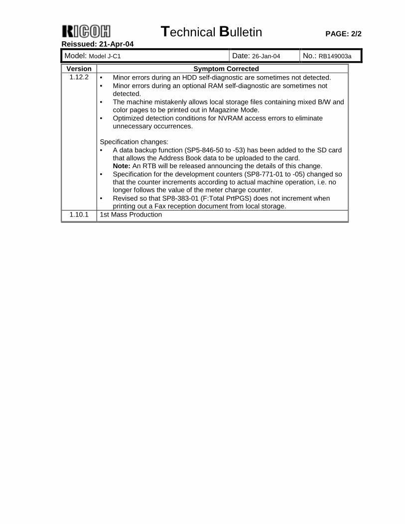
Version Symptom Corrected 1.12.2 • Minor errors during an HDD self-diagnostic are sometimes not detected.
• Minor errors during an optional RAM self-diagnostic are sometimes not detected.
• The machine mistakenly allows local storage files containing mixed B/W and color pages to be printed out in Magazine Mode.
• Optimized detection conditions for NVRAM access errors to eliminate unnecessary occurrences.
Specification changes: • A data backup function (SP5-846-50 to -53) has been added to the SD card
that allows the Address Book data to be uploaded to the card. Note: An RTB will be released announcing the details of this change.
• Specification for the development counters (SP8-771-01 to -05) changed so that the counter increments according to actual machine operation, i.e. no longer follows the value of the meter charge counter.
• Revised so that SP8-383-01 (F:Total PrtPGS) does not increment when printing out a Fax reception document from local storage.
1.10.1 1st Mass Production
Technical Bulletin PAGE: 1/1 Reissued: 21-Apr-04 Model: Model J-C1 Date: 18-Mar-04 No.: RB149019a
RTB Correction The items in bold italics have been corrected or added. Subject: Firmware Release History (Scanner) Prepared by: H. Someya From: 1st Tech. Support Sec. Service Support Dept. Classification: Troubleshooting
Mechanical Paper path
Part information Electrical Transmit/receive
Action required Service manual revision Retrofit information
Other ( )
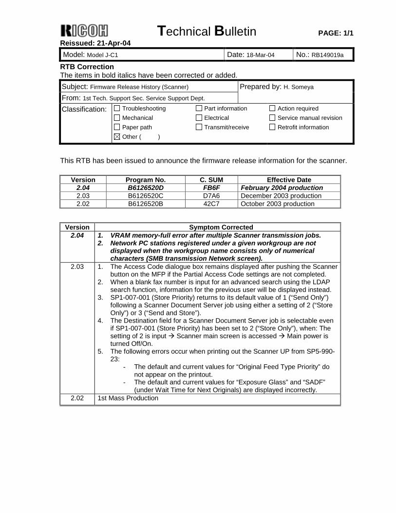
This RTB has been issued to announce the firmware release information for the scanner.
Version Program No. C. SUM Effective Date 2.04 B6126520D FB6F February 2004 production 2.03 B6126520C D7A6 December 2003 production 2.02 B6126520B 42C7 October 2003 production
Version Symptom Corrected
2.04 1. VRAM memory-full error after multiple Scanner transmission jobs. 2. Network PC stations registered under a given workgroup are not
displayed when the workgroup name consists only of numerical characters (SMB transmission Network screen).
2.03 1. The Access Code dialogue box remains displayed after pushing the Scanner button on the MFP if the Partial Access Code settings are not completed.
2. When a blank fax number is input for an advanced search using the LDAP search function, information for the previous user will be displayed instead.
3. SP1-007-001 (Store Priority) returns to its default value of 1 (“Send Only”) following a Scanner Document Server job using either a setting of 2 (“Store Only”) or 3 (“Send and Store”).
4. The Destination field for a Scanner Document Server job is selectable even if SP1-007-001 (Store Priority) has been set to 2 (“Store Only”), when: The setting of 2 is input ! Scanner main screen is accessed ! Main power is turned Off/On.
5. The following errors occur when printing out the Scanner UP from SP5-990-23:
- The default and current values for “Original Feed Type Priority” do not appear on the printout.
- The default and current values for “Exposure Glass” and “SADF” (under Wait Time for Next Originals) are displayed incorrectly.
2.02 1st Mass Production
Technical Bulletin PAGE: 1/1
Model: Model J-C1 Date: 1-Jun-04 No.: RB149022
Subject: SC285, SC387, 388, 389 Prepared by: H.Taguchi From: 1st Tech. Support Sec. Service Support Dept. Classification: Troubleshooting
Mechanical Paper path
Part information Electrical Transmit/receive
Action required Service manual revision Retrofit information
Other ( )
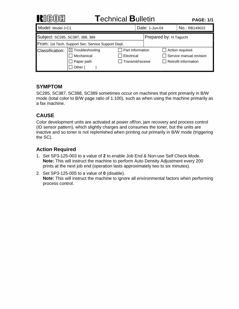
SYMPTOM SC285, SC387, SC388, SC389 sometimes occur on machines that print primarily in B/W mode (total color to B/W page ratio of 1:100), such as when using the machine primarily as a fax machine.
CAUSE Color development units are activated at power off/on, jam recovery and process control (ID sensor pattern), which slightly charges and consumes the toner, but the units are inactive and so toner is not replenished when printing out primarily in B/W mode (triggering the SC).
Action Required 1. Set SP3-125-003 to a value of 2 to enable Job End & Non-use Self Check Mode.
Note: This will instruct the machine to perform Auto Density Adjustment every 200 prints at the next job end (operation lasts approximately two to six minutes).
2. Set SP3-125-005 to a value of 0 (disable). Note: This will instruct the machine to ignore all environmental factors when performing process control.
Technical Bulletin PAGE: 1/1
Model: Model J-C1 Date: 24-Jun-04 No.: RB149023
Subject: SC385 Prepared by: H.Tagucghi From: 1st Tech. Support Sec. Service Support Dept. Classification: Troubleshooting
Mechanical Paper path
Part information Electrical Transmit/receive
Action required Service manual revision Retrofit information
Other ( )
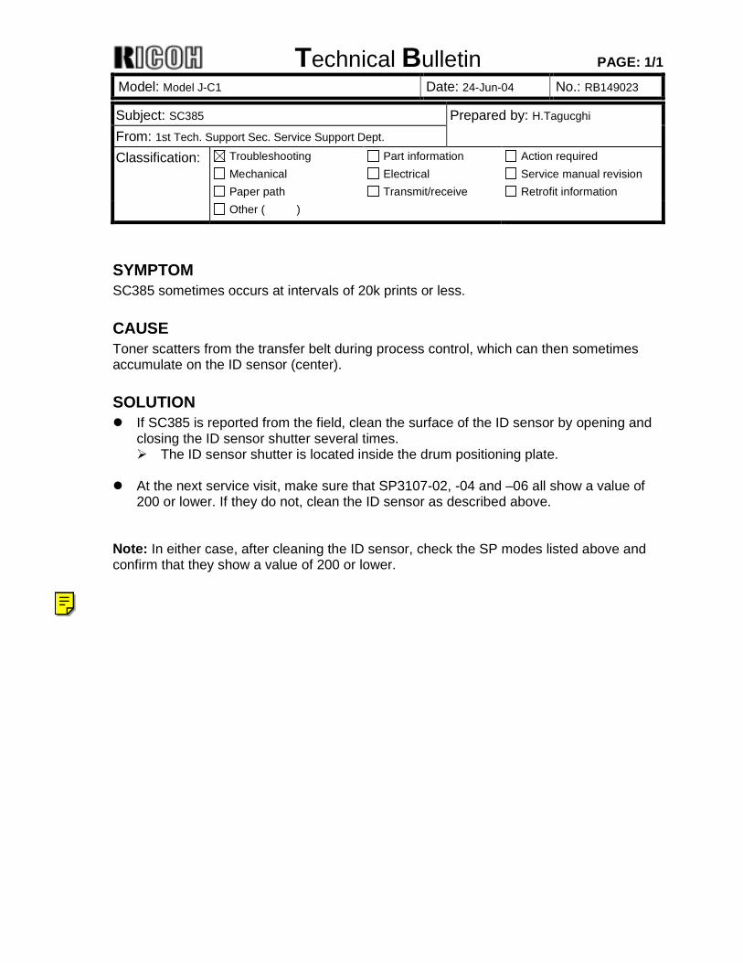
SYMPTOM SC385 sometimes occurs at intervals of 20k prints or less.
CAUSE Toner scatters from the transfer belt during process control, which can then sometimes accumulate on the ID sensor (center).
SOLUTION ! If SC385 is reported from the field, clean the surface of the ID sensor by opening and
closing the ID sensor shutter several times. # The ID sensor shutter is located inside the drum positioning plate.
! At the next service visit, make sure that SP3107-02, -04 and –06 all show a value of
200 or lower. If they do not, clean the ID sensor as described above. Note: In either case, after cleaning the ID sensor, check the SP modes listed above and confirm that they show a value of 200 or lower.
Ricoh Technical Services
See RTB 23b for the latest information
Technical Bulletin PAGE: 1/4
Model: Model J-C1 Date: 27-Jul-04 No.: RB149024
Subject: Paper jam in the duplex unit Prepared by: H.Taguchi From: 1st Tech. Support Sec. Service Support Dept. Classification: Troubleshooting
Mechanical Paper path
Part information Electrical Transmit/receive
Action required Service manual revision Retrofit information
Other ( )
SYMPTOM Paper jam occurs in the duplex unit.
CAUSE The shape of some Mylars in the duplex unit were wrong, and the Mylars were attached at the wrong angle. This blocked the paper when it was sent to the two-tray finisher or booklet finisher. Occurrence conditions: - Mainframe + two-tray finisher and LCT or, - Mainframe + two-tray finisher and paper feed unit (2 trays), or - Mainframe + Booklet finisher
SOLUTION Production Line An inspection has been added to make sure the Mylars have the correct shape and they are attached correctly.
Action in the Field Replace the seven Mylars shown below (P/N G3484682, Sheet: Gate: 2).
Technical Bulletin PAGE: 2/4
Model: Model J-C1 Date: 27-Jul-04 No.: RB149024
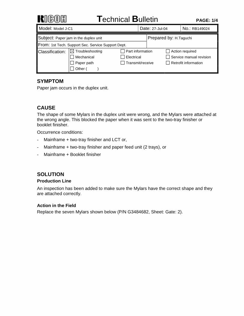
Mylar Replacement Procedure 1. Open the duplex left cover [A]. 2. Remove the top cover (screw x 4).
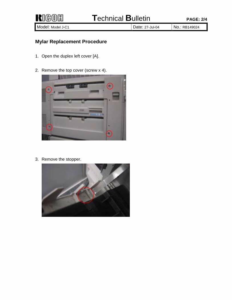
3. Remove the stopper.
Technical Bulletin PAGE: 3/4
Model: Model J-C1 Date: 27-Jul-04 No.: RB149024
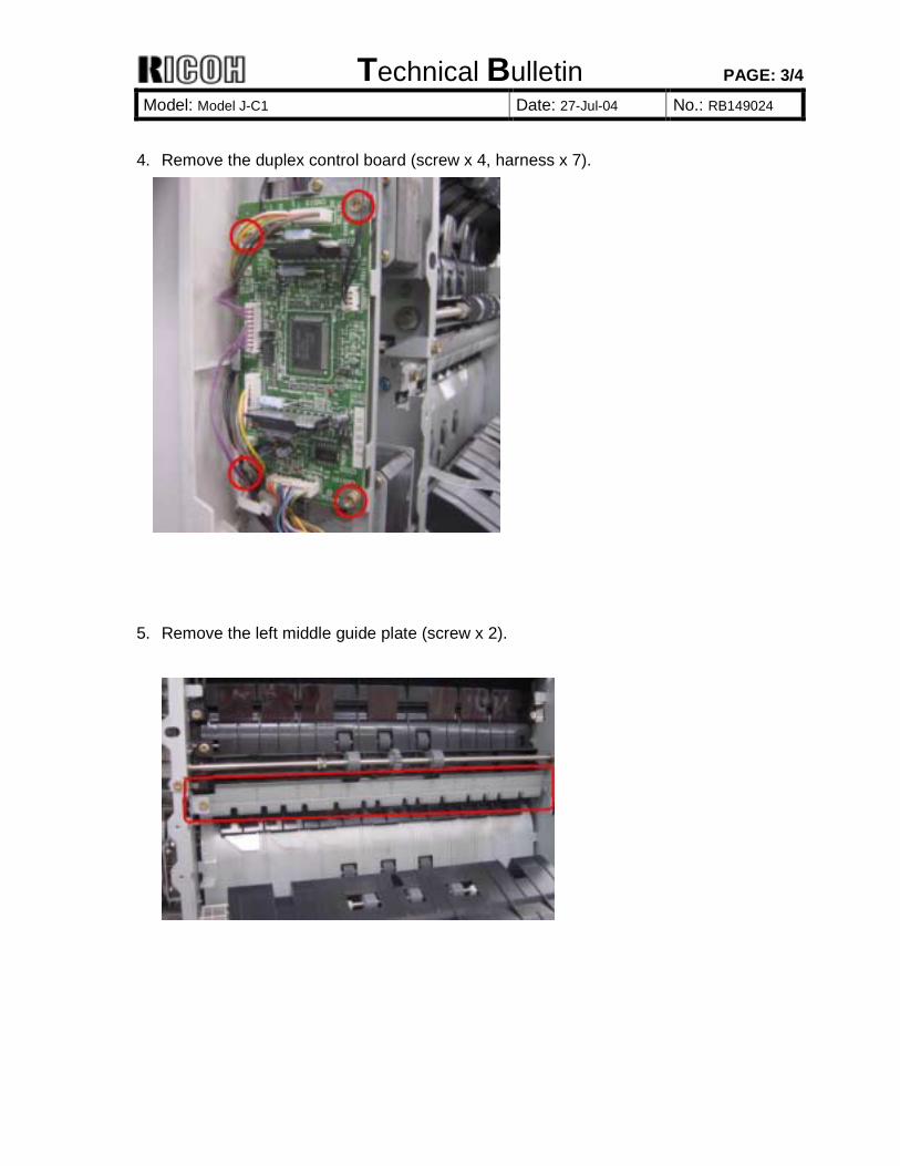
4. Remove the duplex control board (screw x 4, harness x 7).
5. Remove the left middle guide plate (screw x 2).
Technical Bulletin PAGE: 4/4
Model: Model J-C1 Date: 27-Jul-04 No.: RB149024
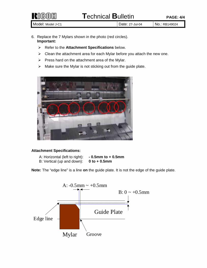
6. Replace the 7 Mylars shown in the photo (red circles).
Important: ! Refer to the Attachment Specifications below. ! Clean the attachment area for each Mylar before you attach the new one. ! Press hard on the attachment area of the Mylar. ! Make sure the Mylar is not sticking out from the guide plate.
Attachment Specifications:
A: Horizontal (left to right): - 0.5mm to + 0.5mm B: Vertical (up and down): 0 to + 0.5mm
Note: The “edge line” is a line on the guide plate. It is not the edge of the guide plate.
Guide Plate
A: -0.5mm ~ +0.5mmB: 0 ~ +0.5mm
Mylar
Edge line
Groove
Technical Bulletin PAGE: 1/1
Model: Model J-C1 Date: 27-Jul-04 No.: RB149025
Subject: Machine cannot detect fax unit if NIB is not installed. Prepared by: H. Someya From: 1st Tech. Support Sec. Service Support Dept. Classification: Troubleshooting
Mechanical Paper path
Part information Electrical Transmit/receive
Action required Service manual revision Retrofit information
Other ( )
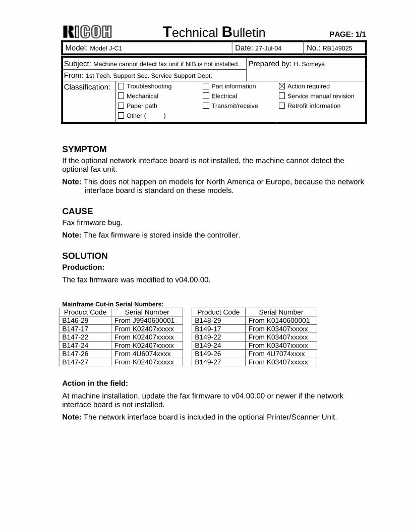
SYMPTOM If the optional network interface board is not installed, the machine cannot detect the optional fax unit. Note: This does not happen on models for North America or Europe, because the network
interface board is standard on these models.
CAUSE Fax firmware bug. Note: The fax firmware is stored inside the controller.
SOLUTION Production: The fax firmware was modified to v04.00.00. Mainframe Cut-in Serial Numbers: Product Code Serial Number Product Code Serial Number B146-29 From J9940600001 B148-29 From K0140600001 B147-17 From K02407xxxxx B149-17 From K03407xxxxx B147-22 From K02407xxxxx B149-22 From K03407xxxxx B147-24 From K02407xxxxx B149-24 From K03407xxxxx B147-26 From 4U6074xxxx B149-26 From 4U7074xxxx B147-27 From K02407xxxxx B149-27 From K03407xxxxx Action in the field: At machine installation, update the fax firmware to v04.00.00 or newer if the network interface board is not installed. Note: The network interface board is included in the optional Printer/Scanner Unit.
Technical Bulletin PAGE: 1/3
Model: Model J-C1 Date: 17-Aug-04 No.: RB149026
Subject: Differences between J-C1y/z and J-C1k Prepared by: H. Someya From: 1st Tech. Support Sec. Service Support Dept. Classification: Troubleshooting
Mechanical Paper path
Part information Electrical Transmit/receive
Action required Service manual revision Retrofit information
Other ( )
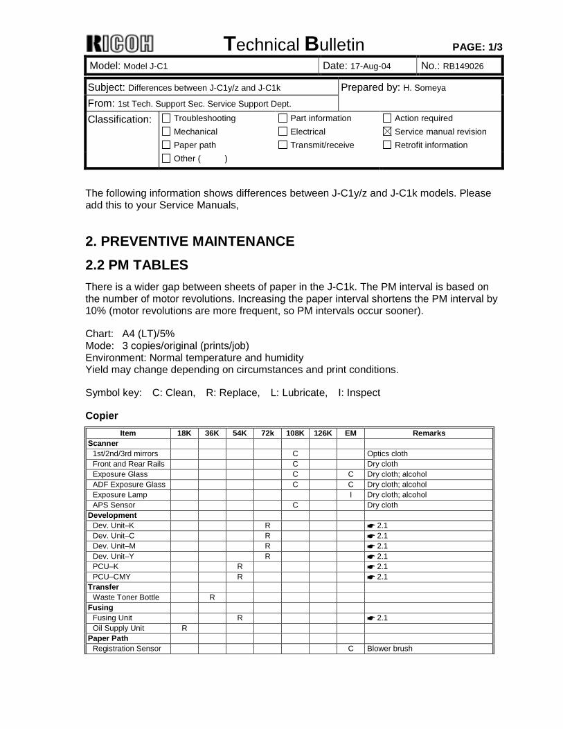
The following information shows differences between J-C1y/z and J-C1k models. Please add this to your Service Manuals,
2. PREVENTIVE MAINTENANCE 2.2 PM TABLES There is a wider gap between sheets of paper in the J-C1k. The PM interval is based on the number of motor revolutions. Increasing the paper interval shortens the PM interval by 10% (motor revolutions are more frequent, so PM intervals occur sooner).
Chart: A4 (LT)/5% Mode: 3 copies/original (prints/job) Environment: Normal temperature and humidity Yield may change depending on circumstances and print conditions.
Symbol key: C: Clean, R: Replace, L: Lubricate, I: Inspect
Copier Item 18K 36K 54K 72k 108K 126K EM Remarks
Scanner 1st/2nd/3rd mirrors C Optics cloth Front and Rear Rails C Dry cloth Exposure Glass C C Dry cloth; alcohol ADF Exposure Glass C C Dry cloth; alcohol Exposure Lamp I Dry cloth; alcohol APS Sensor C Dry cloth
Development Dev. Unit–K R ☛ 2.1 Dev. Unit–C R ☛ 2.1 Dev. Unit–M R ☛ 2.1 Dev. Unit–Y R ☛ 2.1 PCU–K R ☛ 2.1 PCU–CMY R ☛ 2.1
Transfer Waste Toner Bottle R
Fusing Fusing Unit R ☛ 2.1 Oil Supply Unit R
Paper Path Registration Sensor C Blower brush
Technical Bulletin PAGE: 2/3
Model: Model J-C1 Date: 17-Aug-04 No.: RB149026
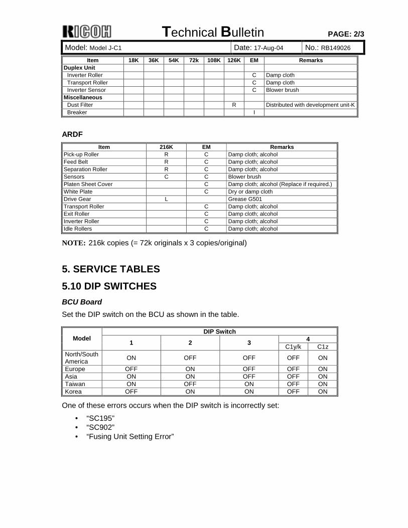
Item 18K 36K 54K 72k 108K 126K EM Remarks Duplex Unit
Inverter Roller C Damp cloth Transport Roller C Damp cloth Inverter Sensor C Blower brush
Miscellaneous Dust Filter R Distributed with development unit-KBreaker I
ARDF
Item 216K EM Remarks Pick-up Roller R C Damp cloth; alcohol Feed Belt R C Damp cloth; alcohol Separation Roller R C Damp cloth; alcohol Sensors C C Blower brush Platen Sheet Cover C Damp cloth; alcohol (Replace if required.) White Plate C Dry or damp cloth Drive Gear L Grease G501 Transport Roller C Damp cloth; alcohol Exit Roller C Damp cloth; alcohol Inverter Roller C Damp cloth; alcohol Idle Rollers C Damp cloth; alcohol
NOTE: 216k copies (= 72k originals x 3 copies/original)
5. SERVICE TABLES 5.10 DIP SWITCHES BCU Board Set the DIP switch on the BCU as shown in the table.
DIP Switch 4 Model 1 2 3 C1y/k C1z
North/South America ON OFF OFF OFF ON
Europe OFF ON OFF OFF ON Asia ON ON OFF OFF ON Taiwan ON OFF ON OFF ON Korea OFF ON ON OFF ON
One of these errors occurs when the DIP switch is incorrectly set:
• “SC195” • “SC902” • “Fusing Unit Setting Error”
Technical Bulletin PAGE: 3/3
Model: Model J-C1 Date: 17-Aug-04 No.: RB149026
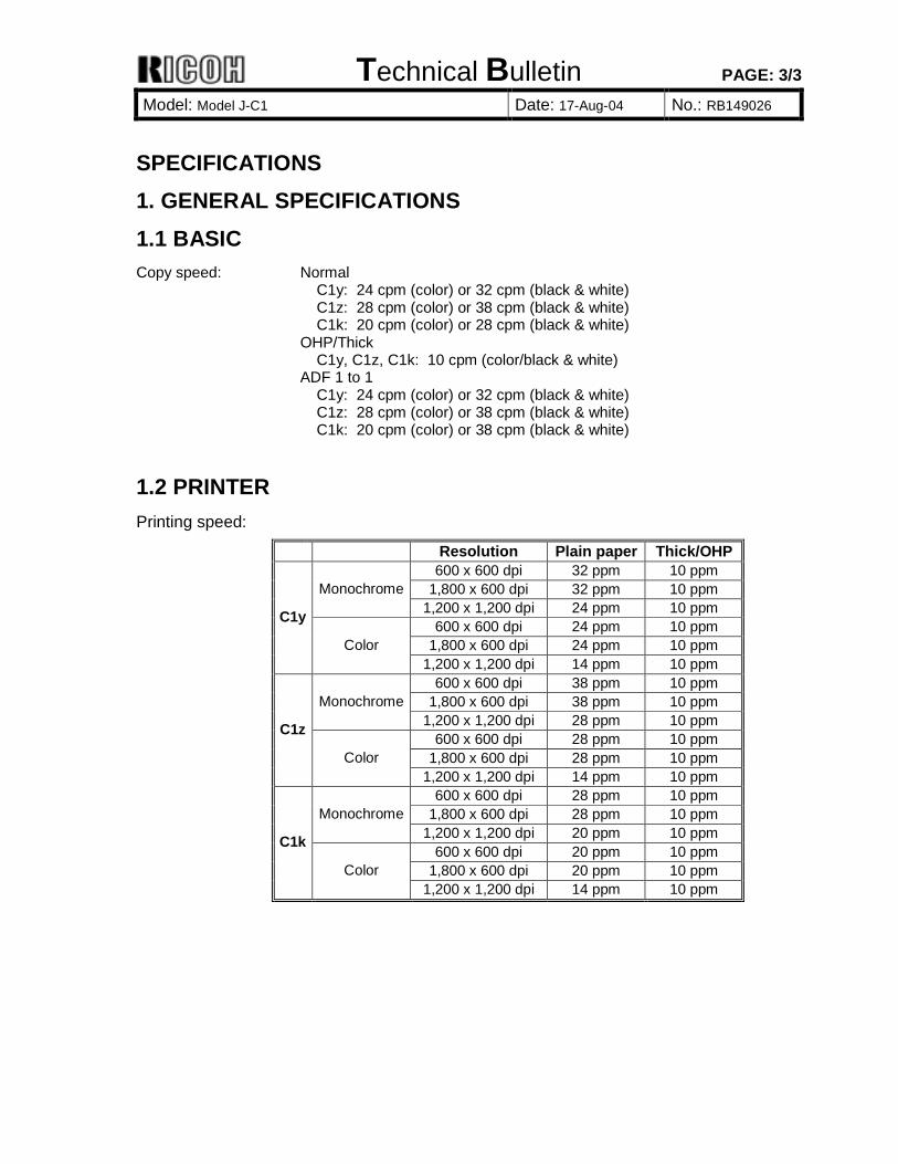
SPECIFICATIONS 1. GENERAL SPECIFICATIONS 1.1 BASIC Copy speed: Normal
C1y: 24 cpm (color) or 32 cpm (black & white) C1z: 28 cpm (color) or 38 cpm (black & white) C1k: 20 cpm (color) or 28 cpm (black & white) OHP/Thick C1y, C1z, C1k: 10 cpm (color/black & white) ADF 1 to 1 C1y: 24 cpm (color) or 32 cpm (black & white) C1z: 28 cpm (color) or 38 cpm (black & white) C1k: 20 cpm (color) or 38 cpm (black & white)
1.2 PRINTER Printing speed:
Resolution Plain paper Thick/OHP 600 x 600 dpi 32 ppm 10 ppm
1,800 x 600 dpi 32 ppm 10 ppm Monochrome1,200 x 1,200 dpi 24 ppm 10 ppm
600 x 600 dpi 24 ppm 10 ppm 1,800 x 600 dpi 24 ppm 10 ppm
C1y
Color 1,200 x 1,200 dpi 14 ppm 10 ppm
600 x 600 dpi 38 ppm 10 ppm 1,800 x 600 dpi 38 ppm 10 ppm Monochrome
1,200 x 1,200 dpi 28 ppm 10 ppm 600 x 600 dpi 28 ppm 10 ppm
1,800 x 600 dpi 28 ppm 10 ppm
C1z
Color 1,200 x 1,200 dpi 14 ppm 10 ppm
600 x 600 dpi 28 ppm 10 ppm 1,800 x 600 dpi 28 ppm 10 ppm Monochrome
1,200 x 1,200 dpi 20 ppm 10 ppm 600 x 600 dpi 20 ppm 10 ppm
1,800 x 600 dpi 20 ppm 10 ppm
C1k
Color 1,200 x 1,200 dpi 14 ppm 10 ppm
Technical Bulletin PAGE: 1/2
Model: Model J-C1 Date: 18-Aug-04 No.: RB149027
Subject: SC387/SC388 Prepared by: H.Taguchi From: 1st Tech. Support Sec. Service Support Dept. Classification: Troubleshooting
Mechanical Paper path
Part information Electrical Transmit/receive
Action required Service manual revision Retrofit information
Other ( )
SYMPTOM SC387/SC388 may occur when you install the machine.
CAUSE The drum plate can bend if development unit K (Y) is not set correctly. This will not let development unit C (M) get set correctly. At this time, development unit C (M) cannot mesh with the mainframe drive gear. As a result, the development unit cannot be driven when the main switch is turned on.
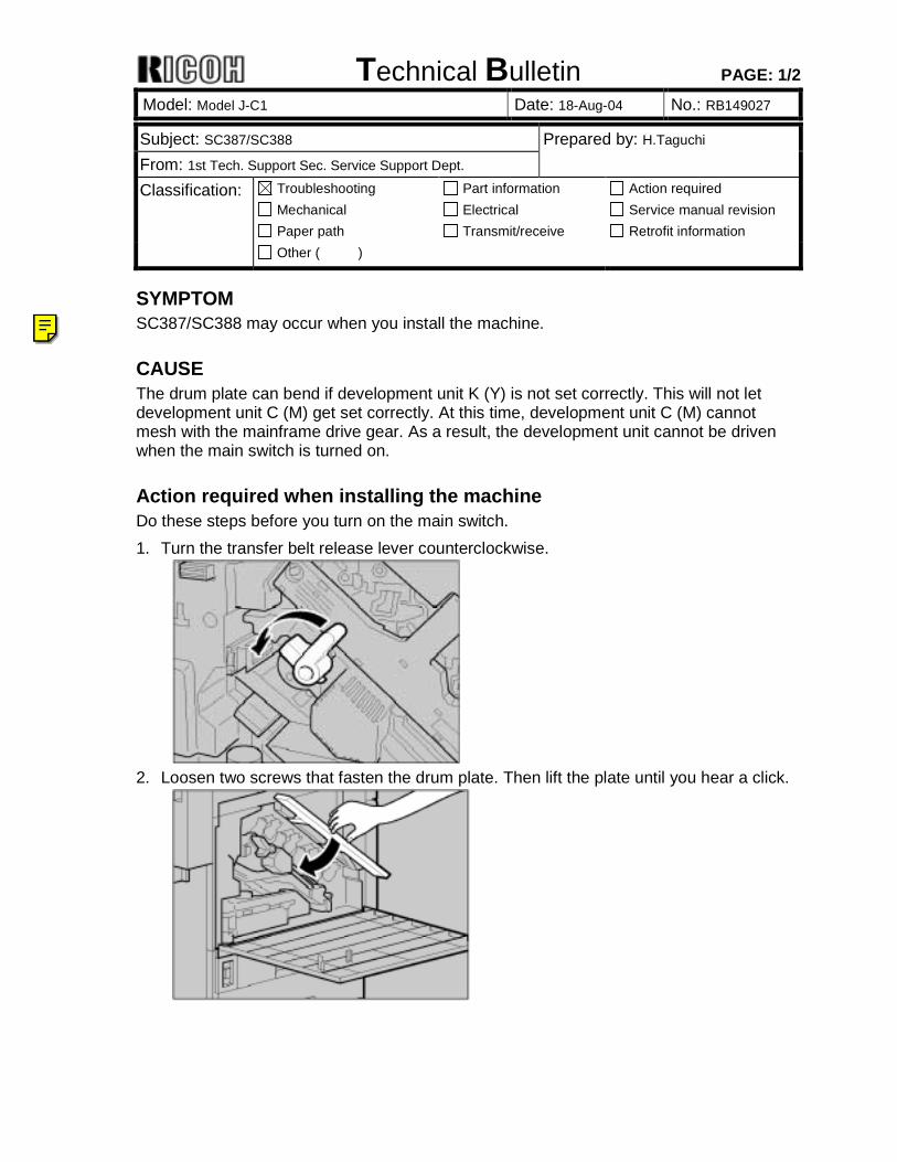
Action required when installing the machine Do these steps before you turn on the main switch. 1. Turn the transfer belt release lever counterclockwise.
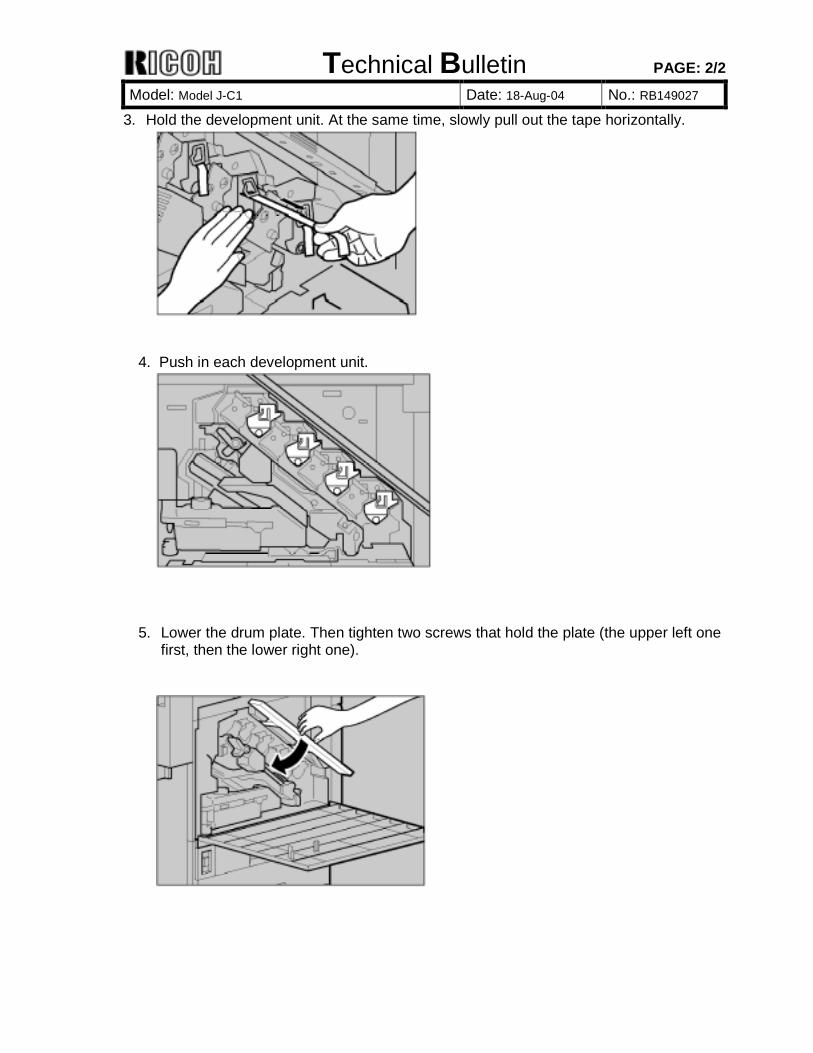
2. Loosen two screws that fasten the drum plate. Then lift the plate until you hear a click.
Ricoh Technical Services
See RTB 27a
Technical Bulletin PAGE: 2/2
Model: Model J-C1 Date: 18-Aug-04 No.: RB149027
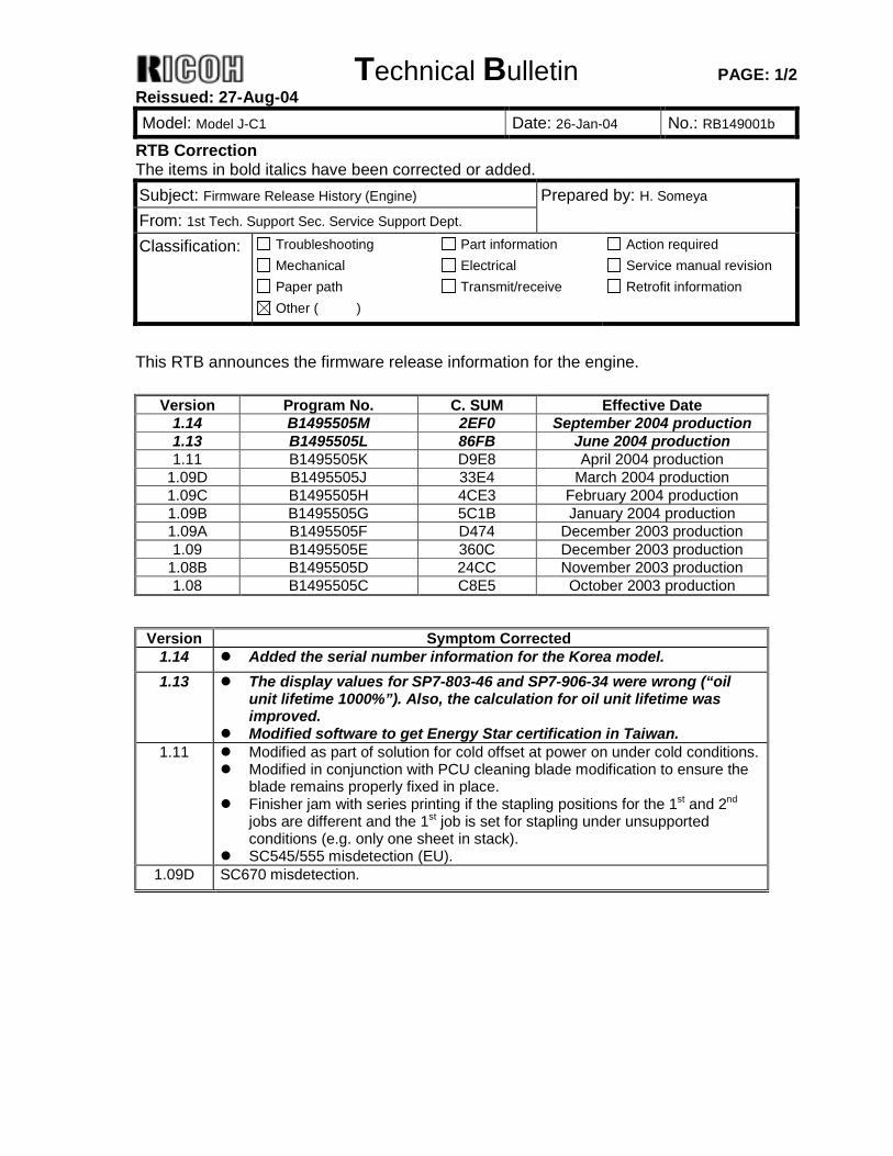
3. Hold the development unit. At the same time, slowly pull out the tape horizontally.
4. Push in each development unit.
5. Lower the drum plate. Then tighten two screws that hold the plate (the upper left one
first, then the lower right one).
Technical Bulletin PAGE: 1/2 Reissued: 27-Aug-04 Model: Model J-C1 Date: 26-Jan-04 No.: RB149001b
RTB Correction The items in bold italics have been corrected or added. Subject: Firmware Release History (Engine) Prepared by: H. Someya From: 1st Tech. Support Sec. Service Support Dept. Classification: Troubleshooting
Mechanical Paper path
Part information Electrical Transmit/receive
Action required Service manual revision Retrofit information
Other ( )
This RTB announces the firmware release information for the engine.
Version Program No. C. SUM Effective Date 1.14 B1495505M 2EF0 September 2004 production 1.13 B1495505L 86FB June 2004 production 1.11 B1495505K D9E8 April 2004 production
1.09D B1495505J 33E4 March 2004 production 1.09C B1495505H 4CE3 February 2004 production 1.09B B1495505G 5C1B January 2004 production 1.09A B1495505F D474 December 2003 production 1.09 B1495505E 360C December 2003 production
1.08B B1495505D 24CC November 2003 production 1.08 B1495505C C8E5 October 2003 production
Version Symptom Corrected
1.14 ! Added the serial number information for the Korea model. 1.13 ! The display values for SP7-803-46 and SP7-906-34 were wrong (“oil
unit lifetime 1000%”). Also, the calculation for oil unit lifetime was improved.
! Modified software to get Energy Star certification in Taiwan. 1.11 ! Modified as part of solution for cold offset at power on under cold conditions.
! Modified in conjunction with PCU cleaning blade modification to ensure the blade remains properly fixed in place.
! Finisher jam with series printing if the stapling positions for the 1st and 2nd jobs are different and the 1st job is set for stapling under unsupported conditions (e.g. only one sheet in stack).
! SC545/555 misdetection (EU). 1.09D SC670 misdetection.

Technical Bulletin PAGE: 2/2 Reissued: 27-Aug-04 Model: Model J-C1 Date: 26-Jan-04 No.: RB149001b
Version Symptom Corrected 1.09C ! Default fusing temperature changed on NA machines for the following
modes in order to increase the glossiness on the second side of a duplex sheet.
1105 6 H:N [K] D 125 *BCU [ 100 to 190 / NA: 170, EU: 165 / 5°C/step]
1105 11 H:N[FC] D 125 *BCU [ 100 to 190 / NA: 170, EU: 170 / 5°C/step] 1105 17 P:N [K] D 125 *BCU [ 0 to 190 / NA: 150, EU: 145 / 5°C/step] 1105 22 P:N[FC] D 125 *BCU [ 0 to 190 / NA: 150, EU: 150 / 5°C/step]
1.09B The counter on a meter charge device installed mistakenly increments twice when all of the following conditions are met. - A meter charge device (e.g. key-card, coin-lock, key-counter) is installed - The 2-tray paper supply unit is installed - SP5-121 is set to “Paper Feed” - A paper misfeed occurs in tray 4 Note: This error occurs only on the external meter charge device. The mainframe meter click counter increments correctly.
1.09A (Changes applied to the Japanese model only). 1.09 ! Optimized conditions for error detection during developer initialization to
ensure that new development units are properly detected (Vt normal range changed from <0.5V to ≦ 0.78V).
! Optimized toner supply control for when printing onto undefined paper types longer than DLT/A3.
! SC220-1 misdetections. ! Optimized detection conditions of output tray JAM 25 to eliminate
unnecessary occurrences. 1.08B Optimized the target pressure roller temperature for when recovering from Low
Power Mode. Note: This applies to the Asia model only.
1.08 1st Mass Production
Technical Bulletin PAGE: 1/2 Reissued: 27-Aug-04 Model: Model J-C1 Date: 26-Jan-04 No.: RB149003b
RTB Correction The items in bold italics have been corrected or added. Subject: Firmware Release History (System) Prepared by: H. Someya From: 1st Tech. Support Sec. Service Support Dept. Classification: Troubleshooting
Mechanical Paper path
Part information Electrical Transmit/receive
Action required Service manual revision Retrofit information
Other ( )
This RTB has been issued to announce the firmware release information for the system.
Version Program No. C. SUM Effective Date 1.19 B1015851H 0086 July 2004 production
1.18.1 B1015851G 6A36 May 2004 production 1.14.1 B1015851F 0EED February 2004 production 1.12.2 B1015851E 7EFF December 2003 production 1.10.1 B1015851D BE45 October 2003 production
Version Symptom Corrected
1.19 • "Near End" messages for oil and waste toner are only displayed when the display language is English or Japanese.
• When a Magazine/Combine job is made, the separator line is printed in the wrong color or it is not printed.
1.18.1 • Added the J-C1k product name. 1.14.1 • After canceling a scan using DeskTopBinder, an internal error will occur if
another scan is attempted afterward. • Unable to send with Scan-to-Folder to an SMB-connected Win98 PC with
shared security settings enabled when all of the following conditions are satisfied: - The destination folder is selected from a registered entry in the Address Book. - A New Password has been set but the User Name has not in the Address
Book MgmtNew Program Folder screen. - Neither the SMB Default User Name nor Default Password has been set in
the File TransferDefault Username/Password (Send) screen. • Network PC stations registered under a given workgroup are not displayed
when the workgroup name consists only of numerical characters (SMB transmission Network screen).
• HDD initialization is performed when the main switch is turned on (see RTB # RB149005 for details).
• SC990 sometimes occurs when the main switch is turned on.

Technical Bulletin PAGE: 2/2 Reissued: 27-Aug-04 Model: Model J-C1 Date: 26-Jan-04 No.: RB149003b
Version Symptom Corrected 1.12.2 • Minor errors during an HDD self-diagnostic are sometimes not detected.
• Minor errors during an optional RAM self-diagnostic are sometimes not detected.
• The machine mistakenly allows local storage files containing mixed B/W and color pages to be printed out in Magazine Mode.
• Optimized detection conditions for NVRAM access errors to eliminate unnecessary occurrences.
Specification changes: • A data backup function (SP5-846-50 to -53) has been added to the SD card
that allows the Address Book data to be uploaded to the card. Note: An RTB will be released announcing the details of this change.
• Specification for the development counters (SP8-771-01 to -05) changed so that the counter increments according to actual machine operation, i.e. no longer follows the value of the meter charge counter.
• Revised so that SP8-383-01 (F:Total PrtPGS) does not increment when printing out a Fax reception document from local storage.
1.10.1 1st Mass Production
Technical Bulletin PAGE: 1/1 Reissued: 27-Aug-04 Model: Model J-C1 Date: 25-Mar-04 No.: RB149020a
RTB Correction The items in bold italics have been corrected or added. Subject: Firmware Release History (Scanner IPU) Prepared by: H. Someya From: 1st Tech. Support Sec. Service Support Dept. Classification: Troubleshooting
Mechanical Paper path
Part information Electrical Transmit/receive
Action required Service manual revision Retrofit information
Other ( )
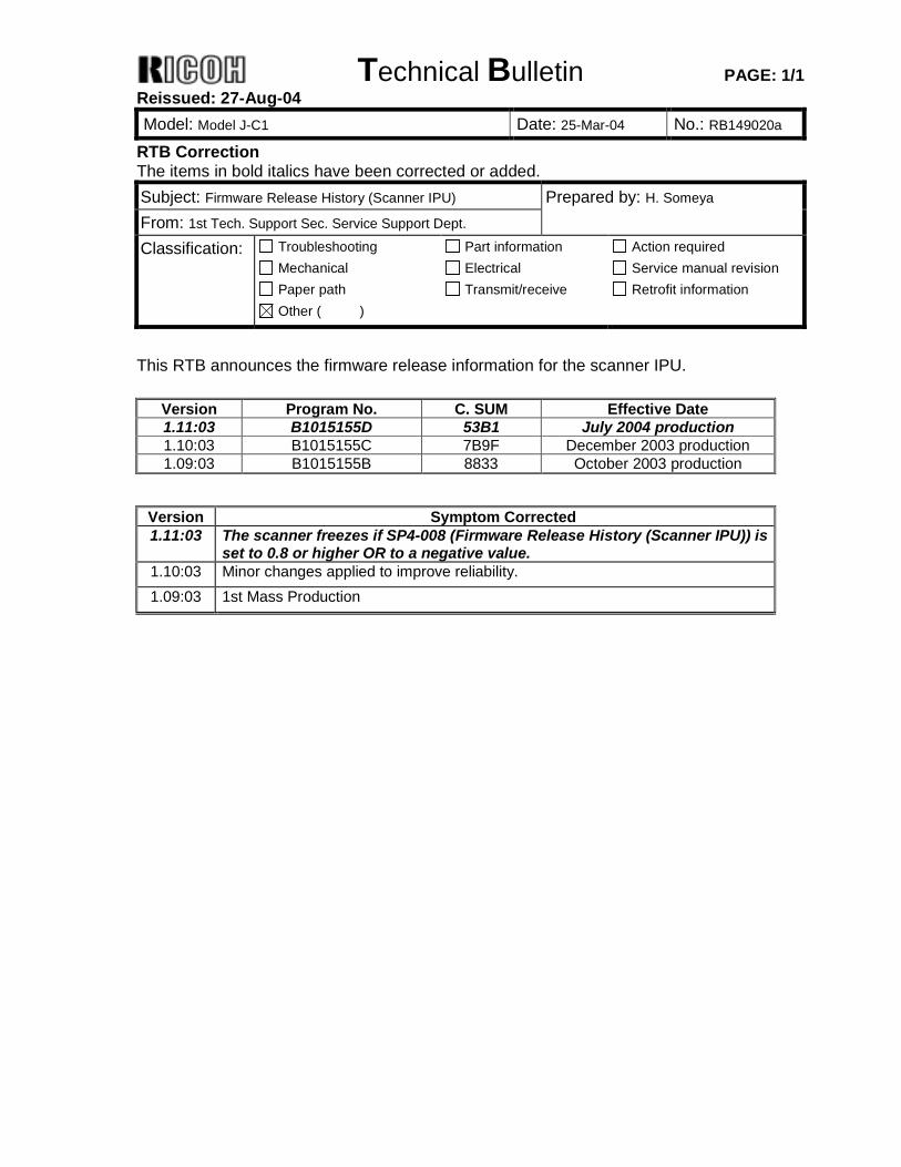
This RTB announces the firmware release information for the scanner IPU.
Version Program No. C. SUM Effective Date 1.11:03 B1015155D 53B1 July 2004 production 1.10:03 B1015155C 7B9F December 2003 production 1.09:03 B1015155B 8833 October 2003 production
Version Symptom Corrected 1.11:03 The scanner freezes if SP4-008 (Firmware Release History (Scanner IPU)) is
set to 0.8 or higher OR to a negative value. 1.10:03 Minor changes applied to improve reliability. 1.09:03 1st Mass Production
Technical Bulletin PAGE: 1/2 Reissued: 27-Aug-04 Model: Model J-C1 Date: 17-Mar-04 No.: RB149017a
RTB Correction The items in bold italics have been corrected or added. Subject: Firmware Release History (LCDC) Prepared by: H. Someya From: 1st Tech. Support Sec. Service Support Dept. Classification: Troubleshooting
Mechanical Paper path
Part information Electrical Transmit/receive
Action required Service manual revision Retrofit information
Other ( )
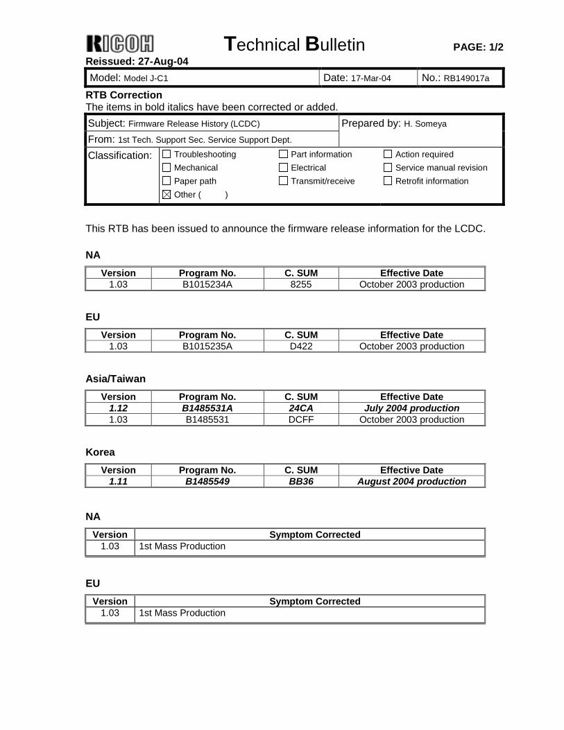
This RTB has been issued to announce the firmware release information for the LCDC. NA
Version Program No. C. SUM Effective Date 1.03 B1015234A 8255 October 2003 production
EU
Version Program No. C. SUM Effective Date 1.03 B1015235A D422 October 2003 production
Asia/Taiwan
Version Program No. C. SUM Effective Date 1.12 B1485531A 24CA July 2004 production 1.03 B1485531 DCFF October 2003 production
Korea
Version Program No. C. SUM Effective Date 1.11 B1485549 BB36 August 2004 production
NA Version Symptom Corrected
1.03 1st Mass Production
EU Version Symptom Corrected
1.03 1st Mass Production
Technical Bulletin PAGE: 2/2 Reissued: 27-Aug-04 Model: Model J-C1 Date: 17-Mar-04 No.: RB149017a
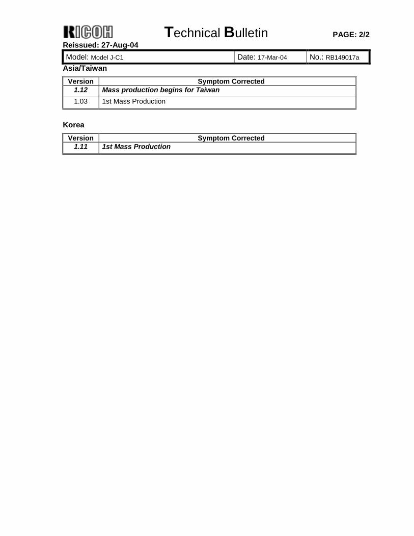
Asia/Taiwan Version Symptom Corrected
1.12 Mass production begins for Taiwan 1.03 1st Mass Production
Korea
Version Symptom Corrected 1.11 1st Mass Production

Technical Bulletin PAGE: 1/1
Model: Model J-1 Date: 27-Aug-04 No.: RB149028
Subject: Firmware Release History (PS) Prepared by: H. Someya From: 1st Tech. Support Sec. Service Support Dept. Classification: Troubleshooting
Mechanical Paper path
Part information Electrical Transmit/receive
Action required Service manual revision Retrofit information
Other ( )
This RTB announces the firmware release information for the PS unit.
Version Program No. C. SUM Effective Date 1.00 G3695907 9337 October 2003 production
Version Symptom Corrected
1.00 1st Mass Production
Technical Bulletin PAGE: 1/1 Reissued: 7-Sep-04 Model: Model J-1 Date: 30-Mar-04 No.: RB149021a
RTB Reissue The items in bold italics have been added. Subject: Firmware Release History (Printer) Prepared by: H. Someya From: 1st Tech. Support Sec. Service Support Dept. Classification: Troubleshooting
Mechanical Paper path
Part information Electrical Transmit/receive
Action required Service manual revision Retrofit information
Other ( )
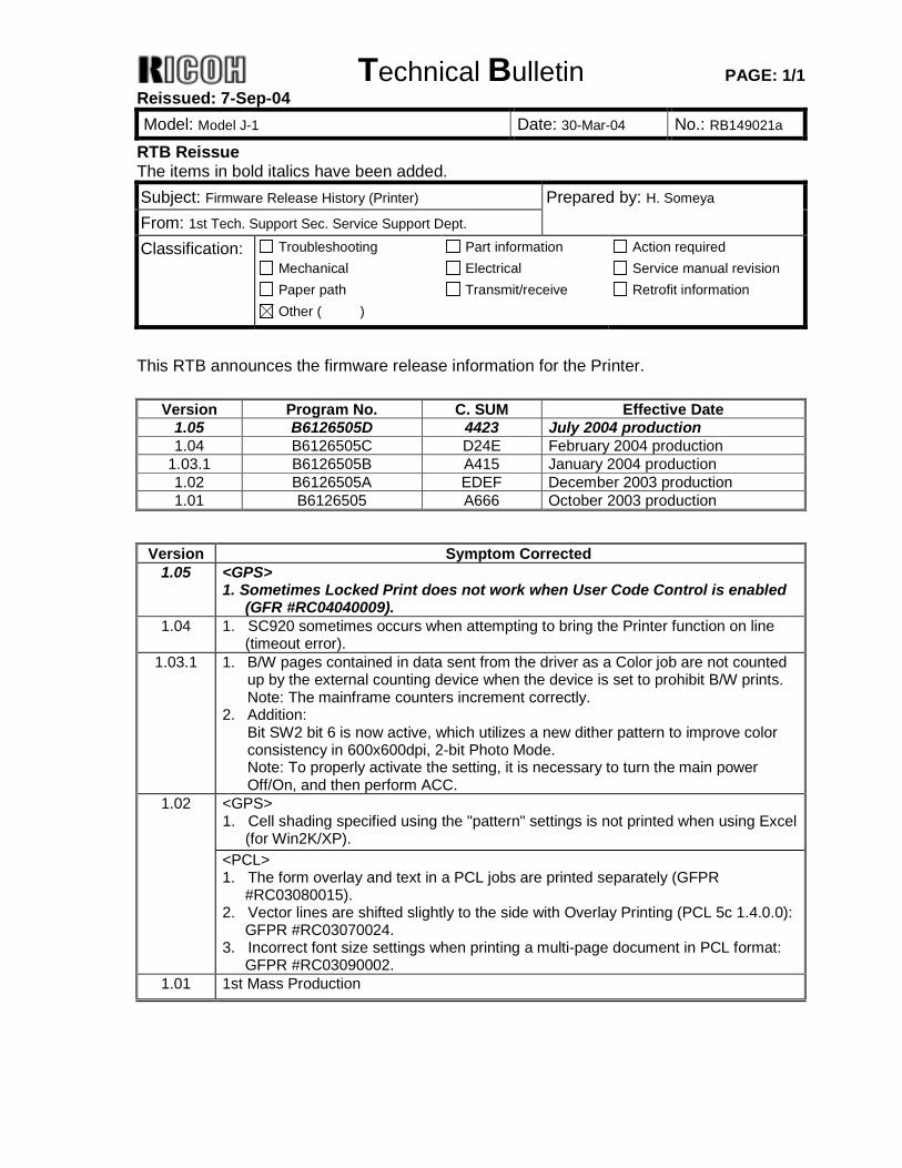
This RTB announces the firmware release information for the Printer.
Version Program No. C. SUM Effective Date 1.05 B6126505D 4423 July 2004 production 1.04 B6126505C D24E February 2004 production
1.03.1 B6126505B A415 January 2004 production 1.02 B6126505A EDEF December 2003 production 1.01 B6126505 A666 October 2003 production
Version Symptom Corrected
1.05 <GPS> 1. Sometimes Locked Print does not work when User Code Control is enabled
(GFR #RC04040009). 1.04 1. SC920 sometimes occurs when attempting to bring the Printer function on line
(timeout error). 1.03.1 1. B/W pages contained in data sent from the driver as a Color job are not counted
up by the external counting device when the device is set to prohibit B/W prints. Note: The mainframe counters increment correctly.
2. Addition: Bit SW2 bit 6 is now active, which utilizes a new dither pattern to improve color consistency in 600x600dpi, 2-bit Photo Mode. Note: To properly activate the setting, it is necessary to turn the main power Off/On, and then perform ACC.
<GPS> 1. Cell shading specified using the "pattern" settings is not printed when using Excel
(for Win2K/XP).
1.02
<PCL> 1. The form overlay and text in a PCL jobs are printed separately (GFPR
#RC03080015). 2. Vector lines are shifted slightly to the side with Overlay Printing (PCL 5c 1.4.0.0):
GFPR #RC03070024. 3. Incorrect font size settings when printing a multi-page document in PCL format:
GFPR #RC03090002. 1.01 1st Mass Production
Technical Bulletin PAGE: 1/1
Model: Model J-C1 Date: 13-Sep-04 No.: RB149029
Subject: Early toner near end alert Prepared by: H.Taguchi From: 1st Tech. Support Sec. Service Support Dept. Classification: Troubleshooting
Mechanical Paper path
Part information Electrical Transmit/receive
Action required Service manual revision Retrofit information
Other ( )
SYMPTOM The toner near end alert shows even if toner remains in the toner cartridge.
CAUSE When the machine is not used for a long period of time, the air supply bulbs cannot work normally. This causes insufficient toner agitation.
SOLUTION Remove the toner cartridge from the machine and shake it side to side 5 to 6 times. Then put it back in the machine.
Technical Bulletin PAGE: 1/2
Model: Model J-C1 Date: 13-Sep-04 No.: RB149030
Subject: Message “Add paper to Tray1 (2)” shows even if there is paper in paper tray 1 (2).
Prepared by: H.Taguchi
From: 1st Tech. Support Sec. Service Support Dept. Classification: Troubleshooting
Mechanical Paper path
Part information Electrical Transmit/receive
Action required Service manual revision Retrofit information
Other ( )
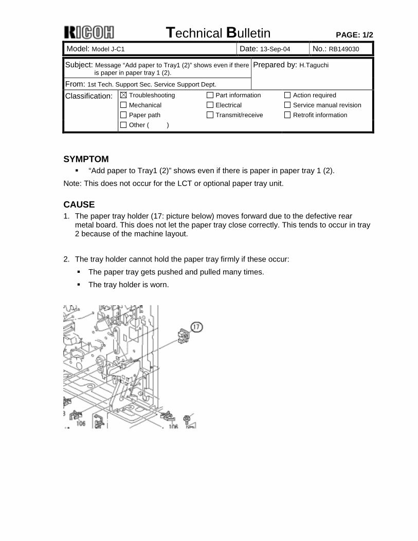
SYMPTOM ! “Add paper to Tray1 (2)” shows even if there is paper in paper tray 1 (2).
Note: This does not occur for the LCT or optional paper tray unit.
CAUSE 1. The paper tray holder (17: picture below) moves forward due to the defective rear
metal board. This does not let the paper tray close correctly. This tends to occur in tray 2 because of the machine layout.
2. The tray holder cannot hold the paper tray firmly if these occur: ! The paper tray gets pushed and pulled many times. ! The tray holder is worn.
Technical Bulletin PAGE: 2/2
Model: Model J-C1 Date: 13-Sep-04 No.: RB149030
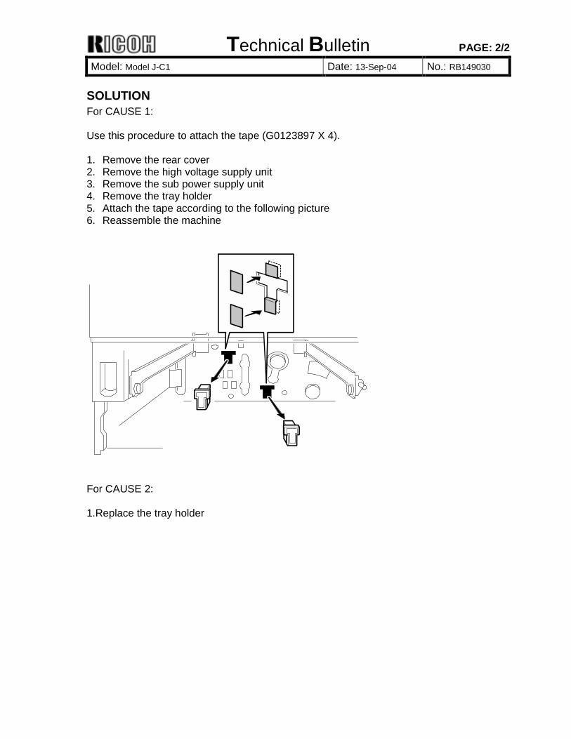
SOLUTION For CAUSE 1: Use this procedure to attach the tape (G0123897 X 4). 1. Remove the rear cover 2. Remove the high voltage supply unit 3. Remove the sub power supply unit 4. Remove the tray holder 5. Attach the tape according to the following picture 6. Reassemble the machine
For CAUSE 2: 1.Replace the tray holder
Technical Bulletin PAGE: 1/2 Reissued: 8-Oct-04 Model: Model J-C1 Date: 26-Jan-04 No.: RB149003c
RTB Correction The items in bold italics have been corrected or added. Subject: Firmware Release History (System) Prepared by: H. Someya From: 1st Tech. Support Sec. Service Support Dept. Classification: Troubleshooting
Mechanical Paper path
Part information Electrical Transmit/receive
Action required Service manual revision Retrofit information
Other ( )
This RTB has been issued to announce the firmware release information for the system.
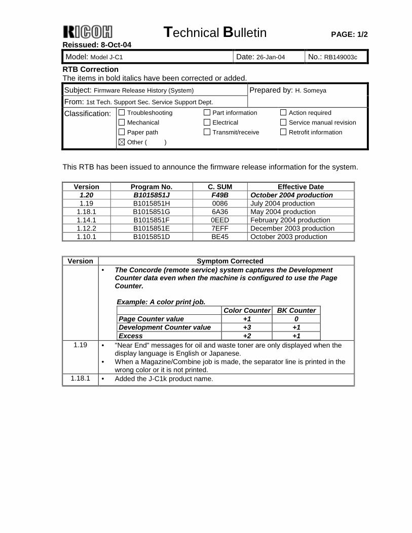
Version Program No. C. SUM Effective Date 1.20 B1015851J F49B October 2004 production 1.19 B1015851H 0086 July 2004 production
1.18.1 B1015851G 6A36 May 2004 production 1.14.1 B1015851F 0EED February 2004 production 1.12.2 B1015851E 7EFF December 2003 production 1.10.1 B1015851D BE45 October 2003 production
Version Symptom Corrected
• The Concorde (remote service) system captures the Development Counter data even when the machine is configured to use the Page Counter. Example: A color print job. Color Counter BK Counter Page Counter value +1 0 Development Counter value +3 +1 Excess +2 +1
1.19 • "Near End" messages for oil and waste toner are only displayed when the display language is English or Japanese.
• When a Magazine/Combine job is made, the separator line is printed in the wrong color or it is not printed.
1.18.1 • Added the J-C1k product name.
Technical Bulletin PAGE: 2/2 Reissued: 8-Oct-04 Model: Model J-C1 Date: 26-Jan-04 No.: RB149003c
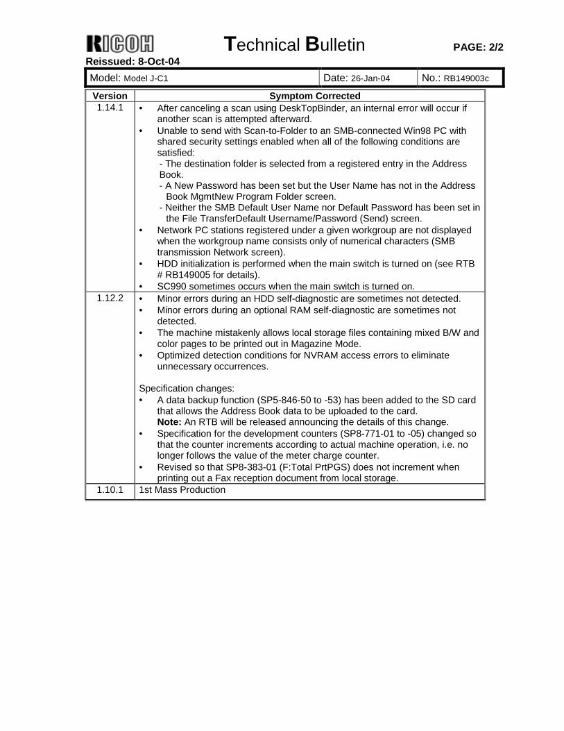
Version Symptom Corrected 1.14.1 • After canceling a scan using DeskTopBinder, an internal error will occur if
another scan is attempted afterward. • Unable to send with Scan-to-Folder to an SMB-connected Win98 PC with
shared security settings enabled when all of the following conditions are satisfied: - The destination folder is selected from a registered entry in the Address Book. - A New Password has been set but the User Name has not in the Address
Book MgmtNew Program Folder screen. - Neither the SMB Default User Name nor Default Password has been set in
the File TransferDefault Username/Password (Send) screen. • Network PC stations registered under a given workgroup are not displayed
when the workgroup name consists only of numerical characters (SMB transmission Network screen).
• HDD initialization is performed when the main switch is turned on (see RTB # RB149005 for details).
• SC990 sometimes occurs when the main switch is turned on. 1.12.2 • Minor errors during an HDD self-diagnostic are sometimes not detected.
• Minor errors during an optional RAM self-diagnostic are sometimes not detected.
• The machine mistakenly allows local storage files containing mixed B/W and color pages to be printed out in Magazine Mode.
• Optimized detection conditions for NVRAM access errors to eliminate unnecessary occurrences.
Specification changes: • A data backup function (SP5-846-50 to -53) has been added to the SD card
that allows the Address Book data to be uploaded to the card. Note: An RTB will be released announcing the details of this change.
• Specification for the development counters (SP8-771-01 to -05) changed so that the counter increments according to actual machine operation, i.e. no longer follows the value of the meter charge counter.
• Revised so that SP8-383-01 (F:Total PrtPGS) does not increment when printing out a Fax reception document from local storage.
1.10.1 1st Mass Production
Technical Bulletin PAGE: 1/1
Model: Model J-C1 Date: 4-Oct-04 No.: RB149031
Subject: Firmware Release History (J-C1k Engine) Prepared by: H. Someya From: 1st Tech. Support Sec. Service Support Dept. Classification: Troubleshooting
Mechanical Paper path
Part information Electrical Transmit/receive
Action required Service manual revision Retrofit information
Other ( )
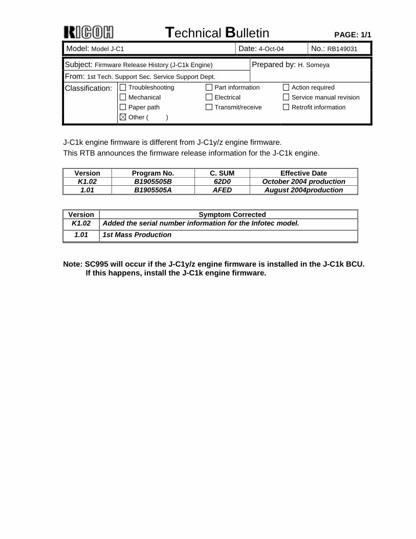
J-C1k engine firmware is different from J-C1y/z engine firmware. This RTB announces the firmware release information for the J-C1k engine.
Version Program No. C. SUM Effective Date K1.02 B1905505B 62D0 October 2004 production 1.01 B1905505A AFED August 2004production
Version Symptom Corrected K1.02 Added the serial number information for the Infotec model. 1.01 1st Mass Production
Note: SC995 will occur if the J-C1y/z engine firmware is installed in the J-C1k BCU. If this happens, install the J-C1k engine firmware.
Technical Bulletin PAGE: 1/3 Reissued: 15-Oct-04 Model: Model J-C1 Date: 18-Aug-04 No.: RB149027a
RTB Correction The items in bold italics have been corrected or added. Subject: SC387/SC388 Prepared by: H.Taguchi From: 1st Tech. Support Sec. Service Support Dept. Classification: Troubleshooting
Mechanical Paper path
Part information Electrical Transmit/receive
Action required Service manual revision Retrofit information
Other ( )
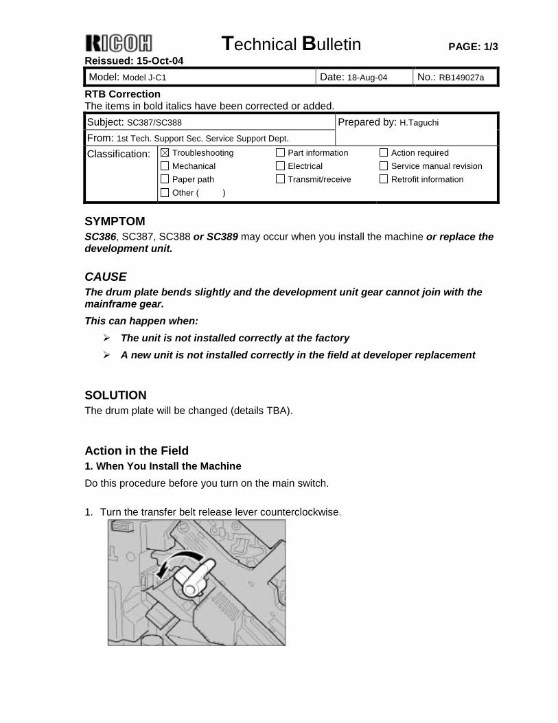
SYMPTOM SC386, SC387, SC388 or SC389 may occur when you install the machine or replace the development unit.
CAUSE The drum plate bends slightly and the development unit gear cannot join with the mainframe gear. This can happen when: ! The unit is not installed correctly at the factory ! A new unit is not installed correctly in the field at developer replacement
SOLUTION The drum plate will be changed (details TBA).
Action in the Field 1. When You Install the Machine Do this procedure before you turn on the main switch. 1. Turn the transfer belt release lever counterclockwise.
Technical Bulletin PAGE: 2/3 Reissued: 15-Oct-04 Model: Model J-C1 Date: 18-Aug-04 No.: RB149027a
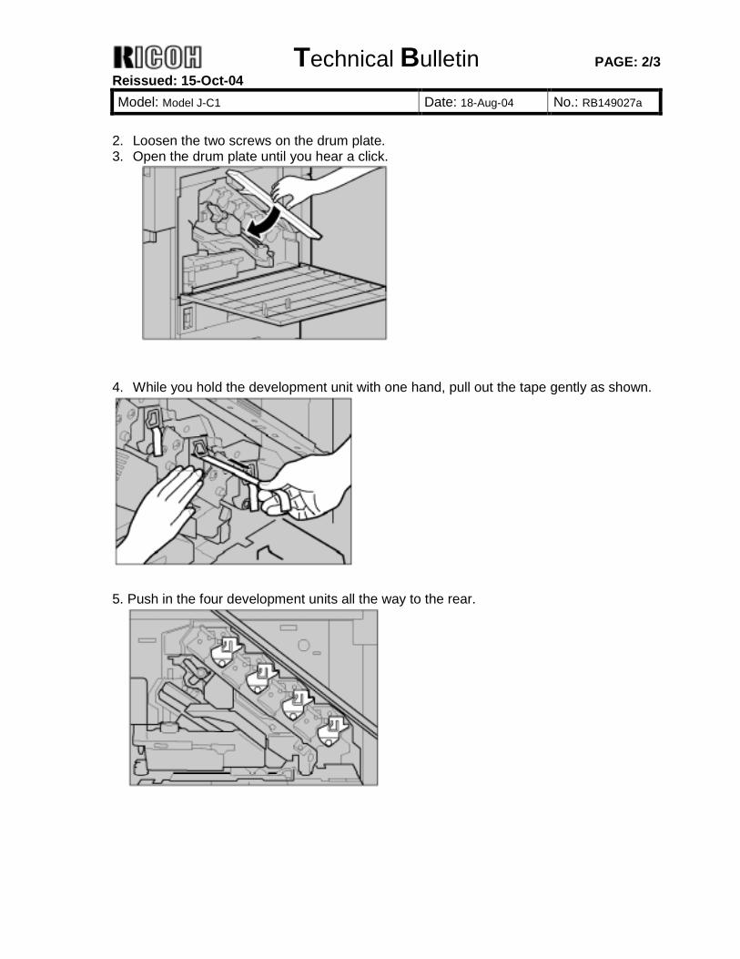
2. Loosen the two screws on the drum plate. 3. Open the drum plate until you hear a click.
4. While you hold the development unit with one hand, pull out the tape gently as shown.
5. Push in the four development units all the way to the rear.
Technical Bulletin PAGE: 3/3 Reissued: 15-Oct-04 Model: Model J-C1 Date: 18-Aug-04 No.: RB149027a
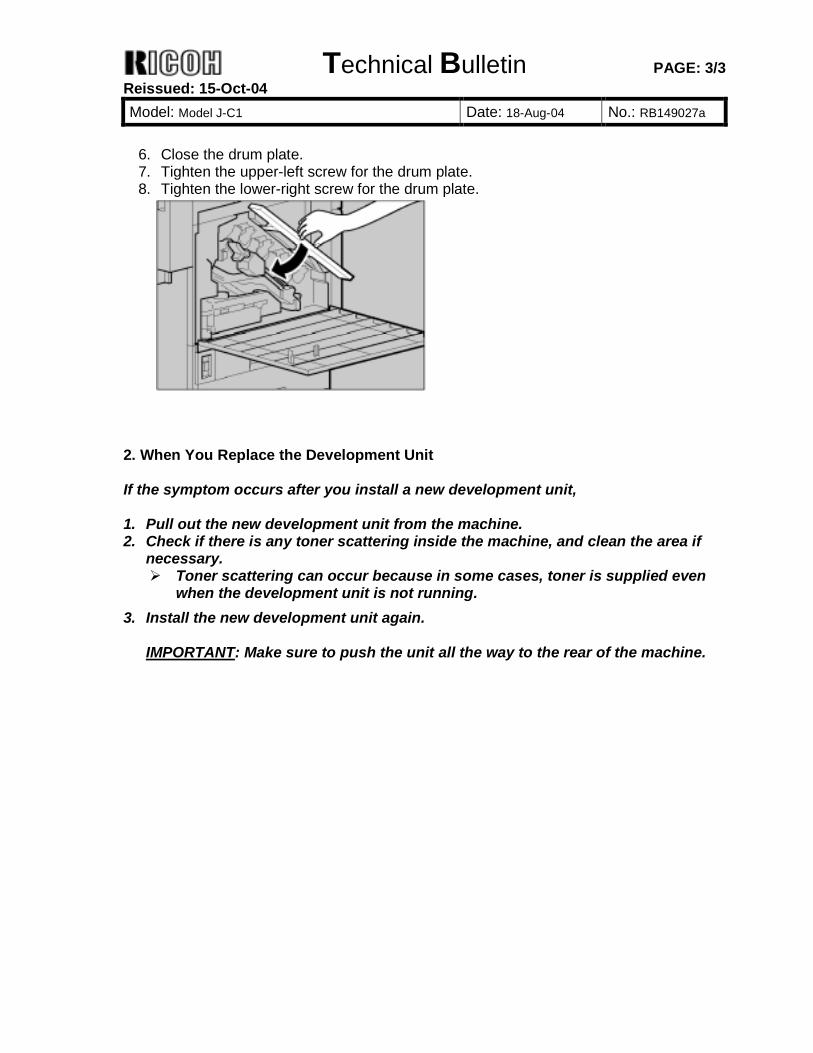
6. Close the drum plate. 7. Tighten the upper-left screw for the drum plate. 8. Tighten the lower-right screw for the drum plate.
2. When You Replace the Development Unit If the symptom occurs after you install a new development unit, 1. Pull out the new development unit from the machine. 2. Check if there is any toner scattering inside the machine, and clean the area if
necessary. ! Toner scattering can occur because in some cases, toner is supplied even
when the development unit is not running. 3. Install the new development unit again.
IMPORTANT: Make sure to push the unit all the way to the rear of the machine.
Technical Bulletin PAGE: 1/1
Model: Model J-C1 Date: 15-Oct-04 No.: RB149033
Subject: Springs on rollers in the transfer unit come off Prepared by: H.Taguchi From: 1st Tech. Support Sec. Service Support Dept. Classification: Troubleshooting
Mechanical Paper path
Part information Electrical Transmit/receive
Action required Service manual revision Retrofit information
Other ( )
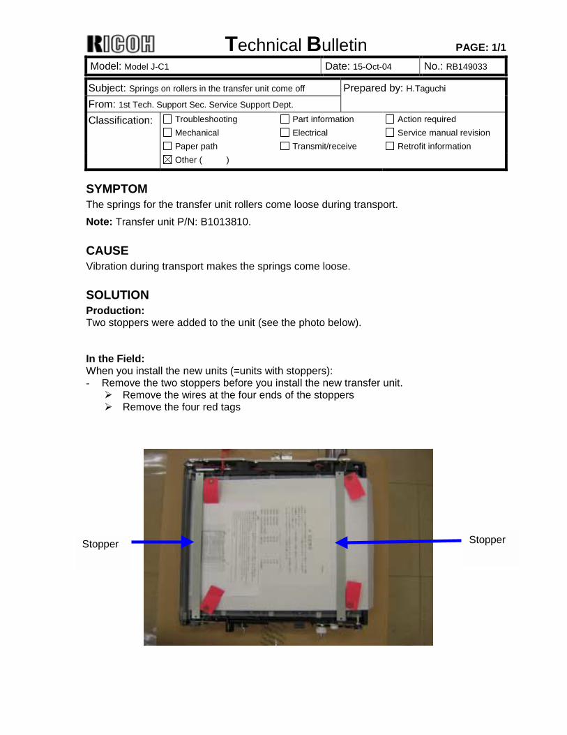
SYMPTOM The springs for the transfer unit rollers come loose during transport. Note: Transfer unit P/N: B1013810.
CAUSE Vibration during transport makes the springs come loose.
SOLUTION Production: Two stoppers were added to the unit (see the photo below). In the Field: When you install the new units (=units with stoppers): - Remove the two stoppers before you install the new transfer unit. ! Remove the wires at the four ends of the stoppers ! Remove the four red tags
Stopper Stopper

Technical Bulletin PAGE: 1/3 Reissued: 2-Nov-04 Model: Model J-C1 Date: 24-Jun-04 No.: RB149023a
RTB Correction The items in bold italics have been corrected or added. Subject: SC385 Prepared by: H.Taguchi From: 1st Tech. Support Sec. Service Support Dept. Classification: Troubleshooting
Mechanical Paper path
Part information Electrical Transmit/receive
Action required Service manual revision Retrofit information
Other ( )
SYMPTOM SC385 sometimes occurs at intervals of 20k prints or less.
CAUSE Toner scatters from the transfer belt during process control. This can sometimes accumulate on the ID sensor (center).
SOLUTION Attach a reinforcing plate (P/N B1499903) according to the following procedure. Note: Check these the next time you make a service call even if this problem does not occur: - Check the SMC history and see whether or not SC385 has occurred, - Check if SP3107-02, -04 and -06 all show a value of 200 or higher. If either is true, install the corrective part (P/N B1499903).
Affected unit From the beginning of mass production to the beginning of July 2004
Attachment Procedure for the Guide Plate Reinforcing Material The following is the procedure for attaching B1499903 (a reinforcing plate) to the bottom of the guide plate. This material will help ensure that the guide plate does not bend.
Technical Bulletin PAGE: 2/3 Reissued: 2-Nov-04 Model: Model J-C1 Date: 24-Jun-04 No.: RB149023a
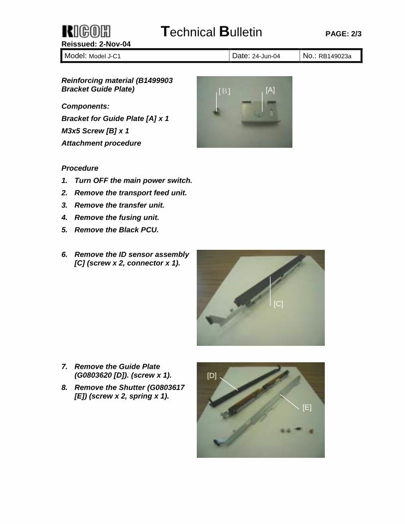
Reinforcing material (B1499903 Bracket Guide Plate) Components: Bracket for Guide Plate [A] x 1 M3x5 Screw [B] x 1 Attachment procedure Procedure 1. Turn OFF the main power switch. 2. Remove the transport feed unit. 3. Remove the transfer unit. 4. Remove the fusing unit. 5. Remove the Black PCU.
6. Remove the ID sensor assembly
[C] (screw x 2, connector x 1).
7. Remove the Guide Plate
(G0803620 [D]). (screw x 1). 8. Remove the Shutter (G0803617
[E]) (screw x 2, spring x 1).
[A][B]
[C]
[D]
[E]
Technical Bulletin PAGE: 3/3 Reissued: 2-Nov-04 Model: Model J-C1 Date: 24-Jun-04 No.: RB149023a
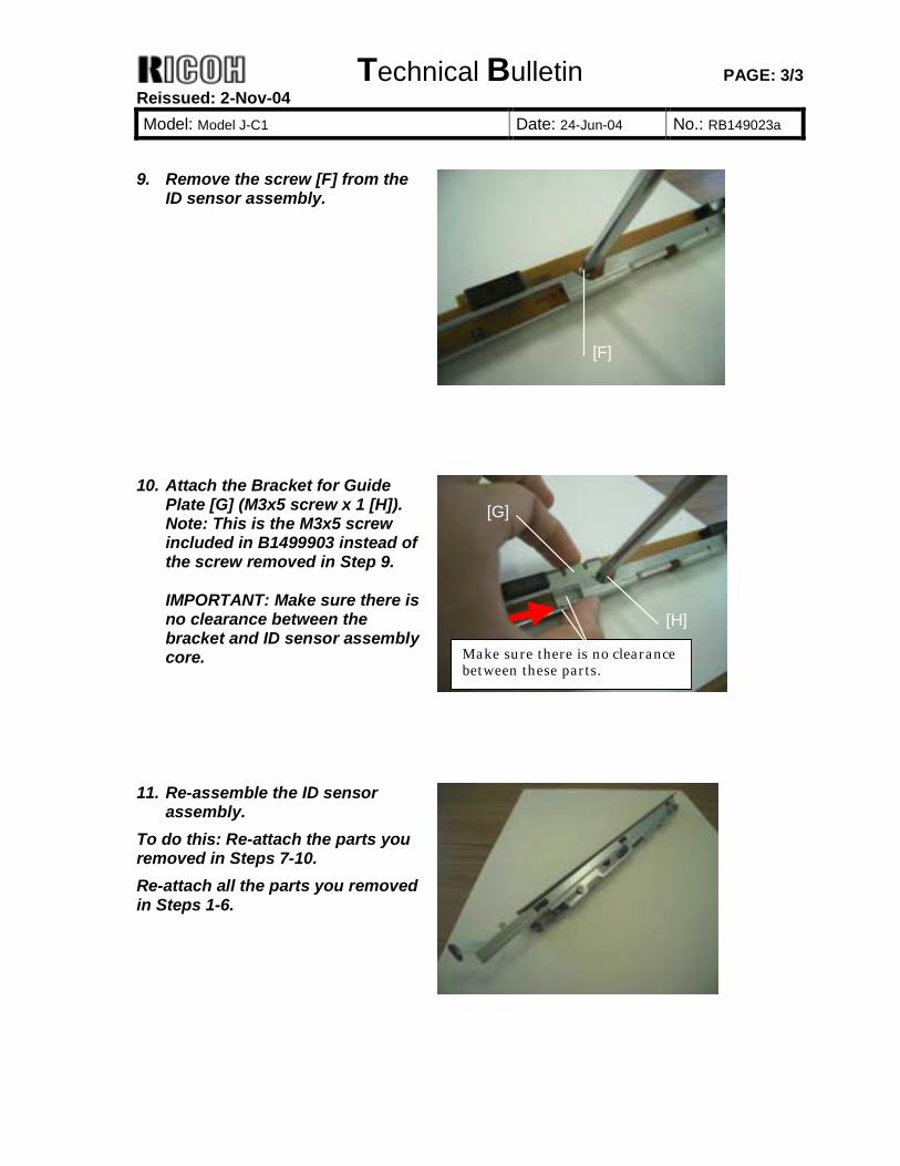
9. Remove the screw [F] from the
ID sensor assembly.
10. Attach the Bracket for Guide
Plate [G] (M3x5 screw x 1 [H]). Note: This is the M3x5 screw included in B1499903 instead of the screw removed in Step 9. IMPORTANT: Make sure there is no clearance between the bracket and ID sensor assembly core.
11. Re-assemble the ID sensor
assembly. To do this: Re-attach the parts you removed in Steps 7-10. Re-attach all the parts you removed in Steps 1-6.
[F]
[G]
[H]
Make sure there is no clearance between these parts.
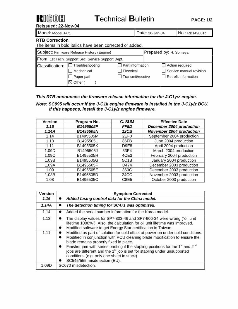
Technical Bulletin PAGE: 1/2 Reissued: 22-Nov-04 Model: Model J-C1 Date: 26-Jan-04 No.: RB149001c
RTB Correction The items in bold italics have been corrected or added. Subject: Firmware Release History (Engine) Prepared by: H. Someya From: 1st Tech. Support Sec. Service Support Dept. Classification: Troubleshooting
Mechanical Paper path
Part information Electrical Transmit/receive
Action required Service manual revision Retrofit information
Other ( )
This RTB announces the firmware release information for the J-C1y/z engine. Note: SC995 will occur if the J-C1k engine firmware is installed in the J-C1y/z BCU.
If this happens, install the J-C1y/z engine firmware.
Version Program No. C. SUM Effective Date 1.16 B1495505P FF5D December 2004 production
1.14A B1495505N 12CB November 2004 production 1.14 B1495505M 2EF0 September 2004 production 1.13 B1495505L 86FB June 2004 production 1.11 B1495505K D9E8 April 2004 production
1.09D B1495505J 33E4 March 2004 production 1.09C B1495505H 4CE3 February 2004 production 1.09B B1495505G 5C1B January 2004 production 1.09A B1495505F D474 December 2003 production 1.09 B1495505E 360C December 2003 production
1.08B B1495505D 24CC November 2003 production 1.08 B1495505C C8E5 October 2003 production
Version Symptom Corrected
1.16 ! Added fusing control data for the China model. 1.14A ! The detection timing for SC471 was optimized. 1.14 ! Added the serial number information for the Korea model. 1.13 ! The display values for SP7-803-46 and SP7-906-34 were wrong (“oil unit
lifetime 1000%”). Also, the calculation for oil unit lifetime was improved. ! Modified software to get Energy Star certification in Taiwan.
1.11 ! Modified as part of solution for cold offset at power on under cold conditions. ! Modified in conjunction with PCU cleaning blade modification to ensure the
blade remains properly fixed in place. ! Finisher jam with series printing if the stapling positions for the 1st and 2nd
jobs are different and the 1st job is set for stapling under unsupported conditions (e.g. only one sheet in stack).
! SC545/555 misdetection (EU). 1.09D SC670 misdetection.
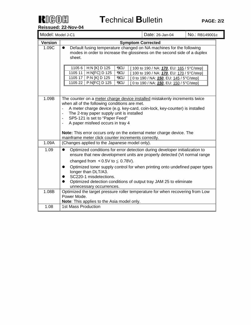
Technical Bulletin PAGE: 2/2 Reissued: 22-Nov-04 Model: Model J-C1 Date: 26-Jan-04 No.: RB149001c
Version Symptom Corrected 1.09C ! Default fusing temperature changed on NA machines for the following
modes in order to increase the glossiness on the second side of a duplex sheet.
1105 6 H:N [K] D 125 *BCU [ 100 to 190 / NA: 170, EU: 165 / 5°C/step]
1105 11 H:N[FC] D 125 *BCU [ 100 to 190 / NA: 170, EU: 170 / 5°C/step] 1105 17 P:N [K] D 125 *BCU [ 0 to 190 / NA: 150, EU: 145 / 5°C/step] 1105 22 P:N[FC] D 125 *BCU [ 0 to 190 / NA: 150, EU: 150 / 5°C/step]
1.09B The counter on a meter charge device installed mistakenly increments twice when all of the following conditions are met. - A meter charge device (e.g. key-card, coin-lock, key-counter) is installed - The 2-tray paper supply unit is installed - SP5-121 is set to “Paper Feed” - A paper misfeed occurs in tray 4 Note: This error occurs only on the external meter charge device. The mainframe meter click counter increments correctly.
1.09A (Changes applied to the Japanese model only). 1.09 ! Optimized conditions for error detection during developer initialization to
ensure that new development units are properly detected (Vt normal range changed from <0.5V to ≦ 0.78V).
! Optimized toner supply control for when printing onto undefined paper types longer than DLT/A3.
! SC220-1 misdetections. ! Optimized detection conditions of output tray JAM 25 to eliminate
unnecessary occurrences. 1.08B Optimized the target pressure roller temperature for when recovering from Low
Power Mode. Note: This applies to the Asia model only.
1.08 1st Mass Production
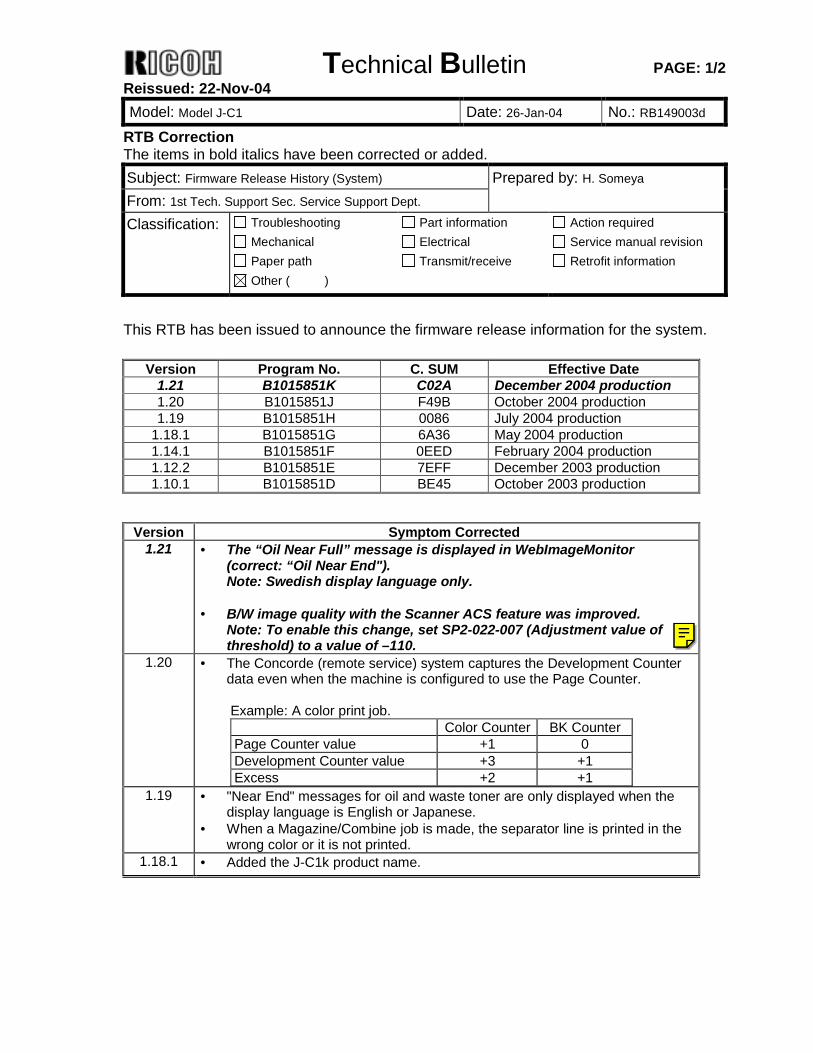
Technical Bulletin PAGE: 1/2 Reissued: 22-Nov-04 Model: Model J-C1 Date: 26-Jan-04 No.: RB149003d
RTB Correction The items in bold italics have been corrected or added. Subject: Firmware Release History (System) Prepared by: H. Someya From: 1st Tech. Support Sec. Service Support Dept. Classification: Troubleshooting
Mechanical Paper path
Part information Electrical Transmit/receive
Action required Service manual revision Retrofit information
Other ( )
This RTB has been issued to announce the firmware release information for the system.
Version Program No. C. SUM Effective Date 1.21 B1015851K C02A December 2004 production 1.20 B1015851J F49B October 2004 production 1.19 B1015851H 0086 July 2004 production
1.18.1 B1015851G 6A36 May 2004 production 1.14.1 B1015851F 0EED February 2004 production 1.12.2 B1015851E 7EFF December 2003 production 1.10.1 B1015851D BE45 October 2003 production
Version Symptom Corrected
1.21 • The “Oil Near Full” message is displayed in WebImageMonitor (correct: “Oil Near End"). Note: Swedish display language only.
• B/W image quality with the Scanner ACS feature was improved.
Note: To enable this change, set SP2-022-007 (Adjustment value of threshold) to a value of –110.
1.20 • The Concorde (remote service) system captures the Development Counter data even when the machine is configured to use the Page Counter. Example: A color print job. Color Counter BK Counter Page Counter value +1 0 Development Counter value +3 +1 Excess +2 +1
1.19 • "Near End" messages for oil and waste toner are only displayed when the display language is English or Japanese.
• When a Magazine/Combine job is made, the separator line is printed in the wrong color or it is not printed.
1.18.1 • Added the J-C1k product name.
Ricoh Technical Services
This is scanner SP 2-022-007.
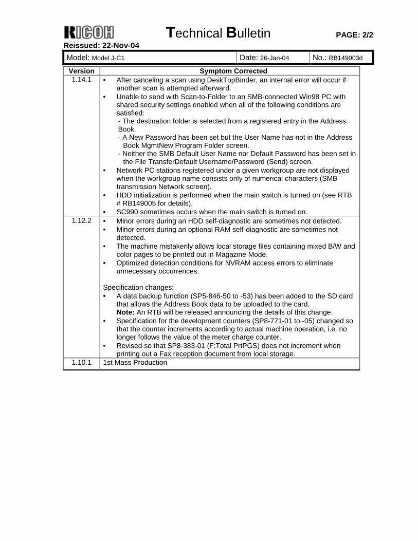
Technical Bulletin PAGE: 2/2 Reissued: 22-Nov-04 Model: Model J-C1 Date: 26-Jan-04 No.: RB149003d
Version Symptom Corrected 1.14.1 • After canceling a scan using DeskTopBinder, an internal error will occur if
another scan is attempted afterward. • Unable to send with Scan-to-Folder to an SMB-connected Win98 PC with
shared security settings enabled when all of the following conditions are satisfied: - The destination folder is selected from a registered entry in the Address Book. - A New Password has been set but the User Name has not in the Address
Book MgmtNew Program Folder screen. - Neither the SMB Default User Name nor Default Password has been set in
the File TransferDefault Username/Password (Send) screen. • Network PC stations registered under a given workgroup are not displayed
when the workgroup name consists only of numerical characters (SMB transmission Network screen).
• HDD initialization is performed when the main switch is turned on (see RTB # RB149005 for details).
• SC990 sometimes occurs when the main switch is turned on. 1.12.2 • Minor errors during an HDD self-diagnostic are sometimes not detected.
• Minor errors during an optional RAM self-diagnostic are sometimes not detected.
• The machine mistakenly allows local storage files containing mixed B/W and color pages to be printed out in Magazine Mode.
• Optimized detection conditions for NVRAM access errors to eliminate unnecessary occurrences.
Specification changes: • A data backup function (SP5-846-50 to -53) has been added to the SD card
that allows the Address Book data to be uploaded to the card. Note: An RTB will be released announcing the details of this change.
• Specification for the development counters (SP8-771-01 to -05) changed so that the counter increments according to actual machine operation, i.e. no longer follows the value of the meter charge counter.
• Revised so that SP8-383-01 (F:Total PrtPGS) does not increment when printing out a Fax reception document from local storage.
1.10.1 1st Mass Production
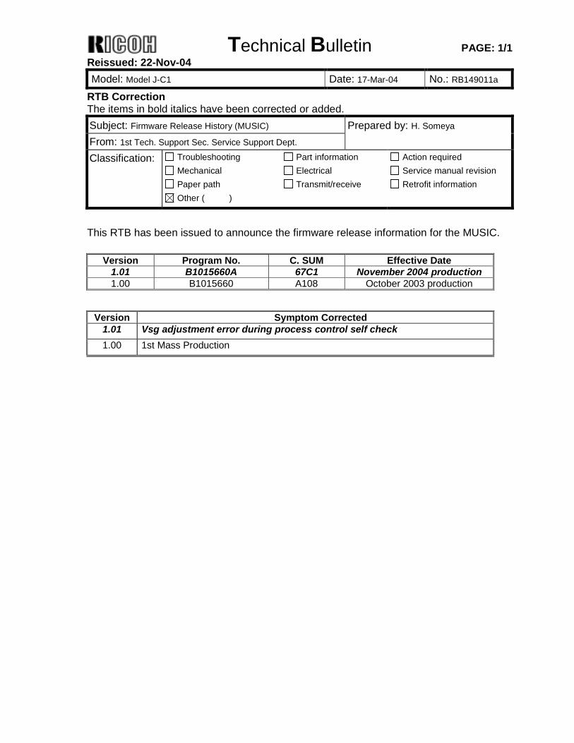
Technical Bulletin PAGE: 1/1 Reissued: 22-Nov-04 Model: Model J-C1 Date: 17-Mar-04 No.: RB149011a
RTB Correction The items in bold italics have been corrected or added. Subject: Firmware Release History (MUSIC) Prepared by: H. Someya From: 1st Tech. Support Sec. Service Support Dept. Classification: Troubleshooting
Mechanical Paper path
Part information Electrical Transmit/receive
Action required Service manual revision Retrofit information
Other ( )
This RTB has been issued to announce the firmware release information for the MUSIC.
Version Program No. C. SUM Effective Date 1.01 B1015660A 67C1 November 2004 production 1.00 B1015660 A108 October 2003 production
Version Symptom Corrected
1.01 Vsg adjustment error during process control self check 1.00 1st Mass Production
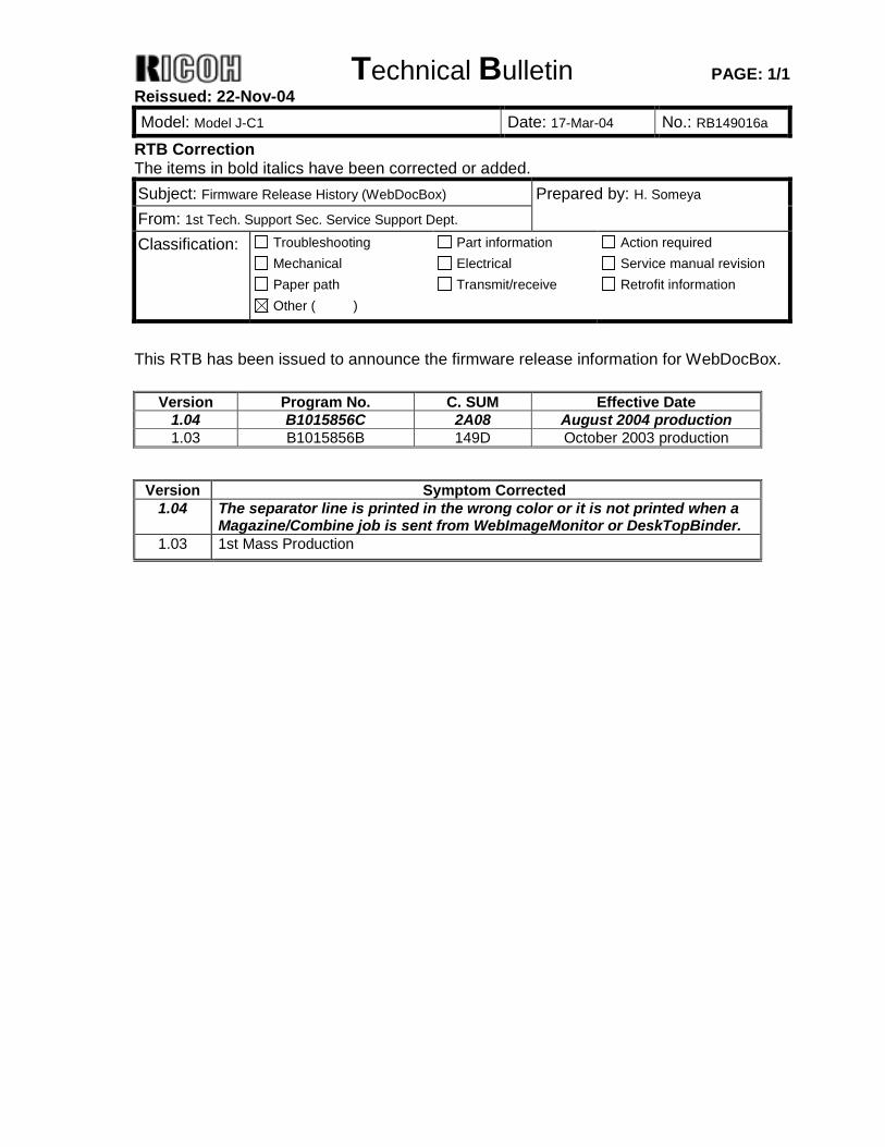
Technical Bulletin PAGE: 1/1 Reissued: 22-Nov-04 Model: Model J-C1 Date: 17-Mar-04 No.: RB149016a
RTB Correction The items in bold italics have been corrected or added. Subject: Firmware Release History (WebDocBox) Prepared by: H. Someya From: 1st Tech. Support Sec. Service Support Dept. Classification: Troubleshooting
Mechanical Paper path
Part information Electrical Transmit/receive
Action required Service manual revision Retrofit information
Other ( )
This RTB has been issued to announce the firmware release information for WebDocBox.
Version Program No. C. SUM Effective Date 1.04 B1015856C 2A08 August 2004 production 1.03 B1015856B 149D October 2003 production
Version Symptom Corrected
1.04 The separator line is printed in the wrong color or it is not printed when a Magazine/Combine job is sent from WebImageMonitor or DeskTopBinder.
1.03 1st Mass Production
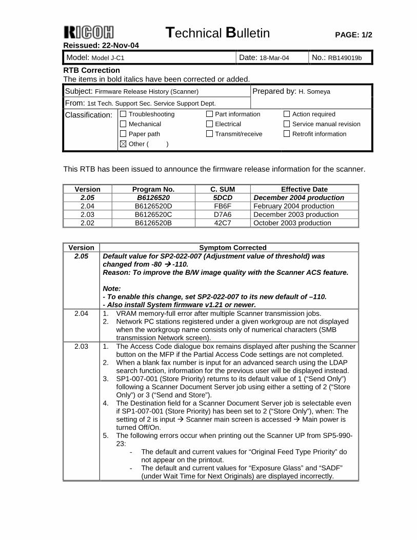
Technical Bulletin PAGE: 1/2 Reissued: 22-Nov-04 Model: Model J-C1 Date: 18-Mar-04 No.: RB149019b
RTB Correction The items in bold italics have been corrected or added. Subject: Firmware Release History (Scanner) Prepared by: H. Someya From: 1st Tech. Support Sec. Service Support Dept. Classification: Troubleshooting
Mechanical Paper path
Part information Electrical Transmit/receive
Action required Service manual revision Retrofit information
Other ( )
This RTB has been issued to announce the firmware release information for the scanner.
Version Program No. C. SUM Effective Date 2.05 B6126520 5DCD December 2004 production 2.04 B6126520D FB6F February 2004 production 2.03 B6126520C D7A6 December 2003 production 2.02 B6126520B 42C7 October 2003 production
Version Symptom Corrected
2.05 Default value for SP2-022-007 (Adjustment value of threshold) was changed from -80 !!!! -110. Reason: To improve the B/W image quality with the Scanner ACS feature. Note: - To enable this change, set SP2-022-007 to its new default of –110. - Also install System firmware v1.21 or newer.
2.04 1. VRAM memory-full error after multiple Scanner transmission jobs. 2. Network PC stations registered under a given workgroup are not displayed
when the workgroup name consists only of numerical characters (SMB transmission Network screen).
2.03 1. The Access Code dialogue box remains displayed after pushing the Scanner button on the MFP if the Partial Access Code settings are not completed.
2. When a blank fax number is input for an advanced search using the LDAP search function, information for the previous user will be displayed instead.
3. SP1-007-001 (Store Priority) returns to its default value of 1 (“Send Only”) following a Scanner Document Server job using either a setting of 2 (“Store Only”) or 3 (“Send and Store”).
4. The Destination field for a Scanner Document Server job is selectable even if SP1-007-001 (Store Priority) has been set to 2 (“Store Only”), when: The setting of 2 is input ! Scanner main screen is accessed ! Main power is turned Off/On.
5. The following errors occur when printing out the Scanner UP from SP5-990-23:
- The default and current values for “Original Feed Type Priority” do not appear on the printout.
- The default and current values for “Exposure Glass” and “SADF” (under Wait Time for Next Originals) are displayed incorrectly.

Technical Bulletin PAGE: 2/2 Reissued: 22-Nov-04 Model: Model J-C1 Date: 18-Mar-04 No.: RB149019b
Version Symptom Corrected 2.02 1st Mass Production
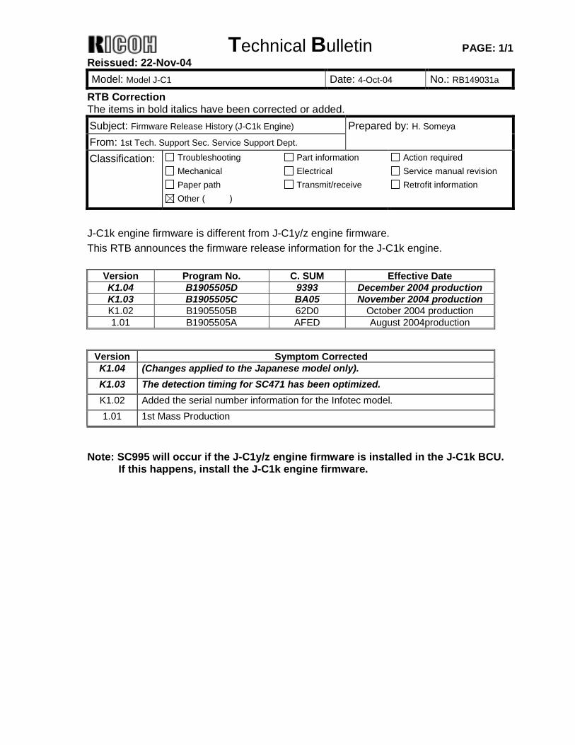
Technical Bulletin PAGE: 1/1 Reissued: 22-Nov-04 Model: Model J-C1 Date: 4-Oct-04 No.: RB149031a
RTB Correction The items in bold italics have been corrected or added. Subject: Firmware Release History (J-C1k Engine) Prepared by: H. Someya From: 1st Tech. Support Sec. Service Support Dept. Classification: Troubleshooting
Mechanical Paper path
Part information Electrical Transmit/receive
Action required Service manual revision Retrofit information
Other ( )
J-C1k engine firmware is different from J-C1y/z engine firmware. This RTB announces the firmware release information for the J-C1k engine.
Version Program No. C. SUM Effective Date K1.04 B1905505D 9393 December 2004 production K1.03 B1905505C BA05 November 2004 production K1.02 B1905505B 62D0 October 2004 production 1.01 B1905505A AFED August 2004production
Version Symptom Corrected K1.04 (Changes applied to the Japanese model only). K1.03 The detection timing for SC471 has been optimized. K1.02 Added the serial number information for the Infotec model. 1.01 1st Mass Production
Note: SC995 will occur if the J-C1y/z engine firmware is installed in the J-C1k BCU. If this happens, install the J-C1k engine firmware.
Technical Bulletin PAGE: 1/1
Model: Model J-C1 Date: 22-Nov-04 No.: RB149034
Subject: The PCU yield has been increased from 40k to 60k. Prepared by: H. Someya From: 1st Tech. Support Sec. Service Support Dept. Classification: Troubleshooting
Mechanical Paper path
Part information Electrical Transmit/receive
Action required Service manual revision Retrofit information
Product Safety Other ( )
Important Note on the Increased PCU Yield (40k!!!! 60k) A lubricant bar was added to the PCU cleaning brush to further ensure that additives in the paper do not stick to the drum surface (See MB149002). This increases the yield from 40k to 60k. In accordance with this change: " The PCU yield has been increased from 40k to 60k. " Both the color and Bk PCUs have been standardized to one part number, as they all
use the same modified cleaning mechanism mentioned above. P/N Changes: " Black PCU: B1492214 ! B1909510 " Color PCU: B1492213 ! B1909510 NOTE: Before replacing any of the new units, be sure and perform the following procedure to enable the new-unit detection program. 1. Check the engine firmware version. 2. If the version is v1.11 or newer, go to step 4. 3. If available, update the engine firmware to v1.11 or newer. 4. Access SP5-999. 5. Select one of the new set programs (SP5-999-001 to 004). 6. Select "1. Enable." 7. Select "OK."
Number Unit Default Settings
Adjustable Range
SP5-999-001 PCU–K SP5-999-002 PCU–Y SP5-999-003 PCU–M SP5-999-004 PCU–C
0 0: Disable 1: Enable
8. Exit SP mode. 9. Turn the main switch off. 10. Replace the unit. 11. Turn the main switch on. The machine will begin the initialization for the new unit. If the
engine firmware is v1.11 or newer, the following step is not required. 12. Only if the engine firmware is older than v1.11:
In User Tools, perform Auto Color Registration (automatic line position adjustment) twice.
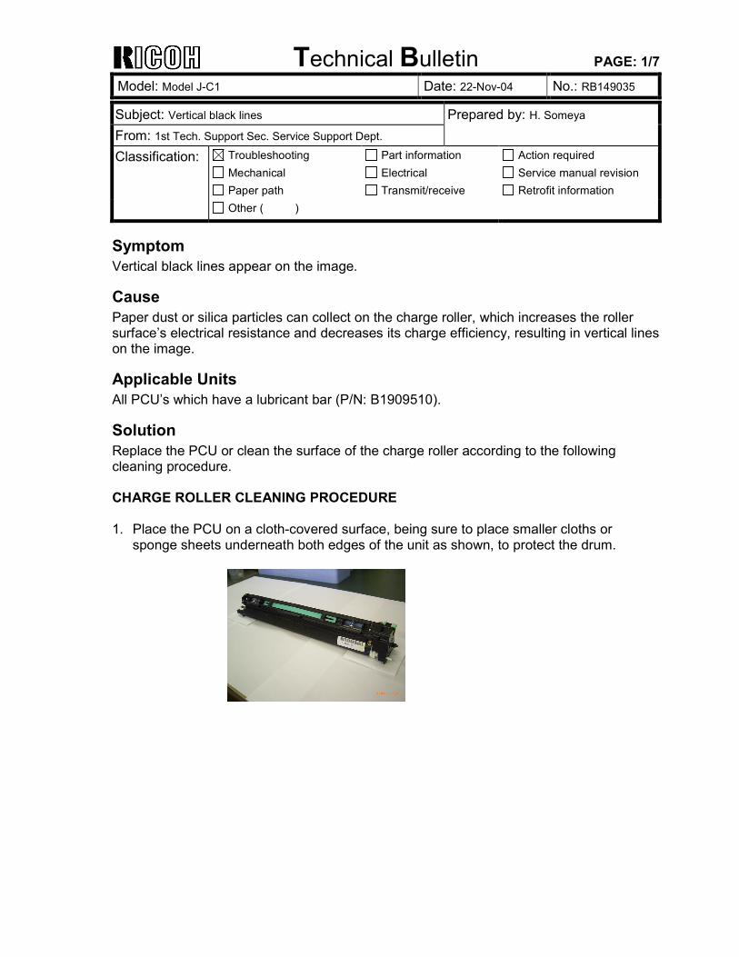
Technical Bulletin PAGE: 1/7
Model: Model J-C1 Date: 22-Nov-04 No.: RB149035
Subject: Vertical black lines Prepared by: H. Someya From: 1st Tech. Support Sec. Service Support Dept. Classification: Troubleshooting
Mechanical Paper path
Part information Electrical Transmit/receive
Action required Service manual revision Retrofit information
Other ( )
Symptom Vertical black lines appear on the image.
Cause Paper dust or silica particles can collect on the charge roller, which increases the roller surface’s electrical resistance and decreases its charge efficiency, resulting in vertical lines on the image.
Applicable Units All PCU’s which have a lubricant bar (P/N: B1909510).
Solution Replace the PCU or clean the surface of the charge roller according to the following cleaning procedure. CHARGE ROLLER CLEANING PROCEDURE 1. Place the PCU on a cloth-covered surface, being sure to place smaller cloths or
sponge sheets underneath both edges of the unit as shown, to protect the drum.
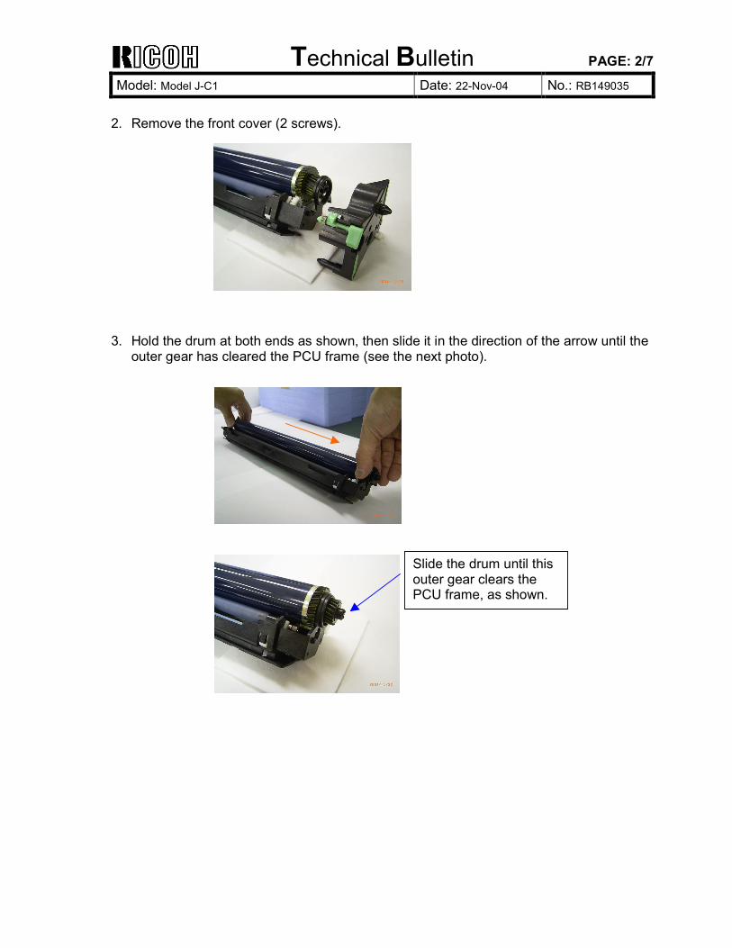
Technical Bulletin PAGE: 2/7
Model: Model J-C1 Date: 22-Nov-04 No.: RB149035
2. Remove the front cover (2 screws). 3. Hold the drum at both ends as shown, then slide it in the direction of the arrow until the
outer gear has cleared the PCU frame (see the next photo).
Slide the drum until this outer gear clears the PCU frame, as shown.
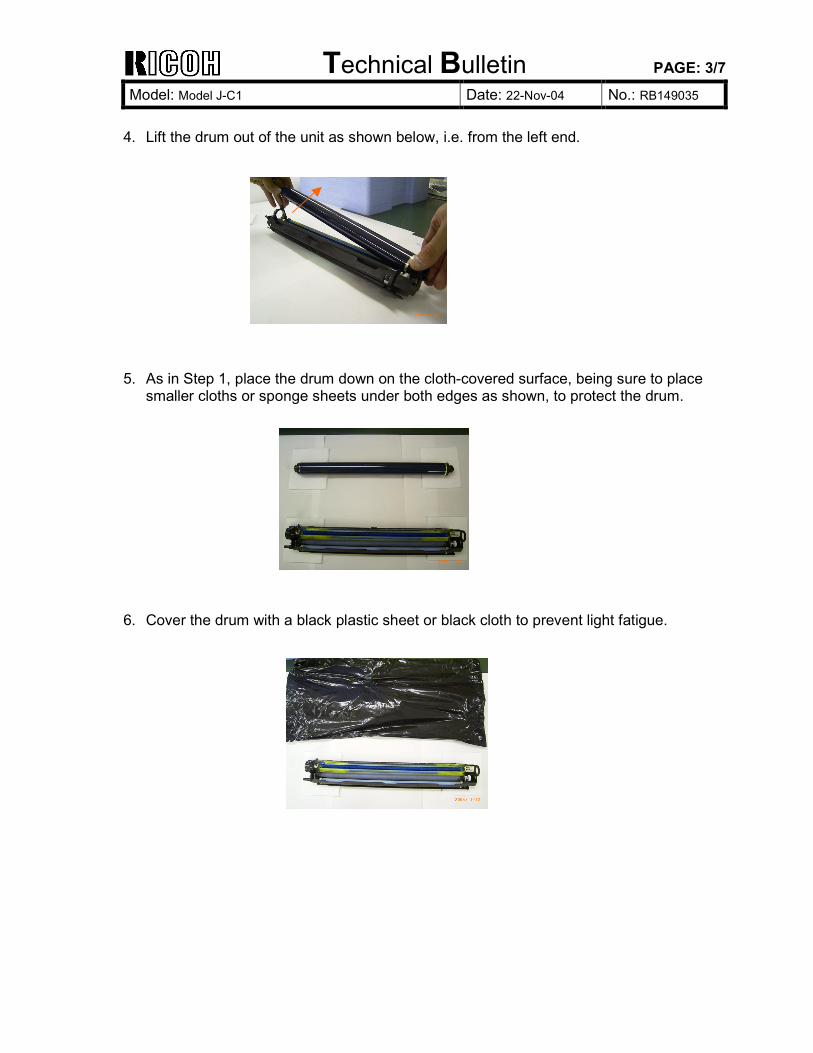
Technical Bulletin PAGE: 3/7
Model: Model J-C1 Date: 22-Nov-04 No.: RB149035
4. Lift the drum out of the unit as shown below, i.e. from the left end. 5. As in Step 1, place the drum down on the cloth-covered surface, being sure to place
smaller cloths or sponge sheets under both edges as shown, to protect the drum. 6. Cover the drum with a black plastic sheet or black cloth to prevent light fatigue.
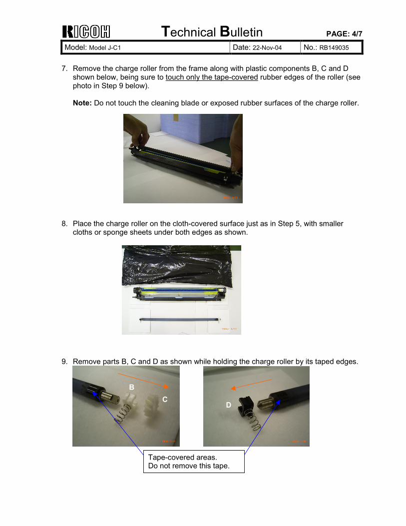
Technical Bulletin PAGE: 4/7
Model: Model J-C1 Date: 22-Nov-04 No.: RB149035
7. Remove the charge roller from the frame along with plastic components B, C and D
shown below, being sure to touch only the tape-covered rubber edges of the roller (see photo in Step 9 below). Note: Do not touch the cleaning blade or exposed rubber surfaces of the charge roller.
8. Place the charge roller on the cloth-covered surface just as in Step 5, with smaller
cloths or sponge sheets under both edges as shown. 9. Remove parts B, C and D as shown while holding the charge roller by its taped edges.
B C
D
Tape-covered areas. Do not remove this tape.
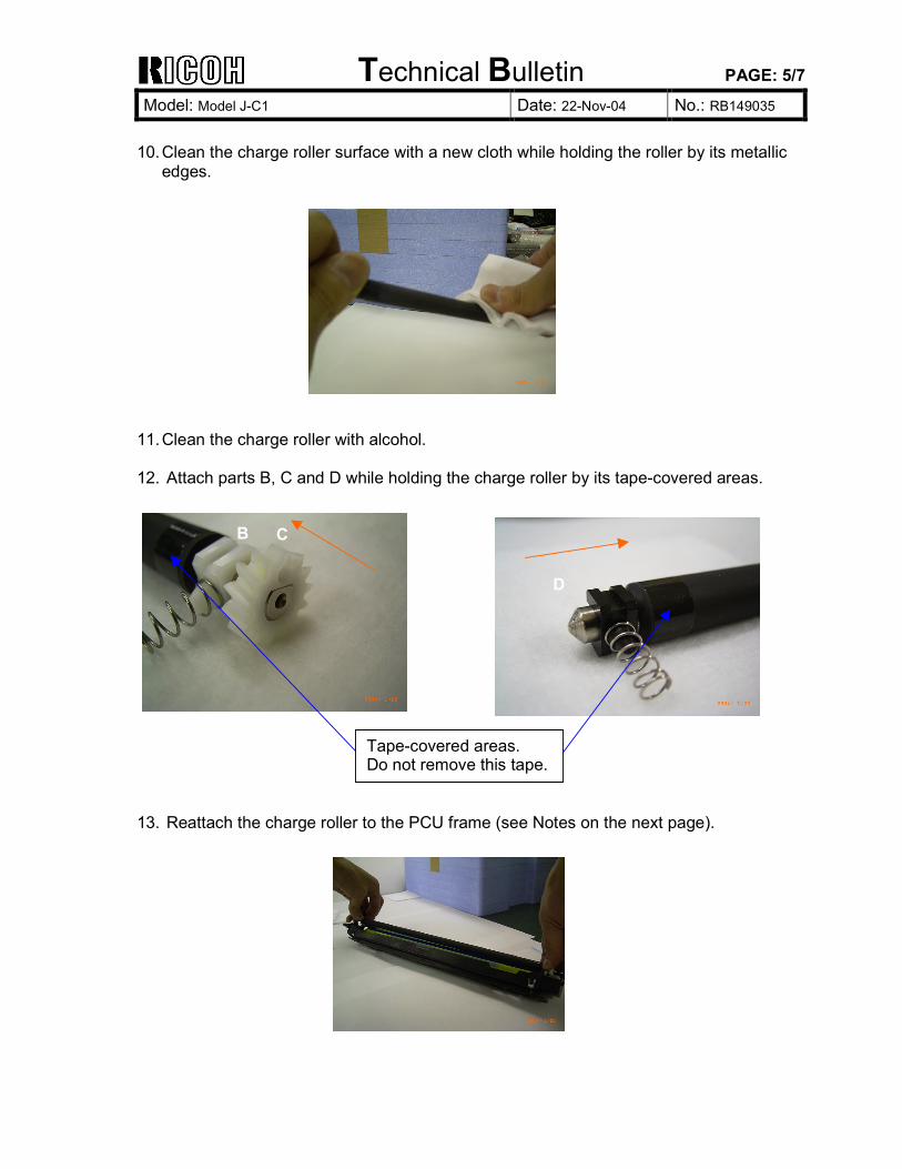
Technical Bulletin PAGE: 5/7
Model: Model J-C1 Date: 22-Nov-04 No.: RB149035
10. Clean the charge roller surface with a new cloth while holding the roller by its metallic
edges. 11. Clean the charge roller with alcohol. 12. Attach parts B, C and D while holding the charge roller by its tape-covered areas. 13. Reattach the charge roller to the PCU frame (see Notes on the next page).
B C
D
Tape-covered areas. Do not remove this tape.
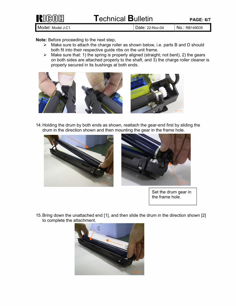
Technical Bulletin PAGE: 6/7
Model: Model J-C1 Date: 22-Nov-04 No.: RB149035
Note: Before proceeding to the next step,
Make sure to attach the charge roller as shown below, i.e. parts B and D should both fit into their respective guide ribs on the unit frame. Make sure that: 1) the spring is properly aligned (straight; not bent), 2) the gears
on both sides are attached properly to the shaft, and 3) the charge roller cleaner is properly secured in its bushings at both ends.
14. Holding the drum by both ends as shown, reattach the gear-end first by sliding the
drum in the direction shown and then mounting the gear in the frame hole. 15. Bring down the unattached end [1], and then slide the drum in the direction shown [2]
to complete the attachment.
①
②
Set the drum gear in the frame hole.
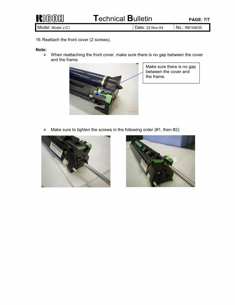
Technical Bulletin PAGE: 7/7
Model: Model J-C1 Date: 22-Nov-04 No.: RB149035
16. Reattach the front cover (2 screws). Note:
When reattaching the front cover, make sure there is no gap between the cover and the frame.
Make sure to tighten the screws in the following order (#1, then #2):
Make sure there is no gap between the cover and the frame.
①①①①
②②②②
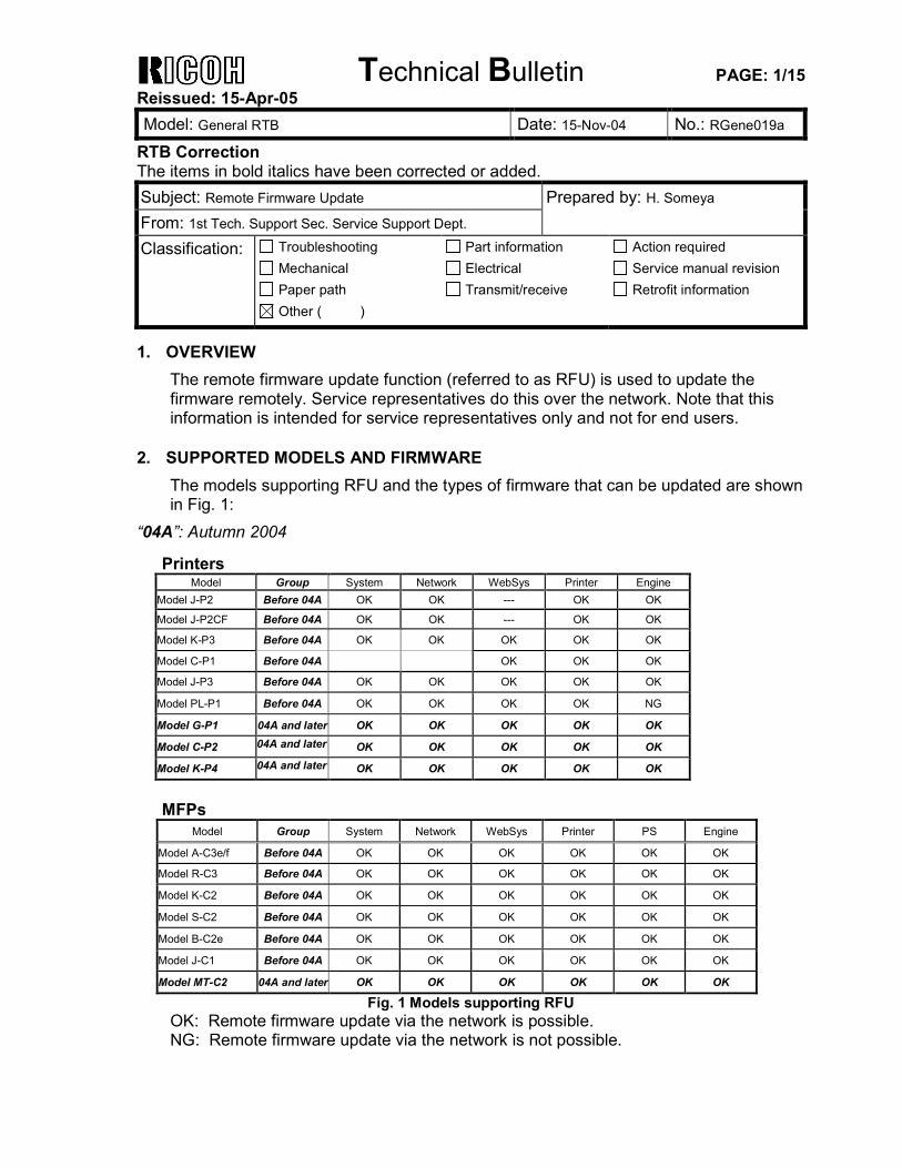
Technical Bulletin PAGE: 1/15 Reissued: 15-Apr-05 Model: General RTB Date: 15-Nov-04 No.: RGene019a
RTB Correction The items in bold italics have been corrected or added. Subject: Remote Firmware Update Prepared by: H. Someya From: 1st Tech. Support Sec. Service Support Dept. Classification: Troubleshooting
Mechanical Paper path
Part information Electrical Transmit/receive
Action required Service manual revision Retrofit information
Other ( )
1. OVERVIEW
The remote firmware update function (referred to as RFU) is used to update the firmware remotely. Service representatives do this over the network. Note that this information is intended for service representatives only and not for end users.
2. SUPPORTED MODELS AND FIRMWARE
The models supporting RFU and the types of firmware that can be updated are shown in Fig. 1:
“04A”: Autumn 2004
Printers Model Group System Network WebSys Printer Engine
Model J-P2 Before 04A OK OK --- OK OK
Model J-P2CF Before 04A OK OK --- OK OK
Model K-P3 Before 04A OK OK OK OK OK
Model C-P1 Before 04A OK OK OK
Model J-P3 Before 04A OK OK OK OK OK
Model PL-P1 Before 04A OK OK OK OK NG
Model G-P1 04A and later OK OK OK OK OK
Model C-P2 04A and later OK OK OK OK OK
Model K-P4 04A and later OK OK OK OK OK
MFPs
Model Group System Network WebSys Printer PS Engine
Model A-C3e/f Before 04A OK OK OK OK OK OK
Model R-C3 Before 04A OK OK OK OK OK OK
Model K-C2 Before 04A OK OK OK OK OK OK
Model S-C2 Before 04A OK OK OK OK OK OK
Model B-C2e Before 04A OK OK OK OK OK OK
Model J-C1 Before 04A OK OK OK OK OK OK
Model MT-C2 04A and later OK OK OK OK OK OK
Fig. 1 Models supporting RFU OK: Remote firmware update via the network is possible. NG: Remote firmware update via the network is not possible.
Technical Bulletin PAGE: 2/15 Reissued: 15-Apr-05 Model: General RTB Date: 15-Nov-04 No.: RGene019a
The following models do not support RFU:
• Printers: Model K-P1/P2, Model J-P1, Model A-P3, Model U-P1, Model AR-P1, and not GW products
• MFPs: Model A-C2/C3, Model R-C2, Model U-C1, Model MT-C1, and not GW products
3. SYSTEM REQUIREMENTS
Network Interface: • 10 Base-T or faster Ethernet LAN • IEEE1284 (Centronics) (A setting must be changed in SP mode.) Note: IEEE1284 does not support error recovery after a power loss. For Recovery Mode: • 10 Base-T or faster Ethernet LAN – the note above says that only 1284 doesn’t
support it. Protocols: For RFU Mode & Recovery Mode: • FTP (The port must be open) Operating System: • Windows Server 2003 • Windows XP • Windows 2000 • Windows NT 4.0 • Windows 9x/Me • Mac OS • UNIX/Linux (Any version) Note: RFU is available for any OS from which FTP is possible. Unsupported environments: • IPP • SMB over TCP/IP • Direct port • AutoNet (169.254.x.x) with DHCP
Technical Bulletin PAGE: 3/15 Reissued: 15-Apr-05 Model: General RTB Date: 15-Nov-04 No.: RGene019a
Ftp settings and commands: • User name (default): Before 04A: rsysupdate 04A and later: admin
• Password (default): Before 04A: password 04A and later: (no password)
Note: These default passwords are the same as the administrator passwords. • Transfer mode: binary • FTP commands supported:
binary (Transfer data in binary mode) dir (List files and directories) put “file name” get version.txt - (Obtain the version.txt file and display its contents.) get errlog.txt - (Obtain the errlog.txt file and display its contents.)
4. STATUS OF UNUPDATEABLE MACHINE
If the printer is in any of the following statuses, RFU will not work. • Print job in progress (copier, printer, fax, network) • Scan job in progress (copier, scanner, fax) • Receiving a print image from the network • Operation panel is in use • Incoming/Outgoing fax message • SC condition You can check the status of the target machine using WebImageMonitor or SmartDeviceMonitor.
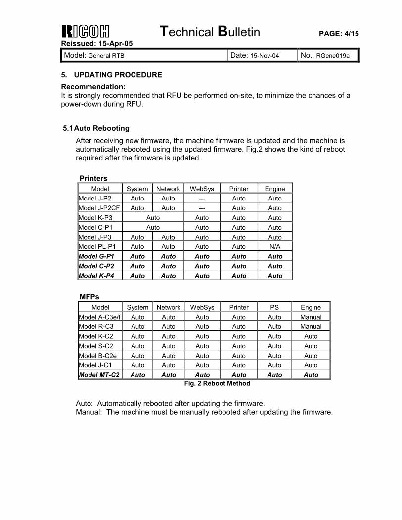
Technical Bulletin PAGE: 4/15 Reissued: 15-Apr-05 Model: General RTB Date: 15-Nov-04 No.: RGene019a
5. UPDATING PROCEDURE Recommendation: It is strongly recommended that RFU be performed on-site, to minimize the chances of a power-down during RFU. 5.1 Auto Rebooting
After receiving new firmware, the machine firmware is updated and the machine is automatically rebooted using the updated firmware. Fig.2 shows the kind of reboot required after the firmware is updated. Printers
Model System Network WebSys Printer Engine Model J-P2 Auto Auto --- Auto Auto Model J-P2CF Auto Auto --- Auto Auto Model K-P3 Auto Auto Auto Auto Model C-P1 Auto Auto Auto Auto Model J-P3 Auto Auto Auto Auto Auto Model PL-P1 Auto Auto Auto Auto N/A Model G-P1 Auto Auto Auto Auto Auto Model C-P2 Auto Auto Auto Auto Auto Model K-P4 Auto Auto Auto Auto Auto
MFPs Model System Network WebSys Printer PS Engine
Model A-C3e/f Auto Auto Auto Auto Auto Manual Model R-C3 Auto Auto Auto Auto Auto Manual Model K-C2 Auto Auto Auto Auto Auto Auto Model S-C2 Auto Auto Auto Auto Auto Auto Model B-C2e Auto Auto Auto Auto Auto Auto Model J-C1 Auto Auto Auto Auto Auto Auto Model MT-C2 Auto Auto Auto Auto Auto Auto
Fig. 2 Reboot Method
Auto: Automatically rebooted after updating the firmware. Manual: The machine must be manually rebooted after updating the firmware.
Technical Bulletin PAGE: 5/15 Reissued: 15-Apr-05 Model: General RTB Date: 15-Nov-04 No.: RGene019a
5.2 Preparation
Before you update the firmware by RFU, carry out three items as shown below. 5.2.1 Checking the IP address
For a machine with static IP address:
• Search for the IP address using SmartDeviceMonitor for Admin or Web • SmartDeviceMonitor. • If the hostname of the machine is registered in a DNS server, use the nslookup
command with the machines hostname. This can also be used for dynamic IP addresses if you are using DDNS.
• If the computer name of the machine is registered in a WINS server use the <……..> command.
For a machine with a dynamic IP address:
• Print the config sheet or the SMC for the machine. • Check the IP address in the DHCP server.
5.2.2 Firmware
• Please download firmware (*.rru or *.rfu files) from our support site and store it in a folder on a local PC to be used for RFU.
5.2.3 Checking the machine status
• Please check the status of the target machine using WebImageMonitor or SmartDeviceMonitor.
Technical Bulletin PAGE: 6/15 Reissued: 15-Apr-05 Model: General RTB Date: 15-Nov-04 No.: RGene019a
5.3 RFU for Windows
1. Open a command prompt. o [Start]-[Program]-[Accessories]-[Command Prompt]
2. Logon to the machine using ftp.
C:\> ftp xxx.xxx.xxx.xxx Specify the machine's IP address
Connected to xxx.xxx.xxx.xxx.
220 (Product name) FTP server (1.00)ready.
User (IP address:(none)):
3. Enter the user name.
User (IP address:(none)):rsysupdate User name
331 Password required for rsysupdate.
Password:
4. Enter the password.
Password:xxxxx
230 User rsysupdate logged in. Login successful.
ftp>
5. Enter "dir" to check that version.txt exists.
ftp> dir
200 PORT command successful.
150 Opening ASCII mode data connection for '/'.
-r--r--r--root root 200 Jan 1 01:08 help
-r--r--r--root root 200 Jan 1 01:08 info
-r--r--r--root root 200 Jan 1 01:08 install
-r--r--r--root root 200 Jan 1 01:08 prnlog
-r--r--r--root root 200 Jan 1 01:08 stat
-r--r--r--root root 200 Jan 1 01:08 syslog
-r--r--r--root root 200 Jan 1 01:08 version.txt
-r--r--r--root root 200 Jan 1 01:08 errlog.txt
226 Transfer complete.
ftp:372 bytes received in n.nn Seconds n.nn Kbytes/sec.
ftp>
Technical Bulletin PAGE: 7/15 Reissued: 15-Apr-05 Model: General RTB Date: 15-Nov-04 No.: RGene019a
6. Enter "get version.txt -" to check the machine's firmware version.f
200 PORT command successful.
150 Opening ASCII mode data connection for 'version.txt'.
PartNo. Module Name Version Module ID
----------------------------------------------------------------------------------------------
G0000000 os & copy 0.20 XXXXXX_copy
G0000000 os & pf 0.20 XXXXXX_system
G570xxxx Onboard Scn 2.04 XXXXXX_scn
G5705387A OptDIMM Fax 1.07 XXXXXX_fax
G5700000 printer 0.19 XXXXXX_printer
G5705383D Network DocBox 2.00 XXXXXX_netfile
G0805920A Network 0.71 XXXXXX_net
G0805601 ENGINE R0.14 :06 XXXXXX_eplot
...
----------------------------------------------------------------------------------------------
226 Transfer complete.
ftp>
7. Enter "binary" to set the file transfer mode to binary.
ftp> binary
200 Type set to I.
ftp>
8. Navigate to the directory on your PC containing the file xxx.rru. 9. Transmit the firmware module file (*.rru or *.rfu) using the "put" command.
ftp> put xxx.rru
200 PORT command successful.
150 Opening BINARY mode data connection for 'xxx.rru'.
226 Transfer complete.
ftp:nnnnnn bytes sent in s.ss Seconds pp.pp Kbytes/sec.
ftp>
Note: Do not turn off the power of the machine while updating the firmware.
Technical Bulletin PAGE: 8/15 Reissued: 15-Apr-05 Model: General RTB Date: 15-Nov-04 No.: RGene019a
ROM Update Receiving Data
Updating... ***____________
When the machine starts to receive the file, the following message appears on the machine's control panel and normal machine functions are disabled.
o Display panel (MFPs)
o Display (Printers)
10. Once the machine has received the entire firmware module file, the firmware update starts automatically. The following message appears:
o Display panel (MFPs)
o Display (Printers)
Note: If the controller firmware is being updated, this message is displayed in English only.
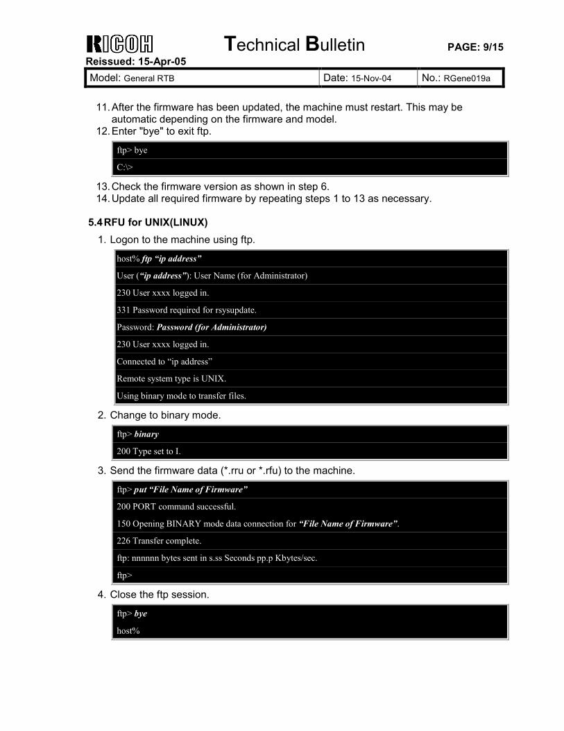
Technical Bulletin PAGE: 9/15 Reissued: 15-Apr-05 Model: General RTB Date: 15-Nov-04 No.: RGene019a
11. After the firmware has been updated, the machine must restart. This may be
automatic depending on the firmware and model. 12. Enter "bye" to exit ftp.
ftp> bye
C:\>
13. Check the firmware version as shown in step 6. 14. Update all required firmware by repeating steps 1 to 13 as necessary.
5.4 RFU for UNIX(LINUX)
1. Logon to the machine using ftp.
host% ftp “ip address”
User (“ip address”): User Name (for Administrator)
230 User xxxx logged in.
331 Password required for rsysupdate.
Password: Password (for Administrator)
230 User xxxx logged in.
Connected to “ip address”
Remote system type is UNIX.
Using binary mode to transfer files.
2. Change to binary mode.
ftp> binary
200 Type set to I.
3. Send the firmware data (*.rru or *.rfu) to the machine.
ftp> put “File Name of Firmware”
200 PORT command successful.
150 Opening BINARY mode data connection for “File Name of Firmware”.
226 Transfer complete.
ftp: nnnnnn bytes sent in s.ss Seconds pp.p Kbytes/sec.
ftp>
4. Close the ftp session.
ftp> bye
host%
Technical Bulletin PAGE: 10/15 Reissued: 15-Apr-05 Model: General RTB Date: 15-Nov-04 No.: RGene019a
5.5 Firmware Update for Centronics (IEEE1284)
Note: • Firmware update via a centronics interface does not require a password. • The only method of recovery available via a centronics interface is an IC or SD
card.
1. Check the target firmware version by printing out the SMC sheet with SP5-990-4. 2. Set SP5-856-2 to a value of 1. This will configure the machine for firmware update
via the Centronics I/F. 3. Send the firmware to the target machine with the copy command.
C:\>copy/b “file name”
4. Cycle the machine’s power (off then on). 5. Confirm the firmware version as shown in step 1. 6. Update all required firmware by repeating steps 1 to 5 as necessary.
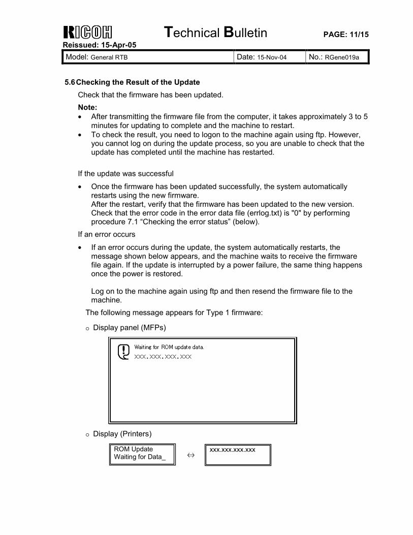
Technical Bulletin PAGE: 11/15 Reissued: 15-Apr-05 Model: General RTB Date: 15-Nov-04 No.: RGene019a
5.6 Checking the Result of the Update
Check that the firmware has been updated. Note: • After transmitting the firmware file from the computer, it takes approximately 3 to 5
minutes for updating to complete and the machine to restart. • To check the result, you need to logon to the machine again using ftp. However,
you cannot log on during the update process, so you are unable to check that the update has completed until the machine has restarted.
If the update was successful
• Once the firmware has been updated successfully, the system automatically restarts using the new firmware. After the restart, verify that the firmware has been updated to the new version. Check that the error code in the error data file (errlog.txt) is "0" by performing procedure 7.1 “Checking the error status” (below).
If an error occurs
• If an error occurs during the update, the system automatically restarts, the message shown below appears, and the machine waits to receive the firmware file again. If the update is interrupted by a power failure, the same thing happens once the power is restored. Log on to the machine again using ftp and then resend the firmware file to the machine.
The following message appears for Type 1 firmware:
o Display panel (MFPs)
o Display (Printers)
ROM Update Waiting for Data_
xxx.xxx.xxx.xxx ⇔
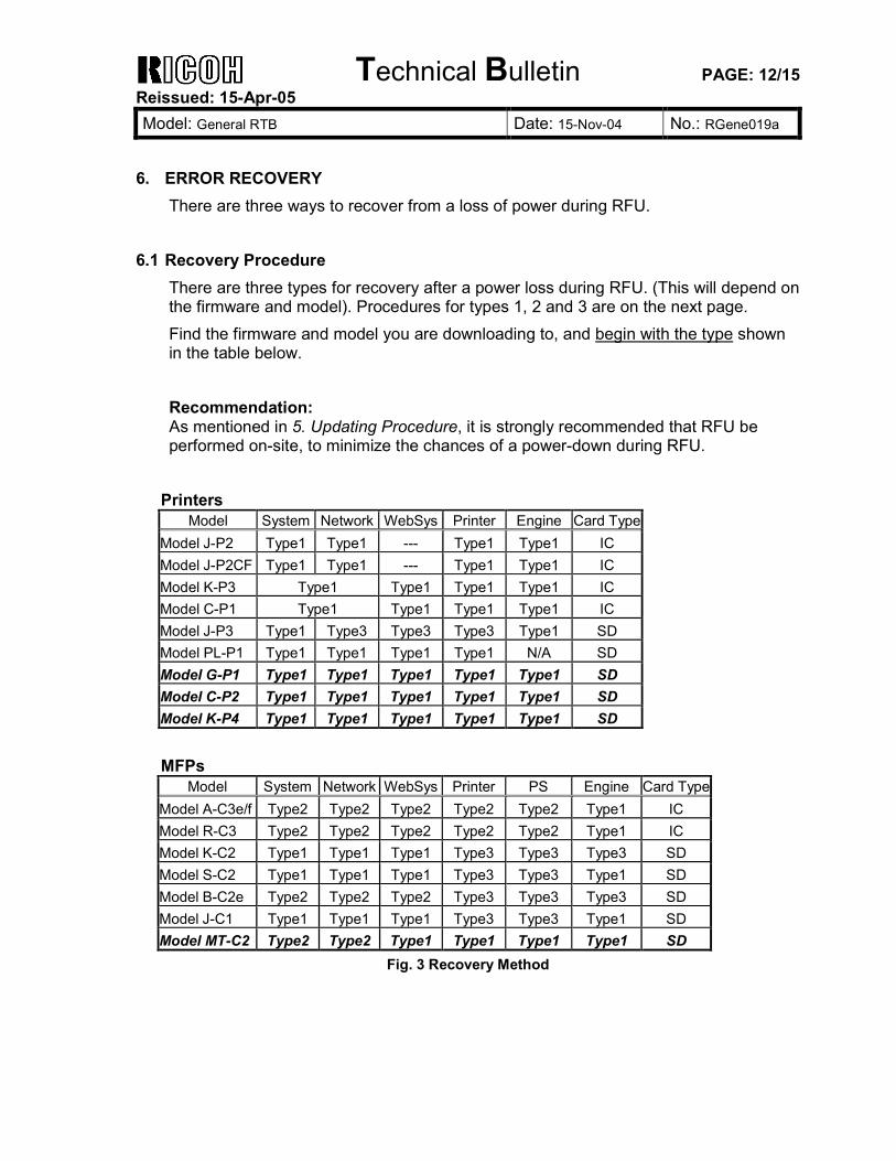
Technical Bulletin PAGE: 12/15 Reissued: 15-Apr-05 Model: General RTB Date: 15-Nov-04 No.: RGene019a
6. ERROR RECOVERY
There are three ways to recover from a loss of power during RFU.
6.1 Recovery Procedure There are three types for recovery after a power loss during RFU. (This will depend on the firmware and model). Procedures for types 1, 2 and 3 are on the next page. Find the firmware and model you are downloading to, and begin with the type shown in the table below. Recommendation: As mentioned in 5. Updating Procedure, it is strongly recommended that RFU be performed on-site, to minimize the chances of a power-down during RFU.
Printers Model System Network WebSys Printer Engine Card Type
Model J-P2 Type1 Type1 --- Type1 Type1 IC Model J-P2CF Type1 Type1 --- Type1 Type1 IC Model K-P3 Type1 Type1 Type1 Type1 IC Model C-P1 Type1 Type1 Type1 Type1 IC Model J-P3 Type1 Type3 Type3 Type3 Type1 SD Model PL-P1 Type1 Type1 Type1 Type1 N/A SD Model G-P1 Type1 Type1 Type1 Type1 Type1 SD Model C-P2 Type1 Type1 Type1 Type1 Type1 SD Model K-P4 Type1 Type1 Type1 Type1 Type1 SD
MFPs
Model System Network WebSys Printer PS Engine Card TypeModel A-C3e/f Type2 Type2 Type2 Type2 Type2 Type1 IC Model R-C3 Type2 Type2 Type2 Type2 Type2 Type1 IC Model K-C2 Type1 Type1 Type1 Type3 Type3 Type3 SD Model S-C2 Type1 Type1 Type1 Type3 Type3 Type1 SD Model B-C2e Type2 Type2 Type2 Type3 Type3 Type3 SD Model J-C1 Type1 Type1 Type1 Type3 Type3 Type1 SD Model MT-C2 Type2 Type2 Type1 Type1 Type1 Type1 SD
Fig. 3 Recovery Method
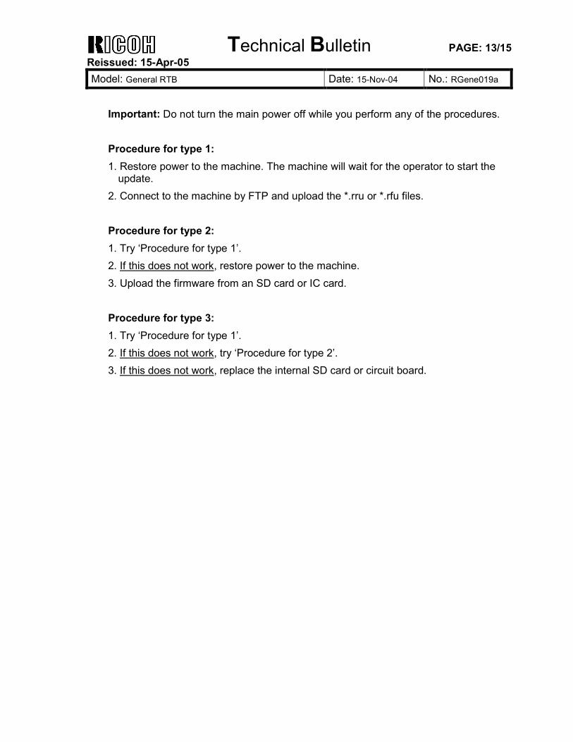
Technical Bulletin PAGE: 13/15 Reissued: 15-Apr-05 Model: General RTB Date: 15-Nov-04 No.: RGene019a
Important: Do not turn the main power off while you perform any of the procedures. Procedure for type 1: 1. Restore power to the machine. The machine will wait for the operator to start the
update. 2. Connect to the machine by FTP and upload the *.rru or *.rfu files. Procedure for type 2: 1. Try ‘Procedure for type 1’. 2. If this does not work, restore power to the machine. 3. Upload the firmware from an SD card or IC card. Procedure for type 3: 1. Try ‘Procedure for type 1’. 2. If this does not work, try ‘Procedure for type 2’. 3. If this does not work, replace the internal SD card or circuit board.
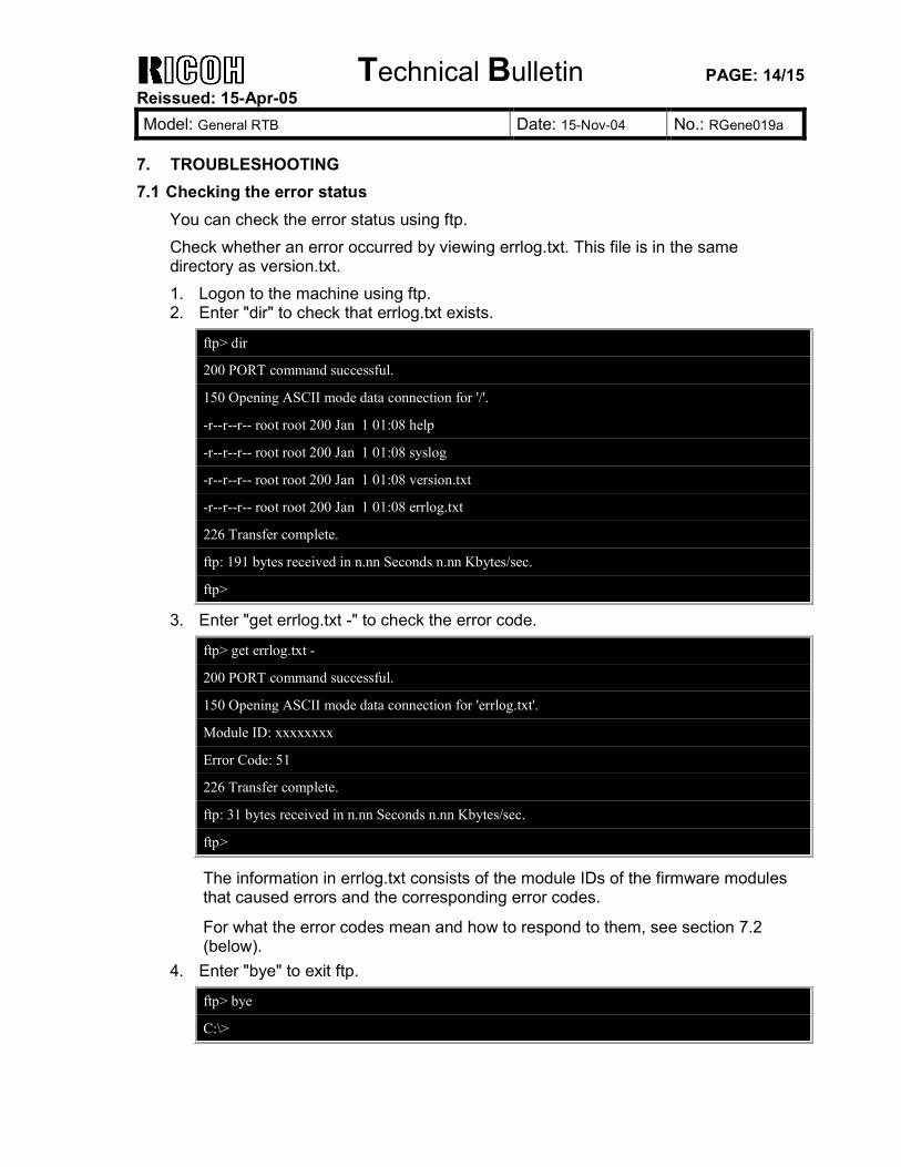
Technical Bulletin PAGE: 14/15 Reissued: 15-Apr-05 Model: General RTB Date: 15-Nov-04 No.: RGene019a
7. TROUBLESHOOTING 7.1 Checking the error status
You can check the error status using ftp. Check whether an error occurred by viewing errlog.txt. This file is in the same directory as version.txt. 1. Logon to the machine using ftp. 2. Enter "dir" to check that errlog.txt exists.
ftp> dir
200 PORT command successful.
150 Opening ASCII mode data connection for '/'.
-r--r--r-- root root 200 Jan 1 01:08 help
-r--r--r-- root root 200 Jan 1 01:08 syslog
-r--r--r-- root root 200 Jan 1 01:08 version.txt
-r--r--r-- root root 200 Jan 1 01:08 errlog.txt
226 Transfer complete.
ftp: 191 bytes received in n.nn Seconds n.nn Kbytes/sec.
ftp>
3. Enter "get errlog.txt -" to check the error code.
ftp> get errlog.txt -
200 PORT command successful.
150 Opening ASCII mode data connection for 'errlog.txt'.
Module ID: xxxxxxxx
Error Code: 51
226 Transfer complete.
ftp: 31 bytes received in n.nn Seconds n.nn Kbytes/sec.
ftp>
The information in errlog.txt consists of the module IDs of the firmware modules that caused errors and the corresponding error codes.
For what the error codes mean and how to respond to them, see section 7.2 (below).
4. Enter "bye" to exit ftp.
ftp> bye
C:\>
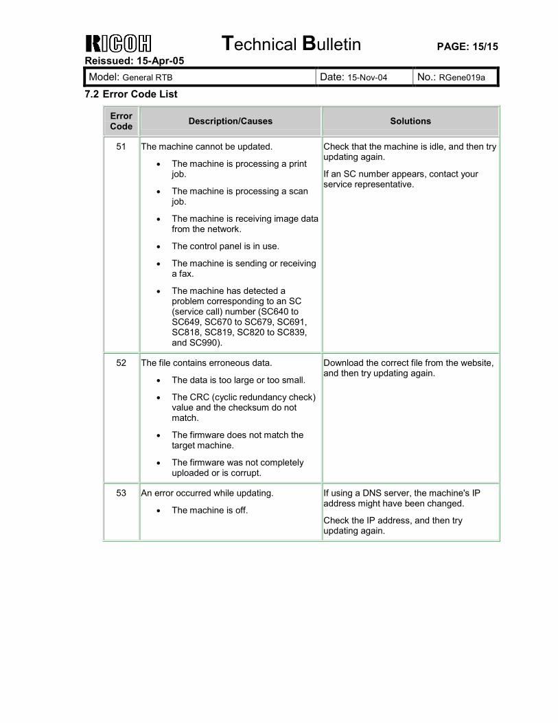
Technical Bulletin PAGE: 15/15 Reissued: 15-Apr-05 Model: General RTB Date: 15-Nov-04 No.: RGene019a
7.2 Error Code List
Error Code Description/Causes Solutions
51 The machine cannot be updated.
• The machine is processing a print job.
• The machine is processing a scan job.
• The machine is receiving image data from the network.
• The control panel is in use.
• The machine is sending or receiving a fax.
• The machine has detected a problem corresponding to an SC (service call) number (SC640 to SC649, SC670 to SC679, SC691, SC818, SC819, SC820 to SC839, and SC990).
Check that the machine is idle, and then try updating again.
If an SC number appears, contact your service representative.
52 The file contains erroneous data.
• The data is too large or too small.
• The CRC (cyclic redundancy check) value and the checksum do not match.
• The firmware does not match the target machine.
• The firmware was not completely uploaded or is corrupt.
Download the correct file from the website, and then try updating again.
53 An error occurred while updating.
• The machine is off.
If using a DNS server, the machine's IP address might have been changed.
Check the IP address, and then try updating again.
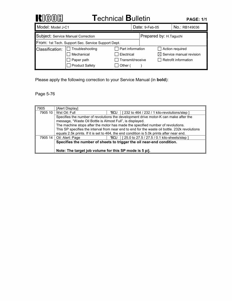
Technical Bulletin PAGE: 1/1
Model: Model J-C1 Date: 9-Feb-05 No.: RB149036
Subject: Service Manual Correction Prepared by: H.Taguchi From: 1st Tech. Support Sec. Service Support Dept. Classification: Troubleshooting
Mechanical Paper path
Part information Electrical Transmit/receive
Action required Service manual revision Retrofit information
Product Safety Other ( )
Please apply the following correction to your Service Manual (in bold): Page 5-76
7905 [Alert Display] Wst Oil: Full *BCU [ 232 to 464 / 232 / 1 kilo-revolutions/step ] 7905 10 Specifies the number of revolutions the development drive motor-K can make after the message, “Waste Oil Bottle is Almost Full”, is displayed. The machine stops after the motor has made the specified number of revolutions. This SP specifies the interval from near end to end for the waste oil bottle. 232k revolutions equals 2.5k prints. If it is set to 464, the end condition is 5.0k prints after near end. Oil: Alert: Page *BCU [ 25.0 to 27.5 / 27.5 / 0.1 kilo-sheets/step ] 7905 14 Specifies the number of sheets to trigger the oil near-end condition. Note: The target job volume for this SP mode is 5 p/j.
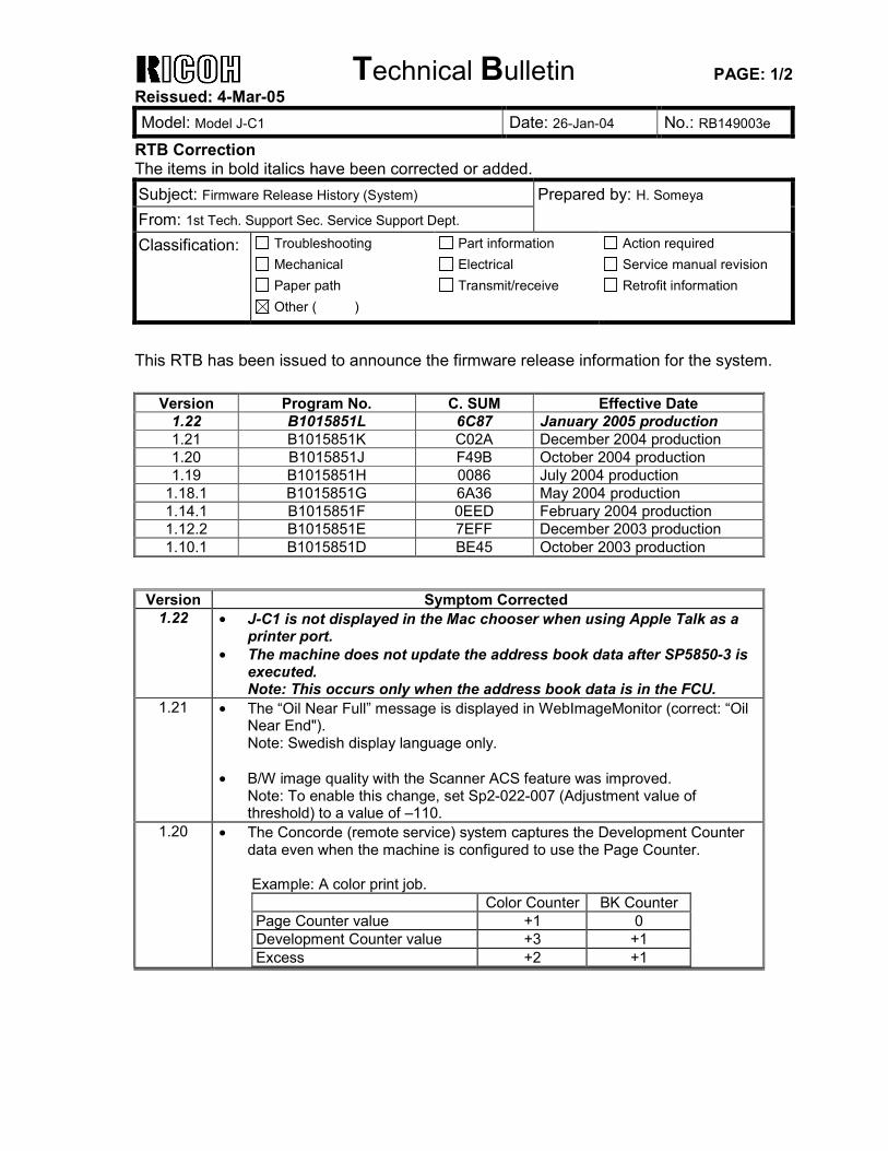
Technical Bulletin PAGE: 1/2 Reissued: 4-Mar-05 Model: Model J-C1 Date: 26-Jan-04 No.: RB149003e
RTB Correction The items in bold italics have been corrected or added. Subject: Firmware Release History (System) Prepared by: H. Someya From: 1st Tech. Support Sec. Service Support Dept. Classification: Troubleshooting
Mechanical Paper path
Part information Electrical Transmit/receive
Action required Service manual revision Retrofit information
Other ( )
This RTB has been issued to announce the firmware release information for the system.
Version Program No. C. SUM Effective Date 1.22 B1015851L 6C87 January 2005 production 1.21 B1015851K C02A December 2004 production 1.20 B1015851J F49B October 2004 production 1.19 B1015851H 0086 July 2004 production
1.18.1 B1015851G 6A36 May 2004 production 1.14.1 B1015851F 0EED February 2004 production 1.12.2 B1015851E 7EFF December 2003 production 1.10.1 B1015851D BE45 October 2003 production
Version Symptom Corrected
1.22 • J-C1 is not displayed in the Mac chooser when using Apple Talk as a printer port.
• The machine does not update the address book data after SP5850-3 is executed. Note: This occurs only when the address book data is in the FCU.
1.21 • The “Oil Near Full” message is displayed in WebImageMonitor (correct: “Oil Near End"). Note: Swedish display language only.
• B/W image quality with the Scanner ACS feature was improved.
Note: To enable this change, set Sp2-022-007 (Adjustment value of threshold) to a value of –110.
1.20 • The Concorde (remote service) system captures the Development Counter data even when the machine is configured to use the Page Counter. Example: A color print job. Color Counter BK Counter Page Counter value +1 0 Development Counter value +3 +1 Excess +2 +1
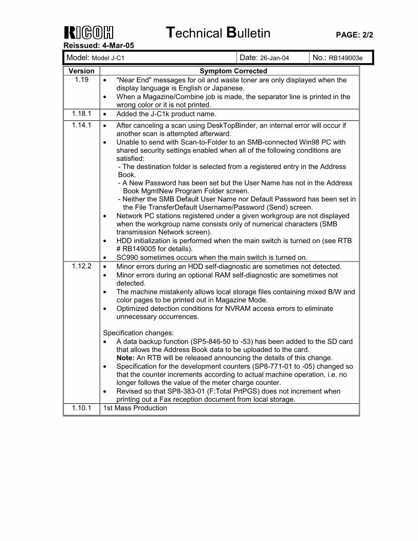
Technical Bulletin PAGE: 2/2 Reissued: 4-Mar-05 Model: Model J-C1 Date: 26-Jan-04 No.: RB149003e
Version Symptom Corrected 1.19 • "Near End" messages for oil and waste toner are only displayed when the
display language is English or Japanese. • When a Magazine/Combine job is made, the separator line is printed in the
wrong color or it is not printed. 1.18.1 • Added the J-C1k product name. 1.14.1 • After canceling a scan using DeskTopBinder, an internal error will occur if
another scan is attempted afterward. • Unable to send with Scan-to-Folder to an SMB-connected Win98 PC with
shared security settings enabled when all of the following conditions are satisfied: - The destination folder is selected from a registered entry in the Address Book. - A New Password has been set but the User Name has not in the Address
Book MgmtNew Program Folder screen. - Neither the SMB Default User Name nor Default Password has been set in
the File TransferDefault Username/Password (Send) screen. • Network PC stations registered under a given workgroup are not displayed
when the workgroup name consists only of numerical characters (SMB transmission Network screen).
• HDD initialization is performed when the main switch is turned on (see RTB # RB149005 for details).
• SC990 sometimes occurs when the main switch is turned on. 1.12.2 • Minor errors during an HDD self-diagnostic are sometimes not detected.
• Minor errors during an optional RAM self-diagnostic are sometimes not detected.
• The machine mistakenly allows local storage files containing mixed B/W and color pages to be printed out in Magazine Mode.
• Optimized detection conditions for NVRAM access errors to eliminate unnecessary occurrences.
Specification changes: • A data backup function (SP5-846-50 to -53) has been added to the SD card
that allows the Address Book data to be uploaded to the card. Note: An RTB will be released announcing the details of this change.
• Specification for the development counters (SP8-771-01 to -05) changed so that the counter increments according to actual machine operation, i.e. no longer follows the value of the meter charge counter.
• Revised so that SP8-383-01 (F:Total PrtPGS) does not increment when printing out a Fax reception document from local storage.
1.10.1 1st Mass Production
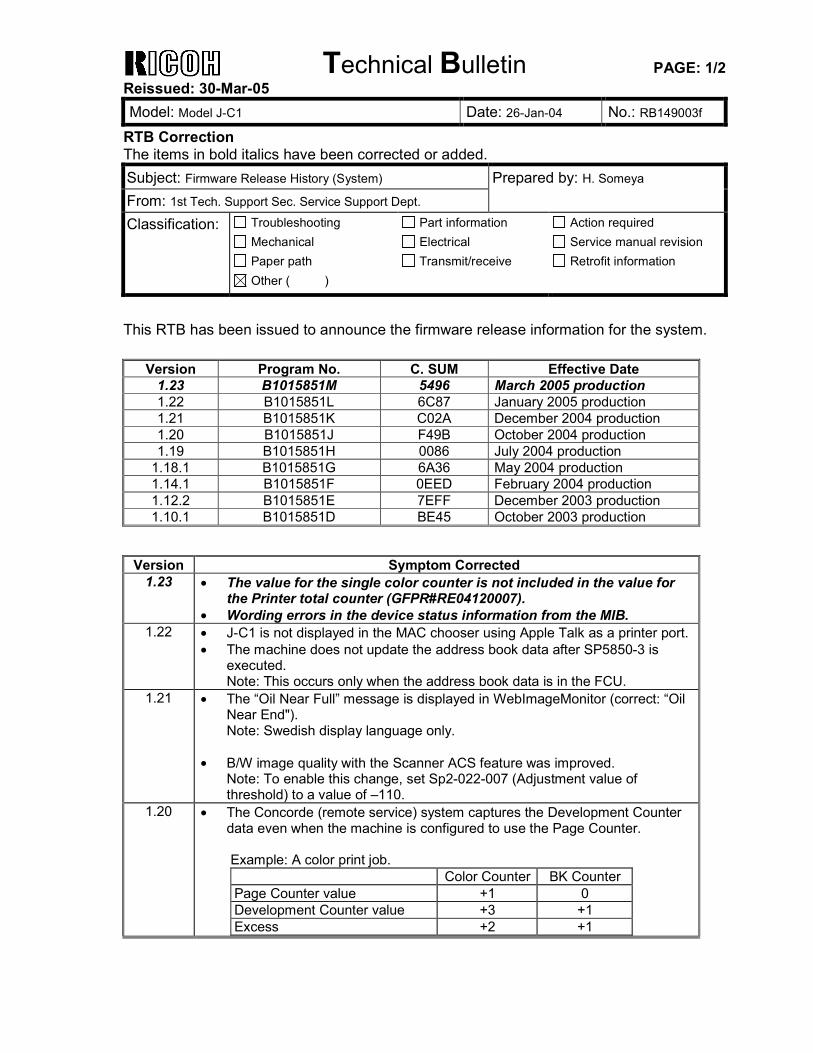
Technical Bulletin PAGE: 1/2 Reissued: 30-Mar-05 Model: Model J-C1 Date: 26-Jan-04 No.: RB149003f
RTB Correction The items in bold italics have been corrected or added. Subject: Firmware Release History (System) Prepared by: H. Someya From: 1st Tech. Support Sec. Service Support Dept. Classification: Troubleshooting
Mechanical Paper path
Part information Electrical Transmit/receive
Action required Service manual revision Retrofit information
Other ( )
This RTB has been issued to announce the firmware release information for the system.
Version Program No. C. SUM Effective Date 1.23 B1015851M 5496 March 2005 production 1.22 B1015851L 6C87 January 2005 production 1.21 B1015851K C02A December 2004 production 1.20 B1015851J F49B October 2004 production 1.19 B1015851H 0086 July 2004 production
1.18.1 B1015851G 6A36 May 2004 production 1.14.1 B1015851F 0EED February 2004 production 1.12.2 B1015851E 7EFF December 2003 production 1.10.1 B1015851D BE45 October 2003 production
Version Symptom Corrected
1.23 • The value for the single color counter is not included in the value for the Printer total counter (GFPR#RE04120007).
• Wording errors in the device status information from the MIB. 1.22 • J-C1 is not displayed in the MAC chooser using Apple Talk as a printer port.
• The machine does not update the address book data after SP5850-3 is executed. Note: This occurs only when the address book data is in the FCU.
1.21 • The “Oil Near Full” message is displayed in WebImageMonitor (correct: “Oil Near End"). Note: Swedish display language only.
• B/W image quality with the Scanner ACS feature was improved.
Note: To enable this change, set Sp2-022-007 (Adjustment value of threshold) to a value of –110.
1.20 • The Concorde (remote service) system captures the Development Counter data even when the machine is configured to use the Page Counter. Example: A color print job. Color Counter BK Counter Page Counter value +1 0 Development Counter value +3 +1 Excess +2 +1
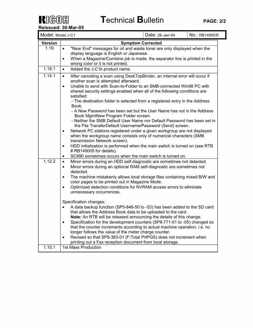
Technical Bulletin PAGE: 2/2 Reissued: 30-Mar-05 Model: Model J-C1 Date: 26-Jan-04 No.: RB149003f
Version Symptom Corrected 1.19 • "Near End" messages for oil and waste toner are only displayed when the
display language is English or Japanese. • When a Magazine/Combine job is made, the separator line is printed in the
wrong color or it is not printed. 1.18.1 • Added the J-C1k product name. 1.14.1 • After canceling a scan using DeskTopBinder, an internal error will occur if
another scan is attempted afterward. • Unable to send with Scan-to-Folder to an SMB-connected Win98 PC with
shared security settings enabled when all of the following conditions are satisfied: - The destination folder is selected from a registered entry in the Address Book. - A New Password has been set but the User Name has not in the Address
Book MgmtNew Program Folder screen. - Neither the SMB Default User Name nor Default Password has been set in
the File TransferDefault Username/Password (Send) screen. • Network PC stations registered under a given workgroup are not displayed
when the workgroup name consists only of numerical characters (SMB transmission Network screen).
• HDD initialization is performed when the main switch is turned on (see RTB # RB149005 for details).
• SC990 sometimes occurs when the main switch is turned on. 1.12.2 • Minor errors during an HDD self-diagnostic are sometimes not detected.
• Minor errors during an optional RAM self-diagnostic are sometimes not detected.
• The machine mistakenly allows local storage files containing mixed B/W and color pages to be printed out in Magazine Mode.
• Optimized detection conditions for NVRAM access errors to eliminate unnecessary occurrences.
Specification changes: • A data backup function (SP5-846-50 to -53) has been added to the SD card
that allows the Address Book data to be uploaded to the card. Note: An RTB will be released announcing the details of this change.
• Specification for the development counters (SP8-771-01 to -05) changed so that the counter increments according to actual machine operation, i.e. no longer follows the value of the meter charge counter.
• Revised so that SP8-383-01 (F:Total PrtPGS) does not increment when printing out a Fax reception document from local storage.
1.10.1 1st Mass Production
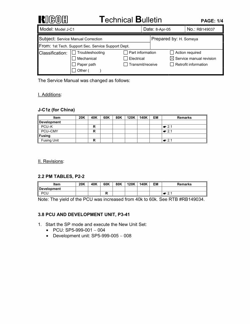
Technical Bulletin PAGE: 1/4
Model: Model J-C1 Date: 8-Apr-05 No.: RB149037
Subject: Service Manual Correction Prepared by: H. Someya From: 1st Tech. Support Sec. Service Support Dept. Classification: Troubleshooting
Mechanical Paper path
Part information Electrical Transmit/receive
Action required Service manual revision Retrofit information
Other ( )
The Service Manual was changed as follows: I. Additions: J-C1z (for China)
Item 20K 40K 60K 80K 120K 140K EM Remarks Development
PCU–K R ☛ 2.1 PCU–CMY R ☛ 2.1
Fusing Fusing Unit R ☛ 2.1
II. Revisions: 2.2 PM TABLES, P2-2
Item 20K 40K 60K 80K 120K 140K EM Remarks Development
PCU R ☛ 2.1
Note: The yield of the PCU was increased from 40k to 60k. See RTB #RB149034. 3.8 PCU AND DEVELOPMENT UNIT, P3-41
1. Start the SP mode and execute the New Unit Set: • PCU: SP5-999-001 ∼ 004 • Development unit: SP5-999-005 ∼ 008
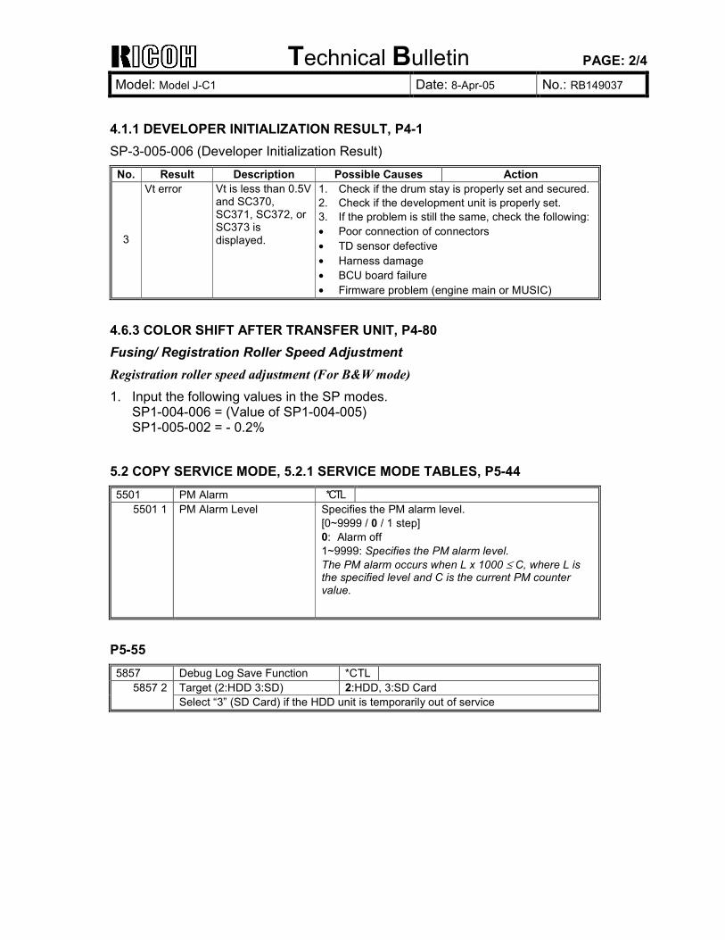
Technical Bulletin PAGE: 2/4
Model: Model J-C1 Date: 8-Apr-05 No.: RB149037
4.1.1 DEVELOPER INITIALIZATION RESULT, P4-1 SP-3-005-006 (Developer Initialization Result)
No. Result Description Possible Causes Action
3
Vt error Vt is less than 0.5V and SC370, SC371, SC372, or SC373 is displayed.
1. Check if the drum stay is properly set and secured. 2. Check if the development unit is properly set. 3. If the problem is still the same, check the following: • Poor connection of connectors • TD sensor defective • Harness damage • BCU board failure • Firmware problem (engine main or MUSIC)
4.6.3 COLOR SHIFT AFTER TRANSFER UNIT, P4-80 Fusing/ Registration Roller Speed Adjustment Registration roller speed adjustment (For B&W mode) 1. Input the following values in the SP modes.
SP1-004-006 = (Value of SP1-004-005) SP1-005-002 = - 0.2%
5.2 COPY SERVICE MODE, 5.2.1 SERVICE MODE TABLES, P5-44
5501 PM Alarm *CTL 5501 1 PM Alarm Level Specifies the PM alarm level.
[0~9999 / 0 / 1 step] 0: Alarm off 1~9999: Specifies the PM alarm level. The PM alarm occurs when L x 1000 ≤ C, where L is the specified level and C is the current PM counter value.
P5-55
5857 Debug Log Save Function *CTL Target (2:HDD 3:SD) 2:HDD, 3:SD Card 5857 2 Select “3” (SD Card) if the HDD unit is temporarily out of service
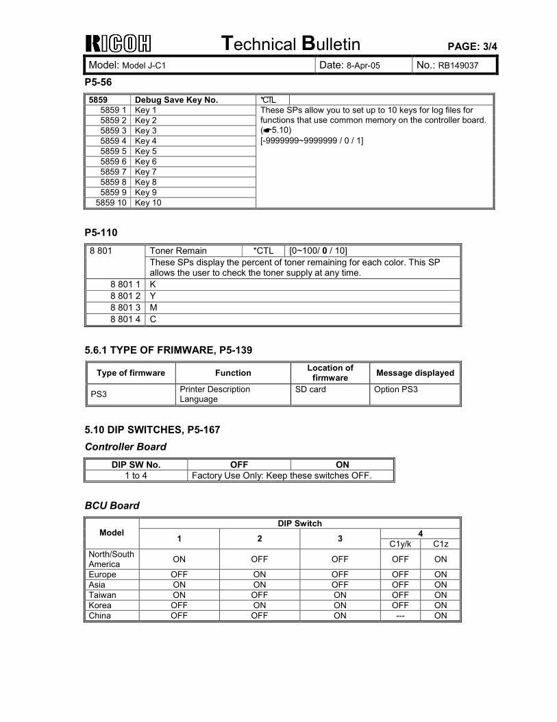
Technical Bulletin PAGE: 3/4
Model: Model J-C1 Date: 8-Apr-05 No.: RB149037
P5-56
5859 Debug Save Key No. *CTL 5859 1 Key 1 5859 2 Key 2 5859 3 Key 3 5859 4 Key 4 5859 5 Key 5 5859 6 Key 6 5859 7 Key 7 5859 8 Key 8 5859 9 Key 9
5859 10 Key 10
These SPs allow you to set up to 10 keys for log files for functions that use common memory on the controller board. (☛5.10) [-9999999~9999999 / 0 / 1]
P5-110
Toner Remain *CTL [0~100/ 0 / 10] 8 801 These SPs display the percent of toner remaining for each color. This SP allows the user to check the toner supply at any time.
8 801 1 K 8 801 2 Y 8 801 3 M 8 801 4 C
5.6.1 TYPE OF FRIMWARE, P5-139
Type of firmware Function Location of firmware Message displayed
PS3 Printer Description Language
SD card Option PS3
5.10 DIP SWITCHES, P5-167 Controller Board
DIP SW No. OFF ON 1 to 4 Factory Use Only: Keep these switches OFF.
BCU Board
DIP Switch 4 Model 1 2 3 C1y/k C1z
North/South America ON OFF OFF OFF ON
Europe OFF ON OFF OFF ON Asia ON ON OFF OFF ON Taiwan ON OFF ON OFF ON Korea OFF ON ON OFF ON China OFF OFF ON --- ON
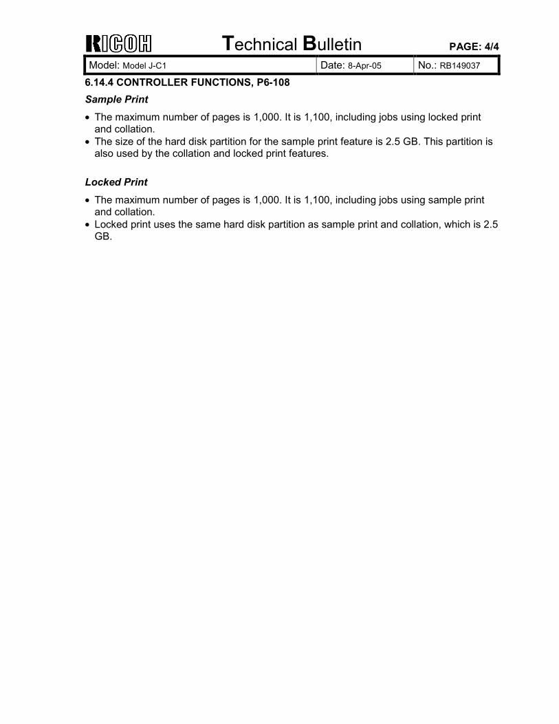
Technical Bulletin PAGE: 4/4
Model: Model J-C1 Date: 8-Apr-05 No.: RB149037
6.14.4 CONTROLLER FUNCTIONS, P6-108 Sample Print • The maximum number of pages is 1,000. It is 1,100, including jobs using locked print
and collation. • The size of the hard disk partition for the sample print feature is 2.5 GB. This partition is
also used by the collation and locked print features. Locked Print • The maximum number of pages is 1,000. It is 1,100, including jobs using sample print
and collation. • Locked print uses the same hard disk partition as sample print and collation, which is 2.5
GB.
Technical Bulletin PAGE: 1/1
Model: Model J-C1 Date: 21-Apr-05 No.: RB149038
Subject: Vertical lines Prepared by: H.Taguchi From: 1st Tech. Support Sec. Service Support Dept. Classification: Troubleshooting
Mechanical Paper path
Part information Electrical Transmit/receive
Action required Service manual revision Retrofit information
Product Safety Other ( )
SYMPTOM Vertical lines temporarily appear on the rear side after at least 200 sheets are printed out continuously. Note: This symptom tends to occur under these conditions:
1) During the initial period after installation, and 2) Soon after the cleaning blade or cleaning unit is replaced
CAUSE The setting powder on the cleaning blade sticks to the edge of the blade and ITB. As a result, the cleaning blade cannot clean all of the toner on the ITB.
SOLUTION PPrroodduuccttiioonn//SSeerrvviiccee PPaarrttss Cleaning blade: The setting powder was removed from the blade. Cleaning unit: The setting powder was removed from the blade and Y toner was added.
Note: Part numbers were not changed. IInn tthhee FFiieelldd Do actions #1 and #2 below. 1. Replace the cleaning blade.
Important: If there is already setting powder on the new cleaning blade, wipe the powder off
and apply Y toner to the blade. If there is no setting powder on the new cleaning blade, apply Y toner to the blade.
2. Replace the ITB.
Important: If you do not have a new ITB, clean the old ITB with a cloth and alcohol. Then,
replace the ITB at the next service visit. After you clean the ITB, wait for the ITB to dry completely.
DO NOT apply setting powder to the ITB in any situation. IMPORTANT: If the symptom still occurs after you do actions #1 and #2, replace the cleaning unit and follow the “Important“ notes in action #1.
Technical Bulletin PAGE: 1/3 Reissued: 9-May-05 Model: Model J-C1 Date: 24-Jun-04 No.: RB149023b
RTB Correction The items in bold italics have been corrected or added. Subject: SC385 Prepared by: H.Tagucghi From: 1st Tech. Support Sec. Service Support Dept. Classification: Troubleshooting
Mechanical Paper path
Part information Electrical Transmit/receive
Action required Service manual revision Retrofit information
Other ( )
SYMPTOM SC385 sometimes occurs at intervals of 20k prints or less.
CAUSE Toner scatters from the transfer belt during process control. This can sometimes accumulate on the ID sensor (center).
SOLUTION Attach a reinforcing material according to the following procedure. Note: Check these the next time you make a service call even if this problem does not occur: - Check the SMC history and see whether or not SC385 has occurred, - Check if SP3107-02, -04 and -06 all show a value of 200 or higher. If either is true, install the corrective part.
Affected unit From the beginning of mass production to the beginning of July 2004
Attachment Procedure for the Guide Plate Reinforcing Material The following is the procedure for attaching a reinforcing material to the bottom of the guide plate. This material will help ensure that the guide plate does not bend.
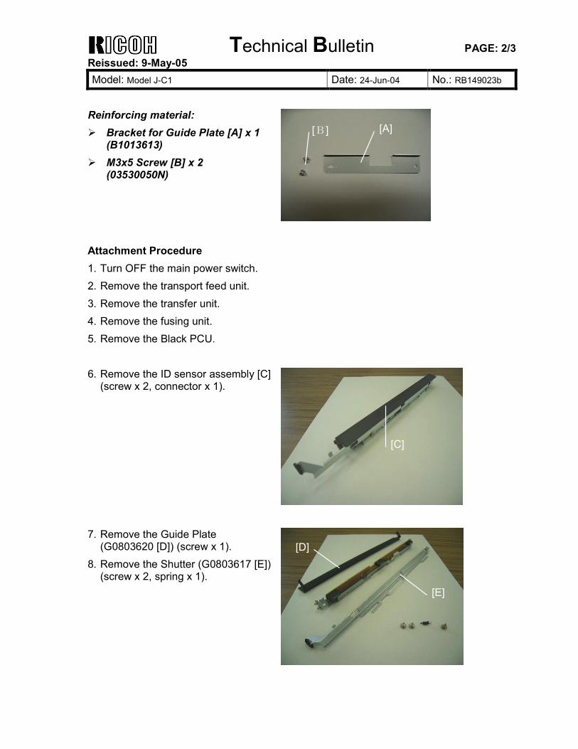
Technical Bulletin PAGE: 2/3 Reissued: 9-May-05 Model: Model J-C1 Date: 24-Jun-04 No.: RB149023b
Reinforcing material: Bracket for Guide Plate [A] x 1
(B1013613) M3x5 Screw [B] x 2
(03530050N)
Attachment Procedure 1. Turn OFF the main power switch. 2. Remove the transport feed unit. 3. Remove the transfer unit. 4. Remove the fusing unit. 5. Remove the Black PCU.
6. Remove the ID sensor assembly [C]
(screw x 2, connector x 1).
7. Remove the Guide Plate
(G0803620 [D]) (screw x 1). 8. Remove the Shutter (G0803617 [E])
(screw x 2, spring x 1).
[A][B]
[C]
[D]
[E]
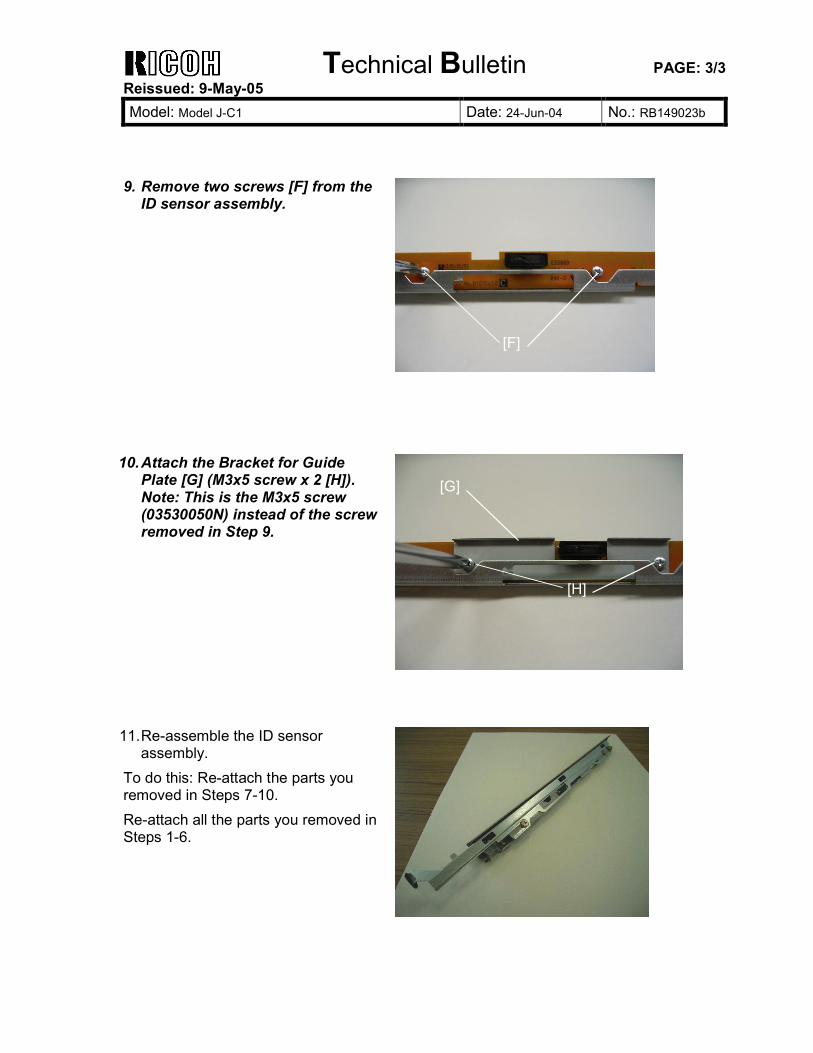
Technical Bulletin PAGE: 3/3 Reissued: 9-May-05 Model: Model J-C1 Date: 24-Jun-04 No.: RB149023b
9. Remove two screws [F] from the
ID sensor assembly.
10. Attach the Bracket for Guide Plate [G] (M3x5 screw x 2 [H]). Note: This is the M3x5 screw (03530050N) instead of the screw removed in Step 9.
11. Re-assemble the ID sensor
assembly. To do this: Re-attach the parts you removed in Steps 7-10. Re-attach all the parts you removed in Steps 1-6.
[F]
[G]
[H]
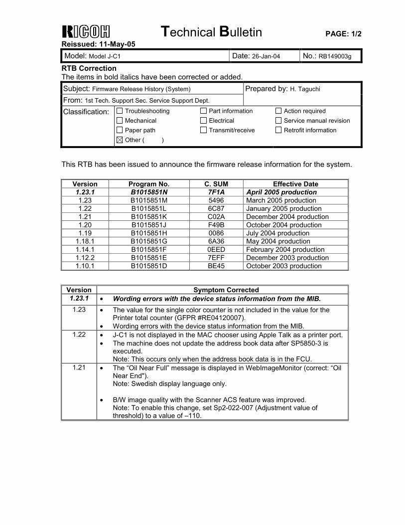
Technical Bulletin PAGE: 1/2 Reissued: 11-May-05 Model: Model J-C1 Date: 26-Jan-04 No.: RB149003g
RTB Correction The items in bold italics have been corrected or added. Subject: Firmware Release History (System) Prepared by: H. Taguchi From: 1st Tech. Support Sec. Service Support Dept. Classification: Troubleshooting
Mechanical Paper path
Part information Electrical Transmit/receive
Action required Service manual revision Retrofit information
Other ( )
This RTB has been issued to announce the firmware release information for the system.
Version Program No. C. SUM Effective Date 1.23.1 B1015851N 7F1A April 2005 production 1.23 B1015851M 5496 March 2005 production 1.22 B1015851L 6C87 January 2005 production 1.21 B1015851K C02A December 2004 production 1.20 B1015851J F49B October 2004 production 1.19 B1015851H 0086 July 2004 production
1.18.1 B1015851G 6A36 May 2004 production 1.14.1 B1015851F 0EED February 2004 production 1.12.2 B1015851E 7EFF December 2003 production 1.10.1 B1015851D BE45 October 2003 production
Version Symptom Corrected 1.23.1 • Wording errors with the device status information from the MIB. 1.23 • The value for the single color counter is not included in the value for the
Printer total counter (GFPR #RE04120007). • Wording errors with the device status information from the MIB.
1.22 • J-C1 is not displayed in the MAC chooser using Apple Talk as a printer port. • The machine does not update the address book data after SP5850-3 is
executed. Note: This occurs only when the address book data is in the FCU.
1.21 • The “Oil Near Full” message is displayed in WebImageMonitor (correct: “Oil Near End"). Note: Swedish display language only.
• B/W image quality with the Scanner ACS feature was improved.
Note: To enable this change, set Sp2-022-007 (Adjustment value of threshold) to a value of –110.
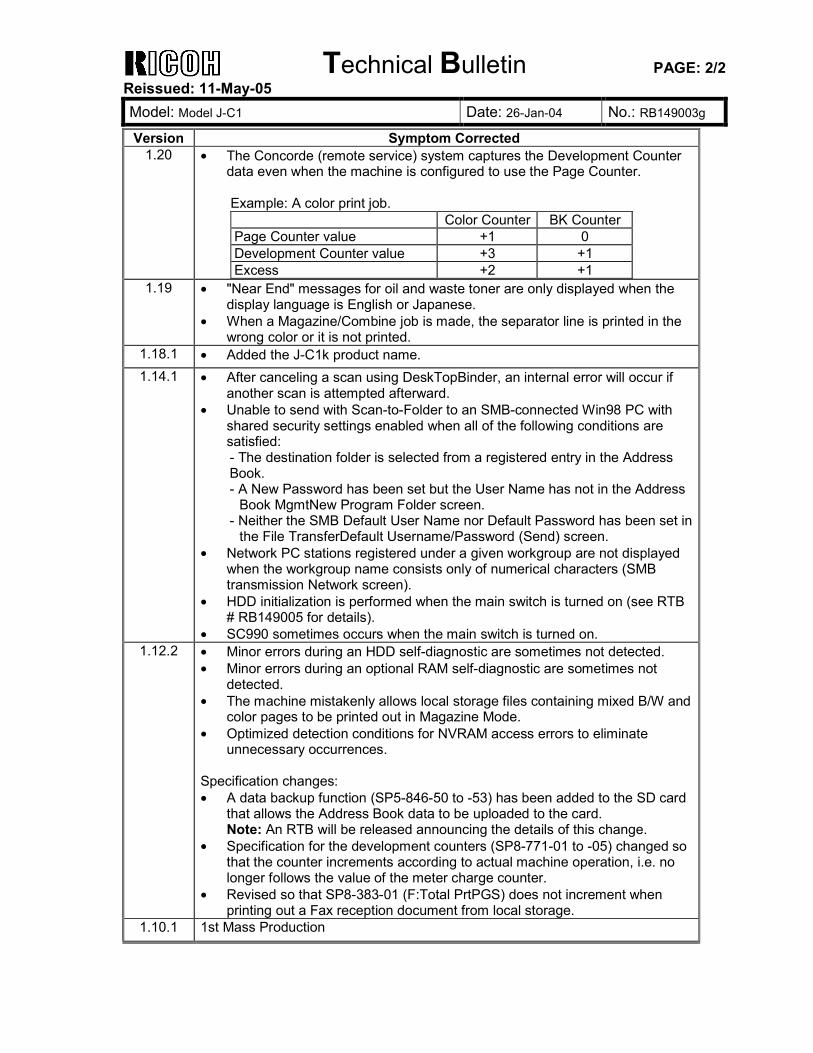
Technical Bulletin PAGE: 2/2 Reissued: 11-May-05 Model: Model J-C1 Date: 26-Jan-04 No.: RB149003g
Version Symptom Corrected 1.20 • The Concorde (remote service) system captures the Development Counter
data even when the machine is configured to use the Page Counter. Example: A color print job. Color Counter BK Counter Page Counter value +1 0 Development Counter value +3 +1 Excess +2 +1
1.19 • "Near End" messages for oil and waste toner are only displayed when the display language is English or Japanese.
• When a Magazine/Combine job is made, the separator line is printed in the wrong color or it is not printed.
1.18.1 • Added the J-C1k product name. 1.14.1 • After canceling a scan using DeskTopBinder, an internal error will occur if
another scan is attempted afterward. • Unable to send with Scan-to-Folder to an SMB-connected Win98 PC with
shared security settings enabled when all of the following conditions are satisfied: - The destination folder is selected from a registered entry in the Address Book. - A New Password has been set but the User Name has not in the Address
Book MgmtNew Program Folder screen. - Neither the SMB Default User Name nor Default Password has been set in
the File TransferDefault Username/Password (Send) screen. • Network PC stations registered under a given workgroup are not displayed
when the workgroup name consists only of numerical characters (SMB transmission Network screen).
• HDD initialization is performed when the main switch is turned on (see RTB # RB149005 for details).
• SC990 sometimes occurs when the main switch is turned on. 1.12.2 • Minor errors during an HDD self-diagnostic are sometimes not detected.
• Minor errors during an optional RAM self-diagnostic are sometimes not detected.
• The machine mistakenly allows local storage files containing mixed B/W and color pages to be printed out in Magazine Mode.
• Optimized detection conditions for NVRAM access errors to eliminate unnecessary occurrences.
Specification changes: • A data backup function (SP5-846-50 to -53) has been added to the SD card
that allows the Address Book data to be uploaded to the card. Note: An RTB will be released announcing the details of this change.
• Specification for the development counters (SP8-771-01 to -05) changed so that the counter increments according to actual machine operation, i.e. no longer follows the value of the meter charge counter.
• Revised so that SP8-383-01 (F:Total PrtPGS) does not increment when printing out a Fax reception document from local storage.
1.10.1 1st Mass Production
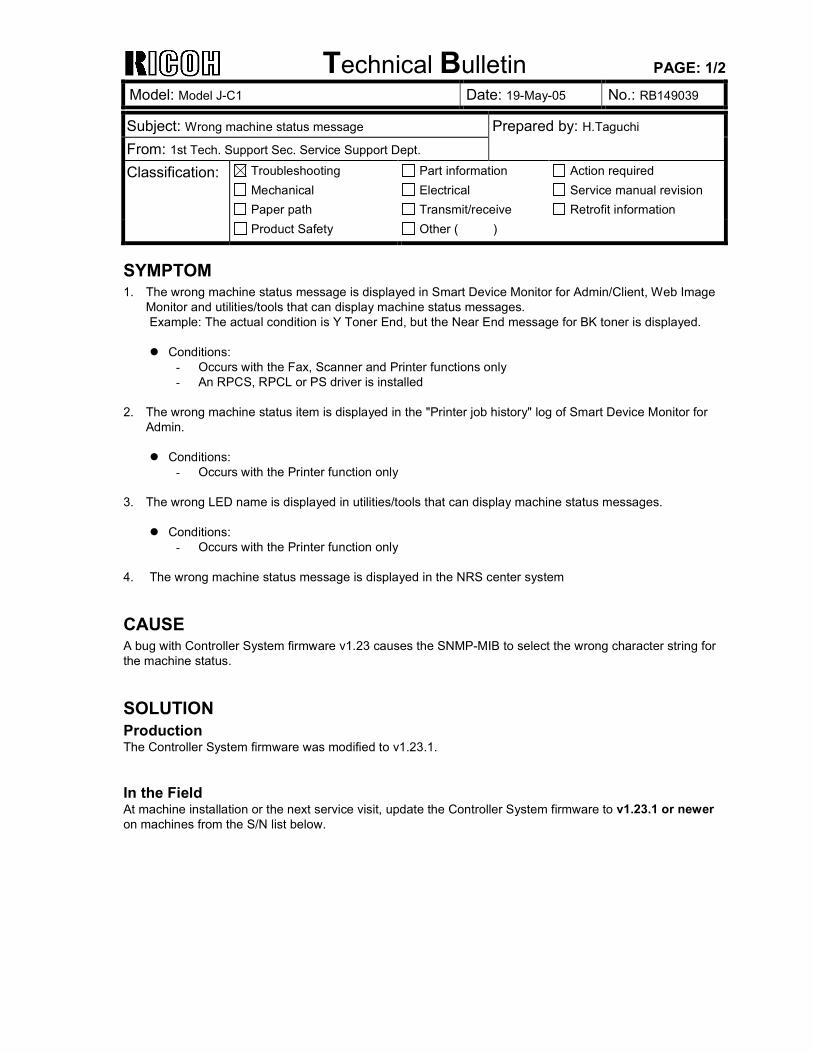
Technical Bulletin PAGE: 1/2
Model: Model J-C1 Date: 19-May-05 No.: RB149039
Subject: Wrong machine status message Prepared by: H.Taguchi From: 1st Tech. Support Sec. Service Support Dept. Classification: Troubleshooting
Mechanical Paper path
Part information Electrical Transmit/receive
Action required Service manual revision Retrofit information
Product Safety Other ( )
SYMPTOM 1. The wrong machine status message is displayed in Smart Device Monitor for Admin/Client, Web Image
Monitor and utilities/tools that can display machine status messages. Example: The actual condition is Y Toner End, but the Near End message for BK toner is displayed. Conditions:
- Occurs with the Fax, Scanner and Printer functions only - An RPCS, RPCL or PS driver is installed
2. The wrong machine status item is displayed in the "Printer job history" log of Smart Device Monitor for
Admin.
Conditions: - Occurs with the Printer function only
3. The wrong LED name is displayed in utilities/tools that can display machine status messages.
Conditions: - Occurs with the Printer function only
4. The wrong machine status message is displayed in the NRS center system
CAUSE A bug with Controller System firmware v1.23 causes the SNMP-MIB to select the wrong character string for the machine status.
SOLUTION Production The Controller System firmware was modified to v1.23.1. In the Field At machine installation or the next service visit, update the Controller System firmware to v1.23.1 or newer on machines from the S/N list below.
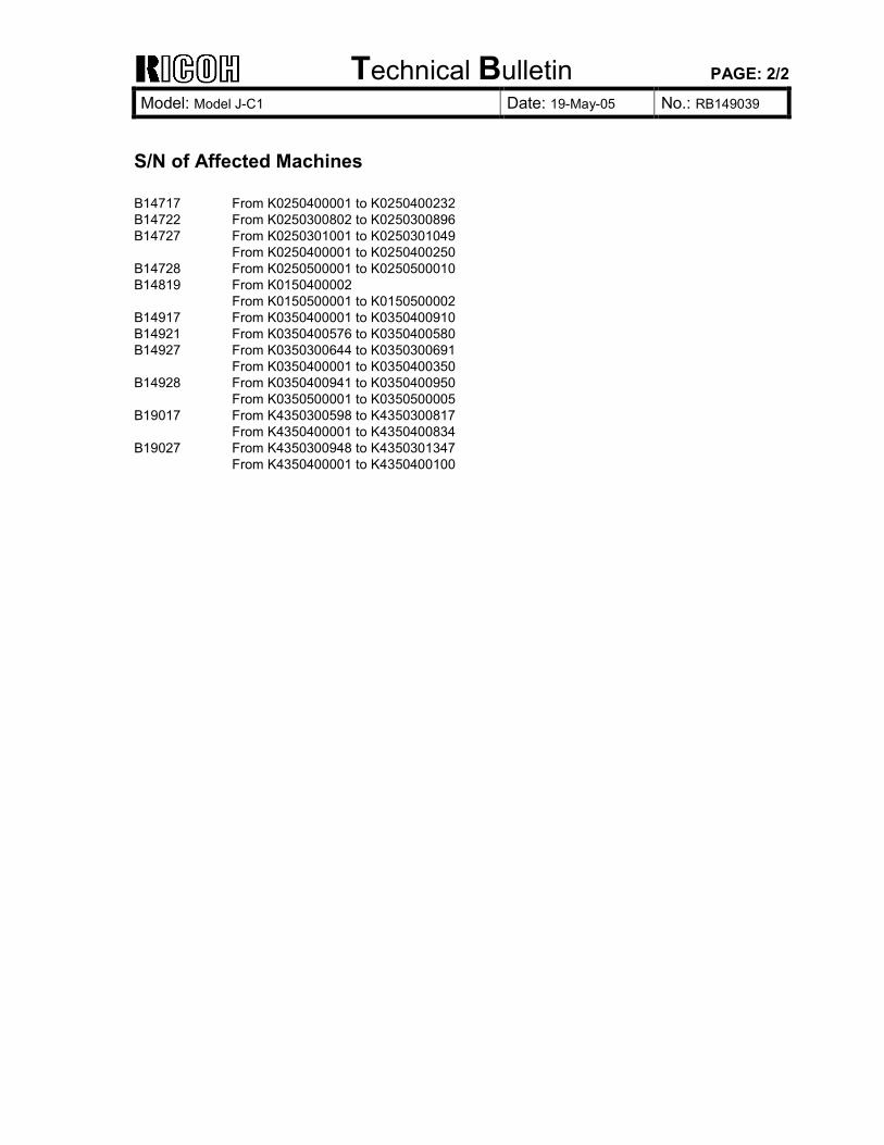
Technical Bulletin PAGE: 2/2
Model: Model J-C1 Date: 19-May-05 No.: RB149039
S/N of Affected Machines B14717 From K0250400001 to K0250400232 B14722 From K0250300802 to K0250300896 B14727 From K0250301001 to K0250301049 From K0250400001 to K0250400250 B14728 From K0250500001 to K0250500010 B14819 From K0150400002 From K0150500001 to K0150500002 B14917 From K0350400001 to K0350400910 B14921 From K0350400576 to K0350400580 B14927 From K0350300644 to K0350300691 From K0350400001 to K0350400350 B14928 From K0350400941 to K0350400950 From K0350500001 to K0350500005 B19017 From K4350300598 to K4350300817 From K4350400001 to K4350400834 B19027 From K4350300948 to K4350301347 From K4350400001 to K4350400100
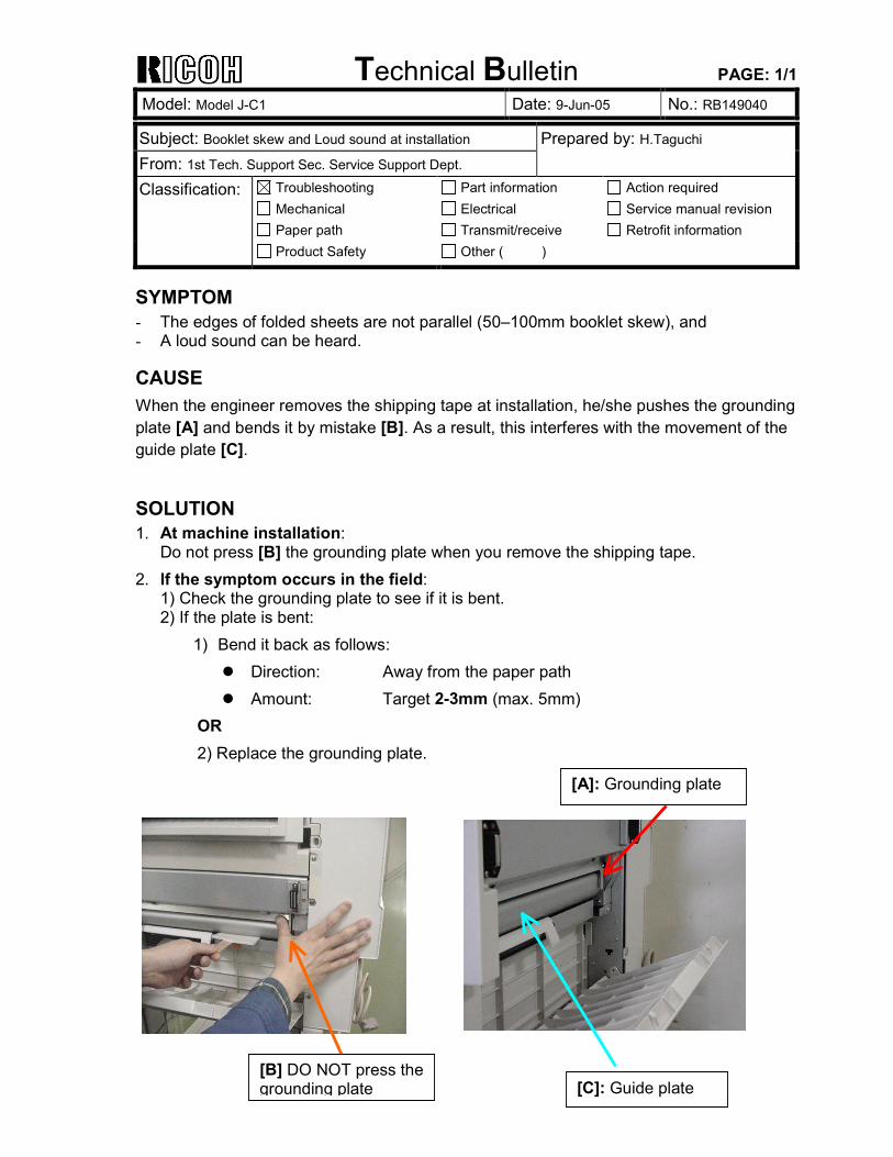
Technical Bulletin PAGE: 1/1
Model: Model J-C1 Date: 9-Jun-05 No.: RB149040
Subject: Booklet skew and Loud sound at installation Prepared by: H.Taguchi From: 1st Tech. Support Sec. Service Support Dept. Classification: Troubleshooting
Mechanical Paper path
Part information Electrical Transmit/receive
Action required Service manual revision Retrofit information
Product Safety Other ( )
SYMPTOM - The edges of folded sheets are not parallel (50–100mm booklet skew), and - A loud sound can be heard.
CAUSE When the engineer removes the shipping tape at installation, he/she pushes the grounding plate [A] and bends it by mistake [B]. As a result, this interferes with the movement of the guide plate [C].
SOLUTION 1. At machine installation:
Do not press [B] the grounding plate when you remove the shipping tape. 2. If the symptom occurs in the field:
1) Check the grounding plate to see if it is bent. 2) If the plate is bent:
1) Bend it back as follows: Direction: Away from the paper path Amount: Target 2-3mm (max. 5mm)
OR 2) Replace the grounding plate.
[A]: Grounding plate
[B] DO NOT press the grounding plate [C]: Guide plate
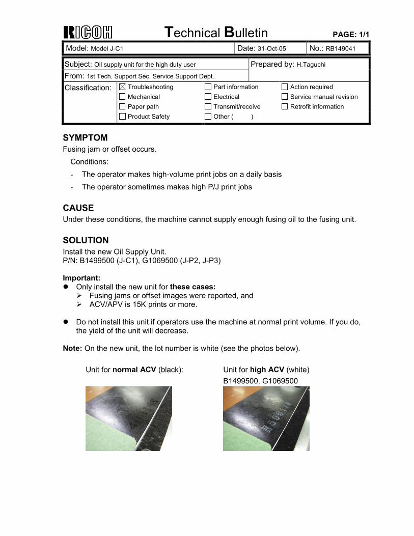
Technical Bulletin PAGE: 1/1
Model: Model J-C1 Date: 31-Oct-05 No.: RB149041
Subject: Oil supply unit for the high duty user Prepared by: H.Taguchi From: 1st Tech. Support Sec. Service Support Dept. Classification: Troubleshooting
Mechanical Paper path
Part information Electrical Transmit/receive
Action required Service manual revision Retrofit information
Product Safety Other ( )
SYMPTOM Fusing jam or offset occurs.
Conditions: - The operator makes high-volume print jobs on a daily basis - The operator sometimes makes high P/J print jobs
CAUSE Under these conditions, the machine cannot supply enough fusing oil to the fusing unit.
SOLUTION Install the new Oil Supply Unit. P/N: B1499500 (J-C1), G1069500 (J-P2, J-P3) Important: Only install the new unit for these cases: Fusing jams or offset images were reported, and ACV/APV is 15K prints or more.
Do not install this unit if operators use the machine at normal print volume. If you do,
the yield of the unit will decrease.
Note: On the new unit, the lot number is white (see the photos below).
Unit for normal ACV (black): Unit for high ACV (white) B1499500, G1069500
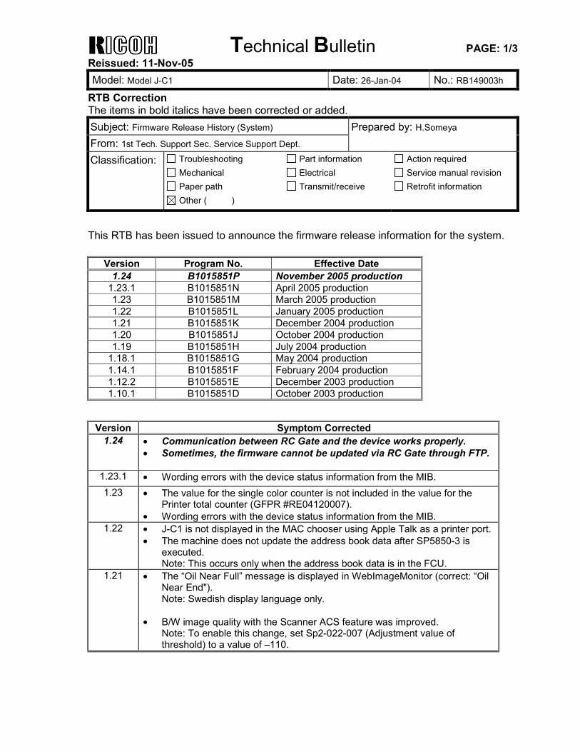
Technical Bulletin PAGE: 1/3 Reissued: 11-Nov-05 Model: Model J-C1 Date: 26-Jan-04 No.: RB149003h
RTB Correction The items in bold italics have been corrected or added. Subject: Firmware Release History (System) Prepared by: H.Someya From: 1st Tech. Support Sec. Service Support Dept. Classification: Troubleshooting
Mechanical Paper path
Part information Electrical Transmit/receive
Action required Service manual revision Retrofit information
Other ( )
This RTB has been issued to announce the firmware release information for the system.
Version Program No. Effective Date 1.24 B1015851P November 2005 production
1.23.1 B1015851N April 2005 production 1.23 B1015851M March 2005 production 1.22 B1015851L January 2005 production 1.21 B1015851K December 2004 production 1.20 B1015851J October 2004 production 1.19 B1015851H July 2004 production
1.18.1 B1015851G May 2004 production 1.14.1 B1015851F February 2004 production 1.12.2 B1015851E December 2003 production 1.10.1 B1015851D October 2003 production
Version Symptom Corrected
1.24 • Communication between RC Gate and the device works properly. • Sometimes, the firmware cannot be updated via RC Gate through FTP.
1.23.1 • Wording errors with the device status information from the MIB. 1.23 • The value for the single color counter is not included in the value for the
Printer total counter (GFPR #RE04120007). • Wording errors with the device status information from the MIB.
1.22 • J-C1 is not displayed in the MAC chooser using Apple Talk as a printer port. • The machine does not update the address book data after SP5850-3 is
executed. Note: This occurs only when the address book data is in the FCU.
1.21 • The “Oil Near Full” message is displayed in WebImageMonitor (correct: “Oil Near End"). Note: Swedish display language only.
• B/W image quality with the Scanner ACS feature was improved.
Note: To enable this change, set Sp2-022-007 (Adjustment value of threshold) to a value of –110.
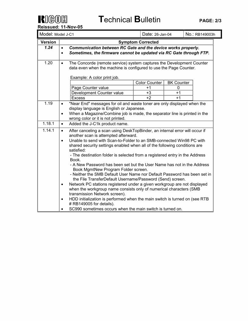
Technical Bulletin PAGE: 2/3 Reissued: 11-Nov-05 Model: Model J-C1 Date: 26-Jan-04 No.: RB149003h
Version Symptom Corrected 1.24 • Communication between RC Gate and the device works properly.
• Sometimes, the firmware cannot be updated via RC Gate through FTP.
1.20 • The Concorde (remote service) system captures the Development Counter data even when the machine is configured to use the Page Counter. Example: A color print job. Color Counter BK Counter Page Counter value +1 0 Development Counter value +3 +1 Excess +2 +1
1.19 • "Near End" messages for oil and waste toner are only displayed when the display language is English or Japanese.
• When a Magazine/Combine job is made, the separator line is printed in the wrong color or it is not printed.
1.18.1 • Added the J-C1k product name. 1.14.1 • After canceling a scan using DeskTopBinder, an internal error will occur if
another scan is attempted afterward. • Unable to send with Scan-to-Folder to an SMB-connected Win98 PC with
shared security settings enabled when all of the following conditions are satisfied: - The destination folder is selected from a registered entry in the Address Book. - A New Password has been set but the User Name has not in the Address
Book MgmtNew Program Folder screen. - Neither the SMB Default User Name nor Default Password has been set in
the File TransferDefault Username/Password (Send) screen. • Network PC stations registered under a given workgroup are not displayed
when the workgroup name consists only of numerical characters (SMB transmission Network screen).
• HDD initialization is performed when the main switch is turned on (see RTB # RB149005 for details).
• SC990 sometimes occurs when the main switch is turned on.
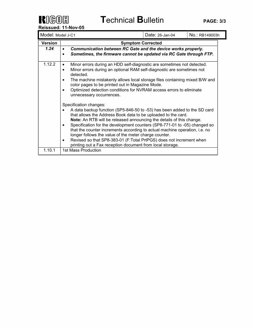
Technical Bulletin PAGE: 3/3 Reissued: 11-Nov-05 Model: Model J-C1 Date: 26-Jan-04 No.: RB149003h
Version Symptom Corrected 1.24 • Communication between RC Gate and the device works properly.
• Sometimes, the firmware cannot be updated via RC Gate through FTP.
1.12.2 • Minor errors during an HDD self-diagnostic are sometimes not detected. • Minor errors during an optional RAM self-diagnostic are sometimes not
detected. • The machine mistakenly allows local storage files containing mixed B/W and
color pages to be printed out in Magazine Mode. • Optimized detection conditions for NVRAM access errors to eliminate
unnecessary occurrences. Specification changes: • A data backup function (SP5-846-50 to -53) has been added to the SD card
that allows the Address Book data to be uploaded to the card. Note: An RTB will be released announcing the details of this change.
• Specification for the development counters (SP8-771-01 to -05) changed so that the counter increments according to actual machine operation, i.e. no longer follows the value of the meter charge counter.
• Revised so that SP8-383-01 (F:Total PrtPGS) does not increment when printing out a Fax reception document from local storage.
1.10.1 1st Mass Production
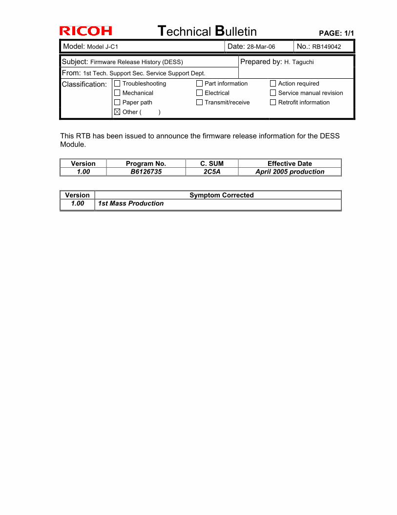
Technical Bulletin PAGE: 1/1
Model: Model J-C1 Date: 28-Mar-06 No.: RB149042
Subject: Firmware Release History (DESS) Prepared by: H. Taguchi From: 1st Tech. Support Sec. Service Support Dept. Classification: Troubleshooting
Mechanical Paper path
Part information Electrical Transmit/receive
Action required Service manual revision Retrofit information
Other ( )
This RTB has been issued to announce the firmware release information for the DESS Module.
Version Program No. C. SUM Effective Date 1.00 B6126735 2C5A April 2005 production
Version Symptom Corrected
1.00 1st Mass Production
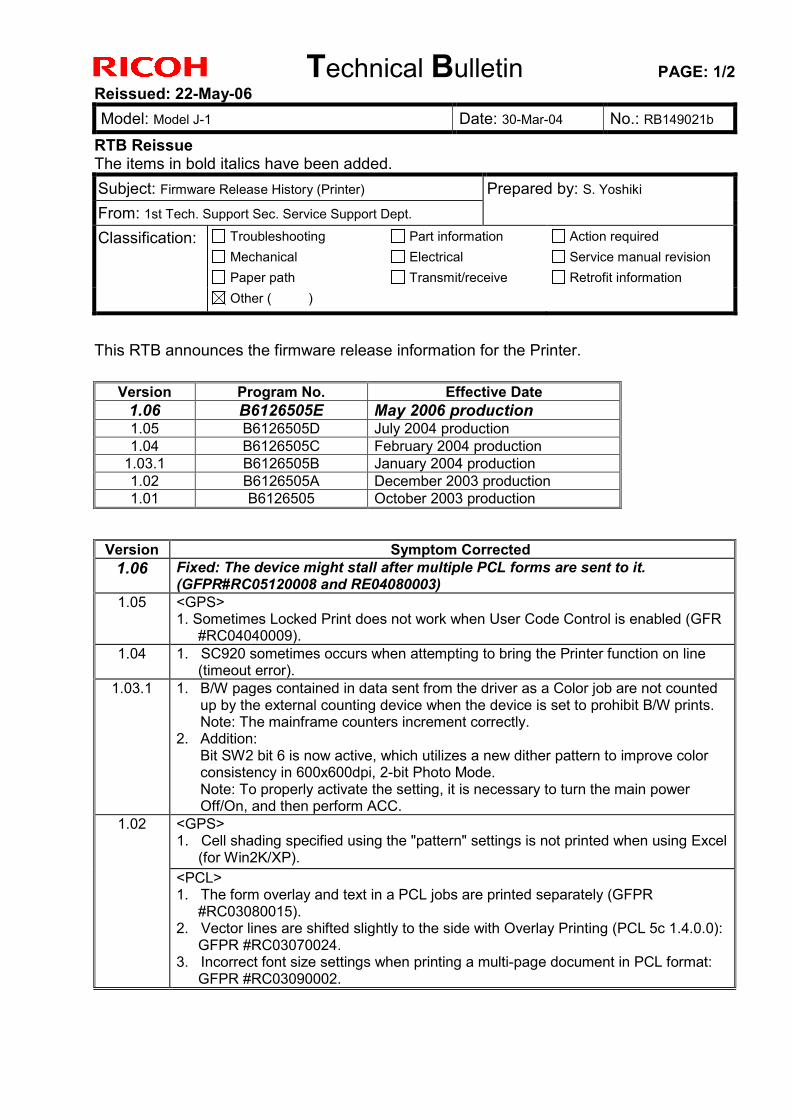
Technical Bulletin PAGE: 1/2 Reissued: 22-May-06 Model: Model J-1 Date: 30-Mar-04 No.: RB149021b
RTB Reissue The items in bold italics have been added. Subject: Firmware Release History (Printer) Prepared by: S. Yoshiki From: 1st Tech. Support Sec. Service Support Dept. Classification: Troubleshooting
Mechanical Paper path
Part information Electrical Transmit/receive
Action required Service manual revision Retrofit information
Other ( )
This RTB announces the firmware release information for the Printer.
Version Program No. Effective Date 1.06 B6126505E May 2006 production 1.05 B6126505D July 2004 production 1.04 B6126505C February 2004 production
1.03.1 B6126505B January 2004 production 1.02 B6126505A December 2003 production 1.01 B6126505 October 2003 production
Version Symptom Corrected
1.06 Fixed: The device might stall after multiple PCL forms are sent to it. (GFPR#RC05120008 and RE04080003)
1.05 <GPS> 1. Sometimes Locked Print does not work when User Code Control is enabled (GFR
#RC04040009). 1.04 1. SC920 sometimes occurs when attempting to bring the Printer function on line
(timeout error). 1.03.1 1. B/W pages contained in data sent from the driver as a Color job are not counted
up by the external counting device when the device is set to prohibit B/W prints. Note: The mainframe counters increment correctly.
2. Addition: Bit SW2 bit 6 is now active, which utilizes a new dither pattern to improve color consistency in 600x600dpi, 2-bit Photo Mode. Note: To properly activate the setting, it is necessary to turn the main power Off/On, and then perform ACC.
<GPS> 1. Cell shading specified using the "pattern" settings is not printed when using Excel
(for Win2K/XP).
1.02
<PCL> 1. The form overlay and text in a PCL jobs are printed separately (GFPR
#RC03080015). 2. Vector lines are shifted slightly to the side with Overlay Printing (PCL 5c 1.4.0.0):
GFPR #RC03070024. 3. Incorrect font size settings when printing a multi-page document in PCL format:
GFPR #RC03090002.

Technical Bulletin PAGE: 2/2 Reissued: 22-May-06 Model: Model J-1 Date: 30-Mar-04 No.: RB149021b
Version Symptom Corrected 1.01 1st Mass Production
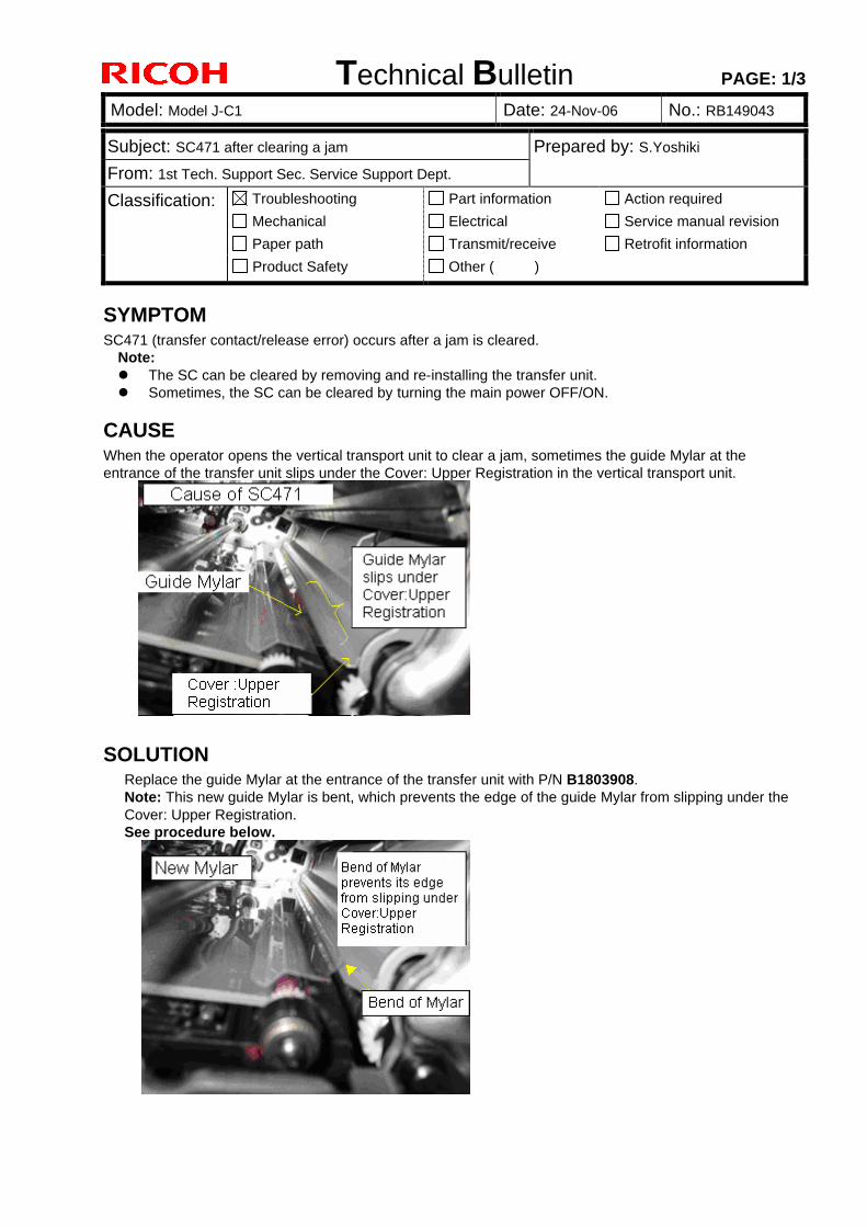
Technical Bulletin PAGE: 1/3
Model: Model J-C1 Date: 24-Nov-06 No.: RB149043
Subject: SC471 after clearing a jam Prepared by: S.Yoshiki From: 1st Tech. Support Sec. Service Support Dept. Classification: Troubleshooting
Mechanical Paper path
Part information Electrical Transmit/receive
Action required Service manual revision Retrofit information
Product Safety Other ( )
SYMPTOM SC471 (transfer contact/release error) occurs after a jam is cleared.
Note: l The SC can be cleared by removing and re-installing the transfer unit. l Sometimes, the SC can be cleared by turning the main power OFF/ON.
CAUSE When the operator opens the vertical transport unit to clear a jam, sometimes the guide Mylar at the entrance of the transfer unit slips under the Cover: Upper Registration in the vertical transport unit.
SOLUTION Replace the guide Mylar at the entrance of the transfer unit with P/N B1803908. Note: This new guide Mylar is bent, which prevents the edge of the guide Mylar from slipping under the Cover: Upper Registration. See procedure below.
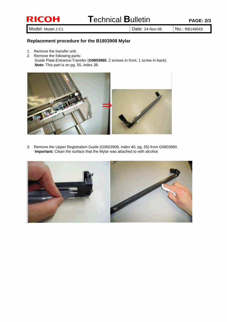
Technical Bulletin PAGE: 2/3
Model: Model J-C1 Date: 24-Nov-06 No.: RB149043
Replacement procedure for the B1803908 Mylar 1. Remove the transfer unit. 2. Remove the following parts:
Guide Plate:Entrance:Transfer (G0803960, 2 screws in front, 1 screw in back). Note: This part is on pg. 55, index 38.
3. Remove the Upper Registration Guide (G0603908, index 40, pg. 55) from G0803960.
Important: Clean the surface that the Mylar was attached to with alcohol.
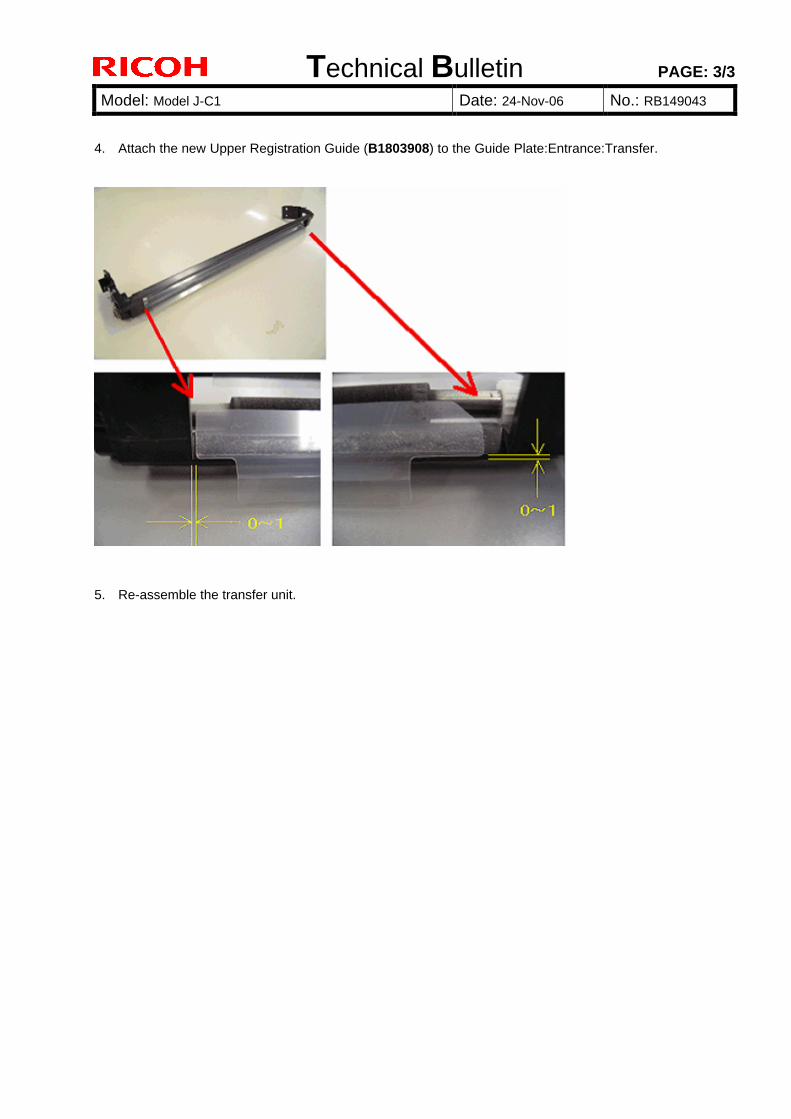
Technical Bulletin PAGE: 3/3
Model: Model J-C1 Date: 24-Nov-06 No.: RB149043
4. Attach the new Upper Registration Guide (B1803908) to the Guide Plate:Entrance:Transfer.
5. Re-assemble the transfer unit.
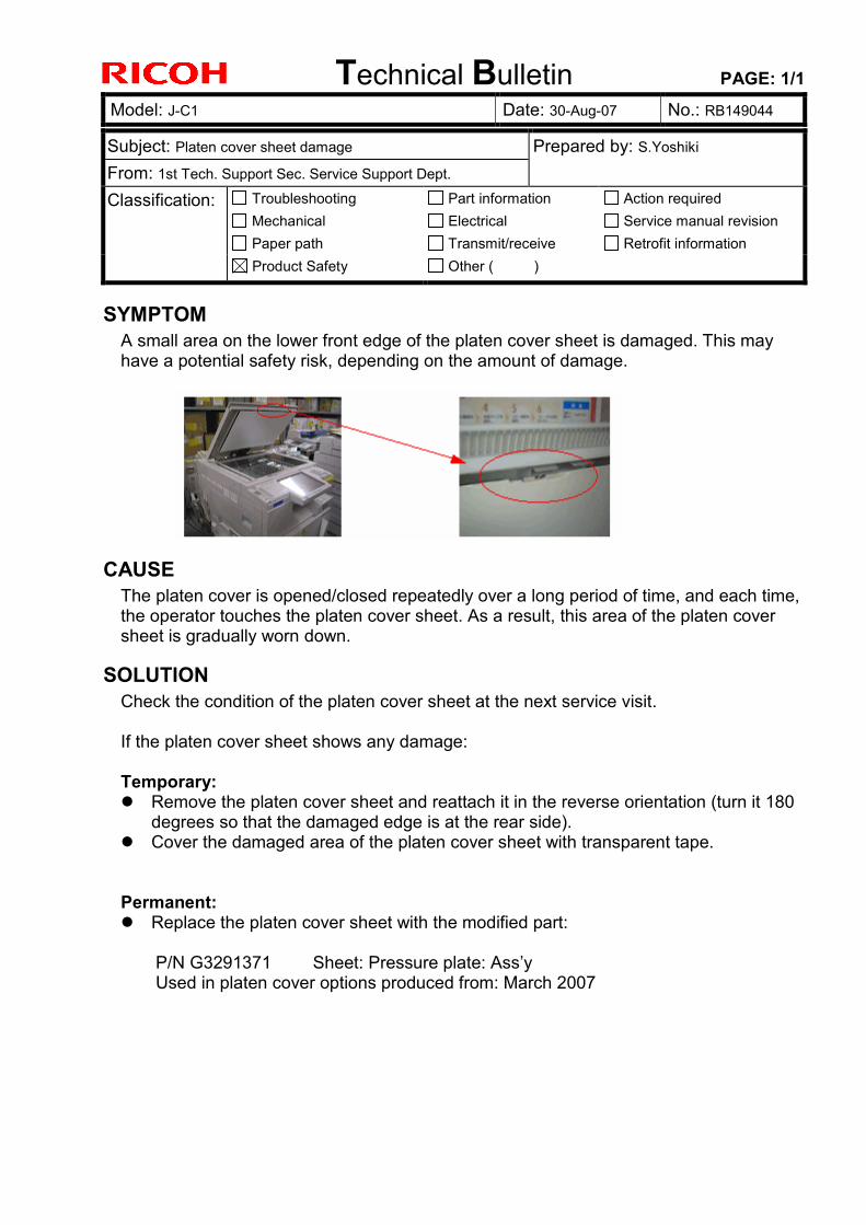
Technical Bulletin PAGE: 1/1
Model: J-C1 Date: 30-Aug-07 No.: RB149044
Subject: Platen cover sheet damage Prepared by: S.Yoshiki From: 1st Tech. Support Sec. Service Support Dept. Classification: Troubleshooting
Mechanical Paper path
Part information Electrical Transmit/receive
Action required Service manual revision Retrofit information
Product Safety Other ( )
SYMPTOM A small area on the lower front edge of the platen cover sheet is damaged. This may have a potential safety risk, depending on the amount of damage.
CAUSE The platen cover is opened/closed repeatedly over a long period of time, and each time, the operator touches the platen cover sheet. As a result, this area of the platen cover sheet is gradually worn down.
SOLUTION Check the condition of the platen cover sheet at the next service visit. If the platen cover sheet shows any damage:
Temporary:
Remove the platen cover sheet and reattach it in the reverse orientation (turn it 180 degrees so that the damaged edge is at the rear side).
Cover the damaged area of the platen cover sheet with transparent tape. Permanent:
Replace the platen cover sheet with the modified part: P/N G3291371 Sheet: Pressure plate: Ass’y Used in platen cover options produced from: March 2007
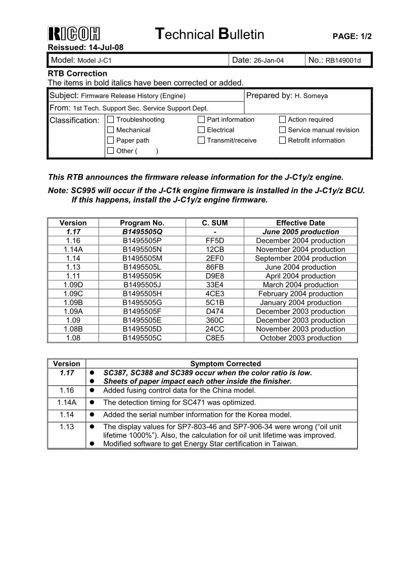
Technical Bulletin PAGE: 1/2 Reissued: 14-Jul-08 Model: Model J-C1 Date: 26-Jan-04 No.: RB149001d
RTB Correction The items in bold italics have been corrected or added. Subject: Firmware Release History (Engine) Prepared by: H. Someya From: 1st Tech. Support Sec. Service Support Dept. Classification: Troubleshooting
Mechanical Paper path
Part information Electrical Transmit/receive
Action required Service manual revision Retrofit information
Other ( )
This RTB announces the firmware release information for the J-C1y/z engine. Note: SC995 will occur if the J-C1k engine firmware is installed in the J-C1y/z BCU.
If this happens, install the J-C1y/z engine firmware.
Version Program No. C. SUM Effective Date 1.17 B1495505Q - June 2005 production 1.16 B1495505P FF5D December 2004 production
1.14A B1495505N 12CB November 2004 production 1.14 B1495505M 2EF0 September 2004 production 1.13 B1495505L 86FB June 2004 production 1.11 B1495505K D9E8 April 2004 production
1.09D B1495505J 33E4 March 2004 production 1.09C B1495505H 4CE3 February 2004 production 1.09B B1495505G 5C1B January 2004 production 1.09A B1495505F D474 December 2003 production 1.09 B1495505E 360C December 2003 production
1.08B B1495505D 24CC November 2003 production 1.08 B1495505C C8E5 October 2003 production
Version Symptom Corrected
1.17 SC387, SC388 and SC389 occur when the color ratio is low. Sheets of paper impact each other inside the finisher.
1.16 Added fusing control data for the China model. 1.14A The detection timing for SC471 was optimized. 1.14 Added the serial number information for the Korea model. 1.13 The display values for SP7-803-46 and SP7-906-34 were wrong (“oil unit
lifetime 1000%”). Also, the calculation for oil unit lifetime was improved. Modified software to get Energy Star certification in Taiwan.
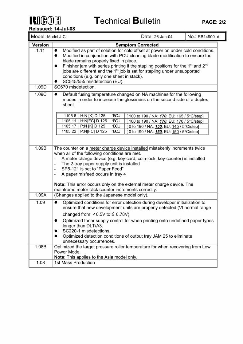
Technical Bulletin PAGE: 2/2 Reissued: 14-Jul-08 Model: Model J-C1 Date: 26-Jan-04 No.: RB149001d
Version Symptom Corrected 1.11 Modified as part of solution for cold offset at power on under cold conditions.
Modified in conjunction with PCU cleaning blade modification to ensure the blade remains properly fixed in place.
Finisher jam with series printing if the stapling positions for the 1st and 2nd jobs are different and the 1st job is set for stapling under unsupported conditions (e.g. only one sheet in stack).
SC545/555 misdetection (EU). 1.09D SC670 misdetection. 1.09C Default fusing temperature changed on NA machines for the following
modes in order to increase the glossiness on the second side of a duplex sheet.
1105 6 H:N [K] D 125 *BCU [ 100 to 190 / NA: 170, EU: 165 / 5°C/step]
1105 11 H:N[FC] D 125 *BCU [ 100 to 190 / NA: 170, EU: 170 / 5°C/step] 1105 17 P:N [K] D 125 *BCU [ 0 to 190 / NA: 150, EU: 145 / 5°C/step] 1105 22 P:N[FC] D 125 *BCU [ 0 to 190 / NA: 150, EU: 150 / 5°C/step]
1.09B The counter on a meter charge device installed mistakenly increments twice when all of the following conditions are met. - A meter charge device (e.g. key-card, coin-lock, key-counter) is installed - The 2-tray paper supply unit is installed - SP5-121 is set to “Paper Feed” - A paper misfeed occurs in tray 4 Note: This error occurs only on the external meter charge device. The mainframe meter click counter increments correctly.
1.09A (Changes applied to the Japanese model only). 1.09 Optimized conditions for error detection during developer initialization to
ensure that new development units are properly detected (Vt normal range changed from <0.5V to ≦ 0.78V).
Optimized toner supply control for when printing onto undefined paper types longer than DLT/A3.
SC220-1 misdetections. Optimized detection conditions of output tray JAM 25 to eliminate
unnecessary occurrences. 1.08B Optimized the target pressure roller temperature for when recovering from Low
Power Mode. Note: This applies to the Asia model only.
1.08 1st Mass Production
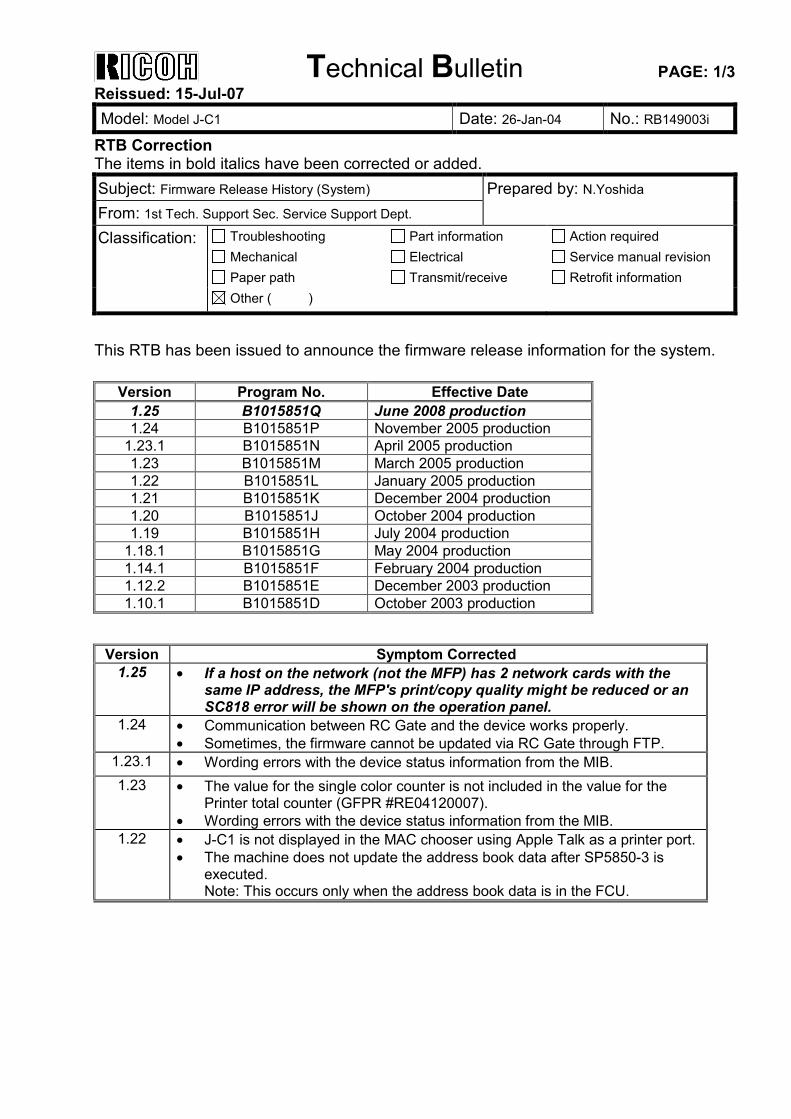
Technical Bulletin PAGE: 1/3 Reissued: 15-Jul-07 Model: Model J-C1 Date: 26-Jan-04 No.: RB149003i
RTB Correction The items in bold italics have been corrected or added. Subject: Firmware Release History (System) Prepared by: N.Yoshida From: 1st Tech. Support Sec. Service Support Dept. Classification: Troubleshooting
Mechanical Paper path
Part information Electrical Transmit/receive
Action required Service manual revision Retrofit information
Other ( )
This RTB has been issued to announce the firmware release information for the system.
Version Program No. Effective Date 1.25 B1015851Q June 2008 production 1.24 B1015851P November 2005 production
1.23.1 B1015851N April 2005 production 1.23 B1015851M March 2005 production 1.22 B1015851L January 2005 production 1.21 B1015851K December 2004 production 1.20 B1015851J October 2004 production 1.19 B1015851H July 2004 production
1.18.1 B1015851G May 2004 production 1.14.1 B1015851F February 2004 production 1.12.2 B1015851E December 2003 production 1.10.1 B1015851D October 2003 production
Version Symptom Corrected
1.25 • If a host on the network (not the MFP) has 2 network cards with the same IP address, the MFP's print/copy quality might be reduced or an SC818 error will be shown on the operation panel.
1.24 • Communication between RC Gate and the device works properly. • Sometimes, the firmware cannot be updated via RC Gate through FTP.
1.23.1 • Wording errors with the device status information from the MIB. 1.23 • The value for the single color counter is not included in the value for the
Printer total counter (GFPR #RE04120007). • Wording errors with the device status information from the MIB.
1.22 • J-C1 is not displayed in the MAC chooser using Apple Talk as a printer port. • The machine does not update the address book data after SP5850-3 is
executed. Note: This occurs only when the address book data is in the FCU.
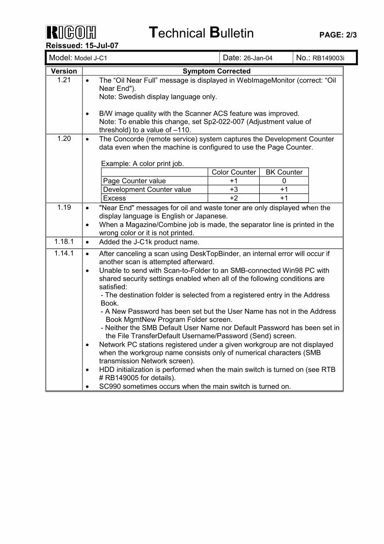
Technical Bulletin PAGE: 2/3 Reissued: 15-Jul-07 Model: Model J-C1 Date: 26-Jan-04 No.: RB149003i
Version Symptom Corrected 1.21 • The “Oil Near Full” message is displayed in WebImageMonitor (correct: “Oil
Near End"). Note: Swedish display language only.
• B/W image quality with the Scanner ACS feature was improved.
Note: To enable this change, set Sp2-022-007 (Adjustment value of threshold) to a value of –110.
1.20 • The Concorde (remote service) system captures the Development Counter data even when the machine is configured to use the Page Counter. Example: A color print job. Color Counter BK Counter Page Counter value +1 0 Development Counter value +3 +1 Excess +2 +1
1.19 • "Near End" messages for oil and waste toner are only displayed when the display language is English or Japanese.
• When a Magazine/Combine job is made, the separator line is printed in the wrong color or it is not printed.
1.18.1 • Added the J-C1k product name. 1.14.1 • After canceling a scan using DeskTopBinder, an internal error will occur if
another scan is attempted afterward. • Unable to send with Scan-to-Folder to an SMB-connected Win98 PC with
shared security settings enabled when all of the following conditions are satisfied: - The destination folder is selected from a registered entry in the Address Book. - A New Password has been set but the User Name has not in the Address
Book MgmtNew Program Folder screen. - Neither the SMB Default User Name nor Default Password has been set in
the File TransferDefault Username/Password (Send) screen. • Network PC stations registered under a given workgroup are not displayed
when the workgroup name consists only of numerical characters (SMB transmission Network screen).
• HDD initialization is performed when the main switch is turned on (see RTB # RB149005 for details).
• SC990 sometimes occurs when the main switch is turned on.
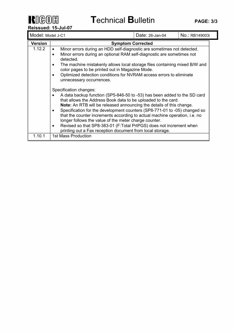
Technical Bulletin PAGE: 3/3 Reissued: 15-Jul-07 Model: Model J-C1 Date: 26-Jan-04 No.: RB149003i
Version Symptom Corrected 1.12.2 • Minor errors during an HDD self-diagnostic are sometimes not detected.
• Minor errors during an optional RAM self-diagnostic are sometimes not detected.
• The machine mistakenly allows local storage files containing mixed B/W and color pages to be printed out in Magazine Mode.
• Optimized detection conditions for NVRAM access errors to eliminate unnecessary occurrences.
Specification changes: • A data backup function (SP5-846-50 to -53) has been added to the SD card
that allows the Address Book data to be uploaded to the card. Note: An RTB will be released announcing the details of this change.
• Specification for the development counters (SP8-771-01 to -05) changed so that the counter increments according to actual machine operation, i.e. no longer follows the value of the meter charge counter.
• Revised so that SP8-383-01 (F:Total PrtPGS) does not increment when printing out a Fax reception document from local storage.
1.10.1 1st Mass Production
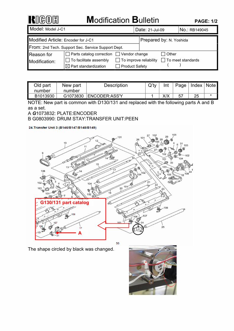
Modification Bulletin PAGE: 1/2 Model: Model J-C1 Date: 21-Jul-09 No.: RB149045
A
G130/131 part catalog
Modified Article: Encoder for J-C1 Prepared by: N. Yoshida From: 2nd Tech. Support Sec. Service Support Dept.
Reason for Modification:
Parts catalog correction To facilitate assembly Part standardization
Vendor change To improve reliability Product Safety
Other To meet standards ( )
Old part number
New part number
Description Q’ty Int Page Index Note
B1013930 G1073830 ENCODER:ASS'Y 1 X/X 57 25 * NOTE: New part is common with D130/131 and replaced with the following parts A and B as a set. A G1073832: PLATE:ENCODER B G0803990: DRUM STAY:TRANSFER UNIT:PEEN The shape circled by black was changed.
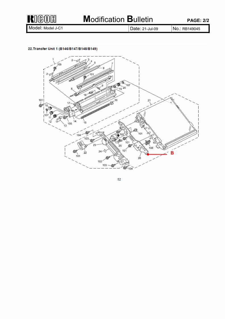
Modification Bulletin PAGE: 2/2 Model: Model J-C1 Date: 21-Jul-09 No.: RB149045
B
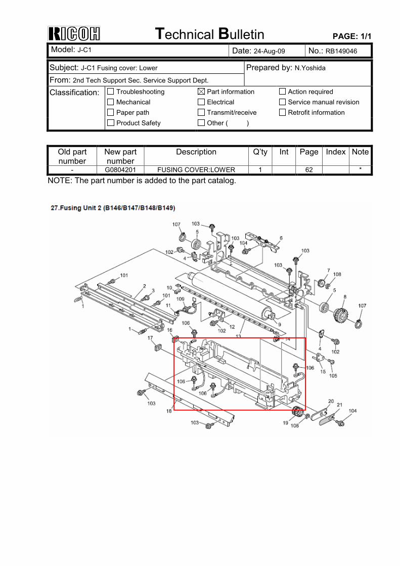
Technical Bulletin PAGE: 1/1 Model: J-C1 Date: 24-Aug-09 No.: RB149046
Subject: J-C1 Fusing cover: Lower Prepared by: N.Yoshida From: 2nd Tech Support Sec. Service Support Dept. Classification: Troubleshooting
Mechanical Paper path
Part information Electrical Transmit/receive
Action required Service manual revision Retrofit information
Product Safety Other ( )
Old part number
New part number
Description Q’ty Int Page Index Note
- G0804201 FUSING COVER:LOWER 1 62 * NOTE: The part number is added to the part catalog.