
TECCO®Cell for shore protection against erosion
12
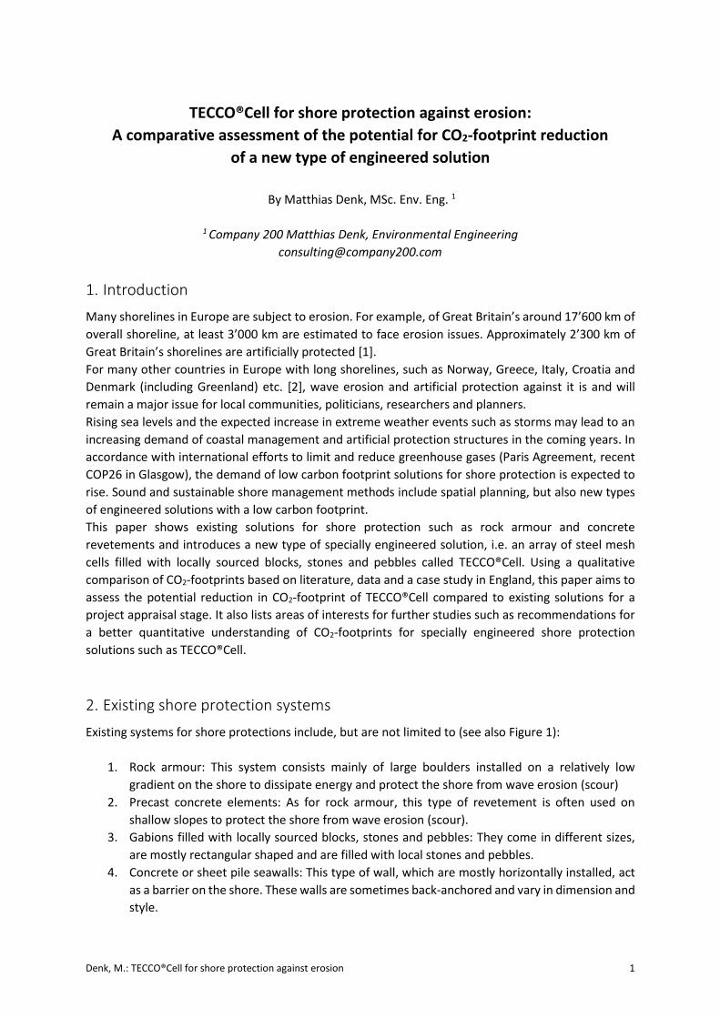
Denk, M.: TECCO®Cell for shore protection against erosion 1 TECCO®Cell for shore protection against erosion: A comparative assessment of the potential for CO2-footprint reduction of a new type of engineered solution By Matthias Denk, MSc. Env. Eng. 1 1 Company 200 Matthias Denk, Environmental Engineering [email protected] 1. Introduction Many shorelines in Europe are subject to erosion. For example, of Great Britain’s around 17’600 km of overall shoreline, at least 3’000 km are estimated to face erosion issues. Approximately 2’300 km of Great Britain’s shorelines are artificially protected [1]. For many other countries in Europe with long shorelines, such as Norway, Greece, Italy, Croatia and Denmark (including Greenland) etc. [2], wave erosion and artificial protection against it is and will remain a major issue for local communities, politicians, researchers and planners. Rising sea levels and the expected increase in extreme weather events such as storms may lead to an increasing demand of coastal management and artificial protection structures in the coming years. In accordance with international efforts to limit and reduce greenhouse gases (Paris Agreement, recent COP26 in Glasgow), the demand of low carbon footprint solutions for shore protection is expected to rise. Sound and sustainable shore management methods include spatial planning, but also new types of engineered solutions with a low carbon footprint. This paper shows existing solutions for shore protection such as rock armour and concrete revetements and introduces a new type of specially engineered solution, i.e. an array of steel mesh cells filled with locally sourced blocks, stones and pebbles called TECCO®Cell. Using a qualitative comparison of CO2-footprints based on literature, data and a case study in England, this paper aims to assess the potential reduction in CO2-footprint of TECCO®Cell compared to existing solutions for a project appraisal stage. It also lists areas of interests for further studies such as recommendations for a better quantitative understanding of CO2-footprints for specially engineered shore protection solutions such as TECCO®Cell. 2. Existing shore protection systems Existing systems for shore protections include, but are not limited to (see also Figure 1): 1. Rock armour: This system consists mainly of large boulders installed on a relatively low gradient on the shore to dissipate energy and protect the shore from wave erosion (scour) 2. Precast concrete elements: As for rock armour, this type of revetement is often used on shallow slopes to protect the shore from wave erosion (scour). 3. Gabions filled with locally sourced blocks, stones and pebbles: They come in different sizes, are mostly rectangular shaped and are filled with local stones and pebbles. 4. Concrete or sheet pile seawalls: This type of wall, which are mostly horizontally installed, act as a barrier on the shore. These walls are sometimes back-anchored and vary in dimension and style.
-
Upload
khangminh22 -
Category
Documents
-
view
3 -
download
0
Transcript of TECCO®Cell for shore protection against erosion
Denk, M.: TECCO®Cell for shore protection against erosion 1
TECCO®Cell for shore protection against erosion:
A comparative assessment of the potential for CO2-footprint reduction
of a new type of engineered solution
By Matthias Denk, MSc. Env. Eng. 1
1 Company 200 Matthias Denk, Environmental Engineering
1. Introduction
Many shorelines in Europe are subject to erosion. For example, of Great Britain’s around 17’600 km of
overall shoreline, at least 3’000 km are estimated to face erosion issues. Approximately 2’300 km of
Great Britain’s shorelines are artificially protected [1].
For many other countries in Europe with long shorelines, such as Norway, Greece, Italy, Croatia and
Denmark (including Greenland) etc. [2], wave erosion and artificial protection against it is and will
remain a major issue for local communities, politicians, researchers and planners.
Rising sea levels and the expected increase in extreme weather events such as storms may lead to an
increasing demand of coastal management and artificial protection structures in the coming years. In
accordance with international efforts to limit and reduce greenhouse gases (Paris Agreement, recent
COP26 in Glasgow), the demand of low carbon footprint solutions for shore protection is expected to
rise. Sound and sustainable shore management methods include spatial planning, but also new types
of engineered solutions with a low carbon footprint.
This paper shows existing solutions for shore protection such as rock armour and concrete
revetements and introduces a new type of specially engineered solution, i.e. an array of steel mesh
cells filled with locally sourced blocks, stones and pebbles called TECCO®Cell. Using a qualitative
comparison of CO2-footprints based on literature, data and a case study in England, this paper aims to
assess the potential reduction in CO2-footprint of TECCO®Cell compared to existing solutions for a
project appraisal stage. It also lists areas of interests for further studies such as recommendations for
a better quantitative understanding of CO2-footprints for specially engineered shore protection
solutions such as TECCO®Cell.
2. Existing shore protection systems
Existing systems for shore protections include, but are not limited to (see also Figure 1):
1. Rock armour: This system consists mainly of large boulders installed on a relatively low
gradient on the shore to dissipate energy and protect the shore from wave erosion (scour)
2. Precast concrete elements: As for rock armour, this type of revetement is often used on
shallow slopes to protect the shore from wave erosion (scour).
3. Gabions filled with locally sourced blocks, stones and pebbles: They come in different sizes,
are mostly rectangular shaped and are filled with local stones and pebbles.
4. Concrete or sheet pile seawalls: This type of wall, which are mostly horizontally installed, act
as a barrier on the shore. These walls are sometimes back-anchored and vary in dimension and
style.

Denk, M.: TECCO®Cell for shore protection against erosion 2
1. Rock armour Picture: [A]
2. Precast concrete elements Picture: Coastalwiki [B]
3. Steel mesh cells filled with blocks, stones and pebbles Picture: Geobrugg [C]
4. Curved concrete seawall Picture: [D]
Figure 1: Different types of shore protection
All the above solutions are proven engineered solutions for coastal protection. Depending on site-
specific conditions, the comparison of advantages and disadvantages of different engineered options
will lead to the choice of the most adapted solution. In the case of shore protection, main factors to
consider are:
- Cost of material and transport
- Cost of installation
- Overall service life
- Resistance to scouring
- Maintenance costs
- Dismantling/recycling
CO2-footprint assessments have become an important tool for decision makers from the beginning of
this century. For example, the Environment Agency for England and Wales (EA) is requesting a carbon
life cycle assessment for any newly funded shore protection structures. Many other countries with
long shorelines have already adopted similar regulations or will probably establish them soon,
considering the aim of the industrialized world to significantly cut back on CO2 emissions.
Denk, M.: TECCO®Cell for shore protection against erosion 3
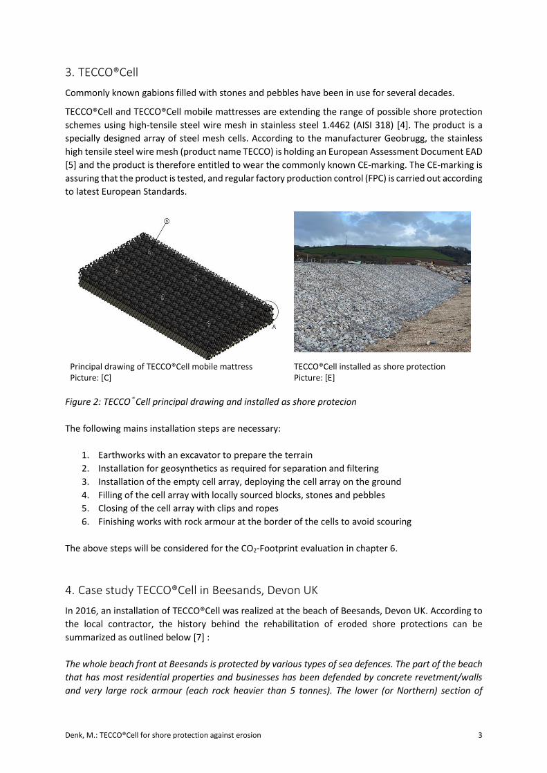
3. TECCO®Cell
Commonly known gabions filled with stones and pebbles have been in use for several decades.
TECCO®Cell and TECCO®Cell mobile mattresses are extending the range of possible shore protection
schemes using high-tensile steel wire mesh in stainless steel 1.4462 (AISI 318) [4]. The product is a
specially designed array of steel mesh cells. According to the manufacturer Geobrugg, the stainless
high tensile steel wire mesh (product name TECCO) is holding an European Assessment Document EAD
[5] and the product is therefore entitled to wear the commonly known CE-marking. The CE-marking is
assuring that the product is tested, and regular factory production control (FPC) is carried out according
to latest European Standards.
Principal drawing of TECCO®Cell mobile mattress Picture: [C]
TECCO®Cell installed as shore protection Picture: [E]
Figure 2: TECCO®Cell principal drawing and installed as shore protecion
The following mains installation steps are necessary:
1. Earthworks with an excavator to prepare the terrain
2. Installation for geosynthetics as required for separation and filtering
3. Installation of the empty cell array, deploying the cell array on the ground
4. Filling of the cell array with locally sourced blocks, stones and pebbles
5. Closing of the cell array with clips and ropes
6. Finishing works with rock armour at the border of the cells to avoid scouring
The above steps will be considered for the CO2-Footprint evaluation in chapter 6.
4. Case study TECCO®Cell in Beesands, Devon UK
In 2016, an installation of TECCO®Cell was realized at the beach of Beesands, Devon UK. According to
the local contractor, the history behind the rehabilitation of eroded shore protections can be
summarized as outlined below [7] :
The whole beach front at Beesands is protected by various types of sea defences. The part of the beach
that has most residential properties and businesses has been defended by concrete revetment/walls
and very large rock armour (each rock heavier than 5 tonnes). The lower (or Northern) section of
Denk, M.: TECCO®Cell for shore protection against erosion 4
Beesands has the village green and around 15 properties behind it. This is the section the case study
focuses on.
Severe storms early in 2014 caused the existing rock armour sea defence to fail along an approximately
150 m stretch of the beach. As a first measure, a geotextile mattress with rock revetment was installed.
That solution failed due to exposure of the geotextile to UV-light and after severe storms. The rock
armour revetement then collapsed.
The local authorities then published a tender to replace the damaged rock armour revetement including
geotextiles and was also calling for innovative solutions for better type of shore protection.
In a joint venture between the contractor and the producer of TECCO®Cell, a custom-made solution was
designed for first an area of 20 metres. The project was installed in 2016 after approval of the
Environment Agency”.
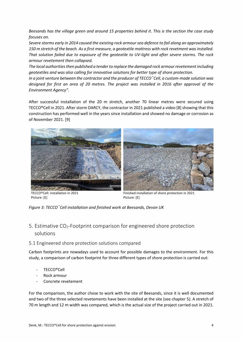
After successful installation of the 20 m stretch, another 70 linear metres were secured using
TECCO®Cell in 2021. After storm DARCY, the contractor in 2021 published a video [8] showing that this
construction has performed well in the years since installation and showed no damage or corrosion as
of November 2021. [9]
TECCO®Cell: installation in 2021 Picture: [E]
Finished installation of shore protection in 2021 Picture: [E]
Figure 3: TECCO®Cell installation and finished work at Beesands, Devon UK
5. Estimative CO2-Footprint comparison for engineered shore protection
solutions
5.1 Engineered shore protection solutions compared
Carbon footprints are nowadays used to account for possible damages to the environment. For this
study, a comparison of carbon footprint for three different types of shore protection is carried out:
- TECCO®Cell
- Rock armour
- Concrete revetement
For the comparison, the author chose to work with the site of Beesands, since it is well documented
and two of the three selected revetements have been installed at the site (see chapter 5). A stretch of
70 m length and 12 m width was compared, which is the actual size of the project carried out in 2021.

Denk, M.: TECCO®Cell for shore protection against erosion 5
5.2 Tools and data
For the estimation of a carbon footprint, the following tools and databases have been used:
- Shipping and construction documents provided by the contractor and the producer of
TECCO®Cell
- Personal communication by the contractor of the Beesands Project
- Various literature values CO2-footprint for the extraction of material, for example [15]
- An online carbon emission calculator for transport [14]
- The latest carbon modeling tool of the British Environment Agency EA [11]
- A paper by a specialized consultant for shore protection in the UK comparing the carbon
footprint of two types of coastal constructions (concrete caissons and rubble mound
breakwater) to compare and verify the data [10]
5.3 Type of assessment
The Environment Agency for England and Wales (EA) distinguishes between primarily two kind of
assessment:
- For an early product appraisal stage: Carbon modelling using databases of existing projects as
estimates. It is mainly used to identify possible alternatives in an early project stage.
- For a project undergoing official approval by the EA: Carbon calculation of the whole product
cycle (whole life carbon assessment).
Since TECCO®Cell can be regarded as a valuable alternative to existing protection solutions, the
following CO2-footprint comparison is carried out for the product appraisal stage.
In the calculations, the author chose to use the data derived from literature and existing online carbon
calculators. It was opted for a cradle-to-gate (for materials) and well-to-wheel (for transport)
approach. For that, some adaptations of the values had to be made by hand.
The calculations were also compared with values from the latest EA carbon modeling tool [11].
Moreover, the values were also compared with an estimation of a local EA expert on CO2-footprint for
verification [13].
5.4 Process
To assess the CO2-footprint of a shore protection system such as breakwaters and dams, one needs to
identify the individual contributors to the total carbon emissions of the construction materials, the
transport to the site, construction activities, operation and maintenance and disposal at the end of the
constructions design life [13].
In short, generally the following stages are considered:
- Material production
- Transport
- Construction/installation
- Operation/maintenance
- Disposal
For this case study, it was the chosen to compare the first three stages only (material – transport –
construction/installation), mainly for the following reasons:

Denk, M.: TECCO®Cell for shore protection against erosion 6
- The first three stages account in most of the cases for the greatest part of the overall CO2-
footprint and would give a good first idea on a project appraisal stage, where options are
evaluated.
- For operation and disposal, it is much harder to find robust data to compare. However, these
stages will need to be accounted for in a whole life carbon assessment and are recommended
to be included when seeking for approval from authorities for a specific project.
- For operation and disposal, a qualitative assessment will be given in chapter 7 (Evaluation of
the results).
6. CO2-footprint assessment: results
The calculations for the CO2-footprint assessment have been made in an Excel-Sheet for the options
outlined above (TECCO®Cell/rock armour/concrete revetement). A summary of the results is shown in
Table 1 below. The detailed calculations are shown in Appendix A.
Table 1: Results of CO2-footprint calculations for three different options of the case study.
7. Evaluation of results
While the raw data of the calculations gives a good first impression on the different CO2-footprints for
the case study, the numbers will need to be put into context for a sound appreciation. Therefore, some
general statements regarding quality of data, sensitivity of values to changes and whether the data
can be generalized are given below.
CO2-Footprint Example Beesands
L = 70 m, B = 12 m
Option 1: TECCO®Cell
Total Material + Transport [t CO2] 38.8
Total Installation [t CO2] 9.16
Total Material + Transport + Installation [t CO2] 48.0
Option 2: Rock armour
Total Material + Transport [t CO2] 57.5
Total Installation [t CO2] 17.09
Total Material + Transport + Installation [t CO2] 74.5
Option 3: Concrete revetement
Total Material + Transport [t CO2] 199.6
Total Installation [t CO2] 10.69
Total Material + Transport + Installation [t CO2] 210.3

Denk, M.: TECCO®Cell for shore protection against erosion 7
7.1 Evaluation of data used
- Generally speaking, data on CO2-footprint values may vary greatly for one specific value and
assumptions needed to be made by the author.
- Operational data for the case study (material weight, transport distances, type of machinery
used and operating hours) are considered to be of good quality, because two of the above
options (TECCO®Cell and rock armour) where built at this site and reports and shipping
documents are available.
- The data of carbon emissions for material extraction was sometimes hard to find and showed
a wide range of values. This is often due to the fact that these values have not been assessed
for the specific case (e.g. block extraction). For example, the material extraction cradle-to-gate
for large blocks may vary greatly (by a factor 10 or more) whether the rock is extracted for that
reason or is “leftover” material. [10]. In this case, the author chose the same value as other
authors did in their study [10], where the material was locally sourced as “leftovers”.
- The author needed to update and estimate the values to obtain cradle-to-gate or well-to-
wheel values for some of the positions. For example, transport industry often gives “tank to
wheel” values, which do not account for the extraction of the fuel itself and show a better
result than in reality.
- The case study is representative, and results may be compared for similar shore-types, wave
impacts, gradients, use of materials and transport distances. However, the case study is one
data point of many to come and results cannot be generalized yet. With each project using this
novel kind of approach, more information on CO2-footprint will be gained and values of this
case study should be confirmed and adopted.
7.2 Comparative evaluation of the results
The information gained from the result in Table 1 was normalized and compared with values from
the EA’s total carbon model (for rock armour vs. concrete revetement) and an EA expert estimation
(for TECCO®Cell vs. rock armour, educated estimate according to [16]). Results are given in Table 2
below:
Table 2: Normalized values of the case study Beesands and comparison with other results
The results of the case study show that TECCO®Cell would result in a significantly smaller CO2-footprint
than rock armour and in a considerably smaller CO2-footprint than a concrete revetement. The reasons
for this result are mainly that
- TECCO®Cell would need significantly less and smaller sized stones that rock armour. This
results in a smaller amount of overall material extraction (which can be easily locally sourced).
Comparison CO2 Footprint Case study Beesands
Evaluation method TECCO®Cell Rock armour Concrete Revetement
Material+Transport+Installation, own model 64% 100% 282%
Total Carbon, Model EA 100% 209%
EA Expert estimation 80% 100%
Range of Difference in CO2 emissions -20%....-36% Reference 100% + 109%....+182%
Proposed wording until further knowledge is
available
"up to 20 - 30% less CO2
emissions than rock
armour revetement in the
case study"
"up to 2 -2.5 times
more CO2 emissions
than rock armour
revetements in the case
study"

Denk, M.: TECCO®Cell for shore protection against erosion 8
- TECCO®Cell and rock armour do not use concrete. The concrete’s cement, reinforcing steel
and the overall weight of this option are the key factor for the much higher carbon footprint
of the concrete revetement solution.
Other findings of the case study are:
- According to the contractor, the blocks for rock armour are often difficult to source locally. For
the Beesands case study, the blocks could be sourced locally, which seems to be an optimum
and rather exceptional case. For other projects with rock armour, blocks needed to be shipped
from overseas Scandinavia or Belgium [9]. If this had been the case for Beesands, the option
TECCO-Cell would be even up to 30 – 40% more CO2-effective than the rock armour solution.
- For the TECCO®Cell, the metal mesh needed to be shipped from overseas (Switzerland). The
rise in CO2-footprint is compensated by the fact the filling was conducted using locally sourced
small stones and pebbles.
For the stages maintenance and dismantling/recycling, which have not been considered in the
calculations, a qualitative appreciation can be made:
- Generally speaking, the two stages maintenance and dismantling are estimated to account for
less than 35% of the overall CO2-footprint, for all 3 options. Yet, depending on site specific
conditions, these stages cannot be neglected for an overall carbon footprint model and sound
estimations of these values need to be found in future studies.
- According to the manufacturer, the metal mesh used for the cell array may be recycled after
use. A value for recycling of stainless-steel wire mesh still needs to be established for further
studies.
- According to installers, the rock armour solution in Beesands needed to be repaired each year
due to heavy storms, and TECCO®Cell showed to be maintenance free in the first 5 years of
service life [9]. This information would further increase the CO2-footprint of the rock armour
solution. While TECCO®Cell is showing promising results after 5 years in use regarding
maintenance, long-term experience regarding service life and maintenance still needs to be
gained.
7.3 Appreciation of the results and recommendations for their use
The case study gives a good impression on the CO2-saving using TECCO®Cell of this specific project for
the stages material extraction, transport and installation and enables evaluation of options at a project
appraisal stage.
Please note that the results of the case study cannot be generalized. Other sites and conditions would
need to be evaluated separately. It is recommended to carry out a separate CO2-footprint assessment
for each future coast protection project using TECCO®Cell or other technologies.
For the communication of the results of this paper until further knowledge is available, the author
proposes a wording as shown it Table 2.

Denk, M.: TECCO®Cell for shore protection against erosion 9
8. Recommendations for future studies
For further CO2-footprint comparisons for TECCO®Cell compared to standard solutions it would be
interesting to study whether:
- For other projects, the values of CO2-footprints remain in the same range as for the case study
Beesands
- For project parameters that differ significantly from the case study Beesands (e.g. steeper
slopes), CO2-footprint of TECCO®Cell including installation remains favorable compared to
standard solutions
- CO2-emission values for maintenance and dismantling/recycling of TECCO®Cell may be
established and confirmed
9. Conclusions
The results of the CO2-footprint assessment of a case study with TECCO®Cell show that this novel kind
of high tensile stainless steel solution may help reducing carbon impact for shore protection. It also
shows that the technology is less dependent on large blocks being transported very long distances to
the construction sites and can use locally sourced material. The steel mesh for the cell array itself needs
to be transported from abroad, but the overall savings in CO2-emissions compared to standard
solutions is significant, considering the parameters of the case study. The results of the case study may
be adopted to similar kind of projects, but not be generalized for any type of project. Thus, it is strongly
recommended (or, depending on the country, even required by law) to carry out similar CO2-footprint
assessments for future projects of a similar type.

Denk, M.: TECCO®Cell for shore protection against erosion 10
Acknowledgements
The author would like to thank all researchers that have contributed to the study of engineered coastal
protection so far, especially those listed in the references section.
This study has been established with financial support of Geobrugg AG. The author is holding neither
any shares of companies nor rights on patents of products described in this article.
References
[1] ClimateChangePost (2021). www.climatechangepost.com
[2] WorldAtlas (2021). https://www.worldatlas.com/
[3] Geobrugg AG (2021). Principal Drawing TECCO®Cell.
[4] Geobrugg AG (2021). Technical Data Sheet High Tensile steel wire mesh TECCO G65/3, stainless.
[5] European Organisation for Technical Approvals EOTA (2016). European Technical Assessment
EAD 230025-00-0106. Flexible facing systems for slope stabilization and rock protection.
[6] Gross D., Kytzia S., Roduner A. (2018). Comparison of the CO2 Record of Different Slope
Stabilization Methods. In: Frikha W., Varaksin S., Viana da Fonseca A. (eds) Soil Testing, Soil
Stability and Ground
[7] Shoredefence / Landmarc Environmental Engineering (2020). Example in Beesands, Devon UK.
Internal Power Point document.
[8] Shoredefence / Landmarc Environmental Engineering (2021). Storm Darcy 2021 TECCO®Cell
Performance. Videoclip. https://www.youtube.com/watch?v=GBauy80rnIk
[9] Shoredefence / Landmarc Environmental Engineering (2021). Personal communication
[10] Broekens R., Escarameia M., Cantelmo C. and Woolhouse G., (2010). Quantifying the carbon
footprint of coastal construction – a new tool HRCAT.
[11] Environment Agency UK (2021). Carbon modeling tool, v.7.5. Excel data sheet including data
base from existing projects
[12] Environment Agency UK (2021). Whole Life (Construction) Carbon Planning Tool. User Guide
[13] Environment Agency UK (2021). Managing Dynamic Coasts. In: Innovation, Current Magazine
Supplement, Issue 3, Summer 2021
[14] Carboncare, Online CO2-footprint calculator for transport (2021).
https://www.carboncare.org/co2-emissions-rechner.html
[15] Life Cycle Databases (2021). https://ghgprotocol.org/life-cycle-databases
[16] Environment Agency for England and Wales (2022). Personal communication
Pictures
[A] Jonathan Wilkins www.geograph.co.uk [B] Coastalwiki www.coastalwiki.org
[C] Geobruggg AG www.geobrugg.com
[D] Engineering Civil https://engineeringcivil.org
[E] Landmarc https://landmarc.co.uk/
All credits as of January 2022.

Denk, M.: TECCO®Cell for shore protection against erosion 11
Appendix A: Calculations case study Beesands
CO2-Footprint Example Beesands
L = 70 m, B = 12 m
Option 1: TECCO®Cell
Material + Transport
Type Description Source CO2 accounted for Net weight Distance CO2 Impact Total CO2
[kg] [km] [kgCO2/kg] [t CO2]
Material Geosynthetics Ekotex 30 (4500) Craddle to gate 405 3.5 1.4
Transport Geosynthetics Transport UK Supplier Well to Weel 300 0.035
Material Cell fill material: stones and pebbles Craddle to gate 1’020’000 0.005 5.1
Transport Stone transport UK Quarry, nearby Well to weel 100 7.3
Material TECCO®Cell Craddle to gate 6’165 4.0 24.7
Transport Transport for TECCO®Cell mesh Supplied from Switzerland Well to Weel 1000 0.4
Total Material + Transport 38.8
Installation
Type Description Operating Hours CO2 accounted for Fuel consumption Fuel consumption CO2 Impact Total CO2
[h] [l/h] [l] [kgCO2/l] [t CO2]
Installation Long reach excavator 23 tonne, type
Liebherr R922 176 Well to Weel 11 1936 3.3 6.4
Installation Excavator 9 tonne, type Caterpillar 70 Well to Weel 6 420 3.3 1.386
Installation Tracked Dumper, type Bergmann 70 Well to Weel 6 420 3.3 1.4
Manpower 3 workers 0.0
Total Installation 9.16
Total Material + Transport + Installation 48.0
Option 2: Rock armour
Material + Transport
Type Description Source CO2 accounted for Net weight Distance CO2 Impact Total CO2
[kg] [km] [kgCO2/kg] [t CO2]
Material Geosynthetics Ekotex 30 (4500) Craddle to gate 405 3.5 1.4
Transport Geosynthetics Transport UK Supplier Well to Weel 300 0.035
Material Blocks for rock armour Craddle to gate 4’200’000 0.005 21.0
Transport Block transport UK Quarry, nearby Well to weel 100 35.0
Material TECCO®Cell Craddle to gate 0 0.0 0.0
Transport Transport for TECCO®Cell mesh Supplied from Switzerland Well to Weel 0 0.0
Total Material + Transport 57.5
Installation
Type Description Operating Hours CO2 accounted for Fuel consumption Fuel consumption CO2 Impact Total CO2
[h] [l/h] [l] [kgCO2/l] [t CO2]
Installation Long reach excavator 23 tonne, type
Liebherr R922 210 Well to Weel 14 2940 3.3 9.7
Installation Excavotor 20 tonne, type Doosan 140 Well to Weel 10 1400 3.3 4.620
Installation Tracked Dumper, type Bergmann 140 Well to Weel 6 840 3.3 2.8
Manpower 3 workers 0.0
Total Installation 17.09
Total Material + Transport + Installation 74.5
Option 3: Concrete revetement
Material + Transport
Type Description Source CO2 accounted for Net weight Distance CO2 Impact Total CO2
[kg] [km] [kgCO2/kg] [t CO2]
Material Geosynthetics Transport Craddle to gate 405 3.5 1.4
Transport Geosynthetics Transport UK Supplier Well to Weel 300 0.035
Material Gravel Craddle to gate 336000 0.005 1.68
Gravel Transport Well to Weel 100 0.70
Material Concrete elements t = 0.65 m thick Craddle to gate 1’340’000 0.12 160.8
Transport Concrete transport UK supplier, nearby Well to weel 100 35.0
Total Material + Transport 199.6
Installation
Type Description Operating Hours CO2 accounted for Fuel consumption Fuel consumption CO2 Impact Total CO2
[h] [l/h] [l] [kgCO2/l] [t CO2]
Installation Long reach excavator 23 tonne, type
Liebherr R922 70 Well to Weel 14 980 3.3 3.2
Installation Excavator 20 tonne, type Doosan 100 Well to Weel 10 1000 3.3 3.300
Installation Tracked Dumper, type Bergmann 210 Well to Weel 6 1260 3.3 4.2
Manpower 3 workers 0.0
Total Installation 10.69
Total Material + Transport + Installation 210.3

Denk, M.: TECCO®Cell for shore protection against erosion 12
Citation proposed
Denk, M. (2022): TECCO®Cell for shore protection against erosion: A comparative assessment of the
potential for CO2-footprint reduction of a new type of engineered solution. Company200 Matthias
Denk, St. Gallen, Switzerland.
Disclaimer
All values and calculations have been carried out to the best of knowledge of the author. Changes of
materials used, or installation methods need to be communicated to the author. The use of the
calculations or conclusions in this paper is only allowed with prior written consent of the author. The
correct interpretation and use of the results of this paper lies with the reader and user of the products
mentioned. The author is declining any legal responsibility for any use of these values without prior
notice and written consent.