«te 50:»,«i, .ซปซ1' 3 i,» «flt, ' . , 1 f - International Nuclear ...
101
L '- A - - 1 - i, •8 -•=•- 6. = nfT- 1' -2 5- .'7-- -=Cr , 'lf.,1 (-r' 2 11 191, 1'.1 -: C ..,- 19&, 33 i.:I<I,Qi,e.t't E--,5.,ti; A' 1 -" r,4,41, »,S . i ILV'I. 29&1 I- fi.S F , 2 2 11} '1: r- _ 3 - - .-. 1., i- -' 1-3 1 - -'i , i-2·., t " 1.1 2 - , - -1 ' Ill '.2. 1- i: , „ 11 1, ,_ r 'L-r'J fit 3'-3.'' t.: * 't'- -t.-,4 t-:.'. : .- = -9, L e - -- ,.;., . -: 1 ---- . .A ''4 - 4,4. 2 , 2 - Ii 11 'f--It 11 11 21 -1 'kil-<- SEE# Lrrif.21111 L #fay;61 - I-- i£*iMPEFE%F f B - I 41- &L p. * I f - t# 9f *. ,-» 1 1;„ : 3 2.r 11: '-: ..... . ' ' " 1 , 1.:s *#S£ -11 1-rl, te'Ili.I- -- Il,1 6-2 11'. 111't, 3.-i .I.. i,--9411 :23. t. 1:111 »kiaa r-:6L#ILI hi: PE-'-6-1»fi-i"I 1 1't 1. 1,0 . ,-3,t. I-,1 ; k. 11 1: »% 661 :ip.k,1 3'.i.'.t-; Y- i('. 1'»1·521&-22_53 '91'1<612_:IL)<I Fl'I it il.)15,92 1 11-31 4VTkbifIL&(ti Q -31(L-FL'31 kill 1-t i.j'f : f -f'I --: lf. 1 6 6.2 2. Lt. 1»4' 615< .65 4 1546- ,,5,--6-ELES i Ff .-4 1·41 f L -:. 2.ri 24..:2..t «3' 2 :2 :. k: : w 'f·_' , 7 V ,_„.:, ...,..-..SI: M I t '-,t- 1. + 1 _"' - 1 "|ifi ... *-a·:. ·„4. .- . - r' ,,-:-t:. , .1 : - 2 , ,-3;#,··,:,-0.t--f»2'Q.:*2& . . .,z..rf'...EL i---t)-tz.iIT zg.t:.2-22:)Tr:*Lfi:L:_t i ,11.. -i t, ii i k:Mljrl'. I Il: F :-1. t,.1-fl.Il: :S-gtbtd:Il.V .85Lri(frt/- if--- .-1 -- - , 1 ,- f,3 3 ,:4, ,_™ 7-,_ C.- • -- 1 '2_ 0,7_& t „1 T , ; 1 1 &- ' . ...I-/ - 1/ 7 9 5 _ '/ -t_ '4 .MS : : si ...z:: - F...al,92.. 62.- I'.'j:T$ L # - T.*6.- 26( 6 4 f f&.TV . * 27.2. :u--.--6;- 3 LA: LAw 53*:.,- A'z,i. 4.:1 .. 1, : JE l,i:KN*J '5:1 -<.ri< i",l r --1-:' S.... -91-:-A- t -a'.t; 4- :-P, . i·-- -" : f. 4 1 &15.3&3 5 3136*tj *:3824SZ #61iA&64;Flpitifigi;Alti 6<;55;ili ia£&;iE#£SH)£E*2 '*ihaigitt r< RQEA; E.M aS£#FiWZLEELJEfittikZE&5 2A2£FS&2ifi #3 44142< 6,1 ., M'. *. 1'rk<i· bA,r:,1 2.7 i. , -P i I '.2 052 il. I ,1.:i-42 4 1-'11. . -1 - p. . _ - . 1 1)#r,ir .-GP. ANNLL+H# 21Ei' 5 . 1, - -( * 9*#<*/%1, 82*7%%iil, l5 ., r. . , *An=*,Ija#(14=5r ., 11 4 M,BR¥21"IMaxi-, S*-,» . - L - . , -...%" r*imt w ,m lk*'Efi'.r'l " ' i, ..-t. . Allii .2 . Splf»,1, *¥2:ce . 4,1, 'F fl;:.irt-:4*kfi. &6 - f.. fi .'L.,0;r- 6851;fleifs_:tt3-5« : 01:14i**#04 544;/00%9 431 L.- 4, 1 37 *laillms5114*fr '1142 E*mif LifiW 2:13..FL . r 1 . "-, . *': i. n im** I f , R:,-3.,211%945,31 - . , t'.2., -'-. - . 42 - .., 412 . JLk *:h= . 1,7%4 »«,) 1, 4 1 r.i , lt-FLIT„ A»9 -- I f , r 1 , - - # , '1 6 -" 1 .whi 1 r /&r . I pir* A , , b, .CKMLA,· »-de,-t #L : -:4, a =. -, -,I '.,-.. 1. .Ait,«11 8 i i 1 ,C 4 *hEMIF-;.4 ;t; ,-: XNr r' , . - 4*W=Y, m=,0 ll.1 k.,1-/ I I ... .. . n 2:.: 16 Fewel/*5964#11*liuillfixt, t. .1,44*Irk./ / : - . i I .., . - : r 144*4'23*R 4#* EL#Wg,Wi#14 16% gy / .. e. 44 -; 1 K 7 . . . prdpared -er· 0 /4 *52 5- -- *I e"930 1*ti:k 1RPI. Lir" ra'imp T. 015-441'-'- ., - •93/,4 ,a. f " 'ir<: f #ff fiff » «te 50:»,«i, .«»«1' 3 i,» «flt, ' . , 1 f 1, c- .6 5ir. 1 g .1 qi: '„:A Ca 98 9* i Sr jaf.1,..,1.1-,***5 1 :9 Pprel>-ili>S': - : ji r#f ·I i ;74". +. nA 41: 5 '11:·14<EL+6&3&,.1.4(5*19,-' 31 * v,-4 r flk *: 1 2 k ' .1 + a: 9 , 1 - 26 '. , :. -A a..- . . . t,SP,',WAL:-IM .g- 2.'-It'.[_, I.A'Ii90dt" 4-<,ex.lki**1, - 4 t»;,A&< '/ .I «: f¢,N.: * -f -1 <.I 5 F.- i--.-. ..ji.>, r,ttti ",1+ ip#, :(i:.' t,·1: i if"i,--»' ·2,IR·i, ,, I ..,<I, ;AS 'K.,-"I"('„» V In:» 3 1"14f-".p9:).'»1,1'i.1.--:.271 - '" .1 zi 442.·p,e4"k-· ' ' ·2· , 1, 6-4· 62,-.2 .,-2,1 '„.'-rgii: ,1-Xlp,-_fi · r-, 4 :r- .. f 2- . . '. ' 2 - 5 .... .. 4 - :- " ]SQ».- 'i ' --,: '143 E- ' 0 26*3 :A'i·t-i-/"w-*TZ:,- " -1...L·. · J,1,'1 -' r»1__ .. 1 --4 .f 57-4 w 21't .,1.,11 ,3,5 .- i.ir.'i ':15.·"I,11'.6.'"V : M..i' :''-47 tt.-- i' ., -, 1 b#55 kifit' 44*21 4351,·24;Thl, L #fi, Li bi: it t ·Zi ,L,I-«'1 24*)4 '#f i "26'WA i. 62 „,SP R klb,-1-': *1 3' 17 2»:j'_ : 1,_: T.'-'.-·Bc. .-8,67 -,rilt, IF, Tlf":id,(r" .5:9 " M- I.I_23I'o, 4,31: 1- t_- 5 f _ -_- 24 _ 4,z-i·il . 1iE,. EC. Li _-'Ii· 1-i., 1, .Ii,_ ,,»-.i , .9.:,4...{.-:..;L f '-6,5 26_· ,-·,--3·.'0'( d.·:4,",'.·'. i -- . .,6.,1, :: '. .I:,.:.1 ..:i.: =-,r, 4... ' 1 .5- . I. 1. '.it, 2 7-: ,.7*-ti.' . 2 '., ir:-,6-, k- - .-• '1• . L..: 1 1.F. ',rE-k ; f . ,·, #;4 -, _,., 1
-
Upload
khangminh22 -
Category
Documents
-
view
0 -
download
0
Transcript of «te 50:»,«i, .ซปซ1' 3 i,» «flt, ' . , 1 f - International Nuclear ...

L '- A - - 1 - i, •8 -•=•- 6. = nfT- 1' -2 5- .'7-- -=Cr ,
'lf.,1 (-r' 2 11 191, 1'.1 -: C ..,- 19&, 33 i.:I<I,Qi,e.t't E--,5.,ti; A' 1 -" r,4,41, »,S . i ILV'I. 29&1 I- fi.S F , 2 2 11} '1: r- _ 3 - - .-. 1., i- -' 1-3 1 - -'i , i-2·., t "1.1 2 - , - -1 ' Ill '.2. 1- i: , „ 11 1, ,_ r 'L-r'J fit 3'-3.'' t.: * 't'- -t.-,4 t-:.'. : .- = -9, L e - -- ,.;., . -: 1 ---- . .A ''4 - 4,4. 2 ,
2 - Ii 11 'f--It 11 11 21 -1 'kil-<- SEE# Lrrif.21111 L #fay;61 - I-- i£*iMPEFE%F f B - I 41- &L p. * I f - t# 9f *. ,-» 1 1;„ : 3 2.r 11: '-: ..... . ' '
"
1
, 1.:s *#S£ -11 1-rl, te'Ili.I- -- Il,1 6-2 11'. 111't, 3.-i .I.. i,--9411 :23. t. 1:111 »kiaa r-:6L#ILI hi: PE-'-6-1»fi-i"I 1 1't 1. 1,0 . ,-3,t. I-,1 ; k. 11 1: »% 661 :ip.k,1 3'.i.'.t-; Y- i('. 1'»1·521&-22_53 '91'1<612_:IL)<I Fl'I it il.)15,92 1 11-31 4VTkbifIL&(ti Q -31(L-FL'31 kill1-t i.j'f : f -f'I --: lf. 1 6 6.2 2. Lt. 1»4' 615< .65 4 1546- ,,5,--6-ELES i Ff .-4 1·41 f L -:. 2.ri 24..:2..t «3' 2 :2 :. k: : w'f·_' , 7 V ,_„.:, ...,..-..SI: M I t '-,t- 1.
+ 1 _"' - 1 "|ifi ...
*-a·:. ·„4. .- . - r' ,,-:-t:. , .1 : - 2 , ,-3;#,··,:,-0.t--f»2'Q.:*2& . . .,z..rf'...EL i---t)-tz.iIT zg.t:.2-22:)Tr:*Lfi:L:_t i ,11.. -i t, ii ik:Mljrl'. I Il: F :-1. t,.1-fl.Il: :S-gtbtd:Il.V .85Lri(frt/- if--- .-1 -- - , 1,- f,3 3 ,:4, ,_™ 7-,_ C.- • -- 1 '2_ 0,7_& t „1 T , ; 1 1 &- ' . ...I-/ - 1/ 7
9 5 _ '/ -t_ '4
.MS : : si ...z:: - F...al,92.. 62.- I'.'j:T$ L # - T.*6.- 26( 6 4 f f&.TV . * 27.2. :u--.--6;- 3
LA: LAw 53*:.,- A'z,i. 4.:1 .. 1, : JE l,i:KN*J '5:1 -<.ri< i",l r --1-:' S.... -91-:-A- t -a'.t; 4- :-P, . i·-- -":
f. 4 1
&15.3&3 5 3136*tj *:3824SZ #61iA&64;Flpitifigi;Alti 6<;55;ili ia£&;iE#£SH)£E*2 '*ihaigitt r< RQEA; E.M aS£#FiWZLEELJEfittikZE&5 2A2£FS&2ifi #3 44142< 6,1
., M'. *. 1'rk<i· bA,r:,1 2.7 i. -
, -P i I '.2
052 il. I ,1.:i-42 4 1-'11. .-1 - p. .
_ - . 1 1)#r,ir .-GP. ANNLL+H# 21Ei' 5. 1, - -( * 9*#<*/%1, 82*7%%iil, l5 ., r. . ,
*An=*,Ija#(14=5r ., 11 4M,BR¥21"IMaxi-, S*-,» . - L -
.
, -...%" r*imt w ,mlk*'Efi'.r'l " ' i, ..-t. . Allii .2 . Splf»,1, *¥2:ce . 4,1, 'F fl;:.irt-:4*kfi. &6 - f.. fi .'L.,0;r-
6851;fleifs_:tt3-5« : 01:14i**#04544;/00%9 431 L.- 4, 1 37
*laillms5114*fr '1142 E*mif LifiW 2:13..FL . r 1 . "-,
. *': i. n im** I f , R:,-3.,211%945,31 -
.
, t'.2., -'-. - . 42 - .., 412 . JLk*:h= . 1,7%4 »«,) 1, 4 1 r.i , lt-FLIT„ A»9 -- I f , r 1 , - - # , '1 6 -" 1 .whi 1 r /&r . I pir* A , , b,.CKMLA,· »-de,-t #L : -:4, a
=. -, -,I '.,-.. 1. .Ait,«11 8 i i 1 ,C 4 *hEMIF-;.4 ;t; ,-: XNr r' , . -4*W=Y, m=,0 ll.1 k.,1-/ I I ... .. .
n 2:.: 16
Fewel/*5964#11*liuillfixt, t. .1,44*Irk./ / : - . iI .., .-
: r 144*4'23*R 4#* EL#Wg,Wi#1416% gy / .. e. 44 -;1
K 7 . . . prdpared -er· 0 /4 *52 5- -- *I e"930 1*ti:k
1RPI. Lir"ra'imp T. 015-441'-'- ., - •93/,4 ,a. f " 'ir<: f #ff fiff
» «te 50:»,«i, .«»«1' 3 i,» «flt, ' . , 1 f 1, c- .6 5ir. 1 g .1
qi: '„:A Ca
98 9* i
Sr jaf.1,..,1.1-,***5 1 :9 Pprel>-ili>S': - : ji r#f ·I i ;74". +. nA
41: 5 '11:·14<EL+6&3&,.1.4(5*19,-' 31* v,-4 r flk *: 1 2 k ' .1 + a:
9 , 1 - 26 '. , :.-A a..- . . . t,SP,',WAL:-IM .g- 2.'-It'.[_, I.A'Ii90dt" 4-<,ex.lki**1, - 4 t»;,A&< '/ .I «: f¢,N.: * -f -1 <.I
5F.- i--.-. ..ji.>,
r,ttti ",1+ ip#, :(i:.' t,·1: i if"i,--»' ·2,IR·i, ,, I ..,<I, ;AS 'K.,-"I"('„» V In:» 3 1"14f-".p9:).'»1,1'i.1.--:.271 - '" .1 zi442.·p,e4"k-· ' ' ·2· , 1, 6-4· 62,-.2 .,-2,1 '„.'-rgii: ,1-Xlp,-_fi · r-, 4 :r- .. f 2- . . '. ' 2 - 5 .... .. 4 - :- " ]SQ».- 'i ' --,: '143
E- ' 0 26*3:A'i·t-i-/"w-*TZ:,- " -1...L·. · J,1,'1 -' r»1__ .. 1 --4 .f 57-4 w
21't .,1.,11 ,3,5 .- i.ir.'i ':15.·"I,11'.6.'"V : M..i' :''-47 tt.-- i' .,
-, 1 b#55 kifit' 44*21 4351,·24;Thl, L #fi, Li bi: it t ·Zi ,L,I-«'1 24*)4'#f i "26'WA i. 62 „,SP R klb,-1-': *1 3' 17 2»:j'_ : 1,_: T.'-'.-·Bc. .-8,67 -,rilt, IF, Tlf":id,(r" .5:9 " M- I.I_23I'o, 4,31: 1- t_- 5 f _ -_- 24 _ 4,z-i·il . 1iE,. EC. Li _-'Ii· 1-i., 1, .Ii,_ ,,»-.i , .9.:,4...{.-:..;L f '-6,5 26_· ,-·,--3·.'0'( d.·:4,",'.·'. i -- . .,6.,1, :: '. .I:,.:.1 ..:i.: =-,r, 4... ' 1 .5- . I. 1. '.it, 2 7-: ,.7*-ti.' . 2 '., ir:-,6-, k- - .-• '1• . L..: 1 1.F. ',rE-k ; f . ,·, #;4 -, _,., 1

DISCLAIMER
This report was prepared as an account of work sponsored by anagency of the United States Government. Neither the United StatesGovernment nor any agency Thereof, nor any of their employees,makes any warranty, express or implied, or assumes any legalliability or responsibility for the accuracy, completeness, orusefulness of any information, apparatus, product, or processdisclosed, or represents that its use would not infringe privatelyowned rights. Reference herein to any specific commercial product,process, or service by trade name, trademark, manufacturer, orotherwise does not necessarily constitute or imply its endorsement,recommendation, or favoring by the United States Government or anyagency thereof. The views and opinions of authors expressed hereindo not necessarily state or reflect those of the United StatesGovernment or any agency thereof.

DISCLAIMER
Portions of this document may be illegible inelectronic image products. Images are producedfrom the best available original document.

ARH-R-172
ANALYSIS OF UNDERGROUND
WASTE STORAGE TANKS 241-SY
AT HANFORD, WASHINGTON
prepared for
Atlantic Richfield Hanford Company
Richland, Washington
October 1974
NOTICE I1 This report was prepared as an account of work2 sponsored by the United States Government, Neither
the United States nor the United States Atomic EnergyCommission, nor any of their employees, nor any oftheir contractors, subcontractors, or their employees, makes any warranty, express or implied, or assumes anylegal liability or responsibility for the accuracy, com-pleteness or usefulness of any information, apparatus,product or process disclosed, or represents that its usewould not infringe privately owned rights.
by
URS/John A. Blume & Associates, Engineers
Sheraton-Palace Hotel
130 Jessie Street
San Francisco, California
MASTER12' Lgw,»«, :1.1 » t 441 11 111,2 Mena:'EVV FYUMITES

ARH-R-172
CONTENTS
22211. INTRODUCTION ......................... ............................ 1
1.1 Purpose ..................................................... 1
1.2 Description of Tanks ........................................ 11.3 Scope of Investigation ........... ........................... 21.4 Safe Shutdown Earthquake (SSE) ..... ......................... 3
2. SOIL PROPERTIES .................. ................................ 5
3. COMPUTATION OF BASE MOTION (DECONVOLUTION) ....................... 6
4. ANALYSIS APPROACH .................... ............................ 8
4.1 General Assumptions ......................................... 84.2 Finite Element Models ......................... .............. 94.3 Load Conditions for Analyses ................................ 11
4.3.1 Gravity Loads .......... .............................. 124.3.2 Hydromechanical Loads ................................ 124.3.3 Thermal Loads ........................................ 144.3.4 Earthquake Ground Motion ............................. 15
4.4 Computer Programs ......................... .... 154.5 Load Combinations and Computation of Stresses ............... 17
5. RESULTS OF ANALYSIS .............................................. 20
5.1 Primary Steel Tank .......................................... 205.2 Concrete Tank ............................................... 22
6. SUMMARY AND CONCLUSIONS ......... ............ ........... 26
7. REFERENCES ....................................................... 27
APPENDIX A: THERMAL-CREEP ANALYSIS OF 241-SY UNDERGROUNDREINFORCED CONCRETE TANK STRUCTURE AT HANFORD,WASHINGTON, by Y. R. Rashid ................... . 56
INVESTIGATION TO DETERMINE DYNAMIC SOIL PROPERTIES AT THE241-SY TANK SITE .............................. following Appendix A
TABLES
1. Soil Properties Based on Geophysical Data ... . . 29
2. Soil Properties Used in Deconvolution ....... . 30
3. Soil-Tank Model Properties .................. 31
- ii - U[ le/IMBS&DWAIN

CONTENTS (continued)
23214. Hydrostatic and Hydrodynamic Pressures ...... ...................... 32
5. Longitudinal Internal Forces in Primary Tank .................. .... 33
6. Circumferential Internal Forces in Primary Tank ................... 34
7. Internal Forces in Concrete Tank Due to Earthquake ................ 35
FIGURES
1. Site Plan ........................................................ 36
2. Section A-A ...................................................... 37
3. Half Vertical Section Through Tank .... ........................... 38
4. Comparison of SSE and Synthetic Time-History Spectra ............. 39
5. Free-Field Surface Motion, Design Basis Earthquake ............... 40
6. Comparison of Response Spectra of Original and RecomputedSurface Motion ................................................. 41
7. Acceleration Time-History of Computed Base Motion ................ 42
8. Axisymmetric Finite Elements ..... 43
9. Soil-Tank Finite Element Model ................................... 44
10a. Detail Near Tank of Soil-Tank Finite Element Model ............... 45
1 Ob. Detail Near Tank of Soil-Tank Finite Element Model ............... 46
11. Assumed Soil Layering in Soil-Tank Finite Element Model .......... 47
12. Primary Steel Tank Model .......................... ............... 48
13· Axisymmetric Shell Elements, Forces and Moments .................. 49
14. Radial Displacements of Primary Steel Tank ........... ............ 50
15· Longitudinal Moments and Forces on Primary Steel Tank ....... "··· 51
16. Circumferential M6ments and Forces on Primary Steel Tank.......... 52
17· Earthquake Longitudinal Moments and Forces on Concrete Tank ...... 53
18. Earthquake Circumferential Moments and Forces on Concrete Tank ... 54
19. Gravity Load Moments and Forces on Base Slab ............. ........ 55
- iii -UNl#3/IMBO=QOMME

1. INTRODUCTION
1.1 Purpose
High level radioactive wastes are generated by the chemical separations
plant at Hanford, Washington. These wastes are stored for long periods in
large underground tanks on the Hanford Project in accordance with the Waste
Management Program being carried out by the Atlantic Richfield Hanford Com-
pany (ARHCO). The 241-SY tank farm is being built to expand the waste stor-
age capacity at Hanford. The 241-SY tanks have to be designed to withstand
all credible load conditions during their use and maintain integrity such
that no leakage to the surrounding soil occurs. URS/John A. Blume & Associ-
ates, Engineers conducted a Phase I review of the tanks and presented the
results of this review in a report (ARHCO Waste Storage Tanks, 241-SY Tank
Farm, Phase I Review) dated February 26, 1974. The report presented a qual-
itative analysis of the tank structure, reviewed the applicability of the
seismic analysis of 241-AZ tanks that are identical to the 241-SY tanks, and
recommended a detailed (Phase II) analysis required for the 241-SY tanks.
URS/Blume was then contracted by ARHCO to make a detailed engineering an-
alysis study as recommended in the Phase I review report, of the proposed
241-SY tank structure for long-term dead, live, and thermal loads plus the
Safe Shutdown Earthquake (SSE) ground motions. The purpose of this report
is to describe and present the results of this study.
1.2 Description of Tanks
The proposed 241-SY tank farm consists of three cylindrical, dome-roofed tanks
(tanks 101, 102, and 103) and is located in the 200 West Area near the 242-S
Evaporator Crystallizer building. The three tanks are eksentially identical
to each other and to the 241-AZ tanksl in the 200 East Area, located approxi-
mately 5 miles east of the 200 West Area. Figures 1 and 2 show the layout of
the tanks and a vertical section through the tanks and the surrounding soil.
Each tank is 56 feet high overall with a minimum height of overburden of
6-1/2 feet above its dome. The outside diameter of each tank is approximately
83 feet and there is a minimum of a 24-foot clear separation between the walls
of adjacent tanks.
-1- 06 [* 9#/IMB L[!=0 [R:A] IN

A half vertical cross section of one of the tanks is shown in Figure 3. The
tank provides dual containment for the liquid waste. The primary contain-
ment is provided by a primary steel tank with plate thickness varying from
3/8 inch in the dome region to 7/8 inch in the base knuckle region. The
secondary containment is provided by a reinforced concrete tank with a steel
plate liner on the inside face. The concrete tank wall is 18 inches thick,
and the thickness of the base slab is generally 11-1/2 inches with a increase
to 24 inches in the circumferential and central areas. The secondary steel
liner is 3/8-inch thick. The concrete cylindrical wall-to-base slab connec-
tion is of the sliding type with a curb on the exterior side of the base slab
limiting the motion of the tank wall. The concrete dome is an ellipsoid, hav-
ing a major diameter of 80 feet and a minor diameter of 30 feet on the inside
face. The thickness of the concrete dome varies from approximately 30 inches
near the wall to 15 inches at the crown. There are several penetrations in
the dome roof of the tank, ranging in diameter from 4 inches to 42 inches,
required for various purposes. The primary and secondary tanks are separated
by a 30-inch annulus of air in the cylindrical region and by an 8-inch-thick
layer of insulating concrete in the base region. In the dome region, the
primary steel tank is directly attached to the secondary concrete tank form-
ing a liner of the latter. Further details of the tank structure may be ob-
tained from Reference 2 drawings.
1.3 Scope of Investigation
The basic purpose of the present investigation was to determine the combined
effects of long-term dead, live, and thermal loads and the SSE ground motions
on the proposed 241-SY Waste Tank Structure. To analyze the structure for
each of the above load conditions, an axisymmetric finite element model of
the tank, with or without the surrounding soil, was used. The axisymmetric
finite element model of the tank with the surrounding soils consists of shell
and solid elements. Although the soil extends infinitely around the tank,
the boundaries of the model were taken only sufficiently far from the tank as
to affect the results of the analysis in and near the tank minimally. The
model was used for the dynamic analysis of the tank-soil interaction during
an earthquake as well as for the static analysis under gravity loads.
The primary steel tank alone, modeled by axisymmetric finite elements, was
used for hydromechanical analyses. Stresses in the primary steel tank due
-2- LD ME%/MBL[LJ] [1 0 IM

to thermal loads were also computed using this model.
The seismic analysis was conducted in two parts. In one part the interac-
tion of the empty tank with the surrounding soil was considered; in the
other the effect of the sloshing liquid on the tank was examined. It was
assumed that the responses of the tank to these two earthquake-induced pheno-
mena are not coupled and may be computed separately. The hydrodynamic effect
of sloshing fluid was considered approximately by a quasistatic approach.
The problem of interaction of tank and soil during earthquake motion was
treated as a dynamic problem using a time-history approach. In this dynamic
analysis, the time-history of responses was computed for the soil-tank finite
element model subjected to a time-history of earthquake motion at its base.
The design earthquake (SSE) has been specified as a time-history of free-
field ground motion at the surface. The equivalent SSE motions at the base
of the soil-tank model were computed by a deconvolution procedure.
A gravity load analysis was also carried out with the same soil-tank
model used in the seismic analysis with some minor changes. The gravity
load condition includes the dead load of tank and soil, live load (surcharge)
and weight of tank contents.
A separate nonlinear thermal-creep analysis of the concrete tank was carried
out by our consultant Dr. Y. R. Rashid. A finite element model of the con-
crete tank and dome, including the secondary steel liner, was used for this
analysis. Gravity load (overburden and lateral soil pressures) was also in-
cluded as the initial mechanical load on the tank. Dr. Rashid's report on
this analysis is included as Appendix A of this report.
1.4 Safe Shutdown Earthquake (SSE)
The 241-SY tanks are located in the 200 West Area, approximately 5 miles
west of the 241-AZ tanks in the 200 East Area. A site seismicity study for
the 241-AZ tanks is reported in the Appendix of Reference 1. Due to the
proximity of the two sites, the SSE (referred to as Design Earthquake in
Reference 1) proposed for the 241-AZ tanks was considered applicable to the
241-SY tank site. The design response spectrum of the SSE for 5% damping is
shown in Figure 4. A synthetic free-field ground acceleration time-history
correlated to the SSE design response spectrum has been developed by URS/John
G=0 [ e/MBO=GLWAIN-3-

A. Blume & Associates, Engineers, and is shown in Figure 5. The 5% damping
response spectrum of the synthetic time-history is compared with the corres-
ponding SSE design spectrum in Figure 4.
-4-01 [ 3 #3/MB & 0=0 [i ] IME
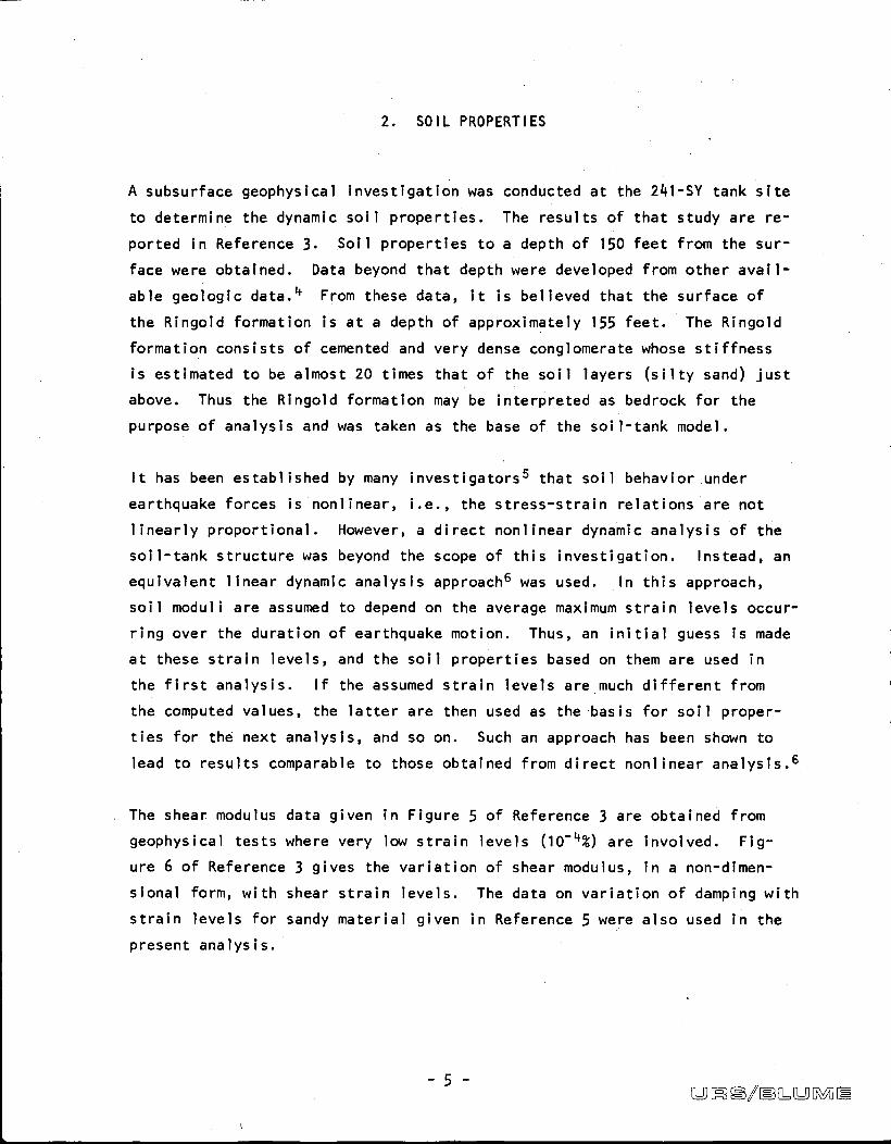
2. SOIL PROPERTIES
A subsurface geophysical investigation was conducted at the 241-SY tank site
to determine the dynamic soil properties. The results of that study are re-
ported in Reference 3. Soil properties to a depth of 150 feet from the sur-
face were obtained. Data beyond that depth were developed from other avail-
able geologic data.4 From these data, it is believed that the surface of
the Ringold formation is at a depth of approximately 155 feet. The Ringold
formation consists of cemented and very dense conglomerate whose stiffness
is estimated to be almost 20 times that of the soil layers (silty sand) just
above. Thus the Ringold formation may be interpreted as bedrock for the
purpose of analysis and was taken as the base of the soil-tank model.
It has been established by many investigators5 that soil behavior under
earthquake forces is nonlinear, i.e., the stress-strain relations are not
linearly proportional. However, a direct nonlinear dynamic analysis of the
soil-tank structure was beyond the scope of this investigation. Instead, an
equivalent linear dynamic analysis approach6 was used. In this approach,
soil moduli are assumed to depend on the average maximum strain levels occur-
ring over the duration of earthquake motion. Thus, an initial guess is made
at these strain levels, and the soil properties based on them are used in
the first analysis. If the assumed strain levels are much different from I
the computed values, the latter are then used as the basis for soil proper-
ties for the next analysis, and so on. Such an approach has been shown to
lead to results comparable to those obtained from direct nonlinear analysis.6
The shear modulus data given in Figure 5 of Reference 3 are obtained from
geophysical tests where very low strain levels (10-4%) are involved. Fig-
ure 6 of Reference 3 gives the variation of shear modulus, in a non-dimen-
sional form, with shear strain levels. The data on variation of damping with
strain levels for sandy material given in Reference 5 were also used in the
present analysis.
-5-aD IN IM/IMB L &0 WA IM

3. COMPUTATION OF BASE MOTION (DECONVOLUTION)
The SSE has been specified in terms of free-field spectra (Figure 4) and
was represented by synthetic free-field acceleration time-history (Figure 5).
To evaluate the response during the SSE of an underground tank and the soil
surrounding it, the input motion must be applied at the base of the soil-
tank model. This base motion should be equivalent to the specified surface
motion.
Such a computation of the motion at the base of soil layers that will pro-
duce a given surface response motion is the reverse of the usual problem of
computing the surface response of soil layers subjected to a given base mo-
tion. It is difficult if not impossible to solve such a problem in the time
domain. However, for stable linear elastic systems, there exists a simple
relationship between the output motion (motion at the surface or any inter-
mediate point) and the input (base) motion in the frequency domain:
Y(W) H(w) · X(w)
where Y(w) and X(w) are the Fourier transforms of the output motion y(t) and
input motion x(t), respectively, and H(w) is the frequency response function
of the system and is solely dependent on the system properties. Here, Y(w)
can be computed because the surface motion y(t) is known. H(w) is simply
the Fourier transform of the. surface response of the soil layers to unit
impulse input at the base. Thus, X(w) may be computed from the above equa-
tion and then x(t) may be obtained by inverse Fourier transform of X(w).
The 155-foot deep soil layers down to the Ringold formation (which was taken
as the bedrock base of the soil-tank model as explained in Section 2) were
modeled by a soil column of unit area for the deconvolution analysis described
above to obtain the base motion time-history at the surface of Ringold forma-
tion. The acceleration time-history at the surface of the soil column was
recomputed using the computed base motion as input. The acceleration response
spectra of the recomputed surface motion and the original free-field motion
are compared in Figure 6.
-6-06 e/IMB LUMIE

The soil properties used in the deconvolution analysis are shown in Table 2.
*As explained in Section 2, the soil properties are strain dependent; conse-
quently, an iterative elastic approach was used. The strain levels are also
shown in Table 2. The computed base acceleration time-history is shown in
Figure 7.
-7-9 £#3/IMB L &9 MI IN

4. ANALYSIS APPROACH
4.1 General Assumptions
Structural analysis of underground tanks with liquid contents subjected to
long-term gravity, thermal, and creep loads, as well as the transient earth-
quake ground motion is a complex problem. The recent development of the
finite element method of analysis of structures has made such analyses pos-
sible. However, a few simplifying assumptions regarding the structure and
the loads were necessary to make such analyses practicable within reasonable
budget limits. Two basic assumptions made in the present analysis are out-
lined below. Several other assumptions will be mentioned in the remainder
of this section.
Each tank was assumed to be axisymmetric. The nonaxisymmetric features of
the tank were either ignored or modeled approximately by equivalent axisym-
metric elements. The soil surrounding the tank was also assumed to extend
axisymmetrically for a large radius (large in relation to tank size). The
effects of neighboring tanks and nonaxisymmetric soil profile were ignored.
It is difficult to estimate the effect of this assumption ori the computed
responses, especially in the case of earthquake forces. When considering
gravity loads, it seems that ignoring the existence of adjacent tanks will
lead to conservative results with regard to lateral soil pressures on the
concrete tank walls; effects elsewhere should be minimal. Also, as will be
observed from the results presented later in this report, the earthquake-
generated stresses are generally much smaller than those caused by static
loads. The computed results should, therefore, be conservative.
The hydrodynamic problem of liquid pressures on the tank due to oscillating
liquid contents was solved separately from the soil-tank interaction problem.
That is, the coupling between the liquid motion and the tank motion was
assumed to be negligible because the frequency differences of the two motions
are large. Hydfodynamic forces computed on the basis of this assumption will
be quite conservative. 7
-8-[U] M) #3/IMB & &0 [R ] ME

4.2 Finite Element Models
The tank and the surrounding soil were modeled as an assemblage of axisymme-
tric, thin, conical shell and toroidal solid finite elements. The shell ele-
ment has, in general, the shape of a conical frustum, but can also represent
a segment of a vertical cylindrical shell and a flat, horizontally oriented
plate at extreme orientations. The solid elements are toroids of triangular
or quadrilateral cross section. A shell element and a quadrilateral solid
element are shown in Figure 8 along with the global reference axes (Z, R,
and 0) and the degrees of freedom involved at each nodal point. For a
description of the finite element method, see Reference 8. Reference 9 devel-
ops the finite element method for axisymmetric structures under axisymmetric
and nonaxisymmetric loading, the particular area of interest in the present
investigation.
The entire soil-tank finite element model is shown in Figure 9. Detail near
the tank region is shown in Figures 10a and 1Ob. The concrete tank, includ-
ing the dome and the base slab, was represented by thin shell elements. The
secondary steel liner attached to the concrete tank was ignored, because it
will contribute very little to the stiffness of the shell. The primary steel
tank was included in the model and was also represented by thin shell ele-
ments. The primary steel tank was assumed to be rigidly attached to the con-
crete shell in the dome region. In the base slab region, the layer of insu-
lating concrete between the primary steel tank and the concrete tank wasrlmodeled by solid elements. The primary tank was assumed to»rigidly attachedto the insulating concrete. This will be the behavior in reality because of
self weight of the tank and the weight of the contents.
The concrete tank dome, wall, and slab were represented by shell elements at
their middle surfaces. To maintain actual geometry, the nodal points of the
shell elements on the middle surface and the nodal points of the adjacent
solid soil elements at the soil-tank boundary were connected by thin shell
elements of appropriate length (usually half the thickness of the concrete
wall or slab), stiffness, and weightless material. Similar solid connector
elements were used in the cantilever portion of the wall footing to maintain
its actual geometry. For dead load analysis, the shell connectors between
concrete walls and adjacent soil were assumed to be pin-connected to elimi-
-9- LDME#l/BLLD[MIE

nate the drag-down effect (transfer of weight of soil) on the concrete wall
from the surrounding soil. This assumption closely simulates actual condi-
tions, because the drag-down effect due to consolidation of the fill around
the tanks diminishes with time after initial construction.
Except for the materials used to define the properties of the cracked con-
crete elements in the dome for the dynamic analysis, all materials, i.e.,
soil, concrete, insulating concrete, steel, etc., were assumed homogeneous
and isotropic for a given analysis run. As indicated in Section 2, the soil
properties were assumed to be dependent on expected strain levels. The
properties used in the analysis for various materials are given in Table 3.
Results of the thermal-creep analysis by Dr. Rashid show some cracking near
the center and in the haunched portion of the dome. The cracking is due to
tensile forces in the circumferential direction. Consequently, in the
dynamic analysis, the cracked concrete was modeled by material having equiv-
alent orthotropic properties with reduced stiffness of only the hoop rein-
forcement in the circumferential direction and the stiffness of the concrete
in the other directions.
Only a finite extent of soil around the tank could be included in the model.
The bottom boundary of the model was assumed to be 155 feet below the ground
surface. The vertical boundary was assumed to be at a radius of 240 feet
from the axis of symmetry of the soil-tank model. The bottom boundary was
at the surface of the Ringold formation, which, as explained in Section 2,
consists of a much sti ffer material than the soil above and thus forms a
natural boundary. The vertical boundary was somewhat artificial; however,
it was sufficiently far from the tank region that the stresses and displace-
ments in this region were little affected by the artificial boundary. Fur-
thermore, to simulate continuity at the vertical boundary, appropriate bound-
ary conditions were assumed: lateral support but freedom of vertical move-
ment under vertical loads, and exactly the reverse under lateral loads. Also,
in the earthquake analysis, dampers were used at the vertical boundary to
simulate radiation dampinglo (loss of energy due to radiation of wave energy
into soil beyond the boundary). The bottom boundary was assumed to be
fixed for all load cases.
- 10 -&DIAO#3/MBLLDOME

No geophysical test data for the tank site were available at the start of
the present investigation, so initially the soil-tank finite element model
was made to extend down to 200 feet below the surface. The model had been
finalized and the input data cards had been punched when the geophysical
investigation results were obtained. The very dense and cemented Ringold
formation is believed to be 155 feet below the surface. It was decided, as
explained in Section 2, that the surface of this formation forms a natural
bottom boundary. To avoid delaying the present investigation, instead of
developing a new model, all nodal points below the 155-foot level were
assumed fixed. The soil-tank model given in Figure 9 shows the model down
to the 155-foot level only.
A separate model of the primary steel tank was used for analysis under hydro-
mechanical pressures that act directly on the primary tank and have very
little effect on the secondary tank. Also, a more refined model of the
primary tank was made possible by analyzing it independently. The model used
in hydromechanical analysis is shown in Figure 12, with the tank liner plate
represented by axixymmetric shell elements. The thermal stress analysis was
darried out with a separate computer program (see Section 4.4) whose limita-
tions made it necessary to model the tank liner plate by axisymmetric solid
elements (5 layers across the thickness).
A separate model of the concrete tank wall and dome was used in thermal-creep
analysis conducted by Dr. Rashid and is described in Appendix A.
The wall-to-base slab joint in the concrete tank is of the sliding type. The
wall was therefore assumed to be free to move laterally with respect to the
base slab under long term loads such as gravity, lateral soil pressure and
thermal loads and under creep effects. However, for the transient earth-
quake ground motion loading, which generally lasts for less than a minute,
the wall and the base slab were assumed to be pin-connected, i.e., free to
rotate but prevented from sliding with respect to each other.
4.3 Load Conditions for Analyses
In addition to the two dynamic load cases, i.e., hydrodynamic loads and earth-
quake ground motion, the gravity (i.e., dead and live), hydrostatic, thermal,
- 11 -[LI] [R)#S/IBLLI][1 0 IM

and vapor pressure (in the primary tank vapor space) loads must also be con-
sidered to obtain the proper combined stress for checking the steel and con-
crete tank sections. A separate thermal-creep analysis of the concrete tank
was conducted by Dr. Y. R. Rashid.
4.3.1 Gravity Loads
Under gravity loads, the weight of the tank and the soil in the model were
considered. The weight of the 1,000,000 gallons of liquid waste (specific
gravity of 1.7) was also considered as was the live load at the ground sur-
face, which consists of a uniform load of 40 psf and a concentrated load of
50 tons. The 50-ton concentrated load was applied only in the central region
at the axis of symmetry. Its application elsewhere makes it a nonaxisymmet-
ric load which cannot be easily modeled by equivalent axisymmetric loads.
The soil-tank model was used in the analysis for gravity loads.
4.3.2 Hydromechanical Loads
The liquid waste to be contained in the primary steel tank will exert hydro-
static pressures on that tank. Vapor in the space above the liquid surface
will also exert pressures on the tank dome. These pressures are long-term in
nature. The motion of the tank under seismic excitation will cause sloshing
of the liquid in the tank, resulting in hydrodynamic pressures on the tank.
Such hydrodynamic pressures will be exerted only for a short time during
an earthquake.
The hydromechanical pressures act directly on the primary steel tank, which
then transfers them to the surrounding soil through connections to the con-
crete tank dome and base slab. The effect of these loads on the concretetank and soil is expected to be minimal. Thus, the primary tanks were ana-
lyzed under such loads under the assumption that the dome and base slab of
the concrete tank provide it rigid supports. An analysis of the entire soil-
tank model under hydrostatic loads confirmed this assumption.
In computing the hydrostatic pressures, the specific gravity of the liquid
contents was assumed to be 1.7. Vapor pressure has been specified as rang-
ing between -6 inches of water to +60 inches of water. Vapor pressure of +60
- 12 -9 R e/BL 013 040 IN

inches of water acts in the same direction as the hydrostatic pressures and
the weight of liquid, and was therefore used in the analysis simultaneously
with the hydrostatic pressures.
Hydrodynamic pressures caused by the sloshing motion of the liquid contents
were computed by a method developed in Reference 7 that is essentially simi-11lar to that developed by Housner. This method assumes that the tank is
rigid; the liquid is nonviscous, incompressible, and homogeneous; the dis-
placements, velocities, and slopes of the free surface of the liquid are all
small; and the flow field is irrotational. From the expression for hydro-
dynamic pressure developed in Reference 7, using only the first sloshing mode
and assuming that the spectral acceleration value at the first mode period
(which is greater than 5 seconds) equals half the maximum ground acceleration,
0 , the pressure on the tank wall at radius R is computed to beg
p (z,0)PR09 {1-fl(R, z)} cos 0
where
H-zcosh 1.84 -
fl(R,Z)R
1.84H2.38 cosh R
In the above expression, H is the height of liquid surface from the base of
the tank, z is the coordinate of depth measured from the surface of the
liquid (positive downward), p is the mass density of the liquid, and 0 is
the circumferential coordinate (angle) measured from the direction of appli-
cation for the base motion.
The model of the primary steel tank used in the hydrostatic and hydrodynamic
analyses is shown in Figure 12. The hydrodynamic pressures on the tank com-
puted by the above procedure are given in Table 4 along with the hydrostatic
pressures.
t
- 13 -
03 * #3/IMB LUMEN

4.3.3 Thermal Loads
The liquid contents in the tank will remain at temperatures of around 250'F
over a long period. The steel and concrete tanks are constructed and remain
at normal atmospheric temperatures (assumed to be 70'F) until the introduc-
tion of the hot liquid waste contents. The base plate and most of the cylin-
drical wall region of the primary steel tank that is in direct contact with
the liquid will reach and remain at the same temperature as that of the
liquid. Temperatures in the remainder of the steel tank and those in the
secondary concrete tank were computed by ARHCO using heat transfer analysis.
Concrete is subject to creep under sustained loading, especially under ele-
vated temperature conditions. The thermal-creep analysis of the concrete
tank that was conducted by Dr. Y. R. Rashid used the temperature data devel-
oped by ARHCO. The temperatures were assumed to rise gradually over a
period of 30 days to the design levels and then remain steady. The analysis
was continued to further steps in time well beyond the time necessary to
establish self-limiting cracking and creep deformations. The soil over-
burden load, live load of 40 psf, and internal vapor pressures in the tank
were included in the analysis as initial mechanical loading on the tank.
This detailed report on the thermal-creep analysis is included as Appendix A.
The detached portion of the primary steel tank (Figure 12) was analyzed for
thermal stresses due to temperature change. Simultaneously, concrete tank
displacements at the dome and the base slab regions where the two tanks are
connected were applied to the steel tank. The displacements of the concrete
tank in the dome region were obtained from the results of the thermal creep
analysis. The displacements in the base slab were computed by the formula
8 a·R·A T
where A is the radial displacement at radius R, a is the coefficient of ex-
pansion for concrete (6.38 x 10⁻⁶ in./in./'F) and AT is the change in tem-
perature.
- 14 -[Ul [* /IMB L LD M IN

4.3.4 Earthquake Ground Motion
Ground motion at a given point due to an earthquake may be represented by
two horizontal components and one vertical component. The rotational com-
ponents are negligible. The soil-tank structure is assumed to be rigid in
the vertical direction, and the responses due to vertical ground motion are
obtained by scaling the gravity load responses by a factor of 0.167 (the
design SSE maximum vertical ground acceleration specified is 2/3 x maximum
horizontal ground acceleration, 0.25g = 0.167g).
The response of the soil-tank structure to a horizontal component of SSE
input base motion time-history was computed. This input base motion was
determined as described in Section 3. The equations of motion for the soil-
tank model were solved by a step-by-step method, and the entire time-histories
of the responses were computed. Only the maximum values of the response
parameters were recorded (with the time of occurrence), mainly because of the
large number of response parameters of interest. Also, instead of computing
the responses of the system to two independent, mutually perpendicular hor-
izontal components, it was assumed that they cause the same maximum re-
sponses, though they may occur at different times.
4.4 Computer Programs
The main computer program used for the analyses reported herein was AXIDYN,
a computer program for the static and dynamic analysis of axisymmetric struc-
tures by the finite element method. The program, written in Fortran IV, was
developed at the Department of Civil Engineering of the University of
California, Berkeley,9 under the direction of Professor E. Wilson, and was
used in all the finite element analyses reported here.
The structure to be analyzed by AXIDYN can consist of axisymmetric shells,
axisymmetric solids, or a combination of the two. The axisymmetric shells
are represented by conical-frustum-shaped shell elements, whereas the axi-
symmetric solid body is represented by an assemblage of toroids of quadri-
lateral or triangular sections. The two types of elements are shown in
Figure 8 with the degrees of freedom considered in the analysis for such
elements. The nodal points on a vertical section are seen in Figure 8 to
be nodal circles.
- 15 - [Lil M)Mj/IN)LOSMIE

The program will handle static or dynamic forces that are axisymmetric or
are such that they can be developed into Fourier series form along the nodal
circles, i.e., as functions of 0. AXIDYN accepts five types of loading
cases:
0 Dead loads
• Arbitrary static loads
• Arbitrary dynamic loads
0 Horizontal earthquake accelerations
0 Vertical earthquake accelerations
Dead loads, arbitrary static loads, and horizontal earthquake accelerations
are the load cases considered in the present analysis.
The program has the capability of performing dynamic analyses both by the
modal superposition approach and by direct integration of the coupled equa-
tions of motion. The latter approach was used in the current investigation.
A new subroutine, developed for the step-by-step integration of equations
by a procedure12 that is more accurate and stable than the procedure origi-
nally developed for the CDC 6600 computer system, was modified to handle
large finite element models encountered in the present analyses on the CDC
7600 computer system. Such a system at the Lawrence Berkeley Laboratory of
the University of California at Berkeley was used for all computer analyses.
Other computer programs were also used for preparation, checking, and plot-
ting of data, and for the deconvolution analysis described in Section 3.
Among these is a program named MATRAN, which performs matrix operations on
data in matrix form, including structural analyses and time-series analyses.
The latter capability was particularly useful for the deconvolution analysis.
MATRAN is a substantially expanded version of program SMIS. The latter pro-
gram was also developed at the Civil Engineering Department of the University
of California, Berkeley.
Another program, SAP IV, also developed by the Civil Engineering Department
of the University of California at Berkeley,13 was used in the thermal analy-
sis of the primary steel tank. SAP IV is a general three-dimensional struc-
- 16 -[u] M 9#3/IMB L[LD [Rfil IM

tural analysis program and was used instead of AXIDYN because the latter does
not handle thermal loads.
4.5 Load Combinations and Computation of Stresses
As explained in Section 4.2, the tanks were entirely modeled by shell ele-
ments. The computer output of forces on shell elements is in'terms of stress
resultants, longitudinal force and moment, circumferential force and moment,
and in-plane shear force and torsional moment. These stress resultants are
shown in Figure 13 for a vertically oriented shell element, which represents
tank walls. Tensile forces and moments producing tension on the outside face
of a shell element are considered positive. This convention is followed in
the figures and tables of this report. For a horizontally oriented shell
element, representing the base slab of the tank, the stress resultants shown
in Figure 13 are still valid except that the longitudinal forces may be
interpreted as the radial forces. Note that no transverse shear (i.e., shear
across the shell thickness) is output by the computer program; it may be
approximately computed from the longitudinal and circumferential moments.
Stresses from the three sets of stress resultants -- longitudinal force and
moment, circumferential force and moment, and shear and torsional moment --
are computed on appropriate sections of the elements. First, though, the
stress resultants from various loads were combined and the following consid-
erations were taken into account in this combination process.
Among the load cases considered here (Section 4.4), two loads -- hydrodynamic
pressures and horizontal earthquake ground motion -- are nonaxisymmetric.
The hydrodynamic pressures act normal to the container wall, and the magni-
tude varies over the circumference as a cosine function of the angle 0 from
the direction of applied ground motion (see Section 4.3.2). A component of
horizontal earthquake ground motion may be represented by radial and tangen-
tial loads (in the horizontal plane) varying over the circumference as cosineand sine functions, respectively, of the angle 0 measured from the direction
of applied ground motion. For both of these nonaxisymmetric loadings the
longitudinal and circumferential stress resultants vary cosinusoidally,
whereas the in-plane shear and torsion vary sinusoidally, from the direction
of applied ground motion. The other three loads -- gravity load, hydrostatic
- 17 -9 M) e/IMB 0= GL [MI IM
.

pressures, and vertical earthquake ground motion -- are axisymmetric. Stress
resultants on an element due to these loads are constant over the circumfer-
ence, and in particular the in-plane shear and torsion are zero everywhere.
The seismic design criteria specify that the horizontal ground motion shall
be represented by two mutually perpendicular components acting simultane-
ously. The maximum values of a stress resultant in an element due to the two
mutually perpendicular horizontal components will occur at 90' angles
and probably at different times. Let us assume that the magnitudes of a
stress resultant due to the two components are equal. If we combine the
particular response due to the two components by the root mean square method,
it is clear that at no point along the circumference will the combined value
of the response be greater than the response due to one component at a sec-
tion parallel to that component. The same argument holds for hydrodynamic
loads because they are generated by horizontal earthquake ground motion.
Therefore, in obtaining the combined stress resultant from dynamic and static
loads, one needs to consider only one component of the horizontal ground mo-
tion. Furthermore, according to the argument presented in the preceding para-
graph, in combining the stress resultants from axisymmetric and nonaxisymmetric
loads included in the present analysis, the circumferential variation of these
stress resultants need not be considered.
For the static loadings (dead load and hydrostatic pressures) the direction
of the action of stress resultants is known from the computer output. How-
ever, for dynamic loadings (vertical and horizontal earthquake ground motions
and hydrodynamic pressures) only the maximum values of the various stress
resultants are known. These may act in either direction and may occur at
different times during the earthquake. Hence, algebraic summation was used
in combining stress resultants from the static load cases, whereas absolute
summation was conservatively used in combining stress resultants from the
dynamic load cases. However, in combining the total static and the total
dynamic forces and moments, directions (or signs) were assigned to the dynamic
forces and moments independently to produce the worst possible stresses.
In determining the stresses in the primary steel tank, the results of our
analyses considering the various load conditions, namely dead, surcharge,
- 18 -[L:[1 [ e/IM3&[WOMIM

thermal, hydromechanical loads, and earthquake ground motion are considered.
The thermal-creep analysis by Dr. Y. R. Rashid, which used a nonlinear method'
of analysis, included the long-term loads,.consisting of dead, surcharge, and
vapor pressure at the inner surface of the dome, as initial mechanical load-
ing on the tank. The results of this thermal-creep analysis and the results
of our earthquake analysis of the tank as a whole were combined to check the
stresses at the concrete tank. Effects of the hydrodynamic loads (which act
directly on the primary steel tank) on the concrete tank are small and are
not consi dered.
1
- 19 -[U][ #3/IMB LILL[i [1 IM

r
5. RESULTS OF ANALYSIS
5.1 Primary Steel Tank
The primary steel tank was analyzed as a part of the overall soil-tank model
(Figure 9) for gravity loads and earthquake ground motion. It was analyzed
separately for hydrostatic and hydrodynamic loads (Figure 12) as well as
thermal loads.
Internal forces (i;e., both forces and moments) in the primary tank caused
by the hydromechanical loads are plotted in Figures 15 and 16. For conve-
nience in plotting, the top knuckle and roof portion and the base knuckle
and base plate portion have been developed vertically in these figures. The
hydrostatic pressures and corresponding internal forces are constant over
the circumference of the tank. The hydrodynamic pressures, which are caused
by earthquake motion, and the corresponding internal forces vary along the
circumference with the cosine of the angle measured from the direction of
applied motion. The values of hydrodynamic internal forces shown in Figures
15 and 16 are maximum values acting on a section parallel to the applied
motion. The hydrodynamic internal forces are generally much smaller than
the hydrostatic internal forces.
The longitudinal (or meridional) and circumferential (or hoop) moments due
to hydromechanical loads are significant only at and near the top and bottom
knuckles. The longitudinal forces are generally of smaller magnitude in
comparison to circumferential forces. The latter are maximum near the base
of the tank for hydrostatic load and are essentially constant over the cylin-
drical portion of the tank for hydrodynamic load. Note that the hoop forces
caused by hydrostatic pressures are generally tensile, whereas the hoop
forces due to hydrodynamic pressures may act either way.
The internal forces in the primary tank caused by gravity loads and soil-
structure interaction due to earthquake ground motion are general,ly much
smaller than those caused by hydromechanical loads, and are listed in Tables
5 and 6. The moments and forces are of any significance only at and near
the base knuckle and to a lesser extent near the top knuckle. The moments
- 20 -' 06[ e/ 11=11:DIMI IM

are more significant in the longitudinal direction and the forces are more
significant in the circumferential direction. Note that the gravity loads
and corresponding internal forces are constant along the circumference,
whereas the earthquake-caused internal forces vary with the cosine of the
angle measured from the direction of applied motion, and the values given in
Tables 5 and 6 are the maximum values. Also note that the earthquake-induced
internal forces may act in either direction.
Due to the nature of the model and computer program used, only the stresses
on the primary tank for thermal loads were available. The stresses are insig-
nificant everywhere except in and near the base and top knuckles of the tank.
In the upper knuckle, the maximum longitudinal and circumferential stresses
are, respectively, 9.6 ksi (compressive) and 3.9 ksi (tensile). For the bot-
tom knuckle, the corresponding maximum stresses are 4.0 ksi and 1.6 ksi (both
tensile).
Stresses due to gravity and hydromechanical loads and earthquake ground
motion were also computed. The circumferential stress is dominated by hoop
tensile force caused by hydrostatic pressures and is maximum at nodal point
(NP) 235, where the thickness of tank liner plate is 1/2 inch. Under long
term loads (gravity + hydrostatic + thermal) the maximum hoop stress at NP 235
is 15.3 ksi, and addition of seismic load stresses boosts it to 20.1 ksi. The
longitudinal stress under long term loads is maximum at NP 133 (at the base of
the base knuckle, see Figure 12) having a value of 13.1 ksi, which increases
to 19.3 ksi when seismic load stresses are added.
The primary tank steel is specified as ASTM 516 Grade 65. According to ASME
Boiler & Pressure Vessel Code Section III Division I,14 the allowable stress
for such steel at temperatures around 250'F is 21 ksi (and the yield stress
is 31.5 ksi). Thus, the maximum computed stresses in the primary steel tank
are less than this allowable value.
The radial displacements of the primary steel tank under hydromechanical
pressures are shown in Figure 14. Maximum displacements of 0.165 inches and
0.104 inches under hydrostatic and hydrodynamic pressures, respectively,
occur near NP 15.
- 21 - 9 [Rle/IMB LL!] 0 ] IN

5.2 Concrete Tank
The secondary concrete tank was analyzed for gravity loads and soil-structure
interaction (due to earthquake ground motion) as a part of the overall soil-
tank model (Figure 9) using computer program AXIDYN. The dome and cylindri-
cal wall portion of it was separately analyzed for thermal loads and creep
by Dr. Rashid using the computer program SAFE-CRACK (Appendix A). This
thermal-creep analysts considered the nonlinear behavior of concrete, and
therefore the gravity loads (including the active lateral soil pressure on
the tank wall) were included as initial mechanical loading in the thermal-
creep analysts.
Hence, for the concrete tank dome and wall, the SAFE-CRACK analysis results
were considered valid for the effect of long term loads (gravity, thermal,
and creep) and AXIDYN analysis results valid for earthquake ground motionloading. However, for the base slab, only AXIDYN results were available for
all loadings and are used herein. Thermal stresses in the base slab are
expected to be small because the connection between the wall and the slab
is of the sliding type. Furthermore, creep will tend to relieve the thermal
stresses. Thus, the effect of thermal loads and creep on the base slab is
considered negligible and is ignored.
The effect of hydromechanical loads, which act directly only on the primary
steel tank, was found to be negligible on the secondary concrete tank and
was ignored.
The lateral displacements in the tank region of the soil-tank model under
earthquake motion are maximum at approximately the same time, 6.56 to 6.57
seconds after the start of earthquake motion. The maximum lateral displace-
ments at the top and bottom of the concrete tank wall (nodal points 359 and
191, respectively) are 1.121 inches and 0.985 inches, respectively, giving a
relative lateral displacement of 0.136 inches between the top and bottom of
the tank wall.
The maximum lateral accelerations due to the earthquake motions are 0.15g at
the base of the tank, 0.21g at the roof of the tank, and 0.295g at the soil
surface close to the right vertical boundary.
- 22 -U m} 98/M3 0.&DMIM

The longitudinal (or meridional) forces and moments and the circumferential
(or hoop) forces and moments on the concrete tank wall, roof slab, and base
slab from the earthquake analysis are given in Table 7. The corresponding
plots of these forces and moments are shown in Figures 17 and 18. The earth-
quake response plots in these figures are envelopes because maximum responses
at different points in the structure may occur at different times and have
either positive or negative values. The earthquake responses are plotted
for a section parallel to the applied horizontal earthquake motion and are
maximum. They vary circumferentially as the cosine of the angle measured
from the direction of applied motion. The internal forces that develop in
the concrete tank under earthquake loading are generally much smaller than
the corresponding responses under dead load.
The results of thermal-creep analysis, including the effect of gravity loads
of the concrete tank dome and wall, are discussed in Appendix A. The forces
and moments on the base slab due to gravity loads, as obtained from AXIDYN
analysis, are shown in Figure 19. The longitudinal moment, which results
mainly from the vertical point load imposed by the tank wall, is maximum
near the tank wall and is the most significant of all internal slab forces
due to gravity loads.
The results from SAFE-CRACK analysis under initial mechanical loading (i.e.,
gravity and soil pressure) indicate an upward displacement of 0.03 inches at
the dome crown and an inward horizontal motion of 0.12 inches of the base of
the wall. Under thermal loading, just after the temperature of the contents
has reached its maximum value (30 days after heating has started), the dis-
placement at the crown is reversed and is now 0.51 inches downwards; simi-
larly, the displacement at wall base has also reversed and is now 0.41 inchesoutward. Due to long-term creep effects, the displacement at the crown of
the dome stabilizes to 0.23 inches upwards and at the base of slab to 0.34
inches outwards.
The results of SAFE-CRACK analysis indicate that under the gravity loads
(initial mechanical loading), there is no cracking in concrete and the maxi-
mum compressive stress in concrete is less than 1000 psi. Maximum stress in
meridional and hoop steel reinforcement is less than 7 ksi compressive and
- 23 -CLD M) g#j/Im) 0=LD[MIE

1 ksi tensile. During heating, the analysis indicates, cracking in con-
crete begins, and by the time temperatures reach their peaks, radial and
meridional cracking has occurred in regions near the dome crown and haunch.
The maximum compressive stress in concrete is less than 1600 psi, except
in a very localized region at the dome crown soffit, where it is 2600 psi.
Maximum stresses in steel reinforcement are less thad 24.2 ksi compressive
and less than 7 ksi tensile. The analysis further indicates that after long-
term creep, when stable conditions are established, the cracking spreads
somewhat but remains in the same general region. The maximum compressive
stress in concrete is now less than 1000 psi, whereas stresses in steel are
less than 24.2 ksi compressive and 4.0 ksi tensile. The high compressive
stress (24.2 ksi) in reinforcement after heating and long-term creep effects
is confined to a very small area near the dome crown, being less than 13 ksi
elsewhere.
The SAFE-CRACK analysis indicates that principal strains in regions of radial
cracking and meridional cracking near the haunch (where diagonal reinforce-
ment exists) are less than 1 percent, indicating adequate reinforcement.
However, principal strains approach 10 percent in the meridionally cracked
region near the dome crown, where no d.iagonal reinforcement exists, indicat-
ing that these cracks may increase in an unstable manner unless diagonal
reinforcement is provided.
The seismic analysis of the tank by AXIDYN computer program was an elastic
analysis, though regions of cracked concrete were modeled by appropriate
elements with reduced stiffness, as explained in Section 4.2. Thus the
results of seismic analysis cannot be directly combined to those from the
nonlinear SAFE-CRACK analysis for long term loads. However, an indication
of additional stresses due to seismic ground motion may be obtained by com-
puting the stresses due to such loading independently. Such computations
indicate maximum stresses (tensile or compressive) of 5.4 ksi in hoop steel
in the cracked concrete region near the dome haunch. The maximum stresses
in the uncracked region of the dome are less than 120 psi compressive in
concrete and 1.7 ksi tensile or compressive in steel. In the tank wall,
maximum compressive stress in concrete is less than 400 psi and maximum
stress in reinforcement steel is 11.5 ksi (indicating some flexural crack-
ing in concrete at the base of the wall in the longitudinal direction.
- 24 -9 e/IMBL[LD [i il Im
b 1

Stresses in the base slab for long-term and seismic loads were computed from
the AXIDYN analysis results. The, longitudinal stresses in a localized re-gion near the tank wall location under long-term (viz. gravity) loading are
quite high: 35.8 ksi tensile in bottom reinforcement steel (indicating some
flexural cracking at the bottom' face) and 2000 psi compressive in concrete.Addition of seismic stresses bcdosts these values to 42.7 ksi and 2475 psi.,
respectively. Elsewhere in the base slab, the stresses are substantially
smaller.
The specified ultimate compressive strength (f ) of the tank concrete is
4500 psi. The allowable compressive stress in concrete, according to the
old ACI 318-6315 code, are 2025 psi for long term loads and 2700 psi when
seismic loads are also considered. Thus the compressive stresses in concrete
are within allowable values everywhere in the tank except in a very localized
region at the dome crown soffit for a short period during and after heating.
Reinforcement steel is specified as ASTM 615-68 Grade 60 with minimum yield'4»,
strength of 60 ksi and allowable stresses of 24 ksi for long-term loads and
32 ksi when seismic stresses are included. The computed stresses in rein-
forcement steel exceed these allowable values in a couple of localized re-
gions at the dome crown and in base slab near the tank wall, though they are
well within the yield strength of the steel.
In-plane shear stresses caused by seismic ground motion result in high
nominal shear stresses in the tank wall ranging from 252 psi to 395 psi,
the latter occurring near the base of the wall. According to ACI 318-63,
the allowable stress is 446 psi, assuming that longitudinal and circum-
ferential steel reinforcement help resist the in-plane shear.
- 25 -9 [* e/MB LLI] 94 ME

r
6. SUMMARY AND CONCLUSIONS
The underground 241-SY tank structure, which consists of a primary steel
tank and a secondary concrete tank and is proposed to provide leakproof
containment for radioactive waste liquids, has been analyzed for gravity
and thermal loads, as well as for Safe Shutdown Earthquake ground motion.
The secondary concrete tank has also been analyzed for long-term creep
effects.
The tank structure was analyzed by the finite element method using an elas-
tic analysis approach, except for the thermal-creep analysis of concrete
tank which involved a nonlinear approach. The surrounding soil was included
in the model for the seismic analysis.
An evaluation of the results indicates that the stresses in the primary steel
tank are within their allowable values. The stresses in concrete and rein-
forcement steel of the concrete tank are also within their respective allow-
able values with the exception of a few localized areas. The stresses in
concrete and steel reinforcement in a very small region at the dome crown
exceed slightly their allowable values. The stress in bottom steel rein-
forcement in the base slab near its junction with the tank wall also exceeds
the allowable value though it is well within its yield strength.
Cracking in the dome and upper wall regions of the concrete tank is expected
under thermal and creep loads. Satisfactory reinforcement exists to limit
this cracking except for certain regions where meridional cracking may in-
crease in an unstable manner. To limit meridional cracking in the concrete
tank, it is recommended that diagonal reinforcement be extended throughout
the dome region and in the cylindrical wall region up to at least 8 feet
below the dome-to-cylinder junction.
- 26 -
0.0 me 8/IMB L 9 94 E

7. REFERENCES
1. John A. Blume & Associates, Engineers, Seismic Analysis of Under-
ground Waste Storage Tanks 241-AZ-101 and -102 at Hanford, Washington,
Report No. JABE-ARHCO-01, prepared for ARHCO, Richland, Washington,
San Francisco, April 1971.
2. ARHCO Drawings
241-SY: H-2-37701, H-2-37706, H-2-37707, H-2-37708, H-2-37773
241-AZ: H-2-67243, H-2-67317
3. John A. Blume & Associates, Engineers, Investigation to Determine
Dynamic Soil Properties at the 241-SY Tank Site, Report No. ARHCO-
JABE-0, prepared for ARHCO, Richland, Washington, San Francisco,
March 1974.
4. Kintzer, F., Internal Memo to A. B. Cunningham, John A. Blume &
Associates, Engineers, San Francisco, April 2, 1974.
5. Seed, H. Bolton and I. M. Idriss, Soil Moduli and Damping Factors
for Dynamic Response Analysis, EERC 70-10, Earthquake Engineering
Research Center, College of Engineering, University of California,
Berkeley, California, December 1970.
6. Seed, H. Bolton, and I.M. Idriss, Response of Horizontal Soil Layers
During Earthquakes, Research Report, Soil Mechanics and Bituminous
Laboratory, University of California, Berkeley, 1967.
7. Edwards, Norman W., A Procedure for the Dynamic Analysis of Thin
Walled Cylindrical Liquid Storage Tanks Subjected to Lateral Ground
Motions, Ph.D. dissertation, University of Michigan, Ann Arbor,
Michigan, 1969.
- 27 - U N3993/BLI ]MIE
6 »

8. Zienkiewicz, 0. C., The Finite Element Method in Structural and
Continuum Mechanics, McGraw-Hill, London, 1968.
9. Ghosh, Sukmar, and Edward Wilson, Dynamic Stress Analysis of
Axisymmetric Structures Under Arbitrary Loading, EERC 69-10,
Earthquake Engineering Research Center of the College of Engineering,
University of California, Berkeley, California, September 1969.
10. Lysmer, John, and Roger L. Kuhlemeyer, "Finite Dynamic Model For
Infinite Media," Journal of Engineering Mechanics Division, Proceedings
ASCE, Vol. 95, No. EM4, August 1969, pp. 859-877.
11. Nuclear Reactors and Earthquakes, TID 7024, USAEC, Division of Reactor
Development, August 1963.
12. Farhoomand, Iraj, Nonlinear Dynamic Stress Analysis of Two-Dimensional
Solids, unpublished dissertation for the degree of Doctor of Philosophy,
University of California, Berkeley, California, 1970.
13. Bathe, K.-J., Wilson, E. L., and F. E. Peterson, SAP IV, A Structural
Analysts Program for Static and Dynamic Response of Linear Systems,
Report No. EERC 73-11, College of Engineering, University of California,
Berkeley, California, June 1973.
14. ASME Boiler and Pressure Vessel Code Section Ill, Division 1, 1971
Edition, American Society of Mechanical Engineers, New York.
15· Building Code Requirements for Reinforced Concrete (ACI 318-63),
American Concrete Institute, Detroit, 1963.
- 28 -
ILL WB 9#3/IM3 L U MI E
d.li....

1--- ---7
WGLICEW COUCLGEG (62(!Indo' 06&10!&' 1323'
12 17 i 'g l u d Cocs Kidn i '.90(u i;2 10:. at.3.i i..:i.Ci t.cea rouc:.Gi:,1 ('dr : 3 2 9.0-:,i '%.-.
TO 1 6,02 2 SUGI.I 091.1 20'3 5 6%) 04 WGC>'gul (9 .1 E('9! t,t€G:.2 1 MS''A '·'· >Lk' '
-
i ·j ' 'VE W E 6 0 At G '·. SIU 9 b :. 0 2 2 F L G A 6 2 2 6 f 004 8 2ncE! OU i i i ' DE A. i 2 ; SU i ' i 8 ji
894:GisA' Cgjttolulg' lauG 1313'
Hebo, r 40' EEKC 13 -1 1' co ;1 88' ,i 0,t.. Eue i UGG l. 1 98 ' ri'u z NA t..2 1 C, \ 94 4 1,1 1.0&u !0.
VUSIAX,2 6LOGLUU 40L 2(agiC 9Uq DAUSDIC wefbOU26 01 FUL GARSEWO'
13' 89£ps' K·-,1' b 4! 1201.1' 9 De E beXGLROU' 246 'Al V .
nu ! AU.:42 i C A et. ct.1 1 1 10 0..1.1 i·S ' '936.1<G ji :.1.' cs .t i i.0Lt.J l g' t.),\(, t.
201192' Ub//112NGq q!226LESCIOU 10: ELS quoLT 002- 06 5,ui 2ob,uA'
.1....-......................SM-I-.. . ......lilI.... I.-.....................--- ........ .. .--I .-.. --'.........,......*..= . ... . ..... .... ....
13' 1.949(2.01., 9'jq 1 1 £51 ' 9013 3 1 :·'Gel. DAus,DE c 2I !.522 yljg 1 AP ;2 01: .LAC..Di WGI.Je i 0139 j
5466, to'3:,K:-ij.i- s y '15'5i*2:. 33e3'
i j BAcisgi. 8...35(5022 guq Go,Elld:i·'ENG< i li D jos':1 ' i il'VE:' ' Di ' ! 2 j eu el... 103'3CEot.
..............
VECE' Aci" 02' 80' Ewf' vnan,r jaea' bo' 923-811
..'...„..«....... ....„„«.,-.i ·- . :· ,·, ri . : ,g ; r, 1 2(i A . i. 1.-.,·, 1 . 1 3 6 1-i· ; Cl,; 9; ; 1 Ir· 7 1, t . 1 fl : rlt, ''id·E-, tui fG T,IG:,1 19 „ i.·'·'.,···· : ··,· 4..Ii···'·A·-'., -· „ - . ..1-. 4,• 2",»: ...., 3.........." .1 Ew,-ic
10" r;.28(i., 501.,U ' '31.1<f b'089£ r * Mip'im ·,2,··,6 1 itkik'Ic.e D.\Hemic Hoq€;i EOL
nui A.19:.. 2 1 .EX 0.1, 'I H 1. C l.1.1 1 91 4 8·P:.i<:3 , 9.>, ' Cg I t i·0 1.1.i &9" 29'046&751. 12.23 '
ESLA,AnGNG EUdisGGLS ad 48269,Cy. CEUEGL 01 CUS Coj loae 04 F iucttioS'........-.... g
, A-, I : .,p,„,0/, , 0,• 0 1. ' ", ·.r '.9 ....·." r':t..trv; 9, f ..7; f i '.9 .' lilia: 51(C 22-jo'Vt, I.., 2.4,1»" 4. '.1<. ,) 4 '-5 '.... S.•' ..... , t- 0 -·- i, -,- : ·,· -··· .
„...,.
:i-':AE,u' Eni<U:'UL' 909 Eqmg:.1 01 1 12:,u : 8 .UD,",ir. 21#.4,2 9 : A. : 04
....................U.......„„.-=.--„..,-.....--
Cou I.' i Unrili.' 1,11't:Cljt'[L, 1'02 ' HCJ :.Eli·'t.- i i i .1 ' ro'jiou ' i ;:·iP R '. ,
--........ .:-I.'.- „„..«----*- ......... .-,-, #.....--"I.---'„-'.,-„7.
8 ' S; Ge KISM i CS 1' 0" 'C' ' 1138 11 t u i c 8. F j GIU€li f. i.:s 'A !. ·9 0' 2 4 2.i 1.tics.,·' 1 1,9 1 90 9

TABLE 1
SOIL PROPERTIES BASED ON GEOPHYSICAL DATA
Depth, Layer Density,Shear Poisson's
ft No. pcf ksf pModulus, Ratio,
1 108 1,900 0.235
2 127 2,200 0.1812
3 108 2,800 0.20
4 108 3,500 0.28
5 108 4,100 0.3436
6 127 4,375 0.38
7 127 4,500 0.3949
8 115 4,600 0.41
9 115 4,670 0.4263
10 108 4,740 0.43
11 108 4,760 0.43
12 108 4,875 0.44
13 108 4,920 0.44
14 108 5,060 0.44
15 108 5,125 0.44
16 108 5,240 0.44
17 108 5,300 0.44
18 108 5,450 0.42155
19 134 87,500 0.37165
20 142 90,000 0.37
- 29 -[L:!] [ EMB/I#) L[LD [i¥il IN

TABLE 2
SOIL PROPERTIES USED IN DECONVOLUTION
Layer Damping,Max. Shear Shear
Depth Strain, Modulus, %No.% ksf
1 0.0042 1710 2.8
5 12 0.0159 1650 5.6
123 0.0289 1736 7.0
4 0.0347 2012 7.0
5 0.0392 2194 7.036
6 0.0469 2188 7.0
7 0.0537 2115 7.049
8 0.0636 2024 7.0
9 0.0711 1985 7.063
10 0.0787 1943 7.0
11 0.0885 1809 7.0
12 0.0928 1828 7.0
13 0.0966 1820 7.0
14 0.0965 1877 7.0
15 0.0909 1932 7.0
16 0.0837 2044 7.0
17 0.0703 2279 7.0
155 18 0.0690 2371 7.0
- -30_ [LD[Rle/IM LUMIM

TABLE 3
SOIL-TANK MODEL PROPERTIES
Mass Modulus of Poisson'sMaterial Density, Elasticity, Ratio,
lbs-sec2/ft4 ksf u
Steel 15.217 396.72 x 10⁴ 0.300
Concrete 4.658 54.72 x 10⁴ 0.150
Insulating Concrete 0.932 2.88 x 10⁴ 0.150
Backfill - Layer 1 3.727 4561.0 0.200
Layer 2 3.727 4880.0 0.200
Layer 3 3.727 8527.0 0.200
Layer 4 3.727 12000.0 0.200
Soil - Layer 5 3.540 4755.0 0.230
Layer 6 3.665 5192.0 0.180
Layer 7 3.354 8890.0 0.270
Layer 8 3.944 12510.0 0.390
Layer 9 3.571 13348.0 0.420
Layer 10 3.354 13776.0 0.435
Layer 11 3.354 14976.0 0.440
- 31 -9 MEMB/IMBILIABM IN

TABLE 4
HYDROSTATIC AND HYDRODYNAMIC PRESSURES
Soil-Tank Steel Tank Coordinates, ft Hydrostatic HydrodynamicModel Model Pressure* Pressure
Node No. Node No. R Z ksf ksf
104 1 31.08 617.76 0 02 32.29 617.76 0 0
119 3 33.50 617.76 0 0133 4 36.50 617.76 3.521 0.787147 5 37.00 617.90 3.507 0.808161 6 37.37 618.26 3.468 0.802175 7 37.50 618.76 3.415 0.814190 8 37.50 619.74 3.305 0.813205 9 37.50 620.83 3.195 0.812220 10 37.50 622.83 2.983 0.809
11 37.50 624.58 2.797 0.804235 12 37.50 626.33 2.612 0.798
13 37.50 628.08 2.426 0.791250 14 37.50 629.83 2.240 0.782
15 37.50 631.54 2.059 0.772265 16 37.50 633.25 1.878 0.760
17 37.50 635.25 1.666 0.744280 18 37.50 637.25 1.454 0.726
19 37.50 639.75 1.188 0.699295 20 37.50 642.25 0.923 0.668
21 37.50 644.25 0.711 0.640310 22 37.50 646.25 0.499 0.608
23 37.50 648.01 0.312 0.577325 24 37.50 649.50 0.312 0
25 37.50 650.50 0.312 0340 26 37.50 651.50 0.312 0349 27 37.50 652.60 0.312 0358 28 37.50 653.70 0.312 0366 29 37.40 654.59 0.312 0375 30 37.11 655.43 0.312 0383 31 36.63 656.19 0.312 0391 32 36.00 656.82 0 0
33 35.00 657.50 0 0397 34 34.00 658.11 0 0
* Pressure includes 5-foot water pressure in vapor space
-32 _ 06 FJMS/BLU[IMIR
1 - 1

TABLE 5
LONGITUDINAL INTERNAL FORCES IN PRIMARY TANK
Soil-Tank Coordinates Hydrostatic Hydrodynamic Dead + Live Load EarthquakeModel
R Z Mom. Force Mom. Force Mom. Force Mom. ForceNode No. ft ft kft/ft k/ft kft/ft k/ft kft/ft k/ft kft/ft k/ft
104 31.08 617.76 0.016 4.30 0.000 0.45 -0.014 6.60 0.015 1.65119 33.50 617.76 0.109 4.24 0.001 0.47 0.055 5.48 0.070 1.31119 33.50 617.76 0.098 4.02 0.001 1.61 0.046 2.27 0.058 0.47133 36.50 617.76 -0.597 3.56 -0.003 1.16 -0.530 -0.36 0.653 2.10147 37.00 617.90 -0.489 2.72 -0.260 1.46 0.427 -2.80 0.244 4.12161 37.37 618.26 -0.253 2.85 -0.308 1.45 0.766 -2.22 0.650 3.67175 37.50 618.76 0.156 1.35 -0.125 0.95 0.527 -1.52 0.522 2.12
W 190 37.50 619.80 0.629 5.18 0.188 2.55 -0.032 -2.09 0.055 1.44W 205 37.50 620.83 0.661 5.28 0.224 3.55 -0.113 -3.91 0.064 2.89
'
205 37.50 620.83 0.022 3.58 0.037 1.94 -0.097 -0.11 0.057 0.53220 37.50 622.83 0.343 3.64 0.013 3.04 -0.004 -2.34 0.014 1.71235 37.50 626.33 0.026 1.83 -0.022 3.22 0.004 -1.91 0.005 1.26235 37.50 626.33 -0.021 4.63 0.003 3.80 0.000 -1.90 0.000 1.02250 37.50 629.83 -0.053 3.65 -0.020 4.14 -0.001 -1.87 0.001 0.90265 37.50 633.25 -0.002 3.44 0.000 4.15 0.000 -1.79 0.001 0.78 1280 37.50 637.25 0.007 3.64 0.004 4.11 0.000 -1.71 0.001 0.27295 37.50 642.25 0.000 3.13 0.003 3.54 0.000 -1.61 0.000 0.31310 37.50 646.25 -0.012 2.96 0.033 3.40 0.000 -1.54 0.001 0.58325 37.50 649.50 -0.018 4.20 -0.043 0.66 0.000 -1.50 0.001 0.55325 37.50 649.50 0.012 2.92 -0.020 2.26 0.001 -1.48 0.001 0.74340 37.50 651.50 0.006 3.60 0.004 1.69 -0.002 -1.56 0.001 0.92349 37.50 652.60 0.056 3.67 0.015 1.39 -0.022 -1.53 0.018 1.05
4 358 37.50 653.70 0.025 3.77 -0.004 1.08 -0.004 -0.04 0.007 2.03
9 366 37.40 654.59 -0.024 3.07 -0.016 0.73 0.022 -1.17 0.021 1.56375 37.11 655.43 -0.105 2.54 -0.014 0.62 0.043 -1.12 0.057 1.33
a 383 36.63 656.19 -0.184 3.17 -0.013 0.60 0.045 -1.59 0.056 3.31391 36.00 656.82 0.254 5.44 0.029 0.60 -0.148 -2.79 0.213 2.90r
C liiiil

TABLE 6
CIRCUMFERENTIAL INTERNAL FORCES IN PRIMARY TANK
Soil-Tank Coordinates Hydrostatic Hydrodynamic Dead + Live Load EarthquakeModel Mom. ForceR Z Mom. Force Mom. Force Mom. ForceNode No. ft ft kft/ft k/ft kft/ft k/ft kft/ft k/ft kft/ft k/ft
104 31.08 617.76 0.005 1.29 0.000 0.14 -0.005 5.08 0.005 6.15119 33.50 617.76 0.034 1.55 0.000 - 2.63 0.017 4.85 0.022 6.73119 33.50 617.76 0.035 1.69 0.000 - 4.37 0.016 6.28 0.025 12.31133 36.50 617.76 -0.192 1.80 -0.001 - 7.08 -0.175 5.06 0.212 13.29147 37.00 617.90 -0.164 6.72 -0.080 - 7.18 0.115 9.37 0.058 9.04161 37.37 618.26 -0.088 25.39 -0.095 - 4.71 0.226 19.92 0.189 4.32175 37.50 618.76 0.044 53.23 -0.038 2.35 0.158 24.83 0.156 13.04190 37.50 619.74 0.189 104.22 0.057 21.09 -0.009 15.97 0.017 12.24
r 205 37.50 620.83 0.198 122.11 0.067 31.46 -0.034 4.12 0.019 4.57205 37.50 620.83 0.007 104.41 0.011 26.64 -0.028 4.27 0.017 4.50220 37.50 622.83 0.010 104.25 0.004 30.48 -0.001 0.93 0.003 0.48235 37.50 626.33 -0.008 89.77 0.000 29.25 0.001 0.08 0.002 0.21235 37.50 626.33 0.006 90.61 0.001 29.42 0.000 0.08 0.000 0.27250 37.50 629.83 -0.016 78.58 -0.006 29.57 0.000 0.01 0.000 0.23265 37.50 633.25 -0.001 63.37 0.000 28.04 0.000 0.01 0.000 0.16280 37.50 637.25 0.002 45.83 0.001 26.49 0.000 0.00 0.000 0.20295 37.50 642.25 0.000 25.73 0.001 - 24.00 0.000 0.00 0.000 0.20310 37.50 646.25 -0.004 11.00 0.010 21.26 0.000 - 0.01 0.000 0.18325 37.50 649.50 -0.005 13.74 -0.013 0.39 0.000 0.08 0.000 0.10325 37.50 649.50 0.004 10.25 -0.006 0.82 0.000 - 0.03 0.000 0.16340 37.50 651.50 0.002 12.60 0.001 0.09 0.000 - 0.22 0.000 0.47349 37.50 652.60 0.017 7.64 0.004 - 1.46 -0.007 1.82 0.055 1.23
C 358 37.50 653.70 0.007 - 4.08 -O.001 - 4.89 -O.001 6.96 0.002 5.45 366 37.40 654.59 -0.008 - 22.52 -0.005 - 8.05 0.007 14.32 0.006 11.15# 375 37.11 655.43 -0.032 - 34.20 -0.004 - 8.04 0.013 14.88 0.017 -11.89
-0.053 - 24.18 -0.004 - 5.19 8.40 0.016 2.71 383 36.63 656.19 0.012
391 36.00 656.82 0.078 1.84 0.009 - 1.48 -0.044 0.34 0.064 8.79rC liiiil

TABLE 7
INTERNAL FORCES IN CONCRETE TANK DUE TO EARTHQUAKE
Longitudinal Circumferential
Area Moment Force Moment ForceNodalPoint
kft/ft k/ft kft/ft k/ft
16 0.044 3.72 0.061 0.5030 0.030 4.70 -0.097 3.6845 0.048 5.41 0.322 6.5560 0.096 7.09 0.373 10.1275 0.242 9.22 0.362 13.60
G 90 1.512 11.22 -0.173 19.440 105 1.762 13.11 0.322 29.41
120 3.345 15.54 0.488 40.25134 4.683 17.45 0.794 46.87148 5.444 18.14 1.058 48.47162 6.481 12.50 1.316 50.30177 0.597 7.04 0.357 50.14193 0.005 2.75 0.388 49.29
191 0.043 5.52 0.196 44.73206 4.505 9.68 -0.502 38.78221 4.801 10.95 -0.588 30.36236 5.568 10.46 -0.785 13.43251 5.831 8.51 -0.892 5.73
'... 266 3.151 7.10 -0.533 12.019 281 2.825 5.50 -0.514 18.903 296 2.280 4.09 -0.461 25.31
311 1.290 3.43 -0.342 33.36326 2.352 3.56 -0.516 41.36341 3.262 3.85 -1.047 54.13350 6.303 4.95 -2.231 77.50359 10.600 4.06 -3.755 96.62
359 10.960 6.98 -0.824 16.46367 10.535 6.98 -0.651 15.36376 9.469 6.52 -0.384 13.21384 7.999 6.19 -0.289 14.34391 6.371 6.03 -0.213 15.10397 4.922 4.25 0.105 12.03403 0.951 2.81 0.174 19.91
I
f 408 0.086 2.39 0.456 24.28413 1.011 2.01 0.436 18.52418 0.756 1.93 0.360 14.07423 0.644 1.49 0.314 10.43427 0.547 1.09 0.262 7.18431 0.422 0.56 0.186 4.15435 0.220 0.49 0.065 1.28
- 35 - [LII [ ] e/INLLD MIN

\N 41
Cn
i - - &2
-==r==1- «2 -1 1
c- 672,+ 672.* 3
i & 1 Wia 1 1 1
j ./ Jil------ Cc N 36*05-..+
A 'A241 -S'Y - lot 2 4/ -S Y- /0/
1111
0 -20 11J d i
\ ,- e072.0 C A/34298- - +1'241·SY·/°B
-1
I -
9 .1.1TE PLAN
SCALE: /11= 501
HANFORD WASTE STORAGETANI<,s 20/- SY PIGUKE 1
- 36 _[!43 93#3/IN)LOLMME

N tn
il V V In2 41 947 0 2111k A 1 k 1,12
EL.475.0 EL. 677.26 f ...<0'. 4/4.9 .//br
/»//44....../// ./.>&//R. / 4.-- » , t-«iE:·rrr< 4%I--'.t
11 1 1 1 "„,=' "
11 PRIMARY TANKS
lillie5
h 11 EL. 0/7.7011 1
TANK TANK24 1 - SY-/oe £41-SY-/0/
SECTION A-ASCALE: 1"=60'
HANFOAD WASTE STOKAGeTAN AS 241 -SY FIGURE t
- 37 -8=81*le/IMBLLO[i [1

EL. 672,25 1///e/>74*7/ev// "12,#121)r -VE4-%I 7n85 - /l tB -\31 f-
I! in6 f I
I .- PLE-#LE. a
4 1
/- * c SPENG UNE /9€/A'\ARY 0/2 0
1 STEE L. TANK JSPRING LINE 10, ,/ f-'i 08 41\ ieCONC. TAN A 9 .5 /f 0 rl. J \al·G*9·60' », , -0%
0 -0, . 1, 0 1 5--
I
- PR:.«ARY STEEL TAN k<*- SECONDARY STEEL TAN K
* bCONCRETE 57'-ro" RAD' uS 4,40
TAN/< ---- -041-. 1.0 .».
I'- sil a I 40(-O' RADIUS :1I- I. i./
( INSULAT/NG CONCRETSEL, 8/7,/9/--: 6 / , // '. -1-oil, 11_4 1 1 64.4,7.70'I . .., 86·6,/7·03' 1
-1 i . . . „ I
. 1.1.....„......HL °Q -- --W . --
, b 2, 4-,fj
.:9'- 311 6291, 7'*,1 S'- 4 8,- ORf -- ..' -t7
HALF VERTICAL ·SECTION THCU TAN 14
HANFORD WASTE STORAGETANKS 14=/-SY FIGUKE 3
- 38 _
WIR#3/M3(LOLMIE

- -1
AA /.0U22 .-R b Z40 070 - 0,80 k
- SS e SPEC TRUM
2/ CSYNTHETICTIME-HISTORY, .., 6 0 9 - 11- A N Specl-RuMe m U v Vi r
3 4w 31 :ba 0,0 -
8 309[ Ci 0,2
0e34 04 0 0.e 0.4 0,9 0.8 1,0 1,% t.* t.(0 i.8 f.0
% 22PER,0/3, JECONOS
i} R COMPARHON OF 416 JYNTHETIC00 10 7146-HISTOAY .SPS CTR.Ai 48* OAMPING =S . m '

r
NkAbk2* .'10 0,400 0
r# S0.' 45
010
&ai -
fijA 114 Al' 1
4 000 F 1 1 111
'
11 ill ' i "I ' - v " 1 " I 11,1 I t b
W -0.€0U09
-0.400.00 1.50 5.00 7.50 10.00 /7.60 /5.00 /7.so 20.00
Tj/VIE IN SECONDS
S m FREE-FiELD SURFACE M°TZON2.J 6,l e DE S jGN bAS 1 5 EARTH QUA Kep :CE , Rh[ijil i

1.0
1 2 &t = n
Z
: 2 0 a.O &
il
.'
It 4 „0 14 0 1 08/G/NAL1 9 RECOMPUTED4 0y k 0%* 0 47 8 8
910 4m 1 o.e
004U,O4 0 ae 0+ ag aa /.0 1,2 1.4. 1,4 1.8 02 0
PaR·t°°, Sec°NOSIg 'bp % COMPARISON OP RES PONSE SPeCTRA
1 OF OR/G/NAL * AeCOMPUTeo 0 JURPACS MOTION
e OAMP/NG a -15
liiiil

9 rthAk2,O.-0V' h 0•40000
06'
XE: a<69*6701 Z'444 = 1 *1CD 0./,5539
-%
3 11 Z
•000000
1
i ,90 K-8 1 --/35533
4 1€4J
-.26•6978r
- .4000000 1 + 6 8 10 le /4- /9 18 10
T/Ale IN Jac°NOS
- ACCELERATION 77*42 -M/STOR Y OFM .01 C COM/14TSO SAJO MOTIONr r.
-4
liiiil

AX/S OF SYMMETIZYSHELL ELEMENT
\ 'Z , -
C, 11 -. 11. /.llA t'6'...A .1 - el4/ \\ rl
I .N --0- ----' 6'1 \\
\\\ / \
---I-----", JNOTE :
(Ol') rl,ZE·,4, 4 el
\R REPRESENT°eGiZESSoP F/ResooM
TORO/OAL ELEMeNT,z
-- ---0 ZZ,
/ ' - -L 42/ 44. 1.. r
I/ rd. / I 'll ..#0.tlirr...ir '.
i C -.\. 11-\ \ i..\ \ %/....0-0. *--0-- -'*,Mitt
....I .../0 ..I- .--- -I.-
L (6,
AXISYMMETZ\C FINITE ELEMENTS
HANFORD WASTE STORAGETANKS '24/-,SY Fleure 8
- 43 -
&9 e/IMB LUIMDE

----
335 336 337 338 339Ck) (300 (i@1 -
r-- 404402'7394 390 382\» 374 305 257 848 'aL------ -% ..i-HVI 62 1-- ****31 @. 8 A ,= 8 i '.--5 2 6 e e
i - -\ „ 6 4 425 347 - 338-5,1 Or f ",
'2* /' -- 5,9 32.63%/ 322. 323---**i h« 3«15/ B2+\\ e .4 --
2,6 , ::, 'B 3S/33; »-'5 e ¢10 · e e FOR ENLARGEMENT -I30574
OF THIS AREA .SEE t w-1- "10" 11» _» -806 307- 302
F\SURS /0 a . 1 261- e .lis QS) 303 < - 309
= 6 689t1131»« 298
290 -29/ 8
ts) 287 6 - 292- (220 (B) 274 <21,) 293- 28043* 273 275
- 6 - 294
22 285
FOR, THM AREA ) 21 212SE£ Fteur i /°b '70 (Q e '59 8 -
' 276 e1
@ 8,5 7 - 2,8 ) 2,1 6 1@ 2,5 256 6 20,e Q G1 -
r,YA DI 278MP 2 40 -1 241--_ 242
-
ZGl243 244 '-)
0 @ e 6i3 "5 e - 179Z25 226 --
227 - 228 /0-, 2 G 24=.1 11 j--L\. \ ,»98- t 5 2/0 46 209 '82 j 20
L 1 1 IT- 1 \ 00% -1 , ,„ 5, „, 47 *™ e .._' @-Sj @\ 03)\ 6)\ ®\»0«9*es,»..., aol'so,42 "* ,« 03 v e 2,6 2G3(/691
5- f/9 34 411 \.7- \7r \34 99 718-78't>Z' VE¥Jh '81 - 6 6 6"»3»,5«»«»,-».11«
-/43 2/4 23O
r M R'20 ' r Y .,/66 /-R -/96 247 126+
©@\®\@\®\@\®\6 "\0\ 144.
7 2/ 6 \' 't, 't: \ i , T'.st». :, - 6 'a, e @-/99 - 215
'83 e - 3 \<A ,„
0 22 37 \ 52 67 8% 97 \/,2 /06 140 /54- /68 (i ) < 200 e 2/6 3 2 3
0
. ® .3 0 - \ - , 30 42 000 04<vix - 249
83 \es //3 /27 /9/ o \ »233- eq l 337 1*
3 ® e ®\ \ e-»»2/7 ,- 20/
23 4,0 24 99 5* 69 84 93 \//4- /28 #2 //<444 56
.' *iril'. CEE) .........»»» 9
\ /86 .4
2ae\-\ \\\\\\\ 2/9
=.«t
3 6) 1.3 8 (8 . C.G.' (f 9 (3 6 J
U \25 4055 J-70 25 /00 t/5 /2-9 /43 55 7 7 7/ 208 \ \ \ 187 e
6 1@ ® @ 6 (S) \ @ 31SOIL-TA\W< F/N' a EL ENT M°DEL\ 0 e/2 21& 4-/ 5-0 7/ 20, /0/ \UG , /30 /*4 /59 72. /28 F/GURE 9 204
- 44 -

1
-13CloW iNPW373 911Nt=1 1 NVI--)10,r 210 1!1 11
8- » -*0 301662
962 L68 u.62 - '<C- h n -1 ) 512.a {f
Adi ;ir m61>. BLE) . --I -4jit 3- .44
*tE fk ha/)E 0/F·
®1 % .-7,@ 0(!R) ,«= 461'1--
bd 441/ (180 528. /1925 LZE E
es'., 4»» 35'64€ - , 2 1·ls' i. 0* l 1 1.Ii;) . :c.(#
(124. 19» <7/2/4 - 100 -$55 - 25 9 L, /50--/4nsE- 66E· /
i ' 92/(Sr /iiD · Ses) 15% /295 TYMVes U t:./.- »10
44» Of, %4),4* 99£ ._.-4'99E) --tls,
7 T,8 91, LL "8.r·) 02 594'E
9 F 91£ -hLI,520 1(29 6LS , E92 : 66# 692 .* 16£ --l'9' r
IDS P.-9.98(LEE - ges)
1062 " ' ' ™ 2 ' k1
kim @ (,4, » S' h0
t!,91 . - %6 1 KS Eot
W /-1 go. D) 4.11
re)
9" e G'.9 - 1..1 @ 666 (106 Dot
9 1* E
hA(0 €0 b. R' „
9'2# '11 :9763
b&EIE A '
(Sh -62* (46) 5SO r. *1 481 ' st, 7
6F, 2 -.0.3 60 l„) 61 €A (i691 004 01. %) - N, 82 #-« (t,) 494 00 0 (11. » (94 " m "" 'IG il *1
ON96*
\\\\ *op 5/F, 02, 5 -- O4 ( 11 Cit P
11Q0- (- Se Lth * 4. h
12,5,
(e, .1, r.' '6,, Ci 6;i) 1,% €P :25 5;&94.L- ;2bLe, 214 Ul 22 4 r 02+ Of# 0/0 99 h Z*# 1,Plf) I F

-1 2bhkkkb
376 22, dip40 6- Al 180 62Kl
*v v :,11 262 288 284
0- 6- 6- @ @/1,5 -2657.1 ehi1
0 e>- *61 167 268?69
-2505 4,- 0 0J
0-i 2 ™ 251 Zse 258
*-•254
B 0- 0- 0 1B
@0·*zo
.237 23$Nn -21,
® ®- (iii)
* €'@ " 0 - ': " 6'1
19 1
. 9.-.* 4, t,»1 - E f " A 9 .T ce ..7 'li-t, 6=1Ck&674...0932 7 S ., -1«:06A , *gLSC »C)e»)4 .*1. 9= 43 -- \ -AS
3 .'111.«1 t 61 11 . 6E 4 26 4 6)i26(:#8 i '3 411'jiti'7111 42 \\171.k.1 -ro-51)
C 18/ \L) *41111*11/,19Hyb LAN<D
0 3 '© ®' Ci>- €)' 6' ®' ®' ®' ®, 4 4 /8 33 48 63 78 95 108 , 860 X) , 10 1-\ 1. \-2/e (e)
8r mC SOIL-TANK FINITE ELEMENT MODELI.O1. 5 0.

'. - -1
ASSUM ED EXCAVATION BOUNDARYy kbh ---j./S- 522 - / ///7< 31 9 -ir./.-._- <94 --2 L - -0 3 -I- 7m
ti 8
49 4#211-1 3 '13'R\\»2'» - - - - - . « -4 - - - - 9
6 h
\\\\'Mi li -\ \\/\» \ Ki -- 10
m --*- - - 1/ EFAJliti ««illilli itill
Clo
NOTE : NUMAERS REFEA 70 JO/L LAYERS IN TAbLe t#3 r ASSUMED 30/ L LAYERjNG IN55 20
0 SOIL- TAN K F/N/Te ELEMeNT MODELrCm 2liiiil

fDI 41'1
e,. C:„©v 0 637 6)
1 79 (394)* 28 (858 - 0 17 (309) 40. 74 (340)O 25
1* (325) aV
• 23
• 20 (3/0)0 2/ NOTE:· 20 (196) NUM'bERSIN
PARENTHESW AAE. /9 C°AAa ASPOND/NG
N,P· NUMbaRS IN. /8 ('280) SO/4- TANK MODe L
le• 17
./9 (294) 1- /5
· 14 (250)• 'B
c /2 (236)
I /1
. 10 (110) 32t 9 (7053 Mt,0 8 (/90) /· 7 (175)9 ('el)»r:f *
(/04) %(N9)(/33) (/*>3
- li aft
PRIMA/TLY STEEL 7=AN 14 MODEL
HANPORD WASTE STORAGETANKS ft'-SY Fleuke le
--
- 48 -
9 Wee/IMB L &0 WA IM

Z1
AXIS OP SYM MSTKY
1 Fis
\' / FTs
Fr7LEGEN° a. SHELL FORCESFss= LONSITUIDINAL F°/ CeFrr = HOOP FOACE647 = SHEAR FOR.CEMss= LONG/TUDINAL MOMENT MSTMTT= CIRCUMPER.ENTIAL tx-
MOMENT 1
\\
MIT=CROSS M°MENTMSS
1 \. %44.
Mrr 1- 8
Mrs6. ;HELL MOMENTS
AXISYMMETRIC SHELL ELEMENTSFORCES AND MOMENTS
HANFORD WASTE .STOKAGETANKS '241-SY „'Gual /5
- 49 -
[6 [ ] #3/IMB & &0 1 IR

9.133 n N.>1 yddn 973,0/7, 7 219 07 1=CidoleADO
1
01407 eADO M 512 wd9 1 M i& 3011 0 #
M IiI 4 5 Ke Z0 42
Til_*31 1,4 1 6 4 1 h 1 1 1 .l2 4 1 1, 0 - W o j>- 486- .. 2 2 8 8 1 2 t i e g i j t. 2 h
* N 4 0 Qo g2/ 7)-* 7
0-
3 4 W0 04 &
-0. 1.1 1
4- -- · k
2 2'·- -i·- •····. ·+
10 5\ A0 4 4.UW- 51--; K A U"-1-1- 3 Z i. 4
4Knq
i 1,11, * B N O 1 0 /2 04 1/. /A' 2 i ' 6 2 4 I 2 0 1 9 21•/ d 4 0 Q 4
-·tr, -
O V)
9 >- 4 4- k1 - 3 - - - 1--- i -3 22
0 Yr1
- 1.-- --
-1- » 1-- - 7=- -- - -- -- - 2 k i - -- ? ac

41
@e30 1 ati aL 0 -/)
1452 1O k
« -« - -] --23* 4%28- -i .-2.- --4Jl-/'
4<26-. -26
i- - --.24.----
L. -22 -' t 22
L- 2
20 __4-- -20--+---
18 la
/G O.-- -. to
1*- - 14
lt---I. 12
-r 1/ 1
to- 1 1 /O 34,-C 1
---.- a 3 1 OV8-2
1 1 2 3 4, 1
/, f , 4' A 1 --- 11 5
. - .-. ---.---.............»-
r.-- 1 g i:1 -t'-1 - Fl-- - f- _*1 2
-4 -2 0 2 4 4 -9 -2 0 2 0 5 -3
b-/YOROSTATIC HYDRODYNAMIC
LONGITUOINAL MOMENTS PORcES ONPRIMARY STEEL TANK
- MOMENT, K - FT, FT,FORCES, K FT,
HANFORD WASTe .ST°RAGSTAN t<S 14/ - Sl' FIGURE 16
-51 -9 M e/IMB [L[L [i¥il IM

W
e Jlib
, *-1 - 1 --" - - - - : _. ----- -2 - - ..-- _--4--- --- ,1 ,-- ------404' -\. 2 92 ,- ..i-
'. - . . -t.......... , -.- -, i 1--t --'.-- - -.....r..I .'Ca
1 -- . X» 1 , i_ 41 1 M-+;768 1 1
4 -I -
i ---r-<E---r-- --- --=--1 -, --1-11-1--gui F-1 - - tte
34- - .-.-- -2 -1 q QI
- I -f-- ----r-.:, f- t t-- rl1 1 ... -" . - 1 1 -
--' 7- -1 2%- 11 --.1- --' - -1- t' -- -« - 20 +--- ... ./. . . ....: I .. -,--- I -Iii 122= ... ...22-1 -,-
-4.- ---- -2
20 __ .i__.- _---. 20 ..... 1
-18 f /8-4'··· · ·-·--- ··-- - - ·-·· ·- -····-4.--··-·„
ig Kr- -- -·.--_L__-
1* 14--=
/1 12 ---
UJ10 10-
- 0 8- 8 TlG.7533 9_. ,/1, , 4,4 11-----.... 4 4 \ Ill 1 713 . _LJ- __
i \'04 14,
1 , 1Ulk- 40 -20 0 '20 40 60 80 100 reo -20 0 70 *O Q 0.J
HYDR°47-ATZ c R./DRODYNAM/C
C/RCUMPERENTIAL MON'ENTS FORCES ONPRiMARZC .STee L TAN/<
MOMENT, K-FT./FTFOACES 11</FT
»IAN FORLCD INALTe STOR.ASSTANKS 24-1-SY FIGURe 16
-52_ [ e/IMBL[LD [MI IN

/0
5
- -- --- --
01 , 0. r 0.#----
--
---S
41 0./0' 0 4 -/
326
1
8/1. i1\
296 L 1
28,- i \1 1
266 - 1 \ /\
-/0 '' '
9,5/ -
-S-236 ; -22/ 1
. 2019 1
12.5-- 130 4f 60 15 40-235 :71 4 . -19#777. ·,-8--„----- -- -- 1418 362 r- --.-I. -- .-$$\ :
-
s -- --
-:4 i
jo
-X
/5 \X.11EARTHQUAKE
LONGjTUO/NAL MOMENTS FORCES ONCONCRETE TANK
MOMENTS, K- FT/FT.po ADES , K/FT.
HANFORD WASTE STORAGETANKS 241-SY F/GURE 11
- 53 -Ell[*e/IMB 0= LD[iMI IM

loo
50
--
4 Ape* e % -m- -- -9 5 --
-50 . &#
.CO
-100 r' <" 4 359, oftil
440'
326
SU 1
296
281
266
-100 26/
-50 264 -I \?Ti:OF
30 45 60 73 92.--1-0.< =:SC '215-if S_- ''·fl2 /*0-0-/48 /02 177
30
100
EARTHQUAKECIRCUM FEREN·rIAL M°MENTS 4£ F°ACES
ON CONCKETE TANK------ MOMENTS, K-FT./ FT.
FORCES , K/FT,
HAN FORD WASTE ST°RAGeTAN '<S e* r- SY F/GURE /8
- 54 _
ILD Me/IBLILD IMI IN

-/00
-50
- i-9, \\ .- -- ..Lr'' - -1' './93t=-2 -16
30 45 60 75 90 /05 /20 < 0 /481 /4 77\\/\/ 150iii
,
,
V100
LONGITUDIAJAL
- AA°MEUTS, K-FT./FT.
FORCES, K/FT.
-50
-25
0.--I--I---------- - -----1, te"--1T f so 45 60 75 90 /05 /20 , ' /1,7.
- ' --'/93
/48.P
2S
30
C; 12 CUMMERENTIAL
GRAVITY LOAD MOMENTS FOECESON BASE SLAB
/HANFORD WASTE JTORABE .,
TANI<S 24/-SY F/6 U R.6 19 -
- 55 -
[LJ][1 e/MBLE:J [IMI [=

APPENDIX A
THERMAL-CREEP ANALYSIS OF
241-SY UNDERGROUND REINFORCED CONCRETE TANK STRUCTURE
AT HANFORD, WASHINGTON
by
Y. R. Rashid

APPENDIX A
THERMAL-CREEP ANALYSIS OF
241-SY UNDERGROUND REINFORCED CONCRETE TANK STRUCTURE
AT HANFORD, WASHINGTON
PURPOSE AND SCOPE
The 241-SY underground reinforced concrete structure is required to carry
sustained soil pressure and thermal loadings with sufficient margin against
degradation of its structural integrity during its design life. Under simi-
lar time invarient loading conditions, creep and cracking generally develop,
initially in transient modes which tend towards self-limiting processes.
The main objective of the present study is to determine whether the self-
limiting cracking and creep deformations in the tank structure during opera-
tion can be verified by appropriate analyses.
The main structural components of the 241-SY tank are:
a) Concrete, which provides compressive capability and is subject to creep
and cracking.
b) Meridional, hoop, and diagonal reinforcement designed to resist or limit
circumferential, radial, and split cracks, respectively.
c) Secondary steel plate liner, which provides leak-tight seal.
While the steel reinforcement and liner are designed to remain elastic, it
is possible that yielding may occur as a result of excessive deformations
or due to the formation of wide cracks. Similarly, the concrete is designed
to remain stressed well below its ultimate strength, but excessive cracking
or misplacement of reinforcement could result in the compressive failure of
the concrete in some localized regions. These aspects are qualitatively
accounted for in the design; the present analysis, however, provides quanti-
tative assessments of these design considerations.
The analysis is highly dependent on the material properties of the structural
constituents, particularly the creep data of the concrete. Because of therelatively high temperature, 250'F, the concrete undergoes thermally activated
-56- [LON]8/IMBLO=DOMIN
J

creep of much larger magnitude than generally encountered in ordinary concrete
structures. Even highly specialized structures, such as prestressed concrete
pressure vessels for gas-cooled reactors, are designed to operate at lower
tempetatures. Therefore, it was of necessity that detailed time-dependent
analysis be performed to verify the structural integrity under such severe
conditions. Although the operating life of the structure may be several dec-
ades, the analysis time need extend only until self-limiting cracking and
creep deformations are established and the results can be safely extrapolated
to the end of life. In other words, stable deformation and cracking condi- '
tions should prevail after only a few years of tank operations, and the anal-
ysis time may be restricted to a small fraction of the design life. This
premise rests on the assumption that the loadings, which include temperature
and soil pressure, remain constant with time.
COMPUTER PROGRAM AND FINITE ELEMENT GRID I
The computer program, SAFE-CRACK, applied to the analysis of this tank is
based on the finite element method for which the structure is idealized as:
a) Triangular axisymmetric elements for the concrete.
b) Uniaxial tension-compression elements for the reinforcement.
c) Axisymmetric membrane elements for the secondary liner.
The reinforcement is placed along the element edges to ensure bond compatibi-
lity between the concrete and reinforcement. Because of the axisymmetric
idealization, the meridional reinforcement is assumed to be continuous in
the hoop direction but with zero hoop stiffness. Reduction of the elastic
modulus of the reinforcement, to account for the concrete and reinforcement
occupying the same position, is made appropriately.
The finite element grid consists of 402 nodes, 660 concrete elements, 66
liner elements, 153 meridional and diagonal reinforcement elements and 148
hoop reinforcement elements. The basic grid, namely, the triangular elements
are placed five layers (10 elements) across the thickness maintaining an
aspect ratio of 4.3 approximately. Based on experience with this type of
analysis, this.as.pect ratio, although larger than desired, is selected to
provide good accuracy while maintaining reasonable running time.
- 57 - 0=01*e/MB L U[Vil IN

MATERIAL PROPERTIES
The material properties and mechanical behavior of concrete and reinforcement
are described below:
a) The concrete is assumed to be elastic-perfectly plastic in compression
and elastic-cracked in tension with the following material data:
Compressive Strength Cault) = 4500 psi at 28 days
Modulus of Elasticity (E) = 3.8 x 10⁶ ps;
Poisson's Ratio (v) = 0.15
Coeficient of Thermal Expansion (a) = 6.38 x 10⁻⁶ in./in./oF
Tensile Strength (a ) = 450 psicrack
b) The liner and reinforcement steels are assumed to be elastic-perfectly
plastic with the following average properties:
Liner
Yield Strength (a ) = 35000 psiyieldModulus Elasticity (E) = 27.7 x 10⁶ psi
Poisson's Ratio (v) = 0.3
Coeficient of Thermal Expansion (a) = 6.38 x 10⁻⁶ in./in./0F
Reinforcement
Yield Strength ('yield) = 60000 psi
Modulus of Elasticity (E) = 27.7 x 10⁶ psi
Coeficient of Thermal Expansion (a) = 6.38 x 10⁻⁶ in./in./oF
c) Creep data for concrete with properties somewhat different than given
above are built into the SAFE-CRACK program. Multiplication by the ratioE
of the two concrete elastic moduli program concrete is used to adjustEtank concrete
the program creep data for the tank concrete.
The ratio is computed internally by the program as a function of temperature
and age. For the case at hand, this ratio is larger than unity, implying
that the tank concrete is softer than the built-in properties. The creep
data in SAFE-CRACK are somewhat complicated expressions of temperature and
age. To provide useful information in this report the adjusted creep curves,
including the elastic response, for the temperatures of 70'F, 150'F, 200'F,
250'F and 300'F and for the initial age of 60 days are plotted in Figure 1.
- 58 _ Xgle3/®[LUMIE

Creep curves for other temperatures can be obtained from Figure 1 by linear
extrapolation. The computer program, however, describes the creep data as
continuous functions of temperature and age. It should be noted that the
temperatures in the tank assumed for this analysis range from 65'F before
heating to 250°F at the end of a 30 days heating period. The age of the
concrete at the start of the heating period is assumed to be 90 days.
ANALYSIS PROCEDURE
As mentioned earlier, the computer program used is SAFE-CRACK. The basic
triangular finite element grid was first established. The steel reinforce-
ment areas were determined from the structural drawings, lumped into uniaxial
elements, and placed along the triangular element boundaries as close as pos-
sible to their original positions. This ensured full bonding compatibility
between the concrete and reinforcement.
The meridional and diagonal (radial) reinforcement, being discontinuous in
the circumferential direction, were modeled as continuous shells but with
zero hoop stiffness. The hoop reinforcement, being geometrically axisym-
metric, was represented exactly in the grid and placed at the nodes closest
to their original positions.
The liner elements were modeled as axisymmetric membrane shell elements, i.e.
with extensional (no bending) meridional and hoop stiffness. These elements
were placed at the inner surface between each pair of nodes. By virtue of
the no-bending properties of these elements, the liner and concrete elements
remain in intimate contact with each other during deformations, implying
that the liner is anchored continuously to the concrete.
The loading, other than thermal, consisted of:
a) Soil overburden extending 6.5 feet above the crown with unit weight of
120 pcf.
b) Live load of 40 psf.
c) Vapor pressure of -6 inches of water at the top inner surface of the dome.
- 59 -U 1*} e/IMBL ] M IN

The soil was assumed to be fully saturated and therefore the soil overburden
was treated as a hydrostatic load on the outside surface of the tank.
The boundary conditions at the bottom were assumed to be sliding with zero
rotation. This type of boundary condition is specified in the design. As
will be discussed later, the sliding condition showed no harmful effects on
the tank according to analysis results.
In order to simulate the tank structure being heated from 65'F to 250'F for
30 days, the thermal loading was treated as pseudo steady state where the
temperature at any time after heating began were obtained by linear extrapo-
lation between the initial (65'F) temperatures and the final temperatures.
This was considered a close approximation to the true transient temperature
field since the heating rate is quite slow.
The time history of the analysis consisted of 30 time steps. The first step
at zero time (corresponding to the age of 90 days) considered only the mech-
anical loads. Time steps 2 through 11 considered the thermal loading as 10%
increments each 3 days. The rest of the time steps covered a period of
approximately 5.5 years and extended the analysis much beyond the time nec-
essary to establish that stable conditions will prevail in the tank struc-
ture during operation.
The output of the computer program consists of:
a) Input data printed for reference
b) The concrete relaxation moduli
c) The element temperature histories
d) The finite element grid description
e) Nodal displacements at each step
f) Element stresses and strains at each step
The last three items are used to study the response of the tank and are
transmitted along with the other output data as a supplement to this report.
-60-[LJ] Mj /IMB LUMM

DISCUSSION OF THE ANALYSIS RESULTS
Figure 2 shows a plot of the axial displacement at the crown as a function
of time. As can be noticed, the initial value, i.e. due to soil pressure
alone is (small) positive in spite of the top overburden. Evidently the
lateral hydrostatic soil pressure over a projected depth of 55 feet is the
cause for net upward displacement at the crown. As heating begins, a nega-
tive crown displacement results because the upward and outward displacement
due to the free thermal expansion is counteracted by a negative thermal
moment. It should be stated that during heating, cracking develops, and
part of the thermal forces are therefore dissipated. At the end of 30 days
all loadings had reached constant values, and the displacement at the crown
followed a rapid transient creep process in the direction of free thermal
expansion, i.e., towards the positive direction. This is in agreement with
the expected behavior of thermal creep problems where the steady state re-
sponse of the structure, after thermal stresses relax out, is primarily con-
trolled by the free thermal expansion.
This general behavior is more evident in Figure 3 where the deformed outer
surface is plotted at 30 days and 2000 days. As mentioned above, the 30-day
deformations show clearly the influence of the thermal moment on the dome.
As the thermal moment relaxes out the deformations tend towards the free
thermal expansion shape as shown by the 2000-day deformed shape. In contrast
with the behavior of the dome, the cylindrical portion of the structure pre-
dictably deformed uniformly outwards due to the thermal loading followed by
a uniform inward deformation under creep.
The cracking behavior of the structure is presented in Figures 4 through 8.
Figures 5 and 6 show the extent of the radial cracks which are caused by the
hoop stresses and Figures 7 and 8 show the extent of the meridional cracks
which are caused by the maximum principal stresses in the R-Z plane. These
figures also show that the majority of the cracks occurred during heating.
With the exception of the haunch region, the cylindrical portion of the
structure is free of cracking.
The most significant fact which needs to be pointed out is that the meridional
cracks are primarily of the split type, i.e., the crack surfaces are in the
- 61 -9 M} Mj/IMB L &0 11 IN

general direction·of the middle surface of the shell. This type of crackcan be controlled by diagonal reinforcement which runs perpendicular to the
middle surface of the structure. The original design provides for such re-
inforcement in the haunch ar4a only. It appears from Figure 5 that the
diagonal reinforcement is required throughout the dome and to a distance
of at least 8 ft. below the outer dome-to-cylinder junction.
By examining the output, in particular the hoop and the principal strains
in the cracked elements, one can easily see that the magnitudes of the hoop
strains are quite small, indicating that the circumferential reinforcement
adequately provides for limiting the radial cracks. Similarly the principal
strains in meridionally cracked elements in the haunch area, where diagonal
reinforcement exists, are also limited to about 1%. This is considered
small and hence stable. In contrast, however, the principal strains approach
10% in the crown, where meridional cracks dominate and where there are no
diagonal reinforcements. Without diagonal reinforcement to limit these cracks,
they might increase in an unstable manner.
The stresses in the liner and reinforcement remain well below the yield
stresses of the materials. This reinforces the other findings of this anal-
ysis that no structural instability is evident.
CONCLUSIONS AND RECOMMENDATIONS
The present analysis indicates the following:
1) The structure is stable under the loading conditions given.
2) Sliding boundary condition at the base, as provided for in the design,
is adequate.
3) The liner and reinforcement remain elastic and hence no unbounded de-
formations occurred. See Stress Table (Table 1).
4) The radial crack sizes, i.e., hoop strains in the cracked elements,
are quite small indicating adequate hoop reinforcement.
5) The meridional crack sizes, i.e., principal strains in the crackedelements, range from about 1% in the haunch area where diagonal re-
inforcement exists to about 8% in the crown area where diagonal re-
inforcement is absent. It is recommended, therefore, that diagonal
- 62 - [1=0 [e #3/IMB & 0.0 WA M

reinforcement be extended throughout the dome and to a depth of at least
8 feet below the dome-to-cylinder junction (at elevation 654.84ft.)
6) The analysis of the primary steel tank and the weld junction connect-
ing the primary tank to the secondary liner was not within the scope
of this analysis. Therefore, no evaluation of the particular area
of structure can be given in this report.
- 63 - [1 [Re/ [L[!J 1] ] IR

TABLE I
HIGHEST STRESSES IN THE STRUCTURE
TimeStructural Stress* Stress Occurred,Component Location psi type Days
Concrete Crown -3000 radial 30
(Principal)
Liner Crown 26000 radial and hoop 30Dome -13000 meridional 30
Reinforcement Crown -25000 hoop 2000 daysHaunch 7000 meridional 2000 days
*Tension is positive
- 64 - Ul[R}e/ [L[Lil[MIN

1.4 x l 0-6 1 1 1 1 1 l i l i 1 1 1 lilli 1 1 1 1 lillI 1 lillI . -
300' S
1.2-11-
e30rn $
-250° FF M
0-
h 8 .Emr .2 1.0z >3> \O H (A CIo m -1 -r1-n IM-1 D--1 0
rrt t 3> ZDon <mionf j ·8
200°F
H .orri CL
ME o0 » 0 0
Z -00 01-1-1 -J* rri (7 « 150°F«»- ...<2 5ES E .6--1 =
270°F
.4
Elastic Strain1 -4.1 00 .2 1 I l l l i l l i I I l l i l l i I I l l i l l I 1 1 1 1 lilI
r 1 10 100 1000 10000
TIME: (t+1 ) DAYSrmi

111 11 l i m
r
-
1 20 m0 00 *r-
. NH
glf)
1 0
£0 It C.J 0 C\.1 92- (0
('UL) gueuiaoeldsla
FIGURE 2 MIDDLE SURFACE DISPLACEMENT AT THE CROWN
agele/IBLU][1¥[1

Z
700 , 1 1 1 1 1 1 1
8/
---------- ---Il.*. *..
60066 18 30 42 54 66 78 90102--1-4-----
.-*.I- -- --
126 ....138 ....
150 ...
1600 0
174186
500 ' 198210
222 /
234 I-
1
400 •246 1_
• •258
0 1/2 1 . •2701 Displacement Scale
• •28230 Days
300 - - - - - - 2000 Days •2941
• •306 11-
. •318 ||
.* 4200 0 •330 | -
.. P• •3421
I
• •35411
100 • •366,/ e
• •378
• •390
0 lilI I i i i ',4020 100 200 300 400 500 R
FIGURE 3 OUTER-SURFACE DISPLACEMENT
U [Re/IMBLLD[IMIE

Z
700 1 1 1 1 · 1 1 1
600 -6 18 30 42 54 66 78 90 102 114 126
138150
160174
186500 198
.
210222
1 1,1111, 1
2341 lilI
,246400 •
z.258All .• -270
- •282
300 . .294. I.
Extent of cracks o •306
o •318
200 - •330CRACK TYPES
• •342 r
A Z r\2>\• •354
4 dZ
100 -Type 2 -
.., • •366
de -1 -"A - Type 3• •378
,r . I1 / drType 1 e •390
0 ' 1 1 1 1 1 1 1 1 J 3402
0 100 200 300 400 500 R
FIGURE 4 EXTENT OF CRACK TYPES 1,2&3 AT 2000 DAYS
U[*e/IN)O=DJ)MIN
F

Z'700 i ,
600 -
138150
160174
186500 198
210222
234
400 •246
o •258
- •270
• .282
300 * •29483
F le Extent of cracks>>>>X<w>...«·.€·.........·:·>... o •306
. •318
200 o •330
• •342
• -354
100 • •366
• •378
• •390
0 i i i i i i i _ 4020 100 200 300 400 500 R
FIGURE 5 TYPE 2 (RADIAL) CRACKS AT 30 DAYS
U] *e/IMB LUMIN
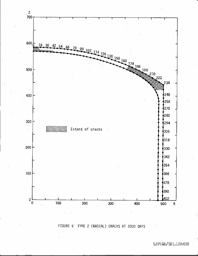
Z
700 i i 1 1 1 1 1 1 1
600 -6 18 30 42 54 66 78 90 102 114 126138
150160
174186
500 198210
222
234
400 .246
• •258
. •270
• •282
300 - •294 -
==%3333 Extent of cracks. •306
-
. •318
200 * •330 -.D
e -342-
• •354
100 • •366 -
• •378
• •390
O ' 1 1 1 ' 1 1 1 1 u 34020 100 200 300 400 500 R
FIGURE 6 TYPE 2 (RADIAL) CRACKS AT 2000 DAYS
U[ e/IMBS[!=0[ ]

-11
Z
700 1 1 1 1 1 1 1 1
600 -6 18 30 42 54 66 78 90 102
114126..7 - ..........'-/4 I Y
138150
160174
186500 _ 198
210222
234
1
.
400 •2461
.
1 •258
- •270
• •282
300 . .294
Extent of crackso •306
= •318
200 , •330.'
- •342
• •354
100 • -366
• •378
• •390
0 ' ' ' ' ' ' 1 1 I w 24020 100 200 300 400 500 R
FIGURE 7 TYPES 1&3 (MERIDIONAL) CRACKS AT 30 DAYS
U M / [L[!=0 WAIN

Z
700 i i i I i i i i
600 -
6 18 30 42 54 66 78 go 102 114 126138
150160
174186
500 198210
222
234
400 .246P
6258. •270
• •282
300 e •294
Extent of crackso •306
. •318
200 " •330
• •342e
• •354
100 • •366
• -378
• •390
0 : , : , , , i i 'w 4020 100 200 300 400 500 R
FIGURE 8 TYPES 1&3 (MERIDIONAL) CRACKS AT 2000 DAYS
[L ] MB#3/IMBO=WOMIM

INVESTIGATION TO DETERMINE
DYNAMIC SOIL PROPERTIES
AT THE
241-SY TANK SITE

-1
INVESTIGATION TO DETERMINE
DYNAMIC SOIL PROPERTIES
AT THE
241-SY TANK SITE
prepared for
ATLANTIC RICHFIELD HANFORD COMPANY
October 1974
by
URS/John A. Blume & Associates, Engineers
Sheraton-Palace Hotel
130 Jessie Street
San Francisco, California 94105

INVESTIGATION TO DETERMINE
DYNAMIC SOIL PROPERTIES
AT THE
241-SY TANK SITE
CONTENTS
.2295.
INTRODUCTION .................... ... 1
FIELD INVESTIGATIONS .................... .
Drilling ................................................. .... 1
Geophysical Measurements ............................................ 3
DYNAMIC SOIL PROPERTIES .................................. 3
Design Modulus Values .........................,........... 10
REFERENCES ............................................... 11
FIGURES
1 Drill Hole 1 and Seismic Refraction Lines 1 and 2, SitePlan 241-SY Waste Storage Tanks ...........................:...... 2
2 Seismic Refraction Line 1, 241-SY Waste Storage Tanks ............. 4
3 Seismic Refraction Line 2, 241-SY Waste Storage Tanks ............. 5
4 Drill Hole 1: Shear (Vs) and Compressional (V ) Velocities, 241-SYWaste Storage Tanks ............................................... 6
5 Maximum Elastic Moduli of Foundation Materials, 241-SYTank Site ...................................····················.. 8
6 Design Elastic Moduli as a Function of Strain, 241-SYTank Site .......................................... ............... 9
APPENDIX A Driller's Log ............... . ... A.1-A.2
Grain Size Classification ..... ... A.3-A. 7
- ii -9 [FR #3/IM SLD [R:AIN

INVESTIGATION TO DETERMINE
DYNAMIC SOIL PROPERTIES
AT THE
241-SY TANK SITE
INTRODUCTION
This report describes results of a subsurface geophysical investigation
carried out at the 241-SY waste storage tank site located in the 200 West
area of the Hanford Atomic Energy Commission Reservation near Richland, Wash-
ington. The work was conducted by URS/John A. Blume & Associates, Engineers,
for Atlantic Richfield Hanford Company (ARHCO) of Richland, Washington. The
investigation consisted of drilling and logging one drill hole to a depth of
150 feet and measuring shear and compressional wave velocities in this drill
hole. Seismic velocities were also measured by refraction techniques across
the ground surface. Dynamic soil properties to be used in seismic analysis
of the tanks were derived from geophysical measurements.
The drilling was completed in late February 1974, and geophysical measure-
ments were carried out in early March. The investigation was directed by
Andrew Cunningham, who also prepared this report with the assistance of
Fred Kintzer.
FIELD INVESTIGATIONS
Drilling
Exploratory drilling at the site was carried out by Hatch Drilling Company
of Richland, Washington, who also compiled the driller's log (shown inAppendix A). Drilling was done using cable tool equipment, and samples were
collected at 5-foot intervals. Steel casing with an approximate diameter of
6 inches was installed in the hole as the drilling proceeded. Representa-
tive soil samples were selected and delivered to a soils laboratory for test-
ing to classify and identify the soils according to ASTM procedures. The
location of drill hole 1 at the 241-SY tank site is shown in Figure 1.
-1- 06 m3 #3/IMB 0= CWWAIN

X 408 SCALE : 1" • 100'
<PUTURE -rANKS .\
'6 \0 0-
N 86388 1
td< CO.0.
% Mii
.r4- 0 .ex k
FUTURE TAN 19,-X
'241- SY TANK FARM
DRILL HOLE / ANS SEIS/V\1CREFRACTION LINES Z AN'·D·2SITE PLAN
24 1-SY TAN/< S/TE FIGURE 1
-2-
9 R) #3/ [L OSM IM

Geophysical Measurements
Geophysical measurements at the site consisted of uphole determinations of
shear and compressional wave velocities and measurements of velocities of
horizontally propagated shear and compressional waves on the ground surface
by seismic refraction techniques. The seismic refraction data confirm that
the velocities measured in the drill hole were comparable to those measured
by refraction techniques around the peri.phery of the drill hole and that the
moduli data, derived from drill-hole measurements, can be extrapolated for
the area surrounding the drill hole.
Uphole velocity measurements were performed in drill hole 1 at the 241-SY
tank site using a triaxial uphole seismometer probe to record the seismic
waves produced by an 8-pound sledge hammer at the ground surface. Electric
signals from the velocity-sensitive geophones were transmitted to the sur-
face via a multiconductor cable. At the surface, the signals were amplified
and recorded on a 6-channel oscillograph recorder. Seismic-wave velocities
were measured at 10-foot intervals as the probe was pulled up from the bot-
tom of the drill hole.
Seismic refraction measurements at the ground surface were made using a
Bison portable seismograph, model 15708, and a 6-channel oscillograph
recorder in conjunction with a triaxial seismometer array. An 8-pound
sledge hammer was again used as the energy source for the surface measure-
ments. Locations of the seismic refraction lines are shown in Figure 1.
Seismic refraction line 1 extends 200 feet to the northeast from drill hole
1, and seismic refraction line 2 extends 200 feet in a southeasterly direc-
tion. Time-distance plots for the seismic refraction lines are shown in
Figures 2 and 3, and a time-depth plot of uphole seismic measurements is
shown in Figure 4.
Time-distance and time-depth graphs are constructed by plotting travel time
against impact distance. Travel time is the time required for the seismic
wave to travel from the energy source, in this case the sledgehammer impact,
to the detector. The impact distance along a surface refraction line is the
distance along the ground between the detector and the point of impact.
-3-
[Al [ Ml/MBL[LD [i ] IN

NMA...I
§
h TZ°
f *fs 00 kx.SHEA R K,AVE VELOC/TY--1
1 too\
i f /45800 FPS.-I
5 M 80 - .
31')0 FPs
9 4 /m & I41 .
g GO3500 FPS \6 '200
- '/00 - '&$00 Fps \ _0600 F f.,tu .0s .or
& 40 - - -- - -
4,
e .000 -, - - /,e CC/11PRESS/0/VAL FVA Va VELOCITYJ <:o -
90 99) '55to 6> 1,00
-/ 0. . .t00 20 40 GO do 100 /10 140 /GO 150 200
11
C - HORIZONTAL DISTANCE (FEET)
9 002
Ss/SM /CREFRACTZON LINE 1
rm1 e

rn*.-*
4f too
1 --COMPPeSS/ONAL WAVE VELOCITY--1 //-1 ·2 80
5600 PPS
3400 FPS 'k 'G- .14 N-- GO \/
i U 27(0
94.59 FPSAPS
J 1/900w 40 1 *6)1./90 6 0 45/ 00. 1-\ 4plf
20 /''
fle Rs•.050 4410 'r
0 • ·0 20 40 Go ao 100 110 140 190 180 200
HORHONTAL D STANCe (peET>
-n
C - SetS/*IC reEBRACTION LINS 29 61M C
AlC 0
1 W

TRAVEL TIME (MSECS,300 20 40 GO 80 too /20 /40
\S- 1 1, - ,1 1 1 1 1-- --1\apjw
12\020 -00 1/ ···-·-t.--- .-t .4 ....--
\
; 4\40 +- .».......
i' 1
h
i 90 220 +-6
1.- 0. 00. 80 \
LU \44Q \ .1 -" 9
1
\15100 EY#1 7 1
'.': u... --I.---.t+I--.-I-- --
i .\
j 20\
Irl-, I --L.
1 \-1 .
140 \...
r
i
\ 2 1 \\1
DR/LL HOLE jSMEAR(Vs) AN° COMPRESSIONAL(Vp) VELOC/TIES241- SY WASTE STORAGE TANKS FIGURS 4.
-6- U [ ]e/IML[!=0 [1 0 IN

Impact distance on a time-depth graph is the vertical distance between the
energy source at the ground surface and the detector, which was positioned at
10-foot intervals down the drill hole. The slope of a line connecting a series
of points on these graphs is equal to the velocity of the wave passing through
the ground. The depths to various soil layers beneath the ground surface can
be derived from the surface refraction measurements using known principles of
wave propagation and refraction. Depths to soil layers having different seis-
mic velocities can be observed directly on the time-depth graphs.
DYNAMIC SOIL PROPERTIES
Dynamic soil properties were derived for the 241-SY tank site from on-site
seismic measurements of shear and compressional wave velocities of verti-
cally propagated seismic waves. Laboratory measurements of moduli on
selected samples obtained in drilling were not undertaken because of special
problems with soils of the Hanford Reservation: because the soils are unce-
mented, it is not possible to keep samples in an undisturbed condition
throughout the sampling and testing procedures, and the relatively high con-
tent of gravels makes it impossible to test much of the material.
Calculated values of shear modulus for comparison were obtained by convert-
ing blow counts recorded during drilling into estimated soil densities using
Gibbs and Holtz's criteria (1957). Using these densities, shear-wave veloc-
ities were calculated by means of formulae derived by Hardin and Richart
(1963). Values of shear modulus at various depths were then derived from
these calculated velocities. Although the reliability of density measure-
ments based on blow counts has been questioned and the data of Hardin and
Richart were extrapolated in these calculations, reasonable similarity was
observed in the two sets of data. Shear moduli derived from measured shear-
wave velocities at the tank site were lower.
The shear modulus for low strain levels, G , calculated from shear-wavemax
velocities, is shown in Figure 5 as a function of depth below ground surface.
Shear modulus is shown in Figure 6 as a decreasing function of strain level.
The moduli are expressed as ratios of the maximum values shown in Figure 5.
-7-LD 50 #3/M30=&0 WA IR

0 »60
G.-/ MAXkti... 1
Z[kQ-
lu
0
100 1
/500 /0 20 30 40
MAXIMUM SHEAR Al°OULUS (KS')
MAAXZMUM 5 LASTX C M°/'PULI °PFOUNOATZON MATERJALS
24/- SY TANK St-r E FIGUe£ 606 M #3/IMB B= 10 MI IN
-8-

l.0
tr
46
3 0.8\b38k*RY 0. G 1
13fS/1 3
3 5 0.4b* *2
RCK 0.2
92h
O ' 1 1 1/0-* /0-8 10-2 /0-1 2
SMEAR STRAIN e)
DESIGN ELASTIC MODUL/ ASA F u N C TION OF STR,Al N< AFTER SEED AN/> 18)RISS, /970)
2 4 1 -SY TAN,'< SIT E FtGURE Co
-9- 0=0 M #j/IMB [L[LO M IN

Design Modulus Values
The design curves in Figures 5 and 6 are recommended for the 241-SY wastestorage tanks. For any depth and shear strain, the appropriate modulus canreadily be computed from Figures 5 and 6. For example, the shear moduluscorresponding to a shear strain of 2 x 10⁻²% at a depth of 50 feet can beevaluated as follows: from Figure 5, G = 31 ksi; the modulus ratio cor-maxresponding to the strain is found from Figure 6 to be 0.65; the desired shear
modulus, G, is then 0.65(31 ksi) = 20.4 ksi.
- 10 -9 [ 8/IMB [L [LS [MI E

=,
REFERENCES.-1
Bechtel Corporation, October 1971, Final Soil Investigation Report for
the Fast Flux Test Facility, Richland, Washington.
Gibbs, H. J., and W. G. Holtz, 1957, "Research on Determining the Densityof Sand by Spoon Penetration Test," Proceedings, Fourth International
Conference on Soil Mechanics and Foundations Engineering, v. 1, pp. 35-39.
Hardin, B. 0., and F. E. Richart, February 1963, "Elastic Wave Velocities
in Granular Soils," Journal of Soil Mechanics and Foundations Division,
ASCE, v. 89, no. SM1, pp. 33-65.
John A. Blume & Associates, Engineers, April 1971, Seismic Analysis of
Underground Waste Storage Tanks 241-AZ-101 and 102 at Hanford, Washington,
JABE-ARHCO-01.
Seed, H. B., and I. M. Idriss, 1970, '"Soil Moduli and Damping Factors for..'
Dynamic Response Analysis," Report No. EERC 70-10, Earthquake Engineering
Research Center, University of California, Berkeley.
Shannon and Wilson, Inc., June 30, 1972, Supplementary Soils Investiga-
tion, Washington Public Power Supply System, Hanford No. 2 Nuclear Power
Plant.
.....
- 11 -06/#3/05&8=0[ 1
r.

-
APPENDIX A
DRILLER'S LOG
DEPTH SAMPLE BLOWCOUNTDESCRIPTION
(ft) Depth Type (blows/inches)
Medium, brown, silty, fine- 0 3.0 D*to-medium sand withoccasional fine-to-coarsegravel and roots 5.0
Dense, gray, fine sandy, 7.0 Dfine-to-coarse gravel 10with some silt
12.0
Very dense alternate layers 14.0 D 31/12"of gray fine-to-medium 17.0 N** 50/5"sand and gray-brown 20 19.0 D 26/12"silty fine sand with 22.0 N 50/5"occasional 2"-lenses 25.0 N 50/6"of hard, sandy silt 30 31.0 N 50/6"
36.0 50/2"35.0 N
Very dense gray-brown,slightly silty to silty, 40medium-to-coarse sand 41.0 D 41/12"
and fine-to-coarse
gravel (42' to 49',very gravelly) 49.0
Very dense, light brown, 50 50.0 N 50/3"slightly silty to silty,
55.0 D 17/6"fine sand with somefine-to-coarse gravel 59.0 N 50/3"60and medium-to-coarsesand 63.0
Very dense, light brown, 65.0 N 50/5"silty, fine-to-mediumsand with occasional 70 70.0 N 50/4"1/2"-lenses of sandy 75.0 N 50/4"Silt 79.0 N 50/5"
80
85.0 D 16/6"
89.5 D 24/6"90 90.0 N 50/5"
95.0 D 18/6"
- A. 1 -ag Ipmj/IMBLUJIB:f[' E

APPENDIX A
DRILLER'S LOG
(cont.)
DEPTH SAMPLE BLOWCOUNTDESCRIPTION
(ft) Depth Type (blows/inches)
Very dense, light brown, 100 100.0 D 22/6"silty, fine-to-medium 100.5 N 50/5"sand with occasional 105.0 D 21/6"1/2"-lenses of sandySilt 109.5 D 22/6"
110 110.0 N 50/4"
115.0 D 21/6"
119.5 D 21/6"120 120.0 N 50/4"
124.5 D 18/6"127.0
129.5 D 24/6"Alternate lenses of silt 130 130.0 N 50/3"
and silty fine-to-mediumsand 135.0 D 21/6"
140 140.0 D 17/6"140.5 N 50/5-1/2"145.0 D 18/6"
149.5 D 17/6"150.0 150 150.0 N 50/5"
Bottom of boring
* D denotes 5"-diameter sampler using 1400 1b hammer, 30" drop
** N denotes standard penetration resistance
- A.2 -[U] [R05/M)&[L [R ] E

1!1!11
S#33NISN, NOIlvONAOJ T SOINVHO3M 11OS 15L 0
NOS11 Al 1 NONNVHS
10-6991-M PL61 HOUVFI ..6
(89-ZE-M 9NIMOH) I,H'a 1-1- U2 B
CE ONVS 4 1!S 'uaoiq-Kei9 115 9'06-0'06 40NO11¥3131SSI73 3ZIS NI¥HOC., ON¥S 41 !5 'uaoiq-KeJD ES 0'06-9 '69
S31¥13OSS¥ 1 1Nnla NHOI % 3 . 'ON3
Id ld 11 N011¥013155¥10 3's n 'id-Hld301VN 31dNVS
S3NIJ ONVS 13,AINS3NIJ
Intall
1 3SBY03 3NIJ | 3SM¥035318800
0 0 0 0 0 0. 58313Mll'll NI 3ZIS NIVWDO 0 0 0 9 0 0 0 0 0 0 0. * . . . . - N W. =1 0 a o
-./ -- - W- - - - -- I. - - - '.-.'-- N W- 0'H O 0 0 0 0 0 0 0 0001
lilI 1 1!i l i l l l 1 i !1 1 lili 1 1 l i l i III 10
06'0i
09
, al OE rn0 m9 \ 4-4 C.
09 rnC' 0, Z0 =
.n
5 09 Z09 rn=Z'
= A =* 0, \\
- \ ".- M
E-* 9 06-0 060COL
0'06-9'68--- T
0Z
0108
Y\\N _ = a -- ---4/21/ w - - w - 0 00 0 0 0 0 0 0 0 0 0 ----- -
2 Z e Z = - , - 55 x O o i 0 2 :44: 5 4Ill Nt 3ZIS NI¥89 OBIONViS S n 'HONI 83d HS3M 30 838MnN I S3HONI HI 9NIN)dO 30 3ZIS
SISAl¥N¥ 8313NOHOAH SISAl¥N¥ 3AllS
.

BIlli
3113]NISM; 1,011¥0NnO, , SOIN,Hll,1 1105 3
NOSlla 1 NONNVHS
cil10-6991-a FL61 HOW¥;1 dM(89-ZE-M 9NIMOM) f'H'l l o., ONVS 1[11!S 'llawq-*019 NS 9'001-0'001 40C.
NOIlVOIJISSnO 3ZIS NI¥89 97,.£ ON¥S All!$ 'Uaolq-Ke,9 NS 0.001-9.66
S31VIOOSS¥ 1 3Nn18 NHOf % .3.mId ld 11 N011¥3131SSV10 .O.s.n 13-Hld30 0N
1VN 31dMVS
SaN 13 S 319800UNVS 13AV89
3 N131
In,03*|3SBVOO 3NIJ | 358¥00
O O 0 0 0 0 $8313MlllIM Nl 3ZIS NI¥89 -....O 0 0 0 000 0 9 0 00......- - W- - -0 0 0- - -- - - - .9 -- - - - - W- - - - - W- - -0 0 0 0 0 0 0 0 0
Oot1
0lili 1 1 I l l i l l i 1 1 111111 1 1 1 1 1 1 1 1 1
06 0t
09 02
0,m OL= O C -0 4rn
C. < 4Z M-e "'
09 0, mr, \g -n% -
m 09 09 10 =3
0'001-9 66 6
m 0, 09 1- -
E 9.1101-0.00...Vi E0C
01
0Z 00\
':li01 06
40. . . . 001- - - - - - - - W. - -0 0 00 0 0 0 0 0 03 = 2 0 02 2 2 2 2 0 - - W I -0 0 2 * 4: 5 -
IN Nl 3ZIS NIVHS 08¥0NviS S'n 'HONI 83d HsiN 30 838NAN 53HONI Nl 9NIN3dO JO 3ZIS
SISAl¥N¥ 8313NOBOAH SISAlIN¥ 3A3 IS

1!!!11
SI33Nlgli NOILIONnOi , SOINTH,ll 710; L
NOSllm I NONNYHS
10-6992-m PL61 HOWVN 06 4g'Z ONVS Ill ls 'umolq-Ke19. NS 0'011-9'611,-4 19!!1
(83-EZ-M 9NIMOH) I"H'a LL UONVS Ellis 'dIA018 NS EC'011-0'OIl 0NOIl¥OHISS¥10 3ZIS NI¥89 6 2 111: Apues 'Unoiq-KeJO 111 O'Oil-9'60, IMS31¥IOOSSY 1 314018 NHOI % 3 m ·ON jlId ld 11 N011VOIJISS¥13 0's n 13-Hld301VN 31dMVS
53Nld 5318800ONVS •„,89
3NIJ| . Mn103W
|358¥00 3 N 13
1358¥03
O 0 . o o o. . · SH313IlllIW NI 3ZIS Nl¥89- - ...
O 0 0 0 0 0 0 0 0 0 0 0 - I. ..- - -0 0 0- - W- - - - ..' ... - - - - W - - - - - 9.---0 0 0 0 0 0 0 0 0Oot
i l i l l i lill 1 1 lili l i l i 111 0
06 0i
08
m#1/ oz.'rn , V
01 9 ' 2 i
0£ .0r, LA
9 C' <-4 m
09 0, ZC.' 0'ozl-9 611 -e0'. -rl% -
os 09 *-=/ =*3
00 --< -<
'E 0, 09rn
/ 7 Z-4 -4/1 =0E
N i01 ECON-0 011- P \Rlili \
1, /1 \,1 \\1 1 110. 1 .1 1 1
7 - w - -W 0 O t= = = = ==2 2 2: = = 2 = = = I - - - WI- -
- .9 -- 0- 0 0 . 2 4 2; 42 : "
N
WIN Nl 3ZIS Nlyllil 08¥ONViS S n 'HONI 83d HS3M 30 838MON I S3H0NI Nl 9NIN3dO JO 3ZIS
SISAlIN¥ H313NOHOAH SISAl¥N¥ 3A3IS
L-

,-
| SIEVE ANALYSIS HYDROMETER ANALYSIS ISIZE OF OPENING IN INCHES 1 NUMBER OF MESH PER INCH, U.S. STANDARD GRAIN SIZE IN IM
- S Z\:\ : 0 0 -0= I- -- - -00 00 0 0- ..... -
100- I. '. I. I. Il - .... -I .. -..
T - - =0- 0 0 -0- -0 - =o\e \-X
go \ \ 30\\\80 20
70 30\*\,= \ kc, . \ 5
'5 ...W W= 60 40 =
Z 120.0-120 \\i - mm\ f- 1 29.5-13[.I
50 50 5
5 * « -26&
8Zs 40 80LU
e E; = ('
W ill. +
m - 3 0 1 : 7 0 5\
al
"
1 :
// 0 Go13].0-130.2
,=.* ic--* 9010
.O 1 1 1/I l l Ill lili 1 1 1 1 i l l i l l 1 1 1 lili 1000 0 0 0 0 0 0 0 O.I. - .. .. - - - - - - - - - - '7 - - - - - - - -0 0 0-0 -M - - ......O 0 0 0 0 0 0 0 0 0 0 0- ™ -
GRAIN SIZE IN MILLIMETERS .0 0 0 0 0 0
COARSE|
FINE COARSE|
MEDIUM|
FINECOBBLES FINESGRAVEL SAND
SAMPLECLASSIFICATION LL PL PIDEPTH-FT U.S.C.
NAT.NO. ..C. % JOHN BLUME & ASSOCIATES
C 120.0-120.3 SM Brown, si.rly JAND GRAIN SIZE CLASSIFICATION
0 71 D,H,1 (BORING W-22-68)129.5-130.0 ML Brown, sandy SILT
F 130.0-130.25 ML Brown, sandy Sl LTMARCH 1974 11-2659-01
r
SHANNON & WILSONSOIl MECHANICS & FOUNDATION ENGINEERS
Kliiiil

810
SH33NISNJ Nall¥ONnOJ , SOIN¥HO3M 110S3
NOSlla 1 NONNVHS ONVS *11!S 'It*OJe NS EE'091-0'091 3J10-69911 *L61 HONVNONVS Kills 'umwa NS 0'091-9'641 am
(89-ZE-M 9NIMOS) r'H'ar.0
Ills 111,0 8 111 O'Itt-9'041 00NO11¥01:1ISS¥13 3ZIS NI¥89
11 IS UMOJ g 1N. 9.OFI-0.Ot 1 7S31¥IOOSS¥ 1 3NO18 NHOr % 3.8 0*s n 13-Hl/30 .ONId ld 11 NO11¥013ISS¥10 31/RVSIVN
'3.1, 3Nli1
In,03"|3SBV03 3Nll 1 3SM¥03
PNVS 13AV89S 318800
O 0 0 0 c o. S8313W1llIN Nl 3ZIS NIYHO - N 6'
O 0 0 0 0 0 0 0 0 0 0 0• - .. -- - -9 0 0- N -- - - - - W. - - - - W- - - - - I.---0 0 0 0 0 0 0 0 0
0011 111 Ill 1 1 1 1 1 1 l i l i lili 1 Ill l i l l i 1
0
08 i ....\
09 \ \\ ".' \ \. 0.091-9.6*1 n
rn Ol OC;0 r..
0 \ = 49 1 b, E€ 091-1 09 1-. 94 mi-4 09 04
-,4c, 1- \ 8
0 \ =Ca '06 409 joqo
5111
O.1,1=
* 0' -6 ,t . 09 -rn- 4- 23 9'0,1-0'071*.\ Or OLf i
O r \\ 1 0.k01 . 06
1\-4/ L .0 - -_-L0. 00'
6 & i i = =2 8 6 2 -6.if./.- fl i 2 -'- f - - - -W - - - - b - -N
- - .... - - : 4--2 5NW NI 3ZIS NIVHS OM¥ONViS S'n 'HONI Bld HS)M 30 838NAN 53HONI NI ONINldO 30 3ZIS
SISAl¥N¥ 8313MOHOAH SISAl¥N¥ 3AllS