TCR Document Control and Records Management
144
ORNL/TM-2020/1736 Michael Russell Ryan Dehoff September 2020 M2TC-20OR04020110 Quality Procedures for TCR Metal Core Structure Advanced Manufacturing Processes Report
-
Upload
khangminh22 -
Category
Documents
-
view
0 -
download
0
Transcript of TCR Document Control and Records Management
ORNL/TM-2020/1736
Michael Russell Ryan Dehoff
September 2020
M2TC-20OR04020110
Quality Procedures for TCR Metal Core Structure Advanced Manufacturing Processes Report

This report was prepared as an account of work sponsored by an agency of the United States Government. Neither the United States Government nor any agency thereof, nor any of their employees, makes any warranty, express or implied, or assumes any legal liability or responsibility for the accuracy, completeness, or usefulness of any information, apparatus, product, or process disclosed, or represents that its use would not infringe privately owned rights. Reference herein to any specific commercial product, process, or service by trade name, trademark, manufacturer, or otherwise, does not necessarily constitute or imply its endorsement, recommendation, or favoring by the United States Government or any agency thereof. The views and opinions of authors expressed herein do not necessarily state or reflect those of the United States Government or any agency thereof.
DOCUMENT AVAILABILITY Reports produced after January 1, 1996, are generally available free via US Department of Energy (DOE) SciTech Connect.
Website www.osti.gov
Reports produced before January 1, 1996, may be purchased by members of the public from the following source:
National Technical Information Service 5285 Port Royal Road Springfield, VA 22161 Telephone 703-605-6000 (1-800-553-6847) TDD 703-487-4639 Fax 703-605-6900 E-mail [email protected] Website http://classic.ntis.gov/
Reports are available to DOE employees, DOE contractors, Energy Technology Data Exchange representatives, and International Nuclear Information System representatives from the following source:
Office of Scientific and Technical Information PO Box 62 Oak Ridge, TN 37831 Telephone 865-576-8401 Fax 865-576-5728 E-mail [email protected] Website http://www.osti.gov/contact.html
ORNL/TM-2020/1736
Transformational Challenge Reactor
QUALITY PROCEDURES FOR TCR METAL CORE STRUCTURE ADVANCED MANUFACTURING PROCESSES REPORT
Michael Russell Ryan Dehoff
September 2020
M2TC-20OR04020110
Prepared by OAK RIDGE NATIONAL LABORATORY
Oak Ridge, TN 37831-6283 managed by
UT-BATTELLE, LLC for the
US DEPARTMENT OF ENERGY under contract DE-AC05-00OR22725

CONTENTS
ABBREVIATIONS ................................................................................................................................ iv 1. INTRODUCTION ........................................................................................................................... 1 2. ADVANCED MANUFACTURING CONTROL AND QA STRATEGY ........................................ 1 3. ADVANCED MANUFACTURING QUALITY PROCEDURES AND RELATED
DOCUMENTS ................................................................................................................................ 1 3.1 Advanced Manufacturing Job Control .................................................................................... 2 3.2 Machine- and Method-Specific Procedures ............................................................................. 2 3.3 Laser Powder Bed Fusion Procedures ..................................................................................... 2 3.4 Powder Procedures ................................................................................................................. 3 3.5 Post-Characterization Procedures ........................................................................................... 3 3.6 Post-Processing Procedures .................................................................................................... 3 3.7 Training and Qualification Control ......................................................................................... 4
4. IMPLEMENTATION AND TEST OF AM QUALITY PROCEDURES .......................................... 4 5. LESSONS LEARNED AND ADDITIONAL TASKS ..................................................................... 5 6. RECORDS ...................................................................................................................................... 6 7. STANDARDS AND REFERENCES ............................................................................................... 6
7.1 Standards ............................................................................................................................... 6 7.2 References ............................................................................................................................. 6
8. APPENDICES................................................................................................................................. 7 APPENDIX A. TCR AM JOB CONTROL .............................................................................................. A-1 APPENDIX B. TCR AM JOB TRAVELER FORM................................................................................ B-1 APPENDIX C. TCR AM PART SEPARATION, EDM AND MACHINING ........................................ C-1 APPENDIX D. AM POWDER SAMPLING AND RECYCLING .......................................................... D-1 APPENDIX E. TCR AM LASER SPOT SIZE MEASUREMENT ......................................................... E-1 APPENDIX F. TCR AM PART CHARACTERIZATION .......................................................................F-1 APPENDIX G. TCR AM METALLOGRAPHY SPECIMEN PREPARATION .................................... G-1 APPENDIX H. TCR AM CONCEPT LASER M2 CUSING SETUP and BUILD START .................... H-1 APPENDIX I. TCR AM CONCEPT LASER JOB DESIGN AND SLICING ..........................................I-1 APPENDIX J. PERSONNEL QUALIFICATION AND TRAINING REQUIREMENTS FOR THE
TCR PROGRAM AT ORNL............................................................................................................. J-1 APPENDIX K. TCR FRAMATOME FUEL ASSEMBLY BRACKET FABRICATION AND
TEST PLAN ..................................................................................................................................... K-1
iii
ABBREVIATIONS
ASME American Society of Mechanical Engineers
DOE US Department of Energy
EDM electrical discharge machining
IDMS Integrated Document Management System
MDF Manufacturing Demonstration Facility
ORNL Oak Ridge National Laboratory
QA quality assurance
SiC silicon carbide
TCR Transformational Challenge Reactor
iv
1. INTRODUCTION
The Transformational Challenge Reactor (TCR) Manufacturing WBS# 3.02.04.02 organization is responsible for the advanced manufacturing process, research, development, and implementation that supports the TCR program under the TCR Additive Manufacturing (AM) Thrust. Advanced manufacturing at Oak Ridge National Laboratory (ORNL) includes the development and capabilities to use modern advanced manufacturing techniques, such as AM (e.g., 3D printing) and other novel methods, to rapidly design, develop, produce, finish, and characterize parts, samples, and components to support the nuclear and other high-quality standards industries. Deliverable # M2TC-20OR04020110 involved the development of TCR quality procedures for the TCR metal core structure by using the advanced manufacturing processes being developed at ORNL’s Manufacturing Demonstration Facility (MDF) and other ORNL locations. This report discusses the details of these procedures.
2. ADVANCED MANUFACTURING CONTROL AND QA STRATEGY
The TCR quality assurance (QA) program is based on the American Society of Mechanical Engineers (ASME) NQA-1-2008/9a, Quality Assurance Requirements for Nuclear Facilities, including the 2009 addendum, in conjunction with US Department of Energy (DOE) Order 414.1D, Quality Assurance. The TCR program’s overarching QA program control is TCR-QA-PLAN-001, TCR Quality Assurance Program Plan, which describes the requirements and controls applied to TCR and the interactions with other standards and applicable ORNL processes. This program requires that all 18 NQA-1 requirements of and the 10 criteria of DOE Order 414.1D be addressed by program procedures, which is applied with a combination of TCR-specific procedures and processes in conjunction with ORNL’s QA and other procedures maintained in the Standards-Based Management System.
As part of NQA-1, Part 1, “Requirements,” advanced manufacturing-specific processes and related procedures are usually controlled as part of Requirement 9, “Control Special Processes.” This criteria references: “Special processes that control or verify quality, such as those used in welding, heat treating, and nondestructive examination, shall be performed by qualified personnel using qualified procedures in accordance with specified requirements.”
This area is often applied to processes—such as welding, heat treatment, fabrication, destructive and non- destructive testing, and machining—that include the advanced manufacturing of metal or ceramic components, such as those at TCR. As such, a series of procedures, forms, templates, and plans was developed to address the special processes that encompass metal and nonmetal AM and related tasks at TCR. Each of these procedures applies the requirements outlined in TCR-PM-PROC-001, “TCR Document Control and Records Management,” which includes the applicable standards, QA references, roles and responsibilities, safety, training, records, and data disposition for each process, as well as the specific procedure steps to address the special process.
3. ADVANCED MANUFACTURING QUALITY PROCEDURES AND RELATED
DOCUMENTS
TCR’s advanced manufacturing quality procedures were developed and implemented in a combination of overarching controls that flow down to method- and equipment-specific procedures and related documentation that adhere to NQA-1 and DOE Order 414.1D requirements. These procedures were developed and controlled in ORNL’s Integrated Document Management System (IDMS) according to TCR procedure TCR-PM-PROC-001, “TCR Document Control and Records Management.” The source- controlled documents were stored on the TCR SharePoint site specifically designed as an official ORNL document management and temporary records repository. IDMS provides version control and approved
1
access for all TCR controlled documents, which ensure that the most up-to-date quality procedures are available to TCR personnel.
The AM procedure set starts with the overarching job control procedure, which outlined all the other specific procedures, standards, references, forms, and travelers required to design, develop, implement, and characterize an advanced manufactured part, sample, and/or component that the procedure hierarchy flowed down to the machine/process specific tasks then to the post-processing and characterization processes. The following sections describe how each of these areas and related procedures were developed and implemented for TCR. The sample listing of TCR AM procedures from IDMS is shown in Appendix B and the first pages of each referenced procedure is shown in Appendix C, for ease of reference.
3.1 ADVANCED MANUFACTURING JOB CONTROL
The overarching control for the TCR AM portion of TCR’s advanced manufacturing processes was developed as TCR-AM-PROC-001, “TCR AM Job Control.” This procedure described the process and specific procedures and forms to be used to design, prepare, build, machine, test, characterize, and inspect AM parts. This procedure included a job traveler form TCR-AM-FORM-001, “TCR Job Traveler Form,” which is used to track the progress of each AM part, including the ability to break into daughter travelers to track individual parts, subparts, and samples associated with the same fabrication or build. The traveler can be modified to align with the specific AM part requirements for pre- and post-build tasks, including logging the specific task procedure, parameters, task results, deviations, time, date, and signature of the person performing the task. The traveler information is captured as a TCR record and is submitted to the TCR database to include the job-specific details as part of the fabrication/build history.
3.2 MACHINE- AND METHOD-SPECIFIC PROCEDURES
To provide specific controls for the advanced manufacturing methods and techniques, a series of machine- and system-specific procedures was developed. These are field-level step-by-step procedures that describe how a specific piece of equipment or process is applied at the TCR and integrates the necessary information to populate the job control traveler referenced previously. These procedures have a level of detail that provides new users with a consistent and repeatable process for performing each task. They also facilitate machine-specific training that allow for the future qualification of TCR personnel to perform AM tasks and provide a needed redundancy to facilitate TCR manufacturing efficiency.
The initial TCR AM systems that are being used at the MDF and ORNL to develop prototype parts and samples include laser powder bed fusion printers and binder jet AM printers. The laser powder bed fusion system uses high-temperature lasers to melt metal powders in a finite layer that repeats itself layer by layer until the part forms. The binder jet powder system uses a chemical binder (i.e., glue) that prints the glue and powder mixture, similar to ink jet printers. The part is then heat treated (i.e., sintered) to remove the binder, which leaves the solid part. TCR currently uses the binder jet method to produce silicon carbide (SiC) parts and samples that will be used within TCR.
3.3 LASER POWDER BED FUSION PROCEDURES
TCR uses the General Electric Concept Laser M2 Cusing and the X-Line 2000 laser powder bed fusion systems. Because these two systems are part of the same manufacturing line and are operated with similar controls, some of the AM-specific procedures use both. TCR developed TCR-AM-PROC-200, “TCR AM Concept Laser M2 Cusing Setup,” to control the setup, operation, and part removal of the M2 Cusing and X-Line 2000 systems control. Also, TCR developed TCR-AM-PROC-201, “TCR AM Concept Laser JobDesign and Slicing,” to control the build design and slicing process. Additionally, TCR-AM-PROC-003,
2
“TCR AM Spot Size Measurement,” describes the method for testing and calibrating the AM laser spot size and machine power characteristics to optimize performance. This procedure uses a special instrument and process knowledge that detects, records, and helps adjust the laser characteristics of laser powder bed fusion systems that are specific to the types of parts and materials being used.
TCR also created an operational procedure to support the use of multiple ExOne binder jet systems used at TCR to print high-temperature ceramics that use SiC or other materials. These ceramics are being used to support TCR reactor prototype core components, including use as nuclear fuel containers and other core components. TCR-AM-PROC-300, “TCR AM Binder Jet Preparation and Planning,” describes the step-by-step process for setting up and performing the builds that use multiple sizes of the ExOne binder jet systems.
3.4 POWDER PROCEDURES
A primary component of high-quality AM parts is managing the quality of AM powder before, during, and after the build process. TCR-AM-PROC-002, “TCR Powder Sampling and Recycling,” defines how powder sampling is gathered and stored before and after the build process to ensure that accurate and representative samples are made available for post-characterization tasks. In 3D, the procedure describes the specific locations to which after-build powder samples are taken and stored before emptying the build chamber and cleaning the parts. The procedure also describes the required steps for recycling the AM powder for future prototype builds, which saves considerable time and cost during prototype development.
3.5 POST-CHARACTERIZATION PROCEDURES
TCR uses partnerships developed through ORNL’s MDF metrology and metallography laboratory to use state-of-the-art electronic characterization equipment provided by Zeiss, including multiple scanning electron and 3D x-ray microscopes, Metrotom computed tomography x-ray scanner, and coordinate measurement machine systems. TCR-AM-PROC-005, “TCR AM Part Characterization,” describes the step-by-step process for operating these advanced systems and recording part data that can then be forwarded to the TCR database and analyzed by using additional data analysis tools.
TCR-AM-PROC-006, “TCR AM Metallography Specimen Preparation,” describes the preparation of TCR samples for use with the advanced microscopy capabilities of the Zeiss and other metallography equipment. This procedure provides step-by-step instructions for cutting, mounting, grinding, and polishing specimens via the MDF metallography laboratories’ equipment and existing controls.
3.6 POST-PROCESSING PROCEDURES
TCR parts must be processed after the builds are completed, cleaned, and—if necessary—heat treated. This post-build processing often includes cutting and separation techniques that use advanced manufacturing tools, including the electrical discharge machining (EDM) located in the TCR area of MDF. The EDM uses a combination of computer control, laser guides, and very fine cutting blades to make very precise cuts that separate AM parts and samples from the build plates, support structures, and each other.
TCR also uses various methods of advanced manufacturing machining systems to supplement the AM productions processes in producing nuclear-ready parts with the precision and tolerances required per the applicable design specifications. MDF uses several versions of the advanced machining systems located adjacent to the TCR area that use state-of-the-art technology and electronic controls, including the Mazak and Makino series of milling machines.
3
TCR-AM-PROC-004, “TCR Part Separation, EDM, and Machining,” describes the step-by-step process for setting up and using the EDM and machining systems for post-finishing TCR parts and samples. This procedure describes the required steps in conjunction with each machine’s operating manual to be used to set up and perform the required machining steps. This procedure also includes the required steps for cleaning AM parts, including the use of bead blasters, chemicals, and hand tools for cleaning final parts. Input parameters and completion summary data are documented in the TCR job traveler and uploaded to the TCR Peregrine database, as applicable.
3.7 TRAINING AND QUALIFICATION CONTROL
Under an NQA-1 QA program, all personnel who support quality efforts must be trained and qualified for their specific role in producing quality AM parts. TCR-TQ-FORM-001, “TCR Personnel Qualification and Training Requirements Form,” describes and documents the training, reading, and experience requirements for each position in the AM production and characterization cycle. The form allows the TCR management team to identify specific requirements and provides personnel information to demonstrate compliance. The signatures of the TCR personnel and technical managers on this form attest that the requirements have been met with reference to supporting documentation.
4. IMPLEMENTATION AND TEST OF AM QUALITY PROCEDURES
To fully implement new field procedures, they must be used and tested in field conditions and evaluated by the users, management team, and QA personnel to ensure that they provide adequate controls for the specific task. TCR had the opportunity to test the new AM procedures on an actual nuclear safety-related component destined for use in a US nuclear power plant. To accomplish this, TCR developed a part- specific fabrication and test plan, TCR-AM-PLAN-001, TCR Framatome Fuel Assembly Bracket Fabrication and Test Plan, which can be used as a template for future TCR fabrication and testing activities. This plan included the step-by-step, process-by-process plan by which the part was to be designed, built, heat treated, machined, tested, characterized, cleaned, and inspected in a cradle-to-grave flow. Each process step described the client requirements, TCR procedures, and interfaces required to accomplish the task safely and with the requisite quality. TCR-AM-FORM-001, “TCR Job Traveler Form,” was successfully used to track progress and document required parameters, deviations, and the qualified personnel performing the tasks. The traveler included the required inspection and quality hold points to ensure that oversight could engage to provide the required approvals and inspections, as needed.
Additional part-specific heat-treatment process and material testing field instructions were developed and integrated directly into the prototype fabrication and test plan document. These steps will be used to further develop procedures to fully control the AM post-processing steps for TCR reactor related parts and samples.
TCR documented the required training, qualifications, and confirmation of compliance for 18 TCR personnel to support the demonstration AM tasks via TCR-TQ-FORM-001. Inputs for required training, experience, and education were solicited from the AM process area owners to identify the requirements documented in the training and qualification forms. The forms were completed by all TCR staff members according to their AM job description, approved by their technical supervisor, and submitted to records in support of the qualified part production, including forms for:
• AM job project managers/owners, • AM technicians, • EDM/machining technicians, • heat-treatment technicians,
4
• quality representatives,• characterization technicians,• metallography technicians, and
• dimensional inspectors.
All AM procedures, templates, and forms were reviewed by TCR’s nuclear client and accepted as part of ORNL being added to their quality supplier list to allow the task and production initiation to start. In total, 16 parts were designed, built, heat treated, machined, characterized, and inspected according to the aforementioned suite of procedures and documentation. All 16 parts met the client and TCR specifications and passed the final inspection process by ORNL’s metrology laboratory before being shipped to the client facilities for final inspection, acceptance, and assembly. This was accomplished on schedule, and the final parts arrived at the nuclear client’s facility on the planned due date despite the restricted work schedules and facility access limitations during the height of the COVID-19 pandemic.
5. LESSONS LEARNED AND ADDITIONAL TASKS
TCR is taking the opportunity to learn from the real-world implementation of the AM procedures and related controls on an actual safety-related nuclear part. During each step of the process, TCR personnel were encouraged to take notes on areas that could be improved with the procedures, process, and documentation. These inputs are being captured as lessons learned to inform future procedure and process updates as part of TCR’s continuing improvement program.
An initial review of these inputs provided the following lessons learned and associated improvement actions.
1. Expand AM-specific procedures to include additional ancillary and post-processing tasks that are notalready covered by existing AM procedures.
2. Develop AM machine- and material-specific specifications (i.e., AM internal standards) to integratebest-quality parameters from production run; material testing; TCR Peregrine, which is a TCR customdeveloped quality analysis software/database; analysis; and final inspections.
3. Expand characterization procedures to include analysis techniques and processes for metrology andmetallography characterization.
4. Develop AM source powder specifications, material controls, and testing procedures based on TCRresearch on part quality in relationship to powder characteristics.
5. Develop additional procedures for heat treatment specific to AM parts, including stress relief,annealing, and the hot isostatic pressing of metal parts and chemical vapor infiltration of ceramicparts.
6. Update TCR-AM-PROC-001, “TCR AM Job Control,” and the related traveler TCR-AM-FORM-001, “TCR Job Traveler Form” to allow for more flexibility and customization for each AM job andrelated process step.
7. Update the TCR AM job traveler (TCR-AM-PROC-001) to an electronic interface that reduces theneed for hardcopy traveler and daughter paper travelers and improves efficiency so that AMpersonnel can enter additional information, which can be recorded in real-time for more efficient andrapid diagnostics and status updates. This reduces the risk of lost or damaged paper copies in harshfield or shop floor environments.
5
8. Update procedures, job control planning, and related specifications to ensure that adequate design andmanufacturing tolerances are applied to address the unique characteristics associated with AMmanufacturing and differences from standard design, fabrication, and post-processing techniques andtolerances.
9. Improve secure data transfer methods from AM, post-processing, and characterization systems toallow direct and real-time inputs into the TCR Peregrine database without the need for manualtransfer post-production.
10. Qualify the AM fabrication and characterization systems and processes to eliminate the need for post- production inspections. Recent updates to the US Nuclear Regulatory Commission licensing stanceon advanced manufacturing1 provided additional support and focus on qualifying the AM processinstead of relying on costly and time-consuming post-production destructive and nondestructivetesting. TCR is uniquely set up to prove the ability to qualify complex AM processes with thesignificant amount of research and testing data developed in support of TCR program tasks and therecent demonstration of the fabrication of a qualified nuclear safety-related parts that uses advancedmanufacturing techniques and classical characterization, testing, and inspection.
6. RECORDS
This document does not generate any records.
7. STANDARDS AND REFERENCES
7.1 STANDARDS
• ASME NQA-1-2008, Quality Assurance Requirements for Nuclear Facility Applications• DOE Order 414.1D, Quality Assurance
7.2 REFERENCES
• TCR-TQ-FORM-001, “TCR Personnel Qualification and Training Requirements Form”• TCR-AM-PLAN-001, TCR Framatome Fuel Assembly Bracket Fabrication and Test Plan• TCR-AM-PROC-001, “TCR AM Job Control”• TCR-AM-PROC-002, “TCR Powder Sampling and Recycling”• TCR-AM-PROC-003, “TCR AM Spot Size Measurement”• TCR-AM-PROC-004, “TCR Part Separation, EDM, and Machining”• TCR-AM-PROC-005, “TCR AM Part Characterization”• TCR-AM-PROC-006, “TCR AM Metallography Specimen Preparation”• TCR-AM-PROC-200, “TCR AM Concept Laser M2 Cusing Setup”• TCR-AM-PROC-201, “TCR AM Concept Laser Job Design and Slicing”• TCR-AM-PROC-300, “TCR AM Binder Jet Preparation and Planning”• TCR-PM-PROC-001, “TCR Document Control and Records Management”• TCR-QA-PLAN-001, Quality Assurance Program Plan for the Transformational Challenge Reactor
Activities Conducted at Oak Ridge National Laboratory
1See Rev. 1 of Action Plan to Prepare the U.S. Nuclear Regulatory Commission for Review of Industry Use of Advanced Manufacturing Technologies, ADAMS document ML19333B980.
6

• TCR-AM-FORM-001, TCR Job Traveler Form
8. APPENDICES
• APPENDIX A, TCR AM JOB CONTROL• APPENDIX B, TCR AM JOB TRAVELER FORM• APPENDIX C, TCR AM PART SEPARATION, EDM AND MACHINING• APPENDIX D, AM POWDER SAMPLING AND RECYCLING• APPENDIX E. TCR AM LASER SPOT SIZE MEASUREMENT• APPENDIX F. TCR AM PART CHARACTERIZATION• APPENDIX G. TCR AM METALLOGRAPHY SPECIMEN PREPARATION• APPENDIX H. TCR AM CONCEPT LASER M2 CUSING SETUP AND BUILD START• APPENDIX I. TCR AM CONCEPT LASER JOB DESIGN AND SLICING• APPENDIX J. PERSONNEL QUALIFICATION AND TRAINING REQUIREMENTS FOR THE
TCR PROGRAM AT ORNL• APPENDIX K. TCR FRAMATOME FUEL ASSEMBLY BRACKET FABRICATION AND TEST
PLAN
7

APPENDIX A. TCR AM JOB CONTROL
A-1

TCR TECHNICAL
PROCEDURE
TCR AM JOB CONTROL
TCR-AM-PROC-001 Rev. 0/CN: 0 Page 1 of 14
Transformational Challenge Reactor Program
Number: TCR-AM-PROC-001
Rev./CN#: 0
Approval Date: 05/05/2020
Issue Date: 05/06/2020
Effective Date: 05/05/2020
Supersedes: N/A
Review Required: 05/05/2023
Title: TCR AM Job Control
IDMS Record #: 24262
Document Owner: Ryan Dehoff, TCR AM Thrust Lead
Author: Michael Russell, TCR QA Representative
Point of Contact: Ryan Dehoff, TCR AM Thrust Lead
Approved by:
Ryan Dehoff, TCR AM Thrust Lead
Mark Vance, TCR QA Manager
Sherri Buchanan, TCR Program Manager
Reviewed by:
Fred List, Deposition Science & Technology
Kurt Terrani, TCR Technical Director
This document has been electronically approved. Electronic signatures of approvers are listed on the IDMS View/Print page associated with the IDMS Record # above.
Before using a copy of this document, compare its issue date to the issue date of the IDMS version to verify that it is the most current version.
TCR TECHNICAL
PROCEDURE
TCR AM JOB CONTROL
TCR-AM-PROC-001 Rev. 0/CN: 0 Page 2 of 14
REVISION LOG
Rev. Date Affected Pages Revision Description
0 05/05/2020 All Initial release
Document pages that are (check as appropriate):
Unclassified, Non-Sensitive: ALL (or) pages
Export Controlled: NONE (or) pages
Controlled, Unclassified, or Sensitive: NONE (or) pages
This document was prepared as an account of work sponsored by an agency of the United States Government. Neither the United States Government nor any agency thereof, nor any of their employees, makes any warranty, express or implied, or assumes any legal liability or responsibility for the accuracy, completeness, or usefulness of any information, apparatus, product, or process disclosed, or represents that its use would not infringe privately owned rights. Reference herein to any specific commercial product, process, or service by trade name, trademark, manufacturer, or otherwise, does not necessarily constitute or imply its endorsement, recommendation, or favoring by the United States Government or any agency thereof. The views and opinions of authors expressed herein do not necessarily state or reflect those of the United States Government or any agency thereof.
TCR TECHNICAL
PROCEDURE
TCR AM JOB CONTROL
TCR-AM-PROC-001 Rev. 0/CN: 0 Page 3 of 14
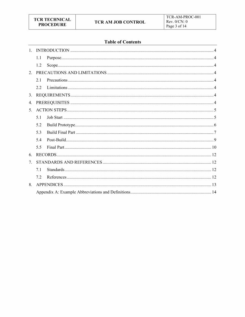
Table of Contents
1. INTRODUCTION ............................................................................................................................ 4
1.1 Purpose.................................................................................................................................... 4
1.2 Scope....................................................................................................................................... 4
2. PRECAUTIONS AND LIMITATIONS ............................................................................................ 4
2.1 Precautions .............................................................................................................................. 4
2.2 Limitations .............................................................................................................................. 4
3. REQUIREMENTS ............................................................................................................................ 4
4. PREREQUISITES ............................................................................................................................ 4
5. ACTION STEPS ............................................................................................................................... 5
5.1 Job Start .................................................................................................................................. 5
5.2 Build Prototype ........................................................................................................................ 6
5.3 Build Final Part ....................................................................................................................... 7
5.4 Post-Build................................................................................................................................ 9
5.5 Final Part ............................................................................................................................... 10
6. RECORDS ...................................................................................................................................... 12
7. STANDARDS AND REFERENCES .............................................................................................. 12
7.1 Standards ............................................................................................................................... 12
7.2 References ............................................................................................................................. 12
8. APPENDICES ................................................................................................................................ 13
Appendix A: Example Abbreviations and Definitions ...................................................................... 14
TCR TECHNICAL
PROCEDURE
TCR AM JOB CONTROL
TCR-AM-PROC-001 Rev. 0/CN: 0 Page 4 of 14
1. INTRODUCTION
1.1 Purpose
This procedure identifies the responsibilities and describes the process for additive manufacturing (AM) job control for the Transformational Challenge Reactor (TCR) program at Oak Ridge National Laboratory (ORNL).
1.2 Scope
This procedure includes the use of tools, drawings, design, equipment, software, processes, raw materials, preprocessing, production, postprocessing, post-characterization/testing, documentation, configuration control, and record keeping associated with the AM of parts, components, and test samples by personnel in support of TCR.
2. PRECAUTIONS AND LIMITATIONS
2.1 Precautions
1. TCR personnel must adhere to all ORNL safety and facility requirements assigned per the location and/or the equipment being used.
2. TCR personnel must be trained, assigned to, and familiar with the specific research safety summary (RSS) for each facility, work, and/or equipment location before obtaining access to or starting work.
3. TCR personnel must be familiar with and adhere to all identified job hazard controls, including using personal protective equipment (PPE) specific to the material, chemical, machine, location, facility, and/or task being performed and the PPE specifically described in third-party equipment manuals or material safety data sheets (MSDSs).
2.2 Limitations
1. This procedure is limited to work being performed under the TCR program in accordance with TCR-QA-PLAN-001, TCR Quality Assurance Program Plan, and/or QAP-ORNL- NR&D-01, Quality Assurance Plan for Nuclear Research and Development Activities Conducted at the Oak Ridge National Laboratory, and associated procedures. This procedure can be used for other programs with approval from the document owner.
3. REQUIREMENTS
1. TCR-QA-PLAN-001, TCR Quality Assurance Program Plan
2. QAP-ORNL-NR&D-01, Quality Assurance Plan for Nuclear Research and Development Activities Conducted at the Oak Ridge National Laboratory
3. TCR-DA-PROC-001, “TCR Design Control”
4. PREREQUISITES
1. TCR personnel must be trained and assigned to the RSS.
2. TCR personnel conducting AM activities at the Manufacturing Demonstration Facility must be trained and assigned to RSS Laser Additive Manufacturing at National Transportation Research Center NTRC-3 17211.1, 16236.2, and/or the RSS applicable to the specific location and/or machine.
3. TCR personnel must be trained to and familiar with the specific AM machine, including the associated operations manual.
TCR TECHNICAL
PROCEDURE
TCR AM JOB CONTROL
TCR-AM-PROC-001 Rev. 0/CN: 0 Page 5 of 14
NOTE 1: Within this procedure, the client can be internal to TCR/ORNL or external.
NOTE 2: This procedure can be used to produce internal testing samples and parts where specific controls are required to support quality production and testing data.
NOTE 3: The following steps may be performed in any order unless noted otherwise.
NOTE 4: Not all steps within this procedure are required for all AM parts. The part-specific production/test plan described in Section 5.1.2 describes the required steps.
NOTE 5: Before a job is considered for production, it must be submitted using the job submission form found on the SharePoint site.
WARNING: POTENTIAL INJURY CAN RESULT FROM USE OF AM MACHINES AND ASSOCIATED MATERIALS IF NOT FAMILIAR WITH SAFETY WARNINGS AND REQUIREMENTS ASSOCIATED WITH AM INCLUDING THE RELATED RSS, MSDS, AND EQUIPMENT MANUALS TO ENSURE ALL REQUIRED SAFETY PRECAUTIONS AND PPE ARE USED.
4. TCR personnel must have documented that they have read this procedure, applicable equipment manual(s), and related MSDSs.
5. ACTION STEPS
5.1 Job Start
5.1.1 Client Design and Specifications Evaluation
Part Lead
Secure preliminary client part specifications (specs) and design drawings.
Review client part specs and drawings with the AM team to discuss and document questions and concerns with part production strategy
Evaluate the design for potential overhangs and support needs/issues.
Evaluate the specs for ORNL and/or subcontract capabilities and requirements.
Discuss the specs and designs that are specific to AM limitations and strengths.
Document the questions and concerns with the designs, drawings, and/or specs.
Conduct client discussion(s) to address questions, concerns, and potential issues.
Update the client design and specs to address AM concerns.
Integrate and agree to the required client changes to the design, drawings, and/or specs.
Discuss and agree upon who will perform specific sections of the technical specs, tests, inspections, and other related documentation.
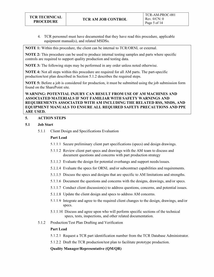
5.1.2 Production/Test Plan Drafting and Verification
Part Lead
Request a TCR part identification number from the TCR Database Administrator.
Draft the TCR production/test plan to facilitate prototype production.
Quality Manager/Representative (QM/QR)
TCR TECHNICAL
PROCEDURE
TCR AM JOB CONTROL
TCR-AM-PROC-001 Rev. 0/CN: 0 Page 6 of 14
Review and verify the quality assurance (QA)/quality control (QC) documentation and required approvals before prototype build.
Part Lead
Submit a request for prototype production approval and scheduling to the TCR AM thrust lead.
TCR AM Thrust Lead
Approve or deny the protype part production request and schedule the priority.
Part Lead
If approved, initiate the TCR AM Job Traveler (TCR-AM-FORM-001) and document steps already completed
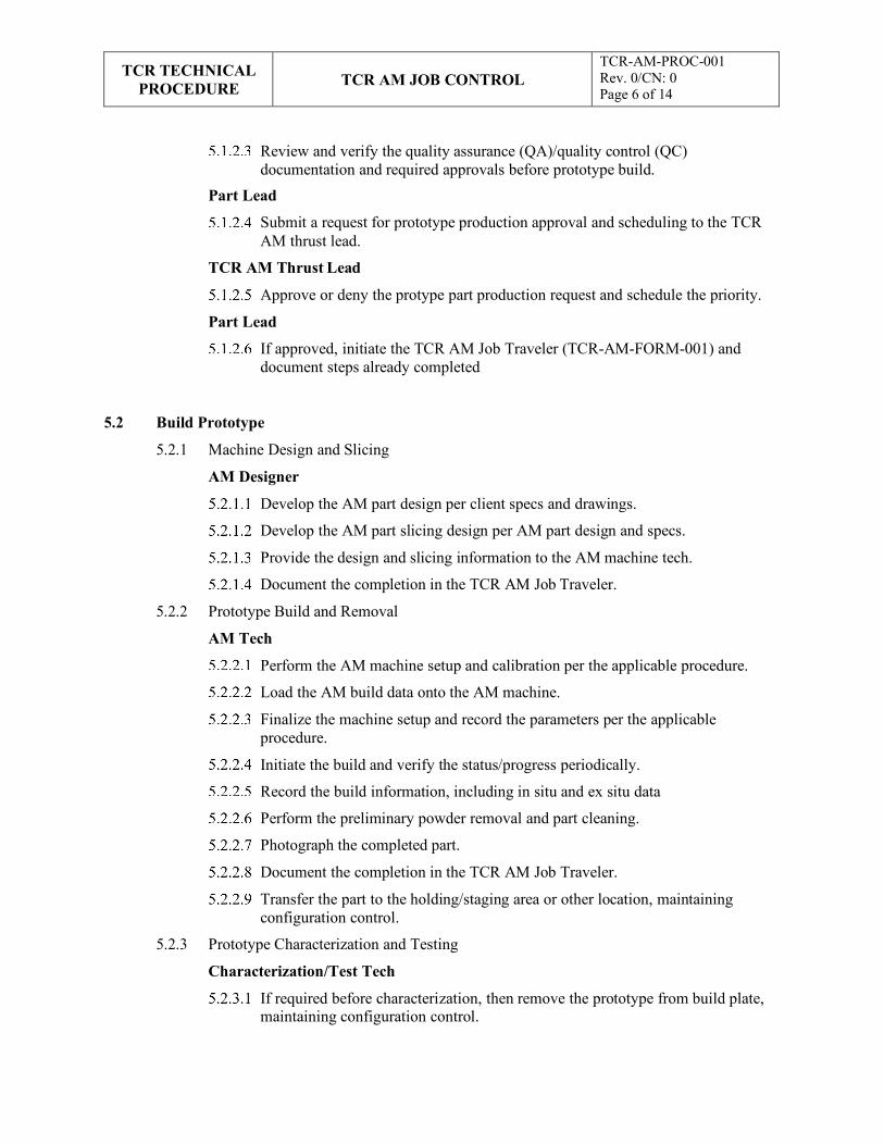
5.2 Build Prototype
5.2.1 Machine Design and Slicing
AM Designer
Develop the AM part design per client specs and drawings.
Develop the AM part slicing design per AM part design and specs.
Provide the design and slicing information to the AM machine tech.
Document the completion in the TCR AM Job Traveler.
5.2.2 Prototype Build and Removal
AM Tech
Perform the AM machine setup and calibration per the applicable procedure.
Load the AM build data onto the AM machine.
Finalize the machine setup and record the parameters per the applicable procedure.
Initiate the build and verify the status/progress periodically.
Record the build information, including in situ and ex situ data
Perform the preliminary powder removal and part cleaning.
Photograph the completed part.
Document the completion in the TCR AM Job Traveler.
Transfer the part to the holding/staging area or other location, maintaining configuration control.
5.2.3 Prototype Characterization and Testing
Characterization/Test Tech
If required before characterization, then remove the prototype from build plate, maintaining configuration control.
TCR TECHNICAL
PROCEDURE
TCR AM JOB CONTROL
TCR-AM-PROC-001 Rev. 0/CN: 0 Page 7 of 14
NOTE: TCR nuclear safety-related procurements are performed per procedure TCR- DA-PROC-001, TCR Design Control.
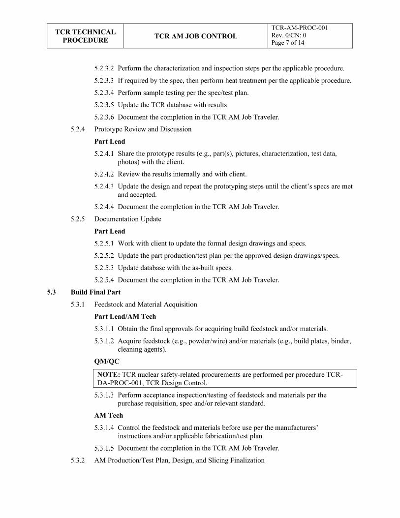
Perform the characterization and inspection steps per the applicable procedure.
If required by the spec, then perform heat treatment per the applicable procedure.
Perform sample testing per the spec/test plan.
Update the TCR database with results
Document the completion in the TCR AM Job Traveler.
5.2.4 Prototype Review and Discussion
Part Lead
Share the prototype results (e.g., part(s), pictures, characterization, test data, photos) with the client.
Review the results internally and with client.
Update the design and repeat the prototyping steps until the client’s specs are met and accepted.
Document the completion in the TCR AM Job Traveler.
5.2.5 Documentation Update
Part Lead
Work with client to update the formal design drawings and specs.
Update the part production/test plan per the approved design drawings/specs.
Update database with the as-built specs.
Document the completion in the TCR AM Job Traveler.
5.3 Build Final Part
5.3.1 Feedstock and Material Acquisition
Part Lead/AM Tech
Obtain the final approvals for acquiring build feedstock and/or materials.
Acquire feedstock (e.g., powder/wire) and/or materials (e.g., build plates, binder, cleaning agents).
QM/QC
Perform acceptance inspection/testing of feedstock and materials per the purchase requisition, spec and/or relevant standard.
AM Tech
Control the feedstock and materials before use per the manufacturers’ instructions and/or applicable fabrication/test plan.
Document the completion in the TCR AM Job Traveler.
5.3.2 AM Production/Test Plan, Design, and Slicing Finalization
TCR TECHNICAL
PROCEDURE
TCR AM JOB CONTROL
TCR-AM-PROC-001 Rev. 0/CN: 0 Page 7 of 14
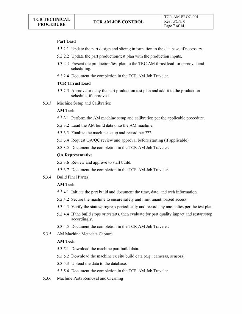
Part Lead
Update the part design and slicing information in the database, if necessary.
Update the part production/test plan with the production inputs.
Present the production/test plan to the TRC AM thrust lead for approval and scheduling.
Document the completion in the TCR AM Job Traveler.
TCR Thrust Lead
Approve or deny the part production test plan and add it to the production schedule, if approved.
5.3.3 Machine Setup and Calibration
AM Tech
Perform the AM machine setup and calibration per the applicable procedure.
Load the AM build data onto the AM machine.
Finalize the machine setup and record per ???.
Request QA/QC review and approval before starting (if applicable).
Document the completion in the TCR AM Job Traveler.
QA Representative
Review and approve to start build.
Document the completion in the TCR AM Job Traveler.
5.3.4 Build Final Part(s)
AM Tech
Initiate the part build and document the time, date, and tech information.
Secure the machine to ensure safety and limit unauthorized access.
Verify the status/progress periodically and record any anomalies per the test plan.
If the build stops or restarts, then evaluate for part quality impact and restart/stop accordingly.
Document the completion in the TCR AM Job Traveler.
5.3.5 AM Machine Metadata Capture
AM Tech
Download the machine part build data.
Download the machine ex situ build data (e.g., cameras, sensors).
Upload the data to the database.
Document the completion in the TCR AM Job Traveler.
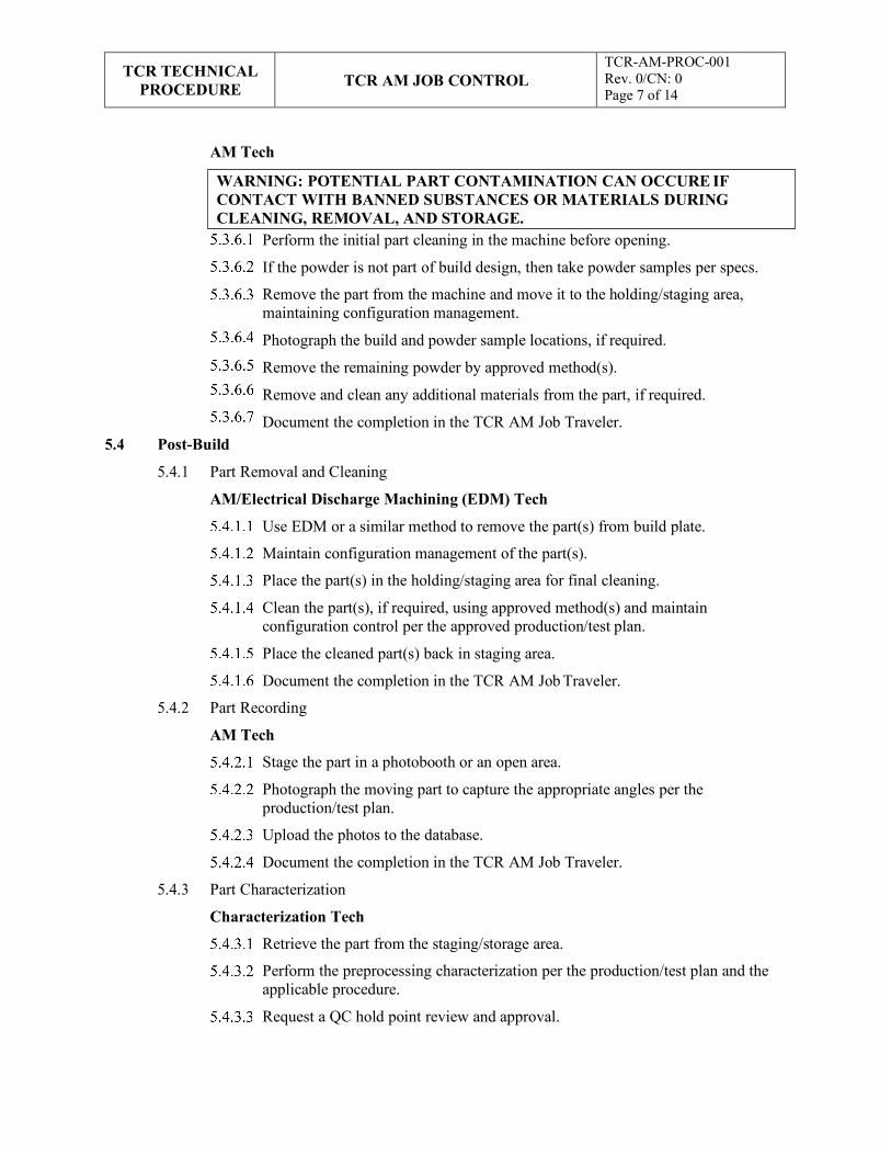
5.3.6 Machine Parts Removal and Cleaning
TCR TECHNICAL
PROCEDURE
TCR AM JOB CONTROL
TCR-AM-PROC-001 Rev. 0/CN: 0 Page 7 of 14
WARNING: POTENTIAL PART CONTAMINATION CAN OCCURE IF CONTACT WITH BANNED SUBSTANCES OR MATERIALS DURING CLEANING, REMOVAL, AND STORAGE.
AM Tech
5.4 Post-Build
Perform the initial part cleaning in the machine before opening.
If the powder is not part of build design, then take powder samples per specs.
Remove the part from the machine and move it to the holding/staging area, maintaining configuration management.
Photograph the build and powder sample locations, if required.
Remove the remaining powder by approved method(s).
Remove and clean any additional materials from the part, if required.
Document the completion in the TCR AM Job Traveler.
5.4.1 Part Removal and Cleaning
AM/Electrical Discharge Machining (EDM) Tech
Use EDM or a similar method to remove the part(s) from build plate.
Maintain configuration management of the part(s).
Place the part(s) in the holding/staging area for final cleaning.
Clean the part(s), if required, using approved method(s) and maintain configuration control per the approved production/test plan.
Place the cleaned part(s) back in staging area.
Document the completion in the TCR AM Job Traveler.
5.4.2 Part Recording
AM Tech
Stage the part in a photobooth or an open area.
Photograph the moving part to capture the appropriate angles per the production/test plan.
Upload the photos to the database.
Document the completion in the TCR AM Job Traveler.
5.4.3 Part Characterization
Characterization Tech
Retrieve the part from the staging/storage area.
Perform the preprocessing characterization per the production/test plan and the applicable procedure.
Request a QC hold point review and approval.
TCR TECHNICAL
PROCEDURE
TCR AM JOB CONTROL
TCR-AM-PROC-001 Rev. 0/CN: 0 Page 10 of 14
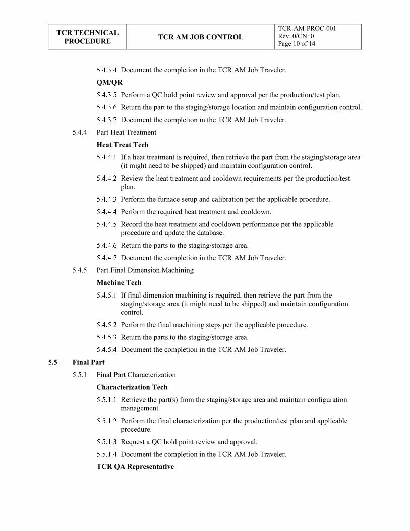
Document the completion in the TCR AM Job Traveler.
QM/QR
Perform a QC hold point review and approval per the production/test plan.
Return the part to the staging/storage location and maintain configuration control.
Document the completion in the TCR AM Job Traveler.
5.4.4 Part Heat Treatment
Heat Treat Tech
If a heat treatment is required, then retrieve the part from the staging/storage area (it might need to be shipped) and maintain configuration control.
Review the heat treatment and cooldown requirements per the production/test plan.
Perform the furnace setup and calibration per the applicable procedure.
Perform the required heat treatment and cooldown.
Record the heat treatment and cooldown performance per the applicable procedure and update the database.
Return the parts to the staging/storage area.
Document the completion in the TCR AM Job Traveler.
5.4.5 Part Final Dimension Machining
Machine Tech
If final dimension machining is required, then retrieve the part from the staging/storage area (it might need to be shipped) and maintain configuration control.
Perform the final machining steps per the applicable procedure.
Return the parts to the staging/storage area.
Document the completion in the TCR AM Job Traveler.
5.5 Final Part
5.5.1 Final Part Characterization
Characterization Tech
Retrieve the part(s) from the staging/storage area and maintain configuration management.
Perform the final characterization per the production/test plan and applicable procedure.
Request a QC hold point review and approval.
Document the completion in the TCR AM Job Traveler.
TCR QA Representative
TCR TECHNICAL
PROCEDURE
TCR AM JOB CONTROL
TCR-AM-PROC-001 Rev. 0/CN: 0 Page 11 of 14
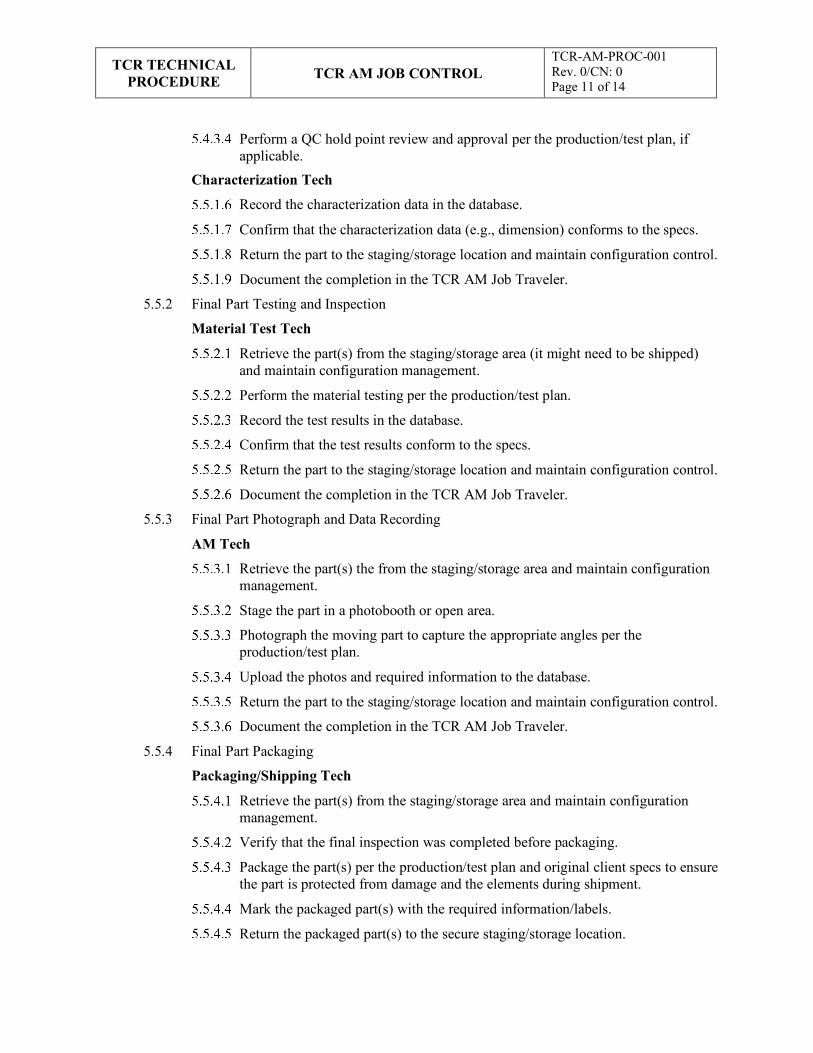
Perform a QC hold point review and approval per the production/test plan, if applicable.
Characterization Tech
Record the characterization data in the database.
Confirm that the characterization data (e.g., dimension) conforms to the specs.
Return the part to the staging/storage location and maintain configuration control.
Document the completion in the TCR AM Job Traveler.
5.5.2 Final Part Testing and Inspection
Material Test Tech
Retrieve the part(s) from the staging/storage area (it might need to be shipped) and maintain configuration management.
Perform the material testing per the production/test plan.
Record the test results in the database.
Confirm that the test results conform to the specs.
Return the part to the staging/storage location and maintain configuration control.
Document the completion in the TCR AM Job Traveler.
5.5.3 Final Part Photograph and Data Recording
AM Tech
Retrieve the part(s) the from the staging/storage area and maintain configuration management.
Stage the part in a photobooth or open area.
Photograph the moving part to capture the appropriate angles per the production/test plan.
Upload the photos and required information to the database.
Return the part to the staging/storage location and maintain configuration control.
Document the completion in the TCR AM Job Traveler.
5.5.4 Final Part Packaging
Packaging/Shipping Tech
Retrieve the part(s) from the staging/storage area and maintain configuration management.
Verify that the final inspection was completed before packaging.
Package the part(s) per the production/test plan and original client specs to ensure the part is protected from damage and the elements during shipment.
Mark the packaged part(s) with the required information/labels.
Return the packaged part(s) to the secure staging/storage location.
TCR TECHNICAL
PROCEDURE
TCR AM JOB CONTROL
TCR-AM-PROC-001 Rev. 0/CN: 0 Page 12 of 14
Document the completion in the TCR AM Job Traveler.
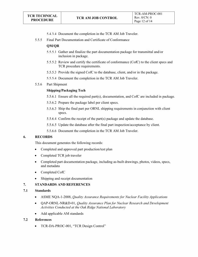
5.5.5 Final Part Documentation and Certificate of Conformance
QM/QR
Gather and finalize the part documentation package for transmittal and/or inclusion in package.
Review and certify the certificate of conformance (CofC) to the client specs and TCR procedure requirements.
Provide the signed CofC to the database, client, and/or in the package.
Document the completion in the TCR AM Job Traveler.
5.5.6 Part Shipment
Shipping/Packaging Tech
Ensure all the required part(s), documentation, and CofC are included in package.
Prepare the package label per client specs.
Ship the final part per ORNL shipping requirements in conjunction with client specs.
Confirm the receipt of the part(s) package and update the database.
Update the database after the final part inspection/acceptance by client.
Document the completion in the TCR AM Job Traveler.
6. RECORDS
This document generates the following records:
• Completed and approved part production/test plan
• Completed TCR job traveler
• Completed part documentation package, including as-built drawings, photos, videos, specs, and metadata
• Completed CofC
• Shipping and receipt documentation
7. STANDARDS AND REFERENCES
7.1 Standards
• ASME NQA-1-2008, Quality Assurance Requirements for Nuclear Facility Applications
• QAP-ORNL-NR&D-01, Quality Assurance Plan for Nuclear Research and Development Activities Conducted at the Oak Ridge National Laboratory
• Add applicable AM standards
7.2 References
• TCR-DA-PROC-001, “TCR Design Control”

TCR TECHNICAL
PROCEDURE
TCR AM JOB CONTROL
TCR-AM-PROC-001 Rev. 0/CN: 0 Page 13 of 14
• TCR-QA-PLAN-001, TCR Quality Assurance Program Plan
• TCR-AM-FORM-001, TCR AM Job Traveler Form
8. APPENDICES
• Appendix A: Abbreviations and Definitions

TCR TECHNICAL
PROCEDURE
TCR AM JOB CONTROL
TCR-AM-PROC-001 Rev. 0/CN: 0 Page 14 of 14
Appendix A: Example Abbreviations and Definitions Abbreviations
AM additive manufacturing
CofC certificate conformance
EDM Electrical Discharge Machining
SDS safety data sheet
ORNL Oak Ridge National Laboratory
PPE personal protective equipment
QA quality assurance
QC quality control
QM quality manager
QR quality representative
RSS research safety summary
Spec specification
TCR Transformational Challenge Reactor
Definitions None

APPENDIX B. TCR AM JOB TRAVELER FORM
B-1

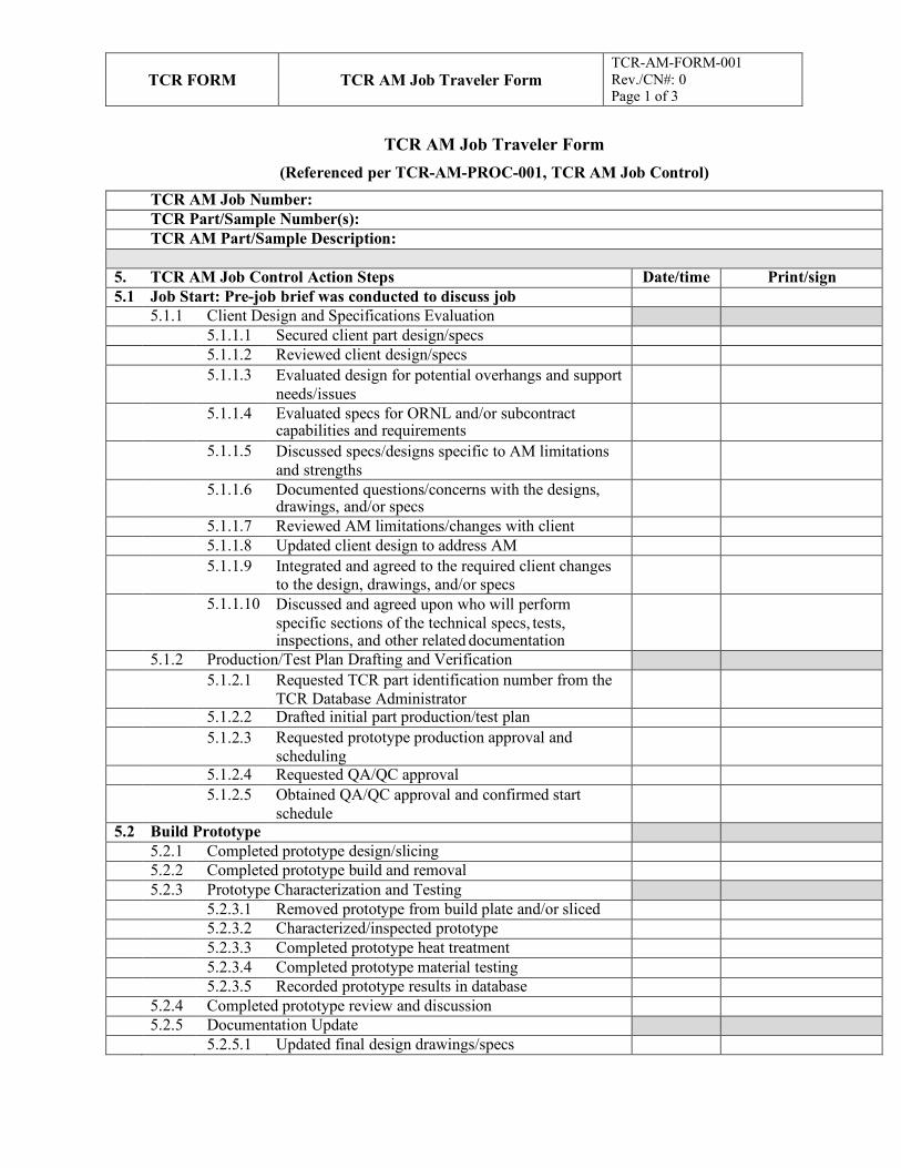
TCR FORM
TCR AM Job Traveler Form TCR-AM-FORM-001 Rev./CN#: 0 Page 1 of 3
TCR AM Job Traveler Form
(Referenced per TCR-AM-PROC-001, TCR AM Job Control)
TCR AM Job Number: TCR Part/Sample Number(s): TCR AM Part/Sample Description:
5. TCR AM Job Control Action Steps Date/time Print/sign 5.1 Job Start: Pre-job brief was conducted to discuss job
5.1.1 Client Design and Specifications Evaluation 5.1.1.1 Secured client part design/specs 5.1.1.2 Reviewed client design/specs 5.1.1.3 Evaluated design for potential overhangs and support
needs/issues
5.1.1.4 Evaluated specs for ORNL and/or subcontract capabilities and requirements
5.1.1.5 Discussed specs/designs specific to AM limitations and strengths
5.1.1.6 Documented questions/concerns with the designs, drawings, and/or specs
5.1.1.7 Reviewed AM limitations/changes with client 5.1.1.8 Updated client design to address AM 5.1.1.9 Integrated and agreed to the required client changes
to the design, drawings, and/or specs
5.1.1.10 Discussed and agreed upon who will perform specific sections of the technical specs, tests, inspections, and other related documentation
5.1.2 Production/Test Plan Drafting and Verification 5.1.2.1 Requested TCR part identification number from the
TCR Database Administrator
5.1.2.2 Drafted initial part production/test plan 5.1.2.3 Requested prototype production approval and
scheduling
5.1.2.4 Requested QA/QC approval 5.1.2.5 Obtained QA/QC approval and confirmed start
schedule
5.2 Build Prototype 5.2.1 Completed prototype design/slicing 5.2.2 Completed prototype build and removal 5.2.3 Prototype Characterization and Testing 5.2.3.1 Removed prototype from build plate and/or sliced 5.2.3.2 Characterized/inspected prototype 5.2.3.3 Completed prototype heat treatment 5.2.3.4 Completed prototype material testing 5.2.3.5 Recorded prototype results in database 5.2.4 Completed prototype review and discussion 5.2.5 Documentation Update 5.2.5.1 Updated final design drawings/specs
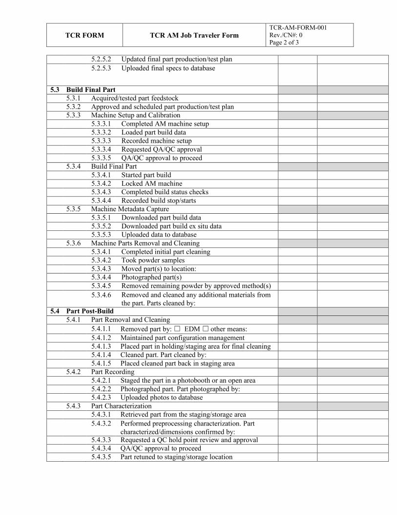
TCR FORM
TCR AM Job Traveler Form TCR-AM-FORM-001 Rev./CN#: 0 Page 2 of 3
5.2.5.2 Updated final part production/test plan 5.2.5.3 Uploaded final specs to database
5.3 Build Final Part 5.3.1 Acquired/tested part feedstock 5.3.2 Approved and scheduled part production/test plan 5.3.3 Machine Setup and Calibration 5.3.3.1 Completed AM machine setup 5.3.3.2 Loaded part build data 5.3.3.3 Recorded machine setup 5.3.3.4 Requested QA/QC approval 5.3.3.5 QA/QC approval to proceed 5.3.4 Build Final Part 5.3.4.1 Started part build 5.3.4.2 Locked AM machine 5.3.4.3 Completed build status checks 5.3.4.4 Recorded build stop/starts 5.3.5 Machine Metadata Capture 5.3.5.1 Downloaded part build data 5.3.5.2 Downloaded part build ex situ data 5.3.5.3 Uploaded data to database 5.3.6 Machine Parts Removal and Cleaning 5.3.4.1 Completed initial part cleaning 5.3.4.2 Took powder samples 5.3.4.3 Moved part(s) to location: 5.3.4.4 Photographed part(s) 5.3.4.5 Removed remaining powder by approved method(s) 5.3.4.6 Removed and cleaned any additional materials from
the part. Parts cleaned by:
5.4 Part Post-Build 5.4.1 Part Removal and Cleaning 5.4.1.1 Removed part by: ☐ EDM ☐ other means: 5.4.1.2 Maintained part configuration management 5.4.1.3 Placed part in holding/staging area for final cleaning 5.4.1.4 Cleaned part. Part cleaned by: 5.4.1.5 Placed cleaned part back in staging area 5.4.2 Part Recording 5.4.2.1 Staged the part in a photobooth or an open area 5.4.2.2 Photographed part. Part photographed by: 5.4.2.3 Uploaded photos to database 5.4.3 Part Characterization 5.4.3.1 Retrieved part from the staging/storage area 5.4.3.2 Performed preprocessing characterization. Part
characterized/dimensions confirmed by:
5.4.3.3 Requested a QC hold point review and approval 5.4.3.4 QA/QC approval to proceed 5.4.3.5 Part retuned to staging/storage location
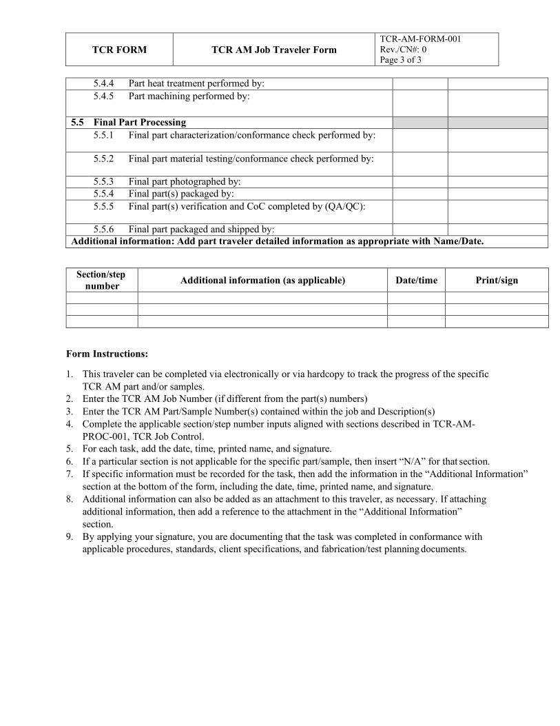
TCR FORM
TCR AM Job Traveler Form TCR-AM-FORM-001 Rev./CN#: 0 Page 3 of 3
5.4.4 Part heat treatment performed by: 5.4.5 Part machining performed by:
5.5 Final Part Processing 5.5.1 Final part characterization/conformance check performed by:
5.5.2 Final part material testing/conformance check performed by:
5.5.3 Final part photographed by: 5.5.4 Final part(s) packaged by: 5.5.5 Final part(s) verification and CoC completed by (QA/QC):
5.5.6 Final part packaged and shipped by: Additional information: Add part traveler detailed information as appropriate with Name/Date.
Section/step number Additional information (as applicable) Date/time Print/sign
Form Instructions:
1. This traveler can be completed via electronically or via hardcopy to track the progress of the specific TCR AM part and/or samples.
2. Enter the TCR AM Job Number (if different from the part(s) numbers) 3. Enter the TCR AM Part/Sample Number(s) contained within the job and Description(s) 4. Complete the applicable section/step number inputs aligned with sections described in TCR-AM-
PROC-001, TCR Job Control. 5. For each task, add the date, time, printed name, and signature. 6. If a particular section is not applicable for the specific part/sample, then insert “N/A” for that section. 7. If specific information must be recorded for the task, then add the information in the “Additional Information”
section at the bottom of the form, including the date, time, printed name, and signature. 8. Additional information can also be added as an attachment to this traveler, as necessary. If attaching
additional information, then add a reference to the attachment in the “Additional Information” section.
9. By applying your signature, you are documenting that the task was completed in conformance with applicable procedures, standards, client specifications, and fabrication/test planning documents.
APPENDIX C. TCR AM PART SEPARATION, EDM AND MACHINING
C-1

TCR TECHNICAL
PROCEDURE TCR AM PART SEPARATION, EDM and
MACHINING
TCR-AM-PROC-004 Rev. 0/CN: 0 Page 1 of 8
Transformational Challenge Reactor Program
Number: TCR-AM-PROC-004
Rev./CN#: 0
Approval Date: 05/14/2020
Issue Date: 05/14/2020
Effective Date: 05/14/2020
Supersedes: N/A
Review Required: 05/14/2023
Title: TCR AM Part Separation, EDM, and Machining
IDMS Record #: 24307
Document Owner: Ryan Dehoff, TCR AM Thrust Lead
Author: Michael Russell, TCR QA Representative
Point of Contact: Ryan Dehoff, TCR AM Thrust Lead
Approved by:
Ryan Dehoff, TCR AM Thrust Lead
Mark Vance, TCR QA Manager
Sherri Buchanan, TCR Program Manager
Reviewed by:
Ryan Duncan, AM/EDM Tech
Kurt Terrani, TCR Technical Director
Emma Betters, MDF Machining Tech
This document has been electronically approved. Electronic signatures of approvers are listed on the IDMS View/Print page associated with the IDMS Record # above.
Before using a copy of this document, compare its issue date to the issue date of the IDMS version to verify that it is the most current version.
TCR TECHNICAL
PROCEDURE TCR AM PART SEPARATION, EDM and
MACHINING
TCR-AM-PROC-004 Rev. 0/CN: 0 Page 2 of 8
REVISION LOG
Rev. Date Affected Pages Revision Description
0 05/14/2020 All Initial release
Document pages that are (check as appropriate):
Unclassified, Non-Sensitive: ALL (or) pages
Export Controlled: NONE (or) pages
Controlled, Unclassified, or Sensitive: NONE (or) pages
This document was prepared as an account of work sponsored by an agency of the United States Government. Neither the United States Government nor any agency thereof, nor any of their employees, makes any warranty, express or implied, or assumes any legal liability or responsibility for the accuracy, completeness, or usefulness of any information, apparatus, product, or process disclosed, or represents that its use would not infringe privately owned rights. Reference herein to any specific commercial product, process, or service by trade name, trademark, manufacturer, or otherwise, does not necessarily constitute or imply its endorsement, recommendation, or favoring by the United States Government or any agency thereof. The views and opinions of authors expressed herein do not necessarily state or reflect those of the United States Government or any agency thereof.
TCR TECHNICAL
PROCEDURE TCR AM PART SEPARATION, EDM and
MACHINING
TCR-AM-PROC-004 Rev. 0/CN: 0 Page 3 of 8
Table of Contents
1. INTRODUCTION ............................................................................................................................ 4
1.1 Purpose.................................................................................................................................... 4
1.2 Scope....................................................................................................................................... 4
2. PRECAUTIONS AND LIMITATIONS ............................................................................................ 4
2.1 Precautions .............................................................................................................................. 4
2.2 Limitations .............................................................................................................................. 4
3. REQUIREMENTS ............................................................................................................................ 4
4. PREREQUISITES ............................................................................................................................ 5
5. ACTION STEPS ............................................................................................................................... 5
5.1 Separation Planning ................................................................................................................. 5
5.2 EDM Machine Preparation and Cutting .................................................................................... 5
5.3 Part Machining and Finishing .................................................................................................. 6
5.4 Part Cleaning ........................................................................................................................... 6
6. RECORDS ........................................................................................................................................ 7
7. STANDARDS AND REFERENCES ................................................................................................ 7
7.1 Standards ................................................................................................................................. 7
7.2 References ............................................................................................................................... 7
8. APPENDICES .................................................................................................................................. 7
Appendix A: Abbreviations and Definitions ...................................................................................... 8
TCR TECHNICAL
PROCEDURE TCR AM PART SEPARATION, EDM and
MACHINING
TCR-AM-PROC-004 Rev. 0/CN: 0 Page 4 of 8
1. INTRODUCTION
1.1 Purpose
This procedure identifies the responsibilities and describes the process for performing additive manufacturing (AM) parts and sample removal, as well as for separating using electrical discharge machining (EDM) or similar separation equipment and machining or finishing at the Oak Ridge National Laboratory (ORNL) Transformational Challenge Reactor (TCR) program.
1.2 Scope
This procedure includes the process for AM part and sample separation, machining and finishing techniques used to support the TCR program at ORNL or other facilities. This process includes techniques for separating, cutting, or otherwise removing parts and/or test samples from the AM build plates and/or from printed parts/samples. This process also includes techniques for machining, drilling and finishing the parts before or after separation from the AM build plates.
2. PRECAUTIONS AND LIMITATIONS
2.1 Precautions
1. TCR personnel must adhere to all ORNL safety and facility requirements assigned per the location and/or equipment being used.
2. TCR personnel must be trained to, assigned to, and familiar with the specific research safety summary (RSS) for each facility, work, and/or equipment location before obtaining access to or starting work.
3. TCR personnel must be familiar with and adhere to all identified job hazard controls, including using personal protective equipment (PPE) specific to the material, chemical, machine, location, facility, and/or task being performed and the PPE specifically described in third-party equipment manuals or material safety data sheets (MSDSs).
4. TCR personnel must use special care when handling AM powders to ensure limited inhalation, exposure, pyrophoric effects, and/or cross-contamination. Personnel must review user manuals and MSDSs before handling new types of powders.
5. TCR personnel must ensure that hazards are appropriately identified and that PPE specific to the identified hazard is used during part removal techniques that use automated and/or sharp saws, knives, blades, or other cutting edges.
6. TCR personnel must ensure that hazards are appropriately identified and that PPE specific to the identified hazard is used during part removal techniques that use chemical hazards, flowing liquids, and other similar hazards.
2.2 Limitations
1. This procedure is limited to work being performed under the TCR program in accordance with TCR-QA-PLAN-001, TCR Quality Assurance Program Plan, and/or QAP-ORNL- NR&D-01, Quality Assurance Plan for Nuclear Research and Development Activities Conducted at the Oak Ridge National Laboratory, and associated procedures. This procedure can be used for other programs with approval from the document owner.
3. REQUIREMENTS
1. TCR-QA-PLAN-001, TCR Quality Assurance Program Plan
TCR TECHNICAL
PROCEDURE TCR AM PART SEPARATION, EDM and
MACHINING
TCR-AM-PROC-004 Rev. 0/CN: 0 Page 5 of 8
NOTE 1: The following steps may be performed in any order unless noted otherwise.
NOTE 2: The following steps are performed in conjunction with the machine operating manual as guidance.
WARNING: WARNING: WARNING: POTENTIAL INJURY CAN RESULT FROM USING CHARACTERIZATION MACHINES, SYSTEMS AND ASSOCIATED MATERIALS IF PERSONNEL ARE NOT FAMILIAR WITH SAFETY WARNINGS AND REQUIREMENTS ASSOCIATED WITH THEM INCLUDING THE RELATED RSS, MSDS, AND EQUIPMENT MANUALS, TO ENSURE ALL REQUIRED SAFETY PRECAUTIONS AND PPE ARE USED.
2. QAP-ORNL-NR&D-01, Quality Assurance Plan for Nuclear Research and Development Activities Conducted at the Oak Ridge National Laboratory
3. TCR-AM-PROC-001, “TCR AM Job Control”
4. TCR-DA-PROC-001, “TCR Design Control”
4. PREREQUISITES
1. TCR personnel must be trained and assigned to the RSS associated with the applicable facility, location, and/or machine.
2. TCR personnel must be trained to and familiar with the specific machine (s) used to remove, machine and/or separate parts including the associated operations manual.
3. TCR personnel must have documented that they have read this procedure, applicable equipment manual(s), and related MSDSs.
5. ACTION STEPS
5.1 Separation Planning
AM/EDM/Machining Tech 5.1.1 Discuss the necessary cuts and/or machining with the design and test team.
5.1.2 Determine the cutting and removal methods and machine(s).
5.1.3 Develop the cutting and removal plan/drawings specific to the part specifications and fabrication/test plan.
5.1.4 Review the cutting/machining plan with design and test team.
5.1.5 Obtain approval for the cutting/machining plan from the project lead.
5.2 EDM Machine Preparation and Cutting
EDM Tech 5.2.1 Perform the cutting machine setup per the operations manual.
5.2.2 Verify that the type of wire or saw loaded in the machine is allowable per the production/test plan and technical specifications (e.g., use of copper or brass for nuclear applications).
5.2.3 Verify that cutting water or fluid is allowable per the production/test plan and technical specifications.
5.2.4 Program any of the necessary cuts to be made in the Esprit software or at the machine.
TCR TECHNICAL
PROCEDURE TCR AM PART SEPARATION, EDM and
MACHINING
TCR-AM-PROC-004 Rev. 0/CN: 0 Page 6 of 8
NOTE: The flatness of the base plate will be evaluated on a granite surface plate. If the part is not flat within 0.001" per inch, the parts can be removed from the plate by EDM prior to subsequent machining operations or machined to required flatness.
5.2.5 Prepare the machine to complete the required cuts.
5.2.6 Make any test cuts that might be needed and verify for accuracy.
5.2.7 When accuracy verification is complete, then make any necessary adjustments to program parameters.
5.2.8 Make all final cuts.
5.2.9 Perform preliminary verification that the cut parts meet the fabrication/test plan.
5.3 Part Machining and Finishing
Machining Tech
5.3.1 Verify flatness of part base plate is within .001” per inch, if applicable per Note 1.
5.3.2 Perform the finishing machine setup per the operations manual.
5.3.3 Verify that the type of finishing tool(s) loaded in the machine is allowable per the production/test plan and technical specifications (e.g., use of copper or brass for nuclear applications).
5.3.4 Verify that machine water or fluid is allowable per the production/test plan and technical specifications.
5.3.5 Mount or clamp the base plate or part into the machine.
5.3.6 Program any of the necessary removals, milling, reaming and/or finishing to be made at the machine per technical specification and fabrication/testing plan.
5.3.7 Perform machining and/or finishing operation per technical specification and fabrication/testing plan.
5.4 Part Cleaning
AM/EDM/Machining Tech 5.4.1 Prepare the method(s) for cleaning the cut part.
5.4.2 Verify that the planned liquids/chemicals are allowed per the part technical specifications and fabrication/test plan.
5.4.3 If using grit blasting or other mechanical cleaning methods, then verify that the materials are allowed per the part technical specifications and fabrication methods.
5.4.4 Clean the part per the technical specification and fabrication/test plan.
5.4.5 Return the part to the staging area.
5.4.6 Update the job traveler with post-processing information, date, time and signature, as applicable.
5.4.7 Notify the part lead of task completion and location of part(s) or sample(s).
TCR TECHNICAL
PROCEDURE TCR AM PART SEPARATION, EDM and
MACHINING
TCR-AM-PROC-004 Rev. 0/CN: 0 Page 7 of 8
6. RECORDS
This document generates the following records:
• Completed job traveler
7. STANDARDS AND REFERENCES
7.1 Standards
• ASME NQA-1-2008, Quality Assurance Requirements for Nuclear Facility Applications
• QAP-ORNL-NR&D-01, Quality Assurance Plan for Nuclear Research and Development Activities Conducted at the Oak Ridge National Laboratory
7.2 References
• TCR-QA-PLAN-001, TCR Quality Assurance Program
• QAP-ORNL-NR&D-01, Quality Assurance Plan for Nuclear Research and Development Activities Conducted at the Oak Ridge National Laboratory
• TCR-AM-PROC-001, TCR AM Job Control
• TCR-DA-PROC-001, TCR Design Control
• TCR-AM-FORM-001, TCR Job Traveler
8. APPENDICES
• Appendix A: Abbreviations and Definitions
TCR TECHNICAL
PROCEDURE TCR AM PART SEPARATION, EDM and
MACHINING
TCR-AM-PROC-004 Rev. 0/CN: 0 Page 8 of 8
Appendix A: Abbreviations and Definitions Abbreviations
AM additive manufacturing
EDM electrical discharge machining
MSDS material safety data sheet
ORNL Oak Ridge National Laboratory
PPE personal protective equipment
RSS research safety summary
TCR Transformational Challenge Reactor
Definitions
AM tech: TCR personnel who have been verified as trained and qualified to perform work on or with AM machines.
EDM tech: TCR personnel who have been verified as trained and qualified to perform work on or with EDM machines.
Machining tech: TCR personnel who have been verified as trained and qualified to perform work on or with machining or finishing machines.

APPENDIX D. AM POWDER SAMPLING AND RECYCLING
D-1


TCR TECHNICAL
PROCEDURE AM POWDER SAMPLING
AND RECYCLING
TCR-AM-PROC-002 Rev. 0/CN 0 Page 1 of 12
Transformational Challenge Reactor Program
Number: TCR-AM-PROC-002
Rev./CN#: 0
Approval Date: 05/05/2020
Issue Date: 05/06/2020
Effective Date: 05/05/2020
Supersedes: N/A
Review Required: 05/05/2023
Title: AM Powder Sampling and Recycling
IDMS Record #: 24158
Document Owner: Ryan Dehoff, TCR AM Thrust Lead
Author: Michael Russell, TCR QA Representative
Point of Contact: Ryan Dehoff, TCR AM Thrust Lead
Approved by:
Ryan Dehoff, TCR AM Thrust Lead
Mark Vance, TCR QA Manager
Sherri Buchanan, TCR Project Manager
Reviewed by:
Fred List, Deposition Science & Technology
Kurt Terrani, TCR Technical Director
This document has been electronically approved. Electronic signatures of approvers are listed on the IDMS View/Print page associated with the IDMS Record # above.
Before using a copy of this document, compare its issue date to the issue date of the IDMS version to verify that it is the most current version.
TCR TECHNICAL
PROCEDURE AM POWDER SAMPLING
AND RECYCLING
TCR-AM-PROC-002 Rev. 0/CN 0 Page 2 of 12
REVISION LOG
Rev. Date Affected Pages Revision Description
0 05/06/2020 All Initial release
Document pages that are (check as appropriate):
Unclassified, Non-Sensitive: ALL (or) pages
Export Controlled: NONE (or) pages
Controlled, Unclassified, or Sensitive: NONE (or) pages
This document was prepared as an account of work sponsored by an agency of the United States Government. Neither the United States Government nor any agency thereof, nor any of their employees, makes any warranty, express or implied, or assumes any legal liability or responsibility for the accuracy, completeness, or usefulness of any information, apparatus, product, or process disclosed, or represents that its use would not infringe privately owned rights. Reference herein to any specific commercial product, process, or service by trade name, trademark, manufacturer, or otherwise, does not necessarily constitute or imply its endorsement, recommendation, or favoring by the United States Government or any agency thereof. The views and opinions of authors expressed herein do not necessarily state or reflect those of the United States Government or any agency thereof.
TCR TECHNICAL
PROCEDURE AM POWDER SAMPLING
AND RECYCLING
TCR-AM-PROC-002 Rev. 0/CN 0 Page 3 of 12
Table of Contents
1. INTRODUCTION ............................................................................................................................ 4
1.1 Purpose.................................................................................................................................... 4
1.2 Scope....................................................................................................................................... 4
2. PRECAUTIONS AND LIMITATIONS ............................................................................................ 4
2.1 Precautions .............................................................................................................................. 4
2.2 Limitations .............................................................................................................................. 4
3. REQUIREMENTS ............................................................................................................................ 4
4. PREREQUISITES ............................................................................................................................ 4
5. ACTION STEPS ............................................................................................................................... 5
5.1 Powder Sampling ..................................................................................................................... 5
5.2 Powder Recycling and Sieving ................................................................................................. 8
6. RECORDS ........................................................................................................................................ 9
7. STANDARDS AND REFERENCES ................................................................................................ 9
7.1 Standards ................................................................................................................................. 9
7.2 References ............................................................................................................................... 9
8. APPENDICES .................................................................................................................................. 9
Appendix A: Example Abbreviations and Definitions ...................................................................... 10
Appendix B: Background on Powder Quality .................................................................................. 11
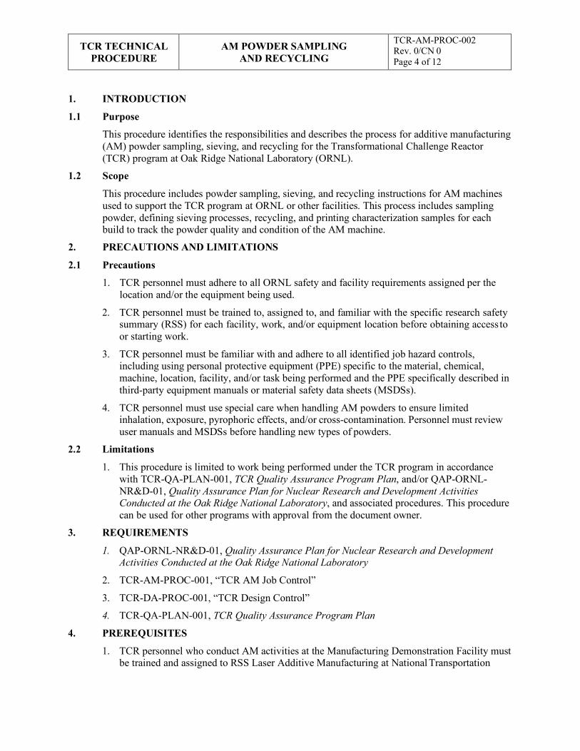
TCR TECHNICAL
PROCEDURE AM POWDER SAMPLING
AND RECYCLING
TCR-AM-PROC-002 Rev. 0/CN 0 Page 4 of 12
1. INTRODUCTION
1.1 Purpose
This procedure identifies the responsibilities and describes the process for additive manufacturing (AM) powder sampling, sieving, and recycling for the Transformational Challenge Reactor (TCR) program at Oak Ridge National Laboratory (ORNL).
1.2 Scope
This procedure includes powder sampling, sieving, and recycling instructions for AM machines used to support the TCR program at ORNL or other facilities. This process includes sampling powder, defining sieving processes, recycling, and printing characterization samples for each build to track the powder quality and condition of the AM machine.
2. PRECAUTIONS AND LIMITATIONS
2.1 Precautions
1. TCR personnel must adhere to all ORNL safety and facility requirements assigned per the location and/or the equipment being used.
2. TCR personnel must be trained to, assigned to, and familiar with the specific research safety summary (RSS) for each facility, work, and/or equipment location before obtaining access to or starting work.
3. TCR personnel must be familiar with and adhere to all identified job hazard controls, including using personal protective equipment (PPE) specific to the material, chemical, machine, location, facility, and/or task being performed and the PPE specifically described in third-party equipment manuals or material safety data sheets (MSDSs).
4. TCR personnel must use special care when handling AM powders to ensure limited inhalation, exposure, pyrophoric effects, and/or cross-contamination. Personnel must review user manuals and MSDSs before handling new types of powders.
2.2 Limitations
1. This procedure is limited to work being performed under the TCR program in accordance with TCR-QA-PLAN-001, TCR Quality Assurance Program Plan, and/or QAP-ORNL- NR&D-01, Quality Assurance Plan for Nuclear Research and Development Activities Conducted at the Oak Ridge National Laboratory, and associated procedures. This procedure can be used for other programs with approval from the document owner.
3. REQUIREMENTS
1. QAP-ORNL-NR&D-01, Quality Assurance Plan for Nuclear Research and Development Activities Conducted at the Oak Ridge National Laboratory
2. TCR-AM-PROC-001, “TCR AM Job Control”
3. TCR-DA-PROC-001, “TCR Design Control”
4. TCR-QA-PLAN-001, TCR Quality Assurance Program Plan
4. PREREQUISITES
1. TCR personnel who conduct AM activities at the Manufacturing Demonstration Facility must be trained and assigned to RSS Laser Additive Manufacturing at National Transportation
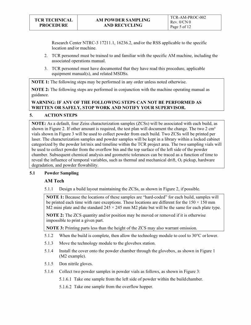
TCR TECHNICAL
PROCEDURE AM POWDER SAMPLING
AND RECYCLING
TCR-AM-PROC-002 Rev. 0/CN 0 Page 5 of 12
NOTE 1: The following steps may be performed in any order unless noted otherwise.
NOTE 2: The following steps are performed in conjunction with the machine operating manual as guidance.
WARNING: IF ANY OF THE FOLLOWING STEPS CAN NOT BE PERFORMED AS WRITTEN OR SAFELY, STOP WORK AND NOTIFY YOUR SUPERVISOR.
NOTE 1: Because the locations of these samples are “hard-coded” for each build, samples will be printed each time with rare exceptions. These locations are different for the 150 × 150 mm M2 mini plate and the standard 245 × 245 mm M2 plate but will be the same for each plate type.
NOTE 2: The ZCS quantity and/or position may be moved or removed if it is otherwise impossible to print a given part.
NOTE 3: Printing parts less than the height of the ZCS may also warrant omission.
Research Center NTRC-3 17211.1, 16236.2, and/or the RSS applicable to the specific location and/or machine.
2. TCR personnel must be trained to and familiar with the specific AM machine, including the associated operations manual.
3. TCR personnel must have documented that they have read this procedure, applicable equipment manual(s), and related MSDSs.
5. ACTION STEPS
5.1 Powder Sampling
AM Tech 5.1.1 Design a build layout maintaining the ZCSs, as shown in Figure 2, if possible.
5.1.2 When the build is complete, then allow the technology module to cool to 30°C or lower.
5.1.3 Move the technology module to the glovebox station.
5.1.4 Install the cover onto the powder chamber through the glovebox, as shown in Figure 1 (M2 example).
5.1.5 Don nitrile gloves.
5.1.6 Collect two powder samples in powder vials as follows, as shown in Figure 3:
Take one sample from the left side of powder within the build chamber.
Take one sample from the overflow hopper.
NOTE: As a default, four Zeiss characterization samples (ZCSs) will be associated with each build, as shown in Figure 2. If other amount is required, the test plan will document the change. The two 2 cm³ vials shown in Figure 3 will be used to collect powder from each build. Two ZCSs will be printed per laser. The characterization samples and powder samples will be kept in a library within a locked cabinet categorized by the powder lot/mix and timeline within the TCR project area. The two sampling vials will be used to collect powder from the overflow bin and the top surface of the left side of the powder chamber. Subsequent chemical analysis and geometric tolerances can be traced as a function of time to reveal the influence of temporal variables, such as thermal and mechanical drift, O2 pickup, hardware degradation, and powder flowability.
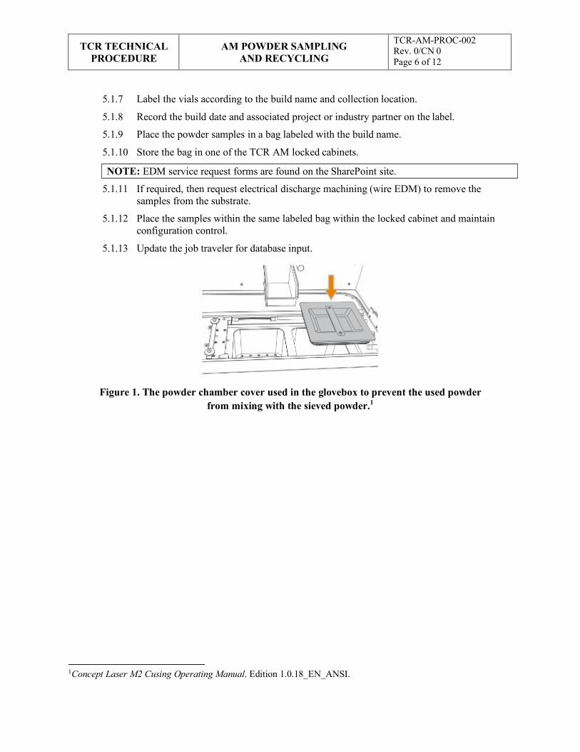
TCR TECHNICAL
PROCEDURE AM POWDER SAMPLING
AND RECYCLING
TCR-AM-PROC-002 Rev. 0/CN 0 Page 6 of 12
NOTE: EDM service request forms are found on the SharePoint site.
5.1.7 Label the vials according to the build name and collection location.
5.1.8 Record the build date and associated project or industry partner on the label.
5.1.9 Place the powder samples in a bag labeled with the build name.
5.1.10 Store the bag in one of the TCR AM locked cabinets.
5.1.11 If required, then request electrical discharge machining (wire EDM) to remove the samples from the substrate.
5.1.12 Place the samples within the same labeled bag within the locked cabinet and maintain configuration control.
5.1.13 Update the job traveler for database input.
Figure 1. The powder chamber cover used in the glovebox to prevent the used powder from mixing with the sieved powder.1
1Concept Laser M2 Cusing Operating Manual. Edition 1.0.18_EN_ANSI.
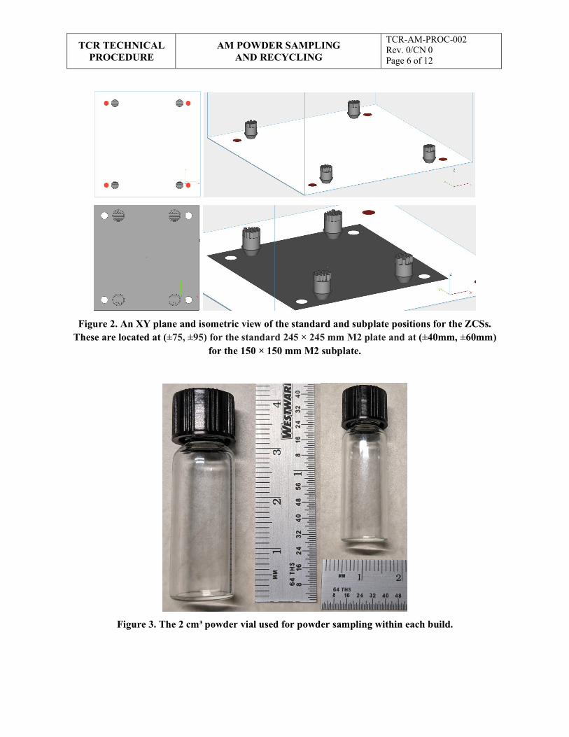
TCR TECHNICAL
PROCEDURE AM POWDER SAMPLING
AND RECYCLING
TCR-AM-PROC-002 Rev. 0/CN 0 Page 6 of 12
Figure 2. An XY plane and isometric view of the standard and subplate positions for the ZCSs. These are located at (±75, ±95) for the standard 245 × 245 mm M2 plate and at (±40mm, ±60mm)
for the 150 × 150 mm M2 subplate.
Figure 3. The 2 cm³ powder vial used for powder sampling within each build.
TCR TECHNICAL
PROCEDURE AM POWDER SAMPLING
AND RECYCLING
TCR-AM-PROC-002 Rev. 0/CN 0 Page 6 of 12
5.2 Powder Recycling and Sieving
AM Tech 5.2.1 Ensure that the technology module is ≤30°C.
5.2.2 Ensure that the powder samples were properly collected, labeled, and stored.
5.2.3 Cover the powder chamber (Figure 1) to prevent the used powder from mixing with the freshly sieved powder.
5.2.4 Vacuum the discolored powder, soot, and spatter particles with the Ruwac wet vacuum.
5.2.5 Sweep the excess powder from the powder chamber into an overflow grate.
5.2.6 Carefully remove the build and recover as much powder as possible from within, around, and on top of the part.
5.2.7 Close the valves connecting the technology module to the overflow hopper.
5.2.8 Use the trolley lift to raise the hopper to mate with the sieving station.
5.2.9 Connect the hopper to the sieve.
5.2.10 Ground the lift to the sieving unit.
5.2.11 Lock the wheels of the trolley to prevent rolling.
5.2.12 Power on the sieve unit and turn on the inerting phase by opening valves 2–5 and pressing the green button.
5.2.13 When the inert phase is completed, then open the overflow hopper valve and begin sieving (takes ~25 min).
5.2.14 Confirm that the overflow hopper is empty.
5.2.15 Close valves 2–5 to maintain an inert hopper.
5.2.16 Remove the overflow hopper and place it back onto the technology module.
5.2.17 Lift the freshly sieved powder hopper over the M2 technology module.
5.2.18 Ground the lift to the M2 AM machine.
5.2.19 Couple the valve to the loading tube.
5.2.20 Ensure that the glovebox is closed and tightly sealed.
5.2.21 Remove the powder chamber cover (Figure 1).
5.2.22 Ground yourself to the M2 AM machine with the blue electrostatic discharge (ESD) wristband.
NOTE : Powder recycling and/or sieving occurs under an argon environment with less than 0.6% O2. The overflow hopper is not maintained inert upon build completion or during build extraction. Oxygen affinity is a function of temperature; thus, it is imperative that the technology module is cooled upon build completion. A typical temperature build plate sensor value during the build is 45°C. The technology module build plate temperature will be cooled to no more than 30°C before moving the technology module to the open-air handling glovebox shown in Figure 1. Inherent to the design of this process is the potential for O2 pickup during reloading.
NOTE 2: The following steps are taken for each build to minimize the powder’s exposure to oxygen.
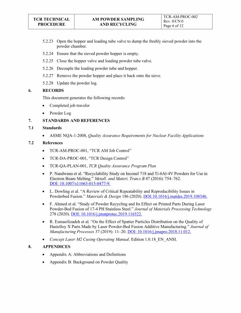
TCR TECHNICAL
PROCEDURE AM POWDER SAMPLING
AND RECYCLING
TCR-AM-PROC-002 Rev. 0/CN 0 Page 6 of 12
5.2.23 Open the hopper and loading tube valve to dump the freshly sieved powder into the powder chamber.
5.2.24 Ensure that the sieved powder hopper is empty.
5.2.25 Close the hopper valve and loading powder tube valve.
5.2.26 Decouple the loading powder tube and hopper.
5.2.27 Remove the powder hopper and place it back onto the sieve.
5.2.28 Update the powder log.
6. RECORDS
This document generates the following records:
• Completed job traveler
• Powder Log
7. STANDARDS AND REFERENCES
7.1 Standards
• ASME NQA-1-2008, Quality Assurance Requirements for Nuclear Facility Applications
7.2 References
• TCR-AM-PROC-001, “TCR AM Job Control”
• TCR-DA-PROC-001, “TCR Design Control”
• TCR-QA-PLAN-001, TCR Quality Assurance Program Plan
• P. Nandwana et al. “Recyclability Study on Inconel 718 and Ti-6Al-4V Powders for Use in Electron Beam Melting.” Metall. and Materi. Tran.s B 47 (2016): 754–762. DOI: 10.1007/s11663-015-0477-9.
• L. Dowling et al. “A Review of Critical Repeatability and Reproducibility Issues in Powderbed Fusion.” Materials & Design 186 (2020). DOI: 10.1016/j.matdes.2019.108346.
• F. Ahmed et al. “Study of Powder Recycling and Its Effect on Printed Parts During Laser Powder-Bed Fusion of 17-4 PH Stainless Steel.” Journal of Materials Processing Technology 278 (2020). DOI: 10.1016/j.jmatprotec.2019.116522.
• R. Esmaeilizadeh et al. “On the Effect of Spatter Particles Distribution on the Quality of Hastelloy X Parts Made by Laser Powder-Bed Fusion Additive Manufacturing.” Journal of Manufacturing Processes 37 (2019): 11–20. DOI: 10.1016/j.jmapro.2018.11.012.
• Concept Laser M2 Cusing Operating Manual. Edition 1.0.18_EN_ANSI.
8. APPENDICES
• Appendix A: Abbreviations and Definitions
• Appendix B: Background on Powder Quality
TCR TECHNICAL
PROCEDURE AM POWDER SAMPLING
AND RECYCLING
TCR-AM-PROC-002 Rev. 0/CN 0 Page 6 of 12
Appendix A: Example Abbreviations and Definitions Abbreviations
AM additive manufacturing
EDM electrical discharge machining
MSDS material safety data sheet
ORNL Oak Ridge National Laboratory
PPE personal protective equipment
RSS research safety summary
TCR Transformational Challenge Reactor
ZCS Zeiss characterization sample
Definitions
AM tech: TCR personnel who have been verified as trained and qualified to perform work on or with AM machines.
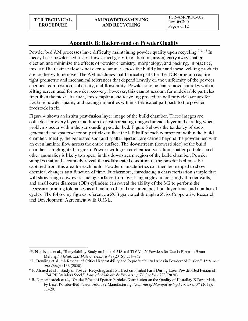
TCR TECHNICAL
PROCEDURE AM POWDER SAMPLING
AND RECYCLING
TCR-AM-PROC-002 Rev. 0/CN 0 Page 6 of 12
Appendix B: Background on Powder Quality Powder bed AM processes have difficulty maintaining powder quality upon recycling.2,3,4,5 In theory laser powder bed fusion flows, inert gases (e.g., helium, argon) carry away spatter ejection and minimize the effects of powder chemistry, morphology, and packing. In practice, this is difficult since flow is not evenly laminar across the build plate and these welding products are too heavy to remove. The AM machines that fabricate parts for the TCR program require tight geometric and mechanical tolerances that depend heavily on the uniformity of the powder chemical composition, sphericity, and flowability. Powder sieving can remove particles with a sifting screen used for powder recovery; however, this cannot account for undesirable particles finer than the mesh. As such, this sampling and recycling procedure will provide avenues for tracking powder quality and tracing impurities within a fabricated part back to the powder feedstock itself. Figure 4 shows an in situ post-fusion layer image of the build chamber. These images are collected for every layer in addition to post-spreading images for each layer and can flag when problems occur within the surrounding powder bed. Figure 5 shows the tendency of soot- generated and spatter-ejection particles to face the left half of each component within the build chamber. Ideally, the generated soot and spatter ejection are carried beyond the powder bed with an even laminar flow across the entire surface. The downstream (leeward side) of the build chamber is highlighted in green. Powder with greater chemical variation, spatter particles, and other anomalies is likely to appear in this downstream region of the build chamber. Powder samples that will accurately reveal the as-fabricated condition of the powder bed must be captured from this area for each build. Powder characteristics can then be mapped to show chemical changes as a function of time. Furthermore, introducing a characterization sample that will show rough downward-facing surfaces from overhang angles, increasingly thinner walls, and small outer diameter (OD) cylinders can reveal the ability of the M2 to perform the necessary printing tolerances as a function of total melt area, position, layer time, and number of cycles. The following figures reference a ZCS generated through a Zeiss Cooperative Research and Development Agreement with ORNL.
2P. Nandwana et al., “Recyclability Study on Inconel 718 and Ti-6Al-4V Powders for Use in Electron Beam Melting,” Metall. and Materi. Trans. B 47 (2016): 754–762.
3 L. Dowling et al., “A Review of Critical Repeatability and Reproducibility Issues in Powderbed Fusion,” Materials and Design 186 (2020).
4 F. Ahmed et al., “Study of Powder Recycling and Its Effect on Printed Parts During Laser Powder-Bed Fusion of 17-4 PH Stainless Steel,” Journal of Materials Processing Technology 278 (2020).
5 R. Esmaeilizadeh et al., “On the Effect of Spatter Particles Distribution on the Quality of Hastelloy X Parts Made by Laser Powder-Bed Fusion Additive Manufacturing,” Journal of Manufacturing Processes 37 (2019): 11–20.
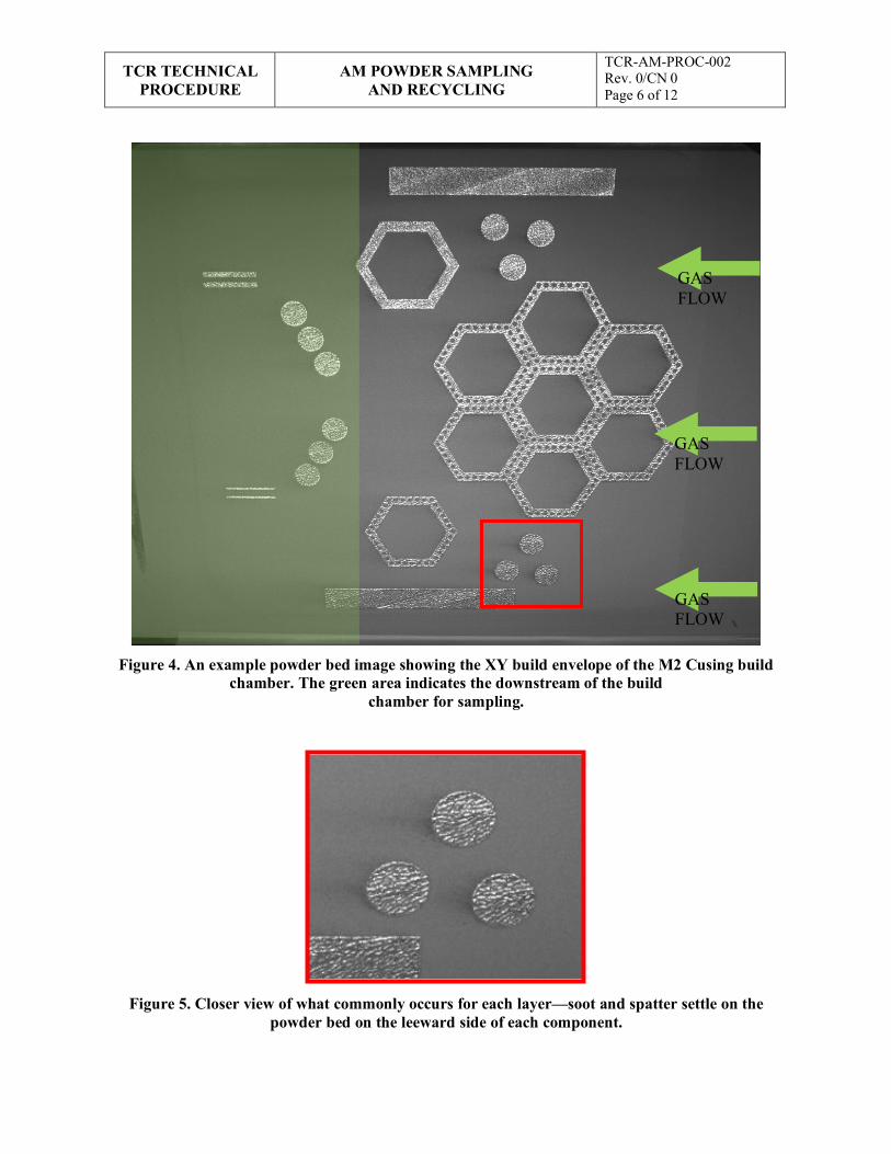
TCR TECHNICAL
PROCEDURE AM POWDER SAMPLING
AND RECYCLING
TCR-AM-PROC-002 Rev. 0/CN 0 Page 6 of 12
Figure 4. An example powder bed image showing the XY build envelope of the M2 Cusing build chamber. The green area indicates the downstream of the build
chamber for sampling.
Figure 5. Closer view of what commonly occurs for each layer—soot and spatter settle on the powder bed on the leeward side of each component.
GAS FLOW
GAS FLOW
GAS FLOW
APPENDIX E. TCR AM LASER SPOT SIZE MEASUREMENT
E-1

TCR TECHNICAL
PROCEDURE TCR AM LASER SPOT SIZE
MEASUREMENT
TCR-AM-PROC-003 Rev. 0/CN: 0 Page 1 of 11
Transformational Challenge Reactor Program
Number: TCR-AM-PROC-003
Rev./CN#: 0
Approval Date: 05/05/2020
Issue Date: 05/06/2020
Effective Date: 05/05/2020
Supersedes: N/A
Review Required: 05/05/2023
Title: TCR AM Spot Size Measurement
IDMS Record #: 24162
Document Owner: Ryan Dehoff, TCR AM Thrust Lead
Author: Michael Russell, TCR QA Representative
Point of Contact: Ryan Dehoff, TCR AM Thrust Lead
Approved by:
Ryan Dehoff, TCR AM Thrust Lead
Mark Vance, TCR QA Manager
Sherri Buchanan, TCR Program Manager
Reviewed by:
Fred List, Deposition Science & Technology
Kurt Terrani, TCR Technical Director
This document has been electronically approved. Electronic signatures of approvers are listed on the IDMS View/Print page associated with the IDMS Record # above.
Before using a copy of this document, compare its issue date to the issue date of the IDMS version to verify that it is the most current version.

TCR TECHNICAL
PROCEDURE TCR AM LASER SPOT SIZE
MEASUREMENT
TCR-AM-PROC-003 Rev. 0/CN: 0 Page 2 of 11
REVISION LOG
Rev. Date Affected Pages Revision Description
0 05/05/2020 All Initial release
Document pages that are (check as appropriate):
Unclassified, Non-Sensitive: ALL (or) pages
Export Controlled: NONE (or) pages
Controlled, Unclassified, or Sensitive: NONE (or) pages
This document was prepared as an account of work sponsored by an agency of the United States Government. Neither the United States Government nor any agency thereof, nor any of their employees, makes any warranty, express or implied, or assumes any legal liability or responsibility for the accuracy, completeness, or usefulness of any information, apparatus, product, or process disclosed, or represents that its use would not infringe privately owned rights. Reference herein to any specific commercial product, process, or service by trade name, trademark, manufacturer, or otherwise, does not necessarily constitute or imply its endorsement, recommendation, or favoring by the United States Government or any agency thereof. The views and opinions of authors expressed herein do not necessarily state or reflect those of the United States Government or any agency thereof.
TCR TECHNICAL
PROCEDURE TCR AM LASER SPOT SIZE
MEASUREMENT
TCR-AM-PROC-003 Rev. 0/CN: 0 Page 3 of 11
Table of Contents
1. INTRODUCTION ............................................................................................................................ 4
1.1 Purpose.................................................................................................................................... 4
1.2 Scope....................................................................................................................................... 4
2. PRECAUTIONS AND LIMITATIONS ............................................................................................ 4
2.1 Precautions .............................................................................................................................. 4
2.2 Limitations .............................................................................................................................. 4
3. REQUIREMENTS ............................................................................................................................ 4
4. PREREQUISITES ............................................................................................................................ 4
5. ACTION STEPS ............................................................................................................................... 5
5.1 AM Machine Preparation ......................................................................................................... 5
5.2 Beam Check Preparation .......................................................................................................... 6
5.3 Measurements .......................................................................................................................... 6
6. RECORDS ........................................................................................................................................ 8
7. STANDARDS AND REFERENCES ................................................................................................ 8
7.1 Standards ................................................................................................................................. 8
7.2 References ............................................................................................................................... 8
8. APPENDICES .................................................................................................................................. 8
Appendix A: Abbreviations and Definitions ...................................................................................... 9
Appendix B: Example Laser Powder Bed Fusion Spot Size Measurement Record Template ............ 10
Appendix B: Example Laser Powder Bed Fusion Spot Size Measurement Record Template (cont’d) .................................................................................................................................................... 11
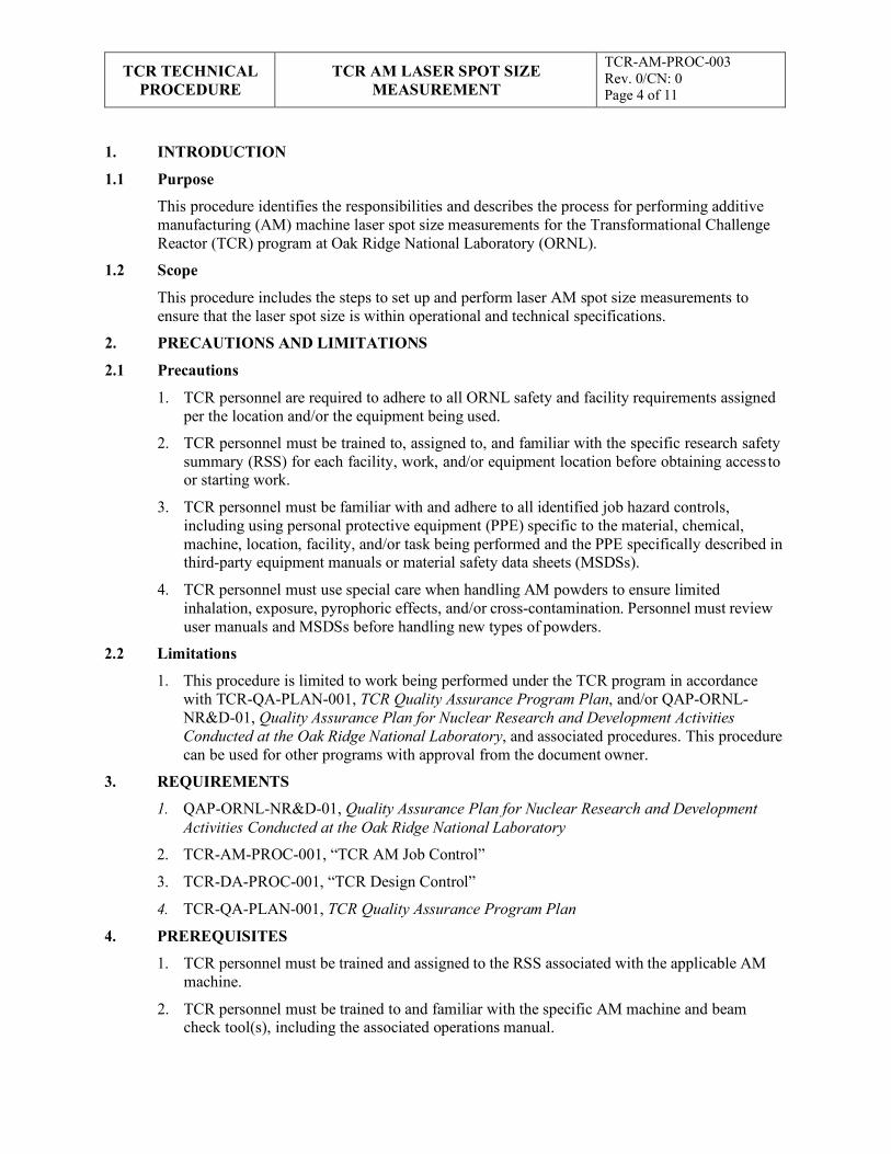
TCR TECHNICAL
PROCEDURE TCR AM LASER SPOT SIZE
MEASUREMENT
TCR-AM-PROC-003 Rev. 0/CN: 0 Page 4 of 11
1. INTRODUCTION
1.1 Purpose
This procedure identifies the responsibilities and describes the process for performing additive manufacturing (AM) machine laser spot size measurements for the Transformational Challenge Reactor (TCR) program at Oak Ridge National Laboratory (ORNL).
1.2 Scope
This procedure includes the steps to set up and perform laser AM spot size measurements to ensure that the laser spot size is within operational and technical specifications.
2. PRECAUTIONS AND LIMITATIONS
2.1 Precautions
1. TCR personnel are required to adhere to all ORNL safety and facility requirements assigned per the location and/or the equipment being used.
2. TCR personnel must be trained to, assigned to, and familiar with the specific research safety summary (RSS) for each facility, work, and/or equipment location before obtaining access to or starting work.
3. TCR personnel must be familiar with and adhere to all identified job hazard controls, including using personal protective equipment (PPE) specific to the material, chemical, machine, location, facility, and/or task being performed and the PPE specifically described in third-party equipment manuals or material safety data sheets (MSDSs).
4. TCR personnel must use special care when handling AM powders to ensure limited inhalation, exposure, pyrophoric effects, and/or cross-contamination. Personnel must review user manuals and MSDSs before handling new types of powders.
2.2 Limitations
1. This procedure is limited to work being performed under the TCR program in accordance with TCR-QA-PLAN-001, TCR Quality Assurance Program Plan, and/or QAP-ORNL- NR&D-01, Quality Assurance Plan for Nuclear Research and Development Activities Conducted at the Oak Ridge National Laboratory, and associated procedures. This procedure can be used for other programs with approval from the document owner.
3. REQUIREMENTS
1. QAP-ORNL-NR&D-01, Quality Assurance Plan for Nuclear Research and Development Activities Conducted at the Oak Ridge National Laboratory
2. TCR-AM-PROC-001, “TCR AM Job Control”
3. TCR-DA-PROC-001, “TCR Design Control”
4. TCR-QA-PLAN-001, TCR Quality Assurance Program Plan
4. PREREQUISITES
1. TCR personnel must be trained and assigned to the RSS associated with the applicable AM machine.
2. TCR personnel must be trained to and familiar with the specific AM machine and beam check tool(s), including the associated operations manual.
TCR TECHNICAL
PROCEDURE TCR AM LASER SPOT SIZE
MEASUREMENT
TCR-AM-PROC-003 Rev. 0/CN: 0 Page 5 of 11
NOTE 1: The following steps must be performed in order unless otherwise noted in the step.
NOTE 2: The following operational steps are performed in conjunction with the machine operating manual as guidance.
WARNING: IF ANY OF THE FOLLOWING STEPS CAN NOT BE PERFORMED AS WRITTEN OR SAFELY, STOP WORK AND NOTIFY YOUR SUPERVISOR.
NOTE: After ~4 sec, the laser will begin firing at the default wattage of 100 W. Since the midpoint for the measured laser was change in Step 5.1.11.1, the measured laser should fire directly straight down rather than at the build plate’s midpoint.
NOTE 1: Do not allow the laser to fire any longer than is necessary to visually verify location.
3. TCR personnel must have documented that they have read this procedure, applicable equipment manual(s), and related MSDSs.
5. ACTION STEPS
5.1 AM Machine Preparation
AM Tech 5.1.1 Prepare the machine per normal cleaning and build-setup procedures with a full-sized
build plate.
5.1.2 Log into the machine control software.
5.1.3 Initiate inerting per the machine operating manual.
5.1.4 Press the physical “Error Reset” button on the machine.
5.1.5 Close the machine control software.
5.1.6 Open “Machine Configuration.”
5.1.7 Log into “Service.”
5.1.8 Click “Laser” in top right corner.
5.1.9 Click “Configuration Selection,” then click “Edit.”
5.1.10 Note the X and Y offsets and rotation angle for each laser for future use.
5.1.11 Change the laser midpoint location depending on which laser is being measured:
Change the laser 1 (X, Y) midpoint values from (0, 0) to (Y offset, -X offset).
Change the laser 2 (X, Y) midpoint values from (0, 0) to (-Y offset, X offset).
5.1.12 Click “Aiming Laser.”
5.1.13 Click “Permanent Exposure.”
5.1.14 Click “Initiate Laser.”
5.1.15 Click “Laser On.”
5.1.16 Visually verify that the laser being measured is firing straight down.
5.1.17 Click “Laser Off.”
5.1.18 Visually verify that the laser is off and no longer melting the build plate.
TCR TECHNICAL
PROCEDURE TCR AM LASER SPOT SIZE
MEASUREMENT
TCR-AM-PROC-003 Rev. 0/CN: 0 Page 6 of 11
NOTE 1: The beam check must be connected to the USB hub, and the hub must be connected to the computer, to operate correctly.
NOTE 2: The beam check and hub must be plugged in and powered before starting the beam check software for the software to boot correctly.
NOTE: The calibration plane for the beam check is the bottom surface of the device’s mounting plate. If the beam check was not supplied with kinematic balls or if the balls have been removed, then Step 5.3.3 does not apply and the build plate is not lowered.
5.1.19 Visually verify that the aiming laser is located at the same spot on the build plate as the burn mark.
5.2 Beam Check Preparation
AM Tech 5.2.1 Close “Service” and log into the machine control software.
5.2.2 Turn off inerting.
5.2.3 Open the process chamber door.
5.2.4 Insert the beam check into the build chamber.
5.2.5 Remove the lens cap from the beam check.
5.2.6 Remove the USB port cover from the machine build chamber wall.
5.2.7 Plug in the USB cable to connect the beam check to the port in the build chamber wall.
5.2.8 Plug the USB cable from the chamber wall into the beam check’s USB hub.
5.2.9 Connect the USB hub to the computer.
5.2.10 Connect the USB hub’s power supply to 110 V AC 50/60 Hz.
5.2.11 Turn on the computer and start the beam check software.
5.2.12 Select the camera source and power measurement device in the beam check software.
5.2.13 Use a clean, white piece of paper to locate the aiming beam in the machine processing chamber.
5.2.14 Move the beam check so that the viewing aperture is directly under the aiming beam.
5.2.15 Use the laser detection output on the beam check software to fine tune the placement of the beam check in the processing chamber.
5.2.16 Ensure that the beam check is placed so that it will not interfere with walls or obstacles when the build plate elevator is lowered.
5.2.17 Verify that the beam check is reading a live signal and that the aiming laser beam is centered in the beam check viewing aperture.
5.3 Measurements
AM Tech 5.3.1 Close the processing chamber door.
5.3.2 Press the physical “Error Reset” button on the machine.
TCR TECHNICAL
PROCEDURE TCR AM LASER SPOT SIZE
MEASUREMENT
TCR-AM-PROC-003 Rev. 0/CN: 0 Page 7 of 11
CAUTION: The ventilator can deposit dust and/or powder on the beam check, which could result in faulty measurements and/or damage to the beam check.
CAUTION: The exact values used in Step 5.1.11 to change midpoint values must be used to ensure that the laser fires in the correct location. Incorrect firing locations can result in irreparable damage to the beam check.
NOTE: Adjusting camera exposure times, camera gains, and white noise levels is necessary for obtaining reliable measurements and detecting the laser beam.
CAUTION: At 100 W, the beam check will overheat if used for more than ~30 min, which can cause faulty measurements and/or damage to the beam check.
5.3.3 Lower the build plate elevator by 3.5 mm to adjust the measurement plane for kinematic balls on the bottom of the beam check.
5.3.4 Initiate inerting per the AM machine user manual.
5.3.5 Turn off the “Ventilator” immediately upon inerting.
5.3.6 Close the machine control software.
5.3.7 Open “Machine Configuration.”
5.3.8 Log into “Service.”
5.3.9 Click “Laser” in top right corner.
5.3.10 Change the laser midpoint location depending on which laser is being measured:
Change the laser 1 (X, Y) midpoint values from (0, 0) to (Y offset, -X offset).
Change the laser 2 (X, Y) midpoint values from (0, 0) to (-Y offset, X offset).
5.3.11 Turn off “Aiming Laser.”
5.3.12 Verify that “Permanent Exposure” is turned on.
5.3.13 Change the “Spot Size” in top right corner to the desired value to be measured.
5.3.14 Click “Initiate Laser.”
5.3.15 Verify that the aiming laser has been turned off via the beam check software.
5.3.16 Click “Laser On.”
5.3.17 Verify that the laser has been turned on via the beam check software.
5.3.18 Click “Laser Off” when measurements are complete.
5.3.19 Verify that the laser has been turned off via the beam check software.
5.3.20 Update machine maintenance log
TCR TECHNICAL
PROCEDURE TCR AM LASER SPOT SIZE
MEASUREMENT
TCR-AM-PROC-003 Rev. 0/CN: 0 Page 8 of 11
6. RECORDS
This document generates the following records:
• Machine maintenance log
• Laser Powder Bed Fusion Spot Size Measurement Record
7. STANDARDS AND REFERENCES
7.1 Standards
• ASME NQA-1-2008, Quality Assurance Requirements for Nuclear Facility Applications
• QAP-ORNL-NR&D-01, Quality Assurance Plan for Nuclear Research and Development Activities Conducted at the Oak Ridge National Laboratory
• Add applicable AM standards
7.2 References
• TCR-QA-PLAN-001, TCR Quality Assurance Program Plan
8. APPENDICES
• Appendix A: Abbreviations and Definitions
• Appendix B: Laser Powder Bed Fusion Spot Size Measurement Record Template
TCR TECHNICAL
PROCEDURE TCR AM LASER SPOT SIZE
MEASUREMENT
TCR-AM-PROC-003 Rev. 0/CN: 0 Page 9 of 11
Appendix A: Abbreviations and Definitions Abbreviations
AM additive manufacturing
MSDS material safety data sheet
ORNL Oak Ridge National Laboratory
PPE personal protective equipment
RSS research safety summary
TCR Transformational Challenge Reactor
Definitions
AM tech: TCR personnel who have been verified as trained and qualified to perform work on or with AM machines.
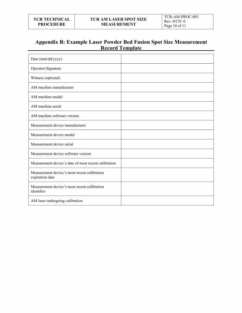
Appendix B: Example Laser Powder Bed Fusion Spot Size Measurement
TCR TECHNICAL PROCEDURE
TCR AM LASER SPOT SIZE MEASUREMENT
TCR-AM-PROC-003 Rev. 0/CN: 0 Page 10 of 11
Record Template
Date (mm/dd/yyyy)
Operator/Signature
Witness (optional)
AM machine manufacturer
AM machine model
AM machine serial
AM machine software version
Measurement device manufacturer
Measurement device model
Measurement device serial
Measurement device software version
Measurement device’s date of most recent calibration
Measurement device’s most recent calibration expiration date
Measurement device’s most recent calibration identifier
AM laser undergoing calibration
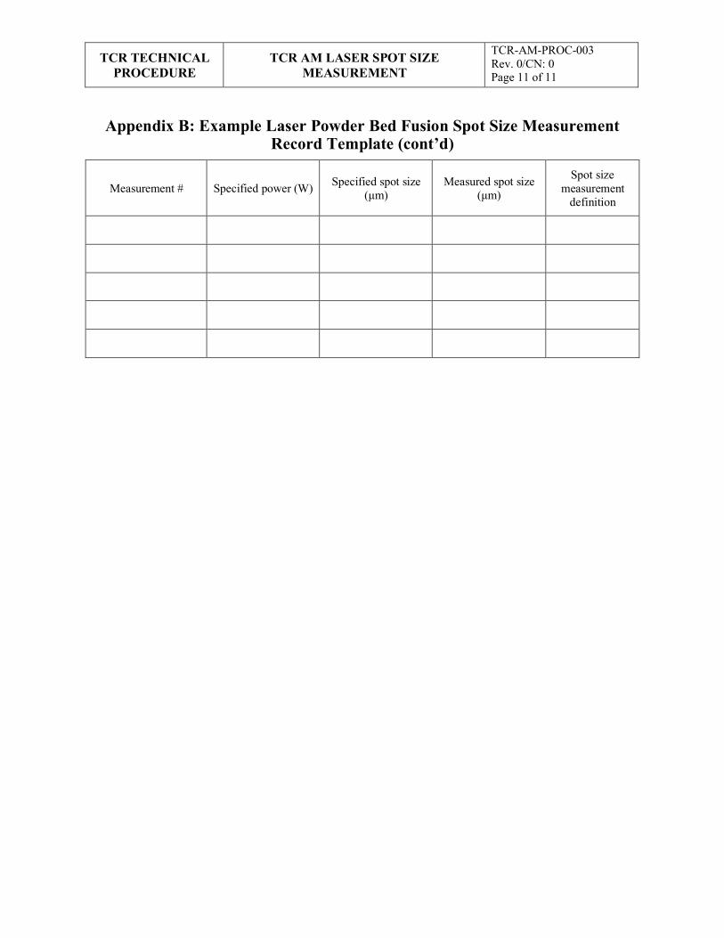
Appendix B: Example Laser Powder Bed Fusion Spot Size Measurement
TCR TECHNICAL PROCEDURE
TCR AM LASER SPOT SIZE MEASUREMENT
TCR-AM-PROC-003 Rev. 0/CN: 0 Page 11 of 11
Record Template (cont’d)
Measurement #
Specified power (W)
Specified spot size
(μm)
Measured spot size
(μm)
Spot size measurement
definition

APPENDIX F. TCR AM PART CHARACTERIZATION
F-1

TCR TECHNICAL
PROCEDURE
TCR AM PART CHARACTERIZATION
TCR-AM-PROC-005 Rev. 0/CN: 0 Page 1 of 14
Transformational Challenge Reactor Program
Number: TCR-AM-PROC-005
Rev./CN#: 0
Approval Date: 05/05/2020
Issue Date: 05/06/2020
Effective Date: 05/05/2020
Supersedes: N/A
Review Required: 05/05/2023
Title: TCR AM Part Characterization
IDMS Record #: 24278
Document Owner: Ryan Dehoff, TCR AM Thrust Lead
Author: Michael Russell, TCR QA Representative
Point of Contact: Andres Marquez, MDF Characterization Lead
Approved by:
Ryan Dehoff, TCR AM Thrust Lead
Mark Vance, TCR QA Manager
Sherri Buchanan, TCR Program Manager
Reviewed by:
Andres Marquez, MDF Characterization Lead
Kurt Terrani, TCR Technical Lead
This document has been electronically approved. Electronic signatures of approvers are listed on the IDMS View/Print page associated with the IDMS Record # above.
Before using a copy of this document, compare its issue date to the issue date of the IDMS version to verify that it is the most current version.
TCR TECHNICAL
PROCEDURE
TCR AM PART CHARACTERIZATION
TCR-AM-PROC-005 Rev. 0/CN: 0 Page 2 of 14
REVISION LOG
Rev. Date Affected Pages Revision Description
0 05/05/2020
All
Initial release
Document pages that are (check as appropriate):
Unclassified, Non-Sensitive: ALL (or) pages
Export Controlled: NONE (or) pages
Controlled, Unclassified, or Sensitive: NONE (or) pages
This document was prepared as an account of work sponsored by an agency of the United States Government. Neither the United States Government nor any agency thereof, nor any of their employees, makes any warranty, express or implied, or assumes any legal liability or responsibility for the accuracy, completeness, or usefulness of any information, apparatus, product, or process disclosed, or represents that its use would not infringe privately owned rights. Reference herein to any specific commercial product, process, or service by trade name, trademark, manufacturer, or otherwise, does not necessarily constitute or imply its endorsement, recommendation, or favoring by the United States Government or any agency thereof. The views and opinions of authors expressed herein do not necessarily state or reflect those of the United States Government or any agency thereof.
TCR TECHNICAL
PROCEDURE
TCR AM PART CHARACTERIZATION
TCR-AM-PROC-005 Rev. 0/CN: 0 Page 3 of 14
Table of Contents
1. INTRODUCTION ............................................................................................................................ 4
1.1 Purpose.................................................................................................................................... 4
1.2 Scope....................................................................................................................................... 4
2. PRECAUTIONS AND LIMITATIONS ............................................................................................ 4
2.1 Precautions .............................................................................................................................. 4
2.2 Limitations .............................................................................................................................. 4
3. REQUIREMENTS ............................................................................................................................ 4
4. PREREQUISITES ............................................................................................................................ 5
5. ACTION STEPS ............................................................................................................................... 5
5.1 Characterization Planning ........................................................................................................ 5
5.2 Macro CT via ZEISS METROTOM......................................................................................... 6
5.3 Micro CT via ZEISS VERSA 3D X-Ray Microscope ............................................................... 7
5.4 SEM via EVO .......................................................................................................................... 8
5.5 SEM via CROSSBEAM ........................................................................................................ 10
5.6 Optical Measurement Qualification via COMET .................................................................... 11
5.7 CMM Qualification via DURAMAX ..................................................................................... 12
6. RECORDS ...................................................................................................................................... 12
7. STANDARDS AND REFERENCES .............................................................................................. 13
7.1 Standards ............................................................................................................................... 13
7.2 References ............................................................................................................................. 13
8. APPENDICES ................................................................................................................................ 13
Appendix A: Abbreviations and Definitions .................................................................................... 14
.
TCR TECHNICAL
PROCEDURE
TCR AM PART CHARACTERIZATION
TCR-AM-PROC-005 Rev. 0/CN: 0 Page 4 of 14
1. INTRODUCTION
1.1 Purpose
This procedure identifies the responsibilities and describes the process for characterizing additive manufacturing (AM) parts or samples at the Oak Ridge National Laboratory (ORNL) Transformational Challenge Reactor (TCR) program.
1.2 Scope
This procedure includes the process for characterizing AM (or other) parts and samples to support the TCR program at ORNL or other facilities. This process includes techniques for analyzing parts and/or samples for dimensions, surface roughness, grain size/alignment, poor/void identification, and other characteristics. Characterization techniques include computer tomography (CT) x-ray, scanning electron microscope (SEM), coordinate measurement machine (CMM), and other techniques.
2. PRECAUTIONS AND LIMITATIONS
2.1 Precautions
1. TCR personnel must adhere to all ORNL safety and facility requirements assigned per the location and/or equipment being used.
2. TCR personnel must be trained to, assigned to, and familiar with the specific research safety summary (RSS) for each facility, work, and/or equipment location before obtaining access to or starting work.
3. TCR personnel must be familiar with and adhere to all identified job hazard controls, including using personal protective equipment (PPE) specific to the material, chemical, machine, location, facility, and/or task being performed and the PPE specifically described in third-party equipment manuals or material safety data sheets (MSDSs).
4. TCR personnel must use special care when handling AM powders to ensure limited inhalation, exposure, pyrophoric effects, and/or cross-contamination. Personnel must review user manuals and MSDSs before handling new types of powders.
2.2 Limitations
This procedure is limited to work being performed under the TCR program in accordance with TCR-QA-PLAN-001, TCR Quality Assurance Program Plan, and/or QAP-ORNL-NR&D-01, Quality Assurance Plan for Nuclear Research and Development Activities Conducted at the Oak Ridge National Laboratory, and associated procedures. This procedure can be used for other programs with approval from the document owner.
3. REQUIREMENTS
1. QAP-ORNL-NR&D-01, Quality Assurance Plan for Nuclear Research and Development Activities Conducted at the Oak Ridge National Laboratory
2. TCR-AM-PROC-001, “TCR AM Job Control”
3. TCR-DA-PROC-001, “TCR Design Control”
4. TCR-QA-PLAN-001, TCR Quality Assurance Program Plan
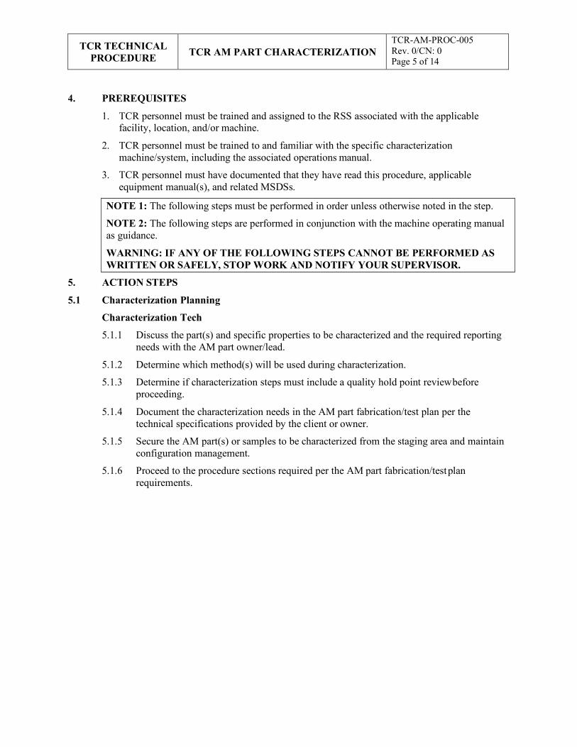
TCR TECHNICAL
PROCEDURE
TCR AM PART CHARACTERIZATION
TCR-AM-PROC-005 Rev. 0/CN: 0 Page 5 of 14
NOTE 1: The following steps must be performed in order unless otherwise noted in the step.
NOTE 2: The following steps are performed in conjunction with the machine operating manual as guidance.
WARNING: IF ANY OF THE FOLLOWING STEPS CANNOT BE PERFORMED AS WRITTEN OR SAFELY, STOP WORK AND NOTIFY YOUR SUPERVISOR.
4. PREREQUISITES
1. TCR personnel must be trained and assigned to the RSS associated with the applicable facility, location, and/or machine.
2. TCR personnel must be trained to and familiar with the specific characterization machine/system, including the associated operations manual.
3. TCR personnel must have documented that they have read this procedure, applicable equipment manual(s), and related MSDSs.
5. ACTION STEPS
5.1 Characterization Planning
Characterization Tech
5.1.1 Discuss the part(s) and specific properties to be characterized and the required reporting needs with the AM part owner/lead.
5.1.2 Determine which method(s) will be used during characterization.
5.1.3 Determine if characterization steps must include a quality hold point review before proceeding.
5.1.4 Document the characterization needs in the AM part fabrication/test plan per the technical specifications provided by the client or owner.
5.1.5 Secure the AM part(s) or samples to be characterized from the staging area and maintain configuration management.
5.1.6 Proceed to the procedure sections required per the AM part fabrication/test plan requirements.
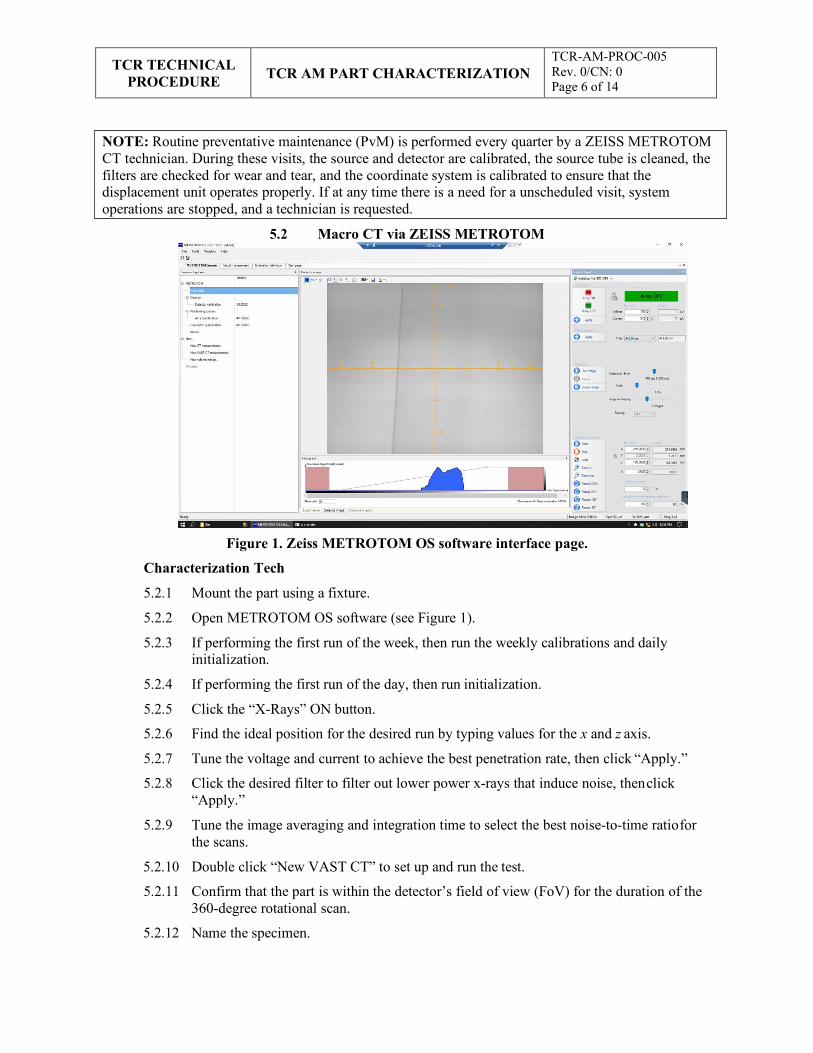
TCR TECHNICAL
PROCEDURE
TCR AM PART CHARACTERIZATION
TCR-AM-PROC-005 Rev. 0/CN: 0 Page 6 of 14
5.2 Macro CT via ZEISS METROTOM
Figure 1. Zeiss METROTOM OS software interface page.
Characterization Tech
5.2.1 Mount the part using a fixture.
5.2.2 Open METROTOM OS software (see Figure 1).
5.2.3 If performing the first run of the week, then run the weekly calibrations and daily initialization.
5.2.4 If performing the first run of the day, then run initialization.
5.2.5 Click the “X-Rays” ON button.
5.2.6 Find the ideal position for the desired run by typing values for the x and z axis.
5.2.7 Tune the voltage and current to achieve the best penetration rate, then click “Apply.”
5.2.8 Click the desired filter to filter out lower power x-rays that induce noise, then click “Apply.”
5.2.9 Tune the image averaging and integration time to select the best noise-to-time ratio for the scans.
5.2.10 Double click “New VAST CT” to set up and run the test.
5.2.11 Confirm that the part is within the detector’s field of view (FoV) for the duration of the 360-degree rotational scan.
5.2.12 Name the specimen.
NOTE: Routine preventative maintenance (PvM) is performed every quarter by a ZEISS METROTOM CT technician. During these visits, the source and detector are calibrated, the source tube is cleaned, the filters are checked for wear and tear, and the coordinate system is calibrated to ensure that the displacement unit operates properly. If at any time there is a need for a unscheduled visit, system operations are stopped, and a technician is requested.
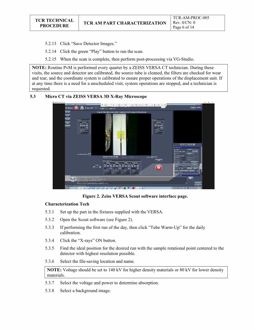
TCR TECHNICAL
PROCEDURE
TCR AM PART CHARACTERIZATION
TCR-AM-PROC-005 Rev. 0/CN: 0 Page 6 of 14
NOTE: Routine PvM is performed every quarter by a ZEISS VERSA CT technician. During these visits, the source and detector are calibrated, the source tube is cleaned, the filters are checked for wear and tear, and the coordinate system is calibrated to ensure proper operations of the displacement unit. If at any time there is a need for a unscheduled visit, system operations are stopped, and a technician is requested.
NOTE: Voltage should be set to 140 kV for higher density materials or 80 kV for lower density materials.
5.2.13 Click “Save Detector Images.”
5.2.14 Click the green “Play” button to run the scan.
5.2.15 When the scan is complete, then perform post-processing via VG-Studio.
5.3 Micro CT via ZEISS VERSA 3D X-Ray Microscope
Figure 2. Zeiss VERSA Scout software interface page.
Characterization Tech
5.3.1 Set up the part in the fixtures supplied with the VERSA.
5.3.2 Open the Scout software (see Figure 2).
5.3.3 If performing the first run of the day, then click “Tube Warm-Up” for the daily calibration.
5.3.4 Click the “X-rays” ON button.
5.3.5 Find the ideal position for the desired run with the sample rotational point centered to the detector with highest resolution possible.
5.3.6 Select the file-saving location and name.
5.3.7 Select the voltage and power to determine absorption.
5.3.8 Select a background image.
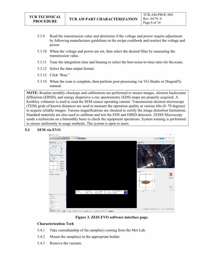
TCR TECHNICAL
PROCEDURE
TCR AM PART CHARACTERIZATION
TCR-AM-PROC-005 Rev. 0/CN: 0 Page 6 of 14
NOTE: Routine monthly checkups and calibrations are performed to ensure images, electron backscatter diffraction (EBSD), and energy dispersive x-ray spectrometry (EDS) maps are properly acquired. A Keithley voltmeter is used to read the SEM source operating current. Transmission electron microscope (TEM) grids of known distances are used to measure the operation quality at various tilts (0–70 degrees) to acquire reliable images. Various magnifications are checked to certify the image distortion limitations. Standard materials are also used to calibrate and test the EDS and EBSD detectors. ZEISS Microscopy sends a technician on a bimonthly basis to check the equipment operations. System training is performed to ensure uniformity in usage methods. The system is open to users.
5.3.9 Read the transmission value and determine if the voltage and power require adjustment by following manufacturer guidelines in the recipe cookbook and reselect the voltage and power.
5.3.10 When the voltage and power are set, then select the desired filter by measuring the transmission value.
5.3.11 Tune the integration time and binning to select the best noise-to-time ratio for the scans.
5.3.12 Select the data output format.
5.3.13 Click “Run.”
5.3.14 When the scan is complete, then perform post-processing via VG-Studio or DragonFly manual.
5.4 SEM via EVO
Figure 3. ZEIS EVO software interface page.
Characterization Tech
5.4.1 Take custodianship of the sample(s) coming from the Met-Lab.
5.4.2 Mount the sample(s) in the appropriate holder.
5.4.3 Remove the vacuum.
TCR TECHNICAL
PROCEDURE
TCR AM PART CHARACTERIZATION
TCR-AM-PROC-005 Rev. 0/CN: 0 Page 6 of 14
5.4.4 Place the sample(s) in the chamber.
5.4.5 Engage the vacuum.
5.4.6 Open the ZEIS EVO software (see Figure 3).
5.4.7 Turn on EHT (Electron High Tension).
5.4.8 Type the desired voltage and current.
5.4.9 Check the emission field to ensure it is centered with the column.
5.4.10 Find the ideal z-height position for the desired scan.
5.4.11 Tune the image quality with focus, stigmation, and wobble.
5.4.12 Acquire images.
5.4.13 Right click to save.
5.4.14 Select “Save Location.”
5.4.15 Select the file names.
5.4.16 If performing EDS/EBSD work, then follow these additional steps.
Set the voltage to 20 kV and the current between 4–20 nA depending on the excitation result of the material.
Launch RemCon software and activate the communication port with EDAX Computer.
Launch the TEAM software for EBSD/EDS analysis.
Select the type of work to be performed.
Acquire the appropriate spectra.
Tune the data acquisition routine.
Select “Saving Location.”
Acquire the data.
Generate the report and save.
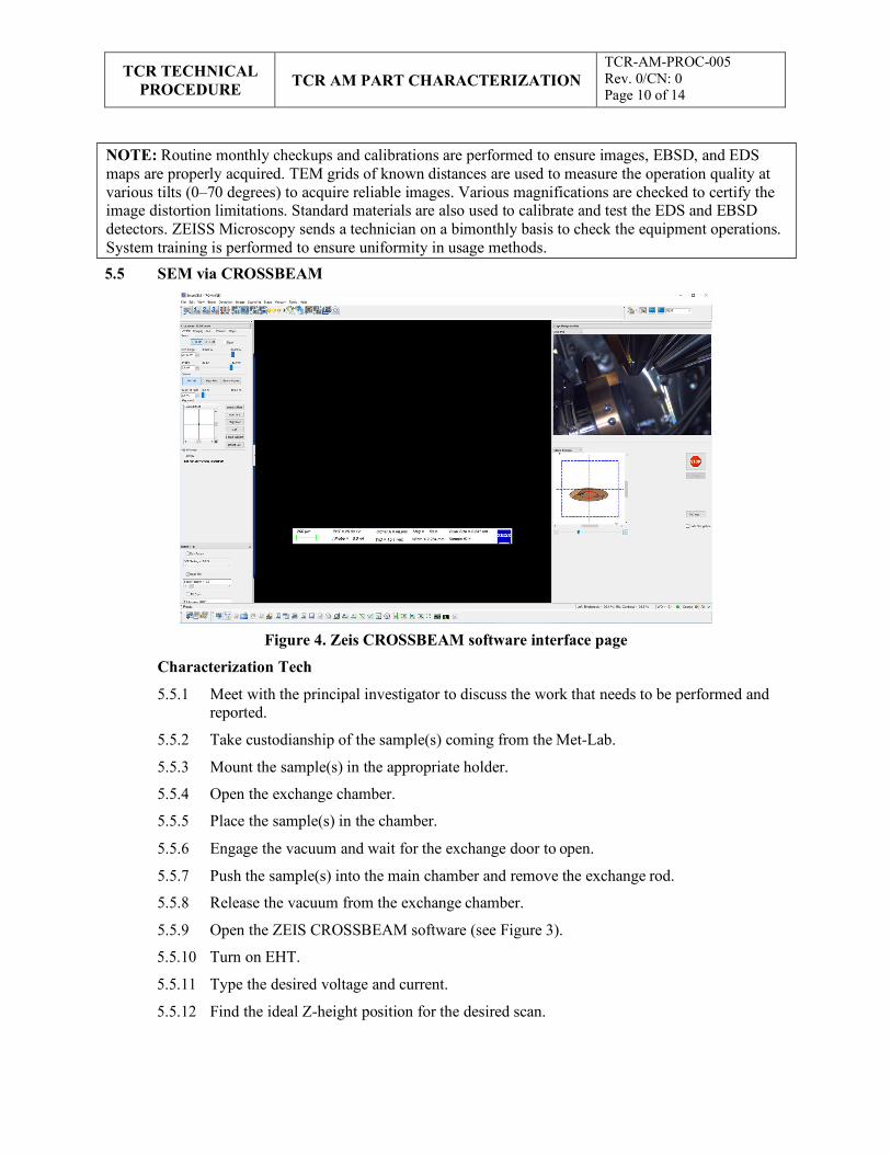
TCR TECHNICAL
PROCEDURE
TCR AM PART CHARACTERIZATION
TCR-AM-PROC-005 Rev. 0/CN: 0 Page 10 of 14
5.5 SEM via CROSSBEAM
Figure 4. Zeis CROSSBEAM software interface page
Characterization Tech
5.5.1 Meet with the principal investigator to discuss the work that needs to be performed and reported.
5.5.2 Take custodianship of the sample(s) coming from the Met-Lab.
5.5.3 Mount the sample(s) in the appropriate holder.
5.5.4 Open the exchange chamber.
5.5.5 Place the sample(s) in the chamber.
5.5.6 Engage the vacuum and wait for the exchange door to open.
5.5.7 Push the sample(s) into the main chamber and remove the exchange rod.
5.5.8 Release the vacuum from the exchange chamber.
5.5.9 Open the ZEIS CROSSBEAM software (see Figure 3).
5.5.10 Turn on EHT.
5.5.11 Type the desired voltage and current.
5.5.12 Find the ideal Z-height position for the desired scan.
NOTE: Routine monthly checkups and calibrations are performed to ensure images, EBSD, and EDS maps are properly acquired. TEM grids of known distances are used to measure the operation quality at various tilts (0–70 degrees) to acquire reliable images. Various magnifications are checked to certify the image distortion limitations. Standard materials are also used to calibrate and test the EDS and EBSD detectors. ZEISS Microscopy sends a technician on a bimonthly basis to check the equipment operations. System training is performed to ensure uniformity in usage methods.
TCR TECHNICAL
PROCEDURE
TCR AM PART CHARACTERIZATION
TCR-AM-PROC-005 Rev. 0/CN: 0 Page 10 of 14
NOTE: Routine calibrations are performed when an objective is changed or when the system has not been used for a week. System training is performed to ensure uniformity in usage methods.
NOTE: The system will determine the angular change based on these points.
5.5.13 Tune the image quality with focus, stigmation, and wobble.
5.5.14 Acquire images.
5.5.15 Right click to save.
5.5.16 Select “Save Location.”
5.5.17 Select the file names.
5.5.18 If performing EDS/EBSD work, then follow these additional steps:
Set the voltage to 20 kV and the current between 4–20 nA depending on the excitation result of the material.
Launch RemCon software and activate the communication port with OXFORD computer.
Launch AZTEC software for EBSD/EDS analysis.
Select the type of work to be performed.
Select the file-saving location.
Acquire the appropriate spectra.
Tune the data acquisition routine.
Acquire data.
Generate the report and save.
5.6 Optical Measurement Qualification via COMET
Characterization Tech
5.6.1 Open COLIN3D software.
5.6.2 Select the COMET model and objectives.
5.6.3 Wait 30 minutes for electronic warmup.
5.6.4 Place the sample on the rotary table.
5.6.5 Activate the rotary table.
5.6.6 Place the COMET in the desired position so that the sample falls in center of the FoV.
5.6.7 Select the rotary option.
5.6.8 Select the number of scans.
5.6.9 Start image acquisition.
5.6.10 When the first image is complete, then determine if the rendering seems correct.
If the rendering is bad, then reposition the COMET to optimize FoV.
Rerun the first image until the desired FoV is achieved.
TCR TECHNICAL
PROCEDURE
TCR AM PART CHARACTERIZATION
TCR-AM-PROC-005 Rev. 0/CN: 0 Page 10 of 14
NOTE: Routine calibrations checks on the probing tool tips are performed before running a sample. These calibration checks are performed to ensure the tip’s circularity, appropriate mounting, and surface finish, as well as the calibration and response of the coordinate system. System training is performed by ZEISS on a 5 day training course to ensure uniformity in usage methods and software.
5.6.11 When the second image is complete, then “clock” the points so that the software can stitch together all the images.
5.6.12 When the final image is acquired, then click “OK.”
5.6.13 Use clipping planes to remove the unwanted objects in the rendering.
5.6.14 Run the mesh analysis.
5.6.15 Open the STL (standard triangle language) file for the part.
5.6.16 Turn on the high-quality comparison to determine the deviation from the desired product.
5.6.17 Create a report and save.
5.7 CMM Qualification via DURAMAX
Characterization Tech
5.7.1 Open Calypso software.
5.7.2 Import the CAD file.
5.7.3 Select the Styli to use.
5.7.4 Run the Styli geometric qualification on the standard sphere.
5.7.5 Save the results.
5.7.6 Place the sample on the table.
5.7.7 Determine the three planes to clock the sample and it’s direction.
5.7.8 Create the routine for measuring characteristics.
5.7.9 Validate the routine.
5.7.10 Manually register the sample location.
5.7.11 Run the measurement plan.
5.7.12 Review the results and create a report file.
5.7.13 Save the report file.
6. RECORDS
This document generates the following records:
• Completed job traveler
• System logs, as applicable
• Job report files
TCR TECHNICAL
PROCEDURE
TCR AM PART CHARACTERIZATION
TCR-AM-PROC-005 Rev. 0/CN: 0 Page 10 of 14
7. STANDARDS AND REFERENCES
7.1 Standards
• ASME NQA-1-2008, Quality Assurance Requirements for Nuclear Facility Applications
• QAP-ORNL-NR&D-01, Quality Assurance Plan for Nuclear Research and Development Activities Conducted at the Oak Ridge National Laboratory
7.2 References
• TCR-AM-PROC-001, “TCR AM Job Control”
• TCR-DA-PROC-001, “TCR Design Control”
• TCR-QA-PLAN-001, TCR Quality Assurance Program Plan
8. APPENDICES
• Appendix A: Abbreviations and Definitions
TCR TECHNICAL
PROCEDURE
TCR AM PART CHARACTERIZATION
TCR-AM-PROC-005 Rev. 0/CN: 0 Page 10 of 14
Appendix A: Abbreviations and Definitions Abbreviations
AM additive manufacturing
CMM coordinate measurement machine
CT computer tomography
EBSD electron backscatter diffraction
EDS energy dispersive x-ray spectrometry
EHT Electron High Tension
FoV field of vision
MSDS material safety data sheet
ORNL Oak Ridge National Laboratory
PPE personal protective equipment
PvM preventative maintenance
RSS research safety summary
SEM scanning electron microscope
STL standard triangle language
TCR Transformational Challenge Reactor
TEM transmission electron microscope
Definitions None
APPENDIX G. TCR AM METALLOGRAPHY SPECIMEN PREPARATION
G-1

TCR TECHNICAL
PROCEDURE TCR AM METALLOGRAPHY SPECIMEN PREPARATION
TCR-AM-PROC-006 Rev./CN#: 0 Page 1 of 15
Transformational Challenge Reactor Program
Number: TCR-AM-PROC-006
Rev./CN#: 0
Approval Date: 06/12/2020
Issue Date: 06/12/20202
Effective Date: 06/12/2020
Supersedes: N/A
Review Required: 06/01/2020
Title: TCR AM Metallography Specimen Preparation
IDMS Record #: 024376
Document Owner: Andres Marquez, MDF Characterization Lead
Author: Michael Russell, TCR QA Representative (with technical input from Sarah Graham, MDF Metallography SME)
Point of Contact: Andres Marquez, MDF Characterization Lead
Approved by:
Andres Marquez, MDF Characterization Lead
Mark Vance, TCR QA Manager
Sherri Buchanan, TCR Program Manager
Reviewed by:
Ryan Dehoff, TCR AM Thrust Lead
Kurt Terrani, TCR Technical Director
Sarah Graham, MDF Metallography SME
This document has been electronically approved. Electronic signatures of approvers are listed on the IDMS View/Print page associated with the IDMS Record # above.
Before using a copy of this document, compare its issue date to the issue date of the IDMS version to verify that it is the most current version.
TCR TECHNICAL
PROCEDURE TCR AM METALLOGRAPHY SPECIMEN PREPARATION
TCR-AM-PROC-006 Rev./CN#: 0 Page 1 of 15
REVISION LOG
Rev. Date Affected Pages Revision Description
0 06/12/2020 All Initial release
Document pages that are (check as appropriate):
Unclassified, Non-Sensitive: x ALL (or) pages
Export Controlled: NONE (or) pages
Controlled, Unclassified, or Sensitive: NONE (or) pages
This document was prepared as an account of work sponsored by an agency of the United States Government. Neither the United States Government nor any agency thereof, nor any of their employees, makes any warranty, express or implied, or assumes any legal liability or responsibility for the accuracy, completeness, or usefulness of any information, apparatus, product, or process disclosed, or represents that its use would not infringe privately owned rights. Reference herein to any specific commercial product, process, or service by trade name, trademark, manufacturer, or otherwise, does not necessarily constitute or imply its endorsement, recommendation, or favoring by the United States Government or any agency thereof. The views and opinions of authors expressed herein do not necessarily state or reflect those of the United States Government or any agency thereof.
TCR TECHNICAL
PROCEDURE TCR AM METALLOGRAPHY SPECIMEN PREPARATION
TCR-AM-PROC-006 Rev./CN#: 0 Page 1 of 15
Table of Contents
1. INTRODUCTION ............................................................................................................................ 4
1.1 Purpose.................................................................................................................................... 4
1.2 Scope....................................................................................................................................... 4
2. PRECAUTIONS AND LIMITATIONS ............................................................................................ 4
2.1 Precautions .............................................................................................................................. 4
2.2 Limitations .............................................................................................................................. 4
3. REQUIREMENTS ............................................................................................................................ 4
4. PREREQUISITES ............................................................................................................................ 5
5. ACTION STEPS ............................................................................................................................... 5
5.1 Sample Planning ...................................................................................................................... 5
5.2 Sample Sectioning ................................................................................................................... 5
5.3 Sample Mounting .................................................................................................................... 6
5.4 Sample Tracking ...................................................................................................................... 8
5.5 Sample Grinding and Polishing .............................................................................................. 10
6. RECORDS ...................................................................................................................................... 10
7. STANDARDS AND REFERENCES .............................................................................................. 10
7.1 Standards ............................................................................................................................... 10
7.2 References ............................................................................................................................. 10
8. APPENDICES ................................................................................................................................ 10
Appendix A: Abbreviations and Definitions .................................................................................... 11
Appendix B: Basic Metallography Instructions for Metals and Ceramics ......................................... 12
.
TCR TECHNICAL
PROCEDURE TCR AM METALLOGRAPHY SPECIMEN PREPARATION
TCR-AM-PROC-006 Rev./CN#: 0 Page 1 of 15
1. INTRODUCTION
1.1 Purpose
This procedure identifies the responsibilities and describes the process for preparing metallography slides or specimens to characterize additive manufacturing (AM) parts or samples at the Oak Ridge National Laboratory (ORNL) Transformational Challenge Reactor (TCR) program.
1.2 Scope
This procedure includes the process for preparing metallography slides and/or samples for characterizing AM or other parts and samples to support the TCR program at ORNL or other facilities. This process includes techniques for specimen identification, sectioning, mounting, grinding, and finish polishing to prepare specimens for characterization per TCR-AM-PROC-005, “TCR Characterization.”
2. PRECAUTIONS AND LIMITATIONS
2.1 Precautions
1. TCR personnel must adhere to all ORNL safety and facility requirements assigned per the location and/or equipment being used.
2. TCR personnel must be trained to, assigned to, and familiar with the specific research safety summary (RSS) for each facility, work, and/or equipment location before obtaining access to or starting work.
3. TCR personnel must be familiar with and adhere to all identified job hazard controls, including using personal protective equipment (PPE) specific to the material, chemical, machine, location, facility, and/or task being performed and the PPE specifically described in third-party equipment manuals or material safety data sheets (MSDSs).
4. TCR personnel must use special care when handling AM powders to ensure limited inhalation, exposure, pyrophoric effects, and/or cross-contamination. Personnel must review user manuals and MSDSs before handling new types of powders.
2.2 Limitations
This procedure is limited to work being performed under the TCR program in accordance with TCR-QA-PLAN-001, TCR Quality Assurance Program Plan, and/or QAP-ORNL-NR&D-01, Quality Assurance Plan for Nuclear Research and Development Activities Conducted at the Oak Ridge National Laboratory, and associated procedures. This procedure can be used for other programs or sample types with approval from the document owner.
3. REQUIREMENTS
1. QAP-ORNL-NR&D-01, Quality Assurance Plan for Nuclear Research and Development Activities Conducted at the Oak Ridge National Laboratory
2. TCR-AM-PROC-001, “TCR AM Job Control”
3. TCR-DA-PROC-001, “TCR Design Control”
4. TCR-QA-PLAN-001, TCR Quality Assurance Program Plan
TCR TECHNICAL
PROCEDURE TCR AM METALLOGRAPHY SPECIMEN PREPARATION
TCR-AM-PROC-006 Rev./CN#: 0 Page 1 of 15
NOTE 1: The following steps in each section must be performed in order unless otherwise noted in the step.
NOTE 2: The following steps are performed in conjunction with the machine operating manual as guidance.
WARNING: POTENTIAL INJURY CAN RESULT FROM USING CHARACTERIZATION MACHINES, SYSTEMS, AND ASSOCIATED MATERIALS IF PERSONNEL ARE NOT FAMILIAR WITH SAFETY WARNINGS AND REQUIREMENTS ASSOCIATED WITH THEM—INCLUDING THE RELATED RSS, MSDS, AND EQUIPMENT MANUALS—TO ENSURE ALL REQUIRED SAFETY PRECAUTIONS AND PPE ARE USED.
4. PREREQUISITES
1. TCR personnel must be trained and assigned to the RSS associated with the applicable facility, location, and/or machine.
2. TCR personnel must be trained to and familiar with the specific characterization machine/system, including the associated operations manual.
3. TCR personnel must have documented that they have read this procedure, applicable equipment manual(s), and related MSDSs.
5. ACTION STEPS
5.1 Sample Planning
Characterization Tech (Metallographer)
5.1.1 Review the required sample preparation with the customer, including the following:
Identify material(s).
Determine which plane(s) to prepare.
Determine mount dimensions.
Determine mount material.
Determine task timeline.
5.1.2 Prepare the required documentation materials to ensure accurate documentation of
metallographic service work, including lab books, scratch paper, permanent markers, paint pens, and other necessary supplies.
5.2 Sample Sectioning
Characterization Tech (Metallographer)
5.2.1 Select the appropriate cutting blade for the material.
5.2.2 Select the appropriate sectioning tool for the task based on the overall volume of the specimen being cut.
5.2.3 Select the appropriate abrasive or bonded discs to minimize the damage done to the specimen and polishing surface(s).
NOTE: A specific metallography lab specimen identification (ID) will also be generated, as described in Section 5.4. These IDs are linked to the TCR AM part ID in the job traveler and uploaded to the TCR AM database.
TCR TECHNICAL
PROCEDURE TCR AM METALLOGRAPHY SPECIMEN PREPARATION
TCR-AM-PROC-006 Rev./CN#: 0 Page 1 of 15
NOTE: Based on the customer’s request, the metallographer can select a “cold” epoxy resin mounting process or a “hot” phenolic resin mounting process. The selection is usually a materials consideration; however, specific polishing challenges can be overcome by the mounting material selection. The epoxy resin and phenolic resin mounts comes in 1.25 and 2 in. standard sizes with custom sizes available.
5.2.4 Select the appropriate high-speed or low-speed saw based on the material and size.
5.2.5 Cut and/or grind the specimen to the appropriate size.
5.2.6 Deburr and clean the specimen using ethanol, acetone, or another solvent to ensure proper adhesion of the mounting material.
5.2.7 Allow the specimen to dry.
5.2.8 Maintain specimen configuration management with temporary labels and/or markings.
5.3 Sample Mounting
Characterization Tech (Metallographer)
5.3.1 Select the appropriate mounting process using the information in the previous note.
5.3.2 For cold epoxy resin mounting, perform the following steps:
Label each mold form with the specimen ID number.
Lightly coat the molds with release agent using clean cotton swabs.
Place the samples in the molds according to the ID labels, making sure to align with polishing orientation.
Mix the resin and hardener using a scale to verify the required amount.
When the resin and hardener are combined, then gently pour the sample epoxy to the desired height.
Place the mold in a vacuum chamber to remove air that could form porosity voids on the surface.
When the vacuum process is complete, then remove the molds from the vacuum chamber and let cure for 8–24 hours to the desired hardness.
5.3.3 For hot phenolic resin mounting, perform the following steps:
Select the press system with the desired mold diameter in accordance with the note before Step 5.3.1.
Power on the mold press.
Use the Buehler software to determine the amount of mounting material necessary for the height and diameter of the test specimen by entering the material type and mass of sample (Figure 1).
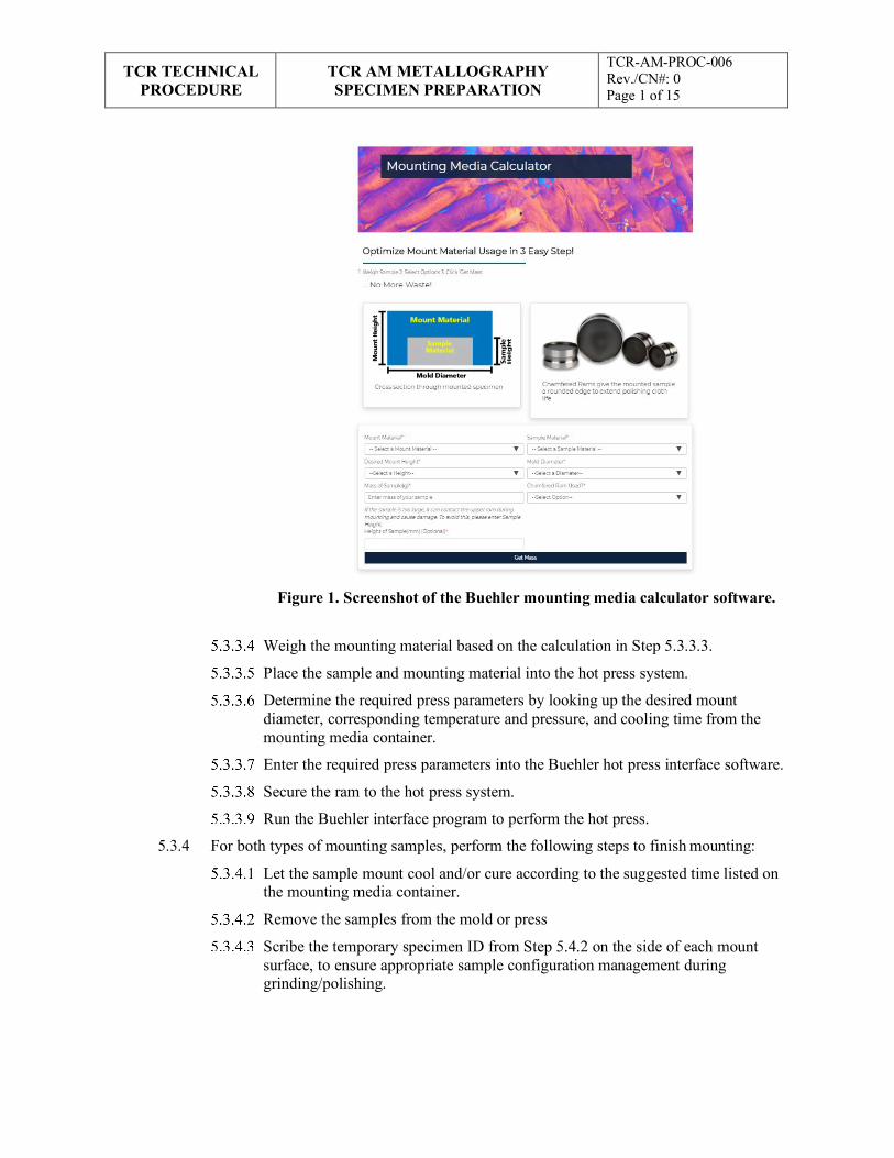
TCR TECHNICAL
PROCEDURE TCR AM METALLOGRAPHY SPECIMEN PREPARATION
TCR-AM-PROC-006 Rev./CN#: 0 Page 1 of 15
Figure 1. Screenshot of the Buehler mounting media calculator software.
Weigh the mounting material based on the calculation in Step 5.3.3.3.
Place the sample and mounting material into the hot press system.
Determine the required press parameters by looking up the desired mount diameter, corresponding temperature and pressure, and cooling time from the mounting media container.
Enter the required press parameters into the Buehler hot press interface software.
Secure the ram to the hot press system.
Run the Buehler interface program to perform the hot press.
5.3.4 For both types of mounting samples, perform the following steps to finish mounting:
Let the sample mount cool and/or cure according to the suggested time listed on the mounting media container.
Remove the samples from the mold or press
Scribe the temporary specimen ID from Step 5.4.2 on the side of each mount surface, to ensure appropriate sample configuration management during grinding/polishing.
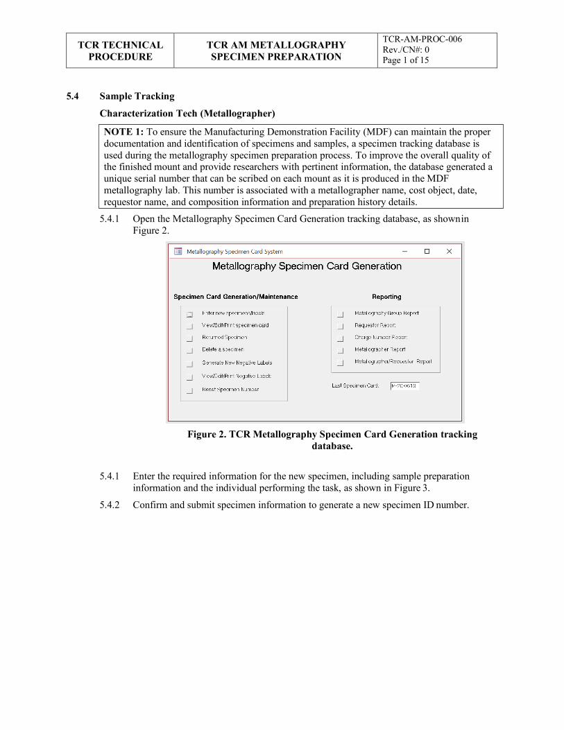
TCR TECHNICAL
PROCEDURE TCR AM METALLOGRAPHY SPECIMEN PREPARATION
TCR-AM-PROC-006 Rev./CN#: 0 Page 1 of 15
NOTE 1: To ensure the Manufacturing Demonstration Facility (MDF) can maintain the proper documentation and identification of specimens and samples, a specimen tracking database is used during the metallography specimen preparation process. To improve the overall quality of the finished mount and provide researchers with pertinent information, the database generated a unique serial number that can be scribed on each mount as it is produced in the MDF metallography lab. This number is associated with a metallographer name, cost object, date, requestor name, and composition information and preparation history details.
5.4 Sample Tracking
Characterization Tech (Metallographer)
5.4.1 Open the Metallography Specimen Card Generation tracking database, as shown in Figure 2.
Figure 2. TCR Metallography Specimen Card Generation tracking
database.
5.4.1 Enter the required information for the new specimen, including sample preparation
information and the individual performing the task, as shown in Figure 3.
5.4.2 Confirm and submit specimen information to generate a new specimen ID number.
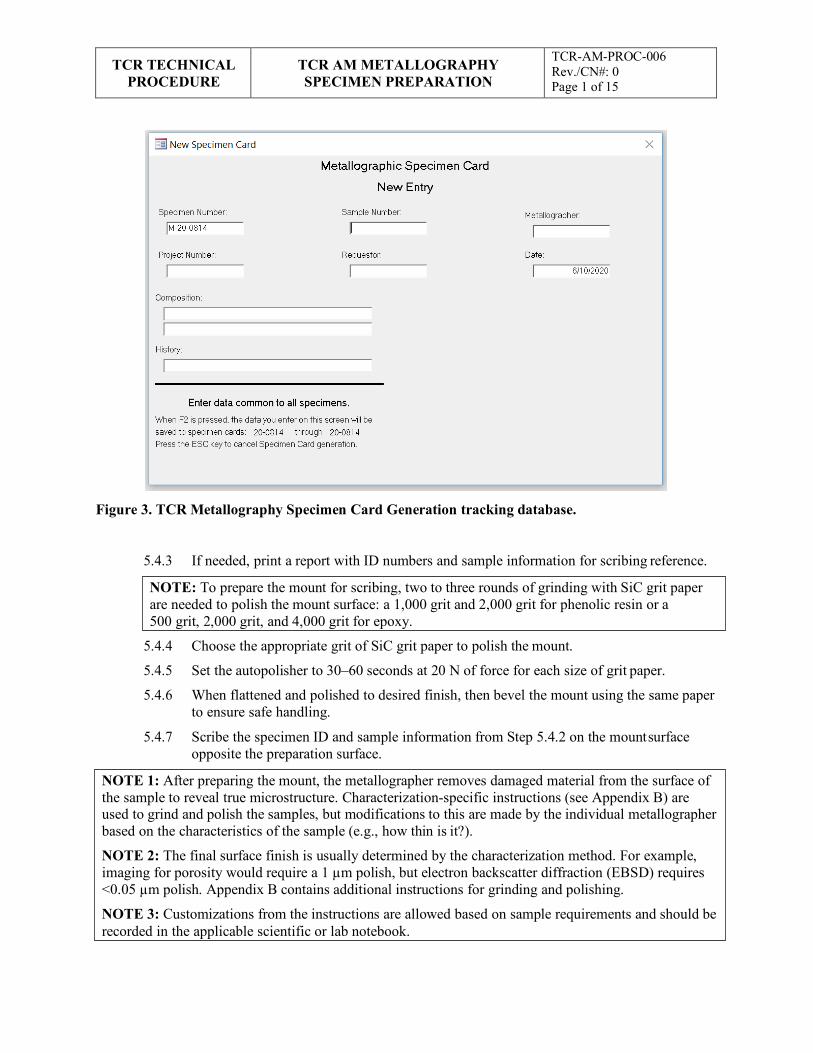
TCR TECHNICAL
PROCEDURE TCR AM METALLOGRAPHY SPECIMEN PREPARATION
TCR-AM-PROC-006 Rev./CN#: 0 Page 1 of 15
NOTE: To prepare the mount for scribing, two to three rounds of grinding with SiC grit paper are needed to polish the mount surface: a 1,000 grit and 2,000 grit for phenolic resin or a 500 grit, 2,000 grit, and 4,000 grit for epoxy.
NOTE 1: After preparing the mount, the metallographer removes damaged material from the surface of the sample to reveal true microstructure. Characterization-specific instructions (see Appendix B) are used to grind and polish the samples, but modifications to this are made by the individual metallographer based on the characteristics of the sample (e.g., how thin is it?).
NOTE 2: The final surface finish is usually determined by the characterization method. For example, imaging for porosity would require a 1 µm polish, but electron backscatter diffraction (EBSD) requires <0.05 µm polish. Appendix B contains additional instructions for grinding and polishing.
NOTE 3: Customizations from the instructions are allowed based on sample requirements and should be recorded in the applicable scientific or lab notebook.
Figure 3. TCR Metallography Specimen Card Generation tracking database.
5.4.3 If needed, print a report with ID numbers and sample information for scribing reference.
5.4.4 Choose the appropriate grit of SiC grit paper to polish the mount.
5.4.5 Set the autopolisher to 30–60 seconds at 20 N of force for each size of grit paper.
5.4.6 When flattened and polished to desired finish, then bevel the mount using the same paper to ensure safe handling.
5.4.7 Scribe the specimen ID and sample information from Step 5.4.2 on the mount surface opposite the preparation surface.
TCR TECHNICAL
PROCEDURE TCR AM METALLOGRAPHY SPECIMEN PREPARATION
TCR-AM-PROC-006 Rev./CN#: 0 Page 1 of 15
5.5 Sample Grinding and Polishing
Characterization Tech (Metallographer)
5.5.1 Identify the appropriate grinding instruction (see Appendix B) for the specific specimen and characterization process to be completed.
5.5.2 Complete the grinding process per the appropriate instruction (see Appendix B).
5.5.3 Complete the polishing process per the appropriate instruction (see Appendix B).
5.5.4 If any customizations were required to prepare the samples, then record them in the applicable scientific or lab notebook for repeatability and traceability.
5.5.5 Place the completed samples in the appropriate storage location and environment (e.g., desiccator, inert, vacuum).
5.5.6 Notify the characterization customer point of contract.
6. RECORDS
This document generates the following records:
• Characterization logs and reports, as applicable
• Job report files and related scientific notebooks
7. STANDARDS AND REFERENCES
7.1 Standards
• ASME NQA-1-2008/9a, Quality Assurance Requirements for Nuclear Facility Applications including 2009 addendum.
7.2 References
• TCR-AM-PROC-001, “TCR AM Job Control”
• TCR-DA-PROC-001, “TCR Design Control”
• TCR-QA-PLAN-001, TCR Quality Assurance Program Plan
• TCR-AM-PROC-005, “TCR Characterization”
• QAP-ORNL-NR&D-01, Quality Assurance Plan for Nuclear Research and Development Activities Conducted at the Oak Ridge National Laboratory
8. APPENDICES
• Appendix A, Abbreviations and Definitions
• Appendix B, Geer Basic Metallography Instructions for Metals and Ceramics
TCR TECHNICAL
PROCEDURE TCR AM METALLOGRAPHY SPECIMEN PREPARATION
TCR-AM-PROC-006 Rev./CN#: 0 Page 1 of 15
Appendix A: Abbreviations and Definitions Abbreviations
AM additive manufacturing
EBSD electron backscatter diffraction
ID identification
MDF Manufacturing Demonstration Facility
MSDS material safety data sheet
ORNL Oak Ridge National Laboratory
PPE personal protective equipment
RSS research safety summary
TCR Transformational Challenge Reactor
Definitions
None
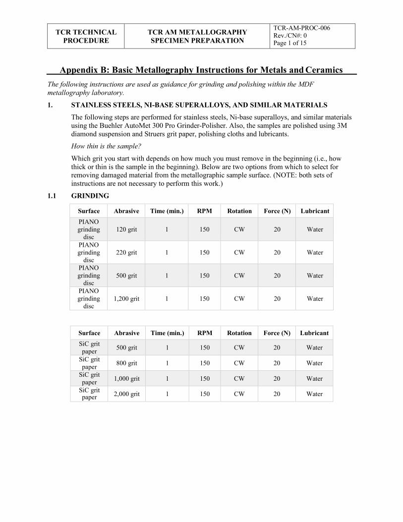
TCR TECHNICAL
PROCEDURE TCR AM METALLOGRAPHY SPECIMEN PREPARATION
TCR-AM-PROC-006 Rev./CN#: 0 Page 1 of 15
Appendix B: Basic Metallography Instructions for Metals and Ceramics The following instructions are used as guidance for grinding and polishing within the MDF metallography laboratory.
1. STAINLESS STEELS, NI-BASE SUPERALLOYS, AND SIMILAR MATERIALS
The following steps are performed for stainless steels, Ni-base superalloys, and similar materials using the Buehler AutoMet 300 Pro Grinder-Polisher. Also, the samples are polished using 3M diamond suspension and Struers grit paper, polishing cloths and lubricants.
How thin is the sample?
Which grit you start with depends on how much you must remove in the beginning (i.e., how thick or thin is the sample in the beginning). Below are two options from which to select for removing damaged material from the metallographic sample surface. (NOTE: both sets of instructions are not necessary to perform this work.)
1.1 GRINDING
Surface Abrasive Time (min.) RPM Rotation Force (N) Lubricant PIANO grinding
disc
120 grit
1
150
CW
20
Water
PIANO grinding
disc
220 grit
1
150
CW
20
Water
PIANO grinding
disc
500 grit
1
150
CW
20
Water
PIANO grinding
disc
1,200 grit
1
150
CW
20
Water
Surface Abrasive Time (min.) RPM Rotation Force (N) Lubricant SiC grit paper 500 grit 1 150 CW 20 Water
SiC grit paper 800 grit 1 150 CW 20 Water
SiC grit paper 1,000 grit 1 150 CW 20 Water
SiC grit paper 2,000 grit 1 150 CW 20 Water
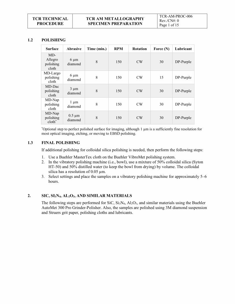
TCR TECHNICAL
PROCEDURE TCR AM METALLOGRAPHY SPECIMEN PREPARATION
TCR-AM-PROC-006 Rev./CN#: 0 Page 1 of 15
1.2 POLISHING
Surface Abrasive Time (min.) RPM Rotation Force (N) Lubricant MD-
Allegro polishing
cloth
6 µm
diamond
8
150
CW
30
DP-Purple
MD-Largo polishing
cloth 6 µm
diamond
8
150
CW
15
DP-Purple
MD-Dac polishing
cloth
3 µm diamond
8
150
CW
30
DP-Purple
MD-Nap polishing
cloth
1 µm diamond
8
150
CW
30
DP-Purple
MD-Nap polishing
cloth* 0.5 µm
diamond
8
150
CW
30
DP-Purple
*Optional step to perfect polished surface for imaging, although 1 µm is a sufficiently fine resolution for most optical imaging, etching, or moving to EBSD polishing.
1.3 FINAL POLISHING
If additional polishing for colloidal silica polishing is needed, then perform the following steps:
1. Use a Buehler MasterTex cloth on the Buehler VibroMet polishing system. 2. In the vibratory polishing machine (i.e., bowl), use a mixture of 50% colloidal silica (Syton
HT-50) and 50% distilled water (to keep the bowl from drying) by volume. The colloidal silica has a resolution of 0.05 µm.
3. Select settings and place the samples on a vibratory polishing machine for approximately 5–6 hours.
2. SIC, SI3N4, AL2O3, AND SIMILAR MATERIALS
The following steps are performed for SiC, Si3N4, Al2O3, and similar materials using the Buehler AutoMet 300 Pro Grinder-Polisher. Also, the samples are polished using 3M diamond suspension and Struers grit paper, polishing cloths and lubricants.
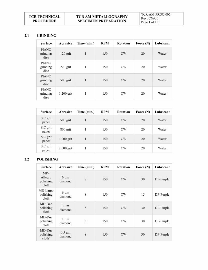
TCR TECHNICAL
PROCEDURE TCR AM METALLOGRAPHY SPECIMEN PREPARATION
TCR-AM-PROC-006 Rev./CN#: 0 Page 1 of 15
2.1 GRINDING
Surface Abrasive Time (min.) RPM Rotation Force (N) Lubricant
PIANO grinding
disc
120 grit
1
150
CW
20
Water
PIANO grinding
disc
220 grit
1
150
CW
20
Water
PIANO grinding
disc
500 grit
1
150
CW
20
Water
PIANO grinding
disc
1,200 grit
1
150
CW
20
Water
Surface Abrasive Time (min.) RPM Rotation Force (N) Lubricant
SiC grit paper 500 grit 1 150 CW 20 Water
SiC grit paper 800 grit 1 150 CW 20 Water
SiC grit paper 1,000 grit 1 150 CW 20 Water
SiC grit paper 2,000 grit 1 150 CW 20 Water
2.2 POLISHING
Surface Abrasive Time (min.) RPM Rotation Force (N) Lubricant
MD- Allegro
polishing cloth
6 µm
diamond
8
150
CW
30
DP-Purple
MD-Largo polishing
cloth
6 µm diamond
8
150
CW
15
DP-Purple
MD-Dac polishing
cloth
3 µm diamond
8
150
CW
30
DP-Purple
MD-Dur polishing
cloth
1 µm diamond
8
150
CW
30
DP-Purple
MD-Dur polishing
cloth*
0.5 µm diamond
8
150
CW
30
DP-Purple
TCR TECHNICAL
PROCEDURE TCR AM METALLOGRAPHY SPECIMEN PREPARATION
TCR-AM-PROC-006 Rev./CN#: 0 Page 1 of 15
*Optional step to perfect polished surface for imaging, although 1 µm is sufficiently fine resolution for most optical imaging, etching, or moving to EBSD polishing.
2.3 FINAL POLISHING
If additional polishing for colloidal silica polishing is needed, then perform the following steps:
1. Use a Buehler MasterTex cloth on the Buehler VibroMet polishing system. 2. In the vibratory polishing machine (i.e., bowl), use a mixture of 50% colloidal silica (Syton
HT-50) and 50% distilled water (to keep the bowl from drying) by volume. The colloidal silica has a resolution of 0.05 µm.
3. Select settings and place the samples on a vibratory polishing machine for approximately 5–6 hours.
APPENDIX H. TCR AM CONCEPT LASER M2 CUSING SETUP and BUILD START
H-1

TCR TECHNICAL
PROCEDURE TCR AM CONCEPT LASER M2 CUSING
SETUP and BUILD START
TCR-AM-PROC-200 Rev. 0/CN 0 Page 1 of 12
Transformational Challenge Reactor Program
Number: TCR-AM-PROC-200
Rev./CN#: 0
Approval Date: 05/05/2020
Issue Date: 05/06/2020
Effective Date: 05/05/2020
Supersedes: N/A
Review Required: 05/05/2023
Title: TCR AM Concept Laser M2 Cusing Setup
IDMS Record #: 24159
Document Owner: Ryan Dehoff, TCR AM Thrust Lead
Author: Michael Russell, TCR QA Representative
Point of Contact: Ryan Dehoff, TCR AM Thrust Lead
Approved by:
Ryan Dehoff, TCR AM Thrust Lead
Mark Vance, TCR QA Manager
Sherri Buchanan, TCR Project Manager
Reviewed by:
Fred List, Deposition Science & Technology
Kurt Terrani, TCR Technical Director
This document has been electronically approved. Electronic signatures of approvers are listed on the IDMS View/Print page associated with the IDMS Record # above.
Before using a copy of this document, compare its issue date to the issue date of the IDMS version to verify that it is the most current version.
TCR TECHNICAL
PROCEDURE TCR AM CONCEPT LASER M2 CUSING
SETUP and BUILD START
TCR-AM-PROC-200 Rev. 0/CN 0 Page 1 of 12
REVISION LOG
Rev. Date Affected Pages Revision Description
0 05/05/2020 All Initial release
Document pages that are (check as appropriate):
Unclassified, Non-Sensitive: ALL (or) pages
Export Controlled: NONE (or) pages
Controlled, Unclassified, or Sensitive: NONE (or) pages
This document was prepared as an account of work sponsored by an agency of the United States Government. Neither the United States Government nor any agency thereof, nor any of their employees, makes any warranty, express or implied, or assumes any legal liability or responsibility for the accuracy, completeness, or usefulness of any information, apparatus, product, or process disclosed, or represents that its use would not infringe privately owned rights. Reference herein to any specific commercial product, process, or service by trade name, trademark, manufacturer, or otherwise, does not necessarily constitute or imply its endorsement, recommendation, or favoring by the United States Government or any agency thereof. The views and opinions of authors expressed herein do not necessarily state or reflect those of the United States Government or any agency thereof.
TCR TECHNICAL
PROCEDURE TCR AM CONCEPT LASER M2 CUSING
SETUP and BUILD START
TCR-AM-PROC-200 Rev. 0/CN 0 Page 1 of 12
Table of Contents
1. INTRODUCTION ............................................................................................................................ 4
1.1 Purpose.................................................................................................................................... 4
1.2 Scope....................................................................................................................................... 4
2. PRECAUTIONS AND LIMITATIONS ............................................................................................ 4
2.1 Precautions .............................................................................................................................. 4
2.2 Limitations .............................................................................................................................. 4
3. REQUIREMENTS ............................................................................................................................ 4
4. PREREQUISITES ............................................................................................................................ 5
5. ACTION STEPS ............................................................................................................................... 5
5.1 Build Plate Selection ................................................................................................................ 5
5.2 Build Plate Installation ............................................................................................................. 7
5.3 Build Plate Levelling ............................................................................................................... 8
5.4 Machine Startup and Calibration .............................................................................................. 9
5.5 AM Build Job Start .................................................................................................................. 9
6. RECORDS ...................................................................................................................................... 10
7. STANDARDS AND REFERENCES .............................................................................................. 10
7.1 Standards ............................................................................................................................... 10
7.2 References ............................................................................................................................. 11
8. APPENDICES ................................................................................................................................ 11
Appendix A: Abbreviations and Definitions .................................................................................... 12
TCR TECHNICAL
PROCEDURE TCR AM CONCEPT LASER M2 CUSING
SETUP and BUILD START
TCR-AM-PROC-200 Rev. 0/CN 0 Page 1 of 12
1. INTRODUCTION
1.1 Purpose
This procedure identifies the responsibilities and describes the process for setting up the Concept Laser M2 Cusing additive manufacturing (AM) machine at the Oak Ridge National Laboratory (ORNL) Transformational Challenge Reactor (TCR) program.
1.2 Scope
This procedure includes machine-specific setup instructions for the Concept Laser M2 Cusing AM machine used to support the TCR program at ORNL or other facilities. The setup includes build plate selection and leveling, machine setup, and calibration before personnel use.
2. PRECAUTIONS AND LIMITATIONS
2.1 Precautions
1. TCR personnel must adhere to all ORNL safety and facility requirements assigned per the location and/or equipment being used.
2. TCR personnel must be trained to, assigned to, and be familiar with the specific research safety summary (RSS) for each facility, work, and/or equipment location before obtaining access to or starting work.
3. TCR personnel must be familiar with and adhere to all identified job hazard controls, including using personal protective equipment (PPE) specific to the material, chemical, machine, location, facility, and/or task being performed and the PPE specifically described in third-party equipment manuals or material safety data sheets (MSDSs).
2.2 Limitations
1. This procedure is limited to work being performed under the TCR program in accordance with TCR-QA-PLAN-001, TCR Quality Assurance Program Plan, and/or QAP-ORNL- NR&D-01, Quality Assurance Plan for Nuclear Research and Development Activities Conducted at the Oak Ridge National Laboratory, and associated procedures. This procedure can be used for other programs with approval from the document owner.
3. REQUIREMENTS
1. QAP-ORNL-NR&D-01, Quality Assurance Plan for Nuclear Research and Development Activities Conducted at the Oak Ridge National Laboratory
2. TCR-AM-PROC-001, “TCR AM Job Control”
3. TCR-DA-PROC-001, “TCR Design Control”
4. TCR-QA-PLAN-001, TCR Quality Assurance Program Plan
TCR TECHNICAL
PROCEDURE TCR AM CONCEPT LASER M2 CUSING
SETUP and BUILD START
TCR-AM-PROC-200 Rev. 0/CN 0 Page 1 of 12
NOTE 1: The following steps should be performed in order unless otherwise noted.
NOTE 2: The following steps are performed in accordance with all applicable machine operating manuals.
NOTE 3: The following steps are machine-specific and should not be used for other machines without evaluating specific machine operational setup differences.
WARNING: IF ANY OF THE FOLLOWING STEPS CANNOT BE PERFORMED AS WRITTEN OR SAFELY, STOP WORK AND NOTIFY YOUR SUPERVISOR.
NOTE: A build plate drawing is shown in Figure 1. A 316 SS build plate is four times more expensive than other steels but could be advantageous if electrical discharge machining (EDM) is required for part removal.
4. PREREQUISITES
1. TCR personnel conducting AM activities at the Manufacturing Demonstration Facility must to be trained and assigned to RSS Laser Additive Manufacturing at the National Transportation Research Center NTRC-3 17211.1, 16236.2, and/or the RSS applicable to the specific location and/or machine.
2. TCR personnel must be trained to and familiar with the specific AM machine, including the associated operations manual.
3. TCR personnel must have documented that they have read this procedure, applicable equipment manual(s), and related MSDSs.
5. ACTION STEPS
5.1 Build Plate Selection
AM Tech
5.1.1 Select the appropriate M2 build plate(s) in accordance with the following:
Determine the build plate material.
Chose a build plate size.
NOTE 1: The M2 Cusing equipment typically uses a standard 245 × 245 × 25 mm build plate made from 1.2312 tool steel, low-carbon steel, or 316 stainless steel (SS). as shown in Figure 1.

TCR TECHNICAL
PROCEDURE TCR AM CONCEPT LASER M2 CUSING
SETUP and BUILD START
TCR-AM-PROC-200 Rev. 0/CN 0 Page 1 of 12
5.1.2 Consider potential build deformation.
Figure 1. The standard 245 × 245 × 25 mm M2 build plate drawing used for most build experiments.
NOTE 1: The M2 Cusing equipment typically uses a standard 245 × 245 × 25 mm build plate.
NOTE 2: A mini build plate (6 × 6 × 0.25 in., 316 SS) may also be used for smaller build volumes and is shown in Figure 2. These mini build plates fasten to the center of a standard M2 build plate that has been appropriately tapped. A mini build plate reduces build costs and allows for easier print handling.
NOTE 3: The 0.25 in. thick mini build plate is prone to distorting when building large, continuous components. Subject matter experts (SMEs) are consulted before choosing a mini build plate for such components.
NOTE 4: Although the size of the X-Y bounding box for the build determines the minimum build plate size, the total melt area should also be considered when selecting the size of the build plate. Large, continuous components built on a 0.25 in. thick mini build plate could cause warping and distortion. The mini build plate is generally suitable for only small, discontinuous components. SMEs are consulted if there is uncertainty.
NOTE 5: If the fastening bolts for the standard or mini build plate seize due to plate warpage or distortion, then the heads of these bolts can be removed by drilling out the heads.
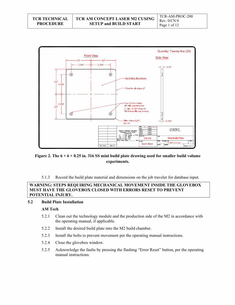
TCR TECHNICAL
PROCEDURE TCR AM CONCEPT LASER M2 CUSING
SETUP and BUILD START
TCR-AM-PROC-200 Rev. 0/CN 0 Page 1 of 12
WARNING: STEPS REQUIRING MECHANICAL MOVEMENT INSIDE THE GLOVEBOX MUST HAVE THE GLOVEBOX CLOSED WITH ERRORS RESET TO PREVENT POTENTIAL INJURY.
Figure 2. The 6 × 6 × 0.25 in. 316 SS mini build plate drawing used for smaller build volume experiments.
5.1.3 Record the build plate material and dimensions on the job traveler for database input.
5.2 Build Plate Installation
AM Tech
5.2.1 Clean out the technology module and the production side of the M2 in accordance with the operating manual, if applicable.
5.2.2 Install the desired build plate into the M2 build chamber.
5.2.3 Install the bolts to prevent movement per the operating manual instructions.
5.2.4 Close the glovebox window.
5.2.5 Acknowledge the faults by pressing the flashing “Error Reset” button, per the operating manual instructions.
TCR TECHNICAL
PROCEDURE TCR AM CONCEPT LASER M2 CUSING
SETUP and BUILD START
TCR-AM-PROC-200 Rev. 0/CN 0 Page 1 of 12
NOTE: Placing a flashlight on the left-hand side of the build plate can aid in the following step.
NOTE: The Concept Laser M2 Cusing machine recommends a gap of 30 µm for optimal layering.
NOTE: A 50 µm feeler gauge should not fit between the rubber blade and the substrate.
NOTE: The powder should remain on the build plate after layering but should not be thick enough to cover the surface. The build plate should be clearly visible through a thin, uniform layer of powder across the entire surface.
5.3 Build Plate Levelling
AM Tech
5.3.1 Lower the powder chamber to the bottom of its travel.
5.3.2 Lower the build chamber out of the path of the recoater by lowering the plate below the top edge of the build chamber.
5.3.3 Move the recoater assembly to a position of 275 mm to locate the recoater over the build/powder chamber threshold.
5.3.4 Install the steel recoater blade.
5.3.5 Locate the build plane using a 500 µm feeler gauge to adjust the screws on the steel recoater.
5.3.6 Close the glovebox window.
5.3.7 Acknowledge faults by pressing the flashing “Error Reset” button.
5.3.8 Move the recoater to the “Build Chamber” position.
5.3.9 Slowly raise the build chamber until it is near the steel blade.
5.3.10 Use a 50 µm feeler gauge to locate the build plate position in relation to the build plane.
5.3.11 When the plate is 50 µm from the build plane, then raise the build plate 20 µm.
5.3.12 Clean a rubber blade and install it into the clean recoater assembly used in production.
5.3.13 Remove the steel blade recoater.
5.3.14 Install the rubber blade recoater.
5.3.15 Use the adjusting screws to change the height of the rubber blade recoater near the build plate.
5.3.16 Use an M8 Allen wrench to tighten the assembly and prevent movement during production.
5.3.17 Move the recoater to the “Right” position.
5.3.18 Raise the powder chamber to the height that the powder will be layered.
5.3.19 Click “Machine Setup” and type “0.25 mm” to raise the powder chamber.
NOTE: The glovebox must be closed and errors must be reset each time to move the build chamber.
TCR TECHNICAL
PROCEDURE TCR AM CONCEPT LASER M2 CUSING
SETUP and BUILD START
TCR-AM-PROC-200 Rev. 0/CN 0 Page 1 of 12
NOTE 1: A removable drive with a .clo file may also be inserted and uploaded into WRX Control by clicking “Build Job Management” and “Import.”
NOTE 2: The standard format is the date and project name (e.g., YYYYMMDD Industry Partner Study).
NOTE: All slice files with the same part parameter file should be loaded at the same time.
5.3.20 When powder wiping is completed, then note the powder layer.
5.3.21 If the powder layer is not ideal, then loosen the locking bolts and turn the adjusting screws one quarter turn.
5.3.22 Tighten the locking bolts and reapply a powder layer.
5.3.23 Repeat Steps 5.3.21 and 5.3.22 until the powder layering is ideal.
5.3.24 Place all tools in the collection bin.
5.3.25 Close and tighten glovebox.
5.3.26 Close all protective doors.
5.3.27 Move the technology module to the production side of the machine.
5.3.28 Begin the inerting stage.
5.4 Machine Startup and Calibration
AM Tech
5.4.1 Ensure that the technology module is on the production side of the M2.
5.4.2 Press the “Reset Errors” button to ensure that no errors are present.
5.5 AM Build Job Start
AM Tech
5.5.1 Open WRX Control software on the Concept Laser M2 Cusing machine.
5.5.2 Create the build job by clicking the “Build job” dropdown menu, then clicking “New.”
5.5.3 Type the desired build name.
5.5.4 Import the .cls files by clicking the “Edit” dropdown menu, then clicking “Read Part.”
5.5.5 Select the desired part parameter file for all loaded .cls files.
5.5.6 Observe the first layer and other layers of interest for hatches and contours for parts and supports.
5.5.7 Ensure that all the parts are touching the base plate and no vectors are missing.
5.5.8 Perform a time estimation.
5.5.9 Save the build job.
5.5.10 Record the build name, time estimation, and pertinent notes on the whiteboard.
TCR TECHNICAL
PROCEDURE TCR AM CONCEPT LASER M2 CUSING
SETUP and BUILD START
TCR-AM-PROC-200 Rev. 0/CN 0 Page 1 of 12
NOTE: The melted area should not appear dark or generate large amounts of soot.
5.5.11 Open QM Coating software and perform the following:
Log in with username and password
Change “analyze” to “After Layering.”
5.5.12 Open QM Meltpool software.
5.5.13 Ensure that two unique machine IP addresses appear, indicating that proper data collection will occur.
5.5.14 Open the “Machine Control” interface.
5.5.15 When the technology module is inert (i.e., less than 0.3% O2), then click “Single Layer Exposure.”
5.5.16 Expose Layer 1 of the build and carefully observe that the melting adheres to the base plate.
5.5.17 If the melting does not adhere to the base plate, then re-expose the first layer to ensure proper melting and adherence to the substrate.
5.5.18 When the first layer is exposed, then click the play button (>) to start the build job.
5.5.19 Observe the first few layers to ensure the following:
• Layers are receiving enough powder
• There is not short feeding
• Parts are not swelling, which could cause a build failure
5.5.20 If the dosing needs to be changed, then change the dosing as follows:
If there is short feeding, then increase the dosing.
If there are thin-walled sections, then gradually and slowly decrease the dosing.
5.5.21 Periodically check the build to ensure there are no critical errors.
5.5.22 Record all inputs and modifications during printing on the AM job traveler for database input, including the AM Tech’s name, ORNL badge number, time, and date
6. RECORDS
This document provides input to or generates the following records:
• Completed job traveler
• TCR M2 system log
7. STANDARDS AND REFERENCES
7.1 Standards
• ASME NQA-1-2008, Quality Assurance Requirements for Nuclear Facility Applications
• QAP-ORNL-NR&D-01, Quality Assurance Plan for Nuclear Research and Development Activities Conducted at the Oak Ridge National Laboratory
TCR TECHNICAL
PROCEDURE TCR AM CONCEPT LASER M2 CUSING
SETUP and BUILD START
TCR-AM-PROC-200 Rev. 0/CN 0 Page 1 of 12
7.2 References
• TCR-AM-PROC-001, “TCR AM Job Control”
• TCR-DA-PROC-001, “TCR Design Control”
• TCR-QA-PLAN-001, TCR Quality Assurance Program Plan
8. APPENDICES
• Appendix A: Abbreviations and Definitions
TCR TECHNICAL
PROCEDURE TCR AM CONCEPT LASER M2 CUSING
SETUP and BUILD START
TCR-AM-PROC-200 Rev. 0/CN 0 Page 1 of 12
Appendix A: Abbreviations and Definitions Abbreviations
AM additive manufacturing
MSDS material safety data sheet
ORNL Oak Ridge National Laboratory
PPE personal protective equipment
RSS research safety summary
SME subject matter expert
SS stainless steel
TCR Transformational Challenge Reactor
Definitions
AM tech: TCR personnel who have been verified as trained and qualified to perform work on or with AM machines.
APPENDIX I. TCR AM CONCEPT LASER JOB DESIGN AND SLICING
I-1

TCR TECHNICAL
PROCEDURE TCR AM CONCEPT LASER JOB DESIGN
AND SLICING
TCR-AM-PROC-201 Rev. 0/CN: 0 Page 1 of 17
Transformational Challenge Reactor Program
Number: TCR-AM-PROC-201
Rev./CN#: 0
Approval Date: 05/05/2020
Issue Date: 05/06/2020
Effective Date: 05/05/2020
Supersedes: N/A
Review Required: 05/05/2023
Title: TCR AM Concept Laser Job Design and Slicing
IDMS Record #: 24261
Document Owner: Ryan Dehoff, TCR AM Thrust Lead
Author: Michael Russell, TCR QA Representative
Point of Contact: Ryan Dehoff, TCR AM Thrust Lead
Approved by:
Ryan Dehoff, TCR AM Thrust Lead
Mark Vance, TCR QA Manager
Sherri Buchanan, TCR Program Manager
Reviewed by:
Fred List, Deposition Science & Technology
Kurt Terrani, TCR Technical Director
This document has been electronically approved. Electronic signatures of approvers are listed on the IDMS View/Print page associated with the IDMS Record # above.
Before using a copy of this document, compare its issue date to the issue date of the IDMS version to verify that it is the most current version.

TCR TECHNICAL
PROCEDURE TCR AM CONCEPT LASER JOB DESIGN
AND SLICING
TCR-AM-PROC-201 Rev. 0/CN: 0 Page 2 of 17
REVISION LOG
Rev. Date Affected Pages Revision Description
0 05/05/2020 All Initial release
Document pages that are (check as appropriate):
Unclassified, Non-Sensitive: ALL (or) pages
Export Controlled: NONE (or) pages
Controlled, Unclassified, or Sensitive: NONE (or) pages
This document was prepared as an account of work sponsored by an agency of the United States Government. Neither the United States Government nor any agency thereof, nor any of their employees, makes any warranty, express or implied, or assumes any legal liability or responsibility for the accuracy, completeness, or usefulness of any information, apparatus, product, or process disclosed, or represents that its use would not infringe privately owned rights. Reference herein to any specific commercial product, process, or service by trade name, trademark, manufacturer, or otherwise, does not necessarily constitute or imply its endorsement, recommendation, or favoring by the United States Government or any agency thereof. The views and opinions of authors expressed herein do not necessarily state or reflect those of the United States Government or any agency thereof.
TCR TECHNICAL
PROCEDURE TCR AM CONCEPT LASER JOB DESIGN
AND SLICING
TCR-AM-PROC-201 Rev. 0/CN: 0 Page 3 of 17
Table of Contents
1. INTRODUCTION ............................................................................................................................ 4
1.1 Purpose.................................................................................................................................... 4
1.2 Scope....................................................................................................................................... 4
1.3 Background ............................................................................................................................. 4
2. PRECAUTIONS AND LIMITATIONS ............................................................................................ 5
2.1 Precautions .............................................................................................................................. 5
2.2 Limitations .............................................................................................................................. 5
3. REQUIREMENTS ............................................................................................................................ 5
4. PREREQUISITES ............................................................................................................................ 5
5. ACTION STEPS ............................................................................................................................... 6
5.1 Magics Support Generation ...................................................................................................... 6
5.2 Magics Slicing ......................................................................................................................... 7
5.3 WRX Control ........................................................................................................................ 10
6. RECORDS ...................................................................................................................................... 16
7. STANDARDS AND REFERENCES .............................................................................................. 16
7.1 Standards ............................................................................................................................... 16
7.2 References ............................................................................................................................. 16
8. APPENDICES ................................................................................................................................ 16
Appendix A: Abbreviations and Definitions .................................................................................... 17
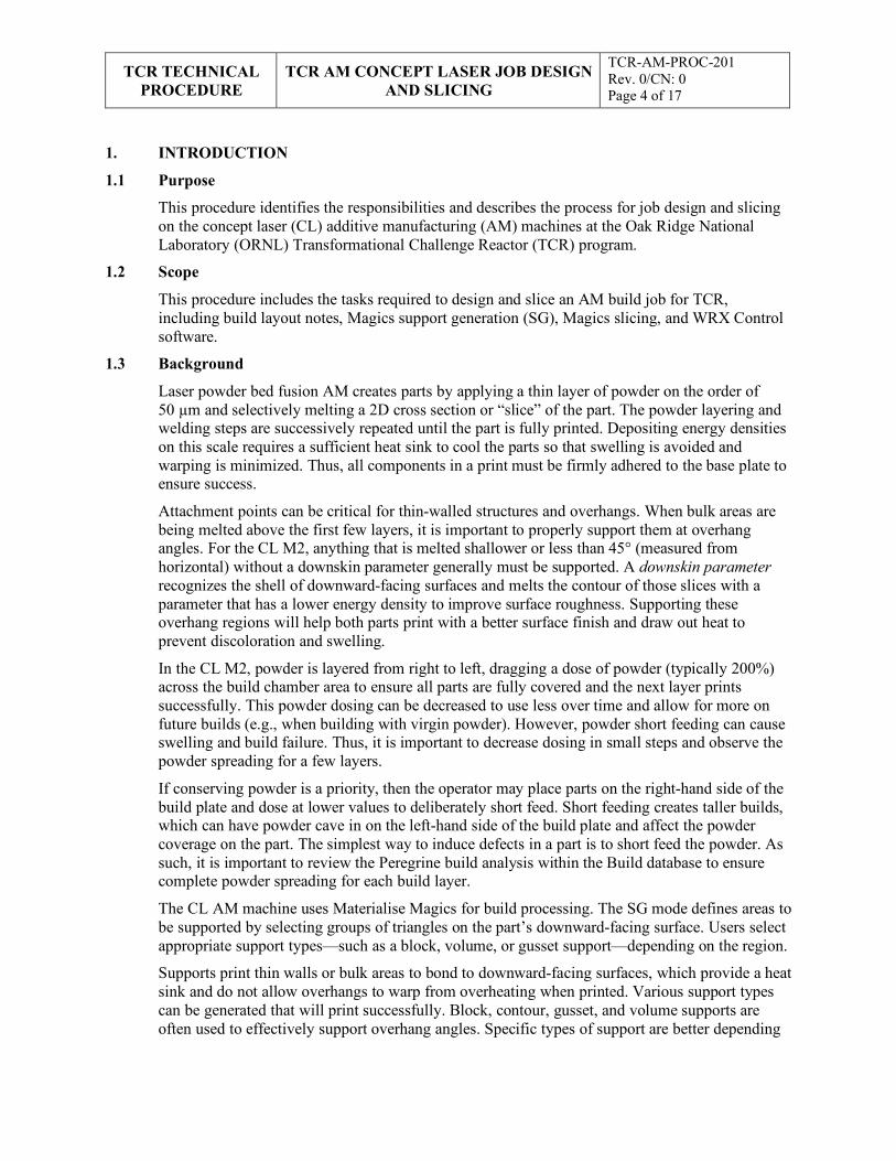
TCR TECHNICAL
PROCEDURE TCR AM CONCEPT LASER JOB DESIGN
AND SLICING
TCR-AM-PROC-201 Rev. 0/CN: 0 Page 4 of 17
1. INTRODUCTION
1.1 Purpose
This procedure identifies the responsibilities and describes the process for job design and slicing on the concept laser (CL) additive manufacturing (AM) machines at the Oak Ridge National Laboratory (ORNL) Transformational Challenge Reactor (TCR) program.
1.2 Scope
This procedure includes the tasks required to design and slice an AM build job for TCR, including build layout notes, Magics support generation (SG), Magics slicing, and WRX Control software.
1.3 Background
Laser powder bed fusion AM creates parts by applying a thin layer of powder on the order of 50 µm and selectively melting a 2D cross section or “slice” of the part. The powder layering and welding steps are successively repeated until the part is fully printed. Depositing energy densities on this scale requires a sufficient heat sink to cool the parts so that swelling is avoided and warping is minimized. Thus, all components in a print must be firmly adhered to the base plate to ensure success.
Attachment points can be critical for thin-walled structures and overhangs. When bulk areas are being melted above the first few layers, it is important to properly support them at overhang angles. For the CL M2, anything that is melted shallower or less than 45° (measured from horizontal) without a downskin parameter generally must be supported. A downskin parameter recognizes the shell of downward-facing surfaces and melts the contour of those slices with a parameter that has a lower energy density to improve surface roughness. Supporting these overhang regions will help both parts print with a better surface finish and draw out heat to prevent discoloration and swelling.
In the CL M2, powder is layered from right to left, dragging a dose of powder (typically 200%) across the build chamber area to ensure all parts are fully covered and the next layer prints successfully. This powder dosing can be decreased to use less over time and allow for more on future builds (e.g., when building with virgin powder). However, powder short feeding can cause swelling and build failure. Thus, it is important to decrease dosing in small steps and observe the powder spreading for a few layers.
If conserving powder is a priority, then the operator may place parts on the right-hand side of the build plate and dose at lower values to deliberately short feed. Short feeding creates taller builds, which can have powder cave in on the left-hand side of the build plate and affect the powder coverage on the part. The simplest way to induce defects in a part is to short feed the powder. As such, it is important to review the Peregrine build analysis within the Build database to ensure complete powder spreading for each build layer.
The CL AM machine uses Materialise Magics for build processing. The SG mode defines areas to be supported by selecting groups of triangles on the part’s downward-facing surface. Users select appropriate support types—such as a block, volume, or gusset support—depending on the region.
Supports print thin walls or bulk areas to bond to downward-facing surfaces, which provide a heat sink and do not allow overhangs to warp from overheating when printed. Various support types can be generated that will print successfully. Block, contour, gusset, and volume supports are often used to effectively support overhang angles. Specific types of support are better depending
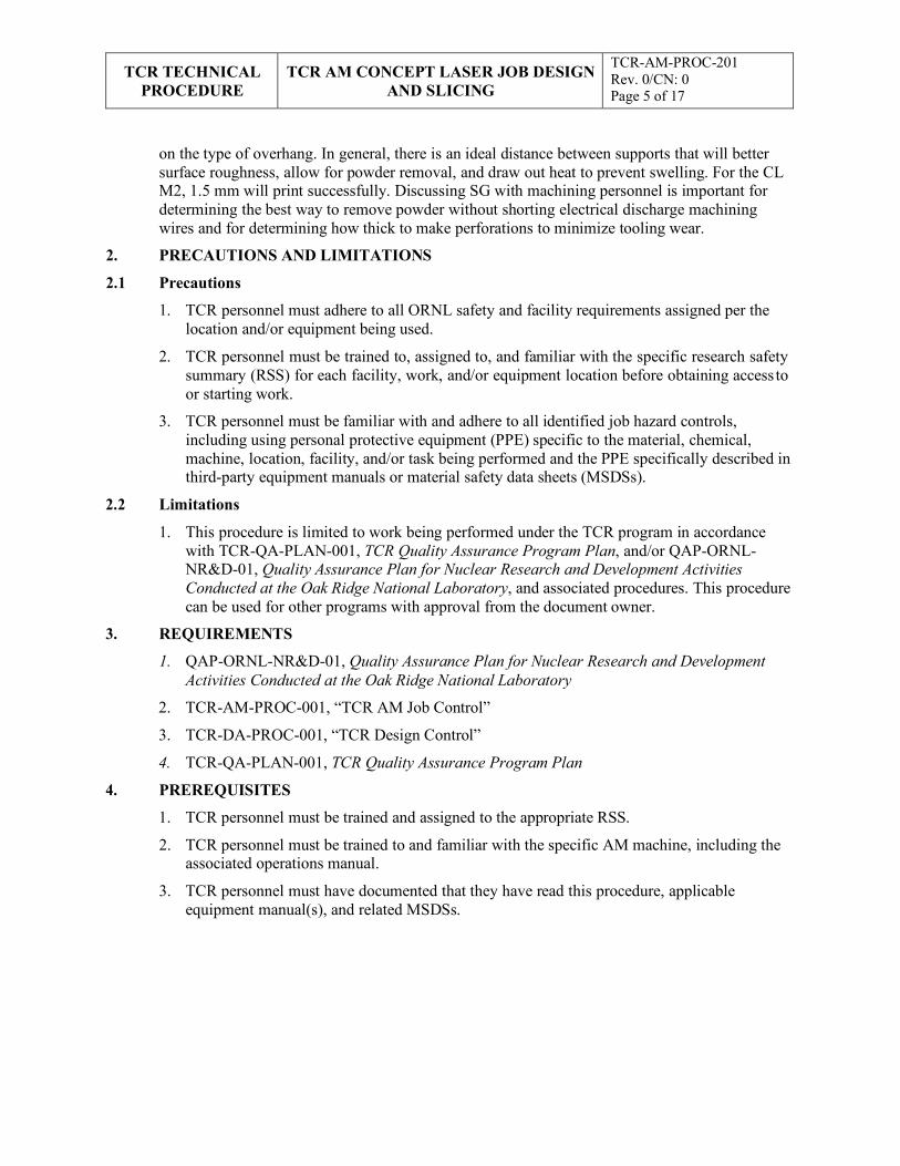
TCR TECHNICAL
PROCEDURE TCR AM CONCEPT LASER JOB DESIGN
AND SLICING
TCR-AM-PROC-201 Rev. 0/CN: 0 Page 5 of 17
on the type of overhang. In general, there is an ideal distance between supports that will better surface roughness, allow for powder removal, and draw out heat to prevent swelling. For the CL M2, 1.5 mm will print successfully. Discussing SG with machining personnel is important for determining the best way to remove powder without shorting electrical discharge machining wires and for determining how thick to make perforations to minimize tooling wear.
2. PRECAUTIONS AND LIMITATIONS
2.1 Precautions
1. TCR personnel must adhere to all ORNL safety and facility requirements assigned per the location and/or equipment being used.
2. TCR personnel must be trained to, assigned to, and familiar with the specific research safety summary (RSS) for each facility, work, and/or equipment location before obtaining access to or starting work.
3. TCR personnel must be familiar with and adhere to all identified job hazard controls, including using personal protective equipment (PPE) specific to the material, chemical, machine, location, facility, and/or task being performed and the PPE specifically described in third-party equipment manuals or material safety data sheets (MSDSs).
2.2 Limitations
1. This procedure is limited to work being performed under the TCR program in accordance with TCR-QA-PLAN-001, TCR Quality Assurance Program Plan, and/or QAP-ORNL- NR&D-01, Quality Assurance Plan for Nuclear Research and Development Activities Conducted at the Oak Ridge National Laboratory, and associated procedures. This procedure can be used for other programs with approval from the document owner.
3. REQUIREMENTS
1. QAP-ORNL-NR&D-01, Quality Assurance Plan for Nuclear Research and Development Activities Conducted at the Oak Ridge National Laboratory
2. TCR-AM-PROC-001, “TCR AM Job Control”
3. TCR-DA-PROC-001, “TCR Design Control”
4. TCR-QA-PLAN-001, TCR Quality Assurance Program Plan
4. PREREQUISITES
1. TCR personnel must be trained and assigned to the appropriate RSS.
2. TCR personnel must be trained to and familiar with the specific AM machine, including the associated operations manual.
3. TCR personnel must have documented that they have read this procedure, applicable equipment manual(s), and related MSDSs.
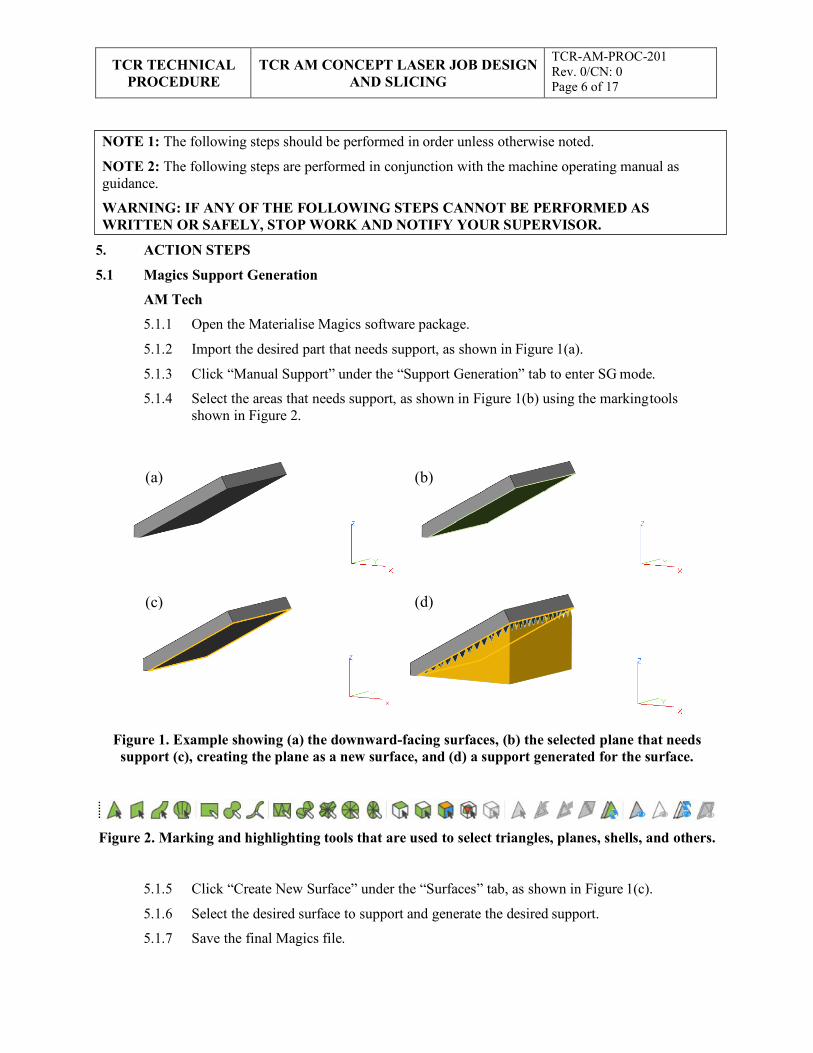
TCR TECHNICAL
PROCEDURE TCR AM CONCEPT LASER JOB DESIGN
AND SLICING
TCR-AM-PROC-201 Rev. 0/CN: 0 Page 6 of 17
(a) (b)
5. ACTION STEPS
5.1 Magics Support Generation
AM Tech
5.1.1 Open the Materialise Magics software package.
5.1.2 Import the desired part that needs support, as shown in Figure 1(a).
5.1.3 Click “Manual Support” under the “Support Generation” tab to enter SG mode.
5.1.4 Select the areas that needs support, as shown in Figure 1(b) using the marking tools shown in Figure 2.
Figure 1. Example showing (a) the downward-facing surfaces, (b) the selected plane that needs support (c), creating the plane as a new surface, and (d) a support generated for the surface.
Figure 2. Marking and highlighting tools that are used to select triangles, planes, shells, and others.
5.1.5 Click “Create New Surface” under the “Surfaces” tab, as shown in Figure 1(c).
5.1.6 Select the desired surface to support and generate the desired support.
5.1.7 Save the final Magics file.
(d) (c)
NOTE 1: The following steps should be performed in order unless otherwise noted.
NOTE 2: The following steps are performed in conjunction with the machine operating manual as guidance.
WARNING: IF ANY OF THE FOLLOWING STEPS CANNOT BE PERFORMED AS WRITTEN OR SAFELY, STOP WORK AND NOTIFY YOUR SUPERVISOR.
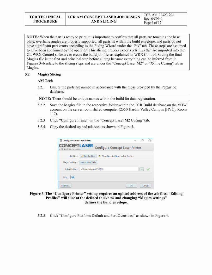
TCR TECHNICAL
PROCEDURE TCR AM CONCEPT LASER JOB DESIGN
AND SLICING
TCR-AM-PROC-201 Rev. 0/CN: 0 Page 6 of 17
NOTE: There should be unique names within the build for data registration.
5.2 Magics Slicing
AM Tech
5.2.1 Ensure the parts are named in accordance with the those provided by the Peregrine database.
5.2.2 Save the Magics file in the respective folder within the TCR Build database on the VOW account on the server room shared computer (2350 Hardin Valley Campus [HVC], Room 117).
5.2.3 Click “Configure Printer” in the “Concept Laser M2 Cusing” tab.
5.2.4 Copy the desired upload address, as shown in Figure 3.
Figure 3. The “Configure Printer” setting requires an upload address of the .cls files. “Editing Profiles” will slice at the defined thickness and changing “Magics settings”
defines the build envelope.
5.2.5 Click “Configure Platform Default and Part Overrides,” as shown in Figure 4.
NOTE: When the part is ready to print, it is important to confirm that all parts are touching the base plate, overhang angles are properly supported, all parts fit within the build envelope, and parts do not have significant part errors according to the Fixing Wizard under the “Fix” tab. These steps are assumed to have been confirmed by the operator. This slicing process exports .cls files that are imported into the CL WRX Control software to create the build job file, as explained in WRX Control. Saving the final Magics file is the first and principal step before slicing because everything can be inferred from it. Figures 3–6 relate to the slicing steps and are under the “Concept Laser M2” or “X-line Cusing” tab in Magics.
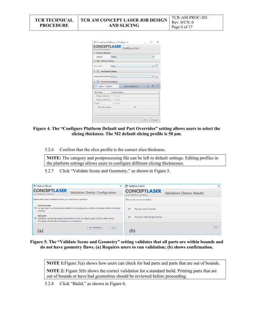
TCR TECHNICAL
PROCEDURE TCR AM CONCEPT LASER JOB DESIGN
AND SLICING
TCR-AM-PROC-201 Rev. 0/CN: 0 Page 6 of 17
NOTE: The category and postprocessing file can be left to default settings. Editing profiles in the platform settings allows users to configure different slicing thicknesses.
(a) (b)
NOTE 1:Figure 5(a) shows how users can check for bad parts and parts that are out of bounds.
NOTE 2: Figure 5(b) shows the correct validation for a standard build. Printing parts that are out of bounds or have bad geometries should be reviewed before proceeding.
Figure 4. The “Configure Platform Default and Part Overrides” setting allows users to select the
slicing thickness. The M2 default slicing profile is 50 µm.
5.2.6 Confirm that the slice profile is the correct slice thickness.
5.2.7 Click “Validate Scene and Geometry,” as shown in Figure 5.
Figure 5. The “Validate Scene and Geometry” setting validates that all parts are within bounds and do not have geometry flaws. (a) Requires users to run validation; (b) shows confirmation.
5.2.8 Click “Build,” as shown in Figure 6.
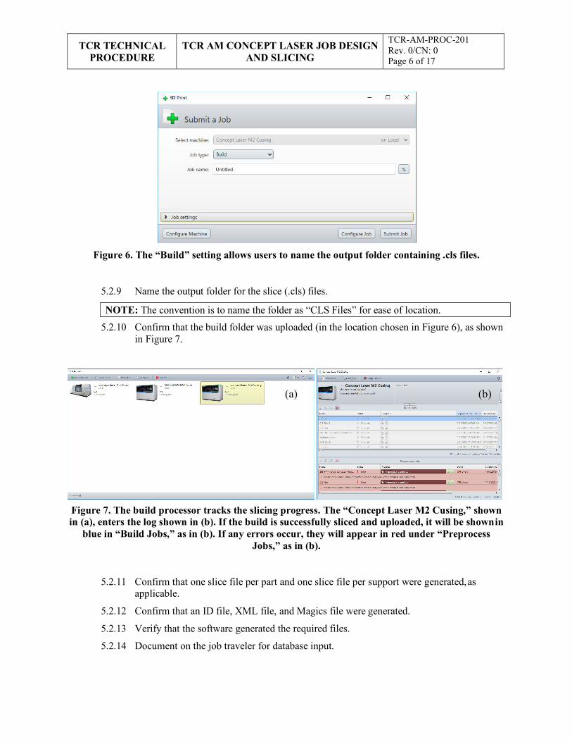
TCR TECHNICAL
PROCEDURE TCR AM CONCEPT LASER JOB DESIGN
AND SLICING
TCR-AM-PROC-201 Rev. 0/CN: 0 Page 6 of 17
NOTE: The convention is to name the folder as “CLS Files” for ease of location.
(a) (b)
Figure 6. The “Build” setting allows users to name the output folder containing .cls files.
5.2.9 Name the output folder for the slice (.cls) files.
5.2.10 Confirm that the build folder was uploaded (in the location chosen in Figure 6), as shown in Figure 7.
Figure 7. The build processor tracks the slicing progress. The “Concept Laser M2 Cusing,” shown in (a), enters the log shown in (b). If the build is successfully sliced and uploaded, it will be shown in
blue in “Build Jobs,” as in (b). If any errors occur, they will appear in red under “Preprocess Jobs,” as in (b).
5.2.11 Confirm that one slice file per part and one slice file per support were generated, as applicable.
5.2.12 Confirm that an ID file, XML file, and Magics file were generated.
5.2.13 Verify that the software generated the required files.
5.2.14 Document on the job traveler for database input.
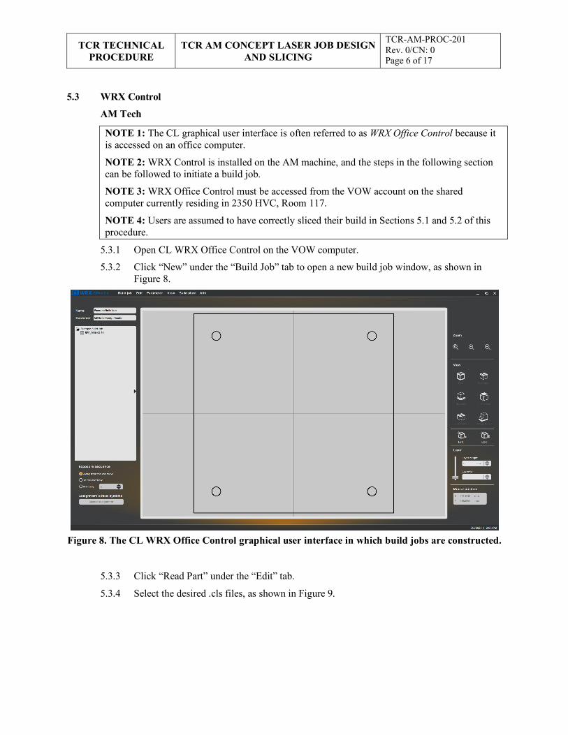
TCR TECHNICAL
PROCEDURE TCR AM CONCEPT LASER JOB DESIGN
AND SLICING
TCR-AM-PROC-201 Rev. 0/CN: 0 Page 6 of 17
5.3 WRX Control
AM Tech
5.3.1 Open CL WRX Office Control on the VOW computer.
5.3.2 Click “New” under the “Build Job” tab to open a new build job window, as shown in Figure 8.
Figure 8. The CL WRX Office Control graphical user interface in which build jobs are constructed.
5.3.3 Click “Read Part” under the “Edit” tab.
5.3.4 Select the desired .cls files, as shown in Figure 9.
NOTE 1: The CL graphical user interface is often referred to as WRX Office Control because it is accessed on an office computer.
NOTE 2: WRX Control is installed on the AM machine, and the steps in the following section can be followed to initiate a build job.
NOTE 3: WRX Office Control must be accessed from the VOW account on the shared computer currently residing in 2350 HVC, Room 117.
NOTE 4: Users are assumed to have correctly sliced their build in Sections 5.1 and 5.2 of this procedure.
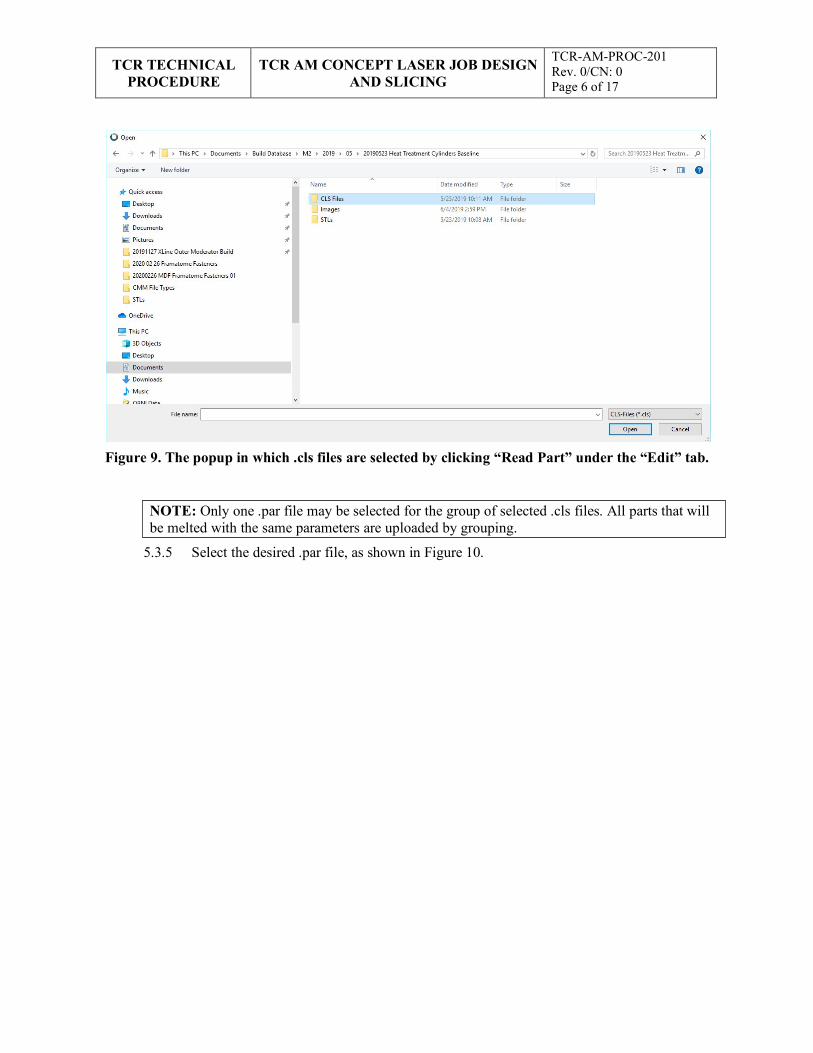
TCR TECHNICAL
PROCEDURE TCR AM CONCEPT LASER JOB DESIGN
AND SLICING
TCR-AM-PROC-201 Rev. 0/CN: 0 Page 6 of 17
NOTE: Only one .par file may be selected for the group of selected .cls files. All parts that will be melted with the same parameters are uploaded by grouping.
Figure 9. The popup in which .cls files are selected by clicking “Read Part” under the “Edit” tab.
5.3.5 Select the desired .par file, as shown in Figure 10.
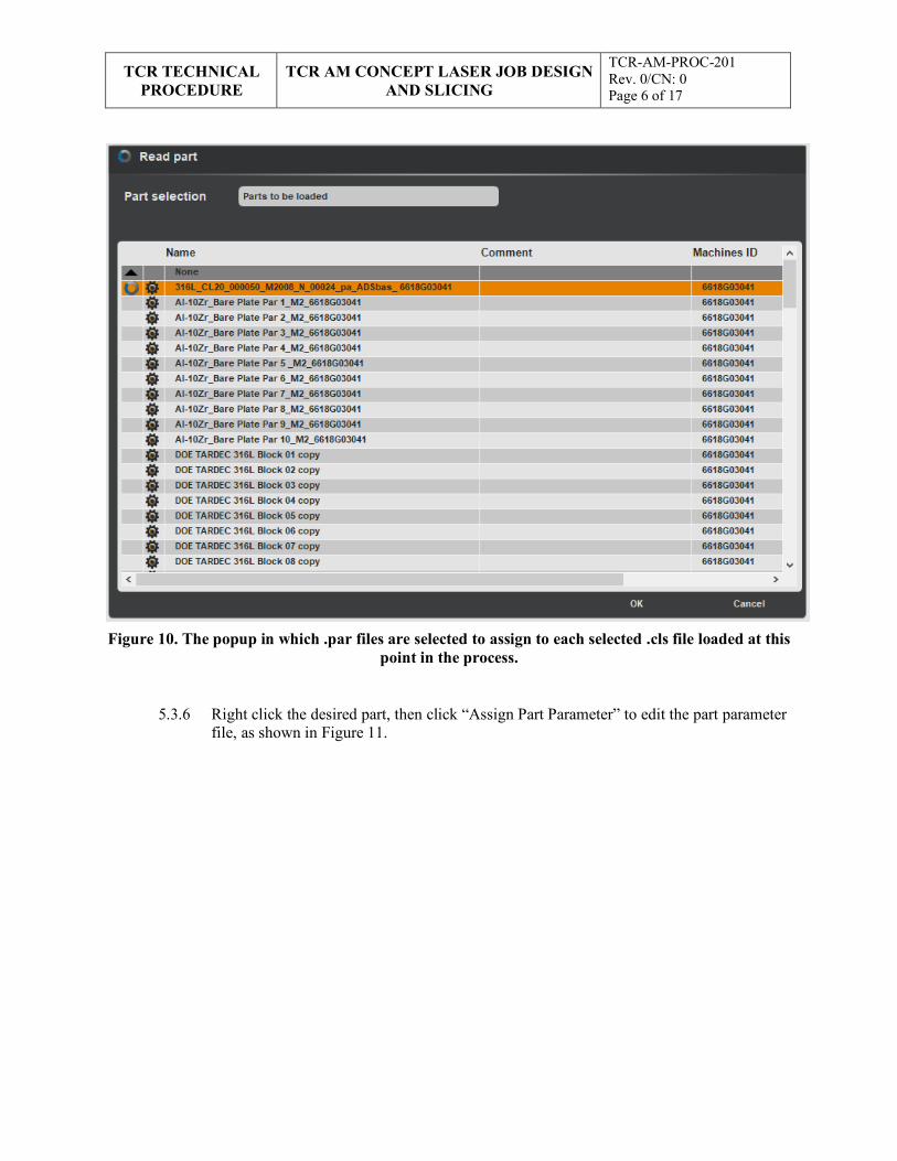
TCR TECHNICAL
PROCEDURE TCR AM CONCEPT LASER JOB DESIGN
AND SLICING
TCR-AM-PROC-201 Rev. 0/CN: 0 Page 6 of 17
Figure 10. The popup in which .par files are selected to assign to each selected .cls file loaded at this
point in the process.
5.3.6 Right click the desired part, then click “Assign Part Parameter” to edit the part parameter file, as shown in Figure 11.
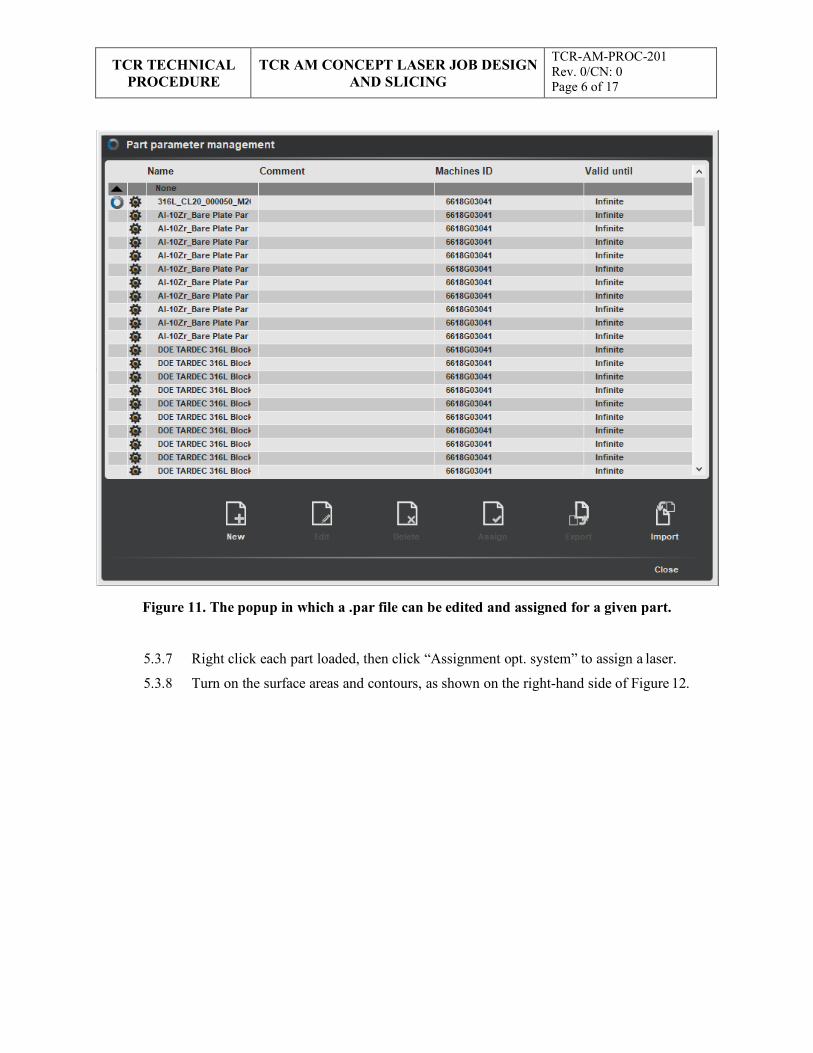
TCR TECHNICAL
PROCEDURE TCR AM CONCEPT LASER JOB DESIGN
AND SLICING
TCR-AM-PROC-201 Rev. 0/CN: 0 Page 6 of 17
Figure 11. The popup in which a .par file can be edited and assigned for a given part.
5.3.7 Right click each part loaded, then click “Assignment opt. system” to assign a laser.
5.3.8 Turn on the surface areas and contours, as shown on the right-hand side of Figure 12.
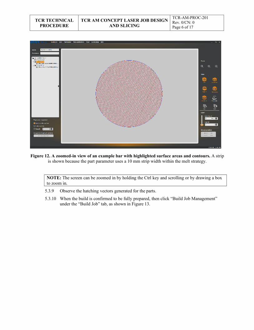
TCR TECHNICAL
PROCEDURE TCR AM CONCEPT LASER JOB DESIGN
AND SLICING
TCR-AM-PROC-201 Rev. 0/CN: 0 Page 6 of 17
NOTE: The screen can be zoomed in by holding the Ctrl key and scrolling or by drawing a box to zoom in.
Figure 12. A zoomed-in view of an example bar with highlighted surface areas and contours. A strip is shown because the part parameter uses a 10 mm strip width within the melt strategy.
5.3.9 Observe the hatching vectors generated for the parts.
5.3.10 When the build is confirmed to be fully prepared, then click “Build Job Management” under the “Build Job” tab, as shown in Figure 13.
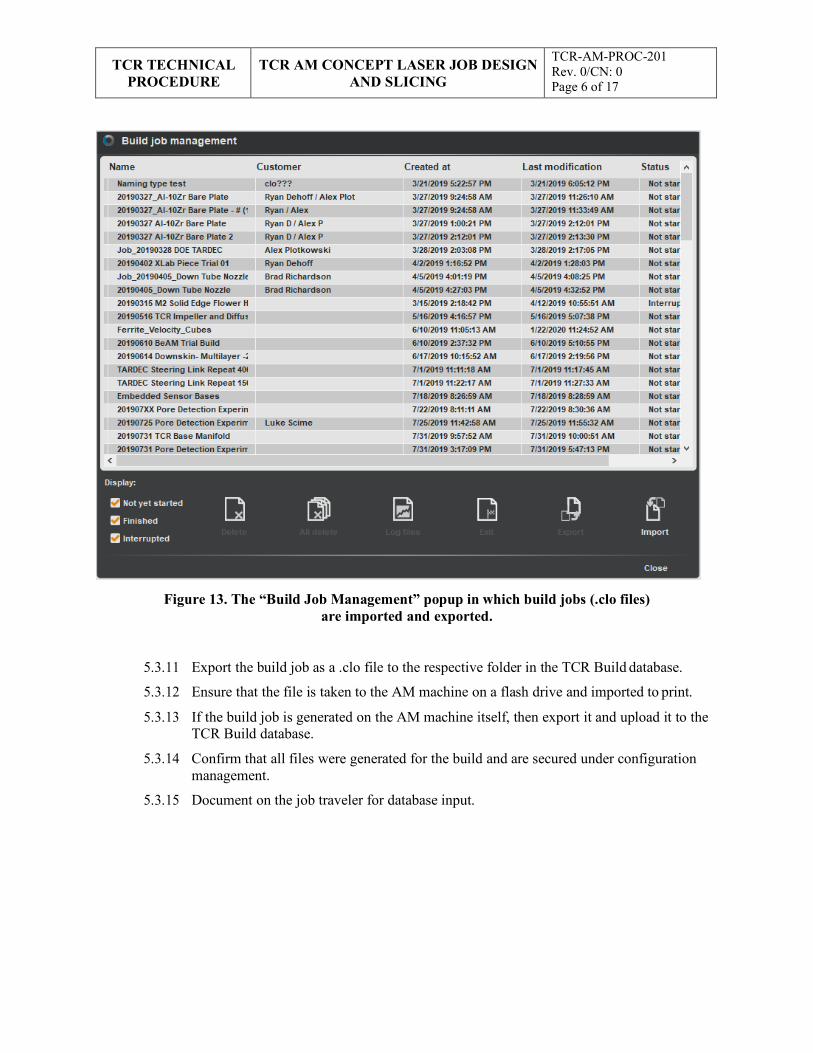
TCR TECHNICAL
PROCEDURE TCR AM CONCEPT LASER JOB DESIGN
AND SLICING
TCR-AM-PROC-201 Rev. 0/CN: 0 Page 6 of 17
Figure 13. The “Build Job Management” popup in which build jobs (.clo files) are imported and exported.
5.3.11 Export the build job as a .clo file to the respective folder in the TCR Build database.
5.3.12 Ensure that the file is taken to the AM machine on a flash drive and imported to print.
5.3.13 If the build job is generated on the AM machine itself, then export it and upload it to the TCR Build database.
5.3.14 Confirm that all files were generated for the build and are secured under configuration management.
5.3.15 Document on the job traveler for database input.
TCR TECHNICAL PROCEDURE
TCR AM CONCEPT LASER JOB DESIGN AND SLICING
TCR-AM-PROC-201 Rev. 0/CN: 0 Page 6 of 17
6. RECORDS
This document generates the following records:
• Completed job traveler
• AM job build design and slicing package
7. STANDARDS AND REFERENCES
7.1 Standards
• ASME NQA-1-2008, Quality Assurance Requirements for Nuclear Facility Applications
• QAP-ORNL-NR&D-01, Quality Assurance Plan for Nuclear Research and DevelopmentActivities Conducted at the Oak Ridge National Laboratory
7.2 References
• Concept Laser M2 Cusing Operating Manual, Edition 1.0.18_EN_ANSI.
• Concept Laser X-Line Operating Manual, Edition 1.1.17_EN_ANSI.
• TCR-AM-PROC-001, “TCR AM Job Control”
• TCR-DA-PROC-001, “TCR Design Control”
• TCR-QA-PLAN-001, TCR Quality Assurance Program Plan
8. APPENDICES
• Appendix A: Abbreviations and Definitions
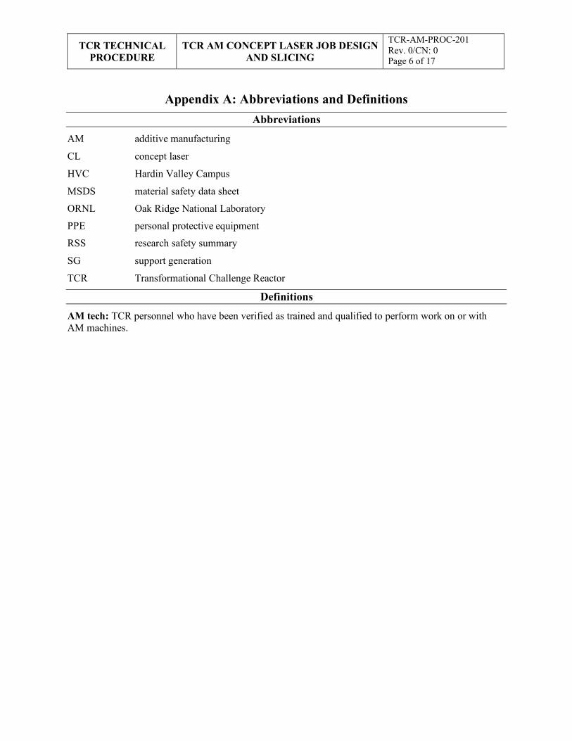
TCR TECHNICAL
PROCEDURE TCR AM CONCEPT LASER JOB DESIGN
AND SLICING
TCR-AM-PROC-201 Rev. 0/CN: 0 Page 6 of 17
Appendix A: Abbreviations and Definitions Abbreviations
AM additive manufacturing
CL concept laser
HVC Hardin Valley Campus
MSDS material safety data sheet
ORNL Oak Ridge National Laboratory
PPE personal protective equipment
RSS research safety summary
SG support generation
TCR Transformational Challenge Reactor
Definitions
AM tech: TCR personnel who have been verified as trained and qualified to perform work on or with AM machines.
APPENDIX J. PERSONNEL QUALIFICATION AND TRAINING REQUIREMENTS FOR THE TCR PROGRAM AT ORNL
J-1

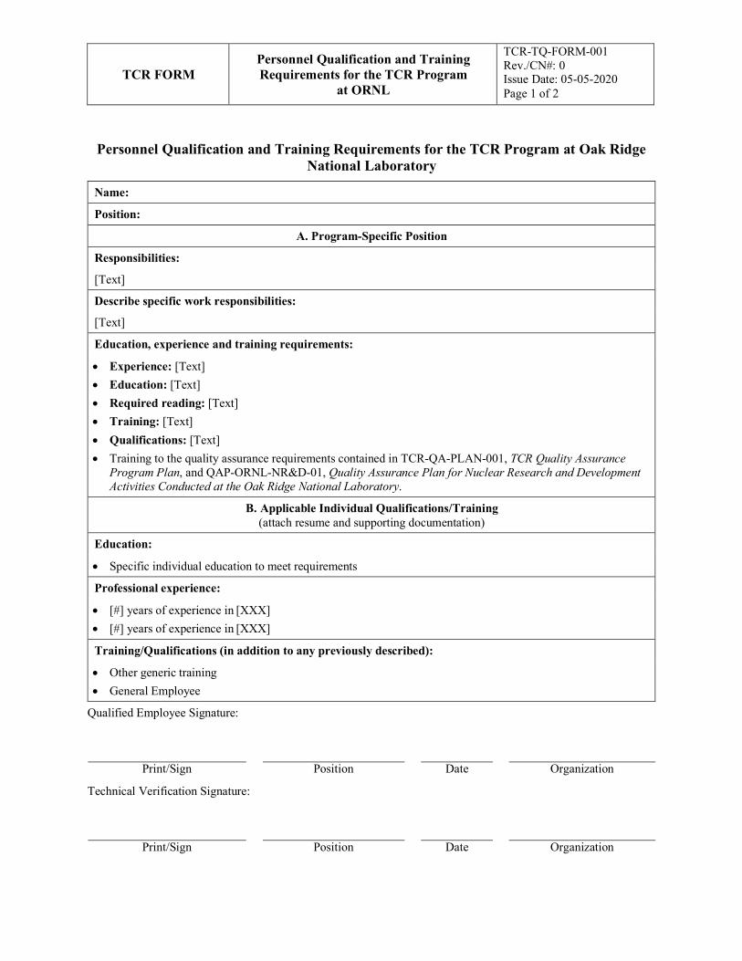
TCR FORM Personnel Qualification and Training Requirements for the TCR Program
at ORNL
TCR-TQ-FORM-001 Rev./CN#: 0 Issue Date: 05-05-2020 Page 1 of 2
Personnel Qualification and Training Requirements for the TCR Program at Oak Ridge National Laboratory
Name:
Position:
A. Program-Specific Position
Responsibilities:
[Text]
Describe specific work responsibilities:
[Text]
Education, experience and training requirements:
• Experience: [Text] • Education: [Text] • Required reading: [Text] • Training: [Text] • Qualifications: [Text] • Training to the quality assurance requirements contained in TCR-QA-PLAN-001, TCR Quality Assurance
Program Plan, and QAP-ORNL-NR&D-01, Quality Assurance Plan for Nuclear Research and Development Activities Conducted at the Oak Ridge National Laboratory.
B. Applicable Individual Qualifications/Training (attach resume and supporting documentation)
Education:
• Specific individual education to meet requirements
Professional experience:
• [#] years of experience in [XXX] • [#] years of experience in [XXX]
Training/Qualifications (in addition to any previously described):
• Other generic training • General Employee
Qualified Employee Signature:
Print/Sign Position Date Organization
Technical Verification Signature:
Print/Sign Position Date Organization
TCR FORM Personnel Qualification and Training Requirements for the TCR Program
at ORNL
TCR-TQ-FORM-001 Rev./CN#: 0 Issue Date: 05-05-2020 Page 2 of 2
Form Instructions:
1. Provide the Name of the individual being qualified. 2. Provide the Position to which the individual is being qualified. 3. Describe generic responsibilities to which the individual is being qualified. 4. Describe specific job responsibilities to which the individual is being qualified. 5. Describe the job-specific experience, education, required reading and training/qualification requirements. 6. Describe the individual’s education. 7. Describe the individual’s years of associated professional experience. 8. Describe the individual’s training and/or qualifications. 9. Attach the individual’s resume and supporting documentation. 10. Qualified Employee: Print Name, Position, Date, Organization and sign form 11. Technical Verifier:
a. Verify required information is documented and attached. b. Print Name, Position, Date, Organization and sign form
APPENDIX K. TCR FRAMATOME FUEL ASSEMBLY BRACKET FABRICATION AND TEST PLAN
NOT AVAILABLE FOR VIEWING REFERENCE ONLY
K-1

TCR PLAN TCR FRAMATOME FUEL ASSEMBLY BRACKET FABRICATION AND TEST
PLAN
TCR-AM-PLAN-001 Rev./CN#: 0 Page 1 of 29
Transformational Challenge Reactor Program
Number: TCR-AM-PLAN-001
Rev./CN#: 0
Approval Date: 07/10/2020
Issue Date: 07/10/2020
Effective Date: 07/10/2020
Supersedes: N/A
Review required: 07/01/2023
Title: TCR Framatome Fuel Assembly Bracket Fabrication and Test Plan
IDMS Record #: 024425
Document Owner: Ryan Dehoff, TCR AM Thrust Lead
Author: Michael Russell, TCR QA Representative (with technical inputs from Keith Carver and Chase Joslin)
Point of Contact: Fred List, TCR AM SME, Job Owner
Approved By:
Ryan Dehoff, TCR AM Thrust Lead
Mark Vance, TCR QA Manager
Kurt Terrani, TCR Technical Director
Reviewed by:
Sherri Buchanan, TCR Program Manager
Fred List, TCR AM SME, Job Owner
TS Byun, TCR Material Test Thrust Lead
Joshua Templeton, Framatome PM/Engineer (by email)
This document has been electronically approved. Electronic signatures of approvers are listed on the IDMS View/Print page associated with the IDMS Record # above.
Before using a copy of this document, compare its issue date to the issue date of the IDMS version to verify that it is the most current version.