TCMC OBSERVATION ROOM Tri-City Medical Center
688
TCMC OBSERVATION ROOM Tri-City Medical Center 4002 Vista Way Oceanside, California 92056 SPECIFICATIONS SA PROJECT NO. 01643.00 12/02/16 S F E I R A R C H I T E C T S, INC. 1350 Columbia Street, Suite 603 San Diego, California 92101 P: 619 299 3917 F: 619 299 5084 www.sfeirarch.com
-
Upload
khangminh22 -
Category
Documents
-
view
1 -
download
0
Transcript of TCMC OBSERVATION ROOM Tri-City Medical Center
TCMC OBSERVATION ROOM
Tri -Ci ty Medical Center
4002 Vista WayOceanside, California 92056
SPECIFICATIONSSA PROJECT NO. 01643.00
12/02/16
S F E I R A R C H I T E C T S, INC.
1350 Columbia Street, Suite 603San Diego, California 92101
P: 619 299 3917F: 619 299 5084
www.sfeirarch.com

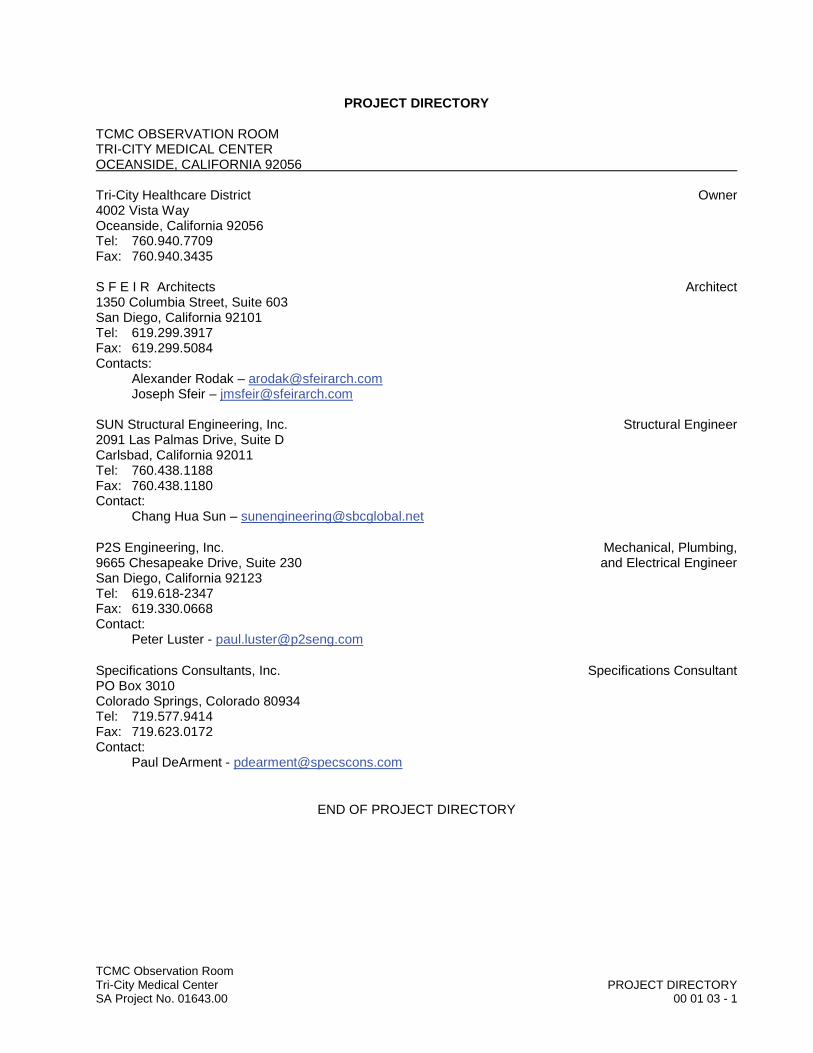
TCMC Observation RoomTri-City Medical Center PROJECT DIRECTORYSA Project No. 01643.00 00 01 03 - 1
PROJECT DIRECTORY
TCMC OBSERVATION ROOMTRI-CITY MEDICAL CENTER OCEANSIDE, CALIFORNIA 92056
Tri-City Healthcare District Owner4002 Vista WayOceanside, California 92056Tel: 760.940.7709Fax: 760.940.3435
S F E I R Architects Architect1350 Columbia Street, Suite 603San Diego, California 92101Tel: 619.299.3917Fax: 619.299.5084 Contacts:
Alexander Rodak – [email protected] Sfeir – [email protected]
SUN Structural Engineering, Inc. Structural Engineer2091 Las Palmas Drive, Suite DCarlsbad, California 92011Tel: 760.438.1188Fax: 760.438.1180Contact:
Chang Hua Sun – [email protected]
P2S Engineering, Inc. Mechanical, Plumbing,9665 Chesapeake Drive, Suite 230 and Electrical EngineerSan Diego, California 92123Tel: 619.618-2347 Fax: 619.330.0668 Contact:
Peter Luster - [email protected]
Specifications Consultants, Inc. Specifications ConsultantPO Box 3010Colorado Springs, Colorado 80934Tel: 719.577.9414 Fax: 719.623.0172 Contact:
Paul DeArment - [email protected]
END OF PROJECT DIRECTORY


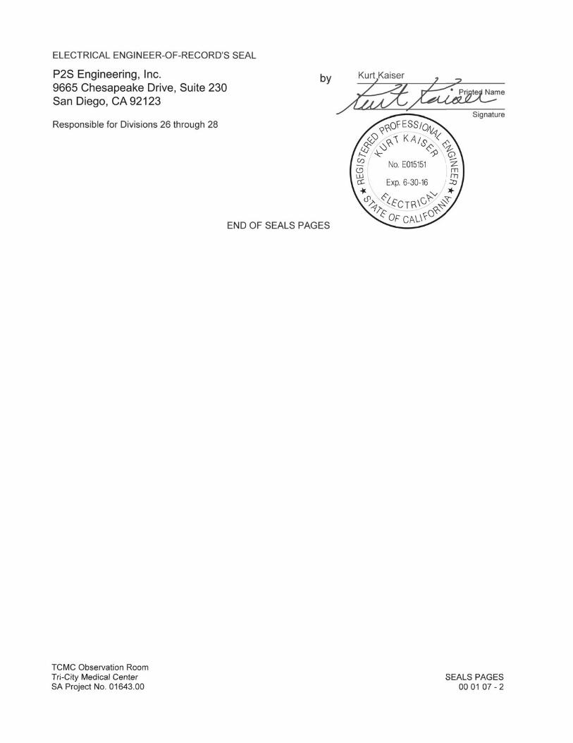
TCMC Observation RoomTri-City Medical Center SEALS PAGESSA Project No. 01643.00 00 01 07 - 1
SEALS PAGES
TCMC OBSERVATION ROOMTRI-CITY MEDICAL CENTEROCEANSIDE, CALIFORNIA 92056
ARCHITECT-OF-RECORD'S SEAL
Sfeir Architects by1350 Columbia Street, Suite 603 Printed Name
San Diego, California 92101Signature
STRUCTURAL ENGINEER-OF-RECORD'S SEAL
SUN Structural Engineering, Inc. by2091 Las Palmas Drive, Suite D Printed Name
Carlsbad, California 92011Signature
MECHANICAL ENGINEER-OF-RECORD'S SEAL
P2S Engineering, Inc. by9665 Chesapeake Drive, Suite 230 Printed Name
San Diego, California 92123Signature
Responsible for Divisions 21 through 23
Changhua Sun
Paul Luster
Joseph SfeirbyPrPrPPrPrPPPrPPPrPrPrPrPrPrPPrPrPP iniiii ted Na
Signat
Joseph Sfeir
Laura Baldrati, Senior Architect
July 06, 2017
TCMC Observation RoomTri-City Medical Center TABLE OF CONTENTSSA Project No. 01643.00 00 01 10 - 1
TCMC OBSERVATION ROOMTRI-CITY MEDICAL CENTER
4002 VISTA WAYOCEANSIDE, CALIFORNIA 92056
SPECIFICATIONS12/02/16
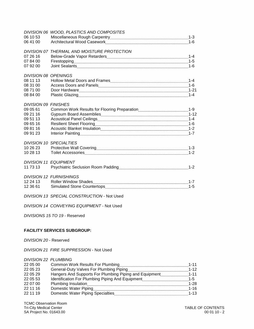
TABLE OF CONTENTS
SPECIFICATIONS GROUP
GENERAL REQUIREMENTS SUBGROUP:
DIVISION 01 GENERAL REQUIREMENTS01 10 00 Summary 1-401 22 00 Unit Prices 101 25 00 Substitution Procedures 1-201 26 00 Contract Modification Procedures 1-201 29 00 Payment Procedures 1-401 31 13 Project Coordination 1-201 31 19 Project Meetings 1-201 33 00 Submittal Procedures 1-601 35 16 Alteration Project Procedures 1-401 41 00 Regulatory Requirements 1-201 42 00 References 1-401 45 20 Quality Control Services 1-301 50 00 Temporary Facilities and Controls 1-401 60 00 Product Requirements 1-301 61 65 Low-Emitting Material Requirements 1-401 71 16 Acceptance of Conditions 1-201 73 19 Installation 1-201 73 29 Cutting and Patching 1-201 77 00 Closeout Procedures 1-401 78 36 Warranties 1-2
FACILITY CONSTRUCTION SUBGROUP:
DIVISION 02 EXISTING CONDITIONS02 41 19.16 Selective Interior Demolition 1-502 42 00 Removal and Salvage of Construction Materials 1-2
DIVISION 03 CONCRETE03 20 00 Concrete Reinforcing 1-303 30 53 Miscellaneous Cast-in-Place Concrete 1-4
DIVISION 04 MASONRY - Not Used
DIVISION 05 METALS05 05 19 Post-Installed Concrete Anchors 1-505 40 00 Cold-Formed Metal Framing 1-205 50 00 Metal Fabrications 1-3
TCMC Observation RoomTri-City Medical Center TABLE OF CONTENTSSA Project No. 01643.00 00 01 10 - 2
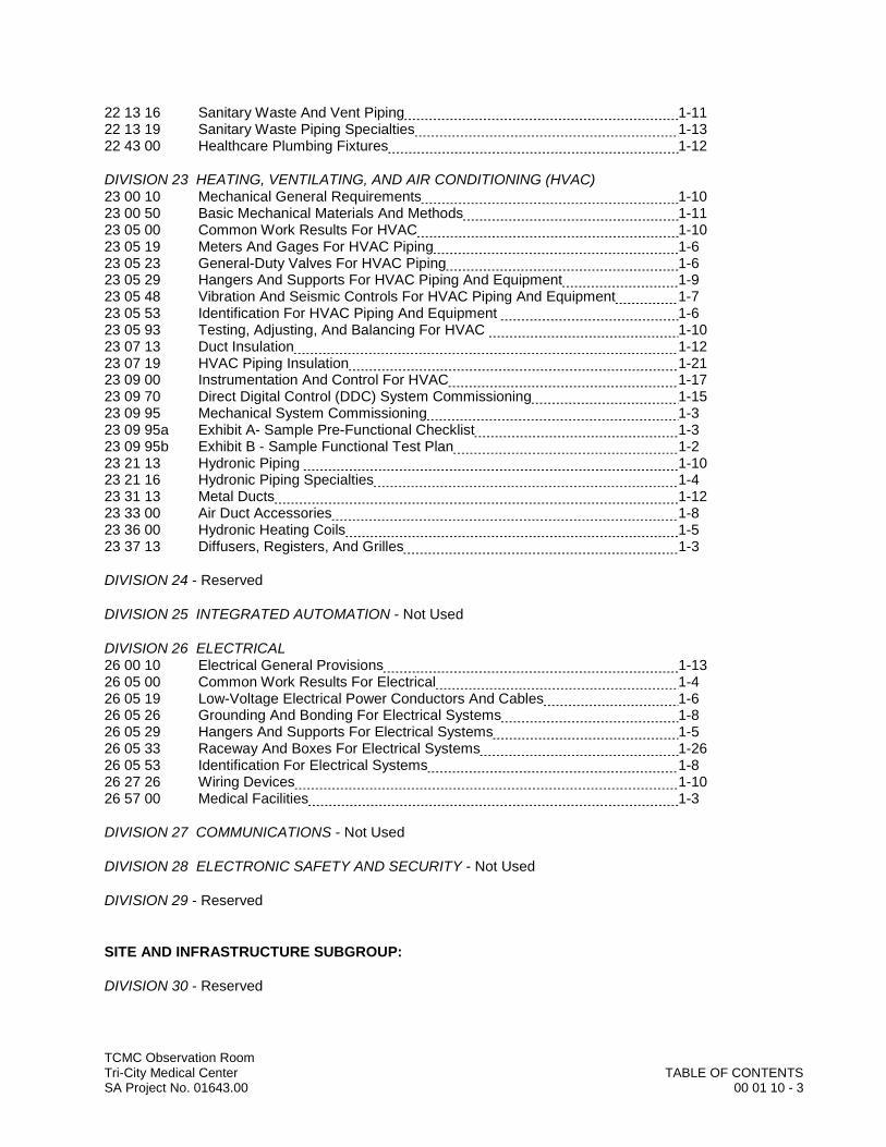
DIVISION 06 WOOD, PLASTICS AND COMPOSITES06 10 53 Miscellaneous Rough Carpentry 1-306 41 00 Architectural Wood Casework 1-6
DIVISION 07 THERMAL AND MOISTURE PROTECTION07 26 16 Below-Grade Vapor Retarders 1-407 84 00 Firestopping 1-507 92 00 Joint Sealants 1-6
DIVISION 08 OPENINGS08 11 13 Hollow Metal Doors and Frames 1-408 31 00 Access Doors and Panels 1-608 71 00 Door Hardware 1-2108 84 00 Plastic Glazing 1-4
DIVISION 09 FINISHES09 05 61 Common Work Results for Flooring Preparation 1-909 21 16 Gypsum Board Assemblies 1-1209 51 13 Acoustical Panel Ceilings 1-409 65 16 Resilient Sheet Flooring 1-609 81 16 Acoustic Blanket Insulation 1-209 91 23 Interior Painting 1-7
DIVISION 10 SPECIALTIES10 26 23 Protective Wall Covering 1-310 28 13 Toilet Accessories 1-2
DIVISION 11 EQUIPMENT11 73 13 Psychiatric Seclusion Room Padding 1-2
DIVISION 12 FURNISHINGS12 24 13 Roller Window Shades 1-712 36 61 Simulated Stone Countertops 1-5
DIVISION 13 SPECIAL CONSTRUCTION - Not Used
DIVISION 14 CONVEYING EQUIPMENT - Not Used
DIVISIONS 15 TO 19 - Reserved
FACILITY SERVICES SUBGROUP:
DIVISION 20 - Reserved
DIVISION 21 FIRE SUPPRESSION - Not Used
DIVISION 22 PLUMBING22 05 00 Common Work Results For Plumbing 1-1122 05 23 General-Duty Valves For Plumbing Piping 1-1222 05 29 Hangers And Supports For Plumbing Piping and Equipment 1-1122 05 53 Identification For Plumbing Piping And Equipment 1-522 07 00 Plumbing Insulation 1-2822 11 16 Domestic Water Piping 1-1622 11 19 Domestic Water Piping Specialties 1-13
TCMC Observation RoomTri-City Medical Center TABLE OF CONTENTSSA Project No. 01643.00 00 01 10 - 3
22 13 16 Sanitary Waste And Vent Piping 1-1122 13 19 Sanitary Waste Piping Specialties 1-1322 43 00 Healthcare Plumbing Fixtures 1-12
DIVISION 23 HEATING, VENTILATING, AND AIR CONDITIONING (HVAC)23 00 10 Mechanical General Requirements 1-1023 00 50 Basic Mechanical Materials And Methods 1-1123 05 00 Common Work Results For HVAC 1-1023 05 19 Meters And Gages For HVAC Piping 1-623 05 23 General-Duty Valves For HVAC Piping 1-623 05 29 Hangers And Supports For HVAC Piping And Equipment 1-923 05 48 Vibration And Seismic Controls For HVAC Piping And Equipment 1-723 05 53 Identification For HVAC Piping And Equipment 1-623 05 93 Testing, Adjusting, And Balancing For HVAC 1-1023 07 13 Duct Insulation 1-1223 07 19 HVAC Piping Insulation 1-2123 09 00 Instrumentation And Control For HVAC 1-1723 09 70 Direct Digital Control (DDC) System Commissioning 1-1523 09 95 Mechanical System Commissioning 1-323 09 95a Exhibit A- Sample Pre-Functional Checklist 1-323 09 95b Exhibit B - Sample Functional Test Plan 1-223 21 13 Hydronic Piping 1-1023 21 16 Hydronic Piping Specialties 1-423 31 13 Metal Ducts 1-1223 33 00 Air Duct Accessories 1-823 36 00 Hydronic Heating Coils 1-523 37 13 Diffusers, Registers, And Grilles 1-3
DIVISION 24 - Reserved
DIVISION 25 INTEGRATED AUTOMATION - Not Used
DIVISION 26 ELECTRICAL26 00 10 Electrical General Provisions 1-1326 05 00 Common Work Results For Electrical 1-426 05 19 Low-Voltage Electrical Power Conductors And Cables 1-626 05 26 Grounding And Bonding For Electrical Systems 1-826 05 29 Hangers And Supports For Electrical Systems 1-526 05 33 Raceway And Boxes For Electrical Systems 1-2626 05 53 Identification For Electrical Systems 1-826 27 26 Wiring Devices 1-1026 57 00 Medical Facilities 1-3
DIVISION 27 COMMUNICATIONS - Not Used
DIVISION 28 ELECTRONIC SAFETY AND SECURITY - Not Used
DIVISION 29 - Reserved
SITE AND INFRASTRUCTURE SUBGROUP:
DIVISION 30 - Reserved
TCMC Observation RoomTri-City Medical Center TABLE OF CONTENTSSA Project No. 01643.00 00 01 10 - 4
DIVISION 31 EARTHWORK31 23 33 Trenching and Backfilling 1-5
DIVISION 32 EXTERIOR IMPROVEMENTS - Not Used
DIVISION 33 UTILITIES - Not Used
DIVISION 34 TRANSPORTATION - Not Used
DIVISION 35 WATERWAY AND MARINE CONSTRUCTION - Not Used
DIVISIONS 36 TO 39 - Reserved
PROCESS EQUIPMENT SUBGROUP:
DIVISIONS 40 TO 49 - Not Used
END OF TABLE OF CONTENTS

DIV
ISIO
N 0
1–
GEN
ERA
L R
EQU
IREM
ENTS
DDDDDDDDDDDDDDDDDDDDDIIIIIIIIIIIIIIIVVVVVVVVVVVVVVVVVVVVVVVV
IIIIIIIIIIIIIIISSSSSSSSSSSSSSSSSSSSSSSSIIIIIIIIIIIIIOOOOOOOOOOOOOOOOOOOOOOOOOOOOO
NNNNNNNNNNNNNNNNNNNNN 000000000000000000000000
111111111111111111111–––––––––––––––
GGGGGGGGGGGGGGGGGGGGGGGGGGEEEEEEEEEEEEEEEEENNNNNNNNNNNNNNNNNNNNNNN
EEEEEEEEEEEEEEEEEERRRRRRRRRRRRRRRRRRRRRRRAAAAAAAAAAAAAAAAAAAAAA
LLLLLLLLLLLLLLLL RRRRRRRRRRRRRRRRRRRRRR
EEEEEEEEEEEEEEEEEEEEEQQQQQQQQQQQQQQQQQQQQQQQQQQQQUUUUUUUUUUUUUUUUUUUUUUU
IIIIIIIIIIIIIIRRRRRRRRRRRRRRRRRRRRRREEEEEEEEEEEEEEEEEEEMMMMMMMMMMMMMMMMMMMMMMM
EEEEEEEEEEEEEEEEEEEENNNNNNNNNNNNNNNNNNNNNTTTTTTTTTTTTTTTTTSSSSSSSSSSSSSSSSSSSSSSSSSSSSS


TCMC Observation RoomTri-City Medical Center SUMMARYSA Project No. 01643.00 01 10 00- 1
SECTION 01 10 00
SUMMARY
PART 1 GENERAL
1.01 GENERAL REQUIREMENTS
A. Division 01 - General Requirements relates to and expands upon the Conditions of the Contract, including the General Conditions and the Supplementary Conditions, but does not supersede requirements specified in those documents or in the Owner/Contractor Agreement.
B. Division 01 - General Requirements governs work under all other divisions of the Specifications, including Project Specifications issued under separate cover, and the Drawings.
1.02 PROJECT IDENTIFICATION AND PRINCIPAL ENTITIES
A. Project Identification and Location:
TCMC Observation RoomTri-City Medical Center 4002 Vista WayOceanside, California 92056
B. Owner: Wherever the word “Owner” is used in this Project Manual, it shall mean:
Tri-City Healthcare District4002 Vista WayOceanside, California 92056
C. Architect: Wherever the word “Architect” is used in this Project Manual, it shall mean:
S F E I R Architects1350 Columbia Street, Suite 603San Diego, California 92101
D. General Contractor: Wherever the words “Contractor” or “General Contractor” are used in this Project Manual, they shall mean the contractor who is party to the Owner/Contractor Agreement.
1.03 WORK COVERED BY CONTRACT DOCUMENTS
A. Single Contract: Unless otherwise indicated or specified, all Work indicated on the Drawings and described in the Specifications is to be executed under one prime contract between Owner and General Contractor.
B. Scope of Work: The Work consists of renovation in the existing Behavioral Health Unit (BHU) onthe first floor of the TCMC facility. 1. Renovation of existing Patient Room 168 in the BHU to an observation room with an
anteroom and an accessible toilet room.2. Modify existing wall and cabinetry between the new Observation Room and the adjacent
nurse station for a window in the wall.
C. The locations of all existing utilities, as indicated on the Drawings, are approximate. General Contractor shall be responsible for verifying location of all underground and above ground utilities
TCMC Observation RoomTri-City Medical Center SUMMARYSA Project No. 01643.00 01 10 00- 2
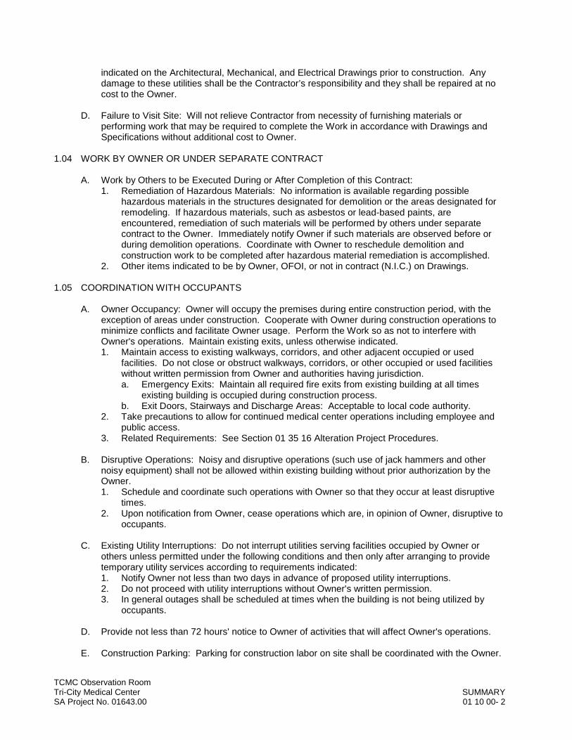
indicated on the Architectural, Mechanical, and Electrical Drawings prior to construction. Any damage to these utilities shall be the Contractor’s responsibility and they shall be repaired at no cost to the Owner.
D. Failure to Visit Site: Will not relieve Contractor from necessity of furnishing materials or performing work that may be required to complete the Work in accordance with Drawings and Specifications without additional cost to Owner.
1.04 WORK BY OWNER OR UNDER SEPARATE CONTRACT
A. Work by Others to be Executed During or After Completion of this Contract: 1. Remediation of Hazardous Materials: No information is available regarding possible
hazardous materials in the structures designated for demolition or the areas designated for remodeling. If hazardous materials, such as asbestos or lead-based paints, are encountered, remediation of such materials will be performed by others under separate contract to the Owner. Immediately notify Owner if such materials are observed before or during demolition operations. Coordinate with Owner to reschedule demolition and construction work to be completed after hazardous material remediation is accomplished.
2. Other items indicated to be by Owner, OFOI, or not in contract (N.I.C.) on Drawings.
1.05 COORDINATION WITH OCCUPANTS
A. Owner Occupancy: Owner will occupy the premises during entire construction period, with the exception of areas under construction. Cooperate with Owner during construction operations to minimize conflicts and facilitate Owner usage. Perform the Work so as not to interfere with Owner's operations. Maintain existing exits, unless otherwise indicated. 1. Maintain access to existing walkways, corridors, and other adjacent occupied or used
facilities. Do not close or obstruct walkways, corridors, or other occupied or used facilities without written permission from Owner and authorities having jurisdiction. a. Emergency Exits: Maintain all required fire exits from existing building at all times
existing building is occupied during construction process.b. Exit Doors, Stairways and Discharge Areas: Acceptable to local code authority.
2. Take precautions to allow for continued medical center operations including employee and public access.
3. Related Requirements: See Section 01 35 16 Alteration Project Procedures.
B. Disruptive Operations: Noisy and disruptive operations (such use of jack hammers and other noisy equipment) shall not be allowed within existing building without prior authorization by the Owner.1. Schedule and coordinate such operations with Owner so that they occur at least disruptive
times.2. Upon notification from Owner, cease operations which are, in opinion of Owner, disruptive to
occupants.
C. Existing Utility Interruptions: Do not interrupt utilities serving facilities occupied by Owner or others unless permitted under the following conditions and then only after arranging to provide temporary utility services according to requirements indicated:1. Notify Owner not less than two days in advance of proposed utility interruptions.2. Do not proceed with utility interruptions without Owner's written permission.3. In general outages shall be scheduled at times when the building is not being utilized by
occupants.
D. Provide not less than 72 hours' notice to Owner of activities that will affect Owner's operations.
E. Construction Parking: Parking for construction labor on site shall be coordinated with the Owner.
TCMC Observation RoomTri-City Medical Center SUMMARYSA Project No. 01643.00 01 10 00- 3
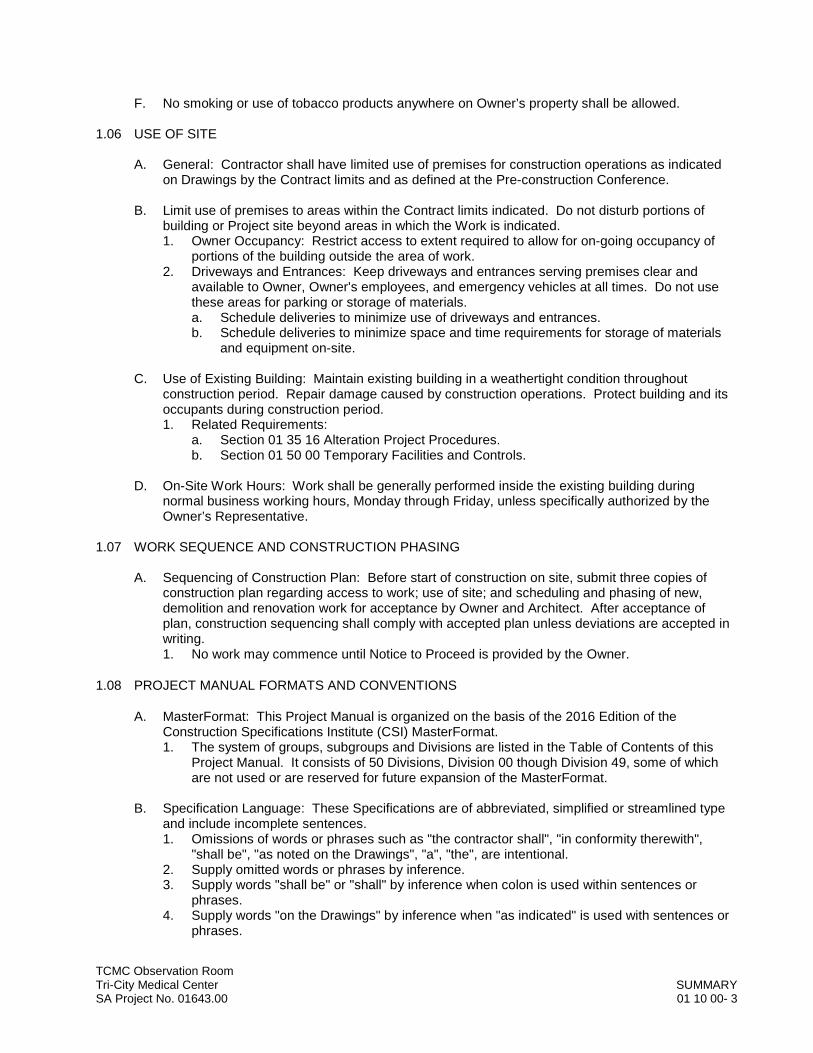
F. No smoking or use of tobacco products anywhere on Owner’s property shall be allowed.
1.06 USE OF SITE
A. General: Contractor shall have limited use of premises for construction operations as indicated on Drawings by the Contract limits and as defined at the Pre-construction Conference.
B. Limit use of premises to areas within the Contract limits indicated. Do not disturb portions of building or Project site beyond areas in which the Work is indicated.1. Owner Occupancy: Restrict access to extent required to allow for on-going occupancy of
portions of the building outside the area of work. 2. Driveways and Entrances: Keep driveways and entrances serving premises clear and
available to Owner, Owner's employees, and emergency vehicles at all times. Do not use these areas for parking or storage of materials.a. Schedule deliveries to minimize use of driveways and entrances.b. Schedule deliveries to minimize space and time requirements for storage of materials
and equipment on-site.
C. Use of Existing Building: Maintain existing building in a weathertight condition throughout construction period. Repair damage caused by construction operations. Protect building and its occupants during construction period.1. Related Requirements:
a. Section 01 35 16 Alteration Project Procedures.b. Section 01 50 00 Temporary Facilities and Controls.
D. On-Site Work Hours: Work shall be generally performed inside the existing building during normal business working hours, Monday through Friday, unless specifically authorized by the Owner’s Representative.
1.07 WORK SEQUENCE AND CONSTRUCTION PHASING
A. Sequencing of Construction Plan: Before start of construction on site, submit three copies of construction plan regarding access to work; use of site; and scheduling and phasing of new, demolition and renovation work for acceptance by Owner and Architect. After acceptance of plan, construction sequencing shall comply with accepted plan unless deviations are accepted in writing.1. No work may commence until Notice to Proceed is provided by the Owner.
1.08 PROJECT MANUAL FORMATS AND CONVENTIONS
A. MasterFormat: This Project Manual is organized on the basis of the 2016 Edition of the Construction Specifications Institute (CSI) MasterFormat. 1. The system of groups, subgroups and Divisions are listed in the Table of Contents of this
Project Manual. It consists of 50 Divisions, Division 00 though Division 49, some of which are not used or are reserved for future expansion of the MasterFormat.
B. Specification Language: These Specifications are of abbreviated, simplified or streamlined type and include incomplete sentences.1. Omissions of words or phrases such as "the contractor shall", "in conformity therewith",
"shall be", "as noted on the Drawings", "a", "the", are intentional.2. Supply omitted words or phrases by inference.3. Supply words "shall be" or "shall" by inference when colon is used within sentences or
phrases.4. Supply words "on the Drawings" by inference when "as indicated" is used with sentences or
phrases.
TCMC Observation RoomTri-City Medical Center SUMMARYSA Project No. 01643.00 01 10 00- 4
PART 2 PRODUCTS - Not Used
PART 3 EXECUTION - Not Used
END OF SECTION
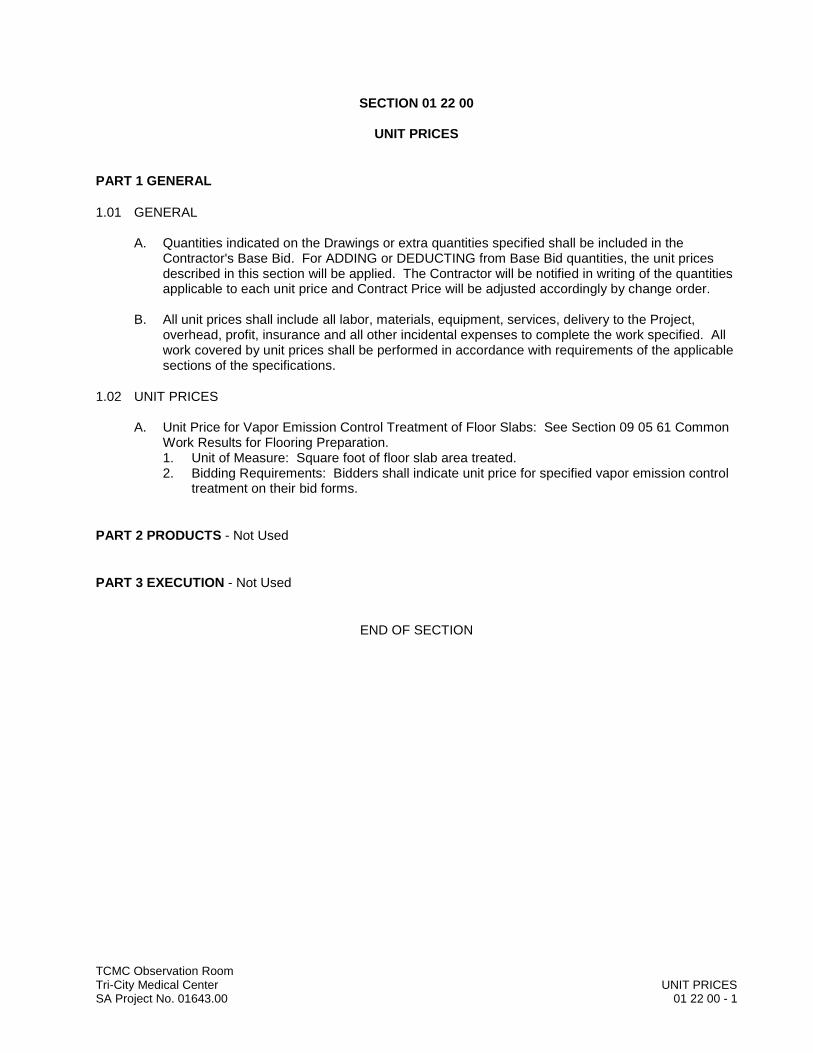
TCMC Observation RoomTri-City Medical Center UNIT PRICESSA Project No. 01643.00 01 22 00 - 1
SECTION 01 22 00
UNIT PRICES
PART 1 GENERAL
1.01 GENERAL
A. Quantities indicated on the Drawings or extra quantities specified shall be included in the Contractor's Base Bid. For ADDING or DEDUCTING from Base Bid quantities, the unit prices described in this section will be applied. The Contractor will be notified in writing of the quantities applicable to each unit price and Contract Price will be adjusted accordingly by change order.
B. All unit prices shall include all labor, materials, equipment, services, delivery to the Project, overhead, profit, insurance and all other incidental expenses to complete the work specified. All work covered by unit prices shall be performed in accordance with requirements of the applicable sections of the specifications.
1.02 UNIT PRICES
A. Unit Price for Vapor Emission Control Treatment of Floor Slabs: See Section 09 05 61 Common Work Results for Flooring Preparation.1. Unit of Measure: Square foot of floor slab area treated.2. Bidding Requirements: Bidders shall indicate unit price for specified vapor emission control
treatment on their bid forms.
PART 2 PRODUCTS - Not Used
PART 3 EXECUTION - Not Used
END OF SECTION

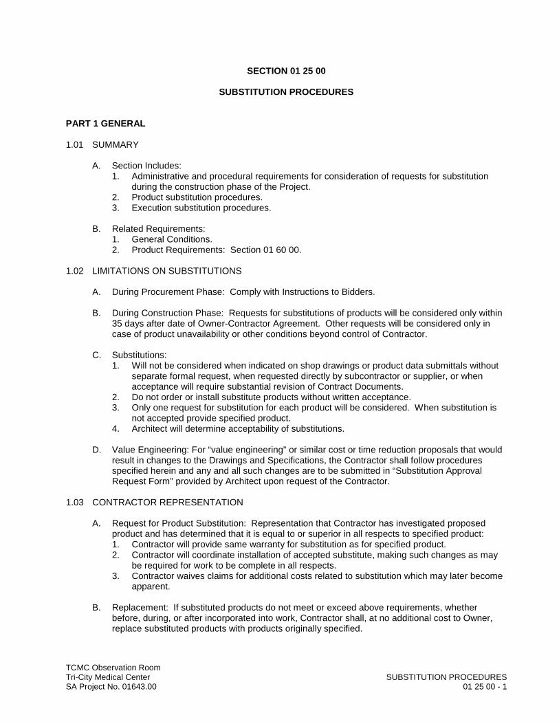
TCMC Observation RoomTri-City Medical Center SUBSTITUTION PROCEDURESSA Project No. 01643.00 01 25 00 - 1
SECTION 01 25 00
SUBSTITUTION PROCEDURES
PART 1 GENERAL
1.01 SUMMARY
A. Section Includes:1. Administrative and procedural requirements for consideration of requests for substitution
during the construction phase of the Project.2. Product substitution procedures.3. Execution substitution procedures.
B. Related Requirements:1. General Conditions.2. Product Requirements: Section 01 60 00.
1.02 LIMITATIONS ON SUBSTITUTIONS
A. During Procurement Phase: Comply with Instructions to Bidders.
B. During Construction Phase: Requests for substitutions of products will be considered only within 35 days after date of Owner-Contractor Agreement. Other requests will be considered only in case of product unavailability or other conditions beyond control of Contractor.
C. Substitutions:1. Will not be considered when indicated on shop drawings or product data submittals without
separate formal request, when requested directly by subcontractor or supplier, or when acceptance will require substantial revision of Contract Documents.
2. Do not order or install substitute products without written acceptance.3. Only one request for substitution for each product will be considered. When substitution is
not accepted provide specified product.4. Architect will determine acceptability of substitutions.
D. Value Engineering: For “value engineering” or similar cost or time reduction proposals that would result in changes to the Drawings and Specifications, the Contractor shall follow procedures specified herein and any and all such changes are to be submitted in “Substitution Approval Request Form” provided by Architect upon request of the Contractor.
1.03 CONTRACTOR REPRESENTATION
A. Request for Product Substitution: Representation that Contractor has investigated proposed product and has determined that it is equal to or superior in all respects to specified product: 1. Contractor will provide same warranty for substitution as for specified product.2. Contractor will coordinate installation of accepted substitute, making such changes as may
be required for work to be complete in all respects.3. Contractor waives claims for additional costs related to substitution which may later become
apparent.
B. Replacement: If substituted products do not meet or exceed above requirements, whether before, during, or after incorporated into work, Contractor shall, at no additional cost to Owner, replace substituted products with products originally specified.
TCMC Observation RoomTri-City Medical Center SUBSTITUTION PROCEDURESSA Project No. 01643.00 01 25 00 - 2
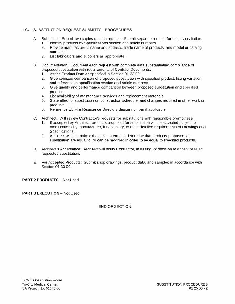
1.04 SUBSTITUTION REQUEST SUBMITTAL PROCEDURES
A. Submittal : Submit two copies of each request. Submit separate request for each substitution.1. Identify products by Specifications section and article numbers. 2. Provide manufacturer's name and address, trade name of products, and model or catalog
number.3. List fabricators and suppliers as appropriate.
B. Documentation: Document each request with complete data substantiating compliance of proposed substitution with requirements of Contract Documents:1. Attach Product Data as specified in Section 01 33 00.2. Give itemized comparison of proposed substitution with specified product, listing variation,
and reference to specification section and article numbers.3. Give quality and performance comparison between proposed substitution and specified
product.4. List availability of maintenance services and replacement materials.5. State effect of substitution on construction schedule, and changes required in other work or
products.6. Reference UL Fire Resistance Directory design number if applicable.
C. Architect: Will review Contractor's requests for substitutions with reasonable promptness.1. If accepted by Architect, products proposed for substitution will be accepted subject to
modifications by manufacturer, if necessary, to meet detailed requirements of Drawings andSpecifications.
2. Architect will not make exhaustive attempt to determine that products proposed for substitution are equal to, or can be modified in order to be equal to specified products.
D. Architect's Acceptance: Architect will notify Contractor, in writing, of decision to accept or reject requested substitution.
E. For Accepted Products: Submit shop drawings, product data, and samples in accordance with Section 01 33 00.
PART 2 PRODUCTS – Not Used
PART 3 EXECUTION – Not Used
END OF SECTION
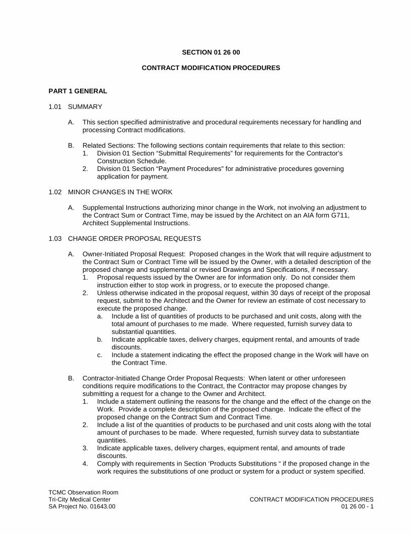
TCMC Observation RoomTri-City Medical Center CONTRACT MODIFICATION PROCEDURESSA Project No. 01643.00 01 26 00 - 1
SECTION 01 26 00
CONTRACT MODIFICATION PROCEDURES
PART 1 GENERAL
1.01 SUMMARY
A. This section specified administrative and procedural requirements necessary for handling and processing Contract modifications.
B. Related Sections: The following sections contain requirements that relate to this section:1. Division 01 Section “Submittal Requirements” for requirements for the Contractor’s
Construction Schedule.2. Division 01 Section “Payment Procedures” for administrative procedures governing
application for payment.
1.02 MINOR CHANGES IN THE WORK
A. Supplemental Instructions authorizing minor change in the Work, not involving an adjustment to the Contract Sum or Contract Time, may be issued by the Architect on an AIA form G711, Architect Supplemental Instructions.
1.03 CHANGE ORDER PROPOSAL REQUESTS
A. Owner-Initiated Proposal Request: Proposed changes in the Work that will require adjustment to the Contract Sum or Contract Time will be issued by the Owner, with a detailed description of the proposed change and supplemental or revised Drawings and Specifications, if necessary.1. Proposal requests issued by the Owner are for information only. Do not consider them
instruction either to stop work in progress, or to execute the proposed change.2. Unless otherwise indicated in the proposal request, within 30 days of receipt of the proposal
request, submit to the Architect and the Owner for review an estimate of cost necessary to execute the proposed change.a. Include a list of quantities of products to be purchased and unit costs, along with the
total amount of purchases to me made. Where requested, furnish survey data to substantial quantities.
b. Indicate applicable taxes, delivery charges, equipment rental, and amounts of trade discounts.
c. Include a statement indicating the effect the proposed change in the Work will have on the Contract Time.
B. Contractor-Initiated Change Order Proposal Requests: When latent or other unforeseen conditions require modifications to the Contract, the Contractor may propose changes by submitting a request for a change to the Owner and Architect.1. Include a statement outlining the reasons for the change and the effect of the change on the
Work. Provide a complete description of the proposed change. Indicate the effect of the proposed change on the Contract Sum and Contract Time.
2. Include a list of the quantities of products to be purchased and unit costs along with the total amount of purchases to be made. Where requested, furnish survey data to substantiate quantities.
3. Indicate applicable taxes, delivery charges, equipment rental, and amounts of trade discounts.
4. Comply with requirements in Section ‘Products Substitutions “ if the proposed change in the work requires the substitutions of one product or system for a product or system specified.

TCMC Observation RoomTri-City Medical Center CONTRACT MODIFICATION PROCEDURESSA Project No. 01643.00 01 26 00 - 2
C. Proposal Request Form: Use forms approved by the Owner for Change Order Proposals.
1.04 CHANGE ORDER PROCEDURES:
A. In addition to the procedure and information stated in the section, herein before: the Contractor shall follow Change Order procedures and information as stated in the General Conditions of the Contract and on the Bid Form.
B. Upon the Owner’s approval of a Change Order proposal Request, the owner will issue a Change Order for signatures of the Owner, Contractor, and Architect.
C. OSHPD Approvals: In accordance with Part 1, Title 24, California Code of Regulations, all addenda and modifications to the Work requiring OSHPD approval shall be approved by the Office of Statewide Health Planning and Development (OSHPD) prior to proceeding with the work.
PART 2 PRODUCTS - Not Used
PART 3 EXECUTION - Not Used
END OF SECTION
TCMC Observation RoomTri-City Medical Center PAYMENT PROCEDURESSA Project No. 01643.00 01 29 00 - 1
SECTION 01 29 00
PAYMENT PROCEDURES
PART 1 GENERAL
1.01 SUMMARY
A. This Section specifies administrative, and procedural requirements governing the Contractor’s Applications for Payment.
B. The Contractor’s Construction Schedule and Submittal Schedule are included in Section “ Submittals”.
1.02 COORDINATION
A. Coordinate preparation of the Schedule of Values with preparation of the Contractor’s Construction Schedule. 1. Correlate line items in the Schedule of Values with other required administrative schedules
and forms, including:a. Contractor’s construction schedule.b. Application for Payment form.c. List of subcontractors.d. Schedule of allowances.e. List of products.f. List of principal suppliers and fabricators.g. Schedule of submittals.
2. Submit the Schedule of Values- Schedule Amounts to the Owner at the earliest feasible date, but in no case later than 7 days before the date schedule for submittal of the initial Application for payment.
1.03 SCHEDULE OF VALUES
A. Identification; Include the following Project identification on the Schedule of Values:1. Name of Owner.2. Project name and location.3. Name of Architect.4. Project number.5. Contractor’s name and address.6. Date of submittal.
B. Arrange the Schedule of Values in a tabular form with separate columns to indicate the following for each item listed;1. Generic name.2. Relate Specification Section.3. Name OF subcontractor.4. Name of manufacturer or fabricator.5. Name of supplier.6. Change Orders (numbers) that have affected value.7. Dollar value.8. Percentage of Contract Sum to the nearest one-hundredth percent, adjusted to total 100
percent.

TCMC Observation RoomTri-City Medical Center PAYMENT PROCEDURESSA Project No. 01643.00 01 29 00 - 2
C. Provide a breakdown of the Contract Sum in sufficient detail to facilitate continued evaluation of Applications for Payment and progress evaluation of Applications fro Payment and progress report. Break principle subcontract amounts down into several line items.
D. Round amounts off to the nearest whole dollar; the total shall equal the Contract Sum.
E. For each part of the Work where an Application for Payment may include materials or equipment, purchased or fabricated and stored, but not yet installed, provide separate line items on the schedule of Values for initial cost of the materials, for each subsequent stage of completion, and for total installed value of that part of the work.
F. Margins of Cost: Show line items for indirect costs, and margins on actual costs, only to the extent that such items will be listed individually and Applications for Payment. Each item in the Schedule of Values and Applications for Payment shall be completed including its total cost and proportionate share of general overhead and profit margin.
G. At the Contractor’s option, temporary facilities and other major cost items that are not direct cost of actual work-in-place may be shown as separate line items in the Schedule of Values or distributed as general overhead expense.
H. Schedule Updating: Update and resubmit the Schedule of Values when change Orders result in a change in the Contract sum.
1.04 APPLICATIONS FOR PAYMENT:
A. Each Application for payment shall be consistent with previous applications and payments ad certified by the Architect and paid for by the Owner.1. The initial Application for payment, the Application fro payment at time of Substantial
Completion, and the final Application for Payment involved additional requirements.
B. Payment Application Times: The date for each progress payment is the first construction progress meeting of each month. The period of construction Work covered by each Application for Payment is the period ending at the last day of the month prior to the date for each progress payment and starting the day following the end of the preceding period.
C. Payment Applications Forms: Use AIA Document G702 and G703.
D. Application Preparation: Complete every entry on the form, including notarization and execution by person authorized to sign legal documents on behalf of the Owner. Incomplete applications will be returned without action.1. Entries shall match data on the Schedule of Values and Contractor’s Construction Schedule.
Use updated schedule if revisions have been made.2. Include amounts of Change Orders and Construction Change Directives issued prior to the
last day of the construction period covered by the application.
E. Transmittal: Submit 5 executed copies of each Application for payment to the Owner and Architect at the first of the bi-weekly Construction Progress Meeting. This meeting will extend into preview and acceptance by all required parties of the Contractors application of payment.1. Transmit each copy with a transmittal form listing attachments, and recording appropriate
information related to the application in a manner acceptable to the Architect.

TCMC Observation RoomTri-City Medical Center PAYMENT PROCEDURESSA Project No. 01643.00 01 29 00 - 3
F. Waivers of Mechanics Lien: With each Application for Payment submit waivers of Mechanic liens from subcontractors or sub-subcontractors and supplier for the construction period covered by the pervious application.1. Submit partial waivers on each item for the amount requested, prior to deduction for
retainage, on each item.2. When an application shows completion of an item, submit final or full waivers.
G. The Owner reserves the right to designate which entities involved in the Work must submit waivers.1. Wavier Delays: Submit each Application for Payment with the Contractors Wavier of
Mechanics lien for the period of construction covered by the application. 2. Submit final Application for payment with or proceeded by final wavier from every entity
involved with performance with Work covered by the Application who could lawfully be entitled to a lien.
3. Waiver Forms: Submit Wavier of lien of forms, and executed in a manner, acceptable to Owner.
H. Initial Application for payment: Administrative action and submittal that must precede or coincide with submittal of the first Application for Payment include but not limited to the following:1. List of subcontractors and their agreements with the Contractor.2. List of principle suppliers and fabricators.3. Schedule of Values.4. Contractors Construction Schedule (preliminary if not final).5. Schedule of principle products.6. Submittal Schedule (preliminary if not final).7. List of Contractor’s staff assignments.8. List of Contractor’s principle consultants.9. Copies of building permits.10. Copies of authorization and licenses from governing authorities for performance of the Work.11. Certificates of insurance and insurance policies.12. Data needed to acquire Owner’s insurance.
I. Application for Payment at Substantial Completion: Following issuance of the Certificate of Substantial Completion, on the entire project, submit an Application for Payment.
J. Administrative actions and submittals that shall precede or coincide with this application include:1. Occupancy permits and similar approvals. 2. Warranties (guarantees) and maintenance agreements.3. Test/ adjust / balance records.4. Maintenance instructions.5. Changeover information related to owner’s occupancy, use, operation and maintenance.6. Final cleaning.7. Application for reduction of retainage, and consent of surety.8. Advice on shifting insurance coverage.9. Final progress photographs.10. List of delayed work, recognized as exceptions to Architect’s Certificate of Substantial
Completion.
K. Final Payment Application: Administrative actions and submittals, which must precede or coincide with submittal of the final payment Application for Payment include the following:1. Completion of project closeout requirements.2. Completion of items specified for completion after Substantial Completion.3. Assurance that unsettled claims will be settled.4. Assurances that work not complete and accepted will complete without undo delay. 5. Transmittal of required Project Construction Records to the Owner.

TCMC Observation RoomTri-City Medical Center PAYMENT PROCEDURESSA Project No. 01643.00 01 29 00 - 4
6. Proof that taxes, fees and similar obligations have been paid.7. Removal of temporary facilities and services.8. Removal of surplus materials, rubbish and similar elements.
PART 2 PRODUCTS - Not Used
PART 3 EXECUTION - Not Used
END OF SECTION
TCMC Observation RoomTri-City Medical Center PROJECT COORDINATIONSA Project No. 01643.00 01 31 13 - 1
SECTION 01 31 13
PROJECT COORDINATION
PART 1 GENERAL
1.01 SUMMARY
A. This section specified administrative and supervisory requirements necessary for Project coordination including, but necessary limited to:1. Coordination.2. Administrative and Supervisory personnel.3. General installation provision.4. Cleaning and protection.5. Time and Manner.
B. Progress meetings, coordination meetings and pre-installation conferences are included in Section “Project Meetings.”\1. Requirements for the Contractor’s Construction Schedule are included in Section
“Submittals.”
1.02 COORDINATION
A. Coordination: Coordinate construction activities included under various Sections of these Specifications to assure efficient and orderly installation of each part of the Work. Coordinate construction operations include under different Sections of the Specifications that are dependent upon each other for proper installation, connection, and operation.1. Where installation of one part of the Work is dependent on installation of other components,
either before or after its own installation, schedule Construction activities in the sequence to obtain the best results.
2. Where availability of space is limited, coordinate installation of different components to assure maximum accessibility for required maintenance, service and repair.
1.03 COORDINATION
A. Make adequate provisions to accommodate items scheduled for later installation.
B. Administrative Procedures: Coordinate scheduling and timing of required Administrative Procedures with other constructions activities to avoid conflicts and ensure orderly progress of the work. Such administrative activities include, but are not limited to the following:1. Preparation of Schedules.2. Installation and removal of temporary facilities.3. Delivery and processing of submittals.4. Progress Meetings.5. Project closeout activities.
C. Conservation: Coordinate Construction activities to ensure that operations are carried out with considerations given to conservation of energy, water, and materials.1. Salvage materials and equipment involved in performance of, but not actually incorporated
in, the Work. Refer to other sections for disposition of salvaged materials that are designated as Owner’s property.
PART 2 PRODUCTS - Not Used
TCMC Observation RoomTri-City Medical Center PROJECT COORDINATIONSA Project No. 01643.00 01 31 13 - 2
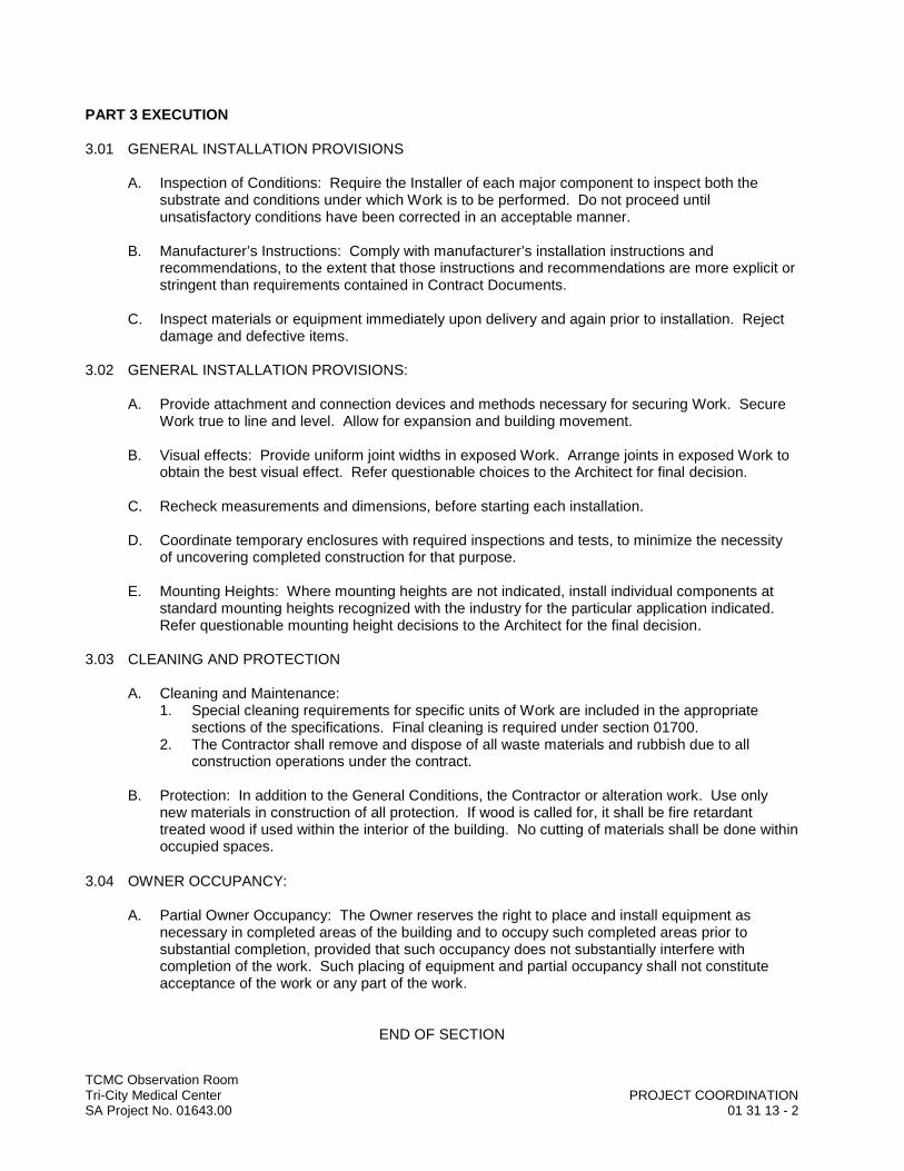
PART 3 EXECUTION
3.01 GENERAL INSTALLATION PROVISIONS
A. Inspection of Conditions: Require the Installer of each major component to inspect both the substrate and conditions under which Work is to be performed. Do not proceed until unsatisfactory conditions have been corrected in an acceptable manner.
B. Manufacturer’s Instructions: Comply with manufacturer’s installation instructions and recommendations, to the extent that those instructions and recommendations are more explicit or stringent than requirements contained in Contract Documents.
C. Inspect materials or equipment immediately upon delivery and again prior to installation. Reject damage and defective items.
3.02 GENERAL INSTALLATION PROVISIONS:
A. Provide attachment and connection devices and methods necessary for securing Work. Secure Work true to line and level. Allow for expansion and building movement.
B. Visual effects: Provide uniform joint widths in exposed Work. Arrange joints in exposed Work to obtain the best visual effect. Refer questionable choices to the Architect for final decision.
C. Recheck measurements and dimensions, before starting each installation.
D. Coordinate temporary enclosures with required inspections and tests, to minimize the necessity of uncovering completed construction for that purpose.
E. Mounting Heights: Where mounting heights are not indicated, install individual components at standard mounting heights recognized with the industry for the particular application indicated. Refer questionable mounting height decisions to the Architect for the final decision.
3.03 CLEANING AND PROTECTION
A. Cleaning and Maintenance:1. Special cleaning requirements for specific units of Work are included in the appropriate
sections of the specifications. Final cleaning is required under section 01700.2. The Contractor shall remove and dispose of all waste materials and rubbish due to all
construction operations under the contract.
B. Protection: In addition to the General Conditions, the Contractor or alteration work. Use only new materials in construction of all protection. If wood is called for, it shall be fire retardant treated wood if used within the interior of the building. No cutting of materials shall be done within occupied spaces.
3.04 OWNER OCCUPANCY:
A. Partial Owner Occupancy: The Owner reserves the right to place and install equipment as necessary in completed areas of the building and to occupy such completed areas prior to substantial completion, provided that such occupancy does not substantially interfere with completion of the work. Such placing of equipment and partial occupancy shall not constitute acceptance of the work or any part of the work.
END OF SECTION
TCMC Observation RoomTri-City Medical Center PROJECT MEETINGSSA Project No. 01643.00 01 31 19 - 1
SECTION 01 31 19
PROJECT MEETINGS
PART 1 GENERAL
1.01 SUMMARY
A. This Section specifies administrative and procedural requirements for project meetings including but not limited to:1. Pre-Construction Conference.2. Pre-Installation Conferences.3. Progress Meetings.
B. Construction schedules are specified in another Division-01 Section.
1.02 PRE-CONSTRUCTION CONFERENCE
A. Schedule a pre-construction conference and organizational meeting at the Project site or other convenient location no later than 5 days after the notice to proceed and prior to commencement of construction activities. Conduct the meeting to review responsibilities and personnel assignments.
B. Attendees: The Owner, Architect and their consultants, the Prime Contractors and their superintendent, major subcontractors, manufactures, suppliers and other concerned parties shall each be represented at the conference by persons familiar with and authorized to conclude matters relating to the Work.
C. Agenda: Discuss items of significance that could affect progress including but not limited to such topics as:1. Tentative construction schedule.2. Critical Work sequencing.3. Designation of responsible personnel.4. Procedures for processing filed decisions and Change Orders.5. Procedures for processing Applications for Payment.6. Distribution of Contract Documents.7. Submittal of Shop Drawings, Product Data and Samples.8. Preparation of record documents.9. Use of the premises.10. Office, work and storage areas.11. Equipment deliveries and priorities.12. Safety procedure13. First aid.14. Security 15. Housekeeping.16. Working Hours.
1.03 PRE-INSTALLATION CONFERENCES
A. Conduct a pre-installation conference at the site before each construction activity that requires coordination with other construction and as specified herein. The Installer and representatives of manufacturers and fabricators involved in or affected by the installation, and its coordination or integration with other materials and installations that have preceded or will follow, shall attend the meeting. Advise the Architect of Schedule meeting dates.
TCMC Observation RoomTri-City Medical Center PROJECT MEETINGSSA Project No. 01643.00 01 31 19 - 2
B. Review the progress of other construction activities and preparations for the particular activity under consideration at each pre-installation conference.
C. Do not proceed if the conference cannot be successfully concluded. Indicate whatever actions are necessary to resolve impediments to performance of Work and reconvene the conference at the earliest feasible date.
1.04 PROGRESS MEETINGS
A. Conduct progress meetings at Project site bi-weekly. Coordinate dates of meeting with preparation of the payment request.
B. Attendees: In addition to representative of the Owner and Architect, each subcontractor, supplier or other entity concerned with current progress or involved in planning, coordination or performance of future activities shall be represented at these meetings by persons familiar with the Project and authorized to conclude matters relating to progress.
C. Agenda: Review and correct or approve minutes of the previous progress meeting. Review other items of significance that could affect progress. Include topics for discussion as appropriate to the current of the Project.1. Contractor’s Construction Schedule: Review progress since the last meeting. Determine
where each activity is in relation to the Contractor’s Construction Schedule, whether on time or ahead or behind schedule. Determine how construction behind schedule will be expedited; secure commitments from parties involved to do so. Discuss schedule revisions are required to ensure that current and subsequent activities will be completed within the Contract Time.
2. Schedule Updating: Revise the construction schedule after each progress meeting where revisions to the schedule have been made or recognized. Issue the revise schedule to the Owner and Architect.
PART 2 PRODUCTS – Not used
PART 3 EXECUTION – Not used
END OF SECTION
TCMC Observation RoomTri-City Medical Center SUBMITTAL PROCEDURESSA Project No. 01643.00 01 33 00 - 1
SECTION 01 33 00
SUBMITTAL PROCEDURES
PART 1 GENERAL
1.01 SUMMARY
A. This Section specifies administrative and procedural requirements for submittals required for performance of the Work, including:1. Contractor’s construction schedule.2. Submittal schedule.3. Construction progress photographs.4. Shop Drawings.5. Product Data.6. Samples.
B. Administrative Submittals: T=Refer to other Division-1 Sections and other Contract Documents for requirements for administrative submittals. Such submittals include, but are not limited to: 1. Permits.2. Applications for payment.3. Performance and payment bonds.4. Insurance certificates.5. List of Subcontractors.
C. The schedule of Values submittal is included in Section “Applications for Payment.”’
D. Inspection and test reports are included in Section “Quality Control Services.”
1.02 SUBMITTAL PROCEDURES
A. Coordination: Coordinate preparation and processing of submittals with performance of construction activities. Transmit each submittal sufficiently in advance of performance of related construction activities to avoid delays.1. Coordinate each submittal with fabricate, purchasing, testing, delivery, other submittals and
related activities that require sequential activities.2. Coordinate transmittal of different types of submittals for related elements of the Work so
processing will not be delayed by the need to review submittals constructed for coordination.a. The Architect reserves the right to withhold action on a submittal requiring coordination
with other submittals until related submittals are received.
B. Processing: Allow sufficient review time so that installation will not be delayed as result of the time required to process submittals, including time for resubmittals.1. Allow two weeks for initial review. Allow Additional time if processing must be delayed to
permit coordination with subsequent submittals. The Architect will promptly advise the contractor when a submittal being processed must be delayed for coordination.
2. If an intermediate submittal is necessary, process the same as initial submittal.3. Allow two weeks for reprocessing each submittal.4. No extension of Contract Time will be authorized because of failure to transmit submittals to
the Architect sufficiently in advance of the work to permit processing.

TCMC Observation RoomTri-City Medical Center SUBMITTAL PROCEDURESSA Project No. 01643.00 01 33 00 - 2
C. Submittal Preparation: Place a permanent label or title block on each submittal for identification. Indicate the name of the entity that prepared each submittal on the label or title block.1. Provide a space approximately 4” x 5” on the label or beside the title block on Shop
Drawings and product Data to record the Contractor’s review and approval markings and the action taken for accuracy, completeness and compliance with the Contract Documents. Submittals without evidence of the Contractor’s review and approval will be returned for resubmission.
2. Include the following information on the label for processing and recording action taken.a. Project name.b. Date.c. Name and address of Architect.d. Name and address of Contractor.e. Name and address of subcontractor.f. Name and address of supplier.g. Name manufacturer.h. Number and title of appropriate Specifications Section.i. Drawings number and detail references, as appropriate.
D. Submittal Transmittal: Package each submittal appropriately for transmittal and handling. Transmit each submittal from Contractor to Architect using a transmittal form with copy of transmittal to Owner. Submittal received from sources other than the Contractor will be returned without action.1. On the transmittal Record relevant information and requests for data. On the form, or
separate sheet, record deviations from Contract Document requirement, including minor variations and limitations. Include Contractor’s certification that information complies with Contract Document requirements.
1.03 CONTRACTORS’ CONSTRUCTION SCHEDULE
A. Bar-Chart Schedule: The General Contractor shall prepare a fully developed, horizontal bar-chart type contractors’ construction schedule. Submit within 10 days of the date of the notice to proceed.1. Provide a separate time bar for each significant construction activity including the related
contracts activities. Provide a continuous vertical line to identify the first working day of each week. Use the same breakdown of units of the work as indicate in the “Schedule of Values.”
2. Within each time bar indicated estimate completion percentage in 10 percent increments. As Work progress, place a contrasting mark in each bar to indicate Actual Completion.
3. Prepare the schedule on a sheet, or series of sheets, of stable transparency, or other reproducible media, of sufficient width to show data for the entire construction period.
4. Secure time commitments for performing critical elements of the Work from parties involved. Coordinate each element on the schedule with other construction activities; include minor elements involved in the sequence of the Work. Show each activity in proper sequence. Indicate graphically sequences necessary for completion of related portions of the Work.
5. Coordinate the Contractors’ construction schedule with the schedule of values, list of subcontracts, submittal schedule, progress reports, payment requests and other schedule.
6. Indicate completion in advance of the date established for schedule Completion. Indicate Substantial Completion on the schedule to allow time for the Architect’s procedures necessary for certification of Substantial Completion.
B. Distribution: Following response to the initial submittal, print and distribute copies to the Architect, Owner, related Prime Contractor, subcontractors, and other parties require to comply with schedule dates. Post copies in the project meeting room and temporary field office.1. When revisions are made, distribute to the same parties and post in the same locations.
Delete parties from distribution when they have completed their assigned portion of the Work and are no longer involved in construction activities.
TCMC Observation RoomTri-City Medical Center SUBMITTAL PROCEDURESSA Project No. 01643.00 01 33 00 - 3
C. Schedule Updating: Revise and reissue the schedule after each meeting or activity, where revisions have been recognized or made.
1.04 SUBMITTAL SCHEDULE
A. After development and acceptance of the Contractors’ construction schedule, each Prime Contractor shall prepare a complete schedule of submittals. Submit the schedule within 10 days from the Pre-Construction Conference.
B. Coordinate submittal schedule with the list of subcontracts, schedule of values and the list of products as well as the Contractor’s construction schedule.
C. Prepare the schedule in chronological order; include submittals required during the first 30 days of Construction. Provide the following information:1. Schedule date for the first submittal.2. Related Section number.3. Submittal category.4. Name of subcontractor.5. Description of the part of the work covered.6. Scheduled date for resubmittal. 7. Scheduled date for the Architect’s final release or approval.
D. Distribution: Following response to initial submittal, print and distribute copies to the Architect’s, Owner, subcontractors, and other parties required to comply with submittal date indicated. Post copies in the Project meeting room and file in office.1. When revisions are made, distribute to the same parties and post in the same locations.
Delete parties from distribution when they have completed their assigned portion of the Work and are no longer involved in construction activities.
E. Schedule Updating: Revise and reissue the schedule after each meeting or activities, where revisions have been recognized or made.
1.05 SHOP DRAWINGS
A. Submit newly prepared information, drawn to accurate scale. Highlight, encircle, or otherwise indicate deviations from the Contract Documents. Do not reproduce Contract Documents or copy standard information as the basis of shop Drawings. Standard information prepared without specific reference to the Project is not considered Shop Drawings.
B. Shop Drawings include fabrication and installation drawings, setting diagrams, schedules, patterns, templates and similar drawings. Include the following information:1. Dimensions.2. Identification of products and materials included.3. Completion with specified standards.4. Notation of coordination requirements.5. Notation of dimensions established field measurement.
C. Sheet Size: Except for templates, patterns and similar full-size Drawings, submit Shop Drawings on sheets at least 8-1/2”x11” but not larger than 30” x 42”
D. Initial Submittal: To Architect submit one correctable translucent reproducible print and one blue-or black-line print for the Architect’s review; the reproducible print will be returned.
TCMC Observation RoomTri-City Medical Center SUBMITTAL PROCEDURESSA Project No. 01643.00 01 33 00 - 4
E. Final Submittal: To Architect a minimum of blue- or black-line prints; submit 8 prints where required for maintenance manuals. 5 prints will be retained; the remainder will be returned.1. One of the prints returned shall be marked-up and maintained as a “Record Document”.2. Do not Shop drawings without an appropriate final stamp indicating action taken in
connection with construction.
1.06 PRODUCT DATA
A. Collect product Data into a single submittal for each element of construction or system. Product Data included printed information such as manufacturer’s installation instructions, catalog cuts, standard color charts, roughing-in diagrams and templates, standard wiring diagrams and performance curves. Where Product Data must be specially prepared because standard printed data is not suitable for use, submit as ‘ Shop Drawings”.
B. Mark each copy to show applicable choices and options. Where printed Product Data included information on several products, some of which are not required. Mark copies to indicate the applicable information. Include the following information:1. Manufacturer’s printed recommendations.2. Compliance with recognized trade association standards.3. Compliance with recognized testing agency standards.4. Application of testing agency labels and seals.5. Notation of dimensions verified by field measurement.6. Notation of coordination requirements.
C. Do not submit Product Data until compliance with requirements of the Contract Documents has been confirmed.
D. Preliminary Submittal: To Architect submit a preliminary single-copy of product Data where selection of options is required.
E. Submittals: To Architect submit a minimum of 7 copies of each required submittal; submit 8 copies where required for maintenance manuals. The Architect will retain 5 copies. And will return the other marked with action taken and corrections or modifications required.
F. Distribution: Furnish copies of final submittal to installers, subcontractors, suppliers, manufacturers, fabricators, and other required for performance of construction activities. Show distribution on transmittal form with copy being sent to Architect and Owner.
1.07 SAMPLES
A. Submit to Architect full-size, fully fabricate Sample cured and finished as specified and physically identical with the material or product proposed. Samples include partial sections of manufactured or fabricate components, cuts or containers of materials; color ranges sets, and swatches showing color, texture and pattern.
B. Mount, display, or package Samples in the manner specified to facilitate review of qualities indicated. Prepare Samples to match the Architect’s Sample. Include the following:1. Generic description of the Sample.2. Sample source.3. Product name or name of manufacturer.4. Compliance with recognized standards.5. Availability and delivery time.
TCMC Observation RoomTri-City Medical Center SUBMITTAL PROCEDURESSA Project No. 01643.00 01 33 00 - 5
C. Submit to Architect Samples for review of kind, color, pattern, and texture, for a final check of these characteristics with other elements, and for a comparison of these characteristic between the final submittal and the actual component as delivered and installed.1. Where variation in color, pattern, texture or other characteristic are inherent in the material or
product represented, submit multiple units (not less than 3), that show approximate limits of the variations.
2. Refer to other Specification sections for requirements for Samples that illustrate workmanship. Fabrication techniques, details of assembly, connections, operation and similar construction characteristic.
3. Refer to other Sections for Samples to be returned to the Contractor for incorporation in the Work. Such Samples must be undamaged at time of use. On the transmittal of Sample submittals.
D. Preliminary submittals: Where Samples are for selection of color, pattern, texture or similar characteristics from a range of standard choices, submit a full set of choices for the material or product.1. Preliminary submittals will be reviewed and returned with the Architect’s mark indicating
selection and other action.
E. Submittals: Except for Samples illustrating assembly details, workmanship, fabrication techniques, connections, operation and similar characteristics, submit 3 sets; one will be returned marked with the action taken.1. Maintain seats of Samples, as returned, at the Project site, for Quality comparisons
throughout the course of construction.2. Unless no completion with Contract Document provisions is observed, the submittal may
serve as the final submittal.3. Sample sets may be used to obtain final acceptance of the construction associate with each
set.
F. Distribution of Samples: Prepare and distribute additional sets to subcontractors, manufacturers, fabricators, supplies, installers, and others as required for performance of the work. Show distribution on transmittal form sent to Architect And Owner.
G. Filed Samples specified in individual Sections are special types of Samples. Field Samples are full-size examples erected on site to illustrate finish coats, or finishing materials and to establish the standard by which the Work will be judge.1. Comply with submittal requirements to the fullest extent possible. Process transmittal forms
to provide a record of activity.
1.08 ARCHITECT’S ACTION
A. Except for submittals for record, information or similar purposes, here action and return is required or requested, the Architect will review each submittal, mark to indicate action taken, and promptly.1. Compliance with specified characteristics is the Contractor’s responsibility.
B. Action Stamp: The Architect will stamp each submittal with a uniform, self-explanatory action stamp. The stamp will be appropriately marked, as follows, to indicate the action taken.1. Final Unrestricted Release: Where submittals are marked “No Exception Taken,” that part of
the work covered by the submittal may proceed provided it complies with requirements of the Contract Documents; final acceptance will depend upon that compliance.
2. Final-but-Restricted Release: When submittals are marked “Make Corrections Noted,” that part of the work covered by the submittal may proceed provided it complies with notations or corrections on the submittal and requirements of the Contract Documents; final acceptance will depend upon that compliance.

TCMC Observation RoomTri-City Medical Center SUBMITTAL PROCEDURESSA Project No. 01643.00 01 33 00 - 6
3. Returned for Resubmittal: When submittal is marked “Revise and Resubmit,” do not proceed with that part of the Work covered by the submittal, including purchasing, fabrication, delivery, or other activity. Revise or prepare a new submittal in accordance with the notations; resubmit without delay. Repeat if necessary to obtain a different action mark.
4. Do not permit submittals marked “Revise and Resubmit” to be used at the Project site, orelsewhere where Work is in progress.
5. Other Action: Where a submittal is primarily for information or record purposes, special processing or other activity, the submittal will be returned.
PART 2 PRODUCTS - Not Used
PART 3 EXECUTION - Not Used
END OF SECTION
TCMC Observation RoomTri-City Medical Center ALTERATION PROJECT PROCEDURESSA Project No. 01643.00 01 35 16 - 1
SECTION 01 35 16
ALTERATION PROJECT PROCEDURES
PART 1 GENERAL
1.01 REQUIREMENTS INCLUDED
A. Coordinate work of trades and schedule elements of alterations and renovation work by procedures and methods to expedite completion of the Work.
B. In addition to demolition specified in Section 02 41 19.16 and that specifically shown, cut, move and remove items as necessary to provide access or to allow alterations and new work to proceed. Include such items as:1. Repair or removal of hazardous or unsanitary conditions. 2. Removal of abandoned items and items serving no useful purpose, such as abandoned
piping, conduit and wiring. 3. Removal of unsuitable or extraneous materials not marked for salvage, such as abandoned
furnishings and equipment, and debris such as rotted wood, rusted metals and deteriorated concrete.
4. Cleaning of surfaces, and removal of surface finishes, as needed to install new work and finishes.
C. Patch, repair and refinish existing items to remain, to the specified conditions for each material, with a workmanlike transition to adjacent new items of construction.
D. Coordination of power outages and major interruptions of progress of construction work with Owner.
1.02 RELATED REQUIREMENTS
A. Materials for Renovation Work: Specifications in Divisions 02 through 31.
B. Use of Premises and Work Restrictions: Section 01 10 00 Summary.
C. Cutting and Patching of New or Existing Work During Construction: Section 01 73 29 Cutting and Patching.
D. Use of Existing Utilities: Section 01 50 00 Temporary Facilities and Controls.
E. Cleaning During Construction: Section 01 50 00 Temporary Facilities and Controls.
F. Selective Interior Demolition: Section 02 41 19.16.
1.03 ALTERATIONS, CUTTING AND PROTECTION
A. Assign the work of moving, removal, cutting and patching to trades qualified to perform the work in a manner to cause least damage to each type of work, and provide means of returning surfaces to appearance of new work.
B. Perform cutting and removal work to remove minimum necessary, and in a manner to avoid damage to adjacent work. 1. Cut finish surfaces such as masonry, tile, stone flooring, plaster or metals by methods to
terminate surfaces in a straight line at a natural point of division.
TCMC Observation RoomTri-City Medical Center ALTERATION PROJECT PROCEDURESSA Project No. 01643.00 01 35 16 - 2
C. Protect existing finishes, equipment and, adjacent work that is scheduled to remain, from damage.1. Protect existing and new work from weather and extremes of temperature.
a. Maintain existing interior work above 60 degrees F. b. Provide weather protection, waterproofing, heat and humidity control as needed to
prevent damage to remaining existing work and to new work.
D. Temporary Enclosures:1. Provide temporary, dustproof enclosures to separate work areas from existing building and
from areas occupied by Owner.
1.04 COORDINATION WITH OWNER'S USE OF THE FACILITY
A. General: Coordinate construction phasing with operation of Owner's existing facility. The Owner intends to occupy portions of the existing building throughout construction.1. Establish effective communications with the Owner regarding Owner’s operation and moving
schedule. Give as much advance notice as possible, in addition to the minimums specified, for construction activities that will affect Owner's operations.
B. Utility Interruptions: Coordinate with Owner. Notify Owner 48 hours in advance of all necessaryutility interruptions, including those scheduled for off hours.
C. Sequence of Construction and Remodeling:1. Coordination: Coordinate construction schedule with Owner's requirements.2. Phasing: See Phasing Plan and Phasing Notes on Drawings.
PART 2 PRODUCTS
2.01 PRODUCTS FOR PATCHING, EXTENDING AND MATCHING
A. General Requirements that Work be Complete:1. Provide same products or types of construction as that in existing structure, as needed to
patch, extend or match existing work.a. Generally Contract Documents will not define products or standards of workmanship
present in existing construction; Contractor shall determine products by inspection and any necessary testing, and workmanship by use of the existing as a sample of comparison.
2. Presence of a product, finish, or type of construction, requires that patching, extending or matching shall be performed as necessary to make work complete and consistent.
PART 3 EXECUTION
3.01 LAYING OUT WORK
A. Verify dimensions and elevations indicated in layout of existing work. Refer discrepancies between Drawings, Specifications and existing conditions to Architect for adjustment before work affected is performed. Failure to make such notification shall place responsibility upon Contractor to carry out work in satisfactory, workmanlike manner.
B. The Contractor shall be held responsible for the location and elevation of the construction contemplated by the Construction Documents.

TCMC Observation RoomTri-City Medical Center ALTERATION PROJECT PROCEDURESSA Project No. 01643.00 01 35 16 - 3
C. Prior to commencing work, carefully compare and check Architectural, Structural, Mechanical and Electrical Drawings, each with the other that in any way affects the location or elevation of the work to be executed, and should any discrepancy be found, immediately report the same to the Architect for verification and adjustment.
3.02 LOCATION OF EQUIPMENT AND PIPING
A. Drawings showing location of equipment, piping, ductwork, etc. are diagrammatic and job conditions shall not always duplicate conditions shown. When this situation occurs, it shall be brought to the Architect's attention immediately and the relocation determined in a joint conference.
3.03 PATCHING EXISTING FACILITIES
A. Existing structures, facilities, etc. that are damaged or removed due to required construction work, shall be patched, repaired or replaced, and be left in their original state of repair by the Contractor, to satisfaction of the Architect.
3.04 INTEGRATING EXISTING WORK
A. Protect existing improvements from damage.
B. Contractor's operations shall be confined to the immediate vicinity of the new work and shall not in any way interfere with or obstruct the ingress or egress to and from adjacent facilities.
C. Where new work is to be connected to existing work, special care shall be exercised not to disturb or damage the existing work more than necessary. All damaged work shall be replaced, repaired and restored to its original condition at no cost to the Owner.
3.05 ADJUSTING
A. Where partitions are removed, patch floors, walls and ceilings with finish materials to match existing.1. Where removal of partitions results in adjacent spaces becoming one, rework floors and
ceilings to provide smooth planes without breaks, steps or bulkheads.2. Where extreme change of plane occurs, request instructions from Architect as to method of
making transition.
B. Trim and refinish existing doors as necessary to clear new floors.
3.06 DAMAGED SURFACES
A. Patch and replace any portion of an existing finished surface which is found to be damaged, lifted, discolored, or shows other imperfections, with matching material.1. Provide adequate support of substrate prior to patching the finish.2. Refinish patched portions of painted or coated surfaces in a manner to produce uniform
color and texture over entire surface.3. When existing surface finish cannot be matched, refinish entire surface to nearest
intersections.
TCMC Observation RoomTri-City Medical Center ALTERATION PROJECT PROCEDURESSA Project No. 01643.00 01 35 16 - 4
3.07 TRANSITION FROM EXISTING TO NEW WORK
A. When new work abuts or finishes flush with existing work, make a smooth and workmanlike transition. Patch work shall match existing adjacent work in texture and appearance so that the patch or transition is invisible at a distance of five feet. 1. When finished surfaces are cut in such a way that a smooth transition with new work is not
possible, terminate existing surface in a neat manner along a straight line at a natural line of division, and provide trim appropriate to finished surface.
3.08 DUST CONTROL
A. Precaution shall be exercised at all times to control dust created as a result of any operations during the construction period. If serious problems arise due to air borne dust, and when directed by Architect, operations causing such problems shall be temporarily discontinued and necessary steps taken to control the dust.
3.09 FIRE PROTECTION
A. Maintain good housekeeping practices to reduce the risk of fire damage and injury to workmen. All scrap materials, rubbish and trash shall be removed daily from in and about the work area and shall not be permitted to be scattered to adjacent areas.
B. Suitable storage space shall be provided outside the immediate building area for storing flammable materials and paints; no storage will be permitted in the building. Excess flammable liquids being used inside the building shall be kept in closed metal container and removed from the building during unused periods.
C. A fire extinguisher shall be available at each location where cutting or welding is being performed. Where electric or gas welding or cutting work is done, interposed shields of incombustible material shall be used to protect against fire damage due to sparks and hot metal. When temporary heating devices are used, a watchman shall be present to cover periods when other workmen are not on the premises.
D. Provide fire extinguishers in accordance with the recommendations of NFPA Bulletins Nos. 10 and 241. However, in all cases a minimum of four fire extinguishers shall be available for each building.
3.10 CLEANING
A. Perform periodic and final cleaning as specified in Section 01 74 00, 01 50 00 and as follows:1. Clean Owner-occupied areas where construction or remodeling is occurring, daily.2. Clean areas of heavy dust production daily. 3. Clean spillage and overspray immediately.
B. At completion of work of each trade, clean area and make surfaces ready for work of successive trades.
C. At completion of work in each area, provide final cleaning and return space to a condition suitable for use by Owner.
END OF SECTION
TCMC Observation RoomTri-City Medical Center REGULATORY REQUIREMENTSSA Project No. 01643.00 01 41 00 - 1
SECTION 01 41 00
REGULATORY REQUIREMENTS
PART 1 GENERAL
1.01 RELATED REQUIREMENTS
A. Code and Regulatory Requirements Data on Sheets A1-00 through A1-02 of the Drawings.
1.02 PERMITS AND FEES
A. Office of Statewide Health Planning and Development (OSHPD) Requirements: OSHPD is the primary agency having jurisdiction over project design and construction within healthcare facilities. 1. Licensed Contractors Declaration: Prepare and submit through Architect license documents
required for OSHPD approval.2. Allow access to the Project site at any time to OSHPD designated Inspector of Record (IOR)
for the Project.3. File OSHPD Verified Report forms every three months during construction.4. Office of Statewide Health Planning and Development (OSHPD) Building Permit will be
obtained and paid for by Owner.
B. Permits, Licenses, and Certificates: See General Conditions. For Owner's records, submit copies of permits, licenses, certifications, inspection reports, releases, jurisdictional settlements, notices, receipts for fee payments, judgments, correspondence, records, and similar documents, established for compliance with environmental regulations bearing on performance of the Work.
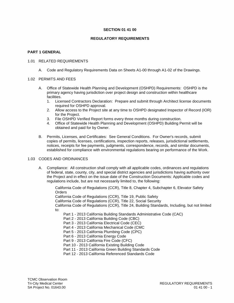
1.03 CODES AND ORDINANCES
A. Compliance: All construction shall comply with all applicable codes, ordinances and regulations of federal, state, county, city, and special district agencies and jurisdictions having authority over the Project and in effect on the issue date of the Construction Documents: Applicable codes and regulations include, but are not necessarily limited to, the following:
California Code of Regulations (CCR), Title 8, Chapter 4, Subchapter 6, Elevator Safety OrdersCalifornia Code of Regulations (CCR), Title 19, Public SafetyCalifornia Code of Regulations (CCR), Title 22, Social SecurityCalifornia Code of Regulations (CCR), Title 24, Building Standards, Including, but not limited to:
Part 1 - 2013 California Building Standards Administrative Code (CAC)Part 2 - 2013 California Building Code (CBC)Part 3 - 2013 California Electrical Code (CEC)Part 4 - 2013 California Mechanical Code (CMCPart 5 - 2013 California Plumbing Code (CPC)Part 6 - 2013 California Energy CodePart 9 - 2013 California Fire Code (CFC)Part 10 - 2013 California Existing Building CodePart 11 - 2013 California Green Building Standards CodePart 12 - 2013 California Referenced Standards Code

TCMC Observation RoomTri-City Medical Center REGULATORY REQUIREMENTSSA Project No. 01643.00 01 41 00 - 2
1.04 ADMINISTRATIVE APPROVALS
A. Compliance: General Contractor and all subcontractors shall comply with requirements of local public utility companies and state and local governmental departments, including but not necessarily limited to following:
Governing fire department requirementsUtility company requirements
1.05 OTHER REGULATORY REQUIREMENTS
A. Compliance: All contractors shall comply with all other applicable laws and regulations in effect on the issue date of the Construction Documents, including but not necessarily limited to, the following:
All local, state, and federal (EPA) construction stormwater pollution control regulations, and monitoring requirementsState and Federal Safety and Health Laws United States Department of Justice – 2010 ADA Standards for Accessible Design, September 15, 2010; available at www.ada.gov/ADAStandards_index.htm.
1.06 DISCREPANCIES
A. If discrepancies occur between Contract Documents, local codes, local utility requirements, etc., most stringent requirements shall apply.
PART 2 PRODUCTS – Not Used
PART 3 EXECUTION – Not Used
END OF SECTION
TCMC Observation RoomTri-City Medical Center REFERENCESSA Project No. 01643.00 01 42 00 - 1
SECTION 01 42 00
REFERENCES
PART 1 GENERAL
1.01 DEFINITIONS
A. General: Basic Contract definitions are included in the General Conditions.
B. Indicated: The term “ indicated “ refers to graphic representations, notes, or schedule on the Drawings, other paragraphs or schedule in the Specifications, and similar requirements in the Contract Documents. Where terms such as “ shown “, “ noted”, “scheduled,” and “specified” are used it is to help the reader locate the reference; no limitations on location is intended.
C. Directed: Terms such as “directed,” “requested,” authorized,” “selected”, “approved,” “required,” and “permitted” mean “directed by the Architect,” requested by the Architect, and similar phrases.
D. Approve: The term “approved,” where used in conjunction with the Architect’s action on the Contractor’s submittals, applications, and requirements, is limited to the Architect’s duties and responsibilities as stated in General and Supplementary Conditions.
E. Regulation: The term “Regulations” included laws, ordinances, statutes, and lawful orders issued by authorities having jurisdiction, as well as rules, conventions, and agreements within the construction industry that control performance of the Work.
F. Furnish: The term “furnish” is used to mean ” supply and deliver to the Project site, ready for unloading, unpacking, assembly, installation, and similar operations.”
G. Install: The term “install” is used to describe operations at project site including the actual “unloading, unpacking, assembly, erection, placing, anchoring, applying, working to dimension, finishing, curing, protecting, cleaning, and similar operations.”
H. Provide: The term “provide “ means “to furnish and install, complete and ready for the intendeduse.”
I. Installer: An “installer” is the Contractor or an entity engaged by the Contractor, either as an employee, subcontractor, or sub-subcontractor, for performance of a particular construction activity, including installation, erection, application, and similar operations. Installers are required to be experienced in the operations they are engaged to perform.1. The term “experienced” when used with the term “Installer” means having a minimum of 5
previous Projects similar in size and scope to this Project, being familiar with the precautions required, and having complied with requirements of the authority having jurisdiction.
J. Trades: Use of titles such as “ carpentry “ is not intended to imply that certain construction activities must be performed by accredited or unionized individuals of a corresponding generic name, such as “ carpenter.” It also does not imply that requirements specified apply exclusively to tradesperson of the corresponding generic name.
K. Assignment of Specialists: Certain Sections of the Specifications require that specified construction activities shall be performed by specialists who are recognized experts in the operations to be performed. The specialists must be engaged for those activities, and
TCMC Observation RoomTri-City Medical Center REFERENCESSA Project No. 01643.00 01 42 00 - 2
assignments are requirements over which the Contractor has no choice or option. Nevertheless, the ultimate responsibility for fulfilling Contract requirements remains with the Contractor.1. This requirement shall not be interpreted to conflict with enforcement of building codes and
similar regulations governing the Work. It is also not intended to interfere with Local trade union jurisdictional settlements and conventions.
L. Project Site is the space available to the Contractor for Performance of construction activities, either exclusively or in conjunction with others performing other work as part of the project. The extent of the Project Site is shown on the Drawings and may or may not be identical with the description of the land upon which the Project is to be built.
M. Testing Laboratories: A “testing laboratory” is an independent entity engaged to perform specific inspections or tests, either at the Project Site or elsewhere, and to report on and, if required, to interpret results of those inspections or tests.
N. Provide: Except as otherwise defined in greater detail, term “provide” means furnish and install, complete and ready for intended use, as applicable in each instance.
O. Approved Equals-Equivalents: 1. The words “similar and equal to”, “or equal”, equivalent” and such other words of similar
content and meaning shall for the purposes of this contract be deemed to mean similar and equivalent to one of the named products. For the purpose of this article and for the purpose of the bidding documents, the word “products” shall be deemed to include the words ” articles”, ”materials”, “items’, ” equipment” and “methods”. Whenever in the contract documents one or more products are specified, the words “similar and equal to” shall be inserted.
2. Wherever any product is specified in the contract documents by a reference to the name, trade name, or catalog number of any manufacturer or supplier, the intent is not to limit competition, but to establish a standard of quality which the Architect has determined isnecessary for the project. The Contractor may at their option use any product other than that specified in the contract documents provided the same is approved by the Architect in accordance with the acceptable procedures. However no substitutions will be allowed after bidding that changes product type or system type, as specified herein unless otherwise noted.
P. Nothing in the contract documents shall be construed as representing, expressly or impliedly, that the named product is available or that there is or there is not a product similar and equal to any of the name products and the Contractor shall have and make no claim by reason of the availability of lack of availability of the named product or of a product similar and equal to any named product.
1.02 TECHNICAL SPECIFICATION FORMAT AND CONTENT EXPLANATION
A. Technical Specification Format: These Technical Specifications are organized into Divisions and Sections on the basis of the 2014 Update to the Construction Specifications Institute (CSI) MasterFormat. 1. The system of groups, subgroups and Divisions are listed in the Table of Contents of this
Project Manual. It consists of 50 Divisions, Division 00 though Division 49, some of which are not used or are reserved for future expansion of the MasterFormat.
B. Technical Specification Content: This Technical Specification uses certain conventions in the use of language and the intended meaning of certain terms, words, and phrases when used in particular situations or circumstances. These conventions are explained as follows:1. Abbreviated Language: Language used in Technical Specifications and other Contract
Documents is the abbreviated type. Implied words and meaning will be appropriately
TCMC Observation RoomTri-City Medical Center REFERENCESSA Project No. 01643.00 01 42 00 - 3
interpreted. Singular words will be interpreted as plural and plural words interpreted as singular where applicable and the full context of the Contract Documents so indicates.
2. Specification Methods: The techniques or methods of specifying to record requirements varies throughout text, and may include “prescriptive,” “open generic descriptive,”” compliance with standards,”” performance,” proprietary,” or a combination of theses. The method used for specifying one unit of work has no bearing on requirements for another unit of work.
3. Overlapping and Conflicting Requirements: Where compliance with 2 or more industry standards or sets of requirements is specified, and overlapping of those different standards or requirements establishes different or conflicting minimum or levels of quality, the most stringent requirement is intended and will be enforced.
C. Contractor’s Options: Except for overlapping or conflicting requirements, where more than one set of requirements are specified for a particular unit of work, option is intended to be Contractor’s regardless of whether or not it is specifically indicated as such.1. Minimum Quality/Quantity: In every instance, the quality level or quantity shown or specified
is intended to be the minimum for the work to be performed or proved. Except as otherwise specifically indicated, the actual work may either comply exactly with that minimum (within specified tolerances). Or may exceed that minimum within reasonable limits. In complying with these requirements, indicated numeric values are either minimums or maximums as noted or as appropriate for context of the requirements. Refer instances of uncertainty to Architect/Engineer for decision before proceeding.
2. Specialists, Assignments: In certain instances, specification text requires (or implies) that specific work is to be assigned to specialists or expert entitles, who must be engaged for the performance of that work. Such assignments shall be recognized as special requirements over which the Contractor has no choice or option. These requirements should not be interpreted so as to conflict with the enforcement of building codes and similar regulations governing the work; they are also not intended to interfere with local union jurisdiction settlements and similar Conventions. Such assignments are intended to establish which party or entity involved in a specific unit of work is recognized as “expert “ for the indicated construction processes or operations. Nevertheless. The final responsibility for fulfillment of the entire set or requirements remains with the Contractor.
3. Trades: Except as otherwise indicated, the use of titles such as “ Carpentry “ in specification text, implies neither that the work must be performed by an accredited or unionized tradesperson of corresponding generic name (such as “carpenter”), nor specified requirements apply exclusively to work by tradespersons of that corresponding generic name.
1.03 INDUSTRY STANDARDS
A. Applicability of Standards: Except where the Contract Documents include more stringent requirements, applicable Construction industry standards have the same force and effects as if bound or copied directly into the Contract Documents. Such Standards are made a part of the Contract Documents by reference.
B. Publication Dates: Where the date of issue of a referenced standard is not specified, comply with the standard in effect as of date of Contract Documents.
C. Conflicting Requirements: Where compliance with two or more standards specified, and the standards establish different or conflicting requirements for minimum quantities or quality levels, refer requirements that are different, but apparently equal, and uncertainties to the Architect for a decision before proceeding.1. Minimum Quantity or Quality Levels: The quantity or quality level shown or specified shall
be the minimum provided or performed. The actual installation may comply exactly with the minimum quantity or quality specified, or it may exceed the minimum within reasonable
TCMC Observation RoomTri-City Medical Center REFERENCESSA Project No. 01643.00 01 42 00 - 4
limits. In complying with these requirements, indicated numeric values are minimum or maximum, as appropriate for the context of the requirements. Refer uncertainties to the Architect for a decision before proceeding.
D. Copies of Standards: Each entity engaged in construction on the Project is required to be familiar with industry standards applicable to that entity’s construction activity. Copies of applicable standards are not bound with the Contract Documents.1. Where copies of documents are needed for performance of a required construction activity,
the Contractor shall obtain Copies from the publication source.2. Although copies of standards needed for enforcement of requirements may be included as
part of required submittals, the Architect reserves the right to require the Contractor to submit additional copies as necessary for enforcement of requirements.
E. Abbreviations and Names: Trade association names and titles of general standards are frequently abbreviated. Where such acronyms or abbreviations are used in the Specifications or other Contract Documents, they mean the recognized name of the trade associations, standards generating organization, authority having jurisdiction, or other entity application to the context of the text provision. Refer to the “Encyclopedia of Associations,” published by Gale Research Co., available in, most libraries.
1.04 SUBMITTALS
A. Permits, Licenses, and Certificates: For the Owner’s records, submit copies of permits, Licenses, certifications, inspection reports, releases, jurisdictional settlements, notices, receipt for fee payments, judgments, and similar documents, correspondence, and records established in conjunction with compliance with standards and regulations bearing upon performance of the Work.
PART 2 PRODUCTS – Not used
PART 3 EXECUTION – Not used
END OF SECTION

TCMC Observation RoomTri-City Medical Center QUALITY CONTROL SERVICESSA Project No. 01643.00 01 45 20 - 1
SECTION 01 45 20
QUALITY CONTROL SERVICES
PART 1 GENERAL
1.01 SUMMARY
A. This Section specifies administrative and procedural requirements for quality control services.
B. Quality control services include inspections and tests and related actions including reports, performed by independent agencies, governing authorities, and the Contractor.
C. Inspection and testing services are required to verify compliance with requirements specified or indicated. These services do no relieve the Contractor of responsibility for compliance with Contract Document requirements.
D. Specific quality control requirements for individual construction activities are specified in the Sections that specify those activities. Those requirements, including inspections and test, cover production of standard products as well as customized fabrication and installation procedures.
E. Inspection, test and related actions specified are not intended to limit the Contractor’s control procedures that facilitate compliance with Contract Document requirements.
F. Requirements for the Contractor to provide quality control services required by the Architect, Owner, or authorities having jurisdiction are not limited by provisions of this Section.
1.02 RESPONSIBILITIES
A. Testing Agency: The District will employ and pay an independent agency, subject to approval by the Architect, to perform specified quality control services.
B. Retesting: The Contractor is responsible for retesting where results of required inspections, tests or similar services prove unsatisfactory and do not indicate compliance with Contract Document requirements.
C. Associated Services: The Contractor shall cooperate with agencies performing required inspections, tests and similar services and provide reasonable auxiliary services as requested. Notify the agency sufficiently in advance of operations to permit assignment of personnel. Auxiliary services required include but are not limited to.1. Providing access to the Work and furnishing incidental labor and facilities necessary to
facilitate inspections and test.2. Taking adequate quantities of representative samples of materials that require testing or
assisting the agency in taking samples.3. Provisions facilities for storage and curing of test samples, and deli every of samples to
testing laboratories.4. Providing the agency with a preliminary design mix proposed fro use for materials mixes that
require control by the testing agency.5. Security and protection of Samples and test equipment at the Project site.
D. Duties of the Testing Agency: The independent testing agency engaged to perform inspections, sampling and testing of materials and construction Sections shall cooperate with the Architect

TCMC Observation RoomTri-City Medical Center QUALITY CONTROL SERVICESSA Project No. 01643.00 01 45 20 - 2
and Contractor in performance of its duties, and shall provide qualified personnel to perform required inspections and tests.1. The agency shall notify the Architect and Contractor promptly of irregularities or deficiencies
observed in the Work during performance of its services.2. The agency is not authorized to release, revoke, alter or enlarge requirements of the
Contract Documents, or approve or accept any portion of the Work.3. The agency shall not perform any duties of the Contractor.
E. Coordination: The Contractor and each agency engaged to perform inspections; tests and similar services shall coordinate the sequence of activities to accommodate required services with a minimum of delay. In addition to Contractor, each agency shall coordinated activities to avoid the necessity of removing and replacing construction to accommodate inspections and tests.
F. The Contractor is responsible for scheduling time for inspections, tests, taking samples and similar activities
1.03 SUBMITTALS
A. The independent testing agency shall submit a certified written repot of each inspection, test or similar service directly to the Architect, in duplicate, with a copy to the Contractor.
B. Submit additional copies of each written report directly to the governing authority, when the authority so directs.
C. Report Data: Written reports of each inspection, test or similar services shall include, but not be limited to: 1. Date of issue.2. Project title and number.3. Name, address and telephone number of testing agency.4. Dates and locations of samples and tests or inspections.5. Names of individuals making the inspection or test.6. Designation of the Work and test method.7. Identification of product and specification Section.8. Complete inspection or test data.9. Test results and an interpretation of test results.10. Ambient conditions at the time of sample taking and testing.11. Comments or professional opinion as to whether inspection or tested Work complies with
Contract Document Requirements.12. Name and signature of laboratory inspector.13. Recommendations on retesting.
PART 2 PRODUCTS - Not Used
PART 3 EXECUTION
3.01 REPAIR AND PROTECTION
A. General: Upon completion of inspection, testing, sample-taking and similar services, repair damage construction and restore substrates and finishes to eliminate deficiencies, including deficiencies in visual qualities of exposed finishes. Comply with Contract Document requirements for ‘Cutting and Patching.”

TCMC Observation RoomTri-City Medical Center QUALITY CONTROL SERVICESSA Project No. 01643.00 01 45 20 - 3
B. Protect construction exposed by or for quality control service activities, and protect repaired construction.
C. Repair and protection is the Contractor’s responsibility, regardless of the assignment of responsibility for inspection, testing or similar services.
END OF SECTION

TCMC Observation RoomTri-City Medical Center TEMPORARY FACILITIES AND CONTROLSSA Project No. 01643.00 01 50 00 - 1
SECTION 01 50 00
TEMPORARY FACILITIES AND CONTROLS
PART 1 GENERAL
1.01 SUMMARY
A. Section Includes:1. Temporary utilities.2. Construction facilities.3. Temporary construction.4. Construction aids.5. Temporary barriers and enclosures.6. Temporary controls.
B. Related Requirements:1. Utility Usage: General Conditions, Article 56.2. Work Restrictions: Section 01 10 00 Summary.3. Alteration Project Procedures: Section 01 35 16.
PART 2 PRODUCTS - Not Used
PART 3 EXECUTION
3.01 TEMPORARY ELECTRICITY AND LIGHTING
A. Service and Distribution:1. Contractor may connect to existing electrical power system for source of temporary
electricity and lighting. Coordinate location and means of connection with Owner.2. Provide temporary electrical service and temporary wiring, outlets, lights, etc. as required for
construction power and lighting during construction period.3. Properly ground service and distribution system in accordance with NEC. Provide ground
fault interrupters as required by code.4. Remove temporary electrical service and wiring upon completion of work.
B. Temporary Power Distribution:1. Supplement existing system as required. Provide minimum of one double duplex 120V
outlet for every 100 lineal feet of temporary loop.2. Each Contractor: Furnish extension cords necessary to convey electricity from temporary
loop outlets to locations of work.3. Special Power Required for Welders or Other Special Equipment: Provided by contractor
requiring such power.4. Distribution equipment and wiring devices for temporary power and lighting need not be new,
however, installation shall conform to safe general practice as required by OSHA.
C. Temporary Lighting:1. Provide one light for every interior room regardless of square footage area except closets
and pipe chases. In larger rooms, provide one light for every 750 square feet.2. Each Contractor: Provide plug-in portable lights as required for task lighting.
TCMC Observation RoomTri-City Medical Center TEMPORARY FACILITIES AND CONTROLSSA Project No. 01643.00 01 50 00 - 2
D. Use of Permanent Systems:1. Existing permanent system and, where applicable, new or modified components of
permanent system installed under this Contract, may be used as necessary for power and light.
2. Be responsible for any damage to permanent wiring or fixtures as result of temporary use.3. Permanent branch circuit wiring may be used to supply pigtail lights if protected by properly
sized circuit breaker or fuse. Do not use permanent receptacles for construction power. Replace receptacles and device plates showing wear or abuse.
4. Provide lamps necessary to temporarily light work in permanently installed fixtures.5. Clean permanently installed light fixtures that are used for temporary lighting during
construction using methods and materials recommended by the manufacturer.6. Remove lamps used temporarily in permanent fixtures and replace with new lamps at
completion of work.
3.02 TEMPORARY HEAT, VENTILATION AND ENCLOSURES
A. Temporary Heat: Provide temporary heat necessary for execution of Work. Install, maintain and operate temporary heating apparatus in manner to facilitate work, to comply with ambient environmental limitations for installation of new products and materials required by the specifications and manufacturer’s installation instructions, to enable work to continue, and to ensure finished work will not be damaged by cold or freezing.
B. Enclosures: Provide temporary enclosures necessary for holding temporary heat for masonry and concrete work.
C. Use of Permanent System:1. In using permanent heating system, assume complete responsibility for its proper operation
and for any damage that may occur to heating apparatus or any phase of work except such wear and tear that would ordinarily result from normal usage.
2. At completion and before work is accepted by Owner, clean air vents and coils, clean cleanable filters and replace replacement air filters.
3. If permanent heating system is used during construction, Contractor shall remain responsible for full mechanical guarantee from date of Notice of Acceptance of total Project by Owner.
3.03 TEMPORARY WATER
A. Existing System: Contractor may connect to existing water distribution system for source of temporary water. 1. Coordinate location and means of connection with Owner. 2. Provide temporary connection, plumbing, piping, etc. necessary to convey same to places
needed.
3.04 TEMPORARY SANITARY FACILITIES
A. Temporary Toilet Facilities: Provide and maintain, in neat and sanitary condition, adequate temporary self-contained chemical toilet facilities for use of employees engaged on work, in compliance with requirements of applicable codes, regulations, laws and ordinances. Locate units within fenced/screened area.1. Toilets in existing buildings shall not be used.
TCMC Observation RoomTri-City Medical Center TEMPORARY FACILITIES AND CONTROLSSA Project No. 01643.00 01 50 00 - 3
3.05 FIELD OFFICE AND OTHER TEMPORARY STRUCTURES
A. Field Office: Provide and maintain suitable temporary field office.1. Telephone and Fax Service: Install telephone with answering machine and fax machine in
field office. Pay for installation, maintenance, removal and other charges for use of telephone.a. Make office and telephone/fax machine available for use by Owner and Architect.
2. Photocopier: Install at least one photocopying machine in field office.3. Maintain current set of Drawings at site and make available for use by Architect.
B. Temporary Structures: Provide temporary structures and storage areas as required.1. Remove offices and other temporary structures from site upon completion of work.2. Locate on site in orderly manner as coordinated with Owner.
3.06 TEMPORARY PROTECTIVE FACILITIES
A. Provide and maintain protective devices and facilities for protection of public and general protection of workmen on project. 1. Provide warning signs against hazards created by such features of construction as
protruding nails, hoists, well holes, window openings, stairways and falling materials. 2. Provide and maintain fire extinguishers and active fire hydrants where required. Maintain
fire lanes to hydrants and other equipment as necessary for proper fire protection during construction.
3. Provide temporary walks, roadways, trench covers, barricades, bulkheads, railings, danger lights and signals, etc. required for work by applicable safety laws and building codes.
4. Maintain temporary protective facilities in good condition throughout term of work. Removeat completion of work. Repair and replace work damaged thereby.
3.07 PROTECTION FOR WORK IN PLACE
A. Work in Place: When subject to injury because of operations being carried on adjacent, cover, board up, or substantially enclose with adequate protection.1. Block and board heads, jambs and sills of permanent openings used as thoroughfares for
introduction of work and materials.2. Construct forms of protection in manner that, upon completion, entire work will be delivered
to Owner in undamaged condition.
3.08 ACCESS
A. Limit access to necessary routes to perform the work. 1. Coordinate access with Owner.2. See Section 01 10 00 for limitations on access to site.
B. Temporarily remove existing window for construction access and exhaust filtered construction duct. Close off opening securely with plywood at the end of each day’s work.
3.09 TEMPORARY CONTROLS
A. General: Comply with local codes, ordinances and regulations. 1. See Section 02 41 19.16 for related requirements during demolition.
B. Noise Control:1. Minimize noise at all times. All equipment shall be properly muffled. Do not operate noisy
equipment after 10:00 p.m.
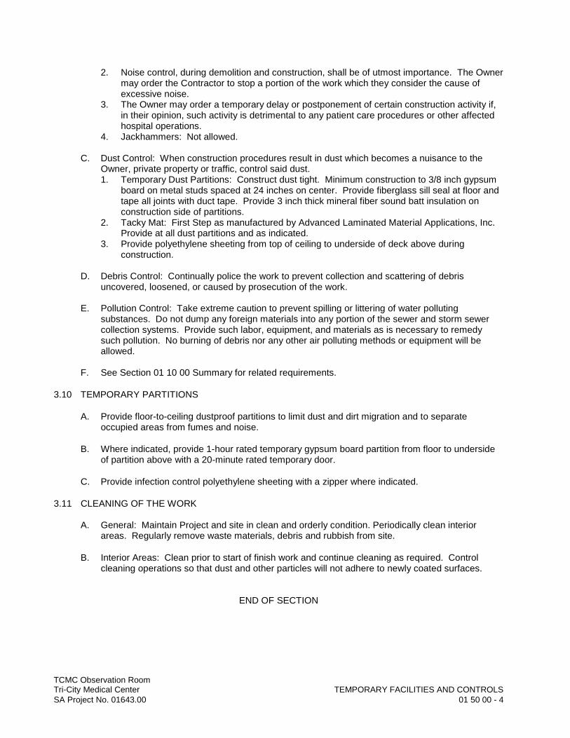
TCMC Observation RoomTri-City Medical Center TEMPORARY FACILITIES AND CONTROLSSA Project No. 01643.00 01 50 00 - 4
2. Noise control, during demolition and construction, shall be of utmost importance. The Owner may order the Contractor to stop a portion of the work which they consider the cause of excessive noise.
3. The Owner may order a temporary delay or postponement of certain construction activity if, in their opinion, such activity is detrimental to any patient care procedures or other affected hospital operations.
4. Jackhammers: Not allowed.
C. Dust Control: When construction procedures result in dust which becomes a nuisance to the Owner, private property or traffic, control said dust.1. Temporary Dust Partitions: Construct dust tight. Minimum construction to 3/8 inch gypsum
board on metal studs spaced at 24 inches on center. Provide fiberglass sill seal at floor and tape all joints with duct tape. Provide 3 inch thick mineral fiber sound batt insulation on construction side of partitions.
2. Tacky Mat: First Step as manufactured by Advanced Laminated Material Applications, Inc. Provide at all dust partitions and as indicated.
3. Provide polyethylene sheeting from top of ceiling to underside of deck above during construction.
D. Debris Control: Continually police the work to prevent collection and scattering of debris uncovered, loosened, or caused by prosecution of the work.
E. Pollution Control: Take extreme caution to prevent spilling or littering of water polluting substances. Do not dump any foreign materials into any portion of the sewer and storm sewer collection systems. Provide such labor, equipment, and materials as is necessary to remedy such pollution. No burning of debris nor any other air polluting methods or equipment will be allowed.
F. See Section 01 10 00 Summary for related requirements.
3.10 TEMPORARY PARTITIONS
A. Provide floor-to-ceiling dustproof partitions to limit dust and dirt migration and to separateoccupied areas from fumes and noise.
B. Where indicated, provide 1-hour rated temporary gypsum board partition from floor to underside of partition above with a 20-minute rated temporary door.
C. Provide infection control polyethylene sheeting with a zipper where indicated.
3.11 CLEANING OF THE WORK
A. General: Maintain Project and site in clean and orderly condition. Periodically clean interior areas. Regularly remove waste materials, debris and rubbish from site.
B. Interior Areas: Clean prior to start of finish work and continue cleaning as required. Control cleaning operations so that dust and other particles will not adhere to newly coated surfaces.
END OF SECTION

TCMC Observation RoomTri-City Medical Center PRODUCT REQUIREMENTSSA Project No. 01643.00 01 60 00 - 1
SECTION 01 60 00
PRODUCT REQUIREMENTS
PART 1 GENERAL
1.01 SUMMARY
A. This Section specifies administrative, and procedural requirements governing the Contractor’s selection of products for use in the Project.
B. The Contractor’s Constructions Schedule and the Schedule of submittals are included under Sections “Submittal Procedures.”
C. Standards: Refer to Section “References” for applicability of industry standards to products specified.
1.02 DEFINITIONS
A. Definitions used in this Article are not intended to change the meaning of other terms used in the Contract Documents, such as “specialties,” “ systems,” “structures,” “finishes.” “ Accessories,” and similar. Such terms such are self-explanatory and have well recognized meanings in the construction industry.1. “Products” are items purchased for incorporation in the Work, whether purchased for the
Project or taken from previously purchased stock. The term “ product” includes the terms “Material,” “ equipment,” “ system,” and terms of similar intent.
2. “Named Products “are items identified by manufacture’s product name, including make or model designation, indicated in the manufacturer’s published product literature, that is current as of the date of the Contract Documents.
3. “Foreign Products”, as distinguished from “domestic products,” are items substantiallymanufactured (50 percent or more of value) outside of the United States and its possessions; or produced or supplied by entities substantially owned (more than 50 percent) by persons who are not citizens nor living within the United States and its possessions.
4. “Materials “, are products that substantially shaped, cut, worked, mixed, finished, refined, or otherwise fabricated, processed, or installed to inform a part of the Work.
5. “Equipment”, is a product with operational part, whether motorized or manually operated, that requires service connections such as wiring or piping.
1.03 QUALITY ASSURANCE
A. Source Limitations: To the fullest extent possible, provide products of the same kind, from a single source. 1. When specified products are available only form sources that do not or cannot produce a
quantity adequate o complete project requirements in a timely manner, consult with the Architect for a determination of the most important product qualities before proceeding. Qualities may include attributes relating to visual appearance, strength, durability, or compatibility. When a determination has been made, select products from sources that produce products that possess these qualities, to the fullest extent possible.
B. Compatibility of Options: When the Contractor is given the option of selecting between two or more products for use on the Projects, the product selected shall be compatible with products previously selected, even if previously selected products were also options.

TCMC Observation RoomTri-City Medical Center PRODUCT REQUIREMENTSSA Project No. 01643.00 01 60 00 - 2
C. Foreign Product Limitations: Except under one or more of the following conditions, provide domestic products, not foreign products, for inclusion in the Work:1. No available domestic product complies with the Contract Document.
D. Nameplates: Except for required labels and operating data, do not attach or imprint manufacture’s or producer’s nameplates or trademarks on exposed surfaces of products that will be exposed to view in occupied spaces or on the exterior.
E. Labels: Locate required product labels and stamps on a concealed surface or, where required for observation after installation, on an accessible surface that is not conspicuous.
F. Equipment Nameplates: Provide a permanent nameplate on each item on service-connected or power-operated equipment. Locate on an easily accessible surface, which are inconspicuous occupied spaces. The nameplate shall contain the following information and other essential operating data:1. Name of product and manufacturer.2. Model and serial number.3. Capacity.4. Speed.5. Ratings.
1.04 PRODUCT DELIVERY, STORAGE, AND HANDLING
A. Deliver, store and handle products in accordance with the manufacture’s recommendations, using meanings and methods that will prevent damage, deterioration and loss, including theft.
B. Schedule delivery to minimize long-term storage at the site and to prevent overcrowding of construction spaces.
C. Coordinate delivery with installation time to ensure minimum holding time for items that are flammable, hazardous, easily damage, or sensitive to deterioration, theft and other losses.
D. Deliver Products to the site in the manufacture’s original sealed container or other packaging system, complete with labels and instructions for handling, storing, unpacking, protecting and installing.
E. Inspect products upon delivery to ensure compliance with the Contract Documents, and to ensure that products are undamaged and properly protected.
F. Store products at the site in a manner that will facilitate inspection and measurement of quantity or counting of units.
G. Store heavy materials away from the project structure in a manner that will not endanger the supporting construction.
H. Store products subjects to damage by the elements above ground, under cover in a weather tight enclosure, with ventilation adequate to prevent condensation. Maintain temperature and humidity within range required by manufacturer’s instructions.

TCMC Observation RoomTri-City Medical Center PRODUCT REQUIREMENTSSA Project No. 01643.00 01 60 00 - 3
PART 2 PRODUCTS
2.01 PRODUCT SELECTION
A. General Product Requirements: Provide products that comply with the Contract Documents, that are undamaged and, unless otherwise indicated, unused at the time of installation.1. Provide products complete with an accessories, trim, finish, safety guards and other.
Indicates and details needed for a complete installation and for the intended use and effect.
B. Standard Products: Where available, provide standard products of types that have been produced and used successfully in similar situations on other projects.
C. Product Selection Procedures: Product selection is governed by the Contract Documents and governing regulations, not by previous Project experience. Procedures governing product selection include the following:1. Where products or manufactures are specified by name, accompanied by the term “or
equal,” or “ or approved equal “ comply with the Contract Document provisions concerning “substitutions” to obtain approval for use of an unnamed product.
2. Descriptive Specification Requirements: Where Specifications describe a product or assembly, listing exact characteristics required, with or without use of a brand or trade name, provide a product or assembly that provides the characteristics and otherwise complies with Contract requirements.
3. Performance Specification Requirements: Where Specifications require compliance with performance requirements, provide products that comply with these requirements, and are recommended by the manufacturer for the application indicated. General overall performance of a product is implied where the product is specified for a specific application.
4. Manufacturer’s recommendations may be contained in published product literature, or by the manufacturer’s certification of performance.
5. Compliance with Standards, Codes and Regulations: Where the Specification only requires compliance with an imposed code, standard or regulation, select a product that complies with the standards, codes or regulations specified.
6. Visual Matching: Where Specifications require matching and established Sample, the Architect’s decision will be final on whether a proposed product matches satisfactorily.
7. Where no product available within the specified category matches satisfactorily and also complies with other specified requirements, comply with provisions of the Contract Documents concerning “ substitutions “ for selection of a matching product in another product category, or for noncompliance with specified requirements.
8. Visual Selection: Where specified product requirements include the phrase “ … as selected from manufacturer’s standard colors, patterns, textures…” or a similar phrase, select a product and manufacturer that comply with other specified requirements. The Architect will select the color, patterned and texture from the product line selected.
PART 3 EXECUTION
3.01 INSTALLATION OF PRODUCTS
A. Comply with manufacturer’s instructions and recommendations for installation of products in the applications indicated. Anchor each product securely in place, accurately located and aligned with other Work.1. Clean exposed surfaces and protect as necessary to ensure freedom from damage and
deterioration until the time of Substantial Completion.
END OF SECTION

TCMC Observation RoomTri-City Medical Center LOW-EMITTING MATERIAL REQUIREMENTSSA Project No. 01643.00 01 61 65 - 1
SECTION 01 61 65
LOW-EMITTING MATERIAL REQUIREMENTS
PART 1 GENERAL
1.01 SUMMARY
A. Section Includes:1. Common VOC requirements for interior adhesives.2. Common VOC requirements for interior sealants.3. VOC and formaldehyde limitations for engineered wood and wood-based panel products.4. Common VOC requirements for flooring.5. Common VOC requirements for acoustical ceiling tiles and wall systems.6. Common VOC requirements for insulation.
B. Related Requirements:1. Common Product Requirements, General: Section 01 60 00 Product Requirements.2. Joint Sealants: Section 07 92 00.3. Acoustical Panel Ceilings: Section 09 51 13.4. Paints and Coatings: Section 09 90 00.5. Sections in Divisions 01 through 49 specify indoor environmental quality requirements
specific to the Work of each of those Sections. .
1.02 REFERENCES
A. Reference Standards: Comply with the following except as otherwise specified in this Project Manual.1. California Department of Public Health's "Standard Method for the Testing and Evaluation of
Volatile Organic Chemical Emissions from Indoor Sources Using Environmental Chambers." 2. South Coast Air Quality Management District (SCAQMD) Rule No. 1168.
B. Definitions: 1. Adhesive: Any substance used to bond one surface to another by attachment. Includes
adhesive bonding primers.2. Interior: For purposes of this Section, “interior” shall mean inside the weatherproofing
system and applied on-site.3. Sealant: Any material with adhesive properties that is formulated primarily to fill, seal, or
waterproof gaps or joints between two surfaces. Sealants include sealant primers and caulks.
1.03 SUBMITTALS
A. Particleboard and MDF: Submit third-party certification that formaldehyde emissions comply with Phase 1 standards of CARB Air Toxic Control Measure (ATCM) for Formaldehyde Emissions from Composite Wood Products, and with ANSI A208.1 or A208.2 as applicable, when tested in accordance with ASTM E1333.1. Provide documentation that composite wood and agrifiber products contain no urea-
formaldehyde resins.
TCMC Observation RoomTri-City Medical Center LOW-EMITTING MATERIAL REQUIREMENTSSA Project No. 01643.00 01 61 65 - 2
PART 2 PRODUCTS
2.01 FORMALDEHYDE LIMITS FOR MATERIALS
A. Formaldehyde limits shall be as follows:1. Hardwood Plywood: 0.05 ppm.2. Particleboard: 0.09 ppm.3. Medium-Density Fiberboard (MDF): 0.11 ppm.4. Thin MDF: 0.13 ppm.
2.02 ADHESIVES
A. Provide low VOC types as recommended by the manufacturer of the material being installed. Adhesives shall comply with SCAQMD Rule 1168 and the IgCC.
B. For interior applications use adhesives that comply with the following limits for VOC content when calculated according to SCAQMD Method 304, 316A or 316B:1. Indoor Carpet Adhesives: 50 g/L2. Carpet Pad Adhesives: 50 g/L3. Outdoor Carpet Adhesives: 150 g/L4. Wood Flooring Adhesive: 100 g/L5. Rubber Floor Adhesives: 60 g/L6. Subfloor Adhesives: 50 g/L7. Ceramic Tile Adhesives: 65 g/L8. VCT And Asphalt Tile Adhesives: 50 g/L9. Dry Wall And Panel Adhesives: 50 g/L10. Cove Base Adhesives: 50 g/L11. Multipurpose Construction Adhesives: 70 g/L12. Structural Glazing Adhesives: 100 g/L13. Single-Ply Roof Membrane Adhesives: 250 g/L14. CPVC Solvent Cement: 490 g/L15. PVC Solvent Cement: 510 g/L16. ABS Solvent Cement: 325 g/L17. Plastic Cement Welding: 250 g/L18. Adhesive Primer For Plastic: 550 g/L19. Contact Adhesive: 80 g/L20. Special-Purpose Contact Adhesives (Contact Adhesives That Are Used to Bond Melamine-
Covered Board, Metal, Unsupported Vinyl, Rubber, or Wood Veneer 1/16 Inch or Less in Thickness to Any Surface): 250 g/L
21. Structural Wood Member Adhesive: 140 g/L
2.03 SEALANTS
A. For interior applications use sealants that comply with the following limits for VOC content when calculated according to SCAQMD Method 304, 316A or 316B:1. Architectural Sealants: 250 g/L2. Architectural Sealant Primer:
a. Nonporous: 250 g/Lb. Porous: 775 g/L
3. Modified Bituminous Sealant Primer: 500 g/L4. Other Sealant Primers: 750 g/L
TCMC Observation RoomTri-City Medical Center LOW-EMITTING MATERIAL REQUIREMENTSSA Project No. 01643.00 01 61 65 - 3
2.04 PAINTS AND COATINGS
A. For interior applications use paints, stains, and coatings that comply with the following limits for VOC content when calculated according to 40 CFR 59, Subpart D (EPA method 24) and the following chemical restrictions:1. Flat Coatings: 50 g/L.2. Nonflat Coatings: 100 g/L.3. Nonflat - High Gloss Coatings: 150 g/L.4. Basement Special Coatings: 400 g/L.5. Bond Breakers: 350 g/L.6. Concrete Curing Compounds: 350 g/L.7. Concrete/Masonry Sealers: 100 g/L.8. Dry-Fog Coatings: 150 g/L.9. Faux Finishing Coatings: 350 g/L.10. Fire-Resistive Coatings: 350 g/L.11. Floor Coatings: 100 g/L.12. Form-Release Compounds: 250 g/L.13. Graphic Arts Coatings (Sign Paints): 500 g/L.14. High-Temperature Coatings: 420 g/L.15. Industrial Maintenance Coatings: 250 g/L.16. Low Solids Coatings: 120 g/L.17. Magnesite Cement Coatings: 450 g/L.18. Mastic Texture Coatings: 100 g/L.19. Metallic Pigmented Coatings: 500 g/L.20. Multi-Color Coatings: 250 g/L.21. Pretreatment Wash Primers: 420 g/L.22. Primers, Sealers, and Undercoaters: 100 g/L.23. Reactive Penetrating Sealers: 350 g/L.24. Recycled Coatings: 250 g/L.25. Rust-Preventive Coatings: 250 g/L.26. Shellacs, Clear: 730 g/L.27. Shellacs, Pigmented: 550 g/L.28. Stains: 250 g/L.29. Stone Consolidants: 450 g/L.30. Swimming Pool Coatings: 340 g/L.31. Tub and Tile Refinish Coatings: 420 g/L.32. Waterproof Membranes: 250 g/L.33. Wood Coatings: 275 g/L.34. Wood Preservatives: 350 g/L.35. Zinc-Rich Primers: 340 g/L.
2.05 FLOORING SYSTEMS
A. Flooring materials shall comply with the requirements of the California Department of Public Health's "Standard Method for the Testing and Evaluation of Volatile Organic Chemical Emissions from Indoor Sources Using Environmental Chambers." Formaldehyde emissions shall not exceed 16.5 micrograms/cu. m or 13.5 ppb, whichever is less. Where postmanufactured coatings or applications have not been applied, concrete; ceramic and concrete tile; clay and concrete pavers; metal; and organic-free, mineral-based flooring shall be deemed to comply with this requirement.
2.06 ACOUSTICAL CEILINGS
A. Acoustic ceilings shall comply with the requirements of the California Department of Public Health's "Standard Method for the Testing and Evaluation of Volatile Organic Chemical Emissions

TCMC Observation RoomTri-City Medical Center LOW-EMITTING MATERIAL REQUIREMENTSSA Project No. 01643.00 01 61 65 - 4
from Indoor Sources Using Environmental Chambers." Formaldehyde emissions shall not exceed 16.5 micrograms/cu. m or 13.5 ppb, whichever is less.
2.07 WALL SYSTEMS
A. Wall systems shall comply with the requirements of the California Department of Public Health's "Standard Method for the Testing and Evaluation of Volatile Organic Chemical Emissions from Indoor Sources Using Environmental Chambers." Formaldehyde emissions shall not exceed 16.5 micrograms/cu. m or 13.5 ppb, whichever is less. Where postmanufactured coatings or applications have not been applied, concrete, concrete masonry, clay masonry, gypsum plaster, ceramic and concrete tile, metal, and organic-free, mineral-based materials shall be deemed to comply with this requirement.
2.08 INSULATION
A. Insulation shall comply with the requirements of the California Department of Public Health's "Standard Method for the Testing and Evaluation of Volatile Organic Chemical Emissions from Indoor Sources Using Environmental Chambers." Formaldehyde emissions shall not exceed 16.5 micrograms/cu. m or 13.5 ppb, whichever is less, except for insulation manufactured without formaldehyde.
2.09 COMPOSITE WOOD AND AGRIFIBER PRODUCTS
A. Do not use composite wood and agrifiber products that contain urea-formaldehyde resin.
B. Engineered Wood Products: 1. Determine formaldehyde concentrations in air from wood products under test conditions of
temperature and relative humidity in accordance with ASTM D6007 or E1333.2. Determine Volatile Organic Compounds {VOC), excluding formaldehyde, emitted from
manufactured wood-based panels in accordance with ASTM D6330.
C. Composite Panel Products: 1. Determine formaldehyde concentrations in air from wood-based panel products under test
conditions of temperature and relative humidity in accordance with ASTM D6007 or E1333.2. Determine Volatile Organic Compounds {VOC), excluding formaldehyde, emitted from
manufactured wood-based panels in accordance with ASTM D6330.3. Particleboard Manufacturer’s, MDF Manufacturer’s, and Melamine Laminator’s Facility: CPA
EPP (Environmentally Preferable Product) Downstream Licensed Facility.
PART 3 EXECUTION – Not Used
END OF SECTION
TCMC Observation RoomTri-City Medical Center ACCEPTANCE OF CONDITIONSSA Project No. 01643.00 01 71 16 - 1
SECTION 01 71 16
ACCEPTANCE OF CONDITIONS
PART 1 GENERAL
1.01 SUMMARY
A. Section Includes:1. Procedures and general requirements for examination of existing conditions and verification
of acceptable conditions for installation.
B. Related Requirements:1. Common Product Requirements: Section 01 60 00 Product Requirements.2. General Product Installation Requirements: Section 01 73 19 Installation.3. Cutting and Patching: Section 01 73 29.
1.02 QUALITY ASSURANCE
A. Manufacturer's Instructions: Where installations include manufactured products, comply with manufacturer's applicable instructions and recommendations for verification of existing conditionsto extent that these instructions and recommendations are more explicit or more stringent than requirements specified or indicated.1. Notify Architect of any conflicts between manufacturer's instructions or recommendations
and requirements specified or indicated.2. Coordinate trades constructing substrate and trades installing products to substrate to
ensure that surface preparation required by manufacturer's instructions is performed before product installation. Convene pre-installation conference if necessary and discuss issues relating to acceptance of conditions at conference.
PART 2 PRODUCTS – Not Used
PART 3 EXECUTION
3.01 EXAMINATION
A. Existing Conditions: The existence and location of site improvements, utilities, and other construction indicated as existing are not guaranteed. Before beginning work, investigate and verify the existence and location of mechanical and electrical systems and other construction affecting the Work.1. Before construction, verify the location and points of connection of utility services.
B. Existing Utilities: The existence and location of underground and other utilities and construction indicated as existing are not guaranteed. Before beginning sitework, investigate and verify the existence and location of underground utilities and other construction affecting the Work.1. Before construction, verify the location and invert elevation at points of connection of
sanitary sewer, storm sewer, and water-service piping; and underground electrical services.2. Furnish location data for work related to Project that must be performed by public utilities
serving Project site.
TCMC Observation RoomTri-City Medical Center ACCEPTANCE OF CONDITIONSSA Project No. 01643.00 01 71 16 - 2
C. Inspection of Substrates: Require installer of each major unit of work to inspect substrate to receive work and conditions under which work is to be performed.1. Verify compatibility with and suitability of substrates, including compatibility with existing
finishes or primers.2. Examine roughing-in for mechanical and electrical systems to verify actual locations of
connections before equipment and fixture installation.3. Examine walls, floors, and roofs for suitable conditions where products and systems are to
be installed.
D. Installer: Report unsatisfactory conditions to General Contractor in writing with copy to Architect.Include recommended corrections.
E. Proceed with installation only after unsatisfactory conditions have been corrected. Proceeding with the Work indicates acceptance of surfaces and conditions.
END OF SECTION
TCMC Observation RoomTri-City Medical Center INSTALLATIONSA Project No. 01643.00 01 73 19 - 1
SECTION 01 73 19
INSTALLATION
PART 1 GENERAL
1.01 SUMMARY
A. Section Includes:1. Common requirements for installing products and materials.
B. Related Requirements:1. Examination and Acceptance of Substrates and In-Place Construction to Receive Product
Installation: Section 01 71 16 Acceptance of Conditions.2. Common Product Requirements, Transportation, Storage and Handling of Products: Section
01 60 00 Product Requirements.3. Cutting and Patching: Section 01 73 29.
1.02 REFERENCES
A. Reference Standards: Comply with the following as applicable:1. United States Department of Justice – 2010 ADA Standards for Accessible Design,
September 15, 2010; available at www.ada.gov/ADAStandards_index.htm.
1.03 QUALITY ASSURANCE
A. Manufacturer's Instructions: Where installations include manufactured products, comply with manufacturer's applicable instructions and recommendations for installation to extent that these instructions and recommendations are more explicit or more stringent than requirements specified or indicated.1. Refer to manufacturer’s warranty, where applicable, and comply with all installation
stipulations necessary to obtain warranty.2. Compliance with manufacturer’s instructions shall include compliance with manufacturer’s
requirements, if any, for verification of conditions and surface preparation prior to installation, and shall include manufacturer’s instructions for protection and cleaning after installation.
3. Notify Architect of any conflicts between manufacturer's instructions or recommendations and requirements specified or indicated.
4. Maintain one copy of each on site from time of product delivery to site until installation and final cleaning of product is complete.
PART 2 PRODUCTS
2.01 MATERIALS
A. Hazardous Materials: Use products, cleaners, and installation materials that are not considered hazardous.
TCMC Observation RoomTri-City Medical Center INSTALLATIONSA Project No. 01643.00 01 73 19 - 2
PART 3 EXECUTION
3.01 INSTALLATION
A. General: Locate the Work and components of the Work accurately, in correct alignment and elevation, as indicated.1. Make vertical work plumb and make horizontal work level.2. Where space is limited, install components to maximize space available for maintenance
and ease of removal for replacement.
B. Attachment: Provide attachment and connection devices and methods for securing work.1. Secure work true to line and level, and within specified tolerances, or if not specified,
industry recognized tolerances.2. Allow for expansion and building movement. 3. Exposed Joints:
a. Provide uniform joint width.b. Arrange joints to obtain best visual effect. c. Refer questionable visual-effect choices to Architect for final decision.
C. Measurements and Dimensions: Recheck as integral step of starting each installation.
D. Climatic Conditions and Project Status: Install each unit of work under conditions to ensure best possible results in coordination with entire Project.1. Isolate each unit of work from incompatible work as necessary to prevent deterioration.2. Coordinate enclosure of work with required inspections and tests to minimize necessity of
uncovering work for those purposes.
E. Mounting Heights: Where not indicated, mount individual units of work at industry recognized standard mounting heights for particular application indicated.1. Refer questionable mounting heights choices to Architect for final decision.2. Comply with ADA Standards as applicable.
F. Conceal pipes, ducts, and wiring in finished areas, unless otherwise indicated.
G. Maintain minimum headroom clearance of 8 feet in spaces without a suspended ceiling.
3.02 PROTECTION
A. Conduct construction operations so no part of the Work is subjected to damaging operations or loading in excess of that expected during normal conditions of occupancy.
END OF SECTION

TCMC Observation RoomTri-City Medical Center CUTTING AND PATCHINGSA Project No. 01643.00 01 73 29 - 1
SECTION 01 73 29
CUTTING AND PATCHING
PART 1 GENERAL
1.01 SUMMARY
A. Work Results: All cutting, fitting and patching required to complete work and to: 1. Make its parts fit together properly.2. Uncover portions of work to provide for installation of ill-timed work.3. Remove and replace defective work.4. Remove and replace work not conforming to requirements of Contract Documents.5. Remove samples of installed work as specified for testing.6. Provide routine penetrations of non-structural surfaces for installation of piping and electrical
conduit.7. Patch floor finish to match existing.
B. Related Requirements:1. Alteration Project Procedures: Section 01 35 16.2. Selective Interior Demolition: Section 02 41 19.16.3. Trenching and Backfill: Section 31 23 33.
1.02 ADMINISTRATIVE REQUIREMENTS
A. Notification of Architect: Notify Architect well in advance of executing any cutting or alteration that affects: 1. Work of Owner or any separate contractor. 2. Structural value or integrity of any element of Project. 3. Integrity or effectiveness of weather-exposed or moisture-resistant elements or systems.4. Efficiency, operational life, maintenance or safety of operational elements.5. Visual qualities of sight-exposed elements.
PART 2 PRODUCTS
2.01 MATERIALS
A. Comply with specifications and standards for each specific product involved.
PART 3 EXECUTION
3.01 EXAMINATION
A. Existing Conditions: 1. Examine existing conditions of Project, including elements subject to damage or to
movement during cutting and patching. 2. After uncovering work, examine conditions affecting installation of products or performance
of work.
B. Notification: Report unsatisfactory or questionable conditions to Architect. Do not proceed with work until Architect has provided further instructions.

TCMC Observation RoomTri-City Medical Center CUTTING AND PATCHINGSA Project No. 01643.00 01 73 29 - 2
3.02 PREPARATION
A. Protection: Provide adequate temporary support as necessary to ensure structural value and integrity of affected portion of work. Provide devices and methods to protect other portions of Project from damage.1. Provide protection from elements for that portion of Project that may be exposed by cutting
and patching work.
3.03 CUTTING AND PATCHING
A. General: Provide openings in construction that are required for later work.1. Various Contractors: Be responsible to supply in advance, proper and sufficiently detailed
information for openings.2. In event of failure to supply this advance information, required cutting shall be done only
after concurrence of Architect and at expense of negligent party.
B. Cutting:1. Execute cutting and demolition by methods that will prevent damage to other work, and will
provide proper surfaces to receive installation or repairs.2. Employ the original installer or fabricator to perform cutting and patching for:
a. Weather-exposed or moisture-resistant elements. b. Sight-exposed finished surfaces.
3. Employ the original installer or fabricator to perform cutting and patching for:a. Weather-exposed or moisture-resistant elements. b. Sight-exposed finished surfaces.
4. Cut asphalt, concrete or masonry using masonry saw or core drill as applicable. Pneumatic tools will not be allowed unless accepted by Architect.
5. Core Drilling Through Structural Concrete Floors:a. Coordinate exact location of core drilling with Architect before core drilling or cutting
structural concrete floor.b. Do not core drill or cut concrete joist stems or beams. Drilling will be allowed only at
approved locations through thinner areas of concrete slab.c. Do not proceed with drilling until Architect's approval of exact location has been
received.
C. Fitting: Execute fitting and adjustment of products to provide finished installation to comply with specified products, functions, tolerances and finishes. Fit work airtight to pipes, sleeves, ducts, conduit and other penetrations through surfaces.
D. Patching: 1. Wherever any pipe, conduit, duct, steel member, bracket, equipment, or other material
penetrates or passes through fire-resistant wall, ceiling or floor, completely seal voids in construction with cement grout, plaster, or fire-resistant material, embedding sealing material full thickness of wall, ceiling or floor.
2. Patch flooring to match existing.
E. Finishing: Where surfaces are exposed, finish with same materials specified in finish schedule or material that is on constructed surfaces.1. Work: Accomplish with mechanics skilled in finish trade. 2. Refinish entire surfaces as necessary to provide even finish to match adjacent finishes:
a. For continuous surfaces, refinish to nearest intersection. b. For assembly, refinish entire unit.
END OF SECTION
TCMC Observation RoomTri-City Medical Center CLOSEOUT PROCEDURESSA Project No. 01643.00 01 77 00- 1
SECTION 01 77 00
CLOSEOUT PROCEDURES
PART 1 GENERAL
1.01 SUMMARY
A. This Section specifies administrative, and procedural requirements for project closeout, including but not limited to.1. Inspection procedures.2. Project record document submittal.3. Operating and maintenance manual submittal.4. Submittal of warranties.5. Final cleaning.
B. Closeout requirements for specific construction activities are included in the appropriate Sections in Divisions 02 through 49.
1.02 SUBSTANTIAL COMPLETION
A. Preliminary Procedures: Before requesting inspection for Certification of Substantial Completion, complete the following. List exception in the request.1. In the Application for Payment that coincides with, or first follows, the date Substantial
Completion is claimed, show 100 percent completion for the portion of the Work claimed as substantially complete. Include supporting documents for completion as indicated in these Contract Documents and a statement showing an accounting of changes to the Contract Sum.a. If 100 percent completion cannot be shown, include a list of delayed items, the value of
delayed construction, and reasons the Work is not complete.2. Submit specific warranties, workmanship bonds, maintenance agreements, final
certifications and similar documents, including the Contractor’s written warranty of all work (in place) written on firm’s letterhead stationary.
B. Obtain and submit release enabling the Owner unrestricted use of the Work and access to services and utilities; include occupancy permits, operating certificates and similar releases, including, but not limited to:1. Affidavit of Releases of Liens on AIA Form G706-A:
From ContractorFrom Sub Contractor(s)From Major material Supplier(s)
2. Affidavit of Debts and Claims Payment on AIA Form G-706:
From ContractorFrom Sub Contractor(s)
3. Submit Contractor’s Guarantee Showing:a. One-year warranty from date of Final Acceptance listing all items, which were unable to
be completed.b. Certified and current copy of Power of Attorney.
4. Submit record drawings, maintenance manuals, final project photographs, damage or settlement survey, and similar final record information.
TCMC Observation RoomTri-City Medical Center CLOSEOUT PROCEDURESSA Project No. 01643.00 01 77 00- 2
5. Deliver tools, spare parts, Extra stock, and similar items.6. Advise the Owner’s personnel of changeover in security provisions.7. Complete start-up testing of systems, and instruction on the Owner’s operating and
maintenance personnel. Determined or change over and remove temporary facilities from the site, along with construction tools, mock-ups, and similar elements.
1.03 FINAL ACCEPTANCE
A. Preliminary Procedures: Before requesting final inspection for certification of final acceptance and final payment, complete the following: List exceptions in the request.1. Submit the final request with release and supporting documentation not previously submitted
and accepted. Include certificates of insurance for products and completed operations where required.
2. Submit an updated final statement, accounting for final additional changes to the Contract Sum.
3. Submit a certificated copy of the Architect’s final inspection list of items to be completed or corrected, stating that each item has been completed or otherwise resolved for acceptance, and the list has been endorsed and dated by the Architect.
4. Submit consent of surety to final payment.5. Submit evidence of final, continuing insurance coverage complying with insurance
requirements.
B. Reinspections Procedure: The Architect will reinspect the Work upon receipt of notice that the Work, including inspection list from earlier inspections, has been completed, except items whose completion has been delayed because of circumstances acceptable to the Architect.
C. Upon completion of reinspections, the Architect will prepare a certificate of final acceptance, or advice the Contractor of Work that is incomplete or of obligations that have not been fulfilled but are required for final acceptance.
D. If necessary, reinspections will be repeated.
1.04 RECORD DOCUMENT SUBMITTALS
A. General: Do not use record documents for construction purposes; protect from deterioration and loss in a secure, fire-resistive location; provide access documents for the Architect’s reference during normal working hours.
B. Record Drawings: Maintain a clean, undamaged set of blue or black line whiteprints of Contract Drawings and Shop Drawings. Mark the set to show the actual installation where the installation varies substantially from the Work originally shown. Mark whichever drawing is most capable of showing conditions fully and accurately; where Shop Drawings are used, record a cross-reference at the corresponding location on the Contract Drawings. Give particular attention to concealed elements that would be difficult to measure and record at a later date.1. Mark record sets with red erasable pencil; use other colors to distinguish between variations
in separate categories of the Work.2. Mark new information that is important to the Owner, but was not shown on Contract
Drawings or shop Drawings.3. Note related change Order numbers where applicable 4. Organize record drawing sheets into manageable sets, bind with durable paper cover
sheets, and print suitable titles, dates and other identification on the cover of each set.
C. Record Specifications: Maintain one complete copy of the Project Manual, including addenda, and one of other written constructions issued in printed form during construction. Mark these documents to show substantial variations in actual Work performed in comparison with the text of

TCMC Observation RoomTri-City Medical Center CLOSEOUT PROCEDURESSA Project No. 01643.00 01 77 00- 3
the Specifications and modification. Give particular attention to substitutions, selection of options and similar information on elements that re concealed or cannot otherwise be readily discerned later by direct observation. Note related record drawing information and Product Data.1. Upon Completion of the Work, submit record Specifications to the Architect for the Owner’s
records.
D. Record Product Data: Maintain one copy of each Product Data submittal. Mark these documents to show significant variations in the actual Work performed in comparison with information submitted. Include variations in products delivered to the site, and from the manufacturer’s installation instructions and recommendations. Give particular attention to concealed products and portions of the Work, which cannot otherwise be readily discerned later by direct observation. Note related Change orders and mark-up of record drawings and specifications.1. Upon completion of mark-up, submit complete set of record Product Data to the Architect for
the Owner’s records.
E. Record Sample Submitted: Immediately prior to the date or dates of Substantial Completion, the Contractor will meet at the site with the Architect and the Owner’s personnel to determine which of the submitted Samples have been maintained during progress of the Work are to be transmitted to the Owner for record purposes. Comply with delivery to the Owner’s Sample storage area.
F. Miscellaneous Record Submittals: Refer to other Specification Sections for requirements of miscellaneous record keeping and submittals in connection with actual performance of the Work. Immediately prior to the date or dates of Substantial Completion, complete miscellaneous records and place in good order, properly identified and bound or filled, ready for continued use and reference. Submit to the Architect for the Owner’s records.
G. Maintenance Manuals: Organize operation and maintenance data into suitable sets of manageable size. Bind properly indexed data in individual heavy-duty 2-inch, 3-inch vinyl-covered binders, with pocket folders for folded sheet information. Mark appropriate identification on front and spine of each binder. Include the following types of information.1. Emergency instructions.2. Spare parts list.3. Copies of warranties.4. Wiring diagrams.5. Recommended “turn around” cycles.6. Inspection procedures.7. Shop Drawings and Product Data.8. Fixture lamping schedule.
PART 2 PRODUCTS - Not Used
PART 3 EXECUTION
3.01 CLOSEOUT PROCEDURES
A. Operating and Maintenance Instructions: Arrange for each installer of equipment that requires regular maintenance to meet with the Owner’s personnel to provide instruction in proper operation and maintenance. If installers are not experienced in procedures, provide instruction by manufacturer’s representative.
TCMC Observation RoomTri-City Medical Center CLOSEOUT PROCEDURESSA Project No. 01643.00 01 77 00- 4
3.02 FINAL CLEANING
A. General: General cleaning during construction is required by the General Conditions and included in Section “Temporary Facilities”.
B. Cleaning: Employ experienced workers or professional cleaners for final cleaning. Clean each surface or unit to the condition excepted in a normal, commercial building cleaning and maintenance program. Comply with manufacturer’s instructions.
C. Complete the following cleaning operations before requesting inspection for certification of Substantial Completion.1. Remove labels that are not permanent labels.2. Clean transparent materials, including mirrors and glass in doors and windows. Remove
glazing compound and other substances that are noticeable vision obscuring materials. Replace chipped or broken glass and other damaged transparent material.
3. Clean exposed exterior and interior hard-surfaced finishes to dust-free conditions, free of stains, films and similar foreign substances. Restore reflective surfaces to their original reflective condition.
4. Wipe surfaces of mechanical and electrical equipment. Remove excess lubrication and other substances. Clean plumbing fixtures to a sanitary condition. Clean light fixtures.
5. Clean the site, including landscape development areas, of rubbish, litter and foreign substances. Sweep paved areas broom clean; remove stains, spills and other foreign deposits. Rake grounds that are neither paved nor planted, to a smooth even-textured surface.
D. Removal of Protection: Remove temporary protection and facility installed for protection of the Work during construction.
E. Compliance: Comply with regulations of authority having jurisdiction and safety standards for cleaning. Do not burn waste materials. Do not bury debris or excess materials on the Owner’s property. Do not discharge volatile, harmful or dangerous materials into drainage systems. Remove waste materials from the site and dispose of in a lawful manner.1. Where extra materials of value remaining after completion of associated Work have become
the Owner’s property, arrange for disposition of these materials as directed.
END OF SECTION
TCMC Observation RoomTri-City Medical Center WARRANTIESSA Project No. 01643.00 01 78 36- 1
SECTION 01 78 39
WARRANTIES
PART 1 GENERAL
1.01 SUMMARY
A. This Section specifies administrative, and procedural requirements for warranties and bonds required by the Contract Documents, including manufacturers standard by the Contractor’s Documents and special warranties.
B. General closeout requirements are included in Section “Project Closeout.’
C. Specific requirements for warranties for the Work and products and installation that are specified to be warranted, are included in the individual Sections of Divisions 02 through 49.
D. Certifications and other commitments and agreements for continuing services to Owner are specified elsewhere in the Contract Documents.
E. Disclaimers and Limitations: Manufacturer’s disclaimers and limitations on product warranties do not relieve the Contractor of the warranty on the Work that incorporates the products, nor does it relieve suppliers, manufacturers, and subcontractors required to countersign special warranties with the Contractor.
1.02 DEFINITIONS
A. Standard Product Warranties are preprinted written warranties published by individual manufacturers for particular products and are specifically endorsed by the manufacturer to theOwner.
B. Special Warranties are written warranties require by or incorporate in the Contract Documents, either to extend time limit provide by standard warranties or to provide greater rights for the Owner.
1.03 WARRANTIES REQUIREMENTS
A. Related Damages and Losses: When correcting warranted Work that this failed, remove and replace other Work that has been damaged as a result of such failure or that must be removed and replaced to provide access for correction of warranted Work.
B. Reinstatement of Warranty: When Work covered by a warranty has failed and been corrected by replacement or rebuilding, reinstate the warranty by written endorsement. The reinstated warranty shall be equal to the original warranty with an equitable adjustment for depreciation.
C. Replacement Cost: Upon determination that Work covered by a warranty has failed, replace or rebuild the Work to an acceptable condition complying with requirements for the cost of replacing or rebuilding defective Work regardless of whether the Owner has benefited from use of the Work through a portion of its anticipated useful service life.
D. Owner’s Recourse: Written warranties made to the Owner are in addition to implied warranties, and shall not limit the duties, obligations, right and remedies otherwise available under the law, nor shall warranty periods be interpreted as limitations on time in which the Owner can enforce such other duties, obligations, rights, or remedies.

TCMC Observation RoomTri-City Medical Center WARRANTIESSA Project No. 01643.00 01 78 36- 2
E. Rejection of Warranties: The Owner reserves the right to reject warranties and to limit selections to products with warranties not in conflict with requirements of the Contract Documents.
F. The Owner reserves the right to refuse to accept Work for the Project where a special warranty, certification, or similar commitment is require on such Work or part of the Work, until evidence is presented that entities required to countersign such commitments are willing to do so.
PART 2 PRODUCTS - Not Used
PART 3 EXECUTION - Not Used
END OF SECTION

DIV
ISIO
N 0
2–
EXIS
TIN
G C
ON
DIT
ION
SDDDDDDDDDDDDDDDDDDDDDD
IIIIIIIIIIIIIIIVVVVVVVVVVVVVVVVVVVVVVVVIIIIIIIIIIIIIIIISSSSSSSSSSSSSSSSSSSSSSSS
IIIIIIIIIIIIIIIIIIIOOOOOOOOOOOOOOOOOOOOOOOOOOOOONNNNNNNNNNNNNNNNNNNNN
0000000000000000000000002222222222222222222222222222
–––––––––––––––––EEEEEEEEEEEEEEEEEEEEXXXXXXXXXXXXXXXXXXXXXXX
IIIIIIIIIIIISSSSSSSSSSSSSSSSSSSSSSSSSSSSSSTTTTTTTTTTTTTTTTTTTIIIIIIIIIIIIIIIIII
NNNNNNNNNNNNNNNNNNNNNNGGGGGGGGGGGGGGGGGGGGGGGGGG
CCCCCCCCCCCCCCCCCCCCCCCCCCCCCOOOOOOOOOOOOOOOOOOOOOOOOOOOOO
NNNNNNNNNNNNNNNNNNNNNNDDDDDDDDDDDDDDDDDDDDDDD
IIIIIIIIIIIIIIIIIITTTTTTTTTTTTTTTTTIIIIIIIIIIIIIIIIIIOOOOOOOOOOOOOOOOOOOOOOOOOOO
NNNNNNNNNNNNNNNNNNNNNNNSSSSSSSSSSSSSSSSSSSSSSSSSSS

TCMC Observation RoomTri-City Medical Center SELECTIVE INTERIOR DEMOLITIONSA Project No. 01643.00 02 41 19.16 - 1
SECTION 02 41 19.16
SELECTIVE INTERIOR DEMOLITION
PART 1 GENERAL
1.01 SUMMARY
A. Work Results:1. Erect dustproof enclosures separating occupied from unoccupied areas before beginning
demolition. Include infection control partitions as noted on Drawings. Remove enclosures when work is completed and patch surfaces damaged by work.
2. Remove designated existing building components and equipment as noted in Demolition Keynotes on Drawings.
3. Remove designated ceiling grid and tiles, gypsum ceiling, light fixtures, air register, HVAC equipment, access panels, and curtain wall track as noted in RCP Demolition Keynotes on Drawings.
4. Provide shoring and bracing as necessary to ensure structural safety during demolition and until erection of new construction.
5. Cap and identify exposed utilities.6. Legally dispose of debris off site.7. Clean up and leave work areas prepared for new construction.
B. Related Requirements:1. Use of Premises: Section 01 10 00 Summary.2. Alteration Project Procedures: Section 01 35 16.3. Barricades, Warning Lights and Signs: Section 01 50 00 Temporary Facilities and Controls.4. Removal and Salvage of Construction Materials: Section 02 42 00.
1.02 DEFINITIONS
A. Remove: Detach items from existing construction and legally dispose of them off-site unless indicated to be removed and salvaged or removed and reinstalled.
B. Remove and Salvage: Carefully detach from existing construction, in a manner to prevent damage, and store as specified in Section 02 42 00.
C. Remove and Reinstall: Detach items from existing construction, prepare for reuse, and reinstall where indicated under Section 02 42 00.
D. Existing to Remain: Existing items of construction that are not to be permanently removed and that are not otherwise indicated to be removed, removed and salvaged, or removed and reinstalled.
1.03 ADMINISTRATIVE REQUIREMENTS
A. Existing Utility Services:1. Capping: Arrange and pay for disconnecting, removing and capping utility services within
areas of demolition. Disconnect and stub off. Notify affected utility company in advance and obtain approval before starting this work.
2. Identification: Place markers to indicate location of disconnected services. Identify service lines and capping locations on Project Record Documents.

TCMC Observation RoomTri-City Medical Center SELECTIVE INTERIOR DEMOLITIONSA Project No. 01643.00 02 41 19.16 - 2
B. Materials Ownership:1. Materials to be Removed by Owner: Items which are removed prior to start of demolition
shall remain property of Owner. All other items indicated to be removed but not indicated for reinstallation shall become property of Contractor who shall remove them from site. a. Items to be Removed By Owner: Will be designated with marking prior to pre-bid tour
of site.2. Unless otherwise indicated, demolition waste becomes property of Contractor.
C. Coordination with Occupants: Portions of the building will be occupied during construction. See Section 01 10 00 Summary and Section 01 35 16. Do not interfere with use of occupied portions of building. Maintain free and safe passage to and from occupied areas.
D. Predemolition Conference: Conduct conference at Project site.1. Inspect and discuss condition of construction to be selectively demolished.2. Review structural load limitations of existing structure.3. Review and finalize selective demolition schedule and verify availability of materials,
demolition personnel, equipment, and facilities needed to make progress and avoid delays.4. Review requirements of work performed by other trades that rely on substrates exposed by
selective demolition operations.5. Review areas where existing construction is to remain and requires protection.
1.04 INFORMATIONAL SUBMITTALS
A. Proposed Protection Measures: Submit report for review and approval, including drawings, that indicates the measures proposed for protecting individuals and property, for dust control, and for weather enclosure of the existing building to remain. Indicate proposed locations and construction of enclosures and barriers.
B. Schedule of Selective Demolition Activities: Indicate the following:1. Detailed sequence of selective demolition and removal work, with starting and ending dates
for each activity. Ensure Owner's on-site operations are uninterrupted.2. Interruption of utility services. Indicate how long utility services will be interrupted.3. Coordination for shutoff, capping, and continuation of utility services.4. Use of elevator and stairs.5. Coordination of Owner's continuing occupancy of portions of existing building and of Owner's
partial occupancy of completed Work.
C. Predemolition Photographs or Video: Submit before Work begins.
1.05 SITE CONDITIONS
A. Existing Conditions: 1. Owner will occupy portions of building immediately adjacent to selective demolition area.
Conduct selective demolition so Owner's operations will not be disrupted.2. Asbestos-Containing Materials: This Project is not known to have asbestos-containing
materials in area designated for construction.
PART 2 PRODUCTS – Not Used
TCMC Observation RoomTri-City Medical Center SELECTIVE INTERIOR DEMOLITIONSA Project No. 01643.00 02 41 19.16 - 3
PART 3 EXECUTION
3.01 PREPARATION
A. Regulatory Requirements: Comply with governing EPA notification regulations before beginning selective demolition. Comply with hauling and disposal regulations of authorities having jurisdiction.
B. Review record documents of existing construction provided by Owner. Owner does not guarantee that existing conditions are same as those indicated in record documents.
C. Survey existing conditions and correlate with requirements indicated to determine extent of selective demolition required.
D. Site Access and Temporary Controls: Conduct selective demolition and debris-removal operations to ensure minimum interference with roads, streets, walks, walkways, and other adjacent occupied and used facilities.
E. Temporary Facilities: Provide temporary barricades and other protection required to prevent injury to people and damage to facilities to remain.1. Provide protection to ensure safe passage of people around selective demolition area and to
and from occupied portions of building.2. Provide temporary weather protection, during interval between selective demolition of
existing construction on exterior surfaces and new construction, to prevent water leakage and damage to structure and interior areas.
3. Protect walls, ceilings, floors, and other existing finish work that are to remain or that are exposed during selective demolition operations.
4. Dust Protection: Erect and maintain dustproof partitions as required to prevent spread of dust, fumes and smoke to other parts of building. Erect and maintain infection control partitions from floor to underside of ceiling with zipper opening as indicated on Drawings. On completion, remove partitions and repair damaged surfaces to match adjacent surfaces.
5. Cover and protect furniture, furnishings, and equipment that have not been removed.
F. Temporary Shoring: Provide and maintain shoring, bracing, and structural supports as required to preserve stability and prevent movement, settlement, or collapse of construction and finishes to remain, and to prevent unexpected or uncontrolled movement or collapse of construction being demolished.1. Strengthen or add new supports when required during progress of selective demolition.
G. Exterior Openings: Erect secure and weatherproof closures for exterior openings where work includes temporary penetration of exterior assemblies.
3.02 SELECTIVE DEMOLITION OF BUILDING ASSEMBLIES AND COMPONENTS
A. Standards: Comply with ANSI/ASSE A10.6 and NFPA 241.
B. General: Demolish and remove existing construction only to the extent required by new construction and as indicated. Demolish in orderly and careful manner as required to accommodate new work. Protect existing foundations and supporting structural members.1. Execute demolition in manner to limit unnecessary dust and noise. Burning of materials on
site not allowed.2. Hazardous Materials: If the Contractor suspects that existing hazardous materials have
been uncovered during demolition, do not disturb; immediately stop work in the area and notify the Owner. Hazardous materials will be removed by Owner under a separate contract.

TCMC Observation RoomTri-City Medical Center SELECTIVE INTERIOR DEMOLITIONSA Project No. 01643.00 02 41 19.16 - 4
3. Neatly cut openings and holes plumb, square, and true to dimensions required. Use cutting methods least likely to damage construction to remain or adjoining construction. Use hand tools or small power tools designed for sawing or grinding, not hammering and chopping, to minimize disturbance of adjacent surfaces. Temporarily cover openings to remain.
4. Cut or drill from the exposed or finished side into concealed surfaces to avoid marring existing finished surfaces.
5. Do not use cutting torches until work area is cleared of flammable materials. At concealed spaces, such as duct and pipe interiors, verify condition and contents of hidden space before starting flame-cutting operations. Maintain fire watch and portable fire-suppression devices during flame-cutting operations.
6. Maintain adequate ventilation when using cutting torches.7. Remove decayed, vermin-infested, or otherwise dangerous or unsuitable materials and
promptly dispose of off-site.8. Remove structural framing members and lower to ground by method suitable to avoid free
fall and to prevent ground impact or dust generation.9. Locate selective demolition equipment and remove debris and materials so as not to impose
excessive loads on supporting walls, floors, or framing.
C. Protection: 1. Provide necessary temporary shoring and bracing to support and protect portions of existing
building during demolition operations. Leave such shoring in place until permanent supports have been installed. Be solely responsible for design, safety and adequacy of temporary shoring and bracing and its ability to carry load for which intended.
2. Protect existing slab to remain. Perform demolition using methods that leave slab surface in optimal condition to receive new construction.
D. Safety: Cease operations and notify Architect immediately if safety of structure appears to be endangered. Take precautions to properly support structure. Do not resume until safety is restored.
E. Repair: Repair demolition performed in excess of that required at no cost to Owner.
3.03 EXISTING FLOOR COVERINGS
A. Remove existing floor coverings where indicated or new floor coverings are scheduled. Remove existing mastic and leave floors smooth and clean and ready for new floor coverings.
3.04 UTILITY SERVICES AND MECHANICAL/ELECTRICAL SYSTEMS
A. Existing Services/Systems to Remain: Maintain services/systems indicated to remain and protect them against damage.
B. Existing Services/Systems to Be Removed, Relocated, or Abandoned: Locate, identify, disconnect, and seal or cap off indicated utility services and mechanical/electrical systems serving areas to be selectively demolished.1. Owner will arrange to shut off indicated services/systems when requested by Contractor.2. If services/systems are required to be removed, relocated, or abandoned, provide temporary
services/systems that bypass area of selective demolition and that maintain continuity of services/systems to other parts of building.
3.05 CLEANING
A. During demolition operations, keep premises free from accumulations of waste material or rubbish caused by employees or work, and at completion of work remove rubbish, tools and surplus material and leave premises clean and ready for subsequent work.
TCMC Observation RoomTri-City Medical Center SELECTIVE INTERIOR DEMOLITIONSA Project No. 01643.00 02 41 19.16 - 5
3.06 WASTE MANAGEMENT
A. General: Comply with Section 01 74 19.
B. Promptly remove waste, rubbish or debris from site.
C. Disposal of Demolished Materials: Except for items or materials indicated to be reused, salvaged, reinstalled, or otherwise indicated to remain Owner's property, remove demolished materials from Project site.1. Do not allow demolished materials to accumulate on-site.2. Remove and transport debris in a manner that will prevent spillage on adjacent surfaces and
areas.
END OF SECTION

TCMC Observation Room REMOVAL AND SALVAGE OFTri-City Medical Center CONSTRUCTION MATERIALSSA Project No. 01643.00 02 42 00 - 1
SECTION 02 42 00
REMOVAL AND SALVAGE OF CONSTRUCTION MATERIALS
PART 1 GENERAL
1.01 SUMMARY
A. Work Results:1. Remove and salvage designated building equipment and fixtures indicated to be relocated in
new construction.2. Store and protect items noted to be saved or relocated.
B. Related Requirements:1. RCP Demolition Notes on Drawings.2. Selective Interior Demolition: Section 02 41 19.16.
1.02 ADMINISTRATIVE REQUIREMENTS
A. Building Occupancy: Carry out removal work to cause as little inconvenience to occupants as possible.
1.03 DELIVERY, STORAGE, AND HANDLING
A. Salvaged materials shall be handled with care and deposited in identified storage areas in an undamaged condition.
B. Maintain salvaged materials, clean and store and preserve materials in existing condition until reuse, delivery to or collection by Owner, or removal from site by Contractor.
PART 2 PRODUCTS
2.01 EXISTING PRODUCTS
A. Materials and Products Removed by Owner: Items that are removed prior to start of demolition shall remain property of Owner.
B. Products and Materials to be Reused: All equipment and fixtures scheduled or noted to be reused in other portions of work shall be salvaged and stored on site for later reinstallation. Such products include, but are not necessarily limited to, the following:1. Casework soffit.2. Portion of acoustical panel ceiling as indicated.
PART 3 EXECUTION
3.01 EXAMINATION
A. Documentation of the original condition of materials to be salvaged for the Owner or for reinstallation shall be the responsibility of the Contractor. Undocumented damage shall become the responsibility of the Contractor and the Contractor shall make necessary repairs to these items before delivery to the Owner or reinstallation in the Project.

TCMC Observation Room REMOVAL AND SALVAGE OFTri-City Medical Center CONSTRUCTION MATERIALSSA Project No. 01643.00 02 42 00 - 2
3.02 REMOVAL OF EQUIPMENT, BUILDING MATERIALS AND COMPONENTS, AND EXISTING EXTERIOR IMPROVEMENTS
A. General: Perform removal in orderly and careful manner as required to accommodate new work. Protect existing supporting structural members.1. Asbestos Containing Materials: If the Contractor suspects that existing asbestos containing
materials have been uncovered during removal, immediately stop work in the area and notify the Owner.
B. Materials to be Reused: Carefully remove materials, specialty items, equipment, etc. scheduled or noted to be reused in other portions of work and store at site for later reinstallation.
3.03 REPAIR
A. Repair removal performed in excess of that required at no cost to Owner.
B. Repair any damage caused during removal, storage or reinstallation to satisfaction of Architect.
3.04 CLEANING AND WASTE MANAGEMENT
A. During removal operations, keep premises free from accumulations of waste material or rubbish caused by employees or work, and at completion of work remove rubbish, tools and surplus material and leave premises clean and ready for subsequent work. Promptly remove waste, rubbish or debris from site.
END OF SECTION

DIV
ISIO
N 0
3–
CO
NC
RET
EDDDDDDDDDDDDDDDDDDDDD
IIIIIIIIIIIIIIIVVVVVVVVVVVVVVVVVVVVVVVIIIIIIIIIIIIIIISSSSSSSSSSSSSSSSSSSSSSSSS
IIIIIIIIIIIIIIIIOOOOOOOOOOOOOOOOOOOOOOOOOOOOOONNNNNNNNNNNNNNNNNNNNNN
0000000000000000000000033333333333333333333333333333
––––––––––––––CCCCCCCCCCCCCCCCCCCCCCCCCCC
OOOOOOOOOOOOOOOOOOOOOOOOOOOOOONNNNNNNNNNNNNNNNNNNNN
CCCCCCCCCCCCCCCCCCCCCCCCCCCCRRRRRRRRRRRRRRRRRRRRRRR
EEEEEEEEEEEEEEEEETTTTTTTTTTTTTTTEEEEEEEEEEEEEEEE

TCMC Observation RoomTri-City Medical Center CONCRETE REINFORCINGSA Project No. 01643.00 03 20 00 - 1
SECTION 03 20 00
CONCRETE REINFORCING
PART 1 GENERAL
1.01 SUMMARY
A. Section Includes:1. Reinforcing bars for cast-in-place concrete.2. Doweling Into existing concrete.
1.02 REFERENCES
A. Reference Standards: See Section 01 42 00. Comply with listed reference standards except as modified by supplemental requirements on the Drawings or by these Specifications.1. ACI 117-10 – Specification for Tolerances for Concrete Construction and Materials.2. ACI 301-10 – Specifications for Structural Concrete.3. ACI 548.12-12 - Specification for Bonding Hardened Concrete and Steel to Hardened
Concrete with an Epoxy Adhesive.
B. Guide References and Standard Practices:1. SP-66(04) – ACI Detailing Manual 2004.2. CRSI MSP - Manual of Standard Practice of the Concrete Reinforcing Steel Institute, 2009,
28th edition.
1.03 COORDINATION
A. Multi-Section Assembly Coordination Requirements: Coordinate the work of this Section with work under the following Sections to provide complete assemblies indicated on the Drawings.1. Fill for Existing Holes in Slab: Section 03 30 53 Miscellaneous Cast-In-Place Concrete.
1.04 ACTION SUBMITTALS
A. Procedures: Submit for review, acceptance and return in accordance with Section 01 33 00.
B. Product Data: Submit manufacturer's current product literature for the following.1. Epoxy bonding adhesive. Include ICC-ES Report.
PART 2 PRODUCTS
2.01 REINFORCING STEEL
A. Reinforcing Bars: ASTM A615, Grade 60, unless otherwise indicated on Structural Drawings.1. Dowels to be Adhesively Bonded Into Hardened Concrete: Embedded portions shall be
straight and free of mill scale, rust and other coatings that may impair the bond with the adhesive.
TCMC Observation RoomTri-City Medical Center CONCRETE REINFORCINGSA Project No. 01643.00 03 20 00 - 2
2.02 ACCESSORIES
A. Bonding Adhesive for Drilled-In Dowels:1. Basis of Design Manufacturer and Product: See Structural Drawings.
a. Hilti Inc.; www.us.hilti.com – HIT RE 500 SD Post-Installed Reinforcing Bar System with two-component epoxy. Refer to ICC ESR-2322.
b. Substitution Requests: Required for all proposed adhesive manufacturers and products not named as Acceptable Manufacturer and Product in this Section or on Drawings. 1) Submit in accordance with Section 01 25 00.
PART 3 EXECUTION
3.01 PREPARATION
A. Reinforcement: Clean prior to placing concrete to remove oil, soil, ice or other coatings that will destroy or reduce bond.
3.02 PLACEMENT
A. General: Comply with General Notes on Structural Drawings and ACI 318.
B. Bending:1. Bend reinforcement cold.2. Provide full-length bars, accurately bent to details by fabricator. 3. Do not field-bend bars partially embedded in concrete except as indicated on the Drawings
or specifically permitted by the Architect. Do not field-bend dowels adhesively bonded to concrete.
C. Placing:1. Place reinforcement accurately and hold firmly in place before and during the placing of
concrete.2. Provide minimum concrete protective cover for reinforcement from the exterior face of
members in accordance with ACI 318 and notes on Drawings.3. Tolerances: Comply with ACI 117.
3.03 DOWELING INTO EXISTING CONCRETE
A. General: Comply with applicable ICC-ES report (ES-ESR) and ACI 548.12.
B. Drilling:1. Drill holes into existing concrete as indicated using drill bit diameter and other tools specified
in ICC ES-ESR for applicable reinforcing bar size.2. Do not drill through existing reinforcement without prior approval of Architect.
C. Surface Preparation:1. Holes: Clean out dust, foreign particles and disintegrated materials for full depth of holes.2. Dowels: Clean to bare metal, free of dust, grease, scale and any other foreign materials on
surface of dowel to be bonded.
D. Adhesive Application and Dowel Insertion:1. Comply with Manufacturer's instructions, including contact time and temperature limitations.2. Insert dowels providing full embedment indicated on Drawings and within permitted
embedment depth range scheduled in ICC ES-ESR.3. Fill entire annular space with adhesive.
TCMC Observation RoomTri-City Medical Center CONCRETE REINFORCINGSA Project No. 01643.00 03 20 00 - 3
E. Protection: Maintain within adhesive manufacturer's recommended temperature range and protect bars from disturbances for minimum 24 hours after installation. Do not place new adjacent concrete until adhesive is fully cured.
3.04 SITE QUALITY CONTROL
A. Inspection:1. Notify Architect and Structural Engineer at least 48 hours before reinforcing steel installation
is ready for inspection.
B. Special Inspection: See General Notes on Structural Drawings and Section 01 45 20 Quality Control. Special Inspection is required for the following work under this Section.1. Adhesive bonding of dowels into existing concrete.
END OF SECTION
TCMC Observation RoomTri-City Medical Center MISCELLANEOUS CAST-IN-PLACE CONCRETESA Project No. 01643.00 03 30 53 - 1
SECTION 03 30 53
MISCELLANEOUS CAST-IN-PLACE CONCRETE
PART 1 GENERAL
1.01 SUMMARY
A. Section Includes:1. Patching and infilling concrete floor slabs as indicated or required to complete the Work.
B. Related Requirements:1. Selective Interior Demolition: Section 02 41 19.16.2. Concrete Reinforcing: Section 03 20 00.
1.02 REFERENCES
A. Reference Standards: Comply with following except as modified by supplementary requirements of this Project Specification. 1. American Concrete Institute (ACI) Standards:
a. ACI 301-10 - Specifications for Structural Concrete.d. ACI 308.1-11 – Standard Specification for Curing Concrete.
2. ASTM International Standards:a. ASTM C94/C94M – Ready-Mixed Concrete.b. Other ASTM standards as referenced in this Section
B. Guide References and Standard Practices: Comply with recommendations of the following except as otherwise specified in this Project Manual.1. ACI 211.5R-01 – Guide for Submittal of Concrete Proportions.2. ACI 309R-05 – Guide for Consolidation of Concrete.
1.03 ACTION SUBMITTALS
A. Procedures: Submit for review, acceptance and return in accordance with Section 01 33 00.
B. Design Data:1. Concrete Mix Designs: Not less than two (2) weeks prior to placing any concrete, submit
concrete mixes for acceptance in accordance ACI 211.5R. Separate mix design shall be submitted for each type of concrete to be used in the Project. Submittals shall include all information used in designing the mixes. See Mixes in Part 2 for design requirements.
1.04 DELIVERY, STORAGE, AND HANDLING
A. Ready-Mixed Concrete: Materials handling and batching shall conform to applicable provisions of ASTM C94.1. Hauling Time: Discharge concrete transmitted in truck mixer, agitator or other transportation
device within 1-1/2 hours after mixing water has been added.2. Deliver concrete to site in exact proportions required by design mix.3. Extra Water: Should extra water be required for workability before depositing concrete and
water/cementitious material ratio of accepted mix design will not be exceeded thereby, General Contractor's superintendent shall have sole authority to authorize addition of water. a. Additional water added to mix after leaving batch plant shall be indicated on truck ticket
and signed by person responsible.
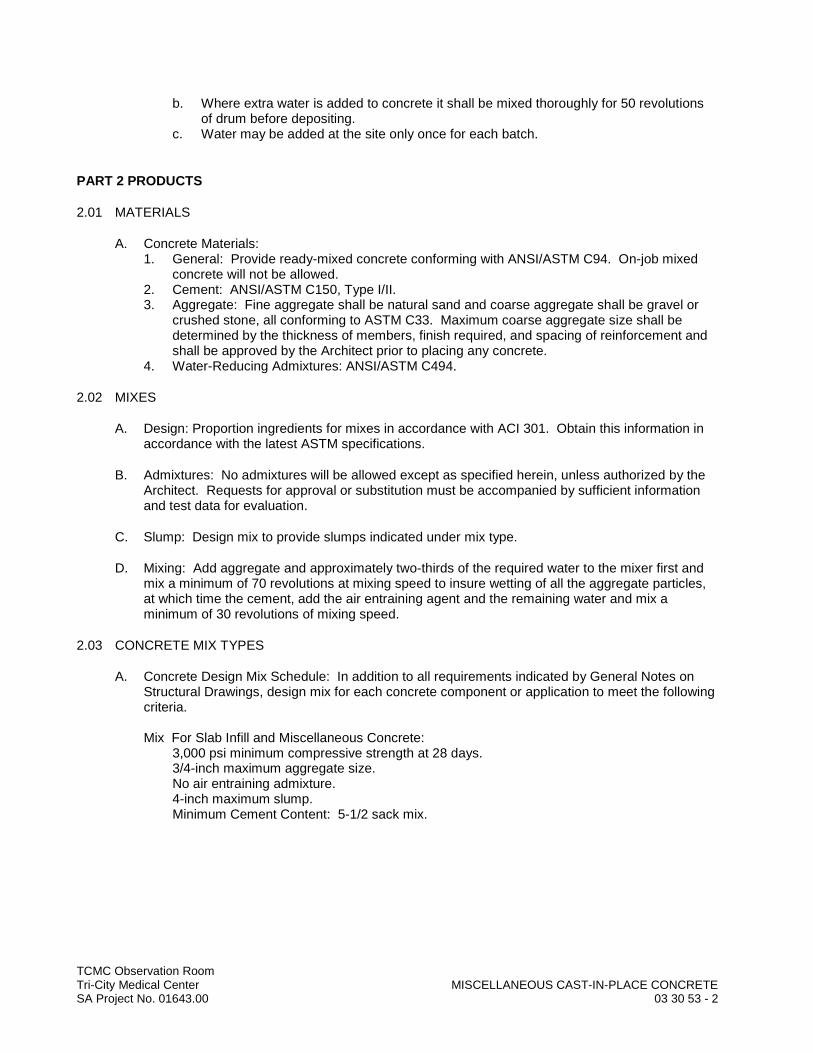
TCMC Observation RoomTri-City Medical Center MISCELLANEOUS CAST-IN-PLACE CONCRETESA Project No. 01643.00 03 30 53 - 2
b. Where extra water is added to concrete it shall be mixed thoroughly for 50 revolutions of drum before depositing.
c. Water may be added at the site only once for each batch.
PART 2 PRODUCTS
2.01 MATERIALS
A. Concrete Materials:1. General: Provide ready-mixed concrete conforming with ANSI/ASTM C94. On-job mixed
concrete will not be allowed.2. Cement: ANSI/ASTM C150, Type I/II.3. Aggregate: Fine aggregate shall be natural sand and coarse aggregate shall be gravel or
crushed stone, all conforming to ASTM C33. Maximum coarse aggregate size shall be determined by the thickness of members, finish required, and spacing of reinforcement and shall be approved by the Architect prior to placing any concrete.
4. Water-Reducing Admixtures: ANSI/ASTM C494.
2.02 MIXES
A. Design: Proportion ingredients for mixes in accordance with ACI 301. Obtain this information in accordance with the latest ASTM specifications.
B. Admixtures: No admixtures will be allowed except as specified herein, unless authorized by the Architect. Requests for approval or substitution must be accompanied by sufficient information and test data for evaluation.
C. Slump: Design mix to provide slumps indicated under mix type.
D. Mixing: Add aggregate and approximately two-thirds of the required water to the mixer first and mix a minimum of 70 revolutions at mixing speed to insure wetting of all the aggregate particles, at which time the cement, add the air entraining agent and the remaining water and mix a minimum of 30 revolutions of mixing speed.
2.03 CONCRETE MIX TYPES
A. Concrete Design Mix Schedule: In addition to all requirements indicated by General Notes on Structural Drawings, design mix for each concrete component or application to meet the following criteria.
Mix For Slab Infill and Miscellaneous Concrete:3,000 psi minimum compressive strength at 28 days.3/4-inch maximum aggregate size.No air entraining admixture.4-inch maximum slump.Minimum Cement Content: 5-1/2 sack mix.

TCMC Observation RoomTri-City Medical Center MISCELLANEOUS CAST-IN-PLACE CONCRETESA Project No. 01643.00 03 30 53 - 3
PART 3 EXECUTION
3.01 EXAMINATION
A. Architect's Examination: Provide ample notice to the Architect to allow observation of the preparation and placing of concrete. Do not begin placement until approval of Architect is obtained.
3.02 PREPARATION
A. Do not begin concrete work until operations are complete enough to allow placement to be carried on as a continuous operation for the entire section that is to be placed. Clean equipment for mixing and transporting the concrete.
B. Protection: Cover masonry walls, glazing, and other finish materials with polyethylene or otherwise protect from damage due to pouring of concrete.
3.03 PLACING CONCRETE
A. General: Comply with ACI 301.
B. Placement: Chuting in such a manner to separate the aggregates will not be permitted. Concrete shall not be dropped over 4'-0".
C. Water: Prevent accumulations of water on the surface of the concrete due to water gain, segregation, or other causes, during placement or compacting, as far as possible by adjustments in the mixture. Make provision for removal of such water as may accumulate so that under no circumstances will concrete be placed in such accumulation.
D. Compaction: Compact concrete during and immediately after placing.
3.04 FLATWORK
A. General: Comply with ACI 301 5.3.4.
B. Screeding: Screed and consolidate surfaces to shape slabs to indicated grades and elevations. Finish surfaces sparingly forcing coarse aggregate slightly below surface. Finish floor slab patches flush with adjacent concrete surfaces. Dusting of wearing surfaces with dry materials will not be permitted.
C. Troweling:1. Floor Slabs: Steel troweled finish in accordance with ACI 301, Paragraph 5.3.4.2.c with two
trowelings. Hand-trowel the surface smooth and free of trowel marks. Continue hand-troweling until a ringing sound is produced as the floor is troweled.
D. Floor Flatness Tolerances: Floor slabs shall be level within following maximum tolerancesmeasured with 10-foot long straightedge, except slope to drains as indicated. 1. Floor Slabs: 1/4-inch in 10 feet.
E. Requirements for Slab Finish: Comply with requirements of other Sections for slab tolerances, finishes, curing, etc. Be responsible to repair or replace slabs as required and specified in these Sections to meet requirements.

TCMC Observation RoomTri-City Medical Center MISCELLANEOUS CAST-IN-PLACE CONCRETESA Project No. 01643.00 03 30 53 - 4
3.05 CURING AND PROTECTION
A. Horizontal Surfaces: Keep the concrete surfaces continuously wet. Do not allow alternate wetting and drying of concrete surfaces.
B. Final curing shall commence as soon as free water has disappeared from the concrete surface after placing and finishing.
C. Moisture Retaining Cover Method: 1. Cover all exposed fresh concrete surfaces and beyond the edge of the concrete surface with
a white polyethylene sheeting of a minimum of 6 mil nominal thickness, placed in widest practicable width with sides and ends lapped at least 3 inches and sealed by waterproof tape or adhesive. Immediately repair any holes or tears during curing period using cover material and waterproof tape.
2. Keep the concrete continuously wet under the sheeting.3. Keep sheeting in place a minimum of 7 days.
D. Protection: Protect exposed surfaces of concrete from premature drying. Protect the concrete from damaging mechanical disturbances during the curing period. Protect finished surfaces from damage by construction equipment, materials or methods, application of curing procedures, or by running water. Protect concrete surfaces from staining, cracking, chipping, and other damage during progress of the work, and leave in good condition upon completion.
3.06 MISCELLANEOUS CONCRETE REQUIREMENTS
A. Other Concrete Work: Furnish and install other concrete work indicated on the Drawings, even though not specifically mentioned herein to complete the work.
3.07 SITE QUALITY CONTROL
A. Record of Work: Keep a record listing the time and date of placement of concrete. Such record shall be kept until the completion of the Project and shall be available to the Architect for examination at any time.
END OF SECTION

TCMC Observation RoomTri-City Medical Center POST-INSTALLED CONCRETE ANCHORSSA Project No. 01643.00 05 05 19 - 1
SECTION 05 05 19
POST-INSTALLED CONCRETE ANCHORS
PART 1 GENERAL
1.01 SUMMARY
A. Section Includes:1. Methods common to multiple sections for fastening metals, fabrications, manufactured
products, hangers, and equipment to in-place concrete, precast concrete, or concrete masonry,. including:a. Post-installed mechanical anchors.b. Post-installed adhesive anchors.
B. Related Requirements:1. Mechanical Expansion Anchors for Electrical Items and Supports: Division 26 Electrical.
1.02 REFERENCES
A. Definitions:1. Interior Use: For purposes of this Section, "Interior Use" shall mean interior applications in a
non-corrosive environment.2. Exterior Use: For purposes of this Section, "Exterior Use" shall mean applications exposed
to weather in service and interior applications in a potentially corrosive environment, including, but not limited to, the interior of parking structures, pool rooms, pool equipment rooms, vehicle service and wash areas, animal holding rooms, shower areas and steam rooms.
B. Reference Standards: See Section 01 42 00.1. American Concrete Institute (ACI) Standards:
a. ACI 355.2-07 - Qualification of Post-Installed Mechanical Anchors in Concrete.b. ACI 355.4-11 - Qualification of Post-Installed Adhesive Anchors in Concrete.
2. International Code Council Evaluation Service (ICC-ES) Standards:a. AC193 – Acceptance Criteria for Mechanical Anchors in Concrete Elements.b. AC308 – Acceptance Criteria for Post-Installed Adhesive Anchors in Concrete
Elements.
1.03 ACTION SUBMITTALS
A. Procedures: Submit for review, action and return in accordance with Section 01 33 00.
B. Product Data: Submit manufacturer's technical data for the following.1. Post-Installed Anchors: Submit for each type proposed for use on Project. Include
statement of proposed applications and locations for each type of anchor.
1.04 INFORMATIONAL SUBMITTALS
A. Procedures: Submit for information and verification in accordance with Section 01 33 00.
B. Evaluation Reports: Submit ICC-ES Evaluation Report for each manufactured anchor product proposed for use on the Project.
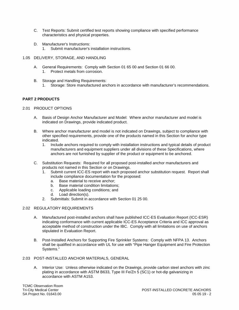
TCMC Observation RoomTri-City Medical Center POST-INSTALLED CONCRETE ANCHORSSA Project No. 01643.00 05 05 19 - 2
C. Test Reports: Submit certified test reports showing compliance with specified performance characteristics and physical properties.
D. Manufacturer's Instructions: 1. Submit manufacturer's installation instructions.
1.05 DELIVERY, STORAGE, AND HANDLING
A. General Requirements: Comply with Section 01 65 00 and Section 01 66 00.1. Protect metals from corrosion.
B. Storage and Handling Requirements:1. Storage: Store manufactured anchors in accordance with manufacturer’s recommendations.
PART 2 PRODUCTS
2.01 PRODUCT OPTIONS
A. Basis of Design Anchor Manufacturer and Model: Where anchor manufacturer and model is indicated on Drawings, provide indicated product.
B. Where anchor manufacturer and model is not indicated on Drawings, subject to compliance with other specified requirements, provide one of the products named in this Section for anchor type indicated. 1. Include anchors required to comply with installation instructions and typical details of product
manufacturers and equipment suppliers under all divisions of these Specifications, where anchors are not furnished by supplier of the product or equipment to be anchored.
C. Substitution Requests: Required for all proposed post-installed anchor manufacturers and products not named in this Section or on Drawings.1. Submit current ICC-ES report with each proposed anchor substitution request. Report shall
include compliance documentation for the proposed:a. Base material to receive anchor;b. Base material condition limitations;c. Applicable loading conditions; andd. Load direction(s).
2. Submittals: Submit in accordance with Section 01 25 00.
2.02 REGULATORY REQUIREMENTS
A. Manufactured post-installed anchors shall have published ICC-ES Evaluation Report (ICC-ESR) indicating conformance with current applicable ICC-ES Acceptance Criteria and ICC approval as acceptable method of construction under the IBC. Comply with all limitations on use of anchors stipulated in Evaluation Report.
B. Post-Installed Anchors for Supporting Fire Sprinkler Systems: Comply with NFPA 13. Anchors shall be qualified in accordance with UL for use with “Pipe Hanger Equipment and Fire Protection Systems.”
2.03 POST-INSTALLED ANCHOR MATERIALS, GENERAL
A. Interior Use: Unless otherwise indicated on the Drawings, provide carbon steel anchors with zinc plating in accordance with ASTM B633, Type III Fe/Zn 5 (SC1) or hot-dip galvanizing in accordance with ASTM A153.
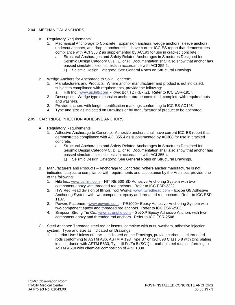
TCMC Observation RoomTri-City Medical Center POST-INSTALLED CONCRETE ANCHORSSA Project No. 01643.00 05 05 19 - 3
2.04 MECHANICAL ANCHORS
A. Regulatory Requirements: 1. Mechanical Anchorage to Concrete: Expansion anchors, wedge anchors, sleeve anchors,
undercut anchors, and drop-in anchors shall have current ICC-ES report that demonstrates compliance with ACI 355.2 as supplemented by AC193 for use in cracked concrete.a. Structural Anchorages and Safety Related Anchorages in Structures Designed for
Seismic Design Category C, D, E, or F: Documentation shall also show that anchor has passed simulated seismic tests in accordance with ACI 355.2.1) Seismic Design Category: See General Notes on Structural Drawings.
B. Wedge Anchors for Anchorage to Solid Concrete:1. Manufacturers and Products: Where anchor manufacturer and product is not indicated,
subject to compliance with requirements, provide the following:a. Hilti Inc.; www.us.hilti.com - Kwik Bolt TZ (KB-TZ). Refer to ICC ESR-1917.
2. Description: Wedge type expansion anchor, torque-controlled, complete with required nuts and washers.
3. Provide anchors with length identification markings conforming to ICC ES AC193. 4. Type and size as indicated on Drawings or by manufacturer of product to be anchored.
2.05 CARTRIDGE INJECTION ADHESIVE ANCHORS
A. Regulatory Requirements.1. Adhesive Anchorage to Concrete: Adhesive anchors shall have current ICC-ES report that
demonstrates compliance with ACI 355.4 as supplemented by AC308 for use in cracked concrete.a. Structural Anchorages and Safety Related Anchorages in Structures Designed for
Seismic Design Category C, D, E, or F: Documentation shall also show that anchor has passed simulated seismic tests in accordance with ACI 355.4.1) Seismic Design Category: See General Notes on Structural Drawings.
B. Manufacturers and Products – Anchorage to Concrete: Where anchor manufacturer is not indicated, subject to compliance with requirements and acceptance by the Architect, provide one of the following:1. Hilti Inc.; www.us.hilti.com – HIT RE 500-SD Adhesive Anchoring System with two-
component epoxy with threaded rod anchors. Refer to ICC ESR-2322. 2. ITW Red Head division of Illinois Tool Works; www.itwredhead.com – Epcon G5 Adhesive
Anchoring System with two-component epoxy and threaded rod anchors. Refer to ICC ESR-1137.
3. Powers Fasteners; www.powers.com - PE1000+ Epoxy Adhesive Anchoring System with two-component epoxy and threaded rod anchors. Refer to ICC ESR-2583.
4. Simpson Strong Tie Co.; www.strongtie.com – Set-XP Epoxy Adhesive Anchors with two-component epoxy and threaded rod anchors. Refer to ICC ESR-2508.
C. Steel Anchors: Threaded steel rod or inserts, complete with nuts, washers, adhesive injection system. Type and size as indicated on Drawings.1. Interior Use: Unless otherwise indicated on the Drawings, provide carbon steel threaded
rods conforming to ASTM A36, ASTM A 193 Type B7 or ISO 898 Class 5.8 with zinc plating in accordance with ASTM B633, Type III Fe/Zn 5 (SC1) or carbon steel rods conforming to ASTM A510 with chemical composition of AISI 1038.
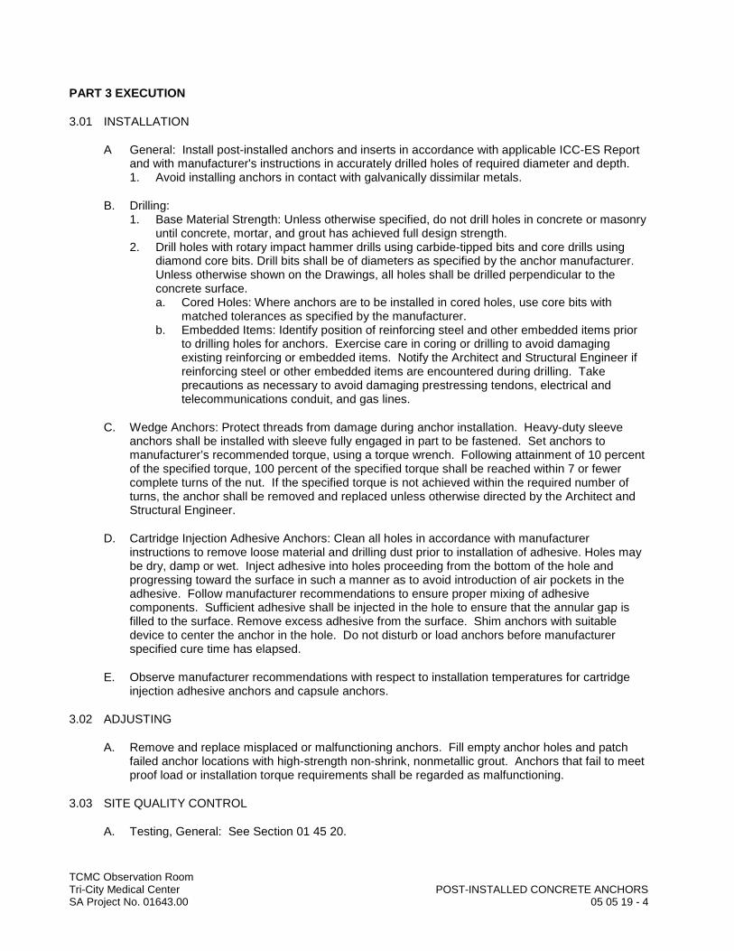
TCMC Observation RoomTri-City Medical Center POST-INSTALLED CONCRETE ANCHORSSA Project No. 01643.00 05 05 19 - 4
PART 3 EXECUTION
3.01 INSTALLATION
A General: Install post-installed anchors and inserts in accordance with applicable ICC-ES Report and with manufacturer's instructions in accurately drilled holes of required diameter and depth. 1. Avoid installing anchors in contact with galvanically dissimilar metals.
B. Drilling:1. Base Material Strength: Unless otherwise specified, do not drill holes in concrete or masonry
until concrete, mortar, and grout has achieved full design strength.2. Drill holes with rotary impact hammer drills using carbide-tipped bits and core drills using
diamond core bits. Drill bits shall be of diameters as specified by the anchor manufacturer. Unless otherwise shown on the Drawings, all holes shall be drilled perpendicular to the concrete surface.a. Cored Holes: Where anchors are to be installed in cored holes, use core bits with
matched tolerances as specified by the manufacturer. b. Embedded Items: Identify position of reinforcing steel and other embedded items prior
to drilling holes for anchors. Exercise care in coring or drilling to avoid damaging existing reinforcing or embedded items. Notify the Architect and Structural Engineer if reinforcing steel or other embedded items are encountered during drilling. Take precautions as necessary to avoid damaging prestressing tendons, electrical and telecommunications conduit, and gas lines.
C. Wedge Anchors: Protect threads from damage during anchor installation. Heavy-duty sleeve anchors shall be installed with sleeve fully engaged in part to be fastened. Set anchors to manufacturer’s recommended torque, using a torque wrench. Following attainment of 10 percent of the specified torque, 100 percent of the specified torque shall be reached within 7 or fewer complete turns of the nut. If the specified torque is not achieved within the required number of turns, the anchor shall be removed and replaced unless otherwise directed by the Architect and Structural Engineer.
D. Cartridge Injection Adhesive Anchors: Clean all holes in accordance with manufacturer instructions to remove loose material and drilling dust prior to installation of adhesive. Holes may be dry, damp or wet. Inject adhesive into holes proceeding from the bottom of the hole and progressing toward the surface in such a manner as to avoid introduction of air pockets in the adhesive. Follow manufacturer recommendations to ensure proper mixing of adhesive components. Sufficient adhesive shall be injected in the hole to ensure that the annular gap is filled to the surface. Remove excess adhesive from the surface. Shim anchors with suitable device to center the anchor in the hole. Do not disturb or load anchors before manufacturer specified cure time has elapsed.
E. Observe manufacturer recommendations with respect to installation temperatures for cartridge injection adhesive anchors and capsule anchors.
3.02 ADJUSTING
A. Remove and replace misplaced or malfunctioning anchors. Fill empty anchor holes and patch failed anchor locations with high-strength non-shrink, nonmetallic grout. Anchors that fail to meet proof load or installation torque requirements shall be regarded as malfunctioning.
3.03 SITE QUALITY CONTROL
A. Testing, General: See Section 01 45 20.

TCMC Observation RoomTri-City Medical Center POST-INSTALLED CONCRETE ANCHORSSA Project No. 01643.00 05 05 19 - 5
B. Testing of Post-Installed Anchors: . Quality control testing shall be performed by independent testing agency in consultation with manufacturer's representative.1. Testing: Comply with Expansion Anchor Bolt Notes on Structural Drawings.
C. Special Inspection: See Section 01 45 20.1. Special inspection is required for all post-installed anchor installations.
END OF SECTION
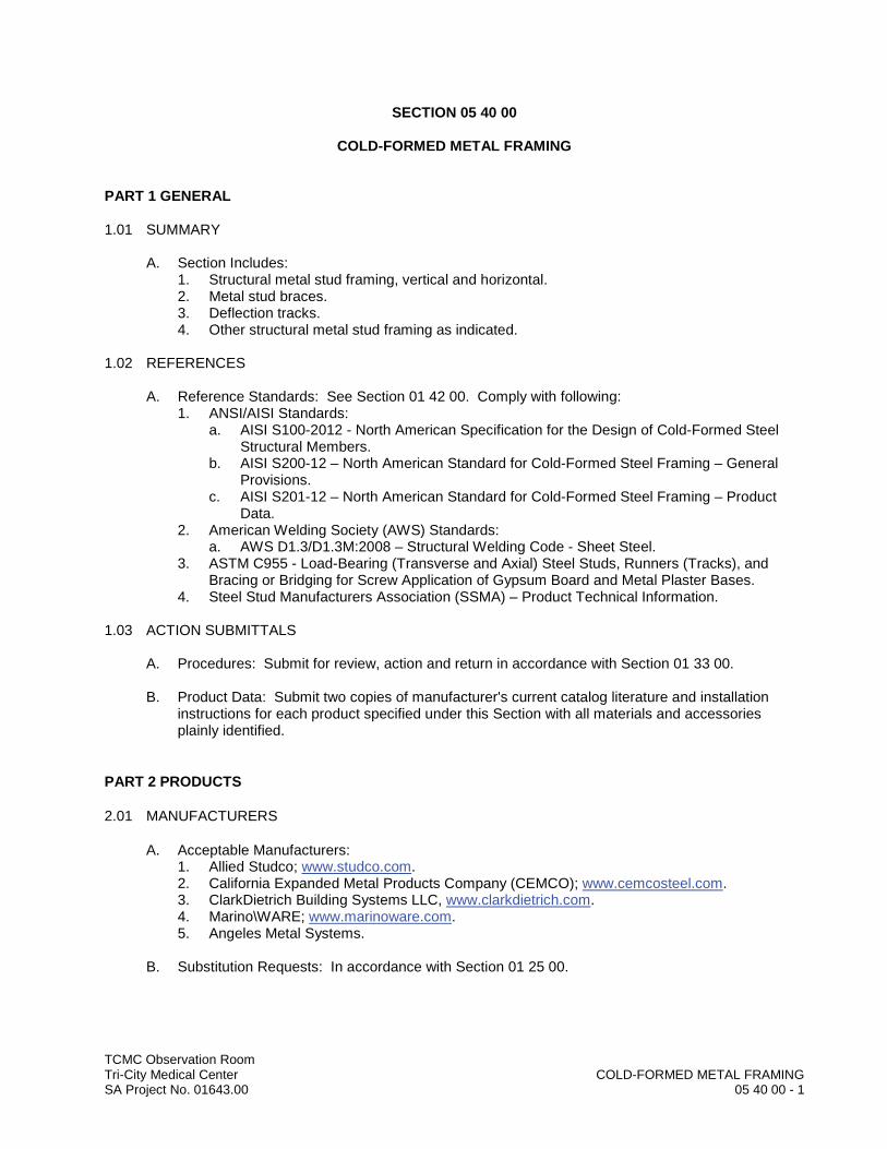
TCMC Observation RoomTri-City Medical Center COLD-FORMED METAL FRAMINGSA Project No. 01643.00 05 40 00 - 1
SECTION 05 40 00
COLD-FORMED METAL FRAMING
PART 1 GENERAL
1.01 SUMMARY
A. Section Includes:1. Structural metal stud framing, vertical and horizontal.2. Metal stud braces.3. Deflection tracks.4. Other structural metal stud framing as indicated.
1.02 REFERENCES
A. Reference Standards: See Section 01 42 00. Comply with following:1. ANSI/AISI Standards:
a. AISI S100-2012 - North American Specification for the Design of Cold-Formed Steel Structural Members.
b. AISI S200-12 – North American Standard for Cold-Formed Steel Framing – General Provisions.
c. AISI S201-12 – North American Standard for Cold-Formed Steel Framing – Product Data.
2. American Welding Society (AWS) Standards:a. AWS D1.3/D1.3M:2008 – Structural Welding Code - Sheet Steel.
3. ASTM C955 - Load-Bearing (Transverse and Axial) Steel Studs, Runners (Tracks), and Bracing or Bridging for Screw Application of Gypsum Board and Metal Plaster Bases.
4. Steel Stud Manufacturers Association (SSMA) – Product Technical Information.
1.03 ACTION SUBMITTALS
A. Procedures: Submit for review, action and return in accordance with Section 01 33 00.
B. Product Data: Submit two copies of manufacturer's current catalog literature and installation instructions for each product specified under this Section with all materials and accessories plainly identified.
PART 2 PRODUCTS
2.01 MANUFACTURERS
A. Acceptable Manufacturers:1. Allied Studco; www.studco.com.2. California Expanded Metal Products Company (CEMCO); www.cemcosteel.com.3. ClarkDietrich Building Systems LLC, www.clarkdietrich.com.4. Marino\WARE; www.marinoware.com.5. Angeles Metal Systems.
B. Substitution Requests: In accordance with Section 01 25 00.

TCMC Observation RoomTri-City Medical Center COLD-FORMED METAL FRAMINGSA Project No. 01643.00 05 40 00 - 2
2.02 MATERIALS
A. Steel Mechanical Properties: Conform to requirements of AISI Specification, Section A3.1. Minimum Yield Point for Material 16 Gage to 10 Gage in Thickness: 50,000 psi.2. Minimum Yield Point for Material 18 Gage and Less in Thickness: 33,000 psi.
B. Steel Sectional Properties and Design: Computed in accordance with AISI Specification.
C. Steel Studs, Tracks, Bracing, Bridging and Related Metal: ASTM C955.1. Sizes and locations as indicated on Drawings.
D. Blocking: 16 gage by 6-inch, 50 ksi sheet metal, unless heavier gage is indicated on Drawings.
E. Finish: Corrosion resistant galvanized coating conforming to ASTM A653, G60 minimum.
2.03 FASTENERS
A. Self-Drilling, Self-Tapping Screws, Bolts, Nuts and Washers: ASTM A90, hot-dip galvanized.
PART 3 EXECUTION
3.01 INSTALLATION
A. Connections: Screwed as indicated on the Structural Drawings.
END OF SECTION

DIV
ISIO
N 0
5–
MET
ALS
DDDDDDDDDDDDDDDDDDDDIIIIIIIIIIIIIIIVVVVVVVVVVVVVVVVVVVVVVV
IIIIIIIIIIIIIIISSSSSSSSSSSSSSSSSSSSSSSSSIIIIIIIIIIIIIIIIIOOOOOOOOOOOOOOOOOOOOOOOOOOOOOOO
NNNNNNNNNNNNNNNNNNNNNN 000000000000000000000000
5555555555555555555555555––––––––––––––
MMMMMMMMMMMMMMMMMMMMMMMMEEEEEEEEEEEEEEEEEETTTTTTTTTTTTTTT
AAAAAAAAAAAAAAAAAAAAAAALLLLLLLLLLLLLLLLLSSSSSSSSSSSSSSSSSSSSSSSSS

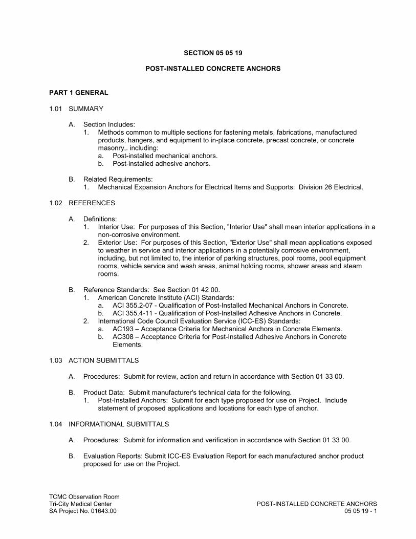
TCMC Observation RoomTri-City Medical Center POST-INSTALLED CONCRETE ANCHORSSA Project No. 01643.00 05 05 19 - 1
SECTION 05 05 19
POST-INSTALLED CONCRETE ANCHORS
PART 1 GENERAL
1.01 SUMMARY
A. Section Includes:1. Methods common to multiple sections for fastening metals, fabrications, manufactured
products, hangers, and equipment to in-place concrete, precast concrete, or concrete masonry,. including:a. Post-installed mechanical anchors.b. Post-installed adhesive anchors.
B. Related Requirements:1. Mechanical Expansion Anchors for Electrical Items and Supports: Division 26 Electrical.
1.02 REFERENCES
A. Definitions:1. Interior Use: For purposes of this Section, "Interior Use" shall mean interior applications in a
non-corrosive environment.2. Exterior Use: For purposes of this Section, "Exterior Use" shall mean applications exposed
to weather in service and interior applications in a potentially corrosive environment, including, but not limited to, the interior of parking structures, pool rooms, pool equipment rooms, vehicle service and wash areas, animal holding rooms, shower areas and steam rooms.
B. Reference Standards: See Section 01 42 00.1. American Concrete Institute (ACI) Standards:
a. ACI 355.2-07 - Qualification of Post-Installed Mechanical Anchors in Concrete.b. ACI 355.4-11 - Qualification of Post-Installed Adhesive Anchors in Concrete.
2. International Code Council Evaluation Service (ICC-ES) Standards:a. AC193 – Acceptance Criteria for Mechanical Anchors in Concrete Elements.b. AC308 – Acceptance Criteria for Post-Installed Adhesive Anchors in Concrete
Elements.
1.03 ACTION SUBMITTALS
A. Procedures: Submit for review, action and return in accordance with Section 01 33 00.
B. Product Data: Submit manufacturer's technical data for the following.1. Post-Installed Anchors: Submit for each type proposed for use on Project. Include
statement of proposed applications and locations for each type of anchor.
1.04 INFORMATIONAL SUBMITTALS
A. Procedures: Submit for information and verification in accordance with Section 01 33 00.
B. Evaluation Reports: Submit ICC-ES Evaluation Report for each manufactured anchor product proposed for use on the Project.

TCMC Observation RoomTri-City Medical Center POST-INSTALLED CONCRETE ANCHORSSA Project No. 01643.00 05 05 19 - 2
C. Test Reports: Submit certified test reports showing compliance with specified performance characteristics and physical properties.
D. Manufacturer's Instructions: 1. Submit manufacturer's installation instructions.
1.05 DELIVERY, STORAGE, AND HANDLING
A. General Requirements: Comply with Section 01 65 00 and Section 01 66 00.1. Protect metals from corrosion.
B. Storage and Handling Requirements:1. Storage: Store manufactured anchors in accordance with manufacturer’s recommendations.
PART 2 PRODUCTS
2.01 PRODUCT OPTIONS
A. Basis of Design Anchor Manufacturer and Model: Where anchor manufacturer and model is indicated on Drawings, provide indicated product.
B. Where anchor manufacturer and model is not indicated on Drawings, subject to compliance with other specified requirements, provide one of the products named in this Section for anchor type indicated. 1. Include anchors required to comply with installation instructions and typical details of product
manufacturers and equipment suppliers under all divisions of these Specifications, where anchors are not furnished by supplier of the product or equipment to be anchored.
C. Substitution Requests: Required for all proposed post-installed anchor manufacturers and products not named in this Section or on Drawings.1. Submit current ICC-ES report with each proposed anchor substitution request. Report shall
include compliance documentation for the proposed:a. Base material to receive anchor;b. Base material condition limitations;c. Applicable loading conditions; andd. Load direction(s).
2. Submittals: Submit in accordance with Section 01 25 00.
2.02 REGULATORY REQUIREMENTS
A. Manufactured post-installed anchors shall have published ICC-ES Evaluation Report (ICC-ESR) indicating conformance with current applicable ICC-ES Acceptance Criteria and ICC approval as acceptable method of construction under the IBC. Comply with all limitations on use of anchors stipulated in Evaluation Report.
B. Post-Installed Anchors for Supporting Fire Sprinkler Systems: Comply with NFPA 13. Anchors shall be qualified in accordance with UL for use with “Pipe Hanger Equipment and Fire Protection Systems.”
2.03 POST-INSTALLED ANCHOR MATERIALS, GENERAL
A. Interior Use: Unless otherwise indicated on the Drawings, provide carbon steel anchors with zinc plating in accordance with ASTM B633, Type III Fe/Zn 5 (SC1) or hot-dip galvanizing in accordance with ASTM A153.
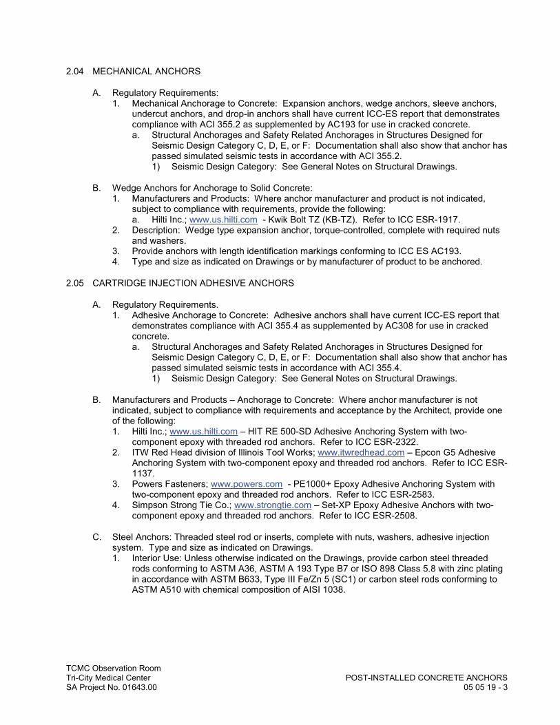
TCMC Observation RoomTri-City Medical Center POST-INSTALLED CONCRETE ANCHORSSA Project No. 01643.00 05 05 19 - 3
2.04 MECHANICAL ANCHORS
A. Regulatory Requirements: 1. Mechanical Anchorage to Concrete: Expansion anchors, wedge anchors, sleeve anchors,
undercut anchors, and drop-in anchors shall have current ICC-ES report that demonstrates compliance with ACI 355.2 as supplemented by AC193 for use in cracked concrete.a. Structural Anchorages and Safety Related Anchorages in Structures Designed for
Seismic Design Category C, D, E, or F: Documentation shall also show that anchor has passed simulated seismic tests in accordance with ACI 355.2.1) Seismic Design Category: See General Notes on Structural Drawings.
B. Wedge Anchors for Anchorage to Solid Concrete:1. Manufacturers and Products: Where anchor manufacturer and product is not indicated,
subject to compliance with requirements, provide the following:a. Hilti Inc.; www.us.hilti.com - Kwik Bolt TZ (KB-TZ). Refer to ICC ESR-1917.
2. Description: Wedge type expansion anchor, torque-controlled, complete with required nuts and washers.
3. Provide anchors with length identification markings conforming to ICC ES AC193. 4. Type and size as indicated on Drawings or by manufacturer of product to be anchored.
2.05 CARTRIDGE INJECTION ADHESIVE ANCHORS
A. Regulatory Requirements.1. Adhesive Anchorage to Concrete: Adhesive anchors shall have current ICC-ES report that
demonstrates compliance with ACI 355.4 as supplemented by AC308 for use in cracked concrete.a. Structural Anchorages and Safety Related Anchorages in Structures Designed for
Seismic Design Category C, D, E, or F: Documentation shall also show that anchor has passed simulated seismic tests in accordance with ACI 355.4.1) Seismic Design Category: See General Notes on Structural Drawings.
B. Manufacturers and Products – Anchorage to Concrete: Where anchor manufacturer is not indicated, subject to compliance with requirements and acceptance by the Architect, provide one of the following:1. Hilti Inc.; www.us.hilti.com – HIT RE 500-SD Adhesive Anchoring System with two-
component epoxy with threaded rod anchors. Refer to ICC ESR-2322. 2. ITW Red Head division of Illinois Tool Works; www.itwredhead.com – Epcon G5 Adhesive
Anchoring System with two-component epoxy and threaded rod anchors. Refer to ICC ESR-1137.
3. Powers Fasteners; www.powers.com - PE1000+ Epoxy Adhesive Anchoring System with two-component epoxy and threaded rod anchors. Refer to ICC ESR-2583.
4. Simpson Strong Tie Co.; www.strongtie.com – Set-XP Epoxy Adhesive Anchors with two-component epoxy and threaded rod anchors. Refer to ICC ESR-2508.
C. Steel Anchors: Threaded steel rod or inserts, complete with nuts, washers, adhesive injection system. Type and size as indicated on Drawings.1. Interior Use: Unless otherwise indicated on the Drawings, provide carbon steel threaded
rods conforming to ASTM A36, ASTM A 193 Type B7 or ISO 898 Class 5.8 with zinc plating in accordance with ASTM B633, Type III Fe/Zn 5 (SC1) or carbon steel rods conforming to ASTM A510 with chemical composition of AISI 1038.

TCMC Observation RoomTri-City Medical Center POST-INSTALLED CONCRETE ANCHORSSA Project No. 01643.00 05 05 19 - 4
PART 3 EXECUTION
3.01 INSTALLATION
A General: Install post-installed anchors and inserts in accordance with applicable ICC-ES Report and with manufacturer's instructions in accurately drilled holes of required diameter and depth. 1. Avoid installing anchors in contact with galvanically dissimilar metals.
B. Drilling:1. Base Material Strength: Unless otherwise specified, do not drill holes in concrete or masonry
until concrete, mortar, and grout has achieved full design strength.2. Drill holes with rotary impact hammer drills using carbide-tipped bits and core drills using
diamond core bits. Drill bits shall be of diameters as specified by the anchor manufacturer. Unless otherwise shown on the Drawings, all holes shall be drilled perpendicular to the concrete surface.a. Cored Holes: Where anchors are to be installed in cored holes, use core bits with
matched tolerances as specified by the manufacturer. b. Embedded Items: Identify position of reinforcing steel and other embedded items prior
to drilling holes for anchors. Exercise care in coring or drilling to avoid damaging existing reinforcing or embedded items. Notify the Architect and Structural Engineer if reinforcing steel or other embedded items are encountered during drilling. Take precautions as necessary to avoid damaging prestressing tendons, electrical and telecommunications conduit, and gas lines.
C. Wedge Anchors: Protect threads from damage during anchor installation. Heavy-duty sleeve anchors shall be installed with sleeve fully engaged in part to be fastened. Set anchors to manufacturer’s recommended torque, using a torque wrench. Following attainment of 10 percent of the specified torque, 100 percent of the specified torque shall be reached within 7 or fewer complete turns of the nut. If the specified torque is not achieved within the required number of turns, the anchor shall be removed and replaced unless otherwise directed by the Architect and Structural Engineer.
D. Cartridge Injection Adhesive Anchors: Clean all holes in accordance with manufacturer instructions to remove loose material and drilling dust prior to installation of adhesive. Holes may be dry, damp or wet. Inject adhesive into holes proceeding from the bottom of the hole and progressing toward the surface in such a manner as to avoid introduction of air pockets in the adhesive. Follow manufacturer recommendations to ensure proper mixing of adhesive components. Sufficient adhesive shall be injected in the hole to ensure that the annular gap is filled to the surface. Remove excess adhesive from the surface. Shim anchors with suitable device to center the anchor in the hole. Do not disturb or load anchors before manufacturer specified cure time has elapsed.
E. Observe manufacturer recommendations with respect to installation temperatures for cartridge injection adhesive anchors and capsule anchors.
3.02 ADJUSTING
A. Remove and replace misplaced or malfunctioning anchors. Fill empty anchor holes and patch failed anchor locations with high-strength non-shrink, nonmetallic grout. Anchors that fail to meet proof load or installation torque requirements shall be regarded as malfunctioning.
3.03 SITE QUALITY CONTROL
A. Testing, General: See Section 01 45 20.
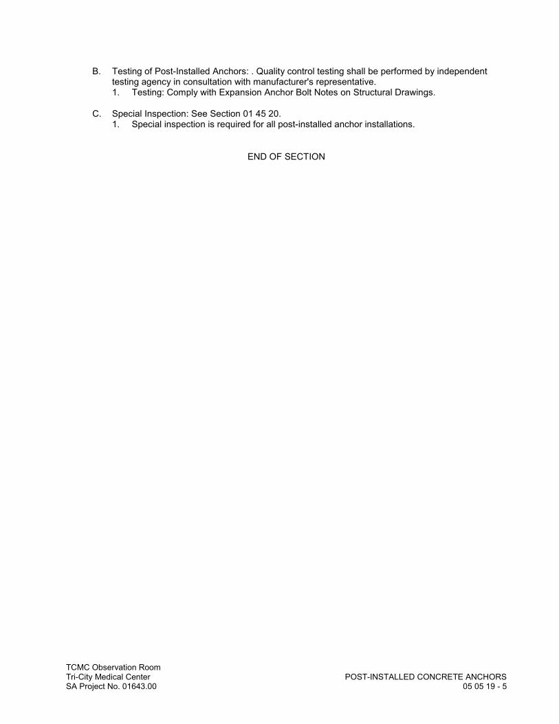
TCMC Observation RoomTri-City Medical Center POST-INSTALLED CONCRETE ANCHORSSA Project No. 01643.00 05 05 19 - 5
B. Testing of Post-Installed Anchors: . Quality control testing shall be performed by independent testing agency in consultation with manufacturer's representative.1. Testing: Comply with Expansion Anchor Bolt Notes on Structural Drawings.
C. Special Inspection: See Section 01 45 20.1. Special inspection is required for all post-installed anchor installations.
END OF SECTION
TCMC Observation RoomTri-City Medical Center COLD-FORMED METAL FRAMINGSA Project No. 01643.00 05 40 00 - 1
SECTION 05 40 00
COLD-FORMED METAL FRAMING
PART 1 GENERAL
1.01 SUMMARY
A. Section Includes:1. Structural metal stud framing, vertical and horizontal.2. Metal stud braces.3. Deflection tracks.4. Other structural metal stud framing as indicated.
1.02 REFERENCES
A. Reference Standards: See Section 01 42 00. Comply with following:1. ANSI/AISI Standards:
a. AISI S100-2012 - North American Specification for the Design of Cold-Formed Steel Structural Members.
b. AISI S200-12 – North American Standard for Cold-Formed Steel Framing – General Provisions.
c. AISI S201-12 – North American Standard for Cold-Formed Steel Framing – Product Data.
2. American Welding Society (AWS) Standards:a. AWS D1.3/D1.3M:2008 – Structural Welding Code - Sheet Steel.
3. ASTM C955 - Load-Bearing (Transverse and Axial) Steel Studs, Runners (Tracks), and Bracing or Bridging for Screw Application of Gypsum Board and Metal Plaster Bases.
4. Steel Stud Manufacturers Association (SSMA) – Product Technical Information.
1.03 ACTION SUBMITTALS
A. Procedures: Submit for review, action and return in accordance with Section 01 33 00.
B. Product Data: Submit two copies of manufacturer's current catalog literature and installation instructions for each product specified under this Section with all materials and accessories plainly identified.
PART 2 PRODUCTS
2.01 MANUFACTURERS
A. Acceptable Manufacturers:1. Allied Studco; www.studco.com.2. California Expanded Metal Products Company (CEMCO); www.cemcosteel.com.3. ClarkDietrich Building Systems LLC, www.clarkdietrich.com.4. Marino\WARE; www.marinoware.com.5. Angeles Metal Systems.
B. Substitution Requests: In accordance with Section 01 25 00.
TCMC Observation RoomTri-City Medical Center COLD-FORMED METAL FRAMINGSA Project No. 01643.00 05 40 00 - 2
2.02 MATERIALS
A. Steel Mechanical Properties: Conform to requirements of AISI Specification, Section A3.1. Minimum Yield Point for Material 16 Gage to 10 Gage in Thickness: 50,000 psi.2. Minimum Yield Point for Material 18 Gage and Less in Thickness: 33,000 psi.
B. Steel Sectional Properties and Design: Computed in accordance with AISI Specification.
C. Steel Studs, Tracks, Bracing, Bridging and Related Metal: ASTM C955.1. Sizes and locations as indicated on Drawings.
D. Blocking: 16 gage by 6-inch, 50 ksi sheet metal, unless heavier gage is indicated on Drawings.
E. Finish: Corrosion resistant galvanized coating conforming to ASTM A653, G60 minimum.
2.03 FASTENERS
A. Self-Drilling, Self-Tapping Screws, Bolts, Nuts and Washers: ASTM A90, hot-dip galvanized.
PART 3 EXECUTION
3.01 INSTALLATION
A. Connections: Screwed as indicated on the Structural Drawings.
END OF SECTION
TCMC Observation RoomTri-City Medical Center METAL FABRICATIONSSA Project No. 01643.00 05 50 00 - 1
SECTION 05 50 00
METAL FABRICATIONS
PART 1 GENERAL
1.01 SUMMARY
A. Section Includes:1. Steel angles for connections of partition braces to underside of floor deck above.2. All other miscellaneous angles, channels, tubes and plates as indicated and required, and
not indicated and specified as structural steel.
B. Related Requirements:1. Post-Installed Concrete Anchors: Section 05 05 19.2. Cold-Formed Metal Framing: Section 05 40 00.3. Field Painting: Section 09 91 23 Interior Painting.
1.02 REFERENCES
A. General Requirements: Refer to Section 01 42 00.
B. Reference Standards: Comply with the following except as otherwise specified in this Project Manual. 1. American Institute of Steel Construction (AISC):
a. Design, Detailing, and Fabrication: ANSI/AISC 360-10 - Specification for Structural Steel Buildings.
b. AISC 303-10 - Code of Standard Practice for Steel Buildings and Bridges, limited to the following:1) Fabrication, Delivery and Erection of Steel: Comply with Sections 5 through 8.2) Fabrication, Erection, and Dimensional Tolerances for Exposed Steel Fabrications:
Comply with Section 10.2. American Welding Society (AWS) Standards:
a. AWS D1.1/D1.1M:2015 – Structural Welding Code – Steel.3. Society for Protective Coatings (SSPC):
a. SSPC-PA 1 - Shop, Field and Maintenance Painting of Steel.
1.03 ACTION SUBMITTALS
A. Procedures: Submit for review, acceptance and return in accordance with Section 01 33 00.
B. Product Data: Submit product data for all manufactured stock items specified under this Section, including the following.1. Anchorage and suspension assembly for CAV box.
C. Shop Drawings: Submit for all custom fabricated items under this Section. 1. Shop drawings shall clearly indicate the following:
a. Profiles, sizes, spacing, and locations of members.b. Connections, attachments, and anchorages.c. Size and type of fasteners.d. Finishes, coatings and shop painting.
2. Include erection drawings, elevations and details where applicable. 3. Indicate weld lengths and sizes.

TCMC Observation RoomTri-City Medical Center METAL FABRICATIONSSA Project No. 01643.00 05 50 00 - 2
1.04 QUALITY ASSURANCE
A. Qualifications: 1. Welder Qualifications: Welding shall be performed only by certified welding operators
currently qualified in accordance with the testing procedures of AWS D1.1 for the weld types and positions required for the fabrications and installations indicated.
1.05 DELIVERY, STORAGE, AND HANDLING
A. General Requirements: Comply with Section 01 65 00 and Section 01 66 00.
B. Storage and Handling Requirements: 1. Store metals above ground on platforms, skids, or other supports. Protect metals from
corrosion.2. Store other materials in weathertight and dry place, until ready for use.
PART 2 PRODUCTS
2.01 MATERIALS
A. Carbon Steel Shapes, Bars and Plates: ASTM A36.
B. Steel Pipe and Tubing: ASTM A53, Grade B, or A500, Grade B, minimum wall thickness 11 gage.
C. Threaded Rod: ASTM A36.
D. Steel Fasteners and Anchors:1. Bolts: ASTM A325.2. Nuts: ASTM A563.3. Washers: ASTM F436.
E. Welding Materials for Carbon Steel:1. Filler Metals for Welding: Meet requirements of AWS D1.1.2. Welding Electrodes: AWS 5.1 or A 5.5.
2.02 FABRICATION
A. Exposed Steel Fabrications: Interior and exterior steel fabrications and connections which will remain exposed and subject to normal view by the public or occupants of the completed structure shall be subject to all requirements for Architecturally Exposed Structural Steel specified in Section 10 of the AISC Code of Standard Practice.
B. Shop Assembly: Fabricate custom metal fabrications as indicated, scheduled or listed in Article 1.01.1. Fabricate in accordance with details and accepted shop drawings. 2. Provide miscellaneous items of metal work indicated or as necessary to complete work.3. Materials: New stock of types and sizes indicated. 4. Make cuts clean and sharp with wire edges ground smooth. Provide straight, rigid, and tight
work, free from defects. 5. Close exposed ends of steel pipe or tubing with welded caps.6. Verify dimensions on site prior to shop fabrication.7. Fabricate items with joints neatly fitted and properly secured.8. Fit and shop assemble, in largest practical sections, for delivery to site.

TCMC Observation RoomTri-City Medical Center METAL FABRICATIONSSA Project No. 01643.00 05 50 00 - 3
9. Exposed mechanical fastenings shall be flush, countersunk screws or bolts, unobtrusively located, consistent with design of structure, except where specifically noted otherwise.
10. Make exposed joints flush butt-type, hairline joints where mechanically fastened.11. Supply components required for proper anchorage of metal fabrications. Fabricate
anchorage and related components of same material and finish as metal fabrication, unlessotherwise specified or detailed.
12. Welding: AWS D1.1. Miter and cope intersections and weld all around. Remove splatter, grind exposed welds to blend and contour surfaces to match those adjacent.
13. Substitutions: Where exact sizes and weights called for are not available, secure Architect's acceptance of suitable sizes prior to proceeding.
2.03 SHOP FINISHES
A. Shop Paint:1. Steel Items to Receive Painted Finish or To Be Concealed in Completed Structure: One of
the following.a. Tnemec Series 10 modified alkyd primer.b. Society for Protective Coatings Specification SSPC Paint 25 lead and chromate free
primer.
B. Shop Priming:1. Surface Preparation: After fabrication and shop assembly, clean off all loose rust, loose mill
scale and weld spatter, slag or flux deposits in accordance with SSPC procedures as follows:a. Surfaces to be Concealed in the Completed Structure: SP-3 power tool cleaning.b. Surfaces to be Exposed in the Completed Structure: SP-6 commercial blast cleaning.
2. Paint Application: Shop coat fabricated items with shop paint in accordance with SSPC-PA-1.a. Omit shop paint on surfaces to be enclosed in concrete and surfaces to be field welded.b. Standard Shop Paint Thickness: 2.5 dry film mils.
PART 3 EXECUTION
3.01 INSTALLATION
A. Weld or bolt items securely in place or otherwise fasten as indicated on the Drawings or accepted shop drawings. Include items indicated, scheduled or listed in Article 1.01.
B. Install items square and level, accurately fitted and free from distortion or defects.
C. Field Welds: Perform field welding in accordance with AWS D1.1. 1. Painted Fabrications: Grind smooth and touch up with compatible primer.
3.02 ADJUSTMENTS
A. Repair of Defective Work: Remove stained or otherwise defective work. Replace with new material.
END OF SECTION


DIV
ISIO
N 0
6–
WO
OD
, PLA
STIC
S, A
ND
CO
MPO
SITE
SDDDDDDDDDDDDDDDDDDDDD
IIIIIIIIIIIIIIIVVVVVVVVVVVVVVVVVVVVVVVVIIIIIIIIIIIIIIISSSSSSSSSSSSSSSSSSSSSSSS
IIIIIIIIIIIIIOOOOOOOOOOOOOOOOOOOOOOOOOOOOONNNNNNNNNNNNNNNNNNNNN
00000000000000000000000066666666666666666666666
–––––––––––––––WWWWWWWWWWWWWWWWWWWWWWWWW
OOOOOOOOOOOOOOOOOOOOOOOOOOOOOOOOOOOOOOOOOOOOOOOOOOOOOOO
DDDDDDDDDDDDDDDDDDDDD,,,,,,,,,,,,,,,,,,,, PPPPPPPPPPPPPPPPPPPPPPPP
LLLLLLLLLLLLLLAAAAAAAAAAAAAAAAAAAAAASSSSSSSSSSSSSSSSSSSSSSSSTTTTTTTTTTTTTTTTTTTTTT
IIIIIIIIIIIIIIICCCCCCCCCCCCCCCCCCCCCCCSSSSSSSSSSSSSSSSSSSSSSSS,,,,,,,,,,,,,,,,,,,,,
AAAAAAAAAAAAAAAAAAAAAAANNNNNNNNNNNNNNNNNNNNN
DDDDDDDDDDDDDDDDDDDDDD CCCCCCCCCCCCCCCCCCCCCCCCCCCCCC
OOOOOOOOOOOOOOOOOOOOOOOOOOOOOOMMMMMMMMMMMMMMMMMMMMMMMMM
PPPPPPPPPPPPPPPPPPPPPOOOOOOOOOOOOOOOOOOOOOOOOOOOOOSSSSSSSSSSSSSSSSSSSSSSSSSSSIIIIIIIIIIIIIIIIII
TTTTTTTTTTTTTTTTTEEEEEEEEEEEEEEEEEEESSSSSSSSSSSSSSSSSSSSSSSSS

TCMC Observation RoomTri-City Medical Center MISCELLANEOUS ROUGH CARPENTRYSA Project No. 01643.00 06 10 53 - 1
SECTION 06 10 53
MISCELLANEOUS ROUGH CARPENTRY
PART 1 GENERAL
1.01 SUMMARY
A. Section Includes:1. Miscellaneous blocking and supports.2. Miscellaneous wood sheathing.3. Fire-retardant treatment.
B. Related Requirements:1. Architectural Wood Casework: Section 06 41 00.
1.02 REFERENCES
A. Reference Standards. See Section 01 42 00. Comply with the following:1. Wood Framing: Comply with requirements of the 2013 California Building Code and
ANSI/AF&PA NDS-2012 National Design Specification for Wood Construction, as published by the American Wood Council of the American Forest and Paper Association.
2. Lumber: Grading Rules for Lumber, latest edition, as published by Western Wood Products Association.
3. Plywood: National Institute of Standards and Technology (NIST) – Voluntary Product Standard PS 1-09 - Structural Plywood.
4. Performance Rated Wood Sheathing Panels: a. APA PRP-108 - Performance Standards and Policies for Structural-Use Panels.b. National Institute of Standards and Technology (NIST) – Voluntary Product Standard
PS 2-10 – Performance Standard for Wood-Based Structural-Use Panels.5. Treatment:
a. AWPA C2 – Lumber, Timber, Bridge Ties and Mine Ties – Preservative Treatment by Pressure Processes.
b. AWPA C20 – Structural Lumber – Fire-Retardant Treatment by Pressure Process.c. AWPA C27- Plywood – Fire-Retardant Treatment by Pressure Process.d. AWPA P5 – Standard for Waterborne Preservatives.e. AWPA Standard P17 - Fire Retardant Formulations.f. AWPA Use Category System, Appendix H.
1.03 QUALITY ASSURANCE
A. Grade Stamps:1. Lumber: Each piece shall be WWPA or WCLIB grade stamped.2. Wood Sheathing: Each panel shall be identified with the grade trademark of the APA.3. Lumber Specified to be Preservative Treated: Each piece shall be stamped to indicate
compliance with AWPA pressure treatment standards.
B. Treatment Labels: Label each piece of treated lumber.1. Fire Treated Lumber: UL labels.
1.04 DELIVERY, STORAGE, AND HANDLING
A. General Requirements: Comply with Section 01 60 00.
TCMC Observation RoomTri-City Medical Center MISCELLANEOUS ROUGH CARPENTRYSA Project No. 01643.00 06 10 53 - 2
B. Storage: Stack all materials minimum of 6 inches above ground to ensure proper ventilation and cover with waterproofing covering.
PART 2 PRODUCTS
2.01 WOOD MATERIALS
A. General Requirements: 1. Lumber: Sound, thoroughly seasoned, surfaced four sides, well manufactured and free from
warp not correctable by bridging, blocking or nailing.2. Moisture Content: Provide dry lumber as defined by the American Softwood Lumber
Standard PS 20, with moisture content limited to maximum 19 percent moisture content, graded S-DRY, KD or KD-HT, as documented by grade stamp.
3. Dimension Lumber Noted on Drawings to be Non-Combustible: Fire retardant treated with chloride salts.
B. Blocking, Furring and Miscellaneous Dimension Lumber: Douglas Fir-Larch or Hem-Fir. StandardGrade or Better.
C. Miscellaneous Panels for Interior Application: APA plywood BDX interior with exterior glue. 3/4-inch thickness unless otherwise indicated.1. Electrical Component Mounting: Fire retardant treated.
2.02 TREATMENT
A. Fire Retardant Treated Plywood: All sheathing required to be fire retardant-treated shall be pressure-treated in accordance with AWPA Standard C27 with an approved low hygroscopic, high temperature Interior Type A-HT fire retardant.1. Each panel shall be labeled or marked by an approved independent testing agency.2. After treatment, plywood shall be dried to an average moisture content of 15 percent or less.
2.03 FASTENERS, ANCHORS AND HARDWARE
A. General: Provide necessary bolts, screws, nails, clips, plates, straps, hangers, etc. necessary for completion of rough carpentry. Provide correct material of proper size and strength for purposeintended conforming to specifications, drawings and applicable building codes. Supply anchors to be cast into concrete and masonry for anchorage of wood for installation under other Sections.
B. Exterior Applications: Provide fasteners hot dip galvanized in accordance with ASTM A153.
C. Fasteners for Use in Pressure Treated Wood: One of the following:1. Stainless steel.2. Steel, hot-dip galvanized to G185 in accordance with ASTM A653.3. Steel, Batch/Post Hot-Dip Galvanized in accordance with ASTM A153.4. Steel, mechanically galvanized to Class 55 or greater in accordance with ASTM B695.
PART 3 EXECUTION
3.01 EXAMINATION
A. Verification of Conditions: Verify that surfaces to receive rough carpentry are prepared to required grades and dimensions.
TCMC Observation RoomTri-City Medical Center MISCELLANEOUS ROUGH CARPENTRYSA Project No. 01643.00 06 10 53 - 3
3.02 INSTALLATION
A. General:1. Perform in substantial manner consistent with accepted standards of carpentry trade.2. Framing: Erect plumb, level and true and rigidly anchor in place. Cut framing square on
bearings, closely fit, accurately set to required lines and levels.3. Nail or spike members in accordance with IBC and General Structural Notes on Drawings.4. Framing: 16 inches on center unless otherwise indicated.5. Shims: Do not use shims for leveling on wood or metal bearings. Use steel shims with full
bearing on masonry or concrete.6. Metal Framing Anchors: Install where required for proper connections in accordance with
manufacturer's recommendations.
B. Anchors: Unless otherwise indicated, bolt plates firmly to concrete or masonry with 3/8-inch by 12 inches (3-inch horizontal leg) anchor bolts, 2'-0" on center or use powder-actuated fastening system. 1. Size and Spacing: Accepted by Architect.
3.03 WOOD BLOCKING AND MISCELLANEOUS LUMBER REQUIRED FOR WORK OF OTHER SECTIONS
A. General: Cooperate with other trades. Provide required grounds, blocking, wood backing and framing. Perform necessary cutting and patching of rough carpentry work as required.
B. Interior Blocking: Install blocking of size required for support of handrails, toilet and bath accessories, wall-mounted door stops, wall cabinets and other wall-mounted accessory items. Set true to line, level or plumb well secured in stud wall and flush with back of drywall or other wall finish.
END OF SECTION

TCMC Observation RoomTri-City Medical Center ARCHITECTURAL WOOD CASEWORKSA Project No. 01643.00 06 41 00 - 1
SECTION 06 41 00
ARCHITECTURAL WOOD CASEWORK
PART 1 GENERAL
1.01 SUMMARY
A. Section Includes:1. Modifying and patching existing casework as indicated on Drawings.
B. Related Requirements:1. Base Cabinet Anchors: Section 05 05 23 Post-Installed Concrete Anchors.2. Metal Blocking: Section 05 40 00 Cold-Formed Metal Framing.3. Door Hardware: Section 08 71 00.4. Solid Surfacing Countertops: Section 12 36 61 Simulated Stone Countertops: 5. Plumbing Fixtures: Division 22.
1.02 REFERENCES
A. Definitions: The following definitions apply to plastic-laminate-clad casework:1. Exposed portions of casework include all surfaces visible when doors and drawers are
closed and all visible members in open shelf cases.2. Semi-exposed portions of casework includes those members behind doors, such as shelves,
divisions, interior faces of ends, case back, drawer sides, backs and bottoms and the back face of doors. Tops of cases 6'-6" or more above floor shall be considered as semi-exposed. All visible members behind glass doors also shall be considered as semi-exposed portions.
3. Concealed portions of case work include sleepers, web frames, dust panels and other surfaces not usually visible after installation.
B. Reference Standards: See Section 01 42 00. Comply with following: 1. Woodwork Institute (WI) Standards:
a. North American Architectural Woodwork Standards – 3.0 (NAAWS), July 1, 2016.1) Comply with Custom Grade if not otherwise specified.2) Seismic Installation Requirements: Annex 10E.
2. American National Standards Institute (ANSI);a. ANSI A135.4-2012 – Basic Hardboard.b. ANSI/BHMA A156.9-2010 - American National Standard for Cabinet Hardware.c. ANSI A208.2-2016 - Medium Density Fiberboard (MDF) for Interior Applications.d. ANSI/NPA A208.1-2009 – Particleboard.
1.03 COORDINATION
A. Blocking and Backing Anchorage: Coordinate with work under other Sections to ensure proper blocking and backing is installed in walls where anchorage of casework must meet seismic requirements. Ensure minimum blocking as follows:1. For Metal Stud Walls: 16 gage by 6-inch, 50 ksi sheet metal.
1.04 ACTION SUBMITTALS
A. Procedures: Submit for review, acceptance and return in accordance with Section 01 33 00.
B. Product Data: Submit catalog data for all countertop surfacing materials, countertop setting and grouting materials, shelving and shelving hardware.
TCMC Observation RoomTri-City Medical Center ARCHITECTURAL WOOD CASEWORKSA Project No. 01643.00 06 41 00 - 2
C. Shop Drawings: Comply with NAAWS Section 1.1. Cabinets and Casework: Submit shop drawings for plastic faced casework and countertops
showing layout, elevations, ends, cross sections, service run spaces, and location of services. Show details and location of anchorages and fitting to floors, walls and base. Indicate all hardware and accessory items.a. Indicate materials, assembly methods, joint details, fastening methods, accessory
listings, location of hardware, and schedule of finishes for each casework item.1) Include a casework fastener schedule, clearly showing the type, size, location and
maximum spacing of the installation fasteners.b. Include Casework elevations showing the center-line height and horizontal locations of
all required, continuous, internal wall blocking installed under other Sections.c. Include layout of units with relation of surrounding walls, doors, windows and other
building components.d. Coordinate shop drawings with other work involved.
D. Samples: Comply with NAAWS Section 1.1. Material Samples:
a. Submit two 2-inch by 3-inch samples of specified plastic laminate colors, patterns and textures for exposed and semi-exposed materials for Architect's selection or verification. Samples will be reviewed by Architect for color, texture and pattern only. Compliance with other specified requirements is the exclusive responsibility of the Contractor.
b. Submit samples of PVC edges for color selection or verification.
1.05 QUALITY ASSURANCE
A. Qualifications:1. Casework Fabricator:
a. Firm with no less than 5 years of production experience similar to this Project, whose qualifications indicate the ability to comply with the requirements of this Section.
b. The fabricator must have at least one project in the past 5 years where the value of the woodwork was within 20 percent of the cost of woodwork for this Project.
c. A licensee in good standing of the Woodwork Institute Certified Compliance Program.
1.06 DELIVERY, STORAGE, AND HANDLING
A. General Requirements: Comply with Section 01 60 00.
B. Delivery and Acceptance Requirements:1. Humidity: Do not deliver material until building or storage area is enclosed and sufficiently
dry to prevent damage from excessive changes in moisture content. Maintain wood material storage area relative humidity at between 25 percent and 55 percent.
C. Storage and Handling Requirements: Comply with NAAWS Section 2. Protect finished surfaces from soiling and damage during handling and installation. Keep covered with polyethylene film or other protective covering.
PART 2 PRODUCTS
2.01 PRODUCT OPTIONS
A. Substitution Requests: Required for all manufacturers and products not named as Acceptable or as Basis of Design, excepting types for which no manufacturer is named.1. Submit in accordance with Section 01 25 00.

TCMC Observation RoomTri-City Medical Center ARCHITECTURAL WOOD CASEWORKSA Project No. 01643.00 06 41 00 - 3
2.02 SOLID STOCK WOOD AND PLYWOOD PANEL MATERIALS
A. General Requirements for Interior Wood Materials:1. Solid Stock Lumber Grade: In accordance with AWI rules for Premium Grade construction
with specified finish unless indicated otherwise.2. Moisture Content: Minimum 5 percent, maximum 10 percent at delivery.
B. Millwork Material: Hardwood, select, kiln-dried.1. Species and Grade:
a. Paint Finish: Poplar, Birch or Maple. AWI Grade II. Clear.2. Millwork Patterns: As indicated on Drawings.
2.03 WOOD-BASED COMPOSITE PANELS
A. Plywood:1. Plywood to Receive Plastic-Laminate: Commercial Standard Good Grade, minimum 3/4-
inch thick before lamination.2. Maximum Allowable Formaldehyde Emissions: 0.05 ppm.
B. Particleboard: ANSI A2.08.1, Grade M3 or better. Matte formed wood particleboard, 40-45# density industrial grade with sealer and lacquer finish. 1. Required Emissions Classification:
a. No-Added Formaldehyde (NAF) and/or Ultra-Low Emitting Formaldehyde (ULEF) as approved by CARB.
2. Acceptable Manufacturers and Products:a. Flakeboard Company Limited; www.flakeboard.com.
1) Duraflake.2) NAUF Panels: Terra Particleboard. 3) ULEF Panels: Vesta Particleboard.
b. SierraPine; www.sierrapine.com - Encore.c. Accepted substitute in accordance with Section 01 25 00.
3. Thickness: 3/4-inch.4. Cabinet Interiors: Acrylic coated 45-47 pound density industrial particleboard.
C. Medium-Density Fiberboard (MDF): ANSI A2.08.2. 1. Grade: Grade 155 MR-50. 2. Required Emissions Classification:
a. No-Added Formaldehyde (NAF) and/or Ultra-Low Emitting Formaldehyde (ULEF) as approved by CARB.
3. Acceptable Manufacturers and Products:a. Flakeboard Company Limited; www.flakeboard.com.
1) Premier MDF.2) NAUF Panels: Terra MDF. 3) ULEF Panels: Vesta MDF.
b. SierraPine; www.sierrapine.com - Medite II.c. Accepted substitute in accordance with Section 01 25 00.
4. Thickness: 3/4-inch unless indicated otherwise.
D. Hardboard: ANSI A135.4. Tempered Grade.
2.04 HIGH PRESSURE LAMINATES (HPL)
A. Basis of Design HPL Overlay Manufacturer: See Finish Legend on Drawings.1. Wilsonart LLC; www.wilsonart.com.
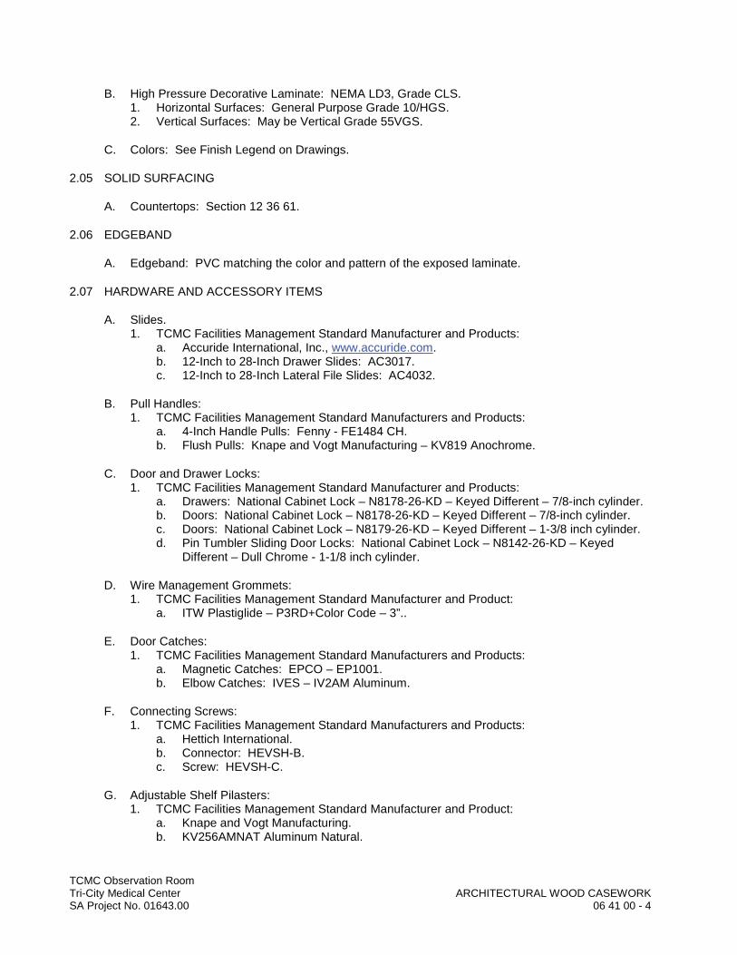
TCMC Observation RoomTri-City Medical Center ARCHITECTURAL WOOD CASEWORKSA Project No. 01643.00 06 41 00 - 4
B. High Pressure Decorative Laminate: NEMA LD3, Grade CLS.1. Horizontal Surfaces: General Purpose Grade 10/HGS.2. Vertical Surfaces: May be Vertical Grade 55VGS.
C. Colors: See Finish Legend on Drawings.
2.05 SOLID SURFACING
A. Countertops: Section 12 36 61.
2.06 EDGEBAND
A. Edgeband: PVC matching the color and pattern of the exposed laminate.
2.07 HARDWARE AND ACCESSORY ITEMS
A. Slides.1. TCMC Facilities Management Standard Manufacturer and Products:
a. Accuride International, Inc., www.accuride.com.b. 12-Inch to 28-Inch Drawer Slides: AC3017.c. 12-Inch to 28-Inch Lateral File Slides: AC4032.
B. Pull Handles:1. TCMC Facilities Management Standard Manufacturers and Products:
a. 4-Inch Handle Pulls: Fenny - FE1484 CH.b. Flush Pulls: Knape and Vogt Manufacturing – KV819 Anochrome.
C. Door and Drawer Locks: 1. TCMC Facilities Management Standard Manufacturer and Products:
a. Drawers: National Cabinet Lock – N8178-26-KD – Keyed Different – 7/8-inch cylinder.b. Doors: National Cabinet Lock – N8178-26-KD – Keyed Different – 7/8-inch cylinder.c. Doors: National Cabinet Lock – N8179-26-KD – Keyed Different – 1-3/8 inch cylinder.d. Pin Tumbler Sliding Door Locks: National Cabinet Lock – N8142-26-KD – Keyed
Different – Dull Chrome - 1-1/8 inch cylinder.
D. Wire Management Grommets: 1. TCMC Facilities Management Standard Manufacturer and Product:
a. ITW Plastiglide – P3RD+Color Code – 3”..
E. Door Catches: 1. TCMC Facilities Management Standard Manufacturers and Products:
a. Magnetic Catches: EPCO – EP1001.b. Elbow Catches: IVES – IV2AM Aluminum.
F. Connecting Screws: 1. TCMC Facilities Management Standard Manufacturers and Products:
a. Hettich International.b. Connector: HEVSH-B.c. Screw: HEVSH-C.
G. Adjustable Shelf Pilasters: 1. TCMC Facilities Management Standard Manufacturer and Product:
a. Knape and Vogt Manufacturing.b. KV256AMNAT Aluminum Natural.
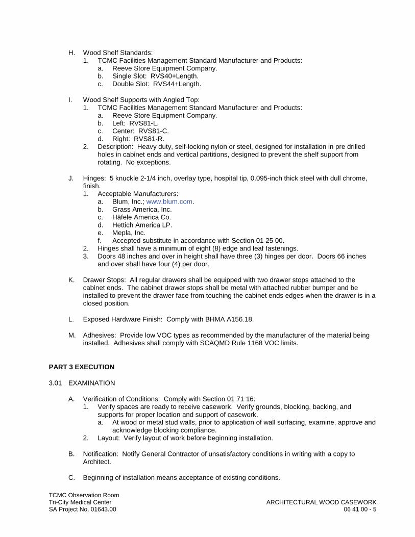
TCMC Observation RoomTri-City Medical Center ARCHITECTURAL WOOD CASEWORKSA Project No. 01643.00 06 41 00 - 5
H. Wood Shelf Standards: 1. TCMC Facilities Management Standard Manufacturer and Products:
a. Reeve Store Equipment Company.b. Single Slot: RVS40+Length.c. Double Slot: RVS44+Length.
I. Wood Shelf Supports with Angled Top: 1. TCMC Facilities Management Standard Manufacturer and Products:
a. Reeve Store Equipment Company.b. Left: RVS81-L.c. Center: RVS81-C.d. Right: RVS81-R.
2. Description: Heavy duty, self-locking nylon or steel, designed for installation in pre drilled holes in cabinet ends and vertical partitions, designed to prevent the shelf support from rotating. No exceptions.
J. Hinges: 5 knuckle 2-1/4 inch, overlay type, hospital tip, 0.095-inch thick steel with dull chrome, finish. 1. Acceptable Manufacturers:
a. Blum, Inc.; www.blum.com.b. Grass America, Inc.c. Häfele America Co.d. Hettich America LP.e. Mepla, Inc.f. Accepted substitute in accordance with Section 01 25 00.
2. Hinges shall have a minimum of eight (8) edge and leaf fastenings. 3. Doors 48 inches and over in height shall have three (3) hinges per door. Doors 66 inches
and over shall have four (4) per door.
K. Drawer Stops: All regular drawers shall be equipped with two drawer stops attached to the cabinet ends. The cabinet drawer stops shall be metal with attached rubber bumper and be installed to prevent the drawer face from touching the cabinet ends edges when the drawer is in aclosed position.
L. Exposed Hardware Finish: Comply with BHMA A156.18.
M. Adhesives: Provide low VOC types as recommended by the manufacturer of the material being installed. Adhesives shall comply with SCAQMD Rule 1168 VOC limits.
PART 3 EXECUTION
3.01 EXAMINATION
A. Verification of Conditions: Comply with Section 01 71 16: 1. Verify spaces are ready to receive casework. Verify grounds, blocking, backing, and
supports for proper location and support of casework.a. At wood or metal stud walls, prior to application of wall surfacing, examine, approve and
acknowledge blocking compliance.2. Layout: Verify layout of work before beginning installation.
B. Notification: Notify General Contractor of unsatisfactory conditions in writing with a copy to Architect.
C. Beginning of installation means acceptance of existing conditions.
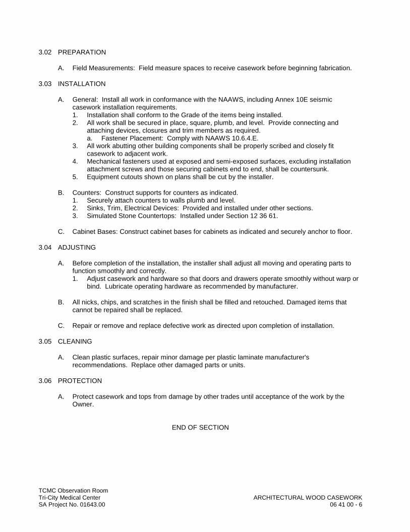
TCMC Observation RoomTri-City Medical Center ARCHITECTURAL WOOD CASEWORKSA Project No. 01643.00 06 41 00 - 6
3.02 PREPARATION
A. Field Measurements: Field measure spaces to receive casework before beginning fabrication.
3.03 INSTALLATION
A. General: Install all work in conformance with the NAAWS, including Annex 10E seismic casework installation requirements.1. Installation shall conform to the Grade of the items being installed.2. All work shall be secured in place, square, plumb, and level. Provide connecting and
attaching devices, closures and trim members as required. a. Fastener Placement: Comply with NAAWS 10.6.4.E.
3. All work abutting other building components shall be properly scribed and closely fit casework to adjacent work.
4. Mechanical fasteners used at exposed and semi-exposed surfaces, excluding installation attachment screws and those securing cabinets end to end, shall be countersunk.
5. Equipment cutouts shown on plans shall be cut by the installer.
B. Counters: Construct supports for counters as indicated. 1. Securely attach counters to walls plumb and level. 2. Sinks, Trim, Electrical Devices: Provided and installed under other sections.3. Simulated Stone Countertops: Installed under Section 12 36 61.
C. Cabinet Bases: Construct cabinet bases for cabinets as indicated and securely anchor to floor.
3.04 ADJUSTING
A. Before completion of the installation, the installer shall adjust all moving and operating parts to function smoothly and correctly.1. Adjust casework and hardware so that doors and drawers operate smoothly without warp or
bind. Lubricate operating hardware as recommended by manufacturer.
B. All nicks, chips, and scratches in the finish shall be filled and retouched. Damaged items that cannot be repaired shall be replaced.
C. Repair or remove and replace defective work as directed upon completion of installation.
3.05 CLEANING
A. Clean plastic surfaces, repair minor damage per plastic laminate manufacturer's recommendations. Replace other damaged parts or units.
3.06 PROTECTION
A. Protect casework and tops from damage by other trades until acceptance of the work by the Owner.
END OF SECTION

DIV
ISIO
N 0
7 –
THER
MA
L A
ND
MO
ISTU
RE
PRO
TEC
TIO
NDDDDDDDDDDDDDDDDDDDDDD
IIIIIIIIIIIIIIIVVVVVVVVVVVVVVVVVVVVVVVVIIIIIIIIIIIIIIIISSSSSSSSSSSSSSSSSSSSSSSS
IIIIIIIIIIIIIIIIIIIOOOOOOOOOOOOOOOOOOOOOOOOOOOOONNNNNNNNNNNNNNNNNNNNN
0000000000000000000000007777777777777777777777
––––––––––––––TTTTTTTTTTTTTTTTHHHHHHHHHHHHHHHHHHHHH
EEEEEEEEEEEEEEEEEEEERRRRRRRRRRRRRRRRRRRRRRRMMMMMMMMMMMMMMMMMMMMMMMM
AAAAAAAAAAAAAAAAAAAAAAALLLLLLLLLLLLLL
AAAAAAAAAAAAAAAAAAAAAAANNNNNNNNNNNNNNNNNNNNNNN
DDDDDDDDDDDDDDDDDDDDDDD MMMMMMMMMMMMMMMMMMMMMMMMM
OOOOOOOOOOOOOOOOOOOOOOOOOOOIIIIIIIIIIIIIIISSSSSSSSSSSSSSSSSSSSSSSSSSS
TTTTTTTTTTTTTTTTUUUUUUUUUUUUUUUUUUUUUUUUURRRRRRRRRRRRRRRRRRRRRR
EEEEEEEEEEEEEEEEEEEE PPPPPPPPPPPPPPPPPPPPPPPPRRRRRRRRRRRRRRRRRRRRRR
OOOOOOOOOOOOOOOOOOOOOOOOOOOOOOTTTTTTTTTTTTTTTTTEEEEEEEEEEEEEEEEEEE
CCCCCCCCCCCCCCCCCCCCCCCCCCCCTTTTTTTTTTTTTTTTTTTTIIIIIIIIIIII
OOOOOOOOOOOOOOOOOOOOOOOOOOOONNNNNNNNNNNNNNNNNNNNNN

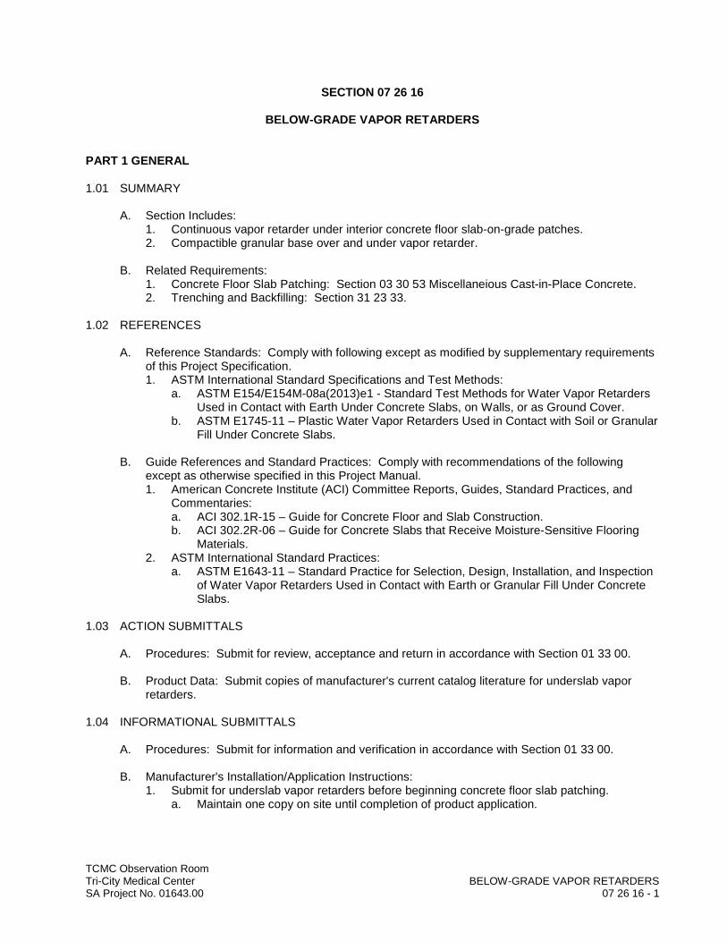
TCMC Observation RoomTri-City Medical Center BELOW-GRADE VAPOR RETARDERSSA Project No. 01643.00 07 26 16 - 1
SECTION 07 26 16
BELOW-GRADE VAPOR RETARDERS
PART 1 GENERAL
1.01 SUMMARY
A. Section Includes:1. Continuous vapor retarder under interior concrete floor slab-on-grade patches.2. Compactible granular base over and under vapor retarder.
B. Related Requirements:1. Concrete Floor Slab Patching: Section 03 30 53 Miscellaneious Cast-in-Place Concrete.2. Trenching and Backfilling: Section 31 23 33.
1.02 REFERENCES
A. Reference Standards: Comply with following except as modified by supplementary requirements of this Project Specification. 1. ASTM International Standard Specifications and Test Methods:
a. ASTM E154/E154M-08a(2013)e1 - Standard Test Methods for Water Vapor Retarders Used in Contact with Earth Under Concrete Slabs, on Walls, or as Ground Cover.
b. ASTM E1745-11 – Plastic Water Vapor Retarders Used in Contact with Soil or Granular Fill Under Concrete Slabs.
B. Guide References and Standard Practices: Comply with recommendations of the following except as otherwise specified in this Project Manual.1. American Concrete Institute (ACI) Committee Reports, Guides, Standard Practices, and
Commentaries:a. ACI 302.1R-15 – Guide for Concrete Floor and Slab Construction.b. ACI 302.2R-06 – Guide for Concrete Slabs that Receive Moisture-Sensitive Flooring
Materials.2. ASTM International Standard Practices:
a. ASTM E1643-11 – Standard Practice for Selection, Design, Installation, and Inspection of Water Vapor Retarders Used in Contact with Earth or Granular Fill Under Concrete Slabs.
1.03 ACTION SUBMITTALS
A. Procedures: Submit for review, acceptance and return in accordance with Section 01 33 00.
B. Product Data: Submit copies of manufacturer's current catalog literature for underslab vapor retarders.
1.04 INFORMATIONAL SUBMITTALS
A. Procedures: Submit for information and verification in accordance with Section 01 33 00.
B. Manufacturer's Installation/Application Instructions: 1. Submit for underslab vapor retarders before beginning concrete floor slab patching.
a. Maintain one copy on site until completion of product application.
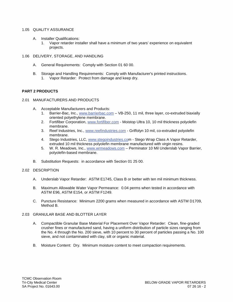
TCMC Observation RoomTri-City Medical Center BELOW-GRADE VAPOR RETARDERSSA Project No. 01643.00 07 26 16 - 2
1.05 QUALITY ASSURANCE
A. Installer Qualifications: 1. Vapor retarder installer shall have a minimum of two years’ experience on equivalent
projects.
1.06 DELIVERY, STORAGE, AND HANDLING
A. General Requirements: Comply with Section 01 60 00.
B. Storage and Handling Requirements: Comply with Manufacturer's printed instructions.1. Vapor Retarder: Protect from damage and keep dry.
PART 2 PRODUCTS
2.01 MANUFACTURERS AND PRODUCTS
A. Acceptable Manufacturers and Products: 1. Barrier-Bac, Inc., www.barrierbac.com – VB-250, 11 mil, three layer, co-extruded biaxially
oriented polyethylene membrane.2. Fortifiber Corporation, www.fortifiber.com - Moistop Ultra 10, 10 mil thickness polyolefin
membrane.3. Reef Industries, Inc., www.reefindustries.com - Griffolyn 10 mil, co-extruded polyolefin
membrane.4. Stego Industries, LLC, www.stegoindustries.com - Stego Wrap Class A Vapor Retarder,
extruded 10 mil thickness polyolefin membrane manufactured with virgin resins.5. W. R. Meadows, Inc., www.wrmeadows.com – Perminator 10 Mil Underslab Vapor Barrier,
polyolefin-based membrane.
B. Substitution Requests: in accordance with Section 01 25 00.
2.02 DESCRIPTION
A. Underslab Vapor Retarder: ASTM E1745, Class B or better with ten mil minimum thickness.
B. Maximum Allowable Water Vapor Permeance: 0.04 perms when tested in accordance with ASTM E96, ASTM E154, or ASTM F1249.
C. Puncture Resistance: Minimum 2200 grams when measured in accordance with ASTM D1709, Method B.
2.03 GRANULAR BASE AND BLOTTER LAYER
A. Compactible Granular Base Material For Placement Over Vapor Retarder: Clean, fine-graded crusher fines or manufactured sand, having a uniform distribution of particle sizes ranging from the No. 4 through the No. 200 sieve, with 10 percent to 30 percent of particles passing a No. 100 sieve, and not contaminated with clay, silt or organic material.
B. Moisture Content: Dry. Minimum moisture content to meet compaction requirements.

TCMC Observation RoomTri-City Medical Center BELOW-GRADE VAPOR RETARDERSSA Project No. 01643.00 07 26 16 - 3
2.04 ACCESSORIES
A. Vapor Retarding Seam Tape: Manufacturer's standard for vapor retarder product used.1. Water Vapor Transmission Rate: ASTM E96, 0.3 perms or lower.2. Color: Contrasting.
B. Vapor Proofing Mastic.1. Water Vapor Transmission Rate: ASTM E96, 0.3 perms or lower.
C. Pipe Boots: Construct pipe boots from vapor barrier material, pressure sensitive tape and/or mastic in accordance with manufacturer’s instructions.
D. Perimeter/Edge Seal: Manufacturer’s standard.
PART 3 EXECUTION
3.01 EXAMINATION
A. Verification of Conditions: 1. Layout: Verify layout of work before beginning installation. 2. Subgrade: Inspect subgrade to verify elevation and compaction requirements.
B. Notification: Notify General Contractor of unsatisfactory conditions in writing with copy to Architect.
C. Acceptance: Beginning of work means acceptance of existing conditions by installer.
3.02 PREPARATION
A. Subgrade Under Slabs and Vapor Retarder: Fine grade to smooth, level surface.1. Place approximately 2 inch thickness of fine-graded granular base material over subgrade.
Roll or compact to provide smooth and level surface without jagged material protruding which could puncture vapor retarder.
3.03 UNDERSLAB VAPOR RETARDER INSTALLATION
A. General: Place vapor retarder under all interior slab on grade patches. 1. Install in accordance with Manufacturer's recommendations and ASTM E1643.2. Use widest practical width of film.3. Install compactible 2-inch granular blotter layer over vapor retarder before placement of
concrete.
B. Laps: Lap new vapor retarder sheet with existing vapor retarder not less than 6 inches around perimeter of all patches. Tape seams in accordance with manufacturer's instructions.1. Place top lap in direction of spreading of compactible granular base.
C. Penetrations: Not allowed except for permanent utilities.1. Carefully fit around service openings. 2. Cut film around pipes and conduit piercing retarder, and apply pressure sensitive tape to
ensure maximum barrier effectiveness.3. Construct pipe boots from vapor retarder material and pressure sensitive tape in accordance
with manufacturer's instructions.
D. Place pipes, conduits, etc. on top of vapor barrier, taking care to prevent film punctures.

TCMC Observation RoomTri-City Medical Center BELOW-GRADE VAPOR RETARDERSSA Project No. 01643.00 07 26 16 - 4
E. Repairs: 1. Repair any damage to film prior to placing granular base. 2. Apply patches of vapor retarder film, lapping damaged area minimum 6 inches and taping all
four sides with manufacturer's tape.
F. Granular Blotter Layer: Immediately prior to placement of concrete, cover vapor barrier with two inch thick uniform compactible granular material. Compact in accordance with requirements of Section 31 23 33 for granular fill under floor slabs. Protect granular layer from excessive moisture beyond minimum required for compaction until concrete is placed.
3.04 SITE QUALITY CONTROL
A. Contractor's Quality Control: The Contractor is responsible for quality control, including workmanship and materials furnished by his subcontractors and suppliers. Contractor shall takeall other reasonable measures necessary to ensure that underslab moisture is controlled, vapor retarder is complete, intact and undamaged prior to concrete placement, water/cement ratio of slab concrete is not exceeded, fresh concrete contains no more water than required for proper placement and cement hydration, and floor slab concrete is properly cured.
END OF SECTION
TCMC Observation RoomTri-City Medical Center FIRESTOPPINGSA Project No. 01643.00 07 84 00 - 1
SECTION 07 84 00
FIRESTOPPING
PART 1 GENERAL
1.01 SUMMARY
A. Section Includes:1. Penetration firestopping, fire-resistant joint sealants, fire safing, and smoke seals as
indicated on the Drawings as well as the following areas:a. All openings in fire-rated floors and walls both empty and those accommodating
penetrating items such as cables, cable trays, conduits, pipes, ducts, etc.
B. Related Requirements:1. Joint Sealants: Section 07 92 00.2. Mechanical and Electrical Work: Divisions 21 through 28.
1.02 REFERENCES
A. Guide References and Standard Practices: Comply with recommendations of the following unless otherwise specified.1. ASTM E2174-14b – Standard Practice for On-Site Inspection of Installed Fire Stops.2. ASTM E2393-10a(2015) – Standard Practice for On-Site Inspection of Installed Fire
Resistive Joint Systems and Perimeter Fire Barriers.3. FCIA Firestop Manual of Practice.
1.03 ACTION SUBMITTALS
A. Procedures: Submit for review, acceptance and return in accordance with Section 01 33 00.
B. Product Data: Submit Manufacturer's printed product data indicating product characteristics, performance and limiting criteria for each product proposed for use.
1.04 INFORMATIONAL SUBMITTALS
A. Procedures: Submit for information and verification in accordance with Section 01 33 00.
B. Installation Instructions: Submit Manufacturer's installation instructions for each type of firestop required by the Project.
1.05 CLOSEOUT SUBMITTALS
A. Procedures: Submit the following in accordance with Section 01 78 00.
B. Documentation: Compile and submit forms identifying products and technical parameters of each firestop installation performed, including manufacturer’s details of the system selected for the application.
1.06 QUALITY ASSURANCE
A. Qualifications:1. Installer Qualifications: Firestopping shall be performed by a contractor trained or approved
by firestop manufacturer.
TCMC Observation RoomTri-City Medical Center FIRESTOPPINGSA Project No. 01643.00 07 84 00 - 2
B. Mock-Up: Prepare job mock-up of each system proposed for use in the Project as directed by Architect. Approved mock-ups may be left in place as part of the finished Project and will constitute the standard for remaining work.
1.07 DELIVERY, STORAGE, AND HANDLING
A. Delivery and Acceptance Requirements: Deliver all materials in original unopened packages fully identified with Manufacturer's name, trade name and UL label.
B. Storage and Handling Requirements: Materials shall be stored off the ground and protected from environmental conditions as required by Manufacturer.
1.08 AMBIENT CONDITIONS
A. Conform to Manufacturer's printed instructions for installation and when applicable, curing in accordance with temperature and humidity. Conform to ventilation and safety requirements.1. Do not install firestopping products when ambient or substrate temperatures are outside
limitations recommended by manufacturer.
B. Do not install firestopping products when substrates are wet due to rain, frost, condensation, or other causes.
1.09 WARRANTY
A. Firestop Installer shall warrant that firestopping systems used meet firestopping requirements as herein specified.
PART 2 PRODUCTS
2.01 MANUFACTURERS AND PRODUCTS
A. Acceptable Firestopping Manufacturers and Systems:1. 3M Fire Protection Products.2. A/D Fire Protection Systems; www.adfire.com, division of the Carboline Company – A/D
Firebarrier,3. Hilti Corporation; www.us.hilti.com - Hilti Firestop Systems.4. Nelson FireStop Products; www.nelsonfirestop.com.5. The RectorSeal Corporation; www.rectorseal.com – Metacaulk Firestopping Products;
www.metacaulk.com..6. Specified Technologies, Inc. (STI); www.stifirestop.com.7. Tremco Fire Protection Systems Group of Tremco Incorporated; www.tremcofirestop.com, -
TREMstop.
B. Basis of Design Fire Safing Manufacturer and Product: Thermafiber, Inc.; www.thermafiber.com -Thermafiber Safing Insulation.1. Size: As required by fire rating and conditions. 2. Accessories; Provide Thermafiber Safing Clips as required.
C. Substitution Requests: In accordance with Section 01 25 00.
2.02 FIRESTOPPING SYSTEMS DESIGN
A. Types of firestop to be used for each condition shall be the responsibility of the installer and shall comply with all specified regulatory requirements.
TCMC Observation RoomTri-City Medical Center FIRESTOPPINGSA Project No. 01643.00 07 84 00 - 3
B. Provide a Flame (F) and Temperature (T) rating of at least one (1) hour but not less than the fire resistance rating of assembly being penetrated, as tested per ASTM E814.
C. Firestop contractor shall immediately notify the Architect if the firestopping systems herein specified cannot meet the requirements of the specification.
2.03 MATERIALS
A. Regulatory Requirements: Firestopping materials proposed for use on this Project shall conform to both Flame (F) and Temperature (T) ratings as tested by nationally accepted test agencies per ASTM E814 or UL 1479 fire tests. The F rating and T rating must be a minimum of one (1) hour but not less than the fire resistance rating of the assembly being penetrated. The fire test shall be conducted with a minimum positive pressure differential of 0.03 inches of water column.
B. General Requirements for Firestopping Materials:1. Materials shall be free of asbestos.2. Firestop materials in exposed areas shall be compatible with specified finishes.3. Materials shall conform to all applicable governing codes.4. All materials shall be compatible with the material penetrating the fire assembly. 5. Provide products that upon curing, do not re-emulsify, dissolve, leach, breakdown or
otherwise deteriorate over time from exposure to atmospheric moisture, sweating pipes, ponding water or other forms of moisture characteristic during and after construction.
6. Provide firestop sealants sufficiently flexible to accommodate motion such as pipe vibration, water hammer, thermal expansion and other normal building movement without damage to the seal.
7. Pipe insulation shall not be removed, cut away or otherwise interrupted through wall or floor openings. Provide products appropriately tested for the thickness and type of insulation utilized.
8. Use sealants that comply with the limits for VOC content according to SCAQMD Rule #1168:a. Sealants: 250 g/L.b. Sealant Primers for Nonporous Substrates: 250 g/L.c. Sealant Primers for Porous Substrates: 775 g/L.
2.04 ACCESSORIES
A. Furnish all accessory materials such as fire safing batts, sleeves, sheet metal, sealants, etc.necessary to complete fire stopping systems unless furnished by others.
PART 3 EXECUTION
3.01 EXAMINATION
A. Verification of Existing Conditions: Contractor shall inspect and verify that the surface and condition of the substrates and all sleeves or blockouts furnished by others have no defects or errors that would interfere with the installation of the firestopping materials.
B. Notification: Notify Architect in writing of any defects or errors in workmanship. Do not proceed with work until all unsatisfactory conditions have been corrected.
C. Acceptance: Start of installation of firestopping shall constitute the Contractor's acceptance of surfaces and conditions of substrates, sleeves and blockouts.
TCMC Observation RoomTri-City Medical Center FIRESTOPPINGSA Project No. 01643.00 07 84 00 - 4
3.02 PREPARATION
A. Clean surfaces and substrates of dirt, oil, loose materials and other foreign materials that may affect the proper bond or installation of the firestops in strict accordance with Manufacturer's written instructions.
B. Provide primers as required which conform to Manufacturer's recommendations for various substrates and conditions.
C. Do not apply firestops to surfaces previously painted or treated with a sealer, curing compound, water repellant or other coating unless tests have been performed to ensure compatibility of materials. Remove coatings as required in compliance with Manufacturer's instructions.
D. Mask where necessary to protect adjoining surfaces.
3.03 INSTALLATION
A. Install in strict accordance with Manufacturer's printed instructions to provide a Flame (F) and Temperature (T) rating of at least one (1) hour but not less than the fire resistance rating of the assembly being penetrated.1. Equipment used shall be in accordance with firestop manufacturer's written installation
instructions.
B. Ensure that all accessories such as anchoring devices, back-up materials, clips, sleeves, supports and other materials used in the actual fire test are installed.
C. Install firestops with sufficient pressure to properly fill and seal openings to ensure an effectivesmokeseal.
D. Tool or trowel exposed surfaces. Remove excess firestop material promptly as work progresses and upon completion.
E. Following each installation, apply a label on or adjacent to each penetration firestop and at regular intervals along each fire-resistive joint sealant application. Label shall identify and document firestopping system installed in accordance with FCIA Firestop Manual of Practice.
3.04 SITE QUALITY CONTROL
A. Firestop contractor shall examine completed firestops to ensure proper installation and full compliance with this specification.
B. All areas of work must be accessible until inspection by the applicable code authorities.
3.05 ADJUSTMENT
A. Correct unacceptable firestops and provide additional inspection to verify compliance with this specification at no additional cost.
3.06 CLEANING
A. When finished work will be visible, clean adjacent surfaces in accordance with Manufacturer's printed instructions. Remove excess material and stains on surfaces as required.
B. If visible in the finished work, remove temporary dams after initial cure of firestops.
TCMC Observation RoomTri-City Medical Center FIRESTOPPINGSA Project No. 01643.00 07 84 00 - 5
C. Correct staining and discoloring on adjacent surfaces.
D. Remove all debris and excess materials entirely from site and leave work in a neat and clean condition.
END OF SECTION

TCMC Observation RoomTri-City Medical Center JOINT SEALANTSSA Project No. 01643.00 07 92 00 - 1
SECTION 07 92 00
JOINT SEALANTS
PART 1 GENERAL
1.01 SUMMARY
A. Work Results: Providing all caulking and sealant indicated on Drawings, specified herein, and not specified under other sections. In general, seal all openings indicated on Drawings and at other locations requiring sealant to seal visually and against infiltration from air and water, or to provide acoustical isolation, including but not limited to following:1. Joints at penetrations of non-fire rated walls, decks and floors by piping and other service
and equipment.2. Joints between items of equipment and other construction. 3. Joints between door frames and adjacent materials.4. Open joints between similar or dissimilar materials as required to close and conceal jointing
of the work.5. Joints at sound-insulated partitions.6. Other joints as indicated.
B. Related Requirements:1. Firestopping: Section 07 84 00.2. Glazing Sealants: Section 08 84 00 Plastic Glazing.
1.02 ADMINISTRATIVE REQUIREMENTS
A. Coordination:1. Coordinate installation of sealants with other construction trades.
1.03 ACTION SUBMITTALS
A. Procedures: Submit for review, acceptance and return in accordance with Section 01 33 00.
B. Product Data: Submit for each material and location of application.
C. Samples: Submit for each type of sealant for color selection.
1.04 CLOSEOUT SUBMITTALS
A. Warranty: Submit in accordance with Section 01 78 36.
1.05 QUALITY ASSURANCE
A. Qualifications:1. Installer: Company specializing in sealant application. Separate subcontractor is required.
a. Experience: Continuously installed sealants in State of California for five years.2. Manufacturer's Technical Representative: Obtain materials only from manufacturers who
will, if required, send qualified technical representative to Project site, for purpose of advising installer of proper procedures and precautions for use of materials.
B. Certifications:1. Elastomeric Sealants: Listed by SWRI on SWR Institute Validation Program Validated
Products List; www.swrionline.org.

TCMC Observation RoomTri-City Medical Center JOINT SEALANTSSA Project No. 01643.00 07 92 00 - 2
1.06 DELIVERY, STORAGE, AND HANDLING
A. General Requirements: Comply with Section 01 60 00.1. Protect materials from excessive moisture in shipment, storage, and handling.
B. Delivery and Acceptance Requirements: Deliver materials to site in manufacturer's original, unopened containers and packaging, with labels clearly identifying material name and manufacturer, production date and/or product code.
C. Storage and Handling Requirements:1. Storage: Store materials in a clean, dry area not subject to extreme heat or cold in
accordance with manufacturer's instructions.2. Handling: Protect materials during handling and installation to prevent damage.
1.07 AMBIENT CONDITIONS
A. Do not apply exterior sealants during wet weather or when outside temperature is below 40 degrees F or apply interior sealants when inside temperature is below 60 degrees F.
1.08 WARRANTY
A. Warranty: Provide three year written warranty covering materials and installation for sealants in accordance with Section 01 78 00. 1. Warranty: Require installer, at no cost to Owner, to repair or replace sealants which fail to
perform as airtight and watertight joints; or fail in joint adhesion, cohesion, abrasion resistance, weather resistance, extrusion resistance, migration resistance, stain resistance, color retention, or general durability; or appear to deteriorate in any manner not clearly specified as inherent quality of material by submitted manufacturer's data.
PART 2 PRODUCTS
2.01 PRODUCT OPTIONS
A. Substitution Requests: Required for all manufacturers and products not named as Acceptable or as Basis of Design, excepting types for which no manufacturer is named.1. Submit in accordance with Section 01 25 00.
2.02 MATERIALS, GENERAL
A. Low-Emitting Material Requirements: Use sealants that comply with the following limits for VOC content when calculated according to SCAQMD Rule #1168:1. Sealants: 250 g/L.2. Sealant Primers for Nonporous Substrates: 250 g/L.3. Sealant Primers for Porous Substrates: 775 g/L.
2.03 LATEX JOINT SEALANTS
A. Interior Caulk and Sealants for Under Thresholds and Non-Moving Joints: Acrylic latex, ASTM C834-10.
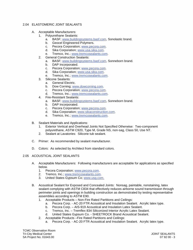
TCMC Observation RoomTri-City Medical Center JOINT SEALANTSSA Project No. 01643.00 07 92 00 - 3
2.04 ELASTOMERIC JOINT SEALANTS
A. Acceptable Manufacturers:1. Polyurethane Sealants:
a. BASF; www.buildingsystems.basf.com, Sonolastic brand. b. Geocel Engineered Polymers.c. Pecora Corporation; www.pecora.com.d. Sika Corporation; www.usa.sika.com.e. Tremco, Inc.; www.tremcosealants.com.
2. General Construction Sealants:a. BASF; www.buildingsystems.basf.com, Sonneborn brand. b. DAP Incorporated.c. Pecora Corporation; www.pecora.com.d. Sika Corporation; www.usa.sika.com.e. Tremco, Inc.; www.tremcosealants.com.
3. Silicone Sealants:a. General Electric.b. Dow Corning; www.dowcorning.com.c. Pecora Corporation; www.pecora.com.d. Tremco, Inc.; www.tremcosealants.com.
4. Fire-Resistant Sealants:a. BASF; www.buildingsystems.basf.com, Sonneborn brand. b. DAP Incorporated.c. Pecora Corporation; www.pecora.com.d. Sika Corporation; www.sikaconstruction.com.e. Tremco, Inc.; www.tremcosealants.com.
B. Sealant Materials and Applications:1. Exterior Vertical and Overhead Joints Not Specified Otherwise: Two-component
polyurethane, ASTM C920, Type M, Grade NS, non-sag, Class 50, Use NT.2. Sealant at Lavatories: Silicone tub sealant.
C. Primer: As recommended by sealant manufacturer.
D. Colors: As selected by Architect from standard colors.
2.05 ACOUSTICAL JOINT SEALANTS
A. Acceptable Manufacturers: Following manufacturers are acceptable for applications as specified below.1. Pecora Corporation; www.pecora.com.2. Tremco, Inc.; www.tremcosealants.com.3. United States Gypsum Co; www.usg.com.
B. Acoustical Sealant for Exposed and Concealed Joints: Nonsag, paintable, nonstaining, latex sealant complying with ASTM C834 that effectively reduces airborne sound transmission through perimeter joints and openings in building construction as demonstrated by testing representative assemblies according to ASTM E90.1. Acceptable Products – Non-Fire Rated Partitions and Ceilings:
a. Pecora Corp. - AC-20 FTR Acoustical and Insulation Sealant. Acrylic latex type.b. Pecora Corp. – AIS-919 Acoustical and Insulation Latex Sealant.c. Tremco, Inc. – Tremflex 834 Siliconized Interior Acrylic Latex Sealant.d. United States Gypsum Co. - SHEETROCK Brand Acoustical Sealant.
2. Acceptable Products –Fire Rated Partitions and Ceilings:a. Pecora Corp. - AC-20 FTR Acoustical and Insulation Sealant. Acrylic latex type.
TCMC Observation RoomTri-City Medical Center JOINT SEALANTSSA Project No. 01643.00 07 92 00 - 4
C. Acoustical Sealant for Concealed Joints: Nondrying, nonhardening, nonskinning, nonstaining, gunnable, synthetic-rubber sealant recommended for sealing interior concealed joints to reduce airborne sound transmission.1. Acceptable Products:
a. Tremco, Inc. - Tremco Acoustical Sealant.
2.06 NON-RATED JOINT BACKING MATERIAL
A. Acceptable Manufacturers:1. BASF; www.buildingsystems.basf.com – Sonolastic.2. Backer Rod Manufacturing Inc.; www.backerrod.com - Denver Foam.3. Dow Chemical Company - Ethafoam.
B. Material: Closed cell polyethylene foam.
C. Shape: Round rod or semi-circular type.
D. Size joint backing material for minimum 30 percent compression when inserted in joint.
2.07 FIRE-RATED JOINT BACKING MATERIAL
A. Acceptable Manufacturers and Products: 1. Backer Rod Mfg. Inc., Denver, Colorado - Ultra Block.
B. Size: As required for joint width.
2.08 BOND BREAKER TAPE
A. Tape: Polyethylene tape or other plastic tape as recommended by sealant manufacturer to be applied to sealant-contact surfaces where bond to substrate or joint filler must be avoided for proper performance of sealant. Provide self-adhesive tape wherever applicable.
PART 3 EXECUTION
3.01 EXAMINATION
A. Verification of Conditions: Comply with Section 01 71 16:1. Inspect joints to be sealed to application of any work under this section.
B. Notification: Notify General Contractor of any joints which cannot be put into proper condition to receive sealants in writing with copy to Architect.
C. Acceptance: Beginning of work means acceptance of existing conditions by installer.
3.02 PREPARATION
A. Preparation of Surfaces:1. Clean surfaces in accordance with manufacturer's recommendations. 2. Mask edges, if required, to protect adjoining surfaces and produce a straight finish line.3. Clean joint surfaces immediately before installation of sealant. Remove dirt, insecure
coatings, moisture and other substances that would interfere with bond of sealant.4. Do not proceed with installation of sealant over joint surfaces that have been painted,
lacquered, waterproofed or treated with water repellent or other treatment of coating. Remove coating or treatment joint surfaces before installing sealant.

TCMC Observation RoomTri-City Medical Center JOINT SEALANTSSA Project No. 01643.00 07 92 00 - 5
B. Priming: If required, prime surfaces which are to be sealed with manufacturer's recommended orstandard primer, after surfaces have been prepared as specified. Before use, check primers for discoloration and dirt pick-up on adjacent surfaces. If staining occurs, after exposure, take adequate measures to prevent primer from being applied over face of adjacent porous materials by masking or other suitable measures.
C. Joint Backing:1. Joints: Depth necessary to provide for specified allowable thickness of sealant and also
required backing where and as specified. Provide backing of extent and type as specified and required to provide for allowable depth of sealant.
2. Back-up Materials for Sealants: Non-staining, compatible with sealant and primer. resilient nature, and as recommended by manufacturer of sealant.a. Size and Shape: As required by width of joint and specified.b. Do not use materials impregnated with oil, solvents or bituminous materials.
3. Compress backing material minimum of 30 percent when inserted in joint. Backing material for upper portion of joints shall be round rod or semi-circular in cross-section where in contact with sealant.
D. Bond Breaker Tape: Install where indicated and as required by manufacturer's recommendations to ensure that sealants will deform properly.
3.03 APPLICATION
A. Joint Sealing, General:1. Apply sealants in continuous beads without open joints, voids or air pockets, using ratchet
hand gun or mechanical powered gun.2. Confine sealants to joint areas with masking tapes or other precautions. Apply compounds
in concealed compression joints accurately so that excess compound will not extrude from joints.
3. Remove excess compound or sealant promptly as work progresses, and clean adjoining surfaces.
4. In rough surfaces or joints of uneven widths, install sealant well back into joint. Recess equal to width of joint, or 3/8-inch minimum at masonry.
5. Use anti-tack agent where necessary to protect freshly applied sealant from public traffic and dirt.
6. Slightly recess joints to facilitate painter's line. Handtool and finish joints throughout construction.
7. Comply with manufacturer's specifications and recommendations.
B. Workmanship: Employ only proven installation techniques, which will ensure that sealants will be deposited in uniform, continuous ribbons without gaps or air pockets, with complete "wetting" of joint bond surfaces equally on opposite sides.1. Except as otherwise indicated, fill sealant rabbet to slightly concave surface, slightly below
adjoining surfaces.2. Where horizontal joints are between horizontal surface and vertical surface, fill joint to form
slight cove, so that joint will not trap moisture and dirt.
C. Joint Sizes: Install sealants to depths as indicated or, as recommended by sealant manufacturer but within following general limitations:1. For normal moving joints sealed with elastomeric sealants but not subject to traffic, fill joints
to depth equal to 50 percent of joint width, but not more than 1/2-inch deep or less than 1/4-inch deep.
2. For joints sealed with non-elastomeric sealants and calking compounds. fill joints to depth in range of 75 percent to 125 percent of joint width.

TCMC Observation RoomTri-City Medical Center JOINT SEALANTSSA Project No. 01643.00 07 92 00 - 6
D. Spillage:1. Do not allow sealants or compounds to overflow or spill onto adjoining surfaces, or to
migrate into voids of adjoining surfaces. Use masking tape or other precautionary devices to prevent staining of adjoining surfaces, by either primer/sealer or sealant.
2. Remove excess and spillage of compounds promptly as work progresses. Clean adjoining surfaces by whatever means may be necessary to eliminate evidence of spillage. Do not damage adjoining surfaces or finishes.
E. Sinks, Lavatories and Showers: Fill joints between dissimilar materials with silicone sealant.
3.04 ACOUSTICAL SEALANT APPLICATION
A. Comply with manufacturer’s instructions for particular conditions of installation in each case.
B. Install materials to comply with sound control requirements noted on Drawings.
C. Use a caulking-type gun, apply ¼-inch minimum round bead of sealant (1/2-inch maximum) to seal perimeter of each sound-insulated partition.
D. Seal sound-insulated partitions on both sides where facings abut dissimilar materials; around perimeter, in the angle formed by panels and abutting dissimilar materials; at all intersections; at all panel terminations in door and window frames; and at control joint locations before attaching the control joint to the panels. Apply continuous beads of sealant around all openings formed for outlets, lights, etc. Completely butter the outside of electrical boxes.1. Caulk ductwork penetrations.
E. Cut gypsum panels with 1/8-inch maximum relief at perimeter to receive sealant. Install before sealant skins.
3.05 CURING
A. Cure sealants and caulking compounds in compliance with manufacturer's instructions and recommendations, to obtain high early bond strength, internal cohesive strength and surface durability.
3.06 SITE QUALITY CONTROL
A. Field Samples: Where directed by Architect, cut out and remove total of three samples consisting of undisturbed sealant and back-up material from joint. Samples shall be 6 inches in length. Reseal cut out areas with same materials.
3.07 CLEANING
A. Clean soiled surfaces immediately.
B. Replace any damaged material that cannot be cleaned with new material.
3.08 PROTECTION
A. Advise General Contractor of procedures required for protection of sealants during construction period, so that they will be without deterioration or damage (other than normal weathering) at time of acceptance.
END OF SECTION

DIV
ISIO
N 0
8–
OPE
NIN
GS
DDDDDDDDDDDDDDDDDDDDDDIIIIIIIIIIIIIIIVVVVVVVVVVVVVVVVVVVVVVVV
IIIIIIIIIIIIIIIISSSSSSSSSSSSSSSSSSSSSSSSIIIIIIIIIIIIIIIIIIOOOOOOOOOOOOOOOOOOOOOOOOOOOOOO
NNNNNNNNNNNNNNNNNNNNN 000000000000000000000000
88888888888888888888888888888–––––––––––––
OOOOOOOOOOOOOOOOOOOOOOOOPPPPPPPPPPPPPPPPPPPPPPPEEEEEEEEEEEEEEEEEEEE
NNNNNNNNNNNNNNNNNNNNNIIIIIIIIIIIIIIINNNNNNNNNNNNNNNNNNNNNNN
GGGGGGGGGGGGGGGGGGGGGGGGGGGGGGGSSSSSSSSSSSSSSSSSSSSSSSSSSS


TCMC Observation RoomTri-City Medical Center HOLLOW METAL DOORS AND FRAMESSA Project No. 01643.00 08 11 13 - 1
SECTION 08 11 13
HOLLOW METAL DOORS AND FRAMES
PART 1 GENERAL
1.01 SUMMARY
A. Section Includes:1. Flush hollow metal doors.2. Hollow metal door frames.3. Hollow metal window frames.
B. Related Requirements:1. Access Panels: Section 08 31 00 Access Doors and Panels.2. Hardware including Thresholds and Weatherstripping: Section 08 71 00 Door Hardware.3. Plastic Glazing: Section 08 84 00.
1.02 REFERENCES
A. General Requirements: Refer to Section 01 42 00.
B. Reference Standards: Comply with the following except as otherwise specified in this Project Manual. 1. American National Standards Institute (ANSI):
a. ANSI A115 - Specifications for Door and Frame Preparation for Hardware.2. National Fire Protection Association (NFPA):
a. NFPA 80 - Standard for Fire Doors and Other Opening Protectives, 2016 Edition.
C. Guide References and Standard Practices: Comply with recommendations of the following except as otherwise specified in this Project Manual.1. Hollow Metal Manufacturers Association (HMMA), a division of the National Association of
Architectural Metal Manufacturers (NAAMM):a. ANSI/HMMA 840-07 –Installation and Storage of Hollow Metal Doors and Frames.b. ANSI/NAAMM HMMA 861-14 – Guide Specifications for Commercial Hollow Metal
Doors and Frames.
1.03 COORDINATION
A. Templates: Hardware templates for hardware mounted on hollow metal work shall be submitted under Section 08 71 00 directly to hollow metal manufacturer immediately after acceptance of hardware schedule. Report failure to receive templates with reasonable promptness to General Contractor.
1.04 ACTION SUBMITTALS
A. Procedures: Submit for review, acceptance and return in accordance with Section 01 33 00.
B. Shop Drawings: Submit drawings indicating dimensions, layout and anchorage details of all hollow metal frames.
TCMC Observation RoomTri-City Medical Center HOLLOW METAL DOORS AND FRAMESSA Project No. 01643.00 08 11 13 - 2
1.05 CLOSEOUT SUBMITTALS
A. Submit the following in accordance with Section 01 77 00.1. Fire Door and Frame Assemblies: Submit documentation for Owner’s records of initial
inspection and approval of fire door assemblies by inspector for authority having jurisdiction.
1.06 DELIVERY, STORAGE, AND HANDLING
A. General Requirements: Comply with Section 01 60 00 and with Manufacturer’s recommendations.
B. Storage and Handling Requirements: 1. Store frames in manner to prevent twisting.2. Doors with dimples or dents will be rejected.
PART 2 PRODUCTS
2.01 REGULATORY REQUIREMENTS
A. Fire Rating: Provide fire rating label acceptable to local building code authority on doors and frames indicated on the door schedule. If any door or frame scheduled to be fire-rated cannot qualify for appropriate labeling because of its design, hardware or any other reason, advise Architect prior to submission of bids.
2.02 HOLLOW METAL FRAMES
A. General: Frames for hollow metal and wood doors, entrances, windows and borrowed lights, etc. indicated to be hollow metal shall be of design sections as detailed and assembled as indicated.
B. Gages:1. Frames on Interior Walls: 16 gage steel.2. Loose Glazing Beads: Not less than 20 gage steel, corners butted.
C. Construction: Construct frames encompassing one or more doors with sidelights or transoms, and steel window walls, etc., in rigid units of as large size as practical to reduce to minimum number of job-fabricated joints.1. Joints and Connections Including Job-Fabricated Joints: Welded and ground and entire
assembly reinforced and braced as required to ensure absolute rigidity.2. Provide expansion joints as indicated or required.3. Where so indicated or as required, provide channel stiffening within and securely welded to
frame member.4. Do not used exposed screws except where specifically accepted.
D. Accessories:1. Reinforcement for Hardware: Machine frames for attachment of hardware, including
mortising, reinforcing, drilling and tapping for hinges.a. Butt Hinges: Seven gage, 12 inches long.b. Closers: 10 gage, 12 inches long, full width of frame or equivalent.c. Strikes, Flush Bolts and Other Surface Mounted Hardware: 12 gage or equivalent.
2. Anchors: Furnish anchors of type and number required for anchoring frames to structure, partitions, etc. as follows: a. Three jamb anchors on seven foot high jamb.b. Four jamb anchors on jambs over seven feet.

TCMC Observation RoomTri-City Medical Center HOLLOW METAL DOORS AND FRAMESSA Project No. 01643.00 08 11 13 - 3
Wire anchors will not be allowed. Provide such installation instructions as are necessary to ensure proper installation of anchors.
3. Silencers: Drill stop of lock jamb of each interior frame for installation of pneumatic rubber door silencers. Silencers shall be furnished under Section 08 71 00, numbers as indicated on schedule.
4. Joints: Conceal welded joints in two-sided mullions or similar sections behind glazing stops. Continuous weld and grind smooth exposed joints.
5. Glazing Stops: Provide removable metal stops, screwed to frame, at borrowed lights and window walls. See Section 08 84 00 for glazing clearance requirements.a. Unless indicated otherwise, glazing stops shall be 5/8-inch x 3/4-inch or 3/4-inch x 3/4-
inch cold-rolled channel, shaped as required or detailed and hand fitted to each opening.
b. Butt Joints: Square and true and tightly fitted.c. Fasten to frame with metal screws 18 inches on center, flathead, countersunk. Do not
over-tighten to cause indentations or puckering at screws. Use vandalproof screws at exterior stops.
E. Hinges: Install mortar protection box behind each hinge cut.
2.03 HOLLOW METAL DOORS
A. General: Doors indicated to be hollow metal shall be hollow metal, flush, swing type doors of types indicated.
B. Construction: Construct hollow metal doors from 16 gage steel, fully welded, ground smooth and completely sound and fire insulated. Provide thermal insulation in exterior doors. Manufacture hollow metal doors and panels with flush tops, sides and bottoms. Plastic inserts are not acceptable. All vertical seams shall be fully welded. Lock seams or epoxy filled seams are not acceptable.
C. Labels: Provide fire rated construction and UL labels where listed in door schedule.
D. Hardware: Mortise and reinforce doors to receive hardware. 1. Hinges: Seven gage steel plate, 9-inches, welded to continuous 16 gage interior edge
channels or equivalent. Drill and tap. Use of coined or extruded holes not acceptable.2. Locks, Latches, Push/Pulls and Panic Devices: 12 gage steel spot welded to 16 gage
interior edge channels or equivalent and designed to provide adequate support and reinforcement for required hardware.
3. Closers: Not less than 12 gage internal reinforcement. Provide special attention to reinforcing doors where closers are to be bolted through door.
E. Insulation: Foam or batt type. Honeycomb core is not acceptable.
F. Vision Lite Systems: Manufacturer's standard kits consisting of glass lite moldings to accommodate thickness and size of vision lite indicated.
2.04 FINISH
A. Cleaning and Primer:1. Thoroughly clean surfaces of grease, rust and scale to insure paint adherence. Apply filler
to doors where required to produce a smooth surface.2. Apply one coat of baked-on factory primer.
TCMC Observation RoomTri-City Medical Center HOLLOW METAL DOORS AND FRAMESSA Project No. 01643.00 08 11 13 - 4
PART 3 EXECUTION
3.01 INSTALLATION
A. Frames:1. Set steel frames accurately in accordance with details, straight and free of twist with head
level and jambs plumb. Rigidly anchor to walls and partitions and securely brace until surrounding work is completed. Provide deflection clearances at frame heads where indicated.
2. Field Welds: Make welds full length of joints. Remove splatter and grind exposed welds to match adjacent surfaces. Provide Architect with ample notice to review welds before finish operations begin.
3. Wherever possible leave spreader bars in place until frames are securely anchored.4. Jambs shall be filled with grout where frames occur in concrete or masonry walls.5. Provide special masonry anchorage devices where required for securing hollow metal
frames to in-place masonry construction. Set anchorage devices, opposite each anchor location in accordance with details on accepted shop drawings and anchorage device manufacturer's recommendations.
B. Doors: Apply hardware in conformance with hardware manufacturer's templates and instructions. Hang doors to be free of binding with hardware functioning properly.1. Clearance Tolerances:
a. Head: 1/8-inch maximum.b. Jamb: 1/8-inch maximum.c. Between Doors (Pair): 1/8-inch maximum.d. Sill without Threshold: 1/2-inch maximum.
C. Fire-Rated Door and Frame Assemblies: Install in compliance with NFPA 80. 1. Install with door clearances within limits listed in NFPA 80.2. Make no field modifications to door assembly that void the label.
D. Miscellaneous Items: Install closures, panels, fillers, etc. as indicated.
3.02 ADJUSTING
A. At completion of job, adjust doors and hardware as required and leave in proper operating condition. Adjust doors to freely swing, completely close, and positively latch.
END OF SECTION

TCMC Observation RoomTri-City Medical Center ACCESS DOORS AND PANELSSA Project No. 01643.00 08 31 00 - 1
SECTION 08 31 00
ACCESS DOORS AND PANELS
PART 1 GENERAL
1.01 SUMMARY
A. Section Includes:1. Access doors into ceiling spaces.2. Access doors into pipe and utility spaces.
B. Related Requirements:1. Furnishing Access Doors as Specified in This Section for Plumbing Equipment: Division 22
Plumbing.2. Furnishing Access Doors as Specified in This Section for Mechanical Equipment: Division
23 Heating, Ventilating, and Air Conditioning (HVAC).3. Furnishing Access Doors as Specified in This Section for Electrical Equipment: Division 26
Electrical.4. Openings for Access Doors and Finishing After Installation: Applicable sections.
1.02 ACTION SUBMITTALS
A. Procedures: Submit for review, acceptance and return in accordance with Section 01 33 00.
B. Product Data: Manufacturer's current product data sheets describing products to be supplied with all selected options clearly identified, basic uses, components, materials, physical properties, precautions and limitations, applicable standards, approvals, and general installation procedures.
C. Shop Drawings: Submit layout plan.
1.03 DELIVERY, STORAGE, AND HANDLING
A. General Requirements: Comply with Section 01 60 00.
B. Delivery and Acceptance Requirements: 1. Deliver materials in original packages bearing brand name and identification of
manufacturer.
B. Storage and Handling Requirements:1. Store doors, frames and panels under cover and in manner to prevent twisting. 2. Doors and panels with dimples or dents will be rejected.
PART 2 PRODUCTS
2.01 FLUSH-MOUNTED, NON-RATED ACCESS DOORS
A. Acceptable Manufacturers and Products - Flush-Mounted, Non-Rated Access Doors for Installation in Masonry, Tile, Concrete, or Gypsum Drywall:1. Acudor Products, Inc.; www.acudor.com - Model UF-5000.2. J.L. Industries; www.jlindustries.com - Model TM.3. Karp Associates, Inc.; www.karpinc.com.- Model DSC-214M.4. Milcor; www.milcorinc.com - Style M.

TCMC Observation RoomTri-City Medical Center ACCESS DOORS AND PANELSSA Project No. 01643.00 08 31 00 - 2
5. Nystrom Building Products; www.nystrom.com - Model NT.6. Williams Brothers Corporation of America; www.wbdoors.com – WB Series.7. Substitution Requests: In accordance with Section 01 25 00.
B. Sizes: As indicated on Drawings or as required to properly service mechanical or electrical equipment.
C. Material: Stainless steel.
D. Finish:1. Stainless Steel: No. 4 satin finish.
E. Locking Devices: Key operated cam locks.
2.02 RECESSED ACCESS DOORS
A. Acceptable Manufacturers and Products - Non-Rated Access Doors, Recessed for Cladding with Gypsum Drywall Panel, for Installation in Non-Rated Gypsum Board Walls and Ceilings:1. Acudor Products, Inc.; www.acudor.com - Model DW-5015.2. Karp Associates, Inc.; www.karpinc.com - Model RDW.3. Nystrom Building Products; www.nystrom.com - Model RW.4. Williams Brothers Corporation of America; www.wbdoors.com - WB-RDW.5. Substitution Requests: In accordance with Section 01 25 00.
B. Acceptable Manufacturers and Products - Non-Rated Access Doors, Recessed for Installation of Acoustical Ceiling Tile:1. Acudor Products, Inc.; www.acudor.com - Model AT-5020.2. Karp Associates, Inc.; www.karpinc.com - Model DSC-210.3. Milcor; www.milcorinc.com - Style CT.4. Nystrom Building Products; www.nystrom.com - Model RA.5. Williams Brothers Corporation of America; www.wbdoors.com - WB-AT.6. Substitution Requests: In accordance with Section 01 25 00.
C. Sizes: As indicated on Drawings or as required to properly service mechanical or electrical equipment.
D. Material: Stainless steel.
E. Finish:1. Stainless Steel: No. 4 satin finish.
F. Locking Devices: Key operated cam locks.
2.03 FIRE-RATED ACCESS DOORS
A. Acceptable Manufacturers and Products – Flush-Mounted Fire-Rated Access Doors:1. Acudor Products, Inc.; www.acudor.com - Model FB-5050.2. Karp Associates, Inc.; www.karpinc.com – Model KRP-150 FR.3. J.L. Industries; www.jlindustries.com- Model FD.4. Milcor; www.milcorinc.com – Style UFR.5. Nystrom Building Products; www.nystrom.com – Model IT.6. Williams Brothers Corporation of America; www.wbdoors.com – Model WB-FR.7. Substitution Requests: In accordance with Section 01 25 00.
TCMC Observation RoomTri-City Medical Center ACCESS DOORS AND PANELSSA Project No. 01643.00 08 31 00 - 3
B. Fire Rating: 1. Provide fire rating label acceptable to local building code authority on access doors to be
installed in fire rated walls and ceilings.2. Walls: 1-1/2 hour UL “B” label.3. Ceilings: Approved by UL or Warnock Hersey International for 20 minutes.
C. Sizes: As indicated on Drawings or as required to properly service mechanical or electrical equipment, but not larger than limit for required fire rating.
D. Material: Stainless steel.
E. Finish:1. Stainless Steel: No. 4 satin finish.
F. Locking Devices: Key operated cam locks.
PART 3 EXECUTION
3.01 INSTALLATION
A. Access Doors:1. Mechanical or Electrical Access: Access doors required for access to mechanical or
electrical equipment shall be provided under Division 22, Division 23, or Division 26 and installed by the trade responsible for the material in which door is located.
2. General Access: Furnish access door indicated on Drawings for general access to be installed by trade responsible for material in which door is located.
3. Type:a. Installation in Non-Rated Walls and Ceilings:
1) In Janitor Rooms, Mechanical and Electrical Rooms, and Other Rooms Generally Accessible to Staff Personnel Only: Flush-mounted, non-rated.
2) Areas and Rooms Accessible to Public: Recessed type, unless flush-mounted is specifically approved by Architect.
b. Installation in Fire-Rated Walls and Ceilings: Fire-rated type.1) Fire Rated Floor/Ceiling Assemblies: Fire-resistive access door with double layer
of gypsum board acceptable provided finished door retains fire rating of floor/ceiling assembly.
END OF SECTION

TCMC Observation RoomTri-City Medical Center DOOR HARDWARESA Project No. 01643.00 08 71 00 - 1
SECTION 08 71 00
DOOR HARDWARE
PART 1 - GENERAL
1.1 SUMMARY
A. Section includes:
1. Mechanical and electrified door hardware for:
a. Swinging doors.
B. Exclusions: Unless specifically listed in hardware sets, hardware is not specified in this section for:
1. Windows2. Cabinets (casework), including locks in cabinets3. Signage4. Toilet accessories5. Overhead doors
C. Related Sections:
1. Division 01 Section “Alternates” for alternates affecting this section.2. Division 07 Section “Joint Sealants” for sealant requirements applicable to threshold
installation specified in this section.3. Division 26 sections for connections to electrical power system and for low-voltage wiring.4. Division 28 sections for coordination with other components of electronic access control
system.
1.2 REFERENCES
A. UL - Underwriters Laboratories
1. UL 10B - Fire Test of Door Assemblies2. UL 10C - Positive Pressure Test of Fire Door Assemblies3. UL 1784 - Air Leakage Tests of Door Assemblies4. UL 305 - Panic Hardware
B. DHI - Door and Hardware Institute
1. Sequence and Format for the Hardware Schedule2. Recommended Locations for Builders Hardware3. Key Systems and Nomenclature
C. ANSI - American National Standards Institute
1. ANSI/BHMA A156.1 - A156.29, and ANSI/BHMA A156.31 - Standards for Hardware and Specialties
TCMC Observation RoomTri-City Medical Center DOOR HARDWARESA Project No. 01643.00 08 71 00 - 2
1.3 SUBMITTALS
A. General:
1. Submit in accordance with Conditions of Contract and Division 01 requirements.2. Highlight, encircle, or otherwise specifically identify on submittals deviations from
Contract Documents, issues of incompatibility or other issues which may detrimentally affect the Work.
3. Prior to forwarding submittal, comply with procedures for verifying existing door and frame compatibility for new hardware, as specified in PART 3, “EXAMINATION” article, herein.
B. Action Submittals:
1. Product Data: Product data including manufacturers’ technical product data for each item of door hardware, installation instructions, maintenance of operating parts and finish, and other information necessary to show compliance with requirements.
2. Riser and Wiring Diagrams: After final approval of hardware schedule, submit details of electrified door hardware, indicating:
a. Wiring Diagrams: For power, signal, and control wiring and including:1) Details of interface of electrified door hardware and building safety and security
systems.2) Schematic diagram of systems that interface with electrified door hardware.3) Point-to-point wiring.4) Risers.
3. Samples for Verification: If requested by Architect, submit production sample or sample installations of each type of exposed hardware unit in finish indicated, and tagged with full description for coordination with schedule.
a. Samples will be returned to supplier in like-new condition. Units that are acceptable to Architect may, after final check of operations, be incorporated into Work, within limitations of key coordination requirements.
4. Door Hardware Schedule: Submit schedule with hardware sets in vertical format as illustrated by Sequence of Format for the Hardware Schedule as published by the Door and Hardware Institute. Indicate complete designations of each item required for each door or opening, include:
a. Door Index; include door number, heading number, and Architects hardware set number.
b. Opening Lock Function Spreadsheet: List locking device and function for each opening.
c. Type, style, function, size, and finish of each hardware item.d. Name and manufacturer of each item.e. Fastenings and other pertinent information.f. Location of each hardware set cross-referenced to indications on Drawings.g. Explanation of all abbreviations, symbols, and codes contained in schedule.h. Mounting locations for hardware.i. Door and frame sizes and materials.j. Name and phone number for local manufacturer's representative for each product.k. Operational Description of openings with any electrified hardware (locks, exits,
electromagnetic locks, electric strikes, automatic operators, door position switches, magnetic holders or closer/holder units, and access control components).
TCMC Observation RoomTri-City Medical Center DOOR HARDWARESA Project No. 01643.00 08 71 00 - 3
Operational description should include how door will operate on egress, ingress, and fire and smoke alarm connection.1) Submittal Sequence: Submit door hardware schedule concurrent with
submissions of Product Data, Samples, and Shop Drawings. Coordinate submission of door hardware schedule with scheduling requirements of other work to facilitate fabrication of other work that is critical in Project construction schedule.
5. Key Schedule:
a. After Keying Conference, provide keying schedule listing levels of keying as well as explanation of key system's function, key symbols used and door numbers controlled.
b. Use ANSI/BHMA A156.28 “Recommended Practices for Keying Systems” as guideline for nomenclature, definitions, and approach for selecting optimal keying system.
c. Provide 3 copies of keying schedule for review prepared and detailed in accordance with referenced DHI publication. Include schematic keying diagram and index each key to unique door designations.
d. Index keying schedule by door number, keyset, hardware heading number, cross keying instructions, and special key stamping instructions.
e. Provide one complete bitting list of key cuts and one key system schematic illustrating system usage and expansion.1) Forward bitting list, key cuts and key system schematic directly to Tri-City
Medical Center, by means as directed by Tri-City Medical Center.
f. Prepare key schedule by or under supervision of supplier, detailing Tri-City Medical Center’s final keying instructions for locks.
6. Templates: After final approval of hardware schedule, provide templates for doors, frames and other work specified to be factory prepared for door hardware installation.
C. Informational Submittals:
1. Qualification Data: For Supplier, Installer and Architectural Hardware Consultant.2. Product Certificates for electrified door hardware, signed by manufacturer:
a. Certify that door hardware approved for use on types and sizes of labeled fire-rated doors complies with listed fire-rated door assemblies.
3. Certificates of Compliance:
a. Certificates of compliance for fire-rated hardware and installation instructions if requested by Architect or Authority Having Jurisdiction.
b. Installer Training Meeting Certification: Letter of compliance, signed by Contractor, attesting to completion of installer training meeting specified in “QUALITY ASSURANCE” article, herein.
c. Electrified Hardware Coordination Conference Certification: Letter of compliance, signed by Contractor, attesting to completion of electrified hardware coordination conference, specified in “QUALITY ASSURANCE” article, herein.
4. Product Test Reports: For compliance with accessibility requirements, based on evaluation of comprehensive tests performed by manufacturer and witnessed by qualified testing agency, for door hardware on doors located in accessible routes.
5. Warranty: Special warranty specified in this Section.
D. Closeout Submittals:

TCMC Observation RoomTri-City Medical Center DOOR HARDWARESA Project No. 01643.00 08 71 00 - 4
1. Operations and Maintenance Data : Provide in accordance with Division 01 and include:
a. Complete information on care, maintenance, and adjustment; data on repair and replacement parts, and information on preservation of finishes.
b. Catalog pages for each product.c. Name, address, and phone number of local representative for each manufacturer.d. Parts list for each product.e. Final approved hardware schedule, edited to reflect conditions as-installed.f. Final keying scheduleg. Copies of floor plans with keying nomenclature h. As-installed wiring diagrams for each opening connected to power, both low voltage
and 110 volts.i. Copy of warranties including appropriate reference numbers for manufacturers to
identify project.
1.4 QUALITY ASSURANCE
A. Product Substitutions: Comply with product requirements stated in Division 01 and as specified herein.
1. Where specific manufacturer’s product is named and accompanied by “No Substitute,” including make or model number or other designation, provide product specified. (Note: Certain products have been selected for their unique characteristics and particular project suitability.)
a. Where no additional products or manufacturers are listed in product category, requirements for “No Substitute” govern product selection.
2. Where products indicate “acceptable manufacturers” or “acceptable manufacturers and products”, provide product from specified manufacturers, subject to compliance with specified requirements and “Single Source Responsibility” requirements stated herein.
B. Supplier Qualifications and Responsibilities: Recognized architectural hardware supplier with record of successful in-service performance for supplying door hardware similar in quantity, type, and quality to that indicated for this Project.
1. Warehousing Facilities: In Project's vicinity.2. Scheduling Responsibility: Preparation of door hardware and keying schedules.3. Engineering Responsibility: Preparation of data for electrified door hardware, including
Shop Drawings, based on testing and engineering analysis of manufacturer's standard units in assemblies similar to those indicated for this Project.
4. Coordination Responsibility: Coordinate installation of electronic security hardware with Architect and electrical engineers and provide installation and technical data to Architect and other related subcontractors.
a. Upon completion of electronic security hardware installation, inspect and verify that all components are working properly.
C. Installer Qualifications: Qualified tradesmen, skilled in application of commercial grade hardware with record of successful in-service performance for installing door hardware similar in quantity, type, and quality to that indicated for this Project.
D. Single Source Responsibility: Obtain each type of door hardware from single manufacturer.

TCMC Observation RoomTri-City Medical Center DOOR HARDWARESA Project No. 01643.00 08 71 00 - 5
1. Provide electrified door hardware from same manufacturer as mechanical door hardware, unless otherwise indicated.
2. Manufacturers that perform electrical modifications and that are listed by testing and inspecting agency acceptable to authorities having jurisdiction are acceptable.
E. Fire-Rated Door Openings: Provide door hardware for fire-rated openings that complies with NFPA 80 and requirements of authorities having jurisdiction. Provide only items of door hardware that are listed and are identical to products tested by Underwriters Laboratories, Intertek Testing Services, or other testing and inspecting organizations acceptable to authorities having jurisdiction for use on types and sizes of doors indicated, based on testing at positive pressure and according to NFPA 252 or UL 10C and in compliance with requirements of fire-rated door and door frame labels.
F. Smoke- and Draft-Control Door Assemblies: Where smoke- and draft-control door assemblies are required, provide door hardware that meets requirements of assemblies tested according to UL 1784 and installed in compliance with NFPA 105.
1. Air Leakage Rate: Maximum air leakage of 0.3 cfm/sq. ft. (3 cu. m per minute/sq. m) at tested pressure differential of 0.3-inch wg (75 Pa) of water.
G. Electrified Door Hardware: Listed and labeled as defined in NFPA 70, Article 100, by testing agency acceptable to authorities having jurisdiction.
H. Means of Egress Doors: Latches do not require more than 15 lbf (67 N) to release latch. Locks do not require use of key, tool, or special knowledge for operation.
I. Accessibility Requirements: For door hardware on doors in an accessible route, comply with governing accessibility regulations cited in “REFERENCES” article, herein.
1. Provide operating devices that do not require tight grasping, pinching, or twisting of wrist and that operate with force of not more than 5 lbf (22.2 N).
2. Maximum opening-force requirements:
a. Interior, Non-Fire-Rated Hinged Doors: 5 lbf (22.2 N) applied perpendicular to door.b. Sliding or Folding Doors: 5 lbf (22.2 N) applied parallel to door at latch.c. Fire Doors: Minimum opening force allowable by authorities having jurisdiction.
3. Bevel raised thresholds with slope of not more than 1:2. Provide thresholds not more than 1/2 inch (13 mm) high.
4. Adjust door closer sweep periods so that, from open position of 70 degrees, door will take at least 3 seconds to move to 3 inches (75 mm) from latch, measured to leading edge of door.
J. Keying Conference: Conduct conference at Project site to comply with requirements in Division 01.
1. Attendees: Tri-City Medical Center, Contractor, Architect, Installer, and Supplier’s Architectural Hardware Consultant.
2. Incorporate keying conference decisions into final keying schedule after reviewing door hardware keying system including:
a. Function of building, flow of traffic, purpose of each area, degree of security required, and plans for future expansion.
b. Preliminary key system schematic diagram.c. Requirements for key control system.d. Requirements for access control.
TCMC Observation RoomTri-City Medical Center DOOR HARDWARESA Project No. 01643.00 08 71 00 - 6
e. Address for delivery of keys.
K. Pre-installation Conference: Conduct conference at Project site
1. Review and finalize construction schedule and verify availability of materials, Installer's personnel, equipment, and facilities needed to make progress and avoid delays.
2. Inspect and discuss preparatory work performed by other trades.3. Inspect and discuss electrical roughing-in for electrified door hardware.4. Review sequence of operation for each type of electrified door hardware.5. Review required testing, inspecting, and certifying procedures.
L. Coordination Conferences:
1. Installation Coordination Conference: Prior to hardware installation, schedule and hold meeting to review questions or concerns related to proper installation and adjustment of door hardware.
a. Attendees: Door hardware supplier, door hardware installer, Contractor.b. After meeting, provide letter of compliance to Architect, indicating when meeting was
held and who was in attendance.
2. Electrified Hardware Coordination Conference: Prior to ordering electrified hardware, schedule and hold meeting to coordinate door hardware with security, electrical, doors and frames, and other related suppliers.
a. Attendees: electrified door hardware supplier, doors and frames supplier, electrified door hardware installer, electrical subcontractor, Tri-City Medical Center, Architect and Contractor.
b. After meeting, provide letter of compliance to Architect, indicating when coordination conference was held and who was in attendance.
1.5 DELIVERY, STORAGE, AND HANDLING
A. Inventory door hardware on receipt and provide secure lock-up for hardware delivered to Project site.
B. Tag each item or package separately with identification coordinated with final door hardware schedule, and include installation instructions, templates, and necessary fasteners with each item or package.
1. Deliver each article of hardware in manufacturer’s original packaging.
C. Project Conditions:
1. Maintain manufacturer-recommended environmental conditions throughout storage and installation periods.
2. Provide secure lock-up for door hardware delivered to Project, but not yet installed. Control handling and installation of hardware items so that completion of Work will not be delayed by hardware losses both before and after installation.
D. Protection and Damage:
1. Promptly replace products damaged during shipping.2. Handle hardware in manner to avoid damage, marring, or scratching. Correct, replace or
repair products damaged during Work.

TCMC Observation RoomTri-City Medical Center DOOR HARDWARESA Project No. 01643.00 08 71 00 - 7
3. Protect products against malfunction due to paint, solvent, cleanser, or any chemical agent.
E. Deliver keys to manufacturer of key control system for subsequent delivery to Tri-City Medical Center.
F. Deliver keys and permanent cores to Tri-City Medical Center as directed.
1.6 COORDINATION
A. Coordinate layout and installation of floor-recessed door hardware with floor construction. Cast anchoring inserts into concrete. Concrete, reinforcement, and formwork requirements are specified in Division 03.
B. Installation Templates: Distribute for doors, frames, and other work specified to be factory prepared. Check Shop Drawings of other work to confirm that adequate provisions are made for locating and installing door hardware to comply with indicated requirements.
C. Security: Coordinate installation of door hardware, keying, and access control with Tri-City Medical Center's security consultant.
D. Electrical System Roughing-In: Coordinate layout and installation of electrified door hardware with connections to power supplies and building safety and security systems.
E. Existing Openings: Where hardware components are scheduled for application to existing construction or where modifications to existing door hardware are required, field verify existing conditions and coordinate installation of door hardware to suit opening conditions and to provide proper door operation.
F. Direct shipments not permitted, unless approved by Contractor.
1.7 WARRANTY
A. Special Warranty: Manufacturer's standard form in which manufacturer agrees to repair or replace components of door hardware that fail in materials or workmanship within specified warranty period.
1. Warranty Period: Years from date of Substantial Completion, for durations indicated.
a. Closers:1) Mechanical: 30 years.
b. Automatic Operators: 2 years.c. Exit Devices:
1) Mechanical: 3 years.2) Electrified: 1 year.
d. Locksets:1) Mechanical: 3 years.2) Electrified: 1 year.
e. Continuous Hinges: Lifetime warrantyf. Key Blanks: Lifetime
TCMC Observation RoomTri-City Medical Center DOOR HARDWARESA Project No. 01643.00 08 71 00 - 8
2. Warranty does not cover damage or faulty operation due to improper installation,improper use or abuse.
PART 2 - PRODUCTS
2.1 MANUFACTURERS
A. The Tri-City Medical Center requires use of certain products for their unique characteristics and particular project suitability to insure continuity of existing and future performance and maintenance standards. After investigating available product offerings, the Awarding Authority has elected to prepare proprietary specifications. These products are specified with the notation: “No Substitute.”
1. Where “No Substitute” is noted, submittals and substitution requests for other products will not be considered.
B. Approval of manufacturers and/or products other than those listed as ”ScheduledManufacturer ” or “Acceptable Manufacturers” in the individual article for the product category shall be in accordance with QUALITY ASSURANCE article, herein.
C. Approval of products from manufacturers indicated in “Acceptable Manufacturers” is contingent upon those products providing all functions and features and meeting all requirements of scheduled manufacturer’s product.
D. Hand of Door: Drawings show direction of slide, swing, or hand of each door leaf. Furnish each item of hardware for proper installation and operation of door movement as shown.
E. Where specified hardware is not adaptable to finished shape or size of members requiring hardware, furnish suitable types having same operation and quality as type specified, subject to Architect's approval.
2.2 MATERIALS
A. Fasteners
1. Provide hardware manufactured to conform to published templates, generally prepared for machine screw installation.
2. Furnish screws for installation with each hardware item. Finish exposed (exposed under any condition) screws to match hardware finish, or, if exposed in surfaces of other work, to match finish of this other work including prepared for paint surfaces to receive painted finish.
3. Provide concealed fasteners for hardware units exposed when door is closed except when no standard units of type specified are available with concealed fasteners. Do not use thru-bolts for installation where bolt head or nut on opposite face is exposed in other work unless thru-bolts are required to fasten hardware securely. Review door specification and advise Architect if thru-bolts are required.
4. Install hardware with fasteners provided by hardware manufacturer.
B. Provide screws, bolts, expansion shields, drop plates and other devices necessary for hardware installation.
1. Where fasteners are exposed to view: Finish to match adjacent door hardware material.

TCMC Observation RoomTri-City Medical Center DOOR HARDWARESA Project No. 01643.00 08 71 00 - 9
2.3 HINGES
A. Provide three-knuckle, concealed bearing hinges.
1. Manufacturers and Products:
a. Scheduled Manufacturer and Product: Ives 3CB seriesb. Acceptable Manufacturers and Products: Hager AB series, McKinney TA series
B. Requirements:
1. 1-3/4 inch (44 mm) thick doors, up to and including 36 inches (914 mm) wide:
a. Exterior: Standard weight, bronze or stainless steel, 4-1/2 inches (114 mm) highb. Interior: Standard weight, steel, 4-1/2 inches (114 mm) high
2. 1-3/4 inch (44 mm) thick doors over 36 inches (914 mm) wide:
a. Exterior: Heavy weight, bronze/stainless steel, 5 inches (127 mm) highb. Interior: Heavy weight, steel, 5 inches (127 mm) high
3. 2 inches or thicker doors:
a. Exterior: Heavy weight, bronze or stainless steel, 5 inches (127 mm) highb. Interior: Heavy weight, steel, 5 inches (127 mm) high
4. Provide three hinges per door leaf for doors 90 inches (2286 mm) or less in height, and one additional hinge for each 30 inches (762 mm) of additional door height.
5. Where new hinges are specified for existing doors or existing frames, provide new hinges of identical size to hinge preparation present in existing door or existing frame.
6. Hinge Pins: Except as otherwise indicated, provide hinge pins as follows:
a. Steel Hinges: Steel pinsb. Non-Ferrous Hinges: Stainless steel pinsc. Out-Swinging Exterior Doors: Non-removable pinsd. Out-Swinging Interior Lockable Doors: Non-removable pinse. Interior Non-lockable Doors: Non-rising pins
7. Width of hinges: 4-1/2 inches (114 mm) at 1-3/4 inch (44 mm) thick doors, and 5 inches(127 mm) at 2 inches (51 mm) or thicker doors. Adjust hinge width as required for door, frame, and wall conditions to allow proper degree of opening.
8. Doors 36 inches (914 mm) wide or less furnish hinges 4-1/2 inches (114 mm) high; doors greater than 36 inches (914 mm) wide furnish hinges 5 inches (127 mm) high, heavy weight or standard weight as specified.
9. Provide hinges with electrified options as scheduled in the hardware sets. Provide with sufficient number and wire gage to accommodate electric function of specified hardware. Locate electric hinge at second hinge from bottom or nearest to electrified locking component.
10. Provide mortar guard for each electrified hinge specified.11. Provide spring hinges where specified. Provide two spring hinges and one bearing hinge
per door leaf for doors 90 inches (2286 mm) or less in height. Provide one additional bearing hinge for each 30 inches (762 mm) of additional door height.
2.4 CONTINUOUS HINGES
A. Stainless Steel
TCMC Observation RoomTri-City Medical Center DOOR HARDWARESA Project No. 01643.00 08 71 00 - 10
1. Manufacturers:
a. Scheduled Manufacturer: Ivesb. Acceptable Manufacturers: Markar, Stanley
2. Requirements:
a. Provide pin and barrel continuous hinges conforming to ANSI/BHMA A156.26, Grade 2.
b. Provide pin and barrel continuous hinges fabricated from 14 gauge, type 304 stainless steel.
c. Provide twin self-lubricated nylon bearings at each hinge knuckle, with 0.25-inch (6 mm) diameter stainless steel pin.
d. Provide hinges capable of supporting door weights up to 600 pounds, and successfully tested for 1,500,000 cycles.
e. On fire-rated doors, provide pin and barrel continuous hinges that are classified for use on rated doors by testing agency acceptable to authority having jurisdiction.
f. Provide pin and barrel continuous hinges with electrified options as scheduled in the hardware sets. Provide with sufficient number and wire gage to accommodate electric function of specified hardware.
g. Install hinges with fasteners supplied by manufacturer. h. Provide hinges with symmetrical hole pattern.
2.5 ELECTRIC POWER TRANSFER
A. Manufacturers:
a. Scheduled Manufacturer: Von Duprinb. Acceptable Manufacturers: Falcon, ABH
B. Provide power transfer with electrified options as scheduled in the hardware sets. Provide with number and gage of wires sufficient to accommodate electric function of specified hardware.
C. Locate electric power transfer per manufacturer’s template and UL requirements, unless interference with operation of door or other hardware items.
2.6 FLUSH BOLTS
A. Manufacturers:
1. Scheduled Manufacturer: Ives2. Acceptable Manufacturers: Trimco, Rockwood
B. Requirements:
1. Provide automatic, constant latching, and manual flush bolts with forged bronze or stainless steel face plates, extruded brass levers, and with wrought brass guides and strikes. Provide 12 inch (305 mm) steel or brass rods at doors up to 90 inches (2286 mm) in height. For doors over 90 inches (2286 mm) in height increase top rods by 6inches (152 mm) for each additional 6 inches (152 mm) of door height. Provide dust-proof strikes at each bottom flush bolt.
TCMC Observation RoomTri-City Medical Center DOOR HARDWARESA Project No. 01643.00 08 71 00 - 11
2.7 COORDINATORS
A. Manufacturers:
1. Scheduled Manufacturer: Ives2. Acceptable Manufacturers: Trimco, Rockwood
B. Requirements:
1. Where pairs of doors are equipped with automatic flush bolts, an astragal, or other hardware that requires synchronized closing of the doors, provide bar-type coordinating device, surface applied to underside of stop at frame head.
2. Provide filler bar of correct length for unit to span entire width of opening, and appropriate brackets for parallel arm door closers and surface vertical rod exit device strikes. Factory-prep coordinators for vertical rod devices if required.
2.8 MORTISE LOCKS
A. Manufacturers and Products:
1. Scheduled Manufacturer and Product: Corbin-Russwin ML2000 series 2. Acceptable Manufacturers and Products: No Substitute
B. Requirements:
1. Provide mortise locks conforming to ANSI/BHMA A156.13 Series 1000, Grade 1 Operational, Grade 1 Security, and manufactured from heavy gauge steel, containing components of steel with a zinc dichromate plating for corrosion resistance. Provide lock case that is multi-function and field reversible for handing without opening case. Cylinders: Refer to “KEYING” article, herein.
2. Provide locks with standard 2-3/4 inches (70 mm) backset with full 3/4 inch (19 mm)throw stainless steel mechanical anti-friction latchbolt. Provide deadbolt with full 1 inch(25 mm) throw, constructed of stainless steel.
3. Provide standard ASA strikes unless extended lip strikes are necessary to protect trim.4. Provide electrified options as scheduled in the hardware sets. Where scheduled, provide
a request to exit (RX) switch that is actuated with rotation of inside lever.5. Lever Trim: Solid brass, bronze, or stainless steel, cast or forged in design specified, with
wrought roses and external lever spring cages. Provide thru-bolted levers with 2-piece spindles.
a. Lever Design: Corbin-Russwin LWA.
2.9 EXIT DEVICES
A. Manufacturer and Product:
1. Scheduled Manufacturer: Von Duprin 98 series2. Acceptable Manufacturers and Products: No Substitute.
B. Manufacturers and Products:
1. Scheduled Manufacturer: To establish standard of quality and design intent, exit device specifications have been based on Von Duprin products. Products of other manufacturers meeting or exceeding design and performance requirements specified
TCMC Observation RoomTri-City Medical Center DOOR HARDWARESA Project No. 01643.00 08 71 00 - 12
herein will be considered for substitution subject to compliance with provisions of Division 01 Section “Product Requirements.”
C. Requirements:
1. Provide exit devices tested to ANSI/BHMA A156.3-2014 Grade 1, UL certified to meet maximum 5 pound requirements according to the California Building Code section 11B-309.4,] and UL listed for Panic Exit or Fire Exit Hardware. Cylinders: Refer to “KEYING” article, herein.
2. Provide touchpad type exit devices, fabricated of brass, bronze, stainless steel, or aluminum, plated to standard architectural finishes to match balance of door hardware.
3. Quiet Operation: Incorporate fluid damper or other device that eliminates noise of exit device operation.
4. Touchpad: Extend minimum of one half of door width, but not the full length of exit device rail. Provide end-cap with two-point attachment to door. Match exit device finish, stainless steel for US26, US26D, US28, US32, and US32D finishes; and for all other finishes, provide compatible finish to exit device. Provide compression springs in devices, latches, and outside trims or controls; tension springs prohibited.
5. Provide rim devices with a dual cylinder or inside thumb turn cylinder option with a visual security indicator that identifies the trims locked/unlocked status of the door from the inside of the room. Indicator in unlocked state presents a 1/2 inch x 1/2 inch white metal flag with black icon at top of device head. Indicator in locked state has no flag present. Provide rim devices without the dual cylinder or inside thumb turn cylinder option capable of being retrofitted with the visual security indicator.
6. Provide exit devices with deadlatching feature for security and for future addition of alarm kits and/or other electrical requirements.
7. Provide exit devices with manufacturer’s approved strikes.8. Provide exit devices cut to door width and height. Locate exit devices at height
recommended by exit device manufacturer, allowable by governing building codes, and approved by Architect.
9. Mount mechanism case flush on face of doors, or provide spacers to fill gaps behind devices. Where glass trim or molding projects off face of door, provide glass bead kits.
10. Where lever handles are specified as outside trim for exit devices, provide heavy-duty lever trims with forged or cast escutcheon plates. Provide vandal-resistant levers that will travel to 90-degree down position when more than 35 pounds of torque are applied, and which can easily be re-set.
a. Lever Style: Match lever style of locksets.
11. Provide UL labeled fire exit hardware for fire rated openings.12. Provide electrified options as scheduled in the hardware sets.
2.10 POWER SUPPLIES
A. Manufacturers and Products:
1. Scheduled Manufacturer and Product: Schlage or Von Duprin PS900 series2. Acceptable Manufacturers and Products: Precision ELR series, Sargent 3500 series,
Dynalock 5000 series, Folger Adam FABPS series, Securitron BPS series, Security Door Controls 600 series
B. Requirements:
TCMC Observation RoomTri-City Medical Center DOOR HARDWARESA Project No. 01643.00 08 71 00 - 13
1. Provide power supplies, recommended and approved by manufacturer of electrified locking component, for operation of electrified locks, electrified exit devices, magnetic locks, electric strikes, and other components requiring power supply.
2. Provide appropriate quantity of power supplies necessary for proper operation of electrified locking components as recommended by manufacturer of electrified locking components with consideration for each electrified component using power supply, location of power supply, and approved wiring diagrams. Locate power supplies as directed by Architect.
3. Provide regulated and filtered 24 VDC power supply , and UL class 2 listed.4. Options:
a. Provide power supply, where specified, with internal capability of charging sealed backup batteries 24 VDC, in addition to operating DC load.
b. Provide sealed batteries for battery back-up at each power supply where specified.c. Provide keyed power supply cabinet.
5. Provide power supply in an enclosure, complete, and requiring 120VAC to fused input.6. Provide power supply with emergency release terminals, where specified, that allow
release of all devices upon activation of fire alarm system complete with fire alarm input for initiating “no delay” exiting mode.
2.11 CYLINDERS MATCH EXISTING KEY SYSTEM OR AS DIRECTED
A. Manufacturers:
1. Scheduled Manufacturer: Corbin-Russwin2. Acceptable Manufacturers: Unknown
B. Requirements:
1. Provide cylinders/cores, from the same manufacturer of locksets, compliant with ANSI/BHMA A156.5; latest revision, Section 12, Grade 1; permanent cylinders; cylinder face finished to match lockset, manufacturer’s series as indicated. Refer to “KEYING” article, herein.
2. Provide cylinders in the below-listed configuration(s), distributed throughout the Project as indicated.
a. Conventional cylinder with interchangeable core (SFIC) core with open keyway.b. Keying: Manufacturer-keyed permanent cylinders/cores, configured into keying
system per “KEYING” article herein.c. Features: Cylinders/cores shall incorporate the following features.
3. Nickel silver bottom pins.4. Replaceable Construction Cores.
a. Provide temporary construction cores replaceable by permanent cores, furnished in accordance with the following requirements.1) 12 construction change (day) keys.
b. Tri-City Medical Center or Tri-City Medical Center’s Representative will replace temporary construction cores with permanent cores.
TCMC Observation RoomTri-City Medical Center DOOR HARDWARESA Project No. 01643.00 08 71 00 - 14
2.12 KEYING MATCH EXISTING KEY SYSTEM OR AS DIRECTED
A. Provide a factory registered keying system, complying with guidelines in ANSI/BHMA A156.28, incorporating decisions made at keying conference.
B. Requirements:
1. Provide permanent cylinders/cores keyed by the manufacturer according to the following key system.
a. Keying system as directed by the Tri-City Medical Center.
2. Forward bitting list and keys separately from cylinders, by means as directed by Tri-City Medical Center. Failure to comply with forwarding requirements shall be cause for replacement of cylinders/cores involved at no additional cost to Tri-City Medical Center.
3. Provide keys with the following features.
a. Material: Nickel silver; minimum thickness of .107-inch (2.3mm)
4. Identification:
a. Mark permanent cylinders/cores and keys with applicable blind code per DHI publication “Keying Systems and Nomenclature” for identification. Blind code marks shall not include actual key cuts.
b. Identification stamping provisions must be approved by the Architect and Tri-City Medical Center.
c. Stamp cylinders/cores and keys with Tri-City Medical Center’s unique key system facility code as established by the manufacturer; key symbol and embossed or stamped with “DO NOT DUPLICATE” along with the “PATENTED” or patent number to enforce the patent protection.
d. Failure to comply with stamping requirements shall be cause for replacement of keys involved at no additional cost to Tri-City Medical Center.
e. Forward permanent cylinders/cores to Tri-City Medical Center, separately from keys, by means as directed by Tri-City Medical Center.
5. Quantity: Furnish in the following quantities.
a. Change (Day) Keys: 3 per cylinder/core.b. Permanent Control Keys: 3.c. Master Keys: 6.d. Unused balance of key blanks shall be furnished to Tri-City Medical Center with the
cut keys.e. Extra Keys:
1) 2 Presentation Keys2) 2 Construction Keys
2.13 DOOR CLOSERS
A. Manufacturers and Products:
1. Scheduled Manufacturer and Product: LCN 4040XP series2. Acceptable Manufacturers and Products: Sargent 281/281P10/281TJ series factory
assembled (without PRV)
B. Requirements:

TCMC Observation RoomTri-City Medical Center DOOR HARDWARESA Project No. 01643.00 08 71 00 - 15
1. Provide door closers conforming to ANSI/BHMA A156.4 Grade 1 requirements by BHMA certified independent testing laboratory. Stamp units with date of manufacture code.
2. Provide door closers with fully hydraulic, full rack and pinion action with high strength cast iron cylinder, and full complement bearings at shaft.
3. Cylinder Body: 1-1/2 inch (38 mm) diameter, with 5/8 inch (16 mm) diameter double heat-treated pinion journal.
4. Hydraulic Fluid: Fireproof, passing requirements of UL10C, and requiring no seasonal closer adjustment for temperatures ranging from 120 degrees F to -30 degrees F.
5. Spring Power: Continuously adjustable over full range of closer sizes, and providing reduced opening force as required by accessibility codes and standards.
6. Hydraulic Regulation: By tamper-proof, non-critical valves with separate adjustment for latch speed, general speed, and backcheck.
7. Provide closers with a solid forged steel main arms and factory assembled heavy-duty forged forearms for parallel arm closers.
8. Pressure Relief Valve (PRV) Technology: Not permitted.9. Finish for Closer Cylinders, Arms, Adapter Plates, and Metal Covers: Powder coating
finish which has been certified to exceed 100 hours salt spray testing as described in ANSI/BHMA Standard A156.4 and ASTM B117, or has special rust inhibitor (SRI).
10. Provide special templates, drop plates, mounting brackets, or adapters for arms as required for details, overhead stops, and other door hardware items interfering with closer mounting.
2.14 ELECTRO-MECHANICAL AUTOMATIC OPERATORS
A. Manufacturers and Products:
1. Scheduled Manufacturer and Product: LCN Senior Swing2. Acceptable Manufacturers and Products: Besam Swingmaster MP, Horton 4000LE series
B. Requirements:
1. Provide low energy automatic operator units that are electro-mechanical design complying with ANSI/BHMA A156.19.
a. Opening: Powered by DC motor working through reduction gears. b. Closing: Spring force. c. Manual, hydraulic, or chain drive closers: Not permitted.d. Operation: Motor is off when door is in closing mode. Door can be manually
operated with power on or off without damage to operator. Provide variable adjustments, including opening and closing speed adjustment.
e. Cover: Aluminum.
2. Provide units with manual off/auto/hold-open switch, push and go function to activate power operator, vestibule interface delay, electric lock delay, hold-open delay adjustable from 2 to 30 seconds, and logic terminal to interface with accessories, mats, and sensors.
3. Provide drop plates, brackets, or adapters for arms as required to suit details.4. Provide hard-wired motion sensors and/or actuator switches for operation as specified.
Provide weather-resistant actuators at exterior applications.5. Provide key switches, with LED’s, recommended and approved by manufacturer of
automatic operator as required for function as described in operation description of hardware sets. Cylinders: Refer to “KEYING” article, herein.
6. Provide complete assemblies of controls, switches, power supplies, relays, and parts/material recommended and approved by manufacturer of automatic operator for each individual leaf. Actuators control both doors simultaneously at pairs. Sequence operation of exterior and vestibule doors with automatic operators to allow ingress or
TCMC Observation RoomTri-City Medical Center DOOR HARDWARESA Project No. 01643.00 08 71 00 - 16
egress through both sets of openings as directed by Architect. Locate actuators, key switches, and other controls as directed by Architect.
7. Provide units with inputs for smoke evacuation doors, where specified, which allow doors to power open upon fire alarm activation and hold open indefinitely or until fire alarm is reset, presence detector input, which prevents closed door from opening or door that is fully opened from closing, hold open toggle input, which allows remote activation for indefinite hold open and close second time input is activated, vestibule inputs, which allow sequencing operation of two units, and SPDT relay for interfacing with latching or locking devices.
2.15 PROTECTION PLATES
A. Manufacturers:
1. Scheduled Manufacturer: Ives2. Acceptable Manufacturers: Trimco, Rockwood
B. Requirements:
1. Provide kick plates, mop plates, and armor plates minimum of 0.050 inch (1 mm) thick,beveled four edges as scheduled. Furnish with sheet metal or wood screws, finished to match plates.
2. Sizes of plates:
a. Kick Plates: 10 inches (254 mm) high by 2 inches (51 mm) less width of door on single doors, 1 inch (25 mm) less width of door on pairs
b. Mop Plates: 4 inches (102 mm) high by 2 inches (51 mm) less width of door on single doors, 1 inch (25 mm) less width of door on pairs
c. Armor Plates: 36 inches (914 mm) high by 2 inches (51 mm) less width of door on single doors, 1 inch (25 mm) less width of door on pairs
2.16 DOOR STOPS AND HOLDERS
A. Manufacturers:
1. Scheduled Manufacturer: Ives2. Acceptable Manufacturers: Trimco, Rockwood
B. Provide door stops at each door leaf:
1. Provide wall stops wherever possible. Provide convex type where mortise type locks are used and concave type where cylindrical type locks are used.
2. Where a wall stop cannot be used, provide universal floor stops for low or high rise options.
3. Where wall or floor stop cannot be used, provide medium duty surface mounted overhead stop.
2.17 THRESHOLDS, SEALS, DOOR SWEEPS, AUTOMATIC DOOR BOTTOMS, AND GASKETING
A. Manufacturers:
1. Scheduled Manufacturer: Zero International2. Acceptable Manufacturers: National Guard, Pemko

TCMC Observation RoomTri-City Medical Center DOOR HARDWARESA Project No. 01643.00 08 71 00 - 17
B. Requirements:
1. Provide thresholds, weather-stripping (including door sweeps, seals, and astragals) and gasketing systems (including smoke, sound, and light) as specified and per architectural details. Match finish of other items.
2. Size of thresholds:
a. Saddle Thresholds: 1/2 inch (13 mm) high by jamb width by door widthb. Bumper Seal Thresholds: 1/2 inch (13 mm) high by 5 inches (127 mm) wide by door
width
3. Provide door sweeps, seals, astragals, and auto door bottoms only of type where resilient or flexible seal strip is easily replaceable and readily available.
2.18 FINSHES
A. Finish: BHMA 626/652 (US26D); except:
1. Hinges at Exterior Doors: BHMA 630 (US32D)2. Continuous Hinges: BHMA 630 (US32D)3. Push Plates, Pulls, and Push Bars: BHMA 630 (US32D)4. Protection Plates: BHMA 630 (US32D)5. Overhead Stops and Holders: BHMA 630 (US32D)6. Door Closers: Powder Coat to Match7. Wall Stops: BHMA 630 (US32D)8. Latch Protectors: BHMA 630 (US32D)9. Weatherstripping: Clear Anodized Aluminum10. Thresholds: Mill Finish Aluminum
PART 3 - EXECUTION
3.1 EXAMINATION
A. Prior to installation of hardware, examine doors and frames, with Installer present, for compliance with requirements for installation tolerances, labeled fire-rated door assembly construction, wall and floor construction, and other conditions affecting performance.
B. Examine roughing-in for electrical power systems to verify actual locations of wiring connections before electrified door hardware installation.
C. Proceed with installation only after unsatisfactory conditions have been corrected.
3.2 INSTALLATION
A. Mounting Heights: Mount door hardware units at heights to comply with the following, unless otherwise indicated or required to comply with governing regulations.
1. Standard Steel Doors and Frames: ANSI/SDI A250.8.2. Custom Steel Doors and Frames: HMMA 831.3. Wood Doors: DHI WDHS.3, "Recommended Locations for Architectural Hardware for
Wood Flush Doors."

TCMC Observation RoomTri-City Medical Center DOOR HARDWARESA Project No. 01643.00 08 71 00 - 18
B. Install each hardware item in compliance with manufacturer’s instructions and recommendations, using only fasteners provided by manufacturer.
C. Do not install surface mounted items until finishes have been completed on substrate. Protect all installed hardware during painting.
D. Set units level, plumb and true to line and location. Adjust and reinforce attachment substrate as necessary for proper installation and operation.
E. Drill and countersink units that are not factory prepared for anchorage fasteners. Space fasteners and anchors according to industry standards.
F. Install operating parts so they move freely and smoothly without binding, sticking, or excessive clearance.
G. Hinges: Install types and in quantities indicated in door hardware schedule but not fewer than quantity recommended by manufacturer for application indicated or one hinge for every 30 inches (750 mm) of door height, whichever is more stringent, unless other equivalent means of support for door, such as spring hinges or pivots, are provided.
H. Lock Cylinders: Install construction cores to secure building and areas during construction period.
1. Replace construction cores with permanent cores as indicated in keying section.
I. Wiring: Coordinate with Division 26, ELECTRICAL sections for:
1. Conduit, junction boxes and wire pulls.2. Connections to and from power supplies to electrified hardware.3. Connections to fire/smoke alarm system and smoke evacuation system.4. Connection of wire to door position switches and wire runs to central room or area, as
directed by Architect.5. Testing and labeling wires with Architect’s opening number.
J. Key Control System: Tag keys and place them on markers and hooks in key control system cabinet, as determined by final keying schedule.
K. Door Closers: Mount closers on room side of corridor doors, inside of exterior doors, and stair side of stairway doors from corridors. Closers shall not be visible in corridors, lobbies and other public spaces unless approved by Architect.
L. Power Supplies: Locate power supplies as indicated or, if not indicated, above accessible ceilings or in equipment room, or alternate location as directed by Architect.
1. Configuration: Provide least number of power supplies required to adequately serve doors with electrified door hardware.
M. Thresholds: Set thresholds in full bed of sealant complying with requirements specified in Division 07 Section "Joint Sealants."
N. Stops: Provide floor stops for doors unless wall or other type stops are indicated in door hardware schedule. Do not mount floor stops where they may impede traffic or present tripping hazard.
O. Perimeter Gasketing: Apply to head and jamb, forming seal between door and frame.
TCMC Observation RoomTri-City Medical Center DOOR HARDWARESA Project No. 01643.00 08 71 00 - 19
P. Meeting Stile Gasketing: Fasten to meeting stiles, forming seal when doors are closed.
Q. Door Bottoms: Apply to bottom of door, forming seal with threshold when door is closed.
3.3 ADJUSTING
A. Initial Adjustment: Adjust and check each operating item of door hardware and each door to ensure proper operation or function of every unit. Replace units that cannot be adjusted to operate as intended. Adjust door control devices to compensate for final operation of heating and ventilating equipment and to comply with referenced accessibility requirements.
1. Door Closers: Adjust sweep period to comply with accessibility requirements and requirements of authorities having jurisdiction.
B. Occupancy Adjustment: Approximately three months after date of Substantial Completion, Installer's Architectural Hardware Consultant shall examine and readjust each item of door hardware, including adjusting operating forces, as necessary to ensure function of doors, door hardware, and electrified door hardware.
3.4 CLEANING AND PROTECTION
A. Clean adjacent surfaces soiled by door hardware installation.
B. Clean operating items as necessary to restore proper function and finish.
C. Provide final protection and maintain conditions that ensure door hardware is without damage or deterioration at time of Substantial Completion.
3.5 DEMONSTRATION
A. Provide training for Tri-City Medical Center's maintenance personnel to adjust, operate, and maintain door hardware and door hardware finishes. Refer to Division 01 Section "Demonstration and Training."
3.6 DOOR HARDWARE SCHEDULE
A. Locksets, exit devices, and other hardware items are referenced in the following hardware sets for series, type and function. Refer to the above-specifications for special features, options, cylinders/keying, and other requirements.

TCMC Observation RoomTri-City Medical Center DOOR HARDWARESA Project No. 01643.00 08 71 00 - 20
B. Hardware Sets:
Hardware Group 01 - OBSERVATION ROOM DOOR
Door(s):168
Qty Description Catalog Number Finish Mfr
1 EA CONT. HINGE 715 630 IVE1 EA MULT PT STOREROOM LM9380F 03A LLL 630 SCH1 EA MORT. CYLINDER BLDG STANDARD 6261 EA MASTER RING
CYLINDER1060 118 77 KWY 626
1 EA PUSH PLATE 8200 6" X 16" 630 IVE1 EA ARMOR PLATE 8400 36" X 2" LDW B-CS 630 IVE1 EA EDGE GUARD 7306B 84" 1.25" 4 EDGE MS US32D IVE1 EA GASKETING 188S-BK S-Bk ZER
Hardware Group 02 - CORRIDOR DOOR
Door(s):168A
Qty Description Catalog Number Finish Mfr
1 EA CONT. HINGE 715 630 IVE1 EA CLASSROOM LOCK ML2055 LWA 630 C-R1 EA MORT. CYLINDER BLDG STANDARD 6261 EA MASTER RING
CYLINDER1060 118 77 KWY 626
1 EA SURFACE CLOSER 4040XP EDA MC 689 LCN1 EA KICK PLATE 8400 10" X 2" LDW B-CS 630 IVE1 EA EDGE GUARD 7306B 84" 1.25" 4 EDGE MS US32D IVE1 EA WALL STOP WS406/407CVX
[REQUIRES WALL BACKING]630 IVE
1 EA GASKETING 188S-BK S-Bk ZER

TCMC Observation RoomTri-City Medical Center DOOR HARDWARESA Project No. 01643.00 08 71 00 - 21
Hardware Group 03 - DOUBLE ACTING TOILET ROOM DOOR
Door(s):168B
Qty Description Catalog Number Finish Mfr
1 EA PIVOT SET 7255 SET 626 IVE1 EA INSTITUTION PRIV
LOCKML2069 LWA LC 630 C-R
1 EA MORT. CYLINDER BLDG STANDARD 6261 EA MASTER RING
CYLINDER1060 118 77 KWY 626
1 EA DOUBLE LIPPED STRIKE
452 6-3/4 26D HAG
1 EA WALL STOP WS406/407CVX[REQUIRES WALL BACKING]
630 IVE
PLEASE NOTE REQUIRED SIGNAGE SPECIFIED IN SECTION 10 14 00
UNK UNK
End of Section

TCMC Observation RoomTri-City Medical Center PLASTIC GLAZINGSA Project No. 01643.00 08 84 00 - 1
SECTION 08 84 00
PLASTIC GLAZING
PART 1 GENERAL
1.01 SUMMARY
A. Section Includes:1. Polycarbonate glazing for:
a. Hollow Metal Doors and Frames: Section 08 11 13.b. Installation over existing aluminum-framed window.
2. Glazing sealants.
1.02 REFERENCES
A. General Requirements: Refer to Section 01 42 00.
B. Reference Standards: Comply with the following except as otherwise specified in this Project Manual. 1. American National Standards Institute (ANSI) Standards; www.ansi.org.
a. ANSI Z97.1-2015 – Safety Glazing Materials Used in Buildings - Safety Performance Specifications and Methods of Test.
1.03 ACTION SUBMITTALS
A. Procedures: Submit for review, acceptance and return in accordance with Section 01 33 00.
B. Product Data: Submit for all glazing products supplied under this Section.
C. Shop Drawings: 1. Submit layout drawings of plastic glazing assemblies.2. Submit drawings of plastic glass panels with vent holes.
D. Samples: 1. Submit samples of each type of plastic glazing material to be supplied.
a. Cut sizes as requested by Architect.2. Submit samples of vandal-proof anchors.
1.04 INFORMATIONAL SUBMITTALS
A. Procedures: Submit for information and verification in accordance with Section 01 33 00.
B. Certificates:1. Submit certification that polycarbonate sheet is listed by UL as a Burglary-Resisting Glazing
Materials under Standard UL 972.2. Submit certification that polycarbonate sheet complies with 16 CFR 1201 Safety Standard
for Architectural Glazing Materials for Category I and Category II applications.
C. Test and Evaluation Reports:1. Test Reports: Upon request, submit certified laboratory test reports confirming physical
characteristics of materials used in the performance of the work of this Section.

TCMC Observation RoomTri-City Medical Center PLASTIC GLAZINGSA Project No. 01643.00 08 84 00 - 2
D. Manufacturer’s Instructions:1. Submit Manufacturer’s cleaning and maintenance instructions.
a. Maintain one additional copy on site until completion of Project.
1.05 CLOSEOUT SUBMITTALS
A. Submit the following in accordance with Section 01 77 00:1. Operating and Maintenance Data: Polycarbonate sheet manufacturer’s cleaning and
maintenance instructions.2. Warranty.
1.06 DELIVERY, STORAGE, AND HANDLING
A. General Requirements: Comply with Section 01 60 00 and with Manufacturer’s recommendations.
B. Storage and Handling Requirements: 1. Storage: Store cases according to printed instructions on case, in areas least subject to
traffic or falling objects. Keep storage area clean and dry.2. Handling: Unpack cases following printed instructions on case. Stack individual sheets on
edge leaned slightly against upright supports with separators between each.
1.07 WARRANTY
A. Provide polycarbonate sheet manufacturer’s ten-year warranty against yellowing, abrasion, breakage, loss of light transmission, and coating failure.
PART 2 PRODUCTS
2.01 MANUFACTURERS AND PRODUCTS
A. Basis of Design Manufacturer and Polycarbonate Product: GE Structured Products – LEXAN MR10 Sheet with Margard II Coating.
B. Substitution Requests: Required for all manufacturers and products not named as Basis of Design or as Acceptable Manufacturer and Product.1. Submit in accordance with Section 01 25 00.
2.02 POLYCARBONATE SHEET
A. Description: Clear polycarbonate resin sheet with abrasion resistant, UV resistant coating.
B. Thickness: 1/4-inch nominal.
C. Regulatory Requirements: Classified CC1 under IBC Section 2606.4.
2.03 FABRICATION
A. Provide factory cut panels in required dimensions, with clean cuts without chips or other deformities; without debris, grease, oil, or other materials lodged inside cells.
B. Vent Holes: Factory drilled at locations indicated on Drawings.

TCMC Observation RoomTri-City Medical Center PLASTIC GLAZINGSA Project No. 01643.00 08 84 00 - 3
C. Fabrication Tolerances:1. Dimensions and Squareness: Plus-or-minus 1/16-inch.
2.04 ACCESSORIES
A. Setting Blocks, Shims and Glazing Clips: Size and type as recommended by plastic sheetmanufacturer.
B. Glazing Gaskets: EPDM or Neoprene rubber.
C. Fasteners: Vandal-proof type, with tamper-proof heads and non-corrosive coating compatible with materials being joined.1. Acceptable Manufacturers and Products:
a. Bryce Fastener; www.brycefastener.com.b. Tamperproof Screw Company; www.tamperproof.com - Torx Fastener.
PART 3 EXECUTION
3.01 EXAMINATION
A. Verification of Conditions: Comply with Section 01 71 16.1. Layout: Verify layout of work before beginning installation. 2. Existing Conditions:
a. Field Measurements: Field measure openings before fabricating plastic sheet products. Be responsible for proper fit of field measured products.
b. Before glazing, verify that frames are plumb and square with stops set for proper sheet-to-stop face clearance.
B. Notification: Notify General Contractor of unsatisfactory conditions in writing with copy to Architect.
C. Acceptance: Beginning of work means acceptance of existing conditions by installer.
3.02 PREPARATION
A. Examine panels for damage prior to installation.
B. Clean surfaces thoroughly prior to installation.
3.03 GLAZING
A. Glazing in Window Frames and Doors: Install plastic sheet on setting blocks as recommended by the polycarbonate sheet manufacturer. Dry glaze using glazing gaskets providing resilient clamping grip on polycarbonate panels.
B. Installing Polycarbonate Over Existing Aluminum Frame: Cover existing glass and frame andfasten polycarbonate sheet with vandal-proof anchors as indicated on Drawings.
3.04 ADJUSTING
A. Upon completion, installation shall be free of scratches and rattles.
B. Breakage: Unless responsibility can be assessed to another contractor, be responsible for glass broken during shipment, storage and installation.
TCMC Observation RoomTri-City Medical Center PLASTIC GLAZINGSA Project No. 01643.00 08 84 00 - 4
3.05 CLEANING
A. Clean polycarbonate in accordance with manufacturer’s written instructions.
3.06 PROTECTION
A. Completely cover during spray painting, texturing or other construction operations that might cause damage to glazing.
END OF SECTION

DIV
ISIO
N 0
9–
FIN
ISH
ESDDDDDDDDDDDDDDDDDDDD
IIIIIIIIIIIIIIIVVVVVVVVVVVVVVVVVVVVVVVIIIIIIIIIIIIIIISSSSSSSSSSSSSSSSSSSSSSSSS
IIIIIIIIIIIIIIIIIOOOOOOOOOOOOOOOOOOOOOOOOOOOOOONNNNNNNNNNNNNNNNNNNNNN
000000000000000000000000999999999999999999999999999999
––––––––––––––FFFFFFFFFFFFFFFFFFIIIIIIIIIIIIIIIII
NNNNNNNNNNNNNNNNNNNIIIIIIIIIIIIIISSSSSSSSSSSSSSSSSSSSSSSSSSSS
HHHHHHHHHHHHHHHHHHHHHEEEEEEEEEEEEEEEEESSSSSSSSSSSSSSSSSSSSSSSSS

TCMC Observation Room COMMON WORK RESULTSTri-City Medical Center FOR FLOORING PREPARATIONSA Project No. 01643.00 09 05 61 - 1
SECTION 09 05 61
COMMON WORK RESULTS FOR FLOORING PREPARATION
PART 1 GENERAL
1.01 SUMMARY
A. Work Results:1. Preparation of concrete slabs to receive finish flooring under flooring sections of Division 09,
and testing procedures to verify conditions of concrete subfloor are suitable to receive finish flooring.a. Types of Concrete Slabs Included, Where They Occur:
1) Existing concrete slab-on-grade floor slabs to receive new flooring.b. Concrete slabs to receive finish flooring of the following types are included, where they
occur:1) Resilient Sheet Flooring: Section 09 65 16.
c. Concrete slabs to receive the following finishes are excluded, where they occur:1) Sealed concrete, without other finish.2) Ceramic, porcelain, glass, and quarry tile installed over cementitious or epoxy-
based setting materials directly to concrete.d. Testing Included:
1) Moisture vapor emission.2) Relative humidity.3) Alkalinity.4) Bond testing for all interior floor slabs to receive adhered floor finish materials.
2. Concrete slab leveling.3. Concrete slab cleaning.4. Vapor emission control treatment, if required.
B. Related Requirements:1. Quality Control and Testing: Section 01 45 20 Quality Control.
1.02 PRICE AND PAYMENT PROCEDURES
A. Unit Price for Vapor Emission Control Treatment: Section 01 22 00 Unit Prices.
1.03 REFERENCES
A. Reference Standards: Comply with following except as modified by supplementary requirements of this Project Specification. 1. American National Standards Institute (ANSI) Standards:
a. ANSI A108 - American National Standard Specifications for Installation of Ceramic Tile:1) A108.01 – General Requirements: Subsurfaces and Preparations by Other Trades
– 2013 (Revised).2. ASTM International Standard Specifications and Test Methods:
a. ASTM F1869-11 - Standard Test Method for Measuring Moisture Vapor Emission Rate of Concrete Subfloor Using Anhydrous Calcium Chloride.
b. ASTM F2170-11 - Standard Test Method for Determining Relative Humidity in Concrete Floor Slabs Using in situ Probes.
TCMC Observation Room COMMON WORK RESULTSTri-City Medical Center FOR FLOORING PREPARATIONSA Project No. 01643.00 09 05 61 - 2
B. Guide References and Standard Practices: Comply with recommendations of the following except as otherwise specified in this Project Manual.1. ASTM International Standard Practices:
a. ASTM F710-11 - Standard Practice for Preparing Concrete Floors to Receive Resilient Flooring.
b. ASTM F2678-10 – Standard Practice for Preparing Panel Underlayments, Thick Poured Gypsum Concrete Underlayments, Thick Poured Lightweight Cellular Concrete Underlayments, and Concrete Subfloors with Underlayment Patching Compounds to Receive Resilient Flooring.
1.04 SCHEDULING
A. Comply with other requirements specific to each flooring type as specified in Division 09 finish flooring specification sections, and with each finish flooring manufacturer's written instructions regarding scheduling limitations, coordination with other trades, and conditions necessary before flooring may be installed.
1.05 ACTION SUBMITTALS
A. Procedures: Submit for review, acceptance and return in accordance with Section 01 33 00.
B. Product Data: Submit for following products for approval by Architect only if products are required to be utilized based on testing results:1. Vapor Emission Control Treatment: Include data documenting compliance with product
performance requirements specified in this section.
1.06 INFORMATIONAL SUBMITTALS
A. Procedures: Submit for information and verification in accordance with Section 01 33 00.
B. Manufacturer's Installation/Application Instructions: Submit for following products for approval by Architect only if products are required to be utilized based on moisture testing results:1. Maintain one copy on site until completion of product application.
1.07 CLOSEOUT SUBMITTALS
A. Procedures: Submit in accordance with Section 01 78 00:
B. Vapor Emission Control Treatment Warranty: If vapor emission control treatment is required, submit Manufacturer's warranty.
1.08 QUALITY ASSURANCE
A. Qualifications: 1. Vapor Emission Control Treatment Installer: Vapor Emission Control Treatment
Manufacturer employed or certified personnel.
1.09 DELIVERY, STORAGE, AND HANDLING
A. General Requirements: Comply with Section 01 60 00.
B. Delivery and Acceptance Requirements: Deliver products in original unopened manufacturer's containers with labels intact.
C. Storage and Handling Requirements: Comply with Manufacturer's printed instructions.

TCMC Observation Room COMMON WORK RESULTSTri-City Medical Center FOR FLOORING PREPARATIONSA Project No. 01643.00 09 05 61 - 3
1.10 WARRANTY
A. Finish Flooring Manufacturers’ Warranties: In addition to flooring preparation and testing specified under this Section, comply with additional requirements, if any, specified by finish flooring manufacturers as warranty conditions.
B. Vapor Emission Treatment Performance and Workmanship Warranty: If vapor emission treatment of floor slabs is required to comply with performance requirements of this section, Manufacturer shall provide, in accordance with Section 01 78 36, an installation workmanship and material performance warranty for a period of ten (10) full years from date of application. In the event of treatment system failure by concrete moisture and alkalinity over slab surfaces, joints or cracks, Manufacturer shall provide materials and installation labor for repair or replacement of damaged flooring system at no charge to the Owner. Warranty shall cover repair or replacement of the flooring system, adhesives, patching compounds, and treatment system.1. Underwriter Coverage of Manufacturer's Warranty: Provide Owner with a warranty
underwritten by a product liability insurance carrier, with a maximum "A" rating from Best or equivalent rating system, in the amount of $5 million per occurrence, and naming Owner, Architect and General Contractor as co-insured.
PART 2 PRODUCTS
2.01 REGULATORY REQUIREMENTS
A. All vapor emission control treatment products shall be certified to be VOC compliant with all applicable federal, state and local regulations.
2.02 VAPOR EMISSION CONTROL TREATMENT SYSTEMS
A. Acceptable Manufacturers and Systems:1. Ardex Engineered Cements; www.ardex.com. – MC Moisture Control System.
a. Primer: Ardex P-MC.b. Sealer: Ardex S-MC.
2. Floor Seal Technology, Inc.; www.floorseal.com – MES 100 vapor emission control systemutilizing all of the following components, unless otherwise recommended by system manufacturer based on Project conditions encountered:a. MES Penetrant water-based modified resinous epoxy.b. MES Coating water-based modified resinous epoxy.c. MES Membrane water-based modified resinous epoxy.
3. Koester American Corporation, 757/425-1206; www.koesterusa.com. - VAP I 2000 System,utilizing all of the following components, unless otherwise recommended by system manufacturer based on Project conditions encountered:a. VAP I Primer, water-based primer/curing agent containing epoxy resins.b. VAP I 2000, 100 percent solids modified resinous epoxy.
4. Synthetics International, 866/646-0356; www.syntheticsintl.com - Synthetic30, utilizing the following materials:a. Non-porous primer b. Synthetic30 penetrating waterborne polymer.
5. Substitution Requests: Required for all manufacturers and products not named asAcceptable Manufacturer and System.a. Submit in accordance with Section 01 25 00.
TCMC Observation Room COMMON WORK RESULTSTri-City Medical Center FOR FLOORING PREPARATIONSA Project No. 01643.00 09 05 61 - 4
B. Performance Requirements: 1. Application of vapor emission treatment system to concrete floor slabs that initially fail to
meet vapor emission performance requirements specified in Article 2.02 “Performance” shall reduce vapor emission to within specified limits.
2. Treatment system shall be certified by independent testing agency to meet the following:a. Water Vapor Transmission Rate: Application shall yield a maximum emission rate of
2.0 lbs/ 24 hours/ 1000 ft² when tested in accordance with ASTM E96.b. Alkali Resistance: Insensitive for long term to pH exposures up to 14 when tested in
accordance with ASTM D1308.c. Pull-Off Concrete Adhesion: Exceeding 500 psi or reaching concrete cohesive failure
when tested in accordance with ASTM D4541.
C. Vapor Emission Control Treatment Materials:1. VOC Content: Not greater than 65 g/liter in accordance with EPA Method 24 or SCAQMD
1168.
D. Cementitious Underlayment: Required over treated slab.1. Acceptable Manufacturers and Products: Ardex K-15 Self-Leveling Underlayment Concrete
or alternate product recommended by treatment system manufacturer and compatible with treatment system materials.
2. System Unit Price: Material, delivery, and installation cost of cementitious underlayment shall be included in unit price of vapor emission control treatment system reported in accordance with Section 01 22 00.
2.03 ALKALINITY NEUTRALIZER
A. Neutralizer for Treating Concrete Floor Slabs with Measured pH Higher Than That Acceptable to Flooring Manufacturer: Use only materials accepted by flooring manufacturer to treat floors to receive flooring manufacturer’s products. Obtain manufacturer’s written acceptance of proposed treatments.
B. Available Manufacturers and Products:1. Foundation Armor; www.foundatinarmor.com – Armor PH Balance.
C. Prohibited Materials: Acids that, if applied, are detrimental to cement and strength of concrete and/or to flooring adhesives or flooring materials shall not be used. 1. Vinegar shall not be used.2. Muriatic acid shall not be used.
PART 3 EXECUTION
3.01 TESTING, GENERAL
A. Contractor's Quality Control: The Contractor is responsible for quality control, including workmanship and materials furnished by his subcontractors and suppliers. Contractor shall strictly follow concrete floor slab specifications, and shall take all other reasonable measures necessary to ensure that moisture is controlled and floor slabs are properly prepared to receive specified finish flooring systems.1. Inspection or testing by the Owner does not relieve Contractor of his responsibility to perform
the Work in accordance with the Contract Documents.
B. Testing Agency: Vapor emission and alkalinity testing will be conducted by an approved testing agency in accordance with ASTM F710 and Section 01 45 20.1. Cooperate fully with those making tests.
TCMC Observation Room COMMON WORK RESULTSTri-City Medical Center FOR FLOORING PREPARATIONSA Project No. 01643.00 09 05 61 - 5
2. Test Reports: a. Distribution: Reports of tests shall be distributed by independent testing laboratory in
accordance with Section 01 45 20. The General Contractor shall make copies and distribute moisture and bond test reports to each flooring contractor.
b. Include testing agency name and primary contact of test performer.c. Include type of testing equipment employed.d. Include floor plan with clearly marked test locations.e. Include written description of test placement quality control practices.f. Vapor Emission Tests:
1). Include estimated building temperature at test location.2) Include test location, starting date, starting time, beginning weight, stopping date,
time and ending weight.3) Indicate computed pounds of emission, including equations.
g. Alkalinity Tests: Indicate measured pH test results.h. Relative Humidity Tests: Report testing results in accordance with ASTM F2170.
C. Testing by Flooring Contractors: If testing by flooring contractor is required by flooring manufacturer as a condition precedent to providing flooring warranty, such testing shall be performed as required by manufacturer, and shall be in addition to testing by the Owner's agency as specified herein.
3.02 SLAB MOISTURE TESTING
A. General: Before beginning installation of finish flooring materials and floor coatings, concrete floor slabs to receive adhesive-applied floor finish materials, fluid-applied flooring, floor coatings, wood flooring, or that will be in contact with moisture-sensitive equipment or products, shall be tested to measure their moisture vapor emission rate (MVER) and internal relative humidity in order to evaluate the slabs’ suitability to receive the proposed flooring installation.
B. Calcium Chloride Tests: Surfaces of concrete floor slabs shall be tested to measure their moisture vapor emission rate (MVER) using the anhydrous calcium chloride testing procedure in accordance with ASTM F1869. 1. Acceptable Test Results: Vapor emission tests will be considered satisfactory if measured
moisture emission does not exceed 3 pounds per 1000 square feet over 24 hours.a. Resilient Flooring: Vapor emission tests will be considered satisfactory if measured
moisture emission does not exceed 3 pounds per 1000 square feet over 24 hours.b. Wood Flooring, Fluid-Applied Flooring, and Floor Coatings: Vapor emission tests will
be considered satisfactory if measured moisture emission does not exceed 3 pounds per 1000 square feet over 24 hours.
c. If flooring manufacturer’s warranty stipulates a stricter standard, vapor emission test results will be required to meet manufacturer’s standard before that flooring may be installed in the failing area of slab.
d. Areas to Receive Finish Flooring Materials Warranted for Vapor Emission Greater Than That Specified: Upon submission of sample warranty documenting flooring manufacturer’s higher allowable vapor emission limit, such higher limit may be substituted for specified 3 pound limit, subject to Architect’s approval.
2. Slabs failing moisture emission test shall receive additional drying time, or, at Owner's option, may be required to receive vapor emission control treatment as specified herein, until further testing demonstrates slab achieves specified moisture vapor emission rate limit.
3. If, at any given test location, slab passes calcium chloride test, but fails alkalinity (pH) test, and no reasonable explanation is evident for pH test failure other than slab moisture, calcium chloride test shall be repeated at that location to verify original test was not a false positive.

TCMC Observation Room COMMON WORK RESULTSTri-City Medical Center FOR FLOORING PREPARATIONSA Project No. 01643.00 09 05 61 - 6
C. Relative Humidity Tests: Interiors of concrete floor slabs shall be tested using the in situ relative humidity testing procedure specified by ASTM F2170.1. Acceptable Test Results: Relative humidity shall be measured at 75 percent or less. .
a. If flooring manufacturer’s warranty stipulates a stricter standard, relative humidity test results will be required to meet manufacturer’s standard before that flooring may be installed in the failing area of slab.
b. Areas to Receive Finish Flooring Materials Warranted for Relative Humidity Greater Than 75 Percent: Upon submission of sample warranty documenting flooring manufacturer’s higher allowable relative humidity limit, such higher limit may be substituted for specified 75 percent limit, subject to Architect’s approval.
2. Slabs failing relative humidity test shall receive additional drying time, or, at Owner's option, may be required to receive vapor emission control treatment as specified herein, until further testing demonstrates slab achieves specified moisture vapor emission rate limit.
D. Test Scheduling: No later than two weeks prior to scheduled finish flooring installation, perform final moisture testing, both calcium chloride and relative humidity tests. Testing shall be a minimum of 3 tests for the first 1,000 square feet of floor area, and one test for each additional 1,000 square feet. Include moisture tests around room perimeter, at columns and where moisture may be evident.
3.03 SLAB ALKALINITY TESTING
A. General: Before beginning installation of finish flooring materials and floor coatings, concrete floor slabs to receive adhesive-applied floor finish materials, fluid-applied flooring, floor coatings, wood flooring, or that will be in contact with moisture-sensitive equipment or products, shall be tested to measure their surface pH in accordance with ASTM F710.
B. Testing Methods: 1. pH Paper Method: Use wide range pH paper, its associated pH chart, and distilled or
deionized water. Place several drops of water on a clean surface of concrete, forming a puddle approximately 1 inch (25 mm) in diameter. Allow the puddle to set for 60 plus-or-minus 5 seconds, then dip the pH paper into the water. Remove immediately, and compare to chart to determine pH reading.
2. Other pH testing methods such as pH pencils or pH meters, or both, are available and may be used to measure pH.
C. Testing Scheduling and Locations: Test at same time, rate and near locations of calcium chloride tests, except as follows.1. Do not test slabs for pH that have been recently bead blasted or otherwise abraded to
remove near surface layer. Allow such slabs to remain exposed to air at least 14 days before testing surface for pH.
D. Acceptable Test Results: Slab alkalinity will be acceptable if measured pH is less than 9.0.
E. Slabs failing alkalinity test shall receive additional drying time, or, at Owner's option, may be required to receive vapor emission control treatment or pH neutralization treatment as specified herein until further testing demonstrates slab meets this alkalinity limitation.
3.04 BOND TESTING FOR RESILIENT FLOORING
A. General: After cleaning of slab surfaces, and before beginning application of resilient flooring adhesive, resilient flooring contractor(s) shall test adhesive bonding to slab.

TCMC Observation Room COMMON WORK RESULTSTri-City Medical Center FOR FLOORING PREPARATIONSA Project No. 01643.00 09 05 61 - 7
B. Testing Procedures:1. Using the flooring material and the proposed adhesives, install 3 foot by 3 foot panels
spaced approximately 50 feet apart throughout the subfloor area. Select areas next to walls, columns or other light traffic areas.
2. Tape edges of panels to prevent edge drying of adhesive.3. After 72 hours, check panels in presence of Architect and General Contractor's
Superintendent.
C. Acceptable Test Results: Test will be considered satisfactory if flooring material is found, in the opinion of the Architect, to be securely bonded such that an unusual amount of force is required to lift it from the subfloor.
D. Slabs failing bond test shall receive additional treatment as specified herein until further testing demonstrates satisfactory bond. Additional treatment may consist of mechanical or chemical cleaning to remove contaminants or vapor emission control treatment of excessively moist concrete subfloor.
3.05 PATCHING AND LEVELING
A. Verification of Conditions: Examine substrate for unevenness which would prevent execution and quality of flooring as specified. Report unsatisfactory conditions to the General Contractor with copy to Architect.1. Examine subfloors prior to installation to determine that surfaces are free from cracks, holes,
ridges, and other defects that might prevent adhesive bond or impair durability or appearance of the flooring material.
2. Levelness: As required by manufacturer of finish flooring material to be installed. In absence of specific criteria from manufacturer, verify subfloor to be level within 3/16 inches in 10 feet.
3. Surface Profile: Verify surface to be smooth troweled finish.
B. Patching: Thoroughly clean concrete floors before applying floor coverings. Remove rough spots and any foreign matter that might be evident through the floor covering. Patch minor roughareas, voids and defects with compatible leveling compound. .
C. Leveling: Level major uneven concrete floor joints or other irregularities by bush hammering or grinding and filling with latex type underlayment. Leveled areas shall be sanded to provide a surface level plus-or-minus 3/16-inch in 10 feet unless flooring manufacturer stipulates stricter criterion. Leveled areas shall be inspected by the Architect before flooring work may proceed.
3.06 VAPOR EMISSION CONTROL TREATMENT
A. General: 1. Floor Slabs-on-Grade: All floor slabs-on-grade shall receive specified vapor emission
control treatment unless testing demonstrates to Owner’s satisfaction that treatment may be waived.
2. Structural Concrete Floor Slabs: Slab areas failing moisture testing shall receive specified vapor emission control treatment. Slab areas still failing test after treatment shall receive further treatment as recommended by vapor emission control treatment manufacturer until further testing demonstrates slab meets specified vapor emission limitation and slab surface is accepted for warrantable installation by finish flooring manufacturer(s).
B. Protection: Mask and protect walls and equipment before beginning scarification and application.
C. Surface Preparation: Shot blast concrete surface to expose uncontaminated, absorptive, andsound concrete. Do not acid etch concrete surface. Grind near wall base and clean all joints for
TCMC Observation Room COMMON WORK RESULTSTri-City Medical Center FOR FLOORING PREPARATIONSA Project No. 01643.00 09 05 61 - 8
treatment application. Broom-sweep and vacuum slab surfaces to remove dust and debris. Do not use clean sweeping agents.1. Fill all cracks, control joints, construction joints, and surface irregularities with resin and
cementitious filling materials in accordance with system manufacturer’s recommendations.2. Fibrous Reinforced Slabs: Burn off or scrape away and vacuum after shot blasting, leaving
no fibers on concrete surfaces.
D. Installation: Manufacturer's personnel or manufacturer-certified applicator shall treat slab surfaces in accordance with manufacturer's standard procedures for system and special instructions for specific test results and slab conditions encountered at this Project.
E. Finishing: Apply primer and cementitious underlayment over treated slabs, using methods recommended by underlayment and treatment manufacturer.
F. Vapor Emission Retesting: After application of vapor emission treatment, retest directly over treatment using calcium chloride method.
3.07 ALKALINITY NEUTRALIZATION TREATMENT
A. General: 1. Comply with finish flooring manufacturer’s instructions. Treat slab surfaces with high
measured pH using methods acceptable to finish flooring manufacturer only, and that will in no way void or compromise finish flooring warranty.
2. Coordinate with MVER testing and relative humidity testing. If high pH is measured in concert with high MVER and/or relative humidity, follow procedures specified for slabs failing moisture testing, including, if required, vapor emission control treatment. Neutralization treatment procedures specified in this Article apply only to slabs with acceptable measured moisture vapor emission and relative humidity, but excessive pH at surface.
B. Water Rinsing: Initial treatment shall consist of neutralizing the slab by rinsing with clean neutral water, using following procedure.1. Start with a clean, porous concrete.2. Spray a small area with clean neutral water, rinsing the slab. If in doubt about the water take
a pH paper and test the water.3. Immediately after the application of the water, thoroughly wet vacuum the area rinsed to
remove any excess water.4. Allow it to dry for 24 hours and retest to verify the slab is neutralized.5. Test pH of neutralized slab again after 7 days to verify pH has not returned to high levels
before proceeding with finish flooring installation.
C. Acid Washing: If water rinsing fails to neutralize slab surface to acceptable pH level, subject to acceptance of finish flooring manufacturer, neutralize slab surface by washing with mild carbonic acid, using following procedure.1. Spray mild carbonic acid onto the surface of the concrete.2. Wet vacuum the excess.3. Immediately rinse the acid with clean neutral water. Do not allow it to dry on the concrete.4. Wet vacuum the excess water and allow it to dry 24 hours.5. Test the surface to be verify the pH is neutralized.6. Test pH of neutralized slab again after 7 days to verify pH has not returned to high levels
before proceeding with finish flooring installation.
3.08 CLEANING
A. Before beginning installation of finish flooring materials and floor coatings, floor slabs shall be cleaned of dirt debris, contaminants and other deleterious materials on slab surfaces.

TCMC Observation Room COMMON WORK RESULTSTri-City Medical Center FOR FLOORING PREPARATIONSA Project No. 01643.00 09 05 61 - 9
B. Curing Compound Membranes and Other Coatings:1. Remove residual curing compound membrane, paint, oils and similar contaminants using
shotblasting or other acceptable mechanical cleaning method, or by specified chemical cleaner and stripper in accordance with manufacturer's instructions.
C. Vacuum or broom-clean surfaces to be covered immediately before the application of flooring.
3.09 PROTECTION
A. During and after flooring preparation, and until commencement of finish flooring installation, protect subfloor slab surfaces from staining, cracking, chipping, and other damage.
B. Protect freshly placed slabs from weather damage.
C. Protect slabs from mortar leakage from placing of slabs above.
D. Take precautions to protect slabs from exposure to significant excess moisture after end of curing period, during drying period, and until commencement of finish flooring installation.1. Promptly remove snow and standing water from floor slabs.2. Do not wash construction tools or materials over floor slabs.
E. Do not permit construction activities such as pipe cutting which could damage or stain floor slabs.
F. Do not store materials on floor slabs that could expose concrete to oil contamination.
END OF SECTION

TCMC Observation RoomTri-City Medical Center GYPSUM BOARD ASSEMBLIESSA Project No. 01643.00 09 21 16 - 1
SECTION 09 21 16
GYPSUM BOARD ASSEMBLIES
PART 1 GENERAL
1.01 SUMMARY
A. Work Results:1. New metal stud and gypsum board partitions.2. Suspended gypsum board ceiling and soffit assemblies.3. Gypsum board ceilings and coves on metal ceiling joist framing.4. Gypsum board and metal stud wall opening infill.5. Patching existing gypsum board walls and ceilings.
B. Products Installed But Not Supplied Under This Section: 1. Access Doors and Panels: Section 08 31 00.2. Acoustical Blanket Insulation: Section 09 81 16.
C. Related Requirements:1. Cold-Formed Framing for Exterior Walls, Structural Metal Stud Framing and Cold-Formed
Metal Joist Framing: Section 05 40 00 Cold-Formed Metal Framing.2. Fire Safing Material for Deflection Channels: Section 07 84 00 Firestopping.3. Acoustical Sealants: Section 07 92 00 Joint Sealants.4. Painting: Section 09 91 23 Interior Painting.
1.02 REFERENCES
A. General Requirements: Refer to Section 01 42 00.
B. Definitions: Meaning of the following terms as used in these Specifications.1. Gypsum Board Construction Terminology: Refer to ASTM C11 for definitions of terms for
gypsum board construction not otherwise defined in this Section or in referenced standards.2. Drywall: Gypsum board.
C. Reference Standards: Comply with the following except as otherwise specified in this Project Manual. 1. ANSI/AISI Standards:
a. AISI S200-12 – North American Standard for Cold-Formed Steel Framing – General Provisions, 2012 Edition.
b. AISI S201-12 – North American Standard for Cold-Formed Steel Framing – Product Data, 2012 Edition.
c. AISI S212-07 (2012) – North American Standard for Cold-Formed Steel Framing –Header Design, 2007 Edition (Reaffirmed 2012).
d. AISI S220-15 – North American Standard for Cold-Formed Steel Framing –Nonstructural Members, 2015 Edition.
2. ASTM International Standards: www.astm.org.a. ASTM C645-14e1 – Standard Specification for Nonstructural Steel Framing Members. b. ASTM C754-15 –Standard Specification for Installation of Steel Framing Members to
Receive Screw-Attached Gypsum Panel Products.c. ASTM C840-16 - Standard Specification for Application and Finishing of Gypsum
Board.d. ASTM C1396 / C1396M-14a – Standard Specification for Gypsum Board.

TCMC Observation RoomTri-City Medical Center GYPSUM BOARD ASSEMBLIESSA Project No. 01643.00 09 21 16 - 2
3. Gypsum Association Standards: www.gypsum.org.a. GA-216-2016 – Application and Finishing of Gypsum Panel Products.b. Fire Rated Construction: GA-600-2015 –Fire Resistance Design Manual.
4. UL Standards: www.ul.com.a. UL Online Certifications Directory: Reference database.ul.com.
D. Guide References and Standard Practices: Follow recommendations of the following:1. Gypsum Association Publications: www.gypsum.org.
a. GA-214-2015 – Recommended Levels of Finish for Gypsum Board, Glass Mat and Fiber-Reinforced Gypsum Panels.
1.03 ACTION SUBMITTALS
A. Procedures: Submit for review, acceptance and return in accordance with Section 01 33 00.
B. Product Data: Submit copies of manufacturer's technical data covering all assembly materials with all options and accessories plainly identified. 1. Submit product data sheets for each type of metal furring channel to be provided. 2. Submit product data sheets for all non-structural metal framing components and accessories
to be provided.a. Include tables showing gage, depth and limiting unsupported heights for studs
demonstrating that proposed stud systems and gages meet performance requirements specified for all conditions indicated on the Drawings. Highlight applicable lines in tables.
1.04 QUALITY ASSURANCE
A. Mockups: 1. Build mockups of at least 100 square feet in surface area to demonstrate aesthetic effects
and to set quality standards for materials and execution for the following:a. Each Level 3, 4, and/or 5 gypsum board finish indicated for use in exposed locations.b. Each texture finish indicated.
2. Use construction methods and materials specified. 3. Prepare mockups to illustrate both pre-decorated and decorated gypsum board finishing for
approval. a. If directed by Architect, apply or install final decoration indicated, including painting and
wallcoverings, over a portion of exposed mockup surfaces, to allow review of mockups for both pre-decorated and decorated conditions in single review.
b. If directed by Architect, obtain approval of pre-decorated gypsum board finish prior to application of final decoration for approval.
4. Simulate finished lighting conditions for review of mockups.5. For mockups illustrating gypsum board finishing to receive paint, afford opportunity to
painting contractor to review and accept gypsum board finishing methods prior to start of painting operations.
6. Accepted Sample Areas: Standard for rest of work. Proceed with work only after sample has been reviewed and approved by Architect.
7. Subject to compliance with requirements, approved mockups may become part of the completed Work if undisturbed at time of Substantial Completion.
1.05 DELIVERY, STORAGE, AND HANDLING:
A. General Requirements: Comply with Section 01 60 00 and with Manufacturer’s recommendations.
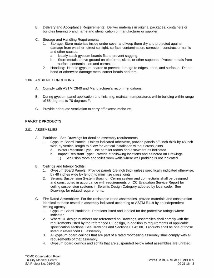
TCMC Observation RoomTri-City Medical Center GYPSUM BOARD ASSEMBLIESSA Project No. 01643.00 09 21 16 - 3
B. Delivery and Acceptance Requirements: Deliver materials in original packages, containers or bundles bearing brand name and identification of manufacturer or supplier.
C. Storage and Handling Requirements:1. Storage: Store materials inside under cover and keep them dry and protected against
damage from weather, direct sunlight, surface contamination, corrosion, construction traffic and other causes. a. Neatly stack gypsum boards flat to prevent sagging.b. Store metals above ground on platforms, skids, or other supports. Protect metals from
surface contamination and corrosion.2. Handling: Handle gypsum boards to prevent damage to edges, ends, and surfaces. Do not
bend or otherwise damage metal corner beads and trim.
1.06 AMBIENT CONDITIONS
A. Comply with ASTM C840 and Manufacturer’s recommendations.
B. During gypsum panel application and finishing, maintain temperatures within building within range of 55 degrees to 70 degrees F.
C. Provide adequate ventilation to carry off excess moisture.
PA%RT 2 PRODUCTS
2.01 ASSEMBLIES
A. Partitions: See Drawings for detailed assembly requirements.1. Gypsum Board Panels: Unless indicated otherwise, provide panels 5/8 inch thick by 48 inch
wide by vertical length to allow for vertical installation without cross joints.a. Water Resistant Type: Use at toilet rooms and elsewhere as indicated.b. Impact Resistant Type: Provide at following locations and as noted on Drawings:
1) Seclusion room and toilet room walls where wall padding is not indicated.
B. Ceilings and Interior Soffits: 1. Gypsum Board Panels: Provide panels 5/8-inch thick unless specifically indicated otherwise,
by 48 inches wide by length to minimize cross joints.2. Seismic Suspension System Bracing: Ceiling system and connections shall be designed
and constructed in accordance with requirements of ICC Evaluation Service Report for ceiling suspension systems in Seismic Design Category adopted by local code. See Drawings for related requirements.
C. Fire Rated Assemblies: For fire-resistance-rated assemblies, provide materials and construction identical to those tested in assembly indicated according to ASTM E119 by an independent testing agency.1. Gypsum Board Partitions: Partitions listed and labeled for fire protective ratings where
indicated.2. Where UL design numbers are referenced on Drawings, assemblies shall comply with the
requirements listed by the referenced UL design, in addition to requirements of applicable specification sections. See Drawings and Sections 01 42 00. Products shall be one of those listed in referenced UL assembly.
3. All gypsum board ceilings that are part of a rated roof/ceiling assembly shall comply with all requirements of that assembly.
4. Gypsum board ceilings and soffits that are suspended below rated assemblies are unrated.
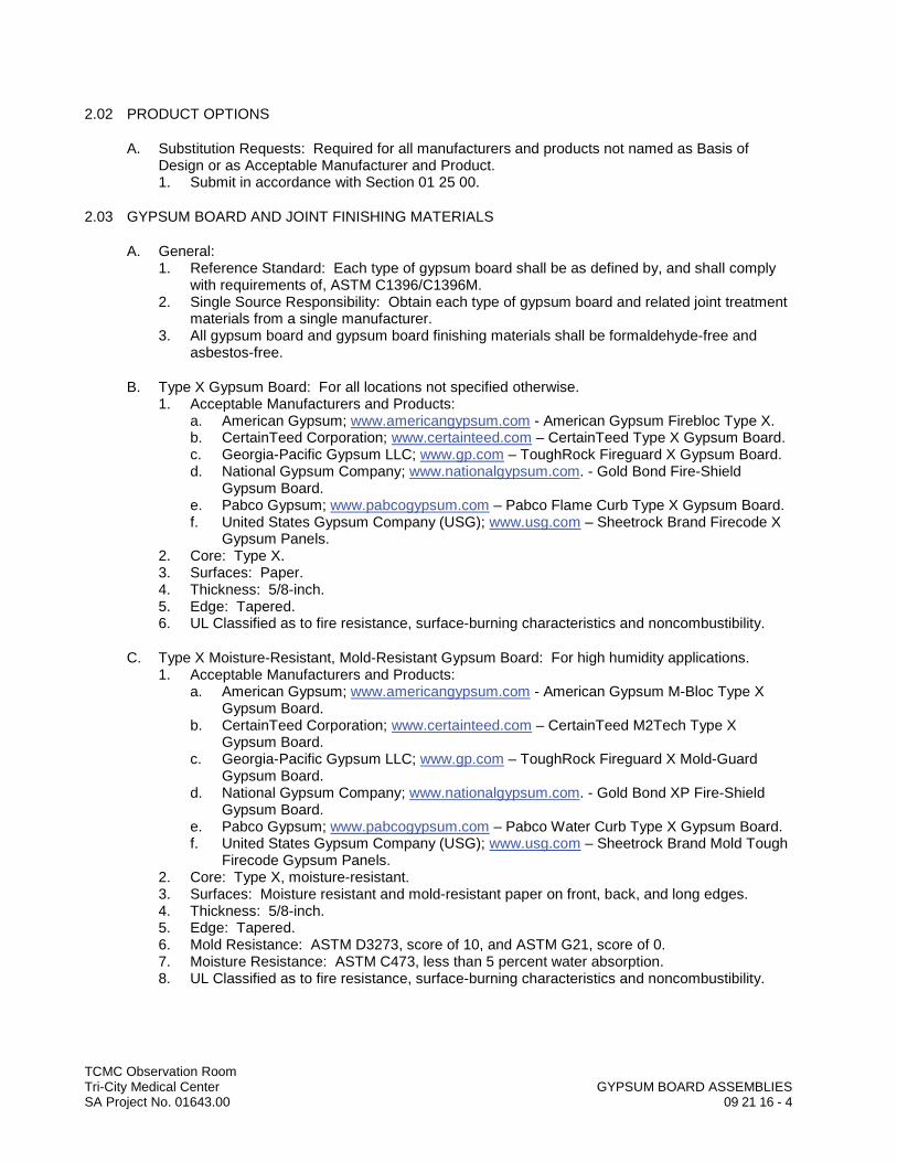
TCMC Observation RoomTri-City Medical Center GYPSUM BOARD ASSEMBLIESSA Project No. 01643.00 09 21 16 - 4
2.02 PRODUCT OPTIONS
A. Substitution Requests: Required for all manufacturers and products not named as Basis of Design or as Acceptable Manufacturer and Product.1. Submit in accordance with Section 01 25 00.
2.03 GYPSUM BOARD AND JOINT FINISHING MATERIALS
A. General:1. Reference Standard: Each type of gypsum board shall be as defined by, and shall comply
with requirements of, ASTM C1396/C1396M. 2. Single Source Responsibility: Obtain each type of gypsum board and related joint treatment
materials from a single manufacturer.3. All gypsum board and gypsum board finishing materials shall be formaldehyde-free and
asbestos-free.
B. Type X Gypsum Board: For all locations not specified otherwise.1. Acceptable Manufacturers and Products:
a. American Gypsum; www.americangypsum.com - American Gypsum Firebloc Type X.b. CertainTeed Corporation; www.certainteed.com – CertainTeed Type X Gypsum Board.c. Georgia-Pacific Gypsum LLC; www.gp.com – ToughRock Fireguard X Gypsum Board.d. National Gypsum Company; www.nationalgypsum.com. - Gold Bond Fire-Shield
Gypsum Board.e. Pabco Gypsum; www.pabcogypsum.com – Pabco Flame Curb Type X Gypsum Board.f. United States Gypsum Company (USG); www.usg.com – Sheetrock Brand Firecode X
Gypsum Panels.2. Core: Type X.3. Surfaces: Paper.4. Thickness: 5/8-inch.5. Edge: Tapered.6. UL Classified as to fire resistance, surface-burning characteristics and noncombustibility.
C. Type X Moisture-Resistant, Mold-Resistant Gypsum Board: For high humidity applications.1. Acceptable Manufacturers and Products:
a. American Gypsum; www.americangypsum.com - American Gypsum M-Bloc Type X Gypsum Board.
b. CertainTeed Corporation; www.certainteed.com – CertainTeed M2Tech Type X Gypsum Board.
c. Georgia-Pacific Gypsum LLC; www.gp.com – ToughRock Fireguard X Mold-Guard Gypsum Board.
d. National Gypsum Company; www.nationalgypsum.com. - Gold Bond XP Fire-Shield Gypsum Board.
e. Pabco Gypsum; www.pabcogypsum.com – Pabco Water Curb Type X Gypsum Board.f. United States Gypsum Company (USG); www.usg.com – Sheetrock Brand Mold Tough
Firecode Gypsum Panels.2. Core: Type X, moisture-resistant. 3. Surfaces: Moisture resistant and mold-resistant paper on front, back, and long edges.4. Thickness: 5/8-inch.5. Edge: Tapered.6. Mold Resistance: ASTM D3273, score of 10, and ASTM G21, score of 0.7. Moisture Resistance: ASTM C473, less than 5 percent water absorption.8. UL Classified as to fire resistance, surface-burning characteristics and noncombustibility.
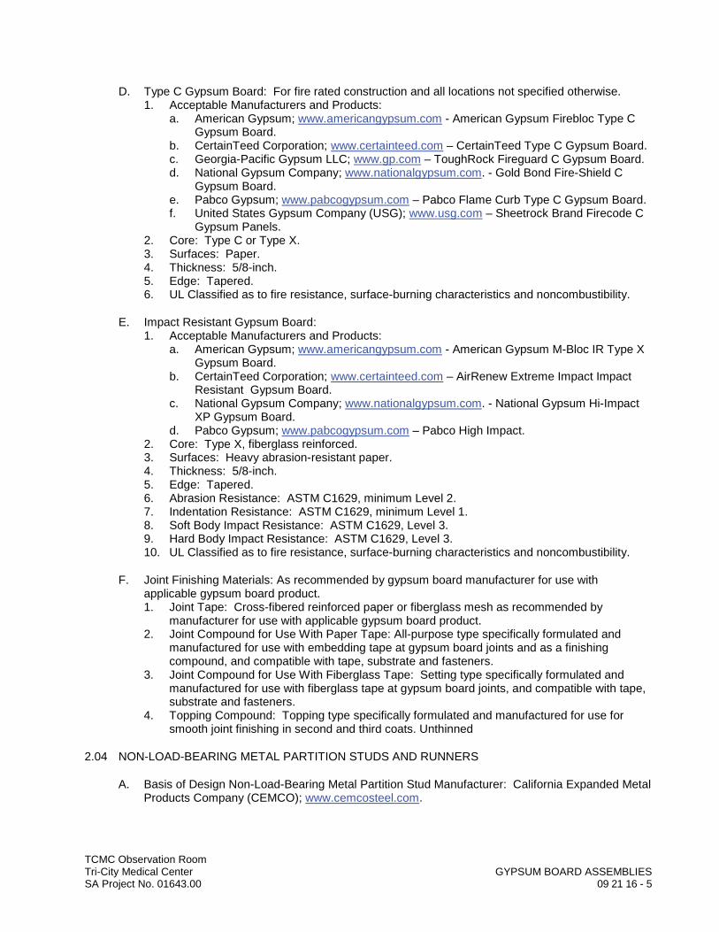
TCMC Observation RoomTri-City Medical Center GYPSUM BOARD ASSEMBLIESSA Project No. 01643.00 09 21 16 - 5
D. Type C Gypsum Board: For fire rated construction and all locations not specified otherwise.1. Acceptable Manufacturers and Products:
a. American Gypsum; www.americangypsum.com - American Gypsum Firebloc Type C Gypsum Board.
b. CertainTeed Corporation; www.certainteed.com – CertainTeed Type C Gypsum Board.c. Georgia-Pacific Gypsum LLC; www.gp.com – ToughRock Fireguard C Gypsum Board.d. National Gypsum Company; www.nationalgypsum.com. - Gold Bond Fire-Shield C
Gypsum Board.e. Pabco Gypsum; www.pabcogypsum.com – Pabco Flame Curb Type C Gypsum Board.f. United States Gypsum Company (USG); www.usg.com – Sheetrock Brand Firecode C
Gypsum Panels.2. Core: Type C or Type X.3. Surfaces: Paper.4. Thickness: 5/8-inch.5. Edge: Tapered.6. UL Classified as to fire resistance, surface-burning characteristics and noncombustibility.
E. Impact Resistant Gypsum Board: 1. Acceptable Manufacturers and Products:
a. American Gypsum; www.americangypsum.com - American Gypsum M-Bloc IR Type X Gypsum Board.
b. CertainTeed Corporation; www.certainteed.com – AirRenew Extreme Impact Impact Resistant Gypsum Board.
c. National Gypsum Company; www.nationalgypsum.com. - National Gypsum Hi-Impact XP Gypsum Board.
d. Pabco Gypsum; www.pabcogypsum.com – Pabco High Impact.2. Core: Type X, fiberglass reinforced.3. Surfaces: Heavy abrasion-resistant paper.4. Thickness: 5/8-inch.5. Edge: Tapered.6. Abrasion Resistance: ASTM C1629, minimum Level 2.7. Indentation Resistance: ASTM C1629, minimum Level 1.8. Soft Body Impact Resistance: ASTM C1629, Level 3.9. Hard Body Impact Resistance: ASTM C1629, Level 3.10. UL Classified as to fire resistance, surface-burning characteristics and noncombustibility.
F. Joint Finishing Materials: As recommended by gypsum board manufacturer for use with applicable gypsum board product.1. Joint Tape: Cross-fibered reinforced paper or fiberglass mesh as recommended by
manufacturer for use with applicable gypsum board product.2. Joint Compound for Use With Paper Tape: All-purpose type specifically formulated and
manufactured for use with embedding tape at gypsum board joints and as a finishing compound, and compatible with tape, substrate and fasteners.
3. Joint Compound for Use With Fiberglass Tape: Setting type specifically formulated and manufactured for use with fiberglass tape at gypsum board joints, and compatible with tape, substrate and fasteners.
4. Topping Compound: Topping type specifically formulated and manufactured for use for smooth joint finishing in second and third coats. Unthinned
2.04 NON-LOAD-BEARING METAL PARTITION STUDS AND RUNNERS
A. Basis of Design Non-Load-Bearing Metal Partition Stud Manufacturer: California Expanded Metal Products Company (CEMCO); www.cemcosteel.com.
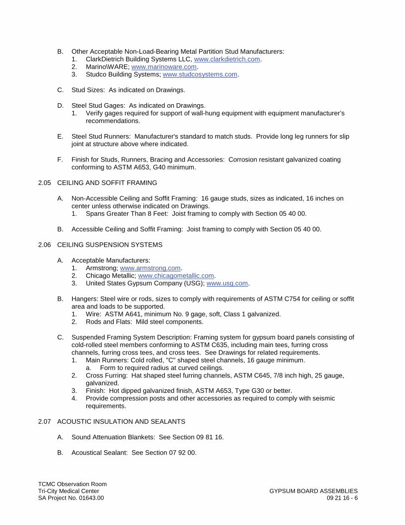
TCMC Observation RoomTri-City Medical Center GYPSUM BOARD ASSEMBLIESSA Project No. 01643.00 09 21 16 - 6
B. Other Acceptable Non-Load-Bearing Metal Partition Stud Manufacturers: 1. ClarkDietrich Building Systems LLC, www.clarkdietrich.com.2. Marino\WARE; www.marinoware.com.3. Studco Building Systems; www.studcosystems.com.
C. Stud Sizes: As indicated on Drawings.
D. Steel Stud Gages: As indicated on Drawings.1. Verify gages required for support of wall-hung equipment with equipment manufacturer’s
recommendations.
E. Steel Stud Runners: Manufacturer's standard to match studs. Provide long leg runners for slip joint at structure above where indicated.
F. Finish for Studs, Runners, Bracing and Accessories: Corrosion resistant galvanized coating conforming to ASTM A653, G40 minimum.
2.05 CEILING AND SOFFIT FRAMING
A. Non-Accessible Ceiling and Soffit Framing: 16 gauge studs, sizes as indicated, 16 inches on center unless otherwise indicated on Drawings.1. Spans Greater Than 8 Feet: Joist framing to comply with Section 05 40 00.
B. Accessible Ceiling and Soffit Framing: Joist framing to comply with Section 05 40 00.
2.06 CEILING SUSPENSION SYSTEMS
A. Acceptable Manufacturers:1. Armstrong; www.armstrong.com.2. Chicago Metallic; www.chicagometallic.com.3. United States Gypsum Company (USG); www.usg.com.
B. Hangers: Steel wire or rods, sizes to comply with requirements of ASTM C754 for ceiling or soffit area and loads to be supported.1. Wire: ASTM A641, minimum No. 9 gage, soft, Class 1 galvanized.2. Rods and Flats: Mild steel components.
C. Suspended Framing System Description: Framing system for gypsum board panels consisting of cold-rolled steel members conforming to ASTM C635, including main tees, furring cross channels, furring cross tees, and cross tees. See Drawings for related requirements.1. Main Runners: Cold rolled, "C" shaped steel channels, 16 gauge minimum.
a. Form to required radius at curved ceilings.2. Cross Furring: Hat shaped steel furring channels, ASTM C645, 7/8 inch high, 25 gauge,
galvanized.3. Finish: Hot dipped galvanized finish, ASTM A653, Type G30 or better.4. Provide compression posts and other accessories as required to comply with seismic
requirements.
2.07 ACOUSTIC INSULATION AND SEALANTS
A. Sound Attenuation Blankets: See Section 09 81 16.
B. Acoustical Sealant: See Section 07 92 00.
TCMC Observation RoomTri-City Medical Center GYPSUM BOARD ASSEMBLIESSA Project No. 01643.00 09 21 16 - 7
2.08 FINISHES
A. Skim Coat Finish: Unthinned topping joint compound formulated for filling, leveling and finishing coats.
2.09 ACCESSORIES
A. Fasteners: ASTM C1002. 1. Fastening to Metal: One-inch Type S gypsum board screws. Use proper type for gage of
stud.
B. Laminating Adhesive: Setting type compound, formaldehyde-free and asbestos-free, and as recommended by gypsum board manufacturer for use with applicable gypsum board product.
C. Cornerbead and Edge Trim for Interior Installation: Provide corner beads, edge trim and control joints that comply with ASTM C1047 and requirements indicated below:1. Acceptable Manufacturers:
a. California Expanded Metal Products Company (CEMCO); www.cemcosteel.com.b. ClarkDietrich Building Systems LLC, www.clarkdietrich.com.c. Phillips Manufacturing Company; www.phillipsmfg.com.d. United States Gypsum Company (USG); www.usg.com - Beadex.
2. Material: Formed metal, or metal combined with paper:3. Edge Trim: USG Sheetrock No. 103 Dur-A-Bead, 1-1/4-inch by 1-1/4-inch, unless otherwise
indicated.4. One-Piece Control Joint: Formed with vee-shaped slot per Fig. 1 in ASTM C1047, with slot
opening covered with removable strip.
PART 3 EXECUTION
3.01 ERECTION OF NON-LOAD-BEARING METAL STUD PARTITIONS
A. Reference Standard: Erect steel framing in accordance with ASTM C754.
B. Layouts: Align partition studs accurately according to partition layout.
C. Anchoring: Anchor runner channels to concrete slabs with concrete stub nails or power-driven anchors at 24 inches on center Anchor runner channels to ceiling grid where applicable with stove bolts. Install headers where required to receive runners where studs extend above ceiling system.
D. Studs: Position studs vertically in runners. Anchor studs located adjacent to openings or partition intersections and corners to runners with USG metal lock fastener or with 1/2-inch Type S pan head screws.1. Space studs 16 inches on center unless otherwise indicated, and not less than that required
by referenced steel framing installation standard.2. Corners and Intersections: Locate studs no more than two inches from abutting partitions,
corners, etc.3. Openings: Frame door openings to comply with details indicated, with GA-219 and with
applicable published recommendations of gypsum board manufacturer. Locate studs not more than two inches from opening frames. Anchor studs to frame anchor clips by bolt or screw attachment. Install runner track section (for cripple studs) at head and secure to jamb studs. Install headers over openings as recommended by the manufacturer.a. Wood Doors and Hollow Metal Doors: Provide two studs at jambs.
4. Metal Strap Blocking: See Drawings.
TCMC Observation RoomTri-City Medical Center GYPSUM BOARD ASSEMBLIESSA Project No. 01643.00 09 21 16 - 8
5. Install runners (tracks) at floors, ceilings and structural walls and columns where gypsum board stud system abuts other construction.a. Where studs are installed directly against exterior walls, install asphalt felt strips
between studs and wall.6. Installation Tolerances: Install each steel framing and furring member so that fastening
surface do not vary more than 1/8 inch from plane of faces of adjacent framing.7. Extend partition framing full height to structural supports or substrates above suspended
ceilings, except where partitions are indicated to terminate at suspended ceilings. Continue framing over frames for doors and openings and frame around ducts penetrating partitions above ceiling to provide support for gypsum board.
8. Terminate partition framing at suspended ceilings where indicated.9. Install steel studs so that flanges point in the same direction and gypsum boards can be
installed in the direction opposite to that of the flange.10. Position studs vertically with open sides facing in same direction and engaging floor and
ceiling runners. Begin and end each arc with a stud and space intermediate studs equally along arcs at stud spacing recommended by gypsum board manufacturer for radii indicated.
11. Attach studs to runners with 3/8-inch long pan head framing screws. On straight lengths at ends of arcs, place studs 6 inches on center with last stud left free standing.
E. Bracing: Provide diagonal bracing at head of studs that terminate above the ceiling level. Bracing shall consist of metal studs bent to V-shape and extending at 45 degrees from partition head to structure above. Locate bracing 48 inches maximum on center
F. Top of Partition Deflection Head Assemblies:1. Provide long leg runners for slip joint at structure above for partitions where indicated.2. Fire Rated Partitions:
a. Firestopping Installation: Under Section 07 84 00.
3.02 CEILING SUSPENSION INSTALLATION
A. General: Install suspension system in accordance with ASTM C754 and manufacturer's instructions and as required to comply with seismic requirements..
B. Hangers: Secure hangers to structural support by connecting directly to structure where possible, otherwise connect to cast in concrete inserts or other anchorage devices or fasteners as indicated. Install wire hangers spaced not over 48 inches on center in direction of 1-1/2-inch main runner channels and within 6 inches of ends of main runners or interruptions of ceiling continuity. Hang from structure above. Install hangers 24 inches on center at gypsum drywall ceilings supporting wood or metal ceilings or other secondary ceiling systems.1. Where spacing of structural members, or width of ducts or other equipment, prevents regular
spacing of hangers, provide supplemental hangers and suspension members and reinforce nearest affected hangers to span extra distance.
2. Attach directly to structural elements only. Do not connect or suspend steel framing from ducts, pipes or conduit. Loop hangers and wire tie directly or provide anchors or inserts.
3. Keep hangers and braces 2 inches clear of ducts, pipes and conduits.
C. At light troffers or other openings, reinforce framing with 3/4-inch cold rolled channels wired atop and parallel to main runner channels.
D. Provide all necessary framing and suspension for offsets, verticals and decorative recesses, etc. Use drywall studs where indicated or required. See Section 09 22 16 for type.
E. Install 1-1/2 inch main runner channels 24 inches on center. at ceilings supporting wood or metal ceilings or other secondary ceiling systems.

TCMC Observation RoomTri-City Medical Center GYPSUM BOARD ASSEMBLIESSA Project No. 01643.00 09 21 16 - 9
F. Seismic Braced System: As indicated.1. Install compression posts, splay wires and other accessories as required to comply with
seismic requirements.2. Extend runners to within 6 inches of walls.3. Wire tie or clip furring members to main runners and to other structural supports indicated.
In fire resistance rated assemblies, wire tie furring members; do not clip.4. Do not permit furring or runners to contact masonry or concrete walls.5. Provide 1 inch clearance between furring or runners and abutting walls and partitions.
G. Installation Tolerances:1. Do not exceed 1/8 inch in 8-foot variation from plumb or level in exposed lines of surface,
except at joints between gypsum board units.2. Do not exceed 1/16 inch variation between planes of abutting edges or ends.3. Shim as required to comply with specified tolerances.
3.03 SOUND TREATMENT
A. General:1. Comply with manufacturer’s instructions for particular conditions of installation in each case.2. Install materials to comply with thermal and sound control requirements noted on Drawings.3. Unfaced Insulation: Not allowed in exposed applications where there is a potential for skin
contact and irritation.
B. Acoustical Blanket Installation in Partitions:1. Batts: Friction-fit in place until interior gypsum wallboard finish is applied. Install batts to fill
entire stud cavity. Place in partitions tight within spaces, around cut openings, behind and around electrical and mechanical items within partitions and tight to items passing through partitions.a. Stud Cavity Heights Up To 8 Feet: Cut lengths to friction-fit against floor and ceiling
tracks or plates.b. Stud Cavity Heights Greater Than 8 Feet: Provide supplemental support as required to
hold batts in place until the interior finish is applied.2. Ductwork Penetrations: Provide one inch wide clearance around ductwork and pack with
fiberglass ready for caulking.
C. Acoustical Blanket Installation Over Ceilings: See Section 09 81 16.
D. Acoustical Sealant: See Section 07 92 00. Apply at perimeter and at all penetrations of gypsum board in single bead.1. Locations: Apply at partitions with sound attenuation blankets.2. Caulk ductwork penetrations.3. Caulk both sides of partitions edges with continuous bead.
3.04 INSTALLATION OF GYPSUM BOARD, GENERAL
A. Reference Standards: Apply and finish gypsum board in accordance with GA-216 and ASTM C840.
B. Fastening: Apply board to studs, furring or framing with gypsum board screws spaced 12 inches on center in field of board and eight inches on center staggered along vertical abutting edges.1. Use Type S-12 screws for attaching to structural studs.
C. Install exposed gypsum board with face side out. Do not install imperfect, damaged or damp boards. Butt boards together for a light contact at edges and ends with not more than 1/16-inch open space between boards. Do not force into place.
TCMC Observation RoomTri-City Medical Center GYPSUM BOARD ASSEMBLIESSA Project No. 01643.00 09 21 16 - 10
D. Position boards so that like edges abut, tapered edges against tapered edges and mill-cut or field-cut ends against mill-cut or field-cut ends. Do not place tapered edges against cut edges or ends.
E. Trim: Apply as recommended by manufacturer, where gypsum board abuts other materials, and as indicated.
F. Tolerances: Gypsum board surface plane within plus-or-minus 1/8-inch in 10 feet.
3.05 INSTALLATION OF GYPSUM BOARD ON PARTITIONS AND WALLS
A. Layout: Apply gypsum wallboard panels vertically with abutting ends and edges occurring over stud flanges or furring. Horizontal installation is not allowed.1. Joints on Opposite Sides of Partitions: Shall not occur over same stud.2. Two Layer Construction: Stagger joints between layers. 3. Locate exposed end-butt joints as far from center of walls as possible, and stagger not less
than 24 inches in alternate courses of board.4. Install wall/partition boards in manner that minimizes the number of end-butt joints or avoids
them entirely where possible. 5. Locate either edge or end joints over supports, except in horizontal applications where
intermediate supports or gypsum board back-blocking is provided behind end joints.
B. Stagger vertical joints over different studs on opposite sides of partitions.
C. Attach gypsum board to steel studs so that leading edge or end of each board is attached to open (unsupported) edge of stud flange first.
D. Spot grout hollow metal door frames for solid core wood doors, hollow metal doors and doors over 32 inches wide. Apply spot grout at each jamb anchor clip just before inserting board into frame.
E. Form control joints and expansion joints at locations indicated, with space between edges of boards, prepared to receive trim accessories.
F. Cover both faces of steel stud partition framing with gypsum board in concealed spaces (above ceilings, etc.), except in chase walls that are braced internally.
G. Isolate perimeter of non-load-bearing gypsum board partitions at structural abutments. Provide 1/4-inch to 1/2-inch space and trim edge with "U" bead edge trim. Seal joints with acoustical sealant.
H. Layers: Install multiple layer gypsum board as indicated.
I. Impact Resistant Boards: Install at locations indicated as recommended by manufacturer for fullheight above finish floor.
J. Corner Bead: Apply as recommended by manufacturer at exposed out corners.
3.06 INSTALLATION OF GYPSUM DRYWALL CEILINGS
A. Install to ceiling framing, to suspended grid framing, or directly to structural framing as indicated.
B. Apply gypsum board of maximum practical length with long dimensions at right angles to furring channels and fasten with drywall screws spaced 12 inches on center in the field of the board and 8 inches on center along abutting edges. All end and edge joints shall occur over furring
TCMC Observation RoomTri-City Medical Center GYPSUM BOARD ASSEMBLIESSA Project No. 01643.00 09 21 16 - 11
channels with end joints staggered. Properly support gypsum board around cutouts and openings.
3.07 FINISHING
A. General: Finish gypsum board in accordance with ASTM C840. Treat gypsum board joints, interior angles, edge trim, control joints, penetrations, fastener heads, surface defects, and elsewhere as required to prepare gypsum board surfaces for decoration. Promptly remove residual joint compound from adjacent surfaces.
B. Joint Finishing: Apply joint treatment at side and end joints, corner bead, trim, penetrations and fastener dimples as recommended by manufacturer. 1. Finish panels to following finish levels as defined by ASTM C840 and as recommended by
GA-214 where not otherwise specified.a. Level 0: Limited to temporary construction. No taping, finishing or accessories
required.b. Level 1: Limited to ceiling plenums and similar concealed areas. Apply tape embedded
in joint compound to all joints and interior angles. Excess joint compound, tool marks and ridges are acceptable.
c. Level 2: Minimum finish level for gypsum board to receive interior adhered masonry veneer, or bonded acoustical ceiling tile. All joints and interior angles shall have tape embedded in joint compound and wiped with a joint knife leaving a thin coating of joint compound over all joints and interior angles. Cover all fastener heads and accessories with one coat of joint compound. Surface shall be free of excess joint compound. Tool marks and ridges are acceptable.
d. Level 3: Minimum finish level for gypsum board to receive ceramic, stone, or glass tile, FRP or other protective wall covering, fixed acoustical panels, or heavy- or medium-texture finishes before final painting. All joints and interior angles shall have tape embedded in joint compound and shall be immediately wiped with a joint knife leaving a thin coating of joint compound over all joints and interior angles. Cover fastener heads and accessories with two separate coats of joint compound as required by ANSI A108.01-2013 for gypsum board to receive tile. The surface shall be smooth and free of tool marks and ridges.
e. Level 4: Minimum finish level for gypsum board to receive light texture, wallcoverings, and for all gypsum board that will be exposed to view but not specified to receive Level 5 finishing. All joints and interior angles shall have tape embedded in joint compound and shall be immediately wiped with a joint knife leaving a thin coating of joint compound over all joints and interior angles. Apply two separate coats of joint compound over all flat joints and one separate coat over interior angles. Cover fastener heads and accessories with three separate coats of joint compound. The surface shall be smooth and free of tool marks and ridges.
f. Level 5: 1) Finish gypsum board to Level 5 where so noted on the Drawings and for following
applications:a) Gypsum board to receive semigloss or gloss paint or other glossy decorative
finish.b) Gypsum board to receive dark or deep tone paint application.
2) Finish joints as specified for Level 4. 3) Apply a skim coat over the entire exposed surface.
2. Prefill open joints and rounded or beveled edges, if any, using setting-type joint compound.3. Apply joint tape at joints between gypsum boards except at trim accessories.4. Joint Compound: Sand smooth between coats and after last coat.
a. Embedding and first coat: Setting-type joint compound.b. Fill coat: Setting-type joint compound.c. Finish coat: Ready-mix drying-type all-purpose or topping compound.
TCMC Observation RoomTri-City Medical Center GYPSUM BOARD ASSEMBLIESSA Project No. 01643.00 09 21 16 - 12
C. Skim Coat Application. Skim coat to be troweled on to straight plumb finish prior to final wall painting application or other finish as shown on Drawings.1. Required for Level 5 finishing.
END OF SECTION
TCMC Observation RoomTri-City Medical Center ACOUSTICAL PANEL CEILINGSSA Project No. 01643.00 09 51 13 - 1
SECTION 09 51 13
ACOUSTICAL PANEL CEILINGS
PART 1 GENERAL
1.01 SUMMARY
A. Work Results:1. New acoustical grid and suspension system for CBC seismic Category D.2. New lay-in panels to match existing.3. Reinstall salvaged ceiling tiles and grid to match existing.
B. Related Requirements:1. Gypsum Board Ceilings: Section 09 21 16 Gypsum Board Assemblies. 2. Interior Painting: Section 09 91 23.
1.02 REFERENCES
A. Reference Standards: See Section 01 42 00. Comply with the following.1. ASTM International References:
a. ASTM C635/C635M-13a - Manufacture, Performance, and Testing of Metal SuspensionSystems for Acoustical Tile and Lay-in Panel Ceilings.
b. ASTM C636/C636M-13 - Standard Practice for Installation of Metal Ceiling Suspension Systems for Acoustical Tile and Lay-In Panels.
c. ASTM E580/E580M-14 – Installation of Ceiling Suspension Systems for Acoustical Tile and Lay-in Panels in Areas Subject to Earthquake Ground Motions.
d. ASTM E1264-14 - Standard Classification for Acoustical Ceiling Products.
1.03 SEQUENCING
A. Do not install acoustical ceilings until dust-generating activities are completed, wet work has dried and overhead mechanical work is completed.
1.04 ACTION SUBMITTALS
A. Procedures: Submit for review, acceptance and return in accordance with Section 01 33 00.
B. Product Data: Submit manufacturer's catalog data indicating all systems proposed for installation. Include details of light fixture protection (if any) required to comply with Article "Performance." If Fixture protection is not required, submit manufacturer's written data so indicating. Also submit specific requirements for holddown clips (if any).
C. Samples: Submit samples of each type of lay-in panel meeting the requirements of this specification to the Architect.
1.05 INFORMATIONAL SUBMITTALS
A. Procedures: Submit for information and verification in accordance with Section 01 33 00.
B. Test and Evaluation Reports: 1. Submit current ICC-ES Evaluation Report (ESR) showing compliance with ICC-acceptance
criteria.
TCMC Observation RoomTri-City Medical Center ACOUSTICAL PANEL CEILINGSSA Project No. 01643.00 09 51 13 - 2
C. Manufacturer’s Instructions:1. Submit Manufacturer’s installation instructions.
a. Maintain one additional copy on site until completion of installation.
1.06 MAINTENANCE MATERIALS SUBMITTALS
A. Extra Materials: Provide Owner with 1 percent of gross area installed, maximum of two cases, of each type of ceiling panel used.
1.07 DELIVERY, STORAGE, AND HANDLING
A. General Requirements: Comply with Section 01 60 00.
B. Deliver in manufacturer's original unopened containers and store in a clean, dry area until ready for use.
1.08 AMBIENT CONDITIONS
A. Maintain minimum of 60 degrees F during and after installation of acoustical ceilings.
PART 2 PRODUCTS
2.01 PRODUCT OPTIONS
A. Substitution Requests: Required for all manufacturers and products not named as Basis of Design or as Acceptable Manufacturer and Product.1. Submit in accordance with Section 01 25 00.
2.02 REGULATORY REQUIREMENTS
A. Seismic Design Compliance: Metal suspension systems and lay-in panel ceilings provided under this Section shall meet the requirements of the CBC for Seismic Design Category D. Systems shall be designed and installed in accordance with ASTM C635, ASTM C636, and ASTM E580, Section 4 – Seismic Design Category D.1. Systems with a current ICC-ES report recognizing the system as a code-compliant
alternative method for installation in Seismic Design Category D construction will be deemed to meet this requirement. Comply with all stipulations and conditions of use stated in the ICC-ESR.
2.03 PERFORMANCE
A. Acoustical Performance:1. Lay-in panels shall have a minimum noise reduction coefficient (NRC) as of .55 in
accordance with ASTM C423 and a CAC rating of the ceiling assembly of 35 in accordance with ASTM E1414.
B. Fire Resistance: 1. Flame Spread: Do not exceed flame spread classifications in CBC Table 803.9.2. System fire rating not required.
2.04 ACOUSTICAL LAY-IN CEILING PANELS
A. Acoustical Lay-In Panels: See Finish Legend on Drawings.
TCMC Observation RoomTri-City Medical Center ACOUSTICAL PANEL CEILINGSSA Project No. 01643.00 09 51 13 - 3
2.05 SUSPENSION SYSTEMS
A. Ceiling Suspension System: Intermediate Duty.1. Exposed Grid Face: Match existing.2. Color: Match existing.
B. Edge Molding: Standard angle molding for seismic suspension system, color to match grid.1. Minimum Horizontal Flange Dimension: 7/8-inch.2. Minimum Vertical Flange Dimension: 7/8-inch.
C. Spacer Bars: Provide system as required to prevent perimeter components from spreading apart.
D. Suspension Wire: Minimum No. 12 gauge galvanized, soft-annealed, mild steel wire.
PART 3 EXECUTION
3.01 INSTALLATION OF SUSPENSION SYSTEMS
A. General: Install suspension systems in accordance with Drawings, ASTM C636, ASTM E580, and manufacturer’s instructions.1. Reflected Ceiling Plan: Follow reflected ceiling plan on Drawings in layout of grid.
Deviations must receive prior acceptance by Architect.2. Install metal edge molding wherever the suspended grid abuts walls, columns and other
vertical surfaces.3. Frame around openings as required.4. Suspend grid with hanger wires from structure above. Install hanger wires at 4 feet on
center along each main runner, at all four corners of lay-in light fixtures and as required to provide maximum deflection of 1/360 of span and level within 1/8-inch in 12 feet.a. Suspension wires shall not hang more than one in six out of plumb unless
countersloping wires are provided.5. Provide a minimum 3/8-inch clearance from the wall on all sides at terminal ends of
suspension members. Overlap metal edge molding angles a minimum of 3/8-inch. Do not fasten terminal ends to wall or to metal edge molding angle. Fasten to prevent terminal endsof main runners and cross runners from spreading.
B. Exposed Grid Suspension System:1. Install main T-runner on 48-inch centers.2. To complete a 24-inch by 48-inch grid, install 48-inch cross T-splines 24 inches on center at
right angles to main T-runners. a. Install additional cross T-splines to form 24-inch grid.
3. Lock T-spline intersecting moldings in place. All main T-runners and cross T-splines shall be straight in alignment and flush at intersections.
4. Avoid use of less than half width units at borders.5. Install edge molding at all intersections with dissimilar vertical surfaces. End joints for edge
moldings shall occur only at T-Runners or Cross T-splines and shall have riveted connections.
3.02 INSTALLATION OF LAY-IN PANELS
A. Panels: Install panels in accordance with manufacturer's instructions and recommendations. Where required, cut units to fit.1. Install square edge panels flush in grid and beveled and tegular edge panels so that grid is
recessed behind face of panels. Ensure each panel to be well supported on all four edges.
TCMC Observation RoomTri-City Medical Center ACOUSTICAL PANEL CEILINGSSA Project No. 01643.00 09 51 13 - 4
2. Where panels run continuous over tops of partitions or where required for specified fire rating, provide holddown clips so panels fit tight to tops of partitions.
B. Hurricane Clips: Install at all open areas and within 20 feet of entrances.
3.03 LIGHTING FIXTURE INSTALLATION AND PROTECTION
A. Mechanically attach all lighting fixtures to ceiling suspension system in accordance with the NEC and ASTM E580 unless fixtures are independently supported.
B. If required for fire resistance assembly specified and by manufacturer's design number install box, tent or flat cover fixture protection as applicable to the assembly being installed.
3.04 SITE QUALITY CONTROL
A. Special Inspection: Special inspection is required for the suspension system, anchoring and bracing of the system. See Section 01 45 20.
3.05 FINAL APPEARANCE
A. On completion, acoustical panels shall be free from defects, clean and lying flat in metal grid.
B. Remove and replace dirty, defaced, scarred or otherwise defective panels. Touch up of scarred panels not acceptable.
END OF SECTION
TCMC Observation RoomTri-City Medical Center RESILIENT SHEET FLOORINGSA Project No. 01643.00 09 65 16 - 1
SECTION 09 65 16
RESILIENT SHEET FLOORING
PART 1 GENERAL
1.01 SUMMARY
A. Section Includes:1. Sheet vinyl flooring with integral cove base.2. New integral sheet vinyl cove base to match existing.3. Patching sheet vinyl flooring and base.
B. Related Requirements:1. Finish Legend on Drawings.2. Concrete Floor Slab Moisture Testing: Section 09 05 61 Common Work Results for Flooring
Preparation.
1.02 REFERENCES
A. Reference Standards: See Section 01 42 00. Comply with the following.1. ASTM International (ASTM):
a. ASTM F1869-16 - Standard Test Method for Measuring Moisture Vapor Emission Rate of Concrete Subfloor Using Anhydrous Calcium Chloride.
b. ASTM F1303-04(2014) - Standard Specification for Sheet Vinyl Floor Covering withBacking.
c. ASTM F1913-04(2014) - Standard Specification for Vinyl Sheet Floor Covering Without Backing.
d. ASTM F2170-16a - Standard Test Method for Determining Relative Humidity in Concrete Floor Slabs Using in situ Probes.
2. Resilient Floor Covering Institute (RFCI):a. RFCI Standard Slab Moisture Test Method (Calcium Chloride Method).
B. Guide References and Standard Practices: Comply with recommendations of the following except as otherwise specified in this Project Manual.1. ASTM International Standard Practices:
a. ASTM F710-11 - Standard Practice for Preparing Concrete Floors to Receive Resilient Flooring.
1.03 ADMINISTRATIVE REQUIREMENTS
A. Coordination:1. Concrete Subfloor Vapor Emission, Alkalinity and Bond Testing and Acceptance:
Coordinate with Section 09 05 61.a. Notwithstanding testing by others, it is the responsibility of the flooring installer to
determine whether the subfloor is sufficiently dry for covering.
B. Sequencing:1. Finishing Operations: Install flooring after finishing operations, including painting and ceiling
operations, have been completed.
C. Scheduling:1. Material shall not be delivered or installed until all concrete, masonry and painting work are
completed and all mechanical work, lighting and other overhead equipment are installed.
TCMC Observation RoomTri-City Medical Center RESILIENT SHEET FLOORINGSA Project No. 01643.00 09 65 16 - 2
1.04 ACTION SUBMITTALS
A. Submittals for Review: Submit the following in accordance with Section 01 33 00:
B. Product Data: Submit manufacturer’s current printed product literature and specifications for allproducts proposed for installation.
C. Shop Drawings: Submit shop drawings to indicate materials, details, and accessories including but not limited to the following: 1. Submit a cut diagram indicating seam locations and roll direction. Use mitered seam layouts
for corners when changing directions 180 degrees (e.g. when running material down corridors which bisect at a right angle), unless approved otherwise.
D. Samples: Submit for verification the brand and color of sheet vinyl to be used.1. Samples shall be complete and up to date. 2. Submit duplicate 12 inch by 12 inch sample pieces of sheet material, 12 inch long gulley
edge, cap strip, joint cover strip, or cove former as applicable.
1.05 INFORMATIONAL SUBMITTALS
A. Procedures: Submit for information and verification in accordance with Section 01 33 00.
B. Manufacturer's Instructions:1. Manufacturer's Installation Instructions:
a. Maintain one copy on site until completion of installation.
1.06 CLOSEOUT SUBMITTALS
A. Submittals for Project Record: Submit the following in accordance with Section 01 78 00.
B. Operation and Maintenance Data: Submit manufacturer's maintenance instructions. 1. Include recommended cleaning and maintenance methods and materials and frequency of
cleaning.2. Include precautions against cleaning materials and methods detrimental to finishes and
performance.
1.07 MAINTENANCE MATERIALS SUBMITTALS
A. Extra Materials: Upon completion of the Project, deliver the following materials to the Owner for future maintenance and repair: 1. Sheet flooring pieces over 4 sq. ft.2. One gallon of each type of adhesive used.
1.08 DELIVERY, STORAGE, AND HANDLING
A. General Requirements: Comply with Section 01 60 00.
B. Delivery and Acceptance Requirements: Deliver materials in manufacturer's original, unopened, undamaged containers with identification labels intact.
C. Storage and Handling Requirements: Store materials protected from exposure to harmful weather conditions and at temperature and humidity conditions recommended by manufacturer.1. Maintain area where materials are to be stored at 55 degrees F and less than 50 percent
relative humidity.2. Store rolls in dry locations. Stand rolls on end. Protect and secure rolls from falling.
TCMC Observation RoomTri-City Medical Center RESILIENT SHEET FLOORINGSA Project No. 01643.00 09 65 16 - 3
1.09 AMBIENT CONDITIONS
A. General: Comply with manufacturer's recommendations.
B. Before beginning work, building shall be warm, dry and well ventilated.
C. Temperature Requirements: Maintain temperature in space to receive base between 70 degrees F and 90 degrees F for not less than 24 hours before and 48 hours after installation. Following 48 hour period maintain minimum temperature of 55 deg F until completion of Work.
PART 2 PRODUCTS
2.01 MANUFACTURERS AND PRODUCTS
A. Basis of Design Manufacturer and Products: See Finish Legend on Drawings.1. Manufacturer: Mannington Resilient Floors; www.mannington.com.
B. Substitution Requests: In accordance with Section 01 25 00.
2.02 PERFORMANCE
A. HUD/FHA Requirements: Exceed.
B. Flooring Radiant Panel Test (ASTM-E648): 0.45 watts/ cm2, Pass - Class 1.
C. N.B.S. Smoke Chamber Test (ASTM-E-662): Less than 450 – Pass.
D. Fire Resistance: 1. Flame Spread: Do not exceed flame spread classifications in CBC Table 803.9.
2.03 SHEET VINYL FLOORING (SV) MATERIALS
A. Homogenous Sheet Vinyl Flooring Without Backing: ASTM F1913. 1. Gauge:
a. Overall Nominal Thickness: 0.080 inch (2.03mm).b. Wearlayer Nominal Inlaid Thickness: 0.080 inch (2.03mm).
2. Color: See Finish Legend on Drawings.
B. Heterogeneous Sheet Vinyl Flooring With Backing: ASTM F1303, Type 1, Grade 1, Class B. 1. Layers: Sheet flooring shall be constructed of four distinct, solid layers, consisting of a wear
layer, pattern layer, interconstruction layer, and backing layer.2. Gauge:
a. Overall Nominal Thickness: 0.080 inch (2.03mm).b. Wearlayer Nominal Inlaid Thickness: 0.020 inch (0.51mm).
C. Heterogeneous Light Sheet Vinyl Flooring With Backing: ASTM F1303, Type 1, Grade 1, Class A. 1. Gauge:
a. Overall Nominal Thickness: 0.080 inch (2.03mm).b. Wearlayer Nominal Inlaid Thickness: 0.020 inch (0.51mm).
2. Color: See Finish Legend on Drawings.
TCMC Observation RoomTri-City Medical Center RESILIENT SHEET FLOORINGSA Project No. 01643.00 09 65 16 - 4
2.04 ACCESSORIES
A. Adhesives: As recommended by the flooring manufacturer of the material being installed. Adhesive for vinyl edging and base shall be a type not affected by heat.1. Low-Emitting Material Requirements: Use adhesives that comply with the limits for VOC
content of SCAQMD Rule #1168:
B. Heat Welding Rod: Color matched or multi-color welding rod as supplied by the flooring manufacturer.
C. Leveling Compound: Ardex Feather Finish or accepted substitute.
D. Metal Trim: Omit.
E. Sealer and Wax: Type recommended by flooring manufacturer.
PART 3 EXECUTION
3.01 EXAMINATION
A. Verification of Conditions: Examine substrate for excessive moisture content and unevenness which would prevent execution and quality of resilient flooring as specified. Report unsatisfactory conditions to the General Contractor with copy to Architect.1. Test moisture content of concrete before installation. Coordinate with vapor emission testing
requirements of Section 03 32 00. If moisture is above level acceptable to flooring or adhesive manufacturer, seal concrete surface as recommended by flooring manufacturer.
2. Verify concrete subfloor to be clean, level, sound and fully cured.
B. Acceptance: Do not proceed with installation of resilient flooring until defects have been corrected except where correction is indicated under Preparation. Beginning of installation means acceptance of existing substrate.
3.02 PREPARATION
A. Adjacent Surfaces Protection: Protect adjacent work areas and finish surfaces from damage during product installation.
B. Subfloor Preparation:1. General: Prepare floor substrate in accordance with manufacturer's instructions. 2. Concrete Subfloor:
a. Reference Standard: Comply with ASTM F710.b. Cleaning, Patching and Priming: Thoroughly clean concrete floors before applying floor
coverings. Remove rough spots and any foreign matter that might be evident through the floor covering. Patch minor rough areas, voids and defects with compatible leveling compound. Prime concrete floors as recommended by the manufacturer of the flooring..
c. Leveling: Level major uneven concrete floor joints or other irregularities by bush hammering or grinding and filling with latex type underlayment. Leveled areas shall be sanded to provide a surface level within 1/4-inch in 10 feet. Leveled areas shall be inspected by the Architect before flooring work may proceed.
C. Subfloor Testing:1. Concrete Moisture Test: Coordinate with Section 03 32 00. Perform moisture tests on
concrete floors regardless of the age or grade level. Verify concrete substrate is dry in

TCMC Observation RoomTri-City Medical Center RESILIENT SHEET FLOORINGSA Project No. 01643.00 09 65 16 - 5
accordance with the RFCI Industry Standards Slab Moisture Test Method (Calcium Chloride Method), in strict accordance with instructions.a. Perform moisture condition test in each major area. A minimum of 1 test per 93 m2
(1000 sq.ft), prior to installation. Moisture emissions from concrete subfloors must not exceed 3 lbs per 1000sf per 24 hours (1.4 kg H2O/24 hr/93 m2) for acrylic adhesive and 5lbs for polyurethane adhesive via the Calcium Chloride Test Method (ASTM F1869).
b. Conduct moisture tests around room perimeter, at columns and where moisture may be evident.
2. Concrete pH Test: Perform alkali tests to ensure pH levels of concrete subfloor surface do not exceed pH 9.9. Concrete must be neutralized if above pH 9.9.
3. Do not proceed with work until results of moisture condition and/or pH tests are acceptable.
3.03 APPLICATION OF ADHESIVES
A. General: Mix and apply adhesives in accordance with manufacturer's instruction. Provide safety precautions during mixing and applications as recommended by adhesive manufacturer. Cover only that amount of area which can be covered by flooring material within the recommended working time of the adhesive.
B. Application: Apply adhesive uniformly over surfaces with notched trowel or other suitable tool. Clean trowel and rework notches as necessary to insure proper application of adhesive.
C. Cleaning: Remove any adhesive which dries or films over. Do not soil walls. bases, or adjacent areas with adhesives. Promptly remove spillage.
3.04 INSTALLATION
A. General: Comply with manufacturer's product data, including product technical bulletins, product catalog installation instructions, and product carton instructions for installation.
B. Sheet Vinyl Flooring: Install according to manufacturer's recommendations. Rout seams with a hand router or electric router and heat weld seams using matching vinyl welding thread. Install fillet cove filler at all walls. Turn sheet flooring up wall to form integral cove base and install aluminum trim at exposed top edge.
3.05 CLEANING
A. General: 1. Remove temporary coverings and protection of adjacent work areas. 2. Repair or replace damaged installed products. 3. Clean installed products in accordance with manufacturer's instructions prior to owner's
acceptance. 4. Remove construction debris from Project site and legally dispose of debris.
B. Remove visible adhesive and other surface blemishes using cleaning methods recommended by floor manufacturer. Remove mastic cement from adjoining work with particular care to not damage such work.
C. Sweep and vacuum floor after installation.
D Clean surfaces using only cleaners approved by the manufacturer.
E. Buffing: Dry mop and buff flooring.

TCMC Observation RoomTri-City Medical Center RESILIENT SHEET FLOORINGSA Project No. 01643.00 09 65 16 - 6
F. Final Cleaning: Mop with warm water and mild detergent as recommended by manufacturer of flooring, then thoroughly machine buff.
3.06 PROTECTION
A. Protect finished work from damage by subsequent construction operations.
B. After flooring is installed, the room shall be kept locked to allow curing time for adhesive. No other trades shall be allowed on the floor until it is accepted by the Architect.
C. Protect the newly installed flooring from foot traffic for 24 hours and heavy rolling traffic for 72 hours.
END OF SECTION
TCMC Observation RoomTri-City Medical Center ACOUSTIC BLANKET INSULATIONSA Project No. 01643.00 09 81 16 - 1
SECTION 09 81 16
ACOUSTIC BLANKET INSULATION
PART 1 GENERAL
1.01 SUMMARY
A. Section Includes:1. Acoustical insulation in partitions as indicated.2. Acoustical insulation over ceilings as indicated.
B. Related Requirements:1. Acoustical Joint Sealants: Section 07 92 00 Joint Sealants.
1.02 ACTION SUBMITTALS
A. Procedures: Submit for review, acceptance and return in accordance with Section 01 33 00.
B. Product Data: Submit manufacturer's current product literature.
C. Samples: Submit manufacturer's sample, minimum 6 inches square.
1.03 DELIVERY, STORAGE, AND HANDLING
A. General Requirements: Comply with Section 01 60 00.1. Protect acoustical materials from excessive moisture in shipment, storage, and handling.
B. Delivery and Acceptance Requirements: 1. Deliver materials to site in manufacturer's original, unopened containers and packaging, with
labels clearly identifying material name and manufacturer, production date and/or product code.
C. Storage and Handling Requirements:1. Storage: Store materials in a clean, dry area in accordance with manufacturer's instructions.2. Handling: Protect materials during handling and installation to prevent damage.
PART 2 PRODUCTS
2.01 FIBER GLASS ACOUSTICAL BLANKET INSULATION
A. Acceptable Manufacturers:1. Johns-Manville, 800/654-3103; www.jm.com.2. Knauf Fiber Glass; 800/825-4434; www.knaufinsulation.us.3. Owens-Corning, 800/GET-PINK; www.owenscorning.com.4. Accepted substitute in accordance with Section 01 25 00.
B. Sound Control Blankets for Partitions: ASTM C665, Type 1, unfaced.1. Acceptable Products:
a. Knauf EcoBatt; www.ecobatt.us.b. Manville Sound Control Batts.c. Accepted substitute in accordance with Section 01 25 00.
2. Material: Formaldehyde-free inorganic fiber glass bonded with thermoset resin.

TCMC Observation RoomTri-City Medical Center ACOUSTIC BLANKET INSULATIONSA Project No. 01643.00 09 81 16 - 2
3. Thickness: 3½ inches thick unless otherwise indicated.4. Width: 16 inches or 24 inches to match partition wall stud spacing or joist spacing as
applicable and as indicated.5. Surface Burning Characteristics: ASTM E84.
a. Flame Spread: Maximum 25.b. Smoke Developed: Maximum 50.
C. Acoustical Batts for Ceilings: ASTM C665, Type 1, unfaced.1. Acceptable Manufacturers and Products:
a. Owens Corning Sonobatts Insulation.b. Accepted substitute in accordance with Section 01 25 00.
2. Size: Sized to fit 2 foot by 4 foot ceiling panel system.3. Thickness: 6¼ inches.4. Surface Burning Characteristics: ASTM E84.
a. Flame Spread: Maximum 10.b. Smoke Developed: Maximum 10.
PART 3 EXECUTION
3.01 INSTALLATION, GENERAL
A. Comply with manufacturer’s instructions for particular conditions of installation in each case.
B. Install materials to comply with thermal and sound control requirements noted on Drawings.
C. Unfaced Insulation: Not allowed in exposed applications where there is a potential for skin contact and irritation.
3.02 ACOUSTICAL BLANKET INSTALLATION IN PARTITIONS
A. Batts: Friction-fit in place until interior finish is applied. Install batts to fill entire stud cavity. Place in partitions tight within spaces, around cut openings, behind and around electrical and mechanical items within partitions and tight to items passing through partitions.1. Stud Cavity Heights Up To 8 Feet: Cut lengths to friction-fit against floor and ceiling tracks
or plates.2. Stud Cavity Heights Greater Than 8 Feet: Provide supplemental support as required to hold
batts in place until the interior finish is applied.
3.03 ACOUSTICAL BLANKET INSULATION INSTALLATION OVER CEILINGS
A. Sound Attenuation Blankets Over Ceilings: 1. Cover ceiling panels for 2 feet each side of acoustically insulated partitions.
B. Sound Attenuation Blankets Over Acoustical Ceilings: Lay batts on top of the ceiling panel and suspension system between tees. Fit batts tightly together.1. Blankets at Light Fixtures: Comply with National Electrical Code. Do not install insulation
over or within 3 inches (76 mm) of recessed light fixtures, unless approved insulated ceiling (IC) lighting fixtures are used.
END OF SECTION
TCMC Observation RoomTri-City Medical Center INTERIOR PAINTINGSA Project No. 01643.00 09 91 23 - 1
SECTION 09 91 23
INTERIOR PAINTING
PART 1 GENERAL
1.01 SUMMARY
A. Section Includes:1. Paint all new or patched interior surfaces.2. Interior painting.3. Touch up painting of existing surfaces abraded or otherwise damaged by construction
operations.4. Painting acoustical ceiling tiles where noted on Drawings.5. Includes:
a. Surface preparation, priming and field application of finish coat(s) to all exterior surfaces not specifically excluded.
b. Surface preparation, priming and field application of finish coat(s) to all interior surfaces not specifically excluded.
c. Painting includes field painting of exposed bare and covered pipes and ducts (including color coding), hangers, exposed steel and iron supports, and surfaces of mechanical and electrical equipment that do not have a factory-applied final finish.
B. Exclusions: In addition to material obviously not requiring paint such as glass, floor, tile, etc. do not paint or finish: 1. Surfaces indicated by the Finish Schedule to remain unfinished. 2. Factory finished surfaces unless otherwise specified.3. Concealed surfaces.4. Operating parts.5. Labels.6. Existing surfaces not included in the Work.
C. Related Requirements:1. Primer for Metal Fabrications: Section 05 50 00 Metal Fabrications.2. Piping Identification: Section 22 05 53 Identification For Plumbing Piping And Equipment.
1.02 REFERENCES
A. Definitions:1. Terminology: ASTM D16-12 – Standard Terminology for Paint, Related Coatings, Materials,
and Applications.2. Coat: An application of paint or coating that is allowed to dry prior to subsequent application.3. Sheen Terms:
a. Flat: Lusterless or matte finish with a gloss range below 15 when measured at an a85-degree meter.
b. Eggshell: Low-sheen finish with a gloss range between 20 and 35 when measured at a 60-degree meter.
c. Semigloss: Medium-sheen finish with a gloss range between 35 and 70 when measured at a 60-degree meter.
d. Full Gloss: High-sheen finish with a gloss range more than 70 when measured at a 60-degree meter.
TCMC Observation RoomTri-City Medical Center INTERIOR PAINTINGSA Project No. 01643.00 09 91 23 - 2
1.03 ACTION SUBMITTALS
A. Procedures: Submit for review, acceptance and return in accordance with Section 01 33 00.
B. Material List: Immediately after award of the contract submit a letter listing the manufacturer and product name of each different paint and coating material for use on the Project. Do not order materials before Material List has been accepted by the Architect.
C. Paint Samples: If requested by Architect, prepare and submit paint samples. Remake samples until accepted.
1.04 MAINTENANCE MATERIALS SUBMITTALS
A. Extra Paint: At the completion of painting, deliver to the Owner one full gallon of each paint color and type used along with the color number or formula for each type. 1. Epoxy and high performance coatings are not included.
1.05 QUALITY ASSURANCE
A. Qualifications:1. Applicator Qualifications: Applicator shall have minimum 5 years’ experience and shall have
successfully completed commercial work of similar scale to this Project.
1.06 DELIVERY, STORAGE, AND HANDLING
A. General Requirements: Comply with Section 01 60 00.
B. Delivery and Acceptance Requirements: Deliver materials required for painting in unbroken packages bearing the brand and name of manufacturer. Order materials sufficiently in advance to be on the job when needed and deliver at the building in sufficient quantities so the work will not be delayed. No claim by the Contractor concerning unsuitability of any material specified or his inability to produce first-class work with the same, will be entertained unless such claim is made, in writing, with the material list submittal.
C. Storage and Mixing: Painter will be assigned a room or space in which to mix or store material. Provide galvanized mixing pans for this paint room or space in which paints shall be mixed. No mixing of paint shall be done except in these pans. Empty containers bearing the name or brand of any manufacturer shall not be brought upon the premises for mixing of paint unless labels are canceled and containers are closely marked as to contents.1. Inspection: The paint storage area shall be open for periodic inspection by the Architect to
ensure only approved materials are being used.
1.07 AMBIENT CONDITIONS
A. Apply coating under following conditions only.1. Temperature of Air: Between 50 and 100 degrees F.2. Temperature of Substrate: Between 50 and 100 degrees F and above dew point.3. Lighting: Maintain 80 foot candles minimum on surfaces to be finished.
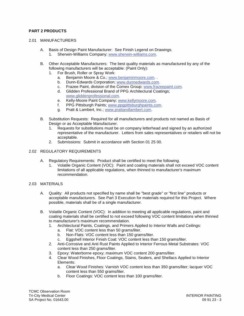
TCMC Observation RoomTri-City Medical Center INTERIOR PAINTINGSA Project No. 01643.00 09 91 23 - 3
PART 2 PRODUCTS
2.01 MANUFACTURERS
A. Basis of Design Paint Manufacturer: See Finish Legend on Drawings.1. Sherwin-Williams Company; www.sherwin-williams.com.
B. Other Acceptable Manufacturers: The best quality materials as manufactured by any of the following manufacturers will be acceptable: (Paint Only):1. For Brush, Roller or Spray Work:
a. Benjamin Moore & Co.; www.benjaminmoore.com. .b. Dunn-Edwards Corporation; www.dunnedwards.com.c. Frazee Paint, division of the Comex Group; www.frazeepaint.com.d. Glidden Professional Brand of PPG Architectural Coatings;
www.gliddenprofessional.com.e. Kelly-Moore Paint Company; www.kellymoore.com.f. PPG Pittsburgh Paints; www.ppgpittsburghpaints.com.g. Pratt & Lambert, Inc.; www.prattandlambert.com.
B. Substitution Requests: Required for all manufacturers and products not named as Basis of Design or as Acceptable Manufacturer.1. Requests for substitutions must be on company letterhead and signed by an authorized
representative of the manufacturer. Letters from sales representatives or retailers will not be acceptable.
2. Submissions: Submit in accordance with Section 01 25 00.
2.02 REGULATORY REQUIREMENTS
A. Regulatory Requirements: Product shall be certified to meet the following.1. Volatile Organic Content (VOC): Paint and coating materials shall not exceed VOC content
limitations of all applicable regulations, when thinned to manufacturer's maximum recommendation.
2.03 MATERIALS
A. Quality: All products not specified by name shall be "best grade" or "first line" products or acceptable manufacturers. See Part 3 Execution for materials required for this Project. Where possible, materials shall be of a single manufacturer.
B. Volatile Organic Content (VOC): In addition to meeting all applicable regulations, paint andcoating materials shall be certified to not exceed following VOC content limitations when thinned to manufacturer's maximum recommendation. 1. Architectural Paints, Coatings, and Primers Applied to Interior Walls and Ceilings:
a. Flat: VOC content less than 50 grams/liter.b. Non-Flats: VOC content less than 150 grams/liter.c. Eggshell Interior Finish Coat: VOC content less than 150 grams/liter.
2. Anti-Corrosive and Anti Rust Paints Applied to Interior Ferrous Metal Substrates: VOC content less than 250 grams/liter.
3. Epoxy: Waterborne epoxy; maximum VOC content 200 grams/liter.4. Clear Wood Finishes, Floor Coatings, Stains, Sealers, and Shellacs Applied to Interior
Elements: a. Clear Wood Finishes: Varnish VOC content less than 350 grams/liter; lacquer VOC
content less than 550 grams/liter.b. Floor Coatings: VOC content less than 100 grams/liter.
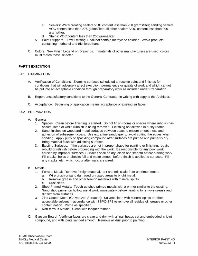
TCMC Observation RoomTri-City Medical Center INTERIOR PAINTINGSA Project No. 01643.00 09 91 23 - 4
c. Sealers: Waterproofing sealers VOC content less than 250 grams/liter; sanding sealers VOC content less than 275 grams/liter; all other sealers VOC content less than 200 grams/liter.
d. Stains: VOC content less than 250 grams/liter.5. Paint Strippers – Low-Emitting: Shall not contain methylene chloride. Avoid products
containing methanol and trichloroethane.
C. Colors: See Finish Legend on Drawings. If materials of other manufacturers are used, colors must match those selected.
PART 3 EXECUTION
3.01 EXAMINATION
A. Verification of Conditions: Examine surfaces scheduled to receive paint and finishes for conditions that will adversely affect execution, permanence or quality of work and which cannot be put into an acceptable condition through preparatory work as included under Preparation.
B. Report unsatisfactory conditions to the General Contractor in writing with copy to the Architect.
C. Acceptance: Beginning of application means acceptance of existing surfaces.
3.02 PREPARATION
A. General:1. Spaces: Clean before finishing is started. Do not finish rooms or spaces where rubbish has
accumulated or while rubbish is being removed. Finishing not allowed in dusty rooms.2. Sand finishes on wood and metal surfaces between coats to ensure smoothness and
adhesion of subsequent coats. Use extra fine sandpaper to avoid cutting the edges when sanding. Apply putty or spackling compound after surfaces are primed and primer is dry. Bring material flush with adjoining surfaces.
3. Existing Surfaces: If the surfaces are not in proper shape for painting or finishing, repair, rebuild or refinish before proceeding with the work. Be responsible for any poor work caused by improper surfaces. Surfaces shall be dry, clean and smooth before starting work. Fill cracks, holes or checks full and make smooth before finish is applied to surfaces. Fill any cracks, etc., which occur after walls are sized.
B. Metals:1. Ferrous Metal: Remove foreign material, rust and mill scale from unprimed metal.
a. Wire brush or sand damaged or rusted areas to bright metal. b. Remove grease and other foreign materials with mineral spirits. c. Dust clean.
2. Shop Primed Metals: Touch-up shop primed metals with a primer similar to the existing. Sand shop primer on hollow metal work immediately before painting to remove grease and dirt film from surfaces.
3. Zinc Coated Metal (Galvanized Surfaces): Solvent clean with mineral spirits or other acceptable solvent in accordance with SSPC-SP1 to remove all residue oil, grease or other contamination. Prime as specified.
4. Non-ferrous Metals: Clean with lacquer thinner.
C. Gypsum Board: Verify surfaces are clean and dry, with all nail heads set and embedded in joint compound, and with joints sanded smooth. Remove all dust prior to painting.
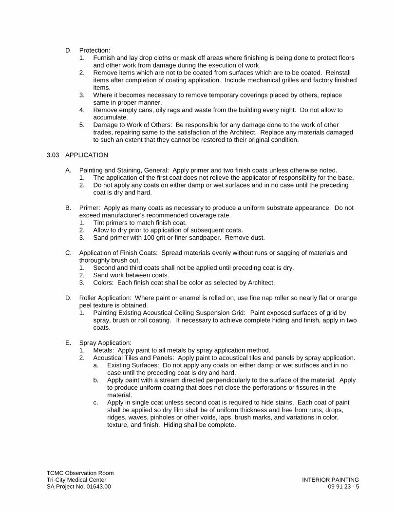
TCMC Observation RoomTri-City Medical Center INTERIOR PAINTINGSA Project No. 01643.00 09 91 23 - 5
D. Protection:1. Furnish and lay drop cloths or mask off areas where finishing is being done to protect floors
and other work from damage during the execution of work. 2. Remove items which are not to be coated from surfaces which are to be coated. Reinstall
items after completion of coating application. Include mechanical grilles and factory finished items.
3. Where it becomes necessary to remove temporary coverings placed by others, replace same in proper manner.
4. Remove empty cans, oily rags and waste from the building every night. Do not allow to accumulate.
5. Damage to Work of Others: Be responsible for any damage done to the work of other trades, repairing same to the satisfaction of the Architect. Replace any materials damaged to such an extent that they cannot be restored to their original condition.
3.03 APPLICATION
A. Painting and Staining, General: Apply primer and two finish coats unless otherwise noted.1. The application of the first coat does not relieve the applicator of responsibility for the base. 2. Do not apply any coats on either damp or wet surfaces and in no case until the preceding
coat is dry and hard.
B. Primer: Apply as many coats as necessary to produce a uniform substrate appearance. Do not exceed manufacturer's recommended coverage rate. 1. Tint primers to match finish coat.2. Allow to dry prior to application of subsequent coats.3. Sand primer with 100 grit or finer sandpaper. Remove dust.
C. Application of Finish Coats: Spread materials evenly without runs or sagging of materials and thoroughly brush out. 1. Second and third coats shall not be applied until preceding coat is dry.2. Sand work between coats.3. Colors: Each finish coat shall be color as selected by Architect.
D. Roller Application: Where paint or enamel is rolled on, use fine nap roller so nearly flat or orange peel texture is obtained. 1. Painting Existing Acoustical Ceiling Suspension Grid: Paint exposed surfaces of grid by
spray, brush or roll coating. If necessary to achieve complete hiding and finish, apply in two coats.
E. Spray Application:1. Metals: Apply paint to all metals by spray application method.2. Acoustical Tiles and Panels: Apply paint to acoustical tiles and panels by spray application.
a. Existing Surfaces: Do not apply any coats on either damp or wet surfaces and in no case until the preceding coat is dry and hard.
b. Apply paint with a stream directed perpendicularly to the surface of the material. Apply to produce uniform coating that does not close the perforations or fissures in the material.
c. Apply in single coat unless second coat is required to hide stains. Each coat of paint shall be applied so dry film shall be of uniform thickness and free from runs, drops, ridges, waves, pinholes or other voids, laps, brush marks, and variations in color, texture, and finish. Hiding shall be complete.
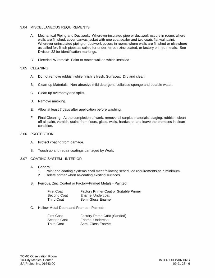
TCMC Observation RoomTri-City Medical Center INTERIOR PAINTINGSA Project No. 01643.00 09 91 23 - 6
3.04 MISCELLANEOUS REQUIREMENTS
A. Mechanical Piping and Ductwork: Wherever insulated pipe or ductwork occurs in rooms where walls are finished, cover canvas jacket with one coat sealer and two coats flat wall paint. Wherever uninsulated piping or ductwork occurs in rooms where walls are finished or elsewhere as called for, finish pipes as called for under ferrous zinc coated, or factory primed metals. See Division 22 for identification markings.
B. Electrical Wiremold: Paint to match wall on which installed.
3.05 CLEANING
A. Do not remove rubbish while finish is fresh. Surfaces: Dry and clean.
B. Clean-up Materials: Non-abrasive mild detergent, cellulose sponge and potable water.
C. Clean up overspray and spills.
D. Remove masking.
E. Allow at least 7 days after application before washing.
F. Final Cleaning: At the completion of work, remove all surplus materials, staging, rubbish; clean off all paint, varnish, stains from floors, glass, walls, hardware; and leave the premises in clean condition.
3.06 PROTECTION
A. Protect coating from damage.
B. Touch up and repair coatings damaged by Work.
3.07 COATING SYSTEM - INTERIOR
A. General:1. Paint and coating systems shall meet following scheduled requirements as a minimum.2. Delete primer when re-coating existing surfaces.
B. Ferrous, Zinc Coated or Factory-Primed Metals - Painted:
First Coat Factory Primer Coat or Suitable PrimerSecond Coat Enamel UndercoatThird Coat Semi-Gloss Enamel
C. Hollow Metal Doors and Frames - Painted:
First Coat Factory-Prime Coat (Sanded)Second Coat Enamel UndercoatThird Coat Semi-Gloss Enamel
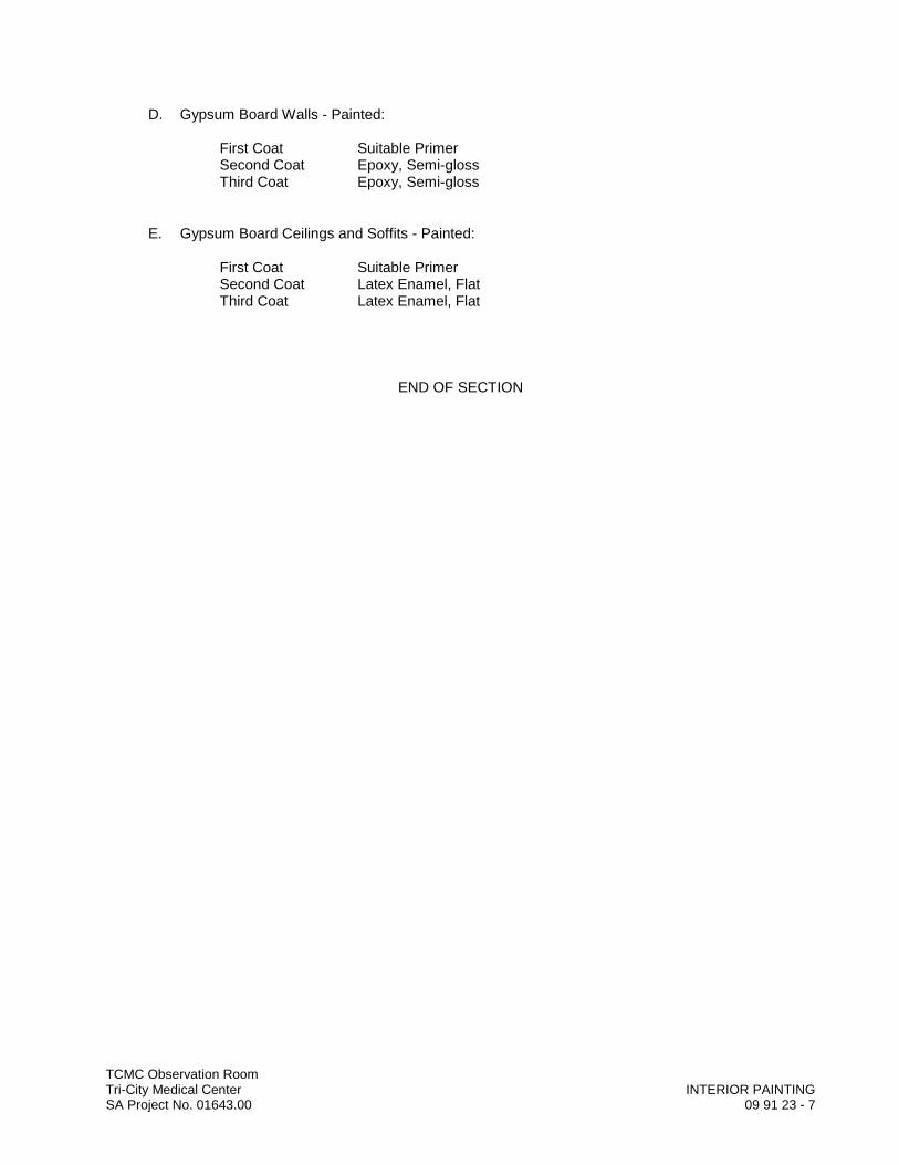
TCMC Observation RoomTri-City Medical Center INTERIOR PAINTINGSA Project No. 01643.00 09 91 23 - 7
D. Gypsum Board Walls - Painted:
First Coat Suitable PrimerSecond Coat Epoxy, Semi-glossThird Coat Epoxy, Semi-gloss
E. Gypsum Board Ceilings and Soffits - Painted:
First Coat Suitable PrimerSecond Coat Latex Enamel, FlatThird Coat Latex Enamel, Flat
END OF SECTION


DIV
ISIO
N 1
0–
SPEC
IALT
IES
DDDDDDDDDDDDDDDDDDDDDIIIIIIIIIIIIIIIVVVVVVVVVVVVVVVVVVVVVVV
IIIIIIIIIIIIIIISSSSSSSSSSSSSSSSSSSSSSSSSIIIIIIIIIIIIIIIIIOOOOOOOOOOOOOOOOOOOOOOOOOOOOO
NNNNNNNNNNNNNNNNNNNN 111111111111111111111111
000000000000000000000000––––––––––––––
SSSSSSSSSSSSSSSSSSSSSSSSSSSSPPPPPPPPPPPPPPPPPPPPPPEEEEEEEEEEEEEEEEEEECCCCCCCCCCCCCCCCCCCCCCCCCCCCC
IIIIIIIIIIIIIIAAAAAAAAAAAAAAAAAAAAAAALLLLLLLLLLLLLLTTTTTTTTTTTTTTTTTTT
IIIIIIIIIIIIIIIIEEEEEEEEEEEEEEEEEEESSSSSSSSSSSSSSSSSSSSSSSSS

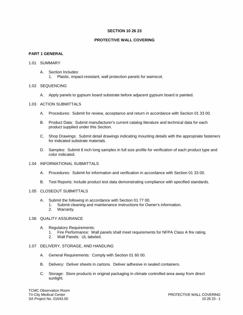
TCMC Observation RoomTri-City Medical Center PROTECTIVE WALL COVERINGSA Project No. 01643.00 10 26 23 - 1
SECTION 10 26 23
PROTECTIVE WALL COVERING
PART 1 GENERAL
1.01 SUMMARY
A. Section Includes:1. Plastic, impact-resistant, wall protection panels for wainscot.
1.02 SEQUENCING
A. Apply panels to gypsum board substrate before adjacent gypsum board is painted.
1.03 ACTION SUBMITTALS
A. Procedures: Submit for review, acceptance and return in accordance with Section 01 33 00.
B. Product Data: Submit manufacturer's current catalog literature and technical data for each product supplied under this Section.
C. Shop Drawings: Submit detail drawings indicating mounting details with the appropriate fasteners for indicated substrate materials.
D. Samples: Submit 8 inch long samples in full size profile for verification of each product type and color indicated.
1.04 INFORMATIONAL SUBMITTALS
A. Procedures: Submit for information and verification in accordance with Section 01 33 00.
B. Test Reports: Include product test data demonstrating compliance with specified standards.
1.05 CLOSEOUT SUBMITTALS
A. Submit the following in accordance with Section 01 77 00.1. Submit cleaning and maintenance instructions for Owner's information.2. Warranty.
1.06 QUALITY ASSURANCE
A. Regulatory Requirements: 1. Fire Performance: Wall panels shall meet requirements for NFPA Class A fire rating.2. Wall Panels: UL labeled.
1.07 DELIVERY, STORAGE, AND HANDLING
A. General Requirements: Comply with Section 01 60 00.
B. Delivery: Deliver sheets in cartons. Deliver adhesive in sealed containers.
C. Storage: Store products in original packaging in climate controlled area away from direct sunlight.
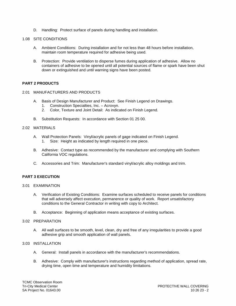
TCMC Observation RoomTri-City Medical Center PROTECTIVE WALL COVERINGSA Project No. 01643.00 10 26 23 - 2
D. Handling: Protect surface of panels during handling and installation.
1.08 SITE CONDITIONS
A. Ambient Conditions: During installation and for not less than 48 hours before installation, maintain room temperature required for adhesive being used.
B. Protection: Provide ventilation to disperse fumes during application of adhesive. Allow no containers of adhesive to be opened until all potential sources of flame or spark have been shut down or extinguished and until warning signs have been posted.
PART 2 PRODUCTS
2.01 MANUFACTURERS AND PRODUCTS
A. Basis of Design Manufacturer and Product: See Finish Legend on Drawings.1. Construction Specialties, Inc. – Acrovyn.2. Color, Texture and Joint Detail: As indicated on Finish Legend.
B. Substitution Requests: In accordance with Section 01 25 00.
2.02 MATERIALS
A. Wall Protection Panels: Vinyl/acrylic panels of gage indicated on Finish Legend.1. Size: Height as indicated by length required in one piece.
B. Adhesive: Contact type as recommended by the manufacturer and complying with Southern California VOC regulations.
C. Accessories and Trim: Manufacturer's standard vinyl/acrylic alloy moldings and trim.
PART 3 EXECUTION
3.01 EXAMINATION
A. Verification of Existing Conditions: Examine surfaces scheduled to receive panels for conditions that will adversely affect execution, permanence or quality of work. Report unsatisfactory conditions to the General Contractor in writing with copy to Architect.
B. Acceptance: Beginning of application means acceptance of existing surfaces.
3.02 PREPARATION
A. All wall surfaces to be smooth, level, clean, dry and free of any irregularities to provide a good adhesive grip and smooth application of wall panels.
3.03 INSTALLATION
A. General: Install panels in accordance with the manufacturer's recommendations.
B. Adhesive: Comply with manufacturer's instructions regarding method of application, spread rate, drying time, open time and temperature and humidity limitations.
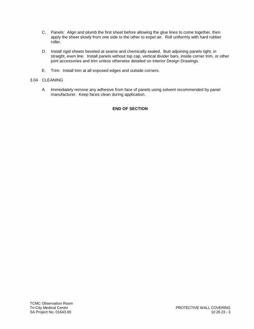
TCMC Observation RoomTri-City Medical Center PROTECTIVE WALL COVERINGSA Project No. 01643.00 10 26 23 - 3
C. Panels: Align and plumb the first sheet before allowing the glue lines to come together, then apply the sheet slowly from one side to the other to expel air. Roll uniformly with hard rubber roller.
D. Install rigid sheets beveled at seams and chemically sealed. Butt adjoining panels tight, in straight, even line. Install panels without top cap, vertical divider bars, inside corner trim, or other joint accessories and trim unless otherwise detailed on Interior Design Drawings.
E. Trim: Install trim at all exposed edges and outside corners.
3.04 CLEANING
A. Immediately remove any adhesive from face of panels using solvent recommended by panel manufacturer. Keep faces clean during application.
END OF SECTION


TCMC Observation RoomTri-City Medical Center TOILET ACCESSORIESSA Project No. 01643.00 10 28 13 - 1
SECTION 10 28 13
TOILET ACCESSORIES
PART 1 GENERAL
1.01 SUMMARY
A. Section Includes:1. Toilet room accessories as indicated and specified.
1.02 REFERENCES
A. Reference Standards: Comply with the following as applicable:1. United States Department of Justice – 2010 ADA Standards for Accessible Design,
September 15, 2010; available at www.ada.gov/ADAStandards_index.htm.
1.03 ACTION SUBMITTALS
A. Procedures: Submit for review, acceptance and return in accordance with Section 01 33 00.
B. Product Data: Submit manufacturer's current product literature.
PART 2 PRODUCTS
2.01 TOILET ACCESSORIES
A. Basis of Design Manufacturers and Products: See Toilet Accessories Schedule on the Drawings.1. Bobrick Washroom Equipment, Inc.; www.bobrick.com.
B. Substitution Requests: Required for all manufacturers and products not named as Basis ofDesign.1. Substitution requests for equivalent products by the following manufacturers will be accepted
for review:a. AJW Architectural Products; www.ajw.com.b. American Specialties, Inc. (ASI); www.americanspecialties.com.c. Bradley Corporation; www.bradleycorp.com.d. Gamco, division of Bobrick Washroom Equipment, Inc.; www.gamcousa.com.
2. Substitution requests for products by other manufacturers may or may not be reviewed at Architect’s option.
3. Submissions: Submit in accordance with Section 01 25 00.
PART 3 EXECUTION
3.01 EXAMINATION
A. Verification of Conditions: Comply with Section 01 71 16.1. Existing Conditions:
a. Verify solid blocking in partitions and walls as required for proper support of toilet accessories.

TCMC Observation RoomTri-City Medical Center TOILET ACCESSORIESSA Project No. 01643.00 10 28 13 - 2
B. Notification: Notify General Contractor of unsatisfactory conditions in writing with copy to Architect.
C. Acceptance: Beginning of work means acceptance of existing conditions by installer.
3.02 INSTALLATION
A. Fasten accessories rigidly and securely to walls using methods and materials recommended by manufacturer.
B. Locate and mount at heights complying with local, state and ADA Standards.
3.03 ADJUSTMENT
A. Before final inspection, inspect each accessory installation for rigid and secure installation. Take action necessary for rigid and secure installations.
END OF SECTION

DIV
ISIO
N 1
1–
EQU
IPM
ENT
DDDDDDDDDDDDDDDDDDDDDDIIIIIIIIIIIIIIIVVVVVVVVVVVVVVVVVVVVVVVV
IIIIIIIIIIIIIIIISSSSSSSSSSSSSSSSSSSSSSSSIIIIIIIIIIIIIIIIIIOOOOOOOOOOOOOOOOOOOOOOOOOOOOOO
NNNNNNNNNNNNNNNNNNNNN1111111111111111111111111111111111111111111
–––––––––––––––––EEEEEEEEEEEEEEEEEEQQQQQQQQQQQQQQQQQQQQQQQQQQQ
UUUUUUUUUUUUUUUUUUUUUUIIIIIIIIIIIIIIIIIIIPPPPPPPPPPPPPPPPPPPPPP
MMMMMMMMMMMMMMMMMMMMMMMEEEEEEEEEEEEEEEEEEENNNNNNNNNNNNNNNNNNNNNNN
TTTTTTTTTTTTTTTTTTT

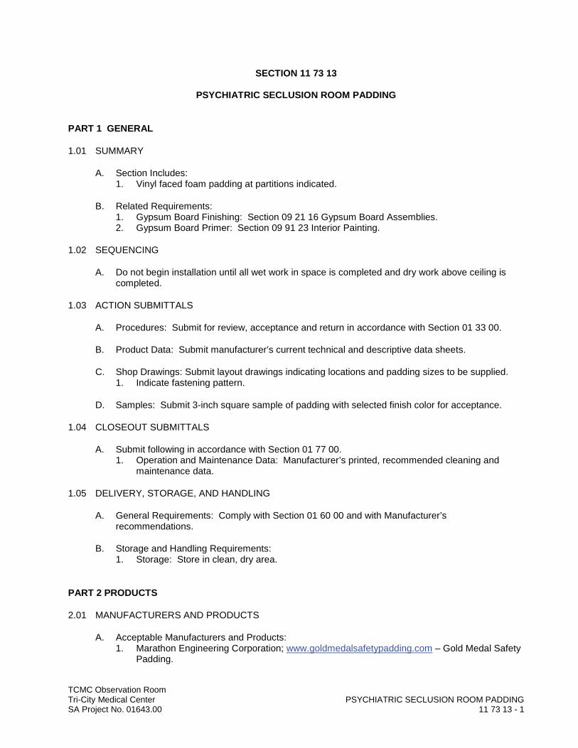
TCMC Observation RoomTri-City Medical Center PSYCHIATRIC SECLUSION ROOM PADDINGSA Project No. 01643.00 11 73 13 - 1
SECTION 11 73 13
PSYCHIATRIC SECLUSION ROOM PADDING
PART 1 GENERAL
1.01 SUMMARY
A. Section Includes:1. Vinyl faced foam padding at partitions indicated.
B. Related Requirements:1. Gypsum Board Finishing: Section 09 21 16 Gypsum Board Assemblies.2. Gypsum Board Primer: Section 09 91 23 Interior Painting.
1.02 SEQUENCING
A. Do not begin installation until all wet work in space is completed and dry work above ceiling is completed.
1.03 ACTION SUBMITTALS
A. Procedures: Submit for review, acceptance and return in accordance with Section 01 33 00.
B. Product Data: Submit manufacturer’s current technical and descriptive data sheets.
C. Shop Drawings: Submit layout drawings indicating locations and padding sizes to be supplied.1. Indicate fastening pattern.
D. Samples: Submit 3-inch square sample of padding with selected finish color for acceptance.
1.04 CLOSEOUT SUBMITTALS
A. Submit following in accordance with Section 01 77 00.1. Operation and Maintenance Data: Manufacturer’s printed, recommended cleaning and
maintenance data.
1.05 DELIVERY, STORAGE, AND HANDLING
A. General Requirements: Comply with Section 01 60 00 and with Manufacturer’s recommendations.
B. Storage and Handling Requirements:1. Storage: Store in clean, dry area.
PART 2 PRODUCTS
2.01 MANUFACTURERS AND PRODUCTS
A. Acceptable Manufacturers and Products:1. Marathon Engineering Corporation; www.goldmedalsafetypadding.com – Gold Medal Safety
Padding.
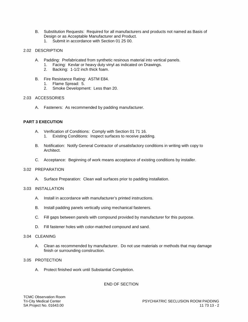
TCMC Observation RoomTri-City Medical Center PSYCHIATRIC SECLUSION ROOM PADDINGSA Project No. 01643.00 11 73 13 - 2
B. Substitution Requests: Required for all manufacturers and products not named as Basis of Design or as Acceptable Manufacturer and Product.1. Submit in accordance with Section 01 25 00.
2.02 DESCRIPTION
A. Padding: Prefabricated from synthetic resinous material into vertical panels.1. Facing: Kevlar or heavy duty vinyl as indicated on Drawings.2. Backing: 1-1/2 inch thick foam.
B. Fire Resistance Rating: ASTM E84.1. Flame Spread: 5.2. Smoke Development: Less than 20.
2.03 ACCESSORIES
A. Fasteners: As recommended by padding manufacturer.
PART 3 EXECUTION
A. Verification of Conditions: Comply with Section 01 71 16.1. Existing Conditions: Inspect surfaces to receive padding.
B. Notification: Notify General Contractor of unsatisfactory conditions in writing with copy to Architect.
C. Acceptance: Beginning of work means acceptance of existing conditions by installer.
3.02 PREPARATION
A. Surface Preparation: Clean wall surfaces prior to padding installation.
3.03 INSTALLATION
A. Install in accordance with manufacturer’s printed instructions.
B. Install padding panels vertically using mechanical fasteners.
C. Fill gaps between panels with compound provided by manufacturer for this purpose.
D. Fill fastener holes with color-matched compound and sand.
3.04 CLEANING
A. Clean as recommended by manufacturer. Do not use materials or methods that may damage finish or surrounding construction.
3.05 PROTECTION
A. Protect finished work until Substantial Completion.
END OF SECTION

DIV
ISIO
N 1
2–
FUR
NIS
HIN
GS
DDDDDDDDDDDDDDDDDDDDDIIIIIIIIIIIIIIIVVVVVVVVVVVVVVVVVVVVVVV
IIIIIIIIIIIIIIISSSSSSSSSSSSSSSSSSSSSSSSSIIIIIIIIIIIIIIIIIOOOOOOOOOOOOOOOOOOOOOOOOOOOOO
NNNNNNNNNNNNNNNNNNN 111111111111111111111111
2222222222222222222222222––––––––––––––
FFFFFFFFFFFFFFFFFFUUUUUUUUUUUUUUUUUUUUUUURRRRRRRRRRRRRRRRRRRRR
NNNNNNNNNNNNNNNNNNNIIIIIIIIIIIIIIISSSSSSSSSSSSSSSSSSSSSSSS
HHHHHHHHHHHHHHHHHHHHHIIIIIIIIIIIIIIINNNNNNNNNNNNNNNNNNNN
GGGGGGGGGGGGGGGGGGGGGGGGGGGGSSSSSSSSSSSSSSSSSSSSSSSSSS

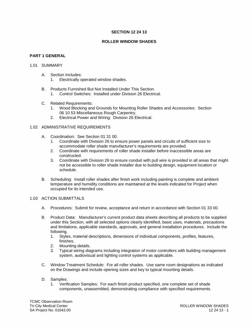
TCMC Observation RoomTri-City Medical Center ROLLER WINDOW SHADESSA Project No. 01643.00 12 24 13 - 1
SECTION 12 24 13
ROLLER WINDOW SHADES
PART 1 GENERAL
1.01 SUMMARY
A. Section Includes:1. Electrically operated window shades.
B. Products Furnished But Not Installed Under This Section. 1. Control Switches: Installed under Division 26 Electrical.
C. Related Requirements:1. Wood Blocking and Grounds for Mounting Roller Shades and Accessories: Section
06,10,53 Miscellaneous Rough Carpentry.2. Electrical Power and Wiring: Division 26 Electrical.
1.02 ADMINISTRATIVE REQUIREMENTS
A. Coordination: See Section 01 31 00.1. Coordinate with Division 26 to ensure power panels and circuits of sufficient size to
accommodate roller shade manufacturer’s requirements are provided.2. Coordinate with requirements of roller shade installer before inaccessible areas are
constructed.3. Coordinate with Division 26 to ensure conduit with pull wire is provided in all areas that might
not be accessible to roller shade installer due to building design, equipment location or schedule.
B. Scheduling: Install roller shades after finish work including painting is complete and ambient temperature and humidity conditions are maintained at the levels indicated for Project when occupied for its intended use.
1.03 ACTION SUBMITTALS
A. Procedures: Submit for review, acceptance and return in accordance with Section 01 33 00.
B. Product Data: Manufacturer's current product data sheets describing all products to be supplied under this Section, with all selected options clearly identified, basic uses, materials, precautions and limitations, applicable standards, approvals, and general installation procedures. Include the following.1. Styles, material descriptions, dimensions of individual components, profiles, features,
finishes.2. Mounting details.3. Typical wiring diagrams including integration of motor controllers with building management
system, audiovisual and lighting control systems as applicable.
C. Window Treatment Schedule: For all roller shades. Use same room designations as indicated on the Drawings and include opening sizes and key to typical mounting details.
D. Samples:1. Verification Samples: For each finish product specified, one complete set of shade
components, unassembled, demonstrating compliance with specified requirements.
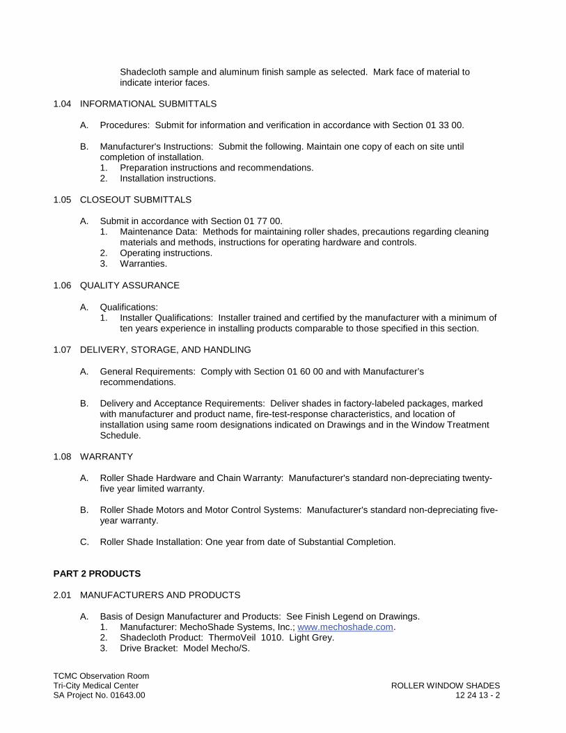
TCMC Observation RoomTri-City Medical Center ROLLER WINDOW SHADESSA Project No. 01643.00 12 24 13 - 2
Shadecloth sample and aluminum finish sample as selected. Mark face of material to indicate interior faces.
1.04 INFORMATIONAL SUBMITTALS
A. Procedures: Submit for information and verification in accordance with Section 01 33 00.
B. Manufacturer's Instructions: Submit the following. Maintain one copy of each on site until completion of installation.1. Preparation instructions and recommendations.2. Installation instructions.
1.05 CLOSEOUT SUBMITTALS
A. Submit in accordance with Section 01 77 00.1. Maintenance Data: Methods for maintaining roller shades, precautions regarding cleaning
materials and methods, instructions for operating hardware and controls.2. Operating instructions. 3. Warranties.
1.06 QUALITY ASSURANCE
A. Qualifications:1. Installer Qualifications: Installer trained and certified by the manufacturer with a minimum of
ten years experience in installing products comparable to those specified in this section.
1.07 DELIVERY, STORAGE, AND HANDLING
A. General Requirements: Comply with Section 01 60 00 and with Manufacturer’s recommendations.
B. Delivery and Acceptance Requirements: Deliver shades in factory-labeled packages, marked with manufacturer and product name, fire-test-response characteristics, and location of installation using same room designations indicated on Drawings and in the Window Treatment Schedule.
1.08 WARRANTY
A. Roller Shade Hardware and Chain Warranty: Manufacturer's standard non-depreciating twenty-five year limited warranty.
B. Roller Shade Motors and Motor Control Systems: Manufacturer's standard non-depreciating five-year warranty.
C. Roller Shade Installation: One year from date of Substantial Completion.
PART 2 PRODUCTS
2.01 MANUFACTURERS AND PRODUCTS
A. Basis of Design Manufacturer and Products: See Finish Legend on Drawings.1. Manufacturer: MechoShade Systems, Inc.; www.mechoshade.com.2. Shadecloth Product: ThermoVeil 1010. Light Grey. 3. Drive Bracket: Model Mecho/S.
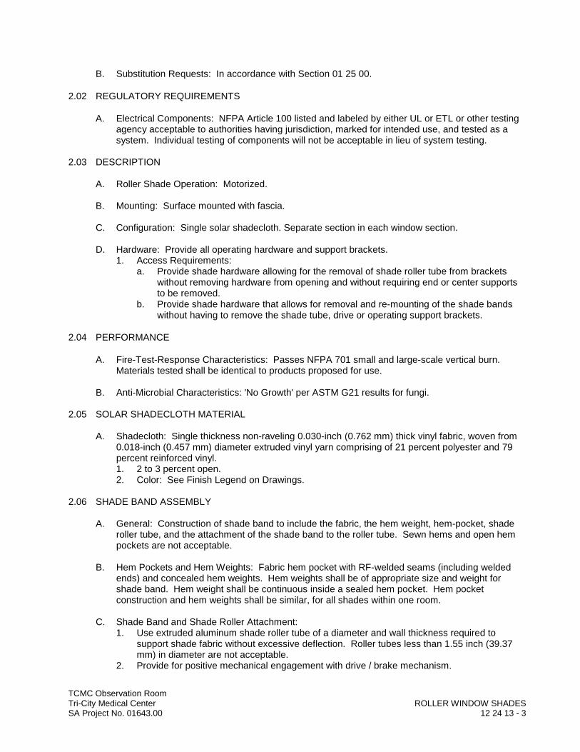
TCMC Observation RoomTri-City Medical Center ROLLER WINDOW SHADESSA Project No. 01643.00 12 24 13 - 3
B. Substitution Requests: In accordance with Section 01 25 00.
2.02 REGULATORY REQUIREMENTS
A. Electrical Components: NFPA Article 100 listed and labeled by either UL or ETL or other testing agency acceptable to authorities having jurisdiction, marked for intended use, and tested as a system. Individual testing of components will not be acceptable in lieu of system testing.
2.03 DESCRIPTION
A. Roller Shade Operation: Motorized.
B. Mounting: Surface mounted with fascia.
C. Configuration: Single solar shadecloth. Separate section in each window section.
D. Hardware: Provide all operating hardware and support brackets. 1. Access Requirements:
a. Provide shade hardware allowing for the removal of shade roller tube from brackets without removing hardware from opening and without requiring end or center supports to be removed.
b. Provide shade hardware that allows for removal and re-mounting of the shade bands without having to remove the shade tube, drive or operating support brackets.
2.04 PERFORMANCE
A. Fire-Test-Response Characteristics: Passes NFPA 701 small and large-scale vertical burn. Materials tested shall be identical to products proposed for use.
B. Anti-Microbial Characteristics: 'No Growth' per ASTM G21 results for fungi.
2.05 SOLAR SHADECLOTH MATERIAL
A. Shadecloth: Single thickness non-raveling 0.030-inch (0.762 mm) thick vinyl fabric, woven from 0.018-inch (0.457 mm) diameter extruded vinyl yarn comprising of 21 percent polyester and 79 percent reinforced vinyl.1. 2 to 3 percent open.2. Color: See Finish Legend on Drawings.
2.06 SHADE BAND ASSEMBLY
A. General: Construction of shade band to include the fabric, the hem weight, hem-pocket, shade roller tube, and the attachment of the shade band to the roller tube. Sewn hems and open hem pockets are not acceptable.
B. Hem Pockets and Hem Weights: Fabric hem pocket with RF-welded seams (including welded ends) and concealed hem weights. Hem weights shall be of appropriate size and weight for shade band. Hem weight shall be continuous inside a sealed hem pocket. Hem pocket construction and hem weights shall be similar, for all shades within one room.
C. Shade Band and Shade Roller Attachment:1. Use extruded aluminum shade roller tube of a diameter and wall thickness required to
support shade fabric without excessive deflection. Roller tubes less than 1.55 inch (39.37 mm) in diameter are not acceptable.
2. Provide for positive mechanical engagement with drive / brake mechanism.

TCMC Observation RoomTri-City Medical Center ROLLER WINDOW SHADESSA Project No. 01643.00 12 24 13 - 4
3. Provide for positive mechanical attachment of shade band to roller tube; shade band shall be made removable / replaceable with a "snap-on" snap-off" spline mounting, without having to remove shade roller from shade brackets.
4. Mounting spline shall not require use of adhesives, adhesive tapes, staples, and/or rivets.5. Any method of attaching shade band to roller tube that requires the use of: adhesive,
adhesive tapes, staples, and/or rivets are not acceptable.
2.07 HARDWARE
A. Access and Material Requirements:1. Provide shade hardware allowing for the removal of shade roller tube from brackets without
removing hardware from opening and without requiring end or center supports to be removed.
2. Provide shade hardware that allows for removal and re-mounting of the shade bands without having to remove the shade tube, drive or operating support brackets.
B. Motorized Shade Hardware and Shade Brackets:1. Provide shade hardware constructed of minimum 1/8-inch (3.18 mm) thick plated steel, or
heavier, thicker, as required to support 150 percent of the full weight of each shade. 2. Provide shade hardware system that allows for field adjustment of motor or replacement of
any operable hardware component without requiring removal of brackets, regardless of mounting position (inside, or outside mount).
C. Manual Operated Chain Drive Hardware and Brackets:1. Provide for universal, regular and offset drive capacity, allowing drive chain to fall at front,
rear or non-offset for all shade drive end brackets. Universal offset shall be adjustable for future change.
2. Provide hardware capable for installation of a removable fascia, for both regular and/or reverse roll, which shall be installed without exposed fastening devices of any kind.
3. Provide shade hardware system that allows for removable regular and/or reverse roll fascias to be mounted continuously across two or more shade bands without requiring exposed fasteners of any kind.
D. Drive Chain: #10 qualified stainless steel chain rated to 90 lb. (41 kg) minimum breaking strength.
2.08 SHADE MOTOR DRIVE SYSTEM
A. Shade Motors:1. Tubular, asynchronous (non-synchronous) motors, with built-in reversible capacitor
operating at 110v AC (60hz), single phase, temperature Class A, thermally protected, totally enclosed, maintenance free with line voltage power supply equipped with locking disconnect plug assembly furnished with each motor.
2. Conceal motors inside shade roller tube.3. Maximum current draw for each shade motor of 2.3 amps.4. Use motors rated at the same nominal speed for all shades in the same room.
B. Total hanging weight of shade band shall not exceed 80 percent of the rated lifting capacity of the shade motor and tube assembly.
2.09 MOTOR CONTROL SYSTEMS
A. Specifications and design of shade motors and motor control system are based on the IQ/MLC motor logic control system manufactured by MechoShade Systems, Inc. Other systems may be acceptable provide that all of the following performance capabilities are provided. Motor logic
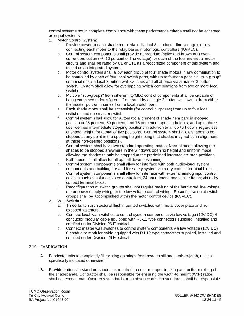
TCMC Observation RoomTri-City Medical Center ROLLER WINDOW SHADESSA Project No. 01643.00 12 24 13 - 5
control systems not in complete compliance with these performance criteria shall not be accepted as equal systems.1. Motor Control System:
a. Provide power to each shade motor via individual 3 conductor line voltage circuits connecting each motor to the relay based motor logic controllers (IQ/MLC).
b. Control system components shall provide appropriate (spike and brown out) over-current protection (+/- 10 percent of line voltage) for each of the four individual motor circuits and shall be rated by UL or ETL as a recognized component of this system and tested as an integrated system.
c. Motor control system shall allow each group of four shade motors in any combination to be controlled by each of four local switch ports, with up to fourteen possible "sub-group" combinations via local 3 button wall switches and all at once via a master 3 button switch. System shall allow for overlapping switch combinations from two or more local switches.
d. Multiple "sub-groups" from different IQ/MLC control components shall be capable of being combined to form "groups" operated by a single 3 button wall switch, from either the master port or in series from a local switch port.
e. Each shade motor shall be accessible (for control purposes) from up to four local switches and one master switch.
f. Control system shall allow for automatic alignment of shade hem bars in stopped position at 25 percent, 50 percent, and 75 percent of opening heights, and up to three user-defined intermediate stopping positions in addition to all up / all down, regardless of shade height, for a total of five positions. Control system shall allow shades to be stopped at any point in the opening height noting that shades may not be in alignment at these non-defined positions).
g. Control system shall have two standard operating modes: Normal mode allowing the shades to be stopped anywhere in the window’s opening height and uniform mode, allowing the shades to only be stopped at the predefined intermediate stop positions. Both modes shall allow for all up / all down positioning.
h. Control system components shall allow for interface with both audiovisual system components and building fire and life safety system via a dry contact terminal block.
i. Control system components shall allow for interface with external analog input control devices such as solar activated controllers, 24 hour timers, and similar items; via a dry contact terminal block.
j. Reconfiguration of switch groups shall not require rewiring of the hardwired line voltage motor power supply wiring, or the low voltage control wiring. Reconfiguration of switch groups shall be accomplished within the motor control device (IQ/MLC).
2. Wall Switches:a. Three-button architectural flush mounted switches with metal cover plate and no
exposed fasteners.b. Connect local wall switches to control system components via low voltage (12V DC) 4-
conductor modular cable equipped with RJ-11 type connectors supplied, installed and certified under Division 26 Electrical.
c. Connect master wall switches to control system components via low voltage (12V DC) 6-conductor modular cable equipped with RJ-12 type connectors supplied, installed and certified under Division 26 Electrical.
2.10 FABRICATION
A. Fabricate units to completely fill existing openings from head to sill and jamb-to-jamb, unless specifically indicated otherwise.
B. Provide battens in standard shades as required to ensure proper tracking and uniform rolling of the shadebands. Contractor shall be responsible for ensuring the width-to-height (W:H) ratios shall not exceed manufacturer's standards or, in absence of such standards, shall be responsible

TCMC Observation RoomTri-City Medical Center ROLLER WINDOW SHADESSA Project No. 01643.00 12 24 13 - 6
for establishing appropriate standards to ensure proper tracking and rolling of the shadecloth within specified standards. Battens shall be roll-formed stainless steel or tempered steel, as required.
C. For railroaded shadebands, provide seams in railroaded multi-width shadebands as required to meet size requirements and in accordance with seam alignment as acceptable to Architect. Seams shall be properly located. Furnish battens in place of plain seams when the width, height, or weight of the shade exceeds manufacturer's standards. In absence of such standards, ensure proper use of seams or battens as required to, and ensure the proper tracking of the railroaded multi-width shadebands.
D. Provide battens for railroaded shades when width-to-height (W:H) ratios meet or exceed manufacturer's standards. In absence of manufacturer's standards, be responsible for proper use and placement of battens to ensure proper tracking and roll of shadebands.
2.11 ACCESSORIES
A. Fascia: Continuous removable extruded aluminum fascia that attaches to shade mounting brackets without the use of adhesives, magnetic strips, or exposed fasteners.1. Fascia shall be able to be installed across two or more shade bands in one piece.2. Fascia shall fully conceal brackets, shade roller and fabric on the tube.3. Provide bracket / fascia end caps where mounting conditions expose outside of roller shade
brackets.4. Notching of fascia for manual chain shall not be acceptable.
PART 3 EXECUTION
3.01 EXAMINATION
A. Do not begin installation until substrates have been properly prepared.
B. If substrate preparation is the responsibility of another installer, notify Architect of unsatisfactory preparation before proceeding.
3.02 PREPARATION
A. Clean surfaces thoroughly prior to installation.
B. Prepare surfaces using the methods recommended by the manufacturer for achieving the best result for the substrate under the Project conditions.
3.03 INSTALLATION
A. Install roller shades level, plumb, square, and true according to manufacturer's written instructions, and located so shade band is not closer than 2 inches (50 mm) to interior face of glass. Allow proper clearances for window operation hardware.
B. Turn-Key Single-Source Responsibility for Motorized Interior Roller Shades: To control the responsibility for performance of motorized roller shade systems, assign the design, engineering, and installation of motorized roller shade systems, motors, controls, and low voltage electrical control wiring specified in this Section to a single manufacturer and their authorized installer/dealer. The Architect will not produce a set of electrical drawings for the installation of control wiring for the motors, or motor controllers of the motorized roller shades. Power wiring (line voltage), shall be provided by the roller shade installer/dealer, in accordance with the
TCMC Observation RoomTri-City Medical Center ROLLER WINDOW SHADESSA Project No. 01643.00 12 24 13 - 7
requirements provided by the manufacturer. Coordinate the following with the roller shade installer/dealer:1. Run line voltage as dedicated home runs (of sufficient quantity, in sufficient capacity as
required) terminating in junction boxes in locations designated on accepted shop drawings.2. Provide and run all line voltage (from the terminating points) to the motor controllers, wire all
roller shade motors to the motor controllers, and provide and run low voltage control wiring from motor controllers to switch/ control locations designated by the Architect. All above-ceiling and concealed wiring shall be plenum-rated, or installed in conduit, as required by the electrical code having jurisdiction.
3.04 ADJUSTING
A. Adjust and balance roller shades to operate smoothly, easily, safely, and free from binding or malfunction throughout entire operational range.
B. Readjust at completion of Project if directed by Architect.
3.05 CLEANING
A. Clean roller shade surfaces after installation, according to manufacturer's written instructions.
3.06 PROTECTION
A. Protect installed products until completion of Project.
B. Touch-up, repair or replace damaged products before Substantial Completion.
3.07 DEMONSTRATION AND TRAINING
A. Engage Installer to train Owner's maintenance personnel to adjust, operate and maintain roller shade systems.
END OF SECTION


TCMC Observation RoomTri-City Medical Center SIMULATED STONE COUNTERTOPSSA Project No. 01643.00 12 36 61 - 1
SECTION 12 36 61
SIMULATED STONE COUNTERTOPS
PART 1 GENERAL
1.01 SUMMARY
A. Section Includes:1. Solid surfacing for countertops.2. Integral sinks where indicated.
B. Related Requirements:1. Steel Supports: Section 05 50 00 Metal Fabrications.2. Plywood Subtops, Custom Cabinet and Countertop Construction: Section 06 41 00
Architectural Casework.
1.02 REFERENCES
A. Reference Standards: See Section 01 42 00. Comply with following: 1. Woodwork Institute (WI) Standards:
a. North American Architectural Woodwork Standards – 3.0 (NAAWS), July 1, 2016.1) Comply with Custom Grade if not otherwise specified.2) Seismic Installation Requirements: Annex 10E.
1.03 ACTION SUBMITTALS
A. Procedures: Submit for review, acceptance and return in accordance with Section 01 33 00.
B. Product Data: Submit catalog data for all countertop surfacing materials and countertop setting and grouting materials.
C. Shop Drawings: Include the following.a. Overall layout of countertop work.b. Type, thickness, and details of countertop materials and components.c. Joints, attachment and anchoring of components.
D. Samples: Submit three sets of samples not less than 12-inch by 12-inch in size of each different color and finish of solid surfacing required. Include in each set the full range of exposed color and texture to be expected in the completed work. Review will be for color and texture only. Retain samples during construction as a standard for judging completed work.
1.04 CLOSEOUT SUBMITTALS
A. Submit the following in accordance with Section 01783.1. Maintenance Data: Submit for countertop surfacing materials. Include cleaning instructions,
scratch removal procedures and materials harmful to facing.
1.05 QUALITY ASSURANCE
A. Qualifications:1. Installer Qualifications: Provide supervision of installation by workmen skilled in this type of
work with at least 5 years’ experience in the installation of similar systems.

TCMC Observation RoomTri-City Medical Center SIMULATED STONE COUNTERTOPSSA Project No. 01643.00 12 36 61 - 2
1.06 DELIVERY, STORAGE, AND HANDLING
A. Delivery: Deliver no components to project site until areas are ready for installation.
B. Storage: Store components indoors prior to installation.
C. Handling: Handle materials to prevent damage to finished surfaces.1. Provide protective coverings to prevent physical damage or staining following installation for
duration of Project.
1.07 AMBIENT CONDITIONS
A. Solid Surfacing: Maintain ambient temperature between 50 and 95 degrees F for 48 hour before, during, and for minimum 7 days after installation of countertops.
B. Comply with minimum temperature requirements of bonding and grouting materials manufacturers.
PART 2 PRODUCTS
2.01 MANUFACTURERS AND PRODUCTS
A. Basis of Design Manufacturers and Products: See Finish Legend on Drawings.
B. Substitution Requests: In accordance with Section 01 25 00.
2.02 MATERIALS
A. Solid Surfacing Material: Solid, nonporous, homogeneous material maintaining the same composition throughout the part with a composition of acrylic polymer, aluminum trihydrate filler and pigment with through body colors meeting ANSI Z124.3 or ANSI Z124.6.1. Size: As indicated.2. Superficial damage to a depth of 0.010 inch (.25 mm) shall be repairable by sanding and/or
polishing.
2.03 FABRICATION
A. Field Measurements: Before fabricating countertops, verify shapes and dimensions of surfaces to be covered.
B. WI Grade: Construct counters as indicated on Drawings and as required for WI Custom Grade work.
C. Solid Surfacing Fabrication: Cut accurately to shape and dimensions shown on final shop drawings. Comply with the fabrication tolerances for the specified finishes.1. Fabricate components to greatest extent practical to sizes and shapes indicated, in
accordance with approved shop drawings and manufacturer’s printed instructions and technical bulletins.
2. Form joints between components using manufacturer’s standard joint adhesive without conspicuous joints. Dress joints (bed and vertical) straight and at 90 degree angle to face unless otherwise shown.a. Reinforce with strip of solid polymer material, 2-inch wide.
TCMC Observation RoomTri-City Medical Center SIMULATED STONE COUNTERTOPSSA Project No. 01643.00 12 36 61 - 3
b. Joint Width: Cut for 1/8-inch joint width. Saw cut or roughly dress back surfaces that will be concealed in the finish work to approximately true planes. Fabricate work to profiles shown, with arises sharp and true, and match at joints between units.
3. Provide corners as detailed.4. Provide factory cutouts for plumbing fittings and bath accessories as indicated on the
drawings.5. Rout and finish component edges with clean, sharp returns.
a. Rout cutouts, radii and contours to template.b. Smooth edges.c. Repair or reject defective and inaccurate work.
6. Fabrication Tolerances:a. Squareness: Panels shall have a maximum out of square (difference in length of the
two diagonal face measurements) differential of not greater than 1/8-inch per 10 feet.b. Warpage: Faces of panels shall not be out of plane more than 1/8-inch for each 10 feet
of either height or width.
2.04 ACCESSORY PRODUCTS
A. Joint Adhesive: Manufacturer’s standard one- or two-part adhesive kit to create inconspicuous, nonporous joints.
B. Sealant: Manufacturer’s standard mildew-resistant, FDA-compliant, NSF 51-compliant (food zone — any type), UL-listed silicone sealant in colors matching components.
C. Sink/Lavatory Mounting Hardware: Manufacturer’s standard bowl clips, panel inserts and fasteners for attachment of undermount sinks/lavatories.
D. Conductive Tape: Manufacturer’s standard aluminum foil tape, with required thickness, for use with cutouts near heat sources.
E. Insulating Felt Tape: Manufacturer’s standard for use with conductive tape in insulating solid surface material from adjacent heat source.
PART 3 EXECUTION
3.01 EXAMINATION
A. Verification of Conditions: 1. Layout: Verify layout of work before beginning installation. 2. Existing Conditions: Before beginning installation, examine surfaces to receive facing for
defects or conditions adversely affecting quality and execution of installation.3. Allowable Substrate Tolerances:
a. Maximum variation in substrate surface: 1/8 inch in 8 feet.b. Maximum height of abrupt irregularities: 1/32 inch.
4. Notification: Notify Contractor and Architect of unsatisfactory conditions in writing.
B. Acceptance: Beginning of work means acceptance of existing conditions by installer.
3.02 PREPARATION
A. Protection: Protect adjoining work surfaces before work begins.
TCMC Observation RoomTri-City Medical Center SIMULATED STONE COUNTERTOPSSA Project No. 01643.00 12 36 61 - 4
B. Cleaning:1. Clean surfaces to remove loose and foreign matter that could impair adhesion.2. Clean panels before setting as recommended by Manufacturer.
C. Surface Preparation: Where possible, correct substrate to conform to allowable substrate tolerances specified. Remove ridges and projections. Fill voids and depressions with patching compound compatible with setting materials and as recommended by Manufacturer.
3.03 INSTALLATION
A. Solid Surfacing, General: Cut to size, seamed and installed with moisture-insensitive adhesive in accordance with Manufacturer's recommendations and as indicated on accepted shop drawings.1. Set with 1/8-inch joints between interior units.2. Minimize joints and pieces less than one half size.3. Job Cutting: Cut to size, seamed in accordance with Manufacturer's recommendations and
as indicated on accepted shop drawings.a. Employ skilled fitters for necessary cutting as the work progresses.b. Locate cuts to be inconspicuous.c. Fit units around projections and at perimeter.d. Smooth and clean cut edges.e. Ensure that trim will completely cover cut edges.
4. Adjustments: Sound surfacing after setting. Replace hollow sounding units.
B. Counters: Construct supports for counters as indicated. Install components plumb, level and rigid, scribed to adjacent finishes, in accordance with approved shop drawings and product data.Securely attach counters to walls and casework, plumb and level.1. Provide product in the largest pieces available.2. Form field joints using manufacturer’s recommended adhesive, with joints inconspicuous in
finished work.a. Exposed joints/seams shall not be allowed.
3. Reinforce field joints with solid surface strips extending a minimum of 1 inch on either side of the seam with the strip being the same thickness as the top.
4. Cut and finish component edges with clean, sharp returns.5. Rout radii and contours to template.6. Anchor securely to base cabinets or other supports.7. Align adjacent countertops and form seams to comply with manufacturer’s written
recommendations using adhesive in color to match countertop.8. Carefully dress joints smooth, remove surface scratches and clean entire surface.9. Install countertops with no more than 1/8-inch (3 mm) sag, bow or other variation from a
straight line.
C. Coved backsplashes and applied sidesplashes:1. Install applied sidesplashes using manufacturer’s standard color-matched silicone sealant.2. Adhere applied sidesplashes to countertops using manufacturer’s standard color-matched
silicone sealant.
3.04 CLEANING
A. Cleaning Solid Surfacing: Clean surfacing not less than 2 days after placement with non-abrasive cleaner. Follow manufacturer's instructions.

TCMC Observation RoomTri-City Medical Center SIMULATED STONE COUNTERTOPSSA Project No. 01643.00 12 36 61 - 5
3.05 PROTECTION
A. Protection: Protect completed work.
END OF SECTION


DIV
ISIO
N 2
2–
PLU
MB
ING
DDDDDDDDDDDDDDDDDDDDDIIIIIIIIIIIIIIIIVVVVVVVVVVVVVVVVVVVVVVVV
IIIIIIIIIIIIIIIISSSSSSSSSSSSSSSSSSSSSSSSSIIIIIIIIIIIIIIIIOOOOOOOOOOOOOOOOOOOOOOOOOOO
NNNNNNNNNNNNNNNNNNNNNNN 22222222222222222222222222
222222222222222222222222––––––––––––
PPPPPPPPPPPPPPPPPPPPPPPLLLLLLLLLLLLLLLLUUUUUUUUUUUUUUUUUUUUUUU
MMMMMMMMMMMMMMMMMMMMMMMMMBBBBBBBBBBBBBBBBBBBBBBB
IIIIIIIIIIIIINNNNNNNNNNNNNNNNNNNNNGGGGGGGGGGGGGGGGGGGGGGGGGGGG


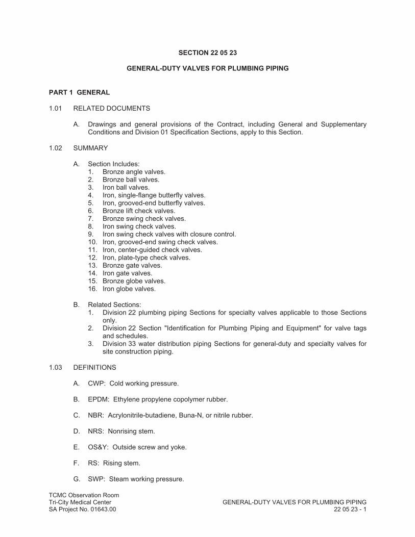
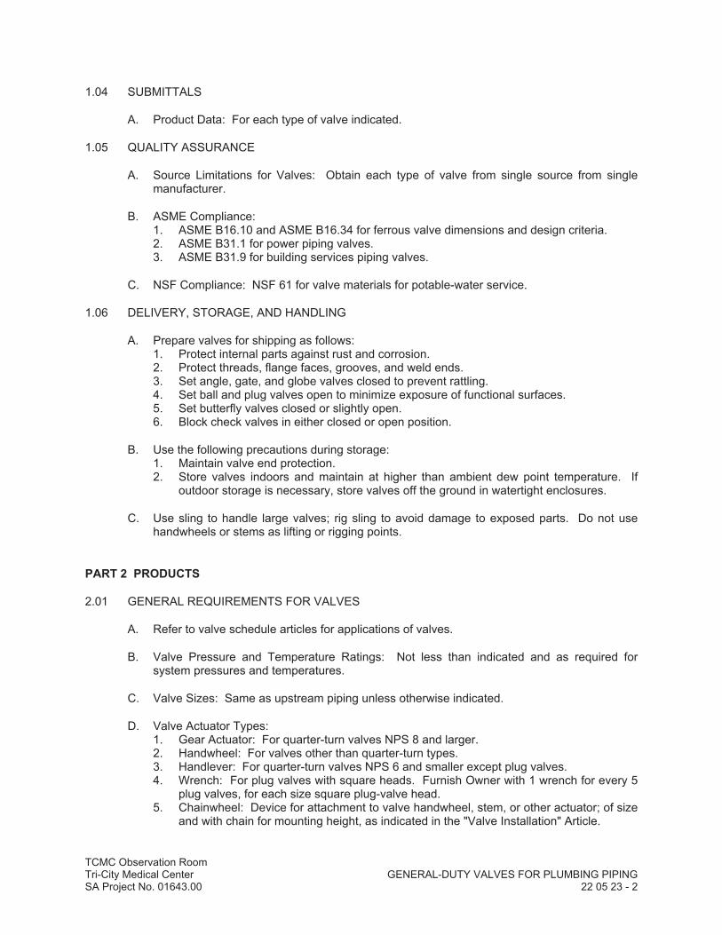
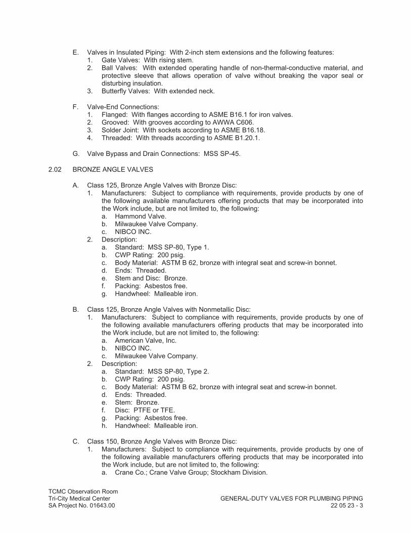
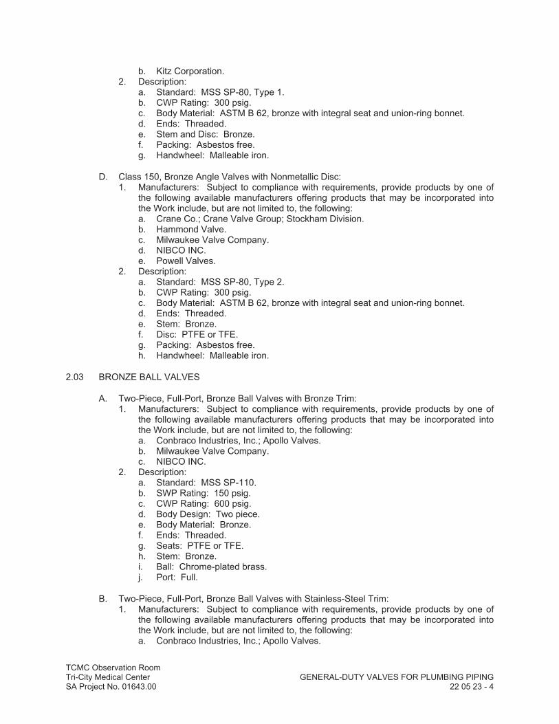

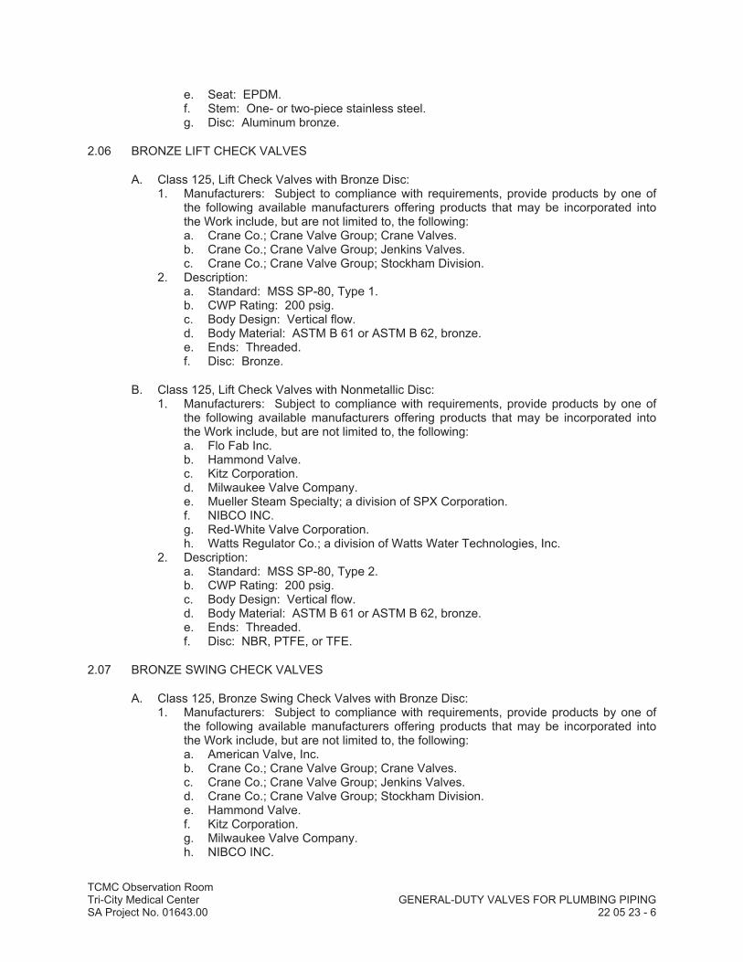
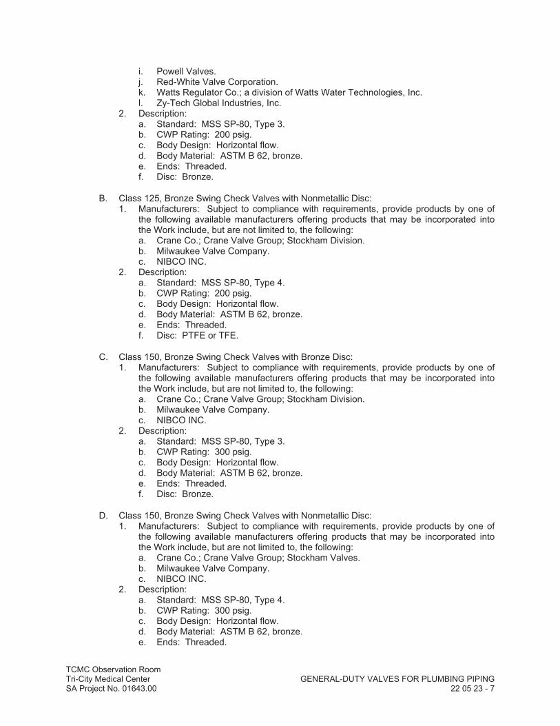
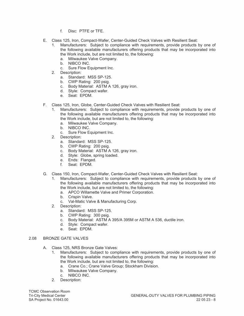

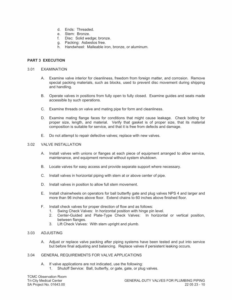


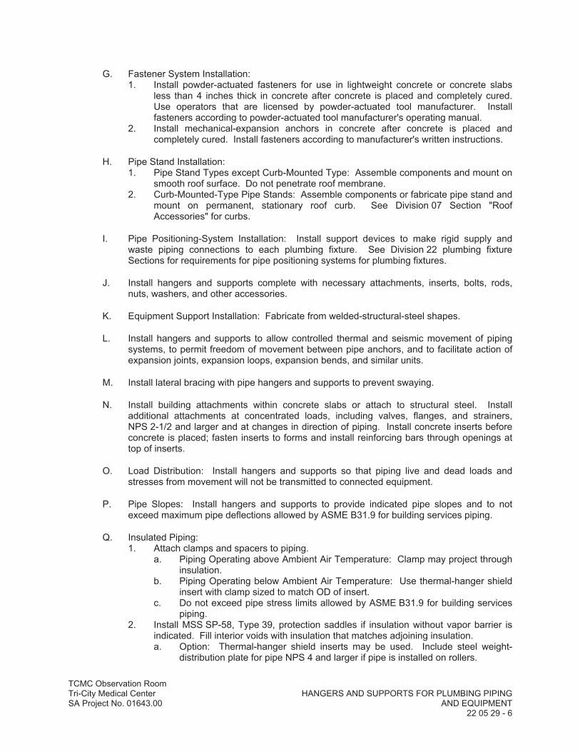
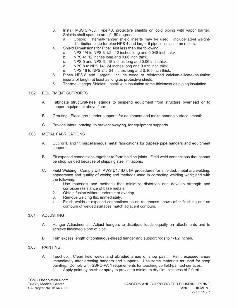
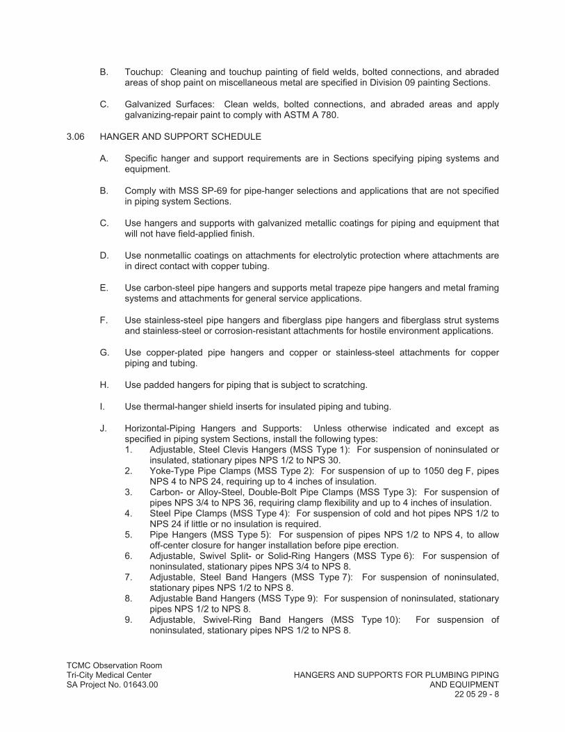
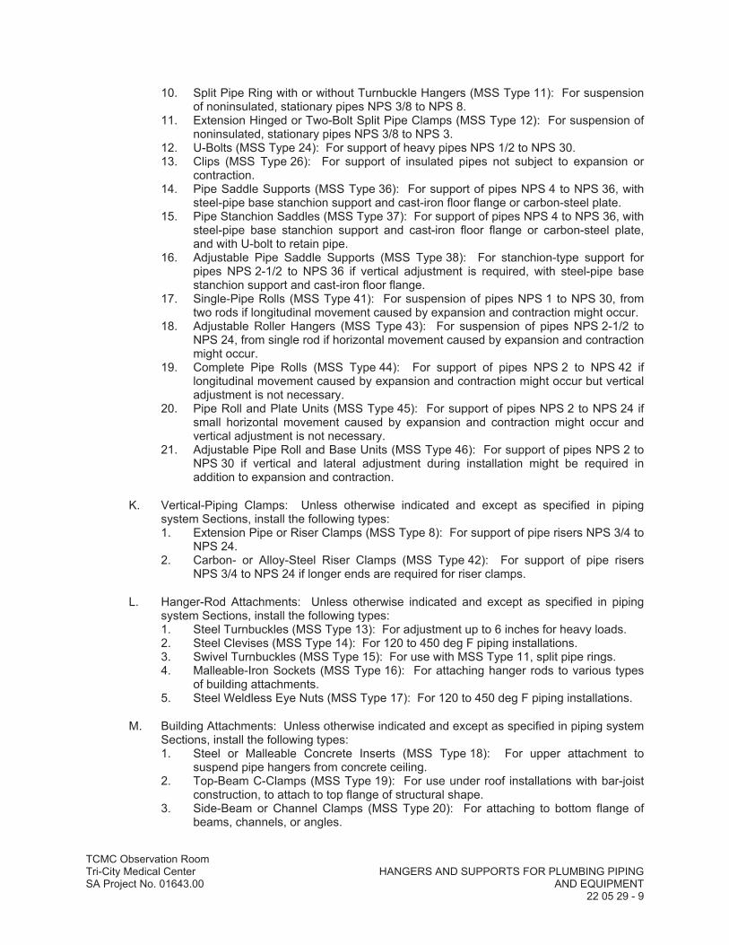


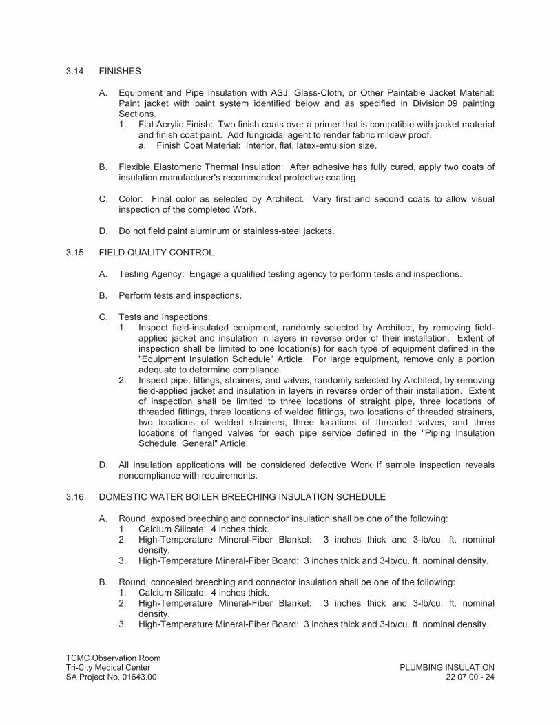


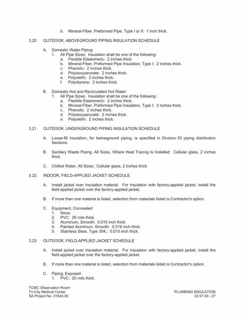
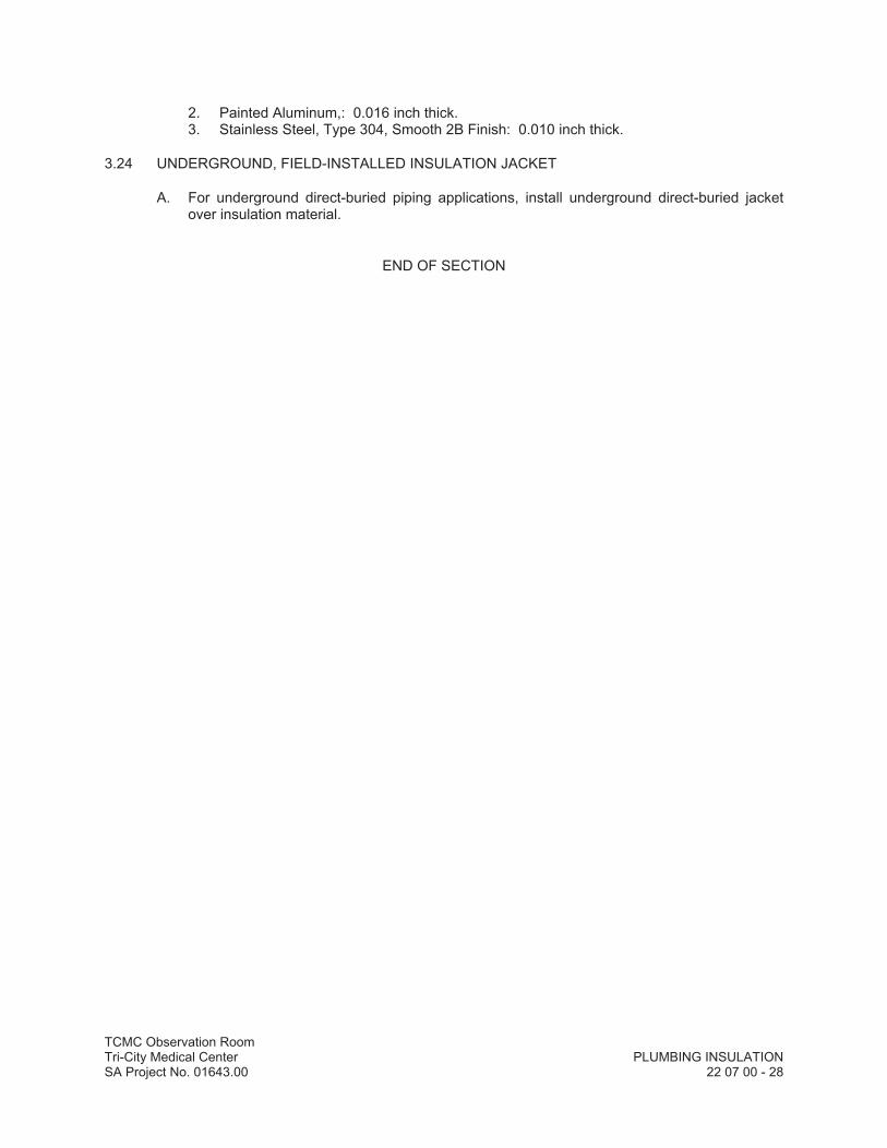


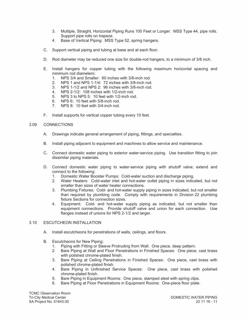


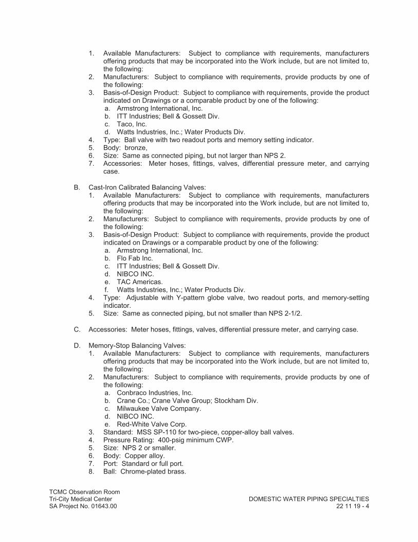
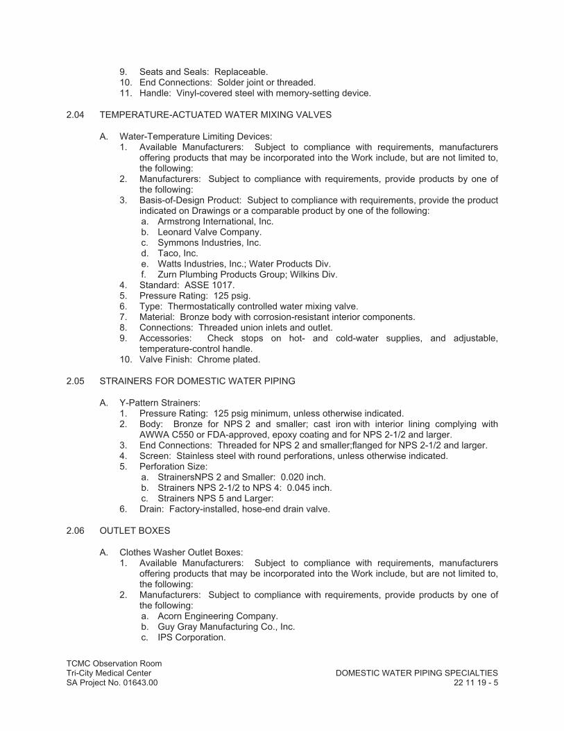
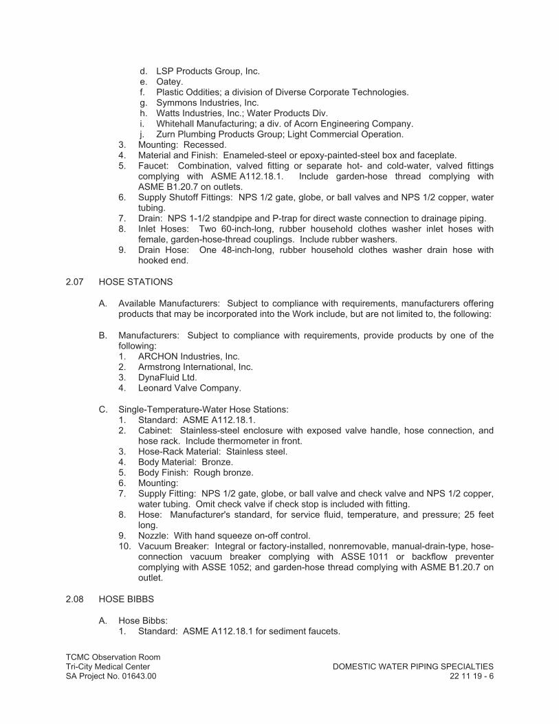
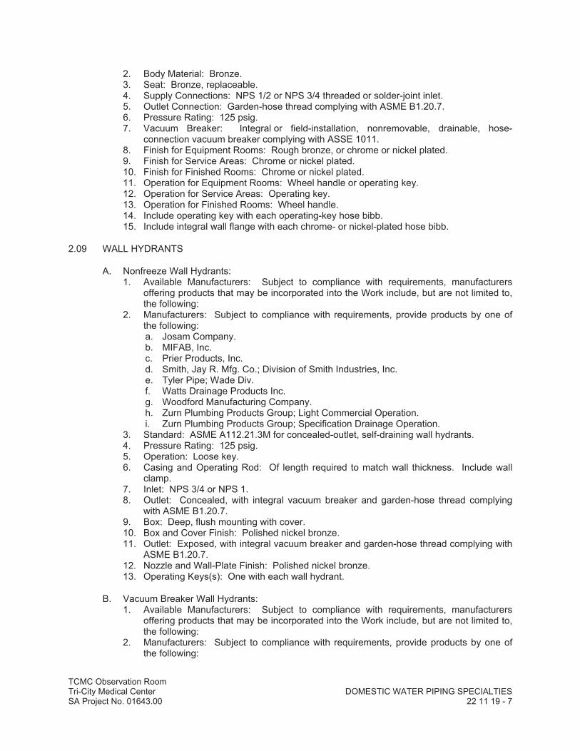


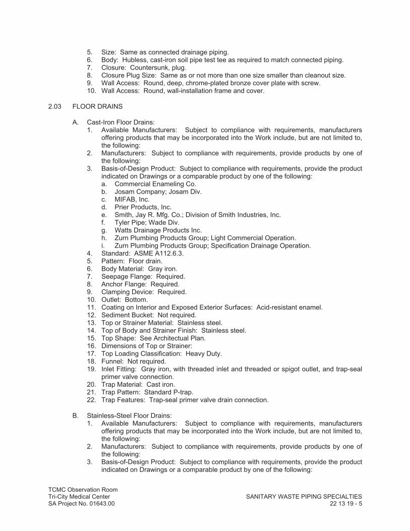
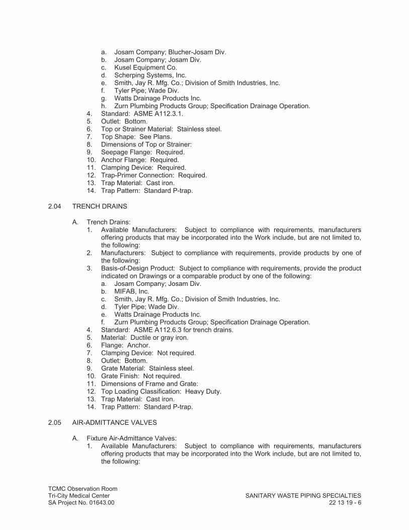
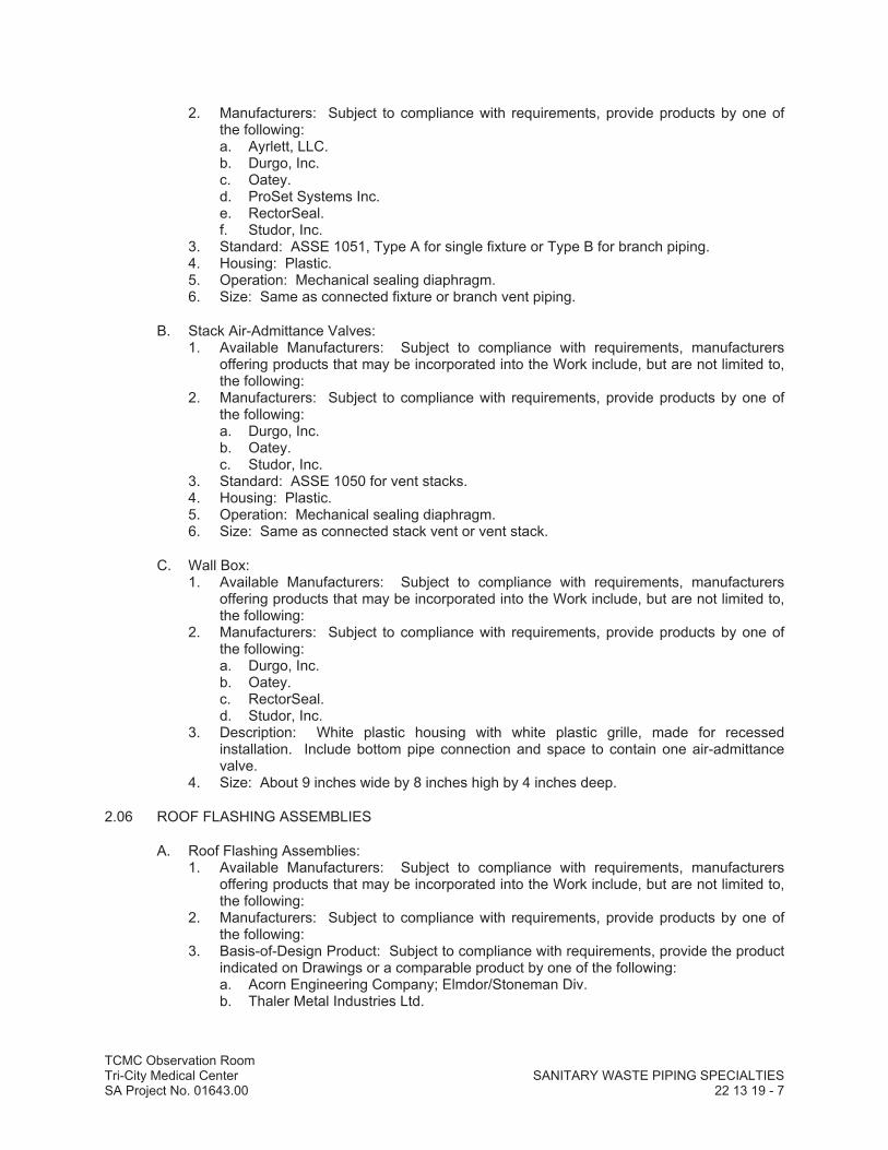
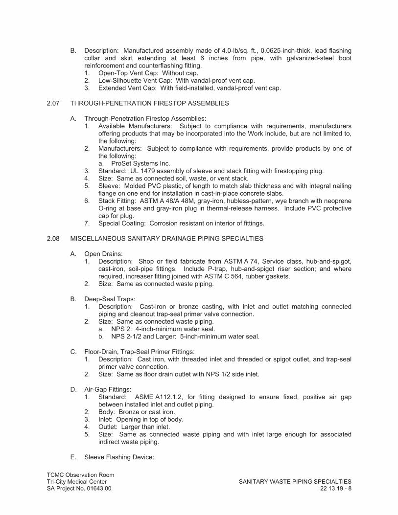


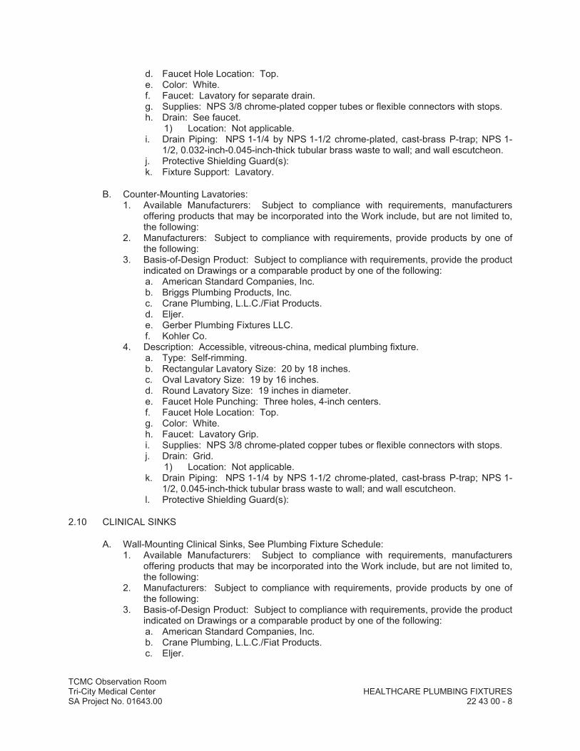
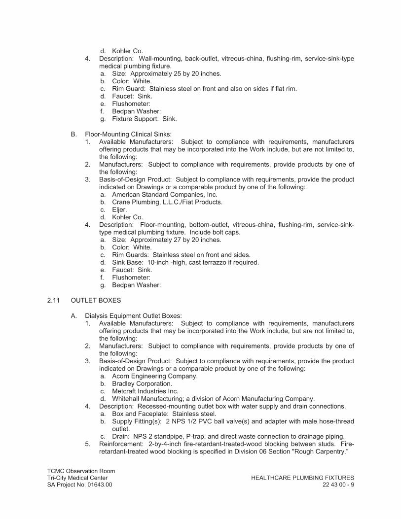
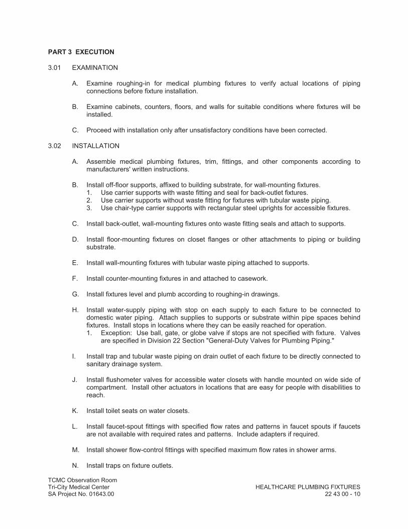
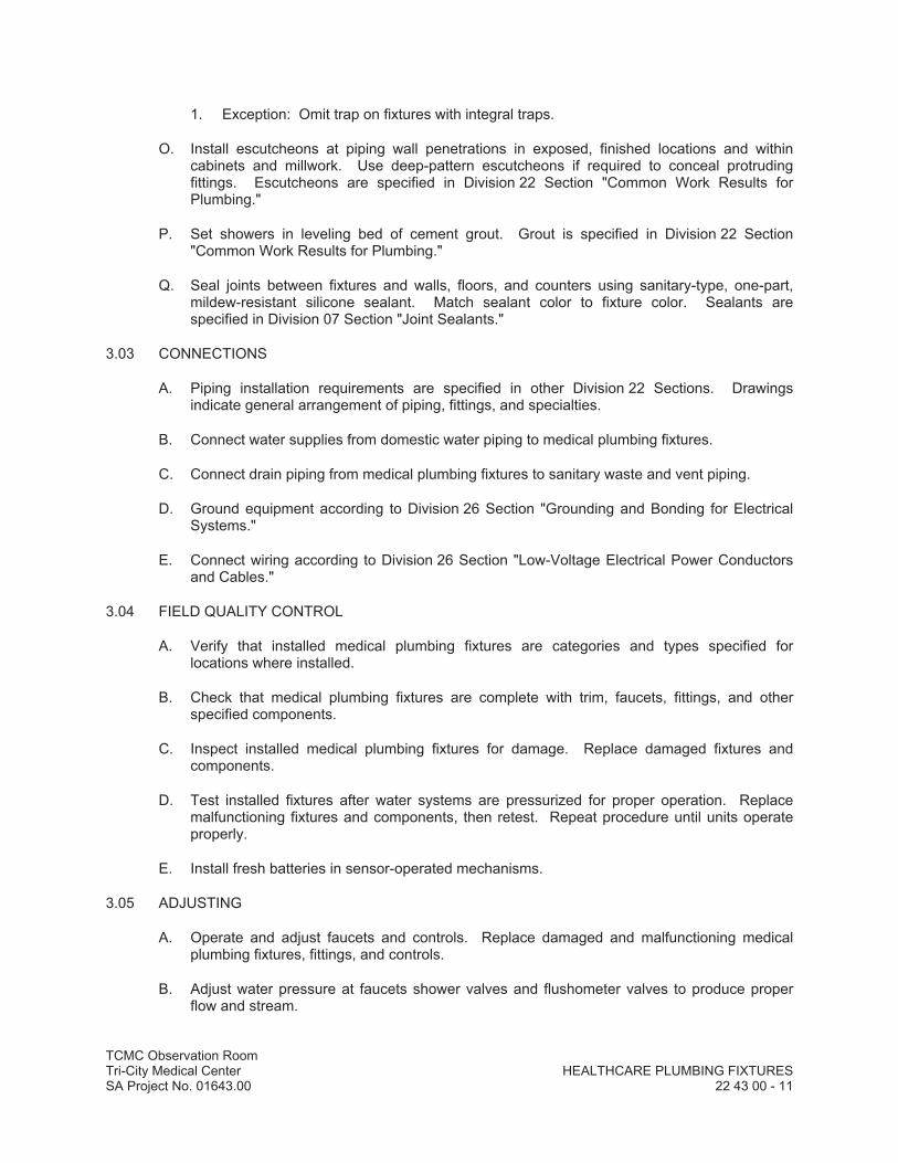

DIV
ISIO
N 2
3–
HVA
CDDDDDDDDDDDDDDDDDDDDDD
IIIIIIIIIIIIIIIVVVVVVVVVVVVVVVVVVVVVVVVIIIIIIIIIIIIIIIISSSSSSSSSSSSSSSSSSSSSSSS
IIIIIIIIIIIIIIIIIOOOOOOOOOOOOOOOOOOOOOOOOOOOOOOONNNNNNNNNNNNNNNNNNN
222222222222222222222222222223333333333333333333333333
–––––––––––HHHHHHHHHHHHHHHHHHHHH
VVVVVVVVVVVVVVVVVVVVVVVAAAAAAAAAAAAAAAAAAAAAAACCCCCCCCCCCCCCCCCCCCCCCCCCCCCC


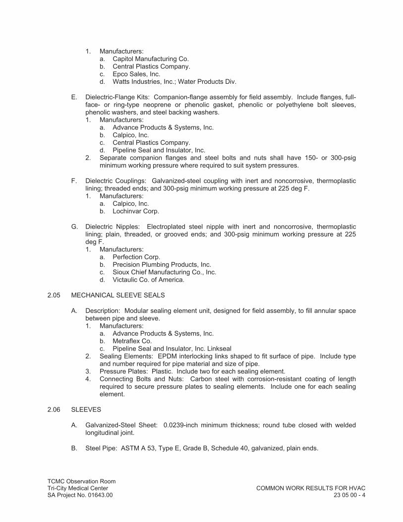
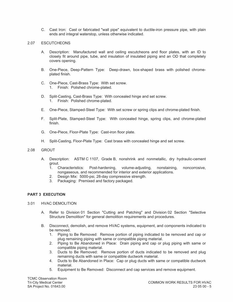

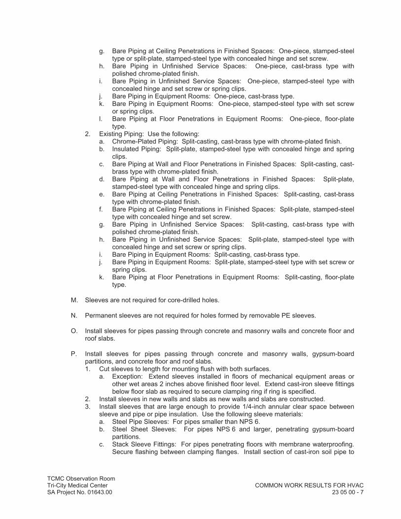
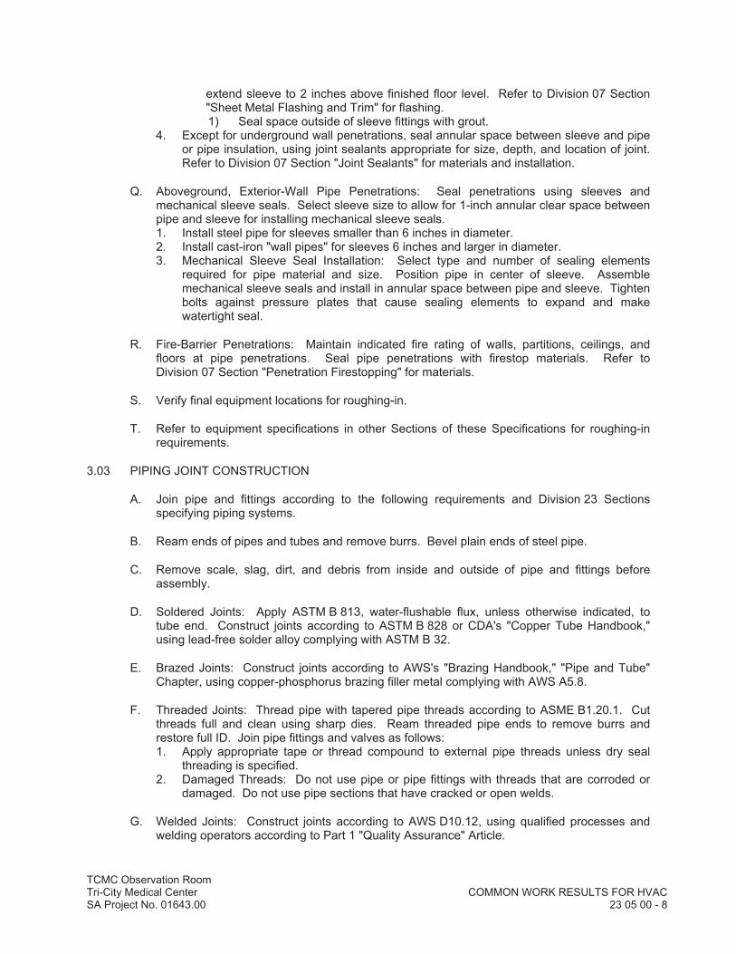


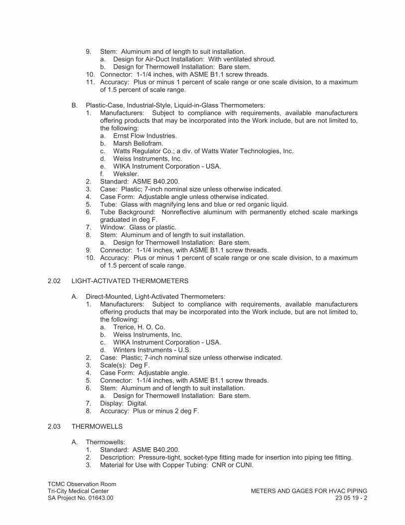
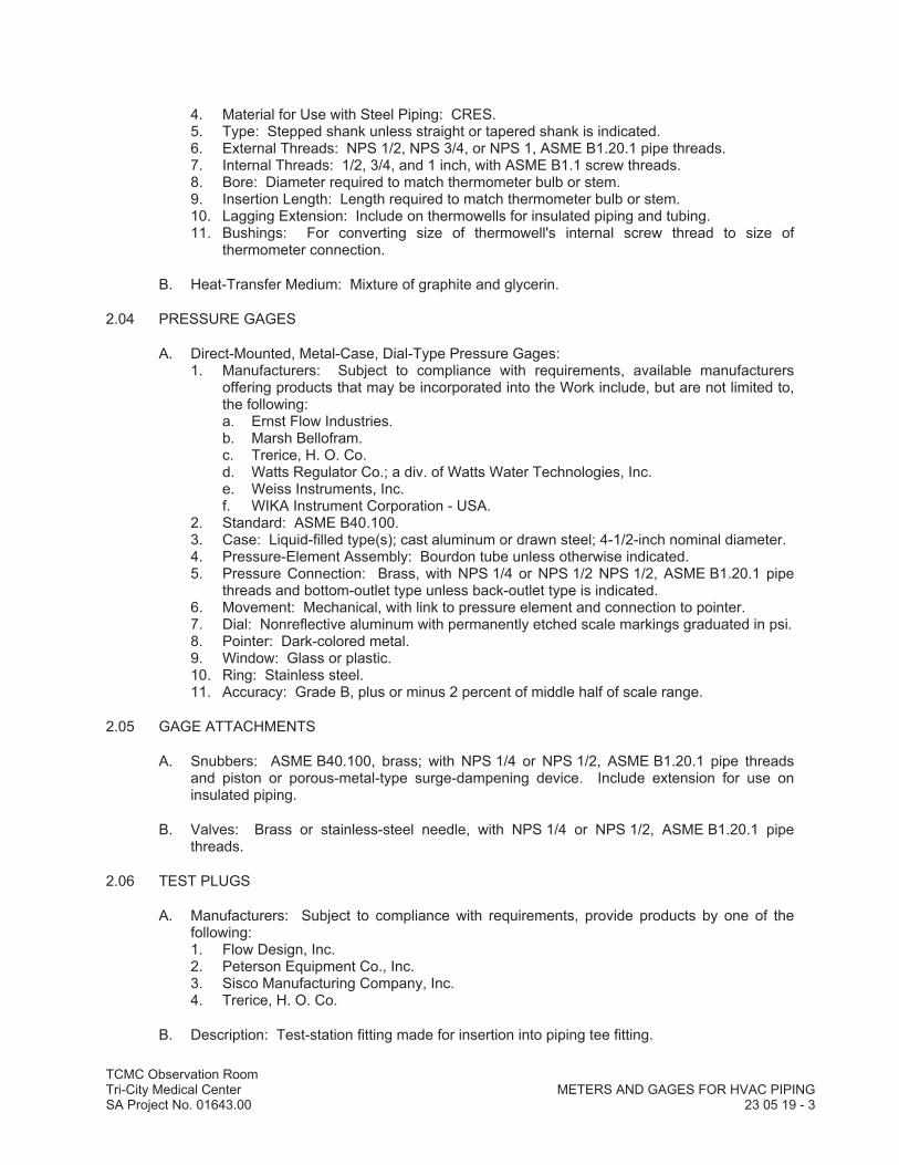
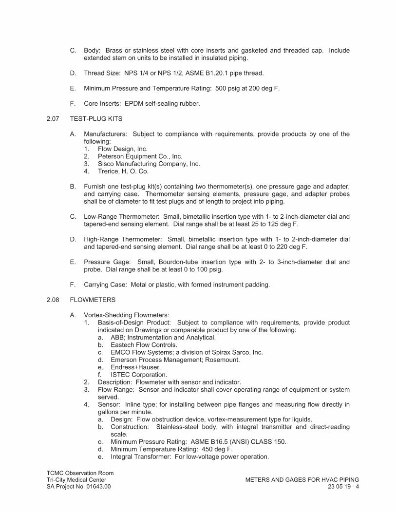

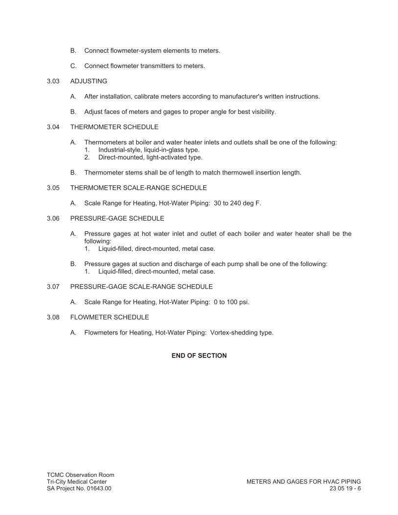

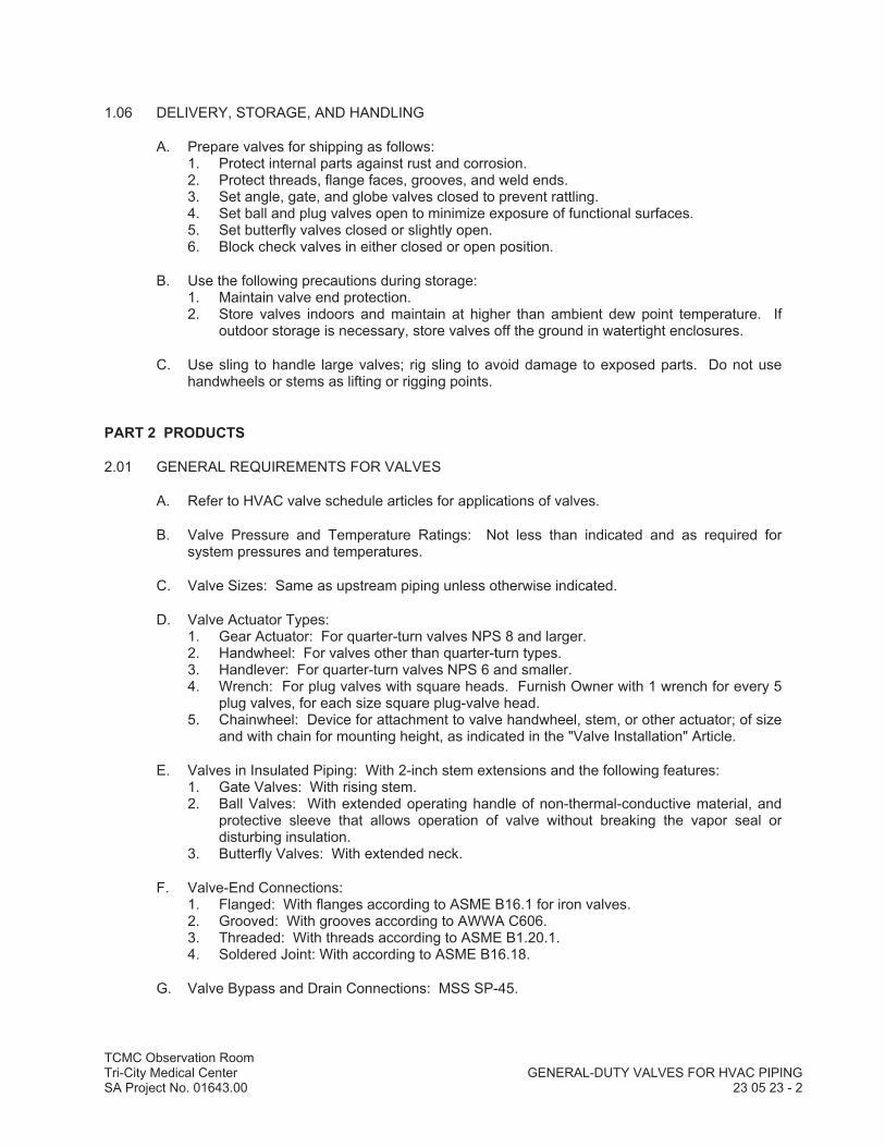
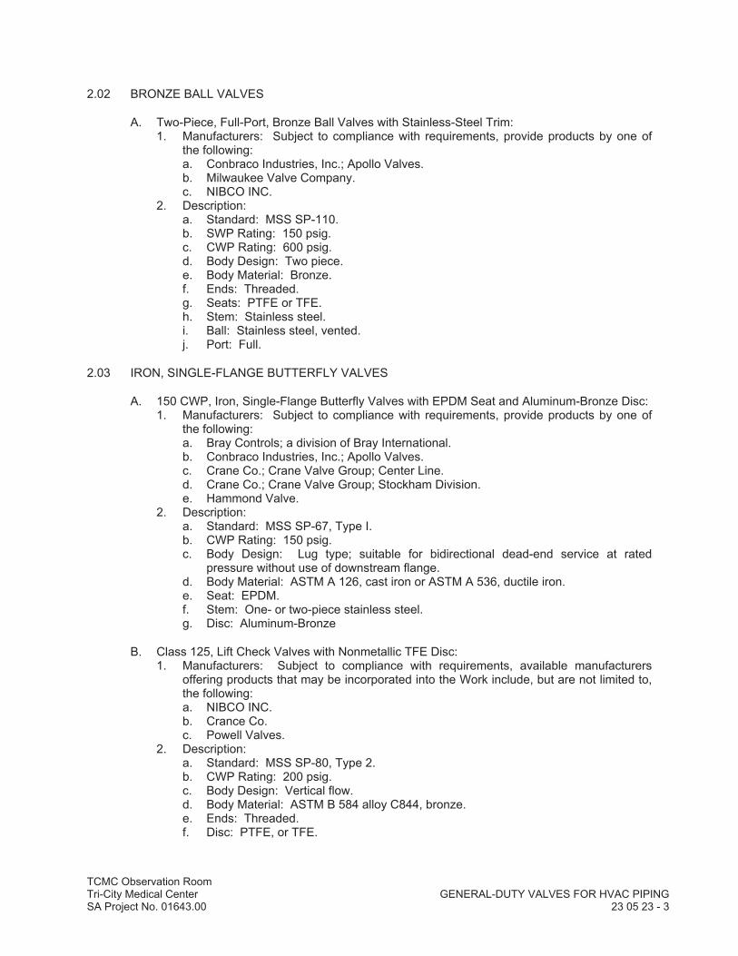
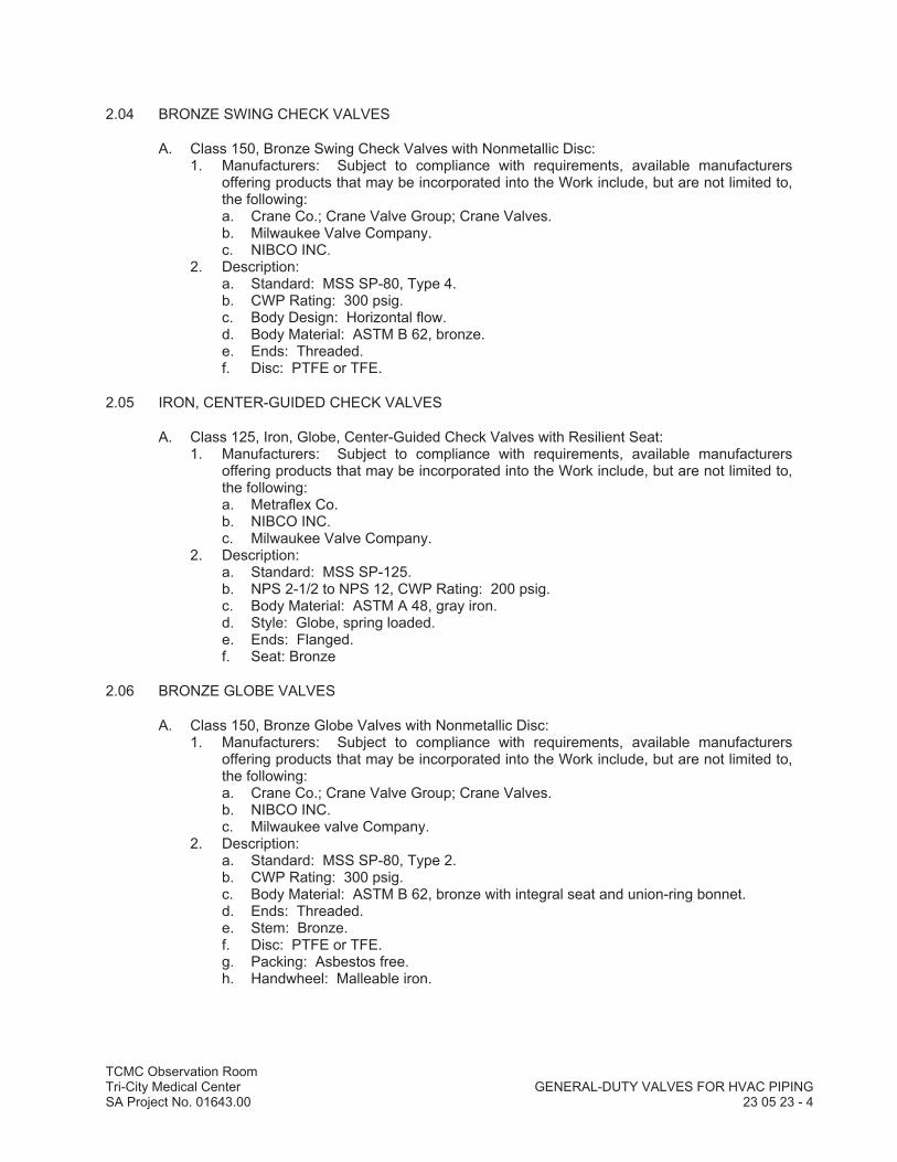

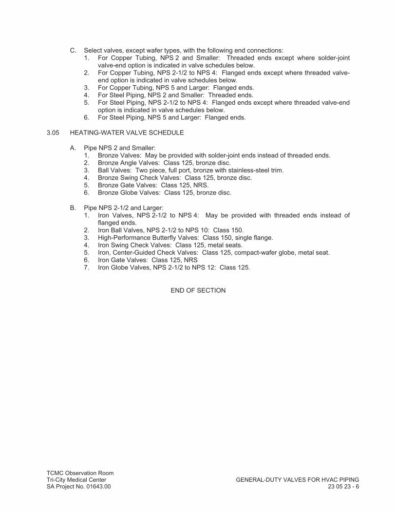


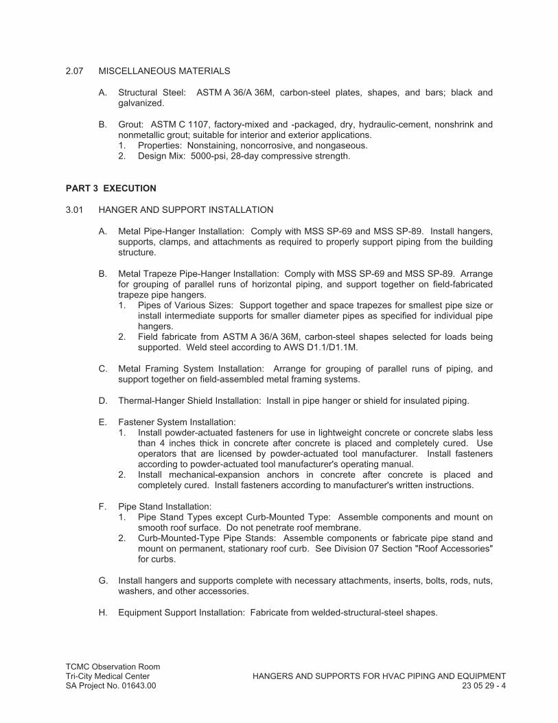
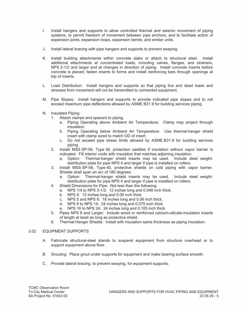
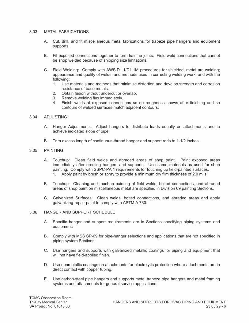


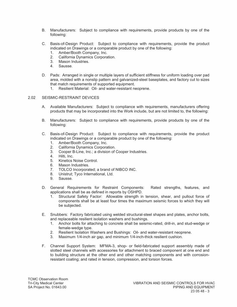
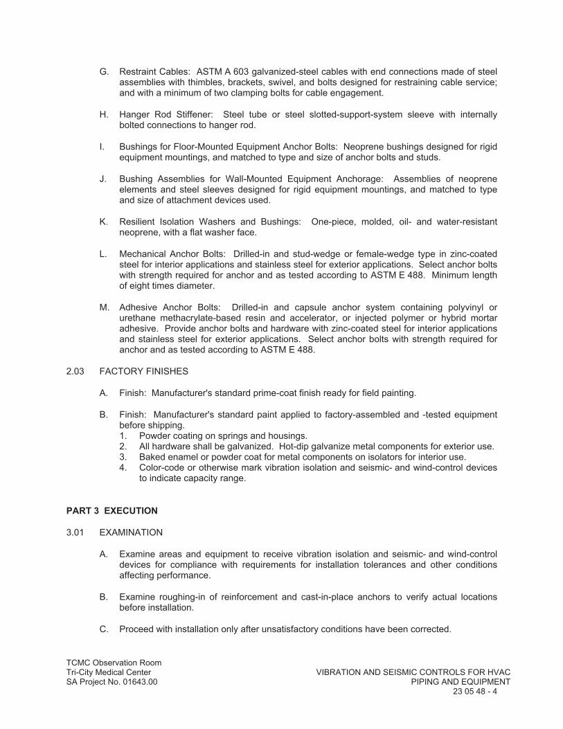
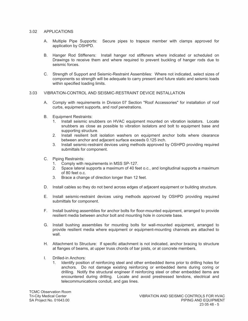
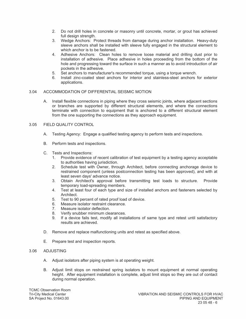


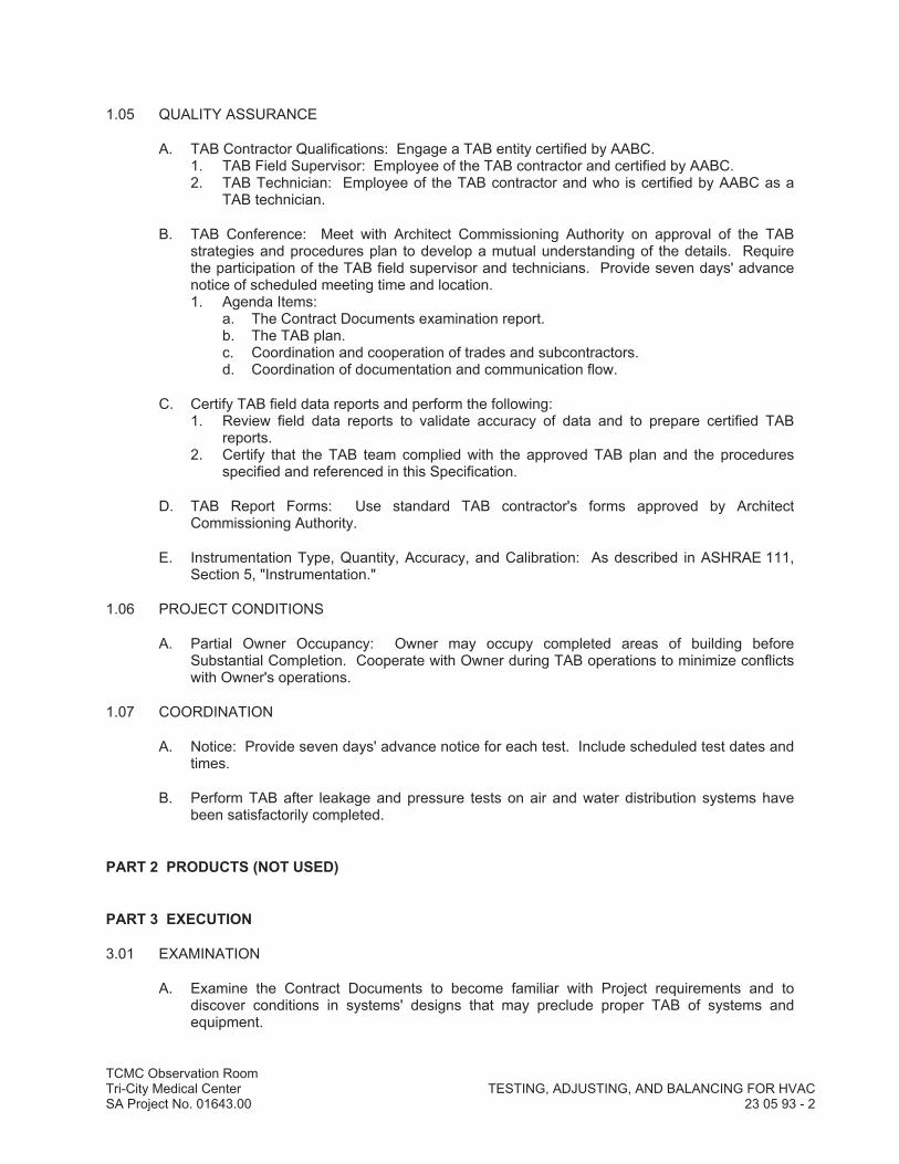

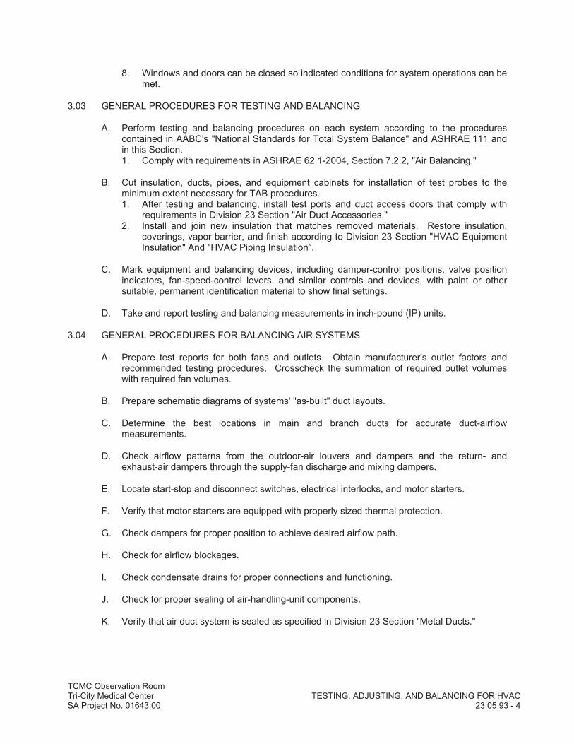


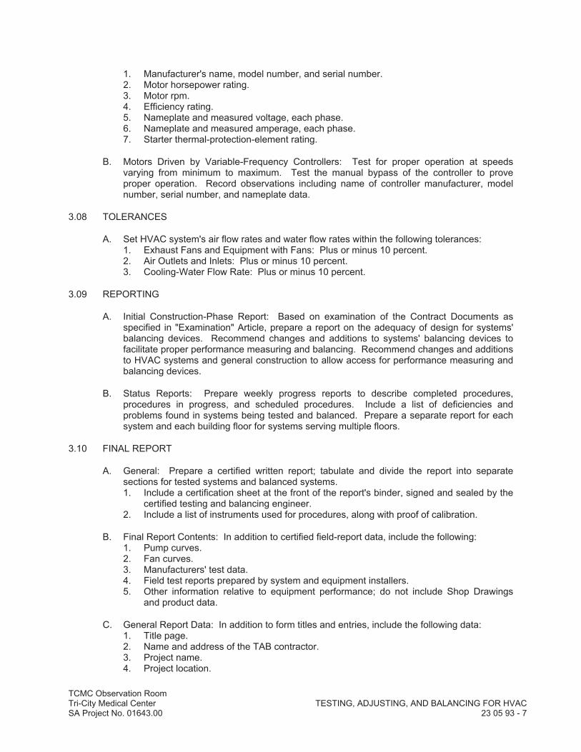
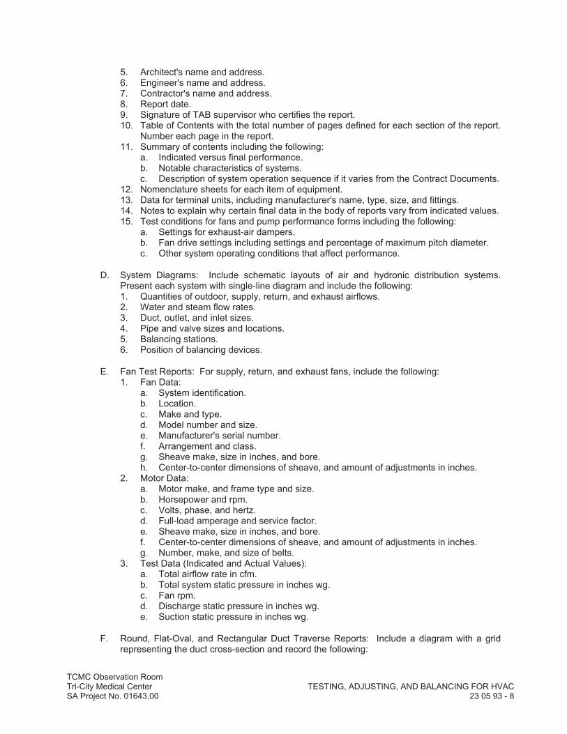


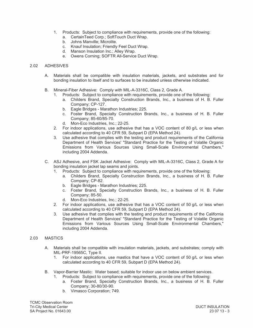
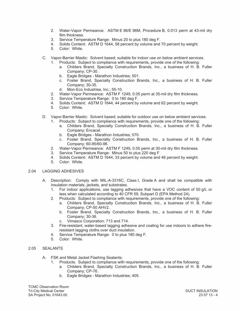
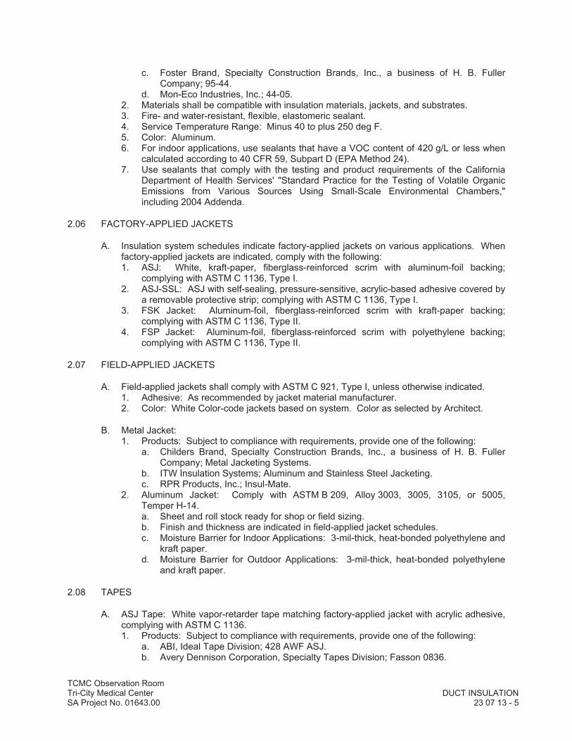

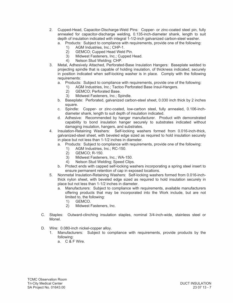
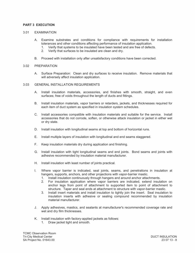


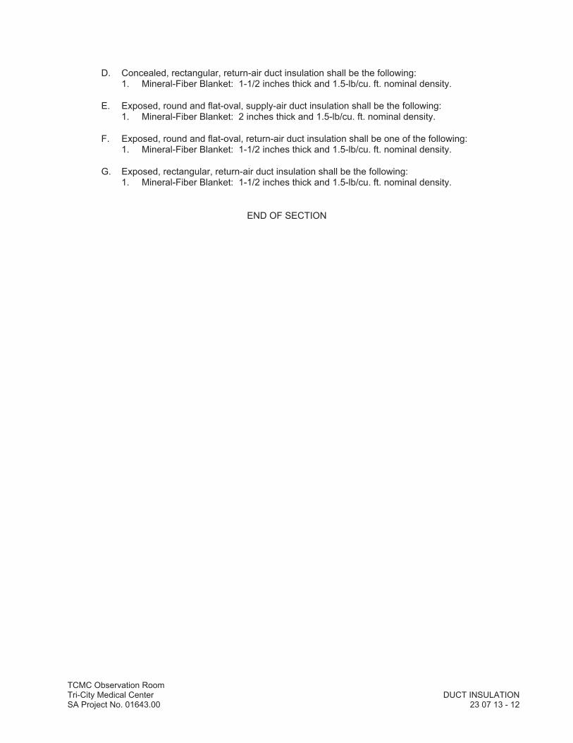


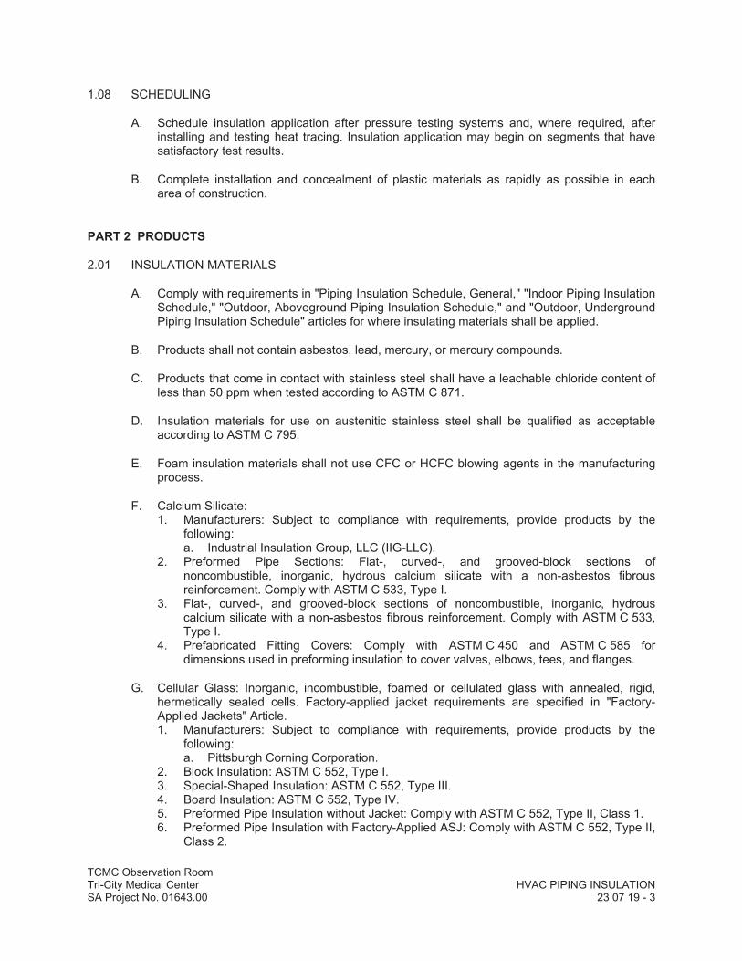


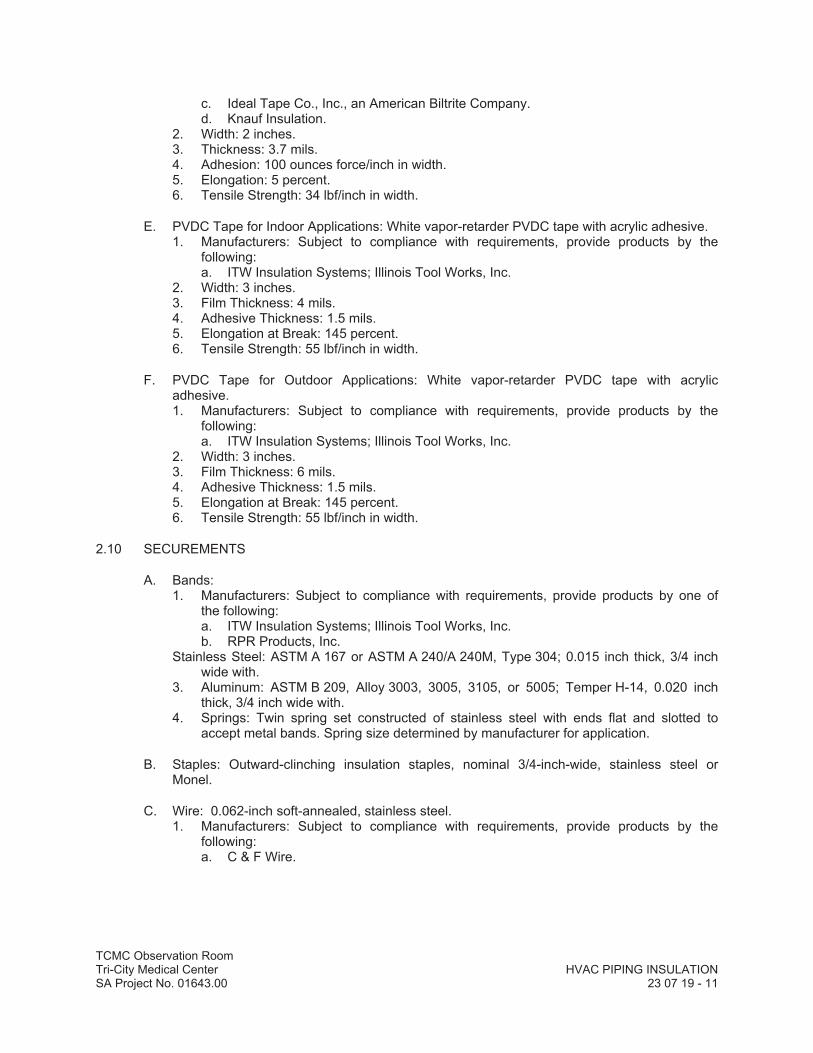
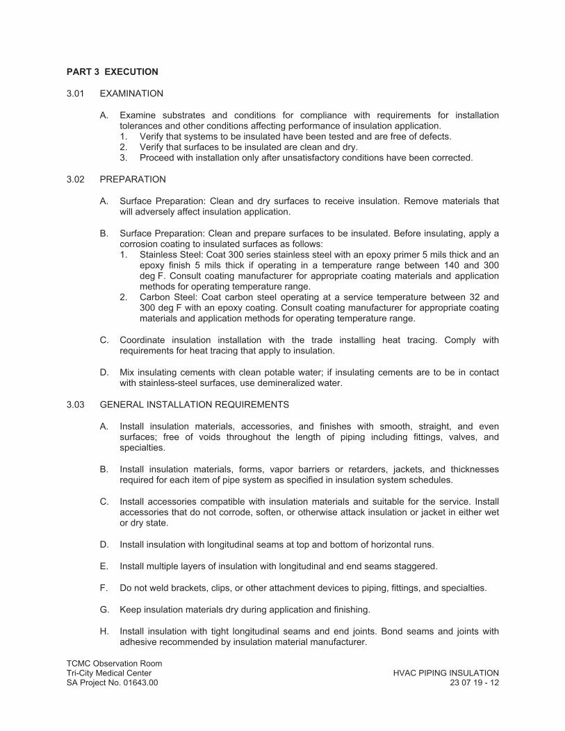
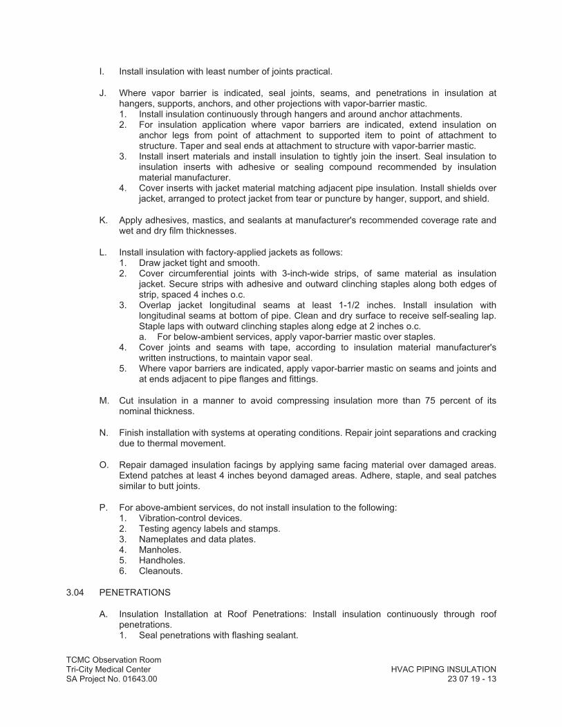


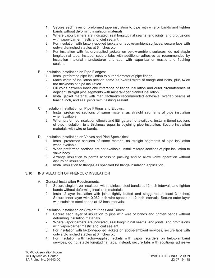

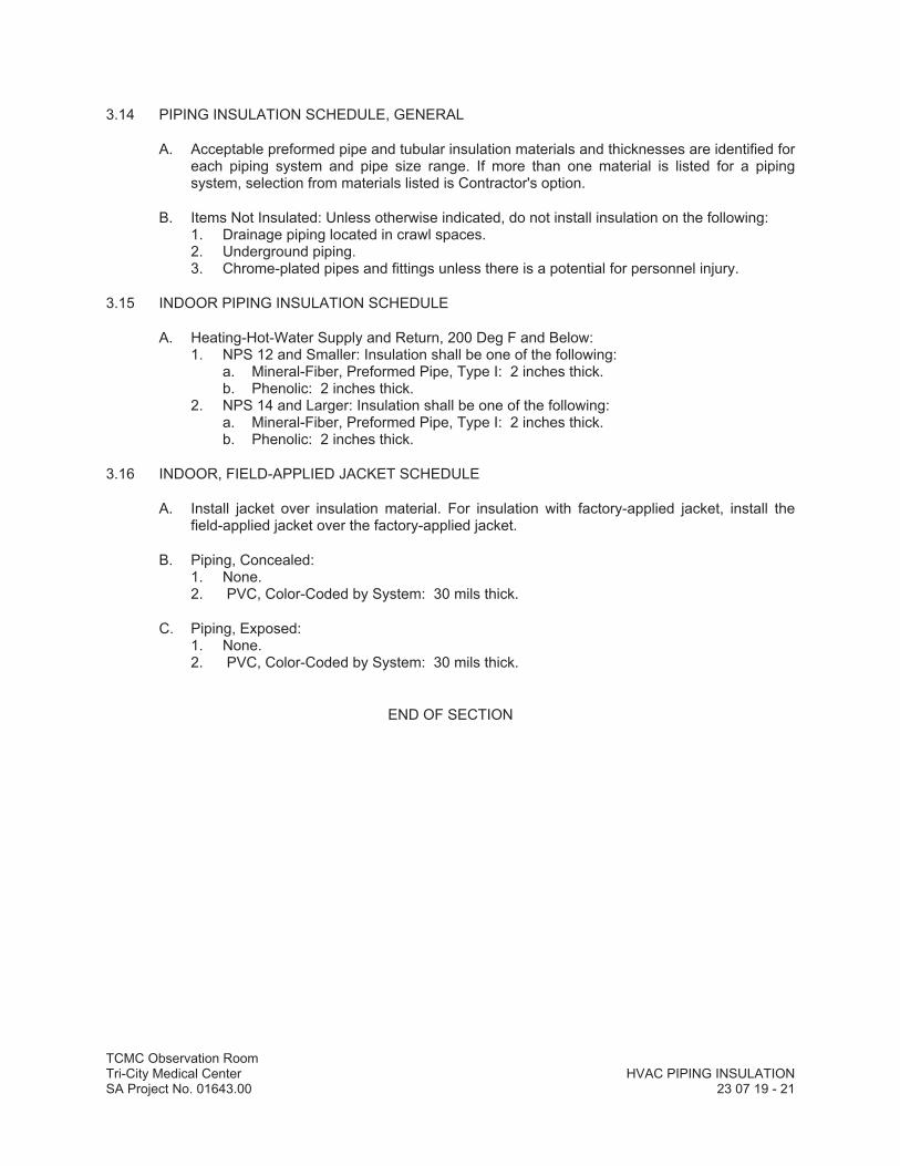


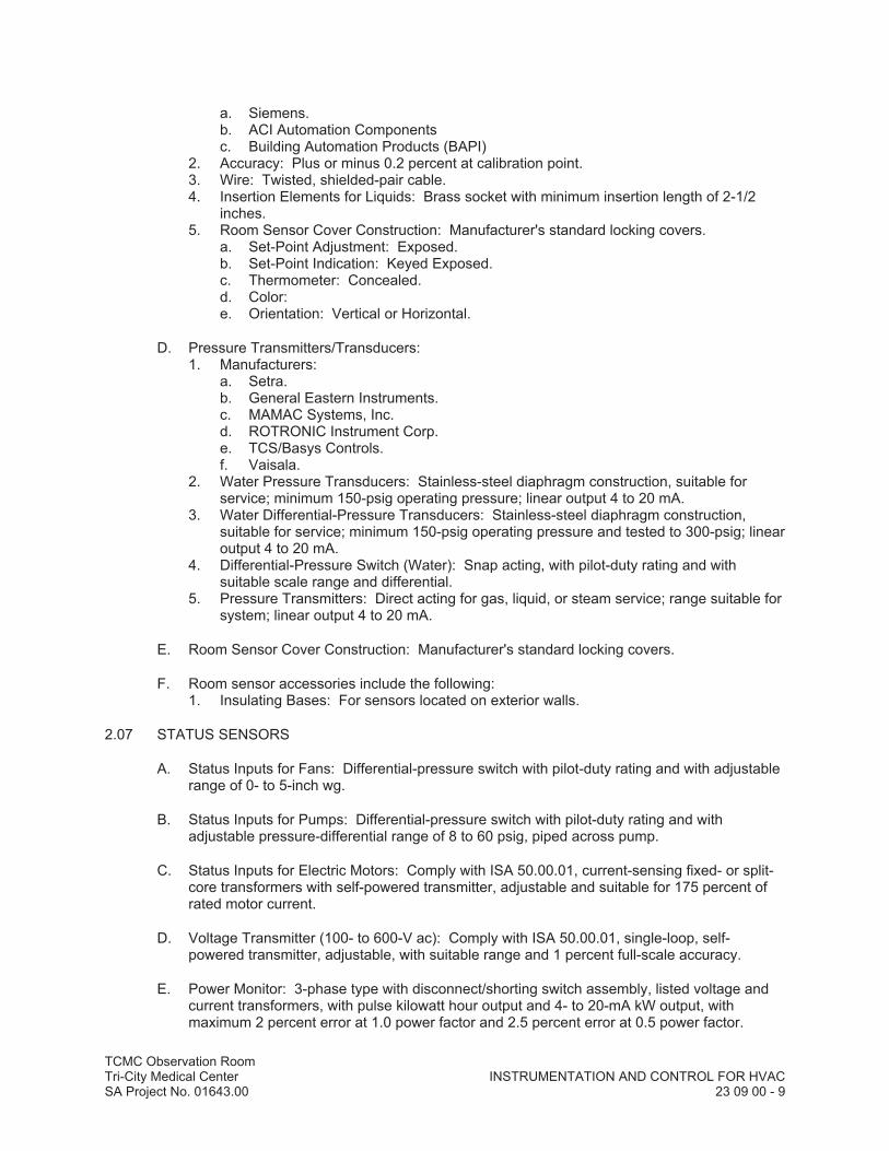
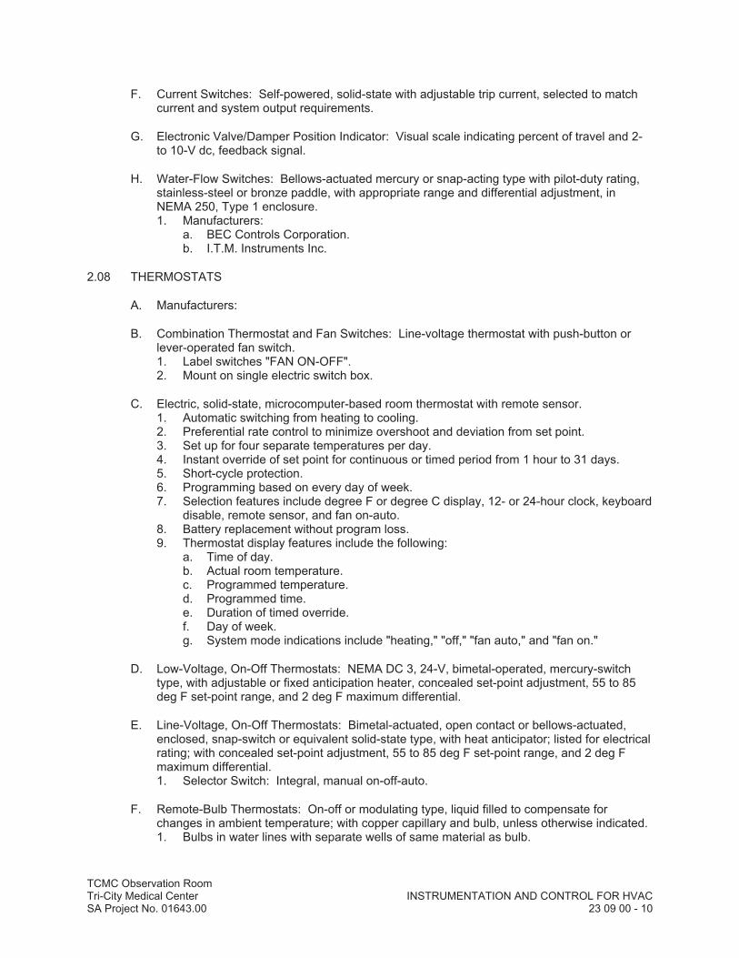
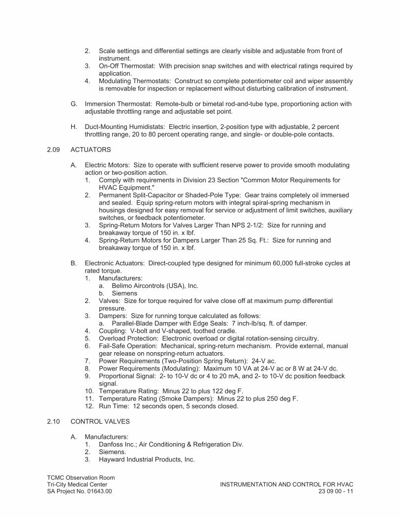
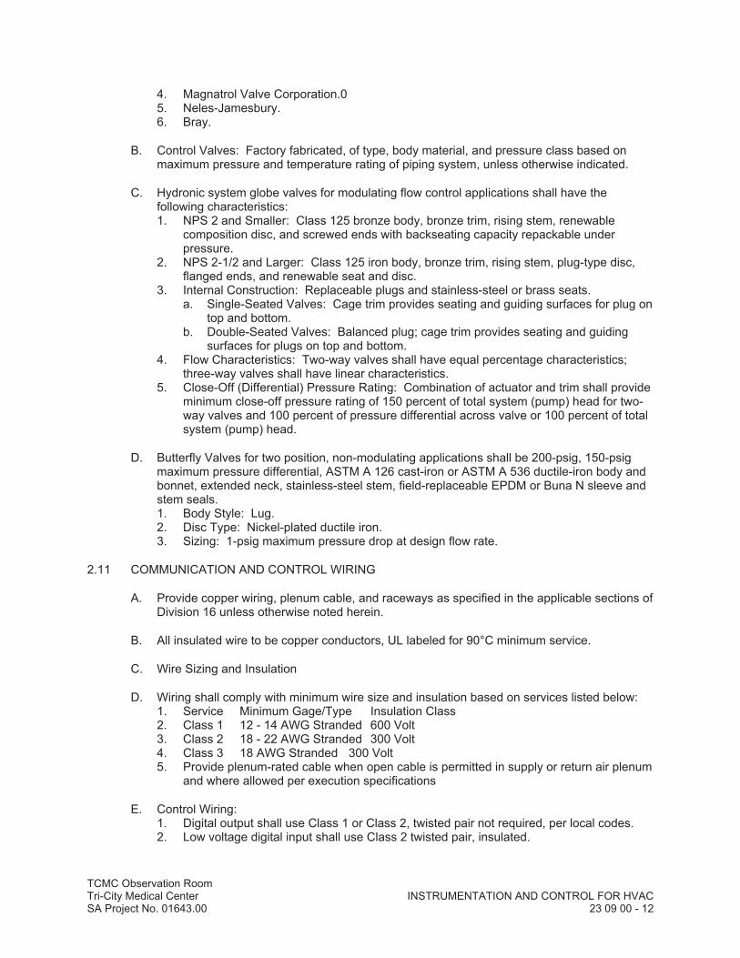


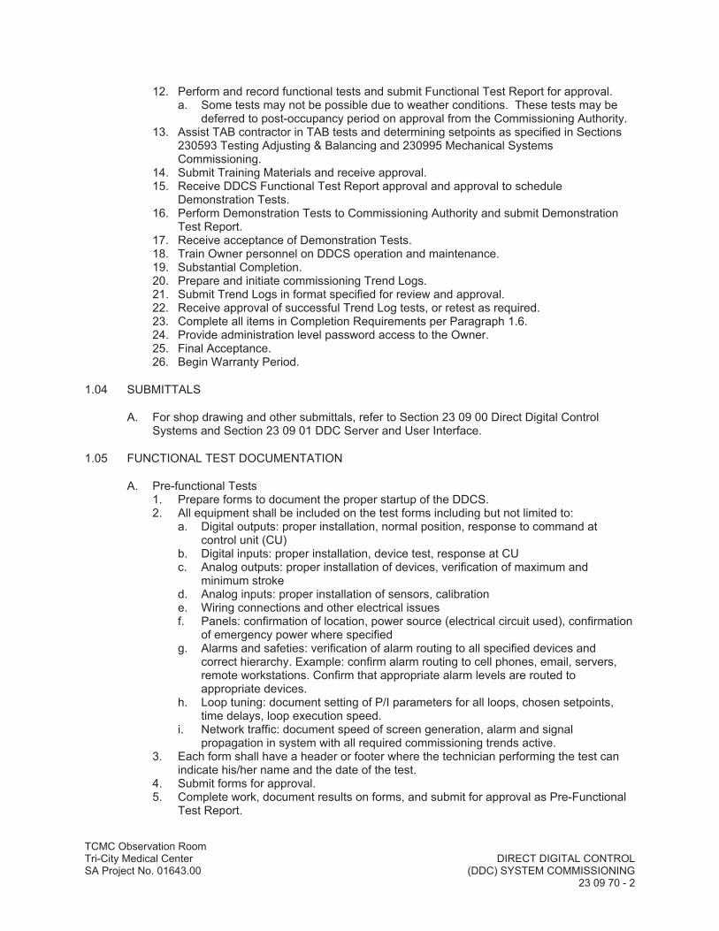
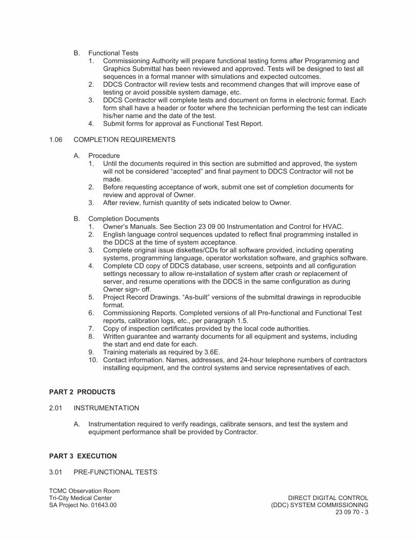


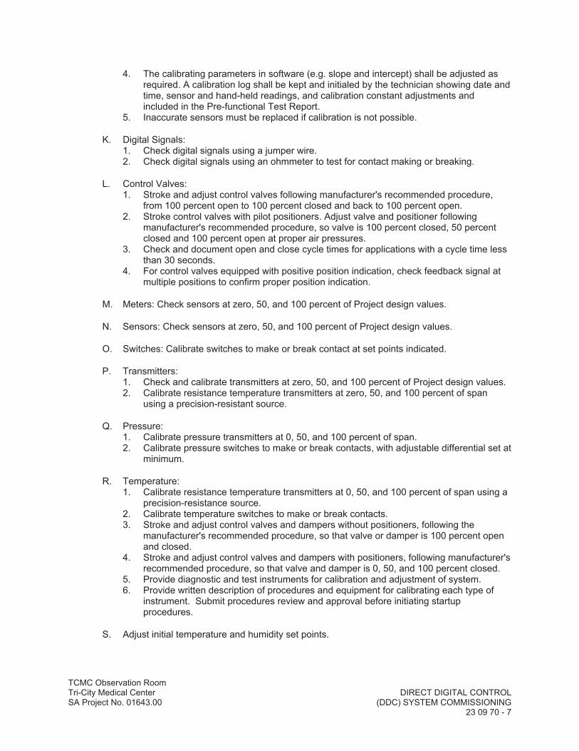

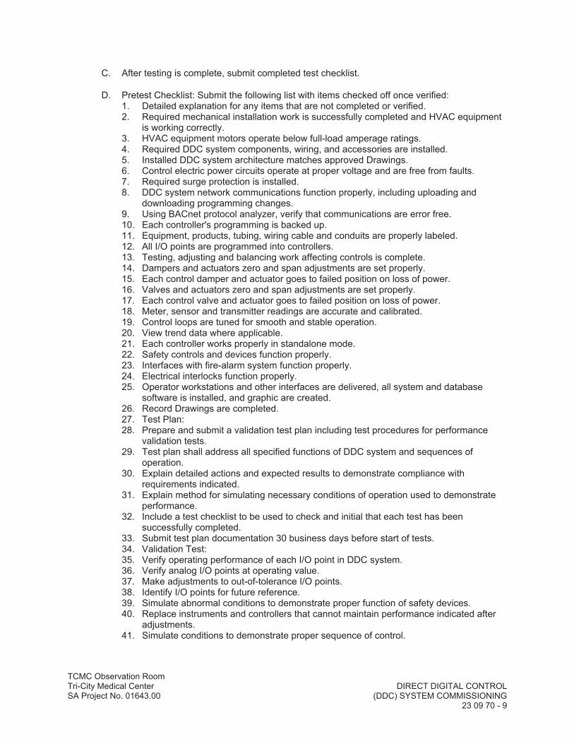

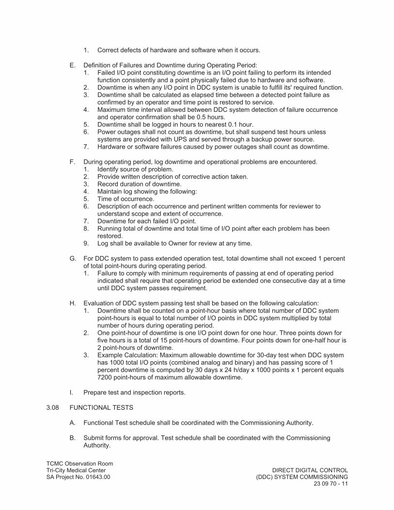
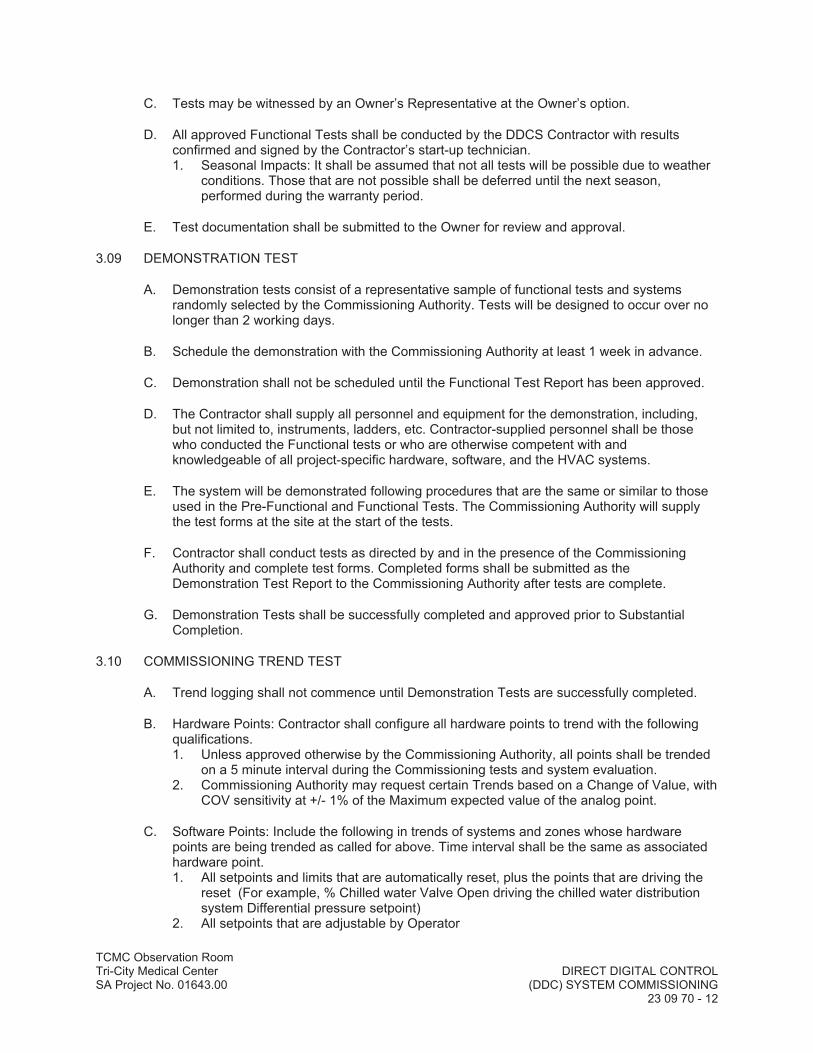

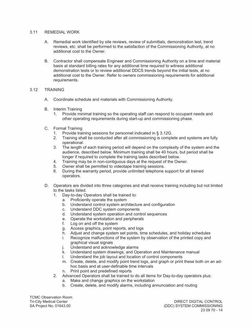


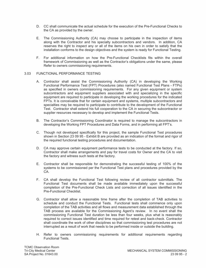


Project Name: ____________________
Equipment Tag (ID) ____________________ Installed On: ____________________
Location: ____________________ PFC Completion Date: ____________________
Sub-Contractor(s) Signature: ____________________ Date: ____________________
Contractor(s) Signature: ____________________ Date: ____________________
By signing this check list, the sub-contractor performing work and contractor confirm that they have diligently examined the installation with respect to the items shown herein and the installation details match what is specified in the plans and specifications and conform to manufacturer's written instructions. Exceptions are noted under the comment column as noted below.
Manufacturer Model Serial Number Capacity BTUH Peak Design Flowrate (GPM)
1 DOCUMENTATION
Verify if the following items have been submitted: 1.01 Manufacturer’s cut sheets including performance data (if available)
1.02 Installation and startup manual / plan
1.03 O&M manuals
1.04 Control sequences

2 GENERAL INSTALLATION
2.01 General appearance good, no apparent damage
2.02 Proper vibration isolators installed and adjusted
2.03 Seismic restraints in place
2.04 Boiler system checked out
2.05 Combustion air provided
2.06 Drains provided
2.07 Gas piping connected
2.09 No gas leakage
2.17 Adequate Boiler & accessory access for maintenance
3 PIPING
3.01 Hydronic piping complete
3.02 Hydronic system flushing complete and strainers cleaned
3.03 Piping insulation in good condition where visible
3.04 Piping not supported on chiller or valves
3.05 Pipe fittings and accessories complete
3.06 Piping type and flow direction labeled on piping
3.07 Isolation valves and balancing valves installed
3.08 Pressure gauges & thermometers installed where specified
3.09 Test ports/plugs installed near all control sensors and per spec
3.10 Flow switch installed as required
3.11 Flow meters installed as required
4 ELECTRICAL & CONTROLS
4.01 Power wiring installed properly
4.02 All electrical components grounded properly
4.03 Control wiring and control system hooked up

4.04 Sensors calibrated (see calibration section below)
4.05 Control system interlocks hooked up and functional
4.07 All control devices and wiring complete
4.08
Safeties installed and safe operating ranges for this equipment provided to the commissioning agent
4.09 Heating, Hot- water pumps pre-functional checklists completed
5 OPERATIONAL
5.01 No unusual noise and vibration when running
5.07
Specified sequences of operation and operating schedules have been implemented with all variations documented
5.08
Specified point-to-point checks have been completed and documentation record submitted for this system
5.09
Startup report completed with this checklist attached. (Includes full listing of all internal settings with notes as to which settings are BAS controlled or monitored and which are integral.

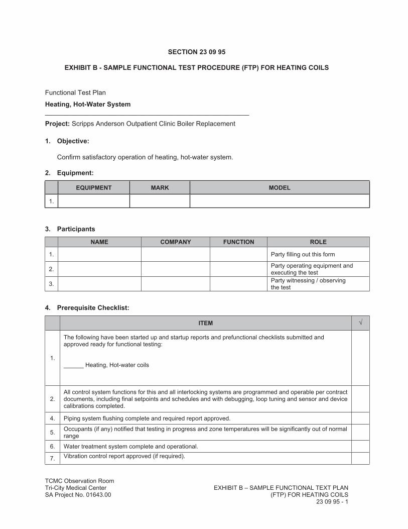
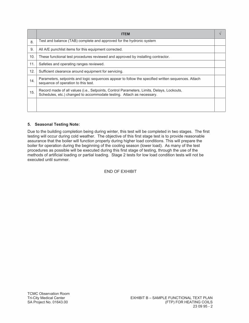
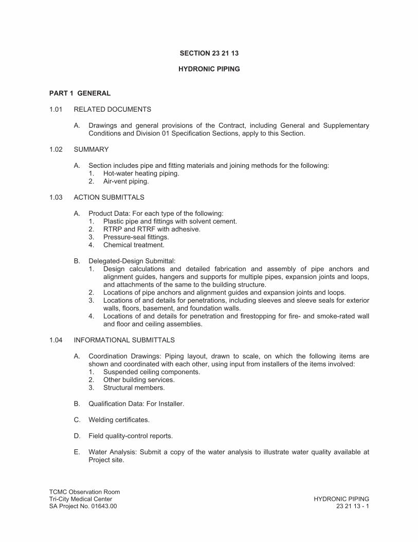


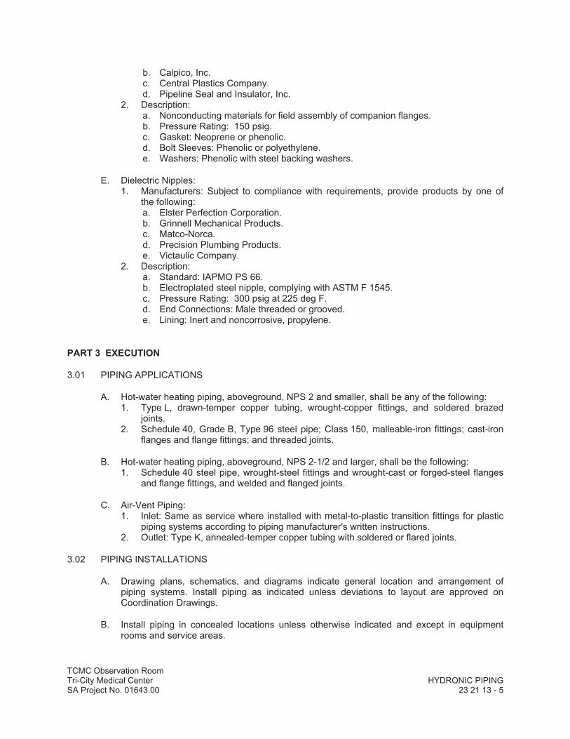


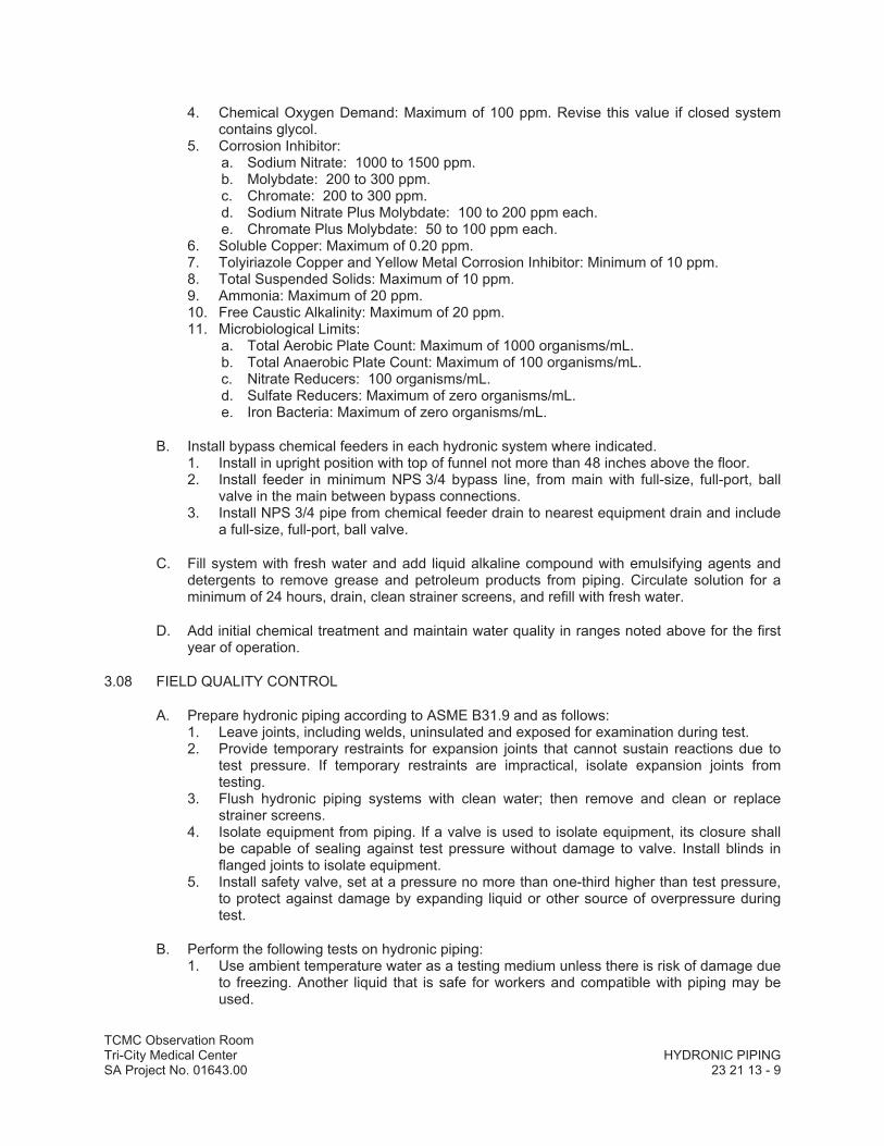
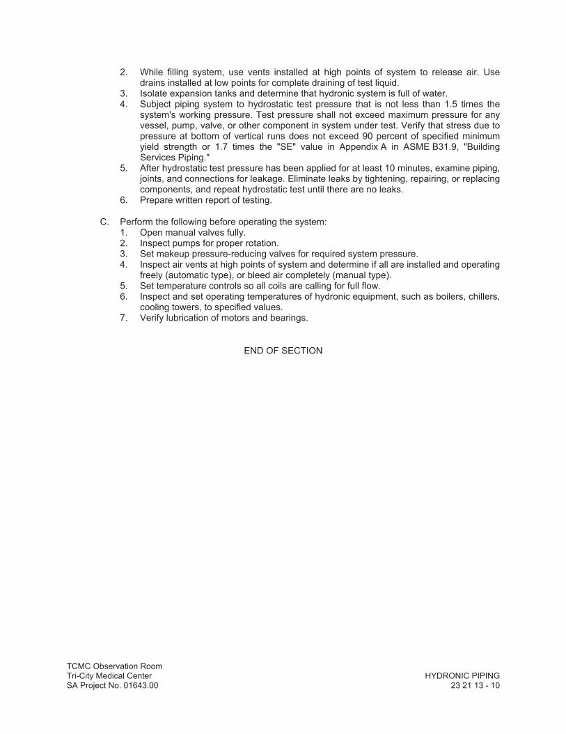
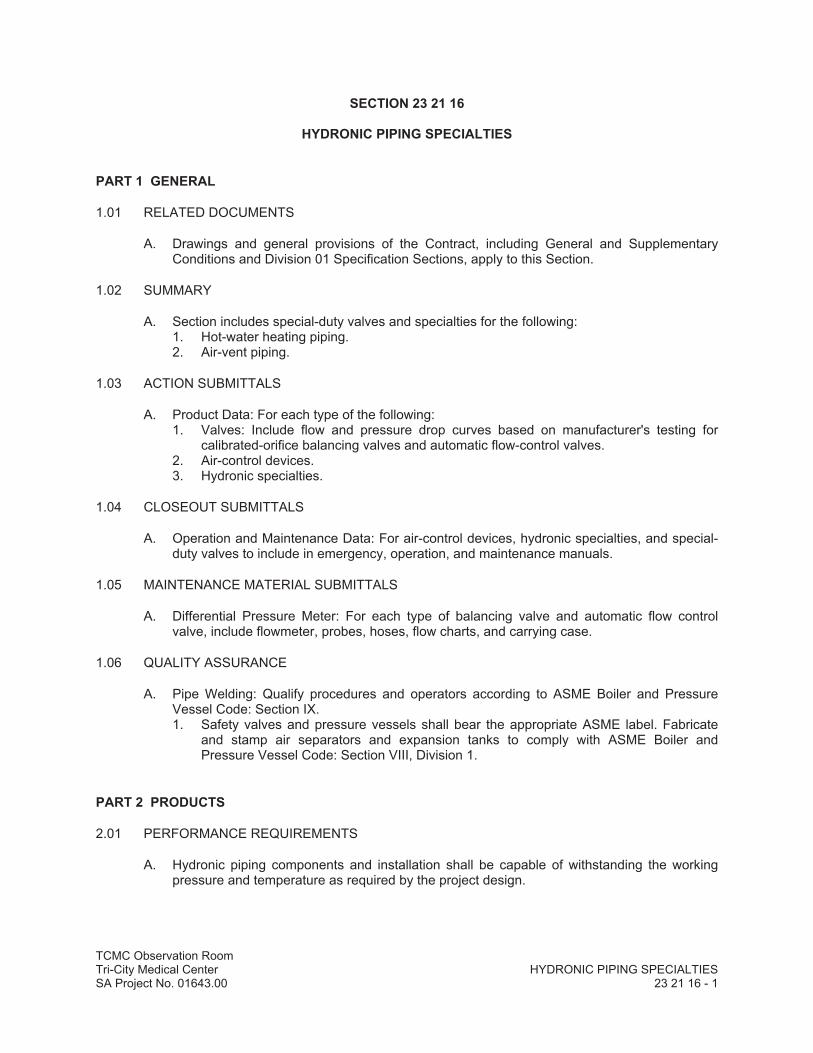
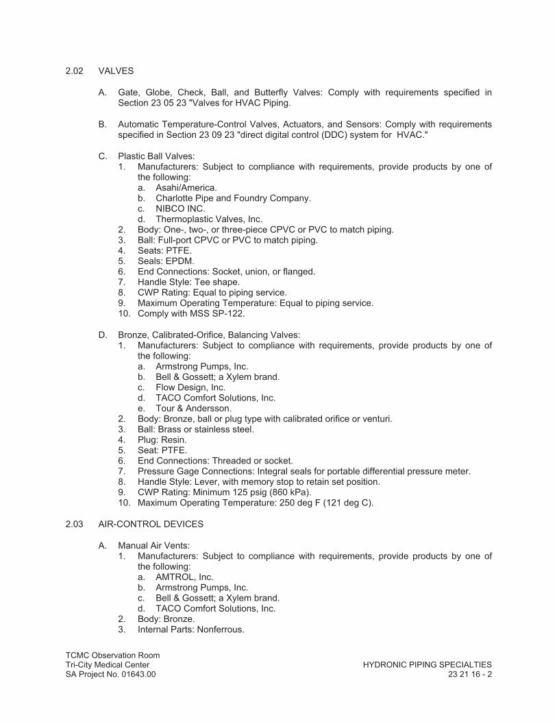
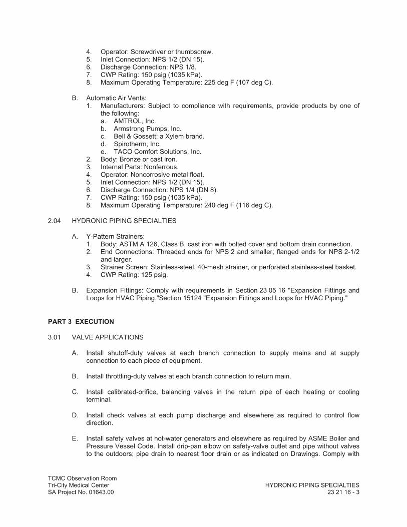
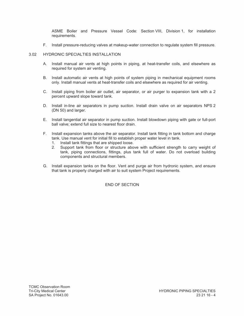

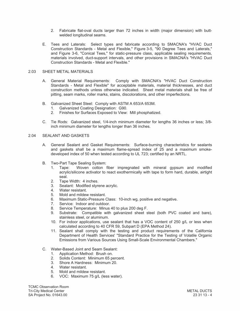
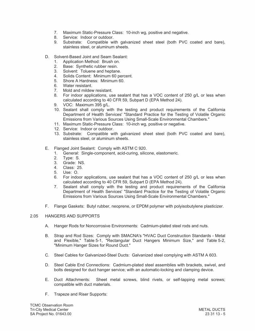
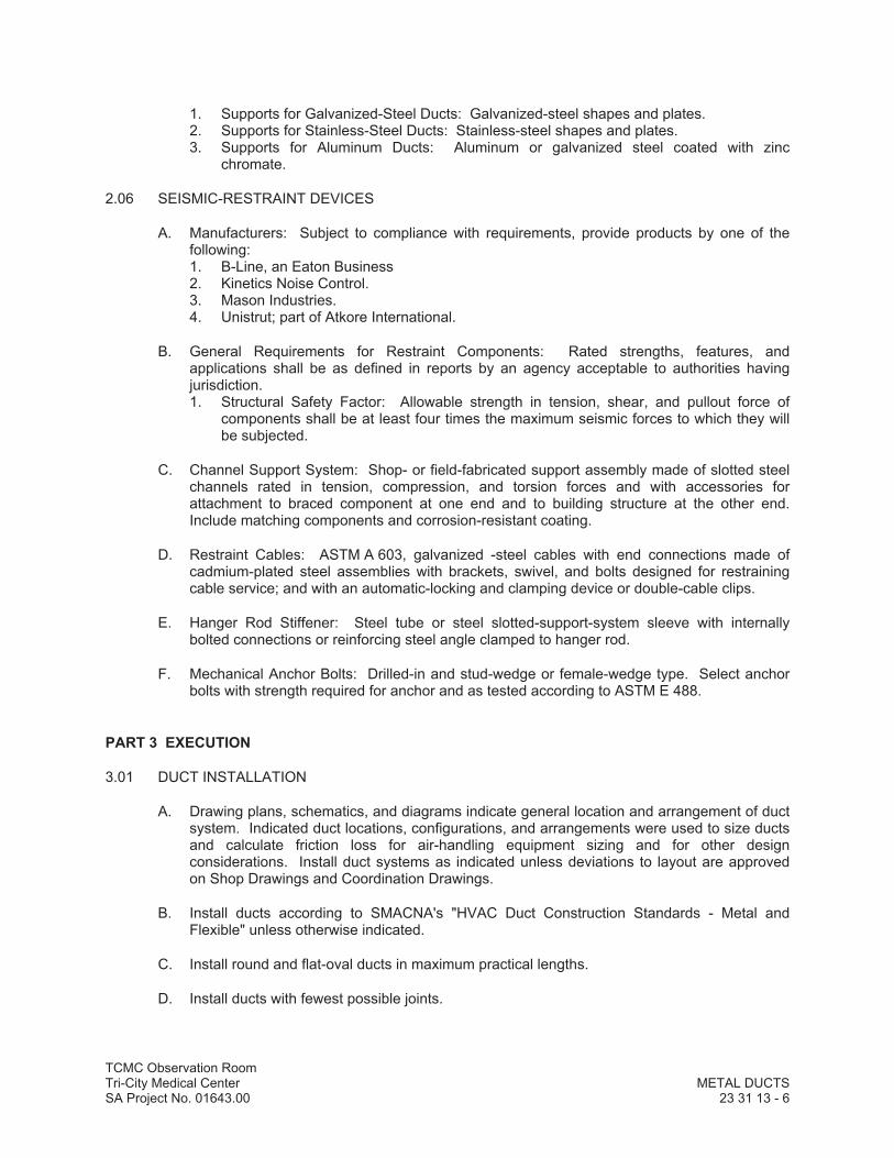

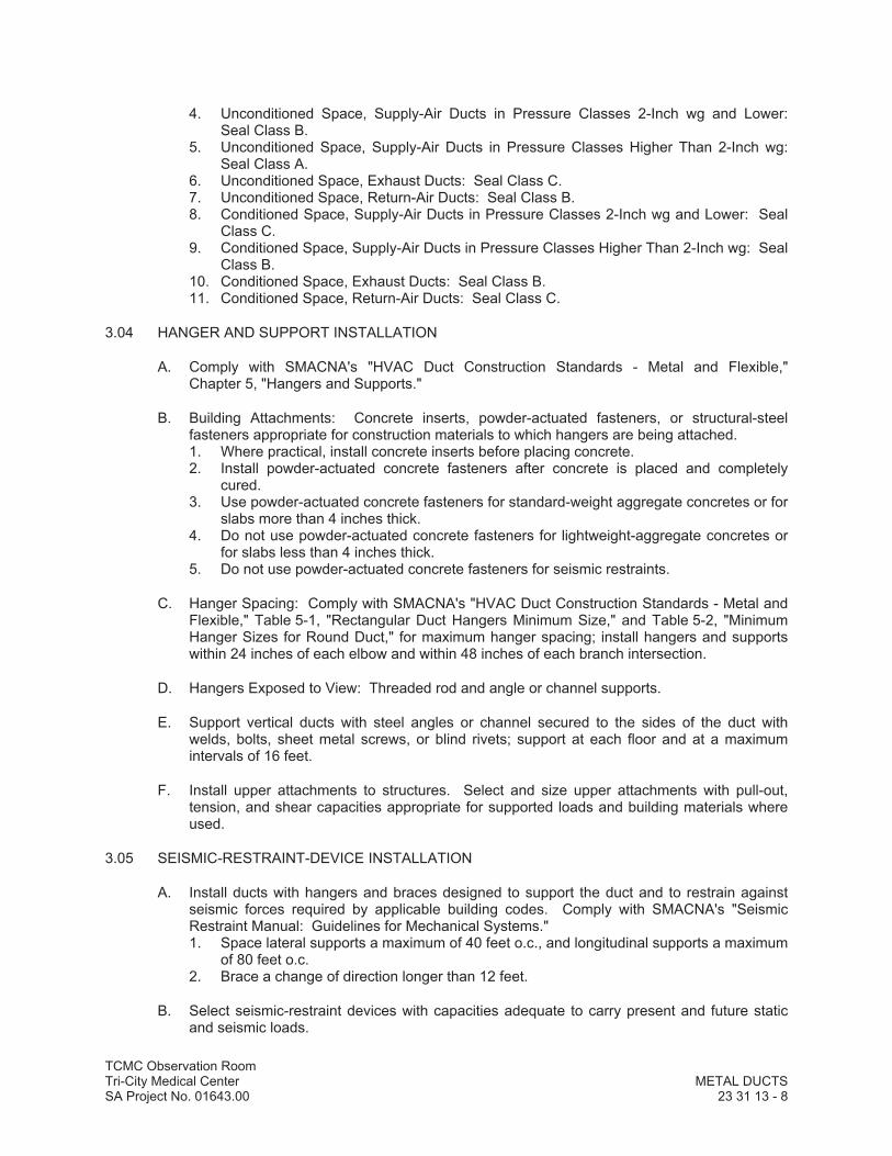

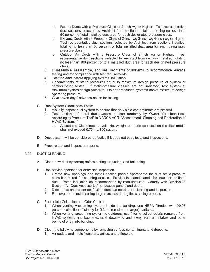
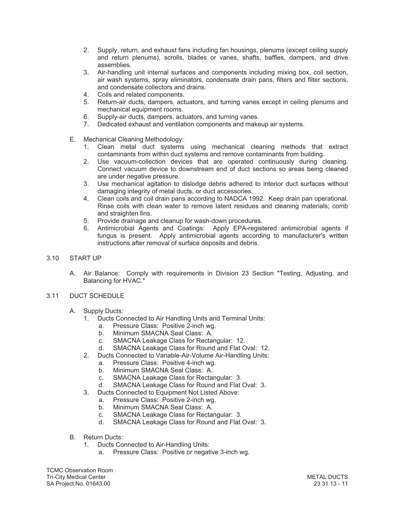
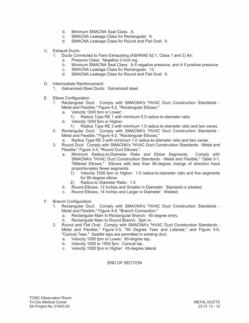
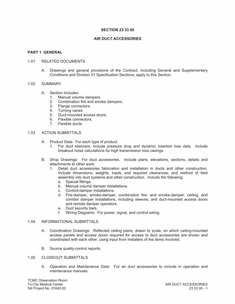
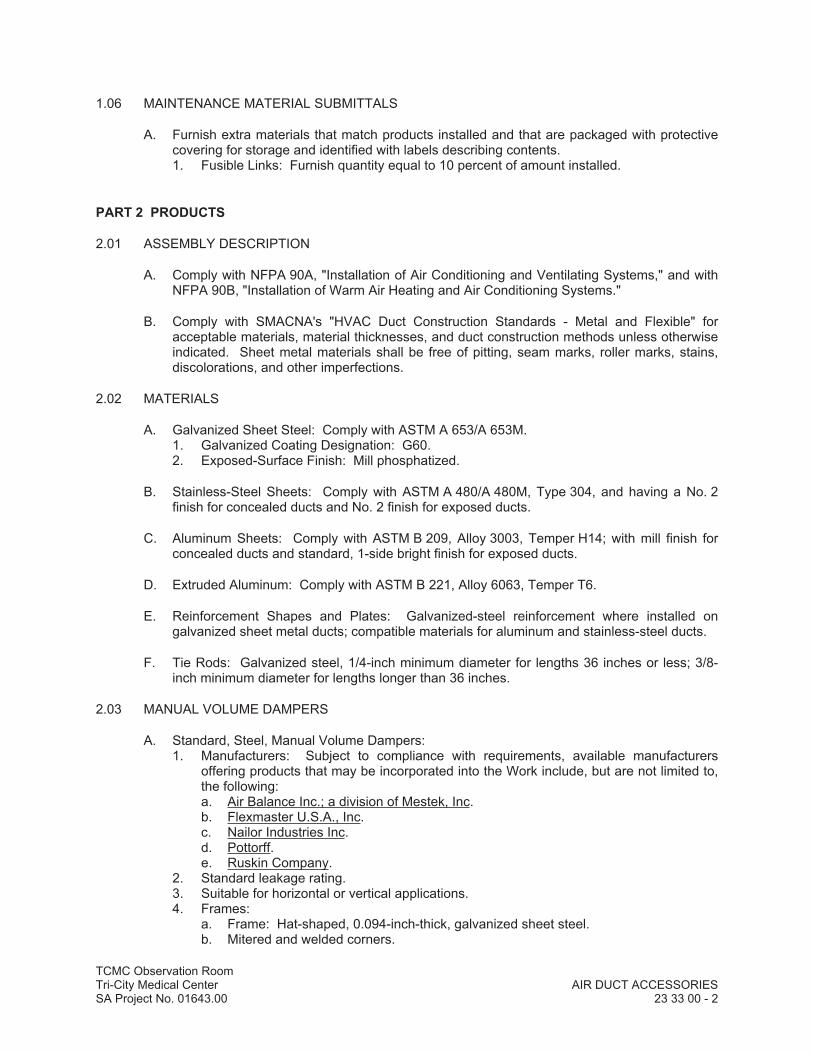
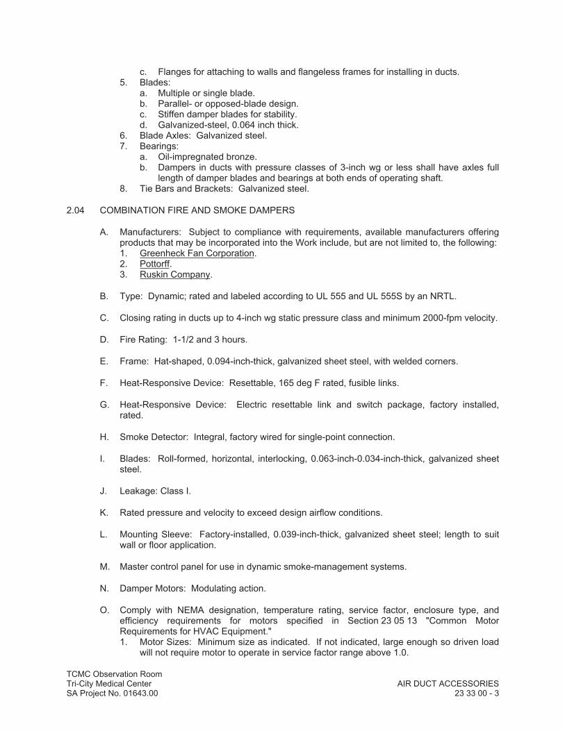
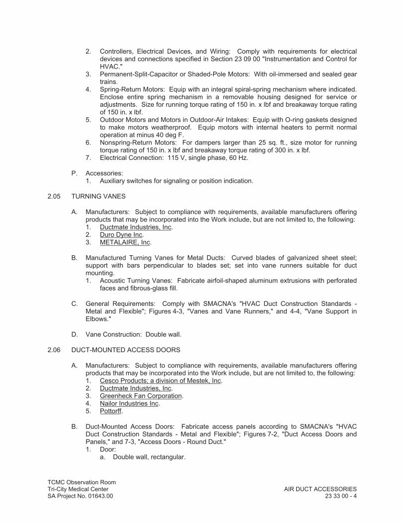
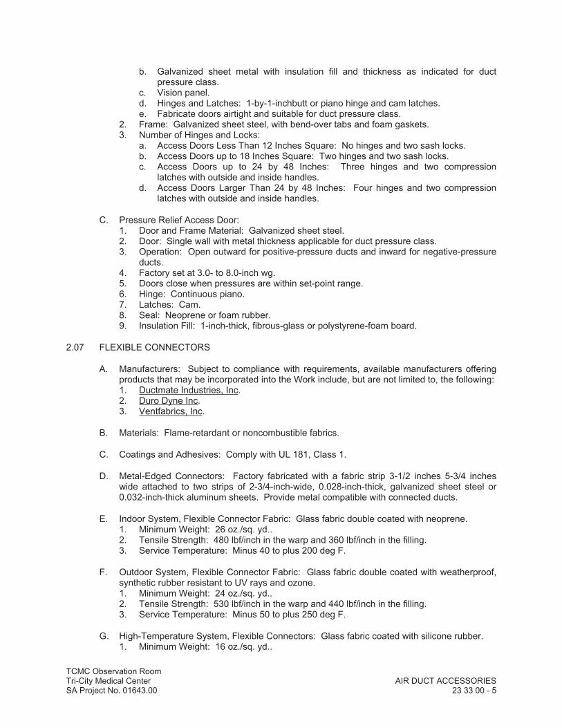


DIV
ISIO
N 2
6–
ELEC
TRIC
AL
DDDDDDDDDDDDDDDDDDDDDDIIIIIIIIIIIIIIIVVVVVVVVVVVVVVVVVVVVVVVV
IIIIIIIIIIIIIIIIISSSSSSSSSSSSSSSSSSSSSSSIIIIIIIIIIIIIIOOOOOOOOOOOOOOOOOOOOOOOOOOOOOO
NNNNNNNNNNNNNNNNNNNNNN22222222222222222222222222666666666666666666666666
––––––––––––––EEEEEEEEEEEEEEEEEELLLLLLLLLLLLLLLLL
EEEEEEEEEEEEEEEEEEECCCCCCCCCCCCCCCCCCCCCCCCCCCTTTTTTTTTTTTTTTTRRRRRRRRRRRRRRRRRRRRRR
IIIIIIIIIIIIIICCCCCCCCCCCCCCCCCCCCCCCCAAAAAAAAAAAAAAAAAAAAAAA
LLLLLLLLLLLLLLLLL

TCMC Observation RoomTri-City Medical Center ELECTRICAL GENERAL PROVISIONSSA Project No. 01643.00 26 00 10 - 1
SECTION 26 00 10
ELECTRICAL GENERAL PROVISIONS
PART 1 GENERAL
1.01 SCOPE
A. Work Included: All labor, materials, appliances, tools, equipment, facilities, transportation and services necessary for and incidental to performing all operations in connection with furnishing, delivery and installation of the work of this Section, complete, as shown on the drawings and/or specified herein. Work includes, but is not necessarily limited to, the following:1. Examine all other sections for work related to those other sections and required to be
included as work under this section.2. General provisions and requirements for electrical work.
B. Organization of the specifications into divisions, sections and articles, and arrangement of drawings shall not control the CONTRACTOR in dividing the contract work among subcontractors or in establishing the extent of work to be performed by any trade.
1.02 GENERAL SUMMARY OF ELECTRICAL WORK
A. The specifications and drawings are intended to cover a complete installation of systems. The omission of expressed reference to any item of labor or material for the proper execution of the work in accordance with present practice of the trade shall not relieve the CONTRACTOR from providing such additional labor and materials.
B. Refer to the drawings and shop drawings of other trades for additional details, which affect the proper installation of this work. Diagrams and symbols showing electrical connections are diagrammatic only. Wiring diagrams do not necessarily show the exact physical arrangement of the equipment.
C. Before submitting a bid, the CONTRACTOR shall become familiar with all features of the building drawings and site drawings, which may affect the execution of the work. No extra payment will be allowed for failure to obtain this information.
D. If there are omissions or conflicts between the drawings and specifications, clarify these points with the OWNER’S REPRESENTATIVE before submitting bid.
E. Provide work and material in conformance with the manufacturer’s publishedrecommendations for respective equipment and systems.
1.03 LOCATIONS OF EQUIPMENT
A. The drawings indicate diagrammatically the desired locations or arrangements of conduit runs, outlets, equipment, etc., and are to be followed as closely as possible. Proper judgment must be exercised in executing the work so as to secure the best possible installation in the available space and to overcome local difficulties due to space limitations or interference of structure conditions encountered.
B. Where outlets are placed on a wall, locate symmetrically with respect to each other and other features or finishes on the wall.
TCMC Observation RoomTri-City Medical Center ELECTRICAL GENERAL PROVISIONSSA Project No. 01643.00 26 00 10 - 2
C. In the event changes in the indicated locations or arrangements are necessary, due to developed conditions in the building construction or rearrangement of furnishings or equipment, such changes made without cost, providing the change is ordered before the conduit runs, etc., and work directly connected to same is installed and no extra materials are required.
D. Lighting fixtures in mechanical spaces are shown in their approximate location only. Do not install light outlets or fixtures until mechanical piping and ductwork is installed; then install lights in a location to provide best lighting.
E. Coordinate and cooperate in every way with other trades in order to avoid interference and assure a satisfactory job.
F. The location of the existing utilities, building, equipment and conduit shown on the drawings is approximate. Verify exact locations and routing of existing systems by potholing all trench routes prior to digging the trench. Pothole at least 100 feet ahead of the actual trenching to allow space to alter the new conduit routing to accommodate existing conditions.
G. Underground detection services existing utility structures1. Services shall be provided utilizing the latest detection equipment available. Services
shall be performed by a company regularly engaged in the business of existing Underground Utility Structure Detection for the past five years.
2. Prior to excavation the following work shall be performed:a. Contractor to mark trenching locations and indicate width and depth.b. Locate, by way of vertical and horizontal control dimensions, existing subgrade
petroleum product pipes, process piping, conduits, sewer, water, gas, storm drain, electrical, telephone and irrigation lines in the affected areas of contract construction work.
c. Arrange and meet with the OWNER'S Representative to review existing underground conditions.
d. The proposed route of each excavation shall be continuously surveyed along the entire excavation path using ground-penetrating radar (GPR) operating from the surface grade. The GPR shall detect and map existing underground metal and non-metal private and public utility lines, pipes, conduits, conductors, etc. The GPR shall identify the horizontal and vertical location of existing underground conditions located at a depth of up to 3 meters below finish grade and located with a vertical and horizontal accuracy within ± 12” of actual condition.
3. Exercise extreme caution in excavating and trenching on this site to avoid existing underground utilities, and to prevent hazard to personnel and/or damage to existing underground utilities or structures. These drawings and specifications do not include necessary components for construction safety, which is the responsibility of the CONTRACTOR.
4. Repair/replace, without additional cost to the contract, and to the satisfaction of the OWNER any existing work damaged that was identified in the record drawings provided; Identified by the Owner’s Representative; Identified by the Underground Detection Services performed; or any existing work damaged as a result of failure to comply with all the referenced requirements.
5. The CONTRACTOR shall contact Underground Service Alert (USA) of Southern California, at least 48 hours prior to excavation, and shall not excavate until verification has been received from the USA and that public utilities serving the site have been located and marked.
H. The locations of existing underground utilities, where shown on drawings, are shown diagrammatically and have not been independently verified by the OWNER, the OWNER’S
TCMC Observation RoomTri-City Medical Center ELECTRICAL GENERAL PROVISIONSSA Project No. 01643.00 26 00 10 - 3
REPRESENTATIVE. The OWNER, the OWNER’S REPRESENTATIVE, and the OWNER’s Consulting ENGINEER'S are not responsible for the location of underground utilities or structures, whether or not shown or detailed and installed under this or any other contracts. The CONTRACTOR shall identify each existing utility line prior to excavation and mark the locations on the ground of each existing utility line.
1.04 AIR CONDITIONING, HEATING, PLUMBING EQUIPMENT WIRING
A. Provide electrical work, materials, and control components required for proper operation of the air conditioning, heating and plumbing systems as indicated on the electrical, mechanical, and plumbing Contract Documents and specified herein.
1.05 POWER SERVICES
A. Within 30 calendar days of receipt of notice that the contract award has been made, the CONTRACTOR shall notify the New Business Departments of the District Office of the serving utility companies concerning the project contract and shall provide information as to the total lighting and power requirements of the contract. The CONTRACTOR shall furnish at the same time information as to the estimated completion date of job or the date when the respective utility company circuits, will be ready for installation, energizing and activation of the respective services.
1.06 PERMITS
A. Take out and pay for all required permits, inspections and examinations without additional cost to the OWNER.
1.07 QUALITY ASSURANCE
A. Work and materials shall be in full accordance with the latest rules and regulations as follows. The following publications shall be included in the contract documents requirements. If a conflict occurs between the following publications and any other part of the contract documents, the requirements describing the more restrictive provisions shall become the applicable contract definition: 1. California Code of Regulations Title 24.2. California Part 3 "California Electrical Code" CEC, Title 24 and Title 8 "Division of
Industrial Safety".3. California Electrical Code-CEC.4. The National Life Safety Code.5. The Uniform Building Code-UBC.6. National Fire Protection Agency-NFPA.7. Underwriter’s Laboratory-U.L.8. Other applicable State and Local Government Agencies laws and regulations.9. National Electrical Installation Standards10. National Electrical Contractors Association (NECA) and National Electrical Installation
Standards (NEIS):a. NECA/NEIS-1: Standard of Practices for Good Workmanship in Electrical
Contractingb. NECA/NEIS-101: Standard for Installing Steel Conduit (Rigid, IMC, etc.)c. NECA/NEIS-400: Recommended Practice for Installing and Maintaining
Switchboardsd. NECA/NEIS-402: Recommended Practice for Installing and Maintaining Motor
Control Centerse. NEIS/NECA Recommended Practice for
TCMC Observation RoomTri-City Medical Center ELECTRICAL GENERAL PROVISIONSSA Project No. 01643.00 26 00 10 - 4
& EGSA-404: Installing Generator Setsf. NEIS/NECA Recommended Practice for
& IESNA-500: Installing Indoor Commercial Lighting Systemsg. NEIS/NECA Recommended Practice for
& IESNA-501: Installing Exterior Lighting Systemsh. NEIS & IESNA-502 Recommended Practice for Installing Industrial Lighting
Systems
B. All material and equipment shall be new and shall be delivered to the site in unbroken packages. All material and equipment shall be listed and labeled by Underwriters Laboratories or other recognized testing laboratories, where such listings are available. Comply with all installation requirements and restrictions pertaining to such listings.
C. Work and material shown on the drawings and in the specifications is new and included in the contract unless specifically indicated as existing or N.I.C. (not in contract).
D. Keep a copy of all applicable codes available at the job site at all times while performing work under this section. Nothing in plans or specifications shall be construed to permit work not conforming to the most stringent of codes.
E. Where a conflict or variation occurs between applicable Codes, the provisions of the most restrictive code shall be the requirement of the Contract Documents. Where a conflict or variation occurs between applicable Codes and the Contract Documents, the requirements of the most restrictive provision(s) shall be the requirement of the Contract Document.
1.08 SUBMITTALS
A. General1. Review of CONTRACTOR'S submittals is for general conformance with the design
concept of the project and general compliance with the information given in the contract documents. Any action shown is subject to the requirements of the plans and specifications. CONTRACTOR is responsible for quantities; dimensions which shall be confirmed and correlated at the job site; fabrication processes and techniques of construction; coordination of work with that of all other trades and satisfactory performance of their work.
2. The CONTRACTOR shall review each submittal in detail for compliance with the requirements of the contract documents prior to submittal. The CONTRACTOR shall "Ink Stamp" and sign each item of the submittal with a statement "CERTIFYING THE SUBMITTAL HAS BEEN REVIEWED BY THE CONTRACTOR AND COMPLIES WITH ALL THE REQUIREMENTS OF THE CONTRACT DOCUMENTS". The CONTRACTOR shall clearly and specifically identify each individual proposed substitution or proposed deviation from the requirements of the contract documents with a statement "THIS ITEM IS A SUBSTITUTION".
3. Departure from the submittal procedure will result in resubmittals and delays. Failure of the CONTRACTOR to comply with the submittal requirements shall render void any acceptance or any approval of the proposed variation. The CONTRACTOR shall then be required to provide the equipment or method without variation from the contract documents and without additional cost to the contract.
4. The CONTRACTOR at no additional cost or delays to the contract shall remove any work, material and correct any deficiencies resulting from deviations from the requirements of the contract documents not approved in advance by the OWNER prior to commencement of work.
5. Shop drawings submitted by the CONTRACTOR, which are not specifically required for submittal by the Contract Documents, or CONTRACTOR shop drawings previously

TCMC Observation RoomTri-City Medical Center ELECTRICAL GENERAL PROVISIONSSA Project No. 01643.00 26 00 10 - 5
reviewed and resubmitted without a written resubmittal request to the CONTRACTOR, will not be reviewed, considered, or commented on. The respective shop drawing submittal/resubmittal will not be returned to the CONTRACTOR and will be destroyed without comment or response to the CONTRACTOR. The respective submittal shall be considered null and void as being not in compliance with the requirements of the Contract Documents.
B. Material Lists and Shop Drawings:1. Submit material list and equipment manufacturers for review within 35 days of award
of contract. Give name of manufacturer and where applicable, brand name, type and/or catalog number of each item. Listing of more than one manufacturer for any one item of equipment, or listing items "as specified", without both make and model or type designation, is not acceptable. Shop drawings shall not be submitted before review completion of manufacturers list. The right is reserved to require submission of samples of any material whether or not particularly mentioned herein.
2. After completion of review of the material and equipment manufacturers list, submit shop drawings for review. Shop drawings shall be submitted in completed bound groups of materials (i.e., all lighting fixtures or all switchgear, etc.). The CONTRACTOR shall verify dimensions of equipment and be satisfied as to fit and thatthey comply with all code requirements relating to clear working space about electrical equipment prior to submitting shop drawings for review. Submittals, which are intended to be reviewed as substitution or departure from the contract documents, must be specifically noted as such or the requirements of the contract documents will prevail regardless of the acceptance of the submittal.
3. Shop drawings shall include catalog data sheets, instruction manuals, dimensioned plans, elevations, details, wiring diagrams and descriptive literature of component parts where applicable. Structural calculations and mounting details, signed by a Structural ENGINEER registered by the State of California, shall be submitted for all equipment weighing over four hundred pounds, and shall be in compliance with Title 21 of the California Code of Regulations.
4. Each shop drawing item shall be identified with the specification section and paragraph numbers, lighting fixture types and drawing sheet numbers; the specific shop drawing is intended to represent. Shop drawings 11" x 17" or smaller in size shall be bound in 3-ring binders. Divider tabs shall be provided in the 3-ring binders identifying and separating each separate shop drawing submittal item. Shop drawings larger than 11" x 17", shop drawing pages/sheets submittals shall be sequentially numbered with unique alphanumeric numbering system to facilitate correspondence referencing identification of individual sheets.
5. The time required to review and comment on the CONTRACTOR’S submittals will not be less than 14 calendar days, [or more than 21 calendar days] after receipt of the submittals at the office of Donn C. Gilmore & Associates. The review of CONTRACTOR submittals and return to CONTRACTOR of submittals with review comments will occur in a timely manner conditioned upon the CONTRACTOR complying with all of the following:a. The submittals contain complete and accurate information, complying with the
requirements of the Contract Documents.b. CONTRACTOR’S submittals are each marked with CONTRACTOR’S approval
“stamp”, and with CONTRACTOR signatures.c. The submittals are received in accordance with a written, shop drawing submittal
schedule for each submittal. The CONTRACTOR distributes the schedule not less than 35-day calendar days in advance of the Shop Drawing Submittals, and the schedule identifies the calendar dates, the CONTRACTOR will deliver the various submittals for review.
6. Shop drawings shall include the manufacturers projected days for shipment from the factory of completed equipment, after the CONTRACTOR releases the equipment for

TCMC Observation RoomTri-City Medical Center ELECTRICAL GENERAL PROVISIONSSA Project No. 01643.00 26 00 10 - 6
production. It shall be the responsibility of the CONTRACTOR to insure that all material and equipment is ordered in time to provide an orderly progression of the work. The CONTRACTOR shall notify the OWNER’S Representative of any changes in delivery, which would affect the project completion date.
7. Submittal Identificationa. Each submittal shall be dated: with submittal transmission date; sequentially
numbered and titled with submittal contents identification and applicable specification/drawing references (i.e. Submittal dated: 5/12/98 Submittal #4 Contents: Branch circuit panelboards Sheet #E5.1 and transformers Specification Section 16050 Paragraph 2.11, etc.).
b. Each resubmittal shall be dated: with original submittal date and resubmittal transmission dates; sequentially numbered with original submittal number and sequential resubmittal revision number and titled with submittal contents identification and applicable specifications/drawing references (i.e. Original Submittal Date: 5/12/98 Resubmittal Date: 10/9/98 Original Submittal #4 resubmittal Revision R2 Contents: Transformer resubmittal Specification Section - 16050 Paragraph 2.11, etc.)
C. The CONTRACTOR shall be responsible for incidental, direct and indirect costs resulting from the CONTRACTOR’S substitution of; or changes to; the specified contract materials and work.
D. The CONTRACTOR shall pay, upon request by the OWNER’S Representative, $125.00 per hour for the OWNER’S Representative time involved in the review of substitution submittals and design changes resulting from the CONTRACTOR'S requested substitutions.
E. Maintenance and Operating Manuals1. The CONTRACTOR shall furnish three copies of typewritten maintenance and
operating manuals for all electrical equipment, fire alarm equipment, nurse call system equipment, etc., to the OWNER.
2. Instruct OWNER’S personnel in correct operation of all equipment at completion of project. Provide the quantity and duration of instruction class as specified; but in no case less than two (2) four (4) hour duration separate instruction classes for each individual equipment group furnished as part of the contract. Instruction classes shall be presented by Manufacturer’s authorized field service ENGINEER at the project site. Instruction class size shall be at the OWNER’S discretion, not less than one (1) or more than fifteen (15) students shall attend each instruction session. Submit 15-written outline copies of the proposed instruction class curriculum, 14 days prior to the class scheduled dates.
3. Maintenance and operating manuals shall be bound in three-ring, hard-cover, plastic binders with table of contents. Manuals shall be delivered to the OWNER’s Representative, with an itemized receipt.
F. Portable or Detachable Parts: The CONTRACTOR shall retain in his possession, and shall be responsible for all portable and detachable parts or portions of the installation such as fuses, keys, locks, adapters, locking clips, and inserts until final completion of contract work. These parts shall then be delivered to the OWNER’s Representative with an itemized receipt.
G. Record Drawings1. Provide and maintain in good order a complete set of electrical contract "record"
prints. Changes to the contract to be clearly recorded on this set of prints. At the end of the project, transfer all changes to one set of transparencies to be delivered unfolded to the OWNER’S Representative.

TCMC Observation RoomTri-City Medical Center ELECTRICAL GENERAL PROVISIONSSA Project No. 01643.00 26 00 10 - 7
2. The actual location and elevation of all buried lines, boxes, monuments, vaults, stub-outs and other provisions for future connections shall be referenced to the building lines or other clearly established base lines and to approved bench marks. If any necessary dimensions are omitted from the record drawings, the CONTRACTOR shall, at his own expense, do all excavation required to expose the buried work and to establish the correct locations.
3. The CONTRACTOR shall keep the "record" prints up to date and current with all work performed.
1.09 CLEANING EQUIPMENT, MATERIALS, PREMISES
A. All parts of the equipment shall be thoroughly cleaned of dirt, rust, cement, plaster, etc., and all cracks and corners scraped out clean. Surfaces to be painted shall be carefully cleaned of grease and oil spots and left smooth, clean and in proper condition to receive paint finish.
1.10 JOB CONDITIONS - PROTECTION
A. Protect all work, materials and equipment from damage from any cause whatever and provide adequate and proper storage facilities during the progress of the work. Provide for the safety and good condition of all the work until final acceptance of the work by the OWNER and replace all damaged or defective work, materials and equipment before requesting final acceptance.
1.11 EXCAVATION, CUTTING, BACKFILL AND PATCHING ADDITIONAL REQUIREMENTS.
A. General1. Perform excavation, cutting, backfill, core drilling, directional boring, and patching of
the construction work required for the proper installation of the electrical work. 2. Patching shall be of the same material, thickness, workmanship and finish as existing
and accurately match surrounding work to the satisfaction of the OWNER’S Representative.
B. Excavation Temporary cover1. Excavations for contract work occurring in streets, vehicular drive areas, parking lots,
sidewalks or any paved surface; provide temporary steel plating and shoring support for the plates, to completely cover the excavations under one or more of the following conditions: a. Excavation shall not remain "open" for more than four (4) calendar days; provide
temporary plating.b. Excavation shall not be "open" over weekends (Saturday, Sunday) or Holidays,
provide temporary plating.2. The temporary plating shall be a minimum of 0.75-inch thickness steel, but in no case
shall the thickness be less than required to support AASHO-H20 traffic loading.3. Provide a minimum of two (2) [one (1)] 100% open lane(s) (10 ft. width) for vehicular
traffic at all times during construction, for vehicle access to all areas.
1.12 IDENTIFICATION
A. Equipment Nameplates1. Panelboards, terminal cabinets, circuit breakers, disconnect switches, starters, relays,
time switches, contactors, push-button control stations, and other apparatus used for the operation or control of feeders, circuits, appliances, or equipment shall be properly identified by means of descriptive nameplates or tags permanently attached to the apparatus and wiring.
TCMC Observation RoomTri-City Medical Center ELECTRICAL GENERAL PROVISIONSSA Project No. 01643.00 26 00 10 - 8
2. Nameplates shall be engraved laminated phenolic. Shop drawings with dimensions and format shall be submitted before installation. Attachment to equipment shall be with escutcheon pins, rivets, self-tapping screws or machine screws. Self-adhering or adhesive backed nameplates shall not be used.
3. Provide black-on-white laminated plastic nameplates engraved in minimum 1/4" high letters to correspond with the designations on the drawings. Provide other or additional information on nameplates where indicated.
B. Plates: All cover and device plates shall be furnished with engraved or etched designations under any one of the following conditions (minimum character size not less than 0.188 inch. Engraving shall indicate circuits and equipment controlled or connected):1. More than two devices under a common coverplate.2. Lock switches.3. Pilot switches.4. Switches in locations from which the equipment or circuits controlled cannot be readily
seen.5. Manual motor starting switches.6. Where so indicated on the drawings.7. As required on all control circuit switches, such as heater controls, motor controls, etc.8. Receptacles other than standard 15 ampere 120 volt duplex receptacles; shall
indicate circuit voltage, ampere, phase and source circuit number.9. Where outlets or switches are connected to emergency power circuit; provide
panelboard and circuit number engraved on plate.
C. For equipment and access doors or gates to equipment containing or operating on circuits of more than 240 volts nominal, provide red-on-white laminated warning signs engraved in 1/2" high letters to read: "DANGER - 480 (or applicable voltage) VOLTS KEEP OUT AUTHORIZED PERSONNEL ONLY".
D. Wire and Cable Identification1. Provide identification on individual wire and cable including signal systems, fire alarm,
electrical power systems (each individual phase, neutral and ground), empty conduit pull ropes, and controls circuit.
2. Permanent identification shall be provided at each termination location, splice location, pullbox, junction box and equipment enclosure.a. Individual wire and cable larger than #6 AWG or 0.25 inch diameter, shall be
provided with polypropylene identification tag holders, with yellow polypropylene tags interchangeable black alpha/numeric characters, character height 0.25 inch. Attach identification tags with plastic “tie” wraps, minimum of two for each tag. As manufactured by Almetek Industries-“EZTAG” series; or TECH Products -“EVERLAST” series.
b. Individual wire and cable #6 AWG and smaller or smaller than 0.25 inch diameter, shall be provided with water and oil resistant, flexible, pressure sensitive machine embossed plastic tags that wrap a minimum of 360 degrees around the wire/cable diameter. The entire tag shall then be covered with a clear flexible waterproof plastic cover wrapped a minimum of 540 degrees around the wire/cable diameter and completely covering the identification.
c. Each identification tag location shall indicate the following information: circuit number, circuit phase, source termination and destination termination equipment name (or outlet number as applicable).
3. Install permanent identification after installation/pulling of wire/cable is complete, to prevent loss or damage to the identification.
E. Cardholders and cards shall be provided for circuit identification in panelboards. Cardholders shall consist of a metal frame retaining a clear plastic cover permanently
TCMC Observation RoomTri-City Medical Center ELECTRICAL GENERAL PROVISIONSSA Project No. 01643.00 26 00 10 - 9
attached to the inside of panel door. List of circuits shall be typewritten on card. Circuit description shall include name or number of circuit, area, and connected load.
F. Junction and pull boxes shall have covers stenciled with box number when shown on the drawings, or circuit numbers according to panel schedule. Data shall be lettered in a conspicuous manner with a color contrasting to finish.
1.13 TESTING
A. The CONTRACTOR shall obtain an independent testing laboratory that will provide all instrumentation and tests on the electrical system and equipment as hereinafter described and further directed by the OWNER’s Representative. The test shall be performed after the completion of all electrical systems included in the Contract Scope of Work. All tests shall be recorded and documented and submitted to the OWNER’S Representative for review.1. Test for Phase to Ground and Neutral Condition:
a. Open main service disconnects.b. Isolate the system neutral from ground by removing the neutral disconnects link
located in the service switchboard.c. Close all submain disconnects.d. Close all branch feeder circuit breakers.e. Turn all switches to “on” position, unplug all portable equipment from outlet
receptacles.f. Measure the resistance of each phase to ground and phase to neutral. A
properly calibrated "megger" type test instrument shall be used. The test voltage shall be a nominal 500 volts.
g. Record all readings after one minute duration and document into a complete report.
2. Isolating Grounds: In the event that low resistance ground neutral connections are found in the system, they shall be isolated and located by testing each circuit individually as outlined above. Make proper corrections to restore the resistance values to an acceptable value.
B. Method of obtaining ground resistance shall be in accordance with the latest edition of the James G. Biddle (Plymouth Meeting, Pennsylvania) manual published on this subject.1. Perform "fall-of-potential" 3-point tests on the main grounding electrode of system per
IEEE Standard No. 81, Section 8.2.1.5. when suitable locations for test rods are not available, a low resistance dead earth or reference ground shall be utilized.
2. Perform the two-point method test per IEEE Standard No. 81, Section 8.2.1.1, to determine the ground resistance between the main grounding system and all major electrical equipment frames, system neutral, and/or derived neutral points.
3. Where the existing surface or subsurface conditions prevent the installation of auxiliary test “driven” ground rods (electric potential test probes), the ground test “driven” ground rods may substitute a “lazy-spike” test alternative. The test instrumentation shall be designed and approved by the test instrument manufacturer to use portable test electrodes instead of temporary “driven” test electrodes (ground rods). The portable test electrodes shall be “coiled” metal chains of flexible metalized grounding mat (lazy-spike) which may lay on the surface on existing undisturbed grade.
C. All equipment and personnel required for testing shall be furnished by the CONTRACTOR.
D. The testing, calibrating and setting of all ground and ground fault equipment circuit breakers, device protection relays, and meters adjustable settings shall be by an
TCMC Observation RoomTri-City Medical Center ELECTRICAL GENERAL PROVISIONSSA Project No. 01643.00 26 00 10 - 10
independent testing laboratory. Set as recommended by the respective manufacturer and coordination study so as to be coordinated with other protection devices within the electrical design. Bound and tabulated copies of the test and settings shall be sent to the OWNER’S Representative.
E. Ampere and voltage measurements:1. Take and record ampere and line voltage measurements under full load on all panel
feeders, switchboard and switchgear feeders, motor control centers and motor circuits provided in the contract. Record measurements at the equipment tested and submit to the OWNER’s Representative for review.
2. Ampere voltage readings shall be:
a. Phase A-B, A-C and B-C.b. Phase A-Neutral, B-Neutral and C-Neutral.
3. The ampere and voltage readings shall be not less than 20 minutes duration for each test. Record and submit the measured minimum, maximum and 20 minute average for each ampere and voltage value and test location. Voltage and ampere measurements shall occur at the connected load end of each respective feeder, not at the source of supply end of each feeder.
4. Test equipment shall be accurate within plus or minus 1-percent.5. Branch circuit devices 40 ampere or less and motor loads 10 horsepower or smaller
are excluded from ampere and voltage testing requirement.6. If, in the opinion of the OWNER’S Representative, the voltages and regulations are
not met within acceptable limits, make arrangements with the serving utility for proper electrical service. Retest feeder line voltages, and submit to OWNER’S Representative for review, after the utility company has completed corrective actions. Reset "voltage taps" on transformers provided or modified as part of the contract work, to adjust line voltages to within acceptable values, as directed by the OWNER’S Representative.
F. The Contractor shall complete the following work before any electrical equipment is energized:1. All equipment shall be permanently anchored.2. All bus connections shall be tightened per manufacturer's instructions and witnessed
by the OWNER'S Representative.3. All ground connections shall be completed and identified. Perform and successfully
complete all required megger and ground resistance tests.4. All feeders shall be connected and identified.5. The interiors of all electrical enclosures including busbars and wiring terminals shall
be cleaned of all loose material and debris, paint, plaster, cleaners or other abrasive's overspray removed and equipment vacuumed clean. The OWNER'S Representative shall observe all interiors before covers are installed.
6. All dry wall work and painting shall be completed within areas containing electrical equipment prior to installation of equipment.
7. All doors to electrical equipment rooms shall be provided with locks in order to restrict access to energized equipment.
8. Electrical rooms shall not be used as a storage rooms after power is energized.9. The electrical system coordination study shall be complete for circuit breakers, ground
relays sets, and circuit relay sets, fuses; tested and calibrated accordingly.
1.14 POWER OUTAGES
A. All electrical services in all occupied facilities of the contract work are to remain operational during the entire contract period. Any interruption of the electrical services for the performance of this work shall be at the convenience of the OWNER and performed only

TCMC Observation RoomTri-City Medical Center ELECTRICAL GENERAL PROVISIONSSA Project No. 01643.00 26 00 10 - 11
after consultation with the OWNER’S Representative. Work involving circuit outages shall be only at such a time and of such a duration as approved in writing. Work involving circuit outages for the work required to connect new equipment and disconnect existing equipment shall be performed at the convenience of the OWNER.
B. Contract work involving outages or disruption of normal function in electrical power systems, telephone/communication systems, fire alarms, shall be performed during the following time periods. The contract work shall be phased to limit outages in the respective systems to the stated periods:1. 11:30 p.m. Friday to 11:30 p.m. Sunday of the same weekend. Work shall occur on
multiple weekend periods if a single weekend is not sufficient time to complete the work.
2. The contract work involving outages shall be phased in multiple work time units, to comply with the permitted outage limitations.
C. Work involving system outages to the building fire alarm system shall be performed only after consultation with the OWNER and shall be only at such a time and of such duration as approved in writing.
D. Provide overtime work; double shift work; night time work; Saturday, Sunday, and holiday work to meet outages schedule.
E. Provide temporary electrical power to meet the requirements of this Article.
F. Any added costs to CONTRACTOR due to necessity of complying with this Article shall be included in the Contract Scope of Work.
G. When electrical work involving power disruptions to existing areas is initiated, the work shall proceed on a continuous basis without stopping until electric power is restored to the affected areas.
H. The CONTRACTOR shall request in writing to the OWNER’S Representative a minimum of three weeks in advance, for any proposed electrical outage.
1.15 ASBESTOS, POLYCHLORINATED BIPHENYL (PCB) OR HAZARDOUS WASTE
A. It is understood and agreed that this contract does not contemplate the handling of asbestos, PCB or any hazardous waste material. If asbestos, PCB or any hazardous waste material is encountered, notify the OWNER’S Representative immediately. Do not disturb, handle or attempt to remove.
1.16 SERIES RATED EQUIPMENT
A. Circuit protective Devices identified as "Series Rated" or "Current Limiting" (i.e. CLCB -current limiting circuit breaker; CLF - current limiting fuse, etc.) shall be series rated and tested (UL 489 & CSA5) by the manufacturer with all equipment and circuit protective devices installed down stream of the identified series rated or current limiting device. Provide nameplates on all equipment located down stream, including the CLCB and CLF devices, to comply with N.E.C. paragraphs 110-22 and 240-83 "CAUTION SERIES RATED SYSTEM - NEW DEVICE INSTALLATIONS AND REPLACEMENTS SHALL BE THE SAME MANUFACTURER AND MODELS".
1.17 INDEPENDENT TESTING LABORATORY

TCMC Observation RoomTri-City Medical Center ELECTRICAL GENERAL PROVISIONSSA Project No. 01643.00 26 00 10 - 12
A. The Testing Laboratory shall meet Federal OSHA criteria for accreditation of Testing Laboratories Title 29 Part 1907.
B. Membership in the National Electrical Testing Association shall constitute proof of meeting said criteria, for testing of electrical systems.
1.18 SPARE FUSES
A. Provide three (3) spare fuses [for each size and type] [at each location] to match the installed fuses where the fuses are provided as part of the Contract. Provide spare fuse holders on inside door of each respective fuse compartment. Provide engraved nameplate on front of fuse access door indicating fuse type/catalog number ampere rating and manufacturer of fuse.
1.19 EQUIPMENT SEISMIC REQUIREMENTS
A. Equipment supports and anchorage’s provided as part of the contract shall be designed, constructed and installed in accordance with the earthquake regulations of the California Code, Title 24, Section 2312, and the Uniform Building Code (UBC).
B. Mounting recommendations shall be provided by the manufacturer based upon approved shake table tests used to verify the seismic design of that type of equipment.
C. The equipment manufacturer shall certify that the equipment can withstand, and function following the seismic event, including both vertical and lateral required response spectra as specified in California Title 24 and the UBC. Alternatively, the manufacturer's certification may be based on an approved detailed structural analysis of the assembly, as specified in California Title 24 and the UBC.
D. The equipment manufacturer shall document the details necessary for proper seismic mounting, anchorage, and bracing of the equipment for back installation location.
E. Seismic qualification shall be considered achieved when the capability of the provided equipment, as described by the test response spectra, meets or exceeds the required response spectra as specified in California Title 24 and the UBC, for all equipment natural frequencies up to 35 HZ.
F. The seismic requirements are typical for each equipment item exceeding 100 pounds, including but not limited to the following:1. Switchgear, switchboards, and motor control centers2. Transformers3. Equipment racks4. Panels5. Conduits with ceiling or wall support suspension attachments.6. Busway and cable tray7. Uninterruptable power supplies (UPS)8. Generators and related equipment9. Lighting equipment
1.20 ELECTRICAL WORK CLOSEOUT
A. Prepare the following items and submit to the OWNER’S REPRESENTATIVE before final acceptance.1. Two copies of all test results as required under this section.

TCMC Observation RoomTri-City Medical Center ELECTRICAL GENERAL PROVISIONSSA Project No. 01643.00 26 00 10 - 13
2. Two copies of local and/or state code enforcing authorities final inspection certificates.3. Copies of record drawings as required under the General Conditions, pertinent
Division One Sections and Electrical General Provisions.4. Two copies of all receipts transferring portable or detachable parts to the OWNER’S
Representative when requested.5. Notify the OWNER’s Representative in writing when installation is complete and that a
final inspection of this work can be performed. In the event any defect or deficiencies are found during this final inspection they shall be corrected to the satisfaction of the OWNER’s Representative before final acceptance can be issued.
6. List of spare fuses and locations identified by equipment name and building designation.
7. Prior to energizing, retighten to the proper torque, each circuit conductor lug landing, each bus bar (phases, neutral and ground) and circuit protection device threaded connections in all switchboards, switchgear, motor control centers, transformers, busways, disconnect switches, motor starters, motor terminals and panelboards, after the equipment is installed/connected and prior to energizing the equipment. The torque values shall comply with manufacturer's recommendations.
END OF SECTION


TCMC Observation RoomTri-City Medical Center COMMON WORK RESULTS FOR ELECTRICALSA Project No. 01643.00 26 05 00 - 1
SECTION 26 05 00
COMMON WORK RESULTS FOR ELECTRICAL
PART 1 GENERAL
1.01 RELATED DOCUMENTS
A. Drawings and general provisions of the Contract, including General and Supplementary Conditions and Division 01 Specification Sections, apply to this Section.
1.02 SUMMARY
A. Section Includes:1. Electrical equipment coordination and installation.2. Sleeves for raceways and cables.3. Sleeve seals.4. Grout.5. Common electrical installation requirements.
1.03 DEFINITIONS
A. EPDM: Ethylene-propylene-diene terpolymer rubber.
B. NBR: Acrylonitrile-butadiene rubber.
1.04 SUBMITTALS
A. Product Data: For sleeve seals.
1.05 COORDINATION
A. Coordinate arrangement, mounting, and support of electrical equipment:1. To allow maximum possible headroom unless specific mounting heights that
reduce headroom are indicated.2. To provide for ease of disconnecting the equipment with minimum interference to
other installations.3. To allow right of way for piping and conduit installed at required slope.4. So connecting raceways, cables, wireways, cable trays, and busways will be clear
of obstructions and of the working and access space of other equipment.
B. Coordinate installation of required supporting devices and set sleeves in cast-in-place concrete, masonry walls, and other structural components as they are constructed.
C. Coordinate location of access panels and doors for electrical items that are behind finished surfaces or otherwise concealed. Access doors and panels are specified in Division 08 Section "Access Doors and Frames."
D. Coordinate sleeve selection and application with selection and application of firestopping specified in Division 07 Section "Penetration Firestopping."."
TCMC Observation RoomTri-City Medical Center COMMON WORK RESULTS FOR ELECTRICALSA Project No. 01643.00 26 05 00 - 2
PART 2 PRODUCTS
2.01 SLEEVES FOR RACEWAYS AND CABLES
A. Steel Pipe Sleeves: ASTM A 53/A 53M, Type E, Grade B, Schedule 40, galvanized steel, plain ends.
B. Cast-Iron Pipe Sleeves: Cast or fabricated "wall pipe," equivalent to ductile-iron pressure pipe, with plain ends and integral waterstop, unless otherwise indicated.
C. Sleeves for Rectangular Openings: Galvanized sheet steel.1. Minimum Metal Thickness:
a. For sleeve cross-section rectangle perimeter less than 50 inches and no side more than 16 inches, thickness shall be 0.052 inch.
b. For sleeve cross-section rectangle perimeter equal to, or more than, 50 inches and 1 or more sides equal to, or more than, 16 inches, thickness shall be 0.138 inch.
2.02 SLEEVE SEALS
A. Description: Modular sealing device, designed for field assembly, to fill annular space between sleeve and raceway or cable.1. Manufacturers: Subject to compliance with requirements, provide products by one
of the following:a. Advance Products & Systems, Inc.b. Calpico, Inc.c. Metraflex Co.d. Pipeline Seal and Insulator, Inc.
2. Sealing Elements: EPDM interlocking links shaped to fit surface of cable or conduit. Include type and number required for material and size of raceway or cable.
3. Pressure Plates: Plastic. Include two for each sealing element.4. Connecting Bolts and Nuts: Carbon steel with corrosion-resistant coating of length
required to secure pressure plates to sealing elements. Include one for each sealing element.
2.03 GROUT
A. Nonmetallic, Shrinkage-Resistant Grout: ASTM C 1107, factory-packaged, nonmetallic aggregate grout, noncorrosive, nonstaining, mixed with water to consistency suitable for application and a 30-minute working time.
PART 3 EXECUTION
3.01 COMMON REQUIREMENTS FOR ELECTRICAL INSTALLATION
A. Comply with NECA 1.
B. Measure indicated mounting heights to bottom of unit for suspended items and to center of unit for wall-mounting items.
C. Headroom Maintenance: If mounting heights or other location criteria are not indicated, arrange and install components and equipment to provide maximum possible headroom consistent with these requirements.
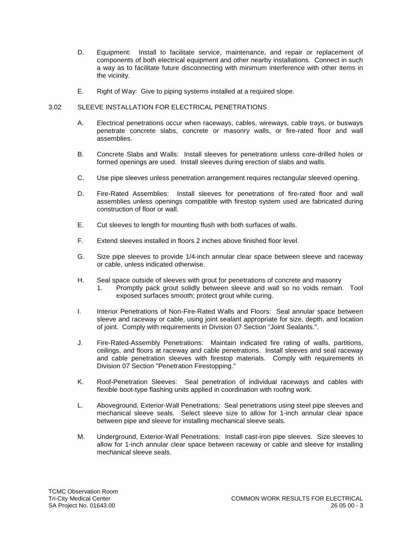
TCMC Observation RoomTri-City Medical Center COMMON WORK RESULTS FOR ELECTRICALSA Project No. 01643.00 26 05 00 - 3
D. Equipment: Install to facilitate service, maintenance, and repair or replacement of components of both electrical equipment and other nearby installations. Connect in such a way as to facilitate future disconnecting with minimum interference with other items in the vicinity.
E. Right of Way: Give to piping systems installed at a required slope.
3.02 SLEEVE INSTALLATION FOR ELECTRICAL PENETRATIONS
A. Electrical penetrations occur when raceways, cables, wireways, cable trays, or busways penetrate concrete slabs, concrete or masonry walls, or fire-rated floor and wall assemblies.
B. Concrete Slabs and Walls: Install sleeves for penetrations unless core-drilled holes or formed openings are used. Install sleeves during erection of slabs and walls.
C. Use pipe sleeves unless penetration arrangement requires rectangular sleeved opening.
D. Fire-Rated Assemblies: Install sleeves for penetrations of fire-rated floor and wall assemblies unless openings compatible with firestop system used are fabricated during construction of floor or wall.
E. Cut sleeves to length for mounting flush with both surfaces of walls.
F. Extend sleeves installed in floors 2 inches above finished floor level.
G. Size pipe sleeves to provide 1/4-inch annular clear space between sleeve and raceway or cable, unless indicated otherwise.
H. Seal space outside of sleeves with grout for penetrations of concrete and masonry1. Promptly pack grout solidly between sleeve and wall so no voids remain. Tool
exposed surfaces smooth; protect grout while curing.
I. Interior Penetrations of Non-Fire-Rated Walls and Floors: Seal annular space between sleeve and raceway or cable, using joint sealant appropriate for size, depth, and location of joint. Comply with requirements in Division 07 Section "Joint Sealants.".
J. Fire-Rated-Assembly Penetrations: Maintain indicated fire rating of walls, partitions, ceilings, and floors at raceway and cable penetrations. Install sleeves and seal raceway and cable penetration sleeves with firestop materials. Comply with requirements in Division 07 Section "Penetration Firestopping."
K. Roof-Penetration Sleeves: Seal penetration of individual raceways and cables with flexible boot-type flashing units applied in coordination with roofing work.
L. Aboveground, Exterior-Wall Penetrations: Seal penetrations using steel pipe sleeves and mechanical sleeve seals. Select sleeve size to allow for 1-inch annular clear space between pipe and sleeve for installing mechanical sleeve seals.
M. Underground, Exterior-Wall Penetrations: Install cast-iron pipe sleeves. Size sleeves to allow for 1-inch annular clear space between raceway or cable and sleeve for installing mechanical sleeve seals.

TCMC Observation RoomTri-City Medical Center COMMON WORK RESULTS FOR ELECTRICALSA Project No. 01643.00 26 05 00 - 4
3.03 SLEEVE-SEAL INSTALLATION
A. Install to seal exterior wall penetrations.
B. Use type and number of sealing elements recommended by manufacturer for raceway or cable material and size. Position raceway or cable in center of sleeve. Assemble mechanical sleeve seals and install in annular space between raceway or cable and sleeve. Tighten bolts against pressure plates that cause sealing elements to expand and make watertight seal.
3.04 FIRESTOPPING
A. Apply firestopping to penetrations of fire-rated floor and wall assemblies for electrical installations to restore original fire-resistance rating of assembly. Firestopping materials and installation requirements are specified in Division 07 Section "Penetration Firestopping."
END OF SECTION
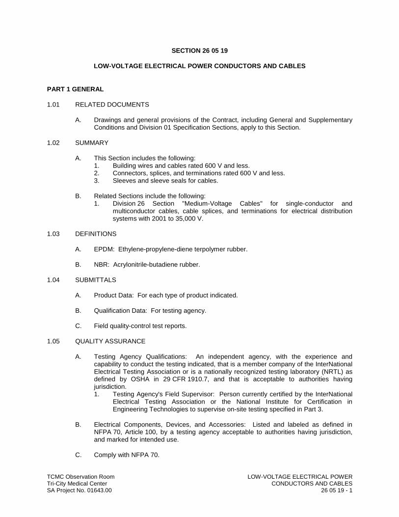
TCMC Observation Room LOW-VOLTAGE ELECTRICAL POWERTri-City Medical Center CONDUCTORS AND CABLESSA Project No. 01643.00 26 05 19 - 1
SECTION 26 05 19
LOW-VOLTAGE ELECTRICAL POWER CONDUCTORS AND CABLES
PART 1 GENERAL
1.01 RELATED DOCUMENTS
A. Drawings and general provisions of the Contract, including General and Supplementary Conditions and Division 01 Specification Sections, apply to this Section.
1.02 SUMMARY
A. This Section includes the following:1. Building wires and cables rated 600 V and less.2. Connectors, splices, and terminations rated 600 V and less.3. Sleeves and sleeve seals for cables.
B. Related Sections include the following:1. Division 26 Section "Medium-Voltage Cables" for single-conductor and
multiconductor cables, cable splices, and terminations for electrical distribution systems with 2001 to 35,000 V.
1.03 DEFINITIONS
A. EPDM: Ethylene-propylene-diene terpolymer rubber.
B. NBR: Acrylonitrile-butadiene rubber.
1.04 SUBMITTALS
A. Product Data: For each type of product indicated.
B. Qualification Data: For testing agency.
C. Field quality-control test reports.
1.05 QUALITY ASSURANCE
A. Testing Agency Qualifications: An independent agency, with the experience and capability to conduct the testing indicated, that is a member company of the InterNational Electrical Testing Association or is a nationally recognized testing laboratory (NRTL) as defined by OSHA in 29 CFR 1910.7, and that is acceptable to authorities having jurisdiction.1. Testing Agency's Field Supervisor: Person currently certified by the InterNational
Electrical Testing Association or the National Institute for Certification in Engineering Technologies to supervise on-site testing specified in Part 3.
B. Electrical Components, Devices, and Accessories: Listed and labeled as defined in NFPA 70, Article 100, by a testing agency acceptable to authorities having jurisdiction, and marked for intended use.
C. Comply with NFPA 70.
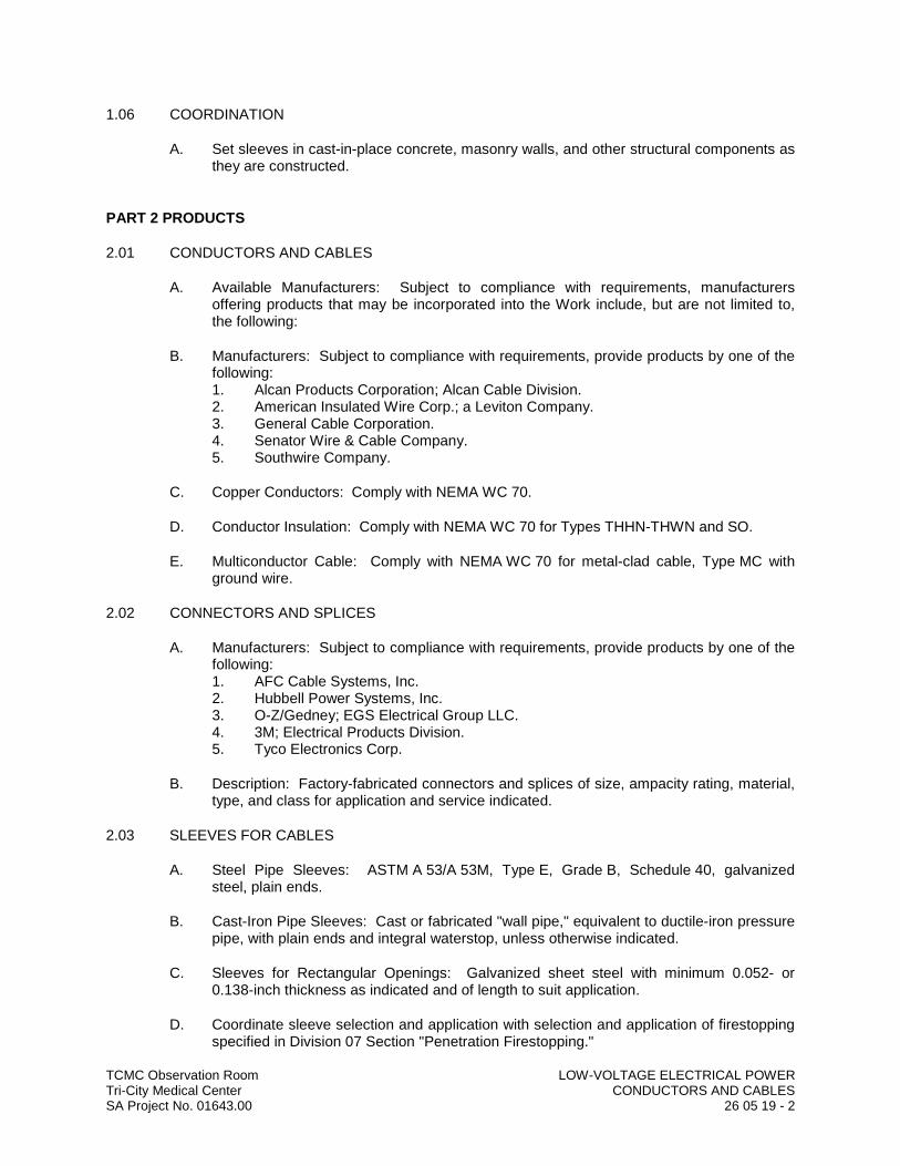
TCMC Observation Room LOW-VOLTAGE ELECTRICAL POWERTri-City Medical Center CONDUCTORS AND CABLESSA Project No. 01643.00 26 05 19 - 2
1.06 COORDINATION
A. Set sleeves in cast-in-place concrete, masonry walls, and other structural components as they are constructed.
PART 2 PRODUCTS
2.01 CONDUCTORS AND CABLES
A. Available Manufacturers: Subject to compliance with requirements, manufacturers offering products that may be incorporated into the Work include, but are not limited to, the following:
B. Manufacturers: Subject to compliance with requirements, provide products by one of the following:1. Alcan Products Corporation; Alcan Cable Division.2. American Insulated Wire Corp.; a Leviton Company.3. General Cable Corporation.4. Senator Wire & Cable Company.5. Southwire Company.
C. Copper Conductors: Comply with NEMA WC 70.
D. Conductor Insulation: Comply with NEMA WC 70 for Types THHN-THWN and SO.
E. Multiconductor Cable: Comply with NEMA WC 70 for metal-clad cable, Type MC with ground wire.
2.02 CONNECTORS AND SPLICES
A. Manufacturers: Subject to compliance with requirements, provide products by one of the following:1. AFC Cable Systems, Inc.2. Hubbell Power Systems, Inc.3. O-Z/Gedney; EGS Electrical Group LLC.4. 3M; Electrical Products Division.5. Tyco Electronics Corp.
B. Description: Factory-fabricated connectors and splices of size, ampacity rating, material, type, and class for application and service indicated.
2.03 SLEEVES FOR CABLES
A. Steel Pipe Sleeves: ASTM A 53/A 53M, Type E, Grade B, Schedule 40, galvanized steel, plain ends.
B. Cast-Iron Pipe Sleeves: Cast or fabricated "wall pipe," equivalent to ductile-iron pressure pipe, with plain ends and integral waterstop, unless otherwise indicated.
C. Sleeves for Rectangular Openings: Galvanized sheet steel with minimum 0.052- or 0.138-inch thickness as indicated and of length to suit application.
D. Coordinate sleeve selection and application with selection and application of firestopping specified in Division 07 Section "Penetration Firestopping."

TCMC Observation Room LOW-VOLTAGE ELECTRICAL POWERTri-City Medical Center CONDUCTORS AND CABLESSA Project No. 01643.00 26 05 19 - 3
2.04 SLEEVE SEALS
A. Available Manufacturers: Subject to compliance with requirements, manufacturers offering products that may be incorporated into the Work include, but are not limited to, the following:
B. Manufacturers: Subject to compliance with requirements, provide products by one of the following:1. Advance Products & Systems, Inc.2. Calpico, Inc.3. Metraflex Co.4. Pipeline Seal and Insulator, Inc.
C. Description: Modular sealing device, designed for field assembly, to fill annular space between sleeve and cable.1. Sealing Elements: EPDM interlocking links shaped to fit surface of cable or
conduit. Include type and number required for material and size of raceway or cable.
2. Pressure Plates: Plastic. Include two for each sealing element.3. Connecting Bolts and Nuts: Carbon steel with corrosion-resistant coating of length
required to secure pressure plates to sealing elements. Include one for each sealing element.
PART 3 EXECUTION
3.01 CONDUCTOR MATERIAL APPLICATIONS
A. Feeders: Copper. Solid for No. 10 AWG and smaller; stranded for No. 8 AWG and larger.
B. Branch Circuits: Copper. Solid for No. 10 AWG and smaller; stranded for No. 8 AWG and larger.
3.02 CONDUCTOR INSULATION AND MULTICONDUCTOR CABLE APPLICATIONS AND WIRING METHODS
A. Service Entrance: Type THHN-THWN, single conductors in raceway.
B. Exposed Feeders: Type THHN-THWN, single conductors in raceway.
C. Feeders Concealed in Ceilings, Walls, Partitions, and Crawlspaces: Type THHN-THWN, single conductors in raceway.
D. Feeders Concealed in Concrete, below Slabs-on-Grade, and Underground: Type THHN-THWN, single conductors in raceway.
E. Feeders in Cable Tray: Type THHN-THWN, single conductors in raceway.
F. Branch Circuits Concealed in Ceilings, Walls, and Partitions: Type THHN-THWN, single conductors in raceway.
G. Branch Circuits Concealed in Concrete, below Slabs-on-Grade, and Underground: Type THHN-THWN, single conductors in raceway.

TCMC Observation Room LOW-VOLTAGE ELECTRICAL POWERTri-City Medical Center CONDUCTORS AND CABLESSA Project No. 01643.00 26 05 19 - 4
H. Branch Circuits in Cable Tray: Type THHN-THWN, single conductors in raceway.
I. Cord Drops and Portable Appliance Connections: Type SO, hard service cord with stainless-steel, wire-mesh, strain relief device at terminations to suit application.
J. Class 1 Control Circuits: Type THHN-THWN, in raceway.
K. Class 2 Control Circuits: Type THHN-THWN, in raceway.
3.03 INSTALLATION OF CONDUCTORS AND CABLES
A. Conceal cables in finished walls, ceilings, and floors, unless otherwise indicated.
B. Use manufacturer-approved pulling compound or lubricant where necessary; compound used must not deteriorate conductor or insulation. Do not exceed manufacturer's recommended maximum pulling tensions and sidewall pressure values.
C. Use pulling means, including fish tape, cable, rope, and basket-weave wire/cable grips, that will not damage cables or raceway.
D. Install exposed cables parallel and perpendicular to surfaces of exposed structural members, and follow surface contours where possible.
E. Support cables according to Division 26 Section "Hangers and Supports for Electrical Systems."
F. Identify and color-code conductors and cables according to Division 26 Section "Identification for Electrical Systems."
3.04 CONNECTIONS
A. Tighten electrical connectors and terminals according to manufacturer's published torque-tightening values. If manufacturer's torque values are not indicated, use those specified in UL 486A and UL 486B.
B. Make splices and taps that are compatible with conductor material and that possess equivalent or better mechanical strength and insulation ratings than unspliced conductors.1. Use oxide inhibitor in each splice and tap conductor for aluminum conductors.
C. Wiring at Outlets: Install conductor at each outlet, with at least 6 inches of slack.
3.05 SLEEVE INSTALLATION FOR ELECTRICAL PENETRATIONS
A. Coordinate sleeve selection and application with selection and application of firestopping specified in Division 07 Section "Penetration Firestopping."
B. Concrete Slabs and Walls: Install sleeves for penetrations unless core-drilled holes or formed openings are used. Install sleeves during erection of slabs and walls.
C. Use pipe sleeves unless penetration arrangement requires rectangular sleeved opening.
D. Rectangular Sleeve Minimum Metal Thickness:1. For sleeve rectangle perimeter less than 50 inches and no side greater than 16
inches, thickness shall be 0.052 inch.
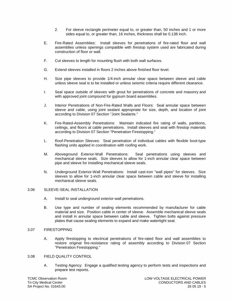
TCMC Observation Room LOW-VOLTAGE ELECTRICAL POWERTri-City Medical Center CONDUCTORS AND CABLESSA Project No. 01643.00 26 05 19 - 5
2. For sleeve rectangle perimeter equal to, or greater than, 50 inches and 1 or more sides equal to, or greater than, 16 inches, thickness shall be 0.138 inch.
E. Fire-Rated Assemblies: Install sleeves for penetrations of fire-rated floor and wall assemblies unless openings compatible with firestop system used are fabricated during construction of floor or wall.
F. Cut sleeves to length for mounting flush with both wall surfaces.
G. Extend sleeves installed in floors 2 inches above finished floor level.
H. Size pipe sleeves to provide 1/4-inch annular clear space between sleeve and cable unless sleeve seal is to be installed or unless seismic criteria require different clearance.
I. Seal space outside of sleeves with grout for penetrations of concrete and masonry and with approved joint compound for gypsum board assemblies.
J. Interior Penetrations of Non-Fire-Rated Walls and Floors: Seal annular space between sleeve and cable, using joint sealant appropriate for size, depth, and location of joint according to Division 07 Section "Joint Sealants."
K. Fire-Rated-Assembly Penetrations: Maintain indicated fire rating of walls, partitions, ceilings, and floors at cable penetrations. Install sleeves and seal with firestop materials according to Division 07 Section "Penetration Firestopping."
L. Roof-Penetration Sleeves: Seal penetration of individual cables with flexible boot-type flashing units applied in coordination with roofing work.
M. Aboveground Exterior-Wall Penetrations: Seal penetrations using sleeves and mechanical sleeve seals. Size sleeves to allow for 1-inch annular clear space between pipe and sleeve for installing mechanical sleeve seals.
N. Underground Exterior-Wall Penetrations: Install cast-iron "wall pipes" for sleeves. Size sleeves to allow for 1-inch annular clear space between cable and sleeve for installing mechanical sleeve seals.
3.06 SLEEVE-SEAL INSTALLATION
A. Install to seal underground exterior-wall penetrations.
B. Use type and number of sealing elements recommended by manufacturer for cable material and size. Position cable in center of sleeve. Assemble mechanical sleeve seals and install in annular space between cable and sleeve. Tighten bolts against pressure plates that cause sealing elements to expand and make watertight seal.
3.07 FIRESTOPPING
A. Apply firestopping to electrical penetrations of fire-rated floor and wall assemblies to restore original fire-resistance rating of assembly according to Division 07 Section "Penetration Firestopping."
3.08 FIELD QUALITY CONTROL
A. Testing Agency: Engage a qualified testing agency to perform tests and inspections and prepare test reports.
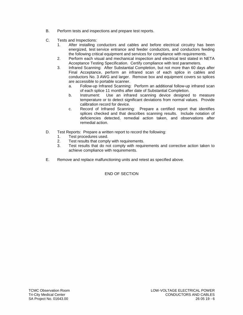
TCMC Observation Room LOW-VOLTAGE ELECTRICAL POWERTri-City Medical Center CONDUCTORS AND CABLESSA Project No. 01643.00 26 05 19 - 6
B. Perform tests and inspections and prepare test reports.
C. Tests and Inspections:1. After installing conductors and cables and before electrical circuitry has been
energized, test service entrance and feeder conductors, and conductors feeding the following critical equipment and services for compliance with requirements.
2. Perform each visual and mechanical inspection and electrical test stated in NETA Acceptance Testing Specification. Certify compliance with test parameters.
3. Infrared Scanning: After Substantial Completion, but not more than 60 days after Final Acceptance, perform an infrared scan of each splice in cables and conductors No. 3 AWG and larger. Remove box and equipment covers so splices are accessible to portable scanner.a. Follow-up Infrared Scanning: Perform an additional follow-up infrared scan
of each splice 11 months after date of Substantial Completion.b. Instrument: Use an infrared scanning device designed to measure
temperature or to detect significant deviations from normal values. Provide calibration record for device.
c. Record of Infrared Scanning: Prepare a certified report that identifies splices checked and that describes scanning results. Include notation of deficiencies detected, remedial action taken, and observations after remedial action.
D. Test Reports: Prepare a written report to record the following:1. Test procedures used.2. Test results that comply with requirements.3. Test results that do not comply with requirements and corrective action taken to
achieve compliance with requirements.
E. Remove and replace malfunctioning units and retest as specified above.
END OF SECTION
TCMC Observation Room GROUNDING AND BONDING Tri-City Medical Center FOR ELECTRICAL SYSTEMSSA Project No. 01643.00 26 05 26 - 1
SECTION 26 05 26
GROUNDING AND BONDING FOR ELECTRICAL SYSTEMS
PART 1 GENERAL
1.01 RELATED DOCUMENTS
A. Drawings and general provisions of the Contract, including General and Supplementary Conditions and Division 01 Specification Sections, apply to this Section.
1.02 SUMMARY
A. This Section includes methods and materials for grounding systems and equipment, plus the following special applications:1. Underground distribution grounding.
1.03 SUBMITTALS
A. Product Data: For each type of product indicated.
B. Other Informational Submittals: Plans showing dimensioned as-built locations of grounding features specified in Part 3 "Field Quality Control" Article, including the following:1. Test wells.2. Ground rods.3. Ground rings.4. Grounding arrangements and connections for separately derived systems.5. Grounding for sensitive electronic equipment.
C. Qualification Data: For testing agency and testing agency's field supervisor.
D. Field quality-control test reports.
E. Operation and Maintenance Data: For grounding to include the following in emergency, operation, and maintenance manuals:1. Instructions for periodic testing and inspection of grounding features at test wells
based on NETA MTS.a. Tests shall be to determine if ground resistance or impedance values
remain within specified maximums, and instructions shall recommend corrective action if they do not.
b. Include recommended testing intervals.
1.04 QUALITY ASSURANCE
A. Testing Agency Qualifications: An independent agency, with the experience and capability to conduct the testing indicated, that is a member company of the InterNational Electrical Testing Association or is a nationally recognized testing laboratory (NRTL) as defined by OSHA in 29 CFR 1910.7, and that is acceptable to authorities having jurisdiction.1. Testing Agency's Field Supervisor: Person currently certified by the InterNational
Electrical Testing Association to supervise on-site testing specified in Part 3.
TCMC Observation Room GROUNDING AND BONDING Tri-City Medical Center FOR ELECTRICAL SYSTEMSSA Project No. 01643.00 26 05 26 - 2
B. Electrical Components, Devices, and Accessories: Listed and labeled as defined in NFPA 70, Article 100, by a testing agency acceptable to authorities having jurisdiction, and marked for intended use.
C. Comply with UL 467 for grounding and bonding materials and equipment.
PART 2 PRODUCTS
2.01 CONDUCTORS
A. Insulated Conductors: Copper wire or cable insulated for 600 V unless otherwise required by applicable Code or authorities having jurisdiction.
B. Bare Copper Conductors:1. Solid Conductors: ASTM B 3.2. Stranded Conductors: ASTM B 8.3. Tinned Conductors: ASTM B 33.4. Bonding Cable: 28 kcmil, 14 strands of No. 17 AWG conductor, 1/4 inch in
diameter.5. Bonding Conductor: No. 4 or No. 6 AWG, stranded conductor.6. Bonding Jumper: Copper tape, braided conductors, terminated with copper
ferrules; 1-5/8 inches wide and 1/16 inch thick.7. Tinned Bonding Jumper: Tinned-copper tape, braided conductors, terminated with
copper ferrules; 1-5/8 inches wide and 1/16 inch thick.
C. Bare Grounding Conductor and Conductor Protector for Wood Poles:1. No. 4 AWG minimum, soft-drawn copper.2. Conductor Protector: Half-round PVC or wood molding. If wood, use pressure-
treated fir or cypress or cedar.
D. Grounding Bus: Rectangular bars of annealed copper, 1/4 by 2 inches in cross section, unless otherwise indicated; with insulators.
2.02 CONNECTORS
A. Listed and labeled by a nationally recognized testing laboratory acceptable to authorities having jurisdiction for applications in which used, and for specific types, sizes, and combinations of conductors and other items connected.
B. Bolted Connectors for Conductors and Pipes: Copper or copper alloy, bolted pressure-type, with at least two bolts.1. Pipe Connectors: Clamp type, sized for pipe.
C. Welded Connectors: Exothermic-welding kits of types recommended by kit manufacturer for materials being joined and installation conditions.
2.03 GROUNDING ELECTRODES
A. Ground Rods: Copper-clad steel, sectional type; 3/4 inch by10 feet in diameter.
B. Chemical-Enhanced Grounding Electrodes: Copper tube, straight or L-shaped, charged with nonhazardous electrolytic chemical salts.1. Termination: Factory-attached No. 4/0 AWG bare conductor at least 48 inches
long.
TCMC Observation Room GROUNDING AND BONDING Tri-City Medical Center FOR ELECTRICAL SYSTEMSSA Project No. 01643.00 26 05 26 - 3
2. Backfill Material: Electrode manufacturer's recommended material.
PART 3 EXECUTION
3.01 APPLICATIONS
A. Conductors: Install solid conductor for No. 8 AWG and smaller, and stranded conductors for No. 6 AWG and larger, unless otherwise indicated.
B. Underground Grounding Conductors: Install barecopper conductor, No. 2/0 AWG minimum.1. Bury at least 24 inches below grade.2. Duct-Bank Grounding Conductor: Bury 12 inches above duct bank when indicated
as part of duct-bank installation.
C. Isolated Grounding Conductors: Green-colored insulation with continuous yellow stripe. On feeders with isolated ground, identify grounding conductor where visible to normal inspection, with alternating bands of green and yellow tape, with at least three bands of green and two bands of yellow.
D. Grounding Bus: Install in electrical and telephone equipment rooms, in rooms housing service equipment, and elsewhere as indicated.1. Install bus on insulated spacers 1 inch, minimum, from wall 6 inches above
finished floor, unless otherwise indicated.2. Where indicated on both sides of doorways, route bus up to top of door frame,
across top of doorway, down to specified height above floor, and connect to horizontal bus.
E. Conductor Terminations and Connections:1. Pipe and Equipment Grounding Conductor Terminations: Bolted connectors.2. Underground Connections: Welded connectors, except at test wells and as
otherwise indicated.3. Connections to Ground Rods at Test Wells: Bolted connectors.4. Connections to Structural Steel: Welded connectors.
3.02 GROUNDING UNDERGROUND DISTRIBUTION SYSTEM COMPONENTS
A. Comply with IEEE C2 grounding requirements.
B. Grounding Manholes and Handholes: Install a driven ground rod through manhole or handhole floor, close to wall, and set rod depth so 4 inches will extend above finished floor. If necessary, install ground rod before manhole is placed and provide No. 1/0 AWG bare, tinned-copper conductor from ground rod into manhole through a waterproof sleeve in manhole wall. Protect ground rods passing through concrete floor with a double wrapping of pressure-sensitive insulating tape or heat-shrunk insulating sleeve from 2inches above to 6 inches below concrete. Seal floor opening with waterproof, nonshrink grout.
C. Grounding Connections to Manhole Components: Bond exposed-metal parts such as inserts, cable racks, pulling irons, ladders, and cable shields within each manhole or handhole, to ground rod or grounding conductor. Make connections with No. 4 AWG minimum, stranded, hard-drawn copper bonding conductor. Train conductors level or plumb around corners and fasten to manhole walls. Connect to cable armor and cable shields as recommended by manufacturer of splicing and termination kits.

TCMC Observation Room GROUNDING AND BONDING Tri-City Medical Center FOR ELECTRICAL SYSTEMSSA Project No. 01643.00 26 05 26 - 4
3.03 CONDUIT GROUNDING
A. Install insulated equipment grounding conductors with all feeders and branch circuits.
B. Where nonmetallic conduit is used in the distribution system, the CONTRACTOR shall install the proper sized copper ground wire in the conduit with the feeder for use as an equipment ground. The electrical metallic raceway system shall be grounded to this ground wire.
C. The maximum ground/bond resistance to the grounding electrode shall not exceed 1 ohms from any location in the electrical system. The maximum ground resistance of the grounding electrode to earth shall not exceed 5 ohms.
D. Ground/Bond Conductors1. Provide an additional, dedicated, green insulation equipment ground/bond wire
inside each conduit type as follows. The metal conduit shall not be permitted to serve (function) as the only (exclusive) electrical ground return path:a. All types of nonmetallic conduit raceways including but not limited to: RNMC
- Rigid Nonmetallic Conduit.b. FMC - Flexible Metal Conduit.c. LTFMC - Liquid Tight Flexible Metal Conduit.d. RMC - Rigid Metal Conduit.e. EMT - Electrical Metal Tubing.
2. The equipment ground/bond wire shall be continuous from the electrical circuit source point of origin to the electrical circuit end termination utilization point as follows:a. Every conduit path containing any length of the above identified conduits.b. Every conduit path connected to any length of the above-identified conduits.
3. The equipment ground/bond wire shall be sized as follows, but in no case smaller than indicated on the drawings. Install equipment ground/bond wire in each conduit/raceway, with the respective phase conductors:
a. Feeder, Subfeeders & Branch Minimum EquipmentCircuit Protection Ground Wire Size15 Amp #1220 Amp #1230 to 60 Amp #1070 to 100 Amp #8101 to 200 Amp #6201 to 400 Amp #2401 to 600 Amp #1801 to 1000 Amp 2/01001 to 1200 Amp 3/01201 to 1600 Amp 4/01601 to 2000 Amp 250 MCM2001 to 2500 Amp 350 MCM2501 to 4000 Amp 500 MCM
4. Isolated grounds - Raceways containing branch circuit or feeder phase conductors connected to panelboards equipment, or receptacles with isolated grounds or isolated ground bus shall contain a dedicated insulated ground conductor connected to the isolated ground system only. The isolated ground conductor shall be continuous the length of the raceways and connected only to the isolated ground terminals in addition to and independent of the equipment bonding/ ground conductor. The isolated ground conductor shall be sized as indicated above, for equipment ground/bond wire.
5. Splices in ground/bond wires shall be permitted only at the following locations:
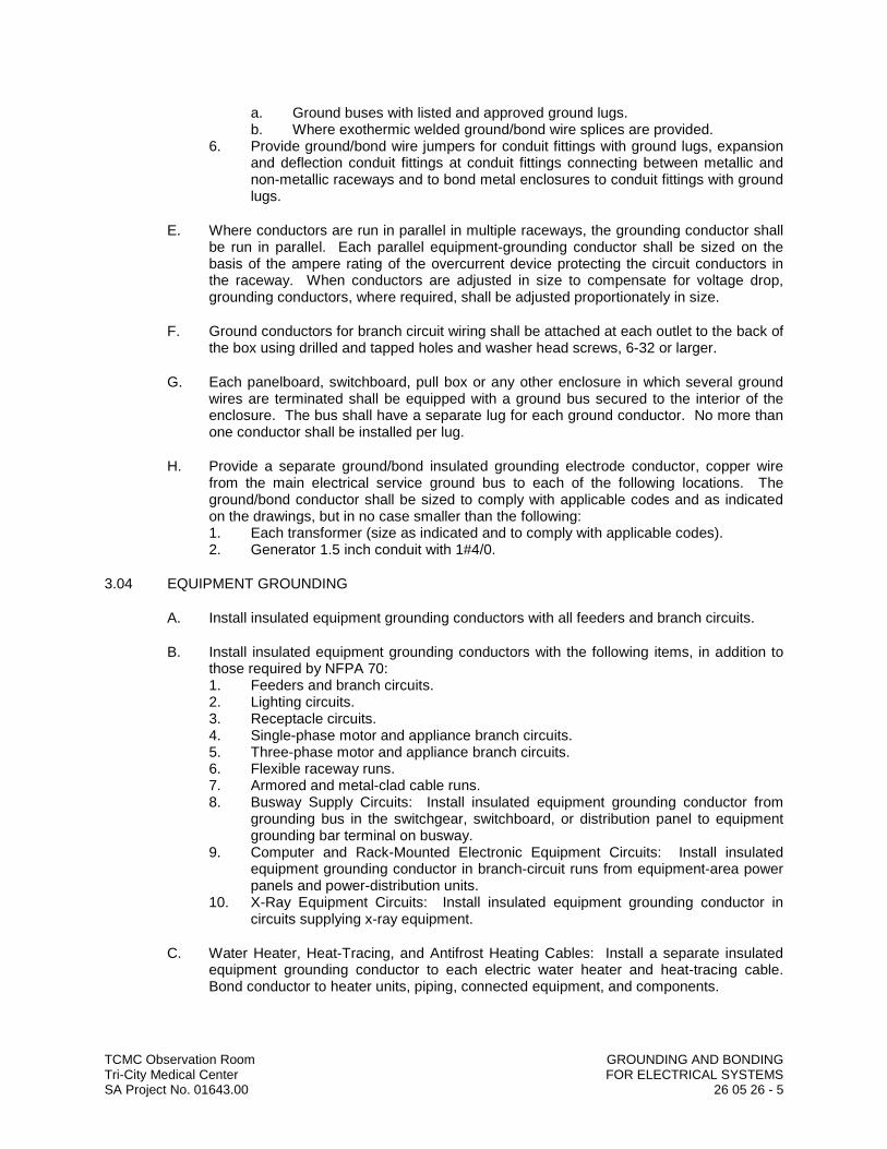
TCMC Observation Room GROUNDING AND BONDING Tri-City Medical Center FOR ELECTRICAL SYSTEMSSA Project No. 01643.00 26 05 26 - 5
a. Ground buses with listed and approved ground lugs.b. Where exothermic welded ground/bond wire splices are provided.
6. Provide ground/bond wire jumpers for conduit fittings with ground lugs, expansion and deflection conduit fittings at conduit fittings connecting between metallic and non-metallic raceways and to bond metal enclosures to conduit fittings with ground lugs.
E. Where conductors are run in parallel in multiple raceways, the grounding conductor shall be run in parallel. Each parallel equipment-grounding conductor shall be sized on the basis of the ampere rating of the overcurrent device protecting the circuit conductors in the raceway. When conductors are adjusted in size to compensate for voltage drop, grounding conductors, where required, shall be adjusted proportionately in size.
F. Ground conductors for branch circuit wiring shall be attached at each outlet to the back of the box using drilled and tapped holes and washer head screws, 6-32 or larger.
G. Each panelboard, switchboard, pull box or any other enclosure in which several ground wires are terminated shall be equipped with a ground bus secured to the interior of the enclosure. The bus shall have a separate lug for each ground conductor. No more than one conductor shall be installed per lug.
H. Provide a separate ground/bond insulated grounding electrode conductor, copper wire from the main electrical service ground bus to each of the following locations. The ground/bond conductor shall be sized to comply with applicable codes and as indicated on the drawings, but in no case smaller than the following:1. Each transformer (size as indicated and to comply with applicable codes).2. Generator 1.5 inch conduit with 1#4/0.
3.04 EQUIPMENT GROUNDING
A. Install insulated equipment grounding conductors with all feeders and branch circuits.
B. Install insulated equipment grounding conductors with the following items, in addition to those required by NFPA 70:1. Feeders and branch circuits.2. Lighting circuits.3. Receptacle circuits.4. Single-phase motor and appliance branch circuits.5. Three-phase motor and appliance branch circuits.6. Flexible raceway runs.7. Armored and metal-clad cable runs.8. Busway Supply Circuits: Install insulated equipment grounding conductor from
grounding bus in the switchgear, switchboard, or distribution panel to equipment grounding bar terminal on busway.
9. Computer and Rack-Mounted Electronic Equipment Circuits: Install insulated equipment grounding conductor in branch-circuit runs from equipment-area power panels and power-distribution units.
10. X-Ray Equipment Circuits: Install insulated equipment grounding conductor in circuits supplying x-ray equipment.
C. Water Heater, Heat-Tracing, and Antifrost Heating Cables: Install a separate insulated equipment grounding conductor to each electric water heater and heat-tracing cable. Bond conductor to heater units, piping, connected equipment, and components.
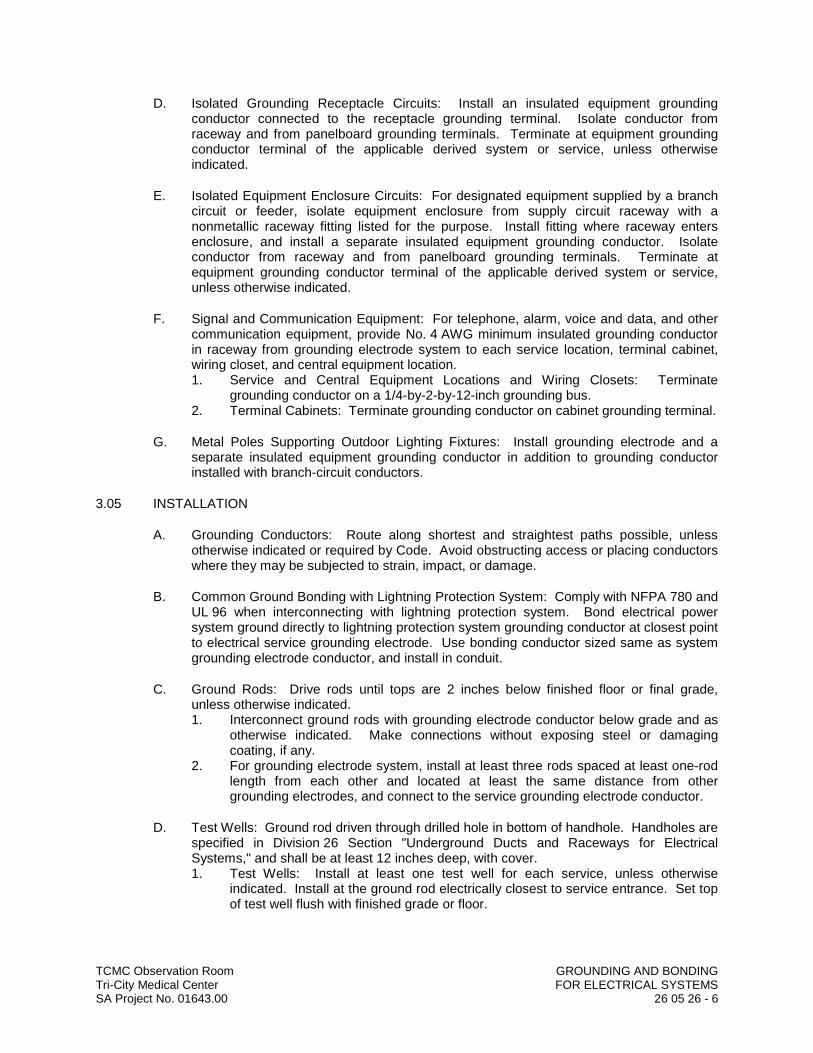
TCMC Observation Room GROUNDING AND BONDING Tri-City Medical Center FOR ELECTRICAL SYSTEMSSA Project No. 01643.00 26 05 26 - 6
D. Isolated Grounding Receptacle Circuits: Install an insulated equipment grounding conductor connected to the receptacle grounding terminal. Isolate conductor from raceway and from panelboard grounding terminals. Terminate at equipment grounding conductor terminal of the applicable derived system or service, unless otherwise indicated.
E. Isolated Equipment Enclosure Circuits: For designated equipment supplied by a branch circuit or feeder, isolate equipment enclosure from supply circuit raceway with a nonmetallic raceway fitting listed for the purpose. Install fitting where raceway enters enclosure, and install a separate insulated equipment grounding conductor. Isolate conductor from raceway and from panelboard grounding terminals. Terminate at equipment grounding conductor terminal of the applicable derived system or service, unless otherwise indicated.
F. Signal and Communication Equipment: For telephone, alarm, voice and data, and other communication equipment, provide No. 4 AWG minimum insulated grounding conductor in raceway from grounding electrode system to each service location, terminal cabinet, wiring closet, and central equipment location.1. Service and Central Equipment Locations and Wiring Closets: Terminate
grounding conductor on a 1/4-by-2-by-12-inch grounding bus.2. Terminal Cabinets: Terminate grounding conductor on cabinet grounding terminal.
G. Metal Poles Supporting Outdoor Lighting Fixtures: Install grounding electrode and a separate insulated equipment grounding conductor in addition to grounding conductor installed with branch-circuit conductors.
3.05 INSTALLATION
A. Grounding Conductors: Route along shortest and straightest paths possible, unless otherwise indicated or required by Code. Avoid obstructing access or placing conductors where they may be subjected to strain, impact, or damage.
B. Common Ground Bonding with Lightning Protection System: Comply with NFPA 780 and UL 96 when interconnecting with lightning protection system. Bond electrical power system ground directly to lightning protection system grounding conductor at closest point to electrical service grounding electrode. Use bonding conductor sized same as system grounding electrode conductor, and install in conduit.
C. Ground Rods: Drive rods until tops are 2 inches below finished floor or final grade, unless otherwise indicated.1. Interconnect ground rods with grounding electrode conductor below grade and as
otherwise indicated. Make connections without exposing steel or damaging coating, if any.
2. For grounding electrode system, install at least three rods spaced at least one-rod length from each other and located at least the same distance from other grounding electrodes, and connect to the service grounding electrode conductor.
D. Test Wells: Ground rod driven through drilled hole in bottom of handhole. Handholes are specified in Division 26 Section "Underground Ducts and Raceways for Electrical Systems," and shall be at least 12 inches deep, with cover.1. Test Wells: Install at least one test well for each service, unless otherwise
indicated. Install at the ground rod electrically closest to service entrance. Set top of test well flush with finished grade or floor.
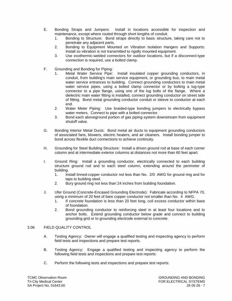
TCMC Observation Room GROUNDING AND BONDING Tri-City Medical Center FOR ELECTRICAL SYSTEMSSA Project No. 01643.00 26 05 26 - 7
E. Bonding Straps and Jumpers: Install in locations accessible for inspection and maintenance, except where routed through short lengths of conduit.1. Bonding to Structure: Bond straps directly to basic structure, taking care not to
penetrate any adjacent parts.2. Bonding to Equipment Mounted on Vibration Isolation Hangers and Supports:
Install so vibration is not transmitted to rigidly mounted equipment.3. Use exothermic-welded connectors for outdoor locations, but if a disconnect-type
connection is required, use a bolted clamp.
F. Grounding and Bonding for Piping:1. Metal Water Service Pipe: Install insulated copper grounding conductors, in
conduit, from building's main service equipment, or grounding bus, to main metal water service entrances to building. Connect grounding conductors to main metal water service pipes, using a bolted clamp connector or by bolting a lug-type connector to a pipe flange, using one of the lug bolts of the flange. Where a dielectric main water fitting is installed, connect grounding conductor on street side of fitting. Bond metal grounding conductor conduit or sleeve to conductor at each end.
2. Water Meter Piping: Use braided-type bonding jumpers to electrically bypass water meters. Connect to pipe with a bolted connector.
3. Bond each aboveground portion of gas piping system downstream from equipment shutoff valve.
G. Bonding Interior Metal Ducts: Bond metal air ducts to equipment grounding conductors of associated fans, blowers, electric heaters, and air cleaners. Install bonding jumper to bond across flexible duct connections to achieve continuity.
H. Grounding for Steel Building Structure: Install a driven ground rod at base of each corner column and at intermediate exterior columns at distances not more than 60 feet apart.
I. Ground Ring: Install a grounding conductor, electrically connected to each building structure ground rod and to each steel column, extending around the perimeter of building.1. Install tinned-copper conductor not less than No. 2/0 AWG for ground ring and for
taps to building steel.2. Bury ground ring not less than 24 inches from building foundation.
J. Ufer Ground (Concrete-Encased Grounding Electrode): Fabricate according to NFPA 70, using a minimum of 20 feet of bare copper conductor not smaller than No. 4 AWG.1. If concrete foundation is less than 20 feet long, coil excess conductor within base
of foundation.2. Bond grounding conductor to reinforcing steel in at least four locations and to
anchor bolts. Extend grounding conductor below grade and connect to building grounding grid or to grounding electrode external to concrete.
3.06 FIELD QUALITY CONTROL
A. Testing Agency: Owner will engage a qualified testing and inspecting agency to perform field tests and inspections and prepare test reports.
B. Testing Agency: Engage a qualified testing and inspecting agency to perform the following field tests and inspections and prepare test reports:
C. Perform the following tests and inspections and prepare test reports:
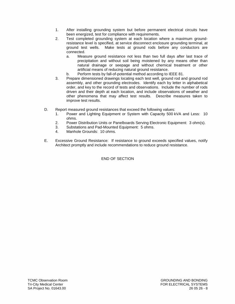
TCMC Observation Room GROUNDING AND BONDING Tri-City Medical Center FOR ELECTRICAL SYSTEMSSA Project No. 01643.00 26 05 26 - 8
1. After installing grounding system but before permanent electrical circuits have been energized, test for compliance with requirements.
2. Test completed grounding system at each location where a maximum ground-resistance level is specified, at service disconnect enclosure grounding terminal, at ground test wells. Make tests at ground rods before any conductors are connected.a. Measure ground resistance not less than two full days after last trace of
precipitation and without soil being moistened by any means other than natural drainage or seepage and without chemical treatment or other artificial means of reducing natural ground resistance.
b. Perform tests by fall-of-potential method according to IEEE 81.3. Prepare dimensioned drawings locating each test well, ground rod and ground rod
assembly, and other grounding electrodes. Identify each by letter in alphabetical order, and key to the record of tests and observations. Include the number of rods driven and their depth at each location, and include observations of weather and other phenomena that may affect test results. Describe measures taken to improve test results.
D. Report measured ground resistances that exceed the following values:1. Power and Lighting Equipment or System with Capacity 500 kVA and Less: 10
ohms.2. Power Distribution Units or Panelboards Serving Electronic Equipment: 3 ohm(s).3. Substations and Pad-Mounted Equipment: 5 ohms.4. Manhole Grounds: 10 ohms.
E. Excessive Ground Resistance: If resistance to ground exceeds specified values, notify Architect promptly and include recommendations to reduce ground resistance.
END OF SECTION
TCMC Observation Room HANGERS AND SUPPORTSTri-City Medical Center FOR ELECTRICAL SYSTEMSSA Project No. 01643.00 26 05 29 - 1
SECTION 26 05 29
HANGERS AND SUPPORTS FOR ELECTRICAL SYSTEMS
PART 1 GENERAL
1.01 RELATED DOCUMENTS
A. Drawings and general provisions of the Contract, including General and Supplementary Conditions and Division 01 Specification Sections, apply to this Section.
1.02 SUMMARY
A. This Section includes the following:1. Hangers and supports for electrical equipment and systems.2. Construction requirements for concrete bases.
B. Related Sections include the following:1. Division 26 Section "Vibration and Seismic Controls for Electrical Systems" for
products and installation requirements necessary for compliance with seismic criteria.
1.03 DEFINITIONS
A. EMT: Electrical metallic tubing.
B. IMC: Intermediate metal conduit.
C. RMC: Rigid metal conduit.
1.04 PERFORMANCE REQUIREMENTS
A. Delegated Design: Design supports for multiple raceways, including comprehensive engineering analysis by a qualified professional engineer, using performance requirements and design criteria indicated.
B. Design supports for multiple raceways capable of supporting combined weight of supported systems and its contents.
C. Design equipment supports capable of supporting combined operating weight of supported equipment and connected systems and components.
D. Rated Strength: Adequate in tension, shear, and pullout force to resist maximum loads calculated or imposed for this Project, with a minimum structural safety factor of five times the applied force.
1.05 SUBMITTALS
A. Product Data: For the following:1. Steel slotted support systems.2. Nonmetallic slotted support systems.
B. Shop Drawings: Signed and sealed by a qualified professional engineer. Show fabrication and installation details and include calculations for the following:

TCMC Observation Room HANGERS AND SUPPORTSTri-City Medical Center FOR ELECTRICAL SYSTEMSSA Project No. 01643.00 26 05 29 - 2
1. Trapeze hangers. Include Product Data for components.2. Steel slotted channel systems. Include Product Data for components.3. Nonmetallic slotted channel systems. Include Product Data for components.4. Equipment supports.
C. Welding certificates.
1.06 QUALITY ASSURANCE
A. Welding: Qualify procedures and personnel according to AWS D1.1/D1.1M, "Structural Welding Code - Steel."
B. Comply with NFPA 70.
1.07 COORDINATION
A. Coordinate size and location of concrete bases. Cast anchor-bolt inserts into bases. Concrete, reinforcement, and formwork requirements are specified in Division 03.
B. Coordinate installation of roof curbs, equipment supports, and roof penetrations. These items are specified in Division 07 Section "Roof Accessories."
PART 2 PRODUCTS
2.01 SUPPORT, ANCHORAGE, AND ATTACHMENT COMPONENTS
A. Steel Slotted Support Systems: Comply with MFMA-4, factory-fabricated components for field assembly.1. Manufacturers: Subject to compliance with requirements, provide products by one
of the following:a. Allied Tube & Conduit.b. Cooper B-Line, Inc.; a division of Cooper Industries.c. ERICO International Corporation.d. GS Metals Corp.e. Thomas & Betts Corporation.f. Unistrut; Tyco International, Ltd.g. Wesanco, Inc.
2. Metallic Coatings: Hot-dip galvanized after fabrication and applied according to MFMA-4.
3. Nonmetallic Coatings: Manufacturer's standard PVC, polyurethane, or polyester coating applied according to MFMA-4.
4. Painted Coatings: Manufacturer's standard painted coating applied according to MFMA-4.
5. Channel Dimensions: Selected for applicable load criteria.
B. Nonmetallic Slotted Support Systems: Structural-grade, factory-formed, glass-fiber-resin channels and angles with 9/16-inch-diameter holes at a maximum of 8 inches o.c., in at least 1 surface.1. Manufacturers: Subject to compliance with requirements, provide products by one
of the following:a. Allied Tube & Conduit.b. Cooper B-Line, Inc.; a division of Cooper Industries.c. Fabco Plastics Wholesale Limited.d. Seasafe, Inc.
TCMC Observation Room HANGERS AND SUPPORTSTri-City Medical Center FOR ELECTRICAL SYSTEMSSA Project No. 01643.00 26 05 29 - 3
2. Fittings and Accessories: Products of channel and angle manufacturer and designed for use with those items.
3. Fitting and Accessory Materials: Same as channels and angles.4. Rated Strength: Selected to suit applicable load criteria.
C. Raceway and Cable Supports: As described in NECA 1 and NECA 101.
D. Conduit and Cable Support Devices: Steel hangers, clamps, and associated fittings, designed for types and sizes of raceway or cable to be supported.
E. Support for Conductors in Vertical Conduit: Factory-fabricated assembly consisting of threaded body and insulating wedging plug or plugs for non-armored electrical conductors or cables in riser conduits. Plugs shall have number, size, and shape of conductor gripping pieces as required to suit individual conductors or cables supported. Body shall be malleable iron.
F. Structural Steel for Fabricated Supports and Restraints: ASTM A 36/A 36M, steel plates, shapes, and bars; black and galvanized.
G. Mounting, Anchoring, and Attachment Components: Items for fastening electrical items or their supports to building surfaces include the following:1. Powder-Actuated Fasteners: Threaded-steel stud, for use in hardened portland
cement concrete, steel, or wood, with tension, shear, and pullout capacities appropriate for supported loads and building materials where used.a. Manufacturers: Subject to compliance with requirements, provide products
by one of the following:1) Hilti Inc.2) ITW Ramset/Red Head; a division of Illinois Tool Works, Inc.3) MKT Fastening, LLC.4) Simpson Strong-Tie Co., Inc.; Masterset Fastening Systems Unit.
2. Mechanical-Expansion Anchors: Insert-wedge-type, zinc-coated steel, for use in hardened portland cement concrete with tension, shear, and pullout capacities appropriate for supported loads and building materials in which used.a. Manufacturers: Subject to compliance with requirements, provide products
by one of the following:1) Cooper B-Line, Inc.; a division of Cooper Industries.2) Empire Tool and Manufacturing Co., Inc.3) Hilti Inc.4) ITW Ramset/Red Head; a division of Illinois Tool Works, Inc.5) MKT Fastening, LLC.
3. Concrete Inserts: Steel or malleable-iron, slotted support system units similar to MSS Type 18; complying with MFMA-4 or MSS SP-58.
4. Clamps for Attachment to Steel Structural Elements: MSS SP-58, type suitable for attached structural element.
5. Through Bolts: Structural type, hex head, and high strength. Comply with ASTM A 325.
6. Toggle Bolts: All-steel springhead type.7. Hanger Rods: Threaded steel.
2.02 FABRICATED METAL EQUIPMENT SUPPORT ASSEMBLIES
A. Description: Welded or bolted, structural-steel shapes, shop or field fabricated to fit dimensions of supported equipment.
TCMC Observation Room HANGERS AND SUPPORTSTri-City Medical Center FOR ELECTRICAL SYSTEMSSA Project No. 01643.00 26 05 29 - 4
B. Materials: Comply with requirements in Division 05 Section "Metal Fabrications" for steel shapes and plates.
PART 3 EXECUTION
3.01 APPLICATION
A. Comply with NECA 1 and NECA 101 for application of hangers and supports for electrical equipment and systems except if requirements in this Section are stricter.
B. Maximum Support Spacing and Minimum Hanger Rod Size for Raceway: Space supports for EMT, IMC, and RMC as required by NFPA 70. Minimum rod size shall be 1/4 inch in diameter.
C. Multiple Raceways or Cables: Install trapeze-type supports fabricated with steel slottedsupport system, sized so capacity can be increased by at least 25 percent in future without exceeding specified design load limits.1. Secure raceways and cables to these supports with two-bolt conduit clamps.
D. Spring-steel clamps designed for supporting single conduits without bolts may be used for 1-1/2-inch and smaller raceways serving branch circuits and communication systems above suspended ceilings and for fastening raceways to trapeze supports.
3.02 SUPPORT INSTALLATION
A. Comply with NECA 1 and NECA 101 for installation requirements except as specified in this Article.
B. Raceway Support Methods: In addition to methods described in NECA 1, EMT, IMC, and RMC may be supported by openings through structure members, as permitted in NFPA 70.
C. Strength of Support Assemblies: Where not indicated, select sizes of components so strength will be adequate to carry present and future static loads within specified loading limits. Minimum static design load used for strength determination shall be weight of supported components plus 200 lb.
D. Mounting and Anchorage of Surface-Mounted Equipment and Components: Anchor and fasten electrical items and their supports to building structural elements by the following methods unless otherwise indicated by code:1. To Wood: Fasten with lag screws or through bolts.2. To New Concrete: Bolt to concrete inserts.3. To Masonry: Approved toggle-type bolts on hollow masonry units and expansion
anchor fasteners on solid masonry units.4. To Existing Concrete: Expansion anchor fasteners.5. Instead of expansion anchors, powder-actuated driven threaded studs provided
with lock washers and nuts may be used in existing standard-weight concrete 4inches thick or greater. Do not use for anchorage to lightweight-aggregate concrete or for slabs less than 4 inches thick.
6. To Steel: Beam clamps (MSS Type 19, 21, 23, 25, or 27) complying with MSS SP-69.
7. To Light Steel: Sheet metal screws.8. Items Mounted on Hollow Walls and Nonstructural Building Surfaces: Mount
cabinets, panelboards, disconnect switches, control enclosures, pull and junction
TCMC Observation Room HANGERS AND SUPPORTSTri-City Medical Center FOR ELECTRICAL SYSTEMSSA Project No. 01643.00 26 05 29 - 5
boxes, transformers, and other devices on slotted-channel racks attached to substrate by means that meet seismic-restraint strength and anchorage requirements.
E. Drill holes for expansion anchors in concrete at locations and to depths that avoid reinforcing bars.
3.03 INSTALLATION OF FABRICATED METAL SUPPORTS
A. Comply with installation requirements in Division 05 Section "Metal Fabrications" for site-fabricated metal supports.
B. Cut, fit, and place miscellaneous metal supports accurately in location, alignment, and elevation to support and anchor electrical materials and equipment.
C. Field Welding: Comply with AWS D1.1/D1.1M.
3.04 CONCRETE BASES
A. Construct concrete bases of dimensions indicated but not less than 4 inches larger in both directions than supported unit, and so anchors will be a minimum of 10 bolt diameters from edge of the base.
B. Use 3000-psi, 28-day compressive-strength concrete. Concrete materials, reinforcement, and placement requirements are specified in Division 03 Section "Cast-in-Place Concrete."
C. Anchor equipment to concrete base.1. Place and secure anchorage devices. Use supported equipment manufacturer's
setting drawings, templates, diagrams, instructions, and directions furnished with items to be embedded.
2. Install anchor bolts to elevations required for proper attachment to supported equipment.
3. Install anchor bolts according to anchor-bolt manufacturer's written instructions.
3.05 PAINTING
A. Touchup: Clean field welds and abraded areas of shop paint. Paint exposed areas immediately after erecting hangers and supports. Use same materials as used for shop painting. Comply with SSPC-PA 1 requirements for touching up field-painted surfaces.1. Apply paint by brush or spray to provide minimum dry film thickness of 2.0 mils.
B. Touchup: Comply with requirements in Division 09 painting Sections for cleaning and touchup painting of field welds, bolted connections, and abraded areas of shop paint on miscellaneous metal.
C. Galvanized Surfaces: Clean welds, bolted connections, and abraded areas and apply galvanizing-repair paint to comply with ASTM A 780.
END OF SECTION


TCMC Observation Room RACEWAY AND BOXES FORTri-City Medical Center ELECTRICAL SYSTEMSSA Project No. 01643.00 26 05 33 - 1
SECTION 26 05 33
RACEWAY AND BOXES FOR ELECTRICAL SYSTEMS
PART 1 GENERAL
1.01 RELATED DOCUMENTS
A. Drawings and general provisions of the Contract, including General and Supplementary Conditions and Division 01 Specification Sections, apply to this Section.
1.02 SUMMARY
A. This Section includes raceways, fittings, boxes, enclosures, wireway, wall duct and cabinets for electrical wiring.
B. Related Sections include the following:1. Division 26 Section "Underground Ducts and Raceways for Electrical
Systems" for exterior ductbanks, manholes, and underground utility construction.
1.03 DEFINITIONS
A. RMC: Rigid metal conduit
B. EMT: Electrical metallic tubing.
C. FMC: Flexible metal conduit.
D. LTFMC: Liquid Tight Flexible metal conduit.
E. RNMC: Rigid nonmetallic conduit.
1.04 SCOPE
A. Work Included: All labor, materials, appliances, tools, equipment, facilities, trans-portation and services necessary for and incidental to performing all operations in connection with furnishing, delivery and installation of the work of this Section, complete as shown on the drawings and/or specified herein. Work includes, but is not necessarily limited to the following:1. Examine all other sections for work related to those other sections and re-
quired to be included as work under this section.2. General provisions and requirements for electrical work.
1.05 SUBMITTALS
A. Product Data: For each type of product indicated.
B. Shop Drawings: For the following raceway components. Include plans, elevations, sections, details, and attachments to other work.1. Custom enclosures and cabinets.2. For handholes and boxes for underground wiring, including the following:
a. Duct entry provisions, including locations and duct sizes.b. Frame and cover design.

TCMC Observation Room RACEWAY AND BOXES FORTri-City Medical Center ELECTRICAL SYSTEMSSA Project No. 01643.00 26 05 33 - 2
c. Grounding details.d. Dimensioned locations of cable rack inserts, and pulling-in and lifting irons.e. Joint details.
C. Coordination Drawings: Conduit routing plans, drawn to scale, on which the following items are shown and coordinated with each other, based on input from installers of the items involved:1. Structural members in the paths of conduit groups with common supports.2. HVAC and plumbing items and architectural features in the paths of conduit
groups with common supports.
D. Manufacturer Seismic Qualification Certification: Submit certification that enclosures and cabinets and their mounting provisions, including those for internal components, will withstand seismic forces defined in Division 26 Section "Vibration and Seismic Controls for Electrical Systems." Include the following:1. Basis for Certification: Indicate whether withstand certification is based on
actual test of assembled components or on calculation.a. The term "withstand" means "the cabinet or enclosure will remain in place
without separation of any parts when subjected to the seismic forces specified and the unit will retain its enclosure characteristics, including its interior accessibility, after the seismic event."
2. Dimensioned Outline Drawings of Equipment Unit: Identify center of gravity and locate and describe mounting and anchorage provisions.
3. Detailed description of equipment anchorage devices on which the certification is based and their installation requirements.
E. Qualification Data: For professional engineer and testing agency.
F. Source quality-control test reports.
G. Submit material list for outlet boxes, conduit and conduit fittings.
H. Submit details and structural engineering calculations for conduit support systems.
1.06 QUALITY ASSURANCE
A. Electrical Components, Devices, and Accessories: Listed and labeled as defined in NFPA 70, Article 100, by a testing agency acceptable to authorities having jurisdiction, and marked for intended use.
B. Comply with NFPA 70.
PART 2 PRODUCTS
2.01 METAL CONDUIT AND TUBING
A. General1. The interior surfaces of conduits and fittings shall be continuous and
smooth, with a constant interior diameter. Conduits and conduit fittings shall provide conductor raceways of fully enclosed circular cross section. The interior surfaces of conduits and fittings shall be without ridges, burrs irregularities or obstructions. Conduits and fittings of the same type shall be of the same uniform weight and thickness.
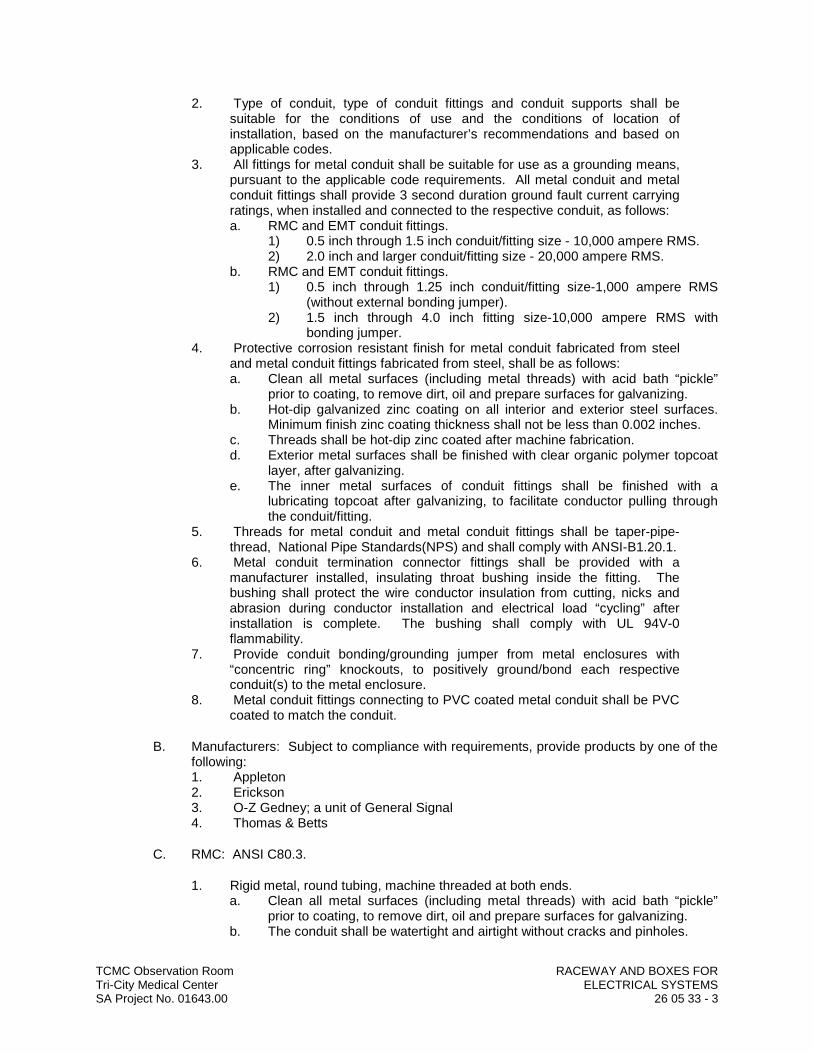
TCMC Observation Room RACEWAY AND BOXES FORTri-City Medical Center ELECTRICAL SYSTEMSSA Project No. 01643.00 26 05 33 - 3
2. Type of conduit, type of conduit fittings and conduit supports shall be suitable for the conditions of use and the conditions of location of installation, based on the manufacturer’s recommendations and based on applicable codes.
3. All fittings for metal conduit shall be suitable for use as a grounding means, pursuant to the applicable code requirements. All metal conduit and metal conduit fittings shall provide 3 second duration ground fault current carrying ratings, when installed and connected to the respective conduit, as follows:a. RMC and EMT conduit fittings.
1) 0.5 inch through 1.5 inch conduit/fitting size - 10,000 ampere RMS.2) 2.0 inch and larger conduit/fitting size - 20,000 ampere RMS.
b. RMC and EMT conduit fittings.1) 0.5 inch through 1.25 inch conduit/fitting size-1,000 ampere RMS
(without external bonding jumper).2) 1.5 inch through 4.0 inch fitting size-10,000 ampere RMS with
bonding jumper.4. Protective corrosion resistant finish for metal conduit fabricated from steel
and metal conduit fittings fabricated from steel, shall be as follows:a. Clean all metal surfaces (including metal threads) with acid bath “pickle”
prior to coating, to remove dirt, oil and prepare surfaces for galvanizing.b. Hot-dip galvanized zinc coating on all interior and exterior steel surfaces.
Minimum finish zinc coating thickness shall not be less than 0.002 inches.c. Threads shall be hot-dip zinc coated after machine fabrication.d. Exterior metal surfaces shall be finished with clear organic polymer topcoat
layer, after galvanizing.e. The inner metal surfaces of conduit fittings shall be finished with a
lubricating topcoat after galvanizing, to facilitate conductor pulling through the conduit/fitting.
5. Threads for metal conduit and metal conduit fittings shall be taper-pipe-thread, National Pipe Standards(NPS) and shall comply with ANSI-B1.20.1.
6. Metal conduit termination connector fittings shall be provided with a manufacturer installed, insulating throat bushing inside the fitting. The bushing shall protect the wire conductor insulation from cutting, nicks andabrasion during conductor installation and electrical load “cycling” after installation is complete. The bushing shall comply with UL 94V-0flammability.
7. Provide conduit bonding/grounding jumper from metal enclosures with “concentric ring” knockouts, to positively ground/bond each respective conduit(s) to the metal enclosure.
8. Metal conduit fittings connecting to PVC coated metal conduit shall be PVC coated to match the conduit.
B. Manufacturers: Subject to compliance with requirements, provide products by one of the following:1. Appleton2. Erickson3. O-Z Gedney; a unit of General Signal4. Thomas & Betts
C. RMC: ANSI C80.3.
1. Rigid metal, round tubing, machine threaded at both ends.a. Clean all metal surfaces (including metal threads) with acid bath “pickle”
prior to coating, to remove dirt, oil and prepare surfaces for galvanizing.b. The conduit shall be watertight and airtight without cracks and pinholes.
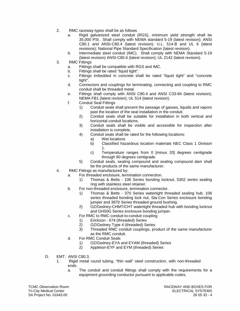
TCMC Observation Room RACEWAY AND BOXES FORTri-City Medical Center ELECTRICAL SYSTEMSSA Project No. 01643.00 26 05 33 - 4
2. RMC raceway types shall be as followsa. Rigid galvanized steel conduit (RGS), minimum yield strength shall be
35,000 PSI. Shall comply with NEMA standard 5-19 (latest revision); ANSI C80.1 and ANSI-C80.4 (latest revision); U.L. 514-B and UL 6 (latest revisions); National Pipe Standard Specification (latest revision).
b. Intermediate steel conduit (IMC). Shall comply with NEMA Standard 5-19 (latest revision) ANSI-C80.6 (latest revision); UL 2142 (latest revision).
3. RMC Fittingsa. Fittings shall be compatible with RGS and IMC.b. Fittings shall be rated “liquid tight”.c. Fittings imbedded in concrete shall be rated “liquid tight” and “concrete
tight”.d. Connectors and couplings for terminating, connecting and coupling to RMC
conduit shall be threaded metal.e. Fittings shall comply with ANSI C80.4 and ANSI C33-84 (latest revision);
NEMA FB1 (latest revision); UL 514 (latest revision).f. Conduit Seal Fittings
1) Conduit seals shall prevent the passage of gasses, liquids and vapors past the location of the seal installation in the conduit.
2) Conduit seals shall be suitable for installation in both vertical and horizontal conduit locations.
3) Conduit seals shall be visible and accessible for inspection after installation is complete.
4) Conduit seals shall be rated for the following locations:a) Wet locationsb) Classified hazardous location materials NEC Class 1 Division
1.c) Temperature ranges from 0 [minus 20] degrees centigrade
through 90 degrees centigrade.5) Conduit seals, sealing compound and sealing compound dam shall
be the products of the same manufacturer.4. RMC Fittings as manufactured by:
a. For threaded enclosure, termination connection.1) Thomas & Betts - 106 Series bonding locknut, 5302 series sealing
ring with stainless steel retainer.b. For non-threaded enclosure, termination connector.
1) Thomas & Betts - 370 Series watertight threaded sealing hub, 106 series threaded bonding lock nut, Sta-Con Series enclosure bonding jumper and 3870 Series threaded ground bushing.
2) OZ/Gedney-CHMT/CHT watertight threaded hub with bonding locknut and GH50G Series enclosure bonding jumper.
c. For RMC to RMC conduit-to-conduit coupling1) Erickson - 674 (threaded) Series2) OZ/Gedney Type 4 (threaded) Series3) Threaded RMC conduit couplings, product of the same manufacturer
as the RMC conduit.d. For RMC Conduit Seals
1) OZ/Gedney-EYA and EYAM (threaded) Series2) Appleton-EYF and EYM (threaded) Series
D. EMT: ANSI C80.3.1. Rigid metal round tubing, “thin wall” steel construction, with non-threaded
ends.a. The conduit and conduit fittings shall comply with the requirements for a
equipment grounding conductor pursuant to applicable codes.

TCMC Observation Room RACEWAY AND BOXES FORTri-City Medical Center ELECTRICAL SYSTEMSSA Project No. 01643.00 26 05 33 - 5
b. The conduit shall be watertight and airtight without cracks and pinholes.2. EMT shall be allowed for conduit size ranges from 0.5 inch through 4.0
inch.3. Comply with ANSI C80.3, C80.4, and ANSI C33.98 (latest revisions); UL
594 and UL 797 (latest revisions); CEC Section 12500 (latest revision).4. EMT Fittings
a. Connectors and couplings for terminating, connecting and coupling to EMT conduit shall be non-threaded steel fabrication.
b. EMT termination connector fittings shall be as follows:1) Set screw type “concrete tight” when installed in dry interior locations.2) Compression types “raintight” and “concrete tight” when installed in
wet or damp locations, outdoors and in concrete or masonry construction.
c. Fittings shall comply with ANSI C33.84 (latest revision); UL 514 (latest revision); NEMA FB-1.
5. EMT Fittings as manufactured by:a. For threaded and non threaded enclosure, termination connector
1) Thomas & Betts-TC5031 (set screw type) Series (with locknuts).2) OZ/Gedney-4000ST (set screw type) Series.3) Thomas & Betts-5123 (compression type) Series (with 2 locknuts).4) OZ/Gedney-7000ST (compression type) Series (with locknut).5) Thomas & Betts-4240 (compression type) Series (90 degree angle
with locknut).6) OZ/Gedney-8000WT (compression type) Series (90 degree angle
with locknut).b. For EMT to EMT conduit-to-conduit coupling:
1) Thomas & Betts-TK121 (set screw type) Series (with locknut).2) OZ/Gedney-5000 (set screw type) Series (with locknut).3) Thomas & Betts-5120 (compression type) Series4) OZ/Gedney-6000S (compression type) Series.
c. For EMT to RMC conduit to conduit combination coupling:1) Thomas & Betts-HT221 (set screw type) Series2) OZ/Gedney-ESR (set screw type) Series.3) Thomas & Betts-530 (compression type) Series4) OZ/Gedney-ETR (compression type) Series.
E. FMC: Zinc-coated steel.1. Round flexible conduit, fabricated from a single continuous steel strip. The
steel shall be factory formed into continuous interlocking convolutions to form a complete lock between steel strips and provide raceway flexibility.
2. Metal to metal grounding contact shall be maintained throughout the length of the FMC conduit.
3. FMC shall be allowed for conduit size ranges from 0.5 inch through 0.75 inch.
4. FMC shall comply with ANSI-C.33.84 and ANSI C33.92; NEMA FB-1; CEC 12-1100.
5. FMC Fittingsa. FMC fittings shall be malleable iron construction or steel construction.b. Fitting shall automatically cause the FMC raceway throat opening to be
centered with respect to the fitting throat opening.c. Straight and angled connector termination fittings shall be threaded on one
end and shall include a threaded locknut, suitable for connection to threaded and unthreaded enclosures.

TCMC Observation Room RACEWAY AND BOXES FORTri-City Medical Center ELECTRICAL SYSTEMSSA Project No. 01643.00 26 05 33 - 6
d. The attachment of the fittings to FMC shall be angled saddle type, to engage and interlock with the FMC spiral groove, and shall be unaffected by vibration. Direct bearing screw type fittings shall not be used.
e. Direct FMC conduit-to-FMC conduit coupling of FMC shall not be permitted.f. Shall comply with ANSI C33.9, and ANSI C33.92 (latest revision); NEMA
FB1 (latest revision); U.L. 514.6. FMC Fittings as manufactured by: a. Straight Termination 45 & 90 Degree Connectors Angle Connectors
1) Thomas & Betts-Thomas & Betts-3110 Series 3130 Series b. FMC to EMT conduit combination coupling:
1) Thomas & Betts 503TB Series.
F. LTFMC: 1. The metal conduit core of LTFMC shall comply with the same requirements
as FMC conduit, with the addition of a thermoplastic exterior flexible jacket over the metal core.
2. The exterior jacket shall be positively locked to the metal core to prevent jacket “sleeving”.
3. The LTFMC shall be rated for installation and operating service temperatures of between 0 [minus 20] degrees centigrade through plus 90 degrees centigrade.
4. The LTFMC jacket shall be suitable for continuous exposure to sunlight, rainwater, water vapor, mineral oils and liquid solvents, without penetrating into the conduit and without deteriorating the jacket.
5. LTFMC sizes from 0.5 inch through 1.25 inches shall include an additional internal ground conductor, fabricated by the manufacturer, as a integral part of the conduit core.
6. Direct LTFMC conduit-to-LTFMC conduit coupling of LTFMC shall not be permitted.
7. LTFMC shall be allowed for conduit size ranges from 0.5 inch through 4.0 inches.
8. In addition to the requirements for FMC conduit, LTFMC shall also comply with ANSI C-33.84 (latest revision); NEMA-FB1 (latest revision); CEC 12-1400 (latest revision).
9. LTFMC fittingsa. Fittings shall include an external mechanical ground/bond wire connector.b. The attachment of the fitting to LTFMC shall be threaded compression type
onto the conduit core with locknut and liquid tight jacket compression seal. The fitting shall automatically prevent “sleeving” of the jacket.
c. Straight and angled termination connector fittings shall be threaded on one end and shall include locknut suitable for connection to threaded and unthreaded enclosures.
10. LTFMC Fittings as manufactured by:a. Termination connector fittings Straight 45 and 90 Degree Angle Connect-
ors1) Thomas & Betts-5331Thomas & Betts-GR Series.5341GR and
5351GR Series.2) Appleton-STB Series; Appleton-STB-L STN-L Series for use Series;
STN-L Series with preformed Series for use “knockouts”. with pre-formed “knockouts”.
3) OZ/Gedney-4QLT Series. OZ/Gedney-4QLT Seriesb. For EMT to EMT conduit-to-conduit coupling:
1) Thomas & Betts-5271 GR Series.2) OZ/Gedney-4QFML Series

TCMC Observation Room RACEWAY AND BOXES FORTri-City Medical Center ELECTRICAL SYSTEMSSA Project No. 01643.00 26 05 33 - 7
G. Fittings for Conduit (Including all Types and Flexible and Liquidtight), EMT, and Cable: NEMA FB 1; listed for type and size raceway with which used, and for application and environment in which installed.1. Conduit Fittings for Hazardous (Classified) Locations: Comply with UL 886.2. Conduit Fittings for Hazardous (Classified) Locations: Comply with UL 886.3. Fittings for EMT: Steel type.4. Coating for Fittings for PVC-Coated Conduit: Minimum thickness, 0.040
inch, with overlapping sleeves protecting threaded joints.
H. Joint Compound for Rigid Steel Conduit or IMC: Listed for use in cable connector assemblies, and compounded for use to lubricate and protect threaded raceway joints from corrosion and enhance their conductivity.
2.02 NONMETALLIC CONDUIT AND TUBING
A. General1. The interior surfaces of conduits and fittings shall be continuous and
smooth, with a constant interior diameter. Conduits and conduit fittings shall provide conductor raceways of fully enclosed circular cross section. The interior surfaces of conduits and fittings shall be without ridges, burrs irregularities or obstructions. Conduits and fittings of the same type shall be of the same uniform weight and thickness.
2. Type of conduit, type of conduit fittings and conduit supports shall be suitable for the conditions of use and the conditions of location of installation, based on the manufacturer’s recommendations and based on applicable codes.
B. Manufacturers: Subject to compliance with requirements, provide products by one of the following:1. Appleton2. Erickson3. O-Z Gedney; a unit of General Signal4. Thomas & Betts
C. RNMC: NEMA TC 2, Type EPC-40-PVC or Type EPC-80-PVC, unless otherwise indicated.1. General
a. Conduit and fittings shall be 90 degree centigrade conductor rated. Fabricated from homogeneous material, free from visible crack holes or foreign inclusions, with integral “end-bell”. The conduit and conduit fittings shall be watertight and airtight.
b. Conduit, conduit fittings and conduit fitting assembly “solvent cement” shall all be the product of the same manufacturer. Conduit fittings shall be solvent cement welded watertight.
c. Conduit and fittings shall be identified with legible markings showing ratings, size and manufacturers name.
d. RNMC and fitting shall be corrosion resistant, watertight.e. Conduit shall be suitable for conductor operating temperatures from minus
20 degrees centigrade to 90 degrees centigrade.f. RNMC shall comply with NEMA TC-2 (PVC 40 conduit, latest revision)
NEMA TC-6 (EB conduit latest revision) and NEMA TC-3 (fittings, latest revision); UL 514 and UL 651 (latest revision).
2. Polyvinyl Chloride (PVC)-RNMCa. PVC-schedule 40 heavy wall construction.b. PVC-schedule 80 extra heavy wall construction.
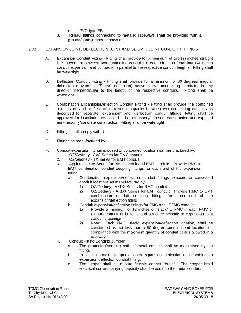
TCMC Observation Room RACEWAY AND BOXES FORTri-City Medical Center ELECTRICAL SYSTEMSSA Project No. 01643.00 26 05 33 - 8
c. PVC-type EB.3. RNMC fittings connecting to metallic raceways shall be provided with a
ground/bond jumper connection.
2.03 EXPANSION JOINT, DEFLECTION JOINT AND SEISMIC JOINT CONDUIT FITTINGS
A. Expansion Conduit Fitting - Fitting shall provide for a minimum of two (2) inches straight line movement between two connecting conduits in each direction (total four (4) inches conduit expansion and contraction) parallel to the respective conduit lengths. Fitting shall be watertight.
B. Deflection Conduit Fitting - Fitting shall provide for a minimum of 30 degrees angular deflection movement (“Shear” deflection) between two connecting conduits, in any direction perpendicular to the length of the respective conduits. Fitting shall be watertight.
C. Combination Expansion/Deflection Conduit Fitting - Fitting shall provide the combined “expansion” and “deflection” movement capacity between two connecting conduits as described for separate “expansion” and “deflection” conduit fittings. Fitting shall be approved for installation concealed in both masonry/concrete construction and exposed non-masonry/concrete construction. Fitting shall be watertight.
D. Fittings shall comply with U.L.
E. Fittings as manufactured by:
F. Conduit expansion fittings exposed or concealed locations as manufactured by:1. OZ/Gedney - AX8 Series for RMC conduit.2. OZ/Gedney - TX Series for EMT conduit3. Appleton - XJ8 Series for RMC conduit and EMT conduits. Provide RMC to
EMT combination conduit coupling fittings for each end of the expansion fitting.a. Combination expansion/deflection conduit fittings exposed or concealed
conduit locations as manufactured by:1) OZ/Gedney - AXDX Series for RMC conduit.2) OZ/Gedney - AXDX Series for EMT conduit. Provide RMC to EMT
combination conduit coupling fittings for each end of the expansion/deflection fitting.
b. Conduit expansion/deflection fittings for FMC and LTFMC conduit.1) Provide a minimum of 12 inches of “slack” LTFMC in each FMC or
LTFMC conduit at building and structure seismic or expansion joint conduit crossings.
2) Note: Each FMC “slack” expansion/deflection location, shall be considered as not less than a 90 degree conduit bend location, for compliance with the maximum quantity of conduit bends allowed in a raceway.
4. Conduit Fitting Bonding Jumpera. The grounding/bonding path of metal conduit shall be maintained by the
fitting.b. Provide a bonding jumper at each expansion, deflection and combination
expansion deflection conduit fitting.c. The jumper shall be a bare flexible copper “braid”. The copper braid
electrical current carrying capacity shall be equal to the metal conduit.

TCMC Observation Room RACEWAY AND BOXES FORTri-City Medical Center ELECTRICAL SYSTEMSSA Project No. 01643.00 26 05 33 - 9
d. Provide a factory terminated ground clamp on each end of the braid with adjusting steel conduit grounding clamps and connect to each respective conduit end.
e. The jumper braid length shall be eight (8) inches longer than the respective conduit fitting.
f. Bonding jumper for FMC and EMT fittings as manufactured by:1) OZ/Gedney - BJ Series2) Appleton - XJB Series
2.04 CONDUIT BODIES CONDUIT FITTING
A. Conduit bodies shall provide conductor access with a removable conduit body cover and wiring area enclosed in metal housing. The conduit body shall facilitate pulling conductors.
B. In-line form “C” conduit bodies shall be prohibited.
C. The interior space “length” of 90 degree “elbow” conduit bodies shall not be less than 6 times the diameter size of the largest conduit connecting to the conduit body.
D. Conduit body covers shall be removable, gasketed; watertight “domed” metal covers with threaded screw attachment to the conduit body.
E. Lubricated, reusable, wire roller guards inside the conduit body shall protect wire from insulation damage during wire “pulling”.
F. Conduit body fittings shall comply with UL 514.1. For RMC Conduit
a. OZ/Gedney - LB 6X/Mogul (90 degree elbow) Series - threaded body.b. Appleton - LB/Mogul (90 degree elbow) Series - threaded body.
2. For EMT Conduita. Same as for RMC conduit. Provide EMT to RMC conduit combination
coupling fitting for each outlet body connection.
2.05 OPTICAL FIBER/COMMUNICATIONS CABLE RACEWAY AND FITTINGS
A. Manufacturers: Subject to compliance with requirements, provide products by one of the following:1. Arnco Corporation.2. Endot Industries Inc.3. IPEX Inc.4. Lamson & Sessions; Carlon Electrical Products.
B. Description: Comply with UL 2024; flexible type, approved for plenum installation.
2.06 METAL WIREWAYS
A. Manufacturers: Subject to compliance with requirements, provide products by one of the following:1. Cooper B-Line, Inc.2. Hoffman.3. Square D; Schneider Electric.
B. Description: Sheet metal sized and shaped as indicated, NEMA 250, Type 1, unless otherwise indicated.
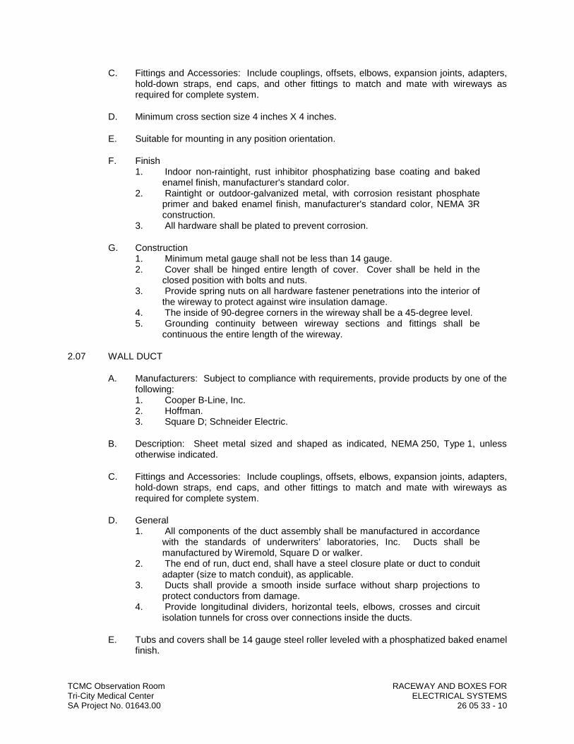
TCMC Observation Room RACEWAY AND BOXES FORTri-City Medical Center ELECTRICAL SYSTEMSSA Project No. 01643.00 26 05 33 - 10
C. Fittings and Accessories: Include couplings, offsets, elbows, expansion joints, adapters, hold-down straps, end caps, and other fittings to match and mate with wireways as required for complete system.
D. Minimum cross section size 4 inches X 4 inches.
E. Suitable for mounting in any position orientation.
F. Finish1. Indoor non-raintight, rust inhibitor phosphatizing base coating and baked
enamel finish, manufacturer's standard color.2. Raintight or outdoor-galvanized metal, with corrosion resistant phosphate
primer and baked enamel finish, manufacturer's standard color, NEMA 3R construction.
3. All hardware shall be plated to prevent corrosion.
G. Construction1. Minimum metal gauge shall not be less than 14 gauge.2. Cover shall be hinged entire length of cover. Cover shall be held in the
closed position with bolts and nuts.3. Provide spring nuts on all hardware fastener penetrations into the interior of
the wireway to protect against wire insulation damage.4. The inside of 90-degree corners in the wireway shall be a 45-degree level.5. Grounding continuity between wireway sections and fittings shall be
continuous the entire length of the wireway.
2.07 WALL DUCT
A. Manufacturers: Subject to compliance with requirements, provide products by one of the following:1. Cooper B-Line, Inc.2. Hoffman.3. Square D; Schneider Electric.
B. Description: Sheet metal sized and shaped as indicated, NEMA 250, Type 1, unless otherwise indicated.
C. Fittings and Accessories: Include couplings, offsets, elbows, expansion joints, adapters, hold-down straps, end caps, and other fittings to match and mate with wireways as required for complete system.
D. General1. All components of the duct assembly shall be manufactured in accordance
with the standards of underwriters’ laboratories, Inc. Ducts shall be manufactured by Wiremold, Square D or walker.
2. The end of run, duct end, shall have a steel closure plate or duct to conduit adapter (size to match conduit), as applicable.
3. Ducts shall provide a smooth inside surface without sharp projections to protect conductors from damage.
4. Provide longitudinal dividers, horizontal teels, elbows, crosses and circuit isolation tunnels for cross over connections inside the ducts.
E. Tubs and covers shall be 14 gauge steel roller leveled with a phosphatized baked enamel finish.

TCMC Observation Room RACEWAY AND BOXES FORTri-City Medical Center ELECTRICAL SYSTEMSSA Project No. 01643.00 26 05 33 - 11
F. Provide trench partitions to maintain separation of high and low potential power systems, signal systems and control system services.
G. The coverplates shall be a maximum of 2’-0” long. Coverplates shall be held in place by screws.
H. Vertical elbows shall be an integral part of a coverplate, elbows, offsets, coverplates, grommets, end closures, risers and connectors shall e provided for a complete installation.
I. The entire duct system shall provide an electrically continuous ground path. Connections between ducts, junction boxes, and conduit fittings shall provide a positive grounding path.
J. Provide not less than (1) #8 AWG (green THHN) continuous copper ground wire in all duct runs.
K. All power wire shall be run through power floor duct and shall not be mixed with other systems.
L. Power wire installed in floor duct shall be #10 (THHN/THWN) minimum or larger as noted on drawing.
M. Circuit wires shall be tagged with circuit I.D. numbers at each junction point and each service entrance or exit.
N. Paint wall duct to match wall finish.
2.08 SURFACE RACEWAYS
A. Surface Metal Raceways: Galvanized steel with snap-on covers. Prime coating, ready for field painting.1. Manufacturers: Subject to compliance with requirements, provide products
by one of the following:a. Thomas & Betts Corporation.b. Walker Systems, Inc.; Wiremold Company (The).c. Wiremold Company (The); Electrical Sales Division.
2.09 BOXES, ENCLOSURES, AND CABINETS
A. Manufacturers: Subject to compliance with requirements, provide products by one of the following:1. Cooper Crouse-Hinds; Div. of Cooper Industries, Inc.2. EGS/Appleton Electric.3. Hubbell Incorporated; Killark Electric Manufacturing Co. Division.4. O-Z/Gedney; a unit of General Signal.5. Thomas & Betts Corporation.6. Walker Systems, Inc.; Wiremold Company (The).
B. Flush or concealed outlet and junction boxes: Pressed steel, hot-dip galvanized, knockout type with conduit entrances sized to match.
C. General Requirements for Boxes, Enclosures, and Cabinets: Boxes, enclosures, and cabinets installed in wet locations shall be listed for use in wet locations.
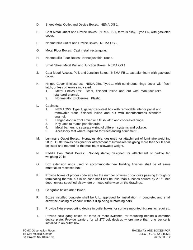
TCMC Observation Room RACEWAY AND BOXES FORTri-City Medical Center ELECTRICAL SYSTEMSSA Project No. 01643.00 26 05 33 - 12
D. Sheet Metal Outlet and Device Boxes: NEMA OS 1.
E. Cast-Metal Outlet and Device Boxes: NEMA FB 1, ferrous alloy, Type FD, with gasketed cover.
F. Nonmetallic Outlet and Device Boxes: NEMA OS 2.
G. Metal Floor Boxes: Cast metal, rectangular.
H. Nonmetallic Floor Boxes: Nonadjustable, round.
I. Small Sheet Metal Pull and Junction Boxes: NEMA OS 1.
J. Cast-Metal Access, Pull, and Junction Boxes: NEMA FB 1, cast aluminum with gasketed cover.
K. Hinged-Cover Enclosures: NEMA 250, Type 1, with continuous-hinge cover with flush latch, unless otherwise indicated.1. Metal Enclosures: Steel, finished inside and out with manufacturer's
standard enamel.2. Nonmetallic Enclosures: Plastic.
L. Cabinets:1. NEMA 250, Type 1, galvanized-steel box with removable interior panel and
removable front, finished inside and out with manufacturer's standard enamel.
2. Hinged door in front cover with flush latch and concealed hinge.3. Key latch to match panelboards.4. Metal barriers to separate wiring of different systems and voltage.5. Accessory feet where required for freestanding equipment.
M. Luminaire Outlet Boxes: Nonadjustable, designed for attachment of luminaire weighing 50 lb. Outlet boxes designed for attachment of luminaires weighing more than 50 lb shall be listed and marked for the maximum allowable weight.
N. Paddle Fan Outlet Boxes: Nonadjustable, designed for attachment of paddle fan weighing 70 lb.
O. Box extension rings used to accommodate new building finishes shall be of same material as recessed box.
P. Provide boxes of proper code size for the number of wires or conduits passing through or terminating therein, but in no case shall box be less than 4 inches square by 2 1/8 inch deep, unless specified elsewhere or noted otherwise on the drawings.
Q. Gangable boxes are allowed.
R. Boxes installed concrete shall be U.L. approved for installation in concrete, and shall allow the placing of conduit without displacing reinforcing bars.
S. Provide fixture-supporting device in outlet boxes for surface mounted fixtures as required.
T. Provide solid gang boxes for three or more switches, for mounting behind a common device plate. Provide barriers for all 277-volt devices where more than one device is installed in an outlet box.
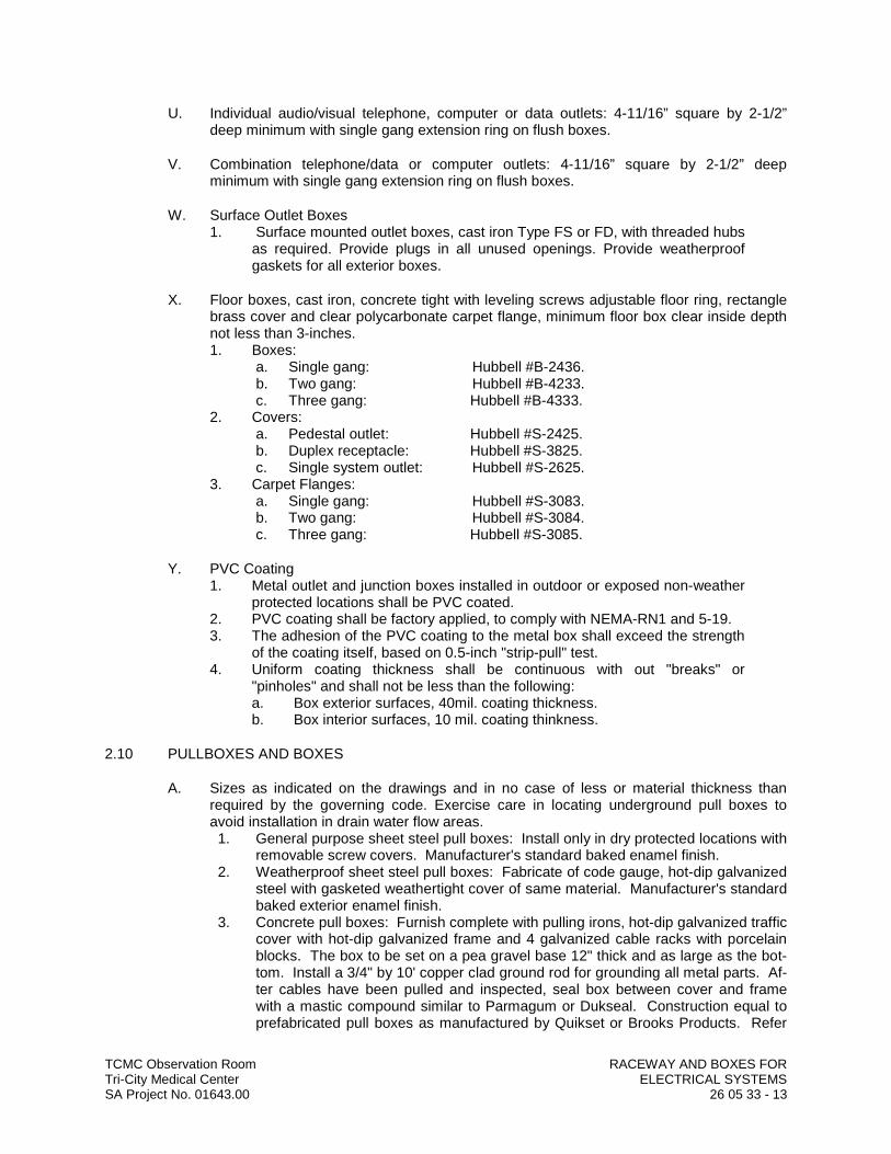
TCMC Observation Room RACEWAY AND BOXES FORTri-City Medical Center ELECTRICAL SYSTEMSSA Project No. 01643.00 26 05 33 - 13
U. Individual audio/visual telephone, computer or data outlets: 4-11/16” square by 2-1/2” deep minimum with single gang extension ring on flush boxes.
V. Combination telephone/data or computer outlets: 4-11/16” square by 2-1/2” deep minimum with single gang extension ring on flush boxes.
W. Surface Outlet Boxes1. Surface mounted outlet boxes, cast iron Type FS or FD, with threaded hubs
as required. Provide plugs in all unused openings. Provide weatherproof gaskets for all exterior boxes.
X. Floor boxes, cast iron, concrete tight with leveling screws adjustable floor ring, rectangle brass cover and clear polycarbonate carpet flange, minimum floor box clear inside depth not less than 3-inches.1. Boxes:
a. Single gang: Hubbell #B-2436.b. Two gang: Hubbell #B-4233.c. Three gang: Hubbell #B-4333.
2. Covers:a. Pedestal outlet: Hubbell #S-2425.b. Duplex receptacle: Hubbell #S-3825.c. Single system outlet: Hubbell #S-2625.
3. Carpet Flanges:a. Single gang: Hubbell #S-3083.b. Two gang: Hubbell #S-3084.c. Three gang: Hubbell #S-3085.
Y. PVC Coating1. Metal outlet and junction boxes installed in outdoor or exposed non-weather
protected locations shall be PVC coated.2. PVC coating shall be factory applied, to comply with NEMA-RN1 and 5-19.3. The adhesion of the PVC coating to the metal box shall exceed the strength
of the coating itself, based on 0.5-inch "strip-pull" test.4. Uniform coating thickness shall be continuous with out "breaks" or
"pinholes" and shall not be less than the following:a. Box exterior surfaces, 40mil. coating thickness.b. Box interior surfaces, 10 mil. coating thinkness.
2.10 PULLBOXES AND BOXES
A. Sizes as indicated on the drawings and in no case of less or material thickness than required by the governing code. Exercise care in locating underground pull boxes to avoid installation in drain water flow areas.1. General purpose sheet steel pull boxes: Install only in dry protected locations with
removable screw covers. Manufacturer's standard baked enamel finish.2. Weatherproof sheet steel pull boxes: Fabricate of code gauge, hot-dip galvanized
steel with gasketed weathertight cover of same material. Manufacturer's standard baked exterior enamel finish.
3. Concrete pull boxes: Furnish complete with pulling irons, hot-dip galvanized traffic cover with hot-dip galvanized frame and 4 galvanized cable racks with porcelain blocks. The box to be set on a pea gravel base 12" thick and as large as the bot-tom. Install a 3/4" by 10' copper clad ground rod for grounding all metal parts. Af-ter cables have been pulled and inspected, seal box between cover and frame with a mastic compound similar to Parmagum or Dukseal. Construction equal to prefabricated pull boxes as manufactured by Quikset or Brooks Products. Refer

TCMC Observation Room RACEWAY AND BOXES FORTri-City Medical Center ELECTRICAL SYSTEMSSA Project No. 01643.00 26 05 33 - 14
to drawings for size. Provide bead weld on cover to pull box to indicate services within pull box (i.e. - "480/277-VOLT, 3-PHASE, 4-WIRE ELECTRICAL" OR "SIGNAL/TEL/P.A./CLOCK/FIRE ALARM").
2.11 HANDHOLES AND BOXES FOR EXTERIOR UNDERGROUND WIRING
A. Description: Comply with SCTE 77.1. Color of Frame and Cover: Green.2. Configuration: Units shall be designed for flush burial and have integral
closed bottom, unless otherwise indicated.3. Cover: Weatherproof, secured by tamper-resistant locking devices and
having structural load rating consistent with enclosure.4. Cover Finish: Nonskid finish shall have a minimum coefficient of friction of
0.50.5. Cover Legend: Molded lettering, as indicated for each service. 6. Conduit Entrance Provisions: Conduit-terminating fittings shall mate with
entering ducts for secure, fixed installation in enclosure wall.7. Handholes 12 inches wide by 24 inches long and larger shall have inserts
for cable racks and pulling-in irons installed before concrete is poured.
B. Polymer-Concrete Handholes and Boxes with Polymer-Concrete Cover: Molded of sand and aggregate, bound together with polymer resin, and reinforced with steel or fiberglass or a combination of the two.1. Manufacturers: Subject to compliance with requirements, provide products
by one of the following:a. Armorcast Products Company.b. Carson Industries LLC.c. CDR Systems Corporation.d. NewBasis.
C. Fiberglass Handholes and Boxes with Polymer-Concrete Frame and Cover: Sheet-molded, fiberglass-reinforced, polyester-resin enclosure joined to polymer-concrete top ring or frame.1. Manufacturers: Subject to compliance with requirements, provide products
by one of the following:a. Armorcast Products Company.b. Carson Industries LLC.c. Christy Concrete Products.d. Synertech Moulded Products, Inc.; a division of Oldcastle Precast.
2.12 SLEEVES FOR RACEWAYS
A. Steel Pipe Sleeves: ASTM A 53/A 53M, Type E, Grade B, Schedule 40, galvanized steel, plain ends.
B. Cast-Iron Pipe Sleeves: Cast or fabricated "wall pipe," equivalent to ductile-iron pressure pipe, with plain ends and integral waterstop, unless otherwise indicated.
C. Sleeves for Rectangular Openings: Galvanized sheet steel with minimum 0.052- or 0.138-inch thickness as indicated and of length to suit application.
D. Coordinate sleeve selection and application with selection and application of firestopping specified in Division 07 Section "Penetration Firestopping."
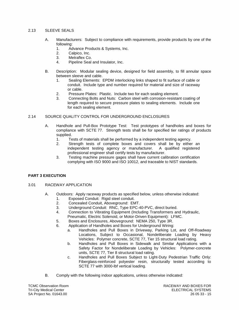
TCMC Observation Room RACEWAY AND BOXES FORTri-City Medical Center ELECTRICAL SYSTEMSSA Project No. 01643.00 26 05 33 - 15
2.13 SLEEVE SEALS
A. Manufacturers: Subject to compliance with requirements, provide products by one of the following:1. Advance Products & Systems, Inc.2. Calpico, Inc.3. Metraflex Co.4. Pipeline Seal and Insulator, Inc.
B. Description: Modular sealing device, designed for field assembly, to fill annular space between sleeve and cable.1. Sealing Elements: EPDM interlocking links shaped to fit surface of cable or
conduit. Include type and number required for material and size of raceway or cable.
2. Pressure Plates: Plastic. Include two for each sealing element.3. Connecting Bolts and Nuts: Carbon steel with corrosion-resistant coating of
length required to secure pressure plates to sealing elements. Include one for each sealing element.
2.14 SOURCE QUALITY CONTROL FOR UNDERGROUND ENCLOSURES
A. Handhole and Pull-Box Prototype Test: Test prototypes of handholes and boxes for compliance with SCTE 77. Strength tests shall be for specified tier ratings of products supplied.1. Tests of materials shall be performed by a independent testing agency.2. Strength tests of complete boxes and covers shall be by either an
independent testing agency or manufacturer. A qualified registered professional engineer shall certify tests by manufacturer.
3. Testing machine pressure gages shall have current calibration certification complying with ISO 9000 and ISO 10012, and traceable to NIST standards.
PART 3 EXECUTION
3.01 RACEWAY APPLICATION
A. Outdoors: Apply raceway products as specified below, unless otherwise indicated:1. Exposed Conduit: Rigid steel conduit.2. Concealed Conduit, Aboveground: EMT.3. Underground Conduit: RNC, Type EPC-40-PVC, direct buried.4. Connection to Vibrating Equipment (Including Transformers and Hydraulic,
Pneumatic, Electric Solenoid, or Motor-Driven Equipment): LFMC.5. Boxes and Enclosures, Aboveground: NEMA 250, Type 3R.6. Application of Handholes and Boxes for Underground Wiring:
a. Handholes and Pull Boxes in Driveway, Parking Lot, and Off-Roadway Locations, Subject to Occasional, Nondeliberate Loading by Heavy Vehicles: Polymer concrete, SCTE 77, Tier 15 structural load rating.
b. Handholes and Pull Boxes in Sidewalk and Similar Applications with a Safety Factor for Nondeliberate Loading by Vehicles: Polymer-concrete units, SCTE 77, Tier 8 structural load rating.
c. Handholes and Pull Boxes Subject to Light-Duty Pedestrian Traffic Only: Fiberglass-reinforced polyester resin, structurally tested according to SCTE 77 with 3000-lbf vertical loading.
B. Comply with the following indoor applications, unless otherwise indicated:

TCMC Observation Room RACEWAY AND BOXES FORTri-City Medical Center ELECTRICAL SYSTEMSSA Project No. 01643.00 26 05 33 - 16
1. Exposed, Not Subject to Physical Damage: EMT.2. Exposed, Not Subject to Severe Physical Damage: EMT.3. Exposed and Subject to Severe Physical Damage: Rigid steel conduit.
Includes raceways in the following locations:a. Loading dock.b. Corridors used for traffic of mechanized carts, forklifts, and pallet-handling
units.c. Mechanical rooms.
4. Concealed in Ceilings and Interior Walls and Partitions: EMT.5. Connection to Vibrating Equipment (Including Transformers and Hydraulic,
Pneumatic, Electric Solenoid, or Motor-Driven Equipment): FMC, except use LFMC in damp or wet locations.
6. Damp or Wet Locations: Rigid steel conduit.7. Raceways for Optical Fiber or Communications Cable in Spaces Used for
Environmental Air: Plenum-type, optical fiber/communications cable raceway.
8. Raceways for Optical Fiber or Communications Cable Risers in Vertical Shafts: Riser-type, optical fiber/communications cable raceway.
9. Raceways for Concealed General Purpose Distribution of Optical Fiber or Communications Cable: General-use, optical fiber/communications cable raceway.
10. Boxes and Enclosures: NEMA 250, Type 1, except use NEMA 250, Type 4, stainless steel in damp or wet locations.
C. Conduit installation1. General
a. The sizes of the conduits for the various circuits shall be as indicated on the drawings, but not less than the conduit size required by code for the size and quantity of conductors to be installed in the conduit.
b. Conduits shall be installed concealed from view. Install conduits concealed in walls, concealed in/below floors and concealed above ceilings, except as specifically noted otherwise.
c. The following systems shall be considered as circuits 100 volts and less, all other circuits shall be considered to be over 100 volts (power circuits) unless specifically noted otherwise: Fire alarm, energy management control, telephone, public address, data, computer, television, intercom, intrusion alarm and nurse call.
d. Conduits shall be provided complete with conduit bends, conduit fittings, outlet boxes, pullboxes, junction boxes, conduit anchors/supports, grounding/bonding for a complete and operating conductor/wire raceway system.
e. Metal and nonmetal conduits shall be provided mechanically continuous between termination connection points. Metal conduit shall be provided electrically continuous between termination connection points.
f. Individual conduit paths and home runs shown on the drawings shall be maintained as separate individual conduits for each homerun and path.
g. Conduits, conduit fittings and installation work occurring in classified hazardous materials locations shall comply with applicable code Class 1 Division 1 requirements, unless specifically noted otherwise.
h. Transitions between conduits constructed of different materials and occurring in above grade locations shall be allowed only at outlet boxes, junction boxes, pull boxes and equipment enclosures unless specifically indicated otherwise. Provide outlet boxes and junction boxes.
i. Metal conduit terminating to nonmetal enclosures; terminating into metal enclosures with “concentric.ring” knockouts; terminating into metal
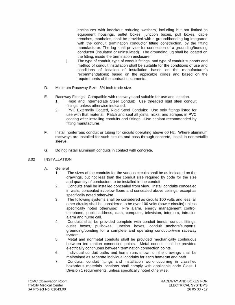
TCMC Observation Room RACEWAY AND BOXES FORTri-City Medical Center ELECTRICAL SYSTEMSSA Project No. 01643.00 26 05 33 - 17
enclosures with knockout reducing washers, including but not limited to equipment housings, outlet boxes, junction boxes, pull boxes, cable trenches, manholes, shall be provided with a ground/bonding lug integrated with the conduit termination conductor fitting construction, by the fitting manufacturer. The lug shall provide for connection of a grounding/bonding conductor (insulated or uninsulated). The grounding lug shall be located on the fitting, inside the termination enclosure.
j. The type of conduit, type of conduit fittings, and type of conduit supports and method of conduit installation shall be suitable for the conditions of use and conditions of location of installation based on the manufacturer’s recommendations; based on the applicable codes and based on the requirements of the contract documents.
D. Minimum Raceway Size: 3/4-inch trade size.
E. Raceway Fittings: Compatible with raceways and suitable for use and location.1. Rigid and Intermediate Steel Conduit: Use threaded rigid steel conduit
fittings, unless otherwise indicated.2. PVC Externally Coated, Rigid Steel Conduits: Use only fittings listed for
use with that material. Patch and seal all joints, nicks, and scrapes in PVC coating after installing conduits and fittings. Use sealant recommended by fitting manufacturer.
F. Install nonferrous conduit or tubing for circuits operating above 60 Hz. Where aluminum raceways are installed for such circuits and pass through concrete, install in nonmetallic sleeve.
G. Do not install aluminum conduits in contact with concrete.
3.02 INSTALLATION
A. General1. The sizes of the conduits for the various circuits shall be as indicated on the
drawings, but not less than the conduit size required by code for the size and quantity of conductors to be installed in the conduit
2. Conduits shall be installed concealed from view. Install conduits concealed in walls, concealed in/below floors and concealed above ceilings, except as specifically noted otherwise.
3. The following systems shall be considered as circuits 100 volts and less, all other circuits shall be considered to be over 100 volts (power circuits) unless specifically noted otherwise: Fire alarm, energy management control,telephone, public address, data, computer, television, intercom, intrusion alarm and nurse call.
4. Conduits shall be provided complete with conduit bends, conduit fittings, outlet boxes, pullboxes, junction boxes, conduit anchors/supports, grounding/bonding for a complete and operating conductor/wire raceway system.
5. Metal and nonmetal conduits shall be provided mechanically continuous between termination connection points. Metal conduit shall be provided electrically continuous between termination connection points.
6. Individual conduit paths and home runs shown on the drawings shall be maintained as separate individual conduits for each homerun and path
7. Conduits, conduit fittings and installation work occurring in classified hazardous materials locations shall comply with applicable code Class 1 Division 1 requirements, unless specifically noted otherwise.

TCMC Observation Room RACEWAY AND BOXES FORTri-City Medical Center ELECTRICAL SYSTEMSSA Project No. 01643.00 26 05 33 - 18
8. Transitions between conduits constructed of different materials and occurring in above grade locations shall be allowed only at outlet boxes, junction boxes, pull boxes and equipment enclosures unless specifically indicated otherwise. Provide outlet boxes and junction boxes.
9. Metal conduit terminating to nonmetal enclosures; terminating into metal enclosures with “concentric.ring” knockouts; terminating into metal enclosures with knockout reducing washers, including but not limited to equipment housings, outlet boxes, junction boxes, pull boxes, cable trenches, manholes, shall be provided with a ground/bonding lug integrated with the conduit termination conductor fitting construction, by the fitting manufacturer. The lug shall provide for connection of a grounding/bonding conductor (insulated or uninsulated). The grounding lug shall be located on the fitting, inside the termination enclosure.
10. The type of conduit, type of conduit fittings, and type of conduit supports and method of conduit installation shall be suitable for the conditions of use and conditions of location of installation based on the manufacturer’s recommendations; based on the applicable codes and based on the requirements of the contract documents.
B. RMC Installation Locations
C. RGS, IMC conduits and RGS, IMC fittings shall be installed in the following locations:1. Embedded in floors, walls, ceilings, roofs, foundations, and footings
constructed with concrete.2. Embedded in walls and foundations constructed with brick and masonry.3. Interior of buildings, within nine feet of finish floor lines for exposed conduit
locations.4. Exterior of building for exposed conduit locations.5. Damp or wet locations, exposed or concealed locations.6. Exposed on roofs.7. In hazardous materials areas and locations; below hazardous materials
areas and locations; above hazardous materials areas and locations.8. Exposed on utility service poles, for pole risers less than 9 feet above finish
grade.9. RMC conduit and RMC fittings may be installed in any location where EMT
and FMC conduit is permitted to be installed.
D. EMT Installation Locations
E. EMT conduit and EMT fittings may be installed in the following locations, for circuit conductors operating below 600 volts to ground; locations containing only “non-hazardous materials”; only dry locations:1. Concealed in hollow non masonry, metal stud frame and wood stud frame
walls.2. Concealed above ceilings.3. Exposed inside interior enclosed crawl spaces.4. Exposed interior locations placed 9 ft. or higher above finished floors.5. Exposed in the following dedicated function areas, interior enclosed room
locations:a. Indoor enclosed electrical equipment rooms and closets.b. Indoor enclosed data and telecommunication terminal rooms and closets.c. Indoor enclosed HVAC equipment rooms and closets.
6. Any location where FMC is described to be installed, except as the final connection to rotating or vibrating equipment.
TCMC Observation Room RACEWAY AND BOXES FORTri-City Medical Center ELECTRICAL SYSTEMSSA Project No. 01643.00 26 05 33 - 19
F. FMC Installation Locations
G. FMC conduit and FMC fittings may be installed in the following locations normal branch for circuit conductors operating below 600 volts to ground; locations containing only “non-hazardous materials”; only dry, interior locations. FMC conduit and FMC fittings are not allowed for emergency branch circuits, including life safety critical or equipment branch circuits and feeders.1. Concealed in hollow non-masonry metal stud frame and wood stud frame
fully enclosed walls.2. Concealed above fully enclosed ceiling spaces.3. FMC conduit shall be installed in continuous lengths between termination
points. FMC shall not be “spliced” or coupled directly to FMC or any other conduit type under any circumstance.
4. The maximum continuous length of FMC that shall be installed between termination end points is 6 feet. Circuits requiring continuous conduit lengths exceeding 6 feet between termination end points shall be installed using either RMC or EMT conduits. FMC lengths shorter than 16 inches are prohibited.
5. The minimum size FMC conduit shall be as shown on the drawings but not be less than the following:a. FMC lengths of six feet or less, minimum FMC conduit size shall be 0.50
inches.
H. LTFMC Installation Locations
I. LTFMC conduit and LTFMC fittings shall be installed in the following locations for circuit conductors operating below 600 volts to ground; locations containing only “non-hazardous materials”:1. Final electrical connection to vibrating or rotating equipment; control and
monitoring devices mounted on vibrating and rotating equipment including the following. Minimum conduit length shall not be less than 24 inches:a. Motor, engines, boilers, solenoids, and valves.b. Fixed mounted.c. Fixed mounted food preparation equipment and “kitchen” equipment.
2. All locations where exposed flexible conduit connections are required, both indoor and outdoor.
3. Final connection to indoors electrical transformers. Minimum conduit length shall not be less than 24 inches, maximum conduit length shall not exceed 72 inches.
4. Do not install LTFMC located in environmental air plenums.
J. RNMC Installation Locations
K. RNMC conduit and RNMC fittings shall be installed in the following locations containing only “non-hazardous material”:1. Underground, concealed below earth grade, unless specifically noted or
specified otherwise.2. Exposed on utility service poles, for pole risers at 9 feet or higher above
finish grade, schedule 80 PVC only.3. RNMC type “EB” conduit(s) shall be concrete encased along the entire
length of the conduits for all installation locations.
L. Comply with NECA 1 for installation requirements applicable to products specified in Part 2 except where requirements on Drawings or in this Article are stricter.
TCMC Observation Room RACEWAY AND BOXES FORTri-City Medical Center ELECTRICAL SYSTEMSSA Project No. 01643.00 26 05 33 - 20
M. Keep raceways at least 6 inches away from parallel runs of flues and steam or hot-water pipes. Install horizontal raceway runs above water and steam piping.
N. Complete raceway installation before starting conductor installation.
O. Support raceways as specified in Division 26 Section "Hangers and Supports for Electrical Systems."
P. Arrange stub-ups so curved portions of bends are not visible above the finished slab.
Q. Install no more than the equivalent of three 90-degree bends in any conduit run except for communications conduits, for which fewer bends are allowed.
R. Conceal conduit and EMT within finished walls, ceilings, and floors, unless otherwise indicated.
S. Raceways Embedded in Slabs:1. Run conduit larger than 1-inch trade size, parallel or at right angles to main
reinforcement. Where at right angles to reinforcement, place conduit close to slab support.
2. Arrange raceways to cross building expansion joints at right angles with expansion fittings.
3. Change from ENT to RNC, Type EPC-40-PVC or rigid steel conduit before rising above the floor.
T. Threaded Conduit Joints, Exposed to Wet, Damp, Corrosive, or Outdoor Conditions: Apply listed compound to threads of raceway and fittings before making up joints. Follow compound manufacturer's written instructions.
U. Raceway Terminations at Locations Subject to Moisture or Vibration: Use insulating bushings to protect conductors, including conductors smaller than No. 4 AWG.
V. Install pull wires in empty raceways. Use polypropylene or monofilament plastic line with not less than 200-lb tensile strength. Leave at least 12 inches of slack at each end of pull wire.
W. Raceways for Optical Fiber and Communications Cable: Install raceways, metallic and nonmetallic, rigid and flexible, as follows:1. 3/4-Inch Trade Size and Smaller: Install raceways in maximum lengths of
50 feet.2. 1-Inch Trade Size and Larger: Install raceways in maximum lengths of 75
feet.3. Install with a maximum of two 90-degree bends or equivalent for each
length of raceway unless Drawings show stricter requirements. Separate lengths with pull or junction boxes or terminations at distribution frames or cabinets where necessary to comply with these requirements.
X. Install raceway sealing fittings at suitable, approved, and accessible locations and fill them with listed sealing compound. For concealed raceways, install each fitting in a flush steel box with a blank cover plate having a finish similar to that of adjacent plates or surfaces. Install raceway sealing fittings at the following points:1. Where conduits pass from warm to cold locations, such as boundaries of
refrigerated spaces.2. Where otherwise required by NFPA 70.
TCMC Observation Room RACEWAY AND BOXES FORTri-City Medical Center ELECTRICAL SYSTEMSSA Project No. 01643.00 26 05 33 - 21
Y. Expansion-Joint Fittings for RNC: Install in each run of aboveground conduit that is located where environmental temperature change may exceed 30 deg F, and that has straight-run length that exceeds 25 feet.1. Install expansion-joint fittings for each of the following locations, and
provide type and quantity of fittings that accommodate temperature change listed for location:a. Outdoor Locations Not Exposed to Direct Sunlight: 125 deg F temperature
change.b. Outdoor Locations Exposed to Direct Sunlight: 155 deg F temperature
change.c. Indoor Spaces: Connected with the Outdoors without Physical Separation:
125 deg F temperature change.d. Attics: 135 deg F temperature change.
2. Install fitting(s) that provide expansion and contraction for at least 0.00041 inch per foot of length of straight run per deg F of temperature change.
3. Install each expansion-joint fitting with position, mounting, and piston setting selected according to manufacturer's written instructions for conditions at specific location at the time of installation.
Z. Flexible Conduit Connections: Use maximum of 72 inches of flexible conduit for recessed and semirecessed lighting fixtures, equipment subject to vibration, noise transmission, or movement; and for transformers and motors.1. Use LFMC in damp or wet locations subject to severe physical damage.
AA. Recessed Boxes in Masonry Walls: Saw-cut opening for box in center of cell of masonry block, and install box flush with surface of wall.
BB. Set metal floor boxes level and flush with finished floor surface.
CC. Set nonmetallic floor boxes level. Trim after installation to fit flush with finished floor surface.
3.03 INSTALLATION OF UNDERGROUND CONDUIT
A. Direct-Buried Conduit:1. Excavate trench bottom to provide firm and uniform support for conduit.
Prepare trench bottom as specified in Division 31 Section "Earth Moving" for pipe less than 6 inches in nominal diameter.
2. Install backfill as specified in Division 31 Section "Earth Moving."3. After installing conduit, backfill and compact. Start at tie-in point, and work
toward end of conduit run, leaving conduit at end of run free to move with expansion and contraction as temperature changes during this process. Firmly hand tamp backfill around conduit to provide maximum supporting strength. After placing controlled backfill to within 12 inches of finished grade, make final conduit connection at end of run and complete backfilling with normal compaction as specified in Division 31 Section "Earth Moving."
4. Install manufactured duct elbows for stub-ups at poles and equipment and at building entrances through the floor, unless otherwise indicated. Encase elbows for stub-up ducts throughout the length of the elbow.
5. Install manufactured rigid steel conduit elbows for stub-ups at poles and equipment and at building entrances through the floor.a. Couple steel conduits to ducts with adapters designed for this purpose, and
encase coupling with 3 inches of concrete.b. For stub-ups at equipment mounted on outdoor concrete bases, extend
steel conduit horizontally a minimum of 60 inches from edge of equipment
TCMC Observation Room RACEWAY AND BOXES FORTri-City Medical Center ELECTRICAL SYSTEMSSA Project No. 01643.00 26 05 33 - 22
pad or foundation. Install insulated grounding bushings on terminations at equipment.
6. Warning Planks: Bury warning planks approximately 12 inches above direct-buried conduits, placing them 24 inches o.c. Align planks along the width and along the centerline of conduit.
3.04 INSTALLATION OF UNDERGROUND HANDHOLES AND BOXES
A. Install handholes and boxes level and plumb and with orientation and depth coordinated with connecting conduits to minimize bends and deflections required for proper entrances.
B. Unless otherwise indicated, support units on a level bed of crushed stone or gravel, graded from 1/2-inch sieve to No. 4 sieve and compacted to same density as adjacent undisturbed earth.
C. Elevation: In paved areas, set so cover surface will be flush with finished grade. Set covers of other enclosures 1 inch above finished grade.
D. Install removable hardware, including pulling eyes, cable stanchions, cable arms, and insulators, as required for installation and support of cables and conductors and as indicated. Select arm lengths to be long enough to provide spare space for future cables, but short enough to preserve adequate working clearances in the enclosure.
E. Field-cut openings for conduits according to enclosure manufacturer's written instructions. Cut wall of enclosure with a tool designed for material to be cut. Size holes for terminating fittings to be used, and seal around penetrations after fittings are installed.
3.05 SLEEVE INSTALLATION FOR ELECTRICAL PENETRATIONS
A. Coordinate sleeve selection and application with selection and application of firestopping specified in Division 07 Section "Penetration Firestopping."
B. Provide sleeves for raceways and conduit passing through the following construction elements:1. Concrete and masonry foundations, floors, walls and slabs.2. Lath and plaster walls and ceilings.3. Building structures (ie., foundations, walls, floors, ceilings, and roofs) with a
fire rating exceeding 20 minutes.
C. Concrete Slabs and Walls: Install sleeves for penetrations unless core-drilled holes or formed openings are used. Install sleeves during erection of slabs and walls.
D. Use pipe sleeves unless penetration arrangement requires rectangular sleeved opening.
E. Rectangular Sleeve Minimum Metal Thickness:1. For sleeve cross-section rectangle perimeter less than 50 inches and no
side greater than 16 inches, thickness shall be 0.052 inch.2. For sleeve cross-section rectangle perimeter equal to, or greater than, 50
inches and 1 or more sides equal to, or greater than, 16 inches, thickness shall be 0.138 inch.
F. Fire-Rated Assemblies: Install sleeves for penetrations of fire-rated floor and wall assemblies unless openings compatible with firestop system used are fabricated during construction of floor or wall.

TCMC Observation Room RACEWAY AND BOXES FORTri-City Medical Center ELECTRICAL SYSTEMSSA Project No. 01643.00 26 05 33 - 23
G. Cut sleeves to length for mounting flush with both surfaces of walls.
H. Extend sleeves installed in floors 2 inches above finished floor level, except under floor standing electrical equipment. Sleeves shall be flush with wall ceiling foundations and partitions exposed to public view and extend approximately 0.5 inch past penetration in fire rated construction. Sleeves shall be installed at exact penetration locations and angles to accommodate raceway and conduit routings.
I. Joists, girders, beams, columns or reinforcing steel shall not be cut or weakened. Where construction necessitates the routing of conduit or raceways through structural members, framing or footings, written permission to make such installation shall first be obtained from the OWNER’S REPRESENTATIVE. Such permission will not be granted, however, if any other method of installation is possible.
J. The layout and design of raceways and conduits located in or routed through masonry or reinforced beams or the OWNER’S REPRESENTATIVE shall review walls before any work is performed. All sleeving shall be accomplished according to the instructions of the OWNER’S REPRESENTATIVE and shall be accepted before any concrete is poured.
K. Sleeves, raceways and conduit shall be located to clear steel reinforcing bars in beams. Reinforcing bars in walls shall be offset to clear piping and sleeves.
L. Provide a continuous clearance between the inside of a sleeve and exterior of conduits and raceways passing through the sleeve not less than the following:1. 0.5 inch clearance except as required otherwise.2. 1.0 inch clearance through outside walls below grade.3. 3.0 inch clearance through seismic joints.
M. Size pipe sleeves to provide 1/4-inch annular clear space between sleeve and raceway unless sleeve seal is to be installed or unless seismic criteria require different clearance.
N. Seal space outside of sleeves with grout for penetrations of concrete and masonry and with approved joint compound for gypsum board assemblies.
O. Interior Penetrations of Non-Fire-Rated Walls and Floors: Seal annular space between sleeve and raceway, using joint sealant appropriate for size, depth, and location of joint. Refer to Division 07 Section "Joint Sealants" for materials and installation.
P. Fire-Rated-Assembly Penetrations: Maintain indicated fire rating of walls, partitions, ceilings, and floors at raceway penetrations. Install sleeves and seal with firestop materials. Comply with Division 07 Section "Penetration Firestopping."
Q. Roof-Penetration Sleeves: Seal penetration of individual raceways with flexible, boot-type flashing units applied in coordination with roofing work.
R. Aboveground, Exterior-Wall Penetrations: Seal penetrations using sleeves and mechanical sleeve seals. Select sleeve size to allow for 1-inch annular clear space between pipe and sleeve for installing mechanical sleeve seals.
S. Underground, Exterior-Wall Penetrations: Install cast-iron "wall pipes" for sleeves. Size sleeves to allow for 1-inch annular clear space between raceway and sleeve for installing mechanical sleeve seals.
T. Sleeve Material:
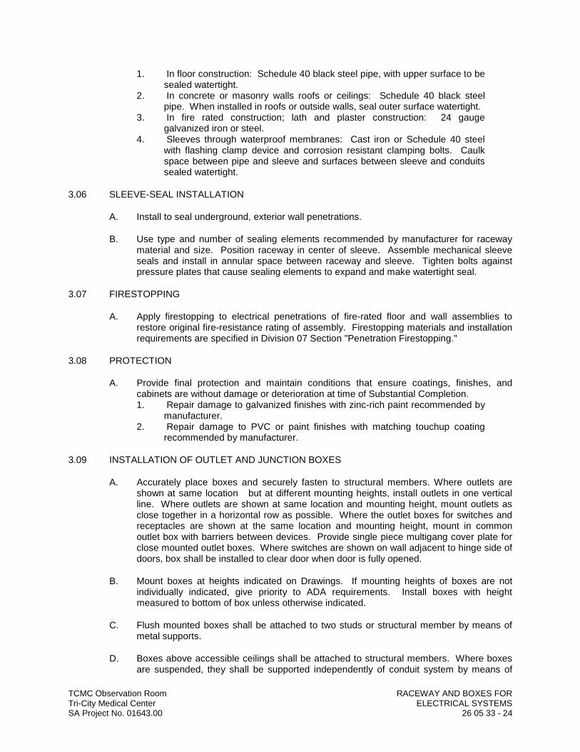
TCMC Observation Room RACEWAY AND BOXES FORTri-City Medical Center ELECTRICAL SYSTEMSSA Project No. 01643.00 26 05 33 - 24
1. In floor construction: Schedule 40 black steel pipe, with upper surface to be sealed watertight.
2. In concrete or masonry walls roofs or ceilings: Schedule 40 black steel pipe. When installed in roofs or outside walls, seal outer surface watertight.
3. In fire rated construction; lath and plaster construction: 24 gauge galvanized iron or steel.
4. Sleeves through waterproof membranes: Cast iron or Schedule 40 steel with flashing clamp device and corrosion resistant clamping bolts. Caulk space between pipe and sleeve and surfaces between sleeve and conduits sealed watertight.
3.06 SLEEVE-SEAL INSTALLATION
A. Install to seal underground, exterior wall penetrations.
B. Use type and number of sealing elements recommended by manufacturer for raceway material and size. Position raceway in center of sleeve. Assemble mechanical sleeve seals and install in annular space between raceway and sleeve. Tighten bolts against pressure plates that cause sealing elements to expand and make watertight seal.
3.07 FIRESTOPPING
A. Apply firestopping to electrical penetrations of fire-rated floor and wall assemblies to restore original fire-resistance rating of assembly. Firestopping materials and installation requirements are specified in Division 07 Section "Penetration Firestopping."
3.08 PROTECTION
A. Provide final protection and maintain conditions that ensure coatings, finishes, and cabinets are without damage or deterioration at time of Substantial Completion.1. Repair damage to galvanized finishes with zinc-rich paint recommended by
manufacturer.2. Repair damage to PVC or paint finishes with matching touchup coating
recommended by manufacturer.
3.09 INSTALLATION OF OUTLET AND JUNCTION BOXES
A. Accurately place boxes and securely fasten to structural members. Where outlets are shown at same location but at different mounting heights, install outlets in one vertical line. Where outlets are shown at same location and mounting height, mount outlets as close together in a horizontal row as possible. Where the outlet boxes for switches and receptacles are shown at the same location and mounting height, mount in common outlet box with barriers between devices. Provide single piece multigang cover plate for close mounted outlet boxes. Where switches are shown on wall adjacent to hinge side of doors, box shall be installed to clear door when door is fully opened.
B. Mount boxes at heights indicated on Drawings. If mounting heights of boxes are not individually indicated, give priority to ADA requirements. Install boxes with height measured to bottom of box unless otherwise indicated.
C. Flush mounted boxes shall be attached to two studs or structural member by means of metal supports.
D. Boxes above accessible ceilings shall be attached to structural members. Where boxes are suspended, they shall be supported independently of conduit system by means of
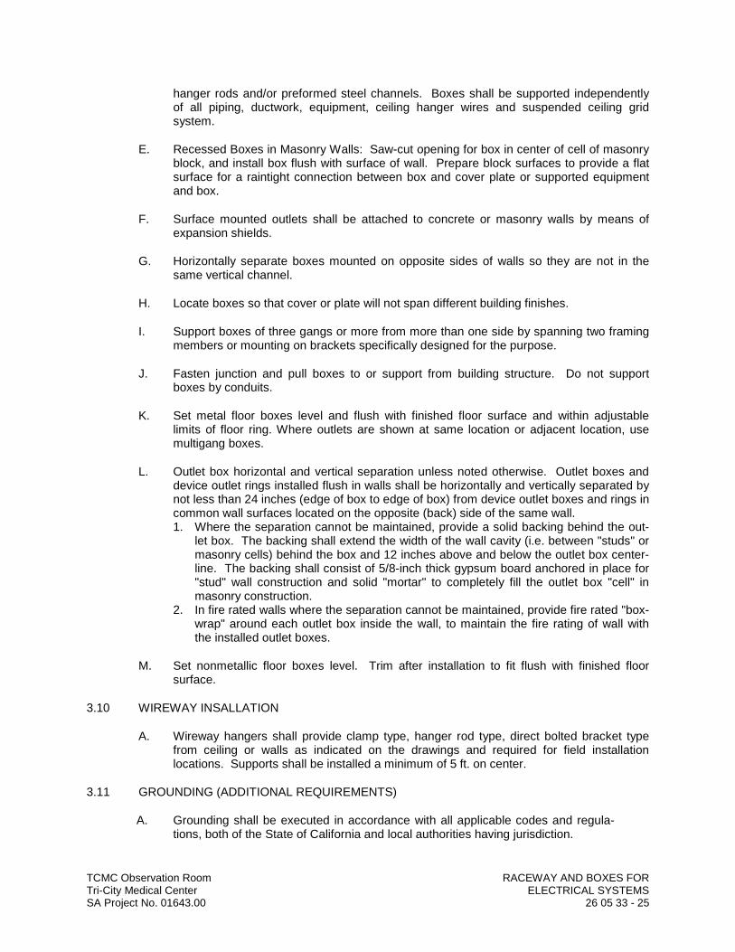
TCMC Observation Room RACEWAY AND BOXES FORTri-City Medical Center ELECTRICAL SYSTEMSSA Project No. 01643.00 26 05 33 - 25
hanger rods and/or preformed steel channels. Boxes shall be supported independently of all piping, ductwork, equipment, ceiling hanger wires and suspended ceiling grid system.
E. Recessed Boxes in Masonry Walls: Saw-cut opening for box in center of cell of masonry block, and install box flush with surface of wall. Prepare block surfaces to provide a flat surface for a raintight connection between box and cover plate or supported equipment and box.
F. Surface mounted outlets shall be attached to concrete or masonry walls by means of expansion shields.
G. Horizontally separate boxes mounted on opposite sides of walls so they are not in the same vertical channel.
H. Locate boxes so that cover or plate will not span different building finishes.
I. Support boxes of three gangs or more from more than one side by spanning two framing members or mounting on brackets specifically designed for the purpose.
J. Fasten junction and pull boxes to or support from building structure. Do not support boxes by conduits.
K. Set metal floor boxes level and flush with finished floor surface and within adjustable limits of floor ring. Where outlets are shown at same location or adjacent location, use multigang boxes.
L. Outlet box horizontal and vertical separation unless noted otherwise. Outlet boxes and device outlet rings installed flush in walls shall be horizontally and vertically separated by not less than 24 inches (edge of box to edge of box) from device outlet boxes and rings in common wall surfaces located on the opposite (back) side of the same wall.1. Where the separation cannot be maintained, provide a solid backing behind the out-
let box. The backing shall extend the width of the wall cavity (i.e. between "studs" or masonry cells) behind the box and 12 inches above and below the outlet box center-line. The backing shall consist of 5/8-inch thick gypsum board anchored in place for "stud" wall construction and solid "mortar" to completely fill the outlet box "cell" in masonry construction.
2. In fire rated walls where the separation cannot be maintained, provide fire rated "box-wrap" around each outlet box inside the wall, to maintain the fire rating of wall with the installed outlet boxes.
M. Set nonmetallic floor boxes level. Trim after installation to fit flush with finished floor surface.
3.10 WIREWAY INSALLATION
A. Wireway hangers shall provide clamp type, hanger rod type, direct bolted bracket type from ceiling or walls as indicated on the drawings and required for field installation locations. Supports shall be installed a minimum of 5 ft. on center.
3.11 GROUNDING (ADDITIONAL REQUIREMENTS)
A. Grounding shall be executed in accordance with all applicable codes and regula-tions, both of the State of California and local authorities having jurisdiction.
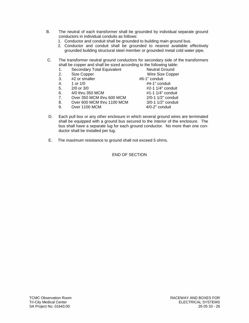
TCMC Observation Room RACEWAY AND BOXES FORTri-City Medical Center ELECTRICAL SYSTEMSSA Project No. 01643.00 26 05 33 - 26
B. The neutral of each transformer shall be grounded by individual separate ground conductors in individual conduits as follows:1. Conductor and conduit shall be grounded to building main ground bus.2. Conductor and conduit shall be grounded to nearest available effectively
grounded building structural steel member or grounded metal cold water pipe.
C. The transformer neutral ground conductors for secondary side of the transformers shall be copper and shall be sized according to the following table: 1. Secondary Total Equivalent Neutral Ground2. Size Copper Wire Size Copper3. #2 or smaller #6-1" conduit4. 1 or 1/0 #4-1" conduit5. 2/0 or 3/0 #2-1 1/4" conduit6. 4/0 thru 350 MCM #1-1 1/4" conduit7. Over 350 MCM thru 600 MCM 2/0-1 1/2" conduit8. Over 600 MCM thru 1100 MCM 3/0-1 1/2" conduit9. Over 1100 MCM 4/0-2" conduit
D. Each pull box or any other enclosure in which several ground wires are terminated shall be equipped with a ground bus secured to the interior of the enclosure. The bus shall have a separate lug for each ground conductor. No more than one con-ductor shall be installed per lug.
E. The maximum resistance to ground shall not exceed 5 ohms.
END OF SECTION
TCMC Observation RoomTri-City Medical Center IDENTIFICATION FOR ELECTRICAL SYSTEMSSA Project No. 01643.00 26 05 53 - 1
SECTION 26 05 53
IDENTIFICATION FOR ELECTRICAL SYSTEMS
PART 1 GENERAL
1.01 RELATED DOCUMENTS
A. Drawings and general provisions of the Contract, including General and Supplementary Conditions and Division 01 Specification Sections, apply to this Section.
1.02 SUMMARY
A. Section Includes:1. Identification for raceways.2. Identification of power and control cables.3. Identification for conductors.4. Underground-line warning tape.5. Warning labels and signs.6. Instruction signs.7. Equipment identification labels.8. Miscellaneous identification products.
1.03 SUBMITTALS
A. Product Data: For each electrical identification product indicated.
B. Samples: For each type of label and sign to illustrate size, colors, lettering style, mounting provisions, and graphic features of identification products.
C. Identification Schedule: An index of nomenclature of electrical equipment and system components used in identification signs and labels.
1.04 QUALITY ASSURANCE
A. Comply with ANSI A13.1.
B. Comply with NFPA 70.
C. Comply with 29 CFR 1910.144 and 29 CFR 1910.145.
D. Comply with ANSI Z535.4 for safety signs and labels.
E. Adhesive-attached labeling materials, including label stocks, laminating adhesives, and inks used by label printers, shall comply with UL 969.
1.05 COORDINATION
A. Coordinate identification names, abbreviations, colors, and other features with requirements in other Sections requiring identification applications, Drawings, Shop Drawings, manufacturer's wiring diagrams, and the Operation and Maintenance Manual; and with those required by codes, standards, and 29 CFR 1910.145. Use consistent designations throughout Project.
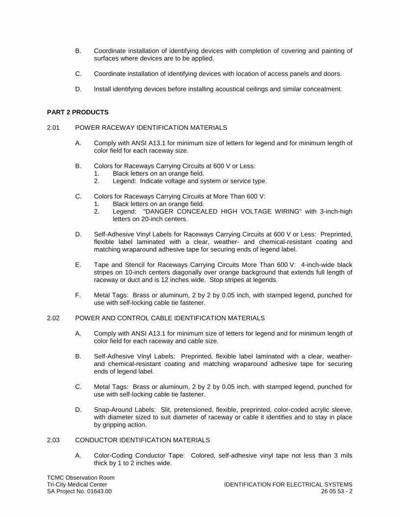
TCMC Observation RoomTri-City Medical Center IDENTIFICATION FOR ELECTRICAL SYSTEMSSA Project No. 01643.00 26 05 53 - 2
B. Coordinate installation of identifying devices with completion of covering and painting of surfaces where devices are to be applied.
C. Coordinate installation of identifying devices with location of access panels and doors.
D. Install identifying devices before installing acoustical ceilings and similar concealment.
PART 2 PRODUCTS
2.01 POWER RACEWAY IDENTIFICATION MATERIALS
A. Comply with ANSI A13.1 for minimum size of letters for legend and for minimum length of color field for each raceway size.
B. Colors for Raceways Carrying Circuits at 600 V or Less: 1. Black letters on an orange field.2. Legend: Indicate voltage and system or service type.
C. Colors for Raceways Carrying Circuits at More Than 600 V:1. Black letters on an orange field.2. Legend: "DANGER CONCEALED HIGH VOLTAGE WIRING" with 3-inch-high
letters on 20-inch centers.
D. Self-Adhesive Vinyl Labels for Raceways Carrying Circuits at 600 V or Less: Preprinted, flexible label laminated with a clear, weather- and chemical-resistant coating and matching wraparound adhesive tape for securing ends of legend label.
E. Tape and Stencil for Raceways Carrying Circuits More Than 600 V: 4-inch-wide black stripes on 10-inch centers diagonally over orange background that extends full length of raceway or duct and is 12 inches wide. Stop stripes at legends.
F. Metal Tags: Brass or aluminum, 2 by 2 by 0.05 inch, with stamped legend, punched for use with self-locking cable tie fastener.
2.02 POWER AND CONTROL CABLE IDENTIFICATION MATERIALS
A. Comply with ANSI A13.1 for minimum size of letters for legend and for minimum length of color field for each raceway and cable size.
B. Self-Adhesive Vinyl Labels: Preprinted, flexible label laminated with a clear, weather-and chemical-resistant coating and matching wraparound adhesive tape for securing ends of legend label.
C. Metal Tags: Brass or aluminum, 2 by 2 by 0.05 inch, with stamped legend, punched for use with self-locking cable tie fastener.
D. Snap-Around Labels: Slit, pretensioned, flexible, preprinted, color-coded acrylic sleeve, with diameter sized to suit diameter of raceway or cable it identifies and to stay in place by gripping action.
2.03 CONDUCTOR IDENTIFICATION MATERIALS
A. Color-Coding Conductor Tape: Colored, self-adhesive vinyl tape not less than 3 milsthick by 1 to 2 inches wide.
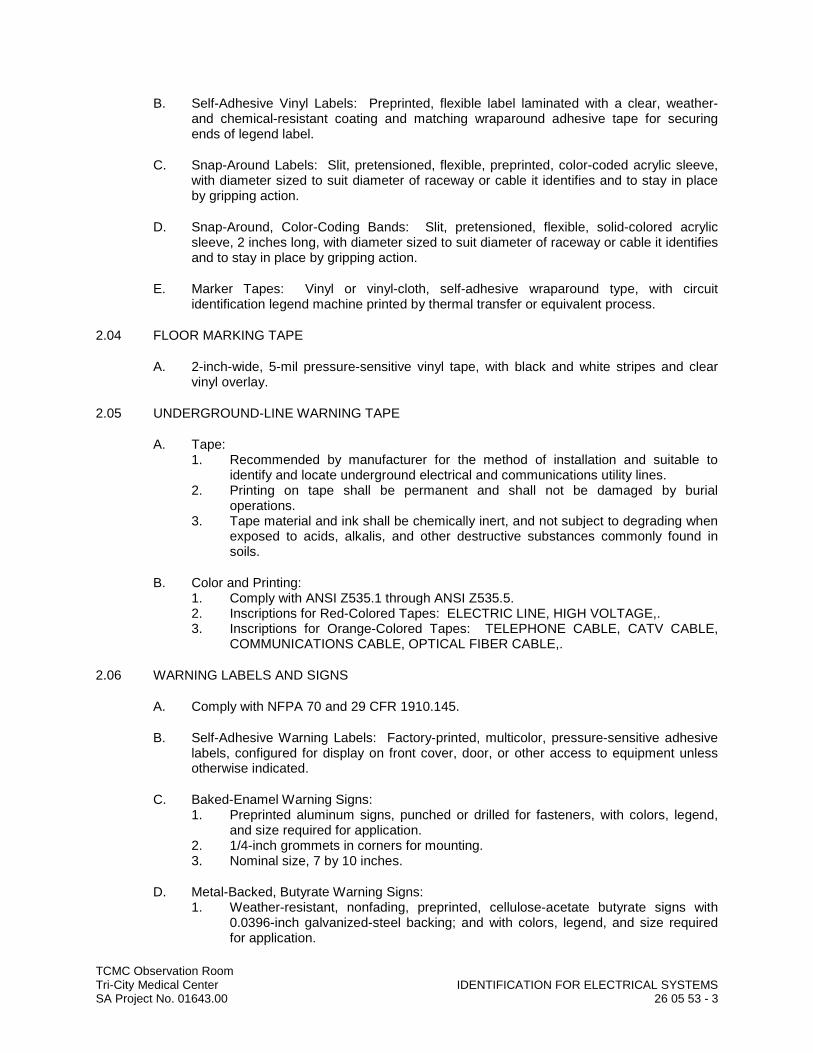
TCMC Observation RoomTri-City Medical Center IDENTIFICATION FOR ELECTRICAL SYSTEMSSA Project No. 01643.00 26 05 53 - 3
B. Self-Adhesive Vinyl Labels: Preprinted, flexible label laminated with a clear, weather-and chemical-resistant coating and matching wraparound adhesive tape for securing ends of legend label.
C. Snap-Around Labels: Slit, pretensioned, flexible, preprinted, color-coded acrylic sleeve, with diameter sized to suit diameter of raceway or cable it identifies and to stay in place by gripping action.
D. Snap-Around, Color-Coding Bands: Slit, pretensioned, flexible, solid-colored acrylic sleeve, 2 inches long, with diameter sized to suit diameter of raceway or cable it identifies and to stay in place by gripping action.
E. Marker Tapes: Vinyl or vinyl-cloth, self-adhesive wraparound type, with circuit identification legend machine printed by thermal transfer or equivalent process.
2.04 FLOOR MARKING TAPE
A. 2-inch-wide, 5-mil pressure-sensitive vinyl tape, with black and white stripes and clear vinyl overlay.
2.05 UNDERGROUND-LINE WARNING TAPE
A. Tape:1. Recommended by manufacturer for the method of installation and suitable to
identify and locate underground electrical and communications utility lines.2. Printing on tape shall be permanent and shall not be damaged by burial
operations.3. Tape material and ink shall be chemically inert, and not subject to degrading when
exposed to acids, alkalis, and other destructive substances commonly found in soils.
B. Color and Printing:1. Comply with ANSI Z535.1 through ANSI Z535.5.2. Inscriptions for Red-Colored Tapes: ELECTRIC LINE, HIGH VOLTAGE,.3. Inscriptions for Orange-Colored Tapes: TELEPHONE CABLE, CATV CABLE,
COMMUNICATIONS CABLE, OPTICAL FIBER CABLE,.
2.06 WARNING LABELS AND SIGNS
A. Comply with NFPA 70 and 29 CFR 1910.145.
B. Self-Adhesive Warning Labels: Factory-printed, multicolor, pressure-sensitive adhesive labels, configured for display on front cover, door, or other access to equipment unless otherwise indicated.
C. Baked-Enamel Warning Signs:1. Preprinted aluminum signs, punched or drilled for fasteners, with colors, legend,
and size required for application.2. 1/4-inch grommets in corners for mounting.3. Nominal size, 7 by 10 inches.
D. Metal-Backed, Butyrate Warning Signs:1. Weather-resistant, nonfading, preprinted, cellulose-acetate butyrate signs with
0.0396-inch galvanized-steel backing; and with colors, legend, and size required for application.
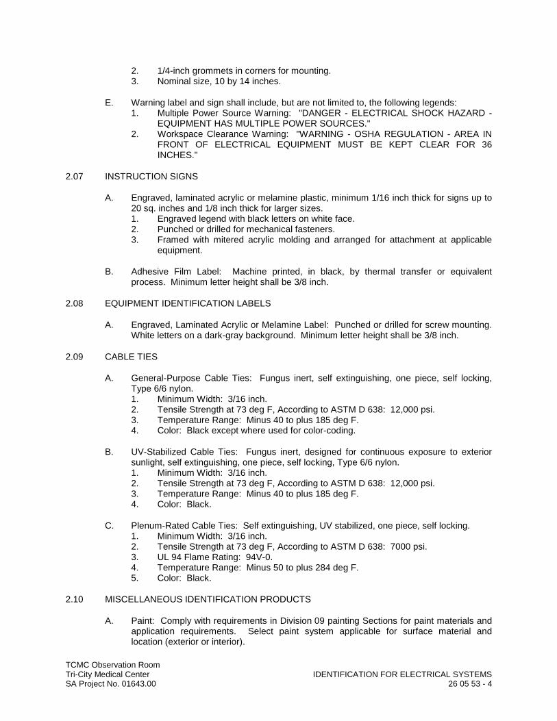
TCMC Observation RoomTri-City Medical Center IDENTIFICATION FOR ELECTRICAL SYSTEMSSA Project No. 01643.00 26 05 53 - 4
2. 1/4-inch grommets in corners for mounting.3. Nominal size, 10 by 14 inches.
E. Warning label and sign shall include, but are not limited to, the following legends:1. Multiple Power Source Warning: "DANGER - ELECTRICAL SHOCK HAZARD -
EQUIPMENT HAS MULTIPLE POWER SOURCES."2. Workspace Clearance Warning: "WARNING - OSHA REGULATION - AREA IN
FRONT OF ELECTRICAL EQUIPMENT MUST BE KEPT CLEAR FOR 36 INCHES."
2.07 INSTRUCTION SIGNS
A. Engraved, laminated acrylic or melamine plastic, minimum 1/16 inch thick for signs up to 20 sq. inches and 1/8 inch thick for larger sizes.1. Engraved legend with black letters on white face.2. Punched or drilled for mechanical fasteners.3. Framed with mitered acrylic molding and arranged for attachment at applicable
equipment.
B. Adhesive Film Label: Machine printed, in black, by thermal transfer or equivalent process. Minimum letter height shall be 3/8 inch.
2.08 EQUIPMENT IDENTIFICATION LABELS
A. Engraved, Laminated Acrylic or Melamine Label: Punched or drilled for screw mounting. White letters on a dark-gray background. Minimum letter height shall be 3/8 inch.
2.09 CABLE TIES
A. General-Purpose Cable Ties: Fungus inert, self extinguishing, one piece, self locking, Type 6/6 nylon.1. Minimum Width: 3/16 inch.2. Tensile Strength at 73 deg F, According to ASTM D 638: 12,000 psi.3. Temperature Range: Minus 40 to plus 185 deg F.4. Color: Black except where used for color-coding.
B. UV-Stabilized Cable Ties: Fungus inert, designed for continuous exposure to exterior sunlight, self extinguishing, one piece, self locking, Type 6/6 nylon.1. Minimum Width: 3/16 inch.2. Tensile Strength at 73 deg F, According to ASTM D 638: 12,000 psi.3. Temperature Range: Minus 40 to plus 185 deg F.4. Color: Black.
C. Plenum-Rated Cable Ties: Self extinguishing, UV stabilized, one piece, self locking.1. Minimum Width: 3/16 inch.2. Tensile Strength at 73 deg F, According to ASTM D 638: 7000 psi.3. UL 94 Flame Rating: 94V-0.4. Temperature Range: Minus 50 to plus 284 deg F.5. Color: Black.
2.10 MISCELLANEOUS IDENTIFICATION PRODUCTS
A. Paint: Comply with requirements in Division 09 painting Sections for paint materials and application requirements. Select paint system applicable for surface material and location (exterior or interior).

TCMC Observation RoomTri-City Medical Center IDENTIFICATION FOR ELECTRICAL SYSTEMSSA Project No. 01643.00 26 05 53 - 5
B. Fasteners for Labels and Signs: Self-tapping, stainless-steel screws or stainless-steel machine screws with nuts and flat and lock washers.
PART 3 EXECUTION
3.01 INSTALLATION
A. Verify identity of each item before installing identification products.
B. Location: Install identification materials and devices at locations for most convenient viewing without interference with operation and maintenance of equipment.
C. Apply identification devices to surfaces that require finish after completing finish work.
D. Self-Adhesive Identification Products: Clean surfaces before application, using materials and methods recommended by manufacturer of identification device.
E. Attach signs and plastic labels that are not self-adhesive type with mechanical fasteners appropriate to the location and substrate.
F. Aluminum Wraparound Marker Labels and Metal Tags: Secure tight to surface of conductor or cable at a location with high visibility and accessibility.
G. Cable Ties: For attaching tags. Use general-purpose type, except as listed below:1. Outdoors: UV-stabilized nylon.2. In Spaces Handling Environmental Air: Plenum rated.
H. Underground-Line Warning Tape: During backfilling of trenches install continuous underground-line warning tape directly above line at 6 to 8 inches below finished grade. Use multiple tapes where width of multiple lines installed in a common trench or concrete envelope exceeds 16 inches overall.
I. Painted Identification: Comply with requirements in Division 09 painting Sections for surface preparation and paint application.
3.02 IDENTIFICATION SCHEDULE
A. Concealed Raceways, Duct Banks, More Than 600 V, within Buildings: Tape and stencil 4-inch-wide black stripes on 10-inch centers over orange background that extends full length of raceway or duct and is 12 inches wide. Stencil legend "DANGER CONCEALED HIGH VOLTAGE WIRING" with 3-inch-high black letters on 20-inch centers. Stop stripes at legends. Apply to the following finished surfaces:1. Floor surface directly above conduits running beneath and within 12 inches of a
floor that is in contact with earth or is framed above unexcavated space.2. Wall surfaces directly external to raceways concealed within wall.3. Accessible surfaces of concrete envelope around raceways in vertical shafts,
exposed in the building, or concealed above suspended ceilings.
B. Accessible Raceways600 V or Less, for Service, Feeder, and Branch Circuits More Than 30 A, and 120 V to ground: Identify with self-adhesive vinyl label. Install labels at 10-footmaximum intervals.
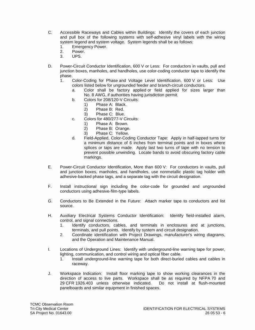
TCMC Observation RoomTri-City Medical Center IDENTIFICATION FOR ELECTRICAL SYSTEMSSA Project No. 01643.00 26 05 53 - 6
C. Accessible Raceways and Cables within Buildings: Identify the covers of each junction and pull box of the following systems with self-adhesive vinyl labels with the wiring system legend and system voltage. System legends shall be as follows:1. Emergency Power.2. Power.3. UPS.
D. Power-Circuit Conductor Identification, 600 V or Less: For conductors in vaults, pull and junction boxes, manholes, and handholes, use color-coding conductor tape to identify the phase.1. Color-Coding for Phase and Voltage Level Identification, 600 V or Less: Use
colors listed below for ungrounded feeder and branch-circuit conductors.a. Color shall be factory applied or field applied for sizes larger than
No. 8 AWG, if authorities having jurisdiction permit.b. Colors for 208/120-V Circuits:
1) Phase A: Black.2) Phase B: Red.3) Phase C: Blue.
c. Colors for 480/277-V Circuits:1) Phase A: Brown.2) Phase B: Orange.3) Phase C: Yellow.
d. Field-Applied, Color-Coding Conductor Tape: Apply in half-lapped turns for a minimum distance of 6 inches from terminal points and in boxes where splices or taps are made. Apply last two turns of tape with no tension to prevent possible unwinding. Locate bands to avoid obscuring factory cable markings.
E. Power-Circuit Conductor Identification, More than 600 V: For conductors in vaults, pull and junction boxes, manholes, and handholes, use nonmetallic plastic tag holder with adhesive-backed phase tags, and a separate tag with the circuit designation.
F. Install instructional sign including the color-code for grounded and ungrounded conductors using adhesive-film-type labels.
G. Conductors to Be Extended in the Future: Attach marker tape to conductors and list source.
H. Auxiliary Electrical Systems Conductor Identification: Identify field-installed alarm, control, and signal connections.1. Identify conductors, cables, and terminals in enclosures and at junctions,
terminals, and pull points. Identify by system and circuit designation.2. Coordinate identification with Project Drawings, manufacturer's wiring diagrams,
and the Operation and Maintenance Manual.
I. Locations of Underground Lines: Identify with underground-line warning tape for power, lighting, communication, and control wiring and optical fiber cable.1. Install underground-line warning tape for both direct-buried cables and cables in
raceway.
J. Workspace Indication: Install floor marking tape to show working clearances in the direction of access to live parts. Workspace shall be as required by NFPA 70 and 29 CFR 1926.403 unless otherwise indicated. Do not install at flush-mounted panelboards and similar equipment in finished spaces.
TCMC Observation RoomTri-City Medical Center IDENTIFICATION FOR ELECTRICAL SYSTEMSSA Project No. 01643.00 26 05 53 - 7
K. Warning Labels for Indoor Cabinets, Boxes, and Enclosures for Power and Lighting: Self-adhesive warning labels.1. Comply with 29 CFR 1910.145.2. Identify system voltage with black letters on an orange background.3. Apply to exterior of door, cover, or other access.4. For equipment with multiple power or control sources, apply to door or cover of
equipment including, but not limited to, the following:a. Power transfer switches.b. Controls with external control power connections.
L. Operating Instruction Signs: Install instruction signs to facilitate proper operation and maintenance of electrical systems and items to which they connect. Install instruction signs with approved legend where instructions are needed for system or equipment operation.
M. Emergency Operating Instruction Signs: Install instruction signs with white legend on ared background with minimum 3/8-inch-high letters for emergency instructions at equipment used for power transfer.
N. Equipment Identification Labels: On each unit of equipment, install unique designation label that is consistent with wiring diagrams, schedules, and the Operation and Maintenance Manual. Apply labels to disconnect switches and protection equipment, central or master units, control panels, control stations, terminal cabinets, and racks of each system. Systems include power, lighting, control, communication, signal, monitoring, and alarm systems unless equipment is provided with its own identification.1. Labeling Instructions:
a. Indoor Equipment: Engraved, laminated acrylic or melamine label. Unless otherwise indicated, provide a single line of text with 1/2-inch-high letters on 1-1/2-inch-high label; where two lines of text are required, use labels 2inches high.
b. Outdoor Equipment: Engraved, laminated acrylic or melamine label.c. Elevated Components: Increase sizes of labels and letters to those
appropriate for viewing from the floor.d. Unless provided with self-adhesive means of attachment, fasten labels with
appropriate mechanical fasteners that do not change the NEMA or NRTL rating of the enclosure.
2. Equipment to Be Labeled:a. Panelboards: Typewritten directory of circuits in the location provided by
panelboard manufacturer. Panelboard identification shall be engraved, laminated acrylic or melamine label.
b. Enclosures and electrical cabinets.c. Access doors and panels for concealed electrical items.d. Switchgear.e. Switchboards.f. Transformers: Label that includes tag designation shown on Drawings for
the transformer, feeder, and panelboards or equipment supplied by the secondary.
g. Substations.h. Emergency system boxes and enclosures.i. Motor-control centers.j. Enclosed switches.k. Enclosed circuit breakers.l. Enclosed controllers.m. Variable-speed controllers.n. Push-button stations.
TCMC Observation RoomTri-City Medical Center IDENTIFICATION FOR ELECTRICAL SYSTEMSSA Project No. 01643.00 26 05 53 - 8
o. Power transfer equipment.p. Contactors.q. Remote-controlled switches, dimmer modules, and control devices.r. Battery-inverter units.s. Battery racks.t. Power-generating units.u. Monitoring and control equipment.v. UPS equipment.
END OF SECTION

TCMC Observation RoomTri-City Medical Center WIRING DEVICESSA Project No. 01643.00 26 27 26 - 1
SECTION 26 27 26
WIRING DEVICES
PART 1 GENERAL
1.01 RELATED DOCUMENTS
A. Drawings and general provisions of the Contract, including General and Supplementary Conditions and Division 01 Specification Sections, apply to this Section.
1.02 SUMMARY
A. This Section includes the following:1. Receptacles, receptacles with integral GFCI, and associated device plates.2. Twist-locking receptacles.3. Wall-box motion sensors.4. Isolated-ground receptacles.5. Hospital-grade receptacles.6. Snap switches and wall-box dimmers.7. Solid-state fan speed controls.8. Floor service outlets, poke-through assemblies, service poles, and multioutlet
assemblies.
B. Related Sections include the following:1. Division 27 Section "Communications Horizontal Cabling" for workstation outlets.
1.03 DEFINITIONS
A. EMI: Electromagnetic interference.
B. GFCI: Ground-fault circuit interrupter.
C. Pigtail: Short lead used to connect a device to a branch-circuit conductor.
D. RFI: Radio-frequency interference.
E. TVSS: Transient voltage surge suppressor.
F. UTP: Unshielded twisted pair.
1.04 SCOPE
A. Work Included: All labor, materials, appliances, tools, equipment, facilities, transportation and services necessary for and incidental to performing all operations in connection with furnishing, delivery and installation of the work of this Section, complete as shown on the drawings and/or specified herein. Work includes, but is not necessarily limited to the fol-lowing:1. Examine all other sections for work related to those other sections and required to
be included as work under this section.2. General provisions and requirements for electrical work.
TCMC Observation RoomTri-City Medical Center WIRING DEVICESSA Project No. 01643.00 26 27 26 - 2
1.05 SUBMITTALS
A. Product Data: For each type of product indicated.
B. Shop Drawings: List of legends and description of materials and process used for premarking wall plates.
C. Samples: One for each type of device and wall plate specified, in each color specified.
D. Field quality-control test reports.
E. Operation and Maintenance Data: For wiring devices to include in all manufacturers' packing label warnings and instruction manuals that include labeling conditions.
1.06 QUALITY ASSURANCE
A. Source Limitations: Obtain each type of wiring device and associated wall plate through one source from a single manufacturer. Insofar as they are available, obtain all wiring devices and associated wall plates from a single manufacturer and one source.
B. Electrical Components, Devices, and Accessories: Listed and labeled as defined in NFPA 70, Article 100, by a testing agency acceptable to authorities having jurisdiction, and marked for intended use.
C. Comply with NFPA 70.
1.07 COORDINATION
A. Receptacles for Owner-Furnished Equipment: Match plug configurations.1. Cord and Plug Sets: Match equipment requirements.
PART 2 PRODUCTS
2.01 MANUFACTURERS
A. Manufacturers' Names: Shortened versions (shown in parentheses) of the following manufacturers' names are used in other Part 2 articles:1. Cooper Wiring Devices; a division of Cooper Industries, Inc. (Cooper).2. Hubbell Incorporated; Wiring Device-Kellems (Hubbell).3. Leviton Mfg. Company Inc. (Leviton).4. Pass & Seymour/Legrand; Wiring Devices & Accessories (Pass & Seymour).
2.02 STRAIGHT BLADE RECEPTACLES (SHALL BE UL LISTED HOSPITAL GRADE)
A. All receptacles in flush type outlet boxes shall be installed with bonding jumper to connect to box to the receptacles ground terminal. Grounding through the receptacle mounting straps is not acceptable. The bonding jumper shall be sized in accordance with the branch circuit protective device as tabulated herein under "Grounding". Bonding jumper shall be attached at each outlet to the back of the box using drilled and tapped holes and washer head screws 6-32 or larger (except isolated ground receptacles). For receptacles in surface mounted outlet boxes direct metal-to-metal contact between receptacle mounting strap (if it is connected to the grounding contacts) and outlet box may be used. Receptacles connected to normal circuits shall be ivory, white or gray as selected by
TCMC Observation RoomTri-City Medical Center WIRING DEVICESSA Project No. 01643.00 26 27 26 - 3
ARCHITECT. Receptacles connected to emergency (ESSENTIAL) power circuits shall be red.
B. Hospital-Grade, Duplex Convenience Receptacles, 125 V, 20 A: Comply with NEMA WD 1, NEMA WD 6 configuration 5-20R, and UL 498 Supplement SD.1. Products: Subject to compliance with requirements, provide one of the following:
a. Cooper; 8300 (duplex).b. Hubbell; HBL8310 (single), HBL8300H (duplex).c. Leviton; 8310 (single), 8300 (duplex).d. Pass & Seymour; 9301-HG (single), 9300-HG (duplex).
C. Isolated-Ground, Duplex Convenience Receptacles, 125 V, 20 A: Comply with NEMA WD 1, NEMA WD 6 configuration 5-20R, and UL 498.1. Products: Subject to compliance with requirements, provide one of the following:
a. Hubbell; CR 5253IG.b. Leviton; 5362-IG.c. Pass & Seymour; IG6300.
2. Description: Straight blade; equipment grounding contacts shall be connected only to the green grounding screw terminal of the device and with inherent electrical isolation from mounting strap. Isolation shall be integral to receptacle construction and not dependent on removable parts.
D. Tamper-Resistant Convenience Receptacles, 125 V, 20 A: Comply with NEMA WD 1, NEMA WD 6 configuration 5-20R, and UL 498.1. Products: Subject to compliance with requirements, provide one of the following:
a. Cooper; TR8300.b. Hubbell; HBL8300SG.c. Leviton; 8300-SGG.d. Pass & Seymour; 63H.
2. Description: Labeled to comply with NFPA 70, "Health Care Facilities" Article, "Pediatric Locations" Section.
2.03 GFCI RECEPTACLES (SHALL BE UL LISTED HOSPITAL GRADE)
A. General Description: Straight blade, feed-through type. Comply with NEMA WD 1, NEMA WD 6, UL 498, and UL 943, Class A, and include indicator light that is lighted when device is tripped.
B. Hospital-Grade, Duplex GFCI Convenience Receptacles, 125 V, 20 A: Comply with UL 498 Supplement SD.1. Products: Subject to compliance with requirements, provide one of the following:
a. Cooper; HGF20.b. Hubbell; HGF8300.c. Leviton; 6898-HG.d. Pass & Seymour; 2091-SHG.
2.04 HAZARDOUS (CLASSIFIED) LOCATION RECEPTACLES
A. Wiring Devices for Hazardous (Classified) Locations: Comply with NEMA FB 11 and UL 1010.1. Manufacturers: Subject to compliance with requirements, provide products by one
of the following:a. Cooper Crouse-Hinds.b. EGS/Appleton Electric.c. Killark; a division of Hubbell Inc.
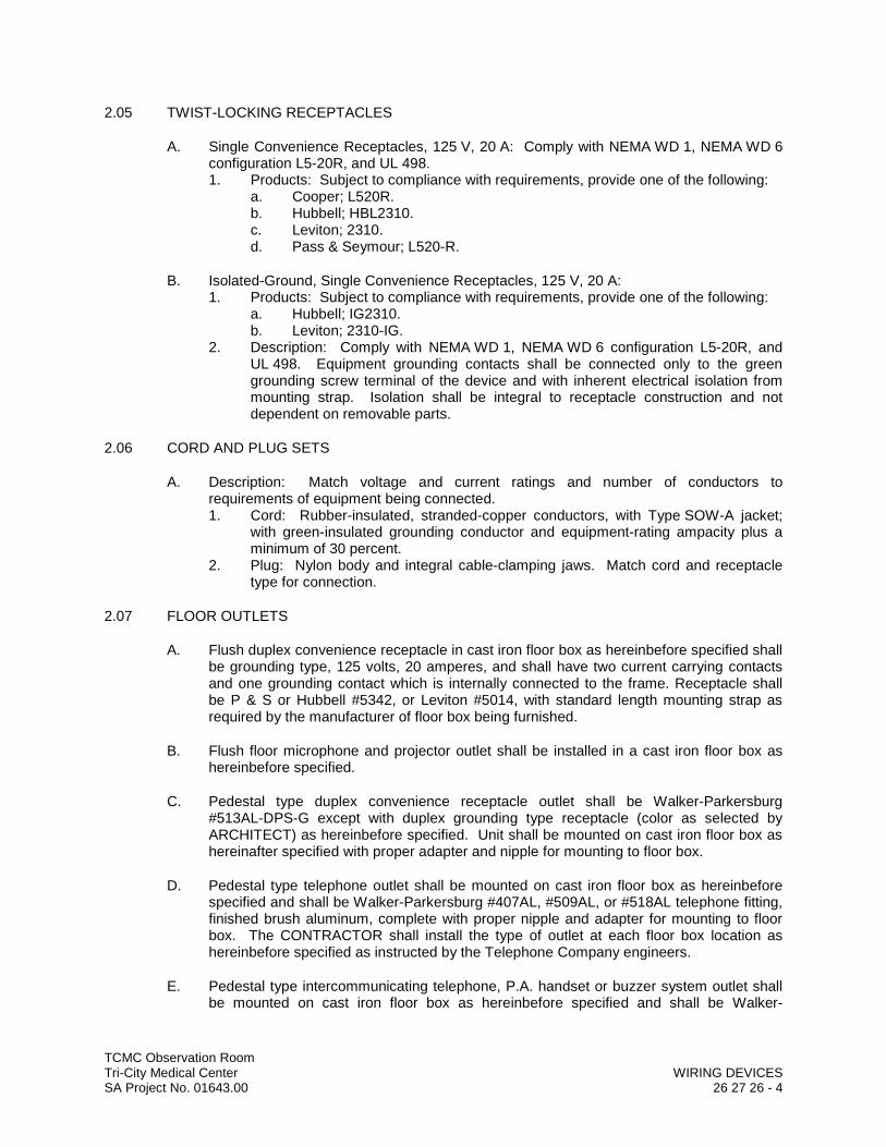
TCMC Observation RoomTri-City Medical Center WIRING DEVICESSA Project No. 01643.00 26 27 26 - 4
2.05 TWIST-LOCKING RECEPTACLES
A. Single Convenience Receptacles, 125 V, 20 A: Comply with NEMA WD 1, NEMA WD 6configuration L5-20R, and UL 498.1. Products: Subject to compliance with requirements, provide one of the following:
a. Cooper; L520R.b. Hubbell; HBL2310.c. Leviton; 2310.d. Pass & Seymour; L520-R.
B. Isolated-Ground, Single Convenience Receptacles, 125 V, 20 A:1. Products: Subject to compliance with requirements, provide one of the following:
a. Hubbell; IG2310.b. Leviton; 2310-IG.
2. Description: Comply with NEMA WD 1, NEMA WD 6 configuration L5-20R, and UL 498. Equipment grounding contacts shall be connected only to the green grounding screw terminal of the device and with inherent electrical isolation from mounting strap. Isolation shall be integral to receptacle construction and not dependent on removable parts.
2.06 CORD AND PLUG SETS
A. Description: Match voltage and current ratings and number of conductors to requirements of equipment being connected.1. Cord: Rubber-insulated, stranded-copper conductors, with Type SOW-A jacket;
with green-insulated grounding conductor and equipment-rating ampacity plus a minimum of 30 percent.
2. Plug: Nylon body and integral cable-clamping jaws. Match cord and receptacle type for connection.
2.07 FLOOR OUTLETS
A. Flush duplex convenience receptacle in cast iron floor box as hereinbefore specified shall be grounding type, 125 volts, 20 amperes, and shall have two current carrying contacts and one grounding contact which is internally connected to the frame. Receptacle shall be P & S or Hubbell #5342, or Leviton #5014, with standard length mounting strap as required by the manufacturer of floor box being furnished.
B. Flush floor microphone and projector outlet shall be installed in a cast iron floor box as hereinbefore specified.
C. Pedestal type duplex convenience receptacle outlet shall be Walker-Parkersburg #513AL-DPS-G except with duplex grounding type receptacle (color as selected by ARCHITECT) as hereinbefore specified. Unit shall be mounted on cast iron floor box as hereinafter specified with proper adapter and nipple for mounting to floor box.
D. Pedestal type telephone outlet shall be mounted on cast iron floor box as hereinbefore specified and shall be Walker-Parkersburg #407AL, #509AL, or #518AL telephone fitting, finished brush aluminum, complete with proper nipple and adapter for mounting to floor box. The CONTRACTOR shall install the type of outlet at each floor box location as hereinbefore specified as instructed by the Telephone Company engineers.
E. Pedestal type intercommunicating telephone, P.A. handset or buzzer system outlet shall be mounted on cast iron floor box as hereinbefore specified and shall be Walker-
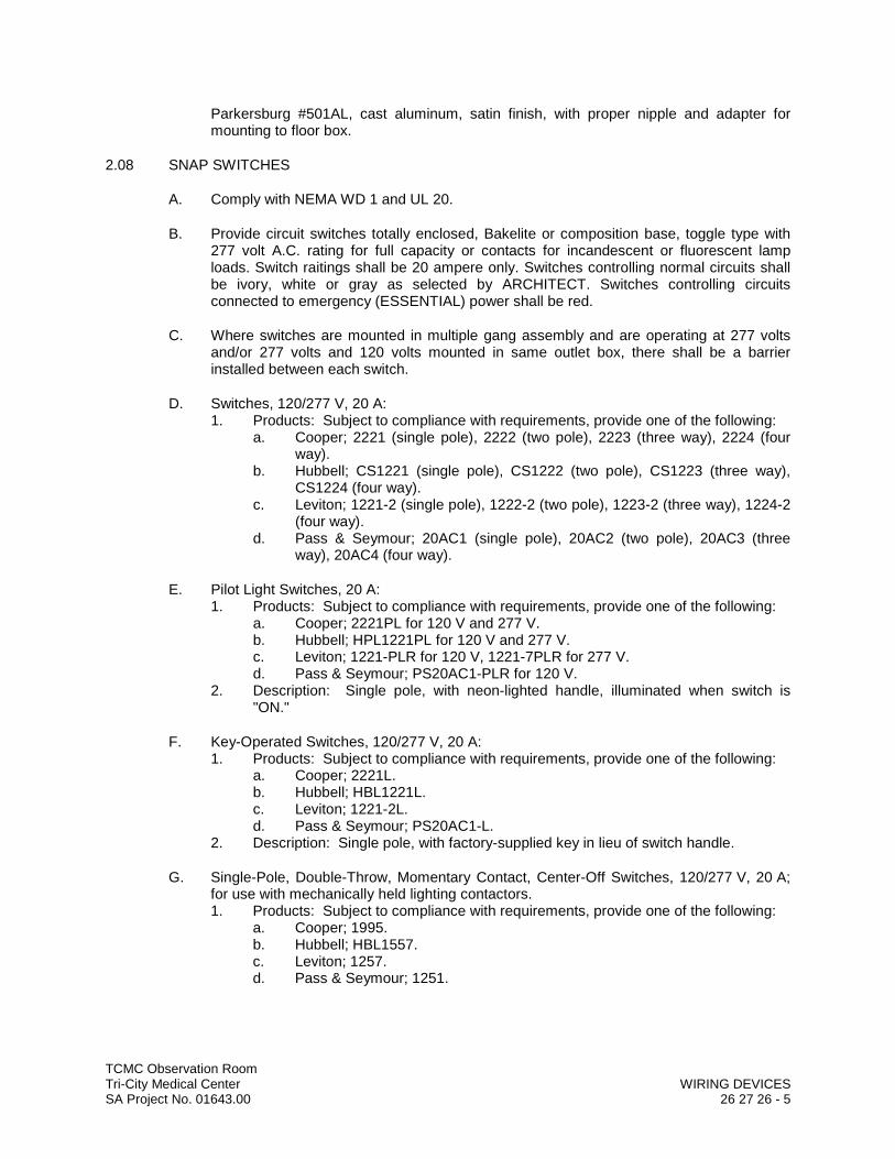
TCMC Observation RoomTri-City Medical Center WIRING DEVICESSA Project No. 01643.00 26 27 26 - 5
Parkersburg #501AL, cast aluminum, satin finish, with proper nipple and adapter for mounting to floor box.
2.08 SNAP SWITCHES
A. Comply with NEMA WD 1 and UL 20.
B. Provide circuit switches totally enclosed, Bakelite or composition base, toggle type with 277 volt A.C. rating for full capacity or contacts for incandescent or fluorescent lamp loads. Switch raitings shall be 20 ampere only. Switches controlling normal circuits shall be ivory, white or gray as selected by ARCHITECT. Switches controlling circuits connected to emergency (ESSENTIAL) power shall be red.
C. Where switches are mounted in multiple gang assembly and are operating at 277 volts and/or 277 volts and 120 volts mounted in same outlet box, there shall be a barrier installed between each switch.
D. Switches, 120/277 V, 20 A:1. Products: Subject to compliance with requirements, provide one of the following:
a. Cooper; 2221 (single pole), 2222 (two pole), 2223 (three way), 2224 (four way).
b. Hubbell; CS1221 (single pole), CS1222 (two pole), CS1223 (three way), CS1224 (four way).
c. Leviton; 1221-2 (single pole), 1222-2 (two pole), 1223-2 (three way), 1224-2(four way).
d. Pass & Seymour; 20AC1 (single pole), 20AC2 (two pole), 20AC3 (three way), 20AC4 (four way).
E. Pilot Light Switches, 20 A:1. Products: Subject to compliance with requirements, provide one of the following:
a. Cooper; 2221PL for 120 V and 277 V.b. Hubbell; HPL1221PL for 120 V and 277 V.c. Leviton; 1221-PLR for 120 V, 1221-7PLR for 277 V.d. Pass & Seymour; PS20AC1-PLR for 120 V.
2. Description: Single pole, with neon-lighted handle, illuminated when switch is "ON."
F. Key-Operated Switches, 120/277 V, 20 A:1. Products: Subject to compliance with requirements, provide one of the following:
a. Cooper; 2221L.b. Hubbell; HBL1221L.c. Leviton; 1221-2L.d. Pass & Seymour; PS20AC1-L.
2. Description: Single pole, with factory-supplied key in lieu of switch handle.
G. Single-Pole, Double-Throw, Momentary Contact, Center-Off Switches, 120/277 V, 20 A; for use with mechanically held lighting contactors.1. Products: Subject to compliance with requirements, provide one of the following:
a. Cooper; 1995.b. Hubbell; HBL1557.c. Leviton; 1257.d. Pass & Seymour; 1251.
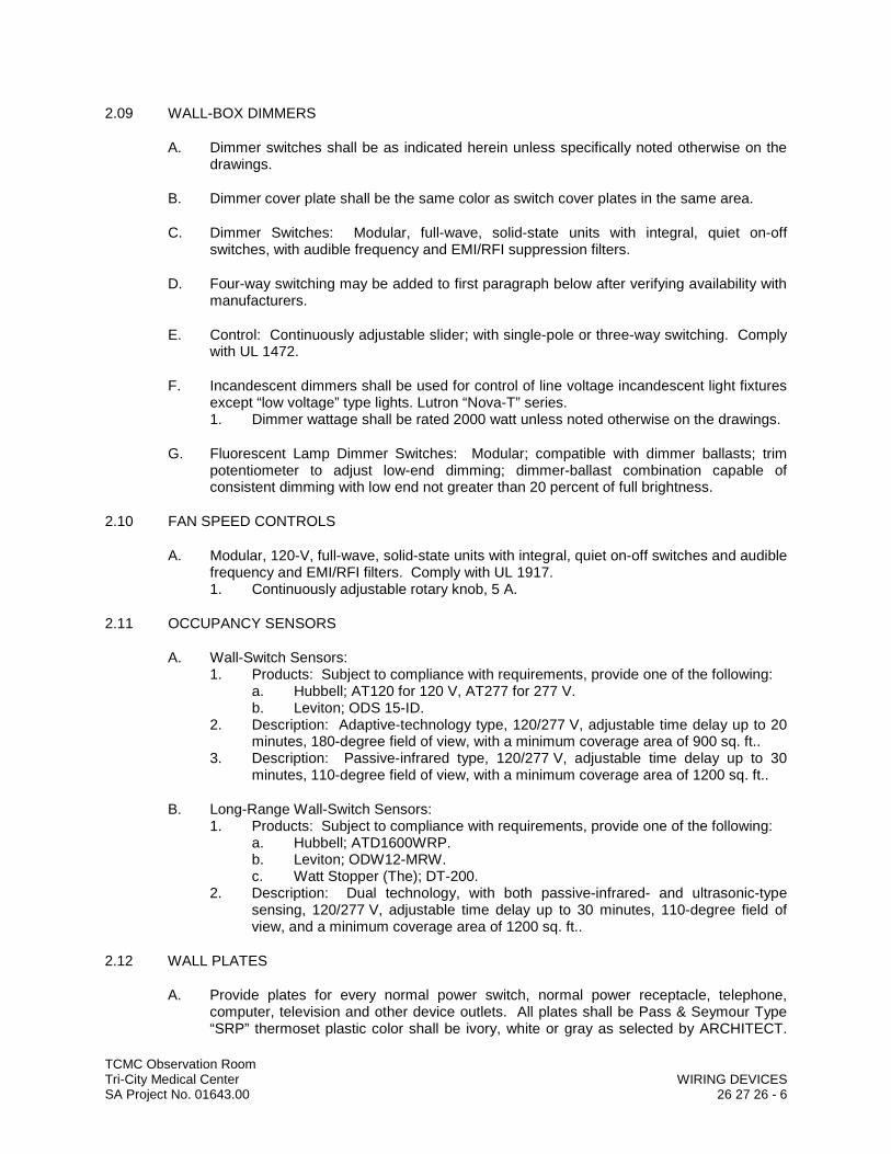
TCMC Observation RoomTri-City Medical Center WIRING DEVICESSA Project No. 01643.00 26 27 26 - 6
2.09 WALL-BOX DIMMERS
A. Dimmer switches shall be as indicated herein unless specifically noted otherwise on the drawings.
B. Dimmer cover plate shall be the same color as switch cover plates in the same area.
C. Dimmer Switches: Modular, full-wave, solid-state units with integral, quiet on-off switches, with audible frequency and EMI/RFI suppression filters.
D. Four-way switching may be added to first paragraph below after verifying availability with manufacturers.
E. Control: Continuously adjustable slider; with single-pole or three-way switching. Comply with UL 1472.
F. Incandescent dimmers shall be used for control of line voltage incandescent light fixtures except “low voltage” type lights. Lutron “Nova-T” series.1. Dimmer wattage shall be rated 2000 watt unless noted otherwise on the drawings.
G. Fluorescent Lamp Dimmer Switches: Modular; compatible with dimmer ballasts; trim potentiometer to adjust low-end dimming; dimmer-ballast combination capable of consistent dimming with low end not greater than 20 percent of full brightness.
2.10 FAN SPEED CONTROLS
A. Modular, 120-V, full-wave, solid-state units with integral, quiet on-off switches and audible frequency and EMI/RFI filters. Comply with UL 1917.1. Continuously adjustable rotary knob, 5 A.
2.11 OCCUPANCY SENSORS
A. Wall-Switch Sensors:1. Products: Subject to compliance with requirements, provide one of the following:
a. Hubbell; AT120 for 120 V, AT277 for 277 V.b. Leviton; ODS 15-ID.
2. Description: Adaptive-technology type, 120/277 V, adjustable time delay up to 20 minutes, 180-degree field of view, with a minimum coverage area of 900 sq. ft..
3. Description: Passive-infrared type, 120/277 V, adjustable time delay up to 30 minutes, 110-degree field of view, with a minimum coverage area of 1200 sq. ft..
B. Long-Range Wall-Switch Sensors:1. Products: Subject to compliance with requirements, provide one of the following:
a. Hubbell; ATD1600WRP.b. Leviton; ODW12-MRW.c. Watt Stopper (The); DT-200.
2. Description: Dual technology, with both passive-infrared- and ultrasonic-type sensing, 120/277 V, adjustable time delay up to 30 minutes, 110-degree field of view, and a minimum coverage area of 1200 sq. ft..
2.12 WALL PLATES
A. Provide plates for every normal power switch, normal power receptacle, telephone, computer, television and other device outlets. All plates shall be Pass & Seymour Type “SRP” thermoset plastic color shall be ivory, white or gray as selected by ARCHITECT.
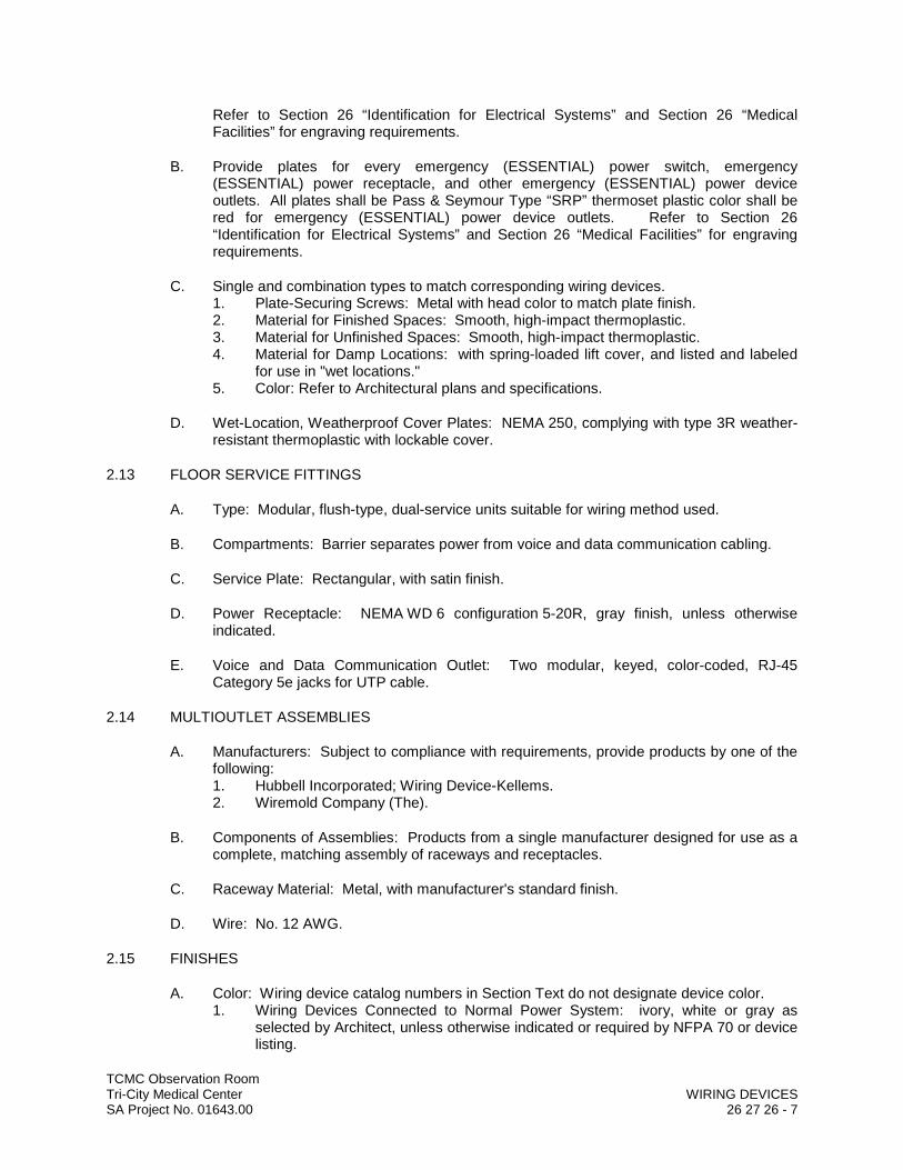
TCMC Observation RoomTri-City Medical Center WIRING DEVICESSA Project No. 01643.00 26 27 26 - 7
Refer to Section 26 “Identification for Electrical Systems” and Section 26 “Medical Facilities” for engraving requirements.
B. Provide plates for every emergency (ESSENTIAL) power switch, emergency (ESSENTIAL) power receptacle, and other emergency (ESSENTIAL) power device outlets. All plates shall be Pass & Seymour Type “SRP” thermoset plastic color shall be red for emergency (ESSENTIAL) power device outlets. Refer to Section 26 “Identification for Electrical Systems” and Section 26 “Medical Facilities” for engraving requirements.
C. Single and combination types to match corresponding wiring devices.1. Plate-Securing Screws: Metal with head color to match plate finish.2. Material for Finished Spaces: Smooth, high-impact thermoplastic.3. Material for Unfinished Spaces: Smooth, high-impact thermoplastic.4. Material for Damp Locations: with spring-loaded lift cover, and listed and labeled
for use in "wet locations."5. Color: Refer to Architectural plans and specifications.
D. Wet-Location, Weatherproof Cover Plates: NEMA 250, complying with type 3R weather-resistant thermoplastic with lockable cover.
2.13 FLOOR SERVICE FITTINGS
A. Type: Modular, flush-type, dual-service units suitable for wiring method used.
B. Compartments: Barrier separates power from voice and data communication cabling.
C. Service Plate: Rectangular, with satin finish.
D. Power Receptacle: NEMA WD 6 configuration 5-20R, gray finish, unless otherwise indicated.
E. Voice and Data Communication Outlet: Two modular, keyed, color-coded, RJ-45 Category 5e jacks for UTP cable.
2.14 MULTIOUTLET ASSEMBLIES
A. Manufacturers: Subject to compliance with requirements, provide products by one of the following:1. Hubbell Incorporated; Wiring Device-Kellems.2. Wiremold Company (The).
B. Components of Assemblies: Products from a single manufacturer designed for use as a complete, matching assembly of raceways and receptacles.
C. Raceway Material: Metal, with manufacturer's standard finish.
D. Wire: No. 12 AWG.
2.15 FINISHES
A. Color: Wiring device catalog numbers in Section Text do not designate device color.1. Wiring Devices Connected to Normal Power System: ivory, white or gray as
selected by Architect, unless otherwise indicated or required by NFPA 70 or device listing.

TCMC Observation RoomTri-City Medical Center WIRING DEVICESSA Project No. 01643.00 26 27 26 - 8
2. Wiring Devices Connected to Emergency (ESSENTIAL) Power System: Red.3. TVSS Devices: Blue.4. Isolated-Ground Receptacles: Orange.
2.16 IDENTIFICATION (ADDITIONAL REQUIREMENTS)
A. The front face device cover plates for switches and outlets shall be engraved with the circuit number and connection source equipment name with 1/4” letters, (i.e. "PNL-A #1"; "PNL-AC #42"; etc.) Additionally device cover plates shall also be engraved 1/8” letters with the circuit ampacity and voltage for circuit exceeding 20 ampere or 120 volts. (i.e. PNL-A #6, 8 - 20 AMP 208V 1 Phase; PNL-2B #10 - 30 AMP 120V 1 Phase; etc.) Lettering for normal circuits shall be black lettering for emergency (essential) circuits shall be black.
PART 3 EXECUTION
3.01 INSTALLATION
A. Comply with NECA 1, including the mounting heights listed in that standard, unless otherwise noted.
B. Coordination with Other Trades:1. Take steps to insure that devices and their boxes are protected. Do not place wall
finish materials over device boxes and do not cut holes for boxes with routers that are guided by riding against outside of the boxes.
2. Keep outlet boxes free of plaster, drywall joint compound, mortar, cement, concrete, dust, paint, and other material that may contaminate the raceway system, conductors, and cables.
3. Install device boxes in brick or block walls so that the cover plate does not cross a joint unless the joint is troweled flush with the face of the wall.
4. Install wiring devices after all wall preparation, including painting, is complete.
C. Conductors:1. Do not strip insulation from conductors until just before they are spliced or
terminated on devices.2. Strip insulation evenly around the conductor using tools designed for the purpose.
Avoid scoring or nicking of solid wire or cutting strands from stranded wire.3. The length of free conductors at outlets for devices shall meet provisions of
NFPA 70, Article 300, without pigtails.4. Existing Conductors:
a. Cut back and pigtail, or replace all damaged conductors.b. Straighten conductors that remain and remove corrosion and foreign matter.c. Pigtailing existing conductors is permitted provided the outlet box is large
enough.
D. Device Installation:1. Replace all devices that have been in temporary use during construction or that
show signs that they were installed before building finishing operations were complete.
2. Keep each wiring device in its package or otherwise protected until it is time to connect conductors.
3. Do not remove surface protection, such as plastic film and smudge covers, until the last possible moment.
TCMC Observation RoomTri-City Medical Center WIRING DEVICESSA Project No. 01643.00 26 27 26 - 9
4. Connect devices to branch circuits using pigtails that are not less than 6 inches in length.
5. When there is a choice, use side wiring with binding-head screw terminals. Wrap solid conductor tightly clockwise, 2/3 to 3/4 of the way around terminal screw.
6. Use a torque screwdriver when a torque is recommended or required by the manufacturer.
7. When conductors larger than No. 12 AWG are installed on 15- or 20-A circuits, splice No. 12 AWG pigtails for device connections.
8. Tighten unused terminal screws on the device.9. When mounting into metal boxes, remove the fiber or plastic washers used to hold
device mounting screws in yokes, allowing metal-to-metal contact.
E. Receptacle Orientation:1. Install ground pin of vertically mounted receptacles up, and on horizontally
mounted receptacles to the right.2. Install hospital-grade receptacles in patient-care areas with the ground pin or
neutral blade at the top.
F. Device Plates: Do not use oversized or extra-deep plates. Repair wall finishes and remount outlet boxes when standard device plates do not fit flush or do not cover rough wall opening.
G. Dimmers:1. Install dimmers within terms of their listing.2. Verify that dimmers used for fan speed control are listed for that application.3. Install unshared neutral conductors on line and load side of dimmers according to
manufacturers' device listing conditions in the written instructions.4. Do not break off dimmer cooling fans.
H. Arrangement of Devices: Unless otherwise indicated, mount flush, with long dimension vertical and with grounding terminal of receptacles on top. Group adjacent switches under single, multigang wall plates.
I. Adjust locations of floor service outlets and service poles to suit arrangement of partitions and furnishings.
J. Occupancy Sensor Light Switches1. Install dimmers within terms of their listing. Installation and location of occupancy
sensors shall be in accordance with manufacturers recommendations.2. Adjust sensitivity control as required for proper operation and to limit coverage to
room controlled. Adjust sensitivity so that persons passing by an open door to the room controlled will not activate the lights and for minimal motion within the room by the occupant will maintain the lights on.
3. Adjust time delay off for 15 minutes.
3.02 IDENTIFICATION
A. Comply with Division 26 Section "Medical Facilities."1. Receptacles: Identify panelboard and circuit number from which served. Use hot,
stamped or engraved machine printing with black-filled lettering on face of plate, and durable wire markers or tags inside outlet boxes.
3.03 FIELD QUALITY CONTROL
A. Perform tests and inspections and prepare test reports.
TCMC Observation RoomTri-City Medical Center WIRING DEVICESSA Project No. 01643.00 26 27 26 - 10
1. In healthcare facilities, prepare reports that comply with recommendations in NFPA 99.
2. Test Instruments: Use instruments that comply with UL 1436.3. Test Instrument for Convenience Receptacles: Digital wiring analyzer with digital
readout or illuminated LED indicators of measurement.
B. Tests for Convenience Receptacles:1. Line Voltage: Acceptable range is 105 to 132 V.2. Percent Voltage Drop under 15-A Load: A value of 6 percent or higher is not
acceptable.3. Ground Impedance: Values of up to 2 ohms are acceptable.4. GFCI Trip: Test for tripping values specified in UL 1436 and UL 943.5. Using the test plug, verify that the device and its outlet box are securely mounted.6. The tests shall be diagnostic, indicating damaged conductors, high resistance at
the circuit breaker, poor connections, inadequate fault current path, defective devices, or similar problems. Correct circuit conditions, remove malfunctioning units and replace with new ones, and retest as specified above.
C. Test straight blade convenience outlets in patient-care areas for the retention force of the grounding blade according to NFPA 99. Retention force shall be not less than 4 oz..
END OF SECTION
TCMC Observation RoomTri-City Medical Center MEDICAL FACILITIESSA Project No. 01643.00 26 57 00 - 1
SECTION 26 57 00
MEDICAL FACILITIES
PART 1 GENERAL
1.01 SCOPE
A. Work Included: All labor, materials, appliances, tools, equipment, facilities, transportation and services necessary for and incidental to performing all operations in connection with furnishing, deliver and installation of the work of this Section, complete as shown on the drawings and/or specified herein. Work includes, but is not necessarily limited to the following:1. Examine all other sections for work related to those other sections and required to be
included as work under this section.2. General provisions and requirements for electrical work.
1.02 SUBMITTALS (ADDITIONAL REQUIREMENTS)
A. Submit product data sheets for all outlet boxes, wiring devices, device plates.
PART 2 PRODUCTS
2.01 ROOM REFERENCE GROUND POINT
A. The room reference ground point shall provide a common reference ground level connection point for the respective room the ground point is installed in.
B. The ground point shall be flush mounting steel box with #304 stainless steel overlapping trim coverplate. A ground bus with individual ground lugs sized to accommodate each of the grounding/bonding conductors shall be provided in the box, including four (4) spare #10 AWG lugs and one (1) - spare #6 AWG lugs.
C. Provide a nameplate on cover "room ground point". Isotrol #RGP, Square D #GS120.
2.02 RECEPTACLES (ADDITIONAL REQUIREMENTS)
A. Receptacles shall be Underwriters Laboratories listed hospital grade.1. Duplex convenience receptacles shall be heavy duty grounding type 120 volt 15 ampere
with two current carrying contacts and one grounding contact which is internally connected to the frame. Outlets shall accommodate standard parallel blade cap and be side wired. Receptacles on normal circuits shall be ivory, white or gray as selected by Architect. Receptacles on emergency (essential) circuit shall be red.a. Hubbell #8200
2. Duplex 20 ampere convenience outlets same as 15 ampere except ampacity shall be used where duplex receptacles is supplied by separate 20-ampere circuit:a. Hubbell #8300
3. Ground fault convenience receptacles provide separate ground fault receptacle at each location indicated on drawings.
a. Hubbell #GF8300
B. Special outlets hospital grade capacities and types shall be as indicated on the drawings.
2.03 IDENTIFICATION (ADDITIONAL REQUIREMENTS)

TCMC Observation RoomTri-City Medical Center MEDICAL FACILITIESSA Project No. 01643.00 26 57 00 - 2
A. The front face device cover plates for switches and outlets shall be engraved with the circuit number and connection source equipment name with 1/4” letters, (i.e. "PNL-A #1"; "PNL-AC #42"; etc.) Additionally device cover plates shall also be engraved 1/8” letters with the circuit ampacity and voltage for circuit exceeding 20 ampere or 120 volts. (i.e. PNL-A #6, 8 - 20 AMP 208V 1 Phase; PNL-2B #10 - 30 AMP 120V 1 Phase; etc.) Lettering for normal circuits shall be black lettering for emergency (essential) circuits shall be red.
PART 3 EXECUTION
3.01 GROUNDING (ADDITIONAL REQUIREMENTS)
A. General1. The drawings do not show all the bonding connection points or conductors runs. Provide
all material and work required for a complete system.2. All conductor raceways both metallic and non-metallic shall have a separate green
equipment ground conductor installed in the raceway with the circuit conductors except as described otherwise for isolated power systems. The raceway shall not be used as the only ground return path. The ground conductor in each raceway shall sized as follows:a. Signal circuit conduits one inch and smaller 1#14 AWG.b. Signal circuit conduits larger then one inch. 1#10 AWG.c. Power circuit raceways.d. Feeders, Subfeeders & Branch Minimum Ground Wire
Circuit Protection Size Size in each Raceway15 Amp #1220 Amp #1230 to 60 Amp #1070 to 100 Amp #8101 to 200 Amp #6201 to 400 Amp #3401 to 600 Amp #1601 to 800 Amp 1/0801 to 1000 Amp 2/01001 to 1200 Amp 3/01201 to 1600 Amp 4/01601 to 2000 Amp 250 MCM2001 t0 2500 Amp 350 MCM2501 to 4000 Amp 500 MCM
B. Grounding In Critical Patient Care Areas1. Grounding in critical patient care areas shall be prepared as follows. Critical patient care
areas include but are not limited to:a. Cath Labb. Interventional radiologyc. Patient Holding
2. The grounding system shall provide for a common electrical potential between all metal surfaces in the room for critical care patient functions.
3. All exposed stationary (non portable) metal and structural surface such as equipment tracks, gas pipes, water pipes, HV/AC ducts grills and pipes, door and window framing, conduits etc. shall be bonded to a common room reference ground point or patient reference ground point. The grounding shall be assured by installation of a continuous #10 AWG ground conductor from the closest room grounding point terminal bus to each respective metal part, with connections made by means of approved copper or brass clamps and lugs. The bond wires shall be concealed in walls and ceilings with or without conduit for non-masonry construction and in conduit in masonry construction. Provide a separate ground wire for each such point. Do not loop grounds between various points.
4. After the non-electrical bonding grounds are installed and before the building walls are closed up, a Independent Test Company shall perform tests and provide certified test
TCMC Observation RoomTri-City Medical Center MEDICAL FACILITIESSA Project No. 01643.00 26 57 00 - 3
reports that all such points do not exceed 0.1 ohm max. level from the main room reference ground. Walls shall not to be closed up until these reports have been reviewed by the Architect.
5. The ground conductors for electrical power branch circuits not connected to isolated power systems shall be installed in the same raceway as the respective branch circuit conductors.
6. Provide 1"C with 1#4 AWG ground conductor extended from the room reference grounding point terminal bus to the ground bus in each branch circuit power panel serving that room.
7. Where existing walls are in place contractor shall provide new ground bonding conductors to the room reference ground and patient reference ground as described herein. Contractor may reuse existing continuous bonding conductors in serviceable condition.
8. A minimum of one room reference grounding point shall be provided in each room containing critical care patients. Additional room reference ground points shall be provided where shown on the plans. These devices shall maintain a common electrical potential between patient ground points. Metal surfaces and isolated power panels.
C. Grounding in General Patient Care Locations1. Grounding in general patient care areas supplied from non-power isolated systems shall
be prepared as follows. General patient care areas include but are not limited to:a. Non-critical patient care areasb. Non-emergency examination roomsc. Non-emergency x-ray roomsd. general nursing area patient roomse. non-emergency treatment rooms
2. Provide ground conductor in same raceway as respective branch circuit phase conductors, back to respective panelboard.
END OF SECTION


DIV
ISIO
N 3
1–
EAR
THW
OR
KDDDDDDDDDDDDDDDDDDDDD
IIIIIIIIIIIIIIIVVVVVVVVVVVVVVVVVVVVVVVVIIIIIIIIIIIIIIISSSSSSSSSSSSSSSSSSSSSSSS
IIIIIIIIIIIIIOOOOOOOOOOOOOOOOOOOOOOOOOOOOONNNNNNNNNNNNNNNNNNNNN
3333333333333333333333333111111111111111111111–––––––––––––––
EEEEEEEEEEEEEEEEEEEEAAAAAAAAAAAAAAAAAAAAAAARRRRRRRRRRRRRRRRRRRRRR
TTTTTTTTTTTTTTTTTTTTTHHHHHHHHHHHHHHHHHHHHHWWWWWWWWWWWWWWWWWWWWWWWWW
OOOOOOOOOOOOOOOOOOOOOOOOOOOORRRRRRRRRRRRRRRRRRRRR
KKKKKKKKKKKKKKKKKKKKKKKKKKK

TCMC Observation RoomTri-City Medical Center TRENCHING AND BACKFILLINGSA Project No. 01643.00 31 23 33 - 1
SECTION 31 23 33
TRENCHING AND BACKFILLING
PART 1 GENERAL
1.01 SUMMARY
A. Section Includes:1. Trench excavation, backfill and compaction for new underslab water line extensions.2. Trench excavation, backfill and compaction for new underslab sanitary sewer line
extensions.
B. Related Requirements:1. Cutting and Removing Concrete Floor Slab: Section 02 41 19.16 Selective Interior
Demolition.2. Underslab Vapor Retarder: Section 07 26 16 Below-Grade Vapor Retarders.3. Water Piping Installation and Encasement: Section 22 11 16 Domestic Water Piping.4. Sanitary Waste Piping Installation and Encasement: Section 22 13 16 Sanitary Waste and
Vent Piping.
1.02 REFERENCES
A. Reference Standards: Comply with the following except as otherwise specified in this Project Manual. 1. Soil Compaction Standard: ASTM D698-12e2 – Standard Test Methods for Laboratory
Compaction Characteristics of Soil Using Standard Effort (12,400 ft-lbf/ft3 (600 kN-m/m3))
1.03 EXISTING CONDITIONS
A. The Contractor's attention is directed to the possible existence of pipe and other underground improvements that may or may not be shown on the Drawings. All reasonable precautions shall be taken to preserve and protect any such improvements whether shown on the Drawings or not. Where it is necessary to remove and replace or to relocate such improvements in order to prosecute the work, they shall be removed, maintained in operation and permanently replaced bythe Contractor at its expense.
PART 2 PRODUCTS
2.01 BACKFILL MATERIAL
A. Use of Excavated Material as Backfill: The Contractor may backfill with the excavated material provided that such material consists of loam, clay, sand, gravel or other materials that, in the opinion of the Architect, are suitable for backfilling.
B. Imported Backfill Materials: Whenever the excavated material is not suitable for backfill, the Contractor shall arrange for and furnish suitable imported backfill material which is capable of attaining the required density at its own expense. Contractor shall legally dispose of the excess trench excavation material off Owner’s property.
C. Crushed Rock or Gravel for Pipe Bedding: Where crushed rock or gravel is specified in the bedding detail on the Drawings, the material shall have the following gradations:
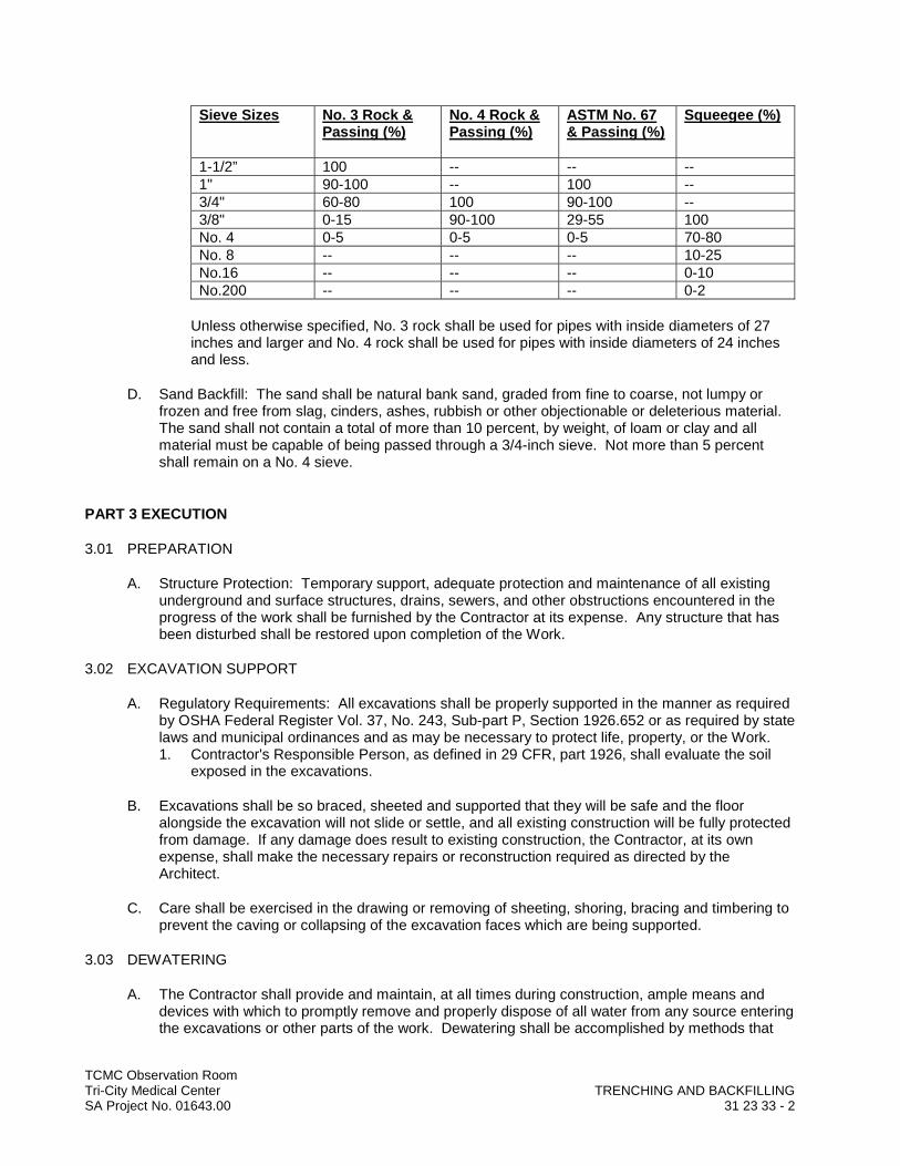
TCMC Observation RoomTri-City Medical Center TRENCHING AND BACKFILLINGSA Project No. 01643.00 31 23 33 - 2
Sieve Sizes No. 3 Rock & Passing (%)
No. 4 Rock & Passing (%)
ASTM No. 67 & Passing (%)
Squeegee (%)
1-1/2” 100 -- -- --1" 90-100 -- 100 --3/4" 60-80 100 90-100 --3/8" 0-15 90-100 29-55 100No. 4 0-5 0-5 0-5 70-80No. 8 -- -- -- 10-25No.16 -- -- -- 0-10No.200 -- -- -- 0-2
Unless otherwise specified, No. 3 rock shall be used for pipes with inside diameters of 27 inches and larger and No. 4 rock shall be used for pipes with inside diameters of 24 inches and less.
D. Sand Backfill: The sand shall be natural bank sand, graded from fine to coarse, not lumpy or frozen and free from slag, cinders, ashes, rubbish or other objectionable or deleterious material.The sand shall not contain a total of more than 10 percent, by weight, of loam or clay and all material must be capable of being passed through a 3/4-inch sieve. Not more than 5 percent shall remain on a No. 4 sieve.
PART 3 EXECUTION
3.01 PREPARATION
A. Structure Protection: Temporary support, adequate protection and maintenance of all existing underground and surface structures, drains, sewers, and other obstructions encountered in the progress of the work shall be furnished by the Contractor at its expense. Any structure that has been disturbed shall be restored upon completion of the Work.
3.02 EXCAVATION SUPPORT
A. Regulatory Requirements: All excavations shall be properly supported in the manner as required by OSHA Federal Register Vol. 37, No. 243, Sub-part P, Section 1926.652 or as required by state laws and municipal ordinances and as may be necessary to protect life, property, or the Work.1. Contractor's Responsible Person, as defined in 29 CFR, part 1926, shall evaluate the soil
exposed in the excavations.
B. Excavations shall be so braced, sheeted and supported that they will be safe and the floor alongside the excavation will not slide or settle, and all existing construction will be fully protected from damage. If any damage does result to existing construction, the Contractor, at its own expense, shall make the necessary repairs or reconstruction required as directed by the Architect.
C. Care shall be exercised in the drawing or removing of sheeting, shoring, bracing and timbering to prevent the caving or collapsing of the excavation faces which are being supported.
3.03 DEWATERING
A. The Contractor shall provide and maintain, at all times during construction, ample means and devices with which to promptly remove and properly dispose of all water from any source entering the excavations or other parts of the work. Dewatering shall be accomplished by methods that
TCMC Observation RoomTri-City Medical Center TRENCHING AND BACKFILLINGSA Project No. 01643.00 31 23 33 - 3
will ensure a dry excavation and preservation of the final lines and grades of the bottoms of excavations.
B. The Contractor shall dispose of the water from the work in a suitable manner without damage to existing construction. No water shall be drained into work built or under construction. Water shall be disposed in such a manner as not to be a menace to the public health.
3.04 TRENCH EXCAVATION
A. General: Excavation for pipelines, fittings and appurtenances shall be open trench to the depth and in the direction necessary for the proper installation of the same as shown on the Contract Drawings or as otherwise approved by the Architect.
B. Trench Width: The overall trench width shall not be more than 16 inches nor less than 12 inches wider than the largest outside diameter of the pipe to be laid therein, measured at a point 12 inches above the top of the pipe, exclusive of branches. Excavating and trenching shall be true to line so that a clear space of not more than 8 inches or less than 6 inches in width is provided on each side of the largest outside diameter of the pipe in place. For the purpose of this section, the largest outside diameter shall be the outside diameter of the bell, on bell and spigot pipe.
C. Excavation to Grade and Ductile Iron Water Pipe:1. The trench shall be excavated to the depth required so as to provide a uniform and
continuous bearing and support for the pipe on solid and undisturbed ground at every point between bell holes. The finished subgrade shall be prepared accurately by means of hand tools.
2. The subgrade beneath the centerline of the pipe shall be finished to within 0.03 feet of a straight line between pipe joints and all tolerances shall be above the specified grade.
D. Trenching by Hand: Hand methods for excavation shall be employed in interior locations.
3.05 PIPE FOUNDATION AND SUBGRADE PREPARATION
A. Trench Bottom for Pipe: The trench bottom shall be graded to provide a smooth, firm and stable foundation at every point throughout the length of the pipe. Should large gravel and cobbles be encountered at the trench bottom or pipe subgrade, they shall be removed from beneath the pipe and replaced with clean imported sand that shall be compacted to provide uniform support and a firm foundation all at the Contractor's expense.
B. Foundation in Poor Soil: If excessively wet, soft, spongy, unstable or similarly unsuitable material is encountered at the surface upon which the bedding material is to be placed, the unsuitable material shall be removed to a depth exposing stable subgrade.
3.06 PIPE BEDDING
A. General:1. The pipe shall be carefully bedded as shown on the Drawings. The Contractor shall be
responsible for accurately shaping the pipe subgrade to fit the bottom of the pipe for the width shown on the bedding details.
2. Each joint shall be recessed in undisturbed soil or bedding material as required by the bedding detail in such a manner as to relieve the bell of the pipe of all load and to ensure continuous bearing along the pipe barrel upon the pipe subgrade.
3. The pipe bedding, using either selected material, clean, imported sand or crushed rock or gravel, shall be compacted by approved methods to Standard Proctor of 95 percent. When the bedding material is selected material or imported sand, the pipe bedding backfill shall be brought to optimum moisture content and shall be placed by hand in layers not exceeding 3
TCMC Observation RoomTri-City Medical Center TRENCHING AND BACKFILLINGSA Project No. 01643.00 31 23 33 - 4
inches in thickness to the centerline (springline) of the pipe and each layer shall be solidly tamped with the proper tools so as not to injure, damage or disturb the pipe. Backfilling shall be carried on simultaneously on each side of the pipe to ensure proper protection of the pipe.
B. Sand for Pipe Bedding: Where the trench excavation and pipe foundation and/or subgrade consist of granular soil, the pipe may be bedded in the material found in the trench as hereinafter provided. Clean imported sand shall be used when the trench excavation material and pipe foundation is not granular soil that is suitable for adequate bedding. In all cases, the material to be used for pipe bedding shall be subject to the approval of the Architect.
3.07 BACKFILLING
A. General:1. All trenches shall be backfilled after pipe, fittings and appurtenances have been installed,
inspected and approved by the Engineer. Whenever a relative compaction requirement value is specified herein, the optimum moisture content and relative density shall bedetermined in accordance with Standard Proctor Density AASHTO T-99 or ASTM D698.
2. All wood and waste material shall be removed from excavation preparatory to backfilling. Backfill material shall be free of trash, wood, large rock or other objectionable debris. Backfilling shall include the refilling and compacting of the fill in trenches of excavations up to the bottom elevation of the floor slab, or, where indicated on the Drawings, to the bottom elevation of the underslab gravel layer with the underslab vapor retarder. Coordinate with Section 07 26 16.
B. Procedure at Pipe Zone: Selected backfill material consisting of loose earth or sand free from stones, clods or other deleterious material shall be placed in the trench simultaneously on each side of the pipe for the full width of the trench in layers of about 6 inches in depth. Each layer shall be thoroughly compacted to a Standard Proctor of 95 percent by tamping. Particular attention is to be given to the underside of the pipe and fittings to provide a firm bedding support along the full length of the pipe. Care shall be exercised in backfilling to avoid damage to the pipe. The pipe zone shall be considered to extend 12 inches above the top of the outside diameter of the pipe bell.
C. Procedure Above Pipe Zone: The remaining portion of the trench shall be backfilled, compacted and/or consolidated by approved methods to obtain a Standard Proctor of 95 percent.
D. Compaction: Compaction shall be done by use of vibratory equipment, tamping rollers, or other mechanical tampers of the type and size approved by the Architect. The backfill shall be placed in horizontal layers of such depths as are considered proper for the type of compacting equipment being used in relation to the backfill material being placed. Each layer shall be evenly spread, properly moistened and compacted to the specified density. Any damage to the pipe as a result of Contractor's operation shall be repaired and/or replaced at the Contractor's expense.
3.08 SITE QUALITY CONTROL
A. General: See Section 01 45 20.1. Field Testing: Soil testing during construction will be conducted by acceptable testing
laboratory.
TCMC Observation RoomTri-City Medical Center TRENCHING AND BACKFILLINGSA Project No. 01643.00 31 23 33 - 5
B. Density and Moisture Content Testing: The density and moisture content of each layer of compacted backfill will be determined by the testing agency in accordance with ASTM D1556 or D6938.
C. Non-Conforming Work: 1. Any material found not to comply with the minimum specified density shall be recompacted
until the required density is obtained. 2. If, because of unsatisfactory test results it is necessary to retest after corrective works, cost
of tests other than initial tests shall be paid by Contractor.
3.09 CLEANING AND WASTE MANAGEMENT
A. Waste Management: The Contractor shall make the necessary arrangements for and shall remove and legally dispose of all excess excavated material off Owner’s property.
B. Cleaning: After backfill has been completed, sweep floor area around the backfilled trench, leaving interior space clean and ready for installation of concrete floor patch.
END OF SECTION