TC 38-3 Guide for Basic Military Preservation and Packing
343
* T C 3 8 - 3 M C O P 4 0 3 0 . 2 3 E N A V S U P P U B 4 4 2 A F P A M ( I ) 2 5 - 2 0 4 D L A I 4 1 4 5 . 1 1 D e c e m b e r 1 9 9 9 D E P A R T M E N T S O F T H E A R M Y , N A V Y , A N D A I R F O R C E , A N D T H E D E F E N S E L O G I S T I C S A G E N C Y T C 3 8 - 3 G U I D E F O R B A S I C M I L I T A R Y P R E S E R V A T I O N A N D P A C K I N G T a b l e o f C o n t e n t s C H A P T E R 1 - I N T R O D U C T I O N G E N E R A L C O N T A C T , F O R M A T , A N D U S E C H A P T E R 2 - M I L I T A R Y P R E S E R V A T I O N I N T R O D U C T I O N T O P R E S E R V A T I O N C O R R O S I O N C O N T R O L C L E A N I N G A N D D R Y I N G E L E C T R O S T A T I C D I S C H A R G E C O N T R O L P R E S E R V A T I V E S P R E S E R V A T I O N M A T E R I A L S A N D H E A T S E A L I N G E Q U I P M E N T C U S H I O N I N G , B L O C K I N G A N D B R A C I N G M E T H O D S O F P R E S E R V A T I O N M I S C E L L A N E O U S P A C K A G I N G R E Q U I R E M E N T S 1
-
Upload
khangminh22 -
Category
Documents
-
view
2 -
download
0
Transcript of TC 38-3 Guide for Basic Military Preservation and Packing

*TC 38-3MCO P4030.23E
NAVSUP PUB 442AFPAM(I) 25-204
DLAI 4145.11 December 1999
DEPARTMENTS OF THE ARMY,NAVY, AND AIR FORCE, AND THE
DEFENSE LOGISTICS AGENCY
TC 38-3
GUIDE FOR BASIC MILITARYPRESERVATION AND
PACKING
Table of Contents
CHAPTER 1 - INTRODUCTION
GENERALCONTACT, FORMAT, AND USE
CHAPTER 2 - MILITARY PRESERVATION
INTRODUCTION TO PRESERVATIONCORROSION CONTROLCLEANING AND DRYINGELECTROSTATIC DISCHARGE CONTROLPRESERVATIVESPRESERVATION MATERIALS AND HEAT SEALING EQUIPMENTCUSHIONING, BLOCKING AND BRACINGMETHODS OF PRESERVATIONMISCELLANEOUS PACKAGING REQUIREMENTS1

CHAPTER 3 - MILITARY PACKING
INTRODUCTION TO MILITARY PACKINGFIBERBOARD SHIPING BOXES (ASTM D 1974/ASTM D 5118)TRIPLE-WALL CORRUGATED FIBERBOARD BOXES (ASTM D 5168)WOODEN BOXESCRATESMISCELLANEOUS CONTAINERS
CHAPTER 4 - PACKING PROCEDURES AND OPERATIONS
WEATHERPROOFING THE PACKCARGO UNITIZATIONMARKING AND LABELINGHAZARDOUS MATERIALSSMALL PARCEL SHIPMENT
AUTHENTICATION
DISTRIBUTION RESTRICTION: Approved for public release, distribution is unlimited.
** This training circular supersedes DA PAM 740-1/NAVSUP PUB 442/AFP 71-14/MCOP4030.23D/DLAH 4145.1, Instructional Guide for Basic Military Preservation and Packing, 29 June 1990.
2
Chapter 1
INTRODUCTION
GENERAL
PURPOSE
This circular provides a series of lessons for use in training personnel in preservation and packingoperations. These lessons are published for use as an official document in the training of military andcivilian personnel from all segments of the Department of Defense (DOD) and supporting agencies.It contains information based on specifications, standards, MIL-STD-2073-1C, Standard Practicefor Military Packaging, and other pertinent documents. In keeping with the established preservationand packing policy, emphasis is placed on efficiency and economy in all preservation and packingoperations. The use of this set of lessons will eliminate the need for the preparation of similar guidesat separate installations
CONTENT, FORMAT, AND USE
GENERAL
These lessons have been prepared for use in training operating personnel working on preservationand packing lines at installations throughout DOD. In the preparation of these lessons, the dominantconsideration has been to make them as flexible as possible so that they may meet the requirementsof a variety of training situations. The technical data and specifications referenced in this pamphletrepresent the current preservation and packing practices. The titles of the documents referenced inthe various lessons herein are listed in appendix A located immediately after chapter 4.
FORMAT AND CONTENT
Lesson Content
This circular consists of lessons on the following:
Introduction to military preservation.Corrosion control.Cleaning and drying.Electrostatic discharge control.Preservatives.Preservation materials and heat sealing equipment.Cushioning, blocking, and bracing.Methods of preservation.Miscellaneous packaging requirements.Introduction to military packing. 3

Fiberboard shipping boxes.Triple-wall corrugated fiberboard boxes.Wooden boxes.Crates.Miscellaneous containers.Weatherproofing the pack.Cargo unitization.Marking and labeling.Hazardous materials.Small parcel shipment.
KEEPING THE TRAINING PRACTICAL
Time Allotments
In accordance with lesson objectives, methods of instruction, and time allotments established foreach lesson, it is suggested that all training be made as practical as possible. This will assure animprovement in the quality of workmanship. The allotment of approximately 25 percent of thetraining time to conference instruction and 65 percent to demonstrations and practical exercisesshould be followed as closely as possible. Actual preservation and packing working areas shouldbe used.
Objective
The what, how, when and why of each major preservation and packaging principle has beenemphasized. These lessons will serve to keep instruction focused on the basic requirements ofmilitary preservation and packing.
Lesson Arrangement and Suggested Time Allotments
The following lesson arrangement may be used as a guide in presenting the information in thispamphlet:
Chapter 1 - IntroductionPurposeContent, Format, and UseChapter 2 - Military PreservationIntroduction to Military Preservation, Conference (1 hour)Corrosion Control, Conference (1 hour)Cleaning and Drying, Conference (1 hour), Practical Exercise (1 hour)Electrostatic Discharge Control, Conference (1 hour)Preservatives, Conference (2 hours), Practical Exercise (1 hour)Preservation Materials and Heat Sealing Equipment, Conference (1 hour), PracticalExercise (1 hour)Cushioning, Blocking, and Bracing, Conference (2 hours), Practical Exercise (1 hour)4
Methods of Preservation, Conference (3 hours), Practical Exercise ( 1 hour)Miscellaneous Packaging Requirements, Conference (2 hours)
Chapter 3 - Military PackingIntroduction to Military Packing, Conference (1 hour)Fiberboard Shipping Boxes, Conference (1.5 hours), Practical Exercise (1.5 hours)Triple-wall Corrugated Fiberboard Boxes, Conference (1 hour), Practical Exercise (1hour)Wooden Boxes, Conference (2 hours), Practical Exercise (2 hours)Crates, Conference (2 hours), Practical Exercise (2 hours)Miscellaneous Containers, Conference (1 hour)
Chapter 4 - Packing Procedures and OperationsWeatherproofing the Pack, Conference (1 hour), Practical Exercise (1 hour)Cargo Unitization, Conference (2 hours), Practical Exercise (1 hour)Marking and Labeling, Conference 2 hours), Practical Exercise (1 hour)Hazardous Materials, Conference (2 hours)Small Parcel Shipment, Conference (1 hour)
Changes and Revisions
Revisions or changes to this publication, due to major changes in preservation packing policy,doctrine, revision of specifications, and other official preservation/packing instructions will be madeon a continuing basis as the need arises.
Users of this training circular are encouraged to submit recommended changes or comments toimprove the publication. Comments should be keyed to the specific page, and line of the text inwhich the change is recommended. Reasons should be provided for each comment to ensureunderstanding and complete evaluation. Comments should be forwarded to Dean, School ofMilitary Packaging Technology, ATTN: ATSL-MPT, 360 Lanyard Road, Aberdeen ProvingGround, MD 21005-5003.
5
CHAPTER 2
Military Preservation
INTRODUCTION TO MILITARY PRESERVATION
NEED FOR TRAINING/PRESERVATION
Need for Preservation Training
An understanding of preservation is needed at all department levels, especially at the operationallevel. Personnel at the operational level have the most physical contact with preservation. They mustknow what they are doing and fully understand the need for doing it.
Deficiencies
Deficiencies in preservation are caused by many different factors. Failure to employ properpreservation instructions results in deficiencies. These packaging deficiencies are reported on SF364, Supply Discrepancy Report (SDR).
Training
To correct deficiencies, personnel must be trained in the proper procedures for preservation ofmilitary supplies.
What is Preservation?
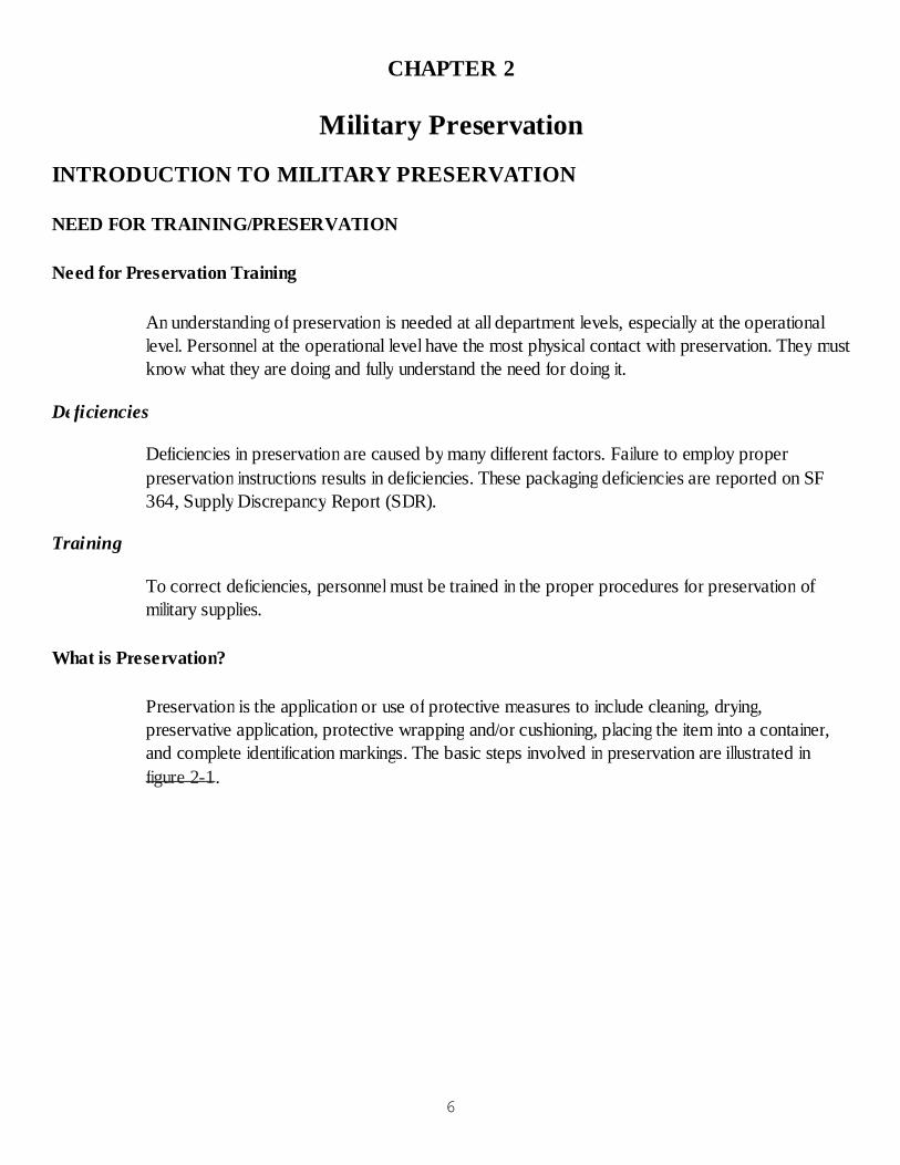
Preservation is the application or use of protective measures to include cleaning, drying,preservative application, protective wrapping and/or cushioning, placing the item into a container,and complete identification markings. The basic steps involved in preservation are illustrated infigure 2-1.
6
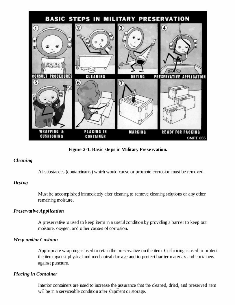
Figure 2-1. Basic steps in Military Preservation.
Cleaning
All substances (contaminants) which would cause or promote corrosion must be removed.
Drying
Must be accomplished immediately after cleaning to remove cleaning solutions or any otherremaining moisture.
Preservative Application
A preservative is used to keep items in a useful condition by providing a barrier to keep outmoisture, oxygen, and other causes of corrosion.
Wrap and/or Cushion
Appropriate wrapping is used to retain the preservative on the item. Cushioning is used to protectthe item against physical and mechanical damage and to protect barrier materials and containersagainst puncture.
Placing in Container
Interior containers are used to increase the assurance that the cleaned, dried, and preserved itemwill be in a serviceable condition after shipment or storage.7
Marking
Markings must be applied to identify the contents.
Hazards to Military Supplies and Equipment
General
We must protect our military supplies and equipment from both climatic and mechanical hazardsfrom procurement to end use.
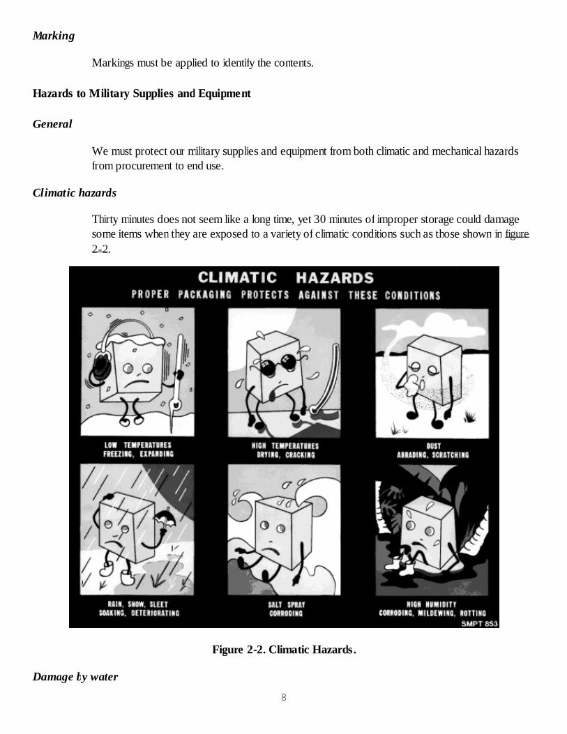
Climatic hazards
Thirty minutes does not seem like a long time, yet 30 minutes of improper storage could damagesome items when they are exposed to a variety of climatic conditions such as those shown in figure2-2.
Figure 2-2. Climatic Hazards.
Damage by water
8

Water damage is the largest source of damage to military items. Water may cause damage in twoways:
Water combined with oxygen will cause rust on iron and steel. It will cause corrosion onother kinds of metals. Corrosion may be caused by water in one of three forms. It may beliquid, such as rain or snow. It may be in the form of mist or spray, such as fog or oceanspray. Ocean spray contains salt and is especially corrosive. It may be in the form of invisiblevapors. This form of water is nearly everywhere and is hard to control since it cannot beseen. Water vapor can penetrate into the smallest crevice and cause damage to even themost intricate item.Water can cause damage by aiding in the growth of mold, mildew, fungi, and rot.
Damage by Dust and Dirt
Dust and dirt can damage small bearings, gears, and small moving parts. A wristwatch, forexample, would be ruined if dust and dirt were allowed inside it. Dust and dirt may contain chemicalingredients which may pit or corrode polished or critical surfaces. Dust from factory wastes may behighly corrosive. Dust and dirt may scratch precision lenses on binoculars, cameras, and fire-controlitems. It may also scratch highly polished metal surfaces. Dust and dirt may also contaminate sterilemedical supplies, such as medicines, bandages, and instruments.
Damage by Direct Sunlight
Direct sunlight will cause some fabrics to fade when exposed and may cause a breakdown andchange in certain chemicals. Films, rubber, and sensitive paper will be ruined by exposure tosunlight or it may cause the rupture of containers if they are filled to capacity with volatile liquids.Direct sunlight or heat may cause expansion of metals, which could result in the decalibration ofhighly precise instruments.
Mechanical hazards
The kind of hazards pictured in figure 2-3 cause severe damage to our supplies and equipment andis the result of improper handling, stacking, or the improper use of equipment, e.g., ships, cranes,slings, nets, etc.
9

Figure 2-3. Mechanical Hazards.
Damage by Insects, Vermin, Rodents, and Birds
Bird droppings and rodent excreta may soil items, particularly fabrics. Moths may eat fabrics,especially wool. Insects and rodents will eat perishables and food stuffs.
Special Consideration Necessary in Storage of Liquids
Liquids may leak or evaporate. This could cause a safety hazard if the liquid is flammable,corrosive, or toxic. Heat can cause the rupture of containers if sufficient room for expansion is notallowed. Many liquids must be protected from freezing or prevented from setting.
Static electricity
Some electronic components are sensitive to electrostatic discharge and must be protected during,handling, storage, and shipment from this hazard.
Policy for the Packaging of Materiel10

Every company or business in operation today operates under some kind of corporate instructions,bylaws, policies, etc. The Department of Defense also has policies which must be followed. Thesepolicies are in the form of instructions and are implemented by the military services and othercomponents of the government. The implementing document is AR 700-15/ NAVSUPINST4030.28D/AFJMAN 24-206/MCO 4030.33D/DLAd 4145.7, Packaging of Materiel.
Policy statement
All defense materiel shall be afforded the degree of protection required to prevent deterioration anddamage during shipment, handling and storage.
Military Packaging Versus Commercial Packaging
There is a clear distinction between the guidelines set forth for the military packaging concept andthose set forth for commercial packaging. The difference between the two is as follows:
Military packaging requires the use of specification materials; interpretation ofpreservation/packing instructions; MIL-STD-129, Military Marking; and the preservationmethods of MIL-STD-2073-1C, Standard Practice for Military Packaging. Militarypackaging should be used for items expected to enter the military distribution system. Themilitary distribution system is the process by which materiel, not intended for immediate use,is stored and/or moved within or between DOD facilities. It may also cover items intendedfor delivery-at-sea, items delivered during wartime, or items requiring reusable containers.Commercial packaging permits use of nonspecification materials, and ASTM D 3951,Standard Practice for Commercial Packaging, provides standard commercial guidelines.Application of preservation/packing techniques is at the discretion of the contractor or theactivity. Items not going into stock, items intended for immediate use (ex. AOG), items fornot mission-capable supply (NMCS), items intended for depot operational consumption,small parcel shipments (CONUS, not-for-stock) and direct vendor deliveries (CONUS)shall be packaged in accordance with standard commercial practice as defined in ASTM D3951.
Levels of Military Protection
A means of specifying the level of packing that a given item requires to assure that it is not degradedduring shipment and storage. Figure 2-4 shows the levels of protection for military packing. Theselevels are identified as level A and level B. Level A provides maximum protection, and level Bprovides moderate protection.
Levels of Packing.Level A. Protection to meet the most severe worldwide shipment, handling, andstorage conditions. A level A pack must, in tandem with the applied preservation, becapable of protecting materiel from the effects of direct exposure to extremes ofclimate, terrain, and operational and transportation environments. Examples ofsituations which indicate a need for use of a level A pack are: mobilization, strategic
11
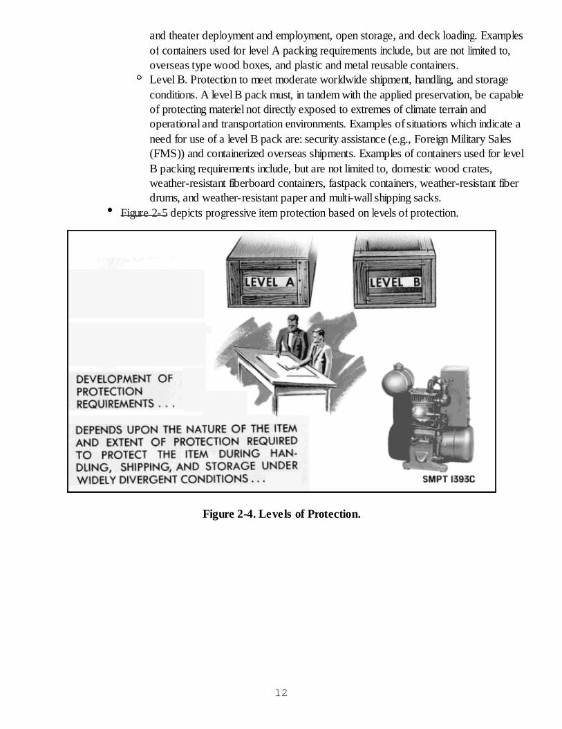
and theater deployment and employment, open storage, and deck loading. Examplesof containers used for level A packing requirements include, but are not limited to,overseas type wood boxes, and plastic and metal reusable containers.Level B. Protection to meet moderate worldwide shipment, handling, and storageconditions. A level B pack must, in tandem with the applied preservation, be capableof protecting materiel not directly exposed to extremes of climate terrain andoperational and transportation environments. Examples of situations which indicate aneed for use of a level B pack are: security assistance (e.g., Foreign Military Sales(FMS)) and containerized overseas shipments. Examples of containers used for levelB packing requirements include, but are not limited to, domestic wood crates,weather-resistant fiberboard containers, fastpack containers, weather-resistant fiberdrums, and weather-resistant paper and multi-wall shipping sacks.
Figure 2-5 depicts progressive item protection based on levels of protection.
Figure 2-4. Levels of Protection.
12
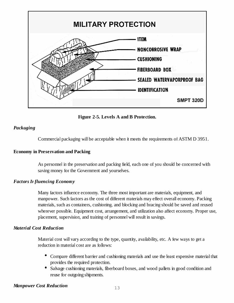
Figure 2-5. Levels A and B Protection.
Packaging
Commercial packaging will be acceptable when it meets the requirements of ASTM D 3951.
Economy in Preservation and Packing
As personnel in the preservation and packing field, each one of you should be concerned withsaving money for the Government and yourselves.
Factors Influencing Economy
Many factors influence economy. The three most important are materials, equipment, andmanpower. Such factors as the cost of different materials may effect overall economy. Packingmaterials, such as containers, cushioning, and blocking and bracing should be saved and reusedwherever possible. Equipment cost, arrangement, and utilization also affect economy. Proper use,placement, supervision, and training of personnel will result in savings.
Material Cost Reduction
Material cost will vary according to the type, quantity, availability, etc. A few ways to get areduction in material cost are as follows:
Compare different barrier and cushioning materials and use the least expensive material thatprovides the required protection.Salvage cushioning materials, fiberboard boxes, and wood pallets in good condition andreuse for outgoing shipments.
Manpower Cost Reduction 13

Reduction of manpower cost may be accomplished in several ways with the most important beingtraining of workers for their jobs.
Management. Every organization must have someone to establish the policies, rules, andregulations for efficient operations.Proper supervision. The quality and quantity of work are directly related to the kind ofsupervision given.Job requirements. It is important to show technical competence on the job and to understandour individual job assignment and its impact on the overall mission.Planning. Each operation in preservation and packing should be well planned in efficient useof personnel and machines.
Checkup
What are the basic steps of military preservation and packing?What are the two levels of military protection?What level of protection is required for the protection of materiel against the most severeconditions known or anticipated to be encountered during shipment, handling, and storage?List some important factors that can influence economy in packing.Why is marking an important step of preservation?Why is it important to dry an item immediately after cleaning?What is the reason for using cushioning inside a package?Why is it important to train personnel at the operational level?
CORROSION CONTROL
CORROSION
Corrosion is the breakdown of metals when they are in contact with water and air. Rust is oftenused to describe any type of corrosion. It is actually a term which describes corrosion on iron orrelated metals. Ferrous metals are any metals which contain or are made from iron.
Corrosion of Ferrous and Nonferrous Metals
Corrosion on iron and steel (ferrous metals) is termed rust. It is usually red in color and forms arusty film which holds moisture and oxygen like a blotter. It speeds up further corrosion by acting asa reservoir which feeds moisture and oxygen to unrusted areas, as shown in figure 2-6.
14

Figure 2-6. Corrosion of Ferrous Metals.
Figure 2-7 illustrates corrosion on nonferrous metals such as zinc and cadmium which is often whiteor gray in color. The terms "white rust and oxidation" are often applied to this type of corrosion.
Figure 2-7. Corrosion of Nonferrous Metals.
WHAT IS KNOWN ABOUT CORROSION--BASIS FOR CONTROL
For the purpose of understanding corrosion control, corrosion will be explained by comparing it tothe operation of a storage battery. In order for corrosion to take place, certain elements have to bepresent. They are a metallic part, water, and oxygen. In order for a battery to produce a charge,certain elements must also be present, as depicted in figure 2-8. They are positive and negativemetallic electrodes, and an electrolyte. The positive electrode is constructed of one kind of metal,and the negative electrode of a different kind of metal. This potential difference (a positive and anegative) must be present for an electric current to be produced. The electrolyte in the storagebattery would be similar to the water and oxygen in the corrosion process, and the battery's metalelectrodes are similar to the metal which corrodes.
15
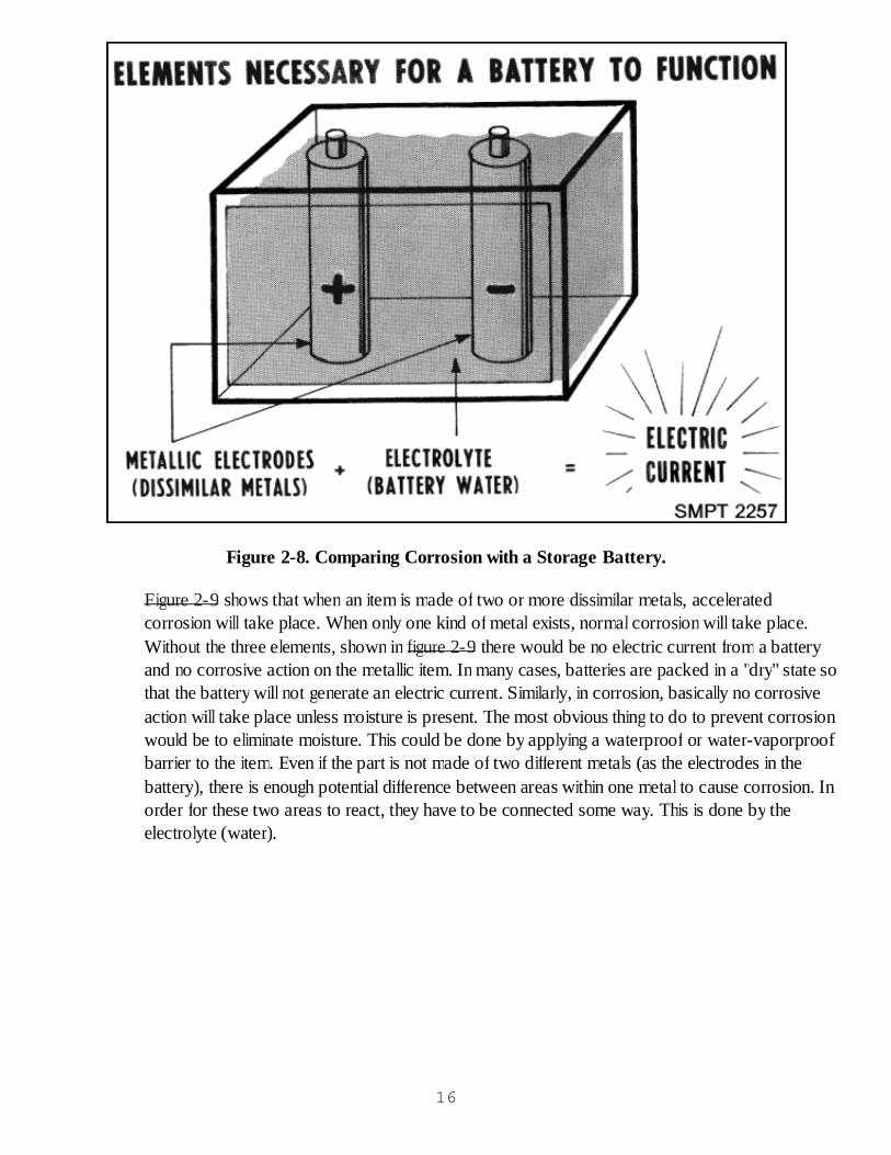
Figure 2-8. Comparing Corrosion with a Storage Battery.
Figure 2-9 shows that when an item is made of two or more dissimilar metals, acceleratedcorrosion will take place. When only one kind of metal exists, normal corrosion will take place.Without the three elements, shown in figure 2-9 there would be no electric current from a batteryand no corrosive action on the metallic item. In many cases, batteries are packed in a "dry" state sothat the battery will not generate an electric current. Similarly, in corrosion, basically no corrosiveaction will take place unless moisture is present. The most obvious thing to do to prevent corrosionwould be to eliminate moisture. This could be done by applying a waterproof or water-vaporproofbarrier to the item. Even if the part is not made of two different metals (as the electrodes in thebattery), there is enough potential difference between areas within one metal to cause corrosion. Inorder for these two areas to react, they have to be connected some way. This is done by theelectrolyte (water).
16
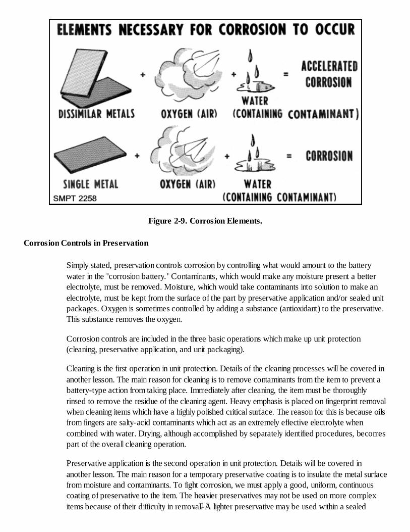
Figure 2-9. Corrosion Elements.
Corrosion Controls in Preservation
Simply stated, preservation controls corrosion by controlling what would amount to the batterywater in the "corrosion battery."Contaminants, which would make any moisture present a betterelectrolyte, must be removed. Moisture, which would take contaminants into solution to make anelectrolyte, must be kept from the surface of the part by preservative application and/or sealed unitpackages. Oxygen is sometimes controlled by adding a substance (antioxidant) to the preservative.This substance removes the oxygen.
Corrosion controls are included in the three basic operations which make up unit protection(cleaning, preservative application, and unit packaging).
Cleaning is the first operation in unit protection. Details of the cleaning processes will be covered inanother lesson. The main reason for cleaning is to remove contaminants from the item to prevent abattery-type action from taking place. Immediately after cleaning, the item must be thoroughlyrinsed to remove the residue of the cleaning agent. Heavy emphasis is placed on fingerprint removalwhen cleaning items which have a highly polished critical surface. The reason for this is because oilsfrom fingers are salty-acid contaminants which act as an extremely effective electrolyte whencombined with water. Drying, although accomplished by separately identified procedures, becomespart of the overall cleaning operation.
Preservative application is the second operation in unit protection. Details will be covered inanother lesson. The main reason for a temporary preservative coating is to insulate the metal surfacefrom moisture and contaminants. To fight corrosion, we must apply a good, uniform, continuouscoating of preservative to the item. The heavier preservatives may not be used on more complexitems because of their difficulty in removal. A lighter preservative may be used within a sealed17
barrier provided in the method of unit protection.
Completing the method of unit protection is the third operation in unit protection. Details will becovered in another lesson. The following general observations relate the preservation methods tocorrosion control.
Cleaning, preservative application, and unit protection make up the techniques required to preventcorrosion. These three operations should be carried out in a continuous cycle without layoverbetween operations. It is especially important that parts not be held over between cleaning andpreservative application.
Checkup
In general, it can be stated that most corrosion takes place in the presence of what threethings?How would a zinc plated steel bolt appear as it becomes progressively corroded?Why can the operation of a storage battery and formation of corrosion be compared?What is the preservation approach to corrosion control?Preservation operations should be performed in one continuous cycle. From a corrosioncontrol standpoint, where is the most damaging place to have a time break in operations?
CLEANING AND DRYING
CLEANING REQUIREMENTS
The cleaning requirements differ for military preservation from those for commercial packaging andare defined below.
Commercial Packaging
The cleaning requirements for commercial packaging are specified in ASTM D 3951. Items will befree from dirt and contaminants which would contribute to deterioration of the item or which wouldrequire special cleaning by the customer prior to use. Coatings and preservatives applied to the itemfor protection are not considered contaminants.
TYPES OF CONTAMINANTS
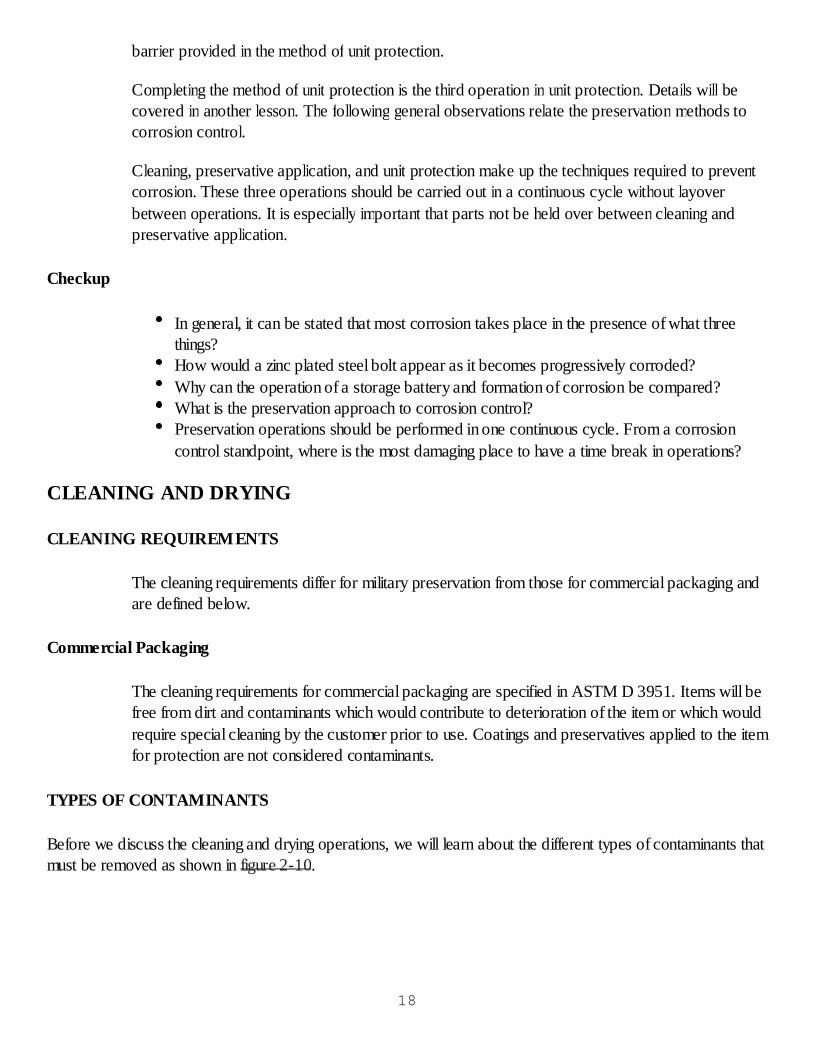
Before we discuss the cleaning and drying operations, we will learn about the different types of contaminants thatmust be removed as shown in figure 2-10.
18
Figure 2-10. Types of Contaminants.
A contaminant is any matter on the item, other than the material it was made from. Dirt is oftencalled a contaminant. In general, we are concerned with four types of contaminants.
Oil Soluble
This group includes all oily or greasy substances. These should be the first contaminants removed inany cleaning operation.
Water Soluble
This group includes fingerprints, perspiration, soldering and welding fluxes, and marking inks. Thesecontaminants are not removed with ordinary solvents or cleaners. They are removed with afingerprint removing compound. 19

Insoluble Loosely Adhering Contaminants
Loosely adhering contaminants may be solid dirt particles, abrasive grains, metal chips and filingswhich can be removed with water or solvents.
Insoluble Tightly Adhering Contaminants
Tightly adhering contaminants may be mill and heat scale, carbon deposits, rust, and othercorrosion products which must be removed by mechanical cleaning processes.
Each of these groups of contaminants must be removed by different means. If contaminants frommore than one group are on the item, the oils and greases must be removed first, then theinsoluble contaminants, followed by the water soluble contaminants.
BASIC CLEANING REQUIREMENT
Good workmanship is necessary to do a good job in cleaning. The following requirementsillustrated in figure 2-11, have been established for cleaning:
Figure 2-11. Basic Requirements for Cleaning.
Cleaning Must be Thorough
20
All contaminants must be removed before the application of a preservative. Any contaminant left onan item will cause corrosion or deterioration.
Process Must Not Injure the Item
Select a process that will not cause damage to an item. You wouldn't select a harsh solvent forleather goods because of its damaging effect.
Disassembly Shall be Limited
Limit the disassembly to a point where reassembly can be easily done without special tools or skills.
Fingerprints Must be Removed From Critical Surfaces
The acid in our fingerprints is corrosive, and, if not removed from critical (precision) surfaces, it willetch these surfaces in a short time.
To assure thorough cleaning of the item, it should pass a cleanliness test. If any contaminant is lefton the item, the item must be recleaned.
CLEANING PROCESSES SELECTION
The selection of a cleaning process depends upon the following factors:
Composition of the Item
The composition of the item limits the choice of the cleaning processes. Items made from aluminumor zinc should not be cleaned in highly alkaline cleaners because of the detrimental effect of thecleaner. Nonmetallic items of rubber, fabric, cork, or other organic composition should not becleaned haphazardly in organic or water-soluble alkaline cleaners. If solvent cleaning is applied tosuch items, the solvent exposure must be brief and scrubbing action limited when dimensions anduse conditions of the item are critical. Solvents are detrimental to most rubber and synthetic rubbermaterials. If metallic and nonmetallic materials are combined in an assembly, the cleaning processmust be carefully considered and the choice of the process governed by the nature of the materialscombined in the assembly.
Surface Finish of the Item
Some cleaning processes are safe to use on highly finished and precision surfaces while otherprocesses are likely to damage the finish. For instance, alkaline cleaning should not be used onpolished aluminum. Acid cleaners are used in iron and steel with extreme care. Solvent cleaningprocesses are usually recommended for most critical surfaces of metal items. Surfaces of roughforgings or castings, rough ground or rough machined items, or surfaces having no finishing afterstamping or drawings are cleaned by alkaline cleaning processes. Items with porous surfaces, smallcrevices, or holes are not cleaned with alkaline cleaning processes because the complete removal of21
all residues is not possible and corrosion will result. Solvent cleaning cannot be appliedindiscriminately to painted surfaces; however, zinc-coated primers, exterior paints, lacquers, andenamels are usually handled safely in solvent cleaners.
Complexity of the Item
Items having irregular surfaces, crevices, undercuts, and pockets that could trap cleaning fluids mayonly be cleaned by brushing or wiping when solvent cleaning is used. Clean complex assembliesbefore they are assembled. Assemblies such as electric generators, motors, starters, gauges,meters, timing devices, and other complex units should be cleaned before assembly and kept cleanthereafter.
Health and Safety Hazards
All cleaning processes have health and safety hazards that must be recognized. These cleaningprocesses must comply with the requirements of the Occupational Safety and Health Act (OSHA)of 1970, or Executive Order 11612, as applicable.
Approved Cleaning Processes
The selection of a cleaning process is very important; if not selected properly, more harm than goodmay result.
Cleaning Process
Items shall be cleaned and dried by any suitable process which is not injurious to the item. Themethods and materials of cleaning may include the following; however, they are not limited to thoselisted below:
Wire brushing may be used to remove loose scales and light rust from items. Oily or greasycontaminants must be removed before wire brushing. Wire brushes should be made of thesame material as the metal being cleaned.Air vacuum cleaning should be used on items which cannot be cleaned by other mechanicalor chemical processes. It can be used on radio and electronic items to remove dust, lintparticles, etc.Barrel tumbling cleans by the use of both chemical and mechanical actions on the corrodedsurface.Chemical cleaners such as pickling baths.
Solvent Cleaning
Solvent cleaning uses several different kinds of solvents. Solvent cleaning is used when the onlycontaminant is a light grease or oil. It will not remove rust or fingerprints and other water-solublecontaminants. Fingerprint removal is used on all items with critical functioning surfaces or items withclose tolerances to remove fingerprints, perspiration, and other water-soluble contaminants. Solvent22
cleaning followed by fingerprint removal is sometimes necessary.
Materials for Solvent Cleaning
The materials used in solvent cleaning are dry cleaning solvent Type III, paint thinner and fingerprintremover corrosion preventive compound.
Dry cleaning solvent (P-D-680), Type III only. This is a water-clear liquid that is neutral tometals and is sometimes known as Stoddard solvent. It is slightly irritating to the skin andmay be mildly nauseating when excessive vapors are breathed. It can be used on metalsurfaces by brushing, wiping, spraying and immersion to remove oils and light greases. Thesolvent must be used only at room temperatures. P-D-680, Types I and II are being phasedout as environmentally hazardous solvents which must be disposed of as a hazardous waste.There are environmentally compliant solvents that clean as well as P-D-680, Types I and II.Approved substitutes that are environmentally compliant solvents at this time includeBreakthrough, Electron 296, Skysol 100, Skysol, and PF. Do not use water-based enzymesas a substitute for P-D-680 as they do not provide corrosion protection. For questionsconcerning the availability of solvent products, contact the Defense Supply CenterRichmond, 8000 Jefferson Davis Highway, Richmond VA 23297-5100, or call 1-800-352-2852 and ask for the Environmental Products catalog.
Note: WARNING: Keep solvent away from any open flame or source of sparks.
Paint Thinner (TT-T-291). This material is supplied in two grades and only grade I is usedfor solvent cleaning. It is similar to dry cleaning solvent (P-D-680) in that it removes oils andlight greases, having a low flashpoint and degree of toxicity. Used paint thinner must bedisposed of as a hazardous waste.Fingerprint Remover Corrosion Preventive Compound (MIL-C-15074). This material is amixture of solvent, soap and water. It is used to remove fingerprints, suppress perspirationcorrosion, and temporarily protect steel surfaces.
Equipment for Solvent Cleaning
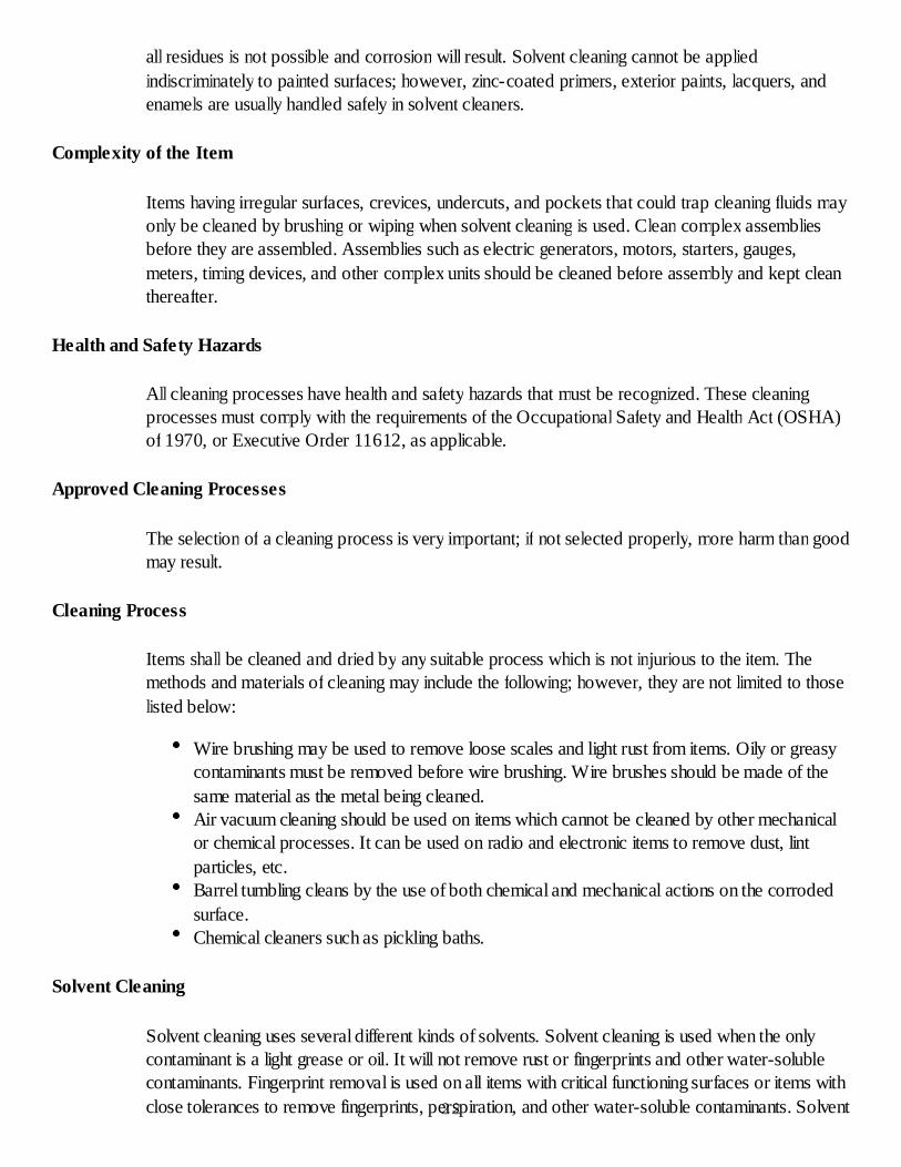
Metal tanks are required for solvent cleaning, and they usually contain provisions for sprayingoperations. The tanks should be equipped with safety features consisting of a tight fitting lid, afusible link, and a ground connection, as shown in figure 2-12. The reasons for the safety featuresare as follows: if the solvent should catch fire, the heat would melt the fusible link and allow the tightfitting lid to close and smother the fire, and the ground connection is used to carry off any staticcharges of electricity. It is important that the fusible link always be in an operable condition and thatthe lid should never be wired or fastened in the open position.
23

Figure 2-12. Solvent tank with safety features.
Safety Precautions for Solvent Cleaning
Observe the following:
When not in use, covers must be kept closed on all solvent tanks.Provide adequate ventilation to prevent vapor fume build up. Inhaling solvent vapors maycause dizziness, fainting and nausea.Fire extinguishers must be located in the area, and personnel must be trained in their use.A fire blanket should be located nearby.Since solvents may cause skin irritations, operators should wear oil resistant rubber or plasticgloves and work aprons during cleaning operations as illustrated in figure 2-13.
24

Figure 2-13. Solvent safety clothing.
Solvent Cleaning
Figure 2-14 depicts two tanks required to clean by immersion. One tank is used for cleaning andthe other for rinsing.
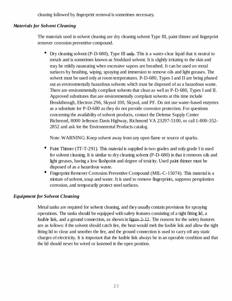
Cleaning by immersion. The solvent cleaning immersion steps are illustrated in figure 2-15.These steps include placing items in the solvent cleaning tank so they receive the mosteffective washing action; agitating the items thoroughly for complete cleaning; using a brushwhere necessary to remove heavy contaminants; removing clean items from the tank andallowing them to drain completely; immersing the items in a second tank (rinse tank) andagitating as necessary; and removing items from the rinse tank and placing them on a tray tothoroughly drain.Cleaning by scrubbing and wiping. When contaminated items are too large for the cleaningtanks, or because it is impractical to clean by immersion or spraying, they should be cleanedby scrubbing and wiping. The solvent cleaning by scrubbing and wiping steps are as shown infigure 2-16. The steps include soaking clean cloth or brush in clean solvent; masking offareas of the item that can be damaged by solvent; applying the soaked cloth and/or brush tothe dirty area and scrubbing and wiping as necessary; rinsing off the area with a clean clothsoaked in clean solvent; and draining and wiping the cleaned area dry.Cleaning by spraying. When items are of a simple construction, free of cavities andindentations where cleaning solvents can be trapped, the cleaning can be done by spraying asdescribed in figure 2-17. The steps involved in solvent cleaning by spraying include loadingitems in a work basket and lowering the basket into a spray tank; turning on the spray pumpand directing the nozzle at items, assuring complete cleaning of the item; and removing thebasket of items from the spray zone and allowing it to drain. A rinse is not required if thespray system is equipped with filters allowing the sprayed solvent to be cleaned.25
Perspiration and fingerprint removal.Solvent cleaning followed by fingerprint removal.
Figure 2-14. Solvent cleaning by immersion.
Figure 2-15. Solvent immersion steps.
26

Figure 2-16. Solvent scrubbing and wiping.
Figure 2-17. Solvent spray cleaning.
Perspiration and Fingerprint Removal
Two tanks are required for cleaning perspiration and fingerprints. One tank should containfingerprint remover compound (MIL-C-15074) and the other a cleaning solvent. This process isused on all items having critical functioning surfaces or close tolerances. Before this process is used,the item must first be cleaned of all other contaminants. Steps involved in the perspiration and27

fingerprint removal process are illustrated in figure 2-18 and include immersing item(s) inperspiration and fingerprint remover compound and agitating while in the compound for 2 to 3minutes; removing item(s) from fingerprint remover compound and allowing them to drain;immersing item(s) in a second tank containing clean dry cleaning solvent and thoroughly rinsing; andafter rinsing, draining and drying the item(s).
28
Figure 2-18. Fingerprint removal operations.
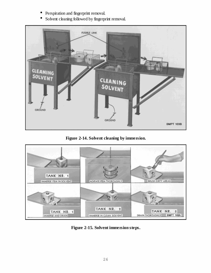
Solvent Cleaning Followed by Fingerprint Removal
This process is accomplished by completing the cleaning steps described for solvent cleaning,followed by perspiration and fingerprint removal. Figure 2-19 details the steps involved.
Figure 2-19. Solvent cleaning followed by fingerprint removal.
Vapor Degreasing
Cleaning by vapor degreasing. This process differs from the previous processes in removingcontaminants from the items. As you recall, cleaning materials were not heated. In this cleaningprocess, we are going to heat nonflammable solvents and use the vapors to throughly remove heavyoils, greases, and wax. This process should not be used on items that can be damaged by heat. Thedegreasing process is quite simple but must be done only in special equipment because of thehazards involved.
Material used in vapor degreasing. The materials used in vapor degreasing are known aschlorinated solvents such as trichloroethane-1,1,1. Trichloroethane-1,1,1 is a clear, non-flammable solvent and can be used either in liquid form or in vapor form after heating. It hasa boiling point of 165oF. These materials will not remove fingerprints, rust, or scale. Itsprimary purpose is to remove heavy oils, greases, and wax. Environmentally friendlydegreasers are also available and are highly recommended for this process.Equipment for vapor degreasing. This cleaning process should only be done in properlydesigned equipment that may vary in size and shape. The manufacturer’s guide must becarefully followed. Figure 2-20 shows the parts of a typical vapor degreaser.Safety precautions for cleaning by vapor degreasing are: (WARNING) VAPORHARMFUL!
1. Use only with adequate ventilation.2. Avoid prolonged or repeated breathing of vapor.29
3. Avoid prolonged or repeated contact with skin.4. Do not take internally.5. Contact with flames or hot glowing surfaces may form corrosive acid fumes.6. The manufacturer’s manual must be used as a guide, with particular attention focused oncleaning the tanks.7. Wear protective clothing, gloves, aprons, and goggles.
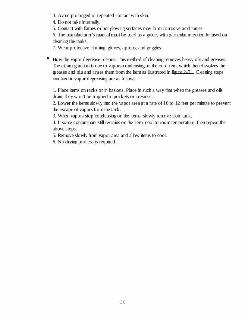
How the vapor degreaser cleans. This method of cleaning removes heavy oils and greases.The cleaning action is due to vapors condensing on the cool item, which then dissolves thegreases and oils and rinses them from the item as illustrated in figure 2-21. Cleaning stepsinvolved in vapor degreasing are as follows:
1. Place items on racks or in baskets. Place in such a way that when the greases and oilsdrain, they won’t be trapped in pockets or crevices.2. Lower the items slowly into the vapor area at a rate of 10 to 12 feet per minute to preventthe escape of vapors from the tank.3. When vapors stop condensing on the items, slowly remove from tank.4. If some contaminant still remains on the item, cool to room temperature, then repeat theabove steps.5. Remove slowly from vapor area and allow items to cool.6. No drying process is required.
30

Figure 2-20. Vapor degreasing.
31
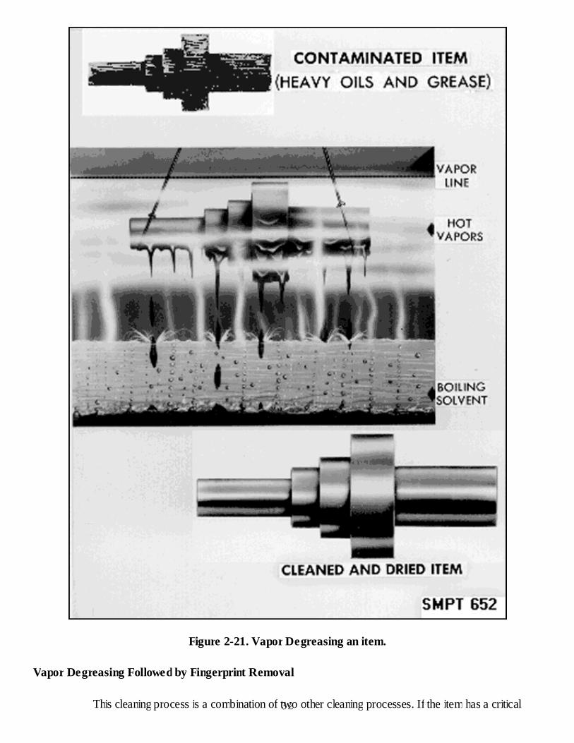
Figure 2-21. Vapor Degreasing an item.
Vapor Degreasing Followed by Fingerprint Removal
This cleaning process is a combination of two other cleaning processes. If the item has a critical32
surface and is coated with heavy oil or grease, the heavy oil or grease must be removed before thefingerprint removal compound is used on the critical surface. Clean the item by vapor degreasingfirst to remove the heavy oil or grease. Allow the item to cool until it reaches room temperature.Then clean the item in the fingerprint removal compound to remove any water soluble contaminantson the critical surfaces of the item.
For environmentally safe substitutes for Trichloroethane 1,1,1, refer to the Environmental ProductsCatalog, Defense Supply Center, Richmond, VA, http://www.dscr.dla.mil. Manufacturer’srecommendations and Material Safety Data Sheets (MSDS) should be consulted.
Jet Spray Washing
Procedures such as solvent cleaning that use solvents, which have chloroflourocarbons in them orare ozone depleting chemicals or water pollutants, are being replaced by environmentally safercleaning processes. Jet spray washing is a cleaning method designed to operate with the lowestbuildup or generation of contaminants which pollute the environment.
Items with heavy or light greases or oils are placed into units which are preheated to temperaturesover 200 oF. A cleaning compound is placed in the units and mixes with the very hot water which is"jet sprayed"with considerable force onto the items until they are clean.
As the items are being jet sprayed, the contaminant is scraped or skimmed from the surface of thesolvent and compressed into a small unit for easy disposal. The liquid portion of the cleaningcompound provides for safer disposal into normal water drainage systems. The items receivethorough cleaning and are very hot at the end of the cleaning cycle. No special drying technique isnecessary.
Regardless of the high temperature, jet spray washing will not remove fingerprints, perspiration, etc.from metal items with critical surfaces. The fingerprint removal compound process will still benecessary. However, this process does not provide the corrosion protection of the chlorinatedsolvents.
Abrasive Blast
The abrasive blast process consists of directing a high velocity stream of an abrasive materialagainst the surface of the item. It should be used on surfaces where the abrasive action will notaffect the function of the item such as rough castings. The choice of abrasive materials is so largethat almost any type of surface finish may be obtained. These materials include hardened cast steelshot, sand, garnet abrasives, and glass beads. The equipment used in this process ranges from smallblast cleaning cabinets to large blasting rooms and open air blasting operations.
In general, the following steps are performed:
Protect yourself with approved protective equipment.Mask off any portions of work that must not be blasted.Adjust pressures of compressed air to the type of surface being cleaned, 60 to 100 psi for33
hard materials or 30 to 50 psi for the softer materials.Direct the stream of abrasive at a 90o angle to the work surface and move nozzle only as fastas the surface is cleaned.If surfaces are dusty and have metal chips clinging to them after blasting, blow off withcompressed air or rinse in an inhibited cleaning solution.If iron dust and metallic particles continue to adhere to metal surfaces after rinsing,demagnetize items prior to further cleaning.
Alkaline Cleaning
The alkaline cleaning process, as pictured in figure 2-22, consists of soaking the items in alkalinecleaner solution and rinsing in clean hot water above 180oF. Items cleaned by this process are of asimple construction having noncritical surfaces. Alkaline cleaning will remove shop dirt, soil, oily andwater-soluble contaminants, and heavy waxes.
Figure 2-22. Alkaline cleaning.
Electrocleaning
This process consists of immersing the item in a solution and making the item an element of anelectrochemical cell. It must be rinsed in clean hot water above 180oF. Figure 2-23 illustrates theremoval of rust by electrocleaning.
34
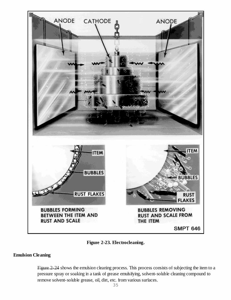
Figure 2-23. Electrocleaning.
Emulsion Cleaning
Figure 2-24 shows the emulsion cleaning process. This process consists of subjecting the item to apressure spray or soaking in a tank of grease emulsifying, solvent-soluble cleaning compound toremove solvent-soluble grease, oil, dirt, etc. from various surfaces.
35
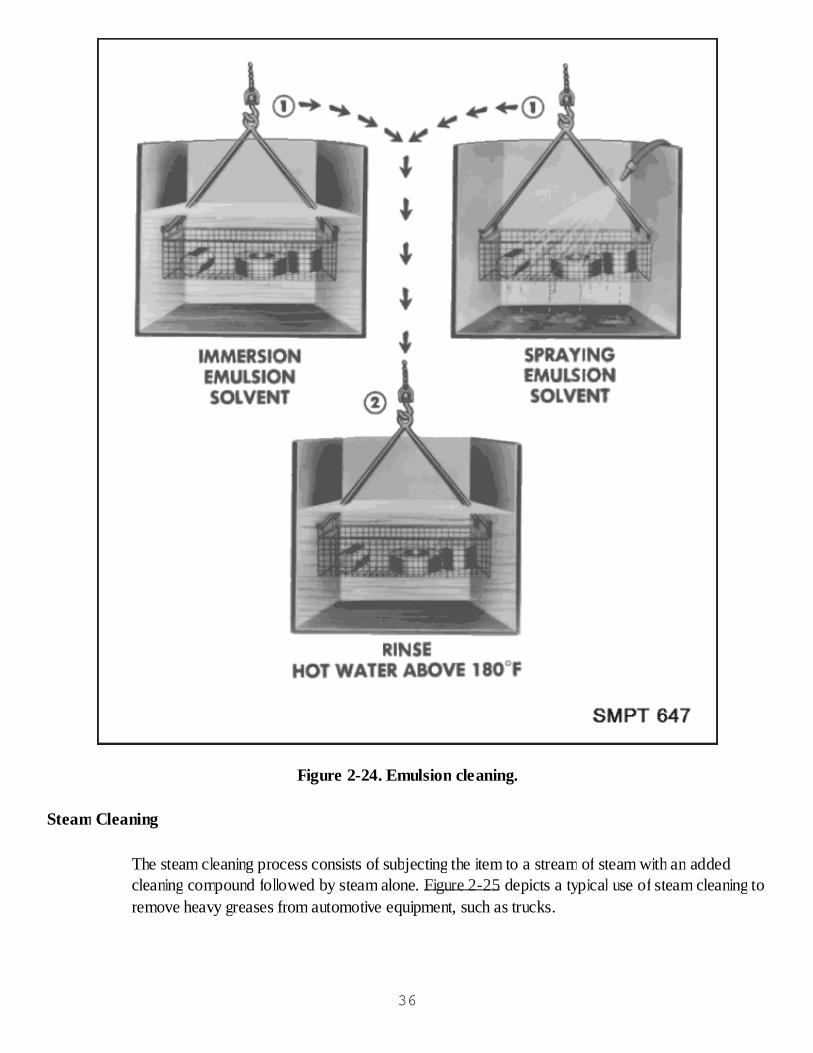
Figure 2-24. Emulsion cleaning.
Steam Cleaning
The steam cleaning process consists of subjecting the item to a stream of steam with an addedcleaning compound followed by steam alone. Figure 2-25 depicts a typical use of steam cleaning toremove heavy greases from automotive equipment, such as trucks.
36
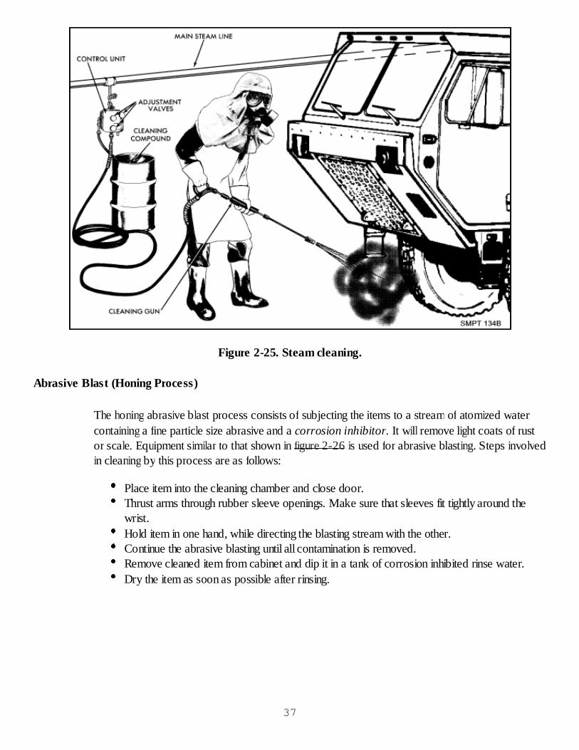
Figure 2-25. Steam cleaning.
Abrasive Blast (Honing Process)
The honing abrasive blast process consists of subjecting the items to a stream of atomized watercontaining a fine particle size abrasive and a corrosion inhibitor. It will remove light coats of rustor scale. Equipment similar to that shown in figure 2-26 is used for abrasive blasting. Steps involvedin cleaning by this process are as follows:
Place item into the cleaning chamber and close door.Thrust arms through rubber sleeve openings. Make sure that sleeves fit tightly around thewrist.Hold item in one hand, while directing the blasting stream with the other.Continue the abrasive blasting until all contamination is removed.Remove cleaned item from cabinet and dip it in a tank of corrosion inhibited rinse water.Dry the item as soon as possible after rinsing.
37
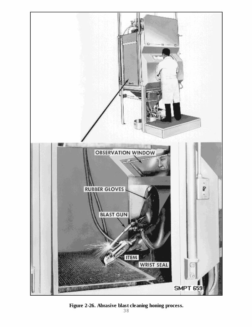
Figure 2-26. Abrasive blast cleaning honing process.38

Soft Grit Blast
The soft grit blast process consists of subjecting the item to a high velocity stream of watercontaining a soft abrasive material.
Ultrasonic Cleaning
Ultrasonic cleaning should be used on nonabsorbent materials such as those found in electronicdevices. This process consists of suspending the item to be cleaned in a cleaning agent, thendirecting the force of high frequency sound waves through the agent against the surfaces to becleaned. The sound waves set up an agitation action along the surface, so in reality the bubblesscrub the contaminant off the surface by means of an implosion as shown in figure 2-27.
Figure 2-27. Ultrasonic cleaning.
Drying Procedures
Immediately after cleaning the item, it must be thoroughly dried to remove any cleaning solutionsor remaining moisture. Figure 2-28 illustrates the approved drying procedures.
39

Figure 2-28. Drying procedures.
Drying With Compressed Air
The air for drying must be free from oil, dirt, and moisture. Dry all surfaces of the item by applyingthe clean air until all solvents disappear. 40
Drying With Ovens
This is done by placing the item into a heated air oven. The oven should be well ventilated andtemperature controlled.
Drying With Infrared Lamps
This is done by placing the item between rows of infrared lamps. This is a commonly usedprocedure for drying.
Drying by Wiping
This is done by wiping the item with clean, lint-free cloths. It is difficult to wipe areas that have blindholes and undercuts.
Drying by Draining
This drying process is used only when the final step in cleaning involves a petroleum solvent, and theitem is to be preserved with a material using a petroleum solvent as a thinning agent.
Checkup
What is the first operation in the preservation of metal items?What type of contaminant is removed by solvent cleaning?Name the three safety feature requirements of a solvent cleaning tank.When can drying by draining be used to dry an item?What are the requirements when drying with compressed air?What cleaning process must be used on items having a critical surface?How long must an item be in a fingerprint removal compound?What must be done to an item after removing it from fingerprint remover compound (MIL-C-15074)?
Cleaning and Drying Practical Exercise
Objective
The student will answer questions on the proper selection and application of the various cleaningprocesses and drying procedures.
General Directions
Objective
The exercise will require approximately one class period, including the critique for41
completion.The instructor will hold the critique when the students have completed the practical exercise.
Conduct of Exercise
Situation
You have received classroom instruction on the selection of cleaning processes and dryingprocedures. Your job is to produce properly cleaned and dried items.
Requirement No. 1. Answer the following questions on cleaning:
1. What cleaning materials may be used for solvent cleaning?
2. Why is it necessary to wear protective clothing during cleaning operations?
3. What contaminants are removed using solvent cleaning?
4. Are fingerprints removed by solvent cleaning?
5. What is the cleaning requirement for an item with a critical surface?
6. What cleaning process uses sound waves to create a cleaning action?
7. After an item is cleaned in the chemical process alkaline cleaning, what must be done before wedry or preserve the item?
8. What processes may be used to remove insoluble tightly adhering contaminants?
9. What process is used to remove heavy greases from automotive equipment such as trucks?
10. If a cleaning compound is used in the steam cleaning process, what must be done immediatelyafter the cleaning compound is turned off?
11. What are the four general types of contaminants?
12. What must be considered in the selection of a cleaning process?
13. What are the basic cleaning requirements?
14. What are the recommended safety features required on a solvent cleaning tank?
Requirement Number 2. Answer the following questions on drying:
1. Why must an item be dried following cleaning?
2. Which process will be used if an item is cleaned by a solvent cleaning process and is to bepreserved with a material using a petroleum solvent as a thinning agent?
42
3. Which drying procedures use heat?
4. What is meant by "Prepared"compressed air?
Critique
Instructor will call on class members to give the answers to the questions.
Care of Area, Training Aids and Equipment
Not applicable.
ELECTROSTATIC DISCHARGE CONTROL
ELECTROSTATIC DISCHARGE
We have been aware for quite some time that static electricity can impose damage on metal oxidesemiconductors (MOS). More recently, we have become aware of the sensitivity of other parts toelectrostatic discharge (ESD) through use, testing, and failure analysis. Sources of ESD policyinclude MIL-W-87893 and MIL-HDBK-773.
Trends in technology are toward greater complexity and construction. Design features of currentmicrotechnology have resulted in parts which can be destroyed or damaged by ESD voltages aslow as 20 volts.
Various electrical and electronic parts which have been determined to be sensitive to electrostaticvoltage levels commonly generated by production, test, operation and maintenance personnelinclude:
Microelectronic and semiconductor devices.Thick and thin film resistors.Chips and hybrid devices.Piezoelectric crystals.All subassemblies, assemblies, and equipment containing these parts not having adequateprotection circuitry are also ESD sensitive (ESDS).
Materials which are prime generators of electrostatic voltage are common plastics such aspolyethylene, vinyls, foam, polyurethane, synthetic textiles, fiberglass, glass, and rubber.
Actions which cause these and other materials to generate electrostatic voltages are the sliding,rubbing, or separation of materials. These movements can frequently result in electrostatic voltagesof 15,000 volts.
Materials can be ranked in accordance with their ability to become positively charged with respectto other materials. This ranking is known as a triboelectric series. Material uppermost in the seriesbecomes positively charged when rubbed with a material lower in the series. The materials lower in
43
the series become negatively charged. Conditions such as cleanliness, variation in chemicalcomposition and processes, humidity, and the mechanics of rubbing or separation affect the seriesto a great extent. Thus the ranking of elements or compounds in the series will not always bereproducible. One of the many versions of the series follows.
Positive (+)
AirHuman hands.AsbestosRabbit furGlassMICAHuman hairNylonWoolFurLeadSilkAluminumPaperCottonSteelWoodAmberSealing waxHard rubberNickel, copperBrass, copperGold, platinumSulfurAcetate rayonPolyesterCelluloidOrlonPolyurethanePolypropylenePVC (vinyl)KEL F
Negative (-)SiliconTeflon
Protection of electrical and electronic ESDS parts assemblies and equipment can be providedthrough the implementation of low cost ESD controls. Lack of control has resulted in high repaircost, excessive equipment downtime, and reduced mission effectiveness because susceptible parts44

are being damaged during processing, assembly, inspection, handling, packaging, shipping, storage,stowage, testing, installation, and maintenance throughout the equipment's life cycle, both at themanufacturer's and the user's facility.
The effects of ESD on electrical and electronic items are not generally recognized because they areoften masked by reasons such as:
Failures due to ESD are often analyzed as being caused by electrical overstress due totransients other than static.Failure caused by ESD is often incorrectly categorized as random, unknown, manufacturingdefect, or other, due to improper depth of failure analysis.Few failure analysis laboratories are equipped with scanning electron microscopes or otherequipment and technology required to trace failures to ESD.Some programs and projects are accepting high operational failure rules as normal andsimply procure more spares instead of recognizing and solving the basic ESD problem.Belief of personnel that static controls are necessary, for only MOS at the partmanufacturer's site and for handling of ordnance, is widespread.Also common is the belief that an ESDS part "protected" by a diode, resistive network orother protective part is non-ESDS.Static discharge failures do not always occur immediately following exposure but may resultin latent defects.
In order to protect ESDS devices while handling and packaging, it is important to provide aconductive path to ground in the environment. Such a path should provide for rapid dissipation ofthe static electrical charge. Figure 2-29 illustrates a typical static protective work station which usesa conductive table and floor mats as well as a wrist strap to ground the operator.
45
Figure 2-29. Protective Work Station.
Because the human body is a conductor, it may be effectively grounded. Clothing, however, willgenerate and retain electrostatic charges, sometimes as high as 30 thousand volts. These staticcharges will not bleed off when grounded.
People handling ESDS items should wear long sleeved ESD protective smocks or close-fitting,short sleeved shirts or blouses.
If long sleeve clothes are worn, the sleeves must be rolled up or else covered with an antistaticsleeve protector, called a gauntlet, from the bare wrist as far up as the elbow. When gauntlets areworn, the clothing does not have to be made of ESD protective material.
Antistatic garments can be made by treating cotton or synthetic clothes with an antistatic chemicalagent in final rinse during laundering. Each time the clothes are washed, the antistatic agent must bereapplied.
The proper control of static electricity is often overlooked in the field. During in-field replacement ofsensitive components or printed circuit boards, the new component or board may be destroyed ordegraded by an ungrounded service technician. An ESD protective field service kit is designed tohelp solve these problems for the field service technician and for field packaging operations as well.
The ESD protective field service kit includes a grounded work surface mat (typically 2' x 2') and aconductive wrist strap.
Some field work surface protective mats contain pockets which are sewn into the mat and can beused to store ESDS components or boards while transporting to and from the field. For largerboards, the mat is folded around the board to provide protection (the ESDS item may requireadditional protection).
The ground lead contains a current limiting series resistor to protect the worker from being shockedin case of accidental contact with line voltage.
For proper operation, the wrist strap cable is connected to the mat at the same terminal where theground lead is also connected. Then the ground lead is connected to a bare metal part of the mainframe of the system containing the part being worked on.
Packaging for protection for ESDS items requires the use of appropriate materials. Protection shallbe provided to prevent physical damage and to maintain leads and terminals in an as-when-manufactured condition during handling and transportation.
An acceptable means of packaging ESDS items would be to first place them in an antistatic orstatic dissipative environment by wrapping and/or cushioning them in one or more of the followingmaterials:
MIL-PRF-81705, type II barrier material, transparent, waterproof, electrostatic protective.PPP-C-795, class 2 antistatic (pink tinted) cushioning material, flexible, cellular, plastic film.PPP-C-1842, type III, type A or B cushioning material, plastic open cell.46

PPP-C-1797, type II cushioning material, resilient, low density, unicellular, polyproplenefoam.After being protected by antistatic or static dissipative materials, they may then be shielded ina bag or pouch conforming to MIL-PRF-81705, type I barrier material watervaporproof,greaseproof electrostatic and electromagnetic protective (opaque).
Marking of ESDS items will be per MIL-STD-129, which requires that unit packs, intermediateand exterior containers be marked with the ESDS device caution label, which is a triangle andreaching hand. All unit packs shall be marked with the ESD label prescribed by ASTM D 5445,Standard Practice for Pictorial Markings for Handling of Goods. The symbol and lettering shall bemarked in black on a yellow background. The label shall include the ESD sensitive device symboland the words "ATTENTION STATIC SENSITIVE DEVICES" and the statement "HANDLEONLY AT STATIC SAFE WORK STATIONS". Unit packs that are not overpacked and areused as exterior containers shall be marked with the unit pack label.
Intermediate and exterior containers shall also be marked with the ESD sensitive devices symboland the words "ATTENTION OBSERVE PRECAUTIONS FOR HANDLINGELECTROSTATIC DISCHARGE SENSITIVE DEVICES." One 2 by 2-inch label shall beplaced on the identification-marked side of the intermediate container. Two 4 by 4-inch labels shallbe placed on each exterior container that exceeds one-half cubic foot. One label shall be placed onthe identification-marked side, and one label shall be placed on the opposite side. Smaller exteriorcontainers shall be marked in the same manner except that the 2 by 2-inch label may be used in lieuof the larger label. The minimum size of the symbol shall be five-eights of an inch measuredvertically at the base of the triangle.
Checkup
What actions cause materials to generate electrostatic voltages?Are certain materials when placed together more apt to generate static electricity than others?How can electronic items be protected from static electricity?What document covers the basic markings required for ESD sensitive items?
PRESERVATIVES
GENERAL
Contact preservatives are materials that are applied to, or come in contact with, items to protectthem from deterioration resulting from exposure to environmental conditions during shipment andstorage.
Some preservatives protect items by providing a physical barrier against moisture, air, and otheragents of corrosion. These are contact preservatives.
Preservatives should be applied whenever items require protection against deterioration. Somemetals such as gold, platinum or beryllium are immune to corrosion under ordinary conditions andseldom require the application of a preservative.47

Many items susceptible to corrosion can be made less subject to deterioration by the application, atthe time of manufacture and subsequent operations, of a protective coating or plating which remainsan integral part of the item during its useful life. Such coatings and platings are called permanentpreservatives.
Many items, however, because of close tolerances, operating characteristics such as rolling, sliding,or bearing surfaces, or other limiting factors cannot be protected with a permanent coating, butmust be protected during shipment and storage by temporary preservatives. These preservativematerials are applied after the item has been manufactured and must be removed before the itemcan be used.
APPLICATION REQUIREMENTS
Most contact preservatives are oily or greasy in nature, and vary greatly in chemical compositionand consistency; therefore, they cannot be used indiscriminately on all kinds of materials. They mayeven destroy the usefulness of an item due to the difficulty of removal.
A preservative may penetrate into unwanted areas and cause swelling or decomposition of thematerial, or reduce its electrical conductivity.
Petroleum preservatives are applied to those metal surfaces on which corrosion in any form wouldimpair the usefulness of the item or assembly.
EXCEPTIONS TO APPLICATION REQUIREMENTS
Petroleum preservatives are not applied to surfaces which are protected by solid film lubricants,plastic or paint coatings. They are not normally used on noncritical metal surfaces that are inherentlyresistant to corrosion such as items made from copper, nickel, chromium, brass, bronze, or othercorrosion resistant metals.
Oily type preservatives are not applied to items that are vulnerable to damage by the petroleumingredients such as textiles, cordage, plastics, mica, rubber, paper, felt, leather or prelubricatedbushings.
Preservatives are not applied to certain types of electrical and electronic components or equipmentsuch as condensers, electrical connectors, distributor rotors, circuit breakers, fuses, switches,resistors and rectifiers.
Preservatives are not applied to any items which would suffer damage to the mechanism orstructure, or where malfunction or unsafe operational conditions would result from the applicationor removal of the preservative.
Need for Temporary Preservatives
A great number of military supplies are made of such materials or are so complex that it is eitherimpossible or impractical to apply a permanent preservative to them. Working parts of machinery,48
for example, are often precision fit and must be free from any type of coating when in use.
Some bare metal items must be given a coating which will protect them from the time they are madeuntil they are used. This coating must be readily applied and easily removed. Petroleum typepreservatives are used for this purpose. Other metal items must be protected by volatile corrosioninhibitors (VCI) or desiccated packs.
Formerly, lubricating oils and greases were used. This was better than no preservative, but theseoils and greases proved inadequate for the full protection desired.
To achieve full protection, there are two kinds of additives used in preservatives to help preventcorrosion. They are known as inhibitors and polar compounds. An inhibitor is a substance thatslows down or prevents rusting by chemical action. A polar compound is a substance that giveswater displacing properties.
Various types of preservative oils and greases containing inhibitors and polar compounds arereferred to in military preservation specifications.
SELECTING THE PRESERVATIVE
It should be realized that there is no one preservative suitable for all purposes. Selecting the rightpreservative must be as carefully considered as selecting a proper cleaning process. In mostinstances, selection of the preservative has been prescribed in procurement documents, processdata sheets, special packaging instructions, or similar forms.
Care must be taken that the preservative selected will not damage the mechanism, structure, orfunction of the item, either when applied, in use, or during removal. In making a selection, thefollowing considerations should be used.
Item Composition
As shown in figure 2-30, the composition of an item determines whether it needs to be preservedand, if so, what kind of preservative will be used. Generally, metal items are preserved with any ofthe petroleum type compounds.
49

Figure 2-30. Composition of the item.
Surface Finish
If the item is forged, stamped, rough cast, rough ground, or rough machined, and has nonprecisionsurface, it may be protected by almost any of the petroleum type preservatives. On the other hand,items with precision surfaces should be protected with an oil or light grease type preservative.Figure 2-31 illustrates various surface finishes.
Figure 2-31. Surface finish of the item.
Complexity of Construction
Items should be cleaned, dried, and preserved in as simple a unit state as possible. Disassembled50
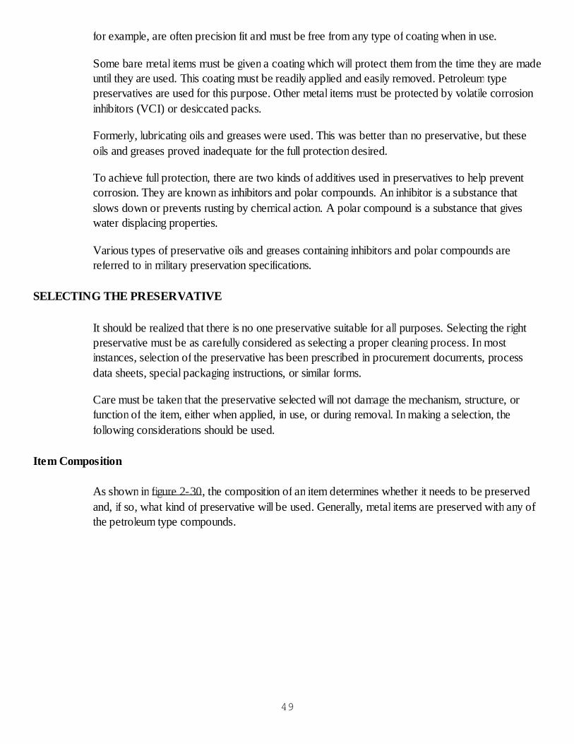
items with close tolerances should not be coated with heavy greases or hard drying types ofpreservatives which may interfere with or prevent reassembly. If disassembly is not practical or theitem is highly irregular with blind holes and crevices, heavy preservatives may be difficult to applyand impossible to remove. Complexity of constructions is depicted in figure 2-32.
Figure 2-32. Complexity of construction.
Extent of Protection Required
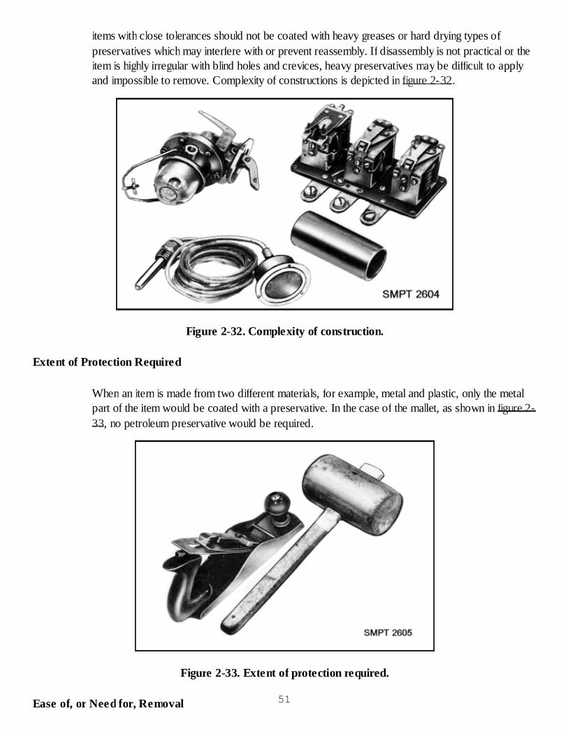
When an item is made from two different materials, for example, metal and plastic, only the metalpart of the item would be coated with a preservative. In the case of the mallet, as shown in figure 2-33, no petroleum preservative would be required.
Figure 2-33. Extent of protection required.
Ease of, or Need for, Removal 51
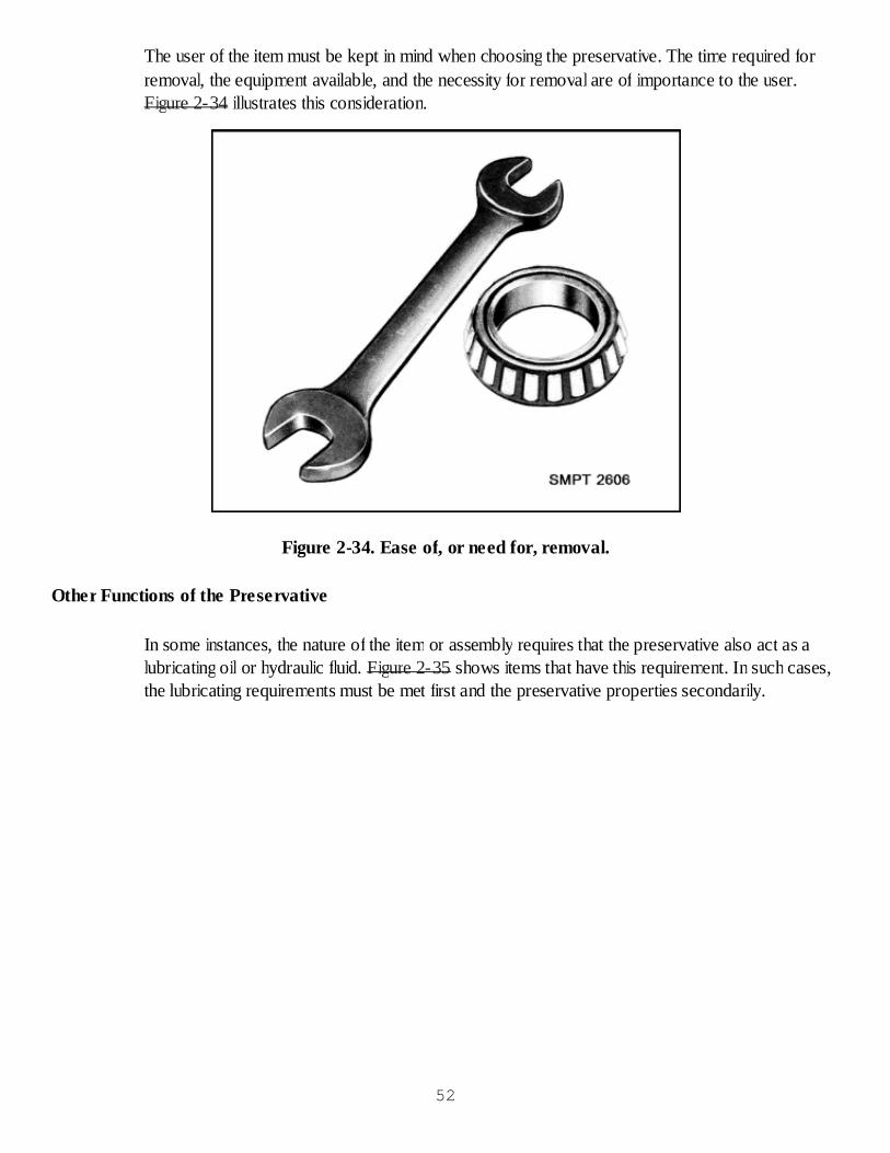
The user of the item must be kept in mind when choosing the preservative. The time required forremoval, the equipment available, and the necessity for removal are of importance to the user.Figure 2-34 illustrates this consideration.
Figure 2-34. Ease of, or need for, removal.
Other Functions of the Preservative
In some instances, the nature of the item or assembly requires that the preservative also act as alubricating oil or hydraulic fluid. Figure 2-35 shows items that have this requirement. In such cases,the lubricating requirements must be met first and the preservative properties secondarily.
52
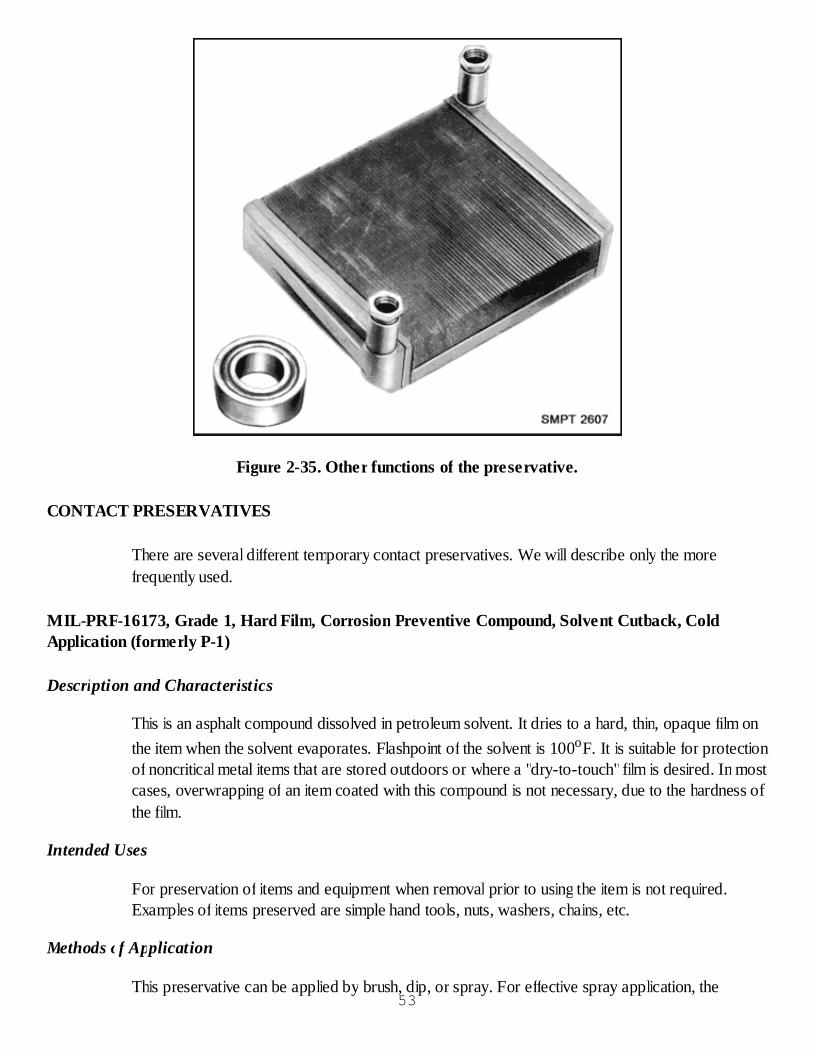
Figure 2-35. Other functions of the preservative.
CONTACT PRESERVATIVES
There are several different temporary contact preservatives. We will describe only the morefrequently used.
MIL-PRF-16173, Grade 1, Hard Film, Corrosion Preventive Compound, Solvent Cutback, ColdApplication (formerly P-1)
Description and Characteristics
This is an asphalt compound dissolved in petroleum solvent. It dries to a hard, thin, opaque film onthe item when the solvent evaporates. Flashpoint of the solvent is 100oF. It is suitable for protectionof noncritical metal items that are stored outdoors or where a "dry-to-touch" film is desired. In mostcases, overwrapping of an item coated with this compound is not necessary, due to the hardness ofthe film.
Intended Uses
For preservation of items and equipment when removal prior to using the item is not required.Examples of items preserved are simple hand tools, nuts, washers, chains, etc.
Methods of Application
This preservative can be applied by brush, dip, or spray. For effective spray application, the53
preservative material requires dilution with dry cleaning solvent to a greater degree than for dippingor brushing.
MIL-PRF-16173, Grade 2, Soft Film, Corrosion Preventive Compound, Solvent Cutback, ColdApplication (formerly P-2)
Description and characteristics
This is a solvent-dispersed, corrosion-preventive compound, which deposits a thin, soft film on theitem. Flashpoint of solvent is 100oF. Items preserved with this require a preliminary greaseproofwrap or are enclosed in a greaseproof bag when a submethod requires a bag as the preliminarycontainer, because it is a soft preservative and will be absorbed by the packing materials.
Intended Uses
It is used to protect interior and exterior metal surfaces destined for extended undercover storage.Examples of items preserved are pipe and tube fittings, pistons, piston rings, bearings andinstruments, and exterior surfaces of machinery. It is used outdoors for limited periods only.
Methods of Application
It is usually applied by brush, dip, or spray.
MIL-PRF-16173, Grade 3, Water Displacing, Corrosion Preventive Compound, Solvent Cutback,Cold Application (formerly P-3)
Description and Characteristics
This is a solvent-dispersed, water-displacing corrosion-preventive compound, which deposits athin, nondrying film on the item upon evaporation of the solvent. Flashpoint 100oF. Due to itschemical composition, this material has a greater attraction to metal surfaces than water and actuallydisplaces water from metal surfaces.
Intended Uses
This water-displacing preservative is intended for use where fresh or salt water must be displacedfrom corrodible surfaces and for the protection of interior surfaces of machinery and equipmentunder cover. Examples of items on which it is used are radiators, boilers, and cooling systems.
Methods of Application
This preservative is generally applied by brushing, dipping, or spraying when used to preserveexterior surfaces. When used on interior or enclosed surfaces, it may be applied by filling orflushing.
MIL-PRF-16173, Grade 4, Transparent Film, Corrosion Preventive Compound, Solvent Cutback,54

Cold Application (formerly P-19)
Description and Characteristics
This is a nontacky, transparent, thin film with a flashpoint of 100oF. This preservative dries to ahard, transparent, nontacky film.
Intended Uses
This preservative is intended for general purpose indoor and limited outdoor preservation ofcorrodible metals with or without an overwrap. This preservative is also used where a transparentcoating is required.
Methods of Application
The preservative may be applied by dipping or brushing at room temperature.
VV-L-800, Lubricating Oil, General Purpose, Preservative (Water Displacing, Low Temperature)(formerly P-9)
Description and characteristics
This is a highly refined, light oil, containing rust-inhibiting additives. It also has water-displacementcharacteristics. Its flashpoint is 275oF.
Intended Uses
VV-L-800 is intended for use in the lubrication and protection against corrosion of small arms andin the lubrication of fuze mechanisms and lubricating and preserving internal surface of machineassemblies (except combustion engines). This oil is used frequently for preserving items submergedin oil in sealed containers. Items, which are to be preserved with another petroleum preservative,will sometimes be dipped in this one first to assure the removal of any traces of water moisture.
Methods of Application
VV-L-800 is applied by brushing, dipping, spraying, flow coating, slushing, filling, and fogging atroom temperature.
MIL-L-21260, Type I, Lubricating Oil, Internal Combustion Engine Preservative and Break-in(grades 10, 30, and 50) (formerly P-10)
Description and Characteristics
The viscosities (weight of oil) of this engine lubricating oil range from very light to very heavyaccording to its grade. There are three grades of engine lubricating oil. The grade of oil you usedepends upon the kind of engine it will be used in-
55
Grade 10 (very thin or light weight oil). Flashpoint 360oF.Grade 30 (medium weight oil). Flashpoint 290oF.Grade 50 (heavy weight oil). Flashpoint 400oF.
Intended Uses
The engine oils being discussed here are intended for use in all types of ground equipment atambient temperatures above -10oF. As preservative media for reciprocating internal combustionengines of both spark-ignition and compression-ignition types, the oils are intended to protectengine parts from deterioration during shipment and storage. The oils should be used as factory-fillfor all new and rebuilt engines intended for shipment and storage.
MIL-H-83282, Hydraulic Preservative Oil
The hydraulic preservative oils are covered by various specifications because of differences insystem requirements. The use of hydraulic preservative oil has two purposes. First, it serves as alubricant and second, it serves as a preservative. The use of hydraulic preservative oil should begoverned by the kind of system to which it will be applied.
MIL-G-10924, Grease, Automobile and Artillery (formerly P-11)
Description and Characteristics
A smooth, homogeneous mixture of mineral or synthetic oil or combination of both with a gellingagent to give low and high temperature performance between -65o and 225oF. Preservative greaseis normally applied to items where removal is not generally required.
Intended Uses
For lubrication of automotive or artillery equipment. For use in the preservation of antifrictionbearings, gear boxes, and plain bearings. For use in ball, roller, and needle bearings.
Methods of Application
Preservative grease is applied by the use of special pressure grease guns, smearing with the hands,or brushing.
MIL-L-22110, MIL-PRF-3420, Volitile Corrosion Inhibitor, Treated Material and MIL-PRF-22019,Transport VCI-Treated Barrier Material (formerly P-18)
Description and Characteristics
Volatile corrosion inhibitors (VCI) are chemical compounds which prevent the corrosion of ferrousmetals by releasing vapors. The vapors surround the item and prevent moisture vapor from comingin contact with the surfaces. The vapor will surround the item as long as the item is in a sealed56
barrier or container. VCI is available in many different forms: powder, bore tubes, impregnated inpapers, in oils, etc.
Intended Uses
For protection of unpreserved ferrous (iron) metal items. For use on nonferrous metals for whichcompatability has been proven. VCI should not be used on optical systems, most nonferrousmetals, or in packs containing desiccants.
MIL-C-10382, Corrosion Preventive (Food Handling Machinery & Equipment, Nontoxic)
Description and Characteristics
A smooth uniform mixture of petrolatum wax, lanolin and additives in petroleum solvent. Flashpoint100oF minimum melt, or flow point minimum 150oF. Preservative is normally applied by sprayingat room temperature to produce a thin easily removable film on drying.
Intended Uses
For use on food handling machinery and equipment.
Method of Application
It is applied by spraying at room temperature.
Methods and Techniques of Applying Preservatives
As soon as practicable after an item has been cleaned and dried, it should be preserved in order toprevent or slow any rusting action. Regardless of the method of application of the preservative, it isimportant to obtain an even continuous coating on the metal item.
Application by Dipping
Figure 2-36 illustrates the dipping process. Due to ease of application, and total coverage affordedby this procedure, it is the preferred method of application. When items are dipped in a tank byhand or by conveyor, care must be taken so that air bubbles are not trapped on the preserved item.Frequent stirring of the preservative will prevent air bubbles from forming. After the preservativehas dried or set, the item should be placed on a precut piece of greaseproof barrier material. This isthe initial wrap for the preservation operation.
57
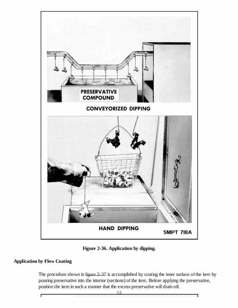
Figure 2-36. Application by dipping.
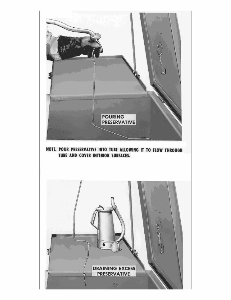
Application by Flow Coating
The procedure shown in figure 2-37 is accomplished by coating the inner surface of the item bypouring preservative into the interior (sections) of the item. Before applying the preservative,position the item in such a manner that the excess preservative will drain off.
58
59

Figure 2-37. Application by flow coating.
Application by Slushing
This procedure is accomplished by pouring the preservative into the part to be preserved androtating, agitating, or slanting it to ensure that all interior surfaces are coated. The excesspreservative is then drained, as depicted in figure 2-38. After slushing, all openings in parts must beclosed to exclude dust, dirt, and other foreign matter. Plastic plugs may be used for this purpose.
60
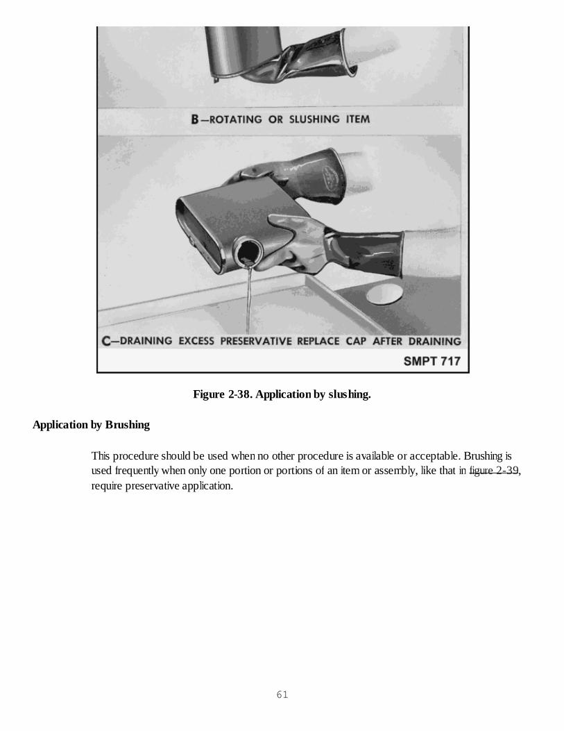
Figure 2-38. Application by slushing.
Application by Brushing
This procedure should be used when no other procedure is available or acceptable. Brushing isused frequently when only one portion or portions of an item or assembly, like that in figure 2-39,require preservative application.
61
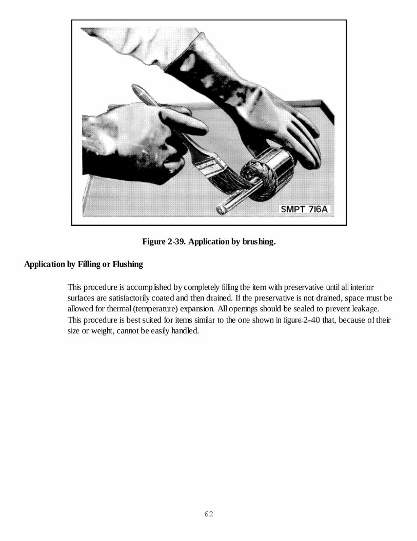
Figure 2-39. Application by brushing.
Application by Filling or Flushing
This procedure is accomplished by completely filling the item with preservative until all interiorsurfaces are satisfactorily coated and then drained. If the preservative is not drained, space must beallowed for thermal (temperature) expansion. All openings should be sealed to prevent leakage.This procedure is best suited for items similar to the one shown in figure 2-40 that, because of theirsize or weight, cannot be easily handled.
62
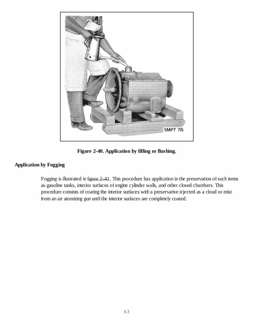
Figure 2-40. Application by filling or flushing.
Application by Fogging
Fogging is illustrated in figure 2-41. This procedure has application in the preservation of such itemsas gasoline tanks, interior surfaces of engine cylinder walls, and other closed chambers. Thisprocedure consists of coating the interior surfaces with a preservative injected as a cloud or mistfrom an air atomizing gun until the interior surfaces are completely coated.
63
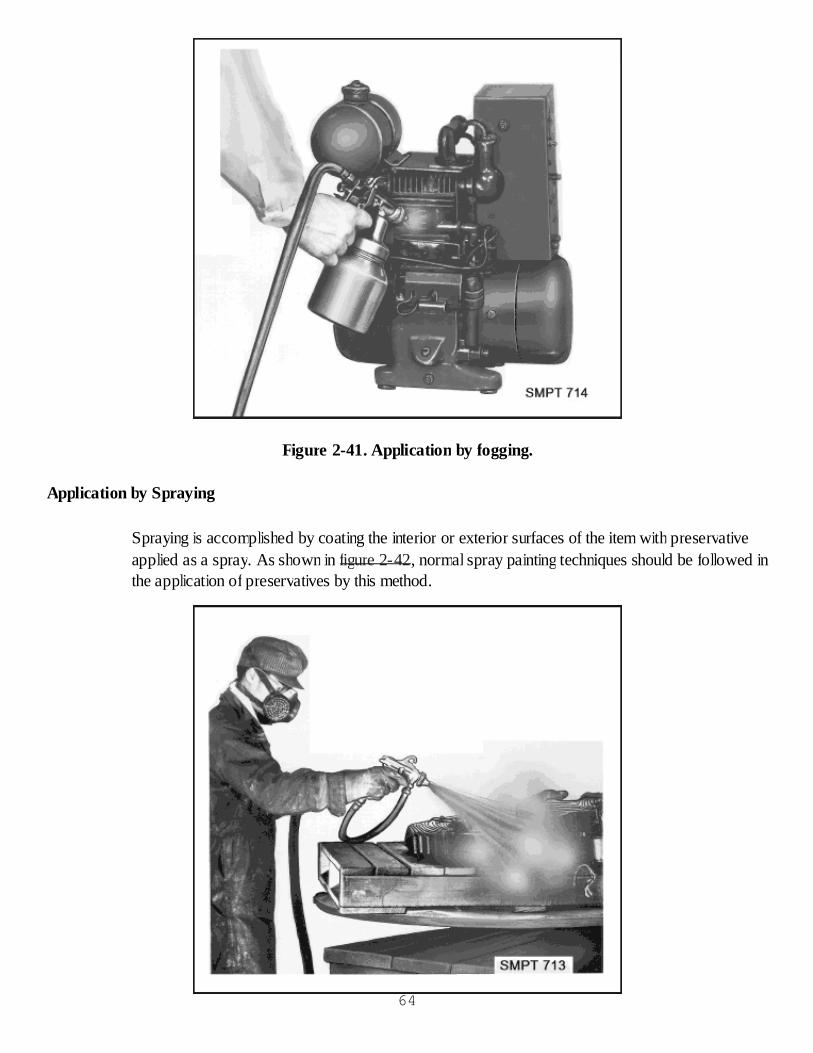
Figure 2-41. Application by fogging.
Application by Spraying
Spraying is accomplished by coating the interior or exterior surfaces of the item with preservativeapplied as a spray. As shown in figure 2-42, normal spray painting techniques should be followed inthe application of preservatives by this method.
64

Figure 2-42. Application by spraying.
Checkup
What is a preservative?What is a distinguishing characteristic of MIL-PRF-16173, Grade 1?Which method of preservative application should we use when no other is available oracceptable?
PRESERVATIVE APPLICATION PRACTICAL EXERCISE
Objective
The student will answer questions on the selection and application of the proper preservative.
General Instructions
This exercise will require approximately 1-1/2 class periods.
The instructor will hold the critique when the students have completed the practical exercise.
Conduct of Exercise
Situation
As a packaging technician, you are to select the correct preservative for metallic items after they arecleaned.
Requirement No. 1. Answer the following questions.
1. What are the two basic types of preservatives?
2. When official information cannot be found, what factors will help to determine the preservative tobe used?
3. Which preservatives are often used for small arms?
4. What are the seven methods of preservative application?
5. What is the preferred method of applying preservatives?
6. What method of applying preservatives should we use only when no other procedure is availableor acceptable?
7. Which preservatives do not usually require overwrapping?
8. Which preservatives can displace water on a metal surface?65
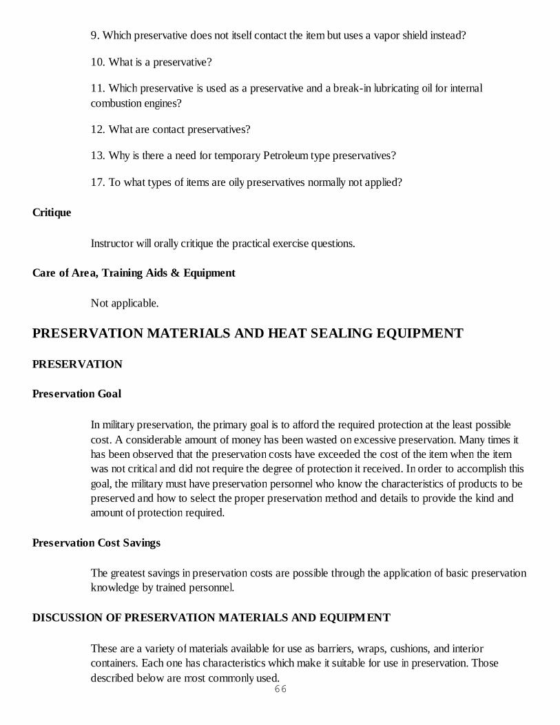
9. Which preservative does not itself contact the item but uses a vapor shield instead?
10. What is a preservative?
11. Which preservative is used as a preservative and a break-in lubricating oil for internalcombustion engines?
12. What are contact preservatives?
13. Why is there a need for temporary Petroleum type preservatives?
17. To what types of items are oily preservatives normally not applied?
Critique
Instructor will orally critique the practical exercise questions.
Care of Area, Training Aids & Equipment
Not applicable.
PRESERVATION MATERIALS AND HEAT SEALING EQUIPMENT
PRESERVATION
Preservation Goal
In military preservation, the primary goal is to afford the required protection at the least possiblecost. A considerable amount of money has been wasted on excessive preservation. Many times ithas been observed that the preservation costs have exceeded the cost of the item when the itemwas not critical and did not require the degree of protection it received. In order to accomplish thisgoal, the military must have preservation personnel who know the characteristics of products to bepreserved and how to select the proper preservation method and details to provide the kind andamount of protection required.
Preservation Cost Savings
The greatest savings in preservation costs are possible through the application of basic preservationknowledge by trained personnel.
DISCUSSION OF PRESERVATION MATERIALS AND EQUIPMENT
These are a variety of materials available for use as barriers, wraps, cushions, and interiorcontainers. Each one has characteristics which make it suitable for use in preservation. Thosedescribed below are most commonly used.
66
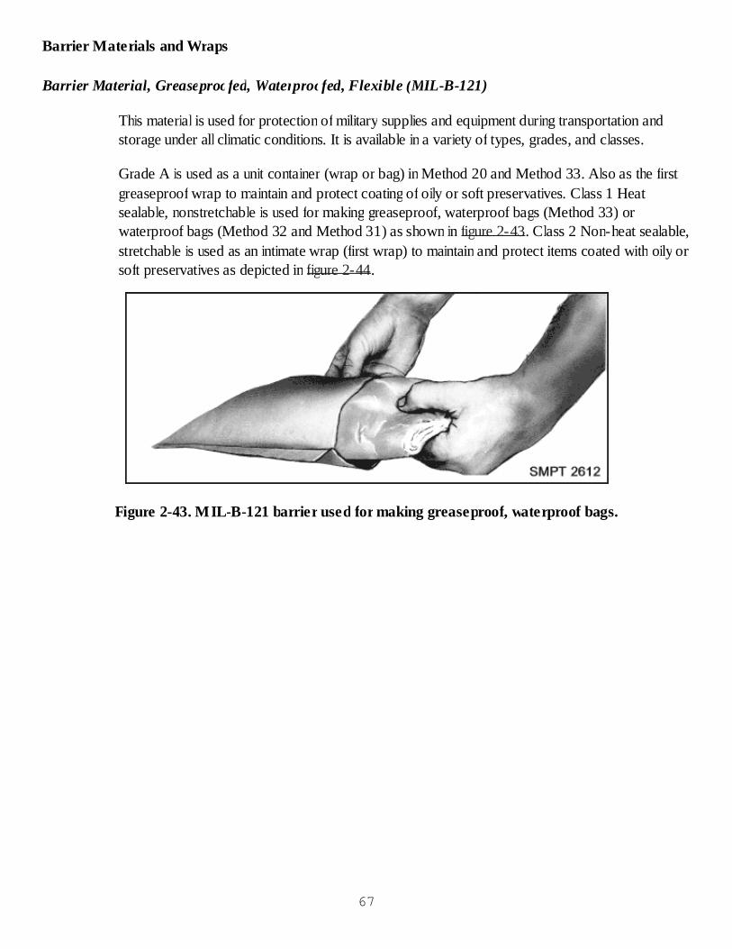
Barrier Materials and Wraps
Barrier Material, Greaseproofed, Waterproofed, Flexible (MIL-B-121)
This material is used for protection of military supplies and equipment during transportation andstorage under all climatic conditions. It is available in a variety of types, grades, and classes.
Grade A is used as a unit container (wrap or bag) in Method 20 and Method 33. Also as the firstgreaseproof wrap to maintain and protect coating of oily or soft preservatives. Class 1 Heatsealable, nonstretchable is used for making greaseproof, waterproof bags (Method 33) orwaterproof bags (Method 32 and Method 31) as shown in figure 2-43. Class 2 Non-heat sealable,stretchable is used as an intimate wrap (first wrap) to maintain and protect items coated with oily orsoft preservatives as depicted in figure 2-44.
Figure 2-43. MIL-B-121 barrier used for making greaseproof, waterproof bags.
67
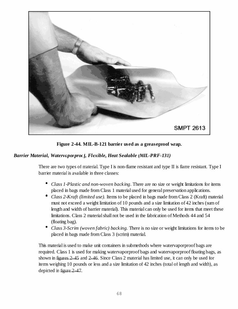
Figure 2-44. MIL-B-121 barrier used as a greaseproof wrap.
Barrier Material, Watervaporproof, Flexible, Heat Sealable (MIL-PRF-131)
There are two types of material. Type I is non-flame resistant and type II is flame resistant. Type Ibarrier material is available in three classes:
Class 1-Plastic and non-woven backing. There are no size or weight limitations for itemsplaced in bags made from Class 1 material used for general preservation applications.Class 2-Kraft (limited use). Items to be placed in bags made from Class 2 (Kraft) materialmust not exceed a weight limitation of 10 pounds and a size limitation of 42 inches (sum oflength and width of barrier material). This material can only be used for items that meet theselimitations. Class 2 material shall not be used in the fabrication of Methods 44 and 54(floating bag).Class 3-Scrim (woven fabric) backing. There is no size or weight limitations for items to beplaced in bags made from Class 3 (scrim) material.
This material is used to make unit containers in submethods where watervaporproof bags arerequired. Class 1 is used for making watervaporproof bags and watervaporproof floating bags, asshown in figures 2-45 and 2-46. Since Class 2 material has limited use, it can only be used foritems weighing 10 pounds or less and a size limitation of 42 inches (total of length and width), asdepicted in figure 2-47.
68
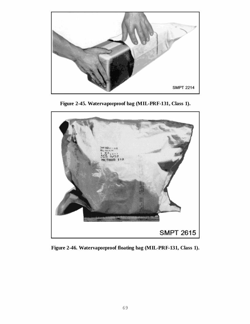
Figure 2-45. Watervaporproof bag (MIL-PRF-131, Class 1).
Figure 2-46. Watervaporproof floating bag (MIL-PRF-131, Class 1).
69
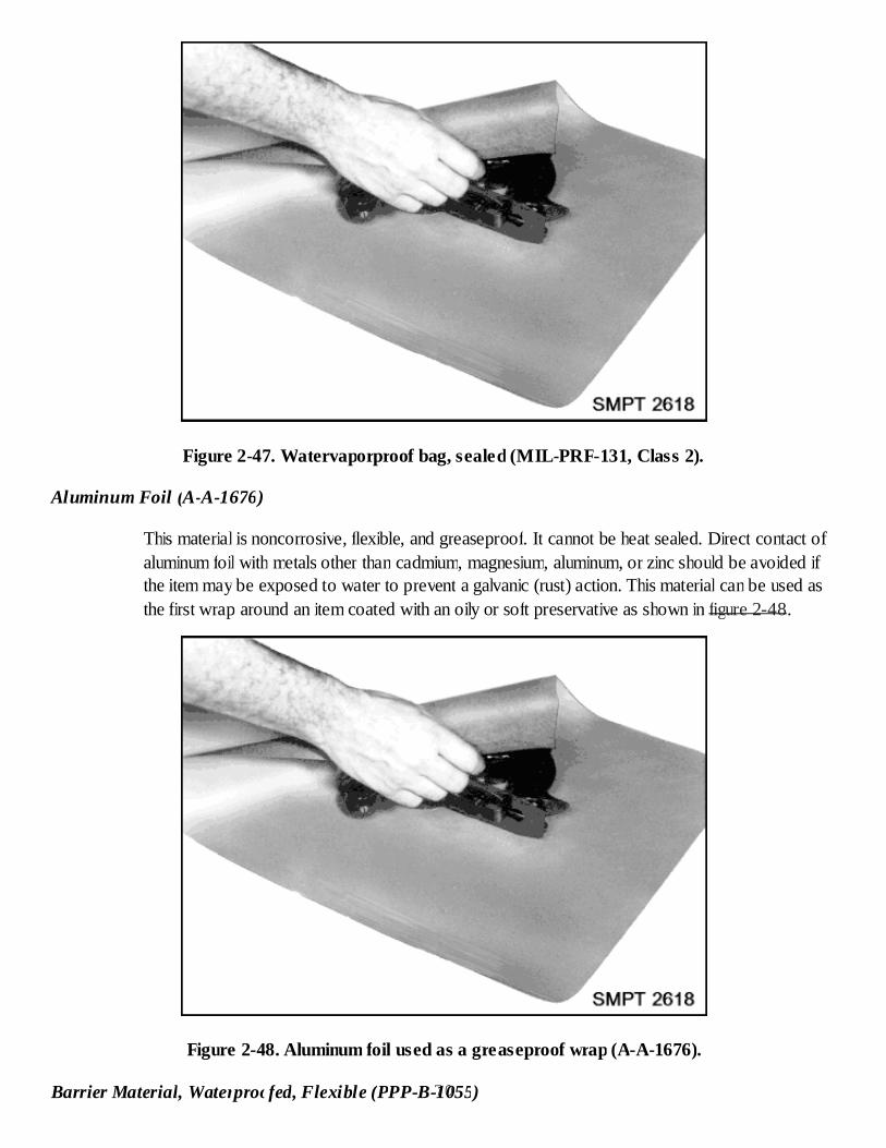
Figure 2-47. Watervaporproof bag, sealed (MIL-PRF-131, Class 2).
Aluminum Foil (A-A-1676)
This material is noncorrosive, flexible, and greaseproof. It cannot be heat sealed. Direct contact ofaluminum foil with metals other than cadmium, magnesium, aluminum, or zinc should be avoided ifthe item may be exposed to water to prevent a galvanic (rust) action. This material can be used asthe first wrap around an item coated with an oily or soft preservative as shown in figure 2-48.
Figure 2-48. Aluminum foil used as a greaseproof wrap (A-A-1676).
Barrier Material, Waterproofed, Flexible (PPP-B-1055)70
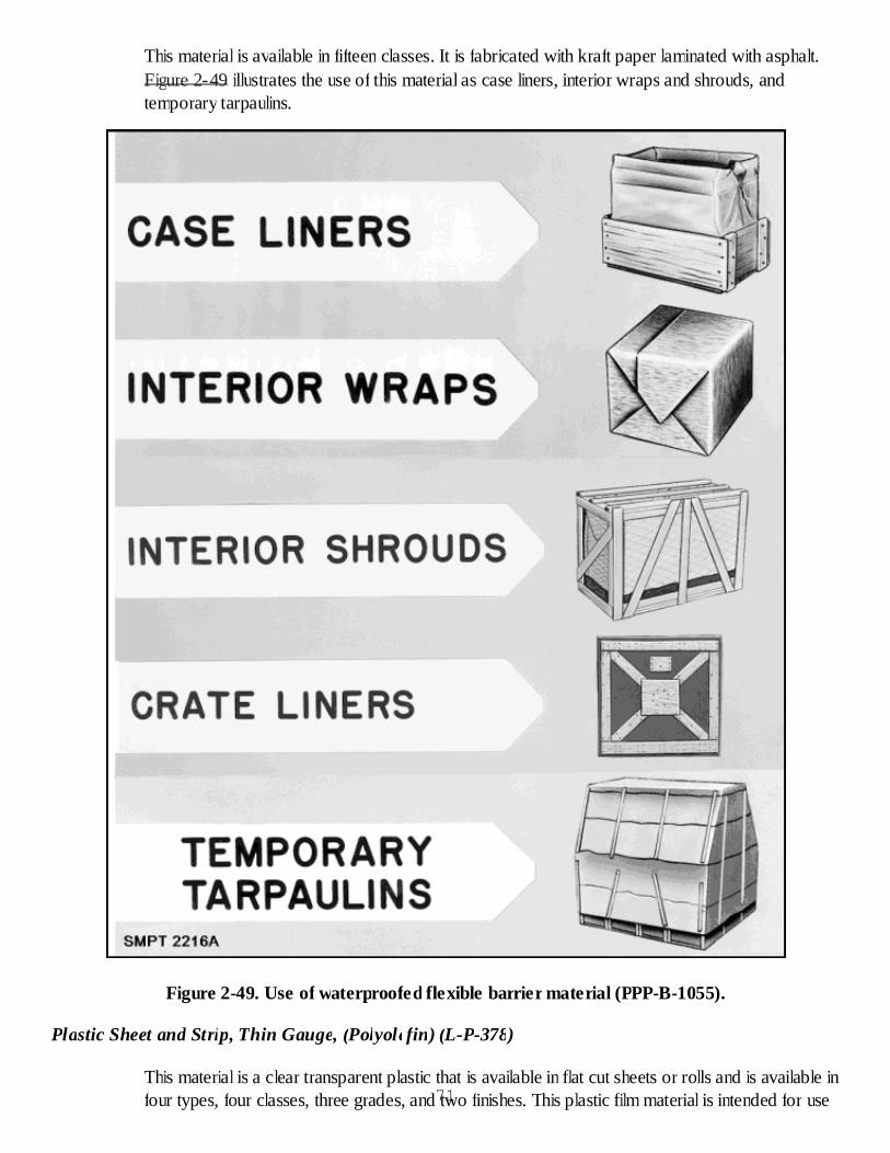
This material is available in fifteen classes. It is fabricated with kraft paper laminated with asphalt.Figure 2-49 illustrates the use of this material as case liners, interior wraps and shrouds, andtemporary tarpaulins.
Figure 2-49. Use of waterproofed flexible barrier material (PPP-B-1055).
Plastic Sheet and Strip, Thin Gauge, (Polyolefin) (L-P-378)
This material is a clear transparent plastic that is available in flat cut sheets or rolls and is available infour types, four classes, three grades, and two finishes. This plastic film material is intended for use71
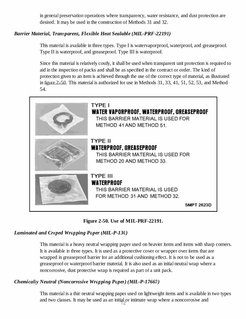
in general preservation operations where transparency, water resistance, and dust protection aredesired. It may be used in the construction of Methods 31 and 32.
Barrier Material, Transparent, Flexible Heat Sealable (MIL-PRF-22191)
This material is available in three types. Type I is watervaporproof, waterproof, and greaseproof.Type II is waterproof, and greaseproof. Type III is waterproof.
Since this material is relatively costly, it shall be used when transparent unit protection is required toaid in the inspection of packs and shall be as specified in the contract or order. The kind ofprotection given to an item is achieved through the use of the correct type of material, as illustratedin figure 2-50. This material is authorized for use in Methods 31, 33, 41, 51, 52, 53, and Method54.
Figure 2-50. Use of MIL-PRF-22191.
Laminated and Creped Wrapping Paper (MIL-P-130)
This material is a heavy neutral wrapping paper used on heavier items and items with sharp corners.It is available in three types. It is used as a protective cover or wrapper over items that arewrapped in greaseproof barrier for an additional cushioning effect. It is not to be used as agreaseproof or waterproof barrier material. It is also used as an initial neutral wrap where anoncorrosive, dust protective wrap is required as part of a unit pack.
Chemically Neutral (Noncorrosive Wrapping Paper) (MIL-P-17667)
This material is a thin neutral wrapping paper used on lightweight items and is available in two typesand two classes. It may be used as an initial or intimate wrap where a noncorrosive and
72
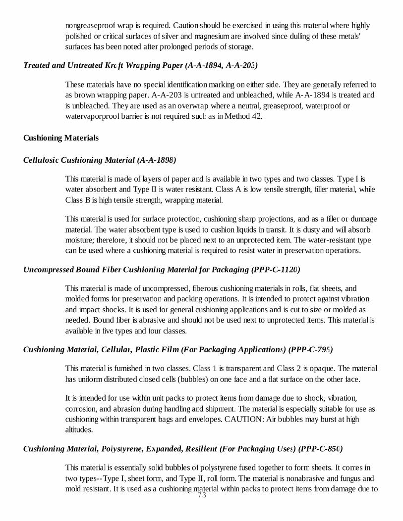
nongreaseproof wrap is required. Caution should be exercised in using this material where highlypolished or critical surfaces of silver and magnesium are involved since dulling of these metals'surfaces has been noted after prolonged periods of storage.
Treated and Untreated Kraft Wrapping Paper (A-A-1894, A-A-203)
These materials have no special identification marking on either side. They are generally referred toas brown wrapping paper. A-A-203 is untreated and unbleached, while A-A-1894 is treated andis unbleached. They are used as an overwrap where a neutral, greaseproof, waterproof orwatervaporproof barrier is not required such as in Method 42.
Cushioning Materials
Cellulosic Cushioning Material (A-A-1898)
This material is made of layers of paper and is available in two types and two classes. Type I iswater absorbent and Type II is water resistant. Class A is low tensile strength, filler material, whileClass B is high tensile strength, wrapping material.
This material is used for surface protection, cushioning sharp projections, and as a filler or dunnagematerial. The water absorbent type is used to cushion liquids in transit. It is dusty and will absorbmoisture; therefore, it should not be placed next to an unprotected item. The water-resistant typecan be used where a cushioning material is required to resist water in preservation operations.
Uncompressed Bound Fiber Cushioning Material for Packaging (PPP-C-1120)
This material is made of uncompressed, fiberous cushioning materials in rolls, flat sheets, andmolded forms for preservation and packing operations. It is intended to protect against vibrationand impact shocks. It is used for general cushioning applications and is cut to size or molded asneeded. Bound fiber is abrasive and should not be used next to unprotected items. This material isavailable in five types and four classes.
Cushioning Material, Cellular, Plastic Film (For Packaging Applications) (PPP-C-795)
This material is furnished in two classes. Class 1 is transparent and Class 2 is opaque. The materialhas uniform distributed closed cells (bubbles) on one face and a flat surface on the other face.
It is intended for use within unit packs to protect items from damage due to shock, vibration,corrosion, and abrasion during handling and shipment. The material is especially suitable for use ascushioning within transparent bags and envelopes. CAUTION: Air bubbles may burst at highaltitudes.
Cushioning Material, Polystyrene, Expanded, Resilient (For Packaging Uses) (PPP-C-850)
This material is essentially solid bubbles of polystyrene fused together to form sheets. It comes intwo types--Type I, sheet form, and Type II, roll form. The material is nonabrasive and fungus andmold resistant. It is used as a cushioning material within packs to protect items from damage due to
73

shock, vibration, and abrasion.
Cushioning Material, Packaging, Closed Cell Foam Plank (A-A-59136) or Packaging Material Sheet(A-A-59135)
This material is preformed polyethylene foam. It comes as planks, sheets, or die cuts in severaldensities. This cushioning is noncorrosive and nonabrasive. One form of the material is designatedas an antistatic sheet and produces no static electricity during use.
Cushioning Material, Resilient, Low-Density, Unicellular, Polypropylene Foam (PPP-C-1797)
This material consists of thin sheets of a low density, closed cell foam in 1/16, 3/32, 1/8, and 1/4-inch thickness. It is noncorrosive, nonabrasive, nondusting and provides good thermal insulation. Itis used to cushion light items and equipment with critical surfaces.
Cushioning Material, Plastic, Open Cell (For Packaging Application) (PPP-C-1842)
This material is formed from plastic sheets laminated together into a network of uniformlydistributed open cells. It is heat-sealable and transparent and comes in three types. Type I ishexagonal; Type II is fluted; and Type III is hexagonal and electrostatic free.
Insulation, Thermal (Vermiculite) (ASTM C 516)
This material is a loose-fill, absorbent cushioning. It is used for cushioning breakable containers ofliquid.
Rigid or Flexible Polyurethane Foam (MIL-PRF-26514)
This material consists of prefoamed rigid and flexible foam. Type I is called standard foam. Type IIis called anti-static foam. Both are available as class 1, rigid, or class 2, flexible. The foam isrelatively non-dusting.
Packaging Tapes
Tape, Gummed, Paper, Reinforced and Plain, for Sealing and Securing (A-A-1492, A-A-1671)
These tapes are gummed paper and require water to activate the adhesive. They are available invarious types, classes, and grades. Types I and II of these tapes are used for closure of fiberboardboxes for domestic shipment and storage; securing wraps on packs; banding of tubes, wire pipe,hose, etc. Type III is used for general sealing of cartons and fiberboard boxes, wrappers of packs,and banding of paper and paper products.
Pressure-Sensative Tape for Packaging, Box Closure, and Sealing (ASTM D 5486)
This tape is water-resistant and pressure-sensitive. It is available in five types and two classes. Thetypes designate the backing material and for which application the tape should be used. Class 1indicates the tape is colored, while class 2 is transparent.
74

Type I is a polyester film-backed pressure-sensitive tape intended for box closure and sealingapplications where strength and resistance to sunlight, rain, and other deteriorating elements arerequired. It is usually used on weather-resistant fiberboard. The tape is intended for H-type closureor sealing of regular slotted boxes and other applications where the tape will be overlapped ontoitself. Type I, class 2 transparent tape can also be used for label attachment and coveringapplications where weather resistance is needed.
Type II is a polyester film-backed pressure-sensitive tape intended for box closure applicationswhere strength and water-resistance are required. It is usually used on domestic grade fiberboard.The tape is most suited for center seam closure of regular or regular slatted boxes and otherapplications where the tape will not be overlapped onto itself. Type II, class 2 tape is also used forlabel attachment and covering applications where water resistance is desired.
Type III is a polypropylene film-backed pressure-sensitive tape intended for box closureapplications where a general purpose water-resistant tape is desired. It is used on domestic gradefiberboard. The tape is suited for center seam closure of regular slotted boxes.
Type IV is a woven cloth-backed pressure-sensitive tape for less critical packaging applicationswhere a cloth-backed tape is desired.
Type V is a paper-backed weather-resistant, water-resistant pressure-sensitive tape for boxclosure and sealing applications where weather resistance and water resistance are required. It maybe used on weather-resistant or domestic fiberboard. The tape is suited for center seam and H-type closures or sealing of regular slotted boxes and other applications where it may be overlappedonto itself.
Pressure-Sensitive Tape for Packaging, Filament Reinforced (ASTM D 5330)
This tape is intended for use in closing and reinforcing fiberboard boxes and for bundling items forshipment. It is available in 4 types as follows:
Type I is an impact and cut-resistant low-tensile strength tape, usually with polyester fiberreinforcement. It is intended for bundling and similar applications and use where a greateramount of stretch before break provides an improvement in impact resistance over glassfilament reinforcement.Type II and III are intended for reinforcement of RSC’s and similar fiberboard boxes andfor bundling, where a snug bundle must be maintained, and other similar applicationsType IV is intended for applications in which weather-resistance high-tensile strength tape isrequired.
Tape, Pressure-Sensitive Adhesive, Plastic Film, Filament (MIL-T-43036)
This tape is available in two types, Type I reinforced polyester film and Type II non-reinforcedpolyester film. It is used primarily for sealing fiber containers and cans.
Interior Containers75
Figure 2-51 illustrates commonly used interior containers.
Figure 2-51. Examples of interior containers.
Fiberboard Shipping Boxes (ASTM D 5118 and ASTM D 1974)
A fiberboard box is a container made of one or more pieces of corrugated or solid fiberboard. Thepieces are creased, slotted, joined, and folded according to standard styles. Fiberboard boxes areavailable in two types: corrugated fiberboard (CF) and solid fiberboard (SF). Type CF is availablein single wall (SW) and double wall (DW). There are four classes of fiberboard boxes: ClassDomestic, Class Weather-Resistant, Class Waterproof and Water Vapor Resistant (WWVR), andClass Domestic/Fire Retardant.
Paperboard Folding Boxes (PPP-B-566)76
These boxes are suitable for use in unit packing of small parts. They are not waterproof and requirea barrier material overwrap for waterproof protection. They are available in 14 styles and manyclasses and subclasses. Weight limitation of contents for this box is 20 pounds.
Setup Boxes (ASTM D 5118)
Setup boxes are used for interior packing of small items and for stackability in storage areas. Theseboxes are available in four types, five classes, and four styles. The weight limitation of contents forthis box is 10 pounds.
Metal Stayed Paperboard Boxes (A-A-866, A-A-1623)
Metal stayed paperboard boxes are used for interior packing of small items and for stackability ofsupplies in storage areas. These boxes are available in nine styles and two classes. The weightlimitation of contents for the class 1 metal stayed box is forty pounds. The class 2 metal stayed boxis for items which weigh 10 pounds or less.
Metal Reusable Shipping and Storage Drums (MIL-D-6055)
The metal reusable drums are made of aluminum or steel and furnished in various sizes. The drumsare made with a fully removable cover secured by an exterior locking ring. This locking ring is heldin place by a removable nut and bolt. The container is supplied with a rubber gasket to provide abarrier against watervapor. The reusable container is mainly used for the packing of delicateinstruments, electrical/electronic components, relays, and small electric motors.
Preservation Equipment
Heat Sealing
The reason for heat sealing is to accomplish closure of certain bags and provide a seal having thesame waterproof or watervaporproof properties as the barrier material itself. Heat sealable barriermaterials are generally constructed of layers of different materials, laminated together, to form asheet, as shown in figure 2-52.
Heat sealable face. The heat sealable face (thermoplastic ply) has the characteristic ofbecoming semifluid when exposed to heat. When two faces are placed together in thepresence of heat, the faces combine with each other. After cooling the two faces are fusedtogether into a leakproof seal.The impervious ply. The impervious ply is made of metal foil (aluminum) or a plastic film.This ply provides the greaseproof, waterproof, or watervaporproof characteristics to thebarrier material.The backing ply. This ply is laminated to the heat sealable face and the impervious ply toprovide the strength and abrasion resistance to the material. It also allows for printing ofrequired information for identification.Temperature. Temperature is an important and critical factor affecting the heat-sealingprocess. Enough heat must be applied to the thermoplastic material on the sheets to be77
bonded to allow it to soften and reach its flow temperature. The thermoplastic plies will flowinto each other and form one continuous mass. When the source of heat is withdrawn, themolten thermoplastic will cool and become a single, solid film producing a seal. Too low atemperature may result in either no seal being made or a weak seal because thethermoplastic has not reached its flow temperature. Too high a temperature may causedelamination or separation of the backing ply from the other plies. Manufacturers of heatsealable barrier materials are required to supply recommended temperatures for effectivesealing of their materials on different types of equipment.Dwell time. Dwell time is the length of time the material remains in the heating zone. Enoughtime must be permitted to raise the temperature of the heat-sealable face to reach its flowtemperature and allow the molten thermoplastic surfaces to form one continuous mass. Dwelltime and temperature are interdependent. The lower the temperature, the greater must be thedwell time, and vice-versa, provided that the limits for each factor are not exceeded.Pressure. The purpose of using pressure is to bring the surfaces to be sealed into intimateand continuous contact. Excessive pressure will force out the molten thermoplastic materialwhich will result in defective seals.
78

Figure 2-52. Construction of heat sealable barrier material.
Heat Sealing Equipment
Heat sealing equipment can be divided into two general classifications - unit type and continuoustype. Each type may have many variations or attachments, depending upon the manufacturer;however, the basic operation is essentially the same within each classification since the machinesmust be equipped with adjustable, directly calibrated controls for pressure, temperature, and dwelltime, as shown in figure 2-53.
79
Unit or jaw-type heat sealer. This type of heat sealer has two opposed, parallel jaws whichcan be brought together either manually or mechanically. One or both of the jaws areprovided with heating elements. The jaws of a unit-type sealer are sometimes covered orcoated with an antistick facing material to prevent adhesion of plastic films to the hotsurfaces. Examples of antistick materials are silicone or teflon. Some sealers are made withone or more resilient jaws which help to smooth out irregular thicknesses of material, such aswrinkles, splices, gussets, etc. The resilient material used on the jaws is silicone rubber.Continuous-type heat sealers. There are two basic variations of the continuous-type sealerknown as rotary and band-type sealers, which are used for high volume heat-sealingoperations. Rotary sealers in their simplest form consist of a pair of driven and heated rollersbetween which the material to be sealed is passed. The rotating wheels are used to applyheat and pressure to the barrier material to effect a seal. Dwell time is controlled by varyingthe rate of speed at which the material passes through the rollers. Rotary sealers are usuallyequipped with a chain or belt-type intake and/or discharge unit to feed the material into thesealer and guide it out after it has been sealed. Some sealers employ "preheaters" to raise thetemperature of the thermoplastic prior to sealing. Band-type continuous sealers make use oftwo thin endless metal belts to carry the material through the heating zone (and sometimes acooling zone) while applying pressure and heat continuously to the barrier material. Theaddition of water blocks for cooling enable this type of sealer to be used for sealingunsupported (plastic) films. Water cooling is used to set the seal before ejecting materialfrom the sealer and to offset sticking of polyethylene and polyolefin. Hose or tubing is runfrom the source to the sealer and out to the sump. A fairly good flow of water isrecommended for sealing polyolefin, polyethylene, and similar films. The band-type sealermay look like a rotary sealer but operates on a different principle. Heat is transferred fromthe heating jaws through the metal bands to the barrier material. Temperature isthermostatically controlled. Dwell time is controlled by varying the speed of the bandsthrough the heating zone. Pressure is usually applied by pressure rollers although a smallamount of pressure is applied to the bands by the heating jaws. The roller pressure iscontrolled by mechanical and/or hydraulic power. Continuous type sealers for unsupportedplastic films are also available. They employ a water cooled belt in addition to the heated beltto eliminate the possibility of the unsupported film melting and fusing onto the steel belt.Other types of heat sealers. There are two other types of heat-sealing machines which areused primarily for the sealing of unsupported (plastic) films. The electronic type uses a highfrequency current to generate heat in the surface to be sealed as the material passes betweentwo electrodes. The electrodes remain at room temperature. The thermo-impulse type sealerlooks like a conventional jaw-type sealer and operates mechanically the same way exceptthat an electrical-resistance wire is mounted on one sealing jaw. The electrical-resistancewire placed in contact with the material is heated in a fraction of a second by a heavy currentflow to melt and fuse the thermoplastic. The jaws remain closed after the flow of current,thus cooling the seal under pressure. Polyethylene, vinyl, polystyrene, and polyester arecommonly sealed using this type of sealer. The thermal-impulse principle allows effectivesealing through liquids, powder, wrinkles, and gussets and makes them adaptable to anyprocess which requires two or more thermo-plastic films to be joined together.
80
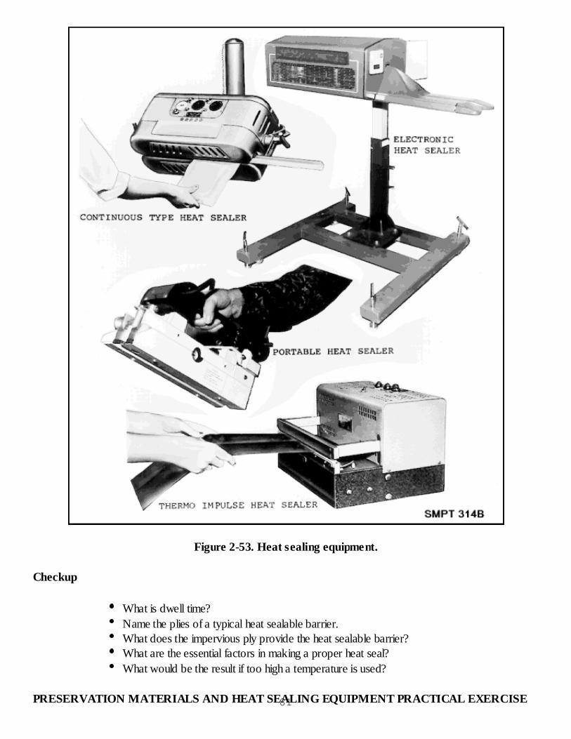
Figure 2-53. Heat sealing equipment.
Checkup
What is dwell time?Name the plies of a typical heat sealable barrier.What does the impervious ply provide the heat sealable barrier?What are the essential factors in making a proper heat seal?What would be the result if too high a temperature is used?
PRESERVATION MATERIALS AND HEAT SEALING EQUIPMENT PRACTICAL EXERCISE81
Objective
As a result of this practice, the student will be able to identify materials used in military preservation.
General Instructions
Each student will identify barrier materials and tapes used in preservation and fabricate a samplebooklet.
The time to accomplish this practical exercise is one hour.
The practical exercise will be conducted in the classroom.
Conduct of Exercise
Situation
As a processor you are required to be familiar with the physical characteristics and intended uses ofthe various barrier materials and tapes used in preservation.
Requirement
Each student will be issued a barrier booklet and 2 metal fasteners. Each student will receive barriermaterials, wraps and tape samples. Identify each sample of material and insert, after the printedsheet which identifies the material. After all samples have been inserted, fabricate material samplesbooklet by attaching booklet cover sheet and pages together and install fasteners.
Critique
Instructor will orally critique the packaging materials sample booklet.
Care of Area
Not applicable.
CUSHIONING, BLOCKING, AND BRACING
CUSHIONING, BLOCKING AND BRACING
Purpose of Cushioning, Blocking, and Bracing Materials
When working with cushioning, blocking, and bracing materials, we should know the purpose ofeach one and when and how they are used.
Cushioning 82
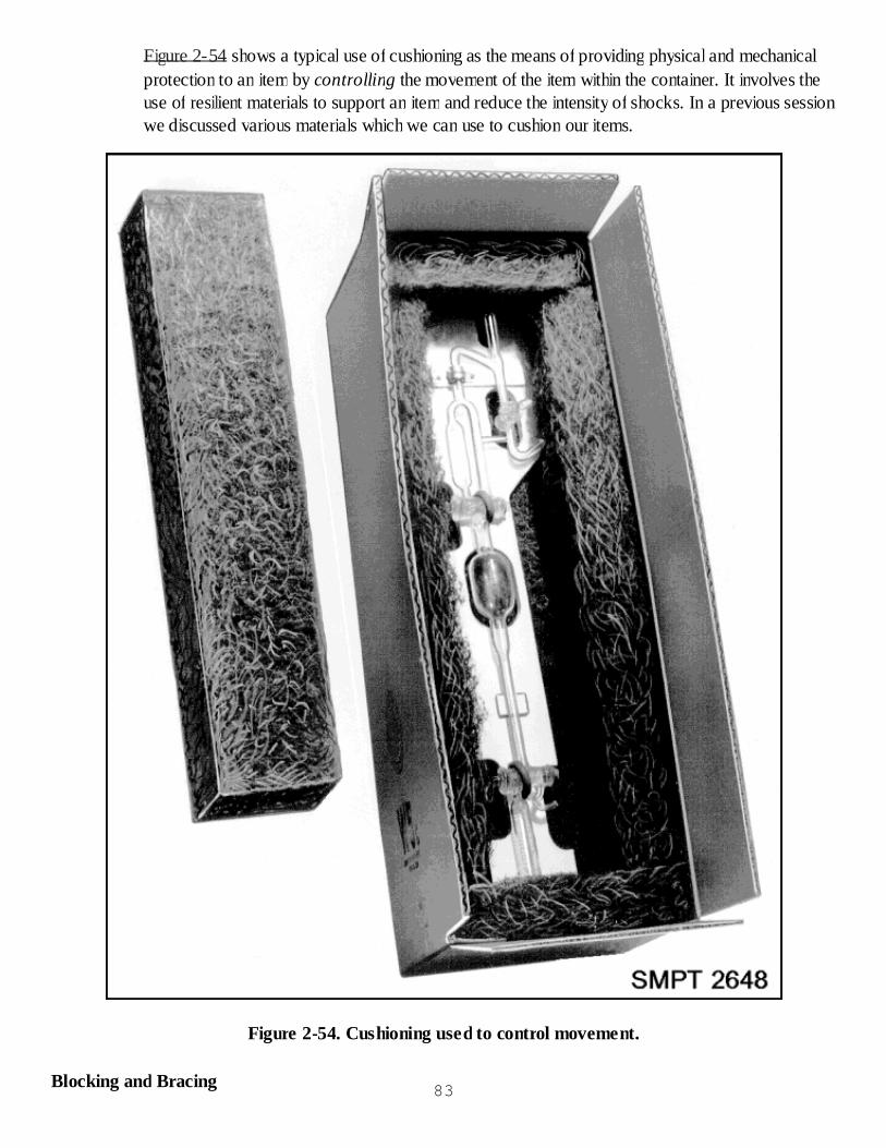
Figure 2-54 shows a typical use of cushioning as the means of providing physical and mechanicalprotection to an item by controlling the movement of the item within the container. It involves theuse of resilient materials to support an item and reduce the intensity of shocks. In a previous sessionwe discussed various materials which we can use to cushion our items.
Figure 2-54. Cushioning used to control movement.
Blocking and Bracing 83
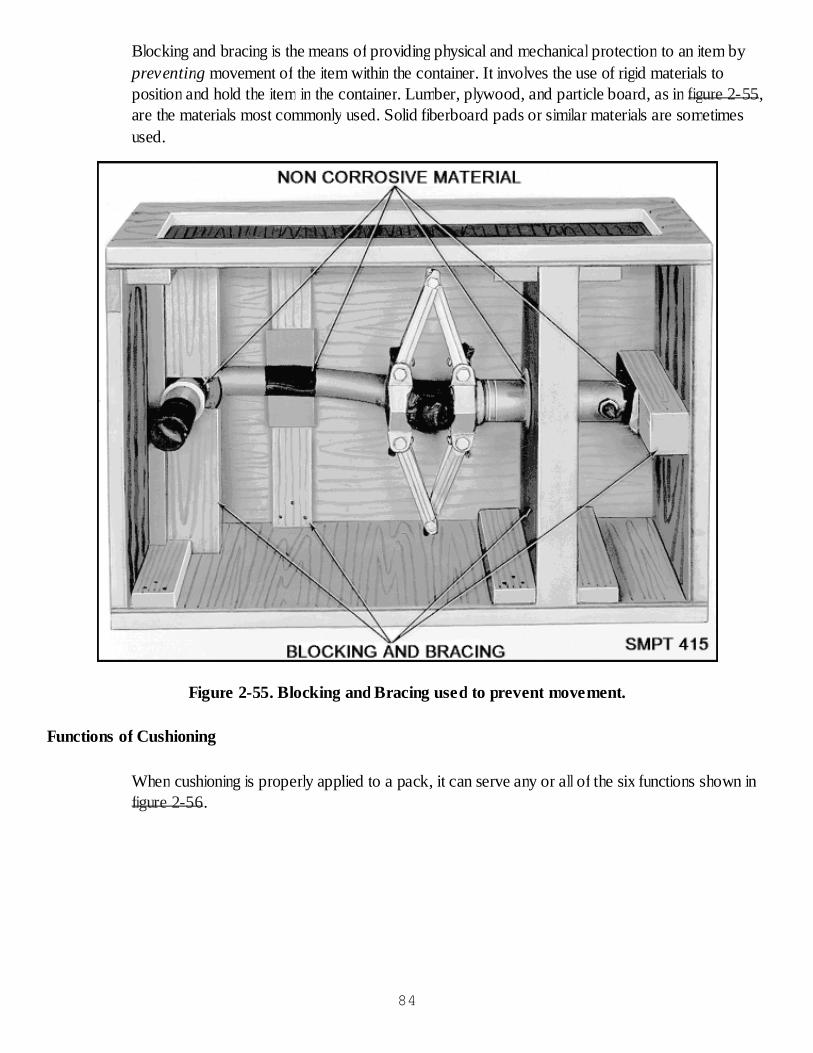
Blocking and bracing is the means of providing physical and mechanical protection to an item bypreventing movement of the item within the container. It involves the use of rigid materials toposition and hold the item in the container. Lumber, plywood, and particle board, as in figure 2-55,are the materials most commonly used. Solid fiberboard pads or similar materials are sometimesused.
Figure 2-55. Blocking and Bracing used to prevent movement.
Functions of Cushioning
When cushioning is properly applied to a pack, it can serve any or all of the six functions shown infigure 2-56.
84

Figure 2-56. Functions of cushioning.
Absorbs Shocks Due to Impact
One of the primary functions of cushioning is to absorb energy transmitted as the result of an impactshock striking the container. The shock is absorbed as the cushioning material is compressed by theitem. The extent of absorbing shocks will depend upon the degree of compressibility of thecushioning material and the thickness in which it is applied.85

Distribute Forces
Cushioning materials reduce the effects of shock to the item by distributing the damaging forcesover a larger area, thus reducing the shock concentration at any one point on the surface of theitem. The most effective distribution of forces will result when the cushioning surrounds the entiresurface of the item.
Control Movement and Vibration
Cushioning, when properly applied, controls movement of the item within the barrier or containerand tends to reduce vibrations due to external forces.
Prevent Surface Abrasion
Cushioning is used to prevent surface abrasion to items that could be damaged from abrasivepreservation and packing materials. This is accomplished by utilizing a thinner application ofcushioning material than that required for shock protection since the purpose is to have thecushioning act as a buffer.
Prevent Rupture of Barriers and Container
In some instances, cushioning is accomplished mainly to protect the container or barrier materialenclosing the item and not the item itself. This function of cushioning has special application in casesin which waterproof or watervaporproof barriers are used as unit containers, and the absence ofwater or moisture is essential to the effectiveness of the package.
Protect Fragile Items
Sometimes fragile or delicate components form a part of otherwise sturdy items and can bedisassembled and packed separately. When disassembly is not allowed and the parts must be lefton the item, adequate cushioning should be provided in relation to their fragility, their place in thecontainer, and anticipated hazards they would come in contact with.
Factors to be Considered with Cushioning, Blocking, and Bracing
In planning to cushion, block or brace an item in a shipping container, the nature and physicallimitations of the item must be thoroughly considered.
Shock Resistance
The resistance of an item to shock is determined by its ability to withstand impact without damage,and is the primary factor in determining whether an item is to be regarded as rugged, semifragile, orfragile:
Items are considered rugged if they can withstand severe impact without damage. Ruggeditems can be blocked and braced rigidly. Generally, cushioning is used with rugged itemsonly to prevent surface abrasion.Items are classed as semifragile if they can withstand a limited amount of impact with86

damage. Many semifragile items are fastened to one face of the container to prevent pressureon the item due to distortion of the container under impact. At least 2 inches clearanceshould be allowed in these cases between the item and all other faces of the container.Cushioning will be used in the packing of semifragile articles to prevent surface abrasion andto absorb part of the impact.Items are classed as fragile if they can withstand very little impact without damage. If an itemis fragile, the interior pack must be made to provide sufficient cushioning to absorb anyshocks the pack may receive. Fragile items should not be fastened to, or come in contactwith, any face of the shipping container. They may be blocked and braced to one or morefaces of an interior container which in turn is floated by cushioning in an exterior container.
Size
A large item does not necessarily require more extensive or stronger blocking or large amounts ofcushioning than a smaller item by virtue of its size alone. The large container needed by the largeitem may require more extensive and stronger blocking to bridge the wider spans between thecontainer faces or frame members. By the same token, a large item may require that the cushioningbe distributed over larger areas than on a smaller one.
Shape
A regular-shaped item requires minimal or no blocking in the container, whereas an irregular-shaped item requires an elaborate system of blocks and braces to secure it in place. Curvedsurfaces call for carefully fitted blocking and bracing to prevent damage of the item. However,foam-in-place polyurethane is a valuable tool for accomplishing a naturally conforming blocking andbracing with a minimum of labor. Long, slender items, especially if heavy, develop considerable endthrust when subjected to impact and must be blocked to prevent endwise movement.
Weight
Where weights are concentrated upon small areas, it is often necessary to distribute the weight overlarger areas or to transmit part of the weight from one container face to the edges or corners of thecontainer. For purposes of blocking and bracing, containers are stronger at or near the corners andare weaker at the unsupported center areas. The heavier and more concentrated the weight of theitem is, the stronger must be the blocking and bracing to safeguard the life of the pack.
Degree of Disassembly Permissible
It is advisable to examine the possibilities of disassembling an item prior to planning the pack,especially if the item has one or more projecting parts. Disassembly may simplify blocking andbracing requirements, reduce the size of the container, or simplify preservation of the various parts.Before disassembling any piece of equipment, proper authorization must be obtained.
Types of Loads
The term type of load refers to the contents of a container (see MIL-STD-2073-1C) and its abilityto add strength or cause damage to the faces of the container. Blocking and bracing is sometimes
87
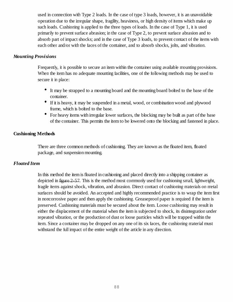
used in connection with Type 2 loads. In the case of type 3 loads, however, it is an unavoidableoperation due to the irregular shape, fragility, heaviness, or high density of items which make upsuch loads. Cushioning is applied to the three types of loads. In the case of Type 1, it is usedprimarily to prevent surface abrasion; in the case of Type 2, to prevent surface abrasion and toabsorb part of impact shocks; and in the case of Type 3 loads, to prevent contact of the items witheach other and/or with the faces of the container, and to absorb shocks, jolts, and vibration.
Mounting Provisions
Frequently, it is possible to secure an item within the container using available mounting provisions.When the item has no adequate mounting facilities, one of the following methods may be used tosecure it in place:
It may be strapped to a mounting board and the mounting board bolted to the base of thecontainer.If it is heavy, it may be suspended in a metal, wood, or combination wood and plywoodframe, which is bolted to the base.For heavy items with irregular lower surfaces, the blocking may be built as part of the baseof the container. This permits the item to be lowered onto the blocking and fastened in place.
Cushioning Methods
There are three common methods of cushioning. They are known as the floated item, floatedpackage, and suspension mounting.
Floated Item
In this method the item is floated in cushioning and placed directly into a shipping container asdepicted in figure 2-57. This is the method most commonly used for cushioning small, lightweight,fragile items against shock, vibration, and abrasion. Direct contact of cushioning materials on metalsurfaces should be avoided. An accepted and highly recommended practice is to wrap the item firstin noncorrosive paper and then apply the cushioning. Greaseproof paper is required if the item ispreserved. Cushioning materials must be secured about the item. Loose cushioning may result ineither the displacement of the material when the item is subjected to shock, its disintegration underrepeated vibration, or the production of dust or loose particles which will be trapped within theitem. Since a container may be dropped on any one of its six faces, the cushioning material mustwithstand the full impact of the entire weight of the article in any direction.
88
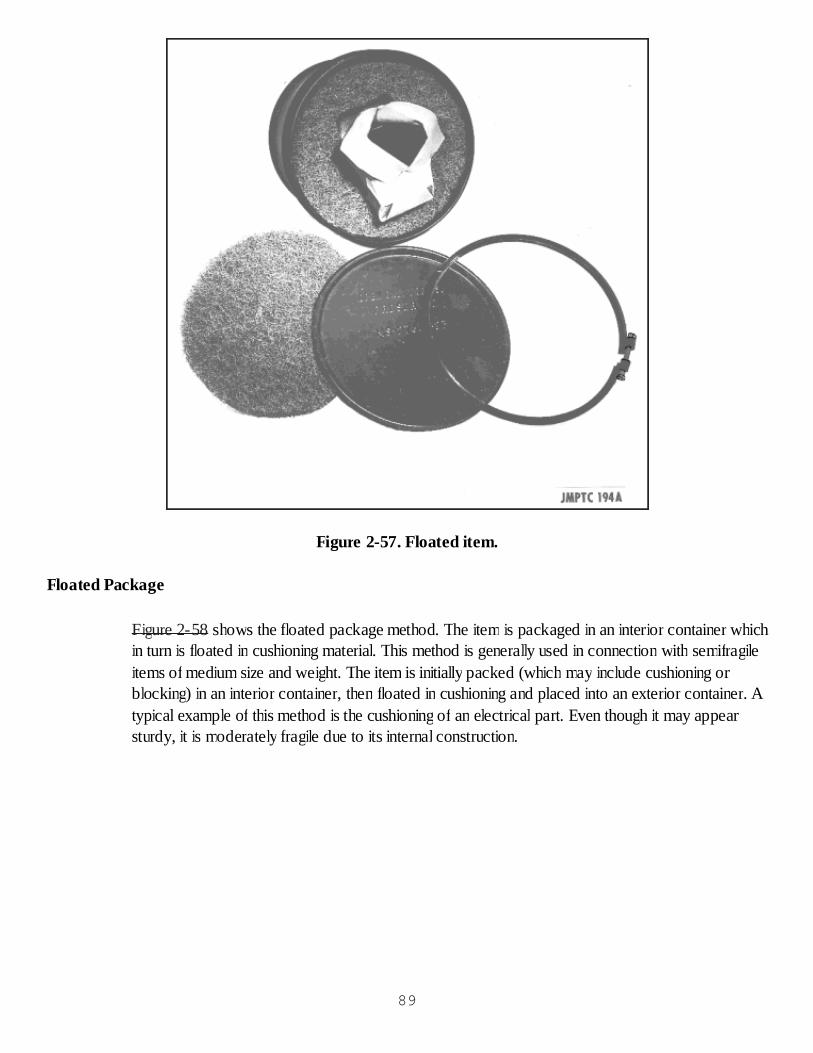
Figure 2-57. Floated item.
Floated Package
Figure 2-58 shows the floated package method. The item is packaged in an interior container whichin turn is floated in cushioning material. This method is generally used in connection with semifragileitems of medium size and weight. The item is initially packed (which may include cushioning orblocking) in an interior container, then floated in cushioning and placed into an exterior container. Atypical example of this method is the cushioning of an electrical part. Even though it may appearsturdy, it is moderately fragile due to its internal construction.
89
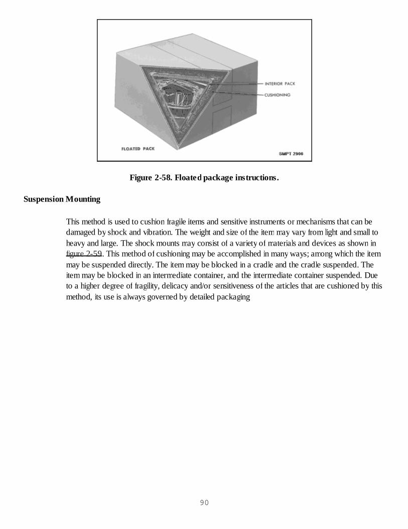
Figure 2-58. Floated package instructions.
Suspension Mounting
This method is used to cushion fragile items and sensitive instruments or mechanisms that can bedamaged by shock and vibration. The weight and size of the item may vary from light and small toheavy and large. The shock mounts may consist of a variety of materials and devices as shown infigure 2-59. This method of cushioning may be accomplished in many ways; among which the itemmay be suspended directly. The item may be blocked in a cradle and the cradle suspended. Theitem may be blocked in an intermediate container, and the intermediate container suspended. Dueto a higher degree of fragility, delicacy and/or sensitiveness of the articles that are cushioned by thismethod, its use is always governed by detailed packaging
90
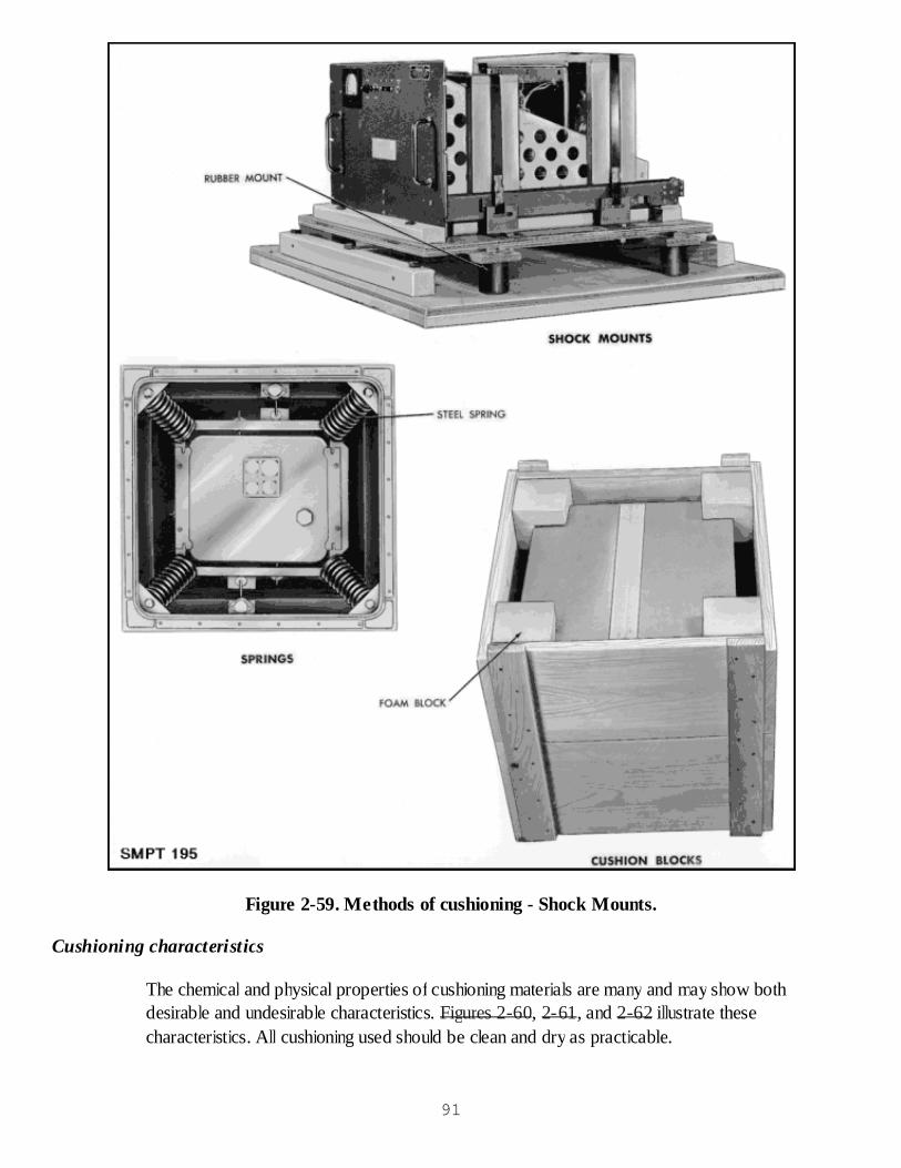
Figure 2-59. Methods of cushioning - Shock Mounts.
Cushioning characteristics
The chemical and physical properties of cushioning materials are many and may show bothdesirable and undesirable characteristics. Figures 2-60, 2-61, and 2-62 illustrate thesecharacteristics. All cushioning used should be clean and dry as practicable.
91
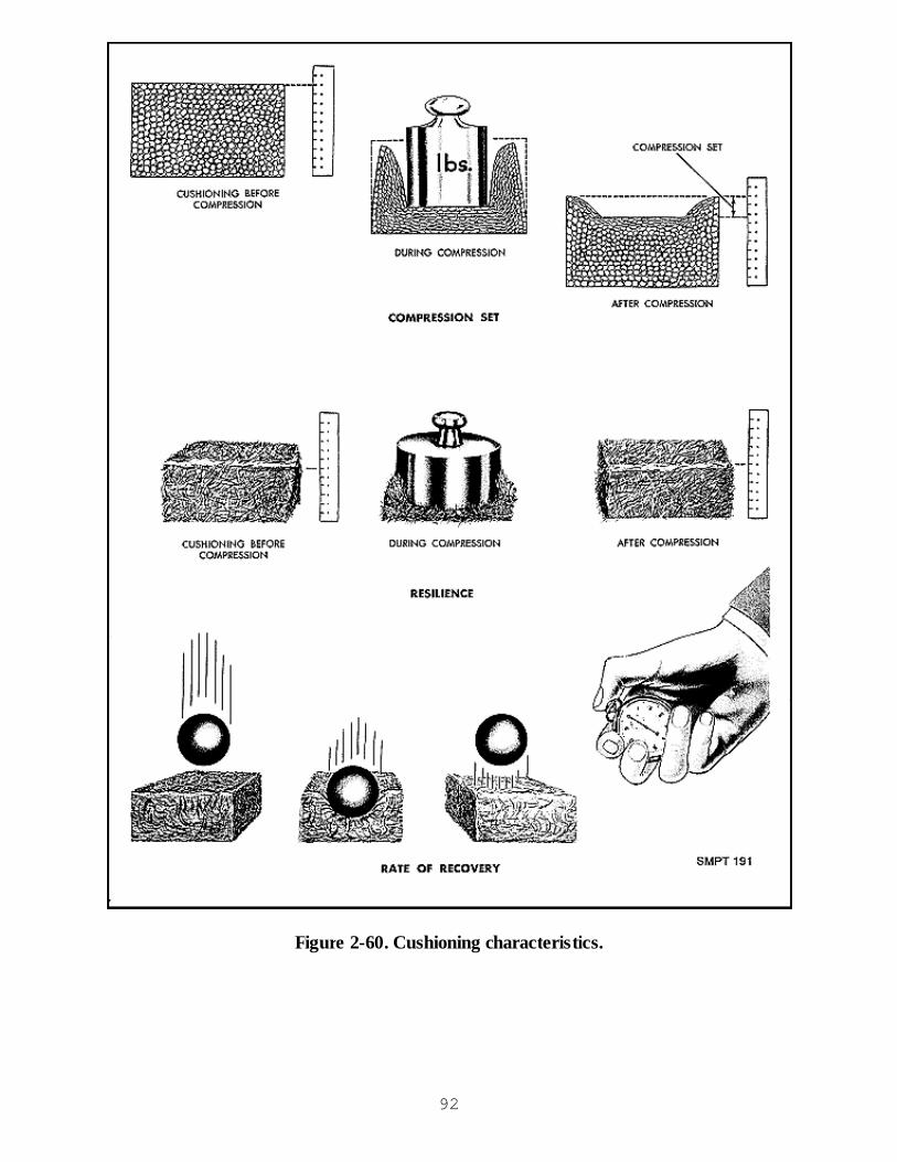
Figure 2-60. Cushioning characteristics.
92

Figure 2-61. Cushioning characteristics.
93
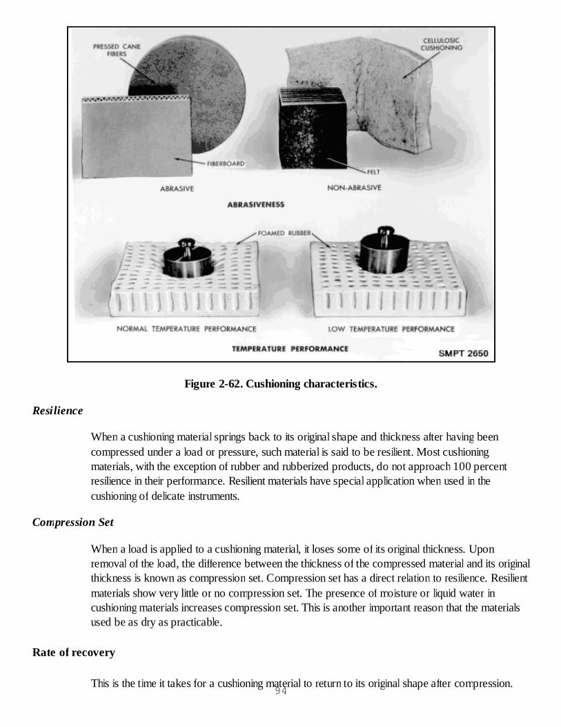
Figure 2-62. Cushioning characteristics.
Resilience
When a cushioning material springs back to its original shape and thickness after having beencompressed under a load or pressure, such material is said to be resilient. Most cushioningmaterials, with the exception of rubber and rubberized products, do not approach 100 percentresilience in their performance. Resilient materials have special application when used in thecushioning of delicate instruments.
Compression Set
When a load is applied to a cushioning material, it loses some of its original thickness. Uponremoval of the load, the difference between the thickness of the compressed material and its originalthickness is known as compression set. Compression set has a direct relation to resilience. Resilientmaterials show very little or no compression set. The presence of moisture or liquid water incushioning materials increases compression set. This is another important reason that the materialsused be as dry as practicable.
Rate of recovery
This is the time it takes for a cushioning material to return to its original shape after compression.94

Some materials have too rapid a recovery and "spring back" so quickly that damage to the itemmay result.
Liquid-Absorption Capacity
The liquid-absorption capacity of cushioning materials varies form highly absorbent to very lowabsorbent materials. In some instances the use of a cushioning material that will absorb liquids dueto leakage or breakage of the container during transit will be advantageous. When cushioning metalitems or items made of organic materials which will be damaged by the presence of moisture orwater, the low absorbent cushioning material will be used.
Dusting
The presence of small particles of fibrous materials in preservation and packing is undesirable sincethese particles can cause damage to mechanical assemblies. All cushioning materials dust to somedegree.
Corrosiveness
Cushioning materials contain chemicals that form corrosive solutions in conjunction with moisture.When an item may be damaged by corrosion, a noncorrosive material should be used or thecushioning should be separated from the item by use of barrier material.
Abrasiveness
Many cushioning materials will cause abrasion on item surfaces. Avoid placing these materials
in direct contact with critical surfaces. Where critical surfaces are involved, barrier material must beused between the item surface and the cushioning.
Temperature Limitations
Cushioning applications for military use are subject to temperatures from -65F to 160F. The highertemperature requirement may cause increased compression set. Lower temperature requirementcauses stiffness, resistance to compression and brittleness.
Electrostatic Field Shielding
This requires enclosing the item in a relatively conductive material. Normally, the greater theconducting of the enclosure, the greater the dissipation of the electrostatic field. Thus, electrostaticdischarge sensitive (ESDS) items should have an overwrap of conductive packaging to protectagainst electrostatic induced fields.
Blocking and Bracing Methods
Boxes available for packing are seldom exactly the right size for the item to be packed. They areusually either too long or too wide or too deep or sometimes a little bit of all three. When you arechoosing a box to pack an item which must be blocked in place, try to find a box as nearly the
95

correct width as possible. It is fairly easy to block off excess length or depth, but much moredifficult to block off excess width. The type of blocking and bracing you use must be suited to theitem you are packing. No one pattern of blocking and bracing will be suitable for all occasions.There are four common methods of blocking and bracing.
Fiberboard, Prefabricated Wood, Particle Board or Plywood Blocking and Bracing
Fiberboard is used primarily in connection with irregularly shaped items. The wood or plywood iscut to fit or support certain portions of the item and nailed to the faces of the container. For itemswith irregular lower surfaces, the blocking may be built as part of the base of the container and theitem lowered onto it. Figure 2-63 shows a number of possible designs.
96
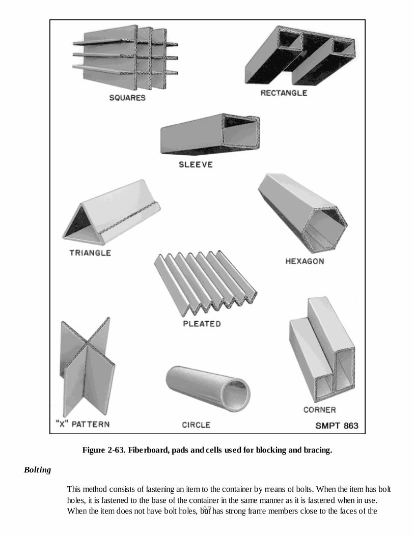
Figure 2-63. Fiberboard, pads and cells used for blocking and bracing.
Bolting
This method consists of fastening an item to the container by means of bolts. When the item has boltholes, it is fastened to the base of the container in the same manner as it is fastened when in use.When the item does not have bolt holes, but has strong frame members close to the faces of the97
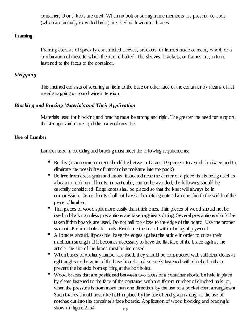
container, U or J-bolts are used. When no bolt or strong frame members are present, tie-rods(which are actually extended bolts) are used with wooden braces.
Framing
Framing consists of specially constructed sleeves, brackets, or frames made of metal, wood, or acombination of these to which the item is bolted. The sleeves, brackets, or frames are, in turn,fastened to the faces of the container.
Strapping
This method consists of securing an item to the base or other face of the container by means of flatmetal strapping or round wire in tension.
Blocking and Bracing Materials and Their Application
Materials used for blocking and bracing must be strong and rigid. The greater the need for support,the stronger and more rigid the material must be.
Use of Lumber
Lumber used in blocking and bracing must meet the following requirements:
Be dry (its moisture content should be between 12 and 19 percent to avoid shrinkage and toeliminate the possibility of introducing moisture into the pack).Be free from cross grain and knots, if located near the center of a piece that is being used asa beam or column. If knots, in particular, cannot be avoided, the following should becarefully considered. Edge knots shall be placed so that the knot will always be incompression. Center knots shall not have a diameter greater than one-fourth the width of thepiece of lumber.Thin pieces of wood split more easily than thick ones. Thin pieces of wood should not beused in blocking unless precautions are taken against splitting. Several precautions should betaken if thin boards are used. Do not nail too close to the edge of the board. Use the propersize nail. Prebore holes for nails. Reinforce the board with a facing of plywood.All braces should, if possible, have the edges against the article in order to utilize theirmaximum strength. If it becomes necessary to have the flat face of the brace against thearticle, the size of the brace must be increased.When bases of ordinary lumber are used, they should be constructed with sufficient cleats atright angles to the grain of the base boards and securely fastened with clinched nails toprevent the boards from splitting at the bolt holes.Wood braces that are positioned between two faces of a container should be held in placeby cleats fastened to the face of the container with a sufficient number of clinched nails, or,when the pressure is from more than one direction, by the use of a pocket cleat arrangement.Such braces should never be held in place by the use of end grain nailing, or the use ofnotches cut into the container's face boards. Application of wood blocking and bracing isshown in figure 2-64. 98
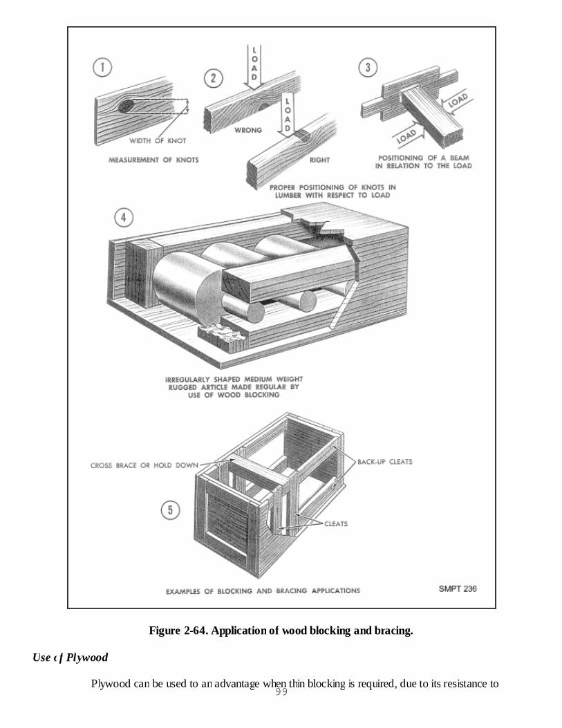
Figure 2-64. Application of wood blocking and bracing.
Use of Plywood
Plywood can be used to an advantage when thin blocking is required, due to its resistance to99

splitting; or where the blocking must be flexible to fit to a curved surface as shown in figure 2-65.Plywood has an added advantage for use as a base as it is available in wide panels. Plywood usedas a base should be 1/2 inch or 3/4 inch thick for light articles. For medium and heavy articles, twoor more pieces of plywood can be fastened together, or a series of strengthening plywood cleatscan be added to the panel.
100

Figure 2-65. Use of plywood - blocking and bracing.
Use of Metal Brackets or Frames
Many articles have attachment points used for bolting but the points are not located on a regularbase which can be fastened directly to the container. In such instances, specially constructedbrackets or frames made of metal, structural iron, wood, or a combination of these, can be used.
Use of Metal Strapping
The use of metal strapping to tie down an article to the base or other face of the container is oftenthe only procedure that can be used. Metal strapping may be flat strapping or round wire. Generalprecautions on the use of both flat strapping and round wire are as follows:
Use annealed wire or strap only for lighter articles since it stretches readily.Straps should be placed only on those strong portions of the article which can withstand theimpact load and weight of the article.Place material such as felt or solid fiberboard between the straps and the article to preventdamaging finished surfaces.Use one piece strapping whenever possible.When strapping over a sharp edge of the item, use corner protectors to prevent strappingfrom fracturing.When it is impossible to encircle the item and its support, anchor the two ends of the metal.For flat strapping, anchor the two ends of the strap to the container with anchor plates, or, ifthe strap is annealed, by direct nailing. For round wire, anchor the two ends of the wire tothe container with drive screws and staples. Loop the wire around the shank of the drivescrew and further fasten it with staples.
Use of Nails
Nails are the most common fastenings for blocking and bracing, especially standard sinkers andcooler nails. Clout nails, which are similar to roofing nails, are recommended where plywood of 1/2inch thickness or less is used, because of their larger heads. Nails used in blocking and bracingshould be cement-coated or chemically etched, particularly when they cannot be clinched. Etchednails should be used in preference to cement-coated nails whenever possible.
Use of Bolts
Bolts commonly used for blocking and bracing are step bolts, carriage bolts, and machine bolts, asshown in figure 2-66. U-bolts and J-bolts are used for special purposes where regular bolts cannotbe applied. The following precautions should be observed in the use of bolts:
In bolting an article to a base, the bolt head should be on the outside of the container baseand should bear against a wide flat washer. The bolt threads should be either coated withthick white paint, or slightly upset near the nut.
101

The base should never be counter-bored for the washer and bolt head.When a container has skids, the bolts should be placed through the skids, if possible, withthe bolt heads on the underside.Where the article has strong frame members fairly close to the faces of the container, U-boltsor J-bolts may be used to advantage.Tie-rods serve as extended bolts and should be used in the same general manner as othertypes of bolts. They should be placed vertically or diagonally in pairs.
102

Figure 2-66. Use of bolts for blocking and bracing.
Foam-In-Place (FIP) Packaging 103
Foam-In-Place is another means of accomplishing cushioning or blocking and bracing.
This process consists of mechanically mixing two chemicals, called components A & B, together toform a urethane foam. The type of foam produced depends on the chemical elements in componentB.
FIP materials used for cushioning are open celled foams normally of 1/2 pound per cubic footdensity called semirigid foam or 1-1/2 pound per cubic foot density foam called flexible foam.
FIP materials used for blocking and bracing are closed cell foams of two pounds per cubic footdensity. These are called rigid foams and absorb little or no shock.
Checkup
What does blocking and bracing accomplish?What does cushioning accomplish?What item, as a general rule, will require more blocking, bracing or cushioning, a regularshaped or an irregular-shaped one? Why?In regard to shock resistance, how are items grouped?Which type of load is blocking and bracing generally associated?What is an important requirement for all materials used in blocking and bracing?What are some of the requirements for cushioning materials?What is the most common method of cushioning small, lightweight, fragile items?
CUSHIONING, BLOCKING AND BRACING APPLICATION PRATICAL EXERCISE
Objective
As a result of this practice, the student will be able to identify various material and their applicationto accomplish preservation and packing operations.
General Instructions
The time allotted for this practical exercise is approximately 2 class periods. In the first class period,the student will write the answers on the work sheets.
The second class period will be devoted to a critique of the practical exercise.
This practical exercise will be conducted in the practical exercise work area.
The instructor will place the items from the kit on desks around the room.
Conduct of Exercise
Situation104

As a packer you are to identify the items displayed and list their usage in preservation and packingon the work sheets contained in this practical exercise.
Requirement
Students will study the numbered items, identify each and give a brief description and thepurpose of each.During the critique of the practical exercise, the students will verify their answers on the worksheets with the answer given during the critique.
Critique
During the critique, each student will give a brief description of an item and how it is used inpreservation and packing operations.
Care of Area, Training Aids and Equipment
Not applicable.
METHODS OF PRESERVATION
METHODS OF PRESERVATION
Proper Preservation
Preservation is the application or use of adequate protective measures to prevent deteriorationincluding as applicable, the use of appropriate cleaning procedures, preservative protectivewrappings, cushioning, interior containers, and complete identification marking up to, but notincluding, the exterior shipping containers.
Unit Preservation or Unit Protection
This is the protection given to one or more items through the application or use of the necessarycleaning, drying, preserving, wrapping, cushioning, interior containers, and marking foridentification.
Unit Pack
The first tie, wrap or container applied to a single item or multiple thereof, or to a group of items ofa single stock number, preserved or unpreserved, which involves a complete or identifiablepackage, as shown in figure 2-67.
105
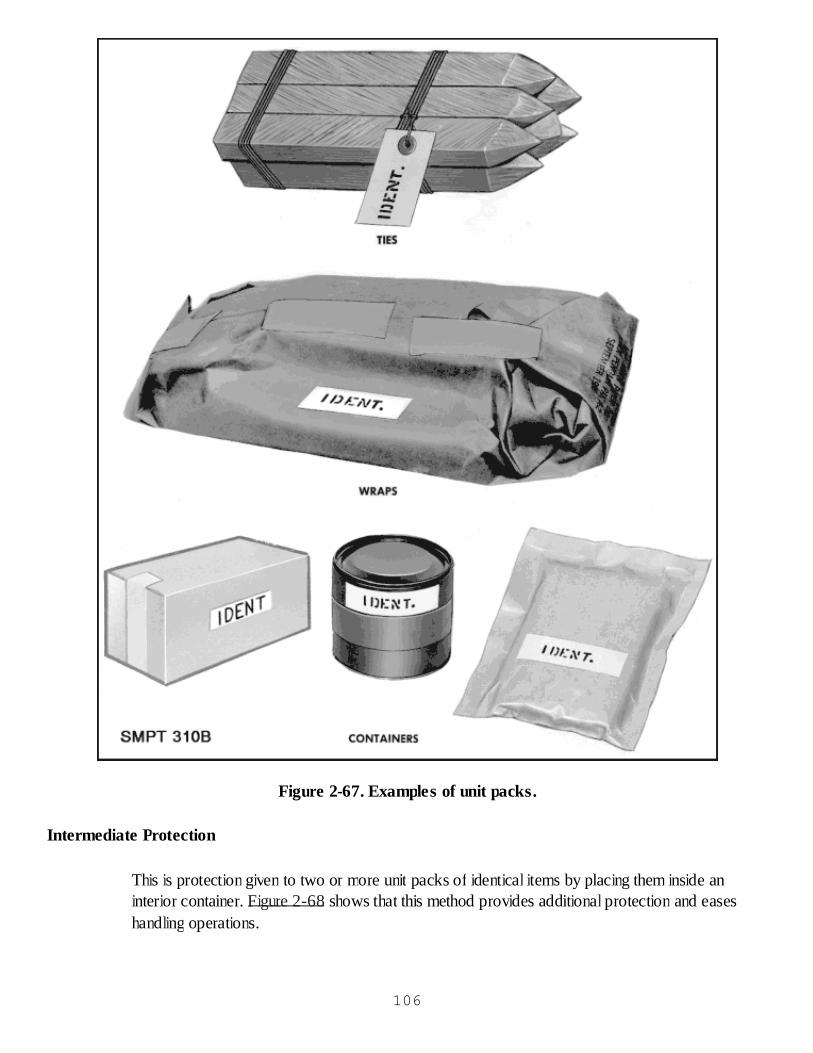
Figure 2-67. Examples of unit packs.
Intermediate Protection
This is protection given to two or more unit packs of identical items by placing them inside aninterior container. Figure 2-68 shows that this method provides additional protection and easeshandling operations.
106

Figure 2-68. Intermediate packs.
Purpose of Preservation 107

Preservation is a very important part of the military supply program. The protection afforded byproper preservation will give assurance that supplies will remain in a suitable condition until they areneeded.
Preservation Assures Usability of Items
Placing of items or supplies in unit packs is for the purpose of furnishing protection. Packs must beconstructed properly, materials and methods must be in accordance with official instructions.
Protection Afforded by Unit Packing
Unit packing helps in keeping a preservative coating in contact with the item and also protects thecoating. It also helps to prevent damage to items against climatic hazards such as rain, snow, heat,cold, high humidity, and salt spray. Unit packing will help prevent damage to items from abrasion,shock, and impact that occurs during handling, storage, and shipment.
Unit Packing Provides for Identification
The final operation of unit preservation is the labeling of the pack with the correct identification andmarkings. Items which are not properly identified are useless to the receiver and are a waste oftime, money, and effort.
Unit Packing Provides a Logical Sequence
Unit preservation is important because it provides a logical sequence of operations whereby theitem is given the necessary protection against external causes of deterioration during shipment andstorage. It is necessary that each operation of unit preservation be followed by the subsequentoperation so that there is a minimum delay of time between operations. The same emphasis onoperational sequence must be applied to methods of unit preservation as was applied to theprocesses of cleaning, drying, and preserving.
Preservation Goal
In military preservation, the primary goal is to afford the required protection at the least possiblecost. The greatest savings in preservation costs are possible through the application of basicpreservation knowledge by trained operators and supervisors.
The Need for Different Methods of Unit Preservation
Military items which must be packed are so numerous and so different from each other that there isno one single method by which all can be protected. Since there is such a variety of items, themethods of preservation will vary according to the following factors:
Composition of the item: Whether the item is made of metal or nonmetal or a combinationof both.
Construction of the item: Whether the item is of simple or complex construction.108

Nature of the item: Whether the item has a critical or noncritical surface, the effect ofwater and watervapor on the item, and the effect of static electricity on the item.
Level of protection: Whether military or commercial packaging is appropriate based on theanticipated types of storage, handling, and or shipment mode.
General Requirements of Methods of Preservation
Preservation materials used in unit packages must meet the following requirements:
Cushioning and dunnage used within waterproof or watervaporproof barriers must be asclean and dry as practicable.Items that are coated with a preservative must have a preliminary wrap conforming to GradeA or C of MIL-B-121, MIL-PRF-22191, Type I or II or A-A-1676.Wrapping, cushioning and dunnage materials in direct contact with bare metal surfaces mustmeet the requirements of Test Method 3005 of Federal Test Standard 101.When greaseproofness is not a requirement, neutral wrapping papers Paper, Wrapping,Laminated and Creped (MIL-P-130); Paper, Wrapping, Chemically Neutral (noncorrosive)(MIL-P-17667); and Paper, Wrapping, Tissue (A-A-1249) meet the requirement and areavailable at lower cost. These wrapping papers are intended as an initial wrap where anoncorrosive, dust protective wrap is required prior to, or as a part of, the unit pack.
General Concept of Preservation
Corrosion occurs when the environment that surrounds the item provides the essential ingredientsthat will attack the material, e.g. water and oxygen. Preservation is the sum total of all the ways thatthe environment surrounding the item can be altered to eliminate one or both of these factors.
The application of a continuous, unbroken coat of contact preservative achieves this end bysurrounding the item with an oily film which is resistant to the entrance of liquid water and alsokeeps oxygen from the surface.
The various barrier materials limit the amount of moisture within the pack to varying degrees,dependent upon their water or moisture vapor transmission rate (WVTR).
Another common way of altering the environment within the pack is to reduce the amount ofmoisture within a watervaporproof barrier through the use of a drying agent or desiccant.
Methods of Preservation
The methods of preservation (unit protection) are those protective measures that are approved forthe prevention of deterioration of military supplies and equipment. They are established by MIL-STD-2073-1C, and illustrated in figure 2-69, and consist of the following basic methods:
Method 10: Physical protection only.Method 20: Preservative coating (with greaseproof wrap as required).109

Method 30: Waterproof enclosure (with preservative as required).Method 40: Water-vaporproof enclosure (with contact preservative as required).Method 50: Water-vaporproof barrier with desiccant (with preservative when required).
Figure 2-69. Concept of basic methods of preservation.
Methods of Unit Preservation
Various specific techniques have been developed to meet the basic Methods 30, 40, 50 which maybe used as appropriate. There are 18 different ways of making unit packs (basic Methods 10 and20 have no variations). There is no ideal method of preservation which would satisfy all therequirements of military preservation. During this lesson, we are going to discuss examples of eachmethod of preservation as follows:
Method 10 Physical protectionMethod 20 Preservative coating (with greaseproof wrap as required)Method 33 Greaseproof, waterproof bag, sealedMethod 42 Container Watervaporproof Bag, sealed, containerMethod 53 Floating watervaporproof bag, sealedMethod 55 Rigid metal container, sealed
Method 10
110

Physical Protection Only
Physical protection is accomplished by cushioning, blocking, or bolting to prevent movement withincontainers and physical damage due to shock and vibration. Mechanical protection is provided toan item to prevent damage from any force that will impair the proper functioning of the item.Method 10 does not provide protection from the entry of water, watervapors, gases or fumes, orthe growth of microorganisms. No preservative is used on items packed by Method 10. Itemsusually packed by this method are of a noncritical nature made of corrosion resistant metals;nonmetals such as crockery, ceramics, and glass; or items that are painted, prime coated, anodizedor have other similar corrosion resistant finishes or coatings. Figure 2-70 illustrates various ways toconstruct a Method 10 pack.
Figure 2-70. Method 10.
Clean and dry item as required.
Apply wraps and cushioning as close to the item as practicable to control free movement in thecontainer.
111

Apply, as required, blocking or bracing against areas of the item that are of sufficient strength andrigidity to resist damage.
Apply cartons, bundling, tying, etc. as required.
Apply identification markings to outer container. This completes a Method 10 unit pack.
Method 20
Preservative Coating (With Greaseproof Wrap as Required)
In Method 20 preservation all the protection given to the item is provided by the preservativecoating. This method is used to protect metal items of a noncritical nature where either the removalof the preservative is not required before the item is used, or removal of the preservative can beaccomplished without further disassembly or damage to the item. When a soft or oily preservative isused on the item, it must be protected with a greaseproof wrap. Some of the most commonly usedpreservatives for Method 20 are MIL-PRF-16173, Grades 1, 2, 3 and 4 and MIL-PRF-3240VCI. A Method 20 pack may be made by use of a hard drying preservative on the item; by use ofa soft film preservative on the item, plus a greaseproof wrap; or by use of VCI treated barriermaterial.
How to Apply Method 20 Preservation Using a Hard Drying Preservative
Figure 2-71 shows the steps required when Method 20 includes the use of a hard dryingpreservative, and includes cleaning and drying the item; applying MIL-PRF-16173, grades 1 or 4preservative, to the item, allowing the excess preservative to drain back into the tank; and letting thepreservative dry hard on the item; and applying identification markings.
112
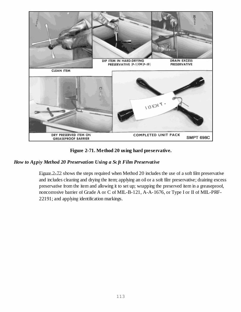
Figure 2-71. Method 20 using hard preservative.
How to Apply Method 20 Preservation Using a Soft Film Preservative
Figure 2-72 shows the steps required when Method 20 includes the use of a soft film preservativeand includes cleaning and drying the item; applying an oil or a soft film preservative; draining excesspreservative from the item and allowing it to set up; wrapping the preserved item in a greaseproof,noncorrosive barrier of Grade A or C of MIL-B-121, A-A-1676, or Type I or II of MIL-PRF-22191; and applying identification markings.
113
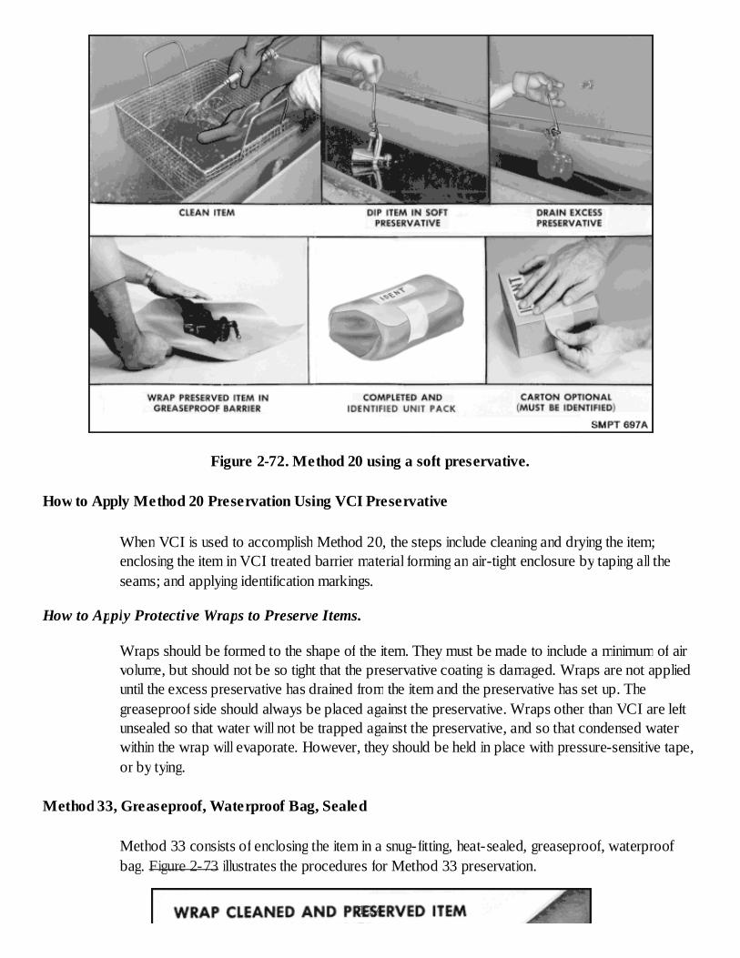
Figure 2-72. Method 20 using a soft preservative.
How to Apply Method 20 Preservation Using VCI Preservative
When VCI is used to accomplish Method 20, the steps include cleaning and drying the item;enclosing the item in VCI treated barrier material forming an air-tight enclosure by taping all theseams; and applying identification markings.
How to Apply Protective Wraps to Preserve Items.
Wraps should be formed to the shape of the item. They must be made to include a minimum of airvolume, but should not be so tight that the preservative coating is damaged. Wraps are not applieduntil the excess preservative has drained from the item and the preservative has set up. Thegreaseproof side should always be placed against the preservative. Wraps other than VCI are leftunsealed so that water will not be trapped against the preservative, and so that condensed waterwithin the wrap will evaporate. However, they should be held in place with pressure-sensitive tape,or by tying.
Method 33, Greaseproof, Waterproof Bag, Sealed
Method 33 consists of enclosing the item in a snug-fitting, heat-sealed, greaseproof, waterproofbag. Figure 2-73 illustrates the procedures for Method 33 preservation.
114
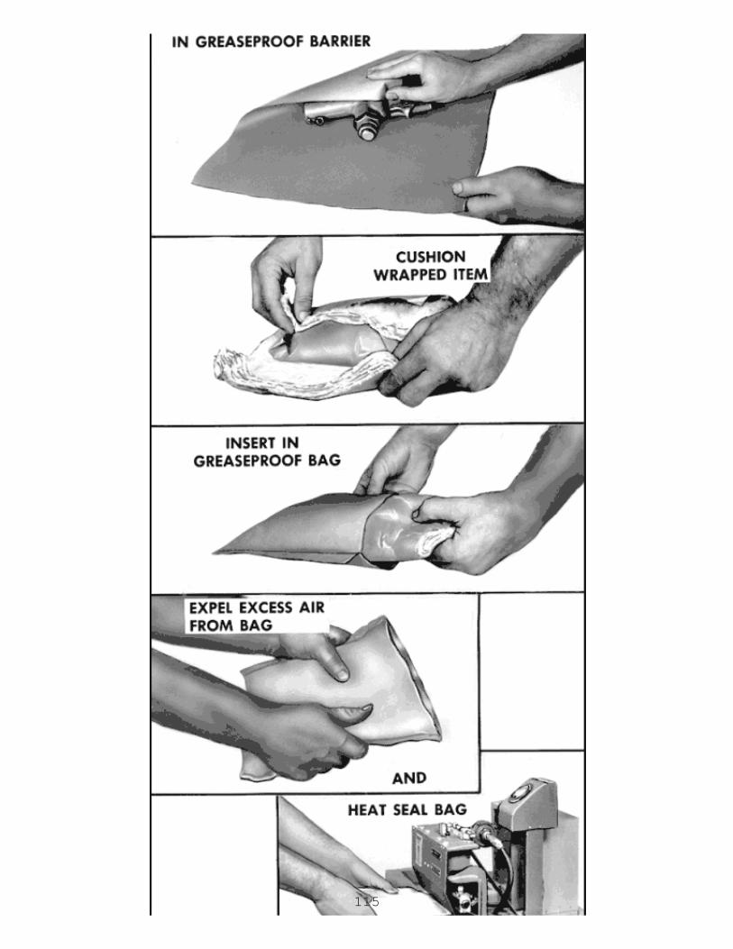
115
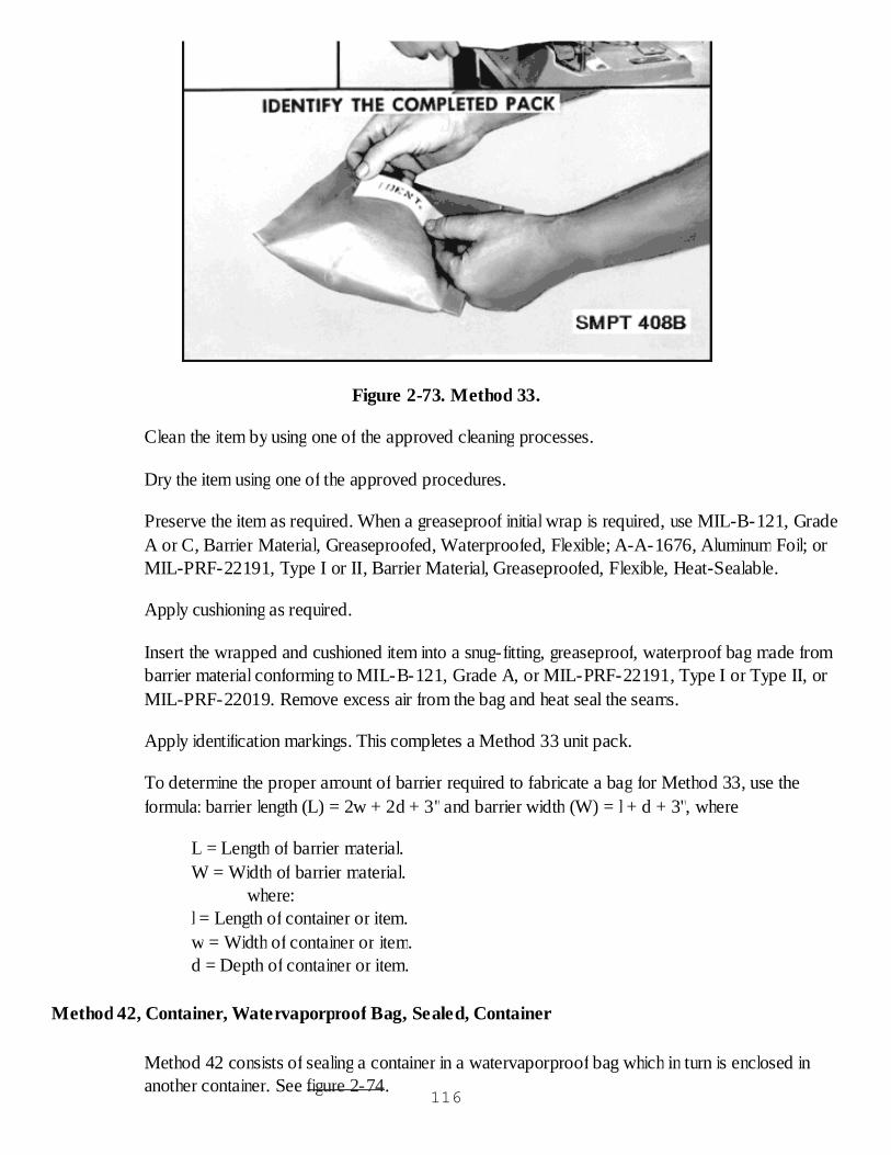
Figure 2-73. Method 33.
Clean the item by using one of the approved cleaning processes.
Dry the item using one of the approved procedures.
Preserve the item as required. When a greaseproof initial wrap is required, use MIL-B-121, GradeA or C, Barrier Material, Greaseproofed, Waterproofed, Flexible; A-A-1676, Aluminum Foil; orMIL-PRF-22191, Type I or II, Barrier Material, Greaseproofed, Flexible, Heat-Sealable.
Apply cushioning as required.
Insert the wrapped and cushioned item into a snug-fitting, greaseproof, waterproof bag made frombarrier material conforming to MIL-B-121, Grade A, or MIL-PRF-22191, Type I or Type II, orMIL-PRF-22019. Remove excess air from the bag and heat seal the seams.
Apply identification markings. This completes a Method 33 unit pack.
To determine the proper amount of barrier required to fabricate a bag for Method 33, use theformula: barrier length (L) = 2w + 2d + 3"and barrier width (W) = l + d + 3", where
L = Length of barrier material.W = Width of barrier material.
where:l = Length of container or item.w = Width of container or item.d = Depth of container or item.
Method 42, Container, Watervaporproof Bag, Sealed, Container
Method 42 consists of sealing a container in a watervaporproof bag which in turn is enclosed inanother container. See figure 2-74.
116
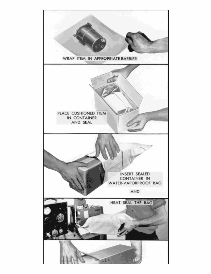
117
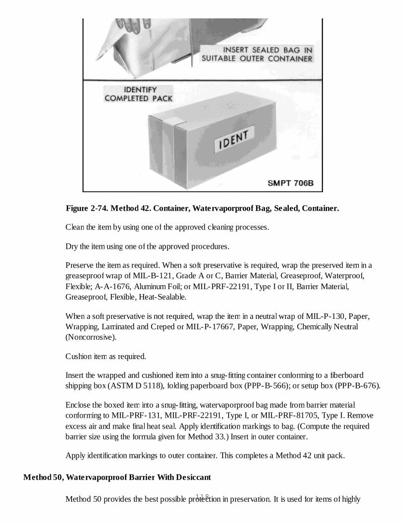
Figure 2-74. Method 42. Container, Watervaporproof Bag, Sealed, Container.
Clean the item by using one of the approved cleaning processes.
Dry the item using one of the approved procedures.
Preserve the item as required. When a soft preservative is required, wrap the preserved item in agreaseproof wrap of MIL-B-121, Grade A or C, Barrier Material, Greaseproof, Waterproof,Flexible; A-A-1676, Aluminum Foil; or MIL-PRF-22191, Type I or II, Barrier Material,Greaseproof, Flexible, Heat-Sealable.
When a soft preservative is not required, wrap the item in a neutral wrap of MIL-P-130, Paper,Wrapping, Laminated and Creped or MIL-P-17667, Paper, Wrapping, Chemically Neutral(Noncorrosive).
Cushion item as required.
Insert the wrapped and cushioned item into a snug-fitting container conforming to a fiberboardshipping box (ASTM D 5118), folding paperboard box (PPP-B-566); or setup box (PPP-B-676).
Enclose the boxed item into a snug-fitting, watervaporproof bag made from barrier materialconforming to MIL-PRF-131, MIL-PRF-22191, Type I, or MIL-PRF-81705, Type I. Removeexcess air and make final heat seal. Apply identification markings to bag. (Compute the requiredbarrier size using the formula given for Method 33.) Insert in outer container.
Apply identification markings to outer container. This completes a Method 42 unit pack.
Method 50, Watervaporproof Barrier With Desiccant
Method 50 provides the best possible protection in preservation. It is used for items of highly118
critical nature, mechanical or electrical, which would normally not be coated with a preservative. AllMethod 50 packages must have the special Method 50 label applied to the outer container. Thosesubmethods that use a heat-sealed bag must have room along the opening edge for two additionalheat seals. This is for inspection purposes. This Method uses an absorbing material, known asdesiccant, to absorb any moisture within the package. It must not be used on any item where theremoval of moisture would cause damage to the item. To determine the proper amount of desiccantto be placed in a Method 50 unit pack, you have to use one of the following formulas:
Formula I. For all Method 50 unit packs utilizing a flexible barrier material:
U = CA + X1D + X2D + X3D + X4D.
Formula II. For all Method 50 unit packs utilizing a sealed rigid metal container:
U = KV + X1D + X2D + X3D + X4D.
Values:
U = Number of units of desiccant.C = .011 when area of flexible barrier is given in square inches or 1.6 when the area isgiven in square feet.K = .0007 when the volume of a rigid container is given in cubic inches or 1.2 whenthe volume is given in cubic feet.A = Area of container in square inches or square feet.V = Volume if container in cubic inches or cubic feet.X1 = 8 for cellulosic material (including wood) and other material not categorizedbelow.X2 = 3.6 for bound fiber.X3 = 2 for glass fiber.X4 = 0.5 for synthetic foams and rubber.D = Pounds of dunnage.
To determine the proper amount of barrier required to fabricate a bag for Method 50submethods, use the formula:
barrier length (L) = 2w + 2d + 3" or (5")barrier width (W) = I + d + 3" or (5)".
Note: The 5" dimension is used to allow for two additional heat seals required for Method 50 packinspection and is used on either the length or width dimension.
Method 53, Floating Watervaporproof Bag, Sealed
Method 53 is used for those items which, because of size, weight, complexity, and construction,necessitate mounting the item to a supporting member or face of a container. Method 53preservation steps, shown in figure 2-75, are as follows:119

Clean the item by one of the approved cleaning processes.Dry the item by one of the approved drying procedures.Preserve the item, as required, by application of one of the approved preservatives.Prepare mounting base by installing gaskets on protruding bolts and cement gaskets in placeby use of gasket cement.Place barrier material on mounting base with bolts protruding through barrier material.Barrier material must meet the requirements of Class 1 or 2, of MIL-PRF-131, Type I ofMIL-PRF-22191, or Type 1, MIL-PRF-81705.Place gaskets on protruding bolts and cement in place against barrier material.Place item on mounting base and secure bolts.Cushion all sharp edges and corners of the item, as required.Attach bags of desiccant to item by means of tape or tying. Care should be taken to preventdesiccant bags from touching critical surfaces of the item.Apply humidity indicator, unless otherwise specified.Fold barrier material over item and heat seal all edges, except for an opening to exhaust airfrom the pack. Remove excess air from bag by use of air extracting device using care not torupture barrier material. Make final heat seal to close barrier. Fold flaps around pack andtape in place.Apply identification markings and Method 50 markings.Place item in suitable outer container for shipping and apply appropriate markings. Thiscompletes a method 53 unit pack.
120
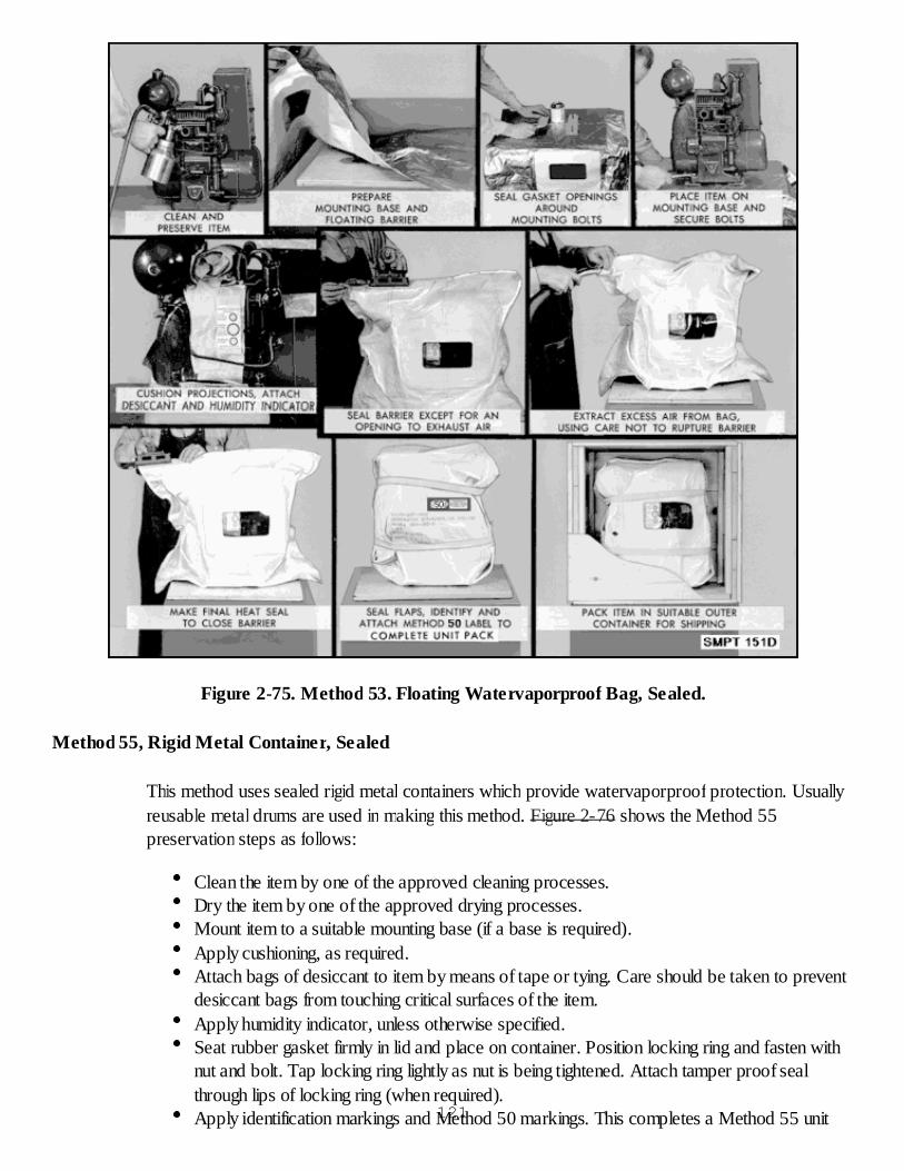
Figure 2-75. Method 53. Floating Watervaporproof Bag, Sealed.
Method 55, Rigid Metal Container, Sealed
This method uses sealed rigid metal containers which provide watervaporproof protection. Usuallyreusable metal drums are used in making this method. Figure 2-76 shows the Method 55preservation steps as follows:
Clean the item by one of the approved cleaning processes.Dry the item by one of the approved drying processes.Mount item to a suitable mounting base (if a base is required).Apply cushioning, as required.Attach bags of desiccant to item by means of tape or tying. Care should be taken to preventdesiccant bags from touching critical surfaces of the item.Apply humidity indicator, unless otherwise specified.Seat rubber gasket firmly in lid and place on container. Position locking ring and fasten withnut and bolt. Tap locking ring lightly as nut is being tightened. Attach tamper proof sealthrough lips of locking ring (when required).Apply identification markings and Method 50 markings. This completes a Method 55 unit121
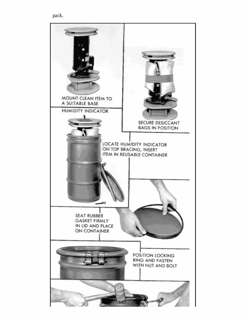
pack.
122
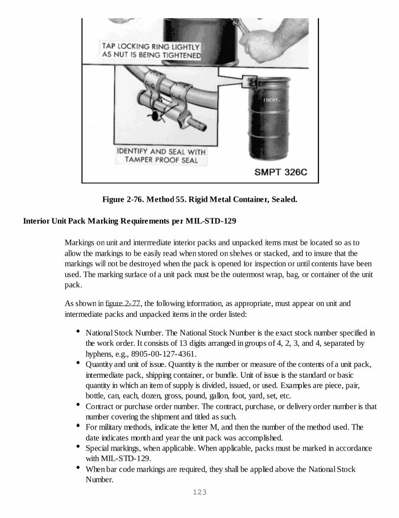
Figure 2-76. Method 55. Rigid Metal Container, Sealed.
Interior Unit Pack Marking Requirements per MIL-STD-129
Markings on unit and intermediate interior packs and unpacked items must be located so as toallow the markings to be easily read when stored on shelves or stacked, and to insure that themarkings will not be destroyed when the pack is opened for inspection or until contents have beenused. The marking surface of a unit pack must be the outermost wrap, bag, or container of the unitpack.
As shown in figure 2-77, the following information, as appropriate, must appear on unit andintermediate packs and unpacked items in the order listed:
National Stock Number. The National Stock Number is the exact stock number specified inthe work order. It consists of 13 digits arranged in groups of 4, 2, 3, and 4, separated byhyphens, e.g., 8905-00-127-4361.Quantity and unit of issue. Quantity is the number or measure of the contents of a unit pack,intermediate pack, shipping container, or bundle. Unit of issue is the standard or basicquantity in which an item of supply is divided, issued, or used. Examples are piece, pair,bottle, can, each, dozen, gross, pound, gallon, foot, yard, set, etc.Contract or purchase order number. The contract, purchase, or delivery order number is thatnumber covering the shipment and titled as such.For military methods, indicate the letter M, and then the number of the method used. Thedate indicates month and year the unit pack was accomplished.Special markings, when applicable. When applicable, packs must be marked in accordancewith MIL-STD-129.When bar code markings are required, they shall be applied above the National StockNumber.
123
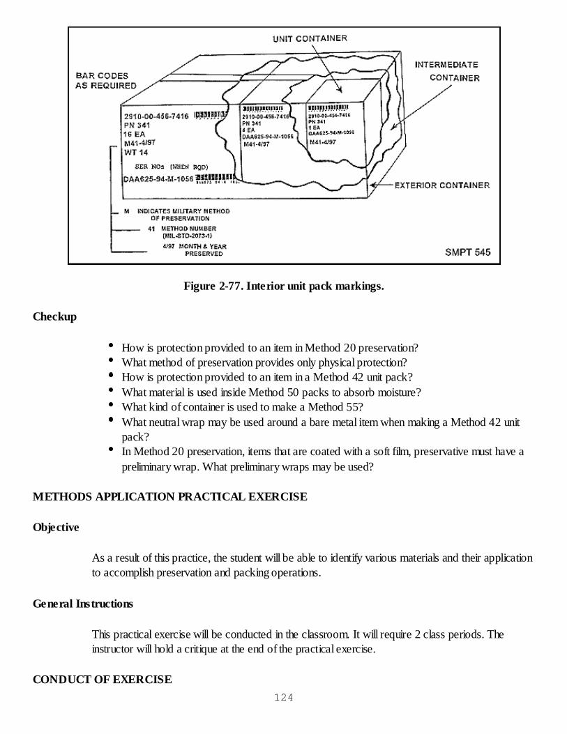
Figure 2-77. Interior unit pack markings.
Checkup
How is protection provided to an item in Method 20 preservation?What method of preservation provides only physical protection?How is protection provided to an item in a Method 42 unit pack?What material is used inside Method 50 packs to absorb moisture?What kind of container is used to make a Method 55?What neutral wrap may be used around a bare metal item when making a Method 42 unitpack?In Method 20 preservation, items that are coated with a soft film, preservative must have apreliminary wrap. What preliminary wraps may be used?
METHODS APPLICATION PRACTICAL EXERCISE
Objective
As a result of this practice, the student will be able to identify various materials and their applicationto accomplish preservation and packing operations.
General Instructions
This practical exercise will be conducted in the classroom. It will require 2 class periods. Theinstructor will hold a critique at the end of the practical exercise.
CONDUCT OF EXERCISE124

Situation
As a preservation line operator, you are responsible for fabricating various Methods ofPreservation.
Requirement
Answer the following questions:
1. What is the goal of all preservation personnel?
2. How is a unit pack defined?
3. What methods use water-vaporproof barrier materials?
4. What protection do we get from Method 50 packs:
5. What packaging operations provide the protection we get in Method 10 packs?
6. What is the first step in constructing any method of preservation?
7. What are three ways a Method 20 pack may be made?
8. What are the hard drying contact preservatives that can be used to make a Method 20pack?
9. Describe a Method 33 pack.
10. When making a Method 33 pack, we find that a greaseproof wrap will be used aroundthe preserved item. Name two materials that can be used.
11. What is the difference in the protection provided by Method 30 and Method 40 packs?
12. What is the title of Method 42?
13. What interior containers can be used to make a Method 42 pack?
14. What must be done to the watervaporproof bag in a 42 pack before it is sealed?
15. What equipment is used to seal a watervaporproof bag made from a barrier such asMIL-PRF-131?
16. If an item is not preserved with a contact preservative in a Method 42 or Method 50pack, what may be used to protect its surface?
17. What material is added to a Method 40 pack to make it a Method 50 pack?
18. What method of preservation is specially designed for giving a low humidity protection toan item which is mounted on a base?125

19. What can be applied to the outside of the barrier to indicate that a pack is Method 50?
20. Metal cans are used to make what Method 50 packs?
21. What method is used on metal items having critical surfaces?
22. What is always the last step in making a unit pack?
23. What factors are considered in choosing a method of preservation?
24. What is the purpose of preservation?
25. When a noncorrosive, protective wrap is required as a part of the unit pack, what wrapscan you use?
26. What method of preservation provides no protection from liquid water?
27. What greaseproof wraps may be used in a Method 33?
28. Describe in your own words how you would complete Method 33 for an automotivewheel bearing.
Critique
The instructor will call on members of the class to answer the questions.
Care of Area, Training Aids & Equipment
Not applicable.
MISCELLANEOUS PACKAGING REQUIREMENTS
RETURN OF REPAIRABLES
Repairable Returns
Experience has proven that we can repair an item for less than half the cost of a new one. Also, itputs the item back into the supply system in a much shorter time than that time required to purchasea new one. Proper packaging can help in the management of repairable items by:
Making certain that all retrograde repairable items are returned promptly and safely to thedesignated overhaul activity.As shown in figure 2-78, insuring that adequate protection is provided to repairable itemsthat may need only adjustment, calibration or simple repairs. If they are handled carelessly,sometimes a complete overhaul will be necessary or the item is damaged beyond economicalrepair. It becomes JUNK.Insuring that correct and complete documentation accompanies each repairable item.126

Figure 2-78. Packing of Repairables.
Processing of Repairable Items
Most repairable items can be protected during their return to overhaul activities by reusing thepacking materials and reusable containers in which the replacement parts are received.
Adequate protection should be given to repairable items and can be accomplished in three ways.First, return the repairable items in their assigned reusable container. Second, provide adequatestorage and careful handling until the item can be properly preserved and packed. Third, apply unitpacking and/or unitized packing, using available materials, to provide the amount of preservationrequired (i.e., unit protection). The item may only require Method 10 protection or it may require asmuch as a Method 50 protection.
Apply identification markings and any special markings to the containers.
When two or more packed repairable items are placed in a single shipping container, place theheaviest or densest item on the bottom. Avoid packing light fragile items with heavy rugged items.
All exterior shipping containers should bear the following minimum markings:
Identification markings.Address markings.Special markings that would be necessary for safe shipment.
Additional Processing Information127
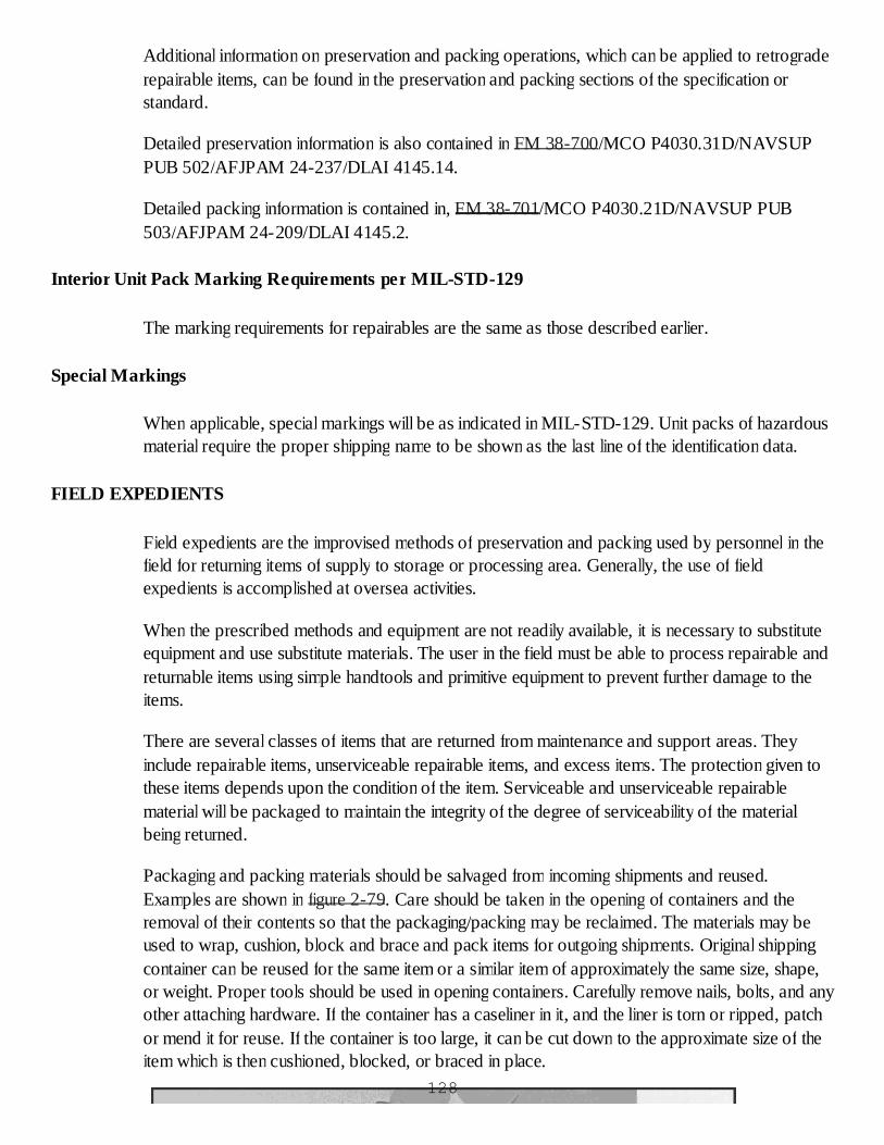
Additional information on preservation and packing operations, which can be applied to retrograderepairable items, can be found in the preservation and packing sections of the specification orstandard.
Detailed preservation information is also contained in FM 38-700/MCO P4030.31D/NAVSUPPUB 502/AFJPAM 24-237/DLAI 4145.14.
Detailed packing information is contained in, FM 38-701/MCO P4030.21D/NAVSUP PUB503/AFJPAM 24-209/DLAI 4145.2.
Interior Unit Pack Marking Requirements per MIL-STD-129
The marking requirements for repairables are the same as those described earlier.
Special Markings
When applicable, special markings will be as indicated in MIL-STD-129. Unit packs of hazardousmaterial require the proper shipping name to be shown as the last line of the identification data.
FIELD EXPEDIENTS
Field expedients are the improvised methods of preservation and packing used by personnel in thefield for returning items of supply to storage or processing area. Generally, the use of fieldexpedients is accomplished at oversea activities.
When the prescribed methods and equipment are not readily available, it is necessary to substituteequipment and use substitute materials. The user in the field must be able to process repairable andreturnable items using simple handtools and primitive equipment to prevent further damage to theitems.
There are several classes of items that are returned from maintenance and support areas. Theyinclude repairable items, unserviceable repairable items, and excess items. The protection given tothese items depends upon the condition of the item. Serviceable and unserviceable repairablematerial will be packaged to maintain the integrity of the degree of serviceability of the materialbeing returned.
Packaging and packing materials should be salvaged from incoming shipments and reused.Examples are shown in figure 2-79. Care should be taken in the opening of containers and theremoval of their contents so that the packaging/packing may be reclaimed. The materials may beused to wrap, cushion, block and brace and pack items for outgoing shipments. Original shippingcontainer can be reused for the same item or a similar item of approximately the same size, shape,or weight. Proper tools should be used in opening containers. Carefully remove nails, bolts, and anyother attaching hardware. If the container has a caseliner in it, and the liner is torn or ripped, patchor mend it for reuse. If the container is too large, it can be cut down to the approximate size of theitem which is then cushioned, blocked, or braced in place.
128
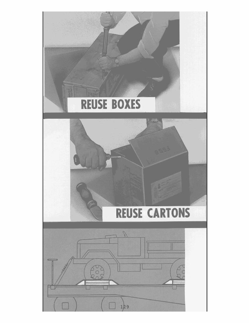
129

Figure 2-79. Salvaging reusable materials from shipments.
When cleaning materials and equipment are not available, alternate processes must be selected.Cleaning must be thorough to remove all dirt and rust from the item. The cleaning processes maydepend on mechanical or chemical action for the removal of dirt and rust.
Mechanical Processes
Cleaning by physical or mechanical action may involve the use of one or more of the followingoperations:
Wiping. This involves wiping dirt and rust from the item. Old burlap bags may be used toremove dirt and wire brushes will remove rust. When clean cloths are available, use twocloths. Use one cloth to remove heavy dirt and use the second cloth as a final wipe.Use of abrasives. Barrel tumbling is a form of abrasive that removes rust, carbon deposits,etc., from dirty and rusty items. It may be used for rugged items. To obtain the scrubbingaction needed, nails, staples, bolts, nuts, sand, screened gravel, or crushed stone with watermay be used. A barrel to do the tumbling may be constructed from a used 55-gallon drumon an improvised rack. Care should be taken that the items cleaned by this method are notdamaged by the abrasive and the water. Hand sanding with sand paper, emery cloth, crocuscloth, and carborundum in the form of discs, sheets, or belts may be used to remove rust,paint, old finishes, and other dry coatings. This process may be used if the surfaces are notmarred or injured to the point of making the items useless or unrepairable.Impact tool cleaning. The removal of scale, rust, or old dry coatings may be done with cross130
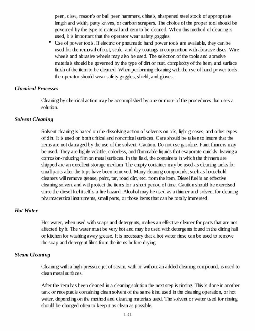
peen, claw, mason's or ball peen hammers, chisels, sharpened steel stock of appropriatelength and width, putty knives, or carbon scrapers. The choice of the proper tool should begoverned by the type of material and item to be cleaned. When this method of cleaning isused, it is important that the operator wear safety goggles.Use of power tools. If electric or pneumatic hand power tools are available, they can beused for the removal of rust, scale, and dry coatings in conjunction with abrasive discs. Wirewheels and abrasive wheels may also be used. The selection of the tools and abrasivematerials should be governed by the type of dirt or rust, complexity of the item, and surfacefinish of the item to be cleaned. When performing cleaning with the use of hand power tools,the operator should wear safety goggles, shield, and gloves.
Chemical Processes
Cleaning by chemical action may be accomplished by one or more of the procedures that uses asolution.
Solvent Cleaning
Solvent cleaning is based on the dissolving action of solvents on oils, light greases, and other typesof dirt. It is used on both critical and noncritical surfaces. Care should be taken to insure that theitems are not damaged by the use of the solvent. Caution. Do not use gasoline. Paint thinners maybe used. They are highly volatile, colorless, and flammable liquids that evaporate quickly, leaving acorrosion-inducing film on metal surfaces. In the field, the containers in which the thinners areshipped are an excellent storage medium. The empty container may be used as cleaning tanks forsmall parts after the tops have been removed. Many cleaning compounds, such as householdcleaners will remove grease, paint, tar, road dirt, etc. from the item. Diesel fuel is an effectivecleaning solvent and will protect the items for a short period of time. Caution should be exercisedsince the diesel fuel itself is a fire hazard. Alcohol may be used as a thinner and solvent for cleaningpharmaceutical instruments, small parts, or those items that can be totally immersed.
Hot Water
Hot water, when used with soaps and detergents, makes an effective cleaner for parts that are notaffected by it. The water must be very hot and may be used with detergents found in the dining hallor kitchen for washing away grease. It is necessary that a hot water rinse can be used to removethe soap and detergent films from the items before drying.
Steam Cleaning
Cleaning with a high-pressure jet of steam, with or without an added cleaning compound, is used toclean metal surfaces.
After the item has been cleaned in a cleaning solution the next step is rinsing. This is done in anothertank or receptacle containing clean solvent of the same kind used in the cleaning operation, or hotwater, depending on the method and cleaning materials used. The solvent or water used for rinsingshould be changed often to keep it as clean as possible.
131

There are several methods of drying which can be used in the field. Compressed air, ovens,spotlights, and ordinary light bulbs can be used as drying methods. If these methods are notavailable, you may dry by wiping with a clean, dry cloth. Items may be dried by draining after usingmost solvents as the final rinse. It is important that the items be handled carefully again after dryingto prevent them from getting dirty again.
Preservatives, if required should be applied as soon as possible after drying. Preservative selectionshould be based on item characteristics and intended uses of the preservative.
There are many ways that material may be processed in the field through the use of fieldconstructed equipment. Some of the more easily constructed equipment are as follows:
Field-constructed hot-dip tank. A hot-dip tank may be made by cutting a 55-gallon drum inhalf to make a round tank and adding a source of heat, as shown in figure 2-80.Field-constructed petroleum-solvent tank. Figure 2-81 shows petroleum solvent tank maybe made by cutting a 55-gallon drum lengthwise and placing on stands. A cover should bemade to fit the tank as tightly as possible. Two-gallon pails and five-gallon cans may alsoserve as containers for the cleaning solvent.Field-constructed drying oven. A drying oven can be constructed from a 55-gallon drum. Toprovide the heat, a good gasoline element from a field kitchen stove can be used. Coal, oil,or wood may also be used to supply the heat required.Field-constructed hot water or alkaline cleaning tank. A 55-gallon drum with the topremoved to make a vat may be used as a hot water or an alkaline cleaning tank as illustratedin figure 2-82. To provide the heat for an alkaline solution, the steam from a steam-cleaningunit may be used. Kitchen lye may be used as the alkaline cleaning material.Field-constructed drum-type tumbling cleaner. Figure 2-82 shows how a tumbling cleanermay be constructed from a 55-gallon drum. The drum should be provided with an axle thatmay be fitted into a bearing surface. One end of the axle should have a handle for turning thedrum. In the side of the drum, there should be an opening with a door that can be secured.Inside there should be agitators (fins) to cause the material to tumble. These may be madefrom angle iron or like materials.Field-constructed small parts dipping baskets. Small parts dipping baskets may beconstructed from cans with holes punched in the sides and bottom so as not to trap solventas shown in figure 2-83. A wire handle should be attached for handling of the baskets.Varying size cans might be obtained from the dining facility. These baskets can also be madefrom screen wire, hardware cloth, etc.Extreme care must be used to assure that the proper preservatives, cleaning, and packingmaterials are not available through normal supply channels before expedients are used. In allcases the field expedients will be used only as a last resort to prevent further damage ofsupplies and equipment.
132

Figure 2-80. Field constructed dip tank.133
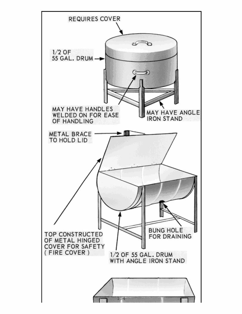
134
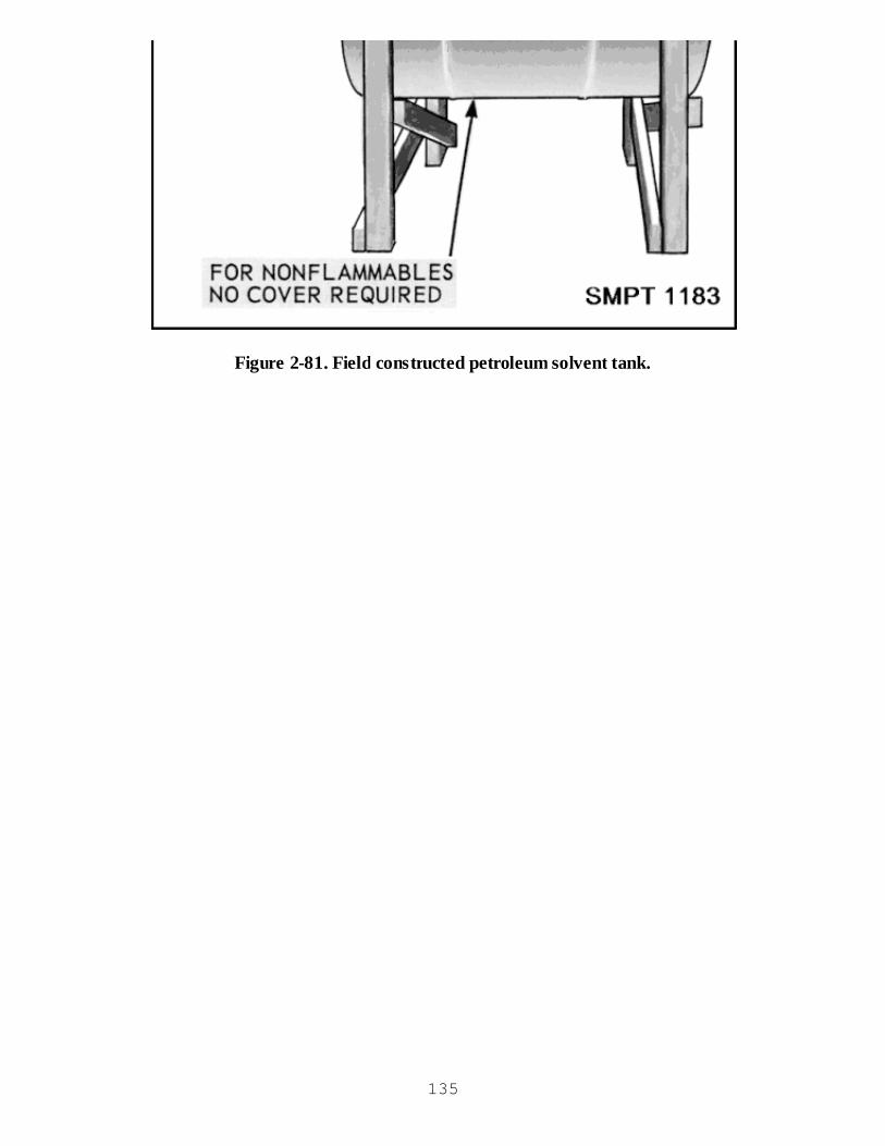
Figure 2-81. Field constructed petroleum solvent tank.
135
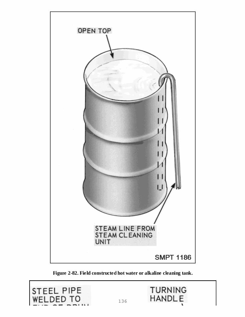
Figure 2-82. Field constructed hot water or alkaline cleaning tank.
136
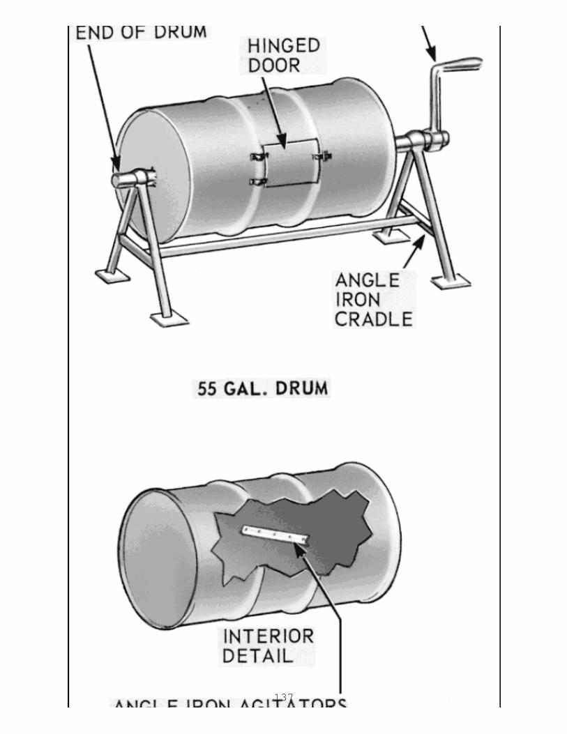
137
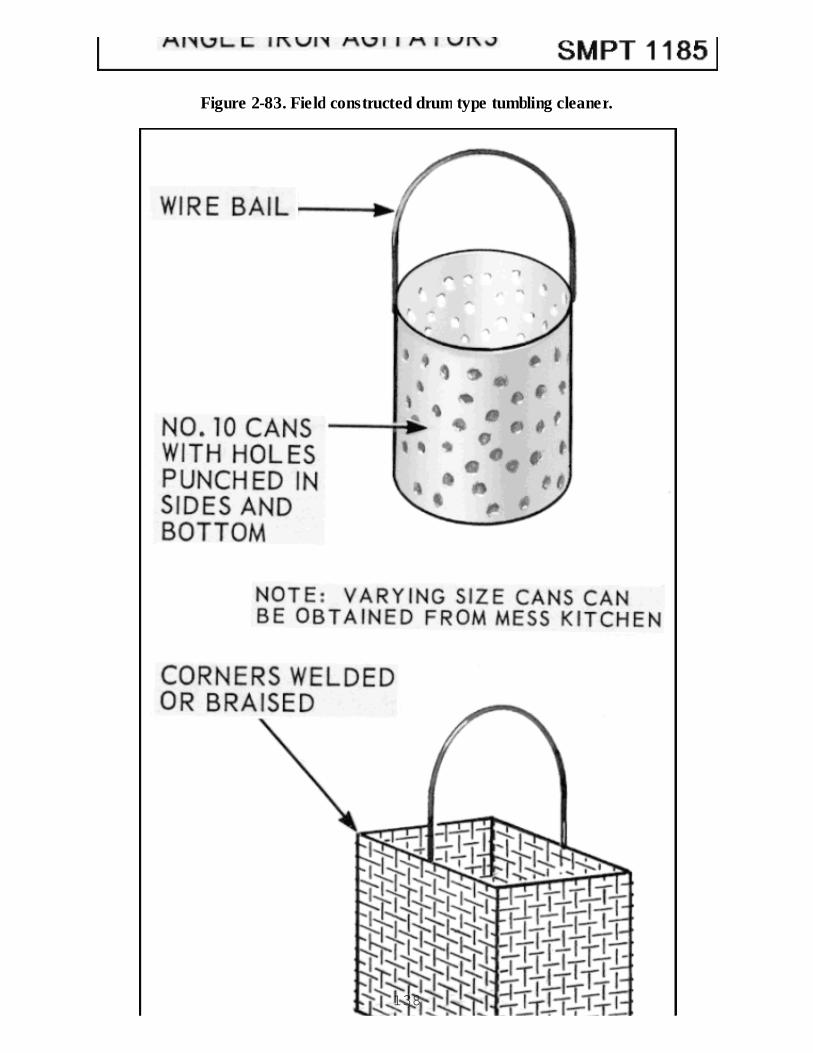
Figure 2-83. Field constructed drum type tumbling cleaner.
138
Figure 2-84. Field constructed small parts dipping baskets.
SAFETY
Policy
It is the government's policy, through regulations, that the provisions of the Occupation Safety andHealth Act will not be compromised or ignored in accomplishing military packaging functions. Theresponsibilities for safety procedures starts with the commander of each DOD organization andends with the individual worker.
Safety Practices
The commander has the responsibility to:
Provide a safe and healthful place to work.Provide safe conditions under which packaging operations can be accomplished.Obtain and maintain safety and protective equipment.Require the use of this equipment.Establish a safety program.Periodically inspect the work area to assure the safety program is being accomplished.
It is the individual worker's responsibility to properly use the safety equipment and work in a safemanner.
Safety is everyone's responsibility. You can affect your fellow workers' safety as well as your ownby not working "by the rules." The best safety program in the world is of little value if the workersleave it in the conference room. Only you can prevent accidents.
HAZARDOUS WASTE
General
We are all becoming more aware of the tremendous number of hazardous materials being usedthroughout the world. Well, what happens when containers of hazardous materials are notcompletely used up by industrial and military installations or materials whose expiration datepassed? They become hazardous wastes. In 1976, Congress passed the Resource Conservationand Recovery Act (RCRA) which defines a hazardous waste as "a solid waste that may cause orsignificantly contribute to serious illness or death..."139

Wastes
The four characteristics which make a material hazardous are:
Ignitability.Corrosivity.Reactivity (or explosiveness).Toxicity.
Many of the materials that are used in packaging operations can end up as a waste product, somehazardous. For example:
Plastics may generate organic chlorine compounds.Paints generate heavy metals, pigments, organic residues.Petroleum products (solvents) generate oils, phenols, organic compounds, ammonia salts,acids, caustics.
Regulations
RCRA
Because of the increasing potential hazards of waste products, the Environmental ProtectionAgency (EPA) has adopted a "cradle-to-grave" control system. This system regulates hazardouswaste from the time it is generated through transportation to final disposal.
Control of all aspects of hazardous waste, as regulated by Code of Federal Regulations (CFR) 40,Protection of Environment, is gradually being turned over to the individual states as they developwaste management programs consistent with RCRA.
Each DOD installation is or will be responsible to the state in which it is located. The commander ofthat installation is responsible for developing a hazardous waste management program, which willestablish how hazardous waste will be identified, collected, stored, transported, and disposed.
CFR 40 regulates the documentation, transportation, storage, and disposal of hazardous waste.
CFR 49, Transportation, regulates the packaging and some transportation of hazardous wastebetween states. This document explains how each container will be marked and labeled. We willhave an opportunity to discuss this to a greater extent in a later lesson.
Your Responsibility
To be part of the solution to the hazardous waste problem:
Recognize that we are all part of the problem-- hazardous waste inevitably results from theproducts used in packaging operations.Reduce the amount of materials we waste--this will not only reduce the quantities ofhazardous waste generated, but will also conserve natural resources, reduce solid waste140
disposal problems, and save us money.Understand the many complexities of the hazardous waste problem--EPA, state, and localgovernments all have regulations.Participate in waste management programs.Recognize that there are no easy solutions.
Checkup
What method of preservation do you use to pack small repairable items?What are field expedients?When the necessary equipment and material are not available, what should the individual do?Why is the proper opening of a carton important?If hot water and soaps are used for cleaning, what should be the next step?What may be used as a petroleum solvent tank in the field?What document explains the proper disposal procedures for hazardous waste?
141

CHAPTER 3
Military Packing
INTRODUCTION TO MILITARY PACKING
NEED FOR TRAINING/PRESERVATION
PACKING
Proper Packing
There is a definite need for proper packing if we are going to give our supplies maximum protectionat minimum cost. How can we do this? It is very simple! Know the characteristics of the item youare packing and apply the protection the item needs. It is important not to over or under packbecause:
Overpacking costs the Government excessive amounts of money for materials and labor.Underpacking can cause excessive damage to many items and make them useless.Properly packing materiel the first time will save money.
Purpose of Packing
The purpose of packing is to protect the item from damage during handling, shipment, and storage.
How Packing is Accomplished
As shown in figure 3-1, packing is accomplished by inserting unit or intermediate packs orunpacked material into a shipping container after the application, when required, of blocking,bracing, cushioning, and waterproof barriers. Packing is completed with the final closure, strapping,and marking of the shipping container.
142

Figure 3-1. Basic steps in military packaging.
Preservation vs. Packing Operations
Preservation and packing operations are sometimes considered as being the same thing, but eachone has its own operations, as illustrated in figure 3-2. The preservation operations are known asthe preservation cycle. This was covered during the first part of the course. The packing operationsare known as the packing cycle. Let's look at each one of these operations individually.
143
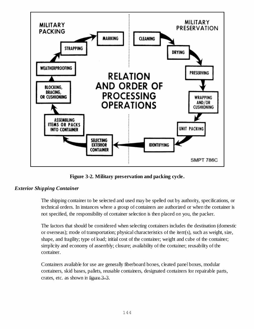
Figure 3-2. Military preservation and packing cycle.
Exterior Shipping Container
The shipping container to be selected and used may be spelled out by authority, specifications, ortechnical orders. In instances where a group of containers are authorized or when the container isnot specified, the responsibility of container selection is then placed on you, the packer.
The factors that should be considered when selecting containers includes the destination (domesticor overseas); mode of transportation; physical characteristics of the item(s), such as weight, size,shape, and fragility; type of load; initial cost of the container; weight and cube of the container;simplicity and economy of assembly; closure; availability of the container; reusability of thecontainer.
Containers available for use are generally fiberboard boxes, cleated panel boxes, modularcontainers, skid bases, pallets, reusable containers, designated containers for repairable parts,crates, etc. as shown in figure 3-3.
144
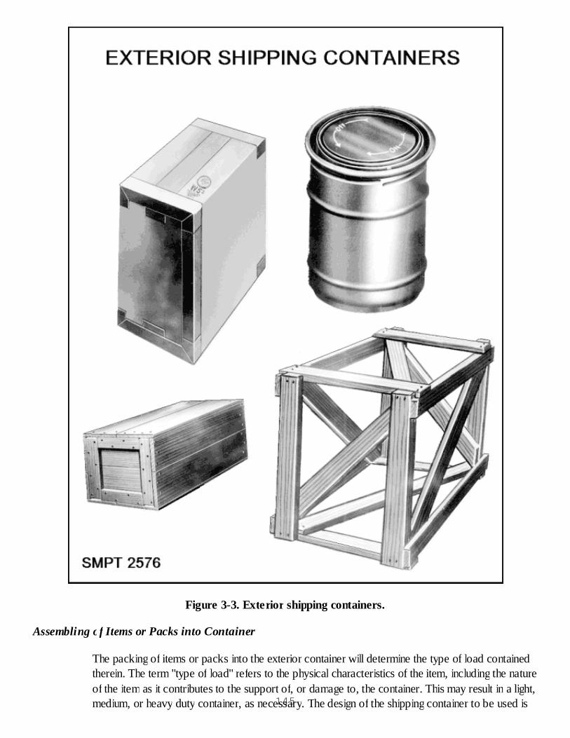
Figure 3-3. Exterior shipping containers.
Assembling of Items or Packs into Container
The packing of items or packs into the exterior container will determine the type of load containedtherein. The term "type of load" refers to the physical characteristics of the item, including the natureof the item as it contributes to the support of, or damage to, the container. This may result in a light,medium, or heavy duty container, as necessary. The design of the shipping container to be used is145

influenced by the type of load. There are three types of loads: Type 1, Type 2, and Type 3, definedin MIL-STD-2073-1C, and depicted in figure 3-4.
Figure 3-4. Types of loads.
Loads
Types of loads are determined by the degree of structural strength supplied to the shippingcontainer by the contents. Loads are classified as Type 1, easy loads; Type 2, average loads; andType 3, difficult loads, as described below:
Type 1, easy load. A Type 1, easy load, is developed from an item which completely fills theouter shipping container or from items of moderate density prepackaged in an interiorcontainer which completely fills the outer shipping container. Easy load items are not easilydamaged by puncture or shock and do not shift or otherwise move within the package.Examples include items packaged in boxes or cans which are prepackaged in fiberboardboxes prior to overpacking in the shipping container, chests, tool kits, and sturdy instrumentswhich are fully in contact with, and support, all faces of the shipping container.Type 2, average load. A Type 2, average load, is developed from item(s) of moderatelyconcentrated weight which are packed directly into the shipping container and provide partialsupport to all panels thereof. It also includes item(s) prepackaged by wrapping or bypositioning in partitions, cells or paperboard boxes, or by other means which provide
146
support to all panels of the shipping container. Examples include items packaged in boxes orcans which are not prepackaged in an interior container and bottles individually separatedone from the other by cells or partitions.Type 3, difficult load. A Type 3, difficult load, is developed from item(s) which require a highdegree of protection to prevent puncture, shock, or distortion of the shipping container. Italso includes item(s) which do not provide complete support to the panels of the shippingcontainer. Examples include wrenches, long bolts, and rods which exert concentrated forceson the shipping container; motors, telephones, typewriters, drop forgings, rivets, hardware,or other items that are random packed in bulk; and fragile or delicate items requiring specialprotection.
Blocking, Bracing, or Cushioning
To assist in determining whether an item has to be blocked and braced and/or cushioned, thefollowing factors have to be carefully considered: the shape of the item, its size, weight, shockresistance, lack or availability of mounting provisions, degree of disassembly permissible or feasible,and the type of load the item represents. The necessities for blocking, bracing, and cushioning areas follows:
Containers are often subjected to rough handling during shipment and transportation. If the itemspacked therein are free to move or if they are not properly protected against repeated shocks, jolts,and vibrations, the end result might be damage or complete loss.
Military situations demand that items be packed to withstand all possible hazards encountered intransportation. This includes proper blocking, bracing, and/or cushioning to insure the stability of thecontents.
Weatherproofing
Weatherproofing, when necessary, is to provide a waterproof barrier in the form of a case liner,crate liner, shroud, or wrap fabricated of barrier materials such as those in PPP-B-1055 or MIL-B-121, if extreme climatic conditions are involved. Such waterproof barriers are primarily intendedto prevent deterioration of the items and the preservation materials used to protect the articles byexcluding the entry of free water, or by diverting water from materials which are subject to waterdamage. In addition, waterproof barriers will afford protection from dust, dirt, and other foreignmatter. Waterproof barriers will not be used when the interior packs are already waterproofed, norwhen asphaltum in some of the barrier materials or sealouts would be injurious to the enclosedarticles.
Strapping
Each military container specification has a section or appendix devoted to requirements forstrapping exterior containers. We will cover the strapping requirements for various containers asthey are discussed throughout this part of the course.
Marking147

Marking is used to speed up the movement of shipments without confusion and delay, and to permitready identification of contents either at transshipping points or at destination. No matter how wellan article is made or packed, it is valueless if it cannot be identified upon reaching its destination.
Packing Policy
Earlier in the course we discussed the levels of protection for the packing of items for shipment orstorage. It was noted that AR 700-15/NAVSUPINST 4030.28D/AFJMAN 24-206/MCO4030.33D/DLAD 4145.7 states: "Materiel will be packaged to prevent damage and deteriorationand to provide for efficient and economical handling. Commercial packaging will be used whensuch packaging is cost effective. Use of commercial packaging should be determined before acontract is awarded or within the life cycle of the contract when substantial savings to theGovernment may result and adequate protection is provided by the commercial packaging. Thesedecisions will be made by the packaging office at the buying activity."
Economy in Packing
As packing personnel, you should be interested in savings, not only for the Government but foryourself (as a taxpayer). Savings can be realized in packing operations without sacrificing protectionof the item. Several factors affecting economy in packing enter into the picture, such as materials,equipment, manpower, etc. Since only three of the most important elements are listed, a few of thehighlights will be mentioned.
Materials and Cost
Cost of materials alone is not the only factor. If personnel are familiar with the various types, when,how, and where to use them, substantial savings may be realized. Used packing materials should bereclaimed and reused to the maximum extent.
Equipment and Cost
The cost of equipment alone is not the only factor. Proper arrangement and utilization of equipment,whether manually operated or mechanized units, will have a bearing on the quantity of workperformed. Savings may be realized through the use of mechanized units providing the cost ofequipment is saved in time, labor, and increased production.
Manpower
The utilization of manpower is the most important single element in any packing operation. Aspacking personnel, you have the opportunity to learn all phases of packing in order to obtain thenecessary knowledge for the growing packing field.
Hazards of Storage
The major hazards to our packs in storage often are the results of extreme temperature changes,148

high or low humidity, bacteria and fungi, and aging. Some of the damage that can result from theseconditions is shown in figure 3-5.
Wood decays or rots.Leather cracks.Cork becomes brittle.Metals rust.Food molds and rots.Textiles fade and mildew.Chemicals change with age.Ceramics check or craze.Rubber cracks and splits.
149
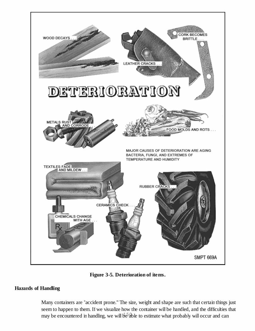
Figure 3-5. Deterioration of items.
Hazards of Handling
Many containers are "accident prone." The size, weight and shape are such that certain things justseem to happen to them. If we visualize how the container will be handled, and the difficulties thatmay be encountered in handling, we will be able to estimate what probably will occur and can150
adjust our packing accordingly.
Deceiving Appearance of an Item
A delicate item such as a wristwatch may be able to take a fairly heavy jolt, while a piece ofelectronic equipment with a rugged looking case may not be able to tolerate much shock at all. Aheavy metal casting may crack when dropped a very short distance.
Damage by Handling Equipment
Some damages that may result from handling equipment are as follows:
Hand trucks, fork lifts, and trailers with flat wheels can cause damaging shock and vibration.Hand trucks with hard tires moving over uneven surfaces can cause similar damage.The improper use of sling cables can cause damage to containers. They can crush boxes andcrates across the top. When long crates or boxes are lifted by cables, they have a tendencyto bend in the middle.
Damage to Containers by Grab Hooks (Box Hooks)
Grab hooks cause a crushing action across the top where the points of the hooks tear and rip intothe container. Since they lift from the top, they place a vertical strain on crates and boxes. Heavyitems on crate bases have a tendency to "drop out" the bottom of the crate.
Damage by Use of Hand Hooks for Handling
Hooks tear and puncture fiberboard boxes. They destroy labels and markings.
Damage by Forklift Trucks
The improper use of forklift trucks often results in damage to shipping and storage containers.Some examples include puncture damage when forklift forks are used for pushing containers; floorboard damage when forklift forks are improperly tilted during lifting; and sagging and/or weakeningof the container structure when long and/or oversize crates are lifted in the center. Damage mayalso result when improperly arranged loads are lifted and containers fall.
Damage by Cargo Nets
Fragile containers may be crushed when the net is lifted. When the net is emptied, containers maytumble and roll causing damage.
Damage Due to Improper Manual Handling
Light containers have a tendency to be thrown. Fiber drums can be damaged by rolling them ontheir sides. Ignoring special handling instruction markings, such as "USE NO HOOKS," "THISSIDE UP," "FRAGILE," etc., may cause damage. Tall containers have a tendency to fall over whenhandled. Heavy containers can be damaged by manhandling. They have a tendency to be dropped.Moving heavy containers by "walking" them may cause them to wrack. Sliding heavy containers151
across the floor can also cause them to wrack. Heavy containers piled on lightweight containers cancrush the lightweight containers. Dropping containers from trucks, planes, docks, etc., when loadingand unloading can damage materiel.
Checkup
What is the purpose of packing?What are the basic steps of military packing?Name the three types of loads.Do the levels of protection that apply to preservation apply to packing?How can savings be realized in packing operations without sacrificing protection to the item?
FIBERBOARD SHIPPING BOXES (ASTM D 1974/ASTM D 5118)
FIBERBOARD BOXES
Description of Fiberboard Boxes
Fiberboard boxes are probably the most generally used shipping container today. They vary insizes, shapes, and styles and may be used for either domestic or oversea shipments.
Types of Loads
Earlier, we discussed the three types of loads. Only type 1 and type 2 loads may be shipped infiberboard boxes. If you have a type 3 load, you must convert it to a type 1 or 2 load by usingcushioning, blocking, or bracing.
Materials
Before we discuss fiberboard boxes in detail, we should have some information on the fiberboardbox materials.
FiberboardFiberboard material (ASTM D 4727) used to make these boxes locally is bought inlarge sheet stock form. Usually it is stored in the box shop; and whenever a specialsize box is needed, it is made from this sheet stock.This fiberboard material is available in two types. One type is called solid fiberboard(SF) and the other is called corrugated fiberboard (CF). Solid fiberboard is fabricatedby gluing several layers of flat fiber sheets together to obtain the desired thickness.Corrugated fiberboard is constructed from facings and corrugated (wavy) sheetsglued together. Corrugated fiberboard may be fabricated either as single-wall (SW) ordouble-wall (DW) stock or triple-wall. Single-wall material consists of onecorrugation between two flat facing sheets while double-wall material consists of oneflat facing between corrugated sheets sandwiched between two outer flat facingsheets. Triple-wall material consists of two flat facing sheets between three corrugated152
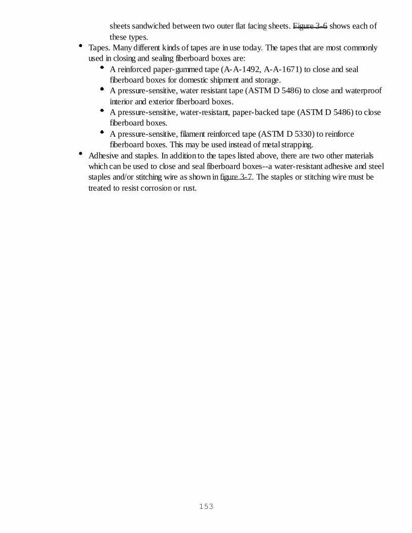
sheets sandwiched between two outer flat facing sheets. Figure 3-6 shows each ofthese types.
Tapes. Many different kinds of tapes are in use today. The tapes that are most commonlyused in closing and sealing fiberboard boxes are:
A reinforced paper-gummed tape (A-A-1492, A-A-1671) to close and sealfiberboard boxes for domestic shipment and storage.A pressure-sensitive, water resistant tape (ASTM D 5486) to close and waterproofinterior and exterior fiberboard boxes.A pressure-sensitive, water-resistant, paper-backed tape (ASTM D 5486) to closefiberboard boxes.A pressure-sensitive, filament reinforced tape (ASTM D 5330) to reinforcefiberboard boxes. This may be used instead of metal strapping.
Adhesive and staples. In addition to the tapes listed above, there are two other materialswhich can be used to close and seal fiberboard boxes--a water-resistant adhesive and steelstaples and/or stitching wire as shown in figure 3-7. The staples or stitching wire must betreated to resist corrosion or rust.
153
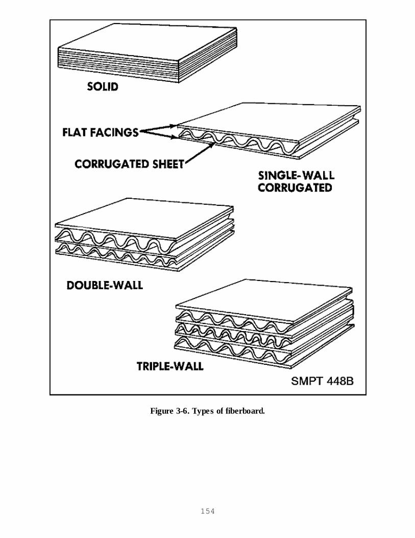
Figure 3-6. Types of fiberboard.
154
Figure 3-7. Closure of fiberboard boxes with adhesive tape or stitches.
Classification of Fiberboard Boxes (ASTM D 5118)
Fiberboard shall conform to Type, Class, Variety and Grade of ASTM D 4727 unless otherwisespecified.
Type. Fiberboard boxes are constructed from two types of fiberboard material, type CF(corrugated fiberboard) and type SF (solid fiberboard).Class. Class designates the amount of weather protection provided. The classes are
155
domestic--slight protection; domestic/fire retardant - slight protection and fire retardancy;weather-resistant (WR)--some protection against liquid water and waterproof andwatervapor resistant (WWVR) good protection against water with only moderate protectionagainst watervapor. The facings and outer piles of weather- resistant fiberboard are treatedwith a water-resistant resin. WWVR fiberboard will be treated with the same resin and has alaminated ply of polyethylene. Both WR and WWVR fiberboard use a water-resistantadhesive to hold the various layers together.Variety. Only the type CF boxes can be divided into the varieties which are single wall (SW)and double wall (DW).Grade. The designations for grade depend upon the class of the box. Class domestic gradesare shown numerically indicating the bursting strength of the fiberboard material, for example275. Class WR and WWVR grades are shown as a capital letter (V or W), a number, and alower case letter (s or c), such as V11c. W or V indicates that fiberboard material is weatherresistant, the number relates to the strength of the material, and the s or c designates the typeof fiberboard material (solid or corrugated).
Design
There are 15 different styles of fiberboard boxes. These styles are determined by the location of theslots and the construction of the box. Of all the styles, the two most widely used styles are theregular slotted container (RSC) and the center special slotted container (CSSC).
Style RSC. Figure 3-8 depicts the features of the RSC. All the flaps of a regular slottedcontainer are the same length, and the outer flaps meet at the center of the box. The spacebetween the inner flaps varies depending upon the relation of the length to the width of thebox. The flaps along the longer edge of the box opening are called the outer flaps. The flapsalong the shorter edge of the box opening are called the inner flaps. Consequently, there willalways be a space between the inner flaps when they are folded in place, except if the lengthand width of the box are the same size.Style CSSC. Figure 3-9 illustrates the CSSC. The style CSSC fiberboard box is similar tothe style RSC fiberboard box except that it is stronger on the top and bottom due to thedouble thickness of the fiberboard in these areas. Both the inner and outer flaps meet in thecenter of the style CSSC fiberboard box. A gap not to exceed 1/4 inch is permitted betweenthe inner and outer flaps when in the closed position.
156

Figure 3-8. Fiberboard box style RSC.
157
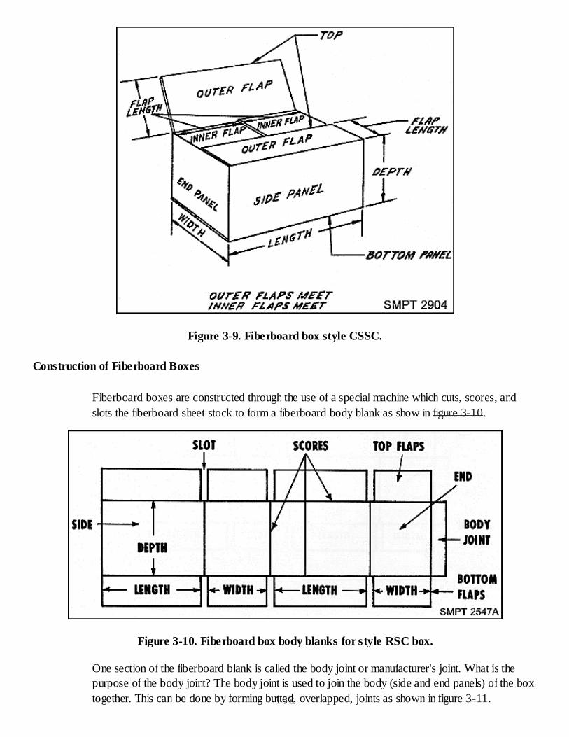
Figure 3-9. Fiberboard box style CSSC.
Construction of Fiberboard Boxes
Fiberboard boxes are constructed through the use of a special machine which cuts, scores, andslots the fiberboard sheet stock to form a fiberboard body blank as show in figure 3-10.
Figure 3-10. Fiberboard box body blanks for style RSC box.
One section of the fiberboard blank is called the body joint or manufacturer's joint. What is thepurpose of the body joint? The body joint is used to join the body (side and end panels) of the boxtogether. This can be done by forming butted, overlapped, joints as shown in figure 3-11.158
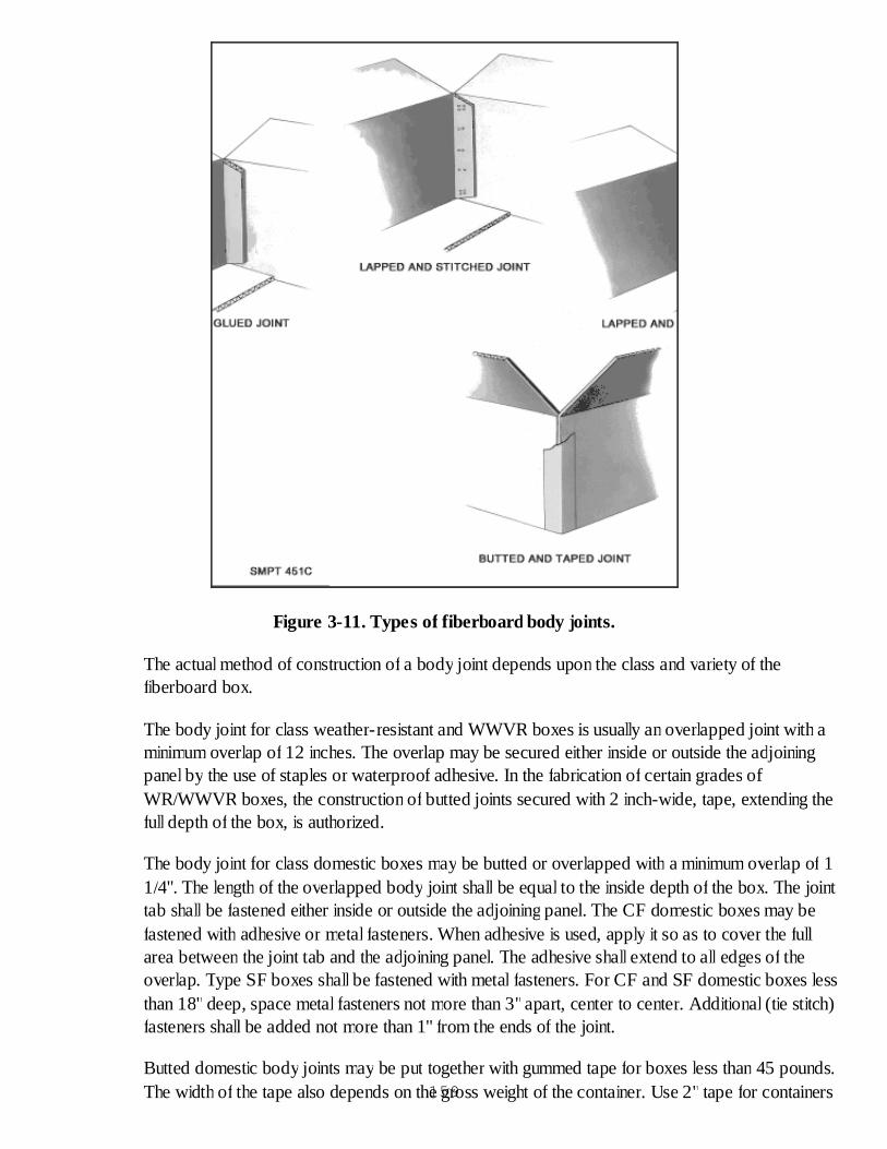
Figure 3-11. Types of fiberboard body joints.
The actual method of construction of a body joint depends upon the class and variety of thefiberboard box.
The body joint for class weather-resistant and WWVR boxes is usually an overlapped joint with aminimum overlap of 12 inches. The overlap may be secured either inside or outside the adjoiningpanel by the use of staples or waterproof adhesive. In the fabrication of certain grades ofWR/WWVR boxes, the construction of butted joints secured with 2 inch-wide, tape, extending thefull depth of the box, is authorized.
The body joint for class domestic boxes may be butted or overlapped with a minimum overlap of 11/4". The length of the overlapped body joint shall be equal to the inside depth of the box. The jointtab shall be fastened either inside or outside the adjoining panel. The CF domestic boxes may befastened with adhesive or metal fasteners. When adhesive is used, apply it so as to cover the fullarea between the joint tab and the adjoining panel. The adhesive shall extend to all edges of theoverlap. Type SF boxes shall be fastened with metal fasteners. For CF and SF domestic boxes lessthan 18" deep, space metal fasteners not more than 3"apart, center to center. Additional (tie stitch)fasteners shall be added not more than 1" from the ends of the joint.
Butted domestic body joints may be put together with gummed tape for boxes less than 45 pounds.The width of the tape also depends on the gross weight of the container. Use 2" tape for containers159
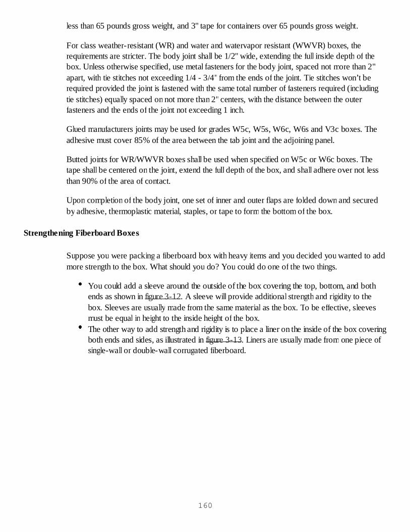
less than 65 pounds gross weight, and 3" tape for containers over 65 pounds gross weight.
For class weather-resistant (WR) and water and watervapor resistant (WWVR) boxes, therequirements are stricter. The body joint shall be 1/2" wide, extending the full inside depth of thebox. Unless otherwise specified, use metal fasteners for the body joint, spaced not more than 2"apart, with tie stitches not exceeding 1/4 - 3/4" from the ends of the joint. Tie stitches won’t berequired provided the joint is fastened with the same total number of fasteners required (includingtie stitches) equally spaced on not more than 2"centers, with the distance between the outerfasteners and the ends of the joint not exceeding 1 inch.
Glued manufacturers joints may be used for grades W5c, W5s, W6c, W6s and V3c boxes. Theadhesive must cover 85% of the area between the tab joint and the adjoining panel.
Butted joints for WR/WWVR boxes shall be used when specified on W5c or W6c boxes. Thetape shall be centered on the joint, extend the full depth of the box, and shall adhere over not lessthan 90% of the area of contact.
Upon completion of the body joint, one set of inner and outer flaps are folded down and securedby adhesive, thermoplastic material, staples, or tape to form the bottom of the box.
Strengthening Fiberboard Boxes
Suppose you were packing a fiberboard box with heavy items and you decided you wanted to addmore strength to the box. What should you do? You could do one of the two things.
You could add a sleeve around the outside of the box covering the top, bottom, and bothends as shown in figure 3-12. A sleeve will provide additional strength and rigidity to thebox. Sleeves are usually made from the same material as the box. To be effective, sleevesmust be equal in height to the inside height of the box.The other way to add strength and rigidity is to place a liner on the inside of the box coveringboth ends and sides, as illustrated in figure 3-13. Liners are usually made from one piece ofsingle-wall or double-wall corrugated fiberboard.
160
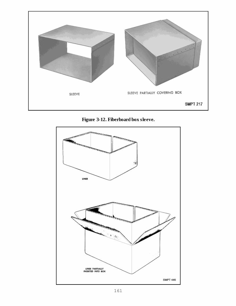
Figure 3-12. Fiberboard box sleeve.
161
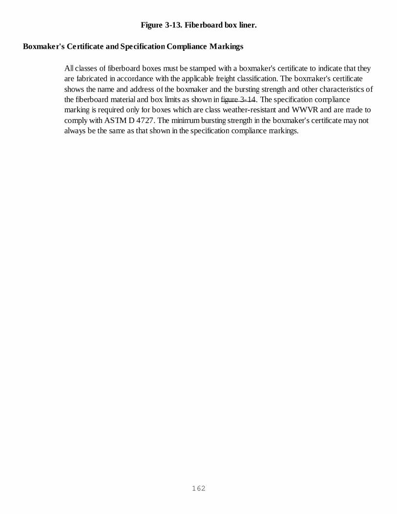
Figure 3-13. Fiberboard box liner.
Boxmaker's Certificate and Specification Compliance Markings
All classes of fiberboard boxes must be stamped with a boxmaker's certificate to indicate that theyare fabricated in accordance with the applicable freight classification. The boxmaker's certificateshows the name and address of the boxmaker and the bursting strength and other characteristics ofthe fiberboard material and box limits as shown in figure 3-14. The specification compliancemarking is required only for boxes which are class weather-resistant and WWVR and are made tocomply with ASTM D 4727. The minimum bursting strength in the boxmaker's certificate may notalways be the same as that shown in the specification compliance markings.
162

Figure 3-14. Boxmakers certificate and specification compliance markings.
Fiberboard Box Weight and Size Limits
You should be careful when packing fiberboard boxes so that you do not go over the weight or sizelimits given in tables 3-1 and 3-2.
163

Table 3-1. Size and weight limitations for types CFa and SFa, Class Domestic Fiberboard Boxesb
Type CF Variety Type SF Max Weight of Boxes andContents
MaxInside Dimensions
SWa DWa Length + Width + Depth
Grade Grade Grade Lb (kg) In. (mm)
125 ………….. 125 20 (9.1) 40 (1016)
150 ………….. ………….. 30 (13.6) 50 (1270)
175 ………….. 175 40 (18.1) 60 (1524)
200 200 200 65 (29.5) 75 (1905)
275 275 275 90 (40.8) 90 (2286)
350 350 350 120 (54.4) 100 (2540)
500 500 140 (63.5) 110 (2794)
600 600 160 (72.6) 120 (3048)
a Explanation of abbreviations in Table 1.CF - Corrugated FiberboardSF - Solid FiberboardSW - Single-wall FiberboardDW - Double-wall Fiberboard
b Size and weight limitations may be modified or waived by the ordering activity, as necessary, when boxes are used for non-shipper or special purpose.
Table 3-2. Size and Weight Limitations for Class Weather-Resistant (WR) and Water and Water VaporResistant (WWVR) Fiberboard Boxes Used as Exterior Containersa
Note - The gross weight and size limit expressed in the circular or rectangular boxmaker’s certificate shallconform to the requirements of the Uniform Freight Classification or National Motor Freight Classification Rules,as applicable, and may not necessarily be the same as those stipulated in table 2.
Gradeb(Compliance Symbol) MaxWeight of Boxes and Contents MaxIns ide Dimens ionsLength + Width + Depth
lb (kg) in. (mm)
V2s 120 (54.4) 100 (2540)
V3s, V4s , and V3c 90 (40.8) 90 (2286)
W5s and W5c 65 (29.5) 75 (1905)
W6s and W6c 30 (13.6) 30 (762)
V11c 160c (72.6) 120 (3048)164
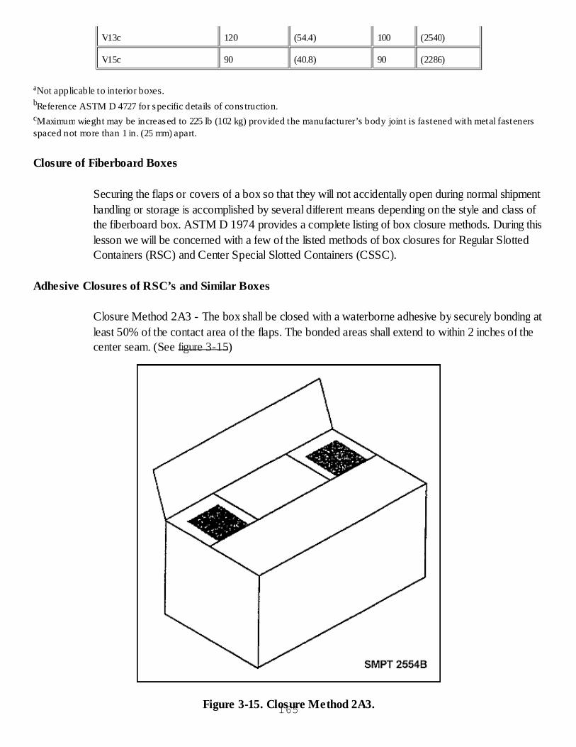
V13c 120 (54.4) 100 (2540)
V15c 90 (40.8) 90 (2286)
aNot applicable to interior boxes.bReference ASTM D 4727 for specific details of cons truction.cMaximum wieght may be increased to 225 lb (102 kg) provided the manufacturer’s body joint is fastened with metal fastenersspaced not more than 1 in. (25 mm) apart.
Closure of Fiberboard Boxes
Securing the flaps or covers of a box so that they will not accidentally open during normal shipmenthandling or storage is accomplished by several different means depending on the style and class ofthe fiberboard box. ASTM D 1974 provides a complete listing of box closure methods. During thislesson we will be concerned with a few of the listed methods of box closures for Regular SlottedContainers (RSC) and Center Special Slotted Containers (CSSC).
Adhesive Closures of RSC’s and Similar Boxes
Closure Method 2A3 - The box shall be closed with a waterborne adhesive by securely bonding atleast 50% of the contact area of the flaps. The bonded areas shall extend to within 2 inches of thecenter seam. (See figure 3-15)
Figure 3-15. Closure Method 2A3.165

Closure Method 2A4 - The box shall be closed with the application of adhesive conforming withMMM-A-250 by securely bonding at least 75% of the contact area of the flaps. The adhesive shallbe applied within 1/4 inch of the edges and score lines of the inner flaps.
Pressure-sensitive Closures of RSC’s and Similar Boxes
Closure Method 2B3 - The box shall be closed with 2-inch wide pressure-sensitive film-backedtape applied over the center seams of the box, continuing at least 2 inches onto the box ends. Thecolored tape shall conform with ASTM D 5486. The box shall be closed with 2-inch wide tape.(See figure 3-16)
Figure 3-16. Closure Method 2B3.
Closure Method 2B7 - The box shall be closed with 2-inch wide paper tape applied over thecenter seams of the box, continuing at least 2 inches onto the box ends. Four additional strips oftape shall be centered over the seam formed by the edges of the outer flaps and the end panels.The tape shall extend within 3/4 inch of the box corners. The tape shall conform to ASTM D 5486,Type V. (See figure 3-17)
166
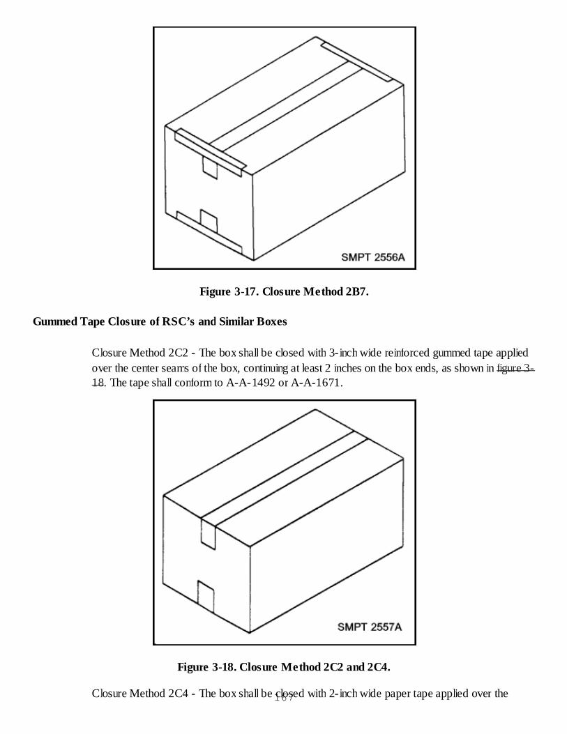
Figure 3-17. Closure Method 2B7.
Gummed Tape Closure of RSC’s and Similar Boxes
Closure Method 2C2 - The box shall be closed with 3-inch wide reinforced gummed tape appliedover the center seams of the box, continuing at least 2 inches on the box ends, as shown in figure 3-18. The tape shall conform to A-A-1492 or A-A-1671.
Figure 3-18. Closure Method 2C2 and 2C4.
Closure Method 2C4 - The box shall be closed with 2-inch wide paper tape applied over the167

center seams of the box, continuing at least 2 inches on the box ends, as shown in figure 3-18. Thetape shall comply with A-A-1492, Grade B.
Staple and Stitch Closure Setup of RSC’s and Similar Boxes
Closure Method 2D3 - The box shall be closed with 2-inch crown staples or stitches applied toeach side of the center seam in the area where outer flaps overlay inner flaps and to the side of theoutside flaps. Fasteners shall not be more than 2 1/2 inches apart.
The number of stitches needed comes from tables referenced in the ASTM D 1974. For closuremethod 2D3 see figure 3-19. Note the number of 1/2"crown staples for an RSC box is based onthe inside width of the box. For a 12"wide box, go down the left column to the number 12. Readright to the far right column under government. For a 12"wide box, 10 staples are required at eachend of the box, evenly spaced (see figure 3-20).
Number of ½-in. Crown Staples or Stitches for Regular Slotted Containers
Number of Fasteners At Each End of Box, by Method
Ins ide Width ofBox, in.
2D1,Commercial,
2D2,Rule 41,
2D3,Government,
6 2 2 6
7 2 4 6
9 4 6 6
10 4 6 8
11 4 6 8
12 4 8 10
14 6 10 12
16 6 10 14
17 6 12 14
18 6 12 16
19 8 14 16
20 8 14 18
22 8 16 20
24 10 16 22
Figure 3-19. Determining Number of Stitches.
168
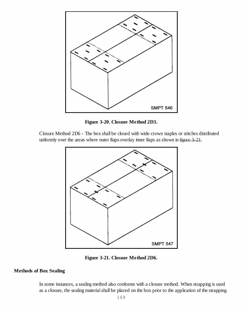
Figure 3-20. Closure Method 2D3.
Closure Method 2D6 - The box shall be closed with wide crown staples or stitches distributeduniformly over the areas where outer flaps overlay inner flaps as shown in figure 3-21.
Figure 3-21. Closure Method 2D6.
Methods of Box Sealing
In some instances, a sealing method also conforms with a closure method. When strapping is usedas a closure, the sealing material shall be placed on the box prior to the application of the strapping.
169
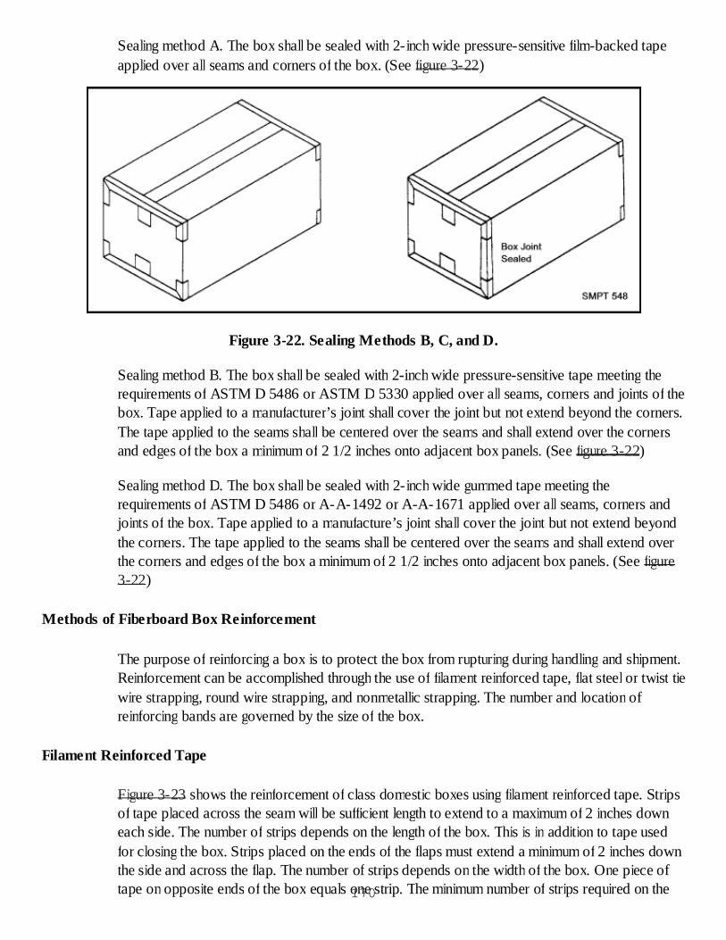
Sealing method A. The box shall be sealed with 2-inch wide pressure-sensitive film-backed tapeapplied over all seams and corners of the box. (See figure 3-22)
Figure 3-22. Sealing Methods B, C, and D.
Sealing method B. The box shall be sealed with 2-inch wide pressure-sensitive tape meeting therequirements of ASTM D 5486 or ASTM D 5330 applied over all seams, corners and joints of thebox. Tape applied to a manufacturer’s joint shall cover the joint but not extend beyond the corners.The tape applied to the seams shall be centered over the seams and shall extend over the cornersand edges of the box a minimum of 2 1/2 inches onto adjacent box panels. (See figure 3-22)
Sealing method D. The box shall be sealed with 2-inch wide gummed tape meeting therequirements of ASTM D 5486 or A-A-1492 or A-A-1671 applied over all seams, corners andjoints of the box. Tape applied to a manufacture’s joint shall cover the joint but not extend beyondthe corners. The tape applied to the seams shall be centered over the seams and shall extend overthe corners and edges of the box a minimum of 2 1/2 inches onto adjacent box panels. (See figure3-22)
Methods of Fiberboard Box Reinforcement
The purpose of reinforcing a box is to protect the box from rupturing during handling and shipment.Reinforcement can be accomplished through the use of filament reinforced tape, flat steel or twist tiewire strapping, round wire strapping, and nonmetallic strapping. The number and location ofreinforcing bands are governed by the size of the box.
Filament Reinforced Tape
Figure 3-23 shows the reinforcement of class domestic boxes using filament reinforced tape. Stripsof tape placed across the seam will be sufficient length to extend to a maximum of 2 inches downeach side. The number of strips depends on the length of the box. This is in addition to tape usedfor closing the box. Strips placed on the ends of the flaps must extend a minimum of 2 inches downthe side and across the flap. The number of strips depends on the width of the box. One piece oftape on opposite ends of the box equals one strip. The minimum number of strips required on the170
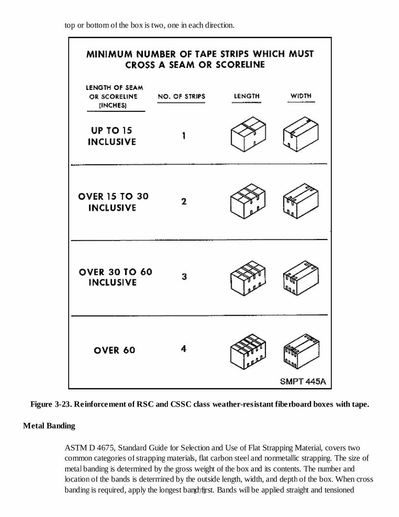
top or bottom of the box is two, one in each direction.
Figure 3-23. Reinforcement of RSC and CSSC class weather-resistant fiberboard boxes with tape.
Metal Banding
ASTM D 4675, Standard Guide for Selection and Use of Flat Strapping Material, covers twocommon categories of strapping materials, flat carbon steel and nonmetallic strapping. The size ofmetal banding is determined by the gross weight of the box and its contents. The number andlocation of the bands is determined by the outside length, width, and depth of the box. When crossbanding is required, apply the longest band first. Bands will be applied straight and tensioned171

sufficiently to embed the bands into the edges of the box but not enough to tear the fiberboard orcrush the contents, as in figure 3-24. Boxes shall have a closure based on ASTM D 1974 and, ifspecified, also conform with a closure method. When strapping is used as a reinforcement, thesealing material shall be placed on the box prior to the application of strapping.
Figure 3-24. Right and wrong way of strapping fiberboard boxes.
Reinforcement Method 2A
The box shall be reinforced with pressure-sensitive filament tape of 2-inch wide bands placedaround the girth of the box. Bands shall overlap onto themselves at least 2 inches with at least oneband for each 15 inches of box length. Boxes over 70 pounds shall use 3/4-inch wide tape. Tapeshall comply with A-A-1687 or ASTM D 5330.
Reinforcement Method 2B
The box shall be reinforced with pressure-sensitive filament tape of 3/4-inch wide bands placedaround the girth of the box. Bands shall overlap onto themselves at least 3 inches with at least oneband for each 15 inches. Boxes over 70 pounds shall use 3/4-inch wide tape. Tape shall complywith A-A-1687 or ASTM D 5330.
Reinforcement Method 2E
The box shall be reinforced with pressure-sensitive filament tape in 2-inch wide by at least 4 incheslong strips placed onto adjacent box panels. At least one strip shall be applied to each end flap.Boxes over 70 pounds shall use 3/4-inch wide tape. The tape shall conform with A-A-1685 orASTM D 5330.
GENERAL PROPERTIES OF STRAP TYPES
Steel Strapping
This product is described in ASTM D 3953 and is generally classified into regular-duty and heavy-duty strapping. Steel strapping has the highest tensile strength of all the types of strapping. It is
172

better suited to expanding or rigid units than it is to units that settle because it has low settlingtolerance. Heavy-duty steel strapping is suggested for applications where break strength orelongation and high-temperature are considerations.
Nonmetallic Strapping
Corded Strapping (Types I and Ia)
The two basic types of corded strapping are described in ASTM D 3950. Rayon and polyester arethe most common, although polyoefin, nylon and polyester plastics are also available. Care shouldbe given to choosing a strapping which won’t stretch out of shape in prolonged storage.
General Uses
Strapping may be used to secure a handling base (skids, pallets, etc.) to a unit to expedite handling.Strapping may be used for load securement to or within the transport vehicle. It is then appliedunder tension to restrain or control the movement of lading, and thus must accommodate in-transitshocks or irregular movements. Carrier regulations provide guidelines or minimum requirements, orboth. Strapping may provide security against accidental loss or theft or indicate a loss or theft.
Strap Selection
Strap size, type, placement, and number required are all a function of the work to be done, that isdetermined by a number of factors. These factors include: size, shape, and weight of unit load;expected severity of handling nature of transport equipment; and exposure to environmentalconditions, particularly if prolonged outdoor exposure is anticipated.
Class Weather-Resistant and WWVR Fiberboard Boxes
Reinforcing bands shall be applied so that it does not cover or obliterate any markings on theshipping container. When only one band is required on a box, in a given direction, it shall becentered, except in the case of lengthwise bands on style RSC or CSSC boxes. Lengthwise bandson RSC and CSSC boxes shall be slightly offset from the seam. When two or more bands arerequired on a box, in a given direction, they shall divide the box into equal parts.
Metal Banding
The number and location of the bands are determined by the outside length, width, and depth of thebox as shown in figure 3-25. When cross banding is required, apply the longest band first. Bandsshall be applied straight and tensioned sufficiently to embed the bands into the edges of the box butnot enough to tear the fiberboard or crush the contents.
173
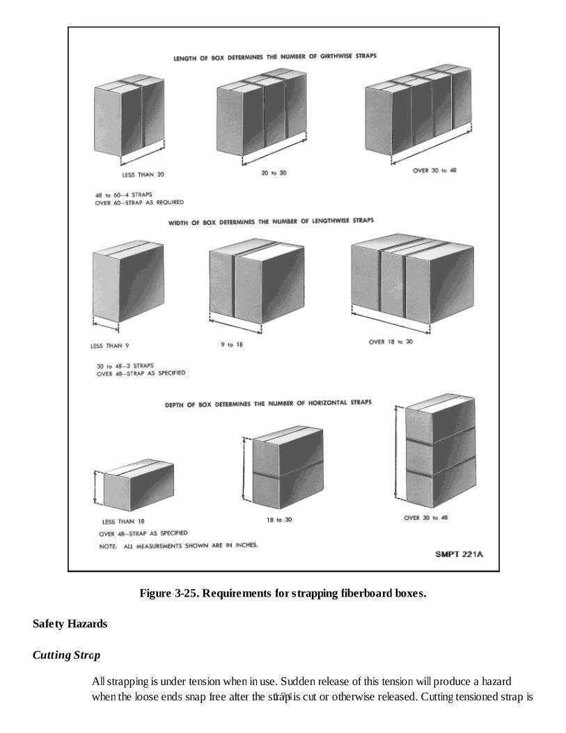
Figure 3-25. Requirements for strapping fiberboard boxes.
Safety Hazards
Cutting Strap
All strapping is under tension when in use. Sudden release of this tension will produce a hazardwhen the loose ends snap free after the strap is cut or otherwise released. Cutting tensioned strap is174

hazardous. Use caution and follow approved safety procedures.
When cutting a tensioned strap always stand to one side of the strap being cut, pressing the strapagainst the package above the cut. THINK SAFETY!
Improper Use
Strapping should be used only as intended. Strapping should not be punched by nails, staples, orother sharp objects. This may cause premature strap failure. Attempting to nail through steelstrapping may present a hazard especially when power nailing or stapling. Type 2 steel strappinghas pre-punched holes intended for nail-on applications. Never use strapping as a means of pullingor lifting packages on unit loads, unless specified by strapping supplier.
Filament reinforced tape. Tape shall be applied in strips completely encircling the box. Thenumber and location of the strips is the same as for metal banding.Nonmetallic strapping. Buckle connectors shall not be used. The number and location of thestraps is the same as for metal banding.
Usage
Fiberboard boxes are intended for use as either shipping (exterior) or packing (interior) containers.The selection of the proper style and strength of fiberboard box is determined by the expectedshipping and handling hazards including the type of load. For example, WWVR boxes are intendedto be used where extreme weather conditions exist or for long-term storage in damp climates.
When you are packing a fiberboard box, use the right size box. Do not force items into afiberboard box that is too small. You will weaken the box and cause it to buckle. Figure 3-26shows both correct and incorrect packing.
Figure 3-26. Fiberboard box packed correctly and fiberboard box packed incorrectly.
Procurement175
For installations which do not fabricate boxes from sheet stock, fiberboard boxes are availablefrom the General Services Administration (GSA). To procure fiberboard boxes from GSA, youmust order by National Stock Number. This stock number can be obtained from applicabledocuments such as the Federal Supply Catalogs, FEDLOG, etc. To determine the proper NationalStock Number, you must know the Type, class, and variety of board; strength (grade) of material;style of box; and the size of box, length, width, and depth.
Checkup
How many classes of fiberboard boxes are there? What are they?What type of loads may be packed in fiberboard boxes?What must you do if you have a Type III load to ship in a fiberboard box?How do we convert a Type 3 load to Type 1 or Type 2 load?What materials may be used to close class domestic fiberboard boxes?When closing class domestic fiberboard boxes, how much of the flap surface area must theadhesive cover?
FIBERBOARD BOX FABRICATION PRACTICAL EXERCISE
Objective
As a result of this training, the student will be able to make, pack, close, and reinforce a single-wallfiberboard box.
General Instructions
This practical exercise will include a demonstration of closing and reinforcing a fiberboard box.
The practical exercise will be conducted in the classroom and will require 2 hours.
Conduct of Exercise
Situation
As a packer you are responsible for making, packing, closing, and reinforcing a single-wallfiberboard box.
Requirement No. 1
Demonstration by instructor.
Demonstrate the closure of the top flaps using ASTM D 5330 pressure-sensitive adhesivetape.Demonstrate the reinforcement of fiberboard boxes using pressure-sensitive adhesive,filament reinforced tape.Demonstrate the weatherproofing of a fiberboard box using ASTM D 5486, Type 5 tape.176
Requirement No. 2
Answer the following questions.
From what two types of material are fiberboard containers made?As a packer, when and why would you strap a class domestic fiberboard box?Is a boxmaker's certificate needed on a fiberboard box?Of all the fiberboard boxes in the system, what two styles are the most often used?How many different styles of fiberboard boxes are there?What are the types of fiberboard body joints?Where is a liner used to obtain added strength and rigidity?What are the classes of fiberboard boxes?Which classes of fiberboard box require a compliance symbol?How many and in which direction are reinforcing straps on a box 22" x 17" x 8"?What must be done to an irregular-shaped item, such as a large brass water valve, in orderto ship it in a fiberboard box?When closing a class WWVR box with glue, how much of the surface of the box flaps mustbe covered?If a fiberboard box is reinforced with metal banding, what determines the size of thebanding?If a sleeve is used to add strength to a fiberboard box, it should cover which surfaces?What does class designate in classification of fiberboard boxes?What does the letter C designate in a grade V11C fiberboard?What are the two varieties of corrugated fiberboard?Describe an RSC fiberboard box.What are two ways of strengthening fiberboard boxes?Identify the methods used to close a class domestic box.
Critique
The instructor will call on class members to give the answers to the questions.
Care of Area, Training Aids & Equipment.
Not applicable.
TRIPLE-WALL CORRUGATED FIBERBOARD BOXES (ASTM D 5168)
DESCRIPTION OF TRIPLE-WALL BOXES
Description of Triple-wall Boxes
Triple-wall boxes are bought either partly assembled or knocked down and in bundles. Thispermits easy storage at the depot. They are generally used as consolidation containers or asmultipacks. Triple-wall boxes are available in a variety of shapes, sizes, and styles, and there are no177
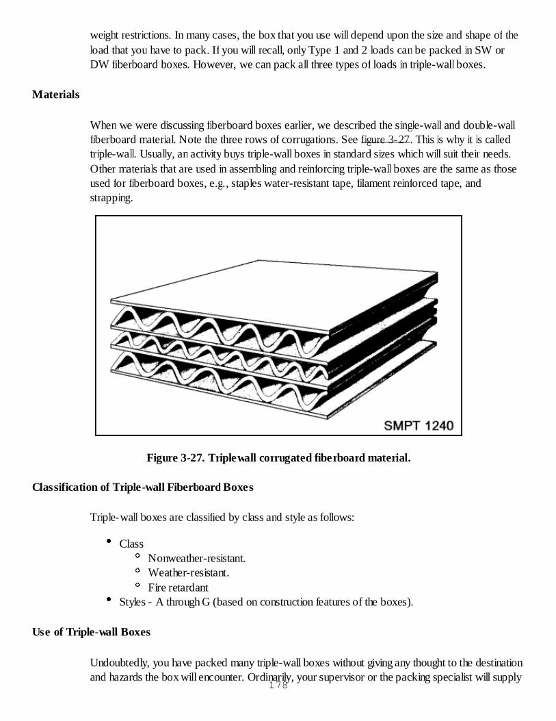
weight restrictions. In many cases, the box that you use will depend upon the size and shape of theload that you have to pack. If you will recall, only Type 1 and 2 loads can be packed in SW orDW fiberboard boxes. However, we can pack all three types of loads in triple-wall boxes.
Materials
When we were discussing fiberboard boxes earlier, we described the single-wall and double-wallfiberboard material. Note the three rows of corrugations. See figure 3-27. This is why it is calledtriple-wall. Usually, an activity buys triple-wall boxes in standard sizes which will suit their needs.Other materials that are used in assembling and reinforcing triple-wall boxes are the same as thoseused for fiberboard boxes, e.g., staples water-resistant tape, filament reinforced tape, andstrapping.
Figure 3-27. Triplewall corrugated fiberboard material.
Classification of Triple-wall Fiberboard Boxes
Triple-wall boxes are classified by class and style as follows:
ClassNonweather-resistant.Weather-resistant.Fire retardant
Styles - A through G (based on construction features of the boxes).
Use of Triple-wall Boxes
Undoubtedly, you have packed many triple-wall boxes without giving any thought to the destinationand hazards the box will encounter. Ordinarily, your supervisor or the packing specialist will supply
178
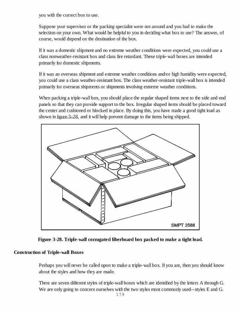
you with the correct box to use.
Suppose your supervisor or the packing specialist were not around and you had to make theselection on your own. What would be helpful to you in deciding what box to use? The answer, ofcourse, would depend on the destination of the box.
If it was a domestic shipment and no extreme weather conditions were expected, you could use aclass nonweather-resistant box and class fire retardant. These triple-wall boxes are intendedprimarily for domestic shipments.
If it was an overseas shipment and extreme weather conditions and/or high humidity were expected,you could use a class weather-resistant box. The class weather-resistant triple-wall box is intendedprimarily for overseas shipments or shipments involving extreme weather conditions.
When packing a triple-wall box, you should place the regular shaped items next to the side and endpanels so that they can provide support to the box. Irregular shaped items should be placed towardthe center and cushioned or blocked in place. By doing this, you have made a good tight load asshown in figure 3-28, and it will help prevent damage to the items being shipped.
Figure 3-28. Triple-wall corrugated fiberboard box packed to make a tight load.
Construction of Triple-wall Boxes
Perhaps you will never be called upon to make a triple-wall box. If you are, then you should knowabout the styles and how they are made.
There are seven different styles of triple-wall boxes which are identified by the letters A through G.We are only going to concern ourselves with the two styles most commonly used--styles E and G.
179
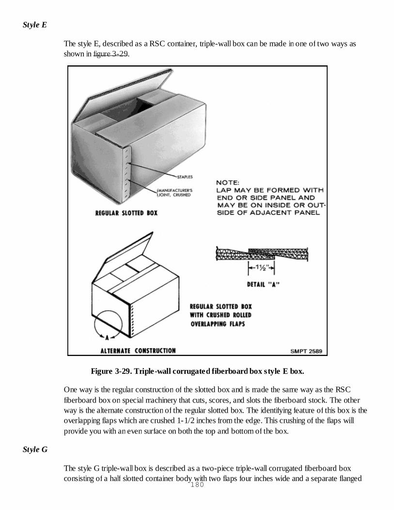
Style E
The style E, described as a RSC container, triple-wall box can be made in one of two ways asshown in figure 3-29.
Figure 3-29. Triple-wall corrugated fiberboard box style E box.
One way is the regular construction of the slotted box and is made the same way as the RSCfiberboard box on special machinery that cuts, scores, and slots the fiberboard stock. The otherway is the alternate construction of the regular slotted box. The identifying feature of this box is theoverlapping flaps which are crushed 1-1/2 inches from the edge. This crushing of the flaps willprovide you with an even surface on both the top and bottom of the box.
Style G
The style G triple-wall box is described as a two-piece triple-wall corrugated fiberboard boxconsisting of a half slotted container body with two flaps four inches wide and a separate flanged
180
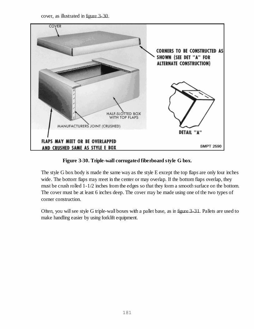
cover, as illustrated in figure 3-30.
Figure 3-30. Triple-wall corrugated fiberboard style G box.
The style G box body is made the same way as the style E except the top flaps are only four incheswide. The bottom flaps may meet in the center or may overlap. If the bottom flaps overlap, theymust be crush rolled 1-1/2 inches from the edges so that they form a smooth surface on the bottom.The cover must be at least 6 inches deep. The cover may be made using one of the two types ofcorner construction.
Often, you will see style G triple-wall boxes with a pallet base, as in figure 3-31. Pallets are used tomake handling easier by using forklift equipment.
181
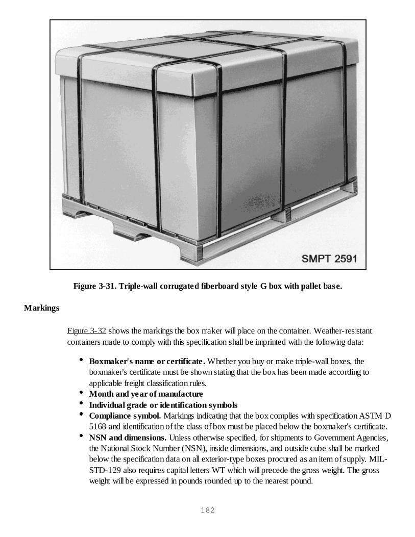
Figure 3-31. Triple-wall corrugated fiberboard style G box with pallet base.
Markings
Figure 3-32 shows the markings the box maker will place on the container. Weather-resistantcontainers made to comply with this specification shall be imprinted with the following data:
Boxmaker's name or certificate. Whether you buy or make triple-wall boxes, theboxmaker's certificate must be shown stating that the box has been made according toapplicable freight classification rules.Month and year of manufactureIndividual grade or identification symbolsCompliance symbol. Markings indicating that the box complies with specification ASTM D5168 and identification of the class of box must be placed below the boxmaker's certificate.NSN and dimensions. Unless otherwise specified, for shipments to Government Agencies,the National Stock Number (NSN), inside dimensions, and outside cube shall be markedbelow the specification data on all exterior-type boxes procured as an item of supply. MIL-STD-129 also requires capital letters WT which will precede the gross weight. The grossweight will be expressed in pounds rounded up to the nearest pound.
182

Figure 3-32. Compliance markings.
Closing and Reinforcing Triple-wall Boxes
After you have packed a triple-wall box, the next step is to close and reinforce the box. The wayyou close the box will depend upon the style of the box. Each style of triple-wall box has its ownclosure requirements. The materials used are nails, staples, steel and nonmetallic strapping, filamentreinforced tape, or a combination of them. When you reinforce a triple-wall box, you may use steelstrapping, nonmetallic strapping, or filament reinforced tape.
Style E Box Closure and Reinforcement
Figure 3-33 illustrates the closing and reinforcing of the style E box.
183
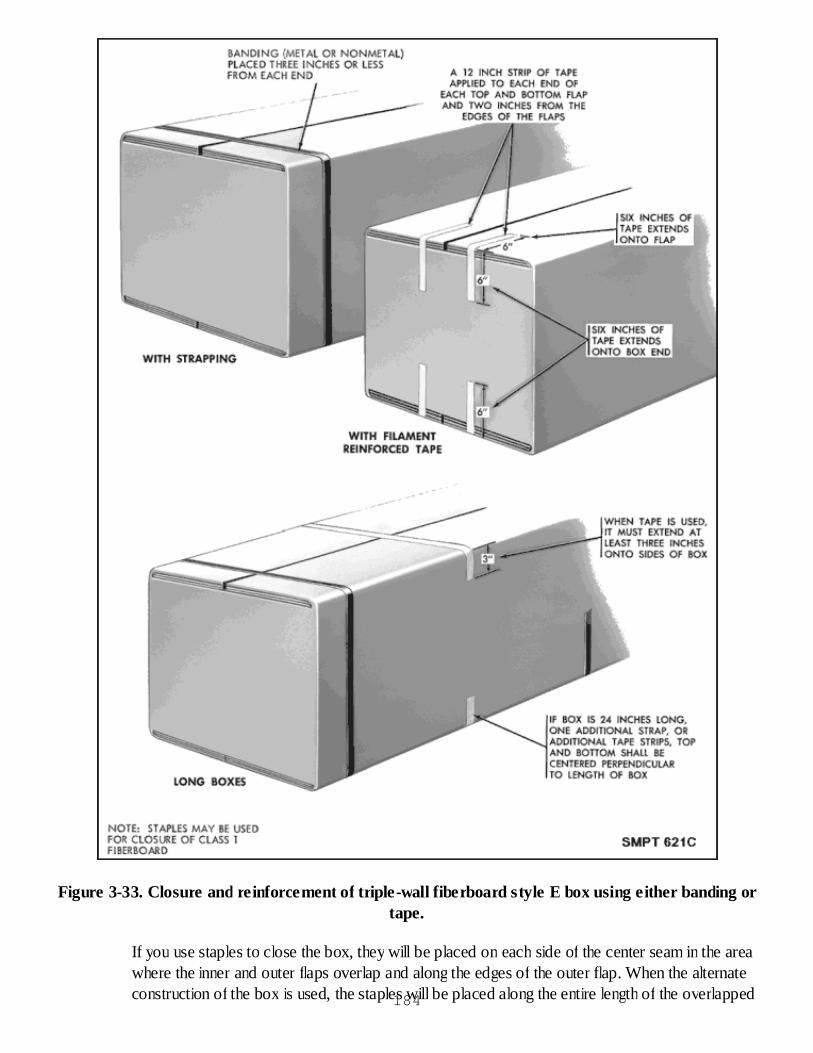
Figure 3-33. Closure and reinforcement of triple-wall fiberboard style E box using either banding ortape.
If you use staples to close the box, they will be placed on each side of the center seam in the areawhere the inner and outer flaps overlap and along the edges of the outer flap. When the alternateconstruction of the box is used, the staples will be placed along the entire length of the overlapped184

seam plus the edge of the outer flaps. The staples will normally be placed a maximum of 2-1/2inches apart.
If you use metal or nonmetallic strapping to close the box, you must apply two girthwise straps.Each strap will be located no more than 3 inches from the ends of the box. If the length of the boxexceeds 24 inches, an additional strap is required around the center.
If you use tape to close the box, you must place a 12-inch strip of tape on each end of the top andbottom flaps, so that 6 inches of tape is attached to the end. The tape should be located 2 inchesfrom the inner edge of the flap. When the length of the box exceeds 24 inches, a strip will be placedgirthwise across the top and bottom of the box. Each strip will extend a minimum of 3 inches oneach side.
When you reinforce a style E box, you place one reinforcement (either tape or strapping) band onboxes greater than 24 inches long. The band is placed girthwise around the box and is located inthe center of the box. For each additional 18 inches of length, an additional reinforcement should beadded. These additional reinforcements should be spaced evenly along the length of the box. Youmay apply lengthwise strapping (as required) to hold the flaps flat.
Style G Box Closure and Reinforcement
There will be times when you will have to close and reinforce the style G triple-wall box. If this isthe case, then you want to know what has to be done and how to do it. See figure 3-34.
Figure 3-34. Closure and reinforcement of triple-wall corrugated fiberboard style G box.
If the style G box is used with a pallet base, the procuring activity will tell you how to close and sealthe box.
185
When the style G box is used without a pallet base, you may close it with either steel or nonmetalstraps, as shown in figure 3-34. One lengthwise strap should be centrally located and should circlethe top, bottom, and ends of the box. Two girthwise straps should be placed at a distance from theends equal to 3/4 the length of the inner bottom flaps. A total of three straps are necessary to closethe box.
You may use either steel or nonmetallic strapping to reinforce the style G box. When the distancebetween the two girthwise straps (used for the closure) is more than 24 inches, additionalreinforcing straps should be used. The additional reinforcing straps should not be spaced more than24 inches apart.
Edge Protectors
Frequently, edge protectors are used under metal strapping to prevent the strapping from cuttinginto the box. You may use either metal edge protectors, fiberboard angleboards, or a piece ofscrap fiberboard.
Sealing of Triple-wall Boxes
There will be times when you will have to seal the box against the entry of water or dust. This canbe done by sealing all seams and joints with water-resistant tape, as in figure 3-35. The tape shouldbe at least 2 inches wide.
186
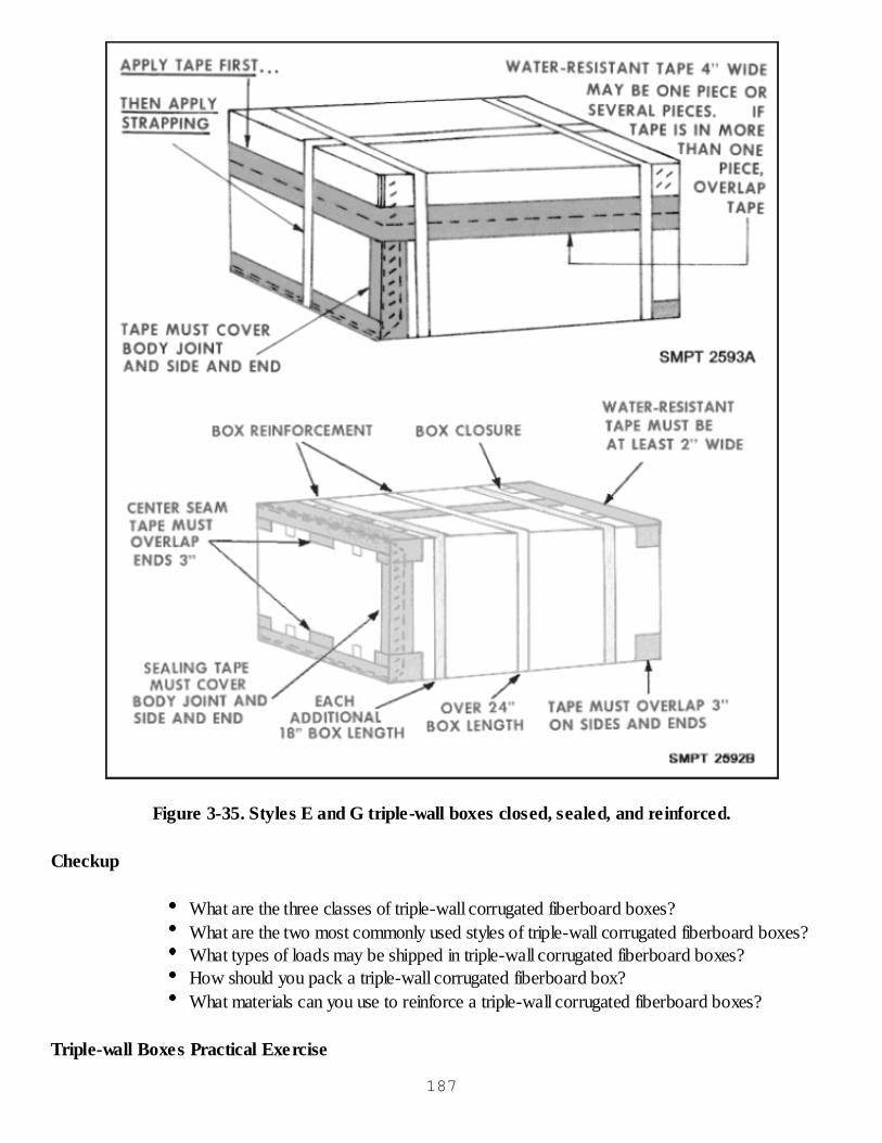
Figure 3-35. Styles E and G triple-wall boxes closed, sealed, and reinforced.
Checkup
What are the three classes of triple-wall corrugated fiberboard boxes?What are the two most commonly used styles of triple-wall corrugated fiberboard boxes?What types of loads may be shipped in triple-wall corrugated fiberboard boxes?How should you pack a triple-wall corrugated fiberboard box?What materials can you use to reinforce a triple-wall corrugated fiberboard boxes?
Triple-wall Boxes Practical Exercise
187

Objective
As a result of this training, the student will be able to pack, seal, close, and reinforce a triple-wallcorrugated fiberboard box.
General Instructions
The time to accomplish this practical exercise is 1 hour.
The practical exercise will be conducted in the classroom.
Conduct of Exercise
Situation
As a packer, you are responsible for packing, sealing, closing, and reinforcing a triple-wallcorrugated fiberboard box.
Requirement No. 1
Answer the following questions.
What style of triple-wall box is the same as an RSC box?How is the Style G triple-wall corrugated fiberboard box described?What types of loads may be shipped in triple-wall corrugated fiberboard boxes?Why do you seal a triple-wall, corrugated fiberboard box with water-resistant tape?How deep must the cover of a style G triple-wall corrugated fiberboard box be?When sealing, closing, and reinforcing a style G triple-wall corrugated fiberboard box, whatis applied first, water-resistant tape or strapping?Which style of triple-wall box may include a pallet base?Triple-wall fiberboard boxes may be obtained in 3 classes. What are they?In closing a style G triple-wall box with metal banding, what is the maximum distanceallowed between bands?If you use banding to close a style E triple-wall box, where is it placed?How many styles of triple-wall fiberboard boxes are there?How many strips of carton sealing tape are used to seal a style E triple-wall box?How far down the end of the box must center seam tape extend when sealing a style Etriple-wall box?How many bands are required to close a style G triple-wall box that is 23" long, 20" wide,and 10" high?What is the preferred way to pack a triple-wall box?How would you close a style E triple-wall box 26 inches long using filament reinforced tape?How would you reinforce this style E triple-wall fiberboard box?What materials may be used to prevent the metal strapping from cutting into the box?
188
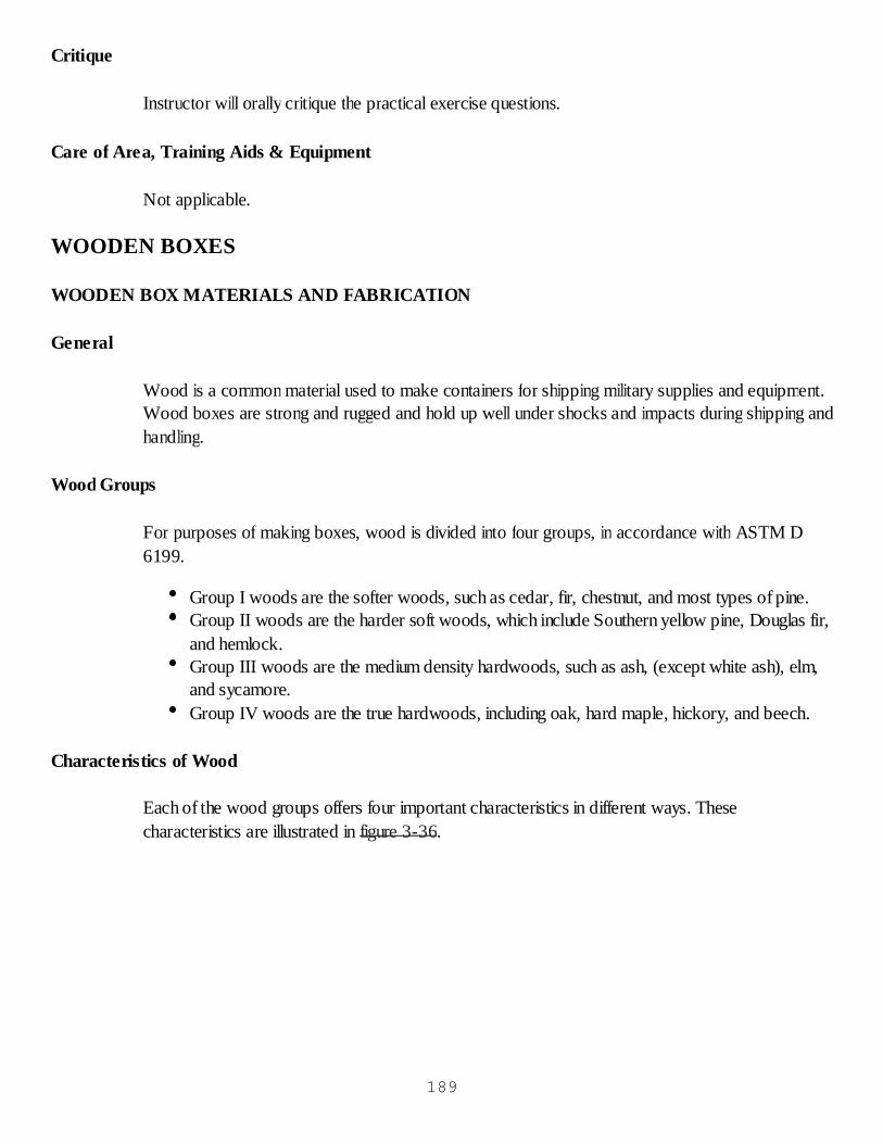
Critique
Instructor will orally critique the practical exercise questions.
Care of Area, Training Aids & Equipment
Not applicable.
WOODEN BOXES
WOODEN BOX MATERIALS AND FABRICATION
General
Wood is a common material used to make containers for shipping military supplies and equipment.Wood boxes are strong and rugged and hold up well under shocks and impacts during shipping andhandling.
Wood Groups
For purposes of making boxes, wood is divided into four groups, in accordance with ASTM D6199.
Group I woods are the softer woods, such as cedar, fir, chestnut, and most types of pine.Group II woods are the harder soft woods, which include Southern yellow pine, Douglas fir,and hemlock.Group III woods are the medium density hardwoods, such as ash, (except white ash), elm,and sycamore.Group IV woods are the true hardwoods, including oak, hard maple, hickory, and beech.
Characteristics of Wood
Each of the wood groups offers four important characteristics in different ways. Thesecharacteristics are illustrated in figure 3-36.
189
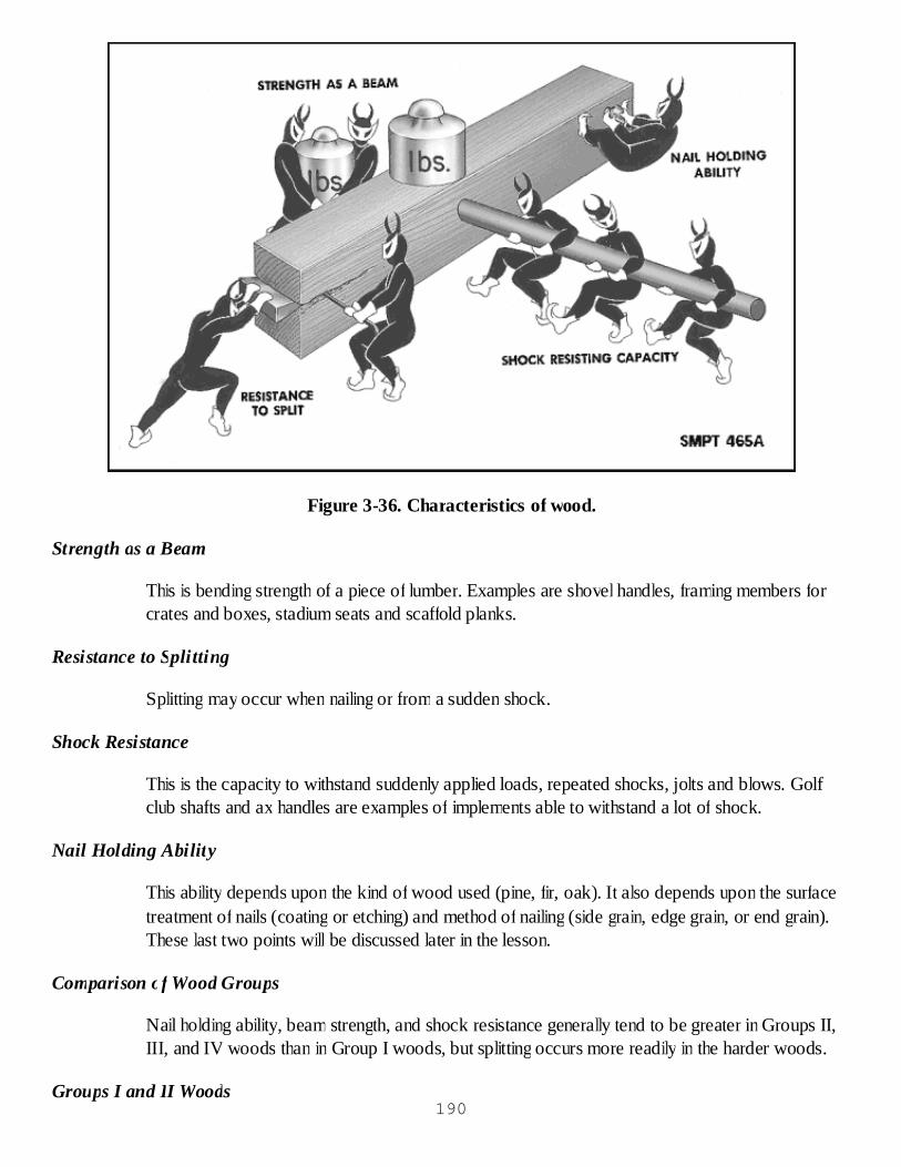
Figure 3-36. Characteristics of wood.
Strength as a Beam
This is bending strength of a piece of lumber. Examples are shovel handles, framing members forcrates and boxes, stadium seats and scaffold planks.
Resistance to Splitting
Splitting may occur when nailing or from a sudden shock.
Shock Resistance
This is the capacity to withstand suddenly applied loads, repeated shocks, jolts and blows. Golfclub shafts and ax handles are examples of implements able to withstand a lot of shock.
Nail Holding Ability
This ability depends upon the kind of wood used (pine, fir, oak). It also depends upon the surfacetreatment of nails (coating or etching) and method of nailing (side grain, edge grain, or end grain).These last two points will be discussed later in the lesson.
Comparison of Wood Groups
Nail holding ability, beam strength, and shock resistance generally tend to be greater in Groups II,III, and IV woods than in Group I woods, but splitting occurs more readily in the harder woods.
Groups I and II Woods190
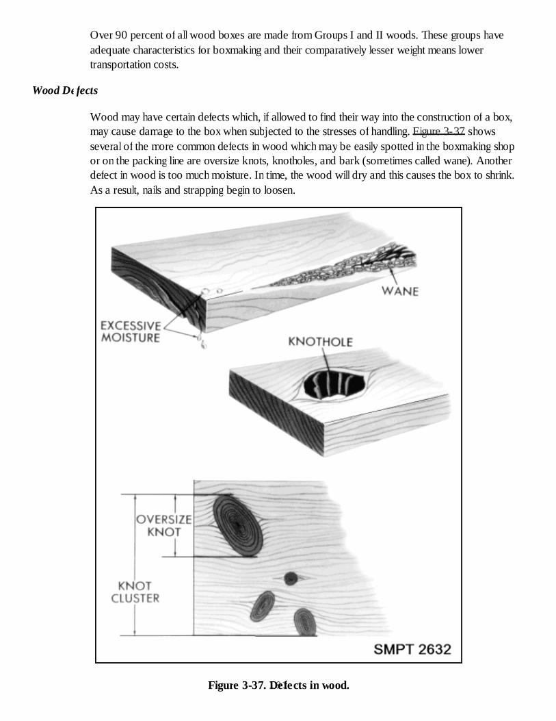
Over 90 percent of all wood boxes are made from Groups I and II woods. These groups haveadequate characteristics for boxmaking and their comparatively lesser weight means lowertransportation costs.
Wood Defects
Wood may have certain defects which, if allowed to find their way into the construction of a box,may cause damage to the box when subjected to the stresses of handling. Figure 3-37 showsseveral of the more common defects in wood which may be easily spotted in the boxmaking shopor on the packing line are oversize knots, knotholes, and bark (sometimes called wane). Anotherdefect in wood is too much moisture. In time, the wood will dry and this causes the box to shrink.As a result, nails and strapping begin to loosen.
Figure 3-37. Defects in wood.191
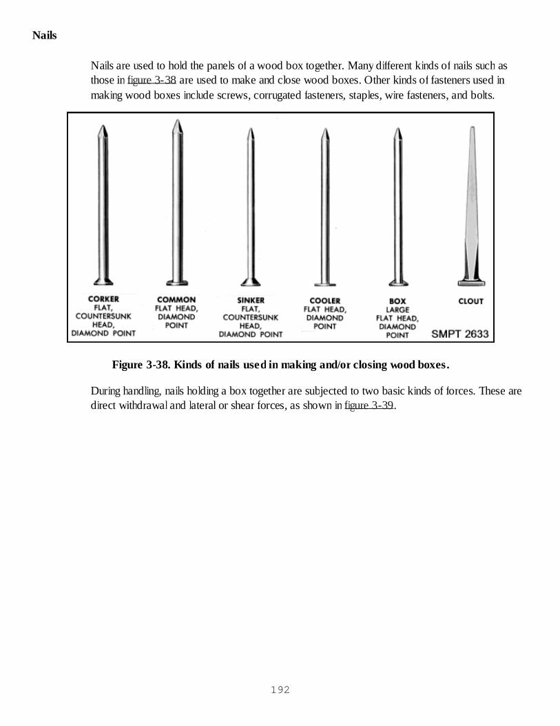
Nails
Nails are used to hold the panels of a wood box together. Many different kinds of nails such asthose in figure 3-38 are used to make and close wood boxes. Other kinds of fasteners used inmaking wood boxes include screws, corrugated fasteners, staples, wire fasteners, and bolts.
Figure 3-38. Kinds of nails used in making and/or closing wood boxes.
During handling, nails holding a box together are subjected to two basic kinds of forces. These aredirect withdrawal and lateral or shear forces, as shown in figure 3-39.
192
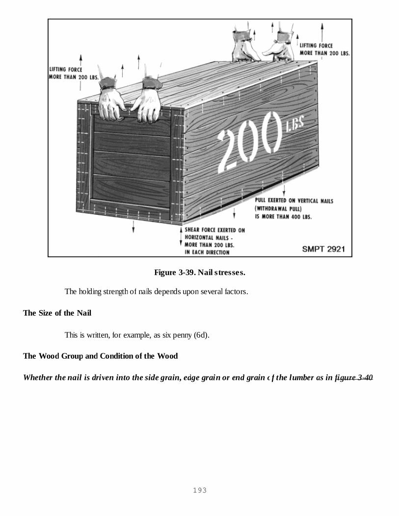
Figure 3-39. Nail stresses.
The holding strength of nails depends upon several factors.
The Size of the Nail
This is written, for example, as six penny (6d).
The Wood Group and Condition of the Wood
Whether the nail is driven into the side grain, edge grain or end grain of the lumber as in figure 3-40
193
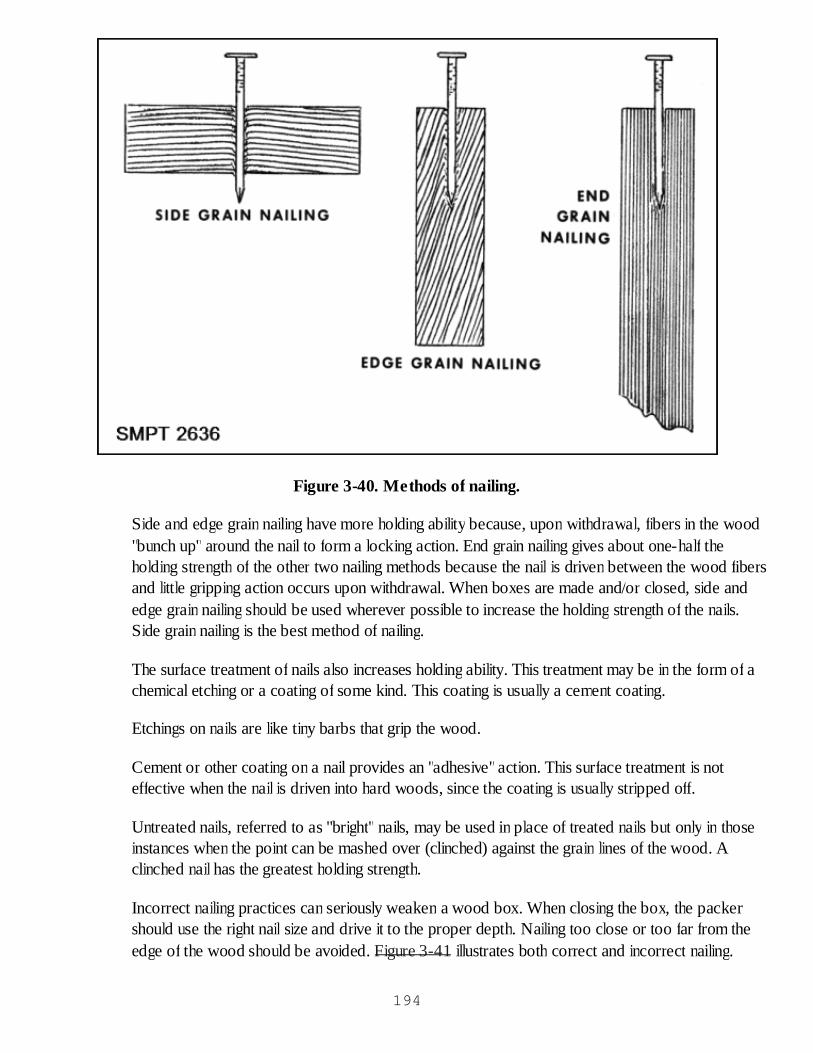
Figure 3-40. Methods of nailing.
Side and edge grain nailing have more holding ability because, upon withdrawal, fibers in the wood"bunch up" around the nail to form a locking action. End grain nailing gives about one-half theholding strength of the other two nailing methods because the nail is driven between the wood fibersand little gripping action occurs upon withdrawal. When boxes are made and/or closed, side andedge grain nailing should be used wherever possible to increase the holding strength of the nails.Side grain nailing is the best method of nailing.
The surface treatment of nails also increases holding ability. This treatment may be in the form of achemical etching or a coating of some kind. This coating is usually a cement coating.
Etchings on nails are like tiny barbs that grip the wood.
Cement or other coating on a nail provides an "adhesive"action. This surface treatment is noteffective when the nail is driven into hard woods, since the coating is usually stripped off.
Untreated nails, referred to as "bright" nails, may be used in place of treated nails but only in thoseinstances when the point can be mashed over (clinched) against the grain lines of the wood. Aclinched nail has the greatest holding strength.
Incorrect nailing practices can seriously weaken a wood box. When closing the box, the packershould use the right nail size and drive it to the proper depth. Nailing too close or too far from theedge of the wood should be avoided. Figure 3-41 illustrates both correct and incorrect nailing.
194

Figure 3-41. Nailing practices.
Types of Wood Boxes
Many kinds and styles of wood boxes are used to ship military supplies and equipment. Three ofthe most widely used boxes are nailed wood boxes, cleated plywood boxes, and wirebound woodboxes. After discussion of each type and certain styles, emphasis will be placed on closing the boxand the strapping requirements.
Boxes, Wood, Nailed and Lock-Corner (PPP-B-621)
Description
These boxes are used to ship a wide variety of commodities. They provide high resistance tocrushing, puncturing, and mashing at the corners. The boxes stack well and are relatively easy tomake in the box shop. The parts of the boxes may be varied in thickness and width so as to permitcarrying a range of weights up to 1,000 pounds.
Components
Nailed wood boxes are made of face boards, end boards, cleats, and battens, as shown in figure3-42. Cleats and battens are pieces of wood attached to the ends and sides of the box for thepurpose of making the box stronger.
195

Figure 3-42. Nailed wood box components.
Styles
Styles 2, 4, and 7 nailed wood boxes, seen in figure 3-43, and shallow boxes are commonly usedin military packing, although five other styles are found in this kind of box. A style 2 box has twosets of cleats on each end. One set consists of two horizontal (filler) cleats. Another set comprisestwo vertical (through) cleats. A style 4 box has two vertical (through) cleats on each end. A style 7box is an internally reinforced box consisting of a skidded base and a separate hood. The side, end,and top panels are prefabricated and then assembled as a hood to be placed over the item. The196

hood is nailed to the base and then strapped. Shallow boxes are boxes with an inside depth of 5inches or less. Cleats are not used. Each side and end of the box is made of one piece, except,when the end is nearly square, it may be made of two pieces. The two pieces are placed togetherso that the grain lines in one is at right angles to the grain in the other.
Figure 3-43. Styles 2, 4, and 7 nailed wood boxes.
Classes of Nailed Wood Boxes
Figure 3-44 shows that nailed boxes are classified as class 1, for domestic shipments, and class 2,for overseas shipments.
197
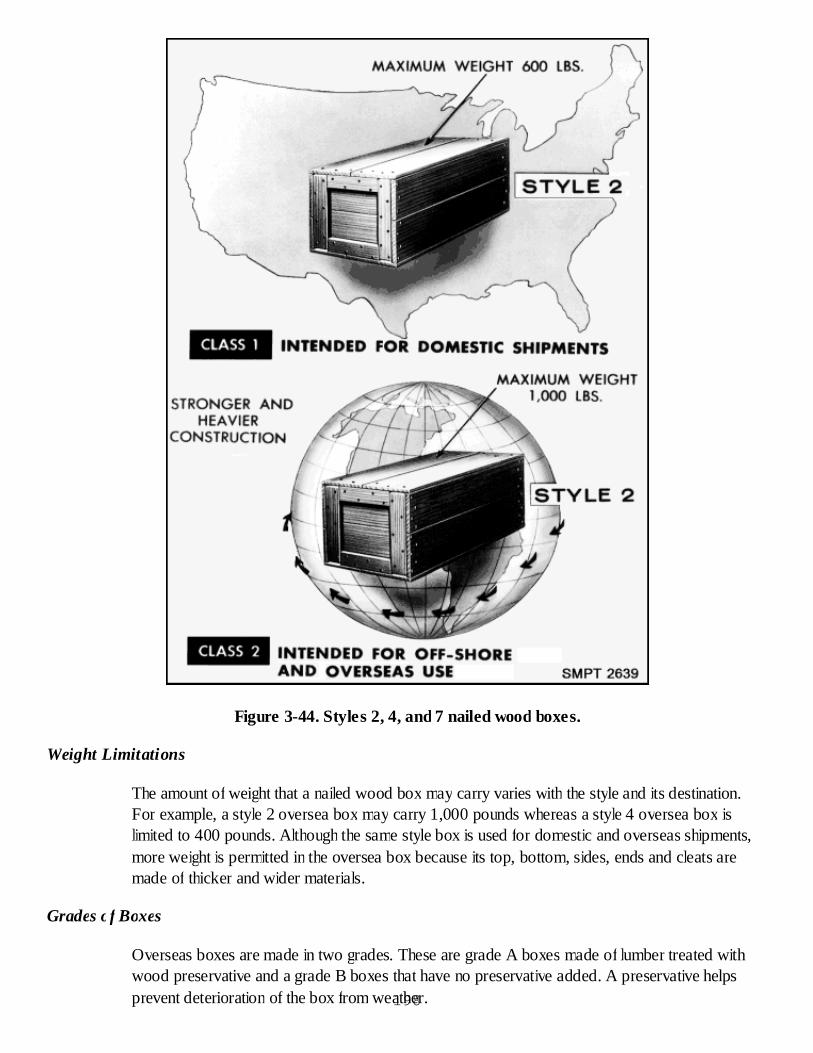
Figure 3-44. Styles 2, 4, and 7 nailed wood boxes.
Weight Limitations
The amount of weight that a nailed wood box may carry varies with the style and its destination.For example, a style 2 oversea box may carry 1,000 pounds whereas a style 4 oversea box islimited to 400 pounds. Although the same style box is used for domestic and overseas shipments,more weight is permitted in the oversea box because its top, bottom, sides, ends and cleats aremade of thicker and wider materials.
Grades of Boxes
Overseas boxes are made in two grades. These are grade A boxes made of lumber treated withwood preservative and a grade B boxes that have no preservative added. A preservative helpsprevent deterioration of the box from weather.198
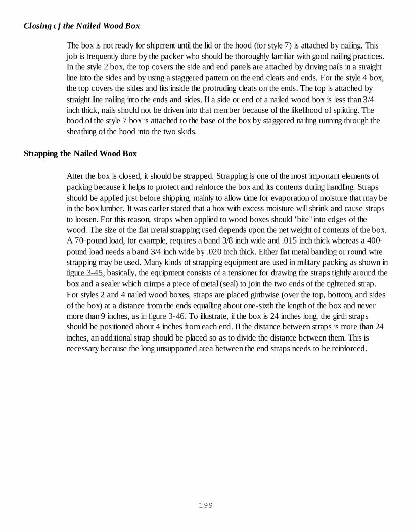
Closing of the Nailed Wood Box
The box is not ready for shipment until the lid or the hood (for style 7) is attached by nailing. Thisjob is frequently done by the packer who should be thoroughly familiar with good nailing practices.In the style 2 box, the top covers the side and end panels are attached by driving nails in a straightline into the sides and by using a staggered pattern on the end cleats and ends. For the style 4 box,the top covers the sides and fits inside the protruding cleats on the ends. The top is attached bystraight line nailing into the ends and sides. If a side or end of a nailed wood box is less than 3/4inch thick, nails should not be driven into that member because of the likelihood of splitting. Thehood of the style 7 box is attached to the base of the box by staggered nailing running through thesheathing of the hood into the two skids.
Strapping the Nailed Wood Box
After the box is closed, it should be strapped. Strapping is one of the most important elements ofpacking because it helps to protect and reinforce the box and its contents during handling. Strapsshould be applied just before shipping, mainly to allow time for evaporation of moisture that may bein the box lumber. It was earlier stated that a box with excess moisture will shrink and cause strapsto loosen. For this reason, straps when applied to wood boxes should "bite" into edges of thewood. The size of the flat metal strapping used depends upon the net weight of contents of the box.A 70-pound load, for example, requires a band 3/8 inch wide and .015 inch thick whereas a 400-pound load needs a band 3/4 inch wide by .020 inch thick. Either flat metal banding or round wirestrapping may be used. Many kinds of strapping equipment are used in military packing as shown infigure 3-45, basically, the equipment consists of a tensioner for drawing the straps tightly around thebox and a sealer which crimps a piece of metal (seal) to join the two ends of the tightened strap.For styles 2 and 4 nailed wood boxes, straps are placed girthwise (over the top, bottom, and sidesof the box) at a distance from the ends equalling about one-sixth the length of the box and nevermore than 9 inches, as in figure 3-46. To illustrate, if the box is 24 inches long, the girth strapsshould be positioned about 4 inches from each end. If the distance between straps is more than 24inches, an additional strap should be placed so as to divide the distance between them. This isnecessary because the long unsupported area between the end straps needs to be reinforced.
199

Figure 3-45. Strapping equipment.
200
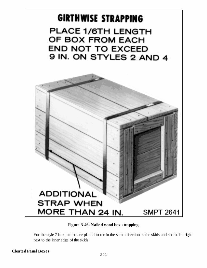
Figure 3-46. Nailed wood box strapping.
For the style 7 box, straps are placed to run in the same direction as the skids and should be rightnext to the inner edge of the skids.
Cleated Panel Boxes201
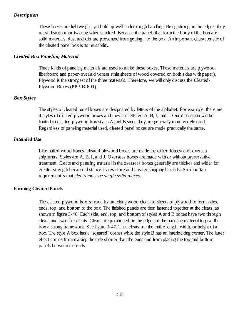
Description
These boxes are lightweight, yet hold up well under rough handling. Being strong on the edges, theyresist distortion or twisting when stacked. Because the panels that form the body of the box aresolid materials, dust and dirt are prevented from getting into the box. An important characteristic ofthe cleated panel box is its reusability.
Cleated Box Paneling Material
Three kinds of paneling materials are used to make these boxes. These materials are plywood,fiberboard and paper-overlaid veneer (thin sheets of wood covered on both sides with paper).Plywood is the strongest of the three materials. Therefore, we will only discuss the Cleated-Plywood Boxes (PPP-B-601).
Box Styles
The styles of cleated panel boxes are designated by letters of the alphabet. For example, there are4 styles of cleated plywood boxes and they are lettered A, B, I, and J. Our discussion will belimited to cleated plywood box styles A and B since they are generally more widely used.Regardless of paneling material used, cleated panel boxes are made practically the same.
Intended Use
Like nailed wood boxes, cleated plywood boxes are made for either domestic or overseashipments. Styles are A, B, I, and J. Overseas boxes are made with or without preservativetreatment. Cleats and paneling material in the overseas boxes generally are thicker and wider forgreater strength because distance invites more and greater shipping hazards. An importantrequirement is that cleats must be single solid pieces.
Forming Cleated Panels
The cleated plywood box is made by attaching wood cleats to sheets of plywood to form sides,ends, top, and bottom of the box. The finished panels are then fastened together at the cleats, asshown in figure 3-48. Each side, end, top, and bottom of styles A and B boxes have two throughcleats and two filler cleats. Cleats are positioned on the edges of the paneling material to give thebox a strong framework. See figure 3-47. Thru cleats run the entire length, width, or height of abox. The style A box has a "squared"corner while the style B has an interlocking corner. The lattereffect comes from making the side shorter than the ends and from placing the top and bottompanels between the ends.
202
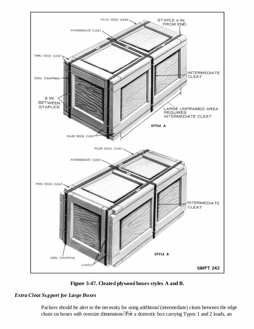
Figure 3-47. Cleated plywood boxes styles A and B.
Extra Cleat Support for Large Boxes
Packers should be alert to the necessity for using additional (intermediate) cleats between the edgecleats on boxes with oversize dimensions. For a domestic box carrying Types 1 and 2 loads, an203

additional cleat is required if the distance between the vertical edge cleats is greater than 24 inches.For an overseas box, packed with a Type 3 load, the distance is reduced to 20 inches. The extracleats help to strengthen large unframed or unsupported areas of the box. A box whose contentsare concentrated near the center of an unframed area should likewise be reinforced with additionalcleats. Intermediate cleats should be the same width and thickness as the edge cleats.
Weight Limitations
One of the main causes of wood box failure during shipping, handling, and storage is too muchweight for the strength of the box. There is a relationship between the amount of weight that a boxcan carry and the size (thickness and width) of its panel material and cleats. For example, a boxintended to carry 1,000 pounds will require larger size cleats and panel materials than a boxcarrying 400 pounds.
Use of Skids
Heavy boxes can best be handled by forklift equipment. To provide for fork handling, boxes andcontents weighing 200 pounds and more should be equipped with at least two skids.
Closing the cleated plywood box
Nailing the top to the box requires certain size nails and a definite spacing between nails. Size andspacing are governed by such factors as thickness of cleats and wood group used. For example, ona domestic cleated plywood box, if the cleat has a thickness of 5/8-inch and is made of Group Iwood, six penny (6d) nails will be driven into the wood every five inches. Remembering a fewpoints will help packers to do more efficient nailing. As the thickness of cleats increases, closerspacing of nails is permitted. Larger nails should be used as cleat thickness increases. Nail sizes canbe reduced when harder woods are used.
Strapping
Like nailed wood boxes, cleated plywood boxes are strapped just before shipping. Flat steel bandsor round wire may be used. When strapping a Style A or B cleated plywood box, the bands travelin a lengthwise direction, that is, they pass over the edges of the cleats of the top, bottom, and ends.Should the box have intermediate cleats, a girthwise band will encircle the box over the cleats.Metal bands are stapled to the box on all surfaces except the bottom. Stapling is not permitted onthe filler edge cleats of the top. Spacing of staples is about 6 inches but no farther from an edgethan 4 inches. The purpose of the staples is to hold the bands tightly against the panels of the box toprevent snagging and possible breaking of the bands.
Wirebound Wood Boxes (PPP-B-585)
Description
Wirebound wood boxes are made by commercial manufacturers and are bought through supplychannels. The boxes are supplied in flat-mat form (unassembled) and later are set up to form a box.They are rugged in construction and will take considerable "punishment"during shipping and204
handling.
Components
Figure 3-48 shows how the box is put together using cleats, faceboards, liners, and binding wires.Cleats form the framework of the box and faceboards are the thin boards that form the six faces ofthe box. Binding wires hold the box together and carry most of the load. The ends of the box maybe plain or may have liners and battens attached to give the box greater strength.
Figure 3-48. Wirebound box components.
Uses of Wirebound Boxes
These boxes are suitable for shipping a variety of general military materials and supplies such asammunition, hardware, and canned foods. In using wirebound boxes, care shall be exercised to usea box designed for the type of load to be carried. For Types 1 and 2 loads, the inside dimensionsshall be sufficiently exact so that the contents fit into the box when packed and give support to thefaces of the box. For Type 3 loads, other than bulk loads, the contents shall be firmly bolted,blocked, braced, or otherwise anchored to the frame of the box in such manner that shifting ofcontents will not occur during handling or shipment. Fragile items and delicate instruments, whichrequire special protection, shall be protected by proper internal cushioning and dunnage. The boxesare classified according to the weight they are intended to carry and their ultimate destination. Theclass 1 box has a weight limit of 500 pounds and is intended for domestic shipments. The class 2box is intended for offshore and overseas destinations where there is protected storage. It has aweight limit of 400 pounds. The class 3 box has a weight limit of 300 pounds and is intended foroverseas destinations where there is no protective storage, and extreme climatic conditions exist.
Styles of Boxes and Tools for Closing
The packer may recognize the style of the box by the way it is closed and by the presence of wire205
ends on one of the styles. The style 1 box has a twisted wire closure. It is closed with a handtwister, a crank twister, or with a power twister, as shown in figure 3-49. Style 2 has a looped wireclosure and nailed ends. It is closed with a tool called a Sallee closer. Figure 3-50 illustrates theclosure. The style 3 box has a looped wire closure and is closed the same way as the style 2. Thedifference between the styles is that the style 3 has a separate end which is joined to the box bodyby means of a tool called a bon ender, shown in figure 3-51. Use of this tool will be described later.
Figure 3-49. Closure of style 1 wirebound box.
206

Figure 3-50. Closure of styles 2 and 3 wirebound boxes.
Figure 3-51. Bon ender used with style 3 wirebound box.
Setting up Style 3 Wirebound Box
As stated, the wirebound box comes through supply channels in flat-mat or unassembled form. Thesides, top, and bottom of the box are one unit, while the two ends are separate and must be
207
inserted in the body of the box during assembly. The four steps involved in setting up a style 3 areshown in figure 3-52. First, bend upright the loops attached to the ends of the box using the hollowhandle of the bon ender for this purpose. Second, lift the sides of the box mat slightly before foldingthe sides at right angles to the bottom. Third, insert ends in the box by passing the upright loopedwires, attached to the ends, through two notches in each of the two cleats. With the tapered andnotched end of the bon ender tool, bend the loops over the binding wires of the sides. Fourth, ifthere are battens (reinforcing members) on the ends, drive a seven penny cement-coated or etchednail through the faceboard and cleat into the batten.
Figure 3-52. Setting up of style 3 wirebound box.
Strapping the Wirebound Box
The number and size of straps for wirebound boxes will depend upon the class (1, 2, or 3), weightof contents, and the construction of the box. Figure 3-53 illustrates the strapping of a style 3wirebound box. Depending upon these factors, strapping may be applied lengthwise, girthwise orhorizontally (a horizontal strap passes over the sides and ends). Strapping must be applied beforethe looped wire closures are made. This is important because reverse procedures may cause theclosure to become loose.
208
Figure 3-53. Girthwise straps on style 3 wirebound box.
Checkup
What are three wood defects that may cause a wood box to become damaged?Which method of nailing is preferred, side grain or end grain?What may happen when nailing the top to a side panel whose thickness is less than 3/4 inch?In which direction are straps applied to styles 2 and 4 nailed wood boxes?What factors govern nail sizes and spacing when nailing the lid to a cleated panel box?What is the maximum distance from the edge of a cleated panel box for the placement ofstaples over banding?What tools are used to set up and close a style 3 wirebound box?
WOOD BOXES PRACTICAL EXERCISE
Objective
As a result of this practice, the student will be able to close and reinforce a nailed wood box,reinforce a cleated panel box, and set up, close, and reinforce a wirebound box.
209

General Instructions
This exercise will be conducted in the classroom.
It will require approximately 2 class periods to complete.
The instructor will conduct the critique when the students have completed the questions.
Conduct of Exercise
Situation
As a packer, you are required to set up, close, and reinforce nailed wood boxes, cleated plywoodboxes, and wirebound wood boxes.
Requirement No. 1
Answer the following questions.
Into how many groups are the various woods used in packing divided?Wooden boxes are usually made from Group II woods. Name some of these woods.Oak or hickory are classified as what type of wood?Name four characteristics of the wood groups.Name four defects that may be found in lumber that are unwanted when used in theconstruction of wooden boxes.What is wane?What do we use to hold the pieces of a wood box such as the ends, cleats, or top, together?Name the three methods of nailing pieces of wood together.Which is the best method of nailing?Nails may have one of three surface finishes. What are they?What are two advantages we get by using nailed wood boxes?In general, the style of a nailed wood box determines the number and direction of end cleats.How many cleats does a style 2 box have?How many cleats does a style 4 box have?In which direction do the cleats on a style 4 box run?How much weight can overseas style 4 box carry?What is any nailed wood box with an inside depth of 5 inches or less called?What style nailed wood box looks more like a crate?What styles of cleated panel boxes may be used for both overseas and domestic shipment?From what three materials may the panels of a cleated panel box be made?In cleated panel boxes, a piece of lumber which runs the entire length, width, or height of thebox is called?What is the difference between a style A and a style B fiberboard cleated panel box?How many styles of wirebound boxes are there?How are the styles of a wirebound box determined?What tool is used to close both a style 2 and 3 wirebound box?210
What type of closure does a style 1 wirebound box have?How are the ends attached to sides of a style 3 wirebound box?What types of loads may be shipped in a style 2 wirebound box?When should a wirebound box be strapped, before or after the closure is made?Explain where girthwise straps are placed on a wirebound box?In which direction is a style A cleated panel box, that does not have any intermediate cleats,strapped? How are the straps placed?How do we make sure the straps, described in the above question, stay in place?In which direction are style 2 or 4 nailed wood boxes strapped?What determines the number of straps required to reinforce a nailed wood box?What is the weight limit of a style 2 nailed wood box?What kind of base does a style 7 box have?Why is having too much moisture in wood considered a defect?What are the key factors that determine the size and spacing of nails in a cleated plywoodbox?What types of materials may be shipped in wirebound boxes?In closing a cleated plywood box, why are the metal bands stapled to the box surface?What is the purpose of an intermediate cleat, and when would you use them to construct acleated panel box?
Critique
Instructor will call on the students to give the answers to each question.
Care of Area, Training Aids & Equipment
Not applicable.
CRATES
TYPES OF CRATES
There are two general types of crates in use today, sheathed and open. They differ in the protectionthey provide.
Sheathed crates are frame structures completely covered with lumber or plywood. Sheathed cratesnot only give protection against weather hazard but also are stronger and more rigid than opencrates.
Open crates are used largely to provide ease of transportation, handling, and storage. Open cratesconsist of frame members only or, at times, partial sheathing for added strength and rigidity.Partially sheathed crates will carry heavier loads than the completely open crates. Open crates maybe covered with plywood or paper-overlaid veneer to give added protection from the elements.They are called covered crates instead of sheathed crates.
211
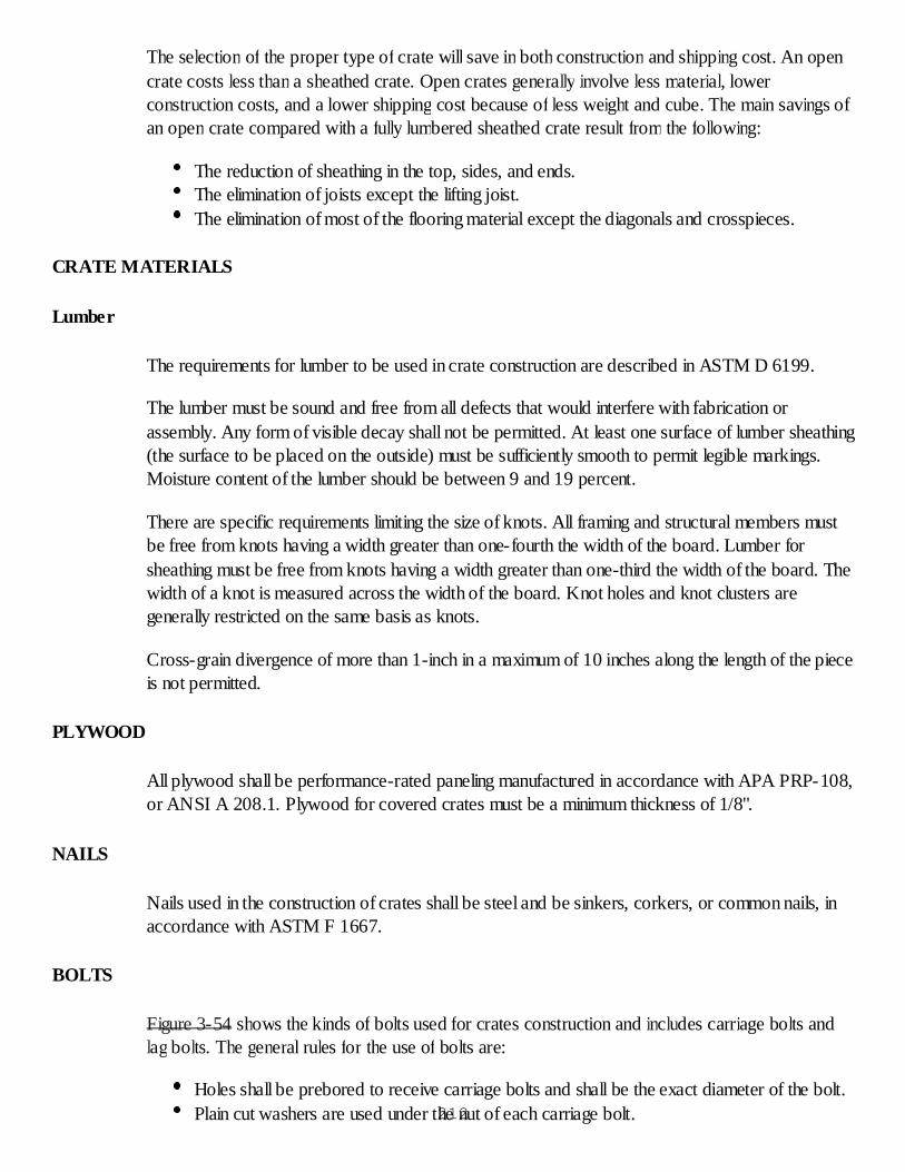
The selection of the proper type of crate will save in both construction and shipping cost. An opencrate costs less than a sheathed crate. Open crates generally involve less material, lowerconstruction costs, and a lower shipping cost because of less weight and cube. The main savings ofan open crate compared with a fully lumbered sheathed crate result from the following:
The reduction of sheathing in the top, sides, and ends.The elimination of joists except the lifting joist.The elimination of most of the flooring material except the diagonals and crosspieces.
CRATE MATERIALS
Lumber
The requirements for lumber to be used in crate construction are described in ASTM D 6199.
The lumber must be sound and free from all defects that would interfere with fabrication orassembly. Any form of visible decay shall not be permitted. At least one surface of lumber sheathing(the surface to be placed on the outside) must be sufficiently smooth to permit legible markings.Moisture content of the lumber should be between 9 and 19 percent.
There are specific requirements limiting the size of knots. All framing and structural members mustbe free from knots having a width greater than one-fourth the width of the board. Lumber forsheathing must be free from knots having a width greater than one-third the width of the board. Thewidth of a knot is measured across the width of the board. Knot holes and knot clusters aregenerally restricted on the same basis as knots.
Cross-grain divergence of more than 1-inch in a maximum of 10 inches along the length of the pieceis not permitted.
PLYWOOD
All plywood shall be performance-rated paneling manufactured in accordance with APA PRP-108,or ANSI A 208.1. Plywood for covered crates must be a minimum thickness of 1/8".
NAILS
Nails used in the construction of crates shall be steel and be sinkers, corkers, or common nails, inaccordance with ASTM F 1667.
BOLTS
Figure 3-54 shows the kinds of bolts used for crates construction and includes carriage bolts andlag bolts. The general rules for the use of bolts are:
Holes shall be prebored to receive carriage bolts and shall be the exact diameter of the bolt.Plain cut washers are used under the nut of each carriage bolt.212

Figure 3-54. Bolts and accessories.
Lag Bolts
Lag bolts are used to fasten together the panels of demountable crates. The general rules for the useof lag bolts are:
Lead holes for the shank portion of lag bolts shall be the same diameter as the shank. Lead holesfor the threaded portion of lag bolts must be smaller than the diameter of the threaded portion.
If for any reason the thread in the wood is stripped when the lag bolts are placed, the lag bolt shallbe removed and placed in a new hole near the old position.213
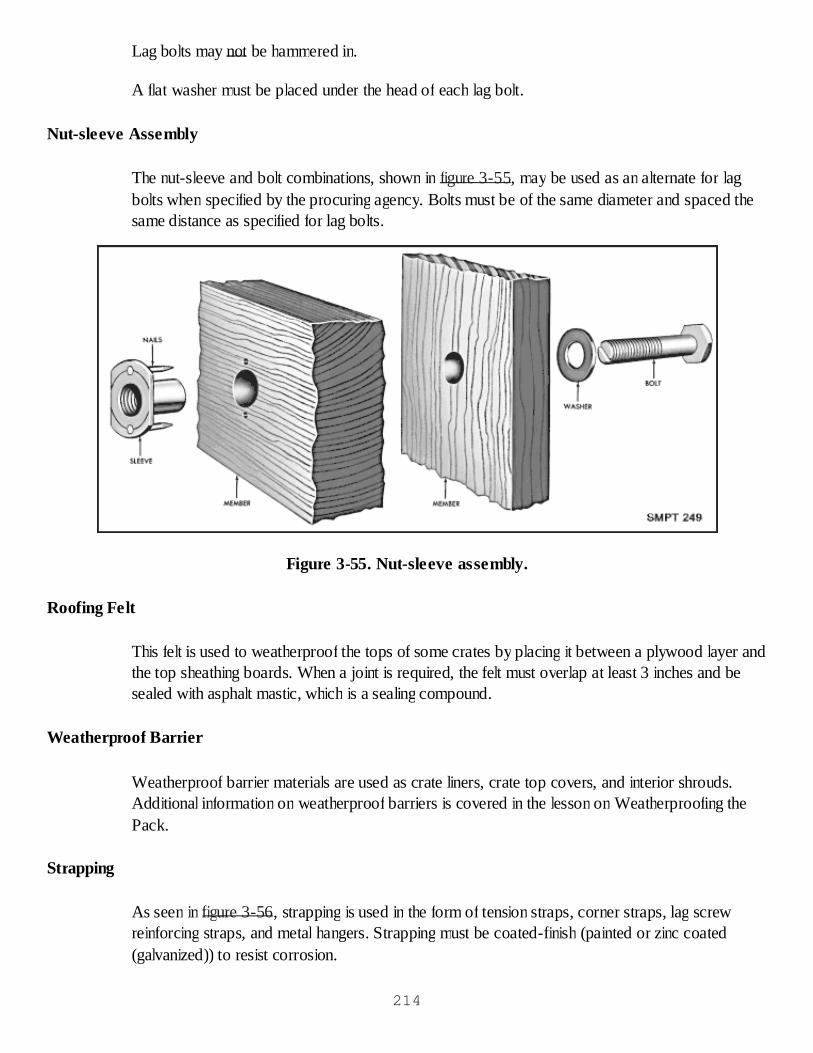
Lag bolts may not be hammered in.
A flat washer must be placed under the head of each lag bolt.
Nut-sleeve Assembly
The nut-sleeve and bolt combinations, shown in figure 3-55, may be used as an alternate for lagbolts when specified by the procuring agency. Bolts must be of the same diameter and spaced thesame distance as specified for lag bolts.
Figure 3-55. Nut-sleeve assembly.
Roofing Felt
This felt is used to weatherproof the tops of some crates by placing it between a plywood layer andthe top sheathing boards. When a joint is required, the felt must overlap at least 3 inches and besealed with asphalt mastic, which is a sealing compound.
Weatherproof Barrier
Weatherproof barrier materials are used as crate liners, crate top covers, and interior shrouds.Additional information on weatherproof barriers is covered in the lesson on Weatherproofing thePack.
Strapping
As seen in figure 3-56, strapping is used in the form of tension straps, corner straps, lag screwreinforcing straps, and metal hangers. Strapping must be coated-finish (painted or zinc coated(galvanized)) to resist corrosion.
214
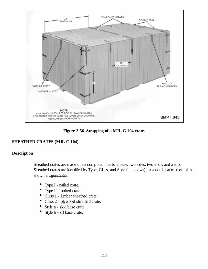
Figure 3-56. Strapping of a MIL-C-104 crate.
SHEATHED CRATES (MIL-C-104)
Description
Sheathed crates are made of six component parts: a base, two sides, two ends, and a top.Sheathed crates are identified by Type, Class, and Style (as follows), or a combination thereof, asshown in figure 3-57.
Type I - nailed crate.Type II - bolted crate.Class 1 - lumber sheathed crate.Class 2 - plywood sheathed crate.Style a - skid base crate.Style b - sill base crate.
215

Figure 3-57. Sheathed crates.
Weight Limitations
The gross weight shall not exceed 20,000 pounds. When this limitation is not practical, the grossweight on skid base crates only may go to 30,000 pounds.
Dimensional Limitation216
The exterior dimensions of the crate must not be greater than the following overall dimensions,unless specified for overseas shipment:
Length 30 feetWidth 9 feetHeight 10 feet
Clearance
A clearance of not less than 1 inch must be allowed between the item and the closest member ofthe sides, ends, and top of the crates. Fragile items or items within floating bag barrier (Methods 43and 53) must be protected with clearance of 2 inches or more.
Bases
The base is the supporting component of the crate. The contents of the crate are always placed onand tied down to the base. There are two styles of bases. They are Style a (skid base) and Style b(sill base).
As shown in figure 3-58, the Style a (skid) base consists of longitudinal skids, rubbing strips,headers, load bearing floorboards, and flooring. The construction of a skid base is the same forboth bolted and nailed crates. The skid base can be constructed to carry loads up to 30,000pounds.
217

Figure 3-58. Skid base.
The Style b (sill) base consists of side sills, end sills, intermediate sills, load-bearing headers,bridging, bottom sheathing, and rubbing straps, as seen in figure 3-59.
218
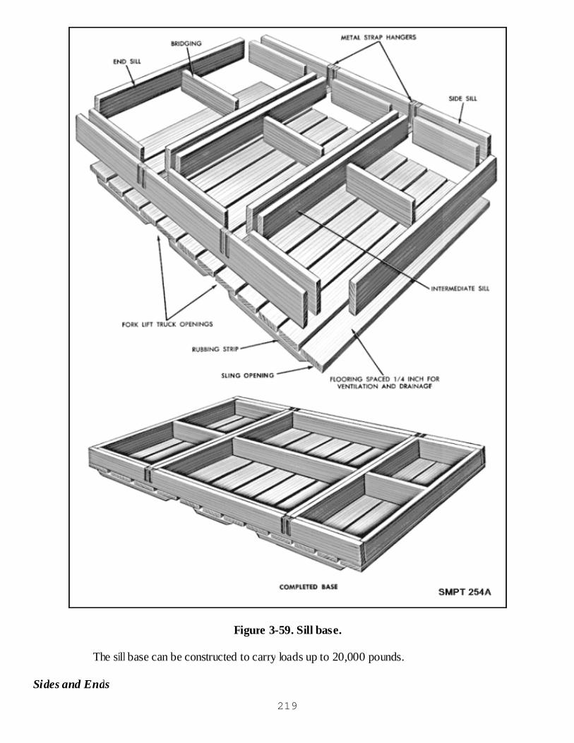
Figure 3-59. Sill base.
The sill base can be constructed to carry loads up to 20,000 pounds.
Sides and Ends
219
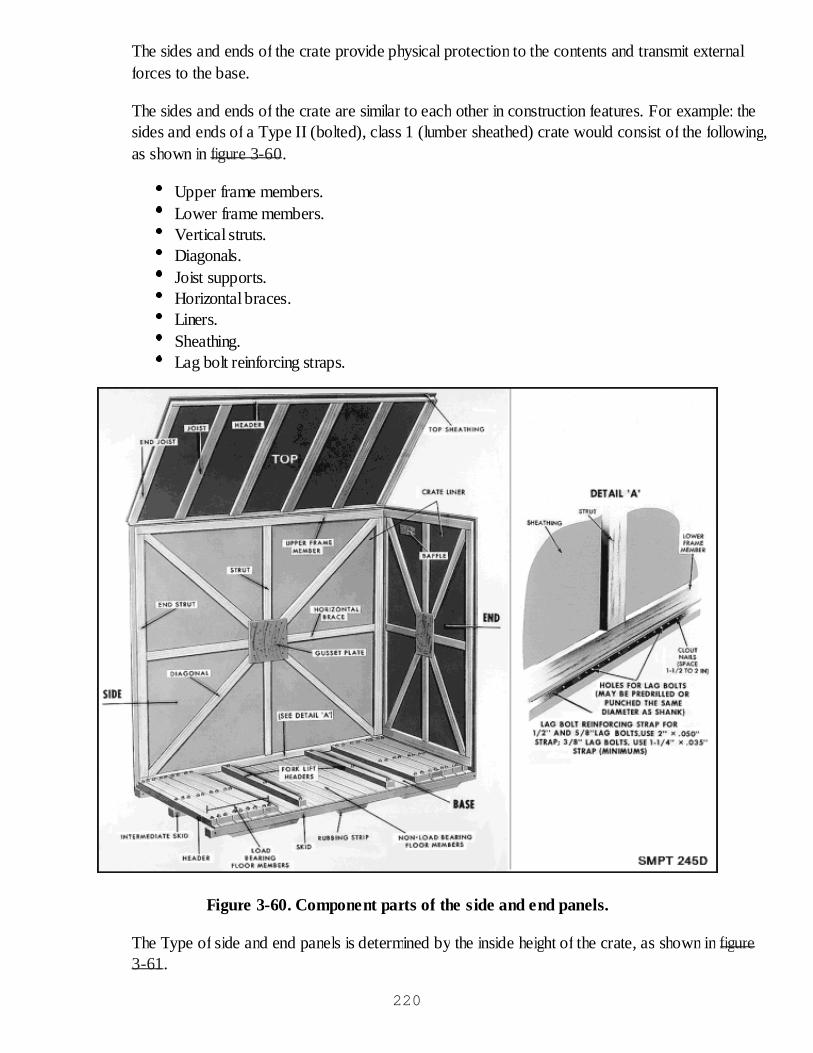
The sides and ends of the crate provide physical protection to the contents and transmit externalforces to the base.
The sides and ends of the crate are similar to each other in construction features. For example: thesides and ends of a Type II (bolted), class 1 (lumber sheathed) crate would consist of the following,as shown in figure 3-60.
Upper frame members.Lower frame members.Vertical struts.Diagonals.Joist supports.Horizontal braces.Liners.Sheathing.Lag bolt reinforcing straps.
Figure 3-60. Component parts of the side and end panels.
The Type of side and end panels is determined by the inside height of the crate, as shown in figure3-61.
220

Figure 3-61. Types A, B, and C panels.
The number of side panels for each full length side is computed by dividing the inside length of thecrate by the inside height of the crate and using the nearest whole number.
Tops221

Figure 3-62 shows the three different tops used on the MIL-C-104 crate. The use of the correcttop depends upon the width of the crate.
Figure 3-62. Top construction of MIL-C-104 crate.
The narrow crate top is used for crates with the width up through 54 inches.
The intermediate crate top is used for crates with the width over 54 inches through 60 inches.222
The wide crate is used for crates with the width over 60 inches through 120 inches.
Tops up to 96 inches wide may be either double sheathed (plywood, roofing felt, and lumber) or1/2 inch plywood sheathed (with waterproof barrier).
Ventilation
Ventilation is provided to sheathed crates to prevent the buildup of moisture or condensation fromdamaging the contents, as shown in figure 3-63.
223
Figure 3-63. Ventilation of sheathed crates.
Ventilation to lumber sheathed crates may be provided by one of the following methods:
End ventilation. Ventilation holes (3/4 inch in diameter) drilled at each end of the crate in one or moreclusters and provided with a baffle.
224
Perimeter ventilation. As an alternate to end ventilation, the 3/4-inch ventilation holes may be spacedevenly in a single line around the perimeter of the crate, just under the top frame members of the sides andends.
Ventilation for plywood sheathed crates is provided by cutting out a small section in each end, then applyingscreening and a baffle to the opening.
OPEN AND COVERED WOODEN CRATES (ASTM D 6039)
General
Open crates are suitable for the shipment of items which would not easily be damaged by outsideforces and require only limited protection from the elements. Shrouds may be used in open cratesto provide watershed protection to the contents.
Covered crates are suitable for the shipment of items which require more positive weatherproofingthan is provided by an open crate and shroud.
Open and covered wooden crates must fit each major unit being shipped. The size of the crate mustallow for any required blocking, bracing, and cushioning.
Description
The ASTM D 6039 for open and covered wood crates covers the requirements for five types andtwo styles of crates with provisions for covering one type with lightweight material.
During this lesson we will only discuss the most generally used crates: Types II, IV, and V.
Before we discuss the types of crates, we should know something about the styles and theircharacteristics.
In general, style A crates have heavier components and are able to withstand rather severe handlingand multiple shipments (heavy-duty)
The style B crates should be confined to handling and shipping that impose only light to moderatehazards on the container (light-duty).
Types and Styles of Open Crates
Figure 3-64 shows the Type II, style A crate which may be used for the shipment of items such asladders, tubing, extrusions, or wallboard, that requires no blocking, bracing, or cushioning. TheType II crates will carry a maximum net load of 1000 pounds.
225
Figure 3-64. Type II, style A crate (ASTM D 6039).
Figure 3-65 illustrates the Type IV crate. Like the Type II, it comes only in style A and is a generalpurpose crate. It will carry a maximum net load of 1000 pounds.
226
Figure 3-65. Type IV, style A crate (ASTM D 6039).
Type V, styles A and B crates are general purpose crates and will carry net loads up to 4000pounds depending upon the style of crate. Either style is further clarified as non-demountable ordemountable. 227

The Type V, style A crate, shown in figure 3-66 will carry a maximum net load of 2500. The outerskids of the base shall consist of 4 x 4 inch lumber. An intermediate 4 x 4 inch skid shall be usedwhen the distance between the outer skids is greater than 36 inches.
228

Figure 3-66. Type V, style A crate (ASTM D 6039).229
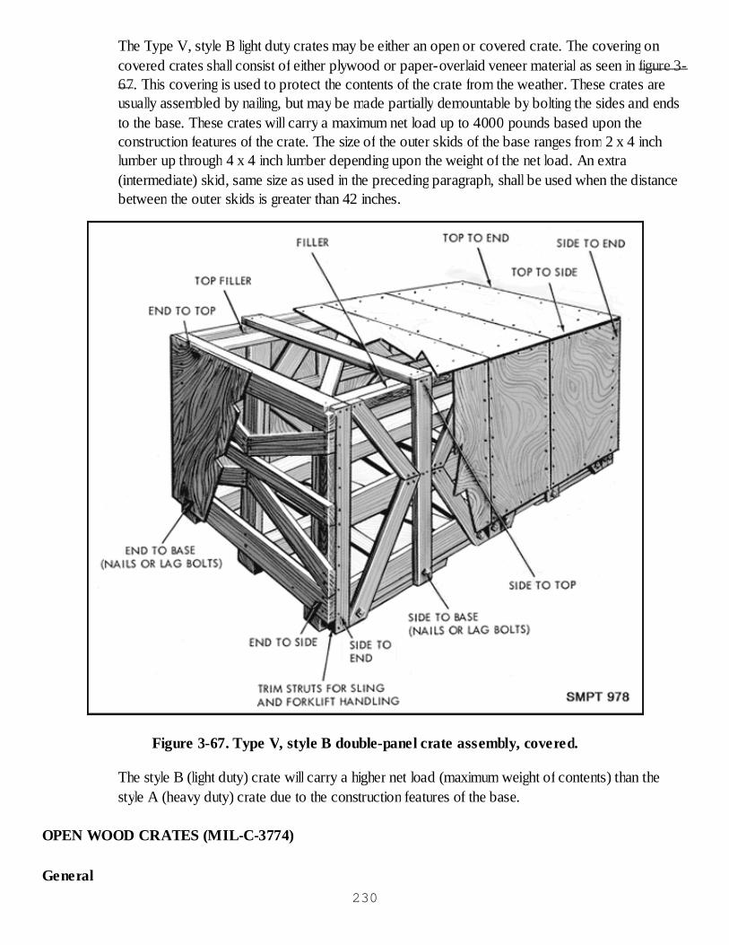
The Type V, style B light duty crates may be either an open or covered crate. The covering oncovered crates shall consist of either plywood or paper-overlaid veneer material as seen in figure 3-67. This covering is used to protect the contents of the crate from the weather. These crates areusually assembled by nailing, but may be made partially demountable by bolting the sides and endsto the base. These crates will carry a maximum net load up to 4000 pounds based upon theconstruction features of the crate. The size of the outer skids of the base ranges from 2 x 4 inchlumber up through 4 x 4 inch lumber depending upon the weight of the net load. An extra(intermediate) skid, same size as used in the preceding paragraph, shall be used when the distancebetween the outer skids is greater than 42 inches.
Figure 3-67. Type V, style B double-panel crate assembly, covered.
The style B (light duty) crate will carry a higher net load (maximum weight of contents) than thestyle A (heavy duty) crate due to the construction features of the base.
OPEN WOOD CRATES (MIL-C-3774)
General230
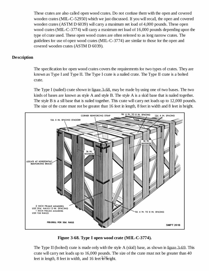
These crates are also called open wood crates. Do not confuse them with the open and coveredwooden crates (MIL-C-52950) which we just discussed. If you will recall, the open and coveredwooden crates (ASTM D 6039) will carry a maximum net load of 4,000 pounds. These openwood crates (MIL-C-3774) will carry a maximum net load of 16,000 pounds depending upon thetype of crate used. These open wood crates are often referred to as long narrow crates. Theguidelines for use of open wood crates (MIL-C-3774) are similar to those for the open andcovered wooden crates (ASTM D 6039).
Description
The specification for open wood crates covers the requirements for two types of crates. They areknown as Type I and Type II. The Type I crate is a nailed crate. The Type II crate is a boltedcrate.
The Type I (nailed) crate shown in figure 3-68, may be made by using one of two bases. The twokinds of bases are known as style A and style B. The style A is a skid base that is nailed together.The style B is a sill base that is nailed together. This crate will carry net loads up to 12,000 pounds.The size of the crate must not be greater than 16 feet in length, 8 feet in width and 8 feet in height.
Figure 3-68. Type I open wood crate (MIL-C-3774).
The Type II (bolted) crate is made only with the style A (skid) base, as shown in figure 3-69. Thiscrate will carry net loads up to 16,000 pounds. The size of the crate must not be greater than 40feet in length, 8 feet in width, and 16 feet in height.231
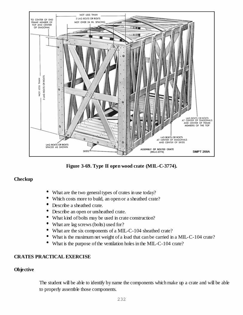
Figure 3-69. Type II open wood crate (MIL-C-3774).
Checkup
What are the two general types of crates in use today?Which costs more to build, an open or a sheathed crate?Describe a sheathed crate.Describe an open or unsheathed crate.What kind of bolts may be used in crate construction?What are lag screws (bolts) used for?What are the six components of a MIL-C-104 sheathed crate?What is the maximum net weight of a load that can be carried in a MIL-C-104 crate?What is the purpose of the ventilation holes in the MIL-C-104 crate?
CRATES PRACTICAL EXERCISE
Objective
The student will be able to identify by name the components which make up a crate and will be ableto properly assemble those components.
232
General Instructions
The purpose of this exercise is to have the students identify the numbered parts of a crate.This exercise including the critique will take 2 class periods.The exercise will be conducted in the classroom.
Conduct of Exercise
Situation
As a packer you are required to identify and assemble the component parts of various crates.
Requirement No. 1
Identify the numbered parts in figures 3-70, 3-71, 3-72, and 3-73.
What crate does figure 3-70 represent?Identify the partsIdentify partsWhat is shown in figure 3-71?For what size crate is this top used?Identify the crate pictured in figure 3-72.Identify the partsWhat style is this crate?Identify the crate in figure 3-73.How much weight may be shipped in this crate?
233

Figure 3-70.
Figure 3-71.
234
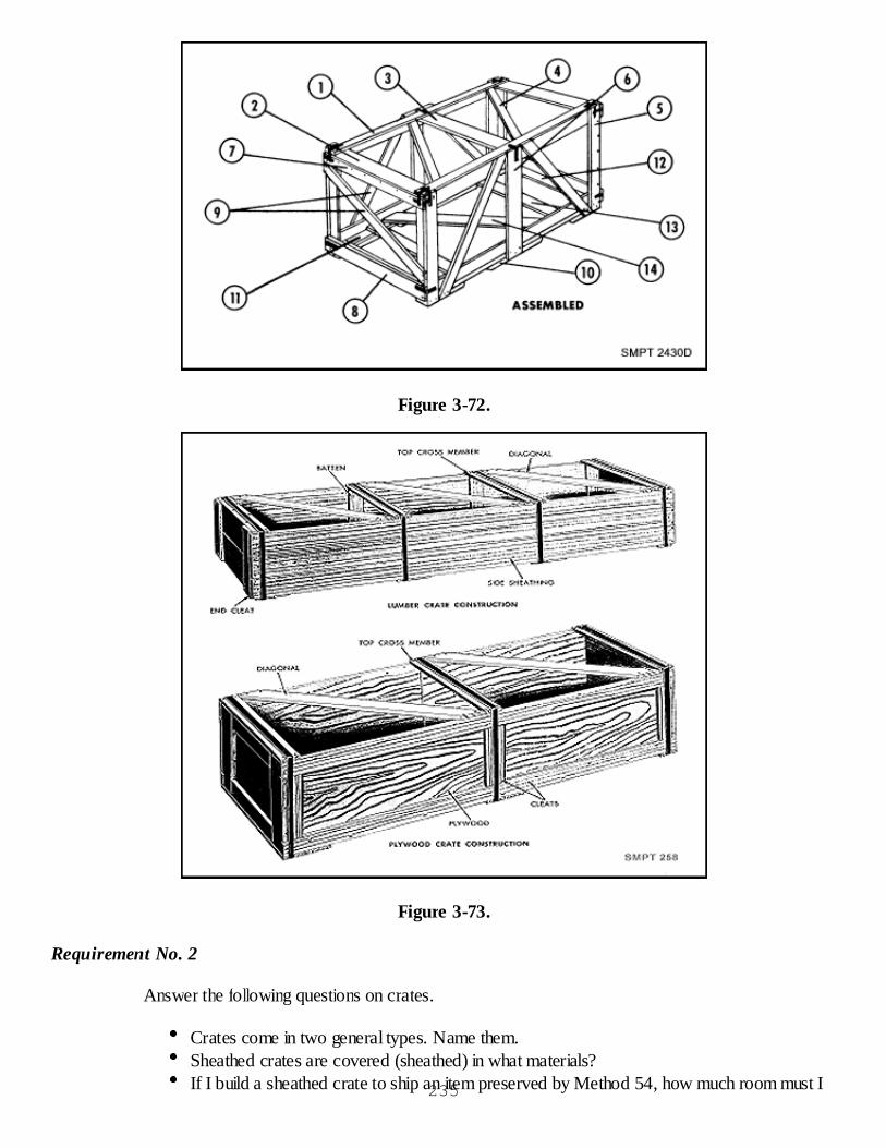
Figure 3-72.
Figure 3-73.
Requirement No. 2
Answer the following questions on crates.
Crates come in two general types. Name them.Sheathed crates are covered (sheathed) in what materials?If I build a sheathed crate to ship an item preserved by Method 54, how much room must I235
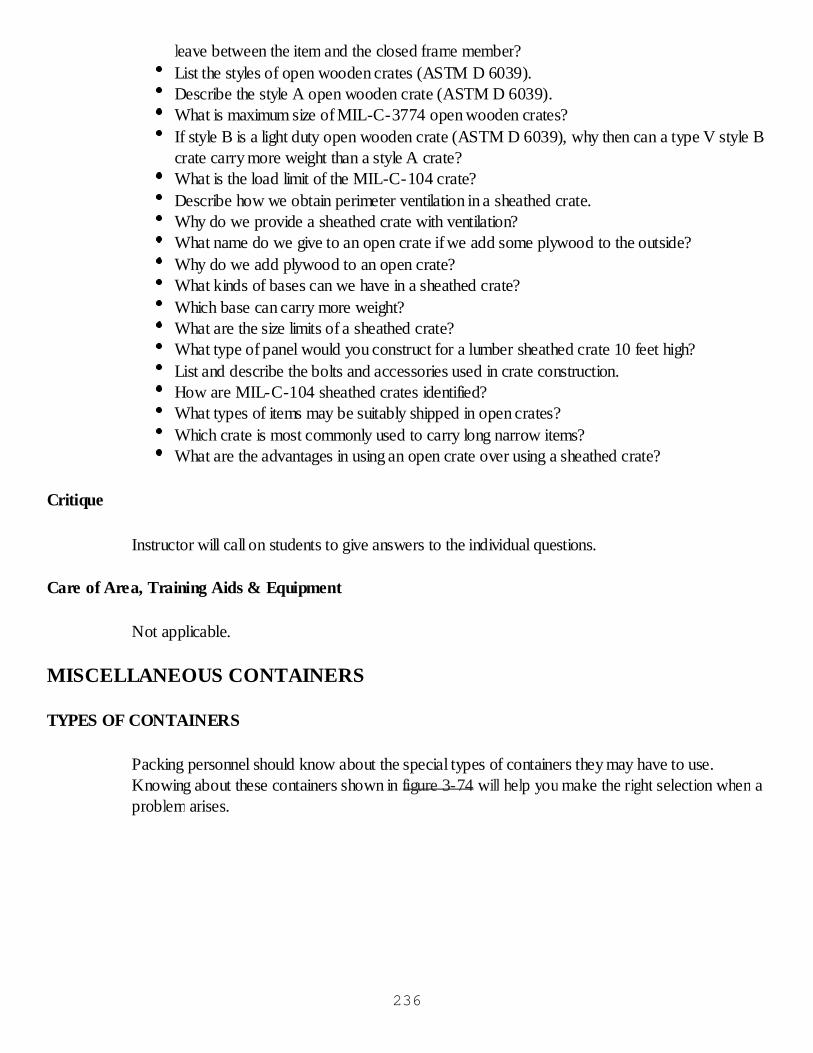
leave between the item and the closed frame member?List the styles of open wooden crates (ASTM D 6039).Describe the style A open wooden crate (ASTM D 6039).What is maximum size of MIL-C-3774 open wooden crates?If style B is a light duty open wooden crate (ASTM D 6039), why then can a type V style Bcrate carry more weight than a style A crate?What is the load limit of the MIL-C-104 crate?Describe how we obtain perimeter ventilation in a sheathed crate.Why do we provide a sheathed crate with ventilation?What name do we give to an open crate if we add some plywood to the outside?Why do we add plywood to an open crate?What kinds of bases can we have in a sheathed crate?Which base can carry more weight?What are the size limits of a sheathed crate?What type of panel would you construct for a lumber sheathed crate 10 feet high?List and describe the bolts and accessories used in crate construction.How are MIL-C-104 sheathed crates identified?What types of items may be suitably shipped in open crates?Which crate is most commonly used to carry long narrow items?What are the advantages in using an open crate over using a sheathed crate?
Critique
Instructor will call on students to give answers to the individual questions.
Care of Area, Training Aids & Equipment
Not applicable.
MISCELLANEOUS CONTAINERS
TYPES OF CONTAINERS
Packing personnel should know about the special types of containers they may have to use.Knowing about these containers shown in figure 3-74 will help you make the right selection when aproblem arises.
236
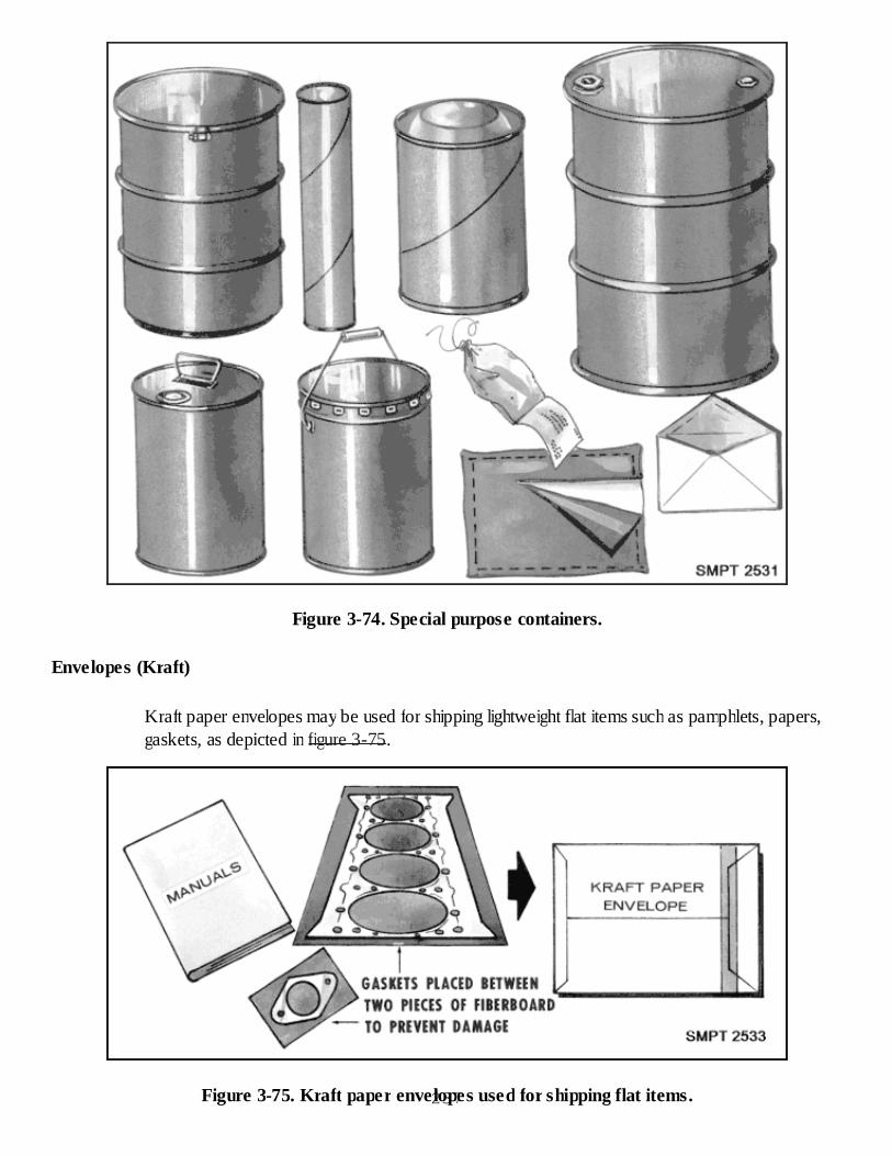
Figure 3-74. Special purpose containers.
Envelopes (Kraft)
Kraft paper envelopes may be used for shipping lightweight flat items such as pamphlets, papers,gaskets, as depicted in figure 3-75.
Figure 3-75. Kraft paper envelopes used for shipping flat items.237
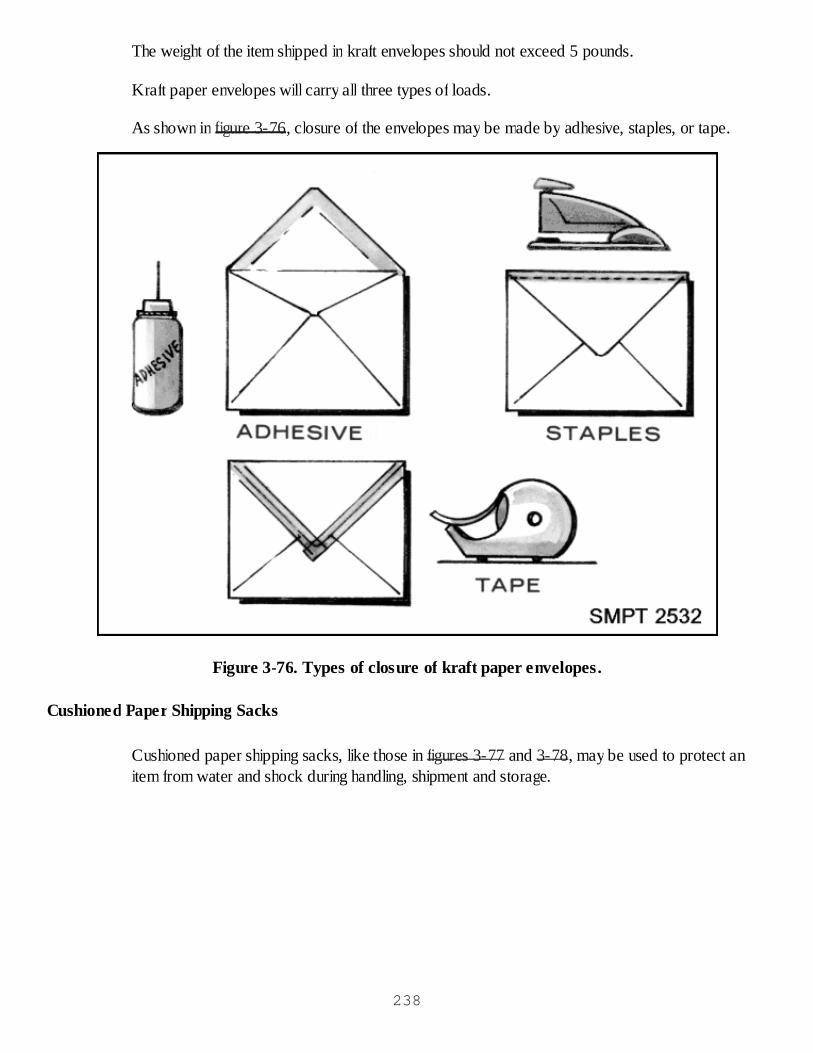
The weight of the item shipped in kraft envelopes should not exceed 5 pounds.
Kraft paper envelopes will carry all three types of loads.
As shown in figure 3-76, closure of the envelopes may be made by adhesive, staples, or tape.
Figure 3-76. Types of closure of kraft paper envelopes.
Cushioned Paper Shipping Sacks
Cushioned paper shipping sacks, like those in figures 3-77 and 3-78, may be used to protect anitem from water and shock during handling, shipment and storage.
238
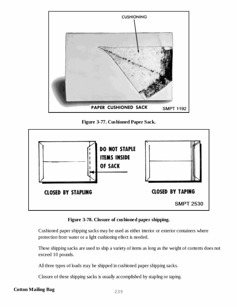
Figure 3-77. Cushioned Paper Sack.
Figure 3-78. Closure of cushioned paper shipping.
Cushioned paper shipping sacks may be used as either interior or exterior containers whereprotection from water or a light cushioning effect is needed.
These shipping sacks are used to ship a variety of items as long as the weight of contents does notexceed 10 pounds.
All three types of loads may be shipped in cushioned paper shipping sacks.
Closure of these shipping sacks is usually accomplished by stapling or taping.
Cotton Mailing Bag 239
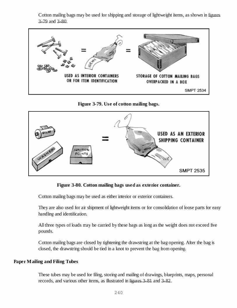
Cotton mailing bags may be used for shipping and storage of lightweight items, as shown in figures3-79 and 3-80.
Figure 3-79. Use of cotton mailing bags.
Figure 3-80. Cotton mailing bags used as exterior container.
Cotton mailing bags may be used as either interior or exterior containers.
They are also used for air shipment of lightweight items or for consolidation of loose parts for easyhandling and identification.
All three types of loads may be carried by these bags as long as the weight does not exceed fivepounds.
Cotton mailing bags are closed by tightening the drawstring at the bag opening. After the bag isclosed, the drawstring should be tied in a knot to prevent the bag from opening.
Paper Mailing and Filing Tubes
These tubes may be used for filing, storing and mailing of drawings, blueprints, maps, personalrecords, and various other items, as illustrated in figures 3-81 and 3-82.
240

Figure 3-81. Types of mailing and filing tubes.
Figure 3-82. Application of liner and coating to tubes.
You may use any one of the following four different kinds of paper mailing and filing tubes forshipping small articles: 241

Plain end tube. It may be closed by using wooden plugs or tape over open end or acombination of both.Tube with paper cuffs. It is closed by tucking the paper cuffs into the end of the tube or bytaping the ends.Tube with metal screw-on cap. It is closed by screwing the metal screw-on cap onto thetube body.Three-piece telescope tube with metal ends. It is closed by sliding the outer tube over theinner sleeve and taping in place with water-resistant tape.
Normally, these tubes are used when the weight of contents is 5 pounds or less.
Special liners of cellophane or greaseproof paper, special spray treatments, or asphalt coatingmake these tubes capable of carrying oily or greasy materials.
These tubes may be used for all three types of loads.
Fiber Drums
Fiber drums are lightweight containers used for shipping different types of military items.
Fiber drums may be used for domestic shipments for such materials as semiliquids, hot-pouredmaterials which solidify on cooling, and for rolled or cylindrical items.
In normal overseas type shipments, they may be used for the shipment of semiliquid or hot-pouredmaterials that solidify on cooling.
For military overseas type use, they may be used to carry dry, solid, or hot-poured materials thatsolidify on cooling.
Figure 3-83 shows fiber drums may be used for carrying weights from 10 gallons or 60 pounds to75 gallons or 550 pounds whichever is higher.
242

Figure 3-83. Weight limits of fiber drums.
Fiber drums may be ordered with the kinds of closures shown in figure 3-84. Fiber drums mayhave the following types of covers:
Friction cap type cover.Metal lever actuated locking ring cover.Press on metal cover with metal clips for hold down.As seen in figure 3-85, the closure of fiber drums may be made in three different ways,depending upon the kind of cover used.
Figure 3-84. Fiber drums.243

Figure 3-85. Fiber drum closures.
Friction Cap Type Cover
Friction cap type cover is slipped on over the top and sleeve and is held in place with two wraps of3-inch pressure-sensitive tape with a 2-inch overlap upon itself.
Metal Lever Actuated Locking Ring Cover
Metal actuated locking ring closure is made by placing the locking ring in position, pressing downon the lever, and fastening tight the metal clip.
Press on Metal Cover With Metal Clips
Metal clip closure is made by pressing the clips through the cover slots and down against the rim ofthe metal top.
Metal Shipping and Storage Drums
These reusable metal shipping drums are divided into two styles. The style of drum is determined byits closure. The style 1 drum has a bolted ring closure and the style 2 drum has a lever actuatedlocking ring closure.
Each style has a full removable head.
The style 1 drum has the cover, with gasket beneath, held in place by a locking ring, which issecured by means of a bolt and nut.
The style 2 drum has a lever actuated locking ring which is drawn tight and secured by means of ahinged lever.
Rolling hoops, which increase the strength, rigidity, and ease of handling, also provide the means of244

anchoring internal blocking and bracing through the use of split steel expanding rings which fit in thegrooves of the rolling hoops.
Blocking and bracing can also be accomplished by the use of cup-type and crate-type inserts.
Cup-type insert
Use of the cup-type insert is by mounting the item in a suspended position between the locking ringand the top cover to prevent movement, as illustrated in figure 3-86.
Figure 3-86. Reusable metal shipping and storage drum with cup-type insert.
Crate-type insert
This insert is also used for mounting items. The item is bolted to a frame in an upright position. Theframe is designed to fit snugly between the top and bottom of the container, as shown in figure 3-87.
245
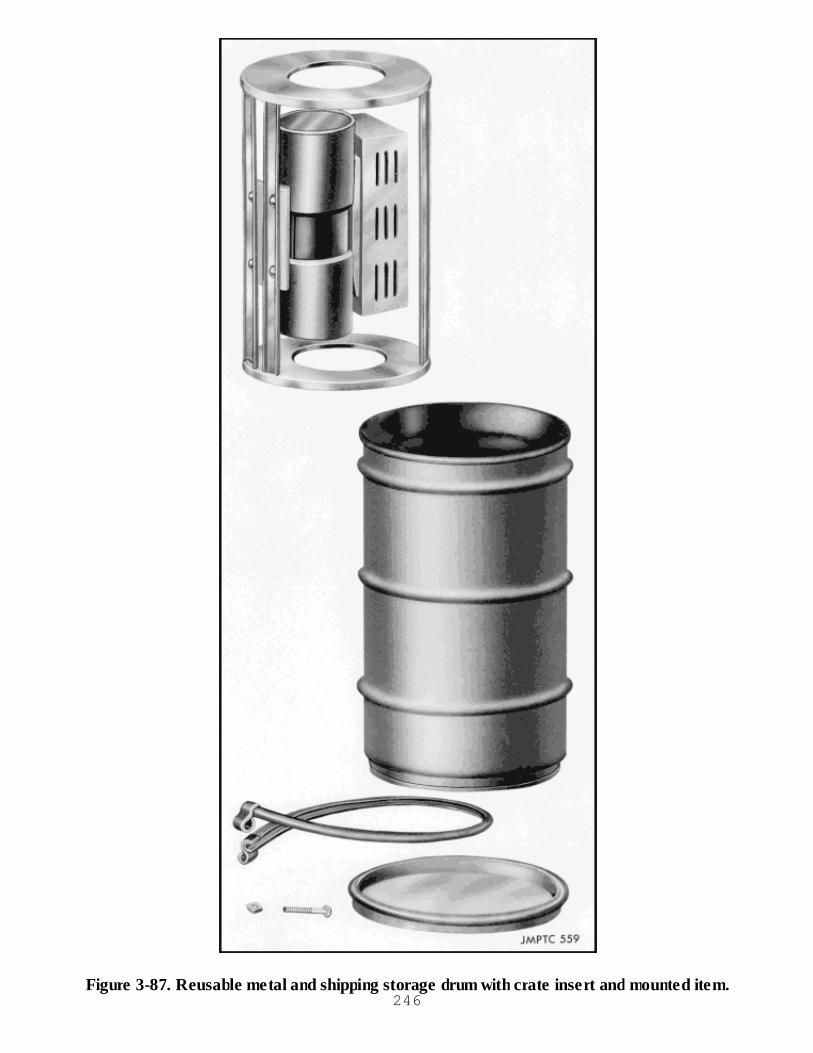
Figure 3-87. Reusable metal and shipping storage drum with crate insert and mounted item.246
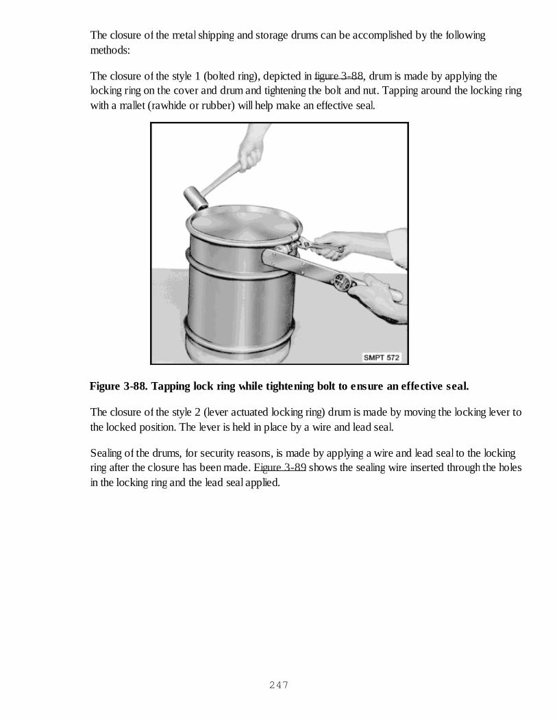
The closure of the metal shipping and storage drums can be accomplished by the followingmethods:
The closure of the style 1 (bolted ring), depicted in figure 3-88, drum is made by applying thelocking ring on the cover and drum and tightening the bolt and nut. Tapping around the locking ringwith a mallet (rawhide or rubber) will help make an effective seal.
Figure 3-88. Tapping lock ring while tightening bolt to ensure an effective seal.
The closure of the style 2 (lever actuated locking ring) drum is made by moving the locking lever tothe locked position. The lever is held in place by a wire and lead seal.
Sealing of the drums, for security reasons, is made by applying a wire and lead seal to the lockingring after the closure has been made. Figure 3-89 shows the sealing wire inserted through the holesin the locking ring and the lead seal applied.
247
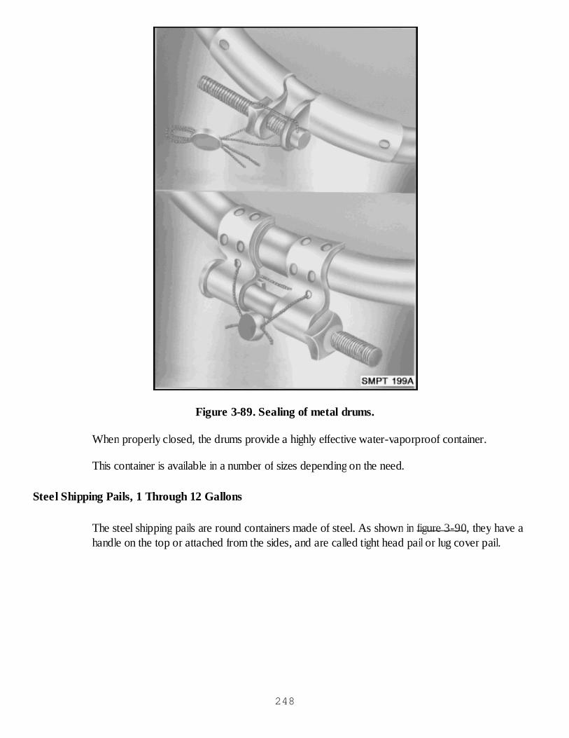
Figure 3-89. Sealing of metal drums.
When properly closed, the drums provide a highly effective water-vaporproof container.
This container is available in a number of sizes depending on the need.
Steel Shipping Pails, 1 Through 12 Gallons
The steel shipping pails are round containers made of steel. As shown in figure 3-90, they have ahandle on the top or attached from the sides, and are called tight head pail or lug cover pail.
248
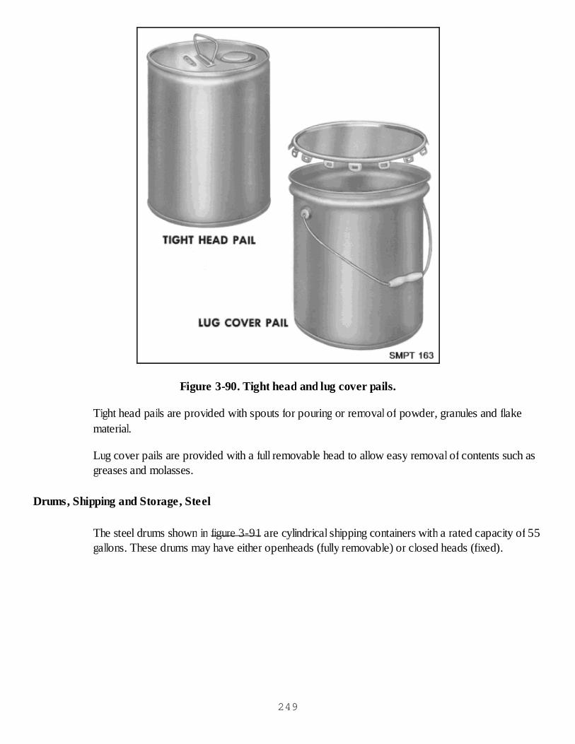
Figure 3-90. Tight head and lug cover pails.
Tight head pails are provided with spouts for pouring or removal of powder, granules and flakematerial.
Lug cover pails are provided with a full removable head to allow easy removal of contents such asgreases and molasses.
Drums, Shipping and Storage, Steel
The steel drums shown in figure 3-91 are cylindrical shipping containers with a rated capacity of 55gallons. These drums may have either openheads (fully removable) or closed heads (fixed).
249
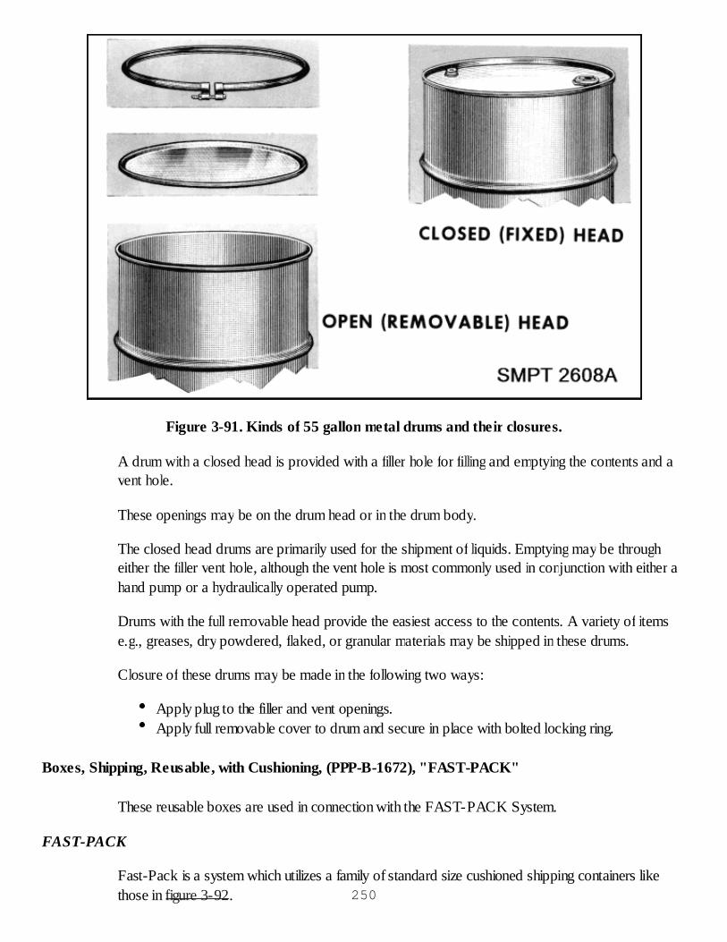
Figure 3-91. Kinds of 55 gallon metal drums and their closures.
A drum with a closed head is provided with a filler hole for filling and emptying the contents and avent hole.
These openings may be on the drum head or in the drum body.
The closed head drums are primarily used for the shipment of liquids. Emptying may be througheither the filler vent hole, although the vent hole is most commonly used in conjunction with either ahand pump or a hydraulically operated pump.
Drums with the full removable head provide the easiest access to the contents. A variety of itemse.g., greases, dry powdered, flaked, or granular materials may be shipped in these drums.
Closure of these drums may be made in the following two ways:
Apply plug to the filler and vent openings.Apply full removable cover to drum and secure in place with bolted locking ring.
Boxes, Shipping, Reusable, with Cushioning, (PPP-B-1672), "FAST-PACK"
These reusable boxes are used in connection with the FAST-PACK System.
FAST-PACK
Fast-Pack is a system which utilizes a family of standard size cushioned shipping containers likethose in figure 3-92. 250
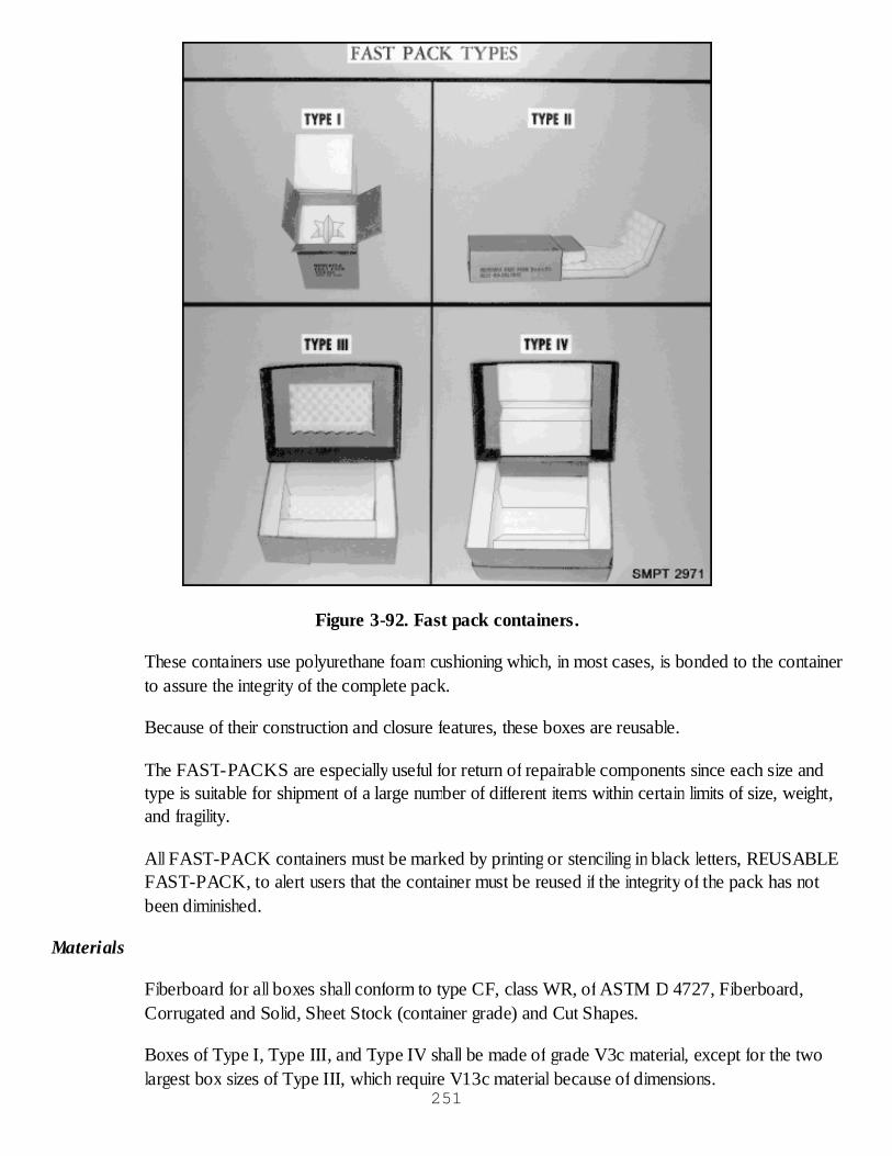
Figure 3-92. Fast pack containers.
These containers use polyurethane foam cushioning which, in most cases, is bonded to the containerto assure the integrity of the complete pack.
Because of their construction and closure features, these boxes are reusable.
The FAST-PACKS are especially useful for return of repairable components since each size andtype is suitable for shipment of a large number of different items within certain limits of size, weight,and fragility.
All FAST-PACK containers must be marked by printing or stenciling in black letters, REUSABLEFAST-PACK, to alert users that the container must be reused if the integrity of the pack has notbeen diminished.
Materials
Fiberboard for all boxes shall conform to type CF, class WR, of ASTM D 4727, Fiberboard,Corrugated and Solid, Sheet Stock (container grade) and Cut Shapes.
Boxes of Type I, Type III, and Type IV shall be made of grade V3c material, except for the twolargest box sizes of Type III, which require V13c material because of dimensions.
251

Type II boxes shall be made of material grade V5c.
Cushioning shall be polyurethane conforming to Type I, class 2, grade C, of MIL-PRF-26514,Polyurethane Foam, Flexible, except for Type II packs which shall be Grade A, B, or C andantistatic.
Types and styles
There are four types and five styles of boxes used in the Fast-Pack System. They are as follows:
Type I - Vertical Star Pack.Type II - Folding Convoluted Pack.Type III - Telescoping Encapsulated Pack.Type IV - Horizontal Star Pack.Style A is a Regular Slotted Container (RSC).Style B is a modified Double Cover Container (DBLCC).Style C is another modified Double Cover Container (DBLCC).Style D is a modified Triple Slide Box (TS).Style G is a modified Full Telescope Design Box (FTC).
Closure and Marking of Fast Packs
Closure of FAST PACKS shall be effected when the item(s) is placed therein and packed forshipment and storage. Marking for military shipment and storage of packs shall comply with MIL-STD-129. Marking of packs for civil agencies shall be in accordance with FED-STD-123. Thetape used for reinforcement and sealing shall be of the specification, type, and size as specified foreach type and style of box to provide Level B packing as specified. Insofar as practical, nopreprinted markings, except container certification marking, shall be obscured by taping orreinforcement. Obscured or obliterated markings that are preprinted on reused boxes need not beremarked except for the pack code.
Closure and Reinforcement for Level B packing
Figure 3-93 illustrates the closure and reinforcement requirements for Level B packing by type andstyle.
252
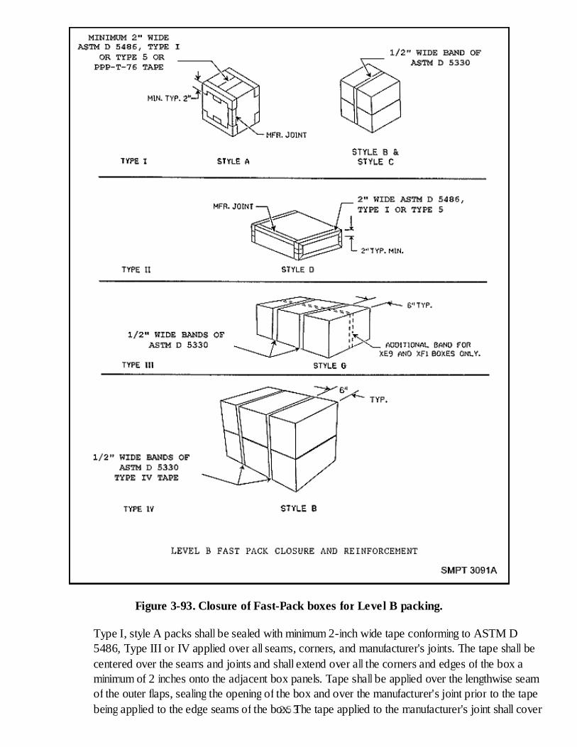
Figure 3-93. Closure of Fast-Pack boxes for Level B packing.
Type I, style A packs shall be sealed with minimum 2-inch wide tape conforming to ASTM D5486, Type III or IV applied over all seams, corners, and manufacturer's joints. The tape shall becentered over the seams and joints and shall extend over all the corners and edges of the box aminimum of 2 inches onto the adjacent box panels. Tape shall be applied over the lengthwise seamof the outer flaps, sealing the opening of the box and over the manufacturer's joint prior to the tapebeing applied to the edge seams of the box. The tape applied to the manufacturer's joint shall cover253
the joint but not extend over the corners of the box onto the adjacent panels. This method alsoserves as the closure.
Type I, styles B and C shall be centrally reinforced with one fully encircling band of 1/2-inch widetape conforming to ASTM D 5330, Type II or III. This method serves as the closure. Sealing is notrequired.
Type II, style D packs will have all open seams and the manufacturer's joint sealed with two inchwide tape conforming to either ASTM D 5486. Type III or IV, or ASTM D 5330. This methodalso serves as the closure.
Type III, style G packs shall be reinforced with fully encircling bands of 1/2-inch wide tapeconforming to ASTM D 5330, Type II or III. Two bands shall be positioned six inches from theends over the top, bottom, and side. Add one lengthwise band over the top, bottom, and ends forXE9 and XF1 FAST PACKS. This method serves as the closure. Sealing is not required.
Type IV, style B. A reinforcement shall be as specified except that the lengthwise band shall notapply. This method serves as the closure. Sealing is not required.
Special Marking Requirements
Type I, II, and IV packs shall be identified with the following data:
REUSABLEFAST-PACK (Appropriate pack size and NSN)
Type II packs require the following markings:
REUSABLEFAST-PACK (Appropriate pack size and NSN)
Each end of the style D box shall be marked with the words: PUSH TO OPEN. In addition, theword "ANTISTATIC" shall be marked on both ends of the slide in 1/4" high letters 3/8 inch belowand not to extend beyond the left margin of the word "OPEN".
Application and Use
Fast-Packs are intended for use as standard, exterior, reusable packing media in the preservation,packing, handling, shipping, and storage of serviceable and repairable items.
Type I packs may be used for items such as meters, gauges, and instruments.
Type II packs may be used for items which are essentially flat (1/4 to 2-1/2 inches thick) such ascircuit boards, electronic modules, and tubes.
Type III packs may be used for black-box type items such as receiver-transmitters, amplifiers,power supply units and electronic indicators.
254

Type IV packs may be used for electrical/electronic items generally having a small cross sectionrelative to length, such as control generators, amplifiers, voltmeters, protection panels, transformers,and regulators.
Opening of Fast Packs
To open the Fast Pack boxes, the closure and reinforcing tape(s) shall be cut with a shallow knifeat the minimum number of seam locations which will permit opening and preclude any damage tothe box. Do not remove totally adhered tape.
Reuse of Fast Packs
In reusing of Fast Packs, the following procedures should be observed:
Surfaces to which tape for closure or reinforcement is to be applied must be free of loose soil, oil,or grease. These surfaces should be wiped clean prior to application of tape.
Tape applied to reused containers should be applied directly over the existing tape.
Loose ends of existing tape should be cut off, not torn loose. Tearing the tape from the boxdamages the box surface and weakens the container walls.
Checkup
What container may be used for shipping pamphlets, papers and other small flat items?What is the weight limit of the load a kraft envelope may carry?How are cushioned paper shipping sacks closed?How is a Type I, style A, Fast-Pack container described?How are blocking and bracing accomplished in metal shipping and storage drums?
255
CHAPTER 4
Packing Procedures and Operations
WEATHERPROOFING THE PACK
GENERAL
Throughout the text, we have stated that we must protect our military supplies and equipment fromthe effects of water, either in its liquid or vapor form.
We can protect the contents of our packs through the use of certain barrier materials in variousapplications.
When these materials are properly applied to the pack, it is called Weatherproofing the Pack.Examples of weatherproofing are shown in figure 4-1.
256
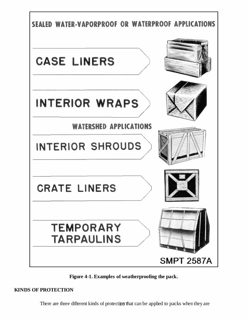
Figure 4-1. Examples of weatherproofing the pack.
KINDS OF PROTECTION
There are three different kinds of protection that can be applied to packs when they are257
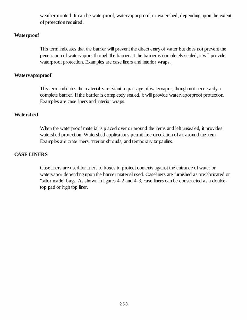
weatherproofed. It can be waterproof, watervaporproof, or watershed, depending upon the extentof protection required.
Waterproof
This term indicates that the barrier will prevent the direct entry of water but does not prevent thepenetration of watervapors through the barrier. If the barrier is completely sealed, it will providewaterproof protection. Examples are case liners and interior wraps.
Watervaporproof
This term indicates the material is resistant to passage of watervapor, though not necessarily acomplete barrier. If the barrier is completely sealed, it will provide watervaporproof protection.Examples are case liners and interior wraps.
Watershed
When the waterproof material is placed over or around the items and left unsealed, it provideswatershed protection. Watershed applications permit free circulation of air around the item.Examples are crate liners, interior shrouds, and temporary tarpaulins.
CASE LINERS
Case liners are used for liners of boxes to protect contents against the entrance of water orwatervapor depending upon the barrier material used. Caseliners are furnished as prefabricated or"tailor made"bags. As shown in figures 4-2 and 4-3, case liners can be constructed as a double-top pad or high top liner.
258

Figure 4-2. High top caseliner.259
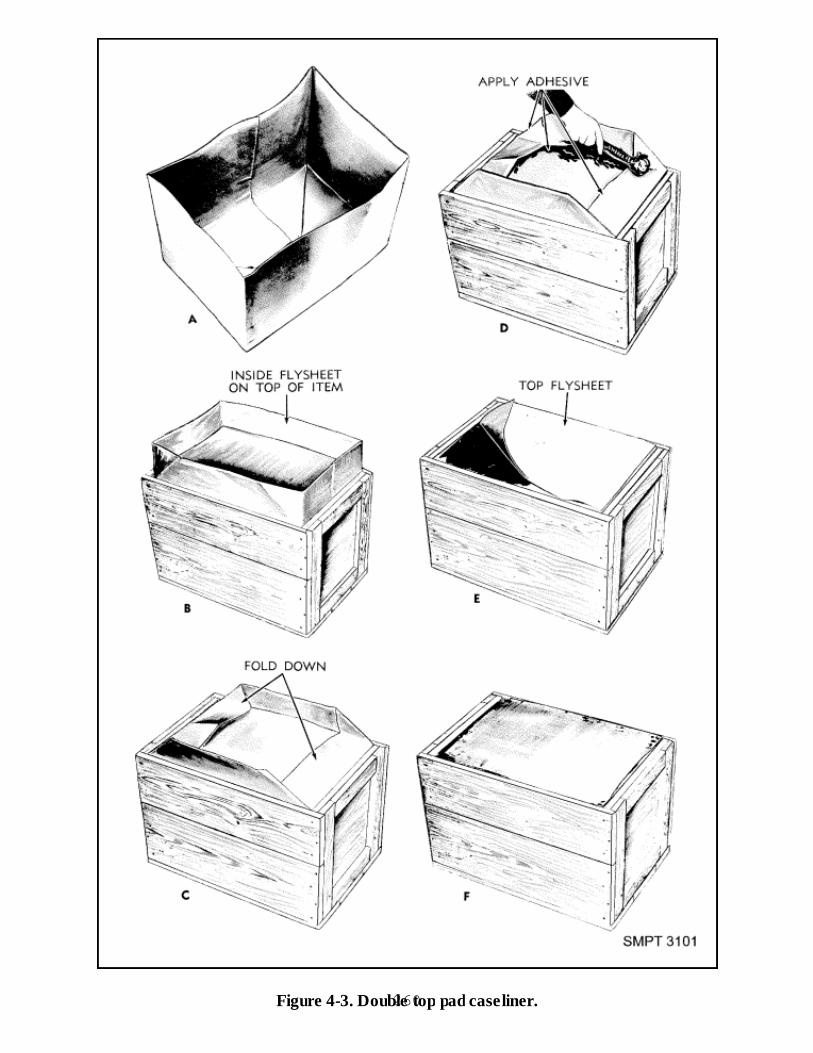
Figure 4-3. Double top pad caseliner.260

The joints, seams, and closures must be sealed to afford water-resistance equal to that of thebarrier material itself. This may be accomplished by heat sealing, adhesive, or tapes. Case linersform a continuous barrier which is a separate part of the box.
Barrier material may be kraft paper or plastic film and affords protection equal to that of the wrapor bag.
Experience has shown that under some conditions, especially when the contents do not completelyfill the case liner, case liners do more harm than good by trapping and holding water rather thanpreventing its entry.
It is not necessary that there be openings in a sealed case liner for this to happen.
If the case liner has a low resistance to watervapor, water can enter in the form of vapor andcondense on the contents within the liner.
It has been found that case liners opened after extended outdoor exposure were partly filled withliquid water.
When packed items need protection against water, it is preferred the protection be provided byindividually wrapped unit packs instead of case liners.
INTERIOR WRAPS
Interior wraps, as illustrated in figure 4-4, are used to protect individual packs or light parts, orsections of items, against penetration of water or watervapor, depending upon the barrier materialused.
261

Figure 4-4. Interior wraps.262
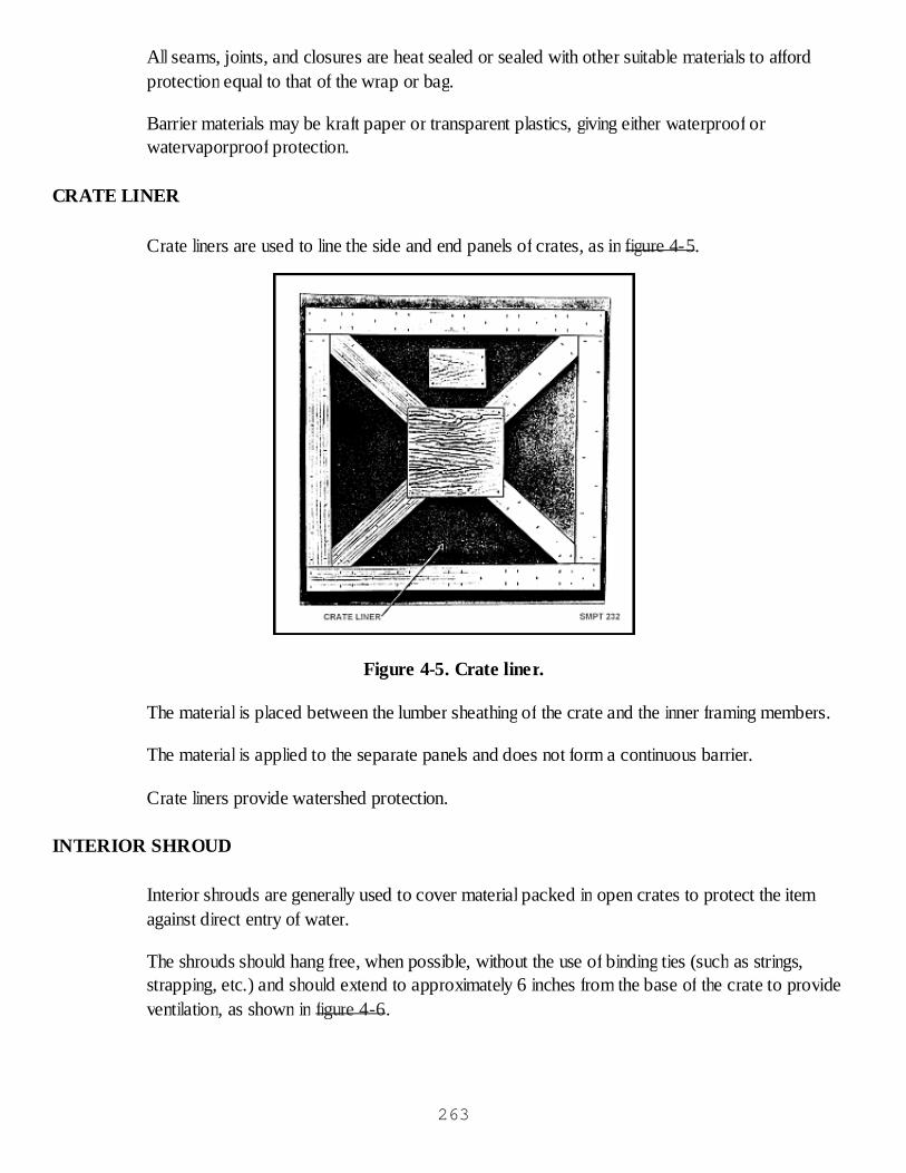
All seams, joints, and closures are heat sealed or sealed with other suitable materials to affordprotection equal to that of the wrap or bag.
Barrier materials may be kraft paper or transparent plastics, giving either waterproof orwatervaporproof protection.
CRATE LINER
Crate liners are used to line the side and end panels of crates, as in figure 4-5.
Figure 4-5. Crate liner.
The material is placed between the lumber sheathing of the crate and the inner framing members.
The material is applied to the separate panels and does not form a continuous barrier.
Crate liners provide watershed protection.
INTERIOR SHROUD
Interior shrouds are generally used to cover material packed in open crates to protect the itemagainst direct entry of water.
The shrouds should hang free, when possible, without the use of binding ties (such as strings,strapping, etc.) and should extend to approximately 6 inches from the base of the crate to provideventilation, as shown in figure 4-6.
263
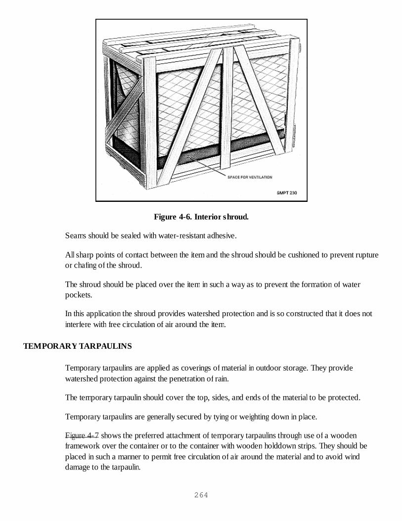
Figure 4-6. Interior shroud.
Seams should be sealed with water-resistant adhesive.
All sharp points of contact between the item and the shroud should be cushioned to prevent ruptureor chafing of the shroud.
The shroud should be placed over the item in such a way as to prevent the formation of waterpockets.
In this application the shroud provides watershed protection and is so constructed that it does notinterfere with free circulation of air around the item.
TEMPORARY TARPAULINS
Temporary tarpaulins are applied as coverings of material in outdoor storage. They providewatershed protection against the penetration of rain.
The temporary tarpaulin should cover the top, sides, and ends of the material to be protected.
Temporary tarpaulins are generally secured by tying or weighting down in place.
Figure 4-7 shows the preferred attachment of temporary tarpaulins through use of a woodenframework over the container or to the container with wooden holddown strips. They should beplaced in such a manner to permit free circulation of air around the material and to avoid winddamage to the tarpaulin.
264

Figure 4-7. Temporary tarpaulin.
SUMMARY
In summary, there are five different ways to weatherproof the pack depending upon the extent ofprotection required. They are caseliner, crateliner, interior wrap, interior shroud, and temporarytarpaulin.
Checkup
What are the three different kinds of protection you can give to your packs whenweatherproofing the pack?What type of protection does a case liner provide?What kind of protection is provided by a crate liner?What type of protection does an interior shroud provide?How far should an interior shroud extend from the base of the crate?What are temporary tarpaulins used for?
WEATHERPROOFING THE PACK PRACTICAL EXERCISE
Objective
As a result of this practical exercise, the student will be able to identify the various methods ofweatherproofing the pack. 265
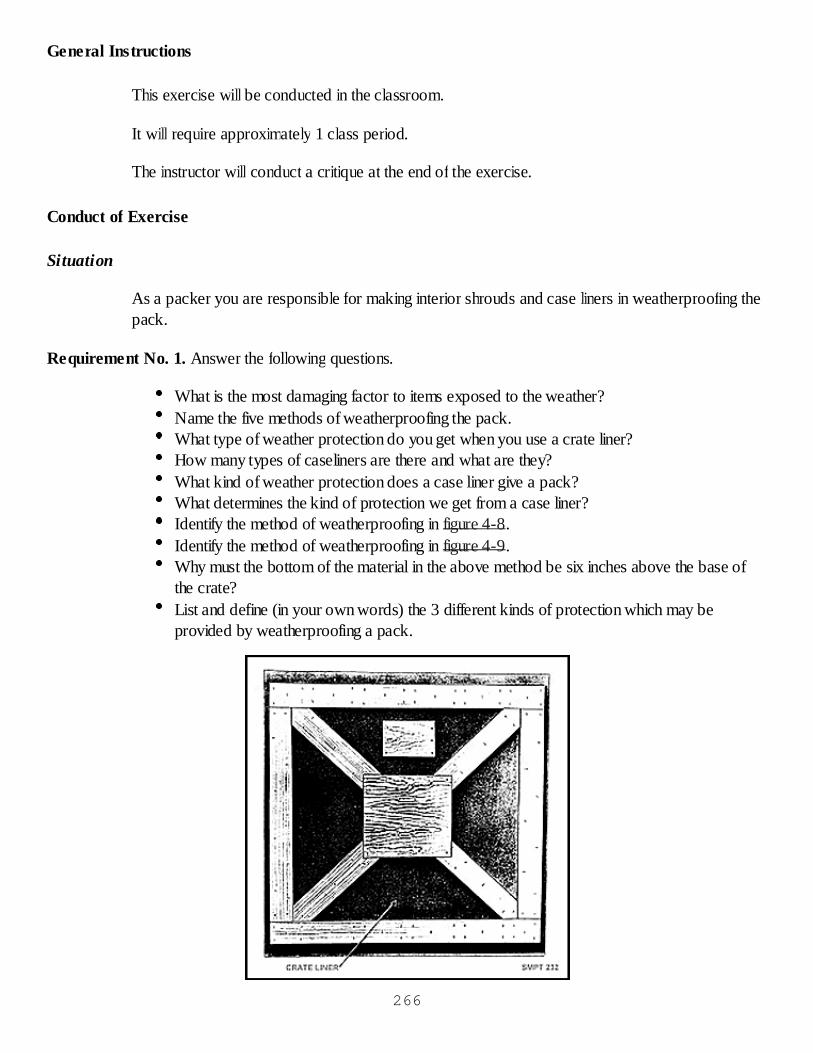
General Instructions
This exercise will be conducted in the classroom.
It will require approximately 1 class period.
The instructor will conduct a critique at the end of the exercise.
Conduct of Exercise
Situation
As a packer you are responsible for making interior shrouds and case liners in weatherproofing thepack.
Requirement No. 1. Answer the following questions.
What is the most damaging factor to items exposed to the weather?Name the five methods of weatherproofing the pack.What type of weather protection do you get when you use a crate liner?How many types of caseliners are there and what are they?What kind of weather protection does a case liner give a pack?What determines the kind of protection we get from a case liner?Identify the method of weatherproofing in figure 4-8.Identify the method of weatherproofing in figure 4-9.Why must the bottom of the material in the above method be six inches above the base ofthe crate?List and define (in your own words) the 3 different kinds of protection which may beprovided by weatherproofing a pack.
266
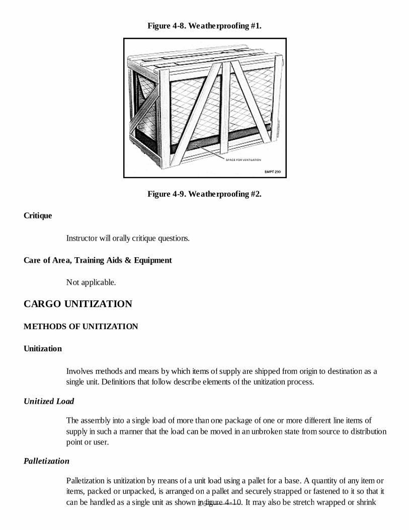
Figure 4-8. Weatherproofing #1.
Figure 4-9. Weatherproofing #2.
Critique
Instructor will orally critique questions.
Care of Area, Training Aids & Equipment
Not applicable.
CARGO UNITIZATION
METHODS OF UNITIZATION
Unitization
Involves methods and means by which items of supply are shipped from origin to destination as asingle unit. Definitions that follow describe elements of the unitization process.
Unitized Load
The assembly into a single load of more than one package of one or more different line items ofsupply in such a manner that the load can be moved in an unbroken state from source to distributionpoint or user.
Palletization
Palletization is unitization by means of a unit load using a pallet for a base. A quantity of any item oritems, packed or unpacked, is arranged on a pallet and securely strapped or fastened to it so that itcan be handled as a single unit as shown in figure 4-10. It may also be stretch wrapped or shrink267
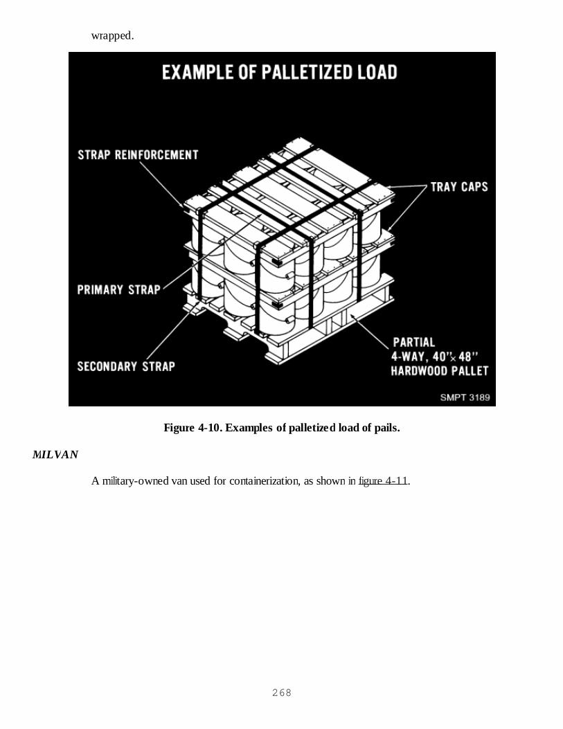
wrapped.
Figure 4-10. Examples of palletized load of pails.
MILVAN
A military-owned van used for containerization, as shown in figure 4-11.
268
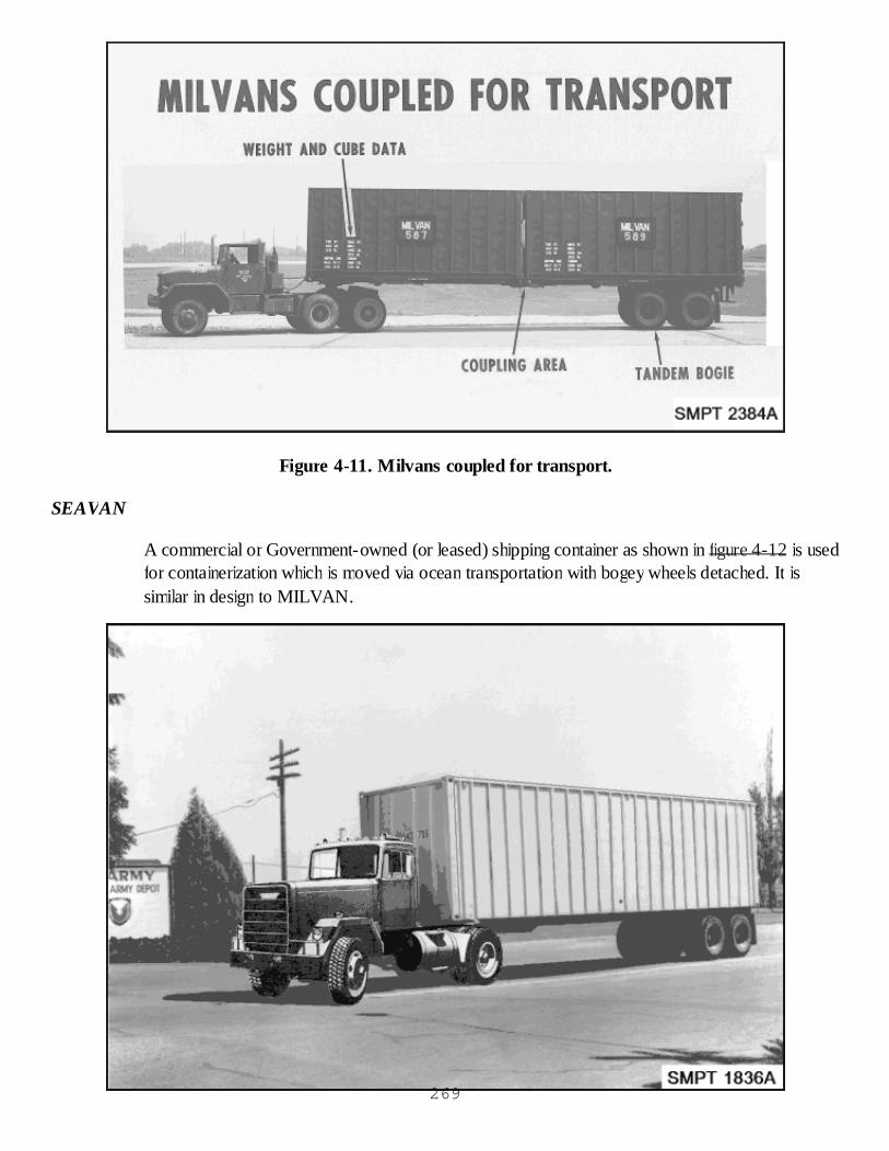
Figure 4-11. Milvans coupled for transport.
SEAVAN
A commercial or Government-owned (or leased) shipping container as shown in figure 4-12 is usedfor containerization which is moved via ocean transportation with bogey wheels detached. It issimilar in design to MILVAN.
269

Figure 4-12. Seavan moving over the road.
Consolidation boxes
Shown in figure 4-13 are boxes used as inserts in MILVANS or SEAVANS or as separateexterior shipping containers.
Figure 4-13. Wood cleated plywood consolidation boxes.
Containerization
In this lesson, the term is intended to refer both to the placing of commodities in plywood,wirebound and fiberboard containers, as well as to the loading of containers in SEAVANS andMILVANS in such a manner as to assure their protection during shipping, handling, and storage
Advantages of Unitization
Economy
Unit loads provide an economical manner of handling, storing, and transporting small items or packs270
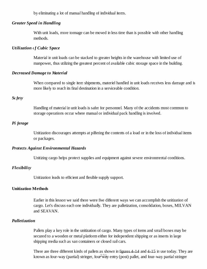
by eliminating a lot of manual handling of individual items.
Greater Speed in Handling
With unit loads, more tonnage can be moved in less time than is possible with other handlingmethods.
Utilization of Cubic Space
Material in unit loads can be stacked to greater heights in the warehouse with limited use ofmanpower, thus utilizing the greatest percent of available cubic storage space in the building.
Decreased Damage to Material
When compared to single item shipments, materiel handled in unit loads receives less damage and ismore likely to reach its final destination in a serviceable condition.
Safety
Handling of material in unit loads is safer for personnel. Many of the accidents most common tostorage operations occur where manual or individual pack handling is involved.
Pilferage
Unitization discourages attempts at pilfering the contents of a load or in the loss of individual itemsor packages.
Protects Against Environmental Hazards
Unitizing cargo helps protect supplies and equipment against severe environmental conditions.
Flexibility
Unitization leads to efficient and flexible supply support.
Unitization Methods
Earlier in this lesson we said there were five different ways we can accomplish the unitization ofcargo. Let's discuss each one individually. They are palletization, consolidation, boxes, MILVANand SEAVAN.
Palletization
Pallets play a key role in the unitization of cargo. Many types of items and small boxes may besecured to a wooden or metal platform either for independent shipping or as inserts in largeshipping media such as van containers or closed rail cars.
There are three different kinds of pallets as shown in figures 4-14 and 4-15 in use today. They areknown as four-way (partial) stringer, four way entry (post) pallet, and four-way partial stringer271
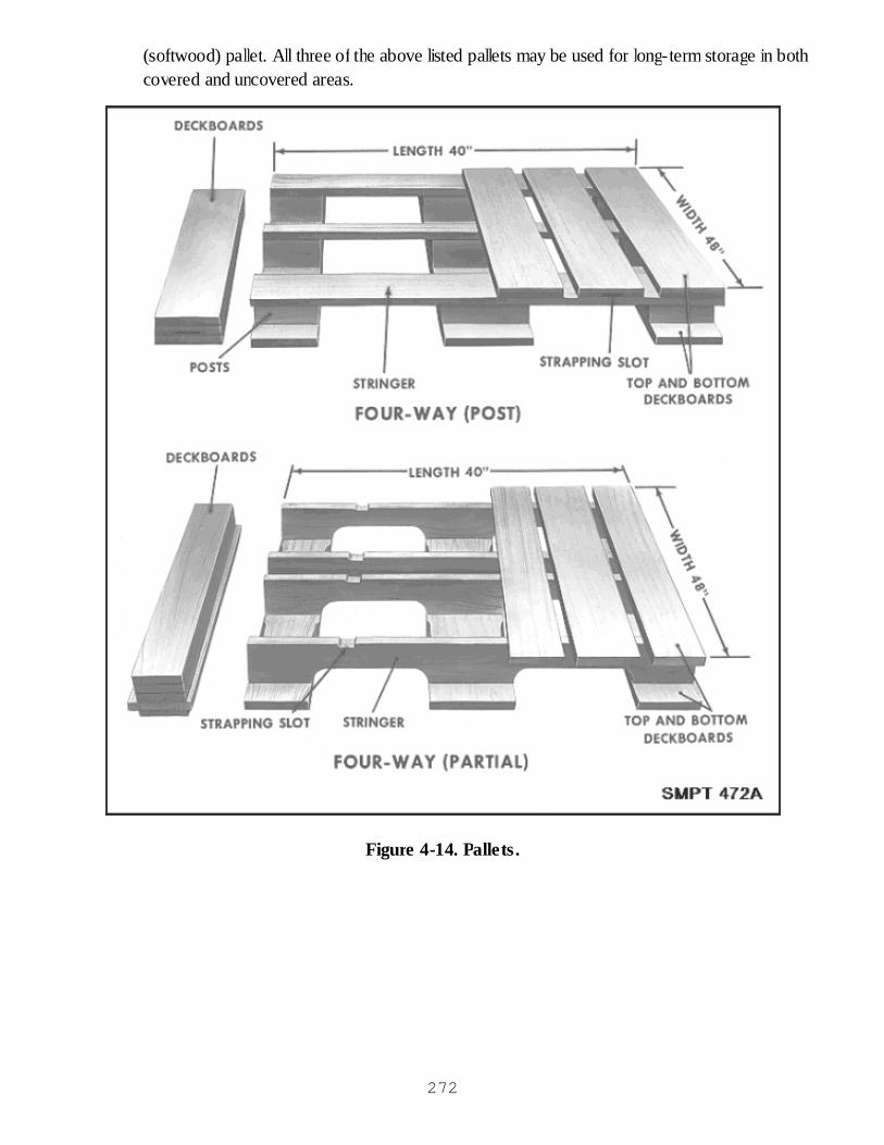
(softwood) pallet. All three of the above listed pallets may be used for long-term storage in bothcovered and uncovered areas.
Figure 4-14. Pallets.
272
Figure 4-15. Softwood pallet.
Size Limits of Pallets
There are many different size pallets in use today. The one we are concerned with is known as thestandard size pallet. It measures 40" x 48". The 40-inch dimension identifies the length of the pallet.The 48-inch dimension identifies the width of the pallet.
Load Limits of Pallets
When loading pallets, there are certain limits to which they can be loaded as shown in figure 4-16.A load cannot exceed 52 inches (widest dimension) which permits an over-hang of 2 inches at eachend of the 48-inch dimension. Load units prepared for shipment in SEAVAN and MILVANshould not exceed 48 inches in width. A load cannot exceed 43 inches (narrow dimension) whichpermits an over-hang of 1-1/2 inches at each end of the 40-inch dimension. Loads for shipment inSEAVAN and MILVAN will not exceed 40 inches in length. A load should not exceed 54 inchesin height, except for loads of compressed gases in cylinders. Loads prepared for shipment inSEAVANS should not be higher than 43 inches. Loads prepared for shipment in MILVANSshould not be higher than 41 inches. Load limits are established in MIL-HDBK 774.
273

Figure 4-16. Other pallet loads.
Weight Limits of Palletized Loads
When loading pallets, we must remain within the weight limitations for palletized loads. Weight limitsapply to the entire load including pallet, bonding, storage aids, and units. The maximum weight of aload for domestic, intercoastal, or overseas shipment will not exceed 3000 pounds per single palletload.
Items To Be Palletized
Types of supplies that can be palletized are: items which are identical and identified by the samestock number; items uneconomical or impractical to pack otherwise; rugged and durable items thatrequire minimum physical protection; boxed items uniform in size requiring additional protection;and items that are moved in large quantities. (See figure 4-16.)
274
Loading of Pallets
The arrangement of items on pallets must provide a rigid, compact, uniform size load. The itemsmust be strongly secured to prevent shifting, and must be capable of resisting impact, vibration,wracking, and compression encountered during handling, storage, and shipment. To properly load apallet, consideration must be given to the type of item, its weight, and destination.
Pattern For Palletization Loads
Containers or items are arranged on the pallet in a particular pattern for each type of item. Whenpossible, the pallet pattern should be arranged to utilize all the pallet area with the least amount ofmargin on the pallet. When the pattern and the loading method have been determined for palletizingitems into a secure load, that pattern and method should be used in preparing similar items into aload. The length, width, and height of each rectangular package must be considered in determiningthe pallet pattern to permit the formation of interlocking patterns and provide stability to the unitload. MIL-HDB-774 contains 124 different kinds of pallet patterns. We will only cover a few atthis time to familiarize you with the pallet patterns. Determine length and width of the container tothe nearest 1/2 inch. Locate the length of the container at the top and the width of the container onthe left side of the index chart, as shown in figure 4-17; the container pattern will be found at theintersection of the two columns.
275
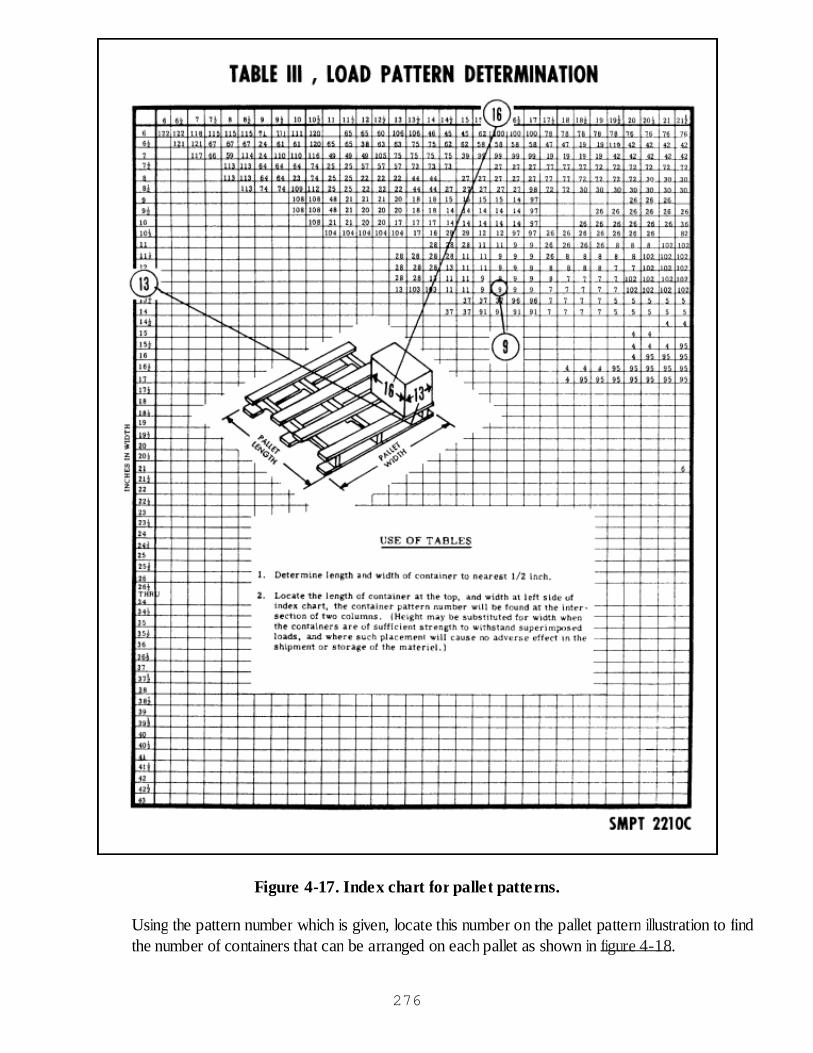
Figure 4-17. Index chart for pallet patterns.
Using the pattern number which is given, locate this number on the pallet pattern illustration to findthe number of containers that can be arranged on each pallet as shown in figure 4-18.
276

Figure 4-18. Finding correct pallet pattern.
Load Classification
There are 18 different load classifications for palletized loads listed in MIL-HDBK-774. The onesmost generally used are Load Type I and Ia which consist of fiberboard boxes, wood boxes, orother suitable hard surface units stacked in single or multiple layer loads as shown in figure 4-19.277
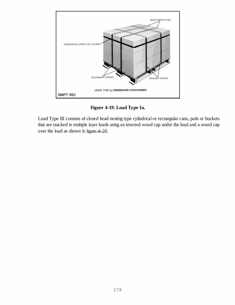
Figure 4-19. Load Type Ia.
Load Type III consists of closed head nesting type cylindrical or rectangular cans, pails or bucketsthat are stacked in multiple layer loads using an inverted wood cap under the load and a wood capover the load as shown in figure 4-20.
278

Figure 4-20. Load Types III and IV.
Load Type IV consists of cylindrical and rectangular cans with removable covers containing plastics, paints, andsemi-liquids (grease and lard), and nontop nesting closed head cans that must be stacked in multiple layers withwood tray caps between layers as shown in figure 4-20. Load Type XIII consists of cylindrical shaped itemssuch as wire, cloth, canvas, wrapping paper, building paper, and sheet metal in rolls that must be stackedvertically in single or multiple layers with a wood cap over and under the load and with a double tray capbetween layers as shown in figure 4-21.
279
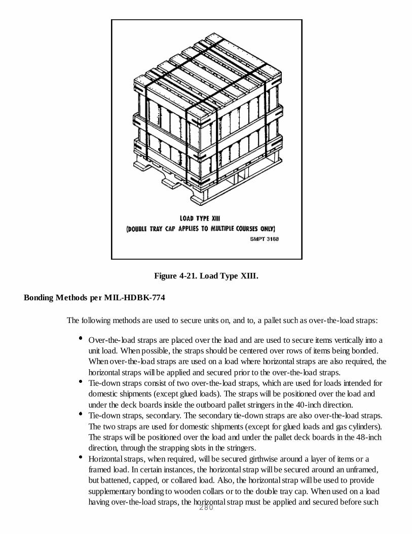
Figure 4-21. Load Type XIII.
Bonding Methods per MIL-HDBK-774
The following methods are used to secure units on, and to, a pallet such as over-the-load straps:
Over-the-load straps are placed over the load and are used to secure items vertically into aunit load. When possible, the straps should be centered over rows of items being bonded.When over-the-load straps are used on a load where horizontal straps are also required, thehorizontal straps will be applied and secured prior to the over-the-load straps.Tie-down straps consist of two over-the-load straps, which are used for loads intended fordomestic shipments (except glued loads). The straps will be positioned over the load andunder the deck boards inside the outboard pallet stringers in the 40-inch direction.Tie-down straps, secondary. The secondary tie-down straps are also over-the-load straps.The two straps are used for domestic shipments (except for glued loads and gas cylinders).The straps will be positioned over the load and under the pallet deck boards in the 48-inchdirection, through the strapping slots in the stringers.Horizontal straps, when required, will be secured girthwise around a layer of items or aframed load. In certain instances, the horizontal strap will be secured around an unframed,but battened, capped, or collared load. Also, the horizontal strap will be used to providesupplementary bonding to wooden collars or to the double tray cap. When used on a loadhaving over-the-load straps, the horizontal strap must be applied and secured before such
280
other straps are applied.Any over-the-load strap, either tie-down or load, which is not a primary or secondary strap,is identified as an auxiliary strap.
Storage Aids
Storage aids must always be used when bonding alone is insufficient. They are constructed ofpaper, canvas, fiberboard, wood or steel, and may be in the form of caps, collars, battens, andframes.
The caps and the items covered must be centered on the pallet to achieve an equal degree ofmargin or overhand on the pallet and to provide squared loads.The fiberboard cap will be used on nonframed loads containing lightweight rectangular stableunits. The plain (nonpartitioned) wood cap must be used, when required, on nonframedloads containing heavy rectangular items or on nonframed loads requiring caps.The double tray cap will be used between layers in multiple layer nonframed loads containingstable units. This cap will be used only in loads which are capped over and under with plaincaps.The special tray cap is recommended in loads (usually two layer loads) containing filled 5-gallon paint-type pails. One cap is used over the top load and one over the lower layer of theload. A cap will not be required over the bottom of the load when the special tray cap isused.The purpose of the wood collar is to secure the upper portion of loads of cylinders ofcompressed gases or loads of similar items. It provides a guard to protect the caps or topsof such units and to provide a substantial base for superimposed loads. Also, the loadsshould be secured with horizontally strapped wooden battens at the lower portion and withover-the-load straps. The collar must be made to fit each specific type of load snugly overthe top; to enclose snugly the caps or valves of the cylinder and extend slightly above thetops of the caps or valves on the cylinders; and to rest on the outside perimeter of the units.The collar is partitioned at strategic places to enclose intermediate rows of cylinders andmust be fitted exactly.
Wood battens will be used in conjunction with horizontal strapping to secure the lower portion ofloads of cylinders of compressed gases (or loads of similar units), loads of bags which cannot beglued, or loads of rectangular metal units in multiple layers. Also, loads of cylinders of gas should besecured with a wooden collar over the top of load and with over-the-load straps. Battens aresecured flatwise against the four sides of the load or on top of certain loads with horizontal or over-the-load straps, which are secured with doubly crimped seals and strapped. The battens are leveledon one side at each end and must be cut to exact size.
Frames may consist of a wood framework which may be sheathed or open. Frames should beconstructed of the lightest weight material that will support three or more superimposed loads.Crosspieces and sheathing, added for additional strength or containment of small items, should bekept to a minimum.
281
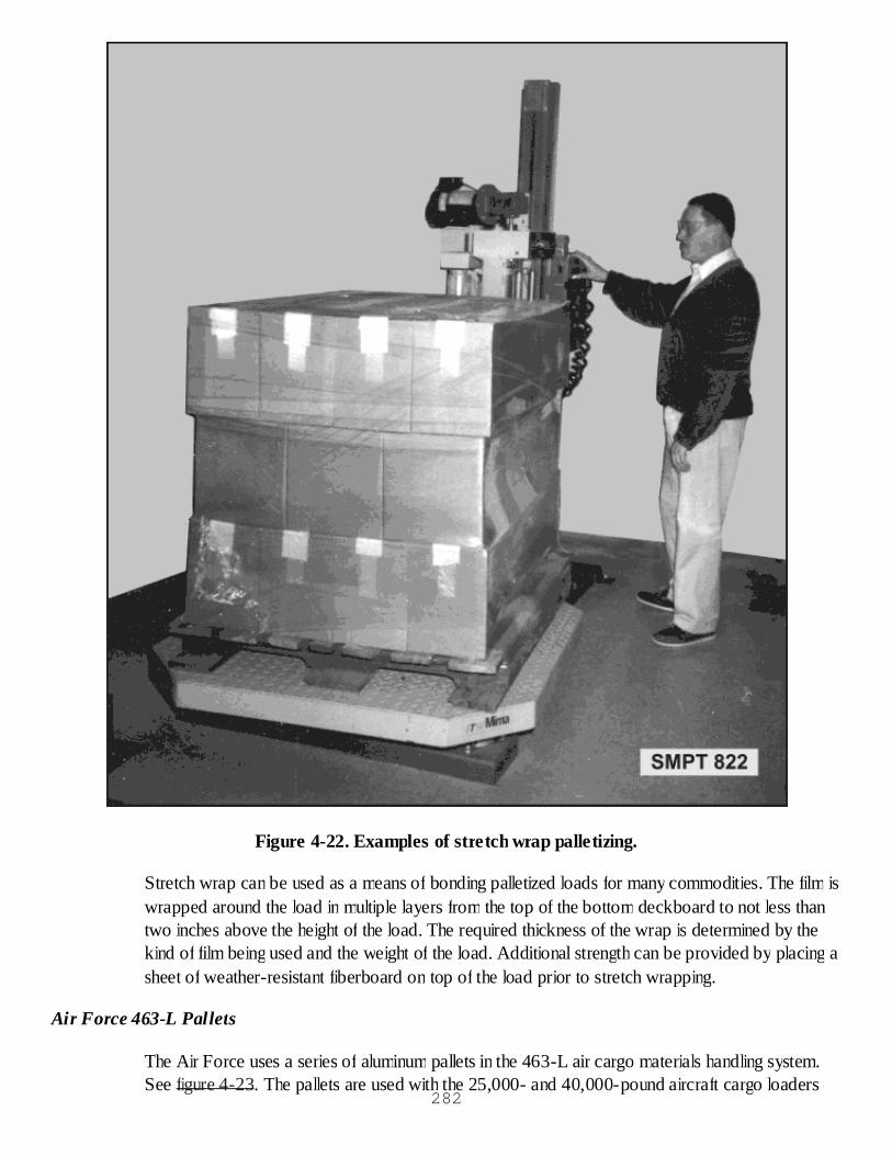
Figure 4-22. Examples of stretch wrap palletizing.
Stretch wrap can be used as a means of bonding palletized loads for many commodities. The film iswrapped around the load in multiple layers from the top of the bottom deckboard to not less thantwo inches above the height of the load. The required thickness of the wrap is determined by thekind of film being used and the weight of the load. Additional strength can be provided by placing asheet of weather-resistant fiberboard on top of the load prior to stretch wrapping.
Air Force 463-L Pallets
The Air Force uses a series of aluminum pallets in the 463-L air cargo materials handling system.See figure 4-23. The pallets are used with the 25,000- and 40,000-pound aircraft cargo loaders
282
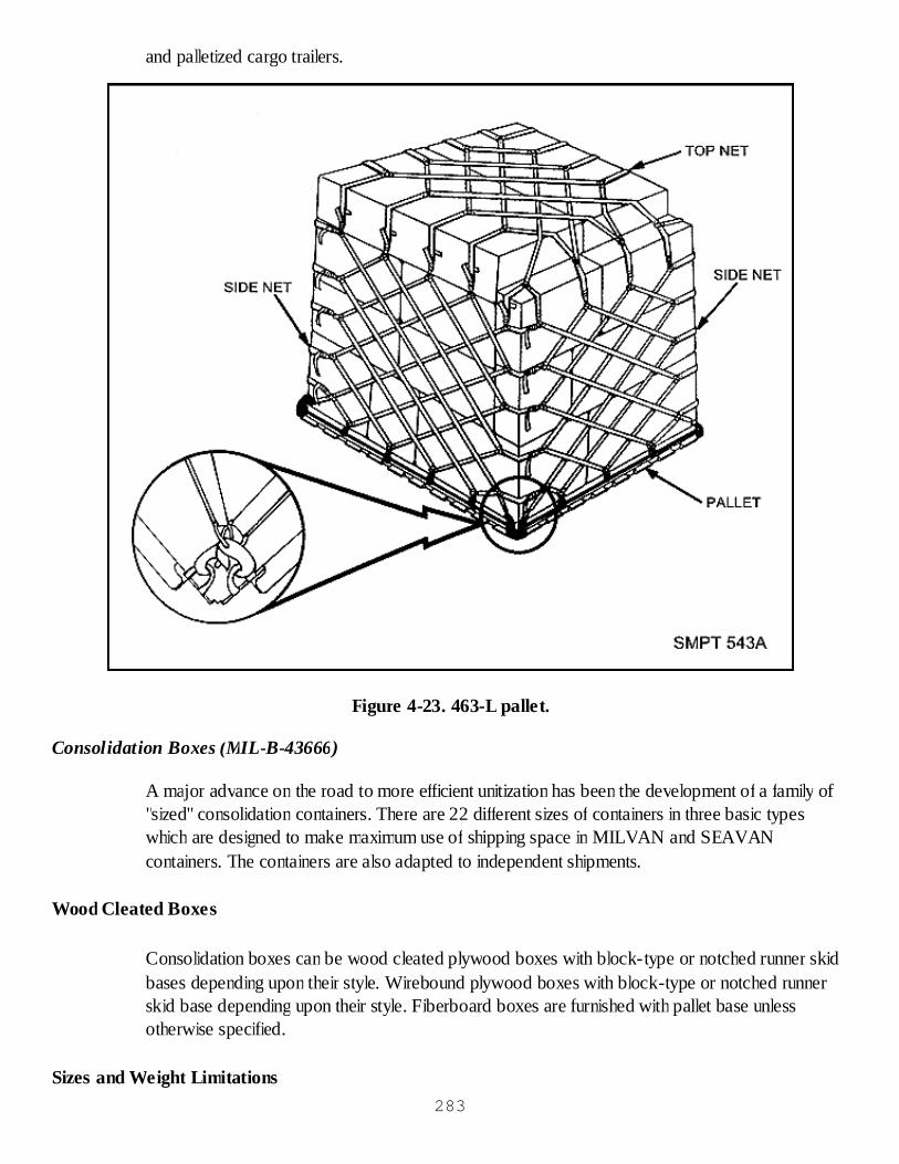
and palletized cargo trailers.
Figure 4-23. 463-L pallet.
Consolidation Boxes (MIL-B-43666)
A major advance on the road to more efficient unitization has been the development of a family of"sized" consolidation containers. There are 22 different sizes of containers in three basic typeswhich are designed to make maximum use of shipping space in MILVAN and SEAVANcontainers. The containers are also adapted to independent shipments.
Wood Cleated Boxes
Consolidation boxes can be wood cleated plywood boxes with block-type or notched runner skidbases depending upon their style. Wirebound plywood boxes with block-type or notched runnerskid base depending upon their style. Fiberboard boxes are furnished with pallet base unlessotherwise specified.
Sizes and Weight Limitations283

Twenty-two sizes of boxes are available with weight limits ranging from 1,000 to 2,600 pounds.
Types of Loads
These boxes may carry Type 1, 2, or 3 loads.
Intended Uses
These boxes are designed to improve packing and unitizing of overseas shipments; compensate forshortage of terminal handling facilities, equipment, and personnel; protect against material pilferage,physical loss, and damage in transit; compensate for lack of covered storage and other severeenvironmental factors; and consolidate shipments of like and unlike stock numbered commodities.
MILVAN
The MILVAN, as shown in figure 4-24, is a military demountable cargo container that has beendeveloped by the Army for containerized shipments. It is an important and widely used method ofshipping unitized loads in vans worldwide.
284
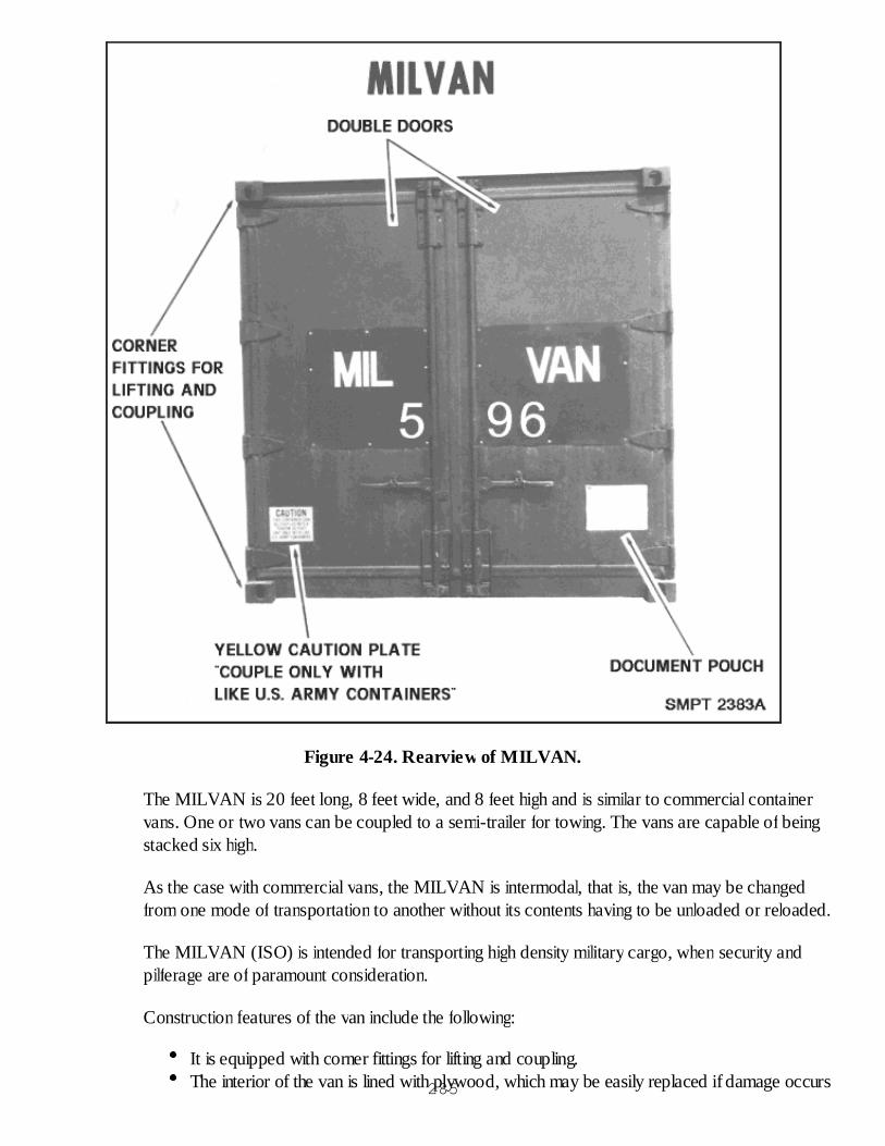
Figure 4-24. Rearview of MILVAN.
The MILVAN is 20 feet long, 8 feet wide, and 8 feet high and is similar to commercial containervans. One or two vans can be coupled to a semi-trailer for towing. The vans are capable of beingstacked six high.
As the case with commercial vans, the MILVAN is intermodal, that is, the van may be changedfrom one mode of transportation to another without its contents having to be unloaded or reloaded.
The MILVAN (ISO) is intended for transporting high density military cargo, when security andpilferage are of paramount consideration.
Construction features of the van include the following:
It is equipped with corner fittings for lifting and coupling.The interior of the van is lined with plywood, which may be easily replaced if damage occurs285
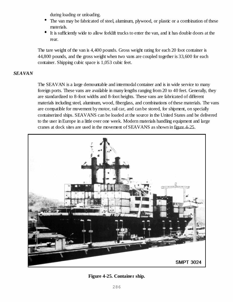
during loading or unloading.The van may be fabricated of steel, aluminum, plywood, or plastic or a combination of thesematerials.It is sufficiently wide to allow forklift trucks to enter the van, and it has double doors at therear.
The tare weight of the van is 4,400 pounds. Gross weight rating for each 20 foot container is44,800 pounds, and the gross weight when two vans are coupled together is 33,600 for eachcontainer. Shipping cubic space is 1,053 cubic feet.
SEAVAN
The SEAVAN is a large demountable and intermodal container and is in wide service to manyforeign ports. These vans are available in many lengths ranging from 20 to 40 feet. Generally, theyare standardized to 8-foot widths and 8-foot heights. These vans are fabricated of differentmaterials including steel, aluminum, wood, fiberglass, and combinations of these materials. The vansare compatible for movement by motor, rail car, and can be stored, for shipment, on speciallycontainerized ships. SEAVANS can be loaded at the source in the United States and be deliveredto the user in Europe in a little over one week. Modern materials handling equipment and largecranes at dock sites are used in the movement of SEAVANS as shown in figure 4-25.
Figure 4-25. Container ship.
286
Containerization as a method of unitization
A variety of containers from small consolidation containers to large demountable vans iscontributing effectively to the unitization movement in the world-wide distribution of supplies.
Checkup
What is a unitized load?What is containerization?What are key advantages of cargo unitization loads?When two MILVANS are transported together, what is the permissible gross weight foreach van?How many pallet patterns are cited in MIL-HDBK-774?
CARGO UNITIZATION PRACTICAL EXERCISE
Objective
As a result of this practice, the student will be able to palletize unit loads and pack consolidationcontainers.
General Instructions
This exercise will be conducted in the classroom.
It will take approximately one class period.
A critique will be held at the end of the exercise.
Conduct of Exercise
Situation
As a packer, you are required to consolidate, unitize, and containerize loads for shipment. You arerequired to determine and apply the correct loading and packing procedures and the application ofspecial cap trays, blocking and bracing, and strapping so that the loads will be properly preparedfor shipment.
Requirement
Answer the following questions.
What is cargo unitization?Name three ways of unitization.What is a base on which items are consolidated for shipment called?
287
What is the size of a standard pallet?What two methods are used to hold items on a pallet?You are going to ship a load of items packed in boxes 19 x 8-1/2 x 2 inches, each weighing40 lbs.What pallet pattern would you use?What are the length and width limitations for the pallet load if it is going into storage?What is the overall height limit if it is to be shipped in a MILVAN?If the pallet is 6" high how many boxes can be loaded on each pallet if it is being loaded in aMILVAN?In addition to the pallet pattern what other information can you obtain by reading MIL-HDBK-774?In which direction do the secondary straps run?What is the most weight you can put in a MIL-B-43666 consolidation box?What name is given to a cargo container, which, after it is packed, can be carried by anymode of transportation without repacking?What is the military intermodal container called?What is the maximum gross weight of a single MILVAN?If two MILVANS are coupled together, what would be their maximum gross weight?What is the size of a single MILVAN?What is the height of a standard pallet load?What is the maximum weight that can be shipped on a single pallet?What items may be palletized using load classification type XIII?What is the purpose of a wooden collar?What are the primary advantages of cargo unitization?What are the advantages of shrink film palletization over conventional unitization?
Critique
Instructor will ask the students to answer each questions orally.
Care of Area, Training Aids & Equipment
Not applicable.
MARKING AND LABELING
MARKING REQUIREMENTS
Purpose
Marking is the application of numbers, letters, labels, tags, symbols, or colors to provideidentification and expedite handling during shipment and storage.
No matter how well an item is made or packed, it has no value if it cannot be identified at itsdestination. 288

General Marking Requirements
All shipments should be marked and labeled in a manner suitable for the mode of shipment to beused.
Unauthorized markings on shipping containers should be obliterated (blanked out, covered withpaint, stencil ink, etc.).
Each palletized unit and unpacked unit should bear the address of the intended receiving activity.
Labels should be used in preference to tags, except when it is impracticable to apply a label.
MIL-STD-129, MIL-HDBK-129, and MILSTAMP provide the requirements for the uniformmarking of military supplies and equipment for shipment and storage.
Markings, Marking Materials and Methods
Marking Materials
Marking materials used shall be those materials specified in MIL-STD-129 or alternate choicesapproved by the cognizant activity. Contractors may obtain the DOD-unique labels discussedherein from commercial sources after obtaining samples from either the procuring activity or thelocal Defense Contract Management Command (DCMC) office.
Waterproofing Materials Used as Protective Coatings
Waterproofing materials such as spar varnish, acrylic coating compound, sealing compound, labeladhesive, polyurethane coatings, and pressure-sensitive tape, that does not restrict or precludelegibility or readability of the package markings, shall be used as protective coatings on containermarkings.
Stencil-Marking Material
Any opaque, nonfading, fast drying, weather resistant stencil ink, lacquer, paint, or enamel shall beused for stencil marking. When applied directly to the item, removable paint that is used for markingunboxed/uncrated equipment, conforming to MIL-P-52905, shall be used. A MIL-C-46168 orMIL-C-53039 coating shall be applied when stenciling containers that have had a top coat ofchemical agent resistant coating (CARC) applied to them.
289
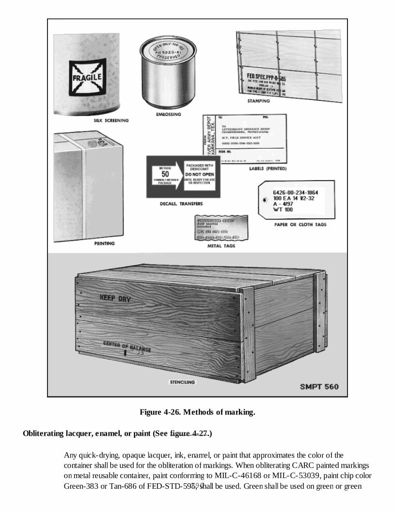
Figure 4-26. Methods of marking.
Obliterating lacquer, enamel, or paint (See figure 4-27.)
Any quick-drying, opaque lacquer, ink, enamel, or paint that approximates the color of thecontainer shall be used for the obliteration of markings. When obliterating CARC painted markingson metal reusable container, paint conforming to MIL-C-46168 or MIL-C-53039, paint chip colorGreen-383 or Tan-686 of FED-STD-595, shall be used. Green shall be used on green or green290

camouflage, and tan shall be used on tan or desert sand camouflage colored containers.
Figure 4-27. Use of obliterating material.
Lithographing, Embossing, Roller Coating, Or Stamping
When lithographing, embossing, or roller coating of markings is authorized, commercial enamels,291
lacquers, or inks in the color specified shall be used. When stamping is specified, commercialwaterproof and petroleum-resistant inks, in the color specified, must offer sufficient durability onexposure to field service.
Labels, Paper, Pressure-Sensitive, Water-Resistant
Labels should be made of a water-resistant grade of paper, film, fabric, or plastic, coated on oneside with water-insoluble, permanent type adhesive. The adhesive shall adhere to metal plastic, orfiberboard surfaces under high and low temperatures. Labels shall have a finish suitable for printingand writing on with ink without feathering or spreading, shall be capable of withstanding normalhandling and storage conditions, and shall remain securely in position. If labels for exteriorcontainers, except vehicles and related items, are not inherently waterproof, they shall bewaterproofed by coating the entire outer surface of the label with a transparent, waterproofingmaterial.
Tags
A metal, cloth, plastic, paper, or other suitable durable material shipping tag, bearing the requiredmarkings, shall be used when specified herein or when it is impractical to stencil mark or apply alabel on the container or unpacked item. Tags conforming to A-A-900 or UU-T-81 arerecommended.
Water-Resistant Envelopes
Water-resistant envelopes shall be used for packing lists and materiel release/receipt documents.Securely affix or fasten the envelope to the package or container. Water-resistant envelopes suchas those conforming to A-A-1658, A-A-1659, or A-A-1660 are recommended for containingpacking lists and other documents.
General
Marking of unit packs, unpacked items, and exterior packs may be accomplished by the use oflabels, stamping, stenciling, printing or tagging. Other processes such as lithographing, stamping,embossing, roller coating, bar coding laser marking, and applying decals may be used, whenspecified, or upon approval by the cognizant activity.
Condition of Surfaces to be Marked
Surfaces to be marked must be dry and free of oil and grease and shall be in a condition so thatmarkings remain permanent, legible, and nonfading.
All markings not applicable to the shipment shall be obliterated. When shipping containers areconsolidated into container vans for shipment to an ultimate consignee, obliteration of currentaddress markings is not required. When original unopened packs are readdressed for shipment bya DOD shipping element, contract data markings shall not be obliterated unless they interfere withother required markings. 292

Legibility, color and durability of markings. Markings shall be applied by any means thatprovides clear, legible, durable, and nonfading markings sufficient to withstand normalexposure to environments and handling to which the package/container might be subjected.The size of the lettering shall be proportional to the size of the container.Use of labels.
Labels are permitted for markings on shipping containers when the type or size ofshipping container does not permit stenciling.When labels are used, the required markings must be printed, typed, and reproduced.Pressure-sensitive labels may be used on containers other than wood.When it is impractical to use a label, markings may be shown on tags.
Use of tags.A metal, cloth, plastic, or paper shipping tag bearing the required markings may beused when specified or whenever the container or unpacked item is such that it isimpracticable to stencil marking thereon or impractical to use a label. Tags may beattached with wire or twine. Wires should not be smaller than 23 gage tag wire orother suitable corrosion resistant metal fastener. When rusting of tag wire will affect ordamage the item to which the tag is attached, then twine must be used for attachingtags. Markings on cloth or paper tags shall be printed with waterproof ink or typed.Markings on metal tags shall be accomplished with dies or punches. Markings onplastic tags shall be accomplished by use of stamping, stenciling, printing, perforating,embossing, or, when specified, by other processes such as lithographing, screening,photo marking, and applying decals or transfers.The methods of securing plastic tags may be accomplished by adhesion, cementing,sewing, clipping, stapling, tacking, or nailing.
Securing and protecting labels.Labels will be securely affixed in place with water-resistant adhesives placed oncomplete underside of label, except when pressure-sensitive labels are used.Labels shall be waterproofed by coating the entire outer surface of the label withwaterproof lacquer, varnish, clear acrylic coating compound, label adhesive ortransparent tape. The label adhesive shall not smear or blur the markings.When vinyl or plastic coated pressure-sensitive labels are authorized for use, nofurther protective coating is required as long as all of the marking is an integral part ofthe label and not added after the original printing.An alternate method of affixing and protecting labels on fiberboard containers, metalcontainers, polyethylene, rubber products, and vehicles is through use of ASTM D5486 transparent pressure-sensitive tape over the entire surface of the label.
Labels for unit packs.The required markings on labels on unit packs shall be printed, typed, or reproduced.Pressure-sensitive labels may be used in lieu of paper labels.When clear (untinted) plastic containers are used for unit protection, the labels may beinserted or affixed inside the container if the label will not affect or be affected by themethod of preservation and will not obscure more than 50 percent of one surface ofthe container.
Size of Markings293
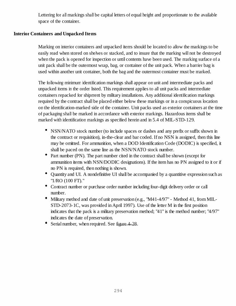
Lettering for all markings shall be capital letters of equal height and proportionate to the availablespace of the container.
Interior Containers and Unpacked Items
Marking on interior containers and unpacked items should be located to allow the markings to beeasily read when stored on shelves or stacked, and to insure that the marking will not be destroyedwhen the pack is opened for inspection or until contents have been used. The marking surface of aunit pack shall be the outermost wrap, bag, or container of the unit pack. When a barrier bag isused within another unit container, both the bag and the outermost container must be marked.
The following minimum identification markings shall appear on unit and intermediate packs andunpacked items in the order listed. This requirement applies to all unit packs and intermediatecontainers repacked for shipment by military installations. Any additional identification markingsrequired by the contract shall be placed either below these markings or in a conspicuous locationon the identification-marked side of the container. Unit packs used as exterior containers at the timeof packaging shall be marked in accordance with exterior markings. Hazardous items shall bemarked with identification markings as specified herein and in 5.4 of MIL-STD-129.
NSN/NATO stock number (to include spaces or dashes and any prefix or suffix shown inthe contract or requisition), in-the-clear and bar coded. If no NSN is assigned, then this linemay be omitted. For ammunition, when a DOD Identification Code (DODIC) is specified, itshall be paced on the same line as the NSN/NATO stock number.Part number (PN). The part number cited in the contract shall be shown (except forammunition items with NSN/DODIC designations). If the item has no PN assigned to it or ifno PN is required, then nothing is shown.Quantity and UI. A nondefinitive UI shall be accompanied by a quantitive expression such as"1/RO (100 FT)."Contract number or purchase order number including four-digit delivery order or callnumber.Military method and date of unit preservation (e.g., "M41-4/97" - Method 41, from MIL-STD-2073-1C, was provided in April 1997). Use of the letter M in the first positionindicates that the pack is a military preservation method; "41" is the method number; "4/97"indicates the date of preservation.Serial number, when required. See figure 4-28.
294
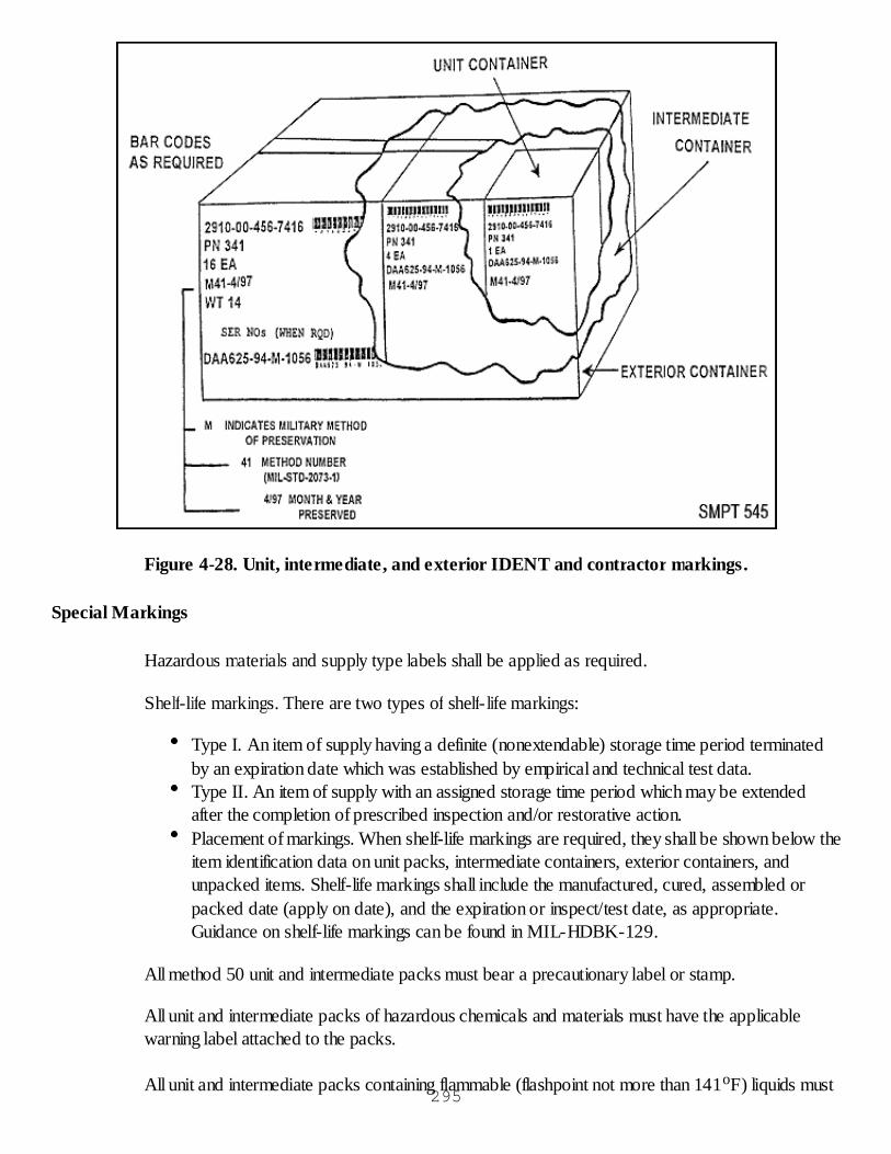
Figure 4-28. Unit, intermediate, and exterior IDENT and contractor markings.
Special Markings
Hazardous materials and supply type labels shall be applied as required.
Shelf-life markings. There are two types of shelf-life markings:
Type I. An item of supply having a definite (nonextendable) storage time period terminatedby an expiration date which was established by empirical and technical test data.Type II. An item of supply with an assigned storage time period which may be extendedafter the completion of prescribed inspection and/or restorative action.Placement of markings. When shelf-life markings are required, they shall be shown below theitem identification data on unit packs, intermediate containers, exterior containers, andunpacked items. Shelf-life markings shall include the manufactured, cured, assembled orpacked date (apply on date), and the expiration or inspect/test date, as appropriate.Guidance on shelf-life markings can be found in MIL-HDBK-129.
All method 50 unit and intermediate packs must bear a precautionary label or stamp.
All unit and intermediate packs of hazardous chemicals and materials must have the applicablewarning label attached to the packs.
All unit and intermediate packs containing flammable (flashpoint not more than 141oF) liquids must295
be marked with the flashpoint of the material. The marking must be expressed in degrees Celsiusand degrees Fahrenheit, in parenthesis, such as "FLASHPOINT 30oC (86oF)", and must beapplied on the identification marked side by means of labeling, printing, stamping, or stenciling.
Exterior Container Identification and Contract Data Markings
Required markings. The required markings shall be placed so as not to be obscured by cleats orstrapping. Unless otherwise specified, one end and the top and bottom of containers shall alwaysbe free of any markings.
Exterior identification markings. Exterior identification markings shall be composed of the followinginformation in the order listed. The words "national stock number," "part number," "quantity," "unitof issue," "method of pack," and "date" shall not be made a part of the marking.
NSN/NATO stock number (See unit markings).Part number, (See unit markings).Quantity and unit of issue.Military method and date of unit preservation (e.g., "M41-4/97" - Method 41, from MIL-STD-2073-1C, was provided in April 1997). Use of the letter M in the first positionindicates that the pack is a military preservation method; "41" is the method number; "4/97"indicates the date of preservation.Serial number(s), when required.Gross weight.Proper shipping names and identification number (United Nations) for hazardous items only.The proper shipping name shall be placed below the gross weight.
NOTES: 1. The inspect/test date and other shelf-life markings, when required, shall be appliedbelow the identification markings.
2. Boxes and crates 10 cubic feet and over shall have identification markings placed on the end ofthe container to the left of the identification-marked side, in addition to the identification side (figure4-29).
296
Figure 4-29. Box 10 IDENT over or under 10 cubic feet.
Exterior Container Contract Data Markings (See Figure 4-28).
Contract data markings shall include the contract or purchase order number and delivery order orcall number, and the modification for change order number (when used). Additional informationmay be required by the procurement contract or order. When more than one contract is applicableto a multipack, contract data markings are not required on the exterior container but shall beapplied to each container in the multipack. Contract data markings shall be placed below theidentification markings on the various exterior containers and unpacked items.
Unless specifically required by a military service or defense agency directive, contract datamarkings are not required on exterior containers when items are repacked for shipment by militaryinstallations.
For Defense Supply Center, Philadelphia (DPSC) Clothing and textile (C&T) items only, the use oflabels is prohibited. The following additional markings are required: shipment number, lot number,and container number. The container number shall be consecutively numbered from each shippingpoint for the duration of the contract. For multiple container shipments of C&T items, the packinglist shall be placed inside the last container to be loaded for each shipment. The words "PACKINGLIST HERE" shall be stenciled on the container.
Marking For Assorted Items
Related items. When an assortment of related items which cannot be identified under one stocknumber, but support a specific weapon system or end item, is packed in a shipping container, thelevel of protection afforded the pack, the date of pack, the gross weight, cube, and specialmarkings shall be applied, plus a brief description of the contents in lieu of the identification data;e.g., spare parts for NSN XXX, Packing List enclosed. Kit or set components shall be suitablysegregated and identified within the unit pack by part number or NSN.
297
Unrelated items. When containers of unrelated items comprised of mixed NSNs which do notsupport a specific weapon system or end item are consolidated into a shipping container. The word"MULTIPACK"shall be applied to the shipping container and the gross weight in lieu of theidentification markings. Examples of marking are as follows:
MULTIPACK
WT 100
When a multipack shipment contains shelf-life material, the following statement will appearimmediately below the identification markings: "CONTAINS SHELF-LIFE ITEMS." This isin addition to any shelf-life marking/data which may be placed on the multipack.When a multipack shipment contains items that are covered by a warranty agreement, thefollowing statement shall appear immediately below the identification markings:"WARRANTED ITEMS INSIDE."When a multipack contains HAZMAT, PSNs with applicable ID numbers, and NA or UNidentification numbers shall be marked on each applicable container in the multipack. Theyshall also be listed on the identification-marked side of the multipack.Caution markings will be applied as required (e.g., Fragile, DOT Hazardous Labels, etc.).
Marking of Gross Weight
The capital letters "WT" shall precede gross weight numerals. All weights shall be numericallyindicated and shall be expressed in pounds to the nearest pound.
When more than one contract is applicable to a multipack container, contract date is not requiredon the exterior container but shall be applied to each individual container within the multipack.Contract data is not required when items are repacked for shipment by military installations.
Packing list and DOD Single Line Item Release/Receipt Document, DD Form 1348-1A
Packing list
Sets, kits, or assemblies composed of unlike items but identified by a single stock number or partnumber, shall have a packing list identifying each item securely attached to the end or side of thecontainer. Sets with two or more exterior shipping containers of different stock numbered or part-numbered items require a master packing list. One copy shall be attached to container No. 1 andone copy placed inside container No. 1. The contents of packages containing installation orassembly hardware such as brackets, connectors, nuts, bolts, and washers shall be listed in detailon the packing list. "Kit contents lists" shall be placed inside the "kit container" and shall not beincluded with the packing list on the outside of the exterior container. An additional packing listplaced inside each container is recommended. For information on exceptions to the use of exteriorcontainer documentation, see below. Automated packing lists (APL) shall contain the minimum datalisted in DOD 4000.25-1-M.
Exceptions to the use of Exterior Container Documentation, Such as Packing Lists, DD Forms 250,DD Forms 1155, and DD Form 1348-1A. 298
With the following exceptions, exterior container documentation is required on all contractor andDOD shipments. No exterior documentation is required for containers of like items or single-itempacks when the contents are listed on a label attached to the boxes, lithographed or printed on theboxes, or when a manufacturer’s part list is provided. For Foreign Military Sales (FMS) shipments,exterior container documentation is always required.
For controlled, sensitive, classified, and pilferable items (except for FMS shipments), the shippingdocumentation shall be placed inside all containers rather than on the outside. For classifiedshipments, markings, which indicate the classified nature of the materiel and its securityclassification, shall not appear on the exterior of each container. If a pilferable shipment is also anFMS shipment, the exception does not apply.
Single Stock Numbered Assembled Sets
Sets consisting of two or more exterior shipping containers consisting of unlike stock numbereditems, packed in more than one shipping container, require a packing list for each container. Thepacking list shall be attached to the exterior of each container. A master packing list shall beprepared for the set and a copy attached to container No. 1.
DD Form 250 (Materiel Inspection and Receiving Report)
The DD Form 250 should be used as a packing list for contractor shipments and shall be applied toexterior containers, as applicable. Packing list copies shall be in addition to the copies required forstandard distribution in the DFAR Supplement to the Federal Acquisition Regulation (DFARSupplement) and shall be marked "Packing List."On multiple container shipments, contractorsshall, when either specified in the contract or requested by the procuring activity/installation, place apacking list inside each container in addition to attaching a packing list to the outside of eachcontainer.
DD Form 1155 (Order for Supplies or Services/ Request for Quotation)
DD Form 1155 shall be attached to the commercial packing list used by vendors and shall beapplied to exterior containers, as applicable. When specified, the case number and the requisitionnumber shall be included.
Application of Packing Lists
Exterior packing lists shall be sealed in water-resistant envelopes and secured to the exterior of thepalletized load or container in the most protected location. An illustration on placement of a packinglist is in figure 4-30.
299

Figure 4-30. Recommended packing list application per MIL-HDBK-129.
Shipment Units Of Single-Line Items
For single-line item shipments, one legible copy of the DD Form 1348-1A shall be attached to themateriel in shipping container No. 1. In addition, at least one legible copy of the applicable formshall be enclosed in a water-resistant envelope attached to the outside of the shipping container.When the storage container is used as the shipping container, the copy normally placed inside thecontainer shall be enclosed with the copy attached to container No.1
Shipment Units of Multiple-Line Items
For multiple-line item shipments, one copy of the DD Form 1348-1A shall be placed in a water-resistant envelope so that the NSN is visible. The envelope shall be attached to the packageapplicable to each requisition. When a polyethylene bag is used to group single items for packing,the same bag shall contain a DD Form 1348-1A folded so that the identification and requisitioninformation are visible. At least one copy of the form, applicable to each requisition, shall also beplaced in a water-resistant envelope attached to the exterior of each multipack container.
Methods of attaching documentation to fiberboard boxes
DD Forms 1348-1A and APLs shall be attached to fiberboard boxes in the following manner.Prior to sealing the fiberboard box, place the appropriate papers in a water-resistant envelope.Then place the envelope under the flaps of the box so that the open end/flap of the envelopeextends down the end of the box under the closure tape. Place the words "PAPERS HERE" on thetape in letters at least half an inch high directly over the envelope containing the papers. This is notauthorized for FMS shipments, except for those sent by registered mail. When shrink or stretch film300
is used to consolidate multiple items, one copy of the DD Form 1348-1A shall be attached to themateriel. For single items, two copies of the applicable form shall be placed under the shrink film insuch a manner as to be read. This method is not authorized for FMS shipments.
Method of Attaching Accompanying Documentation for Shipments of Vehicles
A minimum of two copies of the DD Form 1348-1A or DD Form 250 shall be provided and shallbe securely attached in or on the vehicle as follows:
Interior. Place one copy of the shipping document and one copy of thepreservation/depreservation guide within a sealed bag conforming to Type I, Class B, Style 2or 3 of MIL-B-117 or within a water-resistant envelope. Attach the bag or envelope to aconspicuous location inside the vehicle.Exterior. Place the one remaining copy of the shipping document and thepreservation/depreservation guide, unit packed as specified above, on the vehicle adjacent tothe shipping address and securely attach the bag to the envelope.
Exceptions to the use of Exterior Container Documentation, Such as Packing Lists, DD Forms 250,DD Forms 1155, and DD Form 1348-1A
With the following exceptions, exterior container documentation is required on all contractor andDOD shipments:
No exterior documentation is required for containers of like items or single-item packs when thecontents are listed on a label attached to the boxes, lithographed or printed on the boxes, or when amanufacturer’s part list is provided. For FMS shipments, exterior container documentation isalways required.
For controlled, sensitive, classified, and pilferable items (except for FMS shipments), the shippingdocumentation shall be placed inside all containers rather than on the outside. For classifiedshipment, markings, which indicate the classified nature of the materiel and its security classification,if it will identify the classified nature of the shipment, shall not appear on the exterior of eachcontainer. If a pilferable shipment is also an FMS shipment, the exception does not apply.
Address Markings
Application of Address Marking
The domestic and overseas shipment address markings shall be applied by means of stencils, labels,or tags. When the use of labels will interfere with or obscure other required markings on shippingcontainers, tags shall be used. Separate tags shall be used for identification markings and addressmarkings. Contractors have the option of applying the address markings by means of stenciling orscreening provided procurement costs are not increased.
Military Shipment Address Label as Shown in Figure 4-31 (Except Parcel Post)301
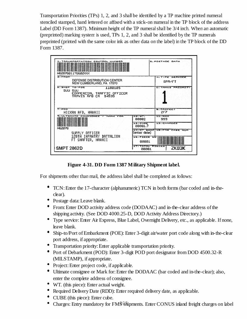
Transportation Priorities (TPs) 1, 2, and 3 shall be identified by a TP machine printed numeralstenciled stamped, hand lettered or affixed with a stick-on numeral in the TP block of the addressLabel (DD Form 1387). Minimum height of the TP numeral shall be 3/4 inch. When an automatic(preprinted) marking system is used, TPs 1, 2, and 3 shall be identified by the TP numeralspreprinted (printed with the same color ink as other data on the label) in the TP block of the DDForm 1387.
Figure 4-31. DD Form 1387 Military Shipment label.
For shipments other than mail, the address label shall be completed as follows:
TCN: Enter the 17-character (alphanumeric) TCN in both forms (bar coded and in-the-clear).Postage data: Leave blank.From: Enter DOD activity address code (DODAAC) and in-the-clear address of theshipping activity. (See DOD 4000.25-D, DOD Activity Address Directory.)Type service: Enter Air Express, Blue Label, Overnight Delivery, etc., as applicable. If none,leave blank.Ship-to/Port of Embarkment (POE): Enter 3-digit air/water port code along with in-the-clearport address, if appropriate.Transportation priority: Enter applicable transportation priority.Port of Debarkment (POD): Enter 3-digit POD port designator from DOD 4500.32-R(MILSTAMP), if appropriate.Project: Enter project code, if applicable.Ultimate consignee or Mark for: Enter the DODAAC (bar coded and in-the-clear); also,enter the complete address of consignee.WT. (this piece): Enter actual weight.Required Delivery Date (RDD): Enter required delivery date, as applicable.CUBE (this piece): Enter cube.Charges: Entry mandatory for FMS shipments. Enter CONUS inland freight charges on label302
of number one piece of shipment unit.Date shipped: Enter four-position julian date (e.g., 8180) or the in-the-clear date (e.g., 29Jun 88).FMS case number: Enter as appropriate.Piece number: Enter bar coded and in-the-clear.Total pieces: Enter total pieces in shipment unit.
For mail shipments, the label shall be completed as follows:
TCN: Enter the 17-character (alphanumeric) TCN in both forms (bar coded and in-the-clear).Postage data: Use one of the following:
For metered mail, leave blank and attach the stick-on metered postage values to ornear this block.For permit imprint mail, enter the appropriate service/agency mail authorization.
Example: First Class Mail Postage and Fees Paid Defense Logistics Agency Permit No. G-53
For standard penalty indicia mail, enter the appropriate service/agency name orabbreviation and its sampling number.
Example: Postage and Fees Paid Department of the Navy DO-316
From: Enter the in-the-clear address of the shipping activity, including the zip code. The phrase "OFFICIALBUSINESS, PENALTY FOR PRIVATE USE $300" must be printed on the bottom line of this block.
Type service: Enter First Class-Priority Mail, Express Mail, Military Ordinary Mail, etc., as applicable.
Ship to/POE: For CONUS mail, enter the complete address of the consignee, including the nine-digit zip code.For mail to overseas locations, enter postal concentration at DTS port or MILSTAMP Air/Water Port identifier(APO/FPO).
Transportation priority: Enter appropriate transportation priority.
POD: Leave blank.
Project: Enter project code, if appropriate.
Ultimate consignee or Mark for: Enter DODAAC of consignee (bar coded and in-the-clear). For CONUS,no other data; for overseas shipments, add detailed address.
WT. (this piece): Enter actual weight.303

RDD: Enter, if applicable.
Cube (this piece): Enter cube.
Charges: Leave blank.
Date shipped: Enter the four-digit date (day f the year) (e.g., 8181) or the in-the-clear date (e.g., 29 Jan 98).
FMS case number: Enter, if applicable.
Piece number: Enter bar coded and in-the-clear.
Total pieces: Enter total pieces in shipment unit.
For unit moves: The address label should be completed as follows:
TCN: Enter the 17-characters (alphanumeric) TCN for shipments entering the DTS, asapplicable, bar coded and in-the-clear.Postage Data: Leave blank.From: Enter the DODAAC and in-the-clear address of the shipping activity.Type service: Leave blank.Ship to POE: Enter three digit air/water port code and in-the-clear port name.Transportation Priority: Leave blank. (There is no TP on unit moves.)POD: enter three digit air/water POD code. (May be coded and/or in-the-clear.) Forclassified moves, leave blank.Project: Enter project code, if applicable.Ultimate Consignee/Mark for:
Enter:Unit Identifier Code (UIC).Vehicle bumper number, if applicable.Vehicle serial number.Equipment description. (TMCR 56-69, paragraph 21-3, Labels will container descriptivedata for ease of matching labels with equipment.)Vehicle/cargo dimensional data (length (L) width (W), height (H); dimensional data will assistcargo handlers in determining whether a peice can fit in a given area.)Classified moves: Do not enter POD. (See MILSTAMP, Volume I, appendix G, paragrapha(3))
Weight (this piece): Enter actual weight.RDD: Enter, if appropriate.CUBE (this piece): Enter cube.Charges: Leave blank.Date Shipped: Leave blank.FMS Case Number: Leave blank.Piece number: Enter bar coded and in-the-clear.Total Pieces: Enter total pieces in shipment unit.
304
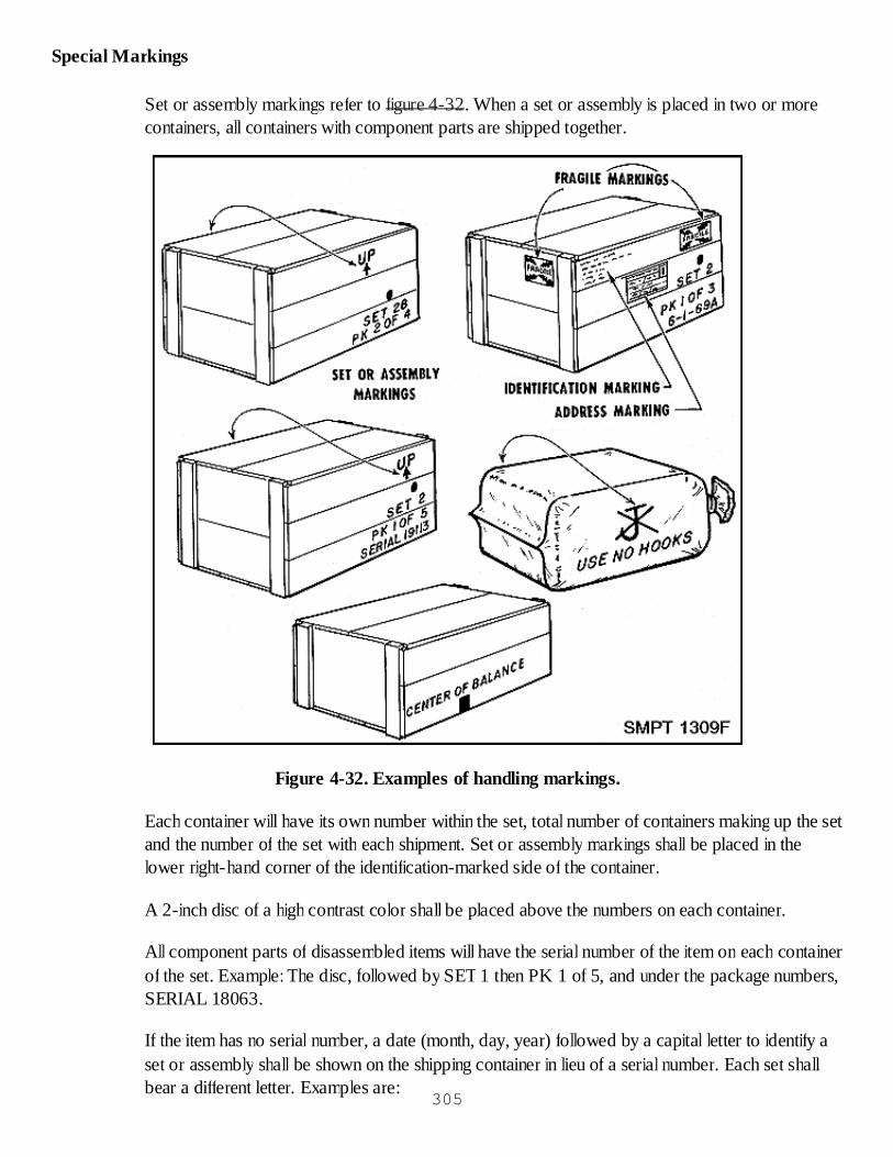
Special Markings
Set or assembly markings refer to figure 4-32. When a set or assembly is placed in two or morecontainers, all containers with component parts are shipped together.
Figure 4-32. Examples of handling markings.
Each container will have its own number within the set, total number of containers making up the setand the number of the set with each shipment. Set or assembly markings shall be placed in thelower right-hand corner of the identification-marked side of the container.
A 2-inch disc of a high contrast color shall be placed above the numbers on each container.
All component parts of disassembled items will have the serial number of the item on each containerof the set. Example: The disc, followed by SET 1 then PK 1 of 5, and under the package numbers,SERIAL 18063.
If the item has no serial number, a date (month, day, year) followed by a capital letter to identify aset or assembly shall be shown on the shipping container in lieu of a serial number. Each set shallbear a different letter. Examples are:
305
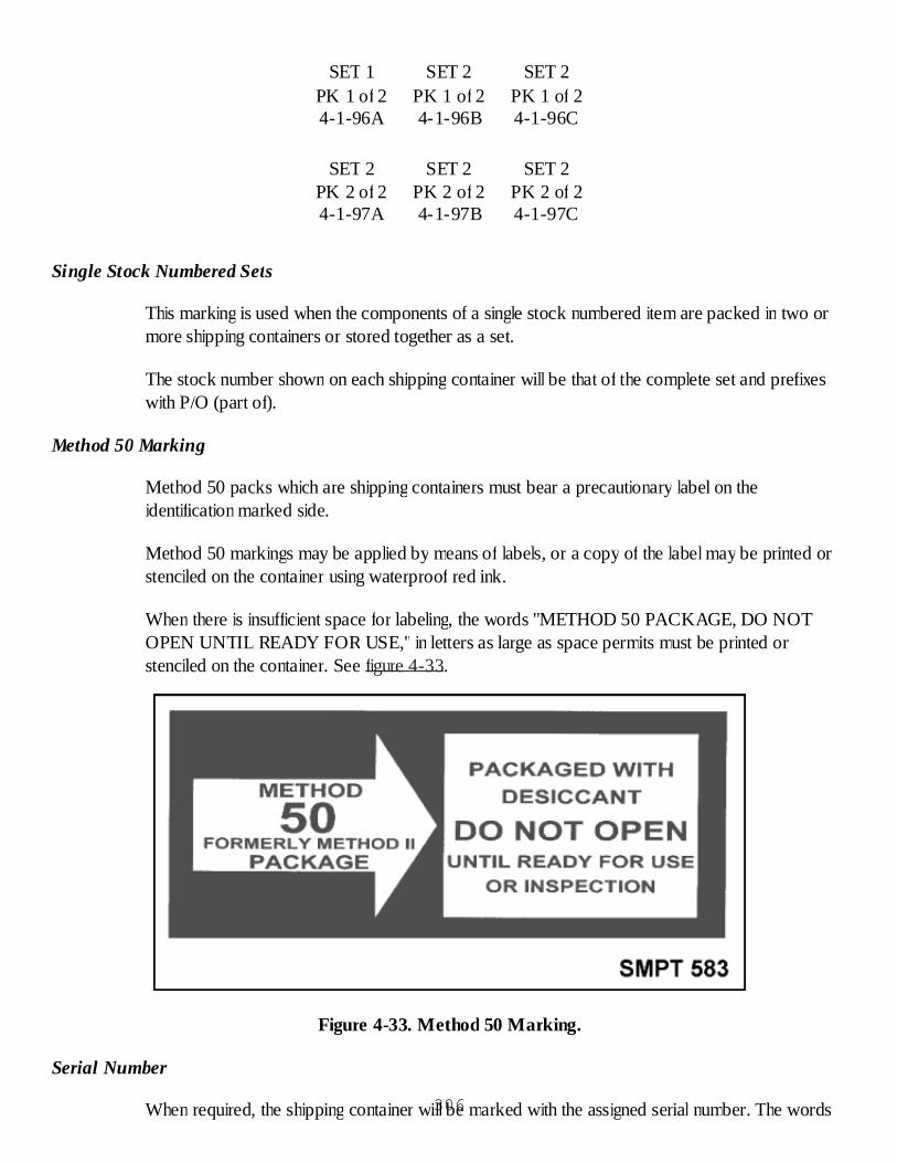
SET 1PK 1 of 24-1-96A
SET 2PK 1 of 24-1-96B
SET 2PK 1 of 24-1-96C
SET 2PK 2 of 24-1-97A
SET 2PK 2 of 24-1-97B
SET 2PK 2 of 24-1-97C
Single Stock Numbered Sets
This marking is used when the components of a single stock numbered item are packed in two ormore shipping containers or stored together as a set.
The stock number shown on each shipping container will be that of the complete set and prefixeswith P/O (part of).
Method 50 Marking
Method 50 packs which are shipping containers must bear a precautionary label on theidentification marked side.
Method 50 markings may be applied by means of labels, or a copy of the label may be printed orstenciled on the container using waterproof red ink.
When there is insufficient space for labeling, the words "METHOD 50 PACKAGE, DO NOTOPEN UNTIL READY FOR USE," in letters as large as space permits must be printed orstenciled on the container. See figure 4-33.
Figure 4-33. Method 50 Marking.
Serial Number
When required, the shipping container will be marked with the assigned serial number. The words306
"Serial No."will be used to identify the information indicated and located directly below theidentification marking. (Example: Serial No. 26481.)
Medical Material
Containers packed with frozen medical material shipments (constant temperature must remainbelow 32oF) must have completed PERISHABLE--KEEP FROZEN labels (DD Form 1502),figure 4-34, applied to the address side of each container. The applicable icing and time data are tobe inserted on the labels at time of shipment. In addition, "ARROW" and "FRAGILE"markingsmust be applied to containers of frozen medical items. When shipping by military air transportation,a completed DD Form 1387-2 (Special Handling Data/Certification Form) is required and must beapplied to the address side of the container. Three copies of the form will also be affixed to the"one end"of the container in a waterproof envelope.
307

Figure 4-34. Frozen medical material shipment form.
Containers packed with chilled medical material shipments (constant temperatures must bemaintained between 35 oand 46oF) must have completed PERISHABLE--KEEP CHILLEDlabels (DD Form 1502-1), figure 4-35, applied to the address side of each container. Theapplicable icing and time data are to be inserted on the labels at time of shipment. In addition,"ARROW" and "FRAGILE" markings must be applied to containers of chilled medical items. Acompleted DD Form 1387-2 is required and must be applied to the address side of the containerwhen shipment is via military air transportation. Three copies of the form will also be affixed to the"one end"of the container in a waterproof envelope.308

309

Figure 4-35. Chilled medical material shipment form.
Containers packed with limited unrefrigerated medical material shipments out of refrigeration (whenreceipt of shipment by consignee is assured within a specified number of days) must havePERISHABLE labels (DD Form 1502-2), figure 4-36 applied to the address side of the eachcontainer. The data applicable to time of removal from refrigeration are to be inserted on the labelat time of shipment. In addition, "ARROW" and "FRAGILE" markings must be applied tocontainers of perishable medical items. A completed DD Form 1387-2 is required and must beapplied to the address side of the container when shipment is via military air transportation. Threecopies of the form will also be affixed to the "one end"of the container in a waterproof envelope.
310

Figure 4-36. Limited unrefrigerated medical shipment.311
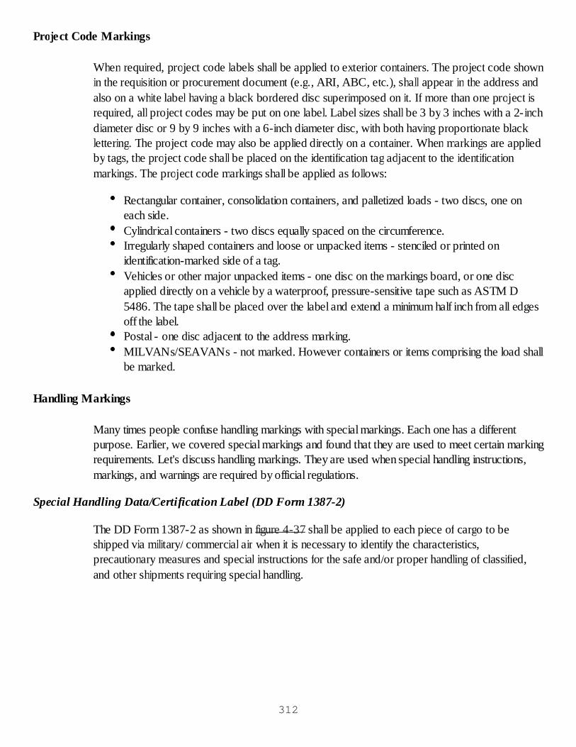
Project Code Markings
When required, project code labels shall be applied to exterior containers. The project code shownin the requisition or procurement document (e.g., ARI, ABC, etc.), shall appear in the address andalso on a white label having a black bordered disc superimposed on it. If more than one project isrequired, all project codes may be put on one label. Label sizes shall be 3 by 3 inches with a 2-inchdiameter disc or 9 by 9 inches with a 6-inch diameter disc, with both having proportionate blacklettering. The project code may also be applied directly on a container. When markings are appliedby tags, the project code shall be placed on the identification tag adjacent to the identificationmarkings. The project code markings shall be applied as follows:
Rectangular container, consolidation containers, and palletized loads - two discs, one oneach side.Cylindrical containers - two discs equally spaced on the circumference.Irregularly shaped containers and loose or unpacked items - stenciled or printed onidentification-marked side of a tag.Vehicles or other major unpacked items - one disc on the markings board, or one discapplied directly on a vehicle by a waterproof, pressure-sensitive tape such as ASTM D5486. The tape shall be placed over the label and extend a minimum half inch from all edgesoff the label.Postal - one disc adjacent to the address marking.MILVANs/SEAVANs - not marked. However containers or items comprising the load shallbe marked.
Handling Markings
Many times people confuse handling markings with special markings. Each one has a differentpurpose. Earlier, we covered special markings and found that they are used to meet certain markingrequirements. Let's discuss handling markings. They are used when special handling instructions,markings, and warnings are required by official regulations.
Special Handling Data/Certification Label (DD Form 1387-2)
The DD Form 1387-2 as shown in figure 4-37 shall be applied to each piece of cargo to beshipped via military/ commercial air when it is necessary to identify the characteristics,precautionary measures and special instructions for the safe and/or proper handling of classified,and other shipments requiring special handling.
312
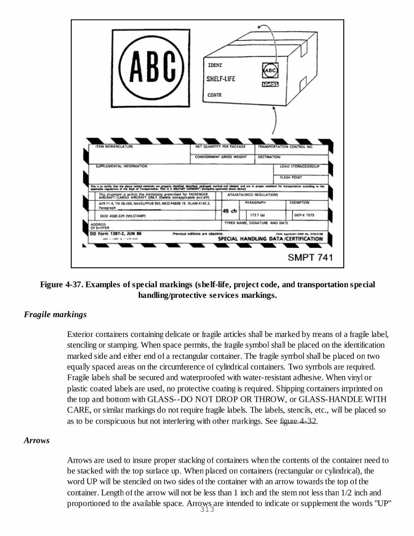
Figure 4-37. Examples of special markings (shelf-life, project code, and transportation specialhandling/protective services markings.
Fragile markings
Exterior containers containing delicate or fragile articles shall be marked by means of a fragile label,stenciling or stamping. When space permits, the fragile symbol shall be placed on the identificationmarked side and either end of a rectangular container. The fragile symbol shall be placed on twoequally spaced areas on the circumference of cylindrical containers. Two symbols are required.Fragile labels shall be secured and waterproofed with water-resistant adhesive. When vinyl orplastic coated labels are used, no protective coating is required. Shipping containers imprinted onthe top and bottom with GLASS--DO NOT DROP OR THROW, or GLASS-HANDLE WITHCARE, or similar markings do not require fragile labels. The labels, stencils, etc., will be placed soas to be conspicuous but not interfering with other markings. See figure 4-32.
Arrows
Arrows are used to insure proper stacking of containers when the contents of the container need tobe stacked with the top surface up. When placed on containers (rectangular or cylindrical), theword UP will be stenciled on two sides of the container with an arrow towards the top of thecontainer. Length of the arrow will not be less than 1 inch and the stem not less than 1/2 inch andproportioned to the available space. Arrows are intended to indicate or supplement the words "UP"
313

or "TOP."These markings are affixed only when necessary. The word UP may be above, below,or on the stem of the arrow. See figure 4-32.
Center of Balance and Sling Points or Lifting Points
A 1-inch wide vertical line not less than 3 inches long and locating the center of balance must beextended up from the bottom of both sides of containers regardless of its length. The words"CENTER OF BALANCE" will be stenciled or printed in 1-inch letters above or alongside thecenter of balance mark. Sling points will be marked on unboxed equipment with white letters. Lightcolored surfaces will be marked in black (example: SLING POINTS). On vehicles which arepainted white, yellow or other light colors, the marking shall be black and the words, "LIFT HERE"with arrows pointing to the lifting eyes shall be placed immediately above or alongside of the liftingeyes. See figure 4-32.
Load-Bearing Areas and Lift Points
These markings are required when shipping containers and contents are subject to damage bytwisting, bending, or uneven container stresses. The words "LOAD BEARING AREA" will bemarked on two opposite panels of the container directly over the load bearing areas. The words"FORKLIFT AREA" will be placed directly over the forklift entry points of the skid and rubbingstrip.
Legend "USE NO HOOKS"
When required, the legend "USE NO HOOKS" in letters not less than 1 2 inches in height shouldbe stenciled on both sides of shipping containers in which the contents are susceptible to damage bythe use of hooks. In addition, a hook symbol with a superimposed "X" sufficiently heavy to conveythe intended prohibitory use of the hooks should be placed directly above the legend. See figure 4-32.
Magnetic Materials Markings as Shown in Figure 4-38
When you are required to pack magnetic material for shipment, you should show whether or notthe material is being shipped by military aircraft. It is important to know this, so that the propermagnetic materials label may be used. Boxes, packages, and items containing magnetized materialsuitable for shipment by military aircraft in conformance with MIL-S-4473, shall be marked inaccordance with MIL-STD-129. Magnetized materials suitable for shipment by commercial airshall be marked in conformance with CFR 49. Boxes, packages, and items containing magnetizedmaterial not suitable for shipment by military aircraft in conformance with MIL-S-4473, shall beconspicuously marked on two opposite sides with a red caution label having white lettering.Magnetic tapes data shall be conspicuously labeled on both interior and exterior containers.
314
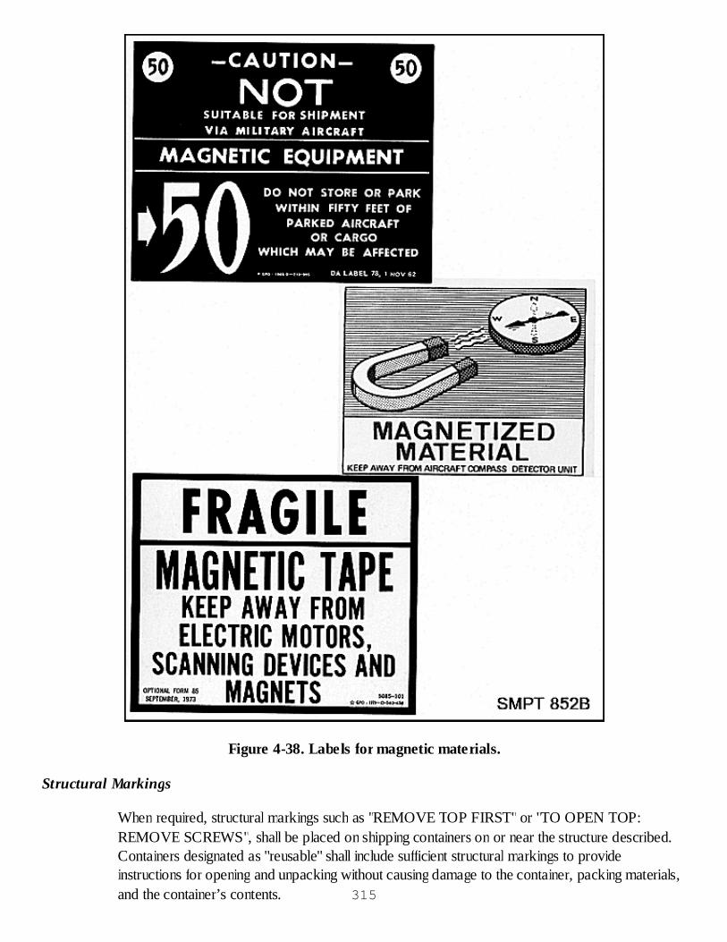
Figure 4-38. Labels for magnetic materials.
Structural Markings
When required, structural markings such as "REMOVE TOP FIRST" or "TO OPEN TOP:REMOVE SCREWS", shall be placed on shipping containers on or near the structure described.Containers designated as "reusable" shall include sufficient structural markings to provideinstructions for opening and unpacking without causing damage to the container, packing materials,and the container’s contents. 315

As you have just seen, handling markings are very important to our packs. When they are usedproperly, we are relatively sure our packs will arrive safely at their destination.
Expedited Handling Markings as Shown in Figure 4-39
Requisitions and contracts identified as NMCS (Not Mission Capable Supply) shipments shall havean NMCS code shown in the required delivery date block of the address label.
The applicable code is 999 or the letter "N" which may be followed by RDD expressed in thenumber of days from the requisition dates.
In addition to appearing on the address label, NMCS condition 999 shipments shall be markedwith two 999 labels on each container.
For NMCS condition other than 999, containers shall be marked with two NMCS labels.
One label shall be placed adjacent to the address marking, and one shall be placed on the oppositeside.
Figure 4-39. Expedited.
Pictorial Symbols for Marking (see figure 4-40)
Containers should be marked with pictorial symbols to indicate special handling and storage needs,such as "TEMPERATURE LIMITS, DO NOT STACK, DO NOT DROP, DO NOT ROLL,
316
CLAMP HERE, FRAGILE, HANDLE WITH CARE, KEEP AWAY FROM HEAT and KEEPAWAY FROM COLD." They may appear on a label or be printed directly on the package.Affirmative and negative symbols need not be framed by border lines, but all negative symbols with"DO NOT ..." should have borders with a slash mark across. Additional pictorial marking symbolsand their application are illustrated in ASTM D 5445.
Figure 4-40. Pictorial symbols.
Marking Procedures for Boxes and Crates
The required markings for boxes and crates must be placed on the location specified and must notbe obscured by cleats and strapping. For the purpose of this lesson, each box or crate must havetwo ends, two sides, a top, and a bottom.
Unless otherwise specified, an end and the top and bottom of containers shall always be free of any317
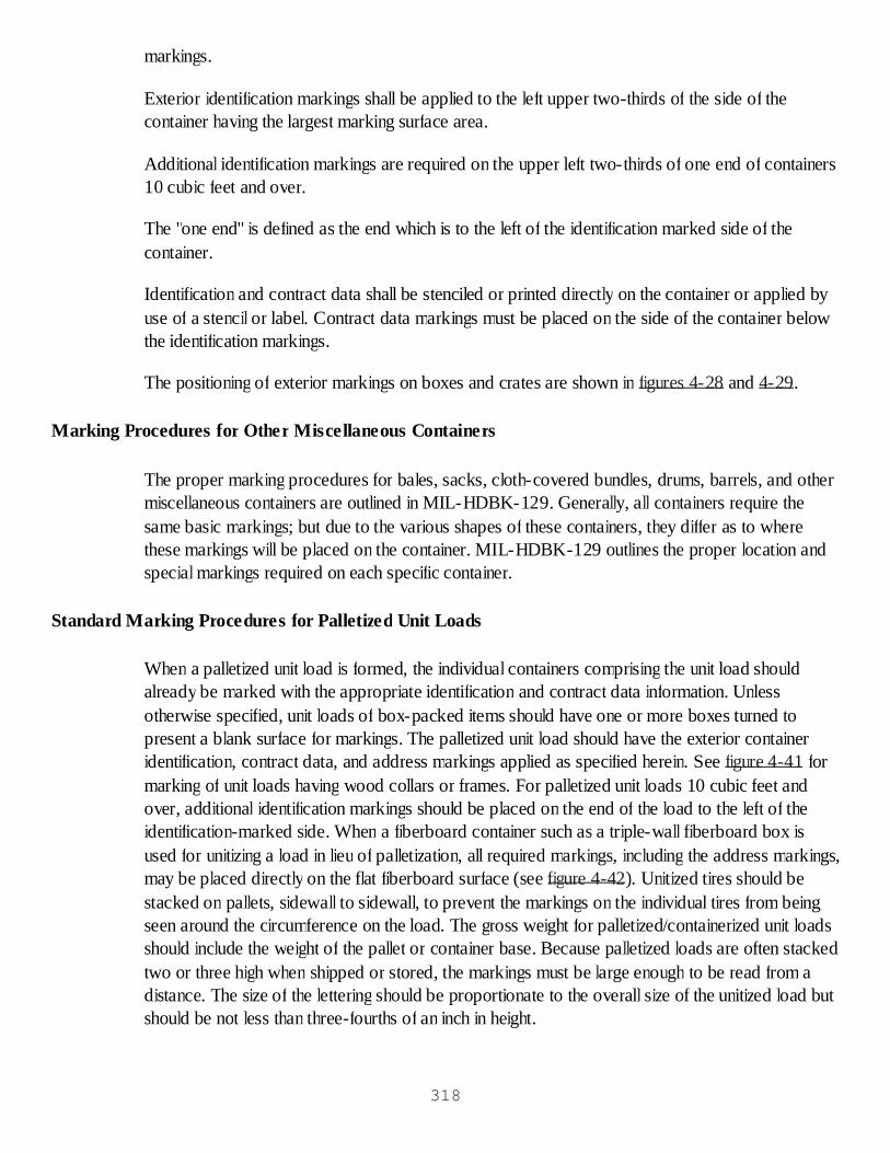
markings.
Exterior identification markings shall be applied to the left upper two-thirds of the side of thecontainer having the largest marking surface area.
Additional identification markings are required on the upper left two-thirds of one end of containers10 cubic feet and over.
The "one end" is defined as the end which is to the left of the identification marked side of thecontainer.
Identification and contract data shall be stenciled or printed directly on the container or applied byuse of a stencil or label. Contract data markings must be placed on the side of the container belowthe identification markings.
The positioning of exterior markings on boxes and crates are shown in figures 4-28 and 4-29.
Marking Procedures for Other Miscellaneous Containers
The proper marking procedures for bales, sacks, cloth-covered bundles, drums, barrels, and othermiscellaneous containers are outlined in MIL-HDBK-129. Generally, all containers require thesame basic markings; but due to the various shapes of these containers, they differ as to wherethese markings will be placed on the container. MIL-HDBK-129 outlines the proper location andspecial markings required on each specific container.
Standard Marking Procedures for Palletized Unit Loads
When a palletized unit load is formed, the individual containers comprising the unit load shouldalready be marked with the appropriate identification and contract data information. Unlessotherwise specified, unit loads of box-packed items should have one or more boxes turned topresent a blank surface for markings. The palletized unit load should have the exterior containeridentification, contract data, and address markings applied as specified herein. See figure 4-41 formarking of unit loads having wood collars or frames. For palletized unit loads 10 cubic feet andover, additional identification markings should be placed on the end of the load to the left of theidentification-marked side. When a fiberboard container such as a triple-wall fiberboard box isused for unitizing a load in lieu of palletization, all required markings, including the address markings,may be placed directly on the flat fiberboard surface (see figure 4-42). Unitized tires should bestacked on pallets, sidewall to sidewall, to prevent the markings on the individual tires from beingseen around the circumference on the load. The gross weight for palletized/containerized unit loadsshould include the weight of the pallet or container base. Because palletized loads are often stackedtwo or three high when shipped or stored, the markings must be large enough to be read from adistance. The size of the lettering should be proportionate to the overall size of the unitized load butshould be not less than three-fourths of an inch in height.
318

Figure 4-41. Marking of unit loads which have wood collars or frames.
319
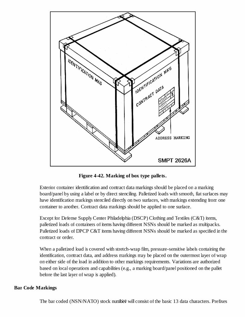
Figure 4-42. Marking of box type pallets.
Exterior container identification and contract data markings should be placed on a markingboard/panel by using a label or by direct stenciling. Palletized loads with smooth, flat surfaces mayhave identification markings stenciled directly on two surfaces, with markings extending from onecontainer to another. Contract data markings should be applied to one surface.
Except for Defense Supply Center Philadelphia (DSCP) Clothing and Textiles (C&T) items,palletized loads of containers of items having different NSNs should be marked as multipacks.Palletized loads of DPCP C&T items having different NSNs should be marked as specified in thecontract or order.
When a palletized load is covered with stretch-wrap film, pressure-sensitive labels containing theidentification, contract data, and address markings may be placed on the outermost layer of wrapon either side of the load in addition to other markings requirements. Variations are authorizedbased on local operations and capabilities (e.g., a marking board/panel positioned on the palletbefore the last layer of wrap is applied).
Bar Code Markings
The bar coded (NSN/NATO) stock number will consist of the basic 13 data characters. Prefixes320
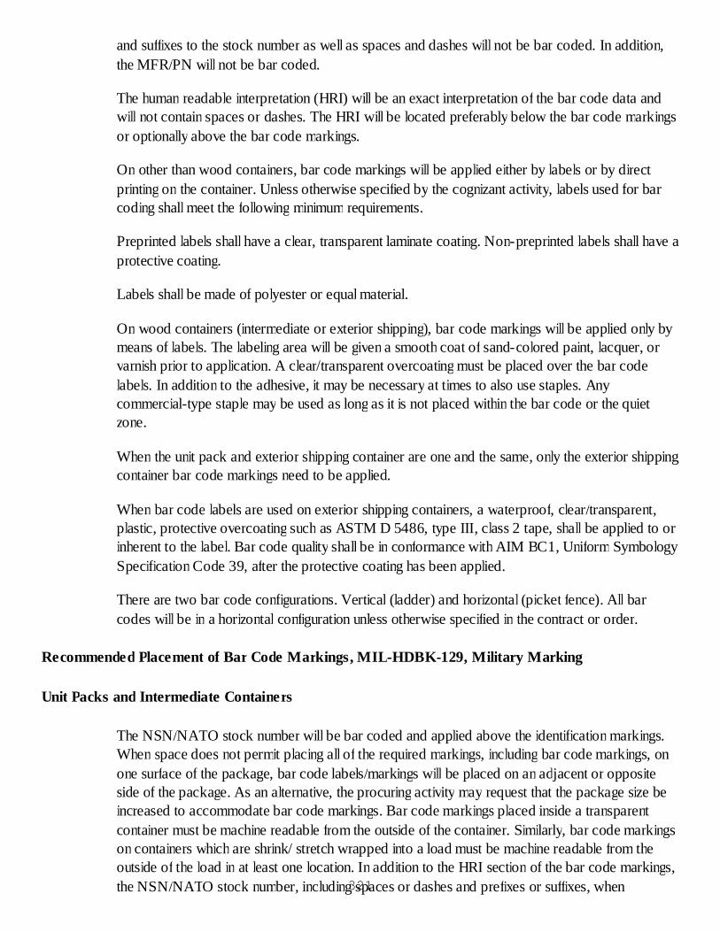
and suffixes to the stock number as well as spaces and dashes will not be bar coded. In addition,the MFR/PN will not be bar coded.
The human readable interpretation (HRI) will be an exact interpretation of the bar code data andwill not contain spaces or dashes. The HRI will be located preferably below the bar code markingsor optionally above the bar code markings.
On other than wood containers, bar code markings will be applied either by labels or by directprinting on the container. Unless otherwise specified by the cognizant activity, labels used for barcoding shall meet the following minimum requirements.
Preprinted labels shall have a clear, transparent laminate coating. Non-preprinted labels shall have aprotective coating.
Labels shall be made of polyester or equal material.
On wood containers (intermediate or exterior shipping), bar code markings will be applied only bymeans of labels. The labeling area will be given a smooth coat of sand-colored paint, lacquer, orvarnish prior to application. A clear/transparent overcoating must be placed over the bar codelabels. In addition to the adhesive, it may be necessary at times to also use staples. Anycommercial-type staple may be used as long as it is not placed within the bar code or the quietzone.
When the unit pack and exterior shipping container are one and the same, only the exterior shippingcontainer bar code markings need to be applied.
When bar code labels are used on exterior shipping containers, a waterproof, clear/transparent,plastic, protective overcoating such as ASTM D 5486, type III, class 2 tape, shall be applied to orinherent to the label. Bar code quality shall be in conformance with AIM BC1, Uniform SymbologySpecification Code 39, after the protective coating has been applied.
There are two bar code configurations. Vertical (ladder) and horizontal (picket fence). All barcodes will be in a horizontal configuration unless otherwise specified in the contract or order.
Recommended Placement of Bar Code Markings, MIL-HDBK-129, Military Marking
Unit Packs and Intermediate Containers
The NSN/NATO stock number will be bar coded and applied above the identification markings.When space does not permit placing all of the required markings, including bar code markings, onone surface of the package, bar code labels/markings will be placed on an adjacent or oppositeside of the package. As an alternative, the procuring activity may request that the package size beincreased to accommodate bar code markings. Bar code markings placed inside a transparentcontainer must be machine readable from the outside of the container. Similarly, bar code markingson containers which are shrink/ stretch wrapped into a load must be machine readable from theoutside of the load in at least one location. In addition to the HRI section of the bar code markings,the NSN/NATO stock number, including spaces or dashes and prefixes or suffixes, when321

applicable, shall be marked in-the-clear as the first line of identification markings.
Exterior Shipping Container Under 10 Cubic Feet
For exterior containers, the NSN/NATO stock number and contract number will be bar coded andwill be applied on the identification side of the container. The bar code symbol will be located in anarea adjacent to the identification markings and will be in a horizontal, or "picket fence,"configuration. The bar code will be applied at minimum distances of 2.0 inches (50.8mm) from thetop and bottom edges, 1.0 inch (25.4mm) from the side edges, and a minimum distance (quietzone) of 0.25 inch (6.35mm) from the nearest identification marking will be maintained. Bar codesmay be applied in either one of the following formats, listed in order of preference, unless otherwisespecified:
Stacked on two separate lines with the NSN/NATO stock number immediately above thecontract number. When a stacked configuration is used, the bar codes shall be left-justified(left-hand (start) characters vertically aligned).Horizontal (in line) with the NSN/NATO stock number preceding the contract number andwith a minimum space of 0.5 inch (12.7mm) separating the two bar codes. Other data, whenspecified, will follow the contract number with a minimum separation of 0.5 inch (12.7mm).See figure 4-43.
322
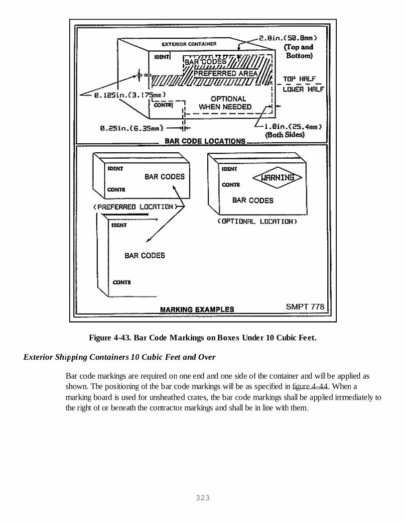
Figure 4-43. Bar Code Markings on Boxes Under 10 Cubic Feet.
Exterior Shipping Containers 10 Cubic Feet and Over
Bar code markings are required on one end and one side of the container and will be applied asshown. The positioning of the bar code markings will be as specified in figure 4-44. When amarking board is used for unsheathed crates, the bar code markings shall be applied immediately tothe right of or beneath the contractor markings and shall be in line with them.
323

Figure 4-44. Exterior container bar code markings on boxes 10 cubic feet and over.
Bar coded tags
If space permits on the identification tag, the bar code label/marking may be applied to the right ofthe identification markings or beneath the contract data markings. If space does not permit, the barcode markings may be applied on the reverse side of the tag.
Multipacks
Item identification markings will not be bar coded on the exterior shipping container of multipackshipments. However, unit packs and intermediate containers require bar coding. The contractnumber will be bar coded on the exterior shipping container of the multipack if the number appliesto all unit and intermediate containers in the multipack. If mixed contract numbers are contained inthe multipack, then each unit or intermediate container will have the contract data bar coded, andthe exterior container will not be bar coded.
Checkup
What is the purpose of marking? 324
What documents cover marking for shipment and storage?What are the required interior unit pack identification markings?How many oversea address labels are required on a box over 10 cubic feet?Where are the identification markings and contract data markings located on a palletizedload of fiberboard boxes?Where is the domestic or overseas shipment address label located on the exterior shippingcontainer?
MARKING AND LABELING APPLICATION PRACTICAL EXERCISE
Objective
As a result of this practical exercise, the student will be able to apply the appropriate marking andlabels to containers being prepared for shipment.
General Instructions
This exercise will take approximately one class period.
This exercise will be conducted in the classroom.
A critique will be conducted at the end of the exercise.
Conduct of Exercise
Situation
As a packer you are responsible for marking and labeling containers for shipment. You are going topack items which will be sent as a multipack to a break bulk point where the individual packs willbe transshipped.
Requirement No. 1. Answer the following questions.
What materials may be used for stencil marking?List at least 4 waterproofing materials used as protective coatings.What special materials are used to obliterate CARC painted markings on metal reusablecontainers?Describe the requirements for pressure sensitive, water-resistant paper labels.What are the general requirements for the condition of surfaces to be marked?What materials may be used for stencil marking?List weatherproofing materials that may be used as protective coatings.What special materials are used to obliterate CARC painted markings on metal reusablecontainers?What are the general requirements for the condition of surfaces to be marked?How many expedited shipment labels are required on each box and where are they placed?A 2-inch black ball on the lower half of the right hand end of the marked side means the box325

is what?What should you do with old or unrequired markings?On a box over 10 cubic ft., where is the address label placed?Where are the identification markings placed on a 12 cu. ft. crate?Under what circumstances are you required to put center of balance markings on acontainer?Describe the two types of shelf-life markings.What markings must be placed on an exterior shipping container of unrelated items?How would you protect the packing list for a military overseas shipment?What labels would you put on a container of frozen medical material which will be shippedby military air?List the proper exterior identification markings in the proper order for the shipment describedbelow.
PN: 3456NSN: 1234-56-789-1234Method and level of pads: M41-4/97Gross weight: 8 lbs. Gross weight should be rounded up to the nearest pound.Quantity and Issue: 2 ea.
Critique
The instructor will hold an oral critique of the exercise when the students have finished answeringthe questions.
Care of Area, Training Aids & Equipment
Not applicable.
HAZARDOUS MATERIALS
GENERAL
Because of the special nature of hazardous materials and the associated dangers, the public and thegovernment are taking greater interest in their shipment and storage. Everyday more and more itemsare being placed under hazardous materials regulation. As the number of regulated hazardousmaterials increases, the greater the chance that they will enter the inventory of items with which youare associated. It is important, therefore, that you be able to readily identify hazardous materialsthrough their labels and special markings.
HAZARDOUS MATERIAL REGULATION
The proper classification of hazardous materials influences the packaging, hazard markings, shippingpaper entries, emergency response, and any other instruction governing the material. It is, therefore,essential that the appropriate classification is made, because improper classification can be326

extremely dangerous.
CLASSIFICATION
Department of Transportation hazardous material class (classification) definitions. (Also used byDOD).
Class 1 (Explosive)
An "explosive"means any substance or article, including a device, which is designed to function byexplosion (i.e., an extremely rapid releases of gas and heat) or which, by chemical reaction withinitself, is able to function in a similar manner even if not designed to function by explosion, unless thesubstance or article is otherwise classed under the provision of CFR 49. Explosives in Class 1 aredivided as follows:
Division 1.1 consists of explosives that have a mass explosion hazard. A mass explosion isone which affects almost the entire load instantaneously.Division 1.2 consists of explosives that have a projection hazard, but not a mass explosionhazard.Division 1.3 consists of explosives that have a fire hazard and either a minor blast hazard or aminor projection hazard or both, but not a mass explosion hazard.Division 1.4 consists of explosive devices that present a minor explosion hazard. No devicein this division may contain more than 25 g (0.9 ounce) of a detonating material.Division 1.5 consists of very insensitive explosives. This division is comprised of substanceswhich have a mass explosion hazard but are so insensitive that there is very little probabilityof initiation or of transition from burning to detonation under normal conditions of transport.Division 1.6 consists of extremely insensitive articles which do not have a mass explosivehazard.
Class 2 (Gases)
Gases in Class 2 are divided as follows:
Division 2.1 (Flammable gas) "Flammable gas" means any material which is a gas at 20oC(68oF) or less and 101.3 kPa (14.7 psi) of pressure (a material which has a boiling point of20oC (68oF) or less at 101.3 kPa (14.7 psi) which is ignitable at 101.3 kPa (14.7 psi) whenin a mixture of 13 percent or less by volume with air; or has a flammable range 101.3 kPa(14.7) with air of at least 12 percent regardless of the lower limit.Division 2.2 (non-flammable, non-poisonous compressed gas). A "non-flammable, nonpoisonous compressed gas" means any material (or mixture) which exerts in the packagingan absolute pressure of 280 kPa (41 psia) at 20oC (68oF), and does not meet the definitionof Division 2.1 or 2.3.Division 2.3 (Poisonous or toxic gas). "Poisonous gas" means a material which is a gas at20oC (68oF) or less and a pressure of 101.3 kPa (14.7 psi) (a material which has a boiling
327

point of 20oC (68oF) or less at 101.3 kPa (14.7 psi) and which is known to be so toxic tohumans as to pose a hazard to health during transportation, or in the absence of adequatedata on human toxicity, is presumed to be toxic to humans based on tests.
Class 3 (Flammable liquids)
A "flammable liquid" means any liquid having a flashpoint of not more than 60.5oC (141oF) withcertain exceptions listed in CFR 49.
Flammable Solids
Class 4 flammable solids are as follows:
Division 4.1 (Flammable Solid). A "flammable solid" means any of the following three typesof material:
Certain wetted explosivesSelf reactive materialsReadily combustible materials
Division 4.2 (Spontaneously Combustible Material). "Spontaneously combustible material" iseither pyrophoric or self-heating.
A pyrophoric material is a liquid or solid that, even in small quantities and without anexternal ignition source, can ignite after coming in contact with air.A self-heating material is a material that, when in contact with air and with an energysupply, is liable to self-heat.
Division 4.3 (Dangerous when wet material). "Dangerous when wet material" means amaterial that is spontaneously flammable or gives off flammable or toxic gases when incontact with water.
Class 5
Class 5 is made up of the following divisions:
Division 5.1 (Oxidizer). "Oxidizer" means a material that may, generally by yielding oxygen,cause or enhance the combustion of other materials.Division 5.2, (Organic Peroxide). "Organic peroxide" means any organic compoundcontaining oxygen (O2) in the bivalent -0-0-structure and which may be considered aderivative of hydrogen peroxide, where one or more of the hydrogen atoms have beenreplaced by organic radicals, with certain exceptions.
Class 6
Class 6 is made up of the following divisions:
Division 6.1 (Poisonous or Toxic Material). A "poisonous material" means a material, other328

than a gas, which is known to be so toxic to humans as to afford a hazard to health duringtransportation, or which, in the absence of adequate data on human toxicity is presumed tobe toxic to humans.Division 6.2 (Infectious Substance). An "infectious substance" means a viable microorganism,or its toxin, which causes or may cause disease in humans or animals, and includes thoseagents listed in 42 CFR 72.3 of the regulations of the Department of Health and HumanServices or any other agent that has the potential to cause severe, disabling or fatal disease.
Class 7 (Radioactive Material)
"Radioactive material" means any materials having a specific activity greater than 0.002 microcurieper gram (µci/g).
Class 8 (Corrosive Material)
A "corrosive material" is a liquid or solid that causes visible destruction or irreversible alterations inhuman skin tissue at the site of contact, or a liquid that has a severe corrosion rate on steel oraluminum.
Miscellaneous Hazardous Materials
"Miscellaneous hazardous materials" means a material which presents a hazard during transport, butwhich is not included in any other hazard class. This class includes:
Any material which has an anesthetic, noxious or other similar property which could causeextreme annoyance or discomfort to a flight crew member so as to prevent the correctperformance of assigned duties.Any material that is not included in any other hazard class, but is subject to the requirementsCFR 49 because it meets the definition of an elevated temperature material, a hazardoussubstance or a hazardous waste.
Other Regulated Materials (ORM)
"ORM-D material" means a material such as a consumer commodity, which, although otherwisesubject to the regulations presents a limited hazard during transportation due to its form, quantityand packaging.
Hazardous Material Identification Numbers
Most hazardous materials have been given identification numbers. These numbers are preceded bythe letters UN for proper shipping names considered appropriate for international transportation aswell as domestic transportation and NA associated with proper shipping names not recognized forinternational transportation, except to and from Canada. Identification numbers may be found onshipping papers, individual packages, placards, and/or panels. These numbers are also a key to aguide published by the Department of Transportation (DOT P5800.5, Emergency Response329
Guidebook) that outlines initial action to be taken by emergency response personnel handlingincidents involving hazardous material. Each guide lists potential hazards and emergency actions thatshould be taken.
Labels
Since each class of hazardous materials has its own characteristic, it is important to be able toidentify the contents of the individual packages. This is accomplished by special markings andlabels. Let us look at the labels first.
All hazardous materials class labels are diamond shaped. Each side of the diamond is at least4 inches long.Each label is distinctive color and contains both a representative symbol plus the classdesignation.Labels are generally required to be placed on the surface of the package bearing the propershipping name.When more than one hazardous material is packaged in a container, more than one label orkind of labels may be needed.In some cases more than one hazard class warning label(s) is required. The first label shownfor an entry indicates the primary hazard of the material and additional labels indicatesubsidiary or secondary hazards.Subsidiary/secondary labels will not bear a hazard class identification number. This is to helpemergency responders identify the primary hazard to which they must respond. Rationale: Itis essential that readers understand there is a difference in primary and subsidiary labels.No label will be used on a package if the material is not hazardous, and no label that lookslike a hazardous label should be used.
Markings
Containers of hazardous materials must be marked per MIL-STD-129, Standard Practice forMilitary Marking. That is, the container must have the normal markings found on all the material inthe Defense Transportation System, such as the identification, contract, and shipping markings.
In addition, the container must have the proper shipping name and the identification numberassigned to the material by CFR 49 applied below the identification markings. For hazardousmaterials classified as an ORM, the appropriate designation must be placed after the propershipping name.
Non-bulk packages having inner packagings containing liquid hazardous material must be packedwith the closure up and legibly marked with "arrows" pointing in the correct upright direction of thepackage.
Radioactive material packs will be marked either Type A or Type B indicating the type of package.When in excess of 110 pounds (50 kilograms), must have its gross weight marked on the outside ofthe package.
330
With a few exceptions, packages containing hazardous materials must be marked with the "propershipping name"as determined from the applicable modal regulations. The proper shipping name isused to provide universal understanding of the contents of the package, since the proper shippingname may be different from the item nomenclature. The four digit identifications number is alsoapplied for this reason.
Markings must be clear and durable, and on a contrasting background.
Most hazardous material packages must be marked with the name and address of the consignee orconsignor.
Only authorized abbreviations, such as "w" for with, "wo" for without, and ORM for OtherRegulated Materials may be used.
Performance Oriented Packaging (POP) markings shall be located opposite the identificationmarked side of the package (see figure 4-45).
331

Figure 4-45. An example of exterior container HAZMAT marking and labeling requirements.
Compatibility
Compatibility of hazardous materials is a key factor that needs to be considered during every phaseof packaging, shipping, storage and transportation. Packages containing hazardous material whichreact dangerously with another are incompatible and must be segregated and/or in some casesseparated during shipment and storage.
Compatibility and other safety considerations are also crucial during loading and movement ofhazardous materials. Compatibility must be determined through the proper use of the Segregationand Separation charts in the CFR 49. Additionally, for movement on military aircraft, the pilot must332

be notified when and where hazardous materials are positioned on the aircraft in case of an incident.
Placards
The final means of identifying shipments of hazardous materials is placarding.
Placards are similar to the labels, but they are placed on the outside of the vehicle.
They are also diamond-shaped, but 10-3/4 inches on each side.
They contain a symbol and description of the contents of the vehicle (not necessarily the class).Placards for tank cars will have the identification number of the material in place of the descriptivewording.
The shipper is responsible for furnishing the required placards to the carrier.
The placards are needed on all ends and sides of the transporting vehicle and some freightcontainers and portable tanks.
General Packaging Requirements
Containers are to be so designed and constructed that there will be no significant release of thehazardous material into the environment.
There must be no mixture of gases that could increase heat or pressure that would reduce theeffectiveness of the package.
Containers labeled with the "Empty" label must be entirely free of any hazardous material.
Many containers will be marked with the Department of Transportation (DOT) specificationnumber for the container, e.g., DOT-1A, DOT23G40, etc.
Containers should be made of materials that do not react with the hazardous material inside.
Containers with screw cap closures should be sealed with a secondary closure to prevent looseningby vibration.
Containers being reused must have the old markings removed or obliterated.
Containers should be marked with the proper shipping name.
For our purpose, it is sufficient to understand that DOD shipments of hazardous materials may bemade in either DOT, UN or federal/military specification containers if they have successfully passedthe performance oriented packaging testing requirements with the material being shipped.
We should always concentrate our efforts to insure that containers of hazardous materials aresound, properly sealed and not leaking. Any indication that the container is not doing its job shouldbe reported and the discrepancy corrected prior to shipment or storage.333

General Handling Requirements
Explosives
To be eligible for transportation, explosives, explosive devices, and munitions, including commercialand foreign, must be tested, approved, and assigned a DOD classification according to TB 700-2/NAVORDINST 8023.3/DLAR 8220.1, DOD Explosive Hazard Classification Procedures. Theservices and DLA must comply with AFI 91-201/TM 9-1300-206/NAVSEA OP 5 for safetyprecautions, standards, and rules when operating in an environment with explosives.
Flammable Liquids
These materials should be stored in cool, well-ventilated areas. They must be stored away fromsources of heat, flames, sparks, combustible materials or oxidizing agents. Containers must be kepttightly closed. In the event of leakage or spillage, rubber gloves, goggles, aprons and respiratorsmust be used.
Flammable Solids and Oxidizing Materials
These materials must be stored in cool, well-ventilated areas away from moisture. They must not bestored near corrosives. All containers must be tightly and securely closed.
Corrosive Materials
Corrosives must be stored in a cool ventilated area away from sources of heat and oxidizing agents.Gas masks, respirators, rubber gloves, goggles, and other protective clothing should be availablefor use in the event of leakage.
Compressed Gases
These materials, in general, must be stored in a cool, well-ventilated area away from fire hazards,sources of heat, ignition, or sparks. Do not drop jar, or slide containers.
Poisonous Materials
Keep cool and away from direct sunlight and high temperatures. Store away from sources ofignition oxidizing materials, and acids. Avoid direct contact with the materials. Wear a gas mask orbreathing apparatus as instructed by safety personnel during exposure.
Radioactive Materials
Handling requirements for these materials can be complex and involved. At least, it should beemphasized that personnel handling these materials take precautions to minimize exposure.Containers should not be opened except for good reason under supervision of radiologicalprotection personnel.
Handling Markings334

Always be sure to comply with all handling markings, e.g., THIS SIDE UP, FRAGILE, etc.
Training
No person will accept the responsibility of handling HAZMAT, including but not limited to packing,marking, labeling, etc., without first meeting the training requirements found in DOD 4500.9-R,Defense Transportation Regulation, Part II, Cargo Movement, Chapter 204, Hazardous Material.
Checkup
Hazard class labels signify what when placed on a package?What markings are placed on the exterior of a package of hazardous material to identify thematerial?May oxidizing materials be packed in the same outside container with corrosive liquids?
SMALL PARCEL SHIPMENT
DEFINITION
The primary factors to keep in mind when defining small parcels are that weight, cube, and quantityplay the big roles in establishing the requirements for shipment. A parcel may be described as asmall wrapped package, box, bundle, or container.
Parcel Shipment Policy
The DOD supports the use of parcel carriers. Contractors are authorized to employ carriers formovement of small packages within the scope of guidance provided by DLA. Just as in theselection freight carriers, they must weigh all factors and choose mode and carrier according todominant consideration. Their decision must accommodate these rules:
In general, choice of mode and carrier depends upon a number of variables; weight, size,cost, urgency destination, and carrier service. This sequence does not necessarily implyorder of importance. Any one factor or combination can determine choice.Consolidate parcels to common destinations if priority, delivery schedule, contractprovisions, or other factors permit. The mechanics, of course, would consist of holdingparcels for a reasonable length of time and combining them on a pallet or in a container forfreight movement. Conversely, do not break up legitimate freight shipments to ship throughsmall package channels.Each package must contain or have attached four copies of DD Form 250.Under no circumstances should items or materials be tendered to USPS or UPS that couldbe dangerous to life or health of their employees, the general public, or compromise thesafety and security of mail/parcels. USPS Publication 52, entitled "Acceptance of Hazardousor Perishable Articles," identifies nonmailable materials and establishes requirements whichmust be met prior to placing other authorized hazardous items in the mail. A publication byUPS, entitled "Guide for Handling Hazardous Material," contains packaging and
335

labeling requirements as well as a long list of prohibited chemical products notnecessarily reflected in 49 CFR. UPS has designated as hazardous some items not soidentified by DOT.
Parcel Carriers
There are several services which provide for small parcel shipment.
Parcel Post
Defined narrowly, parcel post should be viewed as any material or items tendered to USPS fordelivery through USPS channels. There are many rules surrounding use of parcel post. TheCongress of the United States sets forth conditions under which postal services are available to thepublic.
The availability of postal services
The Code of Federal Regulations, Title 39, sets forth service available, prescribes rates, fees, andconditions under which postal services are available. The Postal Service Manual containsregulations and procedures for both public and internal use. Chapter 1 covers procedures for useby the postal department, public, and authorized departments and agencies of the FederalGovernment.
Postal Services for Military Use
The postal services for military use are outlined in DOD Instruction 4525.8, Official Mail. Themilitary post offices are designated as APO's and FPO's for OCONUS and by military activity forCONUS. Both follow the regulations and procedures set forth in the Postal Service Manual.Chapter 1 of the Postal Service Manual covers the parcel post procedure.
Shipment of Military Items
The shipment of military items by parcel post requires the same type of blocking, bracing, containerselection, closure, and marking as previously covered in this document. Shipment of material byparcel post is desirable whenever shipments meet the requirements of the Postal Service. Materialwill be cleaned, dried, and preserved (as required), neutral or greaseproof wrap applied, andcushioning, blocking and/or bracing furnished as needed. Additionally, parcels addressed tooverseas military post offices must be packed in boxes or containers constructed from metal,wood, plastic, or class weather-resistant, class waterproof, or water-vapor resistant fiberboard.Parcels containing mailable (nontoxic and nonflammable) gases, liquids, oils, paint, and substanceswhich easily liquefy, must have sufficient absorbent cushioning material within the containers toabsorb the contents in case of breakage.
Restricted and Nonmailable
The following items as shown in figure 4-46 are restricted and nonmailable to, from, or betweenoverseas military post offices: 336

Matches of all kinds, lighter fluid, or lighters containing fluid.Air shipments of magnetic material capable of producing sufficient magnetic fields to causeappreciable deviation to compass sensing device of an aircraft at fifteen feet or more (doesno apply to surface shipments).Any package of radioactive matter which contains in excess of the quantities listed in theCode of Federal Regulations, Title 49 and United States Postal Services Publication No. 6.,Explosives or ammunition.
Figure 4-46. Restricted and nonmailable items.
Mailings Within the United States
Priority or first-class mail shall be used only for high-priority logistic shipments, such as 999shipments, and Weapon System Pouches (WSP's). Priority or first-class mail shall also be used forUniform Material Movement and Issue Priority System (UMMIPS) priority designators 01-08shipments that are consigned to a location more than 300 miles from the shipper. UMMIPS prioritydesignator 01-08 shipments consigned to location 300 miles or less shall be sent as third or fourth-class mail. All UMMIPS priority designators 09-15 shipments shall be sent third or fouth-class mailor held for consolidation as freight, whichever is less costly.
Mailing Overseas
Mailings to, from, and between overseas are via the MPS. Priority or first-class mail shall be usedonly for high-priority logistics shipments, such as, 999, WSPS and UMMIPS priority designators01-08 shipments. All UMMIPS priority designators 09-15 shipments shall be sent by third orfourth-class mail or held for consolidation as freight, whichever is less costly.
Addressing and Marking
MIL-STD-129, Standard Practice for Military Marking, governs addressing and marking. Exceptfor precautionary labels, packing list, or other markings required by regulation or statute, no othermarkings need appear on an outer wrap or container provided it is a supplemental container usedfor shipping purposes only and the enclosed container has the required identification markings. If a337

USPS mail pouch is used as the outer container for mailing of more than one package as a directpouch to the addressee, each package in the pouch must have a parcel post label attached. Parcelpost shipments to Army Post Office/Air Post Office (APO)/Fleet Post Office (FPO). APO/FPOparcel post shipment address shall be composed as follows. The DD Form 1387 shall be used as aparcel post address label and shall be completed as follows:
C TCN: Enter the 17-character (alphanumeric) TCN in both forms (bar coded and in-the-clear).Postage data: Use one of the following:
For metered mail, leave blank and attach the stick-on metered postage values to ornear this block.For permit imprint mail, enter the appropriate service/agency mail authorization.
Example: First Class Mail Postage and Fees Paid Defense Logistics Agency Permit No. G-53
For standard penalty indicia mail, enter the appropriate service/agency name orabbreviation and its sampling number.
Example: Postage and Fees Paid Department of the Navy DOD-316
From: Enter the in-the-clear address of the shipping activity, including the zip code. Thephrase "OFFICIAL BUSINESS, PENALTY FOR PRIVATE USE $300" must be printedon the bottom line of this block.Type service: Enter First Class- Priority Mail, Express Mail, Military Ordinary Mail, etc., asapplicable.Ship to/POE: For CONUS mail, enter the complete address of the consignee, including thenine-digit zip code. For mail to overseas locations, enter postal concentration at DTS port orMILSTAMP Air/Water Port identifier (APO/FPO).Transportation priority: Enter appropriate transportation priority.POD: Leave blank.Project: Enter project code, if applicable.Ultimate consignee or Mark for: Enter DODAAC of consignee (bar coded and in-the-clear).For CONUS, no other data; for overseas shipments, add detailed address.WT. (this piece): Enter actual weight.RDD: Enter, if applicable.CUBE (this piece): Enter cube.Charges: Leave blank.Date shipped: Enter four-digit julian date (e.g., 8180) or the in-the-clear date (e.g., 29 Jun88).FMS case number: Enter, if applicable.Piece number: Enter bar coded and in-the-clear.
338
Total pieces: Enter number of pieces in the shipment unit.
Hazardous Materials
It is absolutely imperative that shipments do not violate the Postal Service Manual Part 124. Thispart defines material and substances which may not be transmitted through the USPS.
Weight and size limits
Packages are limited to not more than 70 pounds and 108 inches in length and girth combined. Theminimum weight for a package to qualify for parcel post is 16 ounces. Two or more packages maybe mailed as a single parcel, if they are about the same size or shape or if they are parts of onearticle. They must be securely wrapped or fastened together and must not, together, exceed theweight or size limit. To compute the size of a parcel as shown in figure 4-47. Measure the longestside to get the length. Measure distance around the parcel at its thickest part to get the girth. Addthe length and the girth together.
339
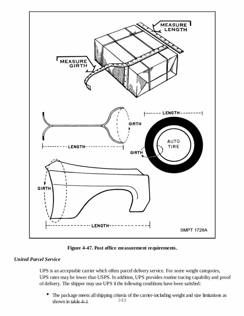
Figure 4-47. Post office measurement requirements.
United Parcel Service
UPS is an acceptable carrier which offers parcel delivery service. For some weight categories,UPS rates may be lower than USPS. In addition, UPS provides routine tracing capability and proofof delivery. The shipper may use UPS if the following conditions have been satisfied:
The package meets all shipping criteria of the carrier-including weight and size limitations asshown in table 4-1 340
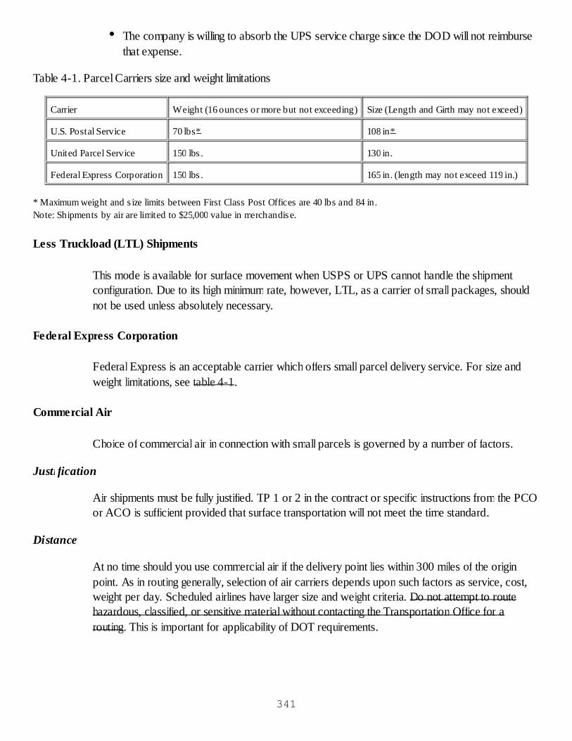
The company is willing to absorb the UPS service charge since the DOD will not reimbursethat expense.
Table 4-1. Parcel Carriers size and weight limitations
Carrier Weight (16 ounces or more but not exceeding) Size (Length and Girth may not exceed)
U.S. Postal Service 70 lbs* 108 in*
United Parcel Service 150 lbs . 130 in.
Federal Express Corporation 150 lbs . 165 in. (length may not exceed 119 in.)
* Maximum weight and s ize limits between First Class Post Offices are 40 lbs and 84 in.Note: Shipments by air are limited to $25,000 value in merchandise.
Less Truckload (LTL) Shipments
This mode is available for surface movement when USPS or UPS cannot handle the shipmentconfiguration. Due to its high minimum rate, however, LTL, as a carrier of small packages, shouldnot be used unless absolutely necessary.
Federal Express Corporation
Federal Express is an acceptable carrier which offers small parcel delivery service. For size andweight limitations, see table 4-1.
Commercial Air
Choice of commercial air in connection with small parcels is governed by a number of factors.
Justification
Air shipments must be fully justified. TP 1 or 2 in the contract or specific instructions from the PCOor ACO is sufficient provided that surface transportation will not meet the time standard.
Distance
At no time should you use commercial air if the delivery point lies within 300 miles of the originpoint. As in routing generally, selection of air carriers depends upon such factors as service, cost,weight per day. Scheduled airlines have larger size and weight criteria. Do not attempt to routehazardous, classified, or sensitive material without contacting the Transportation Office for arouting. This is important for applicability of DOT requirements.
341

342

343